On turbulent friction in straight ducts with complex cross section
11
arXiv:1804.02155v1 [physics.flu-dyn] 6 Apr 2018 Preprint submitted to J. Fluid Mech. 1 On turbulent friction in straight ducts with complex cross section: the wall law and the hydraulic diameter SERGIO PIROZZOLI Dipartimento di Ingegneria Meccanica e Aerospaziale, Sapienza Universit` a di Roma Via Eudossiana 18, 00184 Roma, Italy We develop predictive formulas for friction resistance in ducts with complex cross-sectional shape based on the use of the log law and neglect of wall shear stress nonuniformities. The traditional hydraulic diameter naturally emerges from the analysis as the control- ling length scale for common duct shapes as triangles and regular polygons. The analysis also suggests that a new effective diameter should be used in more general cases, yield- ing corrections of a few percent to friction estimates based on the traditional hydraulic diameter. Fair but consistent predictive improvement is shown for duct geometries of practical relevance, including rectangular and annular ducts, and circular rod bundles. 1. Introduction Internal flows within straight ducts having non-circular cross section are common in many applications of mechanical and hydraulic engineering, including water draining and ventilation systems, nuclear reactors, heat exchangers and turbomachinery. Despite their practical importance, flows in “complex” ducts are understood to a much lesser extent compared to canonical flows in plane channels and circular pipes, one of the main qualitative differences being the occurrence of secondary motions (Prandtl 1926; Nikuradse 1930). Of primary engineering importance is the prediction of the duct friction factor, namely λ = 8 τ w ρu 2 b , (1.1) where τ w is the average wall shear stress along the duct perimeter, ρ is the fluid density, and u b is the duct bulk velocity. For that purpose, a widely used pragmatic approach is assuming that the same friction relationship can be used as for flow in circular pipes, provided a suitable Reynolds number is defined, based on a convenient duct length scale. The most traditional choice, apparently initiated by Schiller (1923), is the hydraulic diameter, defined as D h = 4A P 0 , (1.2) where A is the duct cross-sectional area, and P 0 is the duct perimeter. This choice is frequently justified by the appearance of the area/perimeter ratio in the mean momentum balance equations, which connects the mean wall friction to the duct pressure drop, namely τ w = - A P 0 dp dx , (1.3)
-
Upload
khangminh22 -
Category
Documents
-
view
4 -
download
0
Transcript of On turbulent friction in straight ducts with complex cross section

arX
iv:1
804.
0215
5v1
[ph
ysic
s.fl
u-dy
n] 6
Apr
201
8
Preprint submitted to J. Fluid Mech. 1
On turbulent friction in straight ducts withcomplex cross section: the wall law and the
hydraulic diameter
SERGIO PIROZZOLI
Dipartimento di Ingegneria Meccanica e Aerospaziale, Sapienza Universita di RomaVia Eudossiana 18, 00184 Roma, Italy
We develop predictive formulas for friction resistance in ducts with complex cross-sectionalshape based on the use of the log law and neglect of wall shear stress nonuniformities.The traditional hydraulic diameter naturally emerges from the analysis as the control-ling length scale for common duct shapes as triangles and regular polygons. The analysisalso suggests that a new effective diameter should be used in more general cases, yield-ing corrections of a few percent to friction estimates based on the traditional hydraulicdiameter. Fair but consistent predictive improvement is shown for duct geometries ofpractical relevance, including rectangular and annular ducts, and circular rod bundles.
1. Introduction
Internal flows within straight ducts having non-circular cross section are common inmany applications of mechanical and hydraulic engineering, including water drainingand ventilation systems, nuclear reactors, heat exchangers and turbomachinery. Despitetheir practical importance, flows in “complex” ducts are understood to a much lesserextent compared to canonical flows in plane channels and circular pipes, one of themain qualitative differences being the occurrence of secondary motions (Prandtl 1926;Nikuradse 1930). Of primary engineering importance is the prediction of the duct frictionfactor, namely
λ =8τwρu2
b
, (1.1)
where τw is the average wall shear stress along the duct perimeter, ρ is the fluid density,and ub is the duct bulk velocity. For that purpose, a widely used pragmatic approachis assuming that the same friction relationship can be used as for flow in circular pipes,provided a suitable Reynolds number is defined, based on a convenient duct length scale.The most traditional choice, apparently initiated by Schiller (1923), is the hydraulicdiameter, defined as
Dh =4A
P0, (1.2)
where A is the duct cross-sectional area, and P0 is the duct perimeter. This choice isfrequently justified by the appearance of the area/perimeter ratio in the mean momentumbalance equations, which connects the mean wall friction to the duct pressure drop,namely
τw = −A
P 0
dp
dx, (1.3)

2 S. Pirozzoli
PSfrag replacements yXXw
D P (y)
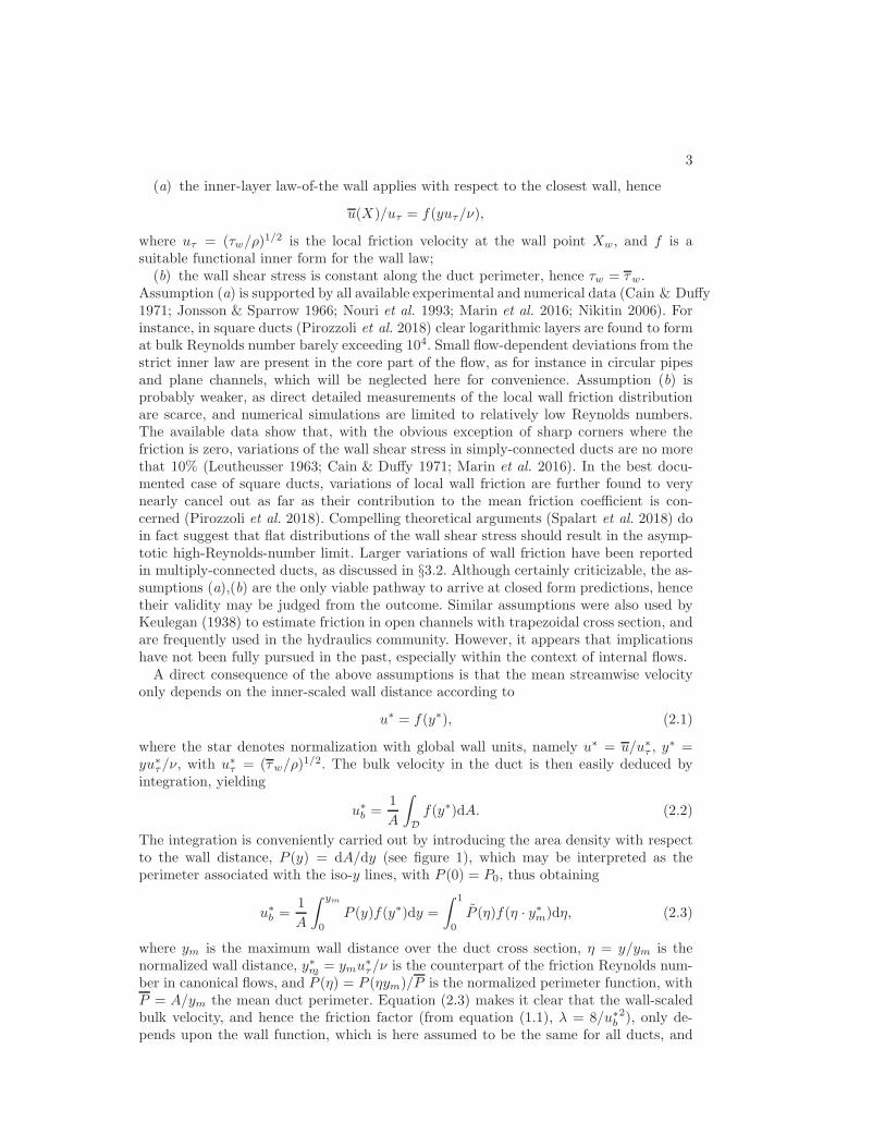
Figure 1: Typical duct cross section (D), with indication of wall distance y, and associatedarea density, P (y). X is a generic point and Xw is its wall foot.
but of course this is a quite tenuous argument. Indeed, limitations of the hydraulicdiameter have emerged, especially in the study of ducts with aspect ratio (here broadlydefined as the ratio of the largest to the smallest dimensions of the duct) significantlydifferent than unity. Hence, semi-empirical corrections to the basic hydraulic diameterconcept have been proposed over the years, tailored to specific duct geometries, as forinstance rectangular ducts (Jones 1976), and general geometries have been frequentlyhandled through ad-hoc extrapolation of laminar results (e.g. Maubach 1970; Rehme1972). More elaborate techniques have sometimes been used relying on application of thelog law in direction normal to the velocity iso-lines, which however require a cumbersomeiterative procedure (Deissler & Taylor 1958).One of the most robust findings in the (few) detailed quantitative studies of non-
canonical duct flow is the presence of logarithmic layers in the wall-normal direction (e.g.Cain & Duffy 1971; Nouri et al. 1993; Jonsson & Sparrow 1966). Even more convincingsupport for the validity of the law-of-the-wall has come from recent numerical studiesdealing with rectangular ducts (Vinuesa et al. 2014), square ducts (Pirozzoli et al. 2018),and hexagonal ducts (Marin et al. 2016), showing that in its inner form it applies withexcellent approximation in the wall-normal direction up to the nearest corner bisector,even near the duct corners, provided the local wall friction is used. A formal theoreticalanalysis of turbulent flow in ducts with complex shape has been recently developed bySpalart et al. (2018). Extending classical inner-outer layer matching arguments, thoseauthors deduced the validity of the logarithmic velocity profile, but also arrived at theinteresting prediction that the wall friction should tend towards being uniform all aroundthe duct except near possible corners, asymptotically as Re → ∞. This was confirmed bynumerical solutions obtained with turbulence models, and it is consistent with recent DNSat moderately high Reynolds number (Pirozzoli et al. 2018). Hence, a reasonably simplestructure of turbulent flow in ducts emerges, which lends itself to analytical treatment.In the forthcoming §2 we develop a simple predictive formula for the friction coefficientfor ducts with arbitrary shape, and in §3 we test its predictive capability. Last, in §4 weoutline implications of the present findings.
2. Friction estimates
The forthcoming discussion pertains to straight ducts with cross-sectional shape Dsuch that a wall distance y (defined at the normal distance to the closest wall) can bedefined for any pointX , as depicted in figure 1. This is a generally acceptable assumption,and counterexamples are difficult to conceive. We hereafter further assume that:
3
(a) the inner-layer law-of-the wall applies with respect to the closest wall, hence
u(X)/uτ = f(yuτ/ν),
where uτ = (τw/ρ)1/2 is the local friction velocity at the wall point Xw, and f is a
suitable functional inner form for the wall law;(b) the wall shear stress is constant along the duct perimeter, hence τw = τw.
Assumption (a) is supported by all available experimental and numerical data (Cain & Duffy1971; Jonsson & Sparrow 1966; Nouri et al. 1993; Marin et al. 2016; Nikitin 2006). Forinstance, in square ducts (Pirozzoli et al. 2018) clear logarithmic layers are found to format bulk Reynolds number barely exceeding 104. Small flow-dependent deviations from thestrict inner law are present in the core part of the flow, as for instance in circular pipesand plane channels, which will be neglected here for convenience. Assumption (b) isprobably weaker, as direct detailed measurements of the local wall friction distributionare scarce, and numerical simulations are limited to relatively low Reynolds numbers.The available data show that, with the obvious exception of sharp corners where thefriction is zero, variations of the wall shear stress in simply-connected ducts are no morethat 10% (Leutheusser 1963; Cain & Duffy 1971; Marin et al. 2016). In the best docu-mented case of square ducts, variations of local wall friction are further found to verynearly cancel out as far as their contribution to the mean friction coefficient is con-cerned (Pirozzoli et al. 2018). Compelling theoretical arguments (Spalart et al. 2018) doin fact suggest that flat distributions of the wall shear stress should result in the asymp-totic high-Reynolds-number limit. Larger variations of wall friction have been reportedin multiply-connected ducts, as discussed in §3.2. Although certainly criticizable, the as-sumptions (a),(b) are the only viable pathway to arrive at closed form predictions, hencetheir validity may be judged from the outcome. Similar assumptions were also used byKeulegan (1938) to estimate friction in open channels with trapezoidal cross section, andare frequently used in the hydraulics community. However, it appears that implicationshave not been fully pursued in the past, especially within the context of internal flows.A direct consequence of the above assumptions is that the mean streamwise velocity
only depends on the inner-scaled wall distance according to
u∗ = f(y∗), (2.1)
where the star denotes normalization with global wall units, namely u∗ = u/u∗τ , y
∗ =yu∗
τ/ν, with u∗τ = (τw/ρ)
1/2. The bulk velocity in the duct is then easily deduced byintegration, yielding
u∗
b =1
A
∫
D
f(y∗)dA. (2.2)
The integration is conveniently carried out by introducing the area density with respectto the wall distance, P (y) = dA/dy (see figure 1), which may be interpreted as theperimeter associated with the iso-y lines, with P (0) = P0, thus obtaining
u∗
b =1
A
∫ ym
0
P (y)f(y∗)dy =
∫ 1
0
P (η)f(η · y∗m)dη, (2.3)
where ym is the maximum wall distance over the duct cross section, η = y/ym is thenormalized wall distance, y∗m = ymu∗
τ/ν is the counterpart of the friction Reynolds num-ber in canonical flows, and P (η) = P (ηym)/P is the normalized perimeter function, withP = A/ym the mean duct perimeter. Equation (2.3) makes it clear that the wall-scaledbulk velocity, and hence the friction factor (from equation (1.1), λ = 8/u∗
b2), only de-
pends upon the wall function, which is here assumed to be the same for all ducts, and
4 S. Pirozzoli
on the duct geometry through the inner-scaled maximum distance y∗m, and the normal-ized perimeter function. For instance, in the case of a circular pipe with diameter D itis straightforward to verify that ym = D/2, P = πD/2, and P = 2(1 − η). Notably,very similar conclusions are obtained for any triangle and for regular polygons, in whichcase ym is the apothem of the cross section, P is half of the outer perimeter, and againP = 2(1 − η). This observation leads to the first important conclusion that, based onthe previous assumptions, triangles and regular polygons should share the same frictionrelation, provided the apothem is used as length scale in the definition of the Reynoldsnumber. However, it is easy to show that for all these geometries the hydraulic diameterdefined in equation (1.2) is two times the duct apothem, hence we find that the assumedstrict validity of the wall law yields as a direct, exact consequence, that the hydraulicdiameter is the proper length scale to achieve universality of the friction coefficient dis-tribution.Additional elaborations can be made by assuming a logarithmic form for the law-of-
the-wall which formally encompasses both the case of smooth and rough walls, namely
u∗ =1
klog(y∗/y∗0) =
1
klog(y/y0), (2.4)
where k is the von Karman constant, and y0 is the virtual origin for the wall law, definedas (Colebrook 1939)
y0 =αν
u∗τ
+ βε, (2.5)
where ε is the equivalent sand-grain roughness height, and α ≈ 1/10, β ≈ 1/33. Partialintegration of (2.3) yields
u∗
b =1
klog (ym/y0) +
1
k
∫ 1
0
P (η) log η dη
︸ ︷︷ ︸
C
, (2.6)
where C is solely a function of the duct geometry. The same asymptotic Reynolds numbertrend also directly stems from matching arguments (Spalart et al. 2018), however theanalysis is here completed by integration over the cross section, thus yielding full frictionpredictions.In the case of flow in a circular pipe, Eqn. (2.6) becomes
u∗
b =1
klog(D/2/y0)−
3
2k. (2.7)
Comparing equations (2.6) and (2.7) shows that the two formulas are identical providedD in equation (2.7) is replaced with
De = 2yme3/2+C , (2.8)
which may then be defined as an effective diameter for the duct, namely the diameterof a circular pipe yielding the same friction coefficient. As previously pointed out, theeffective diameter herein predicted coincides with the traditional hydraulic diameter inducts with triangular and regular polygonal shape, for which C = −3/2. Equation (2.8)however highlights that the correct length scale to achieve universality of the friction lawis in general different than the hydraulic diameter. Differences in the prediction of Cf
may be estimated considering the extreme case of an infinitely wide channel with heightH , whose hydraulic diameter is Dh = 2H , and whose normalized perimeter function isP ≡ 1. From equation (2.8) it follows that De =
√eH ≈ 1.65H , which by construction
returns the log-law based friction law for plane channel flow. Assuming for simplicity
5
(a)
PSfrag replacements
y
XXw
D P (y)
2a
2b
(b) 0.8
0.9
1
0 0.2 0.4 0.6 0.8 1
PSfrag replacements
y
XXw
DP (y)
2a2b
De/D
h
1/A
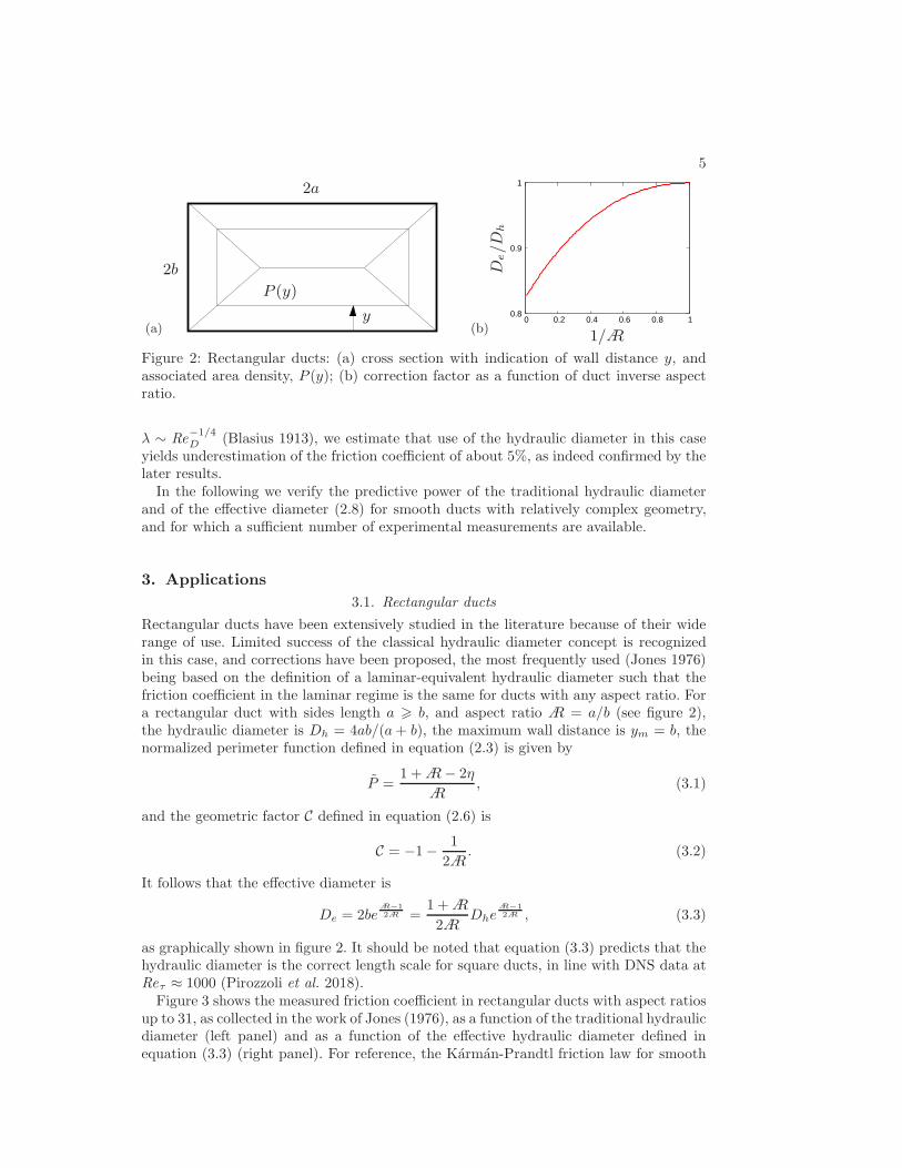
Figure 2: Rectangular ducts: (a) cross section with indication of wall distance y, andassociated area density, P (y); (b) correction factor as a function of duct inverse aspectratio.
λ ∼ Re−1/4D (Blasius 1913), we estimate that use of the hydraulic diameter in this case
yields underestimation of the friction coefficient of about 5%, as indeed confirmed by thelater results.In the following we verify the predictive power of the traditional hydraulic diameter
and of the effective diameter (2.8) for smooth ducts with relatively complex geometry,and for which a sufficient number of experimental measurements are available.
3. Applications
3.1. Rectangular ducts
Rectangular ducts have been extensively studied in the literature because of their widerange of use. Limited success of the classical hydraulic diameter concept is recognizedin this case, and corrections have been proposed, the most frequently used (Jones 1976)being based on the definition of a laminar-equivalent hydraulic diameter such that thefriction coefficient in the laminar regime is the same for ducts with any aspect ratio. Fora rectangular duct with sides length a > b, and aspect ratio A = a/b (see figure 2),the hydraulic diameter is Dh = 4ab/(a+ b), the maximum wall distance is ym = b, thenormalized perimeter function defined in equation (2.3) is given by
P =1 +A− 2η
A, (3.1)
and the geometric factor C defined in equation (2.6) is
C = −1− 1
2A. (3.2)
It follows that the effective diameter is
De = 2beA−1
2A =1 +A
2ADhe
A−1
2A , (3.3)
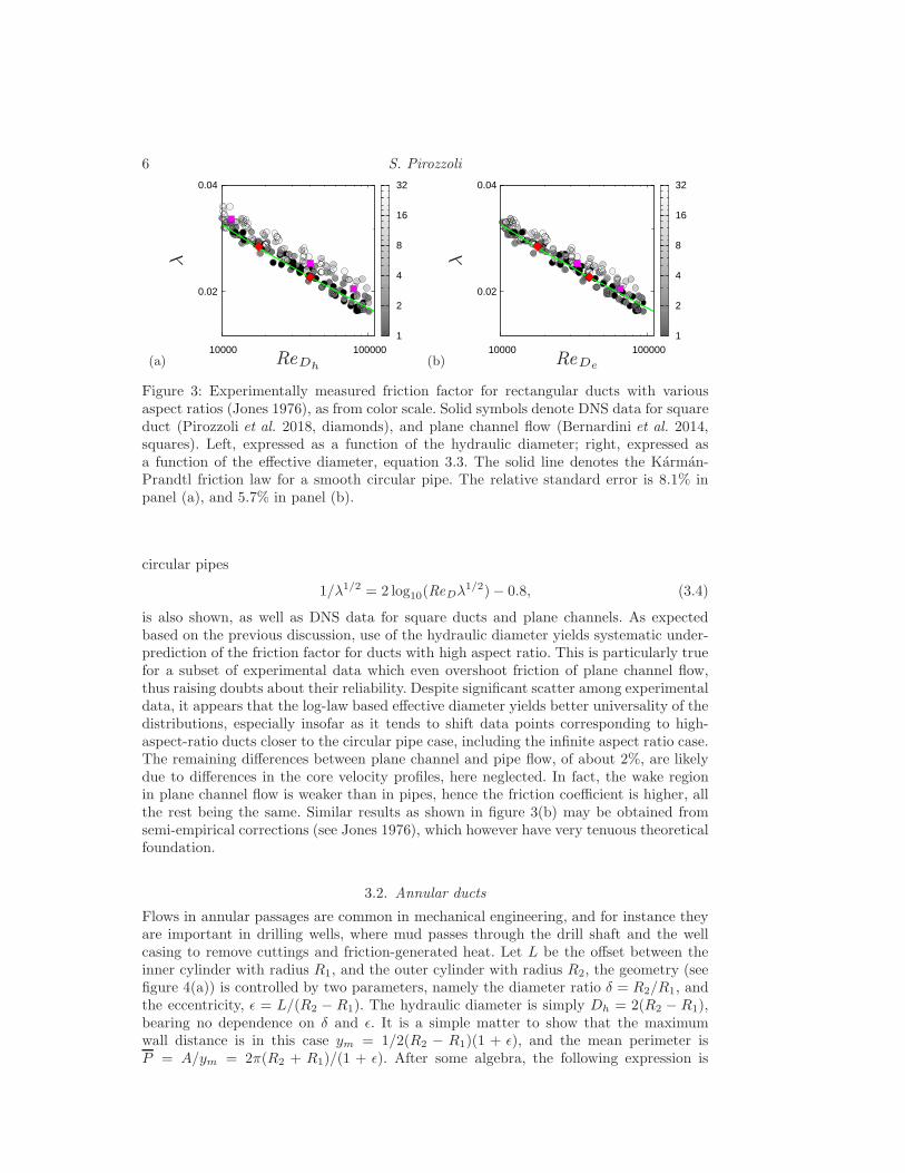
as graphically shown in figure 2. It should be noted that equation (3.3) predicts that thehydraulic diameter is the correct length scale for square ducts, in line with DNS data atReτ ≈ 1000 (Pirozzoli et al. 2018).Figure 3 shows the measured friction coefficient in rectangular ducts with aspect ratios
up to 31, as collected in the work of Jones (1976), as a function of the traditional hydraulicdiameter (left panel) and as a function of the effective hydraulic diameter defined inequation (3.3) (right panel). For reference, the Karman-Prandtl friction law for smooth
6 S. Pirozzoli
(a)
0.02
0.04
10000 100000 1
2
4
8
16
32
PSfrag replacements
λ
ReDh(b)
0.02
0.04
10000 100000 1
2
4
8
16
32
PSfrag replacements
λ
ReDh
ReDe
Figure 3: Experimentally measured friction factor for rectangular ducts with variousaspect ratios (Jones 1976), as from color scale. Solid symbols denote DNS data for squareduct (Pirozzoli et al. 2018, diamonds), and plane channel flow (Bernardini et al. 2014,squares). Left, expressed as a function of the hydraulic diameter; right, expressed asa function of the effective diameter, equation 3.3. The solid line denotes the Karman-Prandtl friction law for a smooth circular pipe. The relative standard error is 8.1% inpanel (a), and 5.7% in panel (b).
circular pipes
1/λ1/2 = 2 log10(ReDλ1/2)− 0.8, (3.4)
is also shown, as well as DNS data for square ducts and plane channels. As expectedbased on the previous discussion, use of the hydraulic diameter yields systematic under-prediction of the friction factor for ducts with high aspect ratio. This is particularly truefor a subset of experimental data which even overshoot friction of plane channel flow,thus raising doubts about their reliability. Despite significant scatter among experimentaldata, it appears that the log-law based effective diameter yields better universality of thedistributions, especially insofar as it tends to shift data points corresponding to high-aspect-ratio ducts closer to the circular pipe case, including the infinite aspect ratio case.The remaining differences between plane channel and pipe flow, of about 2%, are likelydue to differences in the core velocity profiles, here neglected. In fact, the wake regionin plane channel flow is weaker than in pipes, hence the friction coefficient is higher, allthe rest being the same. Similar results as shown in figure 3(b) may be obtained fromsemi-empirical corrections (see Jones 1976), which however have very tenuous theoreticalfoundation.
3.2. Annular ducts
Flows in annular passages are common in mechanical engineering, and for instance theyare important in drilling wells, where mud passes through the drill shaft and the wellcasing to remove cuttings and friction-generated heat. Let L be the offset between theinner cylinder with radius R1, and the outer cylinder with radius R2, the geometry (seefigure 4(a)) is controlled by two parameters, namely the diameter ratio δ = R2/R1, andthe eccentricity, ǫ = L/(R2 − R1). The hydraulic diameter is simply Dh = 2(R2 − R1),bearing no dependence on δ and ǫ. It is a simple matter to show that the maximumwall distance is in this case ym = 1/2(R2 − R1)(1 + ǫ), and the mean perimeter isP = A/ym = 2π(R2 + R1)/(1 + ǫ). After some algebra, the following expression is

7
(a)
PSfrag replacements
y
y
XXw
DL
P (y)
R1
R2
(b)
0.8
0.9
1
1.1
1.2
0 0.2 0.4 0.6 0.8 1
PSfrag replacements
y
XXw
DL
P (y)R1
R2
De/D
h
ǫ
Figure 4: Annular ducts: (a) cross section with indication of wall distance y, and as-sociated area density, P (y), with R1 and R2 the radii of the inner and outer cylinder,respectively, and L the offset between their centers; (b) correction factor as a functionof the duct eccentricity ǫ for various duct diameters ratio: δ = 1.33 (solid), δ = 1.78(dashed), δ = 3.56 (dot-dashed).
(a)
0.01
0.02
0.04
10000 100000 0
0.2
0.4
0.6
0.8
1
PSfrag replacements
λ
ReDh (b)
0.01
0.02
0.04
10000 100000 0
0.2
0.4
0.6
0.8
1
PSfrag replacements
λ
ReDh
ReDe
Figure 5: Experimentally measured friction factor for annular ducts with different ec-centricities (Jonsson & Sparrow 1966), as from color scale, and different diameters ratio:δ = 1.33 (circles); δ = 1.78 (squares), δ = 3.56 (triangles). Left, expressed as a functionof the hydraulic diameter; right, expressed as a function of the effective diameter, equa-tion 2.8. The solid line denotes the Karman-Prandtl friction law for a smooth circularpipe. The relative standard error for ǫ 6 0.25 is 3.0% in panel (a), and 2.5% in panel (b).
obtained for the normalized perimeter function
P (η) =
{1 + ǫ, for 0 6 η 6 η∗
1+ǫπ(δ+1) [δθ2 + θ1 + η/2(δ − 1)(1 + ǫ)(θ1 − θ2)] , for η∗ 6 η 6 1
, (3.5)
where η∗ = (1 − ǫ)/(1 + ǫ),
cos θ1 =(δ + 1) [(1 + ǫ)η − 1] + ǫ2(δ − 1)
ǫ(δ − 1) [2 + η(δ − 1)(1 + ǫ)], cos θ2 =
(δ + 1) [(1 + ǫ)η − 1]− ǫ2(δ − 1)
ǫ(δ − 1) [2δ − η(δ − 1)(1 + ǫ)].
Numerical integration of function C defined in equation (2.6), with P given in equa-tion (3.5) yields the result shown in figure 4(b). As in periodic channel flow, the cor-rective factor over the hydraulic diameter is
√e/2 at zero eccentricity, becoming closer
and exceeding unity at increasing values of ǫ. The dependence on the diameter ratio isquite weak, and confined to high values of ǫ, a good fit for the data at ǫ . 0.6 beingDe/Dh =
√e/2 + 0.217ǫ2.
8 S. Pirozzoli
(a)
PSfrag replacements
y
XXw
DL
P(y)
R
(b) 0.5
0.7
0.9
1.1
1.3
0 0.5 1 1.5 2
PSfrag replacements
y
XXw
DL
P (y)
R
De/D
h
ǫ
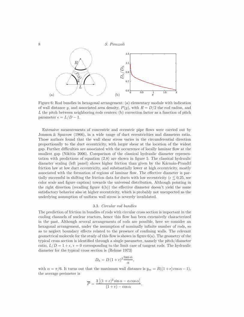
Figure 6: Rod bundles in hexagonal arrangement: (a) elementary module with indicationof wall distance y, and associated area density, P (y), with R = D/2 the rod radius, andL the pitch between neighboring rods centers; (b) correction factor as a function of pitchparameter ǫ = L/D− 1.
Extensive measurements of concentric and eccentric pipe flows were carried out byJonsson & Sparrow (1966), in a wide range of duct eccentricities and diameters ratio.Those authors found that the wall shear stress varies in the circumferential directionproportionally to the duct eccentricity, with larger shear at the location of the widestgap. Further difficulties are associated with the occurrence of locally laminar flow at thesmallest gap (Nikitin 2006). Comparison of the classical hydraulic diameter represen-tation with predictions of equation (2.8) are shown in figure 5. The classical hydraulicdiameter scaling (left panel) shows higher friction than given by the Karman-Prandtlfriction law at low duct eccentricity, and substantially lower at high eccentricity, mostlyassociated with the formation of regions of laminar flow. The effective diameter is par-tially successful in shifting the friction data for ducts with low eccentricity (ǫ . 0.25, seecolor scale and figure caption) towards the universal distribution. Although pointing inthe right direction (recalling figure 4(b)) the effective diameter doesn’t yield the samesatisfactory behavior also at higher eccentricity, which is probably not unexpected as theunderlying assumption of uniform wall stress is severely invalidated.
3.3. Circular rod bundles
The prediction of friction in bundles of rods with circular cross section is important in thecooling channels of nuclear reactors, hence this flow has been extensively characterizedin the past. Although several arrangements of rods are possible, here we consider anhexagonal arrangement, under the assumption of nominally infinite number of rods, soas to neglect boundary effects related to the presence of confining walls. The relevantgeometrical molecule for the study of this flow is shown in figure 6(a). The geometry of thetypical cross section is identified through a single parameter, namely the pitch/diameterratio, L/D = 1+ ǫ, ǫ = 0 corresponding to the limit case of tangent rods. The hydraulicdiameter for the typical cross section is (Rehme 1973)
Dh = D (1 + ǫ)2tanα
α,
with α = π/6. It turns out that the maximum wall distance is ym = R((1+ ǫ) cosα− 1),the average perimeter is
P =3[(1 + ǫ)2 sinα− α cosα
]
(1 + ǫ)− cosα,
9
(a)
0.01
0.02
0.04
10000 100000 0
0.2
0.4
0.6
0.8
1
1.2
1.4
PSfrag replacements
λ
ReDh (b)
0.01
0.02
0.04
10000 100000 0
0.2
0.4
0.6
0.8
1
1.2
1.4
PSfrag replacements
λ
ReDh
ReDe
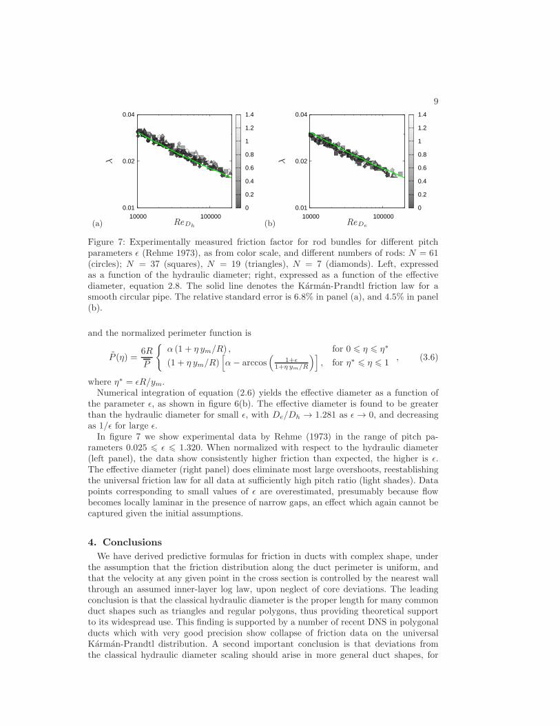
Figure 7: Experimentally measured friction factor for rod bundles for different pitchparameters ǫ (Rehme 1973), as from color scale, and different numbers of rods: N = 61(circles); N = 37 (squares), N = 19 (triangles), N = 7 (diamonds). Left, expressedas a function of the hydraulic diameter; right, expressed as a function of the effectivediameter, equation 2.8. The solid line denotes the Karman-Prandtl friction law for asmooth circular pipe. The relative standard error is 6.8% in panel (a), and 4.5% in panel(b).
and the normalized perimeter function is
P (η) =6R
P
{α (1 + η ym/R) , for 0 6 η 6 η∗
(1 + η ym/R)[
α− arccos(
1+ǫ1+η ym/R
)]
, for η∗ 6 η 6 1, (3.6)
where η∗ = ǫR/ym.Numerical integration of equation (2.6) yields the effective diameter as a function of
the parameter ǫ, as shown in figure 6(b). The effective diameter is found to be greaterthan the hydraulic diameter for small ǫ, with De/Dh → 1.281 as ǫ → 0, and decreasingas 1/ǫ for large ǫ.In figure 7 we show experimental data by Rehme (1973) in the range of pitch pa-
rameters 0.025 6 ǫ 6 1.320. When normalized with respect to the hydraulic diameter(left panel), the data show consistently higher friction than expected, the higher is ǫ.The effective diameter (right panel) does eliminate most large overshoots, reestablishingthe universal friction law for all data at sufficiently high pitch ratio (light shades). Datapoints corresponding to small values of ǫ are overestimated, presumably because flowbecomes locally laminar in the presence of narrow gaps, an effect which again cannot becaptured given the initial assumptions.
4. Conclusions
We have derived predictive formulas for friction in ducts with complex shape, underthe assumption that the friction distribution along the duct perimeter is uniform, andthat the velocity at any given point in the cross section is controlled by the nearest wallthrough an assumed inner-layer log law, upon neglect of core deviations. The leadingconclusion is that the classical hydraulic diameter is the proper length for many commonduct shapes such as triangles and regular polygons, thus providing theoretical supportto its widespread use. This finding is supported by a number of recent DNS in polygonalducts which with very good precision show collapse of friction data on the universalKarman-Prandtl distribution. A second important conclusion is that deviations fromthe classical hydraulic diameter scaling should arise in more general duct shapes, for
10 S. Pirozzoli
which the effective diameter defined in equation (2.8) is expected to be a more accuratechoice. The latter can be easily evaluated, either analytically or numerically, based onthe duct cross-sectional shape. Differences with respect to friction predictions based onthe classical hydraulic diameter are generally small, but more sensible as the duct aspectratio is much different than unity, amounting in practical terms to a few percent. Re-evaluation of classical experiments in smooth ducts with moderately complex shape,namely rectangular and annular ducts, and circular rod bundles, supports small butconsistent predictive improvements when the effective diameter is used instead of thetraditional hydraulic diameter, with all due caveats incurred with tracing differences of afew percent within scattered experimental data. Of course, given the assumptions madein the derivation, the log-law based effective diameter does not perform well in cases inwhich the wall shear stress is far from uniform, such as ducts with narrow gaps or acuteangles, which may even feature locally laminar flow. Measurements at higher Reynoldsnumber and/or for rough ducts would be desirable, to be able to more clearly ascertainthe predictive power of the log-law based effective diameter, and to compare with existingcorrelations based on extrapolation of laminar results.
This paper has benefited from exchange of ideas with P. Orlandi and P.R. Spalart.
REFERENCES
Bernardini, M., Pirozzoli, S. & Orlandi, P. 2014 Velocity statistics in turbulent channelflow up to Reτ = 4000. J. Fluid Mech. 742, 171–191.
Blasius, H. 1913 Das ahnlichkeitsgesetz bei reibungsvorgangen in flussigkeiten. In Mitteilun-gen uber Forschungsarbeiten auf dem Gebiete des Ingenieurwesens (ed. Verein deutscherIngenieure), , vol. 131, pp. 1–41. Springer-Verlag.
Cain, D. & Duffy, J. 1971 An experimental investigation of turbulent flow in elliptical ducts.Int. J. Mech. Sci. 13, 451–459.
Colebrook, C.F. 1939 Turbulent flow in pipes, with particular reference to the transitionregion between the smooth and rough pipe laws. J. Inst. Civil Eng. 11, 133–156.
Deissler, R.G. & Taylor, M.F. 1958 Analysis of turbulent flow and heat transfer in noncir-cular passages. Tech. Rep. TN-4384. NACA.
Jones, O.C. 1976 An improvement in the calculation of turbulent friction in rectangular ducts.ASME J. Fluids Engng. 98, 173–181.
Jonsson, V.K. & Sparrow, E.M. 1966 Experiments on turbulent-flow phenomena in eccentricannular ducts. J. Fluid Mech. 25, 65–86.
Keulegan, G.H. 1938 Laws of turbulent flow in open channels. J. Res. Nat. Bureau Stand. 21,707–741.
Leutheusser, H.J. 1963 Turbulent flow in rectangular ducts. J. Hydr. Div. ASCE 89 (3), 1–19.Marin, O., Vinuesa, R., Obabko, A.V. & Schlatter, P. 2016 Characterization of the
secondary flow in hexagonal ducts. Phys. Fluids 28 (12), 125101.Maubach, K. 1970 Reibungsgesetze turbulenter stromungen. Chemie Ingenieur Technik
42 (15), 995–1004.Nikitin, N. 2006 Direct numerical simulation of turbulent flows in eccentric pipes.
Comp. Math. Math. Phys. 46, 489–504.Nikuradse, J. 1930 Turbulente stromung in nicht-kreisformigen rohren. Ing. Arch. 1, 306–332.Nouri, J.M., Umur, H. & Whitelaw, J.H. 1993 Flow of newtonian and non-newtonian fluids
in concentric and eccentric annuli. J. Fluid Mech. 253, 617–641.Pirozzoli, S., Modesti, D., Orlandi, P. & Grasso, F. 2018 Turbulence and secondary
motions in square duct flow. J. Fluid Mech. 840, 631–655.
Prandtl, L. 1926 Uber die ausgebildete turbulenz. In Int. Congress for Applied Mechanics.Also ”Turbulent Flow”, NACA-TM 435, 1927.
Rehme, K. 1972 Pressure drop performance of rod bundles in hexagonal arrangements.Int. J. Heat Mass Transf. 15 (12), 2499–2517.
11
Rehme, K. 1973 Simple method of predicting friction factors of turbulent flow in non-circularchannels. Int. J. Heat Mass Transf. 16 (5), 933–950.
Schiller, L. 1923 Uber den stromungswiderstand von rohren verschiedenen querschnitts undrauhigkeitsgrades. ZAMM-Zeitschrift fur Angewandte Mathematik und Mechanik 3 (1), 2–13.
Spalart, P.R., Garbaruk, A. & Stabnikov, A. 2018 On the skin friction due to turbulencein ducts of various shapes. J. Fluid Mech. 838, 369–378.
Vinuesa, R., Noorani, A., Lozano-Duran, A., Khoury, G.K.E., Schlatter, P., Fischer,P.F. & Nagib, H.M. 2014 Aspect ratio effects in turbulent duct flows studied throughdirect numerical simulation. J. Turbulence 15 (10), 677–706.


![Straight Lines Slides [Compatibility Mode]](https://static.fdokumen.com/doc/165x107/6316ee6071e3f2062906978b/straight-lines-slides-compatibility-mode.jpg)