On Computing Four-Finger Equilibrium and Force-Closure Grasps of Polyhedral Objects
30
-
Upload
independent -
Category
Documents
-
view
0 -
download
0
Transcript of On Computing Four-Finger Equilibrium and Force-Closure Grasps of Polyhedral Objects
On Computing Four-Finger Equilibrium andForce-Closure Grasps of Polyhedral ObjectsJean Ponce, Steve Sullivan and Attawith SudsangBeckman InstituteUniversity of IllinoisUrbana, IL 61801, USAJean-Daniel Boissonnat and Jean-Pierre MerletINRIA Sophia-Antipolis2004 Route des Lucioles06565 Valbonne Cedex, FranceSubmitted to the International Journal of Robotics Research, February 1995.Abstract: This paper addresses the problem of computing stable grasps of three-dimensional polyhedralobjects. We consider the case of a hand equipped with four hard �ngers and assume point contact withfriction. We prove new necessary and su�cient conditions for equilibrium and force closure, and present ageometric characterization of all possible types of four-�nger equilibrium grasps. We then focus on concurrentgrasps, for which the lines of action of the four contact forces all intersect in a point. In this case, theequilibrium conditions are linear in the unknown grasp parameters, which reduces the problem of computingthe stable grasp regions in con�guration space to the problem of constructing the eight-dimensional projectionof an eleven-dimensional polytope. We present two projection methods: the �rst one uses a simple Gaussianelimination approach, while the second one relies on a novel output-sensitive contour-tracking algorithm.Finally, we use linear optimizationwithin the valid con�guration space regions to compute the maximal objectregions where �ngers can be positioned independently while ensuring force closure. We have implementedthe proposed approach and present several examples.1 IntroductionWhen a hand holds an object at rest, the forces and moments exerted by the �ngers should balanceeach other so as not to disturb the position of this object. We will say that such a grasp achievesequilibrium. For the hand to hold the object securely, it should also be capable of preventing anymotion due to external forces and torques. We will say that such a grasp achieves force closure.This paper addresses the problem of characterizing and computing four-�nger equilibrium andforce-closure grasps of polyhedral objects. Its main contributions are in two areas:� We give a new geometric characterization of equilibrium and force closure. Assuming hard-�nger contact and Coulomb friction, we show in the �rst part of the paper that non-marginalequilibrium grasps are in fact force-closure (Proposition 1). We then use line geometry to completelycharacterize all possible types of four-�nger equilibrium grasps (Proposition 2) and prove a simplesu�cient condition for equilibrium and force closure (Proposition 3).� We present an e�cient algorithm for computing concurrent grasps. In the second part of thepaper we focus on concurrent grasps, a class of equilibrium grasps for which the lines of action of1
the contact forces all intersect in a point. In this case, the equilibrium condition of Proposition3 is linear in the grasp parameters, which reduces the problem of computing the stable graspregions in con�guration space to the problem of constructing the eight-dimensional projection ofan eleven-dimensional polytope. We present two projection methods: the �rst one uses a simpleGaussian elimination approach, while the second one relies on a novel output-sensitive contour-tracking algorithm. Finally, we use linear optimization within the valid con�guration space regionsto compute the maximal object regions where �ngers can be positioned independently while ensuringforce closure.1.1 Related WorkWe brie y review the literature on force closure grasp analysis and synthesis and examine itsrelation with our work (see also [36, 42] and [38, Chapter 5] for recent surveys). The notion offorce closure was introduced by Reulaux at the end of the nineteenth century in his study of theproperties of mechanisms [49], and it has been used in the context of robotic grasp analysis sinceSalisbury's PhD work [53]. Most of the research on force-closure grasping has been concerned withthe following problems:� Deciding how many �ngers are required for force closure. In the frictionless case, Reulaux[49], Somov [55] and, much later, Lakshminarayana [24] have shown that four (resp. seven) �ngersare necessary to achieve force closure of a 2D (resp. 3D) object. In turn, Mishra, Schwartz, andSharir [35] have shown that six (resp. twelve) �ngers are always su�cient for objects withoutrotational symmetries, and Markensco�, Ni, and Papadimitriou [28] have tightened this result byshowing that under very general conditions, four (resp. seven) �ngers are su�cient to achieve aforce-closure grasp of a 2D (resp. 3D) object without rotational symmetries. They have also shownthat when Coulomb friction is taken into account, three �ngers are su�cient in the 2D case, and fourare su�cient in the 3D case. This result and the recent availability of three- and four-�nger handssuch as the Salisbury hand [53] and the Utah/MIT Dextrous Hand [17] are practical motivationsfor our study of four-�nger grasping under Coulomb friction.� Testing for force closure. Given a set of n primitive contact wrenches (i.e., of vectors combiningthe forces and moments exerted by the �ngers, see next section), Salisbury and Roth [53, Chapter 5],[54] have shown that a necessary and su�cient condition for force closure is that a strictly positivelinear combination of the primitive wrenches is zero and the primitive wrenches span the wholewrench space (alternative proofs can be found in [39] and [57] for example). Mishra, Schwartz, andSharir [35] have also shown that equilibrium is achieved when the origin of wrench space lies inthe convex hull of the primitive wrenches, and force closure is achieved when the origin lies in theinterior of the convex hull. These conditions are essentially binary in nature: a grasp is, or is not,force closure. This has motivated Kirkpatrick, Mishra, and Yap [23] and later Ferrari and Canny[11] to develop quantitative tests for force closure using the radius of a maximal ball centered at theorigin and included in the convex hull of the primitive wrenches as a measure of goodness of thegrasp. An alternative quality measure, proposed by Trinkle [57], is the maximum minimum valueof the primitive wrench intensities achieving equilibrium.The conditions for force closure mentioned so far hold for arbitrary numbers of �ngers. Inspeci�c cases (two, three, or four �ngers) it is possible to characterize the geometric arrangementof the contact forces that achieve equilibrium or force closure: in particular, it is easy to show thattwo forces are in equilibrium when they oppose each other and share the same line of action, andthat three forces are in equilibrium when they add to zero and their lines of action intersect ata point. Ji and Roth [18, Chapter 4], [19] have used this fact to give several conditions on the2
�nger positions and surface normals that guarantee that the contact wrenches can resist any pureforce, any pure moment, and any combination of force and moment. In the planar, two-�nger case,Nguyen [39, Corollaries 3 and 4] has proven that non-marginal equilibrium implies force closure, andremarked that the geometric characterization of two-�nger equilibrium given above also provided asu�cient condition for force closure. Ponce and Faverjon [45] have generalized this approach to thethree-�nger case, and we will use this approach once more in the four-�nger case. Characterizingequilibrium geometrically is more di�cult in this case, but it can be done using classical resultsfrom line geometry [2, 8, 33, 37].� Planning force-closure grasps. Algorithms for grasp synthesis may be aimed at computingoptimal grasp forces given �xed �nger positions, at computing at least one (maybe optimal) force-closure grasp �nger con�guration, or at computing whole regions of the grasp con�guration spacethat yield force closure. For given �nger positions, Kerr and Roth [21, Chapter 5] [22] have pro-posed a numerical constrained-search algorithm for optimizing the equilibrium forces applied bythe �ngers, and Ji and Roth [18, Chapter 4] [20] have given an analytical method for minimizingthe dependence of the forces achieving equilibrium on the friction coe�cient. Mishra, Schwartz,and Sharir [35] have proposed linear-time algorithms for computing at least one �nger con�gura-tion achieving force closure for frictionless polyhedral objects. Markensco� and Papadimitriou haveshown how to choose force-closure grasps of polygonal objects that minimize the worst-case forcesthat may have to be applied [29], and Mirtich and Canny [34] have recently proposed algorithmsfor computing optimal grasps of polyhedra according to the criterion of [11] (of course, many otheroptimality criteria could also be used, including the grasp e�ciency measures mentioned earlier[23, 57] or the functional criteria proposed by Li and Sastry [27]).In each of these works, the grasp-planning algorithm outputs a single grasp for a given set ofcontact faces. In [39], Nguyen has proposed instead a geometric method for computing maximalindependent two-�nger grasps of polygons, i.e., segments of the polygonal boundary where thetwo �ngers can be positioned independently while maintaining force closure, requiring as littlepositional accuracy from the robot as possible, and Pollard and Lozano-P�erez [43] have used adirect generalization of this approach to plan three-�nger grasps of polyhedral objects as part ofa whole manipulation system, including obstacle avoidance, and feasibility and reachability tests.Faverjon, Ponce, and Stam [10, 46] and Chen and Burdick [6] have also generalized Nguyen'sapproach to two-�nger grasping of curved objects by using algebraic cell decomposition and globaloptimization methods. In [45], Ponce and Faverjon have proposed a totally di�erent computationalapproach to three-�nger grasp planning, relying on variable elimination (or equivalently, polytopeprojection [12, 16, 25, 26]) to characterize the regions of the grasp con�guration space that yieldforce closure, and using linear optimization within these regions to compute maximal independentgrasps. We generalize this approach to three-dimensional four-�nger grasping in this paper. Froman algorithmic viewpoint, the main di�erence with the two-dimensional three-�nger case is that thedimension of the con�guration space is much higher (eleven instead of �ve), which has promptedus to replace the variant of Fourier's projection algorithm [12] used in [44, 45] by novel and muchmore powerful algorithms for projecting a polytope from a high-dimensional space onto a lower-dimensional sub-space.The rest of the presentation is organized as follows. Section 2 discusses the notions of forceclosure and equilibrium, and gives several necessary and/or su�cient conditions for equilibrium andforce closure. Section 3 describes our grasp-planning algorithm. Results are presented in Section 4.Finally, future research directions are brie y discussed in Section 5. All proofs are relegated to theappendix. A preliminary version of this paper appeared in [47].3
2 Geometric Conditions for Equilibrium and Force ClosureIn this section we start with some elementary notions of screw theory, then formally de�ne forceclosure and equilibrium and clarify the relationship between these two concepts. We also give severalnecessary and/or su�cient conditions for equilibrium and force closure, and present a completecharacterization of all types of four-�nger equilibrium grasps.The whole discussion is based on the notion of wrench from screw theory [2]. Wrenches aresix-dimensional vectors combining forces and moments, and are most conveniently studied using aline- rather than a point-based geometry. Accordingly, our characterization of equilibrium graspsis based on the classi�cation of certain varieties of lines in Grassmann geometry [8].2.1 Screws, Twists and WrenchesWe recall some elementary notions of screw theory. The following is largely based on Roth'sexcellent introduction [52]. See [2, 4, 14, 31, 40, 41] for more details.A screw is a straight line with a pitch. The pitch is a linear magnitude that can be thoughtof as the rectilinear distance through which a nut attached to an ordinary screw is translatedparallel to the screw axis while the nut is rotated through a unit angle [2]. Screws provide a uni�edrepresentation for displacements and forces: from Chasles' theorem, any displacement of a rigidbody can be described by a single rotation about a unique axis, combined with a unique translationparallel to this axis. The rotation axis is called the screw axis, and the ratio of the linear translationto the rotation angle is the pitch of the screw. The displacement is referred to as a twist about ascrew. Its magnitude is the angular rotation about the screw axis. In�nitesimal displacements andrigid body motions can also be described by twists. From Poinsot's theorem, any system of forcesand moments applied to a rigid body can be uniquely replaced by a single force and a couple, suchthat the force is parallel to the axis of the couple. In turn, these can be represented by a uniquescrew axis, a moment about this axis, and a force along it. The pitch of the screw is the ratio of themoment to the force. This combination of force and couple is called a wrench acting on a screw.The magnitude of the wrench is the magnitude of the associated force.Algebraically, a screw can be represented by a sextuple of screw coordinates:s = (u;x� u+ pu);where u is a non-zero vector parallel to the screw axis, x denotes the coordinate vector of an arbi-trary point on the axis, and p is the screw pitch. Alternatively, we can write the screw coordinatesas s = (u;v), where u;v are three-dimensional vectors. Screw coordinates are homogeneous anda screw does not have a meaningful magnitude; in other words, screws form a �ve-dimensionalprojective space. However, screw coordinates can also be used to represent twists and wrenches,which are truly six-dimensional entities. In this case the magnitude of the screw coordinate vectoris the magnitude of the associated twist or wrench.We are now in a position to de�ne force closure, but before closing this section, let us make onemore remark that will be the key to our characterization of equilibrium and force-closure grasps:the wrench associated with a pure force (with no torque component) has a zero pitch; in otherwords, its screw coordinates are those of a line.2.2 Force Closure and EquilibriumWe consider positive grips [35, 36] constructed as non-negative linear combinations of primitivewrenches (this amounts to assuming non-sticky �ngers), and associate with a system of n primitive4

wrenches w1; : : : ;wn the wrench setW = f nXi=1 �iwi : �i � 0 for i = 1; : : : ; ng:De�nition 1 A system of n wrenches w1; : : : ;wn is said to achieve force closure when the corre-sponding wrench set W is equal to IR6.Intuitively, a system of wrenches achieves force closure when any external load can be bal-anced by a non-negative combination of the primitive wrenches. Force closure is sometimes calledforce/torque closure [35, 36]. A related notion is form closure (also called complete restraint)[24, 49, 53]: a system of wrenches acting on some object is said to achieve form closure when itprevents all motions (including in�nitesimal ones) of this object.1 Force and form closure are dualof each other, in the same sense as wrenches and in�nitesimal twists are dual notions [52] and, asnoted in [36, 39] for example, force-closure grasps are form-closure and vice versa. Let us note thatthere is unfortunately no general agreement on terminology in the grasping literature (see [34, 57]for discussions of this problem): for example, Reulaux [49], Salisbury [53], Ji [18], Markensco� etal. [28] and Trinkle [57] use the expression form closure for what we call force closure, and reservethe expression force closure for grasps that can only balance certain external loads. Our de�nitionsmatch the ones used by Mishra et al. [35], Nguyen [39], and Murray et al. [38].A somewhat weaker notion is equilibrium, de�ned below.De�nition 2 A system of n wrenches w1; : : : ;wn is said to achieve equilibrium when the convexhull of the points w1; : : : ;wn in IR6 contains the origin.In other words, a given system of wrenches achieves equilibrium when the equationnXi=1 �iwi = 0 (1)admits a non-trivial, non-negative solution.Mishra, Schwartz, and Sharir [35] have shown that a necessary and su�cient condition for asystem of wrenches to achieve force closure is that the origin of IR6 lies in the interior of the convexhull of the primitive wrenches. In particular, force closure implies equilibrium but there are wrenchsystems that achieve equilibrium but not force closure.22.3 Grasps and FrictionFrom now on we restrict our attention to systems of wrenches generated by hard �ngers and assumeCoulomb friction. While soft �ngers can exert both pure forces and pure torques, a hard �nger canonly exert a pure force. The wrench associated with a hard �nger located at a point x and exertinga force f is the zero-pitch wrench w = (f ;x� f)T (here \�" denotes the operator associating to twovectors the determinant of their coordinates, and x� f is the moment of the force f with respect to1It should be noted that certain grasps which are not form-closure actually immobilize the grasped object: forexample three frictionless �ngers positioned at the centers of the edges of an equilateral triangle cannot prevent anin�nitesimal rotation of the triangle about its center of mass, yet prevent any �nite motion. See [7, 34, 50, 51] andSection 5 for discussions of this phenomenon.2These systems of wrenches are called strong force closure systems by Trinkle [57]. Of course, as noted before, hisnotion of force closure is di�erent from ours. 5
n
f f
n(a) (b)
x x
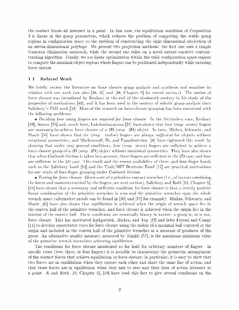
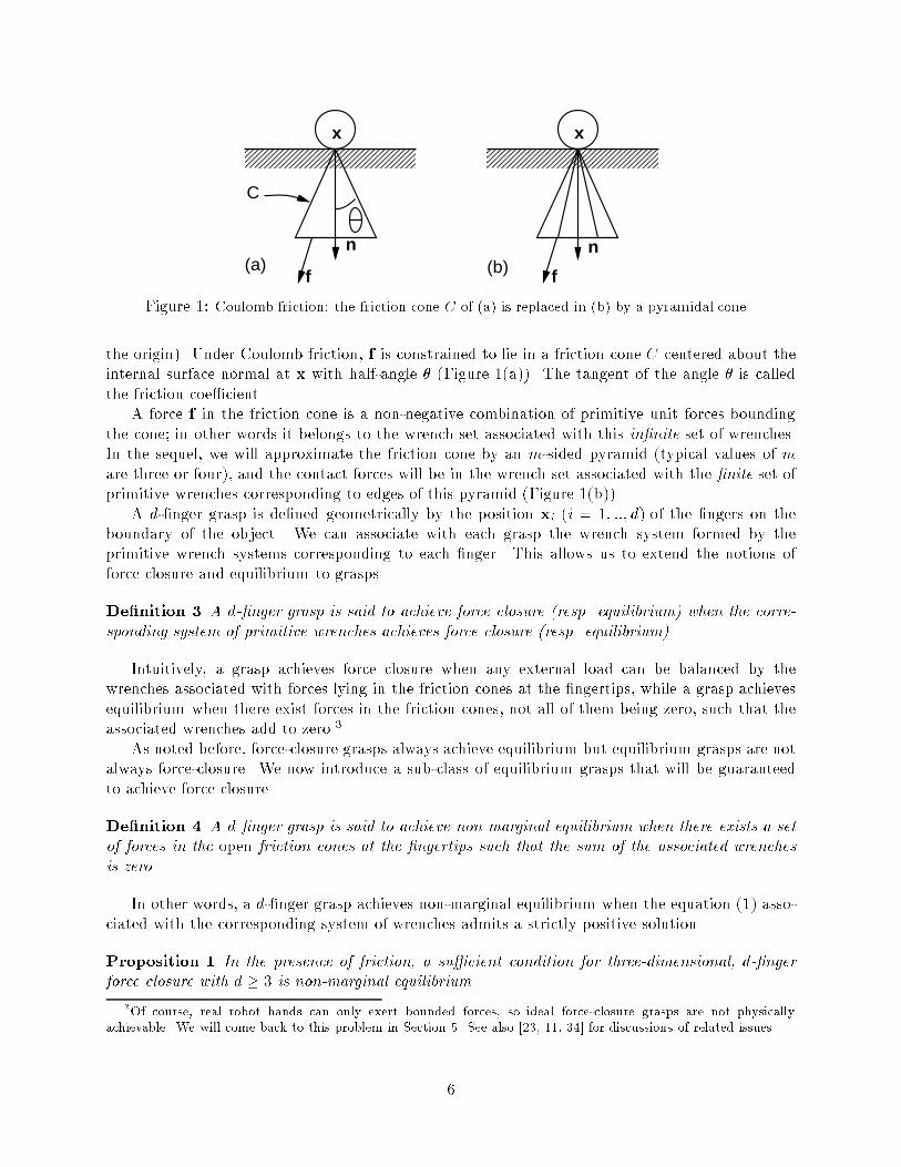
CFigure 1: Coulomb friction: the friction cone C of (a) is replaced in (b) by a pyramidal cone.the origin). Under Coulomb friction, f is constrained to lie in a friction cone C centered about theinternal surface normal at x with half-angle � (Figure 1(a)). The tangent of the angle � is calledthe friction coe�cient.A force f in the friction cone is a non-negative combination of primitive unit forces boundingthe cone; in other words it belongs to the wrench set associated with this in�nite set of wrenches.In the sequel, we will approximate the friction cone by an m-sided pyramid (typical values of mare three or four), and the contact forces will be in the wrench set associated with the �nite set ofprimitive wrenches corresponding to edges of this pyramid (Figure 1(b)).A d-�nger grasp is de�ned geometrically by the position xi (i = 1; ::; d) of the �ngers on theboundary of the object. We can associate with each grasp the wrench system formed by theprimitive wrench systems corresponding to each �nger. This allows us to extend the notions offorce closure and equilibrium to grasps.De�nition 3 A d-�nger grasp is said to achieve force closure (resp. equilibrium) when the corre-sponding system of primitive wrenches achieves force closure (resp. equilibrium).Intuitively, a grasp achieves force closure when any external load can be balanced by thewrenches associated with forces lying in the friction cones at the �ngertips, while a grasp achievesequilibrium when there exist forces in the friction cones, not all of them being zero, such that theassociated wrenches add to zero.3As noted before, force-closure grasps always achieve equilibrium but equilibrium grasps are notalways force-closure. We now introduce a sub-class of equilibrium grasps that will be guaranteedto achieve force closure.De�nition 4 A d-�nger grasp is said to achieve non-marginal equilibrium when there exists a setof forces in the open friction cones at the �ngertips such that the sum of the associated wrenchesis zero.In other words, a d-�nger grasp achieves non-marginal equilibrium when the equation (1) asso-ciated with the corresponding system of wrenches admits a strictly positive solution.Proposition 1 In the presence of friction, a su�cient condition for three-dimensional, d-�ngerforce closure with d � 3 is non-marginal equilibrium.3Of course, real robot hands can only exert bounded forces, so ideal force-closure grasps are not physicallyachievable. We will come back to this problem in Section 5. See also [23, 11, 34] for discussions of related issues.6
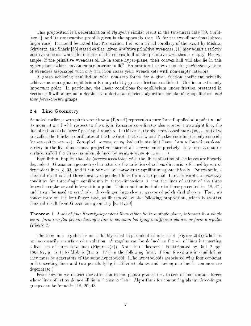
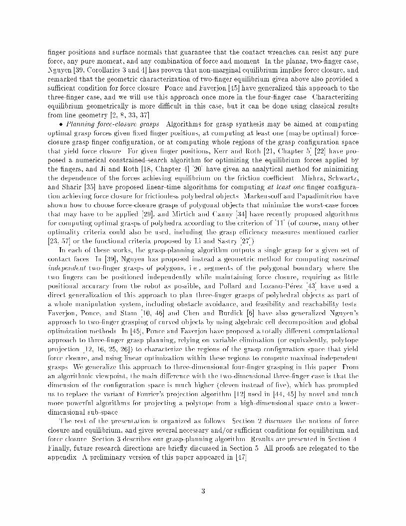
This proposition is a generalization of Nguyen's similar result in the two-�nger case [39, Corol-lary 4], and its constructive proof is given in the appendix (see [45] for the two-dimensional three-�nger case). It should be noted that Proposition 1 is not a trivial corollary of the result by Mishra,Schwartz, and Sharir [35] stated earlier: given arbitrary primitive wrenches, (1) may admit a strictlypositive solution while the interior of the convex hull of the primitive wrenches is empty. For ex-ample, if the primitive wrenches all lie in some hyper-plane, their convex hull will also lie in thishyper-plane, which has an empty interior in IR6. Proposition 1 shows that the particular systemsof wrenches associated with d � 3 friction cones yield wrench sets with non-empty interiors.A grasp achieving equilibrium with non-zero forces for a given friction coe�cient triviallyachieves non-marginal equilibrium for any strictly greater friction coe�cient. This is an extremelyimportant point. In particular, the linear conditions for equilibrium under friction presented inSection 2.6 will allow us in Section 3 to derive an e�cient algorithm for planning equilibrium andthus force-closure grasps.2.4 Line GeometryAs noted earlier, a zero-pitch wrenchw = (f ;x�f) represents a pure force f applied at a point x andits moment x� f with respect to the origin; its screw coordinates also represent a straight line, theline of action of the force f passing through x. In this case, the six screw coordinates (w1; ::; w6) ofware called the Pl�ucker coordinates of the line (note that screw and Pl�ucker coordinates only coincidefor zero-pitch screws). Zero-pitch screws, or equivalently straight lines, form a four-dimensionalvariety in the �ve-dimensional projective space of all screws: more precisely, they form a quadricsurface, called the Grassmannian, de�ned by w1w4 + w2w5 + w3w6 = 0.Equilibrium implies that the (screws associated with the) lines of action of the forces are linearlydependent. Grassmann geometry characterizes the varieties of various dimensions formed by sets ofdependent lines [8, 33], and it can be used to characterize equilibrium geometrically. For example, aclassical result is that three linearly-dependent lines form a at pencil. In other words, a necessarycondition for three-�nger equilibrium in three dimensions is that the lines of action of the threeforces be coplanar and intersect in a point. This condition is similar to those presented in [18, 47],and it can be used to synthesize three-�nger force-closure grasps of polyhedral objects. Here, weconcentrate on the four-�nger case, as illustrated by the following proposition, which is anotherclassical result from Grassmann geometry [8, 14, 33].Theorem 1 A set of four linearly-dependent lines either lie in a single plane, intersect in a singlepoint, form two at pencils having a line in common but lying in di�erent planes, or form a regulus(Figure 2).The lines in a regulus lie on a doubly-ruled hyperboloid of one sheet (Figure 2(d)) which isnot necessarily a surface of revolution. A regulus can be de�ned as the set of lines intersectinga �xed set of three skew lines (Figure 2(e)). Note that Theorem 1 is attributed by Ball [2, pp.186-187, p. 511] to M�obius [37, p. 177] in the following form: if four forces are in equilibriumthey must be generators of the same hyperboloid. (The hyperboloids associated with four coplanaror intersecting lines and two pencils lying in di�erent planes and having one line in common aredegenerate.)From now on we restrict our attention to non-planar grasps, i.e., to sets of four contact forceswhose lines of action do not all lie in the same plane. Algorithms for computing planar three-�ngergrasps can be found in [18, 20, 43]. 7
(a) (b)(c)
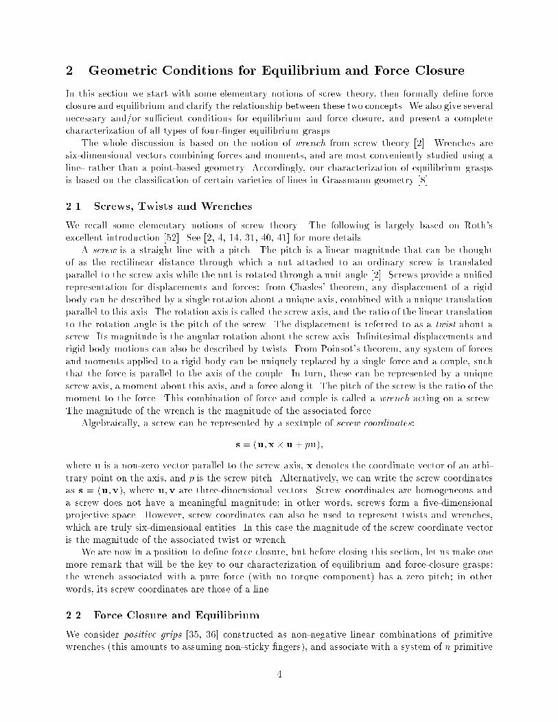
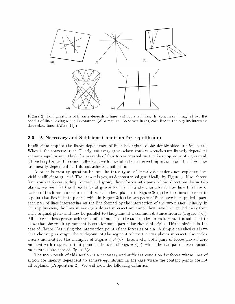
(d) (e)Figure 2: Con�gurations of linearly-dependent lines: (a) coplanar lines, (b) concurrent lines, (c) two atpencils of lines having a line in common, (d) a regulus. As shown in (e), each line in the regulus intersectsthree skew lines. (After [13].)2.5 A Necessary and Su�cient Condition for EquilibriumEquilibrium implies the linear dependence of lines belonging to the double-sided friction cones.When is the converse true? Clearly, not every grasp whose contact wrenches are linearly dependentachieves equilibrium: think for example of four forces exerted on the four top sides of a pyramid,all pushing toward the same half-space, with lines of action intersecting in some point. These linesare linearly dependent, but do not achieve equilibrium.Another interesting question is: can the three types of linearly-dependent non-coplanar linesyield equilibrium grasps? The answer is yes, as demonstrated graphically by Figure 3. If we choosefour contact forces adding to zero and group these forces into pairs whose directions lie in twoplanes, we see that the three types of grasps form a hierarchy characterized by how the lines ofaction of the forces do or do not intersect in these planes: in Figure 3(a), the four lines intersect ina point that lies in both planes, while in Figure 3(b) the two pairs of lines have been pulled apart,each pair of lines intersecting on the line formed by the intersection of the two planes. Finally, inthe regulus case, the lines in each pair do not intersect anymore; they have been pulled away fromtheir original plane and now lie parallel to this plane at a common distance from it (Figure 3(c)).All three of these grasps achieve equilibrium: since the sum of the forces is zero, it is su�cient toshow that the resulting moment is zero for some particular choice of origin. This is obvious in thecase of Figure 3(a), using the intersection point of the forces as origin. A simple calculation showsthat choosing as origin the mid-point of the segment where the two planes intersect also yieldsa zero moment for the examples of Figure 3(b)-(c). Intuitively, both pairs of forces have a zeromoment with respect to that point in the case of Figure 3(b), while the two pairs have oppositemoments in the case of Figure 3(c).The main result of this section is a necessary and su�cient condition for forces whose lines ofaction are linearly dependent to achieve equilibrium in the case where the contact points are notall coplanar (Proposition 2). We will need the following de�nition.8

(a) (b) (c)Figure 3: Examples of grasps achieving equilibrium: (a) the contact forces intersect in one point; (b) theyform two non-coplanar pencils; (c) they form a regulus. The contact faces are not shown.De�nition 5 We say that a set of vectors positively span IRn when any vector in IRn can be writtenas a positive combination of these vectors.Using this terminology, a grasp achieves force closure when the set of wrenches that can beexerted by the �ngers positively span IR6. Here we concentrate on conditions that quadruples ofvectors in IR3 must satisfy to positively span that space. The following lemma gives two suchconditions.Lemma 1 Given four vectors in IR3, the following statements are equivalent:(1) the vectors positively span IR3;(2) no three of the vectors are coplanar, and the zero vector is a strictly positive combination ofthe four vectors;(3) no three of the vectors are coplanar, and the direction opposite to each vector lies in theinterior of the trihedron formed by the other three.Note that the trihedron formed by three vectors is the set of positive combinations of thesevectors. The proof of the lemma is immediate, and it is omitted for the sake of conciseness. Thelemma itself is important because it plays a major role in the proof of Proposition 2 (below) and inthe statement of Proposition 3 (Section 2.6), both of which are keys to our grasp-planning approach.Proposition 2 A necessary and su�cient condition for four non-coplanar points to form an equi-librium grasp with four non-zero contact forces is that(P1) there exist four lines in the corresponding double-sided friction cones that either intersect ina single point, form two at pencils having a line in common but lying in di�erent planes, orform a regulus, and(P2) the vectors parallel to these lines and lying in the internal friction cones at the contact pointspositively span IR3.The proof of this proposition is given in the appendix.9

u4
3u
u2
1u
-u4
C4
3C
C2
4-C
C1
T123Figure 4: Four vectors �-positively spanning IR3. T123 is the intersection of the trihedra formed by all triplesof vectors belonging to C1, C2, and C3.2.6 A Su�cient Condition for EquilibriumWe want conditions for equilibrium that are linear in the unknown grasp parameters (the �ngerpositions and the contact forces) because this will allow us to use linear programming as a basis forgrasp planning (see Section 3). The second condition (P2) of Proposition 2 is de�nitely non-linear:it can be written as 4Xi=1 �ifi = 0; with �i > 0 for i = 1; : : : ; 4;which is a bilinear constraint on the unknown coe�cients �i and contact forces fi.In this section, we give a su�cient condition for equilibrium, using a condition on the surfacenormals which ensures that (P2) is satis�ed. Since, for a given choice of four contact faces, thesurface normals are �xed, this replaces the non-linear condition (P2) by a simple test on thesenormals. We �rst need a de�nition. As before, � denotes the friction angle.De�nition 6 We say that four vectors �-positively span IR3 when, for any triple u1;u2;u3 of thesevectors, the cones C1; C2; C3 of half-angle � centered on u1, u2, and u3 lie in the interior of thesame half-space, and the cone �C4 of half-angle � centered on the direction opposite to the fourthvector u4 lies in the interior of the intersection of the trihedra formed by all triples of vectorsbelonging to C1, C2, and C3 (Figure 4).Clearly, any vector in �C4 lies in the interior of the trihedron formed by any vectors in C1, C2,and C3, and the following proposition is an immediate corollary of Lemma 1 and Proposition 2.Proposition 3 A su�cient condition for four non-coplanar points to form an equilibrium graspwith four non-zero contact forces is that(P1) there exist four lines in the corresponding double-sided friction cones that either intersect ina single point, form two at pencils having a line in common but lying in di�erent planes, orform a regulus, and 10
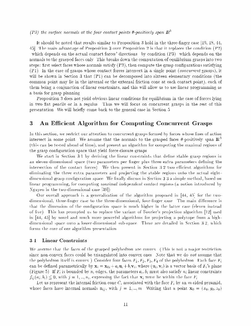
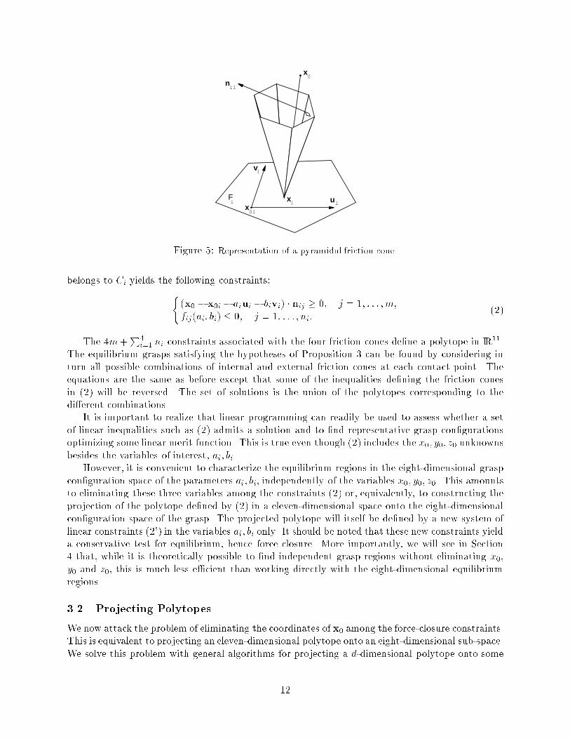
(P3) the surface normals at the four contact points �-positively span IR3.It should be noted that results similar to Proposition 3 hold in the three-�nger case [19, 18, 44,45]. The main advantage of Proposition 3 over Proposition 2 is that it replaces the condition (P2){which depends on the actual contact forces' directions{ by condition (P3) {which depends on thenormals to the grasped faces only. This breaks down the computation of equilibrium grasps into twosteps: �rst select faces whose normals satisfy (P3), then compute the grasp con�gurations satisfying(P1). In the case of grasps whose contact forces intersect in a single point (concurrent grasps), itwill be shown in Section 3 that (P1) can be decomposed into sixteen elementary conditions (thecommon point may lie in the internal or the external friction cone at each contact point), each ofthem being a conjunction of linear constraints, and this will allow us to use linear programming asa basis for grasp planning.Proposition 3 does not yield obvious linear conditions for equilibrium in the case of forces lyingin two at pencils or in a regulus. Thus we will focus on concurrent grasps in the rest of thispresentation. We will brie y come back to the general case in Section 5.3 An E�cient Algorithm for Computing Concurrent GraspsIn this section, we restrict our attention to concurrent grasps formed by forces whose lines of actionintersect in some point. We assume that the normals to the grasped faces �-positively span IR3(this can be tested ahead of time), and present an algorithm for computing the maximal regions ofthe grasp con�guration space that yield force-closure grasps.We start in Section 3.1 by deriving the linear constraints that de�ne stable grasp regions inan eleven-dimensional space (two parameters per �nger plus three extra parameters de�ning theintersection of the contact forces). We then present in Section 3.2 two e�cient algorithms foreliminating the three extra parameters and projecting the stable regions onto the actual eight-dimensional grasp con�guration space. We �nally discuss in Section 3.3 a simple method, based onlinear programming, for computing maximal independent contact regions (a notion introduced byNguyen in the two-dimensional case [39]).Our overall approach is a generalization of the algorithm proposed in [44, 45] for the two-dimensional, three-�nger case to the three-dimensional, four-�nger case. The main di�erence isthat the dimension of the con�guration space is much higher in the latter case (eleven insteadof �ve). This has prompted us to replace the variant of Fourier's projection algorithm [12] usedin [44, 45] by novel and much more powerful algorithms for projecting a polytope from a high-dimensional space onto a lower-dimensional sub-space. These are detailed in Section 3.2, whichforms the core of our algorithm presentation.3.1 Linear ConstraintsWe assume that the faces of the grasped polyhedron are convex. (This is not a major restrictionsince non-convex faces could be triangulated into convex ones. Note that we do not assume thatthe polyhedron itself is convex.) Consider four faces F1; F2; F3; F4 of the polyhedron. Each face Fican be de�ned parametrically by xi = x0i+aiui+bivi, where (ui;vi) is a vector basis of Fi's plane(Figure 5). If Fi is bounded by ni edges, the parameters ai; bi must also satisfy ni linear constraintsfij(ai; bi) � 0, with j = 1; ::; ni, expressing the fact that xi must lie within the face Fi.Let us represent the internal friction cone Ci associated with the face Fi by anm-sided pyramid,whose faces have internal normals nij , with j = 1; ::; m. Writing that a point x0 = (x0; y0; z0)11
x0
xx
i
0i
ui
vi
Fi
ni1
Figure 5: Representation of a pyramidal friction cone.belongs to Ci yields the following constraints:((x0 � x0i � aiui � bivi) � nij � 0; j = 1; : : : ; m;fij(ai; bi) � 0; j = 1; : : : ; ni: (2)The 4m+P4i=1 ni constraints associated with the four friction cones de�ne a polytope in IR11.The equilibrium grasps satisfying the hypotheses of Proposition 3 can be found by considering inturn all possible combinations of internal and external friction cones at each contact point. Theequations are the same as before except that some of the inequalities de�ning the friction conesin (2) will be reversed. The set of solutions is the union of the polytopes corresponding to thedi�erent combinations.It is important to realize that linear programming can readily be used to assess whether a setof linear inequalities such as (2) admits a solution and to �nd representative grasp con�gurationsoptimizing some linear merit function. This is true even though (2) includes the x0; y0; z0 unknownsbesides the variables of interest, ai; bi.However, it is convenient to characterize the equilibrium regions in the eight-dimensional graspcon�guration space of the parameters ai; bi, independently of the variables x0; y0; z0. This amountsto eliminating these three variables among the constraints (2) or, equivalently, to constructing theprojection of the polytope de�ned by (2) in a eleven-dimensional space onto the eight-dimensionalcon�guration space of the grasp. The projected polytope will itself be de�ned by a new system oflinear constraints (2') in the variables ai; bi only. It should be noted that these new constraints yielda conservative test for equilibrium, hence force closure. More importantly, we will see in Section4 that, while it is theoretically possible to �nd independent grasp regions without eliminating x0,y0 and z0, this is much less e�cient than working directly with the eight-dimensional equilibriumregions.3.2 Projecting PolytopesWe now attack the problem of eliminating the coordinates of x0 among the force-closure constraints.This is equivalent to projecting an eleven-dimensional polytope onto an eight-dimensional sub-space.We solve this problem with general algorithms for projecting a d-dimensional polytope onto some12
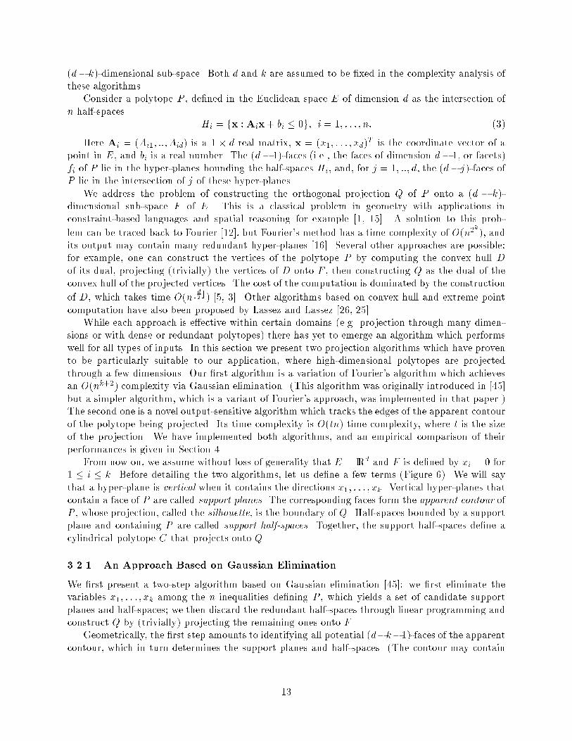
(d� k)-dimensional sub-space. Both d and k are assumed to be �xed in the complexity analysis ofthese algorithms.Consider a polytope P , de�ned in the Euclidean space E of dimension d as the intersection ofn half-spaces Hi = fx :Aix+ bi � 0g; i = 1; : : : ; n: (3)Here Ai = (Ai1; ::; Aid) is a 1 � d real matrix, x = (x1; : : : ; xd)T is the coordinate vector of apoint in E, and bi is a real number. The (d� 1)-faces (i.e., the faces of dimension d� 1, or facets)fi of P lie in the hyper-planes bounding the half-spaces Hi, and, for j = 1; ::; d, the (d� j)-faces ofP lie in the intersection of j of these hyper-planes.We address the problem of constructing the orthogonal projection Q of P onto a (d � k)-dimensional sub-space F of E. This is a classical problem in geometry with applications inconstraint-based languages and spatial reasoning for example [1, 15]. A solution to this prob-lem can be traced back to Fourier [12], but Fourier's method has a time complexity of O(n2k), andits output may contain many redundant hyper-planes [16]. Several other approaches are possible:for example, one can construct the vertices of the polytope P by computing the convex hull Dof its dual, projecting (trivially) the vertices of D onto F , then constructing Q as the dual of theconvex hull of the projected vertices. The cost of the computation is dominated by the constructionof D, which takes time O(nb d2 c) [5, 3]. Other algorithms based on convex hull and extreme pointcomputation have also been proposed by Lassez and Lassez [26, 25].While each approach is e�ective within certain domains (e.g. projection through many dimen-sions or with dense or redundant polytopes) there has yet to emerge an algorithm which performswell for all types of inputs. In this section we present two projection algorithms which have provento be particularly suitable to our application, where high-dimensional polytopes are projectedthrough a few dimensions. Our �rst algorithm is a variation of Fourier's algorithm which achievesan O(nk+2) complexity via Gaussian elimination. (This algorithm was originally introduced in [45]but a simpler algorithm, which is a variant of Fourier's approach, was implemented in that paper.)The second one is a novel output-sensitive algorithm which tracks the edges of the apparent contourof the polytope being projected. Its time complexity is O(tn) time complexity, where t is the sizeof the projection. We have implemented both algorithms, and an empirical comparison of theirperformances is given in Section 4.From now on, we assume without loss of generality that E = IRd and F is de�ned by xi = 0 for1 � i � k. Before detailing the two algorithms, let us de�ne a few terms (Figure 6). We will saythat a hyper-plane is vertical when it contains the directions x1; : : : ; xk. Vertical hyper-planes thatcontain a face of P are called support planes. The corresponding faces form the apparent contour ofP , whose projection, called the silhouette, is the boundary of Q. Half-spaces bounded by a supportplane and containing P are called support half-spaces. Together, the support half-spaces de�ne acylindrical polytope C that projects onto Q.3.2.1 An Approach Based on Gaussian EliminationWe �rst present a two-step algorithm based on Gaussian elimination [45]: we �rst eliminate thevariables x1; : : : ; xk among the n inequalities de�ning P , which yields a set of candidate supportplanes and half-spaces; we then discard the redundant half-spaces through linear programming andconstruct Q by (trivially) projecting the remaining ones onto F .Geometrically, the �rst step amounts to identifying all potential (d�k�1)-faces of the apparentcontour, which in turn determines the support planes and half-spaces. (The contour may contain13
x1
vertical(d-1)-face apparent
contour
P
Q
silhouette
C
(d-2)-face
E
F
(d-1)-facepointing up
(d-1)-facepointing down
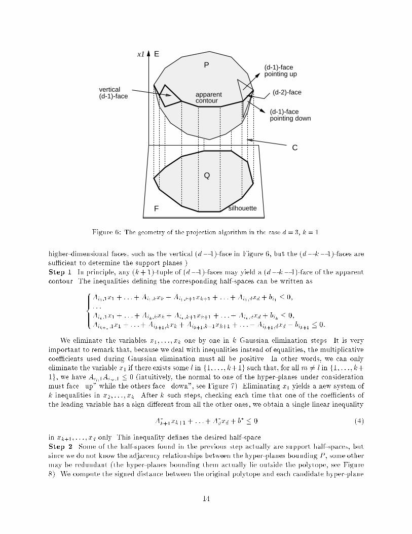
Figure 6: The geometry of the projection algorithm in the case d = 3, k = 1.higher-dimensional faces, such as the vertical (d� 1)-face in Figure 6, but the (d� k� 1)-faces aresu�cient to determine the support planes.)Step 1. In principle, any (k+ 1)-tuple of (d� 1)-faces may yield a (d� k� 1)-face of the apparentcontour. The inequalities de�ning the corresponding half-spaces can be written as8>>><>>>:Ai1;1x1 + : : :+ Ai1;kxk +Ai1;k+1xk+1 + : : :+Ai1;dxd + bi1 � 0;: : :Aik ;1x1 + : : :+ Aik ;kxk + Aik;k+1xk+1 + : : :+ Aik ;dxd + bik � 0;Aik+1 ;1x1 + : : :+Aik+1 ;kxk + Aik+1;k+1xk+1 + : : :+Aik+1 ;dxd + bik+1 � 0:We eliminate the variables x1; : : : ; xk one by one in k Gaussian elimination steps. It is veryimportant to remark that, because we deal with inequalities instead of equalities, the multiplicativecoe�cients used during Gaussian elimination must all be positive. In other words, we can onlyeliminate the variable x1 if there exists some l in f1; : : : ; k+1g such that, for all m 6= l in f1; : : : ; k+1g, we have Ail;1Aim;1 � 0 (intuitively, the normal to one of the hyper-planes under considerationmust face \up" while the others face \down", see Figure 7). Eliminating x1 yields a new system ofk inequalities in x2; : : : ; xk. After k such steps, checking each time that one of the coe�cients ofthe leading variable has a sign di�erent from all the other ones, we obtain a single linear inequalityA�k+1xk+1 + : : :+A�dxd + b� � 0 (4)in xk+1; : : : ; xd only. This inequality de�nes the desired half-space.Step 2. Some of the half-spaces found in the previous step actually are support half-spaces, butsince we do not know the adjacency relationships between the hyper-planes bounding P , some othermay be redundant (the hyper-planes bounding them actually lie outside the polytope, see Figure8). We compute the signed distance between the original polytope and each candidate hyper-plane14
x1
x2
P
Q
A
A
A
3
2
1
a
b
Figure 7: Sign constraints in the case d = 2; k = 1 (the (d � 2)-faces are vertices): the signs of the x1coordinates of the normals A1 and A2 are di�erent: the (d� 2)-face a obtained by eliminating x1 betweenthe equations of the corresponding hyper-planes belongs to the apparent contour. The signs of the x1coordinates of the normals A2 and A3 are the same: the (d� 2)-face b obtained by eliminating x1 betweenthe equations of the corresponding hyper-planes projects inside the silhouette.by maximizing (4) under the original constraints (3) (this is a linear program). We then reject thehyper-planes lying at a strictly negative distance from the polytope.What is the cost of this algorithm? We must consider � nk+1� (k + 1)-tuples of (d� 1)-faces, sofor a �xed k we have to consider a total of O(nk+1) tuples. For a �xed dimension, the cost of thebest linear programming algorithms proposed so far is linear in the number of constraints [32], sorejecting redundant faces can be done in O(nk+2) time.Note that this algorithm is similar to Fourier's method [12]: in the latter algorithm, one variableis �rst eliminated among all possible pairs of inequalities; a second variable is then eliminated amongall pairs of new inequalities, etc.., until k variables have been eliminated. In contrast, our algorithmdirectly eliminates k variables among all possible sets of k+1 inequalities. This simple modi�cationallows us to improve the cost of projection from O(n2k) to O(nk+2). It should also be noted thatthe projection method implemented in [10, 45] is essentially Fourier's algorithm.3.2.2 A Contour-Tracking ApproachWe now propose a novel algorithm that computes the projection Q of P onto F in an output-sensitive way. We restrict the discussion to the case k > 1. The case k = 1 can be easily solvedusing linear programming. We will assume that the hyper-planes Aix + bi = 0, i = 1; : : : ; n, arein general position, i.e. no (d+ 1)-tuples of hyper-planes have a common intersection and no twovertices of P project onto the same vertex of Q. This ensures that the cone formed by the faces ofP incident to each vertex contains a bounded number of faces and that the size of the set of edgesthat belong to the apparent contour is linear in the number of faces of Q. General techniques suchas the simulation of simplicity of [9] can be used to make this hypothesis valid. We will also assumethat P is bounded (which is clearly the case in our grasping application). Methods for dealing withunbounded polytopes are described in [25].The algorithm is again divided into two steps: we �rst use linear programming to �nd an initialpoint on the apparent contour; we then track the edges contained in the contour by shooting raysfrom the visited vertices, and record for each edge the support plane containing it as well as the15
x1
x2
P
Q
a
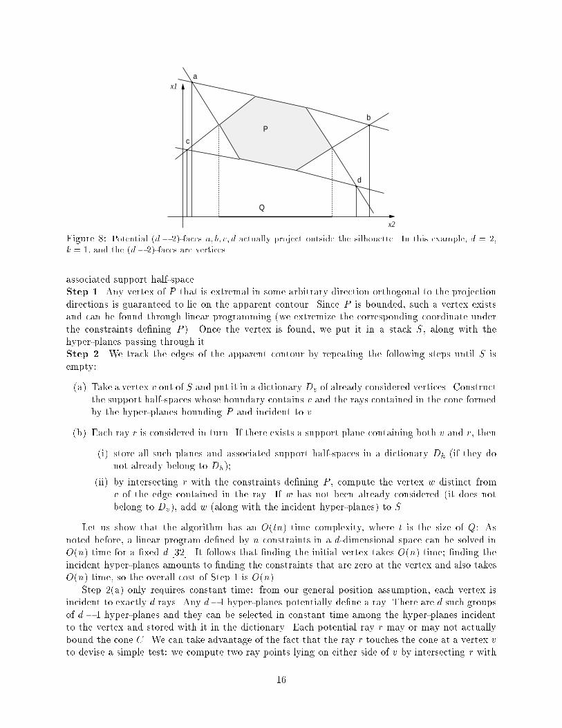
b
c
dFigure 8: Potential (d � 2)-faces a; b; c; d actually project outside the silhouette. In this example, d = 2,k = 1, and the (d� 2)-faces are vertices.associated support half-space.Step 1. Any vertex of P that is extremal in some arbitrary direction orthogonal to the projectiondirections is guaranteed to lie on the apparent contour. Since P is bounded, such a vertex existsand can be found through linear programming (we extremize the corresponding coordinate underthe constraints de�ning P ). Once the vertex is found, we put it in a stack S, along with thehyper-planes passing through it.Step 2. We track the edges of the apparent contour by repeating the following steps until S isempty:(a) Take a vertex v out of S and put it in a dictionary Dv of already considered vertices. Constructthe support half-spaces whose boundary contains v and the rays contained in the cone formedby the hyper-planes bounding P and incident to v.(b) Each ray r is considered in turn. If there exists a support plane containing both v and r, then(i) store all such planes and associated support half-spaces in a dictionary Dh (if they donot already belong to Dh);(ii) by intersecting r with the constraints de�ning P , compute the vertex w distinct fromv of the edge contained in the ray. If w has not been already considered (it does notbelong to Dv), add w (along with the incident hyper-planes) to S.Let us show that the algorithm has an O(tn) time complexity, where t is the size of Q: Asnoted before, a linear program de�ned by n constraints in a d-dimensional space can be solved inO(n) time for a �xed d [32]. It follows that �nding the initial vertex takes O(n) time; �nding theincident hyper-planes amounts to �nding the constraints that are zero at the vertex and also takesO(n) time, so the overall cost of Step 1 is O(n).Step 2(a) only requires constant time: from our general position assumption, each vertex isincident to exactly d rays. Any d�1 hyper-planes potentially de�ne a ray. There are d such groupsof d � 1 hyper-planes and they can be selected in constant time among the hyper-planes incidentto the vertex and stored with it in the dictionary. Each potential ray r may or may not actuallybound the cone C. We can take advantage of the fact that the ray r touches the cone at a vertex vto devise a simple test: we compute two ray points lying on either side of v by intersecting r with16

two hyper-planes; the ray belongs to the cone C if and only if one of the two points satis�es theconstraints de�ning C. This test also requires constant time.At most �d�1k+1� support planes may contain a given ray and they can be found in constanttime. A ray contains an edge of the apparent contour if and only if it belongs to one of theseplanes. Conversely, a potential support plane actually supports the apparent contour if and only ifit contains at least one contour ray. All these tests take constant time. Step 2(b) requires shootingeach ray against all the hyper-planes bounding P , which takes O(n) time. Note that the hyper-planes incident to the new vertex are found at no extra cost during ray shooting. It follows thatthe combined cost of Steps 2(a) and 2(b) is dominated by the O(n) cost of Step 2(b). Since theloop in Step 2 is executed O(t) times, the overall cost of this step is O(tn).In fact, this result can be further improved by preprocessing the hyper-planes Hi so as to answerthe ray-shooting queries in sub-linear time, using a recent result by Matou�sek and Schwarzkopf [30].The details of the improved algorithm and its complexity analysis have been relegated to AppendixB. The main result is the following.Proposition 4 The projection of a polytope from a Euclidean space E of dimension d onto a(d� k)-dimensional sub-space F can be computed in time and spaceT = O �n +"t +"�where " is any positive constant, t is the size of Q, and = 11 + 1b d2 c :In our case, d = 11 so = 5=6.3.3 Finding Independent Contact RegionsWe now return to the problem of computing the grasps. After eliminating the variables x0; y0; z0,we obtain a set of constraints (2') de�ning the polytope representing all equilibrium grasps foreach quadruple of faces. Because of the uncertainty in robotics systems, we would like to minimizethe sensitivity of a grasp to positioning errors. A way of achieving this is to seek quadruplesof independent contact regions (an idea introduced by Nguyen in the two-dimensional case [39]).These regions are such that for any quadruple of contact points chosen in them, the correspondinggrasp achieves equilibrium. In the grasp con�guration space, these regions are represented byparallelepipeds with sides aligned with coordinate axes and contained in the polytope of equilibriumgrasps.We de�ne the maximal independent contact regions as those maximizing a criterion dependingon their size and location. A reasonable criterion is to maximize the minimum of the lengths ofthe parallelepiped edges. Like in the three-�nger planar case [10, 45], we have observed empiricallythat there is not, in general, a unique solution to this problem, and that, for su�ciently large faces,the size of the contact regions depends only on the size of the friction cones. In this case, there is anin�nite set of maximal parallelepipeds, and we add a secondary criterion in order to select a uniquesolution: we try to center as well as possible the center of mass of the object in the tetrahedronformed by the contact points. This enables us to decrease the e�ect of gravitational and inertialforces during the motion of the robot.We now show how to map the problem of �nding the maximal independent contact regions intoa linear programming problem. Recall that the position of �nger number i on face Fi is de�ned by17
two parameters ai and bi (i = 1; ::; 4). A parallelepiped in the grasp con�guration space can thusbe de�ned by four rectangles Ri = [a�i ; a+i ]� [b�i ; b+i ], i = 1; ::; 4, which correspond to its projectionon the parameter space of each face. Because of convexity, we only need to verify that the 256vertices of the parallelepiped are contained in the set of force-closure grasps {i.e., satisfy (2'){ inorder to guarantee that the entire parallelepiped is also contained in it.Let u be the minimum of the lengths of the corresponding intervals, we add to the existing setof linear constraints the following ones:8><>:u � 0;u � a+i � a�i ; i = 1; : : : ; 4;u � b+i � b�i ; (5)which express the fact that u is positive and smaller than the length of each interval. Maximizingthe minimum length criterion thus reduces to maximizing u under the constraints (2') {written 256times, once for each vertex of the parallelepiped{ and (5).The second criterion can also be expressed linearly by introducing an additional variable vmeasuring the L1 distance between the center of mass gp = (xp; yp; zp) of the grasped object andthe center of mass gc = (xc; yc; zc) of the contacts corresponding to the centers of the rectanglesRi. By de�nition, v = max(jxc � xpj; jyc � ypj; jzc � zpj), which yields the following constraints:8>>>>>>><>>>>>>>:v � xp � xc;v � xc � xp;v � yp � yc;v � yc � yp;v � zp � zc;v � zc � zp: (6)Since gp is �xed and xc; yc; zc depend linearly on the unknowns a�i ; a+i ; b�i ; b+i , these constraintson v are themselves linear in all the unknowns. Minimizing the distance criterion amounts tomaximizing �v.In summary, �nding the maximal independent contact regions amounts to solving a linearprogram: the constraints are (2') {again, written once for each one of the 256 vertices of theparallelepiped{, (5), and (6), and the objective function to maximize is a weighted combinationwuu�wvv of the two above criteria (the weights wu and wv are set a priori by the user, typically to0.5 and 0.5). There are 18 variables, namely the main variables a�i ; a+i ; b�i ; b+i (i = 1; ::; 4) and theauxiliary variables u and v. We rank the maximal independent contact regions found for di�erentquadruples of faces by using the output value of the simplex (i.e., the weighted sum of the criteriaafter optimization). For each quadruple of faces, we choose the centers of the maximal independentcontact regions as representative grasps.It should be noted that the independent contact regions can also be found without projectingthe original polytope. In this case, we use the original inequalities (2) instead of those de�ningthe projection. However, we must also add 3 � 256 variables corresponding to the values of x0 ateach vertex of the parallelepiped. The corresponding optimization involves many more variablesthan the original one, and is correspondingly much more expensive. As shown in Section 4, this isempirically con�rmed by our experiments. 18
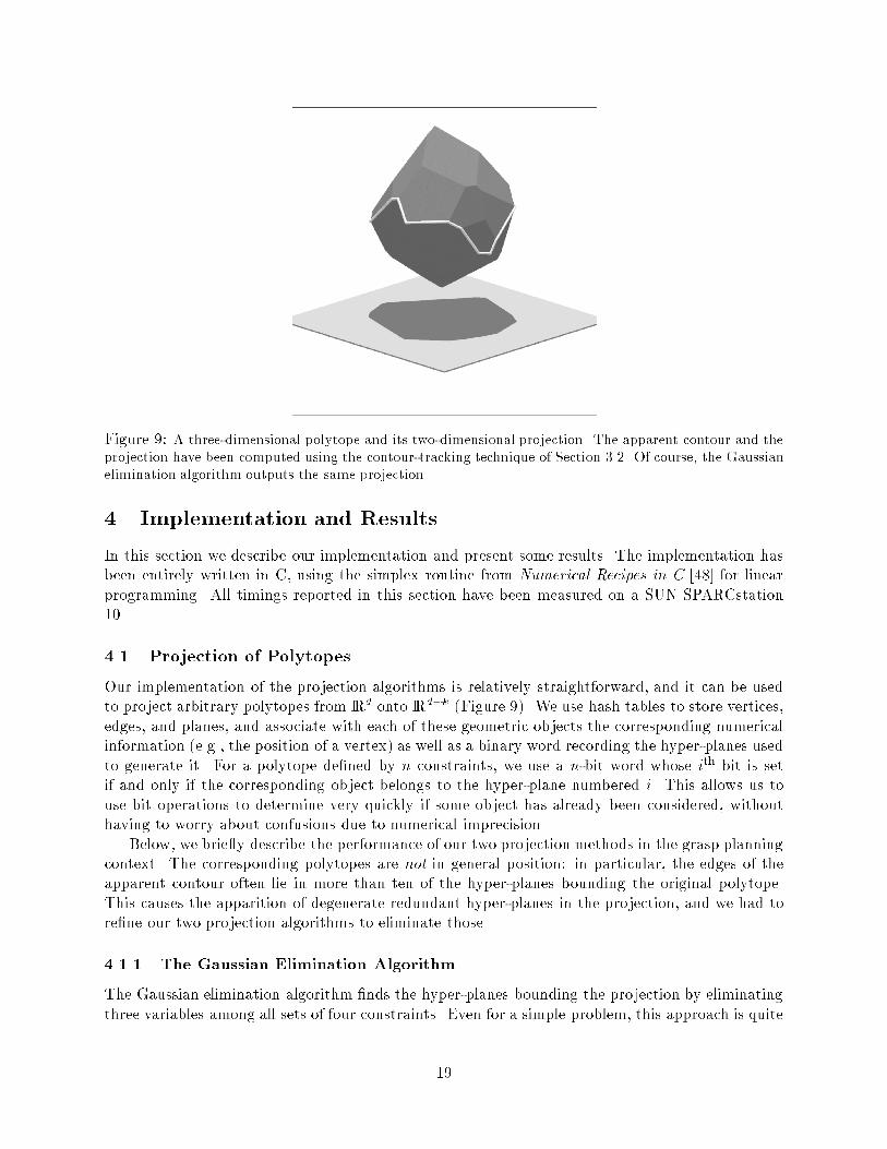
Figure 9: A three-dimensional polytope and its two-dimensional projection. The apparent contour and theprojection have been computed using the contour-tracking technique of Section 3.2. Of course, the Gaussianelimination algorithm outputs the same projection.4 Implementation and ResultsIn this section we describe our implementation and present some results. The implementation hasbeen entirely written in C, using the simplex routine from Numerical Recipes in C [48] for linearprogramming. All timings reported in this section have been measured on a SUN SPARCstation10.4.1 Projection of PolytopesOur implementation of the projection algorithms is relatively straightforward, and it can be usedto project arbitrary polytopes from IRd onto IRd�k (Figure 9). We use hash tables to store vertices,edges, and planes, and associate with each of these geometric objects the corresponding numericalinformation (e.g., the position of a vertex) as well as a binary word recording the hyper-planes usedto generate it. For a polytope de�ned by n constraints, we use a n-bit word whose ith bit is setif and only if the corresponding object belongs to the hyper-plane numbered i. This allows us touse bit operations to determine very quickly if some object has already been considered, withouthaving to worry about confusions due to numerical imprecision.Below, we brie y describe the performance of our two projection methods in the grasp planningcontext. The corresponding polytopes are not in general position: in particular, the edges of theapparent contour often lie in more than ten of the hyper-planes bounding the original polytope.This causes the apparition of degenerate redundant hyper-planes in the projection, and we had tore�ne our two projection algorithms to eliminate those.4.1.1 The Gaussian Elimination AlgorithmThe Gaussian elimination algorithm �nds the hyper-planes bounding the projection by eliminatingthree variables among all sets of four constraints. Even for a simple problem, this approach is quite19
expensive: for example the polytope associated with four triangular faces and the correspondingfour-sided friction cones is bounded by only 28 constraints, but �284 � = 20475 combinations haveto be checked. We take advantage of the fact that the hyper-planes which constrain the contactpoints to lie in each face are vertical, and add those to the projection from the outset. Furthermore,since combining any non-vertical planes with a vertical one produces the same vertical plane, weneed only consider combinations of non-vertical planes. For the case above, these are just theplanes corresponding to friction-cone constraints, with a total of �164 � = 1820 combinations tobe checked. Beyond the computational savings, this means that the cost of projection is almostexclusively determined by the number of planes used to approximate the friction cones and not bythe complexity of the faces being grasped. Step 2 of the original Gaussian elimination algorithm iseasily modi�ed to eliminate degenerate support planes that only touch the original polytope alonga lower-dimensional face: we maximize (4) under the original constraints (3) minus the constraintunder consideration, and reject hyper-planes such that the distance found is negative or zero.4.1.2 Tracking the Apparent ContourWe have implemented the contour-tracking algorithm as follows: at each successive vertex, we wishto determine which incident edges belong to the apparent contour. Given a vertex v, let us denoteby Hv the set of hyper-planes incident to v, and by pv the size of Hv. We �rst �nd a set of verticalhyper-planes containing v, then identify those edges which lie in at least one of the vertical planes.For each of the �pv4 � combinations of four hyper-planes in Hv , we perform Gaussian eliminationto �nd the support planes containing v. Then, since edges are de�ned by d� 1 hyper-planes, wecheck each subset of ten hyper-planes in Hv to see if it contains any of the combinations of fourwhich successfully generated a support plane. For those sets which do contain a combination, wecalculate the direction of the edge and check whether it intersects the polytope in another vertex. Ifso, the edge/vertex information is stored for further exploration (and to prevent duplication), andthe support planes generated by the combinations associated with the edge are output. Thoughthis procedure may seem circuitous, it can be implemented quite e�ciently using our binary wordrepresentation to determine which objects have already been examined and whether a combinationis included in a particular vertex or edge. Another advantage of this algorithm is that the supporthyper-planes are generated as part of the exploration process. There is no need for a post-processingstep to build the support planes from the projected vertices and edges.For generic polytopes, the contour-tracking algorithm does not yield any redundant verticalhyper-plane. However, in the context of grasp planning, there may be vertical hyper-planes touchingthe original polytope along a lower-dimensional face. We take advantage of the vertex informationto eliminate these redundant hyper-planes more e�ciently than through linear programming: weproject the vertices, then check each support plane to see how many dimensions are spanned bythe vertices it contains. Any hyper-plane whose vertices span less than seven dimensions cannotyield a facet of the silhouette polytope, and thus can be rejected as redundant.4.1.3 ResultsTo illustrate the relative performances of the Gaussian elimination and edge-tracking methodsin the context of grasp planning, we have tested them on the polytope associated with the problemof grasping a tetrahedron with m-sided friction cones. Figure 10(a) shows the run times for valuesof m ranging from 3 to 8, corresponding to polytopes de�ned by 24 to 44 constraints. As mighthave been expected, the contour tracking method outperforms the Gaussian elimination method.The tables of Figure 10(b)-(c) give a quantitative comparison of the two algorithms. As shown by20

24 26 28 30 32 34 36 38 40 42 440
500
1000
1500
2000
2500
Elimination
Edge Tracking
Hyperplanes in Convex
Tim
e (
sec)
(a) Time of Projection and Redundancy Removal (SUN Sparc 10)
(b) Cost of Projection for a Typical Grasp PolytopeGaussian Elimination MethodPlanes in Planes in Combinations Output Final Projection TotalCone Polytope Checked Size Size Time Time3 24 495 84 84 1 104 28 1820 173 149 3 295 32 4845 291 214 5 676 36 10626 468 310 11 2917 40 20475 829 492 35 15358 44 35960 1356 748 69 5229(c) Cost of Projection for a Typical Grasp PolytopeContour-Tracking MethodPlanes in Polytope Combinations Vertices Edges Output Final Projection TotalCone Size Checked Found Found Size Size Time Time3 24 432 196 1078 84 84 4 54 28 1227 368 2112 171 149 7 85 32 2355 650 3850 291 214 13 146 36 4088 1044 6336 464 310 26 287 40 7651 2058 12691 826 492 78 838 44 13106 3648 22784 1352 748 147 152Figure 10: (a) Qualitative comparison of the run times for projecting the grasp polytope of a tetrahedronand removing redundant hyper-planes (averaged over all possible grasps). The dashed line indicates theGaussian elimination method, and the solid line indicates the edge-tracking algorithm. (b) This table givesthe number of hyper-planes involved at each step of the projection process, as well as the time (in seconds)for the Gaussian elimination method. The object grasped is a tetrahedron with m-sided friction cones, withm varying from 3 to 8. (c) Table of results for the contour-tracking projection method. The data is the sameas before. 21
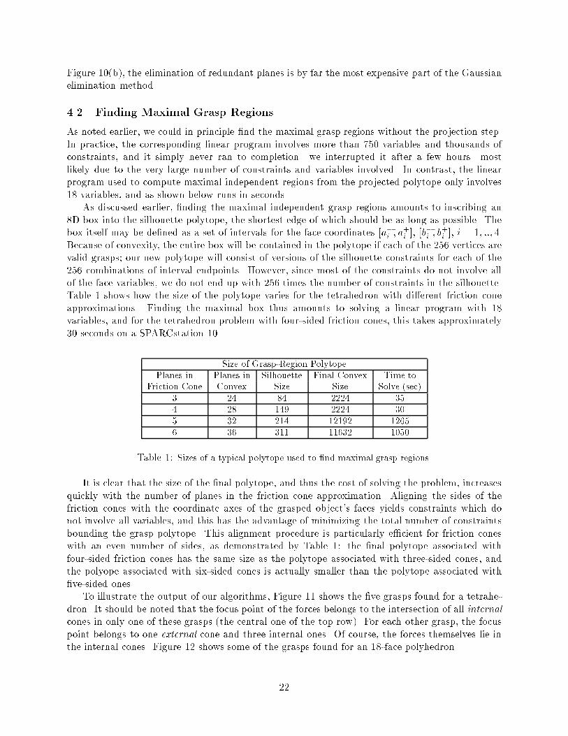
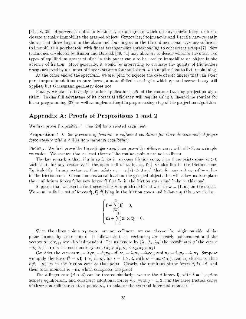
Figure 10(b), the elimination of redundant planes is by far the most expensive part of the Gaussianelimination method.4.2 Finding Maximal Grasp RegionsAs noted earlier, we could in principle �nd the maximal grasp regions without the projection step.In practice, the corresponding linear program involves more than 750 variables and thousands ofconstraints, and it simply never ran to completion {we interrupted it after a few hours{ mostlikely due to the very large number of constraints and variables involved. In contrast, the linearprogram used to compute maximal independent regions from the projected polytope only involves18 variables, and as shown below runs in seconds.As discussed earlier, �nding the maximal independent grasp regions amounts to inscribing an8D box into the silhouette polytope, the shortest edge of which should be as long as possible. Thebox itself may be de�ned as a set of intervals for the face coordinates [a�i ; a+i ], [b�i ; b+i ], i = 1; ::; 4.Because of convexity, the entire box will be contained in the polytope if each of the 256 vertices arevalid grasps; our new polytope will consist of versions of the silhouette constraints for each of the256 combinations of interval endpoints. However, since most of the constraints do not involve allof the face variables, we do not end up with 256 times the number of constraints in the silhouette.Table 1 shows how the size of the polytope varies for the tetrahedron with di�erent friction coneapproximations. Finding the maximal box thus amounts to solving a linear program with 18variables, and for the tetrahedron problem with four-sided friction cones, this takes approximately30 seconds on a SPARCstation 10. Size of Grasp-Region PolytopePlanes in Planes in Silhouette Final Convex Time toFriction Cone Convex Size Size Solve (sec)3 24 84 2224 354 28 149 2224 305 32 214 12192 12656 36 311 11632 1050Table 1: Sizes of a typical polytope used to �nd maximal grasp regions.It is clear that the size of the �nal polytope, and thus the cost of solving the problem, increasesquickly with the number of planes in the friction cone approximation. Aligning the sides of thefriction cones with the coordinate axes of the grasped object's faces yields constraints which donot involve all variables, and this has the advantage of minimizing the total number of constraintsbounding the grasp polytope. This alignment procedure is particularly e�cient for friction coneswith an even number of sides, as demonstrated by Table 1: the �nal polytope associated withfour-sided friction cones has the same size as the polytope associated with three-sided cones, andthe polyope associated with six-sided cones is actually smaller than the polytope associated with�ve-sided ones.To illustrate the output of our algorithms, Figure 11 shows the �ve grasps found for a tetrahe-dron. It should be noted that the focus point of the forces belongs to the intersection of all internalcones in only one of these grasps (the central one of the top row). For each other grasp, the focuspoint belongs to one external cone and three internal ones. Of course, the forces themselves lie inthe internal cones. Figure 12 shows some of the grasps found for an 18-face polyhedron.22
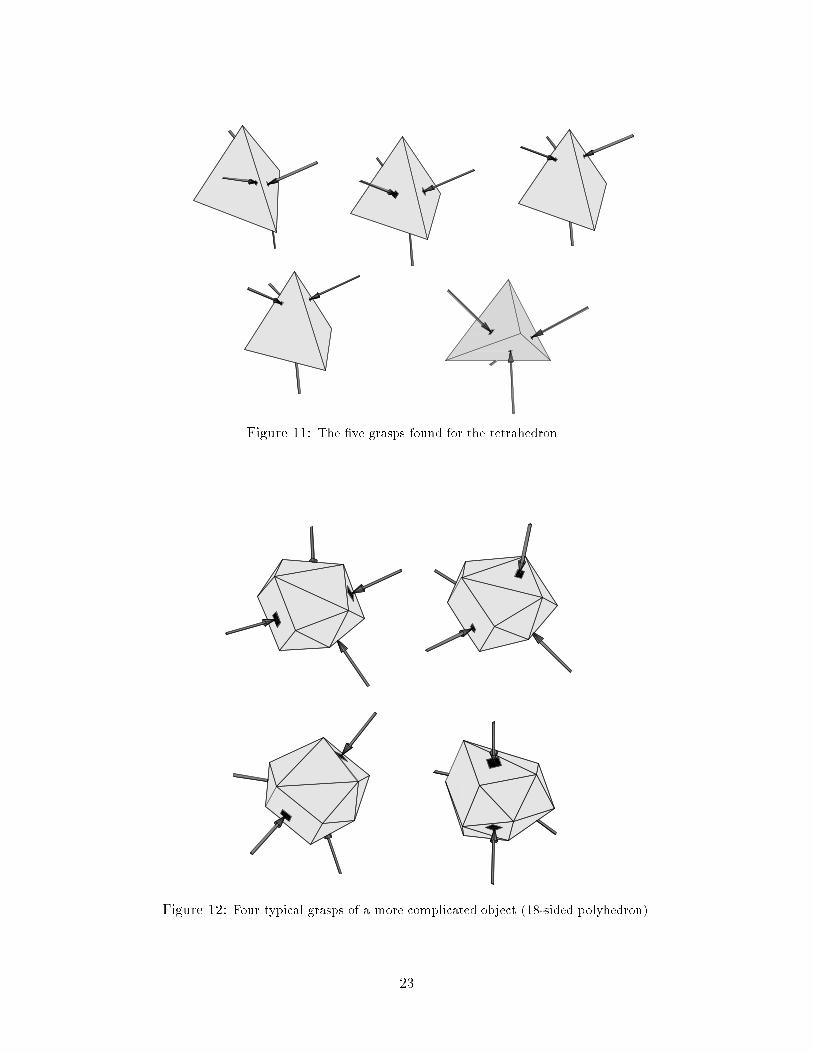
Figure 11: The �ve grasps found for the tetrahedron.
Figure 12: Four typical grasps of a more complicated object (18-sided polyhedron).23

Figure 13: A grasp formed by forces lying in two at pencils having a line in common but lying in di�erentplanes. This grasp was computed using the methods described in [56].5 Discussion and Future WorkWe have presented a geometric characterization of four-�nger equilibrium and force-closure grasps,given algorithms for computing maximal concurrent grasps of polyhedral objects, and demonstratede�cient implementations of these algorithms. Let us conclude by discussing some of the issues raisedby our work and by sketching some future research directions.Even though Propositions 2 and 3 hold for all types of non-planar four-�nger grasps, we haverestricted our attention in the second half of the paper to forces whose lines of action all passthrough some point. It is clearly important to generalize our approach to the other types of four-�nger grasps. Grasps involving forces that lie in two at pencils having a line in common mayprove particularly important in practice, for example for grasping an elongated object with twocooperating robots equipped with simple two-�nger grippers. We have recently developed a methodusing the intersection of inverted friction cones with the contact faces to compute this type of graspsthe direction of the line common to the two pencils is constrained to lie in a prescribed cylinder[56], and Figure 13 shows an example. This is only a �rst step: as mentioned in Section 2, theequations that characterize equilibrium for these more general grasps are normally non-linear, andnew methods will have to be developed.So far, we have computed grasps that were optimal according to a criterion based on size ofthe independent grasp regions and how well the center of mass of the object is centered among thecontact points. It would also be interesting to compute grasps that are optimal according to somefunctional consideration [11, 23, 27, 29, 34]: for example, given a �xed set of contact points andsome bound on the magnitude of the contact forces, Ferarri and Canny [11] propose to compute amaximal ball centered at the origin and contained in the convex formed by the contact wrenches;clearly, the contact forces can generate any wrench contained in this ball, and its radius providesa measure of the grasp's e�ciency. Computing a grasp con�guration which is optimal accordingto this criterion is more challenging; it is a non-linear problem since the moment of the forcesdepends bilinearly on the �nger positions and the force directions. We have recently implementedan iterative approach to this non-linear optimization problem [56] (see [34] for a di�erent method).In this paper we have restricted our attention to point contact with friction. In the frictionlesscase, it is known that four �ngers in the plane and seven �ngers in the three-dimensional caseare necessary and, under very general assumptions, su�cient to achieve force- or form-closure24
[24, 28, 35]. However, as noted in Section 2, certain grasps which do not achieve force- or form-closure actually immobilize the grasped object. Czyzowicz, Stojmenovic and Urrutia have recentlyshown that three �ngers in the plane and four �ngers in the three-dimensional case are su�cientto immobilize a polyhedron, with �nger arrangements corresponding to concurrent grasps [7]. Newtechniques developed by Rimon and Burdick [50, 51] may allow us to decide whether the other twotypes of equilibrium grasps studied in this paper can also be used to immobilize an object in theabsence of friction. More generally, it would be interesting to evaluate the quality of frictionlessgrasps achieved by a number of �ngers between four and seven, with applications to �xture planning.At the other end of the spectrum, we also plan to explore the case of soft �ngers that can exertpure torques in addition to pure forces, a more di�cult setting in which general screw theory stillapplies, but Grassmann geometry does not.Finally, we plan to investigate other applications [25] of the contour-tracking projection algo-rithm. Taking full advantage of its potential e�ciency will require using a linear-time routine forlinear programming [32] as well as implementing the preprocessing step of the projection algorithm.Appendix A: Proofs of Propositions 1 and 2We �rst prove Proposition 1. See [28] for a related argument.Proposition 1 In the presence of friction, a su�cient condition for three-dimensional, d-�ngerforce closure with d � 3 is non-marginal equilibrium.Proof : We �rst prove the three-�nger case, then prove the d-�nger case, with d > 3, as a simpleextension. We assume that at least three of the contact points are not collinear.The key remark is that, if a force fi lies in an open friction cone, then there exists some "i > 0such that, for any vector vi in the open ball of radius "i, fi + vi also lies in the friction cone.Equivalently, for any vector vi, there exists �i = jvij="i > 0 such that, for any � � �i, �fi+ vi liesin the friction cone. Given some external load on the grasped object, this will allow us to replacethe equilibrium forces fi by new forces f 0i that lie in the friction cones and balance this load.Suppose that we exert a (not necessarily zero-pitch) external wrench w = (f ;m) on the object.We want to �nd a set of forces f 01; f 02; f 03 lying in the friction cones and balancing this wrench, i.e.,8>>>><>>>>:f + 3Xi=1 f 0i = 0;m+ 3Xi=1 xi � f 0i = 0:Since the three points x1;x2;x3 are not collinear, we can choose the origin outside of theplane formed by these points. It follows that the vectors xi are linearly independent and thevectors xi � xi+1 are also independent. Let us denote by (�1; �2; �3) the coordinates of the vector�x1 � f +m in the coordinate system (x3 � x1;x1 � x2;x2 � x3).Consider the vectors v1 = �1x1� �2x2� f , v2 = �2x2� �3x3, and v3 = �3x3� �1x1. Supposewe apply the force f 0i = �fi + vi in xi, for i = 1; 2; 3, with � = max(�i), and �i chosen so that�ifi + vi lies in the friction cone at that point. Clearly, the resultant of the forces f 0i is �f , andtheir total moment is �m, which completes the proof.The d-�nger case (d > 3) can be treated similarly: we use the d forces fi, with i = 1; ::; d toachieve equilibrium, and construct additional forces vij , with j = 1; 2; 3 in the three friction conesof three non-collinear contact points xij to balance the external force and moment. 225
We now prove Proposition 2.Proposition 2 A necessary and su�cient condition for four non-coplanar points to form an equi-librium grasp with four non-zero contact forces is that(P1) there exist four lines in the corresponding double-sided friction cones that either intersect ina single point, form two at pencils having a line in common but lying in di�erent planes, orform a regulus, and(P2) the vectors parallel to these lines and lying in the internal friction cones at the contact pointspositively span IR3.Proof : The condition is clearly necessary: since the equilibrium forces are non-zero, their linesof action are well de�ned, and they lie in the double-sided cones. In addition, since the sum of thecorresponding wrenches is zero, the equilibrium forces are linearly dependent, but since the contactpoints are not coplanar, these forces are not coplanar either, and they satisfy (P1). Since the forceslie in the internal friction cones and add up to a zero resultant force, they positively span IR3 andsatisfy (P2).The condition is also su�cient. Let us assume the existence of lines �i (i = 1; ::; 4) satisfying(P1) and (P2). Since these lines satisfy (P1), some linear combination of the associated wrenchesis zero. In particular, if we denote by xi (i = 1; ::; 4) the contact points and by ui (i = 1; ::; 4) thevectors satisfying (P2), there exist coe�cients �i such that P4i=1 �iui = 0. Because the vectors uipositively span IR3, no three of them can be coplanar, and this implies that none of the coe�cients�i is zero. We can therefore set �1 = 1 without loss of generality. Since the vectors ui positivelyspan IR3, we can also write u1 = �P4i=2 �0iui, where the coe�cients �0i are strictly positive. In turn,this implies that P4i=2(�i � �0i)ui = 0, hence �i = �0i for i = 1; ::; 4, so the coe�cients �i are strictlypositive, and the grasp formed by the four contact points exerting the non-zero forces �iui achievesequilibrium. 2Appendix B: Re�ned Contour Tracking AlgorithmThe contour tracking algorithm proposed in Section 3.2.2 has a time complexity of O(tn), wheren is the number of constraints de�ning the input polytope P , and t is the size of its projection Q.This time complexity can be improved by preprocessing the hyperplanes Hi so as to answer theray shooting queries in sublinear time.We use the following recent result by Matou�sek and Schwarzkopf [30].Theorem 2 ([30]) Let m be a parameter such that n � m � nb d2 c and let � be any positiveconstant. One can preprocess a polytope de�ned as the intersection of n half spaces of E in O(m1+�)(deterministic) time and using O(m1+�) space so that, given a query line, the intersection pointsbetween the line and the polytope can be computed in time O� nm1=b d2 c (logn)2d+1�.The idea of our algorithm is to start with little memory and do ray shootings until the cumulatedtime of all the queries performed so far exceeds the preprocessing time and the memory storage. Atthat point, we can allow more memory. Thus we restart a new preprocessing with a bigger value ofm. And repeat that process (each such process will be called a step) until all the faces have beenconstructed. 26
Let T (i) be the time spent in step i, mi be the parameter chosen at that step for the prepro-cessing and ti be the number of edges constructed at that step. We will take ti = n1+�i for some� > 0. We have T (i) = O(m1+�i ) +O0@nti(logn)2d+1m1=b d2 ci 1A :We take mi so as to balance the cost of the preprocessing and the cost of the queries performedat step i, i.e., mi = �nti(logn)2d+1� 1�+1= ;where = 11 + 1b d2 c :In order to satisfy the hypotheses of Theorem 2, it is necessary thatmi � nb d2 c. We �rst supposethat this is the case for all i.It follows from the expression of T (i) thatT (i)=O��nti(logn)2d+1� 1+�1+ ��=O��nti(logn)2d+1� (1+�)� :Using the fact that ti = n1+�i for some � > 0, and summing over the h steps needed to computeall the simplices, we obtain the overall computing time T of the algorithm:T = O �n2(logn)2d+1� (1+�) hXi=1 n� (1+�)i! :The number of steps h is given byhXi=1 ti = t = n1+�nh� � 1n� � 1 ; (7)which implies nh� = O(t=n), and since t = O(nb d2 c), h = O(1).It follows that T = O �n (1+�)t (1+�)(logn)2d+1� :The algorithm above runs as described provided that all mi, i = 1; : : : ; h remain smaller thannb d2 c, that is mh � nb d2 c;�nth(logn)2d+1� 1�+1= � nb d2 c;nth � nb d2 c(�+1+ 1b d2 c );th � nb d2 c(1+�):Furthermore it follows from (7) that t � th1�n�� � 2th for big enough values of n.27
If, for some i, ti > nb d2 c(1+�), we use any worst-case optimal algorithm [3, 5].Using the fact that for any large enough values of n, and for any positive numbers k; l, we have(logn)k < nl, we �nally obtain our main result.Proposition 4 The projection of a polytope from a Euclidean space E of dimension d onto a(d� k)-dimensional sub-space F can be computed in time and spaceT = O �n +"t +"�where " is any positive constant, t is the size of Q, and = 11 + 1b d2 c :Acknowledgment: We wish to thank Dan Halperin, Seth Hutchinson, Catherine and Jean-Louis Lassez,Alison Noble, Elon Rimon, Rajeev Sharma and Ilan Shimshoni for useful discussions and comments. Partof this work was conducted while J. Ponce was visiting INRIA and later Caltech as a Beckman associatewith the Center for Advanced Study of UIUC. We gratefully acknowledge support from these institutionsand from the Beckman Institute for Advanced Science and Technology of UIUC. S. Sullivan was supportedin part by NASA grant NAG 1-613. A. Sudsang was supported in part by a fellowship from the AnandaMahidol Foundation.References[1] Journal of Symbolic Computation, 5, 1988. Special issue on Algorithms in Real Algebraic Geometry.[2] R.S. Ball. A treatise on the theory of screws. Cambridge University Press, 1900.[3] J.-D. Boissonnat, O. Devillers, R. Schott, M. Teillaud, and M. Yvinec. Applications of random samplingto on-line algorithms in computational geometry. Discrete Comput. Geom., 8:51{71, 1992.[4] O. Bottema and B. Roth. Theoretical Kinematics. North Holland Publishing Co., 1979.[5] B. Chazelle. An optimal convex hull algorithm for point sets in any �xed dimension. Technical ReportCS-TR-336-91, Dept. Comput. Sci., Princeton Univ., Princeton, NJ, 1991.[6] I.M. Chen and J.W. Burdick. Finding antipodal point grasps on irregularly shaped objects. In IEEEInt. Conf. on Robotics and Automation, pages 2278{2283, Nice, France, June 1992.[7] J. Czyzowicz, I. Stojmenovic, and J. Urrutia. Immobilizing a polytope. volume 519 of Lecture Notes inComputer Sciences, pages 214{227. Springer-Verlag, 1991.[8] A. Dandurand. The rigidity of compound spatial grid. Structural Topology, 10, 1984.[9] H. Edelsbrunner and E. P. M�ucke. Simulation of simplicity: a technique to cope with degenerate casesin geometric algorithms. ACM Trans. Graph., 9:66{104, 1990.[10] B. Faverjon and J. Ponce. On computing two-�nger force-closure grasps of curved 2D objects. In IEEEInt. Conf. on Robotics and Automation, pages 424{429, Sacramento, CA, April 1991.[11] C. Ferrari and J.F. Canny. Planning optimal grasps. In IEEE Int. Conf. on Robotics and Automation,pages 2290{2295, Nice, France, June 1992.[12] J.B.J. Fourier. Reported in: Analyse des travaux de l'acad�emie royale des sciences pendant l'ann�ee 1824.In Partie math�ematique, Histoire de l'Acad�emie Royale des Sciences de l'Institut de France, volume 7.1827. Partial English translation in: D.A. Kohler, Translation of a Report by Fourier on his work onLinear Inequalities, Opsearch 10 (1973) 38-42. 28

[13] D. Hilbert and S. Cohn-Vossen. Geometry and the Imagination. Chelsea, New York, 1952.[14] K.H. Hunt. Kinematic Geometry of Mechanisms. Clarendon, Oxford, 1978.[15] T. Huynh, L. Joskowicz, C. Lassez, and J-L. Lassez. Reasoning about linear constraints using parametricqueries. In Foundations of Software Technology and Theoretical Computer Science, volume 472 of LectureNotes in Computer Sciences. Springer-Verlag, 1990.[16] T. Huynh, C. Lassez, and J-L. Lassez. Practical issues on the projection of polyhedral sets. Annals ofMathematics and Arti�cial Intelligence, 6, 1992.[17] S.C. Jacobsen, J.E. Wood, D.F. Knutti, and K.B. Biggers. The Utah-MIT Dextrous Hand: Work inprogress. International Journal of Robotics Research, 3(4):21{50, 1984.[18] Z. Ji. Dexterous hands: optimizing grasp by design and planning. PhD thesis, Stanford University,Dept. of Mechanical Engineering, 1987.[19] Z. Ji and B. Roth. Contact force in grasping and kinematic constraints. In Seventh IFToMM WorldCongress, pages 1219{1222, Sevilla, Spain, 1987.[20] Z. Ji and B. Roth. Direct computation of grasping force for three-�nger tip-prehension grasps. Journalof Mechanics, Transmissions, and Automation in Design, 110:405{413, December 1988.[21] J.R Kerr. An Analysis of multi-�ngered hands. PhD thesis, Stanford University, Stanford, CA, 1984.[22] J.R. Kerr and B. Roth. Analysis of multi-�ngered hands. International Journal of Robotics Research,4(4), Winter 1986.[23] D.G. Kirkpatrick, B. Mishra, and C.K. Yap. Quantitative Steinitz's theorems with applications tomulti�ngered grasping. In 20th ACM Symp. on Theory of Computing, pages 341{351, Baltimore, MD,May 1990.[24] K. Lakshminarayana. Mechanics of form closure. Technical Report 78-DET-32, ASME, 1978.[25] C. Lassez and J-L. Lassez. Quanti�er elimination for conjunctions of linear constraints via a convexhull algorithm. In D. Kapur B. Donald and J. Mundy, editors, Symbolic and Numerical Computationfor Arti�cial Intelligence, pages 103{122. Academic Press, 1992.[26] J-L. Lassez. Querying constraints. In ACM conference on Principles of Database Systems, Nashville,1990.[27] Z. Li and S. Sastry. Task-oriented optimal grasping by multi�ngered robot hands. In IEEE Int. Conf.on Robotics and Automation, pages 389{394, 1987.[28] X. Markensco�, L. Ni, and C.H. Papadimitriou. The geometry of grasping. International Journal ofRobotics Research, 9(1):61{74, February 1990.[29] X. Markensco� and C.H. Papadimitriou. Optimum grip of a polygon. International Journal of RoboticsResearch, 8(2):17{29, April 1989.[30] J. Matou�sek and O. Schwarzkopf. Linear optimization queries. In Proc. 8th Annu. ACM Sympos.Comput. Geom., pages 16{25, 1992.[31] J.M. McCarthy. An Introduction to Theoretical Kinematics. MIT Press, 1990.[32] N. Megiddo. Linear programming in linear time when the dimension is �xed. J. Assoc. Comput. Mach.,31:114{127, 1984.[33] J.P. Merlet. Singular con�gurations of parallel manipulators and grassmann geometry. In J.D. Bois-sonnat and J.P. Laumont, editors, Geometry and Robotics, volume 391 of Lecture Notes in ComputerScience, pages 194{212. Springer-Verlag, 1988.[34] B. Mirtich and J.F. Canny. Optimum force-closure grasps. Technical Report ESRC 93-11/RAMP 93-5,Robotics, Automation, and Manufacturing Program, University of California at Berkeley, July 1993.29
[35] B. Mishra, J.T. Schwartz, and M. Sharir. On the existence and synthesis of multi�nger positive grips.Algorithmica, Special Issue: Robotics, 2(4):541{558, November 1987.[36] B. Mishra and N. Silver. Some discussion of static gripping and its stability. IEEE Systems, Man, andCybernetics, 19(4):783{796, 1989.[37] A.F. M�obius. Lehrbuch der Statik. Leipzig, 1837.[38] R.M. Murray, Z. Li, and S.S. Sastry. A mathematical introduction to robotic manipulation. CRC Press,1994.[39] V-D. Nguyen. Constructing force-closure grasps. International Journal of Robotics Research, 7(3):3{16,June 1988.[40] M.S. Ohwovoriole. An extension of screw theory and its application to the automation of industrialassemblies. PhD thesis, Stanford University, Stanford, CA, 1980.[41] M.S. Ohwovoriole. An extension of screw theory. Journal of Mechanical Design, 103:725{735, 1981.[42] J. Pertin-Troccaz. Grasping: a state of the art. In O. Khatib, J. Craig, and T. Lozano-P�erez, editors,The Robotics Review 1. MIT Press, 1989.[43] N.S. Pollard and T. Lozano-P�erez. Grasp stability and feasibility for an arm with an articulated hand.In IEEE Int. Conf. on Robotics and Automation, pages 1581{1585, Cincinatti, OH, 1990.[44] J. Ponce and B. Faverjon. On computing three-�nger force-closure grasps of polygonal objects. InInternational Conference on Advanced Robotics, pages 1018{1023, Pisa, Italy, June 1991.[45] J. Ponce and B. Faverjon. On computing three-�nger force-closure grasps of polygonal objects. IEEETransactions on Robotics and Automation, 1995. In press.[46] J. Ponce, D. Stam, and B. Faverjon. On computing force-closure grasps of curved two-dimensionalobjects. International Journal of Robotics Research, 12(3):263{273, June 1993.[47] J. Ponce, S. Sullivan, J-D. Boissonnat, and J-P. Merlet. On characterizing and computing three- andfour-�nger force-closure grasps of polyhedral objects. In IEEE Int. Conf. on Robotics and Automation,pages 821{827, Atlanta, Georgia, May 1993.[48] W. Press, B. Flannery, S. Teukolsky, and W. Vetterling. Numerical Recipes in C. Cambridge UniversityPress, 1988.[49] F. Reulaux. The kinematics of machinery. MacMillan, NY, 1876. Reprint, Dover, NY, 1963.[50] E. Rimon and J. W. Burdick. Mobility of bodies in contact|i: A new 2nd order mobility index formultiple-�nger grasps. In IEEE Int. Conf. on Robotics and Automation, San Diego, CA, May 1994.[51] E. Rimon and J. W. Burdick. Mobility of bodies in contact|ii: How forces are generated by curvaturee�ects. In IEEE Int. Conf. on Robotics and Automation, San Diego, CA, May 1994.[52] B. Roth. Screws, motors, and wrenches that cannot be bought in a hardware store. In Proc. InternationalSymposium on Robotics Research, pages 679{693. MIT Press, 1984.[53] J.K. Salisbury. Kinematic and force analysis of articulated hands. PhD thesis, Stanford University,Stanford, CA, 1982.[54] J.K. Salisbury and B. Roth. Kinematic and force analysis of articulated hands. ASME Journal ofMechanisms, Transmissions, and Automation in Design, 105:33{41, 1982.[55] P. Somov. �Uber Gebiete von Schraubengeschwindigkeiten eines starren Korpers bie verschiedener Zahlvon Stutz achen. Zeitricht f�ur Mathematik und Physik, 45:245{306, 1900.[56] A. Sudsang. On computing multi-�nger force-closure and optimal grasps of two- and three-dimensionalobjects. Master's thesis, Department of Computer Science, University of Illinois, 1994.[57] J.C. Trinkle. On the stability and instantaneous velocity of grasped frictionless objects. IEEE Trans-actions on Robotics and Automation, 8(5):560{572, October 1992.30