Odyssey Product Catalog - Shearer Supply
148
May2017 SS-PRC028M-EN Split System Air Conditioners Odyssey™ CoolingCondenser—6to25Tons—60Hz AirHandler—5to25Tons—60Hz Product Catalog
-
Upload
khangminh22 -
Category
Documents
-
view
0 -
download
0
Transcript of Odyssey Product Catalog - Shearer Supply

(1,1)
May 2017 SSSS--PPRRCC002288MM--EENN
Split System Air ConditionersOdyssey™™Cooling Condenser — 6 to 25 Tons — 60 HzAir Handler — 5 to 25 Tons — 60 Hz
Product Catalog
(2,1)
©2017 Ingersoll Rand SS-PRC028M-EN
Introduction
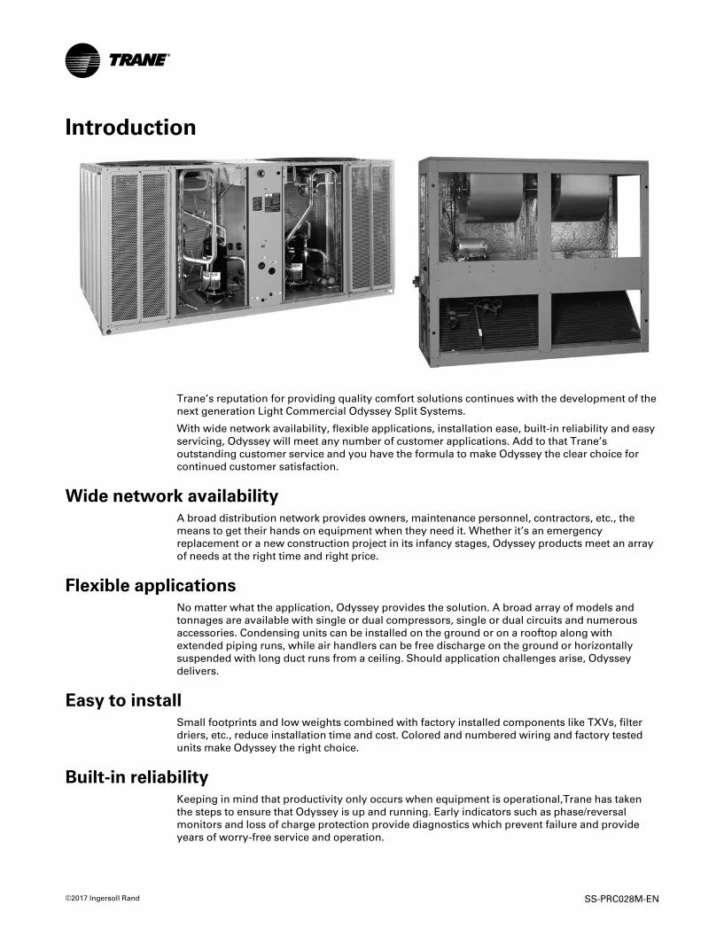
Trane’s reputation for providing quality comfort solutions continues with the development of thenext generation Light Commercial Odyssey Split Systems.
With wide network availability, flexible applications, installation ease, built-in reliability and easyservicing, Odyssey will meet any number of customer applications. Add to that Trane’soutstanding customer service and you have the formula to make Odyssey the clear choice forcontinued customer satisfaction.
Wide network availabilityA broad distribution network provides owners, maintenance personnel, contractors, etc., themeans to get their hands on equipment when they need it. Whether it’s an emergencyreplacement or a new construction project in its infancy stages, Odyssey products meet an arrayof needs at the right time and right price.
Flexible applicationsNo matter what the application, Odyssey provides the solution. A broad array of models andtonnages are available with single or dual compressors, single or dual circuits and numerousaccessories. Condensing units can be installed on the ground or on a rooftop along withextended piping runs, while air handlers can be free discharge on the ground or horizontallysuspended with long duct runs from a ceiling. Should application challenges arise, Odysseydelivers.
Easy to installSmall footprints and low weights combined with factory installed components like TXVs, filterdriers, etc., reduce installation time and cost. Colored and numbered wiring and factory testedunits make Odyssey the right choice.
Built-in reliabilityKeeping in mind that productivity only occurs when equipment is operational,Trane has takenthe steps to ensure that Odyssey is up and running. Early indicators such as phase/reversalmonitors and loss of charge protection provide diagnostics which prevent failure and provideyears of worry-free service and operation.

(3,1)
SS-PRC028M-EN 3
Easy to serviceWhen preventive maintenance or service is required, technicians will find efficient access to bothair handlers and condensers. Panels provide complete, easy access coupled with standardizedcabinets in which all components are located in proximity. Odyssey’s improved design results inminimum service times and costs.
With these capabilities, Odyssey provides customers high efficiency and superior performancefor the best all-around value in the market today.
CopyrightThis document and the information in it are the property of Trane, and may not be used orreproduced in whole or in part without written permission. Trane reserves the right to revise thispublication at any time, and to make changes to its content without obligation to notify anyperson of such revision or change.
TrademarksAll trademarks referenced in this document are the trademarks of their respective owners.
Revision History• General Data updated for AHRI certification information.
• Minor running edits included.
• Mechanical Specifications General information includes additional AHRI certificationinformation.
• Correction to Evaporator fan performance —TWE180 — standard air handler, see Table 58, p.73.
IInnttrroodduuccttiioonn

(4,1)
4 SS-PRC028M-EN
Features . . . . . . . . . . . . . . . . . . . . . . . . . . . . . . . . . . . . . . . . . . . . . . . . . . . . . . . . . . . . . . . . . . . . . . . 6Split System Overview . . . . . . . . . . . . . . . . . . . . . . . . . . . . . . . . . . . . . . . . . . . . . . . . . . . . . . . 6
Other Features. . . . . . . . . . . . . . . . . . . . . . . . . . . . . . . . . . . . . . . . . . . . . . . . . . . . . . . . . . . . . . . 7
Standard and Optional Features. . . . . . . . . . . . . . . . . . . . . . . . . . . . . . . . . . . . . . . . . . . . . . . 7
Standard and Optional Controls. . . . . . . . . . . . . . . . . . . . . . . . . . . . . . . . . . . . . . . . . . . . . . 10
Accessories. . . . . . . . . . . . . . . . . . . . . . . . . . . . . . . . . . . . . . . . . . . . . . . . . . . . . . . . . . . . . . . . . . . 12Cooling Condenser . . . . . . . . . . . . . . . . . . . . . . . . . . . . . . . . . . . . . . . . . . . . . . . . . . . . . . . . . 12
Air Handler . . . . . . . . . . . . . . . . . . . . . . . . . . . . . . . . . . . . . . . . . . . . . . . . . . . . . . . . . . . . . . . . . 13
Electric Heaters . . . . . . . . . . . . . . . . . . . . . . . . . . . . . . . . . . . . . . . . . . . . . . . . . . . . . . . . . . . . . 15
Application Considerations . . . . . . . . . . . . . . . . . . . . . . . . . . . . . . . . . . . . . . . . . . . . . . . . . . . 16Clearance Requirements . . . . . . . . . . . . . . . . . . . . . . . . . . . . . . . . . . . . . . . . . . . . . . . . . . . . 16
180° Blower Rotation. . . . . . . . . . . . . . . . . . . . . . . . . . . . . . . . . . . . . . . . . . . . . . . . . . . . . . . . 16
Low Ambient Cooling . . . . . . . . . . . . . . . . . . . . . . . . . . . . . . . . . . . . . . . . . . . . . . . . . . . . . . . 16
Selection Procedure . . . . . . . . . . . . . . . . . . . . . . . . . . . . . . . . . . . . . . . . . . . . . . . . . . . . . . . . . . 18Cooling Capacity. . . . . . . . . . . . . . . . . . . . . . . . . . . . . . . . . . . . . . . . . . . . . . . . . . . . . . . . . . . . 18
Heating Capacity. . . . . . . . . . . . . . . . . . . . . . . . . . . . . . . . . . . . . . . . . . . . . . . . . . . . . . . . . . . . 18
Air Delivery . . . . . . . . . . . . . . . . . . . . . . . . . . . . . . . . . . . . . . . . . . . . . . . . . . . . . . . . . . . . . . . . 19
Model Number Description . . . . . . . . . . . . . . . . . . . . . . . . . . . . . . . . . . . . . . . . . . . . . . . . . . . 20Cooling Condenser . . . . . . . . . . . . . . . . . . . . . . . . . . . . . . . . . . . . . . . . . . . . . . . . . . . . . . . . . 20
Air Handler . . . . . . . . . . . . . . . . . . . . . . . . . . . . . . . . . . . . . . . . . . . . . . . . . . . . . . . . . . . . . . . . . 21
General Data. . . . . . . . . . . . . . . . . . . . . . . . . . . . . . . . . . . . . . . . . . . . . . . . . . . . . . . . . . . . . . . . . . 22
Performance Data . . . . . . . . . . . . . . . . . . . . . . . . . . . . . . . . . . . . . . . . . . . . . . . . . . . . . . . . . . . . 28
Controls . . . . . . . . . . . . . . . . . . . . . . . . . . . . . . . . . . . . . . . . . . . . . . . . . . . . . . . . . . . . . . . . . . . . . . 95ReliaTel . . . . . . . . . . . . . . . . . . . . . . . . . . . . . . . . . . . . . . . . . . . . . . . . . . . . . . . . . . . . . . . . . . . . 95
Electromechanical . . . . . . . . . . . . . . . . . . . . . . . . . . . . . . . . . . . . . . . . . . . . . . . . . . . . . . . . . . 96
Electrical Data . . . . . . . . . . . . . . . . . . . . . . . . . . . . . . . . . . . . . . . . . . . . . . . . . . . . . . . . . . . . . . . . 97Cooling Condenser . . . . . . . . . . . . . . . . . . . . . . . . . . . . . . . . . . . . . . . . . . . . . . . . . . . . . . . . . 97
Air Handler (Standard, SZVAV and 2-Speed VFD) . . . . . . . . . . . . . . . . . . . . . . . . . . . . . . 99
Jobsite Connections . . . . . . . . . . . . . . . . . . . . . . . . . . . . . . . . . . . . . . . . . . . . . . . . . . . . . . . . . 110Electromechanical Controls. . . . . . . . . . . . . . . . . . . . . . . . . . . . . . . . . . . . . . . . . . . . . . . . . 110
ReliaTel Controls . . . . . . . . . . . . . . . . . . . . . . . . . . . . . . . . . . . . . . . . . . . . . . . . . . . . . . . . . . 110
Table of Contents

(5,1)
SS-PRC028M-EN 5
Dimensional Data. . . . . . . . . . . . . . . . . . . . . . . . . . . . . . . . . . . . . . . . . . . . . . . . . . . . . . . . . . . . 112Cooling Condenser . . . . . . . . . . . . . . . . . . . . . . . . . . . . . . . . . . . . . . . . . . . . . . . . . . . . . . . . 112
Air Handler . . . . . . . . . . . . . . . . . . . . . . . . . . . . . . . . . . . . . . . . . . . . . . . . . . . . . . . . . . . . . . . . 120
Accessories . . . . . . . . . . . . . . . . . . . . . . . . . . . . . . . . . . . . . . . . . . . . . . . . . . . . . . . . . . . . . . . 128
Weights. . . . . . . . . . . . . . . . . . . . . . . . . . . . . . . . . . . . . . . . . . . . . . . . . . . . . . . . . . . . . . . . . . . . . . 135Cooling Condenser . . . . . . . . . . . . . . . . . . . . . . . . . . . . . . . . . . . . . . . . . . . . . . . . . . . . . . . . 135
Air Handler . . . . . . . . . . . . . . . . . . . . . . . . . . . . . . . . . . . . . . . . . . . . . . . . . . . . . . . . . . . . . . . . 136
Accessories . . . . . . . . . . . . . . . . . . . . . . . . . . . . . . . . . . . . . . . . . . . . . . . . . . . . . . . . . . . . . . . 138
Mechanical Specifications . . . . . . . . . . . . . . . . . . . . . . . . . . . . . . . . . . . . . . . . . . . . . . . . . . . 139Condensing Units. . . . . . . . . . . . . . . . . . . . . . . . . . . . . . . . . . . . . . . . . . . . . . . . . . . . . . . . . . 139
Air Handlers . . . . . . . . . . . . . . . . . . . . . . . . . . . . . . . . . . . . . . . . . . . . . . . . . . . . . . . . . . . . . . . 142
TTaabbllee ooff CCoonntteennttss

(6,1)
6 SS-PRC028M-EN
FeaturesSplit System Overview
Unlike typical split systems on the market, Odyssey offers easy servicing, built-in reliability, easeof installation and outstanding customer service. And because today’s owners are very cost-conscious when it comes to service and maintenance, the Odyssey Split System was designedwith direct input from service contractors. This valuable information helped to design a productthat would get the service person off the job quicker and save the owner money.
Flexible ApplicationsOdyssey offers outstanding standard features enhanced by a variety of factory and field installedoptions, multiple control options, rigorously tested proven designs and superior product andtechnical support. Because of this, Odyssey offers ultimate flexibility. Units are built to order inour standard “shortest in the industry” ship cycle time. Odyssey is available with single, dual andmanifolded compressor options. Single compressor outdoor units feature a single refrigerationcircuitry, lowering job installation costs by requiring only one set of refrigerant lines.
Equally important, Odyssey offers single refrigerant circuit/capacity unloading models. Theunloading units feature dual manifolded scroll compressors with two stages of capacitymodulation and a single refrigeration circuit. Dual compressor/dual circuit models give truestand-by protection - if one compressor fails, the second will automatically start-up. Also, the firstcompressor can be serviced without shutting down the unit since the refrigerant circuits areindependent. Dual compressor models also save on energy costs. During light load conditions,only one compressor will operate to save energy.
On select air handlers, a factory installed variable frequency drive (VFD) is available. These 2–Speed and Single Zone VAV (SZVAV) solutions, combined with condensing units that havemultiple compressors, provide increased part load performance (IEER) when conditions are notat the max design condition. Additionally, some states have adopted codes that require this typeof performance. Odyssey units are built with installation in mind. With a smaller footprint, theoutdoor unit takes up less space and weighs less, making its installation more efficient andeconomical. Our indoor air handlers are built to be installed in confined spaces, fitting throughstandard doorways and freight elevators.
Unmatched Product SupportOne of our finest assets, Trane Sales Representatives are a support group that can assist youwith:
• Product
• Application
• Service
• Training
• Special Applications
• Specifications
• Computer Programs and much more
Rigorous TestingOur units are rigorously rain tested to ensure water integrity. Actual shipping tests are performedto determine packaging requirements. Units are test shipped around the country to determinethe best packaging. Factory shake and drop tests are used as part of the package design processto help assure that the unit arrives at the job site in top condition. Rigging tests include lifting aunit into the air and letting it drop one foot, assuring that the lifting lugs and rails hold up understress. A 100% coil leak test is performed at the factory. The condenser coils are leak tested at 660psig and evaporators to 450 psig. All parts are inspected at the point of final assembly. Sub-standard parts are identified and rejected immediately. Every unit receives a 100% unit run testbefore leaving the production line to ensure it lives up to rigorous Trane requirements.

(7,1)
SS-PRC028M-EN 7
Other FeaturesMicrochannel Condenser Coil
Microchannel condensing coils are all-aluminum coils with fully-brazed construction. This designreduces risk of leaks and provides increased coil rigidity —making them more rugged on thejobsite. Their flat streamlined tubes with small ports and metallurgical tube-to-fin bond allow forexceptional heat transfer. Microchannel all-aluminum construction provides several additionalbenefits:
• Light weight (simplifies coil handling)• Easy to recycle• Minimize galvanic corrosion
Standard and Optional Features
Figure 1. Compressors Figure 2. Belt drive motor Figure 3. Easy access to terminal board
22--SSppeeeedd VVFFDD— A variable frequency drive is used to reduce the supply fan motor speed to 66%of its full capacity during part load cooling conditions.
AAiirrffllooww DDiissttrriibbuuttiioonn — Odyssey can replace an older machine with old ductwork and, in manycases, improve the comfort through better air distribution.
AAnnttii--SShhoorrtt CCyyccllee TTiimmeerr — Provides a 3 minute minimum “ON” time and 3 minute “OFF” timefor compressors to enhance compressor reliability by assuring proper oil return.
BBeelltt DDrriivvee MMoottoorrss — For additional static requirements, Odyssey Split Systems offer standardbelt drive motors to meet and exceed a wide range of airflow needs.
CCoolloorreedd AAnndd NNuummbbeerreedd WWiirriinngg — Save time and money tracing wires and diagnosing the unit.
FFeeaattuurreess

(8,1)
8 SS-PRC028M-EN
CCoommpprreessssoorrss — Odyssey Split Systems contain the best compressor technology available toachieve the highest possible performance. Dual compressors perform very well under part loadcooling conditions and system back- up applications. Dual compressors are available on 6-25 tonmodels and allow for efficient cooling utilizing 2-stages of compressor operation.
CCoommpplleettee CCooaatt™™MMiiccrroocchhaannnneell CCoonnddeennsseerr CCooiill — This cathodic, epoxy-type electro-disposition coating is formulated for high edge builds and provides excellent resistance anddurability in potentially corrosive environments due to alkalies, acids, alcohols, petroleum,seawater, salty air, etc. Available for Microchannel units only.
CCoonnvveerrttiibbllee UUnniittss — The air handlers ship in a horizontal configuration. They can be easilyconverted to vertical by simply repositioning the drain pan. Units come complete with ductflanges so the contractor doesn’t have to field fabricate them. These duct flanges are a time andcost saver.
CCrraannkkccaassee HHeeaatteerrss — These band heaters provide improved compressor reliability by warmingthe oil to prevent migration during off-cycles or low ambient conditions.
DDuuaall SSllooppeedd DDrraaiinn PPaannss— Every Odyssey unit has a non-corrosive, removable, double slopeddrain pan that’s easy to clean and reversible to allow installation of drain trap in two positions oneither side of the unit.
EEaassyy AAcccceessss LLooww VVoollttaaggee TTeerrmmiinnaall BBooaarrdd — Odyssey’s Low Voltage Terminal Board isexternal to the line voltage electrical cabinet. It is extremely easy to locate and attach thethermostat wire and test operation of all unit functions. This is another cost and time savinginstallation feature.
EElleeccttrriicc HHeeaatteerrss — Electric heat modules are available in a variety of voltages and capacities.
FFooiill FFaacceedd IInnssuullaattiioonn — All internal air handler surfaces have cleanable foil-faced insulation. Alledges are either captured or sealed to ensure insulation fibers do not get into the airstream.
HHaaiill//VVaannddaall GGuuaarrddss — These coil guards shall be either factory or field installed for condensercoil protection. This feature protects the condenser coil from vandalism and/or hail damage.When ordered factory installed, it also adds additional shipping protection.
HHiigghh//LLooww SSttaattiicc MMoottoorr — Available on many models, this high static motor accessory extendsthe capability of the standard unit.
HHiigghh PPrreessssuurree CCoonnttrrooll — All units include High Pressure Control as standard.
LLooww AAmmbbiieenntt — Provides ability to cool space when outdoor ambient is below 50°F. Choice offan on/off or modulating control.
LLooww AAmmbbiieenntt CCoooolliinngg — All Odyssey microprocessor units have cooling capabilities down to 0°F as standard. Electromechanical models have cooling capabilities to 50°F as built, or to 0°F byadding an optional low ambient kit.
LLooww VVoollttaaggee CCoonnnneeccttiioonnss — The wiring of the low voltage connections to the unit and the zonesensors is as simple as 1-1, 2-2, and 3-3. This simplified systemmakes it easy for the installer towire.
PPhhaassee MMoonniittoorr//RReevveerrssaall PPrrootteeccttiioonn — Phase monitor shall provide 100% protection for motorsand compressors against problems caused by phase loss, phase imbalance, and phase reversal.Phase monitors are equipped with an LED that provides an ON or FAULT indicator.
QQuuiicckk--AAcccceessss PPaanneellss — Remove a few screws for access to the standardized internalcomponents and wiring.
SSiinnggllee PPooiinntt PPoowweerr — A single electrical connection powers the unit.
SSiinnggllee SSiiddee SSeerrvviiccee — Single side service is standard on all units.
SSiinnggllee ZZoonnee VVaarriiaabbllee AAiirr VVoolluummee ((SSZZVVAAVV)) — A variable frequency drive is used in conjunctionwith the ReliaTel Options module to provide supply fan motor speed modulation. For SZVAVcontrol, the drive will accelerate or decelerate as required to meet the Zone Cooling demand. Inorder to maximize energy savings, the VFD will be held at minimum speed until the load in thezone requires the speed to increase. The supply fan speed will be reduced to a minimum of 58%1
during ventilation and part load cooling demands, and 80% during full load cooling demandswith the ability to fully modulate. Units with SZVAV control will utilize a potentiometer on the
FFeeaattuurreess
1. 64% for part load and 83% for full load if a max speed of less than 44.5 Hz is desired.

(9,1)
SS-PRC028M-EN 9
Options module to easily set the commissioning maximum airflow point by adjusting the 0-10VDC output signal sent to the VFD.
SSttaannddaarrddiizzeedd CCoommppoonneennttss — Components are placed in the same location on all Odysseyunits. Because of these standardized components throughout the Odyssey line, contractors/owners can stock fewer parts.
TThheerrmmaall EExxppaannssiioonn VVaallvvee wwiitthh BByyppaassss CChheecckk VVaallvveess — This feature is standard on all indoorunits.
UUnniitt CCaabbiinneett — The compact cabinet takes up less room and is less costly to ship. It’s cabinetdesign also ensures water integrity.
Table 1. Odyssey features – standard and optional
StandardFeatures
Options(a)
FactoryInstalled
FieldInstalled
1-year Limited Parts Warranty X
5-year Limited Compressor Warranty X
2–Speed Variable Frequency Drive X
Anti-Short Cycle Timer X
Belt Drive Motors X
Colored and Numbered Wiring X
Complete Coat™ Microchannel Condenser Coil X
Compressor Discharge Temperature Limit (DTL) X
Convertible Airflow X
Crankcase Heaters X
Easy Access Low Voltage Terminal Board (LTB) X
Electric Heaters X
Filters X
Foil-Faced and Edge Captured Insulation X
Hail/Vandal Guards X X
High Pressure Control X
High Static Motor Kit(b) X
Hot Gas Bypass X
IAQ Dual Sloped and Removable Drain Pans X
Liquid Line Refrigerant Drier X
Low Ambient Cooling X
Low Ambient Cooling to 0°F on Microprocessor Models(c) X
Low Ambient Cooling to 50°F on Electromechanical Models X
Low Pressure Control X
Low Static Motor Kit(b) X
Low Voltage Circuit Protection X
Phase Loss/Reversal Monitor X
Quick Access Panels X
Scroll Compressors X
Single Point Power X
Single Side Service X
Single Zone Variable Air Volume (SZVAV) X
Standardized Components X
Thermal Expansion Valve X
Vibration Isolators X(a) Refer to model number description for option availability or contact Product Support.(b) Available on standard units only. See Accessories chapter for more information.(c) Modulating BAYLOAM recommended.
FFeeaattuurreess

(10,1)
10 SS-PRC028M-EN
Standard and Optional ControlsReliaTel™™ Controls
Figure 4. ReliaTel board
ReliaTel controls provide unit control for heating, cooling, and ventilating, utilizing input fromsensors that measure outdoor and indoor temperature. ReliaTel also provides outputs forbuilding automation systems and expanded diagnostics. Quality and reliability are enhancedthrough ReliaTel control and logic:
• Prevents the unit from short cycling, considerably improving compressor life.
• Ensures the compressor will run for a specific amount of time which allows oil to return forbetter lubrication, enhancing the reliability of the compressor.
• Reduces the number of components required to operate the unit, reducing possibilities forcomponent failure.
ReliaTel Makes Installing and Servicing EasyReliaTel eliminates the need for field-installed, anti-short cycle timer and time delay relays. Thewiring of the low voltage connections to the unit and the zone sensors is as easy as 1-1, 2-2, and3-3. This simplified system makes wiring easier for the installer.
ReliaTel Makes Testing EasyReliaTel requires no special tools to run the unit through its paces. Simply place a jumperbetween Test 1 and Test 2 terminals on the Low Voltage Terminal Board and the unit will walkthrough its operational steps automatically. The unit automatically returns control to the zonesensor after stepping through the test mode a single time, even if the jumper is left on the unit.As long as the unit has power and the “system on” LED is lit, ReliaTel is operational. The lightindicates that the controls are functioning properly. ReliaTel features expanded diagnosticcapabilities when utilized with Trane Integrated Comfort™ Systems. Some zone sensor optionshave central control panel lights which indicate the mode the unit is in and possible diagnosticinformation (dirty filters for example).
ReliaTel Has Other Benefits• The ReliaTel built-in anti-shortcycle timer, time delay relay and minimum “on” time control
functions are factory tested to assure proper operation.
• ReliaTel softens electrical “spikes” by staging on fans, compressors and heaters.
• Intelligent Fallback is a benefit to the building occupant. If a component goes astray, the unitwill continue to operate at predetermined temperature setpoint.
• Intelligent Anticipation is a standard feature. It functions continuously as ReliaTel and zonesensor(s) work together in harmony to provide much tighter comfort control thanconventional electromechanical thermostats.
• The ReliaTel design is standardized across the board, ensuring a lower cost to owners.
Additional ControlsVVaarriiTTrraacc®® BBuuiillddiinngg AAuuttoommaattiioonn SSyysstteemm—When Trane’s changeover VAV System for lightcommercial applications is coupled with the unit, it provides the latest in technological advancesfor comfort management systems and can allow thermostat control in every zone served byVariTrac.
FFeeaattuurreess

(11,1)
SS-PRC028M-EN 11
TTrraannee CCoommmmuunniiccaattiioonn IInntteerrffaaccee ((TTCCII)) — This module, when applied with ReliaTel, easilyinterfaces with the Trane Integrated Comfort System™.
FFrroossttaatt™™— This control utilizes a capillary bulb embedded in the face of the evaporator coilwhich monitors coil temperature to inhibit evaporator icing and protect the compressor.Recommended for applications with low leaving air temperatures, low airflow and/or high latentload applications.
LLoonnTTaallkk®® CCoommmmuunniiccaattiioonnss IInntteerrffaaccee — The LonTalk communications interface allows the unitto communicate as a Tracer™ LCI-V device or directly with generic LonTalk Network BuildingAutomation System Controls.
BBAACCnneett®® CCoommmmuunniiccaattiioonn IInntteerrffaaccee ((BBCCII)) — The BACnet Communication Interface allows theunit to communicate directly with a generic open protocol BACnet MS/TP Network BuildingAutomation Control System.
EElleeccttrroommeecchhaanniiccaall — For the simpler job that does not require a building automation system, orexpanded diagnostics capabilities, Odyssey offers electromechanical controls. This 24-voltcontrol includes the control transformer and contactor pressure lugs for power wiring.
ZZoonnee SSeennssoorrss//TThheerrmmoossttaattss— Available in wireless, programmable, automatic and manualstyles.
Table 2. Odyssey control options – standard and optional
StandardFeatures
Options(a)
FactoryInstalled
FieldInstalled
BACnet Communication Interface (BCI) X
Froststat - Evaporator Defrost Control (EDC) X
LonTalk Communications Interface (LCI) X X
ReliaTel Microprocessor Controls X X
Electromechanical Controls X
Thermostat X
Trane Communications Interface (TCI) X
Wireless Zone Sensor X
Zone Sensor X(a) Refer to model number description for option availability or contact Product Support.
FFeeaattuurreess

(12,1)
12 SS-PRC028M-EN
AccessoriesCooling CondenserTable 3. TTA Accessories
Model UsedWithCoil (Hail/Vandal) Guard
BAYGARD058A TTA073G/H, TTA090G/H
BAYGARD059A TTA120G/H/J
BAYGARD060A TTA150H
BAYGARD061A TTA180H/J, TTA240H/J
BAYGARD062A TTA300JUniversal Hot Gas Bypass Kit
BAYHGBP010B All models
Rubber IsolatorsBAYISLT004A (blue) TTA073G/H, TTA090G/H
BAYISLT005A (black) TTA120G/H/J
BAYISLT009A (red) TTA150H, TTA180H/J
BAYISLT010A (green) TTA240H/J, TTA300J
Steel Spring Isolators
BAYISLT023A (red) TTA073G/H, TTA090G, TTA090H, TTA120G
BAYISLT024A (black) TTA120H/J, TTA150H, TTA180H/J
BAYISLT025A (yellow) TTA240H/J, TTA300J
Low Ambient — On/Off Fan Control (External mount, small cabinets)(a) (b) (c)
BAYLOAMU01B (External Mount, small cabinets)(d) (all voltages)TTA073G/H, TTA090G, TTA090H
BAYLOAMU02B (Internal mount, large cabinets) (all voltages)TTA120G/H/J, TTA150H,TTA180H/J, TTA240H/J, TTA300J
Head Pressure Control(b)
BAYLOAM335A (208–230V, 0.5 HP, Hi-Eff Motor) TTA073G3, TTA090G3, TTA180J3
BAYLOAM336A (208–230V, 1 HP, Hi-Eff Motor) TTA120G3/H3/J3, TTA150H3, TTA180H3,TTA240H3/J3, TTA300J3
BAYLOAM337A (208-230 V, 0.5HP, Hi-Eff motor) TTA073H3, TTA090H3
BAYLOAM435A(380-460V, 0.5HP Hi-Eff Motor) TTA073G4, TTA090G4, TTA180J4
BAYLOAM436A(380-460V, 1 HP Hi-Eff Motor) TTA120G4/H4/J4, TTA150H4, TTA180H4,TTA240H4/J4, TTA300J4
BAYLOAM437A(380-460V, 0.5 HP Hi-Eff Motor) TTA073H4, TTA090H4
BAYLOAMW36A (575V, 1 HP, Hi-Eff Motor) TTA120GW/HW/JW, TTA150HW, TTA180HW/JW, TTA240HW/JW, TTA300JW
Transducer Kit for Head Pressure Control (BAYLOAM335, 336, 435, 436, W36)
BAYLOTR001A(e) TTA120H/J, TTA150H
Trane Communication (3/4 Communications Interface)(f)
BAYICSI003A All ModelsLonTalk Communications Interface(f)
BAYLTCI002B All Models(a) Cycles fan on/off, (no modulating).(b) Quantity of 1 required for each fan (2 total for TTA180-300).(c) ReliaTel™ requires onboard EDC function to be disabled when BAYLOAM is used, remove OA sensor from terminal J8-1&2(d) Kit mounts external to the outdoor unit and operates by sensing ambient and liquid line temperatures.(e) BAYLOTR001 required when modulating BAYLOAM kits used with units that have 2 compressors and 1 condenser fan.(f) BAYWRKT003 must also be installed when using BAYICSI003 or the BAYLTCI002 on the 15-20T Split System Heat Pump units

(13,1)
SS-PRC028M-EN 13
Air HandlerTable 4. TWE Accessories
Model UsedWithBase (Subbase)
BAYBASE009A TWE061D/E
BAYBASE0010A TWE073E, TWE090D/E
BAYBASE0011A TWE120D/E
BAYBASE0012A TWE150E, TWE180E
BAYBASE0013A TWE240E, TWE300E
Drip Kit
BAYDRKT006B TWE061D/E
BAYDRKT007B TWE073E, TWE090D/E
BAYDRKT008B TWE120D/E
BAYDRKT009B TWE150E, TWE180E
BAYDRKT010B TWE240E, TWE300E
High Static Motor Kits(a)
BAYHSMT104B— 1.5HP (230/1) with Motor Sheave, Fan Sheave and Belt TWE061D1/E1
BAYHSMT105B— 1.5HP (230-460/3) with Motor Sheave, Fan Sheave and Belt TWE061D3-4/E3-4
BAYHSMT106B— 1.5HP (575/3) with Motor Sheave, Fan Sheave and Belt TWE061DW/EW
BAYHSMT107B— 2 HP (230/1) with Motor Sheave, Fan Sheave and Belt TWE090D1/E1
BAYHSMT108B— 2HP (230-460/3) with Motor Sheave, Fan Sheave and Belt TWE073, TWE090D3/E3
BAYHSMT109B— 2 HP (575/3) with Motor Sheave, Fan Sheave and Belt TWE073EW, TWE090DW/EW
BAYHSMT110B— 3HP (230/460/3) with Motor Sheave, Fan Sheave and Belt TWE073, TWE090D3/E3
BAYHSMT111B— 3 HP (575/3) with Motor Sheave, Fan Sheave and Belt TWE073EW, TWE090DW/EW
BAYHSMT112B— 3HP (230/460/3) with Motor Sheave, Fan Sheave and Belt TWE120D3/E3
BAYHSMT113B— 3 HP (575/3) with Motor Sheave, Fan Sheave and Belt TWE120DW/EW
BAYHSMT114B— 3HP (230/460/3) with Motor Sheave, Fan Sheave and Belt TWE150E3
BAYHSMT115B— 3 HP (575/3) with Motor Sheave, Fan Sheave and Belt TWE150EW
BAYHSMT116B— 5 HP (230/3) with Motor Sheave, Fan Sheave and Belt TWE150E3
BAYHSMT117B— 5HP (460/3) with Motor Sheave, Fan Sheave and Belt TWE150E3
BAYHSMT118B— 5 HP (575/3) with Motor Sheave, Fan Sheave and Belt TWE150EW
BAYHSMT119B— 5 HP (208-230/3) with Motor Sheave and Fan Sheave (Stock Belt used) TWE180E3
BAYHSMT120B— 5HP (460/380–415/3) with Motor Sheave and Fan Sheave (Stock Belt used) TWE180E3
BAYHSMT121B— 5 HP (575/3) with Motor Sheave and Fan Sheave (Stock Belt used) TWE180EW
BAYHSMT122B— 7.5 HP (230/460/3) with Motor Sheave, Fan Sheave and Belt TWE240E3-4
BAYHSMT123B— 7.5 HP (575/3) with Motor Sheave, Fan Sheave and Belt TWE240EW
Rubber Isolators(b) (c) (d)
BAYISLT004A (Floor — Blue) TWE061D/E, TWE073E, TWE090D/E,TWE120D/E
BAYISLT009A (Floor — Red)(e) TWE150E, TWE180E
BAYISLT010A (Floor — Green)(e)(b) TWE240E, TWE300E
BAYISLT012B (Suspended —Red/Green) TWE150E, TWE180E
BAYISLT013B (Suspended —Red/Green)(d) TWE061D/E
BAYISLT014A (Suspended — Green)(d) TWE073, TWE090D/E
BAYISLT015B (Suspended — Green/Black)(d) TWE120D/E
BAYISLT016B (Suspended —Red/Green) TWE240E, , TWE300E
Steel Spring Isolators(c)
BAYISLT019A (Floor — Red)(e)(b) TWE061D/E, TWE073E, TWE090D/E,TWE120D/E
BAYISLT021A (Floor — Black)(e)(b) TWE150E, TWE180E
BAYISLT032A (Floor — Black/Yellow)(e)(b) TWE240E, TWE300E
AAcccceessssoorriieess

(14,1)
14 SS-PRC028M-EN
Table 4. TWE Accessories (continued)
Model UsedWithBAYISLT028A (Suspended —Tan) TWE061D/E
BAYISLT029A (Suspended — Red) TWE073E, TWE090D/E, TWE120D/E
BAYISLT030A (Suspended — Black) TWE150E, TWE180E
BAYISLT031B (Suspended — Black/Yellow) TWE240E, TWE300E
Low Static Drive Kit(a)
BAYLSMT001B TWE240EPlenum(f)
BAYPLNM015B (Discharge Plenum & Grille)(f) TWE061D/E
BAYPLNM016B (Discharge Plenum & Grille)(f) TWE073E, TWE090D/E
BAYPLNM017B (Discharge Plenum & Grille)(f) TWE120D/E
BAYPLNM018B (Discharge Plenum/Hydronic Coil Plenum & Grille)(f) TWE150E, TWE180E
BAYPLNM019B (Discharge Plenum/Hydronic Coil Plenum & Grille)(f) TWE240E, TWE300E
BAYPLNM020B (Hydronic Coil Discharge Plenum & Grille)(f) TWE061D/E
BAYPLNM021B (Hydronic Coil Discharge Plenum & Grille)(f) TWE073E, TWE090D/E
BAYPLNM022B (Hydronic Coil Discharge Plenum & Grille)(f) TWE120D/E
BAYPLNM030A (Electric Heat Discharge Plenum & Grille)(f) TWE061D/E
BAYPLNM031A (Electric Heat Discharge Plenum & Grille)(f) TWE073E, TWE090D/E
BAYPLNM032A (Electric Heat Discharge Plenum & Grille)(f) TWE120D/E
BAYPLNM033A (Electric Heat Discharge Plenum & Grille)(f) TWE150E, TWE180E
BAYPLNM034A (Electric Heat Discharge Plenum & Grille)(f) TWE240E, TWE300E
Return Air Grille
BAYGRLE001A TWE061D/E
BAYGRLE002A TWE073E, TWE090D/E
BAYGRLE003A TWE120D/E
BAYGRLE004A TWE150E, TWE180E
BAYGRLE005A TWE240E, TWE300E
Transformer
BAYTFMR011C— 75va transformer (230V)(g) TWE073E3, TWE090D3, TWE090E3,TWE120D3, TWE120E3, TWE150E3
BAYTFMR012C— 75va transformer (460/575V)(g) TWE073E3/W, TWE090D3/W, TWE090E3/W,TWE120D3/W, TWE120E3/W, TWE150E4
Water KitsBAYWATR022A (Steam Coil Enclosure)(f) TWE061D/E
BAYWATR023A (Steam Coil Enclosure)(f) TWE073E, TWE090D/E
BAYWATR024A (Steam Coil Enclosure)(f) TWE120D/E
BAYWATR025A (Steam Coil Enclosure)(f) TWE150E, TWE180E
BAYWATR026A (Steam Coil Enclosure)(f) TWE240E, TWE300E
BAYWATR027A (Hot Water Coil Enclosure)(f) TWE061D/E
BAYWATR028A (Hot Water Coil Enclosure)(f) TWE073E, TWE090D/E
BAYWATR029A (Hot Water Coil Enclosure)(f) TWE120D/E
BAYWATR030A (Hot Water Coil Enclosure)(f) TWE150E, TWE180E
BAYWATR031A (Hot Water Coil Enclosure)(f) TWE240E, TWE300E
Wire Kit — 180° Blower Discharge Reversal Kit(h)
BAYWRKT002B TWE061D/E, TWE073E, TWE090D/E,TWE120D/E
(a) Used on standard air handlers only.(b) Requires use of subbase accessory.(c) In units with steam or hot water coils applied vertically or horizontally, check IOM for proper Isolator Kit selection.(d) Do not use if blower will operate less than 600 RPM.(e) When the air handler is in the vertical position and close proximity trapping of condensate is required, use of subbase is required.(f) When installed horizontally, plenum/water coil must be self-supported.(g) Required when 6-10 ton air handlers are matched with 3-6 ton condensing units.(h) Cannot be used on TWE150-300, due to motor mount location.
AAcccceessssoorriieess

(15,1)
SS-PRC028M-EN 15
Electric HeatersTable 5. Electric heaters
Model UsedWith6–10 Ton Electric Heater SelectionBAYHTRL106A— 4.33/5.76 kW Heater 208/240/1 Phase TWE061D1/E1, TWE090D1/E1, TWE120D1/E1
BAYHTRL112A— 8.65/11.52 kW Heater 208/240/1 Phase TWE061D1/E1, TWE090D1/E1, TWE120D1/E1
BAYHTRL117A— 12.98/17.28 kW Heater 208/240/1 Phase TWE061D1/E1, TWE090D1/E1, TWE120D1/E1
BAYHTRL123A— 17.31/23.04 kW Heater 208/240/1 Phase TWE061D1/E1, TWE090D1/E1, TWE120D1/E1
BAYHTRL129A— 21.63/28.80 kW Heater 208/240/1 Phase TWE090D1/E1, TWE120D1/E1
BAYHTRL305A— 3.76/5.00 kW Heater 208/240/3 PhaseTWE061D3/E3, TWE073E3, TWE090D3/E3,
TWE120D3/E3
BAYHTRL310A— 7.48/9.96 kW Heater 208/240/3 PhaseTWE061D3/E3, TWE073E3, TWE090D3/E3,
TWE120D3/E3
BAYHTRL315A— 11.24/14.96 kW Heater 208/240/3 PhaseTWE061D3/E3, TWE073E3, TWE090D3/E3,
TWE120D3/E3
BAYHTRL325A— 18.72/24.92 kW Heater 208/240/3 PhaseTWE061D3/E3, TWE073E3, TWE090D3/E3,
TWE120D3/E3
BAYHTRL335A— 26.20/34.88 kW Heater 208/240/3 Phase TWE073E3, TWE090D3/E3, TWE120D3/E3
BAYHTRL405A— 5.00 kW Heater 460/3 Phase(a)TWE061D4/E4, TWE073E3/4, TWE090D3/E3,TWE090D4/E4, TWE120D3/E3, TWE120D4/E4
BAYHTRL410A— 9.96 kW Heater 460/3 Phase(a)TWE061D4/E4, TWE073E3/4, TWE090D3/E3,TWE090D4/E4, TWE120D3/E3, TWE120D4/E4
BAYHTRL415A— 14.96 kW Heater 460/3 Phase(a)TWE061D4/E4, TWE073E3/4, TWE090D3/E3,TWE090D4/E4, TWE120D3/E3, TWE120D4/E4
BAYHTRL425A— 24.92 kW Heater 460/3 Phase(a)TWE061D4/E4, TWE073E3/4, TWE090D3/E3,TWE090D4/E4, TWE120D3/E3, TWE120D4/E4
BAYHTRL435A— 34.88 kW Heater 460/3 Phase(a)TWE073E3/4, TWE090D3/E3, TWE090D4/E4,
TWE120D3/E3, TWE120D4/E4
BAYHTRLW05A— 5 kW Heater 575/3 PhaseTWE061DW, TWE073EW, TWE090DW/EW,
TWE120DW/EW
BAYHTRLW10A— 9.96 kW Heater 575/3 PhaseTWE061DW, TWE073EW, TWE090DW/EW,
TWE120DW/EW
BAYHTRLW15A— 14.96 kW Heater 575/3 PhaseTWE061DW, TWE073EW, TWE090DW/EW,
TWE120DW/EW
BAYHTRLW25A— 24.92 kW Heater 575/3 PhaseTWE061DW, TWE073EW, TWE090DW/EW,
TWE120DW/EW
BAYHTRLW35A— 34.88 kW Heater 575/3 Phase TWE073EW, TWE090DW/EW, TWE120DW/EW
12.5–25 Ton Electric Heater SelectionBAYHTRM310A— 7.51/10.0 kW Heater 208/230 3 Phase TWE150E3, TWE180E3, TWE240E3 , TWE300E3
BAYHTRM320A— 14.96/19.92 kW Heater 208/230 3 Phase TWE150E3, TWE180E3, TWE240E3 , TWE300E3
BAYHTRM330A— 22.47/29.92 kW Heater 208/230 3 Phase TWE150E3, TWE180E3, TWE240E3 , TWE300E3
BAYHTRM350A— 37.44/49.84 kW Heater 208/230 3 Phase TWE150E3, TWE180E3, TWE240E3 , TWE300E3
BAYHTRM410A— 10.0 kW Heater 460/3 Phase(a)TWE150E3/4, TWE180E3/4, TWE240E4 ,
TWE300E4
BAYHTRM420A— 19.92 kW Heater 460/3 Phase(a)TWE150E3/4, TWE180E3/4, TWE240E4 ,
TWE300E4
BAYHTRM430A— 29.92 kW Heater 460/3 Phase(a)TWE150E3/4, TWE180E3/4, TWE240E4 ,
TWE300E4
BAYHTRM450A— 49.84 kW Heater 460/3 Phase(a)TWE150E3/4, TWE180E3/4, TWE240E4 ,
TWE300E4BAYHTRMW10A— 10.0 kW Heater 575/3 Phase TWE150EW, TWE180EW, TWE240EW, TWE300EW
BAYHTRMW20A— 19.92 kW Heater 575/3 Phase TWE150EW, TWE180EW, TWE240EW, TWE300EW
BAYHTRMW30A— 29.92 kW Heater 575/3 Phase TWE150EW, TWE180EW, TWE240EW, TWE300EW
BAYHTRMW50A— 49.84 kW Heater 575/3 Phase TWE150EW, TWE180EW, TWE240EW, TWE300EW
NNoottee:: Electric Heaters not available for 380/60hz(a) BAYHTRL4**** heaters are available for 230V units that have been field-converted to 460V.
AAcccceessssoorriieess

(16,1)
16 SS-PRC028M-EN
Application ConsiderationsApplication of this product should be within the cataloged airflow and performanceconsiderations.
Clearance RequirementsThe recommended clearances identified with unit dimensions should be maintained to assureadequate serviceability, maximum capacity and peak operating efficiency. Actual clearanceswhich appear inadequate should be reviewed with the local representative.
180° Blower RotationThe 5, 6, 7.5, and 10 ton standard air handler blower section can be rotated 180° to change thedischarge pattern. This modification must be done in the field and requires an additional kit. Seeunit installation guide.
Low Ambient CoolingAs manufactured, electromechanical units can operate to 50°F in the cooling mode of operation.An accessory head pressure control will allow operation to 0°F outdoor ambient. When usingthese units with control systems such as bypass changeover Variable Air Volume, make sure toconsider the requirement for a head pressure control to allow low ambient cooling.
Figure 5. Typical split system application

(17,1)
SS-PRC028M-EN 17
Figure 6. Typical horizontal air handler application
Figure 7. Typical vertical air handler application
AApppplliiccaattiioonn CCoonnssiiddeerraattiioonnss

(18,1)
18 SS-PRC028M-EN
Selection ProcedureCooling Capacity
1. Calculate the building’s total and sensible cooling loads at design conditions, usingstandardized calculation methods.
2. Size the equipment using the gross cooling capacity tables that begin with Table 15, p. 30.Match the cooling loads at design conditions. For example, if the following specifies thebuilding cooling requirements:
Electrical Characteristics: 460/60/3Summer Design Conditions: Entering Evap Coil—80°F DB/67°F WB , Outdoor Ambient—95°FTotal Cooling Load: 86 MBhSensible Cooling Load: 60 MBhAirflow: 3000 cfmExternal Static Pressure: 0.77 inches of water gauge
3. Use Table 15, p. 30 to determine that TTA090G with TWE090D has a gross cooling capacity of94.8 MBh and 72.7 MBh sensible capacity at 95°F DB ambient and 3000 cfm with 80°F DB/67°F WB air entering the evaporator.
4. To find the net cooling capacities, fan motor heat must be subtracted. Determine the total unitstatic pressure:
External Static Duct System: 0.77Standard Filter: 0.10 in.Supplementary Electric Heat: 0.23 in.Total Static Pressure: 1.10 in.
NNootteess::
• The Evaporator Fan Performance Table has included the effect of a 1 in. filteralready. Therefore, the actual Total Static Pressure is 1.10 - 0.10 = 1.00 in. With3000 cfm and 1.00 in., Table 52, p. 67 shows 1.97 Bhp (high static drive kitrequired).
• This formula can be used to calculate Fan Motor Heat:
3.15 X Bhp = MBh3.15 X 1.97 = 6.2 MBhNet Total Cooling Capacity = 94.8 MBh - 6.2 MBh = 88.6 MBhNet Sensible Cooling Capacity = 72.7 MBh - 6.2 MBh = 66.5 MBh
Heating Capacity1. Calculate the building heating load using the Trane calculation form or any other standard
accepted method.
2. Size the equipment using Table 71, p. 86 to match the heating loads at design conditions. Forexample, if the following specifies the building heating requirements:
Total Heating Load: 97.0 MBhAirflow: 3000 cfmSupplementary Electric Heaters
3. Use Table 71, p. 86 to determine that the 34.88 kW heater has a capacity of 119,045 Btuh.
4. From Table 81, p. 103, the 34.88 kW heater at 460V indicates the heater model isBAYHTRL435A.

(19,1)
SS-PRC028M-EN 19
Air Delivery1. The external static pressure drop through the air distribution system is 0.77 inches of water
gauge, use Table 70, p. 85 to determine that the static pressure drop through the electricheater is 0.23 inches of water (0.77 + 0.23 = 1.00 in.).
2. Enter Table 52, p. 67 for TWE090D at 3000cfm and 1.00 static pressure. The high static motorat 1020 RPM gives the desired airflow.
SSeelleeccttiioonn PPrroocceedduurree

(20,1)
20 SS-PRC028M-EN
Model Number DescriptionCooling Condenser
T T A 2 40 J 3 0 0 * *
1 2 3 4 5 6 7 8 9 10 11 12
NNoottee:: When ordering replacement parts or requesting service, be sure to refer to the specificmodel number, serial number, and DL number (if applicable) stamped on the unitnameplate.
DDIIGGIITTSS 11 -- 33:: PPrroodduucctt TTyyppee
TTA = Split System Cooling
DDIIGGIITTSS 44 -- 66:: NNoommiinnaall GGrroossss CCoooolliinngg CCaappaacciittyy ((MMBBhh))
073 = 6 Tons (60Hz)090 = 7.5 Tons (60Hz)120 = 10 Tons (60Hz)150 = 12.5 Tons (60Hz)180 = 15 Tons (60Hz)240 = 20 Tons (60Hz)300 = 25 Tons (60Hz)
DDIIGGIITT 77:: MMaajjoorr DDeevveellooppmmeenntt SSeeqquueennccee
G = Single Compressor, Single Circuit, MicrochannelH = Dual Compressor, Dual Circuit, MicrochannelJ = Dual Compressor, Single Circuit (Manifold Scroll Compressors), Microchannel
DDIIGGIITT 88:: EElleeccttrriiccaall CChhaarraacctteerriissttiiccss
3 = 208–230/60/34 = 460/60/3W = 575/60/3K = 380/60/3
DDIIGGIITTSS 99 -- 1100:: FFaaccttoorryy IInnssttaalllleedd OOppttiioonnss
00 = Packed Stock0S = Coated Coil0R = ReliaTel, no LCI Board0T = ReliaTel, no LCI Board with Coated Coil0U = ReliaTel, with LCI Board0W = ReliaTel, with LCI Board and Coated CoilH0 = Hail Guard with Packed StockHS = Hail Guard with Coated CoilHR = Hail Guard with ReliaTel, no LCI BoardHT = Hail Guard with ReliaTel, no LCI Board with Coated CoilHU = Hail Guard with ReliaTel, with LCI BoardHW = Hail Guard with ReliaTel, with LCI Board and Coated Coil
DDIIGGIITTSS 1111:: MMiinnoorr DDeessiiggnn SSeeqquueennccee
* = Current Design Sequence2
DDIIGGIITTSS 1122:: SSeerrvviiccee DDiiggiitt
* = Current Design Sequence2
2. * = sequential alpha character

(21,1)
SS-PRC028M-EN 21
Air HandlerTWE 2 40 E D 0 0 * *
1 2 3 4 5 6 7 8 9 10 11 12
NNoottee:: When ordering replacement parts or requesting service, be sure to refer to the specificmodel number, serial number, and DL number (if applicable) stamped on the unitnameplate.
DDIIGGIITTSS 11 -- 33:: PPrroodduucctt TTyyppee
TWE = Split System Heat Pump/Cooling Air Handler
DDIIGGIITTSS 44 -- 66:: NNoommiinnaall GGrroossss CCoooolliinngg CCaappaacciittyy ((MMBBhh))
061 = 5 Tons (60 Hz)073 = 6 Tons (60 Hz)090 = 7.5 Tons (60 Hz)120 = 10 Tons (60 Hz)150 = 12.5 Tons (60 Hz)180 = 15 Tons (60 Hz)240 = 20 Tons (60 Hz)300 = 25 Tons (60 Hz)
DDIIGGIITT 77:: MMaajjoorr DDeevveellooppmmeenntt SSeeqquueennccee
D = Single Refrigeration CircuitE = Dual Refrigeration Circuit
DDIIGGIITT 88:: EElleeccttrriiccaall CChhaarraacctteerriissttiiccss
1 = 208-230/60/13 = 208–230/60/34 = 460/60/3W = 575/60/3K = 380/60/3
DDIIGGIITTSS 99 -- 1100:: FFaaccttoorryy IInnssttaalllleedd OOppttiioonnss
00 = Packed Stock (Standard)03 = 2-Speed Variable Frequency Drive (VFD) standard motor (electromechanical condenser only)04 = 2-Speed Variable Frequency Drive (VFD) oversized motor (electromechanical condenseronly)R3 = Single Zone Variable Air Volume (VFD) standard motor - (ReliaTel condenser only)R4 = Single Zone Variable Air Volume (VFD) oversized motor - (ReliaTel condenser only)
DDIIGGIITTSS 1111:: MMiinnoorr DDeessiiggnn SSeeqquueennccee
* = Current Design Sequence3
DDIIGGIITTSS 1122:: SSeerrvviiccee DDiiggiitt
* = Current Design Sequence3
MMooddeell NNuummbbeerr DDeessccrriippttiioonn
3. * = sequential alpha character

(22,1)
22 SS-PRC028M-EN
General DataTable 6. General data — 6-7.5 tons (TTA073G-TTA090H) condensing units — 60 Hz
6 Tons 6 Tons 7.5 Tons 7.5 TonsSingle Compressor
TTA073G*Dual Compressor
TTA073H*Single Compressor
TTA090G*Dual Compressor
TTA090H*Cooling Performance - GrossCooling CapacityMatched Air Handler TWE090D* TWE073E* TWE090D* TWE090E*
AHRI Rated Airflow 2,400 2,400 3,000 3,000
Gross Cooling Capacity - System 76,000 74,000 95,000 95,000
Condensing Unit Only(a) 72,000 72,000 90,000 90,000
AHRI Net Cooling Capacity(b) 74,000 72,000 92,000 92,000
EfficiencyMatched Air Handler (EER)(b) 11.2 11.2 11.2 11.2Condensing Unit Only (EER)(a) 12.5 12.5 12.4 12.4System (IEER)(b) 12.8 13.0 12.0 12.0System kW/Condensing Unit kW 6.6 / 5.8 6.4 / 5.8 8.2 / 7.3 8.2 / 7.3CompressorType Scroll Scroll Scroll ScrollNo./Tons 1 / 5.1 2 / 2.4 1 / 6.9 2 / 3.3System Data
No. Refrigerant Circuits(c) 1 2 1 2Suction Line (in.) OD(c) 1 1/8 7/8 1 3/8 1 1/8Liquid Line (in.) OD(c) 1/2 1/2 1/2 1/2
Outdoor CoilType MCHE MCHE MCHE MCHETube Size OD/Coil Width MCHE (in.) 0.8 0.8 0.8 0.8Face Area (sq ft) 18.5 17.4 18.5 17.4Rows/FPI (Fins per inch) 1/23 1/23 1/23 1/23
Outdoor FanType Propeller Propeller Propeller Propeller
No. Used/Diameter (in.) 1/26 1/26 1/26 1/26Drive Type/No. Speeds Direct/1 Direct/1 Direct/1 Direct/1
CFM 5,100 5,100 5,100 5,100
No. Motor/HP 1 / 0.5 1 / 0.5 1 / 0.5 1 / 0.5
Motor RPM 1,100 1,100 1,100 1,100Refrigerant Charge (FieldSupplied)lbs of R-410A 10.0 7.0 / 7.0 9.7 7.3 / 7.3Shipping DimensionsHxWxD (in.) 45” x 45” x 38” 45” x 45” x 38” 45” x 45” x 38” 45” x 45” x 38”(a) Condensing units are tested in accordance with AHRI Standard 365.(b) Units are AHRI Certified to AHRI Standard 340-360 (I-P)-2007. Rating conditions are 95°F outdoor air temperature, 80°F entering dry bulb, 67°F entering
wet bulb with 25ft of interconnecting refrigerant piping with minimum external static pressure as determined by rating standard.(c) Refer to refrigerant piping applications manual for line sizing and line length.

(23,1)
SS-PRC028M-EN 23
Table 7. General data — 10-12.5 tons (TTA120G-TTA150H) condensing units — 60 Hz
10 Tons 10 Tons 10 Tons 12.5 Tons
Single CompressorTTA120G*
Dual CompressorTTA120H*
ManifoldedCompressorTTA120J*
Dual CompressorTTA150H*
Cooling Performance - GrossCooling CapacityMatched Air Handler TWE120D* TWE120E* TWE120D* TWE150E*
AHRI Rated Airflow 4,000 4,000 4,000 5,000
Gross Cooling Capacity - System 124,000 124,000 124,000 153,000
Condensing Unit Only(a) 120,000 120,000 114,000 144,000(b)
AHRI Net Cooling Capacity(c) 120,000 120,000 120,000 150,000
EfficiencyMatched Air Handler (EER)(c) 11.2 11.2 11.2 11.0Condensing Unit Only (EER)(a) 12.2 12.2 12.2 11.7(b)
System (IEER)(c) 12.0 11.5 14.2 13.1System kW/Condensing Unit kW 10.7 / 9.8 10.7 / 9.8 10.7 / 9.8 13.6 / 12.8CompressorType Scroll Scroll Manifolded Scrolls ScrollNo./Tons 1 / 8.6 2 / 4.3 2 / 4.3 2 / 5.6System Data
No. Refrigerant Circuits(d) 1 2 1 2Suction Line (in.) OD(d) 1 3/8 1 1/8 1 3/8 1 1/8Liquid Line (in.) OD(d) 1/2 1/2 1/2 1/2
Outdoor CoilType MCHE MCHE MCHE MCHETube Size OD/Coil Width MCHE (in.) 0.8 0.8 0.8 1.0Face Area (sq ft) 23.8 22.7 23.8 27.0Rows/FPI (Fins per inch) 1/23 1/23 1/23 1/23
Outdoor FanType Propeller Propeller Propeller Propeller
No. Used/Diameter (in.) 1/28 1/28 1/28 1/28Drive Type/No. Speeds Direct/1 Direct/1 Direct/1 Direct/1
CFM 7,800 7,800 7,800 7,800
No. Motor/HP 1 / 1 1 / 1 1 / 1 1 / 1
Motor RPM 1,100 1,100 1,100 1,100Refrigerant Charge (FieldSupplied)lbs of R-410A 13.6 7.7 / 7.6 13.1 9.8 / 9.8Shipping Dimensions
HxWxD (in.) 45” x 55” x 42” 45” x 55” x 42” 45” x 55” x 42” 52.1” x 55” x 42”(a) Condensing units are tested in accordance with AHRI Standard 365.(b) Condensing units are AHRI Certified to AHRI Standard 365.(c) Units are AHRI Certified to AHRI Standard 340-360 (I-P)-2007. Rating conditions are 95°F outdoor air temperature, 80°F entering dry bulb, 67°F entering
wet bulb with 25ft of interconnecting refrigerant piping with minimum external static pressure as determined by rating standard.(d) Refer to refrigerant piping applications manual for line sizing and line length.
GGeenneerraall DDaattaa

(24,1)
24 SS-PRC028M-EN
Table 8. General data — 15-25 tons (TTA180H-TTA300J) condensing units — 60 Hz
15 Tons 15 Tons 20 Tons 20 Tons 25 Ton
Dual CompressorTTA180H*
ManifoldedCompressorTTA180J*
Dual CompressorTTA240H*
ManifoldedCompressorTTA240J*
ManifoldedCompressorTTA300J*
Cooling Performance - GrossCooling CapacityMatched Air Handler TWE180E* TWE180E* TWE240E* TWE240E* TWE300E*
AHRI Rated Airflow 6,000 6,000 8,000 8,000 N/AGross Cooling Capacity - System 186,000 186,000 256,000 256,000 303,000
Condensing Unit Only(a) 178,000(b) 182,000(b) 248,000(b) 248,000(b) 304,000
AHRI Net Cooling Capacity(c) 180,000 180,000 248,000 248,000 292,000(d)
EfficiencyMatched Air Handler (EER)(c) 11.0 11.0 10.0 10.0 10(d)
Condensing Unit Only (EER)(a) 12.6(b) 12.8(b) 12.1(b) 12.0(b) 11.8System (IEER)(c) 12.8 12.5 11.1 11.9 11.7(d)
System kW/Condensing Unit kW 16.4 / 14.3 16.4 / 14.1 24.8 / 20.5 24.8 / 20.7 29.2 / 25.8CompressorType Scroll Manifolded Scrolls Scroll Manifolded Scroll Manifolded ScrollsNo./Tons 2 / 6.9 2 / 6.9 2 / 10.0 2 / 10.0 2 / 12.0System Data
No. Refrigerant Circuits(e) 2 1 2 1 1Suction Line (in.) OD(e) 1 3/8 1 5/8 1 3/8 1 5/8 2 1/8Liquid Line (in.) OD(e) 1/2 5/8 1/2 5/8 5/8
Outdoor CoilType MCHE MCHE MCHE MCHE MCHETube Size OD/Coil Width MCHE (in.) 0.8 0.8 0.8 0.8 1.0Face Area (sq ft) 44.3 44.3 44.3 44.3 51.3Rows/FPI (Fins per inch) 1/23 1/23 1/23 1/23 1/23
Outdoor FanType Propeller Propeller Propeller Propeller Propeller
No. Used/Diameter (in.) 2/28 2/26 2/28 2/28 2/28Drive Type/No. Speeds Direct/1 Direct/1 Direct/1 Direct/1 Direct/1
CFM 15,500 10,500 15,500 15,500 15,500
No. Motor/HP 2/1 2/0.5 2/1 2/1 2/1
Motor RPM 1,100 1,100 1,100 1,100 1,100Refrigerant Charge (FieldSupplied)lbs of R-410A 11.5 / 11.5 21.3 11.6 / 12.0 23.8 29.8Shipping DimensionsHxWxD (in.) 51.1” x 96” x 48” 51.1” x 96” x 48” 51.1” x 96” x 48” 51.1” x 96” x 48” 57.1” x 96” x 48”(a) Condensing units are tested in accordance with AHRI Standard 365.(b) Condensing units are AHRI Certified to AHRI Standard 365.(c) Units are AHRI Certified to AHRI Standard 340-360 (I-P)-2007. Rating conditions are 95°F outdoor air temperature, 80°F entering dry bulb, 67°F entering
wet bulb with 25ft of interconnecting refrigerant piping with minimum external static pressure as determined by rating standard.(d) Units are tested in accordance with AHRI Standard 340-360.(e) Refer to refrigerant piping applications manual for line sizing and line length.
GGeenneerraall DDaattaa

(25,1)
SS-PRC028M-EN 25
Table9.
Generaldata—5-7.5tons(TWE061D-TWE090E)standardairhandler—60
Hz
5Tons
5Tons
6Tons
7.5Tons
7.5Tons
SingleCircuit
TWE061D1,D3,
D4,DW,DK
DualCircuit
TWE061E1,E3,E4
DualCircuit
TWE073E3,EW,EK
SingleCircuit
TWE090D1,D3,
DW,DK
DualCircuit
TWE090E1,E3,
EW,EK
SystemData
No.RefrigerantCircuits
12
21
2SuctionLineConnection(in.)OD
1-1/8
1-1/8
1-1/8
1-3/8
1-1/8
LiquidLineConnection(in.)OD
1/2
1/2
1/2
1/2
1/2
IndoorCoil
Type
Lanced/Intertwined
Lanced/Intertwined
Lanced/Intertwined
Lanced/Intertwined
Lanced/Intertwined
TubeSize(in.)
0.375
0.375
0.375
0.375
0.375
FaceArea(sq.ft.)
55
8.1
8.1
8.1
Rows/FPI(Finsperinch)
4/14
4/14
4/14
4/14
4/14
RefrigerantControl
ExpansionValve
ExpansionValve
ExpansionValve
ExpansionValve
ExpansionValve
DrainConnectionSize(in.)
1PVC
1PVC
1PVC
1PVC
1PVC
IndoorFan
Type
Centrifugal
Centrifugal
Centrifugal
Centrifugal
Centrifugal
No.Used/DiameterxWidth(in.)
1/12x12
1/12x12
1/15x15
1/15x15
1/15x15
DriveType/No.Speeds
Belt/Adjustable
Belt/Adjustable
Belt/Adjustable
Belt/Adjustable
Belt/Adjustable
CFM
(Nominal)
2,000
2,000
2,400
3,000
3,000
No.Motors
11
11
1MotorHP-Standard/Oversized
0.75/1.5
0.75/1.5
1.5/2.0/3.0
1.5/2.0/3.0
1.5/2.0/3.0
MotorRPM
1725
1725
1725
1725
1725
MotorFrameSize
5656
56H
56H
56H
Filters(a)
Type/Furnished
Throwaway/Yes
Throwaway/Yes
Throwaway/Yes
Throwaway/Yes
Throwaway/Yes
(No.)/SizeRecommended
(1)16x20x1
(1)20x20x1
(1)16x20x1
(1)20x20x1
(3)16X25X1
(3)16X25X1
(3)16X25X1
ShippingDimensions
HxWxD(in.)
55.1''x27.5''x43.5''55.1''x27.5''x43.5''
61.2''x30.5''x53''
61.2''x30.5''x53''
61.2''x30.5''x53''
NNoottee::OversizedmotornotavailableonD1/DKandE1/EKmodels.
(a)Oneinch,throw-awayfiltersshallbestandardonTWE061,TWE073,TWE090,TWE120modelairhandlersfrom
thefactory.Thefilterrackcanbefieldconvertedto
twoinchcapability.Twoinch,throw-awayfiltersshallbestandardonTWE180EandTWE240Emodels.
GGeenneerraall DDaattaa

(26,1)
26 SS-PRC028M-EN
Table10.Generaldata—10-25tons(TWE120D-TWE300E)standardairhandler—60
Hz
10Tons
10Tons
12.5Tons
15Tons
20Tons
25Tons
SingleCircuit
TWE120D1,D3,
DW,DK
DualCircuit
TWE120E1,E3,
EW,EK
DualCircuit
TWE150E3,EW,EK
DualCircuit
TWE180E3,EW,EK
DualCircuit
TWE240E3,E4,
EW,EK
DualCircuit
TWE300E3,E4,
EW,EK
SystemData
No.RefrigerantCircuits
12
22
22
SuctionLineConnection(in.)OD
1-3/8
1-1/8
1-3/8
1-3/8
1-3/8
1-3/8
LiquidLineConnection(in.)OD
1/2
1/2
1/2
1/2
1/2
5/8
IndoorCoil
Type
Lanced/Intertwined
Lanced/Intertwined
Lanced/Intertwined
Lanced/Intertwined
Lanced/Intertwined
Lanced/FaceSplit
TubeSize(in.)
0.375
0.375
0.375
0.375
0.375
0.375
FaceArea(sq.ft.)
11.2
11.2
16.3
16.3
21.7
21.7
Rows/FPI(Finsperinch)
4/14
4/14
4/14
4/14
3/14
4/14
RefrigerantControl
ExpansionValve
ExpansionValve
ExpansionValve
ExpansionValve
ExpansionValve
ExpansionValve
DrainConnectionSize(in.)
1PVC
1PVC
1PVC
1PVC
1PVC
1PVC
IndoorFan
Type
Centrifugal
Centrifugal
Centrifugal
Centrifugal
Centrifugal
Centrifugal
No.Used/DiameterxWidth(in.)
1/15x15
1/15x15
2/15x15
2/15x15
2/15x15
2/15x15
DriveType/No.Speeds
Belt/Adjustable
Belt/Adjustable
Belt/Adjustable
Belt/Adjustable
Belt/Adjustable
Belt/Adjustable
CFM
(Nominal)
4,000
4,000
5,000
6,000
8,000
10,000
No.Motors
11
11
11
MotorHP-Standard/Oversized
2.0/3.0
2.0/3.0
2.0/3.0/5.0
3.0/5.0
3.0/5.0/7.5
7.5
MotorRPM
1725
1725
1755
1,728/1,750
1,750/3,470
3490
MotorFrameSize
56Hz
56Hz
145T
56Hz
184T
184T
Filters(a)
Type/Furnished
Throwaway/Yes
Throwaway/Yes
Throwaway/Yes
Throwaway/Yes
Throwaway/Yes
Throwaway/Yes
(No.)/SizeRecommended
(4)16X25X1
(4)16X25X1
(8)15X20X2
(8)15X20X2
(4)16X25X2
(4)16X20X2
(4)16X25X2
(4)16X20X2
ShippingDimensions
HxWxD(in.)
61.2''x30.5''x69''
61.2''x30.5''x69''
76.3''x33.3''x85''
76.3''x33.3''x85''
79.1''x35.8''x95''
79.1''x35.8''x95''
NNoottee::OversizedmotornotavailableonD1/DKandE1/EKmodels.
(a)Oneinch,throw-awayfiltersshallbestandardonTWE061,TWE073,TWE090,TWE120modelairhandlersfrom
thefactory.Thefilterrackcanbefieldconvertedtotwoinchcapability.Two
inch,throw-awayfiltersshallbestandardonTWE180EandTWE240Emodels.
GGeenneerraall DDaattaa

(27,1)
SS-PRC028M-EN 27
Table 11. General data — 6-10 tons (TWE073E***** - TWE120E*****) SZVAV and 2–speed VFD air handler — 60 Hz
6 Tons 7.5 Tons 10 Tons 10 TonsDual Circuit
TWE073E3****,E4****, EW****
Dual CircuitTWE090E3****,E4****, EW****
Single CircuitTWE120D3****,D4****, DW****
Dual CircuitTWE120E3****,E4****, EW****
Indoor FanType Centrifugal Centrifugal Centrifugal CentrifugalNo. Used/Diameter x Width(in.) 1/15 x 15 1/15 x 15 1/15 x 15 1/15 x 15
Drive Type/No. Speeds Belt/VFD Variable Belt/VFD Variable Belt/VFD Variable Belt/VFD VariableCFM (Nominal) 2,400 3,000 4,000 4,000
No. Motors 1 1 1 1Motor HP - Standard/Oversized 2.0/3.0 2.0/3.0 2.0/3.0 2.0/3.0
Motor RPM 1725 1725 1725 1725
Motor Frame Size 56HZ 56HZ 56HZ 56HZ
Table 12. General data — 12.5-25 tons (TWE150E***** - TWE300E*****) SZVAV and 2–speed VFD air handler — 60Hz
12.5 Tons 15 Tons 20 Tons 25 TonsDual Circuit,
TWE150E3****,E4****, EW****
Dual Circuit,TWE180E3****,E4****, EW****
Dual Circuit,TWE240E3****,E4****, EW****
Dual Circuit,TWE300E3****,E4****, EW****
Indoor FanType Centrifugal Centrifugal Centrifugal CentrifugalNo. Used/Diameter x Width(in.) 2/15 x 15 2/15 x 15 2/15 x 15 2/15 x 15
Drive Type/No. Speeds Belt/VFD Variable Belt/VFD Variable Belt/VFD Variable Belt/VFD VariableCFM (Nominal) 5,000 6,000 8,000 10,000
No. Motors 1 1 1 1Motor HP - Standard/Oversized 2.0/5.0 3.0/5.0 5.0/7.5 7.5(a)
Motor RPM 1755/3450 1725/3450 3450/3470 3470
Motor Frame Size 56HZ 56HZ 56HZ/184T 184T(a) Standard motor only
GGeenneerraall DDaattaa

(28,1)
28 SS-PRC028M-EN
Performance DataTable 13. Gross cooling capacities (MBH) 6 tons TTA073G condensing unit with 7.5 tons TWE090D standard air
handler (IP)
CFM
EntDB(°F)
Ambient Temperature (°F) Ambient Temperature (°F) Ambient Temperature (°F)
85 95 105EnteringWet Bulb (°F) EnteringWet Bulb (°F) EnteringWet Bulb (°F)
61 67 73 61 67 73 61 67 73MBH SHC MBH SHC MBH SHC MBH SHC MBH SHC MBH SHC MBH SHC MBH SHC MBH SHC
2160
75 71.3 60.7 78.0 46.4 84.8 31.2 66.3 66.3 74.8 45.1 81.4 30.0 65.4 57.9 71.5 43.8 77.8 28.7
80 72.3 72.3 78.0 57.9 84.6 42.8 69.8 69.8 74.9 56.5 81.2 41.6 67.2 67.2 71.6 55.1 77.6 40.4
85 75.9 75.9 78.3 69.2 84.5 54.5 73.4 73.4 75.2 67.9 81.1 53.3 70.6 70.6 72.0 66.5 77.5 52.0
90 79.5 79.5 79.6 79.6 84.5 65.9 76.8 76.8 76.9 76.9 81.1 64.6 73.9 73.9 74.1 74.1 77.5 63.2
2400
75 72.6 64.3 79.1 48.5 85.8 31.7 69.7 62.9 75.9 47.2 82.3 30.5 66.6 61.5 72.4 45.9 78.6 29.2
80 74.6 74.6 79.2 61.1 85.5 44.6 72.0 72.0 76.0 59.8 82.1 43.4 69.2 69.2 72.6 58.4 78.4 42.2
85 78.3 78.3 79.7 73.8 85.4 57.5 75.6 75.6 76.5 72.5 82.0 56.2 72.7 72.7 73.2 71.1 78.3 55.1
90 81.8 81.8 82.0 82.0 85.5 70.0 79.0 79.0 79.1 79.1 82.1 68.8 76.0 76.0 76.1 76.1 78.4 67.4
2640
75 73.8 67.9 79.9 50.6 86.5 32.2 70.8 66.5 76.7 49.3 83.1 31.0 67.7 65.1 73.1 47.9 79.3 29.7
80 76.5 76.5 80.1 64.4 86.3 46.4 73.8 73.8 76.9 63.0 82.8 45.2 70.9 70.9 73.4 61.6 79.0 43.9
85 80.3 80.3 80.9 78.4 86.2 60.4 77.5 77.5 77.7 77.0 82.7 59.1 74.4 74.4 74.5 74.5 79.0 57.8
90 83.8 83.8 83.9 83.9 86.3 74.2 80.8 80.8 80.9 80.9 82.9 72.9 77.7 77.7 77.8 77.8 79.2 71.6
2880
75 74.8 71.5 80.7 52.6 87.2 32.7 71.8 70.1 77.3 51.2 83.7 31.5 68.7 68.6 73.8 49.8 79.8 30.2
80 78.2 78.2 80.9 67.6 86.9 48.2 75.4 75.4 77.7 66.2 83.3 47.0 72.4 72.4 74.2 64.8 79.6 45.7
85 81.9 81.9 82.1 82.1 86.8 63.3 79.0 79.0 79.1 79.1 83.3 62.0 75.9 75.9 76.0 76.0 79.5 60.6
90 85.4 85.4 85.5 85.5 87.1 78.4 82.3 82.3 82.4 82.4 83.6 77.1 79.1 79.1 79.1 79.1 79.9 75.7
CFM
EntDB(°F)
Ambient Temperature (°F) Ambient Temperature (°F)
115 125EnteringWet Bulb (°F) EnteringWet Bulb (°F)
61 67 73 61 67 73MBH SHC MBH SHC MBH SHC MBH SHC MBH SHC MBH SHC
2160
75 62.3 56.4 68.0 42.4 74.0 27.4 59.0 54.8 64.2 40.9 69.8 25.9
80 64.3 64.3 68.0 53.6 73.8 39.0 61.3 61.3 64.3 52.1 69.6 37.6
85 67.7 67.7 68.5 65.0 73.6 50.6 64.5 64.5 64.8 63.5 69.4 49.0
90 70.8 70.8 71.0 71.0 73.7 61.8 67.4 67.4 67.5 67.5 69.5 60.3
2400
75 63.4 60.0 68.8 44.5 74.7 27.9 60.0 58.4 64.9 43.0 70.4 26.4
80 66.2 66.2 69.0 56.9 74.5 40.8 63.0 63.0 65.1 55.3 70.2 39.4
85 69.6 69.6 69.8 69.6 74.4 53.4 66.2 66.2 66.3 66.3 70.1 51.9
90 72.7 72.7 72.8 72.8 74.5 66.0 69.1 69.1 69.2 69.2 70.3 64.4
2640
75 64.4 63.6 69.5 46.4 75.3 28.4 61.1 61.1 65.5 44.7 70.9 26.9
80 67.8 67.8 69.8 60.1 75.1 42.6 64.5 64.5 65.9 58.5 70.7 41.2
85 71.2 71.2 71.3 71.3 75.0 56.3 67.6 67.6 67.7 67.7 70.7 54.7
90 74.3 74.3 74.4 74.4 75.3 70.1 70.5 70.5 70.5 70.5 71.0 68.6
2880
75 65.6 65.6 70.1 48.7 75.8 28.9 62.3 62.3 66.1 46.6 71.4 27.4
80 69.2 69.2 70.5 63.3 75.5 44.4 65.7 65.7 66.5 61.6 71.1 42.7
85 72.5 72.5 72.6 72.6 75.5 59.2 68.8 68.8 68.9 68.9 71.1 57.6
90 75.5 75.5 75.6 75.6 75.9 74.3 71.6 71.6 71.6 71.6 71.7 71.7Notes:
1. All capacities shown are gross and have not considered indoor fan heat. To obtain net cooling,subtract indoor fan heat.
2. MBH = Total Gross Capacity, SHC = Sensible Heat Capacity

(29,1)
SS-PRC028M-EN 29
Table 14. Gross cooling capacities (MBH) 6 tons TTA073H condensing unit with 6 tons TWE073E standard/SZVAV/2-speed VFD air handler (IP)
CFM
EntDB(°F)
Ambient Temperature (°F) Ambient Temperature (°F) Ambient Temperature (°F)
85 95 105EnteringWet Bulb (°F) EnteringWet Bulb (°F) EnteringWet Bulb (°F)
61 67 73 61 67 73 61 67 73MBH SHC MBH SHC MBH SHC MBH SHC MBH SHC MBH SHC MBH SHC MBH SHC MBH SHC
2160
75 68.5 59.3 76.3 45.5 84.7 31.1 65.2 57.7 72.8 44.1 81.2 29.9 62.0 56.2 69.2 42.7 77.2 28.5
80 69.6 69.6 76.3 57.0 84.8 42.8 67.0 67.0 72.7 55.5 81.0 41.4 64.2 64.2 69.0 54.0 77.1 40.0
85 73.7 73.7 76.0 67.8 84.7 54.2 70.9 70.9 72.4 66.3 80.9 52.8 68.1 68.1 68.9 64.9 77.0 51.6
90 77.8 77.8 78.0 78.0 84.7 65.7 75.0 75.0 75.1 75.1 80.8 64.3 72.0 72.0 72.1 72.1 77.0 62.9
2400
75 69.9 63.0 77.6 47.7 86.3 31.8 66.7 61.5 73.9 46.2 82.3 30.4 63.2 59.9 70.2 44.8 78.3 29.1
80 72.1 72.1 77.6 60.3 86.1 44.7 69.3 69.3 74.0 58.9 82.2 43.3 66.4 66.4 70.3 57.3 77.8 41.8
85 76.3 76.3 77.3 72.3 86.0 57.3 73.4 73.4 73.7 70.8 82.1 55.9 70.4 70.4 69.9 69.3 77.6 54.5
90 80.6 80.6 80.8 80.8 86.1 70.1 77.7 77.7 77.8 77.8 82.1 68.6 74.6 74.6 74.8 74.8 77.9 67.1
2640
75 71.1 66.6 78.7 49.8 86.9 32.3 67.6 65.0 75.0 48.3 83.3 31.0 64.2 63.0 71.1 47.0 79.2 29.6
80 74.2 74.2 78.6 63.7 86.8 46.4 71.3 71.3 75.1 62.2 83.2 45.2 68.3 68.3 71.2 60.7 78.7 43.6
85 78.7 78.7 78.4 76.6 86.6 60.1 75.7 75.7 74.7 74.7 83.0 58.8 72.4 72.4 70.8 70.8 78.5 57.5
90 83.1 83.1 83.3 83.3 86.9 74.2 80.0 80.0 80.2 80.2 83.4 73.0 76.9 76.9 77.0 77.0 78.8 71.4
2880
75 71.9 70.1 79.6 51.8 87.8 32.8 68.7 68.7 75.8 50.3 84.1 31.6 65.7 65.7 71.8 48.8 79.4 30.0
80 76.1 76.1 79.8 67.0 87.7 48.2 73.0 73.0 76.1 65.5 84.0 47.0 69.9 69.9 71.9 63.9 79.9 45.6
85 80.7 80.7 79.3 79.3 87.5 62.9 77.6 77.6 75.4 75.4 83.9 61.6 74.1 74.1 71.6 71.6 79.7 60.2
90 85.3 85.3 85.5 85.5 87.9 78.6 82.1 82.1 82.2 82.2 84.0 77.2 78.8 78.8 78.9 78.9 80.4 75.9
CFM
EntDB(°F)
Ambient Temperature (°F) Ambient Temperature (°F)
115 125EnteringWet Bulb (°F) EnteringWet Bulb (°F)
61 67 73 61 67 73MBH SHC MBH SHC MBH SHC MBH SHC MBH SHC MBH SHC
2160
75 58.6 54.7 65.7 41.3 73.0 27.0 56.2 53.6 62.3 40.0 69.2 25.7
80 61.6 61.6 65.6 52.6 72.9 38.6 59.0 59.0 62.0 51.4 69.1 37.3
85 65.3 65.3 65.3 63.4 72.7 50.0 62.6 62.6 62.0 61.8 68.9 48.6
90 69.0 69.0 69.2 69.2 72.8 61.3 66.2 66.2 66.3 66.3 69.1 60.0
2400
75 60.2 58.5 66.6 43.4 73.9 27.6 57.2 55.5 63.1 42.1 70.0 26.3
80 63.6 63.6 66.7 55.9 73.8 40.4 60.9 60.9 63.0 54.5 69.9 39.1
85 67.4 67.4 66.3 66.3 73.6 52.9 64.6 64.6 62.9 62.9 69.7 51.5
90 71.3 71.3 71.4 71.4 73.9 65.7 68.3 68.3 68.4 68.4 70.1 64.3
2640
75 61.5 60.9 67.4 45.5 74.6 28.1 58.6 58.6 63.8 44.1 70.6 26.8
80 65.3 65.3 67.6 59.2 74.6 42.2 62.5 62.5 63.8 57.7 70.6 40.9
85 69.3 69.3 67.1 67.1 74.4 55.7 66.3 66.3 63.6 63.6 70.4 54.3
90 73.3 73.3 73.4 73.4 74.2 69.8 70.0 70.0 70.1 70.1 70.7 67.2
2880
75 62.7 62.7 68.0 47.3 75.3 28.7 59.9 59.9 64.4 45.8 71.2 27.3
80 66.8 66.8 67.7 62.6 75.2 43.9 63.8 63.8 64.3 60.9 71.1 42.6
85 70.9 70.9 67.8 67.8 75.0 58.5 67.7 67.7 64.2 64.2 71.0 57.1
90 75.0 75.0 75.1 75.1 75.9 74.2 71.6 71.6 71.6 71.6 71.7 71.7Notes:
1. All capacities shown are gross and have not considered indoor fan heat. To obtain net cooling,subtract indoor fan heat.
2. MBH = Total Gross Capacity, SHC = Sensible Heat Capacity
PPeerrffoorrmmaannccee DDaattaa

(30,1)
30 SS-PRC028M-EN
Table 15. Gross cooling capacities (MBH) 7.5 tons TTA090G condensing unit with 7.5 tons TWE090D standard airhandler (IP)
CFM
EntDB(°F)
Ambient Temperature (°F) Ambient Temperature (°F) Ambient Temperature (°F)
85 95 105EnteringWet Bulb (°F) EnteringWet Bulb (°F) EnteringWet Bulb (°F)
61 67 73 61 67 73 61 67 73MBH SHC MBH SHC MBH SHC MBH SHC MBH SHC MBH SHC MBH SHC MBH SHC MBH SHC
2700
75 89.6 75.5 96.9 60.3 105.5 38.8 86.1 73.8 93.6 56.2 101.4 37.4 82.4 72.1 89.5 54.6 97.1 35.8
80 90.9 89.8 97.5 71.9 105.3 53.6 87.4 87.4 93.7 70.2 101.2 51.8 84.2 84.2 89.7 68.5 96.9 50.2
85 94.9 94.9 98.0 85.8 105.1 67.6 91.7 91.7 94.2 84.2 101.1 66.2 88.4 88.4 90.3 82.5 96.7 64.6
90 99.1 99.1 99.4 99.4 105.3 81.6 95.9 95.9 96.0 96.0 101.2 80.0 92.4 92.4 92.5 92.5 97.0 78.4
3000
75 91.2 80.0 98.1 60.4 106.6 39.4 87.6 78.2 94.7 58.8 102.5 38.0 83.8 76.4 90.6 57.1 98.0 36.4
80 93.2 93.2 98.8 75.8 106.4 56.0 90.0 90.0 95.0 74.2 102.2 54.0 86.6 86.6 90.9 72.4 103.4 54.6
85 97.6 97.6 99.6 91.2 106.2 71.3 94.3 94.3 95.8 89.6 102.1 70.0 90.8 90.8 91.8 87.9 97.8 68.1
90 101.9 101.9 102.0 102.0 106.5 86.5 98.5 98.5 98.6 98.6 102.4 85.0 94.9 94.9 95.0 95.0 98.1 83.4
3300
75 92.5 84.3 99.7 62.9 107.5 40.0 88.9 82.6 95.7 61.3 103.3 38.5 85.1 80.8 91.5 59.7 98.8 37.0
80 95.5 95.5 100.0 79.7 107.3 57.6 92.1 92.1 96.0 78.1 103.1 56.2 88.6 88.6 91.9 76.4 98.6 54.7
85 99.9 99.9 101.0 96.6 107.2 74.8 96.5 96.5 97.2 95.0 103.0 73.2 92.9 92.9 93.2 93.2 98.6 71.6
90 104.2 104.2 104.3 104.3 107.6 91.5 100.7 100.7 100.8 100.8 103.4 89.9 96.9 96.9 97.0 97.0 99.1 88.3
3600
75 93.8 88.7 100.6 65.5 108.3 40.6 90.1 86.9 96.5 63.9 104.0 39.1 86.3 85.1 92.3 61.9 99.5 37.6
80 97.4 97.4 101.0 83.7 108.0 59.8 94.0 94.0 97.0 82.0 103.8 58.4 90.3 90.3 92.8 80.2 99.3 56.9
85 101.9 101.9 102.3 102.0 108.0 78.3 98.4 98.4 98.5 98.5 103.7 76.8 94.6 94.6 94.7 94.7 99.3 75.1
90 106.1 106.1 106.2 106.2 108.5 96.4 102.5 102.5 102.6 102.6 104.3 94.9 98.6 98.6 98.7 98.7 99.9 93.2
CFM
EntDB(°F)
Ambient Temperature (°F) Ambient Temperature (°F)
115 125EnteringWet Bulb (°F) EnteringWet Bulb (°F)
61 67 73 61 67 73MBH SHC MBH SHC MBH SHC MBH SHC MBH SHC MBH SHC
2700
75 78.6 70.3 85.3 52.9 92.4 34.2 74.9 68.5 80.8 51.1 87.4 32.5
80 80.8 80.8 85.5 66.7 92.3 48.6 77.2 77.2 81.0 64.8 87.2 46.9
85 84.8 84.8 86.1 80.7 92.1 62.8 81.0 81.0 81.7 78.8 87.1 60.9
90 88.7 88.7 88.8 88.8 92.4 76.7 84.6 84.6 84.7 84.7 87.4 74.8
3000
75 80.0 74.6 86.3 55.5 93.3 34.8 76.1 72.8 81.7 53.7 88.2 33.1
80 83.0 83.0 86.6 70.6 93.1 50.8 79.2 79.2 82.0 68.7 88.0 49.1
85 87.1 87.1 87.6 86.1 93.1 66.3 83.0 83.0 83.2 83.2 87.9 64.4
90 90.9 90.9 91.0 91.0 93.4 81.6 86.6 86.6 86.7 86.7 88.3 79.7
3300
75 81.2 78.9 87.1 58.0 94.0 35.4 77.2 77.0 82.4 56.3 88.8 33.7
80 84.9 84.9 87.5 74.5 93.8 53.0 80.9 80.9 82.9 72.6 88.6 51.3
85 89.0 89.0 89.1 89.1 93.8 69.8 84.7 84.7 84.8 84.8 88.6 67.9
90 92.8 92.8 92.9 92.9 94.3 86.5 88.2 88.2 88.3 88.3 89.2 84.6
3600
75 82.2 82.2 87.8 60.6 94.6 36.0 78.3 78.3 83.0 58.1 89.3 34.3
80 86.5 86.5 88.4 78.4 94.4 55.2 82.3 82.3 83.6 76.4 89.1 53.5
85 90.5 90.5 90.6 90.6 94.5 73.3 86.1 86.1 86.2 86.2 89.2 71.4
90 94.3 94.3 94.4 94.4 95.2 91.4 89.6 89.6 89.6 89.6 90.0 89.4Notes:
1. All capacities shown are gross and have not considered indoor fan heat. To obtain net cooling,subtract indoor fan heat.
2. MBH = Total Gross Capacity, SHC = Sensible Heat Capacity
PPeerrffoorrmmaannccee DDaattaa

(31,1)
SS-PRC028M-EN 31
Table 16. Gross cooling capacities (MBH) 7.5 tons TTA090H condensing unit with 7.5 tons TWE090E standard/SZVAV/2-speed VFD air handler (IP)
CFM
EntDB(°F)
Ambient Temperature (°F) Ambient Temperature (°F) Ambient Temperature (°F)
85 95 105EnteringWet Bulb (°F) EnteringWet Bulb (°F) EnteringWet Bulb (°F)
61 67 73 61 67 73 61 67 73MBH SHC MBH SHC MBH SHC MBH SHC MBH SHC MBH SHC MBH SHC MBH SHC MBH SHC
2700
75 90.0 77.8 98.1 58.9 106.1 39.1 86.0 76.0 93.5 57.1 101.2 37.3 81.7 74.0 88.8 55.3 96.0 35.5
80 91.7 91.7 98.3 74.0 106.0 54.2 88.2 88.2 93.7 72.2 101.0 52.5 84.4 84.4 89.0 70.2 95.8 50.7
85 96.4 96.4 98.9 88.8 105.9 69.4 92.6 92.6 94.5 86.9 100.9 67.6 88.6 88.6 89.8 85.0 95.8 65.8
90 100.8 100.8 101.0 101.0 106.1 84.4 96.9 96.9 97.0 97.0 101.2 82.6 92.7 92.7 92.8 92.8 96.0 80.8
3000
75 91.6 82.6 99.3 61.7 107.1 39.8 87.5 80.7 94.7 59.8 102.1 38.2 83.2 78.8 89.8 57.9 96.8 36.1
80 94.4 94.4 99.6 78.3 106.9 56.5 90.6 90.6 95.0 76.4 101.9 54.8 86.7 86.7 90.1 74.5 96.6 53.0
85 99.1 99.1 100.5 94.6 106.8 73.2 95.2 95.2 96.0 92.8 101.8 71.4 90.9 90.9 91.3 90.9 96.6 69.6
90 103.5 103.5 103.6 103.6 107.2 89.9 99.3 99.3 99.4 99.4 102.2 88.1 94.9 94.9 95.0 95.0 97.0 86.3
3300
75 92.9 87.3 100.3 64.3 107.8 40.2 88.8 85.5 95.6 62.5 102.7 39.0 84.5 83.5 90.6 60.6 97.4 36.7
80 96.7 96.7 100.7 82.6 107.6 58.7 92.7 92.7 96.0 80.7 102.5 57.0 88.6 88.6 91.1 78.8 97.2 55.3
85 101.4 101.4 102.0 100.4 107.6 76.9 97.2 97.2 97.5 97.5 102.5 75.1 92.8 92.8 92.9 92.9 97.2 73.2
90 105.6 105.6 105.7 105.7 108.1 95.0 101.2 101.2 101.3 101.3 103.0 93.6 96.6 96.6 96.6 96.6 97.7 91.8
3600
75 94.2 92.1 101.1 66.8 108.5 40.5 89.7 89.7 96.3 65.0 103.2 39.7 85.7 85.7 91.3 63.0 97.8 38.2
80 98.6 98.6 101.6 86.8 108.2 60.9 94.5 94.5 96.9 85.0 103.0 59.2 90.2 90.2 91.9 83.0 97.6 57.6
85 103.2 103.2 103.4 103.4 108.2 81.3 98.9 98.9 99.0 99.0 103.1 78.7 94.4 94.4 94.4 94.4 97.7 76.9
90 107.3 107.3 107.4 107.4 109.1 101.0 102.7 102.7 102.8 102.8 103.5 98.2 97.9 97.9 97.9 97.9 98.4 97.3
CFM
EntDB(°F)
Ambient Temperature (°F) Ambient Temperature (°F)
115 125EnteringWet Bulb (°F) EnteringWet Bulb (°F)
61 67 73 61 67 73MBH SHC MBH SHC MBH SHC MBH SHC MBH SHC MBH SHC
2700
75 77.4 72.0 83.9 53.4 90.5 33.7 72.8 70.0 78.7 51.4 84.5 31.7
80 80.5 80.5 84.1 68.3 90.3 48.8 76.2 76.2 79.0 66.2 84.3 46.8
85 84.5 84.5 85.0 83.1 90.3 63.9 79.9 79.9 80.1 79.8 84.3 61.8
90 88.1 88.1 88.2 88.2 90.6 78.8 83.1 83.1 83.2 83.2 84.6 76.7
3000
75 78.7 76.8 84.8 56.0 91.1 34.2 74.0 74.0 79.4 54.0 85.1 32.2
80 82.5 82.5 85.1 72.5 91.0 51.1 78.0 78.0 79.8 70.4 84.9 49.1
85 86.4 86.4 86.5 86.5 91.0 67.8 81.6 81.6 81.7 81.7 84.9 65.5
90 90.1 90.1 90.1 90.1 91.4 84.3 84.7 84.7 84.8 84.8 85.4 82.2
3300
75 80.0 80.0 85.5 58.6 91.7 34.8 75.6 75.6 80.1 56.5 85.5 32.8
80 84.2 84.2 85.9 76.7 91.5 53.4 79.5 79.5 80.6 74.7 85.3 51.4
85 88.1 88.1 88.2 88.2 91.5 71.6 82.9 82.9 83.0 83.0 85.4 69.2
90 91.5 91.5 91.6 91.6 92.1 89.8 85.9 85.9 85.9 85.9 86.0 86.0
3600
75 81.4 81.4 86.0 61.0 92.1 35.4 76.9 76.9 80.6 58.9 85.9 33.4
80 85.6 85.6 86.7 81.0 91.9 55.6 80.7 80.7 81.3 78.9 85.7 53.6
85 89.5 89.5 89.5 89.5 92.0 75.4 84.1 84.1 84.1 84.1 85.8 72.8
90 92.6 92.6 92.6 92.6 92.8 92.8 86.7 86.7 86.7 86.7 86.8 86.8Notes:
1. All capacities shown are gross and have not considered indoor fan heat. To obtain net cooling,subtract indoor fan heat.
2. MBH = Total Gross Capacity, SHC = Sensible Heat Capacity
PPeerrffoorrmmaannccee DDaattaa

(32,1)
32 SS-PRC028M-EN
Table 17. Gross cooling capacities (MBH) 7.5 tons TTA090G condensing unit with 10 tons TWE120D standard airhandler (IP)
CFM
EntDB(°F)
Ambient Temperature (°F) Ambient Temperature (°F) Ambient Temperature (°F)
85 95 105EnteringWet Bulb (°F) EnteringWet Bulb (°F) EnteringWet Bulb (°F)
61 67 73 61 67 73 61 67 73MBH SHC MBH SHC MBH SHC MBH SHC MBH SHC MBH SHC MBH SHC MBH SHC MBH SHC
3100
75 95.1 84.0 103.7 63.6 111.9 41.4 91.3 82.2 99.7 62.0 107.8 40.0 87.3 80.4 95.5 60.3 103.4 38.5
80 98.1 98.1 103.8 79.9 111.5 58.3 94.8 94.8 101.1 78.1 107.5 57.0 91.2 91.2 95.7 76.5 103.0 55.5
85 102.6 102.6 104.5 96.0 111.3 74.9 99.3 99.3 102.1 94.3 107.3 73.4 95.7 95.7 96.3 92.6 103.0 71.8
90 106.9 106.9 106.9 106.9 110.8 91.1 103.5 103.5 103.5 103.5 106.8 89.6 99.9 99.9 99.9 99.9 102.5 88.0
3400
75 97.2 88.8 104.7 66.2 112.9 42.1 93.4 87.0 100.7 64.6 108.7 40.7 89.5 85.1 96.4 62.7 104.2 39.1
80 100.4 100.4 104.9 83.9 112.4 60.5 97.0 97.0 102.1 82.2 108.3 59.1 93.3 93.3 96.8 80.4 103.9 57.7
85 104.9 104.9 106.1 101.5 112.2 78.5 101.5 101.5 102.5 99.9 108.1 77.0 97.8 97.8 97.8 97.8 103.8 75.4
90 109.2 109.2 109.2 109.2 111.6 96.3 105.7 105.7 105.7 105.7 107.5 94.8 101.9 101.9 101.9 101.9 103.2 93.2
3700
75 98.5 93.2 105.6 68.8 113.3 42.7 94.7 91.4 101.5 66.9 109.5 41.3 90.7 89.5 96.5 65.1 104.6 39.8
80 102.3 102.3 105.9 87.8 113.2 62.8 98.9 98.9 102.3 86.2 109.0 61.4 95.1 95.1 97.7 84.4 104.6 59.9
85 106.9 106.9 107.4 105.0 113.0 82.1 103.4 103.4 103.4 103.4 108.9 80.6 99.6 99.6 99.6 99.6 104.5 78.9
90 111.1 111.1 111.1 111.1 112.5 99.2 107.5 107.5 107.5 107.5 108.1 99.9 103.6 103.6 103.6 103.6 103.7 98.3
4000
75 99.6 97.6 106.4 71.4 114.4 43.3 95.7 95.7 102.3 69.2 110.2 41.9 91.9 91.9 96.8 72.8 105.6 40.4
80 104.0 104.0 106.7 91.8 113.8 65.0 100.5 100.5 102.7 90.1 109.6 63.6 96.7 96.7 98.5 88.4 105.2 62.2
85 107.7 107.7 107.7 107.7 113.6 82.2 105.0 105.0 105.0 105.0 109.5 84.1 101.1 101.1 101.1 101.1 105.1 82.5
90 111.8 111.8 111.8 111.8 113.7 102.3 109.0 109.0 109.0 109.0 109.7 109.7 105.1 105.1 105.1 105.1 106.2 103.4
CFM
EntDB(°F)
Ambient Temperature (°F) Ambient Temperature (°F)
115 125EnteringWet Bulb (°F) EnteringWet Bulb (°F)
61 67 73 61 67 73MBH SHC MBH SHC MBH SHC MBH SHC MBH SHC MBH SHC
3100
75 84.2 78.8 91.1 58.6 98.4 36.8 80.7 77.1 86.5 56.9 89.7 34.5
80 87.6 87.6 91.3 74.6 98.4 53.8 83.9 83.9 86.6 72.6 90.5 51.4
85 91.9 91.9 92.0 90.6 98.3 70.0 87.7 87.7 87.7 87.7 90.7 68.1
90 95.9 95.9 95.9 95.9 97.7 86.2 91.5 91.5 91.5 91.5 92.5 84.3
3400
75 85.4 83.2 91.9 60.8 99.4 37.5 81.8 81.5 86.7 58.9 94.0 35.8
80 89.5 89.5 92.3 78.6 99.1 56.0 85.5 85.5 86.9 76.4 93.8 54.3
85 93.8 93.8 93.8 93.8 99.0 73.6 89.5 89.5 89.5 89.5 93.8 71.6
90 97.8 97.8 97.8 97.8 98.4 91.4 93.2 93.2 93.2 93.2 94.2 89.5
3700
75 86.6 86.6 92.6 63.9 99.8 38.1 83.0 83.0 87.9 61.2 94.4 36.4
80 91.2 91.2 93.2 82.5 99.7 58.3 86.9 86.9 88.3 80.5 94.4 56.6
85 95.5 95.5 95.5 95.5 99.7 77.1 91.0 91.0 91.0 91.0 94.3 75.2
90 99.4 99.4 99.4 99.4 98.9 96.6 94.6 94.6 94.6 94.6 95.0 93.5
4000
75 88.0 88.0 92.7 66.5 100.6 38.8 84.2 84.2 88.8 68.6 95.1 37.1
80 92.6 92.6 93.9 86.5 100.3 60.8 88.2 88.2 89.1 84.4 94.9 58.8
85 96.9 96.9 96.9 96.9 100.2 80.7 92.3 92.3 92.3 92.3 94.9 78.7
90 100.7 100.7 100.7 100.7 100.9 99.3 95.8 95.8 95.8 95.8 95.8 95.8Notes:
1. All capacities shown are gross and have not considered indoor fan heat. To obtain net cooling,subtract indoor fan heat.
2. MBH = Total Gross Capacity, SHC = Sensible Heat Capacity
PPeerrffoorrmmaannccee DDaattaa

(33,1)
SS-PRC028M-EN 33
Table 18. Gross cooling capacities (MBH) 10 tons TTA120G condensing unit with 10 tons TWE120D standard airhandler (IP)
CFM
EntDB(°F)
Ambient Temperature (°F) Ambient Temperature (°F) Ambient Temperature (°F)
85 95 105EnteringWet Bulb (°F) EnteringWet Bulb (°F) EnteringWet Bulb (°F)
61 67 73 61 67 73 61 67 73MBH SHC MBH SHC MBH SHC MBH SHC MBH SHC MBH SHC MBH SHC MBH SHC MBH SHC
3600
75 116.1 99.3 127.3 76.1 138.2 51.0 111.2 97.0 121.6 73.9 132.1 48.9 105.2 94.2 115.1 71.4 125.5 46.6
80 118.2 118.2 127.8 95.0 138.3 70.4 113.9 113.9 122.2 92.6 132.1 68.2 109.5 109.5 116.3 90.1 125.5 66.0
85 124.8 124.8 128.6 113.4 138.3 89.7 120.2 120.2 123.1 111.0 132.1 87.4 115.4 115.4 117.4 108.5 125.6 84.9
90 131.1 131.1 131.1 131.1 138.2 108.0 126.3 126.3 126.3 126.3 132.2 105.7 121.1 121.1 121.1 121.1 125.7 103.3
4000
75 118.3 105.2 129.1 79.7 139.5 51.8 113.2 102.8 123.3 77.4 133.2 49.6 108.1 100.4 117.1 75.0 126.5 47.3
80 122.0 122.0 129.8 100.4 139.5 73.3 117.3 117.3 124.0 98.0 133.2 71.1 112.6 112.6 117.9 95.4 126.5 68.8
85 128.7 128.7 130.7 120.6 139.5 94.3 123.9 123.9 125.3 118.2 133.2 92.0 118.7 118.7 119.5 115.6 126.6 89.5
90 134.8 134.8 134.8 134.8 139.2 114.6 129.7 129.7 129.7 129.7 133.5 112.2 124.1 124.1 124.1 124.1 126.7 109.7
4400
75 120.2 111.1 130.5 83.2 140.5 52.5 115.0 108.7 124.5 80.5 134.1 50.2 109.8 106.2 117.5 78.3 127.2 48.0
80 125.2 125.2 131.4 105.7 140.4 76.1 120.3 120.3 125.5 103.2 134.0 74.0 115.2 115.2 119.3 100.7 127.2 71.7
85 131.9 131.9 133.1 127.7 140.3 98.9 126.8 126.8 127.4 125.0 133.9 96.5 121.3 121.3 121.3 121.3 127.1 94.0
90 137.6 137.6 137.6 137.6 139.9 121.0 132.1 132.1 132.1 132.1 134.1 118.6 126.0 126.0 126.0 126.0 127.6 116.1
4800
75 122.0 117.0 131.7 86.1 141.2 53.2 116.6 114.5 125.7 84.3 134.9 51.1 111.1 111.1 119.4 81.1 128.0 48.8
80 128.0 128.0 132.7 110.9 141.1 79.0 122.9 122.9 126.8 108.4 134.6 76.8 117.5 117.5 120.5 105.9 127.7 74.5
85 134.5 134.5 134.8 132.0 141.2 103.4 129.2 129.2 129.2 129.2 134.4 101.0 123.4 123.4 123.4 123.4 127.5 98.5
90 139.5 139.5 139.5 139.5 141.4 127.4 133.6 133.6 133.6 133.6 134.8 125.0 127.1 127.1 127.1 127.1 127.9 122.5
CFM
EntDB(°F)
Ambient Temperature (°F) Ambient Temperature (°F)
115 125EnteringWet Bulb (°F) EnteringWet Bulb (°F)
61 67 73 61 67 73MBH SHC MBH SHC MBH SHC MBH SHC MBH SHC MBH SHC
3600
75 101.6 92.4 109.4 69.2 118.4 44.2 97.7 90.5 104.3 66.9 110.8 41.6
80 105.1 105.1 110.3 87.6 118.5 63.5 100.9 100.9 104.6 85.2 110.7 61.0
85 110.3 110.3 111.2 105.9 118.5 82.3 105.1 105.1 105.1 105.1 110.7 79.4
90 115.5 115.5 115.5 115.5 118.3 100.6 109.0 109.0 109.0 109.0 110.8 97.7
4000
75 103.3 98.1 110.6 72.7 119.4 44.9 99.0 96.1 105.2 69.9 111.5 42.3
80 107.8 107.8 111.6 92.8 119.3 66.4 103.0 103.0 106.3 90.2 111.3 63.7
85 113.1 113.1 113.1 113.1 119.2 86.8 107.0 107.0 107.0 107.0 111.1 83.8
90 117.8 117.8 117.8 117.8 119.3 107.1 110.5 110.5 110.5 110.5 111.2 104.1
4400
75 104.8 103.9 111.9 75.3 119.8 45.6 100.2 100.2 105.8 73.8 112.1 43.1
80 110.0 110.0 112.9 98.0 119.8 69.2 104.7 104.7 106.4 95.3 111.7 66.6
85 115.4 115.4 115.4 115.4 119.6 91.3 108.8 108.8 108.8 108.8 111.6 88.2
90 119.2 119.2 119.2 119.2 119.4 113.4 110.9 110.9 110.9 110.9 112.0 110.4
4800
75 106.3 106.3 112.8 78.4 120.6 46.5 101.7 101.7 106.4 75.8 112.5 43.9
80 111.9 111.9 113.6 103.0 120.2 72.1 106.1 106.1 107.0 100.2 111.9 69.4
85 117.2 117.2 117.2 117.2 119.9 95.7 110.1 110.1 110.1 110.1 111.8 92.7
90 119.4 119.4 119.4 119.4 120.2 120.2 112.2 112.2 112.2 112.2 112.2 112.2Notes:
1. All capacities shown are gross and have not considered indoor fan heat. To obtain net cooling,subtract indoor fan heat.
2. MBH = Total Gross Capacity, SHC = Sensible Heat Capacity
PPeerrffoorrmmaannccee DDaattaa

(34,1)
34 SS-PRC028M-EN
Table 19. Gross cooling capacities (MBH) 10 tons TTA120H condensing unit with 10 tons TWE120E standard/SZVAV/2-speed VFD air handler (IP)
CFM
EntDB(°F)
Ambient Temperature (°F) Ambient Temperature (°F) Ambient Temperature (°F)
85 95 105EnteringWet Bulb (°F) EnteringWet Bulb (°F) EnteringWet Bulb (°F)
61 67 73 61 67 73 61 67 73MBH SHC MBH SHC MBH SHC MBH SHC MBH SHC MBH SHC MBH SHC MBH SHC MBH SHC
3600
75 117.0 101.0 127.3 76.8 137.7 50.9 112.2 98.7 122.0 74.7 132.0 48.8 107.2 96.3 116.4 72.5 126.0 47.1
80 119.3 119.3 127.6 96.1 137.5 70.7 115.4 115.4 122.4 93.9 131.8 68.7 110.6 110.6 116.8 91.6 125.9 66.6
85 125.2 125.2 128.5 115.2 137.3 90.4 120.9 120.9 123.3 113.0 131.7 88.4 116.2 116.2 117.9 110.7 125.8 86.2
90 130.9 130.9 131.1 131.1 136.3 109.0 126.4 126.4 126.5 126.5 132.0 107.4 121.5 121.5 121.7 121.7 126.2 105.2
4000
75 119.0 107.0 128.9 80.3 139.0 51.6 114.2 104.7 123.5 78.2 133.2 49.6 109.0 102.3 117.8 75.9 127.2 47.6
80 122.7 122.7 129.3 101.5 138.8 73.7 118.3 118.3 124.0 99.3 133.0 71.7 113.6 113.6 118.4 96.9 127.0 69.6
85 128.7 128.7 129.7 122.7 137.3 94.7 124.1 124.1 125.3 120.4 133.0 93.1 119.3 119.3 119.9 118.1 127.0 91.0
90 134.3 134.3 134.4 134.4 137.8 116.0 129.5 129.5 129.6 129.6 132.0 113.8 124.4 124.4 124.5 124.5 127.4 112.1
4400
75 120.8 113.0 130.2 83.7 138.7 51.9 115.9 110.7 124.7 81.5 134.3 50.4 110.7 108.2 118.9 79.1 128.1 48.4
80 125.6 125.6 130.6 123.9 138.6 76.2 121.0 121.0 125.3 104.6 134.0 74.7 116.1 116.1 119.6 102.3 127.9 72.7
85 131.6 131.6 132.3 129.9 138.5 99.4 126.8 126.8 127.1 127.1 134.0 97.2 121.7 121.7 121.9 121.9 127.9 95.7
90 135.8 135.8 135.9 135.9 139.3 123.1 132.0 132.0 132.1 132.1 133.3 120.9 126.7 126.7 126.8 126.8 128.5 119.1
4800
75 122.2 119.0 131.3 86.8 139.7 52.2 117.5 116.6 125.7 84.6 135.1 51.3 112.2 112.2 119.9 82.2 128.9 49.2
80 128.0 128.0 131.9 129.9 139.4 79.2 123.3 123.3 126.5 110.0 134.8 77.6 118.3 118.3 120.8 107.6 128.6 75.5
85 133.9 133.9 134.1 134.1 139.4 106.3 129.0 129.0 129.1 129.1 134.8 101.8 123.8 123.8 123.9 123.9 128.6 100.5
90 138.2 138.2 138.3 138.3 140.8 130.2 132.9 132.9 133.0 133.0 134.4 127.8 128.5 128.5 128.6 128.6 129.4 126.0
CFM
EntDB(°F)
Ambient Temperature (°F) Ambient Temperature (°F)
115 125EnteringWet Bulb (°F) EnteringWet Bulb (°F)
61 67 73 61 67 73MBH SHC MBH SHC MBH SHC MBH SHC MBH SHC MBH SHC
3600
75 101.9 93.8 110.5 70.1 119.6 44.6 96.4 91.2 104.3 67.6 112.7 42.2
80 105.8 105.8 111.0 89.1 119.5 64.4 100.7 100.7 104.8 86.5 112.6 62.1
85 111.2 111.2 112.2 108.2 119.5 83.8 105.8 105.8 106.2 105.7 112.6 81.3
90 116.2 116.2 116.4 116.4 119.8 102.8 110.4 110.4 110.6 110.6 113.0 100.3
4000
75 103.7 99.8 111.8 73.5 120.7 45.4 98.1 97.1 105.4 70.8 113.6 43.1
80 108.6 108.6 112.4 94.5 120.5 67.5 103.2 103.2 106.0 91.8 113.5 65.1
85 114.0 114.0 114.2 114.2 120.5 88.6 108.3 108.3 108.4 108.4 113.5 86.0
90 118.9 118.9 119.0 119.0 121.0 109.8 112.8 112.8 112.9 112.8 114.1 107.2
4400
75 105.1 105.1 112.8 76.6 121.5 46.2 99.8 99.8 106.3 74.0 114.4 43.9
80 110.9 110.9 113.6 99.8 121.3 70.4 105.3 105.3 107.1 97.1 114.2 67.9
85 116.2 116.2 116.4 116.4 121.3 93.2 110.3 110.3 110.3 110.3 114.3 90.8
90 120.9 120.9 121.0 121.0 122.0 116.7 114.6 114.6 114.6 114.6 115.1 112.9
4800
75 107.1 107.1 113.7 79.8 122.2 47.0 101.6 101.6 107.1 77.1 114.7 45.7
80 112.9 112.9 114.6 105.1 122.0 73.2 107.0 107.0 108.1 102.3 114.8 70.6
85 118.1 118.1 118.2 118.2 122.0 97.6 111.9 111.9 112.0 112.0 114.9 95.5
90 122.6 122.6 122.6 122.6 122.9 122.9 116.0 116.0 116.1 116.1 116.1 116.1Notes:
1. All capacities shown are gross and have not considered indoor fan heat. To obtain net cooling,subtract indoor fan heat.
2. MBH = Total Gross Capacity, SHC = Sensible Heat Capacity
PPeerrffoorrmmaannccee DDaattaa

(35,1)
SS-PRC028M-EN 35
Table 20. Gross cooling capacities (MBH) one compressor - 10 tons TTA120J condensing unit with 10 tons TWE120Dstandard/SZVAV/2-speed VFD air handler (IP)
CFM
EntDB(°F)
Ambient Temperature (°F) Ambient Temperature (°F) Ambient Temperature (°F)
85 95 105EnteringWet Bulb (°F) EnteringWet Bulb (°F) EnteringWet Bulb (°F)
61 67 73 61 67 73 61 67 73MBH SHC MBH SHC MBH SHC MBH SHC MBH SHC MBH SHC MBH SHC MBH SHC MBH SHC
3600
75 69.7 69.7 73.1 55.0 79.4 31.3 67.4 67.4 70.4 53.9 76.1 30.2 65.1 65.1 67.7 52.8 73.3 29.3
80 73.1 73.1 73.2 73.2 79.2 50.8 70.6 70.6 70.7 70.7 75.9 49.8 68.2 68.2 68.2 68.2 72.7 48.7
85 76.8 76.8 77.0 77.0 79.0 69.3 74.1 74.1 74.2 74.2 75.7 68.1 71.3 71.3 71.8 71.8 72.5 67.0
90 80.5 80.5 80.6 80.6 80.7 77.5 77.4 77.4 77.7 77.7 78.0 72.8 74.4 74.4 74.5 74.5 74.5 74.5
4000
75 71.3 71.3 73.7 58.2 80.0 32.1 68.6 68.6 70.9 54.6 76.9 31.2 66.2 66.2 68.2 56.0 73.8 30.2
80 74.6 74.6 74.6 74.6 79.7 53.9 71.9 71.9 72.0 72.0 76.4 52.8 69.3 69.3 69.3 69.3 73.1 51.8
85 78.3 78.3 78.4 78.4 79.7 74.2 75.4 75.4 75.5 75.5 76.4 73.0 72.5 72.5 73.0 73.0 73.1 71.8
90 82.0 82.0 82.7 82.7 83.0 77.9 78.8 78.8 79.0 79.0 79.1 73.4 75.6 75.6 75.7 75.7 75.9 75.9
4400
75 71.9 71.9 74.2 61.4 80.4 33.0 69.6 69.6 71.3 60.3 77.4 32.1 67.1 67.1 68.6 59.2 74.2 31.1
80 75.8 75.8 75.8 75.8 80.2 56.9 73.0 73.0 73.0 73.0 76.8 55.9 70.2 70.2 70.2 70.2 73.5 53.3
85 79.6 79.6 79.7 79.7 80.3 79.2 76.5 76.5 76.7 76.7 77.3 75.5 73.5 73.5 73.6 73.6 73.6 73.6
90 83.3 83.3 83.5 83.5 83.9 83.9 80.0 80.0 80.1 80.1 80.3 80.3 76.5 76.5 76.6 76.6 76.9 76.9
4800
75 72.9 72.9 74.6 64.6 80.9 33.9 70.2 70.2 71.7 63.4 77.8 33.0 67.9 67.9 69.0 62.3 74.5 31.9
80 76.8 76.8 76.8 76.8 80.3 60.7 73.9 73.9 74.0 74.0 77.3 58.2 71.1 71.1 71.1 71.1 73.8 54.0
85 80.6 80.6 80.9 80.9 81.1 81.1 77.5 77.5 77.6 77.6 77.7 77.7 74.3 74.3 74.4 74.4 74.5 74.5
90 84.4 84.4 84.5 84.5 84.6 84.6 80.9 80.9 81.0 81.0 81.1 81.1 77.4 77.4 77.5 77.5 77.6 77.6
CFM
EntDB(°F)
Ambient Temperature (°F) Ambient Temperature (°F)
115 125EnteringWet Bulb (°F) EnteringWet Bulb (°F)
61 67 73 61 67 73MBH SHC MBH SHC MBH SHC MBH SHC MBH SHC MBH SHC
3600
75 62.6 62.6 64.8 51.7 70.1 28.3 59.9 59.9 61.8 50.4 66.5 27.2
80 65.6 65.6 65.6 65.6 69.4 47.7 62.8 62.8 62.9 62.9 66.1 46.6
85 68.3 68.3 68.7 68.7 69.2 65.7 65.3 65.3 65.4 65.4 65.8 64.5
90 71.2 71.2 71.3 71.3 71.4 71.4 67.8 67.8 67.9 67.9 68.0 68.0
4000
75 63.6 63.6 65.3 54.8 70.5 29.2 60.8 60.8 62.2 53.6 66.8 28.1
80 66.6 66.6 66.6 66.6 69.8 49.4 63.7 63.7 63.8 63.8 66.4 48.1
85 69.4 69.4 69.5 69.5 69.6 69.6 66.2 66.2 66.3 66.3 66.3 66.3
90 72.2 72.2 72.3 72.3 72.4 72.4 68.7 68.7 68.8 68.8 68.9 68.9
4400
75 64.5 64.5 65.7 58.0 70.7 30.0 61.7 61.7 62.7 56.7 66.9 28.9
80 67.4 67.4 67.4 67.4 70.1 52.0 64.5 64.5 64.5 64.5 66.7 50.8
85 70.3 70.3 70.4 70.4 70.5 70.5 67.0 67.0 67.1 67.1 67.2 67.2
90 73.1 73.1 73.2 73.2 73.3 73.3 69.4 69.4 69.5 69.5 69.6 69.6
4800
75 65.2 65.2 66.0 61.1 70.9 30.8 62.3 62.3 63.0 59.8 67.4 29.8
80 68.1 68.1 68.1 68.1 70.4 54.7 65.1 65.1 65.1 65.1 67.1 53.4
85 71.1 71.1 71.2 71.2 71.3 71.3 67.7 67.7 67.8 67.8 67.9 67.9
90 73.8 73.8 73.9 73.9 73.9 73.9 70.1 70.1 70.1 70.1 70.2 70.2Notes:
1. All capacities shown are gross and have not considered indoor fan heat. To obtain net cooling,subtract indoor fan heat.
2. MBH = Total Gross Capacity, SHC = Sensible Heat Capacity
PPeerrffoorrmmaannccee DDaattaa

(36,1)
36 SS-PRC028M-EN
Table 21. Gross cooling capacities (MBH) both compressors - 10 tons TTA120J condensing unit with 10 tonsTWE120D standard/SZVAV/2-speed VFD air handler (IP)
CFM
EntDB(°F)
Ambient Temperature (°F) Ambient Temperature (°F) Ambient Temperature (°F)
85 95 105EnteringWet Bulb (°F) EnteringWet Bulb (°F) EnteringWet Bulb (°F)
61 67 73 61 67 73 61 67 73MBH SHC MBH SHC MBH SHC MBH SHC MBH SHC MBH SHC MBH SHC MBH SHC MBH SHC
3600
75 116.8 100.7 127.8 76.6 137.8 51.6 112.3 98.6 122.8 74.6 132.8 48.9 107.5 96.3 117.6 72.5 127.1 46.9
80 117.7 117.7 127.3 95.8 137.3 71.2 113.8 113.8 122.4 93.7 132.3 68.4 109.7 109.7 117.2 91.5 126.6 66.5
85 123.4 123.4 127.0 112.6 136.4 91.0 119.3 119.3 122.0 110.5 131.8 87.9 115.1 115.1 116.8 108.3 126.1 85.9
90 128.8 128.8 128.9 123.4 136.1 108.6 124.6 124.6 124.9 120.3 131.3 104.9 120.1 120.1 120.4 116.7 125.6 102.8
4000
75 118.8 106.8 129.4 80.1 139.8 51.7 113.7 104.5 124.4 78.1 134.0 49.7 108.8 102.2 119.1 76.0 128.3 47.7
80 121.2 121.2 129.0 101.2 139.3 73.4 117.1 117.1 124.0 99.1 133.5 71.4 112.8 112.8 118.7 96.9 127.8 69.4
85 126.9 126.9 128.6 119.4 138.9 95.1 122.7 122.7 123.5 117.3 132.9 93.1 118.2 118.2 118.2 115.1 127.2 91.1
90 132.3 132.3 132.8 126.9 138.4 113.4 127.8 127.8 127.8 123.7 132.4 111.2 123.1 123.1 123.1 120.9 126.7 109.1
4400
75 120.5 112.8 130.8 83.6 141.1 52.5 115.1 110.4 125.7 81.6 135.1 50.5 110.9 108.4 120.2 79.5 129.3 48.5
80 124.1 124.1 130.5 106.7 140.7 76.5 119.9 119.9 125.3 104.6 134.5 74.4 115.4 115.4 120.0 102.3 128.7 72.4
85 129.8 129.8 129.9 126.1 140.2 100.0 125.4 125.4 125.6 121.6 134.0 98.3 120.7 120.7 120.7 117.5 128.1 96.3
90 135.1 135.1 135.1 135.1 139.8 119.7 130.4 130.4 130.4 129.5 134.0 121.4 125.4 125.4 125.4 125.4 127.5 115.2
4800
75 122.1 118.8 131.9 87.1 142.2 53.3 116.4 116.4 126.7 85.1 136.0 51.3 111.9 111.9 121.2 83.0 130.1 49.3
80 126.6 126.6 131.7 112.1 141.8 79.6 122.2 122.2 126.5 109.9 135.4 77.4 117.6 117.6 120.7 107.6 129.4 75.4
85 132.3 132.3 132.3 128.5 141.3 104.9 127.7 127.7 127.7 125.5 134.9 102.6 122.8 122.8 122.8 119.6 128.8 100.4
90 137.7 137.7 137.7 137.7 140.9 125.8 133.5 133.5 134.6 131.7 134.6 123.0 127.4 127.4 127.4 126.8 128.1 121.2
CFM
EntDB(°F)
Ambient Temperature (°F) Ambient Temperature (°F)
115 125EnteringWet Bulb (°F) EnteringWet Bulb (°F)
61 67 73 61 67 73MBH SHC MBH SHC MBH SHC MBH SHC MBH SHC MBH SHC
3600
75 102.6 94.0 112.1 70.3 121.2 44.8 97.6 91.7 106.3 68.0 114.7 42.6
80 105.4 105.4 111.7 89.2 120.7 64.4 100.8 100.8 105.9 86.8 114.1 62.2
85 110.5 110.5 111.3 106.0 120.1 83.9 105.6 105.6 105.7 102.8 113.6 81.6
90 115.3 115.3 115.4 115.4 119.6 100.6 110.0 110.0 110.2 108.8 113.0 98.2
4000
75 103.6 99.8 113.4 73.8 122.3 45.7 99.1 97.6 107.4 71.5 115.6 43.4
80 108.3 108.3 113.1 94.6 121.7 67.4 103.3 103.3 107.0 92.1 115.1 65.1
85 113.4 113.4 113.6 109.8 121.1 88.6 108.1 108.1 108.1 104.8 114.5 86.1
90 118.0 118.0 118.0 118.0 120.5 106.8 112.3 112.3 112.4 112.4 113.9 104.4
4400
75 105.2 105.2 114.5 77.3 123.1 46.5 100.4 100.4 108.0 75.0 116.4 44.3
80 110.6 110.6 114.3 100.0 122.5 70.4 105.5 105.5 107.9 97.5 115.8 68.1
85 115.7 115.7 115.7 112.8 121.9 93.4 110.2 110.2 110.5 107.7 115.2 92.0
90 120.1 120.1 120.1 120.1 121.3 112.9 114.2 114.2 114.3 114.3 114.5 110.5
4800
75 107.2 107.2 115.4 80.8 123.9 47.3 102.2 102.2 108.7 78.5 117.1 45.1
80 112.7 112.7 114.9 105.3 123.2 73.3 107.3 107.3 108.6 102.8 116.4 71.1
85 117.6 117.6 117.8 115.9 122.6 98.2 111.9 111.9 112.5 109.2 115.7 95.7
90 121.8 121.8 121.8 121.3 121.8 119.0 115.7 115.7 116.0 116.0 116.0 111.3Notes:
1. All capacities shown are gross and have not considered indoor fan heat. To obtain net cooling,subtract indoor fan heat.
2. MBH = Total Gross Capacity, SHC = Sensible Heat Capacity
PPeerrffoorrmmaannccee DDaattaa

(37,1)
SS-PRC028M-EN 37
Table 22. Gross cooling capacities (MBH) 12.5 tons TTA150H condensing unit with 12.5 tons TWE150E standard/SZVAV/2-speed VFD air handler (IP)
CFM
EntDB(°F)
Ambient Temperature (°F) Ambient Temperature (°F) Ambient Temperature (°F)
85 95 105EnteringWet Bulb (°F) EnteringWet Bulb (°F) EnteringWet Bulb (°F)
61 67 73 61 67 73 61 67 73MBH SHC MBH SHC MBH SHC MBH SHC MBH SHC MBH SHC MBH SHC MBH SHC MBH SHC
4500
75 144.8 126.8 158.0 92.1 170.2 62.6 138.6 124.4 151.4 89.4 162.7 60.0 131.9 120.9 144.3 86.5 155.2 57.5
80 144.5 144.5 157.8 120.3 170.0 84.7 139.2 139.2 151.2 117.6 162.0 83.6 133.6 133.6 144.1 114.7 155.0 79.4
85 151.3 151.3 157.8 134.5 169.8 106.4 146.0 146.0 151.1 131.7 161.8 105.3 140.2 140.2 144.0 128.7 154.8 101.1
90 157.9 157.9 158.0 158.0 169.5 137.2 152.3 152.3 152.5 152.5 161.8 135.6 146.3 146.3 146.5 146.5 154.6 131.8
5000
75 147.0 134.5 160.0 95.5 172.1 63.7 139.0 130.4 153.2 92.7 164.3 61.1 132.7 125.9 145.9 89.9 156.5 58.5
80 148.5 148.5 159.8 127.4 171.9 87.6 143.0 143.0 153.0 124.6 164.1 84.9 137.2 137.2 145.7 121.7 156.3 82.2
85 155.3 155.3 159.7 141.6 171.6 111.3 149.7 149.7 153.0 138.7 163.9 108.5 143.7 143.7 145.7 135.7 156.1 105.7
90 161.8 161.8 161.9 161.9 171.4 146.3 156.0 156.0 156.1 156.1 163.7 143.5 149.7 149.7 149.8 149.8 154.7 140.4
5500
75 147.4 139.6 161.6 98.7 173.6 64.8 141.4 135.2 154.6 96.0 165.7 62.2 133.2 133.2 147.2 93.0 158.2 58.6
80 151.8 151.8 161.4 134.3 173.4 90.4 146.2 146.2 154.5 131.6 165.5 87.7 140.1 140.1 147.1 128.6 157.3 84.9
85 158.7 158.7 161.3 148.3 173.2 115.8 152.9 152.9 154.4 145.5 165.3 113.0 146.6 146.6 147.1 142.5 157.2 108.6
90 165.0 165.0 165.1 165.1 173.1 154.8 159.0 159.0 159.1 159.1 163.7 148.9 152.5 152.5 152.6 152.6 155.8 145.3
6000
75 147.5 147.5 162.8 101.8 174.9 65.9 141.8 141.8 155.8 99.0 166.9 63.3 135.8 135.8 148.4 96.0 158.5 60.5
80 154.7 154.7 162.7 141.2 174.7 93.1 148.9 148.9 155.7 138.5 166.7 90.4 142.6 142.6 148.8 133.5 158.3 87.6
85 161.5 161.5 162.6 154.9 174.5 120.1 155.5 155.5 155.6 152.0 166.4 117.2 149.0 149.0 149.1 146.1 158.1 114.3
90 167.8 167.8 167.9 167.9 173.2 161.6 161.0 161.0 161.5 161.5 165.0 155.6 154.7 154.7 154.8 154.8 157.4 150.1
CFM
EntDB(°F)
Ambient Temperature (°F) Ambient Temperature (°F)
115 125EnteringWet Bulb (°F) EnteringWet Bulb (°F)
61 67 73 61 67 73MBH SHC MBH SHC MBH SHC MBH SHC MBH SHC MBH SHC
4500
75 123.7 116.2 136.7 83.5 147.0 54.7 117.2 111.4 128.4 80.2 138.0 51.7
80 127.7 127.7 136.5 111.6 146.9 77.0 121.3 121.3 128.2 108.3 137.8 73.4
85 134.0 134.0 136.5 125.5 146.7 98.1 127.1 127.1 128.1 122.1 137.6 94.8
90 139.8 139.8 140.0 140.0 146.5 129.6 132.5 132.5 132.7 132.7 136.1 124.4
5000
75 126.1 121.1 138.1 86.8 148.2 55.7 118.1 118.1 129.6 83.4 139.0 52.7
80 130.9 130.9 138.0 118.6 148.1 79.4 124.0 124.0 129.5 115.2 138.8 76.3
85 137.2 137.2 138.0 132.5 147.9 102.7 129.9 129.9 130.3 126.6 138.7 99.3
90 142.9 142.9 143.0 143.0 146.6 134.6 135.2 135.2 135.3 135.3 137.8 129.3
5500
75 127.0 127.0 139.3 89.9 149.2 56.7 120.4 120.4 130.7 86.4 139.8 53.6
80 133.7 133.7 139.3 125.5 149.0 82.1 126.5 126.5 129.6 119.6 139.6 79.1
85 139.8 139.8 139.9 137.1 148.8 107.0 132.3 132.3 132.4 130.0 139.5 103.7
90 145.4 145.4 145.5 145.5 147.9 140.1 137.4 137.4 137.5 137.5 138.0 138.0
6000
75 129.3 129.3 140.4 92.8 149.9 57.7 122.4 122.4 131.6 89.3 140.5 54.7
80 136.0 136.0 139.3 128.9 149.7 84.8 128.5 128.5 130.8 124.1 140.3 81.5
85 142.1 142.1 142.5 141.1 149.5 111.2 134.2 134.2 134.2 130.9 140.1 107.8
90 147.4 147.4 147.5 147.5 147.9 147.9 139.1 139.1 139.2 139.2 139.2 139.2Notes:
1. All capacities shown are gross and have not considered indoor fan heat. To obtain net cooling,subtract indoor fan heat.
2. MBH = Total Gross Capacity, SHC = Sensible Heat Capacity
PPeerrffoorrmmaannccee DDaattaa

(38,1)
38 SS-PRC028M-EN
Table 23. Gross cooling capacities (MBH) 15 tons TTA180H condensing unit with 15 tons TWE180E standard/SZVAV/2-speed VFD air handler (IP)
CFM
EntDB(°F)
Ambient Temperature (°F) Ambient Temperature (°F) Ambient Temperature (°F)
85 95 105EnteringWet Bulb (°F) EnteringWet Bulb (°F) EnteringWet Bulb (°F)
61 67 73 61 67 73 61 67 73MBH SHC MBH SHC MBH SHC MBH SHC MBH SHC MBH SHC MBH SHC MBH SHC MBH SHC
5400
75 174.3 148.6 191.4 111.4 207.6 76.1 167.1 145.2 183.8 108.3 199.7 73.3 159.7 141.8 175.6 104.9 191.0 70.3
80 174.3 174.3 191.2 141.6 207.3 103.0 168.3 168.3 183.6 138.5 199.4 100.1 162.0 162.0 175.4 135.2 190.7 96.9
85 183.0 183.0 191.0 163.1 207.1 129.2 176.9 176.9 183.4 159.8 199.1 126.4 170.3 170.3 175.2 156.4 190.5 123.3
90 191.5 191.5 193.9 187.9 206.7 161.2 185.3 185.3 185.5 185.5 198.8 158.2 178.5 178.5 178.8 178.8 190.2 155.1
6000
75 177.3 157.5 194.1 115.8 209.8 77.3 170.1 154.2 186.3 112.6 201.8 74.5 162.5 150.7 178.0 109.3 193.0 71.5
80 179.5 179.5 193.7 149.8 209.6 106.6 173.3 173.3 186.0 146.6 201.5 103.8 166.6 166.6 177.7 143.5 192.7 100.7
85 188.4 188.4 193.7 172.2 209.3 135.4 182.0 182.0 185.9 169.0 201.2 132.6 175.2 175.2 177.6 165.5 192.4 129.5
90 197.0 197.0 202.3 191.2 209.0 171.5 190.5 190.5 190.7 190.7 201.0 168.6 183.4 183.4 183.6 183.6 192.3 165.4
6600
75 180.0 166.4 196.3 120.0 210.6 79.6 172.0 162.8 188.4 116.8 203.5 75.7 164.0 159.2 179.9 113.5 194.6 72.7
80 184.0 184.0 195.9 157.8 210.9 111.5 177.6 177.6 188.1 154.6 203.2 107.3 170.6 170.6 179.6 151.2 194.2 104.2
85 193.0 193.0 195.9 181.1 210.1 144.3 186.4 186.4 188.0 177.9 202.9 138.7 179.3 179.3 179.5 174.4 193.9 135.5
90 201.5 201.5 202.4 202.4 209.7 186.2 194.8 194.8 195.0 195.0 202.8 178.9 187.5 187.5 187.7 187.7 194.0 175.7
7200
75 182.3 175.2 198.1 124.0 213.3 79.7 174.5 171.7 190.1 120.9 204.9 76.8 165.1 165.1 181.5 117.6 195.8 73.8
80 187.8 187.8 197.8 165.7 211.0 118.9 181.2 181.2 189.9 162.6 204.6 110.7 174.1 174.1 181.4 159.2 195.5 107.7
85 196.9 196.9 197.7 189.7 210.7 153.0 190.1 190.1 190.5 190.5 204.2 144.3 182.8 182.8 183.6 176.1 195.2 141.1
90 205.4 205.4 205.5 205.5 212.9 192.2 198.4 198.4 198.6 198.6 204.4 189.2 190.8 190.8 191.0 191.0 195.5 186.0
CFM
EntDB(°F)
Ambient Temperature (°F) Ambient Temperature (°F)
115 125EnteringWet Bulb (°F) EnteringWet Bulb (°F)
61 67 73 61 67 73MBH SHC MBH SHC MBH SHC MBH SHC MBH SHC MBH SHC
5400
75 151.9 138.2 166.9 101.4 181.7 67.0 143.8 134.4 157.7 97.8 171.4 63.5
80 155.2 155.2 166.7 131.8 181.3 93.7 148.1 148.1 157.5 128.2 171.1 90.1
85 163.3 163.3 166.5 152.7 181.1 120.0 155.8 155.8 157.3 148.9 170.8 116.4
90 171.2 171.2 171.5 171.5 180.9 151.7 163.3 163.3 163.5 163.5 170.7 148.0
6000
75 154.5 147.0 169.1 105.8 183.4 68.2 146.2 143.2 159.6 102.1 173.0 64.7
80 159.6 159.6 168.8 140.1 183.1 97.4 152.1 152.1 159.3 135.8 172.7 93.8
85 167.8 167.8 168.7 161.9 182.8 126.3 159.9 159.9 160.3 155.1 172.3 122.5
90 175.8 175.8 175.9 175.9 182.8 162.0 167.3 167.3 167.5 167.5 172.5 158.3
6600
75 154.7 154.7 170.8 110.0 184.9 69.4 147.3 147.3 161.1 106.3 174.2 65.9
80 163.3 163.3 170.5 147.6 184.5 100.9 155.4 155.4 160.9 144.7 173.9 97.4
85 171.6 171.6 172.8 164.3 184.2 132.0 163.3 163.3 164.1 157.3 173.6 128.2
90 179.5 179.5 179.6 179.6 184.5 172.3 170.6 170.6 170.8 170.8 174.0 168.6
7200
75 157.8 157.8 172.3 114.1 186.1 70.6 150.1 150.1 162.3 110.3 175.3 67.1
80 166.5 166.5 172.0 155.5 185.7 104.4 158.3 158.3 162.1 151.6 174.9 100.8
85 174.9 174.9 175.4 169.0 185.4 137.6 166.2 166.2 166.4 161.6 174.6 133.8
90 182.6 182.6 182.7 182.7 184.9 178.9 173.3 173.3 173.5 173.5 174.2 174.2Notes:
1. All capacities shown are gross and have not considered indoor fan heat. To obtain net cooling,subtract indoor fan heat.
2. MBH = Total Gross Capacity, SHC = Sensible Heat Capacity
PPeerrffoorrmmaannccee DDaattaa

(39,1)
SS-PRC028M-EN 39
Table 24. Gross cooling capacities (MBH) 15 tons TTA180H condensing unit with 20 tons TWE240E standard airhandler (IP)
CFM
EntDB(°F)
Ambient Temperature (°F) Ambient Temperature (°F) Ambient Temperature (°F)
85 95 105EnteringWet Bulb (°F) EnteringWet Bulb (°F) EnteringWet Bulb (°F)
61 67 73 61 67 73 61 67 73MBH SHC MBH SHC MBH SHC MBH SHC MBH SHC MBH SHC MBH SHC MBH SHC MBH SHC
6400
75 184.3 170.3 202.5 119.9 219.6 81.2 176.7 166.9 194.4 116.6 211.0 78.3 168.5 163.3 185.6 113.0 201.7 75.2
80 186.0 186.0 202.1 161.9 219.3 110.6 179.6 179.6 194.0 158.8 210.7 107.6 172.7 172.7 185.2 155.2 201.4 104.3
85 195.3 195.3 202.0 177.3 218.9 140.0 188.7 188.7 193.8 173.9 210.3 137.0 181.6 181.6 185.0 170.3 201.0 133.7
90 204.4 204.4 204.7 204.7 218.5 186.9 197.7 197.7 197.9 197.9 209.9 183.8 190.8 190.8 190.5 190.5 200.6 180.6
6700
75 184.3 175.0 203.7 121.8 220.5 81.9 177.8 171.6 195.4 118.5 211.9 79.0 168.6 168.6 186.6 114.9 202.5 75.8
80 188.2 188.2 203.2 166.2 220.2 112.2 181.7 181.7 195.0 163.0 211.6 109.2 174.6 174.6 186.2 159.5 202.2 105.9
85 197.6 197.6 203.1 181.3 219.8 142.7 190.9 190.9 194.9 177.9 211.2 139.7 183.6 183.6 186.0 174.2 201.8 136.3
90 206.7 206.7 206.9 206.9 219.5 192.4 199.8 199.8 200.0 200.0 210.8 189.3 192.4 192.4 192.5 192.5 201.4 186.1
7000
75 184.4 176.1 204.7 123.6 221.4 82.5 178.0 178.0 196.4 120.3 212.7 79.6 168.7 168.7 187.5 116.8 203.6 76.0
80 190.3 190.3 204.3 170.5 221.1 113.8 183.6 183.6 196.0 167.2 212.4 110.7 176.4 176.4 187.1 163.7 202.9 107.5
85 199.7 199.7 204.2 185.2 220.7 145.3 192.9 192.9 195.8 181.8 212.0 142.2 185.5 185.5 186.9 178.1 202.6 138.8
90 208.9 208.9 209.1 209.1 220.3 197.9 201.9 201.9 202.0 202.0 211.6 195.6 194.2 194.2 194.4 194.4 201.7 187.9
7300
75 184.8 184.8 205.7 125.5 222.2 83.1 178.8 178.8 197.3 122.2 213.5 80.2 168.9 168.9 188.3 118.6 204.0 77.1
80 192.2 192.2 205.3 174.7 221.8 115.3 185.4 185.4 196.9 171.5 213.1 112.3 178.2 178.2 187.9 168.0 203.6 109.0
85 201.7 201.7 205.1 189.0 221.5 147.8 194.8 194.8 196.7 185.6 212.8 144.7 187.3 187.3 187.7 182.0 203.2 141.3
90 210.8 210.8 211.0 211.0 221.1 203.4 203.7 203.7 203.9 203.9 212.0 212.0 196.0 196.0 196.1 196.1 204.2 193.5
CFM
EntDB(°F)
Ambient Temperature (°F) Ambient Temperature (°F)
115 125EnteringWet Bulb (°F) EnteringWet Bulb (°F)
61 67 73 61 67 73MBH SHC MBH SHC MBH SHC MBH SHC MBH SHC MBH SHC
6400
75 156.6 156.6 176.2 109.4 191.7 71.8 149.3 149.3 166.3 105.5 180.6 68.1
80 165.3 165.3 175.9 152.1 191.3 100.8 157.6 157.6 165.9 147.7 180.3 97.0
85 174.0 174.0 175.7 166.4 190.9 130.0 165.8 165.8 165.9 163.1 179.9 126.1
90 182.4 182.4 182.5 182.5 190.5 177.0 173.7 173.7 173.8 173.8 177.8 168.2
6700
75 158.4 158.4 177.1 111.2 192.4 72.4 150.8 150.8 167.1 107.4 181.3 68.7
80 167.2 167.2 176.8 156.4 192.0 102.4 159.3 159.3 166.7 151.9 180.9 98.6
85 175.9 175.9 176.6 170.4 191.6 132.6 167.5 167.5 167.7 167.7 180.5 128.7
90 184.2 184.2 184.4 184.4 190.6 179.3 175.3 175.3 175.5 175.5 177.8 177.8
7000
75 160.0 160.0 178.0 113.1 193.1 73.0 152.3 152.3 167.8 109.2 181.9 69.4
80 168.9 168.9 177.6 160.8 192.7 104.0 160.8 160.8 167.5 156.1 181.5 100.2
85 177.6 177.6 177.9 173.0 192.3 135.2 169.1 169.1 169.4 169.4 181.1 131.2
90 186.0 186.0 186.1 186.1 190.9 190.9 176.9 176.9 177.0 177.0 178.9 178.9
7300
75 161.5 161.5 178.7 114.9 193.7 73.7 153.7 153.7 168.4 111.0 182.4 70.0
80 170.5 170.5 178.3 164.3 193.3 105.5 162.2 162.2 168.1 160.3 182.0 101.7
85 179.2 179.2 179.3 178.0 192.9 137.7 170.5 170.5 170.6 170.6 181.7 133.7
90 187.6 187.6 187.7 187.7 191.7 191.7 178.3 178.3 178.4 178.4 179.2 179.2Notes:
1. All capacities shown are gross and have not considered indoor fan heat. To obtain net cooling,subtract indoor fan heat.
2. MBH = Total Gross Capacity, SHC = Sensible Heat Capacity
PPeerrffoorrmmaannccee DDaattaa

(40,1)
40 SS-PRC028M-EN
Table 25. Gross Cooling Capacities (MBH) One Compressor - 15 Tons TTA180J Condensing Unit with 15 TonsTWE180E Standard/SZVAV/2-Speed VFD Air Handler (IP)
CFM
EntDB(°F)
Ambient Temperature (°F) Ambient Temperature (°F) Ambient Temperature (°F)
85 95 105EnteringWet Bulb (°F) EnteringWet Bulb (°F) EnteringWet Bulb (°F)
61 67 73 61 67 73 61 67 73MBH SHC MBH SHC MBH SHC MBH SHC MBH SHC MBH SHC MBH SHC MBH SHC MBH SHC
5400
75 106.6 106.6 112.4 84.4 121.2 47.5 102.6 102.6 107.8 82.8 116.6 46.0 98.1 98.1 102.7 80.9 111.3 44.3
80 112.2 112.2 112.3 112.3 121.0 76.8 108.2 108.2 108.3 108.3 116.1 75.2 103.7 103.7 103.8 103.8 110.9 73.6
85 117.3 117.3 112.2 112.2 121.4 105.1 113.4 113.4 107.7 107.7 116.1 103.3 108.8 108.8 102.6 102.6 111.0 101.5
90 123.5 123.5 112.1 112.1 121.1 121.1 118.7 118.7 107.6 107.6 115.6 115.6 119.8 119.8 102.6 102.6 110.4 110.4
6000
75 108.5 108.5 113.2 89.6 122.1 48.7 104.4 104.4 108.6 88.0 117.4 47.2 99.9 99.9 103.4 86.1 112.0 45.5
80 114.1 114.1 114.2 114.2 121.9 81.4 110.0 110.0 110.1 110.1 116.7 79.7 105.5 105.5 105.5 105.5 111.5 78.1
85 119.6 119.6 112.9 112.9 122.4 112.6 115.1 115.1 108.4 108.4 116.9 110.7 110.5 110.5 103.3 103.3 111.7 108.8
90 126.0 126.0 112.8 112.8 122.0 122.0 121.0 121.0 108.3 108.3 116.4 116.4 115.5 115.5 103.2 103.2 110.9 110.9
6600
75 110.1 110.1 113.8 94.8 122.9 49.8 106.0 106.0 109.3 91.7 118.1 48.4 101.4 101.4 104.1 89.7 112.7 46.7
80 115.7 115.7 115.7 115.7 122.6 85.9 111.6 111.6 111.6 111.6 117.2 84.2 106.9 106.9 106.9 106.9 112.0 82.6
85 121.6 121.6 113.5 113.5 123.4 120.1 116.6 116.6 108.9 108.9 116.8 116.8 111.8 111.8 103.8 103.8 111.9 111.9
90 128.2 128.2 113.3 113.3 122.7 122.7 122.9 122.9 108.8 108.8 117.0 117.0 117.3 117.3 103.7 103.7 111.3 111.3
7200
75 111.5 111.5 114.4 98.3 123.6 51.0 107.3 107.3 109.8 96.6 118.8 49.5 102.6 102.6 104.7 94.5 113.3 47.8
80 117.0 117.0 117.0 117.0 123.2 90.5 112.8 112.8 112.9 112.9 117.7 88.7 108.1 108.1 108.1 108.1 112.4 86.7
85 123.3 123.3 113.9 113.9 123.4 123.4 118.2 118.2 109.4 109.4 118.3 118.3 113.0 113.0 104.2 104.2 113.0 113.0
90 130.0 130.0 113.8 113.8 123.3 123.3 124.6 124.6 109.2 109.2 117.5 117.5 118.7 118.7 104.1 104.1 111.6 111.6
CFM
EntDB(°F)
Ambient Temperature (°F) Ambient Temperature (°F)
115 125EnteringWet Bulb (°F) EnteringWet Bulb (°F)
61 67 73 61 67 73MBH SHC MBH SHC MBH SHC MBH SHC MBH SHC MBH SHC
5400
75 93.4 93.4 97.2 79.0 105.4 42.5 88.2 88.2 91.2 75.6 98.9 40.5
80 98.8 98.8 98.9 98.9 105.2 71.8 93.4 93.4 93.5 93.5 98.9 69.8
85 103.9 103.9 97.1 97.1 105.4 99.6 98.3 98.3 91.2 91.2 99.2 97.4
90 108.3 108.3 97.1 97.1 104.8 104.8 102.5 102.5 91.1 91.1 98.6 98.6
6000
75 95.0 95.0 97.9 82.7 106.1 43.7 89.7 89.7 91.9 80.3 99.4 41.7
80 100.5 100.5 100.5 100.5 105.8 76.3 94.9 94.9 95.0 95.0 99.4 74.4
85 105.4 105.4 97.7 97.7 105.5 105.5 99.7 99.7 91.7 91.7 99.8 99.8
90 109.8 109.8 97.7 97.7 105.3 105.3 103.8 103.8 91.7 91.7 99.0 99.0
6600
75 96.4 96.4 98.5 87.5 106.6 44.9 90.9 90.9 92.5 85.1 99.8 42.8
80 101.8 101.8 101.9 101.9 106.2 80.8 96.2 96.2 96.2 96.2 99.8 78.2
85 106.7 106.7 98.2 98.2 106.8 106.8 100.9 100.9 92.1 92.1 100.9 100.9
90 111.2 111.2 98.1 98.1 105.6 105.6 104.8 104.8 92.1 92.1 99.3 99.3
7200
75 97.5 97.5 99.1 92.3 107.1 46.0 92.0 92.0 93.0 89.9 100.2 43.9
80 102.9 102.9 103.0 103.0 106.6 84.9 97.2 97.2 97.2 97.2 100.1 82.4
85 107.7 107.7 98.6 98.6 107.8 107.8 101.8 101.8 92.5 92.5 101.9 101.9
90 112.6 112.6 98.5 98.5 105.9 105.9 105.7 105.7 92.4 92.4 99.5 99.5Notes:
1. All capacities shown are gross and have not considered indoor fan heat. To obtain net cooling,subtract indoor fan heat.
2. MBH = Total Gross Capacity, SHC = Sensible Heat Capacity
PPeerrffoorrmmaannccee DDaattaa

(41,1)
SS-PRC028M-EN 41
Table 26. Gross cooling capacities (MBH) both compressors - 15 tons TTA180J condensing unit with 15 tonsTWE180E standard/SZVAV/2-speed VFD air handler (IP)
CFM
EntDB(°F)
Ambient Temperature (°F) Ambient Temperature (°F) Ambient Temperature (°F)
85 95 105EnteringWet Bulb (°F) EnteringWet Bulb (°F) EnteringWet Bulb (°F)
61 67 73 61 67 73 61 67 73MBH SHC MBH SHC MBH SHC MBH SHC MBH SHC MBH SHC MBH SHC MBH SHC MBH SHC
5400
75 176.3 151.6 192.0 114.8 207.2 76.1 168.5 148.0 183.7 111.5 198.3 73.0 160.4 144.2 174.8 108.0 188.8 69.8
80 177.4 177.4 192.1 144.0 207.1 105.6 170.8 170.8 183.7 140.7 198.3 102.5 163.7 163.7 174.8 137.0 188.8 99.2
85 186.0 186.0 192.2 167.5 207.1 134.9 179.2 179.2 183.8 164.0 198.3 131.8 171.9 171.9 175.0 160.3 188.8 128.6
90 194.3 194.3 192.3 192.3 207.1 159.3 187.3 187.3 184.0 184.0 198.3 156.0 179.7 179.7 175.1 175.1 188.8 152.5
6000
75 179.1 160.7 194.4 120.1 209.2 77.3 171.2 157.1 185.9 116.7 200.2 74.2 162.9 153.3 176.8 113.2 190.5 70.9
80 182.3 182.3 194.4 152.3 209.2 110.0 175.4 175.4 185.9 148.8 200.1 107.0 168.0 168.0 176.9 145.2 190.5 103.7
85 191.0 191.0 194.5 177.2 209.1 142.6 183.9 183.9 186.1 173.7 200.1 139.5 176.3 176.3 177.0 170.0 190.5 136.3
90 199.3 199.3 194.6 194.6 209.1 168.2 192.0 192.0 186.1 186.1 200.1 164.9 184.1 184.1 177.1 177.1 190.5 161.4
6600
75 181.6 169.7 196.3 125.3 210.9 78.5 173.6 166.1 187.7 121.9 201.7 75.4 165.2 162.2 178.4 118.4 191.9 72.1
80 186.5 186.5 196.4 160.4 210.8 114.5 179.3 179.3 187.8 157.0 201.7 111.4 171.7 171.7 178.7 153.3 191.9 108.1
85 195.2 195.2 196.5 186.6 210.7 150.3 187.9 187.9 187.8 183.1 201.6 147.2 180.0 180.0 178.6 178.6 191.8 144.0
90 203.5 203.5 196.5 196.5 210.7 177.0 196.0 196.0 187.9 187.9 201.6 173.7 187.8 187.8 178.7 178.7 191.8 170.2
7200
75 183.7 178.7 197.9 130.4 212.3 79.6 173.8 173.8 189.2 127.1 203.0 76.6 166.1 166.1 179.8 123.6 193.1 73.2
80 190.1 190.1 198.1 168.5 212.2 118.9 182.7 182.7 189.5 165.1 202.9 115.9 174.8 174.8 180.3 161.4 193.0 112.6
85 198.8 198.8 198.1 195.8 212.1 157.7 191.2 191.2 189.3 189.3 202.8 154.9 183.1 183.1 180.0 180.0 192.9 151.7
90 207.1 207.1 198.1 198.1 212.0 185.5 199.2 199.2 189.3 189.3 202.8 182.2 190.8 190.8 180.0 180.0 192.9 178.7
CFM
EntDB(°F)
Ambient Temperature (°F) Ambient Temperature (°F)
115 125EnteringWet Bulb (°F) EnteringWet Bulb (°F)
61 67 73 61 67 73MBH SHC MBH SHC MBH SHC MBH SHC MBH SHC MBH SHC
5400
75 152.0 140.4 165.4 104.3 178.5 66.2 143.2 136.3 155.2 100.4 167.2 62.4
80 156.4 156.4 165.5 133.2 178.5 95.7 148.3 148.3 155.4 129.1 167.2 91.9
85 164.1 164.1 165.6 156.5 178.5 125.0 155.6 155.6 155.5 152.3 167.2 121.2
90 171.6 171.6 165.7 165.7 178.6 148.8 162.5 162.5 155.5 155.5 167.2 144.7
6000
75 154.4 149.4 167.2 109.5 180.1 67.4 144.2 144.2 156.8 105.6 168.5 63.6
80 160.3 160.3 167.4 141.3 180.0 100.2 151.8 151.8 157.1 137.2 168.5 96.3
85 168.1 168.1 167.4 166.1 180.0 132.8 159.1 159.1 157.0 157.0 168.5 128.5
90 175.6 175.6 167.5 167.5 180.0 157.7 165.9 165.9 157.0 157.0 168.5 153.5
6600
75 155.4 155.4 168.7 114.7 181.3 68.6 147.0 147.0 158.0 110.8 169.6 64.8
80 163.6 163.6 169.1 149.4 181.3 104.6 154.7 154.7 158.6 145.2 169.5 100.8
85 171.5 171.5 168.9 168.9 181.2 140.5 162.0 162.0 158.2 158.2 169.5 135.8
90 178.8 178.8 168.9 168.9 181.2 166.4 168.7 168.7 158.2 158.2 169.4 162.2
7200
75 158.2 158.2 169.9 119.9 182.4 69.7 149.5 149.5 159.1 115.9 170.5 65.8
80 166.4 166.4 170.5 157.5 182.3 109.1 157.2 157.2 159.9 153.3 170.4 105.3
85 174.3 174.3 170.0 170.0 182.3 147.2 164.4 164.4 159.2 159.2 170.5 143.1
90 181.5 181.5 170.0 170.0 182.1 174.9 171.0 171.0 159.2 159.2 170.2 170.2Notes:
1. All capacities shown are gross and have not considered indoor fan heat. To obtain net cooling,subtract indoor fan heat.
2. MBH = Total Gross Capacity, SHC = Sensible Heat Capacity
PPeerrffoorrmmaannccee DDaattaa

(42,1)
42 SS-PRC028M-EN
Table 27. Gross cooling capacities (MBH) 20 tons TTA240H condensing unit with 20 tons TWE240E standard/SZVAV/2-speed VFD air handler (IP)
CFM
EntDB(°F)
Ambient Temperature (°F) Ambient Temperature (°F) Ambient Temperature (°F)
85 95 105EnteringWet Bulb (°F) EnteringWet Bulb (°F) EnteringWet Bulb (°F)
61 67 73 61 67 73 61 67 73MBH SHC MBH SHC MBH SHC MBH SHC MBH SHC MBH SHC MBH SHC MBH SHC MBH SHC
6400
75 237.7 195.3 261.3 144.9 280.8 105.6 227.3 190.4 249.5 139.8 267.8 101.7 215.8 185.3 236.2 134.1 252.0 92.680 234.7 225.0 260.9 186.0 280.6 136.0 221.6 221.6 249.2 181.2 266.1 132.0 212.3 212.3 235.9 175.8 251.8 122.785 241.2 241.2 260.8 203.3 280.4 165.5 232.6 232.6 249.1 198.0 265.9 161.5 222.7 222.7 235.8 192.2 251.6 152.290 252.3 252.3 257.9 247.7 280.1 212.2 243.1 243.1 243.4 243.4 265.4 208.7 232.5 232.5 232.8 232.8 251.2 199.1
7200
75 242.7 208.2 265.6 149.9 285.7 105.9 231.9 203.2 253.3 144.7 272.3 102.0 219.9 197.7 239.5 138.9 254.6 94.180 238.1 238.1 265.3 197.8 285.9 138.3 229.3 229.3 253.0 192.8 270.9 132.7 219.3 219.3 239.0 187.3 254.4 126.785 249.7 249.7 265.2 213.8 285.7 170.7 240.4 240.4 252.9 208.5 270.7 165.1 229.7 229.7 239.1 202.5 254.2 159.190 260.7 260.7 260.9 260.9 285.0 224.8 250.7 250.7 250.9 250.9 270.1 219.4 239.1 239.1 239.2 239.2 253.7 213.5
8000
75 246.9 220.8 269.0 154.7 289.4 107.9 235.7 215.8 256.3 149.4 273.8 102.5 220.1 210.0 241.9 143.5 257.8 95.480 245.1 245.1 268.5 209.3 289.2 143.2 235.8 235.8 256.0 204.3 273.9 136.8 225.2 225.2 241.6 198.8 257.9 130.785 256.7 256.7 268.7 223.9 289.0 178.5 246.8 246.8 255.9 218.4 273.7 172.1 235.3 235.3 241.5 212.4 257.7 168.490 267.4 267.4 267.6 267.6 288.8 239.7 256.5 256.5 256.7 256.7 273.2 234.2 243.8 243.8 244.0 244.0 258.0 230.2
8800
75 250.8 232.4 271.7 159.1 292.9 108.7 235.8 222.4 258.6 153.8 276.7 103.3 220.2 220.2 243.8 147.9 259.0 97.480 251.1 251.1 271.3 220.6 292.6 146.4 241.2 241.2 258.2 215.4 276.4 140.7 230.0 230.0 243.4 209.6 258.7 134.585 262.5 262.5 271.3 233.4 292.4 184.5 251.9 251.9 258.2 227.9 276.1 178.8 239.7 239.7 243.4 221.8 258.4 172.590 272.8 272.8 273.0 273.0 291.8 254.5 261.3 261.3 261.4 261.4 276.0 247.9 248.0 248.0 248.1 248.1 258.9 239.7
9600
75 251.1 235.7 274.0 163.4 295.5 110.5 239.3 230.4 260.4 158.0 278.8 105.0 223.3 223.3 245.3 152.1 260.6 99.080 256.1 256.1 273.5 231.7 295.2 150.3 245.8 245.8 260.0 226.5 278.6 144.4 234.1 234.1 244.9 220.6 260.3 138.185 267.3 267.3 273.6 242.6 294.8 191.0 256.1 256.1 260.0 237.0 278.2 185.0 243.2 243.2 244.9 230.8 260.0 178.590 277.8 277.8 278.0 278.0 294.5 269.3 265.5 265.5 267.5 267.5 278.8 260.3 251.4 251.4 251.6 251.5 262.6 245.0
CFM
EntDB(°F)
Ambient Temperature (°F) Ambient Temperature (°F)
115 125EnteringWet Bulb (°F) EnteringWet Bulb (°F)
61 67 73 61 67 73MBH SHC MBH SHC MBH SHC MBH SHC MBH SHC MBH SHC
6400
75 203.5 179.5 221.9 128.1 235.0 86.6 191.1 173.7 207.2 122.0 217.3 80.580 202.2 202.2 221.6 170.1 234.8 116.4 191.9 191.9 206.9 164.3 217.1 110.185 211.9 211.9 221.5 186.0 234.5 145.9 200.6 200.6 206.8 179.8 216.8 139.690 220.8 220.8 220.9 220.9 234.2 192.9 208.0 208.0 208.2 208.2 216.5 186.6
7200
75 207.0 191.9 224.5 132.8 236.9 88.1 191.8 182.5 209.3 126.7 218.6 81.980 208.5 208.5 224.1 181.4 236.7 120.3 197.3 197.3 208.9 175.3 218.3 113.985 218.0 218.0 224.1 196.2 236.5 152.8 205.5 205.5 208.8 189.9 218.1 146.690 226.0 226.0 226.1 226.1 236.1 207.3 211.7 211.7 211.8 211.8 216.8 205.6
8000
75 207.5 199.0 226.5 137.3 238.6 89.6 192.4 192.4 210.7 131.1 219.7 82.380 213.6 213.6 226.2 192.9 238.6 123.4 201.6 201.6 210.4 186.3 219.4 117.785 222.6 222.6 226.1 206.0 238.1 159.6 209.1 209.1 210.2 199.5 219.7 149.790 229.8 229.8 229.9 229.9 237.9 220.8 214.7 214.7 214.8 214.8 217.5 207.2
8800
75 207.8 207.8 228.0 141.6 240.0 91.2 196.2 196.2 211.8 135.4 220.5 84.880 217.8 217.8 227.6 203.8 239.8 127.9 205.0 205.0 211.8 195.1 220.2 121.485 226.2 226.2 227.5 215.3 239.5 165.7 211.5 211.5 211.7 206.2 220.0 158.890 233.1 233.1 233.2 233.2 238.3 225.3 216.8 216.8 216.8 216.8 217.9 217.9
9600
75 211.5 211.5 229.2 145.8 241.2 92.7 199.3 199.3 212.7 139.6 221.1 86.380 221.2 221.2 228.8 214.4 240.9 131.6 207.7 207.7 213.5 198.6 220.9 124.985 228.8 228.8 229.0 222.5 240.6 171.6 213.7 213.7 213.8 207.9 220.6 164.690 235.7 235.7 235.8 235.8 240.7 240.7 218.2 218.2 219.6 219.6 219.8 219.8
Notes:1. All capacities shown are gross and have not considered indoor fan heat. To obtain net cooling,subtract indoor fan heat.
2. MBH = Total Gross Capacity, SHC = Sensible Heat Capacity
PPeerrffoorrmmaannccee DDaattaa

(43,1)
SS-PRC028M-EN 43
Table 28. Gross cooling capacities (MBH) one compressor - 20 tons TTA240J condensing unit with 20 tons TWE240Estandard/SZVAV/2-speed VFD air handler (IP)
CFM
EntDB(°F)
Ambient Temperature (°F) Ambient Temperature (°F) Ambient Temperature (°F)
85 95 105EnteringWet Bulb (°F) EnteringWet Bulb (°F) EnteringWet Bulb (°F)
61 67 73 61 67 73 61 67 73MBH SHC MBH SHC MBH SHC MBH SHC MBH SHC MBH SHC MBH SHC MBH SHC MBH SHC
6400
75 150.0 150.0 163.6 112.3 174.9 67.0 144.8 144.8 157.1 109.8 167.4 64.6 138.7 138.7 149.5 107.0 158.4 61.880 158.3 158.3 163.8 144.4 176.8 102.7 152.9 152.9 157.4 141.7 168.7 100.1 146.4 146.4 150.0 138.5 159.6 97.185 165.5 165.5 164.0 164.0 177.5 135.7 157.0 157.0 157.2 157.2 169.4 132.6 152.6 152.6 149.7 149.7 160.2 129.290 173.9 173.9 163.6 163.6 177.9 159.4 167.2 167.2 157.0 157.0 169.6 156.3 159.4 159.4 149.6 149.6 160.4 152.9
7200
75 153.8 153.8 165.2 119.3 176.3 68.7 148.3 148.3 158.6 116.9 168.4 66.2 141.9 141.9 150.9 114.0 159.0 63.280 161.8 161.8 164.4 159.5 178.5 108.9 156.1 156.1 158.9 151.9 170.2 106.2 149.4 149.4 151.4 148.6 160.9 103.385 169.6 169.6 165.2 165.2 179.2 145.2 163.1 163.1 158.3 158.3 170.8 142.0 155.6 155.6 150.8 150.8 161.5 138.490 178.1 178.1 165.4 165.4 179.5 170.1 170.9 170.9 158.8 158.8 171.0 166.9 162.5 162.5 150.5 150.5 161.5 161.5
8000
75 156.8 156.8 166.5 122.9 177.3 70.1 151.1 151.1 159.8 120.0 169.1 67.5 144.5 144.5 152.0 121.0 159.4 64.580 164.4 164.4 164.5 164.5 179.9 115.1 158.6 158.6 159.0 159.0 171.4 112.4 151.6 151.6 151.7 151.7 162.0 107.985 173.1 173.1 166.7 166.7 180.6 154.6 166.1 166.1 159.5 159.5 172.0 151.3 158.2 158.2 151.5 151.5 162.5 147.690 181.5 181.5 166.8 166.8 180.8 180.4 173.8 173.8 159.4 159.4 172.1 172.1 164.8 164.8 151.1 151.1 162.4 162.4
8800
75 159.3 159.2 167.5 128.7 178.1 71.4 153.5 153.5 160.8 130.9 169.6 68.8 146.6 146.6 152.8 128.0 159.7 65.780 167.0 167.0 167.1 167.1 181.1 121.3 160.9 160.9 160.4 160.4 172.4 116.8 153.3 153.3 153.3 153.3 162.8 113.785 175.9 175.9 167.9 167.9 181.8 164.0 168.7 168.7 160.4 160.4 173.1 160.6 160.3 160.3 152.6 152.6 163.4 156.790 184.3 184.3 168.0 168.0 181.9 181.9 176.1 176.1 160.4 160.4 173.0 173.0 166.6 166.6 152.0 152.0 163.1 163.1
9600
75 161.3 161.3 168.3 140.3 178.7 72.7 155.4 155.4 161.5 137.9 170.0 70.0 148.4 148.4 153.4 128.8 162.5 71.980 169.3 169.3 169.4 169.4 182.1 125.5 162.5 162.5 162.5 162.5 173.3 122.6 154.7 154.6 154.8 154.8 163.5 119.385 178.4 178.4 168.9 168.9 182.8 173.3 170.8 170.8 161.3 161.3 174.2 168.8 162.1 162.1 152.7 152.7 163.8 158.090 186.5 186.5 169.0 169.0 182.7 182.7 178.0 178.0 161.3 161.3 173.7 173.7 168.0 168.0 152.7 152.7 163.6 163.6
CFM
EntDB(°F)
Ambient Temperature (°F) Ambient Temperature (°F)
115 125EnteringWet Bulb (°F) EnteringWet Bulb (°F)
61 67 73 61 67 73MBH SHC MBH SHC MBH SHC MBH SHC MBH SHC MBH SHC
6400
75 131.7 131.7 140.9 103.8 148.0 58.5 124.0 124.0 131.5 97.0 136.8 55.080 139.0 139.0 141.5 134.8 149.7 93.9 130.8 130.8 130.8 130.8 139.2 87.785 144.5 144.5 141.1 141.1 150.1 125.3 135.4 135.4 131.7 131.7 139.2 121.090 150.5 150.5 141.0 141.0 150.1 149.0 140.3 140.3 131.5 131.5 139.0 139.0
7200
75 134.6 134.6 142.1 110.8 148.4 59.9 126.5 126.5 132.5 107.4 137.3 55.680 141.6 141.6 141.7 141.7 150.8 100.0 132.9 132.9 133.0 133.0 140.0 96.685 147.0 147.0 142.0 142.0 151.1 134.4 137.5 137.5 132.4 132.4 140.0 129.990 152.8 152.8 141.8 141.8 151.0 151.0 141.8 141.8 132.2 132.2 139.6 139.6
8000
75 136.9 136.9 143.1 117.8 148.6 61.1 128.5 128.5 133.4 107.9 137.4 56.880 143.5 143.5 143.5 143.5 151.6 104.5 134.5 134.5 134.5 134.5 140.6 100.985 149.2 149.2 142.6 142.6 152.0 143.4 139.1 139.1 133.0 133.0 140.3 133.090 154.5 154.5 142.3 142.3 151.6 151.6 142.7 142.7 132.7 132.7 140.0 140.0
8800
75 138.8 138.8 143.9 118.0 148.8 62.3 130.2 130.2 134.1 113.3 140.6 58.280 144.9 144.9 145.0 145.0 152.3 110.2 135.7 135.7 135.7 135.7 141.2 106.585 150.9 150.9 143.2 143.2 152.2 145.2 140.4 140.4 133.3 133.3 140.4 140.490 155.7 155.7 142.4 142.4 152.1 152.1 143.2 143.2 133.0 133.0 140.3 140.3
9600
75 140.3 140.3 144.5 123.4 149.1 62.5 131.5 131.5 134.6 118.5 142.7 58.980 145.7 145.3 146.0 146.0 152.9 115.8 136.5 136.5 136.5 136.5 141.7 112.185 152.3 152.3 143.2 143.2 152.3 152.3 141.4 141.4 133.6 133.6 141.4 141.490 156.5 156.5 143.3 143.3 152.5 152.5 143.3 143.3 133.2 133.2 140.6 140.6
Notes:1. All capacities shown are gross and have not considered indoor fan heat. To obtain net cooling,subtract indoor fan heat.
2. MBH = Total Gross Capacity, SHC = Sensible Heat Capacity
PPeerrffoorrmmaannccee DDaattaa

(44,1)
44 SS-PRC028M-EN
Table 29. Gross cooling capacities (MBH) both compressors - 20 tons TTA240J condensing unit with 20 tonsTWE240E standard/SZVAV/2-speed VFD air handler (IP)
CFM
EntDB(°F)
Ambient Temperature (°F) Ambient Temperature (°F) Ambient Temperature (°F)
85 95 105EnteringWet Bulb (°F) EnteringWet Bulb (°F) EnteringWet Bulb (°F)
61 67 73 61 67 73 61 67 73MBH SHC MBH SHC MBH SHC MBH SHC MBH SHC MBH SHC MBH SHC MBH SHC MBH SHC
6400
75 235.9 193.3 260.0 149.6 280.2 102.5 226.1 188.8 248.9 145.1 266.9 97.7 215.2 183.7 236.3 139.9 251.6 92.280 236.0 228.0 259.9 184.6 280.1 137.8 226.2 223.4 248.9 180.0 266.8 133.0 211.5 211.5 236.3 174.8 251.6 127.585 239.7 239.7 259.8 201.7 280.0 172.9 231.6 231.6 248.7 196.7 266.8 168.1 222.3 222.3 236.2 191.2 251.5 162.790 251.1 251.1 259.9 229.8 280.0 191.3 242.5 242.5 248.9 224.9 266.7 186.2 232.7 232.7 236.3 219.3 251.5 180.6
7200
75 240.9 206.0 264.6 156.9 283.6 104.0 230.8 201.2 253.0 152.3 269.5 99.0 219.3 196.0 239.8 147.0 253.4 93.480 236.3 236.3 264.5 196.2 283.6 143.7 228.1 228.1 253.0 191.6 269.4 138.7 218.7 218.7 239.6 186.3 253.4 133.185 248.3 248.3 264.4 212.2 283.5 183.3 239.6 239.6 252.9 207.2 269.4 178.3 229.6 229.6 239.7 201.4 253.3 172.790 259.8 259.8 264.5 243.2 283.3 201.1 250.5 250.5 253.0 238.1 269.3 195.6 239.6 239.6 239.8 232.4 253.3 189.5
8000
75 245.2 218.5 268.2 164.1 286.7 105.6 234.7 213.7 256.2 159.3 271.9 100.4 222.8 209.1 242.5 154.0 255.6 94.480 243.4 243.4 268.0 207.7 287.0 148.8 234.7 234.7 256.0 202.8 271.9 144.7 224.7 224.7 242.4 197.3 255.5 139.185 255.5 255.5 268.1 222.2 286.5 193.7 246.2 246.2 256.1 217.0 271.8 188.6 235.5 235.5 242.4 211.2 255.5 183.190 266.8 266.8 268.1 255.8 284.3 214.7 256.8 256.8 256.1 250.6 271.6 204.6 244.9 244.9 242.5 242.5 255.4 198.5
8800
75 248.8 230.9 271.1 171.1 289.6 106.9 237.9 225.9 258.7 166.4 274.3 101.4 225.7 220.4 244.6 161.0 257.4 95.480 249.5 249.5 270.9 218.8 289.5 155.9 240.3 240.3 258.6 213.9 274.2 150.8 229.8 229.8 244.6 209.0 257.4 145.185 261.6 261.6 271.0 231.6 289.4 204.3 251.7 251.7 258.6 226.4 274.2 199.1 240.3 240.3 244.5 220.5 257.3 193.590 272.4 272.4 271.0 267.8 289.3 219.0 261.6 261.6 258.6 258.6 274.1 213.4 248.7 248.7 244.5 244.5 257.2 207.2
9600
75 251.8 244.3 273.4 178.1 292.1 108.0 241.4 237.3 260.7 173.3 276.3 102.4 230.7 224.1 246.2 167.9 258.9 96.380 254.8 254.8 273.3 229.8 292.0 162.1 245.1 245.1 260.6 224.8 276.2 156.9 234.1 234.1 246.2 220.2 258.8 151.185 266.6 266.6 273.3 240.7 291.9 214.8 256.2 256.2 260.6 235.4 276.2 209.6 244.1 244.1 246.1 229.4 258.8 203.890 276.9 276.9 273.3 273.3 291.8 227.6 265.3 265.3 260.6 260.6 276.1 221.8 251.3 251.3 246.1 246.1 258.7 215.5
CFM
EntDB(°F)
Ambient Temperature (°F) Ambient Temperature (°F)
115 125EnteringWet Bulb (°F) EnteringWet Bulb (°F)
61 67 73 61 67 73MBH SHC MBH SHC MBH SHC MBH SHC MBH SHC MBH SHC
6400
75 203.5 178.1 222.8 134.4 235.0 86.3 192.0 172.8 208.9 128.9 217.5 80.380 202.1 202.1 222.7 169.4 234.9 121.7 192.6 192.6 208.8 163.9 217.4 115.685 212.3 212.3 222.7 185.2 234.8 156.8 201.8 201.8 208.8 179.3 217.3 150.890 221.7 221.7 222.8 213.3 234.8 174.2 209.9 209.9 210.2 210.2 217.3 167.6
7200
75 207.3 191.1 225.6 141.4 236.5 86.5 193.0 181.5 211.1 135.8 218.5 80.980 208.6 208.6 225.5 180.5 236.5 126.4 198.2 198.2 211.0 174.7 218.4 121.385 218.6 218.6 225.6 195.4 235.9 167.7 207.1 207.1 211.0 189.3 218.3 160.890 227.5 227.5 225.6 225.6 236.3 182.4 214.1 214.1 211.0 211.0 218.3 176.5
8000
75 209.0 204.5 227.8 148.4 237.9 88.2 193.0 193.0 212.7 142.6 219.4 81.780 213.9 213.9 227.7 191.5 237.9 133.2 202.7 202.7 212.7 185.5 219.4 127.185 223.7 223.7 227.7 205.0 237.8 177.1 211.1 211.1 212.6 198.8 219.3 171.090 231.5 231.5 227.7 227.7 237.7 192.0 216.4 216.4 212.6 212.6 219.2 185.3
8800
75 209.1 209.1 229.5 155.2 239.2 89.0 196.9 196.9 213.9 149.4 220.1 82.480 218.3 218.3 229.4 202.3 239.1 139.1 206.4 206.4 213.9 196.2 220.0 132.985 227.6 227.6 229.4 214.2 239.0 187.4 213.9 213.9 213.9 207.0 219.9 180.390 233.9 233.9 229.3 229.3 239.0 200.5 217.1 217.1 213.7 213.7 219.8 193.7
9600
75 211.5 211.5 230.7 162.1 240.1 89.8 200.2 200.2 214.9 156.2 220.5 83.280 222.0 222.0 230.7 213.1 240.1 145.0 209.3 209.3 214.8 206.9 220.4 138.785 230.5 230.5 230.6 223.0 240.0 196.8 215.7 215.7 214.6 214.6 220.3 190.090 235.4 235.4 230.5 230.5 239.9 208.8 219.0 219.0 214.5 214.5 220.1 201.8
Notes:1. All capacities shown are gross and have not considered indoor fan heat. To obtain net cooling,subtract indoor fan heat.
2. MBH = Total Gross Capacity, SHC = Sensible Heat Capacity
PPeerrffoorrmmaannccee DDaattaa

(45,1)
SS-PRC028M-EN 45
Table 30. Gross cooling capacities (MBH) one compressor - 25 tons TTA300J condensing unit with 25 tons TWE300Estandard/SZVAV/2-speed VFD air handler (IP)
CFM
EntDB(°F)
Ambient Temperature (°F) Ambient Temperature (°F) Ambient Temperature (°F)
85 95 105EnteringWet Bulb (°F) EnteringWet Bulb (°F) EnteringWet Bulb (°F)
61 67 73 61 67 73 61 67 73MBH SHC MBH SHC MBH SHC MBH SHC MBH SHC MBH SHC MBH SHC MBH SHC MBH SHC
8000
75 175.2 175.2 190.9 134.3 204.3 78.5 169.3 169.3 183.4 129.4 195.5 75.7 162.3 162.3 174.6 128.2 185.0 72.380 184.9 184.9 190.9 173.9 205.3 122.4 178.6 178.6 183.5 170.8 196.5 119.5 171.2 171.2 174.9 167.1 186.4 116.285 193.4 193.4 193.6 190.3 205.3 162.7 186.7 186.7 186.8 186.8 196.3 159.3 178.7 178.7 178.8 178.8 186.0 155.490 202.1 202.1 202.4 202.4 205.0 189.1 194.4 194.4 194.7 194.7 195.8 185.6 185.4 185.4 185.4 185.4 185.5 183.0
9000
75 179.5 179.5 192.8 140.1 205.6 80.2 173.3 173.3 185.2 136.9 196.4 77.3 166.0 166.0 176.3 133.0 185.6 73.980 189.1 189.1 192.9 186.8 207.1 130.1 182.5 182.5 185.5 181.6 198.0 127.1 174.8 174.8 177.4 173.9 187.7 123.885 197.5 197.5 200.7 195.1 207.1 174.4 190.3 190.3 190.3 190.3 197.8 170.9 181.8 181.8 182.4 182.4 187.2 166.990 206.4 206.4 206.6 206.6 206.6 201.6 198.1 198.1 198.3 198.3 198.4 198.4 188.3 188.3 188.4 188.4 188.5 188.5
10000
75 183.0 183.0 194.4 147.6 206.5 81.8 176.6 176.6 186.7 144.3 197.0 78.9 169.0 169.0 177.6 140.3 186.0 75.480 192.4 192.4 194.1 194.1 208.6 137.7 185.6 185.6 185.7 185.7 199.3 134.7 177.5 177.5 177.6 177.6 188.7 129.385 201.2 201.2 201.5 201.5 208.5 186.1 193.4 193.4 193.6 193.6 199.0 182.4 184.4 184.4 184.9 184.9 188.2 178.390 209.8 209.8 210.1 210.1 210.1 210.1 200.9 200.9 201.0 201.0 201.1 201.1 190.2 190.2 190.3 190.3 190.3 190.3
11000
75 186.0 186.0 195.7 155.0 207.1 83.3 179.3 179.3 187.8 151.5 197.4 80.3 171.5 171.5 178.7 147.5 186.2 76.880 195.0 195.0 195.1 195.1 209.8 145.3 188.0 188.0 188.1 188.1 200.3 139.9 179.6 179.6 179.7 179.7 189.6 136.385 204.2 204.2 204.9 204.9 209.6 197.7 196.1 196.1 196.1 196.1 200.0 193.9 186.5 186.5 187.2 187.2 189.7 183.490 212.4 212.4 212.6 212.6 212.7 212.7 202.8 202.8 202.9 202.9 203.0 203.0 191.2 191.2 191.3 191.3 191.3 191.3
12000
75 188.4 188.4 196.7 162.3 207.6 84.8 181.6 181.6 188.8 158.8 197.7 81.7 173.6 173.6 179.5 154.6 186.4 78.280 197.3 197.3 197.4 197.4 210.9 150.2 189.8 189.8 190.6 190.6 201.2 146.9 181.3 181.3 181.3 181.3 190.3 143.385 206.7 206.7 207.0 207.0 210.6 203.0 198.2 198.2 198.3 198.3 200.1 200.1 188.2 188.2 188.3 188.3 190.0 190.090 214.4 214.4 214.5 214.5 214.5 214.5 204.1 204.1 204.2 204.2 204.2 204.2 191.6 191.6 192.9 192.9 194.1 194.1
CFM
EntDB(°F)
Ambient Temperature (°F) Ambient Temperature (°F)
115 125EnteringWet Bulb (°F) EnteringWet Bulb (°F)
61 67 73 61 67 73MBH SHC MBH SHC MBH SHC MBH SHC MBH SHC MBH SHC
8000
75 154.4 154.4 164.8 124.6 173.2 68.6 145.9 145.9 154.2 120.7 160.8 64.780 162.8 162.8 162.9 162.9 175.2 112.6 153.4 153.4 153.5 153.5 163.2 108.885 169.4 169.4 169.8 169.8 174.6 151.0 158.8 158.8 159.2 159.2 162.1 146.290 174.8 174.8 174.9 174.9 174.9 174.9 162.3 162.3 162.3 162.3 162.3 162.3
9000
75 157.7 157.7 166.2 133.3 173.6 70.1 148.7 148.7 155.5 123.8 161.0 66.280 165.9 165.9 165.9 165.9 176.3 120.1 156.0 156.0 156.1 156.1 164.0 114.485 172.0 172.0 172.3 172.3 175.5 162.3 160.9 160.9 161.1 161.1 162.6 157.290 176.5 176.5 176.6 176.6 176.6 176.6 162.5 162.5 162.7 162.7 162.8 162.8
10000
75 160.4 160.4 167.4 135.7 173.8 71.6 151.0 151.0 156.5 130.7 161.2 67.780 168.2 168.2 168.3 168.3 177.1 125.5 157.9 157.9 157.9 157.9 164.6 121.385 174.0 174.0 174.2 174.2 175.5 175.5 162.3 162.3 162.7 162.7 162.9 162.990 177.3 177.3 177.5 177.5 177.6 177.6 162.8 162.8 162.8 162.8 162.8 162.8
11000
75 162.6 162.6 168.4 142.8 173.9 73.0 152.9 152.9 157.3 137.5 161.3 69.180 170.0 170.0 170.0 170.0 177.8 132.4 159.3 159.3 159.3 159.3 165.1 128.285 175.6 175.6 175.6 175.6 175.7 175.7 163.2 163.2 163.2 163.2 163.3 163.390 177.4 177.4 177.6 177.6 177.7 177.7 162.9 162.9 163.2 163.2 163.7 163.7
12000
75 164.4 164.4 169.1 149.7 174.1 74.4 154.5 154.5 157.9 144.3 161.5 70.480 171.4 171.4 171.4 171.4 178.4 139.3 160.3 160.3 160.4 160.4 165.6 135.085 176.7 176.7 176.8 176.8 176.9 176.9 163.8 163.8 164.8 164.8 165.1 165.190 177.4 177.4 178.1 178.1 178.8 178.8 163.2 163.2 163.3 163.3 164.5 164.5
Notes:1. All capacities shown are gross and have not considered indoor fan heat. To obtain net cooling,subtract indoor fan heat.
2. MBH = Total Gross Capacity, SHC = Sensible Heat Capacity
PPeerrffoorrmmaannccee DDaattaa

(46,1)
46 SS-PRC028M-EN
Table 31. Gross cooling capacities (MBH) both compressors- 25 tons TTA300J condensing unit with 25 tons TWE300Estandard/SZVAV/2-speed VFD air handler (IP)
CFM
EntDB(°F)
Ambient Temperature (°F) Ambient Temperature (°F) Ambient Temperature (°F)
85 95 105EnteringWet Bulb (°F) EnteringWet Bulb (°F) EnteringWet Bulb (°F)
61 67 73 61 67 73 61 67 73MBH SHC MBH SHC MBH SHC MBH SHC MBH SHC MBH SHC MBH SHC MBH SHC MBH SHC
8000
75 283.7 235.7 313.7 181.9 340.2 124.4 271.7 230.2 299.8 176.2 324.1 118.5 258.5 223.8 284.7 170.1 306.1 112.180 283.3 278.5 312.9 225.0 339.4 168.0 266.6 266.6 299.1 219.3 323.3 162.2 256.0 256.0 284.0 213.2 305.4 155.785 290.2 290.2 312.1 248.0 338.6 211.4 280.0 280.0 298.3 241.9 322.6 205.6 268.7 268.7 283.2 235.3 304.6 199.290 303.9 303.9 311.6 283.5 337.9 235.8 293.1 293.1 297.8 277.4 321.8 229.7 281.1 281.1 282.6 270.8 303.8 223.0
9000
75 289.8 251.4 319.3 191.1 344.1 126.2 277.2 245.6 304.9 185.3 327.3 120.2 263.5 240.0 289.1 179.0 308.5 113.780 286.2 286.2 318.5 239.6 343.3 175.3 275.9 275.9 304.1 233.8 326.5 169.4 264.4 264.4 288.2 227.4 307.7 162.885 300.6 300.6 317.8 261.6 342.5 224.1 289.6 289.6 303.4 255.4 325.7 218.2 277.5 277.5 287.6 248.7 306.8 211.790 314.5 314.5 317.2 300.8 341.7 248.2 302.8 302.8 302.8 294.5 324.9 241.8 289.6 289.6 289.7 281.8 306.0 234.7
10000
75 294.9 267.0 323.8 200.1 346.8 127.8 281.8 261.0 308.9 194.2 329.4 121.5 267.5 254.6 292.5 187.8 309.9 114.580 294.8 294.8 322.9 253.9 346.0 182.5 283.8 283.8 308.0 247.8 328.6 176.5 271.7 271.7 291.7 241.3 309.0 169.885 309.3 309.3 322.3 274.6 345.2 236.8 297.7 297.7 307.4 268.3 327.8 230.8 284.7 284.7 291.1 261.4 308.2 224.290 323.1 323.1 323.9 312.6 344.4 259.7 310.6 310.6 310.9 301.6 327.0 253.2 296.3 296.3 296.8 292.5 307.4 245.9
11000
75 299.1 283.4 327.4 208.9 348.8 128.8 285.6 276.3 312.1 203.0 330.8 122.4 271.9 266.9 295.3 196.6 310.7 115.380 302.1 302.1 326.6 267.8 348.0 189.6 290.6 290.6 311.3 261.7 330.0 183.6 277.8 277.8 294.5 255.1 309.8 176.885 316.7 316.7 326.0 286.9 347.1 249.4 304.4 304.4 310.6 280.5 329.2 243.4 290.6 290.6 293.8 273.6 309.0 236.690 330.2 330.2 330.3 320.8 346.3 270.6 316.8 316.8 316.8 311.8 328.4 264.0 301.3 301.3 301.5 299.9 308.1 256.7
12000
75 303.7 296.4 330.4 217.7 351.0 130.0 291.2 284.7 314.7 211.7 332.4 123.5 277.9 271.8 297.5 205.2 312.0 116.480 308.4 308.4 329.6 281.6 350.2 197.1 296.4 296.4 313.9 275.5 331.6 190.9 283.0 283.0 296.7 268.8 311.1 184.285 323.0 323.0 328.9 298.8 349.4 262.4 310.0 310.0 313.3 292.3 330.7 255.6 295.4 295.4 296.0 285.2 310.3 248.690 335.9 335.9 336.5 332.7 348.6 281.5 321.6 321.6 322.2 320.8 330.0 274.7 304.9 304.9 307.8 303.0 309.4 267.4
CFM
EntDB(°F)
Ambient Temperature (°F) Ambient Temperature (°F)
115 125EnteringWet Bulb (°F) EnteringWet Bulb (°F)
61 67 73 61 67 73MBH SHC MBH SHC MBH SHC MBH SHC MBH SHC MBH SHC
8000
75 246.0 218.0 269.0 163.8 286.9 105.3 236.3 213.5 254.1 157.9 267.6 98.680 245.6 245.6 268.3 206.9 286.1 149.0 237.1 237.1 253.3 200.9 266.8 142.385 256.9 256.9 267.6 228.5 285.3 192.4 246.1 246.1 252.7 222.2 266.0 185.790 268.2 268.2 268.4 260.9 284.5 215.7 255.3 255.3 257.9 251.0 265.2 208.5
9000
75 250.0 233.2 272.7 172.6 288.3 106.4 239.4 228.4 257.1 166.5 268.0 99.280 252.7 252.7 271.8 220.8 287.5 155.9 242.9 242.9 256.3 214.6 267.2 149.085 264.7 264.7 271.3 241.8 286.7 204.8 252.1 252.1 255.6 235.2 266.3 197.990 275.4 275.4 275.5 267.9 285.8 227.3 260.7 260.7 263.2 258.0 265.4 219.8
10000
75 253.3 248.2 275.5 181.3 288.9 107.1 240.1 240.1 259.3 175.1 268.0 100.680 259.1 259.1 274.7 234.6 288.1 162.8 247.4 247.4 258.5 228.1 267.3 154.485 270.8 270.8 274.1 254.3 287.3 217.1 257.1 257.1 257.8 247.7 266.4 210.490 280.6 280.6 281.1 278.7 286.3 238.3 264.0 264.0 265.1 261.9 265.5 226.7
11000
75 253.6 253.6 277.8 189.9 289.6 108.0 242.0 242.0 261.0 183.7 268.3 100.880 264.4 264.4 277.0 248.2 288.8 169.9 251.5 251.5 260.2 241.7 267.5 162.985 275.7 275.7 276.3 266.4 287.9 229.0 260.8 260.8 263.3 250.0 266.6 221.790 284.1 284.1 286.1 282.5 287.0 249.1 265.3 265.3 265.3 265.3 265.5 241.5
12000
75 256.4 256.4 279.6 198.5 290.3 109.0 245.3 245.3 262.4 192.2 268.5 101.680 268.9 268.9 278.8 261.8 289.4 177.1 255.2 255.2 261.5 255.1 267.7 170.185 279.6 279.6 279.7 271.5 288.6 241.2 263.4 263.4 263.7 254.5 266.7 233.790 286.0 286.0 287.3 285.3 287.6 259.7 265.5 265.5 265.5 265.5 265.5 252.0
Notes:1. All capacities shown are gross and have not considered indoor fan heat. To obtain net cooling,subtract indoor fan heat.
2. MBH = Total Gross Capacity, SHC = Sensible Heat Capacity
PPeerrffoorrmmaannccee DDaattaa

(47,1)
SS-PRC028M-EN 47
Table 32. Gross cooling capacities (MBH) 6 tons TTA073G condensing unit only (IP)
OutdoorTemp (°F)
Suction Temperature (°F)30 35 40 45 50 55
65Head Press (psig) 243.0 247.9 253.1 258.5 264.0 269.5
Capacity (Btuh/1000) 65.1 71.6 78.6 86.1 94.1 102.3Unit Power (kW) 4.0 4.1 4.1 4.2 4.3 4.3
75Head Press (psig) 279.9 285.0 290.4 295.9 301.5 307.0
Capacity (Btuh/1000) 61.7 67.9 74.6 81.6 89.0 96.7Unit Power (kW) 4.5 4.5 4.6 4.7 4.7 4.8
85Head Press (psig) 320.5 325.8 331.3 336.9 342.6 348.1
Capacity (Btuh/1000) 58.2 64.1 70.3 76.9 83.8 90.9Unit Power (kW) 5.0 5.1 5.1 5.2 5.2 5.3
95Head Press (psig) 364.8 370.3 376.0 381.7 387.4 392.8
Capacity (Btuh/1000) 54.5 60.0 65.8 72.0 78.4 85.0Unit Power (kW) 5.6 5.6 5.7 5.8 5.8 5.9
105Head Press (psig) 413.1 418.7 424.5 430.2 435.8 441.2
Capacity (Btuh/1000) 50.6 55.8 61.3 67.0 73.0 79.0Unit Power (kW) 6.3 6.3 6.4 6.4 6.5 6.5
115Head Press (psig) 465.3 471.0 476.8 482.5 488.0 493.2
Capacity (Btuh/1000) 46.5 51.4 56.6 61.9 67.4 72.9Unit Power (kW) 7.0 7.1 7.1 7.2 7.2 7.3
125Head Press (psig) 521.5 527.1 532.7 538.1 543.3 548.1
Capacity (Btuh/1000) 42.4 46.9 51.7 56.6 61.6 66.4Unit Power (kW) 7.9 8.0 8.0 8.0 8.1 8.1
NNoottee:: Performance data calculated at 15°F subcooling and 15°F superheat and does not include capacity loss due to refrigerant lines.
Figure 8. TTA073G capacity curve
PPeerrffoorrmmaannccee DDaattaa

(48,1)
48 SS-PRC028M-EN
Table 33. Gross cooling capacities (MBH) 6 tons TTA073H condensing unit only (IP)
OutdoorTemp (°F)
Suction Temperature (°F)30 35 40 45 50 55
65Head Press (psig) 263.9 270.2 275.6 281.1 286.0 290.1
Capacity (Btuh/1000) 67.1 74.1 81.7 89.8 98.6 107.9Unit Power (kW) 3.9 3.9 4.0 4.0 4.1 4.1
75Head Press (psig) 303.7 310.2 316.7 322.8 328.4 333.0
Capacity (Btuh/1000) 63.4 70.1 77.3 85.1 93.5 102.4Unit Power (kW) 4.4 4.4 4.5 4.5 4.6 4.6
85Head Press (psig) 347.2 354.4 361.5 368.4 374.6 379.8
Capacity (Btuh/1000) 59.5 65.9 72.7 80.1 88.1 96.6Unit Power (kW) 4.9 5.0 5.0 5.1 5.1 5.1
95Head Press (psig) 394.6 402.4 410.3 417.8 424.7 430.5
Capacity (Btuh/1000) 55.4 61.4 68.0 75.0 82.6 90.7Unit Power (kW) 5.5 5.5 5.6 5.7 5.7 5.7
105Head Press (psig) 445.9 454.3 462.7 470.8 478.3 484.6
Capacity (Btuh/1000) 51.2 57.0 63.2 69.9 77.2 85.0Unit Power (kW) 6.2 6.2 6.3 6.3 6.4 6.4
115Head Press (psig) 506.2 509.8 518.5 526.9 534.6 541.1
Capacity (Btuh/1000) 47.1 52.7 58.7 65.2 72.3 79.8Unit Power (kW) 7.1 7.1 7.1 7.1 7.2 7.2
125Head Press (psig) 594.4 593.3 591.1 589.4 592.4 598.9
Capacity (Btuh/1000) 44.2 49.6 55.3 61.3 67.8 74.9Unit Power (kW) 8.5 8.4 8.2 8.1 8.0 8.0
NNoottee:: Performance data calculated at 15°F subcooling and 15°F superheat and does not include capacity loss due to refrigerant lines.
Figure 9. TTA073H capacity curve
PPeerrffoorrmmaannccee DDaattaa

(49,1)
SS-PRC028M-EN 49
Table 34. Gross cooling capacities (MBH) 7.5 tons TTA090G condensing unit only (IP)
OutdoorTemp (°F)
Suction Temperature (°F)30 35 40 45 50 55
65Head Press (psig) 264.0 270.6 277.4 284.5 291.8 299.1
Capacity (Btuh/1000) 82.9 90.5 98.6 107.1 116.1 125.3Unit Power (kW) 5.2 5.3 5.5 5.6 5.7 5.9
75Head Press (psig) 302.2 309.0 316.2 323.5 330.9 338.2
Capacity (Btuh/1000) 78.7 86.0 93.6 101.7 110.2 118.8Unit Power (kW) 5.7 5.8 5.9 6.1 6.2 6.4
85Head Press (psig) 343.9 351.0 358.3 365.8 373.3 380.7
Capacity (Btuh/1000) 74.1 81.0 88.3 96.0 103.9 112.0Unit Power (kW) 6.3 6.4 6.5 6.6 6.8 6.9
95Head Press (psig) 389.2 396.5 404.0 411.7 419.2 426.6
Capacity (Btuh/1000) 69.4 75.9 82.8 90.0 97.4 104.9Unit Power (kW) 6.9 7.0 7.1 7.3 7.4 7.5
105Head Press (psig) 438.3 445.8 453.5 461.1 468.6 475.9
Capacity (Btuh/1000) 64.5 70.6 77.2 83.9 90.8 97.7Unit Power (kW) 7.6 7.7 7.8 8.0 8.1 8.2
115Head Press (psig) 491.3 498.8 506.4 513.9 521.2 528.1
Capacity (Btuh/1000) 59.6 65.4 71.5 77.8 84.1 90.3Unit Power (kW) 8.4 8.5 8.6 8.7 8.9 9.0
125Head Press (psig) 548.5 555.1 562.3 569.3 576.1 582.5
Capacity (Btuh/1000) 54.8 60.1 65.7 71.4 77.0 82.5Unit Power (kW) 9.3 9.4 9.5 9.6 9.7 9.8
NNoottee:: Performance data calculated at 15°F subcooling and 15°F superheat and does not include capacity loss due to refrigerant lines.
Figure 10. TTA090G capacity curve
PPeerrffoorrmmaannccee DDaattaa

(50,1)
50 SS-PRC028M-EN
Table 35. Gross cooling capacities (MBH) 7.5 tons TTA090H condensing unit only (IP)
OutdoorTemp (°F)
Suction Temperature (°F)30 35 40 45 50 55
65Head Press (psig) 268.1 271.7 274.9 279.1 286.3 284.1
Capacity (Btuh/1000) 81.1 89.7 98.7 108.2 118.2 126.5Unit Power (kW) 5.2 5.2 5.2 5.3 5.3 5.2
75Head Press (psig) 308.3 311.5 314.7 317.6 317.5 321.9
Capacity (Btuh/1000) 76.2 84.8 93.4 102.4 110.8 119.4Unit Power (kW) 5.8 5.8 5.8 5.8 5.8 5.8
85Head Press (psig) 352.1 355.2 358.3 360.8 359.0 363.4
Capacity (Btuh/1000) 71.5 79.7 87.9 96.3 104.1 112.1Unit Power (kW) 6.5 6.5 6.5 6.5 6.4 6.4
95Head Press (psig) 382.0 402.9 406.1 408.3 404.3 408.6
Capacity (Btuh/1000) 67.0 74.2 82.0 90.0 97.3 104.7Unit Power (kW) 7.0 7.3 7.3 7.3 7.1 7.1
105Head Press (psig) 432.8 436.4 457.7 459.9 453.4 457.5
Capacity (Btuh/1000) 61.8 68.6 76.2 83.8 90.4 97.2Unit Power (kW) 8.0 7.9 8.2 8.2 8.0 7.9
115Head Press (psig) 487.9 491.5 513.1 501.1 506.2 510.1
Capacity (Btuh/1000) 56.6 63.1 70.5 76.7 83.4 89.7Unit Power (kW) 9.0 9.0 9.3 8.9 8.9 8.9
125Head Press (psig) 546.9 550.4 553.4 557.2 562.1 565.6
Capacity (Btuh/1000) 51.5 57.7 63.9 70.1 76.3 81.9Unit Power (kW) 10.2 10.2 10.1 10.0 10.0 9.9
NNoottee:: Performance data calculated at 15°F subcooling and 15°F superheat and does not include capacity loss due to refrigerant lines.
Figure 11. TTA090H capacity curve
PPeerrffoorrmmaannccee DDaattaa

(51,1)
SS-PRC028M-EN 51
Table 36. Gross cooling capacities (MBH) 10 tons TTA120G condensing unit only (IP)
OutdoorTemp (°F)
Suction Temperature (°F)30 35 40 45 50 55
65Head Press (psig) 277.6 279.1 280.1 280.7 285.8 290.8
Capacity (Btuh/1000) 107.1 118.1 129.8 142.0 154.8 168.0Unit Power (kW) 7.5 7.5 7.5 7.6 7.7 7.8
75Head Press (psig) 319.5 319.9 320.4 320.2 324.1 328.5
Capacity (Btuh/1000) 101.7 112.5 123.3 134.9 147.0 159.3Unit Power (kW) 8.2 8.2 8.2 8.2 8.3 8.4
85Head Press (psig) 366.4 366.0 365.1 363.7 366.2 369.9
Capacity (Btuh/1000) 95.9 105.9 116.5 127.5 138.8 150.2Unit Power (kW) 9.0 9.0 9.0 9.0 9.0 9.1
95Head Press (psig) 418.8 416.8 414.4 411.6 412.1 415.0
Capacity (Btuh/1000) 90.0 99.5 109.6 120.0 130.5 140.9Unit Power (kW) 10.0 10.0 9.9 9.8 9.8 9.9
105Head Press (psig) 477.2 472.9 468.4 463.9 461.8 463.7
Capacity (Btuh/1000) 84.2 93.1 102.6 112.3 121.9 131.4Unit Power (kW) 11.1 11.0 10.9 10.8 10.8 10.8
115Head Press (psig) 540.7 533.6 526.8 520.2 514.8 515.6
Capacity (Btuh/1000) 79.0 87.2 95.9 104.8 113.3 121.7Unit Power (kW) 12.3 12.2 12.1 11.9 11.8 11.8
125Head Press (psig) 607.4 597.9 588.7 580.1 571.9 570.0
Capacity (Btuh/1000) 74.9 82.2 89.8 97.5 104.6 111.3Unit Power (kW) 13.6 13.4 13.3 13.1 12.9 12.9
NNoottee:: Performance data calculated at 15°F subcooling and 15°F superheat and does not include capacity loss due to refrigerant lines.
Figure 12. TTA120G capacity curve
PPeerrffoorrmmaannccee DDaattaa

(52,1)
52 SS-PRC028M-EN
Table 37. Gross cooling capacities (MBH) 10 tons TTA120H condensing unit only (IP)
OutdoorTemp (°F)
Suction Temperature (°F)30 35 40 45 50 55
65Head Press (psig) 258.3 263.5 268.7 273.9 278.7 283.1
Capacity (Btuh/1000) 109.3 119.8 130.9 142.7 155.3 168.3Unit Power (kW) 7.0 7.1 7.2 7.2 7.3 7.4
75Head Press (psig) 295.9 301.2 306.6 311.8 316.6 321.0
Capacity (Btuh/1000) 103.7 113.6 124.0 135.4 147.3 159.3Unit Power (kW) 7.8 7.9 7.9 8.0 8.1 8.2
85Head Press (psig) 336.9 342.5 347.9 353.0 357.8 362.2
Capacity (Btuh/1000) 97.7 107.0 117.1 127.8 138.9 150.1Unit Power (kW) 8.6 8.7 8.8 8.9 9.0 9.0
95Head Press (psig) 381.6 387.2 392.7 397.8 402.5 406.7
Capacity (Btuh/1000) 91.3 100.2 109.9 120.0 130.3 140.6Unit Power (kW) 9.6 9.7 9.8 9.8 9.9 10.0
105Head Press (psig) 429.9 435.6 441.0 446.1 450.7 454.7
Capacity (Btuh/1000) 84.7 93.4 102.5 111.9 121.5 131.0Unit Power (kW) 10.7 10.8 10.9 10.9 11.0 11.0
115Head Press (psig) 481.8 487.4 492.8 497.7 502.1 506.0
Capacity (Btuh/1000) 78.2 86.4 94.9 103.7 112.6 121.2Unit Power (kW) 12.0 12.1 12.1 12.2 12.2 12.2
125Head Press (psig) 537.2 542.6 547.7 552.4 556.5 560.1
Capacity (Btuh/1000) 71.4 79.1 87.1 95.2 103.2 110.9Unit Power (kW) 13.5 13.5 13.5 13.6 13.6 13.6
NNoottee:: Performance data calculated at 15°F subcooling and 15°F superheat and does not include capacity loss due to refrigerant lines.
Figure 13. TTA120H capacity curve
PPeerrffoorrmmaannccee DDaattaa

(53,1)
SS-PRC028M-EN 53
Table 38. Gross cooling capacities (MBH) one compressor - 10 tons TTA120J condensing unit only (IP)
OutdoorTemp (°F)
Suction Temperature (°F)30 35 40 45 50 55
65Head Press (psig) 220.9 223.6 226.4 229.3 232.3 235.3
Capacity (Btuh/1000) 52.1 57.3 62.9 68.9 75.3 82.1Unit Power (kW) 3.6 3.6 3.6 3.6 3.6 3.7
75Head Press (psig) 256.2 258.9 261.8 264.8 267.8 270.8
Capacity (Btuh/1000) 49.5 54.4 59.7 65.4 71.4 77.8Unit Power (kW) 3.9 3.9 3.9 3.9 4.0 4.0
85Head Press (psig) 295.1 297.9 300.9 303.9 306.9 309.9
Capacity (Btuh/1000) 46.8 51.5 56.5 61.8 67.4 73.4Unit Power (kW) 4.2 4.3 4.3 4.3 4.3 4.3
95Head Press (psig) 338.0 340.9 343.8 346.9 349.9 352.9
Capacity (Btuh/1000) 43.9 48.3 53.0 58.1 63.3 68.9Unit Power (kW) 4.6 4.6 4.7 4.7 4.7 4.7
105Head Press (psig) 385.0 387.9 390.9 393.9 396.9 399.9
Capacity (Btuh/1000) 40.9 45.1 49.5 54.2 59.1 64.2Unit Power (kW) 5.1 5.1 5.1 5.1 5.1 5.2
115Head Press (psig) 436.3 439.3 442.2 445.2 448.1 451.0
Capacity (Btuh/1000) 37.7 41.6 45.8 50.2 54.8 59.4Unit Power (kW) 5.6 5.6 5.6 5.6 5.6 5.7
125Head Press (psig) 492.1 495.0 497.9 500.7 503.5 506.2
Capacity (Btuh/1000) 34.4 38.1 42.0 46.0 50.2 54.3Unit Power (kW) 6.2 6.2 6.2 6.2 6.2 6.2
NNoottee:: Performance data calculated at 15°F subcooling and 15°F superheat and does not include capacity loss due to refrigerant lines.
Figure 14. TTA120J - one compressor - capacity curve
PPeerrffoorrmmaannccee DDaattaa

(54,1)
54 SS-PRC028M-EN
Table 39. Gross cooling capacities (MBH) both compressors - 10 tons TTA120J condensing unit only (IP)
OutdoorTemp (°F)
Suction Temperature (°F)30 35 40 45 50 55
65Head Press (psig) 259.8 266.3 273.1 280.1 287.1 293.8
Capacity (Btuh/1000) 103.8 113.9 124.6 136.1 148.1 160.5Unit Power (kW) 6.6 6.7 6.8 7.0 7.1 7.2
75Head Press (psig) 297.6 304.2 311.1 318.2 325.1 331.7
Capacity (Btuh/1000) 98.5 108.1 118.2 129.0 140.3 151.8Unit Power (kW) 7.3 7.4 7.5 7.7 7.8 7.9
85Head Press (psig) 339.8 345.7 352.8 359.9 366.7 373.1
Capacity (Btuh/1000) 92.9 101.9 111.5 121.6 132.2 142.9Unit Power (kW) 8.1 8.2 8.3 8.4 8.6 8.7
95Head Press (psig) 386.0 391.0 398.2 405.3 412.0 418.1
Capacity (Btuh/1000) 86.9 95.5 104.5 114.0 123.9 133.7Unit Power (kW) 9.1 9.1 9.2 9.3 9.4 9.5
105Head Press (psig) 436.4 440.6 447.4 454.4 460.9 466.7
Capacity (Btuh/1000) 80.8 88.9 97.4 106.3 115.4 124.5Unit Power (kW) 10.1 10.2 10.2 10.3 10.4 10.5
115Head Press (psig) 491.1 495.1 500.1 506.9 513.1 518.5
Capacity (Btuh/1000) 74.5 82.2 90.2 98.5 106.9 115.1Unit Power (kW) 11.4 11.4 11.4 11.5 11.6 11.6
125Head Press (psig) 550.1 553.5 556.9 562.3 568.0 572.8
Capacity (Btuh/1000) 68.3 75.5 82.9 90.4 98.0 105.2Unit Power (kW) 12.8 12.8 12.7 12.8 12.8 12.9
NNoottee:: Performance data calculated at 15°F subcooling and 15°F superheat and does not include capacity loss due to refrigerant lines.
Figure 15. TTA120J - both compressors - capacity curve
PPeerrffoorrmmaannccee DDaattaa

(55,1)
SS-PRC028M-EN 55
Table 40. Gross cooling capacities (MBH) 12.5 tons TTA150H condensing unit only (IP)
OutdoorTemp (°F)
Suction Temperature (°F)30 35 40 45 50 55
65Head Press (psig) 273.5 280.9 288.9 296.5 304.6 312.5
Capacity (Btuh/1000) 131.7 144.7 159.1 173.0 188.0 203.1Unit Power (kW) 9.0 9.1 9.2 9.3 9.4 9.6
75Head Press (psig) 312.8 320.5 328.8 336.7 345.0 353.0
Capacity (Btuh/1000) 124.6 137.0 150.6 163.6 177.6 191.7Unit Power (kW) 9.9 10.0 10.1 10.2 10.3 10.5
85Head Press (psig) 356.4 363.6 372.0 380.5 388.9 397.0
Capacity (Btuh/1000) 117.1 128.8 141.1 153.9 167.1 180.2Unit Power (kW) 10.8 11.0 11.1 11.2 11.3 11.4
95Head Press (psig) 405.7 410.5 419.0 427.8 436.3 444.4
Capacity (Btuh/1000) 109.3 120.3 132.0 144.0 156.4 168.7Unit Power (kW) 12.0 12.1 12.2 12.3 12.4 12.5
105Head Press (psig) 459.8 464.3 469.6 478.5 487.0 494.9
Capacity (Btuh/1000) 101.1 111.8 122.7 134.2 145.7 157.0Unit Power (kW) 13.3 13.3 13.4 13.5 13.6 13.7
115Head Press (psig) 519.3 522.9 527.0 532.0 540.3 547.8
Capacity (Btuh/1000) 92.9 103.1 113.5 124.1 134.7 145.1Unit Power (kW) 14.7 14.7 14.8 14.8 14.9 14.9
125Head Press (psig) 583.0 586.9 589.4 592.6 595.9 602.1
Capacity (Btuh/1000) 84.7 94.4 104.2 113.9 123.2 132.3Unit Power (kW) 16.2 16.2 16.2 16.3 16.3 16.3
NNoottee:: Performance data calculated at 15°F subcooling and 15°F superheat and does not include capacity loss due to refrigerant lines.
Figure 16. TTA150H capacity curve
PPeerrffoorrmmaannccee DDaattaa

(56,1)
56 SS-PRC028M-EN
Table 41. Gross cooling capacities (MBH) 15 tons TTA180H condensing unit only (IP)
OutdoorTemp (°F)
Suction Temperature (°F)30 35 40 45 50 55
65Head Press (psig) 244.6 249.6 254.8 260.4 266.3 272.3
Capacity (Btuh/1000) 160.9 175.9 192.0 209.4 228.0 247.8Unit Power (kW) 10.5 10.7 10.9 11.1 11.4 11.7
75Head Press (psig) 281.5 286.7 292.2 298.0 304.0 310.1
Capacity (Btuh/1000) 153.2 167.6 183.1 199.8 217.6 236.5Unit Power (kW) 11.4 11.6 11.8 12.0 12.3 12.5
85Head Press (psig) 322.1 327.4 333.1 339.1 345.3 351.5
Capacity (Btuh/1000) 144.7 158.5 173.3 189.2 206.2 224.2Unit Power (kW) 12.4 12.6 12.8 13.0 13.2 13.5
95Head Press (psig) 367.5 372.0 377.9 384.1 390.3 396.5
Capacity (Btuh/1000) 135.6 148.8 162.9 178.0 194.2 211.2Unit Power (kW) 13.6 13.7 13.9 14.1 14.3 14.6
105Head Press (psig) 417.5 421.3 426.7 432.9 439.2 445.4
Capacity (Btuh/1000) 126.2 138.7 152.2 166.5 181.8 197.9Unit Power (kW) 15.0 15.1 15.2 15.4 15.6 15.8
115Head Press (psig) 472.4 475.9 479.6 485.8 492.0 497.9
Capacity (Btuh/1000) 116.8 128.7 141.4 155.0 169.3 184.3Unit Power (kW) 16.5 16.6 16.7 16.9 17.1 17.3
125Head Press (psig) 532.5 535.6 538.7 542.3 548.1 553.6
Capacity (Btuh/1000) 107.8 119.0 131.0 143.5 156.6 170.3Unit Power (kW) 18.3 18.4 18.5 18.6 18.7 18.9
NNoottee:: Performance data calculated at 15°F subcooling and 15°F superheat and does not include capacity loss due to refrigerant lines.
Figure 17. TTA180H capacity curve
PPeerrffoorrmmaannccee DDaattaa

(57,1)
SS-PRC028M-EN 57
Table 42. Gross cooling capacities (MBH) one compressor - 15 tons TTA180J condensing unit only (IP)
OutdoorTemp (°F)
Suction Temperature (°F)30 35 40 45 50 55
65Head Press (psig) 228.4 231.6 235.0 238.7 242.6 246.7
Capacity (Btuh/1000) 83.8 91.6 99.9 108.8 118.6 129.1Unit Power (kW) 5.2 5.3 5.4 5.5 5.6 5.7
75Head Press (psig) 264.5 267.9 271.5 275.4 279.5 283.7
Capacity (Btuh/1000) 79.9 87.3 95.4 104.1 113.5 123.5Unit Power (kW) 5.7 5.7 5.8 5.9 6.0 6.2
85Head Press (psig) 304.2 307.8 311.6 315.6 319.9 324.3
Capacity (Btuh/1000) 75.5 82.7 90.4 98.8 107.8 117.4Unit Power (kW) 6.2 6.3 6.3 6.4 6.5 6.6
95Head Press (psig) 347.9 351.6 355.5 359.7 364.0 368.5
Capacity (Btuh/1000) 70.8 77.7 85.1 93.1 101.7 110.8Unit Power (kW) 6.8 6.8 6.9 7.0 7.1 7.2
105Head Press (psig) 395.7 399.5 403.5 407.7 412.2 416.7
Capacity (Btuh/1000) 65.9 72.5 79.5 87.1 95.2 103.8Unit Power (kW) 7.4 7.5 7.6 7.7 7.8 7.9
115Head Press (psig) 447.9 451.7 455.7 460.0 464.4 468.8
Capacity (Btuh/1000) 60.9 67.1 73.8 81.0 88.6 96.7Unit Power (kW) 8.2 8.3 8.3 8.4 8.5 8.6
125Head Press (psig) 504.9 508.5 512.3 516.4 520.5 524.8
Capacity (Btuh/1000) 55.9 61.7 68.0 74.7 81.8 89.2Unit Power (kW) 9.1 9.1 9.2 9.3 9.3 9.4
NNoottee:: Performance data calculated at 15°F subcooling and 15°F superheat and does not include capacity loss due to refrigerant lines.
Figure 18. TTA180J - one compressor - capacity curve
PPeerrffoorrmmaannccee DDaattaa

(58,1)
58 SS-PRC028M-EN
Table 43. Gross cooling capacities (MBH) both compressors - 15 tons TTA180J condensing unit only (IP)
OutdoorTemp (°F)
Suction Temperature (°F)30 35 40 45 50 55
65Head Press (psig) 273.9 280.3 288.3 296.8 305.7 314.9
Capacity (Btuh/1000) 167.1 182.3 198.8 216.2 234.7 254.1Unit Power (kW) 10.1 10.3 10.6 10.9 11.2 11.5
75Head Press (psig) 313.6 319.4 327.7 336.5 345.7 355.0
Capacity (Btuh/1000) 158.6 173.1 188.8 205.4 222.9 241.2Unit Power (kW) 11.1 11.3 11.6 11.9 12.2 12.5
85Head Press (psig) 357.0 362.9 370.6 379.6 389.0 398.5
Capacity (Btuh/1000) 149.4 163.3 178.1 193.9 210.5 227.7Unit Power (kW) 12.2 12.4 12.7 13.0 13.3 13.6
95Head Press (psig) 405.2 410.6 417.1 426.3 435.8 445.3
Capacity (Btuh/1000) 140.2 153.1 167.0 182.0 197.7 213.9Unit Power (kW) 13.5 13.7 13.9 14.2 14.5 14.8
105Head Press (psig) 456.7 462.6 468.6 476.6 486.0 495.2
Capacity (Btuh/1000) 130.3 142.9 156.1 170.1 184.9 200.1Unit Power (kW) 15.0 15.2 15.4 15.6 15.9 16.2
115Head Press (psig) 513.1 518.8 524.5 530.4 538.9 547.7
Capacity (Btuh/1000) 121.2 133.2 145.6 158.4 172.0 185.9Unit Power (kW) 16.7 16.9 17.0 17.2 17.5 17.7
125Head Press (psig) 574.1 579.0 584.1 589.3 594.5 601.5
Capacity (Btuh/1000) 112.6 123.8 135.3 147.0 158.6 170.6Unit Power (kW) 18.6 18.7 18.9 19.0 19.2 19.4
NNoottee:: Performance data calculated at 15°F subcooling and 15°F superheat and does not include capacity loss due to refrigerant lines.
Figure 19. TTA180J - both compressors - capacity curve
PPeerrffoorrmmaannccee DDaattaa

(59,1)
SS-PRC028M-EN 59
Table 44. Gross cooling capacities (MBH) 20 tons TTA240H condensing unit only (IP)
OutdoorTemp (°F)
Suction Temperature (°F)30 35 40 45 50 55
65Head Press (psig) 270.0 277.6 284.9 291.1 295.5 297.5
Capacity (Btuh/1000) 224.2 247.6 272.0 296.9 321.0 344.0Unit Power (kW) 15.1 15.5 15.9 16.3 16.7 17.0
75Head Press (psig) 308.7 316.4 323.6 329.6 333.6 335.0
Capacity (Btuh/1000) 213.9 236.0 258.9 282.0 304.0 326.0Unit Power (kW) 16.3 16.7 17.2 17.6 17.9 18.2
85Head Press (psig) 350.8 358.6 365.7 371.3 374.7 375.6
Capacity (Btuh/1000) 202.3 222.9 244.3 265.7 285.6 306.5Unit Power (kW) 17.7 18.1 18.6 18.9 19.3 19.5
95Head Press (psig) 397.0 404.1 410.9 416.1 418.9 419.1
Capacity (Btuh/1000) 189.3 208.5 228.4 248.0 265.8 286.0Unit Power (kW) 19.4 19.7 20.1 20.5 20.8 21.0
105Head Press (psig) 447.9 452.8 459.3 463.9 466.0 465.6
Capacity (Btuh/1000) 175.5 193.4 211.7 229.6 247.0 266.0Unit Power (kW) 21.3 21.5 21.9 22.2 22.4 22.6
115Head Press (psig) 502.7 504.9 510.8 514.7 516.1 515.7
Capacity (Btuh/1000) 161.8 178.2 194.9 211.0 228.0 246.0Unit Power (kW) 23.3 23.5 23.8 24.0 24.2 24.3
125Head Press (psig) 562.3 562.0 565.6 568.7 569.3 568.7
Capacity (Btuh/1000) 149.3 164.2 178.7 192.9 209.5 226.0Unit Power (kW) 25.6 25.7 25.8 26.0 26.1 26.2
NNoottee:: Performance data calculated at 15°F subcooling and 15°F superheat and does not include capacity loss due to refrigerant lines.
Figure 20. TTA240H capacity curve
PPeerrffoorrmmaannccee DDaattaa

(60,1)
60 SS-PRC028M-EN
Table 45. Gross cooling capacities (MBH) one compressor - 20 tons TTA240J condensing unit only (IP)
OutdoorTemp (°F)
Suction Temperature (°F)30 35 40 45 50 55
65Head Press (psig) 220.3 223.5 226.9 230.3 233.5 236.2
Capacity (Btuh/1000) 110.9 122.8 135.4 148.9 163.0 177.6Unit Power (kW) 7.9 8.0 8.2 8.3 8.4 8.6
75Head Press (psig) 255.9 259.4 262.9 266.3 269.5 272.2
Capacity (Btuh/1000) 106.5 117.9 130.0 142.8 156.3 170.1Unit Power (kW) 8.3 8.5 8.6 8.8 8.9 9.1
85Head Press (psig) 295.3 298.9 302.5 305.9 309.1 311.6
Capacity (Btuh/1000) 101.4 112.3 123.8 136.0 148.7 161.6Unit Power (kW) 8.9 9.0 9.2 9.3 9.5 9.6
95Head Press (psig) 338.5 342.2 345.8 349.3 352.3 354.7
Capacity (Btuh/1000) 95.6 105.9 116.8 128.2 140.1 151.9Unit Power (kW) 9.6 9.7 9.9 10.0 10.1 10.3
105Head Press (psig) 385.8 389.5 393.1 396.4 399.3 401.4
Capacity (Btuh/1000) 89.1 98.8 109.0 119.6 130.6 142.0Unit Power (kW) 10.4 10.5 10.6 10.8 10.9 11.0
115Head Press (psig) 437.3 440.9 444.4 447.5 450.1 452.0
Capacity (Btuh/1000) 82.1 91.1 100.5 110.4 120.4 131.0Unit Power (kW) 11.3 11.4 11.5 11.7 11.8 11.9
125Head Press (psig) 493.1 496.6 499.8 502.7 504.9 506.4
Capacity (Btuh/1000) 74.6 82.9 91.7 100.7 109.6 119.7Unit Power (kW) 12.3 12.4 12.5 12.6 12.7 12.8
NNoottee:: Performance data calculated at 15°F subcooling and 15°F superheat and does not include capacity loss due to refrigerant lines.
Figure 21. TTA240J - One compressor - capacity curves
PPeerrffoorrmmaannccee DDaattaa

(61,1)
SS-PRC028M-EN 61
Table 46. Gross cooling capacities (MBH) both compressors - 20 tons TTA240J condensing unit only (IP)
OutdoorTemp (°F)
Suction Temperature (°F)30 35 40 45 50 55
65Head Press (psig) 280.8 283.4 288.5 296.3 302.4 304.9
Capacity (Btuh/1000) 224.0 247.0 271.1 296.5 321.6 346.0Unit Power (kW) 15.4 15.6 16.0 16.4 16.8 17.1
75Head Press (psig) 322.0 324.1 328.1 335.7 341.2 343.0
Capacity (Btuh/1000) 213.6 235.6 258.2 281.8 305.0 327.0Unit Power (kW) 16.7 16.9 17.2 17.7 18.0 18.3
85Head Press (psig) 367.1 368.5 370.8 378.2 383.1 383.9
Capacity (Btuh/1000) 201.7 222.5 243.6 265.6 286.8 307.0Unit Power (kW) 18.2 18.4 18.6 19.1 19.4 19.6
95Head Press (psig) 416.3 416.7 416.8 423.7 427.8 429.0
Capacity (Btuh/1000) 188.5 208.2 227.8 248.0 267.4 287.0Unit Power (kW) 20.0 20.1 20.2 20.6 20.9 21.1
105Head Press (psig) 461.0 464.0 467.4 472.3 475.5 476.5
Capacity (Btuh/1000) 174.8 193.2 211.6 230.1 247.3 266.0Unit Power (kW) 21.9 22.0 22.1 22.4 22.6 22.7
115Head Press (psig) 519.0 520.5 522.0 523.8 526.0 527.0
Capacity (Btuh/1000) 162.0 179.0 195.7 212.1 229.0 246.0Unit Power (kW) 23.5 23.7 24.0 24.2 24.4 24.4
125Head Press (psig) 570.0 573.0 575.5 578.4 579.5 581.0
Capacity (Btuh/1000) 152.1 167.1 181.5 196.0 212.0 227.0Unit Power (kW) 19.8 26.0 26.1 26.2 26.3 26.4
NNoottee:: Performance data calculated at 15°F subcooling and 15°F superheat and does not include capacity loss due to refrigerant lines.
Figure 22. TTA240J - both compressors - capacity curves
PPeerrffoorrmmaannccee DDaattaa

(62,1)
62 SS-PRC028M-EN
Table 47. Gross cooling capacities (MBH) one compressor - 25 tons TTA300J condensing unit only (IP)
OutdoorTemp (°F)
Suction Temperature (°F)30 35 40 45 50 55
65Head Press (psig) 235.1 238.1 241.0 244.6 249.4 253.9
Capacity (Btuh/1000) 134.8 148.7 163.6 179.4 196.3 214.0Unit Power (kW) 9.1 9.2 9.3 9.4 9.5 9.7
75Head Press (psig) 272.3 275.4 278.3 281.8 286.7 291.2
Capacity (Btuh/1000) 129.5 143.0 157.4 172.6 188.7 205.6Unit Power (kW) 9.6 9.8 9.9 10.0 10.2 10.3
85Head Press (psig) 313.3 316.4 319.3 322.5 327.5 331.8
Capacity (Btuh/1000) 123.4 136.3 150.1 164.6 179.9 195.8Unit Power (kW) 10.4 10.5 10.6 10.8 11.0 11.1
95Head Press (psig) 358.4 361.5 364.3 367.0 371.9 376.0
Capacity (Btuh/1000) 116.4 128.7 141.7 155.4 169.8 184.7Unit Power (kW) 11.2 11.4 11.5 11.6 11.8 12.0
105Head Press (psig) 407.9 410.8 413.3 415.4 420.0 423.8
Capacity (Btuh/1000) 108.6 120.1 132.3 145.1 158.6 172.5Unit Power (kW) 12.2 12.3 12.5 12.6 12.8 13.0
115Head Press (psig) 462.1 464.6 466.7 468.3 471.9 475.2
Capacity (Btuh/1000) 100.1 110.9 122.3 134.2 146.7 160.0Unit Power (kW) 13.3 13.4 13.6 13.7 13.9 14.0
125Head Press (psig) 521.4 523.2 524.6 525.6 527.7 530.2
Capacity (Btuh/1000) 91.6 101.6 112.2 123.2 134.6 147.0Unit Power (kW) 14.6 14.7 14.8 14.9 15.0 15.1
NNoottee:: Performance data calculated at 15°F subcooling and 15°F superheat and does not include capacity loss due to refrigerant lines.
Figure 23. TTA300J - one compressors - capacity curves
PPeerrffoorrmmaannccee DDaattaa

(63,1)
SS-PRC028M-EN 63
Table 48. Gross cooling capacities (MBH) both compressors - 25 tons TTA300J condensing unit only (IP)
OutdoorTemp (°F)
Suction Temperature (°F)30 35 40 45 50 55
65Head Press (psig) 325.4 328.1 329.9 330.7 333.0 336.6
Capacity (Btuh/1000) 274.5 302.6 332.0 361.8 391.0 421.2Unit Power (kW) 19.4 19.6 19.8 20.0 20.2 20.6
75Head Press (psig) 372.1 373.7 374.3 375.1 376.0 376.9
Capacity (Btuh/1000) 260.8 287.7 315.7 344.0 371.5 399.2Unit Power (kW) 21.2 21.4 21.6 21.8 21.9 22.2
85Head Press (psig) 417.3 420.0 420.5 422.5 423.5 424.0
Capacity (Btuh/1000) 245.5 271.1 297.6 324.4 350.2 375.4Unit Power (kW) 23.3 23.5 23.6 23.7 23.7 24.0
95Head Press (psig) 465.6 465.8 470.4 474.2 477.1 479.3
Capacity (Btuh/1000) 230.3 254.3 279.2 304.0 327.9 351.0Unit Power (kW) 25.7 25.7 25.7 25.7 25.7 25.9
105Head Press (psig) 514.2 517.0 523.6 529.2 534.1 538.3
Capacity (Btuh/1000) 218.3 240.3 262.9 285.3 306.3 328.0Unit Power (kW) 27.8 27.9 27.9 28.0 28.0 28.1
115Head Press (psig) 565.4 572.2 580.7 587.9 594.2 599.8
Capacity (Btuh/1000) 205.0 227.0 248.0 268.0 287.0 307.0Unit Power (kW) 30.0 30.1 30.3 30.5 30.6 30.8
125Head Press (psig) 619.9 633.1 644.5 653.9 661.5 667.5
Capacity (Btuh/1000) 194.0 213.0 232.0 250.0 267.0 285.0Unit Power (kW) 32.2 32.4 32.6 32.8 33.0 33.2
NNoottee:: Performance data calculated at 15°F subcooling and 15°F superheat and does not include capacity loss due to refrigerant lines.
Figure 24. TTA300J - both compressors - capacity curves
PPeerrffoorrmmaannccee DDaattaa

(64,1)
64 SS-PRC028M-EN
Table 49. Evaporator fan performance —TWE061 — standard air handler
External Static Pressure (Inches ofWater Gauge)0.10" 0.20" 0.30" 0.40" 0.50" 0.60" 0.70" 0.80" 0.90" 1.00" 1.10"
CFM RPM BHP RPM BHP RPM BHP RPM BHP RPM BHP RPM BHP RPM BHP RPM BHP RPM BHP RPM BHP RPM BHP
3/4 HP Standard Motor 1.5 HP High StaticMotor
1600 — — 738 0.33 790 0.38 840 0.44 888 0.50 936 0.56 980 0.62 1025 0.69 1070 0.76 1111 0.83 1152 0.911700 719 0.33 771 0.38 821 0.44 869 0.50 914 0.56 959 0.62 1003 0.68 1047 0.75 1089 0.82 1129 0.90 1170 0.981800 756 0.39 804 0.44 853 0.50 898 0.56 942 0.62 985 0.69 1028 0.75 1068 0.82 1109 0.89 1149 0.97 1187 1.051900 792 0.45 838 0.51 884 0.57 928 0.63 971 0.69 1012 0.76 1052 0.83 1092 0.90 1131 0.97 1170 1.05 1207 1.132000 829 0.52 873 0.58 917 0.64 959 0.71 1000 0.77 1040 0.84 1079 0.91 1117 0.98 1155 1.06 1192 1.14 1227 1.212100 866 0.60 908 0.66 950 0.72 991 0.79 1030 0.86 1069 0.93 1106 1.00 1144 1.08 1179 1.15 1215 1.23 1250 1.312200 903 0.68 944 0.74 983 0.81 1023 0.88 1061 0.95 1099 1.02 1134 1.10 1170 1.18 1206 1.26 1241 1.34 1274 1.422300 940 0.78 979 0.84 1017 0.90 1055 0.97 1093 1.05 1129 1.13 1164 1.21 1198 1.28 1232 1.37 1266 1.45 1299 1.532400 978 0.88 1015 0.94 1052 1.01 1089 1.08 1125 1.16 1160 1.24 1194 1.32 1227 1.40 1259 1.48 1292 1.57 — —
External Static Pressure (Inches ofWater Gauge)1.20" 1.30" 1.40"
CFM RPM BHP RPM BHP RPM BHP1.5 HP High Static Motor
1600 1191 0.99 1229 1.07 1264 1.141700 1208 1.06 1246 1.14 1281 1.221800 1226 1.13 1263 1.22 1300 1.301900 1245 1.21 1281 1.30 1317 1.392000 1265 1.30 1300 1.39 1335 1.482100 1285 1.39 1319 1.48 — —2200 1308 1.50 — — — —2300 — — — — — —2400 — — — — — —Notes:
1. Data includes pressure drop due to wet coil and 1" filter.2. Fan motor heat (MBh) = 3.15 x BHP.3. Check General Data for indoor fan motor HP availability.4. For 380/60Hz models: Performance is limited to standard motor CFM/static range. No high static or oversized motors are available.5. Factory supplied motors, in commercial equipment, are definite purpose motors, specifically designed and tested to operate reliably andcontinuously at all cataloged conditions. Using the full horsepower range of our fan motors as shown in our tabular data will not result in nuisancetripping or premature motor failure. Our product's warranty will not be affected.
IImmppoorrttaanntt:: See fan motor values in Table 64, p. 79 - Table 67, p. 82.
PPeerrffoorrmmaannccee DDaattaa

(65,1)
SS-PRC028M-EN 65
Table 50. Evaporator fan performance —TWE073 — standard air handler
External Static Pressure (Inches ofWater Gauge)
0.10" 0.20" 0.30" 0.40" 0.50" 0.60" 0.70" 0.80" 0.90" 1.00" 1.10"
CFM RPM BHP RPM BHP RPM BHP RPM BHP RPM BHP RPM BHP RPM BHP RPM BHP RPM BHP RPM BHP RPM BHP
1.5 HP Standard Motor 2 HP High StaticMotor
1920 — — — — 569 0.30 632 0.49 690 0.54 748 0.56 804 0.59 857 0.61 909 0.63 951 1.05 997 1.352040 — — — — 585 0.37 646 0.54 703 0.61 760 0.66 813 0.70 865 0.73 911 1.05 959 1.16 1003 1.402160 — — — — 601 0.45 660 0.60 716 0.69 771 0.76 823 0.82 873 0.84 920 1.14 966 1.26 1010 1.472280 — — — — 616 0.53 675 0.66 729 0.77 783 0.86 833 0.94 882 0.97 928 1.23 974 1.37 1017 1.542400 — — 572 0.52 634 0.61 691 0.74 744 0.85 795 0.96 844 1.08 892 1.21 939 1.35 982 1.48 1023 1.622520 — — 587 0.55 648 0.68 703 0.80 756 0.93 806 1.05 851 1.13 899 1.28 945 1.42 989 1.57 1030 1.712640 — — 604 0.61 663 0.76 718 0.88 769 1.01 817 1.14 862 1.24 910 1.38 954 1.52 996 1.67 1036 1.802760 560 0.58 621 0.67 679 0.84 732 0.96 782 1.09 829 1.23 874 1.35 920 1.49 962 1.62 1004 1.77 1043 1.912880 579 0.68 639 0.74 695 0.92 746 1.05 795 1.18 840 1.32 886 1.46 930 1.59 971 1.72 1011 1.86 1050 2.02
External Static Pressure (Inches ofWater Gauge)
1.20" 1.30" 1.40" 1.50" 1.60" 1.70" 1.80" 1.90" 2.00"
CFM RPM BHP RPM BHP RPM BHP RPM BHP RPM BHP RPM BHP RPM BHP RPM BHP RPM BHP2 HP High Static Motor 3 HP Ultra High Static Motor
1920 1027 1.41 1041 1.52 1039 1.61 1021 1.68 988 1.76 1227 2.04 1249 2.30 1277 2.54 1312 2.612040 1036 1.48 1065 1.61 1085 1.67 1099 1.76 1186 1.93 1229 2.12 1255 2.34 1284 2.57 1317 2.662160 1046 1.56 1077 1.69 1104 1.75 1158 1.92 1193 2.05 1233 2.21 1261 2.40 1290 2.60 1323 2.712280 1054 1.65 1089 1.77 1130 1.92 1165 2.03 1200 2.17 1236 2.32 1267 2.48 1297 2.64 1328 2.772400 1062 1.75 1101 1.89 1137 2.03 1172 2.15 1207 2.29 1241 2.44 1273 2.58 1303 2.71 1334 2.852520 1069 1.86 1107 1.99 1143 2.15 1179 2.28 1213 2.42 1246 2.57 1279 2.71 1309 2.85 1340 2.992640 1076 1.96 1114 2.10 1150 2.26 1186 2.40 1220 2.55 1252 2.70 1285 2.86 1316 3.01 — —2760 1083 2.08 1120 2.21 1157 2.38 1193 2.53 1226 2.68 1258 2.84 1291 3.02 — — — —2880 1089 2.18 1127 2.33 1163 2.50 1199 2.66 1233 2.81 1266 2.98 — — — — — —Notes:
1. Data includes pressure drop due to wet coil and 1" filter.2. Fan motor heat (MBh) = 3.15 x BHP.3. Check General Data for indoor fan motor HP availability.4. For 380/60Hz models: Performance is limited to standard motor CFM/static range. No high static or oversized motors are available.5. Factory supplied motors, in commercial equipment, are definite purpose motors, specifically designed and tested to operate reliably andcontinuously at all cataloged conditions. Using the full horsepower range of our fan motors as shown in our tabular data will not result in nuisancetripping or premature motor failure. Our product's warranty will not be affected.
IImmppoorrttaanntt:: See fan motor values in Table 64, p. 79 - Table 67, p. 82.
PPeerrffoorrmmaannccee DDaattaa

(66,1)
66 SS-PRC028M-EN
Table51.Evaporatorfanperformance-TWE073****-2-speedVFD,SZVAVairhandler
ExternalStaticPressure(InchesofWaterGauge)
0.10"
0.20"
0.30"
0.40"
0.50"
0.60"
0.70"
0.80"
0.90"
1.00"
CFM
RPMHZBHPRPMHZBHPRPMHZBHPRPMHZBHPRPMHZBHPRPMHZBHPRPMHZBHPRPMHZBHPRPMHZBHPRPMHZBHP
2HPStandardDrive
1920
——
——
——
578
310.34
641
340.52
701
380.62
758
410.68
811
440.77
865
460.95
920
491.14
965
521.25
2040
——
——
——
592
320.41
653
350.56
711
380.67
766
410.75
819
440.84
871
471.00
923
501.18
968
521.30
2160
——
——
——
605
320.47
666
360.62
722
390.73
776
420.82
827
440.91
877
471.06
928
501.23
972
521.35
2280
——
—558
300.50
619
330.54
678
360.68
733
390.79
785
420.89
835
450.99
884
471.13
933
501.29
977
521.42
2400
——
—572
310.52
634
340.62
691
370.74
744
400.86
795
430.96
844
451.08
892
481.21
939
501.35
982
531.49
2520
——
—588
320.57
648
350.68
704
380.80
756
410.93
806
431.04
853
461.16
900
481.29
946
511.43
988
531.57
2640
——
—604
320.62
663
360.76
717
390.88
768
411.00
817
441.13
863
461.25
908
491.38
953
511.51
995
531.66
2760
560
300.62
620
330.68
678
360.83
731
390.95
781
421.08
829
441.22
874
471.35
918
491.47
961
521.61
1003
541.76
2880
579
310.68
637
340.75
693
370.91
745
401.04
794
431.17
841
451.31
885
471.45
928
501.57
970
521.71
1011
541.86
ExternalStaticPressure(InchesofWaterGauge)
1.10"
1.20"
1.30"
1.40"
1.50"
1.60"
1.70"
1.80"
1.90"
2.00"
CFM
RPMHZBHPRPMHZBHPRPMHZBHPRPMHZBHPRPMHZBHPRPMHZBHPRPMHZBHPRPMHZBHPRPMHZBHPRPMHZBHP
2HPStandardDrive
3HPHighStaticDrive
1920
992
531.31
1027
551.41
1075
581.44
1100
591.58
1128
611.67
1152
621.75
1227
542.04
1241
552.28
1277
572.13
1312
582.24
2040
1000
541.38
1036
561.47
1082
581.55
1110
601.69
1140
611.79
1167
631.90
1229
542.12
1250
552.30
1284
572.28
1317
582.39
2160
1008
541.45
1046
561.56
1088
581.67
1120
601.80
1151
621.93
1193
532.06
1233
552.21
1258
562.37
1290
572.42
1323
592.55
2280
1016
551.53
1054
571.65
1095
591.78
1128
611.92
1165
522.04
1200
532.17
1236
552.32
1266
562.46
1297
572.57
1328
592.70
2400
1023
551.62
1062
571.75
1101
591.89
1137
502.03
1172
522.16
1207
532.30
1241
552.44
1273
562.58
1303
582.71
1334
592.85
2520
1030
551.72
1069
571.86
1107
592.00
1143
512.14
1179
522.28
1213
542.42
1246
552.57
1280
572.72
1309
582.85
1340
593.00
2640
1037
561.81
1076
581.96
1114
492.12
1150
512.26
1186
532.41
1220
542.55
1252
552.70
1285
572.86
1316
583.00
——
—2760
1043
561.91
1082
582.06
1121
502.23
1157
512.38
1193
532.53
1226
542.68
1258
562.84
1291
573.01
——
——
——
2880
1050
562.02
1087
582.16
1127
502.34
1163
522.50
1199
532.66
1233
552.82
1266
562.98
1295
573.15
——
——
——
Notes: 1.2-SpeedVFDorSZVAVapplicationsarecapableofrunningbelow320cfm/tonduringlowspeedairflowoperation,but"full"airflowmustbesetto320cfm/tonorhigher.
2.CheckGeneralDataforindoorfanmotorHPavailability.For380/60Hzmodels:PerformanceislimitedtostandardmotorCFM/staticrange.Nohighstaticoroversizedmotorsareavailable.
PPeerrffoorrmmaannccee DDaattaa

(67,1)
SS-PRC028M-EN 67
Table 52. Evaporator fan performance —TWE090 — standard air handler
External Static Pressure (Inches ofWater Gauge)0.10" 0.20" 0.30" 0.40" 0.50" 0.60" 0.70" 0.80" 0.90" 1.00" 1.10"
CFM RPM BHP RPM BHP RPM BHP RPM BHP RPM BHP RPM BHP RPM BHP RPM BHP RPM BHP RPM BHP RPM BHP1.5 HP Standard Motor 2 HP High Static Motor
2400 — — 572 0.52 634 0.62 691 0.74 744 0.85 795 0.96 844 1.08 892 1.21 939 1.35 982 1.49 1023 1.622550 — — 592 0.59 652 0.70 707 0.82 759 0.95 809 1.06 856 1.18 902 1.31 947 1.45 990 1.59 1032 1.742700 — — 612 0.67 670 0.79 724 0.91 774 1.05 822 1.18 868 1.29 913 1.42 957 1.56 999 1.71 1040 1.862850 575 0.68 633 0.73 689 0.89 741 1.01 790 1.15 837 1.29 882 1.42 925 1.55 967 1.68 1008 1.83 1048 1.993000 599 0.76 654 0.82 709 0.99 760 1.13 807 1.26 853 1.41 896 1.56 939 1.69 980 1.82 1020 1.97 1058 2.123150 623 0.85 675 0.93 729 1.11 778 1.25 825 1.39 869 1.54 911 1.70 953 1.85 992 1.98 1031 2.12 1069 2.273300 647 0.95 697 1.09 749 1.22 797 1.38 842 1.52 886 1.67 927 1.83 967 2.00 1007 2.15 1045 2.30 1082 2.453450 673 1.08 724 1.26 770 1.32 816 1.52 861 1.67 903 1.82 943 1.98 983 2.16 1020 2.33 1058 2.48 1094 2.633600 698 1.21 746 1.43 790 1.43 836 1.67 880 1.83 922 1.98 961 2.14 999 2.32 1037 2.51 1073 2.68 1107 2.84
External Static Pressure (Inches ofWater Gauge)1.20" 1.30" 1.40" 1.50" 1.60" 1.70" 1.80" 1.90" 2.00"
CFM RPM BHP RPM BHP RPM BHP RPM BHP RPM BHP RPM BHP RPM BHP RPM BHP RPM BHP2 HP HighStaticMotor
3 HP Ultra High Static Motor
2400 1062 1.75 1101 1.89 1137 2.03 1172 2.16 1207 2.30 1241 2.44 1273 2.58 1303 2.71 1334 2.852550 1071 1.88 1109 2.03 1145 2.17 1181 2.32 1215 2.46 1248 2.61 1281 2.75 1311 2.89 1341 3.042700 1079 2.01 1117 2.17 1154 2.32 1189 2.47 1223 2.62 1255 2.77 1288 2.93 — — — —2850 1087 2.14 1126 2.31 1161 2.47 1198 2.63 1232 2.79 1264 2.95 — — — — — —3000 1096 2.29 1135 2.46 1171 2.63 1206 2.80 1239 2.96 — — — — — — — —3150 1105 2.43 1142 2.60 1179 2.79 1214 2.96 — — — — — — — — — —3300 1118 2.61 1154 2.78 1187 2.95 — — — — — — — — — — — —3450 1130 2.79 1164 2.96 — — — — — — — — — — — — — —3600 1144 3.00 — — — — — — — — — — — — — — — —Notes:
1. Data includes pressure drop due to wet coil and 1" filter.2. Fan motor heat (MBh) = 3.15 x BHP.3. Check General Data for indoor fan motor HP availability.4. For 380/60Hz models: Performance is limited to standard motor CFM/static range. No high static or oversized motors are available.5. Factory supplied motors, in commercial equipment, are definite purpose motors, specifically designed and tested to operate reliably andcontinuously at all cataloged conditions. Using the full horsepower range of our fan motors as shown in our tabular data will not result in nuisancetripping or premature motor failure. Our product's warranty will not be affected.
IImmppoorrttaanntt:: See fan motor values in Table 64, p. 79 - Table 67, p. 82.
PPeerrffoorrmmaannccee DDaattaa

(68,1)
68 SS-PRC028M-EN
Table53.Evaporatorfanperformance-TWE090****-2-speedVFD,SZVAVairhandler
ExternalStaticPressure(InchesofWaterGauge)
0.10"
0.20"
0.30"
0.40"
0.50"
0.60"
0.70"
0.80"
0.90"
1.00"
CFM
RPMHZBHPRPMHZBHPRPMHZBHPRPMHZBHPRPMHZBHPRPMHZBHPRPMHZBHPRPMHZBHPRPMHZBHPRPMHZBHP
2HPStandardDrive
2400
——
—572
310.52
634
340.62
691
370.74
744
400.85
795
430.96
844
451.08
892
481.21
939
501.35
982
531.49
2550
——
—592
320.59
652
350.70
707
380.82
759
410.95
809
431.06
856
461.18
902
481.31
947
511.45
990
531.59
2700
——
—612
330.67
670
360.79
724
390.91
774
421.05
822
441.18
868
471.29
913
491.42
957
511.56
999
541.71
2850
575
310.68
633
340.73
689
370.89
741
401.01
790
421.15
837
451.29
882
471.42
925
501.55
967
521.68
1008
541.83
3000
599
320.76
654
350.82
709
380.99
760
411.13
807
431.26
853
461.41
896
481.56
939
501.69
980
531.82
1020
551.97
3150
623
330.85
675
360.93
729
391.11
778
421.25
825
441.39
869
471.54
911
491.70
953
511.85
992
531.98
1031
462.12
3300
647
350.95
697
371.09
749
401.22
797
431.38
842
451.52
886
481.67
927
501.83
967
522.00
1007
452.15
1045
462.30
3450
673
361.08
724
391.26
770
411.32
816
441.52
861
461.67
903
481.82
943
511.98
983
442.16
1020
452.33
1058
472.48
3600
698
371.21
746
401.43
790
421.43
836
451.67
880
471.83
922
491.98
961
432.14
999
442.32
1037
462.51
1073
482.68
ExternalStaticPressure(InchesofWaterGauge)
1.10"
1.20"
1.30"
1.40"
1.50"
1.60"
1.70"
1.80"
1.90"
2.00"
CFM
RPMHZBHPRPMHZBHPRPMHZBHPRPMHZBHPRPMHZBHPRPMHZBHPRPMHZBHPRPMHZBHPRPMHZBHPRPMHZBHP
2HPStandardDrive
3HPHighStaticDrive
2400
1023
551.62
1062
571.75
1101
591.89
1137
502.03
1172
522.16
1207
532.30
1241
552.44
1273
562.58
1303
582.71
1334
592.85
2550
1032
551.74
1071
571.88
1109
602.03
1145
512.17
1181
522.32
1215
542.46
1248
552.61
1281
572.75
1311
582.89
1341
593.04
2700
1040
561.86
1079
582.01
1117
492.17
1154
512.32
1189
532.47
1223
542.62
1255
562.77
1288
572.93
——
——
——
2850
1048
561.99
1087
482.14
1126
502.31
1161
512.47
1198
532.63
1232
552.79
1264
562.95
——
——
——
——
—3000
1058
472.12
1096
492.29
1135
502.46
1171
522.63
1206
532.80
1239
552.96
——
——
——
——
——
——
3150
1069
472.27
1105
492.43
1142
512.60
1179
522.79
1214
542.96
——
——
——
——
——
——
——
—3300
1082
482.45
1118
502.61
1154
512.78
1187
532.95
——
——
——
——
——
——
——
——
——
3450
1094
482.63
1130
502.79
1164
522.96
——
——
——
——
——
——
——
——
——
——
—3600
1107
492.84
1144
513.00
——
——
——
——
——
——
——
——
——
——
——
——
Notes: 1.2-SpeedVFDorSZVAVapplicationsarecapableofrunningbelow320cfm/tonduringlowspeedairflowoperation,but"full"airflowmustbesetto320cfm/tonorhigher.
2.CheckGeneralDataforindoorfanmotorHPavailability.For380/60Hzmodels:PerformanceislimitedtostandardmotorCFM/staticrange.Nohighstaticoroversizedmotorsareavailable.
PPeerrffoorrmmaannccee DDaattaa

(69,1)
SS-PRC028M-EN 69
Table 54. Evaporator fan performance —TWE120 — standard air handler
External Static Pressure (Inches ofWater Gauge)0.10" 0.20" 0.30" 0.40" 0.50" 0.60" 0.70" 0.80" 0.90" 1.00" 1.10"
CFM RPM BHP RPM BHP RPM BHP RPM BHP RPM BHP RPM BHP RPM BHP RPM BHP RPM BHP RPM BHP RPM BHP
2 HP Standard Motor3 HP HighStaticMotor
3200 — — — — 588 0.87 625 0.95 658 1.03 691 1.13 722 1.22 753 1.32 783 1.40 812 1.48 839 1.583400 — — — — 611 1.01 646 1.09 679 1.18 711 1.27 742 1.38 771 1.48 799 1.57 828 1.67 854 1.753600 — — 598 1.04 634 1.16 668 1.26 700 1.34 731 1.44 761 1.54 789 1.65 817 1.76 844 1.86 871 1.963800 588 1.17 624 1.24 658 1.29 691 1.43 722 1.53 752 1.62 781 1.72 809 1.83 835 1.95 862 2.07 887 2.184000 616 1.34 651 1.47 682 1.45 714 1.63 745 1.73 774 1.83 801 1.93 829 2.04 855 2.16 880 2.28 905 2.404200 643 1.52 677 1.70 706 1.65 738 1.81 767 1.95 795 2.05 823 2.15 849 2.26 874 2.38 899 2.50 923 2.634400 670 1.74 703 1.94 731 1.90 761 2.00 790 2.19 818 2.29 844 2.40 870 2.51 895 2.63 919 2.75 942 2.884600 698 1.97 729 2.19 756 2.20 785 2.21 814 2.44 840 2.56 866 2.67 891 2.78 915 2.90 — — — —4800 726 2.23 755 2.46 785 2.53 809 2.47 837 2.65 863 2.85 889 2.96 — — — — — — — —
External Static Pressure (Inches ofWater Gauge)1.20" 1.30" 1.40" 1.50" 1.60" 1.70" 1.80" 1.90" 2.00" 2.10" 2.20"
CFM RPM BHP RPM BHP RPM BHP RPM BHP RPM BHP RPM BHP RPM BHP RPM BHP RPM BHP RPM BHP RPM BHP3 HP High Static Motor 3 HP High Static Motor w/Field Supplied Sheave & Belt
3200 866 1.67 893 1.77 920 1.88 946 1.99 971 2.10 996 2.21 1019 2.32 1044 2.43 1066 2.54 1088 2.64 1109 2.753400 881 1.85 906 1.95 931 2.05 957 2.16 982 2.28 1007 2.40 1030 2.51 1054 2.63 1076 2.74 1098 2.86 1120 2.973600 896 2.05 922 2.15 946 2.25 970 2.36 993 2.47 1018 2.59 1042 2.72 1065 2.84 1087 2.96 — — — —3800 912 2.28 937 2.38 961 2.48 985 2.58 1008 2.70 1030 2.81 1053 2.93 — — — — — — — —4000 930 2.52 953 2.62 977 2.73 1000 2.83 1022 2.94 — — — — — — — — — — — —4200 947 2.76 970 2.89 993 3.00 — — — — — — — — — — — — — — — —4400 — — — — — — — — — — — — — — — — — — — — — —4600 — — — — — — — — — — — — — — — — — — — — — —4800 — — — — — — — — — — — — — — — — — — — — — —
Notes:1. Data includes pressure drop due to wet coil and 1" filter.2. Fan motor heat (MBh) = 3.15 x BHP.3. Check General Data for indoor fan motor HP availability.4. For 380/60Hz models: Performance is limited to standard motor CFM/static range. No high static or oversized motors are available.5. Factory supplied motors, in commercial equipment, are definite purpose motors, specifically designed and tested to operate reliably andcontinuously at all cataloged conditions. Using the full horsepower range of our fan motors as shown in our tabular data will not result in nuisancetripping or premature motor failure. Our product's warranty will not be affected.
IImmppoorrttaanntt:: See fan motor values in Table 64, p. 79 - Table 67, p. 82.
PPeerrffoorrmmaannccee DDaattaa

(70,1)
70 SS-PRC028M-EN
Table55.Evaporatorfanperformance-TWE120****-2-speedVFD,SZVAVairhandler
ExternalStaticPressure(InchesofWaterGauge)
0.10"
0.20"
0.30"
0.40"
0.50"
0.60"
0.70"
0.80"
0.90"
1.00"
CFM
RPMHZBHPRPMHZBHPRPMHZBHPRPMHZBHPRPMHZBHPRPMHZBHPRPMHZBHPRPMHZBHPRPMHZBHPRPMHZBHP
2HPStandardDrive
3200
——
——
——
588
380.87
625
410.95
658
431.03
691
451.13
722
471.22
753
491.32
783
511.40
812
531.48
3400
——
——
——
611
401.01
646
421.09
679
441.18
711
471.27
742
491.38
771
501.48
799
521.57
828
441.67
3600
——
—598
391.04
634
411.16
668
441.26
700
461.34
731
481.44
761
501.54
789
521.65
817
531.76
844
451.86
3800
588
381.17
624
411.24
658
431.29
691
451.43
722
471.53
752
491.62
781
511.72
809
531.83
835
441.95
862
462.07
4000
616
401.34
651
431.47
682
451.45
714
471.63
745
491.73
774
511.83
801
521.93
829
442.04
855
452.16
880
472.28
4200
643
421.52
677
441.70
706
461.65
738
481.81
767
501.95
795
422.05
823
442.15
849
452.26
874
462.38
899
482.50
4400
670
441.74
703
461.94
731
481.90
761
502.00
790
422.19
818
432.29
844
452.40
870
462.51
895
472.63
919
492.75
4600
698
461.97
729
392.19
756
402.20
785
422.21
814
432.44
840
442.56
866
462.67
891
472.78
915
482.90
——
—4800
726
382.23
755
402.46
785
422.53
809
432.47
837
442.65
863
462.85
889
472.96
——
——
——
——
—ExternalStaticPressure(InchesofWaterGauge)
1.10"
1.20"
1.30"
1.40"
1.50"
1.60"
1.70"
1.80"
1.90"
2.00"
CFM
RPMHZBHPRPMHZBHPRPMHZBHPRPMHZBHPRPMHZBHPRPMHZBHPRPMHZBHPRPMHZBHPRPMHZBHPRPMHZBHP
3HPHighStaticDrive
3200
839
441.58
866
461.67
893
471.77
920
491.88
946
501.99
971
512.10
996
532.21
1019
542.32
1044
552.43
1066
562.54
3400
854
451.75
881
471.85
906
481.95
931
492.05
957
512.16
982
522.28
1007
532.40
1030
542.51
1054
562.63
1076
572.74
3600
871
461.96
896
472.05
922
492.15
946
502.25
970
512.36
993
532.47
1018
542.59
1042
552.72
1065
562.84
1087
582.96
3800
887
472.18
912
482.28
937
502.38
961
512.48
985
522.58
1008
532.70
1030
542.81
1053
562.93
——
——
——
4000
905
482.40
930
492.52
953
502.62
977
522.73
1000
532.83
1022
542.94
——
——
——
——
——
——
4200
923
492.63
947
502.76
970
512.89
993
533.00
——
——
——
——
——
——
——
——
——
4400
942
502.88
——
——
——
——
——
——
——
——
——
——
——
——
——
—4600
——
——
——
——
——
——
——
——
——
——
——
——
——
——
——
4800
——
——
——
——
——
——
——
——
——
——
——
——
——
——
——
ExternalStaticPressure(InchesofWaterGauge)
2.10"
2.20"
CFM
RPMHZBHPRPMHZBHP
3HPHighStaticDrive
3200
1088
582.64
1109
592.75
3400
1098
582.86
1120
592.97
3600
——
——
——
3800
——
——
——
4000
——
——
——
4200
——
——
——
4400
——
——
——
4600
——
——
——
4800
——
——
——
Notes: 1.2-SpeedVFDorSZVAVapplicationsarecapableofrunningbelow320cfm/tonduringlowspeedairflowoperation,but"full"airflowmustbesetto320cfm/tonorhigher.
2.CheckGeneralDataforindoorfanmotorHPavailability.For380/60Hzmodels:PerformanceislimitedtostandardmotorCFM/staticrange.Nohighstaticoroversizedmotorsare
available.
PPeerrffoorrmmaannccee DDaattaa

(71,1)
SS-PRC028M-EN 71
Table 56. Evaporator fan performance —TWE150 — standard air handler
External Static Pressure (Inches ofWater Gauge)0.10" 0.20" 0.30" 0.40" 0.50" 0.60" 0.70" 0.80" 0.90" 1.00" 1.10"
CFM RPM BHP RPM BHP RPM BHP RPM BHP RPM BHP RPM BHP RPM BHP RPM BHP RPM BHP RPM BHP RPM BHP
2 HP Standard Motor2 HP Standard Motor w/FieldSupplied Sheave & Belt
4000 — — — — — — 614 0.85 658 0.98 698 1.12 728 1.22 756 1.32 786 1.43 817 1.56 849 1.704200 — — — — 581 0.80 627 0.93 669 1.05 710 1.21 744 1.34 772 1.44 799 1.55 827 1.66 858 1.804400 — — — — 595 0.88 640 1.02 682 1.15 722 1.29 758 1.45 789 1.58 814 1.68 840 1.79 867 1.924600 — — 563 0.82 609 0.96 653 1.11 695 1.25 732 1.38 771 1.55 804 1.71 831 1.83 856 1.94 880 2.054800 — — 579 0.90 624 1.05 667 1.20 707 1.35 745 1.50 783 1.66 817 1.83 847 1.98 872 2.10 896 2.225000 — — 595 0.99 639 1.15 681 1.31 721 1.47 759 1.62 794 1.77 828 1.94 861 2.12 888 2.27 911 2.395200 568 0.95 612 1.09 655 1.25 695 1.42 735 1.58 771 1.74 806 1.90 840 2.06 873 2.25 903 2.43 927 2.575400 587 1.05 628 1.20 670 1.36 710 1.53 748 1.71 784 1.88 819 2.04 852 2.20 885 2.38 915 2.58 943 2.765600 605 1.16 645 1.31 686 1.48 724 1.66 762 1.83 798 2.01 832 2.19 864 2.35 896 2.52 928 2.73 956 2.925800 624 1.28 662 1.43 702 1.60 740 1.79 777 1.97 812 2.15 845 2.34 877 2.51 908 2.68 938 2.87 969 3.096000 643 1.40 679 1.56 719 1.74 755 1.92 791 2.12 826 2.30 858 2.49 891 2.68 920 2.86 950 3.03 980 3.25
External Static Pressure (Inches ofWater Gauge)1.20" 1.30" 1.40" 1.50" 1.60" 1.70" 1.80" 1.90" 2.00" 2.10" 2.20"
CFM RPM BHP RPM BHP RPM BHP RPM BHP RPM BHP RPM BHP RPM BHP RPM BHP RPM BHP RPM BHP RPM BHP3 HP High Static Motor 5 HP Ultra High Static Motor
4000 882 1.85 915 2.02 947 2.19 976 2.36 1002 2.52 1028 2.69 1053 2.86 1078 3.03 1101 3.20 1126 3.38 1148 3.544200 888 1.95 919 2.11 950 2.28 980 2.45 1010 2.64 1036 2.81 1061 2.98 1085 3.15 1109 3.33 1132 3.51 1155 3.694400 896 2.06 925 2.21 955 2.38 985 2.55 1013 2.73 1044 2.93 1070 3.11 1094 3.30 1117 3.47 1141 3.66 1163 3.844600 906 2.19 934 2.33 961 2.49 989 2.66 1018 2.84 1045 3.02 1074 3.22 1101 3.43 1125 3.61 1150 3.81 1172 4.004800 918 2.33 944 2.47 970 2.63 996 2.79 1023 2.96 1051 3.15 1078 3.34 1105 3.55 1131 3.74 1157 3.96 1179 4.155000 934 2.51 956 2.64 980 2.78 1005 2.93 1031 3.11 1057 3.28 1083 3.48 1109 3.67 1135 3.87 1161 4.09 1186 4.305200 950 2.71 972 2.83 993 2.95 1016 3.11 1040 3.27 1064 3.43 1090 3.62 1115 3.82 1139 4.01 1164 4.21 1189 4.445400 966 2.90 989 3.04 1008 3.17 1029 3.30 1051 3.45 1075 3.62 1098 3.79 1122 3.98 1146 4.17 1170 4.38 1193 4.585600 982 3.11 1004 3.25 1025 3.39 1045 3.52 1065 3.66 1085 3.81 1108 3.98 1130 4.16 1153 4.35 1176 4.55 1198 4.745800 996 3.29 1020 3.47 1041 3.62 1062 3.77 1081 3.91 1099 4.04 1120 4.20 1141 4.37 1162 4.55 1184 4.74 1206 4.946000 1008 3.46 1034 3.67 1057 3.86 1077 4.01 1097 4.16 1115 4.30 1134 4.45 1153 4.60 1174 4.78 1194 4.96 — —
External Static Pressure (Inches ofWater Gauge)2.30” 2.40”
CFM RPM BHP RPM BHP5 HP Ultra HighStatic Motor
4000 1170 3.73 1191 3.894200 1179 3.88 1200 4.064400 1186 4.03 1208 4.234600 1193 4.18 1215 4.374800 1202 4.36 — —5000 1210 4.52 — —5200 1214 4.66 — —5400 1218 4.81 — —5600 1222 4.97 — —5800 — — — —6000 — — — —Notes:
1. Data includes pressure drop due to wet coil and 1" filter.2. Fan motor heat (MBh) = 3.15 x BHP.3. Check General Data for indoor fan motor HP availability.4. For 380/60Hz models: Performance is limited to standard motor CFM/static range. No high static or oversized motors are available.5. Factory supplied motors, in commercial equipment, are definite purpose motors, specifically designed and tested to operate reliably andcontinuously at all cataloged conditions. Using the full horsepower range of our fan motors as shown in our tabular data will not result in nuisancetripping or premature motor failure. Our product's warranty will not be affected.
IImmppoorrttaanntt:: See fan motor values in Table 64, p. 79 - Table 67, p. 82.
PPeerrffoorrmmaannccee DDaattaa

(72,1)
72 SS-PRC028M-EN
Table57.Evaporatorfanperformance-TWE150****-2-speedVFD,SZVAVairhandler
ExternalStaticPressure(InchesofWaterGauge)
0.10"
0.20"
0.30"
0.40"
0.50"
0.60"
0.70"
0.80"
0.90"
1.00"
CFM
RPMHZBHPRPMHZBHPRPMHZBHPRPMHZBHPRPMHZBHPRPMHZBHPRPMHZBHPRPMHZBHPRPMHZBHPRPMHZBHP
2HPStandardDrive
4000
——
——
——
——
—614
400.85
658
430.98
698
461.12
728
481.22
756
491.32
786
511.43
817
531.56
4200
——
——
——
581
380.80
627
410.93
669
441.05
710
461.21
744
491.34
772
511.44
799
521.55
827
541.66
4400
——
——
——
595
390.88
640
421.02
682
451.15
722
471.29
758
501.45
789
521.58
814
531.68
840
551.79
4600
——
——
——
609
400.96
653
431.11
695
451.25
732
481.38
771
501.55
804
531.71
831
541.83
856
561.94
4800
——
—579
380.90
624
411.05
667
441.20
707
461.35
745
491.50
783
511.66
817
531.83
847
551.98
872
572.10
5000
——
—595
390.99
639
421.15
681
451.31
721
471.47
759
501.62
794
521.77
828
541.94
861
562.12
888
452.27
5200
——
—612
401.09
655
431.25
695
451.42
735
481.58
771
501.74
806
531.90
840
552.06
873
442.25
903
452.43
5400
587
381.05
628
411.20
670
441.36
710
461.53
748
491.71
784
511.88
819
542.04
852
432.20
885
452.38
915
462.58
5600
605
401.16
645
421.31
686
451.48
724
471.66
762
501.83
798
522.01
832
422.19
864
442.35
896
452.52
928
472.73
5800
624
411.28
662
431.43
702
461.60
740
481.79
777
511.97
812
532.15
845
432.34
877
442.51
908
462.68
938
472.87
6000
643
421.40
679
441.56
719
471.74
755
491.92
791
522.12
826
422.30
858
432.49
891
452.68
920
462.86
950
483.03
ExternalStaticPressure(InchesofWaterGauge)
1.10"
1.20"
1.30"
1.40"
1.50"
1.60"
1.70"
1.80"
1.90"
2.00"
CFM
RPMHZBHPRPMHZBHPRPMHZBHPRPMHZBHPRPMHZBHPRPMHZBHPRPMHZBHPRPMHZBHPRPMHZBHPRPMHZBHP
5HPHighStaticDrive
4000
849
431.70
882
441.85
915
462.02
947
482.19
976
492.36
1002
502.52
1028
522.69
1053
532.86
1078
543.03
1101
553.20
4200
858
431.80
888
451.95
919
462.11
950
482.28
980
492.45
1010
512.64
1036
522.81
1061
532.98
1085
553.15
1109
563.33
4400
867
441.92
896
452.06
925
472.21
955
482.38
985
502.55
1013
512.73
1044
532.93
1070
543.11
1094
553.30
1117
563.47
4600
880
442.05
906
462.19
934
472.33
961
482.49
989
502.66
1018
512.84
1045
533.02
1074
543.22
1101
553.43
1125
573.61
4800
896
452.22
918
462.33
944
482.47
970
492.63
996
502.79
1023
522.96
1051
533.15
1078
543.34
1105
563.55
1131
573.74
5000
911
462.39
934
472.51
956
482.64
980
492.78
1005
512.93
1031
523.11
1057
533.28
1083
553.48
1109
563.67
1135
573.87
5200
927
472.57
950
482.71
972
492.83
993
502.95
1016
513.11
1040
523.27
1064
543.43
1090
553.62
1115
563.82
1139
574.01
5400
943
482.76
966
492.90
989
503.04
1008
513.17
1029
523.30
1051
533.45
1075
543.62
1098
553.79
1122
573.98
1146
584.17
5600
956
482.92
982
493.11
1004
513.25
1025
523.39
1045
533.52
1065
543.66
1085
553.81
1108
563.98
1130
574.16
1153
584.35
5800
969
493.09
996
503.29
1020
513.47
1041
523.62
1062
543.77
1081
543.91
1099
554.04
1120
564.20
1141
574.37
1162
594.55
6000
980
493.25
1008
513.46
1034
523.67
1057
533.86
1077
544.01
1097
554.16
1115
564.30
1134
574.45
1153
584.60
1174
594.78
ExternalStaticPressure(InchesofWaterGauge)
2.10"
2.20"
2.30"
2.40"
CFM
RPMHZBHPRPMHZBHPRPMHZBHPRPMHZBHP
5HPHighStaticDrive
4000
1126
573.38
1148
583.54
1170
593.73
1191
603.89
4200
1132
573.51
1155
583.69
1179
593.88
1200
604.06
4400
1141
573.66
1163
593.84
1186
604.03
——
—4600
1150
583.81
1172
594.00
1193
604.18
——
—4800
1157
583.96
1179
594.15
——
——
——
5000
1161
584.09
1186
604.30
——
——
——
5200
1164
594.21
1189
604.44
——
——
——
5400
1170
594.38
1193
604.58
——
——
——
5600
1176
594.55
1198
604.74
——
——
——
5800
1184
604.74
——
——
——
——
—6000
1194
604.96
——
——
——
——
—Notes: 1.2-SpeedVFDorSZVAVapplicationsarecapableofrunningbelow320cfm/tonduringlowspeedairflowoperation,but"full"airflowmustbesetto320cfm/tonorhigher.
2.CheckGeneralDataforindoorfanmotorHPavailability.For380/60Hzmodels:PerformanceislimitedtostandardmotorCFM/staticrange.Nohighstaticoroversizedmotorsareavailable.
PPeerrffoorrmmaannccee DDaattaa

(73,1)
SS-PRC028M-EN 73
Table 58. Evaporator fan performance —TWE180 — standard air handler
External Static Pressure (Inches ofWater Gauge)0.10" 0.20" 0.30" 0.40" 0.50" 0.60" 0.70" 0.80" 0.90" 1.00" 1.10"
CFM RPM BHP RPM BHP RPM BHP RPM BHP RPM BHP RPM BHP RPM BHP RPM BHP RPM BHP RPM BHP RPM BHP
3 HP Standard Motor w/ FieldSupplied Sheave & Belt 3 HP Standard Motor
5 HP HighStaticMotor
4800 492 0.80 539 0.94 583 1.08 624 1.21 663 1.34 701 1.49 738 1.66 774 1.82 807 1.98 839 2.14 869 2.305100 517 0.95 562 1.08 604 1.24 644 1.38 681 1.52 718 1.67 753 1.83 788 2.00 821 2.18 853 2.35 883 2.525400 542 1.11 585 1.25 625 1.41 663 1.57 700 1.71 735 1.86 769 2.02 802 2.20 835 2.38 866 2.57 897 2.755700 567 1.29 609 1.43 647 1.60 684 1.78 719 1.93 753 2.08 786 2.24 818 2.41 849 2.60 881 2.80 910 2.996000 593 1.48 632 1.64 669 1.80 705 1.99 739 2.16 773 2.32 804 2.48 835 2.66 865 2.84 895 3.04 924 3.256300 619 1.70 656 1.86 692 2.03 726 2.22 760 2.42 792 2.59 823 2.75 853 2.93 882 3.12 910 3.31 939 3.526600 644 1.94 681 2.11 715 2.28 748 2.48 781 2.69 811 2.87 841 3.04 871 3.22 899 3.40 927 3.60 954 3.816900 670 2.20 705 2.37 739 2.55 771 2.75 802 2.97 832 3.18 861 3.36 890 3.54 917 3.72 944 3.92 971 4.137200 696 2.49 730 2.66 763 2.85 794 3.05 824 3.27 853 3.49 881 3.70 909 3.89 936 4.08 963 4.28 988 4.48
External Static Pressure (Inches ofWater Gauge)1.20" 1.30" 1.40" 1.50" 1.60" 1.70" 1.80" 1.90" 2.00" 2.10" 2.20"
CFM RPM BHP RPM BHP RPM BHP RPM BHP RPM BHP RPM BHP RPM BHP RPM BHP RPM BHP RPM BHP RPM BHP
5 HP High Static Motor5 HP High Static Motor w/ Field Supplied Sheave &
Belt4800 897 2.46 926 2.62 953 2.77 979 2.93 1004 3.08 1029 3.24 1051 3.38 1075 3.54 1097 3.69 1120 3.84 1141 3.995100 911 2.69 940 2.86 965 3.02 992 3.19 1017 3.36 1042 3.52 1065 3.68 1088 3.84 1111 4.02 1132 4.17 1154 4.335400 925 2.93 953 3.11 980 3.29 1005 3.47 1031 3.65 1055 3.82 1078 3.99 1102 4.17 1123 4.34 1146 4.52 1167 4.695700 940 3.19 966 3.38 993 3.57 1019 3.75 1044 3.94 1068 4.13 1092 4.32 1114 4.50 1137 4.69 1159 4.87 1180 5.066000 953 3.45 980 3.65 1008 3.86 1033 4.06 1057 4.26 1081 4.45 1105 4.66 1129 4.86 1150 5.05 — — — —6300 967 3.73 995 3.95 1022 4.17 1046 4.37 1071 4.59 1095 4.79 1119 5.01 — — — — — — — —6600 981 4.02 1009 4.25 1035 4.48 1061 4.71 1085 4.93 — — — — — — — — — — — —6900 998 4.35 1022 4.57 1049 4.81 1074 5.04 — — — — — — — — — — — — — —7200 1014 4.70 1039 4.93 1063 5.15 — — — — — — — — — — — — — — — —
External Static Pressure (Inches ofWater Gauge)2.30” 2.40”
CFM RPM BHP RPM BHP5 HP High StaticMotor w/ Field
Supplied Sheave &Belt
4800 1162 4.14 1183 4.305100 1175 4.49 1196 4.665400 1188 4.86 1209 5.045700 — — — —6000 — — — —6300 — — — —6600 — — — —6900 — — — —7200 — — — —Notes:
1. Data includes pressure drop due to wet coil and 1" filter.2. Fan motor heat (MBh) = 3.15 x BHP.3. Check General Data for indoor fan motor HP availability.4. For 380/60Hz models: Performance is limited to standard motor CFM/static range. No high static or oversized motors are available.5. Factory supplied motors, in commercial equipment, are definite purpose motors, specifically designed and tested to operate reliably andcontinuously at all cataloged conditions. Using the full horsepower range of our fan motors as shown in our tabular data will not result in nuisancetripping or premature motor failure. Our product's warranty will not be affected.
IImmppoorrttaanntt:: See fan motor values in Table 64, p. 79 - Table 67, p. 82.
PPeerrffoorrmmaannccee DDaattaa

(74,1)
74 SS-PRC028M-EN
Table59.Evaporatorfanperformance-TWE180****-2-speedVFD,SZVAVairhandler
ExternalStaticPressure(InchesofWaterGauge)
0.10"
0.20"
0.30"
0.40"
0.50"
0.60"
0.70"
0.80"
0.90"
CFM
RPMHZBHPRPM
HZBHPRPM
HZBHPRPM
HZBHPRPM
HZBHPRPM
HZBHPRPM
HZBHPRPM
HZBHPRPM
HZBHP
3HPStandardDrive
4800
——
—539
380.94
583
411.08
624
441.21
663
471.34
701
491.49
738
521.66
774
541.82
807
571.98
5100
——
—562
391.08
604
421.24
644
451.38
681
481.52
718
501.67
753
531.83
788
552.00
821
582.18
5400
542
381.11
585
411.25
625
441.41
663
471.57
700
491.71
735
521.86
769
542.02
802
562.20
835
592.38
5700
567
401.29
609
431.43
647
451.60
684
481.78
719
511.93
753
532.08
786
552.24
818
572.41
849
602.60
6000
593
421.48
632
441.64
669
471.80
705
501.99
739
522.16
773
542.32
804
562.48
835
592.66
865
442.84
6300
619
431.70
656
461.86
692
492.03
726
512.22
760
532.42
792
562.59
823
582.75
853
602.93
882
443.12
6600
644
451.94
681
482.11
715
502.28
748
532.48
781
552.69
811
572.87
841
593.04
871
443.22
899
453.40
6900
670
472.20
705
502.37
739
522.55
771
542.75
802
562.97
832
423.18
861
433.36
890
453.54
917
463.72
7200
696
492.49
730
512.66
763
542.85
794
563.05
824
423.27
853
433.49
881
443.70
909
463.89
936
474.08
ExternalStaticPressure(InchesofWaterGauge)
1.00"
1.10"
1.20"
1.30"
1.40"
1.50"
1.60"
1.70"
1.80"
CFM
RPM
HZBHPRPM
HZBHPRPM
HZBHPRPM
HZBHPRPM
HZBHPRPM
HZBHPRPM
HZBHPRPM
HZBHPRPM
HZBHP
3HPStandard
Drive
5HPHighStaticDrive
4800
839
592.14
869
442.30
897
452.46
926
472.62
953
482.77
979
492.93
1004
513.08
1029
523.24
1051
533.38
5100
853
602.35
883
442.52
911
462.69
940
472.86
965
493.02
992
503.19
1017
513.36
1042
523.52
1065
543.68
5400
866
442.57
897
452.75
925
472.93
953
483.11
980
493.29
1005
513.47
1031
523.65
1055
533.82
1078
543.99
5700
881
442.80
910
462.99
940
473.19
966
493.38
993
503.57
1019
513.75
1044
533.94
1068
544.13
1092
554.32
6000
895
453.04
924
473.25
953
483.45
980
493.65
1008
513.86
1033
524.06
1057
534.26
1081
544.45
1105
564.66
6300
910
463.31
939
473.52
967
493.73
995
503.95
1022
514.17
1046
534.37
1071
544.59
1095
554.79
1119
565.01
6600
927
473.60
954
483.81
981
494.02
1009
514.25
1035
524.48
1061
534.71
1085
554.93
——
——
——
6900
944
483.92
971
494.13
998
504.35
1022
514.57
1049
534.81
1074
545.04
——
——
——
——
—7200
963
494.28
988
504.48
1014
514.70
1039
524.93
1063
545.15
——
——
——
——
——
——
ExternalStaticPressure(InchesofWaterGauge)
1.90"
2.00"
2.10"
2.20"
2.30"
2.40"
CFM
RPM
HZBHPRPM
HZBHPRPM
HZBHPRPM
HZBHPRPM
HZBHPRPM
HZBHP
5HPHighStaticDrive
4800
1075
543.54
1097
553.69
1120
563.84
1141
573.99
1162
594.14
1183
604.30
5100
1088
553.84
1111
564.02
1132
574.17
1154
584.33
1175
594.49
1196
604.66
5400
1102
564.17
1123
574.34
1146
584.52
1167
594.69
1188
604.86
——
—5700
1114
564.50
1137
574.69
1159
584.87
1180
595.06
——
——
——
6000
1129
574.86
1150
585.05
——
——
——
——
——
——
6300
——
——
——
——
——
——
——
——
——
6600
——
——
——
——
——
——
——
——
——
6900
——
——
——
——
——
——
——
——
——
7200
——
——
——
——
——
——
——
——
——
Notes: 1.2-SpeedVFDorSZVAVapplicationsarecapableofrunningbelow320cfm/tonduringlowspeedairflowoperation,but"full"airflowmustbesetto320cfm/tonorhigher.
2.CheckGeneralDataforindoorfanmotorHPavailability.For380/60Hzmodels:PerformanceislimitedtostandardmotorCFM/staticrange.Nohighstaticoroversizedmotorsare
available.
PPeerrffoorrmmaannccee DDaattaa

(75,1)
SS-PRC028M-EN 75
Table 60. Evaporator fan performance — TWE240 — standard air handler
External Static Pressure (Inches ofWater Gauge)0.10" 0.20" 0.30" 0.40" 0.50" 0.60" 0.70" 0.80" 0.90" 1.00"
CFM RPM BHP RPM BHP RPM BHP RPM BHP RPM BHP RPM BHP RPM BHP RPM BHP RPM BHP RPM BHP3 HP Low Static Motor 5 HP Standard Motor
6400 — — — — 652 1.55 693 1.70 732 1.86 769 2.02 802 2.17 833 2.33 867 2.53 901 2.756800 — — — — 677 1.79 717 1.96 754 2.12 791 2.29 824 2.46 855 2.62 885 2.79 916 3.007200 — — 661 1.87 703 2.05 742 2.24 778 2.42 812 2.59 846 2.77 878 2.95 906 3.11 934 3.297600 647 1.98 688 2.15 729 2.34 766 2.55 802 2.74 835 2.92 868 3.10 900 3.29 929 3.48 956 3.668000 677 2.29 716 2.47 755 2.67 791 2.88 826 3.09 858 3.28 889 3.47 921 3.67 951 3.87 979 4.068400 707 2.63 744 2.82 781 3.02 817 3.24 851 3.46 883 3.68 913 3.87 942 4.07 972 4.28 1000 4.498800 737 3.01 773 3.21 808 3.41 843 3.63 876 3.87 907 4.10 937 4.31 965 4.52 994 4.73 1022 4.959200 767 3.41 802 3.63 836 3.84 869 4.06 901 4.30 932 4.55 961 4.79 989 5.00 1016 5.21 1044 5.449600 797 3.86 831 4.08 863 4.30 896 4.53 927 4.78 957 5.03 986 5.29 1013 5.52 1040 5.75 1065 5.97
External Static Pressure (Inches ofWater Gauge)1.10" 1.20" 1.30" 1.40" 1.50" 1.60" 1.70" 1.80" 1.90" 2.00"
CFM RPM BHP RPM BHP RPM BHP RPM BHP RPM BHP RPM BHP RPM BHP RPM BHP RPM BHP RPM BHP
5 HP Standard Motor5 HP High Standard Motor w/Field Supplied
Sheaves7.5 HP Ultra HighStatic Motor
7.5 HP Ultra HighStatic Motor w/FieldSupplied Fan Sheave &
Belt6400 934 2.95 965 3.16 996 3.37 1028 3.58 1059 3.81 1091 4.03 1120 4.25 1148 4.46 1177 4.69 1204 4.906800 948 3.22 979 3.45 1008 3.66 1039 3.89 1069 4.12 1099 4.35 1128 4.58 1156 4.81 1185 5.05 1212 5.287200 964 3.51 994 3.75 1024 3.99 1052 4.22 1079 4.45 1108 4.69 1136 4.93 1166 5.19 1193 5.43 1219 5.677600 982 3.85 1011 4.07 1039 4.31 1066 4.56 1095 4.82 1121 5.06 1148 5.31 1174 5.56 1202 5.82 1228 6.078000 1004 4.25 1029 4.45 1055 4.67 1082 4.92 1109 5.19 1136 5.46 1161 5.71 1186 5.97 1213 6.24 1236 6.488400 1027 4.70 1051 4.90 1075 5.10 1100 5.33 1125 5.58 1151 5.85 1177 6.14 1202 6.42 1225 6.68 1250 6.968800 1049 5.17 1074 5.39 1097 5.59 1120 5.81 1144 6.03 1168 6.30 1192 6.57 1216 6.85 1241 7.16 1264 7.449200 1071 5.68 1096 5.90 1120 6.13 1143 6.34 1164 6.56 1186 6.79 1209 7.05 1233 7.35 — — — —9600 1092 6.21 1117 6.45 1142 6.69 1166 6.93 1187 7.15 1208 7.38 — — — — — — — —
External Static Pressure (Inches ofWater Gauge)2.10" 2.20" 2.30" 2.40"
CFM RPM BHP RPM BHP RPM BHP RPM BHP7.5 HP Ultra High Static Motor w/Field
Supplied Fan Sheave & Belt6400 1230 5.11 1257 5.33 1282 5.54 1308 5.776800 1239 5.52 1265 5.75 1290 5.98 1315 6.207200 1246 5.92 1272 6.17 1298 6.41 1323 6.667600 1255 6.35 1282 6.61 1306 6.86 — —8000 1262 6.76 1289 7.04 1313 7.31 — —8400 1273 7.22 — — — — — —8800 — — — — — — — —9200 — — — — — — — —9600 — — — — — — — —Notes:
1. Data includes pressure drop due to wet coil and 1" filter.2. Fan motor heat (MBh) = 3.15 x BHP.3. Check General Data for indoor fan motor HP availability.4. For 380/60Hz models: Performance is limited to standard motor CFM/static range. No high static or oversized motors are available.5. Factory supplied motors, in commercial equipment, are definite purpose motors, specifically designed and tested to operate reliably and continuouslyat all cataloged conditions. Using the full horsepower range of our fan motors as shown in our tabular data will not result in nuisance tripping orpremature motor failure. Our product's warranty will not be affected.
IImmppoorrttaanntt:: See fan motor values in Table 64, p. 79 - Table 67, p. 82.
PPeerrffoorrmmaannccee DDaattaa

(76,1)
76 SS-PRC028M-EN
Table61.Evaporatorfanperformance-TWE240****-2-speedVFD,SZVAVairhandler
ExternalStaticPressure(InchesofWaterGauge)
0.10"
0.20"ESP
0.30"ESP
0.40"ESP
0.50"ESP
0.60"ESP
0.70"ESP
0.80"ESP
0.90"ESP
1.00"ESP
CFM
RPMHZBHPRPMHZBHPRPMHZBHPRPMHZBHPRPMHZBHPRPMHZBHPRPMHZBHPRPMHZBHPRPMHZBHPRPMHZBHP
5HPStandardDrive
6400
——
——
——
——
——
——
732
391.86
769
412.02
802
422.17
833
442.33
867
462.53
901
472.75
6800
——
——
——
——
—717
381.96
754
402.12
791
422.29
824
432.46
855
452.62
885
472.79
916
483.00
7200
——
——
——
——
—742
392.24
778
412.42
812
432.59
846
452.77
878
462.95
906
483.11
934
493.29
7600
——
——
——
729
382.34
766
402.55
802
422.74
835
442.92
868
463.10
900
473.29
929
493.48
956
503.66
8000
——
—716
382.47
755
402.67
791
422.88
826
443.09
858
453.28
889
473.47
921
493.67
951
503.87
979
524.06
8400
——
—744
392.82
781
413.02
817
433.24
851
453.46
883
473.68
913
483.87
942
504.07
972
514.28
1000
534.49
8800
737
393.01
773
413.21
808
433.41
843
443.63
876
463.87
907
484.10
937
494.31
965
514.52
994
524.73
1022
544.95
9200
767
403.41
802
423.63
836
443.84
869
464.06
901
474.30
932
494.55
961
514.79
989
525.00
1016
465.21
1044
475.44
9600
797
423.86
831
444.08
863
454.30
896
474.53
927
494.78
957
505.03
986
455.29
1013
465.52
1040
475.75
1065
485.97
ExternalStaticPressure(InchesofWaterGauge)
1.10"ESP
1.20"ESP
1.30"ESP
1.40"ESP
1.50"ESP
1.60"ESP
1.70"ESP
1.80"ESP
1.90"ESP
2.00"ESP
CFM
RPMHZBHPRPMHZBHPRPMHZBHPRPMHZBHPRPMHZBHPRPMHZBHPRPMHZBHPRPMHZBHPRPMHZBHPRPMHZBHP
5HPStandardDrive
7.5HPStandardDrive
6400
934
492.95
965
513.16
996
523.37
1028
543.58
1059
563.81
1091
574.03
1120
514.25
1148
524.46
1177
534.69
1204
554.90
6800
948
503.22
979
523.45
1008
533.66
1039
553.89
1069
564.12
1099
504.35
1128
514.58
1156
534.81
1185
545.05
1212
555.28
7200
964
513.51
994
523.75
1024
543.99
1052
554.22
1079
574.45
1108
504.69
1136
524.93
1166
535.19
1193
545.43
1219
555.67
7600
982
523.85
1011
534.07
1039
554.31
1066
564.56
1095
504.82
1121
515.06
1148
525.31
1174
535.56
1202
555.82
1228
566.07
8000
1004
534.25
1029
544.45
1055
564.67
1082
574.92
1109
505.19
1136
525.46
1161
535.71
1186
545.97
1213
556.24
1236
566.48
8400
1027
544.70
1051
554.90
1075
575.10
1100
505.33
1125
515.58
1151
525.85
1177
536.14
1202
556.42
1225
566.68
1250
576.96
8800
1049
485.17
1074
495.39
1097
505.59
1120
515.81
1144
526.03
1168
536.30
1192
546.57
1216
556.85
1241
567.16
1264
577.44
9200
1071
495.68
1096
505.90
1120
516.13
1143
526.34
1164
536.56
1186
546.79
1209
557.05
1233
567.35
——
——
——
9600
1092
506.21
1117
516.45
1142
526.69
1166
536.93
1187
547.15
1208
557.38
——
——
——
——
——
——
ExternalStaticPressure(InchesofWaterGauge)
2.10"ESP
2.20"ESP
2.30"ESP
2.40"ESP
CFM
RPMHZBHPRPMHZBHPRPMHZBHPRPMHZBHP
7.5HPStandardDrive
6400
1230
565.11
1257
575.33
1282
585.54
1308
595.77
6800
1239
565.52
1265
575.75
1290
595.98
1315
606.20
7200
1246
575.92
1272
586.17
1298
596.41
1323
606.66
7600
1255
576.35
1282
586.61
1306
596.86
——
—8000
1262
576.76
1289
597.04
1313
607.31
——
—8400
1273
587.22
——
——
——
——
—8800
——
——
——
——
——
——
9200
——
——
——
——
——
——
9600
——
——
——
——
——
——
Notes: 1.2-SpeedVFDorSZVAVapplicationsarecapableofrunningbelow320cfm/tonduringlowspeedairflowoperation,but"full"airflowmustbesetto320cfm/tonorhigher.
2.CheckGeneralDataforindoorfanmotorHPavailability.For380/60Hzmodels:PerformanceislimitedtostandardmotorCFM/staticrange.Nohighstaticoroversizedmotorsare
available.
PPeerrffoorrmmaannccee DDaattaa

(77,1)
SS-PRC028M-EN 77
Table 62. Evaporator fan performance —TWE300 — standard air handler
External Static Pressure (Inches ofWater Gauge)0.10" 0.20" 0.30" 0.40" 0.50" 0.60" 0.70" 0.80" 0.90" 1.00" 1.10"
CFM RPM BHP RPM BHP RPM BHP RPM BHP RPM BHP RPM BHP RPM BHP RPM BHP RPM BHP RPM BHP RPM BHP7.5 HP Standard Motor & Low Static
Drive Field Installed Sheaves 7.5 HP Standard Motor & Drive8000 — — — — 702 2.23 734 2.42 765 2.60 796 2.80 826 3.02 852 3.16 877 3.29 904 3.49 932 3.748500 — — — — 733 2.58 765 2.80 794 2.99 824 3.19 853 3.41 881 3.64 905 3.79 928 3.92 953 4.129000 — — 730 2.74 764 2.98 796 3.21 825 3.43 852 3.63 879 3.85 908 4.09 933 4.33 956 4.49 977 4.619500 727 2.89 763 3.16 796 3.42 826 3.67 855 3.91 881 4.12 907 4.34 934 4.58 960 4.83 984 5.08 1006 5.2610000 761 3.34 796 3.62 828 3.90 857 4.17 886 4.42 912 4.67 936 4.88 961 5.12 986 5.37 1011 5.64 1034 5.9110500 796 3.83 829 4.14 860 4.43 889 4.71 916 4.98 942 5.25 966 5.49 990 5.72 1013 5.97 1038 6.25 1061 6.5211000 831 4.37 863 4.69 893 5.00 921 5.30 947 5.59 973 5.88 997 6.15 1019 6.39 1042 6.64 1064 6.90 1087 7.1811500 866 4.96 896 5.30 925 5.63 953 5.94 979 6.25 1004 6.55 1028 6.84 1050 7.11 1071 7.36 1093 7.63 1114 7.9012000 900 5.61 930 5.96 958 6.30 985 6.64 1010 6.96 1035 7.28 1058 7.59 1081 7.89 1101 8.16 1122 8.42 — —
External Static Pressure (Inches ofWater Gauge)1.20" 1.30" 1.40" 1.50" 1.60" 1.70" 1.80" 1.90" 2.00" 2.10" 2.20"
CFM RPM BHP RPM BHP RPM BHP RPM BHP RPM BHP RPM BHP RPM BHP RPM BHP RPM BHP RPM BHP RPM BHP
7.5 HP Standard Motor & Drive 7.5 HP Standard Motor & High Static Drive Field InstalledSheaves
8000 964 4.07 992 4.35 1016 4.58 1040 4.81 1063 5.03 1085 5.25 1106 5.47 1127 5.69 1148 5.91 1168 6.13 1188 6.358500 980 4.38 1008 4.69 1036 5.02 1062 5.31 1084 5.55 1106 5.78 1127 6.01 1149 6.25 1169 6.48 1189 6.71 1209 6.969000 1001 4.81 1025 5.05 1052 5.37 1079 5.73 1104 6.06 1128 6.34 1149 6.59 1170 6.85 1190 7.09 1211 7.35 1230 7.599500 1026 5.39 1048 5.57 1070 5.80 1095 6.11 1121 6.47 1147 6.84 1171 7.20 1191 7.47 1212 7.74 1231 8.00 1251 8.2710000 1056 6.11 1075 6.25 1095 6.41 1116 6.65 1138 6.91 1162 7.26 1186 7.64 1211 8.05 1233 8.41 — — — —10500 1083 6.81 1104 7.04 1122 7.18 1141 7.33 1161 7.55 1181 7.81 1203 8.13 1226 8.50 — — — — — —11000 1110 7.48 1132 7.78 1152 8.04 1170 8.21 1187 8.35 1205 8.55 — — — — — — — — — —11500 1136 8.21 1158 8.51 — — — — — — — — — — — — — — — — — —12000 — — — — — — — — — — — — — — — — — — — — — —
External Static Pressure (Inches ofWater Gauge)2.30" 2.40"
CFM RPM BHP RPM BHP7.5 HP StandardMotor & High Static
Drive FieldInstalled Sheaves
8000 1208 6.57 1226 6.788500 1228 7.19 1248 7.439000 1249 7.85 1268 8.109500 1270 8.53 — —10000 — — — —10500 — — — —11000 — — — —11500 — — — —12000 — — — —Notes:
1. Data includes pressure drop due to wet coil and 1" filter.2. Fan motor heat (MBh) = 3.15 x BHP.3. Check General Data for indoor fan motor HP availability.4. For 380/60Hz models: Performance is limited to standard motor CFM/static range. No high static or oversized motors are available.5. Factory supplied motors, in commercial equipment, are definite purpose motors, specifically designed and tested to operate reliably andcontinuously at all cataloged conditions. Using the full horsepower range of our fan motors as shown in our tabular data will not result in nuisancetripping or premature motor failure. Our product's warranty will not be affected.
IImmppoorrttaanntt:: See fan motor values in Table 64, p. 79 - Table 67, p. 82.
PPeerrffoorrmmaannccee DDaattaa

(78,1)
78 SS-PRC028M-EN
Table63.Evaporatorfanperformance-TWE300****-2-speedVFD,SZVAVairhandler
ExternalStaticPressure(InchesofWaterGauge)
0.10"
0.20"
0.30"
0.40"
0.50"
0.60"
0.70"
0.80"
0.90"
CFM
RPM
HZBHPRPM
HZBHPRPM
HZBHPRPM
HZBHPRPM
HZBHPRPM
HZBHPRPM
HZBHPRPM
HZBHPRPM
HZBHP
7.5HPStandardMotor&Drive
8000
——
——
——
——
——
——
——
——
——
826
393.02
852
403.16
877
413.29
8500
——
——
——
——
——
——
——
—824
393.19
853
403.41
881
423.64
905
433.79
9000
——
——
——
——
——
——
825
393.43
852
403.63
879
423.85
908
434.09
933
444.33
9500
——
——
——
——
—826
393.67
855
403.91
881
424.12
907
434.34
934
444.58
960
454.83
10000
——
——
——
828
393.90
857
414.17
886
424.42
912
434.67
936
444.88
961
455.12
986
475.37
10500
——
—829
394.14
860
414.43
889
424.71
916
434.98
942
455.25
966
465.49
990
475.72
1013
485.97
11000
831
394.37
863
414.69
893
425.00
921
445.30
947
455.59
973
465.88
997
476.15
1019
486.39
1042
496.64
11500
866
414.96
896
425.30
925
445.63
953
455.94
979
466.25
1004
476.55
1028
496.84
1050
507.11
1071
517.36
12000
900
435.61
930
445.96
958
456.30
985
476.64
1010
486.96
1035
497.28
1058
507.59
1081
517.89
1101
528.16
ExternalStaticPressure(InchesofWaterGauge)
1.00"
1.10"
1.20"
1.30"
1.40"
1.50"
1.60"
1.70"
1.80"
CFM
RPM
HZBHPRPM
HZBHPRPM
HZBHPRPM
HZBHPRPM
HZBHPRPM
HZBHPRPM
HZBHPRPM
HZBHPRPM
HZBHP
7.5HPStandardMotor&Drive
8000
904
433.49
932
443.74
964
464.07
992
474.35
1016
484.58
1040
494.81
1063
505.03
1085
515.25
1106
525.47
8500
928
443.92
953
454.12
980
464.38
1008
484.69
1036
495.02
1062
505.31
1084
515.55
1106
525.78
1127
536.01
9000
956
454.49
977
464.61
1001
474.81
1025
485.05
1052
505.37
1079
515.73
1104
526.06
1128
536.34
1149
546.59
9500
984
475.08
1006
485.26
1026
495.39
1048
505.57
1070
515.80
1095
526.11
1121
536.47
1147
546.84
1171
557.20
10000
1011
485.64
1034
495.91
1056
506.11
1075
516.25
1095
526.41
1116
536.65
1138
546.91
1162
557.26
1186
567.64
10500
1038
496.25
1061
506.52
1083
516.81
1104
527.04
1122
537.18
1141
547.33
1161
557.55
1181
567.81
1203
578.13
11000
1064
506.90
1087
517.18
1110
527.48
1132
547.78
1152
548.04
1170
558.21
1187
568.35
1205
578.55
——
—11500
1093
527.63
1114
537.90
1136
548.21
1158
558.51
——
——
——
——
——
——
——
—12000
1122
538.42
——
——
——
——
——
——
——
——
——
——
——
——
ExternalStaticPressure(InchesofWaterGauge)
1.90"
2.00"
2.10"
2.20"
2.30"
2.40"
CFM
RPM
HZBHPRPM
HZBHPRPM
HZBHPRPM
HZBHPRPM
HZBHPRPM
HZBHP
7.5HPStandardMotor&Drive
8000
1127
535.69
1148
545.91
1168
556.13
1188
566.35
1208
576.57
1226
586.78
8500
1149
546.25
1169
556.48
1189
566.71
1209
576.96
1228
587.19
1248
597.43
9000
1170
556.85
1190
567.09
1211
577.35
1230
587.59
1249
597.85
1268
608.10
9500
1191
567.47
1212
577.74
1231
588.00
1251
598.27
——
——
——
10000
1211
578.05
1233
588.41
——
——
——
——
——
——
10500
1226
588.50
——
——
——
——
——
——
——
—11000
——
——
——
——
——
——
——
——
——
11500
——
——
——
——
——
——
——
——
——
12000
——
——
——
——
——
——
——
——
——
Notes: 1.2-SpeedVFDorSZVAVapplicationsarecapableofrunningbelow320cfm/tonduringlowspeedairflowoperation,but"full"airflowmustbesetto320cfm/tonorhigher.
2.CheckGeneralDataforindoorfanmotorHPavailability.For380/60Hzmodels:PerformanceislimitedtostandardmotorCFM/staticrange.Nohighstaticoroversizedmotorsare
available.
PPeerrffoorrmmaannccee DDaattaa

(79,1)
SS-PRC028M-EN 79
Table 64. Low static fan motors - standard air handlers
Model Motor
MotorSheaveTurnsOpen
NominalRPM
Required Field Supplied Components
Motor Sheave Blower Sheave Belt
TWE180
Standard Motorwith Field SuppliedComponents
3 HP
0 649Variable Pitch (2.4 - 3.4Inch Pitch Diameter),0.875 Inch Bore, SingleGroove, Browning1VL40
Fixed Pitch (9.5 InchPitch Diameter),1.4375 Inch Bore,Single Groove,Browning BK105
Browning AX59
1 6132 5573 5004 4445 469
TWE240 Low Static Motor3 HP
0 855
N/A N/A N/A
1 8122 7693 7264 6835 640
TWE300Standard Motor with FieldSupplied Components
7.5 HP
1 929Variable Pitch (3.1 - 4.1Inch Pitch Diameter),1.125 Inch Bore, SingleGroove, Browning1VL44
Fixed Pitch (15.4 InchPitch Diameter),1.4375 Inch Bore,Single Groove,Browning BK160
Browning BX70
2 8843 8394 7935 7486 703
Table 65. Standard fan motors - standard air handlers
Model Motor
MotorSheaveTurnsOpen
NominalRPM
Required Field Supplied Components
Motor Sheave Blower Sheave Belt
TWE061 Standard Motor.75 HP
0 1071
N/A N/A N/A
1 10002 9283 8574 7855 714
TWE073 Standard Motor1.5 HP
0 847
N/A N/A N/A
1 7912 7343 6784 6215 565
TWE090 Standard Motor1.5 HP
0 847
N/A N/A N/A
1 7912 7343 6784 6215 565
TWE120 Standard Motor2 HP
0 818
N/A N/A N/A
1 7732 7273 6824 6365 591
TWE150 Standard Motor2 HP
0 768
N/A N/A N/A
1 7252 6833 6404 5985 555
PPeerrffoorrmmaannccee DDaattaa

(80,1)
80 SS-PRC028M-EN
Table 65. Standard fan motors - standard air handlers (continued)
Model Motor
MotorSheaveTurnsOpen
NominalRPM
Required Field Supplied Components
Motor Sheave Blower Sheave Belt
TWE180 Standard Motor3 HP
0 845
N/A N/A N/A
1 8122 7283 7454 7115 6786 644
TWE240 Standard Motor5 HP
0 966
N/A N/A N/A
1 9322 8993 8654 8315 7986 764
TWE300 Standard Motor7.5 HP
0 1068
N/A N/A N/A
1 10162 9643 9124 8595 807
Table 66. High static fan motors - standard air handlers
Model Motor
MotorSheaveTurnsOpen
NominalRPM
Required Field Supplied Components
Motor Sheave Blower Sheave Belt
TWE061 High Static Motor1.5 HP
0 1346
N/A N/A N/A
1 12792 12123 11444 10775 1010
TWE073 High Static Motor2 HP
0 1094
N/A N/A N/A
1 10392 9843 9304 8755 820
TWE090 High Static Motor2 HP
0 1094
N/A N/A N/A
1 10392 9843 9304 8755 820
TWE120 High Static Motor3 HP
0 972
N/A N/A N/A
1 9232 8753 8264 7785 729
TWE120
High Static Motorwith Field SuppliedComponents
3 HP
0 1129Variable Pitch (2.8 - 3.8Inch Pitch Diameter),0.875 Inch Bore, SingleGroove, Browning1VP44
Fixed Pitch (6.0 InchPitch Diameter), 1.0Inch Bore, SingleGroove, BrowningAK64
Browning A50
1 10732 10163 9604 9035 847
PPeerrffoorrmmaannccee DDaattaa

(81,1)
SS-PRC028M-EN 81
Table 66. High static fan motors - standard air handlers (continued)
Model Motor
MotorSheaveTurnsOpen
NominalRPM
Required Field Supplied Components
Motor Sheave Blower Sheave Belt
TWE150 High Static Motor3 HP
0 913
N/A N/A N/A
1 8622 8063 7494 6935 659
TWE150
High Static Motorwith Field SuppliedComponents
2 HP
0 1094Variable Pitch (2.4 - 3.4Inch Pitch Diameter),0.875 Inch Bore, SingleGroove, Browning1VL40
Fixed Pitch (6.7 InchPitch Diameter),1.4375 Inch Bore,Single Groove,Browning AK71
Browning A55
1 10392 9913 9424 8935 820
TWE180 High Static Motor5 HP
0 1024
N/A N/A N/A
1 9892 9533 9184 8825 8476 811
TWE180
High Static Motorwith Field SuppliedComponents
5 HP
0 1217
Variable Pitch (3.4 - 4.4Inch Pitch Diameter),1.125 Inch Bore, SingleGroove, Browning1VP50
Fixed Pitch (7.4 InchPitch Diameter),1.4375 Inch Bore,Single Groove,Browning BK72
Browning BX58
1 11752 11183 10624 10065 9646 964
TWE240Standard Motor with FieldSupplied Components
5 HP
0 1091
Variable Pitch (3.4 - 4.4Inch Pitch Diameter),1.125 Inch Bore, SingleGroove, Browning1VP50
Fixed Pitch (7.4 InchPitch Diameter),1.4375 Inch Bore,Single Groove,Browning BK115
Browning BX57
1 10532 10153 9784 9405 9026 864
TWE300Standard Motor with FieldSupplied Components
7.5 HP
0 N/A
Variable Pitch (3.1 - 4.1Inch Pitch Diameter),1.125 Inch Bore, SingleGroove, Browning1VP50
Fixed Pitch (10.9 InchPitch Diameter),1.4375 Inch Bore,Single Groove,Browning BK115
Browning BX63
1 13132 12493 11854 11215 10576 993
PPeerrffoorrmmaannccee DDaattaa

(82,1)
82 SS-PRC028M-EN
Table 67. Ultra high static fan motors - standard air handlers
Model Motor
MotorSheaveTurnsOpen
NominalRPM
Required Field Supplied Components
Motor Sheave Blower Sheave Belt
TWE073 Ultra High Static Motor3 HP
0 1346
N/A N/A N/A
1 12412 11363 10304 9255 820— —
TWE090 Ultra High Static Motor3 HP
0 1346
N/A N/A N/A
1 12412 11363 10304 9255 820— —
TWE150 Ultra High Static Motor5 HP
0 1217
N/A N/A N/A
1 11752 11333 10914 10485 10066 964
TWE240 Ultra High Static Motor7.5 HP
0 1294
N/A N/A N/A
1 12432 11913 11404 10895 10376 986
TWE240Ultra High Static Motor withField Supplied Components
7.5 HP
0 1315
Variable Pitch (2.8 - 3.8Inch Pitch Diameter),1.125 Inch Bore, SingleGroove, Browning1VP44
Fixed Pitch (10.4 InchPitch Diameter),1.4375 Inch Bore,Single Groove,Browning BK110
Browning BX62
1 12812 12433 12054 11685 11006 1111
Table 68. Discharge plenum and grille assembly throw distance (ft) — standard/SZVAV/2Speed VFD air handler
Tons Model No. CFMLouver Angle Deflection Position
Straight 20° 40° 55°
5 TWE061D/E
1600 42 31 26 201800 46 37 29 222000 48 43 33 242200 51 50 36 252400 54 57 39 29
6 TWE073E
1920 48 33 30 272160 50 38 32 282400 52 43 35 292640 54 47 38 302880 57 51 41 32
7.5 TWE090D/E
2400 52 43 35 292700 55 48 38 313000 58 53 42 323300 62 57 46 353600 66 60 50 37
PPeerrffoorrmmaannccee DDaattaa

(83,1)
SS-PRC028M-EN 83
Table 68. Discharge plenum and grille assembly throw distance (ft) — standard/SZVAV/2Speed VFD air handler(continued)
Tons Model No. CFMLouver Angle Deflection Position
Straight 20° 40° 55°
10 TWE120D/E
3200 56 46 38 303600 62 51 42 334000 66 57 47 354400 71 62 52 384800 76 67 56 42
12.5 TWE150E
4900 47 38 32 255400 52 44 37 296000 57 49 41 326600 61 53 43 347200 65 57 46 35
15 TWE180E
4900 47 38 32 255400 52 44 37 296000 57 49 41 326600 61 53 43 347200 65 57 46 35
20 TWE240E
6400 56 46 38 307200 62 51 42 338000 66 57 47 358800 71 62 52 389600 76 67 56 42
25 TWE300E
8000 66 57 47 359000 72 63 53 3910000 78 70 59 4311000 84 76 65 4612000 90 83 71 50
Notes:1. Assumes incompressible and adiabatic flow through grille.2. Throw distance values are based on a terminal velocity of 75 FPM.3. Throw distance values at other terminal velocities may be established by multiplying throwdistances in the table above by throw factor as follows: for 50 FPM terminal velocity, multiply by1.50 throw factor; for 100 FPM terminal velocity, multiply by 0.75 throw factor; for 150 FPMterminal velocity, multiply by 0.50 throw factor.
4. SZVAV/2-Speed VFD available for 6–25 ton only.
Table 69. Electric heat discharge plenum and grille airflow (CFM)—standard/SZVAV/2-Speed VFD air handler
Tons Unit Model No. Electric HeaterModel No.
Airflow (CFM)
Minimum Maximum
5
TWE061D1, E1 BAYHTRL117A 2000 2400TWE061D3, E3 BAYHTRL315A 2000 2400TWE061D4, E4 BAYHTRL415A 2000 2400
6
TWE073E3 BAYHTRL315A 2000 2880TWE073E3 BAYHTRL325A 2000 2880TWE073E3(a) BAYHTRL415A 2000 2880TWE073E3(a) BAYHTRL425A 2000 2880
7.5TWE090D1, E1 BAYHTRL117A 3000 3600TWE090D1, E1 BAYHTRL123A 3375 3600
7.5
TWE090D3, E3 BAYHTRL315A 2625 3600TWE090D3, E3 BAYHTRL325A 3000 3600TWE090D3, E3(a) BAYHTRL415A 2625 3600TWE090D3, E3(a) BAYHTRL425A 2625 3600
10TWE120D1, E1 BAYHTRL117A 3500 4800TWE120D1, E1 BAYHTRL123A 4000 4800
PPeerrffoorrmmaannccee DDaattaa

(84,1)
84 SS-PRC028M-EN
Table 69. Electric heat discharge plenum and grille airflow (CFM)—standard/SZVAV/2-Speed VFD air handler(continued)
Tons Unit Model No. Electric HeaterModel No.
Airflow (CFM)
Minimum Maximum
10
TWE120D3, E3 BAYHTRL315A 4000 4800TWE120D3, E3 BAYHTRL325A 3500 4800
TWE120D3, E3(a),D4, E4 BAYHTRL415A 3500 4800TWE120D3, E3(a),D4, E4 BAYHTRL425A 3500 4800
12.5TWE150E3 BAYHTRM330A 5250 6000
TWE150E3(a), TWE150E4 BAYHTRM430A 5250 6000
15TWE180E3 BAYHTRM330A 5250 7200
TWE180E3(a), TWE180E4 BAYHTRM430A 5250 7200
20TWE240E3 BAYHTRM330A 7000 9600TWE240E4 BAYHTRM430A 7000 9600
25TWE300E3 BAYHTRM330A 8750 12000TWE300E4 BAYHTRM430A 8750 12000
NNoottee:: SZVAV/2-Speed VFD available for 6–25 ton only.(a) Standard Air Handler field wired for 460V, use with BAYHTR*4** only. See Electric Heaters in the Accessories chapter.
PPeerrffoorrmmaannccee DDaattaa

(85,1)
SS-PRC028M-EN 85
Table 70. Static pressure drop through accessories (inches of water column) — Standard/SZVAV/2-Speed VFD airhandler
Tons Unit ModelNo. CFM Return
Grille
DischargePlenum&Grille
Electric Heaters (kW) Hydronic Coils
5–10 15–20 25–30 35–50 Steam HotWater
5 TWE061D/E1600 0.12 0.21 0.08 0.08 0.14 — 0.44 0.312000 0.18 0.33 0.13 0.13 0.19 — 0.62 0.442400 0.28 0.47 0.19 0.19 0.37 — 0.80 0.59
6 TWE073E1920 0.04 0.20 0.01 0.03 0.04 0.06 0.31 0.162400 0.08 0.27 0.03 0.06 0.08 0.12 0.38 0.232880 0.12 0.37 0.05 0.11 0.15 0.21 0.48 0.31
7.5 TWE090D/E2400 0.08 0.27 0.03 0.06 0.08 0.12 0.38 0.233000 0.13 0.40 0.06 0.12 0.17 0.23 0.50 0.333600 0.18 0.58 0.08 0.16 0.24 0.32 0.66 0.44
10 TWE120D/E3200 0.70 0.43 0.06 0.13 0.19 0.26 0.42 0.404000 0.11 0.66 0.10 0.20 0.30 0.40 0.59 0.564800 0.15 0.95 0.14 0.28 0.42 0.57 0.76 0.75
12.5 TWE150E4000 0.06 0.16 0.02 0.02 0.04 0.08 0.28 0.245000 0.10 0.25 0.03 0.03 0.08 0.12 0.44 0.386000 0.14 0.36 0.04 0.05 0.12 0.17 0.64 0.54
15 TWE180E4800 0.09 0.23 0.03 0.03 0.06 0.08 0.46 0.386000 0.15 0.34 0.06 0.06 0.12 0.17 0.64 0.547200 0.20 0.49 0.08 0.08 0.16 0.24 0.82 0.72
20 TWE240E6400 0.11 0.43 0.06 0.06 0.13 0.19 0.50 0.418000 0.17 0.66 0.10 0.10 0.20 0.30 0.70 0.589600 0.23 0.95 0.14 0.14 0.28 0.42 0.89 0.78
25 TWE300E8000 0.17 0.66 0.10 0.10 0.20 0.30 0.70 0.5810000 0.25 1.03 0.15 0.15 0.30 0.45 0.94 0.8312000 0.32 1.49 0.20 0.20 0.42 0.62 1.16 1.14
Notes:1. SZVAV/2-Speed VFD available for 6–25 ton only.2. Return air filter ESP included in Fan Performance Table data.3. Discharge plenum and grille - at louver opening angle of 42°. For ESP at other angle openings, see accessory installation instructions.
PPeerrffoorrmmaannccee DDaattaa

(86,1)
86 SS-PRC028M-EN
Table 71. Auxiliary electric heat capacity - standard/SZVAV/2-Speed air handler
Unit Model No. Total kWNo. ofStages
Stage 1 Stage 2 Total
kW Input BTUHOutput kW Input BTUH
Output kW Input BTUHOutput
TWE061D1, TWE061E1
5.76 1 5.76 19659 – – 5.76 19659
11.52 1 11.52 39318 – – 11.52 39318
17.28 1 17.28 58977 – – 17.28 58977
23.04 2 11.52 39318 11.52 39318 23.04 78636
TWE061D3, TWE061D4,TWE061DW, TWE061E3,
TWE061E4
5.00 1 5.00 17065 – – 5.00 170659.96 1 9.96 33993 – – 9.96 3399314.96 1 14.96 51058 – – 14.96 5105824.92 2 14.96 51058 9.96 33993 24.92 85051
TWE073E3(a) , TWE073E4,TWE073EW
5.00 1 5.00 17065 – – 5.00 170659.96 1 9.96 33993 – – 9.96 3399314.96 1 14.96 51058 – – 14.96 5105824.92 2 14.96 51058 9.96 33993 24.92 85051
TWE090D1, TWE090E1
5.76 1 5.76 19659 – – 5.76 1965911.52 1 11.52 39318 – – 11.52 3931817.28 1 17.28 58977 – – 17.28 5897723.04 2 11.52 39318 11.52 39318 23.04 78636
TWE090D3(a), TWE090E3(a),TWE090E4, TWE090EW
5.00 1 5.00 17065 – – 5.00 170659.96 1 9.96 33993 – – 9.96 3399314.96 1 14.96 51058 – – 14.96 5105824.92 2 14.96 51058 9.96 33993 24.92 85051
TWE090D110.00 1 10.00 34130 – – 10.00 3413028.80 2 17.28 58977 11.52 39318 28.80 9829534.88 2 19.92 67987 14.96 51058 34.88 119045
TWE090D3(a), TWE090E4,TWE090EW
10.00 1 10.00 34130 – – 10.00 3413028.80 2 17.28 58977 11.52 39318 28.80 9829534.88 2 19.92 67987 14.96 51058 34.88 119045
TWE120D1, TWE120E1
5.76 1 5.76 19659 – – 5.76 1965911.52 1 11.52 39318 – – 11.52 3931817.28 1 17.28 58977 – – 17.28 5897723.04 2 11.52 39318 11.52 39318 23.04 78636
TWE120D3(a), TWE120DW,TWE120D4, TWE120E4,TWE120E3(a), TWE120EW
5.00 1 5.00 17065 – – 5.00 170659.96 1 9.96 33993 – – 9.96 3399314.96 1 14.96 51058 – – 14.96 5105824.92 2 14.96 51058 9.96 33993 24.92 85051
TWE120D1, TWE120E110.00 1 10.00 34130 – – 10.00 3413028.80 2 17.28 58977 11.52 39318 28.80 9829534.88 2 19.92 67987 14.96 51058 34.88 119045
TWE120D3(a), TWE120D4,TWE120DW, TWE120E3(a),TWE120E4, TWE120EW
10.00 1 10.00 34130 – – 10.00 3413028.80 2 17.28 58977 11.52 39318 28.80 9829534.88 2 19.92 67987 14.96 51058 34.88 119045
TWE150E
10.00 1 10.00 34130 – – 10.00 3413019.92 1 19.92 67987 – – 19.92 6798729.92 2 19.92 67987 10.00 34130 29.92 10211749.84 2 29.92 102117 19.92 67987 49.84 170104
TWE180E
10.00 1 10.00 34130 – – 10.00 3413019.92 1 19.92 67987 – – 19.92 6798729.92 2 19.92 67987 10.00 34130 29.92 10211749.84 2 29.92 102117 19.92 67987 49.84 170104
TWE240E
10.00 1 10.00 34130 – – 10.00 3413019.92 1 19.92 67987 – – 19.92 6798729.92 2 19.92 67987 10.00 34130 29.92 10211749.84 2 29.92 102117 19.92 67987 49.84 170104
PPeerrffoorrmmaannccee DDaattaa

(87,1)
SS-PRC028M-EN 87
Table 71. Auxiliary electric heat capacity - standard/SZVAV/2-Speed air handler (continued)
Unit Model No. Total kWNo. ofStages
Stage 1 Stage 2 Total
kW Input BTUHOutput kW Input BTUH
Output kW Input BTUHOutput
TWE300E
10.00 1 10.00 34130 – – 10.00 3413019.92 1 19.92 67987 – – 19.92 6798729.92 2 19.92 67987 10.00 34130 29.92 10211749.84 2 29.92 102117 19.92 67987 49.84 170104
Notes:1. Heaters are rated at 240V, 480V, and 600V. For other than rated voltage, capacity = (Voltage/Related Voltage)2 x Rated Capacity.2. SZVAV/2-Speed VFD available for 6–25 ton only.
(a) Standard air handler field converted to 460V.
Table 72. Steam heating coil capacity – standard/SZVAV/2-Speed VFD air handlers steam pressure (PSIG)
UnitModel No.
Airflow(CFM)
EAT(°F)
Steam Pressure (PSIG)
2 PSI 5 PSI 10 PSI 15 PSI 25 PSI
LAT MBhCond.lb/hr LAT MBh
Cond.lb/hr LAT MBh
Cond.lb/hr LAT MBh
Cond.lb/hr LAT MBh
Cond.lb/hr
TWE061D,TWE061E
160040 97 99 103 100 104 108 104 111 117 108 117 124 113 127 13660 111 88 91 114 93 97 118 100 105 121 106 112 127 116 12480 125 77 80 127 82 85 131 89 94 135 95 101 140 105 112
200040 90 108 112 93 114 118 96 122 128 99 129 136 104 139 14960 104 96 100 107 102 106 111 110 115 114 116 123 119 127 13680 119 84 87 121 90 93 125 98 102 128 104 110 133 115 123
240040 85 116 120 87 123 127 90 131 137 93 138 146 98 150 16060 100 104 107 102 110 114 105 118 124 108 125 132 113 137 14680 115 91 94 117 97 100 120 105 110 123 112 118 127 123 132
TWE073E
192040 106 151 157 112 159 165 116 169 178 121 179 189 126 194 20760 120 134 139 124 141 147 128 153 160 133 162 172 139 177 18980 133 117 121 136 125 131 140 136 143 145 144 152 151 159 170
240040 102 162 168 106 171 177 110 182 191 114 192 203 120 208 22260 115 144 149 119 152 158 123 164 172 127 174 184 133 190 20380 129 126 130 132 134 140 136 146 153 140 155 164 146 171 183
288040 96 174 180 100 183 190 104 196 205 107 206 218 113 223 23960 110 154 159 113 163 170 117 176 184 121 186 197 126 204 21880 124 135 140 127 144 150 131 157 164 134 166 176 140 184 197
TWE090D,TWE090E
240040 102 162 168 106 171 177 110 182 191 114 192 203 120 208 22260 115 144 149 119 152 158 123 164 172 127 174 184 133 190 20380 129 126 130 132 134 140 136 146 153 140 155 164 146 171 183
300040 95 178 183 97 187 194 101 200 209 105 210 222 110 228 24460 109 158 163 111 167 174 115 180 188 119 190 201 124 208 22280 122 138 143 125 147 153 129 160 168 132 170 180 138 188 201
360040 89 191 197 91 201 208 95 215 225 97 226 239 103 245 26260 103 170 175 106 180 187 110 193 203 112 205 216 117 224 23980 118 149 154 121 158 164 124 172 180 127 183 194 132 202 216
TWE120D,TWE120E
320040 99 203 210 102 214 222 106 229 240 109 241 254 115 261 27960 112 181 187 115 191 199 119 206 216 123 218 230 129 238 25580 126 158 164 129 169 175 133 183 192 136 195 206 142 215 230
400040 91 222 229 94 234 243 98 250 262 101 264 278 106 286 30660 106 198 204 108 209 217 112 225 236 115 239 252 120 261 27980 120 173 179 123 184 192 126 200 210 129 214 226 134 236 252
480040 86 239 246 88 251 261 92 269 282 94 284 299 99 307 32960 101 212 219 103 225 233 107 242 254 109 257 271 114 280 30080 116 186 192 118 198 206 121 215 226 124 230 243 129 253 271
PPeerrffoorrmmaannccee DDaattaa

(88,1)
88 SS-PRC028M-EN
Table 72. Steam heating coil capacity – standard/SZVAV/2-Speed VFD air handlers steam pressure (PSIG)(continued)
UnitModel No.
Airflow(CFM)
EAT(°F)
Steam Pressure (PSIG)
2 PSI 5 PSI 10 PSI 15 PSI 25 PSI
LAT MBhCond.lb/hr LAT MBh
Cond.lb/hr LAT MBh
Cond.lb/hr LAT MBh
Cond.lb/hr LAT MBh
Cond.lb/hr
TWE150E
400040 103 274 283 106 288 299 111 308 323 115 325 343 121 352 37660 116 244 252 119 258 268 124 277 291 128 294 310 134 321 34380 129 213 220 132 227 236 137 247 259 141 263 278 147 290 310
500040 95 300 309 98 316 328 102 337 354 106 356 346 111 286 41260 109 267 275 112 282 293 116 304 318 119 322 340 125 352 37680 123 234 241 126 249 259 130 270 283 133 288 305 139 318 340
600040 90 322 332 92 339 352 96 363 380 99 383 404 104 415 44460 104 287 296 107 303 315 110 327 342 113 347 366 118 379 40580 119 251 259 121 268 278 125 291 305 128 310 328 133 342 366
TWE180E
480040 97 295 304 100 310 322 104 332 348 107 350 369 113 379 40660 110 262 271 113 278 288 117 299 313 121 317 334 126 346 37080 124 230 237 127 245 254 131 266 279 134 284 299 140 313 334
600040 90 322 332 92 339 352 96 363 380 99 383 404 104 415 44460 104 287 296 107 303 315 110 327 343 113 347 366 118 379 40580 119 251 259 121 268 278 125 291 305 128 310 328 133 342 366
720040 84 346 356 87 364 378 90 390 408 93 411 434 97 446 47760 99 308 318 102 326 338 105 351 368 108 373 393 112 407 43580 115 270 278 117 287 299 120 313 327 123 334 352 127 368 394
TWE240E
640040 95 379 391 97 399 414 102 427 447 105 450 475 110 488 52260 109 337 348 111 357 371 115 384 403 119 408 430 124 445 47680 123 295 305 125 315 327 129 342 358 133 365 385 138 402 430
800040 88 414 426 90 436 452 94 467 488 97 492 519 102 534 57160 102 368 380 105 390 405 108 420 440 111 446 470 116 487 52180 117 322 333 120 344 357 123 374 392 126 399 421 131 440 471
960040 83 443 457 85 468 485 88 501 524 91 529 558 95 574 61360 98 395 407 100 418 434 103 451 473 106 479 505 110 524 56080 113 346 357 115 369 383 119 402 421 121 429 453 125 473 506
TWE300E
800040 88 414 426 90 436 452 94 467 488 97 492 519 102 534 57160 102 368 380 105 390 405 108 420 440 111 446 470 116 487 52180 117 322 333 120 344 357 123 374 392 126 399 421 131 440 471
1000040 82 450 464 84 475 492 87 509 533 90 537 567 94 583 62360 97 401 413 99 425 441 102 459 480 105 487 513 109 532 56980 112 352 363 115 375 389 118 408 427 120 436 460 124 481 514
1200040 77 479 493 79 509 527 82 546 571 84 577 608 88 627 66960 93 430 443 95 456 473 98 492 515 100 523 551 104 572 61180 109 377 389 111 402 418 114 438 459 116 468 494 120 517 553
Notes:1. Type NS Coil, 1 Row, 1" OD, SF Fins, 132 Fins per Foot.2. SZVAV/2-Speed VFD available for 6–25 ton only.3. LAT = Leaving Air Temperature (°F)4. MBh Capacity= BTU/HR/10005. Cond. Lb/Hr = Condensate pound per hour
PPeerrffoorrmmaannccee DDaattaa

(89,1)
SS-PRC028M-EN 89
Table 73. Hot water heating coil capacity—standard/SZVAV/2-Speed VFD air handler
Tons UnitModel No.
Airflow(CFM)
EnterAirTemp(°F)
EnteringWater Temperature (°F)
180Water Temperature Drop (°F)
20 30 40GPM MBh LAT GPM MBh LAT GPM MBh LAT
5 TWE061D,TWE061E
160040 10.9 106.1 101.0 6.6 96.5 96.0 4.5 87.4 90.060 9.0 88.3 111.0 5.4 79.1 106.0 3.6 70.3 100.080 7.2 70.6 121.0 4.2 61.8 116.0 2.7 53.4 111.0
200040 12.3 119.8 95.0 7.4 108.6 90.0 5.0 97.9 851.060 10.2 99.6 106.0 6.1 88.8 101.0 4.0 78.6 96.080 8.1 79.5 117.0 4.7 69.2 112.0 3.0 59.6 107.0
240040 13.5 132.0 91.0 8.1 119.2 86.0 5.5 107.1 811.060 11.2 109.6 102.0 6.6 97.4 97.0 4.4 85.9 931.080 9.0 87.4 114.0 5.2 75.7 109.0 3.3 64.9 105.0
6 TWE073E
192040 15.4 150.3 112.5 9.4 137.6 106.4 6.4 124.9 100.260 12.8 124.9 120.2 7.6 111.3 113.7 5.2 101.5 109.080 10.2 99.6 128.0 6.0 87.8 122.4 3.9 76.1 116.7
240040 17.0 165.9 104.0 10.4 152.3 98.0 7.1 139.2 93.060 14.2 138.4 113.0 8.5 125.2 108.0 5.7 112.5 103.080 11.4 111.1 123.0 6.7 98.3 118.0 4.4 86.1 113.0
288040 18.7 182.5 98.7 11.5 168.4 94.1 7.7 150.3 88.360 15.6 152.3 109.0 9.2 134.7 103.3 6.4 124.9 100.280 12.5 122.0 119.2 7.2 105.4 113.9 4.7 91.7 109.5
7.5 TWE090D,TWE090E
240040 17.0 165.9 104.0 10.4 152.3 98.0 7.1 139.2 93.060 14.2 138.4 113.0 8.5 125.2 108.0 5.7 112.5 103.080 11.4 111.1 123.0 6.7 98.3 118.0 4.4 86.1 113.0
300040 19.3 187.9 98.0 11.7 171.9 93.0 8.0 156.5 88.060 16.1 156.7 108.0 9.6 141.1 103.0 6.4 126.3 991.080 12.9 125.5 119.0 7.5 110.6 114.0 4.9 96.5 110.0
360040 21.2 207.3 93.0 12.9 189.1 88.0 8.8 171.6 84.060 17.7 172.7 104.0 10.6 155.0 100.0 7.1 138.3 95.080 14.2 138.2 115.0 8.3 121.2 111.0 5.4 105.4 107.0
10 TWE120D,TWE120E
320040 24.5 239.1 109.0 14.3 210.0 100.0 9.1 178.7 91.060 20.2 197.3 117.0 11.5 168.4 108.0 6.9 134.8 99.080 15.9 155.6 125.0 8.6 126.1 116.0 4.0 78.7 103.0
400040 27.8 271.7 103.0 16.2 237.5 95.0 10.3 201.9 86.060 22.9 223.8 112.0 13.0 190.3 104.0 7.8 153.3 95.080 18.1 176.2 121.0 9.7 142.6 113.0 5.0 97.3 102.0
480040 30.7 300.0 98.0 17.8 261.3 90.0 11.3 221.7 82.060 25.3 246.9 107.0 14.3 209.1 100.0 8.6 168.9 92.080 19.9 194.0 117.0 10.7 156.7 110.0 5.6 110.2 101.0
12.5 TWE150E
400040 31.7 318.0 113.3 19.2 287.7 106.3 12.8 256.5 99.160 26.4 264.4 120.9 15.6 234.4 114.0 10.2 203.2 106.980 21.1 210.9 128.6 12.1 181.1 121.7 7.4 148.9 114.3
500040 36.0 360.6 106.5 21.7 325.2 100.0 14.4 288.8 93.360 29.9 299.6 115.3 17.6 264.5 108.8 11.4 228.3 102.180 23.8 238.7 124.0 13.6 203.8 117.6 8.4 167.5 110.9
600040 39.7 397.0 101.0 23.8 357.0 94.9 15.8 316.1 88.660 32.9 329.6 110.7 19.3 290.0 104.6 12.5 249.5 98.380 26.2 262.3 120.3 14.9 223.1 114.3 9.1 182.8 108.1
PPeerrffoorrmmaannccee DDaattaa

(90,1)
90 SS-PRC028M-EN
Table 73. Hot water heating coil capacity—standard/SZVAV/2-Speed VFD air handler (continued)
Tons UnitModel No.
Airflow(CFM)
EnterAirTemp(°F)
EnteringWater Temperature (°F)
180Water Temperature Drop (°F)
20 30 40GPM MBh LAT GPM MBh LAT GPM MBh LAT
15 TWE180E
480040 35.2 343.9 106.0 21.2 310.3 100.0 14.1 276.3 93.060 29.3 285.7 115.0 17.2 252.7 108.0 11.2 218.5 102.080 23.3 227.7 124.0 13.3 195.0 117.0 8.2 159.9 111.0
600040 40.0 390.3 100.0 23.9 350.8 94.0 15.9 311.4 884.060 33.3 323.9 110.0 19.5 285.3 104.0 12.6 246.2 98.080 26.4 257.7 120.0 15.0 219.9 114.0 9.2 180.5 108.0
720040 44.2 431.3 95.0 26.4 386.5 89.0 17.5 342.1 84.060 36.6 357.6 106.0 21.4 313.9 100.0 13.8 270.6 95.080 29.1 284.2 116.0 16.5 241.6 111.0 10.1 198.3 105.0
20 TWE240E
640040 46.8 456.2 106.0 28.4 416.5 100.0 19.3 376.7 94.060 39.0 380.2 115.0 23.3 341.2 109.0 15.4 301.7 103.080 31.2 304.5 124.0 18.2 266.0 118.0 11.6 227.0 113.0
800040 53.0 517.5 100.0 32.1 470.9 94.0 21.7 424.5 89.060 44.2 430.9 110.0 26.3 385.2 104.0 17.4 339.6 99.080 35.3 344.6 120.0 20.5 299.8 115.0 13.0 255.2 109.0
960040 58.6 572.0 94.0 35.4 519.1 90.0 23.9 466.8 85.060 48.8 475.9 106.0 28.9 424.2 101.0 19.1 373.3 96.080 39.0 380.2 116.0 22.5 329.6 112.0 14.3 280.0 107.0
25 TWE300E
800040 52.0 520.2 100.0 31.6 474.4 94.7 21.4 427.6 89.360 43.3 433.6 110.0 25.9 388.2 104.7 17.1 341.6 99.480 34.7 347.0 120.0 20.1 301.9 114.8 12.8 255.3 109.4
1000040 57.9 579.4 93.4 35.1 526.9 88.6 23.7 473.6 83.760 48.2 482.5 104.5 28.7 430.6 99.7 18.9 377.7 94.880 38.5 385.7 115.6 22.3 334.3 110.8 14.1 281.6 106.0
1200040 62.8 628.6 88.3 38.0 570.5 83.8 25.6 511.7 79.360 52.3 523.2 100.2 31.0 465.8 95.8 20.4 407.5 91.380 41.7 417.9 112.2 24.1 361.2 107.8 15.2 303.3 103.3
Tons UnitModel No.
Airflow(CFM)
EnterAirTemp(°F)
EnteringWater Temperature (°F)
200Water Temperature Drop (°F)
20 30 40GPM MBh LAT GPM MBh LAT GPM MBh LAT
5 TWE061D,TWE061E
160040 12.9 124.9 112.0 7.9 115.4 106.0 5.5 106.3 101.060 11.0 107.0 122.0 6.7 97.8 116.0 4.6 88.9 111.080 9.2 89.1 131.0 5.5 80.2 126.0 3.7 71.7 121.0
200040 4.5 141.3 105.0 8.9 130.1 100.0 6.1 119.4 95.060 12.4 120.9 116.0 7.5 110.1 111.0 5.1 99.7 106.080 10.4 100.6 126.0 6.2 90.2 122.0 4.1 80.3 117.0
240040 6.0 155.8 100.0 9.8 143.1 95.0 6.7 131.0 90.060 3.7 133.3 111.0 8.3 120.9 106.0 5.6 109.2 102.080 11.4 110.8 123.0 6.8 98.9 118.0 4.5 87.8 114.0
PPeerrffoorrmmaannccee DDaattaa

(91,1)
SS-PRC028M-EN 91
Table 73. Hot water heating coil capacity—standard/SZVAV/2-Speed VFD air handler (continued)
Tons UnitModel No.
Airflow(CFM)
EnterAirTemp(°F)
EnteringWater Temperature (°F)
200Water Temperature Drop (°F)
20 30 40GPM MBh LAT GPM MBh LAT GPM MBh LAT
6 TWE073E
192040 17.9 174.7 124.3 11.2 164.0 119.1 7.9 154.2 114.460 15.6 152.3 133.4 9.6 140.5 127.8 6.5 126.9 121.280 13.0 126.9 141.2 8.0 117.1 136.5 5.4 105.4 130.8
240040 20.0 194.8 115.0 12.4 181.2 110.0 8.6 168.2 105.060 17.2 167.1 124.0 10.6 153.9 119.0 7.2 141.2 114.080 14.4 139.6 134.0 8.7 126.8 129.0 5.9 114.3 124.0
288040 21.9 213.7 108.7 13.7 200.6 104.5 9.6 187.4 100.260 19.0 185.4 119.6 11.7 171.3 115.1 8.0 156.2 110.280 15.8 154.2 129.6 9.7 142.0 125.7 6.5 126.9 120.8
7.5 TWE090D,TWE090E
240040 20.0 194.8 115.0 12.4 181.2 110.0 8.6 168.2 105.060 17.2 167.1 124.0 10.6 153.9 119.0 7.2 141.2 114.080 14.4 139.6 134.0 8.7 126.8 129.0 5.9 114.3 124.0
300040 22.7 220.9 108.0 14.0 204.9 103.0 9.7 189.6 98.060 9.5 189.4 118.0 11.9 173.9 113.0 8.2 159.0 109.080 16.3 158.1 129.0 9.8 143.0 124.0 6.6 128.5 119.0
360040 25.1 244.0 102.0 15.5 225.7 981.0 0.7 208.4 93.060 21.5 209.1 113.0 13.1 191.4 109.0 9.0 174.4 105.080 17.9 174.3 125.0 10.8 157.1 120.0 7.2 140.9 116.0
10 TWE120D,TWE120E
320040 29.3 284.7 122.0 17.6 256.8 114.0 11.7 228.6 106.060 25.0 242.6 130.0 14.7 215.2 122.0 9.6 186.9 114.080 20.6 200.6 138.0 11.9 173.6 130.0 7.4 144.3 122.0
400040 33.4 324.1 115.0 19.9 291.0 107.0 13.3 258.2 99.060 28.4 275.8 124.0 16.7 243.6 116.0 10.8 211.0 109.080 23.4 227.7 132.0 13.4 196.2 125.0 8.4 163.2 118.0
480040 36.9 358.3 109.0 22.0 320.7 102.0 14.6 283.7 94.060 31.4 304.7 118.0 18.4 268.1 111.0 11.9 231.6 104.080 25.9 251.3 128.0 14.8 215.6 121.0 9.2 179.4 114.0
12.5 TWE150E
400040 37.3 374.5 126.3 23.0 345.9 119.7 15.8 316.5 113.060 32.0 320.9 134.0 19.4 292.5 127.4 13.1 263.1 120.780 26.6 267.4 141.6 15.9 293.1 135.1 10.5 209.7 128.3
500040 42.4 425.4 118.5 26.0 391.7 112.2 17.8 357.2 105.960 36.3 364.3 127.2 22.0 330.8 121.0 14.8 296.5 114.780 30.2 303.2 135.9 17.9 269.9 129.8 11.8 235.8 123.5
600040 46.7 468.8 112.0 28.6 430.6 106.2 19.5 391.7 100.260 40.0 401.2 121.7 24.2 363.3 115.8 16.2 324.8 109.980 33.2 333.6 131.3 19.7 296.1 125.5 12.9 257.8 119.6
15 TWE180E
480040 41.8 406.0 118.0 25.6 373.4 112.0 17.5 341.0 105.060 35.8 347.5 127.0 21.6 315.4 121.0 14.6 283.4 114.080 29.8 289.1 135.0 17.7 257.6 129.0 11.6 225.7 123.0
600040 7.5 461.4 111.0 29.0 423.0 105.0 19.8 385.0 99.060 40.6 394.6 121.0 24.5 356.9 115.0 16.4 319.6 109.080 33.8 327.9 130.0 19.9 291.0 125.0 13.1 254.3 119.0
720040 52.5 510.4 105.0 32.0 466.7 100.0 21.8 423.8 94.060 44.9 436.3 116.0 27.0 393.5 110.0 18.0 351.4 105.080 37.3 362.2 126.0 22.0 320.5 121.0 14.3 279.5 116.0
PPeerrffoorrmmaannccee DDaattaa

(92,1)
92 SS-PRC028M-EN
Table 73. Hot water heating coil capacity—standard/SZVAV/2-Speed VFD air handler (continued)
Tons UnitModel No.
Airflow(CFM)
EnterAirTemp(°F)
EnteringWater Temperature (°F)
200Water Temperature Drop (°F)
20 30 40GPM MBh LAT GPM MBh LAT GPM MBh LAT
20 TWE240E
640040 55.2 536.5 117.0 34.1 497.8 112.0 23.6 459.4 106.060 47.4 460.2 126.0 28.9 422.1 121.0 19.7 384.2 115.080 39.5 384.0 135.0 23.8 346.5 130.0 15.9 308.9 124.0
800040 62.7 609.2 110.0 38.6 563.8 105.0 26.6 518.8 100.060 53.8 522.2 120.0 32.7 477.6 115.0 22.2 433.3 110.080 44.8 435.4 130.0 26.8 391.5 125.0 17.9 347.9 120.0
960040 69.4 673.9 105.0 42.7 622.3 100.0 29.3 571.5 95.060 59.4 577.4 115.0 36.1 526.8 111.0 24.5 476.7 106.080 49.5 481.0 126.0 29.6 431.4 121.0 19.6 382.6 117.0
25 TWE300E
800040 60.9 611.5 110.5 37.7 567.6 105.4 26.1 523.0 100.360 52.3 524.6 120.5 32.0 481.1 115.5 21.8 436.7 110.380 43.6 437.8 130.5 26.2 394.6 125.5 17.5 350.3 120.4
1000040 67.9 681.6 102.9 42.0 631.2 98.2 28.9 580.2 93.560 58.2 584.4 113.9 35.5 534.5 109.3 24.1 483.9 104.680 48.6 487.4 124.9 29.1 437.9 120.4 19.3 387.5 115.7
1200040 73.7 740.0 96.9 45.5 684.0 92.6 31.3 627.7 88.260 63.2 634.2 108.7 38.5 578.9 104.5 26.1 523.0 100.280 52.7 528.6 120.6 31.5 473.8 116.4 20.9 418.3 112.1
Tons UnitModel No.
Airflow(CFM)
EnterAirTemp(°F)
EnteringWater Temperature (°F)
210Water Temperature Drop (°F)
20 30 40GPM MBh LAT GPM MBh LAT GPM MBh LAT
5 TWE061D,TWE061E
160040 13.9 134.3 117.0 8.6 124.8 112.0 6.0 115.8 107.060 12.0 116.3 127.0 7.4 107.1 122.0 5.1 98.3 117.080 10.2 98.4 137.0 6.1 89.5 132.0 4.2 80.9 127.0
200040 15.7 152.0 110.0 9.7 140.9 105.0 6.7 130.2 100.060 13.6 131.6 121.0 8.3 120.7 116.0 5.7 110.5 111.080 11.5 111.2 131.0 6.9 100.7 126.0 4.7 90.7 122.0
240040 17.3 167.7 104.0 10.6 155.0 99.0 7.4 142.9 95.060 15.0 145.1 116.0 9.1 132.8 111.0 6.2 121.0 106.080 12.6 122.6 127.0 7.6 110.6 122.0 5.1 99.3 118.0
6 TWE073E
192040 19.5 190.3 131.8 12.0 175.7 124.7 8.5 165.9 120.060 16.8 164.0 139.1 10.4 152.3 133.4 7.3 142.5 128.780 14.5 141.5 148.2 8.8 128.8 142.1 5.9 115.2 135.5
240040 21.6 209.2 120.0 13.4 195.7 115.0 9.4 182.7 110.060 18.7 181.5 130.0 11.6 168.3 125.0 8.0 155.6 120.080 15.9 153.9 139.0 9.7 141.0 134.0 6.6 128.6 129.0
288040 23.9 233.3 115.0 14.7 215.2 109.2 10.3 201.1 104.660 20.6 201.1 124.6 12.7 185.9 119.8 8.8 171.8 115.280 17.7 172.8 135.5 10.6 155.2 129.9 7.1 138.6 124.6
PPeerrffoorrmmaannccee DDaattaa
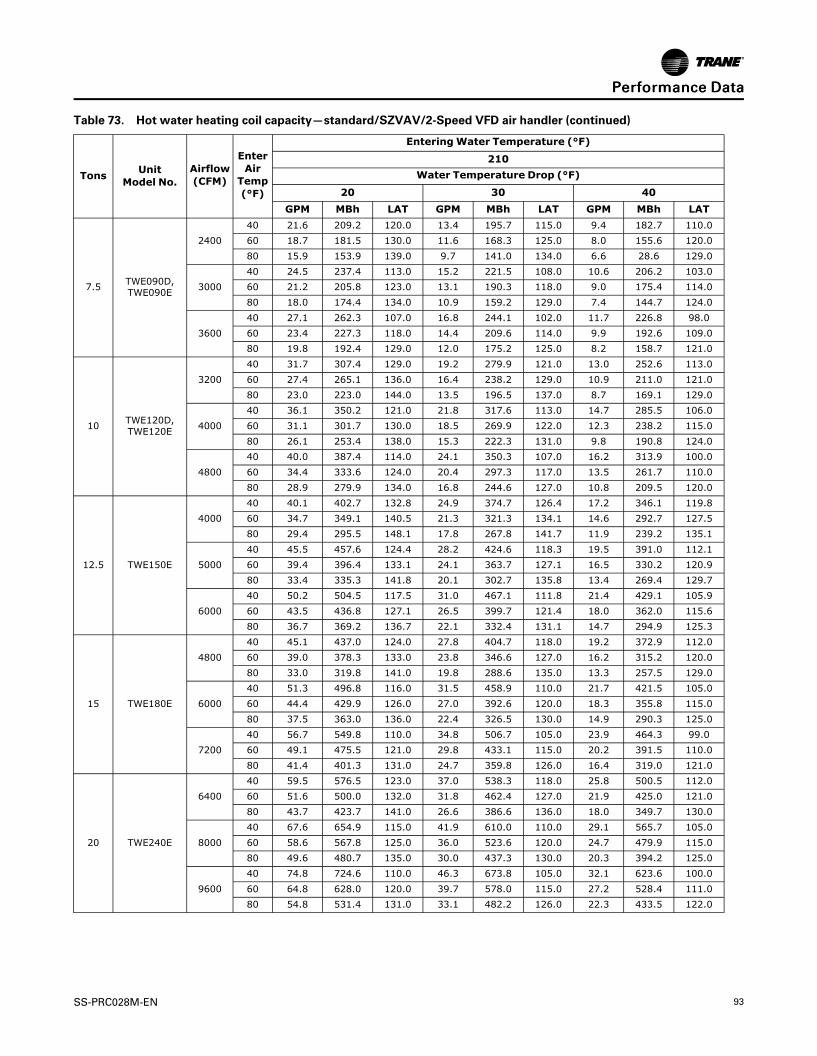
(93,1)
SS-PRC028M-EN 93
Table 73. Hot water heating coil capacity—standard/SZVAV/2-Speed VFD air handler (continued)
Tons UnitModel No.
Airflow(CFM)
EnterAirTemp(°F)
EnteringWater Temperature (°F)
210Water Temperature Drop (°F)
20 30 40GPM MBh LAT GPM MBh LAT GPM MBh LAT
7.5 TWE090D,TWE090E
240040 21.6 209.2 120.0 13.4 195.7 115.0 9.4 182.7 110.060 18.7 181.5 130.0 11.6 168.3 125.0 8.0 155.6 120.080 15.9 153.9 139.0 9.7 141.0 134.0 6.6 28.6 129.0
300040 24.5 237.4 113.0 15.2 221.5 108.0 10.6 206.2 103.060 21.2 205.8 123.0 13.1 190.3 118.0 9.0 175.4 114.080 18.0 174.4 134.0 10.9 159.2 129.0 7.4 144.7 124.0
360040 27.1 262.3 107.0 16.8 244.1 102.0 11.7 226.8 98.060 23.4 227.3 118.0 14.4 209.6 114.0 9.9 192.6 109.080 19.8 192.4 129.0 12.0 175.2 125.0 8.2 158.7 121.0
10 TWE120D,TWE120E
320040 31.7 307.4 129.0 19.2 279.9 121.0 13.0 252.6 113.060 27.4 265.1 136.0 16.4 238.2 129.0 10.9 211.0 121.080 23.0 223.0 144.0 13.5 196.5 137.0 8.7 169.1 129.0
400040 36.1 350.2 121.0 21.8 317.6 113.0 14.7 285.5 106.060 31.1 301.7 130.0 18.5 269.9 122.0 12.3 238.2 115.080 26.1 253.4 138.0 15.3 222.3 131.0 9.8 190.8 124.0
480040 40.0 387.4 114.0 24.1 350.3 107.0 16.2 313.9 100.060 34.4 333.6 124.0 20.4 297.3 117.0 13.5 261.7 110.080 28.9 279.9 134.0 16.8 244.6 127.0 10.8 209.5 120.0
12.5 TWE150E
400040 40.1 402.7 132.8 24.9 374.7 126.4 17.2 346.1 119.860 34.7 349.1 140.5 21.3 321.3 134.1 14.6 292.7 127.580 29.4 295.5 148.1 17.8 267.8 141.7 11.9 239.2 135.1
500040 45.5 457.6 124.4 28.2 424.6 118.3 19.5 391.0 112.160 39.4 396.4 133.1 24.1 363.7 127.1 16.5 330.2 120.980 33.4 335.3 141.8 20.1 302.7 135.8 13.4 269.4 129.7
600040 50.2 504.5 117.5 31.0 467.1 111.8 21.4 429.1 105.960 43.5 436.8 127.1 26.5 399.7 121.4 18.0 362.0 115.680 36.7 369.2 136.7 22.1 332.4 131.1 14.7 294.9 125.3
15 TWE180E
480040 45.1 437.0 124.0 27.8 404.7 118.0 19.2 372.9 112.060 39.0 378.3 133.0 23.8 346.6 127.0 16.2 315.2 120.080 33.0 319.8 141.0 19.8 288.6 135.0 13.3 257.5 129.0
600040 51.3 496.8 116.0 31.5 458.9 110.0 21.7 421.5 105.060 44.4 429.9 126.0 27.0 392.6 120.0 18.3 355.8 115.080 37.5 363.0 136.0 22.4 326.5 130.0 14.9 290.3 125.0
720040 56.7 549.8 110.0 34.8 506.7 105.0 23.9 464.3 99.060 49.1 475.5 121.0 29.8 433.1 115.0 20.2 391.5 110.080 41.4 401.3 131.0 24.7 359.8 126.0 16.4 319.0 121.0
20 TWE240E
640040 59.5 576.5 123.0 37.0 538.3 118.0 25.8 500.5 112.060 51.6 500.0 132.0 31.8 462.4 127.0 21.9 425.0 121.080 43.7 423.7 141.0 26.6 386.6 136.0 18.0 349.7 130.0
800040 67.6 654.9 115.0 41.9 610.0 110.0 29.1 565.7 105.060 58.6 567.8 125.0 36.0 523.6 120.0 24.7 479.9 115.080 49.6 480.7 135.0 30.0 437.3 130.0 20.3 394.2 125.0
960040 74.8 724.6 110.0 46.3 673.8 105.0 32.1 623.6 100.060 64.8 628.0 120.0 39.7 578.0 115.0 27.2 528.4 111.080 54.8 531.4 131.0 33.1 482.2 126.0 22.3 433.5 122.0
PPeerrffoorrmmaannccee DDaattaa

(94,1)
94 SS-PRC028M-EN
Table 73. Hot water heating coil capacity—standard/SZVAV/2-Speed VFD air handler (continued)
Tons UnitModel No.
Airflow(CFM)
EnterAirTemp(°F)
EnteringWater Temperature (°F)
210Water Temperature Drop (°F)
20 30 40GPM MBh LAT GPM MBh LAT GPM MBh LAT
25 TWE300E
800040 65.4 656.9 115.7 40.7 613.8 110.8 28.4 570.1 105.760 56.7 569.9 125.7 35.0 527.2 120.8 24.1 483.8 115.880 48.1 483.1 135.7 29.3 440.6 130.8 19.8 397.3 125.8
1000040 72.9 732.5 107.5 45.3 683.0 103.0 31.5 633.0 98.460 63.2 635.2 118.6 38.9 586.2 114.1 26.7 536.5 109.580 53.5 538.0 129.6 32.5 489.4 125.1 21.9 440.0 120.6
1200040 79.2 795.5 101.1 49.2 740.5 96.9 34.1 685.1 92.760 68.6 689.5 113.0 42.2 635.1 108.8 28.9 580.3 104.680 58.1 583.7 124.9 35.2 529.9 120.7 23.7 475.4 116.5
Notes:1. SZVAV/2-Speed VFD available for 6–25 ton only.2. GPM = Gallons Per Minute3. MBh Capacity: BTU/HR/10004. LAT = Leaving Air Temperature (°F)
Table 74. Hot water heating coil - water side pressure drop @ 180°F entering water temperature - standard/SZVAV/2-Speed VFD air handler
Tons Unit ModelNo.
Gallons Per Minute (GPM)
2 4 6 8 10 12 14 16 18 20 22 24 26 28 30 32 34 36 38Pressure Drop (Ft. of Water)
5 TWE061D,E 0.02 0.70 0.15 0.26 0.40 0.56 0.75 0.97 1.22 1.49 1.78 - - - - - - - -6 TWE073E - - 0.06 0.11 0.16 0.23 0.30 0.39 0.48 0.58 0.70 0.82 0.95 1.09 1.24 1.40 1.57 - -7.5 TWE090D,E - - 0.06 0.11 0.16 0.23 0.30 0.39 0.48 0.58 0.70 0.82 0.95 1.09 1.24 1.40 1.57 - -10 TWE120D,E - - - 0.06 0.09 0.13 0.17 0.22 0.27 0.33 0.39 0.46 0.54 0.62 0.70 0.79 0.89 0.99 1.1012.5 TWE150E - - - - 0.11 0.15 0.20 0.26 0.32 0.39 0.47 0.55 0.64 0.73 0.83 0.94 1.05 1.17 1.2915 TWE180E - - - - 0.11 0.15 0.20 0.26 0.32 0.39 0.47 0.55 0.64 0.73 0.83 0.94 1.05 1.17 1.2920 TWE240E - - - - - 0.17 0.23 0.30 0.37 0.45 0.53 0.63 0.72 0.83 0.94 1.06 1.19 1.32 1.4625 TWE300E - - - - - 0.17 0.23 0.30 0.37 0.45 0.53 0.63 0.72 0.83 0.94 1.06 1.19 1.32 1.46
Tons Unit ModelNo.
Gallons Per Minute (GPM)
40 42 44 46 48 50 52 54 56 58 60 62 64 66 68 70 72 74 76Pressure Drop (Ft. of Water)
5 TWE061D,E - - - - - - - - - - - - - - - - - - -6 TWE073E - - - - - - - - - - - - - - - - - - -7.5 TWE090D,E - - - - - - - - - - - - - - - - - - -10 TWE120D,E 1.21 1.32 1.44 1.57 1.70 1.84 - - - - - - - - - - - - -12.5 TWE150E 1.42 1.56 1.70 1.85 2.00 2.16 2.33 2.50 2.67 2.86 3.04 3.24 3.44 3.64 3.85 4.07 - - -15 TWE180E 1.42 1.56 1.70 1.85 2.00 2.16 2.33 2.50 2.67 2.86 3.04 3.24 3.44 3.64 3.85 4.07 - - -20 TWE240E 1.61 1.76 1.92 2.09 2.26 2.44 2.63 2.82 3.02 3.22 3.43 3.65 3.87 4.10 4.34 4.58 4.83 5.08 5.3425 TWE300E 1.61 1.76 1.92 2.09 2.26 2.44 2.63 2.82 3.02 3.22 3.43 3.65 3.87 4.10 4.34 4.58 4.83 5.08 5.34
NNoottee:: SZVAV/2-Speed VFD available for 6-25 ton only.
PPeerrffoorrmmaannccee DDaattaa

(95,1)
SS-PRC028M-EN 95
ControlsReliaTel
Zone Sensors are the building occupant’s comfort control devices. Zone sensors are required forSZVAV applications. The following zone sensor options are available for units with ReliaTelcontrol.
Manual Changeover(BAYSENS106*)
Manual/AutomaticChangeover (BAYSENS108*)
Manual/AutomaticChangeover (BAYSENS110*)
Heat, Cool or Off System Switch.Fan Auto or Off Switch. Onetemperature setpoint lever.
Auto, Heat, Cool or Off SystemSwitch. Fan Auto or Off Switch.Two temperature setpoint levers.
Auto, Heat, Cool or Off SystemSwitch. Fan Auto or Off Switch.Two temperature setpoint levers.Status Indication LED lights,System On, Heat, Cool, orService.
Integrated Comfort™ System(BAYSENS074*)
Remote Sensor(BAYSENS077*)
Wireless Zone Sensor(BAYSENS050*)
Programmable Night Setback(BAYSENS119*)
Sensor(s) available with optionaltemperature adjustment andoverride buttons to providecentral control through a TraneIntegrated Comfort™ system.
Sensor(s) available for all zonesensors to provide remotesensing capabilities.
LCD display that provides heat,cool, auto or off. Includes twotemperature setpoints and alockable setting with °F or °Cindicators.
Auto or manual changeover withseven-day programming.Keyboard selection of Heat, Cool,Fan, Auto, EM Heat or On. Allsensors have System On, Heat,Cool, Service LED/ indicators asstandard. Night Setback Sensorshave one (1) Occupied, one (1)Un-occupied, and one (1)Override program per day.

(96,1)
96 SS-PRC028M-EN
ElectromechanicalNon-Programmable Thermostats
TCONT200*** (1H/1C) TCONT401*** (2H/1C) TCONT402*** (3H/2C)
$
FA N M O D EFILTER
Fan ModeFilter/O D
$
Fan ModeFilter/O D
$
Auto-changeover Backlit Display &Keys Filter Reminder Keypad Lock
Auto-changeover Backlit Display &Keys Filter Reminder Keypad LockOutdoor Temp Sensor Available
Auto-changeover Backlit Display &Keys Filter Reminder Keypad LockOutdoor Temp Sensor Included
Programmable Thermostats
TCONT600***(1H/1C) TCONT602***(2H/2C)
5/2 or 5/1/1 Programming Actualand Setpoint temps displayedsimultaneously
5/2 or 5/1/1 Programming Actualand Setpoint temps displayedsimultaneously
TCONT800*** (1H/1C) TCONT802*** (3H/2C) TCONT803*** (3H/2C)
Interactive touchscreen Largedisplay Real time clock
Interactive touchscreen Largedisplay Real time clock
Interactive touchscreen Largedisplay Real time clock Built-inhumidity sensor
NNootteess::
• All thermostats may be used with ReliaTel units.
• Thermostats may be used with ReliaTel-equipped Cooling units, but only whenmatched with Standard Air Handlers (SZVAV Air Handlers excluded).
CCoonnttrroollss

(97,1)
SS-PRC028M-EN 97
Electrical DataCooling CondenserTable 75. Electrical characteristics — compressor and condenser fan motors — 60 Hz
TonsUnitModelNumber
Compressor Motor Condenser Fan Motor
No. Volts PhaseAmps
No. Volts PhaseAmps
RLA LRA FLA LRA(Ea.) (Ea.) (Ea.) (Ea.)
6
TTA073G3 1 208-230 3 21.9 136 1 208-230 1 3.1 8.1
TTA073G4 1 460 3 9.1 66.1 1 460 1 1.6 3.8
TTA073GK 1 380 3 10.3 83 1 380 1 1.9 4.9
TTA073GW 1 575 3 7.4 55.3 1 575 1 1.2 3
6
TTA073H3 2 208-230 3 9 71 1 208-230 1 3.1 8.1
TTA073H4 2 460 3 5.7 38 1 460 1 1.6 3.8
TTA073HK 2 380 3 5.5 45 1 380 1 1.9 4.9
TTA073HW 2 575 3 3.8 36.5 1 575 1 1.2 3
7.5
TTA090G3 1 208-230 3 25 164 1 208-230 1 3.1 8.1
TTA090G4 1 460 3 12.9 100 1 460 1 1.6 3.8
TTA090GK 1 380 3 13.9 94.3 1 380 1 1.9 4.9
TTA090GW 1 575 3 10.6 78 1 575 1 1.2 3
7.5
TTA090H3 2 208-230 3 14.6 83.1 1 208-230 1 3.1 8.1
TTA090H4 2 460 3 6.8 41 1 460 1 1.6 3.8
TTA090HK 2 380 3 7.6 51.8 1 380 1 1.9 4.9
TTA090HW 2 575 3 4.9 33 1 575 1 1.2 3
10
TTA120G3 1 208-230 3 33 267 1 208-230 1 5 14.4
TTA120G4 1 460 3 17 142 1 460 1 2.5 5.8
TTA120GK 1 380 3 25 160 1 380 1 3.4 7.8
TTA120GW 1 575 3 16 80 1 575 1 2 5.1
10
TTA120H3 2 208-230 3 17.8 110 1 208-230 1 5 14.4
TTA120H4 2 460 3 8.6 52 1 460 1 2.5 5.8
TTA120HK 2 380 3 8.6 51.5 1 380 1 3.4 7.8
TTA120HW 2 575 3 6.4 38.9 1 575 1 2 5.1
10
TTA120J3 2 208-230 3 16 110 1 208-230 1 5 14.4
TTA120J4 2 460 3 7.8 52 1 460 1 2.5 5.8
TTA120JW 2 575 3 5.7 39 1 575 1 2 5.1
12.5
TTA150H3 2 208-230 3 22.4 149 1 208-230 1 5 14.4
TTA150H4 2 460 3 10.6 75 1 460 1 2.5 5.8
TTA150HK 2 380 3 11.3 88 1 380 1 3.4 7.8
TTA150HW 2 575 3 7.7 54 1 575 1 2 5.1
15
TTA180H3 2 208-230 3 25 164 2 208-230 1 5 14.4
TTA180H4 2 460 3 12.2 100 2 460 1 2.5 5.8
TTA180HK 2 380 3 13.9 94 2 380 1 3.4 7.8
TTA180HW 2 575 3 9.2 78 2 575 1 2 5.1
15
TTA180J3 2 208-230 3 25.8 164 2 208-230 1 3.1 8.1
TTA180J4 2 460 3 12.5 100 2 460 1 1.6 3.8
TTA180JK 2 380 3 14.3 94 2 380 1 1.9 4.9
TTA180JW 2 575 3 10.3 78 2 575 1 1.2 3
20
TTA240H3 2 208-230 3 39.1 267 2 208-230 1 5 14.4
TTA240H4 2 460 3 18.6 142 2 460 1 2.5 5.8
TTA240HK 2 380 3 22.4 160 2 380 1 3.4 7.8
TTA240HW 2 575 3 15.4 103 2 575 1 2 5.1

(98,1)
98 SS-PRC028M-EN
Table 75. Electrical characteristics — compressor and condenser fan motors — 60 Hz (continued)
TonsUnitModelNumber
Compressor Motor Condenser Fan Motor
No. Volts PhaseAmps
No. Volts PhaseAmps
RLA LRA FLA LRA(Ea.) (Ea.) (Ea.) (Ea.)
20
TTA240J3 2 208-230 3 39.1 267 2 208-230 1 5 14.4
TTA240J4 2 460 3 19.8 142 2 460 1 2.5 5.8
TTA240JK 2 380 3 22.4 160 2 380 1 3.4 7.8
TTA240JW 2 575 3 15.8 103 2 575 1 2 5.1
25
TTA300J3 2 208-230 3 41 304 2 208-230 1 5 14.4
TTA300J4 2 460 3 19.4 147 2 460 1 2.5 5.8
TTA300JK 2 380 3 23.8 168 2 380 1 3.4 7.8
TTA300JW 2 575 3 16.7 122 2 575 1 2 5.1NNoottee:: Electrical characteristics reflect nameplate values and are calculated in accordance with cULus specifications.
Table 76. Unit wiring — condensing units — 60 Hz
Tons Unit Model NumberUnit OperatingVoltage Range Minimum Circuit Ampacity Maximum Fuse or HACR
Circuit Breaker Size
6
TTA073G3 187-253 30.5 50
TTA073G4 414-506 13.0 20
TTA073GK 342-418 15.0 20
TTA073GW 518-632 10.5 15
6
TTA073H3 187-253 24.0 30
TTA073H4 414-506 15.0 20
TTA073HK 342-418 15.0 15
TTA073HW 518-632 10.0 15
7.5
TTA090G3 187-253 34.4 50
TTA090G4 414-506 17.7 25
TTA090GK 342-418 20.0 30
TTA090GW 518-632 14.5 20
7.5
TTA090H3 187-253 36.0 50
TTA090H4 414-506 16.9 20
TTA090HK 342-418 20.0 25
TTA090HW 518-632 12.2 15
10
TTA120G3 187-253 46.3 70
TTA120G4 414-506 23.5 40
TTA120GK 342-418 34.7 50
TTA120GW 518-632 22.0 35
10
TTA120H3 187-253 41.0 50
TTA120H4 414-506 21.9 25
TTA120HK 342-418 22.8 30
TTA120HW 518-632 16.4 20
10
TTA120J3 187-253 41.0 50
TTA120J4 414-506 20.0 25
TTA120JW 518-632 15.0 20
12.5
TTA150H3 187-253 56.0 70
TTA150H4 414-506 27.0 35
TTA150HK 342-418 29.0 40
TTA150HW 518-632 20.0 25
EElleeccttrriiccaall DDaattaa

(99,1)
SS-PRC028M-EN 99
Table 76. Unit wiring — condensing units — 60 Hz (continued)
Tons Unit Model NumberUnit OperatingVoltage Range Minimum Circuit Ampacity Maximum Fuse or HACR
Circuit Breaker Size
15
TTA180H3 187-253 67.0 90
TTA180H4 414-506 33.0 40
TTA180HK 342-418 39.0 50
TTA180HW 518-632 25.0 30
15
TTA180J3 187-253 65.0 80
TTA180J4 414-506 32.0 40
TTA180JK 342-418 37.0 50
TTA180JW 518-632 26.0 35
20
TTA240H3 187-253 98.0 125
TTA240H4 414-506 47.0 60
TTA240HK 342-418 58.0 70
TTA240HW 518-632 39.0 50
20
TTA240J3 187-253 98.0 125
TTA240J4 414-506 47.0 60
TTA240JK 342-418 58.0 70
TTA240JW 518-632 39.0 50
25
TTA300J3 187-253 103.0 125
TTA300J4 414-506 49.0 60
TTA300JK 342-418 61.0 80
TTA300JW 518-632 42.0 50Notes:
1. Electrical characteristics reflect nameplate values and are calculated in accordance with cULus specifications. 7.5 and 10 ton values aresystem rated; 12.5 - 25 ton values are condensing unit only rated.
2. HACR type circuit breaker per NEC.
Air Handler (Standard, SZVAV and 2-Speed VFD)Table 77. Voltage operating range (all air handlers)
Model Number:Digit 8
ElectricalCharacteristics
Unit OperatingVoltage Range
1 208-230/60/1 187-253
3 208-230/60/3 187-253
4 460/60/3 414-506
K 380/60/3 342-418
W 575/60/3 518-632
Table 78. Electrical characteristics — 5–25 ton standard and low static motors — 60 Hz standard air handler
Tons UnitModel Number
Standard Evaporator Fan Motor Low Static Evaporator Fan Motor
No. Volts Phase HpAmps
MCA MFS No. Volts Phase HpAmps
MCA MFSFLA LRA FLA LRA
5
TWE061D1, E1 1 208 1 0.75 6.0 41.0 7.5 15 N/A N/A N/A N/A N/A N/A N/A N/A
TWE061D1, E1 1 230 1 0.75 5.9 45.0 7.4 15 N/A N/A N/A N/A N/A N/A N/A N/A
TWE061D3, E3 1 208 3 0.75 2.5 16.4 3.1 15 N/A N/A N/A N/A N/A N/A N/A N/A
TWE061D3, E3 1 230 3 0.75 2.4 16.4 3.0 15 N/A N/A N/A N/A N/A N/A N/A N/A
TWE061D4, E4 1 460 3 0.75 1.2 8.2 1.5 15 N/A N/A N/A N/A N/A N/A N/A N/A
TWE061DW 1 575 3 0.75 1.3 6.1 1.6 15 N/A N/A N/A N/A N/A N/A N/A N/A
EElleeccttrriiccaall DDaattaa

(100,1)
100 SS-PRC028M-EN
Table 78. Electrical characteristics — 5–25 ton standard and low static motors — 60 Hz standard air handler(continued)
Tons UnitModel Number
Standard Evaporator Fan Motor Low Static Evaporator Fan Motor
No. Volts Phase HpAmps
MCA MFS No. Volts Phase HpAmps
MCA MFSFLA LRA FLA LRA
6
TWE073E3 1 208 3 1.5 5.3 34.3 6.6 15 N/A N/A N/A N/A N/A N/A N/A N/A
TWE073E3 1 230 3 1.5 5.0 34.3 6.3 15 N/A N/A N/A N/A N/A N/A N/A N/A
TWE073EK 1 380 3 1.5 3.0 20.2 3.8 15 N/A N/A N/A N/A N/A N/A N/A N/A
TWE073E3(a) 1 460 3 1.5 2.5 17.0 3.1 15 N/A N/A N/A N/A N/A N/A N/A N/A
TWE073EW 1 575 3 1.5 1.8 13.6 2.3 15 N/A N/A N/A N/A N/A N/A N/A N/A
7.5
TWE090D1, E1 1 208 1 1.5 6.8 31.5 8.5 20 N/A N/A N/A N/A N/A N/A N/A N/A
TWE090D1, E1 1 230 1 1.5 6.2 31.5 7.8 15 N/A N/A N/A N/A N/A N/A N/A N/A
TWE090D3, E3 1 208 3 1.5 5.3 34.3 6.6 15 N/A N/A N/A N/A N/A N/A N/A N/A
TWE090D3, E3 1 230 3 1.5 5.0 34.3 6.3 15 N/A N/A N/A N/A N/A N/A N/A N/A
TWE090DK, EK 1 380 3 1.5 3.0 20.2 3.8 15 N/A N/A N/A N/A N/A N/A N/A N/A
TWE090D3, E3(a) 1 460 3 1.5 2.5 17.0 3.1 15 N/A N/A N/A N/A N/A N/A N/A N/A
TWE090DW, EW 1 575 3 1.5 1.8 13.6 2.3 15 N/A N/A N/A N/A N/A N/A N/A N/A
10
TWE120D1, E1 1 208 1 2 8.5 57.4 10.6 15 N/A N/A N/A N/A N/A N/A N/A N/A
TWE120D1, E1 1 230 1 2 7.7 57.4 9.6 15 N/A N/A N/A N/A N/A N/A N/A N/A
TWE120D3, E3 1 208 3 2 7.0 33.9 9.0 15 N/A N/A N/A N/A N/A N/A N/A N/A
TWE120D3, E3 1 230 3 2 6.6 33.9 7.3 15 N/A N/A N/A N/A N/A N/A N/A N/A
TWE120DK, EK 1 380 3 2 3.3 28.0 4.1 15 N/A N/A N/A N/A N/A N/A N/A N/A
TWE120D3, E3(a) 1 460 3 2 3.3 19.0 3.6 15 N/A N/A N/A N/A N/A N/A N/A N/A
TWE120DW, EW 1 575 3 2 2.3 15.6 4.0 15 N/A N/A N/A N/A N/A N/A N/A N/A
12.5
TWE150E3 1 208 3 2 6.0 23.0 7.4 15 N/A N/A N/A N/A N/A N/A N/A N/A
TWE150E3 1 230 3 2 5.5 23.0 6.9 15 N/A N/A N/A N/A N/A N/A N/A N/A
TWE150EK 1 380 3 2 3.3 28.0 4.1 15 N/A N/A N/A N/A N/A N/A N/A N/A
TWE150E3(a) 1 460 3 2 2.8 23.0 3.4 15 N/A N/A N/A N/A N/A N/A N/A N/A
TWE150EW 1 575 3 2 2.2 18.0 2.8 15 N/A N/A N/A N/A N/A N/A N/A N/A
15
TWE180E3 1 208 3 3 9.4 74.9 11.8 20 N/A N/A N/A N/A N/A N/A N/A N/A
TWE180E3 1 230 3 3 9.2 74.9 11.5 20 N/A N/A N/A N/A N/A N/A N/A N/A
TWE180EK 1 380 3 5 8.1 63.5 10.1 15 N/A N/A N/A N/A N/A N/A N/A N/A
TWE180E3(a) 1 460 3 3 4.6 39.3 5.8 15 N/A N/A N/A N/A N/A N/A N/A N/A
TWE180EW 1 575 3 3 3.4 24.6 4.3 15 N/A N/A N/A N/A N/A N/A N/A N/A
20
TWE240E3 1 208 3 5 14.0 90.8 17.5 30 1 208 3 3 9.4 74.9 11.8 25
TWE240E3 1 230 3 5 13.6 103.0 17.0 30 1 230 3 3 9.2 74.9 11.5 25
TWE240EK 1 380 3 5 8.1 63.5 10.1 15 N/A N/A N/A N/A N/A N/A N/A N/A
TWE240E4 1 460 3 5 6.6 44.8 9.0 15 1 460 3 3 4.6 39.3 5.8 15
TWE240EW 1 575 3 5 5.3 36.2 6.6 15 1 575 3 3 3.4 24.6 4.3 15
25
TWE300E3 1 208 3 7.5 19.6 150.0 25.0 40 1 208 3 7.5 19.6 150 25 40
TWE300E3 1 230 3 7.5 17.8 150.0 25.0 40 1 230 3 7.5 17.8 150 25 40
TWE300EK 1 380 3 7.5 10.9 72.9 13.6 20 N/A N/A N/A N/A N/A N/A N/A N/A
TWE300E4 1 460 3 7.5 8.9 75.0 12.0 20 1 460 3 7.5 8.9 75 12 20
TWE300EW 1 575 3 7.5 7.1 60.0 9.0 15 1 575 3 7.5 7.1 60 9 15
NNoottee:: For additional information contact product support.
(a) Field wired for 460V.
EElleeccttrriiccaall DDaattaa

(101,1)
SS-PRC028M-EN 101
Table 79. Electrical characteristics — 5–25 ton high and ultra-high static motors — 60 Hz standard air handler
Tons UnitModel Number
High Static Evaporator Fan Motor Ultra-High Static Evaporator Fan Motor
No. Volts Phase HpAmps
MCA MFS No. Volts Phase HpAmps
MCA MFSFLA LRA FLA LRA
5
TWE061D1, E1 1 208 1 1.5 6.8 31.5 8.5 15 N/A N/A N/A N/A N/A N/A N/A N/A
TWE061D1, E1 1 230 1 1.5 6.2 31.5 7.8 15 N/A N/A N/A N/A N/A N/A N/A N/A
TWE061D3, E3 1 208 3 1.5 5.3 34.3 6.6 15 N/A N/A N/A N/A N/A N/A N/A N/A
TWE061D3, E3 1 230 3 1.5 5 34.3 6.3 15 N/A N/A N/A N/A N/A N/A N/A N/A
TWE061D4, E4 1 460 3 1.5 2.5 17 3.1 15 N/A N/A N/A N/A N/A N/A N/A N/A
TWE061DW 1 575 3 1.5 1.8 13.6 2.3 15 N/A N/A N/A N/A N/A N/A N/A N/A
6
TWE073E3 1 208 3 2 7 33.9 7.8 15 1 208 3 3 9.4 74.9 11.8 20
TWE073E3 1 230 3 2 6.6 33.9 7.3 15 1 230 3 3 9.2 74.9 11.5 20
TWE073E3(a) 1 460 3 2 3.3 19 5 15 1 460 3 3 4.6 39.3 5.8 15
TWE073EW 1 575 3 2 2.3 15.6 4 15 1 575 3 3 3.4 24.6 4.3 15
7.5
TWE090D1, E1 1 208 1 2 8.5 57.4 10.6 20 N/A N/A N/A N/A N/A N/A N/A N/A
TWE090D1, E1 1 230 1 2 7.7 57.4 9.6 20 N/A N/A N/A N/A N/A N/A N/A N/A
TWE090D3, E3 1 208 3 2 7 33.9 7.8 15 1 208 3 3 9.4 74.9 11.8 20
TWE090D3, E3 1 230 3 2 6.6 33.9 7.3 15 1 230 3 3 9.2 74.9 11.5 20
TWE090D3, E3(a) 1 460 3 2 3.3 19 5 15 1 460 3 3 4.6 39.3 5.8 15
TWE090DW, EW 1 575 3 2 2.3 15.6 4 15 1 575 3 3 3.4 24.6 4.3 15
10
TWE120D1, E1 N/A N/A N/A N/A N/A N/A N/A N/A N/A N/A N/A N/A N/A N/A N/A N/A
TWE120D1, E1 N/A N/A N/A N/A N/A N/A N/A N/A N/A N/A N/A N/A N/A N/A N/A N/A
TWE120D3, E3 1 208 3 3 9.4 74.9 11.8 20 N/A N/A N/A N/A N/A N/A N/A N/A
TWE120D3, E3 1 230 3 3 9.2 74.9 11.5 20 N/A N/A N/A N/A N/A N/A N/A N/A
TWE120D3, E3(a) 1 460 3 3 4.6 39.3 5.8 15 N/A N/A N/A N/A N/A N/A N/A N/A
TWE120DW, EW 1 575 3 3 3.4 24.6 4.3 15 N/A N/A N/A N/A N/A N/A N/A N/A
12.5
TWE150E3 1 208 3 3 9.4 74.9 11.8 20 1 208 3 5 14 98 17.5 30
TWE150E3 1 230 3 3 9.2 74.9 11.5 20 1 230 3 5 13.6 103 17 30
TWE150E3(a) 1 460 3 3 4.6 39.3 5.8 15 1 460 3 5 6.6 44.8 8.3 15
TWE150EW 1 575 3 3 3.4 24.6 4.3 15 1 575 3 5 5.2 36.2 6.5 15
15
TWE180E3 1 208 3 5 14 98 17.5 30 N/A N/A N/A N/A N/A N/A N/A N/A
TWE180E3 1 230 3 5 13.6 103 17 30 N/A N/A N/A N/A N/A N/A N/A N/A
TWE180E3(a) 1 460 3 5 6.6 44.8 8.3 15 N/A N/A N/A N/A N/A N/A N/A N/A
TWE180EW 1 575 3 5 5.2 36.2 6.5 15 N/A N/A N/A N/A N/A N/A N/A N/A
20
TWE240E3 N/A N/A N/A N/A N/A N/A N/A N/A 1 208 3 7.5 19.6 114 25 40
TWE240E3 N/A N/A N/A N/A N/A N/A N/A N/A 1 230 3 7.5 17.6 126 22 40
TWE240E4 N/A N/A N/A N/A N/A N/A N/A N/A 1 460 3 7.5 9 61.4 11.3 20
TWE240EW N/A N/A N/A N/A N/A N/A N/A N/A 1 575 3 7.5 7.2 49.8 9 15
25
TWE300E3 N/A N/A N/A N/A N/A N/A N/A N/A N/A N/A N/A N/A N/A N/A N/A N/A
TWE300E3 N/A N/A N/A N/A N/A N/A N/A N/A N/A N/A N/A N/A N/A N/A N/A N/A
TWE300E4 N/A N/A N/A N/A N/A N/A N/A N/A N/A N/A N/A N/A N/A N/A N/A N/A
TWE300EW N/A N/A N/A N/A N/A N/A N/A N/A N/A N/A N/A N/A N/A N/A N/A N/A
NNoottee:: For additional information contact product support.
(a) Field wired for 460V.
EElleeccttrriiccaall DDaattaa

(102,1)
102 SS-PRC028M-EN
Table 80. Electrical characteristics — standard and oversized motors — 6–25 ton SZVAV and 2-Speed VFD air handler— 60 Hz
Tons UnitModel Number
Standard Evaporator Fan Motor High Static Evaporator Fan Motor
No. Volts Phase HpAmps
MCA MFS No. Volts Phase HpAmps
MCA MFSFLA LRA FLA LRA
6
TWE073E3 1 208 3 2 6.2 43.4 8 15 1 208 3 3 9.4 71 12 20
TWE073E3 1 230 3 2 5.8 48 8 15 1 230 3 3 9.2 64 12 20
TWE073E4 1 460 3 2 2.9 24 4 15 1 460 3 3 4.6 35.5 6 15
TWE073EW 1 575 3 2 2.2 20.6 3 15 1 575 3 3 3.7 28.4 5 15
7.5
TWE090E3 1 208 3 2 6.2 43.4 8 15 1 208 3 3 9.4 71 12 20
TWE090E3 1 230 3 2 5.8 48 8 15 1 230 3 3 9.2 64 12 20
TWE090E4 1 460 3 2 2.9 24 4 15 1 460 3 3 4.6 35.5 6 15
TWE090EW 1 575 3 2 2.2 20.6 3 15 1 575 3 3 3.7 28.4 5 15
10
TWE120D3, E3 1 208 3 2 6.2 43.4 8 15 1 208 3 3 9.4 71 12 20
TWE120D3, E3 1 230 3 2 5.8 48 8 15 1 230 3 3 9.2 64 12 20
TWE120D4, E4 1 460 3 2 2.9 24 4 15 1 460 3 3 4.6 35.5 6 15
TWE120DW, EW 1 575 3 2 2.2 20.6 3 15 1 575 3 3 3.7 28.4 5 15
12.5
TWE150E3 1 208 3 2 6.2 43.4 8 15 1 208 3 5 13.4 99.5 17 30
TWE150E3 1 230 3 2 5.8 48 8 15 1 230 3 5 12.6 110 17 30
TWE150E4 1 460 3 2 2.9 24 4 15 1 460 3 5 6.3 55 8 15
TWE150EW 1 575 3 2 2.2 20.6 3 15 1 575 3 5 5.1 44 7 15
15
TWE180E3 1 208 3 3 9.4 71 12 20 1 208 3 5 13.4 99.5 17 30
TWE180E3 1 230 3 3 9.2 64 12 20 1 230 3 5 12.6 110 17 30
TWE180E4 1 460 3 3 4.6 35.5 6 15 1 460 3 5 6.3 55 8 15
TWE180EW 1 575 3 3 3.7 28.4 5 15 1 575 3 5 5.1 44 7 15
20
TWE240E3 1 208 3 5 13.4 99.5 17 30 1 208 3 7.5 19.6 113.4 25 45
TWE240E3 1 230 3 5 12.6 110 17 30 1 230 3 7.5 17.6 124 25 45
TWE240E4 1 460 3 5 6.3 55 8 15 1 460 3 7.5 8.8 63 11 15
TWE240EW 1 575 3 5 5.1 44 7 15 1 575 3 7.5 7.1 50.4 9 15
25
TWE300E3 1 208 3 7.5 19.6 113.4 25 45 N/A N/A N/A N/A N/A N/A N/A N/A
TWE300E3 1 230 3 7.5 17.6 124 25 45 N/A N/A N/A N/A N/A N/A N/A N/A
TWE300E4 1 460 3 7.5 8.8 63 12 20 N/A N/A N/A N/A N/A N/A N/A N/A
TWE300EW 1 575 3 7.5 7.1 50.4 9 15 N/A N/A N/A N/A N/A N/A N/A N/ANotes:
1. For additional information contact product support.2. Not available with 380/60 Hz models.
EElleeccttrriiccaall DDaattaa

(103,1)
SS-PRC028M-EN 103
Table 81. Unit wiring with electric heat (single point connection) — 5-25 ton standard air handlers — 60 Hz
Tons UsedWith Heater ModelNumber
Heater kWRating
Unit PowerSupply
ControlStages
Minimum CircuitAmpacity
Maximum Fuseor HACR CircuitBreaker Size
5 TWE061D1,TWE061E1
BAYHTRL106* 4.33/5.76
208-230/1/60
1 33.5/37.4 35.0/40.0
BAYHTRL112* 8.65/11.52 1 59.5/67.4 60.0/70.0
BAYHTRL117* 12.98/17.28 1 85.5/97.4 90.0/100.0
BAYHTRL123* 17.31/23.04 2 111.5/127.4(a) 125.0/150.0
5 TWE061D3,TWE061E3
BAYHTRL305* 3.76/5.00
208-230/3/60
1 16.1/18.0 20.0/20.0
BAYHTRL310* 7.48/9.96 1 29.0/33.0 30.0/35.0
BAYHTRL315* 11.24/14.96 1 42.2/48.0 45.0/50.0
BAYHTRL325* 18.72/24.92 2 68.0/77.9(a) 70.0/80.0
5 TWE061D4,TWE061E4
BAYHTRL405* 5.00
460/3/60
1 10.0 15.0
BAYHTRL410* 9.96 1 17.0 20.0
BAYHTRL415* 14.96 1 25.0 25.0
BAYHTRL425* 24.92 2 40.0 40.0
5 TWE061DW
BAYHTRLW05* 5.00
575/3/60
1 8.0 15.0
BAYHTRLW10* 9.96 1 15.0 15.0
BAYHTRLW15* 14.96 1 21.0 25.0
BAYHTRLW25* 24.92 2 33.0 35.0
6 TWE073E3
BAYHTRL305* 3.76/5.00
208-230/3/60
1 19.6/21.3 20.0/25.0
BAYHTRL310* 7.48/9.96 1 32.5/36.2 35.0/40.0
BAYHTRL315* 11.24/14.96 1 45.7/51.2 50.0/60.0
BAYHTRL325* 18.72/24.92 2 71.5/82.0(a) 80.0/90.0
BAYHTRL335* 26.20/34.88 2 98.7/112(b) 100.0/125.0
6 TWE073E3(c)
BAYHTRL405* 5.00
460/3/60
1 11.0 15.0
BAYHTRL410* 9.96 1 19.0 20.0
BAYHTRL415* 14.96 1 26.0 30.0
BAYHTRL425* 24.92 2 41.0 40.0
BAYHTRL435* 34.88 2 56.0 60.0
6 TWE073EW
BAYHTRLW05* 5.00
575/3/60
1 11.0 15.0
BAYHTRLW10* 9.96 1 17.0 20.0
BAYHTRLW15* 14.96 1 23.0 25.0
BAYHTRLW25* 24.92 2 36.0 40.0
BAYHTRLW35* 34.88 2 48.0 50.0
7.5 TWE090D1,TWE090E1
BAYHTRL106* 4.33/5.76
208-230/1/60
1 34.5/37.8 35.0/40.0
BAYHTRL112* 8.65/11.52 1 60.5/67.8(a) 70.0/70.0
BAYHTRL117* 12.98/17.28 1 86.5/97.8 90.0/100.0
BAYHTRL123* 17.31/23.04 2 112.5/127.8(a) 125.0/150.0
BAYHTRL129* 21.63/28.80 2 138.6/157.8(a) 150.0/175.0
7.5 TWE090D3,TWE090E3
BAYHTRL305* 3.76/5.00
208-230/3/60
1 19.6/21.3 20.0/25.0
BAYHTRL310* 7.48/9.96 1 32.5/36.2 35.0/40.0
BAYHTRL315* 11.24/14.96 1 45.7/51.2 50.0/60.0
BAYHTRL325* 18.72/24.92 2 71.5/82.0(a) 80.0/90.0
BAYHTRL335* 26.20/34.88 2 98.7/112(b) 100.0/125.0
7.5 TWE090D3,TWE090E3(c)
BAYHTRL405* 5.00
460/3/60
1 11.0 15.0
BAYHTRL410* 9.96 1 19.0 20.0
BAYHTRL415* 14.96 1 26.0 25.0
BAYHTRL425* 24.92 2 41.0 40.0
BAYHTRL435* 34.88 2 56.0 60.0
EElleeccttrriiccaall DDaattaa

(104,1)
104 SS-PRC028M-EN
Table 81. Unit wiring with electric heat (single point connection) — 5-25 ton standard air handlers — 60 Hz(continued)
Tons UsedWith Heater ModelNumber
Heater kWRating
Unit PowerSupply
ControlStages
Minimum CircuitAmpacity
Maximum Fuseor HACR CircuitBreaker Size
7.5 TWE090DW,TWE090EW
BAYHTRLW05* 5.00
575/3/60
1 11.0 15.0
BAYHTRLW10* 9.96 1 17.0 20.0
BAYHTRLW15* 14.96 1 23.0 25.0
BAYHTRLW25* 24.92 2 36.0 40.0
BAYHTRLW35* 34.88 2 48.0 50.0
10 TWE120D1,TWE120E1
BAYHTRL106* 4.33/5.76
208-230/1/60
1 36.6/39.6 40.0/45.0
BAYHTRL112* 8.65/11.52 1 62.6/69.6(a) 70.0/80.0
BAYHTRL117* 12.98/17.28 1 88.6/99.6 90.0/110.0
BAYHTRL123* 17.31/23.04 2 114.6/129.6(a) 125.0/150.0
BAYHTRL129* 21.63/28.80 2 140.7/159.6(a) 150.0/175.0
10 TWE120D3,TWE120E3
BAYHTRL305* 3.76/5.00
208-230/3/60
1 21.0/23.0 25.0/25.0
BAYHTRL310* 7.48/9.96 1 34.0/38.0 35.0/40.0
BAYHTRL315* 11.24/14.96 1 47.0/53.0 50.0/60.0
BAYHTRL325* 18.72/24.92 2 73.0/83.0(a) 80.0/90.0
BAYHTRL335* 26.20/34.88 2 98.7/113.0(b) 100.0/125.0
10 TWE120D3(c),TWE120E3(c)
BAYHTRL405* 5.00
460/3/60
1 12.0 15.0
BAYHTRL410* 9.96 1 20.0 20.0
BAYHTRL415* 14.96 1 27.0 30.0
BAYHTRL425* 24.92 2 42.0 45.0
BAYHTRL435* 34.88 2 57.0 60.0
10 TWE120DW,TWE120EW
BAYHTRLW05* 5.00
575/3/60
1 10.0 15.0
BAYHTRLW10* 9.96 1 16.0 15.0
BAYHTRLW15* 14.96 1 22.0 25.0
BAYHTRLW25* 24.92 2 35.0 35.0
BAYHTRLW35* 34.88 2 47.0 50.0
12.5 TWE150E3
BAYHTRM310A 7.51/10.00
208-230/3/60
1 33.5/36.9 35/40
BAYHTRM320A 14.96/19.92 1 59.3/66.8 60/70
BAYHTRM330A 22.47/29.92 2 85.5/96.8 90/100
BAYHTRM350A 37.44/49.84 2 137.3/156.7 150/175
12.5 TWE150E3(c)
BAYHTRM410* 10.00
460/3/60
1 19.0 20.0
BAYHTRM420* 19.92 1 34.0 35.0
BAYHTRM430* 29.92 2 49.0 50.0
BAYHTRM450* 49.84 2 79.0 80.0
12.5 TWE150EW
BAYHTRMW10* 10.00
575/3/60
1 15.0 20.0
BAYHTRMW20* 19.92 1 27.0 30.0
BAYHTRMW30* 29.92 2 39.0 40.0
BAYHTRMW50* 49.84 2 63.0 70.0
15 TWE180E3
BAYHTRM310* 7.51/10.00
208-230/3/60
1 37.8/41.6 40.0/45.0
BAYHTRM320* 14.96/19.92 1 63.7/71.4 70.0/80.0
BAYHTRM330* 22.47/29.92 2 89.8/101.5 90.0/110.0
BAYHTRM350* 37.44/49.84 2 141.6/161.4(b) 150.0/175.0
15 TWE180E3(c)
BAYHTRM410* 10.00
460/3/60
1 21.0 25.0
BAYHTRM420* 19.92 1 36.0 40.0
BAYHTRM430* 29.92 2 51.0 60.0
BAYHTRM450* 49.84 2 81.0 90.0
EElleeccttrriiccaall DDaattaa

(105,1)
SS-PRC028M-EN 105
Table 81. Unit wiring with electric heat (single point connection) — 5-25 ton standard air handlers — 60 Hz(continued)
Tons UsedWith Heater ModelNumber
Heater kWRating
Unit PowerSupply
ControlStages
Minimum CircuitAmpacity
Maximum Fuseor HACR CircuitBreaker Size
15 TWE180EW
BAYHTRMW10* 10.00
575/3/60
1 17.0 20.0
BAYHTRMW20* 19.92 1 30.0 30.0
BAYHTRMW30* 29.92 2 42.0 45.0
BAYHTRMW50* 49.84 2 67.0 70.0
20 TWE240E3
BAYHTRM310* 7.51/10.00
208-230/3/60
1 44.1/49.0 50.0/50.0
BAYHTRM320* 14.96/19.92 1 71.0/79.0 80.0/80.0
BAYHTRM330* 22.47/29.92 2 97.0/109.0 100.0/110.0
BAYHTRM350* 37.44/49.84 2 149.0/169.0(b) 150.0/175.0
20 TWE240E4
BAYHTRM410* 10.00
460/3/60
1 24.0 25.0
BAYHTRM420* 19.92 1 39.0 40.0
BAYHTRM430* 29.92 2 54.0 60.0
BAYHTRM450* 49.84 2 84.0 90.0
20 TWE240EW
BAYHTRMW10* 10.00
575/3/60
1 20.0 25.0
BAYHTRMW20* 19.92 1 32.0 35.0
BAYHTRMW30* 29.92 2 45.0 45.0
BAYHTRMW50* 49.84 2 70.0 70.0
25 TWE300E3
BAYHTRM310* 7.51/10
208-230/3/60
1 51.0/53.0 60.0/60.0
BAYHTRM320* 14.96/19.92 1 77.0/83.0 85.0/90.0
BAYHTRM330* 22.47/29.92 2 103.0/113.0 110.0/125.0
BAYHTRM350* 37.44/49.84 2 155.0/173.0 175.0/175.0
25 TWE300E4
BAYHTRM410* 10.00
460/3/60
1 27.0 30.0
BAYHTRM420* 19.92 1 42.0 45.0
BAYHTRM430* 29.92 2 57.0 60.0
BAYHTRM450* 49.84 2 87.0 90.0
25 TWE300EW
BAYHTRMW10* 10.00
575/3/60
1 22.0 25.0
BAYHTRMW20* 19.92 1 34.0 35.0
BAYHTRMW30* 29.92 2 47.0 50.0
BAYHTRMW50* 49.84 2 72.0 80.0Notes:
1. kW ratings are at: 208/240V for 208-230V air handlers; 480V for 460V air handlers; 600V for 575V air handlers. For otherthan rated voltage, capacity = (voltage/rated voltage)2 x rated capacity.
2. Any power supply and circuits must be wired and protected in accordance with local codes.3. Electric heat not available with 380/60 Hz models.4. The HACR circuit breaker is for U.S.A. installations only.
(a) Field wire must be rated at least 75°C.(b) Field wire must be rated at least 90°C.(c) With motor field wired for 460V.
Table 82. Unit wiring with electric heat (single point connection) — 6-25 ton SZVAV and 2-Speed VFD air handlers —60 Hz
Tons UsedWith Heater ModelNumber
Heater KWRating
Unit PowerSupply
ControlStages
MinimumCircuitAmpacity
Maximum Fuse orHACR CircuitBreaker Size
6 TWE073E3*3
BAYHTRL305* 3.76/5.00
208-230/3/60
1 21/23 25/25
BAYHTRL310* 7.48/9.96 1 34/38 35/40
BAYHTRL315* 11.24/14.96 1 47/53 50/60
BAYHTRL325* 18.72/24.92 2 73/83 80/90
BAYHTRL335* 26.20/34.88 2 99/113 100/125
EElleeccttrriiccaall DDaattaa

(106,1)
106 SS-PRC028M-EN
Table 82. Unit wiring with electric heat (single point connection) — 6-25 ton SZVAV and 2-Speed VFD air handlers —60 Hz (continued)
6 TWE073E3*4
BAYHTRL305* 3.76/5.00
208-230/3/60
1 25/27 30/30
BAYHTRL310* 7.48/9.96 1 38/42 40/45
BAYHTRL315* 11.24/14.96 1 51/57 60/60
BAYHTRL325* 18.72/24.92 2 77/87 80/90
BAYHTRL335* 26.20/34.88 2 103/117 110/125
6 TWE073E4*3
BAYHTRL405* 5.00
460/3/60
1 12 15
BAYHTRL410* 9.96 1 19 20
BAYHTRL415* 14.96 1 27 30
BAYHTRL425* 24.92 2 42 45
BAYHTRL435* 34.88 2 57 60
6 TWE073E4*4
BAYHTRL405* 5.00
460/3/60
1 14 15
BAYHTRL410* 9.96 1 21 25
BAYHTRL415* 14.96 1 29 30
BAYHTRL425* 24.92 2 44 45
BAYHTRL435* 34.88 2 59 60
6 TWE073EW*3
BAYHTRLW05* 5.00
575/3/60
1 9 15
BAYHTRLW10* 9.96 1 16 20
BAYHTRLW15* 14.96 1 22 25
BAYHTRLW25* 24.92 2 34 35
BAYHTRLW35* 34.88 2 47 50
6 TWE073EW*4
BAYHTRLW05* 5.00
575/3/60
1 11 15
BAYHTRLW10* 9.96 1 18 20
BAYHTRLW15* 14.96 1 24 25
BAYHTRLW25* 24.92 2 36 40
BAYHTRLW35* 34.88 2 49 50
7.5 TWE090E3*3
BAYHTRL305* 3.76/5.00
208-230/3/60
1 21/23 25/25
BAYHTRL310* 7.48/9.96 1 34/38 35/40
BAYHTRL315* 11.24/14.96 1 47/53 50/60
BAYHTRL325* 18.72/24.92 2 73/83 80/90
BAYHTRL335* 26.20/34.88 2 99/113 100/125
7.5 TWE090E3*4
BAYHTRL305* 3.76/5.00
208-230/3/60
1 25/27 30/30
BAYHTRL310* 7.48/9.96 1 38/42 40/45
BAYHTRL315* 11.24/14.96 1 51/57 60/60
BAYHTRL325* 18.72/24.92 2 77/87 80/90
BAYHTRL335* 26.20/34.88 2 103/117 110/125
7.5 TWE090E4*3
BAYHTRL405* 5.00
460/3/60
1 12 15
BAYHTRL410* 9.96 1 19 20
BAYHTRL415* 14.96 1 27 30
BAYHTRL425* 24.92 2 42 45
BAYHTRL435* 34.88 2 57 60
7.5 TWE090E4*4
BAYHTRL405* 5.00
460/3/60
1 14 15
BAYHTRL410* 9.96 1 21 25
BAYHTRL415* 14.96 1 29 30
BAYHTRL425* 24.92 2 44 45
BAYHTRL435* 34.88 2 59 60
7.5 TWE090EW*3
BAYHTRLW05* 5.00
575/3/60
1 9 15
BAYHTRLW10* 9.96 1 16 20
BAYHTRLW15* 14.96 1 22 25
BAYHTRLW25* 24.92 2 34 35
BAYHTRLW35* 34.88 2 47 50
EElleeccttrriiccaall DDaattaa

(107,1)
SS-PRC028M-EN 107
Table 82. Unit wiring with electric heat (single point connection) — 6-25 ton SZVAV and 2-Speed VFD air handlers —60 Hz (continued)
7.5 TWE090EW*4
BAYHTRLW05* 5.00
575/3/60
1 11 15
BAYHTRLW10* 9.96 1 18 20
BAYHTRLW15* 14.96 1 24 25
BAYHTRLW25* 24.92 2 36 40
BAYHTRLW35* 34.88 2 49 50
10 TWE120D3*3, E3*3
BAYHTRL305* 3.76/5.00
208-230/3/60
1 21/23 25/25
BAYHTRL310* 7.48/9.96 1 34/38 35/40
BAYHTRL315* 11.24/14.96 1 47/53 50/60
BAYHTRL325* 18.72/24.92 2 73/83 80/90
BAYHTRL335* 26.20/34.88 2 99/113 100/125
10 TWE120D3*4, E3*4
BAYHTRL305* 3.76/5.00
208-230/3/60
1 25/27 30/30
BAYHTRL310* 7.48/9.96 1 38/42 40/45
BAYHTRL315* 11.24/14.96 1 51/57 60/60
BAYHTRL325* 18.72/24.92 2 77/87 80/90
BAYHTRL335* 26.20/34.88 2 103/117 110/125
10 TWE120D4*3, E4*3
BAYHTRL405* 5.00
460/3/60
1 12 15
BAYHTRL410* 9.96 1 19 20
BAYHTRL415* 14.96 1 27 30
BAYHTRL425* 24.92 2 42 45
BAYHTRL435* 34.88 2 57 60
10 TWE120D4*4, E4*4
BAYHTRL405* 5.00
460/3/60
1 14 15
BAYHTRL410* 9.96 1 21 25
BAYHTRL415* 14.96 1 29 30
BAYHTRL425* 24.92 2 44 45
BAYHTRL435* 34.88 2 59 60
10 TWE120DW*3, EW*3
BAYHTRLW05* 5.00
575/3/60
1 9 15
BAYHTRLW10* 9.96 1 16 20
BAYHTRLW15* 14.96 1 22 25
BAYHTRLW25* 24.92 2 34 35
BAYHTRLW35* 34.88 2 47 50
10 TWE120DW*4, EW*4
BAYHTRLW05* 5.00
575/3/60
1 11 15
BAYHTRLW10* 9.96 1 18 20
BAYHTRLW15* 14.96 1 24 25
BAYHTRLW25* 24.92 2 36 40
BAYHTRLW35* 34.88 2 49 50
12.5 TWE150E3*3
BAYHTRM310* 7.51/10.00
208-230/3/60
1 34/38 35/40
BAYHTRM320* 14.96/19.92 1 60/68 60/70
BAYHTRM330* 22.47/29.92 2 86/98 90/100
BAYHTRM350* 37.44/49.84 2 138/158 150/175
12.5 TWE150E3*4
BAYHTRM310* 7.51/10.00
208-230/3/60
1 43/47 45/50
BAYHTRM320* 14.96/19.92 1 69/77 70/80
BAYHTRM330* 22.47/29.92 2 95/107 100/110
BAYHTRM350* 37.44/49.84 2 147/167 150/175
12.5 TWE150E4*3
BAYHTRM410* 10.00
460/3/60
1 19 20
BAYHTRM420* 19.92 1 34 35
BAYHTRM430* 29.92 2 49 50
BAYHTRM450* 49.84 2 79 80
EElleeccttrriiccaall DDaattaa

(108,1)
108 SS-PRC028M-EN
Table 82. Unit wiring with electric heat (single point connection) — 6-25 ton SZVAV and 2-Speed VFD air handlers —60 Hz (continued)
12.5 TWE150E4*4
BAYHTRM410* 10.00
460/3/60
1 23 25
BAYHTRM420* 19.92 1 38 40
BAYHTRM430* 29.92 2 53 60
BAYHTRM450* 49.84 2 83 90
12.5 TWE150EW*3
BAYHTRMW10* 10.00
575/3/60
1 16 20
BAYHTRMW20* 19.92 1 28 30
BAYHTRMW30* 29.92 2 41 45
BAYHTRMW50* 49.84 2 66 70
12.5 TWE150EW*4
BAYHTRMW10* 10.00
575/3/60
1 19 20
BAYHTRMW20* 19.92 1 32 35
BAYHTRMW30* 29.92 2 44 45
BAYHTRMW50* 49.84 2 69 70
15 TWE180E3*3
BAYHTRM310* 7.51/10.00
208-230/3/60
1 38/42 40/45
BAYHTRM320* 14.96/19.92 1 64/72 70/80
BAYHTRM330* 22.47/29.92 2 90/102 90/110
BAYHTRM350* 37.44/49.84 2 142/162 150/175
15 TWE180E3*4
BAYHTRM310* 7.51/10.00
208-230/3/60
1 43/47 45/50
BAYHTRM320* 14.96/19.92 1 69/77 70/80
BAYHTRM330* 22.47/29.92 2 95/107 100/110
BAYHTRM350* 37.44/49.84 2 147/167 150/175
15 TWE180E4*3
BAYHTRM410* 10.00
460/3/60
1 21 25
BAYHTRM420* 19.92 1 36 40
BAYHTRM430* 29.92 2 51 60
BAYHTRM450* 49.84 2 81 90
15 TWE180E4*4
BAYHTRM410* 10.00
460/3/60
1 23 25
BAYHTRM420* 19.92 1 38 40
BAYHTRM430* 29.92 2 53 60
BAYHTRM450* 49.84 2 83 90
15 TWE180EW*3
BAYHTRMW10* 10.00
575/3/60
1 18 20
BAYHTRMW20* 19.92 1 30 30
BAYHTRMW30* 29.92 2 43 45
BAYHTRMW50* 49.84 2 68 70
15 TWE180EW*4
BAYHTRMW10* 10.00
575/3/60
1 19 20
BAYHTRMW20* 19.92 1 32 35
BAYHTRMW30* 29.92 2 44 45
BAYHTRMW50* 49.84 2 69 70
20 TWE240E3*3
BAYHTRM310* 7.51/10.00
208-230/3/60
1 43/47 45/50
BAYHTRM320* 14.96/19.92 1 69/77 70/80
BAYHTRM330* 22.47/29.92 2 95/107 100/110
BAYHTRM350* 37.44/49.84 2 147/167 150/175
20 TWE240E3*4
BAYHTRM310* 7.51/10.00
208-230/3/60
1 51/55 60/60
BAYHTRM320* 14.96/19.92 1 77/85 80/90
BAYHTRM330* 22.47/29.92 2 103/115 110/125
BAYHTRM350* 37.44/49.84 2 155/175 175/175
20 TWE240E4*3
BAYHTRM410* 10.00
460/3/60
1 23 25
BAYHTRM420* 19.92 1 38 40
BAYHTRM430* 29.92 2 53 60
BAYHTRM450* 49.84 2 83 90
EElleeccttrriiccaall DDaattaa

(109,1)
SS-PRC028M-EN 109
Table 82. Unit wiring with electric heat (single point connection) — 6-25 ton SZVAV and 2-Speed VFD air handlers —60 Hz (continued)
20 TWE240E4*4
BAYHTRM410* 10.00
460/3/60
1 26 30
BAYHTRM420* 19.92 1 41 45
BAYHTRM430* 29.92 2 56 60
BAYHTRM450* 49.84 2 86 90
20 TWE240EW*3
BAYHTRMW10* 10.00
575/3/60
1 19 20
BAYHTRMW20* 19.92 1 32 35
BAYHTRMW30* 29.92 2 44 45
BAYHTRMW50* 49.84 2 69 70
20 TWE240EW*4
BAYHTRMW10* 10.00
575/3/60
1 22 25
BAYHTRMW20* 19.92 1 34 35
BAYHTRMW30* 29.92 2 47 50
BAYHTRMW50* 49.84 2 72 80
25 TWE300E3*3
BAYHTRM310* 7.51/10.00
208-230/3/60
1 51/55 60/60
BAYHTRM320* 14.96/19.92 1 77/85 80/90
BAYHTRM330* 22.47/29.92 2 103/115 110/125
BAYHTRM350* 37.44/49.84 2 155/175 175/175
25 TWE300E4*3
BAYHTRM410* 10.00
460/3/60
1 26 30
BAYHTRM420* 19.92 1 41 45
BAYHTRM430* 29.92 2 56 60
BAYHTRM450* 49.84 2 86 90
25 TWE300EW*3
BAYHTRMW10* 10.00
575/3/60
1 22 25
BAYHTRMW20* 19.92 1 34 35
BAYHTRMW30* 29.92 2 47 50
BAYHTRMW50* 49.84 2 72 80Notes:
1. kW ratings are at: 208/240V for 208-230V air handlers; 480V for 460V air handlers; 600V for 575V air handlers. For other than ratedvoltage, capacity = (voltage/rated voltage)2 x rated capacity.
2. Any power supply and circuits must be wired and protected in accordance with local codes.3. Electric heat not available with 380/60 Hz models.4. The HACR circuit breaker is for U.S.A. installations only.
EElleeccttrriiccaall DDaattaa

(110,1)
110 SS-PRC028M-EN
Jobsite ConnectionsElectromechanical Controls
Wiring shown with dashed lines is to be furnished and installed by the customer. All customersupplied wiring must be copper only and must conform to NEC and local electrical codes. Codesmay require line of sight between disconnect switch and unit.
NNoottee:: When electric heater accessory is used, single point power entry or dual point power entryis field optional. Single point power entry option is through electric heater only.
IImmppoorrttaanntt:: For the EDC switch to be functional and thereby facilitate reliable unit operation,make the EDC connections from the indoor to the outdoor control boxes.
Figure 25. Electromechanical jobsite connections
A. 3 power wires, line voltage for 3 phase, (2 power wires for single phase)
B. 3 power wires, line voltage for 3 phase, (2 power wires for single phase)
C. Cooling only thermostat: 3 to 7 wires depending on stages of electric heat
D. 3 to 7 wires depending on type of outdoor unit(s)
ReliaTel ControlsWiring shown with dashed lines is to be furnished and installed by the customer. All customersupplied wiring must be copper only and must conform to NEC and local electrical codes. Codesmay require line of sight between disconnect switch and unit.
NNootteess::
1. When electric heater accessory is used, single point power entry or dual point powerentry is field optional. Single point power entry option is through electric heater only.
2. ***Choose only one of the following; Thermostat, Zone Sensor, or NSB Panel.
IImmppoorrttaanntt:: For the EDC switch to be functional and thereby facilitate reliable unit operation,make the EDC connections from the indoor to the outdoor control boxes.

(111,1)
SS-PRC028M-EN 111
Figure 26. ReliaTel jobsite connections
A. 3 power wires, line voltage for 3 phase, (2 power wires for single phase)
B. 3 power wires, line voltage for 3 phase, (2 power wires for single phase)
C. Cooling only thermostat: 3 to 7 wires depending on stages of electric heat
D. 3 to 7 wires depending on type of outdoor unit(s)
E. Zone Sensor: 4 to 10 wires depending on zone sensor model(a)
F. Night Setback Panel: 7 wires
(a) For SZVAV air handlers: 4 additional wires are required (2 of which require twisted pair or shielded wire) in order to makeconnections between ReliaTel boards in the condenser and air handler.
JJoobbssiittee CCoonnnneeccttiioonnss

(112,1)
112 SS-PRC028M-EN
Dimensional DataCooling CondenserFigure 27. 6-7.5 ton condensing unit, single compressor, microchannel

(113,1)
SS-PRC028M-EN 113
Figure 28. 6, 7.5 ton condensing unit, dual compressor, microchannel
DDiimmeennssiioonnaall DDaattaa

(114,1)
114 SS-PRC028M-EN
Figure 29. 10 ton condensing unit, single and manifolded compressor. microchannel
DDiimmeennssiioonnaall DDaattaa

(115,1)
SS-PRC028M-EN 115
Figure 30. 10 ton condensing unit, dual compressor, microchannel
DDiimmeennssiioonnaall DDaattaa

(116,1)
116 SS-PRC028M-EN
Figure 31. 12.5 ton condensing unit, dual compressor, microchannel
DDiimmeennssiioonnaall DDaattaa

(117,1)
SS-PRC028M-EN 117
Figure 32. 15-20 ton condensing unit, dual compressor, microchannel
DDiimmeennssiioonnaall DDaattaa

(118,1)
118 SS-PRC028M-EN
Figure 33. 15-20 condensing unit, manifolded compressor, microchannel
DDiimmeennssiioonnaall DDaattaa

(119,1)
SS-PRC028M-EN 119
Figure 34. 25 ton condensing unit, manifolded compressor, microchannel
DDiimmeennssiioonnaall DDaattaa

(120,1)
120 SS-PRC028M-EN
Air HandlerFigure 35. 5 ton air handler, single circuit
DDiimmeennssiioonnaall DDaattaa

(121,1)
SS-PRC028M-EN 121
Figure 36. 5 ton air handler, dual circuit
DDiimmeennssiioonnaall DDaattaa

(122,1)
122 SS-PRC028M-EN
Figure 37. 7.5 ton air handler, single circuit
DDiimmeennssiioonnaall DDaattaa

(123,1)
SS-PRC028M-EN 123
Figure 38. 6–7.5 ton air handler, dual circuit
DDiimmeennssiioonnaall DDaattaa

(124,1)
124 SS-PRC028M-EN
Figure 39. 10 ton air handler, single circuit
DDiimmeennssiioonnaall DDaattaa

(125,1)
SS-PRC028M-EN 125
Figure 40. 10 ton air handler, dual circuit
DDiimmeennssiioonnaall DDaattaa

(126,1)
126 SS-PRC028M-EN
Figure 41. 12.5, 15 ton air handler, dual circuit
DDiimmeennssiioonnaall DDaattaa

(127,1)
SS-PRC028M-EN 127
Figure 42. 20, 25 ton air handler, dual circuit
DDiimmeennssiioonnaall DDaattaa

(128,1)
128 SS-PRC028M-EN
AccessoriesFigure 43. Rubber isolator accessory dimensions
Table 83. Rubber isolator accessory dimensions
Model No. L W H A B C D E
BAYISLT004 3-1/8 (79.375) 1-3/4 (44.45) 1-1/4 (31.75) 1-1/4 (31.75) 3/8 (9.525) 2-3/8 (60.325) 3/8 (9.525) 1/4 (6.35)
BAYISLT005 3-7/8 (98.425) 2-3/8 (60.325) 1-3/4 (44.45) 1-3/4 (44.45) 3/8 (9.525) 3 (76.2) 3/8 (9.525) 1/4 (6.35)
BAYISLT009 3-7/8 (98.425) 2-3/8 (60.325) 1-3/4 (44.45) 1-3/4 (44.45) 3/8 (9.525) 3 (76.2) 3/8 (9.525) 1/4 (6.35)
BAYISLT010 3-7/8 (98.425) 2-3/8 (60.325) 1-3/4 (44.45) 1-3/4 (44.45) 3/8 (9.525) 3 (76.2) 3/8 (9.525) 1/4 (6.35)
BAYISLT013 2-1/4 (57.15) 2 (50.8) 3 (76.2) 1-3/8 (34.925) 3/4 (19.05) 3/8 (9.525) 1/2 (12.7) —
BAYISLT014 2-1/4 (57.15) 2 (50.8) 3 (76.2) 1-3/8 (34.925) 3/4 (19.05) 3/8 (9.525) 1/2 (12.7) —
BAYISLT015 2-1/4 (57.15) 2 (50.8) 3 (76.2) 1-3/8 (34.925) 3/4 (19.05) 3/8 (9.525) 1/2 (12.7) —
BAYISLT012 3 (76.2) 2-1/4 (57.15) 4-1/2 (114.3) 1-7/8 (47.625) 1/4 (6.35) 5/8 (15.875) 3/4 (19.05) —
BAYISLT015(a) 3 (76.2) 2-1/4 (57.15) 4-1/2 (114.3) 1-7/8 (47.625) 1/4 (6.35) 5/8 (15.875) 3/4 (19.05) —
BAYISLT016 3 (76.2) 2-1/4 (57.15) 4-1/2 (114.3) 1-7/8 (47.625) 1/4 (6.35) 5/8 (15.875) 3/4 (19.05) —
NNoottee:: BAYISLT015 contains a quantity 2 of the 2-1/4 x 2 x 3 isolators and quantity of 3 of the 3 x 2-1/4 x 4-1/2 isolators.
DDiimmeennssiioonnaall DDaattaa

(129,1)
SS-PRC028M-EN 129
Figure 44. Spring isolator accessory dimensions – inches (millimeters)
Figure 45. Electric heater accessory for 5-10 ton air handlers – inches (millimeters)
DDiimmeennssiioonnaall DDaattaa

(130,1)
130 SS-PRC028M-EN
Figure 46. Electric heater accessory for 12.5-25 ton air handlers – inches (millimeters)
DDiimmeennssiioonnaall DDaattaa

(131,1)
SS-PRC028M-EN 131
Figure 47. Hot water coil accessory – inches (millimeters)
Table 84. Hot water coil accessory – inches (millimeters)
Model No. A B C D E F G H
BAYWATR027 38.14 (969) 22.74 (576) 13.74 (349) 5 (127) 9 (229) 13.65 (347) 16 (406) 26 (660)
BAYWATR028 47.74 (1213) 25.74 (654) 15.95 (405) 5 (127) 10.84 (275) 17.17 (436) 16 (406) 30 (762)
BAYWATR029 63.84 (1621) 25.74 (654) 15.95 (405) 6 (152) 11.84 (301) 17.16 (436) 18 (457) 36 (914)
BAYWATR030 79.74 (2025) 29.18 (741) 14.36 (365) 8 (203) 10.85 (276) 19.67 (500) 22 (559) 51 (1295)
BAYWATR031 92.74 (2356) 31.24 (793) 16.48 (419) 8 (203) 10.85 (276) 19.67 (500) 22 (559) 64 (1626)
Model No. J K L M N P Q
BAYWATR027 12 (305) 6 (152) 4.94 (125) 7.79 (198) 2.88 (73) 10.24 (260) 2 NPT (51) NPTI
BAYWATR028 18 (457) 8.88 (225) 8.45 (215) 10.27 (261) 2.88 (73) 7.77 (197) 2.5 NPTI (64)NPTI
BAYWATR029 18 (457) 13.88 (352) 8.45 (215) 10.03 (255) 2.88 (73) 7.58 (192) 2.5 NPTI (64)NPTI
BAYWATR030 18 (457) 14.25 (362) 6.86 (174) 9.91 (252) 1.88 (48) 7.41 (188) 2.5 NPTI (64)NPTI
BAYWATR031 18 (457) 14.25 (362) 8.98 (228) 9.88 (251) 3.75 (95) 7.38 (187) 2.5 NPTI (64)NPTI
NNoottee:: Hot Water Coil Dimensions - inches (millimeters)
DDiimmeennssiioonnaall DDaattaa

(132,1)
132 SS-PRC028M-EN
Figure 48. Steam coil accessory – inches (millimeters)
Table 85. Steam coil accessory – inches (millimeters)
Model No. A B C D E F G H J K
BAYWATR022 38.14 (969) 22.74 (577) 14.32 (364) 5 (127) 9 (229) 13.67 (347) 16 (406) 10.88 (276) 11.17 (284) 2 (51)
BAYWATR02347.74(1212) 25.74 (654) 20.14 (511) 5 (127) 10.84 (275) 17.17 (436) 16 (406) 10.88 (276) 11.17 (284) 2 (51)
BAYWATR02463.84(1621) 25.74 (654) 20.14 (511) 6 (152) 11.87 (301) 17.16 (436) 18 (457) 13.70 (348) 10.57 (268) 2.5 (64)
BAYWATR02579.74(2025) 29.18 (741) 18.55 (471) 8 (203) 10.85 (275) 19.67 (500) 22 (559) 12.11 (308) 10.05 (255) 2.5 (64)
BAYWATR02692.74(2355) 31.24 (793) 20.67 (525) 8 (203) 10.85 (275) 19.67 (500) 22 (559) 14.23 (361) 10.01 (254) 2.5 (64)
Model No. L M N P Q R
BAYWATR022 1.5 (38) 26 (660) 12 (305) 6 (152) 2.87 (73) 9.95 (253)
BAYWATR023 2 (51) 30 (762) 18 (457) 8.87 (225) 2.87 (73) 9.95 (253)
BAYWATR024 2 (51) 36 (914) 18 (457) 13.87 (352) 2.87 (73) 9.13 (232)
BAYWATR025 2 (51) 51 (1295) 18 (457) 14.12 (359) 1.87 (48) 8.61 (219)
BAYWATR026 2 (51) 64 (1626) 18 (457) 14.12 (359) 3.75 (95) 8.58 (218)
DDiimmeennssiioonnaall DDaattaa

(133,1)
SS-PRC028M-EN 133
Figure 49. Discharge plenum and grille accessory
Table 86. Discharge plenum and grille dimensions – no heat – inches (millimeters)
Unit Model No.(a) A B CTWE061 BAYPLNM015 37.94 (963.6) 21.94 (557.2) 28 (711.2)
TWE073, TWE090 BAYPLNM016 47.5 (1206.5) 24.99 (634.7) 28 (711.2)
TWE120 BAYPLNM017 63.5 (1612.9) 24.99 (634.7) 28 (711.2)TWE150, TWE180 BAYPLNM018(b) 79.5 (2019.3) 27.63 (701.8) 22 (558.8)TWE240, TWE300 BAYPLNM019(b) 92.5 (2349.5) 30.43 (772.9) 24 (609.6)
TWE061 BAYPLNM020 37.91 (962.9) 21.91 (556.5) 14.75 (374.65)
TWE090 BAYPLNM021 47.5 (1206.5) 24.99 (634.7) 14.75 (374.65)TWE120 BAYPLNM022 63.5 (1612.9) 24.99 (634.7) 14.75 (374.65)
(a) When installed horizontally, plenum/water coil must be self-supported.(b) For use with hydronic heat or no heat.
Figure 50. Discharge plenum and grille accessory
DDiimmeennssiioonnaall DDaattaa

(134,1)
134 SS-PRC028M-EN
Table 87. Discharge plenum and grille dimensions – inches (millimeters) – (for use with electric heat)
Tons Model No. A B CTWE061 BAYPLNM030 38.07 (967) 22.69 (576.3) 29.05 (738)TWE073,TWE090 BAYPLNM031 47.86 (1216) 25.69 (652.5) 29.05 (738)
TWE120 BAYPLNM032 63.86 (1622) 25.69 (652.5) 29.05 (738)TWE150,TWE180 BAYPLNM033 80.14 (2036) 29.10 (739.1) 35.11 (892)
TWE240,TWE300 BAYPLNM034 92.96 (2361) 31.10 (789.9) 35.05 (890)
Figure 51. Subbase accessory – inches (millimeters)
Table 88. Subbase dimensions – inches (millimeters)
Tons Model No. A BTWE061 BAYBASE009 38 (965.2) 22.63 (574.8)TWE073,TWE090 BAYBASE010 47.5 (1206.5) 25.51 (648.0)
TWE120 BAYBASE011 63.5 (1612.9) 25.52 (648.2)TWE150,TWE180 BAYBASE012 79.5 (2019.3) 29.04 (737.6)
TWE240,TWE300 BAYBASE013 92.5 (2349.5) 31.14 (791.0)
DDiimmeennssiioonnaall DDaattaa

(135,1)
SS-PRC028M-EN 135
WeightsCooling CondenserTable 89. TTA unit and corner weights — lbs (60 Hz)
Tons Model No.ShippingMax (lbs)
Net Max(lbs)
CornerWeights
1 2 3 4
6TTA073G 310 241 68 72 35 65
TTA073H 348 279 90 82 54 53
7.5TTA090G 320 251 71 75 37 68
TTA090H 384 315 99 91 63 62
10
TTA120G 416 340 114 89 60 77
TTA120H 428 352 110 102 71 69
TTA120J 474 417 110 168 87 52
12.5 TTA150H 514 457 127 148 77 106
15TTA180H 750 648 195 226 120 106
TTA180J 750 648 195 226 120 106
20TTA240H 904 762 239 218 149 156
TTA240J 904 762 239 218 149 156
25 TTA300J 969 857 288 241 216 111
Figure 52. TTA073, 090, 120, 150 Figure 53. TTA180, 240, 300

(136,1)
136 SS-PRC028M-EN
Air HandlerTable 90. Standard air handler (TWE) — unit and corner weights - (60 Hz)
Tons ModelNumber
ShippingMax (lbs)
Net Max(lbs)
CornerWeights - Vertical CornerWeights - Horizontal
1 2 3 4 1 2 3 45 TWE061D/E 285 232 55 71 51 55 54 67 50 61
6 TWE073E 385 323 67 99 75 82 56 92 87 88
7.5 TWE090D/E 385 323 67 99 75 82 56 92 87 88
10 TWE120D/E 441 393 77 121 110 85 79 118 77 119
12.5 TWE150E 753 676 168 192 181 135 196 164 145 171
15 TWE180E 752 675 167 192 181 135 196 163 145 171
20 TWE240E 912 818 258 168 161 231 256 181 146 235
25 TWE300E 993 899 211 229 184 275 272 176 228 223
Table 91. SZVAV and 2-Speed VFD air handler (TWE) — unit and corner weights - (60 Hz)
Tons ModelNumber
ShippingMax (lbs)
Net Max(lbs)
CornerWeights - Vertical CornerWeights - Horizontal
1 2 3 4 1 2 3 46 TWE073E 385 323 67 99 75 82 56 92 87 88
7.5 TWE090E 385 323 67 99 75 82 56 92 87 88
10 TWE120D/E 441 393 77 121 110 85 79 118 77 119
12.5 TWE150E 753 676 168 192 181 135 196 164 145 171
15 TWE180E 752 675 167 192 181 135 196 163 145 171
20 TWE240E 912 818 258 168 161 231 256 181 146 235
25 TWE300E 993 899 211 229 184 275 272 176 228 223
Figure 54. Vertical — TWE061, 073, 090, 120
Figure 55. Vertical — TWE150, 180, 240, 300
WWeeiigghhttss

(137,1)
SS-PRC028M-EN 137
Figure 56. Horizontal — TWE061, 073, 090, 120
Figure 57. Horizontal — TWE150, 180, 240, 300
WWeeiigghhttss

(138,1)
138 SS-PRC028M-EN
AccessoriesTable 92. Accessory weights (net lbs.)
UnitUsed withTons
HotWaterCoil Steam Coil
DischargePlenumand Grillewith
HydronicHeat
DischargePlenumand GrillewithoutHeat
DischargePlenumand GrillewithElectricHeat
Return AirGrille
ElectricHeat Min/Max Subbase
OversizedMotor
6 116 131 78 73 160 5 27/45 19.4 48
7.5 116 131 78 73 160 5 27/45 19.4 48
10 165 148 97 92 195 7 27/45 23.5 50
12.5 211 234 — 230 235 10 79/100 28.4 80
15 211 234 — 230 235 10 79/100 28.4 80
20 242 261 — 145 265 12 79/100 31.7 88
25 242 261 — 145 265 12 79/100 31.7 —
UnitUsed withTons
RISIsolatorFloorMount
RISIsolatorSuspend-ed Mount
SteelSpringIsolatorFloorMount
SteelSpringIsolatorSuspend-ed Mount
HailGuard
ControlTrans-former Sensors
Modulat-ing LowAmbient
On/OffLow
Ambient6 2 6 12 6 21 4 1 23 2
7.5 2 6 12 6 21 4 1 23 2
10 2 7 12 6 28 4 1 23 2
12.5 2 7 12 6 33 — 1 23 2
15 2 7 12 6 55 — 123 (req. qty
2)1 (req. qty
2)
20 2 9 12 6 55 — 142 (req. qty
2)1 (req. qty.
2)
25 2 9 12 6 71 — 142 (req. qty
2)1 (req. qty.
2)
WWeeiigghhttss

(139,1)
SS-PRC028M-EN 139
Mechanical SpecificationsCondensing UnitsStandard Options
General• Weatherproofed steel mounting/lifting rails• Hermetic scroll compressors• Microchannel condenser coils• Fans and motors• Standard operating range 50-125°F (min. 0°F with low ambient accessory)• Nitrogen holding charge• Certified and rated in accordance with AHRI and DOE standards• Certified to UL 1995• Capacities and efficiencies for split systems are rated within the scope of the Air-
Conditioning, Heating, & Refrigeration Institute (AHRI) certification program and display theAHRI Standard 340-360 (I-P) mark. This standard applies to units between 65,000 and 250,000btu/hr.
• Capacities and efficiencies for split system cooling condensers are rated within the scope ofthe Air-Conditioning, Heating, & Refrigeration Institute (AHRI) certification program anddisplay the AHRI Standard 365 (I-P) mark. This standard applies to cooling units between135,000 and 250,000 btu/hr.
Casing• Zinc coated, heavy gauge, galvanized steel• Weather resistant baked enamel finish• Meets ASTM B117, 672 hour salt spray test• Removable single side maintenance access panels• Lifting handles in maintenance access panels• Unit base provisions for forklift and/or crane lifting
Refrigeration System - Single Compressor (TTA073G, TTA090G, TTA120G)• Single refrigeration circuit with integral subcooling circuit• Single direct drive hermetic scroll compressor• Suction gas-cooled motor w/ ± 10% voltage utilization range of unit nameplate voltage• Crankcase heater• Internal temperature and current sensitive motor overloads• No compressor suction and/or discharge valves (reduced vibration/sound)• Factory installed liquid line filter drier• Phase loss/reverse rotation monitor• Liquid line service valve (with gauge port)• Suction line service valve (with gauge port)• External high pressure cutout device• External low pressure cutout device• Evaporator defrost control• Loss of charge protection (discharge temperature limit)
Refrigeration System - Dual Compressor (TTA073H, TTA090H, TTA120H,TTA150H, TTA180H, TTA240H)• Two (2) separate and independent refrigerant circuits• Each refrigeration circuit equipped with integral subcooling circuit• Front or rear refrigerant line connections (TTA180H/240H)• Two (2) direct drive hermetic scroll compressor• Suction gas-cooled motors w/ ± 10% voltage utilization range of unit nameplate voltage• Crankcase Heaters

(140,1)
140 SS-PRC028M-EN
• Internal temperature and current sensitive motor overloads• Factory installed liquid line filter driers• Phase loss/reverse rotation monitor• Liquid line service valves (with gauge port)• Suction line service valves (with gauge port)• No compressor suction and/or discharge valves (reduced vibration/sound)• External high pressure cutout devices• External low pressure cutout devices• Evaporator defrost control• Loss of charge protection (discharge temperature limit)
Refrigeration System - Dual Manifolded Compressors (TTA120J, TTA180J,TTA240J, TTA300J)• Single refrigerant circuit with integral subcooling circuit• Two (2) direct drive hermetic scroll compressor• Suction gas-cooled motors w/ ± 10% voltage utilization range of unit nameplate voltage• Crankcase Heaters• Internal temperature and current sensitive motor overloads• No compressor suction and/or discharge valves (reduced vibration/sound)• Factory installed liquid line filter drier• Phase loss/reverse rotation monitor• Liquid line service valve (with gauge port)• Suction line service valve (with gauge port)• External high pressure cutout devices• External low pressure cutout devices• Evaporator defrost control• Loss of charge protection (discharge line thermostats)• Front or rear refrigerant line connections (TTA 180J/240J/300J only)
Condenser Coil (Microchannel)• Microchannel coils burst tested by the manufacturer• Coils shall be leak tested to ensure the pressure integrity• Factory pressure and leak tested to 660 psig• Perforated steel hail guards available (factory installed option or field installed accessory)
Condenser Fan• 26" or 28" propeller fan(s)• Direct drive• Statically and dynamically balanced
Condenser Motor(s)• Permanently lubricated totally enclosed or open construction• Built-in current and thermal overloads• Ball or sleeve bearing type
Controls• Choice of electromechanical or microprocessor• Completely internally wired• Numbered and colored wires• Contactor pressure lugs or terminal block• Unit external mounting location for disconnect device• Single point power entry• Front or rear electrical connections (TTA 180H/J, 240H/J, 300J only)
MMeecchhaanniiccaall SSppeecciiffiiccaattiioonnss

(141,1)
SS-PRC028M-EN 141
Factory Installed Options
Hail Guards• Condenser coil protection from hail, vandals, etc.• Perforated, painted galvanized steel• Factory or field installed
Complete Coat™™Microchannel Condenser Coil• Available on Microchannel units only• Cathodic, epoxy-type, electro-disposition coating formulated for high edge build• Coating provides excellent resistance and durability to corrosive effects of alkalies, acids,
alcohols, petroleum, seawater, salty air and other corrosive environments
LonTalk Communication Interface• Factory or field installed• Communications board• Allows unit communication as a Tracer™ LCI-R device• Allows unit communication with generic LonTalk® Network building automation controls
Controls: Electro-Mechanical• 24V control circuit• Control transformer• Thermostat compatible• Anti-Short Cycle Timer
Controls: Microprocessor• Centralized processor• Indoor and outdoor temperature sensors drive algorithms, making decisions for all heating,
cooling, and ventilation• Integrated anti-short cycle timer• Integrated time delay between compressors
Field Installed Options
Low Ambient (Fan ON/OFF)• Provides unit cooling operation to outdoor ambient of 0°F• Low cost solution• Liquid line temperature controls condenser fan operation• 1 kit per condenser fan required
Low Ambient (Modulating)• Provides unit cooling operation to outdoor ambient of 0°F• “Wave-chopper”• Discharge line pressure controls condenser fan operation• 1 kit per condenser fan required
Vibration Isolators• Neoprene-in-shear or spring flex choice• Reduce vibration transmission to building structures, equipment, and adjacent spaces• Reduce noise transmission to building structures, equipment, and adjacent spaces
Hot Gas Bypass• Provides capacity modulation solution
Zone Sensor• Interfaces with microprocessor units• Manual or automatic programmable
MMeecchhaanniiccaall SSppeecciiffiiccaattiioonnss

(142,1)
142 SS-PRC028M-EN
• Systemmalfunction lights• Remote sensor options• Wireless option
Thermostat• 1H/1C available• 2H/1C available• Manual or automatic changeover available• Programmable and non-programmable solutions available
LonTalk Communication Interface• Factory or field installed• Communications board• Allows unit communication as a Tracer™ LCI-R device• Allows unit communication with generic LonTalk® Network building automation controls
BACnet Communication Interface• Communicates directly with a generic open protocol BACnet MS/TP Network building
automation system control
Air HandlersStandard Options
General• Completely factory assembled• Convertible for horizontal or vertical configuration• Convertible for cooling only or heat pump application• Convertible for left or right external connections (refrigerant and/or electrical)• Convertible for front or bottom air return• Nitrogen holding charge• Certified to UL 1995 for indoor blower coil units
Casing• Zinc coated, heavy gauge, galvanized steel• Weather resistant baked enamel finish• Access panels with captive screws• Completely insulated with foil faced, cleanable, fire retardant, permanent, odorless glass fiber
material• Captured or sealed insulation edges• Electrical connection bushings or plugs• Refrigerant connection bushings or plugs• Withstand elevated internal static pressure
Refrigeration System• Single or dual circuit• Distributor(s)• Thermal expansion valves (TXVs)
Evaporator Coil• 3/8” internally enhanced copper tube mechanically bonded to lanced aluminum plate fins• Factory pressure and leak tested to 449 psig.• Draw-through airflow• Dual circuits are interlaced/intertwined• Double sloped, removable, cleanable, composite drain pan• Four drain pan positions
MMeecchhaanniiccaall SSppeecciiffiiccaattiioonnss

(143,1)
SS-PRC028M-EN 143
Indoor Fan• Double inlet, double width, forward curved, centrifugal type fan• Dual fans on 12.5 - 25 ton air handlers• Adjustable belt drive• Permanently lubricated bearings
Indoor Motor• Adjustable motor sheaves (standard units)• Fixed motors sheaves (SZVAV and 2-Speed VFD)• Thermal overload protection• Permanently lubricated bearings• Meet energy policy of 1992 (EPACT)• Optional oversized motors for high static applications
Controls• Completely internally wired• Numbered and colored wires• Magnetic indoor fan contactor• Low voltage terminal strip• Single point power entry• Evaporator defrost control
Filters• Access from side coil panels• Filters slide on rack• One inch (1"), throwaway filters on 5 - 10 ton units• Filter rack convertible to two inch (2") capability on 5 - 10 ton units• Two inch (2"), throwaway filters on 12.5 - 25 ton units
Factory Installed Options
2-Speed VFD Control• Variable Frequency Drive (VFD)
• Motor soft start — avoids start up belt noise and increases belt life
• Programmable keypad accessible outside of airstream
• VFD rated motor
• Factory installed high static motor available
Single Zone Variable Air Volume• Variable Frequency Drive (VFD)• Motor soft start — avoids start up belt noise and increases belt life• Programmable keypad accessible outside of airstream• Airflow adjustment via potentiometer• Discharge air sensor• ReliaTel options module• VFD rated motor• Factory installed high static motor available
Field Installed Options
Electric Heaters• Heavy duty nickel chromium elements• Agency approved• Installs directly on fan discharge• One or two stage control (dependent upon capacity)
MMeecchhaanniiccaall SSppeecciiffiiccaattiioonnss

(144,1)
144 SS-PRC028M-EN
• Single point power entry• Terminal strip connections• 460V Heaters
– Internally wye connected– Automatic line break high limit controls
• 230V Heaters– Internally delta connected– Automatic reset of high limit controls through pilot duty with secondary backup fuse links
Hydronic Heat Coils• One row steam• Two row hot water• Installs directly on fan discharge• Heavy gauge sheet metal casing matches air handler• Convertible for horizontal or vertical configurations
Discharge Plenums and Grilles• Vertical, free discharge applications• Heavy gauge sheet metal casing matches air handler• Satin-finished, 4-way adjustable louver grilles
Return Air Grilles• Vertical, free discharge applications• Satin-finished, non-adjustable louver grilles• Replaces front lower access panel
Mounting Sub-Base• Vertical floor mount configuration requirement• Heavy gauge sheet metal casing matches air handler• Provides additional clearance for condensate drain trapping• Required when isolators are used
Vibration Isolators• Neoprene-in-shear or spring flex choice• Floor or suspended applications• Reduce vibration transmission to building structures, equipment, and adjacent spaces• Reduce noise transmission to building structures, equipment, and adjacent spaces
Oversize Motors• High static applications• Motor, sheaves, belt included
MMeecchhaanniiccaall SSppeecciiffiiccaattiioonnss

(145,1)
SS-PRC028M-EN 145
NNootteess

(146,1)
146 SS-PRC028M-EN
NNootteess

(147,1)
SS-PRC028M-EN 147
NNootteess

(148,1)
Ingersoll Rand (NYSE: IR) advances the quality of life by creating comfortable, sustainable and efficientenvironments. Our people and our family of brands— including Club Car®, Ingersoll Rand®, Thermo King® andTrane®—work together to enhance the quality and comfort of air in homes and buildings; transport and protectfood and perishables; and increase industrial productivity and efficiency. We are a global business committed to aworld of sustainable progress and enduring results.
ingersollrand.com
The AHRI Certified mark indicates Ingersoll Rand participation in the AHRI Certification program. For verification of individual certified products,go to www.ahridirectory.org.
Ingersoll Rand has a policy of continuous product and product data improvements and reserves the right to change design and specificationswithout notice.We are committed to using environmentally conscious print practices.
SS-PRC028M-EN 26 May 2017
Supersedes SS-PRC028L-EN (January 2016) ©2017 Ingersoll Rand
laovl
AHRIcert_210-240 Unitary Small AC
laovl
AHRIcert_365 Unitary AC Cond Units