o n m air units 1_20120503144627 - City of Clinton, Iowa
422
TITAN AIR INCORPORATED OPERATING AND SERVICE MANUAL DIRECT FIRED GAS MAKE UP AIR UNITS TAGS: 10-MAUOl; 21-MAU01; 24-MAUOl; 28-MAUOl; 29-MAUOl; 29-MAU02 CITY OF CLINTON, IA FEBRUARY 2012 SECTION 15605-2 REVISION B
-
Upload
khangminh22 -
Category
Documents
-
view
2 -
download
0
Transcript of o n m air units 1_20120503144627 - City of Clinton, Iowa
TITAN AIR INCORPORATED
OPERATING AND SERVICE MANUAL
DIRECT FIRED GAS MAKE UP AIR UNITS
TAGS: 10-MAUOl; 21-MAU01; 24-MAUOl; 28-MAUOl; 29-MAUOl; 29-MAU02
CITY OF CLINTON, IA
FEBRUARY 2012
SECTION 15605-2
REVISION B

OWNER
City of Clinton 611 S. Third Street Clinton, IA 52732
Phone: 563-242-0261
CONTRACTOR
Air Control, Inc. 80 14th Ave. North Clinton, IA 52732
Phone: 563-243-7228 www.acifabricators.com
ENGINEER
HDR Engineering 8404 Indian Hills Dr.
Omaha, NE 68114 Phone: 420-399-1000
www.hdrinc.com
MANUFACTURER
Titan Air Inc. PO Box 717
Osseo. WI 54758 Phone:715-597-2050 www.Titan-Air.com
REPRESENTITIVE
John J. Morgan Co. 1338 Bayard Ave.
St. Paul, MN 55116 Phone: 651-698-0089 www.JJmorgan.com
TAB 1
TAB 2
TAB 3
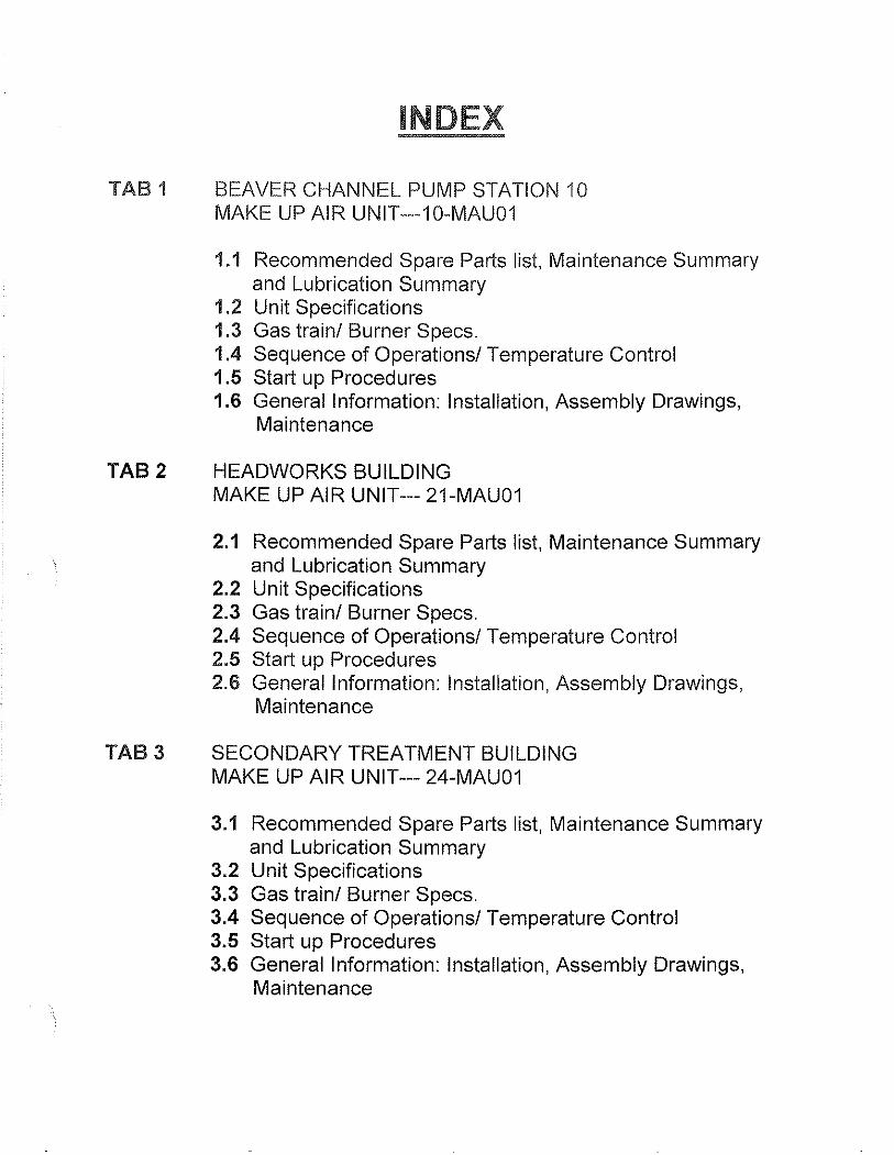
INDEX
BEAVER CHANNEL PUMP STATION 10 MAKE UP AIR UNIT---10-MAU01
1.1 Recommended Spare Parts list, Maintenance Summary and Lubrication Summary
1.2 Unit Specifications 1.3 Gas train! Burner Specs. 1.4 Sequence of Operations! Temperature Control 1.5 Start up Procedures 1.6 General Information: Installation, Assembly Drawings,
Maintenance
HEADWORKS BUILDING MAKE UP AIR UNIT--- 21-MAU01
2.1 Recommended Spare Parts list, Maintenance Summary and Lubrication Summary
2.2 Unit Specifications 2.3 Gas train! Burner Specs. 2.4 Sequence of Operations! Temperature Control 2.5 Start up Procedures 2.6 General Information: Installation, Assembly Drawings,
Maintenance
SECONDARY TREATMENT BUILDING MAKE UP AIR UNIT--- 24-MAU01
3.1 Recommended Spare Parts list, Maintenance Summary and Lubrication Summary
3.2 Unit Specifications 3.3 Gas train! Burner Specs. 3.4 Sequence of Operations! Temperature Control 3.5 Start up Procedures 3.6 General Information: Installation, Assembly Drawings,
Maintenance
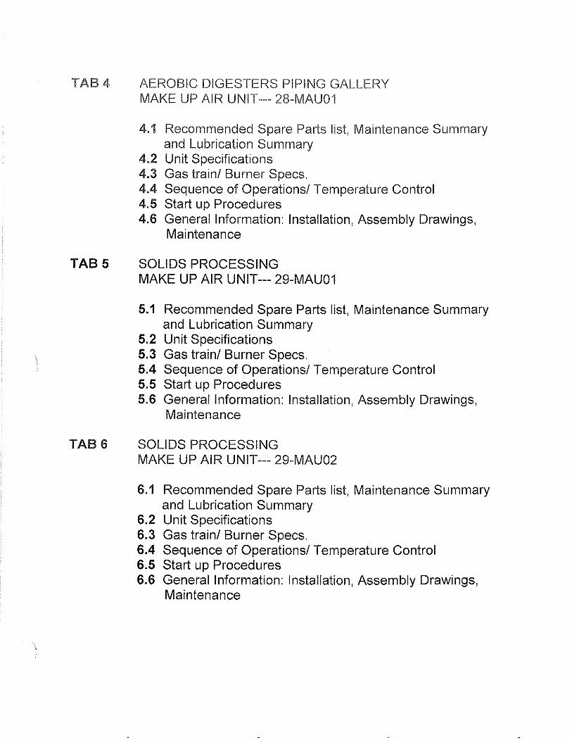
TAB4
TAB 5
TABS
AEROBIC DIGESTERS PIPING GALLERY MAKE UP AIR UNIT--- 28-MAU01
4.1 Recommended Spare Parts list, Maintenance Summary and Lubrication Summary
4.2 Unit Specifications 4.3 Gas train/ Burner Specs. 4.4 Sequence of Operations/ Temperature Control 4.5 Start up Procedures 4.6 General Information: Installation, Assembly Drawings,
Maintenance
SOLIDS PROCESSING MAKE UP AIR UNIT--- 29-MAU01
5.1 Recommended Spare Parts list, Maintenance Summary and Lubrication Summary
5.2 Unit Specifications 5.3 Gas train/ Burner Specs. 5.4 Sequence of Operations/ Temperature Control 5.5 Start up Procedures 5.S General Information: Installation, Assembly Drawings,
Maintenance
SOLIDS PROCESSING MAKE UP AIR UNIT--- 29-MAU02
6.1 Recommended Spare Parts list, Maintenance Summary and Lubrication Summary
6.2 Unit Specifications 6.3 Gas train/ Burner Specs. 6.4 Sequence of Operations/ Temperature Control 6.5 Start up Procedures 6.6 General Information: Installation, Assembly Drawings,
Maintenance
1.1 Recommended Spare Parts List, Maintenance Summary and Lubrication Summary

EXHIBIT C·t Equipment Record
.::-c--;:--.. ---.----.---'Pro'c>.:;t/ 69986
" ______ *~ _________ , •• H.}~d~J·_~?·_ .• _, -~-,,- - ____________ _ Eqllipillent M(\{l(lfacturer TITAN~R-~!-NC~'~'~-' Add-ress' -r-o -sox -ji-ioSSEO:WI5475S-- -- -------- --- --- --- ----- -.. - :el1one 715-597-2050
:-Fa_~---'-'-;--_"7'''-C-::---.. -.,.--_"",-_-:--._.-_. __ ... - -- - - -- - - -- --~iel; ,gi,. --wWw.r-ITAN:AIR:COM_------;,,·;;"'-.~, ___ • ____ - • ___ - - _¥ - H ___ ________ _
------._--_.-.-LocaIVellctoriSOIv;e< Cenl,r JOHN J. MORGAN CO.
EqUIp. 10-MAUOI Make TITAN AIR IDNa. I::'NO 145 T Size
Other:
ELECTRICAL NAMEPLATE DATA Equip. lO-MAUOI Make TITAN AIR IDNo. Frame No. 145T HP 2 Duly Code Ins. CI.
j,n81 No. 13565
Amp. 3.9 HZ 60 PH 3 RPM 1750 SF --t=,-.:..::..::....---t;;o;-;~"'-'----t;,c-;;A::m"'b."'--- Temp. Rise 79 F Rating
Mod., No. TA-109 NG HRD
-_ .. Other:
Part No SPARE PARTS PROVIDED PER CO~N"-T,-,R-"A,,,C,-,T ________ -._-;:::=;;;-_
PM Name Quantity
~------ ----1---.-----... ----------------------_._-----------
RECOMMENDED SPARE PARTS -PsrtNo. Part Name
----_ .. _._- -
SEE ATTACHED
.
_ .. --
. (Jun 1990, ReVIsed Ovt 2001, Revised Nov 2007) Copyright 1991 HOR Engineering. Inc.
007-91090047·003 MSS - MASTER SPECIFICATION SYSTEM MASTER SPECIFICATION SECTION·
SUBMIHALS 01340 - 3
- Quantity - ----
-

RECOMMENDED SPARE IlARTS LIST
Equipment No: 10-MAUOl
Description Part Number Cost (111112)
P-1 PRESSURE SWITCH DDP-109-187 $147.00 EA
FS-1 FlREYE MEC120 $548.00 EA
MERT4 $218.00 EA
MEP537 $865.00 EA
TS-1 TEMP DISCHARGE RTC DFTS w/DAT-12 $225.00 EA SENSOR
TC-1 TEMP CONTROLLER RTC DFC-1 $281.00 EA
BELT A-40 $18.00EA
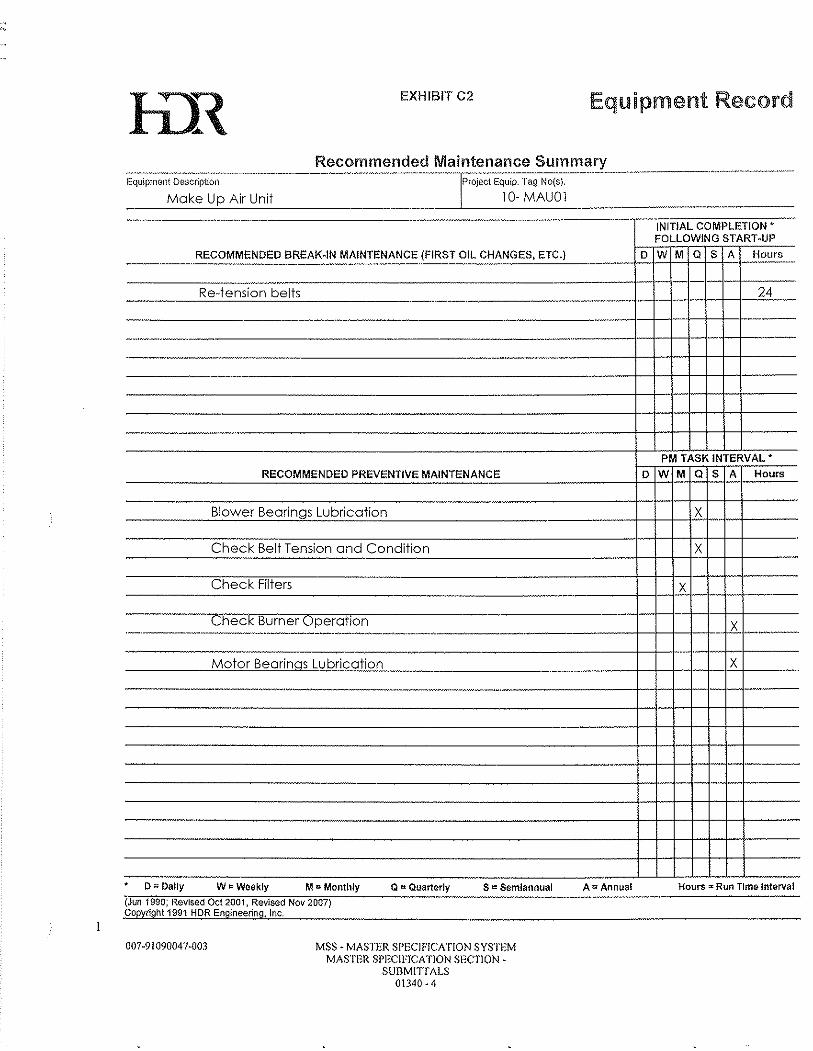
EXHIBIT C2 Equipment Record
Recommended Maintenance Summary -----------------------_.. -------.-.-.---------Equipment DeSCfil}tion Project Equip. Tag No(s}.
Make Up Air Unit 10· MAUD] ____ _ ___ ----'-'---"--'-'-'-_____________ ._ ---1. _______ • ____ ...........-::= __ =~=
RECOMMENDED BREAK·IN MAINTENANCE (FIRST OIL CHANGES, ETC.) "~--",--~ .. ---
---Re·tension belts -----
-.. ----~~--'".-... ~------ '._-..
-----
... .•
RECOMMENDED PREVENTIVE MAINTENANCE -Blower Bearings Lubrication
Check Belt Tension and Condition
Check Filters
Check Burner Operation .-----------.-.--------.--------~--.-.----~
-Motor Bearings Lubrication .
,- -~~.~.~-,
"
I) ~ Dally W eo Wc(}kly M 0 Monthly Q I::l Quarterly S I.'!: Semiannual (Jun 19S0; Revised Oct 2001, Revised Nov 2007) Coeyo9ht 1991 HOR Engineering, Inc.
007·91090047·003 MSS· MASTER SPECIFICATION SYSTEM MASTER SPECIFTCATJON SECTION·
SUIlMITT ALS 01340·4
.. _._. -
D --
-
D
-.
.-.--.
-
A:I: Annual
---INITIAL COMPLETION' FOLLOWING START·UP
W M Q S A Hours ----- - -
24
--
PM TASK INTERVAL'
W M Q S A Hours
-iL f--
X
X -
_..6. ----.. _--
X
Hours <:< Run Tlm& Int9rval
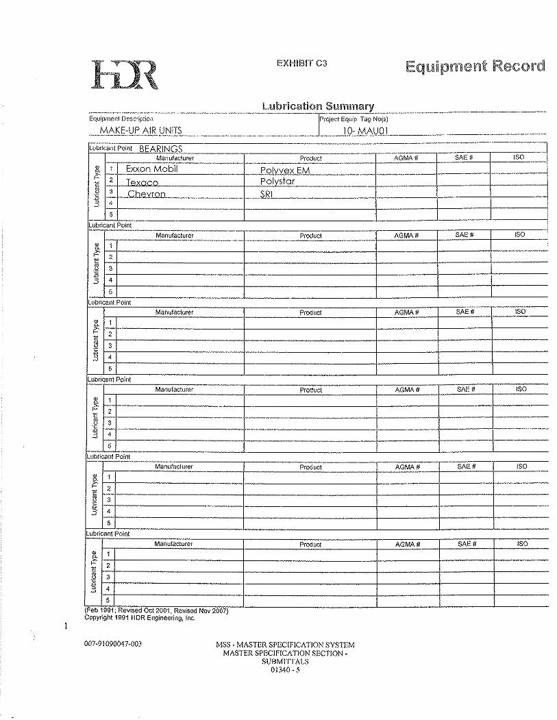
lil{ EXHIBITC3
- ,.-. ._,"-,-l.ubricant Point BEARINGS -------- .--- -.--,~
ManufClcturer Produci AGMA if ~--- SAE# ISO J::[--------'----'----.-.~- -.-.---.------.-~----.~.--.
_M ____
g 1 Exxon Mobil Polvvex EM ---~ >.
f- 2 Polystar .-c ----
\
__ N'
~ 3 ,_Gb~'irQ1L_, __________ __ 2RL~ _______ . ___ 'k::
"4 -- --, ~
I , ~ -- .~~.-
G - -, .;.-
Lubricant Point -- --~.-~------.~.----SA[# ISO I- ---.~~~<?:~~!-~." Produci AGMA#
,.-,,-.--.-~~.-- --.--.--~------,----.--.. --w 1 ~
i?: .-.. _---E
2 -II 3 ,0 "'- --, 4 ~
5 ------- -.-----Lubricant Point Manufacturer Product AGMA# SAE# ISO
-- -- "~'~~--'--~
-~ ~ -- ----C:' E
2
~ 3 :g "" ~ ~ 4
5
Lubricant Point '" Manufactorer Product AGMA# SAE# ISO --w
~ 1 f------~ >, ----I- 2 E -,,-----.. .-----
1l ----.--.. -~,.~~ 3
'0
"4 -- _ ... ~-n +-- ---J-'" -I ,,--5
LUbricantP;Trit~ -"'~~---" -----_. ._.-
Manufacturer Product AGMA# SAEfI ISO -~--. "- -
~ 1 ?: ---E 2 --~ 3
-" , 4 -' -- -- --'J 5 -" Lubricant Point
.~~.
Manufactu(er Product AGMA# SAE# ISO w 1 0.
i?: 2 C 8 3 'C
'" , 4 ~ ... -. 5
Feb 1991' R v; -( , e sed Oct 2001, Rev!sed Nov 2007) Copyright 1991 HOR Engineering, Inc.
007,,91090047-003 MSS • MASTER SPECIPICATION SYSTEM MASTER SPECIFICATION SECTION"
SUI3MrnALS 01340 - 5

1.2 Unit Specifications
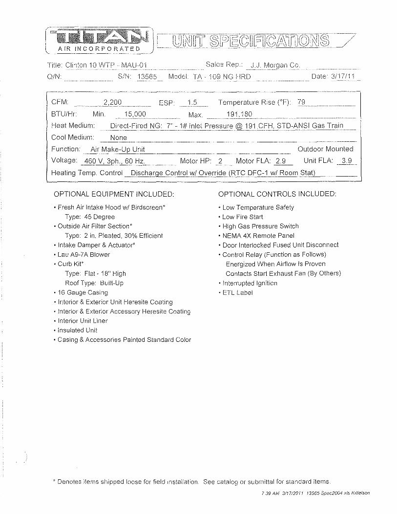
Title Clinton 10 WTP - MAU01 Sales Rep. J.J I~organCo
OIN SIN 13565 Model T;\ - 109 NG HRD Date. 3/17/11
CFM
BTUIHr
1.5 Temperature Rise (OF) [9 ________________ _
Min. Max. 191,180 -" . ----.~ .. -.-.. -.
Heat Medium: _P i rec;_t~£irEl~ N c:;~7~=1#Jr1IElt£':Elss u rEl@l~1c;FI::J!S T D::.~Ii"31_9 a~_I~OJill .. Cool Medium None
Fu nction ~~l\I1a ke-Ue.~nJt_____ _ ______ ... _. ________ ._ .. _. __________ .. __ Outdoor Mounted
Voltage: _ 469 V, 3~,,-_60 Hzc _______ Motor HP: 2 ____ Motor FLA: ~~_ Unit FLA: 3.9
Heating Temp. Control __ Dischar~ Control wi Override (RTC DFC~~\I\I( Room§J<3_tL_
OPTIONAL EOUIPMENT INCLUDED:
• Fresh Air Intake Hood wi Birdscreen*
Type: 45 Degree
• Outside Air Filter Section'
Type: 2 in_ Pleated, 30% Efficient
• Intake Damper & Actuator'
• Lau A9-7A Blower
• Curb Kit'
Type: Flat - 18" High
Roof Type: Built-Up
• 16 Gauge Casing
• Interior & Exterior Unit Heresite Coating
• Interior & Exterior Accessory Heresite Coating
• Interior Unit Liner
• Insulated Unit
• Casing & Accessories Painted Standard Color
OPTIONAL CONTROLS INCLUDED:
• Low Temperature Safety
• Low Fire Start • High Gas Pressure Switch
• NEMA 4X Remote Panel
• Door Interlocked Fused Unit Disconnect
• Control Relay (Function as Follows)
Energized When Airflow Is Proven
Contacts Start Exhaust Fan (By Others)
• Interrupted Ignition
• ETL Label
, Denotes items shipped loose for field Installation See catalog or submittal for standard items
7 39 AM 311712011 13565 Spec2004 xis Kittelson
2·8
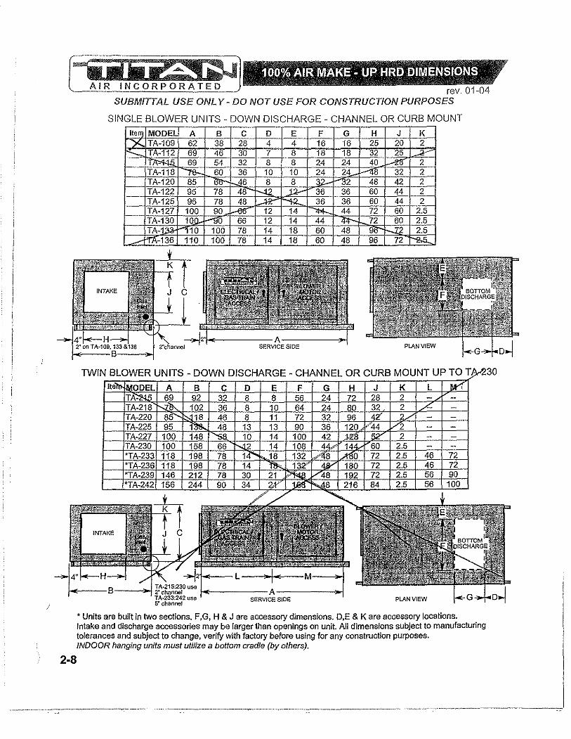
rev. 01-04 SUBMITTAL USE ONL Y - DO NOT USE FOR CONSTRUCTION PURPOSES
SINGLE BLOWER UNITS - DOWN DISCHARGE - CHANNEL OR CURB MOUNT Ite MODEL A B C 0 E F G H J K
TA-109 62 38 28 4 4 16 16 25 20 2 -112 69 46 30 7 8 18 18 32 25
69 54 32 8 8 24 24 40 2 TA-118 60 36 10 10 24 24 8 32 2 TA-120 85 46 8 8 3 2 48 42 2 TA-122 95 78 48 36 36 60 44 2 TA-125 95 78 48 36 36 60 44 2 TA-127 100 90 12 14 44 72 60 2.5 TA-130 10 0 66 12 14 44 72 60 2.5 TA-1 10 100 78 14 18 60 48 9 2 2.5
-136 110 100 78 14 18 60 48 96 72
TWIN BLOWER UNITS - DOWN DISCHARGE - CHANNEL OR CURB MOUNT UP TO T
• Units are built in two sections. F,G, H & J are accessory dimensions. D,E & K are accessory locations. Intake and discharge accessories may be larger than openings on unit. All dimensions subject to manufacturing tolerances and subject to change, verify with factory before using for any construction purposes. INDOOR hanging units must utilize a boltom cradle (by others).
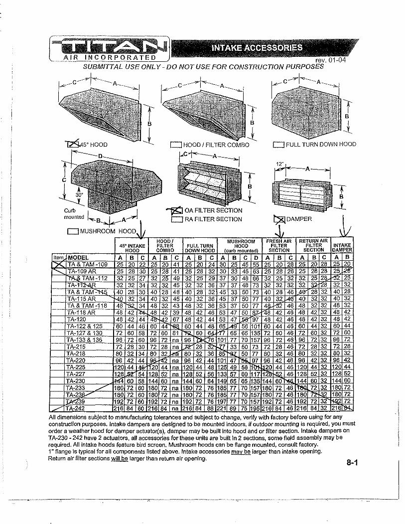
Item
X ..........
../
'Y" ,"",~~,"" "" ~"'~"'~"'"'1~",j :i.1",/,,"<jC!) ~"?" ''<fl' INTAKE ACCESSORIES ,
"'" ,0 ~ _ if" ''l~" ,~( e" '>V
rev. 01-04 SUBMITTAL USE ONL Y - DO NOT USE FOR CONSTRUCTION PURPOSES
f B
1 f
B
1 D HOOD I FILTER COMBO
f B
J D FULL TURN DOWN HOOD
mounted B~A D RA FILTER SECTION t;&lDAMPER
DMUSHROOM HOOD, Ii .Jl ~ II HOODI MUSHROOM FRESH AIR RETURN AIR
45° INTAKE FILTER FULL TURN HOOD FILTER FILTER INTAKE HOOD COMBO DOWN HOOD Jcurb mounted) SECTION SECTION DAMPER
MODEL A B C A B C A B C A B C D A B C A B C A B TA& TAM-109 25 20 22 25 20 41 25 20 24 30 25 45 5.5 .25 20 28 25 20 28 25 20 TA-109AR 25 28 30 25 28 41 25 28 32 30 33 45 63 25 28 28 25 28 28 25 ~ li'\..& TAM -112 32 25 27 32 25 49 32 25 29 37 30 48 66 32 25 32 32 25 28 -32 25 TA-112-1\.R 32 32 34 32 32 45 32 32 36 37 37 48 73 32 32 32 32 32-128 32 32 TA&TAM~ 40 28 30 40 28 48 40 28 32 45 33 50 73 40 28 46 '.<lZ 28 32 40 28 TA-115AR -4.Q 32 34 40 32 45 40 32 36 45 37 50 77 40 32 IA{j 40 32 32 40 32 TA & TAM -118 48 ~ 34 48 32 43 48 32 36 53 37 50 77 41).. 1-32 46 48 32 32 48 32 TA-118AR 48 42 I'l>!- 48 42 39 48 42 46 53 47 50 8y ~8 42 46 48 42 32 48 42 TA-120 48 42 44 ~ fd2 67 48 42 44 53 47 ..5Ir 97 48 42 46 48 42 32 48 42 TA-122 & 125 60 44 46 60 44 -;oa 60 44 48 65 t.41r 56 101 60 44 46 60 44 32 60 44 TA-127 & 130 72 60 58 72 60 81 'R 60 64- "77 65 65 135 72 60 46 72 60 32 72 60 TA-133 & 136 96 72 60 96 72 na 96 ~ ::16 101 77 70 157 96 72 46 96 72 32 96 72 TA-215 72 28 30 72 28 na ;Jfl: 28 32' .:u 33 50 73 72 28 46 72 28 32 72 28 TA-218 80 32 34 80 32 I-fIlf 80 32 36 85 rs.z. 50 77 80 32 46 80 32 32 80 32 TA-220 96 42 44 96- i-'f2 na 96 42 44 101 47 I'!l8.. 97 96 42 46 96 42 32 96 42 TA-225 120 44 4.6- rI20 44 na 120 44 48 125 49 56 1"01 ~20 44 46 120 44 32 120 44 TA-227 128 M 54 128 52 na 128 52 56 133 57 60 117 12~ f.&2 46 128 52 32 128 52 TA-230 ;!-!(4 60 58 144 60 na 144 60 64 149 65 65 135 144 60 "'i<i 144 60 32 144 60 TA-233 ,./ 180 72 60 180 72 na 180 72 76 185 77 70 157 180 72 46 IteQ 72 32 180 72 TA-23jl/ 180 72 60 180 72 na 180 72 76 185 77 70 157 180 72 46 180 7'Z '32 180 72 ];A<239 192 72 60 192 72 na 192 72 76 197 77 70 157 192 72 46 192 72 32 1-ID 72 TA-242 216 84 60 216 84 na 216 84 88 221 89 75 195 216 84 46 216 84 32 216 1-
All dimensions subject to manufacturing tolerances and subject to change, verify with factory before uSing for any construction purposes. Intake dampers are designed to be mounted indoors, if outdoor mounting is required, you must order a weather hood for damper actuator(s), damper may be built into hood and or filter section. Intake dampers on TA-230 - 242 have 2 actuators, all accessories for these units are built in 2 sections, some field assembly may be required. All intake hoods feature bird screen. Mushroom hoods can be flange mounted, consult factory. 1" flange is typical for all components listed above. Intake accessories may be larger than intake opening. Return air filter sections ~ larger than return air opening.
8-1
--.~---:c-.
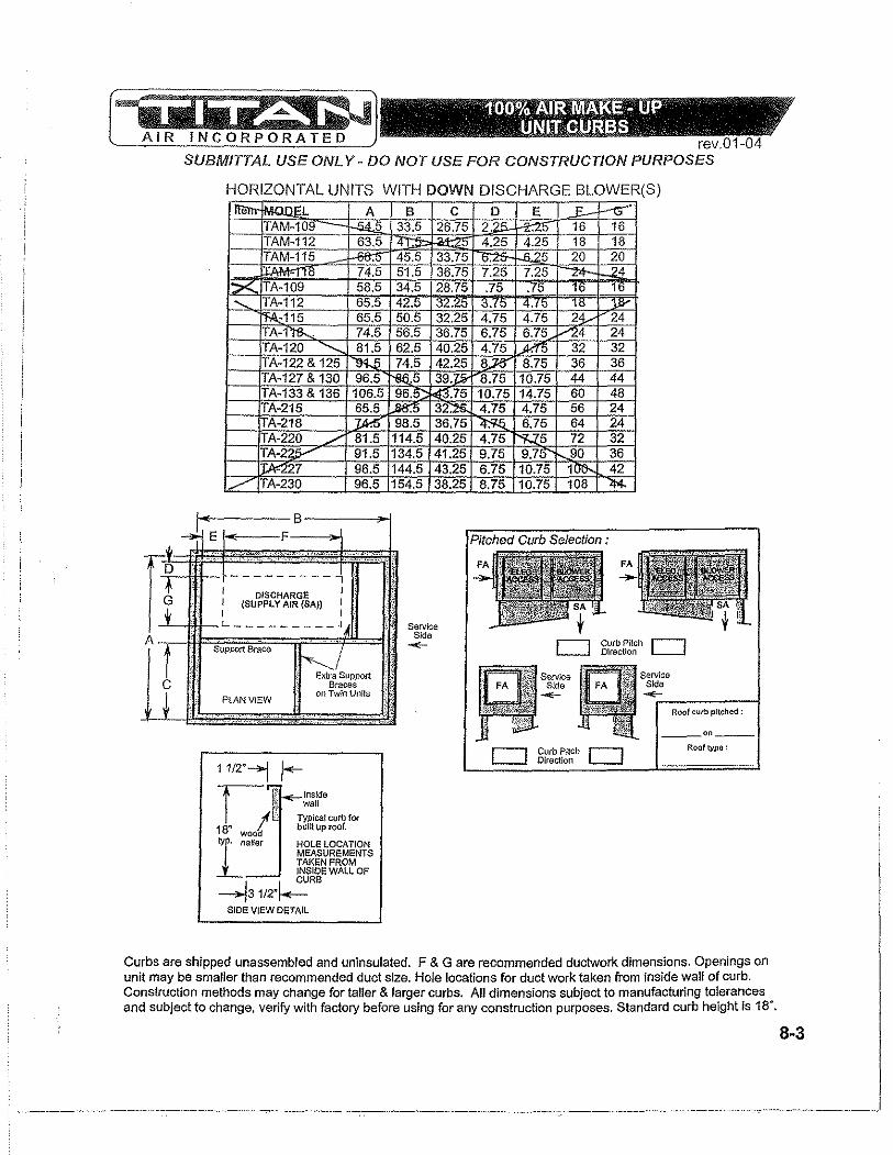
.." . 100%'~ llJl~ -IlIP .." I' . '." lIN,~t~JlR~U3 1"
rev.01-04 SUBMITTAL USE ONL y .. DO NOT USE FOR CONSTRUCTION PURPOSES
HORIZONTAL UNITS WITH DOWN DISCHARGE BLOWER(S)
m'" A B C D E .£.- -:<,' rIAM-1LJ~ ,33.5 121 .75 16 16 ITAM-112 6: 5 ! 4 2! 4.25 18 18 ITA~ 15 4, .5 13 .75 20
5 51 .5 .75 7.25 ':::>< b 3~.5 .75 .75 "- 'A- 1: 65.5 4Z.0 O>Z.;<O 0 .10
65.5 50.5 ~.25 .7! 2 .... :4 fA-l '&.. 56.5 .7 ~ 24
'" 162. 32 fA-' ~2 & 125 74. ~.2 }6 IA-' ~7 & 130 16. r-s6., 31 1.J,!iY .75 .75 44 fA-133 & 136 ' 106.5 I 96. 11 .7. 60 48 -A-215 65. .sa ffi. 56 24
ITA-218 '5 24
~ ./' i5 32
~5 r-.. 36 96.5 144. 143.25 6.75 110.75 l}... 42
./ fA-230 96.5 154.5 138.25 8.75 110.75 08 '14.
1< B ...,. E i-<---F Pitched Curb Selection: .".._... ........
n 0- .... ,~_"
'''''~' " ....
A
t 1
", .- . ---------"1
I DISCHARGE I I (SUPPLY AIR (SA» I I I L _________ '~
Support Brace
.~"PP"" Braces
PLAN VIEW on TwIn Units
___ .".' v""" , ._, . ". -,."
11/2"-1 r--I,/J~;;~:wrnf~ 18" wooa built up roof. I oail" HOLE LOCATION
MEASUREMENTS TAKEN FROM .:-- ~J~~E WALL OF
--13 1/2"/-= SIDE VIEW DETAIL
l .';
~ ~
''1
, , ..
Service Side
-E-
Curb Pilch Direction
Curb Pitch r-I DIrection L-......J
Service S~e
""'"'r------; Roof curb pitched :
--'"--Rooftypil :
Curbs are shipped unassembled and uninsulated. F & G are recommended ductwork dimensions. Openings on unit may be smaller than recommended duct size. Hole locations for duct work taken from inside wall of curb. Construction methods may change for taller & larger curbs. All dimensions subject to manufacturing tolerances and subject to change. verify with factory before using for any construction purposes. Standard curb height is 18".
8-3
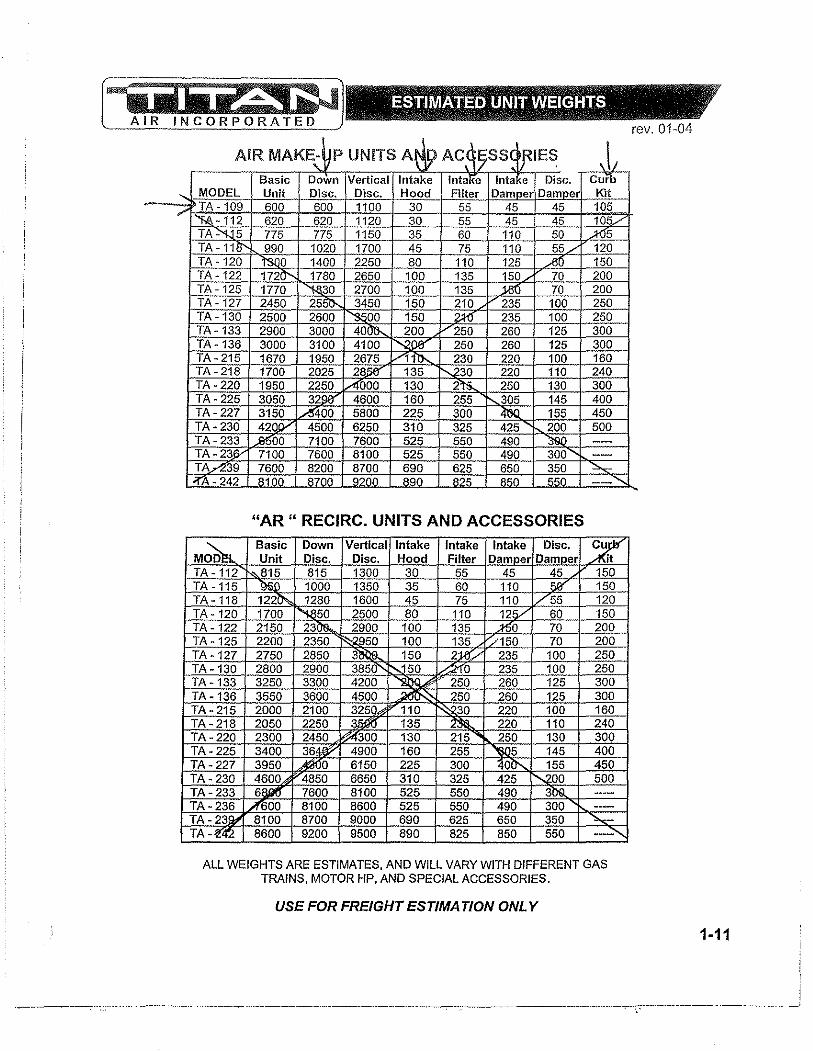
,- 320 120 ,5 /' r75 150 30 1 0
\- 990 020 1700 15 75 110 55/ 0 T, \ - 20 lSOo 1~ 2250 80 110 !5...60 150 TA -122 l' 20'-- 2650 1 15 iO 70 200
_IA - 125 1770 2700 1 15 i1J~-,C'70'--f-'2~00-j TA -127 2450 "3450 0 15 00 T A - 2500 !600 "'$.5110 150 z;!jJ 235 100
, - 2! 3000 401" 200 -250 260 125 ,- 3100 ~ll 0 NOO" 50 .12Q.~O-+--~,-+-;3s;;;-00-l ,- 1950 .1§Z! V 30 ~ 160 \ - 2025 ~~"-+~--!t'-..;~3~0+--'2~2:~COH~+2~4CO-l , - . 50 !50 AOO( 'I'S- 250 300 \ - 2: 050 !ll8' 4600 0 255 05 145 400 , - 2: 315 A 0 5800 1&'H~~jO,'.d---;;;;;;-t_~45UC-l 1-: 4: V ~ 25 15 500 1- fl 0 ~ 50 10 --I-::3l> 7' 8100 50 90 --".,.-239 71 00 8700 ,25 50 """
'I' ,242 A100 A700 9200 A90 A?" Alii fifiO "
"AR " RECIRC. UNITS AND ACCESSORIES
TA - '" 815 1300 :0 45 150 1000 :350 150
1- a-, 1< :0600 ./ ,- 120 '00 ~ 0 !500 110 125/ ,- 122 2150 23 18. 2900 100 135 ;150 70
fA -125 2200 2350 100 135 :/150 70 21 0
, - 1, 3250 O( 4201 '2!lQA' !5( 2 ,- 1: 3550 :01 4501 ~ 250 26C 125 1-21 2000 2100 ~ '110 ~ 100 0
fA - : 2051 2250 ~::H_~13!--I-~ -~~d--C~-+--;1"*, 100~_~ 2"0';-1
I-:;~~, ~ 4900 ~~ ~ 00
, - 3951 To- 6150 3)0 Cl'-.. 5 , - 46( 6650 325 42f ~)O
fA - 23 6/li 8100 525 550 49( lQ. ---
fA - 23 A =Be-- --' 25 ..§§Q. 49( 300 ---rA:J};it 8 '--- -' )"-0-t--;~~-+-~ 65(~_~ 350,-+_""'-=.:-:...;o-l IA -le,!"'! 8 ' ')0 825 850 550 -- ,
ALL WEIGHTS ARE ESTIMATES, AND WILL VARY WITH DIFFERENT GAS TRAINS, MOTOR HP, AND SPECIAL ACCESSORIES.
USE FOR FREIGHT ESTIMA TION ONL Y
rev, 01-04
1·11
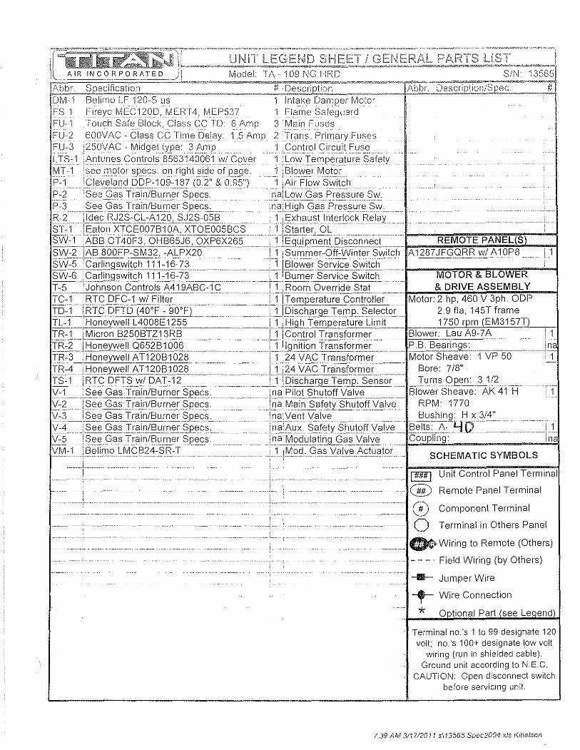
I[]J!!R:~JF~~=~~~El:1~Si~~b~R:r·sj~l§~~:~;~ Ablx. Slecification -.--.• ~".-"~" '" .. # Description ~~~"~-"~'7A'bbT. ~De~c-r-iptior~~ #
DM·1 Belimo LF 12o.·S us Intake Damper Motor' FS-1 Fireye MEC120D, MERT4, MEI"537 Flame Safeguard F:U··1 Touch Safe Block, Class CC TD: 6 Amp 3 Main Fuses FU-2 6o.OVAC - Class CC Time Delay 1.5 Amp 2 Trans. Primary Fuses FU-3 ,250VAC - MidgettYEe: 3 i\rnE Control Circuit Fuse LTS-1 .Antunes Controls 8563140.0.61 w/ Cover 1 Low Temperature Safety MT -1 : see nl0t()r_~p<3cs: on righLsideofpage, 1 Blower Motor P-1Cleveland[)[)F':1o.fl:1~7(o.2"&Ofl5") 1 Air Flow Switch P-2SeeC;_asTrainIElurner§pecs na; Low Gas Pres~u_re Sw. P-3 ___ §.eeC;a_s:rrain/E'l~Lner Specs,_nal-:lighc;?sPressure§\I\i R-2 :'-d<::cP"J:2S:C;,=-:A12QLS~~S-D~_El _ 1 :Exhaust Interlock Relay 81'-1 !Eaton XTCEo.o.7B1DA, XTOEo.o.5BCS ---'jT8tarter,O[---SW=rTABSOT4o.F3,-OHB65J6, OXP6X265 iEquipmenlDiscon':'ect REMOTE PANEL S SW--:i!ABBo.o. FP -S r-i3'2~-:,AIp X2o.---'- U_JSul-)1.me;::Qlf::~i nlElL§iYitch __ A 1.2..87 :'E.9..ClBpw lJ\:'Qf'8 ____L1.
~00:fl~:~:~~:~t~~ ; tf~~:;r==--HI~~~~~~~~+J~f:~~- MOTOR & BLOWER T-5 -TJohnsooControls-A419ABC-1 C -. ·TljRoom:Override_§tat_.__ & DRIVE ASSEMBLY TC-1 - iRTC DFC-1wIFilter'----· i 1 iTemperature Controller Motor: 2 hp, 460. V 3ph. ODP
~~~==I~:~e~~~~926;:L=:~=:=:·FB~f~~~~~~;e§~~~tor ~i5~ar' ~~~~;~~T TR-1 I Micron B250BTZ13RB---·--·--·----!'i·i Conii'olTransformer -.--.. Blower: Lau A9-7 A I 1 TR-2--THoneywell Q652B1o.06LIil9.~hion Transform.E'i PB Bearings _____ ' in IR=3~]f:lDn<3~ell AT120B162ii:~ iJJ24 Vp,~J:rilnsformer' MotorSheave 1 VP 50 • 1 TR-4 !Honeywell AT120B1o.28 11124 VAC Transformer Bore: 7/8" :ti;~LTRt:C_QFTS~/DAT:-:j2== ............... \iTi5ischarge Tem~'Sens(ii'-- Iurns Opel'l:'},1/;>__ Y:1 J§Ele GasTrainL~urner §pecs ......... ---:rlarPilot Shutof{\;alve~---- Ellower Sheave: AK 41 H ----TT Y:2 ...... i§E;e Ga".I,Clin/.Ell1rne~..?PeE§Tn§JM.ai~ Salety ShIJtgH.,!aj\7e-= RPM 1770. V -3__JSe<::. G C]s.Jr?in/B u r:.n er§pec~ .!l1Cl!y§ntyalv'::.__...... .._ B u".h i n9g
•.... H~~/4': ,/:" L§eeC;§sIraill/BurllE;r§p_ecs. il1.?:!'I.u_x§_af",ty§r,1l1offlj§lv§ Belts A- .. V V-5 : See Gas Train/Burner Specs i na.Modulating Gas Valve ... Coupling: .... - . n
viVl= 1}3'~li;no L Me Bi4':sFi=T--. ··Ili0od(3"sj/911/.e:!\~tuj,tor sc H E MATI C S YM B 0 LS
!!!!!l Unit Control Panel Terminal
-- --.- ......... - -.--I@ Remote Panel Terminal
........ .. ..= 0 Component Terminal
------- 0 Terminal in Others Panel
= 0> Wiring to Remote (Others)
. - - _. Field Wiring (by Others)
--Ill- Jumper Wire
-.- Wire Connection
* Terminal no.'s 1 to 99 designate 120 volt; no.'s 100+ designate low volt
wiring (run ill shielded cable). Ground unit according to NEe.
CAUTION: Open disconnect switch before serviCing unit.
7.39 AM 311712011 5113565 Spec2004.x/s Kittelson

O.A. Filter(s)
TOTAL STATIC 2200 2.07
2" Cleanable
R.A. Filters
Linked Panel (1" Rack)
-
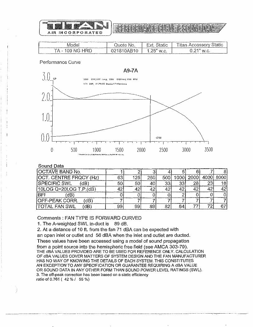
E Model .----:=-"
Quote No, Ext. Static Titan Accessory Static I TA -109 NG HRD 021810AB10 1.25" w.C. 0.21" w.c.
Performance Curve
A9·7A
2200 CFM,207 I.w.g, 3"3"B4 ov{rtlm;nl, noo RPM
171 BllP, 41.7% SE Stand".-d P<:<fo«nunte
20 ~-' . ~,I---=====~----~
1.0
o.o+----~ I Iii iii Iii iii , I i
o 500 1000 1500 2000 2500 3000 • ,,,,,,,, •• , .. ... " ... ,<O .. ~ ... "~~":(~""_'''_.I,' '"
Sound Data OCTAVE BAND No. 1 2 3 4 5 6 OCT. CENTRE FRQCY (Hz) 63 125 250 500 1000 2000 SPECIFIC SWL (dB) 50 50 40 33 33 10LOG Q+20LOG T'p.(dB) 42 42 42 42 42 BFI (dB) 0 0 0 0 2 OFF-PEAK CORR. (dB) 7 7 7 7 7 TOTAL FAN SWL (dB) 99 99 89 82 84
Comments: FAN TYPE IS FORWARD CURVED 1. The A-weighted SWL in-duct is 89 dB. 2. At a distance of 10 ft. from the fan 71 dBA can be expected with an open inlet or outlet and 56 dBA when the inlet and outlet are ducted. These values have been accessed using a model of sound propagation from a point source into the hemispheric free field (see AMCA 303-79).
28 42
0 7
77
, I
3500
7 4000
23 42
0 7
72
THE dBA VALUES PROVIDED ARE TO BE USED FOR REFERENCE ONLY. CALCULATION OF dBA VALUES COVER MATTERS OF SYSTEM DESIGN AND THE FAN MANUFACTURER HAS NO WAY OF KNOWING THE DETAILS OF EACH SYSTEM. THIS CONSTITUTES AN EXCEPTION TO ANY SPECIFICATION OR GUARANTEE REQUIRING A dBA VALUE OR SOUND DATA IN ANY OTHER FORM THAN SOUND POWER LEVEL RATINGS (SWL). 3. The off-peak correction has been based on a static efficiency ratio of 0.761 ( 42 % / 55 %)
I
8 8000
18 42
0 7
67

1.3 Gas train/ Burner Specs.
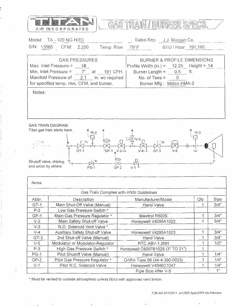
Model TA - 109 NG HRD Sales Rep. JJ .1\II0lgan Co.
SIN 13565 C F M 2,200 Teillp. Rise 79T BTU / Hour 191 180
--_._-----------------_._,--- ----------------.-----
GAS PRESSURES Max. Inlet Pressure = __ 111 __ Min. Inlet Pressure = 7" at 191 CFH. _._---_ .. _"". .-~----... ,.,~.
Manifold Pressure of _ .. 2J_ in. wc required for specified telllP. rise, CFM, and burner.
BURNER & PROFILE DIMENSIONS Profile Width (in.) = 12.25 Height =14
Burner Length = __ iU' __ ft.
No. of Tees = 0 --~----~-
Burner Mfg. MidcoHI\IIA-~ --~---- ------------~
Notes:
GAS TRAIN DIAGRAM: Titan gas train starts here. A I; A A
. ..... \tlj?il'_4jv'~~' . .. r GT-1 'GP-1 I; V-2, , ~- V-5 ,I" Shutoff valve, dripleg, - ,----r*:J'" . $1------"Q~ --___ ._. ______ ._ -+ and union by others PG-1 GP-2 V~
Notes: -
Gas Train Complies with ANSI Guidelines
Abbr. Description Manufacturer/Model Oty. Size . -
GT-1 Main Shut-Off Valve (Manual) Hand Valve 1 3/4" P-2 Low Gas Pressure Switch *
GP-1 Main Gas Pressure Regulator * Maxitrol RSOOS 1 3/4"
V-2 Main Safety Shut-off Valve Honeywell V429SA 1 023 1 3/4"
V-3 N.O. Solenoid Vent Valve * V-4 Auxiliary Safety Shut-off Valve Honeywell V429SA 1 023 1 3/4"
GT-3 2nd Shut-off Valve (Manual) Hand Valve 1 3/4"
V-S Modulator or Modulator-Regulator RTC ABV-1.2NN 1 1/2"
P-3 High Gas Pressure Switch * Honeywell C6097B1028 (3" TO 21") 1
PG-1 Pilot Shutoff Valve (Manual) Hand Valve 1 1/4"
GP-2 Pilot Gas Pressure Regulator * OARA Type 96 (44-4-390-002S) 1 1/4"
V-1 Pilot N.C. Solenoid Valve -- Honeywell V4046C1047 1 1/4"
Pipe Size After V-S 1"
* Must be vented to outside atmosphere unless fitted with approved vent limiter.
7:39 AM 311712011 sl13565 Spec2004.xls Kittelson
1.4 Sequence of Operations/ Temperature Control
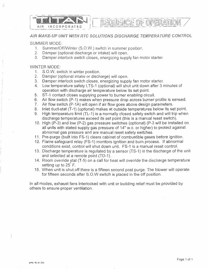
AIR II~CORPORATED
AIR MAKE-UP UNIT WITH RTC SOLUTIONS DISCHARGE TEMPERATURE CONTROL
SUMMER MODE 1. SUlllmer/Off/Winter (S.O.W.) switch in summer position. 2. Damper (optional discharge or intake) will open. 3. Damper interlock switch closes, energizing supply fan motor starter.
WINTER MODE: 1. S.O.W. switch in winter position. 2. Damper (optional intake or discharge) will open. 3. Damper interlock switch closes, energizing supply fan motor starter. 4. Low temperature safety L TS-1 (optional) will shut unit down after 3 minutes of
operation with discharge air temperature below its set point. 5. ST -1 contact closes supplying power to burner enabling circuit. 6. Air flow switch (P-1) makes when pressure drop across burner profile is sensed. 7. Air flow switch (P-1A) will open if air flow goes above design parameters. 8. Inlet duct-stat (T-1) (optional) makes at outside temperatures below its set point 9. High temperature limit (TL-1) is a normally closed safety switch and will trip when
discharge temperatures exceed its set point (this is a manual reset switch). 10. High (P-3) and low (P-2) gas pressure switches (optional) (P-3 will be installed on
all units with stated supply gas pressure of 14" w.c. or higher) to protect against abnormal gas pressure and are manual reset safety switches.
11. Pre-purge (built into FS-1) clears cabinet of combustible gases before ignition. 12. Flame safeguard relay (FS-1) monitors ignition and burn process. If abnormal
conditions exist, control will shut down unit. FS-1 is a manual reset control. 13. Discharge temperature is regulated by a sensor (TS-1) in the discharge of the unit
and selected at a remote pOint (TO-i). 14. Room override stat (T-5) on a call for heat will override the discharge temperature
setting up to 25' F. 15. When unit is shut off there is a fifteen second post purge. The blower will operate
for fifteen seconds after S.O.W switch is placed in the off position.
In all modes, exhaust fans interlocked with unit or building relief must be provided by others to ensure proper ventilation.
Page 1 of 1 emu ric ot. cloc
!~il!i~Jl \,-" AiR INCORPORATED)
100% OA RTC AMU JOB Clinton WTP SERIAL NUM8ER 13565-70 DATE 04/12/11 DRAWN8Y KK
wi DISCHARGE TEMP. CONTROL SW-1: FU-1 ST-1 ~ OL's
~?:)
TC
OFF
SUM --4,!,::>VVIN
460/230/208 3ph 3 wire
supply wI transformer
L1----o--:C ~ L2- - --o--:-c f--("}---{).i \.0 (MT-1
L3--
R2-1 @]-----O-j kJ-..----@J
Exhaust Interlock Contact TR-1
120VAC 7
~ ... --------
SW·2
g DM-1 N -_ c G _ - - ~ -n~<:- - - - -. -~ _ _ _ _ <::T_
I T·5 '~I--,--1-', ()--j f-Or[.----,
---Black r
TR·3
Low voltage wiring must be run in shielded cabie.
~ ~ ~ • " ~
~ •
" '" ;g -~;22 iJ/'''i!5!,,~i~~et f~.~ymboi description. ( ~ = unit to remote wiring) \ --------------~)~
II
II
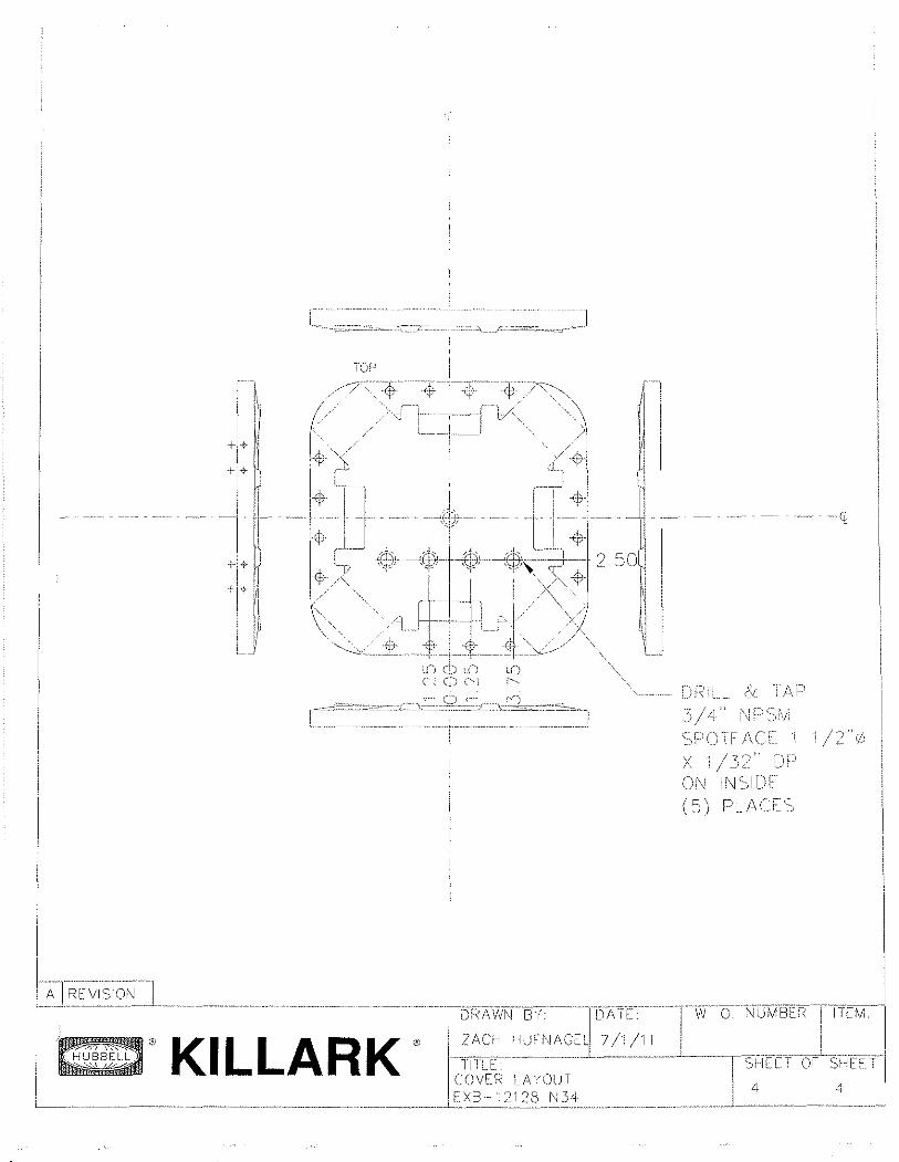
TOP
I,
II Ii
II\JSTAU.
A REVISIOI~
, /.,' ) / ~1 i\;
f"-:·7-
IL.
I r- .--
{--. 1\ L~~._
I
TOP
l ... ':?~"i'-::;;:;-~
I//~ll·---T-·-·ll \~IJ ~ + -.j J'
1 .. ·· .. ····-/ I '----I· 1', i i
( . ,
I - --.-..-- , ---
I - -1----
I
,0 ___ .J.
i ..
1\. ',SI;lI---·---J--·T . "
l I J 4 78 1\ i r i I r /1 J , __ .":::=L . _____ J. ..---- - --t -~ .. ~.-."_ ______ J~~ ... ~J . _____ ._ ,
1
I-I r--J [ I I !
II
I
t
78 ~ .. I i
I 0 KILLARK ®
r_~~~~:N,~~~N:~:r~/,~,,~ T.~_ ~.·~UMB~J ITI~~ 1 111LE SH[T~ OF SIWI T
L_______ __________ ~ __ .. ____ .. _ ..... __ ... _ .. 'BOX I .. A YOU T L~ X B ···1 2: 28J':},!1_
, ') Ll i . __ .. __ ._ ... _ ... ______ 1._ ... ____ . _______ --_____ .... _~ ____ J
j /\
\
"~--i-----
1-1'" --" . I
TITLE. SHeET Of' SHEET :Y/~N I~AYOUT ".
~. _ .. _._.J~ x B ~~.L~~~_ ::: 8 _. __ ~"?~~. _ .... __ ., ___ ._. ___ ._~ _______ ._. __ "_~) __ .. ".''"_._~. _______ ~~ __ ._ .. ~ I I~.~.~ ... --~-
TOP
r:)~\iLl p
o A
I IA--I-R;;vl;;;r;~;-l i-~--~-=--=~--- .-~------- .--~----- .... ------TD;~AWN--BY---rDAYE-1 IN 0 NU~vfBtR-1 TfEM -I
,~ ® KI L LA R K"' li~IA~~-1-I~~FI'MCEl! /:~-~-~ -~---__rSl1tFf O/Sf.fU-t 'I
COVEe< t A (OU T I" '--__ ~_~. __ ._~_ . _______ .~. __ ~ ____ ~. ____ ~.. _ _ ___ ~_ _Lf .. X B _=-iJ ~ 2 s.r: ~d ~.. J _~~ _ _ _ __~ _-"__ J
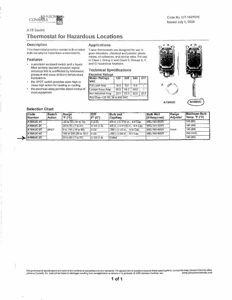
A 19 Series
Code No. LlT·1927045
Issued July 1, 2006
Thermostat for Hazardous Locations Description This thermostat provides remote bulb or coiled bulb sensing for l1azardous environments.
Features a precision enclosed switch and a liquidfilled sensing element provides repeat accuracy that is unaffected by barometric pressure and cross-ambient temperature fluctuations the SPOT switch provides open high or close high action for heating or cooling the electrical rating permits direct control of most equipment
Selection Chart Code Switch Range Number Action of (0C)
A19AUC·1C -30 to 50 (-34 10 10)
A19AUC-2C 20 to 80 (-7 to 27)
A19AUC-3C SPOT o to 150 (-18 to 66)
A19AUC-4C 100 to 250 (3a to 121)
A198UC-2C 20 to 80 (-710 27)
Applications These thermostats are designed for use in grain elevators, chemical and powder plants, mines, oll refineries, and similar sites. For use in Class I, Group 0 and Class II, Groups E, F, and G hazardous locations.
Technical Specifications Electrical Ratings Motor Ratings 120 208 240 277 VAC Full Load Amp 16.0 9.2 8.0 - ~. r'\ Locked Rotor Amp 96.0 55.2 48,0 -Non-Inductive Amp 22.0 22.0 22.0 22.0 \J Pilot Duty 125 VA, 24 to 600 VAC
A19AUC
Oiff Bulb and Bulb Well Range FO (CO) Capillary (If Required) Adjuster
5 (2.8) 3/8 in, x 4-1/16 in., 6ftCap. WEl14A-602R
3-1/2 (1.9) 3/8 in. x 4-31/32 in., 6 ft Cap. WEL 14A-603R
6 (3) .290 x 2·1f2 in., 10 ft Cap. WEl16A-600R Knob
6 (3) .290 x 2-3/8 in., 10 t Cap. WEl16A-600R
3-1f2(1.9) Coiled -
Maximum Bulb Temp. of ee) 140 (60)
140 (60)
190 (88)
290 (143)
140 (60)
The performance specifications are nominal and confonn to acceptable industry standards For applications at conditions beyond these specrflcations, consult the local Johnson Controls office Johnson Controls, Inc shall not be liable for damages resulting from misapplication or misuse of Its products. © 2006 Johnson Controls, Inc. www.johnsoncontro!s.com
1 of 1

1.5 Start up Procedures
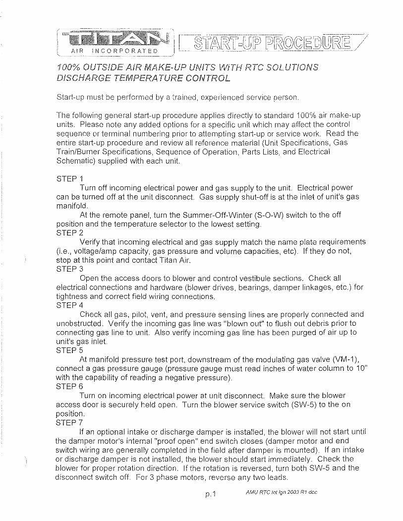
100% OUTStDE All=? MAKE·UP UNITS WiTH RTC SOLUTIONS DISCHARGE TEMPERA TURE CONTROL
Start-up must be performed by a trained, experienced service person.
The following general start-up procedure applies directly to standard 100% air make-up units. Please note any added options for a specific unit which may affect the control sequence or terminal numbering prior to attempting stali-up or service work. Read the entire start-up procedure and review all reference material (Unit Specifications, Gas Train/Burner Specifications, Sequence of Operation, Parts Lists, and Electrical Schematic) supplied with each unit.
STEP 1 Turn off incoming electrical power and gas supply to the unit. Electrical power
can be turned off at the unit disconnect. Gas supply shut-off is at the inlet of unit's gas manifold.
At the remote panel, turn the Summer-Off-Winter (S-O-W) switch to the off position and the temperature selector to the lowest setting. STEP 2
Verify that incoming electrical and gas supply match the name plate requirements (i.e., voltage/amp capacity, gas pressure and volume capacities, etc) If they do not, stop at this point and contact Titan Air. STEP 3
Open the access doors to blower and control vestibule sections. Check all electrical connections and hardware (blower drives, bearings, damper linkages, etc.) for tightness and correct field wiring connections. STEP 4
Check all gas, pilot, vent, and pressure sensing lines are properly connected and unobstructed. Verify the incoming gas line was "blown out" to flush out debris prior to connecting gas line to unit. Also verify incoming gas line has been purged of air up to unit's gas inlet. STEP 5
At manifold pressure test port, downstream of the modulating gas valve (VM-1), connect a gas pressure gauge (pressure gauge must read inches of water column to 10" with the capability of reading a negative pressure). STEP 6
Turn on incoming electrical power at unit disconnect. Make sure the blower access door 'IS securely held open. Turn the blower service switch (SW-5) to the on position. STEP 7
If an optional intake or discharge damper is installed, the blower will not start until the damper motor's internal "proof open" end switch closes (damper motor and end switch wiring are generally completed in the field after damper is mounted). If an intake or discharge damper is not installed, the blower should start immediately. Check the blower for proper rotation direction. If the rotation is reversed, turn both SW-5 and the disconnect switch off. For 3 phase motors, reverse any two leads.
p. 1 AMU RTC /11//gl1 2003 R1 doc
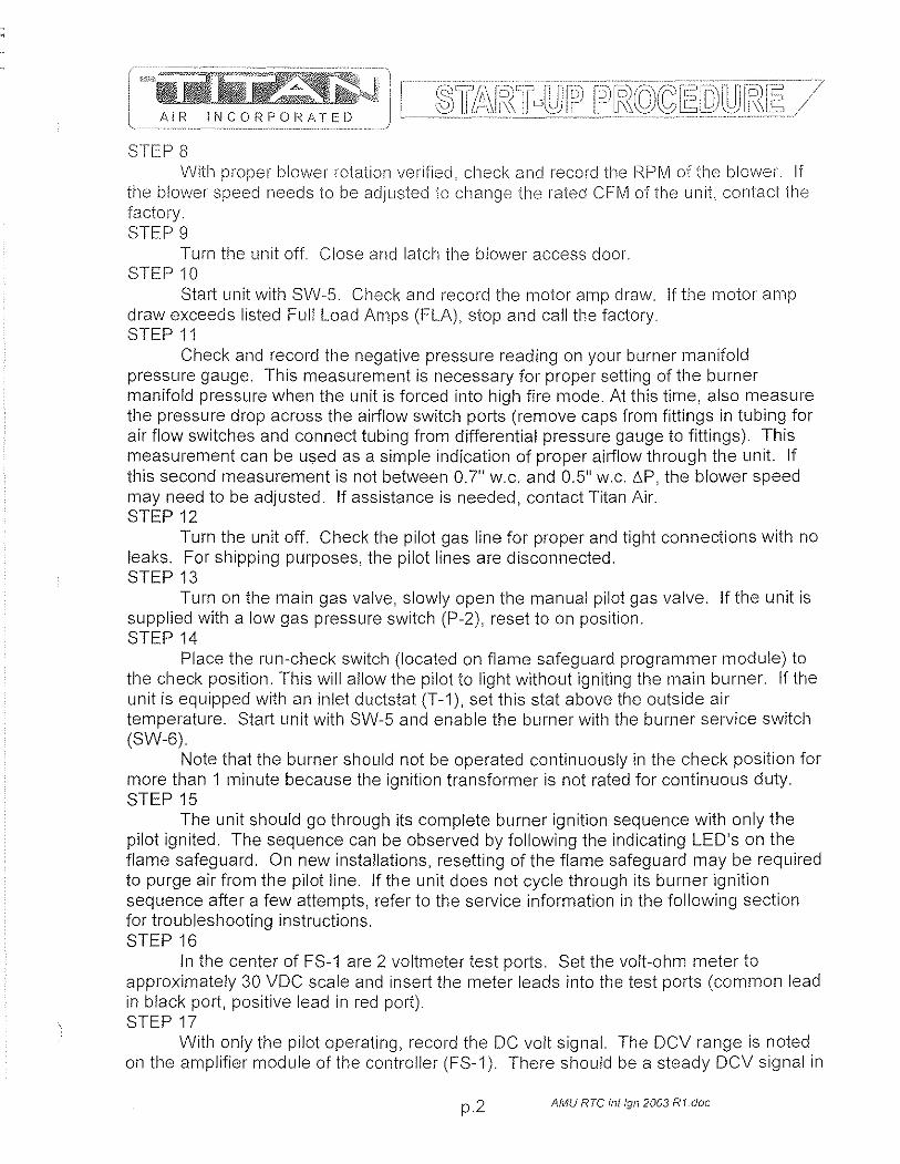
;~l~=i3F."=-:L-V~ t ...
- _~Jlllr:;m ~-~ AIR INCORPORATED
STEP 8 With propel· blower rotation verified, check and recol·d the I~PM of the blower. If
the blower speed needs to be adjusted to change the rated CFM of the unit, contact the factory. STEP 9
Tum the unit off. Close and latch the blower access door. STEP 10
Start unit with SW-S. Check and record the motor amp draw. If the motor amp draw exceeds listed Full Load Amps (FLA), stop and call the factory. STEP 11
Check and record the negative pressure reading on your burner manifold pressure gauge. This measurement is necessary for proper setting of the burner manifold pressure when the unit is forced into high fire mode. At this time, also measure the pressure drop across the airflow switch ports (remove caps from fittings in tubing for air flow switches and connect tubing from differential pressure gauge to fittings). This measurement can be used as a simple indication of proper airflow through the unit If this second measurement is not between 0.7" w.c. and O.S" W.c. L\.P, the blower speed may need to be adjusted. If assistance is needed, contact Titan Air. STEP 12
Tum the unit off. Check the pilot gas line for proper and tight connections with no leaks. For shipping purposes, the pilot lines are disconnected. STEP 13
Tum on the main gas valve, slowly open the manual pilot gas valve. If the unit is supplied with a low gas pressure switch (P-2), reset to on position. STEP 14
Place the run-check switch (located on flame safeguard programmer module) to the check position. This will allow the pilot to light without igniting the main burner. If the unit is equipped with an inlet ductstat (T-1), set this stat above the outside air temperature. Start unit with SW-S and enable the burner with the burner sell/ice switch (SW-6).
Note that the burner should not be operated continuously in the check position for more than 1 minute because the ignition transformer is not rated for continuous duty. STEP1S
The unit should go through its complete burner ignition sequence with only the pilot ignited. The sequence can be observed by following the indicating LED's on the flame safeguard. On new installations, resetting of the flame safeguard may be required to purge air from the pilot line. If the unit does not cycle through its burner ignition sequence after a few attempts, refer to the service information in the following section for troubleshooting instructions. STEP 16
In the center of FS-1 are 2 voltmeter test ports. Set the volt-ohm meter to approximately 30 VDC scale and insert the meter leads into the test ports (common lead in black port, positive lead in red port). STEP 17
With only the pilot operating, record the DC volt signal. The DCV range is noted on the amplifier module of the controller (FS-1). There should be a steady DCV signal in
p.2 AMU RTC II1/1gl12003 R1.doc

the upper range stated on the controller. STEP 18
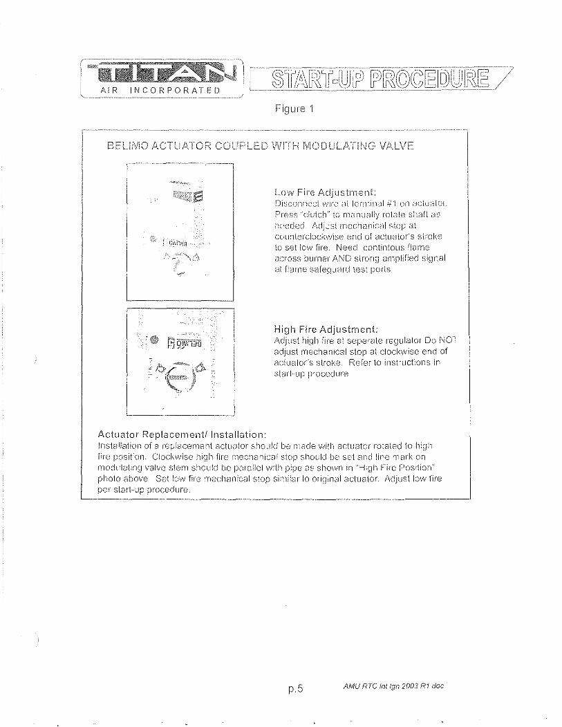
Once stable pilot is achieved, shut unit dowil and place run·check switch in the run position. Carefully remove the wire from terminal one (1) on gas modulating actuator (VM-1). Do not allow the wire to touch the unit casing or any metal. Release actuator gear by pressing black button on side of actuator (see figure 1), rotating mechanism counterclockwise to stop. Start unit and check and record DC voltage as in previous step. Check to make sure the flame is contained in the burner casting and extends the full length of the burner with no breaks in the flame. An ideal low fire setting results in a small flame with no breaks and that also produces a stable DC voltage signal in the upper end of the range listed on the flame safeguard amplifier module. If the low fire setting is adjusted, verify that both the DC voltage signal and visual appearance of the flame are satisfactory. See figure 1 at end of start-up procedure for low fire adjustments if necessary. STEP 19
Once stable signal is achieved on low fire, release actuator gear by pressing black button on side of actuator (see figure 1) and rotate mechanism clockwise to stop. This will force the burner into high fire. On your manifold pressure gauge, check the manifold pressure. The reading on your manifold pressure gauge needs to be added to the negative pressure recorded in step 11. The resulting total manifold pressure should be compared to the unit's rated manifold pressure. If the total is higher or lower than the rated pressure, adjustment can be made at the gas pressure regulator (GP-1). Total manifold pressure should not exceed unit's rated manifold pressure.
Because of possible variations in the BTU content of gas, it may be necessary to set the manifold pressure to the rated temperature rise (temperature difference between the incoming air and the unit discharge air).
The high fire flame should be visually observed to verify proper combustion. Experienced service personnel should be able to assess the appearance of a proper high fire flame. If assistance is needed, contact the factory. STEP 20
With the burner on high fire, turn the high temperature limit (TL-1) to its lowest setting. The limit should trip out and shut down the burner. Turn TL-1 back to the factory setting of 185 deg. F and reset the control. Reconnect wire at VM-1. STEP 21
With ali wiring in place and the unit operating in the winter mode, adjust temperature setpoint on the remote mounted controller (TO-i) up and down (from highest to lowest setting) observing the modulation of the burner. When actual discharge air is below TO-1's setpoint, the unit should discharge maximum temperature. When actual discharge air is above TO-1's setpoint, the unit should discharge minimum temperature. STEP 22
With the unit operating in the summer mode, cycle the burner from SW-6 Verify that burner fully lights within a few seconds of proved pilot. STEP 23
If the unit is equipped with a low temperature safety (L TS-1), check this control's operation. Standard L TS-1 can be checked by disconnecting the sensor wires. The unit
p. 3 AMU RTC Inllgn 2003 R1 ,doc
AIR INCORPORATED
should then shut down after the buill-in timer setting has "timed-oui". Replace the sensor wil'es when proper operation has been verified Turn the unit off and back on to reset 1_ TS-1. STEP 24
With the unit operating in the winter mode, close the 2nd manual gas shutoff valve (GT-3), The burner should shut down in a few seconds (look for flame LED to go out on FS-1) with the unit shutting down in 30 seconds or less, Open GT-3 and reset FS-1 by pressing button protruding through cover. STEP 25
Turn SW-5, SW-6 and the disconnect off Verify all terminals, electrical connections and hardware (bearings, sheaves, blower wheels, etc,) are securely tightened. Adjust all controls to desired settings. Remove all gauges, meters, and hand tools from the unit. Replace all covers on controls. Make sure all safety devices are reset. STEP 26
Turn the disconnect on. Start the unit from the remote panel. Verify proper operation in all modes according to unit's sequence of operation.
The unit should be ready for operation. If any problems arise, refer to the service information on the following page. To assure long lasting and efficient operation of Titan equipment, a regular service inspection should be set up. Refer to the maintenance section at the back of this manual for detailed maintenance information.
pA AMU RTC 111119112003 R1.doc
AIR INCORPORATED
BEurViO ,ll .. CTUATOF' CO
, , L-_________ ~
Actuator Replacement/Installation:
Figure 1
LovlI Fire Adjustment: [J'1~;c{)!lnecl \".'Ire ;,'1t le,rililkil ii-'l on [:Jclu;:][UI
Press "clutch" tf) Ili<_lllually rotate shaft ,:W
n(·:,cch~d. !\djJst lTH.;chanici:ll slop at coun\ercbckw'lse end 01 clclu,:llor's sl:DI<.e to set low fire. Need contintolls flame across burner AND stron~J 81l:pJified ~::;ignal <--It flame safeQ~lanj test porls.
High Fire Adjustment: .i\djust hiqll fire at seperdte regulator Do ',OT adjust mechanical stop at clockwise end of actuator's stroke. Refer to inst:"uctiolls in SleJrl-up p''Ocedure
Jnsi81Jcllioil of 8 replacement 8ctll~ltor SilOllkJ be Ill(lde \;\Iith actuc.ltor rotated to Ilinh nrc positioll. Clocl\\<visc high fire meclicl'lical stop should be set and line 'TlCHk on modulcltfllg valv(; stenl should t)O pafe:lel with pipe a~: shown in ":...{:gh Fire Position' photo above, Set low fire mechanical stop similar to originsl 8ctuator. Adjust lo\v fire pcr stall-Up procedure.
p.5 AMU RTC inlign2003 RI.doc
Brandon
1.6 General Information: Installation, Assembly Drawings, Maintenance

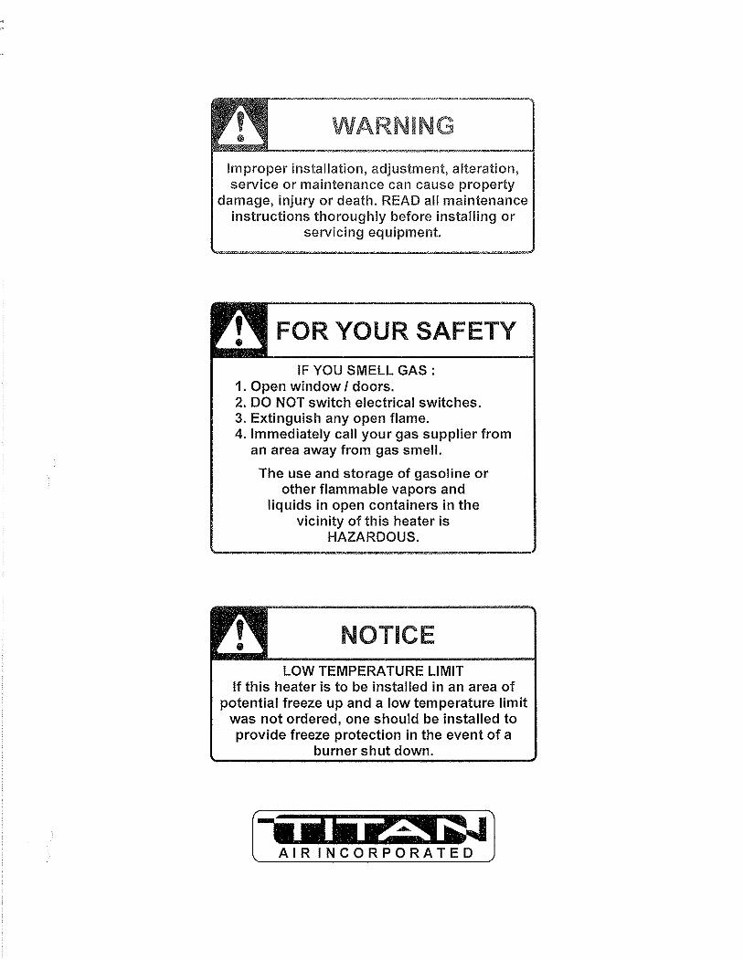
WARNING
Improper installation, adjustment, alteration, service or maintenance can cause property
damage, injury or death. READ all maintenance instructions thoroughly before installing or
servicing equipment.
FOR YOUR SAFETY
IF YOU SMELL GAS: 1. Open window I doors. 2. DO NOT switch electrical switches. 3. Extinguish any open flame. 4. Immediately call your gas supplier from
an area away from gas smell.
The use and storage of gasoline or other flammable vapors and
liquids in open containers in the vicinity of this heater is
HAZARDOUS.
NOTICE LOW TEMPERATURE LIMIT
If this heater is to be installed in an area of potential freeze up and a low temperature limit
was not ordered, one should be installed to provide freeze protection in the event of a
burner shut down.
[-ut1i it -"' G~} AIR INCORPORATED
24 MONTH WARRANTY Titan Air, Inc. hereby warrants its products against defects in material and
workmanship for a period of (24) twenty four months from date of shipment. Start up checklist is due back within (30) thirty days of start-up or 120 days from date
of delivery for 24 month warranty to be effective. After (30) thirty days, and up until (60) sixty days, a (13) thirteenth month warranty will be observed. All warranties are null and void if start up checklist is not received within (60) sixty days from start-up or 120 days from date of delivery. NO EXCEPTIONS WILL BE MADE.
Titan Air, Inc. reserves the right at Titan Air, Inc.'s option, to replace or repair free of charge, any part proven by Titan Air, Inc. to be defective. Prompt notification of defective part must be given to Titan Air, Inc. and defective part must be returned freight prepaid within (30) thirty days of notification.
WARRANTY INCLUDES ONLY PARTS SUPPLIED BY TITAN AIR, INC. INCIDENTAL COSTS AND LABOR CHARGES SHALL BE THE RESPONSIBILITY OF OTHERS. This warranty does not cover fuses, belts, filters or water damaged parts which are the result of improper storage or installation.
This warranty is void in event the product is improperly installed and/or operated under conditions other than normal published ratings, improperly maintained, misused or not in compliance with applicable codes or not in accordance with Titan Air, Inc.'s operating instructions.
This warranty is void if attempts to correct or repair any alleged defective part or parts are made by unauthorized personnel without Titan Air, Inc.'s written approval.
In no event shall Titan Air, Inc. be held liable for any damage, incidental or consequential, arising from the installation, performance or operation of the product.
This warranty supersedes, voids, and/or is in lieu of any other verbal or written understanding which may not be in total accordance with this expressed warranty.
Warranted parts must be returned to Titan Air, Inc. within 60 days to receive credit.
PURPOSE I APPLICABILITY This manual is intended to provide installation, operating and service information on
Titan Air's standard direct-fired air make-up units. Other Titan Air units, such as AR/80™, AR/75™, Demand-Air™, H.O.T. ™ and units that do not feature a direct-fired burner, will have separate operating and service manuals.
A packet of reference materials for a specific unit (tracked by its Serial Number) is generally included with this Operating and Service Manual. The reference materials include Unit Specifications, Parts Lists, Gas Train and Burner Specifications, Electrical Schematic, and a Sequence of Operation. A start up checklist is also included in this packet. Review the reference materials for a specific unit and note any optional equipment or controls which are not specifically addressed in this manual prior to attempting start-up or service work.
The information and recommendations contained in this publication are based on general observation and are not intended to supplant requirements of federal, state or local codes having jurisdiction. These codes should be reviewed before installation of equipment. All units must be installed in accordance with national, state or local codes.
It is the responsibility of the purchaser at the time of order, to specify any and all code or insurance requirements that may dictate the addition of components to the equipment in order to comply with those requirements.
Only qualified personnel who have experience with the installation and operation of industrial/commercial direct fired equipment should attempt to service Titan Air equipment.
WARRANTY
TABLE OF CONTENTS
GENERAL INFORMATION Y Equipment Arrival Y Components
AIR FLOW SWITCH OPERATION
INSTALLATION Y Installation and Field Wiring Overview
TYPICAL ASSEMBLY DRAWINGS
MAINTENANCE
FLAME FAIL DIAGNOSTICS
START-UP PREPARATION
VALVE LEAK TEST
SPECIFIC EQUIPMENT DETAILS y Unit Specification y Sequence of Operation y Parts I Legend Sheet y Schematic y Start-Up Procedure y Troubleshooting (optional)
Page I
2
3
7
8
11
14
17
19
20
pages not numbered
Note that operating and service manuals are occasionally requested prior to production of a unit. These manuals will be marked "Pre-Production Release" on the front cover. The final copy of the operating and service manual for a specific unit will be sent with the unit. Additional copies of the manual for a specific unit are available.
A detailed unit specification sheet, partsllegend sheet, schematic, sequence of operation and start-up procedure are provided in the start-up section of each operating and service manual generated for a specific unit. Selected vendor cut sheets on components will also be included.
2
EQUIPMENT ARRIVAL When the air make-up unit arrives, be sure to inspect for shipping damage. The
equipment was thoroughly inspected before leaving the factory and the driver signed for it. Read tile bill of lading and verify that all of the items listed are accounted for. Any damaged or missing items should be reported to the transporter immediately. DO NOT SEND DAMAGED FREIGHT BACK TO TITAN AIR! All claims must be filed with the transporter. Be sure to take photographs and get the drivers signature to confirm the damage. The driver will have a number for you to call to file a claim. Request a written inspection report from the claims inspector to sUbstantiate any necessary claim. Be sure to open the unit access doors and inspect for internal damage.
If for some reason you are unable to install the equipment immediately, be sure that the equipment is protected from the elements. Water damaged parts are not covered by Titan Air's warranty. If the equipment is stored for an extended length of time, be sure to completely check the unit for any internal damage which may have been caused by excessive condensation. Also check for damage caused by rodents, and be sure to eliminate any dust that may have built up on the components while the unit was in storage.
CAREFULLY AND THOROUGHLY READ TITAN AIR'S PRODUCT WARRANTY Each unit is tested at the factory prior to shipping. Because we are not able to
simulate exact field conditions and sometimes actual conditions are different than what was stated on the order, you may need to make some adjustments in the field. This is why it is very important that only qualified personnel start-up and service Titan Air equipment. The start-up checklist (provided in packet with this manual) must be filled out and returned to Titan Air in order to validate equipment warranty.
For a fee, Titan Air personnel will travel to the job site, supervise start-up and provide operation and maintenance training for the equipment.
BLOWERS The typical blower(s) used in Titan Air equipment are AMCA rated industrial type
forward curve D.W.D.I. fans. Backward incline, backward airfoil, and plenum/plug fans are used occasionally. Models TA-109 through TA-136 utilize a single blower while models TA-215 through TA-242 utilize twin blowers. All blower wheels are mounted on a solid, turned, ground and polished shaft. 9" and 12" blowers are supported with permanently lubricated ball bearings. Larger blowers are supported by lubricated pillow block ball bearings.
MOTOR & DRIVE Rigid base, T-Frame, motors are utilized. The motor is mounted on an adjustable
slide base. Variable pitch motor sheaves are provided to allow airflow adjustment if the motor is no larger than 30 Hp.
3
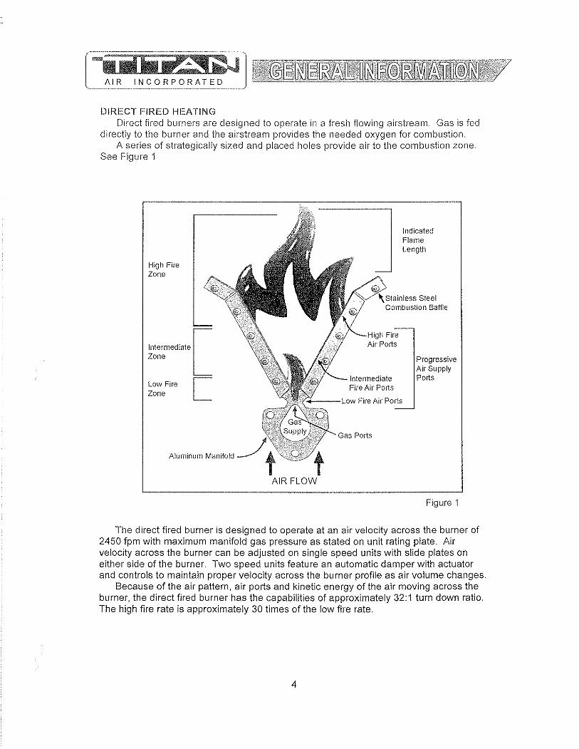
DIRECT FIRED HEATING Direct fired burners are designed to operate in a fresll flowing airstream. Gas is fed
directly to the burner and tile airstream provides the needed oxygen for combustion. A series of strategically sized and placed 110Ies provide air to the combustion zone.
See Figure 1
High Fire Zone
Intermediate [ Zone
Low Fire I Zone L
Aluminum Manifold
Indicated Flame Length
';'Ainle," Steel Combustion Baffle
~-H"i 1n Fire Air POlts
Progressive Air Supply Ports
+---l_ow Fire Air Ports
AIR FLOW
Figure 1
The direct fired burner is designed to operate at an air velocity across the burner of 2450 fpm with maximum manifold gas pressure as stated on unit rating plate. Air velocity across the burner can be adjusted on single speed units with slide plates on either side of the burner. Two speed units feature an automatic damper with actuator and controls to maintain proper velocity across the burner profile as air volume changes.
Because of the air pattern, air ports and kinetic energy of the air moving across the burner, the direct fired burner has the capabilities of approximately 32:1 turn down ratio. The high fire rate is approximately 30 times of the low fire rate.
4
BURNER OPERATING PRINCIPLES The direct fired burner is designed to operate in a cabinet of flowing fresh air. Fuel
gas is fed directly to the burner; kinetic energy of the airstream furnishes combustion air. It will function properly at the design velocity and pressure associated with ventilating systems.
The burner must be installed to fire with, and parallel to, the air flow. By virtue of velocity impact and suction generated by the diverging shape of the combustion baffles, air is induced through the air ports into the combustion zone. The air supply is constant, even though only that which mixes with the gas takes part in combustion.
When a very small quantity of gas is admitted to the burner, sufficient mixing takes place in the low fire slot where combustion takes place. Since the low fire zone is contained within the burner casting it is effectively shielded from uncontrolled air entry.
As the gas supply is increased the flame progresses into the intermediate fire zone where an additional supply of air is available. At higher or full capacity, mixing occurs at the larger air ports of the high fire zone augmented by air flowing over the end of the baffles.
On a reduction of gas supply the reverse sequence takes place, the flame recedes to a location of lesser air supply until the low fire zone is reached. The burner is suitable for a turndown range of approximately 30 to 1.
AIR SUPPLY The supply fan is typically positioned to draw air across the burner. Air flow across
the burner must be substantially straight (laminar) and velocity must be within the proper range to develop the desired turndown and capacity.
The direct fired burner is designed to operate in an air make-up heater with all air crossing the burner taken directly from outdoors. Rare exceptions involve equipment that serves an unoccupied space.
Total pressure rating of the blower includes allowance for the pressure drop through the primary air handling unit including the burner, together with pressure losses at the inlet screen, inlet damper, filters, outlet damper if used, plus the external pressure rating of the system.
BURNERS Burners are purchased in 6" and 12" straight lengths and 12" tee sections and
are assembled to meet the BTU requirements of each piece of equipment. According to national safety standards, the following factors could influence safe
operation of a direct fired air make-up unit and must be interlocked to either prevent the burner from firing or shut it down if unsafe conditions occur.
1. AIR SOURCE - If a damper is used, it must be interlocked to prove it is open before the blower can start.
2. BLOWER STARTER INTERLOCK - An auxiliary contact from the blower starter must be placed in series with the burner controls to prevent burner operation when the blower is not operating.
3. AIR FLOW SWITCHES - Monitor the air flow (pressure drop) across the burner. The switches (one high differential and one low differential) will not allow burner to operate if pressure drop across the burner is outside of the high and low set points.
4. HIGH TEMPERATURE LIMIT - A manual reset high temperature limit control must be utilized to prevent high temperature situations caused by excessive fuel pressure or lack of air flow.
5
5. rL6.M.l~9AI~ECUARD - Monitors tile combustion process during ignition and operation for safe conditions.
6. HICH CAS PRESSURE SWITCH - Monitors gas pressure to tile burner. Tilis de-energizes the burner in tile event gas pressure increases above its set point.
The burner's design and flexibility, coupled with proper controls, make direct fired air make-up equipment the safest and most efficient method of tempering outdoor air.
GAS CONTROLS Titan Air TA Series equipment is constructed to meet A.N.S.I Z83.4/CSA 3.7-1999
standards. Components in the gas delivery manifold on standard equipment include: two manual shut-off valves, gas pressure regulator, two safety shut-off valves and an electronic gas modulating valve. The pilot control includes a shutoff valve, gas pressure regulator and a pilot solenoid.
ELECTRIC/ELECTRONIC CONTROLS TA series air make-up units come standard with the following items: disconnect
switch, starter and overload assembly(s), control power transformer (if a 3 wire system), air proving switches, high temperature limit, electronic flame safeguard and electronic flame modulation with remote set point adjustment. Many other options including low temperature limit, inlet duct stat, and operating lights are available.
If the malfunction of the heater creates a hazard to other fuel burning equipment in the served building (i.e. supplying make-up air to boiler room) it is to be interlocked to open an inlet air damper in case of failure.
CABINET Titan Air TA series equipment comes with either a galvanized finish or a painted
finish. In both cases, the minimum gauge metal used is 18 gao
6
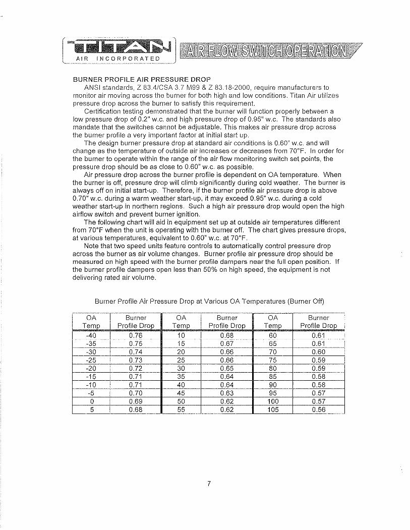
BURNER PROFILE AIR PRESSURE DROP ANSI standards, Z 83,4/CSA 3.7 M99 & Z 83.18··2000, require manufacturers to
monitor air moving across the burner for both high and low conditions. Titan Air utilizes pressure drop across the burner to satisfy this requirement.
Certification testing demonstrated that the burner will function properly between a low pressure drop of 0.2" w.c. and high pressure drop of 0.95" w.c. The standards also mandate that the switches cannot be adjustable. This makes air pressure drop across the burner profile a very important factor at initial start up.
The design burner pressure drop at standard air conditions is 0.60" w.c. and will change as the temperature of outside air increases or decreases from 70°F. In order for the burner to operate within the range of the air flow rnonitoring switch set points, the pressure drop should be as close to 0.60" w.c. as possible.
Air pressure drop across the burner profile is dependent on OA temperature. When the burner is off, pressure drop will climb significantly during cold weather. The burner is always off on initial start-up. Therefore, if the burner profile air pressure drop is above 0.70" w.c. during a warm weather start-up, it may exceed 0.95" w.c. during a cold weather start-up in northern regions. Such a high air pressure drop would open the high airflow switch and prevent burner ignition.
The following chart will aid in equipment set up at outside air temperatures different from 70°F when the unit is operating with the burner off. The chart gives pressure drops, at various temperatures, equivalent to 0.60" w.c. at 70°F.
Note that two speed units feature controls to automatically control pressure drop across the burner as air volume changes. Burner profile air pressure drop should be measured on high speed with the burner profile darnpers near the full open position. If the burner profile dampers open less than 50% on high speed, the equipment is not delivering rated air volume.
Burner Profile Air Pressure Drop at Various OA Temperatures (Burner Off)
----.~-.. --.-" .. - .. --.~" --OA Burner OA Burner OA Burner
Ternp Profile Drop Temp Profile Drop Temp Profile Drop
-40 0.76 10 0.68 60 0.61 -35 0.75 15 0.67 65 0.61 -30 0.74 20 0.66 70 0.60 -25 0.73 25 0.66 75 0.59 -20 0.72 30 0.65 80 0.59 -15 0.71 35 0.64 85 0.58 -10 0.71 40 0.64 90 0.58 -5 0.70 45 0.63 95 0.57 a 0.69 50 0.62 100 0.57
~_ 5 0.68 55 ------- 0.62 105 0.56
7
CONTROLS Contml systems can be designed to meet specific requirements. Numerous
temperature controls are available. Since standard air make-up units usually temper outside air to replace the air exhausted from a building, modulating discharge temperature control is typical. A room override thermostat is occasionally included to automatically increase the discharge temperature set point if space temperature drops too low.
Titan Air units are typically supplied with a remote control panel. This panel will include switching for blower & burner operation and a temperature setpoint. Some units feature operating lights, discharge temperature display, custom contmls or contacts by others to enable the blower and/or burner.
Refer to the unit specification sheets, parts list, schematic, sequence of operation and start-up procedure for a specific unit to determine the control options included.
PRE-INSTALLATION Inspect the equipment making sure all parts and accessories are on the job site.
Check equipment against order and packing list. If the equipment has been sitting in storage for some time, inspect it for moisture (from condensation, rain or snow) and/or dust accumulation. Both can cause damage to electrical and electronic components as well as bearings and insulation.
INSTALLATION Care taken during the installation and start-up is vital to the longevity and reliability of
the equipment. Confirm that gas and electric utilities match the rating on the equipment name plate.
> This heater shall be installed in accordance with local codes or, in the absence of local code, according to ANSI Z223.1.
> If the heater is to be installed in an airplane hanger, refer to ANSI/NFPA 409.
> If the heater is to be installed in a parking garage, refer to ANSI/NFPA 88A
> If the heater is to be installed in a service garage, refer to ANSI/NFPA 88B.
> For installations in Canada, refer to CAN/CGA B149.
> Adequate exhaust and/or relief must be provided to prevent over pressurizing the served space when the heater is operating at its rated capacity.
> If in doubt regarding the application of the direct fired heater, contact the sales representative or the factory.
POSITIONING THE HEATER Locate the heater exactly level, making certain minimum clearance required by local
codes is maintained between the heater and any combustible materials. See name plate on unit for minimum recommended clearances.
8

CURBING (OUTDOOR MOUNTING) The use of a full perimeter curb or mounting rails under the heater is recommended.
The only openings in the roof should be for the supply air duct, return air duct (if required), gas and electrical connections (if applicable). These openings must be sealed properly after installation. Titan Air ships all curbs unassembled and un-insulated. Installing contractor supplies gaskets, cant strips, insulation, etc.
GAS PIPING Gas piping must be sized and installed in accordance with applicable codes. It must
be able to deliver the specified CFH and gas pressure at full flow. Refer to unit nameplate or unit specification sheets for specified CFH and gas pressure.
Care must be taken with the gas piping to prevent problems at start-up and later during operation. Before the union between the supply line and the unit is connected, the supply line should be cleaned out to remove any foreign material (dirt, rust, metal shavings, etc.) and a drip leg should be utilized.
Refer to unit nameplate to determine the minimum gas supply pressure required to attain the maximum specified gas.
All suitable gas controls, regulators and valves (equipped with a diaphragm) in this device are furnished with an ANSI approved vent limiter. If local codes require these components be vented to the outside, it is the responsibility of the installing contractor.
The heater and its individual shut off valve must be disconnected from the gas supply piping system during any pressure testing in excess of Y, PSIG.
The heater must be isolated from the gas supply piping system by closing its individual shut off valve during any pressure testing of the supply system at pressures equal to or less the Y, PSIG.
During start-up, the technician should perform a gas leak check on all valves and piping during the heater's normal operation. (See page 20)
DUCTWORK Ductwork must be sized and installed in accordance with applicable codes and
standards. A size variation may exist from recommended duct size to unit flange size. Recommended duct size applies to the size of the duct at the connection to the equipment. A properly designed duct transition from the blower outlet to a larger duct is recommended for long ducts or ducts with numerous elbows.
On heaters mounted outdoors, discharge ductwork should be insulated to minimize condensation during the "off' cycle in cold weather. A fresh air intake hood with bird screen is required. Discharge duct should be common to both blowers on twin blower units. Individual ducts for each blower are not recommended.
On a heater mounted indoors with through the roof intake, a "mushroom" type intake hood is recommended to prevent moisture entrainment. When using "through the wall" intake duct, the intake louver should have adequate moisture baffling characteristics. All intake ductwork exposed to the heated space should be insulated.
9

SOUND AND VIBRATION CONTROL Flexible connectors are recommended on at least one ductwork connection.
Vibration isolators that mount between the unit and support structure are optional and can be supplied with the equipment for installation by others. Another option is internal isolation of the blower/motor assembly with internal flexible connections between the blower housing and the unit structure.
Appropriate insulation on the interior of ductwork significantly reduces sound levels.
DISCHARGE TEMPERATURE SENSOR BULB INSTALLATION & WIRING The installing contractor may be responsible for field installation of the discharge
temperature sensor. Field installation of the discharge temperature sensor in the discharge ductwork results in a better measurement of the average supply air temperature. Utilize shielded cable for field installed discharge sensor wiring.
FIELD WIRING Power supply wiring should be routed from a dedicated branch circuit per schematic.
Depending upon how the equipment was ordered, a single point power connection may be subdivided to individual loads or multiple power supply circuits may be required.
If an intake or discharge damper was ordered as a loose accessory, it will have to be mounted and the actuator must be wired. The remote panel must be mounted in a convenient location and wired to the unit. Interlocks between the exhaust, unit and possibly spray booth will have to be connected by field wiring.
Carefully review the schematic and associated schematic symbol legend. Note that legend may be on the parts/legend sheet rather than on the schematic.
Many codes require that low voltage wiring (connecting terminals numbered 100+) be routed in separate conduit from line voltage wiring. If low voltage wiring is routed with 120 VAC control voltage wiring, it must be placed in shielded cable(s). Even if low voltage wiring is routed in separate conduit, very low voltage sensor outputs and actuator control signals should be routed in shielded cable.
NOTE: All field wiring must conform to N.E.C. and/or any state or local codes.
SUPPORT OF ACCESSORIES Most Titan Air equipment is supplied with loose accessories (i.e. damper, hood,
discharge diffuser or filter section). If an intake hood is supplied by others, the design shall minimize entry of snow/rain and include an intake screen to meet ANSI standards. Intake accessories on large equipment may be shipped in two pieces for field assembly. Two damper actuators may need to be field wired on large equipment as well.
It is the responsibility of the installing contractor to support accessory items from a rigid point or points to ensure solid mounting.
POST INSTALLATION Caulking is required between all parts prior to assembly and seams must be
re-caulked after assembly. Air make-up units shipped in multiple sections wiII include a IJigh quality caulk tape and caulk tubes. Caulk tape is applied between sections with exterior caulking applied after the unit sections have been joined. Sealing integrity should be rechecked on a yearly basis.
Water damaged parts are not covered by Titan Air's warranty.
10

On split units, contractor is responsible for inter'connectlon of componenis Service
DISCHAI,GE DAMF'EF<
Mount accessories with allacc~s~do()rs and damper motors facing' sanie 'direction' as 'unit access doors.
::",' ,e," ;,'"
Intake or discharge dampe-r shou!dbe'mounted at the wallor ceiling (incide b~ilding)
All components mu~t b~ 9,a,ulkeq:'"to~p're{>eht water from entering system. Re caulk Ijft plates after installation.
Accessories,should be ,spppprt~d,after inslal.lation (supports by others).
TA-233 through TA-242 feature 2. piece accessories that need to be 'assembled, supported and sealed in the field. Intake dampers have two motors to wire.
Make sure gas piping and'electrical service does not interfere with any door op€,ning and I or tHter removaL
Note: Due to infinite install~tion possibilities, a section 'of duct or transiti(),n ',may ,b~ ~~qujred for proper,accessory mounting, These items are the responsibility of others.
Recommend the use ,of flex connector between unit and.duct work.
Note: All main powerwiri[1g must be sized and installed in acc?rda,nc,e with ,appH()abh~ local, slate or federal codes;' Low voltage wiring must be run in separate conduit or shielded cable.
(by olhers)
CURB
Note: Discharge damper may be larger than respective flanges or opening on unit.
DAMPER
REMOTE PANEL
Mount Indoors
INTAKE HOOD
INTAKE FILTER SECTION
Split (must seal)
11
INTAKE DAMPER
TA-233 through 242 Filter sections are accessed from both sides
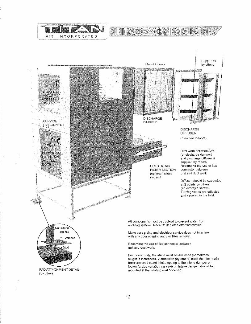
PAD ATTACHMENT DETAIL (by others)
OUTSIDE AIR FILTER SECTION (optlonal) slides into unit
Supported by others
DISCHARGE DIFFUSER
(mounted indoors)
Duct work between AMU (or discharge damper) and discharge diffuser is supplied by others. Recomend the use of flex connector between unit and duct work.
Diffuser should be supported at 2 points by others. (an example shown) Turning vanes are adj~jsted and secured in the field.
AU components must be caulked to prevent water from entering system Recau!k lift plates after installation.
Make sure piping and electrical service does not interfere with any door opening and / or filter removal.
Recoment the use of flex connector between unit and duct work,
For indoor units, the stand must be enclosed (sometimes height is increased). A transition (by others) must then be made from enclosed stand intake opeing to the intake damper or louver (a size variation may exist). Intake damper should be lT10lmted at the building wlal or ceiling.
12

SERVICE
DIS\ONNEiCT
f' t ·-~~'i!
" ELECTRICAL 'GAS TRAIN' jACCESS ,DOOR
Larger units have more legs
PAD ATIACHMENT DETAIL (by others)
I!I Nut
(optional) slides into unit
Sealant goes between each section before assembly. Bolts and caulking are in packing box. Recaulk seams and lifting plates after assembly.
2-PIECE UNIT ASSEMBLY DETAIL (by others)
13
Suppolied by others
(mounted indoors)
Duct work between AMU (or discharge damper) and discharge diffuser is supplied by others. Recomend the use of flex connector between unit and duct work.
Diffuser should be supported at 2 points by others. (an example shown) Turning vanes are adjusted and secured in the field
AI! components must be caulked to prevent water from entering system. Recaulk lift plates after installation.
Make SLife piping and electrical service does not interfere with any door opening and J or filter removal
For indoor units, the stand must be enclosed (sometimes height is increased). A transition (by others) must then be made from enclosed stand intake opening to the intake damper or louver (a size variation may exist). Intake damper should be mounted at the building wall or ceiling.

GENERAL IVIAINTENANCE As with any equipment or machinery, a maintenance program should be
implemented. A well maintained unit will perform efficiently for many years.
Equipment maintenance should include the following: 1. Cileck filters and clean or replace as needed. 2. Lube bearings. 3. Check belts and belt tension. (Do not over tension.) 4. Check all hardware (bearings, etc.) for tightness. 5. Check settings for all controls. 6. Check duct connections for leaks. 7. Re-caulk seams if needed. 8. Check burner and flame rod - clean if necessary. 9. Perform complete start-up procedure once per year (prior to heating season).
FILTERS Dirty or clogged filters will restrict air flow which in turn affects the burner operation.
Therefore, it is necessary to check filters on a regular basis. Cleanable filters can be removed from the filter rack and sprayed with a low pressure water. Always spray these filters in the opposite direction to air flow and apply new coating to filters when dry.
BURNER Maintaining the pilot assembly is essential to reliable operation. During pre-heating
season maintenance, the burner should be lit numerous times to confirm reliability. If ignition system components require servicing, pay attention to the following:
1. Handle porcelain spark rod and flame rod with care. Small cracks lead to intermittent ignition problems.
2. Midco burners utilize the pilot gas tube as a ground point for the ignition rod. Keep this grounding point free from scale or other contaminant build-up.
3. Ignition wire routing should remain separated from sheet metal cabinet to maintain optimal spark strength.
4. Dielectric grease is utilized inside of the ignition and flame sensor connection boots to limit potential for moisture in the connection.
5. Maintaining low pilot regulator output pressure typically produces reliable ignition. Excess pilot pressure creates a gas rich region that will not ignite consistently.
6. The pilot solenoid is disabled following main flame ignition. The low fire setting must be high enough to maintain a proper amplified flame rectification signal.
Check that burner baffles are firmly attached to each other and to the burner casting. Do not use excessive force on screws in burner casting. Clean burner baffles with a wire brush if necessary.
Burner orifices may need to be re-drilled due to rust or other build-up. Burners with aluminum castings will rarely require orifice cleaning. Use drill bit sizes listed below.
Fuel Type Burner Model Orifice Size Natural Gas Eclipse AH-MA 2.4 mm Bit Natural Gas Midco HMA-2 1/8" Bit
LP Gas Eclipse AH-MA 2.0 mm Bit LP Gas Midco HMA-2 #45 Bit
14
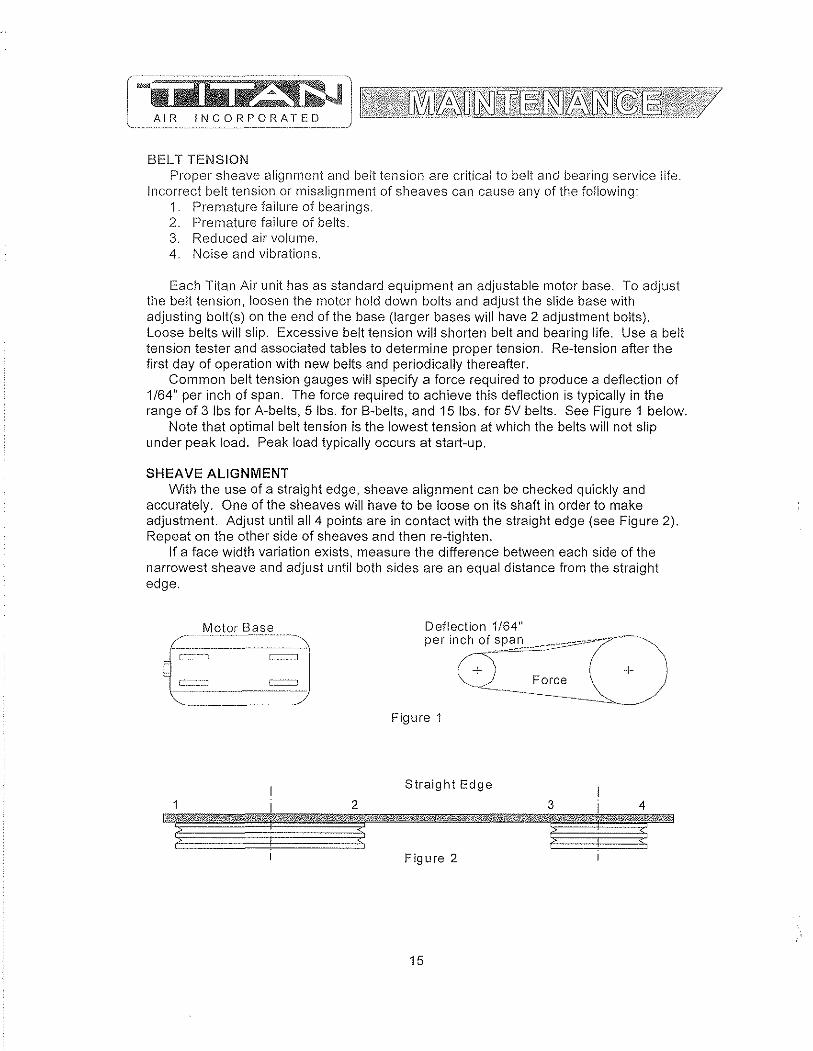
BELT TENSION Proper sheave alignment and belt tension are critical to belt and bearing service life.
Incorrect belt tension or misalignment of sheaves can cause any of the following: 1. Premature failure of bearings. 2. Premature failure of belts. 3. Reduced air volume. 4. Noise and vibrations.
Each Titan Air unit has as standard equipment an adjustable motor base, To adjust the belt tension, loosen the motor hold down bolts and adjust the slide base with adjusting bolt(s) on the end of the base (larger bases will have 2 adjustment bolts), Loose belts will slip, Excessive belt tension will sholien belt and bearing life, Use a belt tension tester and associated tables to determine proper tension, Re-tension after the first day of operation with new belts and periodically thereafter,
Common belt tension gauges will specify a force required to produce a deflection of 1/64" per inch of span, The force required to achieve this deflection is typically in the range of 3 Ibs for A-belts, 5 Ibs, for B-belts, and 15 Ibs, for 5V belts, See Figure 1 below,
Note that optimal belt tension is the lowest tension at which the belts will not slip under peak load, Peak load typically occurs at start-up,
SHEAVE ALIGNMENT With the use of a straight edge, sheave alignment can be checked quickly and
accurately, One of the sheaves will have to be loose on its shaft in order to make adjustment. Adjust until all 4 points are in contact with the straight edge (see Figure 2), Repeat on the other side of sheaves and then re-tighten,
If a face width variation exists, measure the difference between each side of the narrowest sheave and adjust until both sides are an equal distance from the straight edge,
Motor Base
e-~~-~==-=-""""""""'-: ~. [:"',,"::=~~::J t .. _.~ •• ".,~_.J
C=::.::J C~=:J . __ ._-_._----.. ---.~.~~---
Figure 1
Straight Edge
Figure 2
15

BLOWER BEARINGS Bearings must be checked during each periodic maintenance inspection. Bolts and
set screws should be checked for tightness and the bearings may need lubrication. The following is intended only as a guide to aid you in setting up your own schedule
LUBRICATION GUIDE FOR BLOWER BEARINGS
Ope rati n g co n d ilio n s. ___ -'B"'e"'a"'r"'i n",gLT-,-"-e!m~,,,p,,-. -l.(°..lF-1) ____ G"""re"'a"'s"'e'-'.!.l n",te"-r",v",,,a I Clean 32 - 120 6 - 10 months
120 - 150 1 - 3 months 150 - 200 1 - 4 weeks
Dirty 32 - 150 1 - 4 weeks 150 - 200 Daily - 1 week
Moisture 32 - 200 Daily - 1 week
MOTOR BEARINGS Motor bearings in a clean environment should be lubricated every 2 to 3 years.
Under more severe conditions of dirt or moisture, lubrication may be required every 6 months to 1 year. Typical motor bearing lubrication procedure follows:
1, Remove fill and drain plugs, 2, Clean drain port of hard grease (with wire if necessary), 3, Add grease (cavity should be no more than Yz ful!.), 4, Start motor and let run for 10 minutes, 5, Wipe off any drained grease and replace fill and drain plugs,
Avoid adding an excessive amount of grease since this a common cause of motor failure,
BLOWER Ensure that blower hub is securely fastened to shafL Inspect blower wheel and
blades for signs of damage or cracks, Clean blades if necessary to maintain proper balance and performance, Avoid use of excessive grease on blower bearings that can coat fan blades and attract dirt
16
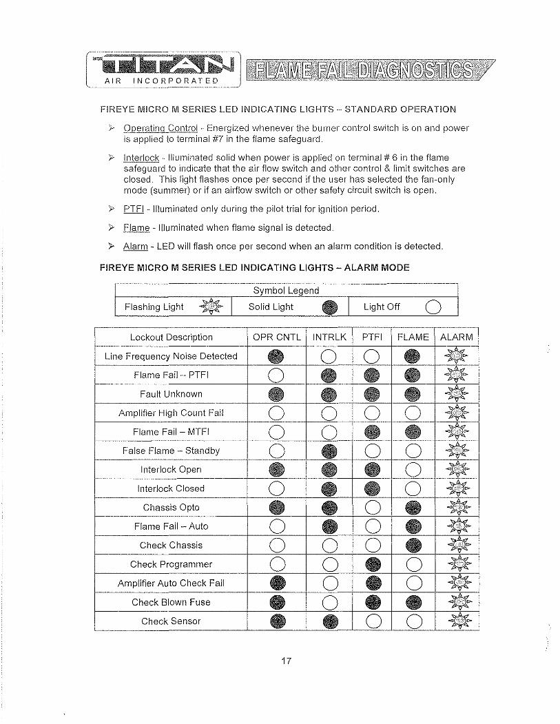
FIREYE MICRO M SERIES LED INDICATING LIGHTS - STANDARD OPERATION
'r Operating Control - Energized whenever the burner control switch is on and power is applied to terminal #7 in the flame safeguard.
}> Interlock - Illuminated solid when power is applied on terminal # 6 in the flame safeguard to indicate that the air flow switch and other control & limit switches are closed. This light flashes once per second if the user has selected the fan-only mode (summer) or if an airflow switch or other safety circuit switch is open.
}> PTFI - Illuminated only during the pilot trial for ignition period.
>- Flame - Illuminated when flame signal is detected.
>- Alarm - LED will flash once per second when an alarm condition is detected_
FIREYE MICRO M SERIES LED INDICATING LIGHTS - ALARM MODE
Symbol Legend
Flashing Light .. I Solid Light e I Light Off 0 r----· - ._--
Lockout Description OPR CNTL INTRLK PTFI FLAME ALARM
Line Frequency Noise Detected e 0 0 e ~~~ ~v <:::I.
Flame Fail - PTFI 0 __ e e e ~"~~ P~~ -_._ .... _. ._-
Fault Unknown e e_ e e .. -------,--_.-
Amplifier High Count Fail ____ 0 ____ __ 0 0 0 '<:;;.6.~ ~~~ .t{""~
---------_ .. _--- _ ..•. ,---_ ... _--~*--Flame Fail - MTFI 0 0 e e p"""",
-- ... _-_. .. False Flame - Standby 0 e 0 0 t---- - - .. Interlock Open e e e 0 ____ Interlock Closed 0 e e 0 .. --
p,,,,~
Chassis Opto e • 0 e ~~~ p/"~
Flame Fail - Auto 0 • 0 e .. Check Chassis 0 0 0 • * P"'<lo.
1---0 0 • 0 ";;oA~
Check Programmer 1>~.t" ---- • 0 • 0 * Amplifier Auto Check Fail --t-- e e .. Check Blown Fuse 0 • -
Check Sensor e e o 0 .. -- ----- ------
17
jjIJ£,,_Freguen£'L Noise Detected "" At start up, the MICI'(O M measLires the AC line to determine if the input is 50 Hz or 60 Hz and set its flag accordingly" As the system is running, line frequency is constantly monitored" Outside interference causing a momentary shift in line frequency could be from SCI'( controls, VFD's, etc"
Flam"," Fail - PTFI - No flame signal present at the end of pilot trial for ignition period"
Fault Unknown - A catch all message when, under certain high noise conditions, the lockout message may become garbled and not translatable into any existing message
Amplifier Count Fail - A message used to detect a failed amplifier module that would generate an inordinate amount of pulses to micro computer, usually due to a shorted transistor or oscillating electronic filter,
Flame Fail - MTFI - No flame signal present during main burner trial for ignition period"
Flame Fail - Standby - Flame signal present, for a constant 60 seconds, while control is in standby or off condition"
Interlock Open - Interlock safety circuit (terminal #6) has been detected open for longer than ten minutes during the purge cycle or during main flame period on MEP 562"
Interlock Closed - If selected by dip switches, air flow or interlock switch (terminal #6) is closed 30 seconds after the start of a cycle or when terminal #7 is closed" Titan Air does not use this function,
Chassis Opto - Opto coupler located on chassis has been found to be defective" Opto couplers are checked every 1/2 cycle of the AC main(s) to ensure they are off during the negative 112 cycle"
Flame Fail Auto - If dip switches selected for non-recycle, no flame is detected during the run cycle or main flame period"
Checl< Chassis - At beginning of cycle terminal #5 is energized,
Check Programmer - At beginning of cycle terminal #3 is energized or an internal diagnostics test for the Micro controller has failed"
Check Amplifier - Diagnostic problem with amplifier has been found"
Amplifier Auto Check - The amplifier is checked every 8 seconds by the micro computer to assure it is responding properly"
Check Blown Fuse - At the end of pilot try for ignition, no flame is detected and no power is present on terminal #3, indicating the fuse, located on chassis, is blown"
Check Scanner - The UV self check scanner (UV equipped units only) is producing flame pulses during the shutter closed period due to a malfunctioning shutter or a runaway UV tu be"
18
GENERAL START-UP INFORMATION Evon though Titan Air equipment is tested at the factory, it is not the type of
equipment you can throw the switch and walk away from. A complete start-up procedure must be performed.
The factory cannot duplicate the conditions the equipment will see in the actual installation (i.e. gas pressure, static pressure, desired control settings, etc ... ). For this reason there are field adjustments that have to be made. Performing a complete startup procedure will help ensure that correct adjustments are made and correct operation is verified. A step-by-step start-up procedure is provided on subsequent pages. While working through the start-up procedure, record information on the start-up checklist and return to Titan Air to validate the equipment warranty. The start-up checklist is provided on cardstock with Titan Air's address pre-printed on one side.
Because most component failures occur during start-up, it is very important that the function of every component be checked out during start-up, It is just as important that the start-up technician realize the malfunction of a component may be caused by other factors (Le. air flow, gas pressure, field wiring, etc ... ) and should fully investigate a component malfunction and its cause before replacing the component.
Titan Air checks out all returned components and has found approximately 70% of returned parts are in full operational condition. This history has proven that a little extra time invested in troubleshooting will often save the considerable investment in parts, time, and paperwork associated with replacing components,
SUGGESTED TOOLS AND INSTRUMENTS NEEDED FOR START-UP: Volt/Ohm Meter Ammeter Tachometer Thermometer Gas pressure manometer (-10" to a to +10" of water column typical scale) Air differential pressure manometer (-2" to a to +2" of water column typical scale) Standard Hand Tools.
Additional items for Maxitrol Series 14 or 44 temperature controls: ~ Y:; watt, 10,000 Ohm resistor
Additional items for FX Series temperature controls: ~ 10,000 Ohm resistor (supplied) ~ 1,000 Ohm resistor (supplied)
19

Valve Leal< Test This is a test for checking the closure tightness of the gas safety Sllutoff valve. It should be performed by trained and experienced technicians. This test should be part of the scheduled inspections and maintenance procedures.
1) Close the upstream manual gas valve. 2) Make sure manual test cock on leak test assembly is closed. 3) Remove the test plug on leaving side of gas valve. 4) Close the downstream manual gas valve. 5) Open the upstream manual gas valve. 6) Through the safety system enable the gas valve momentarily. 7) Immerse a )1,;" tube vertically into a jar of water. 8) Slowly open the test cock on the leak assembly. 9) Once the rate of bubbles through the test assembly stabilizes, count the number of bubbles appearing during the ten second time frame. Each bubble is approximately 0.001 cfh. 10) Do this test for each shut off valve.
Reference below leak test assembly and leakage rate chart
Pipe Size (in)
3/8 & 1/2
3/4 & 1
H/4 & 1-1/2
2
1-1/2
3
-
A
UPSTREAM MANUAL GAS COCK
Medium
.64 aas 1.57 LP .64 aas 1.57 LP .64 aas 1.57 LP .640as 1.57 LP .64 nas 1.57 LP .64 aas 1.57 LP
-
PRY J\
c
1/4 IN. (6 MM) FLEXIBLE TUBING
114 IN. (6 MM) ALUMINUM OR COPPER PIWT
D LEAK TEST TAP
E DOWNSTREAM MANUAL GAS COCK
BURNER
r JAR OR GLASS TUBING ~ " VVlTH WATER
.---=!+....!.....,
i i 1/2 (13 MM) t t
-o--+--~j -_-1 .! CUT AT
,
Allowable Leakaae SCCH 294 188 _____ 301 192 .. _ .... _ .•. _-532 341 578 370 752 481 . --925 592
20
45 DEGREE ANGLE
Max. # of Bubbles in 10 Sec. 7 4 ._------7 .. -5 13 8 15 9 19 12 24 15
Min. # of sec. for 10 bubbles 13 20.4 ---12.7 19.9 7.2 11.2 6.6 10.3 5.1 8 4.1 ---6.5

'RTcJ Solutions
DlRECT FIRED DIGrrAL 'fEMPERATURE CONTROL INSTALLATION, OPERATION, AND MAINTENANCE MANUAL
This manual covers the following products:
DFC-I
DFC-2
DHS
Standard direct fired temperature control 0-24VDC output
Direct fired control with integraI40-90"F (4-32"C) dial 0-24VDC output
Temperature senor 40-2S0"F (4-121 "c)
DFTD-XXXX Temperature dialS selectable ranges
DAT-12 D;scharge a;r tube
PWM-IOV PWl'vI to lOV output converter
Table of Contents Overview ... Specifications ....
Power Requirements .. DFC Ambient Temperature Limits .. DFTSjDFrD Ambient Temperature Limits ... Accuracy ..
Installation , ... Wiring ..
Standard control with remote set point .. Stondard control with integral set point.... Optional room space control .. Optional multiple sel point tem.perature control..
Operation .. Start up .. Sequence of operation .. Calibration .. Troubleshooting ... DFTS and DFTD Resistance chart ..
DOC# TOOOll1.14.2006 DFC-I O&M
Ph. (919) 845-1579 Fax (919) 845-8102
1
www.RTC-Solutions.com Email:[email protected]
, """""""".2
"""""",2
, .... , .... , , ..... , .. , 2 ..,',.,', .. ,', ... , .. ,. 2
"', .... " .. ,.2 ,. """",.2 ". , .. ".". 2
. .. """"",2
. .... , ................................ 2 . .". """""","',"",. 3
"""""""",.3
. .. """"""" 3 . "" .. ",4
, "',. "",.4 "'" """"""""",4
"""""".,.4 " .. , ",.4
,. "".4
755 Sw 120l l> Way Davie, FL 33325
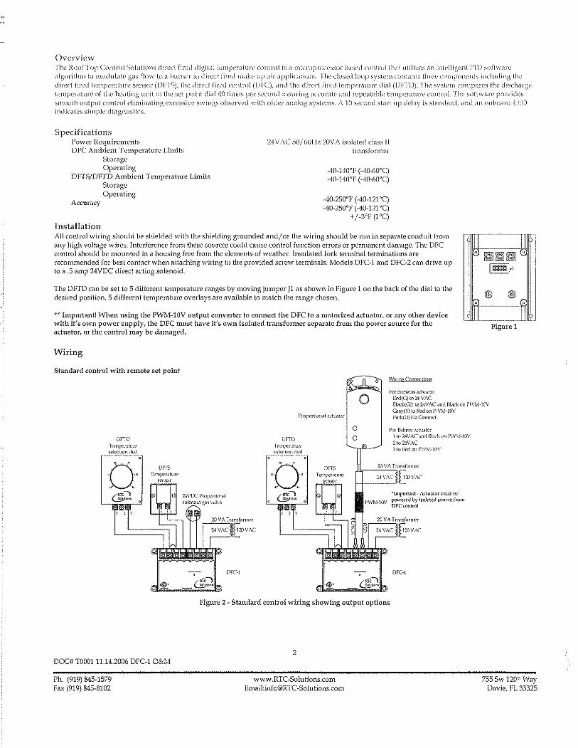
Overview rJw {{,lOr Top Conlrul Solu lions d ir"l'l fired tli(;ilc11 1<.'mp:l'dlul'l' <.'(mlml is d microprGl:l'ssllj hlSl~d nmlml tiL,lt utili/,(:s dn inll'llii\l'nl 1'1]) suj'[w<lrl' (\ii"orithm to ll\,)dulatc g<lS flow to il burner in direct fired Illdke up ilir applic<lliol1s, The closed loop system conl<lins Ihn:,; UlmpOnl'nts including the dired fin'd lempcnllun' sensu)" (nFTS), the dirl'd fired nmlrol (nrC), and tlw direct fired kmpel"illul"(, didl (U),"rJ)). The system cOHlpares t!w dischdl'gl: lcmj)l'rillurc of the healing Ullitlo the set poinl dinl ,W limes per second insuring deeUl'dt,' and )"('pCillilbk l\:mpl'l'alu)"(' controL Tlw softwnr(' provi(iL's smooth output control eliminating exu;ssivl' swings obsl:rv('d with o!tkl" (llWlog s),s[el11s. ;\ 10 second stilrl up delay is slimdilrd, nnd an ollbo(lrd LF)) indicd!es simple di<lgnnstics
Specifications Power Requirements DFC Ambient TemperMure Limits
Storage Opemting
DFTS/DFTD Ambient Temp<'l"ature Limits Storage Operating
Accuracy
Installation
24 \lAC 50/601-1:.>; 20V J\ isolated class IJ trill1sfonner
AO-HO"F (-40-60"C) AO-140"F ("lO-60'C)
-40-250"1' (-40-121"C) -40-250"F (-40-121'C)
+ / _3"1' (1"C)
All control wiring should be shielded with the shielding grounded and/ Or the wiring should be nm in separate conduit from any high voltage wires. Interference from these sources could cause control function errors Or permanent damage. The DFC control should be rnounted in a housing free from the elements of weather. Insulated fork tenninal terminations are recommended for best contact when attaching wiring to the provided screw terminals. Models DrC-l and DFC-2 can drive up to a .5 amp 24 VDe direct acting solenoid.
The DFTD can be set to 5 different temperature ranges by moving jumper J1 as shown in Figure 1 on the back of the dial to the desired position. 5 different temperature overlays are available to match the range chosen.
*~- Important! -When using the P'WM-10V output converter to connect the DFe to a motorized actuator, or any other device with it's own power supply, the DFe must have it's own isolated transfomler separate from the power source for the actuator, or the control may be damaged,
Wiring
Standard control with remote set point WlfUP ('QIlDfyllQll"
For SK!l"«'11S actuator IlB.i(G) to 24 VAC
IH-===-)}jli I
Figure 1
!31~ck(GO) \0 2WAC ~nd IJiJ(kon I'WM·l0V CraY(l') to R<?cIon FlVlvl·1(\V
DFTD Tl'ln)X'r"t"rl' select"'" (iI,11
a DI'IS Tl'mp<"I,ltun,>
S('nS':>f
DOC# TOOOl11.14.2006 me-l O&M
Ph. (919) 845-1579 Fax (919) 845-8102
2·\VOCI'f('f",rt"IJ'kI1 sOlcnold gJS v.,ll'c
DrC-l
DFrO h-n'pe,.ltull' 'eie.,tlOll <il.ll
" . O· .
DFTS Temp'cf"ture
sensor
o o
'"
I'W:vj·lOV
Fink(U) 1':0 Conncocl
For L'-cll!l1o adtt.)(Or 1 to 2·1\IAC ,mel BLick ()E1l'\\'cv!-lOV 2to2WAC 3to j<'x!on J'\VM·!(lV
'jJnp()r!,lI1t- Adll,llor lJlust tw powered by isolat\'d 501ln'\, from DFC(OnlroI
DFC-l
Figure 2 ~ Standard control wiring showing output options
2
www_RTe~Solutions.com
Emaii:[email protected] 755 Sw 1201), Way
Davie, FL 33325

S[,llHi.ard conirol with lntl!gf<ll sd point
Optional room space control
DFlD T,-n1J>~'''U''
r-~l D~"'~O ~o~Qo , , It, ~!\ , ,
DFIS
T""I'H''''''
---- ------L-..=1 ==;=jl
Figure 3 ~ Control with integral se\-point
FigllIC 4 - Room space control with thennostat Figure 5 ~ Room space conh'ol with digital space control
A standard make or break thermostat with normally open contacts can be connected between terminals 1 and 2 as shown in Figure 4. When COImected in this way the thermostat may be set for a desired room temperature for space control applications. Potentiometer Rl on the back of the DFTD sets how much the temperature will increase by when the room thermostat calls for more heaL When the room thermostat is satisfied, the discharge temperature will rel"um to the temperature set on the dial on the front of the DFTD. For proportional morn space control, the DFC~l can be connected as shmvn in Figure 5. See RTC~11iterature for details.
Optional multiple set point temperature control
v,~, AC
Figure 6 • Control with multiple set points
More than one temperature dial can be connected as shown in Figure 3 for applications such as paint spray booths or process control.
DOC# T0001 11.14.2006 DFC-1 O&M
Ph. (919) 845-1579 Fax (919) 845-8102
3
www.RTC·Solutions.com Email:info@RTC~Solutions.com
755 Sw 12011< Way Davie, FL 33325

Operation
S(ar( up Selting I(l\', lil\' - l'ih-' 111inillluill firing I'd Iv Jl1dy h,,' sl'l by I'('llloving tIll' wire CJ'Onl It.'nnilldi numlwr 6 1)11 ilw I )j,(_' \'(mll'\,I_ i'his dis\ ()nlwd~ tlw p\)\\'\'I' 1\) lIll' (()11lr()1 1/,llv(' R,'i'cl' [n tIl<" (,(lIlll'ui v,1I1/(' !l1dnuL,duJ\'s iilc'J',ltUl'l' lor this iHljusll1wnt
Setting hil~h fin' nw maximulll firing r,)\F 11\(1)' he S('[ by removing 111l' vvin' from (('I'nlinill numb('l ,1 on lIw ])re contmi. This disconnects Ill\' discharge air Sl'nsor and sets the oUlput to the control v,live to it's maximum. Rd('l' 10 Ilw control vill\-'\., n1ilnllfiKtures liler<1ture for this adju:,lml~llt
Sequence of operation Upon applying pmver to the OFe (onlrol the 10 second stMt up deJay will begin indicated by a slow blinking LE)) (about OIK'l' every 2 seconds) on the [ace of the control. 1\[ter the start up deJay has completed, the U::D will turn solid and the control will begin modulating the output as required. Any system errors are indicated by a filsl blinking LED (about twice per second) for instance when the discharge air sensor is disconnected or outside of the non))al operating range.
Calibration The lem.perature control should maintain an accuracy of +/- 3"F (rq. In the event thai the discharge is inaccurate due to duct losses the control may be calibrnted in two ways, The potentiometer on the face of the DFC labeled" ADJUST" will adjust the discharge tempewture by +/- 10"F (5°C) when rotated. Hotating it clockwise \vill increase the tempenlture and counter clockwise will decrease the temperature. The system may also be adjusted f!'Om the DFTD if installed by adjusting potentiometer 1<3 on the back in the same manner as the DFC procedure above.
Troubleshooting The DFC control provides some diagnostics via the on board LED labeled "POWER/ST ATU5". A system fault is indicated by a fast blinking LED (about twice per second). This usually indicates that the sensor or dial arc either disconnected or improperly wired. Check all connections per the included wiring diagrams. The fault also may be caused by a damaged sensor or dial. Both devices may be tested with an Ohmmeter by removing the wires from the DFC control and measuring across the device, The devices should measure between 12.SK and 7K OHMS, If there is a fault light and the devices measure the proper resistance then the control may be damaged. If there is no fault light but the system is not modulating properly you may check the control output by repeating the start up procedure and measuring terminals 5 and 6 on the DFC as follows.
For DFC-l and DFC-2 Remove the wire from terminal number 4 on the DFC control and measure the voltage across terminals 5 and 6 with a voltmeter. The meter should read from 20 to 24 Volts, If it does not, disconnect the wires from the valve and measure the output without the valve connected. If it reads 20 to 24 Volts, refer to the valve manufactures literature for troubleshooting the valve. If it does not the control may be damaged.
DFT5 and DFfD Resistance chart
DCX# T000111.14.2006 DFC-l O&M
Ph. (919) 845-1579 Fax (919) 845-8102
4
www.RTC-Solutions.com Email:[email protected]
7555w 120111 Way Davie, FL 33325

~~liNSON CONIT<t:3LS ProductfTechnical Bulletin
Issue Date A419
April 4, 2008
A419 Series Electronic Temperature Controls with Display and NEMA 1 or NEMA 4X Watertight Enclosures
The A419 series controls are single-stage, electronic temperature controls with a Single-Pole, Double-Tilrow (SPOT) output relay. They feature a lockalJle front-panel touchpad for setup and adjustment, and a Liquid Crystal Display (LCD) for viewing the temperature and status of other functions. A Light-Emitting Diode (LED) indicates the controls' output relay OnlOff status. The A419 controls are available in 24 VAC or 120/240 VAC powered models.
The A419 controls have heating and cooling modes, adjustable setpoint and differential, an adjustable anti-short cycle delay, and a temperature offset function. The setpoint range is -30 to 212'F (-34 to 100'C). The controls feature remote sensing capability and interchangeable sensors. The A419 controls are available in either NEMA 1, high-impact plastic enclosure suitable for surface or DIN rail mounting or NEMA 4X watertight, corrosion-resistant surface-mount enclosures.
Figure 1: A419 Temperature Control with NEMA 1 Enclosure and A99 Temperature Sensor
Features and Benefits
Easy-to-Read Front-Panel Liquid Crystal Display
Wide Temperature Differential Adjustment Range (1 to 30F' or C')
Adjustable Anti-Short Cycle Delay (0 to 12 Minutes in i-Minute Increments)
Switch-Activated Temperature Offset Function
High-Impact, Thermoplastic NEMA 1 or NEMA 4X Watertight, Corrosion-Resistant Enclosures
Lockable Front Panel Touchpad
Low- and Line-Voltage Models
© 2008 Johnson Controls, Inc. Code No. LlT-125188
Displays the sensed temperature and control-function status clearly; custom icons on the display indicate the control and system status at a glance
Allows the user to set a precise (1 F' or C') temperature differential from 1 to 30F' or C'; providing a much tighter differential than electromechanical controls
Ensures that the output relay remains off for a user-set time delay, which helps avoid hard starts, nuisance overload outages, and unnecessary equipment wear
Allows the user to shift the cut-in and cutout setpoints by an adjustable offset based on the status of a user-installed, external switch, such as a time clock
Increase application options, allowing surface and snap-fit DIN rail mount, or Watertight surface mount
Allows easy set up and adjustment of the A419 control setpoint, differential, and other functions; a concealed jumper locks the touchpad, and deters unauthorized adjustment of the control settings
Provide options for most refrigeration and HVAC control-voltage applications
1 www.johnsoncontrols.com

Application
IMPORTANT: The A419 Series Temperature Controls are intended to control equipment under normal operating conditions. Where failure or malfunction of an A419 Series Control could lead to an abnormal operating condition that could cause personal injury or damage to the equipment or other property, other devices (limit or safety controls) or systems (alarm or supervisory) intended to warn of or protect against failure or malfunction of the A419 Series Control must be incorporated into and maintained as part of the control system.
The A419 Electronic Temperature Control can be used to control a wide variety of single-stage refrigeration or Heating Ventilating, and Air Conditioning (HVAC) equipment. Typical applications include:
• retail store display freezers and reach-in coolers
• supermarket display cases for produce/meats
• retail store walk-in coolers and freezers
• boiler operating control (used as a thermostat)
• condenser fan cycling or staging
• cooling tower pump and fan control
• space and return air temperature control
FCC Compliance
This device complies with Part 15 of the FCC Rules. Operation is subject to the following two conditions: (1) this device may not cause harmful interference, and (2) this device must accept any interference that may cause undesired operation.
This equipment has been tested and found to comply with the limits for a Class A digital device pursuant to Part 15 of FCC rules. These limits are designed to provide reasonable protection against harmful interference when this equipment is operated in a commercial environment. This equipment generates, uses, and can radiate radio frequency energy and, if not installed and used in accordance with the instruction manual, may cause harmful interference to radio communications. Operation of this equipment in a residential area is likely to cause harmful interference, in which case the user will be required to correct the interference at his or her own expense.
Canadian Compliance Statement
This digital apparatus does not exceed the Class A limits for radio noise emissions from digital apparatus set out in the Radio Interference Regulations of the Canadian Department of Communications.
Dimensions
1
4-- 2-318~_.~1 (61) i
I , .
o 0
DIN Rail
1-9/16 ~ ~ (11)
l Sensor
t: I, (520) •
(6)
[ [
[
(!} ··=-==·='ili----.·-------.·
=,ii0ifi~ - - t CJ t, a 1(1~7)
~k:"~ "t-.,] .' III (102)
~
I
, 2-3/8->-1 (61)
M-f
2-3/8
7/8---- (61)
(i2) ~ 7/8 (1/2 in. Trade Size) (22) Conduit Hole
Figure 2: A419 Temperature Control with NEMA 1 Enclosure, Dimensions, in.l(mm)
-oil!: 2-114 )0 1~1/16t""
~ (56) ~--l-~J~~-=~~-" .... "'m'-'"~,I 'J..' M19 J...._ --- .
II 6-5/8 (168)
Figure 3: A419 Temperature Control with NEMA 4X Watertight, Corrosion-resistant,
Enclosure, Dimensions, in.l(mm)
2 A419 Series Electronic Temperature Controls with Display and NEMA 1 or NEMA 4X Watertight Enclosures Productffechnical Bulletin
Figure 4: A419 Temperature Control with NEMA 4X Enclosure and A99 Temperature Sensor
Operation Overview The A419 control's front-panel, LCD, LED, and the A419 control functions are described below. See the Adjustments section for instructions on setting up and adjusting the A419 control.
A419 Control Front-Panel
The front panel of the A419 control has a three-button touch pad and LCD for adjusting control function values, and an LED indicator that displays the On/Off status of the SPOT output relay. See Figure 5.
Temperature Offset Indicator
Temperature Units Indicator
Operating Mode Indicator
Liquid Crystal Display
MENU Button
DOWN Arrow Button
UP Arrow Button
Output Relay Status Indicator
LED
Figure 5: A419 Control Front-Panel with Display
Liquid Crystal Display
During normal operation, the LCD displays the temperature at the sensor, the units of temperature ('F or 'C), and an icon indicating if the control is set for Heating (<1) or Cooling (*) mode. The LCD also displays BIN if the Temperature Offset function is activated. See Figure 5.
During control set up or adjustment, the LCD displays the control functions and their values (settings), After 30 seconds of inactivity, the display returns to the sensed-temperature display. See the Adjustments section to adjust the control setting.
Output Relay Status Indicator LED
A green LED on the control's front panel illuminates when the SPOT output relay is energized and the Normally Open (N,O.) contacts are closed. See Figure 5.
A419 Control Definitions
Cut-in is the temperature at which the N.O. contacts on the SPOT output relay close.
Cutout is the temperature at which the N,O contacts on the SPOT output relay open.
A419 Functions Set at the Front-Panel
Setpoint (SP) establishes the temperature value that energizes or de-energizes the output relay, depending on the user selected mode of operation. The control may be set either to cut in or to cut out at Setpoint. See the Coofing/Heating and Setpoint Modes. The Setpoint range is -30 to 212'F (-34 to 100'C).
If Setpoint mode is Cut-in, Setpoint is the temperature value that closes the N.O. contacts, If Setpoint mode is Cutout, Setpoint is the temperature value that opens the N.O. contacts. See Figure 7 and Figure 8.
Differential (dIP) establishes the difference in temperature (in F' or CO) between the cut-in and cutout values, The differential is set relative to Setpoint and may be set from 1 to 30Fo or Co. See Figure 7 and Figure 8,
Anti-Short Cycle Delay (ASd) establishes the minimum time that the N.O. contacts remains open (after reaching cutout) before closing again. The delay overrides any Load Demand and does not allow the N,O. contacts to close until the set time-delay value has elapsed. See Figure 6. When the delay is activated, the LCD alternately flashes the sensor temperature and ASd, The delay may be set for 0 to 12 minutes in 1-minute increments,
A419 Series Electronic Temperature Controls with Display and NEMA 1 or NEMA 4X Watertight Enclosures ProductiTechnical Bulletin 3

For example, if the anti-short cycle delay is set for l minutes, the A419 control will no! restart the equipment for '7 minutes after the equipment has cut out, even if the cut-in temperature value is reached during the delay. If the temperature reaches the cut-in value during the delay period, the display flashes between the sensed temperature and ASd, indicating that the next On-cycle is being delayed. After the set delay time has elapsed, the A419 control returns to normal operation, restarts the equiprnent (if cut-in has been reached), ASd stops flashing, and the LCD reverts to the normal operating display.
Note: Any interruption in supply power to the A419 control activates the anti-short cycle delay.
TIme)l Load Demand ,~ Ovenidden
~ LLoadDemand
~OUIPutStatus AnliMshort
Cycle Delay
Figure 6: Anti-short Cycle Delay
Sensor Failure Operation (SF) establishes how the A419 control operates the eqUipment in the event of a sensor or sensor-wiring failure. The A419 control may be set to run the equipment continuously or to shut it down if the sensor or sensor wire fails. When a failure is detected the LCD flashes SF alternately with OP if the sensor circuit is open, or SF and SH if the sensor circuit is shorted. The control implements a i-minute delay before initiating a failure response to allow for verification of the failure condition and to avoid nuisance failure indications.
Temperature Units establishes the units of temperature (F' or C') displayed on the LCD.
Temperature Offset (OFS) establishes the value of setpoint-shift (in F' or CO) applied to Setpoint (and Differential) when a (user-installed) circuit is closed between the binary input (BIN) and common (COM) terminals. The offset value may be set from 0 to 50F' or C'.
The Temperature Offset function is used to reset the Heating Setpoint to a lower temperature (secondary) setpoint or reset the Cooling Setpoint to a higher temperature (secondary) setpoint by the temperature value set in Temperature Offset.
The BIN and COM terminals may be connected to a (user-supplied) external switching device, such as a time clock, that has a set of Single-Pole, Single-Throw (SPST) contacts. Closing a circuit between the BIN and COM terminals activates the Temperature Offset. See Wiring.
This function enables the control to alternate between two temperature setpoints based on the position of the binary input switch. The difference between the primary and secondary setpoints (in F' or C') is set in the Temperature Offset function (OFS) using the touchpad. See Selling Olller Functions.
Table 1 shows an example of Temperature Offset.
Table 1: Temperature Offset Example
Mode of Setpoint
Temperature Secondary Operation Offset Value Setpoin!'
Cooling 70' 8' 7SO Heating 700 80 62'
Setpotnt when ClrcUlt between broary Input terminals (BIN and COM) is closed
When the circuit is closed between the binary input (BIN) common (COM) terminals, the offset function is enabled and the A419 control cycles on the secondary setpoints. B/N is displayed on the LCD above the 'F or 'C symbol when the offset is enabled. See Figure 5.
A4i9 Control Functions Set by Jumper Position
For instructions on positioning jumpers, see Positioning the Jumpers in the Adjustments section. Refer to Figure 12 and Figure 13.
Touchpad Lock: The jumper at P5 establishes whether the touch pad is locked or unlocked. Locking the touch pad deters accidental or unauthorized changes to all of the function parameters.
Heating/Cooling Mode is established by positioning the jumper on the top two pins of the P4 jumper. See Figure 13.
Setpoint Mode: Removing or installing the lower jumper at P4 establishes whether Setpoint is the cut-in temperature or cutout temperature. See Figure 13.
Cooling/Heating and Setpoin! Modes
The A419 control may be in four operating modes: Cooling/Cut-in, Cooling/Cutout, Heating/Cut-in, and Heating/Cutout. Position the jumpers located on the circuit board under the A419 control cover to set the desired mode of operation. See Positioning the Jumpers.
In Cooling/Cut-in mode the differential is below Setpoint. The output relay energizes and the LED illuminates when the temperature rises to Set point. When the temperature drops to Setpoint minus the differential value, the relay and LED de-energize.
4 A419 Series Electronic Temperature Controls with Display and NEMA 1 or NEMA 4X Watertight Enclosures ProducUTechnical Bulletin
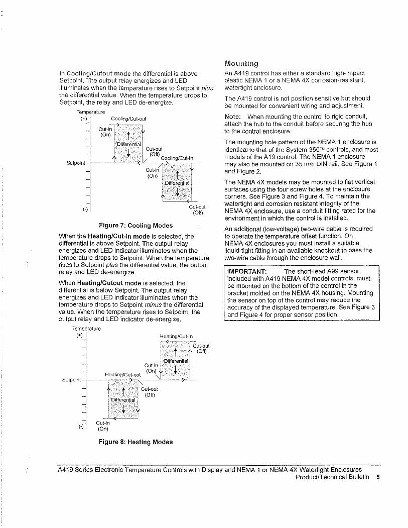
In CoolinglCutout mode the differential is above Set point. The output relay energizes and LED illuminates when the temperature rises to Setpoint plus the differential value. When the temperature drops to Setpoint, the relay and LED de-energize.
Temperature (+) Cooling/Cut-out
Selpoint
(-)
->-_ .. _. Cut-in (On) t
Differential Cut-out
(Off) Cooling/Cut-in
~~~)g,~.e.j ..• ~.e.··~ .. ti ••. ·.a.,.··.I.J.r:-..... <J ...••..
CuI-out (Off)
Figure 7: Cooling Modes
When the Heating/Cut-in mode is selected, the differential is above Setpoint. The output relay energizes and LED indicator illuminates when the temperature drops to Set point. When the temperature rises to Setpoint plus the differential value, the output relay and LED de-energize.
When Heating/Cutout mode is selected, the differential is below Setpoint. The output relay energizes and LED indicator illuminates when the temperature drops to Setpoint minus the differential value. When the temperature rises to Setpoint, the output relay and LED indicator de-energize.
Temperature (+)
Cut-in (On)
Heating/Cut-in
L ~, :'-'-- ",,-. -'lcut-out t. (Off)
Differential
r Heating/Cut-out """ Selpoint +----r,---,_+-,,_-----'''-'_-'---~L...
(-) Cut-in (On)
Differential
Cut-out (Off)
Figure 8: Heating Modes
Mounting An A41 9 control has either a standard high-impact plastic NEMA 1 or a NEMA 4X corrosion-resistant, watertight enclosure.
The A419 control is not position sensitive but should be mounted for convenient wiring and adjustment.
Note: When mounting the control to rigid conduit, attach the hub to the conduit before securing the hub to the control enclosure.
The mounting hole pattern of the NEMA 1 enclosure is identical to that of the System 350'" controls, and most models of the A 19 control. The NEMA 1 enclosure may also be mounted on 35 mm DIN rail. See Figure 1 and Figure 2.
The NEMA 4X models may be mounted to fiat vertical surfaces using the four screw holes at the enclosure corners, See Figure 3 and Figure 4, To maintain the watertight and corrosion resistant integrity of the NEMA 4X enclosure, use a conduit fitting rated for the environment in which the control is installed.
An additional (low-voltage) two-wire cable is required to operate the temperature offset function, On NEMA 4X enclosures you must install a suitable liquid-tight fitting in an available knockout to pass the two-wire cable through the enclosure wall.
IMPORTANT: The short-lead A99 sensor, included with A419 NEMA 4X model controls, must be mounted on the bottom of the control in the bracket molded on the NEMA 4X housing. Mounting the sensor on top of the control may reduce the accuracy of the displayed temperature, See Figure 3 and Figure 4 for proper sensor position.
A419 Series Electronic Temperature Controls with Display and NEMA 1 or NEMA 4X Watertight Enclosures ProductiTechnical Bulletin 5
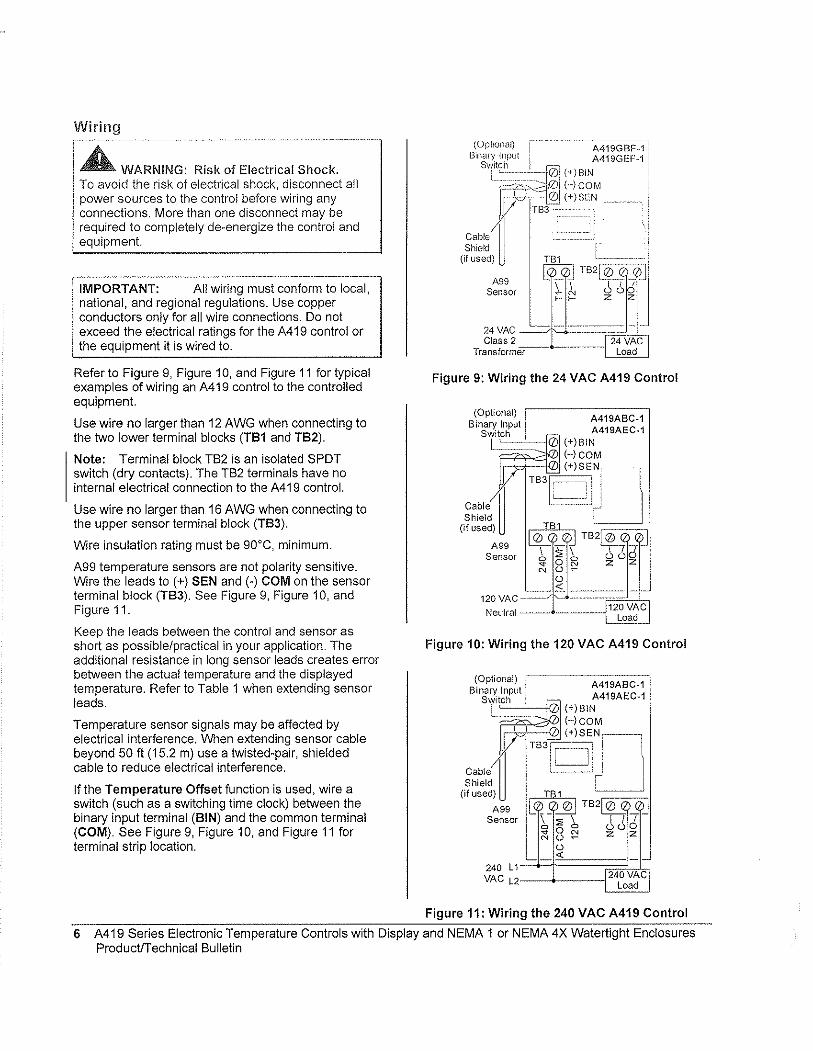
Wiring
A WARNING: Risk of Electrical Shock. To avoid the risk of electrical S110ck, disconnect all power sources to the control before wiring any connections. More than one disconnect may be required to completely de-energize the control and equipment.
IMPORTANT: All wiring must conform to local, national, and regional regulations. Use copper conductors only for all wire connections. Do not exceed the electrical ratings for the A419 control or the equipment it is wired to.
Refer to Figure 9, Figure 10, and Figure 11 for typical examples of wiring an A419 control to the controlled equipment.
Use wire no larger than 12 AWG when connecting to the two lower terminal blocks (TB1 and TB2).
Note: Terminal block TB2 is an isolated SPOT switch (dry contacts). The TB2 terminals have no internal electrical connection to the A419 control.
Use wire no larger than 16 AWG when connecting to the upper sensor terminal block (TB3).
Wire insulation rating must be 90°C, minimum.
A99 temperature sensors are not polarity sensitive. Wire the leads to (+) SEN and (-) COM on the sensor terminal block (TB3). See Figure 9, Figure 10, and Figure 11.
Keep the leads between the control and sensor as short as pOSSible/practical in your application. The additional resistance in long sensor leads creates error between the actual temperature and the displayed temperature. Refer to Table 1 when extending sensor leads.
Temperature sensor signals may be affected by electrical interference. VVihen ex1ending sensor cable beyond 50 It (15.2 m) use a twisted-pair, shielded cable to reduce electrical interference.
If the Temperature Offset function is used, wire a switch (such as a switching time clock) between the binary input terminal (BIN) and the common terminal (COM). See Figure 9, Figure 10, and Figure 11 for terminal strip location.
(Optional) A419GBF-11 Binary Input A419GEF-1 !
Switch I r--' I
I' ,'::~J0! (+)BIN ~-A".:::J01 HCOM
[
'led ':::"1.'2: (+) SEN •
~ 183 .1
~~~~ - I (If used) TB1
l).0~ T:!,B~zl-lQ, A99
Sensor 1-1- Z ZJ
24VAC __ . - -----Class 2 24 VAC
Transforme-r-- - - - --- ~ Load
Figure 9: Wiring the 24 VAC A419 Control
(Optional) A419ABC-1 Bmary Input A419AEC-1
swmtCh i]) (+)BIN HCOM
[ (+)SEN,
cabll TB3g ,l Jl Shield ~ I
(if U$ed~99 I ~ T~B~f~ TB2r:=-:lif ~:-:::-1'7rl Sensor Sf 0 ~ ~ ()~
N U -U
~ --120VAC- ~- ~
Neutral - -- ----- -IT vAel Load~
Figure 10: Wiring the 120 VAC A419 Control
(Optional)
"""~ Cable ~
I:'--~-'-t A419ABC-1 A419AEC-1 i]) (+)8IN
HCOM
TB3l[~;ET-l Shield
(if used)
A99 Sensor
240 L1 VAC L2
j I ~Bt2J TB2@i!j'.i 0
\ " ~ t1J 6 0
;:\ ON Z Z U -U
'" 240 VAC Load
Figure 11: Wiring the 240 VAC A419 Control
6 A419 Series Electronic Temperature Controls with Display and NEMA 1 or NEMA 4X Watertight Enclosures ProductlTechnical Bulletin
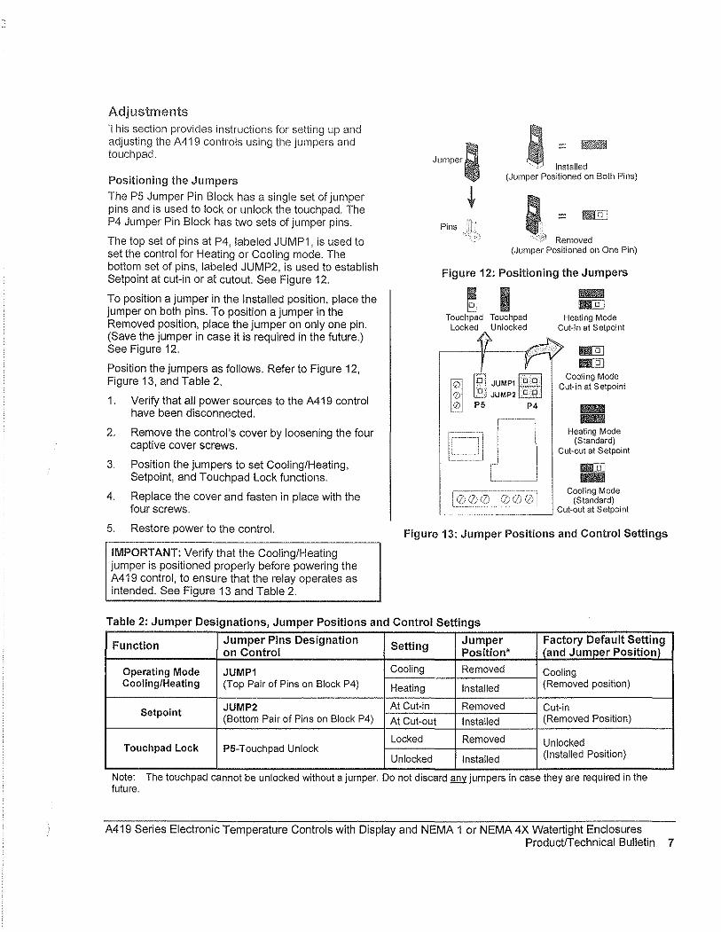
Adjustments This section provides instructions for setting up and adjusting the A419 controls using tl1e jumpers and touchpad.
Positioning the Jumpers
The P5 Jumper Pin Block has a single set of jumper pins and is used to lock or unlock the touchpad. The P4 Jumper Pin Block has Wio sets of jumper pins.
The top set of pins at P4, labeled JUMP1, is used to set the control for Heating or Cooling mode. The bottom set of pins, labeled JUMP2, is used to establish Setpoint at cut-in or at cutout. See Figure 12.
To position a jumper in the Installed position, place the jumper on both pins. To position a jumper in the Removed position, place the jumper on only one pin. (Save the jumper in case it is required in the future.) See Figure 12.
Position the jumpers as follows. Refer to Figure 12, Figure 13, and Table 2.
1. Verify that all power sources to the A419 control have been disconnected.
2. Remove the control's cover by loosening the four captive cover screws.
3. Position the jumpers to set Cooling/Heating, Setpoint, and Touchpad Lock functions.
4. Replace the cover and fasten in place with the four screws.
5. Restore power to the control.
IMPORTANT: Verify that the Cooling/Heating jumper is positioned properly before powering the A419 control, to ensure that the relay operates as intended. See Figure 13 and Table 2.
Jumper;
t Pins
e! "" ~ I Installed
(Jumper Positioned on Both Pins)
; Rill ",,<'~ Removed
(,Jumper Positioned on One Pin)
Figure 12: Positioning the Jumpers
Touchpad Touchpad Locked Unlocked
~ ~
Heating Mode Cut-in at Selpoinl
I!IIDD I!IIDD
Cooling Mode Cut-in at Setpoint
fIIiIIIIilIlI fIIiIIIIilIlI
Heating Mode (Standard)
Cut-out at Setpoint
fl!lUjJ fIIiIIIIilIlI
Cooling Mode (Standard)
Cut-out at Setpoint
Figure 13: Jumper Positions and Control Settings
Table 2: Jumper Designations Jumper Positions and Control Settings ,
Function Jumper Pins Designation Setting Jumper Factory Default Setting on Control Position* I (and Jumper Positioni
Operating Mode JUMP1 Cooling Removed Cooling Cooling/Heating (Top Pair of Pins on Block P4) Heating Installed (Removed position)
Setpoint JUMP2 At Cut-in Removed Cut-in (Bottom Pair of Pins on Block P4) At Cut-out Installed (Removed Position)
Locked Removed Unlocked Touchpad Lock P5-Touchpad Unlock (Installed Position) Unlocked Installed
Note: The touch pad cannot be unlocked Without a Jumper. Do not discard gm: Jumpers In case they are reqUIred In the future.
A419 Series Electronic Temperature Controls with Display and NEMA 1 or NEMA 4X Watertight Enclosures ProductlTechnical Bulletin 7
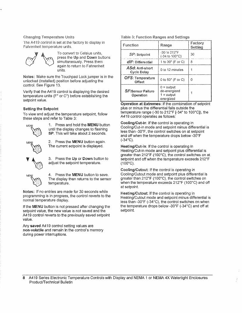
Changing Temperature Units
The A419 control is set at tile factory to display in Fahrenheit temperature units.
rnYJ press the Up and Down buttons "' ~ To convert to Celsius units,
V simultaneously. Press them again to return to Fahrenheit units.
Notes: Make sure the Touchpad Lock jumper is in the unlocked (installed) position before adjusting the control. See Figure 13.
Verify that the A419 control is displaying the desired temperature units (F' or CO) before establishing the setpoint value.
Setting the Setpoint To view and adjust the temperature setpoint, follow these steps and refer to Table 3:
MEN~
MEN~
'~ MEN~
1. Press and hold the MENU button until the display changes to flashing SP. This will take about 2 seconds.
2. Press the MENU button again. The current setpoint is displayed.
3. Press the Up or Down button to adjust the setpoint temperature.
4. Press the MENU button to save. The display then returns to the sensor temperature.
Notes: If no entries are made for 30 seconds while programming is in progress, the control reverts to the normal temperature display.
If the MENU button is not pressed after changing the setpoint value, the new value is not saved and the A419 control reverts to the previously saved setpoint value.
Any saved A419 control setting values are non-volatile and remain in the control's memory during power interruptions.
Table 3: Function Ranges and Settings
Function Range Factory Setting
SP: Setpoint -30 to 212'F
30 -~-------
~'l_t~ 100'S:_) _. I----~--
dlF: Differential 1 to 30' (F or C) 5 -- -- r--~-'
ASd: Anti-short o to 12 minutes 1 Cycle Delay
-----OFS: Temperature o to 50' (F or C) 0
Offset 0= output
SF:Sensor Failure de-energized 1 Operation 1 = output
energized OperatIOn at Extremes: If the combination of setpolnt plus or minus the differential falls outside the temperature range (-30 to 212'F [_34' to 100'C]), the A419 control operates as follows:
Cooling/Cut-in: If the control is operating in Cooling/Cut-in mode and setpoint minus differential is less than -30'F, the control switches on at setpoint and off when the temperature drops below -30'F (-34'C).
Heating/Cut-in: If the control is operating in Heating/Cut-in mode and setpoint plus differential is greater than 212'F (1 OO'C), the control switches on at setpoint and off when the temperature exceeds 212'F (100'C).
Cooling/Cutout: If the control is operating in Cooling/Cutout mode and setpoint plus differential is greater than 212'F (1 OO'C), the control switches on when the temperature exceeds 212'F (1 OO'C) and off at setpoin!.
Heating/Cutout: If the control is operating in Heating/Cutout mode and setpoint minus differential is less than -30'F (-34 'C), the control switches on when the temperature drops below -30'F (-34'C) and off at setpoin!.
8 A419 Series Electronic Temperature Controls with Display and NEMA 1 or NEMA 4X Watertight Enclosures Productrrechnical Bulletin
Setting Other Functions
To set the Differential (dIF), Anti··short Cycle Delay (ASd), Ternperature Offset (OFS), or Sensor Failure (SF) operation, use the rnethod illustrated and outlined below.
Figure 14 illustrates the order of functions shown using the Up or Down button. The Up button accesses functions in the clockwise direction; the Down button accesses functions in the counterclockwise direction. Refer to Table 3 for function ranges and factory settings.
Up A Button
-ydIF"(
S P A.
~
, -..i,
Down Button
S F ~
~
A S d A
Figure 14: Order of the Functions
ME~
'\:) MEN~
'\:) MEN~
1. Press and hold the MENU button until the display changes to flashing SP. This will take about 2 seconds.
2. Press the Up or Down button repeatedly until the desired function is displayed. See Table 3.
3. Press the MENU button to display the function's current value.
4. Press the Up or Down button until the desired value is displayed.
5. Press the MENU button to save the new value. The display then returns to the sensor tern perature.
Notes: If no entries are rnade for 30 seconds while prograrnrning is in progress, the control reverts to the norrnal tern perature display.
If the MENU button is not pressed after setting a new value, the new value is not saved and the A419 control reverts to the previously saved value for that function.
Any saved A419 control setting values are non-volatile and rernain in the control's rnernory during power interruptions.
Checkout Before applying power, rnake sure installation and wiring connections are according to job specifications. After necessary adjustrnents and electrical connections have been rnade, put the systern in operation and observe the control for at least three cornplete operating cycles before leaving the installation.
Troubleshooting If the control systern does not function properly, verify that the unit is wired, configured, and set properly. If the problern persists, use the following procedures to deterrnine the cause of the problern:
1. Check for proper supply voltage to the A419 control.
a. Rernove the cover by loosening the four captive cover screws.
A WARNING: Risk of Electrical Shock. High voltages rnay be present at electrical terrninals and other exposed internal rnetal suriaces. Avoid contact with all rnetal suriaces on control when cover is rernoved.
b. Use a reliable AC voltrneter to check the voltage between the COM and 120V or 240V terrninals on line voltage rnodels and the two 24V terrninals on low-voltage rnodels. Refer to Figure 9, Figure 10, and Figure 11.
c. The voltage rnust be between: 20 and 30 VAC for 24 volt applications. 102 and 132 VAC for 120 volt applications, 177 and 264 VAC for 208/240 volt applications
Notes: If the voltage reading is within the required range, proceed to Step 2.
If the voltage reading is not within the required range, check the power source and input power wires for problerns.
A419 Series Electronic Temperature Controls with Display and NEMA 1 or NEMA 4X Watertight Enclosures Product/Technical Bulletin 9
2. Check for proper sensor operation.
Disconnect all power sources to control.
3.
a. Take a temperature reading at the sensor location, using an accurate thermometer.
b. Disconnect the sensor from the control.
c. Use a reliable ohmmeter, to measure the resistance across the two sensor leads while the sensor is at the temperature taken in Step b.
d. Refer to Figure 15 to verify that the measured temperature and resistance conform to established temperature and resistance values.
e. If the measured values conform to the values in Figure 15, proceed to Step 3.
f. If the sensor's measured resistance value is substantially different from the expected value for that temperature, check the sensor wiring. If sensor wiring is okay, replace the sensor.
Temperature COF) Temperature ("C)
500 700 900 110013001500170019002100
Resistance in Ohms
Figure 15: Nominal Temperature vs. Sensor Resistance
Check the A419 for proper operation.
a. Perform Troubleshooting Steps 1 and 2 before performing this step.
b. Disconnect the load from the output relay terminals.
c. Ensure that the Touchpad Lock jumper is installed, so that the touch pad is unlocked.
d. Reconnect the sensor leads and supply power to the control.
e. Replace the cover.
f. Check the control settings for proper values.
g. Press and hold the MENU button until Setpoint appears (occurs in about 2 seconds).
h. Use the Up and Down buttons to change the Setpoint temperature above and below the current sensor temperature until the output relay energizes and de-energizes as shown in Table 4.
If the anti-short cycle delay has a time greater than 0 minutes, the relay will not energize until the timed delay has elapsed.
i. If the output relay does not perform as indicated in Table 4, replace the A419 control.
j. If proper operation of the A419 control is verified, reconnect the load and consult the equipment manufacturer's instructions for troubleshooting the controlled equipment.
Table 4: A419 Output Relay Operation
Output Output Relay
Setpoint Operating Relay De-energized Mode Mode Energized
at ... at. .. Setpoint
Cooling plus Setpoint
Cutout differential
Setpoint Heating minus Setpoint
differential
Setpoint Cooling Setpoint minus
CutMin differential -Heating Setpoint Setpoint plus
differential
Note: When the relay IS energized, the N.O. contacts are closed and the LED is illuminated.
10 A419 Series Electronic Temperature Controls with Display and NEMA 1 or NEMA 4X Watertight Enclosures ProductiTechnical Bulletin

Fault Codes
A419 controls are programmed to display certain fault codes on the LCD as described in Table 5.
Table 5: Fault Codes Defined
Fault Code Definition i System Status Solution
SF flashing Open temperature Output functions according to See Troubleshooting section. alternately with OP sensor or sensor the selected sensor failure
Cycle power to reset the control. wiring mode (SF setting) ... ._. - --
SF flashing Shorted temperature Output functions according to See Troubleshooting section. alternately with SH sensor or sensor the selected sensor failure
Cycle power to reset the control. -- wi.ring mode (SF setting)
Reset the control by pressing the Menu EE Program failure Output is off button. If problems persist, replace the
control.
Repairs and Replacement Ordering Information Do not attempt to repair or recalibrate the Refer to Table 6 to order controls and accessories. A419 Control. In case of a defective or improperly functioning control, contact your nearest Authorized Johnson Controls/PENN® Distributor or Sales Representative.
When contacting your Johnson Controls/PENN distributor, have the model number of the control available. This number can be found on the label inside the cover of the control.
Table 6: Ordering Information
Prod uct Code Item Number
A419ABC-1C Line Voltage, NEMA 1 Enclosure A419 Series Electronic Temperature Control with Display, A99 Sensor Included
A419AEC-1C Line Voltage, NEMA 4X Enclosure A419 Series E!ectronic Temperature Control with Display, A99 Sensor Included
A419GBF-1C 24 VAC, NEMA 1 Enclosure A419 Series Electronic Temperature Control with Display, A99 Sensor Included
A419GEF-1C 24 VAC, NEMA 4X Enclosure A419 Series Electronic Temperature Control with Display, A99 Sensor Included
A99BB-200C Replacement Temperature Sensors A99BA-200C A99BB-25C
BKT287-1R Accessory Mounting Hardware
BKT287-2R
PLT344-1R
CLK350-2C Digital Clock
WEL11A-601R Immersion WeI!
Description
Supply Voltage: 120 or 240 VAC Range: -30 to 212'F (-34 to 100'C)
Dlfferential: 1 to 30F' (1 to 30C')
Sensor Lead Length: NEMA 1 Models 6-1/2 ft (2 m), NEMA 4X Models 9 in (0.25 m)
Supply Voltage: 24 VAC, Class 2
Range: -30 to 212'F (-34 to 100'C)
Differential: 1 to 30F' (1 to 30C')
Sensor Lead Length: NEMA 1 Models 6-1/2 ft (2 m), NEMA 4X Models 9 in (0.25 m)
PTC Sensor with 6-1/2 ft (2 m) Leads PTC Sensor with 6-1/2 ft (2 m) Shielded Leads PTC Sensor with 9 in (0.25 m)
12 in. (305 mm) long DIN Rail 36 in. (914 mm) long DIN Rail
Two End Clamps for DIN Rail Mounting
7 -Day Programmable Digital Clock for controlling Temperature Offset Function
Immersion Well for applying sensor in fluid applications
A419 Series Electronic Temperature Controls with Display and NEMA 1 or NEMA 4X Watertight Enclosures ProductfTechnical Bulletin 11

Technical Specifications
Product A419 Series Electronic Temperature Controls with NEMA 1 General Purpose or NEMA 4X . Watertig ht, COI·rosi~~~~~~,~~:~.~.~:cj~~~~_~~ _____ ... ____ ._ .. ~ __ .~_ _ .... _._._.~" .... ~_
Setpoint Range .. ~-.. -"-.----~--.----.. -Differential Range
Supply Voltage
-30 to 212"F (-34 to 100"C)
1 to 30Fo (1 to 30C1_~ __
24 VAC, 60 Hz, Ctass 2: A419GBF-1 (NEMA 1 Enclosure Model) A419GEF-1 (NEMA 4X Watertight Enclosure Model)
120 or 240 VAC, 60 Hz: A419ABC-1 (NEMA 1 Enclosure Model) A419AEC-1 (NEMA 4X Watertight Enclosure Model)
Power Consumption 1.8 VA Maximum ---:c---:::-:--::--'--- .. _ ... _- -:---- ---:-~~
Output Relay Contacts 24 VAC Models: A419GBF·1 (NEMA 1 Enclosure) Electrical Ratings A419GEF-1 (NEMA 4X Watertight Enclosure)
~~~~~~~~~~1QOO~~3~0~V~A~C~~~~~C~la~s~s~2~~~~~~._ .. _. __ 120/240 VAC Models: A419ABC.1 (NEMA 1 Enclosure)
A419AEC·1 (NEMA 4X Watertight Enclosure)
Applied Voltage: 120 VAC 208 VAC
Horsepower N.O. (N.C.): 1 (0.25) hp 1 (0.33) hp Full Load Amperes N.O. (N.C.): 16 (5.8) A 9.2 (4.0) A Locked Rotor Amperes N.O. (N.C.): 96 (34.8) A 55.2 (24) A Non·inductive Amperes N.O. (N.C.): 15 (10) A 10 (10) A
Pilot Duty: 125 VA (N.O. contacts)@ 24 to 240 VAC 125VA(N.C. contacts)@120t0240VAC 50 VA (N.C. contacts)@24VAC
Sensor Type A99BB Type PTC Sensor (See Table 6)
Control Ambient Operating: -26 to 140°F (-32 to 60°C) Temperature Shipping: -40 to 185°F (-40 to 85°C)
Ambient Humidity 0 to 95% RH Non-condensing; Maximum Dew Point 85°F (29°C)
Control Material Case and Cover: NEMA 1 High-Impact Thennoplastic
240 VAC
1 (0.5) hp 8.0 (4.9) A 48 (29.4) A 10(10)A
NEMA 4X Watertight, Corrosion-Resistant, High-Impact Noryl® Thennoplastic
Agency Listings UL: File E27734; CCN's XAPX (US), XAPX7 (Canada) FCC: CFR 47, Part 15, Class A DOC, Class A
The perfo/mance specifications are nomina/and confofm to acceptable industry standards. For application at conditions beyond these specifications, contact Application Engineering at 1-800-275-5676. Johnson Controls, Inc. shalf not be liable for damages resulting from misapplication or misuse of its products.
0l8lHNSON CON1R~S
Controls Group 507 E. Michigan Street P.O. Box 423 Milwaukee, WI 53201
Printed in U.S.A. www.johnsoncontrols.com
12 A419 Series Electronic Temperature Controls with Display and NEMA 1 or NEMA 4X Watertight Enclosures ProductlTechnical Bulletin
Brandon
2.1 Recommended Spare Parts List, Maintenance Summary and Lubrication Summary
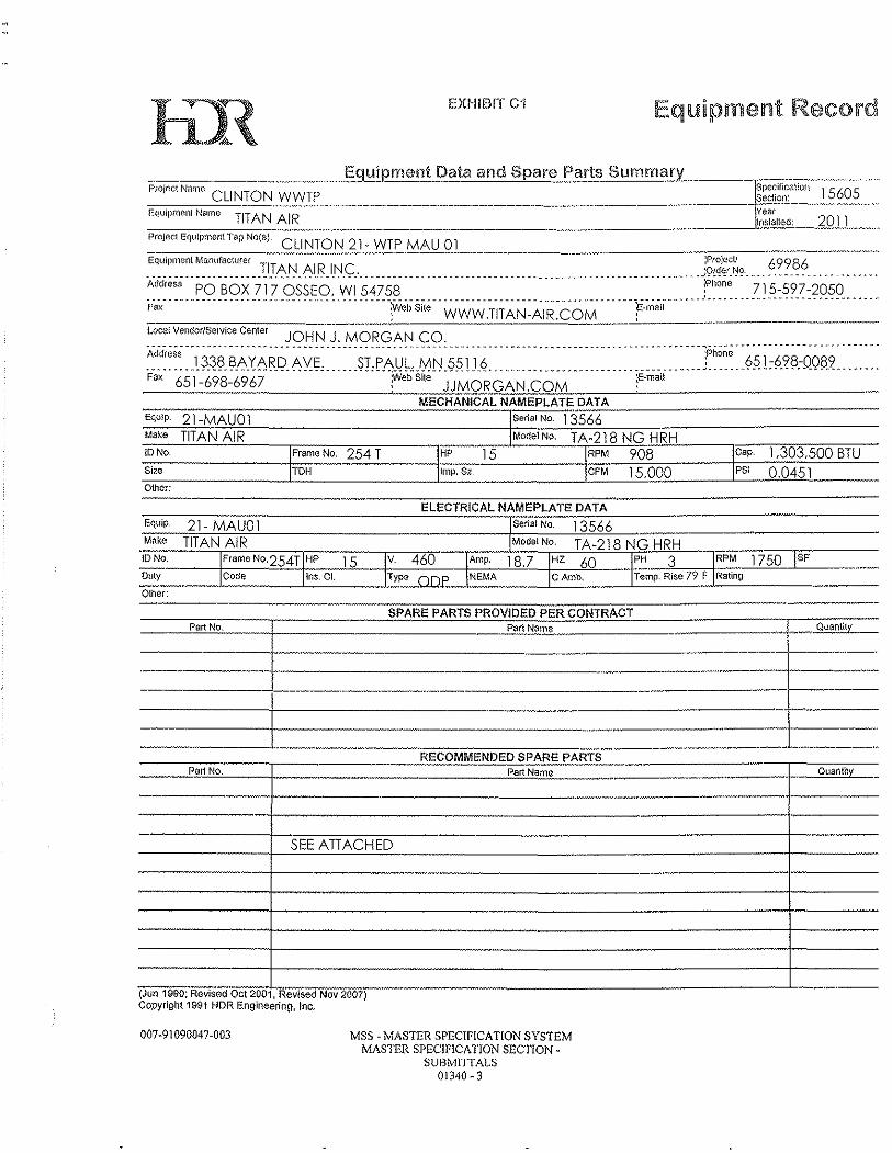
EXHIBIT C·j Equipment Record
____ .. _____ ...... _.. §.guiement Data and Spare. !".llrts Summa~y' .... ___ .. _.,,_. __ ..... PlOj'" Na", 3"""0<"°11 I 5605 .. . CLINTON WWTP 'ect,on E/!uipmel,l Name T .. IT·AN .. A·"~I· .. R~-···"~·-'·--· ..... - -- -- ---------- - --------ye;:---------..... ~~~~~,.::.:..:..::.:.. .... --........... -. ......... . .... _ '0£""'" 2011 prOjectEq"'pmen'TagNoi') CLINTON 21· WTP MAU 01
,"'-""------Equipment Mantlfactllref TITAN AIR INC. . .. __ . _, _p _ ______ ., • _ .-,~i~(~~~. ___ . ???_~? __ . ~_ .. ~ ..... A"ir.ss··p·O·BOX·ii70SSEO:wis475S .... · .. · .. · ........ · .... · ..... p'lOne 715.597.2050
,:'x·· .. · ...... ··.. ...... .......... :~: __ .. ·.:~3i"; si,." WWW.T·ITAN:AIR:CO;;'· .. · .. Y;nal,··· .. · .. ·· .. · ....... '.:~~:~~~:_"_'_" L='VendcrISGlv'ceCen'e, JOHN J. MORGAN CO.
Ad;,;.ss"ii:ii; ;;~ Y~R'[; ~VE:"'" ·ST:P~UL.· ~~ ·55116···· .... ·· ........................... "·;PI;OO. '~~i~~~~:'QQ3i: :::::: 'FOX" 65·1·:69·8:6967···· ................. ';web si'e" jJ'MORG~N :CO~"""""" :E.ma;'············
MECHANICAL NAMEPLATE DA~TA:::... ________ _
jS"'" No. 13566 Equip. 21·MAU01 Make TITAN AIR !DNo,
~.,.-____________ --'E=L:'::E~C.:'TR~I::::CA~L::.:N~A~M~EPLATE:.:D::.A::.T:.:.A _______ _
Equ',. 21· MAU01 13566 Make TITAN AIR ...L=::.;...,,-!T!:.A~.2"-'1'-'8C!N-2Gs.LH~R,r:HL...--r.=-:_:-==,......,,=-__ _
ION<>. Fran1eNo.254T ~_1_5_ HZ 60 PH 3 RPM 1750 ISF Duly CQde Ins. CL ·-t=-.....::.::::.....:----i~':-:-...!.O~-+;C~Am"'bJ;.~--'~ T'Z~p. Rise 79 F Rating -O-th-er-'---·--~:~------~~~----~~~ue--~~----.....:~~
SPARE PARTS PROVIDED PER CO~NT=R=A=C=T=========+=::g;~iL:= __ ._ .. ~~~~-l ___ . __ . _____________ P_'rt_N:':'"~e~~~-~.~-::.-::.-::.-::.-_-_-_-_-=-__ . ______ -+_~~::~~~_y _ I
RECOMMENDED SPARE PARTS "
Part No. Part Name
._----------1-.
SEE ATTACHED
.
(Jun 1990, Re\llsed Oct 2001, ReVIsed Nov 2:007) Copyright 1991 HDR Engineering, Inc.
007·91090047·003 MSS . MASTER SPECifiCATION SYSTEM MASTER SPECIFICATION SECTION·
SUBMI'ITALS 01340·3
. " . OllCH'ltily
"" .. ..
..
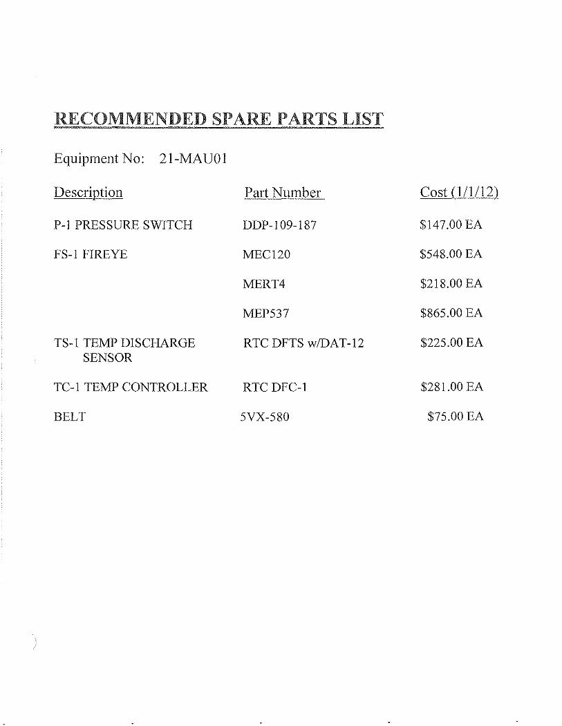
RECOMMENDED SPARE PARTS LIST
Equipment No: 21-MAU01
Description Part Number Cost (l/1/12)
P-1 PRESSURE SWITCH DDP-109-187 $147.00 EA
FS-1 FlREYE MEC120 $548.00 EA
MERT4 $218.00 EA
MEP537 $865.00 EA
TS-1 TEMP DISCHARGE RTC DFTS w/DAT-12 $225.00 EA SENSOR
TC-1 TEMP CONTROLLER RTC DFC-1 $281.00 EA
BELT 5VX-580 $75.00 EA

EXHIBITC2 Equipment Record
Recommended Maintenance Summary Equipmcml Description -~-.,--,-~-.~ IprOject Equip. Tag NC{$}.
__ -,-M-,-a~ke,-U:.!:.p-,-A:;;.if-,--U:cn.'-it'--_____________ ~ __ ••. __ J..! __ 2_1_-_M_A_U_O_l _____________ _ .-~~~.~-- .-.-.~ ---- _.
INITIAL COMPLETION' FOLLOWING START·UP
RECOMMENDED BREAK·IN MAINTENANCE (FIRST OIL CHANGES, ETC.) 0 W M Q S A Hours --,--_._-_.- ---.
Re-tension belts 24 . --.-~.~-~ . .
. _-------" ,--,~~~----" ._-
_. -._- -
._- ._----_ ..
PM TASK INTERVAL'
RECOMMENDED PREVENTIVE MAINTENANCe 0 W M Q S A Hours
-Blower Bearings Lubrication X
Check Belt Tension and Condition X -Check Filters X -
_. Check Burner Operation --p .~~.--~--.---~ ... ~---.---------------.-.. -.---.--------. -----
--
Motor Bearings Lubrication X ---~-.-.-.~.~,.
------.• -~~~---.-~,
-.-----
..
_. D = Dally Wc:Wec-kly Me Monthly Q I:: Quarterly s ~ Semiannual
(Jun 1990: Revised Oct 2001, Revised Nov 2007) COPy tight 1991 HOR Engineelinq, Inc.
007·91090047-003 MSS - MASTER SPECIFlCATION SYSTEM MASTER SPECIFTCATION SECTION ..
SUIlMITT ALS 01340·4
---
A= Annual Hours = Run Time Interval
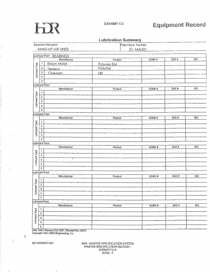
EXHIBIT C3 Equipment Record
I:-:--,-L--,-'::--c--,-------.----'--------.---- ____ L-___ -'--_____ '---__ _
~~~~-~~~~---,--,_---~~----,_~~7--~-~~~-~~-Manufacturer Product AGMA # SAE # ISO
H-----------i---------+----+-----j------~---·--·----_+---------~----~-----r----
Fr=-'-='---;-;::-=:=c----,--------:::----:---:---- .. ---,----;-:=-::---,--;;;;-;::;----,---;;:;;-Manufacturer Product AGMA tJ SAE # ISO
~--~==~-----i---~~---+--=~-----'~~-r-~~-H------------4---------~-----4---_r·-----H------,-" ----1-----.. ·-·----.. --·-------+-----1-·----·----+----
----------+-------_.---j-----j-------{-----1-1:----------+-----.. ----------1------1---.. -- - .. -.----
-------------'--------------'------'--._._---'-----F'F'c-:;;;.::.......---,--.... ,,:c::-:::------,----;:::-:-::-,;-.-------,--:=-;:-;;-.- ----::-:-~---,---:::c:--
M8nufacturer Proouct AGtv1A # SAE # !SO l-:-r-·-.......:.:::::.:::::=:'----.. ----j-------'c:.=:.:.:.....---+---'-'-=.:'-'c-· .. ·-+---"'=--l----"=--· .... H----------··-------------~·------+-----+------·-
1-'-+-------.. ---1----------1----+-----1---------.. -::-+---------+-----------+-----+----_ .... ------
ManuFacturer Product
~(F"e~b~,~9~9,f;1R~eNv~;SAedrlnO~ct~2~.O~OT,.IR~e~v".s~oorlNN~OV~20VO~7')-J..----------------L------~L..-------~L..--.. ----Copyright 1991 HDR EngIneerIng, Inc.
007-91090047-003 MSS - MASTER SPECIFICATION SYSTEM MASTER SPECIFICATION SECTION -
SUBMITrALS 01340 -5

2.2 Unit Specifications
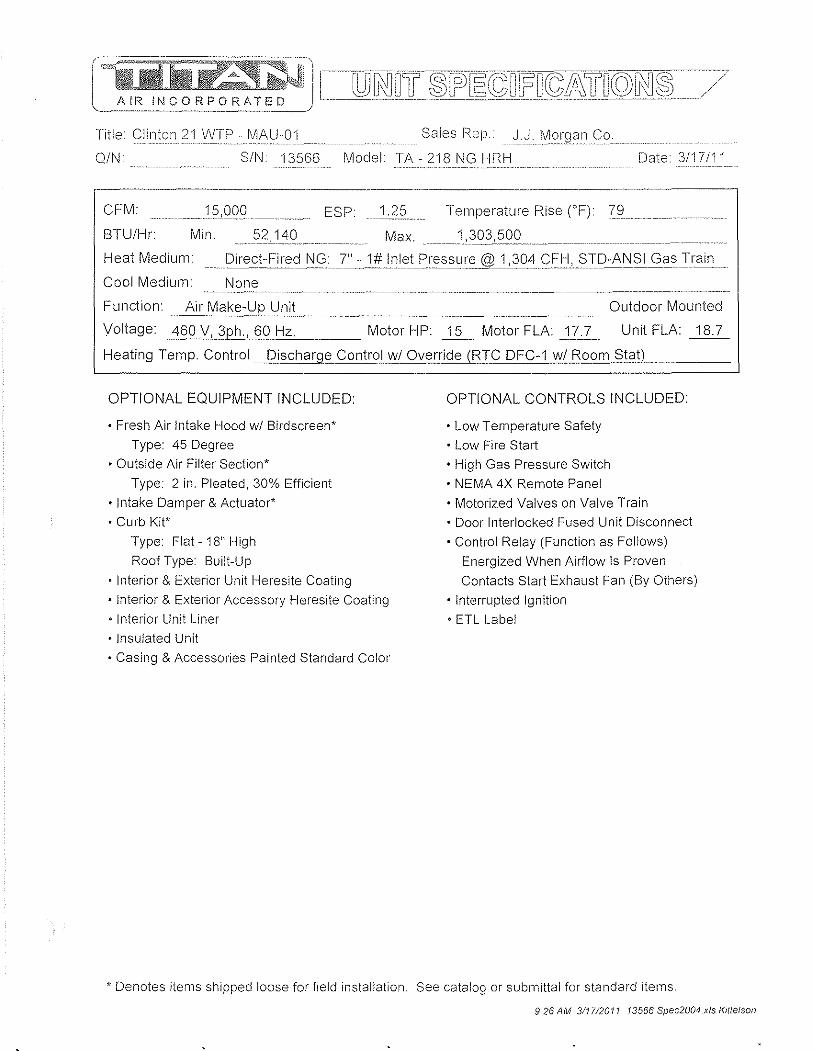
Title Clinton 21 WTP - MAU-01 Sales f'<ep. _J.: ... ,J:: .. '.'.:.:_: .. 0;' .. :.: .. : Co.
Q/N SIN. 13566 Model TA-218NGHRH Date 3/17/11
.----_._-, .. _--------CFM:. ____ l5~0_QO_,._ .. _,_ ESP __ L:2~ Temperature Rise CF) 79
BTU/Hr Min. 140 Max.1:3032QQ..._,.,
Heat Med i u m : ... _ ... [) i re,c!:: F i reci.I\i<:;!''.-:.1!*11l1.B,t£I(,;S s ur?@.!.J.Q.'I.C::f=,H,§TD-A!'i S I,Clils,!ra in,
Cool Medium: None
F unction. ,~~ake_-:'LJP U niL, ___ , __ ~_, _____ ,._, ____ , ___ , Outdoor Mounted
Unit FLA: 18.7 Voltage: ,460 V, 32JlL60,~ ___ Motor HP: j2, .. Motor FLA: ,17",1:...
Heating Temp. Control_J2.ischarge ControJIJ\II Override (RIC DFC-1 vii Room Stat)
OPTIONAL EQUIPMENT INCLUDED
• Fresh Air Intake Hood wi Birdscreen* Type: 45 Degree
• Outside Air Filter Section* Type: 2 in. Pleated, 30% Efficient
• Intake Damper & Actuator*
• Curb Kit* Type: Flat, 18" High
Roof Type: Built-Up
• Interior & Exterior Unit Heresite Coating • Interior & Exterior Accessory Heresite Coating
• Interior Unit Liner • Insulated Unit
• Casing & Accessories Painted Standard Color
OPTIONAL CONTROLS INCLUDED:
• low Temperature Safety • low Fire Start • High Gas Pressure Switch • NEMA 4X Remote Panel
• Motorized Valves on Valve Train • Door Interlocked Fused Unit Disconnect
• Control Relay (Function as Follows) Energized When Airflow Is Proven
Contacts Start Exhaust Fan (By Others)
• Interrupted Ignition
• ETl label
* Denotes items shipped loose for field installation. See catalog or submittal for standard items
9:26 AM 311712011 13566 Spec2004 xis KJttelson
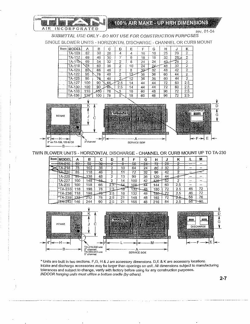
rev. 01·04 SUBMITTAL USE. ONL y .. DO NOT USE. FOR CONSTRUCTION PURPOSES
SINGLE BLOWER UNITS- HORIZONTAL DISCHARC;E - CHANNEL OR CURB MOUNT
TWIN BLOWER UNITS - HORIZONTAL DISCHARGE - CHANNEL OR CURB MOUNT UP TO TA-230 Item MODEL A 8 C
X TA-218 78 102 36 0 85 118 46
TA-225 ~ 138 48 __ --TA-227 100 148 ~
.. TA-230 10~_ _ 15~ .. ... ~~ "TAm 118 198 78
1--' '1*Ti\:236 118 198 ...:r-a-
"TA-239 J.; 12 78 --~2 146 244 90
~---B--~ TA·215,230uw T A·233,242 "e
D E
2 10 2 11
_1... - 13 2 14
2. . 2.
~4- 18 2.5 21 2.5 21
F G H J K L M
64 24 80 32 2 72 32 96 42 2 ~.
.. 44 ~ 90 36 120 -::- c--=-.. -..
100 42 2 2 .--
N= I-ll4 144 60 2.5 -46-:-180 72 2.5 72 . 13f_ ~-- 2 2.5 46 72 .. .
148 48 192 72 ~ 56 76 168 48 216 84 2.5 5 ..
SERVICE SIDE
* Units are built in two sections. F,G, H & J are accessory dimensions. D,E & K are accessory locations. Intake and discharge accessories may be larger than openings on unit. All dimensions subject to manufacturing tolerances and subject to change, verify with factory before using for any construction purposes. INDOOR hanging units must utilize a bottom cradle (by others}.
2-7
rev_ SUBMITTAL USE ONLY- DO NOT USE FOR CONSTRUCTiON PURPOSES
1""'/ c ~Yr,,--· A
r B
") .. I
B
1
-):I
B
-1 1-1000 1 D HOOD I FILTER COMBO D FULL TURN DOWN HOOD
'r--"-A ~I
M OA FILTER SECTION
[,1=fRA FILTER SECTION
T B
-1
All dimensions subject to manufacturing tolerances and subject to change, verify with factory before using for any construction purposes. Intake dampers are designed to be mounted indoors, jf outdoor mounting is required, you must order a weather hood for damper actuator(s), damper may be built into hood and or filter section. Intake dampers on TA·230· 242 have 2 actuators, all accessories for these units are built in 2 sections, some field assembly may be required, All intake hoods feature bird screen. Mushroom hoods can be flange mounted, consult factory. 1" flange is typical for a/l components listed above. Intake accessories may be larger than intake opening. Return air filter sections will be larger than return air opening.
8·1
AIR ~ .. KE-WP UNITS AI\ JL~ ,I,,<;,! , r----.~-"--'-"r':"\ ~~IJfLI~"T-"-' / /" /' \ .J/
MODE BU!i~C ~O;:,~ ·!:liSC .• I~~~: I~~~~~ ~ntake Disc. C~;t TA,11 ... 600 00 1100 30 .. ' 55 .. 45 05/ .~1 620 20 1120. 30. 55 45 ___ 05 TA,l5-- J75 775 1150 35 60. 110 V 105 TA-118 9'00- 1020 1700 45 75..-111J 55 120 TA,120 1300 l'4W.. 2250 0 if 125 60 150 TA,122 1720 1781 '":!%D lJY" 15 150 70 200 JA e 125.. 1770 1831 270Q.. ~ lQ 15 150 200 TA,127 2450 2551 V-l'f50 150 1--2.10 235 11 250 TA -130 2500 ;;retJI 3500 150 21U"-- ,235 11 250 TA·133· .ZlJOO' 3000 4000 200 250 ?'ilrl-- 125 300 r A . ll>- -3000 4100 20 30 260 ffi. 300
,,"'" 16,'0 l675 l' 30 220 ""tSQ ,. 1700 2850 13 220 ~
lH'U UUU 1; LbC ~_.
, • Q 3290 1600 16< 255 305 4QQ. A·2: 3150 ~ 1800 225 ~oo 35 450 A • 230 4200 4500 ~5 200 500 , . : ~33 6500 .l1QQ. 0)0 3 --
~,-=,-:"",36 7100 ~ 8100 5:!5 bbU 3·-, " l;J ~ 8200 8700 690 625 ,50 _ r2 81 OC 870C 9200 89G 825 850 5 "'-
"AR " RECIRC. UNITS AND ACCESSORIES
'e I\< 815 815 1300 30 55 45 45 " Ii! 950 1000 1350 35 60 110 50
A ·11 '1220 1280 1600 15 / 110 55 TA ·120 1100 18 2500 80 1fI' 125 .. 60 TA·122 2150 '900 IO~ 15 151 70 TP !5 2200 !9S0 100 /1:IS 1500 rA· ~7 2750 h 1800 150/'Z10 .235 ...... ,100. r A . 0 2800 )00 ·'3(150 150' 210 235 100 r A . 133 .. 3250 3300 .. 4200.. 200 260 125 TA . 136 3550 3601 4500 co( 10 260 125 TA·215 2000 210 3250/ 1), 220 100 T ,. 2 8 2050 ~1~00:5 220
2300 2451 fi300 1: :0 '1 Q 250 , e 2: 3400 36' 0 4900 16 255 305 , . 3950 430.0' 6150 22 300 "400 , . 4600 481 0 6650 31 325 42!i 00
TA· '33 6800 1/7600 81 00:j5 ~ 4,C '- 300 TA·236 7600/ 8100 Ii 5 ~ 4,0 300 TA·239 81JJtJ 8700 Q.O 690 325 630 350 TA·242 )l'600 9200 890 825 830 550
o o
150 200 .. 200
250 300 300 160 240 30
30 ... -_.--.....
ALL WEIGHTS ARE ESTIMATES, AND WILL VARY WITH DIFFERENT GAS TRAINS, MOTOR HP, AND SPECIAL ACCESSORIES.
USE FOR FREIGHT ESTIMA TlON ONL Y
1-11
r]:I!i:~J=~~·~"·:~!~~1"··~~~~~·~~~~}~Giri~k=~lilliU§!~I;~-::::j Abbr, S eeification ---"-·~-~·~~#Deseriptioll -~~~ - IAbbr"l)e'~cripiiol;7:S~~# m~··1 Belimo NFBUP·S us Intake Damper Motor FS··I r'ireye IVlEC120D, IVlERT4, MEP537 1 Flame Safegual'd FU-1 lauch Safe 13loek,Class JTD 30 Amp 3 Main Fuses FU-2 ,600VAC -Class CC Time Delay: 1.5 Amp 2 Trans. Primary Fuses FU-3250VAC·· Midget type 3 Amp Control Circuit Fuse L TS-1 . Antunes Controls 856314()()61 wi Cover 1 . LovvTelTiperature Safety MT·1§eemotorspe_cs,onri9ht§i~eofpag'" 1 . Blower~otor P-1 , Cleveland DDP-1 09-187 (0.2" & 0.95") ,1i'1iLEIOvv?_vviteh P-2 '; See-GasTra~';BLlrnerSpecs-- ,na Low Gas Pressure Sw. P-3 . :§iic;fl~fr§injBLJrnerS:jJ~c~ . na; High Gas Pressure Sw. R-2ldee RJ2S-CL-A 120, SJ2S-05BT:ExiiaustTiiiellockR8Ia:y ST-11 EatonYfcE025C10A, XTC)E020CCS ITTStarter;Oi.---------SWliABEi-OT40F3,OHB65J6,-O X P6x2i35f 'E q ulpment D isconnect- l--":""R"'E"'M"'O"'T~E"P~A'T':':N~El'"L~S:\'""''''':''-l §W~~JAE3]QO_EF'::_S:M32, ~fi:~L.£'_X.2J)-----r1Tsummer-Off-Winier Swiicfl- A 1287 JFGORR wi A 1 OP8 1
1
... 1. §W -5 JCa rIi,rl,g switch 111-16-7 3 H "iTIBlowerServic-esWiiCh-- ----... -----------.-----".--SW-6 i Carlingswitch 111-16-73 .----..-.. --:-"1-: Burner" Service Switch MOTOR & BLOWER I-S:::-JJohnson C.ol1irolS A~{9iiBg:1.:g: -···-I.1..1~rrlQ~erride Stat=~-- & DRIVE ASSEMBLY TC:l __ 1 RTC OFg.:.1..... wi F~~_______;,J...iTemperature Controller. _. Motor: 15 hp, 460 V 3ph. ODP Tf2.~1.._RTC QUO (<\..Q:E..:: 90o EL __ .......... _m.,1.,Discharge Temp. Selector__ 17.7 fla, 254T frame TL-1 iHoneywel1 L4008E1255, i 11High Temperature Limit 1750 r m EM2513T 'rR=1:]Micro;;[3250BTZ~3RB_:-:~=--=~~nJ,c:;..Clnirol Transformer' Blower Lau A18 ... 18A 12 TR~~_Jl,1oneywell 0652B1 006_____1J...:Lgt1ition TransformerP.B. Beanngs- VPB-223:";;:i-ill TR-3 I Honeywell AT120B1028 i 1 124 VAC Transformer-... ···· Motor Sheave: JVS 150-i -- IJ.. TP:4-THo-neyWejlAT120B1 028-----------T1124 VAC Transformer--, - Bore: 1 5/8"
I§":I~:::BI-g:D FTS wL DA T_:I~_=~~~TIJ Discha rge- ::r,Elm p,::::,,~r;.s-~~~ _ Turn s ..2E.I3~":.3._1!.? _________ _ V-1 ISee Gas Train/Burner Specs. 'nalPilot Shutoff Valve Blower Sheave: 2/5V975SK !_L IT;"SeeGaS-Train/BurnerSpees: ·····-jnatMain Safety Shutoff Valve- RPM 908 V-3 ··!See GasTrain/Burner Specs~--TllaiVent V8!ve----------- Bushing: SK x 17/16" 0:4-1 See Gas-Traln/Burner-Specs .. _ .. r;.§::AuX Safell' Sh0oi[,{alv.e: - Bel~ 5\(i'~5[[1 :-- --...II V-5I~~~9a-s..tr:alniBurrJEl.r:s:pi~i InalModulatlng Gas Valve .. Couplln in V~.:.1 .. !13.~lil110L..l\I1gB?4-"I3.1'T ··T1'MC;dGas'2.§f~AclL§i(,-r- SCHEMATIC SYMBOLS
..... _ ... m __ ... __ I-=""""":"~:--.-~"'"""':"=~ 'IL. ~ Unit Control Panel Terminal
____ -~i~=:~:_ ... -· .•.. :..=:-=-:-=::_::=:=::-~i=,:=::=~~== .. =:=:::-=== ~ ::::~en::tn~~~~::ilnal ; I
---•• - ......... -.------- ... --.------ ... - H ______ ... _. - •• __ ...... L_' ___ .... _._._ .... -.- ---....... ---.-... --... -- 0 Terminal in Others Panel ._. _______ ~ ___ ,. ,_ . _______ ._.. . .... _J __ _
.~ •. __ ._-_!
-- :::_::_-_ -= .. Wifing to Remote (Others)
Field Wiring (by Others)
-III- Jumper Wire
-.- Wire Connection
* Terminal no.'s 1 to 99 designate 120
volt: no.'s 100+ designate low volt wiring (run in shielded cable).
Ground unit according to N.E.C. CAUTION: Open disconnect switch
before servicing unit.
9:26 AM 311712011 $113566 Spec2004.xfs Kittelson

O.A. Filter(s)
RA. Filters 2" Throw Away
2" Pleated 30% Efficient

el E ___ ~M.'C:O~d h Quote No. Ext. Static Titan Accessory Static TA-218N G HRH _021810AB21 1.25" w.c. 0.41" w.c.
Performance Curve
JO Sp
2 A18·18A
15000 C~M, 2 42 i_woO, 2613 OV(~(MI"}, SOS RPM
to.GO OHi', 53.B% S~ st«l\d~rd P",{o""oncQ
2.0
1.0
00 L __ ---- t;FM
• l-r~_~I~'_~~~_~~'·_' ~'~I~'-' ~,~-~, ~'~I-' ~"'-' ~I~i-"l
o 5000 10000 15000 20000 25000 30000 35000 40000
Sound Data OCTAVE BAND No. 1 2 3 4 5 6 7 OCT. CENTRE FRQCY (Hz) 63 125 250 500 1000 2000 4000 SPECIFIC SWL (dB) 50 50 40 33 33 10LOG Q+20LOG T.P.fdS) 51 51 51 51 51 BFI (dB) 0 0 0 0 2 OFF-PEAK CORR. (dB) 1 1 1 1 1 TOTAL FAN SWL (dB) 102 102 92 85 87
Comments: FAN TYPE IS FORWARD CURVED 1. The A-weighted SWL in-duct is 92 dB. 2. At a distance of 10 ft. from the fan 74 dBA can be expected with an open inlet or outlet and 59 dBA when the inlet and outlet are ducted. These values have been accessed using a model of sound propagation from a point source into the hemispheric free field (see AMCA 303-79).
28 51 0 1
80
THE dBA VALUES PROVIDED ARE TO BE USED FOR REFERENCE ONLY. CALCULATION OF dBA VALUES COVER MATTERS OF SYSTEM DESIGN AND THE FAN MANUFACTURER HAS NO WAY OF KNOWING THE DETAILS OF EACH SYSTEM. THIS CONSTITUTES AN EXCEPTION TO ANY SPECIFICATION OR GUARANTEE REQUIRING A dBA VALUE OR SOUND DATA IN ANY OTHER FORM THAN SOUND POWER LEVEL RATINGS (SWL). 3. The off-peak correction has been based on a static efficiency ratioofO.917( 54%1 59%)
23 51 0 1
75
8 8000
18 51 0 1
70

2.3 Gas train/ Burner Specs.
Model TA-218NGHRH Sales Rep. J.J. MgrganC:;g.
SIN 13566 CfcM 15,000 Temp Rise 79°F' BTU / Hour 1,303,500
GAS PRESSURES Max. Inlet Pressure'" 1 #
BURNER & PROFILE DIMENSIONS
Profile Width (in.) =_--"~_ .. Height "'_~} Min. Inlet Pressure = __ 7..~ __ at~}QLf CFH.
Manifold Pressure of ... _)~?L_ in. we required for specified temp. rise, CFM, and burner.
Notes:
GAS TRAIN DIAGRAM:
Burner Length "'._ 2.5 ___ ft.
No. of Tees'" 0 --.-.---~
Burn e I' M f g. J\'1i.cl.c_'2...f1_I\!1J\':L
Titan gas train starts here. A A.- A J..., : 'P-2' : 'P-3
\ _ .. :\:?! ' 'V-3 ~:.
GT-1 *GP-1 t V-2 ~ GT-3 V-5 '. ce,.. "r-c*J~ --'",Q~-~- ': :---1
Shutoff valve, dripleg, .. ____ * _____ ~-- ~Q~ ___ -jJ and union by others PG-1 GP.2 V~
Notes: ._------
Gas Train Complies with ANSI Guidelines
Abbr. Description Manufacturer/Model Oty. Size - .. _.
GT-1 Main Shut-Off Valve (Manual) Hand Valve 1 1 1/2" P-2 Low Gas Pressure Switch *
GP-1 Main Gas Pressure Regulator * Maxitrol RV81 1 1 1/2"
V-2 Main Safety Shut-off Valve Honeywell V4055A/5055A 1020 1 1 1/2"
V-3 N.O. Solenoid Vent Valve * V-4 Auxiliary Safety Shut-off Valve Honeywell V4055A/5055A 1020 1 1 1/2"
GT-3 2nd Shut-off Valve (Manual) Hand Valve 1 1 1/2"
V-5 Modulator or Modulator-Regulator RTC ABV-1.0NN 1 1" P-3 High Gas Pressure Switch * Honeywell C6097B1028 (3" TO 21") 1
PG-1 Pilot Shutoff Valve (Manual) Hand Valve 1 1/4"
GP-2 Pilot Gas Pressure Regulator * OARA Type 96 (44-4-390-002S) 1 1/4"
V-1 Pilot N.C. Solenoid Valve Honeywell V4046C1047 1 1/4"
Pipe Size After V-S 2"
• Must be vented to outside atmosphere unless fitted with approved vent limiter.
3.28 PM 312112011 sl 13566 Spec2004.xls Kittelson
2.4 Sequence of Operations/ Temperature Control
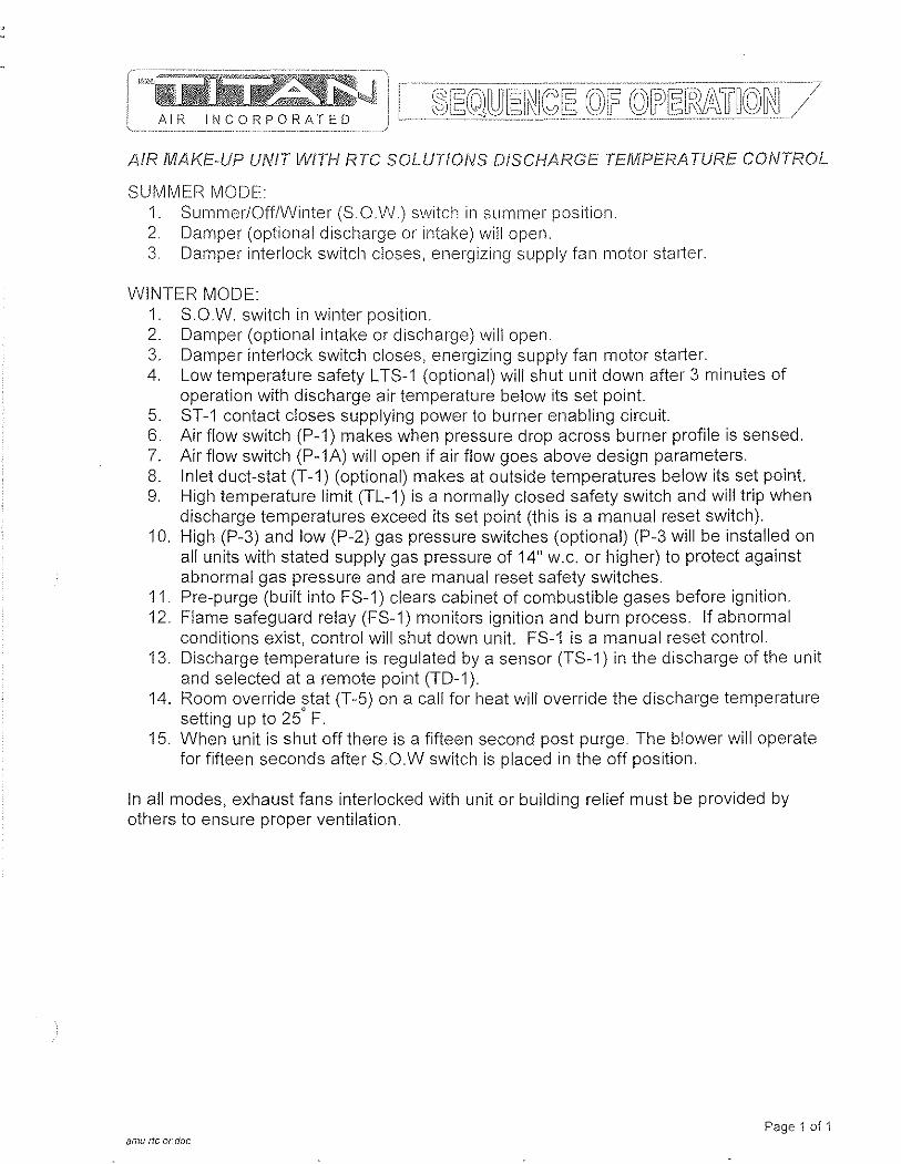
AIR Ii"CORPORATED
AII~ MAKE·UP UNIT WITH RTC SOLUTIOfIiS DISCHARGE TEMPERA TURE CONTROL
SUMMER MODE 1. Summer/OfflWinter (S.OW) switch in summer position. 2. Damper (optional discharge or intake) will open. 3. Damper interlock switch closes, energizing supply fan motor starter.
WINTER MODE: 1. S.O.W. switch in winter position. 2. Damper (optional intake or discharge) will open. 3. Damper interlock switch closes, energizing supply fan motor starter. 4. Low temperature safety L TS-1 (optional) will shut unit down after 3 minutes of
operation with discharge air temperature below its set point. 5. ST-1 contact closes supplying power to burner enabling circuit. 6. Airflow switch (P-1) makes when pressure drop across burner profile is sensed. 7. Air flow switch (P-1A) will open if air flow goes above design parameters. 8. Inlet duct-stat (T-1) (optional) makes at outside temperatures below its set point. 9. High temperature limit (TL-1) is a normally closed safety switch and will trip when
discharge temperatures exceed its set point (this is a manual reset switch). 10. High (P-3) and low (P-2) gas pressure switches (optional) (P-3 will be installed on
all units with stated supply gas pressure of 14" w.c. or higher) to protect against abnormal gas pressure and are manual reset safety switches.
11. Pre-purge (built into FS-1) clears cabinet of combustible gases before ignition. 12. Flame safeguard relay (FS-1) monitors ignition and burn process. If abnormal
conditions exist, control will shut down unit. FS-1 is a manual reset control. 13. Discharge temperature is regulated by a sensor (TS-1) in the discharge of the unit
and selected at a remote point (TO-i). 14. Room override stat (T-5) on a call for heat will override the discharge temperature ,
setting up to 25 F. 15. When unit is shut off there is a fifteen second post purge. The blower will operate
for fifteen seconds after S.O.W switch is placed in the off position.
In all modes, exhaust fans interlocked with unit or building relief must be provided by others to ensure proper ventilation.
Page 1 of 1 amu lie or doc

.! '
·.~~~~;:J 100% OA RTC AMU JOB Clinton WTP SERIAL NUMBER 13565-70 DATE 04/12/11 DRAWN B" KK
,~_:":lR !NCORPORATED wi DISCHARGE TEMP. CONTROL SW-1: FU-1 ST-1 . ~ OL·s L1- - --o---rc ~
OFF
SUI\'l-<1i ~);.- WiN
S\IV-2
T-5 r-----hl 0-; HJ+I----,
L\..:J "---/ I TS~'!
460/230/208 3ph 3 wire
supply wI transformer
L2- - --o--:-c I-O--------d \.n ( MT-1
L3- -~ I-O--------d
R2-1 ~~
Exhaust Interlock Contact TR-1
120VAC 7
g OM-1 H N -------------
OL's - c @--~
:,~,
TR-3
: c~-: Low voltage wiring must be run in shieided cable.
-- ------... ---c-- ;:-:;;;;;.-----: ____ -----:-____ -, '""2 '_e- -.ce; So.eet for symbol description. ( ~ = unit to remote wiring)
-----_ .. __ ._.
~ ~ ~
" o ~ , E •
!\ (
INSTAll 1\1 AM Ef~L A TE
INS T Ai.!.. HI N CE·11L
,
I
=pl J---L-L=Lho "
INSTALL. I'v!OUN TING tTET-~
A I REVISION .................. - .. -.~~-... -.--..... ---.. --... ----.-... --.-.-.. r;r;-~~FC~-
DRAWN BY GATE. -W·Q.N_UMBER ·j-TiTIii: '~ @KILLARK®ZACHHUFNAGE .. L7_I .l/ll
1~.UB ... 8EL~~._ " AT~~I(~BLY LAyOUT ··--.L--~SHEET OF SHEEr
_~~_ EXB-12128 N34 4 _~_ ... _________ . ____ .. _ _._-........-J
-/ u , -
,--_~ //1" i\! !--') 1
I ,
1- 478 1 --~--------~ I
---- '" 781
++ +. +
TOf;) I /~ ---f- - -:;F-i-f-~-f----~,
+ r5tJ r---!~ -1~-r
--- !I --- + + -+
--1----.---- --
+ I + ,
+ ~- -IC--J : ~-;-'$' 3 _____ ~--.---.--L __ ~ ++
+-+
,,_. + 4. I -$.&. . ________ .. _________ .1 _____ L __ L-___ . ___ .. _,' ,_, _________
I
I
TITLE ]:;I-IEET OF SI-IE(T BOX LA YOU T -, 4 EXB-12128 N34 •
- ------
l"=·KlllARK ·
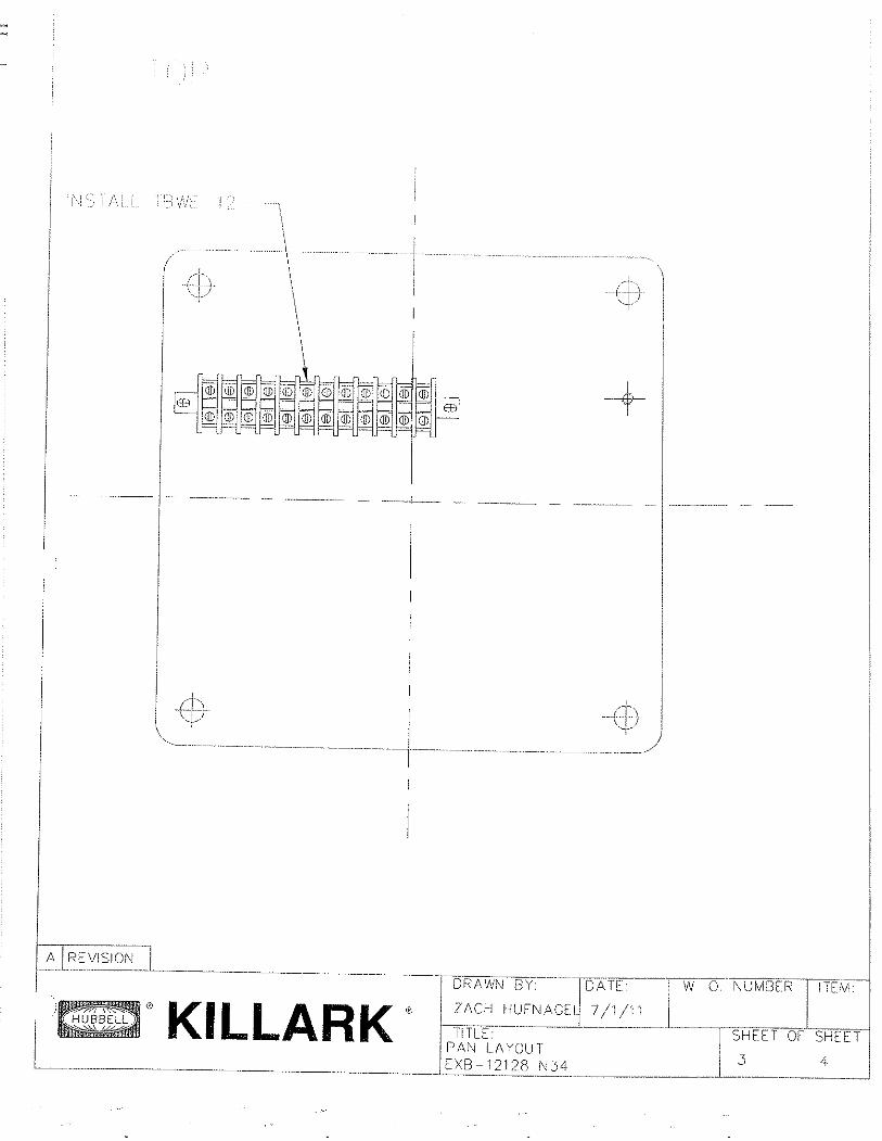
i
-j--
"- -------
~'KILLARK· 4
-------------~,
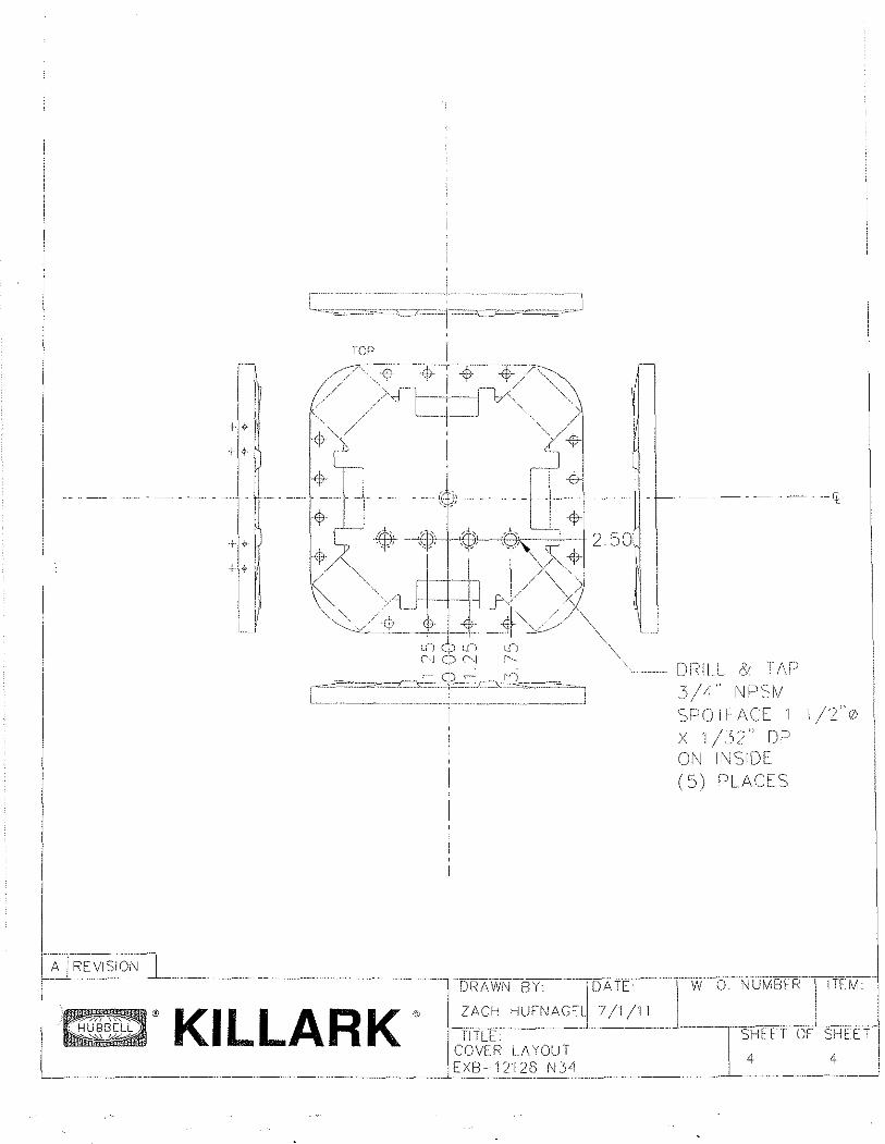
--- - -- - ·-ft.
m\ill /Y TAP 3/4' N!JSM SPOil/\CEI 1./2"0 X 1 /~\2" OP Ol\j INSIDE (5) PLACES
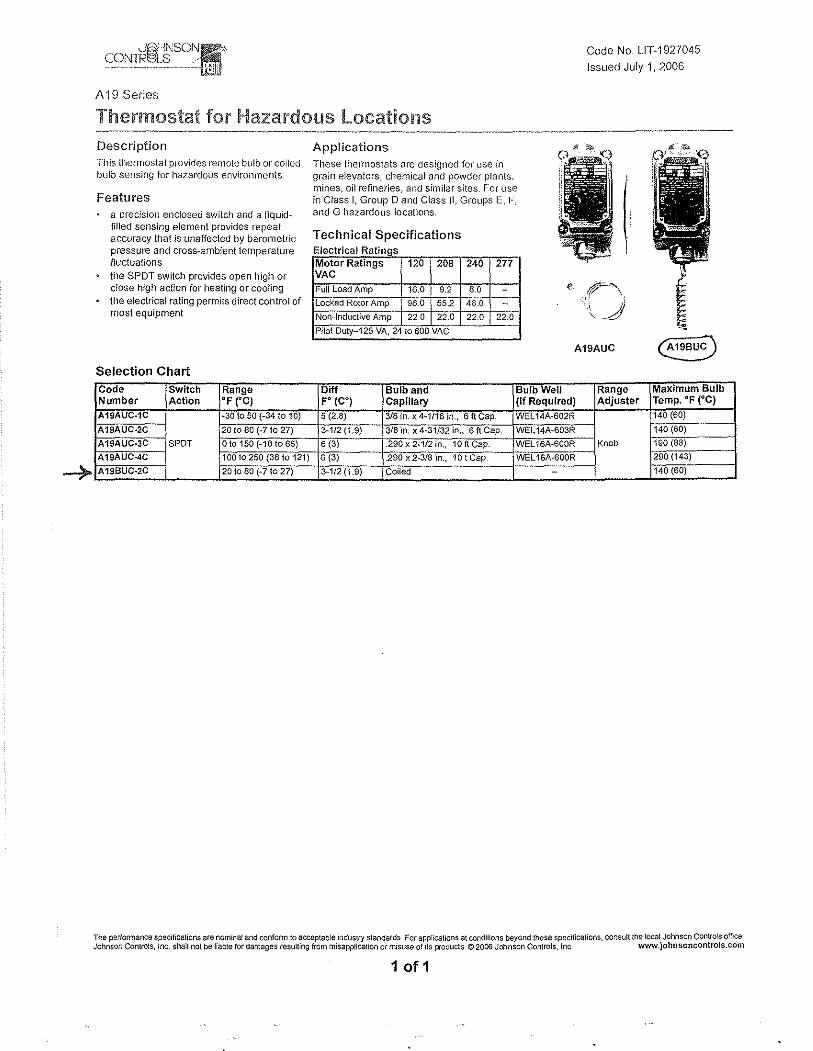
A 19 Series
Code No. LlT-1927045
Issued July 1,2006
Thermostat for Hazardous locations Description This thermostat p(ovides remote bulb or coiled bulb sensing for hazardous environments
Features a precision enclosed switch and a liquidfilled sensing element provides repeat accuracy that is unaffected by barometric pressure and cross-ambient temperature fluctuations
the SPOT switch provides open high or dose high action for 11eaUng or cooling the electrical rating permits direct control of most equipment
Selection Chart Code Switch Range Number Action OF ('C) A19AUC·1C ~30 to 50 (-34 to 10)
A19AUC·2C 20 to 80 (-710 27)
A19AUC-3C SPOT o to 150 (-18 to 66)
A19AUC-4C 10010250 (3810 121)
A19BUC·2C 20 to 80 (-7 to 27)
Applications These tiw(fnostats are designed for use in grain elevators, chemical and powder plants, mines, oil refineries, and similar sites. For use in Class I, Group 0 and Class II, Groups E, 1-, and G hazardous locations.
Technical Specifications Electrical Ratings Motor Ratings 120 208 VAC
Full Load Amp 16,0 9.2 locked Rotor Amp 96.0 55.2
Non-Inductive Amp 22.0 22.0
Pilo! Duty 125 VA, 24 to 600 VAC
240 277
8.0
48:0 - ---22.0 22:0
A19AUC
Ciff Bulb and Bulb Well Range FO (CO) Caplllal)' (If Required) Adjuster
5 (2.8) 3/8 in. x 4·1/16 in., 6ftCap. WEL 14A-602R
3-1/2(1.9) 3/8 in. x 4-31/32 in" 6 ft Cap, WEL 14A-603R
6 (3) .290x 2·1/2 in" 10ftCap. WEL 16A-600R Knob
6 (3) .290 x 2-3/8 in., 10 I Cap. WEl16A-600R
3-1/2 (1.9) Coiled
Maximum BUlb Temp, OF (OC)
140 (60)
140 (60)
190 (88)
290 (143)
140 (60)
The performance speCifications are nominal and confonn to acceptable mdustry standards For applications at conditions beyond these specifications, consult the local Johnson Controls office Johnson Controls, Inc. shalt not be liable for damages resulting from misapplication or misuse of its products © 2006 Johnson Controls, Inc. www.johnsoncontrols.com
1 of 1
2.5 Start up Procedures
1'2'iiilifii"~~~j AlP INCOPPOR/,TED
100% OUTSIDE AiR MAKE-UP UNiTS lllllTH RTC SOLUTIONS DISCHARGE TEMPERA TURE CONTROL
Start··up must be peliormed by a trained, experienced service person.
The following general start-up procedure applies directly to standard 100% air make-up units. Please note any added options for a specific unit which may affect the control sequence or terminal numbering prior to attempting start-up or service work. Read the entire start-up procedure and review all reference material (Unit Specifications, Gas Train/Burner Specifications, Sequence of Operation, Parts Lists, and Electrical Schematic) supplied with each unit.
STEP 1 Turn off incoming electrical power and gas supply to the unit. Electrical power
can be turned off at the unit disconnect. Gas supply shut-off is at the inlet of unit's gas manifold.
At the remote panel, turn the Summer-Off-Winter (S-O-W) switch to the off position and the temperature selector to the lowest setting. STEP 2
Verify that incoming electrical and gas supply match the name plate requirements (i.e., voltage/amp capacity, gas pressure and volume capacities, etc). If they do not, stop at this point and contact Titan Air. STEP 3
Open the access doors to blower and control vestibule sections. Check all electrical connections and hardware (blower drives, bearings, damper linkages, etc.) for tightness and correct field wiring connections. STEP 4
Check all gas, pilot, vent, and pressure sensing lines are properly connected and unobstructed. Verify the incoming gas line was "blown out" to flush out debris prior to connecting gas line to unit. Also verify incoming gas line has been purged of air up to unit's gas inlet. STEP 5
At manifold pressure test port, downstream of the modulating gas valve (VM-i), connect a gas pressure gauge (pressure gauge must read inches of water column to 10" with the capability of reading a negative pressure). STEP 6
Turn on incoming electrical power at unit disconnect. Make sure the blower access door is securely held open. Turn the blower service switch (SW-5) to the on position. STEP 7
If an optional intake or discharge damper is installed, the blower will not start until the damper motor's internal "proof open" end switch closes (damper motor and end switch wiring are generally completed in the field after damper is mounted). If an intake or discharge damper is not installed, the blower should start immediately. Check the blower for proper rotation direction. If the rotation is reversed, turn both SW-5 and the disconnect switch off. For 3 phase motors, reverse any two leads.
p.i AMU RTC Inllgn 2003 R1.doc
.-.-.. ,---....... -..... "~
[~cU41~[J~~[=lr)[J~[2)l~~li~@(~[~t~~~[=1~// ccmiTiilJi~,>J AIR INCORPORATED
STEP 8 With proper blower rotation verified, check and record the I'\PM of the blower. If
the blower speed needs to be adjusted to change the rated CFM of the unit, contact the factory. STEP 9
Turn the unit off. Close and latch the blower access door. STEP 10
Stal'( unit with SW~5. Check and record the motor amp draw. If the motor amp draw exceeds listed Full Load Amps (FLA), stop and call the factory. STEP 11
Check and record the negative pressure reading on your burner manifold pressure gauge. This measurement is necessary for proper setting of the burner manifold pressure when the unit is forced into high fire mode. At this time, also measure the pressure drop across the airflow switch ports (remove caps from fittings in tubing for air flow switches and connect tubing from differential pressure gauge to fittings). This measurement can be used as a simple indication of proper airflow through the unit. If this second measurement is not between 0.7" w.c. and 0.5" w.c. liP, the blower speed may need to be adjusted. If assistance is needed, contact Titan Air. STEP 12
Turn the unit off. Check the pilot gas line for proper and tight connections with no leaks. For shipping purposes, the pilot lines are disconnected. STEP 13
Turn on the main gas valve, slowly open the manual pilot gas valve. If the unit is supplied with a low gas pressure switch (P~2), reset to on position. STEP 14
Place the run-check switch (located on flame safeguard programmer module) to the check position. This will allow the pilot to l'lght without igniting the main burner. If the unit is equipped with an inlet ductstat (T-1), set this stat above the outside air temperature. Start unit with SW-5 and enable the burner with the burner service switch (SW-6).
Note that the burner should not be operated continuously in the check position for more than 1 minute because the ignition transformer is not rated for continuous duty. STEP 15
The unit should go through its complete burner ignition sequence with only the pilot ignited. The sequence can be observed by following the indicating LED's on the flame safeguard. On new installations, resetting of the flame safeguard may be required to purge air from the pilot line. If the unit does not cycle through its burner ignition sequence after a few attempts, refer to the service information in the following section for troubleshooting instructions. STEP 16
In the center of FS-1 are 2 voltmeter test ports. Set the volt-ohm meter to approximately 30 VDC scale and insert the meter leads into the test ports (common lead in black port, positive lead in red port). STEP 17
With only the pilot operating, record the DC volt signal. The DCV range is noted on the amplifier module of the controller (FS-1). There should be a steady DCV signal in
p.2 AMU RTC 1I111gl1 2003 Ridoe
AIF< INCORPORATED
the upper range stated on the controller. STEP 18
Once stable pilot is achieved, shut unit down and place rUll-check switch in the run position. Carefully remove the wire from terminal one (1) on gas modulating actuator (VIVI-1). Do not allow the wire to touch the unit casing or any metal. Release actuator gear by pressing black button on side of actuator (see figure 1), rotating mechanism counterclockwise to stop. Start unit and check and record DC voltage as in previous step. Check to make sure the flame is contained in the burner casting and extends the full length of the burner with no breaks in the flame. An ideal low fire setting results in a small flame with no breaks and that also produces a stable DC voltage signal in the upper end of the range listed on the flame safeguard amplifier module. If the low fire setting is adjusted, verify that both the DC voltage signal and visual appearance of the flame are satisfactory. See figure 1 at end of start-up procedure for low fire adjustments if necessary. STEP 19
Once stable signal is achieved on low fire, release actuator gear by pressing black button on side of actuator (see figure 1) and rotate mechanism clockwise to stop. This will force the burner into high fire. On your manifold pressure gauge, check the manifold pressure. The reading on your manifold pressure gauge needs to be added to the negative pressure recorded in step 11. The resulting total manifold pressure should be compared to the unit's rated manifold pressure. If the total is higher or lower than the rated pressure, adjustment can be made at the gas pressure regulator (GP-1). Total manifold pressure should not exceed unit's rated manifold pressure.
Because of possible variations in the BTU content of gas, it may be necessary to set the manifold pressure to the rated temperature rise (temperature difference between the incoming air and the unit discharge air).
The high fire flame should be visually observed to verify proper combustion. Experienced service personnel should be able to assess the appearance of a proper high fire flame. If assistance is needed, contact the factory. STEP 20
With the burner on high fire, turn the high temperature limit (TL-1) to its lowest setting The limit should trip out and shut down the burner. Turn TL-1 back to the factory setting of 185 deg. F and reset the control. Reconnect wire at VM-1. STEP 21
With all wiring in place and the unit operating in the winter mode, adjust temperature setpoint on the remote mounted controller (TO-i) up and down (from highest to lowest setting) observing the modulation of the burner. When actual discharge air is below TO-1's setpoint, the unit should discharge maximum temperature. When actual discharge air is above TO-1's setpoint, the unit should discharge minimum temperature. STEP 22
With the unit operating in the summer mode, cycle the burner from SW-S. Verify that burner fully lights within a few seconds of proved pilot. STEP 23
If the unit is equipped with a low temperature safety (L TS-1), check this control's operation. Standard L TS-1 can be checked by disconnecting the sensor wires. The unit
p. 3 AMU RTC tnt {gn 2003 R1.doc
should then shut down after the built-in timer setting 11as "timed-out". Replace the sensor wires when proper operation has been verified. Turn the unit off and back on to reset L TS-1. STEP 24
With the unit operating in the winter mode, close the 2nd manual gas shutoff valve (GT-3). The burner should shut down in a few seconds (look for flame LED to go out on FS-1) with the unit shutting down in 30 seconds or less. Open GT -3 and reset FS-1 by pressing button protruding through cover. STEP 25
Turn SW-5, SW-6 and the disconnect off. Verify all terminals, electrical connections and hardware (bearings, sheaves, blower wheels, etc.) are securely tightened. Adjust all controls to desired settings. Remove all gauges, meters, and hand tools from the unit. Replace all covers on controls. Make sure all safety devices are reset. STEP 26
Turn the disconnect on. Start the unit from the remote panel. Verify proper operation in all modes according to unit's sequence of operation.
The unit should be ready for operation. If any problems arise, refer to the service information on the following page. To assure long lasting and efficient operation of Titan equipment, a regular service inspection should be set up. Refer to the maintenance section at the back of this manual for detailed maintenance information.
p. 4 AMU RTC Int Ign 2003 R1.doc
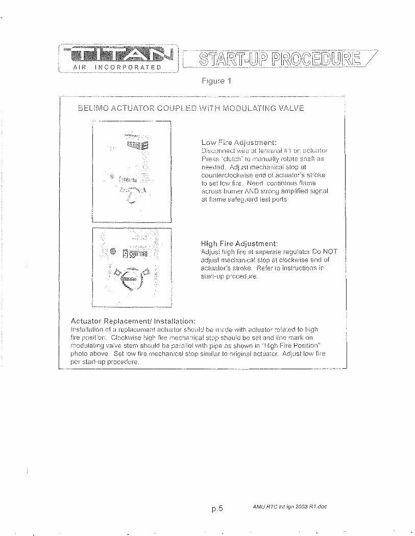
AIR INCORPORATED
Figure 1
BELi!VIO ACTU/\TOR COUPLE.D VVITH !\f!ODULAT!NG \fJ.\LVE
1----------··----
--
/..\ctuator Replacement/Installation:
Low Fire Adjustment: [li~cOllrh:.;cl \~.'Ir(; dt termlrla! ;;,' 1 on ClC(UdlOf
PI'E':SS "clutch" to nl,mlJally rot3te shaft as lleed€·:d. /\djJst mechanical slop at counterclockwise end of aclLlCl[o(S sl:"oke to set 10vII fil"e. Need contintous flan18 a:~ross burner AND strong Biliplified signal at flame safe~1L18r(j test ports
High Fire Adjustment: ildjustl11gh fire "t seperflte regulatcll Do NOT acijust mechanical stop tit clockwise enel of actuator's stroke. Refer to instructions in slart-up p!"ocedure.
Installation of i;1 repl8cement actuator should be n1cl(Je \Vitll actuator t"CJlated 10 hiqh fir"e position. CI:)ckwise high fire mecita:licClI stop should be set and line !llark on IllOduJ8ting valve stern should be pcH8;!ell,vlih pipe 8S shown in "High Fire Position" photo 8bove_ Set !m.y fire IIlech8nic8! stop similar to original actuator. Adjust lov~: fire per start-up procedure.
p.5 AMU RTC /nt /gl1 2003 R1.doc
Brandon
2.6 General Information: Installation, Assembly Drawings, Maintenance


WARNING
Improper installation, adjustment, alteration, service or maintenance can cause property
damage, injury or death. READ all maintenance instructions thoroughly before installing or
servicing equipment.
FOR YOUR SAFETY IF YOU SMELL GAS:
1. Open window I doors. 2. DO NOT switch electrical switches. 3. Extinguish any open flame. 4. Immediately call your gas supplier from
an area away from gas smell.
The use and storage of gasoline or other flammable vapors and
liquids in open containers in the vicinity of this heater is
HAZARDOUS.
NOTICE LOW TEMPERATURE LIMIT
If this heater is to be installed in an area of potential freeze up and a low temperature limit
was not ordered, one should be installed to provide freeze protection in the event of a
burner shut down.
24 MONTH WARRANTY Titan Air, Inc. hereby warrants its products against defects in material and
workmanship for a period of (24) twenty four months from date of shipment. Start up checklist is due back within (30) thirty days of start-up or 120 days from date
of delivery for 24 month warranty to be effective. After (30) thirty days, and up until (60) sixty days, a (13) thirteenth month warranty will be observed. All warranties are null and void if start up checklist is not received within (60) sixty days from start-up or 120 days from date of delivery. NO EXCEPTIONS WILL BE MADE.
Titan Air, Inc. reserves the right at Titan Air, Inc.'s option, to replace or repair free of charge, any part proven by Titan Air, Inc. to be defective. Prompt notification of defective part must be given to Titan Air, Inc. and defective part must be returned freight prepaid within (30) thirty days of notification.
WARRANTY INCLUDES ONLY PARTS SUPPLIED BY TITAN AIR, INC. INCIDENTAL COSTS AND LABOR CHARGES SHALL BE THE RESPONSIBILITY OF OTHERS. This warranty does not cover fuses, belts, filters or water damaged parts which are the result of improper storage or installation.
This warranty is void in event the product is improperly installed and/or operated under conditions other than normal published ratings, improperly maintained, misused or not in compliance with applicable codes or not in accordance with Titan Air, Inc.'s operating instructions.
This warranty is void if attempts to correct or repair any alleged defective part or parts are made by unauthorized personnel without Titan Air, Inc.'s written approval.
In no event shall Titan Air, Inc. be held liable for any damage, incidental or consequential, arising from the installation, performance or operation of the product.
This warranty supersedes, voids, and/or is in lieu of any other verbal or written understanding which may not be in total accordance with this expressed warranty.
Warranted parts must be returned to Titan Air, Inc. within 60 days to receive credit.
PURPOSE / APPLICABILITY This manual is intended to provide installation, operating and service information on
Titan Air's standard direct-fired air make-up units. Other Titan Air units, such as AR/80™, AR/75™, Demand-AirTM, H.O.TIM and units that do not feature a direct-fired burner, will have separate operating and service manuals.
A packet of reference materials for a specific unit (tracked by its Serial Number) is generally included with this Operating and Service Manual. The reference materials include Unit Specifications, Parts Lists, Gas Train and Burner Specifications, Electrical Schematic, and a Sequence of Operation. A start up checklist is also included in this packet. Review the reference materials for a specific unit and note any optional equipment or controls which are not specifically addressed in this manual prior to attempting start-up or service work.
The information and recommendations contained in this publication are based on general observation and are not intended to supplant requirements of federal, state or local codes having jurisdiction. These codes should be reviewed before installation of equipment. All units must be installed in accordance with national, state or local codes.
It is the responsibility of the purchaser at the time of order, to specify any and all code or insurance requirements that may dictate the addition of components to the equipment in order to comply with those requirements.
Only qualified personnel who have experience with the installation and operation of industrial/commercial direct fired equipment should attempt to service Titan Air equipment.
1
"'iilIiP:~i~ AIR INCORPORATED
WARRANTY
TABLE OF CONTENTS
GENERAL INFORMATION " Equipment Arrival " Components
AIR FLOW SWITCH OPERATION
INSTALLATION " Installation and Field Wiring Overview
TYPICAL ASSEMBLY DRAWINGS
MAINTENANCE
FLAME FAIL DIAGNOSTICS
START-UP PREPARATION
VALVE LEAK TEST
SPECIFIC EQUIPMENT DETAILS " Unit Specification " Sequence of Operation " Parts / Legend Sheet " Schematic " Start-Up Procedure " Troubleshooting (optional)
Page 1
2
3
7
8
11
14
17
19
20
pages not numbered
Note that operating and service manuals are occasionally requested prior to production of a unit. These manuals will be marked "Pre-Production Release" on the front cover. The final copy of the operating and service manual for a specific unit will be sent with the unit. Additional copies of the manual for a specific unit are available.
A detailed unit specification sheet, parts/legend sheet, schematic, sequence of operation and start-up procedure are provided in the start-up section of each operating and service manual generated for a specific unit. Selected vendor cut sheets on components will also be included.
2
EQUIPMENT ARRIVAL When the air make-up unit arrives, be sure to inspect for shipping damage. The
equipment was thoroughly inspected before leaving the factory and the driver signed for it. Read the bill of lading and verify that all of the items listed are accounted for. Any damaged or missing items should be reported to the transporter immediately. DO NOT SEND DAMAGED FREIGHT BACK TO TITAN AIR! All claims must be filed with the transporter. Be sure to take photographs and get the drivers signature to confirm the damage. The driver will have a number for you to call to file a claim. Request a written inspection report from the claims inspector to substantiate any necessary claim. Be sure to open the unit access doors and inspect for internal damage.
If for some reason you are unable to install the equipment immediately, be sure that the equipment is protected from the elements. Water damaged parts are not covered by Titan Air's warranty. If the equipment is stored for an extended length of time, be sure to completely check the unit for any internal damage which may have been caused by excessive condensation. Also check for damage caused by rodents, and be sure to eliminate any dust that may have built up on the components while the unit was in storage.
CAREFULLY AND THOROUGHLY READ TITAN AIR'S PRODUCT WARRANTY Each unit is tested at the factory prior to shipping. Because we are not able to
simulate exact field conditions and sometimes actual conditions are different than what was stated on the order, you may need to make some adjustments in the field. This is why it is very important that only qualified personnel start-up and service Titan Air equipment. The start-up checklist (provided in packet with this manual) must be filled out and returned to Titan Air in order to validate equipment warranty.
For a fee, Titan Air personnel will travel to the job site, supervise start-up and provide operation and maintenance training for the equipment.
BLOWERS The typical blower(s) used in Titan Air equipment are AMCA rated industrial type
forward curve D.W.D.1. fans. Backward incline, backward airfoil, and plenum/plug fans are used occasionally. Models TA-1 09 through TA-136 utilize a single blower while models TA-215 through TA-242 utilize twin blowers. All blower wheels are mounted on a solid, turned, ground and polished shaft. 9" and 12" blowers are supported with permanently lubricated ball bearings. Larger blowers are supported by lubricated pillow block ball bearings.
MOTOR & DRIVE Rigid base, T-Frame, motors are utilized. The motor is mounted on an adjustable
slide base. Variable pitch motor sheaves are provided to allow airflow adjustment if the motor is no larger than 30 Hp.
3

DIRECT FIRED HEATING Direct fired burners are designed to operate in a fresh flowing airstream. Gas is fed
directly to the burner and the airstream provides the needed oxygen for combustion. A series of strategically sized and placed holes provide air to the combustion zone.
See Figure 1
High Fire Zone
Intermediate [ Zone
Low Fire I Zone L
Aluminum Manifold
Indicated Flame Length
i Steel Combustion Baffle
'-.Hi,'" Fire Air POliS
Progressive Air Supply
Intermediate Ports Fire Air Po Its
'y.i--- Low Fire Air Ports
AIR FLOW
Figure 1
The direct fired burner is designed to operate at an air velocity across the burner of 2450 fpm with maximum manifold gas pressure as stated on unit rating plate. Air velocity across the burner can be adjusted on single speed units with slide plates on either side of the burner. Two speed units feature an automatic damper with actuator and controls to maintain proper velocity across the burner profile as air volume changes,
Because of the air pattern, air ports and kinetic energy of the air moving across the burner, the direct fired burner has the capabilities of approximately 32:1 turn down ratio, The high fire rate is approximately 30 times of the low fire rate,
4
""iiI1i itA i t:J AIR INCORPORATED
BURNER OPERATING PRINCIPLES The direct fired burner is designed to operate in a cabinet of flowing fresh air. Fuel
gas is fed directly to the burner; kinetic energy of the airstream furnishes combustion air. It will function properly at the design velocity and pressure associated with ventilating systems.
The burner must be installed to fire with, and parallel to, the air flow. By virtue of velocity impact and suction generated by the diverging shape of the combustion baffles, air is induced through the air ports into the combustion zone. The air supply is constant, even though only that which mixes with the gas takes part in combustion.
When a very small quantity of gas is admitted to the burner, sufficient mixing takes place in the low fire slot where combustion takes place. Since the low fire zone is contained within the burner casting it is effectively shielded from uncontrolled air entry.
As the gas supply is increased the flame progresses into the intermediate fire zone where an additional supply of air is available. At higher or full capacity, mixing occurs at the larger air ports of the high fire zone augmented by air flowing over the end of the baffles.
On a reduction of gas supply the reverse sequence takes place, the flame recedes to a location of lesser airsupply until the low fire zone is reached. The burner is suitable for a turndown range of approximately 30 to 1.
AIR SUPPLY The supply fan is typically positioned to draw air across the burner. Air flow across
the burner must be substantially straight (laminar) and velocity must be within the proper range to develop the desired turndown and capacity.
The direct fired burner is designed to operate in an air make-up heater with all air crossing the burner taken directly from outdoors. Rare exceptions involve equipment that serves an unoccupied space.
Total pressure rating of the blower includes allowance for the pressure drop through the primary air handling unit including the burner, together with pressure losses at the inlet screen, inlet damper, filters, outlet damper if used, plus the external pressure rating of the system.
BURNERS Burners are purchased in 6" and 12" straight lengths and 12" tee sections and
are assembled to meet the BTU requirements of each piece of equipment. According to national safety standards, the following factors could influence safe
operation of a direct fired air make-up unit and must be interlocked to either prevent the burner from firing or shut it down if unsafe conditions occur.
1. AIR SOURCE - If a damper is used, it must be interlocked to prove it is open before the blower can start.
2. BLOWER STARTER INTERLOCK - An auxiliary contact from the blower starter must be placed in series with the burner controls to prevent burner operation when the blower is not operating.
3. AIR FLOW SWITCHES - Monitor the air flow (pressure drop) across the burner. The switches (one high differential and one low differential) will not allow burner to operate if pressure drop across the burner is outside of the high and low set points.
4. HIGH TEMPERATURE LIMIT - A manual reset high temperature limit control must be utilized to prevent high temperature situations caused by excessive fuel pressure or lack of air flow.
5
"'iiOii7Ai~ AIR INCORPORATED
5. FLAME SAFEGUARD - Monitors the combustion process during ignition and operation for safe conditions.
6. HIGH GAS PRESSURE SWITCH - Monitors gas pressure to the burner. This de-energizes the burner in the event gas pressure increases above its set point.
The burner's design and flexibility, coupled with proper controls, make direct fired air make-up equipment the safest and most efficient method of tempering outdoor air.
GAS CONTROLS Titan Air TA Series equipment is constructed to meet AN.S.I Z83.4/CSA 3.7-1999
standards. Components in the gas delivery manifold on standard equipment include: two manual shut-off valves, gas pressure regulator, two safety shut-off valves and an electronic gas modulating valve. The pilot control includes a shutoff valve, gas pressure regulator and a pilot solenoid.
ELECTRIC/ELECTRONIC CONTROLS TA series air make-up units come standard with the following items: disconnect
switch, starter and overload assembly(s), control power transformer (if a 3 wire system), air proving switches, high temperature limit, electronic flame safeguard and electronic flame modulation with remote set point adjustment. Many other options including low temperature limit, inlet duct stat, and operating lights are available.
If the malfunction of the heater creates a hazard to other fuel burning equipment in the served building (i.e. supplying make-up air to boiler room) it is to be interlocked to open an inlet air damper in case of failure.
CABINET Titan Air TA series equipment comes with either a galvanized finish or a painted
finish. In both cases, the minimum gauge metal used is 18 gao
6
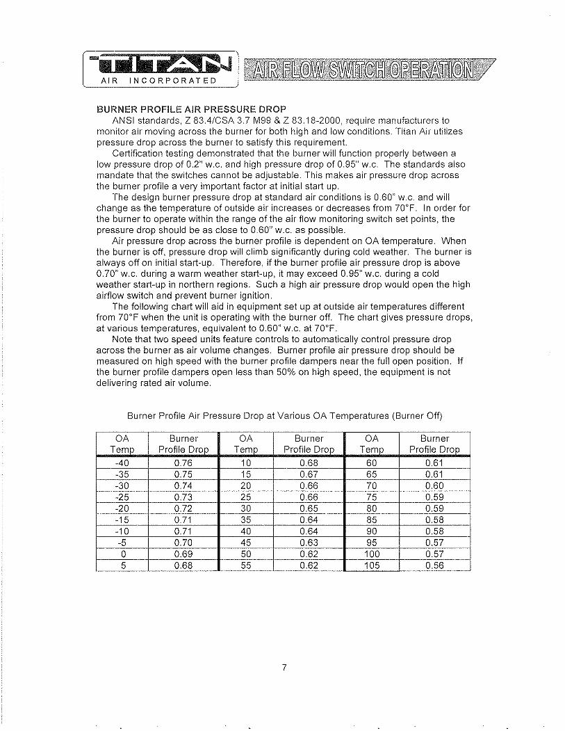
BURNER PROFILE AIR PRESSURE DROP ANSI standards, Z 83.4/CSA 3.7 M99 & Z 83.18-2000, require manufacturers to
monitor air moving across the burner for both high and low conditions. Titan Air utilizes pressure drop across the burner to satisfy this requirement.
Certification testing demonstrated that the burner will function properly between a low pressure drop of 0.2" w.c. and high pressure drop of 0.95" w.c. The standards also mandate that the switches cannot be adjustable. This makes air pressure drop across the burner profile a very important factor at initial start up.
The design burner pressure drop at standard air conditions is 0.60" w.c. and will change as the temperature of outside air increases or decreases from 70'F. In order for the burner to operate within the range of the air flow monitoring switch set points, the pressure drop should be as close to 0.60" w.c. as possible.
Air pressure drop across the burner profile is dependent on OA temperature. When the burner is off, pressure drop will climb significantly during cold weather. The burner is always off on initial start-up. Therefore, if the burner profile air pressure drop is above 0.70" w.c. during a warm weather start-up, it may exceed 0.95" w.c. during a cold weather start-up in northern regions. Such a high air pressure drop would open the high airflow switch and prevent burner ignition.
The following chart will aid in equipment set up at outside air temperatures different from 70'F when the unit is operating with the burner off. The chart gives pressure drops, at various temperatures, equivalent to 0.60" w.c. at 70'F.
Note that two speed units feature controls to automatically control pressure drop across the burner as air volume changes. Burner profile air pressure drop should be measured on high speed with the burner profile dampers near the full open position. If the burner profile dampers open less than 50% on high speed, the equipment is not delivering rated air volume.
Burner Profile Air Pressure Drop at Various OA Temperatures (Burner Off)
I OA Burner OA Burner OA Burner Temp I Profile Drop Temp Profile Drop Temp Profile Drop
-40 0.76 10 0.68 60 0.61 ---35
-----_. --0.75 15 0.67 65 0.61
-30 0.74 20 0.66 -- 70 0.60 ----_._--- f-------. _. -25 0.73 25 0.66 75 __ 0.59 -20 0.72 30 0.65 80 ___ --- 0.59 ._-----15 0.71 35 0.64 85 0.58 -10 0.71 40
,-0.64 90 0.58
-5 0.70 45 0.63 95 0.57 a 0.69 50 0.62 100 0.57 5 0_68 55 0_62 105 a_56
7
-"_.
--
-
~ ~ -iiilIlli!~1~ AIR INCORPORATED __ ~
CONTROLS Control systems can be designed to meet specific requirements_ Numerous
temperature controls are available_ Since standard air make-up units usually temper outside air to replace the air exhausted from a building, modulating discharge temperature control is typicaL A room override thermostat is occasionally included to automatically increase the discharge temperature set point if space temperature drops too low_
Titan Air units are typically supplied with a remote control paneL This panel will include switching for blower & burner operation and a temperature setpoint. Some units feature operating lights, discharge temperature display, custom controls or contacts by others to enable the blower and/or burner.
Refer to the unit specification sheets, parts list, schematic, sequence of operation and start-up procedure for a specific unit to determine the control options included.
PRE·INSTALLA TION Inspect the equipment making sure all parts and accessories are on the job site.
Check equipment against order and packing list. If the equipment has been sitting in storage for some time, inspect it for moisture (from condensation, rain or snow) and/or dust accumulation_ 60th can cause damage to electrical and electronic components as well as bearings and insulation.
INSTALLATION Care taken during the installation and start-up is vital to the longevity and reliability of
the equipment. Confirm that gas and electric utilities match the rating on the equipment name plate.
> This heater shall be installed in accordance with local codes or, in the absence of local code, according to ANSI Z223. 1_
> If the heater is to be installed in an airplane hanger, refer to ANSI/NFPA 409.
> If the heater is to be installed in a parking garage, refer to ANSI/NFPA 88A.
> If the heater is to be installed in a service garage, refer to ANSI/NFPA 886.
> For installations in Canada, refer to CAN/CGA 6149.
> Adequate exhaust and/or relief must be provided to prevent over pressurizing the served space when the heater is operating at its rated capacity.
> If in doubt regarding the application of the direct fired heater, contact the sales representative or the factory.
POSITIONING THE HEATER Locate the heater exactly level, making certain minimum clearance required by local
codes is maintained between the heater and any combustible materials. See name plate on unit for minimum recommended clearances.
8
-iiilii p:~ i ~ AIR INCORPORATED
CURBING (OUTDOOR MOUNTING) The use of a full perimeter curb or mounting rails under the heater is recommended.
The only openings in the roof should be for the supply air duct, return air duct (if required), gas and electrical connections (if applicable). These openings must be sealed properly after installation. Titan Air ships all curbs unassembled and un-insulated. Installing contractor supplies gaskets, cant strips, insulation, etc.
GAS PIPING Gas piping must be sized and installed in accordance with applicable codes. It must
be able to deliver the specified CFH and gas pressure at full flow. Refer to unit nameplate or unit specification sheets for specified CFH and gas pressure.
Care must be taken with the gas piping to prevent problems at start-up and later during operation. Before the union between the supply line and the unit is connected, the supply line should be cleaned out to remove any foreign material (dirt, rust, metal shavings, etc.) and a drip leg should be utilized.
Refer to unit nameplate to determine the minimum gas supply pressure required to attain the maximum specified gas.
All suitable gas controls, regulators and valves (equipped with a diaphragm) in this device are furnished with an ANSI approved vent limiter. If local codes require these components be vented to the outside, it is the responsibility of the installing contractor.
The heater and its individual shut off valve must be disconnected from the gas supply piping system during any pressure testing in excess of Y, PSIG.
The heater must be isolated from the gas supply piping system by closing its individual shut off valve during any pressure testing of the supply system at pressures equal to or less the y, PSIG.
During start-up, the technician should perform a gas leak check on all valves and piping during the heater's normal operation. (See page 20)
DUCTWORK Ductwork must be sized and installed in accordance with applicable codes and
standards. A size variation may exist from recommended duct size to unit flange size. Recommended duct size applies to the size of the duct at the connection to the equipment. A properly designed duct transition from the blower outlet to a larger duct is recommended for long ducts or ducts with numerous elbows.
On heaters mounted outdoors, discharge ductwork should be insulated to minimize condensation during the "off' cycle in cold weather. A fresh air intake hood with bird screen is required. Discharge duct should be common to both blowers on twin blower units. Individual ducts for each blower are not recommended.
On a heater mounted indoors with through the roof intake, a "mushroom" type intake hood is recommended to prevent moisture entrainment. When using "through the wall" intake duct, the intake louver should have adequate moisture baffling characteristics. All intake ductwork exposed to the heated space should be insulated.
9
SOUND AND VIBRATION CONTROL Flexible connectors are recommended on at least one ductwork connection.
Vibration isolators that mount between the unit and support structure are optional and can be supplied with the equipment for installation by others. Another option is internal isolation of the blower/motor assembly with internal flexible connections between the blower housing and the unit structure.
Appropriate insulation on the interior of ductwork significantly reduces sound levels.
DISCHARGE TEMPERATURE SENSOR BULB INSTALLATION & WIRING The installing contractor may be responsible for field installation of the discharge
temperature sensor. Field installation of the discharge temperature sensor in the discharge ductwork results in a better measurement of the average supply air temperature. Utilize shielded cable for field installed discharge sensor wiring.
FIELD WIRING Power supply wiring should be routed from a dedicated branch circuit per schematic.
Depending upon how the equipment was ordered, a single point power connection may be subdivided to individual loads or multiple power supply circuits may be required.
If an intake or discharge damper was ordered as a loose accessory, it will have to be mounted and the actuator must be wired. The remote panel must be mounted in a convenient location and wired to the unit. Interlocks between the exhaust, unit and possibly spray booth will have to be connected by field wiring.
Carefully review the schematic and associated schematic symbol legend. Note that legend may be on the parts/legend sheet rather than on the schematic.
Many codes require that low voltage wiring (connecting terminals numbered 100+) be routed in separate conduit from line voltage wiring. If low voltage wiring is routed with 120 VAC control voltage wiring, it must be placed in shielded cable(s). Even if low voltage wiring is routed in separate conduit, very low voltage sensor outputs and actuator control signals should be routed in shielded cable.
NOTE: All field wiring must conform to N.E.C. and/or any state or local codes.
SUPPORT OF ACCESSORIES Most Titan Air equipment is supplied with loose accessories (i.e. damper, hood,
discharge diffuser or filter section). If an intake hood is supplied by others, the design shall minimize entry of snow/rain and include an intake screen to meet ANSI standards. Intake accessories on large equipment may be shipped in two pieces for field assembly. Two damper actuators may need to be field wired on large equipment as well.
It is the responsibility of the installing contractor to support accessory items from a rigid point or points to ensure solid mounting.
POST INSTALLATION Caulking is required between all parts prior to assembly and seams must be
re-caulked after assembly. Air make-up units shipped in multiple sections will include a high quality caulk tape and caulk tubes. Caulk tape is applied between sections with exterior caulking applied after the unit sections have been joined. Sealing integrity should be rechecked on a yearly basis.
Water damaged parts are not covered by Titan Air's warranty.
10
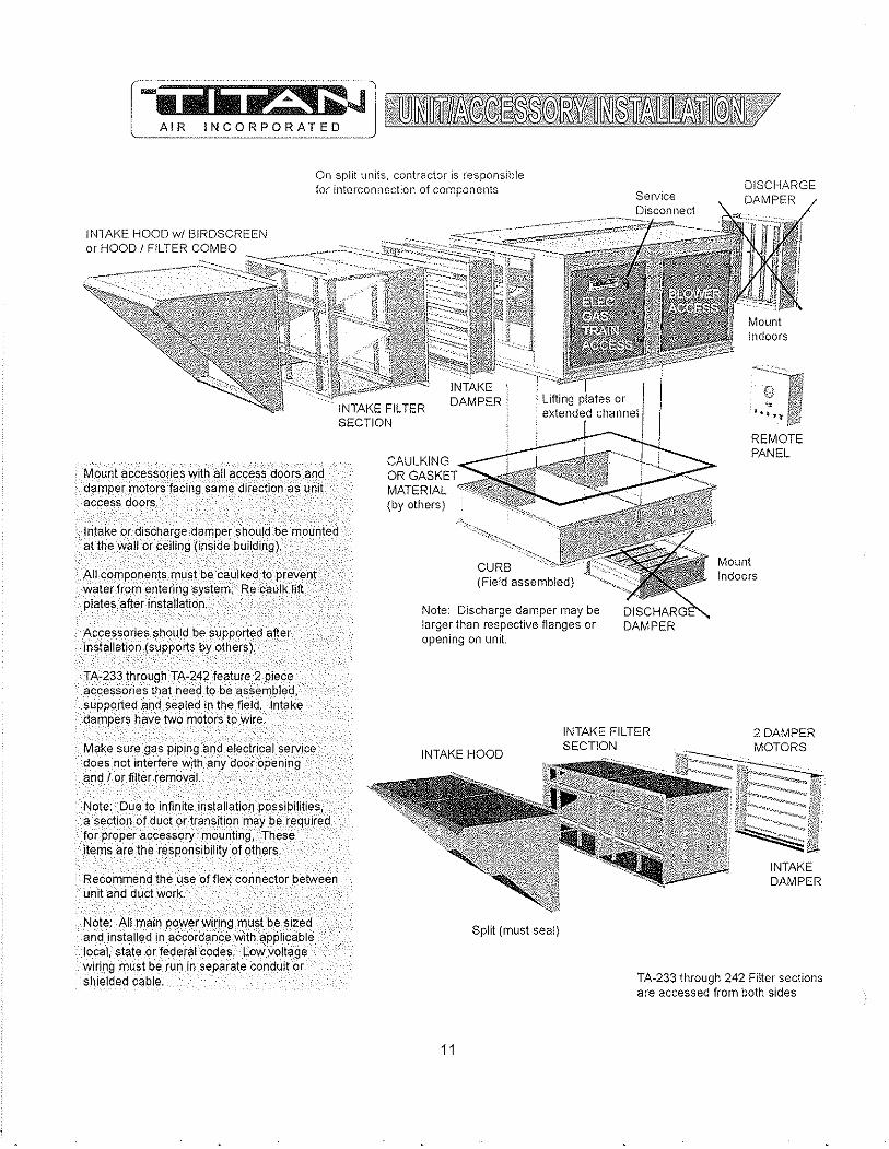
On split units, contractor is responsible for interconnection of components DISCHARGE
DAMPER Service Disconnect
INTAKE HOOD wi BIRDSCREEN '~""'<~~":::~:;:::,::~~§~'::;~~~~~~::;;~~:'~~II or HOOD I FILTER COMBO '"
Mount accessories with all access doors and damper motors facing same direction as unit access doors,
Intake or discharge dafTlper should be mounted at the wall or ceiling (inside building),
All components must be 'c,a~!ked to prevent water from entering ~ystem,' Re caulk lift plates after installation,
Accessories should be supported after installation (supports by others),
TA-233 through TA-242 feature 2 piece accessories that need to be assembled, supported and sealed in the field, Intake dampers have two motors to wire,
Make sure gas piping and electrical seIViee does not interfere with -any door opening and I or filter removaL
Note: Due to infinite installation possibilities, a section of duct or transition may be required for proper aC,cessory mounting, These items are the responsibility of others,
Recommend the use 'offJex connector between unit and duct work.
Note: .AII main power wiring must.be sized and installed in accordance with applicable local, state or federal codes, Low voltage wiring must be run In separate conduit or shielded cable,
(by others)
Note: Discharge damper may be larger than respective flanges or opening on unit.
DAMPER
REMOTE PANEL
Mount Indoors
INTAKE HOOD
INTAKE FILTER SECTION
2 DAMPER
Split (must seal)
11
TA-233 through 242 Filter sections are accessed from both sides
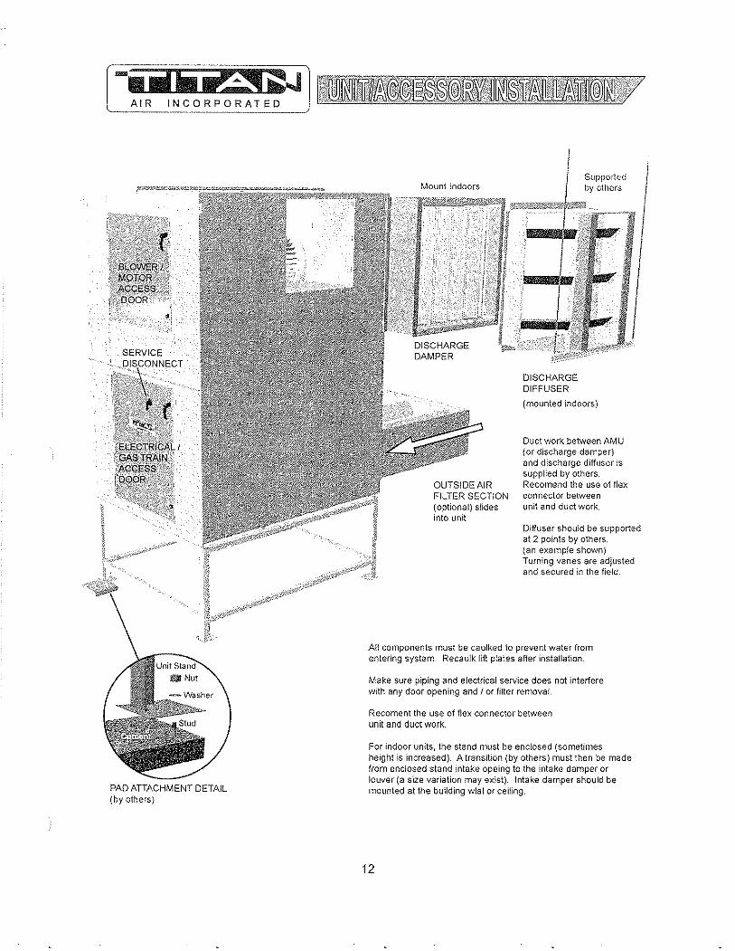
PAD ATTACHMENT DETAIL (by others)
Mo\mt Indoors Supported by others
;~]I.~ilR~'~'1J1f"j!llE0)j_~0JJ)j
OUTSIDE AIR FILTER SECTION (optional) slides into unit
DISCHARGE DIFFUSER
(mounted indoors)
Duct work between AMU {or discharge damper} and discharge diffuser is supplied by others. Recomend the use of flex connector between unit and duct work.
Diffuser should be supported at 2 points by others. (an example shown) Turning vanes are adjusted and secured in the field.
AU components must be caulked to prevent water from entering system. Recaulk lift plates after installation.
Make sure piping and electrical service does not interfere with any door opening and I or filter removal.
Recoment the use of flex connector between unit and duct work.
For indoor units, the stand must be enclosed (sometimes height is increased). A transition (by others) must then be made from enclosed stand intake opeing to the intake damper or louver (a size variation may exist). Intake damper should be mOlmted at the bullding wlal or ceiling.
12
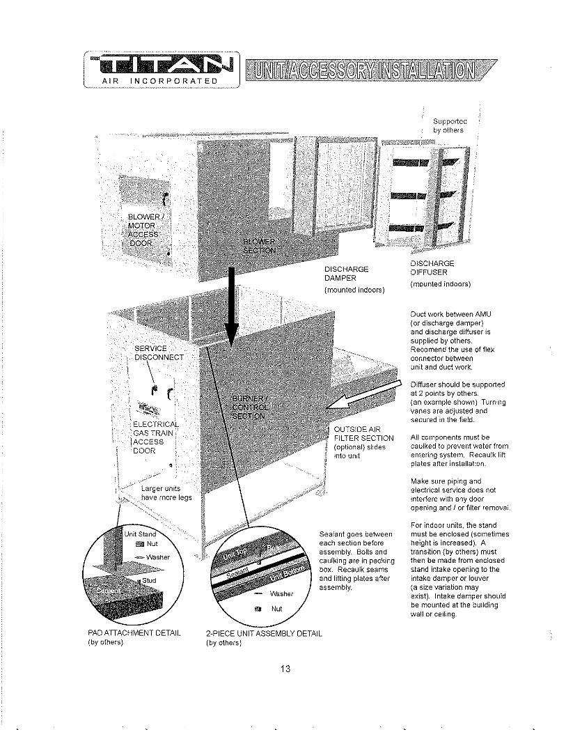
SERVICE
DIS\ONNECT
f' r ~~"
ELECTRICAL GAS TRAIN' ACCESS DOOR
•
Larger units have more legs
PAD ATIACHMENT DETAIL (by others)
Supported
~.~ 'lil£ili!1~~~.¥!l~""'t''''11i'"'''''~,%c§ll!ibY ott) ers
9 Nut
(optional) slides into unit
Sealant goes between each section before assembly. Bolts and caulking are in packing box. Recaulk seams and lifting plates after assembly.
2-PIECE UNIT ASSEMBLY DETAIL (by others)
13
DISCHARGE DIFFUSER
(mounted indoors)
Duct work between AMU (or discharge damper) and discharge diffuser is supplied by others. Recomend the use of flex connector between unit and duct work.
Diffuser should be supported at 2 points by others. (an example shown) Turning vanes are adjusted and secured in the field
All components must be caulked to prevent water from entering system. Recau!k lift plates after installation .
Make sure piping and electrical service does not interfere witt) any door opening and J or filter removal.
For indoor units, the stand must be enclosed (sometimes height is increased). A transition (by others) must then be made from enclosed stand intake opening to the intake damper or louver (a size variation may exist). Intake damper should be mounted at the building wall or ceiling.

~ .
.... 1 'liprA.i~J AIR INCORPORATED ...
GENERAL MAINTENANCE As with any equipment or machinery, a maintenance program should be
implemented. A well maintained unit will perform efficiently for many years.
Equipment maintenance should include the following: 1. Check filters and clean or replace as needed. 2. Lube bearings, 3, Check belts and belt tension. (Do not over tension,) 4, Check all hardware (bearings, etc,) for tightness. 5, Check settings for all controls. 6, Check duct connections for leaks, 7. Re-caulk seams if needed, 8. Check burner and flame rod - clean if necessary. 9, Perform complete start-up procedure once per year (prior to heating season),
FILTERS Dirty or clogged filters will restrict air flow which in turn affects the burner operation,
Therefore, it is necessary to check filters on a regular basis. Cleanable filters can be removed from the filter rack and sprayed with a low pressure water, Always spray these filters in the opposite direction to air flow and apply new coating to filters when dry,
BURNER Maintaining the pilot assembly is essential to reliable operation, During pre-heating
season maintenance, the burner should be lit numerous times to confirm reliability, If ignition system components require servicing, pay attention to the following:
1, Handle porcelain spark rod and flame rod with care. Small cracks lead to intermittent ignition problems,
2, Midco burners utilize the pilot gas tube as a ground point for the ignition rod, Keep this grounding point free from scale or other contaminant build-up.
3, Ignition wire routing should remain separated from sheet rnetal cabinet to rnaintain optimal spark strength,
4, Dielectric grease is utilized inside of the ignition and flame sensor connection boots to limit potential for moisture in the connection,
5. Maintaining low pilot regulator output pressure typically produces reliable ignition. Excess pilot pressure creates a gas rich region that will not ignite consistently,
6, The pilot solenoid is disabled following main flame ignition. The low fire setting must be high enough to maintain a proper amplified flame rectification signal.
Check that burner baffles are firmly attached to each other and to the burner casting, Do not use excessive force on screws in burner casting, Clean burner baffles with a wire brush if necessary,
Burner orifices may need to be re-drilled due to rust or other build-up. Burners with aluminum castings will rarely require orifice cleaning. Use drill bit sizes listed below.
Fuel Tvoe Burner Model Orifice Size Natural Gas Ecliose AH-MA 2.4 mm Bit Natural Gas Midco HMA-2 1/8" Bit
LP Gas Ecliose AH-MA 2,0 mm Bit LP Gas Midco HMA-2 #45 Bit
14
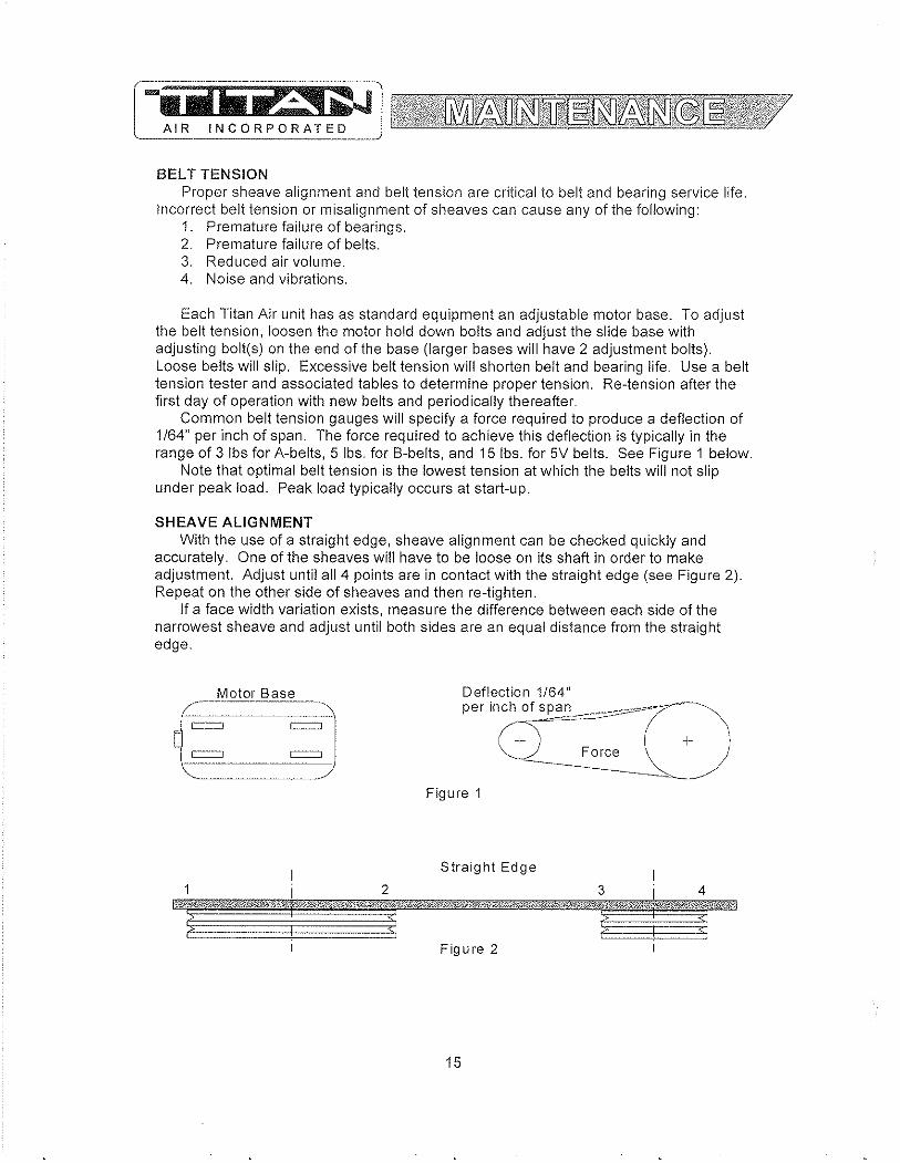
[iiiIii -r~i ~J AIR INCORPORA!ED ___ _
BELT TENSION Proper sheave alignment and belt tension are critical to belt and bearing service life.
Incorrect belt tension or misalignment of sheaves can cause any of the following: 1. Premature failure of bearings. 2. Premature failure of belts. 3. Reduced air volume. 4. Noise and vibrations.
Each Titan Air unit has as standard equipment an adjustable motor base. To adjust the belt tension, loosen the motor hold down bolts and adjust the slide base with adjusting bolt(s) on the end of the base (larger bases will have 2 adjustment bolts). Loose belts will slip. Excessive belt tension will shorten belt and bearing life. Use a belt tension tester and associated tables to determine proper tension. Re-tension after the first day of operation with new belts and periodically thereafter.
Common belt tension gauges will specify a force required to produce a deflection of 1/64" per inch of span. The force required to achieve this deflection is typically in the range of 3 Ibs for A-belts, 5 Ibs. for B-belts, and 15 Ibs. for 5V belts. See Figure 1 below.
Note that optimal belt tension is the lowest tension at which the belts will not slip under peak load. Peak load typically occurs at start-up.
SHEAVE ALIGNMENT With the use of a straight edge, sheave alignment can be checked quickly and
accurately. One of the sheaves will have to be loose on its shaft in order to make adjustment. Adjust until all 4 points are in contact with the straight edge (see Figure 2). Repeat on the other side of sheaves and then re-tighten.
If a face width variation exists, measure the difference between each side of the narrowest sheave and adjust until both sides are an equal distance from the straight edge.
Motor Base
{:-=-~ Figure 1
Straight Edge
2 3 4
Figure 2
15

BLOWER BEARINGS Bearings must be checked during each periodic maintenance inspection, Bolts and
set screws should be checked for tightness and the bearings may need lubrication, The following is intended only as a guide to aid you in setting up your own schedule
LUBRICATION GUIDE FOR BLOWER BEARINGS
Operating conditions Clean
Dirty
Moisture
MOTOR BEARINGS
Bearing Temp, CF) 32 - 120
120 - 150 150 - 200 32 - 150
150 - 200 32 - 200
Grease Interval 6 - 10 months 1 - 3 months 1 - 4 weeks 1 - 4 weeks Daily - 1 week Daily - 1 week
Motor bearings in a clean environment should be lubricated every 2 to 3 years, Under more severe conditions of dirt or moisture, lubrication may be required every 6 months to 1 year. Typical motor bearing lubrication procedure follows:
1, Remove fill and drain plugs, 2, Clean drain port of hard grease (with wire if necessary), 3, Add grease (cavity should be no more than Yo fulL), 4, Start motor and let run for 10 minutes, 5, Wipe off any drained grease and replace fill and drain plugs,
Avoid adding an excessive amount of grease since this a common cause of motor failure,
BLOWER Ensure that blower hub is securely fastened to shaft Inspect blower wheel and
blades for signs of damage or cracks, Clean blades if necessary to maintain proper balance and performance, Avoid use of excessive grease on blower bearings that can coat fan blades and attract dirt
16
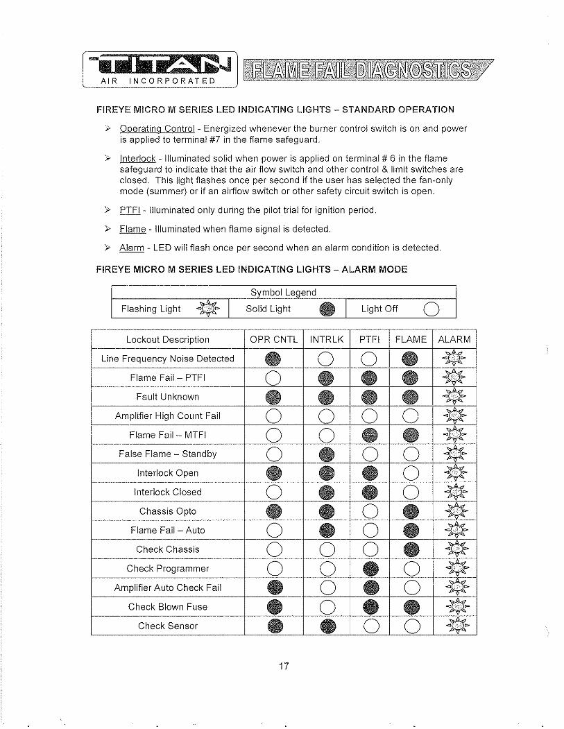
.... iilii iV~ 5' ~J AIR INCORPORATED
FIREYE MICRO M SERIES LED INDICATING LIGHTS - STANDARD OPERATION
i- Operating Control - Energized whenever the burner control switch is on and power is applied to terminal #7 in the flame safeguard.
i- Interlock - Illuminated solid when power is applied on terminal # 6 in the flame safeguard to indicate that the air flow switch and other control & limit switches are closed. This light flashes once per second if the user has selected the fan-only mode (summer) or if an airflow switch or other safety circuit switch is open.
i- PTFI - Illuminated only during the pilot trial for ignition period.
i- Flame - Illuminated when flame signal is detected.
i- Alarm - LED will flash once per second when an alarm condition is detected.
FIREYE MICRO M SERIES LED INDICATING LIGHTS - ALARM MODE
r-____________ ~~-,----S=.y~m~~bo~I~L~e£ge~n~d~~,_------------=_~ Flashing Light * I Solid Light • I Light Off 0
--- .. -- ---Lockout Description OPR CNTL INTRLK PTFI FLAME ALARM
Line Frequency Noise Detected • __ 0 __ 0 · --~~ f----.-.--
Flame Fail- PTFI 0 • • • ~~~ "''' . - ,"_ ... _---_._--_. __ ._----._ .
Fault Unknown • • • • ~~ Amplifier High Count Fail 0 0 0 0 '$ ··:}t,,~
1------___ 0_ 0 • • ~ Flame Fail - MTFI <I -,-,,", po
"''' -_. __ ._-- .. __ .. _-----._--_._------_ .. "_ .. - ..
* False Flame - Standby 0 • 0 0 Interlock Open • • • 0 r-~p.--
"''' Interlock Closed 0 • • 0 * Chassis Opto • • 0 • * p--~
-
Flame Fail - Auto 0 • 0 • * " Check Chassis 0 0 0 • * Check Programmer 0 0 • 0 ¥ Amplifier Auto Check Fail • 0 • 0 * '" "
Check Blown Fuse • 0 • • ~~ '" " f-.--------.- • • 0 0 * Check Sensor
17
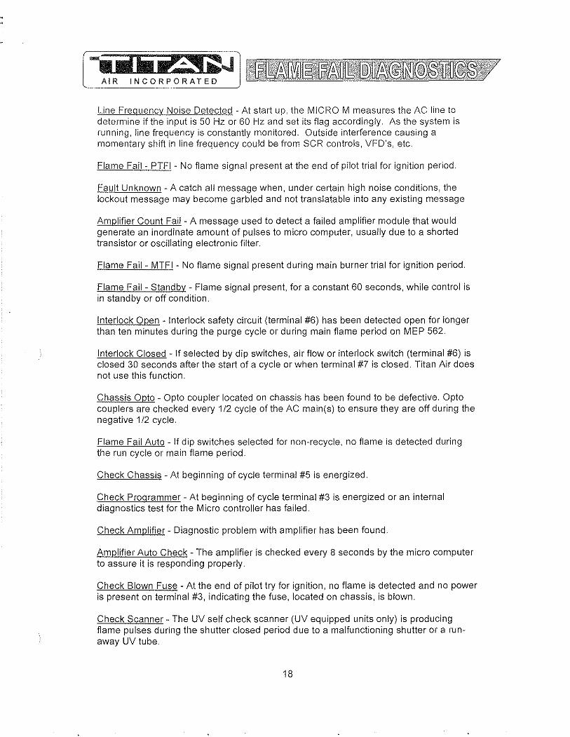
-iiDiit~i~JJ AIR_ INCO~!"ORATED
Line Frequency Noise Detected - At start up, the MICRO M measures the AC line to determine if the input is 50 Hz or 60 Hz and set its flag accordingly, As the system is running, line frequency is constantly monitored, Outside interference causing a momentary shift in line frequency could be from SCR controls, VFD's, etc,
Flame Fail - PTFI - No flame signal present at the end of pilot trial for ignition period,
Fault Unknown - A catch all message when, under certain high noise conditions, the lockout message may become garbled and not translatable into any existing message
Amplifier Count Fail - A message used to detect a failed amplifier module that would generate an inordinate amount of pulses to micro computer, usually due to a shorted transistor or OSCillating electronic filter,
Flame Fail - MTFI - No flame signal present during main burner trial for ignition period,
Flame Fail - Standby - Flame signal present, for a constant 60 seconds, while control is in standby or off condition,
Interlock Open - Interlock safety circuit (terminal #6) has been detected open for longer than ten minutes during the purge cycle or during main flame period on MEP 562,
Interlock Closed - If selected by dip switches, air flow or interlock switch (terminal #6) is closed 30 seconds after the start of a cycle or when terminal #7 is closed, Titan Air does not use this function,
Chassis Opto - Opto coupler located on chassis has been found to be defective. Opto couplers are checked every 1/2 cycle of the AC main(s) to ensure they are off during the negative 1/2 cycle.
Flame Fail Auto - If dip switches selected for non-recycle, no flame is detected during the run cycle or main flame period.
Check Chassis - At beginning of cycle terminal #5 is energized.
Check Programmer - At beginning of cycle terminal #3 is energized or an internal diagnostics test for the Micro controller has failed.
Check Amplifier - Diagnostic problem with amplifier has been found.
Amplifier Auto Check - The amplifier is checked every 8 seconds by the micro computer to assure it is responding properly.
Check Blown Fuse - At the end of pilot try for ignition, no flame is detected and no power is present on terminal #3, indicating the fuse, located on chassis, is blown.
Check Scanner - The UV self check scanner (UV equipped units only) is producing flame pulses during the shutter closed period due to a malfunctioning shutter or a runaway UV tube.
18
.... iiiIli"~ i a:.J AIR INCORPORATED
GENERAL START-UP INFORMATION Even though Titan Air equipment is tested at the factory, it is not the type of
equipment you can throw the switch and walk away from. A complete start-up procedure must be performed.
The factory cannot duplicate the conditions the equipment will see in the actual installation (i.e. gas pressure, static pressure, desired control settings, etc ... ). For this reason there are field adjustments that have to be made. Performing a complete startup procedure will help ensure that correct adjustments are made and correct operation is verified. A step-by-step start-up procedure is provided on subsequent pages. While working through the start-up procedure, record information on the start-up checklist and return to Titan Air to validate the equipment warranty. The start-up checklist is provided on cardstock with Titan Air's address pre-printed on one side.
Because most component failures occur during start-up, it is very important that the function of every component be checked out during start-up. It is just as important that the start-up technician realize the malfunction of a component may be caused by other factors (i.e. air flow, gas pressure, field wiring, etc ... ) and should fully investigate a component malfunction and its cause before replacing the component.
Titan Air checks out all returned components and has found approximately 70% of returned parts are in full operational condition. This history has proven that a little extra time invested in troubleshooting will often save the considerable investment in parts, time, and paperwork associated with replacing components.
SUGGESTED TOOLS AND INSTRUMENTS NEEDED FOR START-UP: Volt/Ohm Meter Ammeter Tachometer Thermometer Gas pressure manometer (-10" to 0 to +10" of water column typical scale) Air differential pressure manometer (-2" to 0 to +2" of water column typical scale) Standard Hand Tools.
Additional items for Maxitrol Series 14 or 44 temperature controls: :>- y" watt, 10,000 Ohm resistor
Additional items for FX Series temperature controls: :>- 10,000 Ohm resistor (supplied) :>- 1,000 Ohm resistor (supplied)
19

Valve Leak Test This is a test for checking the closure tlgl1tness of the gas safety shutoff valve. It should be performed by trained and experienced technicians. This test should be part of the scheduled inspections and maintenance procedures.
1) Close the upstream manual gas valve. 2) Make sure manual test cock on leak test assembly is closed. 3) Remove the test plug on leaving side of gas valve. 4) Close the downstream manual gas valve. 5) Open the upstream manual gas valve. 6) Through the safety system enable the gas valve momentarily. 7) Immerse a Yo" tube vertically into a jar of water. 8) Slowly open the test cock on the leak assembly. 9) Once the rate of bubbles through the test assembly stabilizes, count the number of bubbles appearing during the ten second time frame. Each bubble is approximately 0.001 cfh. 10) Do this test for each shut off valve.
Reference below leak test assembly and leakage rate chart.
A
GAS COCK
Pipe Size (in) Medium
318 & 112 .64 qas 1.57 LP
314 & 1 .64 qas 1.57 LP
1-114 & 1-112 .64 gas 1.57 LP
2 .64 gas 1.57 LP --
1-1/2 .64 gas 1.57 LP
3 .64 gas 1.57 LP -
c
1/4 N (6MM) FLEXIBLE TUBING
1f41N. (6 MM) ALUMINUM OR COPPER PILOT
o LEAK TEST TAP
E DOWNSTREAM MANUAL GAS COCl(
BURNER
r JAR OR GLASS TUB!NG ~ X VVlTHWATER
r---++--L.-L
tJ ....,.--+--- --_-L CUT AT 4 450EGREE
1/2 (13 MM)
ANGLE
Allowable Max. # of Bubbles Leakaae SCCH in 10 Sec. 294 7 188 4 301 7 192 5 532 13 341 8 578 15 .. _-370 9 752 19 481 12 925 24 592 15
20
Min. # of sec. for 10 bubbles .. -13 20A 12.7 19.9 7.2 11.2
~----.-----.--. 10.3 __ 5.1 8 4.1 6.5

(R~ Solutions
DIRECT FIRED DIGITAL TEMPERATURE CONTROL INSTALLATION, OPERATION, AND MAINTENANCE MANUAL
This manual covers the following products:
DFC-1
DFC-2
DFrs
Standard direct fired temperature control OH24VDC output
Direct fired control with integra140·90"F (4H 32<>C) dial 0-24VDC output
TemperahHc senor 40-250"F (4-121°C)
DFfD-XXXX Temperature dialS select<lble ranges
DAT-12 Discharge ail' tube
PWM-IOV P\-\'M to 10V output converter
Table of Contents Ovclview ... ". Specifications ..
Power Requirements ... DFC Ambient Temperature Limits .... DFTSjDFrD Ambient Temperature Limits., Accuracy.
Installation ". Wiring ..
Standard control with remote set point.. Standard control \'lith integral set point... Optional room space control .. Optional multiple sel poinllemperature controL.
Operation ... . Start up ..... . Sequence of operation ... Calibration .. Troubleshooting ... DFTS and DFTD Resistance chart..
DOC# T000111.14.2006 DFC-1 O&lv1 1
..2
.. 2
..2
..2
.. 2
.. 2
..2
..2
.. 2
.. 3
..3
.. 3
..4 . .. 4
. . .4
. .. 4
... 4
... 4
Ph. (919) 845-1579 Fax (919) 845-8102
''lww. RTC -So Itt Hons.com Email:[email protected]
755 5w 120111 "Vay Davie, FL 33325
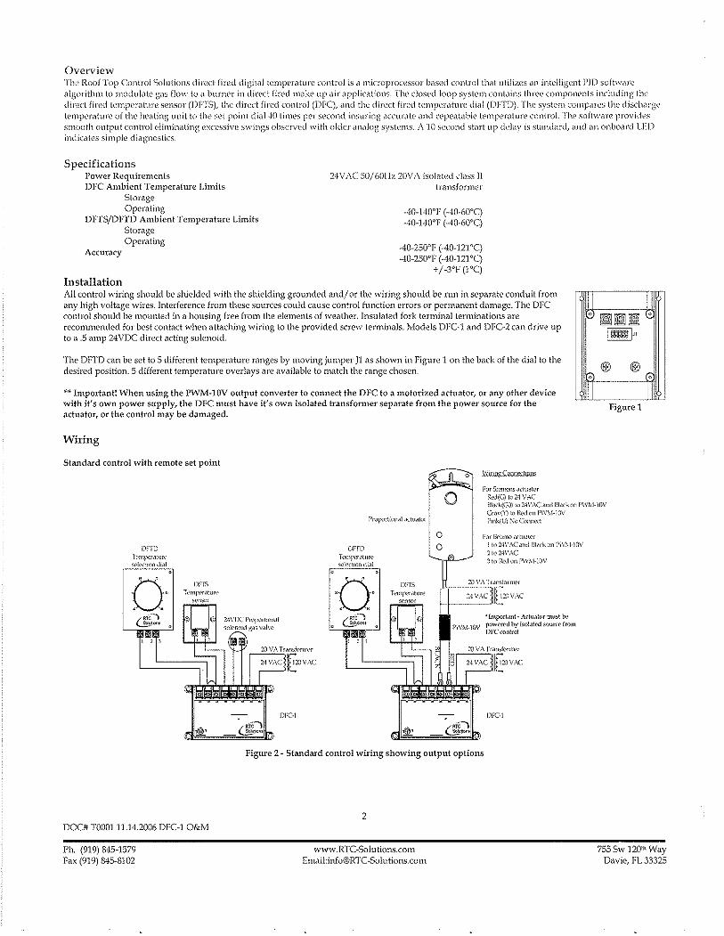
Overview TIlt' RoofTop Control Solutions direct fired digital temperature control is a microprocessor based control that utilizes ill1 intelligent PI)) software algorithm to modulate gas flow to i1 burner in direct fired Illake up air ilppliCi,tions. The dosed loop system contains three compol1l'nts including tlw direct fired temperature sensor (DFTS), the din'ct fired control (DFC), and the direct fired temperature dial (DFTD). The system compares the dischMge templ'rature of the healing unit to the set point dial·!O times pef second insuring aCCllfilte and repeatable temperature control. The software provides smooth output control eliminating excessive swings observed with older analog systems, A 10 second stMI up deJay is standard, and an onboMd LED indicates simple diagnostics.
Specifications Power Requirements DFC Ambient Temperature Limits
Storage Operating
DFrSjDFTD Ambient Temperature Limits Storage Operating
Accuracy
Installation
24VAC 50/601-h 2()V;\ isolated class II transformer
·40-140"F (-40-60'C) -40-140'1' (-40-60'C)
-40-250'1' (-40-121'C) -40-250'1' (-40-121 'c)
+/-3'1' (I 'C)
All control wiring should be shielded with the shielding grounded and/ or the wiring should be run in separate conduit from any high voltage wires, Interference froIn these sources could cause control function errors or permanent damage. The OFC control should be mounted in a housing free from the elements of weather. Insulated fork terminal terminations are recommended for best contact when attaching wiring to the provided screw tenninals. lVlodels DFe1 and DFC~2 can drive up to a .5 amp 24VDC direct acting solenoid.
The 0171'0 can be set to 5 different temperature ranges by moving jumper ]1 as shown in Figure 1 on the back of the dial to the desired position. 5 different temperature overlays are available to match the range chosen.
** ImpoItant! When using the PWM~10V output converter to connect the DFC to a motorized actuator, or any other device with it's own power supply, the DFC must have it's own isolated transformer separate from the power source for the actuator, or the control may be damaged.
Wiring
Standard control with remote set point o Wiring CQ!lIlf.,.tmu:;
For SJ('!1\('ns aclualor 1~,d(C} 10 2·1 V:\C
~ ~ I ~ilil .
, [§ill!ll"
I @ I® , , ---------fjLJ
Figure 1
o Bi,l(k(GO) t02.1\'A(' and il).,\<·kon 1'\\,~·I·lOV
CrM(Y) to R<.'do!l I'\V~I-ll1V
Dl'm T('In))CT.lllll\' sl'k.,:!Jon <i"ll
a DFIS Tl''''I)\'r,lt\''''
~\.'[1sar
DOC# T000111.14.2006 DFC-l O&M
Ph. (919) 845-1579 Fax (919) 845-8102
Df'fi) THnp",,.,llur,> ",'l~(\lon dial
. . O· ,
DFf5 Tl'tn)x'1<lture
sensor
o o
l'mk(L1 ,,0 Conned
For I)CJllllo.~ ,Kl\I<\lor 1 to 2·jV.-\C "nd BI,wk on I'\\,\ j·10V
2 10 24VAC 3 to I.((,.i on j'IV\·I·lOV
'Important· Adu,llor must lw powfff'd by !SOia!fd SOlUn from DFC(onlrol
DFGl
Figure 2 ~ Standard control wiring showing output options
2
\VWW, RTC ~Solu tions.com Emai1:info@RTC~Solutions.com
755 Sw 12011\ Way Davie, FL 33325
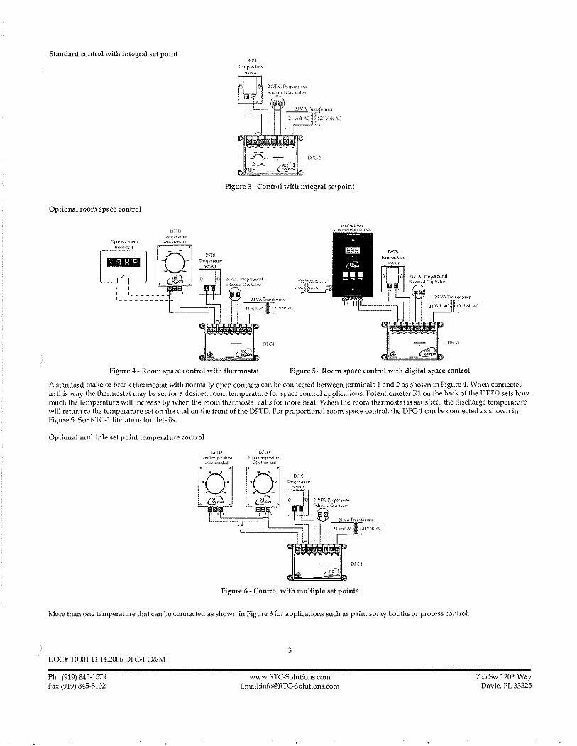
Standard control with integral set poil}l
Optional room space control
DF::,
I"mi~'f.'l"'"
Figure 3 - Control with integral setpoint
l'ollAC
Figure 4 - Room space con hal with thermostat Figure 5 - Room space control with digital space control
A standard make or break thermostat with normally open contacts can be cOImected between terminals 1 and 2 as shown in Figure 4. When cOlUlected in this way the thermostat may be set for a desired room temperature for space control applications. Potentiometer Rl on the back of the DFTD sets how much the temperature will increase by when the room thermostat calls for more heat. When the room thermostat is satisfied, the discharge temperature will return to the temperature set on the dial on the front of the DFTD. For proportional room space control, the DFC-l can be connected as shown in Figure 5. See RTC-lliterature for details.
Optional multiple set point temperahtre control
DrTD OFm
Figure 6 - Control with multiple set points
More than one temperature dial can be cOImected as shown in Figure 3 for applications such as paint spray booths or process control.
DOC# T000111.14.2006 DK-1 O&M
Ph. (919) 845-1579 Fa, (919) 845-8102
3
www.RTC-Solutions.com Email:[email protected]
755 Sw 12011\ Way Davie, fL 33325
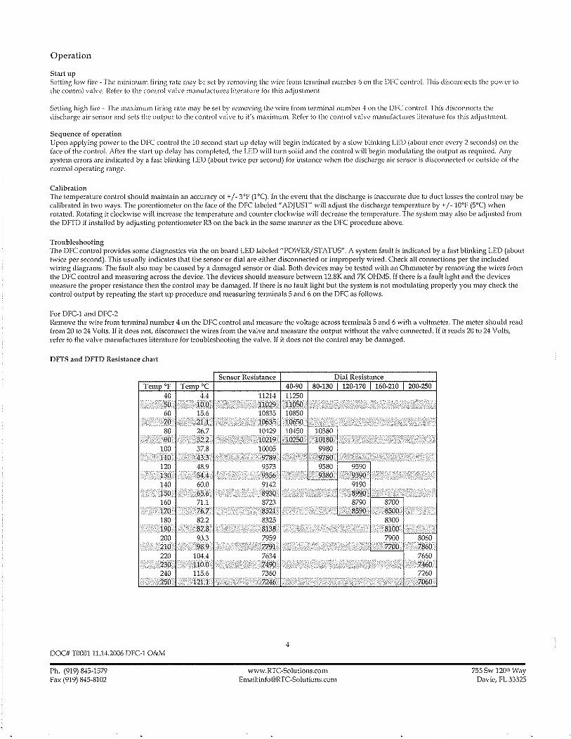
Operation
Start up Setting I{HY fire - The minimum firing rilte lllay be set by rt'moving the wire from terminal number 6 on the DFC control rllis disconnects the p{)\,vel" to the control valve. Refer to the control villve manufactun's litel'ilture for this adjustment.
Setting high fire - The !l1ilximuJ11 firing rate may be set by fl'lHoving the wire [rom (-er111i)),1J number 4 on the DFC control This disconnects the discharge air sensor ilnd sets the output to the control valve to it's maximum. Refer 10 the control valve manufactures lit{'J'ilture for this adjustment.
Sequence of operation Upon applying power to the DFC control the 10 second stilrt up delily will begin indicated by a slow blinking LED (about once every 2 seconds) on the face of the control. Aftel" the stilrl up delay has completed, the LED will turn solid and the control will begin modulilting the output as required. Any system errors are indicated by a fast blinking LED (about twice per second) for instance when the discharge air sensor is disconnected or outside of the normal operating range.
Calibration The temperature control should maintain all accuracy of + / - 3"F (1 "c). In the event that the discharge is inaccurilte due to duct losses the control may be calibrated in two ways. The potentiometer on the face of the DFC labeled" ADJUST" will adjust the discharge temperature by + / - lO"F (5°C) when rotated. Rotating it clockwise will incre,)se the temperature and counter clockwise will decrease the temperature. The system may also be adjusted from the DrTD if installed by adjusting potentiometer R3 on the back in the same manner as the DFC procedure above.
Trollbleshooting The DFC control provides some diagnostics via the on board LED labeled "POWER/STATUS". A system fault is indicated by a fast blinking LED (about twice per second). This usually indicates that the sensor or dial are either disconnected or improperly wired. Check all connections per the included wiring diagrams. The fault also may be caused by a damaged sensor or diaL Both devices may be tested v'lith an Ohmmeter by removing the wires from the DFC control and measuring across the device. The devices should measure beh,veen l2.SK and 7K OHMS. If there is a fault light and the devices measure the proper resistance then the control may be damaged. If there is no fault light but the system is not modulating properly you may check the control output by repeating the start up procedure and measuring terminals 5 and 6 on the DFC as follows.
For DFC-l and DFC-2 Remove the wire from terminal number 4 on the DFC control and measure the voltage across terminals 5 and 6 with a voltmeter. The meter should read from 20 to 24 Volts. If it does not, disconnect the wires from the valve and measure the output without the valve connected. If it reads 20 to 24 Volts, refer to the valve manufactures literature for troubleshooting the valve. If it does not the control may be damaged.
DFl'S and DFfn Resistance chart
Sensor Resistance Dial Resistance Tem OF TeIll °C 40-90 80-130 120-170 160-210 200-250
DOC# '1'000111.14.2006 DFC-l O&M
Ph. (919) 845-1579 Fax (919) 845-8102
7900 8060
~;~~~.p:0C~~0"~~¥I{f;'~;j{'0,;,c;~LL.~·77~boq·I?3~Qd 7660 ~460 7260 7060
115.6 121.1
4
www.RTC-Solutions.com Email:[email protected]
755 Sw 120lh Way Davie, FL 33325
Jf3lHNSON CONTR0LS ProducUTechnical Bulletin
Issue Date A419
April 4, 2008
A419 Series Electronic Temperature Controls with Display and NEMA 1 or NEMA 4X Watertight Enclosures
The A419 series controls are single-stage, electronic temperature controls with a Single-Pole, Double-Throw (SPD7) output relay. They feature a lockable front-panel touchpad for setup and adjustment, and a Liquid Crystal Display (LCD) for viewing the temperature and status of other functions. A Light-Emitting Diode (LED) indicates the controls' output relay On/Off status. The A419 controls are available in 24 VAC or 120/240 VAC powered models.
The A419 controls have heating and cooling modes, adjustable setpoint and differential, an adjustable anti-short cycle delay, and a temperature offset function. The setpoint range is -30 to 212°F (-34 to 100°C), The controls feature remote sensing capability and interchangeable sensors. The A419 controls are available in either NEMA 1, high-impact plastic enclosure suitable for surface or DIN rail mounting or NEMA 4X watertight, corrosion-resistant surface-mount enclosures.
Figure 1: A419 Temperature Control with NEMA 1 Enclosure and A99 Temperature Sensor
Features and Benefits
Easy-to-Read Front-Panel Liquid Crystal Display
Wide Temperature Differential Adjustment Range (1 to 30Fo or CO)
Adjustable Anti-Short Cycle Delay (0 to 12 Minutes in 1-Minute Increments)
Switch-Activated Temperature Offset Function
High-Impact, Thermoplastic NEMA 1 or NEMA 4X Watertight, Corrosion-Resistant Enclosures
Lockable Front Panel Touchpad
Low- and Line-Voltage Models
© 2008 Johnson Controls, Inc. Code No. LlT-125188
Displays the sensed temperature and control-function status clearly; custom icons on the display indicate the control and system status at a glance
Allows the user to set a precise (1 FO or CO) temperature differential from 1 to 30Fo or Co; providing a much tighter differential than electromechanical controls
Ensures that the output relay remains off for a user-set time delay, which helps avoid hard starts, nuisance overload outages, and unnecessary equipment wear
Allows the user to shift the cut-in and cutout setpoints by an adjustable offset based on the status of a user-installed, external switch, such as a time clock
Increase application options, allowing surface and snap-fit DIN rail mount, or Watertight surface mount
Allows easy set up and adjustment of the A419 control setpoint, differential, and other functions; a concealed jumper locks the touchpad, and deters unauthorized adjustment of the control settings
Provide options for most refrigeration and HVAC control-voltage applications
1 www.johnsoncontrols.com
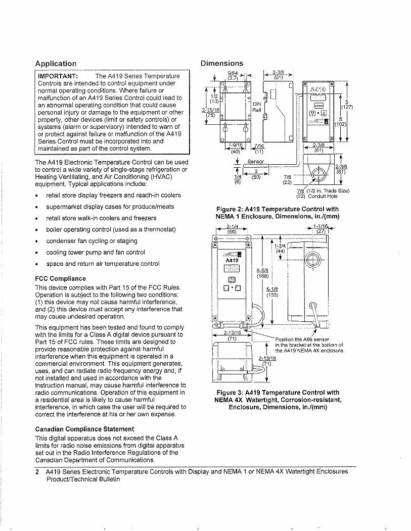
Application
IMPORTANT: The A419 Series Temperature Controls are intended to control equipment under normal operating conditions. Where failure or malfunction of an A419 Series Control could lead to an abnormal operating condition that could cause personal injury or damage to the equipment or other property, other devices (limit or safety controls) or systems (alarm or supervisory) intended to warn of or protect against failure or malfunction of the A419 Series Control must be incorporated into and maintained as part of the control system.
The A419 Electronic Temperature Control can be used to control a wide variety of single-stage refrigeration or Heating Ventilating, and Air Conditioning (HVAC) equipment. Typical applications include:
• retail store display freezers and reach-in coolers
• supermarket display cases for produce/meats
• retail store walk-in coolers and freezers
• boiler operating control (used as a thermostat)
• condenser fan cycling or staging
• cooling tower pump and fan control
• space and return air temperature control
FCC Compliance
This device complies with Part 15 of the FCC Rules. Operation is subject to the following two conditions: (1) this device may not cause harmful interference, and (2) this device must accept any interference that may cause undesired operation.
This equipment has been tested and found to comply with the limits for a Class A digital device pursuant to Part 15 of FCC rules. These limits are designed to provide reasonable protection against harmful interference when this equipment is operated in a commercial environment. This equipment generates, uses, and can radiate radio frequency energy and, if not installed and used in accordance with the instruction manual, may cause harmful interference to radio communications. Operation of this equipment in a residential area is likely to cause harmful interference, in which case the user will be required to correct the interference at his or her own expense.
Canadian Compliance Statement
This digital apparatus does not exceed the Class A limits for radio noise emissions from digital apparatus set out in the Radio Interference Regulations of the Canadian Department of Communications.
Dimensions
l
I + .11< (13)
-15/16 _2 __ r5)
,
9/64 (3:71* -<I-
--,
-----,
DIN Raj I
1
..( 2-3/8 ~ 1 (61)
[
[ •
ji~,{)~®
CJ ~
@].[!l]
"'W"1!i
.. _ .. _-•
l 1
(10
0 0 [ • 1-9/16 ~
6 I' 2-3/8 -I (61) ~ 1) (40) (1
l Sensor M ,2"=2==1===7/=8 '.. ~6~~ rl"'-'(5~0'-) .... 1
(6) (22) ~ 7..& (1/2 in. Trade Size) (22) Conduit Hole
Figure 2: A419 Temperature Control with NEMA 1 Enclosure, Dimensions, in.l(mm)
• l' (±j
li±
2 114 _t __ ==;tjNi+ -• I (56)
""
r [$
.;.;d?f'~11
A419
0 I;;;;) ;"C'.;
Q'E'j
6-51 (16
__ 8
8)
~ ® )
1-3/4 . (44)
L·_·S)'
2-13/16~ I (71) I Position the A99 sensor --t- in the bracket at the boltom of
the A419 NEMA 4X enclosure.
I-.. -'"·~-----'-i 2-13/16 ! (7i)
cd ,I :>1 "dJ=lLI __ ..£!'5- _J_
Figure 3: A419 Temperature Control with NEMA 4X Watertight, Corrosion·resistant,
Enclosure, Dimensions, in.l(mm)
2 A419 Series Electronic Temperature Controls with Display and NEMA 1 or NEMA 4X Watertight Enclosures ProducifTechnical Bulletin
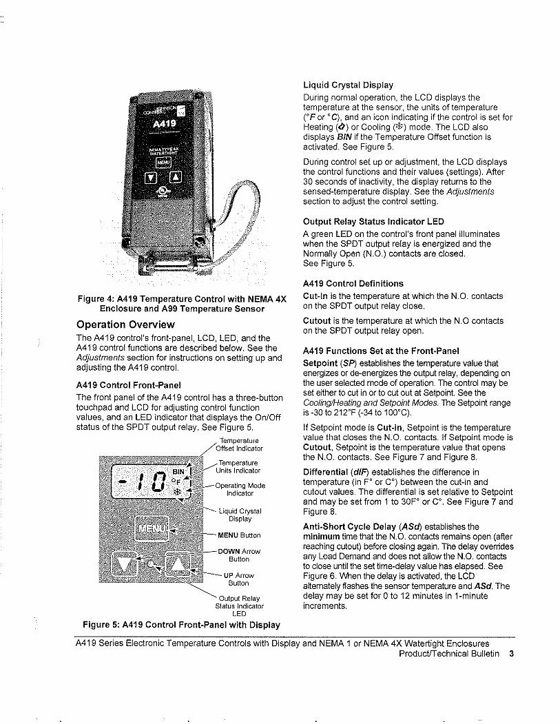
Figure 4: A419 Temperature Control with NEMA 4X Enclosure and A99 Temperature Sensor
Operation Overview The A419 control's front-panel, LCD, LED, and the A419 control functions are described below. See the Adjustments section for instructions on setting up and adjusting the A419 control.
A419 Control Front-Panel
The front panel of the A419 control has a three-button touch pad and LCD for adjusting control function values, and an LED indicator that displays the On/Off status of the SPDT output relay. See Figure 5.
Temperature Offset Indicator
Temperature Units Indicator
_Oo,,,atilnq Mode Indicator
Liquid Crystal Display
--DCIWN Arrow Button
UP Arrow Button
Output Relay Status Indicator
LED
Figure 5: A419 Control Front-Panel with Display
Liquid Crystal Display
During normal operation, the LCD displays the temperature at the sensor, the units of temperature CF or 'C), and an icon indicating if the control is set for Heating (<I) or Cooling (*) mode. The LCD also displays BIN if the Temperature Offset function is activated. See Figure 5.
During control set up or adjustment, the LCD displays the control functions and their values (settings). After 30 seconds of inactivity, the display returns to the sensed-temperature display. See the Adjustments section to adjust the control setting.
Output Relay Status Indicator LED
A green LED on the control's front panel illuminates when the SPDT output relay is energized and the Normally Open (N.O.) contacts are closed. See Figure 5.
A419 Control Definitions
Cut-in is the temperature at which the N.O. contacts on the SPDT output relay close.
Cutout is the temperature at which the N.O contacts on the SPDT output relay open.
A419 Functions Set at the Front-Panel
Setpoint (SP) establishes the temperature value that energizes or de-energizes the output relay, depending on the user selected mode of operation. The control may be set either to cut in or to cut out at Setpoint. See the Cooling/Heating and Setpoint Modes. The Setpoint range is -30 to 212'F (-34 to 100'C).
If Setpoint mode is Cut-in, Setpoint is the temperature value that closes the N.O. contacts. If Set point mode is Cutout, Setpoint is the temperature value that opens the N.O. contacts. See Figure 7 and Figure 8.
Differential (diP) establishes the difference in temperature (in F' or C') between the cut-in and cutout values. The differential is set relative to Setpoint and may be set from 1 to 30F' or C'. See Figure 7 and Figure 8.
Anti-Short Cycle Delay (ASci) establishes the minimum time that the N.O. contacts remains open (after reaching cutout) before closing again. The delay overrides any Load Demand and does not allow the N.O. contacts to close until the set time-delay value has elapsed. See Figure 6. lNhen the delay is activated, the LCD altemately flashes the sensor temperature and ASd. The delay may be set for 0 to 12 minutes in 1-minute increments.
A419 Series Electronic Temperature Controls with Display and NEMA 1 or NEMA 4X Watertight Enclosures ProductlTechnical Bulletin 3
For example, if the anti-short cycle delay is set for 7 minutes, the A419 control will not restart the equipment for 7 minutes after the equipment has cut out, even if the cut-in temperature value is reached during the delay. If the temperature reaches the cut-in value during the delay period, the display flashes between the sensed temperature and ASd, indicating that the next On-cycle is being delayed. After the set delay time has elapsed, the A419 control returns to normal operation, restarts the equipment (if cut-in has been reached), ASd stops flashing, and the LCD reverts to the normal operating display.
Note: Any interruption in supply power to the A419 control activates the anti-short cycle delay.
Time): Load Demand ~ Overridden
~ LLoadDemand
~.. -:·~OUIPutSlatus Anti-short
Cyde Delay
Figure 6: Anti-short Cycle Delay
Sensor Failure Operation (SF) establishes how the A419 control operates the equipment in the event of a sensor or sensor-wiring failure. The A419 control may be set to run the equipment continuously or to shut it down if the sensor or sensor wire fails. When a failure is detected the LCD flashes SF alternately with OP if the sensor circuit is open, or SF and SH if the sensor circuit is shorted. The control implements a 1-minute delay before initiating a failure response to allow for verification of the failure condition and to avoid nuisance failure indications.
Temperature Units establishes the units of temperature (FO or CO) displayed on the LCD.
Temperature Offset (OFS) establishes the value of setpoint-shift (in FO or CO) applied to Setpoint (and Differential) when a (user-installed) circuit is closed between the binary input (BIN) and common (COM) terminals. The offset value may be set from 0 to 50Fo or CO.
The Temperature Offset function is used to reset the Heating Setpoint to a lower temperature (secondary) setpoint or reset the Cooling Setpoint to a higher temperature (secondary) setpoint by the temperature value set in Temperature Offset.
The BIN and COM terminals may be connected to a (user-supplied) external switching device, such as a time clock, that has a set of Single-Pole, Single-Throw (SPST) contacts. Closing a circuit between the BIN and COM terminals activates the Temperature Offset. See Wiring.
This function enables the control to alternate between two temperature setpoints based on the position of the binary input switch. The difference between the primary and secondary setpoints (in FO or CO) is set in the Temperature Offset function (OFS) using the touch pad. See Setting Other Functions.
Table 1 shows an example of Temperature Offset.
Table 1: Temperature Offset Example
Mode of Setpoint Temperature Secondary Operation Offset Value Setpoint'
Cooling 70° 8° 78'
Heating 70° 8' 62°
* Setpolnt when CirCUit between binary Input terminals (BIN and COM) is closed
When the circuit is closed between the binary input (BIN) common (COM) terminals, the offset function is enabled and the A419 control cycles on the secondary setpoints. BIN is displayed on the LCD above the of or °C symbol when the offset is enabled. See Figure 5.
A419 Control Functions Set by Jumper Position
For instructions on positioning jumpers, see Positioning the Jumpers in the Adjustments section. Refer to Figure 12 and Figure 13.
Touchpad Lock: The jumper at P5 establishes whether the touchpad is locked or unlocked. Locking the touch pad deters accidental or unauthorized changes to all of the function parameters.
Heating/Cooling Mode is established by positioning the jumper on the top two pins of the P4 jumper. See Figure 13.
Setpoint Mode: Removing or installing the lower jumper at P4 establishes whether Setpoint is the cut-in temperature or cutout temperature. See Figure 13.
Cooling/Heating and Setpoint Modes
The A419 control may be in four operating modes: Cooling/Cut-in, Cooling/Cutout, Heating/Cut-in, and Heating/Cutout. Position the jumpers located on the circuit board under the A419 control cover to set the desired mode of operation. See Positioning the Jumpers.
In Cooling/Cut-in mode the differential is below Setpoint. The output relay energizes and the LED illuminates when the temperature rises to Setpoint. When the temperature drops to Setpoint minus the differential value, the relay and LED de-energize.
4 A4i9 Series Electronic Temperature Controls with Display and NEMA 1 or NEMA 4X Watertight Enclosures ProductfTechnical Bulletin
In Cooling/Cutout mode the differential is above Set paint. The output relay energizes and LED illuminates when the temperature rises to Setpoint plus the differential value. When the temperature drops to Setpoint, the relay and LED de-energize.
Temperature (+) Cooling/Cut-out
Djffere~ti'al , 'r Cut-out
~~~)lI7i tJ' , ,: '; (Off) Cooling/Cut-in
Selpoint -+ __ -L,---,-':'~c-.L:_--;~~:'::'::~_
(-)
Figure 7: Cooling Modes
When the Heating/Cut-in mode is selected, the differential is above Setpoint. The output relay energizes and LED indicator illuminates when the temperature drops to Setpoint. When the temperature rises to Setpoint plus the differential value, the output relay and LED de-energize.
When Heating/Cutout mode is selected, the differential is below Setpoint. The output relay energizes and LED indicator illuminates when the temperature drops to Setpoint minus the differential value. When the temperature rises to Setpoint, the output relay and LED indicator de-energize.
Temperature (+)
(-)
Figure 8: Heating Modes
Mounting An A419 control has either a standard high-impact plastic NEMA 1 or a NEMA 4X corrosion-resistant, watertight enclosure.
The A419 control is not position sensitive but should be mounted for convenient wiring and adjustment.
Note: When mounting the control to rigid conduit, attach the hub to the conduit before securing the hub to the control enclosure.
The mounting hole pattern of the NEMA 1 enclosure is identical to that of the System 350'" controls, and most models of the A 19 control. The NEMA 1 enclosure may also be mounted on 35 mm DIN rail. See Figure 1 and Figure 2.
The NEMA 4X models may be mounted to fiat vertical surfaces using the four screw holes at the enclosure corners. See Figure 3 and Figure 4. To maintain the watertight and corrosion resistant integrity of the NEMA 4X enclosure, use a conduit fitting rated for the environment in which the control is installed.
An additional (low-voltage) two-wire cable is required to operate the temperature offset function. On NEMA 4X enclosures you must install a suitable liquid-tight fitting in an available knockout to pass the two-wire cable through the enclosure wall.
IMPORTANT: The short-lead A99 sensor, included with A419 NEMA 4X model controls, must be mounted on the bottom of the control in the bracket molded on the NEMA 4X housing. Mounting the sensor on top of the control may reduce the accuracy of the displayed temperature. See Figure 3 and Figure 4 for proper sensor position.
A419 Series Electronic Temperature Controls with Display and NEMA 1 or NEMA 4X Watertight Enclosures ProductfTechnical Bulletin 5
Wiring
A WARNING: Risk of Electrical Shock. To avoid the risk of electrical shock. disconnect all power sources to the control before wiring any connections. More than one disconnect may be required to completely de-energize the control and equipment.
IMPORTANT: All wiring must conform to local. national, and regional regulations. Use copper conductors only for all wire connections. Do not exceed the electrical ratings for the A419 control or the equipment it is wired to.
Refer to Figure 9, Figure 10, and Figure 11 for typical examples of wiring an A419 control to the controlled equipment.
Use wire no larger than 12 AWG when connecting to the two lower terminal blocks (TB1 and TB2).
Note: Terminal block TB2 is an isolated SPDT switch (dry contacts). The TB2 terminals have no internal electrical connection to the A419 control.
Use wire no larger than 16 AWG when connecting to the upper sensor terminal block (TB3).
Wire insulation rating must be 90°C, minimum.
A99 temperature sensors are not polarity sensitive. Wire the leads to (+) SEN and (-) COM on the sensor terminal block (TB3). See Figure 9, Figure 10, and Figure 11.
Keep the leads between the control and sensor as short as possible/practical in your application. The additional resistance in long sensor leads creates error between the actual temperature and the displayed temperature. Refer to Table 1 when extending sensor leads.
Temperature sensor signals may be affected by electrical interference. When extending sensor cable beyond 50 It (15.2 m) use a twisted-pair, shielded cable to reduce electrical interference.
If the Temperature Offset function is used, wire a switch (such as a switching time clock) between the binary input terminal (BIN) and the common terminal (COM). See Figure 9, Figure 10, and Figure 11 for terminal strip location.
Figure 9: Wiring the 24 VAC A419 Control
(Optional) Binary Input
Si'itCh
A419ABC-1 rn; A419AEC-1
(+)BIN IDe (-) COM
1V (+) SEN _____ .
TB3r=l 1
~ ,: :: I :' \
Cable 1.= __ .J : I ,-Shield ;
(if used) ~ TB210i- 0 S
A99 \;, \ \ / ~ ensor Si?o~ §EU~
N U -U
'--;~ ----1-120 VAC 11-20 VAGI
Neutral .- - ..... ----1 Load-I
Figure 10: Wiring the 120 VAC A419 Control
(Optional) I A419ABC-1 I Blnar~ Input A419AEC-1 i
SWitch ~
~' ',(+)BIN, (-)COM
(+)SEN----. , % TB3! r----, •
i~i~l~ ~ L i~ (if used~99 8 T1B1 0\1 TB'-21-9-~-_-"1 0
Sensor \.::;: 000 uuO ~ u ~ z z
U
240 L 1-'=:l::1:«===~~;t VAC L2 __ .+-I __ -i1240 VAC
I Load
Figure 11: Wiring the 240 VAC A419 Control
6 A419 Series Electronic Temperature Controls with Display and NEMA 1 or NEMA 4X Watertight Enclosures ProductrT echnical Bulletin
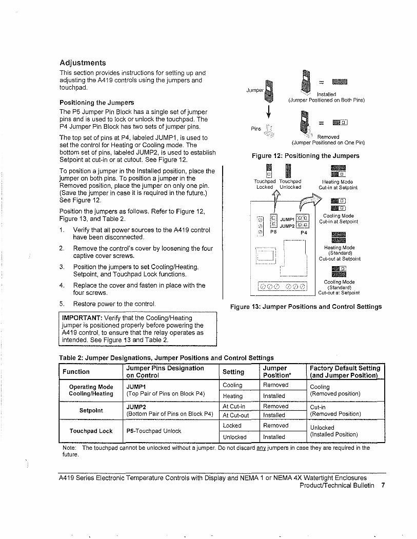
Adjustments This section provides instructions for setting up and adjusting the A419 controls using the jumpers and touchpad.
Positioning the Jumpers
The P5 Jumper Pin Block has a single set of jumper pins and is used to lock or unlock the touchpad. The P4 Jumper Pin Block has two sets of jumper pins.
The top set of pins at P4, labeled JUMP1, is used to set the control for Heating or Cooling mode. The bottom set of pins, labeled JUMP2, is used to establish Setpoint at cut-in or at cutout. See Figure 12.
To position a jumper in the Installed position, place the jumper on both pins. To position a jumper in the Removed position, place the jumper on only one pin. (Save the jumper in case it is required in the future.) See Figure 12.
Position the jumpers as follows. Refer to Figure 12, Figure 13, and Table 2.
1. Verify that all power sources to the A419 control have been disconnected.
2. Remove the control's cover by loosening the four captive cover screws.
3. Position the jumpers to set Cooling/Heating, Setpoint, and Touchpad Lock functions.
4. Replace the cover and fasten in place with the four screws.
5. Restore power to the control.
IMPORTANT: Verify that the Cooling/Heating jumper is positioned properly before powering the A419 control, to ensure that the relay operates as intended. See Figure 13 and Table 2.
Jumper;
t ; I:talle~
(Jumper Positioned on Both Pins)
Pins ; = Bill
":',Yf Removed (Jumper Positioned on One Pin)
Figure 12: Positioning the Jumpers
Touchpad Touchpad locked Unlocked
iQi'11Dl JUMP1 fDbl ! 0 l.::J JUMP2 ~ ,
10 P5 P4
III\1IIII!iII Bill
Heating Mode Cut-in at Setpoint
IIII[Q] IIII[Q]
Cooling Mode Cut-in at Setpoint
IIII!IIII!!IIII IIII!IIII!!IIII
Heating Mode (Standard)
Cut-out at Setpoint
IIII[Q] IIII!IIII!!IIII
Cooling Mode (Standard) L.=======--J Cut-out at Setpoint
Figure 13: Jumper Positions and Control Settings
Table 2: Jumper Designations, Jumper Positions and Control Settings
Function Jumper Pins Designation
Setting Jumper Factory Default Setting
on Control Position* (and Jumper Position)'
Operating Mode JUMP1 Cooling Removed Cooling Coaling/Healing (Top Pair of Pins on Block P4) Heating Installed (Removed position)
Selpoint JUMP2 At Cut-in Removed Cut-in (Bottom Pair of Pins on Block P4) At Cut-out Instalied (Removed Position)
Locked Removed Unlocked Touchpad Lock P5-Touchpad Unlock (Instalied Position) Unlocked Installed
Note: The touch pad cannot be unlocked without a Jumper. Do not dlscard.®1 Jumpers In case they are required In the future.
A419 Series Electronic Temperature Controls with Display and NEMA 1 or NEMA 4X Watertight Enclosures ProductlTechnical Bulletin 7
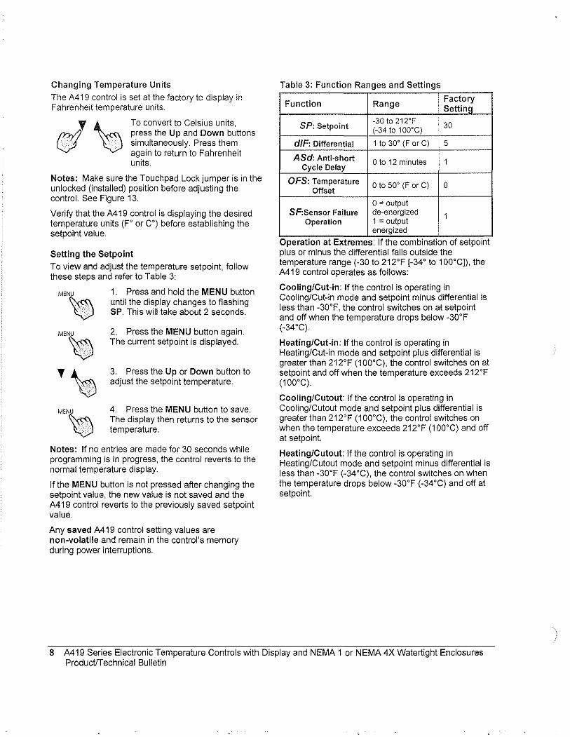
Changing Temperature Units
The A419 control is set at the factory to display in Fahrenheit temperature units.
J '0 To convert to Celsius units, fnIJ press the Up and Down buttons V simultaneously. Press them
. again to return to Fahrenheit units.
Notes: Make sure the Touchpad Lock jumper is in the unlocked (installed) position before adjusting the control. See Figure 13.
Verify that the A419 control is displaying the desired temperature units (F' or C') before establishing the setpoint value.
Setting the Setpoint
To view and adjust the temperature setpoint, follow these steps and refer to Table 3:
MEN~
MEN~
'~ MEN~
1. Press and hold the MENU button until the display changes to flashing SP. This will take about 2 seconds.
2. Press the MENU button again. The current setpoint is displayed.
3. Press the Up or Down button to adjust the setpoint temperature.
4. Press the MENU button to save. The display then returns to the sensor temperature.
Notes: If no entries are made for 30 seconds while programming is in progress, the control reverts to the normal temperature display.
If the MENU button is not pressed after changing the setpoint value, the new value is not saved and the A419 control reverts to the previously saved setpoint value.
Any saved A419 control setting values are non-volatile and remain in the control's memory during power interruptions.
Table 3: Function Ranges and Settings
Function Range Factory Setting
SP: Setpoint -30 to 212'F 30 (-34 to 100'C)
dlF: Differential 1 to 30' (F or C) 5
ASd: Anti-short o to 12 minutes 1 Cycle Delay
OFS: Temperature o to 50' (F or C) 0 Offset
0= output SF:Sensor Failure de-energized 1
Operation 1 = output energized
OperatIon at Extremes. If the combinatIon of setpolnt plus or minus the differential falls outside the temperature range (-30 to 212'F [-34' to 100'C]), the A419 control operates as follows:
Cooling/Cut-in: If the control is operating in Cooling/Cut-in mode and setpoint minus differential is less than -30'F, the control switches on at setpoint and off when the temperature drops below -30'F (-34'C).
Heating/Cut-in: If the control is operating in Heating/Cut-in mode and setpoint plus differential is greater than 212'F (1 OO'C), the control switches on at setpoint and off when the temperature exceeds 212'F (100'C).
Cooling/Cutout: If the control is operating in Cooling/Cutout mode and setpoint plus differential is greater than 212'F (1 OO'C), the control switches on when the temperature exceeds 212'F (1 OO'C) and off at setpoin!.
Heating/Cutout: If the control is operating in Heating/Cutout mode and setpoint minus differential is less than -30'F (-34'C), the control switches on when the temperature drops below -30'F (-34'C) and off at setpoin!.
8 A419 Series Electronic Temperature Controls with Display and NEMA 1 or NEMA 4X Watertight Enclosures ProductiTechnical Bulletin
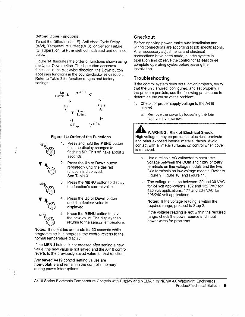
Setting Other Functions
To set the Differential (dIF), Anti-short Cycle Delay (ASd), Temperature Offset (OFS), or Sensor Failure (SF) operation, use the method illustrated and outlined below,
Figure 14 illustrates the order of functions shown using the Up or Down button, The Up button accesses functions in the clockwise direction; the Down button accesses functions in the counterclockwise direction, Refer to Table 3 for function ranges and factory settings,
Up Button !
-rd I f « ~
S P A ,
..... S f
Down Button
"
-..4 A S d A
Figure 14: Order of the Functions
MEN~
'\0 MEN~
'\0 ME~
1, Press and hold the MENU button until the display changes to fiashing SP, This will take about 2 seconds,
2, Press the Up or Down button repeatedly until the desired function is displayed. See Table 3,
3, Press the MENU button to display the function's current value,
4. Press the Up or Down button until the desired value is displayed,
5, Press the MENU button to save the new value, The display then returns to the sensor temperature,
Notes: If no entries are made for 30 seconds while programming is in progress, the control reverts to the normal temperature display.
If the MENU button is not pressed after setting a new value, the new value is not saved and the A419 control reverts to the previously saved value for that function,
Any saved A419 control setting values are non-volatile and remain in the control's memory during power interruptions,
Checkout Before applying power, make sure installation and wiring connections are according to job specifications. After necessary adjustments and electrical connections have been made, put the system in operation and observe the control for at least three complete operating cycles before leaving the installation,
Troubleshooting If the control system does not function properly, verify that the unit is wired, configured, and set properly, If the problem persists, use the following procedures to determine the cause of the problem:
1, Check for proper supply voltage to the A419 control.
a. Remove the cover by loosening the four captive cover screws .
A WARNING: Risk of Electrical Shock. High voltages may be present at electrical terminals and other exposed internal metal surfaces, Avoid contact with all metal surfaces on control when cover is removed,
b, Use a reliable AC voltmeter to check the voltage between the COM and 120V or 240V terminals on line voltage models and the two 24V terminals on low-voltage models, Refer to Figure 9, Figure 10, and Figure 11.
c. The voltage must be between: 20 and 30 VAC for 24 volt applications, 102 and 132 VAC for 120 volt applications, 177 and 264 VAC for 208/240 volt applications
Notes: If the voltage reading is within the required range, proceed to Step 2,
If the voltage reading is not within the required range, check the power source and input power wires for problems,
A419 Series Electronic Temperature Controls with Display and NEMA 1 or NEMA 4X Watertight Enclosures ProductlTechnical Bulletin 9
2. Check for proper sensor operation.
Disconnect all power sources to control.
a, Take a temperature reading at the sensor location, using an accurate thermometer,
b, Disconnect the sensor from the control.
c. Use a reliable ohmmeter, to measure the resistance across the two sensor leads while the sensor is at the temperature taken in Step b,
d, Refer to Figure 15 to verify that the measured temperature and resistance conform to established temperature and resistance values,
e, If the measured values conform to the values in Figure 15, proceed to Step 3,
f, If the sensor's measured resistance value is substantially different from the expected value for that temperature, check the sensor wiring. If sensor wiring is okay, replace the sensor.
Temperature (OF) Temperature (OC)
260 -l i----- t--_·- ----j 120 240 j +---1 ' 220 _ ............ --r I "i 100 200 ' : ,
180 E'~-i--'---~'-+--i 80 160 -,----j------/-- --r---I 140 .. -.-., . ' -. 60 120 j. -j I : I 100 i : I... I .... " 40 80, - ,=:1 i-~--i 60 .!--+.~-=~~~y-- -.-.~ ... """--' ..... , ... -..... ~ .---t~-.:r 20 40 I -----7 . 0 20 I f I !---=r
-2g -Ii .... . ....... :"'~~~_.~- ~20 -40, - -40
500 700 900 110013001500170019002100
Resistance in Ohms
Figure 15: Nominal Temperature vs. Sensor Resistance
3, Check the A419 for proper operation,
a. Perform Troubleshooting Steps 1 and 2 before performing this step,
b, Disconnect the load from the output relay terminals,
c, Ensure that the T ouch pad Lock jumper is installed, so that the touchpad is unlocked,
d, Reconnect the sensor leads and supply power to the control.
e, Replace the cover.
f, Check the control settings for proper values,
g, Press and hold the MENU button until Setpoint appears (occurs in about 2 seconds).
h, Use the Up and Down buttons to change the Setpoint temperature above and below the current sensor temperature until the output relay energizes and de-energizes as shown in Table 4,
If the anti· short cycle delay has a time greater than 0 minutes, the relay will not energize until the timed delay has elapsed,
i. If the output relay does not perform as indicated in Table 4, replace the A419 control.
j, If proper operation of the A419 control is verified, reconnect the load and consult the equipment manufacturer's instructions for troubleshooting the controlled equipment.
Table 4: A419 Output Relay Operation
Output Output Relay Setpoint Operating Relay De-energized Mode Mode Energized at...
at. .. Setpoint
Cooling plus Setpoint
Cutout differential
Setpoint Heating minus Setpoint
differential
Setpoint Cooling Setpoint minus
Cut·in differential
Heating Setpoint Setpoint plus differential
Note: When the relay IS energized, the N.O. contacts are closed and the LED is illuminated.
10 A419 Series Electronic Temperature Controls with Display and NEMA 1 or NEMA 4X Watertight Enclosures ProductiTechnical Bulletin
Fault Codes
A419 controls are programmed to display certain fault codes on the LCD as described in Table 5.
Table 5: Fault Codes Defined
Fault Code Definition i System Status Solution
SF flashing Open temperature Output functions according to See Troubleshooting section. alternately with OP sensor or sensor the selected sensor failure
Cycle power to reset the control. wiring mode (SF setting)
SF flashing Shorted temperature Output functions according to See Troubleshooting section.
alternately with SH sensor or sensor the selected sensor failure Cycle power to reset the control. wiring mode (SF setting)
Reset the control by pressing the Menu EE Program failure Output is off button. If problems perSist, replace the
control.
Repairs and Replacement Ordering Information Do not attempt to repair or recalibrate the Refer to Table 6 to order controls and accessories. A419 Control. In case of a defective or improperly functioning control, contact your nearest Authorized Johnson Controls/PENN® Distributor or Sales Representative.
When contacting your Johnson Controls/PENN distributor, have the model number of the control available. This number can be found on the label inside the cover of the control.
Table 6: Ordering Information
Product Code Item Number
A419ABC-1C Line Voltage, NEMA 1 Enclosure A419 Series Electronic Temperature Control with Display, A99 Sensor Included
A419AEC-1C Line Voltage, NEMA 4X Enclosure A419 Series Electronic Temperature Control with Display, A99 Sensor Included
A419GBF-1C 24 VAC, NEMA 1 Enclosure A419 Series Electronic Temperature Control with Display, A99 Sensor Included
A419GEF-1C 24 VAC, NEMA 4X Enclosure A419 Series Electronic Temperature Control with Display, A99 Sensor Included
A99BB-200C Replacement Temperature Sensors A99BA-200C A99BB-25C
BKT287-1R Accessory Mounting Hardware BKT287-2R
PLT344-1R
CLK350-2C Digital Clock
WEL11A-601R Immersion Well
Description
Supply Voltage: 120 or 240 VAC
Range: -30 to 212'F (-34 to 100'C)
Differential: 1 to 30F' (1 to 30C')
Sensor Lead Length: NEMA 1 Models 6-1/2 ft (2 m), NEMA 4X Models 9 in (0.25 m)
Supply Voltage: 24 VAC, Class 2
Range: -30 to 212'F (-34 to 100'C)
Differential: 1 to 30F' (1 to 30C')
Sensor Lead Length'. NEMA 1 Models 6-1/2 ft (2 m), NEMA 4X Models 9 in (0.25 m)
PTC Sensor with 6-1/2 ft (2 m) Leads PTC Sensor with 6-1/2 ft (2 m) Shielded Leads PTC Sensor with 9 in (0.25 m)
12 in. (305 mm) long DIN Rail 36 in. (914 mm) long DIN Rail Two End Clamps for DIN Rail Mounting
7-Day Programmable Digital Clock for controlling Temperature Offset Function
Immersion Well for applying sensor in fluid applications
A419 Series Electronic Temperature Controls with Display and NEMA 1 or NEMA 4X Watertight Enclosures ProductiTechnical Bulletin 11
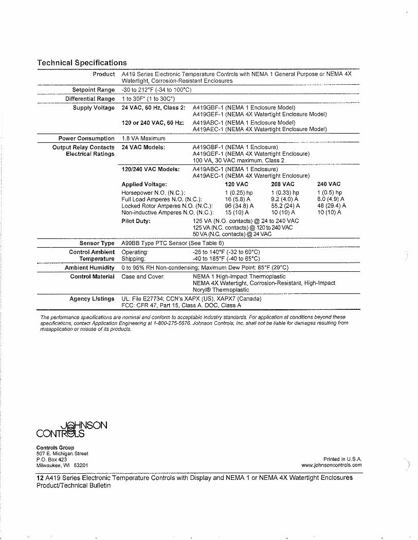
Technical Specifications Product A419 Series Electronic Ternperature Controls with NEMA 1 General Purpose or NEMA 4X
Watertight, Corrosion-Resistant Enclosures
Setpoin! Range -30 to 212°F (-34 to 100°C)
Differential Range 1 to 30Fo (1 to 30CO)
Supply Voltage 24 VAC, 60 Hz, Class 2: A419GBF-1 (NEMA 1 Enclosure Model) A419GEF-1 (NEMA 4X Watertight Enclosure Model)
120 or 240 VAC, 60 Hz: A419ABC-1 (NEMA 1 Enclosure Model) A419AEC-1 (NEMA 4X Watertight Enclosure Model)
Power Consumption
Output Relay Contacts Electrical Ratings
1.8 VA Maximum
24 VAC Models:
120/240 VAC Models:
A419GBF-1 (NEMA 1 Enclosure) A419GEF-1 (NEMA 4X Watertight Enclosure) 100 VA, 30 VAC maximum, Class 2
A419ABC-1 (NEMA 1 Enclosure) A419AEC-1 (NEMA 4X Watertight Enclosure)
Applied Voltage: 120 VAC 208 VAC Horsepower N.O. (N.C.): 1 (0.25) hp 1 (0.33) hp Full Load Amperes N.O. (N.C.): 16 (5.8) A 9.2 (4.0) A Locked Rotor Amperes N.O. (N.C.): 96 (34.8) A 55.2 (24) A Non-inductive Amperes N.O. (N.C.): 15 (10) A 10 (10) A
Pilot Duty: 125 VA (N.O. contacts)@ 24 to 240 VAC 125 VA (N.C. contacts)@120t0240VAC 50 VA (N.C. contacts)@24VAC
Sensor Type A99BB Type PTC Sensor (See Table 6)
Control Ambient Operating: -26 to 140°F (-32 to 6Q°C) Temperature Shipping: -40 to 185°F (-40 to 85°C)
Ambient Humidity 0 to 95% RH Non-condensing; Maximum Dew Point: 85°F (29°C)
Control Material Case and Cover: NEMA 1 High-Impact Themnoplastic
240 VAC 1 (0.5) hp 8.0 (4.9) A 48 (29.4) A 10 (10) A
NEMA 4X Watertight, Corrosion-Resistant, High-Impact Noryl® Themnoplastic
Agency Listings UL: File E27734; CCN's XAPX (US), XAPX7 (Canada) FCC: CFR 47, Part 15, Class A. DOC, Class A
The performance specifications are nominal and conform to acceptable industry standards. For application at conditions beyond these specifications, contact Application Engineering at 1-800-275-5676. Johnson Controls, Inc. shall not be liable for damages resuffing from misapplication or misuse of its products.
~NSON CONTR~S Controls Group 507 E. Michigan Street P.O. Box 423 Milwaukee, WI 53201
Printed in U.S.A. www.johnsoncontrols.com
12 A419 Series Electronic Temperature Controls with Display and NEMA 1 or NEMA 4X Watertight Enclosures ProductfTechnical Bulletin
Brandon
3.1 Recommended Spare Parts List, Maintenance Summary and Lubrication Summary
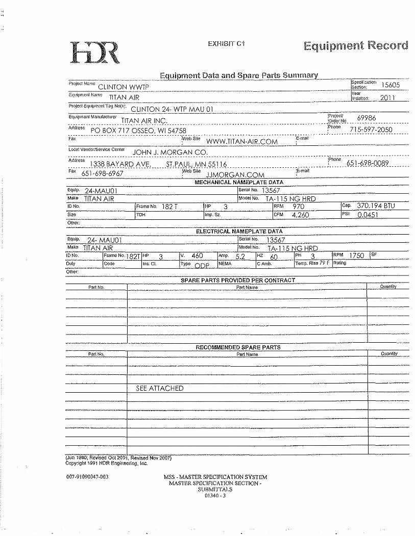
EXHIBIT C'I Equipment Record
----.---,-~~-.--.-.. "~,, ..... . Proj'" N,,,, CLINTON WWTP
.,-,,,,,,~,~-,.,,-~,,,.-- .. Equipment Name TITAN A!R
Equip.
Make
IDNe.
$i2G
Other:
24-MAUOI TITAN AIR
Equip, 24- MAUO 1 Make TITAN AIR
FmmeNo.
TDH 182 T HP 3 Cap. 370,194 BTU
Imp, S.z. CFM 4,260 PSI 0.0451
ELECTRICAL NAMEPLATE DATA
Senal No. 13567
Duly Ins. CL
TA-115 NG HRD HZ 60 I=P,...H--,,,,,3'-o;=+.R,-PM 1 7 50 I SF C Amb. Temp. Rise 79 F Rating
ID No. Frame No, 1 82T HP 3
----Other:
SPARE PARTS PROVIDED PER CONTRACT Part No Part Name Quantity
----- -----j--._-".,,-
,---------+-------------------
RECOMMENDED SPARE PARTS Pert No. Part Name
----------- --
SEE ATTACHED
,
--- -
-, , (Jun 19M, ReVIsed Ovt 2001, ReVISed Nov 2007) Copyrigh! 1991 !-lDR Engineering, Inc.
007-91090047-003 MSS - MASTER SPEClF[CA TlON SYSTEM MASTER SPECIFICATION SECTION
SUBMITI'ALS 0[340 - 3
.,
-
-
-
-- QUC'lntilY --
---
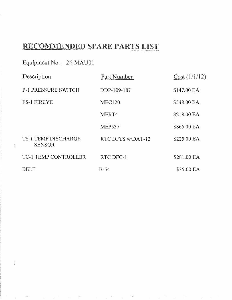
RECOMMENDED SPARE PARTS LIST
Equipment No: 24-MAUOI
Description Part Number Cost (111112)
P-1 PRESSURE SWITCH DDP-109-187 $147.00 EA
FS-1 FIREYE MEC120 $548.00 EA
MERT4 $218.00 EA
MEP537 $865.00 EA
TS-1 TEMP DISCHARGE RTC DFTS w/DAT-12 $225.00 EA SENSOR
TC-1 TEMP CONTROLLER RTC DFC-1 $281.00 EA
BELT B-54 $35.00 EA
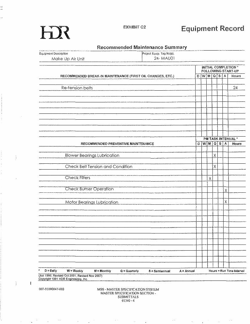
EXHIBITC2 Equipment Record
Rec?~':l!~,~~ed Mai ntenance Su mm_~_r.¥.. ___ " _________________ _ EquipmGnt Description PrOject Equip. Tag No(s}.
24- MAUOI Make Up Air Unit ----"'------'-------
--~.~~
RECOMMENDED eREAI~-IN MAINTENANCE (FIRST Oil CHANGES, ETC.) ---~---..
- --Re-tension belts . -~~" .. -~-~
---¥~.~ .. ----"-.--.~-"-,--. ----
----
. --
RECOMMENDED PREVENTIVE MAINTENANCE
Blower Bearings Lubrication
Check Belt Tension and Condition
Check Filters
Check Burner Operation .-.--~----------"~.------.-----.--".-----
-
.. _._.¥-
D
D
Motor Bearings Lubrication -.------.-... ----
.-
-----WtsWeekly M D Monthly Q I:i Quarte-rly S = Semiannual
(Jun 1990; Revised Oct 2001, Revised Nov 2007) Copylight 1991 HDR Engineering, Inc.
007-91090047-003 MSS - MASTER SPECIFICATION SYSTEM MASTER SPECIFfCA TlON SECTION -
SUBMITTALS 01340 - 4
-
A:l: Annual
--INITIAL COMPLETION' FOLLOWING START-UP
W M Q S A Hours
24 -
-_ .
PM TASK INTERVAL'
W M Q S A Hours
X
X -
X -
---- X ~~,~----
X -----
--
----
Hours"" Run Time Interval
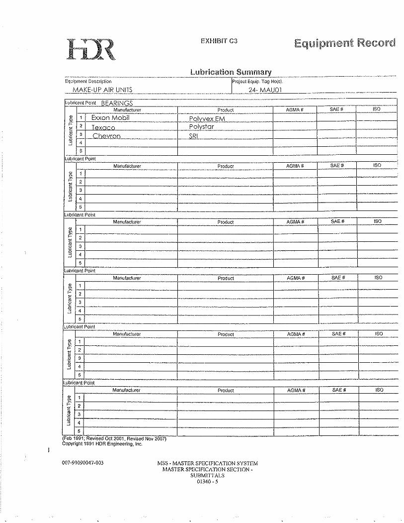
EXHIBIT C3
Manufacturer Product AGMA # SAE # ISO r.----~====~-----+------~~,------_4--~~~---~~~~----------
$ 1 ~ I-:---~-------------j-----------I-------+-------I-----~ 1-24-----------I------__________ -4 ____ 1-_____ ~------~ 3 E ~,----------------------_+---------------------I----------.-~------~~------- .. -.3 ' 1-5-+----------------~----------I--------+--------+-------
lubrics nt Point FT"""-=''-----:==:c:------,--- -----::;--.-;---------,---=:-:;--,-----::-:-=-;;--,--0=--Manufact\.lrer Product AGMA # I SAE # ISO
~ 1 ~
I~ 2 ~ ~ 3
H------------+------------I--------l---------------I H----------j·_-------·--------------+-----+-----+-----
-c ,-- - .. ---n
" 4 ---------+---------+------,,-----_4----
-,
~ 1 $'- 1-:--1------------------------- ----------------------+-------1-------- --------.--_ 2
~ rs-----------------------j----------------------j----------i-------t--------Ii 1--1------------------·,,-------------------------,-----------1---------1-----·------. o 4
~ r-I---------_4----------------r----I-----~---------5
lubricant Point
1-:-.-___ ~M~a~n~u~m~ct~ur~e~r_. ____ -1 ______ ~p~rod~u~ct~ ____ -t_~A~G~MA,~# __ _+-~S~A=E~#-_+--~'S~O~-
! I-:-:r------------+----------------.. --------r----_+----·-~
~ r37t------------------~---------------------_+---------_1--------_l------.3 4
5 -r---------------I-------+-----~-----
(Feb 1991; Revised Oct 2001 , Rewsed Nov 20D?} Copyright 1991 HOR Engineering, (nc.
007 -91 09004 7 -003 MSS" MASTER SPECIFICATION SYSTEM MASTER SPECIF1CATION SECTlON -
SUBMITtALS 01340 - 5

3.2 Unit Specifications
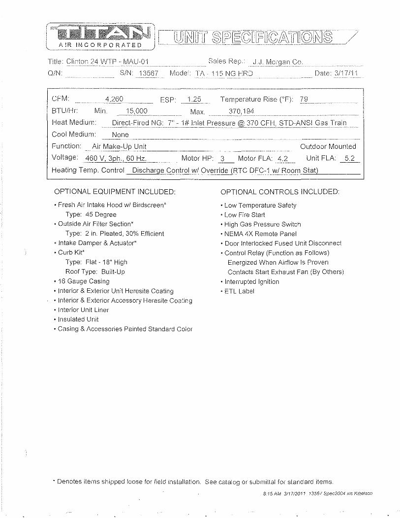
(
l ----_ .... \
! j []OJ_il~lITu~~_~I}~~_[:;_n[E_m{5_-~-~_'clJlQYu~~[/' AIR if'.]CORPORATED
Title Clinton 24 WTP - MAU-01 Sales I'<ep. J.J.Morgan Co.
Q/N SIN 13567 ModelTA - '1 '15 NG HRD .' .. ::::: .... _ ...... -- ........... . Date 3/17/11
CFM _______ ~,26_~_ ESP~2~ Temperature Rise (OF) 79 __
BTUIHr Min. _~5c022_ .... ____. Max. 194
Heat Medium: ... __ [)i,:ect :r=ir:ElCJf\JG: 7"J!fI:1'~tF'rEl~s u r,,_@3i'~C£Ij!_?21:l:~_N SI_G a ,,-Ir:C1in
Cool Medium: None
Function: Air Ma~El-Up U~it ___ .__________ _ __________________ _ Outdoor Mounted
Unit FLA 5.2 Voltage: 460 V, 3ph:!_ 60 Hz. Motor HP: 3 Motor FLA: 4.2
OPTIONAL EQUIPMENT INCLUDED:
• Fresh Air Intake Hood wi Birdscreen*
Type: 45 Degree
• Outside Air Filter Section*
Type: 2 in. Pleated, 30% Efficient
• Intake Damper & Actuator*
• Curb Kit'
Type: Flat - 18" High
Roof Type: Built-Up
·16 Gauge Casing
• Interior & Exterior Unit Heresite Coating
• Interior & Exterior Accessory Heresite Coating
• Interior Unit Liner
• Insulated Unit
• CaSing & Accessories Painted Standard Color
OPTIONAL CONTROLS INCLUDED
• Low Temperature Safety
• Low Fire Start • High Gas Pressure Switch
• NEMA 4X Remote Panel
• Door Interlocked Fused Unit Disconnect
• Control Relay (Function as Follows) Energized When Airflow Is Proven
Contacts Start Exhaust Fan (By Others)
• Interrupted Ignition
• ETl label
* Denotes items shipped loose for field installation. See catalog or submittal for standard items.
8 15 AM 311712011 13567 Spec2004 xis I<rue/soll
2-8
rev. 01-04 SUBMITTAL USE ONL Y - DO NOT USE FOR CONSTRUCTION PURPOSES
SINGLE BLOWER UNITS - DOWN DISCHARGE - CHANNEL OR CURB MOUNT Item MODEL A B C D E F G H J K
TA- 4 4 8 2
TA-115 69 54 32 8 8 24 24 40 28 2 TA-118 78 60 36 10 10 24 24 48 32 TA- 5 66 46 8 8 32 32 4 2 TA-122 95 48 12 12 36 60 44 2 TA-125 95 78 1 36 60 44 2 TA-127 100 90 66 44 44 72 60 2.5 TA-130 100 12 14 4 72 60 2.5 TA-133 100 78 14 18 60 48 72 2.5
- 6 110 100 78 14 18 60 48 96 72
TWIN BLOWER UNITS - DOWN DISCHARGE - CHANNEL OR CURB MOUNT UP TO TA-230
* Units are built in two sections. F,G, H & J are accessory dimensions. D,E & K are accessory locations. Intake and discharge accessories may be larger than openings on unit. All dimensions subject to manufacturing tolerances and subject to change, verify with factory before using for any construction purposes. INDOOR hanging units must utilize a boltom cradle (by others).
'" '" PR '" j" A e-"/ " ,~ ,~~~ ,.. • 0~s
INTAKE ACCESSORIES "r ,,~
rev. 01-04 SUBMITTAL USE ONL Y - DO NOT USE FOR CONSTRUCTION PURPOSES
I~V~~---A
r B
t B
-1 f B
-1 1 D HOOD / FILTER COMBO D FULL TURN DOWN HOOD
T"--A:=-i
rA- IA rA A~I-112
IA-I~ fA rA~I-115
~l OAb 140 ITA Ir FAM -118 14, 'TA-1 I AR --.... 4: TA-TA-
fA 3
4 o
32 45 I 3 l2 16 3' !8484' 324 12 ,b4
!3 4 )9 4: :7 4: :8 61 1 7:
t"na..191
36 5 4, I 5
15
o Ina 7: 12~
l7 48 72 l3 50 m j( bL I (
5017; 5018; 55197
151
28128 ~5 !8 ,32
! 32 16
140 16 3 16 IAZ
42132 ~4132 :0
132 '2 '2 12 )6 7:
73 8 16 !8 72 181 14 8 132 Ina 181 18! I 3; 50177!80 2146 )2 180 l2
rp,-230 rA-233
'A-242
196 '42144 961421na.1.a1 r42144 1120 44 46 121 44-rna : 48
28 ;2 Ina 14 :0 'na ro 8' Ina 111
180 lO 11 '7: na 192 72 60 IN2 7: na 216184 60 8' na
76 76 88
mR. 559796142146 1!S. ,12 144146 ,12C 14
161 I 52128 52132 161 160132
2 72
70 18 72 146 rz. ~~ 70 ~1~ 97;;n2: 47,H;6,;,@-i;'72:;-r.;;~ 75J1g§"",-,-,,,-1 8",,-,-41~ 462 .... 11~' 694:w1=... 32=",-,-,
All dimensions subject to manufacturing tolerances and subject to change, verify with factory before using for any construction purposes. Intake dampers are designed to be mounted indoors, if outdoor mounting is required, you must order a weather hood for damper actuator(s), damper may be built Into hood and or filter section. Intake dampers on TA-230 - 242 have 2 actuators, all accessories for these units are built in 2 sections, some field assembly may be required. All intake hoods feature bird screen. Mushroom hoods can be flange mounted, consult factory. 1" flange is typical for all components listed above. Intake accessories may be larger than intake opening. Return air filter sections will be larger than return air opening.
8·1
--.-" _.-._-----_ ... _-_._---.. --_ .. ._.~~ ___ ._ .. _________ .. _ ..... _____ . _____ .. ________ ._ .... _. ____ I
~ •••••• ' 8" '1'00% ~'R 1171' IS;~' . -, '''', '. ., W)AI1JLC.!ilB.Ii~. " '
rev.01·04 SUBMITTAL USE ONL y .. DO NOT USE FOR CONSTRUCTION PURPOSES
HORIZONTAL UNITS WITH DOWN DISCHARGE BLOWER(S) Item MODEL A B C D E F G ..
'!:AM·109 54.5 33.5 26.75 2.25 2.25 16 -'f6 TAM·1TI----. 63.5 41.5 31.25 4.25 ...4- 8 18 TAM-115 6 . 5 33 6.25 20 20 .. TAM·118 74.li. 7.25 7.25 24 24 TA·109 --- J08.5 34.5 28.75 16 16 17'\-112 65.5 42.5 32.25 3.75 4.75 "'ttl-- 18
--X TA·115 65.5 50.5 32.25 4.75 4.75 24 24 ~118 74.5 56.5 36.75 6.75 6.75 24 .PI' TA-12S-. 81.5 62.5 40.25 4.75 4.75 ~ 32 TA·122 & f25. 91.5 74.5 42.25 8.75 8.~ 36 36 TA·127 & 130 9lhQ.. 86.5 39.75 8p '0.75 44 44 TA·133 & 136 106.5 1w..5.. 43,pr 10.75 14.75 60 48 TA·215 65.5 88. 5 4.75 4.75 56 24 TA·218 74.li- !"!18.5 36.75' '4.75 6.75 64 24 TA·220 1--tl1.5 114.5 40.25 4.75' .:[.75 72 32 TA·22o,...--" 91.5 134.5 41.25 9.75 9.rn-. 90 36 CJ.'\"227 96.5 144.5 43.25 6.75 10.75 101:1 42 , TA·230 96.5 154.5 38.25 8.75 10.75 108 44
-;orE B
F Pitched Curb Selection: J, ..' ',.,,-,. , .,-" .~~~ < ,,~., •• . '.
n .. A
1 t
.... - ". ~. .- .,
r---------, I DISCHARGE I I (SUPPLY AIR (SA) I I I L J
Support Brace
~( Extra Support
Braces
PLAN VIEW on Twin Units
-.. n_·_·· ~'-' ,~,- .
11/2"-/ /<-r-1~~!lf' II ,1 ~ TYPical curb for
18~ wood bum up roof.
typ, nailer HOLE LOCATION
1 ME:ASUREMENTS TAKEN FROM . ,_ ~J~~E WALL OF
.......j31/2"1---= SIDE VIEW DETAIL
.
Service Side --
Curb Pilch Direction
CUrb Pitch r-I Direction L--.J
Service Side
--,.-------1 Roofeurb pit¢f1ad:
--'"--Roof typo :
Curbs are shipped unassembled and uninsulated. F & G are recommended ductwork dimensions. Openings on unit may be smaller than recommended duct size. Hole locations for duct work taken from inside wall of curb. Construction methods may change for taller & larger curbs. All dimensions subject to manufacturing tolerances and subject to change, verify with factory before using for any construction purposes. Standard curb height is 18".
8-3
"c ~~- ~ ? ~~ >' >'-:( '0' ,,,,,,, ~ ~- "f-
ESTIMATED UNIT WEIGHTS / ). ~ ~ ~ " ,~~'"'" ~ w~ "
30 A-l09 ~ ,-112 40 105 \ - 15 175 T 1 )5 ~ )90 ~,
TA - ll( 1300 ./ ;0 J1'. - 'V20 30 W50 1 00 135 150 IV )0 TA -1, 1778,. 1830 2700 100 135 150 V70 )0
,-1: 3010 )0 4 ,....-250 260 \ - 215 1670 950 2675 ~ 230 220 100
-A - 218 1700 :025 285( 230 220 110 TA - 220 1950 2250 4J)6( 1 '-;2j 2 130 0
,- 23 )8( 7100 7600 5:!5 550 190 "SOO __ -"A - 23, 7100 7600 8100 525 550 490 30(J'-.. ---
TA ~3 7600 ~ 8700 690 625 650 350 ""'-fA. 242 8100 JlZ.QQ. 9200890 825850550
"AR" RECIRC. UNITS AND ACCESSORIES
"t"ln B~~i~c ~~:,,~ I YDi~~~'II~~::~:I~~: Intake Disc.
1- 2 315 1115 1300 30::::5i 45 42'" s--. 350 1000 1350 35 61110 /50
1- 8 'f§20 1280 1600 45 75 110 55 <-120 1700--.. 1850 2500 80 110 128' 60
A-122 2150 ~ 2900 100 135 //1'50 70 TA-1: 2200 ~ 2950 0 i5 150
,-, 1: 2750 350 "'lla9Q 0 w 135 1 0 \-1: 2800 lOO'~ 0 /)! 0 135 1 I - 1, 3250 300 4200 ~ 250 160 115 \-1: 355 3 4500 ~ 250 125
50 200 200
;~: r. :-~_ k-:I 11 ~~~ .... !3C '- 4:\ljO 215.... 300
rA: :;~ :--~ ~ ;~~ 32~_~:~~,-+:~~0"=00-+-,:",,:~0,,,-00-l TA - 236 1 iltJ 86C 525 490 ---TA - 239 1100 90C jJ90 .650 --:rA - 242 8600 11200 9500 890 i25 850 --
ALL WEIGHTS ARE ESTIMATES, AND WILL VARY WITH DIFFERENT GAS TRAINS, MOTOR HP, AND SPECIAL ACCESSORIES.
USE FOR FREIGHT ESTIMA TlON ONL Y
1·11
'~"-~--~~-""-=""""""T"""""""""""""'"''''",,,-,,,,,,,,,,,,,,,,,,,,,,,,,~,,,,~,~,,,,,,,,,,,,,,,,-,,,,,,,,,~~,"""''''~'''''~''''''''''''~-'''''''''~'''''; (""i",,'iI"" li' ~,~,,,, ell U!Y'" L''''G'' ''''r I'D" C'[ "~E"['" /' G"cf"'''R''''P'' F"R'?'''' I I"<:::~I" i [ , : 1 -'-; .J!:! r'i~ll '.t;:.: r:,t~;"W':X'Uc:,= 'Ct\tt:~rl,L. ~·<r>~:\.(w~0' f l ~~ ~ i£i~T E D_"J i""""""""~~'M;;d;;I'" TA ~. 115 I~G '1=iI~rJ"-""~~=~~'S7N:"'13'567 Abbe. S ecification _",:""""-" ""~ ~~~' Abbe. Descriptio7;!s;;eC"" # DM,1 Belimo LF 120"S us 1 Intake Damper Motor FS,1 Fireye IvlEC120D, MERT4, IvIEP53l 1 Flame Safeguard FU,1 Touch Safe Block Class CC TD; 8 Amp 3 Main F"uses FU,2 600VAC, Class CC Time Delay: 1 ,5 I~mp 2 Trans, Primary Fuses FU,3 250VAC, Midgettyfile3/\lllP Control Circuii Fuse LTS,1 Antunes Controls 8563140061 wi Cover Lov'T'elllperatureSafety MT,1see motorspecs, on right side of page, Blower Motor P,,1 .ClevelandbDP~109~187iO,2"&()95';) Air Flow Switch P,2SeeGasTraTnIBufl1erSpecs, "" "'"'' "'n§Lo"w Gas Pressure Sw, p,3iSeeGas Train/Burne'r Specs :najHighc;as_Pr"ssLlr~vv R,2 "II~~~RJ2§:S;L:jI,j?,O,SJ2S~05~_ 1 Exhaustlnterlock Relay ST,,1 ;Eaton XTCE007B10A, XTOE005BCS 11 ;Starter,OC-"" sw~TiABB-OT40F3,OH B65J6 :-05CP'(lX26sTTTEq uipmentDisco;'-n-ect REMOTE PANEL S
~~i~1~:r~~~::~~20~:-=~~~ .,,"FEI ~~:~li~~~~~~~~~~~~ ~~§.7~f.c;9£'B;vL~1Slf"L+1 SW,,6 ICarlingswitch 111-16,,73 ! 1 iBurner Service Switch MOTOR & BLOWER T,5''''iJohn-son ControlSA4i9ABC-:i"C'''--'--TTI-Room Override Stat & DRIVE ASSEMBLY Tc~i iRTcDFc~1 wi Filter '--"""'''''---', f]'remperature Controiier-~ Motor: 3 hp, 460 V 3ph. ODP TD-1[RTC DFTD (40'F ~-96'F)=:':'=::::=--=~ JJJ Discharge Temp Selector'" 4.2 fia, 182T frame TL,,1 I Honeywell L4008E1255,_, __ ~", i 1 IHigh Temperature Limit .,,__ 1750 r m EM3211T ffiTjMicron B250BTZ13RB J1.iContrC2l]ransformer __ ,,,, Blower,_ Lau A15-15A "L1 TR-2 I Hc,rieYweli 0652B1 006 J1 [gnition Transformer P,B, Bearings: VPI?.::2"z].:,i\,Ii_J3 TR:::JTHOneywell AT120B1028 1"1',24 VAC Transformer'-- Motor Sheave: 1 VP 56 i 1 TR~4-IHoneywell AT120B1028 ".,."'- "" ---'''-TT[24 VAC Transformer Bore: 1 1/8" ,-Ts,j-IRTC DFTS wi DAT-1Z-"---""'---"'TTjDlscharge Ternp,Senso-r--- Turns Operl:'.:t ___ .,~", __ _ V,1"=]See GaSTra;;:;;su~rlElE.§..~~S_===_:: "''''l~.§rpllolShutoffVajve --"'SlOwer Sheave 19r B86SDS 11 V,,2 """ 18ee Gas Train/Burner Specs, . Jnill Main§,afet~'S'hutoff\70ilv(J:: RPM 970 V-3!See Gas Train/Burner Specs~ InalVent Valve Bushing: SDS x 17/16" VA TSeeGas-Train/Burner specs-!i;aIAux,saietyShutc;fivaive-- Belts B'-:591"'''''-' 11 v -5 jSeeGas TralniB u me r Specs ·llla!Mc)d u lati n g'GasVaTv-e----!,;C,;:o;:,:u;:,tp;:;1 i::;n~g;,.:' _'_' ______ '"1 n~ VM,1 "!BeiimoLMCB24-SR=T'-'''' ·""'TiMod. GasValve'AcTu-ator'
i ·11---'''''''''''''·-'''''''''''''''''''''-- SCHEMATIC SYMBOLS
III---"'::==--= [!!!!! Unit Control Panel Terminal _______ "''''_".,'''' ____ ,,_,L, ",,"', ___ .',,_,_,"',, ___ "" @ Remote Panel Terminal
! --" "~:=-:--~:====,:-:==~---~=~:::i:t:=::=="~::=:~::=~~'== ~ ~::~:Iei~t ~;::~:~nel .... -~J ...
-:'",":::-=_::=:--:::' _--- -- --- --=:-::'r:-.: OC>Wlring to Remote (Others)
" """-". " -''''--- - - -, Field Wiring (by Others)
-til- Jumper Wire
-.- Wire Connection
* end
Terminal no.'s 1 to 99 designate 120 volt: no.'s 100+ deSignate low volt
wiring (run in shielded cable)" Ground unit according to NEe.
CAUTION: Open disconnect switch before servicing unit.
8:15AM 311712011 sl13567 Spec2004.xls Kittelson
OA Filter(s)
TOTAL STATIC 2.13
R.A. Filters
Other
F Model Quote No. Ext. Static Titan Accessory TA-115NGHRD 021810AB24 1.25" W.c. 0.21" W.c.
Performance Curve
3.0 Sf'
A15-15A
47.M CFM,2.13 Iw_O. 2119 OV(ftf""'n),S70 RPM
2.3i Imp, GU"IoSE st""d~fd PQ<form""c~
1.0
o 2500 5000 7500 10000 12500
Sound Data OCTAVE BAND No. 1 2 3 4 5 6 7 OCT. CENTRE FRQCY (Hz) 63 125 250 500 1000 2000 4000 SPECIFIC SWL (dB) 50 50 40 33 33 10LOG Q+20LOG T.P.!dB) 44 44 44 44 44 BFI (dB) 0 0 0 0 2 OFF-PEAK CORR. (dB) 0 0 0 0 0 TOTAL FAN SWL (dB) 94 94 84 77 79
Comments: FAN TYPE IS FORWARD CURVED 1. The A-weighted SWL in-duct is 84 dB. 2. At a distance of 10 ft. from the fan 66 dBA can be expected with an open inlet or outlet and 51 dBA when the inlet and outlet are ducted. These values have been accessed using a model of sound propagation from a point source into the hemispheric free field (see AMCA 303-79).
28 44
0 0
72
THE dBA VALUES PROVIDED ARE TO BE USED FOR REFERENCE ONLY. CALCULATION OF dBA VALUES COVER MATTERS OF SYSTEM DESIGN AND THE FAN MANUFACTURER HAS NO WAY OF KNOWING THE DETAILS OF EACH SYSTEM. THIS CONSTITUTES AN EXCEPTION TO ANY SPECIFICATION OR GUARANTEE REQUIRING A dBA VALUE OR SOUND DATA IN ANY OTHER FORM THAN SOUND POWER LEVEL RATINGS (SWL). 3. The off-peak correction has been based on a static efficiency ratio of 0.995 ( 62 % / 62 %)
23 44
0 0
67
8 8000
18 44
0 0
62

3.3 Gas train/ Burner Specs.
AIR INCORPORATED
Model TA - 115 NG HRD S a I es Rep .LLI\liorg§n Co.
SIN. 13567 CFM~,~60 Temp. Rise 79T BTU I Hour 370194
--_.----------- --------,.-----
GAS PRESSURES Max. Inlet Pressure = 1#
Min. Inlet Pressure = 7" at 391 CFH. ._ .. _._---- .. --.~.-.. ----Manifold Pressure of ____ .. 1.9 ___ in. we required
for specified temp. rise, CFM, and burner.
BURI\JER & PROFILE DIMENSIONS
Profile Width (in.) =_1§J.5 Burner Length = 1
No. of Tees = 0 ._--"---,-_._-
Height =_?Q ft.
Burner Mfg.l\i1icfe.oHMA-2_ ---------------_._---
Notes.
GAS TRAIN DIAGRAM. Titan gas train starts here. ,;,,;,,;, ,;,
: *P-2 ': : *P-3
\[£l-;;~~1:':~--£----tSil '1'1 GT-1 'GP-1 ,;, V-2 V-4 GT-3 V-5
Shutoff valve, dnpleg, , ~_ ~__ ~Q~ ___________________ ----;r---) and union by others PG-1 GP-2 ~
Notes.
Gas Train Complies with ANSI Guidelines
Abbe. Description Manufacturer/Model Oty, Size GT-1 Main Shut-Off Valve (Manual) Hand Valve 1 3/4"
P-2 Low Gas Pressure Switch' GP-1 Main Gas Pressure Regulator ,. Maxitrol RV61 1 1" V-2 Main Safety Shut-off Valve Honeywell V4295A1023 1 3/4"
V-3 N,O, Solenoid Vent Valve * VA Auxiliary Safety Shut-off Valve Honeywell V4295A1023 1 3/4"
GT-3 2nd Shut-off Valve (Manual) Hand Valve 1 3/4" V-5 Modulator or Modulator-Regulator RTC ABV-1 ,2NN 1 1/2"
P-3 High Gas Pressure Switch * Honeywell C6097B1028 (3" TO 21") 1 PG-1 Pilot Shutoff Valve (Manual) Hand Valve 1 1/4"
GP-2 Pilot Gas Pressure Regulator * OARA Type 96 (44A-390-0025) 1 1/4"
V-1 Pilot N.C, Solenoid Valve Honeywell V4046C1047 1 1/4"
Pipe Size After V-5 1"
* Must be vented to outside atmosphere unless fitted with approved vent limiter.
8: 15 AM 311712011 sl13567 Spec2004.xls Kittelson
3.4 Sequence of Operations/ Temperature Control

AIR MAKE-UP UNIT ViI/TN RTC SOLUTIONS DISCNARGE TEMPERA TURE CONTROL
SUMMER MODE 1. Summer/Off/Winter (S.O.W.) switch in summer position. 2. Damper (optional discharge or illtake) will open. 3. Damper interlock switch closes, energizing supply fan motor stal-ter.
WINTER MODE 1. S.O.W. switch in winter position. 2. Damper (optional intake or discharge) will open. 3. Damper interlock switch closes, energizing supply fan motor starter. 4. Low temperature safety L TS-1 (optional) will shut unit down after 3 minutes of
operation with discharge air temperature below its set point. 5. ST-1 contact closes supplying power to burner enabling circuit. 6. Air flow switch (P-1) makes when pressure drop across burner profile is sensed. 7. Air flow switch (P-1A) will open if air flow goes above design parameters. 8. Inlet duct-stat (T-1) (optional) makes at outside temperatures below its set point. 9. High temperature limit (TL-1) is a normally closed safety switch and will trip when
discharge temperatures exceed its set point (this is a manual reset switch). 10. High (P-3) and low (P-2) gas pressure switches (optional) (P-3 will be installed on
all units with stated supply gas pressure of 14" w.c. or higher) to protect against abnormal gas pressure and are manual reset safety switches.
11. Pre-purge (built into FS-1) clears cabinet of combustible gases before ignition. 12. Flame safeguard relay (FS-1) monitors ignition and burn process. If abnormal
conditions exist, control will shut down unit. FS-1 is a manual reset control. 13. Discharge temperature is regulated by a sensor (TS-1) in the discharge of the unit
and selected at a remote point (TD-1). 14. Room override stat (T-5) on a call for heat will override the discharge temperature
setting up to 25' F. 15. When unit is shut off there is a fifteen second post purge. The blower will operate
for fifteen seconds after S. O. W switch is placed in the off position.
In all modes, exhaust fans interlocked with unit or building relief must be provided by others to ensure proper ventilation.
Page 1 of 1 amu 11c or. doc
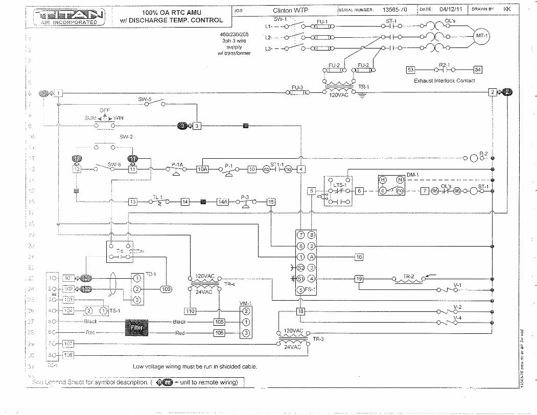
JOB" ~-;;i'rw,!Z:J::Jl 100% OA RTC AMU ·······~·-----fT·~~-::-\i",l~C:Cl~PORATED) wi DISCHARGE TEMP. CONTROL
46012301208 3ph 3 wire
supply wI transformer
Clinion WTP SEHIAL NUMBER 13565~70 DATE 04112111 DRAWN BY
SW-1. FU-1 ST-1 L 1- -~ f--O--O-I
OL's
L2. -~ f--O--O-I \.0 ( MT·1
L3- - ·()-(=:JD--7~r f--O----01!
R2-1 ~H>---{E]
Exhaust Interlock Contact
120VAC
OFF
SUiIJ1...;{ ~» WIN
,-----<.----~~ ~1-------llilllllil------, S'01-2
P-1
g DM., H N -------------
OL's - c @l--~
T-5 ,--------+-0-
TR-2
TR-4
TR-3
"~., Low voltage wiring must be run in shielded cable.
. - -.~ .. -~.-.. -~ ...... ~~ .. "-~-.. ~ ... ~~-----~ . "_."-, U:o. t '""fxl Sheet Tor symboi description. ( ~ = unit to remote wiring)
KK
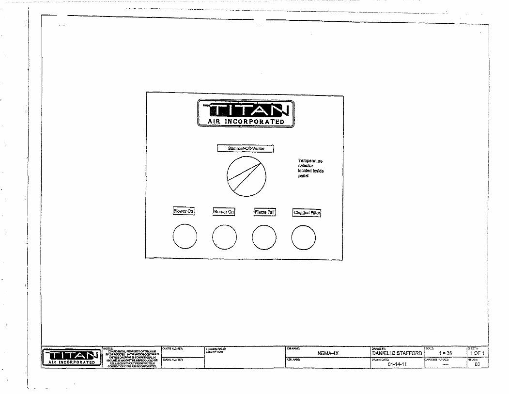
i
,I
"'
-"------.-.---.-.-~--.-------------, ._-------_._-----"------- -~- -- - --- ------
Summar..off·Wlnlar
IB~ IB~ IFlameFaUI
Temperature .. I<><tor localea Inside panel
I Clogged FUterl
0000
NEMA-4X STAFFORD 1 =36
T451 , T651 Motor~Rated Precision Thermostats
APPLICATION The T651 thermostat provides direct, accurate line voltage control of inductively-rated heating, ventilating, or cooling equipment used in commeroia! or industrial environments.
The T451 provides precision line voltage control of motorrated electric, gas or oil heating equipment.
CL 4-01 • © Honeywell LimitedJLimitee 2001
FEATURES a Deluxe styling for commercial buildings •
.. Industrial grade MICRO SWITCHTM mechanism rated 1/2 hp inductive, 5 kW resistive.
o Vertical mounting on 2" x 4" NEMARstandard single-gang outlet box.
• High-sensitivity, vapo .... filled stainless steel dual diaphragm sensing element.
• Engineering plastic base to isolate sensor from switch heat and minimize droop.
• CSA Certified, UL Listed.
• Altitude compensation.
• 44°F (JOe) "frost protection" setting for heating application, inde,pend~nt of calibration or altitude.
• Color~coded leadwire connections.
• Range stops/locking cover security features for public areas.
Contents
Specifications ..•.....•...••.....•••......•.•.. 2 Ordering Information ••.•...•.•••.....•.•.....••. 2 Instal/ation .•.•.........•.•...•••...•...•..•... 3 Setting and Adjustment .•.............••......... 4
111111111111111111
95C~10903·1

flTlportan'l: The speedications given in this pu!JJfcaLion do nol incll!de no(rna! manufacturing to/e(()lIces. Therefore this unit may not exactly rnatcti the listed specifications. iNs product is le::;teci and calibrated uncier closely cOfltro//ed conclitions, and some minor difforences in porformanco can be: expected if these conditio!!s are chanDed.
Models: T451A SPST and T451E3 OPST (with positive off) for heating only. T651 A SPOT for heating/cooling.
Control Range: 44 - 86'F (7 - 28'C) for models T451A, T651A. 50 - 86'F (10 - 28'C) for model T451B.
Sensing Element: Vapor-filled dual diaphragm.
Differential: 2'F (1 'c)
Droop: 2"F @ mid load range.
Barometer Sensitivity: 1/8'Fl"wc (0.3'C/kPa).
Thermometer: 50 - 90'F CIO - 30'C) in 10'F (5'C) increments.
Electrical Ratings:
SO/60Hz 120 V 208V 240V 277V
Full Load 9.8A 5.6A 4.9A 4.2A
Locked Rotor 58.8A 33.6A 29AA 25.2A
Pilot Duty 125 VA
Resistive 22A Non Inductive I 19ANI
Heating Only 2.5kW I 4.5kW I 5kW
ORDERING INFORMATION
Finish: Classic tx:ige-and-1i9ht gold standard. \Nhite rnodels available.
Mounting: Mounts directly on vertic'ai, ~'illgle··g~)ng !'lEMA Slandard (2" x ..j ") electrical box.
Wiring Connections: 6" (150 Illln) leacJwires suitable for connecting to aluminum conductors wiring if used with approved special service CO/ALR solderless wire connectors. Leadwires color· coded red for heating, blue for cooling, black for common.
Approvals: Canadian Standards Association Certified; File No, LR1322 Performance Certified for electric heating per C273.4A UL file E47434.
Accessories: 272804A Range stops and cover locking assembly
(included in selected models only). 220213 Wallplate, covers old T451/T651 (1000 series)
wall marks. TG511 Thermostat guard for security and protection.
Fig. 1 - Dimensions of T451 J T651 in inches {mm}:
1'_ 75 ----.J
12-15/10J . ·-1
115 [4-1I2J
-(2-1181_ 54
l ----"-T " [2~1/161
1 115
'-L~_.,---_14r h:1~2J+[df~
When purchasing replacement and modernization products from your TRADELlNE® wholesaler or your dlstributor, refer to the TRADELINE catalog or price sheets for complete ordering number, or specify:
1. Model 2. Electricalload(s) 3. Accessories.
If you have additional questions, need further information, or would like to comment on our products or services, please write or phone:
1. Your local Honeywell Home and Building ConiTol Sales Office (check white pages or phone directory). 2. Home and Building Control Customer Satisfaction
Honeywell Inc., 1885 Douglas Drive North. Minneapolis, MN 55422 (612) 951-1000
3. In Canada-Honeywell limited, 35 Dynamic Drive, Toronto, ON M1V 4Z9, 1-800-405-9835. International Sales and Service Offices in all principal cities of the world. Manufacturing in Australia, Canada, Finland, France, Germany, Japan, Mexico, Netherlands, Spain, Taiwan, United Kingdom, U.S,A.
2 95C-10903-1
------ -- ------- .----- ------ -----_.
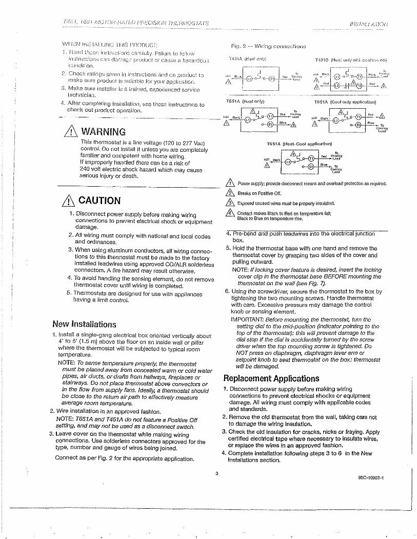
T"hf, ':(5bl MUrCJirl;AFLU {)f-iLCISJCHJ fJ-ILh'iAU,'3i/I{S
V,/ll[N INST!\LU[\j(~ THiS PHODUCT:
1. Head lh(~se irrs:xuc[ion,-, carefully. r:ailUl"0 to folfm'! instructions C"lJl d:ulI.Joe product or Cf1U~;e <l h~v,"ndou~; cOfKiilion.
2. Check ratings given in instructions and on pl"Oducl to rnake sure product is suitable for your application.
3. Make sure installer is a trained, experienced service technician.
4. After completing installation, use these instructions to ctlock out product operation.
& WARNING This thermostat is a !lne voltage (120 to 277 Vac) con~l:oL Do not install it unless you are completely fa~T)Jllar and competent with home wiring. If Improperly handled there can be a risk of 240 volt electric shock hazard which may cause serious injury or death.
& CAUTION 1. Disconn.ect power supply before making wiring
connectIons to prevent electrical shocl<. or equipment damage.
2. All wiring must comply with national and local codes and ordinances.
3. When using aluminum conductors, all wiring connec~ions to this thermostat must be made to the factory Installed leadwires using approved CO/ALR solderless connectors. A fire hazard may result otherwise.
4. To avoid handling the senSing element, do not remove thermostat cover until wiring is completed.
5. Thermostats are designed for use with appliances having a limit control.
New Installations 1. Install a single-gang electrical box oriented vertically about
4' to 5' (1.5 m) above the floor on an inside wan or pillar where the thermostat will be subjected to typical room temperature.
NOTE: To sense temperature properly. the thermostat must be placed away from concealed warm or cold water pitx:s, air ducts, or drafts from halfways, fireplaces or staIrways. Do not place thermostat above convectors or in the flow from supply fans. Ideally, a thermostat should be close to the return air path to effectively measure average room temperature.
2. Wire installation in an approved fashion.
NOTE: T651A and T451A do not feature a PosiUve Off setting, and may not be used as a disconnect switch.
3. Leave cover on the thermostat while making wiring connections. Use solder/ess conneotors approved for the type, number and gauge of wires being joined.
Connect as per Fig. 2 for the appropriate application.
3
IlIS //'tI.l A i IOIV
Fiq. 2 .~.~ Wiring connections
T651A (Heat only) T651A (Cool only application)
T651A (Heat-Cool application)
.&. Power supply; provIde disconnect means and overload protection as required.
& Breaks on Positive Off.
&. Exposed unused wires must be properly inStllated.
8 Contact makes Slack to Red on temperature fall; Black to Slue on temperature rise.
4. PreMbend and push leadwjres into the electrical junction box.
5. Hold the thermostat base with one hand and remove the thennostat cover by grasping two sides of the cover and pulling outward.
NOTE: If locking cover feature is desired, insert the locking cover clip in the thermostat base BEFORE mounting the thermostat on the wall (see Fig. 7).
6. Using the screwdriver, secure the thermostat to the box by tightening the two mounting screws. Handle thermostat with care. Excessive pressure may damage the control knob or sonsing element. IMPORTANT: Before mounUng tl7e thel7nostat, tum the
setting dial to the mid-position (indicator pointing to the top of the thermostat): this wi/J prevent damage to the dial stop if the dial is accidentally turned by the screw driver when the top mounting screw is tightened. Do NOT press on dlaphragm, diaphragm lever arm or setpoint knob to seat thermostat on the box: thermostat wi/! be damaged.
Replacement Applications 1. Disconnect power supply before making wiring
connections to prevent electrical shooks or eqUipment damage. All wiring must comply with applicable codes and standards.
2. Remove the old thermostat from the wall. taking care not to damage the wiring insulation.
3. Check the old Insulation for cracks. nicks or fraying. Apply certified electrical tape where necessary to insulate wires, or replace the wires in an approved fashion.
4. Complete instalfation following steps 3 to 6 in the New Installations section.
.------------~-.---
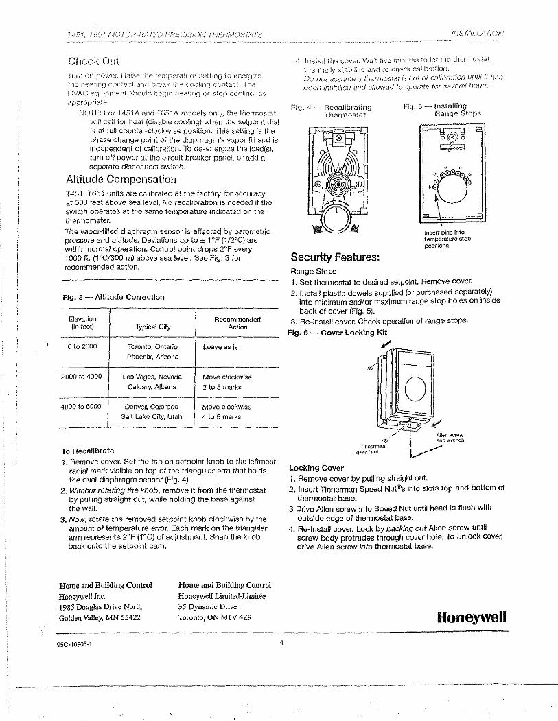
;>'b f, i 651 /t,lUJD.!"}--F'Ai i.':U !--'!iLCiS;/()N (f'lf:;/-
3.5 Start up Procedures
AIR INCORPORI\TED
100% OUTSiDE AtI~ {l,MKE"UP UNITS WiTH RTC SOLUTIONS DISCHARGE TEMPERA TURE CONTROL
Stali-up must be performed by a trained, experienced service person.
The following general start-up procedure applies directly to standard 100% air make-up units. Please note any added options for a specific unit which may affect the control sequence or terminal numbering prior to attempting start-up or service work. Read the entire start-up procedure and review all reference material (Unit Specifications, Gas Train/Burner Specifications, Sequence of Operation, Parts Lists, and Electrical Schematic) supplied with each unit.
STEP 1 Turn off incoming electrical power and gas supply to the unit. Electrical power
can be turned off at the unit disconnect. Gas supply shut-off is at the inlet of unit's gas manifold.
At the remote panel, turn the Summer-Off-Winter (S-O-W) switch to the off position and the temperature selector to the lowest setting. STEP 2
Verify that incoming electrical and gas supply match the name plate requirements (i.e., voltage/amp capacity, gas pressure and volume capacities, etc). If they do not, stop at this point and contact Titan Air. STEP 3
Open the access doors to blower and control vestibule sections. Check all electrical connections and hardware (blower drives, bearings, damper linkages, etc.) for tightness and correct field wiring connections. STEP 4
Check all gas, pilot, vent, and pressure sensing lines are properly connected and unobstructed. Verify the incoming gas line was "blown out" to flush out debris prior to connecting gas line to unit. Also verify incoming gas line has been purged of air up to unit's gas inlet. STEP 5
At manifold pressure test port, downstream of the modulating gas valve (VM-1), connect a gas pressure gauge (pressure gauge must read inches of water column to 10" with the capability of reading a negative pressure). STEP 6
Turn on incoming electrical power at unit disconnect. Make sure the blower access door is securely held open. Turn the blower service switch (SW-5) to the on position. STEP 7
If an optional intake or discharge damper is installed, the blower will not start until the damper motor's internal "proof open" end switch closes (damper motor and end switch wiring are generally completed in the field after damper is mounted). If an intake or discharge damper is not installed, the blower should start immediately. Check the blower for proper rotation direction. If the rotation is reversed, turn both SW-5 and the disconnect switch off, For 3 phase motors, reverse any two leads.
p.1 AMU RTC Int 19n 2003 R1 doc
STEP 8 With proper blower rotation verified, check and record the I'<.I~M of the blower. If
tile blower speed needs to be adjusted to change the rated CFM of the unit, contact the factory. STEP 9
Turn the unit off. Close and latch the blower access door. STEP 10
Start unit with SW··5. Check and record the motor amp draw. If the motor amp draw exceeds listed Full Load Amps (FLA), stop and call the factory. STEP 11
Check and record the negative pressure reading on your burner manifold pressure gauge. This measurement is necessary for proper setting of the burner manifold pressure when the unit is forced into high fire mode. At this time, also measure the pressure drop across the airflow switch ports (remove caps from fittings in tubing for air flow switches and connect tubing from differential pressure gauge to fittings). This measurement can be used as a simple indication of proper airflow through the unit. If this second measurement is not between 0.7" w.c. and 0.5" w.c. 6P, the blower speed may need to be adjusted. If assistance is needed, contact Titan Air. STEP 12
Turn the unit off. Check the pilot gas line for proper and tight connections with no leaks. For shipping purposes, the pilot lines are disconnected. STEP 13
Turn on the main gas valve, slowly open the manual pilot gas valve. If the unit is supplied with a low gas pressure switch (P-2), reset to on position. STEP 14
Place the run-check switch (located on flame safeguard programmer module) to the check position. This will allow the pilot to light without igniting the main burner. If the unit is equipped with an inlet ductstat (T-1), set this stat above the outside air temperature. Start unit with SW-5 and enable the burner with the burner service switch (SW-6).
Note that the burner should not be operated continuously in the check position for more than 1 minute because the ignition transformer is not rated for continuous duty. STEP 15
The unit should go through its complete burner ignition sequence with only the pilot ignited. The sequence can be observed by following the indicating LED's on the flame safeguard. On new installations, resetting of the flame safeguard may be required to purge air from the pilot line. If the unit does not cycle through its burner ignition sequence after a few attempts, refer to the service information in the following section for troubleshooting instructions. STEP 16
In the center of FS-1 are 2 voltmeter test ports. Set the volt-ohm meter to approximately 30 VDC scale and insert the meter leads into the test ports (common lead in black port, positive lead in red port). STEP 17
With only the pilot operating, record the DC volt signal. The DCV range is noted on the amplifier module of the controller (FS-1). There should be a steady DCV signal in
p.2 AMU RTC /n/ /9112003 RI.doc
AIR INCORPORATED
tile upper range stated on the cOlltroller. STEP 18
Once stable pilot is achieved, shut unit down alld place run-check switch in the run position. Carefully remove the wire from terminal one (1) 011 gas modulating actuator (VM-1). Do not allow the wire to touch the unit casing or any metal. Release actuator gear by pressing black button on side of actuator (see figure 1), rotating mechanism counterclockwise to stop. Start unit and check and record DC voltage as in previous step. Check to make sure the flame is contained in the burner casting and extends tile full length of the burner with no breaks in the flame. An ideal low fire setting results in a small flame with no breaks and that also produces a stable DC voltage signal in the upper end of the range listed on the flame safeguard amplifier module. If the low fire setting is adjusted, verify that both the DC voltage signal and visual appearance of the flame are satisfactory. See figure 1 at end of start-up procedure for low fire adjustments if necessary. STEP 19
Once stable signal is achieved on low fire, release actuator gear by pressing black button on side of actuator (see figure 1) and rotate mechanism clockwise to stop. This will force the burner into high fire. On your manifold pressure gauge, check the manifold pressul-e. The reading on your manifold pressure gauge needs to be added to the negative pressure recorded in step 11. The resulting total manifold pressure should be compared to the unit's rated manifold pressure. If the total is higher or lower than the rated pressure, adjustment can be made at the gas pressure regulator (GP-1), Total manifold pressure should not exceed unit's rated manifold pressure,
Because of possible variations in the BTU content of gas, it may be necessary to set the manifold pressure to the rated temperature rise (temperature difference between the incoming air and the unit discharge air),
The high fire flame should be visually observed to verify proper combustion. Experienced service personnel should be able to assess the appearance of a proper high fire flame, If assistance is needed, contact the factory, STEP 20
With the burner on high fire, turn the h'lgh temperature limit (TL-1) to its lowest setting, The limit should trip out and shut down the burner. Turn TL-1 back to the factory setting of 185 deg, F and reset the control. Reconnect wire at VM-1, STEP 21
With all wiring in place and the unit operating in the winter mode, adjust temperature setpoint on the remote mounted controller (TO-1) up and down (from highest to lowest setting) observing the modulation of the burner, When actual discharge air is below TO-1's setpoint, the unit should discharge maximum temperature, When actual discharge air is above TO-1 's setpoint, the unit should discharge minimum temperature, STEP 22
With the unit operating in the summer mode, cycle the burner from SW-6, Verify that burner fully lights within a few seconds of proved pilot. STEP 23
If the unit is equipped with a low temperature safety (L TS-1), check this control's operation, Standard LTS-1 can be checked by disconnecting the sensor wires, The unit
p.3 AMU RTC Inllgl1 2003 Rldoe
AIR INCORPORATED
should then shut down after the built-in timer setting has "timed-out". Replace the sensor wires when pmper operation has been verified. Tum the unit off and back all to reset L TS-1. STEP 24
With the unit operating in the winter mode, close the 2nd manual gas shutoff valve (GT-3). The burner should shut down in a few seconds (look for flame LED to go out on FS-1) with the unit shutting down in 30 seconds or less. Open GT-3 and reset FS-1 by pressing button pmtruding through cover. STEP 25
Turn SW-5, SW-6 and the disconnect off. Verify all terminals, electrical connections and hardware (bearings, sheaves, blower wheels, etc.) are securely tightened. Adjust all controls to desired settings. Remove all gauges, meters, and hand tools from the unit. Replace all covers on controls. Make sure all safety devices are reset. STEP 26
Turn the disconnect on. Start the unit from the remote panel. Verify proper operation in all modes according to unit's sequence of operation,
The unit should be ready for operation, If any problems arise, refer to the service information on the following page, To assure long lasting and efficient operation of Titan equipment, a regular service inspection should be set up. Refer to the maintenance section at the back of this manual for detailed maintenance information.
pA AMU RTC 1I111gl12003 R1.doc
Actuator Replacement/Installation:
Figure 1
Low Fire t-\djustmsnt: Di~2GUIIIK;cl \~!lrB <:it tellnil-I,.;I +I-"J nIl ~:l(),u,,~lr.jl
Pr(~ss "ciU1Ch-' to Ill'.-1I1ually 1'Ot;_'1!('~ shaft ,;lS neeckd. /\dj,.lst mech;:,lIliccll stop at counle;rclockwise end of ~'lctLidtor'S st:"oke to set Imv fire. Need contintous flarne acmss IJurnE'r Ai\! 0 strong 31l1plifi8d siqnai at flame safeQ~I,:-lf"d test ports.
High Fire Adjustment: Adjust high iire al seperale re[!ulator Do "OT adjust mecllanrcal stop at clockwise end of actuator's stroke. Refer' to instructions in start-up IYOC8dure.
Installation of El replacernent clctu8tor should be made with ,)ctuator rotated to hiOh fil"e position. C!:::~cl<.wise high fire rnccilo1icai stop Sii0Uld be set and line ~Tlarl\ on rnodulating valve stelrl should l)e p8ra:lel with pipE";' clS shovm in "'High F"ire Position' photo above Set 10\1\,1 fil"e 1l1l~cl)8nic81 stop sirnilar to original actuator. Adjust lov\: fire per 2,tmt-up procedure.
p.5 AMU RTC Intlgn 2003 R1.doc
Brandon

3.6 General Information: Installation, Assembly Drawings, Maintenance

WARNING
Improper installation, adjustment, alteration, service or maintenance can cause property
damage, injury or death. READ all maintenance instructions thoroughly before installing or
serviCing equipment.
FOR YOUR SAFETY
IF YOU SMELL GAS: 1. Open window I doors. 2. DO NOT switch electrical switches. 3. Extinguish any open flame. 4. Immediately call your gas supplier from
an area away from gas smell.
The use and storage of gasoline or other flammable vapors and
liquids in open containers in the vicinity of this heater is
HAZARDOUS.
NOTICE LOW TEMPERATURE LIMIT
If this heater is to be installed in an area of potential freeze up and a low temperature limit
was not ordered, one should be installed to provide freeze protection in the event of a
burner shut down.
[-utiI r:--- GJ 1 AIR INCORPORATED
24 MONTH WARRANTY Titan Air, Inc. hereby warrants its products against defects in material and
workmanship for a period of (24) twenty four months from date of shipment. Start up checklist is due back within (30) thirty days of start-up or 120 days from date
of delivery for 24 month warranty to be effective. After (30) thirty days, and up until (60) sixty days, a (13) thirteenth month warranty will be observed. All warranties are null and void if start up checklist is not received within (60) sixty days from start-up or 120 days from date of delivery. NO EXCEPTIONS WILL BE MADE.
Titan Air, Inc. reserves the right at Titan Air, Inc.'s option, to replace or repair free of charge, any part proven by Titan Air, Inc. to be defective. Prompt notification of defective part must be given to Titan Air, Inc. and defective part must be returned freight prepaid within (30) thirty days of notification.
WARRANTY INCLUDES ONLY PARTS SUPPLIED BY TITAN AIR, INC. INCIDENTAL COSTS AND LABOR CHARGES SHALL BE THE RESPONSIBILITY OF OTHERS. This warranty does not cover fuses, belts, filters or water damaged parts which are the result of improper storage or installation.
This warranty is void in event the product is improperly installed and/or operated under conditions other than normal published ratings, improperly maintained, misused or not in compliance with applicable codes or not in accordance with Titan Air, Inc.'s operating instructions.
This warranty is void if attempts to correct or repair any alleged defective part or parts are made by unauthorized personnel without Titan Air, Inc.'s written approval.
In no event shall Titan Air, Inc. be held liable for any damage, incidental or consequential, arising from the installation, performance or operation of the product.
This warranty supersedes, voids, and/or is in lieu of any other verbal or written understanding which may not be in total accordance with this expressed warranty.
Warranted parts must be returned to Titan Air, Inc. within 60 days to receive credit.
PURPOSE / APPLICABILITY This manual is intended to provide installation, operating and service information on
Titan Air's standard direct-fired air make-up units. Other Titan Air units, such as AR/80™, AR/75™, Demand-AirTM, H.O.TTM and units that do not feature a direct-fired burner, will have separate operating and service manuals.
A packet of reference materials for a specific unit (tracked by its Serial Number) is generally included with this Operating and Service Manual. The reference materials include Unit Specifications, Parts Lists, Gas Train and Burner Specifications, Electrical Schematic, and a Sequence of Operation. A start up checklist is also included in this packet. Review the reference materials for a specific unit and note any optional equipment or controls which are not specifically addressed in this manual prior to attempting start-up or service work.
The information and recommendations contained in this publication are based on general observation and are not intended to supplant requirements of federal, state or local codes having jurisdiction. These codes should be reviewed before installation of equipment. All units must be installed in accordance with national, state or local codes.
It is the responsibility of the purchaser at the time of order, to specify any and all code or insurance requirements that may dictate the addition of components to the equipment in order to comply with those requirements.
Only qualified personnel who have experience with the installation and operation of industrial/commercial direct fired equipment should attempt to service Titan Air equipment.
WAPRANTY
TABLE OF CONTENTS
GENERAL INFORMATION ';> Equipment Arrival ';> Components
AIR FLOW SWITCH OPEPATION
INSTALLATION ';> Installation and Field Wiring Overview
TYPICAL ASSEMBLY DRAWINGS
MAINTENANCE
FLAME FAIL DIAGNOSTICS
START-UP PPEPAPATION
VALVE LEAK TEST
SPECIFIC EQUIPMENT DETAILS ';> Unit Specification ';> Sequence of Operation ';> Parts / Legend Sheet ';> Schematic ';> Start-Up Procedure ';> Troubleshooting (optional)
Page 1
2
3
7
8
11
14
17
19
20
pages not numbered
Note that operating and service manuals are occasionally requested prior to production of a unit. These manuals will be marked "Pre-Production Pelease" on the front cover. The final copy of the operating and service manual for a specific unit will be sent with the unit. Additional copies of the manual for a specific unit are available.
A detailed unit specification sheet, parts/legend sheet, schematic, sequence of operation and start-up procedure are provided in the start-up section of each operating and service manual generated for a specific unit. Selected vendor cut sheets on components will also be included.
2

EQUIPMENT ARRIVAL Wilen the air make-up unit arrives, be sure to inspect for shipping damage. The
equipment was thoroughly inspected before leaving the factory and the driver signed for it. Read the bill of lading and verify that all of the items listed are accounted for. Any damaged or missing items should be reported to the transporter immediately. DO NOT SEND DAMAGED FREIGHT BACK TO TITAN AIR! All claims mustbe filed with th" jransporter. Be sure to take photographs and get the drivers signature to confirm the damage. The driver will have a number for you to call to file a claim. Request a written inspection report from the claims inspector to substantiate any necessary claim. Be sure to open the unit access doors and inspect for internal damage.
If for some reason you are unable to install the equipment immediately, be sure that the equipment is protected from the elements. Water damaged parts are not covered by Titan Air's warranty. If the equipment is stored for an extended length of time, be sure to completely check the unit for any internal damage which may have been caused by excessive condensation. Also check for damage caused by rodents, and be sure to eliminate any dust that may have built up on the components while the unit was in storage.
CAREFULLY AND THOROUGHLY READ TITAN AIR'S PRODUCT WARRANTY Each unit is tested at the factory prior to shipping. Because we are not able to
simulate exact field conditions and sometimes actual conditions are different than what was stated on the order, you may need to make some adjustments in the field. This is why it is very important that only qualified personnel start-up and service Titan Air equipment. The start-up checklist (provided in packet with this manual) must be filled out and returned to Titan Air in order to validate equipment warranty.
For a fee, Titan Air personnel will travel to the job site, supervise start-up and provide operation and maintenance training for the equipment.
BLOWERS The typical blower(s) used in Titan Air equipment are AMCA rated industrial type
forward curve D.W.D.I. fans. Backward incline, backward airfoil, and plenum/plug fans are used occasionally. Models TA-109 through TA-136 utilize a single blower while models TA-215 through TA-242 utilize twin blowers. All blower wheels are mounted on a solid, turned, ground and polished shaft. 9" and 12" blowers are supported with permanently lubricated ball bearings. Larger blowers are supported by lubricated pillow block ball bearings.
MOTOR & DRIVE Rigid base, T-Frame, motors are utilized. The motor is mounted on an adjustable
slide base. Variable pitch motor sheaves are provided to allow airflow adjustment if the motor is no larger than 30 Hp.
3
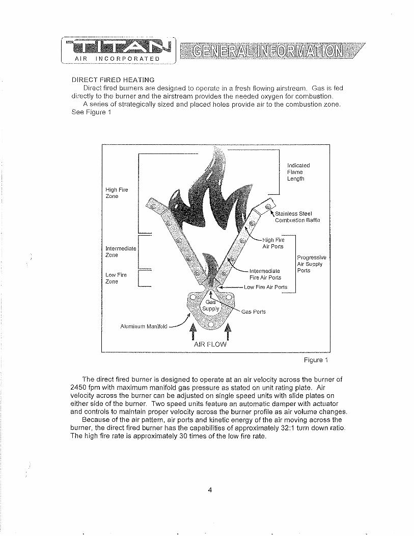
DIRECT FIRED HEATING Direct fired burners are designed to operate in a fresh flowing airstream. Gas is feci
directly to the burner and the airstream provides the needed oxygen for combustion. A series of strategically sized and placed holes provide air to the combustion zone.
See Figure 1
r-----------~~~====~-------~
High Fire Zone
Intermediate [ Zone
Low Fire I Zone L
Aluminum Manifold
Indicated Flame Length
i I Sleel Combustion Baffle
'--_Hi',,, Fire Air Poris
Progressive Air Supply
Intermediate Ports Fire Air Ports
,y .. --- Low Fire Air Ports
AIR FLOW
Figure 1
The direct fired burner is designed to operate at an air velocity across the burner of 2450 fpm with maximum manifold gas pressure as stated on unit rating plate. Air velocity across the burner can be adjusted on single speed units with slide plates on either side of the burner. Two speed units feature an automatic damper with actuator and controls to maintain proper velocity across the burner profile as air volume changes.
Because of the air pattern, air ports and kinetic energy of the air moving across the burner, the direct fired burner has the capabilities of approximately 32: 1 turn down ratio. The high fire rate is approximately 30 times of the low fire rate.
4
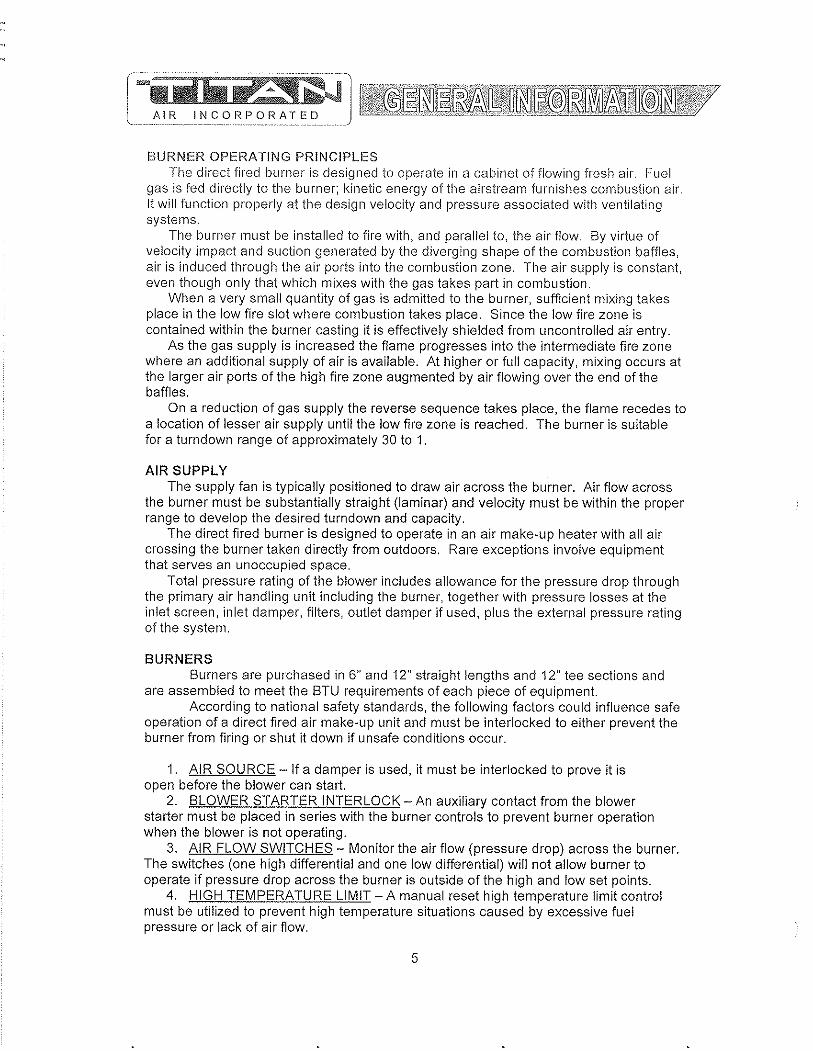
BURNER OPERATING PRINCIPLES The direct fired burner is designed to operate in a cabinet of flowing fresh air. r~uel
gas is fed directly to the burner; kinetic energy of the airstream furnishes combustion air. It will function properly at the design velocity and pressure associated with ventilating systems.
The burner must be installed to fire with, and parallel to, the air flow. By virtue of velocity impact and suction generated by the diverging shape of the combustion baffles, air is induced through the air ports into the combustion zone. The air supply is constant, even though only that which mixes with the gas takes part in combustion.
When a very small quantity of gas is admitted to the burner, sufficient mixing takes place in the low fire slot where combustion takes place. Since the low fire zone is contained within the burner casting it is effectively shielded from uncontrolled air entry.
As the gas supply is increased the flame progresses into the intermediate fire zone where an additional supply of air is available. At higher or full capacity, mixing occurs at the larger air ports of the high fire zone augmented by air flowing over the end of the baffles.
On a reduction of gas supply the reverse sequence takes place, the flame recedes to a location of lesser air supply until the low fire zone is reached. The burner is suitable for a turndown range of approximately 30 to 1.
AIR SUPPLY The supply fan is typically positioned to draw air across the burner. Air flow across
the burner must be substantially straight (laminar) and velocity must be within the proper range to develop the desired turndown and capacity.
The direct fired burner is designed to operate in an air make-up heater with all air crossing the burner taken directly from outdoors. Rare exceptions involve equipment that serves an unoccupied space.
Total pressure rating of the blower includes allowance for the pressure drop through the primary air handling unit including the burner, together with pressure losses at the inlet screen, inlet damper, filters, outlet damper if used, plus the external pressure rating of the system.
BURNERS Burners are purchased in 6" and 12" straight lengths and 12" tee sections and
are assembled to meet the BTU requirements of each piece of equipment. According to national safety standards, the following factors could influence safe
operation of a direct fired air make-up unit and must be interlocked to either prevent the burner from firing or shut it down if unsafe conditions occur.
1. AIR SOURCE - If a damper is used, it must be interlocked to prove it is open before the blower can start.
2. BLOWER STARTER INTERLOCK - An auxiliary contact from the blower starter must be placed in series with the burner controls to prevent burner operation when the blower is not operating.
3. AIR FLOW SWITCHES - Monitor the air flow (pressure drop) across the burner. The switches (one high differential and one low differential) will not allow burner to operate if pressure drop across the burner is outside of the high and low set points.
4. HIGH TEMPERATURE LIMIT - A manual reset high temperature limit control must be utilized to prevent high temperature situations caused by excessive fuel pressure or lack of air flow.
5

5. fl~AME SAF-];GI,JAFill- Monitors the combustion process during ignition and operation for safe conditions_
6. HIGH GAS PRi::SSURE SWITCH - Monitors gas pressure to the burner. This de-energizes the burner in the event gas pressure increases above its set point.
The burner's design and flexibility, coupled with proper controls, make direct fired air make-up equipment the safest and most efficient method of tempering outdoor air.
GAS CONTROLS Titan Air TA Series equipment is constructed to meet AN.S.I Z83A/CSA 3.7 .. 1999
standards_ Components in the gas delivery manifold on standard equipment include: two manual shut-off valves, gas pressure regulator, two safety shut-off valves and an electronic gas modulating valve. The pilot control includes a shutoff valve, gas pressure regulator and a pilot solenoid_
ELECTRIC/ELECTRONIC CONTROLS TA series air make-up units come standard with the following items: disconnect
switch, starter and overload assembly(s), control power transformer (if a 3 wire system), air proving switches, high temperature limit, electronic flame safeguard and electronic flame modulation with remote set point adjustment. Many other options including low temperature limit, inlet duct stat, and operating lights are available.
If the malfunction of the heater creates a hazard to other fuel burning equipment in the served building (i.e. supplying make-up air to boiler room) it is to be interlocked to open an inlet air damper in case of failure.
CABINET Titan Air TA series equipment comes with either a galvanized finish or a painted
finish. In both cases, the minimum gauge metal used is 18 gao
6
AIR INCORPORATED
BURNER PROFILE AIR PRESSURE DROP ANSI standards, Z 83.4/CSA 3.7 M99 & Z 83.18 .. 2000, require manufacturers to
monitor air moving across the burner for both high and low conditions. Titan Air utilizes pressure drop across the burner to satisfy this requirement.
Certification testing demonstrated that the burner will function properly between a low pressure drop of 0.2" w.c. and high pressure drop of 0.95" w.c. The standards also mandate that the switches cannot be adjustable. This makes air pressure drop across the burner profile a very important factor at initial start up.
The design burner pressure drop at standard air conditions is 0.60" w.c. and will cllange as the temperature of outside air increases or decreases from 70"F. In order for the burner to operate within the range of the air flow monitoring switch set points, the pressure drop should be as close to 0.60" w.c. as possible.
Air pressure drop across the burner profile is dependent on OA temperature. When the burner is off, pressure drop will climb significantly during cold weather. The burner is always off on initial start-up. Therefore, if the burner profile air pressure drop is above 0.70" w.c. during a warm weather start-up, it may exceed 0.95" w.c. during a cold weather start-up in northern regions. Such a high air pressure drop would open the high airflow switch and prevent burner ignition.
The following chart will aid in equipment set up at outside air temperatures different from 70"F when the unit is operating with the burner off. The chart gives pressure drops, at various temperatures, equivalent to 0.60" w.c. at 70"F.
Note that two speed units feature controls to automatically control pressure drop across the burner as air volume changes. Burner profile air pressure drop should be measured on high speed with the burner profile dampers near the full open position. If the burner profile dampers open less than 50% on high speed, the equipment is not delivering rated air volume.
Burner Profile Air Pressure Drop at Various OA Temperatures (Burner Off)
... _._--_._ •.. _ .. _ .. __ ._--_ ... - .-.. -~.-----~-----..... . .. ~-~,--.-~.-.~.-.... ~.'""
OA Burner OA Burner OA Burner Temp Profile Drop Temp Profile Drop Temp Profile Drop
-40 0.76 10 0.68 60 0.61 ..... _---_.- .. ---- ------- .. _---35 0.75 15 0.67 65 0.61 ........ --------30 0.74 20 0.66 70 0.60 -25 0.73 25 0.66 75 0.59 -20 0.72 30 0.65 80 0.59 ---15 0.71 35 0.64 85 0.58 ----10 0.71 40 0.64 90 0.58 ..
-5 0.70 45 0.63 95 0.57 ._- - --a 0.69 50 0.62 100 0.57 5 0.68 55 0.62 105 0.56
7

CONTROLS Control systems can be designed to meet specific requirements. Numerous
temperature controls are available. Since standard air make-up units usually temper outside air to replace the air exhausted from a building, modulating discharge temperature control is typical. A room override thermostat is occasionally included to automatically increase the discharge temperature set point if space temperature drops too low.
Titan Air units are typically supplied with a remote control panel. This panel will include switching for blower & burner operation and a temperature setpoint. Some units feature operating lights, discharge temperature display, custom controls or contacts by others to enable the blower and/or burner.
Refer to the unit specification sheets, parts list, schematic, sequence of operation and start-up procedure for a specific unit to determine the control options included.
PRE-INSTALLATION Inspect the equipment making sure all parts and accessories are on the job site.
Check equipment against order and packing list. If the equipment has been sitting in storage for some time, inspect it for moisture (from condensation, rain or snow) and/or dust accumulation. Both can cause damage to electrical and electronic components as well as bearings and insulation.
INSTALLATION Care taken during the installation and start-up is vital to the longevity and reliability of
the equipment. Confirm that gas and electric utilities match the rating on the equipment name plate.
» This heater shall be installed in accordance with local codes or, in the absence of local code, according to ANSI Z223.1.
» If the heater is to be installed in an airplane hanger, refer to ANSI/NFPA 409.
» If the heater is to be installed in a parking garage, refer to ANSI/NFPA 88A.
» If the heater is to be installed in a service garage, refer to ANSI/NFPA 88B.
» For installations in Canada, refer to CAN/CGA B149.
» Adequate exhaust and/or relief must be provided to prevent over pressurizing the served space when the heater is operating at its rated capacity.
» If in doubt regarding the application of the direct fired heater, contact the sales representative or the factory.
POSITIONING THE HEATER Locate the heater exactly level, making certain minimum clearance required by local
codes is maintained between the heater and any combustible materials. See name plate on unit for minimum recommended clearances.
8
CURBING (OUTDOOR MOUNTING) The use of a full perimeter curb or mounting rails under the heater is recommended.
The only openings in the roof should be for the supply air duct, return air duct (if required), gas and electrical connections (if applicable). These openings must be sealed properly after installation. Titan Air ships all curbs unassembled and un-insulated. Installing contractor supplies gaskets, cant strips, insulation, etc.
GAS PIPING Gas piping must be sized and installed in accordance with applicable codes, It must
be able to deliver the specified CFH and gas pressure at full flow, Refer to unit nameplate or unit specification sheets for specified CFH and gas pressure.
Care must be taken with the gas piping to prevent problems at start-up and later during operation. Before the union between the supply line and the unit is connected, the supply line should be cleaned out to remove any foreign material (dirt, rust, metal shavings, etc.) and a drip leg should be utilized.
Refer to unit nameplate to determine the minimum gas supply pressure required to attain the maximum specified gas.
All suitable gas controls, regulators and valves (equipped with a diaphragm) in this device are furnished with an ANSI approved vent limiter. If local codes require these components be vented to the outside, it is the responsibility of the installing contractor.
The heater and its individual shut off valve must be disconnected from the gas supply piping system during any pressure testing in excess of Y, PSIG.
The heater must be isolated from the gas supply piping system by closing its individual shut off valve during any pressure testing of the supply system at pressures equal to or less the Y, PSIG.
During start-up, the technician should perform a gas leak check on all valves and piping during the heater's normal operation. (See page 20)
DUCTWORK Ductwork must be sized and installed in accordance with applicable codes and
standards. A size variation may exist from recommended duct size to unit flange size. Recommended duct size applies to the size of the duct at the connection to the equipment. A properly designed duct transition from the blower outlet to a larger duct is recommended for long ducts or ducts with numerous elbows.
On heaters mounted outdoors, discharge ductwork should be insulated to minimize condensation during the "off' cycle in cold weather, A fresh air intake hood with bird screen is required. Discharge duct should be common to both blowers on twin blower units. Individual ducts for each blower are not recommended.
On a heater mounted indoors with through the roof intake, a "mushroom" type intake hood is recommended to prevent moisture entrainment. When using "through the wall" intake duct, the intake louver should have adequate moisture baffling characteristics. All intake ductwork exposed to the heated space should be insulated,
9
SOUND AND VIBRATION CONTROL Flexible connectors are recommended on at least one ductwork connection.
Vibration isolators that mount between the unit and support structure arc" optional and can be supplied with the equipment for installation by others. Another option is internal isolation of the blower/motor assembly with internal flexible connections between the blower housing and the unit structure.
Appropriate insulation on the interior of ductwork significantly reduces sound levels.
DISCHARGE TEMPERATURE SENSOR BULB INSTALLATION & WIRING The installing contractor may be responsible for field installation of the discharge
temperature sensor. Field installation of the discharge temperature sensor in the discharge ductwork results in a better measurement of the average supply air temperature. Utilize shielded cable for field installed discharge sensor wiring.
FIELD WIRING Power supply wiring should be routed from a dedicated branch circuit per schematic.
Depending upon how the equipment was ordered, a single point power connection may be subdivided to individual loads or multiple power supply circuits may be required.
If an intake or discharge damper was ordered as a loose accessory, it will have to be mounted and the actuator must be wired. The remote panel must be mounted in a convenient location and wired to the unit. Interlocks between the exhaust, unit and possibly spray booth will have to be connected by field wiring.
Carefully review the schematic and associated schematic symbol legend. Note that legend may be on the parts/legend sheet rather than on the schematic.
Many codes require that low voltage wiring (connecting terminals numbered 100+) be routed in separate conduit from line voltage wiring. If low voltage wiring is routed with 120 VAC control voltage wiring, it must be placed in shielded cable(s). Even if low voltage wiring is routed in separate conduit, very low voltage sensor outputs and actuator control signals should be routed in shielded cable.
NOTE: All field wiring must conform to N.E.C. and/or any state or local codes.
SUPPORT OF ACCESSORIES Most Titan Air equipment is supplied with loose accessories (i.e. damper, hood,
discharge diffuser or filter section). If an intake hood is supplied by others, the design shall minimize entry of snow/rain and include an intake screen to meet ANSI standards. Intake accessories on large equipment may be shipped in two pieces for field assembly. Two damper actuators may need to be field wired on large equipment as well.
It is the responsibility of the installing contractor to support accessory items from a rigid point or points to ensure solid mounting.
POST INSTALLATION Caulking is required between all parts prior to assembly and seams must be
re-caulked after assembly. Air make-up units shipped in multiple sections will include a high quality caulk tape and caulk tubes. Caulk tape is applied between sections with exterior caulking applied after the unit sections have been joined. Sealing integrity should be rechecked on a yearly basis.
Water damaged parts are not covered by Titan Air's warranty.
10

On splillinits, contractor is responsible tor int(·Hconnectton of components
Mount accessories with 'all access doors and damper motors'facing' same direction',as' u:nit acce'5s doors.
Intake or discharge damper should ,be mounted at the, wall or ceiling (insidebuildjng),
All 'c'omponents m,ust}.e. ¢,aulkedJo 'pr~ve'rit' waterfrorn entering system. 'Re' calilk lift plates after installation,
Accessori,es'shouJd be support€;d ,aft~r installation (supports by others),
TA-233 through TA-242feature 2 piece accessories that need to be assembJ,ed, supported and sealed in the field. Intake dampers have two motors to wire,
(by others)
Note: Discharge damper may be larger than respective flanges or opening on unit.
DAMPER
DISCHAFlGE DAMf'EF,
REMOTE PANEL
Mount Indoors
Make sure gas piping ahd e,l,ectrical, service does not interfere with any door opening and I or filter removal.
INTAKE HOOD
INTAKE FILTER SECTION
2 DAMPER MOTORS
Note: Due to infinite installation possibilities, a section of duct ortransition may be re,quired for proper accessory mounting, 'These items are the responsibility of others,
Recommend the use ·of flex connector between unit and duct work.
Note: ,All main P?werwiring musJ.be sized and installed in accordance with applicable local, state or federal codes, 'Low voltage wiring must be run in separate conduit or shielded cable,
11
Split (must seal)
INTAKE DAMPER
TA-233 through 242 Filter sections are accessed from both sides

PAD ATTACHMENT DETAIL (by others)
Mount Indoors
OUTSIDE AIR FILTER SECTION (optional) slides into unit
DISCHARGE DIFFUSER
Supported by others
(mounted indoors)
Duct work between AMU (or discharge damper) and discharge diffuser is supplied by others. Recomend the use of flex connector between ~Hlit and duct work.
DIffuser should be supported at 2 points by others. (an example shown) Turning vanes are adjusted and secured in the field.
All components must be caulked to prevent water from entering system. Recaulk lift plates after installation.
Make sure piping and electrical service does not interfere with any door opening and I or filter removal.
Recoment the use of flex connector betv'l8en unit and duct work.
For indoor units, the stand must be enclosed (sometimes height is increased). A transition (by others) must then be made from enclosed stand intake opeing to the intake damper or louver (a size variation may exist). Intake damper should be mounted at the building wlal or ceiling.
12
SERVICE DIS\ONNECT
fI n ~~:i
ELECTRICAL GAS TRAIN! ACCESS DOOR
Larger units have more legs
PAD ATTACHMENT DETAIL (by others)
Supported by otll8rs
f@£f3li!L&2££'~\1;X1'Zgl}~mlJJ'_il'Ni~%,%Ji
o Nut
(optional) slides into unit
Sealant goes between each section before assembly. Bolts and caulking are in packing box. Recaulk seams and lifting plates after assembly.
2-PIECE UNIT ASSEMBLY DETAIL (by others)
13
DISCHARGE DIFFUSER
(mounted indoors)
Duct work between AMU (or discharge damper) and discharge diffuser is supplied by others. Recomend the use of flex connector between unit and duct work.
Diffuser should be supported at 2 points by others. (an example shown) Turning vanes are adjusted and secured in the field
All components must be caulked to prevent water from entering system. Recaulk lift plates after installation.
Make sure piping and electrical service does nol interfere with any door opening and J or filter removal.
For indoor units, the stand must be enclosed (sometimes height is increased). A transition (by others) must then be made from enclosed stand intake opening to the intake damper or louver (a size variation may exist). Intake damper should be mounted at the building wall or cei!lng.

GENERAL MAINTENANCE As with any equipment or machinery, a maintenance program should be
implemented. A well maintained unit will perform efficiently for many years.
Equipment maintenance should include the following: 1. Check filters and clean or replace as needed. 2. l.ube bearings. 3. Check belts and belt tension. (Do not over tension.) 4. Check all hardware (bearings, etc.) for tightness. 5. Check settings for all controls. 6. Check duct connections for leaks. 7. Re-caulk seams if needed. 8. Check burner and flame rod - clean if necessary. 9. Perform complete start-up procedure once per year (prior to heating season).
FILTERS Dirty or clogged filters will restrict air flow which in turn affects the burner operation.
Therefore, it is necessary to check filters on a regular basis. Cleanable filters can be removed from the filter rack and sprayed with a low pressure water. Always spray these filters in the opposite direction to air flow and apply new coating to filters when dry.
BURNER Maintaining the pilot assembly is essential to reliable operation. During pre-heating
season maintenance, the burner should be lit numerous tirnes to confirm reliability. If ignition systern components require servicing, pay attention to the following:
1. Handle porcelain spark rod and flame rod with care. Small cracks lead to intermittent ignition problems.
2. Midco burners utilize the pilot gas tube as a ground point for the ignition rod. Keep this grounding point free from scale or other contaminant build-up.
3. Ignition wire routing should remain separated from sheet metal cabinet to maintain optimal spark strength.
4. Dielectric grease is utilized inside of the ignition and flame sensor connection boots to limit potential for moisture in the connection.
5. Maintaining low pilot regulator output pressure typically produces reliable ignition. Excess pilot pressure creates a gas rich region that will not ignite consistently.
6. The pilot solenoid is disabled following main flame ignition. The low fire setting must be high enough to maintain a proper amplified flame rectification signal.
Check that burner baffles are firmly attached to each other and to the burner casting. Do not use excessive force on screws in burner casting. Clean burner baffles with a wire brush if necessary.
Burner orifices may need to be re-drilled due to rust or other build-up. Burners with aluminum castings will rarely require orifice cleaning. Use drill bit sizes listed below.
Fuel T~ _______ --- Burner Model Orifice Size Natural Gas Eclipse AH-MA 2.4 mm Bit _ .. --Natural Gas Midco HMA-2 1/8" Bit
LP Gas Eclipse AH-MA 2.0 mm Bit --LP Gas Midco HMA-2 #45 Bit --
14
BELT TENSION Proper sheave alignment and belt tension are critical to belt and bearing service life.
Incorrect belt tension or misalignment of sheaves can cause any of the following: 1. Premature failure of bearings. 2. IOremature failure of belts. 3. Reduced air volume. 4. Noise and vibrations.
Eacll Titan Air unit has as standard equipment an adjustable motor base. To adjust the belt tension, loosen the motor hold down bolts and adjust the slide base with adjusting bolt(s) on the end of the base (larger bases will have 2 adjustment bolts). Loose belts will slip. Excessive belt tension will shorten belt and bearing life. Use a belt tension tester and associated tables to determine proper tension. Re-tension after the first day of operation with new belts and periodically thereafter.
Common belt tension gauges will specify a force required to produce a deflection of 1/64" per inch of span. The force required to achieve this deflection is typically in the range of 3 Ibs for A-belts, 5 Ibs. for B-belts, and 15 Ibs. for 5V belts. See Figure 1 below.
Note that optimal belt tension is the lowest tension at which the belts will not slip under peak load. Peak load typically occurs at start-up.
SHEAVE ALIGNMENT With the use of a straight edge, sheave alignment can be checked quickly and
accurately. One of the sheaves will have to be loose on its shaft in order to make adjustment. Adjust until all 4 points are in contact with the straight edge (see Figure 2). Repeat on the other side of sheaves and then re-tighten.
If a face width variation exists, measure the difference between each side of the narrowest sheave and adjust until both sides are an equal distance from the straight edge.
Motor Base
~-::~ Figure 1
Straight Edge
2 3 I I
i "C'&;:,,'" o<!§!&;i§.S;Z0q:0.li""""%B%4:¢3:M%0'!l£""~'"b:, "'8'i&i:%i:K. ",.:i om} :>W+,,"~,._
Figure 2
15
4
BLOWER BEARINGS Bearings must be checked during each periodic maintenance inspection. Bolts and
set screws should be checked for tightness and the bearings may need lubrication. The following is intended only as a guide to aid you in setting up your own schedule
LUBRICATION GUIDE FOR BLOWER BEARINGS
Operating conditions Clean
Dirty
Moisture
MOTOR BEARINGS
Bearing Temp. CfL 32 - 120
120 - 150 150 - 200
32 - 150 150 - 200 32 - 200
Grease Interval 6 - 10 months 1 - 3 montils 1 - 4 weeks 1 - 4 weeks Daily - 1 week Daily - 1 week
Motor bearings in a clean environment should be lubricated every 2 to 3 years. Under more severe conditions of dirt or moisture, lubrication may be required every 6 months to 1 year. Typical motor bearing lubrication procedure follows:
1. Remove fill and drain plugs. 2. Clean drain port of hard grease (with wire if necessary). 3. Add grease (cavity should be no more than % fulL). 4. Start motor and let run for 10 minutes. 5. Wipe off any drained grease and replace fill and drain plugs.
Avoid adding an excessive amount of grease since this a common cause of motor failure.
BLOWER Ensure that blower hub is securely fastened to shaft. Inspect blower wheel and
blades for signs of damage or cracks. Clean blades if necessary to maintain proper balance and performance. Avoid use of excessive grease on blower bearings that can coat fan blades and attract diri
16
FIREYE IVIICRO IVI SERIES LED INDICATING LIGHTS -- STANDARD OPERATION
'r Operating Control -- Energized whenever the burner control switch is on and power is applied to terminal #7 in the flame safeguard_
'r Interlock - Illuminated solid when power is applied on terminal # 6 in the flame safeguard to indicate that the air flow switch and other control & limit switches are closed_ This light flashes once per second if the user has selected the fan-only mode (summer) or if an airflow switch or other safety circuit switch is open_
'r PTFI - Illuminated only during the pilot trial for ignition period_
'r Flame - Illuminated when flame signal is detected_
> Alarm - LED will flash once per second when an alarm condition is detected_
FIREYE MICRO M SERIES LED INDICATING LIGHTS - ALARM MODE
Symbol Legend
Flashing Light .. I Solid Light • I Light Off 0 -------,---r- --
Lockout Description OPR CNTL INTRLK PTFI FLAME ALARM
Line Frequency Noise Detected • 0 0 • ~}
0 r-e • • ","",
Flame Fail - PTFI ~~4 -- -- --Fault Unknown • • • • * Amplifier High Count Fail _____ 0 ___ ___ 0_ __ 0 __ 0 ~~} ----... --~.- ----- ------
Flame Fail - MTFI 0 0 • • ~~$<'~ ,,'< ---
0 .. False Flame - Standby ___ tt_ _0 __ 0 ---_._-_._---'--~;'-'I Interlock Open • • • 0 ------ r------------ f---'--- ----<
Interlock Closed 0 • • 0 .. p"",<:\
Chassis Opto • • 0 • '\:;:t;.d ~~~ p.-,~
-Flame Fail - Auto 0 • 0 • * Check Chassis 0 0 0 • .. Check Programmer 0 0 • 0 ~~~
Amplifier Auto Check Fail • 0 • 0 g " '" _._._ .. _-_. -------_. ----- --- ------Check Blown Fuse • 0 • • ~~ " '" -----------
Check Sensor • • 0 0 * 17
l,jl]Q Fregu8ll.Cjllloise Delill'Je~Q ~ At start up, the MICI~O M measures the AC line to determine if the input is 50 Hz or 60 Hz and set its flag accordingly. As the system is running, line frequency is constantly monitored. Outside interference causing a momentary shift in line frequency could be from SCR controls, VFD's, etc.
Flame£ail...:EIfl ~ No flame signal present at the end of pilot trial for ignition period.
Fault Unknown - A catch all message when, under certain high noise conditions, the lockout message may become garbled and not translatable into any existing message
Amplifier Count Fail - A message used to detect a failed amplifier module that would generate an inordinate amount of pulses to micro computer, usually due to a shorted transistor or oscillating electronic filter.
Flame Fail - MTFI - No flame signal present during main burner trial for ignition period.
Flame Fail - Standby - Flame signal present, for a constant 60 seconds, while control is in standby or off condition.
Interlock Open - Interlock safety circuit (terminal #6) has been detected open for longer than ten minutes during the purge cycle or during main flame period on MEP 562,
Interlock Closed - If selected by dip switches, air flow or interlock switch (terminal #6) is closed 30 seconds after the start of a cycle or when terminal #7 is closed. Titan Air does not use this function.
Chassis Opto - Opto coupler located on chassis has been found to be defective. Opto couplers are checked every 1/2 cycle of the AC main(s) to ensure they are off during the negative 1/2 cycle.
Flame Fi!iLAuto - If dip switches selected for non-recycle, no flame is detected during the run cycle or main flame period.
Check Chassis - At beginning of cycle terminal #5 is energized.
Check Programmer - At beginning of cycle terminal #3 is energized or an internal diagnostics test for the Micro controller has failed,
Check Amplifier - Diagnostic problem with amplifier has been found,
Amplifier Auto Check - The amplifier is checked every 8 seconds by the micro computer to assure it is responding properly,
Check Blown Fuse - At the end of pilot try for ignition, no flame is detected and no power is present on terminal #3, indicating the fuse, located on chassis, is blown,
Check Scanner - The UV self check scanner (UV equipped units only) is producing flame pulses during the shutter closed period due to a malfunctioning shutter or a runaway UV tube.
18

GENERAL START-UP INFORMATION Even thougl'l Titan Air equipment is tested at the factory, it is not the type of
equipment you can throw the switch and walk away from. A complete start-up procedure must be performed.
The factory cannot duplicate the conditions the equipment will see in the actual installation (i.e. gas pressure, static pressure, desired control settings, etc ... ). For this reason there are field adjustments that have to be made. Performing a complete startup procedure will help ensure that correct adjustments are made and correct operation is verified. A step-by-step start-up procedure is provided on subsequent pages. While working through the start-up procedure, record information on the start-up checklist and return to Titan Air to validate the equipment warranty. The start-up checklist is provided on card stock with Titan Air's address pre-printed on one side.
Because most component failures occur during start-up, it is very important that the function of every component be checked out during start-up. It is just as important that the start-up technician realize the malfunction of a component may be caused by other factors (i.e. air flow, gas pressure, field wiring, etc ... ) and should fully investigate a component malfunction and its cause before replacing the component.
Titan Air checks out all returned components and has found approximately 70% of returned parts are in full operational condition. This history has proven that a little extra time invested in troubleshooting will often save the considerable investment in parts, time, and papelWork associated with replacing components.
SUGGESTED TOOLS AND INSTRUMENTS NEEDED FOR START·UP: Volt/Ohm Meter Ammeter Tachometer Thermometer Gas pressure manometer (-10" to 0 to +10" of water column typical scale) Air differential pressure manometer (-2" to 0 to +2" of water column typical scale) Standard Hand Tools.
Additional items for Maxitrol Series 14 or 44 temperature controls: '" y" watt, 1 0,000 Ohm resistor
Additional items for FX Series temperature controls: '" 1 0,000 Ohm resistor (supplied) '" 1 ,000 Ohm resistor (supplied)
19

AIR INCOHPORATED
Valve Leak Test This is a test for checking the closure tiglltness of the gas safety shutoff valv(". It should be performed by trained and experienced technicians. This test should be pmt of the scheduled inspections and maintenance procedures.
1) Close the upstream manual gas valve. 2) Make sure manual test cock on leak test assembly is closed. 3) Remove the test plug on leaving side of gas valve. 4) Close the downstream manual gas valve. 5) Open the upstream manual gas valve. 6) Through the safety system enable the gas valve momentarily. 7) Immerse a )1," tube vertically into a jar of water. 8) Slowly open the test cock on the leak assembly. 9) Once the rate of bubbles through the test assembly stabilizes, count the number of bubbles appearing during the ten second time frame. Each bubble is approximately 0.001 cfh. 10) Do this test for each shut off valve.
Reference below leak test assembly and leakage rate chart.
A
Pipe Size (in) Medium
~172----f---64Qas
~&1 1.57 LP .64 aas
-
1.57 LP 1-114 & 1-1/2 .64 aas
1.57 LP 2 ~as
1.57 LP _. .64Qas 1-112 1.57 LP
3 .64 aas 1.57 LP
c
1/4 IN. (6 MM) FLEXIBl.E TUBING
1/4 IN. (6 MM) ALUMINUM OF( COPPEF~ Pl101
a LEAK TEST TAP
E DOWI\)STREAM MANUAL. GAS COCK
BURNER
TUBING ~ r JAR OR GLASS "" VvlTH WATER
r---+.J.-L-.
1/2 (13MM) L! -,---1--- v ~ __ -'_ A CUT AT
Allowable Leakaae SCCH 294 188 301 192 532 341 578 370 752 481
~----592
20
45 DEGREE ANGLE
Max. # of Bubbles in 10 Sec, 7 4 7 5 13 ._----8 15 9 19 12 24 15
---Min. # of sec. for 10 bubbles ---13 20.4 ---12.7 19.9 --7.2 --11.2 ._-6.6 10.3 5.1 8 4.1 6.5 ---


·RIeI Solutions
DIRECT FIRED DIGITAL TEMPERATURE CONTROL INSTALLATION, OPERATION, AND MAINTENANCE MANUAL
This manual covers the following products:
DFC-1
DFC-2
DFTS
Standard dircct fired temperahuc control O~24VDC output
Direct fired control with integra140-90°F (4-32"C) dial 0-24VDC output
Temperature senor 40-2S0"F (4-121 "c)
DFTD-XXXX Temperature dialS selectable ranges
DAT-12 Discharge air tube
PWM-IOV PWM to 10V output converter
Table of Contents Overview .... 5peciJications ..
Power Requirernents .. DFC Ambient Tenlper<lture Limits ... DFTSjDFTD Ambient Temperature Limits. Accuracy.
Installation .. Wiring ..
Standard control with remote sct point.. Standard control with integral set point... Optional room space control .. Optional multiple sel point temperature control ..
Operation ... StMt up ... Sequence of operation .. Calibration .. Troubleshooting .. OFTS and OFTO Resistance chart.. . ................................................ ..
DDC# T000111.14.2006 DFC-1 O&M 1
. ..... 2 . .... 2 . ..... 2 . ... 2
. ..... 2
. ..... 2
.. .... 2
. ..... 2
...... 2
..... 3
. ..... 3
. ..... 3
. ...... ; . ... 4
. .. .4 . .... .4 . .... .4 . ..... 4
Ph. (919) 845-1579 Fax (919) 845·8102
www.RTC~Solutions.com
Emai1:info@RTC~Solutions.com
755 S".' 120111 Way Davie, FL 33325
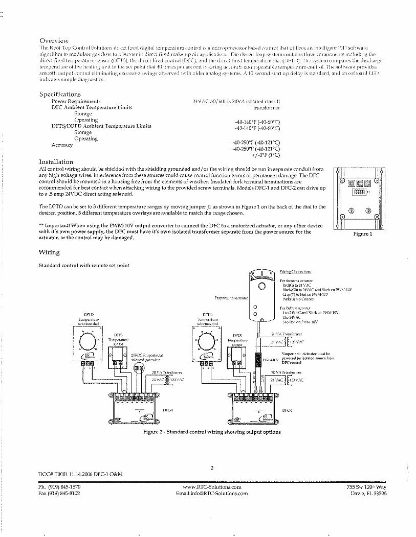
Overview TIll' Roof Tup Cun\wl Solutions d ired fired digit'll tcmpt;ratuH' control is <I micropnlt:\'ssor bas\~d control th,ll utilizl'.'i ,111 intdligenl PIl) software <Ilgorilhm to ll1odui;tle gdS now to ,1 bunwr in din.'cl fired 11l<lke up air applicatiolls. Tlw dosed loop system contains thl"\~l~ compollellts including th" direct (ired tell1jw)",llure seJlsor (DFI'S). Ilk dirl'd iirl'li control (DFC), dnc! the dircrl (in~d lcll1pl~rilllln' didl (])IT])). TIl\' sys[(~m compMes the dischiHi',(' iempCl'dtllJ"C of thl' hl'dling unitt!) tlw s('t poinl di,li..tO limes ]!l'r second insuring <lCCUl',l\e and l'(~pCiltable [l'lnjJ(')"<lture (()nlroL rlw soltWd)'(' provides smooth output control eliminating l'xn'ssiv(' s\-vings observed with older <l1liliog systcl1ls. i\ I () sl;("(md start up dda)' is standilrd, (lnd an unlK'Md ! .ED indicates simple diagnostics
Specifications Power Requirements DFC Ambient Temperature Limits
Storage Opcmting
DFrS/DFTD Ambient Temperature limits Storage Operating
Acctlxacy
Installation
24 V AC SO/ tiOl !z 20\1 A isolated class II tJ'ansformer
-40-HOT (AO·60T) -40-140'1' (AO-6f)oC)
-40-250'F (A0-121'C) AD-250'F (-40-121'C)
+/-3'F (FC)
All control wiring should be shielded with the shielding grounded and/ or the wiring should be run in separate conduit from any high voltage wires. Interference from these sources could cause control function errors or permanent danl<"1ge. The DFe control should be mounted in a housing free from the elements of weather. Insulated fork terminal terminations are recommended for best contact when attaching wiring to the provided screw tenninals. Models DFC-1 and DFC-2 can drive up to a .5 amp 24VDC direct acting solenoid.
The DFfD can be set to 5 different temperature ranges by moving jumper J1 as shown in Figure 1 on the back of the dial to the desired position. 5 different temperature overlays are available to match the range chosen.
** Important! 'When using the PWM-10V output converter to connect the DFC to a motorized achlator, or any other device with it's own power supply, the DFC must have it's own isolated transformer separate from the power source for the actuator, or the control may be damaged.
Wiring
Standard control with remote set point o Wiling CWnecllQ!)$
For SKlllCrIS ,Kluator Rl:ci(G) to 2-1 V .. \(
II lJi rv ~~~ <2 I
I~I"
blQ1D Q1Dr;
II I FIgure 1
o Blod;(GO) t,,24VAC and 1,lro:konl'W,\-!·10V Crav(,D to Red onl'\V~vl·1l1V l'mk(U) No ConnoX(
OFlD
DOC# T000111.14.2006 DFC-1 O&M
Ph. (919) 845-1579 Fax (919) 845-8102
CI'm TunpCf.lluW s~k"uoll dldl
DFfS T('mp(,r.ltut\'
S<'nsor
,),
o o
For &~!!n;> aCll",lO. 1 (l124VACami m.ld, onI'W).'I·l0Y 21024VAC 3 to ll.t:<l on J'\V:-'·l-lOV
20 V,\ Transfol'll'Cl
f.~ _"'M ••• :::.~~~d[AlV'\C
rW:V!-lOV
o
'lmpMlall! - A(lu.I(O! must be p"w~rcd by is(>I~!~d smm:~ from DFC ,'onlr,,]
DFCI
Figure 2 - Standard control wiring showing output options
2
www.RTC-Solutions.com ErHail:[email protected]
755 Sw 120111 Way Davie, FL 33325

Slamlard conlrol with integral sd point
"':111"'":'''''
Figurc 3 ~ Conhol with integral setpoint
OptionaJ room space control
r"" ['.,- .,~ "I" ",,'':',c'(\,hd
FigUl"e 4 - Room space control with thermostat
.) I,
mCl
Figure 5 ~ Room space control with digital space conh'ol
A standard make or brenk thermostat vl'ith normally open contacts can be cormected between terminals 1 and 2 as shown in Figure 4, When connected in this way the thermostat may be set for a desired room temperature for space control applications. Potentiometer Rl on the back of the DFTD sets ho\"\' much the temperature will ulCrease by when the room thermostat calls for more heat. When the room thermostat is satisfied, the discharge temperature will return to the ten1perature set on the dial on the front of the DFTD. For proportional room space control, the DFC~l can be connected as shown in Figure 5. See RTC~l literature for details.
Optional multiple set point temperature control
DFTD
DFi:; T''''\f''~,"'m'
DFCl
Figure 6 - Control with multiple set points
More than one temperature dial can be cOimected as shmvn in Figme 3 for applications stich as paint spray booths or process control.
DOC# T000111.14.2006 DFC-1 O&M
Ph. (919) 845-1579 Fax (919) 845-8102
3
www.RTC-Solutions.com Email:jnfo@RTC~Solutions.com
755 Sw 1201), Way Davie, FL 33325

Operatiun
Star! up ~i(-\!in); low (in' rlw mini:nuJlL fiJ"ing j"dlv 1\1,1)' 1)(' Sl~l by rl'llloving tlw wirt' (l'OIl1 ti'rmin,,) llullllwr Ii on till' I)FC control, J his di:-,,'\lllllH b tlw j,H)W('r til Ow CllIllJ"()] valvv. Rd(']' to till' ("(lnll'ol v,liv(' m,H)u!,IC[IIJ"t'S lill'J"aluJ"c (or this adjustnwnt
Sdting high fire l'lw Jl1ilxil11UI11 firing rail' n1(\)' he set by n'111oving tht: wire (rom tCJ'l11illdl l1ul11ber ,1 ollllw j)re ,'lllltroL This discunnects Ih(discharg(> ili!" sensor and sds the output to tlw control villvv to it's maximum. Rder ioihe control Vilh'T l11illHlfacturcs lil('j"a\ure for (his adjtlstnwJ1l
Sequence of operation Upon applying pmver to the DFC control the 10 second StMt up delay \vilJ begin indicated by a slow blinking LED (about once every 2 svconds) on llw face of the controL Aftl'r the start up delay hilS completed, the LED will turn solid and the control will begin modulating the output as required, Any system {'rrors are indicated by a fast blinking LED (aboultwice per second) for instance when Ow dischMge air sensor is disconnected or outside of llw normn) operating rangl',
Calibration The tempernlur{' control should maintain an accuracy of +/- 3°F (PC). In the evenl that the discharge is inaccurate due to c\ucllosses the control may be calibrated in two \vays. The potentiometer on the face of the DFC labeled" ADJUST" will adjust the discharge temperature by + /- 10"F (SoC) wlw11 rotated. Rotating it clockwise vvi11 increase the temperature and counter clockwise will decrease the temperature. The system m{\y also be adjusted from the DFTD if installed by adjusting potentiometer R3 on the back in the same manner as the DFC procedure above.
Troubleshooting The DFC control provides some diagnostics via the on board LED labeled "PO\-\'EH/STATU5". A system faulL is indicated by a fast blinking LED (about twice per second). This usually indicates that the sensor or dial are either disconnected or improperly wired. Check all connections per the included wiring diagrams. The fault also may be caused by a damaged sensor or dial. Both devices may be tested with an Ohmmeter by removing the wires from the DFe control and measuring across the device. The devices should measure between l2.8K and 7K OHMS. If there is a fault light and the devices measure the proper resistance then the control may be damaged. If there is no fault light but the system is not modulating properly you may check the control output by repeating the start up procedure and measuring terminals 5 and 6 on the DFe as follows.
For DFC-l and DPC>2 Remove the wire from terminal number 4 on the DPC control and measure the voltage across terminals 5 and 6 with a voltmeter. The meter should read from 20 to 2'1 Volts. If it does not, disconnect the wires from the valve and measure the output without the valve connected. If it reads 20 to 24 Volts, refer to the valve mallufactures literal1lre for troubleshooting the valve. If it does not the control may be damaged.
DFTS and DFfD Resistance chart
DOC# T000111.14.2006 DFC-l O&M
Ph. (919) 845-1579 Fa, (919) 845-8102
4
www.RTC-Solutlons.com Email:[email protected]
755 Sw l20!h Way Davie, FL 33325

,J@HNSON CONTF<t::JLS .. ProductlTeclll1ical Bulletin
Issue Date A419
April 4, 2008
.. ~a~~i~~~~C1tr~~~CE~:~~;~~~~!~~la~l The A419 series controls are single-stage, electronic temperature controls with a Single-Pole, Double-Throw (SPOT) output relay They feature a lockable front-panel touchpad for setup and adjustment, and a Liquid Crystal Display (LCD) for viewing the temperature and status of other functions. A Light-Emitting Diode (LED) indicates lhe controls' output relay On/Off status. The A419 controls are available in 24 VAC or 120/240 VAC powered models.
The A419 controls have heating and cooling modes, adjustable setpoint and differential, an adjustable anti-short cycle delay, and a temperature offset function. The setpoint range is -30 to 212°F (-34 to 100°C). The controls feature remote sensing capability and interchangeable sensors. Tile A419 controls are available in either NEMA 1, high-impact plastic enclosure suitable for surface or DIN rail mounting or NEMA 4X watertight, corrosion-resistant surface-mount enclosures.
Figure 1: A419 Temperature Control with NEMA 1 Enclosure and A99 Temperature Sensor
Features and Benefits
Easy-to-Read Front-Panel Liquid Crystal Display
Wide Temperature Differential Adjustment Range (1 to 30Fo or CO)
Adjustable Anti-Short Cycle Delay (0 to 12 Minutes in 1-Minute Increments)
Switch-Activated Temperature Offset Function
High-Impact, Thermoplastic NEMA 1 or NEMA 4X Watertight, Corrosion-Resistant Enclosures
Lockable Front Panel Touchpad
Low- and Line-Voltage Models
© 2008 Johnson Controls, Inc. Code No. LlT-125188
Displays the sensed temperature and control-function status clearly; custom icons on the display indicate the control and system status at a glance
Allows the user to set a precise (1 FO or CO) temperature differential from 1 to 30Fo or Co; providing a much tighter differential than electromechanical controls
Ensures that the output relay remains off for a user-set time delay, which helps avoid hard starts, nuisance overload outages, and unnecessary equipment wear
Allows the user to shift the cut-in and cutout setpoints by an adjustable offset based on the status of a user-installed, external switch, such as a time clock
Increase application options, allowing surface and snap-fit DIN rail mount, or Watertight surface mount
Allows easy set up and adjustment of the A419 control setpoint, differential, and other functions; a concealed jumper locks the touchpad, and deters unauthorized adjustment of the control settings
Provide options for most refrigeration and HVAC control-voltage applications
1 www.johnsoncontrols.com
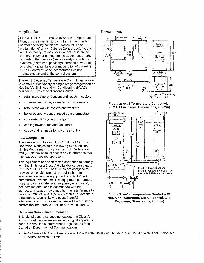
Application
IMPORTANT: The A419 Series Temperature Controls are intended to control equipment under normal operating conditions. Where failure or malfunction of an A419 Series Control could lead to an abnormal operating condition that could cause personal injury or damage to the equipment or other property, other devices (limit or safety controls) or systems (alarm or supervisory) intended to warn of or protect against failure or malfunction of the A419 Series Control must be incorporated into and maintained as part of the control system.
The A419 Electronic Temperature Control can be used to control a wide variety of single-stage refrigeration or Heating Ventilating, and Air Conditioning (HVAC) equipment. Typical applications include:
• retail store display freezers and reach-in coolers
• supermarket display cases for produce/meats
• retail store walk-in coolers and freezers
• boiler operating control (used as a thermostat)
• condenser fan cycling or staging
• cooling tower pump and fan control
• space and return air temperature control
FCC Compliance
This device complies with Part 15 of the FCC Rules. Operation is subject to the following two conditions: (1) this device may not cause harmful interference, and (2) this device must accept any interference that may cause undesired operation.
This equipment has been tested and found to comply with the limits for a Class A digital device pursuant to Part 15 of FCC rules. These limits are designed to provide reasonable protection against harmful interference when this equipment is operated in a commercial environment. This equipment generates, uses, and can radiate radio frequency energy and, if not installed and used in accordance with the instruction manual, may cause harmful interference to radio communications. Operation of this equipment in a residential area is likely to cause harmful interference, in which case the user will be required to correct the interference at his or her own expense.
Canadian Compliance Statement
This digital apparatus does not exceed the Class A limits for radio noise emissions from digital apparatus set out in the Radio Interference Regulations of the Canadian Department of Communications.
Dimensions
.j~ f{~*' ~~ 1<{-·-~6~·~--~1
r(l~-f~~ I DIN
~_,1.:;!J§ Rail (75) t ____ .._,
o 0 1-9/16 .Jl:!!i
I
[
[
14( 2~3/B »: I
(61) ~ (11)
l Sensor
TI 2 1/4 ~-l>-(6) ~.liH-2t8 (61)
(;~ /-:. 7/8 (1/2 in. Trade Size) (22) Conduit Hole
Figure 2: A419 Temperature Control with NEMA 1 Enclosure, Dimensions, in.l(mm)
-2 114 1-1I16f.<-(27) I
tL~4 :;=:::;=j=J1 ~~56)~t _____ , ----$---r-~' +. 1-3
,.-,di",w.,! (4 4)
L j --4*+-ll+-A419 -
l. '·1 6-5/8
~ (168)
Oo[] 6-1/8 (155)
~ )J Ii± ®
• 2-13116 ~I .. I (71) Position the A99 sensor
I
~·-·~·-~t in the bracket at the bottom of the A419 NEMA 4X enclosure.
Figure 3: A419 Temperature Control with NEMA 4X Watertight, Corrosion-resistant,
Enclosure, Dimensions, in.l(mm)
2 A419 Series Electronic Temperature Controls with Display and NEMA 1 or NEMA 4X Watertight Enclosures ProductfTechnical Bulletin

Figure 4: A419 Temperature Control with NEMA 4X Enclosure and A99 Temperature Sensor
Operation Overview The A419 control's front-panel, LCD, LED, and the A419 control functions are described below. See the Adjustments section for instructions all setting up and adjusting the A419 control.
A419 Control Front-Panel
The front panel of the A419 control has a three-button touchpad and LCD for adjusting control function values, and an LED indicator that displays the On/Off status of the SPDT output relay. See Figure 5.
Temperature Indicator
Units Indicator
Operating Mode Indicator
Liquid Crystal Display
DOWN Arrow Button
UP Arrow Button
Output Relay Status Indicator
LED
Figure 5: A419 Control Front-Panel with Display
Liquid Crystal Display
During normal operation, the LCD displays the temperature at the sensor, the units of temperature (' For 'C), and an icon indicating if the control is set for Heating (0) or Cooling (*) mode. The LCD also displays BIN if the Temperature Offset function is activated. See Figure 5.
During control set up or adjustment, the LCD displays the control functions and their values (settings). After 30 seconds of inactivity, the display returns to the sensed-temperature display. See the Adjustments section to adjust the control setting.
Output Relay Status Indicator LED
A green LED on the control's front panel illuminates when the SPOT output relay is energized and the Normally Open (N.O.) contacts are closed. See Figure 5.
A419 Control Definitions
Cut-in is the temperature at which the N.O. contacts on the SPDT output relay close.
Cutout is the temperature at which the N,O contacts on the SPDT output relay open.
A419 Functions Set at the Front-Panel
Setpoint (SP) establishes the temperature value that energizes or de-energizes the output relay, depending on the user selected mode of operation. The control may be set either to cut in or to cut out at Setpoint. See the CoolinglHeating and Selpoinl Modes. The Setpoint range is -30 to 212°F (-34 to 100°C).
If Setpoint mode is Cut-in, Setpoint is the temperature value that closes the N.O, contacts. If Setpoint mode is Cutout, Setpoint is the temperature value that opens the N.O. contacts. See Figure 7 and Figure 8.
Differential (dlF) establishes the difference in temperature (in FO or CO) between the cut-in and cutout values. The differential is set relative to Setpoint and may be set from 1 to 30Fo or Co. See Figure 7 and Figure 8.
Anti-Short Cycle Delay (ASci) establishes the minimum time that the N.O, contacts remains open (after reaching cutout) before closing again, The delay overrides any Load Demand and does not allow the N,O. contacts to close until the set time-delay value has elapsed. See Figure 6, When the delay is activated, the LCD alternately flashes the sensor temperature and ASd, The delay may be set for 0 to 12 minutes in 1-minute increments.
A419 Series Electronic Temperature Controls with Display and NEMA 1 or NEMA 4X Watertight Enclosures ProductlTechnical Bulletin 3

F'or example, if tile anti .. sl1ort cycle delay is set for I minutes, the A419 control will not restart the equipment for 7 minutes after the equipment has cut out, even if the cut-in temperature value is reached during the delay. If the temperature reaches the cut-in value during the delay period, the display flashes between the sensed temperature and ASd, indicating that the next On-cycle is being delayed. After the set delay time has elapsed, the A419 control returns to normal operation, restarts the equipment (if cut-in has been reached), ASd stops flashing, and the LCD reverts to the normal operating display.
Note: Any interruption in supply power to the A419 control activates the anti-short cycle delay.
TIme)o Load Demand 7l Overridden
-~ __ W LLoad Demand
~ 01( '~): lLoutput Status Anti-short
Cyde Delay
Figure 6: Anti-short Cycle Delay
Sensor Failure Operation (SF) establishes how the A419 control operates the equipment in the event of a sensor or sensor-wiring failure. The A419 control may be set to run the equipment continuously or to shut it down if the sensor or sensor wire fails. When a failure is detected the LCD flashes SF alternately with OP if the sensor circuit is open, or SF and SH if the sensor circuit is shorted, The control implements a i-minute delay before initiating a failure response to allow for verification of the failure condition and to avoid nuisance failure indications.
Temperature Units establishes the units of temperature (F' or C') displayed on the LCD.
Temperature Offset (OFS) establishes the value of setpoint-shift (in F' or C') applied to Setpoint (and Differential) when a (user-installed) circuit is closed between the binary input (BIN) and common (COM) terminals. The offset value may be set from 0 to 50F' or C'.
The Temperature Offset function is used to reset the Heating Setpoint to a lower temperature (secondary) setpoint or reset the Cooling Setpoint to a higher temperature (secondary) setpoint by the temperature value set in Temperature Offset.
The BIN and COM terminals may be connected to a (user-supplied) external switching device, such as a time clock, that has a set of Single-Pole, Single-Throw (SPST) contacts. Closing a circuit between the BIN and COM terminals activates the Temperature Offset. See Wiring.
This function enables the control to alternate between two temperature setpoints based on the position of tile binalY input switch. The difference between the prirnalY and secondary setpoints (in F' or CO) is set in the Temperature Offset function (OFS) using the touch pad. See Setting Otller Functions.
Table 1 shows an example of Temperature Offset.
Table 1: Temperature Offset Example
Mode of Setpoint Temperature Secondary Operation Offset Value Setpoin!"
Cooling 70' 8' 78' --
Heating 70' 8' 62'
* Setpomt when CircUIt between binary Input terminals (BIN and COM) is closed
When the circuit is closed between the binary input (BIN) common (COM) terminals, the offset function is enabled and the A419 control cycles on the secondary setpoints. BIN is displayed on the LCD above the of or 'C symbol when the offset is enabled. See Figure 5.
A419 Control Functions Set by Jumper Position
For instructions on positioning jumpers, see Positioning the Jumpers in the Adjustments section. Refer to Figure 12 and Figure 13.
Touchpad Lock: The jumper at P5 establishes whether the touch pad is locked or unlocked. Locking the touch pad deters accidental or unauthorized changes to all of the function parameters.
Heating/Cooling Mode is established by positioning the jumper on the top two pins of the P4 jumper. See Figure 13.
Setpoint Mode: Removing or installing the lower jumper at P4 establishes whether Setpoint is the cut-in temperature or cutout temperature. See Figure 13.
Cooling/Heating and Setpoint Modes
The A419 control may be in four operating modes: Cooling/Cut-in, Cooling/Cutout, Heating/Cut-in, and Heating/Cutout. Position the jumpers located on the circuit board under the A419 control cover to set the desired mode of operation. See Positioning the Jumpers.
In Cooling/Cut-in mode the differential is below Setpoint. The output relay energizes and the LED illuminates when the temperature rises to Setpoint. When the temperature drops to Setpoint minus the differential value, the relay and LED de-energize.
4 A419 Series Electronic Temperature Controls with Display and NEMA 1 or NEMA 4X Watertight Enclosures ProductlTechnical Bulletin
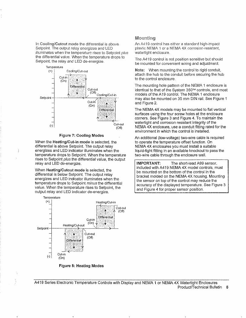
In Cooling/Cutout mode tile differential is above Setpoint. Tile output relay energizes and LED illuminates when the temperature rises to Setpoint plus tile differential value. When the temperature drops to Setpoint, the relay and LED de-energize.
Temperature
(+) Cooling/Cut-out
(-)
Cut-in (On)
Figure 7: Cooling Modes
Cut-oul (Off)
When the Heating/Cut-in mode is selected, the differential is above Setpoint. The output relay energizes and LED indicator illuminates when the temperature drops to Setpoint. When the temperature rises to Setpoint plus the differential value, the output relay and LED de-energize.
When Heating/Cutout mode is selected, the differential is below Setpoint. The output relay energizes and LED indicator illuminates when the temperature drops to Setpoint minus the differential value. When the temperature rises to Setpoint, the output relay and LED indicator de-energize.
Temperature (+) Heating/Cut-in
.. t ...... (Off)
Cut-in ~;._D. __ : ..... jf._::f.,:e.>.r~n ...•. l __ i .•. a ....•..... 1 (on) •• l .. ~2·\·······,rcut-out
Heating/Cut-out "",I> "''--: ': 0-: SelPOinl-+---~:::::"~+.~.; ~,,---=C>L-'-~7).i_
(-)
l~~et~II •. a .•.•.••. I.i ~ Cut-in (On)
Cut-oul (Off)
Figure 8: Heating Modes
Mounting An A419 control has either a standard high-impact plastic NEMA 1 or a NEMA 4X corrosion'Tesistant, watertigllt enclosure.
Tile A419 control is not position sensitive but should be mounted for convenient wiring and adjustment.
Note: When mounting the control to rigid conduit, attach the hub to the conduit before securing the hub to the control enclosure.
The mounting hole pattern of the NEMA 1 enclosure is identical to that of the System 350m controls, and most models of the A 19 control. The NEMA 1 enclosure may also be mounted on 35 mm DIN rail. See Figure 1 and Figure 2.
The NEMA 4X models may be mounted to fiat vertical surfaces using the four screw holes at the enclosure corners. See Figure 3 and Figure 4. To maintain the watertight and corrosion resistant integrity of the NEMA 4X enclosure, use a conduit fitting rated for the environment in which the control is installed.
An additional (low-voltage) two-wire cable is required to operate the temperature offset function. On NEMA 4X enclosures you must install a suitable liquid-tight fitting in an available knockout to pass the two-wire cable through the enclosure wall.
IMPORTANT: The short-lead A99 sensor, included with A419 NEMA 4X model controls, must be mounted on the bottom of the control in the bracket molded on the NEMA 4X housing. Mounting the sensor on top of the control may reduce the accuracy of the displayed temperature. See Figure 3 and Figure 4 for proper sensor position.
A419 Series Electronic Temperature Controls with Display and NEMA 1 or NEMA 4X Watertight Enclosures Product/Technical Bulletin 5

Wiring
A WARNING: Risk of Electrical Shock. To avoid the risk of electrical shock. disconnect all power sources to the control before wiring any connections. More than one disconnect may be required to completely de-energize the control and equipment.
IMPORTANT: All wiring must conform to local. national, and regional regulations. Use copper conductors only for all wire connections. Do not exceed the electrical ratings for the A419 control or the equipment it is wired to.
Refer to Figure 9, Figure 10, and Figure 11 for typical examples of wiring an A419 control to the controlled equipment.
Use wire no larger than 12 AWG when connecting to the two lower terminal blocks (TB1 and TB2).
Note: Terminal block TB2 is an isolated SPOT switch (dry contacts). The TB2 terminals have no internal electrical connection to the A419 control.
Use wire no larger than 16 AWG when connecting to the upper sensor terminal block (TB3).
Wire insulation rating must be 90°C, minimum.
A99 temperature sensors are not polarity sensitive. Wire the leads to (+) SEN and (-) COM on the sensor terminal block (TB3). See Figure 9, Figure 10, and Figure 11.
Keep the leads between the control and sensor as short as possible/practical in your application. The additional resistance in long sensor leads creates error between the actual temperature and the displayed temperature. Refer to Table 1 when extending sensor leads.
Temperature sensor signals may be affected by electrical interference. When extending sensor cable beyond 50 it (15.2 m) use a twisted-pair, shielded cable to reduce electrical interference.
If the Temperature Offset function is used, wire a switch (such as a switching time clock) between the binary input terminal (BIN) and the common terminal (COM). See Figure 9, Figure 10, and Figure 11 for terminal strip location.
(Optionai) A419GBF,1 Bimlry Input A419GEF-1
SVl~,~~~~:::~=_:~:~:~l.21 (-I-) BI N
~1'~'7''i'''<'1 I H co M 1"\c.J,c-LiZll (+ I SEN
cable%~' ITB3 '" Shield
(If used) TB1
"~: Jlf"!'fi Class 2 _ 24 VAC
Transforme-r-- Load
Figure 9: Wiring the 24 VAC A419 Control
\Optional) I A419ABC-1 Blnarx Input A419AEC-1
swmtCh (+IBIN (-I COM
r: (+ISEN
J:~:f "lG,:;!==::
,:~:~~~r~ "'1 Neutral __ ,~ __ [120 VAG]
1 _l:~~_J
Figure 10: Wiring the 120 VAC A419 Control
(.Optional) I-··~-. --- A419ABG.1 Binary Input A419AEC-1 sw~tCh r-o (+IBIN
(-) COM
f~ TB3IE~~r,l, Cable ~,:, Shield i!
(lfused) m ._~_.-...J A99 __ 0 TB2~
Sensor \::2: il171....! 000 uuO C!i u ~ z z
u
240 L 1 =-=1O:=~~~~~ VAC L2 240 VAC Load
Figure 11: Wiring the 240 VAC A419 Control
6 A419 Series Electronic Temperature Controls with Display and NEMA 1 or NEMA 4X Watertight Enclosures ProductIT echnical Bulletin
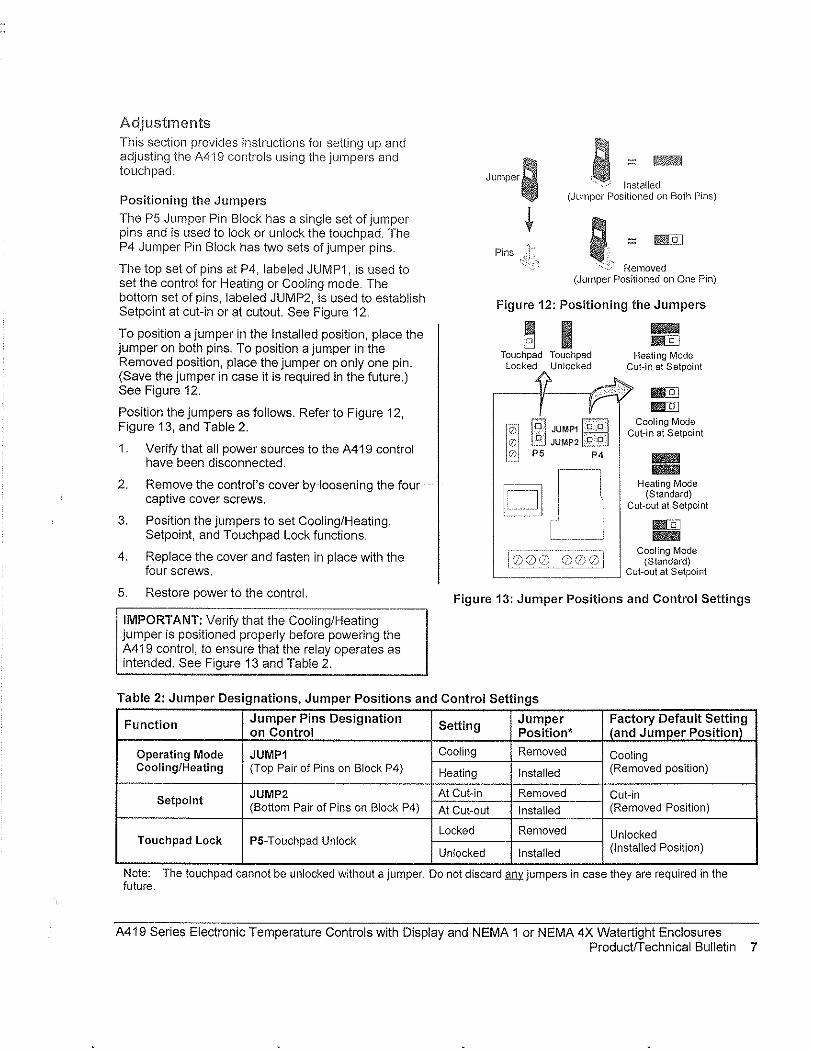
Adjustments This section provides instructions for setting up and adjusting the A419 controls using the jumpers and touchpad.
Positioning the Jumpers
The P5 Jumper Pin Block has a single set of jumper pins and is used to lock or unlock the touchpad. The P4 Jumper Pin Block has two sets of jumper pins.
The top set of pins at P4, labeled JUMP1, is used to set the control for Heating or Cooling mode. The bottom set of pins, labeled JUMP2, is used to establish Setpoint at cut-in or at cutout. See Figure 12.
To position a jumper in the Installed position, place the jumper on both pins. To position a jumper in the Removed position, place the jumper on only one pin. (Save the jumper in case it is required in the future.) See Figure 12.
Position the jumpers as follows. Refer to Figure 12, Figure 13, and Table 2.
1. Verify that all power sources to the A419 control have been disconnected.
2. Remove the control's cover by loosening the four captive cover screws.
3. Position the jumpers to set Cooling/Heating, Setpoint, and Touchpad Lock functions.
4. Replace the cover and fasten in place with the four screws,
5. Restore power to the control.
IMPORTANT: Verify that the Cooling/Heating jumper is positioned properly before powering the A419 control, to ensure that the relay operates as intended. See Figure 13 and Table 2.
Jumper; a I:talle~ (Jumper l:losilioned on Both Pins)
Pins ; = &[j]
-':C:'l Removed (Jumper Positioned on One Pin)
Figure 12: Positioning the Jumpers
Touchpad Touchpad Locked Unlocked
r~ [Ol JUMP1 fO"Ol
.
Q) .. ~.. @JJUMP2!t§] o P5 P4
IIIli!IlIi I!il[ijJ
Heati ng Mode Cut-in at Setpoint
mID mID
Cooling Mode Cut-in at Setpoint
II!IlIJill II!IlIJill
Heating Mode (Standard)
Cut-out at Setpoint
II!I!l[Q] II!IlIJill
Cooling Mode (Standard)
Cut-out at Setpoint
Figure 13: Jumper Positions and Control Settings
Table 2: Jumper Designations, Jumper Positions and Control Settings
Function Jumper Pins Designation Setting Jumper Factory Default Setting
on Control Position' (and Jumper Positionf
Operating Mode JUMP1 Cooling Removed Cooling Cooling/Heating (Top Pair of Pins on Block P4) Heating Installed (Removed position)
Setpoint JUMP2 At Cut-in Removed Cut-in (Bottom Pair of Pins on Block P4) At Cut-out Installed (Removed Position)
Locked Removed Unlocked Touchpad Lock P5-Touchpad Unlock (Installed Position) Unlocked Installed
Note: The touch pad cannot be unlocked without a jumper. Do not discard MY jumpers in case they are required in the future.
A419 Series Electronic Temperature Controls with Display and NEMA 1 or NEMA 4X Watertight Enclosures ProductfTechnical Bulletin 7

Changing Temperature Units
The A419 control is set at the factory to display in Fahrenheit temperature units.
rnr1 press the Up and Down buttons " ~ To convert to Celsius units,
V simultaneously. Press them again to return to Fahrenheit units.
Notes: Make sure the Touchpad Lock jumper is in the unlocked (installed) position before adjusting the control. See Figure 13.
Verify that the A419 control is displaying the desired temperature units (F' or C') before establishing the setpoint value.
Setting the Setpoint
To view and adjust the temperature setpoint, follow these steps and refer to Table 3:
MEN~
MEN~
'~ ME~
1. Press and hold the MENU button until the display changes to flashing SP. This will take about 2 seconds.
2. Press the MENU button again. The current setpoint is displayed.
3. Press the Up or Down button to adjust the setpoint temperature.
4. Press the MENU button to save. The display then returns to the sensor temperature.
Notes: If no entries are made for 30 seconds while programming is in progress, the control reverts to the normal temperature display.
If the MENU button is not pressed after changing the setpoint value, the new value is not saved and the A419 control reverts to the previously saved setpoint value.
Any saved A419 control setting values are non-volatile and remain in the control's memory during power interruptions.
Table 3: Function Ranges and Settings '-" ..
Function Range Factory Settin(j
SP: Setpoint -30 to 212'F 30 (-34 to 100°C)
~--.. --.--.-.----- .. --.----.~.-
d/F: Differential 1 to 30' (F or C) 5 "",-_._--------ASd: Anti-short o to 12 minutes 1
Cycle Delay
OFS: Temperature o to 50' (F or C) 0 Offset
!-----0= output
-------
SF:Sensor Failure de-energized 1 Operation 1 = output
energized
Operation at Extremes. If the combination of setpolnt plus or minus the differential falls outside the temperature range (-30 to 212'F [_34' to 100'C]), the A419 control operates as follows:
Cooling/Cut-in: If the control is operating in Cooling/Cut-in mode and setpoint minus differential is less than -30'F, the control switches on at setpoint and off when the temperature drops below -30'F (-34'C).
Heating/Cut-in: If the control is operating in Heating/Cut-in mode and setpoint plus differential is greater than 212'F (1 OO'C), the control switches on at setpoint and off when the temperature exceeds 212'F (100'C).
Cooling/Cutout: If the control is operating in Cooling/Cutout mode and setpoint plus differential is greater than 212'F (1 OO'C), the control switches on when the temperature exceeds 212'F (100'C) and off at set point.
Heating/Cutout: If the control is operating in Heating/Cutout mode and setpoint minus differential is less than -30'F (-34'C), the control switches on when the temperature drops below -30'F (-34'C) and off at setpoint.
8 A419 Series Electronic Temperature Controls with Display and NEMA 1 or NEMA 4X Watertight Enclosures ProductiTechnical Bulletin
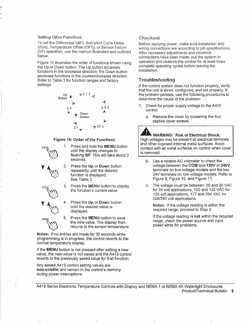
Setting Other Functions
To set the Differential (dIF), Anti··short Cycle Delay (ASd), Temperature Offset (OFS), or Sensor Failure (SF) operation, use the method illustrated and outlined below.
Figure 14 illustrates the order of functions shown using the Up or Down button. The Up button accesses functions in the clockwise direction; the Down button accesses functions in the counterclockwise direction. Refer to Table 3 for function ranges and factory settings.
Up A Button
~ S P A
'f
-.\ S F
Down Button
'"
~ A S d A.
Figure 14: Order of the Functions
Mr~
'\0 MrN~
'\:J MEN~
1. Press and hold the MENU button until the display changes to flashing SP. This will take about 2 seconds.
2. Press the Up or Down button repeatedly until the desired function is displayed. See Table 3,
3. Press the MENU button to display the function's current value.
4. Press the Up or Down button until the desired value is displayed,
5. Press the MENU button to save the new value. The display then returns to the sensor temperature.
Notes: If no entries are made for 30 seconds while programming is in progress, the control reverts to the normal temperature display.
If the MENU button is not pressed after setting a new value, the new value is not saved and the A419 control reverts to the previously saved value for that function.
Any saved A419 control setting values are non-volatile and remain in the control's memory during power interruptions.
Checkout Before applying power, make sure installation and wiring connections are according to job specifications. After necessary adjustments and electrical connections have been made, put the system in operation and observe the control for at least three complete operating cycles before leaving the installation.
Troubleshooting If the control system does not function properly, verify that the unit is wired, configured, and set properly. If the problem persists, use the following procedures to determine the cause of the problem:
1. Check for proper supply voltage to the A419 control.
a. Remove the cover by loosening the four captive cover screws.
A WARNING: Risk of Electrical Shock. High voltages may be present at electrical terminals and other exposed internal metal surfaces. Avoid contact with all metal surfaces on control when cover is removed.
b. Use a reliable AC voltmeter to check the voltage between the COM and 120V or 240V terminals on line voltage models and the two 24V terminals on low-voltage models. Refer to Figure 9, Figure 10, and Figure 11.
c. The voltage must be between: 20 and 30 VAC for 24 volt applications, 102 and 132 VAC for 120 volt applications, 177 and 264 VAC for 208/240 volt applications
Notes: If the voltage reading is within the required range, proceed to Step 2.
If the voltage reading is not within the required range, check the power source and input power wires for problems.
A419 Series Electronic Temperature Controls with Display and NEMA 1 or NEMA 4X Watertight Enclosures Productrrechnical Bulletin 9
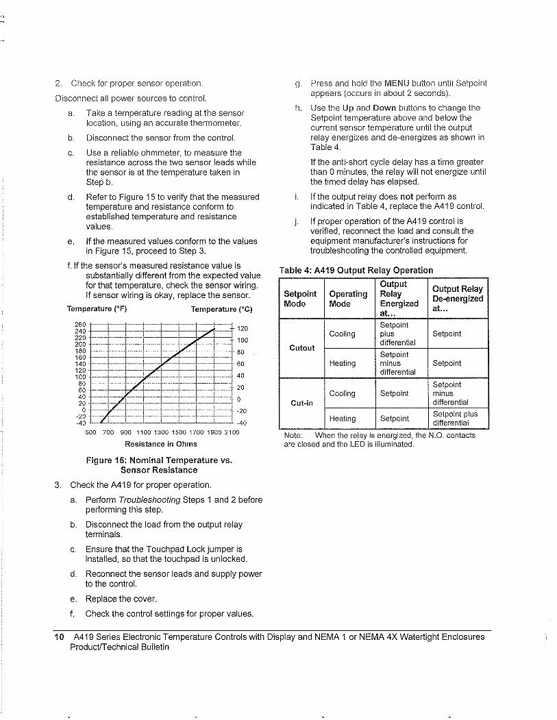
2. Check for proper sensor operation.
Disconnect all power sources to control.
a. Take a temperature reading at the sensor location, using an accurate thermometer.
b. Disconnect the sensor from the control.
c. Use a reliable ohmmeter, to measure the resistance across the two sensor leads while the sensor is at the temperature taken in Step b.
d. Refer to Figure 15 to verify that the measured temperature and resistance conform to established temperature and resistance values.
e. If the measured values conform to the values in Figure 15, proceed to Step 3.
f.lf the sensor's measured resistance value is substantially different from the expected value for that temperature, check the sensor wiring. If sensor wiring is okay, replace the sensor.
Temperature (OF) Temperature (OC)
260 1--·-120 240
220 .~~~: r'-+ - .. 100 200 180 80 160 ~. ~ .. -:~~ ----140 60 120 . --~-L"J' T 100 40 80 20 60 40 l 0 20 ..
0 ! ·20 -20 -40 -40
500 700 900 110013001500170019002100
Resistance in Ohms
Figure 15: Nominal Temperature vs. Sensor Resistance
3. Check the A419 for proper operation.
a. Perform Troubleshooting Steps 1 and 2 before performing this step.
b. Disconnect the load from the output relay terminals.
c. Ensure that the Touchpad Lock jumper is installed, so that the touchpad is unlocked.
d. Reconnect the sensor leads and supply power to the control.
e. Replace the cover.
f. Check the control settings for proper values.
g.
h.
i.
j.
Press and hold tile MENU button until Setpoint appears (occurs in about 2 seconds).
Use the Up and Down buttons to change the Setpoint temperature above and below the current sensor temperature until the output relay energizes and de-energizes as shown in Table 4.
If the anti-short cycle delay has a time greater than 0 minutes, the relay will not energize until the timed delay has elapsed.
If the output relay does not perform as indicated in Table 4, replace the A419 control.
If proper operation of the A419 control is verified, reconnect the load and consult the equipment manufacturer's instructions for troubleshooting the controlled equipment.
Table 4: A419 Output Relay Operation
Output Output Relay
Setpoint Operating Relay De-energ ized Mode Mode Energized
at", at."
Setpoint Cooling plus Setpoint
Cutout differential Setpoint
Heating minus Setpoint differential
Setpoint Cooling Setpoint minus
Cut~in differential
Heating Setpoint Setpoint plus differential
Note: When the relay IS energized, the N,Q. contacts are closed and the LED is illuminated.
10 A419 Series Electronic Temperature Controls with Display and NEMA 1 or NEMA 4X Watertight Enclosures Productrrechnical Bulletin
Fault Codes
A419 controls are programmed to display certain fault codes on the LCD as described in Table 5.
Table 5: Fault Codes Defined
Fault Code Definition System Status
SF flashing Open temperature Output functions according to
alternately with OP sensor or sensor the selected sensor failure wiring mode (SF setling)
Shorted temperature Output functions according to SF flashing alternately with SH sensor or sensor the selected sensor failure
wiring ~ (SF setting)
EE Program failure Output is off
Solution
See TlOubleshooting section.
Cycle power to reset the control.
See Troubleshooting section. Cycle power to reset the control.
Reset the control by pressing the Menu button. If problems persist, replace the control.
Repairs and Replacement Ordering Information Do not attempt to repair or recalibrate the A419 Control. In case of a defective or improperly functioning control, contact your nearest Authorized Johnson Controls/PENN® Distributor or Sales Representative.
When contacting your Johnson Controls/PENN distributor, have the model number of the control available. This number can be found on the label inside the cover of the control.
Table 6: Ordering Information
Product Code Item Number
A419ABC-1C Line Voltage, NEMA 1 Enclosure
Refer to Table 6 to order controls and accessories.
Description
120 or 240 VAC Supply Voltage: A419 Series Electronic Temperature Control Range: -30 to 212'F (-34 to 100'C) with Display, A99 Sensor Included
Differential: 1 to 30F' (1 to 30C')
--
--
A419AEC-1C Line Voltage, NEMA 4X Enclosure A419 Series Electronic Temperature Control Sensor Lead Length: NEMA 1 Models 6-1/2 ft (2 m),
with Display, A99 Sensor Included NEMA 4X Models 9 in (0.25 m)
A419GBF-1C 24 VAC, NEMA 1 Enclosure Supply Voltage: 24 VAC, Class 2 A419 Series Electronic Temperature Control Range: -30 to 212'F (-34 to 100'C) with Display, A99 Sensor Included
A419GEF-1C 24 VAC, NEMA 4X Enclosure Differential: 1 to 30F' (1 to 30C')
A419 Series Electronic Temperature Control Sensor Lead Length: NEMA 1 Models 6-1/2 ft (2 m),
with Display, A99 Sensor Included NEMA 4X Models 9 in (0.25 m)
A99BB-200C Replacement Temperature Sensors PTC Sensor with 6-1/2 ft (2 m) Leads A99BA-200C PTC Sensor with 6-1/2 ft (2 m) Shielded Leads A99BB-25C PTC Sensor with 9 in (0.25 m)
BKT287-1R Accessory Mounting Hardware 12 in. (305 mm) long DIN Rail
BKT287-2R 36 in. (914 mm) long DIN Rail
PLT344-1R Two End Clamps for DIN Rail Mounting
CLK350-2C Digital Clock 7-Day Programmable Digital Clock for controlling Temperature Offset Function
WEL 11A-601R Immersion Well Immersion Well for applying sensor in fluid applications
A419 Series Electronic Temperature Controls with Display and NEMA 1 or NEMA 4X Watertight Enclosures ProductiTechnical Bulletin 11
Technical Specifications Product A419 Series Electronic Temperature Controls with NEMA 1 General Purpose or NEMA 4X
.~.~ .. ~ .. ____ ~~_ .. _"_~. __ .. ~. ___ ,Watertig ht, COITosion··Hesistan! En~~~ure~ .. ___ ._~._._~~~ ____ .~ __ . __ . __ . __ ._ .. _. ______ ._._.
Setpoint Range .~O t03.13.:~£l~.t~~~0.'.c;L .. ~._~_ .... _~......~ ... _ ...............••. __ ..... . Differential Range 1 to 30F' (1 to 30C') .-.. -~ ... -=~~;.:=~-:-:::.~0.~~~-:-:c=-::--;.c:=:~-=--:-~~-
Supply Voltage 24 VAC, 60 Hz, Class 2: A419GBF·1 (NEMA 1 Enclosure Model)
Power Consumption
Output Relay Contacts Electrical Ratings
Sensor Type
Control Ambient Temperature
Ambient Humidity
Control Material
Agency Listings
A419GEF·1 (NEMA 4X Watertight Enclosure Model)
120 or 240 VAG, 60 Hz: A419ABC·1 (NEMA 1 Enclosure Model) A419AEC·1 (NEMA 4X Watertight Enclosure Mode.!.I) ___ _
1.8 VA Maximum
24 VAG Models:
120/240 VAG Models:
A419GBF·1 (NEMA 1 Enclosure) A419GEF·1 (NEMA 4X Wateliight Enclosure) 100 VA, 30 VAC maximum, Class 2
A419ABC·1 (NEMA 1 Enclosure) A419AEC·1 (NEMA 4X Watertight Enclosure)
Applied Voltage: 120 VAG 208 VAG
Horsepower N.O. (N.C.): 1 (0.25) hp 1 (0.33) hp Full Load Amperes N.O. (N.G.): 16 (5.8) A 9.2 (4.0) A Locked Rotor Amperes N.O. (N.C.): 96 (34.8) A 55.2 (24) A Non·inductive Amperes N.O. (N.C.): 15 (10) A 10 (10) A
Pilot Duty: 125 VA (N.O. contacts)@ 24 to 240 VAC 125 VA (N.C. contacts)@ 120 to 240 VAC
240 VAG
1 (0.5) hp 8.0 (4.9) A 48 (29A) A 10 (10) A
50 VA (N.C. contacts)@24:...V:.:,A:::C'--_________ _
A99BB Type PTC Sensor (See Table 6)
Operating: ·26 to 140'F (·32 to 60'C) Shipping: -40 to 185'F (·40 to 85'C)
o to 95% RH Non-condensing; Maximum Dew Point: 85°F (29"C)
Case and Cover: NEMA 1 High·lmpact Thenmoplastic NEMA 4X Watertight, Corrosion·Resistant, High·lmpact Noryl® Thenmoplastic
UL: File E27734; CCN's XAPX (US), XAPX7 (Canada) FCC: CFR 47, Part 15, Class A DOC, Class A
The performance specifications are nominal and conform to acceptable industry standards. For application at conditions beyond these specifications, contact Application Engineering at 1-800-275-5676. Johnson Controls, Inc. shall not be liable for damages resulting from misapplication or misuse of its products.
~NSON CONlR~S Controls Group 507 E. Michigan Street P.O. Box 423 Milwaukee, WI 53201
Printed in U.S.A. WW'N.johnsoncontrols.com
12 A419 Series Electronic Temperature Controls with Display and NEMA 1 or NEMA 4X Watertight Enclosures ProductrT echnical Bulletin
4.1 Recommended Spare Parts List, Maintenance Summary and Lubrication Summary
EXHIBIT C·j Equipment i~ec()rdl
- - ____________ v - __ •• _ - - ___ _ Address ----------------------------------------_. --------------------------------. --,,- " .. ------------~Pilone 1338 BAYARD AVE. ST.PAUL, MN 55116 . . .J .. """9~H).~~:QQ~"L"" ...
F'~"' {;';I".i9"8~6967"""""" """""""""""""""" ":Website" "jJMO~q;~.·CO~"""··· ... "". jE"mal"" "" MECHANICAL NAMEPLATE DATA -------------
Equip. 28-MAUOI 13568
IDNo.
Make TITAN AIR 182 T
T A-I 1 5 H R 12,-------,;,-;:::--;;-;;-;-;;-;0;;-;""-RPM 972 Cap. 39 ],050 BTU CFM 4,500 PSI 0.0451
Other:
ELECTRICAL NAMEPLATE DATA
Equip. 28- MAUOI _-+~.;:;----!1",3","56~8"-,----:,.. _____ - ______ . Make TITANAIR TA-115HRD ID No. Frame No. 18lT::!... 3 ~·;:-""''''Hz::-!..!6::':0:'!'''!-'''-'-ip;SH:---:::3--T.R;;P;;:;M;--·1;-:7:;-:5;:;0:;-lOls'<F----Duty CQde lns. Cc:"I."""---1~--'-"---t=;:--=~-+'C:-A:-m-;-b"'. "----.-- Temp. Rise 79 F Rating (Y~--.--~----~----~~~~-L----~--
Pert No SPARE PARTS PROVIDED PER CO~N!!.T!.!R~A~CC!T _________ -r_-;;:=:--:-_
Pari Name Quanti;y
-----_. __ ._---+-._._ .... --
RgCOMMENDED SPARE PARTS Pert No. Part Name
SEE ATIACHED
..
-~"-------' , . .. (Jl n 1990, ReVIsed Oct 2001, ReVIsed Nov 2007) Copyright 1991 HDR Engineering. Inc,
007·91090047"003 MSS • MASTER SPECIFiCATION SYSTEM MASTER SPECIFICATION SECTION
SUBMITI'AI.S 01340 - 3
- - Quantity -
.--
-
-

RECOMMENDED SPARE PARTS LIST
Equipment No: 28-MAU01
Description Part Number Cost (111112)
P-1 PRESSURE SWITCH DDP-109-187 $147.00 EA
FS-1 FIREYE MEC120 $548.00 EA
MERT4 $218.00 EA
MEP537 $865.00 EA
TS-J TEMP DISCHARGE RTC DFTS w/DAT-12 $225.00 EA SENSOR
TC-J TEMP CONTROLLER RTC DFC-1 $281.00 EA
BELT B-54 $35.00 EA
EXHIBITC2 Equipment Record
Recommended Maintenance Summary .~-" .. ~-~-.-~--- .--,.-.~~----
Equip!l1c>n! Description
Make Air Unit
-.
Project Equip. Tag No(s).
28· MAUOl
RECOMMENDED BREAK-IN MAINTENANCE (FIRST OIL CHANGES, ETC.) •. -.
Re-tension belts
-~-,~~~---.. _._-
. -..
-----,.~.~-~
RECOMMENDED PREVENTiVE MAINTENANCE
Blower Bearings Lubrication
Check Belt Tension and Condition
Check Filters ----
Check Burner Operation .-----".--~" .. ~--~.~~.~--.-~-~.------.---------
.. _----- -
.. _.
.-
.
-
Motor Bearings Lu brication "--~.~.~ ..... ~
.- -~~~~~.~-,
.
-0= Dally W=Wce-kly M::; Monthly Q ~ Quarterly S t'! Semiannual
(Jun 19S0; RevIsed Oct 2001, Revised Nov 2007) COpYright 1991 HOR Engineering, Inc.
007·91090047-003 MSS • MASTER SPECIFICATION SYSTEM MASTER SPECIFfCATJON SECTION -
SUBMITTALS 01340 - 4
..
A:;; Annual
D
D
.-INITIAL COMPLETION' FOLLOWING START-UP
W M Q S A Hours .----
24
--PM TASK INTERVAL'
W M Q S A Hours
1'15. 1--.
X -
X
X
--X --
Hours = Run Tlma Interval
EXHIBIT C3
Lubricant Point BEARINGS -- ----Manufacturer Product
.~-. ,,-----------------.._._-_._ .. _-----~--
11 1 Exxon Mobil Polyvex EM ,-,- 2 Polystar -c ~ 3 --c.tJgy=-------------- _.....sEL~ ___________ 'C ~
.3 4
5
UibM~POir1l --'- ---_._------.
Manufacturer Product ------------------ -m 1 a_ I!' -e 2
~ 3
" 4 ~
5
Lubricant Point Manufacturer Product
m f-~ . ~
?--2 -e
---~ ~ 3 E " 4 ~
5
Lubricant Point . Manufacturer Product
m 1 ~
I::' ---2 -e
----------~~ ... ,,--"~-.-~ 3 -c
'4 n -l-----" -, 5
LW)rican; POint ~r-'----.. -----.. ---·-
Manufacturer Proouc\ ___ M~"_. __
m 1
'" .-~~~-
t-- 2 -e r-;-g D -" 4 ~ --
5
Lubricant Point
Manuracturer Product -m 1 ~
I!' 2 -e ~ 3 -c _0
" 4 ~
5
Feb 1991' R vi ( , e sed Oct 2001, Rewsed Nov 2007) Copyright 1991 HDR EngineerIng, Inc.
007 ·91 090047·003 MSS· MASTER SPECIFICATION SYSTEM MASTER SPECIFICATION SECTION·
SUBMITTALS 01340 -5
-..
-,~~
Equipment Record
.~.-.
--_. AGMAil ~--
SAE# ISO ------M __
-~~.-
- ''--'---
I --
.--. _- --.
AGMA# SAE# ISO ---
.
AGMA# SAE# 1S0 --------"
-_.
-
AGMA# SAE# ISO
f-------
--- J-----_. ---.~
- -AGMA# SAE# ISO ._-- .~--
- ."~-.
..
AGMA# SAE# ISO

4.2 Unit Specifications
AIR INCORPORATED
Title Clinton 28 INTF'_MAU-01 Sales Rep. J.J. Ivlorganeo
Q/N SIN 13568 Model TA - 115 NG HRD Date. 3/17111
CFM
BTUIHr
___ 'l~QCL_ ___ ESP . __ 1_~2_ Temperature Rise (OF) 79 ___________ _
Min. Max. 391,050 ---- -------------------_.-------
Heat Medium: _[)ir.E'c:t~Fi red .I':Lc:;~ __ 7"~1it.l~le~£rEl"sJ:l re.@ 391c::F.!j-,-§T[)=i\i'J§IC:;Cl".Tr§in_
Cool Medium: None
Function Air Make-Up Uf!i!______________~ ___ ~ _____ .. _____ ~ Outdoor Mounted
Voltage:_'l60 V, 3ph.L 60 Hz. ______ ~ Motor HP: 3 Motor FLA: 4.2 Unit FLA: 5.2
Heating Temp. Control_Discharg~~()I1J.rol wi Override (RTC DFC-:Lw/£~oom Stat)
OPTIONAL EQUIPMENT INCLUDED
• Fresh Air Intake Hood wi Birdscreen*
Type: 45 Degree
• Outside Air Filter Section'
Type: 2 in. Pleated, 30% Efficient
• Intake Damper & Actuator'
• Curb Kit'
Type: Flat - 18" High
Roof Type: Built-Up
• 16 Gauge Casing
• Interior & Exterior Unit Heresite Coating
• Interior & Exterior Accessory Heresite Coating
• Interior Unit Liner
• Insulated Unit
• Casing & Accessories Painted Standard Color
OPTIONAL CONTROLS INCLUDED:
• low Temperature Safety
• low Fire Start
• High Gas Pressure Switch
• NEMA 4X Remote Panel
• Door Interlocked Fused Unit Disconnect
• Control Relay (Function as Follows) Energized When Airflow Is Proven
Contacts Start Exhaust Fan (By Others)
• Interrupted Ignition
• ETl label
, Denotes items shipped loose for field installation. See catalog or submittal for standard items.
804 AM 311712011 13568 Spec2004 xis Kitlelson
2·8
rev. SUBMITTAL USE ONt y. DO NOT USE FOR CONSTRUCTION PURPOSES
SINGLE BLOWER UNITS - DOWN DISCHARGE - CHANNEL OR CURB MOUNT Item MODEL A 8 C D E F G H J K
T 8 28 4 4 1 TA-112 2 25 2 TA-115 69 54 32 8 8 24 24 40 28 2
85 66 46 8 8 32 32 2 90 48 12 12 36 60 44 2 95 78 2 6 36 60 44 2 100 90 66 44 44 72 60 2.5 100 6 12 14 72 60 2.5
100 78 14 18 60 48 72 2.5 110 100 78 14 18 60 48 96 7
TWINS CHARGE - CHANNEL OR CURB MOUNT UP TO TA-230
* Units are built in two sections. F,G, H & J are accessory dimensions. D,E & K are accessory locations. Intake and discharge accessories may be larger than openings on unit. All dimensions subject to ma'nufacturing tolerances and subject to change, verify with factory before using for any construction purposes. INDOOR hanging units must utilize a bottom cradle (by others).
rev. SUBMITTAL USE ONL Y - DO NOT USE FOR CONSTRUCTION PURPOSES
f B
f B
. I -l..
HOOD -1 D HOOD I FILTER COMBO D FULL TURN DOWN HOOD
12"
B-j--A D RA FILTER SECTION DAMPER
Jj DMUSHROOM HOOD, / J/ ¢I OA FILTER SECTION
mounted
HOODI MUSHROOM FRESH AIR RETURN AIR 45'INTAKE FILTER FULL TURN HOOD FILTER FILTER INTAKE
HOOD COMBO DOWN HOOD (curb mounted) SECTION SECTION DAMPER
Item MODEL A B C A B C A B C A B C 0 A B C A B C A B TA 20 22
~ 20 41 25 20 24 30 25 45 55 25 20 28 20
TA-109 AR 25 28 3lT 28 32 3 L, 28 25 28 28 25 28 TA& TAM-112 32 25 27 <0 L~ 32 25 32 32 25 28 32 25 TA-11 32 34 32 32 45 32 32 36 37 37 48 73 32 32 28 32 32
~ TA&TAM-115 40 28 30 40 28 48 40 28 32 45 33 /j0 73 40 28 46 40 28 32 40 28 -~A-115 AR 40 32 34 40 32 45 40 32 36 45 37 50 77 40 32 46 40 32 32 4Jl- 32 TA~M-118 48 32 34 48 32 43 48 32 36 53 37 50 77 48 32 46 48 32 l.;32-' 48 32 TA-118 AR'- 48 42 44 48 42 39 48 42 46 53 47 50 87 48 42 46 43- -42 32 48 42 TA-120 '4<l 42 44 48 42 67 48 42 44 53 47 55 97 48 42 CAB' 48 42 32 48 42 TA-122 & 125 60 1411- 46 60 44 68 60 44 48 65 49 56 101 1!lP-1"'f4 46 60 44 32 60 44 TA-127 & 130 72 60 58 'n.. 60 81 72 60 64 77 65 65 J.a5 72 60 46 72 60 32 72 60 TA-133 & 136 96 72 60 96 Tl:' "'" 96 72 76 101 '];I- '70 157 96 72 46 96 72 32 96 72 TA-215 72 28 30 72 28 na "1'i!. 28 32- I-'i'1' 33 50 73 72 28 46 72 28 32 72 28 TA-218 80 32 34 80 32 na 80 2 RlD 85 37 50 77 80 32 46 80 32 32 80 32 TA-220 96 42 44 96 42 na.. i'96 42 44 I'M 47 55 97 96 42 46 96 42 32 96 42 TA-225 120 44 46 120 .M" na 120 44 48 125 4~ -sa 101 120 44 46 120 44 32 120 44 TA-227 128
~ 54- 1':[8 52 na 128 52 56 133 57 60 111'i' 128 52 46 128 52 32 128 52
TA-230 141 58 144 60 na 144 60 64 149 65 65 135 144 rsa, 46 144 60 32 144 60 TA-233
----"r80 72 60 180 72 na 180 72 76 185 77 70 157 180 72 '!e- f:U)0 72 32 180 72
TA-236 ___ 180 72 60 180 72 na 180 72 76 185 77 70 157 180 72 46 180 "9!2. 32 180 72 ~9 192 72 60 192 72 na 192 72 76 197 77 70 157 192 72 46 192 72 32- 492 72 .- TA-242 216 84 60 216 84 na 216 84 88 221 89 75 195 216 84 46 216 84 32 216 84
All dimensions subject to manufacturing tolerances and subject to change, verify with factory before using for any construction purposes. Intake dampers are designed to be mounted indoors, if outdoor mounting is required, you must order a weather hood for damper actuator(s), damper may be built into hood and or filter section. Intake dampers on TA-230 - 242 have 2 actuators, all accessories for these units are built in 2 sections, some field assembly may be required. All intake hoods feature bird screen. Mushroom hoods can be flange mounted, consult factory. 1" flange is typical for all components listed above. Intake accessories may be larger than intake opening. Return air filter sections will be larger than return air opening. I
8·1
"" e \H)DO/';"~IFnll~ e Ef .l!IP ,e, ~y
'e e "Ue IFITI CtUSB~ 1 rev.01-04
SUBMITTAL USE ONL Y - DO NOT USE FOR CONSTRUCTION PURPOSES
...lEE
HORIZONTAL UNITS WITH DOWN DISCHARGE BLOWER(S) litem ~O DEL
x
IM1-1U9
'AM-115 ITA~I-118 rA- ,9
A-A-
A J3 C D 54.5 33.5 26.7 2.25 2. ~5 63.5 41.5 31.2( 4.25
45.5 33. b ?5
:.5 81.5 162
13
7 7.25 b
e3. ~ 4.: 4.75 c. {"
F 16
20 24 16
TA-220 ...a-r.5 114.5 40.25 4:rs.. e.75 72 3' 41.25 75 ~ )0
B F Pitched Curb Selection:
2 1 1
L.
3~
32
~ e, " ... "., .. , ...... "
n A
t ,
r
""
r----------I , DISCHARGE
, , (SUPPLY AIR (SA»
, , , L - J
= SuPPOrt Brace
'~!s"P""rt . Braces
PLAN VIEW on Twin Units
., ,,~ .. "' .
11/2"-1 r-~-J' --,,,", i; -----wall
! ;:. TypIcal curb fOf 18n wood buill up roof.
typo nailer HOLE LOCATION
L MEASUREMENTS TAKEN FROM
_ :-- ~US~~E WALL OF
~31/2"~ SIDE VIEW DETAil
; , ,
))
. ,
SeNies Side
-<-
Curb Pitch Direction
Curb Pitch ,.---, DirectIon L---.J
SeNies Side
-<-.r------j Roof curb pitched:
--'"-Roof type:
Curbs are shipped unassembled and uninsulated. F & G are recommended ductwork dimensions. Openings on unit may be smaller than recommended duct size. Hole locations for duct work taken from inside wall of curb. Construction methods may change for taller & larger curbs. All dimensions subject to manufacturing tolerances and subject to change. verify with factory before using for any construction purposes. Standard curb height is 18".
-----------~--.--------.
8-3
'7' ,,~V" ~ ": ~A 'J ~~~",-; '( ,~,)"q .. ~fU!,,+\'0" oo:""~ ~ ,~, '~=
ESTIMATED UNIT WEIGHTS ;C' I",,'), ~ ,~"' -,"" ,~,: "",,' "", JLow *~';o." 0~ _, i '" ~'
,- 45 105 -~ \- 775 775 )0 110 105
\.: 990 1020 7' 15 75 110 55 120 \-'tIl( 1300 1400 2250 80 110 125 60 ).80
TA-122 N720 80 21 5S;-0HO~0+-~1:_-+_~15CO-+_-;,70r''/T-;;:200~'C0-j TA -125 17'76.. 2: )0 )0 1: 150 200 TA -127_?450 ~ 3' 500 2, 23Y 0 !5( TA-130 2500 2 31 JO 1 0 210,.;/:35 0 !5f TA - 13: 2900 300( ~ 00 :Q,/ 260 125 00
, - 3000 00 !OO ./,;0 260 300 \ - 1670 50 VO 220 160 \- 1700 ,/" 0 220 240
1\-220 1950 ~ ~ 250 (O( ,- 225 3050 .....,16~00-f-:!=-+~ 255!.;::-....... +-~300~(+-~-+-';1~0(-I
A - 227 3150 ;800 30( 'lIQ,{ 150
A - 8100 8700 890 825 850
"AR" RECIRC. UNITS AND ACCESSORIES
Mnnl" BJ'~i~c ~~;:,~ Disc. I~~'::': I~:I~~~ _Intake _ Disc. C~~b TA-112 815 !'.e815 1300 30 55 45 45 150 TA-115 950 WlO 1350 35 60 110/ 50 150 TA-11 1220 21~ 15 1,1'0 55 120 T 1700 81 0 0 / 150
2' :0 Q. 200 22JO 31 ~ 0 136 100
\ - 127 2750 285 3800 't!;0 .2'10 235 100 150 'A - 130 2800 2900 3850 150'-- 210 235 100 150
TA -1 13 3250 3300 20 100/ ~ 25 300 , - 16 3550 3)00 ;0 190 25
5 2000 2 OQ /110 JO ,- 8 2050 2:!50 135 ~H~10H~S(-l ,- 0 2300 2'150 130 215 25t-., 30 ,- 225 3400 3641 49 JO 60 25( 305 "- 145 4(
T ,- 3950 4301 !5 30 450 , - 00 4850/ 6650 0 32 500
JO 16~ O( 55 --, - JO )!f0( O( 550 \ - JO /3700 O( 6 625 --,- !42 8600 9200 9500 890 825 850 550 ---
All WEIGHTS ARE ESTIMATES, AND Will VARY WITH DIFFERENT GAS TRAINS, MOTOR HP, AND SPECIAL ACCESSORIES.
USE FOR FREIGHT ESTIMATION ONL Y
rev, 01-04
1·11

(,::;'i;-"ii"'~~ .~ i!··~~7~~r<ii.·.'."T~··~··~···"~l··I";;;;::·L··E··~.·;.;:;~~D·"'···S··:':I·.·;::"·;·::::·E:~;' r ;=:;::·~~'·P~;\;::.~~:;·:~~;::~·! , . l A! ""'bill; J' . ~,'r r "",cN', ~t ! (.:); t'\!'C,'ZAL ~ hi" 0 L,u , i
L",£iRIw CO RP.~'i A; ~;"% C:~:,.~. MS~!I.~~~~ NGHRf '" ~:=~-~"~~~~""'~~fr~y,5~81 AbIJr. S )ecification _~ __ . ______ # Description Abbr. Description/Spec. __ #_ DM·1 Belil110 LF 120·S us Intake Damper Motor FS·1 Fireye MEC120D, MEr~T4, MEP537 1 Flame Safeguard FU·1 Touel1 Safe Block. Class CC TO: 8 Amp 3 Main Fuses FU·2 600V/,C· Class CC Time Delay 1.5 Al11p, 2 Trans. PrimaryFuses FU·3 250V/,C.Midgettype: 3 Amp . Control Circuit Fuse L TS·1 Antunes Controls 8563140061 wi CoverL()vII.Ternperature Safety MT~1;seel11otor specs. onright sideol page BloVlier Motor P·1 ...gleveI9n~jJjJf5jO:9:1:S1j02;; 8, 095") Air Flow Switch P·2See Gas Train/BurnerSpecs. naiLowGasPressure Sw. P·3SeeGaslrain/SurnerSpecsna High Gas Pressure Sw. R·2 . :Id"'ec RJ2S~C L ~A12b~s J2S:05B ;T, Exllaustli;terlockRelay S T·1 ... Eato;;XTCE 00 iEiioA;-xfOE005BC S . 1rsiart~rl=i:S:~=" .......•.............
SW~1IE@i:5Fo£j!o8B .. 6~:JE:oXPEi.>i:?6tL ....... 1 EqLJip.rn."..n.t.J2isg()n~n."gL__ REMOTE PANEL S SW~2 !AB 800FP~SM32, -ALPX20 ! 1 !Sul11mer-Off~Winter Switch A1287JFGORR wi A10P8 11 SW:5rCaiiingswitch111~i&:73---'-" :',[', Blower~Service-SwTich--- -~~~~---"-'~'--'''--''-''I''-''
sW-6i Carlingswitch11i:16-73----- ..... j11BurrrierServiceSwitcf)- MOTOR & BLOWER T -5 -"TJohnsonControls A419ABC-1C" "T1\ Room Override-Stat"'" & DRIVE ASSEMBLY TC~1-1RTCDFC_1WiFjjier-·-·-.. ~~-TTITemperature Controller ... , Motor: 3 hp, 460 V 3ph. ODP TD~i'IRfc DFTD (40'F - 90'F)-'-""-'-"r 110ischarge Temp. Selector 4.2 Ila, 182T frame TL-1-:HoneyweITL4CiOsE12ss::~=====TiIHighTemperatur§'Limit__ 1750 r m EM3211T "r-R':1'TMicron B250BTZ13RB .. jJ..jControl Tra~?former __ . __ Blower: Lau A 15-15A __ .1..1. TR:2~"THoneywell 0652B1006'------·- ; 1 I Ignition Transformer P B Bearings' VPI3-223~1::I._ '..1. TR--3iHoneywell AT120B1028---"~-"- .·'1l24 VACTrans!c;nner-- - Motor Sheave. 1 VP 56 1 TR=4'-l Honeywell AT120B 1 028 -~~".-. "~--'-Tf!24 V iC~Transforl11er .-~ ... --- Bore: 1 1/8" . TS::j--!RTCDFTS wi DAT:1Z' ........ ·····T11Discharge Temp Sensor'-- Turns Open: 4 V ~!.~] Se.'3 . .Gas T r~ln/B urner§pe'cs~ . '~J~".§!p i lot.§i1tJtoff,Y.§,1v-",_-==:= B lowerS heave"~1gr-B86S D s-I} V~'L .. J~§'."..§.§~I.rflin/Burner 2pecs,nai,Main Safety SI1utoff Valve RPM: 972 V-3 ,See Gas Train/Burner Specslf1~!yenTvalve-=~====~= Bushing SOS x 1 7/16" \;-:4 .. :SeeGasTrain/BurnerSpecs .. In_al''''LJ~ Sal",ty~s..hL,Jt()ff\fClI\l'" ..•. , IE;TI~_B=5:r-L .-- , 1 V-5 ISee'Gascfrain/Blii:ner-Specs: !na!Modulating GasValve Coupling: in VM -11!3effrii()LIv1CA?~:~§FET"-- . if ii0(,a:~9~S ValveA~t~LJator S C H E MATI C SYMBOLS
j
1 ---;--
-- ._ ............. -I-~~~~~~"""'~ ...... ,....... I ~ Unit Control Panel Terl11inal
...... ,- @ Rel110te Panel Terl11inal
:::=: ... , .... _.'t::===:__~=:=:= 0 Component Terminal , ... ".-.--.. -.- r-- ,
. .....i::-- .. :~:"'_===L:"~~"'===:"=LL1.,, _,,= ~:i~:~n:~ i~eO~:~~s(::hne~~) ... _.- - - -. Field Wiring (by Others)
---- Jumper Wire
-.- Wire Connection
* Terminal no.'s 1 to 99 designate 120 volt; no.'s 100+ designate low volt
wiring (run in shielded cable). Ground unit according to NEe.
CAUTION: Open disconnect switch before servicing unit.
8:04 AM 3117120'11 5113568 Soec2004.xls Kittelson
O.A. Filter(s)
TOTAL STATIC 2.13
R.A Filters
Linked Panel (1" Rack)
Other
E Model Quote No. I Ext. Static Titan Accessory Static TA-115NGHRD 021810AB28 I 1.25" w.C. 0.21" w.C.
Performance Curve
3.0 SP
A15-15A
.15GO CFM,2.13 Lwg. 2236 OWtJmt"~972 RPM
2A1 BHP, 61.0%SE Sl.nclard P"rf<>r"'~nc"
1.0
o.o~ (FM
o 2500 7500 10000 12500 • , .... ~.·' .. 1 •• ", .. ,~1 .. "" .... p.,.:.,,, ... ~,,,,,,, .• ,,: ""
Sound Data OCTAVE BAND No. 1 2 3 4 5 6 7 OCT. CENTRE FRQCY (Hz) 63 125 250 500 1000 2000 4000 SPECIFIC SWL (dB) 50 50 40 33 33 10LOG Q+20LOG T.P.(dB) 44 44 44 44 44 SFI (dB) 0 0 0 0 2 OFF-PEAK CORR. (dB) 0 0 0 0 0 TOTAL FAN SWL (dB) 94 94 84 77 79
Comments: FAN TYPE IS FORWARD CURVED 1. The A-weighted SWL in-duct is 84 dB. 2. At a distance of 10 ft. from the fan 66 dBA can be expected with an open inlet or outlet and 51 dBA when the inlet and outlet are ducted. These values have been accessed using a model of sound propagation from a point source into the hemispheric free field (see AMCA 303-79).
28 44 0 0
72
THE dBA VALUES PROVIDED ARE TO BE USED FOR REFERENCE ONLY. CALCULATION OF dBA VALUES COVER MATTERS OF SYSTEM DESIGN AND THE FAN MANUFACTURER HAS NO WAY OF KNOWING THE DETAILS OF EACH SYSTEM. THIS CONSTITUTES AN EXCEPTION TO ANY SPECIFICATION OR GUARANTEE REQUIRING A dBA VALUE OR SOUND DATA IN ANY OTHER FORM THAN SOUND POWER LEVEL RATINGS (SWL). 3. The off-peak correction has been based on a static efficiency ratio of 0.983 ( 61 % I 62 %)
23 44
0 0
67
8 8000
18 44
0 0
62
4.3 Gas train/ Burner Specs.
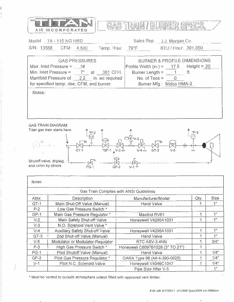
AiR II~CORPORATED
Model TA -115 NG HRD_ ................. . Sales Rep J.J .1\II019"n(:;0 SIN 13568 CFM 500 Temp. Rise 79T BTU I Hour: 391 .c:: ... : .. , .. : ... :.:: ........... .
GAS PRESSURES BURNER & PROFILE DIMENSIONS
Max. Inlet Pressure "_1#_ Profile Width (in.)" 17.5 Height ".2g Min. Inlet Pressure" __ .2" __ at _Jl_21 CFH. Burner Length" .. ____ 1 __ . ft.
Manifold Pressure of __ :2.1_ . in. wc required No. of Tees" . __ Jl __ _ for specified temp. rise, CFM, and burner. Burner Mfg.: Midco HMA-2
. ______ .. L______ _. ____________ ~
Notes:
GAS TRAIN DIAGRAM: Titan gas train starts here. A ~ ~
: 'P-2 'P-3
--t
Shutoff valve, dripleg, -£ ~---?1 and union by others PG-1 GP-2 V-1
Notes:
Gas Train Complies with ANSI Guidelines --_.-
Abbr. Description Manufacturer/Model Qty. Size GT-1 Main Shut-Off Valve (Manual) Hand Valve 1 1" P-2 Low G as Pressure Switch *
GP-1 Main Gas Pressure Regulator' Maxitrol RV61 1 1" V-2 Main Safety Shut-off Valve Honeywell V4295A1031 1 1 " V-3 N.O. Solenoid Vent Valve * V-4 Auxiliary Safety Shut-off Valve Honeywell V4295A 1031 1 1" GT-3 2nd Shut-off Valve (Manual) Hand Valve 1 1 " V-5 Modulator or Modulator-Regulator RTC ABV-3.4NN 1 3/4"
P-3 High Gas Pressure Switch * Honeywell C6097B1028 (3" TO 21") 1 PG-1 Pilot Shutoff Valve (Manual) Hand Valve 1 1/4" GP-2 Pilot Gas Pressure Regulator * OARA Type 96 (44-4-390-0025) 1 1/4"
V-1 Pilot N.C. Solenoid Valve Honeywell V4046C1047 1 1/4"
Pipe Size After V-5 1"
* Must be vented to outside atmosphere unless fitted with approved vent limiter.
8:04 AM 311712011 sl13568 Spec2004.xls Kittelson

4.4 Sequence of Operations/ Temperature Control
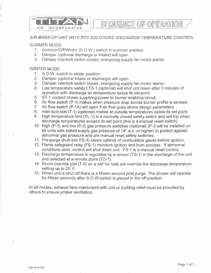
'n"i"iDif~~tc~~ AIR INCORPOR/ATED
AIR MAI-(E·UP UNIT WITI-I RTC SOLUTIONS DISCHARGE TEMPERA TURE CONTROL
SUMMER MODE 1. Summer/Off/Winter (S.OW) switch in summer position 2. Damper (optional discharge or intake) will open. 3. Damper interlock switch closes, energizing supply fan motor starter.
WINTER MODE: 1. S.O.W. switch in winter position. 2. Damper (optional intake or discharge) will open. 3. Damper interlock switch closes, energizing supply fan motor starter. 4. Low temperature safety L TS-1 (optional) will shut unit down after 3 minutes of
operation with discharge air temperature below its set point. 5. ST-1 contact closes supplying power to burner enabling circuit. 6. Air flow switch (P-1) makes when pressure drop across burner profile is sensed. 7. Air flow switch (P-1A) will open if air flow goes above design parameters. 8. Inlet duct-stat (T-1) (optional) makes at outside temperatures below its set point. 9. High temperature limit (TL-1) is a normally closed safety switch and will trip when
discharge temperatures exceed its set point (this is a manual reset switch). 10. High (P-3) and low (P-2) gas pressure switches (optional) (P-3 will be installed on
all units with stated supply gas pressure of 14" w.c. or higher) to protect against abnormal gas pressure and are manual reset safety switches.
11. Pre-purge (built into FS-1) clears cabinet of combustible gases before ignition. 12. Flame safeguard relay (FS-1) monitors ignition and burn process. If abnormal
conditions exist, control will shut down unit. FS-1 is a manual reset control. 13. Discharge temperature is regulated by a sensor (TS-1) in the discharge of the unit
and selected at a remote point (TD-1). 14. Room override stat (T-5) on a call for heat will override the discharge temperature
setting up to 25' F. 15. When unit is shut off there is a fifteen second post purge. The blower will operate
for fifteen seconds after S.O.W switch is placed in the off position.
In all modes, exhaust fans interlocked with unit or building relief must be provided by others to ensure proper ventilation.
Page 1 of 1 amu rtc 0(. doc
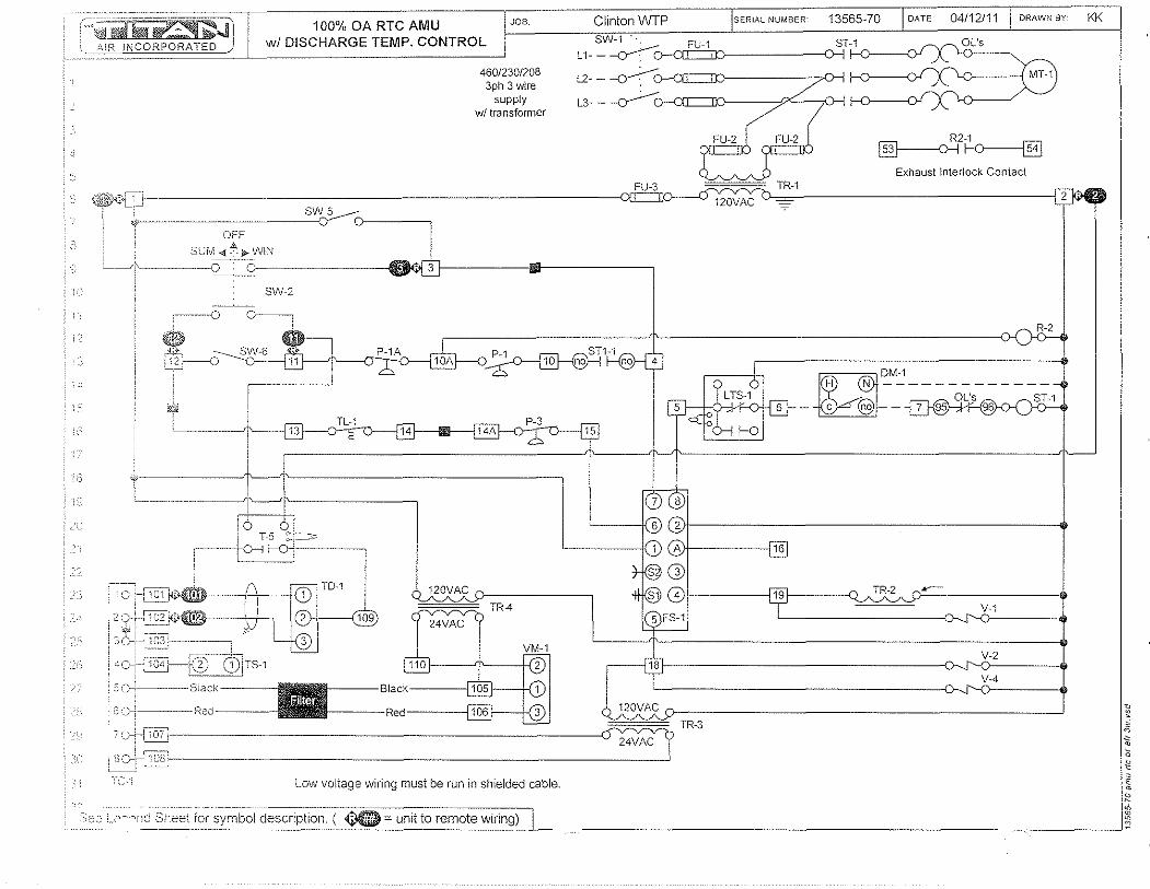
':::;~~.J 100% OA RTC AMU JOB Clinton WTP SER"l NUMBER 13565-70 DATE 04/12/11 DRAWN BY KK
,,_~}-\IR INCORPORATED wi DISCHARGE TEMP. CONTROL SW-1: FU-1 ST-1 __ OL's L 1- - --o--:C 1--0----0'
! ()
; ,~-
OFF
SUM4:~».WIN
SW-2
----0
$ ,iii, ii2)---0
T-S ~I __ r---t f--O+;---,
120VAC
24VAC
46012301208 3ph 3 wire
supply wI transformer
Low voltage wiring must be run in shielded cable.
,<;;co L_?~'.oild Sheet Tor symbol description. ( ~ = unit to remote wiring) ------_._._-_.
L2- -~ 1--0----0' \..0 { MT-1
L3- -
R2-1
~~ Exhaust Interlock Contact
120VAC
~DM-1
H N -------------OL's
- c @--~
TR-2
120VAC
TR-3
24VAC
~
~
~ ~ o
~ o E •
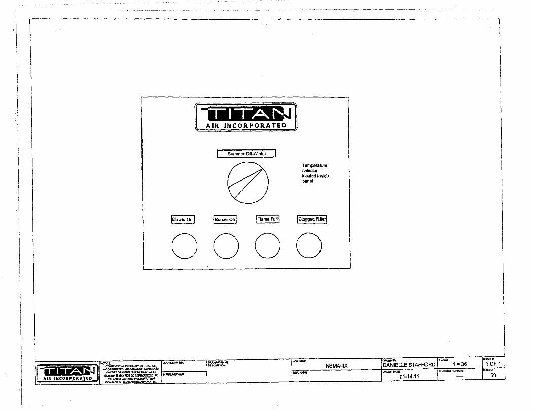
· \
i
I 'I
j
I
I I I
Summer..Qff-Wlnter
!B~~~I IB~;;'e;onl ~I
Temperature .. lector located Inside panel
I~FU§
0000
STAFFORD 1 =36

Honeywell
T451 , T651 Motor",Rated Precision Thermostats
APPLICATION The T651 thermostat provides direct, accurate line voltage control of inductively-rated heating, yentilating, or cooling equipment used in commercia! or industria! environments.
The T451 provides precision line voltage control of motorrated electric, gas or oil heating equipment.
FEATURES III Deluxe styling for commercial buildings.
Industrial grade MICRO SWITCHTM mechanism rated 1/2 hp inductive, 5 kW resistive.
III Vertical mounting on 2" x 4" NEMA~standard 5in916"9a09 outlet box.
• High~sensitivity, vapor~filled stainless steel dual diaphragm sensing element.
III Engineering plastic base to isolate sensor from switch heat and minimize droop.
• eSA Certified, UL Listed.
" Altitude compensation.
• 44°F (7°C) "frost protection" setting for heating application, independent of calibration or altitude.
• Color~coded leadwire connections.
• Range stops/Jocking cover security features for public areas.
Contents
Specifications •....•..............•............ 2 Ordering Information .......................•...• 2 Installation .•......••....•..........•.......... 3 Setting and Adjustment .......................... 4
1111111111111111111111111111111111 11111111 CL 4-01 • © Honeywell LimitedlUmitee 2001 95C·10903·1
T451, T651 MOTOf?--/-iI\TEn rIiFCISION T/-Ic:nl\,10S7ATS
Important: The specifications given in this puNicalion do not include normal mclnuf<:lCturing t-a/orances. Therefore this unit may not eX<lct'ly match the listed specifications, This product is tested ancf c~l/ibratcd under closely controlled conditions, and some minot differences in performance can be expected if t!Jese conditions are changed.
Models: T451A SPST and T4518 DPST (with positive oft) for heating only. T651A SPOT for heating/cooling.
Control Range: 44 - 86°F (7 - 28°G) for models T451A, T651A. 50 - 86°F (10 - 28'G) for model T451B.
Sensing Element: Vapor-filled dual diaphragm.
Differential: 2°F (1 0G)
Droop: 2°F @ mid load range.
Barometer Sensitivity: 1/8°F/"wc (0.3°C/kPa).
Thermometer: 50 - gO°F (10 - 30°G) in 10°F (5°C) increments.
Electrical Ratings:
50/60Hz 120V 208V 240V 277V
Full Load 9.8A 5.6A 4.9A 4.2A
Locked Rotor 58.8A 33.6A 29.4A 25.2A
Pilot Duty 125 VA
Resistive 22A Non Inductive 19ANI
Heating Only 2.5kW 4.5kW 5kW
ORDERING INFORMATION
SPECIFlCATlONS " Or?fX:r? fNH)I-?MAnON
Finish: Classic beige-and-light gold standard. White models available.
Mounting: Mounts directly on vertical, single-gang NEMA Standard (2" x 4") electrical box.
Wiring Connections: 6" (150 mm) leadwlres suitable for connect'lng to alum'lnum conductors wiring if used with approved special service CO/ALR soldedess wire connectors. Leadwires colorcoded red for fleating, blue for cooling, black for common.
Approvals: Canadian Standards Association Certified; File No. LR1322 Performance Certified for electric heating per C273.4A UL file E47434.
Accessories: 272804A Range stops and cover locking assembly
(included in selected models only). 220213 Wallplate, covers old T4511T651 (1000 selies)
wall marks. TG511 Thermostat guard for security and protection.
Fig. 1 - Dimensions of T451, T651 in inches (mm):
--I,:iI8J=j =: T -. T
<>0 ~o
,\''''1, 115 53
- - 1 115
~-L~E-_-,-___ 14'r h1:19/2JtJ~lj
When purchasing replacement and modernization products from your TRADElINE® wholesaler or your distributor, refer to the TRADELINE catalog or price sheets for complete ordering number, or specify:
1. Model 2. Electrical load(s) 3. Accessories.
If you have additional questions, need further information, or would like to comment on our products or selVices, please write or phone:
1. Your local Honeywell Home and Building Control Sales Office (check white pages or phone directory). 2. Home and Building Control Customer Satisfaction
Honeywell Inc., 1885 Doug/as Drive North. Minneapolis, MN 55422 (612) 951-1000
3. In Canada-Honeywell Limited, 35 Dynamic Drive, Toronto, ON M1V 4Z9, 1-800-405-9835. International Sales and Service Offices in all principal cities of the world. Manufacturing in Australia. Canada, Finland, France, Germany, Japan, Mexico. Netherlands, Spain, Taiwan, United Klngdom, U.S.A.
2

WI--jEN INS'IALUNO TI--IIS PFiODUCT:
1. Heo.d thWl8 im,tructioM carefully. Fsilure to follow instructions can damage': produ~t or cause a 11ElZardous condition.
2. Check ratings given in instructions and on product to make sure product is suitable for your application.
3. Make sure installer is a trained, experienced service technician.
4. After completing installation, use these instructions to check out product operation.
& WARNING This thermostat is a line voltage (120 to 277 Vac) con~~ol. Do not instal! it unless you are completely famliJar and competent with home wiring. If improperly handled there can be a risk of 24~ volt. ~lectric shock Ilazard which may cause senous injury or death.
& CAUTION 1. Disconn.ect power supply before making wiring
connectrons to prevent electrical shocl<. or equipment damage.
2. All wiring must comply with national and local codes and ordinances.
3. When using aluminum conductors, all wiring connec~jons to this thermostat must be made to the factory mstaUed leadwires using approved cal ALR solder/ess connectors. A fire hazard may result otherwise.
4. To avoid handling the sensing element, do not remove thermostat cover until wiring is completed.
5. Thermostats are designed for use with appliances having a limit control.
New Installations 1. Install a single-gang electrical box oriented vertically about
4' to 6' (1.5 m) above the floor on an inside wal! or pillar where the thermostat will be subjected to typical room temperature.
NOTE: To sense temperature properly, the thermostat must be placed away from concealed warm or cold water pip~s, air ducts, or drafts from halfways, fireplaces or staIrways. 00 not place thermostat above convectors or in the flow from supply fans. Ideally. a thermostat should be close to the return air path to effectively measure average room temperature.
2. Wire installation in an approved fashion.
NOTE: T651A and T451A do not feature a Positive Off setting, and may not be used as a disconnect switch.
3. Leave cover on the thermostat while making wiring connections. Use solderless connectors approved for the type, number and gauge of wires being joined.
Connect as per Fig. 2 for the appropriate application.
3
INSIIlU.A liON
Fig. 2 - Wiring connections
T451A (Heat only) 14516 (Heal only with positive off)
'''.' J-:. '~-3 ~., '~'".';''' &'''l~'O-- v---(Iy~ -~-.. -(o:.!
._---
T651A (Heat only) l651A (Cool only application)
'0 n ~ I(o";ng
,,~
S, "m .&
T651A (Heat--Cool application)
" 00, ."""""",1 ,"'_ ':lfr-(rjH--"~"-'...;Ii'~~~9 .&
& Power supply; provide disconnect means and overload protection as required.
& Breaks on Positive Off.
&.. Exposed unused wires must be properly insulated.
~ Contact makes Black to Red on temperature fall; Black to Blue on temperature rise.
4. Pre-bend and push leadwires into the electrical junction box.
5. Hold the thermostat base with one hand and remove the thermostat cover by grasping two sides of the cover and pulling outward.
NOTE: If locking cover feature is desired, ;nserr the locking cover clip in the thermostat base BEFORE mounting the thermostat on the wall (see Fig. 7).
6. Using the screwdriver, secure the thermostat to the box by tightening the two mounting screwS. Handle thermostat with care. Excessive pressure may damage the control knob or sensing element.
IMPORTANT: Before mounUng the thermostat, tum the setting dial to the mid-position (indicator pointing to the top of the thermostat): this will prevent damage to the dial stop if the dial is aCcidentally turned by the screw driver when the top mounting screw is tightened. Do NOT press on diaphragm, diaphragm fever arm or setpoint knob to seat thermostat on the box: thermostat will be damaged.
Replacement Applications 1. Disconnect power supply before making wiring
connections to prevent electrical shocks or equipment damage. All wiring must comply with applicable codes and standards.
2. Remove the old thermostat from the wall, taking care not to damage the wiring insulation.
3. Check the old insulation for cracks, nicks or fraying. Apply certified electrical tape where necessary to insulate wires, or replace the wires in an approved fashion.
4. Complete installation following steps 3 to 6 in the New Installations section.
'(.'15-1,7051 /vIOTOn·RATED P!-?ECtSfON nIERtvi(X31ATS
Check Out Turn on power. F1aise the temperature setting to energize tr18 fleating contact and break the cooling contact. The rWI\C equipment should begin heating or stop coofing, as appropriate.
NOTE: For T451A and T651A models only, the thermostat will call for heat (disable cooling) when the setpoint dial is at full counter-clockwise position. This setting is the pilase change point of tile diaphragm's vapor WI and is independent of calibration. To de-energize tile load(s), turn off power at the circuit breaker panel, or add a separate disconnect switch.
Altitude Compensation T451, T651 units are calibrated at the factory for accuracy at 500 feet above sea level. No recalibration is needed if the switch operates at the same temperature indicated on the thermometer,
The vapor-filled diaphragm sensor is affected by barometric pressure and altitude. Deviations up to ± 1°F (112°C) are within normal operation. Control point drops 2°F every 1000 ft. (1°C/300 m) above sea level. See Fig. 3 for recommended action.
Fig. 3 - Altitude Correction
Elevation Recommended (in feet) Typical City Action
o to 2000 Toronto, Ontario Leave as is PhoenIx, ArIzona
2000 to 4000 Las Vegas, Nevada Move clockwise Calgary, Alberta 2 to 3 marks
.--~--' '-4000 to 6000 Denver, Colorado Move clockwise
Salt Lake City, Utah 4 to 5 marks ... _---,
To Recalibrate
1. Remove cover. Set the tab on setpoint knob to the leftmost radial mark visible on top of the triangular arm that holds the dual diaphragm sensor (Fig. 4).
2. Without rotaUng the knob, remove it from the thermostat by pulling straight out, while holding the base against the wall.
3. Now, rotate the removed setpoint knob clockwise by the amount of temperature error. Each mark on the triangular arm represents 2°F we) of adjustment. Snap the knob back onto the setpoint cam.
Home and Building Control
Honeywell Inc. 1985 Douglas Drive North
Golden Valley, MN 55422
95C-10903~1
Home and Building Control
Honeywell Limited-Limitee 35 Dynamic Drive Toronto, ONMIV 429
4
INS"fALLA nON
4. Install the cover: Wait five minutes to let the thermostat thermally stabilize and re-check calibration. Do not assume 8 thermostat is out of calibration until it has been installed and aI/owed to operate for several hours.
Fig. 4·- Becalibrating Thermostat
Security Features: Range Stops
Fig. 5 - Installing Range Stops
0,::"",, . , . , , .
Insert pins into temperature stop posiflons
1. Set thermostat to desired setpoint. Remove cover, 2. Install plastiC dowels supplied (or purchased separately)
into minimum and/or maximum range stop holes on inside back of cover (Fig. 5).
3. Re-instaJl cover. Check operation of range stops.
Fig, 6 - Cover Locking Kit
Locking Cover
JtI ,..,
-!if?"
o ~y
L;f Tinnorman
spoed nut
..... i AHen screw i and wreocn
~
1. Remove cover by pulling straight out. 2. Insert linnerman Speed Nut®s into slots top and bottom of
thermostat base. 3 Drive Allen screw into Speed Nut until head is flush with
outside edge of thermostat base. 4. Re-install cover. Lock by backing out Allen screw until
screw body protrudes through cover hole. To unlock cover, drive Allen screw into thermostat base.
Honeywell
4.5 Start up Procedures
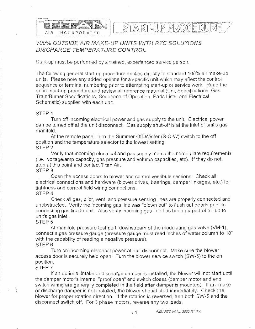
AIR INCORPORATED
100% OUTSIDE AIR MA!{E-UP UNITS WiTH RTC SOLUTIONS DISCHARGE TEMPERA TURE CONTROL
Start-up must be peliormed by a trained, experienced service person.
The following general start-up procedure applies directly to standard 100% air make-up units. Please note any added options for a specific unit which may affect the control sequence or terminal numbering prior to attempting start-up or service work. Read the entire start-up procedure and review all reference material (Unit Specifications, Gas Train/Burner Specifications, Sequence of Operation, Parts Lists, and Electrical Schematic) supplied with each unit
STEP 1 Turn off incoming electrical power and gas supply to the unit Electrical power
can be turned off at the unit disconnect Gas supply shut-off is at the inlet of unit's gas manifold.
At the remote panel, turn the Summer-Off-Winter (S-O-W) switch to the off position and the temperature selector to the lowest setting. STEP 2
Verify that incoming electrical and gas supply match the name plate requirements (i.e., voltage/amp capacity, gas pressure and volume capacities, etc). If they do not, stop at this point and contact Titan Air. STEP 3
Open the access doors to blower and control vestibule sections. Check all electrical connections and hardware (blower drives, bearings, damper linkages, etc.) for tightness and correct field wiring connections. STEP 4
Check all gas, pilot, vent, and pressure sensing lines are properly connected and unobstructed. Verify the incoming gas line was "blown out" to flush out debris prior to connecting gas line to unit Also verify incoming gas line has been purged of air up to unit's gas inlet STEP 5
At manifold pressure test port, downstream of the modulating gas valve (VM-1), connect a gas pressure gauge (pressure gauge must read inches of water column to 10" with the capability of reading a negative pressure). STEP 6
Turn on incoming electrical power at unit disconnect. Make sure the blower access door is securely held open. Turn the blower service switch (SW-5) to the on position. STEP 7
If an optional intake or discharge damper is installed, the blower will not start until the damper motor's internal "proof open" end switch closes (damper motor and end switch wiring are gener?lly completed in the field after damper is mounted). If an intake or discharge damper isnot installed, the blower should start immediately. Check the blower for proper rotation direction. If the rotation is reversed, turn both SW-5 and the disconnect switch off. For 3 phase motors, reverse any two leads.
p.1 AMU RTC 111//gl1 2003 RI.doc

AIR INCORPORATED
STEeP 8 With proper blower rotation verified, check and record the RPIVI of the blower. If
the blower speed needs to be adjusted to change the rated CFIVI of the unit, contact the factory. STEP g
Tum the unit off. Close and latch the blower access door. STEP 10
Start unit with SW-5, Check and record the motor amp draw, If the motor amp draw exceeds listed Full Load Amps (FLA), stop and call the factory, STEP 11
Check and record the negative pressure reading on your burner manifold pressure gauge, This measurement is necessary for proper setting of the burner manifold pressure when the unit is forced into high fire mode, At this time, also measure the pressure drop across the airflow switch ports (remove caps from fittings in tubing for air flow switches and connect tubing from differential pressure gauge to fittings), This measurement can be used as a simple indication of proper airflow through the unit. If this second measurement is not between 0,7" w,c, and 0.5" w,c, LIP, the blower speed may need to be adjusted, If assistance is needed, contact Titan Air, STEP 12
Turn the unit off, Check the pilot gas line for proper and tight connections with no leaks, For shipping purposes, the pilot lines are disconnected, STEP 13
Turn on the main gas valve, slowly open the manual pilot gas valve, If the unit is supplied with a low gas pressure switch (P-2), reset to on position, STEP 14
Place the run-check switch (located on flame safeguard programmer module) to the check position, This will allow the pilot to light without igniting the main burner. If the unit is equipped with an inlet ductstat (T-1), set this stat above the outside air temperature, Start unit with SW-5 and enable the burner with the burner service switch (SW-6).
Note that the burner should not be operated continuously in the check position for more than 1 minute because the ignition transformer is not rated for continuous duty, STEP 15
The unit should go through its complete burner ignition sequence with only the pilot ignited, The sequence can be observed by following the indicating LED's on the flame safeguard, On new installations, resetting of the flame safeguard may be required to purge air from the pilot line, If the unit does not cycle through its burner ignition sequence after a few attempts, refer to the service information in the following section for troubleshooting instructions, STEP 16
In the center of FS-1 are 2 voltmeter test ports, Set the volt-ohm meter to approximately 30 VDC scale and insert the meter leads into the test ports (common lead in black port, positive lead in red port). STEP 17
With only the pilot operating, record the DC volt signal. The DCV range is noted on the amplifier module of the controller (FS-1). There should be a steady DCV signal in
p,2 AMU RTC /11//gl1 2003 R1.doc
tile upper range stated on tile controller. STEP 18
Once stable pilot is achieved, shut unit down and place run-check switcll in the run position. Carefully remove the wire from terminal one (1) on gas modulating actuator (VM-1). Do not allow tile wire to touch tile unit casing or any metal. Release actuator gear by pressing black button on side of actuator (see figure 1), rotating mechanism counterclockwise to stop. Start unit and check and record DC voltage as in previous step. Check to make sure the flame is contained ill tile burner casting and extends the full length of the burner with no breaks in the flam~. An ideal low fire setting results in a small flame with no breaks and that also produces a stable DC voltage signal in the upper end of the range listed on the flame safeguard amplifier module. If the low fire setting is adjusted, verify that both the DC voltage signal and visual appearance of the flame are satisfactory. See figure 1 at end of start-up procedure for low fire adjustments if necessary. STEP 19
Once stable signal is achieved on low fire, release actuator gear by pressing black button on side of actuator (see figure 1) and rotate mechanism clockwise to stop. This will force the burner into high fire. On your manifold pressure gauge, check the manifold pressure. The reading on your manifold pressure gauge needs to be added to the negative pressure recorded in step 11. The resulting total manifold pressure should be compared to the unit's rated manifold pressure. If the total is higher or lower than the rated pressure, adjustment can be made at the gas pressure regulator (GP-1). Total manifold pressure should not exceed unit's rated manifold pressure.
Because of possible variations in the BTU content of gas, it may be necessary to set the manifold pressure to the rated temperature rise (temperature difference between the incoming air and the unit discharge air).
The high fire flame should be visually observed to verify proper combustion. Experienced service personnel should be able to assess the appearance of a proper high fire flame. If assistance is needed, contact the factory. STEP 20
With the burner on high fire, turn the high temperature limit (TL-1) to its lowest setting. The limit should trip out and shut down the burner. Turn TL-1 back to the factory setting of 185 deg. F and reset the control. Reconnect wire at VM-1. STEP 21
With all wiring in place and the unit operating in the winter mode, adjust temperature setpoint on the remote mounted controller (TD-1) up and down (from highest to lowest setting) observing the modulation of the burner. When actual discharge air is below TO-1's setpoint, the unit should discharge maximum temperature. When actual discharge air is above TO-1's setpoint, the unit should discharge minimum temperature. STEP 22
With the unit operating in the summer mode, cycle the burner from SW-6. Verify that burner fully lights within a few seconds of proved pilot. STEP 23
If the unit is equipped with a low temperature safety (L TS-1), check this control's operation. Standard L TS-1 can be checked by disconnecting the sensor wires. The unit
p. 3 AfVlU RTC Int Ign 2003 R1.doc
should then shut dOWll after the built-in timer setting Ilas "timed-out". Replace the sensor wires whell propel' operation has been verified. Turn the unit off and back on to reset L TS-1 . STEP 24
With the unit operating in the winter mode, close the 2nd manual gas shutoff valve (GT-3). The burner should shut down in a few seconds (look fOl' flame LEO to go out on FS-1) with the unit shutting down in 30 seconds 01' less. Open GT-3 and reset FS-1 by pressing button protruding through covel'. STEP 25
Turn SW-5, SW-6 and the disconnect off Verify all terminals, electrical connections and hardware (bearings, sheaves, blower wheels, etc.) are securely tightened. Adjust all controls to desired settings. Remove all gauges, meters, and hand tools from the unit. Replace all covers on controls. Make sure all safety devices are reset. STEP 26
Turn the disconnect on. Start the unit from the remote panel. Verify proper operation in all modes according to unit's sequence of operation.
The unit should be ready for operation. If any problems arise, refer to the service information on the following page. To assure long lasting and efficient operation of Titan equipment, a regular service inspection should be set up. Refer to the maintenance section at the back of this manual for detailed maintenance information.
p. 4 AMU RTC Inllgn 2003 R1.doc
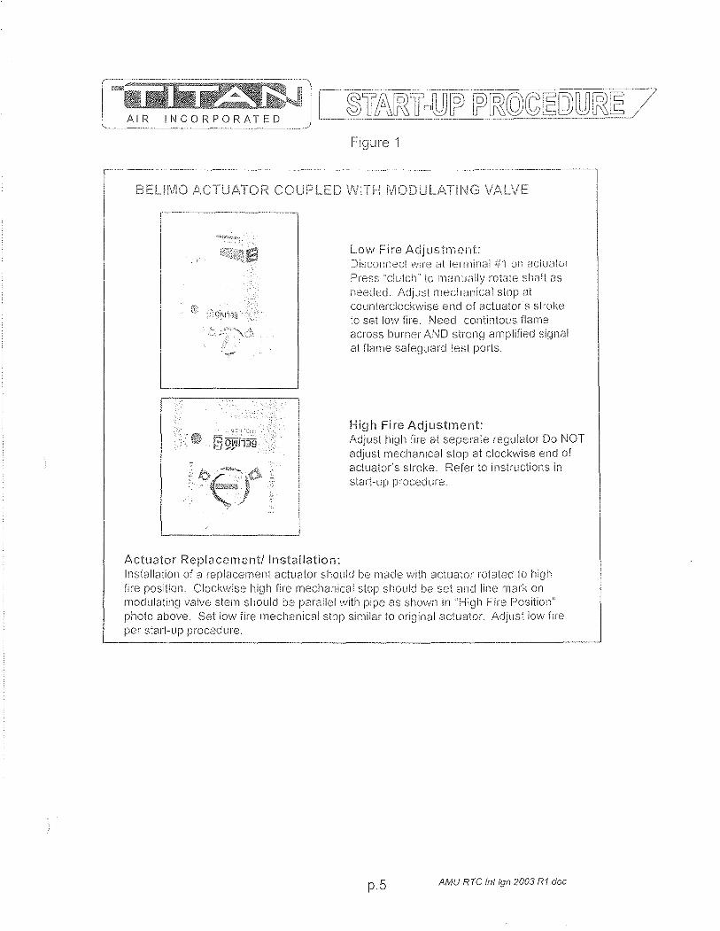
AIR INCORPORATED
Figure 1
BElilVIO /\CTWi.TOi1 COUPLED WITH MODUU\TII\IG V,il,LVE
--.. -----
/I,ctuator Replacement! Installation:
L.ow Fire Adjustrnent: Di~_;cOllnecl \~,'II'e , .. il 1f:-:ITnirkl.l irl on i:';I:,;\u,--diJl
Pr"ess "ciu1ch-' to Ill<JI1U{3l1y rotate sh,~ft as n~;ed{~d. !~djJst mech~.lIlic(JI stDP at cOLinterdock\vise end of actuator"s sl:"oke to set low fire. Need contilltous fl(:in18
across burner AND strong amplified si[Jnal at flclrne saf8~J,-j8rci test ports.
High Fire Adjustment: Adjust hlgll life at seperate regulator Do NOT adjust mechanical stop at clockwise end of actuator's stroke, Refer to inst~uctions in start-up procedure.
Installation of a replacement actuator should be n18de \Nith actuator ro1ated 10 high fire position. Cloch,vise hj~~h fire mechanical SlOP s!'lou!d be sci and line !ilark on nlodulating valvo stem should L)e paraded with pipe 8S shmvn in "High Fire f-)osition" photo above, Set Im·v fire mechanical stop sirnilar to original actuator. Adjust low fire pee stan-up procedure.
p,5 AMU RTC Inl19112003 RI.doc
Brandon

4.6 General Information: Installation, Assembly Drawings, Maintenance


WARNING
Improper installation, adjustment, alteration, service or maintenance can cause property
damage, injury or death. READ all maintenance instructions thoroughly before installing or
servicing equipment.
FOR YOUR SAFETY
IF YOU SMELL GAS: 1. Open window J doors. 2. DO NOT switch electrical switches. 3. Extinguish any open flame. 4. Immediately call your gas supplier from
an area away from gas smell.
The use and storage of gasoline or other flammable vapors and
liquids in open containers in the vicinity of this heater is
HAZARDOUS.
NOTICE LOW TEMPERATURE LIMIT
If this heater is to be installed in an area of potential freeze up and a low temperature limit
was not ordered, one should be installed to provide freeze protection in the event of a
burner shut down.
[ ..... i!A-;;~ A I R INC 0 R P 0 R iTtD
AIH lNCOHPOHATED
24 MONTH WARRANTY Titan Air, Inc. hereby warrants its products against defects in matel'ial and
workmanship for a period of (24) twenty four months from date of shipment. Start up checklist is due back within (30) thirty days of start-up or 120 days from date
of delivery for 24 month warranty to be effective. Afier (30) thirty days, and up until (60) sixty days, a (13) thirteenth month warranty will be observed. All warranties are null and void if start up checklist is not received within (60) sixty days from start-up or 120 days from date of delivery. NO EXCEPTIONS WILL BE MADE.
Titan Air, Inc. reserves the right at Titan Air, Inc.'s option, to replace or repair free of charge, any part proven by Titan Air, Inc. to be defective. Prompt notification of defective part must be given to Titan Air, Inc. and defective part must be returned freight prepaid within (30) thirty days of notification.
WARRANTY INCLUDES ONLY PARTS SUPPLIED BY TITAN AIR, INC. INCIDENTAL COSTS AND LABOR CHARGES SHALL BE THE RESPONSIBILITY OF OTHERS. This warranty does not cover fuses, belts, filters or water damaged parts which are the result of improper storage or installation.
This warranty is void in event the product is improperly installed and/or operated under conditions other than normal published ratings, improperly maintained, misused or not in compliance with applicable codes or not in accordance with Titan Air, Inc.'s operating instructions.
This warranty is void if attempts to correct or repair any alleged defective part or parts are made by unauthorized personnel without Titan Air, Inc.'s written approval.
In no event shall Titan Air, Inc. be held liable for any damage, incidental or consequential, arising from the installation, performance or operation of the product.
This warranty supersedes, voids, and/or is in lieu of any other verbal or written understanding which may not be in total accordance with this expressed warranty.
Warranted parts must be returned to Titan Air, Inc. within 60 days to receive credit.
PURPOSE I APPLICABILITY This manual is intended to provide installation, operating and service information on
Titan Air's standard direct-fired air make-up units. Other Titan Air units, such as ARI80™, AR/75™, Demand·-Ai(fM, H.O.TTM and units that do not feature a direct-fired burner, will have separate operating and selvice manuals.
A packet of reference materials for a specific unit (tracked by its Serial Number) is generally included with this Operating and Service Manual. The reference materials include Unit Specifications, Parts Lists, Gas Train and Burner Specifications, Electrical Schematic, and a Sequence of Operation. A start up checklist is also included in this packet. Review the reference materials for a specific unit and note any optional equipment or controls which are not specifically addressed in this manual prior to attempting start-up or service work.
The information and recommendations contained in this publication are based on general observation and are not intended to supplant requirements of federal, state or local codes having jurisdiction. These codes should be reviewed before installation of equipment. All units must be installed in accordance with national, state or local codes.
It is the responsibility of the purchaser at the time of order, to specify any and all code or insurance requirements that may dictate the addition of components to the equipment in order to comply with those requirements.
Only qualified personnel who have experience with the installation and operation of industrial/commercial direct fired equipment should attempt to service Titan Air equipment.
WAPPANTY
TABLE OF CONTENTS
GENERAL INFOPMATION 'Y Equipment Arrival 'Y Components
AIR FLOW SWITCH OPEPATION
INSTALLATION 'Y Installation and Field Wiring Overview
TYPICAL ASSEMBLY DRAWINGS
MAINTENANCE
FLAME FAIL DIAGNOSTICS
START-UP PREPARATION
VALVE LEAK TEST
SPECIFIC EQUIPMENT DETAILS 'Y Unit Specification 'Y Sequence of Operation 'Y Parts / Legend Sheet 'Y Schematic » Start-Up Procedure 'Y Troubleshooting (optional)
Page 1
2
3
7
8
11
14
17
19
20
pages not numbered
Note that operating and service manuals are occasionally requested prior to production of a unit. These manuals will be marked "Pre-Production Release" on the front cover. The final copy of the operating and service manual for a specific unit will be sent with the unit. Additional copies of the manual for a specific unit are available.
A detailed unit specification sheet, parts/legend sheet, schematic, sequence of operation and start-up procedure are provided in the start-up section of each operating and service manual generated for a specific unit. Selected vendor cut sheets on components will also be included.
2
EQUIPMENT MmIVAL. When the air make··up unit arrives, be slire to inspect for shippinq damage. The
equipment was thoroughly inspected beforE; leaving the factory and the driver signed for it. Pead the bill of lading and verify that all of the items listed are accounted for. Any damaged or missing items should be repolied to the transporter immediately. DO NOT SEND DAMAGED FPEIGHT BACK TO TITAN AIPI All claims must bE!Jiled with the tr.,,-,,-sportE!L Be sure to take photographs and get the drivers signature to confirm the damage. The driver will have a number for you to call to file a claim. Pequest a written inspection report from the claims inspector to substantiate any necessary claim .. Be sur~ l<umen the unit access doors and inspect for internal dam9JJS
If for some reason you are unable to install the equipment immediately, be sure that the equipment is protected from the elements. Water damaged parts are not covered by Titan Air's warranty. If the equipment is stored for an extended length of time, be sure to completely check the unit for any internal damage which may have been caused by excessive condensation. Also check for damage caused by rodents, and be sure to eliminate any dust that may have built up on the components while the unit was in storage.
CAREFULLY AND THOROUGHLY READ TITAN AIR'S PRODUCT WARRANTY Each unit is tested at the factory prior to shipping. Because we are not able to
simulate exact field conditions and sometimes actual conditions are different than what was stated on the order, you may need to make some adjustments in the field. This is why it is very important that only qualified personnel start-up and service Titan Air equipment The start-up checklist (provided in packet with this manual) must be filled out and returned to Titan Air in order to validate equipment warranty.
For a fee, Titan Air personnel will travel to the job site, supervise start-up and provide operation and maintenance training for the equipment.
BLOWERS The typical blower(s) used in Titan Air equipment are AMCA rated industrial type
forward curve D.W.D.1. fans. Backward incline, backward airfoil, and plenum/plug fans are used occasionally. Models lA-109 through TA-136 utilize a single blower while models TA-215 through TA-242 utilize twin blowers. All blower wheels are mounted on a solid, turned, ground and polished shaft. 9" and 12" blowers are supported with permanently lubricated ball bearings. Larger blowers are supported by lubricated pillow block ball bearings.
MOTOR & DRIVE Rigid base, T-Frame, motors are utilized. The motor is mounted on an adjustable
slide base. Variable pitch motor sheaves are provided to allow airflow adjustment if the motor is no larger than 30 Hp.
3
DIRECT FIRED HEATING Direct fired burners are designed to operate in a fresh flowing airstream. Gas is fed
directly to the burner and the airstream provides the needed oxygen for combustion. A series of strategically sized and placed holes provide air to the combustion zone.
See Figure 1
Higtl Fire Zone
Intermediate [ Zone
Low Fire I Zone L
Aiuminuill Manifold
Indicated Flame Length
i Steel Combustion Baffle
'-... Hiclh Fire Air Ports
Progressive Air Supply
Intermediate Ports Fire Air Ports
~\'f'4--- Low Fire Air Poris
Figure 1
The direct fired burner is designed to operate at an air velocity across the burner of 2450 fpm with maximum manifold gas pressure as stated on unit rating plate. Air velocity across the burner can be adjusted on single speed units with slide plates on either side of the burner. Two speed units feature an automatic damper with actuator and controls to maintain proper velocity across the burner profile as air volume changes.
Because of the air pattern, air ports and kinetic energy of the air moving across the burner, the direct fired burner has the capabilities of approximately 32:1 turn down ratio. The high fire rate is approximately 30 times of the low fire rate.
4

BURNER OPERATING PRINCIPLES The direct fired burner is designed to operate in a cabinet of flowing fresh air. Fuel
gas is fed directly to the burner; kinetic energy of the airstream furnishes combustion air. It will function properly at the design velocity and pressure associated with ventilating systems.
The burner must be installed to fire with, and parallel to, the air flow. By virtue of velocity impact and suction generated by the diverging shape of the combustion baffles, air is induced through the air ports into the combustion zone. The air supply is constant, even though only that which mixes with the gas takes part in combustion.
When a very small quantity of gas is admitted to the burner, sufficient mixing takes place in the low fire slot where combustion takes place. Since the low fire zone is contained within the burner casting it is effectively shielded from uncontrolled air entry.
As the gas supply is increased the flame progresses into the intermediate fire zone where an additional supply of air is available. At higher or full capacity, mixing occurs at the larger air ports of the high fire zone augmented by air flowing over the end of the baffles.
On a reduction of gas supply the reverse sequence takes place, the flame recedes to a location of lesser air supply until the low fire zone is reached. The burner is suitable for a turndown range of approximately 30 to 1.
AIR SUPPLY The supply fan is typically positioned to draw air across the burner. Air flow across
the burner must be substantially straight (laminar) and velocity must be within the proper range to develop the desired turndown and capacity.
The direct fired burner is designed to operate in an air make-up heater with all air crossing the burner taken directly from outdoors. Rare exceptions involve equipment that serves an unoccupied space.
Total pressure rating of the blower includes allowance for the pressure drop through the primary air handling unit including the burner, together with pressure losses at the inlet screen, inlet damper, filters, outlet damper if used, plus the external pressure rating of the system.
BURNERS Burners are purchased in 6" and 12" straight lengths and 12" tee sections and
are assembled to meet the BTU requirements of each piece of equipment. According to national safety standards, the following factors could influence safe
operation of a direct fired air make-up unit and must be interlocked to either prevent the burner from firing or shut it down if unsafe conditions occur.
1. AIR SOURCE - If a damper is used, it must be interlocked to prove it is open before the blower can start.
2. BLOWER STARTER INTERLOCK An auxiliary contact from the blower starter must be placed in series with the burner controls to prevent burner operation when the blower is not operating.
3. AIR FLOW SWITCHES - Monitor the air flow (pressure drop) across the burner. The switches (one high differential and one low differential) will not allow burner to operate if pressure drop across the burner is outside of the high and low set points.
4. HIGH TEMPERATURE LIMIT - A manual reset high temperature limit control must be utilized to prevent high temperature situations caused by excessive fuel pressure or lack of air flow.
5

5. fLflcMJ:; .. SAI'EGUAPD .... Monitors the combustion process during ignition and operation for safe conditions.
6. jjKi.H GAS PPESSUPE SWITCH - Monitors gas pressure to the burner. This de-energizes the burner in the event gas pressure increases above its set point.
The burner's design and flexibility, coupled with proper controls, make direct fired air make-up equipment tile safest and most efficient method of tempering outdoor air.
GAS CONTROLS Titan Air TA Series equipment is constructed to meet A.N.S.I Z83,4/CSA 3.7-1999
standards. Components in the gas delivery manifold on standard equipment include: two manual shut-off valves, gas pressure regulator, two safety shut-off valves and an electronic gas modulating valve. The pilot control includes a shutoff valve, gas pressure regulator and a pilot solenoid.
ELECTRIC/ELECTRONIC CONTROLS TA series air make-up units come standard with the following items: disconnect
switch, starter and overload assembly(s), control power transformer (if a 3 wire system), air proving switches, high temperature limit, electronic flame safeguard and electronic flame modulation with remote set point adjustment. Many other options including low temperature limit, inlet duct stat, and operating lights are available.
If the malfunction of the heater creates a hazard to other fuel burning equipment in the served building (i.e. supplying make-up air to boiler room) it is to be interlocked to open an inlet air damper in case of failure,
CABINET Titan Air TA series equipment comes with either a galvanized finish or a painted
finish. In both cases, the minimum gauge metal used is 18 gao
6
AIR INCORPORATED
BURNER PROFILE AIR PRESSURE DROP ANSI standards, Z 83.4/CSA 3.7 M99 & Z 83.18 .. 2000, require manufacturers to
monitor air moving across the burner for both high and low conditions. Titan Air utilizes pressure drop across the burner to satisfy this requirement.
Certification testing demonstrated that the burner will function properly between a low pressure drop of 0.2" w.c. and high pressure drop of 0.95" w.c. The standards also mandate that the switches cannot be adjustable. This makes air pressure drop across the burner profile a very important factor at initial start up.
The design burner pressure drop at standard air conditions is 0.60" w.c. and will change as the temperature of outside air increases or decreases from 70"F. In order for the burner to operate within the range of the air flow monitoring switch set points, the pressure drop should be as close to 0.60" w.c. as possible.
Air pressure drop across the burner profile is dependent on OA temperature. When the burner is off, pressure drop will climb significantly during cold weather. The burner is always off on initial start-up. Therefore, if the burner profile air pressure drop is above 0.70" w.c. during a warm weather start-up, it may exceed 0.95" w.e. during a cold weather start-up in northern regions. Such a high air pressure drop would open the high airflow switch and prevent burner ignition.
The following chart will aid in equipment set up at outside air temperatures different from 70"F when the unit is operating with the burner off. The chart gives pressure drops, at various temperatures, equivalent to 0.60" w.c. at 70"F.
Note that two speed units feature controls to automatically control pressure drop across the burner as air volume changes. Burner profile air pressure drop should be measured on high speed with the burner profile dampers near the full open position. If the burner profile dampers open less than 50% on high speed, the equipment is not delivering rated air volume.
Burner Profile Air Pressure Drop at Various OA Temperatures (Burner Off)
---- '-"--"'-- ... ----.. -. --~~~--~~-.-
OA Burner OA Burner OA Burner TemD Profile Drop Temp Profile Drop Temp Profile Drop
__ ..::.1Q.. __ 0.76 10 0.68 60 0.61 ----~--
_. -35 0.75 15 ___ --.9.§L ___ e---. 65 0.61 -30 _ '-- __ JL?L ___ 20 0.66 70 0.60 ._._--_.-- . -25 . . ,--.__0.73 ___ 25 0.66 75 0.59 -20 0.72 30 0.65 80 0.59 1----._--15 0.71 35 0.64 85 0.58 .. _.- .. --10 0.71 40 0.64 90 0.58 --_._----5 0.70 45 0.63 95 0.67
1-. 0 0.69 50 0.62 100 0.57 6 0.68 66 0.62 106 0.66
7
CONTROLS Control systems can be designed to meet specific requirements. Numerous
temperature controls are available. Since standard air make-up units usually temper outside air to replace the air exhausted from a building, modulating discharge temperature control is typical. A room override thermostat is occasionally included to automatically increase the discharge temperature set point if space temperature drops too low.
Titan Air units are typically supplied with a remote control panel. This panel will include switching for blower & burner operation and a temperature setpoin!. Some units feature operating lights, discharge temperature display, custom controls or contacts by others to enable the blower and/or burner.
Refer to the unit specification sheets, parts list, schematic, sequence of operation and start-up procedure for a specific unit to determine the control options included.
PRE-INSTALLATION Inspect the equipment making sure all parts and accessories are on the job site.
Check equipment against order and packing list. If the equipment has been sitting in storage for some time, inspect it for moisture (from condensation, rain or snow) and/or dust accumulation. Both can cause damage to electrical and electronic components as well as bearings and insulation.
INSTALLATION Care taken during the installation and start-up is vital to the longevity and reliability of
the equipment. Confirm that gas and electric utilities match the rating on the equipment name plate.
> This heater shall be installed in accordance with local codes or, in the absence of local code, according to ANSI Z223.1.
> If the heater is to be installed in an airplane hanger, refer to ANSI/NFPA 409.
> If the heater is to be installed in a parking garage, refer to ANSI/NFPA 88A.
> If the heater is to be installed in a service garage, refer to ANSI/NFPA 88B.
> For installations in Canada, refer to CAN/CGA B149.
'" Adequate exhaust and/or relief must be provided to prevent over pressurizing the served space when the heater is operating at its rated capacity.
'" If in doubt regarding the application of the direct fired heater, contact the sales representative or the factory.
POSITIONING THE HEATER Locate the heater exactly level, making certain minimum clearance required by local
codes is maintained between the heater and any combustible materials. See name plate on unit for minimum recommended clearances.
8
CURBING (OUTDOOR MOUNTING) The use of a full perimeter curb or mounting rails under the heater is recommended.
The only openings in the roof should be for the supply air duct, return air duct (if required), gas and electrical connections (if applicable). These openings must be sealed properly after installation. Titan Air ships all curbs unassembled and un-insulated. Installing contractor supplies gaskets, cant strips, insulation, etc.
GAS PIPING Gas piping must be sized and installed in accordance with applicable codes. It must
be able to deliver the specified CFH and gas pressure at full flow. Refer to unit nameplate or unit specification sheets for specified CFH and gas pressure.
Care must be taken with the gas piping to prevent problems at start-up and later during operation. Before the union between the supply line and the unit is connected, the supply line should be cleaned out to remove any foreign material (dirt, rust, metal shavings, etc.) and a drip leg should be utilized.
Refer to unit nameplate to determine the minimum gas supply pressure required to attain the maximum specified gas.
All suitable gas controls, regulators and valves (equipped with a diaphragm) in this device are furnished with an ANSI approved vent limiter. If local codes require these components be vented to the outside, it is the responsibility of the installing contractor.
The heater and its individual shut off valve must be disconnected from the gas supply piping system during any pressure testing in excess of Yz PSIG.
The heater must be isolated from the gas supply piping system by closing its individual shut off valve during any pressure testing of the supply system at pressures equal to or less the Yz PSIG.
During start-up, the technician should perform a gas leak check on all valves and piping during the heater's normal operation. (See page 20)
DUCTWORK Ductwork must be sized and installed in accordance with applicable codes and
standards. A size variation may exist from recommended duct size to unit flange size. Recommended duct size applies to the size of the duct at the connection to the equipment. A properly designed duct transition from the blower outlet to a larger duct is recommended for long ducts or ducts with numerous elbows.
On heaters mounted outdoors, discharge ductwork should be insulated to minimize condensation during the "off' cycle in cold weather. A fresh air intake hood with bird screen is required. Discharge duct should be common to both blowers on twin blower units. Individual ducts for each blower are not recommended.
On a heater mounted indoors with through the roof intake, a "mushroom" type intake hood is recommended to prevent moisture entrainment. When using "through the wall" intake duct, the intake louver should have adequate moisture baffling characteristics. All intake ductwork exposed to the heated space should be insulated.
9
SOUND AND VIBRATION CONTROL Flexible connectors are recommended on at least one ductwork connection.
Vibration isolators that mount between the unit and support structure are optional and can be supplied with the equipment for installation by others. Another option is internal isolation of the blower/motor assembly with internal flexible connections between the blower housing and the unit structure.
Appropriate insulation on the interior of ductwork significantly reduces sound levels.
DISCHARGE TEMPERATURE SENSOR BULB INSTALLATION & WIRING The installing contractor may be responsible for field installation of the discharge
temperature sensor. Field installation of the discharge temperature sensor in the discharge ductwork results in a better measurement of the average supply air temperature. Utilize shielded cable for field installed discharge sensor wiring.
FIELD WIRING Power supply wiring should be routed from a dedicated branch circuit per schematic.
Depending upon how the equipment was ordered, a single point power connection may be subdivided to individual loads or multiple power supply circuits may be required.
If an intake or discharge damper was ordered as a loose accessory, it will have to be mounted and the actuator must be wired. The remote panel must be mounted in a convenient location and wired to the unit. Interlocks between the exhaust, unit and possibly spray booth will have to be connected by field wiring.
Carefully review the schematic and associated schematic symbol legend. Note that legend may be on the parts/legend sheet rather than on the schematic.
Many codes require that low voltage wiring (connecting terminals numbered 100+) be routed in separate conduit from line voltage wiring. If low voltage wiring is routed with 120 VAC control voltage wiring, it must be placed in shielded cable(s). Even if low voltage wiring is routed in separate conduit, very low voltage sensor outputs and actuator control signals should be routed in shielded cable.
NOTE: All field wiring must conform to N.E.C. and/or any state or local codes.
SUPPORT OF ACCESSORIES Most Titan Air equipment is supplied with loose accessories (i.e. damper, hood,
discharge diffuser or filter section). If an intake hood is supplied by others, the design shall minimize entry of snow/rain and include an intake screen to meet ANSI standards. Intake accessories on large equipment may be shipped in two pieces for field assembly. Two damper actuators may need to be field wired on large equipment as well.
It is the responsibility of the installing contractor to support accessory items from a rigid point or points to ensure solid mounting.
POST INSTALLATION Caulking is required between all parts prior to assembly and seams must be
re-caulked after assembly. Air make-up units shipped in multiple sections will include a high quality caulk tape and caulk tubes. Caulk tape is applied between sections with exterior caulking applied after the unit sections have been joined. Sealing integrity should be rechecked on a yearly basis.
Water damaged parts are not covered by Titan Air's warranty.
10

On split units, contractor' is responsible for interconnection of components
Service Disconnect
DISCHARGE DAMPEF,
INTAKE HOOD wi BIRDSCREEN or HOOD I FIl.TER COMBO
Mount accessories witl1ali accessdoors and damper motors facing same direction as'unit, access doors,
Intake' or discharge damper should be mounted at thewali o[ceiling (i~sid.e building).,
AU components ~u~t,b,e ~:(lu,l,ke?,_to, preve-nt water from entering system.-' Re caulk Hft plates after instaliation.
Accessories should be SUppo,rt~d after installation (s~pports by others).
TA-233 through TA-242 feature 2 piece accessories that need to 'be assembled, supported and sealed in the field. Intake damper~ have two motors to wire.
Make sure gas pipj~g an'd el,eCtrical s,ervice does not interfere with any door opening and I or filter removal.
Note: Due to infinite installation' p:ossibHities, a section of duct or transition rnay be required for proper accessory' mounting, 'These items are the responsibility of others.
Recommend the use of flex connector between unit and ,duct work.
Note: All main po",erwiring must be sized and installed in accordance with ,~ppHc~.b,Je local, state or federal codes. Low voltage wiring must be run in separate conduit or shielded cable.
CAULKING OR MATERIAL (by others)
Note: Discharge damper may be larger than respective flanges or opening on Lmit
REMOTE PANEL
Mount Indoors
INTAKE HOOD
INTAKE FILTER SECTION
Split (must seal)
11
INTAKE DAMPER
TA-233 through 242 Filter sections are accessed from both sides

PAD ATTACHMENT DETAIL (by others)
OUTSIDE AIR FILTER SECTION (optiona!) slides into unit
Supp01ted by others
DISCHARGE DIFFUSER
(mounted indoors)
Duct work between AMU (or discharge damper) and discharge diffuser is supplied by others. Recornend the use of flex connector between unit and duct work.
Diffuser should be supported at 2 points by others. (an example shown) Turning vanes are adjusted and secured in Ule field.
All components must be caulked to prevent water from entering system. Recaulk lift plates after installation.
Make sure piping and electrical service does not interfere with any door opening and lor fflter removal.
Recoment the use of flex connector between unit and duct work.
For indoor units, the stand must be enclosed (sometimes height is increased). A transition (by others) must then be made from enclosed stand intake opeing to the intake damper or louver (a size variation may exist). Intake damper should be mounted at the building wlal Of ceiling.
12
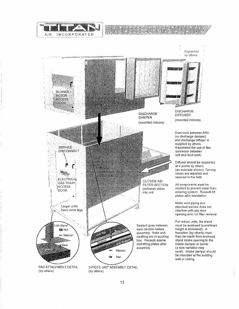
SERVICE
,. DIS\ONNECT
fi r ~1t11
I ELECTRICA}, • GAS TRAINj iACCESS DOOR
Larger units !lave more legs
PAD ATTACHMENT DETAIL (by others)
Suppo!ied by otl1ers
-r)ll~1~~&1.JI!tii{tI§iEfIJ,!§f<mi!r4
ImI Nut
(optional) slides into unit
Sealant goes between each section before assembly. 80lts and caulking are in packing box. Recaulk seams and lifting plates after assembly.
2-PIECE UNIT ASSEMBLY DETAIL (by others)
13
DISCHARGE DIFFUSER
(mounted indoors)
Duct work between AMU (or discharge damper) and discharge diffuser is supplied by others. Recomend the use of flex connector between unit and duct work.
Diffuser should be supported at 2 points by others. (a.n example shown) Turning vanes are adjllsted and secured in the field
All components must be caulked to prevent water from entering system. Recaulk lift plates after installation.
Make sure piping and electrical service does not intertere with any door opening and J or filter removal
For indoor units, the stand must be enclosed (sometimes height is increased). A transition (by others) mllst then be made from enclosed stand intake opening to the intake damper or louver (a size variation may exist). Intake damper should be mounted at the bullding walt or ceiling.
GENERAL MAINTENANCE As with any equipment or machinery, a maintenance prograrn should be
implemented. A well maintained unit will perform efficiently for many years.
Equipment maintenance should include the following: 1. Check filters and clean or replace as needed. 2. Lube bearings. 3. Check belts and belt tension, (Do not over tension.) 4. Check all hardware (bearings, etc.) for tightness. 5. Check settings for all controls. 6. Check duct connections for leaks. 7. Re-caulk seams if needed. 8, Check burner and flame rod - clean if necessary. 9. Perform complete start-up procedure once per year (prior to heating season).
FILTERS Dirty or clogged filters will restrict air flow which in turn affects the burner operation.
Therefore, it is necessary to check filters on a regular basis. Cleanable filters can be removed from the filter rack and sprayed with a low pressure water. Always spray these filters in the opposite direction to air flow and apply new coating to filters when dry.
BURNER Maintaining the pilot assembly is essential to reliable operation. During pre-heating
season maintenance, the burner should be lit numerous times to confirm reliability. If ignition system components require servicing, pay attention to the following:
1. Handle porcelain spark rod and flame rod with care, Small cracks lead to intermittent ignition problems,
2. Midco burners utilize the pilot gas tube as a ground point for the ignition rod. Keep this grounding point free from scale or other contaminant build-up.
3. Ignition wire routing should remain separated from sheet metal cabinet to maintain optimal spark strength.
4. Dielectric grease is utilized inside of the ignition and flame sensor connection boots to limit potential for moisture in the connection.
5. Maintaining low pilot regulator output pressure typically produces reliable ignition. Excess pilot pressure creates a gas rich region that will not ignite consistently.
6, The pilot solenoid is disabled following main flame ignition. The low fire setting must be high enough to maintain a proper amplified flame rectification signal.
Check that burner baffles are firmly attached to each other and to the burner casting. Do not use excessive force on screws in burner casting, Clean burner baffles with a wire brush if necessary,
Burner orifices may need to be re-drilled due to rust or other build-up. Burners with aluminum castings will rarely require orifice cleaning. Use drill bit sizes listed below.
Fuel Tvpe Burner Model Orifice Size ---Eclipse AH-MA Natural Gas 2.4 mm Bit --
Natural Gas Midco HMA-2 1/8" Bit LP Gas Eclipse AH-MA 2.0 mm Bit LP Gas Midco HMA-2 #45 Bit
14
BELT TENSION Proper sheave alignment and belt tension are critical to belt and bearing service life.
Incorrect belt tension or misalignment of sheaves can cause any of the following: 1. Premature failure of bearings. 2. Premature failure of belts. 3. Reduced air volume. 4. Noise and vibrations.
Each Titan Air unit has as standard equipment an adjustable motor base. To adjust the belt tension, loosen the motor hold down bolts and adjust the slide base with adjusting bolt(s) on the end of the base (larger bases will have 2 adjustment bolts). Loose belts will slip. Excessive belt tension will shorten belt and bearing life. Use a belt tension tester and associated tables to determine proper tension. Re-tension after the first day of operation with new belts and periodically thereafter.
Common belt tension gauges will specify a force required to produce a deflection of 1/64" per inch of span. The force required to achieve this deflection is typically in the range of 3 Ibs for A-belts, 5 Ibs. for B-belts, and 15 Ibs. for 5V belts. See Figure 1 below.
Note that optimal belt tension is the lowest tension at which the belts will not slip under peak load. Peak load typically occurs at start-up.
SHEAVE ALIGNMENT With the use of a straight edge, sheave alignment can be checked quickly and
accurately. One of the sheaves will have to be loose on its shaft in order to make adjustment. Adjust until all 4 points are in contact with the straight edge (see Figure 2). Repeat on the other side of sheaves and then re-tighten.
If a face width variation exists, measure the difference between each side of the narrowest sheave and adjust until both sides are an equal distance from the straight edge.
Motor Base Deflection 1/64" .. ---~ .. --..... - ... ~
( ..... ~ ............................ -~-c:=::J C=:J
L"".~_,,J c:==J -~--... -.-.... --
-----------
per in8:::=T"~-) -----~/
Figure 1
Straight Edge
Figure 2 I
15

BLOWER BEARINGS 13earings must be checked during each periodic maintenance inspection. Bolts and
set screws should be checked for tightness and the bearings may need lubrication. The following is intended only as a guide to aid you in setting up your own schedule
LUBRICATION GUIDE FOR BLOWER BEARINGS
Operating conditions Clean
Dirty
Moisture
MOTOR BEARINGS
Bearing Temp. rF) 32 - 120
120-150 150 - 200
32 - 150 150 - 200
32 - 200
Grease Interval 6 - 10 months 1 - 3 months 1 - 4 weeks 1 - 4 weeks Daily - 1 week Daily - 1 week
Motor bearings in a clean environment should be lubricated every 2 to 3 years. Under more severe conditions of dirt or moisture, lubrication may be required every 6 months to 1 year. Typical motor bearing lubrication procedure follows:
1. Remove fill and drain plugs. 2. Clean drain port of hard grease (with wire if necessary). 3. Add grease (cavity should be no more than y, full.). 4. Start motor and let run for 10 minutes. 5. Wipe off any drained grease and replace fill and drain plugs.
Avoid adding an excessive amount of grease since this a common cause of motor failure.
BLOWER Ensure that blower hub is securely fastened to shaft. Inspect blower wheel and
blades for signs of damage or cracks. Clean blades if necessary to maintain proper balance and performance. Avoid use of excessive grease on blower bearings that can coat fan blades and attract dirt
16
AIR INCORPORATED
FIREYE MICRO M SERIES LED INDICATING LIGHTS - STANDARD OPERATION
'r Operating Control - Energized whenever the burner control switch is on and power is applied to terminal #7 in the flame safeguard.
'" I..QJ~.dock - Illuminated solid when power is applied on terminal # 6 in the flame safeguard to indicate that the air flow switch and other control & limit switches are closed. This light flashes once per second if the user has selected the fan-only mode (summer) or if an airflow switch or other safety circuit switch is open.
'" PTFI - Illuminated only during the pilot trial for ignition period.
'" Flame - Illuminated when flame signal is detected.
'r Alarm - LED will flash once per second when an alarm condition is detected.
FIREYE MICRO M SERIES LED INDICATING LIGHTS - ALARM MODE
,-------------------~~~--~---------------------
Symbol Legend
Flashing Light *- I Solid Light • I Light Off o --------------.-~--.----.. -.. ---.--- ---
Lockout Description OPR CNTL INTRLK PTFI FLAME ALARM
Line Frequency Noise Detected • 0 0 • ~$~ "'" -_._--_._-" -
Flame Fail - PTFI ___ 0 __ • -----------------_ .. _._._--.. _- • • <l ,~i< C> $ P""~
-
Fault Unknown • • • _._-~¥--. -
0 0 0 ,,'<' Amplifier High Count Fail 0 ~V~ ....• ~ ..... ~.---.----~.------------ --
Flame Fail -- MTFI -~--- __ .. 0 __ .. -- • ~'$~~
----_ .. "'" -_ .. False Flame - Standby ___ 0 ___ . • -- 0 0 *-
Interlock Open • • • 0 *e> p"''<I. -_ .•. - ...... _ .. __ .. _----
Interlock Closed 0 • • 0 *------------- ---_.
~C> Chassis Opto • r---. 0 • j3""'1<:l"
Flame Fail - Auto 0 • 0 • *-Check Chassis 0 0 0 • * p"-'-~
Check Programmer 0 0 • 0 <I.e> p'"
Amplifier Auto Check Fail • 0 • 0 ~~ Check Blown Fuse • 0 • • ~1J.-s:7
~0?~ Check Sensor • • '------ 0 0 *~ /;$"4
17

lJ!l~ FreQvellcy Noise Detected .. At start up, the MICRO M measures the AC line to determine if the input is 50 Hz or 60 Hz and set its flag accordingly. As the system is running, line frequency is constantly monitored. Outside interference causing a momentary shift in line frequency could be from SCR controls, VFD's, etc.
flame Fail - PTFI - No flame signal present at the end of pilot trial for ignition period.
Fault Unknown - A catch all message when, under certain high noise conditions, the lockout message may become garbled and not translatable into any existing message
Amplifier Count Fail - A message used to detect a failed amplifier module that would generate an inordinate amount of pulses to micro computer, usually due to a shorted transistor or oscillating electronic filter.
Flame Fail - MTFI - No flame signal present during main burner trial for ignition period.
Flame Fail - Standby - Flame signal present, for a constant 60 seconds, while control is in standby or off condition.
Interlock Open - Interlock safety circuit (terminal #6) has been detected open for longer than ten minutes during the purge cycle or during main flame period on MEP 562.
Interlock Closed - If selected by dip switches, air flow or interlock switch (terminal #6) is closed 30 seconds after the start of a cycle or when terminal #7 is closed. Titan Air does not use this function.
Chassis Opto - Opto coupler located on chassis has been found to be defective. Opto couplers are checked every 1/2 cycle of the AC main(s) to ensure they are off during the negative 112 cycle.
Flame Fail Auto - If dip switches selected for non-recycle, no flame is detected during the run cycle or main flame period.
Check Chassis - At beginning of cycle terminal #5 is energized.
Check Programmer - At beginning of cycle terminal #3 is energized or an internal diagnostics test for the Micro controlier has failed.
Check Amplifier - Diagnostic problem with amplifier has been found.
Amplifier Auto Check - The amplifier is checked every 8 seconds by the micro computer to assure it is responding properly.
Check Blown Fuse - At the end of pilot try for ignition, no flame is detected and no power is present on terminal #3, indicating the fuse, located on chassis, is blown.
Check Scanner - The UV self check scanner (UV equipped units only) is producing flame pulses during the shutter closed period due to a malfunctioning shutter or a runaway UV tube.
18
GENERAL START-UP INFORMATION Even though Titan Air equipment is tested at the factory, it is not the type of
equipment you can throw the switch and walk away from. A complete start .. up procedure must be performed.
The factory cannot duplicate the conditions the equipment will see in the actual installation (i.e. gas pressure, static pressure, desired control settings, etc ... ). For this reason there are field adjustments that have to be made. Performing a complete staliup procedure will help ensure that correct adjustments are made and correct operation is verified. A step-by-step start-up procedure is provided on subsequent pages. While working through the start-up procedure, record information on the start .. up checklist and return to Titan Air to validate the equipment warranty. The start-up checklist is provided on cardstock with Titan Air's address pre-printed on one side.
Because most component failures occur during start-up, it is very important that the function of every component be checked out during start-up. It is just as important that the start-up technician realize the malfunction of a component may be caused by other factors (i.e. air flow, gas pressure, field wiring, etc ... ) and should fully investigate a component malfunction and its cause before replacing the component.
Titan Air checks out all returned components and has found approximately 70% of returned parts are in full operational condition. This history has proven that a little extra time invested in troubleshooting will often save the considerable investment in parts, time, and paperwork associated with replacing components.
SUGGESTED TOOLS AND INSTRUMENTS NEEDED FOR START-UP: Volt/Ohm Meter Ammeter Tachometer Thermometer Gas pressure manometer (-10" to 0 to +10" of water column typical scale) Air differential pressure manometer (-2" to 0 to +2" of water column typical scale) Standard Hand Tools.
Additional items for Maxitrol Series 14 or 44 temperature controls: > y" watt, 10,000 Ohm resistor
Additional items for FX Series temperature controls: ;. 10,000 Ohm resistor (supplied) ;. 1,000 Ohm resistor (supplied)
19
Valve Leak Test This is a test for checking the closure tigl1tness of the gas safety shuloff valve. It sl10uld be performed by trained and experienced technicians. This test should be part of the scheduled inspections and maintenance procedures.
1) Close the upstream manual gas valve. 2) Make sure manual test cock on leak test assembly is closed. 3) Remove the test plug on leaving side of gas valve. 4) Close the downstream manual gas valve. 5) Open the upstream manual gas valve. 6) Through the safety system enable the gas valve momentarily. 7) Immerse a %" tube vertically into a jar of water. 8) Slowly open the test cock on the leak assembly. 9) Once the rate of bubbles through the test assembly stabilizes, count the number of bubbles appearing during the ten second time frame. Each bubble is approximately 0.001 cfh. 10) Do this test for each shut off valve.
Reference below leak test assembly and leakage rate chart.
-Pipe Size (in)
3/8 & 1/2
3/4 & 1
1-114 & 1-112
2
1-112
3
A
UPSTREAM MANUAL GAS COCK
Medium
. 64 gas 1.57 LP .64 gas 1.57 LP .64 gas 1.57 LP .64 gas 1.57 LP .64 Qas 1.57 LP .64 gas 1.57 LP
PRY 1\
c D LEAK TEST TAP
1fLl IN, (6 MM) FLEXIBLE TU8ING~
1/4 IN. (6 MM) ALUMINUM OR COPPER PILOT
E DOWNSTREAM MANUAL GAS COCK
BURNER
TUBIi'IG ---........ JAR OR GLASS "-'.. r VV1TH WATER
...--++-"--,.
1/2(13 MM)
.. -Allowable Leakage SCCH 294 188 301 192 532 341 578 370 752 481 925 592
20
CUT AT 45 DEGREE ANGLE
Max, # of Bubbles in 10 Sec . 7 4 7 5 13 8 15 -9 19 12 24 15
Min, # of sec~~ 10 bubbles 13 20.4 --12.7 19.9 7.2 --11.2 6.6 10.3 5.1 - --8 4.1 6.5

/Rrc-l Solutions
DIRECT FIRED DIGrrAL 'fEMPERAIUI1E CONTROL INSTALLA'rION, OPERATION, AND MAIN'IENANCE MANUAL
This manual covers the following products:
DFC-1
DFC-2
DHS
Standard direct fired temperature control 0-24VDC output
Direct fired control with integraI40-90°F (4-32°C) dial 0-24VDC output
Temperature senor 40-250°F (4-121°C)
DFTD-XXXX Tempernture dialS selectable ranges
OAT-12 Discharge air tube
PWM-lOV PWM to IOV output converter
Table of Contents Overview ... Speci£icatiOlls ..
Power Requirements .. DFC Ambient Temperature Limits .... DFTS/DFTD Ambient Temperature Limits .. Accuracy .. .
Install<1tion .. . Wiring ..
Standnrd control with remote set point ... Standard control with integral set point. .. Optional room space control ... Optional multiple sel point temperature control ..
Operntion .. . Start up .. . Sequence of operation ... Calibmtion .. Troubleshooting .. DFrS and DFrD Resistance chart.. . .................... , .. , ..
DOC# T000111.14.2006 DFC-l O&M
Ph. (919) 845-1579 Fax (919) 845-8102
1
www.RTCSolutions.com Email:inf{)@RTC~Solutions.com
.. 2 . ................................. 2
. .......................... 2 . ................... 2
. ........................ 2 . ................. 2 . ................... 2 ........................ 2
. ... 2 ........................ 3
. .................... 3 . ... 3
. ........................... 4 . .............................. 4
. ............................ 4 .................................. 4
. ........... 4 . .................................. 4
755 Sw 120!h Way Davie, FL 33325

Overview 'j'lw Roof Top Control Solutions direct f ift'd digital temperature control is d micropruu'sso) b"st't! controJ 111,1t utilizl's "n int('lligeHI PIJ) sof!w<I«(' algorithm to nloduldte gas flow 10 il bUrllt'r in direct fired make up air ilpplicaiions, The clo~('d loop syslt'l1l conl<lins !hn't' (ompo)Wnls induding Ow direct fir('d kmpcriltuw sensor (PITS), llw direct fired control (PFC), and the dirt'Ct fil't'(i !t'nljWl\ltlln' tii,,] (DrTD), The system COmpiln!S the disd,Mgt' kmpcriltun: of the heating unit to the sd point di;\I ·10 times per second insuring aCClILllP dnt! r(,p(~<lt;lbk tl'll1jWr,'lurc control. The SOf\lvilrt' provides smooth output control eJiminilling excessive swin)~s Obsl'lved with older al1illog systems i\ 'j() Sl':'cont'! sIMI up tklilY is standilnl, and iln onboard I.El ) indicales simpl" diagnostics
Specifications POw('!" Requirements DFC Ambient Temperature Limits
Storage Operating
DFfSjDFfO Ambient Temperature Limits Storage Operating
Accuracy
Installation
24 VAC 50/ 60Hz 20V;\ isolilLed class II transforn1l'!'
-40-HO°F HO·60'C) -40·140"F (-40-60"C)
-40-250"1' HO-l2l"C) -40-250"F HO-121"C)
+/-3"F (l"C)
All control wiring should be shielded with the shielding grounded and/ or the wiring should be nm in separate conduit from any high voltage wires. Interference from these sources could cause control function errors or permanent dam.('lge. The OFC control should be mounted in a housing free from the elements of weather. Insulated fork tennfnal terminations are recommended for best contact when attaching wiring to the provided screw terminals. Models OFCI and OFC-2 can drive up to a .5 amp 24VDC direct acting solenoid.
The DFfO can be set to 5 different ten1perahlre ranges by moving jumper JI as shown in Figure '1 on the back of the dial to the desired position. 5 different temperature overlays are available to match the range chosen.
ITT-----r ,~ iii iii iii ~
I rmlll"'
~.* Important! When using the PYVM-I0V output converter to connect the DFC to a motorized achlator, or any other device with it's own power supply, the DFC mIlst have it's own isolated transformer separate from the power source for the actuator, or the control may be damaged.
uru.1"--:::-1---,-1 J Figure 1
Wiring
Standard control with remote set point
DF!D T"lllpc;-.llum s~ledJOn d"ll
0" "
" Diers
Teml:>"r,l!UI\' S~I1:<lr
DOCII TOD01 11.14.2006 DFC-1 O&M
Ph. (919) 845-1579 Pax (919) 845-8102
DFCI
Dr'TD T<'mf"X:(,ltuw $€iC(lIOI\ dl~1
"0· ". , ,
DFrS Temper,lltHe
sensor
o o
o
PW~vl·lOV
ForSlernellS aclu~lor Rt."t{G) to 24 VAC Biack(GO) t02.JVAC and Blackon f'IYM·lOV Cr,w(Y) 10 r'('donI'W1vl·lOV I'II\.~(U) No Conn,,:!
I'm ikJJJ)lO i\L:lU,llOr
llo 24VAC and mock on PW:vl·lOV 2102WAC 3lo (<crl 011 PW,\,!·lOV
'Jmpor1Jnl- Adualor must b~ pow~rcd by isolated soun:e from DFC(ontrol
DFCl
Figure 2 - Standard control wiring showing output options
2
www.RTC-Solutions.com Email:[email protected]
755 Sw 120(h Way Davie, FL 33325

Standard control \vith in[cgJ"at se{ point
Optionall'Oom space control
lJfJD
, I'"''''
DFl';, T"nl'~"'u".
lTi',
l"'''I'<'r.:I""
Figure 3 - ConiTOI with integral setpoinl
L'·",'",-,,';n "'·"'-,,.'ll'''"''=·''''''-
'~"-'-'JIl'." V"II AC
mel
Figme 4 w Room space control with thermostat Figure 5 .. Room space control with digital space control
A standard make or break thermostat with normally open contacts can be connected behveen terminals 1 and 2 as shown in Figure 4. When connected in this way the thermostat may be set for a desired room temperature for space control applications. Potentiometer Rl on the back of the DFTD sets how much the temperature will increase by when the room thennostat calls for more heat. When the room thermostat is satisfied, the discharge temperature will return to the temperature set on the dial on the front of the DITD. For proportional room space control, the DFC-l Can be connected ns shown in Figure 5. See RTC-1 literi'lture for detai.ls.
Optiollalmultiple sd point temperature control
lJHD [)f1D
Figure 6 R Control with multiple set points
More than one temperature dial (an be connected as shown in Figure 3 for applications such as paint spray booths or process control.
DOC# T000111.14.2006 DFC-1 O&M
Ph. (919) 845-1579 Fax (919) 845-8102
3
www.RTC-Solutions.com Email:[email protected]
755 Sw 120 lh Way Davie, FL 33325
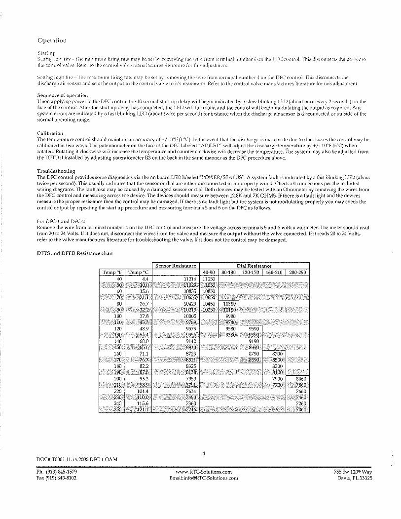
OPCl.flt-iOll
Start up St'!ling )()\\ rire rill' minirnu m firing nile mil)' be set by 1'('1l1o"ing tltv wire from tcrminc11 llumlwr 6 on Ilw 1)1,( - clll1lmL I hi~; dis(o!1iwcb the !XJI\'('f I() OW \:onlrol villv\' I~d('r to 11K control va]vl' O1Mnliactuf('s lit('r;llun' for this atljustnwnt.
Sl'lting high fir!' - rlw l11(lXill11J))l firing l"<ltc' 111ay 1)(' s('1 by removing tlw wire from [crminal l'llunbn .. J on the pre controL This disconnects tl ... dischilJ'G(' ilil' sensor and sets [he uutput to till' control v,llvt' to it's m<1ximuJ)1 Pdcr to the control valve manufac[urrs li(('l'nll1r(' for this ildjuslnwnt
Sequence of operation Upon applying pmver to the DFC control the.10 second start up deby will begin indicated by a slow blinking LED (about once every 2 seconds) on the [are of the controL After the start up delay has completed, the LED will turn solid and the controJ will begin modulating the output as required. Any system errors are indicated by a fasl blinking LED (about twice per second) for iJlstilllce whel1 the discharge air sensor is disconnected or outside of the normal operating range.
Calibration The temperature control should ll"laint,lin an accuracy of -1-/ -3°F (1 "C). In the event that the discharge is inaccurate due to duct losses the conlml may be calibrated in two ways. The potentiometer on [h(! face of thc DFe l"b{Md "ADJUST" will adjust tl10 discharge tcmperature by + /- 10°F (5°C) when rotated. Rotating it clockwise will increase the tempel"i1ture and counter clockwise will decrc,'se the temperature. The system llWy also be adjusted from the DFTD if inst<111ed by adjusting potentiometer R3 on the back in the same manner as the DFC procedure <1bove.
Troubleshooting The DFC control provides some diagnostics via the on board LED labeled "POWER/STATUS". A system fault is indicMed by a fast blinking LED (about twice per second). This usu<111y indicates thut the sensor or dial nre either disconnected or improperly wired. Check all connections per the included wiring diagrams. The fault also may be caused by a damaged sensor or dial. Both devices may be tested wilh an Ohmmeter by removing the wires from the DFC control and measuring across the device. The devices should measure between 12.SK and 7K OHMS. If there is a fault light and the devices me<1sure the proper resistance then the control may be damaged. If there is no foul! light but the system is not modulating properly you may check the control output by repeating the start up procedure and measuring terminals 5 and 6 on the DFC as follows.
For DFC-] and DFC-2 Remove the wire from terminal number 4 on the DFC control and measure the voltage across terminals 5 and 6 with a voltmeter. The meter should read from 20 to 24 Volts. If it does not, disconnect the wires from the volvc and measure the output without the valve connect(~d.1f it reads 20 to 24 Volts, refer to the valve manufactmes literature for troubleshooting the valve. If it does not the control may be damaged.
DITS and DFfD Resistance chart
DOC# T000111.14.2006 DFC-1 O&M
Ph. (919) 845-1579 Fax (919) 845-8102
4
www.RTC-Solutions.com En1(lii:[email protected]
755 Sw 120 lh Way Davie, FL 33325
,)6HNSON CDNTR~LS Product/Technical Bulletin
Issue Date M19
April 4, 2008
A419 Series Electronic Temperature Controls with Display and NEMA 1 or NEMA 4X Watertight Enclosures
The A419 series controls are single-stage, electronic temperature controls with a Single-Pole, Double-Throw (SPOT) output relay. They feature a lockable front-panel touchpad for setup and adjustment, and a Liquid Crystal Display (LCD) for viewing the temperature and status of other functions. A Light-Emitting Diode (LED) indicates the controls' output relay On/Off status. The A419 controls are available in 24 VAC or 120/240 VAC powered models.
The A419 controls have heating and cooling modes, adjustable setpoint and differential, an adjustable anti-short cycle delay, and a temperature offset function. The setpoint range is -30 to 212'F (-34 to 100'C). The controls feature remote sensing capability and interchangeable sensors. The A419 controls are available in either NEMA 1, high-impact plastic enclosure suitable for surface or DIN rail mounting or NEMA 4X watertight, corrosk:JIJ-resistant surface-mount enclosures.
Figure 1: A4i9 Temperature Control with NEMA 1 Enclosure and A99 Temperature Sensor
Features and Benefits
Easy-to-Read Front-Panel Liquid Crystal Display
Wide Temperature Differential Adjustment Range (1 to 30F' or C')
Adjustable Anti-Short Cycle Delay (0 to 12 Minutes in i-Minute Increments)
Switch-Activated Temperature Offset Function
High-Impact, Thermoplastic NEMA 1 or NEMA 4X Watertight, Corrosion-Resistant Enclosures
Lockable Front Panel Touchpad
Low- and Line-Voltage Models
© 2008 Johnson Controls, Inc. Code No. LlT-1251BB
Displays the sensed temperature and control-function status clearly; custom icons on the display indicate Ihe control and system status at a glance
Allows the user to set a precise (1 F' or C') temperature differential from 1 to 30F' or C'; providing a much tighter differential than electromechanical controls
Ensures that the output relay remains off for a user-set time delay, which helps avoid hard starts, nuisance overload outages, and unnecessary equipment wear
Allows the user to shift the cut-in and cutout setpoints by an adjustable offset based on the status of a user-installed, external switch, such as a time clock
Increase application options, allowing surface and snap-fit DIN rail mount, or Watertight surface mount
Allows easy set up and adjustment of the A419 control setpoint, differential, and other functions; a concealed jumper locks the touchpad, and deters unauthorized adjustment of the control settings
Provide options for most refrigeration and HVAC control-voltage applications
1 www.johnsoncontrols.com

Application
IMPORTANT: The A419 Series Temperature Controls are intended to control equipment under normal operating conditions. Where failure or malfunction of an A419 Series Control could lead to an abnormal operating condition that could cause personal injury or damage to the equipment or other property, other devices (limit or safety controls) or systems (alarm or supervisory) intended to warn of or protect against failure or malfunction of the A419 Series Control must be incorporated into and maintained as part of the control system.
The A419 Electronic Temperature Control can be used to control a wide variety of single-stage refrigeration or Heating Ventilating, and Air Conditioning (HVAC) equipment. Typical applications include:
• retail store display freezers and reach-in coolers
• supermarket display cases for produce/meats
• retail store walk-in coolers and freezers
• boiler operating control (used as a thermostat)
• condenser fan cycling or staging
• cooling tower pump and fan control
• space and return air temperature control
FCC Compliance
This device complies with Part 15 of the FCC Rules. Operation is subject to the following two conditions: (1) this device may not cause harmful interference, and (2) this device must accept any interference that may cause undesired operation.
This equipment has been tested and found to comply with the limits for a Class A digital device pursuant to Part 15 of FCC rules. These limits are designed to provide reasonable protection against harmful interference when this equipment is operated in a commercial environment. This equipment generates, uses, and can radiate radio frequency energy and, if not installed and used in accordance with the instruction manual, may cause harmful interference to radio communications. Operation of this equipment in a residential area is likely to cause harmful interference, in which case the user will be required to correct the interference at his or her own expense.
Canadian Compliance Statement
This digital apparatus does not exceed the Class A limits for radio noise emissions from digital apparatus set out in the Radio Interference Regulations of the Canadian Department of Communications.
Dimensions
(i~ .. ~ ~.. I'~-'~~'-?l
r it!+fL~ --'+H' ~ r [-'" --d 'P r i (13)" ,'l~" 5
DIN ~ (127) 2-15/16 Rai!
(75)' " ®. G\J (1~2J t 0 --~ [. ","'~c~ ]
11-9/16 7/16 I' 2-3/B _I
""(40;>- 111) (61)
l Sensor - I \jj, -, - ~f~ II. (520) • 7/8 '.
(6) (22j ~ 7/8 (1/2 in. Trade Size) (22) Conduit Hole
Figure 2: A419 Temperature Control with NEMA 1 Enclosure, Dimensions, in./(mm)
~ GJ'I"J
6-51B (168)
!LiLa
<3.;---i:±l ~) (1155) T""" -~.~,~
t~cc~--:m-=: ~ ... --.~~,." -'-"~""""'''~'~-~---li, 2-13/16 ~I ---------1 I (71)'~_M __ ' __ '~~ - Position the A99 sensor i --j t in the bracket at the bottom of , l the A419 NEMA 4X enclosure.
l . 2-13/16
J~~_T Figure 3: A419 Temperature Control with
NEMA 4X Watertight, Corrosion-resistant, Enclosure, Dimensions, in./(mm)
2 A419 Series Electronic Temperature Controls with Display and NEMA 1 or NEMA 4X Watertight Enclosures ProductlTechnical Bulletin
Figure 4: A419 Temperature Control with NEMA 4X Enclosure and A99 Temperature Sensor
Operation Overview The A419 control's front-panel, LCD, LED, and the A419 control functions are described below. See the Adjustments section for instructions on setting up and adjusting the A419 control.
A419 Control Front-Panel
The front panel of the A419 control has a three-button touch pad and LCD for adjusting control function values, and an LED indicator that displays the On/Off status of the SPOT output relay. See Figure 5.
Temperature Offset Indicator
Temperature Units Indicator
Operating Mode Indicator
liquid Crystal Display
DOWN Arrow Button
UP Arrow Button
Output Relay Status Indicator
LED
Figure 5: A419 Control Front-Panel with Display
Liquid Crystal Display
During normal operation, the LCD displays tile temperature at the sensor, the units of temperature CF or 0c), and an icon indicating if the control is set for Heating (<1) or Cooling (*) mode. The LCD also displays BIN if the Temperature Offset function is activated. See Figure 5.
During control set up or adjustment, the LCD displays the control functions and their values (settings). After 30 seconds of inactivity, the display returns to the sensed-temperature display. See the Adjustments section to adjust the control setting.
Output Relay Status Indicator LED
A green LED on the control's front panel illuminates when the SPOT output relay is energized and the Normally Open (N.O.) contacts are closed. See Figure 5.
A419 Control Definitions
Cut-in is the temperature at which the N.O. contacts on the SPOT output relay close.
Cutout is the temperature at which the N.O contacts on the SPDT output relay open.
A419 Functions Set at the Front-Panel
Setpoint (SP) establishes the temperature value that energizes or de-energizes the output relay, depending on the user selected mode of operation. The control may be set either to cut in or to cut out at Setpoin!. See the Coofing/Heating and Setpoint Modes. The Setpoint range is -30 to 212°F (-34 to 100°G).
If Setpoint mode is Cut-in, Setpoint is the temperature value that closes the N.O. contacts. If Setpoint mode is Cutout, Setpoint is the temperature value that opens the N.O. contacts. See Figure 7 and Figure 8.
Differential (diP) establishes the difference in temperature (in FO or CO) between the cut-in and cutout values. The differential is set relative to Setpoint and may be set from 1 to 30Fo or Co. See Figure 7 and Figure 8.
Anti-Short Cycle Delay (ASci) establishes the minimum time that the N.O. contacts remains open (after reaching cutout) before closing again. The delay overrides any Load Demand and does not allow the N. O. contacts to close until the set time-delay value has elapsed. See Figure 6. When the delay is activated, the LCD altemately flashes the sensor temperature and ASd. The delay may be set for 0 to 12 minutes in 1-minute increments.
A419 Series Electronic Temperature Controls with Display and NEMA 1 or NEMA 4X Watertight Enclosures Product/Technical Bulletin 3

For example, if the an[j.,short cycle delay is set for 7 minutes, the A419 control will not restart the equipment for 7 minutes after the equipment has cut out, even if the cut, in temperature value is reached during the delay, If the temperature reaches the cut,in value during the delay period, the display fiashes between the sensed temperature and ASd, indicating that the next On,cycle is being delayed, After the set delay time has elapsed, the A419 control returns to normal operation, restarts the equiprnent (if cut,in has been reached), ASd stops fiashing, and the LCD reverts to the normal operating display,
Note: Any interruption in supply power to the A419 control activates the anti,short cycle delay,
Time ~ Load Demand _,L Overridden
~LLoadDernarld 1Oill~~1I
..QffJ I ,I L Output Status Anti-short
Cyde Delay
Figure 6: Anti·short Cycle Delay
Sensor Failure Operation (SF) establishes how the A419 control operates the equipment in the event of a sensor or sensor,wiring failure, The A419 control may be set to run the equipment continuously or to shut it down if the sensor or sensor wire fails, When a failure is detected the LCD fiashes SF alternately with OP if the sensor circuit is open, or SF and SH if the sensor circuit is shorted, The control implements a 1,minute delay before initiating a failure response to allow for verification of the failure condition and to avoid nuisance failure indications,
Temperature Units establishes the units of temperature (F' or CO) displayed on the LCD,
Temperature Offset (OFS) establishes the value of setpoint·shift (in FO or CO) applied to Set point (and Differential) when a (user,installed) circuit is closed between the binary input (BIN) and common (COM) terminals, The offset value may be set from 0 to 50F' or Co,
The Temperature Offset function is used to reset the Heating Setpoint to a lower temperature (secondary) setpoint or reset the Cooling Setpoint to a higher temperature (secondary) setpoint by the temperature value set in Temperature Offset
The BIN and COM terminals may be connected to a (user,supplied) external switching device, such as a time clock, that has a set of Single,Pole, Single,Throw (SPST) contacts, Closing a circuit between the BIN and COM terminals activates the Temperature Offset See Wiring,
This function enables the control to alternate between two temperature setpoints based on the position of tile binary input switch, The difference between the primary and secondary setpoints (in F' or CO) is set in the Temperature Offset function (OFS) using the touch pad, See Setting Otller Functions,
Table 1 shows an example of Temperature Offset
Table 1: Temperature Offset Example
Mode of Setpoint Temperature Secondary Operation Offset Value Setpoin!'
Cooling 700 80 780
Heating 700 80 62'
Setpotnt when CirCUit between bmary mput terminals (BIN and COM) is closed
When the circuit is closed between the binary input (BIN) common (COM) terminals, the offset function is enabled and the A419 control cycles on the secondary setpoints, B/N is displayed on the LCD above the 'F or 'C symbol when the offset is enabled, See Figure 5,
A419 Control Functions Set by Jumper Position
For instructions on positioning jumpers, see Positioning the Jumpers in the Adjustments section, Refer to Figure 12 and Figure 13,
Touchpad Lock: The jumper at P5 establishes whether the touchpad is locked or unlocked, Locking the touch pad deters accidental or unauthorized changes to all of the function parameters,
Heating/Cooling Mode is established by positioning the jumper on the top two pins of the P4 jumper. See Figure 13,
Setpoint Mode: Removing or installing the lower jumper at P4 establishes whether Setpoint is the cut,in temperature or cutout temperature, See Figure 13,
Cooling/Heating and Setpoint Modes
The A419 control may be in four operating modes: Cooling/Cut,in, Cooling/Cutout, Heating/Cut-in, and Heating/Cutout Position the jumpers located on the circuit board under the A419 control cover to set the desired mode of operation, See Positioning tile Jumpers,
In Cooling/Cut,in mode the differential is below Setpoint. The output relay energizes and the LED illuminates when the temperature rises to Setpoint When the temperature drops to Setpoint minus the differential value, the relay and LED de,energize,
4 A419 Series Electronic Temperature Controls with Display and NEMA 1 or NEMA 4X Watertight Enclosures ProductlTechnical Bulletin

In Cooling/Cutout. mode the differential is above Setpolnt. The output relay energizes and LED Illuminates when the temperature rises to Setpoint pius the differential value. When the temperature drops to Setpolnt, the relay and LED de-energize.
Temperature (+) Cooling/Cut~out
Cut-in (On)
Cut-out (Off)
setPoint-t--~LS~-<j~=~j~¥z~i-Cut~in
(On)
(-)
Figure 7: Cooling Modes
Cui-out (Off)
When the Heating/Cut-in mode is selected, the differential is above Setpoin!. The output relay energizes and LED indicator illuminates when the temperature drops to Setpoin!. When the temperature rises to Setpoint plus the differential value, the output relay and LED de-energize.
When Heating/Cutout mode is selected, the differential is below Setpoin!. The output relay energizes and LED indicator illuminates when the temperature drops to Setpoint minus the differential value. When the temperature rises to Setpoint, the output relay and LED indicator de-energize.
Temperature (+)
(-)
Heating/Cut-out
Cui-in (On)
Heatjng/CLlt~in
~~c"rc ., .••.. :: .•...•••••••..•.••..•.•........... :, ..... ' ....• ' ....•.. ' ......•. ,' .•..•...•..•.• '-" ....•. :' ••.••• '........... Cut~out "1." (Off)
1.· .... D ...•..... ·.i .... ff •. · .. , .. e.· ..... re ...• ,n ....• t ... ·.' •. " .•.•..•.. I •. 1 Cut~in -",".<".'-".'-". <"
(On) ... ··4·· ..
Figure 8: Heating Modes
Mounting An A419 control has either a standard high .. impact plastiC NEMA 1 or a NEMA 4X corrosion-resistant, wateltight enclosure.
The A419 control is not position sensitive but should be mounted for convenient wiring and adjustment.
Note: When mounting the control to rigid conduit, attach the hub to the conduit before securing the hub to the control enclosure.
The mounting hole pattern of the NEMA 1 enclosure is identical to that of the System 350'" controls, and most models of the A 19 control. The NEMA 1 enclosure may also be mounted on 35 mm DIN rail. See Figure 1 and Figure 2.
The NEMA 4X models may be mounted to fiat vertical surfaces using the four screw holes at the enclosure corners. See Figure 3 and Figure 4. To maintain the watertight and corrosion resistant integrity of the NEMA 4X enclosure, use a conduit fitting rated for the environment in which the control is installed.
An additional (low-voltage) two-wire cable is required to operate the temperature offset function. On NEMA 4X enclosures you must install a suitable liquid-tight fitting in an available knockout to pass the two-wire cable through the enclosure wall.
IMPORTANT: The short-lead A99 sensor, included with A419 NEMA 4X model controls, must be mounted on the bottom of the control in the bracket molded on the NEMA 4X housing. Mounting the sensor on top of the control may reduce the accuracy of the displayed temperature. See Figure 3 and Figure 4 for proper sensor position.
A419 Series Electronic Temperature Controls with Display and NEMA 1 or NEMA 4X Watertight Enclosures ProductlTechnical Bulletin 5

Wiring ... ~.. .. ...... -" ....... "."" .•. " .•. ~ '. --,-,---- -------- --_ .. _--_.-
A WARNING: Risk of Electrical Shock. To avoid the risk of electrical shock, disconnect all power sources to the control before wiring any connections. More than one disconnect may be required to completely de-energize the control and equipment.
IMPORTANT: All wiring must conform to local, national, and regional regulations. Use copper conductors only for all wire connections. Do not exceed the electrical ratings for the A419 control or the equipment it is wired to.
Refer to Figure 9, Figure 10, and Figure 11 for typical examples of wiring an A419 control to the controlled equipment.
Use wire no larger than 12 AWG when connecting to the two lower terminal blocks (TBi and TB2).
Note: Terminal block TB2 is an isolated SPOT switch (dry contacts). The TB2 terminals have no internal electrical connection to the A419 control.
Use wire no larger than 16 AWG when connecting to the upper sensor terminal block (TB3).
Wire insulation rating must be 90°C, minimum.
A99 temperature sensors are not polarity sensitive. Wire the leads to (+) SEN and (-) COM on the sensor terminal block (TB3). See Figure 9, Figure 10, and Figure 11.
Keep the leads between the control and sensor as short as pOSSible/practical in your application. The additional resistance in long sensor leads creates error between the actual temperature and the displayed temperature. Refer to Table 1 when extending sensor leads.
Temperature sensor signals may be affected by electrical interference. When extending sensor cable beyond 50 ft (15.2 m) use a twisted-pair, shielded cable to reduce electrical interference.
If the Temperature Offset function is used, wire a switch (such as a switching time clock) between the binary input terminal (BIN) and the common terminal (COM). See Figure 9, Figure 10, and Figure 11 for terminal strip location.
.(()Ptional) r------------ A419GBF-1 Bln~r~ Input I A419GEF-1
SWitch I 1"-1
~j~li:i;: ~~~:~ II ,
W used) U I 8B1
2::~:: _L __ l/j-I~~f",1 :r Class 2 =--_<-__ -1 24 VAV]
Transformer Load
Figure 9: Wiring the 24 VAC A419 Control
\Optional) 1--- A419ABC.1 Blnarx Input I A419AEC~1 sw~tCh (+)BIN
(-lCOM -(/) (+)SEN,.-----)( TB31'=1' i 'J
Cable ~ [- j Shield
(if used:99 I ~ TB ~ ~ TB~I? j~rD Sensor '" 0 A \! "§i
N " ~
" 120 VAC -- ""- --- -1--Neutral _ ' ___ J120 VAC -~-l Load
Figure 10: Wiring the 120 VAC M19 Control
(Optional)
t I A419ABC-1 A419AEC-1 (+)BIN
(-)COM (+)SEN
'
--
1 TB3lL_ (I "'""~
Cable ~ Shield
(if used)
A99 Sensor
240 L1 VAC L2
, J ~TB2lQ!jjD \"6 116 ~ 0 N ~uz N () ~
()
"" 240VAC
Load
Figure 11: Wiring the 240 VAC A419 Control
6 A419 Series Electronic Temperature Controls with Display and NEMA 1 or NEMA 4X Watertight Enclosures ProductlTechnical Bulletin
Adjustments This section provides instructions for setting up and adjusting the A419 controls using the jumpers and touchpad.
Positioning the Jumpers
The P5 Jumper Pin Block has a single set of jumper pins and is used to lock or unlock the touchpad. The P4 Jumper Pin Block has two sets of jumper pins.
The top set of pins at P4, labeled JUMP1, is used to set the control for Heating or Cooling mode. The bottom set of pins, labeled JUMP2, is used to establish Setpoint at cut-in or at cutout. See Figure 12.
To position a jumper in the Installed position, place the jumper on both pins. To position a jumper in the Removed position, place the jumper on only one pin. (Save the jumper in case it is required in the future.) See Figure 12.
Position the jumpers as follows. Refer to Figure 12, Figure 13, and Table 2.
1. Verify that all power sources to the A419 control have been disconnected.
2. Remove the control's cover by loosening the four captive cover screws.
3. Position the jumpers to set Cooling/Heating, Setpoint, and Touchpad Lock functions.
4. Replace the cover and fasten in place with the four screws.
6. Restore power to the control.
IMPORTANT: Verify that the Cooling/Heating jumper is positioned properly before powering the A419 control, to ensure that the relay operates as intended. See Figure 13 and Table 2.
.Jumper; ; 1:lalle~
(Jumper Positioned on 80th Pins)
• Pins ; BID
;":>1 Removed (Jumper Positioned on One Pin)
Figure 12: Positioning the Jumpers
~ I Touchpad Touchpad
l:Ckc:tnlocked
'1°1101 JUMP1 [DD] v.... IE] JUMP2 ~ o P5 P4
I
I
IIii!RJll Iill'UiJ
Heating Mode Cut·in at Setpoint
IIifl:iD RJTI
Cool i ng Mode Cut-in at Setpoint
miII1ll1 miII1ll1
Heating Mode {Standard}
Cut-out at Setpoint
B:QJ miII1ll1
Cooling Mode
L~:======---J (Standard) .~~_____ Cut-Qut at Setpoint
Figure 13: Jumper Positions and Control Settings
Table 2: Jumper Designations, Jumper Positions and Control Settings
Function Jumper Pins Designation Setting
Jumper Factory Default Setting on Control Position< i (and Jumper Position)
Operating Mode JUMP1 Cooling Removed Cooling Cooling/Heating (Top Pair of Pins on Block P4) Heating Installed (Removed position)
Selpolnl JUMP2 At Cut-in Removed Cut-in (Bottom Pair of Pins on Block P4) At Cut-out Installed (Removed Position)
Locked Removed Unlocked TOllchpad Lock P5-Touchpad Unlock (Installed Position) Unlocked Installed
Note: The touch pad cannot be unlocked without a jumper. Do not discard illlY jumpers in case they are required in the future.
A419 Series Electronic Temperature Controls with Display and NEMA 1 or NEMA 4X Watertight Enclosures ProductiTechnical Bulletin 7

Changing Temperature Units
The A419 control is set at tile factory to display in Fahrenheit temperature units.
frJ7J press the Up and Down buttons y '0 To convert to Celsius units,
V simultaneously. Press them again to return to Fahrenheit units.
Notes: Make sure the Touchpad Lock jumper is in the unlocked (installed) position before adjusting the control. See Figure 13.
Verify that the A419 control is displaying the desired temperature units (FO or CO) before establishing the setpoint value.
Setting the Setpoint
To view and adjust the temperature setpoint, follow these steps and refer to Table 3:
MEN~
MEN~
'~ MEN~
1. Press and hold the MENU button until the display changes to fiashing SP. This will take about 2 seconds.
2. Press the MENU button again. The current set point is displayed.
3. Press the Up or Down button to adjust the setpoint temperature.
4. Press the MENU button to save. The display then returns to the sensor temperature.
Notes: If no entries are made for 30 seconds while programming is in progress, the control reverts to the normal temperature display.
If the MENU button is not pressed after changing the setpoint value, the new value is not saved and the A419 control reverts to the previously saved setpoint value.
Any saved A419 control setting values are non-volatile and remain in the control's memory during power interruptions.
Table 3: Function Ranges and Settings
Function Range Factory Setting
SP: Selpoln! -30 to 212°F 30 (..34 to 100°C) -- -~--.---
d/F: Differential 1 to 30° (F or C) 5 ._----------- --
ASd: Anti-short o to 12 minutes 1 Cycle Delay
OFS: Temperature o to 50° (F or C) 0 Offset .-
0 0 output SF:Sensor Failure de~energjzed 1
Operation 1 0 output energized
Operation at Extremes: If the combination of setpolnt plus or minus the differential falls outside the temperature range (-30 to 212°F [_34° to 100°C]), the A419 control operates as follows:
Cooling/Cut-in: If the control is operating in Cooling/Cut-in mode and setpoint minus differential is less than -30°F, the control switches on at setpoint and off when the temperature drops below -30°F (-34°C).
Heating/Cut-in: If the control is operating in Heating/Cut-in mode and setpoint plus differential is greater than 212°F (1 OooG), the control switches on at setpoint and off when the temperature exceeds 212°F (1000 G).
Cooling/Cutout: If the control is operating in Cooling/Cutout mode and setpoint plus differential is greater than 212°F (1 OO°G), the control switches on when the temperature exceeds 212°F (100 0 G) and off at setpoin!.
Heating/Cutout: If the control is operating in Heating/Cutout mode and setpoint minus differential is less than -30°F (-34°C), the control switches on when the temperature drops below -30°F (-34°C) and off at setpoin!.
8 A419 Series Electronic Temperature Controls with Display and NEMA 1 or NEMA 4X Watertight Enclosures ProducifTechnical Bulletin

Setting Other Functions
To set the Differential (dIF), Anti-short Cycle Delay (ASd), Temperature Offset (OFS), or Sensor Failure (SF) operation, use the method illustrated and outlined below.
Figure 14 illustrates the order of functions shown using the Up or Down button. The Up button accesses functions in the clockwise direction; the Down button accesses functions in the counterclockwise direction. Refer to Table 3 for function ranges and factory settings.
Up Button A.
~ S P
" '(
4 S F
Down Bulton
"
~ A S d A.
Figure 14: Order of the Functions
MEN~
'\:) MEN~
'\:) ME~
1. Press and hold the MENU button until the display changes to flashing SP. This will take about 2 seconds.
2. Press the Up or Down button repeatedly until the desired function is displayed. See Table 3.
3. Press the MENU button to display the function's current value.
4. Press the Up or Down button until the desired value is displayed.
5. Press the MENU button to save the new value. The display then returns to the sensor temperature.
Notes: If no entries are made for 30 seconds while programming is in progress, the control reverts to the normal temperature display.
If the MENU button is not pressed after setting a new value, the new value is not saved and the A419 control reverts to the previously saved value for that function,
Any saved A419 control setting values are non-volatile and remain in the control's memory during power interruptions.
Checkout
Before applying power, make sure installation and wiring connections are according to job specifications. After necessary adjustments and electrical connections have been made, put the system in operation and observe the control for at least three complete operating cycles before leaving the installation.
Troubleshooting
If the control system does not function properly, verify that the unit is wired, configured, and set properly. If the problem persists, use the following procedures to determine the cause of the problem:
1. Check for proper supply voltage to the A419 control.
a. Remove the cover by loosening the four captive cover screws.
A WARNING: Risk of Electrical Shock. High voltages may be present at electrical terminals and other exposed internal metal surfaces. Avoid contact with all metal surfaces on control when cover is removed.
b. Use a reliable AC voltmeter to check the voltage between the COM and 120V or 240V terminals on line voltage models and the two 24V terminals on low-voltage models. Refer to Figure 9, Figure 10, and Figure 11.
c. The voltage must be between: 20 and 30 VAC for 24 volt applications, 102 and 132 VAC for 120 volt applications, 177 and 264 VAC for 208/240 volt applications
Notes: If the voltage reading is within the required range, proceed to Step 2.
If the voltage reading is not within the required range, check the power source and input power wires for problems.
A419 Series Electronic Temperature Controls with Display and NEMA 1 or NEMA 4X Watertight Enclosures ProductiTechnical Bulletin 9
2. Check for proper sensor operation.
Disconnect all power sources to control.
a. Take a temperature reading at the sensor location, using an accurate thermometer.
b. Disconnect the sensor from the control.
c. Use a reliable ohmmeter, to measure the resistance across the two sensor leads while the sensor is at the temperature taken in Step b.
d. Refer to Figure 15 to verify that the measured temperature and resistance conform to established temperature and resistance values.
e. If the measured values conform to the values in Figure 15, proceed to Step 3.
f. If the sensor's measured resistance value is substantially different from the expected value for that temperature, check the sensor wiring. If sensor wiring is okay, replace the sensor.
Temperature (OF) Temperature (oG)
120 260 ~+=+=f=+==1==+=;;:;1== 240 +-§6g . ~~~!.~._.- ............ ~. :;;;~ .. ~-c 100
180 . -r-- . I-- 80
40'=± 2g Y :~g L ..
'1-.+.~.' 40
20
o ·20
-40 500 700 900 110013001500170019002100
Resistance in Ohms
Figure 15: Nominal Temperature vs. Sensor Resistance
3. Check the A419 for proper operation.
a. Perform Troubleshooting Steps 1 and 2 before performing this step.
b. Disconnect the load from the output relay terminals.
c. Ensure that the Touchpad Lock jumper is installed, so that the touch pad is unlocked.
d. Reconnect the sensor leads and supply power to the control.
e. Replace the cover.
f. Check the control settings for proper values.
g. Press and 110Id the IVIENU button until Setpoint appears (occurs in about 2 seconds).
h. Use the Up and Down buttons to change the Setpoint temperature above and below the current sensor temperature until the output relay energizes and de·energizes as shown in Table 4.
If the anti·short cycle delay has a time greater than 0 minutes, the relay will not energize until the timed delay has elapsed.
i. If the output relay does not perform as indicated in Table 4, replace the A419 control.
j. If proper operation of the A419 control is verified, reconnect the load and consult the equipment manufacturer's instructions for troubleshooting the controlled eqUipment.
Table 4: A419 Output Relay Operation
Output Output Relay Setpoint Operating Relay De-energized Mode Mode Energized at. ..
at. .. Setpoint
Cooling plus Setpoint
Cutout differential Setpoint
Heating minus Setpoint differential
Setpoint Cooling Setpolnt minus
Cutwin differential
Heating Setpolnt Setpolnt plus differential
Note: When the relay IS energized, the N.O. contacts are closed and the LED is illuminated.
10 A419 Series Electronic Temperature Controls with Display and NEMA 1 or NEMA 4X Watertight Enclosures ProducUTechnical Bulletin

Fault Codes
A419 controls are programmed to display certain fault codes on the LCD as described in Table 5.
Table 5: Fault Codes Defined
Fault Code Definition i System Status
SF flashing Open temperature Output functions according to sensor or sensor the selected sensor failure alternately with OP wiring mode (SF setting) --_. Shorted temperature SF flashing Output functions according to sensor or sensor the selected sensor failure alternately with SH wiring mode (SF setting) ._-_ .. -
EE Program failure Output is off
Solution
See Troubleshooting section. Cycle power to reset the control.
See Troubleshooting section.
Cycle power to reset the control. --Reset the control by pressing the Menu button. If problems persist, replace the control.
Repairs and Replacement Ordering Information Do not attempt to repair or recalibrate the A419 Control. In case of a defective or improperly functioning control, contact your nearest Authorized Johnson Controls/PENN® Distributor or Sales Representative.
When contacting your Johnson Controls/PENN distributor, have the model number of the control available. This number can be found on the label inside the cover of the control.
Table 6: Ordering Information
Product Code Item Number
A419ABC-1C Line Voltage, NEMA 1 Enclosure
Refer to Table 6 to order controls and accessories.
Description
120 or 240 VAC Supply Voltage: A419 Series Electronic Temperature Control
Range: -30 to 212°F (-34 to 100°C) with Display, A99 Sensor Included
A419AEC-1C Line Voltage, NEMA 4X Enclosure Differential: 1 to 30Fo (1 to 30CO)
Sensor Lead Length: NEMA 1 Models 6-1/2 ft (2 m),
--
A419 Series Electronic Temperature Control with Display, A99 Sensor Included NEMA 4X Models 9 in (0.25 m)
A419GBF-1C 24 VAC, NEMA 1 Enclosure Supply Voltage: 24 VAC, Class 2 A419 Series Electronic Temperature Control Range: ·30 to 212°F (-34 to 100°C) with Display, A99 Sensor Included
A419GEF-1C 24 VAC, NEMA 4X Enclosure Differential: 1 to 30Fo (1 to 30CO)
A419 Series Electronic Temperature Control Sensor Lead Length: NEMA 1 Models 6-1/2 ft (2 m),
with Display, A99 Sensor Included NEMA 4X Models 9 in (0.25 m)
A99BB-200C Replacement Temperature Sensors PTC Sensor with 6-1/2 ft (2 m) Leads A99BA·200C PTC Sensor with 6-1/2 ft (2 m) Shielded Leads A99BB·25C PTC Sensor with 9 in (0.25 m)
BKT287·1R Accessory Mounting Hardware 12 in. (305 mm) long DIN Rail BKT287·2R 36 in. (914 mm) long DIN Rail
PLT344·1R Two End Clamps for 01 N Rail Mounting
CLK350-2C Digital Clock 7-Day Programmable Digital Clock for controlling Temperature Offset Function
WEL 11A·601 R Immersion Well Immersion Well for applying sensor in fluid applications
A419 Series Electronic Temperature Controls with Display and NEMA 1 or NEMA 4X Watertight Enclosures ProductlTechnical Bulletin 11

Technical Specifications
_ .. _ ... __ ._Setpo_in_t ~n9.':... .. .Jl0 to 212°F ( • ..c3_4..cto-'-'1O'-0'-o .... C-'-) ______ _ Differential Range 1 to 30F' (1 to 30CO)
Supply Voltage 24 VAC, 60 Hz, Class 2: A419GBF··1 (NEMA 1 Enclosure Model) A419GEF-1 (NEMA 4X Watertight Enclosure Model)
120 or 240 VAC, 60 Hz: A419ABC-1 (NEMA 1 Enclosure Model) A419AEC-1 (NEMA 4X Watertight Enclosure Model) --_._-----_. -----
Power Consumption 1.8 VA Maximum ---~~~~~~~
Output Relay Contacts 24 VAC Models: A419GBF-1 (NEMA 1 Enclosure) Electrical Ratings
120/240 VAC Models:
A419GEF-1 (NEMA 4X Watertight Enclosure) 100 VA, 30 VAC maximum, Class 2
A419ABC-1 (NEMA 1 Enclosure) A419AEC-1 (NEMA 4X Watertight Enclosure)
Applied Voltage: 120 VAC 208 VAC
Horsepower N.O. (N.C.): 1 (0.25) hp 1 (0.33) hp Full Load Amperes N.O. (N.C.): 16 (5.8) A 9.2 (4.0) A Locked Rotor Amperes N.O. (N.C.): 96 (34.8) A 55.2 (24) A Non·inductive Amperes N.O. (N.C.): 15 (10) A 10 (10) A
Pilot Duty: 125 VA (N.O. contacts)@ 24 to 240 VAC 125 VA (N.C. contacts)@ 120 to 240 VAC
240 VAC
1 (0.5) hp 8.0 (4.9) A 48 (29.4) A 10(10)A
50 VA (N.C. contacts)@24VAC ----~-~-~~~~~~~~~~~~~------.---
Sensor Type A99BB Type PTC Sensor (See Table 6)
Control Ambient Operating: -26 to 140°F (-32 to 60°C) Temperature Shipping: -40 to 185°F (-40 to 85°C)
Ambient Humidity 0 to 95% RH Non-condensing; Maximum Dew Point: 8S<>F (29°C)
Control Material Case and Cover: NEMA 1 High·lmpact Thermoplastic NEMA 4X Watertight, Corrosion· Resistant, High·lmpact Noryl® Thermoplastic
Agency Listings UL: File E27734; CCN's XAPX (US), XAPX7 (Canada) FCC: CFR 47, Part 15. Class A DOC. Class A
The performance specifications are nominal and confonn to acceptable industlY standards. For application at conditions beyond these specifications, contact Application Engineering at 1-800-275-5676. Johnson Controls, Inc. shalf not be liable for damages resulting from misapplication or misuse of its products.
~NSON CONTR~S Controls Group 507 E, Michigan Street P.O, Box 423 Milwaukee, WI 53201
Printed in U.S.A. www.johnsoncontrols.com
12 A419 Series Electronic Temperature Controls with Display and NEMA 1 or NEMA 4X Watertight Enclosures ProducUTechnical Bulletin
Brandon
5.1 Recommended Spare Parts List, Maintenance Summary and Lubrication Summary
EXHIBIT c-t Equipment Record
Equip.
Make
10 No.
Size
Other:
29-MAU01 TITAN AIR
Equip. 29- MAU01 Make TITAN AIR
Frame: No. 254 T TDH Imp, $7.. CFM 15,000 PSI 0.0451
ELECTRICAL NAMEPLATE DATA
IDNo.
Duly Frame No. 2;;",4::..TjcH",P-;:c_1",5'-_1i=:-'-=_--f;:;;oi;;:--'-""'--j,H",Z=",6,,0 __ Code Ins. CI. C Amh. Temp. Rise 79 F Rating
PH RPM 1750 ISF
-_.----- --~~--~~-----Other:
15605
2011
SPARE PARTS PROVIDED PER CO=N=T=R~A~C=T========:::r=:g;;~L=
. __ ~~~_ 3 _______________ P_'_rt_N_'m_e _________ .:------I--~:~::~y---------1
RECOMMENDED SPARE PARTS Part No. Part Name
~--- -
SEE ATIACHED -
- -(Jun 1990, ReVIsed Oct 2001, Rev/sed Nov 200i') Copyrigh! 1991 HDR Engineering, Inc.
007-9 I 090047-0DJ MSS - MASTER SPECIFICATION SYSTEM MASTER SPECIFICATION SECTION
SUBMIHALS 01340 - 3
--- Quantlly - --
-

RECOMMENDED S»ARE PARTS LIST
Equipment No: 29-MAUOl
Description Part Number Cost 0/1/12)
P-1 PRESSURE SWITCH DDP-109-187 $147.00 EA
FS-1 FIREYE MEC120 $548.00 EA
MERT4 $218.00 EA
MEP537 $865.00 EA
TS-1 TEMP DISCHARGE RTC DFTS w/DAT-12 $225.00 EA SENSOR
TC-1 TEMP CONTROLLER RTC DFC-1 $281.00 EA
BELT 5VX-580 $75.00 EA

EXHIBITC2 Equipment Record
Recommended Maintenance Summary ----------~~~~~.------ ----------------------
Equip!llGnt D8sCfiptlOn Project Equip. Tag No(s),
Make Up Air Unit 29· MAUOl .-.. -_._.- I ---~ .... - - -.
RECOMMENDED eREAI~·IN MAINTENANCE (FIRST OIL CHANGES, ETC.) D ~,~,-,-~,---,-----, ~-
.~ --Re-tension belts
. __ ._._--"._._---
... --""--.. -~--. -,-.-.. ~-~--. -
-_. -
-.
RECOMMENDED PREVENTIVE MAINTENANCE D
Blower Bearings Lubrication
Check Belt Tension and Condition
Check Filters
Check Burner Operation - -.-.. --.-~- -------~---------.------------~,
Motor Bearings Lubrication --_.-.. _'.--, ------.-.-
----_.
D. Dally W"'Weekly M I:l Monthly Q f:I Quarterly s ~ Semiannual (JUIl 19S0; Revised Oct 2001, Revised Nov 2007) COPyright 1991 HDR Engineering, Inc.
007-91090047-003 MSS - MASTER SPECIFICATION SYSTEM MASTER SPECIFlCATION SECTION·
SUBMITTALS 01340·4
-------~.
-
A::. Annual
. --
INITIAL COMPLETION' FOLLOWING START-UP
W M Q S A Hours -~ ~---
I--24
. ------
-
PM TASK INTERVAL'
W M Q S A Hours
X
X -
X
-- X
X
-.-
HourS = Run Tlm& Interval
EXHIBIT C3
r;c-;:-:==;--;;~",,",~---------------'--'--'--'~"~------'--'"
Lub,icant Point BEARINGS -cc::-c-,'---:-= _ -'-'--' -.-.~.-~ ~ ·"S· ISO -"." •. ~ '1' ~ExXonM~Gr~~:~-----'-~'-w ·'_··_P~'I~~:;i~~·~~'"" __ ·' _____ · __ I-_:..:Ao:G::.M,_A:..:il,-__ __.-'::.A::.E:.:'c.' __ + ________ _ ~, - ~-~-----~ ~ 2 TE Polystar .-.--+------f--------j
j 1-,::-1' 1-.. __ .C_h<_§_y._[QQ_~_-_. _-.-_ .. _-_. __ '-t--_.",,_.2E_R_1 -.===----~------.----.--+.------+\-----=.,,=. -=,,=3=:,-.:..-.:..=-.:..-.:..==~_·-=~:-I;
. __ .=::-:"~=-----.------'-------------1--- I ~~ca~.:.0.~ .. _.__________ -,--==-;;---,-"'Z:;:-;;--,--~;;_--
ill '1 _____ M_an_U~~~!~~.~. ___ ~ ___ . __ ~~ __ ."' __ p_I'c:9.~ _________ _+--'-A;.:;G"MA::..:.#'---~.-"'S"A::E::.#-__j-_...:::IS",O,--_ .. __
~ 1-2+---------------------+--------------------~----------4-------1--------1"
~ r3~----------~------------_r-----+----·-t-----3 4
Manufacturer Product AGMA # SAE # ISO r.--~~~~---+---~~~--~-~~~-+_~~-I·-·-~--
~ 1 ?:.' "2 1" -~ 3 is 3 4
--------~---------I----_+--·----r----
r:-I.--------4---------~---+_--_T-----.
5
Lubrir.ant Point FT""-'-='--==:-:----,-----=:::--::-·-.. --,----;:;:;:;:-:;;----r--~:___,__~;____ L_-r ___ ...::M"a:::n::uf:::a::ct::":.::re:...r ______ + _____ ..:P:c'::.O~dU~O::t__ AGMA.# 1 ____ :::S"A:;:E.;;.#_--jr-_..::ctS"o'__ __ r ·---'"--'-'==--"--.·-r
I-::-t-.----------:-I:-I---------+-.--+---+-.-----I-::-t---------I-----·-·---.. -------·-----+-----+-----+---
·--------t---·------I-----·-·----·---j----H-----------j~.-------------I_--------I--.--------------
I=F'-'-··-.. ----·---c=::------r-----;:;=-:-------,-~c;;;-;;--·-·- --=:;---.--~-M9nllfaC~!~~ _____ . ____ _+------'Pc.fod="c.ot'--------I_-'-A"GcMA.-#_ ... _I-__ ::SA:..:;::E.::" _ _1---""'IS"'O'-----
ID 1 [5 1-:-f----------·---··------------+---------1-----+---··---_ 2
B r3!--------------------+--------------------~--------_r------_:_I---------Jj 1-=-+-------.. --·--1----------1--·----+-----1--·----· .. · 3 ~_I__-------------------I__--.... ---_-.. -.----+-----......;I__-----_
5 .-.----
~~l~-----__ -----~---------------~---------L-------L-------Lubricant Pdnt
Product AG~ .. ~# __ _1---"'S'-A=f..::#--_1----.::IS=O~--1_,-----'M::;a"n"'u:;;fa:.::c:::lu:..:fC:;.f----_ ID 1 [5 1~i_-----------------------r---·-·----------------·--4--------_t--------t-----.. --.---1" 2
.g :3
.0 3 4
5 ~199~1L.ER~ev~lS~e~d~O"c.t'20ruO~1'.MR~ev~ls~od~N~O'V~2~O~07")--L-----------------L..--------~L------~------Copyright 1991 HDR Engineering, Inc.
007-91090047-003 MSS .. MASTER SPECIFICATION SYSTEM MASTER SPECIFICATION SECTION
SUBMITTALS 01340-5

5.2 Unit Specifications
Title Clinton 29 WTP .. MAU-01 Sales FZep. J.J. MOlganCo
Oil'! SIN 13569 Model TA - 218 NG HRD Date 3/17/11
CFM ____ 12,DOQ_ ESP _12t5___ Temperature Rise (OF) 79 ._... __
BTU/Hr Min. ____ 5_2_,1.~0 ... _____ Max. ______ l,~Q~!_§O_O____ .__ __
He a t Me diu m __ [)i!Elc;t:Eir.ElcJ.J'l.Q.~.Z"::J# I n le_tF'r:Elssu~El.@~!~Q~_gE!j,_~:rj):A ~§.~ G asTrilir1._
Cool Medium: None
Function __ ,l\ir_f\I1§1~e-Up Unit . ______________ ._ .. _______________ . Outdoor Mounted
Unit FLA 18.7 Voltage ~§O V, 3ph., 60 Hz.____ __ Motor HP: ~_ Motor FLA ..1LL
OPTIONAL EQUIPMENT INCLUDED
• Fresh Air Intake Hood wi Birdscreen'
Type: 45 Degree
• Outside Air Filter Section'
Type: 2 in. Pleated, 30% Efficient
• Intake Damper & Actuator*
• Curb Kit'
Type: Flat - 18" High
Roof Type: Built-Up
• Interior & Exterior Unit Heresite Coating
• Interior & Exterior Accessory Heresite Coating
• Interior Unit liner
• Insulated Unit
• Casing & Accessories Painted Standard Color
OPTIONAL CONTROLS INCLUDED
• low Temperature Safety
• Low Fire Start • High Gas Pressure Switch
• NEMA 4X Remote Panel
• Motorized Valves on Valve Train
• Door Interlocked Fused Unit Disconnect
• Control Relay (Function as Follows)
Energized Wilen Airflow Is Proven
Contacts Start Exhaust Fan (By Others)
• Interrupted Ignition
• ETl label
* Denotes items shipped loose for field installation. See catalog or submittal for standard items.
9 02 AM 311712011 13569 Spec2004 xis Kittelson
rev. 01-04 SUBMITTAL USE ONL Y - DO NOT USE FOR CONSTRUCTION PURPOSES
SINGLE BLOWER UNITS - DOWN DISCHARGE - CHANNEl OR CURB MOUNT -Item MODEL A B C D __ E F G H J .....-K
T!NJ29 62 38 28 4 --+,;-- "16-25- ',AIJ 2 4 16
TA-1 'Ill: FJj9- 46 30 7 8 18 18 ~ 20 2 TA-115 O!l.. r--..,Q4 32 8 8 24 ~ 40 _,,.--'-28 2 TA-118 78 1'-69'" 1'--36 10 10 24 24~ ~48 32 2 TA-120 85 66" '<40"- 8 8 /32- -32 48 42 2 TA-122 95 78 48" ''of:!--. k1?/ 36 36 60 44 2 TA-125 95 78 48 ~( ~ 36 36 60 44 2 -TA-127 100 90 j)fY 12 ""'kI ~ 44 72 60 2.5 TA-130 100 gg,... 66 12 14 . 44 ""4<l 72 60 2.5 TA-133 11Jk ~oo 78 14 18 '''BQ 48 ~ 72 2.5 TA-136 -:frO 100 78 14 18 60" '. 48 96 .......:z.2 2.5
.......
TWIN BLOWER UNITS - DOWN DISCHARGE - CHANNEL OR CURB MOUNT UP TO TA-230
* Units are built in two sections. F,G, H & J are accessory dimensions. D,E & K are accessory locations. Intake and discharge accessories may be larger than openings on unit. All dimensions subject to manufacturing tolerances and subject to change, verify with factory before using for any construction purposes. INDOOR hanging units must utilize a bottom cradle (by others).
2-8
rev. SUBMITTAL USE ONL Y" DO NOT USE FOR CONSTRUCTION PURPOSES
C --'71""----I~~' .
t t B
B
-1 -1 o HOOD I FILTER COMBO o FULL TURN DOWN HOOD
1----A " ............. :---i 12"
litem Inn~1 ABCABCAB~ABCDABCABlc AB i\&TA -lU8 20 2UI22 :!tj'20 412512024301251455512512025202 1.20 "-IV'"' 25128130 25,28 41 25128! 3230 145 63125128128 20 2 "'~~:rl A & TA -1 125 127 32 25 49 32 125 !9 17 148 61 132 25' 3<1. ~-2
TA-112 AR 32TS;!" 32 32 45 32 32 ;6 4~ 7: ;2..~-32 32 32! 28 rA&TA"-115 ·0 !28 13 i"IG. 148 10 5Q ~O 0 28'32 TA-115 A 0 32 3 14C r4l>- 1050L70 3232 12 rA&TA~I-1188'32 i3 143 18"::f! 50 778 321328 12
f-_r,T~A-'1-;;.11:8",A"'-'-_"_I_:;;;-J.:,;41:2;;...r.::4CI+4':BH' Ill" 4 rs;l.. 50 187148 4232 8 2 fA-120 8 42 44 18 42 I 4 153 "$.L97 148 I 42 8 rA-122 125 60 4: 41: 144 ·60 4414: 165 56 101''6Q.44 . 44 rA-127 130 -'i'Z161 158 160 81 72160 64 77 6E 165 1135 7216( 6C '2 ~-1 967:160 172na967;'610 701579E7246 ~ 16 """~15 '212 na 13 73 72 • 28 '2
">< TA-218 0 na 13 13 '7 80 32 30
TA-2 ITA-227
I 4 14 96 ;;!:::; 41:';#;:2H;,;;"6;;r.;'2;-j 149 120 ~ 12C 44 na
na 15: 151 1O
157 52 2 128 5: 114' 160 ! 58 144 13514460146114416C
70 157 180 72 I 46 '=1--=+ 72~2~~C-l 118C 72 60 7> ~ Ina 1lliJ '2 72 185
T"" ~ 72 60 17: Ina 192 '2 76 197 70 157 21§134 60 I 84 I na 1216 84 88 221 39 75
All dimensions subject to manufacturing tolerances and subject to change, verify with factory before using for any construction purposes. Intake dampers are designed to be mounted Indoors, if outdoor mounting is required, you must order a weather hood for damper actuator(s), damper may be built into hood and or filter section. Intake dampers on TA-230 - 242 have 2 actuators, all accessories for these units are built in 2 sections, some field assembly may be required. All intake hoods feature bird screen. Mushroom hoods can be flange mounted, consult factory. 1" flange is typical for all components listed above. Intake accessories may be larger than intake opening. Return air filter sections will be larger than return air opening.
8-1
SUBMITTAL USE ONL Y - DO NOT USE FOR CONSTRUCTION PURPOSES
HORIZONTAL UNITS WITH DOWN DISCHARGE BLOWER(S) Item MODEL A B C 0 E F G
TAM-109 54.5 33.5 26.75 2.25 2.25 16 16 , TAM-112 63.5 41.5 31.25 4.25 4.25 18 18
ITAM,115 68.5 45.5 33.75 6.25 6.25 1/20 20 --TAM-1't&-... 74.5 51.5 36.75 7.25 J.!l5 24 24 TA-109 ~8.5 34.5 28.75 .])Y .75 16 16 TA-112 65:5... 42.5 32.Z;;- 3.75 4.75 18 18 TA-115 65.5 .51hli. .22.25 4.75 4.75 24 24 TA-118 74.5 I~ ~5 6.75 6.75 24 24 TA-120 8j.$ 62.5 40.25' "<1..75 4.75 32 32 TA-122 & 1:;,5- 91.5 74.5 42.25 8.-m- 8.75 36 36 TA-12Z-KJ30 96.5 86.5 39.75 8.75 1~ 44 44 lJl.-'f33 & 136 106.5 96.5 43.75 10.75 14.75 "'6Q.. 48
/'. ITA~215 65.5 88.5 32.25 4.75 4.75 56 1'24 :;><.., TA-218 74.5 98.5 36.75 4.75 6.75 64. 24 T~ 81.5 114.5 40.25 4.75 7.l0 CZ . j~
TA-225 .41. . 5 90 36 TA-227 43. .75 100 42 T~~u 96.5 154.5 38.25 8.75 10.75 lUll'" 44
J~E B F Pitched Curb Selection: n ...
t
.'-' ... ., ...• , '." ,"-
r----------, I DISCHARGE I I (SUPPLY AIR (SA)) I I I L .• ________ J~ . Service
Side A
1 ~
Support Brace rc-----) Extra Support
Braces
PLAN VIEW on TwlnUnlts
'"v •.. " .-. .- . - -,~
1 1/2"-1 /'<-
r 18" I
Inside wall
Typical curb for built up roof.
wood typ, nailer HOLE LOCATION
L MEASUREMENTS TAKEN FROM INSIDE WALL OF CURB
--l31/2"~ SIDE VIEW DETAil
., --
Curb Pitch Direction
CUrb Pitch r-I Direction L-...J
Service Side
....... .--------i ROOf ¢Urb pltcl1ed:
--""--Rooflypa:
Curbs are shipped unassembled and uninsulated. F & G are recommended ductwork dimensions. Openings on unit may be smaller than recommended duct size. Hole locations for duct work taken from inside wall of curb. Construction methods may change for taller & larger cuibs. All dimensions subject to manufacturing tolerances and subject to change, verify with factory before using for any construction purposes. Standard curb height is 18".
8-3
Mon", BUa~j;C ~f:;~ '~'jSC, '~~~: '~i,~~~ InLike Disc, C~~b ~ - 19 600 600 1100 30' 55 45 45 10V TA - H-2.. 620 620 1',20 30 5 45 45 ---r05 TA - 115 "-RJ5 775 50 35 6 110 -51J 105 TA-118 990 c- 020 QQ 45 7 .J.:kY' 5 TA-1Z0 130 ~250 80 l1JY 125 TA -122 1720 780 1lJ5Q 100 -135 150 71 10 TA-12 1770 1830 270e >11lD 135 150 70 200 TA-12 2450 2550 Wl'i 10 235 100 250 T,l-13 ~ ~ 150 0 lJ"o... 235 T ,-13 )00 ooe 10 0 ZlQ., T/, -13 100 4100 200 250 260-----
_Tl."..£11j 16, )50 2675 110 230 220 11 ,- 218 1700 2025 2850 135 230 220 1
TA -~220 1950 225000 30 250 130 ;JOO , - 3290 60 105 ~ 400 l - ~7 115e 25 0 155 450 l - 230 120e 4500 u..-~ ,5 125 200 500 l - 233 3500 7100 490 300 --
TA - 23( 7100 Ai<Itl 8100 525 550 Q 300 -----TA - 23f ..7eII\"f 8200 8700 690 ~ 650 "'35\j.. --
CA ,2lr R100 _8-'1:00 920C 890 ~ 850 'i'iO ::::;,.
"AR " RECIRC. UNITS AND ACCESSORIES
15 1310 30 55 45 ./ iO l'- i~ 1350 35 60 110 /'
,- 1, '1' 20 1600 45 75 110 ,0 , - 120 170l}-... [)§{J 2500 80 l' 125 60 150
TA -122 2150 "S300 ~ 100 1, 5ff" 70 TA - 12~ 2200 2351 ~ 00 ./ 50 7e
200
l - 13 2800 Joe 185Q. '50,~ 235 l' ,- 13 3250 loe 1200 ,200,):;: 250 260 1 l - 136 3550 3600 00 261( '250 260 125 300
TA - 21 2000 2' 50 010"'" 230--- 220 00 160 ,- 21 2030 135 ..NQ.. "220 11 , - 2; 2, 130 215"'" 250--
a
,- 2: ,34,)0 19' 160 255 'S05 ,,1, ,- 3930 615e 225 300 40~ '1, \ - 4600 ~ 310 '-200 500
TA - 525 3UR --,- 2 ~ _525 300 ,---l - 239_ QQ. 690 350 ~ l - ;14'2 8600 890 ,5 350 550 ---
ALL WEIGHTS ARE ESTIMATES, AND WILL VARY WITH DIFFERENT GAS TRAINS, MOTOR HP, AND SPECIAL ACCESSORIES,
USE FOR FREIGHT ESTIMATION ONL Y
1·11
!', I .... 'Ifu, .. £' Ii ',('i .:.,.,t;:"'-5 ["<iU ':':;;'1"<.<~t::.;.,....t f 'y, ,\.~~'\.F\':"'" ,:"f-;;J"Zt0J -v'l ! i"~:;:i"';"'lii"~~?ii'~"-=iZ'~,;::~~",;:-~"",:"";;'\r'"-"-u--;";"-"r ;::;::E:-;:~:;~:~;;;-E-:;-';"C'::'-E":"[~;-E:"[::;-r"p-;;'~:--:;'~L-'lc, :::~"---"~i
MRIN CO ~~~ltJr'~~':::=~=M';d~,~A718NcHRD:=~~-::=:~~------= -~~' ;}2~ f\bbr. Specification _____ , , __ ~. ~~De~cription ., l/,bbr DesClip~~_, __ ::=Il DM-1 13elimo NFI3UP-S us 1 Intake Damper Motor FS-1 F'il"eyeMEC120D, MERT4, MEP537 1 Flal11e Safeguard FU-l Touch Safe r3lock, Class J TO: 30 Amp 3 Main F"uses FU-26QOVAC - Class CC Til11e Delay 1.5 Amp 2 Trans, Primary Fuses FU-3 250VAC - MidgettYpe3f1n1p 1 Control Circuit Fuse LTS,1 ,Antunes Controls 8563140061 wi Cover 1 Low Tel11perature Safety MT-1seernoJ()r"pe_csonrightsieieofpage" 1 Blower Motor P, 191(3~(3la_n(j_DgP:109, 187(02"1'095") Air Flow Switch P-2 ,See Gas Train/Burner Specs, na; Low Gas Pressure Sw, P-3 T§ie9a_sTrCliniSurner§pe~ na .. f1.ighc;a"Pressure Sw, R:2 """" Idecl3}1§:9L-AJ1Q,_§R§:QtiEl ' 1 ,Exhaust Interlock Relay ST-1 !Eaton XTCE025C10A, XTOE020CCS 11iStarter,Ol:-
~~:~I~~~~o~~~~i~~~:c~~~~'><£fo)(I~~m=~TI~~~t:~%~~~~e~(3~biich A 1287 ;~~~~~~~S __ _ i 1 SW -5 [Cariing swiictl111=16=73· .. ··········TlJBI~~~i§~:;;ticeSwiLCh=I-sW,6T9~rj;~giwitch 1l.1 .. :16:?}~=~___ __ U_lEl."-,-~~r Service SI'li!cJ:1 MOTOR & BLOWER T-5jJoh t1son Controls A419ABC_:1C; ____ L~JBooI129ve-'~~,,_~!"'~___ & DRIVE ASSEMBLY TC-1 iRTC DFC,1 wi Filter i 1 ITemperature Controller Motor: 15 hp, 460 V 3ph, ODP TD=l]RTC DFTD (40'F, 90'F)_~=:::}Jg-,~charg:ejE)rrl£l §_E)~~.t0r 17.7 fla, 254T frame TL-1 IHoneywel1 L4008E1255 i 1 ,High Temperature Limit 1750 r rn EM2513T) TR-1 'Micron B250BTZ13RB---rnControl Transform"er---"----- Blower: Lau A18-18A i 2 TR-2--1 Honeywell 0652B1 006- --------"T1ilgnition TranSfOrmer----"- FiB-Searings: VPB,223,AH . T3' ~~:~:::I~~~~~::: ~~f§~~::=::=-r::::--rm~0~~ ~~:~::~~~:~ - .. M-~~;eSh~~~~:, JVS 150-211
TS-1-1 RTC[lFTS wi OAT, 12"---~"-"--"-"-TTI Discharge Tel11p, Sensor Turns Open:~"_1 12 __ " __ \Tl---TSeeGaS:lrai~/l3urner-s-pecsT:-----:na1 Pilot-Shutoff Valve---- Blower Sheave 2/5V975SK ... IT 1)='2 i§!3e_Ga:;Ir",in/Burne~PElC:~: ............... -TnaiMain Safety Si1-Utoffl /"alve-- RPM: 908 \(=3 !See Gas Train/Burner Specs, .. ;n8lVentVahie-"~"-"-"---"----"-- Bushing: SK x 1 7/16"
V,:4 ·WeeGas ··1'ra; n/BurnerSpecsll-aiAli;;S-~i~i)l"h_utoff\lalv~_... Belis§'Z5(~S:'BQ=::::-: V-51§~",9~s}raTniBill~ir:§!l~c:snal Mod ulating Gas Valve. fC;;;;o;;;;u;:.ip;:,;l:,;;in:il;. ________ "'1 n
9-""
:2
VM"1 Belirno LMCB24,SR-T!iTMod-:Gas Va-iveActuator SCHEMATIC SYMBOLS ..... -,,-.'''~ _ ..... _- -,-,------------_.- ... _._. " ........ --- .---_.-.. _ .. __ ..•. - -.-,--'"', .--~, .. "
.~ .. L
i ............ _ .. __ .. _ .. __ .. . , .J J.
"I "" _"'_ I I - ..... --.. --" .... ~-. -·----I--i t::!!!l
@ Unit Control Panel Terrninal
Remote Panel Terl11inal
......-----Cl-- ..... .....- -:::::=::: 0 Cornponent Terminal
Terl11inal in Others Panel " 0 .. ___ . _________ ,,_.. _~ __ l_ _ _ __ ~~ .. ~.~ ___ ~ ___ .. __ . _____ ~ __
......... --~!-"---~~: "Wiring to Remote (Others)
Field Wiring (by Others)
-lI!m- Jumper Wire
-.- Wire Connection
* Terminal no.'s 1 to 99 designate 120 volt; no.'s 100+ designate low volt
wiring (run in shielded cable). Ground unit according to NEe.
CAUTION: Open disconnect switch before servicing unit.
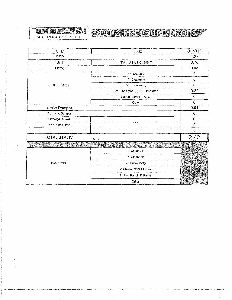
O.A. Filter(s)
R.A Filters
Other

--r- .--Model Quote No. Ext. Static Titan Accessory Static
TA-218 NG HRD 021810AB29 1.25" W.c. 0.41" W.c.
Performance Curve
3.0 SP
2 A18·18A
160W CFM,2,4Z i.W_9, 2(;13 OYj!Um;n~ooe RPM
10 60 BliP, ~3.e'h 56 standard P"rlorm.M<>
2,0
1,0
0,0 o 5000 10000 15000 20000 25000 30000 35000 40000
. "" .. ".· ... ! •. ,j· ... ' ... VM.U.""""·,"',.,. .. , .• " ''',
Sound Data OCTAVE BAND No. 1 2 3 4 5 6 7 OCT. CENTRE FRQCY (Hz) 63 125 250 500 1000 2000 4000 SPECIFIC SWL (dB) 50 50 40 33 33 10LOG Q+20LOG T'p.(dB) 51 51 51 51 51 BFI (dB) 0 0 0 0 2 OFF-PEAK CORR. (dB) 1 1 1 1 1 TOTAL FAN SWL (dB) 102 102 92 85 87
Comments: FAN TYPE IS FORWARD CURVED 1. The A-weighted SWL in-duct is 92 dB. 2. At a distance of 10 ft. from the fan 74 dBA can be expected with an open inlet or outlet and 59 dBA when the inlet and outlet are ducted. These values have been accessed using a model of sound propagation from a point source into the hemispheric free field (see AMCA 303-79).
28 51 0 1
80
THE dBA VALUES PROVIDED ARE TO BE USED FOR REFERENCE ONLY. CALCULATION OF dBA VALUES COVER MAnERS OF SYSTEM DESIGN AND THE FAN MANUFACTURER HAS NO WAY OF KNOWING THE DETAILS OF EACH SYSTEM. THIS CONSTITUTES AN EXCEPTION TO ANY SPECIFICATION OR GUARANTEE REQUIRING A dBA VALUE OR SOUND DATA IN ANY OTHER FORM THAN SOUND POWER LEVEL RATINGS (SWL). 3. The off-peak correction has been based on a static efficiency ratio of 0.917 ( 54 % I 59 %)
23 51 0 1
75
8 8000
18 51 0 1
70

5.3 Gas train/ Burner Specs.
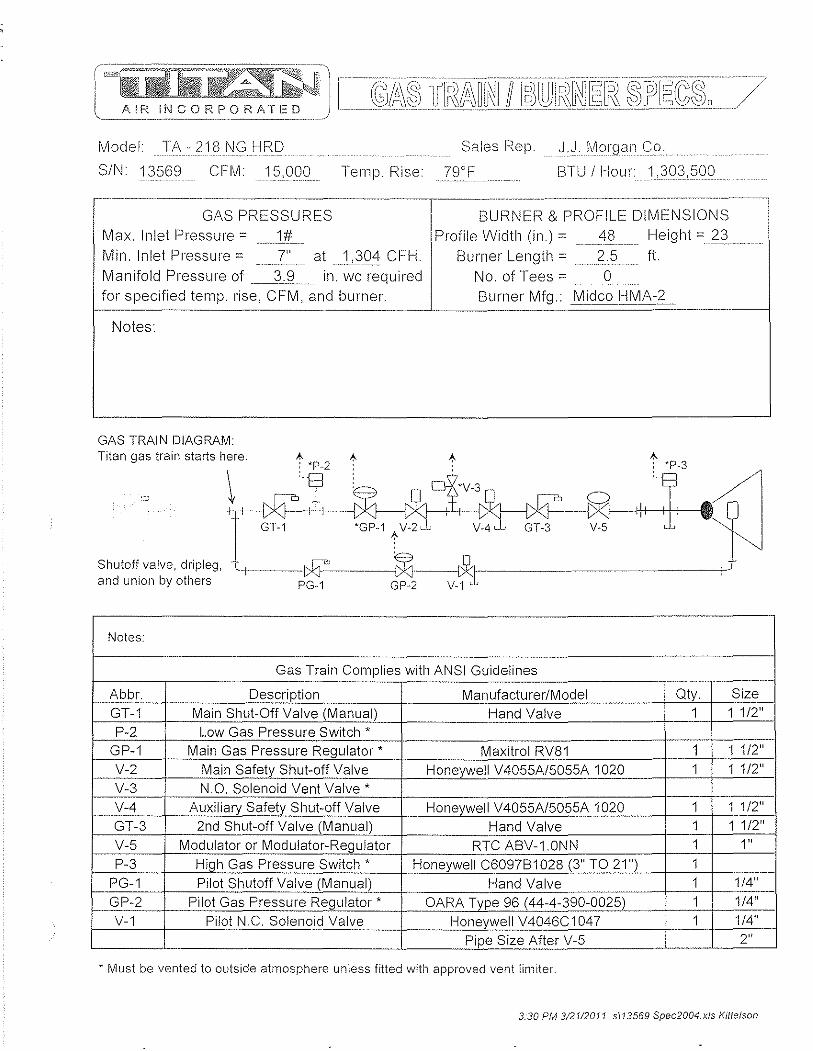
Model TA-218NGHRD Sales Rep J.J. Morgan Co.
SIN. 13569 CFM15,OOO Temp Rise 79°F 1.3TU / HOLir 1,303,500
.. -.. ------.. ~-... -~~-.. -..... ------.----.---... - .............. -.. - ..... -........... __ ..... _-_ .. ..
GAS PRESSURES BURNER & PROFILE DIMENSIONS
Max. Inlet Pressure" 1# .... -.~.---------
Min. Inlet Pressure" 7" at _J,,30<1: CFH.
Profile Width (in.) = 48
Burner Length = 2.5 Height "n . It.
Manifold Pressure of ... .....3~~ .... in. wc required No. of Tees =_ ..... g ...... for specified temp. rise, CFM, and burner. Burner Mfg .• Mjdco HMA-~_
.. ~-----~-----------------~
GAS TRAIN DIAGRAM: Titan gas train starts here """ "
hh~f E? II oE:",Q~ ,I;' -6'l-~' j G1-1 ~ ;;:fz;;:r- V-5 ~
Shutoff valve, dripleg, 'I .t*}..'....... .... ~ .. --"y-" _ ... ___ .. _____ ~ and union by others PG.1 GP-2 v_~x.:L
.-
Notes:
Gas Train Complies with ANSI Guidelines ..
Abbr. Description Manufacturer/Model Qty. Size GT .. 1 Main Shut-Off Valve (Manual) Hand Valve 1 1 1/2"
P-2 Low Gas Pressure Switch * GP-1 Main Gas Pressure Regulator * Maxitrol RV81 1 1 1/2" V-2 Main Safety Shut-off Valve Honeywell V4055A/5055A 1020 1 1 1/2"
V-3 N.O. Solenoid Vent Valve * V-4 Auxiliary Safety Shut-off Valve Honeywell V4055A/5055A 1020 1 1 1/2" GT-3 2nd Shut-off Valve (Manual) Hand Valve 1 1 1/2"
V-5 Modulator or Modulator-Regulator RTC ABV-1.0NN 1 1"
P-3 High Gas Pressure Switch * Honeywell C6097B1028 (3" TO 21") 1
PG-1 _ .. Pilot Shutoff Valve (Manual) Hand Valve 1 1/4"
GP-2 Pilot Gas Pressure Regulator * OARA Type 96 (44-4-390-0025) 1 1/4"
V-1 Pilot N.C. Solenoid Valve Honeywell V4046C1047 1 1/4"
Pipe Size After V-5 2"
* Must be vented to outside atmosphere unless fitted with approved vent limiter.
3:30 PM 3/2112011 sl13569 Spec2004.xls Kittelson
5.4 Sequence of Operations/ Temperature Control

AIR II,CORPORATED
AIR MAKE-UP UNIT WITH RTC SOLUTIONS DISCHARGE TEMPERA TURE CONTROL
SUMMER MODE 1. Summer/Off/Winter (S.O.W.) switch in summer position. 2. Damper (optional discharge or intake) will open. 3. Damper interlock switch closes, energizing supply fan motor starter.
WINTER MODE 1. S.O.W. switch in winter position. 2. Damper (optional intake or discharge) will open. 3. Damper interlock switch closes, energizing supply fan motor starter. 4. Low temperature safety L TS-1 (optional) will shut unit down after 3 minutes of
operation with discharge air temperature below its set point. 5. ST-1 contact closes supplying power to burner enabling circuit. 6. Air flow switch (P-1) makes when pressure drop across burner profile is sensed, 7, Air flow switch (P-1A) will open if air flow goes above design parameters, 8, Inlet duct-stat (T-1) (optional) makes at outside temperatures below its set point. 9, High temperature limit (TL-1) is a normally closed safety switch and will trip when
discharge temperatures exceed its set point (this is a manual reset switch), 10, High (P-3) and low (P-2) gas pressure switches (optional) (P-3 will be installed on
all units with stated supply gas pressure of 14" w,c, or higher) to protect against abnormal gas pressure and are manual reset safety switches,
11, Pre-purge (built into FS-1) clears cabinet of combustible gases before ignition, 12, Flame safeguard relay (FS-1) monitors ignition and burn process, If abnormal
conditions exist, control will shut down unit. FS-1 is a manual reset control. 13. Discharge temperature is regulated by a sensor (TS-1) in the discharge of the unit
and selected at a remote point (TO-i), 14. Room override stat (T-5) on a call for heat will override the discharge temperature
setting up to 25" F, 15, When unit is shut off there is a fifteen second post purge, The blower will operate
for fifteen seconds after S,O,W switch is placed in the off position,
In all modes, exhaust fans interlocked with unit or building relief must be provided by others to ensure proper ventilation,
Page 1 01 1 amul1c or doc
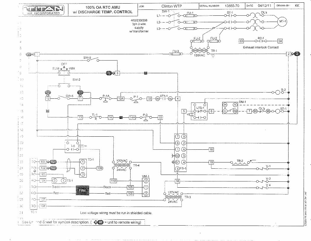
i=:~~: Kfir.~Jfl--- 100% OA RTC AMU JOB- Clinton WTP SERIAL NUMBER 13565-70 DATE 04/12/11 DRAWN BY KK
,~~,O",,~ INCORPORATEO~ I wi DISCHARGE TEMP. CONTROL 8W.~ .~ FU-1 8T·1
OFF
46012301208 3ph 3 wire
supply wI transformer
OL's L 1- - --cr: o-o=x>----D--I I-O------<)l
l2. -~ I--O---Q-f \.0 ( MT-1
L3- -
R2~1
~~ Exhaust Interlock Contact
TR-1
120VAC
-------'''-
SUfl,1 -4~'»- WIN ~ _ r!, ~ .. ----D C ~f-. -----;IIIiIIIi----------,
SW-2
g DM.1 H N -------------
OL's - c i§J--~
TR·3
24VAC
Lovv voltage wiring must be run in shielded cable.
:>::>.: Lf' -·'-:~_~~~~:~L~r symbol description. ¢G = unit to remote wiring) I I
\
I I
·1
j
I I i
I
Summer..Qff·Wlnter
IB~ [BUffi8CO;;! ~"jJ!
Temperature selector located Inside panel
[clOgi;,;j Filter[
0000
NEMA-4X STAFFORD 1 =36
Honeywell
T451 , T651 Motor",Rated Precision Thermostats
APPLICATION The T651 thermostat provides direct, accurate line voltage control of inductively-rated heating, ventilating, or cooling equipment used in commercial or industrial environments.
The T451 provides precision line voltage control of motorrated electric, gas or oil heating equipment
CL 4-01 • © Honeywell Limited/Umitee 2001
FEATURES o Deluxe styling for commercial buildings.
1/1 Industrial grade MICRO SWITCHTM mechanism rated 1/2 hp inductive, 5 kW resistive.
" Vertical mounting on 2" x 4" NEMA-standard single~gang outlet box.
• High"sensitivity, vapor-filled stainless steel dual diaphragm sensing element.
• Engineering plastic base to isolate sensor from switch heat and minimize droop.
• CSA Certified, UL Listed.
• Altitude compensation.
• 44°F (7°C) IIfrost protection" setting for heating application, independent of calibration or altitude.
• ColorRcoded lead wire connections.
• Range stopsllocking cover security features for public areas.
Contents
Specifications ......................•.......•.. 2 Ordering Information ...... , ........•.•.......... 2 Installation .........................•.........• 3 Setting and Adjustment .......................... 4
1111111111111 111111111111111 1111 1II1
95C-10903-1
T45I, {(1St MOTOFH-i'fl.TCO PF?F:CfSJON F/-fEFffvJOSlATS
Important: lho spocifications given in this pufJlication cio (lot include 170rrnai manufacturing tolerancos. 7hereroro this onit may not exactly match tflo listed specifications. Tills product is tested and ca/ifJratcd under closely controlled conditions, anc1 somo minor differences in performance can be expocted if these conditions are changed.
Models: T45-1A SPST and T451 B OPST (with positive off) for heating only. T651A SPOT for heating/cooling.
Control Range: 44 - 86'F (7 - 28'C) for models T451A, T651A. 50 - 86'F (10 - 28'C) for model T451B.
Sensing Element: Vapor-filled dual diaphragm.
Differential: 2'F (1 'c)
Droop: 2°F @ mid load range.
Barometer Sensitivity: 1I8°F/"wc (O.3°C/kPa).
Thermometer: 50 - 90'F (10 - 30'C) in 10'F (5°C) increments.
Electrical Ratings:
50/60Hz 120 V 208V 240V 277V
Full Load 9.8A 5.6A 4.9A 4.2A
Locked Rotor 58.8A 33.6A 29.4A 25.2A
Pilot Duty 125 VA
Resistive 22A Non Inductive 19ANI
/-Ieating Only 2.5kW I 4.5kW 5kW
ORDERING INFORMATION
SPECfFICATlO{l/S " or-wrF? INH)Fi't'l1/IT/()N ........................
Finish: CIQssic IJoige··and-light gold standarcL vVllite models available.
Mounting: Mounts directly on vertical, single-gang NEMA Standard (2" x 4") electrical box.
Wiring Connections: 6" (150 mm) laadwires suitable for connecting to aluminum conductors wiring if us~"d with approved special service CO/ALR solderless wire connectors. Leadwires colorcoded red for heating, blue for cooling, black for common.
Approvals: Canadian Standards Association Certified; File No. LR1322 Performance Certified for electric heating per C273.4A. UL file E47434.
Accessories: 272804A Range stops and cover locking assembly
(included in selected models only). 220213 Wallplate, covers old T451!T651 (1000 series)
wall marks. TG511 Thermostat guard for security and protection.
Fig. 1 - Dimensions of T 451, T651 in inches (mm):
l __ 7S_J I [2~1S116J J
--(2~t8Jl __ _
1 115
'---L~!',-_-c-___ [4'r 1[1~~2J"*;!~rl
When purchasing replacement and modernization products from your TRADELlNE® wholesaler or your distributor, refer to the TRADEUNE catalog or price sheets for complete ordering number, or specify:
1. Model 2. Electricalload(s) 3. Accessories.
If you have additional questions, need further information, or would like to comment on our products or services, please write or phone:
1. Your local Honeywell Home and Building Control Sales Office (check white pages or phone directory). 2. Home and Building Control Customer Satisfaction
Honeywell Inc., 1885 Douglas Drive North. Minneapolis, MN 55422 (612) 951-1000
3. In Canada-Honeywell Limited, 35 Dynamic Drive, Toronto, ON MiV 429,1-800-405-9835. International Sales and Service Offices in all principal cities of the world. Manufacturing in Australia, Canada, Flnland, France, Germany, Japan, Mexico, Netherlands, Spain, Taiwan, United Kingdom, U.S.A.
2 95C-10903·1

T451, Ff3Sf MOTOI-1--h'AILV ('nrCISION Tl-iE:FlfAUS1AFS
VVI-II::i\lINS1ALUNG TlllS PHODUCT:
1. He2.cJ these instnJctiom; can:fufly. Failure to follow instructions can damWJ0 product or cause a hu;carclol)s condition.
2, Check ratings given in illstructions and on product to make sure product is suitable for your application.
a. Make slire installer is a train8cl, experienced service technician.
4. After completing installation, use these instructions to check out product operation.
ill WARNING This thermostat is a line voltage (120 to 277 Vac) con~~o!. 00 not instal! it unless you are completely fa~r!lar and competent with home wiring. If Improperly handled there can be a risk of 240 volt electric shock hazard which may cause serious injury or death.
ill CAUTION 1. Disconnect power supply before making wiring
connections to prevent electrical shock or equipment damage.
2. AI! wiring must comply with national and loca! codes and ordinances.
3. ~hen usi~g aluminum conductors, all wiring connec~!ons to thIs thermostat must be made to the factory Installed feadwires using approved CO/ALR solder/ess connectors. A fire hazard may result otherwise,
4. To avoid handling the sensing element, do not remove thermostat cover until wiring is completed.
5. Thermostats are designed for use with appliances having a limit control.
New Installations 1. Instal! a single-gang electrical box oriented vertically about
4' to 5' (1.5 m) above the floor on an inside wal! or pillar where the thermostat will be subjected to typical room temperature.
NOTE: To sense temperature properly, the thermostat must be placed away from concealed warm or cold water pip~s, a;r ducts, or drafts from hallways, fireplaces or st8l1ways. Do not place thermostat above convectors or in the ffow from supply fans. Ideally, a thermostat should be close to the return air path to effectively measure average room temperature,
2. Wire installation in an approved fashion.
NOTE: T651A and T451A do not feature a Positive Off setting, and may not be used as a disconnect switch.
3. Leave cover on the thermostat while maklng wiring connections. Use solder1ess connectors approved for the type, number and gauge of wires being joined.
Connect as per Fig. 2 for the appropriate application.
3
INS lALLA 1/01')
Fig. 2 ."~~ Wiring connections
T45iA (Healoniy) H51B (!-l(,~lt oilly wHh positive aii)
T65iA (Heat only) l551A (Coo! only application)
" I(o";r.~
~",d "'" ""t"-'~ ~ fA .... - ~ $1 mUg.& .----
T651A (Heat-Coo! application)
1I0T 8~
11 " I14d He".\ino
T1 .- Load
& POlVer supply; provide disconnect means and overload protection as required.
&. Breaks on Positive Off.
&. Exposed unused wires must be properly insulated.
& Contact makes Black to Red on temperature fall; Black to Blue on temperature rise.
4. Pre~bend and push leadwires into the electrical junction box.
5. Hold the thermostat base with one hand and remove the thennostat cover by grasping two sides of the cover and pulling outward.
NOTE: If locking cover feature is desired, insert the locking cover clip in the thermosta.t ba.se BEFORE mounting the thermostat on the waif (see Fig. 7).
6. Using the screwdriver, secure the thermostat to the box by tightening the two mounting screws. Handle thermostat with care. Excessive pressure may damage the control knob or sensing element.
IMPORTANT: Before mounting the thermostat, turn tile setting dial to the mid-position (indicator pointing to the top of the thermostat): this will prevent damage to the dial stop if the dial is accidentally turned by the screw driver when the top mounting screw is tightened. Do NOT press on diaphragm, diaphragm lever arm or setpoint knob to seat thermostat on the box: thermostat will be damaged.
Replacement Applications 1, Disconnect power supply before making wiring
connections to prevent electrical shocks or equipment damage. All wiring must comply with applicable codes and standards.
2. Remove the old thermostat from the wall, taking care not to damage the wiring insulation.
3. Check the old insulation for cracks, nicks or fraying. Apply certified electrical tape where necessary to insulate wires, or replace the wires in an approved fashion.
4. Complete installation following steps 3 to 6 in the New Installations section.
95C-10903-1
Cheek Out Turn on power. HGlise the tenlpcratufc settino to ener~)izc lilO tv;ating contact and brc:ak 018 cooling contact The HVJ\C equipmont Si'louid begin ileating or stop cooling, as appropriate.
NOTE: For Ttl51A and T651A models only, the thermostat will cal! for heat (disable cooling) when the set pOint dial is at full counter-clockwise position. This setting is the phase change point of tile diaphragm's vapor fill and is independent of calibration. To de-energjze the load(s), turn off power at the circuit breaker panel, or add a separate disconnect switch.
Altitude Compensation T451, T6S1 units are calibrated at the factory for accuracy at 500 feet above sea level. No recalibration is needed if the switch operates at the same temperature indicated on the thermometer.
The vapor-filled diaphragm sensor is affected by barometric pressure and altitude. Deviations up to ± 1°F (1/2°C) are within norma! operation. Control point drops 2°F every 1000 ft. we/300 m) above sea level. See Fig. 3 for recommended action.
Fig. 3 - Altitude Correction
E!evation Recommended (in feet) Typical City Action
o to 2000 Toronto, Ontario Leave as is
Phoenix, Arizona
2000 to 4000 Las Vegas, Nevada Move clockwise
Calgary, Alberta 2 to 3 marks
~~--" -- -4000 to 6000 Denver, Colorado Move clockwise
Salt Lake City, Utah 4 to 5 marks
-- --------------- -------------
To Recalibrate
1. Remove cover. Set the tab on setpoint knob to the leftmost radial mark visible on top of the triangular arm that holds the dual diaphragm sensor (Fig. 4).
2. Without rotating the knob, remove it from the thermostat by pulling straight out, while holding the base against the wall.
3. Now, rotate the removed setpoint knob clockwise by the amount of temperature error. Each mark on the triangular arm represents 2°F (1°C) of adjustment. Snap the knob back onto the setpoint cam.
Home and Building Control
Honeywell Inc. 1985 Douglas Drive North
Golden Valley, MN 55422
Home and Building Control
Honeywell Limited-Limitee 35 Dynamic Drive
Toronto, ON MIV 4Z9
4
INS lALLA lION
4. Inslal! [he covel'. Wait five Inillutes to lel tIle thermoGtat therlllaHy stabilize 8.rld re··check calibl"ation. Do not assume a thermostat is out of calibration untif if has beon installod and a/towed to operate for severat hours.
Fig. 4 - Recalibrating TI1ermostat
Security Features: Range Stops
Fig.5 - Installing Range Stops
. . . . , . 0, ::.:'."
Insert pins into temperature stop positions
1. Set thermostat to desired setpoint. Remove cover. 2. Install plastic dowels supplied (or purchased separately)
into minimum and/or maximum range stop holes on inside back of cover (Fig. 5).
3. Re-install cover. Check operation of range stops.
Fig. 6 - Cover Locking Kit
",;,,!r1Tr== ~.,
o "?"'" c3 Sf"
."" i Alkln screw
L;j .' and wrench Tinnonnan ~....,.,........
spoednut ~
Locking Cover 1. Remove cover by pulling straight out. 2. Insert Trnnerman Speed Nut®s into slots top and bottom of
thermostat base. 3 Drive Allen screw into Speed Nut until head is flush with
outside edge of thermostat base. 4. Re-instaU cover. Lock by backing out Allen screw until
screw body protrudes through cover hole. To unlock cover, drive Allen screw into thermostat base.
Honeywell

5.5 Start up Procedures
AIR INCORPORATED
100% OUTSiDE AIR MAKE-UP UNiTS WITH RTC SOLUTfONS DISCHARGE TEMPERA TURE CONTROL
Start-up must be performed by a trained, experienced service person.
The following general start··up procedure applies directly to standard 100% air make-up units. Please note any added options for a specific unit which may affect the control sequence or terminal numbering prior to attempting start-up or service work. Read the entire start-up procedure and review all reference material (Unit Specifications, Gas Train/Burner Specifications, Sequence of Operation, Parts Lists, and Electrical Schematic) supplied with each unit.
STEP 1 Turn off incoming electrical power and gas supply to the unit. Electrical power
can be turned off at the unit disconnect. Gas supply shut-off is at the inlet of unit's gas manifold.
At the remote panel, turn the Summer-Off-Winter (S-O-W) switch to the off position and the temperature selector to the lowest setting. STEP 2
Verify that incoming electrical and gas supply match the name plate requirements (i.e., voltage/amp capacity, gas pressure and volume capacities, etc). If they do not, stop at this point and contact Titan Air. STEP 3
Open the access doors to blower and control vestibule sections. Check all electrical connections and hardware (blower drives, bearings, damper linkages, etc.) for tightness and correct field wiring connections. STEP 4
Check all gas, pilot, vent, and pressure sensing lines are properly connected and unobstructed. Verify the incoming gas line was "blown out" to flush out debris prior to connecting gas line to unit. Also verify incoming gas line has been purged of air up to unit's gas inlet. STEP 5
At manifold pressure test port, downstream of the modulating gas valve (VM-i), connect a gas pressure gauge (pressure gauge must read inches of water column to 10" with the capability of reading a negative pressure). STEP 6
Turn on incoming electrical power at unit disconnect. Make sure the blower access door is securely held open. Turn the blower service switch (SW-5) to the on position. STEP 7
If an optional intake or discharge damper is installed, the blower will not start until the damper motor's internal "proof open" end switch closes (damper motor and end switch wiring are generally completed in the field after damper is mounted). If an intake or discharge damper is not installed, the blower should start immediately. Check the blower for proper rotation direction. If the rotation is reversed, turn both SW-5 and the disconnect switch off. For 3 phase motors, reverse any two leads.
p.i AMU RTC Inllgn 2003 R1.doc
STEP 8 With proper blower mtatioll verified, check and record the RPM of the blower. If
the blower speed needs to be adjusted to change the rated CFM of the unit, contact the factory. STEP 9
Turn the unit off Close and latch the blower access door. STEP 10
Start unit with SW-S. Check and record the motor amp draw. If the motor amp draw exceeds listed Full Load Amps (FLA), stop and call the factory. STEP 11
Check and record the negative pressure reading on your burner manifold pressure gauge. This measurement is necessary for proper setting of the burner manifold pressure when the unit is forced into high fire mode. At this time, also measure the pressure dmp across the airflow switch ports (remove caps from fittings in tubing for air flow switches and connect tubing from differential pressure gauge to fittings). This measurement can be used as a simple indication of proper airflow through the unit. If this second measurement is not between 0.7" w.c. and O.S" w.c. L'lP, the blower speed may need to be adjusted. If assistance is needed, contact Titan Air. STEP 12
Turn the unit off. Check the pilot gas line for proper and tight connections with no leaks. For shipping purposes, the pilot lines are disconnected. STEP 13
Turn on the main gas valve, slowly open the manual pilot gas valve. If the unit is supplied with a low gas pressure switch (1"-2), reset to on position. STEP 14
Place the run-check switch (located on flame safeguard programmer module) to the check position This will allow the pilot to light without igniting the main burner. If the unit is equipped with an inlet ductstat (T-1), set this stat above the outside air temperature. Start unit with SW-S and enable the burner with the burner service switch (SW-6).
Note that the burner should not be operated continuously in the check position for rnore than 1 minute because the ignition transformer is not rated for continuous duty. STEP is
The unit should go through its complete burner ignition sequence with only the pilot ignited. The sequence can be observed by following the indicating LED's on the flame safeguard. On new installations, resetting of the flame safeguard may be required to purge air from the pilot line. If the unit does not cycle through its burner ignition sequence after a few attempts, refer to the service information in the following section for troubleshooting instructions. STEP 16
In the center of FS-1 are 2 voltmeter test ports. Set the volt-ohm meter to approximately 30 VDC scale and insert the meter leads into the test ports (common lead in black port, positive lead in red port). STEP 17
With only the pilot operating, record the DC volt signal. The DCV range is noted on the amplifier module of the controller (FS-1). There should be a steady DCV signal in
p. 2 AMU RTC Int Jgn 2003 R1.doc

b2iJi1i~~" AIR
the upper range stated on the controller. STEP 18
Once stable pilot is achieved, shut unit down and place run-check switch in the run position. Carefully remove the wire from terminal one (1) on gas modulating actuator (VM-1). Do not allow the wire to touch the unit casing or any metal Release actuator gear by pressing black button on side of actuator (see figure 1), rotating mechanism counterclockwise to stop. Start unit and check and record DC voltage as in previous step. Check to make sure the flame is contained in the burner casting and extends the full length of the burner with no breaks in the flame. An ideal low fire setting results in a small flame with no breaks and that also produces a stable DC voltage signal in the upper end of the range listed on the flame safeguard amplifier module. If the low fire setting is adjusted, verify that both the DC voltage signal and visual appearance of the flame are satisfactory. See figure 1 at end of start-up procedure for low fire adjustments if necessary. STEP 19
Once stable signal is achieved on low fire, release actuator gear by pressing black button on side of actuator (see figure 1) and rotate mechanism clockwise to stop. This will force the burner into high fire. On your manifold pressure gauge, check the manifold pressure. The reading on your manifold pressure gauge needs to be added to the negative pressure recorded in step 11. The resulting total manifold pressure should be compared to the unit's rated manifold pressure. If the total is higher or lower than the rated pressure, adjustment can be made at the gas pressure regulator (GP-1). Total manifold pressure should not exceed unit's rated manifold pressure.
Because of possible variations in the BTU content of gas, it may be necessary to set the manifold pressure to the rated temperature rise (temperature difference between the incoming air and the unit discharge air).
The high fire flame should be visually observed to verify proper combustion. Experienced service personnel should be able to assess the appearance of a proper high fire flame. If assistance is needed, contact the factory. STEP 20
With the burner on high fire, turn the high temperature limit (TL-1) to its lowest setting. The limit should trip out and shut down the burner. Turn TL-1 back to the factory setting of 185 deg. F and reset the control Reconnect wire at VM-1. STEP 21
With all wiring in place and the unit operating in the winter mode, adjust temperature setpoint on the remote mounted controller (TO-1) up and down (from highest to lowest setting) observing the modulation of the burner. When actual discharge air is below TO-1's setpoint, the unit should discharge maximum temperature. When actual discharge air is above TO-1's setpoint, the unit should discharge minimum tem perature. STEP 22
With the unit operating in the summer mode, cycle the burner from SW-6. Verify that burner fully lights within a few seconds of proved pilot. STEP 23
If the unit is equipped with a low temperature safety (L TS-1), check this control's operation. Standard L TS-1 can be checked by disconnecting the sensor wires. The unit
p. 3 AMU RTC /n//gn 2003 R1 doc
AIR INCORPORATED
should thell shut down after the built-ill timer setting has "timed-out". Replace the sensor wires when proper operation has been verified. Tum the unit off and back on to reset L TS-1. STEP 24
With the unit operating in the winter mode, close the 2nd manual gas shutoff valve (GT-3). The burner should shut down in a few seconds (look for flame LED to go out on FS-1) with the unit shutting down in 30 seconds or less. Open GT -3 and reset FS-1 by pressing button protruding through cover. STEP 25
Turn SW-5, SW-6 and the disconnect off. Verify all terminals, electrical connections and hardware (bearings, sheaves, blower wheels, etc.) are securely tightened. Adjust all controls to desired settings. Remove all gauges, meters, and hand tools from the unit. Replace all covers on controls. Make sure all safety devices are reset. STEP 26
Turn the disconnect on. Start the unit from the remote panel. Verify proper operation in all modes according to unit's sequence of operation.
The unit should be ready for operation. If any problems arise, refer to the service information on the following page. To assure long lasting and efficient operation of Titan equipment, a regular service inspection should be set up. Refer to the maintenance section at the back of this manual for detailed maintenance information.
p.4 AMU RTC /n/lgn 2003 R1 doc
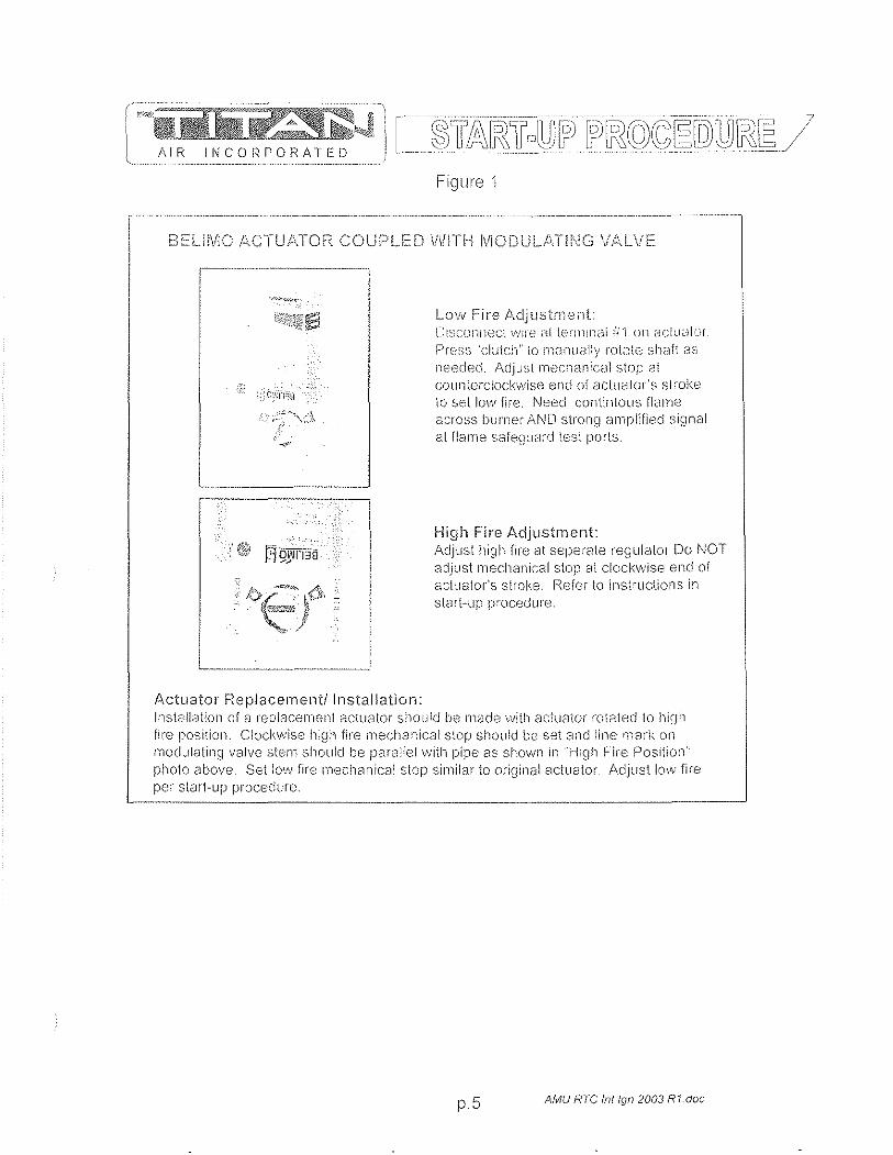
W~~.1iDi ~kJ AIR INCORPORATED
Figlne 1
BELH\AO !~,CTUt\TOF< COUP D \NlTH l\flODUL.J\Tl[\JG V/\LVE
'-"
Actuator Replacement/Installation:
Low Fire AdjustrYient: O:~:;c(mllecl ; .. '.'11"0 d[ l(~T!llrldi i!'l 011 aclu~·)!ur
Prc"";ss 'clutch" to rn,HllJ,311y rot3te Si"i,:lft ,;l~J
n;;.;eded. /\djJ:;! mechanic;,,]l stop ai counlerclockwise enci of actucltOr'S s[:"oke to set low "fire, Neeel contlntous flame a:~rOss burnel" Ai\!D strong r:'lrnplified si~lnal at flame safeS)J<--lrd test porls.
High Fire Adjustment: ,"eljust high file at seperate regulator Do NOT adjust rneclianical stop at clockv\,ljse end of actuator's stroke Refer to instructions in sl(Jrt~lIp procedure.
Installcltion of ::1 repiacen181':1 actuator should be made vvith actuator rotated 10 hiqtl fil"e position. Ci:)ckwlse high fire 111eCh2l~·lical stop should be S8t and line !118rl\ on modulating valve stern should be p8ra:lell"vith pipe 8S shovvn in "High Fire Position' photo above, Set low fire mechanical stop similar to original actuator. Adjust 100v fire per start-up procedure.
p.5 AMU RTC fntlgn 2003 R1doe
5.6 General Information: Installation, Assembly Drawings, Maintenance

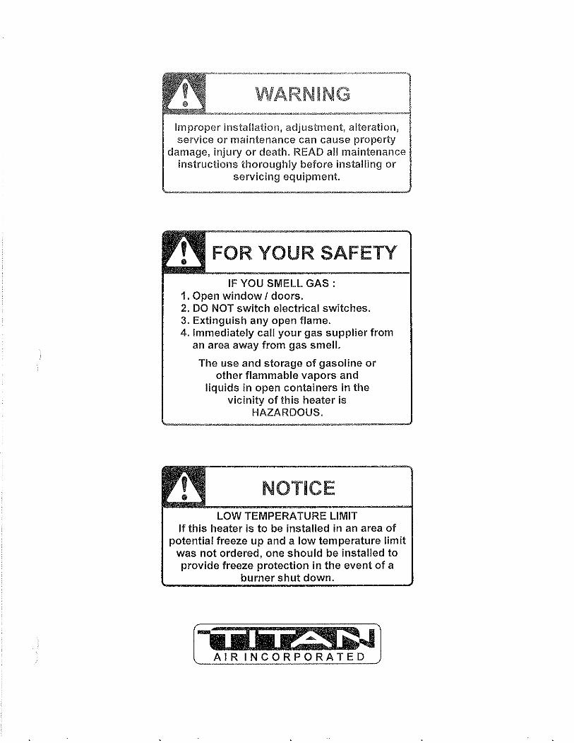
WARNING
Improper installation, adjustment, alteration, service or maintenance can cause property
damage, injury or death. READ all maintenance instructions thoroughly before installing or
servicing equipment.
FOR YOUR SAFETY
IF YOU SMELL GAS: 1. Open window I doors. 2. DO NOT switch electrical switches. 3. Extinguish any open flame. 4. Immediately call your gas supplier from
an area away from gas smell.
The use and storage of gasoline or other flammable vapors and
liquids in open containers in the vicinity of this heater is
HAZARDOUS.
NOTICE LOW TEMPERATURE LIMIT
If this heater is to be installed in an area of potential freeze up and a low temperature limit
was not ordered, one should be installed to provide freeze protection in the event of a
burner shut down.
( AIR INCORPORATED)

24 MONTH WARRANTY Titan Air, Inc. hereby warrants its products against defects in material and
workmanship for a period of (24) twenty four months from date of shipment. Start up checklist is due back within (30) thirty days of start-up or 120 days from date
of delivery for 24 month warranty to be effective. After (30) thirty days, and up until (60) sixty days, a (13) thirteenth month warranty will be observed. All warranties are null and void if start up checklist is not received within (60) sixty days from start-up or 120 days from date of delivery. NO EXCEPTIONS WILL BE MADE.
Titan Air, Inc. reserves the right at Titan Air, Inc:s option, to replace or repair free of charge, any part proven by Titan Air, Inc. to be defective. Prompt notification of defective part must be given to Titan Air, Inc. and defective part must be returned freight prepaid within (30) thirty days of notification.
WARRANTY INCLUDES ONLY PARTS SUPPLIED BY TITAN AIR, INC. INCIDENTAL COSTS AND LABOR CHARGES SHALL BE THE RESPONSIBILITY OF OTHERS. This warranty does not cover fuses, belts, filters or water damaged parts which are the result of improper storage or installation.
This warranty is void in event the product is improperly installed and/or operated under conditions other than normal published ratings, improperly maintained, misused or not in compliance with applicable codes or not in accordance with Titan Air, Inc:s operating instructions.
This warranty is void if attempts to correct or repair any alleged defective part or parts are made by unauthorized personnel without Titan Air, Inc:s written approval.
In no event shall Titan Air, Inc. be held liable for any damage, incidental or consequential, arising from the installation, performance or operation of the product.
This warranty supersedes, voids, and/or is in lieu of any other verbal or written understanding which may not be in total accordance with this expressed warranty.
Warranted parts must be returned to Titan Air, Inc. within 60 days to receive credit.
PURPOSE / APPLICABILITY This manual is intended to provide installation, operating and service information on
Titan Air's standard direct-fired air make-up units. Other Titan Air units, such as AR/80™, AR/75™, Demand-Air™, H.O.TTM and units that do not feature a direct-fired burner, will have separate operating and service manuals.
A packet of reference materials for a specific unit (tracked by its Serial Number) is generally included with this Operating and Service Manual. The reference materials include Unit Specifications, Parts Lists, Gas Train and Burner Specifications, Electrical Schematic, and a Sequence of Operation. A start up checklist is also included in this packet. Review the reference materials for a specific unit and note any optional equipment or controls which are not specifically addressed in this manual prior to attempting start-up or service work.
The information and recommendations contained in this publication are based on general observation and are not intended to supplant requirements of federal, state or local codes having jurisdiction. These codes should be reviewed before installation of equipment. All units must be installed in accordance with national, state or local codes.
It is the responsibility of the purchaser at the time of order, to specify any and all code or insurance requirements that may dictate the addition of components to the equipment in order to comply with those requirements.
Only qualified personnel who have experience with the installation and operation of industrial/commercial direct fired equipment should attempt to service Titan Air equipment.
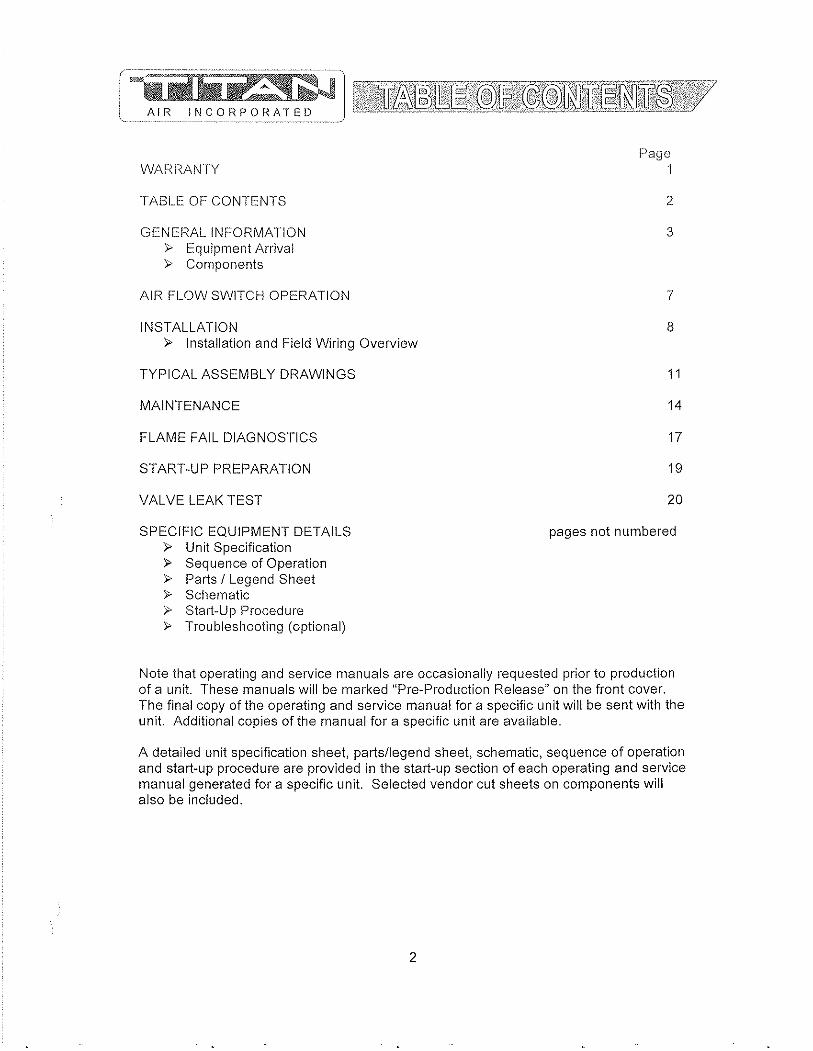
W AF< I~A N T Y
TABLE OF CONTENTS
GENEPAL INFOPMATION " Equipment Arrival " Components
AlP FLOW SWITCH OPEPATION
INSTALLATION " Installation and Field Wiring Overview
TYPICAL ASSEMBLY DPAWINGS
MAINTENANCE
FLAME FAIL DIAGNOSTICS
STAPT-UP PPEPAPATION
VALVE LEAK TEST
SPECIFIC EQUIPMENT DETAILS » Unit Specification » Sequence of Operation " Parts / Legend Sheet » Schematic » Start-Up Procedure » Troubleshooting (optional)
Page 1
2
3
7
8
11
14
17
19
20
pages not numbered
Note that operating and service manuals are occasionally requested prior to production of a unit. These manuals will be marked "Pre-Production Pelease" on the front cover. The final copy of the operating and service manual for a specific unit will be sent with the unit. Additional copies of the manual for a specific unit are available.
A detailed unit specification sheet, parts/legend sheet, schematic, sequence of operation and start-up procedure are provided in the start-up section of each operating and service manual generated for a specific unit. Selected vendor cut sheets on components will also be included.
2
EQUIPMENT ARRIVAL When the air make··up unit arrives, be sure to inspect for shipping damage. The
equipment was thoroughly inspected before leaving the factory and the driver signed for it. Read the bill of lading and verify that all of the items listed are accounted for. Any damaged or missing items should be reported to the transporter immediately. DO NOT SEND DAMAGED FREIGHT BACK TO TITAN AIR! All claims must be filed with the transporter. Be sure to take photographs and get the drivers signature to confirm the damage. The driver will have a number for you to call to file a claim. Request a written inspection report from the claims inspector to substantiate any necessary claim. Be sure to open the unit access doors and inspect for internal damage.
If for some reason you are unable to install the equipment immediately, be sure that the equipment is protected from the elements. Water damaged parts are not covered by Titan Air's warranty. If the equipment is stored for an extended length of time, be sure to completely check the unit for any internal damage which may have been caused by excessive condensation. Also check for damage caused by rodents, and be sure to eliminate any dust that may have built up on the components while the unit was in storage.
CAREFULLY AND THOROUGHLY READ TITAN AIR'S PRODUCT WARRANTY Each unit is tested at the factory prior to shipping. Because we are not able to
simulate exact field conditions and sometimes actual conditions are different than what was stated on the order, you may need to make some adjustments in the field. This is why it is very important that only qualified personnel start-up and service Titan Air equipment. The start-up checklist (provided in packet with this manual) must be filled out and returned to Titan Air in order to validate equipment warranty.
For a fee, Titan Air personnel will travel to the job site, supenvise start-up and provide operation and maintenance training for the equipment.
BLOWERS The typical blower(s) used in Titan Air equipment are AMCA rated industrial type
forward curve D.W.D.1. fans. Backward incline, backward airfoil, and plenum/plug fans are used occasionally. Models TA-109 through TA-136 utilize a single blower while models TA-215 through TA-242 utilize twin blowers. All blower wheels are mounted on a solid, turned, ground and polished shaft. 9" and 12" blowers are supported with permanently lubricated ball bearings. Larger blowers are supported by lubricated pillow block ball bearings.
MOTOR & DRIVE Rigid base, T-Frame, motors are utilized. The motor is mounted on an adjustable
slide base. Variable pitch motor sheaves are provided to allow airflow adjustment if the motor is no larger than 30 Hp.
3
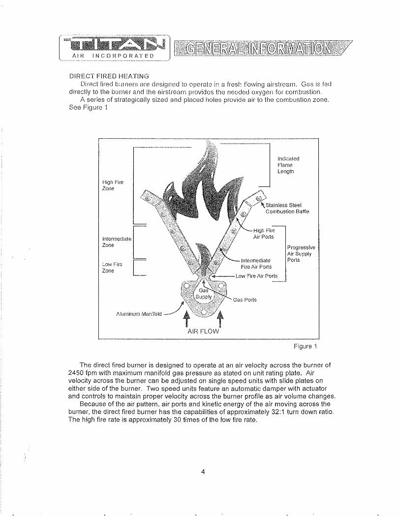
DIRECT FIRED HEATING Direct fired burners are designed to operate in a fresh flowing airstream, Gas is fed
directly to the burner and the airstream provides the needed oxygen for combustion, A series of strategically sized and placed holes provide air to the combustion zone,
See Figure 1
----'-----=--=====-------,
High Fire Zone
Intermediate [ Zone
Low Fire r-= Zone L
Aluminum Manifold
Indicated Flame LengUl
i Steel Combustion Baffle
High Fire Air Polis
Progressive Air Supply
Intermediate Ports Fire Air Ports
Fire Air Ports
Figure 1
The direct fired burner is designed to operate at an air velocity across the burner of 2450 fpm with maximum manifold gas pressure as stated on unit rating plate. Air velocity across the burner can be adjusted on single speed units with slide plates on either side of the burner. Two speed units feature an automatic damper with actuator and controls to maintain proper velocity across the burner profile as air volume changes.
Because of the air pattern, air ports and kinetic energy of the air moving across the burner, the direct fired burner has the capabilities of approximately 32:1 turn down ratio. The high fire rate is approximately 30 times of the low fire rate.
4
Bur'<NER OPERATING PRINCIPLES The direct fired burner is designed to operate in a cal1inet of flowing fresh air. Fuel
gas is fed directly to the bumer; kinetic energy of the airstream furnishes combustion air. It will function properly at the design velocity and pressure associated with ventilating systems.
The burner must be installed to fire with, and parallel to, the air. flow. By virtue of velocity impact and suction generated by the diverging sllape of the combustion baffles, air is induced through the air poris into the combustion zone. The air supply is constant, even though only that which mixes with the gas takes pari in combustion.
When a very small quantity of gas is admitted to the burner, sufficient mixing takes place in the low fire slot where combustion takes place. Since the low fire zone is contained within the burner casting it is effectively shielded from uncontrolled air entry.
As the gas supply is increased the flame progresses into the intermediate fire zone where an additional supply of air is available. At higher or full capacity, mixing occurs at the larger air ports of the high fire zone augmented by air flowing over the end of the baffles.
On a reduction of gas supply the reverse sequence takes place, the flame recedes to a location of lesser air supply until the low fire zone is reached. The burner is suitable for a turndown range of approximately 30 to 1.
AIR SUPPLY The supply fan is typically positioned to draw air across the burner. Air flow across
the burner must be substantially straight (laminar) and velocity must be within the proper range to develop the desired turndown and capacity.
The direct fired burner is designed to operate in an air make-up heater with all air crossing the burner taken directly from outdoors. Rare exceptions involve equipment that serves an unoccupied space.
Total pressure rating of the blower includes allowance for the pressure drop through the primary air handling unit including the burner, together with pressure losses at the inlet screen, inlet damper, filters, outlet damper if used, plus the external pressure rating of the system.
BURNERS Burners are purchased in 6" and 12" straight lengths and 12" tee sections and
are assembled to meet the BTU requirements of each piece of equipment. According to national safety standards, the following factors could influence safe
operation of a direct fired air make-up unit and must be interlocked to either prevent the burner from firing or shut it down if unsafe conditions occur.
1. AIR SOURCE - If a damper is used, it must be interlocked to prove it is open before the blower can start.
2. BLOWER STARTER INTERLOCK - An auxiliary contact from the blower starter must be placed in series with the burner controls to prevent burner operation when the blower is not operating.
3. AIR FLOW SWITCHES - Monitor the air flow (pressure drop) across the burner. The switches (one high differential and one low differential) will not allow burner to operate if pressure drop across the burner is outside of the high and low set points.
4. HIGH TEMPERATURE LIMIT - A manual reset high temperature limit control must be utilized to prevent high temperature situations caused by excessive fuel pressure or lack of air flow.
5

5. fLAMLSf\LlQI,J.,L\f:iQ ... lvIonitors the combustion process during ignition and operation for safe conditions.
6. IjlGH GAS PPlSSURE SWjTCH -·lvIonitors gas pressure to the burner. This de-energizes the burner in the event gas pressure increases above its set point
The burner's design and flexibility, coupled with proper controls, make direct fired air make-up equipment the safest and most efficient method of tempering outdoor air.
GAS CONTROLS Titan Air TA Series equipment is constructed to meet A.N.S.I Z83AICSA 3.7-1999
standards. Components in the gas delivery manifold on standard equipment include: two manual shut-off valves, gas pressure regulator, two safety shut-off valves and an electronic gas modulating valve. The pilot control includes a shutoff valve, gas pressure regulator and a pilot solenoid.
ELECTRIC/ELECTRONIC CONTROLS TA series air make-up units come standard with the following items: disconnect
switch, starter and overload assembly(s), control power transformer (if a 3 wire system), air proving switches, high temperature limit, electronic flame safeguard and electronic flame modulation with remote set point adjustment lvIany other options including low temperature limit, inlet duct stat, and operating lights are available.
If the malfunction of the heater creates a hazard to other fuel burning equipment in the served building (Le. supplying make-up air to boiler room) it is to be interlocked to open an inlet air damper in case of failure.
CABINET Titan Air TA series equipment comes with either a galvanized finish or a painted
finish. In both cases, the minimum gauge metal used is 18 ga.
6
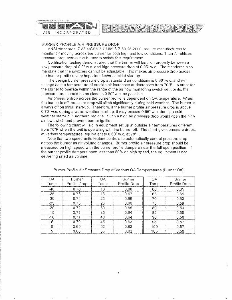
AIR INCORPOF<ATED
BURNER PROFILE AIR PRESSURE DROP ANSI standards, Z 83.4/CSA 3.1 M99 & Z 83.18-2000. require manufacturers to
monitor air moving across the burner for both high and low conditions. Titan Air utilizes pressure drop across the burner to satisfy this requirement.
Certification testing demonstrated that the burner will function properly between a low pressure drop of 0.2" w.c. and high pressure drop of 0.95" w.c. The standards also mandate that the switches cannot be adjustable. This makes air pressure drop across the burner profile a very important factor at initial start up.
The design burner pressure drop at standard air conditions is 0.60" w.c. and will change as the temperature of outside air increases or decreases from 70°F. In order for the burner to operate within the range of the air flow monitoring switch set points, the pressure drop should be as close to 0.60" w.c. as possible.
Air pressure drop across the burner profile is dependent on OA temperature. When the burner is off, pressure drop will climb significantly during cold weather. The burner is always off on initial start-up. Therefore, if the burner profile air pressure drop is above 0.70" w.c. during a warm weather start-up, it may exceed 0.95" w.c. during a cold weather start-up in northern regions. Such a high air pressure drop would open the high airflow switch and prevent burner ignition.
The following chart will aid in equipment set up at outside air temperatures different from 70°F when the unit is operating with the burner off. The chart gives pressure drops, at various temperatures, equivalent to 0.60" w.c. at 70°F.
Note that two speed units feature controls to automatically control pressure drop across the burner as air volume changes. Burner profile air pressure drop should be measured on high speed with the burner profile dampers near the full open position. If the burner profile dampers open less than 50% on high speed, the equipment is not delivering rated air volume.
Burner Profile Air Pressure Drop at Various OA Temperatures (Burner Off)
-~-.. --.-- ._-----_. __ ... _--_. __ .. ------_._ .. _. __ .. _. __ ... _._ .. ..----_._._--- .-
OA Burner OA I Burner OA Burner Temp Profile Drop Temp Profile Drop Temp Profile Drop
-40 0.76 10 I 0.68 60 0.61
'---,
----.-.... ~ _._._-_. __ .... _. ···---Ts·-- ._._-_ .... _ .. .. -.. 35 0.75 0.67 65 0.61 ----.-..... -. ~~ .. - ..... -.--.. ---".""-.. . ..• _ ... _ .. -30 0.74 20 0.66 70 0.60
---~----- - .. _ ..
-25 0.73 25 0.66 75 0.59 --_. ..
-20 0.72 30 0.65 80 0.59 _._----0.71 35 0.64 85 0.58 -15 1-- 1-- . -.-~---
-10 0.71 40 0.64 90 0.58 I -5 0.70 45 0.63 95 0.57 0 0.69 50 0.62 100 0.57 5 0.68 55 0.62 105 0.56
7

CONTROLS Control systems can be designed to meet specific requirements. Numerous
temperature controls are available. Since standard air make-up units usually temper outside air to replace the air exhausted from a building, modulating discharge temperature control is typical. A room override thermostat is occasionally included to automatically increase the discharge temperature set point if space temperature drops too low.
Titan Air units are typically supplied with a remote control panel. This panel will include switching for blower & burner operation and a temperature setpoint. Some units feature operating lights, discharge temperature display, custom controls or contacts by others to enable the blower andlor burner.
Refer to the unit specification sheets, parts list, schematic, sequence of operation and start-up procedure for a specific unit to determine the control options included.
PRE-INSTALLATION Inspect the equipment making sure all parts and accessories are on the job site.
Check equipment against order and packing list. If the equipment has been sitting in storage for some time, inspect it for moisture (from condensation, rain or snow) andlor dust accumulation. Both can cause damage to electrical and electronic components as well as bearings and insulation.
INSTALLATION Care taken during the installation and start-up is vital to the longevity and reliability of
the equipment. Confirm that gas and electric utilities match the rating on the equipment name plate.
>- This heater shall be installed in accordance with local codes or, in the absence of local code, according to ANSI Z223.1.
>- If the heater is to be installed in an airplane hanger, refer to ANSI/NFPA 409.
>- If the heater is to be installed in a parking garage, refer to ANSI/NFPA 88A.
>- If the heater is to be installed in a service garage, refer to ANSI/NFPA 88B.
>- For installations in Canada, refer to CAN/CGA B149.
>- Adequate exhaust andlor relief must be provided to prevent over pressurizing the served space when the heater is operating at its rated capacity.
» If in doubt regarding the application of the direct fired heater, contact the sales representative or the factory.
POSITIONING THE HEATER Locate the heater exactly level, making certain minimum clearance required by local
codes is maintained between the heater and any combustible materials. See name plate on unit for minimum recommended clearances.
8
CURBING (OUTDOOR MOUNTING) The use of a full perimeter curb or mounting rails under the heater is recommended.
The only openings in the roof should be for the supply air duct, return air duct (if required), gas and electrical connections (if applicable). These openings must be sealed properly after installation. Titan Air ships all curbs unassembled and un-insulated. Installing contractor supplies gaskets, cant strips, insulation, etc.
GAS PIPING Gas piping must be sized and installed in accordance with applicable codes. It must
be able to deliver the specified CFH and gas pressure at full flow. Refer to unit nameplate or unit specification sheets for specified CFH and gas pressure.
Care must be taken with the gas piping to prevent problems at start-up and later during operation. Before the union between the supply line and the unit is connected, the supply line should be cleaned out to remove any foreign material (dirt, rust, metal shavings, etc.) and a drip leg should be utilized.
Refer to unit nameplate to determine the minimum gas supply pressure required to attain the maximum specified gas.
All suitable gas controls, regulators and valves (equipped with a diaphragm) in this device are furnished with an ANSI approved vent limiter. If local codes require these components be vented to the outside, it is the responsibility of the installing contractor.
The heater and its individual shut off valve must be disconnected from the gas supply piping system during any pressure testing in excess of Y, PSIG.
The heater must be isolated from the gas supply piping system by closing its individual shut off valve during any pressure testing of the supply system at pressures equal to or less the Y, PSIG.
During start-up, the technician should perform a gas leak check on all valves and piping during the heater's normal operation. (See page 20)
DUCTWORK Ductwork must be sized and installed in accordance with applicable codes and
standards. A size variation may exist from recommended duct size to unit flange size. Recommended duct size applies to the size of the duct at the connection to the equipment. A properly designed duct transition from the blower outlet to a larger duct is recommended for long ducts or ducts with numerous elbows.
On heaters mounted outdoors, discharge ductwork should be insulated to minimize condensation during the "off' cycle in cold weather. A fresh air intake hood with bird screen is required. Discharge duct should be common to both blowers on twin blower units. Individual ducts for each blower are not recommended.
On a heater mounted indoors with through the roof intake, a "mushroom" type intake hood is recommended to prevent moisture entrainment. When using "through the wall" intake duct, the intake louver should have adequate moisture baffling characteristics. All intake ductwork exposed to the heated space should be insulated.
9
SOUND AND VIBRATION CONTROL 1=lexible connectors are recommended on alleast one ductwork connection.
Vibration isolators that mount between the unit and support structure are optional and can be supplied with the equipment for installation by others. Another option is internal isolation of the blower/motor assembly with internal flexible connections between the blower housing and the unit structure.
Appropriate insulation on the interior of ductwork significantly reduces sound levels.
DISCHARGE TEMPERATURE SENSOR BULB INSTALLATION & WIRING The installing contractor may be responsible for field installation of the discharge
temperature sensor. Field installation of the discharge temperature sensor in the discharge ductwork results in a better measurement of the average supply air temperature. Utilize shielded cable for field installed discharge sensor wiring.
FIELD WIRING Power supply wiring should be routed from a dedicated branch circuit per schematic.
Depending upon how the equipment was ordered, a single point power connection may be subdivided to individual loads or multiple power supply circuits may be required.
If an intake or discharge damper was ordered as a loose accessory, it will have to be mounted and the actuator must be wired. The remote panel must be mounted in a convenient location and wired to the unit. Interlocks between the exhaust, unit and possibly spray booth will have to be connected by field wiring.
Carefully review the schematic and associated schematic symbol legend. Note that legend may be on the parts/legend sheet rather than on the schematic.
Many codes require that low voltage wiring (connecting terminals numbered 100+) be routed in separate conduit from line voltage wiring. If low voltage wiring is routed with 120 VAC control voltage wiring, it must be placed in shielded cable(s). Even if low voltage wiring is routed in separate conduit, very low voltage sensor outputs and actuator control signals should be routed in shielded cable.
NOTE: All field wiring must conform to N.E.C. and/or any state or local codes.
SUPPORT OF ACCESSORIES Most Titan Air equipment is supplied with loose accessories (i.e. damper, hood,
discharge diffuser or filter section). If an intake hood is supplied by others, the design shall minimize entry of snow/rain and include an intake screen to meet ANSI standards. Intake accessories on large equipment may be shipped in two pieces for field assembly. Two damper actuators may need to be field wired on large equipment as well.
It is the responsibility of the installing contractor to support accessory items from a rigid point or points to ensure solid mounting.
POST INSTALLATION Caulking is required between all parts prior to assembly and seams must be
re-caulked after assembly. Air make-up units shipped in multiple sections will include a high quality caulk tape and caulk tubes. Caulk tape is applied between sections with exterior caulking applied after the unit sections have been joined. Sealing integrity should be rechecked on a yearly basis.
Water damaged parts are not covered by Titan Air's warranty.
10
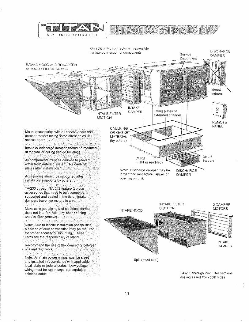
AIR INCORPORATED
On split units, contractor" is responsible for intel'connectlon of components
Sefyice Disconnect
DISCHARGE DAMPER
Mount accessories with all access doors and damper motors facin'g same direc{ion as unit access doors.
Intake or discharge damper should be mounted althe wall or ceiling (inside building),
AII'components must"b_E! c,au!ke~J?','p'revent water from enterlng system, Re'caulk lift plates after installation.
Accessories should be supported after installation (supports by others). .
TA·233 through TA·242 feature 2 piece accessories that needto be assembled, supported and sealed in the field. Intake dampers have two motors to wire,
Make sure gas piping 'and electrical service does not interfere with any door opening and I or filter removal.
Note: Due to infinite in~tallation possibilities, a section of duct or tranSition, may,be required for proper accessory mounting, }hese items are the responsibility of others,
Recommend the use of flex connector between unit and duct work,
Note: All main power ",iring must be sized and installed in ,accordance with ,applicable local, state or federal codes. Low voltage wiring must be run in separate conduit or shielded cable,
CAULKING OR "~~KFr MATERIAL (by others)
Note: Discharge damper may be larger than respective flanges or opening on unit.
REMOTE PANEL
INTAKE FILTER SECTION
2 DAMPER
Split (must seal)
11
INTAKE DAMPER
TA-233 through 242 Filter sections are accessed from both sides

AIR INCORPORATED
PAD ATTACHMENT DETAIL (by others)
Mount Indoors Supported by o\helS
J~l~~~:&~ltllfti!~f" (§tQ';BllFii(i8ilF~i;§Jl
OUTSIDE AIR FILTER SECTION (optional) slides into unit
DISCHARGE DIFFUSER
(mounted indoors)
Duct work between AMU (or discharge damper) and discharge diffuser is supplied by others. Recomend the use of flex connector between lmlt and duct work.
Diffuser should be supported at 2 points by others. (an example shown) Turning vanes are adjusted and secured in the field.
All components must be caulked to prevent water from entering system Recaulk lift plates after installation.
Make sure piping and electrical service does not interiere with any door opening and IOf filter removal.
Recoment the use of flex connector between unit and duct work.
For indoor units, the stand must be enclosed (sometimes height is increased). A transition (by others) must then be made from enclosed stand intake opeing to the intake damper or louver (a size variation may exist). Intake damper should be Illolmted at the building wlai or ceiling.
12

AIR INCORPORATED
SERVICE
DIS\ONNECT
j\1 rl .~W , ELECTRICAL GAS TRAIN
jACCESS DOOR
Larger units l18ve more !egs
PAD ATTACHMENT OETAIL (by others)
o Nut
OUTSIDE AIR FILTER SECTION (optional) slides lnto unit
Sealant goes between each section before assembly. Bolts and caulking are in packing box. Recaulk seams and lifting plates after assembly.
2-PtECE UNIT ASSEMBLY DETAIL (by others)
13
Supported by others
DISCHARGE DIFFUSER
(mounted indoors)
Duct work between AMU (or discharge damper) and discharge diffuser is supplied by others. Recomend the use of flex connector between unit and duct work.
Diffuser should be supported at 2 points by others. (an example shown) Tllrning vanes are adjusted and secured in the field
All components must be caulked to prevent water from entering system. Recaulk lift plates after installation.
Make sure piping and electrical service does not interfere with any door opening and / or filter removal.
For indoor units, the stand must be enclosed (sometimes height is increased). A transition (by oHiers) must then be made from enclosed stand intake opening to the intake damper or louver (a size variation may exist). Intake damper should be mounted at the building wart Of ceiling.
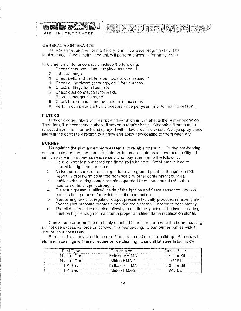
GENERAL MAINTENANCE As with any equipment or machinery, a maintenanCE, program should be
implemented. A well maintained unit will perform ef1'iciently for many years.
Equipment maintenance should include the following: 1. Check filters and clean or replace as needed. 2. Lube bearings. 3. Check belts and belt tension, (Do not over tension.) 4. Check all hardware (bearings, etc.) for tightness. 5. Check settings for all controls. 6, Check duct connections for leaks. 7. Re-caulk seams if needed, 8, Check burner and flame rod - clean if necessary. 9. Perform complete start-up procedure once per year (prior to heating season).
FILTERS Dirty or clogged filters will restrict air flow which in turn affects the burner operation,
Therefore, it is necessary to check filters on a regular basis. Cleanable filters can be removed from the filter rack and sprayed with a low pressure water. Always spray these filters in the opposite direction to air flow and apply new coating to filters when dry,
BURNER Maintaining the pilot assembly is essential to reliable operation. During pre-heating
season maintenance, the burner should be lit numerous times to confirm reliability. If ignition system components require servicing, pay attention to the following:
1. Handle porcelain spark rod and flame rod with care. Small cracks lead to intermittent ignition problems,
2. Midco burners utilize the pilot gas tube as a ground point for the ignition rod. Keep this grounding point free from scale or other contaminant build-up.
3. Ignition wire routing should remain separated from sheet metal cabinet to maintain optimal spark strength.
4. Dielectric grease is utilized inside of the ignition and flame sensor connection boots to limit potential for moisture in the connection.
5, Maintaining low pilot regulator output pressure typically produces reliable ignition. Excess pilot pressure creates a gas rich region that will not ignite conSistently.
6. The pilot solenoid is disabled following main flame ignition. The low fire setting must be high enough to maintain a proper amplified flame rectification signal.
Check that burner baffles are firmly attached to each other and to the burner casting. Do not use excessive force on screws in burner casting, Clean burner baffles with a wire brush if necessary.
Burner orifices may need to be re-drilled due to rust or other build-up. Burners with aluminum castings will rarely require orifice cleaning. Use drill bit sizes listed below.
-- -Fuel Type Burner Model Orifice Size
Natural Gas Ecli~se AH-MA 2.4 mm Bit Natural Gas Midco HMA-2 1/8" Bit .-
LP Gas Eclipse AH-MA 2.0 mm Bit f---LP Gas Midco HMA-2 #45 Bit '-- -----_._.- . _._-_ .. _-
14

BELT TENSION Proper sheave alignment and belt tension are critical to belt and bearing service life.
Incorrect belt tension or misalignment of sheaves can cause any of the following: 1. F'remature failure of bearings. 2. Premature failure of belts. 3. Reduced air volume. 4. Noise and vibrations.
Each Titan Air unit has as standard equipment an adjustable motor base. To adjust the belt tension, loosen the motor hold down bolts and adjust the slide base with adjusting bolt(s) on the end of the base (larger bases will have 2 adjustment bolts), Loose belts will slip, Excessive belt tension will shorten belt and bearing life. Use a belt tension tester and associated tables to determine proper tension, Re-tension after the first day of operation with new belts and periodically thereafter,
Common belt tension gauges will specify a force required to produce a deflection of 1/64" per inch of span, The force required to achieve this deflection is typically in the range of 3 Ibs for A-belts, 5 Ibs, for B-beits, and 15 Ibs, for 5V belts, See Figure 1 below,
Note that optimal belt tension is the lowest tension at which the belts will not slip under peak load, Peak load typically occurs at start-up,
SHEAVE ALIGNMENT With the use of a straight edge, sheave alignment can be checked quickly and
accurately, One of the sheaves will have to be loose on its shaft in order to make adjustment Adjust until all 4 points are in contact with the straight edge (see Figure 2), Repeat on the other side of sheaves and then re-tighten,
If a face width variation exists, measure the difference between each side of the narrowest sheave and adjust until both sides are an equal distance from the straight edge,
Motor Base
{;:-~~ Straight Edge
2 3 4
Figure 2
15
BLOWER BEARINGS l~earings must be checked during each periodic maintenance inspection. Bolts and
set screws should be checked for tightness and the bearings may need lubrication. The following is intended only as a guide to aid you in setting up your own schedule
LUBRICATION GUIDE FOR BLOWER BEARINGS
Operating condition", Clean
Dirty
Moisture
MOTOR BEARINGS
Bearing Temp. (,I') 32 - 120
120 - 150 150 - 200 32 - 150
150 - 200 32 - 200
Grease Interval 6 - 10 months 1 - 3 months 1 - 4 weeks 1 - 4 weeks Daily - 1 week Daily - 1 week
Motor bearings in a clean environment should be lubricated every 2 to 3 years. Under more severe conditions of dirt or moisture, lubrication may be required every 6 months to 1 year. Typical motor bearing lubrication procedure follows:
1. Remove fill and drain plugs. 2. Clean drain port of hard grease (with wire if necessary). 3. Add grease (cavity should be no more than y, full.). 4. Start motor and let run for 10 minutes. 5. Wipe off any drained grease and replace fill and drain plugs.
Avoid adding an excessive amount of grease since this a common cause of motor failure.
BL.OWER Ensure that blower hub is securely fastened to shaft. Inspect blower wheel and
blades for signs of damage or cracks. Clean blades if necessary to maintain proper balance and performance. Avoid use of excessive grease on blower bearings that can coat fan blades and attract dirt
16
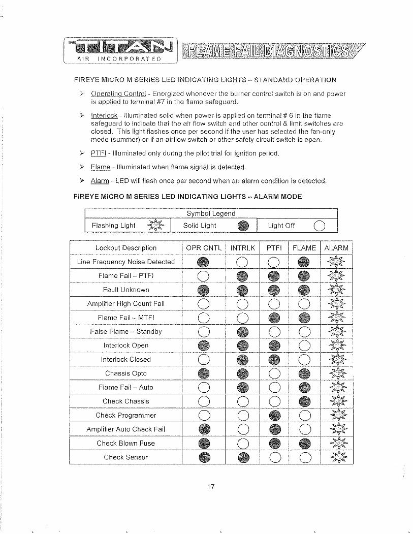
AIF~ INCORPORATED
FIREYE IVIICRO IVI SERIES LED INDICATING LIGHTS -. STANDARD OPERATION
> 9J2erating Control· Icnergized whenever the burner control switch is on and power is applied to terminal #7 in the flame safeguard.
> Interlock· Illuminated solid when power is applied on terminal # 6 in the flame safeguard to indicate that the air flow switch and other control & limit switches are closed. This light flashes once per second if the user has selected the fan··only mode (summer) or if an airflow switch or other safety circuit switch is open.
> PTFI· Illuminated only during the pilot trial for ignition period.
> Flame· Illuminated when flame signal is detected.
> Alarm· LED will flash once per second when an alarm condition is detected.
FIREYE MICRO M SERIES LED INDICATING LIGHTS - ALARM MODE
,-~~~~--~--.-•... - .. -.------.. ~~~~~~~~~.---
Symbol Legend
Flashing Light * I Solid Light ., I Light Off o . ------_.-
Lockout Description aPR CNTL INTRLK PTFI FLAME ALARM
Line Frequency Noise Detected • ._.0. 0 ., ~~$t> p,,-
0 • • • '>'<1 Flame Fail - PTFI ~V4 r·_····-- ..
Fault Unknown ..•.•..• _ •.......... _ .. _e __ •• • .--*~ .-----.. "-.---""-.-.. - ... ~-.-.-
Amplifier High Count Fail 0 __ 0._ _2 o ~~ .-~-------.. -------~--- .. -.-.----... -.-~- r--~----~----
Flame Fail - MTFI __ .0 ____ ._.0 • ..u* --,---- ... -... --..... -~,-"" .... ,,-.--,-, .... --.-, ...•. - .. --.-.•... -_. __ . False Flame - Standby 0 · .- --_Q_- 0
1 * _._--_ .. _ .. ······---t··-~· Interlock Open • • _.8_- o ~'@)~~ .~-.-
. 0 * Interlock Closed 0 • • ._._-_.-
Chassis Opto • • 0 • ';;;.D.d
~q74 r--0 • 0 • * Flame Fail - Auto
Check Chassis 0 0 0 • * r-'--0 0 • 0 ~~» Check Programmer p,,-
.
~ Amplifier Auto Check Fail • 0 • 0 Check Blown Fuse • 0 • • ";.;Jt:.~
~Qo-p "-
Check Sensor • • 0 0 ~~
17
8.·.· .•. ··.•.· .. ·. . .. -...... ..-.• '7 ..... -. "-.• ~·.=5·.~ .......••. ·' .•• ;:) .• · ........ ·T .... ·. '~'7: ... ,.-........ =. ..•.•..•• .r ............ ;-; .... · ... .•............. '. ' ...................................... -.... ~ .......•.. • .. l'iii> .. ·.· .. · .. ·.tQ.\.i.~ •.. ·.· .. ·.1\'·.' .•. ',;;T7 8~fi~!~J~t~~~~m!~[!!ll!~~t!J~mr~~~'
Line.f.L",guenc;yJ~gl$.Q.Q~"te"-t",~j· At start up, the MICRO M measures tile AC line to determine if the input is 50 Hz or 60 Hz and set its flag accordingly. As tho system is running, line frequency is constantly monitored. Outside interference causing a momentary shift in line frequency could be from SCR controls, VFO's, etc.
Flall1§'.f.?IL£'JFj· No flame signal present at the end of pilot trial for ignition period.
Fault Unknown· A catch all message when, under certain high noise conditions, the lockout message may become garbled and not translatable into any existing message
Amplifier Count Fail· A message used to detect a failed amplifier module that would generate an inordinate amount of pulses to micro computer, usually due to a shorted transistor or oscillating electronic filter.
Flame Fail· MTFI . No flame signal present during main burner trial for ignition period.
Flame Fail· Standby· Flame signal present, for a constant 60 seconds, while control is in standby or off condition.
Interlock ORen· Interlock safety circuit (terminal #6) has been detected open for longer than ten minutes during the purge cycle or during main flame period on MEP 562.
Interlock Closed· If selected by dip switches, air flow or interlock switch (terminal #6) is closed 30 seconds after the start of a cycle or when terminal #7 is closed. Titan Air does not use this function.
Chassis Opto . Opto coupler located on chassis has been found to be defective. Opto couplers are checked every 1/2 cycle of the AC main(s) to ensure they are off during the negative 1/2 cycle.
Flame Fail Auto· If dip switches selected for non·recycle, no flame is detected during the run cycle or main flame period.
Check Chassis· At beginning of cycle terminal #5 is energized.
Check Programmer· At beginning of cycle terminal #3 is energized or an internal diagnostics test for the Micro controller has failed.
Check Amplifier - Diagnostic problem with amplifier has been found.
Amplifier Auto Check· The amplifier is checked every 8 seconds by the micro computer to assure it is responding properly.
Check Blown Fuse· At the end of pilot try for ignition, no flame is detected and no power is present on terminal #3, indicating the fuse, located on chassis, is blown.
Check Scanner· The UV self check scanner (UV equipped units only) is producing flame pulses during the shutter closed period due to a malfunctioning shutter or a runaway UV tube.
18
GENERAL START-UP INFORMATION Even though Titan Air equipment is tested at the factory, it is not the type of
equipment you can throw the switch and walk away from. A complete start-up procedure must be performed.
The factory cannot duplicate the conditions the equipment will see in the actual installation (Le. gas pressure, static pressure, desired control settings, etc ... ). For this reason there are field adjustments that have to be made. Performing a complete startup procedure will help ensure that correct adjustments are made and correct operation is verified. A step-by-step start-up procedure is provided on subsequent pages. While working through the start-up procedure, record information on the start··up checklist and return to Titan Air to validate the equipment warranty. The start-up checklist is provided on cardstock with Titan Air's address pre-printed on one side.
Because most component failures occur during start-up, it is very important that the function of every component be checked out during start-up. It is just as important that the start-up technician realize the malfunction of a component may be caused by other factors (Le. air flow, gas pressure, field wiring, etc ... ) and should fully investigate a component malfunction and its cause before replacing the component.
Titan Air checks out all returned components and has found approximately 70% of returned parts are in full operational condition. This history has proven that a little extra time invested in troubleshooting will often save the considerable investment in paris, time, and paperwork associated with replacing components.
SUGGESTED TOOLS AND INSTRUMENTS NEEDED FOR START·UP: Volt/Ohm Meter Ammeter Tachometer Thermometer Gas pressure manometer (-10" to a to +10" of water column typical scale) Air differential pressure manometer (-2" to a to +2" of water column typical scale) Standard Hand Tools.
Additional items for Maxitrol Series 14 or 44 temperature controls: » Yo watt, 10,000 Ohm resistor
Additional items for FX Series temperature controls: » 1 0,000 Ohm resistor (supplied) » 1 ,000 Ohm resistor (supplied)
19
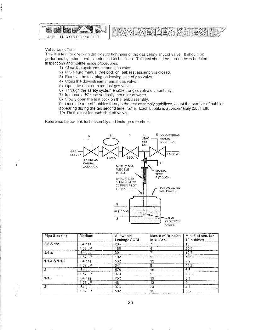
AIR INCORPOHATED
Valve Leak Test This is a test for checking Hie closure tightness of the gas safety shutoff valve. It should be performed by trained and experienced technicians. This test should be part of the scheduled inspections and maintenance procedures.
1) Close the upstream manual gas valve. 2) Make sure manual test cock on leak test assembly is closed. 3) F,emove the test plug on leaving side of gas valve. 4) Close tire downstream manual gas valve. 5) Open the upstream manual gas valve. 6) Through the safety system enable the gas valve momentarily. 7) Immerse a ;'-:;" tube vertically into a jar of water. 8) Slowly open the test cock on the leak assembly. 9) Once the rate of bubbles through the test assembly stabilizes, count the number of bubbles appearing during the ten second time frame. Each bubble is approximately 0.001 cfh. 10) Do this test for each shut off valve.
Reference below leak test assembly and leakage rate chart.
A
GAS COCK
Pipe Size (in)
13/8&1/2 84 "e, 1.57 LP
1 3/4 & 1 .64 qas 1.57 LP
11-1/4&1-1/2 .64 qas 1.57 LP
12 .64 qas 1.57 LP
li:1}2- .64 aas 1.57L.P
3 64aas 157 LP
8 c
C) o
lE/\K TEST TAP
E OOWt'/STREAM MANUAL GASCQCK
1/4 IN. (6 MM) FLEXIBLE
TU8ING~
114 IN. (0 MM) AlUM1NUt'l'IOR COPPER PILOT
BURNER
F
~ Mp.NUAL
TEST PETCOCK
TUBING ~ r ,)ARORGL.!\SS '" V<ATH WATER
.--++-~
1/2 (13 tvHvl) tJ -r.----~--- ~---.I CUT AT
45DEGF-lEE ANGLE
I o~';.n~I~CCH ~a1xO ;Z~BUbbleS
294 7 188 4
I 301 7 192 5 532 13 341 8
I 578 15 I 3ib [) 'i52 1481 ~ I 5~
20
~~n. II of sec. for
13 !OA 12.7 19.9 '.2
11.2 I 6.6
10.3 ;.1
1.1
I i5

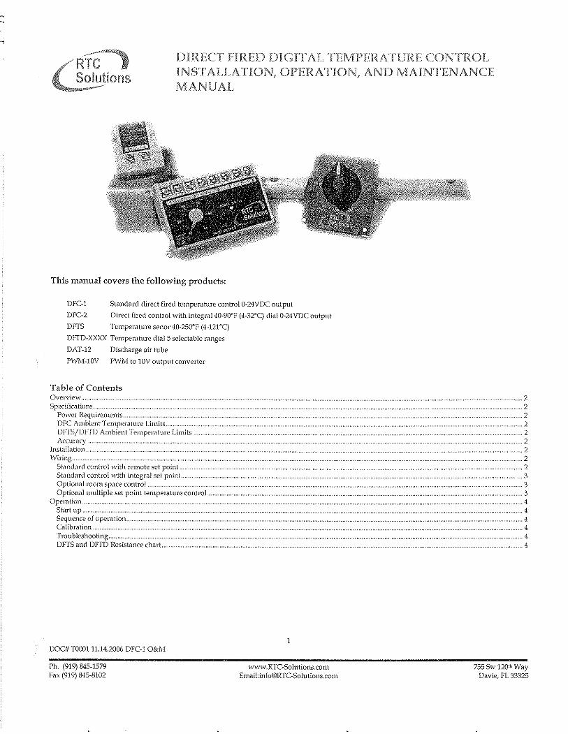
'RTCI Solutions
DlREcr FIRED DIGrrALTEMPERATURE CONTROL INST'ALLATION, OPERA'fION, AND MAINTENANCE MANUAL
This manual covers the following products:
DFC-1
DFC-2
DHS
Standard direct fired temperature control 0-24VDC output
Direct fired control with integra140-90°F (4-32°C) dial 0-24VDC output
Temperature senor 40-250°F (4-121°C)
DFTD-XXXX Temperature dialS selectable ranges
DAT-12 Disc1wge ah tube
PWM-I0V PWM to lOVoutputconverter
Table of Contents Overview .. Specifications ..
Pov,'er Reqnirements .. DFC Ambient-Temperature Limits, .. DFTSjDFTD Ambient Temperature Limits, Accuracy.
Installation ...
St<'mdard control with remote set point ,. Standard control with integ!",,1 set point.. Optional room space control .. Optional multiple sel point temperature control ..
Operation ... Start up .. Sequence of operation ... Calibmtion .. Troubleshooting .. DFTS and DFTD Resistance chart..
DOCff TOO0l1l.J4.2006 DFC-1 O&M
Ph, (919) 845-1579 fax (919) 845-8102
1
www.IUC-Solutions.com Emai1:[email protected]
""""",,,,,,,,,,,,,,,,.2
".,,,.,, ... ,,.,.2 . ........................................... 2
""""""""""""""",,,,,,,,,,,2
"""""""""""""""""",,2
, .. ".,., ... " .. 2 ,,,,,., .. , ... 2
2 """"""",,",,'" ,,,.2 ..... " .... ", ......... ",3
.. .................. 3 . ... ".,,""""" 3
. ..... , .. ,., ..... , ... , ... " .... ".4 . ............... "", .. ", ... ".,,,., ....... 4
,,,.,,4 • •• """"""",4
. ......................................... 4 '"''''''''''''''''"'',,'''',,.,,''''' 4
755Sw 120lh Way Davie, FL 33325

Overview J'ih' RoofT()p COlltrol (~~,It1li()l\S dirc'd rin~d digit'l! 1(,111p('r,'I11I\' control is ,1 mil mprun:ssnr bdSt'd control thalu!ilizes all intl'lligenll)J]) soflwiln' digoJ'ithm\u JllOdlllalt' gilS now 10 <l burner in direct iiJ'ed Illilb' up air ilpplic<ltiol1S. The d()Sl~d loop system contains lhn'l~ components induding till.' din'c! iiJhi krnjlCl'iltlll'l' Sl'l1Sor (DFIS), the dired (ifni control (OrC), ,md tiw din:cl (jn~d tl'lllpI;ralun: dial (])Fr]). riw syslem con11MI'(,S Ilw disc!o;HW' [l'Jl1PCI'<lluJ'C of tlw IW<lling unit to thv ;;l'l point didl -lO tillll'~; per s('cond insllrinfi ,Krur<llc dlld rqwalabk Il'mp('l"il!lll'l' nllllroL Tlw so[IWiHl' provid(;~; smooth output ((JIllfol eliminating cv'('ssivl' swings obs('J'v('d vvilh older <ll1'llog syc,kms. /\ 10 second S[;lr[ up ddilY is Slill1dard, and an onbo<1nl !-ED indicates sirnpk didgnosli('s
Specifications PO\ver Requirements DFe Ambient Temperature Limits
Storage Operating
DFTSjDFTD Ambient Temperature Limits Storage Operating
Accuracy
Installation
24 V;\C SOl 60l-lz 20V A iso];lled class JJ tmJ1SfOnlWl
-40-140'1' ("1O-60T) -40-140'F (AO-60'e:)
-40-250'1' (·40-121'q "1O-250'F (-40-121 'q
+/_3'1' We:)
All control wiring should be shielded with the shielding grounded imdj or the wiring should be run in separate conduit from any high voltage wires. Interference from these sources could cause control function errors or permanent damage. The DFC control should be mounted in a housing free from the elements of weather. Insulated fork termrnal terminations are recommended for best contact when attaching wiring to the provided scre\,\' terminals. Models DFC-1 and DFC-2 can drive up to £1.5 amp 24VDC direct acting solenoid.
The I)Fff) can be set to 5 different temperature ranges by moving jumper 11 as shown in Figure 1 on the back of the dial to the desired position. 5 different temperature overJoys are available to mi1tch the range chosen.
,.,. Importrult! When using the PWM-IOV output converter to connect the DFC to a motorized achlator, or any other device with it's own power supply, the DFC must have it's own isolated trrulsfonner separate n:om the power source for the actuator, or the control may be drunaged.
Wiring
Standard control with remote set point \Vjrjno C(Um,yt'Qn<
For$lCOlel1S actuator IW(G) l02·) VAC
Figure 1
61~d;(GO) !02-1\'A(' ,mct llIc.ckon P\V~l·IOV Crav(Y) to Red on PI\,,\'I·lOV l'mk(U) ,'>;0 Ccnn<xl
DnD rl'mj-X'r,1\Uh'
Sd0.·UUhdl,ll
10" ". i "
DF1S T~[\l!x'r,\lu,,>
s~nscr
DOC# T000111.14.2006 IlK-I O&M
Ph. (919) 845-1579 Fax (919) 845-8102
Dl·TO T('n1 l"'r,ltIlH.' ~d~CllOI\(l!,\l
"0· ". " "
DFr$ rrnl!"'r,1tul\'
I'WM·l0V
Fl>l !:dIlHO ilcllJ,l\Uf
1 t<l2.1VAC ,mrl Il!,\,!,; on I'W:Vl·}()V 2 to 24VAC :1 to Iwd 0]\ !'IV,,",·j·lOV
'lmpilrl,\)l(. Adu,llor umsl 1)(' pow~red by isolated SOllf(C fmlll orC(onlrol
DFCl
Figure 2 - Standard control wiring showing output options
2
www.RTC-Solutions.com Emoil:[email protected]
755Sw 120ll> Way Davie, FL 33325

Standard control with inlegrai set point
Optional room space conl-rol
Ol~'"''·'i''''''' tl,'en",,,,!
EJ
Figme 3 ~ Control with intcgr<ll sdpoint
Figure 4 - RaoUl space control with thelmostat Figure 5 .. RaoUl space control with digital space conlTol
A stand.ard make or bre<lk thermostat with nOrIJ1<llly open contacts can be connected between terminals 1 and 2. as shown in Figure 4. When connected in this Wily the thermostat may be set for a desired room temperature for sp<lce control applications. Potentiometer Rl on the back of the DFTD sets hol'." much the temperature will increase by when the room thermostat calls for more heat. When the room thermostat is satisfied, the discharge temperature will return to the temperature set on the clial on the front of the DFTD. For proportional room space control, the DFCl can be connected as ShO'\'l1 in Figure 5. See RTC-lliterature for details.
Optional multiple set point temperahue conhol
DHD (~7.oJh'n'I"""""
q3~o I
0",,-,0 ~-~'.,..,
O!·l'; I"""P~'""~'
DrC-l
FiglUe 6 ~ Control with multiple set points
More than one temperature dial can be connected as shown in Figure 3 for applications such as paint spray booths or process control.
DOC# T000111.14.2006 DFC-l O&M
Ph. (919) 845-1579 Fex (919) 845-8102
3
www.RTC~Solulions.com
El11an:info@RTC~Solutions.com
755 Sw 120111 Way Davie, FL 33325

Operation
Start up S(>lling In\\' jil't, ]'Iw mininwl11 fij'in~j rdtl' I1l"Y h~ s('1 by 1"l'lllUviI11', lill' \\'il\' frum Il'rl'l1il1<1i illlmiwJ' () (\n ()w i )j.'C.' ('(mimi, rhis dis\ UIlIW,"!:, till' jX)\,\'('I' t<)
the control valve. i{cJt,r to the (onlroi villvl' 1l1ilI111fiKluH'S iikrature foJ' this "djustnwl1[
Selling high nn~ - I"Iw m,1xim,\lil1 firing I'ilt(' llldY he St't hy removing tilt: win' (rom terminal ntunlwr·f on Ilw l)j-'(' ~"ol1lroL ')"his dis('ol1l1('(.\s tl'\<' discharge ,1ir sensor and s('ts the outpul' to the control vdlve to it's maximum. Refer to til\' control valve m,lIlu(ilc\Ul'l'S litel'ature for this adjuslllwnl
Sequence of operation Upon applying power to tht: DFC control the 10 second stml up ddily will begin indicated by i\ slow blinking LED (about once every 2 seconds) on Ilw face of the control. AJter the start up delay has completed, till' LED will turn solid and the control will begin modulating the output as required. Any system errors are indicated by a fast blinking LEU (about twice per second) for instance when the discharge air sensor is disconnected or outside of tlll' normal operating fimgc,
Calibration The temperature control should maintain an accuracy of '1) - 3°F (1 DC). In the event that the discharge is inaccurate due to duct losses the control may be calibrated in t\VO \vays. The potentiometer on the face of the DFC IOlbelcd "ADJUST" \vill adjust the discharge temperature by +/_lO°F (SoC) when rotated. Rotating it clockwise will increase the temperature and counter dockwise will decrease the temperi1lUl'e. The system mOly (liso be adjusted from the DFTD if installed by adjusting potentiometer R3 on the back in the S,Hne manner as the DFe procedure above.
Troubleshooting The DFC control provides some diagnostics via the on board LED labeled "POWER/STATUS". A system fault is indicat(~d by a fast blinking LED (about twice per second). This usually indicates that the sensor or dial are either disconnected or improperly wired. Check all connections per the included wiring diagrams. The fault also may be caused by a damaged sensor or dial. Both devices may be tested with an Ohnuneter by removing the wires from the DFe control and me(lsuring across the device. The devices should measure between 12.SK and 7K OHMS. If there is a fault light (lnd the devices measure the proper resistance then the control may be damaged. If there is no fault light but the system is not modulating properly you may check the control output by repeating the start up procedure and measuring tenninals 5 and 6 on the DFC as follows.
For DFC-l and DFC-2 Remove the wire from terminol nmnber 4 on the DFC control and measure the voltage across terminals 5 and 6 ,vith a voltmeter. The owte)" should read from 20 to 24 Volts. If it does not, disconnect the wires from the valve and measure the output without the valve connected. If it reads 20 to 24 Volts, refer to the valve manufactures literature for troubleshooting the valve. Jf it does not the control may be damaged.
DFl'S and DFrD Resistance chart
Tem OF Tem °C
DOC# T000111.14.2006 me·1 O&M
Ph. (919) 845·1579 Fax (919) 845·8102
Sensor Resistance Dial Resistance 40-90 80-130 120-170 160-210 200-2.S0
4
www.RTC-Solutions.com Email:[email protected]
755Sw 1201\t Way Davie, FL 33325

,JiS1HNSON CDNTRl':JLS Product/Technical Bulletin
Issue Date Mig
April 4, 2008
9 Series Electronic Temperature Controls with Display and NEMA 1 or NEMA 4X Watertight Enclosures
Tile A419 series contmls are single-stage, electmnic temperature contmls with a Single-Pole, DouNe-Tilrow (SPD T) output relay. They feature a lockable front-panel touchpad for setup and adjustment, and a Uquid Crystal Display (LCD) for viewing the temperature and status of other functions. A Ligi7t-Emitting Diode (LED) indicates the contmls' output relay On/Off status. The A419 contmls are available in 24 VAC or 120/240 VAC powered models.
The A419 controls have heating and coaling modes, adjustable setpoint and differential, an adjustable anti-short cycle delay, and a temperature offset function. The setpoint range is -30 to 212°F (-34 to 100°C). The controls feature remote sensing capability and interchangeable sensors. The A419 contmls are available in either NEMA 1, high-impact plastic enclosure suitable for surface or DIN fail mounting or NEMA 4X watertight, corrosion-resistant surface-mount enclosures.
Figure 1: A419 Temperature Control with NEMA 1 Enclosure and A99 Temperature Sensor
Features and Benefits
Easy-to-Read Front-Panel Liquid Crystal Display
Wide Temperature Differential Adjustment Range (1 to 30Fo or CO)
Adjustable Anti-Short Cycle Delay (0 to 12 Minutes in 1-Minute Increments)
Switch-Activated Temperature Offset Function
High-Impact, Thermoplastic NEMA 1 or NEMA 4X Watertight, Corrosion-Resistant Enclosures
Lockable Front Panel Touchpad
Low- and Line-Voltage Models
© 2008 Johnson Controls, Inc. Code No. LlT-125188
Displays the sensed temperature and control-function status clearly; custom icons on the display indicate the control and system status at a glance
Allows the user to set a precise (1 FO or CO) temperature differential from 1 to 30Fo or Co; providing a much tighter differential than electromechanical controls
Ensures that the output relay remains off for a user-set time delay, which helps avoid hard starts, nuisance overload outages, and unnecessary equipment wear
Allows the user to shift the cut-in and cutout setpoints by an adjustable offset based on the status of a user-installed, external switch, such as a time clock
Increase application options, allowing surface and snap-fit DIN rail mount, or Watertight surface mount
Allows easy set up and adjustment of the A419 control setpoint, differential, and other functions; a concealed jumper locks the touchpad, and deters unauthorized adjustment of the control settings
Provide options for most refrigeration and HVAC control-voltage applications
1 www.johnsoncontrols.com

Application
IMPORTANT: Tile A419 Series Temperature Controls are intended to control equipment under normal operating conditions. Where failure or malfunction of an A419 Series Control could lead to an abnormal operating condition that could cause personal injury or damage to the equipment or other property, other devices (limit or safety controls) or systems (alarm or supervisory) intended to warn of or protect against failure or malfunction of the A419 Series Control must be incorporated into and maintained as part of the control system.
The A419 Electronic Temperature Control can be used to control a wide variety of single-stage refrigeration or Heating Ventilating, and Air Conditioning (HVAC) equipment. Typical applications include:
• retail store display freezers and reach-in coolers
• supermarket display cases for produce/meats
• retail store walk-in coolers and freezers
• boiler operating control (used as a thermostat)
• condenser fan cycling or staging
• cooling tower pump and fan control
• space and return air temperature control
FCC Compliance
This device complies with Part 15 of the FCC Rules. Operation is subject to the following two conditions: (1) this device may not cause harmful interference, and (2) this device must accept any interference that may cause undesired operation.
This equipment has been tested and found to comply with the limits for a Class A digital device pursuant to Part 15 of FCC rules. These limits are designed to provide reasonable protection against harmful interference when this equipment is operated in a commercial environment. This equipment generates, uses, and can radiate radio frequency energy and, if not installed and used in accordance with the instruction manual, may cause harmful interference to radio communications. Operation of this equipment in a residential area is likely to cause harmful interference, in which case the user will be required to correct the interference at his or her own expense.
Canadian Compliance Statement
This digital apparatus does not exceed the Class A limits for radio noise emissions from digital apparatus set out in the Radio Interference Regulations of the Canadian Department of Communications.
Dimensions
-.-'--:: m
.... r ! L. i ;;;<Al -i) ~~{;
J. , .
! L:::::J r(1~ I §0
@).~
+1 "e":-1Il:
[ ~
7)
6 I~ 2-318 -I ) (61)
M 2-318
718 ---. (61)
(22) ~-7/8 (1/2 in. Trade Size) (22) Conduit Hole
Figure 2: A419 Temperature Control with NEMA 1 Enclosure, Dimensions, in.l(mm)
.• 2-114 •. 1-1116f+ (56) I (27) I
~-.. '.-. -'~~=:::-l-::-;t=--- --~~- . .. ,.-"'1"'l!l (44)
A419 J·-----1it-I-lH-
o 6-5ill . (168)
IiJ • [j 6-118 (155)
~l ~ @) I :~. -.:..:-'::::':::::=':::::== . .... _ 2-13116 ~ I I
(71) I Position the A99 sensor
~-T.':--- ' •. :--- ----------t---- in the bracket at the bottom of
! j 'I the A419 NEMA 4X enclosure . .. L ______ ..l_ 2-13116
! ii (71)" , c:_' __ "ji 1 '1 I' ".J1_ [ill--~..
Figure 3: A419 Temperature Control with NEMA 4X Watertight, Corrosion-resistant,
Enclosure, Dimensions, in.l(mm)
2 A419 Series Electronic Temperature Controls with Display and NEMA 1 or NEMA 4X Watertight Enclosures ProductlTechnical Bulletin
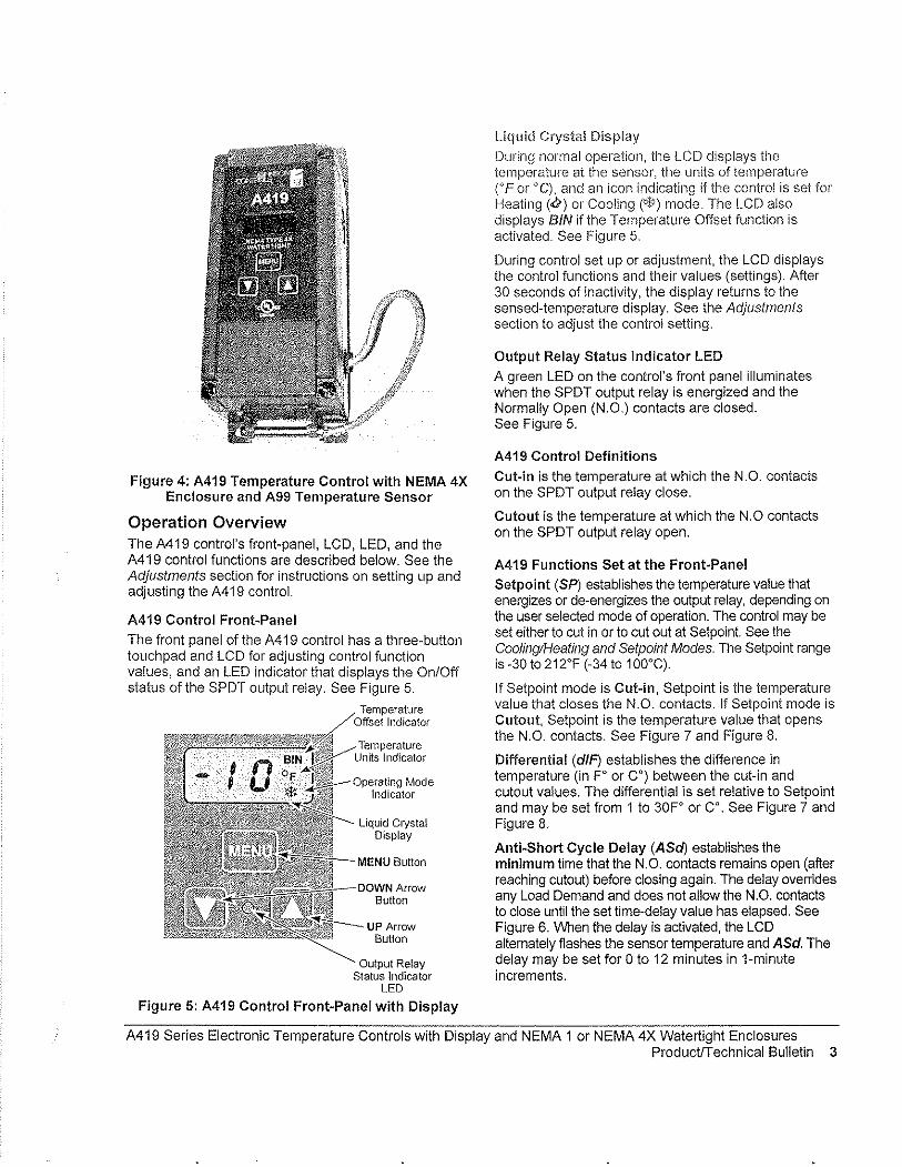
Figure 4: A419 Temperature Control with NEMA 4X Enclosure and A99 Temperature Sensor
Operation Overview The A419 control's front-panel, LCD, LED, and the A419 control functions are described below. See the Adjustments section for instructions on setting up and adjusting the A419 control.
A419 Control Front-Panel
The front panel of the A419 control has a three-button touch pad and LCD for adjusting control function values, and an LED indicator that displays the On/Off status of the SPDT output relay. See Figure 5.
Indicator
Operating Mode Indicator
Liquid Crystal Display
--DIJWN Arrow Button
UP Arrow Button
Output Relay Status Indicator
LED
Figure 5: A419 Control Front-Panel with Display
Liquid Cryslal Display
During normal operation, the LCD displays the temperature at tile sensor, the units of temperature ('F or 'C), and an icon indicating if the control is set for Heating ('&) or Cooling (*) mode. The LCD also displays BIN if the Temperature Offset function is activated. See Figure 5.
During control set up or adjustment, the LCD displays the control functions and their values (settings). After 30 seconds of inactivity, the display returns to the sensed-temperature display. See the Adjustments section to adjust the control setting.
Output Relay Status Indicator LED
A green LED on the control's front panel illuminates when the SPOT output relay is energized and the Normally Open (N.O.) contacts are closed. See Figure 5.
A419 Control Definitions
Cut-in is the temperature at which the N.O. contacts on the SPOT output relay close.
Cutout is the temperature at which the N.O contacts on the SPOT output relay open.
A419 Functions Set at the Front-Panel
Setpoin! (SP) establishes the temperature value that energizes or de-energizes the output relay, depending on the user selected mode of operation. The control may be set either to cut in or to cut out at Setpoin!. See the Cooling/Heating and Setpoint Modes. The Setpoint range is -30 to 212'F (-34 to 100°G).
If Setpoint mode is Cut-in, Setpoint is the temperature value that closes the N.O. contacts. If Setpoint mode is Cutout, Setpoint is the temperature value that opens the N.O. contacts. See Figure 7 and Figure 8.
Differential (dIP) establishes the difference in temperature (in F' or C') between the cut-in and cutout values. The differential is set relative to Setpoint and may be set from 1 to 30F' or Co. See Figure 7 and Figure 8.
Anti-Short Cycle Delay (ASci) establishes the minimum time that the N.O. contacts remains open (after reaching cutout) before closing again. The delay overrides any Load Demand and does not allow the N.O. contacts to close until the set time-delay value has elapsed. See Figure 6. When the delay is activated, the LCD alternately flashes the sensor temperature and ASd. The delay may be set for 0 to 12 minutes in i-minute increments.
A419 Series Electronic Temperature Controls with Display and NEMA 1 or NEMA 4X Watertight Enclosures Product/Technical Bulletin 3
For example, if the anti··short cycle delay is set for '7 minutes, the A419 control will not restali the equipment for 7 minutes after the equipment has cut out, even if the cut-in temperature value is reached during the delay. If the temperature reaches the cut-in value during tile delay period, the display flashes between the sensed temperature and ASd, indicating that the next On-cycle is being delayed. After the set delay time has elapsed, the A419 control returns to normal operation, restarts the equipment (if cut-in has been reached), ASd stops flashing, and the LCD reverts to the normal operating display.
Note: Any interruption in supply power to the A4i9 control activates the anti-short cycle delay.
Time): Load Demand ,.,--~ Overridden
~~ LLoad Demand rolil.~11
..QfU t=====:J L Output Status Anti~short
Cyde DeJay
Figure 6: Anti-short Cycle Delay
Sensor Failure Operation (SF) establishes how the A4i9 control operates the equipment in the event of a sensor or sensor-wiring failure. The A419 control may be set to run the equipment continuously or to shut it down if the sensor or sensor wire fails. When a failure is detected the LCD flashes SF alternately with OP if the sensor circuit is open, or SF and SH if the sensor circuit is shorted. The control implements a i-minute delay before initiating a failure response to allow for verification of the failure condition and to avoid nuisance failure indications.
Temperature Units establishes the units of temperature (FO or CO) displayed on the LCD.
Temperature Offset (OFS) establishes the value of setpoint-shift (in FO or CO) applied to Setpoint (and Differential) when a (user-installed) circuit is closed between the binary input (BIN) and common (COM) terminals. The offset value may be set from 0 to 50Fo or Co.
The Temperature Offset function is used to reset the Heating Setpoint to a lower temperature (secondary) setpoint or reset the Cooling Setpoint to a higher temperature (secondary) setpoint by the temperature value set in Temperature Offset.
The BIN and COM terminals may be connected to a (user-supplied) external switching device, such as a time clock, that has a set of Single-Pole, Single-Throw (SPST) contacts. Closing a circuit between the BIN and COM terminals activates the Temperature Offset. See Wiring.
This fUllction enables the control to alternate between two temperature setpoints based on the position of the binary input switcll. The difference between the primary and secondary setpoints (in FO or CO) is set in the Temperature Offset function (OFS) using the touchpad. See SettJilg Other Functions.
Table 1 shows an example of Temperature Offset.
Table 1: Temperature Offset Example
Mode of Se!point Temperature Secondary Operation Offset Value Setpoin!'
Cooling 70° 8° 78° --Heating 70° go 62°
Setpomt when CircUit between binary Input termmals (BIN and COM) is closed
When the circuit is closed between the binary input (BIN) common (COM) terminals, the offset function is enabled and the A419 control cycles on the secondary setpoints. BIN is displayed on the LCD above the OF or °C symbol when the offset is enabled. See Figure 5.
A419 Control Functions Set by Jumper Position
For instructions on positioning jumpers, see Positioning the Jumpers in the Adjustments section. Refer to Figure 12 and Figure 13.
Touchpad Lock: The jumper at P5 establishes whether the touch pad is locked or unlocked. Locking the touch pad deters accidental or unauthorized changes to all of the function parameters.
Heating/Cooling Mode is established by positioning the jumper on the top two pins of the P4 jumper. See Figure 13.
Setpoint Mode: Removing or installing the lower jumper at P4 establishes whether Setpoint is the cut-in temperature or cutout temperature. See Figure 13.
Cooling/Heating and Setpoint Modes
The A4i9 control may be in four operating modes: Cooling/Cut-in, Cooling/Cutout, Heating/Cut-in, and Heating/Cutout. Position the jumpers located on the circuit board under the A419 control cover to set the desired rnode of operation. See Positioning the Jumpers.
In Cooling/Cut-in mode the differential is below Setpoint. The output relay energizes and the LED illuminates when the temperature rises to Setpoint. When the temperature drops to Setpoint minus the differential value, the relay and LED de-energize.
4 A419 Series Electronic Temperature Controls with Display and NEMA 1 or NEMA 4X Watertight Enclosures ProductlTechnical Bulletin
In Cooling/Cutout mode the differential is above Setpoint The output relay energizes and LED illuminates when the temperature rises to Set point plus the differential value. When the temperature drops to Setpoint, the relay and LED de·energize.
Temperature (+) Cooling/Cui-out
Cut·j~+·······1 (OI1)t
Differential
~. Cut-out
(Oft) Cooling/Cut-in Setpoint - --_.L:.... .. ~,C<_IL._~r-.::....._~
Cui-in (On)
Figure 7: Cooling Modes
Cut-out (Off)
When the Heating/Cut-in mode is selected, the differential is above Setpoin!. The output relay energizes and LED indicator illuminates when the temperature drops to Setpoin!. When the temperature rises to Setpoint plus the differential value, the output relay and LED de·energize.
When Heating/Cutout mode is selected, the differential is below Setpoin!. The output relay energizes and LED indicator illuminates when the temperature drops to Setpoint minus the differential value. When the temperature rises to Setpoint, the output relay and LED indicator de·energize.
Temperature (+) Heating/Cut-in
r"'~rc I,,> :'<:; -':""'. _ Cut-oul lit·· .... [ (OrD
Differential Cut-in (On)
Heating/Cut-out Setpoint -I-__ ~_::'+-~_""':"'-'''''':''''':';'':'l.
(.)
t Cut-out
l~rrE (Off)
iira~ Cut-in (On)
Figure 8: Heating Modes
Mounting An A419 control has either a standard high·impact plastic NEMA 1 or a NEMA 4X corrosion·resistant, watertight enclosure.
The A419 control is not position sensitive but should be mounted for convenient wiring and adjustment.
Note: When mounting the control to rigid conduit, attach the hub to the conduit before securing the hub to the control enclosure.
The mounting hole pattern of the NEMA 1 enclosure is identical to that of the System 350'" controls, and most models of the A 19 control. The NEMA 1 enclosure may also be mounted on 35 mm DIN rail. See Figure 1 and Figure 2.
The NEMA 4X models may be mounted to fiat vertical surfaces using the four screw holes at the enclosure corners. See Figure 3 and Figure 4. To maintain the watertight and corrosion resistant integrity of the NEMA 4X enclosure, use a conduit fitting rated for the environment in which the control is installed.
An additional (Iow·voltage) two·wire cable is required to operate the temperature offset function. On NEMA 4X enclosures you must install a suitable liquid-tight fitting in an available knockout to pass the two-wire cable through the enclosure wall.
IMPORTANT: The short·lead A99 sensor, included with A419 NEMA 4X model controls, must be mounted on the bottom of the control in the bracket molded on the NEMA 4X housing. Mounting the sensor on top of the control may reduce the accuracy of the displayed temperature. See Figure 3 and Figure 4 for proper sensor position.
A419 Series Electronic Temperature Controls with Display and NEMA 1 or NEMA 4X Watertight Enclosures ProductlTechnical Bulletin 5
Wiring .......... ___ ._._._ .... ~ . . ................ ~ u._.~, __ ... ~
.A WARNING: Risl, of Electrical Shock. To avoid the risk of electrical shock, disconnect all power sources to the control before wiring any connections. More than one disconnect may be required to completely de-energize the control and equipment.
IMPORTANT: All wiring must conform to local, national, and regional regulations. Use copper conductors only for all wire connections. Do not exceed the electrical ratings for the A419 control or the equipment it is wired to.
Refer to Figure 9, Figure 10, and Figure 11 for typical examples of wiring an A419 control to the controlled equipment.
Use wire no larger than 12 AWG when connecting to the two lower terminal blocks (TB1 and TB2).
Note: Terminal block TB2 is an isolated SPDT switch (dry contacts). The TB2 terminals have no internal electrical connection to the A419 control.
Use wire no larger than 16 AWG when connecting to the upper sensor terminal block (TB3).
Wire insulation rating must be 90'C, minimum.
A99 temperature sensors are not polarity sensitive. Wire the leads to (+) SEN and (-) COM on the sensor terminal block (TB3). See Figure 9, Figure 10, and Figure 11.
Keep the leads between the control and sensor as short as possible/practical in your application. The additional resistance in long sensor leads creates error between the actual temperature and the displayed temperature. Refer to Table 1 when extending sensor leads.
Temperature sensor signals may be affected by electrical interference. Willen extending sensor cable beyond 50 It (15.2 m) use a twisted-pair, shielded cable to reduce electrical interference.
If the Temperature Offset function is used, wire a switch (such as a switching time clock) between the binary input terminal (BIN) and the common terminal (COM). See Figure 9, Figure 10, and Figure 11 for terminal strip location.
Figure 9: Wiring the 24 VAC A419 Control
(Optional) 1-----A~19ABC-1 I
Bln~~t~~f~ut I A419AEC-1 I I ~ 0 I+)BIN
~HCOM
r;: I+)SEN )( TB3i----1
Cable [I 1..:' .. ~ ... _J,_, 1 Shield ~ i
lif used:99 1~~~'~r'~@6i~~=:=~~'1-=::-'81 Sensor ~ 0 ~ ~ u Z
N () -()
~_ 5.. ______ . 120VAC-~------../ ~ __ _
Neutral----- ~ f120 VAC] --------1 Load
Figure 10: Wiring the 120 VAC A419 Control
(Optional) I A419ABC"1 Binary Input A419AEC.1
SWltcll r:-l
I [tJf-tI+)BIN HCOM (+)SEN---
)( TB3 rr= I I, Cable ~ -- , Shield ;-"
lif used)@'---.J A99 ~ 0 TB2rei00l
Sensor '\ - :;! J-i17o l-' CI 0 0 uo ~ u ~ Z 2
()
-'=~±12:O: ====;;;~t-240 L1 VAC L2--.~--_11240VAC
I Load
Figure 11: Wiring the 240 VAC A419 Control
6 A419 Series Electronic Temperature Controls with Display and NEMA 1 or NEMA 4X Watertight Enclosures ProductiTechnical Bulletin

Adjustments This section provides instructions for setting up and adjusting the A41 9 controls using the jumpers and touchpad.
Positioning the Jumpers
The P5 Jumper Pin Block has a single set of jumper pins and is used to lock or unlock the touchpad. The P4 Jumper Pin Block has two sets of jumper pins.
The top set of pins at P4, labeled JUMP1, is used to set the control for Heating or Cooling mode. The bottom set of pins, labeled JUMP2, is used to establish Setpoin! at cut-in or at cutout. See Figure 12.
To position a jumper in the Installed position, place the jumper on both pins. To position a jumper in the Removed position, place the jumper on only one pin. (Save the jumper in case it is required in the future.) See Figure 12.
Position the jumpers as follows. Refer to Figure 12, Figure 13, and Table 2.
1. Verify that all power sources to the A419 control have been disconnected.
2. Remove the control's cover by loosening the four captive cover screws.
3. Position the jumpers to set Cooling/Heating, Setpoint, and Touchpad Lock functions.
4. Replace the cover and fasten in place with the four screws,
5. Restore power to the control.
IMPORTANT: Verify that the Cooling/Heating jumper is positioned properly before powering the A419 control, to ensure that the relay operates as intended. See Figure 13 and Table 2.
Jumper; a ~ ~ "'.' Installed
(Jumper Positioned on Both Pins)
Pins ; -- f&llED
/'j Removed (Jumper Positioned on One Pin)
Figure 12: Positioning the Jumpers
~ I Touchpad Touchpad
Locked Unlocked
101 [01 JUMP1 fODl 16 @J JUMP2~ I.?? P5 P4
1_
~ II1[§]
Heati ng Mode Cui-in at Setpoinl
IIilI[QJ IIilI[QJ
Cooling Mode Cut-i n at Selpoi nl
== Heating Mode (Standard)
Cut-out at Setpoint
1lfIillQ] ~
Cooling Mode (Standard)
Cut-oul at Setpoint
Figure 13: Jumper Positions and Control Settings
Table 2: Jumper Designations, Jumper Positions and Control Settings
Function Jumper Pins Designation Setting Jumper Factory Default Setting
on Control Position* (and Jumoer Position)
Operating Mode JUMP1 Cooling Removed Cooling Cooling/Heating (Top Pair of Pins on Block P4) Heating Installed (Removed position)
Setpoint JUMP2 At Cut-in Removed Cut-in (Bottom Pair of Pins on Block P4) At Cut-out Installed (Removed Position)
Locked Removed Unlocked Touchpad Lock P5-Touchpad Unlock (Installed Position) Unlocked Installed
Note: The touch pad cannot be unlocked Without a Jumper. Do not discard illJ.)! Jumpers III case they are reqUired In the future.
A419 Series Electronic Temperature Controls with Display and NEMA 1 or NEMA 4X Watertight Enclosures Product/Technical Bulletin 7
Changing Temperature Units
The A419 contl"Ol is set at the factory to display in Fahrenheit tenlperature units.
rntJ press the Up and Down buttons " \J To convert to Celsius units,
V simultaneously. Press them again to return to Fahrenheit units.
Notes: Make sure the Touchpad Lockjumper is in the unlocked (installed) position before adjusting the controi. See Figure 13.
Verify that the A419 control is displaying the desired temperature units (F' or C') before establishing the setpoint value.
Setting the Setpoint To view and adjust the temperature setpoint, follow these steps and refer to Table 3:
MEN\:J
MEN~
'~ MEN\:J
1. Press and hold the MENU button until the display changes to fiashing SP. This will take about 2 seconds.
2. Press the MENU button again. The current setpoint is displayed.
3. Press the Up or Down button to adjust the setpoint temperature.
4. Press the MENU button to save. The display then returns to the sensor temperature.
Notes: If no entries are made for 30 seconds while programming is in progress, the control reverts to the normal temperature display.
If the MENU button is not pressed after changing the setpoint value, the new value is not saved and the A419 control reverts to the previously saved setpoint value.
Any saved A419 control setting values are non-volatile and remain in the control's memory during power interruptions.
Tab!e 3: Function Ranges and Settings ----- 1 Factory ---
Function Range Settin>!
SP: Selpoin! -30 to 212'F
I 30 ".-~ .. -.~--.. -.-~----.-- J:24Jo 11l,0'C), _.----_._--_.-
d/F: Differential 1 to 30' (F or C) 5 _._-_._----_._--, .. _-_._. __ ..... _. __ .... ._-_ .. _._._--" .. ,-_ .. __ ._-- ..... ,-_ .. ,--_ ...... _--ASd: Anti-short o to 12 minutes 1
_, Cycle Delay ~-----.---I----~--.-~--,-
OFS: Temperature o to 50' (F or C) 0 Offset
0" output SF:Sensor Failure deMenergized 1
Operation 1 " output energized
Operation at Extremes. If the combination of setpolnt plus or minus the differential falls outside the temperature range (-30 to 212'F [-34' to 10aOC]), the A419 control operates as follows:
Cooling/Cut-in: If the control is operating in Cooling/Cut-in mode and setpoint minus differential is less than -30'F, the control switches on at setpoin! and off when the temperature drops below -30'F (-34'C).
Heating/Cut-in: If the control is operating in Heating/Cut-in mode and setpoint plus differential is greater than 212°F (1 OO'C), the control switches on at setpoint and off when the temperature exceeds 212'F (1 aO'C).
Cooling/Cutout: If the control is operating in Cooling/Cutout mode and setpoint plus differential is greater than 212'F (100°C), the control switches on when the temperature exceeds 212'F (100°C) and off a! setpoin!.
Heating/Cutout: If the control is operating in Heating/Cutout mode and setpoint minus differential is less than -30'F (-34°C), the control switches on when the temperature drops below -30°F (-34'C) and off at setpoin!.
8 A419 Series Electronic Temperature Controls with Display and NEMA 1 or NEMA 4X Watertight Enclosures ProductIT echnical Bulletin

Setting Other Functions
To set tile Differential (dIF). Anti-siloli Cycle Delay (ASd). Temperature Offset (OFS). or Sensor I"ailure (SF) operation. use tile metilod illustrated and outlined below.
Figure 14 illustrates the order of functions shown using the Up or Down button. The Up button accesses functions in the clockwise direction; the Down button accesses functions in the counterclockwise direction. Refer to Table 3 for function ranges and factory settings.
Up A Button -r
dlf"
Iv S P A
" Down Button
--4 A S d A
Figure 14: Order of the Functions
MEN~
'\:J
1. Press and hold the MENU button until the display changes to flashing SP. This will take about 2 seconds.
2. Press the Up or Down button repeatedly until the desired function is displayed. See Table 3.
3. Press the MENU button to display the function's current value.
4. Press the Up or Down button until the desired value is displayed.
5. Press the MENU button to save the new value. The display then returns to the sensor temperature.
Notes: If no entries are made for 30 seconds while programming is in progress, the control reverts to the normal temperature display.
If the MENU button is not pressed after setting a new value, the new value is not saved and the A419 control reverts to the previously saved value for that function.
Any saved A419 control setting values are non-volatile and remain in the control's memory during power interruptions.
Checkout Before applying power, make sure installation and wiring connections are according to job specifications. After necessary adjustments and electrical connections have been made, put the system in operation and observe the control for at least three complete operating cycles before leaving the installation.
Troubleshooting If the control system does not function properly, verify that the unit is wired, configured, and set properly. If the problem persists, use the following procedures to determine the cause of the problem:
1. Check for proper supply voltage to the A419 control.
a. Remove the cover by loosening the four captive cover screws.
A WARNING: Risk of Electrical Shock. High voltages may be present at electrical terminals and other exposed internal metal surfaces. Avoid contact with all metal surfaces on control when cover is removed.
b. Use a reliable AC voltmeter to check the voltage between the COM and 120V or 240V terminals on line voltage models and the two 24V terminals on low-voltage models. Refer to Figure 9. Figure 10, and Figure 11.
c. The voltage must be between: 20 and 30 VAC for 24 volt applications, 102 and 132 VAC for 120 volt applications, 177 and 264 VAC for 208/240 volt applications
Notes: If the voltage reading is within the required range, proceed to Step 2.
If the voltage reading is not within the required range, check the power source and input power wires for problems.
A419 Series Electronic Temperature Controls with Display and NEMA 1 or NEMA 4X Watertight Enclosures ProductiTechnical Bulletin 9
2. Check for proper sensor operation.
Disconnect all power sources to control.
a. Take a temperature reading at the sensor location, using an accurate thermometer.
b. Disconnect the sensor from the control.
c. Use a reliable ohmmeter, to measure the resistance across the two sensor leads while the sensor is at the temperature taken in Step b.
d. Refer to Figure 15 to verify that the measured temperature and resistance conform to established temperature and resistance values.
e. If the measured values conform to the values in Figure 15, proceed to Step 3.
f. If the sensor's measured resistance value is substantially different from the expected value for that temperature, check the sensor wiring. If sensor wiring is okay, replace the sensor.
Temperature (OF) Temperature (OC)
500 700 900 110013001500170019002100
Resistance in Ohms
Figure 15: Nominal Temperature vs. Sensor Resistance
3. Check the A419 for proper operation.
a. Perform Troubleshooting Steps 1 and 2 before performing this step.
b. Disconnect the load from the output relay terminals.
c. Ensure that the Touchpad Lock jumper is installed, so that the touch pad is unlocked.
d. Reconnect the sensor leads and supply power to the control.
e. Replace the cover.
f. Check the control settings for proper values.
g. Press and hold the IVIENU button until Setpoint appears (occurs in about 2 seconds).
h. Use the Up and Down buttons to change the Setpoint temperature above and below the current sensor temperature until the output relay energizes and de-energizes as shown in Table 4.
If the anti-short cycle delay has a time greater than 0 minutes, the relay will not energize until the timed delay has elapsed.
i. If the output relay does not perform as indicated in Table 4, replace the A419 control.
j. If proper operation of the A419 control is verified, reconnect the load and consult the equipment manufacturer's instructions for troubleshooting the controlled equipment.
Table 4: A419 Output Relay Operation
Output Output Relay
Setpoint Operating Relay De-energized
Mode Mode Energized at... a!. .. Setpoint
Cooling plus Setpoint
Cutout differential
Setpoint Heating minus Setpoint
differential
Setpoint Cooling Setpoint minus
CutHin differential
Heating Setpoint Setpoint plus differential
Note: When the relay is energized, the N.O. contacts are closed and the LED is illuminated.
10 A419 Series Electronic Temperature Controls with Display and NEMA 1 or NEMA 4X Watertight Enclosures ProductfTechnical Bulletin
Faul! Codes
A419 controls are programmed to display certain fault codes on the LCD as described in Table 5.
Table 5: Fault Codes Defined
Fault Code Definition i System Status --
Solution
SF flashing Open temperature Output functions according to See Troubleshooting section. alternately with OP sensor or sensor the selected sensor failure
Cycle power to reset the control. w'lr'lng f-'nOde (SF setting) __ --_ .•. _._ .. - -_._._-_.- ---_. Shorted temperature SF flashing
Output functions according to See Troubleshooting section. alternately with SH sensor or sensor the selected sensor failure
Cycle power to reset the contro!. wiring mode (SF setting) -~--.-.. ---. .. . ._----
Reset the control by pressing the Menu EE Program failure Output is off button. If problems persist, replace the
control.
Repairs and Replacement Ordering Information Do not attempt to repair or recalibrate the Refer to Table 6 to order controls and accessories. A419 Control. In case of a defective or improperly functioning control, contact your nearest Authorized Johnson Controls/PENN® Distributor or Sales Representative.
When contacting your Johnson Controls/PENN distributor, have the model number of the control available. This number can be found on the label inside the cover of the control.
Table 6: Ordering Information
Product Code Item Number
A419ABC-1C Line Voltage) NEMA 1 Enclosure A419 Series Electronic Temperature Control with Display, A99 Sensor Included
A419AEC-1C Line Voltage, NEMA 4X Enclosure A419 Series Electronic Temperature Control with Display, A99 Sensor Included
A419GBF-1C 24 VAC, NEMA 1 Enclosure A419 Series Electronic Temperature Control willl Display, A99 Sensor Included
A419GEF-1C 24 VAC, NEMA 4X Enclosure A419 Serles Electronic Temperature Control with Display, A99 Sensor Included
A99BB-200C Replacement Temperature Sensors A99BA-200C A99BB-25C
BKT287-1R Accessory Mounting Hardware
BKT287-2R
PLT344-1R
CLK350-2C Digital Clock
WEL11A-601R Immersion WeI!
Description
Supply Voltage: 120 or 240 VAC
Range: ·30 to 212"F (·34 to 100"C)
Differential: 1 to 30F" (1 to 30C")
Sensor Lead Length: NEMA 1 Models 6·1/2 ft (2 m), NEMA 4X Models 9 in (0.25 m)
Supply Voltage: 24 VAC, Class 2
Range: -30 to 212"F (-34 to 100"C)
Differential: 1 to 30F" (1 to 30C")
Sensor Lead Length: NEMA 1 Models 6-1/2 ft (2 m), NEMA 4X Models 9 in (0.25 m)
PTC Sensor with 6·1/2 ft (2 m) Leads PTC Sensor with 6·1/2 ft (2 m) Shielded Leads PTC Sensor with 9 in (0.25 m)
12 in. (305 mm) long DIN Rail
36 in. (914 mm) long DIN Rail
Two End Clamps for DIN Rail Mounting
7·Day Programmable Digital Clock for controlling Temperature Offset Function
Immersion Well for applying sensor in fluid applications
A419 Series Electronic Temperature Controls with Display and NEMA 1 or NEMA 4X Watertight Enclosures ProductrTechnical Bulletin 11

Technical Specifications
Product A419 Series Electronic Temperature Controls witil NEMA 1 Gellel"a! Purpose or NEMA 4X Corrosion~H.esistant Enclosures
_____ ~ __ Se..!l:().iIlt..Rang_e _:3~!cl212°F \:.:J~~ __ 1~0~C)
_______[)iff~r,,"tialF<_"I1§l,,_1_1cl.:J~~I1_tcJ:3°C:~) ~.~ ... __c~c-::-:c::c-~~c~~--Supply Voltage 24 VAC, 60 Hz, Class 2: A419GBF-1 (NEMA 1 Enclosure Model)
A419GEF-1 (NEMA 4X Watertight Enclosure Model)
120 or 240 VAC, 60 Hz: A419ABC-1 (NEMA 1 Enclosure Model) A419AEC-1 (NEMA 4X Watertight Enclosure Model)
Power Consumption
Output Relay Contacts Electrical Ratings
1.8 VA Maximum
24 VAC Models:
120/240 VAC Models:
A419GBF-1 (NEMA 1 Enclosure) A419GEF-1 (NEMA 4X Watertight Enclosure) 100 VA, 30 VAC maximum, Class 2
A419ABC-1 (NEMA 1 Enclosure) A419AEC-1 (NEMA 4X Watertight Enclosure)
Applied Voltage: 120 VAC 208 VAC
Horsepower N.O. (N.C.): 1 (0.25) hp 1 (0.33) hp Full Load Amperes N.O. (N.C.): 16 (5.8) A 9.2 (4.0) A Locked Rotor Amperes N.O. (N.C.): 96 (34.8) A 55.2 (24) A Non-inductive Amperes N.O. (N.C.): 15 (10) A 10 (10) A
Pilot DUty: 125 VA (N.O. contacts)@ 24 to 240 VAC 125 VA (N.C. contacts)@ 120to 240 VAC 50 VA (N.C. contacts)@24VAC
240 VAC
1 (0.5) hp 8.0 (4.9) A 48 (29.4) A 10(10)A
Sensor Type A99BB Type PTC Sensor (.S,,-::ee=:c:-T=ab:.:le=6,:-) -:-::--::-:--.:-:=-:-___________ _ Control Ambient Operating: -26 to 140"F (-32 to 60"C)
Temperature Shipping: -40 to 185"F (-40 to 85°C)
Ambient Humidity 0 to 95% RH Non~condensing; Maximum Dew Point 85°F (29°C)
Control Material Case and Cover: NEMA 1 High-Impact Thermoplastic NEMA 4X Watertight, Corrosion-Resistant, High-Impact Noryl® ThermoplastiC
Agency Listings UL: File E27734; CCN's XAPX (US), XAPX7 (Canada) FCC: CFR 47, Part 15, Class A. DOC, Class A
The petiormance specifications are nominal and confonn to acceptable industry standards. For application at conditions beyond these specifications, contact Application Engineeting at 1-800-275-5676. Johnson Controls, Inc. sIJall not be liable for damages resulting from misapplication or misuse of its products.
~NSON CONTR~S Controls Group 507 E. Michigan Street P.O. Box 423 Milwaukee, WI 53201
Printed in U.S.A. www.johnsoncontro!s.com
12 A419 Series Electronic Temperature Controls with Display and NEMA 1 or NEMA 4X Watertight Enclosures ProductlTechnical Bulletin
Brandon
6.1 Recommended Spare Parts List, Maintenance Summary and Lubrication Summary
I=il~ EXHIBIT C'I Equipment Record!
Add',"; "j 33;; ii~'y ;R'C;; ~E:' "" 'ST:P~UL, MN' 55; ;'{,'"'''''''''''' ''',,'''' "'" "'" '" )";000' '~ii~~~~:-QQ~~"'" -, Fa,' '65-1-~6'~;8:6967-'"'''''''''''''' '''' ':Web si'e' jJ'MO~y.;~ ,'co;';""'"'''''' :E,;';~,i""" 0"
Equip, 29-MAU02 TITAN AIR
MECHANICAL NAMEPlATE OA~T:2A __________ _ Jser'.' No, "i':3570 ______ _
___ ] Model No, TA- 1 15 NG ,f::1f!R"'D"--__ -,,,-::;:--o:""'=:;r;=_ MaKe
ITDF"'Hme No, 213 T lHP 7,5 IRPM 1132 Icap, 825,000 BTU
.,s:;:"'= ______ -'-, ________ 30-1.."_"""s':..__ -'CFM 7,500" PSt 0,0451 Other:
IDNa .
~z-~~~~~-------~E=L=E2CT~R~IC~A~L~N~A~M~EPLATEO~A~T~A~--_______ ' Equ'p, 13570 , Make TA-115 NG HRD lD No, Frame No, 213T HP 7,5 HZ 60 PH 3 RPM 1 750 SF
"'D"'",C'y ---*CO:::;dc:-e-~=+':-ns", C"',-, L.>'---+.=...:.:::.::c..-+~:-'-"'!......*c::-A:-mb::>,~' Temp. Rise 79 F r;:ating
SPARE PARTS PROVIDED PER CONTRACT
, _____ :~~~~ •. _____ p_a_rt_N_'m_e_, ________ -:...-,----t--::~:-y,_ ,
RECOMMENDED SPARE PARTS -Part No. Part Name
,------,--
SEE ATTACHED
-
-----__ '_'_0 (JllO 1990, ReVised Oct 2001, ReVIsed Nov 2007) Copyright 1991 HOR Engineering, Inc.
007,91090047-003 MSS - MASTER SPECIFICATION SYSTEM MASTER SPECIFICATION SECTION
SlIRM1Tl'Al.S 01340 - 3
Quantity - -
RECOMMENDED SPARE PARTS LIST
Equipment No: 29-MAOO2
Description Part Number Cost 0/1/12)
P-1 PRESSURE SWITCH DDP-109-187 $147.00 EA
FS-1 FIREYE MEC120 $548.00 EA
MERT4 $218.00 EA
MEP537 $865.00 EA
TS-l TEMP DISCHARGE RTC DFTS w/DAT-12 $225.00 EA SENSOR
TC-l TEMP CONTROLLER RTC DFC-1 $281.00 EA
BELT B-50 $35.00 EA
EXHIBITC2 Equipment Record
Recommended Maintenance Summary Equip:n8nt D&sCription
Make Up Air Unit I ~,.-.. --.-.- .~-- "
,--.~- ,,-.~'Y .-INITIAL COMPLETION' FOLLOWING START"UP
RECOMMENDED BREAK"IN MAINTENANCE (FIRST OIL CHANGES, ETC.) -rJ"WMQSA Hours ------ -.. -~.-.
---"-- - -Re-tension belts 24 .. -----~.~- ... - .-
- ----,-.-.. ~~-."--~,,- __ 4 __ '_ -
-.-.. - -
_._- --
-----.~~~ --
PM TASK INTERVAL'
RECOMMENDED PREVENTIVE MAINTENANCE D W M Q S A Hours
Blower Bearings Lubrication X
Check Belt Tension and Condition X
Check Filters X --Check Burner Operation eX .-.-----.-----.. --~--,,-,,-~.~~-.-~--------------------- - ----
-.~-. -X Motor Bearings Lubrication .. _._._-.. ".
..
o = Dally W IZ Weekly M '" Monthly
(Jun 1990; Revised Oct 2001, Revised Nov 2007) COpYright 1991 HOR Engineering, Inc.
------.
Q I::l Quarterly s ~ Semiannual
007-91090047"003 MSS " MASTER SPECIFICATION SYSTEM MASTER SPECIFICATION SECTION -
SUBMITTALS 01340 - 4
-
A= Annual Hour1; ::; Run TIme Interval
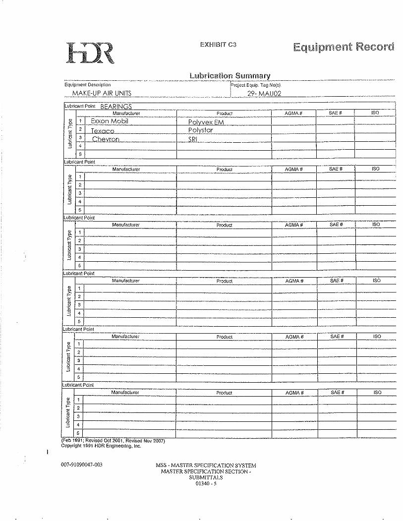
lil~ EXHIBIT C3
Lubrlcanl Polnl BEARINGS ........ ~,~¥ _____ ~~~.~ ___ . ___ . ______ ._ .. __ ._ .. _. __ .!.~~5l~~~,~_ .. _~-_-+-_-_---,-A.::G"M:::A.:..:.tI, __ ~~._-=SAc:l::.o""_-I __ -,I::.S::.O __
11: 1 Exxon Mobil PoIvvex EM __ -----.--1-----1 r~ 2 T, Polystar
~ I-~:+-' _C_h_e_y._1QO_-=-_ .. ~_--_--_-_-__ .-+-_ .. ,,_ . .sE_R_I_ -_-_-_-.==~_ -_-----.. ---=t-:---------_-_-_-_--t~-:"-_~._-_-_=j-i=======~l
lubricant Point --- ------·--·----'M7.--n"U7ra-cl"u-r0·-r-------,..---- --CP:C,::-od-:-u"C'CI ------ AGMA #- SAl! # ISO
- - .. -.----.. ---.. --.... --.--- .. --.... --.. -.. -- .... _ .. _ .. __ .. · __ .. _ .... -----1---"'-="---1- --==::.-t-----""'----ill O.
~ ~2t_-------------t_-------------t--·-·----t------t--------E
~ r3~-----------------~--------------------t---. :3 4 ~-------~--------+----5 I:-
L"ub:-r",ca-'-:II.':p"O"in:-I-----------.---- ___________ . __________ ..L ______ -'-______ '-____ _
Manufacturer Product AGMA ;:.# __ -t_....::S:...A=E.:;#_. _____ IS_O __ _
1< 1 ~ -; ---·-·--·-------------1----------------------1----------+---- ----1-------E H----------i---.---------t------i----+---B 3 zH·----------I!--------------4-------+---~--:3 , 1-1------
5
Lubricant Point Manufacturer
ill
!~ 1-:-+--------2
Product AGMA# SAE# ISO
~ ~3t--------------- -------.-----.-.--+------+-:3 '-14:-1_==_-___________ j. ___ . .-----t------, -- ---_._------+------+-_._---- ------
5
Lubricant Point -.---.---.... :::-c::-::-------,------;:C7:C----.. -----r----c:-::::-c:-::
M~nllfactu~~E"~ __ " _____ + ______ p,,r..::od,,l::.:'C::.I _____ _I_---'A-cG"MA:::":.::'# ___ II--S",Ac::E::.-,,II--1--":""'S"'o-"-ID
~ ~t----------------~, . r-------_ 2
~ "3--------·------------+--------------------4---------1--------+--------E I~t_-----------------"--I--------------------~---------_+-------II-------:3 1~4:~------------------+_--------------------~--------+_------------------5
Lubricant Point Manufacturer Product AGMA# SAEff ISO
ill
~ I~+-----------------------_r---------·--------------~---·--------_r--------_+-------·--c 2 g 3 .0 3 4
5
(Feb 1991, Revised Oct 2001, R0V!S~ Nov 2007) Copyright 199"1 HDR Engineering, Inc.
007 ·91 090047-003 MSS - MASTER SPECIFICA TlON SYSTEM MASTER SPECIFICATION SECTION·
SUBMITTALS 01340 - 5
6.2 Unit Specifications
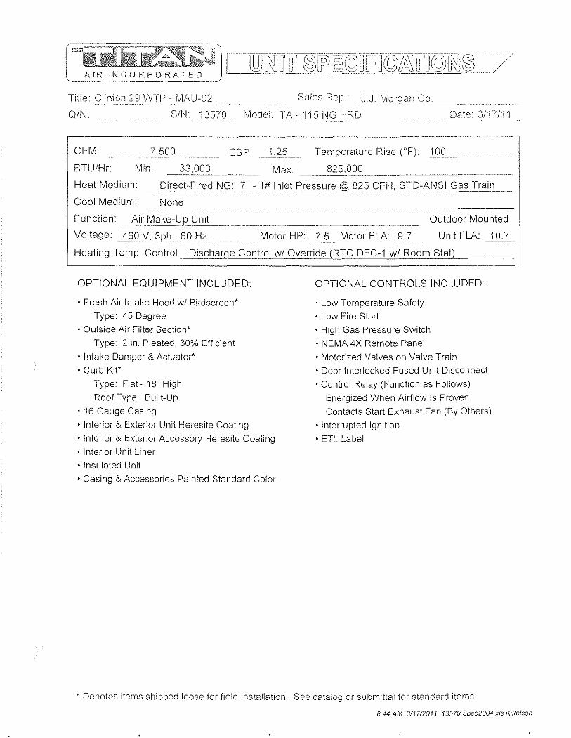
Title Clinton 29 VVTP - IVlAU··02 ,:c ......... . Sales I\ep. J.J. MorganC;o
Q/N SIN 13570 Model fA - n 5 NG HRD Date 3117111
CFM ___ 7,500 ESP_Jc.~"-_ Temperature Rise (OF) c1. 0." .. :0"_. ____ ._......... _
BTUIHr Min. __ .:o~!Q9g Max.825!Q()~_______ __ ~____ __ ~_
Heat M ed i u m • __ gi.r.e~J~ FirecJ_I\I~_T:~1f.IJ~1IElt_P ressLI!". @1l_2§c:::f_f:i!?:r[):J\I\I§IC:;0l~:rLain
Cool Medium. None
Fun ct ion '~Ai rll~a ke-Y~LJn it_________ _________ ~ ______ . Outdoor Mounted
Voltage. 460 V, 3p_l}" 60 H~ ______ Motor HP. 2!5~ Motor FLA ~ Unit FLA 10.7
Heating Temp Control_ Diss;ha.,rge COlltr:CJ.Lw/Qverrid~ . .1FiI~_ DFC-1 wi Room Stat)
OPTIONAL EQUIPMENT INCLUDED
• Fresh Air Intake Hood wi Birdscreen*
Type. 45 Degree
• Outside Air Filter Section*
Type: 2 in. Pleated, 30% Efficient
• Intake Damper & Actuator'
• Curb Kit' Type: Flat - 18" High
Roof Type Built-Up
• 16 Gauge Casing
• Interior & Exterior Unit Heresite Coating
• Interior & Exterior Accessory Heresite Coating
• Interior Unit Liner
• Insulated Unit
• Casing & Accessories Painted Standard Color
OPTIONAL CONTROLS INCLUDED
• low Temperature Safety
• low Fire Start
• High Gas Pressure Switch
• NEMA 4X Remote Panel
• Motorized Valves on Valve Train • Door Interlocked Fused Unit Disconnect
• Control Relay (Function as Follows)
Energized When Airflow Is Proven
Contacts Start Exhaust Fan (By Others)
• Interrupted Ignition
• ETl label
* Denotes items shipped loose for field installation. See catalog or submittal for standard items
844 AM 311712011 13570 Spec2004 xis Kille/son
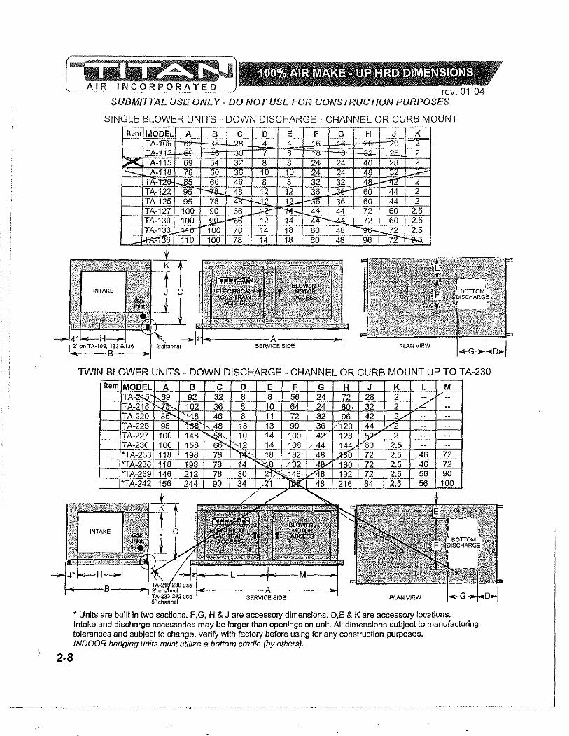
2-8
rev. 01-04 SUBMITTAL USE ONL Y - DO NOT USE FOR CONSTRUCTION PURPOSES
SINGLE BLOWER UNITS .. DOWN DISCHARGE - CHANNEL OR CURB MOUNT
Item MODEL A B C D E_ F G H J K TA- 4 .~ ",' , 4 L
1-TA~ I 8 2 LX TA-115 69 54 32 8 8 24 24 40 28 2 1"- TA-118 78 60 36 10 10 24 24 48 32 ;.;,.-;-
TA- 5 66 46 8 8 32 32 18-r--'l2 2 TA-122 95 ---;<a. 48 12 12 36 ..sa- 60 44 2 ,-TA-125 95 78 12 1 36 60 44 2 TA-127 100 90 66 44 44 72 60 2.5 TA-130 100 \ 12 14 4 72 60 2.5 TA-133 .-:I-ttT" 100 78 14 18 60 48 ""9&- 72 2.5 ~36 110 100 78 14 18 60 48 96 72 ~
TWIN BLOWER UNITS - DOWN DISCHARGE - CHANNEL OR CURB MOUNT UP TO TA-230
* Units are built in two sections. F,G, H & J are accessory dimensions. D,E & K are accessory locations. Intake and discharge accessories may be larger than openings on unit. All dimensions subject to manufacturing tolerances and subject to change, verify with factory before using for any construction purposes. INDOOR hanging units must utilize a bottom cradle (by others).
Item
I"-,L"
",' ! '0 f ' '1, '?:?~ "'cx " ) "''iY~ '{;i/" "'\:~B"*)~" - ~"~P/!" ltvfj
INl':AKE :AGGESSORIES .• ' \,,0 ~ 'V- ,," " 'Z."'" V '~p'" ,J , ! ~
rev. 01-04 SUBMITTAL USE ONL Y - DO NOT USE FOR CONSTRUCTION PURPOSES
t B
1 f
B
-1 o HOOD / FILTER COMBO
t B
-1 o FULL TURN DOWN HOOD
fo'---A =:---i
T B
--l ~AFILTER L::J RA FILTER SECTION ~DAMPER B "
o MUSHROOM HOOD ~ ~J \ lJ HOODI MUSHROOM FRESH AIR RETURN AIR
45° INTAKE FILTER FULL TURN HOOD FILTER FILTER INTAKE HOOD COMBO DOWN HOOD (curb mounted) SECTION SECTION DAMPER
MODEL A B C A B C A B C A B C D A B C A B C A B TA 25 20 22 25 20 41 25 20 24 30 25 45 55 25 20 28 0 TA-109 AR 25 I "n 25 28 32 30 28 25 28 28 25 28 TA&TAM-112 32 25 27 3 32 25 32
~ 25 28 32 25
TA-112 34 32 32 45 32 32 36 37 37 48 73 32 32 32 TA&TAM-115 40 28 30 40 28 48 40 28 32 45 33 50 73 40 28 46 40 28 32 40 28
- .4' "4 14~ "" 4~ 140 32 36 45 37 150 77 ,40 32 46 40 32 32 40 ~ TA &""'f/l.M -118 48 32 34 48 32 43 48 32 36 53 37 50 77 48 32 46 48 32 32- 1"\8 32 TA-118 AR _______ 48 42 44 48 42 39 48 42 46 53 47 50 87 48 42 46 48 AZ 32 48 42 TA-120 "1t&- 42 44 48 42 67 48 42 44 53 47 55 97 48 42 .~ r.;!8 42 32 48 42 TA-122 & 125 60 4.f" Na 60 44 68 60 44 48 65 49 56 101 6 44 46 60 44 32 60 44 TA-127 & 130 72 60 58 f2.- l.Po 81 72 60 64 77 65 65 l.38 "12 60 46 72 60 32 72 60 TA-133 & 136 96 72 60 96 72 rna. 96 72 76
~ 77- '-rtJ 157 96 72 46 96 72 32 96 72
TA-215 72 28 30 72 28 na 72-~ 32 33 50 73 72 28 46 72 28 32 72 28 TA-218 80 32 34 80 32 na 80 85 37 50 77 80 32 46 80 32 32 80 32 TA-220 96 42 44 96 42 na ..el5' 42 44 1G'1 -4l 55 97 96 42 46 96 42 32 96 42 TA-225 120 44 46 120 1AA- na 120 44 48 125 49 "36- /101 120 44 46 120 44 32 120 44 TA-227 128 52 54 ~ 52 na 128 52 56 133 57 60 11'7' '\.2B 52 46 128 52 32 128 52 TA-230 144 JlG- 1)8 144 60 na 144 60 64 149 65 65 135 144 ~ 46 144 60 32 144 60 TA-233 'i'S1l 72 60 180 72 na 180 72 76 185 77 70 157 180 72 46' '1.aJ:l 72 32 180 72 TA-236 ,.-/ 180 72 60 180 72 na 180 72 76 185 77 70 157 180 72 46 180 n 1-32
~ M-T~ 192 72 60 192 72 na 192 72 76 197 77 70 157 192 72 46 192 72 32
*" TA-242 216 84 60 216 84 na 216 84 88 221 89 75 195 216 84 46 216 84 32 216 All dimensions subject to manufacturing tolerances and subject to change, verify with factory before uSing for any construction purposes. Intake dampers are designed to be mounted indoors, jf outdoor mounting is required. you must order a weather hood for damper actuator(s), damper may be built into hood and or filter section. Intake dampers on TA-230 - 242 have 2 actuators, all accessories for these units are built in 2 sections, some field assembly may be required. All intake hoods feature bird screen. Mushroom hoods can be flange mounted, consult factory. 1" flange is typical for all components listed above. Intake accessories may be larger than intake opening. Return air filter sections will be larger than return air opening.
8-1
SUBMITTAL USE ONL y. DO NOT USE FOR CONSTRUCTION PURPOSES
HORIZONTAL UNITS WITH DOWN DISCHARGE BLOWER(S) /tern MODEL ABC D E F ~ -~. 109 5'"4;'c.5+ 3"'3"'.5o-1C2"'6"'. 7"'5,-f-Z.2S+2".2"5c-1--C1"'6C- -""
TAM·1T2---. 63.5 41.5 31.25 4.25 ..;I.. 8 18 TAM-115 6 . 5 33 6.25 20 20 TAM-118 74.l>- 7.25 7.25 24 24 TA-109 ____ 58.5 34.5 28.75 16 16 '11\-112 65.5 42.5 32.25 3.75 4.75 't8- 18
--x TA-115 65.5 50.5 32.25 4.75 4.75 24 24 fl"l::118 74.5 56.5 36.75 6.75 6.75 24 PI' TA-f2S.. 81.5 62.5 40.25 4.75 4.75 32-" 32 TA-122 & f2S.. 91.5 74.5 42.25 8.75 8"w 36 36 TA-127 & 130 9l!:Q, 86.5 39.75 8"w'10.75 44 44 TA-133 & 136 106.5 ~ 43]:10- "[0.75 14.75 60 48 TA-215 65.5 88. 5 4.75 4.75 56 24 TA-218 74.Jl. -ml.5 36.75 '-4.75 6.75 64 24 TA-220 f-61.5 114.5 40.25 4.70' .:z.75 72 32 TA-22~ 91.5 134.5 41.25 9.75 9.7~ 90 36 iJA"227 96.5 144.5 43.25 6.75 10.75 11)6 42
- TA-230 96.5 154.5 38.25 8.75 10.75 108 44
-.i":"'E B F Pitched Curb Selection .'
~ ..... '"''
n A 1 J
r---------i 1 DISCHARGE
1 1 (SUPPLY AIR (SA» I 1 1
L.---------'1\ Support Brace
t"<:~~ Extra Support
Braces
PLAN VIEW on Twin Units
.- -.
11/2"-1 r-1,-'17l...- I",ld' ::r- wall
I L Typical curb for 18" wooa built up roof.
typo nailer HOLE LOCATION
L MEASUREMENTS TAKEN FROM
. :--- ~US~~E WALL OF
--131/2"1---= SIDE VIEW DETAIL
.,
Service Side
-<:-
Curb Pitch Direction
Curb Pitch r-1 Direction L-J
Sa/vlcs Side
...... ,------1 Roof curb pltchod:
--'"---Roof typo :
Curbs are shipped unassembled and un insulated. F & G are recommended ductwork dimensions. Openings on unit may be smaller than recommended duct size. Hole locations for duct work taken from inside wall of curb. Construction methods may change for taller & larger curbs. All dimensions subject to manufacturing tolerances and subject to change, verify with factory before using for any construction purposes. Standard curb height is 18".
8-3
MOO'"
. - 101
B~~iitC ~~;~ IV~'~~~' II~~~~ Intake Intake
10 \ - 11. on.
J/ Curl
\ - H 75 )5 's: H 90 1020 1700 45 75 110 55 12j}' \ -m 1300 1400 2250 80 110 125 60 A50
T ,-122 "-.:1.:'20 1780 2050 100 15 150 7V 2)0 T ,-125 1'!R i§QO 2,'00 100 15 10 VLQ 2
. - 127 2, 50 ,"-.;~50 3,,50 150 0 8' 00 230 J ,-130 21 00 ~6~ 3500 150 210 V 135 100 250 T,l. -1 2900 3000 "4000 200 IW 260 125 301
TA - 301 11QI~f--",4j1~COl;?+~'7'f/~15;;-0H=+~:-t-o"':H TA- 16: ~ 26, TA - 171 2021 28§<¥H",5'-..~~13;7-0+-~-+-+.':~~:;H rA-. 191 400l '-;/.J5 fA - L 3050 30~ ~600 160 255'-.. .05 1 400 fA - 227 3150 :;0 5800 "'4C;5 450
242 8100 8700 9200 890 825 850 S5G
"AR " RECIRC. UNITS AND ACCESSORIES
TA-1J 815 815 00 30 51 45 .y TA-1 950 11 5( 35 10 /!
\ - !2C 1; OC 45 10 70a-... 1: ~50( 80 0 % 150
,- 150 ":S.::t00 2900 100 135 J/ 50 70 200 \- ~5 2200 235!'\... 2950 100 135. 150 70 200
TA- 2, =tI 150 2te' 235 10 TA - 150'A10 ~~§ l'
,- 420~~~00~'(~~~~250-+~2~600-+~1~L-f--~~1 , - 3 4500 Zl!JI( 250 260 12 300 \- ~15 2000 2100 3250 #10 .230 220 100 160 \-218 2050 2251 ~# 135 ~ 220 110 240
300
2273950 '/ /6150 225 300 Cl'. 1: 450 \ - 230 4600 4 6650 110 325 25 "-:1.( 500 , - 233 6800 ;r}/ 00 525 550 490 300 ---,- 236 7600, 81. 00 525 ...§QQ. 490 300 ---
TA - 239 81.00 Me 10 690 ~ 65C 50 TA - 242 _8600 f.J20 DC 890 825 850 550 ---
ALL WEIGHTS ~RE ESTIMATES, AND WILL VARY WITH DIFFERENT GAS TRAINS, MOTOR HP, AND SPECIAL ACCESSORIES.
USE FOR FREIGHT ESTIMA TlON ONL Y
1-11
rt:~~~"";'~~'-:~"~':J'\I"······'··'·"u'i~~:ri. EGEr~Dsl~·EE:I:i·Glil~8;~.ii~,-p;:RTs·Lls1:··'···'··i L~5~! ~~Jt:"':=~~d~i'~5 N.9Jll;{C···~~~~·~:=~~0·~~ IIbbr. S )ecification # Description 'Abbr. Descri (ion/S )ec ~ DM,1 Belima LF 120,S us '1 Intake Damper Motor FS·1 Fireye MEC120D, MERT4,MI=:P537 1 IClame Safeguard FU,1 Touch Safe Block, Class CC Tel 20 limp 3 Main Fuses FU·2600\iIlC· Class CC Time Delay: 1.5 limp 2 Trans. Primary Fuses FU,3 ,250VIIC·Midgettype:3 limp 1 Control Circuit Fuse L TS, 1 Antulles Controls 8563140061 wi Cover 1· Low Tenlperature Safety MT1see motorsp.ec;sonrightskJ!"ol p§ge 1 ,Blo",erlV1(jtor P,1C,I",vEj"ndDiJp:109·187(Q2"&O.95") : 1 !lIir FI()w Switch P,2 [See GasTrainlBurner Specs na: LoVli C;asF'reS!3~re2"', P·3iSeeGas Train/BurnerSpecs na,f:lighc;asF're~~ure_§vv R·2 i IcJecRJ2S=C!:.·A120,SJ2S=05B . 1 : Exhaust Interlock Relay ST,1 [Eatori5<TCE012B10A:XTOE020I3CS .... , TTStarter, OL' ..... .
S\7V~1i,ll]:r30T40F3,'6HB6@l~6XI"6X2.6S .'II}Eil!ipmentDisc0r16e:t:C REMOTE PANEL S SW,2 :AB BOOFP,SM32, ,ALPX20 I 1 [Summer·Oft,Winter Switch !'.1;ZS}}FGQRI3 wi I\.1QPB 11
~~~'I~:~::~~~~*E~~~r':==~ i}-!f~~~~:-~:~~~: __ -__ MOTOR & BLOWERT
r=5--Tfohnson Controls A419A8(;={C-"- \ 1 I Room Override Stat & DRIVE ASSEMBLY TGTlRTC DFC·1 wi F;lter~""-"-- iITrem~ControIEr~" Motor 7.5 hp, 460 V 3ph. ODP TO·f"nonc DFTO (40°F .. 96'Fj--·_ .. ··· i 1 iDischarge Temp. Selector" 9.7 fla, 213T frame I.h:1]Ho!:l.<3ywell L400BE125~='===:=-'i1-'!HighTemperatu-re Lirnii'-- 1750 r m (EM3311T TR·1 I Micron B250BTZ13RB]Ijcontrol TransiOrmer :::i== i:llower, Lau A 1!'.:.1.(),"'----' .. __ ! 1
~lF[~~~~ ~~~~~~~,===~~=:"'+·f I ~4n~~~ ~~nns:~:ir"" ~~!~'G~:~! 1~~~~3:!\.f1rf TR-4 i Honeywell AT120B 1 02B 'u. 11124 V IICTransformer--'- Bore: 1 31B" TS, 1]RfC DFTS wi DAI~12=_,. ..............]1] Discilarge TernP=§:E;nio:r:= Turns Open ,,!,_1 /2_,__'_1_ V·1 ISee Gas Train/Burner Specs. jnalPilot Shutoff Valve Blower Sheave: 29r BBOSK .. 1. V·2TS-ee GasTrainiSUrnerSpecs'TriaiMainS'afetYShutoffV'E,1ve' RPM 1132 V,3 ·jS",,,c;a~Train£1:l0.n.e-,S[lec.s. ··'naiVent'Vaive--'---·-·, _ BushJ.nil,§!S.>Ul/l§" ............ ;',1 VA ! See G~s Train/Burner Specs. inaTAux.SafetY"Shutofi'Valve': Belts: B:5.o. V·S "TSee 'GasTraTn/BurnerSrecsnaiModuii;ifrlg GasVaive-- CoupHn VM,1 .. ig~Er1l:oLIIA.(;.I:l.~±S,I3:T' .... ....... . . 11iMo~ C;§~-'y~ive=Aciua.t(jr F~:'::S~C"H;"E-M-A-T-I-C-S-Y-M-B-O-L-S""';.:..:.:q
L .- .. ---.--~.--..J-. ---- .... -....... -,- ---.------.-.-.. -~-
: '1 i---- .. · i---~'====== ............ ····-:,:=Fl':==:==::~:==
.... 1" .. ·-··· .. ··-· .. -.. -1-· ...... ,- ..
...... " [!!l!!] Unit Control Panel Terminal
... -. (jjij) Remote Panel Terminal
~:= 0 Component Terminal
" .. ,""- 0 Terminal in Others Panel
=::: .. Wiring to Remote (Others)
u •• - - -. Field Wiring (by Others)
--till- Jumper Wire
-.- Wire Connection
* Terminal no.'s 1 to 99 designate 120 volt, no.'s 100+ designate low volt
wiring (run in shielded cable). Ground unit according to NEC.
CAUTION: Open disconnect switch before servicing unit.

OA Filter(s)
TOTAL STATIC 7500 2.63
RA Filters
linked Panel (1" Rack)
Other

6.3 Gas train/ Burner Specs.
Model TI\·· 115 NG HI'<O Sales Rep J.J. Morgan Co.
S/I'J 13570 CFML?OO Temp. Rise 1 OO"F BTU I Hour~~!),(J(J(J_
-_._----------------
GAS PRESSURES Max. Inlet Pressure = Min. Inlet Pressure =
1# BURNER & PROFILE DIMENSIONS
Profile Width (in.) =_lZ__ Height =_~(J 7" at 825 CFH. Burner Length = ____ 1J2__ ft.
Manifold Pressure of ___ 4d __ in. wc required No. of Tees = ._ .. _1. __ _ for specified temp rise, CFM, and burner. Burner Mfg.: J',1i~J:::II\ilA-2
-_.--'-----
Notes',
GAS TRAIN DIAGRAM: Titan gas train starts here. A -i-
\ :l~~ t+~LO """:;" ~V-4 Shutoff valve, drip leg , tl-'-'-~V<J-- ----t*:J--- __ _ and union by others PG-1 GP-2 V-1
Notes: ._--' ._---_.-
Gas Train Complies with ANSI Guidelines ------> . .. _---
Abbr, Description Manufacturer/Model Qty.
.. -
Size
GT-1 Main Shut-Off Valve (Manual) Hand Valve 1 1 1/4"
P-2 Low Gas Pressure Switch * GP-1 Main Gas Pressure Regulator * Maxitrol RV61 1 1 1/4" V-2 Main Safety Shut-off Valve Honeywell V4055A/5055A 1012 1 1 1/4"
V-3 N.O. Solenoid Vent Valve * V-4 Auxiliary Safety Shut-off Valve Honeywell V4055A/5055A 1012 1 1 1/4" GT-3 2nd Shut-off Valve (Manual) Hand Valve 1 1 1/4"
V-5 Modulator or Modulator-Regulator RTC ABV-3.4NN 1 3/4"
P-3 High Gas Pressure Switch * Honeywell C6097B1028 (3" TO 21") 1
PG-1 Pilot Shutoff Valve (Manual) Hand Valve 1 1/4"
GP-2 Pilot Gas Pressure Regulator * OARA Type 96 (44-4-390-0025) 1 1/4"
V-1 Pilot N,C. Solenoid Valve Honeywell V4046C1047 1 1/4" ---_. Pipe Size After V-5 1 1/2"
* Must be vented to outside atmosphere unless fitted with approved vent limiter
8:44 AM 3/1712011 5\ 13570 Spec2004.xls }<ittelson
6.4 Sequence of Operations/ Temperature Control
AIR MAKE-UP UNIT WITH I'?TC SOLUTIONS DISCHARGE TEMPEI'?A TURE CONTROL
SUMMER MODE 1. Summer/OfflWinter (S.O.W.) switch in summer position. 2. Damper (optional discharge or intake) will open. 3. Damper interlock switch closes, energizing supply fan motor starter.
WINTER MODE 1. S.O.W. switch in winter position. 2. Damper (optional intake or discharge) will open. 3. Damper interlock switch closes, energizing supply fan motor starter. 4. Low temperature safety L TS-1 (optional) will shut unit down after 3 minutes of
operation with discharge air temperature below its set point. 5. ST -1 contact closes supplying power to burner enabling circuit. 6. Air flow switch (P-1) makes when pressure drop across burner profile is sensed. 7. Air flow switch (P-1A) will open if air flow goes above design parameters. 8. Inlet duct-stat (T-1) (optional) makes at outside temperatures below its set point. 9. High temperature limit (TL-1) is a normally closed safety switch and will trip when
discharge temperatures exceed its set point (tllis is a manual reset switch). 10. High (P-3) and low (P-2) gas pressure switches (optional) (P-3 will be installed on
all units with stated supply gas pressure of 14" w.c. or higher) to protect against abnormal gas pressure and are manual reset safety switches.
11. Pre-purge (built into FS-1) clears cabinet of combustible gases before ignition. 12. Flame safeguard relay (FS-1) monitors ignition and burn process. If abnormal
conditions exist, control will shut down unit. FS-1 is a manual reset control. 13. Discharge temperature is regulated by a sensor (TS-1) in the discharge of the unit
and selected at a remote point (TO-1). 14. Room override stat (T-5) on a call for heat will override the discharge temperature
setting up to 25' F. 15. When unit is shut off there is a fifteen second post purge. The blower will operate
for fifteen seconds after S.O.W switch is placed in the off position.
In all modes, exhaust fans interlocked with unit or building relief must be provided by others to ensure proper ventilation.
Page 1 of 1 amu Itc or doc
=\tiiiii[kiJl;:~"i:J1 100% OA RTC AMU JOB Clinton WTP JSERIAl NUMBER 13565-70 DATE 04/12/11 DRAWN 6Y KK , ;}.IR INCORPORATED wi DISCHARGE TEMP. CONTROL SW·1: FU-·, ST-1 _ OL·s
L 1- - -o--:C f.:-o---..-o.1
";<J":;'
OFF
SUM....: ~~VViN
SW-2
460/230/208 3ph 3 wire
supply wI transformer
T-5 --- i-:::r-i r-o}-r-----~
·-:-~-·~"-L:;lack
,J ()- !:::eci· ·~--~I
Low vOltage wiring must be run in shielded cable.
L2- - ---o--:C ~"-o-.------! MT-1
L3- - -o---'-C I--Q-----Of
R2-1 ~kJ----@
Exhaust Interlock Contact TR-1
120VAC
I gN ~M~ __ ~==-== ____ T . .TS-1 OL's ~-c @--~
TR-3
, ~ ~ ~ ~ ·,d Si128t for symbol description. ~ = unit to remote wiring)
.. ---~~. ~-----~!~

I
I I
j [- SUmmer-Qff·Wlnter
[a1O;NOn] !Bum_ronl !Ram_Fall!
Temperature .. lector located Inside panel
[Ci09~
0000
NEMA-4X STAFFORD 1 =36
Honeywell
. T451 , T651 Motor~Rated Precision Thermostats
APPLICATION The T651 thermostat provides direct, accurate line voltage control of inductively-rated heating, yentllating, or cooling equipment used in commercial or industrial environments,
The T451 provides precision line voltage contra! of motor~ rated electric, gas or oil heating equipment.
CL 4-01 • © Honeywell LimitedlLimitee 2001
FEATURES Deluxe styling for commercial buildings.
Industrial grade MICRO SWITCHTM mechanism rated 1/2 hp inductive, 5 kW resistive.
G Vertical mounting on 2" x 41J NEMA~standard
single-gang outlet box.
o High-sensitivity, vapor-filled stainless steel dual diaphragm sensing element.
• Engineering plastic base to isolate sensor from switch heat and minimize droop.
• CSA Certified, UL Listed.
eo Altitude compensation.
" 44°F (7°C) "frost protection" setting for heating application, independent of calibration or altitude.
• CoJor~coded leadwire connections.
• Range stops/focking cover security features for public areas.
Contents
Specifications ••..•••••••............•...••.•.. 2 Ordering Information ...............••........... 2 Installation .•..••..••...............••......... 3 Setting and Adjustment. ......................... 4
""1111111111 111111111111111111
Important: The sr:('cificatio[)s giVOfl in tf)ls puiJ/icalion (io no! indii(ir:! norrnaJ me,nuf,)ciu{i{)!) tolerance.";. Ihen.:;{ore thi~o'
unit may no! exactly match the fisi.'::}(j specificalions. This product is iostc(j and cnfibrat-ed under closely controllcd conditions, and some minor cfif{C')(ences /0 performance can he expected if (hese: conditions are changed,
Models: T451A SPST and T4518 DrS! (with positive om for ~leating only, T651A SPOT for heating/cooling,
Control Range: 44 - 86°F (7 - 28'C) for models T45·IA, T651A. 50 - 86°F (10 - 28°C) for model T451B.
Sensing Element: Vapor-filled dual diaphragm.
Differential: 2°F WC)
Droop: 2°F @ mid load range.
Barometer Sensitivity: 1I8°Fl"wc (0.3°C/kPa).
Thermometer: 50 - gO°F (10 - 30°C) in 10°F (5°C) increments.
Electrical Ratings:
50/60Hz 120 V 208V 240V 277V
Full Load 9.8A 5.6A 4.9A 4.2A
Locked Rotor 58.8A 33.6A 29.4A 25.2A Pilot Duty 125 VA
Resistive 22A Non Inductive 19ANI
Heating Only 2.5kW 4.5kW 5kW
ORDERING INFORMATION
Finish: Classic tJeigo,·cIlKHight gold stanliarcl. vVllite rnodels available.
Mounting: Mounts directly on vertical, single··9ang NEMA Standard (2" x 4") ole,ctrical box.
Wiring Connections: 6" (150 mrn) leadwires suitable for connecting to aluminul1l conductors wiring if used with approved special service CO/ALH solderless wire connectors. Leadwires colorcoded red for ileating, blue for cooling, black for common.
Approvals: Canadian Standards Association Certified; Flle No, LR1322 Pelformance Certified for electric heating per C273.4A UL file E47434,
Accessories! 272804A Range stops and cover locking assembly
(included in selected models only). 220213 Wallplate, covers old T4511T651 (1000 series)
wall marks. TG511 Thermostat guard for security and protection.
Fig. 1 - Dimensions of T451 1 T651 in inches (mm):
T -1,:tI811i
111----111 'I
"'-'t:jr I':;;') 1:'16;" L...._L~"'-_-c __ ._. __ 14·r)
r[1:'~2rl~~J~rl
When purchasing replacement and modernization produots from your TRADELlNE® wholesaler or your distributor, refer to the TAADELINE catalog or price sheets for complete ordering number, or specify:
1. Model 2. Electricalload(s) 3. Accessories.
If you have additional questions, need further information, or would like to comment on our products or services, please write or phone:
1. Your local Honeywell Home and Building Control Sales Office (check white pages or phone directory). 2, Home and Building Control Customer Satisfaction
Honeywell Inc., 1885 Douglas Drive North. Minneapolis, MN 55422 (612) 951-1000
3. In Canada-Honeywell Limited, 35 Dynamic Drive, Toronto, ON M1V 4Z9, 1-800-405-9835. International Sales and Service Offices in all principal cities of the world. Manufacturing in Australia, Canada, Finland, France, Germany, Japan, Mexico, Netherlands, Spain, Taiwan, United Kingdom, U.S.A.
2 95C-10g03~1

vVHLN 1r'J:';1/\U .. INC1-I'l-IIS PFIODUCr:
1. rlc;i'lc.1 lhuc;c; illstruclion,-, cardully. Fa'llum te· follow iilSlnJc(iUII~; C,_lll danw.fY,) prnducl or cc:use 2 ilJ.:-::ar!jOlis condition.
~.!. Cl18C!.z ratings given in illstructions and on product to rnake sure product is suitalJle for your application.
3. Make sure installer is a trained, experienced service technician.
4. After completing installation, use these instructions to clleck out product operation.
& WARNING This thermostat is a line voltage (120 to 277 Vac) con~~oL Do not instal! it unless you are completely famIliar and competent with home wiring If improperly handled there can be a risk 'of 240 volt electric shock hazard which may cause serious injury or death.
& CAUTION 1. Disconn.ect power supply before ma!~jng wiring
connections to prevent electrical shoel" or equipment damage.
2. AU wiring must comply with national and local codes and ordinances.
3. When using aluminum conductors, all wiring connec~ions to this thermostat must be made to the factory Installed leadwires using approved CO/ALR solderless connectors. A fire hazard may result otherwise.
4. To avoid handling the sensing element, do not remove thermostat cover until wiring is completed.
5. The.rmostats are designed for use with appliances Ilavlng a limit control.
New Installations 1. I~stall ~ single-gang electrical box oriented vertically about
4 to 5 (1.5 m) above the floor on an inside wall or pHIal' where the thermostat will be subjected to typical room temperature.
NOTE: To sense temperature properly, the thermostat must be placed away from concealed warm or cold water piPr:s, air ducts, or drafts from hal/ways, fireplaces or staIrways. Do not place thermostat above convectors or in the flow from supply fans. Ideally. a thermostat should be close to the return air path to effectively measure average room temperature.
2. Wire installation in an approved fashion.
NOTE: T651A and T451A do not feature a Positive Off setting, and may not be used as a disconnect switch.
3. Leave cover on the thermostat while making wiring connections. Use solder!ess connectors approved for the type, number and gauge of wires being joined.
Connect as per Fig. 2 for the appropriate application.
--. -----•• ---
3
INStAl I A liON
Fig. 2·, . Wiring connections
T·t51 D (Heat only with posiliv<, ofi)
T651A (lieatollly) T65iA (Coo! only applicatlon)
T651A (Heal"--Cool application)
UOT Illl>e~
& _ ''''s,' I ",",0000, • " Cooflng
",,' 6 POlVer supply; provide disconnect means and overload protection as required.
&. Breaks on Positive Off.
&. Exposed unused wires must be properly insulated.
& Contact makes Black to Red on temperature fall; Black to Blue on temperature rise.
4. Pre-bend and push leadwires into the electrical junction box.
5. Hold the thermostat base with one hand and remove the thermostat cover by grasping two sides of the cover and pulling outward.
NOTE: If locking cover feature is desired, insert the locking cover clip in the thermostat base BEFORE mounting the thermostat on the waif (see Fig. 7).
6. Using the screwdriver, secure tJle thermostat to the box by tightening the two mounting screws. Handle thermostat with care. Excessive pressure may damage the control knob or senSing element
IMPORTANT: Before mounting the thermostat, turn the setting dial to tbe midpposition (indicator pointing to the top of the thermostat): this wiJI prevent damage to the dial stop if the dial ;s aCCidentally turned by the screw driver when the top mounting screw is tightened. Do NOT press on dlaphragm, diaphragm lever arm or setpoint knob to seat thermostat on the box: thermostat will be damaged.
Replacement Applications 1. Disconnect power supply before making wiring
connections to prevent electrical shocks or eqUipment damage. All wiring must comply with applicable codes and standards.
2. Remove the old thermostat from the wall, laking care not to damage the wiring insulation.
3. Check the old insulation for cracks, nicks or fraying. Apply certified electrical tape where necessary to insulate wires, or replace the wires in an approved fashion.
4. Complete installation following steps 3 to 6 in the New Installations section.
Cfl0Ck Out Turn on pov/c;(, r--L3is(: tile tonlpOnJ!Ufe SCtliflQ lo en(~rqilS the heatino contnci and b(eak thrJ coolino contact Th·::) HV!\C equipr1wnl shouid t)8gin hc;::tting or stop cooling, as appropriat().
NOTE: For T4b1A alld T651A rnocJeis only, ttle tilermostat wi!! call for Ileat (disable cooling) when ttlG setpoint dial is at full Gounter-clockwise position. This setting is the phase change pOint of the diaphragm's vapor fill and is independent of calibration. To de-energize the load(s), turn off power at the circuit breaker panel, or add a separate disconnect switch.
Altitude Compensation T451, T651 units are calibrated at the factory for accuracy at 500 feet above sea level. No recalibration is needed if the switch operates at the same temperature indicated on the thermometer.
The vapor-filled diaphragm sensor is affected by barometric pressure and altitude, Deviations up to ± 1°F (1/2°0) are within normal operation. Control pOint drops 2°F every 1000 ft. WC/300 m) above sea level. See Fig. 3 for recommended action.
Fig. 3 - Altitude Correction
Elevation Recommended (In feet) Typical City Action
o to 2000 Toronto, Ontario Leave as is
Phoenix, Arizona
2000 to 4000 Las Vegas, Nevada Move clockwise
Calgary, Alberta 2 to 3 marks
-'- -_ ... _---_._-----_.-. 4000 to 6000 Denver, Colorado Move clockwise
Salt lake City, Utah 4 to 5 marks
----------- -,,---_. -'_.'_.'
To Recalibrate
1. Remove Gover. Set the tab on setpoint knob to the leftmost radial mark visible on top of the triangular arm that holds the dual diaphragm sensor (Fig. 4).
2. Without rotating the knob, remove it from the thermostat by pulling straight out, while holding the base against the wall.
3. Now, rotate the removed setpoint knob clockwise by the amount of temperature error. Each mark on the triangular arm represents 2°F we) of adjustment. Snap the knob back onto the setpoint cam.
Horne and Building Control
Honeywell Inc. 1985 Douglas Drive North
Golden Valley, MN 55422
Home and Building Control Honeywell Limited-Limitee 35 Dynamic Drive Toronto, ON M I V 4Z9
4
trK; IAiJ/\ nON
il, Inst8il U1e CO'ler, VVait fi'.rc~ tniIlUh}s to let the tlw{nlostat therrnally stabilize and fc,·cr10c)" calibration. Do not assurrJO () thorrnos[al is uut of ca!i/xalion unli! ii has heen insta//ocf and alloweci to operate for several hours.
Fig. 4 - RecaHbrating Thermostat
Security Features: Range Stops
Fig. 5 -- !nstaHing Range Stops
0"<:,,",,, . . . . , .
Insert pins into temperature stop positions
1. Set thermostat to desired setpoint. Remove cover, 2. Install plastic dowels supplied (or purcl18sed separately)
into minimum and/or maximum range stop holes on inside back of cover (Fig. 5).
3. Re-instaJl cover. Check operation of range stops.
Fig. 6 - Cover Locking Kit
Locking Cover
~
0/ Tinnarman
speed nut
o • AHen screw i and wrench
~
1" Remove cover by pulling straight out. 2. Insert linnerman Speed Nut®s into slots top and bottom of
thermostat base. 3 Drive Allen screw into Speed Nut until head is flush with
outside edge of thermostat base. 4. Re-install cover. lock by backing out Allen screw until
screw body protrudes through cover hole. To unlock cover, drive Allen screw into thermostat base.
Honeywell
6.5 Start up Procedures

AIR INCORPORATED
100% OUTSiDE AiR MAKE.,UP UNITS Vl/fTH RTC SOLUTfONS D!SCHARGE TEMPERA TURE CONTROL
Start-up must be pelformed by a trained, experienced service person.
The following general start-up procedure applies directly to standard 100% air make-up units. Please note any added options for a specific unit which may affect the control sequence or terminal numbering prior to attempting start-up or service work. Read the entire start-up procedure and review all reference material (Unit Specifications, Gas Train/Burner Specifications, Sequence of Operation, Parts Lists, and Electrical Schematic) supplied with each unit.
STEP 1 Turn off incoming electrical power and gas supply to the unit. Electrical power
can be turned off at the unit disconnect. Gas supply shut-off is at the inlet of unit's gas manifold.
At the remote panel, turn the Summer-Off-Winter (S-O-W) switch to the off position and the temperature selector to the lowest setting. STEP 2
Verify that incoming electrical and gas supply match the name plate requirements (Le., voltage/amp capacity, gas pressure and volume capacities, etc). If they do not, stop at this point and contact Titan Air. STEP 3
Open the access doors to blower and control vestibule sections. Check all electrical connections and hardware (blower drives, bearings, damper linkages, etc.) for tightness and correct field wiring connections. STEP 4
Check all gas, pilot, vent, and pressure sensing lines are properly connected and unobstructed. Verify the incoming gas line was "blown out" to flush out debris prior to connecting gas line to unit. Also verify incoming gas line has been purged of air up to unit's gas inlet. STEP 5
At manifold pressure test port, downstream of the modulating gas valve (VM-1), connect a gas pressure gauge (pressure gauge must read inches of water column to 10" with the capability of reading a negative pressure). STEP 6
Turn on incoming electrical power at unit disconnect. Make sure the blower access door is securely held open. Turn the blower service switch (SW-5) to the on position. STEP 7
If an optional intake or discharge damper is installed, the blower will not start until the damper motor's intemal "proof open" end switch closes (damper motor and end switch wiring are generally completed in the field after damper is mounted). If an intake or discharge damper is not installed, the blower should start immediately. Check the blower for proper rotation direction. If the rotation is reversed, turn both SW-5 and the disconnect switch off For 3 phase motors, reverse any two leads.
p.1 AMU RTC /n/ /gl1 2003 RI.doc
AIR II'JCORPOR!\TED
STEF' i3 With proper blower rotation verified, check and record the F,(PIVI of the blower. If
the blower speed needs to be adjusted to change the rated CFIVI of the unit, COlltact the factory. STEP 9
Turn the unit off. Close and latch the blower access door. STEP 10
Start unit with SW-S. Check and record the motor amp draw. If the motor amp draw exceeds listed Full Load Amps (FLA), stop and call the factory. STEP 11
Check and record the negative pressure reading on your burner manifold pressure gauge. This measurement is necessary for proper setting of the burner manifold pressure when the unit is forced into high fire mode. At this time, also measure the pressure drop across the airflow switch ports (remove caps from fittings in tubing for air flow switches and connect tubing from differential pressure gauge to fittings). This measurement can be used as a simple indication of proper airflow through the unit. If this second measurement is not between 0.7" w.c. and 0.5" W.c. 6P, the blower speed may need to be adjusted. If assistance is needed, contact Titan Air. STEP 12
Turn the unit off. Check the pilot gas line for proper and tight connections with no leaks. For shipping purposes, the pilot lines are disconnected. STEP 13
Turn on the main gas valve, slowly open the manual pilot gas valve. If the unit is supplied with a low gas pressure switch (P-2), reset to on position. STEP 14
Place the run-check switch (located on flame safeguard programmer module) to the check position. This will allow the pilot to light without igniting the main burner. If the unit is equipped with an inlet ductstat (T-1), set this stat above the outside air temperature. Start unit with SW-S and enable the burner with the burner service switch (SW-6).
Note that the burner should not be operated continuously in the check position for more than 1 minute because the ignition transformer is not rated for continuous duty. STEP 15
The unit should go through its complete burner ignition sequence with only the pilot ignited. The sequence can be observed by following the indicating LED's on the flame safeguard. On new installations, resetting of the flame safeguard may be required to purge air from the pilot line. If the unit does not cycle through its burner ignition sequence after a few attempts, refer to the service information in the following section for troubleshooting instructions. STEP 16
In the center of FS-1 are 2 voltmeter test ports. Set the volt-ohm meter to approximately 30 VDC scale and insert the meter leads into the test ports (common lead in black port, positive lead in red port). STEP 17
With only the pilot operating, record the DC volt signal. The DCV range is noted on the amplifier module of the controller (FS-1). There should be a steady DCV signal in
p.2 AMU RTC 1111 Igl1 2003 RI.doc

"'i~iiJiiZ~~,,'Z1 AIR INCORPORATED
tile upper range stated on the controllel·. ST[J) 18
Once stable pilot is achieved, shut unit down and place run-check switch in the run position. Carefully remove the wire from terminal one (1) on gas modulating actuator (VM-1). Do not allow the wire to touch the unit casing or any metal. Release actuator gear by pressing black button on side of actuator (see figure 1), rotating mechanism counterclockwise to stop. Start un'lt and check and record DC voltage as in previous step. Check to make sure the flame is contained in the burner casting and extends the full length of the burner with no breaks in the flame. An ideal low fire setting results in a small flame with no breaks and that also produces a stable DC voltage signal in the upper end of the range listed on the flame safeguard amplifier module. If the low fire setting is adjusted, verify that both the DC voltage signal and visual appearance of the flame are satisfactory. See figure 1 at end of start-up procedure for low fire adjustments if necessary. STEP 19
Once stable signal is achieved on low fire, release actuator gear by pressing black button on side of actuator (see figure 1) and rotate mechanism clockwise to stop. This will force the burner into high fire. On your manifold pressure gauge, check the manifold pressure. The reading on your manifold pressure gauge needs to be added to the negative pressure recorded in step 11. The resulting total manifold pressure should be compared to the unit's rated manifold pressure. If the total is higher or lower than the rated pressure, adjustment can be made at the gas pressure regulator (GP-1). Total manifold pressure should not exceed unit's rated manifold pressure.
Because of possible variations in the BTU content of gas, it may be necessary to set the manifold pressure to the rated temperature rise (temperature difference between the incoming air and the unit discharge air).
The high fire flame should be visually observed to verify proper combustion. Experienced service personnel should be able to assess the appearance of a proper high fire flame. If assistance is needed, contact the factory. STEP 20
With the burner on high fire, turn the high temperature limit (TL-1) to its lowest setting. The limit should trip out and shut down the burner. Turn TL-1 back to the factory setting of 185 deg. F and reset the control. Reconnect wire at VM-1. STEP 21
With all wiring in place and the unit operating in the winter mode, adjust temperature setpoint on the remote mounted controller (TO-i) up and down (from highest to lowest setting) observing the modulation of the burner. When actual discharge air is below TD-1 's setpoint, the unit should discharge maximum temperature. When actual discharge air is above TD-1's setpoint, the unit should discharge minimum temperature. STEP 22
With the unit operating in the summer mode, cycle the burner from SW-6. Verify that burner fully lights within a few seconds of proved pilot STEP 23
If the unit is equipped with a low temperature safety (L TS-1), check this control's operation. Standard L TS-1 can be checked by disconnecting the sensor wires. The unit
p.3 AMU RTC 1I111gl12003 R1.doc
AIR INCORPORATED
should then shut down after the built-in timer setting has "timed-out". Replace the sensm wires when propel' operation has been verified. Turn the unit off and back on to reset L TS-1. STEP 24
With the unit operating in the winter mode, close the 2nd manual gas shutoff valve (GT-3). The burner should shut down in a few seconds (look for flame LEO to go out on FS-1) with the unit shutting down in 30 seconds m less. Open GT-3 and reset FS-1 by pressing button protruding through cover. STEP 25
Turn SW-5, SW-6 and the disconnect off. Verify all terminals, electrical connections and hardware (bearings, sheaves, blower wheels, etc.) are securely tightened. Adjust all controls to desired settings. Remove all gauges, meters, and hand tools from the unit. Replace all covers on controls. Make sure all safety devices are reset. STEP 26
Turn the disconnect on. Start the unit from the remote panel. Verify proper operation in all modes according to unit's sequence of operation.
The unit should be ready for operation. If any problems arise, refer to the service information on the following page. To assure long lasting and efficient operation of Titan equipment, a regular service inspection should be set up. Refer to the maintenance section at the back of this manual for detailed maintenance information.
p.4 AMU RTC Int 19n 2003 R1 doc
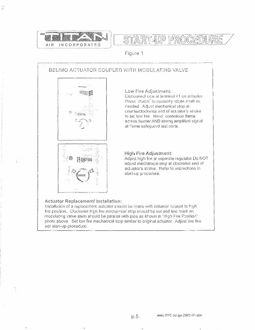
AIR INCORPORATED
:,,-. '-' 9i\l"nii
Actuator Replacement/Installation:
Figure 1
I_OW Fire Adjustment: Di:::cfJl'\!lec\ V'J:re ;:ll lefinillCii i/1 on aCluaicii Press 'clu1c!!":0 111,JrJually 1'01;][(.:;: sh,~ft ,:1:':'
n~:ecled. !\djJst rnechanic(:ll stop at cOLinlercl~)Ck'vvise end 01 aClualor's sl~-ol<..e
to set \m·v fire. i'Jeed contintolls flame across bumer AND slronq aniplifjed ~;i~Jnal at flame safe~j~lcHd lest ports.
High Fire Adjustment: Adjust high rire al seperale regulolo< Do NOT 8djust rl1ecilanlcsl stop at clockvvise end of actuator's stroke. Refer to insUuctions in 0larl-up IYOcedlire
Installation of El replaC8il1ent actuator should be made \.\lit1"l actuator rot8ted \0 hi~jh fire position. Clockwise high fire rnechcnicai stop should be set and line 11ark on modulating valve stelYl should be pmaqe! with pipe 88 shoVJn In "H:gh Fire Position" photo above. Set lovv fire rnecli8nical stop similar to original actuator Adjust low fire pel- start--up procedure_
p _ 5 AMU RTC Inl Ign 2003 RI doc
Brandon
6.6 General Information: Installation, Assembly Drawings, Maintenance


WARNING
Improper installation, adjustment, alteration, service or maintenance can cause property
damage, injury or death. READ ali maintenance instructions thoroughly before installing or
servicing equipment.
FOR YOUR SAFETY
IF YOU SMELL GAS: 1. Open window I doors. 2. DO NOT switch electrical switches. 3. Extinguish any open flame. 4. Immediately cali your gas supplier from
an area away from gas smell.
The use and storage of gasoline or other flammable vapors and
liquids in open containers in the vicinity of this heater is
HAZARDOUS.
NOTICE LOW TEMPERATURE LIMIT
If this heater is to be installed in an area of potential freeze up and a low temperature limit
was not ordered, one should be installed to provide freeze protection in the event of a
burner shut down.
[ ..... r:~§\JJ AIR INCORPORATED
24 MONTH WARRANTY Titan Air, Inc, hereby warrants its products against defects in material and
workmanship for a period of (24) twenty four months from date of shipment. Start up checklist is due back within (30) thirty days of start-up or 120 days from date
of delivery for 24 month warranty to be effective, After (30) thirty days, and up until (60) sixty days, a (13) thirteenth month warranty will be observed, All warranties are null and void if start up checklist is not received within (60) sixty days from start-up or 120 days from date of delivery, NO EXCEPTIONS WILL BE MADE,
Titan Air, Inc, reserves the right at Titan Air, Inc.'s option, to replace or repair free of charge, any part proven by Titan Air, Inc, to be defective, Prompt notification of defective part must be given to Titan Air, Inc, and defective part must be returned freight prepaid within (30) thirty days of notification,
WARRANTY INCLUDES ONLY PARTS SUPPLIED BY TITAN AIR, INC, INCIDENTAL COSTS AND LABOR CHARGES SHALL BE THE RESPONSIBILITY OF OTHERS, This warranty does not cover fuses, belts, filters or water damaged parts which are the result of improper storage or installation,
This warranty is void in event the product is improperly installed and/or operated under conditions other than normal published ratings, improperly maintained, misused or not in compliance with applicable codes or not in accordance with Titan Air, Inc.'s operating instructions,
This warranty is void if attempts to correct or repair any alleged defective part or parts are made by unauthorized personnel without Titan Air, Inc.'s written approval.
In no event shall Titan Air, Inc, be held liable for any damage, incidental or consequential, arising from the installation, performance or operation of the product.
This warranty supersedes, voids, and/or is in lieu of any other verbal or written understanding which may not be in total accordance with this expressed warranty,
Warranted parts must be returned to Titan Air, Inc, within 60 days to receive credit
PURPOSE / APPLICABILITY This manual is intended to provide installation, operating and service information on
Titan Air's standard direct-fired air make-up units, Other Titan Air units, such as AR/80 TfA , AR/75™, Demand-AirTM, H,O,TIM and units that do not feature a direct-fired burner, will have separate operating and service manuals,
A packet of reference materials for a specific unit (tracked by its Serial Number) is generally included with this Operating and Service Manual. The reference materials include Unit Specifications, Parts Lists, Gas Train and Burner Specifications, Electrical Schematic, and a Sequence of Operation, A start up checklist is also included in this packet. Review the reference materials for a specific unit and note any optional equipment or controls which are not specifically addressed in this manual prior to attempting start-up or service work,
The information and recommendations contained in this publication are based on general observation and are not intended to supplant requirements of federal, state or local codes having jurisdiction, These codes should be reviewed before installation of equipment. All units must be installed in accordance with national, state or local codes,
It is the responsibility of the purchaser at the time of order, to specify any and all code or insurance requirements that may dictate the addition of components to the equipment in order to comply with those requirements,
Only qualified personnel who have experience with the installation and operation of industrial/commercial direct fired equipment should attempt to service Titan Air equipment
WAIc(PANTY
TABLE OF CONTENTS
GENEPAL INFORMATION 'y Equipment Arrival > Components
AIR FLOW SWITCH OPERATION
INSTALLATION > Installation and Field Wiring Overview
TYPICAL ASSEMBLY DRAWINGS
MAINTENANCE
FLAME FAIL DIAGNOSTICS
START-UP PREPAPATION
VALVE LEAK TEST
SPECIFIC EQUIPMENT DETAILS > Unit Specification > Sequence of Operation 'y Parts / Legend Sheet 'y Schematic > Stari-U p Procedure 'y Troubleshooting (optional)
Page 1
2
3
7
8
11
14
17
19
20
pages not numbered
Note that operating and service manuals are occasionally requested prior to production of a unit. These manuals will be marked "Pre-Production Release" on the front cover. The final copy of the operating and service manual for a specific unit will be sent with the unit. Additional copies of the manual for a specific unit are available.
A detailed unit specification sheet, parts/legend sheet, schematic, sequence of operation and start-up procedure are provided in the start-up section of each operating and service manual generated for a specific unit. Selected vendor cut sheets on components will also be included.
2
EQUIPMENT ARRIVAL When the air make-up unit arrives, be sure to inspect for shipping damage. The
equipment was thoroughly inspected before leaving the factory and the driver signfld for it. Read the bill of lading and verify that all of the items listed are accounted for. Any damaged or missing items should be reported to the transporter immediately. DO NOT SEND DAMAGED Ff,EIGHT BACK TO TITAN AIR! AIL.clairr:L~ .. n:lUst b"-.filed with th\!. transporter. Be sure to take photographs and get the drivers signature to confirm the damage. The driver will have a number for you to cali to file a claim. Request a written inspection report from the claims inspector to substantiate any necessary claim. Be sure to open the unit access doors and inspect for internal damage.
If for some reason you are unable to install the equipment immediately, be sure that the equipment is protected from the elements. Water damaged parts are not covered by Titan Air's warranty. If the equipment is stored for an extended length of time, be sure to completely check the unit for any internal damage which may have been caused by excessive condensation. Also check for damage caused by rodents, and be sure to eliminate any dust that may have built up on the components while the unit was in storage.
CAREFULLY AND THOROUGHLY READ TITAN AIR'S PRODUCT WARRANTY Each unit is tested at the factory prior to shipping. Because we are not able to
simulate exact field conditions and sometimes actual conditions are different than what was stated on the order, you may need to make some adjustments in the field. This is why it is very important that only qualified personnel start-up and service Titan Air equipment. The start-up checklist (provided in packet with this manual) must be filled out and returned to Titan Air in order to validate equipment warranty.
For a fee, Titan Air personnel will travel to the job site, supervise start-up and provide operation and maintenance training for the equipment.
BLOWERS The typical blower(s) used in Titan Air equipment are AMCA rated industrial type
forward curve D.W.D.1. fans. Backward incline, backward airfoil, and plenum/plug fans are used occasionally. Models TA-1 09 through TA-136 utilize a single blower while models TA-215 through TA-242 utilize twin blowers. All blower wheels are mounted on a solid, turned, ground and polished shaft. 9" and 12" blowers are supported with permanently lubricated bali bearings. Larger blowers are supported by lubricated pillow block ball bearings.
MOTOR & DRIVE Rigid base, T-Frame, motors are utilized. The motor is mounted on an adjustable
slide base. Variable pitch motor sheaves are provided to allow airflow adjustment if the motor is no larger than 30 Hp.
3

DIRECT FIRED HEATING Direct fired burners are designed to operate in a fresh flowing airstream. Gas is fed
directly to the burner and the airstream provides the needed oxygen for combustion. A series of strategically sized and placed holes provide air to the combustion zone.
See Figure 1
Higtl Fire Zone
Intermediate [ Zone
Low Fire [ Zone
Alurninum Manifold
Indicated Flame Lengttl
'S,taintess Steel Combustion Baffle
Higtl Fire Air Ports
Progressive Air Supply
Interrnecliate Ports Fire Air POlis
4--- Low Fire Air Ports
Figure 1
The direct fired burner is designed to operate at an air velocity across the burner of 2450 fpm with maximum manifold gas pressure as stated on unit rating plate. Air velocity across the burner can be adjusted on single speed units with slide plates on either side of the burner. Two speed units feature an automatic damper with actuator and controls to maintain proper velocity across the burner profile as air volume changes.
Because of the air pattern, air ports and kinetic energy of the air moving across the burner, the direct fired burner has the capabilities of approximately 32:1 turn down ratio. The high fire rate is approximately 30 times of the low fire rate.
4
BURNER OPERATING PRINCIPLES The direct fired burner is designed to operate in a cabinet of flowing fresh air. Fuel
gas is fed directly to the burner; kinetic energy of the airstream furnishes combustion air. It will function properly at the design velocity and pressure associated with ventilating systems.
The burner must be installed to fire with, and parallel to, the air flow. By virtue of velocity impact and suction generated by the diverging shape of the combustion baffles, air is induced through the air ports into the combustion zone. The air supply is constant, even though only that which mixes with the gas takes part in combustion.
When a very small quantity of gas is admitted to the burner, sufficient mixing takes place in the low fire slot where combustion takes place. Since the low fire zone is contained within the burner casting it is effectively shielded from uncontrolled air entry.
As the gas supply is increased the flame progresses into the intermediate fire zone where an additional supply of air is available. At higher or full capacity, mixing occurs at the larger air ports of the high fire zone augmented by air flowing over the end of the baffles.
On a reduction of gas supply the reverse sequence takes place, the flame recedes to a location of lesser air supply until the low fire zone is reached. The burner is suitable for a turndown range of approximately 30 to 1.
AIR SUPPLY The supply fan is typically positioned to draw air across the burner. Air flow across
the burner must be substantially straight (laminar) and velocity must be within the proper range to develop the desired turndown and capacity.
The direct fired burner is designed to operate in an air make-up heater with all air crossing the burner taken directly from outdoors. Rare exceptions involve equipment that serves an unoccupied space.
Total pressure rating of the blower includes allowance for the pressure drop through the primary air handling unit including the burner, together with pressure losses at the inlet screen, inlet damper, filters, outlet damper if used, plus the external pressure rating of the system.
BURNERS Burners are purchased in 6" and 12" straight lengths and 12" tee sections and
are assembled to meet the BTU requirements of each piece of equipment. According to national safety standards, the following factors could influence safe
operation of a direct fired air make-up unit and must be interlocked to either prevent the burner from firing or shut it down if unsafe conditions occur.
1. AIR SOURCE - If a damper is used, it must be interlocked to prove it is open before the blower can start.
2. BLOWER STARTER INTERLOCK - An auxiliary contact from the blower starter must be placed in series with the burner controls to prevent burner operation when the blower is not operating.
3. AIR FLOW SWITCHES - Monitor the air flow (pressure drop) across the burner. The switches (one high differential and one low differential) will not allow burner to operate if pressure drop across the burner is outside of the high and low set points.
4. HIGH TEMPERATURE LIMIT - A manual reset high temperature limit control must be utilized to prevent high temperature situations caused by excessive fuel pressure or lack of air flow.
5

5. [1~6j1JLE:.i'l"fE:(3UAF~D·· Monitors the combustion process during ignition and operation for safe conditions.
6. li!GH C;ASYRE:$SUllE SWITGJi - Monitors gas pressure to the burner. This de-energizes the burner in the event gas pressure increases above its set point.
The burner's design and flexibility, coupled with proper controls, make direct fired air make-up equipment the safest and most efficient method of tempering outdoor air.
GAS CONTROLS Titan Air TA Series equipment is constructed to meet A.N.S.I Z83.4/CSA 3.7 .. 1999
standards. Components in the gas delivery manifold on standard equipment include: two manual shut-off valves, gas pressure regulator, two safety shut-off valves and an electronic gas modulating valve. The pilot control includes a shutoff valve, gas pressure regulator and a pilot solenoid.
ELECTRIC/ELECTRONIC CONTROLS TA series air make-up units come standard with the following items: disconnect
switch, starter and overload assembly(s), control power transformer (if a 3 wire system), air proving switches, high temperature limit, electronic flame safeguard and electronic flame modulation with remote set point adjustment. Many other options including low temperature limit, inlet duct stat, and operating lights are available.
If the malfunction of the heater creates a hazard to other fuel burning equiprnent in the served building (Le. supplying make-up air to boiler room) it is to be interlocked to open an inlet air damper in case of failure.
CABINET Titan Air TA series equipment comes with either a galvanized finish or a painted
finish. In both cases, the minimum gauge metal used is 18 gao
6
All! INCORPORATED
BURNER PROFILE AIR PRESSURE DROP ANSI standards, Z 83AICSA 3.7 M99 & Z 83,18,2000, require manufacturers to
monitor air moving across the burner for both high and low conditions, Titan Air utilizes pressure drop across the burner to satisfy this requirement.
Certification testing demonstrated that the burner will function properly between a low pressure drop of 02" w,c, and high pressure drop of 0,95" w,c, The standards also mandate that the switches cannot be adjustable, This makes air pressure clrop across the burner profile a velY important factor at initial start up,
The design burner pressure drop at standard air conditions is 0,60" w,c, and will change as the temperature of outside air increases or decreases from 70°F, In order for the burner to operate within the range of the air flow monitoring switch set points, the pressure drop should be as close to 0,60" w,c, as possible,
Air pressure drop across the burner profile is dependent on OA temperature, When the burner is off, pressure drop will climb significantly during cold weather, The burner is always off on initial start-up, Therefore, if the burner profile air pressure drop is above 0.70" w,c, during a warm weather start-up, it may exceed 0,95" w,c, during a cold weather start-up in northern regions, Such a high air pressure drop would open the high airflow switch and prevent burner ignition,
The following chart will aid in equipment set up at outside air temperatures different from 70°F when the unit is operating with the burner off, The chart gives pressure drops, at various temperatures, equivalent to 0,60" w,c, at 70°F,
Note that two speed units feature controls to automatically control pressure drop across the burner as air volume changes, Burner profile air pressure drop should be measured on high speed with the burner profile dampers near the full open position, If the burner profile dampers open less than 50% on high speed, the equipment is not delivering rated air volume,
Burner Profile Air Pressure Drop at Various OA Temperatures (Burner Off)
'''''---- ,--""---,---,-,-- ,,----- ~.~~~----~.~----.-.-
OA Burner OA Burner OA Burner Temp Profile Drop Temp Profile Drop Temp Profile Drop
-40 0,76 10 0,68 60 0,61 ._- --_._---_._---- - --.--,------_.- ----------- .-.- ---------- ------ .... _ ........ _-_. __ . . .. ........... -.. ,.~ ... -35 0,75 15 0,67 65 0,61 ------ ~ .. - .. ~~.--.--~~~ --------- -- ~.-.----"~ ,,-- -----"'- ----_._----_ ...• -30 __ 0,74 20 0,66 70 0,60 ._----- '''' --------_._--25 0,73 25 0,66 75 0,59 ----20 0,72 30 0,65 80 0,59
'''''''--,-,--'" -- ---_ .... _--15 0,71 35 0,64 85 0,58
-, -- ---------1 ° 0,71 40 0,64 90 0.58 ---5 0,70 45 0,63 95 0,57
° 0,69 50 0.62 10O 0,57 5 0,68 55 0,62 105 0,56 --
7
'i , I I

AIR INCORPOF<ATED
CONTROLS Control systems can be designed to n,,"et specific requirements. Numerous
temperature controls are available. Since standard air make .. up units usually temper outside air to replace the air exhausted from a building, modulating discharge temperature control is typical. A room override thermostat is occasionally included to automatically increase the discharge temperature set point if space temperature drops too low.
Titan Air units are typically supplied with a remote control panel. This panel will include switching for blower & burner operation and a temperature setpoint. Some units feature operating lights, discharge temperature display, custom controls or contacts by others to enable the blower and/or burner.
Refer to the unit specification sheets, parts list, schematic, sequence of operation and start-up procedure for a specific unit to determine the control options included.
PRE-INSTALLATION Inspect the equipment making sure all parts and accessories are on the job site.
Check equipment against order and packing list. If the equipment has been sitting in storage for some time, inspect it for moisture (from condensation, rain or snow) and/or dust accumulation. Both can cause damage to electrical and electronic components as well as bearings and insulation.
INSTALLATION Care taken during the installation and start-up is vital to the longevity and reliability of
the equipment. Confirm that gas and electric utilities match the rating on the equipment name plate.
> This heater shall be installed in accordance with local codes or, in the absence of local code, according to ANSI Z223.1.
» If the heater is to be installed in an airplane hanger, refer to ANSI/NFPA 409.
> If the heater is to be installed in a parking garage, refer to ANSIINFPA 88A.
> If the heater is to be installed in a service garage, refer to ANSI/NFPA 88B.
> For installations in Canada, refer to CAN/CGA B149.
> Adequate exhaust and/or relief must be provided to prevent over pressurizing the served space when the heater is operating at its rated capacity.
> If in doubt regarding the application of the direct fired heater, contact the sales representative or the factory.
POSITIONING THE HEATER Locate the heater exactly level, making certain minimum clearance required by local
codes is maintained between the heater and any combustible materials. See name plate on unit for minimum recommended clearances.
8
CURBING (OUTDOOR MOUNTING) The use of a full perimeter curb or mounting rails under the heater is recommended.
The only openings in the roof should be for the supply air duct, return air duct (if required), gas and electrical connections (if applicable). These openings must be sealed properly after installation. Titan Air ships all curbs unassembled and un-insulated. Installing contractor supplies gaskets, cant strips, insulation, etc.
GAS PIPING Gas piping must be sized and installed in accordance with applicable codes. It must
be able to deliver the specified CFH and gas pressure at ill!! flow. Refer to unit nameplate or unit specification sheets for specified CFH and gas pressure.
Care must be taken with the gas piping to prevent problems at start-up and later during operation. Before the union between the supply line and the unit is connected, the supply line should be cleaned out to remove any foreign material (dirt, rust, metal shavings, etc.) and a drip leg should be utilized.
Refer to unit nameplate to determine the minimum gas supply pressure required to attain the maximum specified gas.
All suitable gas controls, regulators and valves (equipped with a diaphragm) in this device are furnished with an ANSI approved vent limiter. If local codes require these components be vented to the outside, it is the responsibility of the installing contractor.
The heater and its individual shut off valve must be disconnected from the gas supply piping system during any pressure testing in excess of % PSIG.
The heater must be isolated from the gas supply piping system by closing its individual shut off valve during any pressure testing of the supply system at pressures equal to or less the % PSIG.
During start-up, the technician should perform a gas leak check on all valves and piping during the heater's normal operation. (See page 20)
DUCTWORK Ductwork must be sized and installed in accordance with applicable codes and
standards. A size variation may exist from recommended duct size to unit flange size. Recommended duct size applies to the size of the duct at the connection to the equipment. A properly designed duct transition from the blower outlet to a larger duct is recommended for long ducts or ducts with numerous elbows.
On heaters mounted outdoors, discharge ductwork should be insulated to minimize condensation during the "off' cycle in cold weather. A fresh air intake hood with bird screen is required. Discharge duct should be common to both blowers on twin blower units. Individual ducts for each blower are not recommended.
On a heater mounted indoors with through the roof intake, a "mushroom" type intake hood is recommended to prevent moisture entrainment. When using "through the wall" intake duct, the intake louver should have adequate moisture baffling characteristics. All intake ductwork exposed to the heated space should be insulated.
9

SOUND AND VIBRATION CONTROL Flexible connectors are recommended on at least one ductwork connection.
Vibration isolators that mount between the unit and support structure are optional and can be supplied with the equipment for installation by others. Another option is internal isolation of the blower/motor assembly with internal flexible connections between the blower housing and the unit structure.
Appropriate insulation on the interior of ductwork significantly reduces sound levels.
DISCHARGE TEMPERATURE SENSOR BULB INSTALLATION & WIRING The installing contractor may be responsible for field installation of the discharge
temperature sensor, Field installation of the discharge temperature sensor in the discharge ductwork results in a better measurement of the average supply air temperature, Utilize shielded cable for field installed discharge sensor wiring,
FIELD WIRING Power supply wiring should be routed from a dedicated branch circuit per schematic,
Depending upon how the equipment was ordered, a single point power connection may be subdivided to individual loads or multiple power supply circuits may be required,
If an intake or discharge damper was ordered as a loose accessory, it will have to be mounted and the actuator must be wired, The remote panel must be mounted in a convenient location and wired to the unit. Interlocks between the exhaust, unit and possibly spray booth will have to be connected by field wiring,
Carefully review the schematic and associated schematic symbol legend, Note that legend may be on the parts/legend sheet rather than on the schematic,
Many codes require that low voltage wiring (connecting terminals numbered 100+) be routed in separate conduit from line voltage wiring, If low voltage wiring is routed with 120 VAC control voltage wiring, it must be placed in shielded cable(s), Even if low voltage wiring is routed in separate conduit, very low voltage sensor outputs and actuator control signals should be routed in shielded cable,
NOTE: All field wiring must conform to N,E, C, and/or any state or local codes,
SUPPORT OF ACCESSORIES Most Titan Air equipment is supplied with loose accessories (I.e, damper, hood,
discharge diffuser or filter section), If an intake hood is supplied by others, the design shall minimize entry of snow/rain and include an intake screen to meet ANSI standards, Intake accessories on large equipment may be shipped in two pieces for field assembly, Two damper actuators may need to be field wired on large equipment as well.
It is the responsibility of the installing contractor to support accessory items from a rigid point or points to ensure solid mounting,
POST INSTALLATION Caulking is required between all parts prior to assembly and seams must be
re-caulked after assembly, Air make-up units shipped in multiple sections will include a high quality caulk tape and caulk tubes, Caulk tape is applied between sections with exterior caulking applied after the unit sections have been joined. Sealing integrity should be rechecked on a yearly basis.
Water damaged parts are not covered by Titan Air's warranty,
10
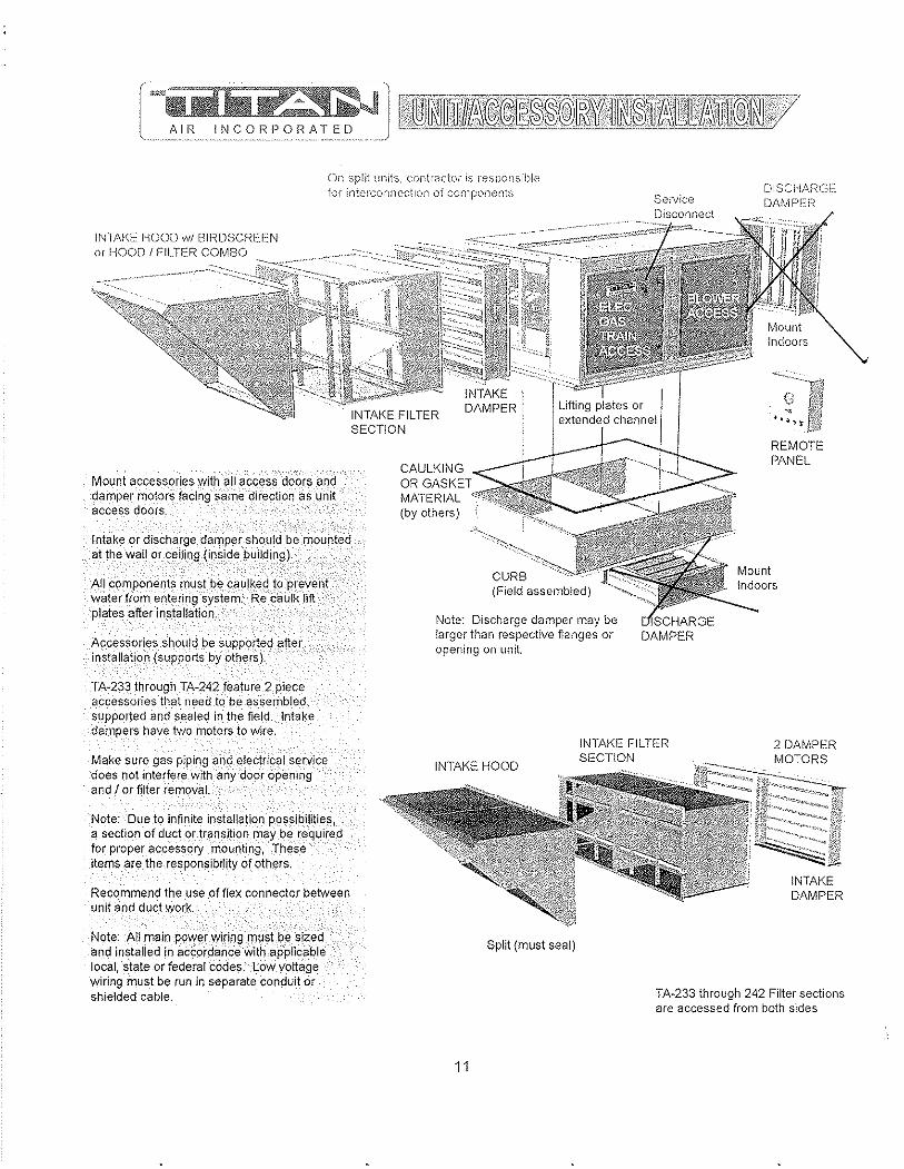
On spiit units. contractor is responsible for interconn(~ctlon of components Service
Disconnect
DISCHARCl::: DAMPEr:;
INTAKE. HOOD wi BlrmSCREEN or HOOD I f'lLTER COMBO
Mount accessories with all access doors and damper motors facing same'direction as unit access doors.
Intake or discharge damper should be mounted at the wall or ceiling (inside building).
All components must,'be caulked to pr~veht water from entering system. Re caulk lift plates after installation,
Acc~ssories should be supported after installation (SlipportS by others),
'JA-233 through TA-242 feature 2 piece accessories that need to be assembled, suppOlted and $ealed in the field. Intake dampers have two motors to wire.
Make sure gas piping and electrical service does not interfere with any door opening and I or filter removal.
Note; Due to infinite installation possibWties! a section of duct or transition may be required for proper accessory mounting, Thes:e items are the responsibility of others,
Recommend the use of flex connector between unit and duct work.
Note: All main powerwiring must be sized and installed in accordance with applic,;:3ble local, state or federal codes, Low voltage wiring must be run in separate conduit or shielded cable.
CAULKING OR MATERIAL (by others)
CURB
Note: Discharge damper may be larger than respective fianges or opening on unit.
DAMPER
REMOTE PANEL
INTAKE HOOD
INTAKE FILTER SECTION
2 DAMPER
Split (must seal)
11
INTAKE DAMPER
TAA233 through 242 Filter sections are accessed from both sides
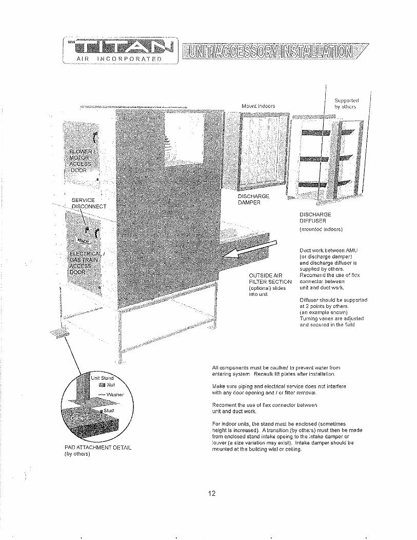
[~~~!]!::~Jl ~l~~II~~l~@@~~~IT~l~~~~~!ljftu~~W ---.-" _ ... _.-, ... "', .. _',,,.,._---- ------- -.---------~---" .. --,-" .•.... _-- ------------ -----
PAD ATTACHMENT DETAIL (by others)
OUTSIDE AIR FILTER SECTION (optional) slides into unit
Supported by others
DISCHARGE DIFFUSER
(mounted indoors)
Duct work between AMU (or discharge damper) and discharge diffuser is supplied by others. Recomend the use of flex connector between lmit and duct work.
Diffuser should be supported at 2 points by others. (an example shown) Turning vanes are adjusted and secured in the field.
All components must be caulked to prevent water from entering system. Recaulk lift plates after installation.
Make sure piping and electrical service does not interiere with any door opening and I or filter removal.
Recoment the use of flex connector between unit and duct work.
For indoor units, i!le stand must be enclosed (sometimes height is increased). A transition (by others) must then be made from enclosed stand intake opeing to the intake damper or louver (a size variation may exist). Intake damper should be mounted at the building wlal or ceiling.
12
SERVICE
DIS\ONNECT
,. r ~1t"
" ELECTRICAL 'GAS mAIN' iACCESS DOOR
Larger units have more legs
PAD ATTACHMENT DETAIL (by others)
StJpported by OUl01"S
1I,:rig:ri&&?;;031X;IiYl)jii2W"':I0:iiM ??HII;
W1I Nut
(optional) slides into unit
Sealant goes between each section before assembly. Bolts and caulking are in packing box. Recau!k seams and lifting plates after assembly.
2-PIECE UNIT ASSEMBLY DETAIL (by others)
13
DISCHARGE DIFFUSER
(mounted indoors)
Duct work between AMU (or discharge damper) and discharge diffuser is supplied by others. Recomend the use of flex connector between unit and duct work.
Diffuser should be supported at 2 points by others. (an example shown) Turning vanes are adjusted and secured in the field
All components must be caulked to prevent water from entering system. Recaulk lift plates after installation.
Make SUfe piping and electrical service does not inteliere with any door opening and J or filter removal
For indoor units, the stand must be enclosed (sometimes height is increased). A transition (by others) must then be made from enclosed stand intake opening to the intake damper or louver (a size variation may exist). Intake damper should be mounted at tt)e buHding wall or ceiling.
GENERAL. MAINTENANCE As with any equipment or machinery, a maintenance program should be
implemented. A well maintained unit will perform efficiently for many years.
I=quipment maintenance should include the following: 1. Check filters and clean or replace as needed. 2. Lube bearings. 3. Check belts and belt tension. (Do not over tension.) 4. Check all hardware (bearings, etc.) for tightness. 5. Check settings for all controls. 6. Check duct connections for leaks. 7. Re-caulk seams if needed. 8. Check burner and flame rod - clean if necessary. 9. Perform complete start-up procedure once per year (prior to heating season).
FILTERS Dirty or clogged filters will restrict air flow which in turn affects the burner operation.
Therefore, it is necessary to check filters on a regular basis. Cleanable filters can be removed from the filter rack and sprayed with a low pressure water. Always spray these filters in the opposite direction to air flow and apply new coating to filters when dry.
BURNER Maintaining the pilot assembly is essential to reliable operation. During pre-heating
season maintenance, the burner should be lit numerous times to confirm reliability. If ignition system components require servicing, pay attention to the following:
1. Handle porcelain spark rod and flame rod with care. Small cracks lead to intermittent ignition problems.
2. Midco burners utilize the pilot gas tube as a ground point for the ignition rod. Keep this grounding point free from scale or other contaminant build-up.
3. Ignition wire routing should remain separated from sheet metal cabinet to maintain optimal spark strength.
4. Dielectric grease is utilized inside of the ignition and flame sensor connection boots to limit potential for moisture in the connection.
5. Maintaining low pilot regulator output pressure typically produces reliable ignition. Excess pilot pressure creates a gas rich region that will not ignite consistently.
6. The pilot solenoid is disabled following main flame ignition. The low fire setting must be high enough to maintain a proper amplified flame rectification signal.
Check that burner baffles are firmly attached to each other and to the burner casting. Do not use excessive force 011 screws in burner casting. Clean burner baffles with a wire brush if necessary.
Burner orifices may need to be re-drilled due to rust or other build-up. Burners with aluminum castings will rarely require orifice cleaning. Use drill bit sizes listed below.
Fuel Type Burner Model Orifice Size ---Natural Gas Ecliose AH-MA 2.4 mm Bit ---
f----. Natural Gas Midco HMA-2 1/8" Bit LP Gas Ecliose AH-MA 2.0 mm Bit -.. LP Gas I Midco HMA-2 #45 Bit
14

BELT TENSION I"roper sheave alignment and belt tension are critical to belt and bearing service life.
Incorrect belt tension or misalignment of sheaves can cause any of the following: 1. fOremature failure of bearings. 2. Premature failure of belts. 3. Reduced air volume. 4. Noise and vibrations.
Each Titan Air unit has as standard equipment an adjustable motor base. To adjust the belt tension, loosen the motor hold down bolts and adjust the slide base with adjusting bolt(s) on the end of the base (larger bases will have 2 adjustment bolts). Loose belts will slip. Excessive belt tension will shorten belt and bearing life. Use a belt tension tester and associated tables to determine proper tension. Re-tension after the first day of operation with new belts and periodically thereafter.
Common belt tension gauges will specify a force required to produce a deflection of 1/64" per inch of span. The force required to achieve this deflection is typically in the range of 3 Ibs for A-belts, 5 Ibs. for B-belts, and 15 Ibs. for 5V belts. See Figure 1 below.
Note that optimal belt tension is the lowest tension at which the belts will not slip under peak load. Peak load typically occurs at start-up.
SHEAVE ALIGNMENT With the use of a straight edge, sheave alignment can be checked quickly and
accurately. One of the sheaves will have to be loose on its shaft in order to make adjustment. Adjust until all 4 points are in contact with the straight edge (see Figure 2). Repeat on the other side of sheaves and then re-tighten.
If a face width variation exists, measure the difference between each side of the narrowest sheave and adjust until both sides are an equal distance from the straight edge.
(:=:=~:=to'==~=:"=~ __ C_" .. :-.. ] r==--=-~]
[~ r- -"] r=:=1
---.. ~.-.~----~~~-
--------------_ .. -----Figure 1
Straight Edge
2 3 4
Figure 2
15
BLOWER BEARINGS Bearings must be checked during each periodic maintenance inspection. l'lolts and
set screws should be checked for tightness and the bearings may need lubrication. The following is intended only as a guide to aid you in setting up your own schedule
LUBRICATION GUIDE FOR BLOWER BEARINGS
OperatinSl conditions Clean
Dirty
Moisture
MOTOR BEARINGS
Bearing Temp. CF) 32 - 120
120 - 150 150 - 200 32 - 150
150 - 200 32 - 200
Grease Interval 6 - 10 months 1 - 3 months 1 - 4 weeks 1 - 4 weeks Daily - 1 week Daily - 1 week
Motor bearings in a clean environment should be lubricated every 2 to 3 years. Under more severe conditions of dirt or moisture, lubrication may be required every 6 months to 1 year. Typical motor bearing lubrication procedure follows:
1. Remove fill and drain plugs. 2. Clean drain port of hard grease (wah wire if necessary). 3. Add grease (cavity should be no more than Y, full.). 4. Start motor and let run for 10 minutes. 5. Wipe off any drained grease and replace fill and drain plugs.
Avoid adding an excessive amount of grease since this a common cause of motor failure.
BLOWER Ensure that blower hub is securely fastened to shaft. Inspect blower wheel and
blades for signs of damage or cracks. Clean blades if necessary to maintain proper balance and performance. Avoid use of excessive grease on blower bearings that can coat fan blades and attract dirt
16
FIREYE MICRO M SERIES LED INDICATING LIGHTS - STANDARD OPERATION
" QQeratinq Control - Energized whenever the burner control switch is on and power is applied to terminal #7 in the flame safeguard.
" Interlock - Illuminated solid when power is applied on terminal # 6 in the flame safeguard to indicate that the air flow switch and other control & limit switches are closed. This light flashes once per second if the user has selected the fan-only mode (summer) or if an airflow switch or other safety circuit switch is open.
" PTtl- Illuminated only during the pilot trial for ignition period.
" Elame - Illuminated when flame signal is detected.
" Alarm - LED will flash once per second when an alarm condition is detected.
FIREYE MICRO M SERIES LED INDICATING LIGHTS - ALARM MODE
Lockout DescriPtion~OPR CNTL INTRLK PTFI FLAME ALARM ----_._--_. __ ._--- _._--_ .. - ----
~~$~~ Line Frequency Noise Detected . __ (I __ . 0 0 (I " " . ~
Flame Fail - PTFI 0 (I (I (I <11:~<11> p"~
. .~-Fault Unknown
--_ •..... - _0__. (I .. ~·f'~ .. --,-.~.-,-.,- -.-.. ---~--.. ~ ~--~-_O -]-~~-Amplifier High Count Fail ° . __ 0 ..... ~--~ ... - .. -.. -.-----.-...... --~-.-.-----.-.- ... _._----,._-
Flame Fail - MTFI __ 0 ___ ___ 0 (I (I ~ ~y~~. __ 0_- ~
False Flame - Standby 0 (I .Q- ~-¥ ----- .. _ .. _------_. __ ._-_. __ ._._--------.-- -- --
In te rlock ? PEll~. __ ._.--..l (I (I (I __ 0 __ "",A~
_. PY.i - ----h
Interlock Closed ° (I (I ° ¥ Chassis Opto (I (I ° (I ~l>.d
~y~ p"1<::l,.
Flame Fail - Auto 0 (I ° (I *---- ._-r--------I---
° Check Chassis 0 0 .. * p'" <¢."
Check Programmer 0 0 • -0- ~yl> "" ----_ .. -
Amplifier Auto Check Fail (I 0 • ° ~~ --Check Blown Fuse (I 0 (I • ~<71>
" " Check Sensor (I (I ° ° ~~ ""
17
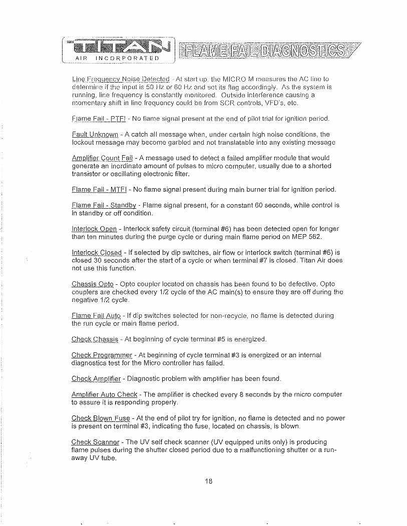
AIH
· ~ ~' .. '.'.'.-.'.'.'.' •. -.' ...••• "'" ' ...•........ ,-•.. '.,._ ............•..•..•.••.. ~ ..........•..•... ' .....••.... ;--................. -....•.... -... -.... -.7' .... - .. ' ...........••. " ..... -........... C" •. -..... -•...•.•.. -.....•..•..• ~ ..........•.••....•. 7' ..•..•..•..•.••.•..•...•.. ". ~~~lW~D~@1f?~~~tl~·u[~[1~~~~~mR~~~@"j·v INC 0 R P 0 RAT E D'"~'-' -.~-... --..•. ~-.,-........ -,-~-.-~.~---. -'-~---'-' <-y
l...iOQ.£r"91lE!J]c2LJ:l9.i§.'2.De.\".(~t<2'! ... At start up, the MICFW M measures the AC line to determine if the input is 50 Hz or 60 Hz and set its flag accordingly, As the system is running, line frequency is constantly monitored. Outside interference causing a momentary shift in line frequency could be from SCR controls, VFD's, etc,
flame fa i I.::.J::'.TF I . No flame signal present at the end of pilot trial for ignition period,
Fault Unknown· A catch all message when, under certain high noise conditions, the lockout message may become garbled and not translatable into any existing message
!\Jli.Rlifier Count Fai! - A message used to detect a failed amplifier module that would generate an inordinate amount of pulses to micro computer, usually due to a shorted transistor or oscillating electronic filter.
Flame Fail - MTFI • No flame signal present during main burner trial for ignition period,
Flame Fail· Standby· Flame signal present, for a constant 60 seconds, while control is in standby or off condition,
Interlock Open· Interlock safety circuit (terminal #6) has been detected open for longer than ten minutes during the purge cycle or during main flame period on MEP 562,
Interlock Closed - If selected by dip switches, air flow or interlock switch (terminal #6) is closed 30 seconds after the start of a cycle or when terminal #7 is closed. Titan Air does not use this function,
Chassis Opto - Opto coupler located on chassis has been found to be defective, Oplo couplers are checked every 1/2 cycle of the AC main(s) to ensure they are off during the negative 1/2 cycle,
Flame Fail Auto· If dip switches selected for nan··recycle, no flame is detected during the run cycle or main flame period,
Check Chassi§ - At beginning of cycle terminal #5 is energized,
Check PrQgfammer - At beginning of cycle terminal #3 is energized or an internal diagnostics test for the Micro controller has failed,
Check Amplifier - Diagnostic problem with amplifier has been found.
Amplifier Auto Check· The amplifier is checked every 8 seconds by the micro computer to assure it is responding properly,
Check Blown Fuse - At the end of pilot try for ignition, no flame is detected and no power is present on terminal #3, indicating the fuse, located on chassis, is blown.
Check Scanner - The UV self check scanner (UV equipped units only) is producing flame pulses during the shutter closed period due to a malfunctioning shutter or a run· away UV tube,
18

GENEHAL START-UP INFORMATION Even though 'ritan Air equipment is tested at the factory, it is not the type of
equipment you can throw the switch and walk away from. A complete Starh'l) procedure must be performed.
The factory cannot duplicate the conditions the equipment will see in the actual installation (i.e. gas pressure, static pressure, desired control settings, etc ... ). For this reason there are field adjustments that have to be made. Performing a complete start· up procedure will help ensure that correct adjustments are made and correct operation is verified, A step-by-step start-up procedure is provided on subsequent pages, While working through the start-up procedure, record information on the start-up checklist and return to Titan Air to validate the equipment warranty. The start-up checklist is provided on card stock with Titan Air's address pre-printed on one side.
Because most component failures occur during start-up, it is very imporiant that the function of every component be checked out during start-up, It is just as important that the start-up technician realize the malfunction of a component may be caused by other factors (i.e, air flow, gas pressure, field wiring, etc .. ,) and should fully investigate a component malfunction and its cause before replacing the component.
Titan Air checks out all returned components and has found approximately 70% of returned parts are in full operational condition, This history has proven that a little extra time invested in troubleshooting will often save the considerable investment in parts, time, and paperwork associated with replacing components.
SUGGESTED TOOLS AND INSTRUMENTS NEEDED FOR START-UP: Volt/Ohm Meter Ammeter Tachometer Thermometer Gas pressure manometer (-10" to 0 to +10" of water column typical scale) Air differential pressure manometer (-2" to 0 to +2" of water column typical scale) Standard Hand Tools.
Additional items for Maxitrol Series 14 or 44 temperature controls: " Y:, watt, 10,000 Ohm resistor
Additional items for FX Series temperature controls: " 10,000 Ohm resistor (supplied) " 1,000 Ohm resistor (supplied)
19
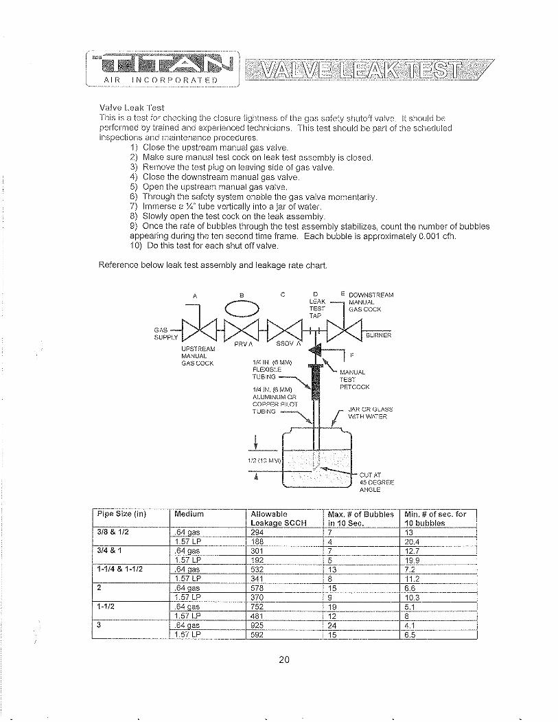
AIR li'lCORPORATED
Valve Leak Test This is a test for checking ti1E) closure tightness of the gas safety shutoff valve. It should be performed by trained and experienced tecl1nicians. This test should be part of tl1e scheduled inspections and maintenance procedures.
1) Close the upstream manual gas valve. 2) Make sure manual test cock on leak test assembly is closed. 3) Remove the test plug on leaving side of gas valve. 4) Close the downstream manual gas valve. 5) Open the upstream manual gas valve. 6) Through the safety system enable the gas valve momentarily. 7) Immerse a )1.;" tube vertically into a jar of water. 8) Slowly open the test cock on the leak assembly. 9) Once the rate of bubbles through the test assembly stabilizes, count the number of bubbles appearing during the ten second time frame. Each bubble is approximately 0.001 dh. 10) Do this test for each shut off valve.
Reference below leak test assembly and leakage rate chart.
-_ .. -Pipe Size (in)
3/8 & 1/2
~4&1 . _-
1-114 & 1-1/2
2
1-1/2
3
'--.
--
,\
UPSTREAM MANUAL Gfl.SCOCK
Medium
.640as 1.57 LP .64 cas 1.57 LP .64 cas 1.57 LP --_ ..... ~§4 qas 1.57 LP .64 aas 1.57 LP . 64 qas 1.57 LP
8 c
C) D
LE,\K TEST
E DOWNSTREAM MANUAL GAS COCK
--
1ft! IN. (6 MM) FLEXIBlJ~
TUBING ---....
1f4fN, (GMM) , ALUMINUM OF:. COPPER PILOT
BURNER
I JAR OR G L.'\SS TUBING ~
~ WiTH WATER
.---+1.....2.-.
1/2(13 MM)
-_. __ . Allowable Leakaae SCCH 294 ._------188 301 192 ---532 -341 578 -370 752 481
I 925 592 - .
20
CUT PT 45 DEGI~EE ANGLG
--- ._---_._._----Max. # of Bubbles Min. # of sec. for in 10 Sec. 10 bubbles 7 13
~-------.---- ~---:--=-~::----_L. __ . __ . ____ . __ . .2.. __ .. ______ ... _ .. _ .. _ .. . __ !.lJ,§__ __
13 7.2 --8 ~-----15 6.6 9 10.3 .UJ... ___ ... __ . __ . __ 5.1 12 8
-~---.--. --24 4.1 15 6.5


/RTC) Solutions
DIRECT' l'II{EI) DIGITAl., 'I'EMPERlI..TURE CONTROL INSTALLKrION, OPERA'nON, AND MA1NTENANCF MANUAL
This manual covers the following products:
DFC-l
DFC-2
DFrs
Standard direct fired temper<lture control 0-24VIX: output
Direct fired control with intcgn,140-90"F (4-32°C) dial 0-24VDC output
Tempt>rature senor 40-250°F (4-121"C)
DFTD-XXXX Temperature dinlS selectable ranges
DAT-12 D;scharge ah tube
PWM-I0V PWM to 10V output converter
Table of Contents Overview ..
Requirements .. DFC Ambient Temperature Limits ... DFTS/DFTD Ambient Temperature Limits. Accur<lcy ...
Installation ..
otand,mt control \'>'it11 remote set point .. Standard control vdlh integrals<:'t point.. Optiomli room space control ... Optionul multiple set point temperature controL..
Operation .. . Start up .. . Sequence of operation .. Calibration .. Troubleshooting .. DFTS and DFTD Resistance chart..
DOC' '1'000111.14.2006 mC-l O&M
Ph. (919) 845-1579 Fax (919) 845-8102
1
www.RTC~Soiutions.com
Email:[email protected]
. .... 2 , .............. 2
...2 ._.n 2
. .... 2
..... 2
.. ... 2 2
.... 2 ..... 3 .. ... 3 .... 3
.. ... 4 .. ... 4 .. .. 4 . .... 4 ..... 4 ..... 4
755Sw 12011> Way Davie, FL 33325
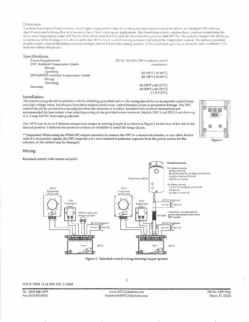
Ovel'vic\Il,T The Roof Top (:ou\roi Suiulions dil'(:ci fin,d lligil<11 tl'lnjXI',llul"(' control is ,I ll1inOprll,-,>SSOI h.b('d (ontrol Ih<,1 utili/v.'; <111 illl('llig(>nl I'll) suftWili"\' <,lgorilhm 10 llloduidte gilS flo\\' to il bunll'r in dil'cd j il"l:d 111,.kc up <lir ilpplit','lillllS, TIll' dl)Sl~d loop system nmldins lhr('l' comjJlllwnts includinl\ Ilw dircd (in'd Il'mpCliIi1Hl' S('ltS()]" (LWI S), ilw din:d fin~d nmlroi (nrC), ,md ,Iw di!'('c! fin'd l('mp(,l"illlll'l~ di,li (DrT])), ]"11(" sySkll1 (OmpM('S Ilw disd1Mg(' l('mpl'J'(liuJ'(, (If Illl' hl'il!illg uilillo tlw sd j)nil1l didl -!i) lim('s pcr second illsl1rjnl~ dCCliJ"dl(' <lnti rCJll\llilbk Il'mpndiurt' dmll'()1 riw soflwil!"(' proVilks smooth uulpul cunlrol l:iimi11<lling exc('ssive :>win,,,s Ob:-;,'lV('d with old<.']" illlit!Og S),'*'111S. ;\ I () SI'Clmd SiMI up dQb')." is SlanddJ"d, ilnd dl1 Onh(lilni [ )·:1)
indicl\('s simpl" di<lgnOc,lics
Specifications Po\"\'e1' Requirements DFC Ambient Temperature Limits
SI-orage Operating
DFrS/DFTD Ambient Temperature Limits Stomge Operating
Accuracy
Installation
24VAC SO/60l-1/, 20V;\ isoi"led cla:,;; 1I [ran;;fOfnwl
AO··140"F (··lO·woq -'10·140"1' (-40·60"q
·40·250"F (AO·121"q -'10·250"1' (·40·121"q
+/·3"F (I"q
All control wiring should be shielded with the shielding grounded and/ Or the wiring should be run in separate conduit from any high voltage wires. Interference from these sources could celllse control function errors or permanent damage. The DFe control should be mounted in a housing free from the elements of \\'eath('r. Insulated fork terminal terminations are reconunended for best contact when Clttaching wiring to the provided screw terminals. Models DFC~1 and DFC~2 can drive up to a .5 amp 24VDC direct acting solenoid.
The DFfD can be set to 5 different temperature ranges by moving jumper JI <IS shown in Figure 1 on the back of the di<ll to the desired position. 5 different temperature overlays Me available to match the range chosen.
~.~. Important! When using the P\VIvl~10V output converter to connect the DPC to a motorized ilchwtor, or any other device with it's own power supply, the DPC Il1ust have it's own isolated transformer separate from the power source for the actuator, or the control may be damaged.
Wiring
Standard control with remote set point
For SI0W.'IlS a(l\,alol Rcd{G) 1024 VAC
Figure 1
o ProportlOnal,lCluator
[llack(CO) lo24VAC Jnd Illackon PW;"-I-\OV O'<w{l') l(l Ikd on P\\'!vl.lOV l'mk(U) r-.'(l Comw.;i
DFlD Ti'lllr:<'r,ltm"l? sek,,:llOlld,,11
Q ~J
ll! , , ,
01''1'5 Ten'lvr,ltllf<'
s~n""r
DOC# TOOO!11.14.2006 DK·! O&M
Ph. (919) 845·1579 Fax (919) 845·8102
DFC·1
DFTD ·)i.'mfx~,'luf('
s..'!~(I"Jild,~1 ---0"
'0' '. "" "
DFrs T('111lx'r,llur(>
$('H5t'f
o f'o! BdIElK) Mi\l,llcr
o 11n2·\VAC,lIld Bi,lrk,," I'W\-1-10V 2 t(l24VAC
[l&--~ }IO I,{';\ on 1'\\')I.,I·lOV
: _..!! VA T,-,msiorn)2'
_.~~I:~Jr31V .. \C 'lmport<lnl- Actu.llor musllw powe~d by jso!~ted SO\HW {rom DI'C(ontrol
DFC·1
Figure 2 ~ Standard control wiring showing output options
2
www.RTC-Solutions.com Email:[email protected]
755 Sw 120110 Way D<lvie, FL 33325

SI;md,'Hd control with inh'gral se{ point
Figure 3 ~ Cont-rol with integral setpoinl
Optional room space conlTol
DFC\
Figure 4· Room space control with thennost;lt Figm'e 5 .. Room space control with digital space control
A standard make or break thermostat with normally open contacts can be connected between terminals 1 and 2 as shown in Figure 4, When connected in this \vay the thermostal may be set for a desired room temperature for space control applications. Potentiometer Rl on the back of the DfTD sets how much the temperature will increase by when the room thennastat calls for more heat. When the room thennosLat is satisfied, the discharge temperature will return to the temperature set on the dial on the front of the DFTD. For proportioned room space control, the DFCl can be connected as shown in figure 5. See KrC·1 literature for details.
Optional multiple set point tempera hue control
:'-]VOC PIOf"<-""""'] <;,-k"",d c~, V,,]w
·1 , i DK 1
~ _Gp.!
Figure 6 - Control with multiple set points
More than one temperature dial can be connected [\s shown in figure 3 for applications such as paint spray booths or process control.
DOC# T000111.14.2006 DFC·1 O&M
Ph. (919) 845·1579 Fax (919) 845·8102
3
\\'ww.RTC·Solutions.com Email:[email protected]
755 Sw 120lh Way Davie, FL 33325
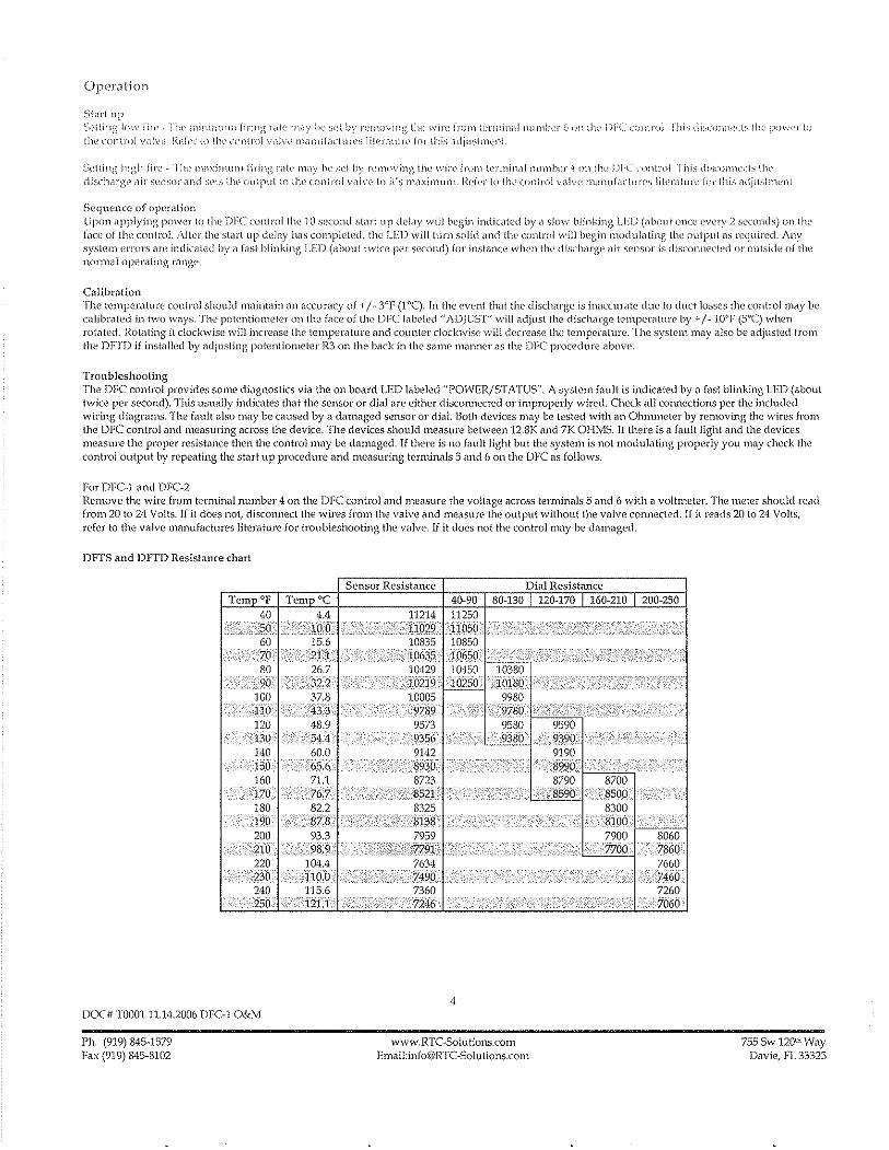
Operation
Start up ~;t'!lllig I()\~ 1";1'[' nw minimllJll fil'in)~ I'd!,' nlt,y h,_' sl'l hy )','rn()\-'in,_~ !he wire (lUI)) lc'l'Il1indi 1111m\wJ" h un til,' I)FCu-'I1!wl I'll)..; di_~l_"mlw;:[;, illl' i'''\\('j' \0 the control vidvl' ]\('kJ' tn Ow control vdv(' m;II1t;i(lc[u)'('s li[e),(1Iun' for thi;; adjustnwnt
Sdling high fin', rlw nl,l:>:imllnl fil'ing 1',11\' 1ll(1)' 1)(' ;;('\ hy 1"'llloving tlw win.' frol11 tl'1'IJ1in,ll rlumlwr i on Ilw I)rc (onln)] Tbi_', di,',n)l)lwd~ Ilw di~;charg(' ,1i1' sVllsor ,ll1d ~;('Is llll' ()(1[put III till' c()niJ'llI valve to it's maximum j<'d('f In Ow clln\j'()i v,llv(' mdlLuf,K\lln';; ii[er,lturc fol' this <1dju;;tl11(:l1t
SeqmOllCt: of operation Upon applying power to llw ))FC controllhe 10 s(~('()nd startup del,)y wi)] begin indicdted by a slow blinking LEI) (about onu' cwry 2 seconds) tmlhe {nce of the: conlrol. After the stiH"lup dL'lily has completed, the LED willtunl solid <lnd the ClmtroJ will begin modulating tlw output as required, Any system errors arc indicated by i1 (ast blinking LED (about twice per second) for instance when tIll' discharge air sensor is tiisco11lwcled or oulsi(h~ of the normal operating filnge.
CalibrMion The temperature control should maintain an accuracy of +/- 3°F (l0C). In the event thM the discharge is inaccurate due to duCliosses the control may bp calibrated in l\vO ways, The potentiometer on the face of the DFC lab(>kd "ADJUST" \-vill adjust the discharge tC'mperilture by + / .. 'JO"F (5°C) when mtnted. Rotating it clockwise will increase the temperature nnd counter clockwise will decrease the temperature. The system may also be adjusted from the DFTD if installed by ndjusting potentiometer R3 on the back in the same manner as the DFC procedure above.
Troubleshooting The DFC control provides some di,1gnostics via the on board LED labeled "POWER/STATUS". A system fnuit is indicated by a fast bUnking LED (about twice per second). This usually indicntes that the sensor or dial are either disconnected or improperly wired. Check nil connections per the included wiring dingrams. The fault also mny be caused by a damaged sensol" 01" dial. Both devices may be tested with an OhllUl1eter by removing the wires from the OFC control anci mensuring across the device. The devices should measure between 12.8K and 7K OHMS. If there is a fault light and the devices medSUl"e the proper resisti'lnce then the control may be damaged. If there is no filUIt light but the system is not modulating properly you may check the control output by repeating the SiMI up procedure and measuring terminals 5 and 6 on the OPC as follows.
For DFC-J i'lnd DFC-2 Remove the wire from terminal number 4 on the DFC control and mei'lsure the voltage across terminals 5 and 6 with d voltmeter. The meter should read from 20 to 24 Volts. If it does not, ciisconnect the wires from the valve and measure the output without the valve connected. If it reads 20 to 24 Volts, refer to the volve manufactures litemt-ure for troubleshooting the valve. If it does not the control may be damaged.
DFTS ond DFI'D Resistance chart
Tem OF
DOC' TOOOl 11.14.2006 DFC-1 O&M
Ph. (919) 845-1579 Fax (919) 845-8102
Sensor Resistance Dial Resistance 80-130 120-170 160-210 200-250
10380 102®'_ :10180
9980 '97so
4
9580 9380
www.RTC-Solutions.com Email:[email protected]
755 Sw 12011\ Way Davie, fL 33323
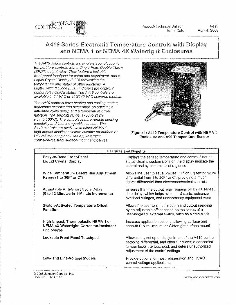
Product/Technical Bulletin Issue Date
Mig April 4, 2008
[ .. =: .... -.... -.- ............................ -..... -.. -----.. -...... -.. ---.---.---... -----...... .. -.... -... --... -.. ------.-.--.. ---- .... ---...... -.. -_ ...... _-.. ·_·-1
A419 Series Electronic Temperature Controls with Display I and NEMA 1 or NEMA 4X Watertight Enclosures ---------.J
The A419 series controls are single-stage, electronic temperature controls with a Single-Pole, DouNe-Throw (SPOT) output relay They feature a lockable front-panel touchpad for setup and adjustment, and a Liquid Crystal Display (LCD) for viewing the temperature and status of other functions. A Ligilt-Emilling Diode (LED) indicates the controls' output relay OnlOff status. The A419 controls are available in 24 VAC or 120/240 VAC powered models.
The A419 controls have Ileating and cooling modes, adjustable setpoint and differential, an adjustaNe anti-short cycle delay, and a temperature offset function. The setpoint range is -30 to 212'F (-34 to 100'C). The controls feature remote senSing capability and interchangeable sensors. The A419 controls are available in eitller NEMA 1, high-impact plastic enclosure suitable for surface or DIN rail mounting or NEMA 4X watertight, corrosion-resistant surface-mount enclosures.
Figure 1: A419 Temperature Control with NEMA 1 Enclosure and A99 Temperature Sensor
Features and Benefits
Easy-to-Read Front-Panel Liquid Crystal Display
Wide Temperature Differential Adjustment Range (1 to 30F' or C')
Adjustable Anti-Short Cycle Delay (0 to 12 Minutes in 1-Minute Increments)
Switch-Activated Temperature Offset Function
High-Impact, Thermoplastic NEMA 1 or NEMA 4X Watertight, Corrosion-Resistant Enclosures
Lockable Front Panel Touchpad
Low- and Line-Voltage Models
© 2008 Johnson Controls, Inc. Code No. LlT-125188
Displays the sensed temperature and control-function status clearly; custom icons on the display indicate the control and system status at a glance
Allows the user to set a precise (1 F' or C') temperature differential from 1 to 30F' or C'; providing a much tighter differential than electromechanical controls
Ensures that the output relay remains off for a user-set time delay, which helps avoid hard starts, nuisance overload outages, and unnecessary equipment wear
Allows the user to shift the cut-in and cutout setpoints by an adjustable offset based on the status of a user-installed, external switch, such as a time clock
Increase application options, allowing surface and snap-fit DIN rail mount, or Watertight surface mount
Allows easy set up and adjustment of the A419 control setpoint, differential, and other functions; a concealed jumper locks the touchpad, and deters unauthorized adjustment of the control settings
Provide options for most refrigeration and HVAC control-voltage applications
1 www.johnsoncontrois.com
Application
IMPORTANT: Tile A419 Series Temperature Controls are intended to control equipment under normal operating conditions. Where failure or malfunction of an A419 Series Control could lead to an abnormal operating condition that could cause personal injury or damage to the eqUipment or other property, other devices (limit or safety controls) or systems (alarm or supervisory) intended to warn of or protect against failure or malfunction of the A419 Series Control must be incorporated into and maintained as part of the control system.
The A419 Electronic Temperature Control can be used to control a wide variety of Single-stage refrigeration or Heating Ventilating, and Air Conditioning (HVAC) equipment. Typical applications include:
• retail store display freezers and reach-in coolers
• supermarket display cases for produce/meats
• retail store walk-in coolers and freezers
• boiler operating control (used as a thermostat)
• condenser fan cycling or staging
• cooling tower pump and fan control
• space and return air temperature control
FCC Compliance
This device complies with Part 15 of the FCC Rules. Operation is subject to the following two conditions: (1) this device may not cause harmful interference, and (2) this device must accept any interference that may cause undesired operation.
This equipment has been tested and found to comply with the limits for a Class A digital device pursuant to Part 15 of FCC rules. These limits are designed to provide reasonable protection against harmful interference when this equipment is operated in a commercial environment. This equipment generates, uses, and can radiate radio frequency energy and, if not installed and used in accordance with the instruction manual, may cause harmful interference to radio communications. Operation of this equipment in a residential area is likely to cause harmful interference, in which case the user will be required to correct the interference at his or her own expense.
Canadian Compliance Statement
This digital apparatus does not exceed the Class A limits for radio noise emissions from digital apparatus set out in the Radio Interference Regulations of the Canadian Department of Communications.
Dimensions
I "-~jj~9"" I
o 0
DIN F~ail
, l
1-9116 7116 ""'(40)>- <(11)
1- Sensor
t: r, (520) • '1
(6)
I':
[
~··"ill i ';:'.:Ai"JlD -"0 ...... .
r(1~i)
.~~ tl 1
-4( 2-3/8 " I (61)
. Ii· N: 718 (22) ~
7/8 (1/2 in. Trade Size) (22) Conduit Hole
Figure 2: A419 Temperature Control with NEMA 1 Enclosure, Dimensions, in.l(mm)
• 2-114 • ... 1-1116;..-(56) (27) I
~~;~. trf'~~,) 6-518 (168)
E3 0 I'J 6-1Bl (155)
Figure 3: A419 Temperature Control with NEMA 4X Watertight, Corrosion-resistant,
Enclosure, Dimensions, in.l(mm)
2 A419 Series Electronic Temperature Controls with Display and NEMA 1 or NEMA 4X Watertight Enclosures ProductlTechnical Bulletin
Figure 4: A419 Temperature Control with NEMA 4X Enclosure and A99 Temperature Sensor
Operation Overview The A419 control's front-panel, LCD, LED, and the A419 control functions are described below. See the Adjustments section for instructions on setting up and adjusting the A419 control.
A419 Control Front-Panel
The front panel of the A419 control has a three-button touch pad and LCD for adjusting control function values, and an LED indicator that displays the On/Off status of the SPOT output relay. See Figure 5.
Temperature Indicator
Units Indicator
Operating Mode Indicator
Liquid Crysla! Display
DOWN Arrow Button
UP Arrow Button
Output Relay Status Indicator
LED
Figure 5: A419 Control Front-Panel with Display
Liquid Cryst.al Display
During normal operation, tile LCD displays tile temperature at the sensor, the ullits of temperature C For °C), and all icon indicating if the control is set for Heating (b) or Cooling (*) mode. The LCD also displays BIN if the Temperature Offset function is activated. See Figure 5.
During control set up or adjustment, the LCD displays the control functions and their values (settings). After 30 seconds of inactivity, the display returns to the sensed-temperature display. See the Adjustments section to adjust the control setting.
Output Relay Status Indicator LED
A green LED on the control's front panel illuminates when the SPDT output relay is energized and the Normally Open (N.O.) contacts are closed. See Figure 5.
A419 Control Definitions
Cut-in is the temperature at which the N.O. contacts on the SPDT output relay close.
Cutout is the temperature at which the N.O contacts on the SPOT output relay open.
A419 Functions Set at the Front·Panel Setpoint (SP) establishes the temperature value that energizes or de-energizes the output relay, depending on the user selected mode of operation. The control may be set either to cut in or to cut out at Setpoint. See the CoolinglHeating and Setpoint Modes. The Setpoint range is ·30 to 212'F (-34 to 100'C).
If Setpoin! mode is Cut-in, Setpoint is the temperature value that closes the N.O. contacts. If Setpoint mode is Cutout, Setpoint is the temperature value that opens the N.O. contacts. See Figure 7 and Figure 8.
Differential (dIP) establishes the difference in temperature (in F' or C') between the cut-in and cutout values. The differential is set relative to Setpoint and may be set from 1 to 30F' or C'. See Figure 7 and Figure 8.
Anti-Short Cycle Delay (ASci) establishes the minimum time that the N.O. contacts remains open (after reaching cutout) before closing again. The delay overrides any Load Demand and does not allow the N.O. contacts to close until the set time-delay value has elapsed. See Figure 6. When the delay is activated, the LCD alternately fiashes the sensor temperature and ASd. The delay may be set for 0 to 12 minutes in 1-minute increments.
A419 Series Electronic Temperature Controls with Display and NEMA 1 or NEMA 4X Watertight Enclosures ProductlTechnical Bulletin 3
ICor example, if the anti-short cycle delay is set for '7 minutes, the A419 control will not restart the equipment for 7 minutes after the equipment 11as cut out, even if the cut-in temperature value is reached during the delay. If the temperature reaches tile cut-in value during the delay period, the display fiashes between the sensed temperature and ASd, indicating that the next On-cycle is being delayed. After the set delay time has elapsed, the A419 control returns to normal operation, restarts the equipment (if cut-in has been reached), ASd stops flashing, and the LCD reverts to the normal operating display.
Note: Any interruption in supply power to the A419 control activates the anti-short cycle delay.
Time}l Load Demand
~~OL:::~::and __ ront... :~II
QIlJ ~-,L Output Status Anti~short
Cyde Delay
Figure 6: Anti-short Cycle Delay
Sensor Failure Operation (SF) establishes how the A419 control operates the equipment in the event of a sensor or sensor-wiring failure. The A419 control may be set to run the equipment continuously or to shut it down if the sensor or sensor wire fails. When a failure is detected the LCD flashes SF alternately with OP if the sensor circuit is open, or SF and SH if the sensor circuit is shorted. The control implements a 1 -minute delay before initiating a failure response to allow for verification of the failure condition and to avoid nuisance failure indications.
Temperature Units establishes the units of temperature (FO or CO) displayed on the LCD.
Temperature Offset (OFS) establishes the value of setpoint-shift (in FO or CO) applied to Set point (and Differential) when a (user-installed) circuit is closed between the binary input (BIN) and common (COM) terminals. The offset value may be set from 0 to 50Fo or Co,
The Temperature Offset function is used to reset the Heating Setpoint to a lower temperature (secondary) setpoint or reset the Cooling Setpoint to a higher temperature (secondary) setpoint by the temperature value set in Temperature Offset.
The BIN and COM terminals may be connected to a (user-supplied) external switching device, such as a time clock, that has a set of Single-Pole, Single-Throw (SPST) contacts. Closing a circuit between the BIN and COM terminals activates the Temperature Offset. See Wiring.
This function enables the control to alternate between two temperature setpoints based on the position of the binary input switcll. The difference between the primary and secondary setpoints (in F" or CO) is set in tile Temperature Offset function (OFS) using the touchpad. See Setting Other FUllctions.
Table 1 shows an example of Temperature Offset
Table 1: Temperature Offset Example
Mode of Setpoint Temperature Secondary
Operation Offset Value Setpoint' Cooling 70° 80 78 0 _._-_.-Heating 70 0 80 62°
Setpolnt when CirCUit between binary mput terminals (BIN and COM) is closed
When the circuit is closed between the binary input (BIN) common (COM) terminals, the offset function is enabled and the A419 control cycles on the secondary setpoints. BIN is displayed on the LCD above the OF or °C symbol when the offset is enabled. See Figure 5.
A419 Control Functions Set by Jumper Position
For instructions on positioning jumpers, see Positioning the Jumpers in the Adjustments section, Refer to Figure 12 and Figure 13.
Touchpad Lock: The jumper at P5 establishes whether the touchpad is locked or unlocked. Locking the touch pad deters accidental or unauthorized changes to all of the function parameters.
Heating/Cooling Mode is established by positioning the jumper on the top two pins of the P4 jumper. See Figure 13.
Setpoin! Mode: Removing or installing the lower jumper at P4 establishes whether Setpoint is the cut-in temperature or cutout temperature. See Figure 13.
Cooling/Heating and Setpoint Modes
The A419 control may be in four operating modes: Cooling/Cut-in, Cooling/Cutout, Heating/Cut-in, and Heating/Cutout. Position the jumpers located on the circuit board under the A419 control cover to set the desired mode of operation, See Positioning the Jumpers.
In Cooling/Cut-in mode the differential is below Setpoint. The output relay energizes and the LED illuminates when the temperature rises to Setpoin!. When the temperature drops to Setpoint minus the differential value, the relay and LED de-energize,
4 A419 Series Electronic Temperature Controls with Display and NEMA 1 or NEMA 4X Watertight Enclosures ProducUTechnical Bulletin
In Cooling/Cutout mode the differential is above Setpoint. The output relay energiz.es and LED illuminates when the temperature rises to Setpoint plus the differential value. When the temperature drops to Setpoint, the relay and LED de-energize.
Temperature (;.) Cooling/Cut-out
cut-i~ll+"--"'!" (On) Diffe;ential C(6~ut
I', ,"',- ,+ -,' -JL.- Cooling/Cut-in Setpoint ._-- ~ /L~- c.; _,~-,-_'_<_ ,1
Cut-in I;, . r
(-)
",' !~~~I Figure 7: Cooling Modes
Cut~out
(Off)
When the HeatinglCut-in mode is selected, the differential is above Setpoin!. The output relay energizes and LED indicator illuminates when the temperature drops to Setpoin!. When the temperature rises to Setpoint plus the differential value, the output relay and LED de-energize.
When Heating/Cutout mode is selected, the differential is below Setpoin!. The output relay energizes and LED indicator illuminates when the temperature drops to Set point minus the differential value. When the temperature rises to Setpoint, the output relay and LED indicator de-energize.
Temperature (+) Heating/Cut-in
Setpoint
(-)
r~~T-JC(6mt
'"~ I~"-:"' I Heating/cu;t0ut (on)~" ~ ...... _
'" t Cut-out
J (Off)
Differential
~ '( --<----
Cui-in (On)
Figure 8: Heating Modes
Mounting An A41 9 control has either a standard high··impact plastic NEMA 1 or a NE:MA 4X corrosion·resistant, watel1ight enclosure.
The A419 control is not position sensitive but should be 1110unted for convenient wiring and adjustment.
Note: When mounting the control to rigid conduit, attach the hub to the conduit before securing the hub to the control enclosure.
The mounting hole pattern of the NEMA 1 enclosure is identical to that of the System 350'" controls, and most models of the A 19 control. The NEMA 1 enclosure may also be mounted on 35 111m DIN rail. See Figure 1 and Figure 2.
The NEMA 4X models may be 1110unted to fiat vel1ical surfaces using the four screw holes at the enclosure corners. See Figure 3 and Figure 4. To maintain the watertight and corrosion resistant integrity of the NEMA 4X enclosure, use a conduit fitting rated for the environment in which the control is installed.
An additional (low-voltage) two-wire cable is required to operate the temperature offset function. On NEMA 4X enclosures you must install a suitable liquid-tight fitting in an available knockout to pass the two-wire cable through the enclosure wall.
IMPORTANT: The short-lead A99 sensor, included with A419 NEMA 4X model controls, must be mounted on the bottom of the control in the bracket molded on the NEMA 4X housing. Mounting the sensor on top of the control may reduce the accuracy of the displayed temperature. See Figure 3 and Figure 4 for proper sensor position.
A419 Series Electronic Temperature Controls with Display and NEMA 1 or NEMA 4X Watel1ight Enclosures ProductrTechnical Bulletin 5

Wiring
A WARNING: Risk of Electrical Shocie To avoid the risk of electrical S110ck, disconnect all power sources to the control before wiring any connections. More than one disconnect may be required to completely de-energize the control and equipment.
IMPORTANT: All wiring must conform to local, national, and regional regulations. Use copper conductors only for all wire connections. Do not exceed tile electrical ratings for the A419 control or the equipment it is wired to.
Refer to Figure 9, Figure 10, and Figure 11 for typical examples of wiring an A419 control to the controlled equipment.
Use wire no larger than 12 AWG when connecting to the two lower terminal blocks (TBi and TB2).
Note: Terminal block TB2 is an isolated SPOT switch (dry contacts). The TB2 terminals have no internal electrical connection to the A419 control.
Use wire no larger than 16 AWG when connecting to the upper sensor terminal block (TB3).
\Nire insulation rating must be 90°C, minimum.
A99 temperature sensors are not polarity sensitive. \Nire the leads to (+) SEN and (-) COM on the sensor terminal block (TB3). See Figure 9, Figure 10, and Figure 11.
Keep the leads between the control and sensor as short as possible/practical in your application. The additional resistance in long sensor leads creates error between the actual temperature and the displayed temperature. Refer to Table 1 when extending sensor leads.
Temperature sensor signals may be affected by electrical interference. When extending sensor cable beyond 50 It (15.2 m) use a twisted-pair, shielded cable to reduce electrical interference.
If the Temperature Offset function is used, wire a switch (such as a switching time clock) between the binary input terminal (BIN) and the common terminal (COM). See Figure 9, Figure 10, and Figure 11 for terminal strip location.
(Optional) A419GBF-1 Binary Input A419GEF-1
SWitch i 17"1 I ... ' .. ························ 0, (+IBIN c~;jC;:;:Jr01 H COM
Jfbi .... 1'Zli (+IS[,N
Cable ~'II II
TB3'-
Shield (if used) ! I T81
AgO I [§\911 '"'1¥1?ll
Sensor I N 00 i ;::,,- Z ZjJ L_~ __ _
24VAC _~...../ __ Class 2 24 VAG]
Transformer load .. J
Figure 9: Wiring the 24 VAC A419 Control
Figure 10: Wiring the 120 VAC A419 Control
(Optional) [-- A419ABC=-1-Binary Input A419AEC-1
SW%lirr~(+18IN (-I COM (+ISEN~-... ;
Cable ~ TB3[eJ ~ Shield i
(if used) ~ '-~~~~I AgO L~ SJ....QJ T82@j 'i 0
Sensor \:::: \ I { 01 000 <...)u ~ U ~ Z Z
o
240 L 1-=:t=i"'===~~~ VAC L2 __ +-~~--1240VAC
--- Load
Figure 11: Wiring the 240 VAC A419 Control
6 A419 Series Electronic Temperature Controls with Display and NEMA 1 or NEMA 4X Watertight Enclosures ProductiTechnical Bulletin
Adjustments Tllis section provides instructions for setting up and adjusting the A419 controls using the jumpers and touchpad.
Positioning the Jumpers
The P5 Jumper Pin Block has a single set of jumper pins and is used to lock or unlock the touchpad. The P4 Jumper Pin Block has two sets of jumper pins.
The top set of pins at P4, labeled JUMP1, is used to set the control for Heating or Cooling mode. The bottom set of pins, labeled JUMP2, is used to establish Setpoin! at cut-in or at cutout. See Figure 12.
To position a jumper in the Installed position, place the jumper on both pins. To position a jumper in the Removed position, place the jumper on only one pin. (Save the jumper in case it is required in the future.) See Figure 12.
Position the jumpers as follows. Refer to Figure 12, Figure 13, and Table 2.
1. Verify that all power sources to the A419 control have been disconnected.
2. Remove the control's cover by loosening the four captive cover screws.
3. Position the jumpers to set Cooling/Heating, Setpoint, and Touchpad Lock functions.
4. Replace the cover and fasten in place with the four screws.
5. Restore power to the control. --------
IMPORTANT: Verify that the Cooling/Heating jumper is positioned properly before powering the A419 control, to ensure that the relay operates as intended. See Figure 13 and Table 2.
f!I f!I ~ ]I
Installed Jumper,
(Jumper Positioned on 80tl1 Pins)
Pins I == .ill
<-<I Hemoved (Jumper Positioned on One Pin)
Figure 12: Positioning the Jumpers
~ I Touchpad Touchpad
~unlOCked
[01 101 JUMP1 rool iq)1 ~ JUMP2 ~ '0 ' L._! P5 P4
~ Bill
Heati n9 Mode Cut-in at Setpoint
Bill IB!D
Cooling Mode Cut-in a\ Setpoint
Bi! Bi!
Heating Mode (Standard)
Cut-out at Setpoint
."01 ~
Cooling Mode (Standard)
Cut-out at Setpoint
Figure 13: Jumper Positions and Control Settings
Table 2: Jumper Designations, Jumper Positions and Control Settings
Function Jumper Pins Designation Setting
Jumper Factory Default Setting on Control Position* (and Jumper Position)-
Operating Mode JUMP1 Cooling Removed Cooling Cooling/Heating (Top Pair of Pins on Block P4) Heating Installed (Removed position)
Setpolnt JUMP2 At Cut-in Removed Cut-in (Bottom Pair of Pins on Block P4) At Cut-out Installed (Removed Position)
Locked Removed Unlocked Touchpad Lock P5-Touchpad Unlock (Installed Position) Unlocked Installed
Note. The touchpad cannot be unlocked Without a Jumper. Do not discard !illY Jumpers 111 case they are reqUired In the future.
A419 Series Electronic Temperature Controls with Display and NEMA 1 or NEMA 4X Watertight Enclosures ProductfTechnical Bulletin 7

Changing Temperature Units
The A419 control is set at the factory to display in Fahrenheit temperature units.
fh'tJ press the Up and Down buttons J \:) To convert to Celsius units,
V simultaneously. Press them again to return to Fahrenheit units.
Notes: Make sure the Touchpad Lock jumper is in the unlocked (installed) position before adjusting the control. See Figure 13.
Verify that the A419 control is displaying the desired temperature units (F' or C') before establishing the setpoint value.
Setting the Setpoin!
To view and adjust the temperature setpoint, follow these steps and refer to Table 3:
MEN~
MEN~
'~ MEN~
1. Press and hold the MENU button until the display changes to flashing SP. This will take about 2 seconds.
2. Press the MENU button again. The current setpoint is displayed.
3. Press the Up or Down button to adjust the setpoint temperature.
4. Press the MENU button to save. The display then returns to the sensor temperature.
Notes: If no entries are made for 30 seconds while programming is in progress, the control reverts to the normal temperature display.
If the MENU button is not pressed after changing the setpoin! value, the new value is not saved and the A419 control reverts to the previously saved setpoint value.
Any saved A419 control setting values are non-volatile and remain in the control's memory during power interruptions.
Table 3: Function Ranges and Settings -~-~'--'"-,'"''"-'"-''
I Factory Function Range Setting --,-~-
.... .. 30 to 212"F I
SP: Setpoint I 30 . .~ ... ~.-, ... '"'~, .. -.. - .. ~, .. ,.,-..• - .... -~ .... ~ (:~4t<J~ OO:...CL ........ L .. _ ....... _ .....
dlF: Differential 1 to 30" (F or C) 5 r-- ...................... _ ...... ASd: Anti-short o to 12 minutes i
Cycle Delay _ .. ----OFS: Temperature o to 50' (F or C) 0
Offset ._-----_._--_ .. i---0= output
SF:Sensor Failure de-energized 1
Operation 1 = output energized
OperatIOn at Extremes. If the combination of setpolnt plus or minus the differential falls outside the temperature range (-30 to 212'F [-34' to 100'C]), the A419 control operates as follows:
Cooling/Cut-in: If the control is operating in Cooling/Cut-in mode and setpoint minus differential is less than -30'F, the control switches on at setpoint and off when the temperature drops below -30'F (-34'C).
Heating/Cut-in: If the control is operating in Heating/Cut-in mode and setpoint plus differential is greater than 212'F (1 OO'C), the control switches on at setpoint and off when the temperature exceeds 212'F (100'C).
Cooling/Cutout: If the control is operating in Cooling/Cutout mode and setpoint plus differential is greater than 212'F (100'C), the control switches on when the temperature exceeds 212'F (100'C) and off at setpoin!.
Heating/Cutout: If the control is operating in Heating/Cutout mode and setpoint minus differential is less than -30'F (-34'C), the control switches on when the temperature drops below -30'F (-34'C) and off at setpoin!.
8 A419 Series Electronic Temperature Controls with Display and NEMA 1 or NEMA 4X Watertight Enclosures ProductlTechnical Bulietin

Setting Other Functions
To set the Differential (dIF), Anti-short Cycle Delay (ASd), Temperature Offset (OFS), or Sensor Failure (SF) operation, use the method illustrated and outlined below.
Figure 14 illustrates the order of functions shown using the Up or Down button. The Up button accesses functions in the clockwise direction; the Down button accesses functions in the counterclockwise direction. Refer to Table 3 for function ranges and factory settings.
Up It. Button 7
dlf""
S P A.
i--
'I Down Button
.... Sf"
...j
A S d A
Figure 14: Order of the Functions
MEN~
'" 1. Press and hold the MENU button
until the display changes to flashing SP. This will take about 2 seconds.
2. Press the Up or Down button repeatedly until the desired function is displayed. See Table 3.
3. Press the MENU button to display the function's current value.
4. Press the Up or Down button until the desired value is displayed.
5. Press the MENU button to save the new value. The display then returns to the sensor temperature.
Notes: If no entries are made for 30 seconds while programming is in progress, the control reverts to the normal temperature display.
If the MENU button is not pressed after setting a new value, the new value is not saved and the A419 control reverts to the previously saved value for that function.
Any saved A419 control setting values are non-volatile and remain in the control's memory during power interruptions.
Checkout Before applying power, make sure installation and wiring connections are according to job specifications. After necessary adjustments and electrical connections have been made, put the system in operation and observe the control for at least three complete operating cycles before leaving the installation.
Troubleshooting If the control system does not function properly, verify that the unit is wired, configured, and set properly. If the problem persists, use the following procedures to determine the cause of the problem:
1. Check for proper supply voltage to the A419 control.
a. Remove the cover by loosening the four captive cover screws .
A WARNING: Risk of Electrical Shock. High voltages may be present at electrical terminals and other exposed internal metal surfaces. Avoid contact with all metal surfaces on control when cover is removed.
b. Use a reliable AC voltmeter to check the voltage between the COM and 120V or 240V terminals on line voltage models and the two 24V terminals on low-voltage models. Refer to Figure 9, Figure 10, and Figure 11.
c. The voltage must be between: 20 and 30 VAC for 24 volt applications, 102 and 132 VAC for 120 volt applications, 177 and 264 VAC for 208/240 volt applications
Notes: If the voltage reading is within the required range, proceed to Step 2.
If the voltage reading is not within the required range, check the power source and input power wires for problems.
A419 Series Electronic Temperature Controls with Display and NEMA 1 or NEMA 4X Watertight Enclosures ProducVTechnical Bulletin 9
2. Clieck for proper sensor operation.
Disconnect all power sources to control.
a. Take a temperature reading at the sensor location, using an accurate thermometer.
b. Disconnect the sensor from the control.
c. Use a reliable ohmmeter, to measure the resistance across the two sensor leads wllile the sensor is at the temperature taken in Step b.
d. Refer to Figure 15 to verify that the measured temperature and resistance conform to established temperature and resistance values.
e. If the measured values conform to the values in Figure 15, proceed to Step 3.
f.lf the sensor's measured resistance value is substantially different from the expected value for that temperature, clleck the sensor wiring. If sensor wiring is okay, replace the sensor.
Temperature (OF) Temperature (OC)
Figure 15: Nominal Temperature vs. Sensor Resistance
3. Check the A419 for proper operation.
a. Perform Troubleshooting Steps 1 and 2 before performing this step.
b. Disconnect the load from the output relay terminals.
c. Ensure that the Touchpad Lock jumper is installed, so that the touchpad is unlocked.
d. Reconnect the sensor leads and supply power to the control.
e. Replace the cover.
f. Check the control settings for proper values.
g. Press anel holel the MENU button until Setpoint appears (occurs in about 2 seconds).
11. Use the Up and Down buttons to change the Setpoint temperature above and below the current sensor temperature until the output relay energizes and de-energizes as shown in Table 4.
If the anti-short cycle delay has a time greater tllan 0 minutes, the relay will not energize until the timed delay has elapsed.
i. If the output relay does not perform as indicated in Table 4, replace the A419 control.
j. If proper operation of the A419 control is verified, reconnect the load and consult the equipment manufacturer's instructions for troubleshooting the controlled equipment.
Table 4: A419 Output Relay Operation
Output Output Relay
Setpoint Operating Relay De-energized
Mode Mode Energized at... at ... Setpoint
Cooling plus Setpoint
Cutout differential
Setpoint Heating minus Setpoint
differential
Setpoint Cooling Setpoint minus
Cutwin differential
Heating Setpoint Setpoint plus differential
Note: When the relay IS energized, the N.O. contacts are closed and the LED is illuminated.
10 A419 Series Electronic Temperature Controls with Display and NEMA 1 or NEMA 4X Watertight Enclosures ProductrTechnical Bulletin

Faull Codes
A419 controls are programmed to display certain faull codes on the LCD as described in Table 5.
Table 5: Fault Codes Defined
Fault Code Definition ! System Status Solution
SF flashing Open temperature Output functions according to See Troubleshooting section. alternately with OP sensor or sensor the selected sensor failure
Cycle power to reset the control. wiring mode (~F setting) -_ .. _ .. - - -~--.. ~--... -------------------SF flashing Shorted temperature Output functions according to See Troubleshooting section.
alternately with SH sensor or sensor the selected sensor failure Cycle power to reset the control.
----------- wiring _. ___ . mode (SF setting) ------------------------Reset the control by pressing the Menu
EE Program failure Output is off button. If problems persist, replace the control.
Repairs and Replacement Ordering Information Do not attempt to repair or recalibrate the Refer to Table 6 to order controls and accessories_ A419 Control. In case of a defective or improperly functioning control, contact your nearest Authorized Johnson Controls/PENN® Distributor or Sales Representative.
When contacting your Johnson Controls/PENN distributor, have the model number of the control available_ This number can be found on the label inside the cover of the control.
Table 6: Ordering Information
Product Code Item Number
A419ABC-1C Line Voltage, NEMA 1 Enclosure A419 Series Electronic Temperature Control with Display, A99 Sensor Included
A419AEC·1C Line Voltage, NEMA 4X Enclosure A419 Series Electronic Temperature Control with Display, A99 Sensor Included
A419GBF·1C 24 VAC, NEMA 1 Enclosure A419 Series Electronic Temperature Control wilh Display, A99 Sensor Included
A419GEF·1C 24 VAC, NEMA 4X Enclosure A419 Series Electronic Temperature Control wilh Display, A99 Sensor Included
A99BB·200C Replacement Temperature Sensors A99BA·200C A99BB-25C
BKT287·1R Accessory Mounting Hardware
BKT287·2R
PLT344·1R
CLK350·2C Digital Clock
WEL 11A-601R Immersion Well
Description
Supply Voltage: 120 or 240 VAC
Range: -30 to 212'F (-34 to 100'C)
Differential: 1 to 30F' (1 to 30C')
Sensor Lead Length: NEMA 1 Models 6-1/2 ft (2 m), NEMA 4X Models 9 in (0.25 m)
Supply Voltage: 24 VAC, Class 2
Range: -30 to 212'F (-34 to 100'C)
Differential: 1 to 30F' (1 to 30C')
Sensor Lead Length: NEMA 1 Models 6-1/2 ft (2 m), NEMA 4X Models 9 in (0_25 m)
PTC Sensor with 6-1/2 ft (2 m) Leads PTC Sensor with 6-1/2 ft (2 m) Shielded Leads PTC Sensor with 9 in (0.25 m)
12 in. (305 mm) long DIN Rail 36 in. (914 mm) long DIN Rail Two End Clamps for DIN Rail Mounting
7-Day Programmable Digital Clock for controlling Temperature Offset Function
Immersion Well for applying sensor in fluid applications
A419 Series Electronic Temperature Controls with Display and NEMA 1 or NEMA 4X Watertight Enclosures Productrrechnical Bulletin 11

Technical Specifications -.~--~.. .------.-'"~~
Product A419 Series Electronic Ternpel'8ture Controls with NEMA 1 General Purpose or NEMA 4X Corrosion-I~esistant Enclosures
. ....................i3~!I'.0il't.Ral'.fle ...... ~:l0~0 .. 2.13°~'l:3.~~12(]~c;) .. __ ..._ ..............._ •. __ ..~ .. '" __
. __ . __ .. _[)ifferentia I R""9.". ... .1.to 30F:J2_l<l.3.'lC;:L_ .. ___ .' .. _'_._.~._."._'_ .. ' ... ___ .... _ ... " __ .'" ... __ ... '.' Supply Voltage 24 VAC, 60 Hz, Class 2: A419GBF-1 (NEMA 1 Enclosure Model)
A419GEF-1 (NEMA 4X Watertight Enclosure Model)
120 or240 VAC, 60 Hz: A419ABC·1 (NEMA 1 Enclosure Model) A419AEC-1 (NEMA 4X Watertigllt Enclosure Model)
Power Consumption
Output Relay Contacts Electrical Ratings
1.8 VA Maximum
24 VAC Models: ..• _---------_._--
A419GBF·1 (NEMA 1 Enclosure) A419GEF·1 (NEMA 4X Watertight Enclosure) 100 VA, 30 VAC maximum, Class 2
120/240 VAG Models: A419ABC·1 (NEMA 1 Enclosure) A419AEC-1 (NEMA 4X Watertight Enclosure)
Applied Voltage: 120 VAC 208 VAG
Horsepower N.O. (N.C.): 1 (0.25) hp 1 (0.33) hp Full Load Amperes N.O. (N.C.): 16 (5.8) A 9.2 (4.0) A Locked Rotor Amperes N.O. (N.C.): 96 (34.8) A 55.2 (24) A Non-inductive Amperes N.O. (N.C.): 15 (10) A 10 (10) A
Pilot DUty: 125 VA (N.O. contacts)@ 24 to 240 VAC 125 VA (N.C. contacts)@ 120 to 240 VAC 50 VA (N.C. contacts)@24VAC
_. ________ S=-e,,':.:'sc;:0=-r-'T.!.y"-pe=---=-A:.:9..:9=BB Type PTC Sensor (See Table 6)
Gontrol Ambient Operating: -26 to 140°F (-32 to 60°C) Temperature Shipping: -40 to 185'F (-40 to 85°C)
Ambient Humidity 0 to 95% RH Non-condensing; Maximum Dew Point: 85"F (29"C)
Control Material Case and Cover: NEMA 1 High-Impact Thermoplastic
240 VAG
1 (0.5) hp 8.0 (4.9) A 48 (29.4) A 10 (10) A
NEMA 4X Watertight, Corrosion-Resistant, High-Impact Noryl® Thermoplastic
Agency Listings UL: File E27734; CCN's XAPX (US), XAPX7 (Canada) FCC: CFR 47, Part 15, Class A. DOC, Class A
The performance specifications are nominal and conform to acceptable industry standards. For application at conditions beyond these specifications, contact Application Engineering at 1-800-275-5676. Johnson Controls, Inc, shall not be liable for damages resulting from misapplication or misuse of its products.
~NSON CONTR~S Controls Group 507 E. Michigan Street P.O. Box 423 Milwaukee, WI 53201
Printed in U.S.A. www.johnsoncontrols.com
12 A419 Series Electronic Temperature Controls with Display and NEMA 1 or NEMA 4X Watertight Enclosures ProductIT echnical Bulletin