Numerical Simulation of Long Wave Run-up for Breaking and Non-breaking Waves
Numerical Modelling of Regular Waves Propagation and
Breaking Using waves2Foam
B. Chenari 1, S. S. Saadatian
2, Almerindo D. Ferreira
3
1 & 2. MSC Student in Energy for Sustainability program, University of Coimbra, Department of Mechanical Engineering, Polo II, 3030-788 Coimbra, Portugal; [email protected]
3. University of Coimbra, Department of Mechanical Engineering, Polo II, 3030-788 Coimbra, Portugal; [email protected]
Abstract
Nowadays, in order to develop renewable energy production, ocean energy has attracted more attention
among the researchers due to its massive energy potential. There are still some technical issues that must
be solved to harness the real power stored in ocean waves. Several prototypes of wave energy converters
devices were built but many of them were damaged and destroyed after a while because they could not
withstand the severe storms. As designing, constructing and testing the prototypes are both expensive and
time consuming, today numerical models of wave tanks is becoming an alternative or a complement of
the experimental models. Recently, many researchers have developed numerical wave tanks to simulate
the behaviour of the waves as well as the interaction of waves with wave energy converters.
This paper aims to model numerical wave tanks, using waves2Foam - a solver within OpenFOAM, to
show the propagation of waves, as well as different wave breaking types. Firstly, a flat-bottom wave tank
is modelled in order to simulate both generation and absorption of the waves. Such results are
benchmarked against laboratory experiments data and the comparison between simulation and experiment
results showed a good agreement. Furthermore, some additional cases are modelled to assess the
capability of waves2Foam in absorption of waves’ reflection from the outlet boundary. Secondly,
different sloped wave tanks are modelled to investigate the capability of waves2Foam in properly
simulating wave breakings. Results demonstrated that waves2Foam is not only able to well simulate wave
generation and absorption but it is also able to simulate all types of wave breaking. This work presents
waves2Foam as powerful toolbox which can properly model waves based on different wave theories.
However, some limitations of the solver were identified, and some recommendations are given for further
improvements of the present work.
Key words: breaking waves, numerical wave tank, OpenFOAM, relaxation zone, Stokes wave theory,
waves2Foam
1. Introduction
Pollutant depletion and global warming caused by consumption of fossil energies have led researchers to
find sustainable alternatives. Nowadays, renewable energy has become the top priority in most developed
and some developing countries. There are various types of renewable energy with different capacity all
over the world. In recent years, as wave energy has the highest potential in comparison with other
renewables, it attracts more attention among the researchers and research institutes. However, there are
still some technical issues and barriers which are required to be solved in order to get the real wave
power. It is definitely crucial to design and construct sturdy wave energy converters which can cope with
the harsh condition of the oceans (Du & Leung, 2011).
In the past, wave studies were based on experimental and physical models which were both time and cost
consuming. Today, due to improvement and development of powerful computers and computational
methods, numerical models are mostly used. Recently, many researchers have developed their numerical
wave tanks to simulate ocean waves (Liu & Losada, 2002). Numerical models are still under development
in order to become an appropriate alternative for laboratory experiments. Numerical models are in fact
mathematical models that use some sort of numerical time-stepping procedure (in transient studies) to
obtain the models’ behaviour over time. Numerical modelling is a powerful method of predicting and
visualizing the dynamic behaviour of physical systems. Computational fluid dynamics (CFD) software
uses simplified equations but they will speed up the research as well as making it easier to study
behaviour of wave and its behaviour when interacting with floating devices, sloped sea bed and also
shore-based devices.
Open Field Operation And Manipulation, known as OpenFOAM, is an open source computational fluid
dynamics package of C++ libraries and codes that are created to conduct numerical modelling of solid
and fluid mechanics problems and it was first released in 2004 (OpenFOAM, 2013). OpenFOAM is
distributed with a large number of solvers and utilities to cover a wide range of problems. However, it is
possible for users to write their own codes and solvers for their specific problems or to modify the
existing solvers due to the open source nature of OpenFOAM. waves2Foam is a toolbox recently
developed by OpenFOAM users to simulate free surface wave generation and absorption (Jacobsen,
Fuhrman, & Fredsøe, 2012). A relaxation zone technique known as active sponge layer has been applied
to the library as well as a large range of different wave theories. The base of this toolbox is interFoam
while an active sponge layer zone defined as relaxation zone method has been added to the solver.
2. Governing Equations and Wave Theories
There are various types of wave theories, as Fenton (1990) introduced and explained them but Navier-
Stokes equations are basically used by OpenFOAM which are described as below:
� ����� + ����� + �
��� +
����� = −
� �� + � �
������ +
����� +
�������+ ��� (1)
� ����� + ����� + �
��� +
����� = −
� � + � �
������ +
����� +
�������+ ��� (2)
� ���� + ���� + � �� + ��� � = −
��� + � ������ +
���� +
����� �+ ��� (3)
Where ρ represents density in [kg.m-3],t represents time in [s], p represents pressure in [Pa], g represents
acceleration gravity in [m.s-2], μ represents dynamic viscosity in [Pa.s] and u, v and w represent velocity
components in x, y and z directions, respectively in [m.s-1].
As the flow is considered incompressible, ρ is constant so the continuity equation that must be satisfied is
as below:
���� +
��� +
��� = 0 (4)
Volume of fluid (VOF) is a numerical method for tracking and locating free surface which is the interface
of air and water in the present study. This method is used by OpenFOAM to specify the fraction of each
fluid (air and water) in each cell. The volume (phase) fraction equation is presented below in which α
represents the volume (phase) fraction, t represents time and U refers to velocity. α is always between 0
and 1. α = 0 means the cell is fully filled by air and α = 1 means the cell is only filled by water.
���� + �. ���� = 0 (5)
The density of each cell can be calculated by the following equation, where ρ� is the water density and
ρ� is the air density:
� = ��� + �1 − ���� (6)
Note that this density is the density of the mixture of air and water inside each cell.
Among all wave theories, Stokes wave theory has been often applied to the studies which investigating
behaviour of waves. Stokes first order wave or airy wave theory refers to a linear wave theory which is
used for modelling of gravity waves on the surface of a fluid. Stokes first order wave theory is used in
coastal and ocean engineering for simulating waves’ behaviour. This theory is also used for simulating
tsunami waves before reaching the coastal area. Stokes second order wave theory refers to a non-linear
theory which is used for modelling of periodic regular free surface waves. Stokes second order wave
theory is generally used for simulation of the interaction between waves and structures (both shore-based
and off-shore). They are applied on the studies in order to specify wave behaviours such as free surface
elevation and flow particle velocity. As Stokes theory does not work well for shallow water, it is mostly
used for deep water and medium depth areas.
2.1. Particle Velocity Equation
Particle velocity is the velocity of a particle which is transferred by a wave. The particle velocity
according the Stokes second order theory is given as below:
� = −��
��=
�
2��
��ℎ � ℎ + ��
��ℎ �ℎ�� �� − �� +
3
16��� ��ℎ 2� ℎ + ��
���ℎ� �ℎ�� 2(�� −�) (7)
� = −��
��=
�
2��
���ℎ �(ℎ + �)
��ℎ �ℎ��� �� − �� +
3
16��� ���ℎ 2� ℎ + ��
���ℎ� �ℎ��� 2(�� − �) (8)
� is the horizontal component of particle velocity and � is the vertical component. Both � and � are
partial derivatives of velocity potential �. � represents the wave height from peak to trough in [m], �
represents acceleration due togravity in [m.s-2
], ℎ represents water depth in [m] while is the vertical
coordinate to describe wave motion (the points in which = 0 makes a line known as still water level). � represents time in [s],� represents the distance along longitudinal direction in [m], represents the
frequency of the wave in [Rad.s-1
] and � represents the wave number in [Rad.m-1
]. and � are defined in
following equations in which � is the wavelength in [m].
� = (�� ���ℎ �ℎ) � (9)
� =2�� (10)
2.2. Surface Elevation Equation
In waves based on Stokes second order theory, the following equation, known as surface elevation
equation, shows the displacement of water surface from still water level (SWL). The result of the
numerical model developed in present study is validated against the analytical result of surface elevation
equation.
� � �2 ���� � �� � ��
16 ���� ������ �2 � ���� 2����� 2� � �� (11)
3. Breaking Waves and Surf Zone
A breaking wave is a water surface wave that its amplitude reaches a critical point which causes the crest
of wave breaks and comes down. Waves will break both in shallow and deep water but the reason of
breaking of wave in shallow water and deep water is completely different. In shallow water breaking of
the waves is due to reaching shallower area (the beach) and also because wave heights are greater than
before in this region while in deep water, breaking of waves is because of hydrodynamic instability
(Lambert, 2012).
The region near the beach where wave breaks is called surf zone. The study will show that OpenFOAM
has the ability to model the waves in surf zone considering a parameter called surf similarity, which can
specify the type of breaking waves as well as wave run-up. As pointed out in Sarpkaya and Isaacson
(1981), there are four types of breaking waves. Three types of breaking waves are listed and briefly
explained in following.
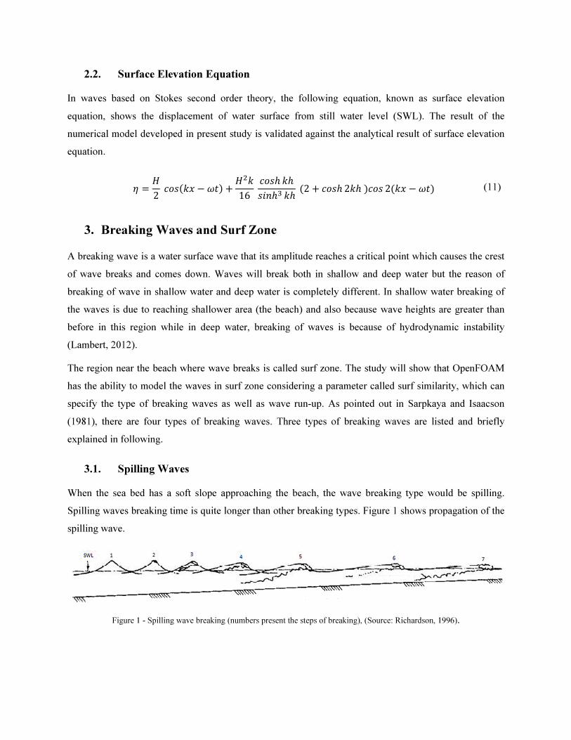
3.1. Spilling Waves
When the sea bed has a soft slope approaching the beach, the wave breaking type would be spilling.
Spilling waves breaking time is quite longer than other breaking types. Figure 1 shows propagation of the
spilling wave.
Figure 1 - Spilling wave breaking (numbers present the steps of breaking), (Source: Richardson, 1996).
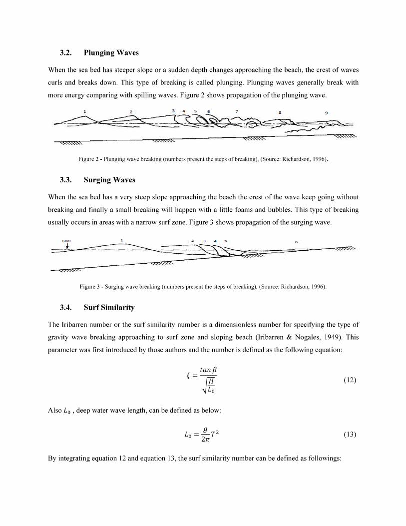
3.2. Plunging Waves
When the sea bed has steeper slope or a sudden depth changes approaching the beach, the crest of waves
curls and breaks down. This type of breaking is called plunging. Plunging waves generally break with
more energy comparing with spilling waves. Figure 2 shows propagation of the plunging wave.
Figure 2 - Plunging wave breaking (numbers present the steps of breaking), (Source: Richardson, 1996).
3.3. Surging Waves
When the sea bed has a very steep slope approaching the beach the crest of the wave keep going without
breaking and finally a small breaking will happen with a little foams and bubbles. This type of breaking
usually occurs in areas with a narrow surf zone. Figure 3 shows propagation of the surging wave.
Figure 3 - Surging wave breaking (numbers present the steps of breaking), (Source: Richardson, 1996).
3.4. Surf Similarity
The Iribarren number or the surf similarity number is a dimensionless number for specifying the type of
gravity wave breaking approaching to surf zone and sloping beach (Iribarren & Nogales, 1949). This
parameter was first introduced by those authors and the number is defined as the following equation:
� � ��� �
����
(12)
Also �� , deep water wave length, can be defined as below:
�� � �2� �� (13)
By integrating equation 12 and equation 13, the surf similarity number can be defined as followings:
�� � ��� �
�2������
(14)
where �� represents surf similarity number for deep water region, � represents the bed slope angle in
[degree], �� represents the deep water wave height in [m], �� represents the deep water wave length in
[m], � represents period in [s] and � is gravity acceleration in [m.s-2
].
Table 1 shows different types of breaking waves using surf similarity number which were presented by
Battjes (1974).
Table 1 – Surf similarity approximation for distinguishing breaking type (Battjes, 1974).
Breaking Type ��
Surging or Collapsing �� � 3.3
Plunging 0.5 $ �� $ 3.3
Spilling �� $ 0.5
4. Methodology
4.1. Definition of Modelled Scenarios
In this study a basic flat bottom numerical wave tank is simulated to replicate the propagation of ocean
waves, and also sloped numerical wave tanks are simulated to show different wave breaking types.
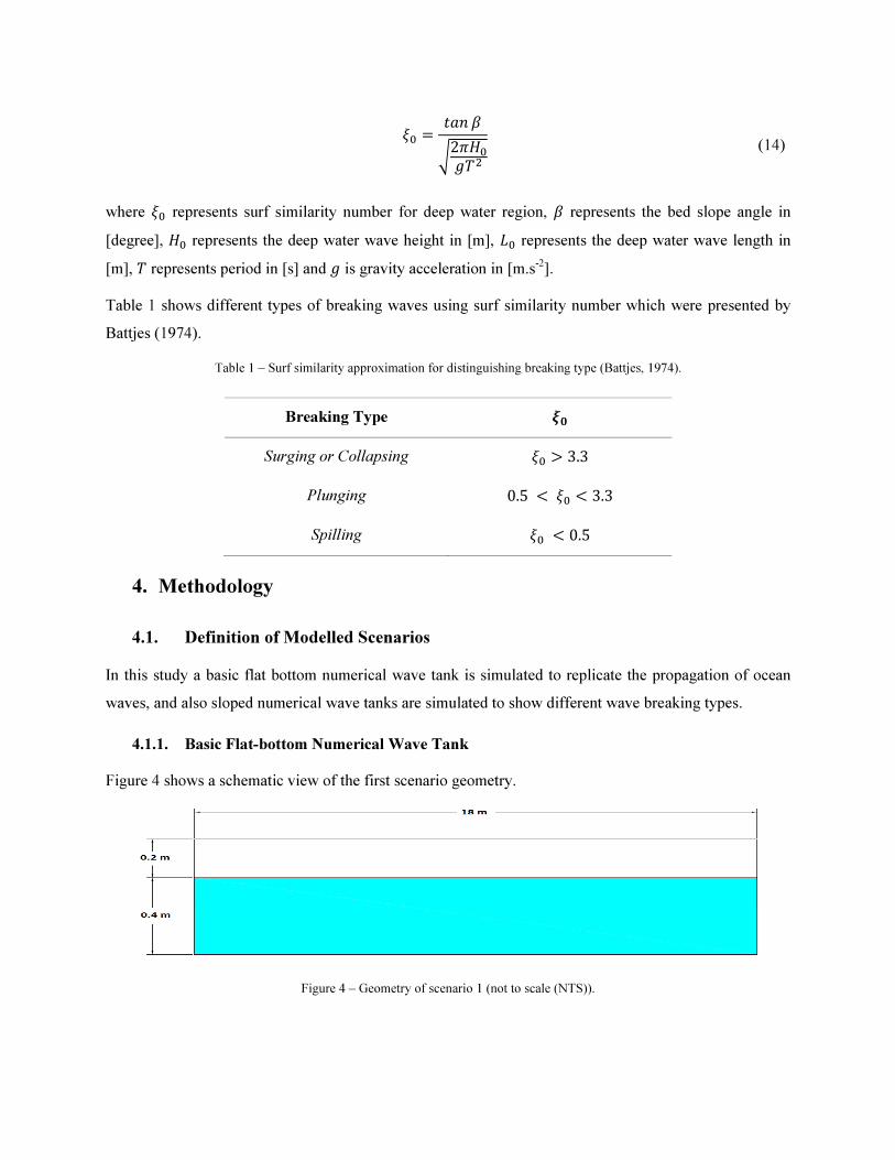
4.1.1. Basic Flat-bottom Numerical Wave Tank
Figure 4 shows a schematic view of the first scenario geometry.
Figure 4 – Geometry of scenario 1 (not to scale (NTS)).
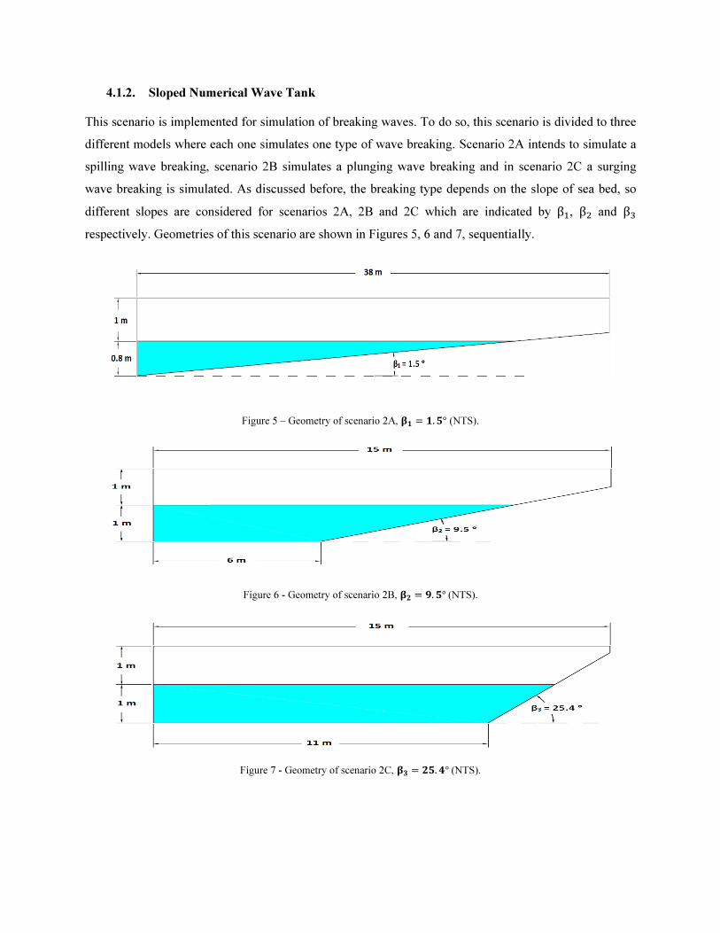
4.1.2. Sloped Numerical Wave Tank
This scenario is implemented for simulation of breaking waves. To do so, this scenario is divided to three
different models where each one simulates one type of wave breaking. Scenario 2A intends to simulate a
spilling wave breaking, scenario 2B simulates a plunging wave breaking and in scenario 2C a surging
wave breaking is simulated. As discussed before, the breaking type depends on the slope of sea bed, so
different slopes are considered for scenarios 2A, 2B and 2C which are indicated by β�, β� and β�
respectively. Geometries of this scenario are shown in Figures 5, 6 and 7, sequentially.
Figure 5 – Geometry of scenario 2A, �� � �. �° (NTS).
Figure 6 - Geometry of scenario 2B, �� � �. �°(NTS).
Figure 7 - Geometry of scenario 2C, �� � �. °(NTS).
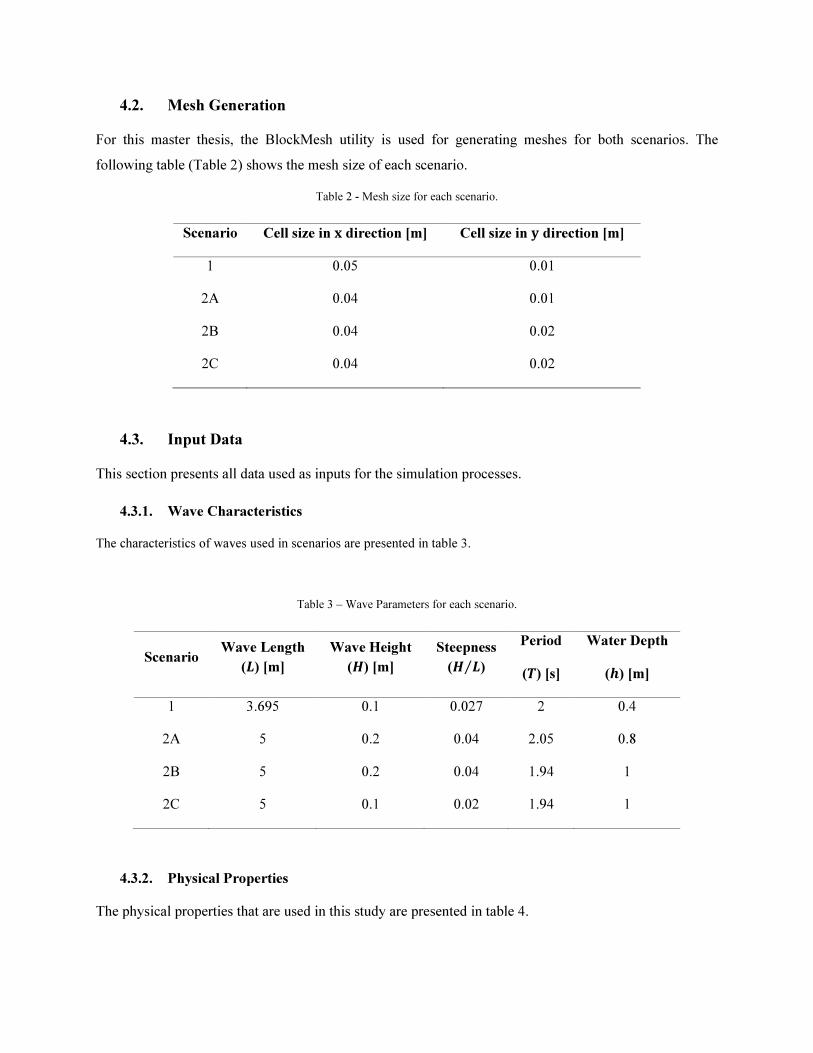
4.2. Mesh Generation
For this master thesis, the BlockMesh utility is used for generating meshes for both scenarios. The
following table (Table 2) shows the mesh size of each scenario.
Table 2 - Mesh size for each scenario.
4.3. Input Data
This section presents all data used as inputs for the simulation processes.
4.3.1. Wave Characteristics
The characteristics of waves used in scenarios are presented in table 3.
Table 3 – Wave Parameters for each scenario.
Scenario Wave Length
(�) [m] Wave Height
( ) [m] Steepness
( �⁄ ) Period
(") [s] Water Depth
(#) [m] 1 3.695 0.1 0.027 2 0.4
2A 5 0.2 0.04 2.05 0.8
2B 5 0.2 0.04 1.94 1
2C 5 0.1 0.02 1.94 1
4.3.2. Physical Properties
The physical properties that are used in this study are presented in table 4.
Scenario Cell size in $ direction [m] Cell size in % direction [m] 1 0.05 0.01
2A 0.04 0.01
2B 0.04 0.02
2C 0.04 0.02
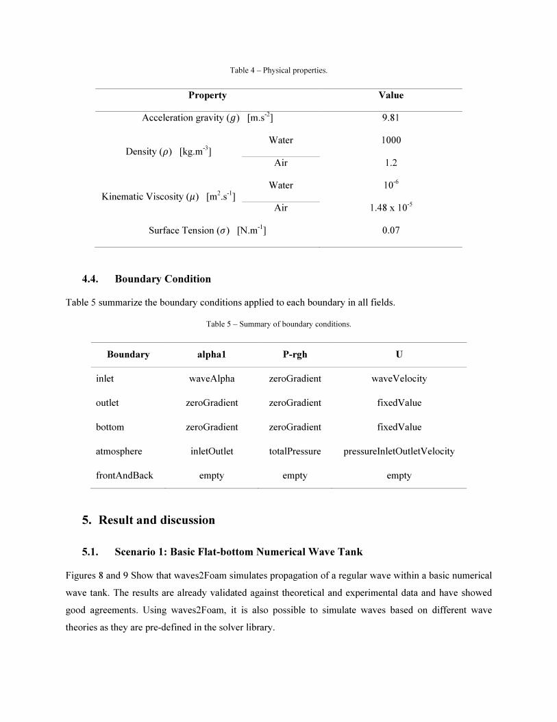
Table 4 – Physical properties.
Property Value
Acceleration gravity (�) [m.s-2
] 9.81
Density (�) [kg.m-3
] Water 1000
Air 1.2
Kinematic Viscosity (�) [m2.s
-1]
Water 10-6
Air 1.48 x 10⁻⁵
Surface Tension (&) [N.m-1
] 0.07
4.4. Boundary Condition
Table 5 summarize the boundary conditions applied to each boundary in all fields.
Table 5 – Summary of boundary conditions.
Boundary alpha1 P-rgh U
inlet waveAlpha zeroGradient waveVelocity
outlet zeroGradient zeroGradient fixedValue
bottom zeroGradient zeroGradient fixedValue
atmosphere inletOutlet totalPressure pressureInletOutletVelocity
frontAndBack empty empty empty
5. Result and discussion
5.1. Scenario 1: Basic Flat-bottom Numerical Wave Tank
Figures 8 and 9 Show that waves2Foam simulates propagation of a regular wave within a basic numerical
wave tank. The results are already validated against theoretical and experimental data and have showed
good agreements. Using waves2Foam, it is also possible to simulate waves based on different wave
theories as they are pre-defined in the solver library.
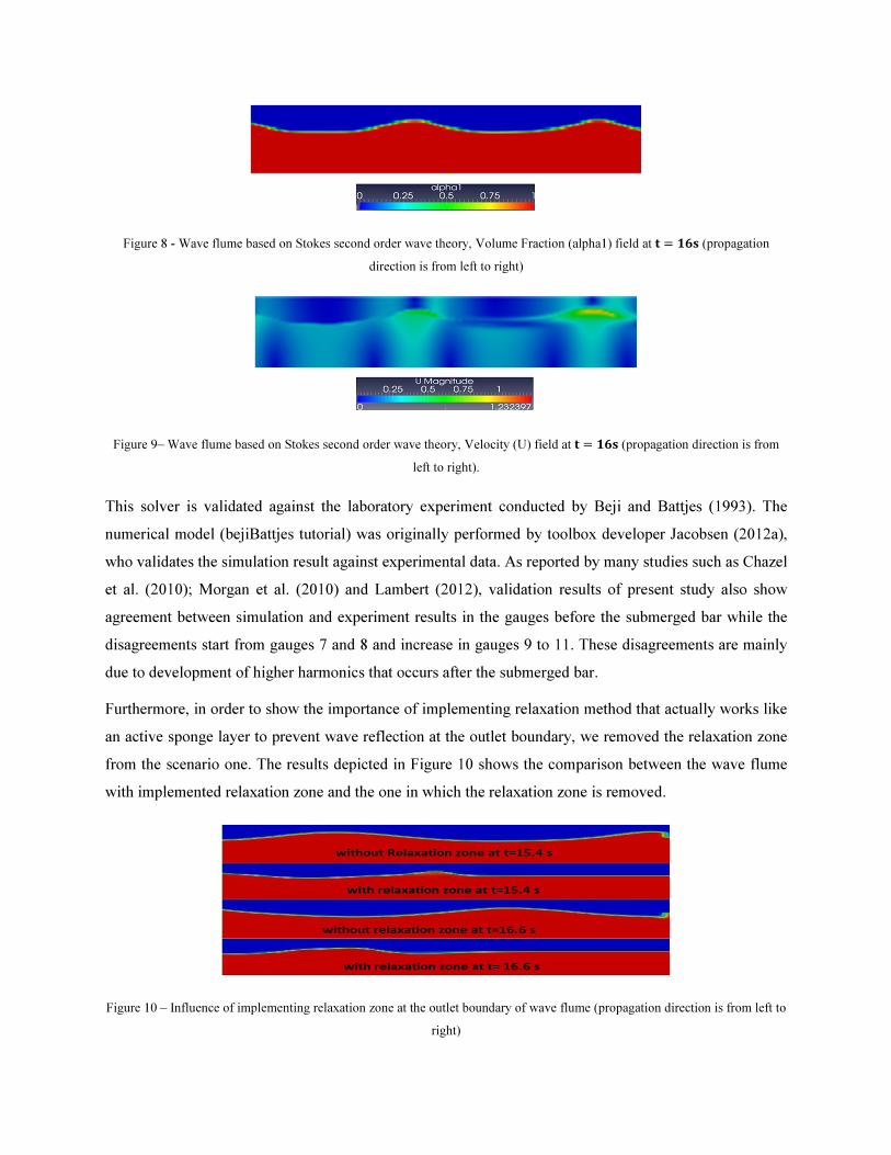
Figure 8 - Wave flume based on Stokes second order wave theory, Volume Fraction (alpha1) field at � � �� (propagation
direction is from left to right)
Figure 9– Wave flume based on Stokes second order wave theory, Velocity (U) field at � � �� (propagation direction is from
left to right).
This solver is validated against the laboratory experiment conducted by Beji and Battjes (1993). The
numerical model (bejiBattjes tutorial) was originally performed by toolbox developer Jacobsen (2012a),
who validates the simulation result against experimental data. As reported by many studies such as Chazel
et al. (2010); Morgan et al. (2010) and Lambert (2012), validation results of present study also show
agreement between simulation and experiment results in the gauges before the submerged bar while the
disagreements start from gauges 7 and 8 and increase in gauges 9 to 11. These disagreements are mainly
due to development of higher harmonics that occurs after the submerged bar.
Furthermore, in order to show the importance of implementing relaxation method that actually works like
an active sponge layer to prevent wave reflection at the outlet boundary, we removed the relaxation zone
from the scenario one. The results depicted in Figure 10 shows the comparison between the wave flume
with implemented relaxation zone and the one in which the relaxation zone is removed.
Figure 10 – Influence of implementing relaxation zone at the outlet boundary of wave flume (propagation direction is from left to
right)
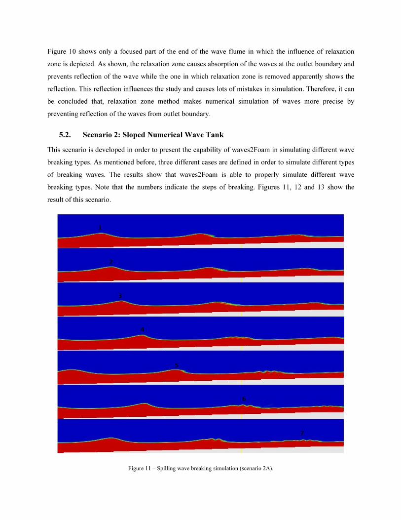
Figure 10 shows only a focused part of the end of the wave flume in which the influence of relaxation
zone is depicted. As shown, the relaxation zone causes absorption of the waves at the outlet boundary and
prevents reflection of the wave while the one in which relaxation zone is removed apparently shows the
reflection. This reflection influences the study and causes lots of mistakes in simulation. Therefore, it can
be concluded that, relaxation zone method makes numerical simulation of waves more precise by
preventing reflection of the waves from outlet boundary.
5.2. Scenario 2: Sloped Numerical Wave Tank
This scenario is developed in order to present the capability of waves2Foam in simulating different wave
breaking types. As mentioned before, three different cases are defined in order to simulate different types
of breaking waves. The results show that waves2Foam is able to properly simulate different wave
breaking types. Note that the numbers indicate the steps of breaking. Figures 11, 12 and 13 show the
result of this scenario.
Figure 11 – Spilling wave breaking simulation (scenario 2A).
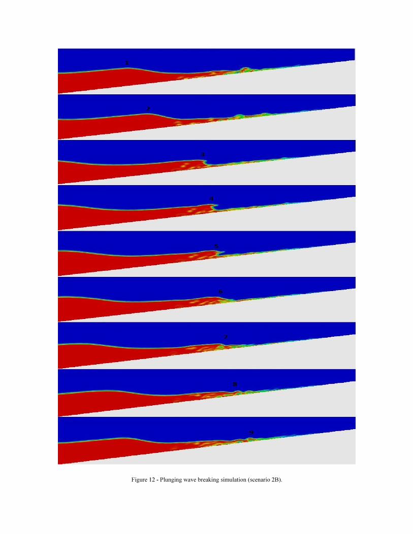
Figure 12 - Plunging wave breaking simulation (scenario 2B).
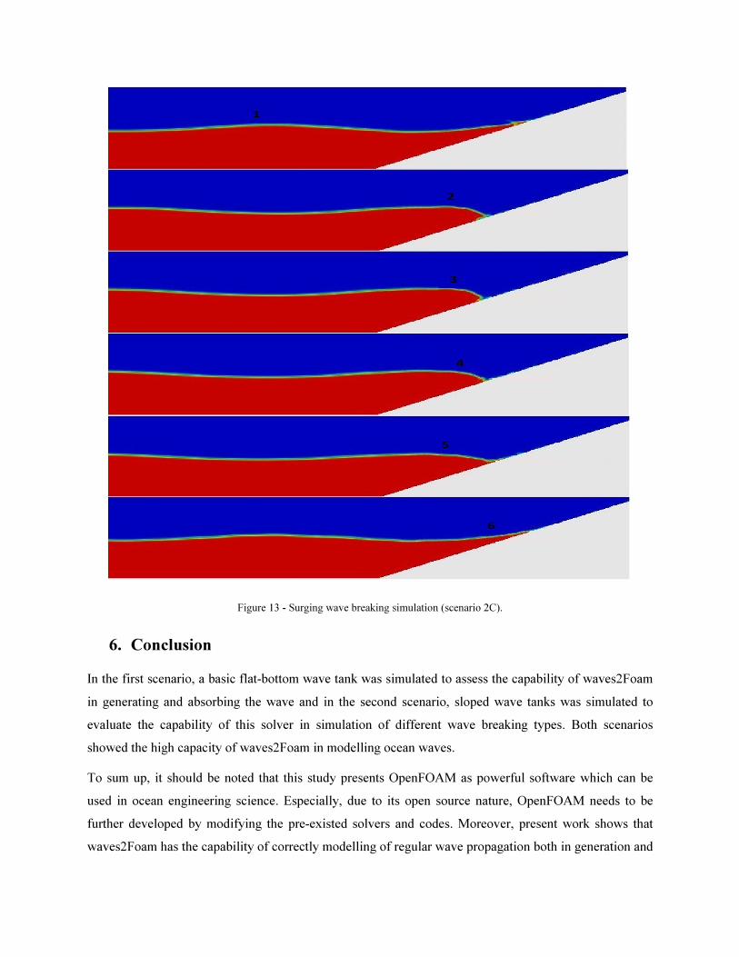
Figure 13 - Surging wave breaking simulation (scenario 2C).
6. Conclusion
In the first scenario, a basic flat-bottom wave tank was simulated to assess the capability of waves2Foam
in generating and absorbing the wave and in the second scenario, sloped wave tanks was simulated to
evaluate the capability of this solver in simulation of different wave breaking types. Both scenarios
showed the high capacity of waves2Foam in modelling ocean waves.
To sum up, it should be noted that this study presents OpenFOAM as powerful software which can be
used in ocean engineering science. Especially, due to its open source nature, OpenFOAM needs to be
further developed by modifying the pre-existed solvers and codes. Moreover, present work shows that
waves2Foam has the capability of correctly modelling of regular wave propagation both in generation and
absorption of the waves as well as simulating the wave behaviour interacting with seabed and its breaking
steps.
Finally, based on limitation of the software and toolbox discussed in this work, some recommendations
for future developments are presented below:
• Reasons which cause higher harmonics after the submerged bar such as non-linearity and
dispersion should be investigated to find a proper way, preventing higher harmonics after the bar
in order to improve the agreement between results of simulations and laboratory experiments;
• The ability of the software and toolbox in terms of simulating waves with steepness above 0.05
should be assessed and increased;
• As an extension of the present work, also the ability of waves2Foam in simulating floating object
within the numerical wave tank should be checked.
References
Battjes, J.A., 1974. Surf Similarity. Proceedings of the 14th Internatinal Conference on Coastal
Engineering, Copenhagen, Denmark, pp. 466–480.
Beji, S., Battjes, J. A., 1993. Experimental investigation of wave propagation over a bar. Coastal
Engineering, 19, pp. 151–162.
Chazel, F., Benoit, M., Ern, A., 2010. Validation of a double-layer Boussinesq-type dodel for highly
nonlinear and dispersive waves. Proceedings of the 32nd
Internatinal Conference on Coastal
Engineering, Shanghai, China, pp. 1–8.
Du, Q., Leung, D.Y.C., 2011. 2D Numerical Simulation of Ocean Waves. Volume 9, Marine and Ocean
Technology, 2183.
Fenton, J.D., 1990. Nonlinear Wave Theories. The Sea, 9(1): Ocean Engineering Science, Le Méhauté,
B., Hanes, D.M. (eds), Wiley, New York.
Iribarren, C.R., Nogales, C., 1949. Protection des Ports, in: XVIIth International Navigation Congress.
Lisbon, Portugal, pp. 31–80.
Jacobsen, N.G., 2012a. waves2Foam Toolbox BejiBattjes Validation Case Tutorial. Available from
http://openfoamwiki.net/index.php/Contrib/waves2Foam, Last accessed on 5th January 2014.
Jacobsen, N.G., Fuhrman, D.R., Fredsøe, J., 2012. A wave generation toolbox for the open-source CFD
library : OpenFoam. International Journal for Numerical Methods in Fluids, 70(9), pp. 1073-1088.
Lambert, R.J., 2012. Development of Numerical Wave Tank Using OpenFOAM. Master Science Thesis,
Energy for Sustainability Program, University of Coimbra.
Liu, P..-F., Losada, I.., 2002. Wave propagation modeling in coastal engineering. Journal of Hydraulic
Research, 40(3), pp. 229–240.
Morgan, G.C.J., Zang, J., Greaves, D., Heath, A., Whitlow, C.D., Young, J.R., 2010. Using the
rasInterFoam CFD model for wave transformation and coastal modelling. Proceedings of 32nd
Conference on Coastal Engineering, Shanghai, China. pp. 1–9.
OpenFOAM, 2013. User Guide Version 2.2.0. Available from http://www.openfoam.org/docs/user, Last
accessed on 22nd
February 2013.
Richardson, J.E., 1996. Surf similarity. Flow Science Technical Note* 4, 96.
Sarpkaya, T., Isaacson, M., 1981. Mechanics of wave forces on offshore structures. (Vol. 96). New York:
Van Nostrand Reinhold Company.
Copyright © 2022 FDOKUMEN