NSG 1007 Series II AC Power Source User Manual - prom.st
259
Teseq AG Nordstrasse 11F 4542 Luterbach Switzerland T +41 32681 40 40 F +41 32681 40 48 www.teseq.com NSG 1007 Series II AC Power Source User Manual
-
Upload
khangminh22 -
Category
Documents
-
view
0 -
download
0
Transcript of NSG 1007 Series II AC Power Source User Manual - prom.st

Teseq AG Nordstrasse 11F 4542 Luterbach Switzerland T +41 32681 40 40 F +41 32681 40 48 www.teseq.com
NSG 1007 Series IIAC Power Source
User Manual

User Manual Teseq
User's ManualAC Power SourceTeseq
Models :
• NSG 1007-3• NSG 1007-5-208• NSG 1007-5-400• NSG 1007-9• NSG 1007-10-208• NSG 1007-10-400• 10002iX• 10002iX-400• NSG 1007-15S-208• NSG 1007-15S-400• NSG 1007-15-208• NSG 1007-15-400• NSG 1007-30-208• NSG 1007-30-400
Copyright 2006-2007 Teseq. Rev F, September 2007.
2 NSG 1007 Series II

User Manual Teseq
SAFETY SUMMARY
This power source contains high voltage and current circuits which are potentially lethal. Because of its size and weight, mechanical stability must be ensured. The following safety guidelines must be followed when operating or servicing this equipment. These guidelines are not a substitute for vigilance and common sense. Teseq assumes no liability for the customer’s failure to comply with these requirements. If the power source is used in a manner not specified by Teseq, the protection provided by the equipment may be impaired.
BEFORE APPLYING POWER
1. Verify the correct voltage is applied to the unit (for example 240V).
2. The chassis and cabinet of this power source must be grounded to minimize shock hazard. A chassis ground is provided at the input terminal block. This is located at the back of the cabinet on the lower right hand side. The chassis ground must be connected to an electrical ground through an insulated wire of sufficient gauge.
FUSESUse only fuses of the specified current, voltage, and protection speed (slow blow, normal blow, fast blow) rating. Do not short out the fuse holder or use a repaired fuse.
DO NOT OPERATE IN A VOLATILE ATMOSPHERE
Do not operate the power source in the presence of flammable gases or fumes.
DO NOT TOUCH ENERGIZED CIRCUITS
Disconnect the power cable before servicing this equipment. Even with the power cable disconnected, high voltage can still exist on some circuits. Discharge these voltages before servicing. Only qualified service personnel may remove covers, replace components or make adjustments.
DO NOT SERVICE ALONE
Do not remove covers, replace components, or make adjustments unless another person, who can administer first aid, is present.
DO NOT EXCEED INPUT RATINGS
Do not exceed the rated input voltage or frequency. Additional hazards may be introduced because of component failure or improper operation.
DO NOT MODIFY INSTRUMENT OR SUBSTITUTE PARTS
Do not modify this instrument or substitute parts. Additional hazards may be introduced because of component failure or improper operation.
MOVING THE POWER SOURCE
When moving the power source, observe the following:
1. Remove all AC power to unit.2. Use two people to prevent injury.
ALLOW CAPACITORS TO DISCHARGE
Capacitors in the power source may hold a hazardous electrical charge even if the power source has been disconnected from the mains supply. Allow capacitors to discharge to a safe voltage before servicing internal circuits or touching exposed pins of mains supply connectors.
NSG 1007 Series II 3
User Manual Teseq
4 NSG 1007 Series II
User Manual Teseq
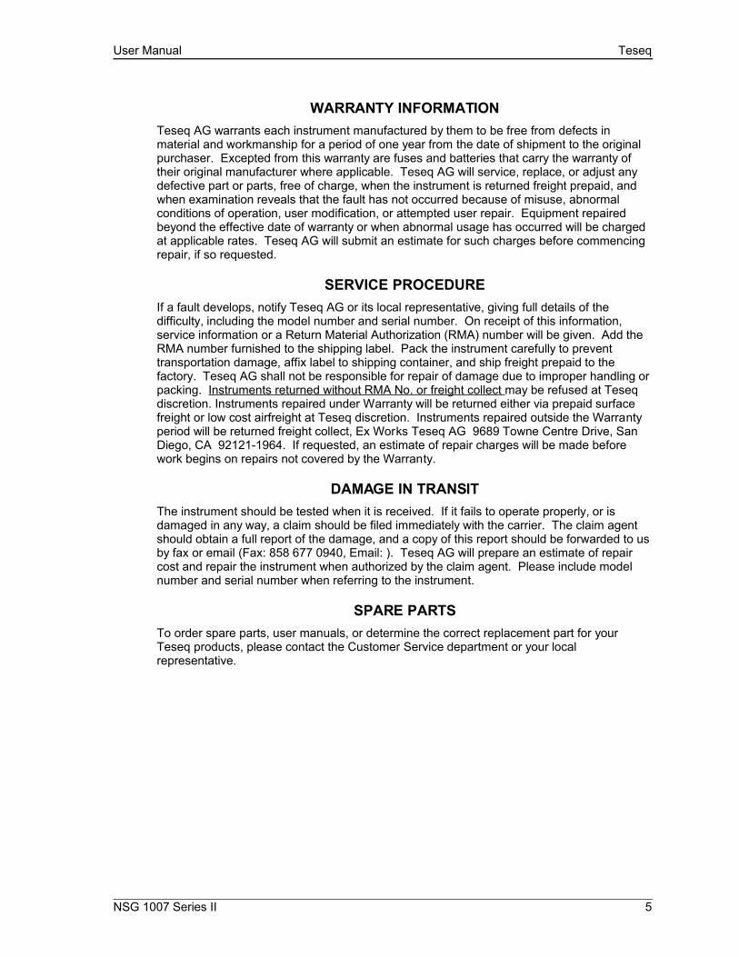
WARRANTY INFORMATIONTeseq AG warrants each instrument manufactured by them to be free from defects in material and workmanship for a period of one year from the date of shipment to the original purchaser. Excepted from this warranty are fuses and batteries that carry the warranty of their original manufacturer where applicable. Teseq AG will service, replace, or adjust any defective part or parts, free of charge, when the instrument is returned freight prepaid, and when examination reveals that the fault has not occurred because of misuse, abnormal conditions of operation, user modification, or attempted user repair. Equipment repaired beyond the effective date of warranty or when abnormal usage has occurred will be charged at applicable rates. Teseq AG will submit an estimate for such charges before commencing repair, if so requested.
SERVICE PROCEDUREIf a fault develops, notify Teseq AG or its local representative, giving full details of the difficulty, including the model number and serial number. On receipt of this information, service information or a Return Material Authorization (RMA) number will be given. Add the RMA number furnished to the shipping label. Pack the instrument carefully to prevent transportation damage, affix label to shipping container, and ship freight prepaid to the factory. Teseq AG shall not be responsible for repair of damage due to improper handling or packing. Instruments returned without RMA No. or freight collect may be refused at Teseq discretion. Instruments repaired under Warranty will be returned either via prepaid surface freight or low cost airfreight at Teseq discretion. Instruments repaired outside the Warranty period will be returned freight collect, Ex Works Teseq AG 9689 Towne Centre Drive, San Diego, CA 92121-1964. If requested, an estimate of repair charges will be made before work begins on repairs not covered by the Warranty.
DAMAGE IN TRANSITThe instrument should be tested when it is received. If it fails to operate properly, or is damaged in any way, a claim should be filed immediately with the carrier. The claim agent should obtain a full report of the damage, and a copy of this report should be forwarded to us by fax or email (Fax: 858 677 0940, Email: ). Teseq AG will prepare an estimate of repair cost and repair the instrument when authorized by the claim agent. Please include model number and serial number when referring to the instrument.
SPARE PARTSTo order spare parts, user manuals, or determine the correct replacement part for your Teseq products, please contact the Customer Service department or your local representative.
NSG 1007 Series II 5
User Manual Teseq
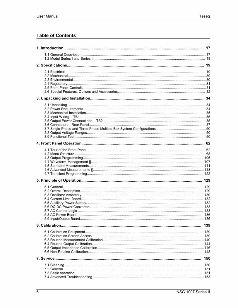
Table of Contents
1. Introduction.................................................................................................................................. 171.1 General Description................................................................................................................................ 171.2 Model Series I and Series II................................................................................................................... 18
2. Specifications............................................................................................................................... 192.1 Electrical................................................................................................................................................. 192.2 Mechanical.............................................................................................................................................. 302.3 Environmental......................................................................................................................................... 302.4 Regulatory.............................................................................................................................................. 312.5 Front Panel Controls............................................................................................................................... 312.6 Special Features, Options and Accessories.......................................................................................... 32
3. Unpacking and Installation.......................................................................................................... 343.1 Unpacking .............................................................................................................................................. 343.2 Power Requirements.............................................................................................................................. 343.3 Mechanical Installation........................................................................................................................... 353.4 Input Wiring – TB1.................................................................................................................................. 353.5 Output Power Connections – TB2.......................................................................................................... 353.6 Connectors - Rear Panel........................................................................................................................ 373.7 Single-Phase and Three Phase Multiple Box System Configurations....................................................503.8 Output Voltage Ranges.......................................................................................................................... 503.9 Functional Test....................................................................................................................................... 50
4. Front Panel Operation.................................................................................................................. 624.1 Tour of the Front Panel........................................................................................................................... 624.2 Menu Structure....................................................................................................................................... 684.3 Output Programming............................................................................................................................ 1054.4 Waveform Management [].................................................................................................................... 1074.5 Standard Measurements...................................................................................................................... 1114.6 Advanced Measurements [].................................................................................................................. 1134.7 Transient Programming........................................................................................................................ 122
5. Principle of Operation................................................................................................................ 1295.1 General................................................................................................................................................. 1295.2 Overall Description............................................................................................................................... 1295.3 Oscillator Assembly.............................................................................................................................. 1305.4 Current Limit Board.............................................................................................................................. 1325.5 Auxiliary Power Supply......................................................................................................................... 1325.6 DC-DC Power Converter...................................................................................................................... 1335.7 AC Control Logic ................................................................................................................................. 1335.8 AC Power Board................................................................................................................................... 1365.9 Input/Output Board............................................................................................................................... 136
6. Calibration.................................................................................................................................. 1396.1 Calibration Equipment.......................................................................................................................... 1396.2 Calibration Screen Access................................................................................................................... 1396.3 Routine Measurement Calibration........................................................................................................ 1406.4 Routine Output Calibration................................................................................................................... 1446.5 Output Impedance Calibration.............................................................................................................. 1466.6 Non-Routine Calibration....................................................................................................................... 148
7. Service........................................................................................................................................ 1507.1 Cleaning................................................................................................................................................1507.2 General................................................................................................................................................. 1517.3 Basic operation..................................................................................................................................... 1517.4 Advanced Troubleshooting................................................................................................................... 153
6 NSG 1007 Series II

User Manual Teseq
8. Top Assembly Replaceable Parts............................................................................................. 1578.1 Sub assemblies.................................................................................................................................... 1578.2 Fuses.................................................................................................................................................... 158
9. Options........................................................................................................................................ 1599.1 RTCA/DO-160 Option........................................................................................................................... 1599.2 IEC 61000-4-11 Option......................................................................................................................... 1769.3 IEC 61000-4-13 Option......................................................................................................................... 1849.4 EOS Option........................................................................................................................................... 1969.5 Mode iX Option..................................................................................................................................... 2119.6 Omni Options........................................................................................................................................ 2199.7 LNS Option and INA 2145 Option........................................................................................................ 2309.8 Option –704: MilStd704 Tests.............................................................................................................. 2369.9 ABD Option: Airbus ABD0100.1.8 Test................................................................................................ 2489.10 AMD Option: Airbus AMD24C Test.................................................................................................... 2489.11 787 Option: Boeing B787-0147 Test.................................................................................................. 2489.12 WHM Option....................................................................................................................................... 249
10. Error Messages........................................................................................................................ 252
11. Index.......................................................................................................................................... 257
NSG 1007 Series II 7

User Manual Teseq
List of Figures
Figure 2-1: NSG 1007-3 / NSG 1007-9 - Voltage Current rating, AC mode................................... 22
Figure 2-2: NSG 1007-3 / NSG 1007-9 - Voltage Current Rating, DC mode.................................. 22
Figure 2-3: NSG 1007-5-208 / NSG 1007-15-208 - Voltage Current rating, AC mode................... 23
Figure 2-4: NSG 1007-5-208 / NSG 1007-15-208 - Voltage Current rating, DC mode.................. 23
Figure 2-5: NSG 1007-10-208 / NSG 1007-30-208 - Voltage Current rating, AC mode................. 24
Figure 2-6: NSG 1007-10-208 / NSG 1007-30-208 - Voltage Current rating, DC mode................. 24
Figure 2-7: NSG 1007-15S-208 - Voltage Current rating, AC mode.............................................. 25
Figure 2-8: NSG 1007-15S-208 - Voltage Current rating, DC mode.............................................. 25
Figure 2-9: Maximum RMS voltage versus frequency rating in 300V AC range......................... 26
Figure 3-10: The NSG 1007-5-208 Power Source........................................................................... 34
Figure 3-11: RS232C Cable for PC Connection wiring diagram – Units without USB................ 41
Figure 3-12: USB Connector pin orientation.................................................................................. 41
Figure 3-13: Function Strobe Connection...................................................................................... 43
Figure 3-14: Function Strobe / Trigger Output Accessory............................................................ 44
Figure 3-15: Rear Panel View for the 3001i/NSG 1007-3 (Series II)............................................... 46
Figure 3-16: Rear Panel View for the 3001i/NSG 1007-3 (Series I, no USB)................................. 47
Figure 3-17: Rear Panel View for the 5001i/NSG 1007-5-208 (Series II)........................................ 47
Figure 3-18: Rear Panel View for the 5001i/NSG 1007-5-208 (Series I, no USB).......................... 49
Figure 3-19: Connection For Single Power Source (NSG 1007-5-208/i, NSG 1007-3/i)............... 52
Figure 3-20: Functional Test Setup................................................................................................. 53
Figure 3-21: Single Phase 10000 VA System (NSG 1007-10-208/i).............................................. 54
Figure 3-22: Two Phase 10000 VA System (10002i/iX – One Controller)..................................... 55
Figure 3-23: Three Phase 15000 VA System (NSG 1007-15-208/i-LK Three Controllers)...........56
Figure 3-24: Single Phase 15000 VA System (NSG 1007-15S-208/i)............................................ 57
Figure 3-25: Three-Phase 15000 VA system (NSG 1007-15-208/i - One Controller)................... 58
Figure 3-26: Connection With MODE Option................................................................................ 59
8 NSG 1007 Series II

User Manual Teseq
Figure 3-27: Two Phase 10000 VA System (10002i-LK Two Controllers).................................... 60
Figure 3-28: Three-Phase 9000 VA System (NSG 1007-9/i – One Controller)............................. 61
Figure 4-29: Shuttle Knob................................................................................................................ 63
Figure 4-30: FUNCTION keypad..................................................................................................... 64
Figure 4-31: Entering value from decimal keypad........................................................................ 65
Figure 4-32: Cursor UP key movement.......................................................................................... 66
Figure 4-33: Cursor DOWN key movement................................................................................... 66
Figure 4-34: Main Menu 1 screen................................................................................................... 67
Figure 4-35: Menu 1 through 3....................................................................................................... 68
Figure 4-36: PROGRAM Menu........................................................................................................ 72
Figure 4-37: MEASUREMENTS Screen, single phase and three phase modes......................... 74
Figure 4-38: HARMONICS/TRACE ANALYSIS screen................................................................... 76
Figure 4-39: TRANSIENTS menu.................................................................................................... 79
Figure 4-40: VOLTAGE SURGE/SAG SETUP screen.................................................................... 80
Figure 4-41: VOLTAGE SWEEP/STEP SETUP screen.................................................................. 82
Figure 4-42: FREQUENCY SWEEP/STEP SETUP screen............................................................. 84
Figure 4-43: VOLTAGE/FREQUENCY SWEEP/STEP SETUP screen........................................... 85
Figure 4-44: START/VIEW TRANSIENT SEQUENCE screen......................................................... 86
Figure 4-45: WAVEFORMS menu................................................................................................... 87
Figure 4-46: APPLICATIONS menu................................................................................................ 90
Figure 4-47: SETUP REGISTERS menu......................................................................................... 91
Figure 4-48: UTILITY menu............................................................................................................. 92
Figure 4-49: GPIB/RS232 SETUP menu......................................................................................... 94
Figure 4-50: VOLTAGE/CURRENT CONTROL SETUP menu....................................................... 95
Figure 4-51: INITIAL SETUP menus................................................................................................ 97
Figure 4-52:LIMIT SETUP menu...................................................................................................... 99
Figure 4-53: CONFIGURATION SETUP Menus............................................................................. 100
NSG 1007 Series II 9

User Manual Teseq
Figure 4-54: OUTPUT IMPEDANCE menu.................................................................................... 102
Figure 4-55: MEASUREMENT CAL FACTORS menu................................................................... 103
Figure 4-56: OUTPUT CAL FACTORS menu................................................................................ 104
Figure 4-57: Selecting a waveform.......................................................................................... 107
Figure 4-58: Selecting waveforms for single phase or all phases............................................ 107
Figure 4-59: Custom waveform creation with GUI program....................................................... 108
Figure 4-60: Waveform crest factor affects max. rms voltage.................................................... 109
Figure 4-61: Waveform frequency domain view mode............................................................... 110
Figure 4-62: Scrolling through tabular FFT data........................................................................ 114
Figure 4-63: Scrolling through bar chart FFT data..................................................................... 114
Figure 4-64: Scrolling through acquired waveform data........................................................... 116
Figure 4-65: SET VOLT trigger source acquisition..................................................................... 118
Figure 4-66: Positive trigger delay (Post trigger data)............................................................... 120
Figure 4-67: Negative trigger delay (Pre-trigger data)................................................................ 121
Figure 4-68: Pulse Transients...................................................................................................... 123
Figure 4-69: List Transients.......................................................................................................... 124
Figure 4-70: Switching waveforms in a transient list................................................................. 127
Figure 4-71: START/VIEW TRANSIENT SEQUENCE menu........................................................ 128
Figure 5-72: AC Power System Block Diagram........................................................................... 129
Figure 5-73: Power Source Module Block Diagram.................................................................... 131
Figure 5-74: 5001i Internal Layout................................................................................................. 134
Figure 5-75: Logic Board LED's.................................................................................................... 135
Figure 5-76: AC Power Stage Layout............................................................................................ 137
Figure 5-77: AC Control Logic Block Diagram............................................................................ 137
Figure 6-78: Test Equipment Hook-up for Measurement Calibration........................................ 141
Figure 6-79: Test Equipment Hookup for Routine Output Calibration...................................... 145
Figure 6-80: Adjustment Location................................................................................................. 150
10 NSG 1007 Series II

User Manual Teseq
Figure 9-81: Application Menu...................................................................................................... 161
Figure 9-82: DO160 Main Menu..................................................................................................... 161
Figure 9-83: Normal state.............................................................................................................. 162
Figure 9-84: Voltage Modulation.................................................................................................. 164
Figure 9-85: Frequency Modulation.............................................................................................. 165
Figure 9-86: Power Interrupt.......................................................................................................... 166
Figure 9-87: Power Interrupt for Group 2 and 3........................................................................... 167
Figure 9-88: Emergency Screen.................................................................................................... 168
Figure 9-89: Abnormal Screen....................................................................................................... 170
Figure 9-90: DO-160 DC Main Menu.............................................................................................. 172
Figure 9-91: Normal State.............................................................................................................. 172
Figure 9-92: Abnormal State.......................................................................................................... 174
Figure 9-93: Application menu ..................................................................................................... 178
Figure 9-94: IEC1000-4-11 Menu................................................................................................... 178
Figure 9-95: IEC Dips and Interrupts............................................................................................ 179
Figure 9-96: Voltage Variation screen.......................................................................................... 181
Figure 9-97: EN 61000-4-11 Voltage Variation specification- Edition 1.0................................... 182
Figure 9-98: EN 61000-4-11 Voltage Variation specification- Edition 2.0................................... 182
Figure 9-99: IEC 61000-4-11 GUI screen....................................................................................... 183
Figure 9-100: Application menu ................................................................................................... 185
Figure 9-101: IEC 61000-4-13 Menu.............................................................................................. 185
Figure 9-102: IEC 61000-4-13 FCurve............................................................................................ 187
Figure 9-103: IEC 61000-4-13 OSwing........................................................................................... 187
Figure 9-104: IEC 61000-4-13 Sweep............................................................................................. 188
Figure 9-105: IEC 61000-4-13 Harmonics..................................................................................... 189
Figure 9-106: IEC 61000-4-13 Inter harmonics............................................................................. 190
Figure 9-107: IEC 61000-4-13 Meister Curve................................................................................ 191
NSG 1007 Series II 11
User Manual Teseq
Figure 9-108: IEC 61000-4-13 Test Flowchart Class 1 and 2....................................................... 192
Figure 9-109: IEC 61000-4-13 Test Flowchart Class 3................................................................. 193
Figure 9-110: MENU 2 SCREEN..................................................................................................... 195
Figure 9-111: INTERHARMONICS SCREEN.................................................................................. 195
Figure 9-112: Example Connection With NSG 1007-5-208 and EOS-1....................................... 202
Figure 9-113: Example Connection With Compliance Test System and EOS-1........................ 203
Figure 9-114: NSG 1007-15-208-CTS-EOS3-LR3 ......................................................................... 204
Figure 9-115: NSG 1007-15-208/3-EOS3....................................................................................... 205
Figure 9-116: EOS3 Location of 70/80 Taps for each phase....................................................... 209
Figure 9-117: Example Connection With INA 2162 ..................................................................... 216
Figure 9-118: Example Connections With INA 2151.................................................................... 223
Figure 9-119: Example Connections With INA 2154.................................................................... 224
Figure 9-120: Schematic Showing Imepdance 1-37i and1-37iJ Connected to NSG 1007-5-208 System..................................................................................................................................... 225
Figure 9-121: Schematic Showing INA 2153 Connected to NSG 1007-30-208 System............. 226
Figure 9-122: Applications Screen.............................................................................................. 227
Figure 9-123: Imepdance Control Screen..................................................................................... 228
Figure 9-124: Imepdance Control Screen..................................................................................... 228
Figure 9-125: INA 2145 Module Dimensions................................................................................ 232
Figure 9-126: INA 2145 Connection on Low Range..................................................................... 233
12 NSG 1007 Series II
User Manual Teseq
Figure 9-127: INA 2145 Connection on High Range
.................................................................................................................................................. 234
Figure 9-128: Application Menu.................................................................................................... 238
Figure 9-129: MIL704 Menu.......................................................................................................... 239
Figure 9-130: Steady State Menu.................................................................................................. 239
Figure 9-131: Transient Menu....................................................................................................... 241
Figure 9-132: Emergency Menu................................................................................................... 242
Figure 9-133: Abnormal Screen.................................................................................................... 243
Figure 9-134: MIL704 DC Menu..................................................................................................... 244
Figure 9-135: Steady State DC..................................................................................................... 244
NSG 1007 Series II 13
User Manual Teseq
Figure 9-136: Transient Menu...................................................................................................... 245
Figure 9-137: Abnormal Test Screen............................................................................................ 246
Figure 9-138: Emergency Test...................................................................................................... 247
Figure 9-139: Application Screen.................................................................................................. 249
Figure 9-140 Watt-Hour Meter Screen.......................................................................................... 249
Figure 9-141: WH-Meter Screen With Function Active................................................................ 250
14 NSG 1007 Series II
User Manual Teseq
List of Tables
Table 3-1: Wire Sizes....................................................................................................................... 36
Table 3-2: System Interface Connector (J22)................................................................................ 37
Table 3-3: Remote Sense Connector – TB3................................................................................... 39
Table 3-4: RS232 Connector pin out – Units with RS232 and USB.............................................. 40
Table 3-5: RS232C Connector – Units with RS232 but no USB.................................................... 40
Table 3-6: USB Connector pin out.................................................................................................. 41
Table 3-7: RJ45 LAN Connector pin out......................................................................................... 42
Table 5-8: Logic Board LED’s........................................................................................................ 136
Table 6-9: Calibration Load For Each Phase................................................................................ 140
Table 6-10: Measurement Calibration Table................................................................................ 143
Table 6-11: Output Calibration Table .......................................................................................... 144
Table 6-12: Programmable Z adjustment pots............................................................................. 147
Table 6-13: Formulas to calculate R and L................................................................................... 147
Table 7-14: Basic Symptoms........................................................................................................ 151
Table 7-15: Auxiliary Power Supply Fuse Ratings...................................................................... 155
Table 8-16: Replaceable Parts...................................................................................................... 157
Table 8-17: Fuses.......................................................................................................................... 158
Table 9-18: Normal Voltage and Frequency minimum................................................................ 162
Table 9-19: Normal Voltage and Frequency Maximum................................................................ 162
Table 9-20: Normal Voltage Unbalance........................................................................................ 163
Table 9-21: Normal VoltageSurge Sequence............................................................................... 167
Table 9-22: Normal Frequency Transient Sequence................................................................... 168
Table 9-23: Normal Frequency Variation Sequence.................................................................... 168
Table 9-24: Emergency Voltage and Frequency Minimum......................................................... 169
Table 9-25: Emergency Voltage and Frequency Maximum......................................................... 169
NSG 1007 Series II 15

User Manual Teseq
Table 9-26: Emergency Voltage Unbalance................................................................................. 169
Table 9-27: Abnormal Voltage Minimum...................................................................................... 170
Table 9-28: Abnormal Voltage Maximum...................................................................................... 170
Table 9-29: Abnormal Frequency Transient................................................................................. 171
Table 9-30: Normal Voltage Minimum........................................................................................... 172
Table 9-31: Normal Voltage Maximum.......................................................................................... 173
Table 9-32: Voltage Surge............................................................................................................. 173
Table 9-33: Abnormal Voltage Surge............................................................................................ 175
Table 9-34: Phase mapping........................................................................................................... 177
Table 9-35: IEC 61000-3-34 Table C.2........................................................................................... 177
Table 9-36: Dips and Interruptions Tests Performed During RUN ALL.................................... 180
Table 9-37: Voltage Variations Test Performed During RUN ALL............................................. 181
Table 9-38: EOS Versions.............................................................................................................. 196
Table 10-39: Error Messages......................................................................................................... 256
16 NSG 1007 Series II

User Manual California Instruments
1.Introduction
This instruction manual contains information on the installation, operation, calibration and maintenance of all power systems that use the 3001i, 5001i, NSG 1007-3, and NSG 1007-5-208 power sources with the second generation (Series II) programmable controller (P/N 7003-718).
This user manual also covers higher power configurations consisting of multiple units operated in parallel. Such models are NSG 1007-10-208, 10002iX, NSG 1007-15-208 and NSG 1007-30-208.
This manual also covers the manual operation mode only iM models. The iM models are similar to the i Models except they can only be operated from the front panel and lack measurement functions and transient capabilities. The iM Series II replaces the original iM Series with analog oscillator which is no longer available.
1.1General Description
The 3001i, 5001i, NSG 1007-3, and NSG 1007-5-208 are high efficiency, lightweight AC power sources that provide a precise output with low distortion. The NSG 1007 offers a 0-150/0-300 AC voltage range and a 200/400 V DC range. Full power is available from 135/270V to full-scale voltage using a constant power mode of operation.
Two or three NSG 1007-5 units can be connected in parallel as a single-phase system for 10 kVA or 15 kVA respectively.
Three or six units can be connected as a three-phase system. They can be operated with AC or DC output.
The NSG 1007 also offers AC+DC output mode.
The iM Series is a subset of the i Series and lacks load measurement functions and transient programming. For operating information on the iM Series models, refer to the equivalent i Series models in this user manual.
USB and LAN Interfaces
Models shipped after July 2007 (Top assembly P/N 7000-485 and P/N 7000-486) are equipped with GPIB, RS232 and USB interfaces. Older models did not have the USB interface. These newer models also support a LAN (Ethernet) interface option.
NSG 1007 Series II 17
User Manual California Instruments
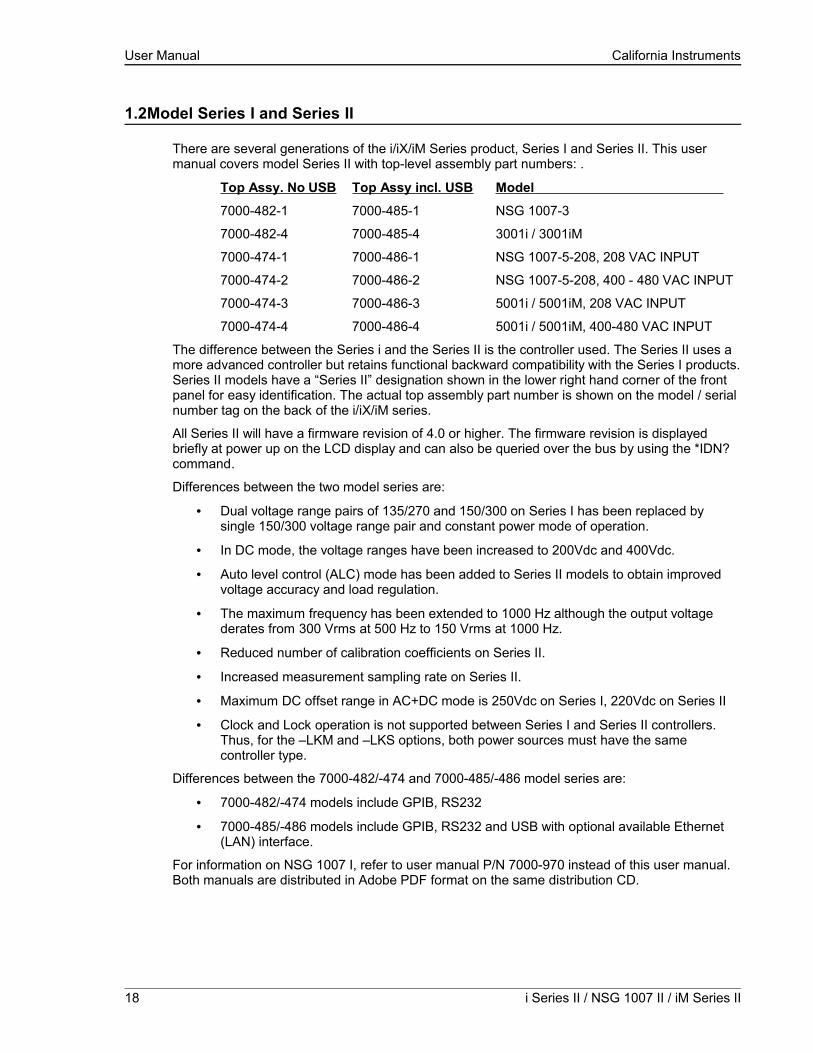
1.2Model Series I and Series II
There are several generations of the i/iX/iM Series product, Series I and Series II. This user manual covers model Series II with top-level assembly part numbers: .
Top Assy. No USB Top Assy incl. USB Model
7000-482-1 7000-485-1 NSG 1007-3
7000-482-4 7000-485-4 3001i / 3001iM
7000-474-1 7000-486-1 NSG 1007-5-208, 208 VAC INPUT
7000-474-2 7000-486-2 NSG 1007-5-208, 400 - 480 VAC INPUT
7000-474-3 7000-486-3 5001i / 5001iM, 208 VAC INPUT
7000-474-4 7000-486-4 5001i / 5001iM, 400-480 VAC INPUT
The difference between the Series i and the Series II is the controller used. The Series II uses a more advanced controller but retains functional backward compatibility with the Series I products. Series II models have a “Series II” designation shown in the lower right hand corner of the front panel for easy identification. The actual top assembly part number is shown on the model / serial number tag on the back of the i/iX/iM series.
All Series II will have a firmware revision of 4.0 or higher. The firmware revision is displayed briefly at power up on the LCD display and can also be queried over the bus by using the *IDN? command.
Differences between the two model series are:
• Dual voltage range pairs of 135/270 and 150/300 on Series I has been replaced by single 150/300 voltage range pair and constant power mode of operation.
• In DC mode, the voltage ranges have been increased to 200Vdc and 400Vdc.
• Auto level control (ALC) mode has been added to Series II models to obtain improved voltage accuracy and load regulation.
• The maximum frequency has been extended to 1000 Hz although the output voltage derates from 300 Vrms at 500 Hz to 150 Vrms at 1000 Hz.
• Reduced number of calibration coefficients on Series II.
• Increased measurement sampling rate on Series II.
• Maximum DC offset range in AC+DC mode is 250Vdc on Series I, 220Vdc on Series II
• Clock and Lock operation is not supported between Series I and Series II controllers. Thus, for the –LKM and –LKS options, both power sources must have the same controller type.
Differences between the 7000-482/-474 and 7000-485/-486 model series are:
• 7000-482/-474 models include GPIB, RS232
• 7000-485/-486 models include GPIB, RS232 and USB with optional available Ethernet (LAN) interface.
For information on NSG 1007 I, refer to user manual P/N 7000-970 instead of this user manual. Both manuals are distributed in Adobe PDF format on the same distribution CD.
18 i Series II / NSG 1007 II / iM Series II

User Manual California Instruments
2.Specifications
All specifications are for a single i or NSG 1007 II unit and 25 ± 5°C sine wave output with a resistive load unless noted otherwise.
2.1Electrical
2.1.1Input
Parameter 3001i / iX / iM 5001i / iX / iM
Line Voltage: 208-240 ±10% VAC, single phase 208-240 VLL ±10%, (Standard)
400-440 VLL ±10%, (-400)
400-480 VLL ±10%, (-400)
3 phase, 3 wire + ground
Line VA: 5000VA 8000VA
Line Current: 25 A RMS max. (Per Box) 23 A RMS max. at 208-240 VAC
12 A RMS max. at 400-440 VAC and 400-480 VAC (Per Box)
Line Frequency: 50-60 Hz ±10%
Efficiency: 80% (typical) depending on line and load
Power Factor: 0.7 (typical) 0.9 (typical)
Inrush Current: 100 Apk for 100 µs 100 Apk for 100 µs at 208-240V
50 Apk for 100 µs at 400-440 VACand 400-480 VAC
Hold-Up Time: 15 ms
Isolation Voltage: 2200 VAC input to output
1350 VAC input to chassis
NSG 1007 Series II 19
User Manual California Instruments
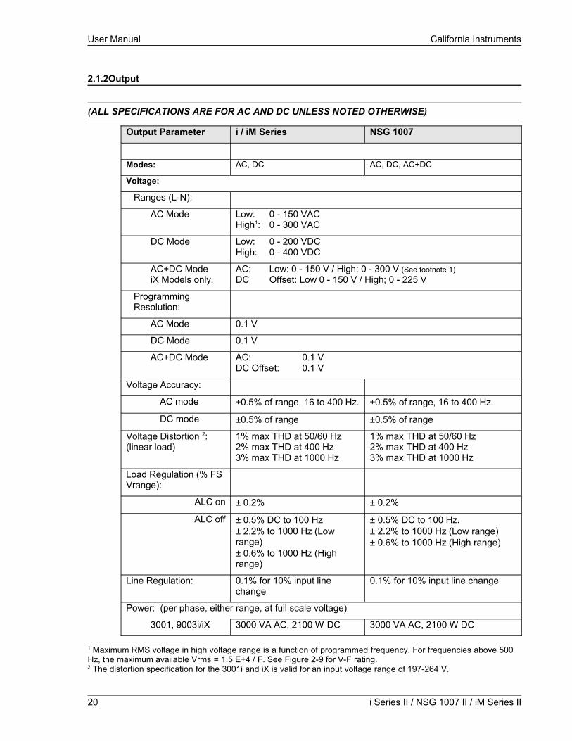
2.1.2Output
(ALL SPECIFICATIONS ARE FOR AC AND DC UNLESS NOTED OTHERWISE)
Output Parameter i / iM Series NSG 1007
Modes: AC, DC AC, DC, AC+DC
Voltage:
Ranges (L-N):
AC Mode Low: 0 - 150 VACHigh1: 0 - 300 VAC
DC Mode Low: 0 - 200 VDCHigh: 0 - 400 VDC
AC+DC ModeiX Models only.
AC: Low: 0 - 150 V / High: 0 - 300 V (See footnote 1)DC Offset: Low 0 - 150 V / High; 0 - 225 V
Programming Resolution:
AC Mode 0.1 V
DC Mode 0.1 V
AC+DC Mode AC: 0.1 VDC Offset: 0.1 V
Voltage Accuracy:
AC mode ±0.5% of range, 16 to 400 Hz. ±0.5% of range, 16 to 400 Hz.
DC mode ±0.5% of range ±0.5% of range
Voltage Distortion 2:(linear load)
1% max THD at 50/60 Hz2% max THD at 400 Hz3% max THD at 1000 Hz
1% max THD at 50/60 Hz2% max THD at 400 Hz3% max THD at 1000 Hz
Load Regulation (% FS Vrange):
ALC on ± 0.2% ± 0.2%
ALC off ± 0.5% DC to 100 Hz± 2.2% to 1000 Hz (Low range)± 0.6% to 1000 Hz (High range)
± 0.5% DC to 100 Hz.± 2.2% to 1000 Hz (Low range)± 0.6% to 1000 Hz (High range)
Line Regulation: 0.1% for 10% input line change
0.1% for 10% input line change
Power: (per phase, either range, at full scale voltage)
3001, 9003i/iX 3000 VA AC, 2100 W DC 3000 VA AC, 2100 W DC
1 Maximum RMS voltage in high voltage range is a function of programmed frequency. For frequencies above 500 Hz, the maximum available Vrms = 1.5 E+4 / F. See Figure 2-9 for V-F rating.2 The distortion specification for the 3001i and iX is valid for an input voltage range of 197-264 V.
20 i Series II / NSG 1007 II / iM Series II

User Manual California Instruments
Output Parameter i / iM Series NSG 1007
5001, 15003i/iX
10001i/iX
1NSG 1007-5
5000 VA AC, 3500 W DC
10000 VA AC, 7000 W DC
15000 VA AC, 10500 W DC
5000 VA AC, 3500 W DC
10000 VA AC, 7000 W DC
15000 VA AC, 10500 W DC
Current, maximum amps per phase:
NSG 1007-3 22.2 Arms @ 135 VAC in 150 Vrange11.1 Arms @ 270 VAC in 300 Vrange
15.5 Adc @ 135 VDC in 200 Vrange7.77 Adc @ 270 VDC in 400 Vrange
5001 /15003i/iX per phase
37.0 Arms @ 135 VAC in 150 Vrange18.5 Arms @ 270 VAC in 300 Vrange
25.9 Adc @ 135 VDC in 200 Vrange12.95 Adc @ 270 VDC in 400 Vrange
10001i/iX 74.0 Arms @ 135 VAC in 150 Vrange37.0 Arms @ 270 VAC in 300 Vrange
51.8 Adc @ 135 VDC in 200 Vrange25.9 Adc @ 270 VDC in 400 Vrange
10001i/iX 111 Arms @ 135 VAC in 150 Vrange55.5 Arms @ 270 VAC in 300 Vrange
77.7 Adc @ 135 VDC in 200 Vrange38.8 Adc @ 270 VDC in 400 Vrange
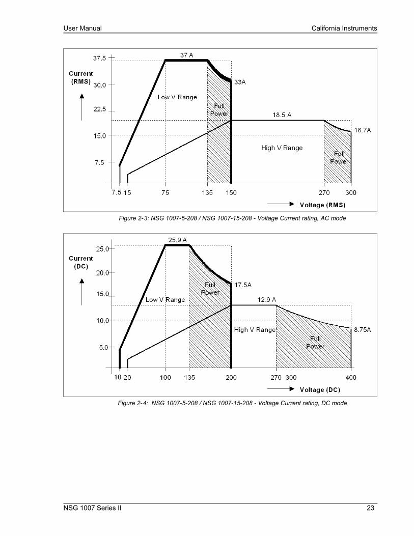
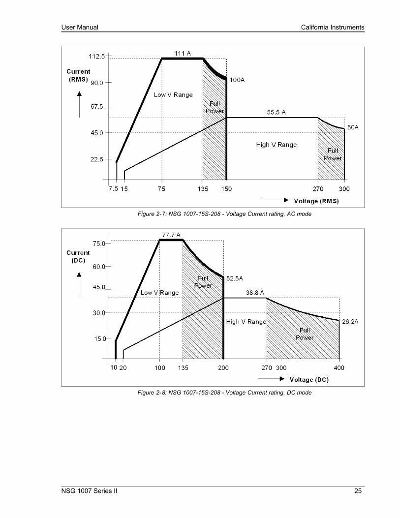
Current derates at higher voltage settings along constant power curve. See Figures Figure 2-1 through Figure 2-8 for voltage current ratings per phase or output by model.
Maximum current for which specifications apply is derated linearly from 50% of voltage to 10% of specified current at 5% of voltage range as shown. Higher currents are available but not all specification will apply under these conditions.
Note: For the NSG 1007, the current output in the AC & DC mode is equal to the current in the AC mode if the DC voltage is less than 20% of the full scale voltage. It is equal to the DC current for DC voltages more than 20% of full scale
NSG 1007 Series II 21

User Manual California Instruments
Figure 2-1: NSG 1007-3 / NSG 1007-9 - Voltage Current rating, AC mode
Figure 2-2: NSG 1007-3 / NSG 1007-9 - Voltage Current Rating, DC mode
22 i Series II / NSG 1007 II / iM Series II
User Manual California Instruments
Figure 2-3: NSG 1007-5-208 / NSG 1007-15-208 - Voltage Current rating, AC mode
Figure 2-4: NSG 1007-5-208 / NSG 1007-15-208 - Voltage Current rating, DC mode
NSG 1007 Series II 23

User Manual California Instruments
Figure 2-5: NSG 1007-10-208 / NSG 1007-30-208 - Voltage Current rating, AC mode
Figure 2-6: NSG 1007-10-208 / NSG 1007-30-208 - Voltage Current rating, DC mode
24 i Series II / NSG 1007 II / iM Series II
User Manual California Instruments
Figure 2-7: NSG 1007-15S-208 - Voltage Current rating, AC mode
Figure 2-8: NSG 1007-15S-208 - Voltage Current rating, DC mode
NSG 1007 Series II 25

User Manual California Instruments
Figure 2-9: Maximum RMS voltage versus frequency rating in 300V AC range.
Output Parameter i / iM Series NSG 1007
Current Limit
Range Programmable 0 to 100% of range for all ranges
Resolution 0.1 Arms
Accuracy ± 0.5A
Frequency Range: 16.00 - 81.91 Hz (0.01 Hz resolution)81.0 – 819.1 Hz (0.1 Hz resolution)820 – 1000 Hz1 (1 Hz resolution)
Frequency Accuracy: ± 0.01% of programmed value
DC Offset Voltage: Less than 20 mV with linear load.
Output Impedance
Range: n/a Rmin to 1000 mΩ
Lmin to 1000 µH
Resolution: n/a 4 mΩ
4 µH
Accuracy: n/a ± 2% F.S. at 796 µH and 400 mΩ
Output Noise: (20 kHz to 1 MHz)
<250 mV rms (typ), <250 mV rms (typ),
1 Note: AC voltage in 300V range derates from 300 Vrms max. at 500 Hz to 150 Vrms max. at 1000 Hz. See V-F rating chart figure Figure 2-9.
26 i Series II / NSG 1007 II / iM Series II

User Manual California Instruments
Output Parameter i / iM Series NSG 1007
<500 mV rms (max) <500 mV rms (max)
Peak Rep AC Current:
NSG 1007-3NSG 1007-59003i/iX15003i/iX
110 A for 150 V range,92 A for 300 V range
110 A for 150V range,92 A for 300 V range,
10001i/iX 220 A for 150 V range,184 A for 300 V range
220 A for 150 V range,184 A for 300 V range
1NSG 1007-5 330 A for 150 V range,276 A for 300 V range
330 A for 150 V range,276 A for 300 V range
Crest Factor: Up to 5:1 Up to 5:1
2.1.3AC Measurements
Note: Measurements are not available on iM Series II models.
Parameter Range Accuracy (±) Resolution
Frequency 16.00 - 1000 Hz 2 counts 0.01: 16 to 81.91 Hz0.1: 82.0 to 819.0 Hz1: 820 to 1000 Hz
RMS Voltage 0 - 300 Volts 0.25V + 0.1%, <100 Hz0.25V + 0.2%, 100-1000 Hz
0.01 Volt
RMS Current 0 - 40 Amps 0.25A + 0.1%, <100 Hz0.25A + 0.2%, 100-1000 Hz
0.001 Amp
Peak Current 0 - 119 Amps 0.5A + 0.2%, <100 Hz0.5A + 0.5%, 100-1000 Hz
0.01 Amp
VA Power 0 – 6000 VA 10 VA + 0.1%, <100 Hz20 VA + 0.2%, 100-1000 Hz
1 VA
Real Power 0 – 6000 W 10 W + 0.1%, <100 Hz20 W + 0.2%, 100-1000 Hz
1 W
Power Factor (>0.2kVA)
0 - 1.00 0.01
1007-10-208 and times three for NSG 1007-15S-208. For NSG 1007-10-208 and NSG 1007-15S-208, resolution decreases by factor of 10, ranges for current and power increases by factor of three. Measurement bandwidth is limited to 16 Khz.
2.1.4DC Measurements
Note: Measurements are not available on iM Series II models.
Parameter Range Accuracy (±) Resolution
Voltage 0 – 400 Volts 0.4 Volts 0.01 Volt
Current 0 – 40 Amps 0.1 Amps 0.001 Amp
Power 0 – 6000 W 20 W 1 W
NSG 1007 Series II 27

User Manual California Instruments
Parameter Range Accuracy (±) Resolution
Accuracy specifications apply above 100 counts. Current and Power Accuracy specifications are times two for NSG 1007-10-208 and times three for NSG 1007-15S-208. For NSG 1007-10-208 and NSG 1007-15S-208, resolution decreases by factor of 10, ranges for current and power increases by factor of three.
2.1.5Harmonic Measurements (NSG 1007)
Parameter Range Accuracy ( ± ) Resolution
Frequency fundamental 16.00 - 1000 Hz 2 counts 0.01 Hz to 1 Hz
Frequency harmonics 32.00 Hz - 16 kHz 2° typ. 0.5°
Voltage Fundamental 0.25V 0.01V
Harmonic 2 - 50 0.25V + 0.1% + 0.1%/kHz 0.01V
Current Fundamental 0.05A 0.01A
Harmonic 2 - 50 0.05A + 0.1% + 0.1%/kHz 0.01A
Accuracy specifications are times three for three phase mode. Harmonics frequency range in three-phase mode is 32 Hz - 16 kHz. Resolution decreases by factor of 10 for NSG 1007-10-208 and NSG 1007-15S-208.
2.1.6System Specification
Parameter Specification
External Modulation: 0 to 10%
Synchronization Input:
Isolated TTL input for external frequency control. Requires 5V at 5 ma for logic high.
Trigger Output: 400 µs pulse for voltage or frequency change. Isolated output that requires a pull-up resistor, 22K Ω, to + 5 VDC.
Non volatile memory storage:
16 complete instrument setups and transient lists, 100 events per list.
Waveforms Sine (i series)Sine, square, clipped, user defined (NSG 1007)
Transients Voltage: drop, step, sag, surge, sweep
(i/iX only) Frequency: step, sag, surge, sweep
Voltage and Frequency: step, sweep
IEEE-488 Interface: SH1, AH1, T6, L3, SR1, RL2, DC1, DT1IEEE 488.2 and SCPIResponse time is 10 ms (typical)
RS232C Interface: Bi-directional serial interface9 pin D-shell connectorHandshake: CTS, RTSData bits: 7, 8Stop bits: 1,2Baud rate: 9600, 19200, 38400 (Models without USB I/F)Baud rate: 9600, 19200, 38400, 57600, 115200, 230400, 460800IEEE 488.2 and SCPI.
28 i Series II / NSG 1007 II / iM Series II
User Manual California Instruments
Parameter Specification
Note: Disconnect any USB connection when using the RS232 interface.
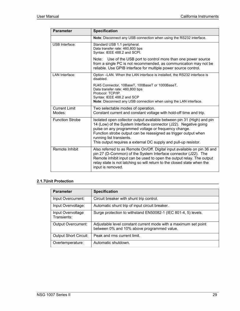
USB Interface: Standard USB 1.1 peripheral.Data transfer rate: 460,800 bpsSyntax: IEEE 488.2 and SCPI.
Note: Use of the USB port to control more than one power source from a single PC is not recommended, as communication may not be reliable. Use GPIB interface for multiple power source control.
LAN Interface: Option –LAN. When the LAN interface is installed, the RS232 interface is disabled.
RJ45 Connector, 10BaseT, 100BaseT or 1000BaseT, Data transfer rate: 460,800 bps Protocol: TCP/IP.Syntax: IEEE 488.2 and SCPNote: Disconnect any USB connection when using the LAN interface.
Current Limit Modes:
Two selectable modes of operation.Constant current and constant voltage with hold-off time and trip.
Function Strobe Isolated open collector output available between pin 31 (High) and pin 14 (Low) of the System Interface connector (J22). Negative going pulse on any programmed voltage or frequency change.Function strobe output can be reassigned as trigger output when running list transients.This output requires a external DC supply and pull-up resistor.
Remote Inhibit Also referred to as Remote On/Off. Digital input available on pin 36 and pin 27 (D-Common) of the System Interface connector (J22). The Remote inhibit input can be used to open the output relay. The output relay state is not latching so will return to the closed state when the input is removed.
2.1.7Unit Protection
Parameter Specification
Input Overcurrent: Circuit breaker with shunt trip control.
Input Overvoltage: Automatic shunt trip of input circuit breaker.
Input Overvoltage Transients:
Surge protection to withstand EN50082-1 (IEC 801-4, 5) levels.
Output Overcurrent: Adjustable level constant current mode with a maximum set point between 0% and 10% above programmed value.
Output Short Circuit: Peak and rms current limit.
Overtemperature: Automatic shutdown.
NSG 1007 Series II 29

User Manual California Instruments
2.2Mechanical
Parameter Specification
Dimensions: 19” (483 mm) wide x 7” (178 mm) high x 24” (610 mm) deep chassis size which is available in a rack mount or stand-alone configuration.
Unit Weight: 61 lb. (28 kg)
Material: Aluminum chassis, panels and cover.
Finish: Light textured painted external surfaces.
Front and rear panels semi-gloss polyurethane color no. 26440 (medium gray)
Top, bottom and sides semi-gloss polyurethane color no. 26622 (light gray).
Cooling: Fan cooled with air intake on the sides and exhaust to the rear.
Internal Construction:
Modular sub assemblies.
Rear Panel Connections:
(see section 3 for description of connections)
Input terminal block with cover
Output terminal block with cover
Remote voltage sense terminal block
System interface (not for table top use, use only in rack enclosed systems)
Clock and Lock (not for table top use, use only in rack enclosed systems)
RS232, GPIB, USB, LAN (option)
2.3Environmental
Parameter Specification
Operating Temp: 0 to +40 °C.
Storage Temp: -40 to +85 °C.
Altitude: < 2000 m
Relative Humidity: 80% maximum for temperatures up to 31°C decreasing linearly to 50% at 40°C.
Installation/Over voltage Category: ΙΙ
Pollution Degree: 2
Indoor Use Only
Vibration: Designed to meet NSTA 1A transportation levels.
Shock: Designed to meet NSTA 1A transportation levels.
30 i Series II / NSG 1007 II / iM Series II
User Manual California Instruments
2.4Regulatory
Electromagnetic Emissions and Immunity:
Designed to meet EN50081-2 and EN50082-2 European Emissions and Immunity standards as required for the “CE” mark.
Acoustic Noise: 65 dBA maximum at 0% to 50% load, 75 dBA maximum greater than 50% load to 100% load. Measured at one meter.
Safety: Designed EN61010-1 European safety standards as required for the “CE” mark.
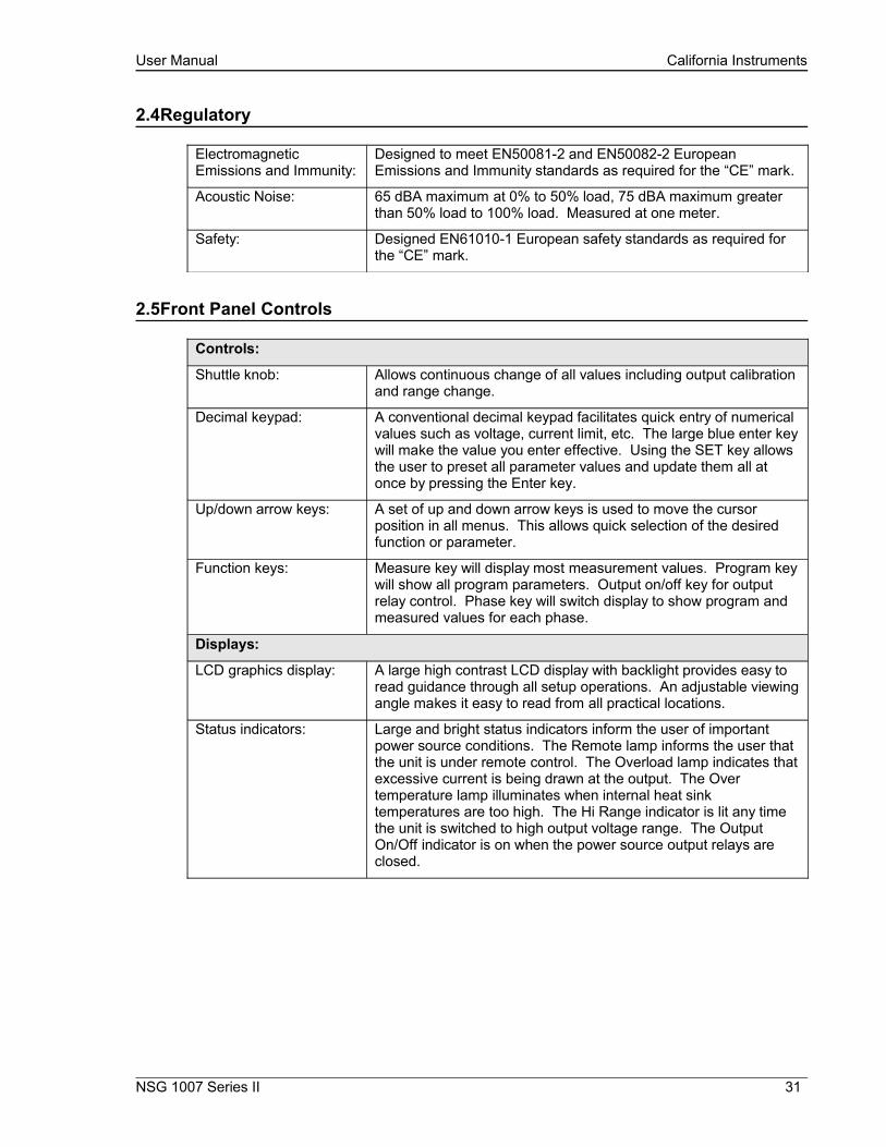
2.5Front Panel Controls
Controls:
Shuttle knob: Allows continuous change of all values including output calibration and range change.
Decimal keypad: A conventional decimal keypad facilitates quick entry of numerical values such as voltage, current limit, etc. The large blue enter key will make the value you enter effective. Using the SET key allows the user to preset all parameter values and update them all at once by pressing the Enter key.
Up/down arrow keys: A set of up and down arrow keys is used to move the cursor position in all menus. This allows quick selection of the desired function or parameter.
Function keys: Measure key will display most measurement values. Program key will show all program parameters. Output on/off key for output relay control. Phase key will switch display to show program and measured values for each phase.
Displays:
LCD graphics display: A large high contrast LCD display with backlight provides easy to read guidance through all setup operations. An adjustable viewing angle makes it easy to read from all practical locations.
Status indicators: Large and bright status indicators inform the user of important power source conditions. The Remote lamp informs the user that the unit is under remote control. The Overload lamp indicates that excessive current is being drawn at the output. The Over temperature lamp illuminates when internal heat sink temperatures are too high. The Hi Range indicator is lit any time the unit is switched to high output voltage range. The Output On/Off indicator is on when the power source output relays are closed.
NSG 1007 Series II 31

User Manual California Instruments
2.6Special Features, Options and Accessories
Feature Description
Programmable Impedance.
Output impedance programming available on models NSG 1007-3, NSG 1007-5-208, NSG 1007-9 and NSG 1007-15-208 only.
Parallel Operation: Up to three units can be paralleled in a single-phase configuration (with one master controller and one or two slave units). (NSG 1007-10-208 and NSG 1007-15S-208).
Three Phase Output: Three units (all with single-phase controllers) can be connected in a three-phase configuration using CLOCK and LOCK connections. Requires –LKM option in master and –LKS option in auxiliary units. Recommended is use of NSG 1007-9, NSG 1007-15-208 or NSG 1007-30-208 three phase system however.Note: Clock and lock operation is not supported between Series I and Series II controller types. For this mode of operation, both models have the have the same controller type.
Controller: Programmable controller front panel assembly.
Output Relay: Standard output relay feature to isolate AC source from the load.
Output On/Off: The output relay can be used to quickly disconnect the load. A green status indicator displays the status of the output relay.
Three-Phase Output NSG 1007-9/15003Ix
Three power sources with one controller in the Phase A power source. The one controller controls all three outputs.
NSG 1007-15-208 – LKM/-LKS
Three power sources each with a controller for 3-phase output
Option Description
Note Avionics and IEC test options not available on iM Series models.
- 704 Mil Std 704D & E test firmware.
Mil Std 704A, B, C, & F test software (refer to Avionics Software Manual P/N 4994-971 for details).Note: Requires use of CIGuiSII Windows application software provided on CD ROM CIC496.
- 787 Boeing 787 Test software (refer to Avionics Software Manual P/N 4994-971 for details).Note: Requires use of CIGuiSII Windows application software provided on CD ROM CIC496.
- 160 RTCA/DO-160D test firmware
RTCA/DO-160E test software (refer to Avionics Software Manual P/N 4994-971 for details)..Note: Requires use of CIGuiSII Windows application software provided on CD ROM CIC496.
- 411 IEC 1000-4-11 test firmware
- 413 IEC 1000-4-13 test hardware and firmware
-ABD Airbus ABD0100.1.8 Test software (refer to Avionics Software Manual P/N 4994-971 for details).. Note: Requires use of CIGuiSII Windows application software
32 i Series II / NSG 1007 II / iM Series II

User Manual California Instruments
provided on CD ROM CIC496.
-AMD Airbus AMD24C Test software (refer to Avionics Software Manual P/N 4994-971 for details).. Note: Requires use of CIGuiSII Windows application software provided on CD ROM CIC496.
-EOS1 / -EOS3 Electronic output switch for IEC 61000-4-11 testing. Includes –411 firmware option. Single or three phase versions. (i/iX Only)
-LAN Adds Ethernet interface (RJ45 connector) for local area network connection. (Available on P/N 7000-485 and 7000-486 models only).
-LF Limits maximum output frequency to 500 Hz.
- LNS Line sync option to synchronize output frequency to input mains line frequency
-MODE-iX Available for NSG 1007-9 and NSG 1007-15-208 configurations only. Switches output configurations between single-phase and three-phase mode of operation. Note that programmable impedance function on systems with –MODE-iX option is only available when in 3 phase mode.
- RMS Rack mounting kit with slides. Removable rack ears/handles standard.
Lumped Impedances Available in different power levels and no. of phases as listed.
-Imepdance-1-18i Single phase lumped reference impedance network of IEC1000-3-3 Flicker test
-Imepdance-1-37i Single phase lumped reference impedance network of IEC1000-3-3 Flicker test – High current.
-INA 2154 Three phase lumped reference impedance network of IEC1000-3-3 Flicker test
-INA 2153 Three phase lumped reference impedance network of IEC1000-3-3 Flicker test – High current.
Accessories Description
-TI Function strobe break out box. Function strobe / Trigger Output connection break out box. Provides BNC output with internal 9Vdc pull up for connection to external equipment such as oscilloscope. Compatible with NSG 1007-3 and NSG 1007-5. Refer to section 3.6.7.
-TIS Function strobe break out box for systems. Function strobe / Trigger Output connection break out box. Provides BNC output with internal 9Vdc pull up for connection to external equipment such as oscilloscope. Compatible with multi-chassis NSG 1007 configurations. Refer to section 3.6.7.
NSG 1007 Series II 33

User Manual California Instruments
3.Unpacking and Installation
3.1Unpacking
Inspect the unit for any possible shipping damage immediately upon receipt. If damage is evident, notify the carrier. DO NOT return an instrument to the factory without prior approval. Do not destroy the packing container until the unit has been inspected for damage in shipment.
WARNING: This power source weighs 61 lb (28kg). Obtain adequate help when moving or mounting the unit.
3.2Power Requirements
The NSG 1007-3 AC Power Source has been designed to operate from a single-phase 208 to 240 volt AC line. The NSG 1007-5 AC Power Source and its systems have been designed to operate from a three-phase AC line voltage. Three three-phase input models are available for inputs of 208-240 VLL, 400-440 VLL (option -400), or 400-480 VLL (option -400).
CAUTION: Do not connect 400-480V into the 208-240V unit, the result could be a severely damaged unit.
34 i Series II / NSG 1007 II / iM Series II
Figure 3-10: The NSG 1007-5-208 Power Source

User Manual California Instruments
3.3Mechanical Installation
The NSG 1007-3 and NSG 1007-5 are completely self-contained power sources. They may be used free standing on a bench top or rack mounted using the optional rack mount/handle kit. The units are fan cooled, drawing air in from the sides and exhausting at the rear. The sides of each unit must be kept clear of obstruction and a 6” clearance must be maintained to the rear. Special consideration of overall air flow characteristics and the resultant internal heat rise must be allowed for with systems installed inside enclosed cabinets to avoid self heating and over temperature problems.
3.4Input Wiring – TB1
The input terminal block, TB1, is located at the rear of the unit. Ground (earth) wire must be connected to the chassis of the AC power system. The mains source must have a current rating equal to or greater than the input circuit breaker and the input wiring must be sized to satisfy the applicable electrical codes. The input terminal block cover and strain relief must be installed in table top applications to maintain protection against hazardous voltages.
CAUTION: Capacitors in the power source may hold a hazardous electrical charge even if the power source has been disconnected from the mains supply. Allow capacitors to discharge to a safe voltage before touching exposed pins of mains supply connectors.
3.5Output Power Connections – TB2
The output terminal block, TB2, is located at the rear of the unit. The external sense inputs allow the power system output voltages to be monitored directly at the load and must be connected either at TB2 or the load when the sense is programmed for external. The external sense input does not have to be connected when Internal Sense is programmed. The external sense wires are to be connected to TB3 on the rear panel and should be run as a twisted pair for short lengths. Sense leads over three (3) feet long should be run as a twisted shielded pair. Refer to Figures 3-2 through 3-12 for all connections.
Note: The output of the power source is isolated from the input line and floating from chassis ground. If needed, either side (HI or LO) may be grounded.
NSG 1007 Series II 35

User Manual California Instruments
The output power cables must be large enough to prevent a total voltage drop exceeding 1% of the rated output voltage between the power source and the load. Table 3-1 shows the AWG size of the cables that may be used. Cable lengths must not exceed twenty-five (25) feet. For lengths greater than 25 feet, calculate the voltage drop from the following formula:
2 X DISTANCE X CABLE RESISTANCE PER FT. X CURRENT = VOLT DROP
Table 3-1: Wire Sizes
LOAD CURRENT WIRE GAGE
22 AMPS 10 AWG37 AMPS 8 AWG74 AMPS 4 AWG111 AMPS 2 AWG
36 i Series II / NSG 1007 II / iM Series II

User Manual California Instruments
3.6Connectors - Rear Panel
A number of connectors are located along the top rear covers. These connectors are in a recessed area to protect them from shipment damage.
3.6.1System Interface, Clock and Lock Connectors
WARNING: The system interface connector and Clock and Lock connectors may be at hazardous voltages. These connections may not be used in table top applications. In table top applications the safety cover must be in place. These connections may only be used when the equipment is enclosed in a rack, only within one rack, only with Teseq supplied cables, and only between Teseq equipment.
J21 and J20 are the Clock and Lock connectors and are used to synchronize and control the phase shift between the three outputs when 3 units are operating as a three-phase system with the NSG 1007-15-208 - LK option.
The System Interface connector, J22, is used to connect the slave power sources to the Master power source (the one with the controller) in multiple box systems. The connector is also used for the external sync input, external modulation input and trigger output.
Table 3-2: System Interface Connector (J22)
J22 Description 1 Analog Common: analog signal common
2 MR B: Phase B master signal
3 Analog Common
4 CS B: Phase B current sum
5 CT Common: Current transformer common
6 OSC B: Phase B oscillator output
7 Analog Common
8 CL B: Phase B current limit reference
9 EXT MOD: External modulation input. A 10 volt input will modulate the output 10%. Original versions of iX power sources required a 100 volt input to modulate the output by 10%. If you experience problems using the external modulation input, contact Teseq customer service.
10 : A logic low output to indicate an over temperature condition.
11 : Output relay state: Logic HI = open, LOW = closed.
12 FLT C: Phase C current limit fault control
13 FLT A: Phase A current limit fault control
14 F STB LO: Function Strobe / Trigger output Low signal. This is the emitter lead of an optically isolated NPN transistor. The internal power controller turns this transistor on to indicate a change of programmed values. See section 3.6.7 for details.
15 EX SYNC LO: External Sync Low signal. This is the ground return for the TTL external sync input. It connects to the cathode of an LED at the input of an opto coupler. Refer to J22-32.
NSG 1007 Series II 37

User Manual California Instruments
J22 Description 16 AMP SHARE B
17 PARALLEL
18 CL ENA
19 MR C: Phase C master signal
20 MR A: Phase A master signal
21 CS C: Phase C current sum
22 CS A: Phase A current sum
23 OSC C: Phase C oscillator output
24 OSC A: Phase A oscillator output
25 CL C: Phase C current limit reference
26 CL A: Phase A current limit reference
27 D COM: Digital Common
28 RNG HI: Voltage range state: Logic HI = high range, LOW = low range
29 Overload
30 FLT B: Phase B current limit fault control
31 F STB HI: Function Strobe / Trigger output HI. A low-going pulse, >400µs, that indicates voltage or frequency change. Isolated output that requires a pull-up resistor, 22KΩ, to +5 VDC. Use J22 pin 14 (F STB LO) for common. See section 3.6.7 for details.
32 EX SYNC HI, External Sync input HI. This is an input that can be used to synchronize the outputs of the AC Power System. This input requires a logic high level of at least +4.5 VDC at 5 mA. The input should have a duty cycle 50 ±30%. J22-15 is the common input. The External Sync input is optically isolated. It must be enabled from the SNC screen.
33 AMP SHARE C
34 AMP SHARE A
35 FLICKER / BYPASS
36 REMOTE ON: This is a logic input that can be used to remove the programmed output voltage. A logic low on this pin will cause the output voltages to be programmed to 0.0 volts and the output relays to open. A logic high will cause the programmed output voltage to be restored at the output terminals. A contact closure between this pin and J22-27 (D COM) will simulate a logic low state.
38 i Series II / NSG 1007 II / iM Series II

User Manual California Instruments
3.6.2Remote Sense Connector TB3
When selecting external sense mode, it is important that the remote sense connections are hooked up at the EUT or at the sense point. For single-phase systems, connect Phase A to phase A and neutral to neutral. For three-phase system configurations, connect all three phase.
NOTE: Do not reverse or swap sense connection phasing or damage to the unit may result.
NOTE: Do not disconnect the external sense connection if external sense mode is selected. Doing so will cause the output voltage to go to its maximum value and could potentially damage an EUT.
All NSG 1007-3 and NSG 1007-5-208 AC Sources are shipped with the sense connections wired to the output terminals. This will prevent a voltage fault when the external sense mode is selected. On systems consisting of multiple NSG 1007-3 or NSG 1007-5-208 chassis, the end user has to connect the external sense inputs to allow the system to operate. Some system configuration do not support Internal sense mode in which case the sense connection must always be present at TB3.
To prevent an excessive output voltage caused by an open external sense condition on single chassis i/iX systems (3001,5001), a set of 10Kohm, 10 Watt resistors can be used to connect the output terminal block (TB2) to the external sense connection. This will cause a 0.2% error if the sense lines are not connected. The 10 Watt rating will keep the resistor from burning if the sense lines connected to the load but the output wiring becomes disconnected. On three phase systems, the output of all phase output terminals must be connected to the master sense connector of the master unit to accomplish the same.
Table 3-3: Remote Sense Connector – TB3
Pin Description
A Phase A sense
B Phase B sense
C Phase C sense
N Neutral sense
NSG 1007 Series II 39

User Manual California Instruments
3.6.3RS232C Serial Interface Connector – J18
Note that two versions of the RS232 exist on the iX/i model Series II depending on the age of the unit. Older models can be identified by the fact that they will not have a USB interface.
Pin Name Direction
1 N/C
2 TxD Output
3 RxD Input
4 N/C
5 Common Common
6 N/C
7 CTS Input
8 RTS Output
9 N/C
Table 3-4: RS232 Connector pin out – Units with RS232 and USB.
Pin Name Direction
1 N/C
2 RxD, Receive data Output
3 TxD. Transmit data Input
4 DTR, Data Terminal Ready DTR, Data Terminal Ready
5 Common Common
6 N/C N/C
7 RTS, Request to Send Output
8 N/C N/C
9 N/C N/C
Table 3-5: RS232C Connector – Units with RS232 but no USB.
On i/iX models without a USB interface, a special RS232 cable is required to connect to a PC. With these models, a special 6 foot / 2 meter long cable (CI P/N 7000-263-1) is supplied in the NSG 1007 ship-kit. The wiring diagram for this cable is shown below in case a longer cable has to be constructed. Alternatively, a generic straight thru DB9 male to DB9 female cable can be used to extend the supplied cable.
The i/iX models that have both RS232 and USB interface use a regular straight through DB9 male to DB9 female serial cable, which is supplied in the i/iX ship kit for these models. To connect the NSG 1007-5-208 to a PC’s 9-pin DB9 serial port, a special RS232 cable is required.
40 i Series II / NSG 1007 II / iM Series II
User Manual California Instruments
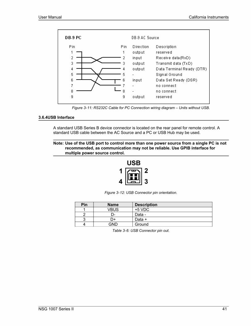
Figure 3-11: RS232C Cable for PC Connection wiring diagram – Units without USB.
3.6.4USB Interface
A standard USB Series B device connector is located on the rear panel for remote control. A standard USB cable between the AC Source and a PC or USB Hub may be used.
Note: Use of the USB port to control more than one power source from a single PC is not recommended, as communication may not be reliable. Use GPIB interface for multiple power source control.
Figure 3-12: USB Connector pin orientation.
Pin Name Description1 VBUS +5 VDC2 D- Data -3 D+ Data +4 GND Ground
Table 3-6: USB Connector pin out.
NSG 1007 Series II 41
User Manual California Instruments
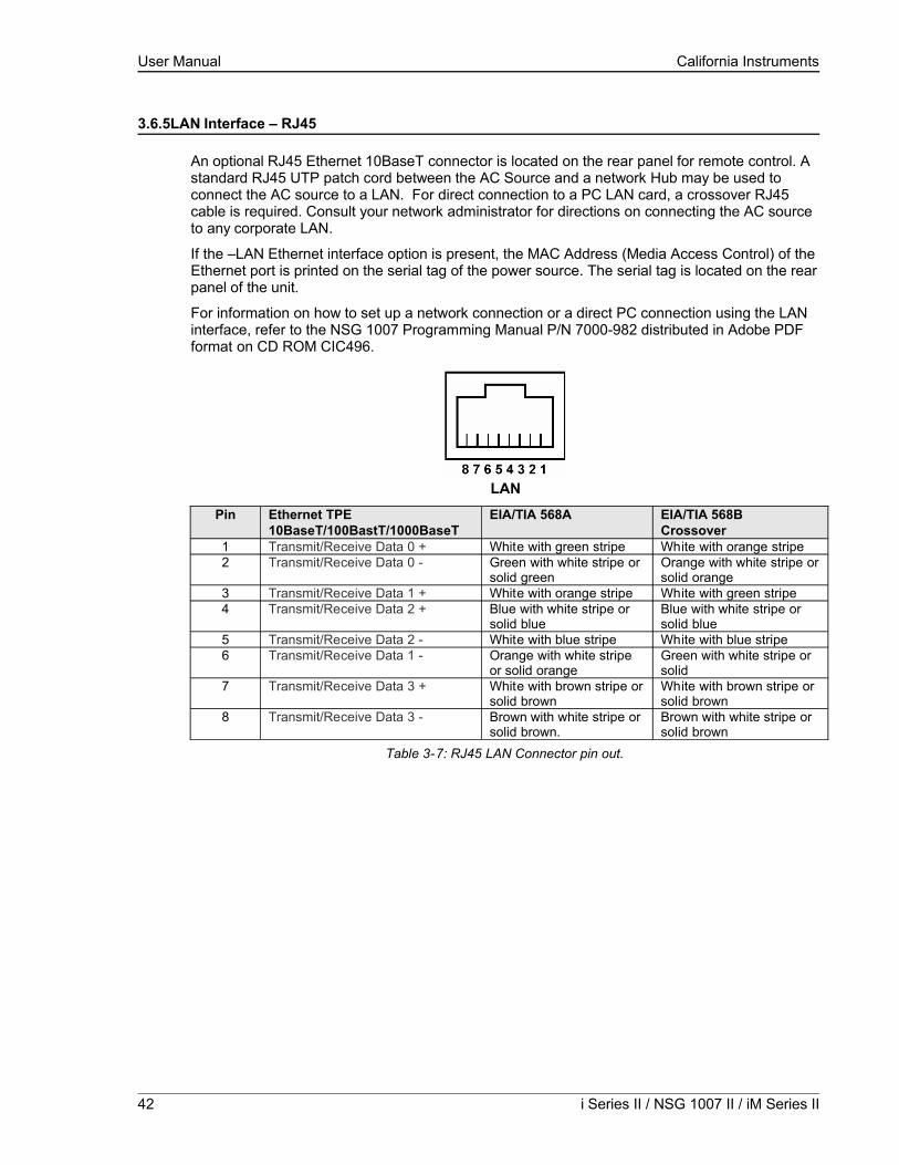
3.6.5LAN Interface – RJ45
An optional RJ45 Ethernet 10BaseT connector is located on the rear panel for remote control. A standard RJ45 UTP patch cord between the AC Source and a network Hub may be used to connect the AC source to a LAN. For direct connection to a PC LAN card, a crossover RJ45 cable is required. Consult your network administrator for directions on connecting the AC source to any corporate LAN.
If the –LAN Ethernet interface option is present, the MAC Address (Media Access Control) of the Ethernet port is printed on the serial tag of the power source. The serial tag is located on the rear panel of the unit.
For information on how to set up a network connection or a direct PC connection using the LAN interface, refer to the NSG 1007 Programming Manual P/N 7000-982 distributed in Adobe PDF format on CD ROM CIC496.
LAN
Pin Ethernet TPE10BaseT/100BastT/1000BaseT
EIA/TIA 568A EIA/TIA 568BCrossover
1 Transmit/Receive Data 0 + White with green stripe White with orange stripe2 Transmit/Receive Data 0 - Green with white stripe or
solid greenOrange with white stripe or solid orange
3 Transmit/Receive Data 1 + White with orange stripe White with green stripe4 Transmit/Receive Data 2 + Blue with white stripe or
solid blueBlue with white stripe or solid blue
5 Transmit/Receive Data 2 - White with blue stripe White with blue stripe6 Transmit/Receive Data 1 - Orange with white stripe
or solid orangeGreen with white stripe or solid
7 Transmit/Receive Data 3 + White with brown stripe or solid brown
White with brown stripe or solid brown
8 Transmit/Receive Data 3 - Brown with white stripe or solid brown.
Brown with white stripe or solid brown
Table 3-7: RJ45 LAN Connector pin out.
42 i Series II / NSG 1007 II / iM Series II
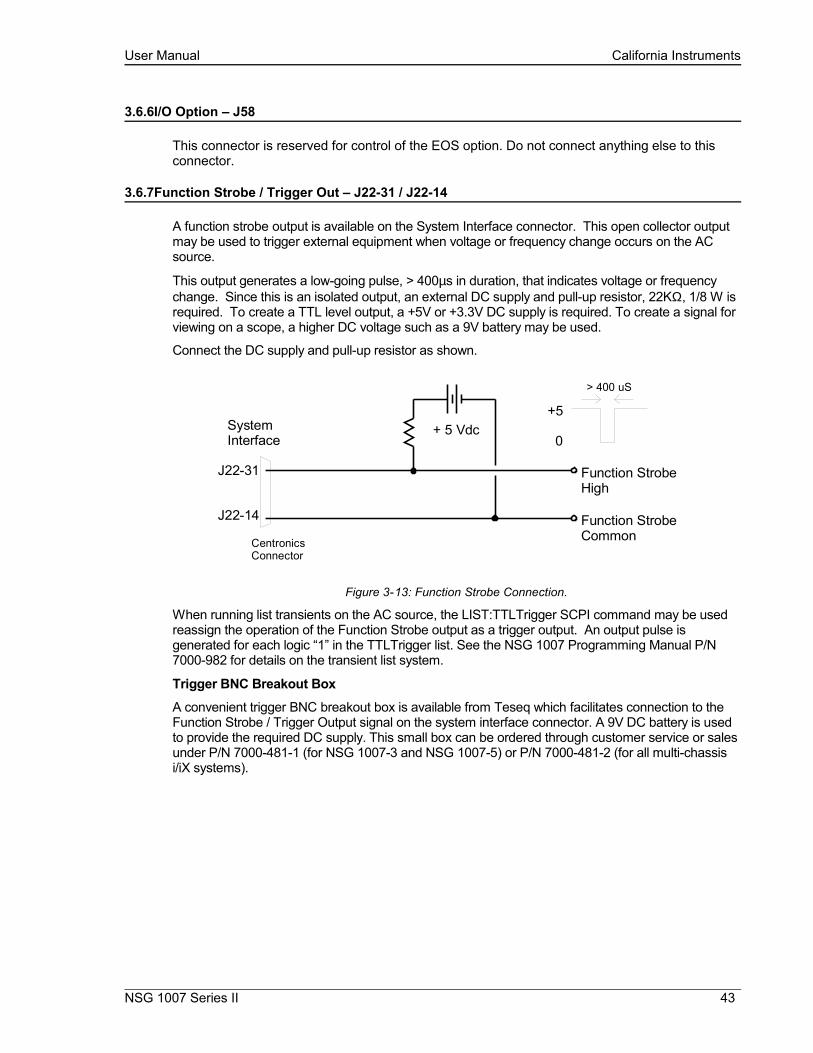
User Manual California Instruments
3.6.6I/O Option – J58
This connector is reserved for control of the EOS option. Do not connect anything else to this connector.
3.6.7Function Strobe / Trigger Out – J22-31 / J22-14
A function strobe output is available on the System Interface connector. This open collector output may be used to trigger external equipment when voltage or frequency change occurs on the AC source.
This output generates a low-going pulse, > 400µs in duration, that indicates voltage or frequency change. Since this is an isolated output, an external DC supply and pull-up resistor, 22KΩ, 1/8 W is required. To create a TTL level output, a +5V or +3.3V DC supply is required. To create a signal for viewing on a scope, a higher DC voltage such as a 9V battery may be used.
Connect the DC supply and pull-up resistor as shown.
+ 5 Vdc
J22-31
J22-14
Function StrobeHigh
Function StrobeCommonCentronics
Connector
SystemInterface
+5
0
> 400 uS
Figure 3-13: Function Strobe Connection.
When running list transients on the AC source, the LIST:TTLTrigger SCPI command may be used reassign the operation of the Function Strobe output as a trigger output. An output pulse is generated for each logic “1” in the TTLTrigger list. See the NSG 1007 Programming Manual P/N 7000-982 for details on the transient list system.
Trigger BNC Breakout Box
A convenient trigger BNC breakout box is available from Teseq which facilitates connection to the Function Strobe / Trigger Output signal on the system interface connector. A 9V DC battery is used to provide the required DC supply. This small box can be ordered through customer service or sales under P/N 7000-481-1 (for NSG 1007-3 and NSG 1007-5) or P/N 7000-481-2 (for all multi-chassis i/iX systems).
NSG 1007 Series II 43

User Manual California Instruments
Figure 3-14: Function Strobe / Trigger Output Accessory.
44 i Series II / NSG 1007 II / iM Series II

User Manual California Instruments
3.6.8Remote Inhibit – J22-36 / J22-27
The Remote Inhibit input J22 pin 36 can be used to open and close the output relay of the AC power source. This input overrides the state of the output relay programmed from the front panel or the bus. It may be used for safety interlock purposes.
The default level for remote inhibit is a logic low or contact closure between pin J22-36 and pin J22-27 (D COM). This will cause the output voltage to be programmed to 0.0 volts and the output relays to open. Alternative, the level can be reversed using the “output:ri:level high” command over the bus.
The mode of operation of the remote inhibit can be changed using the Output mode bus command. This command selects the mode of operation of the Remote Inhibit protection. The following modes can be selected:
LATChing A TTL low at the RI input latches the output in the protection shutdown state, which can only be cleared by OUTPut:PROTection:CLEar.
LIVE The output state follows the state of the RI input. A TTL low at the RI input turns the output off; a TTL high turns the output on.
OFF The instrument ignores the RI input.The RI output state is saved at power down. The factory default state is LIVE.
For details on programming the remote inhibit function, refer to the iX programming manual (P/N 7000-982).
NSG 1007 Series II 45
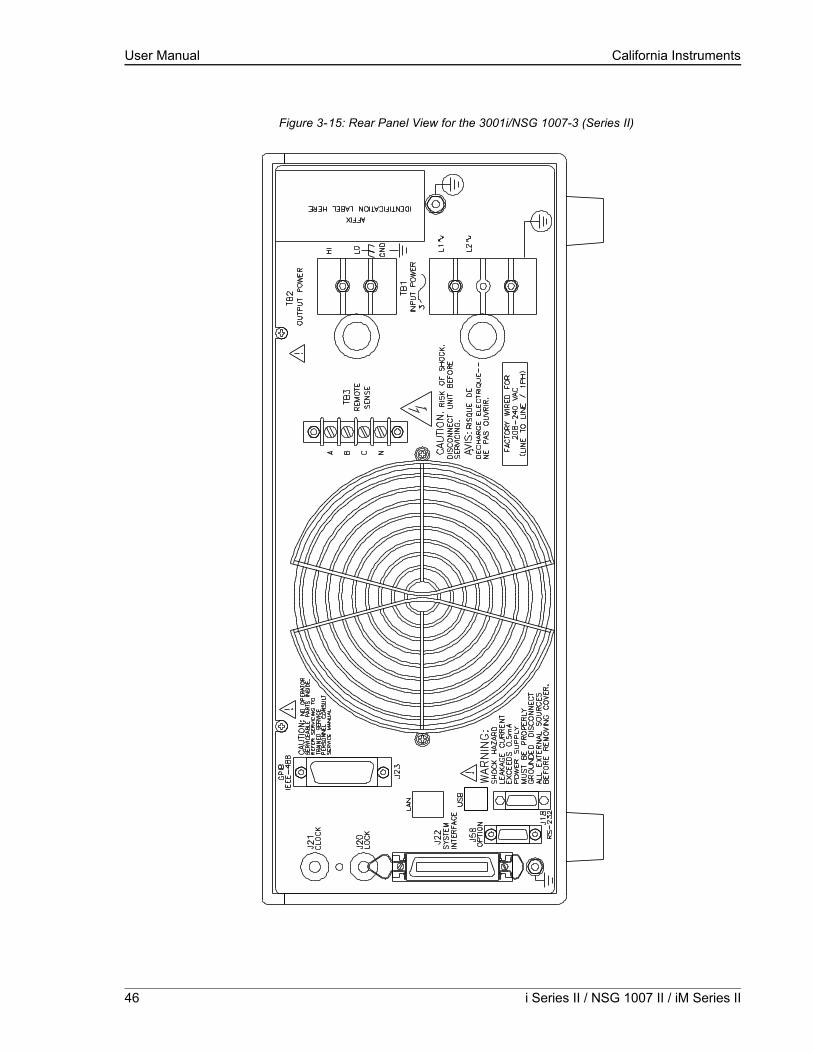
User Manual California Instruments
Figure 3-15: Rear Panel View for the 3001i/NSG 1007-3 (Series II)
46 i Series II / NSG 1007 II / iM Series II

User Manual California Instruments
NSG 1007 Series II 47
Figure 3-16: Rear Panel View for the 3001i/NSG 1007-3 (Series I, no USB)
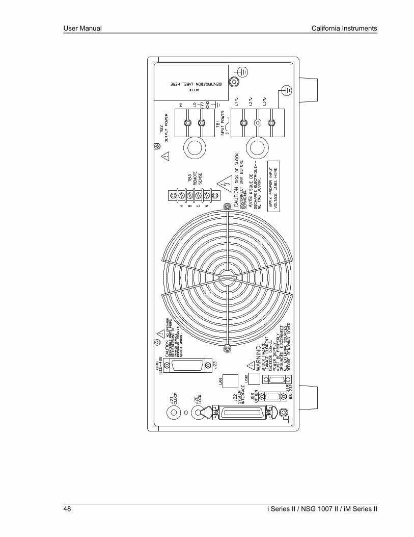
User Manual California Instruments
48 i Series II / NSG 1007 II / iM Series II

User Manual California Instruments
Figure 3-18: Rear Panel View for the 5001i/NSG 1007-5-208 (Series I, no USB)
NSG 1007 Series II 49
User Manual California Instruments
3.7Single-Phase and Three Phase Multiple Box System Configurations
Three Phase System:
The three phase system will be configured ready for use when ordered as such from the factory. One unit, with the controller, will be identified as Phase A on the serial number tag. The other two units will be identified on their serial number tags as either Phase B or Phase C. The power sources must be installed in the system according to the phase markings on the serial number tags. There will be one master unit that will have a full controller and the slaves will have blank front panels except for the circuit breaker and indicator lights.
The three units must be interconnected using the system Interface cable. The three LO outputs must also be connected together before applying power.
If the units were purchased as single phase units and have not been configured for a three phase system please consult the factory.
Single Phase System:
In a single phase system consisting of two or three units there will be one master unit that will have a full controller and the slaves will have blank front panels except for the circuit breaker and indicator lights.
The units must all be connected with the system interface cable, but not the clock and lock cables. The HI outputs on all the terminal blocks should be connected together. The LO outputs should all be connected together and a heavy duty cable run to the load from the HI and LO outputs. See Table 3-1 for cable sizing.
The appropriate jumpers have been installed at the factory before shipment. If it becomes necessary to change the system to three phase output, please consult the factory.
3.8Output Voltage Ranges
The NSG 1007 II power sources have two AC voltage ranges (150Vrms and 300Vrms) and two DC voltage ranged (200Vdc and 400Vdc). The maximum available load current is a function of both the mode of operation (AC, DC or AC+DC mode) and the selected voltage range (high or low).
3.9Functional Test
CAUTION: Work carefully when performing these tests, hazardous voltages are present on the input and output during this test.
Refer to Figure 3-20 for the test set up.
1. Connect an oscilloscope, voltmeter and/or distortion analyzer to the AC source output at the output terminal block (TB2).
2. With the AC mains verified as being off, apply the correct three phase AC power input voltage connections to the AC source input terminals barrier (TB1). Apply the AC mains power and turn on the main circuit breaker on the AC source front panel.
50 i Series II / NSG 1007 II / iM Series II
User Manual California Instruments
3. Verify the front panel LCD display lights up with the initial start up screen showing the unit ID and serial number. A self check routine screen with follow and finally the system will display the main “Menu 1” screen with the cursor highlighting the “Program” selection.
4. Press “ENTER” and the unit will display the Program selection screen. Set the following output parameters: output voltage = 150 volts, frequency = 60 Hz, voltage range = 150 volts, and current limit = 20.0 amps (NSG 1007-3) or 33.3 amps (NSG 1007-5-208). Press “ENTER”.
5. Enable the output by pressing the output “on/off” button below the front panel display screen. The green LED next to the button will light green when the output is on. The output should be a clean 150 volt AC sinewave having less than 1% distortion.
6. Apply full load to the output of the source and verify the output remains within 2% of the initial 150 volt value. The output should still be clean and the distortion should still be less than 1% at 60 Hz.
7. Using the PROGRAM screen set the output current limit value to 17 amps. The system should go into current limit. Return the current value to 20.0 amps (NSG 1007-3) or 33.3 amps (NSG 1007-5-208) and press the output on/off button to turn the output off. Disconnect the load.
8. Repeat steps 4 through 7 but set the output for the following: output voltage = 300 volts, output range = 300 volts, current limit = 10.0 amps (NSG 1007-3) or 16.7 amps (NSG 1007-5-208). For step 7, the current limit value can be set to 8 amps.
In the unlikely event the power source does not pass the functional test, refer to the calibration procedure in Section 6 or call California Instrument’s customer satisfaction department for further assistance.
NSG 1007 Series II 51

User Manual California Instruments
Figure 3-19: Connection For Single Power Source (NSG 1007-5-208/i, NSG 1007-3/i)
52 i Series II / NSG 1007 II / iM Series II
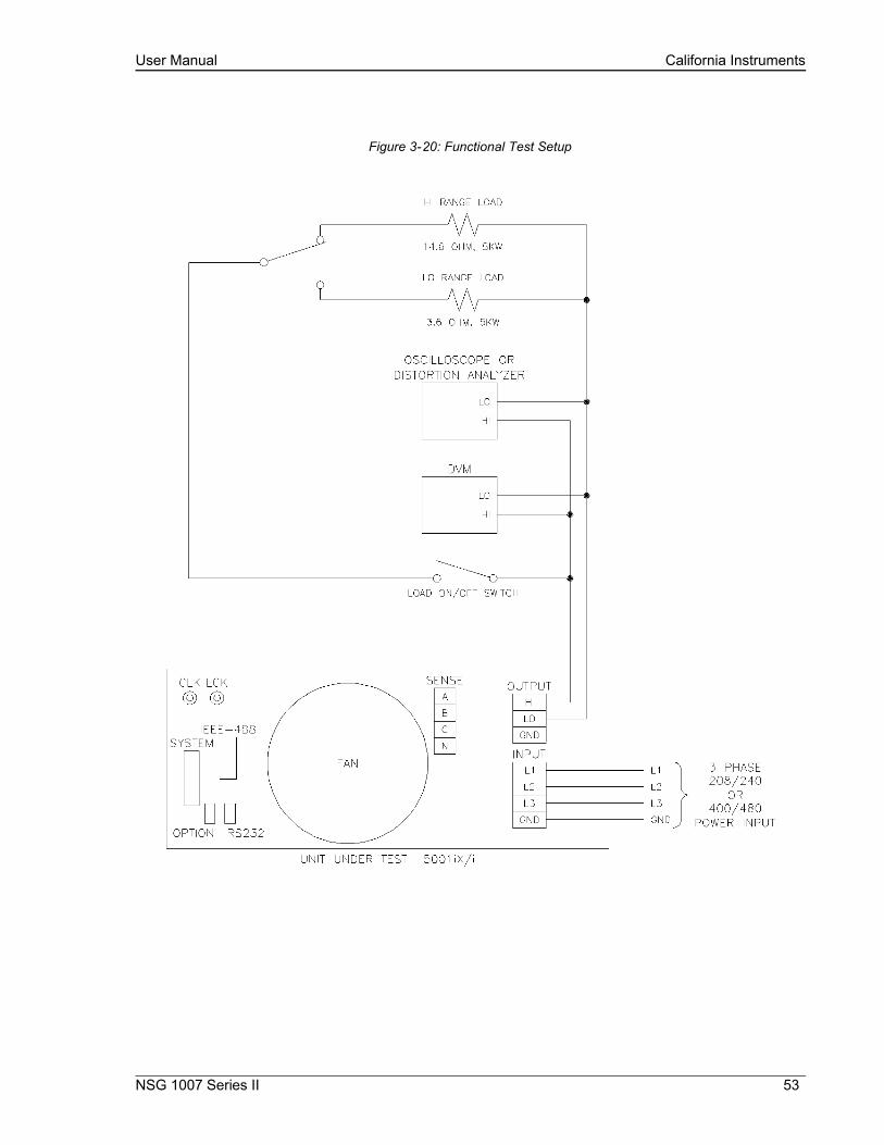
User Manual California Instruments
Figure 3-20: Functional Test Setup
NSG 1007 Series II 53
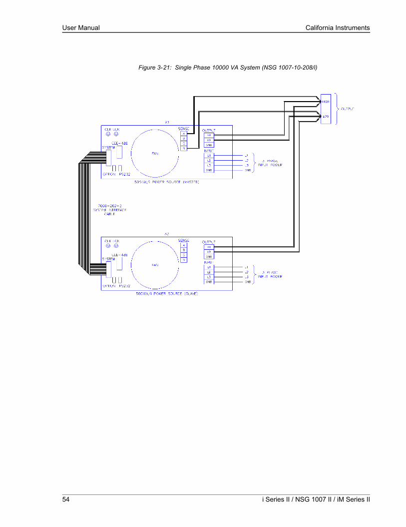
User Manual California Instruments
Figure 3-21: Single Phase 10000 VA System (NSG 1007-10-208/i)
54 i Series II / NSG 1007 II / iM Series II

User Manual California Instruments
Figure 3-22: Two Phase 10000 VA System (10002i/iX – One Controller)
NSG 1007 Series II 55

User Manual California Instruments
Figure 3-23: Three Phase 15000 VA System (NSG 1007-15-208/i-LK Three Controllers)
56 i Series II / NSG 1007 II / iM Series II

User Manual California Instruments
Figure 3-24: Single Phase 15000 VA System (NSG 1007-15S-208/i)
NSG 1007 Series II 57

User Manual California Instruments
Figure 3-25: Three-Phase 15000 VA system (NSG 1007-15-208/i - One Controller)
58 i Series II / NSG 1007 II / iM Series II
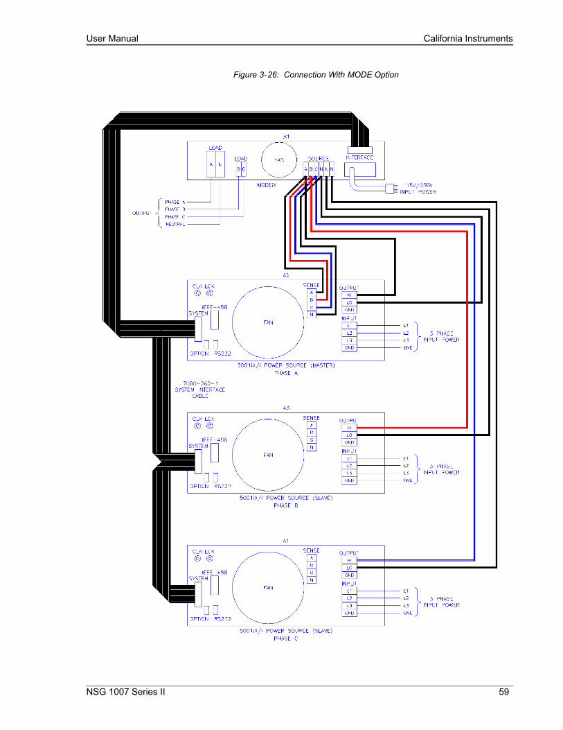
User Manual California Instruments
Figure 3-26: Connection With MODE Option
NSG 1007 Series II 59

User Manual California Instruments
Figure 3-27: Two Phase 10000 VA System (10002i-LK Two Controllers)
60 i Series II / NSG 1007 II / iM Series II

User Manual California Instruments
Figure 3-28: Three-Phase 9000 VA System (NSG 1007-9/i – One Controller)
NSG 1007 Series II 61

User Manual California Instruments
4.Front Panel Operation
4.1Tour of the Front Panel
The i, iM and NSG 1007 front panels are identical although some of the keys found on the front panel are only used by i Series or NSG 1007 models. If your unit is an i Series or iM Series, these keys will act as don’t cares. This chapter provides information on operating the i, iX and iM Series AC sources from the front panel keyboard.
Before operating the AC source using the front panel, it helps to understand the operation of the front panel controls. Specifically, the operation of the knob, keyboard and the menu layout are covered in the next few paragraphs.
4.1.1Front Panel Controls and Indicators
The front panel can be divided in a small number of functional areas:
• Mains circuit breaker
• Status Indicator lights
• Shuttle knob
• LCD display
• FUNCTION keypad
• DATA ENTRY keypad
4.1.2Mains Circuit Breaker
The circuit breaker located on the bottom left side of the front panel disconnects the AC source from the three phase Line input. It will automatically trip when the input current rating of the unit is exceeded due to some component failure. The contrasting black color and large size throw bar make it easy to locate in case of an emergency.
4.1.3Status Indicator Lights
Four LED status indicators are located directly above the mains circuit breaker. These LED’s correspond to the following conditions:
REMOTE The REMOTE LED indicates that the unit is in remote control mode. If the IEEE-488 interface is used, this indicator will be lit whenever the REM line (REMOTE ENABLE) line is asserted by the IEEE controller. If the RS232C, USB or LAN interface is used, the REMOTE state can be enabled by the controller using the SYST:REM command. Any time the REMOTE LED is lit, the front panel of the i Series unit is disabled. There is no LOCAL button that allows the user to regain control of the front panel. This prevents accidental change of settings in ATE applications.
OVERLOAD The OVERLOAD LED indicates an output overload condition. This condition can be controlled by setting the current limit value in the PROGRAM menu. Removing the load using the OUTPUT ON/OFF button will recover from an overload condition.
62 i Series II / NSG 1007 II / iM Series II

User Manual California Instruments
OVER TEMPERATURE The OVER TEMPERATURE LED indicates an overheating problem inside the unit. This is an abnormal condition, which will cause the unit to shut off. Check the air openings to make sure they are not blocked.
HI RANGE The HI RANGE LED is on when the high voltage output range has been selected.
4.1.4The Shuttle Knob
CounterClockwise
Clockwise
INCRDECR
Figure 4-29: Shuttle Knob
The shuttle knob is located to the right of the LCD screen and is used to change setup parameters. Note that it cannot be used to move the cursor position between menu fields. Use the UP and DOWN arrow keys in the FUNCTION keypad for this.
The shuttle knob can operate in one of two distinct modes of operation:
MODE DESCRIPTION
IMMEDIATE mode Any time the ENTER key is pressed, the NSG 1007 returns to its normal mode of operation. In this mode, changes made with the shuttle knob or the data entry keypad will take immediate effect. The IMMEDIATE mode is useful for slewing output values such as voltage and frequency and observing the effect on the load.
SET mode When the SET key located in the FUNCTION keypad is pressed, changes made with the shuttle to any output parameter will not take effect until the ENTER key is pressed. In this mode, any changes made to a setup menu will be blinking to indicate the pending change condition. This mode allows changes to be made to all output parameters and executing them all at once by pressing the ENTER key.
NSG 1007 Series II 63
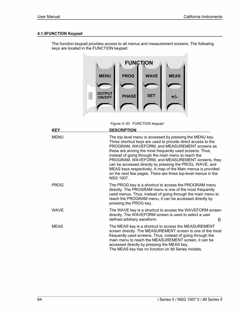
User Manual California Instruments
4.1.5FUNCTION Keypad
The function keypad provides access to all menus and measurement screens. The following keys are located in the FUNCTION keypad:
MENU PROG WAVE MEAS
OUTPUTON/OFF PHASE SET +/-
FUNCTION
Figure 4-30: FUNCTION keypad
KEY DESCRIPTION
MENU The top level menu is accessed by pressing the MENU key. Three shortcut keys are used to provide direct access to the PROGRAM, WAVEFORM, and MEASUREMENT screens as these are among the most frequently used screens. Thus, instead of going through the main menu to reach the PROGRAM, WAVEFORM, and MEASUREMENT screens, they can be accessed directly by pressing the PROG, WAVE, and MEAS keys respectively. A map of the Main menus is provided on the next few pages. There are three top-level menus in the NSG 1007.
PROG The PROG key is a shortcut to access the PROGRAM menu directly. The PROGRAM menu is one of the most frequently used menus. Thus, instead of going through the main menu to reach the PROGRAM menu, it can be accessed directly by pressing the PROG key.
WAVE The WAVE key is a shortcut to access the WAVEFORM screen directly. The WAVEFORM screen is used to select a user defined arbitrary waveform. ()
MEAS The MEAS key is a shortcut to access the MEASUREMENT screen directly. The MEASUREMENT screen is one of the most frequently used screens. Thus, instead of going through the main menu to reach the MEASUREMENT screen, it can be accessed directly by pressing the MEAS key.The MEAS key has no function on iM Series models.
64 i Series II / NSG 1007 II / iM Series II

User Manual California Instruments
OUTPUT ON/OFF The OUTPUT ON/OFF key toggles the output relay on or off. The state of the output relay is reflected by the green LED located directly to the left of the OUTPUT ON/OFF key. If the green LED is lit, the output relay is enabled (closed) and the programmed output voltage is present at the output terminals. If the green LED is off, the output relay is open and both the HIGH and LO terminal of the output terminal block are disconnected from the power source. In this mode, the output is floating. The ON/OFF button provides a convenient way to disconnect the load without having to remove any wires.
PHASE The PHASE key is used to select the phase on a three-phase NSG 1007-9 or NSG 1007-15-208 unit. Pressing the PHASE key will toggle phase A, B, C or ABC. Some screens may not support the ABC or show all phase information in which case this mode is skipped.
(NSG 1007 with three phase controller only)
SET The SET key is used to select the mode of operation of the shuttle. Refer to section 4.1.1 for details on its operation and the use of the SET key.
+/- The +/- key can be used to toggle the sign for those parameters for which it is relevant. This is typically the output voltage when in DC mode of operation. For fields that have only two possible values such as the voltage range field, the +/- key can be used to toggle between these two values.
4.1.6DECIMAL KEYPAD
The decimal keypad may be used to enter any numeric parameter required in any of the menu fields. Several fields accept input from either the keypad or the knob. Data entered from the keypad is normally accepted once the ENTER key is pressed unless the front panel mode is in the SET mode. The following keys are available on the decimal keypad:
7
ENTRY
ENTER
8 9
4 5 6
1 2 3
.0
Figure 4-31: Entering value from decimal keypad
NSG 1007 Series II 65

User Manual California Instruments
CURSOR UP The UP key moves the cursor position upwards one position to the previous available cursor position. If the present cursor position is at the top of the right hand column, the cursor is moved to the bottom position of the left hand column. If the present cursor is at the top of the left hand column, the cursor is moved to the bottom of the right hand column. Figure 4-32 depicts the cursor movement through a two-column menu.
Figure 4-32: Cursor UP key movement
CURSOR DOWN The DOWN key moves the cursor position downwards one position to the next available cursor position. If the present cursor position is at the bottom of the left hand column, the cursor is moved to the top position of the right hand column. If the present cursor is at the bottom of the right hand column, the cursor is moved to the top of the left hand column. Figure 4-33 depicts the cursor movement through a two column menu.
Figure 4-33: Cursor DOWN key movement
The decimal keypad can be used at any time in lieu of the shuttle knob to change output parameters. Direct data entry is often faster to effect large changes in values than using the shuttle knob. Note that pressing the ENTER key while in SET mode of operation will cause the AC source to revert back to IMMEDIATE mode. Thus, to change all parameters in SET mode, enter a value for each field and then proceed to the next field without pressing the ENTER key.
0 through 9 The numeric keys provide all decimal number for entry of parameters.
DECIMAL POINT The decimal point key is used to enter fractional parts of values for fields that have a resolution less than 1. The amount of resolution for each menu field is normally visible on the LCD. If more digits are entered after the decimal point than can be accepted by a field, the value is automatically rounded to the available resolution when the ENTER key is pressed.
BACKSPACE The BACKSPACE (←) key can be used to erase one digit at a time if you make a data entry error.
66 i Series II / NSG 1007 II / iM Series II

User Manual California Instruments
4.1.7LCD Display
The LCD display of the i and NSG 1007 AC power source provides information on instrument settings and also guides the user through the various menus. To ease reading of the displayed information, most screens are widely spaced. A sample of the main menu 1 screen that appears when the i Series AC source is powered up is shown in Figure 4-34. Due to the amount of space available on each screen, some menus have been split into parts. The MORE selection located at the bottom right hand side provides access to menu choices at the same level that did not fit on a single screen. Thus, to access MENU 2, the cursor should be placed on the ‘MORE’ selection followed by pressing the ‘ENTER’ key. Alternatively, the MENU key may be pressed to move to the MENU 2 screen.
The present cursor position is always shown with a inverse bar. The cursor is located on the ‘MORE’ selection in Figure 4-34. Pressing ENTER would cause MENU 2 to be displayed.
The cursor position can be moved by using the UP and DOWN keys located in the DECIMAL keypad.
Figure 4-34: Main Menu 1 screen
NSG 1007 Series II 67

User Manual California Instruments
4.2Menu Structure
The next few pages show a map of the available menus in the NSG 1007. There are three main level (level 1) menus from which all other menus can be reached. Frequently used (level 2) menus have a short cut key that provides direct access. Examples of such menus are Program, Measurements, and Waveform. In any case, there are never more than three levels of menus although some menus may be spread across more than one screen.
4.2.1MAIN Menus
Figure 4-35: Menu 1 through 3
The top-level menu is split in three parts, MENU 1 through MENU 3 to allow spacing between menu entries. MENU 2 and 3 can be reached from MENU 1 by selecting the MORE entry or by pressing the MENU key repeatedly, which will toggle from MENU 1 to 2 to 3 and back to 1. The division of menu choices between the two screens is graphically illustrated in sections 4.2.2 and 4.2.3 by the boxes in level 1. Each box represents one screen. Subsequent screens can be reached using the MORE entry.
68 i Series II / NSG 1007 II / iM Series II

User Manual California Instruments
The following top-level menu choices can be accessed from the MENU key:
Entry Description MENU 1
PROGRAM The PROGRAM menu allows output parameters the be changed.
MEASUREMENTS The MEASUREMENTS screens are not menus in that no user entries are required.
TRANSIENTS The TRANSIENTS menu allows output transients to be programmed. (i and )
WAVEFORMS The WAVEFORMS menu allows different waveforms to be selected from the waveform library. ()
MORE The MORE selection causes the second part of the MENU screen to be displayed. (MENU 2)
MENU 2
ADVANCED MEAS. The ADVANCED MEAS. screens are for display only. No user entries are required. ()
APPLICATIONS The APPLICATIONS menu provides access to the optional firmware application programs that may be installed in the NSG 1007 AC source.
SETUP REGISTERS The SETUP REGISTERS menu allows complete instrument settings and transient list programs to be saved to nonvolatile memory.
MORE The MORE selection causes the third part of the MENU screen to be displayed. (MENU 3)
MENU 3
UTILITY The UTILITY menu provides access to less commonly used setup screens such as those for the GPIB and RS232C (also applies to USB and LAN) interface settings, initial startup values, etc.
OUTPUT IMPEDANCE The OUTPUT IMPEDANCE menu provides control of the AC source output impedance. (Available only on NSG 1007-3, NSG 1007-5-208, NSG 1007-9 and NSG 1007-15-208 models. On systems with –MODE-iX option, only available when in 3 phase mode.)
MEASUREMENT CAL The MEASUREMENT CAL menu allows for calibration of the AC source measurement system.
OUTPUT CAL The OUTPUT CAL menu allows for calibration of the AC source output.
Following the Menu overview pages is a detailed description of each menu and sub menu.
NSG 1007 Series II 69

User Manual California Instruments
4.2.2Overview of Menu 1
level 1 level 2 level 3
MENU 1 PROGRAM PROGRAM1VOLTAGEFREQVOLT RANGECURR LIMITMORE
PROGRAM2PHASECLOCK MODEVOLT MODEDC OFFSETSTART ø
MEASUREMENTS MEASUREMENTS1VOLTAGECURRENTFREQPOWERMORE
MEASUREMENTS 2VA POWERPEAK CURRPOWER FACTCREST FACTPEAK CURR RESET
MEASUREMENTS 3VOLT THDCURR THDINST PK CURRPHASE
HARMONICS/TRACEANALYSIS
FUNCTIONVIEWDATA MODESCALETRIG MODETRIG SOURCETRIG PHASETRIG DELAYSTART
TRANSIENTS VOLT SURGE/SAG START øVOLT SWEEP/STEP START ø GO TO VOLTFREQ SWEEP/STEP DURATION END VOLT DUR SCALEVOLT/FREQ SWEEP/STEP DURATION END FREQ DUR SCALE DURATIONSTART/VIEW SEQUENCE START END VOLT END DELAY DURATION END VOLTPREVIOUS SCREEN PAUSE END FREQ FUNCTION END DELAY END DELAY
REPEAT #0 END DELAY REPEAT FUNCTION FUNCTIONCLEAR SEQ FUNCTION EVENT# REPEAT REPEAT
REPEAT PREVIOUS SCREEN EVENT# EVENT##1 SEQUENCE# PREVIOUS SCREEN PREV. SCREEN#2 PREVIOUS SCREEN..#98#99PREVIOUS SCREEN
WAVEFORMS CLIP LEVELGROUPMODESINESQUARECLIPPEDUSER WAVE....
MORE USER WAVE
70 i Series II / NSG 1007 II / iM Series II
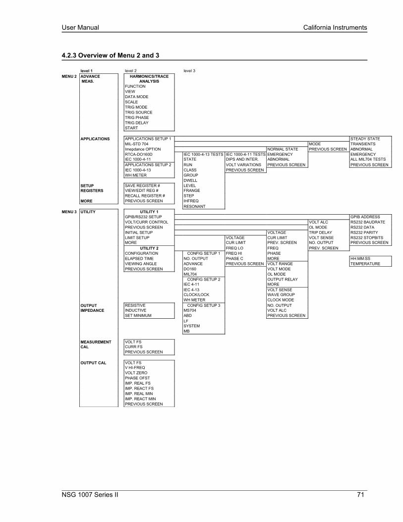
User Manual California Instruments
4.2.3 Overview of Menu 2 and 3
level 1 level 2 level 3MENU 2 ADVANCE HARMONICS/TRACE
MEAS. ANALYSISFUNCTIONVIEWDATA MODESCALETRIG MODETRIG SOURCETRIG PHASETRIG DELAYSTART
APPLICATIONS APPLICATIONS SETUP 1 STEADY STATEMIL-STD 704 MODE TRANSIENTSImepdance OPTION NORMAL STATE PREVIOUS SCREEN ABNORMALRTCA-DO160D IEC 1000-4-13 TESTS IEC 1000-4-11 TESTS EMERGENCY EMERGENCYIEC 1000-4-11 STATE DIPS AND INTER. ABNORMAL ALL MIL704 TESTSAPPLICATIONS SETUP 2 RUN VOLT VARIATIONS PREVIOUS SCREEN PREVIOUS SCREENIEC 1000-4-13 CLASS PREVIOUS SCREENWH METER GROUP
DWELLSETUP SAVE REGISTER # LEVELREGISTERS VIEW/EDIT REG # FRANGE
RECALL REGISTER # STEPMORE PREVIOUS SCREEN IHFREQ
RESONANTMENU 3 UTILITY UTILITY 1
GPIB/RS232 SETUP GPIB ADDRESSVOLT/CURR CONTROL VOLT ALC RS232 BAUDRATEPREVIOUS SCREEN OL MODE RS232 DATAINITIAL SETUP VOLTAGE TRIP DELAY RS232 PARITYLIMIT SETUP VOLTAGE CUR LIMIT VOLT SENSE RS232 STOPBITSMORE CUR LIMIT PREV. SCREEN NO. OUTPUT PREVIOUS SCREEN
UTILITY 2 FREQ LO FREQ PREV. SCREENCONFIGURATION CONFIG SETUP 1 FREQ HI PHASEELAPSED TIME NO. OUTPUT PHASE C MORE HH:MM:SSVIEWING ANGLE ADVANCE PREVIOUS SCREEN VOLT RANGE TEMPERATUREPREVIOUS SCREEN DO160 VOLT MODE
MIL704 OL MODECONFIG SETUP 2 OUTPUT RELAY
IEC 4-11 MOREIEC 4-13 VOLT SENSECLOCK/LOCK WAVE GROUPWH METER CLOCK MODE
OUTPUT RESISTIVE CONFIG SETUP 3 NO. OUTPUTIMPEDANCE INDUCTIVE MS704 VOLT ALC
SET MINIMUM ABD PREVIOUS SCREENLFSYSTEMMB
MEASUREMENT VOLT FSCAL CURR FS
PREVIOUS SCREEN
OUTPUT CAL VOLT FSV HI-FREQVOLT ZEROPHASE OFSTIMP. REAL FSIMP. REACT FSIMP. REAL MINIMP. REACT MINPREVIOUS SCREEN
NSG 1007 Series II 71

User Manual California Instruments
4.2.4PROGRAM Menu
Figure 4-36: PROGRAM Menu
The PROGRAM menu is shown in Figure 4-36. It can be reached in one of two ways:
1. by selecting the PROGRAM entry in the MENU screen and pressing the ENTER key
2. by pressing the PROG key in the FUNCTION keypad
The PROGRAM menu is used to change output parameters. The most commonly used parameters are all located in PROGRAM 1. The PREVIOUS SCREEN entry, when selected, will return the user to the most recently selected menu. This is normally the MENU screen unless the PROGRAM menu was selected using the PROG key on the FUNCTION keypad. Less frequently used parameters are located in PROGRAM 2, which can be reached from the PROGRAM 1 screen using the MORE selection, or by pressing the PROGRAM key twice.
The following choices are available in the PROGRAM menus:
Entry Description
PROGRAM 1
VOLTAGE Programs the output voltage in rms. when in AC mode or absolute voltage when in DC mode. In DC mode, negative values can be entered.
FREQ Programs the output frequency when in AC mode. If the unit is in DC mode, the value for FREQ will be set to DC and cannot be changed until AC mode is selected. When in AC mode, the frequency can be changed from 16 Hz to 500 Hz. Values entered that fall outside this range will generate a -200 RANGE ERROR and will not be accepted.
VOLT RANGE Selects 150V or 300V range in AC mode and 200V or 400V range in DC mode. The actual range values may be different depending on the configuration. The value of this field can only be changed with the shuttle or the +/- key.
Note that the voltage range is coupled with the output relay state. If the output relay is closed (OUTPUT ON), the voltage range cannot be changed.
CURR LIMIT Sets the current limit value for the current detection system. When the load current value exceeds the set current limit, a fault condition is generated. The actual response of the AC Source to a current limit fault is determined by the protection mode selected in the CONFIGURATION menu. (CC = Constant Current, CV = Constant Voltage).
72 i Series II / NSG 1007 II / iM Series II

User Manual California Instruments
PROGRAM 2
PHASE Selects the phase angle between the external clock and the output of the AC source. If the clock source is internal, this parameter has no effect.
CLOCK MODE Selects internal or external clock source. The NSG 1007 uses an open air crystal timebase with an accuracy of 100 ppm. To improve output frequency stability and accuracy, an external clock generator may be used.
VOLT MODE The NSG 1007 offers three output modes, AC, DC and AC+DC. The VOLT MODE field can be used to toggle between these three output modes. Both the Knob and the +/- key may be used to toggle through these three selections. In DC mode, no frequency selection is possible and all maximum current and power ratings are divided by two. The i Series offers AC or DC modes.
DC OFFSET When the AC+DC mode is selected, the VOLTAGE field in the PROGRAM 1 screen is used to set the AC portion of the output voltage. The DC OFFSET field in the PROGRAM 2 screen can be used to set the DC offset level. Either the knob or the decimal keypad may be used to set the DC offset level.
STARTø Selects the start phase angle for output changes made to either voltage or frequency. This allows changing the output at a specific phase angle. The output on key also uses this phase angle setting to program the output voltage up to the set level after the output relay is closed. The default value for this field is RANDOM.
NSG 1007 Series II 73

User Manual California Instruments
4.2.5MEASUREMENTS Screens
The NSG 1007 uses a DSP based data acquisition system to provide extensive information regarding the output of the Source. This data acquisition system digitizes the voltage and current waveforms and calculates several parameters from this digitized data. The result of these calcalutions is displayed in a series of measurement data screens. The actual digitized waveforms can also be displayed by selecting the Harmonics/Trace Analysis screen. A total of four measurement screens are used to display all this information (). The iM Series offers no measurement functions.
Figure 4-37: MEASUREMENTS Screen, single phase and three phase modes
The first three Measurement screens available on the NSG 1007 are not menus in that no changes can be made anywhere. Instead, these three screens provide load parameter readouts. The fourth measurement screen provides access to the advanced measurements and does offer several user accessible fields (). The measurement screens can be reached by successively pressing the MEAS key, which will toggle to all four available screens.
In three-phase configuration NSG 1007, measurements are available for each phase individually. To select the desired phase, use the PHASE key to toggle through phase A, B, C, or ABC. The ABC mode displays the data for all three phases simultaneously.
The following parameters are available in the first three measurement screens:
Entry Description
MEASUREMENT 1 [i and ]
VOLTAGE When in AC or AC+DC mode, this value is the true rms output voltage measured at the voltage sense lines. In DC only mode, the voltage is the DC voltage including polarity.
CURRENT When in AC or AC+DC mode, this value is the true rms output current drawn by the load. In DC only mode, the current is the DC current including polarity
FREQ When in AC or AC+DC mode, the output frequency is measured at the sense lines. When in DC only mode, this value always reads “DC”.
POWER In both AC and DC mode, this value is the real rms. power consumed by the load.
MEASUREMENT 2 [i and ]
VA POWER In AC or AC+DC mode, this value is the apparent rms. power consumed by the load. In DC mode, this value is always the same as the POWER readout.
74 i Series II / NSG 1007 II / iM Series II
User Manual California Instruments
PEAK CURR This readout reflects the peak current value detected at the output. To measure inrush current for a unit under test, open the output relay and reset the peak current value using the PEAK CURR RESET entry. Then program the output voltage and frequency and turn on the output relay. The peak current measurement will continuously track the maximum current value detected until reset.
POWER FACTOR This readout shows the power factor of the load.
CREST FACTOR This readout displays the ratio between peak current and rms current.
MEASUREMENT 3 []
VOLT THD This readout displays the total voltage distortion for the selected phase. The distortion calculation is based on the H2 through H50 with the fundamental voltage (H1) in the denominator. Note that other common definitions of THD use the RMS value of the voltage as the denominator. This may result in different readings between instruments depending on the implementation chosen. The mode used by the power source is selectable over the bus.
CURR THD This readout displays the total current distortion for the selected phase. The distortion calculation is based on the H2 through H50 with the fundamental current (H1) in the denominator. Note that other common definitions of THD use the RMS value of the current as the denominator. This may result in different readings between instruments depending on the implementation chosen. The mode used by the power source is selectable over the bus.
INST PK CURR This readout reflects the instantaneous peak current value detected at the output. This value is updated continuously and does not require a reset operation like the PEAK CURR readout. The instantaneous peak current does not use a track and hold mechanism like the PEAK CURR measurement in the MEASUREMENT 2 screen. Instead, it tracks the peak current on a cycle by cycle basis. The INST PK CURR typically tracks the rms current and the crest factor.
Update Program Functions from Measurement Screen
The Shuttle can be used to update program parameters such as voltage, frequency or current from the measurement screen. This can be achieved with the following sequence:
1. Select the program 1 screen using the PROG key.
2. Use the up and down key to select the desired function to update. (Selects parameter that will be changed by the shuttle once in the MEAS1 screen)
3. Select the measurement 1 screen by pressing the MEAS key.
The pointer symbol ( ) points to the programmed parameter (V,F or CL) that will be affected by turning the shuttle.
NSG 1007 Series II 75

User Manual California Instruments
HARMONICS/TRACE ANALYSIS Screen []
The fourth measurement screen is dedicated to the advanced measurements available on the . This screen is not available on the i Series. The Harmonics/Trace Analysis measurement screen is a true menu screen offering several user accessible fields. These fields are used to select the desired acquisition trigger and display mode. The actual data is displayed whenever the ENTER key is pressed while the cursor is on the VIEW or START field. The following fields are available on this menu:
Figure 4-38: HARMONICS/TRACE ANALYSIS screen
Entry Description FUNCTION Selects Voltage, Current or Both parameters for display.
VIEW Available display modes are TABLE, BAR and TRACE.
TABLE mode: displays the first 50 harmonics in a tabular text format.
BAR mode: displays the first 50 harmonics in a graphical bar chart display.
TRACE mode: displays the selected Function in a time domain (waveform) graphical display.
76 i Series II / NSG 1007 II / iM Series II

User Manual California Instruments
DATA MODE Selects absolute or relative harmonics display for TABLE and BAR view modes. In relative mode, all harmonics are shown in a percentage of the fundamental which is normalized at 100 %. In absolute mode, the harmonic amplitudes are shown in absolute volts or amperes.
This mode does not apply to the TRACE view display mode and is ignored when this mode is selected.
SCALE Sets the horizontal time axis for the TRACE view display mode. The fields range is 4 ms to 42 ms in single-phase mode or 12 ms to 128 ms in three phase mode.
This parameter is ignored when the TABLE or BAR view display mode is selected.
TRIG MODE This field sets the trigger mode for the acquisition. Available options are SINGLE (single shot acquisition) or CONT (continuous acquisition). In SINGLE shot mode, the acquisition is triggered once each time the START field is selected and the ENTER key is pressed. The selected trigger source is used to determine the trigger point. Once the acquisition has been triggered, the data are displayed and do not change until the next acquisition is triggered. This mode is most appropriate for single shot events such as start up currents.
In the CONT mode, acquisitions occur repeatedly and the data is updated on screen after each trigger occurs. This provides a continuous update of the data and is most appropriate for repetitive signals.
TRIG SOURCE The trigger source selects the event that will trigger a measurement acquisition. Available options for this field are IMM (immediate), PHASE A or SET VOLT. The IMM trigger source causes the acquisition to trigger immediately when the ENTER key is pressed on the START field. Essentially, this is an asynchronous trigger event. The acquisition will always be triggered in this mode and data is available immediately.
The PHASE A source will cause the acquisition to trigger on the occurrence of a set phase angle for the voltage on phase A. The trigger source is always phase A when in this mode, regardless of the phase selection shown in the top right corner of the display. When the acquisition is started, the acquisition system waits for the specified phase angle to occur before triggering the acquisition. This mode allows exact positioning of the acquisition data window with respect to the voltage waveform.
The SET VOLT mode causes the acquisition to trigger at the specified voltage. This mode also programs the selected phase or all three phases when the measurement is started from the START field. As such, this trigger source selection also programs the output voltage to the selected rms level.
TRIG PHASE / SET VOLT This field changes purpose, depending on the trigger source selected immediately above it. If the trigger source equals IMM or PHASE A, this field can be used to program the trigger phase angle (TRIG PHASE). In IMM mode, the value of this field is ignored.
NSG 1007 Series II 77
User Manual California Instruments
If the trigger source is set to SET VOLT, this field can be used to specify the rms voltage to program the output to and trigger the measurement on. The voltage value set here should not exceed the maximum voltage range selected or the rms capability for the waveshape selected on the phase or phases programmed.
TRIG DELAY The trigger delay field allows the trigger point to be positioned anywhere in the acquisition window. A negative value will provide pre-trigger information on data leading up to the trigger event. The pre-trigger delay cannot exceed the length of the acquisition buffer See paragraph 4.6.3.3 for details. A positive trigger delay positions the data window after the trigger event. Positive trigger delays can exceed the length of the acquisition buffer in which case the trigger event itself will not be in the buffer any more. The maximum value of the trigger delay is 1000 ms. The default trigger delay value is 0.0 ms which puts the trigger event at the beginning of the acquisition window.
START The START field is used to start a new acquisition run. To start an acquisition, place the cursor on the START field and press the ENTER key. Once the ENTER key is pressed, the display toggles to the data display mode selected in the VIEW field as soon as the selected trigger event occurs. To return to the HARMONICS/TRACE ANALYSIS menu, press the ENTER key while in the data display mode.
To change display modes without triggering a new acquisition, make the desired changes in the menu and move the cursor to the VIEW field. Once on the VIEW field, press the ENTER key. This will not trigger a new acquisition, which means the original data is retained.
78 i Series II / NSG 1007 II / iM Series II
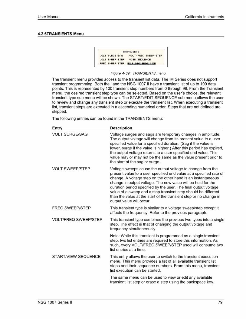
User Manual California Instruments
4.2.6TRANSIENTS Menu
Figure 4-39: TRANSIENTS menu
The transient menu provides access to the transient list data. The iM Series does not support transient programming. Both the i and the NSG 1007 II have a transient list of up to 100 data points. This is represented by 100 transient step numbers from 0 through 99. From the Transient menu, the desired transient step type can be selected. Based on the user’s choice, the relevant transient type sub menu will be shown. The START/EDIT SEQUENCE sub menu allows the user to review and change any transient step or execute the transient list. When executing a transient list, transient steps are executed in a ascending numerical order. Steps that are not defined are skipped.
The following entries can be found in the TRANSIENTS menu:
Entry Description VOLT SURGE/SAG Voltage surges and sags are temporary changes in amplitude.
The output voltage will change from its present value to a user specified value for a specified duration. (Sag if the value is lower, surge if the value is higher.) After this period has expired, the output voltage returns to a user specified end value. This value may or may not be the same as the value present prior to the start of the sag or surge.
VOLT SWEEP/STEP Voltage sweeps cause the output voltage to change from the present value to a user specified end value at a specified rate of change. A voltage step on the other hand is an instantaneous change in output voltage. The new value will be held for the duration period specified by the user. The final output voltage value of a sweep and a step transient step should be different than the value at the start of the transient step or no change in output value will occur.
FREQ SWEEP/STEP This transient type is similar to a voltage sweep/step except it affects the frequency. Refer to the previous paragraph.
VOLT/FREQ SWEEP/STEP This transient type combines the previous two types into a single step. The effect is that of changing the output voltage and frequency simultaneously.
Note: While this transient is programmed as a single transient step, two list entries are required to store this information. As such, every VOLT/FREQ SWEEP/STEP used will consume two list entries at a time.
START/VIEW SEQUENCE This entry allows the user to switch to the transient execution menu. This menu provides a list of all available transient list steps and their sequence numbers. From this menu, transient list execution can be started.
The same menu can be used to view or edit any available transient list step or erase a step using the backspace key.
NSG 1007 Series II 79

User Manual California Instruments
4.2.6.1VOLT SURGE/SAG sub menu
Figure 4-40: VOLTAGE SURGE/SAG SETUP screen
The Voltage surge and sag screen shown in Figure 4-40 can be reached from the transient screen as follows:
1. Scroll to the VOLT SURGE/SAG entry using the up and down cursor keys.
2. Press the ENTER key to bring up the VOLT SURGE/SAG screen.
The VOLT SURGE/SAG screen has several data fields. All data fields that are blank to the right of the equal sign must be filled or an error message will occur when trying to leave this screen. The EVENT # is the last data field to be filled. Entering the event data field will cause the display to return to the TRANSIENT screen where a new selection can be made.
The VOLT/SURGE/SAG screen has the following fields:START ø This field will show the start phase angle of the voltage transient
in degrees. Only one start phase angle per transient sequence is allowed. The start phase angle must be in the first transient event in the list. The start phase angle is not valid for DC transients. If no start phase angle is required, this field can be set to RANDOM by pressing the BACKSPACE (<-) key on the decimal keypad.
GO TO VOLT This field will set the voltage level during the transient duration in volts
DUR SCALE Duration scale default is time in seconds. Use the Shuttle knob to select CYCLES if desired. Note that durations expressed in cycles may cause rounding errors if the period of the selected frequency setting is not an integer number of mss. Thus, for 50 Hz applications, no rounding errors occur but for 60 Hz, the 16.6 ms period will cause a rounding error when converted. The Duration scale selection affects both the DURATION and END DELAY parameters.
DURATION Duration is the time the output voltage level will dwell at the GO TO VOLT level. The DUR SCALE defines the time scale of this parameter in CYCLES or SECONDS
END VOLT This is the output voltage level at the end of the transient EVENT and after a time specified by the DURATION
END DELAY This is the time delay the voltage level will stay at the END VOLT level before it proceeds with the next transient event or completes the transient.
FUNCTION [] This field can be used to select the waveshape to be used during this step of the transient sequence. Each step can use a different waveshape from the available library of 50 user defined waveforms or the three standard waveforms. The output waveshape changes upon entry into each step and remains in effect for the duration of the step. The default waveshape is always the SINE (sinewave).
80 i Series II / NSG 1007 II / iM Series II

User Manual California Instruments
REPEAT This is the number of times the SURGE/SAG transient event will repeat before it will proceed to the next event or exit the transient program. Note that the number of times the transient event is generated is equal to the REPEAT + 1. Leave this value at zero if only one execution of this event in the list is required.
EVENT # This must be the last item in the transient edit screen. All data fields must be entered before inserting the EVENT #. The EVENT # takes a value from 1 to 99. The EVENT # defines the order of execution of the transient events in a multiple event transient. It is a good practice to enter spaced EVENT #’s to allow insertion of an EVENT later if needed. (For example, space them by 5.) Entry of a sequence EVENT # number will cause the display to return to the TRANSIENT screen.
NSG 1007 Series II 81

User Manual California Instruments
4.2.6.2VOLTAGE SWEEP/STEP sub menu
Figure 4-41: VOLTAGE SWEEP/STEP SETUP screen
The Voltage sweep and step screen shown in Figure 4-41 can be reached from the transient screen as follows:
1. Scroll to the VOLT SWEEP/STEP entry using the up and down keys.
2. Press the ENTER key to bring up the VOLTAGE SWEEP/STEP screen.
The VOLTAGE SWEEP/STEP screen has several data fields. All data fields that are blank to the right of the equal sign must be filled or an error message will occur when trying to leave this screen. The EVENT # is the last data field to be filled. Entering the event data field will cause the display to return to the TRANSIENT screen where a new selection can be made.
The VOLTAGE SWEEP/STEP screen has the following fields:
START This field will show the start phase angle of the voltage transient in degrees. Only one start phase angle per transient sequence is allowed. The start phase angle must be in the first transient event in the list. The start phase angle is not valid for DC transient.
END VOLT This is the output voltage level at the end of the transient event in volts.
DUR SCALE Duration scale default is time in seconds. Use the Shuttle knob to select CYCLES if desired. Note that durations expressed in cycles may cause rounding errors if the period of the selected frequency setting is not an integer number of mss. Thus, for 50 Hz applications, no rounding errors occur but for 60 Hz, the 16.6 ms period will cause a rounding error when converted. The Duration scale selection affects both the DURATION and END DELAY parameters.
DURATION Duration is the time it will take for the output voltage to reach the END VOLT level. As such, “Duration” will define the slew rate of the output voltage for the event. A duration of 0 seconds will cause the output voltage to reach the end voltage immediately. The DUR SCALE defines the time parameter CYCLES or SECONDS
END DELAY This is the time delay the voltage level will stay at END VOLT before it proceeds with the next transient event or completes the transient.
FUNCTION [] This field can be used to select the wave shape to be used during this step of the transient sequence. Each step can use a different wave shape from the available library of 50 user-defined waveforms or the three standard waveforms. The output wave shape changes upon entry into each step and remains in effect for the duration of the step. The default wave shape is always the SINE (sine wave).
82 i Series II / NSG 1007 II / iM Series II

User Manual California Instruments
REPEAT This is the number of times the VOLTAGE SWEEP/STEP transient event will repeat before it will proceed to the next event or exit the transient program. Note that the number of times the transient event is generated is equal to the REPEAT + 1. Leave this value at zero if only one execution of this event in the list is required.
EVENT # This must be the last item in the transient edit screen. All data fields must be entered before inserting the EVENT #. The EVENT # takes a value from 1 to 99. The EVENT # defines the order of execution of the transient events in a multiple event transient. It is a good practice to enter spaced EVENT #’s to allow insertion of an EVENT later if needed. (For example, space them by 5.) Entry of a sequence EVENT # number will cause the display to return to the TRANSIENT screen.
NSG 1007 Series II 83
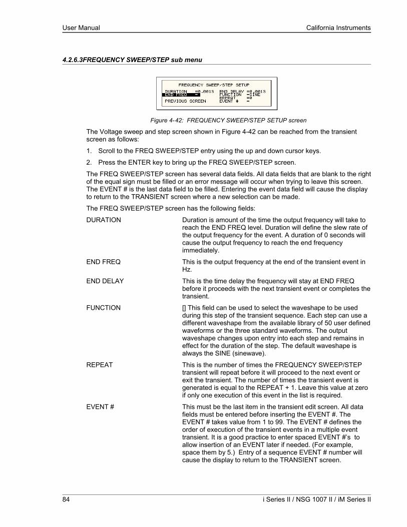
User Manual California Instruments
4.2.6.3FREQUENCY SWEEP/STEP sub menu
Figure 4-42: FREQUENCY SWEEP/STEP SETUP screen
The Voltage sweep and step screen shown in Figure 4-42 can be reached from the transient screen as follows:
1. Scroll to the FREQ SWEEP/STEP entry using the up and down cursor keys.
2. Press the ENTER key to bring up the FREQ SWEEP/STEP screen.
The FREQ SWEEP/STEP screen has several data fields. All data fields that are blank to the right of the equal sign must be filled or an error message will occur when trying to leave this screen. The EVENT # is the last data field to be filled. Entering the event data field will cause the display to return to the TRANSIENT screen where a new selection can be made.
The FREQ SWEEP/STEP screen has the following fields:
DURATION Duration is amount of the time the output frequency will take to reach the END FREQ level. Duration will define the slew rate of the output frequency for the event. A duration of 0 seconds will cause the output frequency to reach the end frequency immediately.
END FREQ This is the output frequency at the end of the transient event in Hz.
END DELAY This is the time delay the frequency will stay at END FREQ before it proceeds with the next transient event or completes the transient.
FUNCTION [] This field can be used to select the waveshape to be used during this step of the transient sequence. Each step can use a different waveshape from the available library of 50 user defined waveforms or the three standard waveforms. The output waveshape changes upon entry into each step and remains in effect for the duration of the step. The default waveshape is always the SINE (sinewave).
REPEAT This is the number of times the FREQUENCY SWEEP/STEP transient will repeat before it will proceed to the next event or exit the transient. The number of times the transient event is generated is equal to the REPEAT + 1. Leave this value at zero if only one execution of this event in the list is required.
EVENT # This must be the last item in the transient edit screen. All data fields must be entered before inserting the EVENT #. The EVENT # takes value from 1 to 99. The EVENT # defines the order of execution of the transient events in a multiple event transient. It is a good practice to enter spaced EVENT #’s to allow insertion of an EVENT later if needed. (For example, space them by 5.) Entry of a sequence EVENT # number will cause the display to return to the TRANSIENT screen.
84 i Series II / NSG 1007 II / iM Series II

User Manual California Instruments
4.2.6.4VOLTAGE/FREQUENCY SWEEP/STEP sub menu
Figure 4-43: VOLTAGE/FREQUENCY SWEEP/STEP SETUP screen
The Volt/freq sweep/step screen shown in Figure 4-43 can be reached from the transient screen as follows:
1. Scroll to the VOLT/FREQ SWEEP/STEP entry using the up and down cursor keys.
2. Press the ENTER key to bring up the VOLT/FREQ SWEEP/STEP screen.
The VOLT/FREQ SWEEP/STEP screen has several data fields. All data fields that are blank to the right of the equal sign must be filled or an error message will occur when trying to leave this screen. The EVENT # is the last data field to be filled. Entering the event data field will cause the display to return to the TRANSIENT screen where a new selection can be made.
The VOLT/FREQ SWEEP/STEP screen has the following fields:
DURATION Duration is the amount of time the output voltage and frequency will take to reach the END FREQ and END VOLT levels. Duration will define the slew rate of the output voltage and frequency for the event. A duration of 0 seconds will cause the output voltage and frequency to reach their end value immediately.
END FREQ This is the output frequency at the end of the transient event in Hz.
END VOLT This is the output voltage at the end of the transient event in volts.
END DELAY This is the time delay the output frequency and voltage will stay at END FREQ and END VOLT before proceeding with the next transient event or completing the transient.
FUNCTION [] This field can be used to select the wave shape to be used during this step of the transient sequence. Each step can use a different wave shape from the available library of 50 user defined waveforms or the three standard waveforms. The output wave shape changes upon entry into each step and remains in effect for the duration of the step. The default wave shape is always the SINE (sine wave).
REPEAT This is the number of times the VOLTAGE/FREQUENCY SWEEP/STEP transient will repeat before it will proceed to the next event or exit the transient. The number of times the transient event is generated is equal to the REPEAT + 1. Leave this value at zero if only one execution of this event in the list is required.
NSG 1007 Series II 85

User Manual California Instruments
EVENT # This must be the last item in the transient edit screen. All data fields must be entered before inserting the EVENT #. The EVENT # takes value from 1 to 99. The EVENT # defines the order of execution of the transient events in a multiple event transient. It is a good practice to enter spaced EVENT #’s to allow insertion of an EVENT later if needed. (For example, space them by 5.) Entry of a sequence EVENT # number will cause the display to return to the TRANSIENT screen.
4.2.6.5START/VIEW TRANSIENT SEQUENCE sub menu
Figure 4-44: START/VIEW TRANSIENT SEQUENCE screen
The START/VIEW TRANSIENT SEQUENCE screen is used to control transient execution. It also provides an overview of available transient list events. This list appears in the order they were assigned event numbers. Editing an existing event can be accomplished from this screen by positioning the cursor on the event to be edited and pressing the ENTER key. This method can also be used to review the parameters of a previously entered event.
The START/VIEW TRANSIENT SEQUENCE screen has the following fields:START / ABORT The START field is used to start a transient execution. When
the cursor is positioned on the START field and the ENTER key is pressed, transient execution starts. The output relay must be closed or an error message will appear and the transient will not start.
Once a transient is in progress, this field changes to ABORT and can be used to abort a transient in progress. If the transient completes execution, the field reverts back to START.
PAUSE / RESUME The PAUSE field may be used to suspend execution of a transient list in progress. If the cursor is on the PAUSE field and the ENTER key is pressed, the transient is suspended and this field changes to RESUME. Pressing the ENTER key again will cause the transient list to resume execution from the point where it was suspended.
REPEAT # This field determines the number of times a transient list is repeated. The default value is zero, which means the programmed list runs only once. The range for this field is from 0 through 99999. This repeat function should not be confused with the REPEAT function available for individual events. The event specific repeat value will cause only that event to be repeated, not the entire list.
CLEAR SEQ Moving the cursor to this field and pressing the ENTER key will cause the entire programmed transient list to be erased. Be careful not to press ENTER accidentally while on this field as you will loose the programmed transient list. Note that a list may be stored as part of the front panel setup in the nonvolatile memory registers.
86 i Series II / NSG 1007 II / iM Series II

User Manual California Instruments
4.2.7WAVEFORMS Menu []
Figure 4-45: WAVEFORMS menu
The WAVEFORMS menu is available on the . If your unit is an i Series, pressing the WAVE key on the front panel function keypad has no effect. The WAVEFORMS menu allows selection of the wave shape for each phase individually or all phases at once. For three phase versions of the NSG 1007, the mode is determined by the phase coupling. If only a single phase is selected in the top right corner of the display (øA, øB or øC), the selected wave shape will be applied to that phase. If all phases are selected (phase coupling), the selected waveform will apply to all three phases.
For single-phase versions of the NSG 1007, the phase coupling is always set to phase A, so pressing the PHASE button has no effect.
The following fields are available in the WAVEFORMS menu:
CLIP LEVEL This parameter determines the amount of total harmonic distortion of the built-in CLIPPED sine wave waveform. The range is 0 % through 20 % THD.
Note that changing the distortion level of the CLIPPED sine wave while the CLIPPED sinewave is used on the output of one or more phases, forces the output of the AC Source to be dropped momentarily. To avoid this, make sure none of the phases is using the CLIPPED sinewave function when changing the clip level.
GROUP The group field displays the currently selected waveform group. The NSG 1007 provides four groups of 50 user defined waveforms each for a total of 200 waveforms. Only one group can be active at a time however. This field only displays the selected waveform group. It cannot be used to change the actual group selected. Group selection must occur at power up and is done from the INITIAL SETUP 3 screen. See section 4.2.11.3 for details.
MODE The mode field determines the operation mode of the WAVEFORMS display screen. Available options for this field are:
PROG: This mode is used to change the programmed wave shape function on the selected phase. This is also the default mode of operation.
VIEW(T): This mode can be used to display any of the available user defined waveforms in a time domain display. Previewing a waveform can be useful if you are unsure about the nature of the waveform that was stored.
NSG 1007 Series II 87
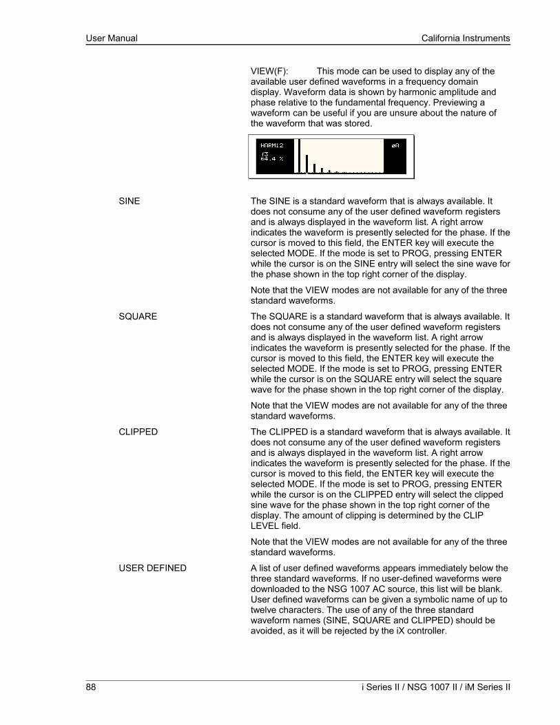
User Manual California Instruments
VIEW(F): This mode can be used to display any of the available user defined waveforms in a frequency domain display. Waveform data is shown by harmonic amplitude and phase relative to the fundamental frequency. Previewing a waveform can be useful if you are unsure about the nature of the waveform that was stored.
SINE The SINE is a standard waveform that is always available. It does not consume any of the user defined waveform registers and is always displayed in the waveform list. A right arrow indicates the waveform is presently selected for the phase. If the cursor is moved to this field, the ENTER key will execute the selected MODE. If the mode is set to PROG, pressing ENTER while the cursor is on the SINE entry will select the sine wave for the phase shown in the top right corner of the display.
Note that the VIEW modes are not available for any of the three standard waveforms.
SQUARE The SQUARE is a standard waveform that is always available. It does not consume any of the user defined waveform registers and is always displayed in the waveform list. A right arrow indicates the waveform is presently selected for the phase. If the cursor is moved to this field, the ENTER key will execute the selected MODE. If the mode is set to PROG, pressing ENTER while the cursor is on the SQUARE entry will select the square wave for the phase shown in the top right corner of the display.
Note that the VIEW modes are not available for any of the three standard waveforms.
CLIPPED The CLIPPED is a standard waveform that is always available. It does not consume any of the user defined waveform registers and is always displayed in the waveform list. A right arrow indicates the waveform is presently selected for the phase. If the cursor is moved to this field, the ENTER key will execute the selected MODE. If the mode is set to PROG, pressing ENTER while the cursor is on the CLIPPED entry will select the clipped sine wave for the phase shown in the top right corner of the display. The amount of clipping is determined by the CLIP LEVEL field.
Note that the VIEW modes are not available for any of the three standard waveforms.
USER DEFINED A list of user defined waveforms appears immediately below the three standard waveforms. If no user-defined waveforms were downloaded to the NSG 1007 AC source, this list will be blank. User defined waveforms can be given a symbolic name of up to twelve characters. The use of any of the three standard waveform names (SINE, SQUARE and CLIPPED) should be avoided, as it will be rejected by the iX controller.
88 i Series II / NSG 1007 II / iM Series II

User Manual California Instruments
A right arrow indicates the waveform is presently selected for the phase. If the cursor is moved to this field, the ENTER key will execute the selected MODE. If the mode is set to PROG, pressing ENTER while the cursor is on the user defined entry will select the custom waveform for the phase shown in the top right corner of the display.
If the MODE is set to either VIEW option, the waveform data under the cursor will be displayed when the ENTER key is pressed. Press the ENTER key again to return to the WAVEFORMS menu.
NSG 1007 Series II 89

User Manual California Instruments
4.2.8ADVANCE MEAS. Menu []
This entry in the MENU 2 screen displays the HARMONICS/TRACE ANALYSIS screen which is covered in section 4.2.5. This field can be used in lieu of the MEAS key to directly bring up the advanced measurements screens.
4.2.9APPLICATIONS Menu
Figure 4-46: APPLICATIONS menu
The APPLICATIONS menu provides access to the optional application specific pre-programmed test sequences. Since these test sequences are optional, this menu may have no choices if none of the options are installed. The following entries may be found in the APPLICATIONS menu:
Entry Description MIL-STD 704 Test sequence for MIL standard 704 AC and DC tests.
Imepdance OPTION This entry selects the Imepdance control menu. The Imepdance option provides a lumped reference impedance for use in IEC 1000-3-3 Flicker test applications. The NSG 1007 also provides programmable impedance, so, in most cases, the Imepdance option is not required. For the i Series, the Imepdance impedance is available as an option. If the Imepdance option is installed, this screen allows the impedance to be ENGAGED or BYPASSED.
RTCA/DO-160 Test sequence for RTCA DO160 commercial aviation AC and DC tests.
IEC-1000-4-11 Test sequences for IEC 1000-4-11 Voltage Dips and Variations test standard.
IEC-1000-4-13 Test sequence for IEC 1000-4-13 Harmonics and Inter harmonics test standard.
WH METER Watt Hour meter measurement option. Tracks energy usage over a period of time and calculates Watt Hours used.
90 i Series II / NSG 1007 II / iM Series II

User Manual California Instruments
4.2.10SETUP REGISTERS Menu
Figure 4-47: SETUP REGISTERS menu
The SETUP REGISTERS menu allows the user to store and recall complete instrument setups, including transient program lists. A total of 16 non-volatile setup registers is available, numbered sequentially from 0 through 7.
The following entries can be found in the SETUP REGISTERS menu:
Entry Description
SAVE REGISTER Save present instrument setup to a register number selected by the user. The numeric data entry keypad should be used to enter a number between 0 and 15. Once the ENTER key is pressed, all settings are saved. A message will appear at the bottom of the screen to confirm the save operation.
RECALL REGISTER Recall instrument setup from a register number selected by the user. The numeric data entry keypad should be used to enter a number between 0 and 15. Once the ENTER key is pressed, all settings are recalled. A message will appear at the bottom of the screen to confirm the recall operation.
VIEW/EDIT REGISTER The View/Edit entry can be used to display the contents of a setup register before it is recalled. After the user enters a register number to view or edit and presses the ENTER key, the PROGRAM screen will appear. All parameters that will be changed by recalling the register will be blinking. If ENTER is pressed again, the register will be recalled and the new values take effect. To edit the register content, change all parameters that need to be changed. Pressing ENTER will save the new values and make them active.
NSG 1007 Series II 91
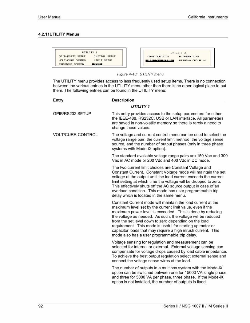
User Manual California Instruments
4.2.11UTILITY Menus
Figure 4-48: UTILITY menu
The UTILITY menu provides access to less frequently used setup items. There is no connection between the various entries in the UTILITY menu other than there is no other logical place to put them. The following entries can be found in the UTILITY menu:
Entry Description UTILITY 1
GPIB/RS232 SETUP This entry provides access to the setup parameters for either the IEEE-488, RS232C, USB or LAN interface. All parameters are saved in non-volatile memory so there is rarely a need to change these values.
VOLT/CURR CONTROL The voltage and current control menu can be used to select the voltage range pair, the current limit method, the voltage sense source, and the number of output phases (only in three phase systems with Mode-iX option).
The standard available voltage range pairs are 150 Vac and 300 Vac in AC mode or 200 Vdc and 400 Vdc in DC mode.
The two current limit choices are Constant Voltage and Constant Current. Constant Voltage mode will maintain the set voltage at the output until the load current exceeds the current limit setting at which time the voltage will be dropped to zero. This effectively shuts off the AC source output in case of an overload condition. This mode has user programmable trip delay which is located in the same menu.
Constant Current mode will maintain the load current at the maximum level set by the current limit value, even if the maximum power level is exceeded. This is done by reducing the voltage as needed. As such, the voltage will be reduced from the set level down to zero depending on the load requirement. This mode is useful for starting up motor or capacitor loads that may require a high inrush current. This mode also has a user programmable trip delay.
Voltage sensing for regulation and measurement can be selected for internal or external. External voltage sensing can compensate for voltage drops caused by load cable impedance. To achieve the best output regulation select external sense and connect the voltage sense wires at the load.
The number of outputs in a multibox system with the Mode-iX option can be switched between one for 15000 VA single phase, and three for 5000 VA per phase, three phase. If the Mode-iX option is not installed, the number of outputs is fixed.
92 i Series II / NSG 1007 II / iM Series II
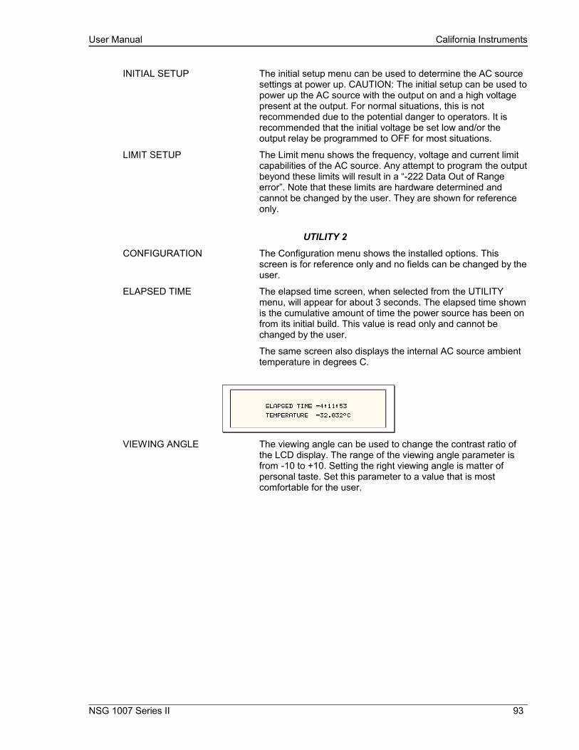
User Manual California Instruments
INITIAL SETUP The initial setup menu can be used to determine the AC source settings at power up. CAUTION: The initial setup can be used to power up the AC source with the output on and a high voltage present at the output. For normal situations, this is not recommended due to the potential danger to operators. It is recommended that the initial voltage be set low and/or the output relay be programmed to OFF for most situations.
LIMIT SETUP The Limit menu shows the frequency, voltage and current limit capabilities of the AC source. Any attempt to program the output beyond these limits will result in a “-222 Data Out of Range error”. Note that these limits are hardware determined and cannot be changed by the user. They are shown for reference only.
UTILITY 2
CONFIGURATION The Configuration menu shows the installed options. This screen is for reference only and no fields can be changed by the user.
ELAPSED TIME The elapsed time screen, when selected from the UTILITY menu, will appear for about 3 seconds. The elapsed time shown is the cumulative amount of time the power source has been on from its initial build. This value is read only and cannot be changed by the user.
The same screen also displays the internal AC source ambient temperature in degrees C.
VIEWING ANGLE The viewing angle can be used to change the contrast ratio of the LCD display. The range of the viewing angle parameter is from -10 to +10. Setting the right viewing angle is matter of personal taste. Set this parameter to a value that is most comfortable for the user.
NSG 1007 Series II 93
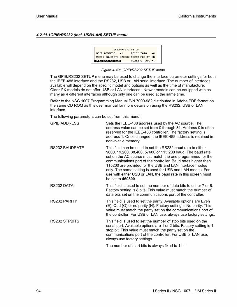
User Manual California Instruments
4.2.11.1GPIB/RS232 (incl. USB/LAN) SETUP menu
Figure 4-49: GPIB/RS232 SETUP menu
The GPIB/RS232 SETUP menu may be used to change the interface parameter settings for both the IEEE-488 interface and the RS232, USB or LAN serial interface. The number of interfaces available will depend on the specific model and options as well as the time of manufacture. Older i/iX models do not offer USB or LAN interfaces. Newer models can be equipped with as many as 4 different interfaces although only one can be used at the same time.
Refer to the NSG 1007 Programming Manual P/N 7000-982 distributed in Adobe PDF format on the same CD ROM as this user manual for more details on using the RS232, USB or LAN interface.
The following parameters can be set from this menu:
GPIB ADDRESS Sets the IEEE-488 address used by the AC source. The address value can be set from 0 through 31. Address 0 is often reserved for the IEEE-488 controller. The factory setting is address 1. Once changed, the IEEE-488 address is retained in nonvolatile memory.
RS232 BAUDRATE This field can be used to set the RS232 baud rate to either 9600, 19,200, 38,400, 57600 or 115,200 baud. The baud rate set on the AC source must match the one programmed for the communications port of the controller. Baud rates higher than 115200 are provided for the USB and LAN interface modes only. The same setting is used for USB and LAN modes. For use with either USB or LAN, the baud rate in this screen must be set to 460800.
RS232 DATA This field is used to set the number of data bits to either 7 or 8. Factory setting is 8 bits. This value must match the number of data bits set on the communications port of the controller.
RS232 PARITY This field is used to set the parity. Available options are Even (E), Odd (O) or no parity (N). Factory setting is No parity. This value must match the parity set on the communications port of the controller. For USB or LAN use, always use factory settings.
RS232 STPBITS This field is used to set the number of stop bits used on the serial port. Available options are 1 or 2 bits. Factory setting is 1 stop bit. This value must match the parity set on the communications port of the controller. For USB or LAN use, always use factory settings.
The number of start bits is always fixed to 1 bit.
94 i Series II / NSG 1007 II / iM Series II

User Manual California Instruments
4.2.11.2VOLTAGE/CURRENT CONTROL SETUP menu
Figure 4-50: VOLTAGE/CURRENT CONTROL SETUP menu
The VOLTAGE/CURRENT CONTROL SETUP menu may be used to set output voltage and current control parameters. These parameters are not frequently changed in the normal operation of the AC source and are thus located on the UTILITY rather than the PROGRAM menu.
The following options are available in this menu:ALC MODE Automatic Level Control of programmed output voltage. This
mode will use the internal voltage measurements to adjust the output voltage continuously as needed. This effectively increases the output accuracy and regulation beyond what is possible with ALC off.There are three settings for the ALC mode, ON, REG and OFF. ON: If ALC is ON, any event or load condition that prevents the power source from regulating the programmed voltage will cause it to trip the output off and generate a –801, “Output Voltage Fault”. There may be situations where it is desirable to continue driving the load even if the programmed voltage cannot be maintained. REG: In the REG (Regulate) mode ALC will regulate the output but not trip the output if for some reason it can’t. OFF: If the ALC is set OFF, no additional regulation is performed by the controller other than the hardware control loop. Note that if the current limit mode is set to CC (Constant Current) and the ALC is ON, the output will not trip off if the load current is at the programmed current limit forcing the unit into the cc operating mode which requires the voltage to be reduced from the set value.
Note: The Automatic Voltage Level Control (ALC) mode is mutually exclusive with the Programmable Impedance function of the iX. One must be turned off the enable the other.
OL MODE This field is used to select constant current (CC) or constant voltage (CV) mode. The constant current mode will limit the maximum amount of current drawn by the load to the set value. The voltage will be reduced as needed after the trip delay time to maintain the level of programmed current.
The constant voltage mode will maintain the set voltage as long as the current drawn by the load does not exceed the current limit programmed. If the current limit is exceeded, the output will be shut off after the trip delay time.
NSG 1007 Series II 95
User Manual California Instruments
TRIP DELAY The trip delay field may be used to set the amount of time to hold off the current limit trip point. The minimum amount of time is 100 ms or 0.1 sec. The maximum amount of time is 5.00 sec.
VOLT SENSE This field selects the internal or external sense line inputs. Internal sense does not require the external sense lines to be connected as sensing occurs at the output relay of the AC source. For best results, connect the external sense lines and select the EXT sense mode in this field. This will compensate for voltage drop in the cables to the load. The measurements are also taken at the sense points, so the external sense mode should be used for best measurement results.
NO. OUTPUT This field is only accessible if the phase mode option is installed. It allows the number of output phases to be toggled between single and three-phase mode. In single-phase mode, all power is available on phase A. The Mode-iX option is available to route all power to a single output terminal pair.
96 i Series II / NSG 1007 II / iM Series II

User Manual California Instruments
4.2.11.3INITIAL SETUP menu
Figure 4-51: INITIAL SETUP menus
Any time the AC source is powered up, the output will reflect the values stored as the INITIAL setup values. This allows the unit to be powered up in a known state at all times. The INITIAL values can be set in the INITIAL SETUP menus.
The initial setup can be used to power up the AC source with the output on and a high voltage present at the output. For normal situations, this is not recommended due to the potential danger to the operator. It is recommended that the initial voltage be set low and/or the output relay be programmed to OFF for most situations.
The following fields are provided in the INITIAL SETUP menus:
Entry Description
INITIAL SETUP 1
VOLTAGE Sets the power-on AC voltage for AC and AC+DC modes or the DC voltage for DC mode.
CURR LIMIT Sets the power-on current limit value.
FREQ Sets the power-on frequency value.
PHASE Sets the power-on frequency for phase A with respect to an external sync signal. If the internal oscillator is used (default) this setting has no effect.
INITIAL SETUP 2
VOLT RANGE Sets the power-on voltage range value. The available choices are determined by the VOLT PAIR selected in the VOLTAGE/CURRENT CONTROL SETUP menu.
VOLT MODE Sets the power-on voltage mode. Available settings are AC mode, DC mode or AC+DC mode [].
OL MODE Sets the power-on overload mode. Available settings are Constant Current (CC) or Constant Voltage (CV) mode.
OUTPUT RELAY Sets the power-on state of the output relay. Available settings are ON or OFF.
NSG 1007 Series II 97
User Manual California Instruments
INITIAL SETUP 3
VOLT SENSE Sets the power-on state of the voltage sense mode. Available settings are Internal (INT) or External (EXT).
WAVE GROUP [] Sets the user defined waveform group that will be loaded at power on. Available groups are 0, 1, 2 and 3. Each group can contain up to 50 user-defined waveforms. A waveform group can only be loaded at power up. To change groups, you must change this field to the desired new group and cycle the power to the AC source or issue a *RST command over one bus.
CLOCK MODE Sets the clock source used at power up. Available settings are Stand Alone (STAND), MASTER, and SLAVE.
NO. OUTPUT [] Sets the phase mode at power up. Available options are determined by the presence of the phase mode option. If the phase mode option is installed, available options are single phase mode (ONE), three phase mode (THREE) or last used phase mode (LAST). If the phase mode option is not installed, this field is either fiXed to ONE or THREE.
VOLT ALC Determines ALC mode at power on. The ALC mode adjusts the output voltage based on internal voltage measurement system and provides enhanced output regulation and accuracy. Available settings are ON, OFF or REG.
98 i Series II / NSG 1007 II / iM Series II
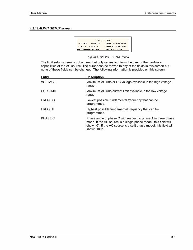
User Manual California Instruments
4.2.11.4LIMIT SETUP screen
Figure 4-52:LIMIT SETUP menu
The limit setup screen is not a menu but only serves to inform the user of the hardware capabilities of the AC source. The cursor can be moved to any of the fields in this screen but none of these fields can be changed. The following information is provided on this screen:
Entry Description VOLTAGE Maximum AC rms or DC voltage available in the high voltage
range.
CUR LIMIT Maximum AC rms current limit available in the low voltage range.
FREQ LO Lowest possible fundamental frequency that can be programmed.
FREQ HI Highest possible fundamental frequency that can be programmed.
PHASE C Phase angle of phase C with respect to phase A in three phase mode. If the AC source is a single phase model, this field will shown 0°. If the AC source is a split phase model, this field will shown 180°.
NSG 1007 Series II 99

User Manual California Instruments
4.2.11.5CONFIGURATION SETUP screen
Figure 4-53: CONFIGURATION SETUP Menus
The configuration setup screen is not a menu but only serves to inform the user of the software options installed in the AC source. The cursor can be moved to any of the fields in this screen but none of these fields can be changed. The following information is provided on this screen:
Entry Description CONFIGURATION SETUP 1
NO. OUTPUT Displays the phase mode option. SELECT indicates the phase mode option is installed and the user can select between single and three phase modes of operation.
FIXED indicates the phase mode option is not installed and only single phase or three phase mode of operation is possible.
ADVANCE [iX models only] This field indicates the presence of advanced capabilities for waveform generation and measurement analysis are present.
DO160 Indicates the presence of the RTCA DO160 test option. If this option is installed, this field will show ON. If this option is not installed, this field will show N/A (not available).
MIL704 Indicates the presence of the MIL/STD-704 Revision D and E test option. If this option is installed, this field will show ON. If this option is not installed, this field will show N/A (not available).
CONFIGURATION SETUP 2
IEC 4-11 Indicates the presence of the IEC 61000-4-11 test option. If this option is installed, this field will show ON. If this option is not installed, this field will show N/A (not available).
IEC 4-13 Indicates the presence of the IEC 61000-4-13 test option. If this option is installed, this field will show ON. If this option is not installed, this field will show N/A (not available).
CLOCK/LOCK Indicates the presence of the -LKS clock and lock auxiliary option. For units without -LKS, this field is set to N/A. For units with the -LKS option installed, this field is set to ON. Note that master unit (with -LKM) also has this field set to N/A.
WH METER Indicates the presence of the Watt Hour Meter option.
CONFIGURATION SETUP 3
100 i Series II / NSG 1007 II / iM Series II

User Manual California Instruments
MS704 Indicates the presence of the MIL/STD-704 Revision A through F test option. If this option is installed, this field will show ON. If this option is not installed, this field will show N/A (not available). This field is available on Series II i/iX systems only.
ABD Indicates the presence of the ABD0100.1.8 test option. If this option is installed, this field will show ON. If this option is not installed, this field will show N/A (not available).
LF Indicates the presence of the Low Frequency limit option. If this option is set, the maximum frequency that can be programmed is 500 Hz.
SYSTEM This field sets the controller for the correct multi box system model configuration.If this field is set incorrectly, the current limit scaling and current measurement will be off by a factor of three. This field is protected and cannot be changed unless the optional MB configuration has been enabled.
MB Indicates the presence of the Multi-box option. If this option is set, the SYSTEM field (above) can be changed to accommodate reconfiguration of the iX system. If this option is not set, the SYSTEM configuration is fixed and cannot be changed by the user.
NOTE: If the MB option is enabled, great care MUST be taken to set the correct SYSTEM setting for the configured hardware. Failing do so will result in incorrect operation of the iX power system and could even result in damage of iX or the equipment under test.
NSG 1007 Series II 101
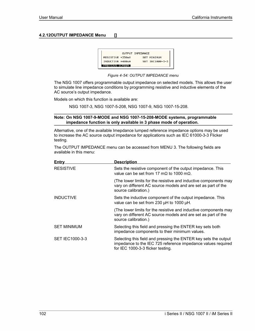
User Manual California Instruments
4.2.12OUTPUT IMPEDANCE Menu []
Figure 4-54: OUTPUT IMPEDANCE menu
The NSG 1007 offers programmable output impedance on selected models. This allows the user to simulate line impedance conditions by programming resistive and inductive elements of the AC source’s output impedance.
Models on which this function is available are:
NSG 1007-3, NSG 1007-5-208, NSG 1007-9, NSG 1007-15-208.
Note: On NSG 1007-9-MODE and NSG 1007-15-208-MODE systems, programmable impedance function is only available in 3 phase mode of operation.
Alternative, one of the available Imepdance lumped reference impedance options may be used to increase the AC source output impedance for applications such as IEC 61000-3-3 Flicker testing.
The OUTPUT IMPEDANCE menu can be accessed from MENU 3. The following fields are available in this menu:
Entry Description RESISTIVE Sets the resistive component of the output impedance. This
value can be set from 17 mΩ to 1000 mΩ.
(The lower limits for the resistive and inductive components may vary on different AC source models and are set as part of the source calibration.)
INDUCTIVE Sets the inductive component of the output impedance. This value can be set from 230 µH to 1000 µH.
(The lower limits for the resistive and inductive components may vary on different AC source models and are set as part of the source calibration.)
SET MINIMUM Selecting this field and pressing the ENTER key sets both impedance components to their minimum values.
SET IEC1000-3-3 Selecting this field and pressing the ENTER key sets the output impedance to the IEC 725 reference impedance values required for IEC 1000-3-3 flicker testing.
102 i Series II / NSG 1007 II / iM Series II

User Manual California Instruments
4.2.13MEASUREMENT CAL FACTORS Menu
Figure 4-55: MEASUREMENT CAL FACTORS menu
The MEASUREMENT CAL FACTORS menu provides access to the measurement calibration parameters. The parameters shown are for the mode of operation (AC or DC) selected. For three phase configurations, the PHASE keys toggle between the three calibration screens for each phase. These parameters are password protected and can only be changed after the calibration password has been entered. Refer to the calibration section in this manual for details on performing a calibration.
The following calibration factors are available from this menu:
Entry Description VOLT FS Full scale voltage measurement calibration factor. AC or DC
mode.
CURR FS Full scale current measurement calibration factor. AC or DC mode.
NSG 1007 Series II 103
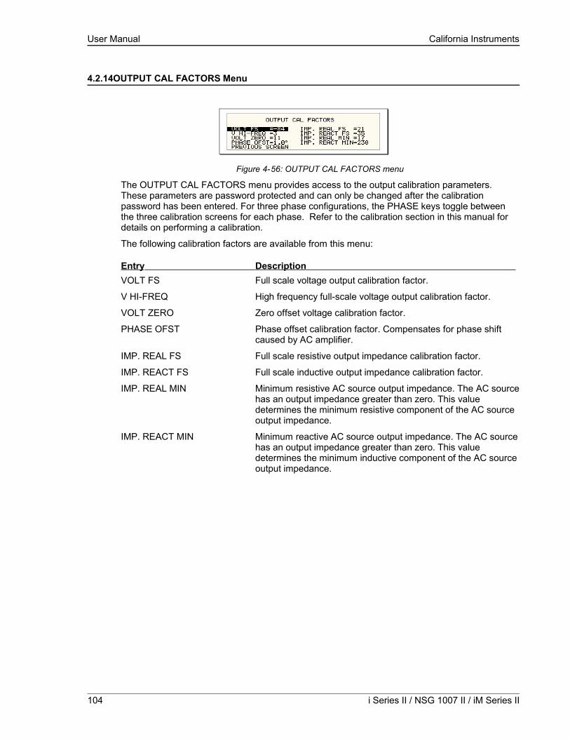
User Manual California Instruments
4.2.14OUTPUT CAL FACTORS Menu
Figure 4-56: OUTPUT CAL FACTORS menu
The OUTPUT CAL FACTORS menu provides access to the output calibration parameters. These parameters are password protected and can only be changed after the calibration password has been entered. For three phase configurations, the PHASE keys toggle between the three calibration screens for each phase. Refer to the calibration section in this manual for details on performing a calibration.
The following calibration factors are available from this menu:
Entry Description VOLT FS Full scale voltage output calibration factor.
V HI-FREQ High frequency full-scale voltage output calibration factor.
VOLT ZERO Zero offset voltage calibration factor.
PHASE OFST Phase offset calibration factor. Compensates for phase shift caused by AC amplifier.
IMP. REAL FS Full scale resistive output impedance calibration factor.
IMP. REACT FS Full scale inductive output impedance calibration factor.
IMP. REAL MIN Minimum resistive AC source output impedance. The AC source has an output impedance greater than zero. This value determines the minimum resistive component of the AC source output impedance.
IMP. REACT MIN Minimum reactive AC source output impedance. The AC source has an output impedance greater than zero. This value determines the minimum inductive component of the AC source output impedance.
104 i Series II / NSG 1007 II / iM Series II
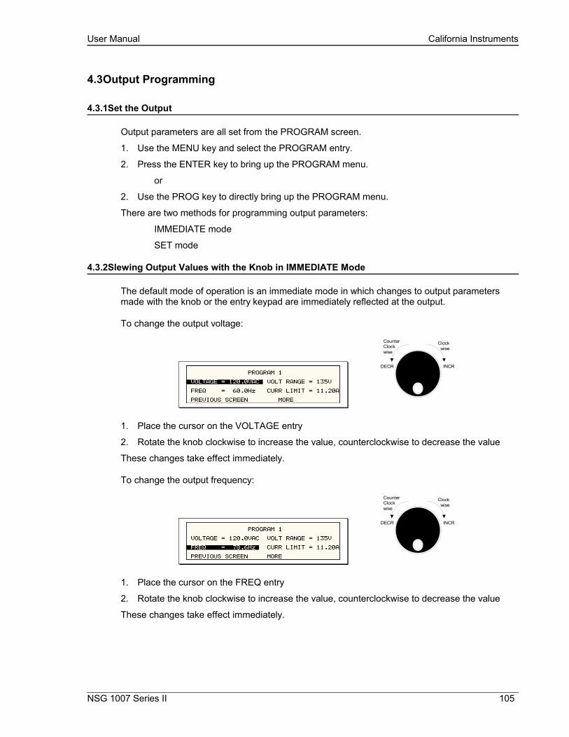
User Manual California Instruments
4.3Output Programming
4.3.1Set the Output
Output parameters are all set from the PROGRAM screen.
1. Use the MENU key and select the PROGRAM entry.
2. Press the ENTER key to bring up the PROGRAM menu.
or
2. Use the PROG key to directly bring up the PROGRAM menu.
There are two methods for programming output parameters:
IMMEDIATE mode
SET mode
4.3.2Slewing Output Values with the Knob in IMMEDIATE Mode
The default mode of operation is an immediate mode in which changes to output parameters made with the knob or the entry keypad are immediately reflected at the output.
To change the output voltage:
CounterClockwise
Clockwise
INCRDECR
1. Place the cursor on the VOLTAGE entry
2. Rotate the knob clockwise to increase the value, counterclockwise to decrease the value
These changes take effect immediately.
To change the output frequency:
CounterClockwise
Clockwise
INCRDECR
1. Place the cursor on the FREQ entry
2. Rotate the knob clockwise to increase the value, counterclockwise to decrease the value
These changes take effect immediately.
NSG 1007 Series II 105

User Manual California Instruments
4.3.3Change Output Values with the Knob in SET Mode
The SET mode of operation is a mode in which changes to output parameters made with the knob or the entry keypad do not affect the output until the ENTER key is pressed. The AC source is put in this SET mode by pressing the SET key.
To change the output voltage:
CounterClockwise
Clockwise
INCRDECR
1. Press the SET key
2. Place the cursor on the VOLTAGE entry
3. Rotate the knob clockwise to increase the value, counterclockwise to decrease the value
4. The VOLTAGE field will be blinking to indicate a change in settings but the output remains unchanged.
5. Place the cursor on the FREQ entry
6. Rotate the knob clockwise to increase the value, counterclockwise to decrease the value
7. The FREQ field will be blinking to indicate a change in settings but the output remains unchanged.
8. Press the ENTER key.
Both new voltage and frequency output values are now present at the output. The unit has returned to immediate mode of operation until the SET key is pressed again.
106 i Series II / NSG 1007 II / iM Series II

User Manual California Instruments
4.4Waveform Management []
The NSG 1007 employs independent arbitrary waveform generators for each phase. This allows the user to create custom waveforms. In addition, the iX offers three standard waveforms that are always available. This chapter covers issues that relate to defining, downloading and managing custom waveforms.
4.4.1Standard Waveforms
For many AC applications, a sine wave shape is used. The sine wave is one of the standard waveforms provided on the NSG 1007. The standard sine wave is always available and is the default waveform at power-on. In addition to the sine wave, two more standard waveforms are available, square and clipped.
Figure 4-57: Selecting a waveform
The square wave provides a high frequency content waveform with relative fast rise and fall times. Due to AC amplifier bandwidth limitations, the frequency content of the standard square wave has been kept within the amplifier’s capabilities. As the fundamental frequency is increased, the relative contribution of higher harmonics is reduced.The clipped sine wave may be used to simulate voltage distortion levels to the unit under test. The total harmonic distortion level may be programmed in percent using the CLIP LEVEL field of the WAVEFORMS menu. Changing the distortion level of the CLIP waveform forces the AC source to regenerate the CLIPPED sine wave’s data points and reload the waveform register with the newly requested data. This process requires the output to be dropped briefly. To avoid interrupting the voltage output to the unit under test, select a different waveform such as the standard sine wave first, change the clip level and change the waveform back to the CLIPPED sine wave. This will avoid any output interruption.
4.4.2Phase Selection
Figure 4-58: Selecting waveforms for single phase or all phases
If the NSG 1007-9 orNSG 1007-15-208, different waveforms may be selected for each phase. The number of custom waveforms from which to select remains 50 but each phase can be assigned a different custom or standard waveform. The specific output phase for which the wave shape is programmed is selected with the PHASE key on the front panel. The selected phase is always shown in the top right hand corner of the WAVEFORMS display.
To select the same wave shape for all three phases in a three phase configuration, press the PHASE key until the øABC enunciator appears in the top right corner of the WAVEFORMS menu. Waveform selections made in this mode will apply to all three phases.
NSG 1007 Series II 107

User Manual California Instruments
4.4.3Creating Custom Waveforms
The NSG 1007 provides four groups of 50 custom defined waveforms each for a total of 200 waveforms in addition to the 3 standard waveforms. Of these four groups, one may be active at a time. The active group is selected in the INITIAL SETUP menu.
Custom waveforms cannot be created from the front panel of the NSG 1007. Rather, they have to be downloaded through the IEEE-488 or RS232C interface. A Windows based program is included with the NSG 1007 that allows waveforms to be created and downloaded easily. This Graphical User Interface program allows waveforms to be created by specifying harmonic amplitudes and phase angles with respect to the fundamental. It also offers an arbitrary waveform data entry mode that allows individual data points to be specified.
Figure 4-59: Custom waveform creation with GUI program
Once downloaded, waveforms remain in non-volatile memory and will be visible in the WAVEFORMS menu for selection. The user can assign a 12-character name to each custom waveform. Avoid using any of the standard waveform names (SINE, SQUARE or CLIPPED) as these names will not be accepted.
Waveforms may be deleted using the IEEE-488 or RS232C interface as well. Custom waveforms cannot be deleted from the front panel however to avoid accidental erasure.
4.4.4Waveform Groups
Waveform groups extend the number of available custom waveform to 200. Each group can contain up to 50 user defined waveforms. Groups are numbered 0 through 3 and may be selected from the INITIAL SETUP 3 menu. To switch waveform groups, proceed as follows:
1. Press the MENU key three times to select the MENU 3 screen.
2. Move the cursor to the UTILITY entry end press ENTER. You are now in the UTILITY 1 menu.
3. Move the cursor to the INITIAL SETUP field and press ENTER. You are now in the INITIAL SETUP 1 menu.
108 i Series II / NSG 1007 II / iM Series II

User Manual California Instruments
4. Move the cursor to the MORE field at the end of this menu and press the ENTER key. You are now in the INITIAL SETUP 2 menu.
5. Move the cursor to the MORE field at the end of this menu and press the ENTER key. You are now in the INITIAL SETUP 3 menu.
6. Move the cursor to the WAVE GROUP = field. You can now use the knob or the 0 through 3 key on the front panel to select a different waveform group.
7. Press ENTER to confirm your new selection.
8. To activate your new selection, YOU MUST CYCLE THE POWER so the AC source re-initializes. If the source is operated over the bus, a IEEE-488 Device Clear or reset command (*RST) command will have the same effect.
The new wave group will be active after you turn the power to the unit back on.
4.4.5RMS Amplitude Restrictions
The output of a sinewave may be programmed to the full rms value of the voltage range selected. If the AC source is in the 300 V range, the maximum programmable rms voltage is 300 Volt. If a custom waveform is used however, the maximum programmable rms voltage may be less than the maximum range value. The voltage range limit is based on the use of a sine wave with a 1.414 crest factor. A 300 V rms sine wave has a 424 Volt peak voltage. The AC source has a maximum peak voltage capability that is determined by the selected voltage range. If the user selects a custom waveform with a crest factor that is higher than 1.414, the peak voltage would exceed this maximum if the rms voltage were to be programmed at 300 V rms.
The NSG 1007 automatically limits the maximum allowable programmed rms voltage of a any custom waveform by calculating the crest factor of the selected waveform and controlling the rms limit accordingly. Thus, each custom waveform may have a different maximum rms value. The iX controller will prevent the user from programming the rms voltage above this limit. If a value is entered in the PROGRAM 1 menu above this value, a “Voltage peak error” message is generated.
Figure 4-60: Waveform crest factor affects max. rms voltage
The figure shown here illustrates the relationship between the crest factor of the wave shape (or its “peakiness”) and the maximum peak voltage allowed for a given voltage range. Since the peak voltage cannot exceed the AC source’s capabilities, the programmable rms voltage has to be restricted, in this case to only 167.8785 volt for the waveform on the left. The sine wave on the right can be programmed to the full 300 V rms as this still falls within the same peak voltage limitation of the AC source.
NSG 1007 Series II 109
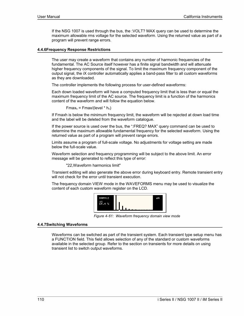
User Manual California Instruments
If the NSG 1007 is used through the bus, the :VOLT? MAX query can be used to determine the maximum allowable rms voltage for the selected waveform. Using the returned value as part of a program will prevent range errors.
4.4.6Frequency Response Restrictions
The user may create a waveform that contains any number of harmonic frequencies of the fundamental. The AC Source itself however has a finite signal bandwidth and will attenuate higher frequency components of the signal. To limit the maximum frequency component of the output signal, the iX controller automatically applies a band-pass filter to all custom waveforms as they are downloaded.
The controller implements the following process for user-defined waveforms:
Each down loaded waveform will have a computed frequency limit that is less than or equal the maximum frequency limit of the AC source. The frequency limit is a function of the harmonics content of the waveform and will follow the equation below.
Fmaxh = Fmax/(level * hn)
If Fmaxh is below the minimum frequency limit, the waveform will be rejected at down load time and the label will be deleted from the waveform catalogue.
If the power source is used over the bus, the “:FREQ? MAX” query command can be used to determine the maximum allowable fundamental frequency for the selected waveform. Using the returned value as part of a program will prevent range errors.
Limits assume a program of full-scale voltage. No adjustments for voltage setting are made below the full-scale value.
Waveform selection and frequency programming will be subject to the above limit. An error message will be generated to reflect this type of error:
"22,Waveform harmonics limit"
Transient editing will also generate the above error during keyboard entry. Remote transient entry will not check for the error until transient execution.
The frequency domain VIEW mode in the WAVEFORMS menu may be used to visualize the content of each custom waveform register on the LCD.
Figure 4-61: Waveform frequency domain view mode
4.4.7Switching Waveforms
Waveforms can be switched as part of the transient system. Each transient type setup menu has a FUNCTION field. This field allows selection of any of the standard or custom waveforms available in the selected group. Refer to the section on transients for more details on using transient list to switch output waveforms.
110 i Series II / NSG 1007 II / iM Series II
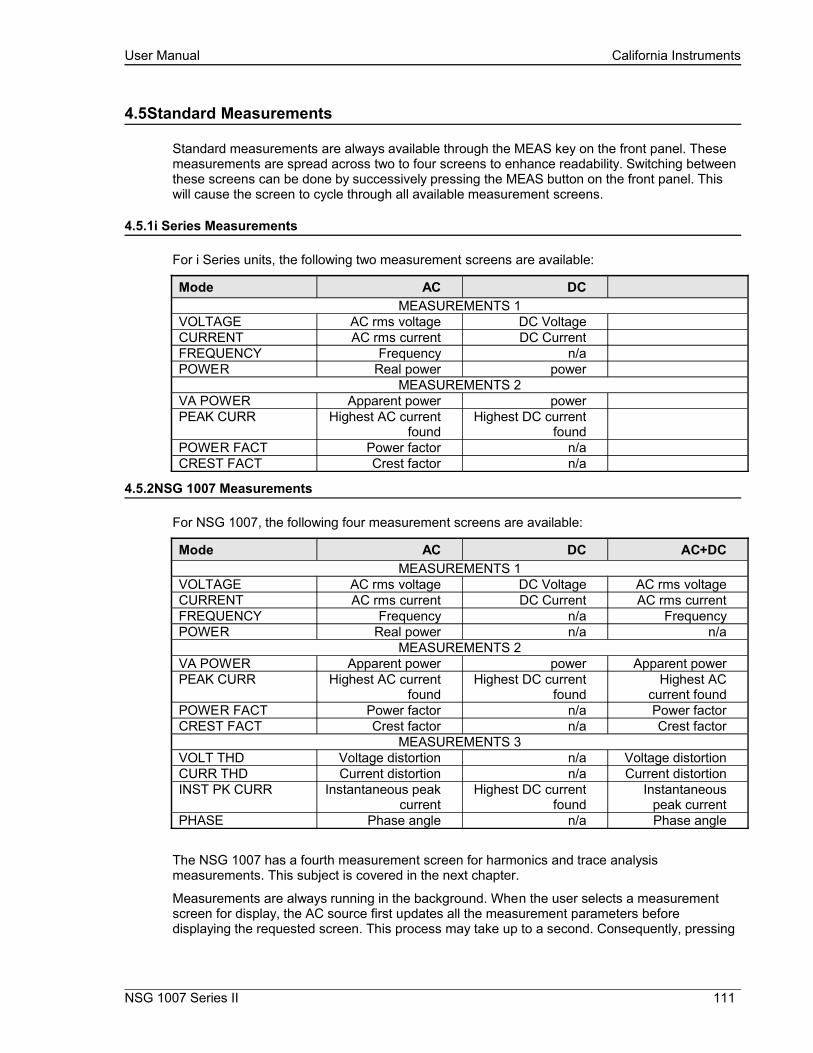
User Manual California Instruments
4.5Standard Measurements
Standard measurements are always available through the MEAS key on the front panel. These measurements are spread across two to four screens to enhance readability. Switching between these screens can be done by successively pressing the MEAS button on the front panel. This will cause the screen to cycle through all available measurement screens.
4.5.1i Series Measurements
For i Series units, the following two measurement screens are available:
Mode AC DCMEASUREMENTS 1
VOLTAGE AC rms voltage DC VoltageCURRENT AC rms current DC CurrentFREQUENCY Frequency n/aPOWER Real power power
MEASUREMENTS 2VA POWER Apparent power powerPEAK CURR Highest AC current
foundHighest DC current
foundPOWER FACT Power factor n/aCREST FACT Crest factor n/a
4.5.2NSG 1007 Measurements
For NSG 1007, the following four measurement screens are available:
Mode AC DC AC+DCMEASUREMENTS 1
VOLTAGE AC rms voltage DC Voltage AC rms voltageCURRENT AC rms current DC Current AC rms currentFREQUENCY Frequency n/a FrequencyPOWER Real power n/a n/a
MEASUREMENTS 2VA POWER Apparent power power Apparent powerPEAK CURR Highest AC current
foundHighest DC current
foundHighest AC
current foundPOWER FACT Power factor n/a Power factorCREST FACT Crest factor n/a Crest factor
MEASUREMENTS 3VOLT THD Voltage distortion n/a Voltage distortionCURR THD Current distortion n/a Current distortionINST PK CURR Instantaneous peak
currentHighest DC current
foundInstantaneous
peak currentPHASE Phase angle n/a Phase angle
The NSG 1007 has a fourth measurement screen for harmonics and trace analysis measurements. This subject is covered in the next chapter.
Measurements are always running in the background. When the user selects a measurement screen for display, the AC source first updates all the measurement parameters before displaying the requested screen. This process may take up to a second. Consequently, pressing
NSG 1007 Series II 111

User Manual California Instruments
the MEAS key may not always bring up the selected screen immediately. There will be a perceptible delay. This will prevent the screen from appearing with invalid or blank readouts.
The measurement method for voltage and current will depend on the power source operating mode. The following table shows the return value type (rms or average) and method of coupling when the measurement command is initiated with a different extension at various operating modes (AC, DC or AC + DC).
Measurement Extension and Coupling
Operating Mode
AC DC AC + DC
AC rms rms rms
DC rms rms average
Coupling AC DC DC
4.5.3Accuracy Considerations
Any measurement system has a finite accuracy specification. Measurement specifications are listed in Section 2. When using the AC source for measurement purposes, always consider these specifications when interpreting results. Measurement inaccuracies become more pronounced as the signal being measured is at the low end of the measurement range. This is particularly relevant for low current measurements. The i and NSG 1007 are high power AC sources optimized for providing and measuring high load currents. When powering low power loads, measurement inaccuracies on rms and peak current measurements will greatly affect derived measurements such as power, power factor and crest factor.
The measurement system on the i and NSG 1007 II uses a data acquisition system with a 16 kHz bandwidth. This means that high frequency components of the measured signal are filtered out. Any contribution to the rms value of voltage and current above this cutoff frequency will not be reflected in the i and NSG 1007 measurements. When using an external measurement reference, this may account for discrepancies in readings.
112 i Series II / NSG 1007 II / iM Series II
User Manual California Instruments
4.6Advanced Measurements []
The NSG 1007 offers advanced power analyzer measurement capabilities. These functions may be accessed from the MEAS button or the MENU 2 screen. The phase for which the analysis or waveform acquisition is done may be selected using the PHASE key in three phase configurations. This chapter covers the use and application of these advanced measurement functions.
4.6.1Harmonic Analysis
The iX power analyzer performs fast fourrier transformation on both voltage and current on each available phase. The resulting frequency spectrum can be displayed on the LCD display in a tabular as well as a graphical mode.
4.6.1.1Acquiring FFT data
To perform an FFT analysis on the output of the AC source, proceed as follows:
1. Press the MEAS button four times or until the HARMONICS/TRACE ANALYSIS screen appears.
2. Move the cursor to the FUNCTION field and select VOLT or CURR. (The BOTH selection will default to CURR as only one FFT result can be displayed at a time.)
3. Move the cursor to the VIEW field and select the TABLE or BAR display mode. The TRACE display mode does not apply to FFT results.
4. Move the cursor to the DATA MODE field and select ABS or REL. Absolute display mode will show all harmonic components in volts or amps. Relative display mode will use the fundamental as a 100 % reference and display all harmonics as a percentage of the fundamental. Phase angles are always shown with respect to the fundamental frequency. The phase angle of the fundamental is always shown with respect to phase A.
5. Skip the SCALE field as it only applies to the TRACE display mode.
6. Move the cursor to the TRIG MODE and select SINGLE or CONT. The SINGLE mode will acquire the data once and show the result. If you select CONT, the data will be updated continuously.
7. Move the cursor to the TRIG SOURCE field and select IMM. We will cover additional trigger modes later.
8. Move the cursor to the START field and press the ENTER key. The display that you selected will be shown. If you are in CONT trigger mode, the data will be updated about once per second.
You can return to the HARMONICS/TRACE ANALYSIS screen by pressing the ENTER key. To display the data in a different format, change to the selections you want and move the cursor to the VIEW field. Pressing the ENTER key will re-display the data without triggering a new acquisition. (This is true even if you were in CONT trigger mode.) To start a new acquisition, you must go through the START field instead.
NSG 1007 Series II 113

User Manual California Instruments
4.6.1.2Analyzing FFT data
The data displays available for FFT data allow you to scroll through the entire data set. For table displays, the UP and DOWN arrow keys may be used to scroll through the table data vertically. The knob has no function while in this display mode. The triangle on the left edge of the LCD screen points to the current position in the table.
Figure 4-62: Scrolling through tabular FFT data
Bar chart format FFT data displays show the same data in a graphical format. While the amplitude information is shown graphically, phase data is only displayed in numeric form to the left for the currently selected harmonic component. The display can show up to 24 components at a time. The triangle at the bottom of the display shows the currently selected component for which numeric data is shown on the left. This data includes the harmonic number (DC through 50), the absolute or relative amplitude (depending on selected VIEW mode) and the phase angle with respect to the fundamental. The knob can be used to scroll through the display horizontally. The UP and DOWN cursor keys have no effect in this display mode.
CounterClockwise
Clockwise
INCRDECR
Figure 4-63: Scrolling through bar chart FFT data
114 i Series II / NSG 1007 II / iM Series II
Arrow indicator can be moved up or down using UP/DOWN cursor keys.
Arrow indicator points to harmonic for which readout is shown on the left. Can be moved with knob.
User Manual California Instruments
4.6.2Waveform Acquisition
The waveform acquisition mode allows voltage and/or current data waveforms to be captured and displayed. This mode is selected by choosing the VIEW =TRACE mode in the HARMONICS/TRACE ANALYSIS screen. Voltage and current may be viewed separately or combined into a single display using the FUNCTION field.
4.6.2.1Acquiring waveform data
To perform a waveform acquisition on the output of the AC source, proceed as follows:
1. Press the MEAS button four times or until the HARMONICS/TRACE ANALYSIS screen appears.
2. Move the cursor to the FUNCTION field and select VOLT, CURR or BOTH.
3. Move the cursor to the VIEW field and select the TRACE display mode.
4. Skip the DATA MODE field as it only applies to the TABLE and BAR display modes.
5. Move the cursor to the SCALE field and select a horizontal time base value to allows you to see at least one cycle of the output waveform. If the output is programmed at 50 Hz, a 20 ms scale would display exactly one signal period.
6. Move the cursor to the TRIG MODE and select SINGLE or CONT. The SINGLE mode will acquire the data once and show the result. If you select CONT, the data will be updated continuously.
7. Move the cursor to the TRIG SOURCE field and select IMM. We will cover additional trigger modes later.
8. Move the cursor to the START field and press the ENTER key. The display that you selected will be shown. If you are in CONT trigger mode, the data will be updated about once per second.
You can return to the HARMONICS/TRACE ANALYSIS screen by pressing the ENTER key. To display the data in a different format or to select voltage instead of current or current instead of voltage, change to the selections you want and move the cursor to the VIEW field. Pressing the ENTER key will re-display the data without triggering a new acquisition. (This is true even if you were in CONT trigger mode.) To start a new acquisition, you must go through the START field instead.
NSG 1007 Series II 115

User Manual California Instruments
4.6.2.2Analyzing waveform data
The data displays available for acquired waveform data allow you to scroll through the entire acquisition buffer. For waveform displays, the knob can be used to scroll through the display horizontally. The UP and DOWN cursor keys have no effect in this display mode.
CounterClockwise
Clockwise
INCRDECR
Figure 4-64: Scrolling through acquired waveform data
The acquisition buffer may be longer than the selected horizontal scale in which case only a portion of the acquisition window will be visible. The left portion of the LCD display is used to read out the data under the vertical cursor. This cursor is a dotted line that can be moved using the knob. If the left or right edge of the display window is reached, the entire display will shift so the cursor always remains visible. The time from the trigger point to the vertical cursor is displayed in the left hand portion of the LCD in ms. Also displayed here are the absolute voltage and/or current value under the cursor.
To change the horizontal display scale without re-triggering an acquisition, press the ENTER key to return to the HARMONICS/TRACE ANALYSIS screen, change the SCALE value, move the cursor to the VIEW field and press ENTER. This will display the same data set at the new scale without triggering a new acquisition.
116 i Series II / NSG 1007 II / iM Series II
Readouts on the left track the vertical cursor position on the waveform. Trigger point is at 0.0 ms.

User Manual California Instruments
4.6.3Triggering Measurements
Both FFT results and waveform acquisitions may have to positioned at a specific moment in time. To allow the data acquisition to coincide with user specified events, the measurement system can be triggered in different ways. Trigger modes are available from both the bus and the front panel. If the IEEE-488 or RS232C bus is used, acquisitions may also be triggered from the transient list system. Refer to the programming manual for details on this mode of operation.
4.6.3.1Trigger mode
The following trigger modes are supported by the NSG 1007:
Single (SINGLE) This mode causes the acquisition system to be armed only once. The iX source waits for the user to press the ENTER key while on the START field. As soon as the trigger event specified occurs, data is acquired and the acquisition system is put in an idle state. A new user initiated START event must be given to trigger an new acquisition.
This mode is appropriate for capturing events that occur only once such as the inrush current when turning on a load.
Continuous (CONT) This mode causes the trigger system to re-arm itself after each trigger event. Every time a new trigger event occurs, new data is acquired and the LCD display is updated. No user intervention is required after the initial START event.
This mode is appropriate for capturing repetitive events or to monitor the source output continuously. Display updates will occur about once per second.
4.6.3.2Trigger source
The NSG 1007 offers a choice of trigger sources in front panel operation mode. The following trigger sources are available from the HARMONICS/TRACE ANALYSIS, TRIG SOURCE field:
Immediate (IMM) This mode causes a trigger to occur as soon as the ENTER key is pressed with the cursor on the START field. No trigger source needs to be specified for this trigger mode. This mode is equivalent to the INIT:IMM:ACQ bus command.
This trigger source is appropriate if no trigger condition is known or desired. When using this trigger source, the acquisition is always triggered.
Phase (PHASE A) This mode causes the iX acquisition system to wait for a specified phase angle on the phase A voltage output. This allows the acquisition to be positioned in time with respect to any phase angle on phase A, B or C. Note that phase A, B and C are typically at 0°, 240° and 120° with respect to the specified trigger phase in this field. An example of this trigger source mode is shown in Figure 4-66.
When selecting this trigger source, the field below the TRIG SOURCE field changed to “TRIG PHASE =“. Use this field to enter the desired voltage phase angle to trigger the measurement on.
NSG 1007 Series II 117
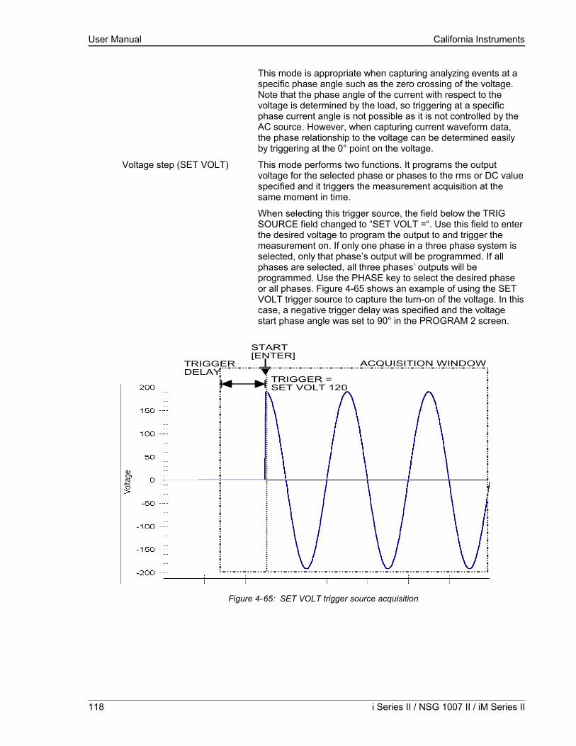
User Manual California Instruments
This mode is appropriate when capturing analyzing events at a specific phase angle such as the zero crossing of the voltage. Note that the phase angle of the current with respect to the voltage is determined by the load, so triggering at a specific phase current angle is not possible as it is not controlled by the AC source. However, when capturing current waveform data, the phase relationship to the voltage can be determined easily by triggering at the 0° point on the voltage.
Voltage step (SET VOLT) This mode performs two functions. It programs the output voltage for the selected phase or phases to the rms or DC value specified and it triggers the measurement acquisition at the same moment in time.
When selecting this trigger source, the field below the TRIG SOURCE field changed to “SET VOLT =“. Use this field to enter the desired voltage to program the output to and trigger the measurement on. If only one phase in a three phase system is selected, only that phase’s output will be programmed. If all phases are selected, all three phases’ outputs will be programmed. Use the PHASE key to select the desired phase or all phases. Figure 4-65 shows an example of using the SET VOLT trigger source to capture the turn-on of the voltage. In this case, a negative trigger delay was specified and the voltage start phase angle was set to 90° in the PROGRAM 2 screen.
TRIGGERDELAY
ACQUISITION WINDOW
TRIGGER =SET VOLT 120
START[ENTER]
Figure 4-65: SET VOLT trigger source acquisition
118 i Series II / NSG 1007 II / iM Series II

User Manual California Instruments
This mode is appropriate for capturing the inrush current of a load by programming the voltage to a specified value and capturing the voltage and current at that moment in time. A further refinement can be made by specifying the voltage start phase angle in the PROGRAM 2 screen. If this field is changed from RANDOM to 90°, the inrush current can be captured under worst case conditions. In this case, the voltage should be programmed to 0 volt before triggering the acquisition using the START field.
Note: When using the SET VOLT trigger source, the output relay MUST be closed to generate a trigger. If the output is open, the acquisition will be armed when the START [ENTER] key is pressed but will wait for the trigger event. Closing the output relay will generate the trigger event. If the output relay was already closed when the START [ENTER] key is pressed, the trigger will occur immediately.
NSG 1007 Series II 119

User Manual California Instruments
4.6.3.3Trigger delay
The trigger delay field allows the user the set the amount of pre- or post-trigger data that should be used when positioning the data acquisition window with respect to the trigger moment.
POST-TRIGGER DELAY
A positive trigger delay value means the acquisition window is delayed by the amount of time specified. In this case, the actual trigger moment itself is no longer present in the acquisition buffer. This situation is shown in Figure 4-66 where a 20 ms trigger delay is used after triggering on phase A = 180°. The fundamental frequency of the output is 50 Hz. The trigger point is indicated by the dashed line. It occurs on the first 180 degree point that occurs after the user presses the ENTER key while on the START field. Once the trigger occurs, the acquisition holds off the specified 20 ms at which point the data requested is captured. Using a positive trigger delay value always yields post trigger data.
Figure 4-66: Positive trigger delay (Post trigger data)
Positive trigger delay values may be set from 0.0 ms to 1000.0 ms (1 second) in 0.1 ms increments. The value may be entered directly from the keyboard or using the knob.
120 i Series II / NSG 1007 II / iM Series II

User Manual California Instruments
PRE TRIGGER DELAY
Alternatively, a negative trigger delay value may be specified up to the maximum time window depth of the acquisition window. The value may be entered directly from the keyboard or using the knob. The following time interval range is available:
Single-phase mode: 42.6 msec to 426 msec.
Three-phase mode: 128 msec to 1280 msec.
This situation is shown in Figure 4-67. The example shows a similar scenario as before, only this time the trigger delay was set a -20 ms. Notice that the data acquisition window now contains data that occurred before the user pressed the ENTER key to start the acquisition.
START[ENTER]
TRIG SOURCE=PHASE 0° ACQUISITION WINDOW
TRIGGERDELAY
Figure 4-67: Negative trigger delay (Pre-trigger data)
NSG 1007 Series II 121

User Manual California Instruments
4.7Transient Programming
4.7.1Introduction
Transient programming provides a precise timing control over output voltage and frequency changes. This mode of operation can be used to test a product for susceptibility to common AC line conditions such as surges, sags, brownouts and spikes. By combining transient programming with custom waveforms [], virtually any AC condition can be simulated on the output of the AC source.
The default voltage mode is FIXED which means the output voltage is constant and remains at the level set by the user. Changes made to the output voltage made from the PROGRAM 1 menu take effect immediately. In front panel operation mode, the voltage and frequency slew rates (rate of change) are always at their maximum of 1E9 V/s and 1E9 Hz/s. Slew rate programming is only possible over the IEEE-488 or RS232C bus. On power up, the AC source always reverts to the maximum slew rate for both voltage and frequency.
4.7.2Using Transient Modes
The voltage can be programmed in the following transient operating modes:STEP causes the output to permanently change to its triggered value.
PULSE causes the output to change to its triggered value for a specific time, as determined by the Pulse menu parameters.
LIST causes the output to sequence through a number of values, as determined by points entered in the List menu.
FIXED disables transient operation for the selected function.
4.7.3Step Transients
Step transients let you specify an alternate or triggered voltage level that the AC source will apply to the output when it receives a trigger. Because the default transient voltage level is zero volts, you must first enter a triggered voltage before you can trigger the AC source to change the output amplitude. Step transients can only be programmed through the bus, not the front panel. Refer to the SCPI Programming Manual for more information about programming Step transients and triggers.
122 i Series II / NSG 1007 II / iM Series II
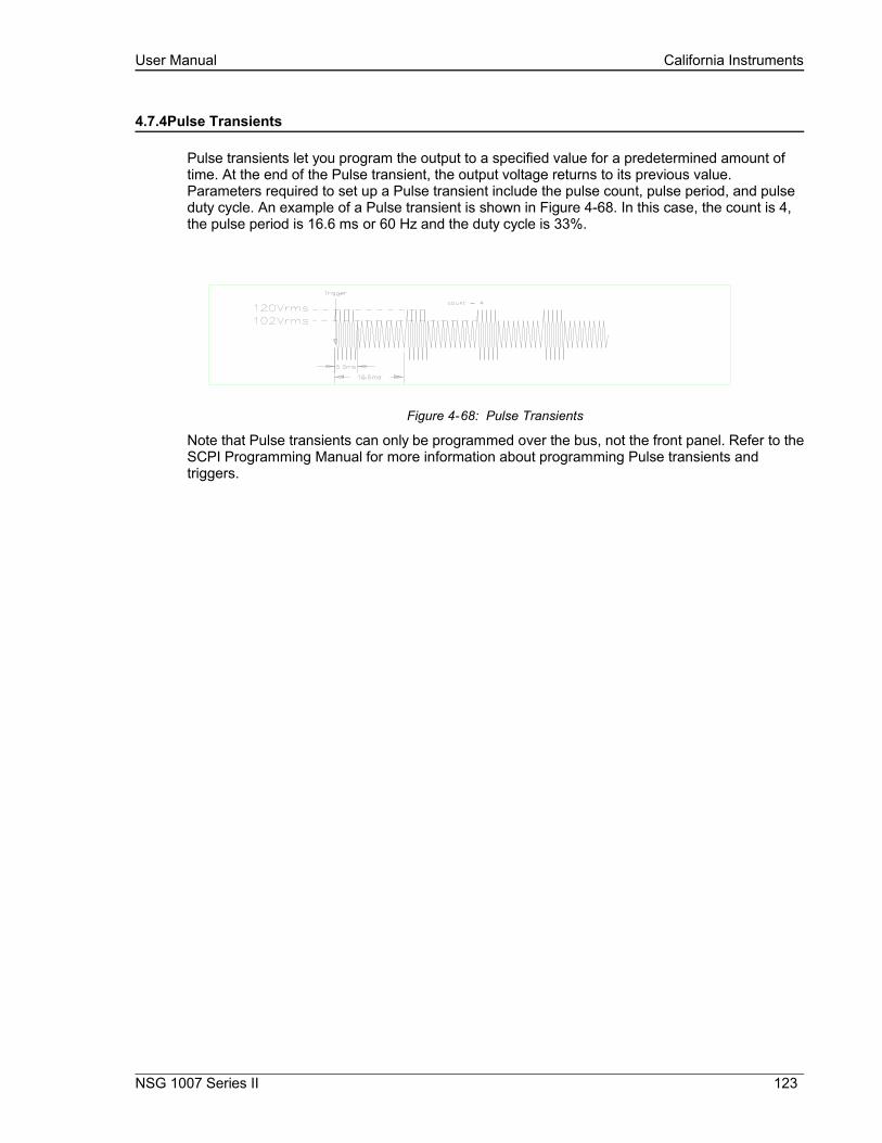
User Manual California Instruments
4.7.4Pulse Transients
Pulse transients let you program the output to a specified value for a predetermined amount of time. At the end of the Pulse transient, the output voltage returns to its previous value. Parameters required to set up a Pulse transient include the pulse count, pulse period, and pulse duty cycle. An example of a Pulse transient is shown in Figure 4-68. In this case, the count is 4, the pulse period is 16.6 ms or 60 Hz and the duty cycle is 33%.
Figure 4-68: Pulse Transients
Note that Pulse transients can only be programmed over the bus, not the front panel. Refer to the SCPI Programming Manual for more information about programming Pulse transients and triggers.
NSG 1007 Series II 123

User Manual California Instruments
4.7.5List Transients
List transients provide the most versatile means of controlling the output in a specific manner as they allow a series of parameters to be programmed in a timed sequence. The following figure shows a voltage output generated from a list. The output shown represents three different AC voltage pulses (160 volts for 33 milliseconds, 120 volts for 83 milliseconds, and 80 volts for 150 milliseconds) separated by 67 millisecond, zero volt intervals.
Transient list programming is supported from the front panel and may be accessed by selecting the TRANSIENTS entry in the MENU 1 screen. Transient lists can also be programmed over the bus. Refer to the SCPI Programming Manual for more information about programming List transients and triggers over the bus.
Figure 4-69: List Transients
The list specifies the pulses as three voltage points (point 0, 2, and 4), each with its corresponding dwell point. The intervals are three zero-voltage points (point 1, 3, and 5) of equal intervals. The count parameter causes the list to execute twice when started by a single trigger.
To set up this type of transient list, proceed as follows:
1. Press the PROG key to bring up the PROGRAM 1 menu.
2. Move the cursor to the VOLTAGE field and enter 0 Volt. Press ENTER to confirm your setting.
3. Make sure you are in the HIGH voltage range as we will program a surge to 160 V rms. The low range would only allow 150 V rms.
4. Press the MENU key to bring up MENU 1.
5. Move the cursor to the TRANSIENTS entry and press the ENTER key. You are now in the TRANSIENTS menu.
6. Move the cursor to the VOLT SURGE/SAG entry and press the ENTER key. You are now in the VOLT SURGE/SAG SETUP menu.
7. If you have a three phase configuration and are in the three phase mode, use the PHASE key to select all three phases. (øABC will be displayed in the top right corner of the screen.)
124 i Series II / NSG 1007 II / iM Series II
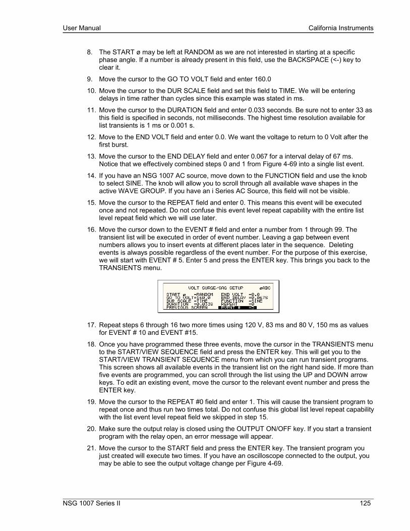
User Manual California Instruments
8. The START ø may be left at RANDOM as we are not interested in starting at a specific phase angle. If a number is already present in this field, use the BACKSPACE (<-) key to clear it.
9. Move the cursor to the GO TO VOLT field and enter 160.0
10. Move the cursor to the DUR SCALE field and set this field to TIME. We will be entering delays in time rather than cycles since this example was stated in ms.
11. Move the cursor to the DURATION field and enter 0.033 seconds. Be sure not to enter 33 as this field is specified in seconds, not milliseconds. The highest time resolution available for list transients is 1 ms or 0.001 s.
12. Move to the END VOLT field and enter 0.0. We want the voltage to return to 0 Volt after the first burst.
13. Move the cursor to the END DELAY field and enter 0.067 for a interval delay of 67 ms. Notice that we effectively combined steps 0 and 1 from Figure 4-69 into a single list event.
14. If you have an NSG 1007 AC source, move down to the FUNCTION field and use the knob to select SINE. The knob will allow you to scroll through all available wave shapes in the active WAVE GROUP. If you have an i Series AC Source, this field will not be visible.
15. Move the cursor to the REPEAT field and enter 0. This means this event will be executed once and not repeated. Do not confuse this event level repeat capability with the entire list level repeat field which we will use later.
16. Move the cursor down to the EVENT # field and enter a number from 1 through 99. The transient list will be executed in order of event number. Leaving a gap between event numbers allows you to insert events at different places later in the sequence. Deleting events is always possible regardless of the event number. For the purpose of this exercise, we will start with EVENT # 5. Enter 5 and press the ENTER key. This brings you back to the TRANSIENTS menu.
17. Repeat steps 6 through 16 two more times using 120 V, 83 ms and 80 V, 150 ms as values for EVENT # 10 and EVENT #15.
18. Once you have programmed these three events, move the cursor in the TRANSIENTS menu to the START/VIEW SEQUENCE field and press the ENTER key. This will get you to the START/VIEW TRANSIENT SEQUENCE menu from which you can run transient programs. This screen shows all available events in the transient list on the right hand side. If more than five events are programmed, you can scroll through the list using the UP and DOWN arrow keys. To edit an existing event, move the cursor to the relevant event number and press the ENTER key.
19. Move the cursor to the REPEAT #0 field and enter 1. This will cause the transient program to repeat once and thus run two times total. Do not confuse this global list level repeat capability with the list event level repeat field we skipped in step 15.
20. Make sure the output relay is closed using the OUTPUT ON/OFF key. If you start a transient program with the relay open, an error message will appear.
21. Move the cursor to the START field and press the ENTER key. The transient program you just created will execute two times. If you have an oscilloscope connected to the output, you may be able to see the output voltage change per Figure 4-69.
NSG 1007 Series II 125

User Manual California Instruments
Note: The AC source output remains at the last programmed values at the completion of the list.
In three-phase mode, the voltage lists are phase selectable. You can set up a different voltage list for each phase. To do this, use the PHASE key to choose the desired phase, as described in the example. Note that fields common to all phases such as DURATION, END DELAY and REPEAT always apply to all three phases in three-phase mode. When the cursor is moved to any of these fields, the phase enunciator in the top right-hand corner always reverts to øABC. Frequency transients are identical to voltage transients except they apply to all three phases at all times in a three-phase configuration.
4.7.6Programming Slew Rates
As shown in the previous examples there are a number of ways that you can generate custom waveforms. Programmable slew rates provide additional flexibility when customizing waveforms. Slew rates determine how fast the voltage or frequency is changed by the controller when a step, pulse, or list transient is triggered. Slew rates cannot be programmed from the front panel and are always set to their maximum values at power on. To use programmable slew rates, the AC source must be programmed over the bus. Refer to the SCPI Programming Manual for more information about programming slew rates.
126 i Series II / NSG 1007 II / iM Series II

User Manual California Instruments
4.7.7Switching Waveforms
The FUNCTION field available in each transient list event setup menu may be used to dynamically switch waveforms during transient execution. This allows different waveforms to be used during transient execution. Waveforms may be switched without the output of the source being turned off. For three phase configurations, each phase has its own waveform list so different waveforms may be programmed on different phases during transient execution.
Figure 4-70 illustrates the concept of using different waveforms at different steps in a transient list. In this case, the change was programmed to occur at the zero crossing. Any phase angle can be used to start a transient step however.
Figure 4-70: Switching waveforms in a transient list
NSG 1007 Series II 127
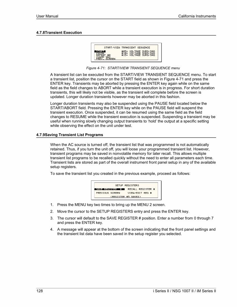
User Manual California Instruments
4.7.8Transient Execution
Figure 4-71: START/VIEW TRANSIENT SEQUENCE menu
A transient list can be executed from the START/VIEW TRANSIENT SEQUENCE menu. To start a transient list, position the cursor on the START field as shown in Figure 4-71 and press the ENTER key. Transients may be aborted by pressing the ENTER key again while on the same field as the field changes to ABORT while a transient execution is in progress. For short duration transients, this will likely not be visible, as the transient will complete before the screen is updated. Longer duration transients however may be aborted in this fashion.
Longer duration transients may also be suspended using the PAUSE field located below the START/ABORT field. Pressing the ENTER key while on the PAUSE field will suspend the transient execution. Once suspended, it can be resumed using the same field as the field changes to RESUME while the transient execution is suspended. Suspending a transient may be useful when running slowly changing output transients to ‘hold’ the output at a specific setting while observing the effect on the unit under test.
4.7.9Saving Transient List Programs
When the AC source is turned off, the transient list that was programmed is not automatically retained. Thus, if you turn the unit off, you will loose your programmed transient list. However, transient programs may be saved in nonvolatile memory for later recall. This allows multiple transient list programs to be recalled quickly without the need to enter all parameters each time. Transient lists are stored as part of the overall instrument front panel setup in any of the available setup registers.
To save the transient list you created in the previous example, proceed as follows:
1. Press the MENU key two times to bring up the MENU 2 screen.
2. Move the cursor to the SETUP REGISTERS entry and press the ENTER key.
3. The cursor will default to the SAVE REGISTER # position. Enter a number from 0 through 7 and press the ENTER key.
4. A message will appear at the bottom of the screen indicating that the front panel settings and the transient list data have been saved in the setup register you selected.
128 i Series II / NSG 1007 II / iM Series II
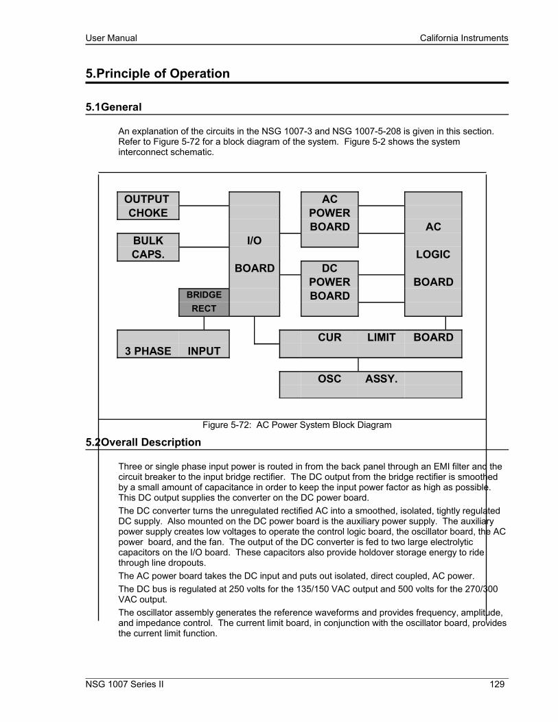
User Manual California Instruments
5.Principle of Operation
5.1General
An explanation of the circuits in the NSG 1007-3 and NSG 1007-5-208 is given in this section. Refer to Figure 5-72 for a block diagram of the system. Figure 5-2 shows the system interconnect schematic.
OUTPUT ACCHOKE POWER
BOARD ACBULK I/OCAPS. LOGIC
BOARD DCPOWER BOARD
BRIDGE BOARDRECT
CUR LIMIT BOARD3 PHASE INPUT
OSC ASSY.
Figure 5-72: AC Power System Block Diagram
5.2Overall Description
Three or single phase input power is routed in from the back panel through an EMI filter and the circuit breaker to the input bridge rectifier. The DC output from the bridge rectifier is smoothed by a small amount of capacitance in order to keep the input power factor as high as possible. This DC output supplies the converter on the DC power board.The DC converter turns the unregulated rectified AC into a smoothed, isolated, tightly regulated DC supply. Also mounted on the DC power board is the auxiliary power supply. The auxiliary power supply creates low voltages to operate the control logic board, the oscillator board, the AC power board, and the fan. The output of the DC converter is fed to two large electrolytic capacitors on the I/O board. These capacitors also provide holdover storage energy to ride through line dropouts. The AC power board takes the DC input and puts out isolated, direct coupled, AC power.The DC bus is regulated at 250 volts for the 135/150 VAC output and 500 volts for the 270/300 VAC output.The oscillator assembly generates the reference waveforms and provides frequency, amplitude, and impedance control. The current limit board, in conjunction with the oscillator board, provides the current limit function.
NSG 1007 Series II 129
User Manual California Instruments
The assemblies are described in more detail in the following paragraphs. Refer to Figure 5-72 for an overall block diagram.
5.3Oscillator Assembly
The oscillator assembly consists of three printed circuit board assemblies connected by a ribbon cable. The oscillator generates the sine wave signal setting the frequency, amplitude and current limit level. It also senses the output voltage to provide closed loop control of the output.
5.3.1CPU Board
This board assembly, A7, consists of the components for the CPU (DSP), generating the Phase waveform signals to the power amplifiers, programmable impedance (iX models only) and all of the program, waveform and data memory. In addition, the waveform board contains the circuits for all measurements. The clock and lock circuit required to support the clock and lock mode of operation of multiple i/iX units is also on this board assembly. For three phase i/iX models, all three phases are contained on the same board assembly 7003-718-3 (1 phase) or 7003-718-1 (3 phase). If the -413 option is present, a separate inter harmonic generator board is connected to the CPU board.
5.3.2Keyboard/Display Board
The keyboard/display assembly is assembly A9. It is mounted to the front panel and holds the 23 rubber keys. It also has the LCD graphics display. A shaft encoder is mounted on the board that is used for a shuttle input.
5.3.3GPIB / RS232 or GPIB / RS232 / USB / LAN IO Board
This board assembly is identified as A10. It has the IEEE 488, RS232 and USB transceivers and optionally an Ethernet interface (-LAN option). USB and LAN are available on top assembly 7000-485 and 7000-486 iX/i models only. It also has isolators to provide safety isolation for all control interfaces.
130 i Series II / NSG 1007 II / iM Series II

User Manual California Instruments
Figure 5-73: Power Source Module Block Diagram
NSG 1007 Series II 131

User Manual California Instruments
5.4Current Limit Board
The current limit board, A6, receives the oscillator signal and passes it through to the amplifier. All current limit functions are handled by the 7003-718 CPU board.
When two or three units are connected as a single-phase system the MRA output from the master oscillator amplifier drives all the power amplifiers over the system interface cable.
An over current condition on any amplifier will act to reduce the output voltage and put the entire system into the constant current mode.
5.5Auxiliary Power Supply
The auxiliary power supply is mounted on the DC-DC power board. This assembly generates nine low voltage outputs. These outputs from the auxiliary power supply provide logic power to all the modules.
a) +/- 18V to the AC logic board and the oscillator.
b) +8V to the oscillator.
c) + 15V to the DC-DC converter.
d) Three + 18V supplies to the AC power amplifier gate drives.
e) +24V for the fan and relay power.
f) +8V for the digital front panel meter or GPIB/RS232 board.
All the supplies a), b) and e) have a common ground. The supplies in c) and d) are all isolated from each other and from a), b) and e). LED’s on the AC logic board and the AC power board are lit when each output is in regulation. If an overload condition causes the output to drop more than 10% or the output has failed, the corresponding LED will extinguish. This feature is helpful in troubleshooting the unit. See Service section 7.
132 i Series II / NSG 1007 II / iM Series II
User Manual California Instruments
5.6DC-DC Power Converter
The DC-DC power converter, A3, is powered from the rectified AC input. The converter is a PWM (pulse width modulated) full bridge type that uses IGBT’s as the power switches. The control logic supply for the DC-DC converter is derived from the auxiliary power supply so the DC-DC converter does not start switching until after the auxiliary power supply has started up and comes into regulation. This feature ensures a smooth start up.
The output of the DC converter is automatically selected for 250 VDC or 500 VDC output depending on whether the low range output (150 Vac) or high range output (300 Vac) is selected. The 250/500 VDC range selection is made by a relay that selects one of two taps on the DC output transformer. The converter is fully protected with input current limit and overvoltage protection. When the output of the DC converter is up and in regulation, the LED on the input/output board will be lit. The LED can only be seen by looking directly down between the large storage capacitors and the input/output board. (See Figure 5-74)
5.7AC Control Logic
The main function of the control board, A4, is to generate the gate drive signals for the AC power stage. This board also includes the circuit for the current limit and when two or three units are operated in parallel, the load sharing circuit. (See Figure 5-77)
The signal from the oscillator is fed through a low pass filter circuit and sent to the reference input of the error amplifier. The voltage output of the unit is differentially sensed and fed back to the error amplifier thereby completing the control loop. The output of the error amplifier drives a 37.5 kHz pulse width modulator. The modulator output is sent to four gate drivers which drive the IGBT’s on the AC power board after going through opto couplers that provide the necessary isolation.
NSG 1007 Series II 133

User Manual California Instruments
Figure 5-74: 5001i Internal Layout
134 i Series II / NSG 1007 II / iM Series II

User Manual California Instruments
Figure 5-75: Logic Board LED's
NSG 1007 Series II 135

User Manual California Instruments
There are six LED indicators on the logic board. Their positions are shown in Figure 5-75. The LED functions are listed in Table 5-8.
Table 5-8: Logic Board LED’s
LED# FUNCTION COMMENTS
DS2 +15V +15V logic supplyDS3 -15V -15V logic supplyDS4 +8V +8V oscillator supplyDS7 +24V +24V supply for relays and logic.DS5 PARALLEL LED should be lit when units are paralleled and K1 is closed.DS1 FAULT LED is lit - unit normal. No light indicates pwr. stage failed
5.8AC Power Board
The AC power assembly takes a 250V/500V DC input and generates a 150V/300V AC direct coupled output. The AC power amplifier is a full bridge inverter with three paralleled IGBT’s in each leg for a total of twelve IGBT’s. The switching frequency of the bridge is 37.5 kHz and this frequency is smoothed out by two inductors that are mounted behind the input/output board and several smoothing capacitors on the AC power board to provide a precision low frequency (16-500 Hz) output. (See Figure 5-74 and Figure 5-76)
Three isolated 18V supplies provide power for the gate drives. The 18V is regulated down to 15V by three TO220 regulators that are mounted on three discrete sheet metal heat sinks. If the 15V is in regulation, an LED will be lit in front of each heat sink. There is a red, a green and an orange LED, one for each supply. The other four green LED’s will be lit when there is gate drive present at the IGBT’s. If the green LED’s are not lit there will be no gate drive and hence no output.
5.9Input/Output Board
The input/output board holds a lot of the large components and provides interconnection between the AC input, the DC-DC board, the AC power board and the output without the use of heavy cables. The output relay and the output current metering circuit are also mounted on this board. The output AC inductors, the DC-DC transformer and the DC output choke are mounted on brackets behind the input/output board. These brackets also provide support for the input/output board.
136 i Series II / NSG 1007 II / iM Series II

User Manual California Instruments
NSG 1007 Series II 137
Figure 5-76: AC Power Stage LayoutFigure 5-77: AC Control Logic Block Diagram

User Manual California Instruments
CAUTIONVOLTAGES UP TO 480 VAC AND 700 VDC ARE PRESENT IN
CERTAIN SECTIONS OF THIS POWER SOURCE. THIS EQUIPMENT GENERATES
POTENTIALLY LETHAL VOLTAGES.
DEATH ON CONTACT MAY RESULT IF PERSONNEL FAIL TO OBSERVE SAFETY PRECAUTIONS. DO NOT TOUCH ELECTRONIC CIRCUITS WHEN POWER IS APPLIED.
138 i Series II / NSG 1007 II / iM Series II

User Manual California Instruments
6.Calibration
The Routine Calibration should be performed every 12 months. Non-routine Calibration is only required if a related assembly is replaced or if the periodic calibration is unsuccessful.
All standard models and configurations of the iX /i / iM Series may be calibrated using a PC running Windows 2000/XP, and the latest version of the CIGuiSII AC source control software. Refer to the CIGuiSII online help file of the CIGUISII software for additional procedures and guidance. To download the latest version of the CIGUISII, visit www.calinst.com.
For iM Series II model calibration, refer to the I Series II model information in this chapter.
6.1Calibration Equipment
Digital Phase Meter: Krohn-Hite, Model 6620 or equivalent. (0.01° resolution, 0.02° accuracy.)
Digital Multimeter: Fluke 8506A or equivalent.HP 34401A
10 milliohm Current Shunt: Isotek Model RUG-Z-R010-0.1 or equivalent
1 milliohm Current Shunt: Isotek Model RUG-Z-R001-0.1(10001i/iX, 15001i/ix andNSG 1007-15-208-MODE):
Load Bank: Various high power load resistors will be needed.
Computer (Optional) PC to operate Teseq GUI.
6.2Calibration Screen Access
Output
To access the OUTPUT CALIBRATION screen for the first time press the MENU key twice to display the MENU 3 screen. Press the ↑ or ↓ key several times to highlight OUTPUT CAL. Press the ENTER key.
Type 5000 and press the ENTER key to show the OUTPUT CALIBRATION screen.
Press the PHASE key to select the phase to be calibrated for a 9003i/iX ,10002i/iX or 15003i/iX power system.
Measurements
To show the MEASUREMENT CALIBRATION screen follow the steps in paragraph 6.2.
Select the MEASUREMENT CAL function instead of OUTPUT CAL from the MENU 2 screen.
If another CALIBRATION screen has been accessed since power-up no password is needed. If prompted for a password, use the value 5000.
NSG 1007 Series II 139

User Manual California Instruments
6.3Routine Measurement Calibration
Note: The Fluke 8506A Digital Multimeter must be used for the following calibration. The 8506A must be set to the AC HI ACCUR mode for all AC measurements.
Connect the test equipment to the power source as shown in Figure 6-2. If the power system is a multi-phase system with one controller, the DVM for calibrating the measurement voltage should always be connected to the Remote Sense connector (TB3) on the Phase A power source.
The shunt must be connected to the power source as shown in Figure 6-78. If the Current measurement can’t be successfully performed, adjust the Current Measurement Pot. This adjustment is described in the Non-routine Calibration section of this manual. If the DC current measurement displays more than 70 counts on the display, perform the non-routine current monitor adjustment.
Connect the load to the output. Recommend current shunt values are 0.010 ohm for 3001/5001/9003/15003 and 0.001 ohm for 10001, 15001.
To calibrate all measurement functions, the desired value for the measurement value of current or voltage must be entered for the corresponding calibration value. Make the indicated adjustments by typing in the desired display value. This should be the value indicated by the external DVM. If a 10 milliohm current shunt is used for current, 300 mV represents 30 amps.
The Measurement Calibration Table is a summary of the measurement calibration procedure. The following text is a detailed explanation of the procedure.
PARAMETER POWER SYSTEM
3001 / 9003 5001 / 15003 10001 / 30003 15001
AC Current Full-Scale 6.0 Ω, 3 KW 3.6 Ω, 5 KW 1.8 Ω, 10 KW 1.3 Ω, 15 KW
DC Current Full-Scale 13.5 Ω, 1.5 KW 4.8 Ω, 3.5 KW 2.4 Ω, 7 KW 1.6 Ω, 10.5 KW
Table 6-9: Calibration Load For Each Phase
140 i Series II / NSG 1007 II / iM Series II

User Manual California Instruments
Figure 6-78: Test Equipment Hook-up for Measurement Calibration
NSG 1007 Series II 141

User Manual California Instruments
Note: The Fluke 8506A Digital Multimeter must be used for the following calibration. The 8506A must be set to the AC HI ACCUR mode for all AC measurements.
AC Volt Full-scale:
1. Select the AC mode of operation.
1. Program the output to the 300 VAC range. Close the output relay.
2. Program the output to 240 volts and 60 Hz.
3. Go to the MEASUREMENT CALIBRATION screen.
4. Enter the actual AC output voltage for the VOLT FS parameter and press the ENTER key.
5. Allow the controller to complete the calibration cycle. This may take several minutes.
6. When completed, the new cal coefficient will be displayed.
7. Press the SET key to save the new calibration coefficients.
AC Current Full-scale:
2. Select the AC mode of operation.
3. Apply a load to the output. Refer to Table 6-9.
4. Program the output to 135 VAC and 60 Hz on the 150 Volt AC range.
5. Observe the actual output current and enter this value for the CURR FS parameter. Press the ENTER key.
6. Allow the controller to complete the calibration cycle. This may take several minutes.
7. When completed, the new cal coefficient will be displayed.
8. Press the SET key to save the new calibration coefficients.
DC Volt Full-scale:
1. Select the DC mode of operation.
2. Program the output to the 400 VDC range. Close the output relay.
3. Program the output to 320 volts DC.
4. Go to the MEASUREMENT CALIBRATION screen.
5. Enter the actual DC output voltage for the VOLT FS parameter and press the ENTER key.
6. Allow the controller to complete the calibration cycle. This may take several minutes.
7. When completed, the new cal coefficient will be displayed.
8. Press the SET key to save the new calibration coefficients.
DC Current Full-scale:
1. Select the DC mode of operation.
2. Apply a load to the output. Refer to Table 6-9.
3. Program the output to 120 VDC on the 200 Volt DC range.
4. Observe the actual output current and enter this value for the CURR FS parameter. Press the ENTER key.
142 i Series II / NSG 1007 II / iM Series II

User Manual California Instruments
5. Allow the controller to complete the calibration cycle. This may take several minutes.
6. When completed, the new cal coefficient will be displayed.
7. Press the SET key to save the new calibration coefficients.
TITLE PROGRAM / LOAD PARAMETERS PARAMETER ADJUST TO
AC Volt Full-scale 240 VAC, 60 Hz VOLT FS Vac
AC Current Full-scale 150 Range, 135 VAC, full load CURR FS Iac
DC Volt Full-scale 320 VDC VOLT FS Vdc
DC Current Full-scale 200 Range, 120 VDC, full load CURR FS Idc
Table 6-10: Measurement Calibration Table
For a multi-phase power system that uses one controller, 9003i/iX, 10002i/iX, 15003i/iX or 30003i/iX, repeat paragraph 6.3 for each phase. Move the external test equipment to the phase that is being calibrated. Refer to Figure 6-78.
While viewing the calibration screen, press the PHASE key to select the respective phase.
NSG 1007 Series II 143

User Manual California Instruments
6.4Routine Output Calibration
Connect the test equipment to the power source as shown in Figure 6-79. If any output parameter can’t be calibrated refer to the Power Source Gain Adjustment in the Non-routine Output Calibration section of the manual.
The AC output calibration does not require an AC DVM operating with the highest accuracy. Either a Fluke 8506A or a HP 34401A may be used. If a HP 34401A is used it must be put into the slow filter mode.
1. Connect the DVM across the Phase A output terminals and set to VDC mode.
2. To show the OUTPUT CALIBRATION screen for the first time, choose OUTPUT CAL from the MENU screen.
3. Type 5000 as the password.
4. Press the PHASE key to select the phase to be calibrated.
5. All output adjustments will be made in the OUTPUT CALIBRATION screen.
6. If the VOLT FS coefficient for the selected phase is considerably different from 21000, enter 21000 using the numeric keypad.
7. Program the power source to the AC mode, ALC OFF, 300V AC range and 0.0 V.
8. Close the output relay (Output ON)
9. Adjust the VOLT ZERO for minimal DC offset.
10. Change the DVM to VAC mode and program 240VAC, 60 Hz.
11. Adjust the VOLT FS cal coefficient up or down until the DVM reads 240Vac ± 0.10 VAC.
12. Press the SET key to save the new coefficient values.
13. Repeat this test for the Phase B and C outputs respectively.
Summary output calibration table:
TITLE PROGRAM VALUES CALIBRATION VALUE ADJUST TO
High VAC range DC Zero 300V range, 0.0 V VOLT ZERO 0 ± 15 mv DC
High VAC range Volt FS 240.0 V, 60 Hz VOLT FSHint: This value should be around 21000. For a quick adjustment first program this value with the keypad.
240 ± 0.10 VAC
Table 6-11: Output Calibration Table
144 i Series II / NSG 1007 II / iM Series II

User Manual California Instruments
Figure 6-79: Test Equipment Hookup for Routine Output Calibration
NSG 1007 Series II 145

User Manual California Instruments
6.5Output Impedance Calibration
Note: Applies to NSG 1007-3, NSG 1007-5-208, NSG 1007-9, and NSG 1007-15-208 models only.
For the output impedance calibration, one or two HP 34401A DMM's or equivalent may be used. The following modes must be programmed: 6 digits, AC Filter, slow: 3 Hz and 6 digits. One DMM is used to measure the output voltage, one to measure the load current using a suitable CT. A single DMM may be switched between front and rear inputs to toggle between voltage and current measurements.
The calibration should be done for each phase individually. Furthermore, an accurate phase meter with at least 0.01° resolution is needed. (See equipment list section 6.1). The reference input of the phase meter must be connected to the LOCK output of the controller at the rear panel of the master NSG 1007-5-208 chassis. This is a square wave TTL signal. Select Square wave input on the phase meter. The other input of the phase meter must be connected at the AC source output of the phase being calibrated. Select Sine wave input on the phase meter for this input. Note that this is a 230 Vrms signal so the Phase Meter must have sufficient input range on this input. The phase meter is used to determine the phase shift between no load and full load conditions (∆Φ).
The readings from the DMM's and Phase meter should be written down to aid with calculations. A calculator is used to calculate the R and L portions of the impedance using the formulas shown in Table 6-13.
To verify or adjust the programmable impedance function, proceed as follows for each phase:
1. Program the power source to 230.0VAC and 50Hz.
2. Program the output impedance resistance and inductance to the lowest values from the OUTPUT IMPEDANCE screen. This will be the IMP. REAL MIN and IMP. REACT MIN values that have been set in the OUTPUT CAL screen. Press the PHASE key to select the phase to be calibrated. (A, B or C).
3. Measure the output voltage of the power source with no load and record this value (VNL).
4. Using a resistive load bank, load the output of the power source to about 16 amps. Measure the output voltage of the power source under load and record this value (VL). Also measure the load current and record this value. (I).
5. Calculate the resistive and inductive component R and L using the formulas shown in Table6-13.
6. Enter these values, in the OUTPUT CAL screen for the IMP. REAL MIN and IMP. REACT MIN value respectively. Make sure the correct phase is selected or use the PHASE key if not.
7. Remove or turn off the load.
8. From the MENU 3 screen, select OUTPUT IMPEDANCE. Press the PHASE key to select the phase to be calibrated. Program the output inductance to 796 uH and the resistance to 400 mOhms.
9. Select the Calibration, Output screen and move the cursor to the IMP REAL FS field. Measure the R and L by removing and applying the load as described before and calculating the R and L using the formula's in Table 6-12.Adjust the resistive output impedance using the shuttle until the measured output is as close as possible to 400 mOhm. Make sure the correct phase is selected or use the PHASE key if not. Do the same with the IMP REACT FS field. Note that the adjustment range for R is 0 to 100, for L is 0 to 300.
146 i Series II / NSG 1007 II / iM Series II

User Manual California Instruments
10. If there is not enough range in the full-scale calibration coefficient for either resistive or inductive portion, it may be necessary to tweak the adjustment pots on the iX controller. These pots were originally adjusted at the factory and normally do not have to be adjusted again. The Full Scale calibration coefficients should have enough adjustment range. Double check the connections and phase measurements if this is not the case to make sure the measurement readings you get are indeed correct.If it is necessary to adjust the pots, see Table 6-12 for the corresponding pot designators. The top cover has to be removed to access these pots. They are located along the top edge of the 7003-718 controller board.
11. Repeat steps 2 through 10 for phase B and C. (except on single phase only models.)
Phase / Board Assembly # R resistive Xl inductivePhase A (7003-718-1 / 7003-718-3) R121 R122Phase B (7003-718-1) R112 R111Phase C (7003-718-1) R114 R115
Table 6-12: Programmable Z adjustment pots
Definitions:
VNL = Measured RMS voltage under no load.
VL = Measured RMS voltage under load
I = Measured RMS current.
F = Source frequency (50 Hz).
∆Φ= Phase angle shift between load and no load conditions. Record phase angle from phase meter under NL and L condition and determine phase shift.
Formulas to calculate R and L component of output impedance:
R = ( VNL * cos(∆Φ) - VL ) / I
XL = ( VNL * sin(∆Φ)) / I
L = XL / (2 * Pi * F)
Table 6-13: Formulas to calculate R and L
NSG 1007 Series II 147

User Manual California Instruments
6.6Non-Routine Calibration
All internal adjustments are set at the factory at the time or original shipment. As such, non-routine calibration is generally not required unless one or more amplifier assemblies have been replaced in the field. In this case, perform the following sections in the order shown.
The non-routine calibration involves removing the top cover from the power source. Remove the line power from the power source before removing the top cover. Most of the adjustments are on the Current Limit Assembly. One adjustment is on I/O Board Assembly. Refer to Figure 6-80 for the location of the adjustments.
6.6.1DC Offset Adjustment
1. Turn off the AC input power to the power source using the front circuit breaker. Not that AC voltage is still present inside the unit so DO NOT touch the contacts of the circuit breaker inside the unit.
2. Connect a 22 µF tantalum capacitor in series with a 100kΩ 1% resistor across the output.
3. Connect a DVM to read DC volts across the capacitor.
4. Short test point TP1 to test point TP6 on the Current Limit Board using a jumper wire.
5. Power up the unit in AC mode, 150 VAC range, 0.0 V programmed and close the output relay. Adjust the DC offset to 0.0 mVDC +/-5.0 mVDC using R95 on the AC Logic Board.
6. Remove short on the Current Limit Board.
7. Open the output relay when done.
6.6.2Current Monitor Offset Adjustment
1. Select Phase A.
2. Program the 300 VAC range, 0.0 volts, and turn the Output ON.
3. On the current limit board, monitor test point TP5 with respect to test point TP1 (common) using a DMM in VDC mode.
4. Adjust R23 on the input/output board for 0.0 mVDC ± 0.5 mVDC on TP5.
5. Cycle the AC input power using the front panel circuit breaker.
CAUTION: Use extreme care in adjusting R23. Do not touch any connections on the Input/Output Board Assy. Dangerous voltages exist on most exposed connections.
148 i Series II / NSG 1007 II / iM Series II
User Manual California Instruments
6.6.3Power Source Gain Adjustment:
To make this adjustment the top cover must be removed and voltages must be monitored at various test points. The test point used depends upon the phase (chassis) to be adjusted. The adjustment is R14 on the Current Limit Board. Refer to Figure 6-80 for the location R14 on the Current Limit Board.
1. Monitor the AC output of the Phase A power source using a DMM in VAC mode.
2. Turn the ALC mode OFF in the UTILITY, VOLTAGE CURRENT control screen of the master power source. The ALC mode would interfere with this adjustment if left ON.
3. Select AC mode, high voltage range and program 240 VAC.
4. Program the frequency to 60 Hz.
5. Record the output voltage with the external AC DVM. Make no adjustment at this point.
6. Now program 400 Hz and adjust R14 to the AC output recorded in step 5.
7. Repeat steps 4 through 6 until the voltage at 400 Hz is within ± 1.0 VAC of the voltage at 60 Hz.
For multiphase power systems with one controller, 9003i/iX, 10002i/iX or 15003i/iX, the adjustment for Phase B and C must be made to R14 on the Current Limit Board for the power source chassis of the respective phase.
For 30003i/iX systems, the adjustment must be made to all six chassis’ current limit boards.
6.6.4Output Adjustment:
Connect the test equipment to the power source as shown in Figure 6-79. The AC output calibration does not require an AC DVM operating with the highest accuracy. Either a Fluke 8506A or a HP 34401A may be used. If a HP 34401A is used it must be put into the slow filter mode.
Proceed as follows:
1. Program the power source to the AC mode, ALC OFF,
2. Select the Low AC voltage range (150VAC range)
3. Program 10VAC and 60 Hz.
4. Connect the AC DVM across the Phase A output terminals.
5. Close the output relay (Output ON)
6. Adjust R234 on the Controller to obtain a 10 VAC reading on the DVM.
7. Repeat this test for the Phase B and C output terminals but adjust R235 for Phase B and R236 for Phase C. The DMM connections must be moved to phase B and phase C respectively.
Next, perform the output calibration as shown in 6.4.
NSG 1007 Series II 149
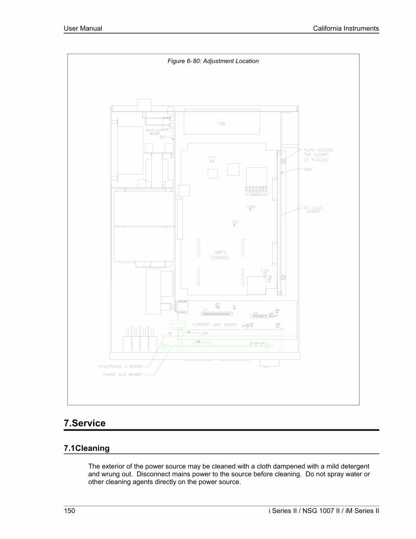
User Manual California Instruments
7.Service
7.1Cleaning
The exterior of the power source may be cleaned with a cloth dampened with a mild detergent and wrung out. Disconnect mains power to the source before cleaning. Do not spray water or other cleaning agents directly on the power source.
150 i Series II / NSG 1007 II / iM Series II
Figure 6-80: Adjustment Location

User Manual California Instruments
7.2General
This section describes the suggested maintenance and troubleshooting procedures. The troubleshooting procedure is divided into two sections. The first section deals with basic operation and connection of the equipment. The second section requires opening the unit and using the LED indicators and a simple multimeter to troubleshoot the unit down to the module level. Only a qualified electronic technician should attempt this level troubleshooting.
7.3Basic operation
Table 7-14: Basic Symptoms
PARAGRAPH PROBLEM
7.3.1 Excessive Output Voltage7.3.2 Poor Output Voltage Regulation7.3.3 Overload Light On7.3.4 Distorted Output7.3.5 Unit Shuts Down After 1-2 Seconds 7.3.6 No Output and no lights on front panel7.3.7 No output but “power on” LED on front panel is lit.
7.3.1Excessive Output Voltage
CAUSE SOLUTION
External sense not connected Connect the external sense to the AC power outlet TB2.
7.3.2Poor Output Voltage Regulation
CAUSE SOLUTION
Unit is overloaded Remove overloadUnit is programmed to wrong voltage range.
Select correct voltage range.
Input line has fallen below spec. limit. Check supply voltage.
7.3.3Overload Light is On
CAUSE SOLUTION
Unit is overloaded Remove overloadUnit is switched to high voltage range. Select correct voltage range.
7.3.4Distorted Output
CAUSE SOLUTION
Power source is grossly overloaded. Reduce loadThe crest factor of the load exceeds 3:1 on the low range or 5:1 on the high range.
Reduce load current peaks by reducing load.
NSG 1007 Series II 151

User Manual California Instruments
7.3.5Unit Shuts Down after 1-2 Seconds
CAUSE SOLUTION
Output shorted Remove output shortOutput grossly overloaded. Remove overload.Operating load with too high inrush or start up currents.
Consult factory for application advice.
7.3.6No Output and No Lights on Front Panel
CAUSE SOLUTION
Input circuit breaker switched off. Switch the breaker on.No input power to TB3. Ensure 3 phase power is getting to TB3.Unit tripped on overvoltage or overcurrent. Turn circuit breaker off - wait five seconds
- turn circuit breaker back on.
7.3.7No Output But “Power On” LED on Front Panel is Lit
CAUSE SOLUTION
“OUTPUT ON” switch is turned off. Turn OUTPUT ON switch to “ON”.REMOTE SHUTDOWN logic line at J22 pin 36 is shorted to D COM or A COM.
Remove connection from J22 pin 3.
Current limit programmed down or to zero. Program current limit higher.Voltage programmed down or to zero. Turn amplitude control up.Unit tripped on overvoltage or overcurrent. Turn circuit breaker off - wait five seconds
- turn circuit breaker back on.
152 i Series II / NSG 1007 II / iM Series II

User Manual California Instruments
7.4Advanced Troubleshooting.
WARNING: Do not connect 400-480V into the 208-240V unit, the result could be a severely damaged unit.
CAUTION: VOLTAGES UP TO 480 VAC AND 700 VDC ARE PRESENT IN CERTAIN SECTIONS OF THIS POWER SOURCE.
WARNING: THIS EQUIPMENT GENERATES POTENTIALLY LETHAL VOLTAGES. DEATH ON CONTACT MAY RESULT IF PERSONNEL FAIL TO OBSERVE SAFETY PRECAUTIONS. DO NOT TOUCH ELECTRONIC CIRCUITS WHEN POWER IS APPLIED
7.4.1Switch Off Unit
Switch of the unit at the circuit breaker on the front panel as well as removing the input power from the unit.
WARNING: Wait 10 minutes for all internal capacitors to discharge.
7.4.2Removing Top Cover
Remove the screws securing the top cover and remove the top cover.
7.4.3Initial Inspection
Make a visual inspection of the unit and ensure all the connectors are properly mated and there are no loose or broken wires.
NSG 1007 Series II 153

User Manual California Instruments
7.4.4Fuse Check
See Figure 5-74 and Figure 5-76. Check the fuse F1 on the AC power board at the top of the unit using the ohmmeter. If the fuse is open do not replace but check all the IGBT’s. To check the IGBT’s connect the positive lead of the ohmmeter to the collector (center leg) and measure the resistance to the gate and the emitter (outside legs) of each IGBT. If the resistance reading is lower than 1000 ohms it indicates a blown IGBT. The IGBT’s are not field replaceable and the module should be returned to the factory for exchange or repair. See paragraph 7.4.6. for disassembly instructions. If a low resistance reading is not found, replace the fuse and proceed with the check procedure.
Check the fuse F1 on the end of the input/output board. If the fuse is blown do not replace but proceed to paragraph 7.4.6 for disassembly instructions and remove the AC power board. With the AC power board removed check the IGBT’s Q2 through Q9 using the procedure detailed in the paragraph above. See Figure 6-1: Internal Top View of DC-DC Converter Board.
If one or more IGBT’s show a low resistance reading do not replace the fuse but return the module to the factory for exchange or repair. If a low resistance is not found, replace the fuse and carry on with the check procedure.
7.4.5Power-on Troubleshooting Using the LED’s.
If no fuses were blown or if fuses were found blown but all the IGBT’s checked out as good, replace blown fuses and reconnect power to the unit.
WARNING: Do not touch any parts inside the unit during this test as they will be live and dangerous. Always wear safety glasses.
Auxiliary PS: Turn the main breaker on and check the LED’s on the AC logic board.(see Figure5-75). The +15V (DS2-red), -15V (DS3-green), and the 24V (DS7-amber) LED’s located at the top right of the board should all be lit. The 8V logic supply LED (DS4- red) should be lit. On the AC power board (see Figure 5-76) the three gate drive power supply lights, DS5-green, DS6-amber, and DS7-red, should all be lit. If any of these LED’s are not lit then the most likely cause is a blown fuse. These logic power fuses are all located on the DC-DC board. Switch the unit off at the front panel breaker and remove the input power.
Wait 10 minutes to allow the capacitors to discharge before attempting to disassemble the unit.
Proceed to paragraph 7.4.6. for disassembly instructions. Remove the AC power board and locate the P.C. mount fuses F2 through F10 (see Table 7-15 for fuse functions). Replace any blown fuses. Always replace fuses with same type and rating. (See Table 8-17.)
154 i Series II / NSG 1007 II / iM Series II
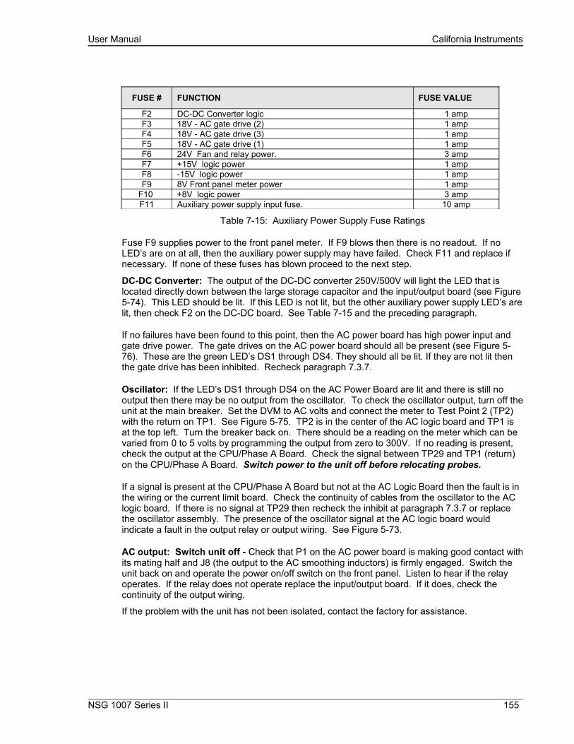
User Manual California Instruments
FUSE # FUNCTION FUSE VALUE
F2 DC-DC Converter logic 1 ampF3 18V - AC gate drive (2) 1 ampF4 18V - AC gate drive (3) 1 ampF5 18V - AC gate drive (1) 1 ampF6 24V Fan and relay power. 3 ampF7 +15V logic power 1 ampF8 -15V logic power 1 ampF9 8V Front panel meter power 1 amp
F10 +8V logic power 3 ampF11 Auxiliary power supply input fuse. 10 amp
Table 7-15: Auxiliary Power Supply Fuse Ratings
Fuse F9 supplies power to the front panel meter. If F9 blows then there is no readout. If no LED’s are on at all, then the auxiliary power supply may have failed. Check F11 and replace if necessary. If none of these fuses has blown proceed to the next step.
DC-DC Converter: The output of the DC-DC converter 250V/500V will light the LED that is located directly down between the large storage capacitor and the input/output board (see Figure5-74). This LED should be lit. If this LED is not lit, but the other auxiliary power supply LED’s are lit, then check F2 on the DC-DC board. See Table 7-15 and the preceding paragraph.
If no failures have been found to this point, then the AC power board has high power input and gate drive power. The gate drives on the AC power board should all be present (see Figure 5-76). These are the green LED’s DS1 through DS4. They should all be lit. If they are not lit then the gate drive has been inhibited. Recheck paragraph 7.3.7.
Oscillator: If the LED’s DS1 through DS4 on the AC Power Board are lit and there is still no output then there may be no output from the oscillator. To check the oscillator output, turn off the unit at the main breaker. Set the DVM to AC volts and connect the meter to Test Point 2 (TP2) with the return on TP1. See Figure 5-75. TP2 is in the center of the AC logic board and TP1 is at the top left. Turn the breaker back on. There should be a reading on the meter which can be varied from 0 to 5 volts by programming the output from zero to 300V. If no reading is present, check the output at the CPU/Phase A Board. Check the signal between TP29 and TP1 (return) on the CPU/Phase A Board. Switch power to the unit off before relocating probes.
If a signal is present at the CPU/Phase A Board but not at the AC Logic Board then the fault is in the wiring or the current limit board. Check the continuity of cables from the oscillator to the AC logic board. If there is no signal at TP29 then recheck the inhibit at paragraph 7.3.7 or replace the oscillator assembly. The presence of the oscillator signal at the AC logic board would indicate a fault in the output relay or output wiring. See Figure 5-73.
AC output: Switch unit off - Check that P1 on the AC power board is making good contact with its mating half and J8 (the output to the AC smoothing inductors) is firmly engaged. Switch the unit back on and operate the power on/off switch on the front panel. Listen to hear if the relay operates. If the relay does not operate replace the input/output board. If it does, check the continuity of the output wiring.
If the problem with the unit has not been isolated, contact the factory for assistance.
NSG 1007 Series II 155

User Manual California Instruments
7.4.6Disassembly Procedure
Disconnect mains power to the source and wait 10 minutes to allow the capacitors to discharge before attempting to disassemble the unit. Remove the top cover, unplug P7 from the current limit board, and unplug the fan from the AC logic board connector. Then carefully unplug the AC logic board from the AC and the DC power boards. The AC logic board can then be lifted from the unit.
Using a 5/16 inch socket driver remove the four bolts that hold the AC power module heat sink. There is one bolt at each corner. Carefully remove all the hardware from the unit. The AC power module can now be unplugged from the input/output board and removed from the unit.
The DC - DC module can be unplugged by first removing the two nuts holding the clamp that secures the heat sink to the chassis. See . Care must be taken in unplugging the two connectors P4 and J12.
To reassemble, reverse the above procedure, taking care to ensure J12 on the DC-DC board and J8 on the AC board are properly mated. This may entail supporting the connector from behind with a screwdriver.
156 i Series II / NSG 1007 II / iM Series II
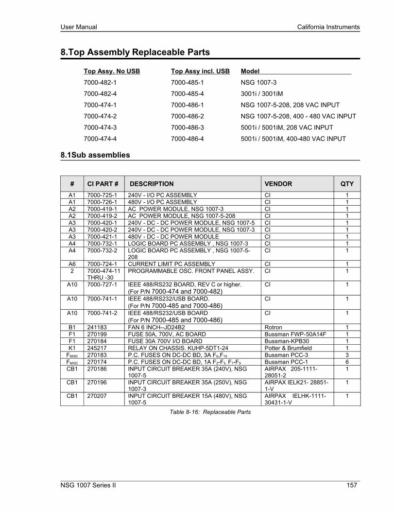
User Manual California Instruments
8.Top Assembly Replaceable Parts
Top Assy. No USB Top Assy incl. USB Model
7000-482-1 7000-485-1 NSG 1007-3
7000-482-4 7000-485-4 3001i / 3001iM
7000-474-1 7000-486-1 NSG 1007-5-208, 208 VAC INPUT
7000-474-2 7000-486-2 NSG 1007-5-208, 400 - 480 VAC INPUT
7000-474-3 7000-486-3 5001i / 5001iM, 208 VAC INPUT
7000-474-4 7000-486-4 5001i / 5001iM, 400-480 VAC INPUT
8.1Sub assemblies
# CI PART # DESCRIPTION VENDOR QTYA1 7000-725-1 240V - I/O PC ASSEMBLY CI 1A1 7000-726-1 480V - I/O PC ASSEMBLY CI 1A2 7000-419-1 AC POWER MODULE, NSG 1007-3 CI 1A2 7000-419-2 AC POWER MODULE, NSG 1007-5-208 CI 1A3 7000-420-1 240V - DC - DC POWER MODULE, NSG 1007-5 CI 1A3 7000-420-2 240V - DC - DC POWER MODULE, NSG 1007-3 CI 1A3 7000-421-1 480V - DC - DC POWER MODULE CI 1A4 7000-732-1 LOGIC BOARD PC ASSEMBLY , NSG 1007-3 CI 1A4 7000-732-2 LOGIC BOARD PC ASSEMBLY , NSG 1007-5-
208CI 1
A6 7000-724-1 CURRENT LIMIT PC ASSEMBLY CI 12 7000-474-11
THRU -30PROGRAMMABLE OSC. FRONT PANEL ASSY. CI 1
A10 7000-727-1 IEEE 488/RS232 BOARD, REV C or higher.(For P/N 7000-474 and 7000-482)
CI 1
A10 7000-741-1 IEEE 488/RS232/USB BOARD.(For P/N 7000-485 and 7000-486)
CI 1
A10 7000-741-2 IEEE 488/RS232/USB BOARD(For P/N 7000-485 and 7000-486)
CI 1
B1 241183 FAN 6 INCH--JD24B2 Rotron 1F1 270199 FUSE 50A, 700V, AC BOARD Bussman FWP-50A14F 1F1 270184 FUSE 30A 700V I/O BOARD Bussman-KPB30 1K1 245217 RELAY ON CHASSIS. KUHP-5DT1-24 Potter & Brumfield 1
FMISC 270183 P.C. FUSES ON DC-DC BD, 3A F6,F10 Bussman PCC-3 3FMISC 270174 P.C. FUSES ON DC-DC BD, 1A F2-F5, F7-F9 Bussman PCC-1 6CB1 270186 INPUT CIRCUIT BREAKER 35A (240V), NSG
1007-5AIRPAX 205-1111-28051-2
1
CB1 270196 INPUT CIRCUIT BREAKER 35A (250V), NSG 1007-3
AIRPAX IELK21- 28851-1-V
1
CB1 270207 INPUT CIRCUIT BREAKER 15A (480V), NSG 1007-5
AIRPAX IELHK-1111-30431-1-V
1
Table 8-16: Replaceable Parts
NSG 1007 Series II 157

User Manual California Instruments
8.2Fuses
SEQ# CI PART # DESCRIPTIONDC - DC POWER ASSY. 7000-729 AND 7000-731
F2 270174 1 amp, 250 vac, quick actingF3 270174 1 amp, 250 vac, quick actingF4 270174 1 amp, 250 vac, quick actingF5 270174 1 amp, 250 vac, quick actingF6 270183 3 amp, 250 vac, quick actingF7 270174 1 amp, 250 vac, quick actingF8 270174 1 amp, 250 vac, quick actingF9 270174 1 amp, 250 vac, quick acting
F10 270183 3 amp, 250 vac, quick actingF11 270182 10 amp, 250 vac, time lag
AC POWER ASSY. 7000-730F1 270199 50 amp, 700 vac, very quick acting
240 VOLT I/O ASSY. 7000-725F1 270184 30 amp, 700 vac, very quick actingF2 270183 3 amp, 250 vac, quick actingF3 270183 3 amp, 250 vac, quick acting
400 VOLT I/O ASSY, 7000-726F1 270185 15 amp, 700 vac, very quick actingF2 270183 3 amp, 250 vac, quick actingF3 270183 3 amp, 250 vac, quick actingF4 270183 3 amp, 250 vac, quick acting
Table 8-17: Fuses
158 i Series II / NSG 1007 II / iM Series II

User Manual California Instruments
9.Options
9.1RTCA/DO-160 Option
The RTCA/DO-160 Option is made up of both firmware that resides in the power source and the CIGuiSII Windows application program. The firmware covers revision D, and the GUI covers revision E.
The user interface for each implementation is different however. The revision D tests can be operated directly from the power source’s front panel or through the supplied GUI program. The Revision E tests can only be operated through the GUI windows software. Thus, for Rev E use, a Windows PC and interface is required.
Section 9.1.1 covers operation of the firmware based revision D tests.
For information regarding the operation of the DO160 revision E tests with the CIGuiSII, please refer to the Avionics Software Manual (CI part no. 4994-971 included on CDROM). Note that future updates of the CIGuiSII may include overlapping coverage for revision D in the software as the CIGuiSII program is designed to support all revisions. For now, revision D has no associated data files in the CIGuiSII but does have it’s own user interface control screen.
9.1.1Option –160: RTCA/DO160 rev D Tests (Firmware)
9.1.1.1General
The RTCA/DO-160D option is capable of performing all sections of RTCA/DO-160D, Section 16 and EUROCAE-14D / RTCA DO160D, Section 16 for the AC Source signal. A selection is made available to specify the type of standard, and groups.
Throughout this document, Groups 1 through 3 will be used to refer to EUROCAE-14D standard.
9.1.1.2Initial Setup
Nominal parameters for the AC Power source are as follows:
Output Voltage 115V L-N or 230V L-N
Output Frequency 360 Hz to 800 Hz
Nominal parameters for the DC Power source are as follows:
Output Voltage 28V or 14V L-N
A setting outside these nominal values will disable the test and will prevent accessing to its Menu screens. To access the test for the 230V L-N, the power source must be capable of programming 360V.
NSG 1007 Series II 159

User Manual California Instruments
9.1.1.3Tests Performed
9.1.1.3.1NORMAL STATEAC Source:
1. Normal State Voltage and Frequency test
2. Voltage unbalance test3. Waveform Distortion test
4. Voltage Modulation test
5. Frequency Modulation test
6. Momentary Power Interrupt (Undervoltage) test
7. Voltage Surge (Overvoltage) test
8. Frequency Transients test(Group 1 only)Frequency Variation test (Group 2 and 3 only)
DC Source:
1. Normal State Voltage test
2. Momentary Power Interrupt (Undervoltage) test
3. Voltage Surge and Under
9.1.1.3.2EMERGENCY TESTAC Source:
1. Emergency Voltage and Frequency minimum
2. Emergency Voltage and Frequency maximum
3. Voltage unbalance
DC Source:1. Emergency Voltage
9.1.1.3.3ABNORMAL TESTAC Source:1. Abnormal Voltage minimum
2. Abnormal Voltage maximum
3. Voltage Drop
4. Voltage Surge
5. Frequency Transients test (group 1 only)DC Source:1. Abnormal Voltage minimum
2. Abnormal Voltage maximum
3. Abnormal Voltage low4. Voltage Drop
5. Voltage Surge
160 i Series II / NSG 1007 II / iM Series II

User Manual California Instruments
9.1.1.4Front Panel Entry
To perform a test from the keyboard, from the MENU 2 screen, select the APPLICATIONS screen. The APPLICATIONS screen will appear as shown in Figure 9-81.
Figure 9-81: Application Menu
Scroll to the RTCA/DO-160D entry using the up and down cursor keys. Press the ENTER key to select the RTCA/DO 160D main menu. The screen will appear as shown in Figure 9-82.
Note: The user has to turn on the Output relay before starting a test.
Figure 9-82: DO160 Main Menu
NSG 1007 Series II 161

User Manual California Instruments
9.1.1.5AC TESTS
Note: Prior to test selection the standard and the group selection are required. Use the shuttle to select the standard and the group if applicable.
9.1.1.5.1Normal state testScroll to the NORMAL STATE AC entry using the up and down cursor keys. Press the ENTER key to select the NORMAL STATE screens. The screen will appear as shown in Figure 9-83.
Figure 9-83: Normal state
The DO160 NORMAL 1 and NORMAL 2 screens have the following tests:
1 VOLT FREQ MIN
2 VOLT FREQ MAX
3 VOLT UNBALANCE
4 WAVEFORM DISTORTION
5 VOLT MODULATION
6 FREQ MODULATION
7 POWER INTERRUPT
8 VOLTAGE SURGE
9 FREQ TRANSIENT (group 1)
FREQ VARIATION (group 2 & 3)
The above tests can be selected by scrolling to the highlighted selection using the up and down key and the ENTER key to start the selected test. For some of these tests, numeric data entry may be required to define the test number or the modulation rate.
VOLT FREQ MIN
Standard/Group RTCA Group1 Group2 Group3Voltage 1 100 104 104 104
3 101.5 105.5 105.5 105.5Frequency 380 390 360 360
Table 9-18: Normal Voltage and Frequency minimum
Standard/Group RTCA Group1 Group2 Group3Voltage 1 122 122 122 122
3 120.5 120.5 120.5 120.5Frequency 420 410 650 800
Table 9-19: Normal Voltage and Frequency Maximum
This test will set the voltage and frequency to levels defined by Table 9-18. The test will last for 30 minutes. The test will be repeated for the Group 2 and 3 using the Voltage setting from Table 9-19 and the frequency from Table 9-1. The ← key (backspace) will terminate the test at any time.
162 i Series II / NSG 1007 II / iM Series II

User Manual California Instruments
VOLT FREQ MAX
This test will set the voltage and frequency to levels defined by Table 9-2. The test will last for 30 minutes. The test will be repeated for the EURO standard using the Voltage setting from Table 9-1 and the frequency from Table 9-2. The CLR Key in local operation will terminate the test at any time. Group execute trigger will terminate the test remotely. The unselected phases will remain at 115 volts. The ← key (backspace) will terminate the test at any time.
VOLT UNBALANCE
Standard/Group RTCA Group1 Group2 Group3Voltage offset 6 6 6 9
Frequency 400 400 360/650 360/800
Table 9-20: Normal Voltage Unbalance
This test will change the output voltage for each phase from 115 volts to 115V + offset. Refer to Table 9-20 for the offset value and the Frequency. The test will last 30 minutes. The test will be repeated for a second Frequency if applicable. The test can be terminated at any time. The ← key will terminate the test at any time.
WAVEFORM DISTORTION
This test will generate a 5% THD voltage distortion on the output voltage waveform. The distortion is generated by using a clipped sinewave. The test will last for 30 minutes. The ← key (backspace) will terminate the test at any time.
VOLTAGE MODULATIONThis test requires a numeric value entry equal to the modulation rate in Hz. This entry value must be between 1 Hz and 200 Hz. The amplitude modulation is calculated based on the modulation rate as defined in Figure 9-84. This test will last for 2 minutes.
NSG 1007 Series II 163

User Manual California Instruments
Figure 9-84: Voltage Modulation
164 i Series II / NSG 1007 II / iM Series II

User Manual California Instruments
FREQUENCY MODULATIONThis test requires a numeric value equal to the modulation rate in Hz. This value must be between 0.01 Hz and 100 Hz. The frequency modulation is calculated based on the modulation rate as defined in Figure 9-85. This test will last for a minimum of 2 minutes.
Figure 9-85: Frequency Modulation
NSG 1007 Series II 165

User Manual California Instruments
POWER INTERRUPT
This test requires a numeric entry value equal to the test number. The tests are grouped as follows:• Test numbers 1 through 15 are for all Standard and Groups. See Figure 9-86 for details of the tests.
• Test numbers 16 and 17 for all equipment that does not incorporate digital circuit. Test number 16 will drop the output to zero voltage for 50 ms. Test number 17 will drop the output to zero voltage for 200 ms. Test number 18 is used for DC equipment and will drop the output for 1 sec.
• Test numbers 21 through 26 are applicable for Groups 2 and 3 only. Output frequency will be set to the F1 value for 1 second prior to the test. The output frequency will remain set to the F2 value when the test is completed. This will allow the user to apply sequence of power interrupts. See Figure 9-87 for detail of the tests.
V (NOM)
% of V NOMINAL(V MIN)
0 VOLTS
T1
T2 T3
DO160 Table 16-1: Test conditions for equipment with digital circuits.NOTES 1: Definitions:
T1 Power interrupt timeT2 Time it would take for the applied voltage to decay from V (nom) to zero volts.T3 Time it would take for the applied voltage to rise from zero to V (nom) volts.V MIN The minimum level (expressed as a percentage of V NOMINAL) to which the applied
voltage is permitted to decay.2: Tolerance to T1, T2, T3 = ± 10%3: Test condition numbers 8 and 15 are for category Z, dc powered equipment only.
ApplicableCategory:
A A, Z Z A, B, Z A, Z Z
Test Condition No.
1** 2 3 4 5 6 7 8 9 10 11 12 13 14 15
T1 (ms) 2** 10 25 50 75 100 200 1000 10 25 50 75 100 200 1000
T2 (ms) <1 20* 20 20 20 20 20 20 50* 50* 50 50 50 50 50
T3 (ms) <1 5 5 5 5 5 5 5 20 20 20 20 20 20 20
%V Nom.(V min)
0 50 15 10 5 0 0 0 80 50 0 15 5 0 0
* Voltage will not reach zero in this test condition.** Equipment performance standards may require to repeat test n°1 with T1 varying from 5 to 200 ms by step defined in the test equipment performance standards (step typically comprised between 5 ms and 20 ms depending on equipment design.
Figure 9-86: Power Interrupt
166 i Series II / NSG 1007 II / iM Series II
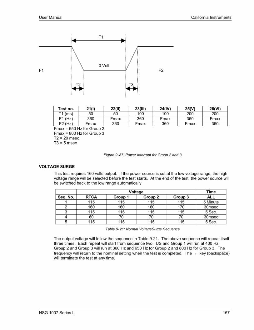
User Manual California Instruments
T1
0 VoltF1 F2
T2 T3
Test no. 21(I) 22(II) 23(III) 24(IV) 25(V) 26(VI)T1 (ms) 50 50 100 100 200 200F1 (Hz) 360 Fmax 360 Fmax 360 FmaxF2 (Hz) Fmax 360 Fmax 360 Fmax 360
Fmax = 650 Hz for Group 2Fmax = 800 Hz for Group 3T2 = 20 msecT3 = 5 msec
Figure 9-87: Power Interrupt for Group 2 and 3
VOLTAGE SURGEThis test requires 160 volts output. If the power source is set at the low voltage range, the high voltage range will be selected before the test starts. At the end of the test, the power source will be switched back to the low range automatically
Voltage TimeSeq. No. RTCA Group 1 Group 2 Group 3 ALL
1 115 115 115 115 5 Minute2 160 160 160 170 30msec3 115 115 115 115 5 Sec.4 60 70 70 70 30msec5 115 115 115 115 5 Sec.
Table 9-21: Normal VoltageSurge Sequence
The output voltage will follow the sequence in Table 9-21. The above sequence will repeat itself three times. Each repeat will start from sequence two. US and Group 1 will run at 400 Hz. Group 2 and Group 3 will run at 360 Hz and 650 Hz for Group 2 and 800 Hz for Group 3. The frequency will return to the nominal setting when the test is completed. The ← key (backspace) will terminate the test at any time.
NSG 1007 Series II 167
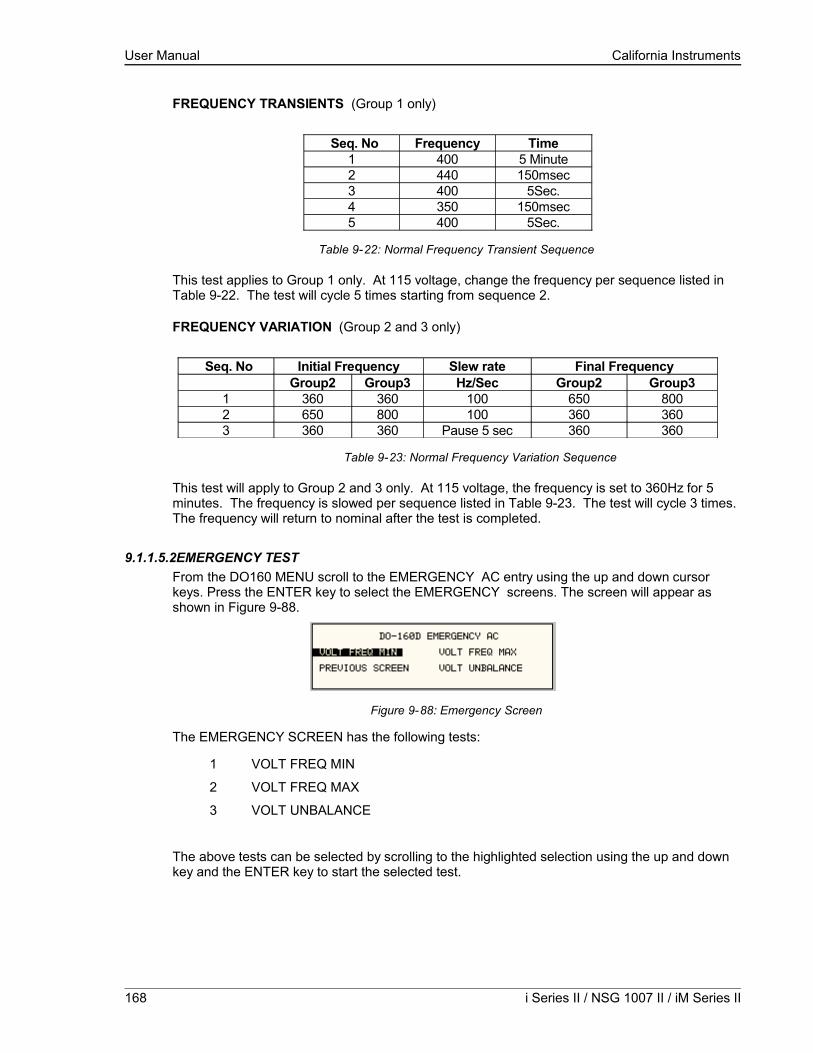
User Manual California Instruments
FREQUENCY TRANSIENTS (Group 1 only)
Seq. No Frequency Time1 400 5 Minute2 440 150msec3 400 5Sec.4 350 150msec5 400 5Sec.
Table 9-22: Normal Frequency Transient Sequence
This test applies to Group 1 only. At 115 voltage, change the frequency per sequence listed in Table 9-22. The test will cycle 5 times starting from sequence 2.
FREQUENCY VARIATION (Group 2 and 3 only)
Seq. No Initial Frequency Slew rate Final FrequencyGroup2 Group3 Hz/Sec Group2 Group3
1 360 360 100 650 8002 650 800 100 360 3603 360 360 Pause 5 sec 360 360
Table 9-23: Normal Frequency Variation Sequence
This test will apply to Group 2 and 3 only. At 115 voltage, the frequency is set to 360Hz for 5 minutes. The frequency is slowed per sequence listed in Table 9-23. The test will cycle 3 times. The frequency will return to nominal after the test is completed.
9.1.1.5.2EMERGENCY TESTFrom the DO160 MENU scroll to the EMERGENCY AC entry using the up and down cursor keys. Press the ENTER key to select the EMERGENCY screens. The screen will appear as shown in Figure 9-88.
Figure 9-88: Emergency Screen
The EMERGENCY SCREEN has the following tests:
1 VOLT FREQ MIN
2 VOLT FREQ MAX
3 VOLT UNBALANCE
The above tests can be selected by scrolling to the highlighted selection using the up and down key and the ENTER key to start the selected test.
168 i Series II / NSG 1007 II / iM Series II
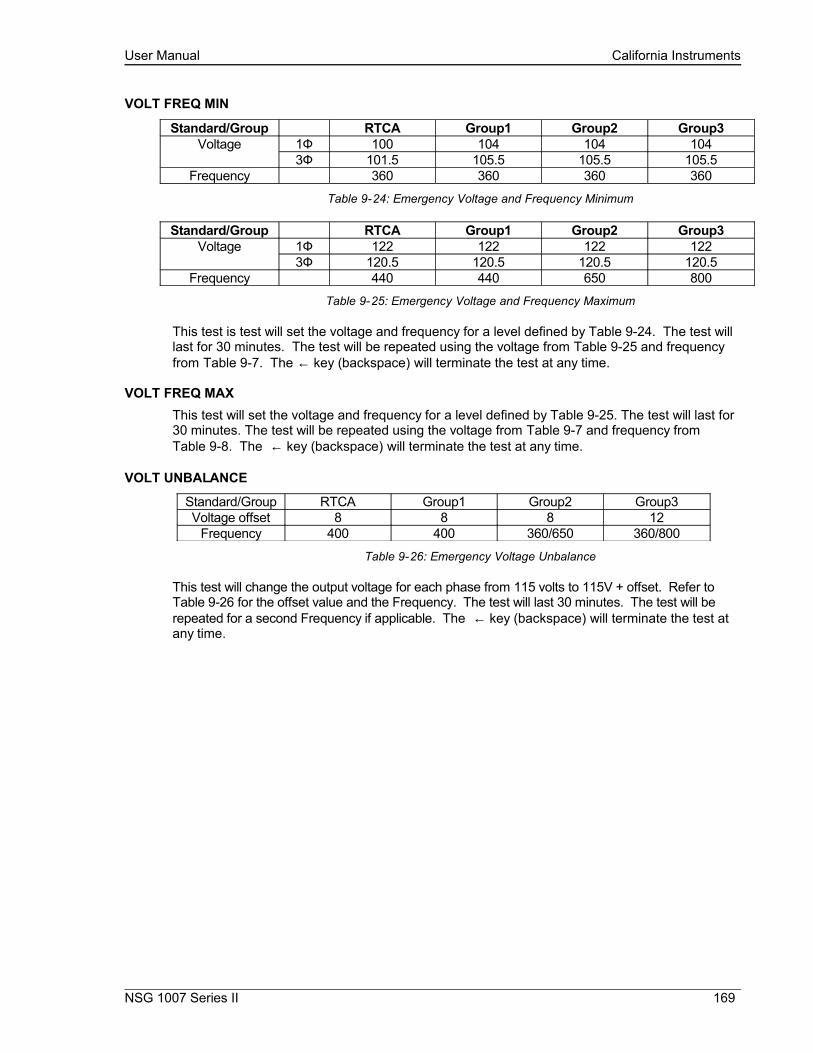
User Manual California Instruments
VOLT FREQ MIN
Standard/Group RTCA Group1 Group2 Group3Voltage 1Ф 100 104 104 104
3Ф 101.5 105.5 105.5 105.5Frequency 360 360 360 360
Table 9-24: Emergency Voltage and Frequency Minimum
Standard/Group RTCA Group1 Group2 Group3Voltage 1Ф 122 122 122 122
3Ф 120.5 120.5 120.5 120.5Frequency 440 440 650 800
Table 9-25: Emergency Voltage and Frequency Maximum
This test is test will set the voltage and frequency for a level defined by Table 9-24. The test will last for 30 minutes. The test will be repeated using the voltage from Table 9-25 and frequency from Table 9-7. The ← key (backspace) will terminate the test at any time.
VOLT FREQ MAXThis test will set the voltage and frequency for a level defined by Table 9-25. The test will last for 30 minutes. The test will be repeated using the voltage from Table 9-7 and frequency from Table 9-8. The ← key (backspace) will terminate the test at any time.
VOLT UNBALANCE
Standard/Group RTCA Group1 Group2 Group3Voltage offset 8 8 8 12
Frequency 400 400 360/650 360/800
Table 9-26: Emergency Voltage Unbalance
This test will change the output voltage for each phase from 115 volts to 115V + offset. Refer to Table 9-26 for the offset value and the Frequency. The test will last 30 minutes. The test will be repeated for a second Frequency if applicable. The ← key (backspace) will terminate the test at any time.
NSG 1007 Series II 169
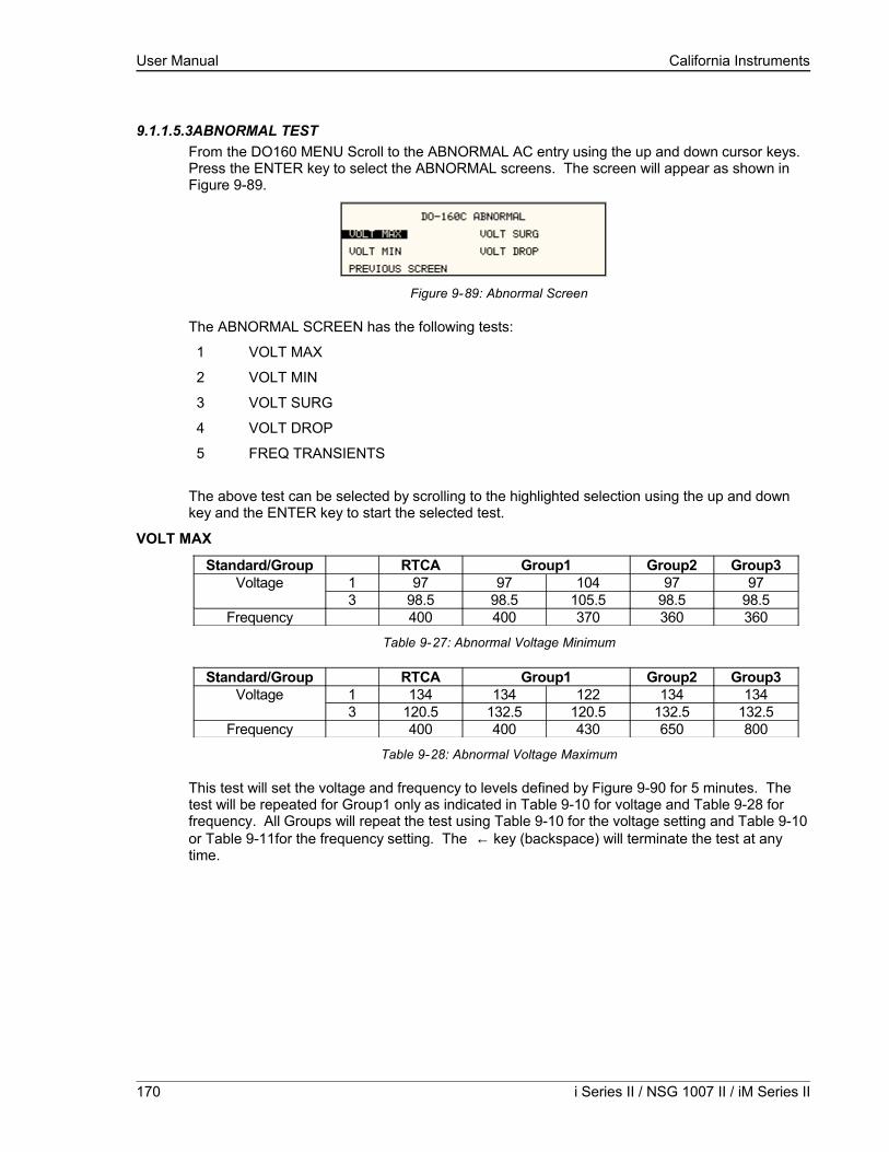
User Manual California Instruments
9.1.1.5.3ABNORMAL TESTFrom the DO160 MENU Scroll to the ABNORMAL AC entry using the up and down cursor keys. Press the ENTER key to select the ABNORMAL screens. The screen will appear as shown in Figure 9-89.
Figure 9-89: Abnormal Screen
The ABNORMAL SCREEN has the following tests:
1 VOLT MAX
2 VOLT MIN
3 VOLT SURG
4 VOLT DROP
5 FREQ TRANSIENTS
The above test can be selected by scrolling to the highlighted selection using the up and down key and the ENTER key to start the selected test.
VOLT MAX
Standard/Group RTCA Group1 Group2 Group3Voltage 1 97 97 104 97 97
3 98.5 98.5 105.5 98.5 98.5Frequency 400 400 370 360 360
Table 9-27: Abnormal Voltage Minimum
Standard/Group RTCA Group1 Group2 Group3Voltage 1 134 134 122 134 134
3 120.5 132.5 120.5 132.5 132.5Frequency 400 400 430 650 800
Table 9-28: Abnormal Voltage Maximum
This test will set the voltage and frequency to levels defined by Figure 9-90 for 5 minutes. The test will be repeated for Group1 only as indicated in Table 9-10 for voltage and Table 9-28 for frequency. All Groups will repeat the test using Table 9-10 for the voltage setting and Table 9-10 or Table 9-11for the frequency setting. The ← key (backspace) will terminate the test at any time.
170 i Series II / NSG 1007 II / iM Series II

User Manual California Instruments
VOLT MIN
This test will set the voltage and frequency to levels defined by Table 9-28 for 5 minutes. The test will be repeated for Group1 only as indicated in Table 9-28. All Groups will repeat the test using Table 9-28 for the voltage setting and Table 9-27 for the frequency setting. The ← key (backspace) will terminate the test at any time.
VOLT UNDER
This test will drop the output voltage from 115 volts to 60 volts for 7 seconds.
VOLT SURGE
This test requires 180 volts output. If the power source is set at the low voltage range, the high voltage range will be selected before the test starts. At the end of the test the AC source will be switched back to the low range.
The output voltage will surge to 180 volts for 100 ms. followed by drop to 148 volts for 1 sec before it returns to 115 volts. The ← key (backspace) will terminate the test at any time.
FREQUENCY TRANSIENTS (Group 1 only)
Seq. No. Frequency Time1 400 5 minutes2 480 5 sec.3 400 10 sec.4 320 5 sec.5 400 10 sec.
Table 9-29: Abnormal Frequency Transient
This test will set the voltage at 115V and will remain at this voltage through out the test. The test will cycle the frequency three times as shown in Table 9-29. Each repeat will start from sequence 2.
NSG 1007 Series II 171
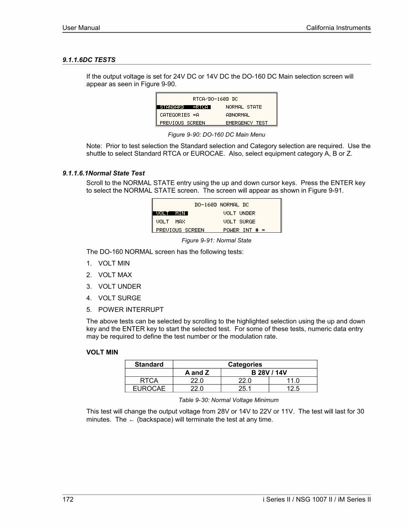
User Manual California Instruments
9.1.1.6DC TESTS
If the output voltage is set for 24V DC or 14V DC the DO-160 DC Main selection screen will appear as seen in Figure 9-90.
Figure 9-90: DO-160 DC Main Menu
Note: Prior to test selection the Standard selection and Category selection are required. Use the shuttle to select Standard RTCA or EUROCAE. Also, select equipment category A, B or Z.
9.1.1.6.1Normal State TestScroll to the NORMAL STATE entry using the up and down cursor keys. Press the ENTER key to select the NORMAL STATE screen. The screen will appear as shown in Figure 9-91.
Figure 9-91: Normal State
The DO-160 NORMAL screen has the following tests:
1. VOLT MIN
2. VOLT MAX
3. VOLT UNDER
4. VOLT SURGE
5. POWER INTERRUPT
The above tests can be selected by scrolling to the highlighted selection using the up and down key and the ENTER key to start the selected test. For some of these tests, numeric data entry may be required to define the test number or the modulation rate.
VOLT MIN
Standard CategoriesA and Z B 28V / 14V
RTCA 22.0 22.0 11.0EUROCAE 22.0 25.1 12.5
Table 9-30: Normal Voltage Minimum
This test will change the output voltage from 28V or 14V to 22V or 11V. The test will last for 30 minutes. The ← (backspace) will terminate the test at any time.
172 i Series II / NSG 1007 II / iM Series II
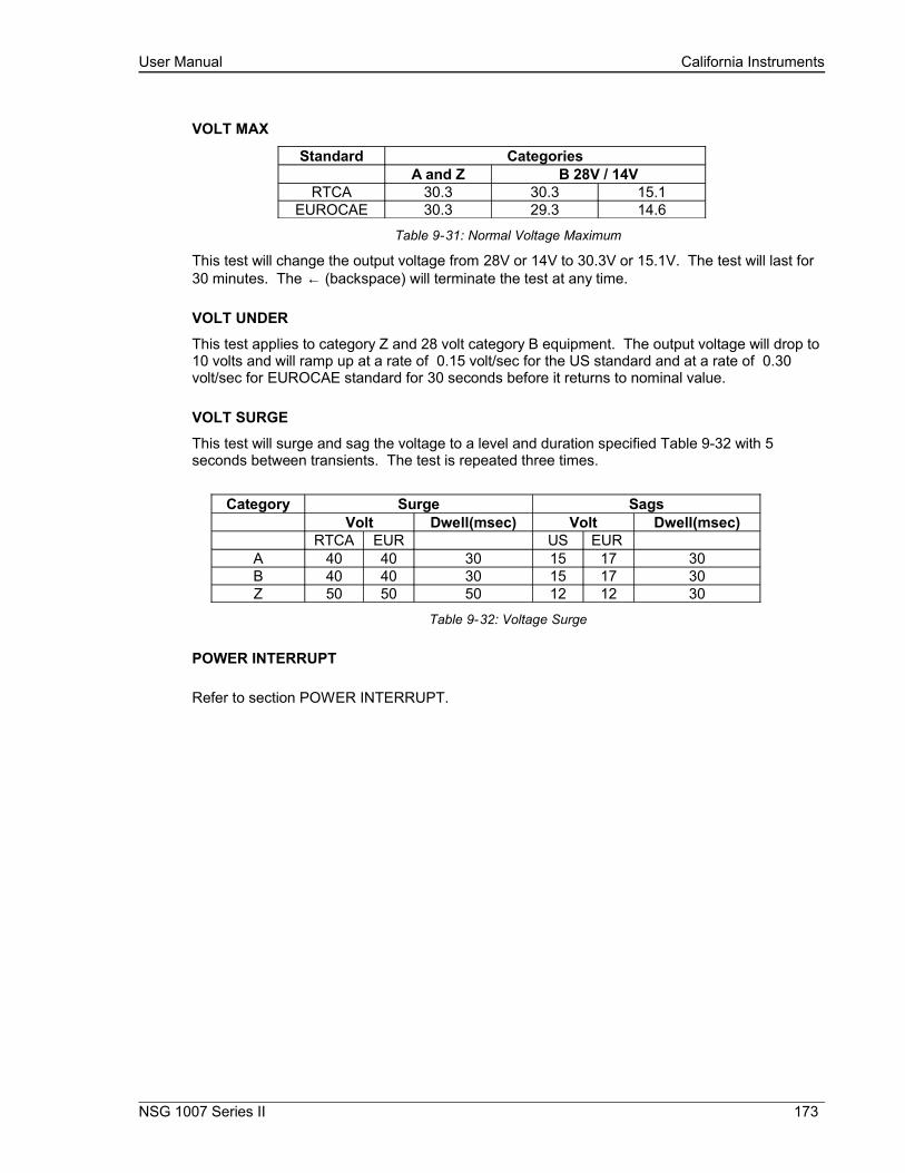
User Manual California Instruments
VOLT MAX
Standard CategoriesA and Z B 28V / 14V
RTCA 30.3 30.3 15.1EUROCAE 30.3 29.3 14.6
Table 9-31: Normal Voltage Maximum
This test will change the output voltage from 28V or 14V to 30.3V or 15.1V. The test will last for 30 minutes. The ← (backspace) will terminate the test at any time.
VOLT UNDER
This test applies to category Z and 28 volt category B equipment. The output voltage will drop to 10 volts and will ramp up at a rate of 0.15 volt/sec for the US standard and at a rate of 0.30 volt/sec for EUROCAE standard for 30 seconds before it returns to nominal value.
VOLT SURGE
This test will surge and sag the voltage to a level and duration specified Table 9-32 with 5 seconds between transients. The test is repeated three times.
Category Surge SagsVolt Dwell(msec) Volt Dwell(msec)
RTCA EUR US EURA 40 40 30 15 17 30B 40 40 30 15 17 30Z 50 50 50 12 12 30
Table 9-32: Voltage Surge
POWER INTERRUPT
Refer to section POWER INTERRUPT.
NSG 1007 Series II 173

User Manual California Instruments
9.1.1.6.2Abnormal TestFrom the DO-160 MENU scroll to the ABNORMAL DC entry using the up and down cursor keys. Press the ENTER key to select the ABNORMAL screen. The screen will appear as shown Figure 9-92.
Figure 9-92: Abnormal State
The Abnormal Test has the following tests:
1. VOLT MIN
2. VOLT MAX
3. VOLT LOW
4. VOLT DROP
5. VOLT SURGE
The above tests can be selected by scrolling to the highlighted selection using the up and down key and the ENTER key to start the selected test.
VOLT MIN
This test will change the output voltage from 28V or 14V to 20.5V or 10V. The test will last for 30 minutes. The ← key (backspace) will terminate the test at any time.
VOLT MAX
This test will change the output voltage from 28V or 14V to 32.2V or 16V. The test will last for 30 minutes. The ← key (backspace) will terminate the test at any time.
VOLT LOW
This test applies for category B equipment.
This test will change the output voltage to the voltage minimum for one minute. The voltage will decay linearly to zero voltage in a ten minute period before returning to its nominal voltage.
VOLT DROP
This test will change the output to 12V from 28V or to 6V from 14V for seven seconds. The output voltage will return to nominal voltage after seven seconds.
174 i Series II / NSG 1007 II / iM Series II
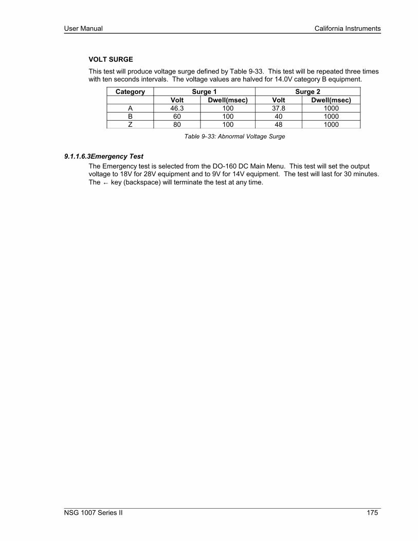
User Manual California Instruments
VOLT SURGE
This test will produce voltage surge defined by Table 9-33. This test will be repeated three times with ten seconds intervals. The voltage values are halved for 14.0V category B equipment.
Category Surge 1 Surge 2Volt Dwell(msec) Volt Dwell(msec)
A 46.3 100 37.8 1000B 60 100 40 1000Z 80 100 48 1000
Table 9-33: Abnormal Voltage Surge
9.1.1.6.3Emergency TestThe Emergency test is selected from the DO-160 DC Main Menu. This test will set the output voltage to 18V for 28V equipment and to 9V for 14V equipment. The test will last for 30 minutes. The ← key (backspace) will terminate the test at any time.
NSG 1007 Series II 175
User Manual California Instruments
9.2IEC 61000-4-11 Option
9.2.1General
The IEC1000-4-11 option is capable of performing IEC1000-4 section 11 voltage dips, short interruptions and voltage variations immunity tests. On three-phase iX/i Configurations, the user can select one, two or all three phases to be active during the IEC1000-4-11 tests in this configuration.
9.2.2Standard Revisions and EUT Classes
The–411 option supports both the first (1994-06) and the second edition (2004-03) of the IEC 61000-4-11 test standard. The desired standard revision can be selected when using the GUI Windows program. From the front panel, there is no need to select the revision but data values can be set that support either version of the standard.
Generic tests files are distributed with the GUI program for both editions of the test standard. Files applicable to Edition 2.0 have ED20 in their file name. Do not mix these files, as the data setup will not be correct if you do. To load a test file, select the Mode (Dips or Vars) and test standard revision first, then use the File, Open menu to load the test parameters. Test parameters can be a function of the EUT class. The different files provided with the program cover the various EUT classes. The relevant EUT class 1, 2, 3 or X is listed in the file names.
When using front panel operation, the user has to set levels for each individual test step in SINGLE mode.
9.2.3Initial Setup
The user must set the operating frequency and voltage and close the output relay prior to the start of test. It is possible to change the normal voltage (Ut) from the IEC1000-4-11 menus before running each test. To run any IEC 61000-4-11 test, the IEC411 state must be turned on. If an EOS1 or EOS3 is detected, it will be put in ACTIVE mode as long as the IEC411 state is ON.
9.2.4Phase Selection
On three phase power source models, phase selection for individually executed dips or the preset RUN ALL selection can be made using the PHASE key on the front panel. The phase or phases selected will be displayed in the upper right hand corner of the LCD as either A, B, C, AB, AC, BC or ABD.
With the introduction of Edition 2.0, three phase voltage dips testing has been redefined for both Wye and Delta loads.
For Star (Wye) connected three-phase EUT’s,.voltage dips should be performed on both individual Line-to-Neutral voltages as well as on all three Line-to-Line voltages. Thus, each test should be run 6 times, each time selecting a different phase option: A, B, C, A+B, A+C and B+C.
For Delta connected three-phase EUT’s,.voltage dips, only Line-to-Line voltages dips have to be run. Thus, each test can be run 3 times, each time selecting a different phase A+B, A+C and B+C.
Note that the –411 option in NSG 1007 AC sources with Firmware revision lower than 2.38 will not support 2 phase out of 3 selections. NSG 1007 I systems with firmware revision 3.04 or higher and NSG 1007 II systems with firmware revision 4.17 or higher support three phase dips testing using the preferred method referenced in figure 4b) (A) of IEC 61000-4-11, Edition 2.0. iX
176 i Series II / NSG 1007 II / iM Series II

User Manual California Instruments
units with revisions prior to this will change the L-N amplitude by the set dip level but retain the normally programmed phase angle relationship. For firmware upgrades, contact .
Note that required phase angles and amplitudes are automatically set for dips of 0, 40, 70, 80 and 100% to conform with method (A). For all other dip levels, method (A) can be used by programming the required phase angles to be used during the programmed dips. The amplitude and phase angles required to obtain the correct line-to-line voltage dip per method (A) for standard dip levels of 40, 70 and 80% are embedded in the firmware and conform to table C.2 of IEC 61000-4-34.
Since all phase programming on the NSG 1007 is referenced to phase A, voltage dip with a phase angle for A other than 0° are implemented by offsetting all three phases by the required number of degrees to get phase A at 0°. This is reflected in the actual output settings shown on the iX versus the data in table C.2 of the IEC61000-4-34. The actual output settings are shown in the last 3 columns.
Phase Mapping
The phase rotation on the NSG 1007 is ACB. This means phase A is mapped to L1, phase B is mapped to L3 and phase C is mapped to L2. The required phase selection letter combination for the required Line-to-line dip is shown in table C.2 for reference.
IEC Tables iX ReferenceL1 AL2 CL3 B
Table 9-34: Phase mapping
To select the desired phase-to-phase dip, select the phase selection as shown in column 8 and either 80, 70 or 40 % dip level from the IEC411 screen or the Gui. Table C.2
Line to Line Line to Neutral Phase iX SettingL1-L2 L2-L3 L3-L1 L1-N L2-N L3-N Selection A-N C-N B-N
100% dip 100 % 100 % 100 % 100 % 100 % 100 % n/a 100 % 100 % 100 %(no dip) 150° 270° 30° 0° 120° 240° 0° 120° 240°80% dip 80% 100% 92% 72% 100% 100% AC 72% 100% 100%
L1-L2 150° 270° 41° 14° 120° 240° 0° 106° 226°80% dip 92% 80% 100% 100% 72% 230 BC 100% 72% 100%
L2-L3 161° 270° 30° 0° 134° 240° 0° 134° 240°80% dip 100% 92% 80% 100% 100% 72% AB 100% 100% 72%
L1-L3 150° 281° 30° 0° 120° 254° 0° 120° 254°70% dip 70% 100% 89% 61% 100% 100% AC 61% 100% 100%
L1-L2 150° 270° 47° 25° 120° 240° 0° 95° 215°70% dip 89% 70% 100% 100% 61% 100% BC 100% 61% 100%
L2-L3 167° 270° 30° 0° 145° 240° 0° 145° 240°70% dip 100% 89% 70% 100% 100% 61% AB 100% 100% 61%
L1-L3 150° 287° 30° 0° 120° 265° 0° 120° 265°40% dip 40% 100% 87% 53% 100% 100% AC 53% 100% 100%
L1-L2 150° 270° 67° 79° 120° 240° 0° 41° 161°40% dip 87% 40% 100% 100% 53% 100% BC 100% 53% 100%
L2-L3 187° 270° 30° 0° 199° 240° 0° 199° 240°40% dip 100% 87% 40% 100% 100% 53% AB 100% 100% 53%
L1-L3 150° 307° 30° 0° 120° 319° 0° 120° 319°
Table 9-35: IEC 61000-3-34 Table C.2
NSG 1007 Series II 177

User Manual California Instruments
Other Dip levels for 2 phase selections.
Note that any other dip level not listed in this table will result in voltage dips conform method (B) so both phases will dip by the actual dip percentage set.
To implement user defined three phase dips other than those listed in this table, the IEC411 phase setting for phases A, B and C may be used to set the desired phase angle for each dips. This setting is ignored if the dip levels is set to 80, 70 or 40 but otherwise controls the phase angle of the selected phase during the dip.
9.2.5Tests Performed
DIPS AND INTERRUPTIONS
1. Run All Run predefined sequence of tests.2. Run Single Run user defined test.VOLTAGE VARIATIONS
1. Run All Run predefined sequence of tests.2. Run Single Run user defined test.
9.2.6Front Panel Entry
To perform a test from the keyboard, select the APPLICATIONS screen from the MENU 2 screen. The APPLICATIONS screen will appear as shown in Figure 9-93
Figure 9-93: Application menu
Scroll to the IEC 1000-4-11 entry using the up and down cursor keys. Press the ENTER key to select the IEC 1000-4-11 main menu. The screen will appear as shown in Figure 9-94.
Figure 9-94: IEC1000-4-11 Menu
178 i Series II / NSG 1007 II / iM Series II

User Manual California Instruments
9.2.6.1DIPS AND INTERRUPTIONS TEST
Scroll to the DIPS AND INTERRUPTIONS entry using the up and down cursor keys. Press the ENTER key to select the DIPS AND INTERRUPTIONS menu. The screen will appear as shown in Figure 9-95.
Figure 9-95: IEC Dips and Interrupts
STATE
This field enables or disables the -411 test mode. If an EOS option is present, it will be engaged when the STATE is toggled on. This field may also be used to reset a fault condition occurring on the EOS option due to a temperature or over current fault.
EOS STATE
This field can have one of three values:
N/A Indicates no EOS option is present or the EOS option was not powered up when the STATE was enabled.
ACTIVE The EOS option is active. When active, the –411 firmware will use the EOS for voltage dips at 0, 40 or 70% test levels. If a second generation EOS is used and the 70/80 Tap selection on the EOS is set to 80%, you must still program 70 as the DIP TO level to activate the 80% tap as the firmware only has one control code for this tap. Thus, the 70% programmed level will activate the 70/80 tap. The actual level will be determined by the setting of the EOS in this case.
OFF The EOS option is in Bypass mode.
NSG 1007 Series II 179

User Manual California Instruments
RUN ALLThe RUN ALL selection will cause the following automated test sequence suggested by the standard to be run:
Step Output in % of UT
No of Cycles Start angle (degrees)
Repeat # times
Delay between
repeats (s)1 0 0.5 0 3 102 0 0.5 180 3 103 0 1 0,45,90 3 at diff ø 104 0 5 45,90,135 3 at diff ø 105 0 10 90,135,180 3 at diff ø 106 0 25 180,225,270 3 at diff ø 107 0 50 270,315,0 3 at diff ø 108 40 0.5 0 3 109 40 0.5 180 3 10
10 40 1 0,45,90 3 at diff ø 1011 40 5 45,90,135 3 at diff ø 1012 40 10 90,135,180 3 at diff ø 1013 40 25 180,225,270 3 at diff ø 1014 40 50 270,315,0 3 at diff ø 1015 70 0.5 0 3 1016 70 0.5 180 3 1017 70 1 0,45,90 3 at diff ø 1018 70 5 45,90,135 3 at diff ø 1019 70 10 90,135,180 3 at diff ø 1020 70 25 180,225,270 3 at diff ø 1021 70 50 270,315,0 3 at diff ø 10
Table 9-36: Dips and Interruptions Tests Performed During RUN ALL
The user can change the NOMINAL Ut voltage for this. The RUN ALL Command line will change to ABORT during the test. Selecting ABORT and pressing the ENTER key will terminate the test at any time and the output voltage will return to the nominal value.
RUN SINGLERUN SINGLE command will run a single test once. The Dip or Interrupt test is defined by the DIP TO, NO CYCLES, and START ANGLE parameters. These parameters must be set before starting the test. The following is a description of these parameters.
DIP TO: The dip voltage level as a percentage of the nominal voltage.
NO CYCLES: The dip duration in cycles.
START ANGLE: The start phase angle of the dip
Note: After each individual run, a 10 second delay is inserted.
180 i Series II / NSG 1007 II / iM Series II
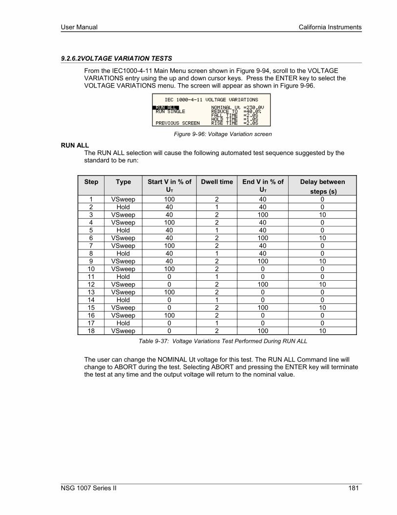
User Manual California Instruments
9.2.6.2VOLTAGE VARIATION TESTS
From the IEC1000-4-11 Main Menu screen shown in Figure 9-94, scroll to the VOLTAGE VARIATIONS entry using the up and down cursor keys. Press the ENTER key to select the VOLTAGE VARIATIONS menu. The screen will appear as shown in Figure 9-96.
Figure 9-96: Voltage Variation screen
RUN ALLThe RUN ALL selection will cause the following automated test sequence suggested by the standard to be run:
Step Type Start V in % of UT
Dwell time End V in % of UT
Delay between steps (s)
1 VSweep 100 2 40 02 Hold 40 1 40 03 VSweep 40 2 100 104 VSweep 100 2 40 05 Hold 40 1 40 06 VSweep 40 2 100 107 VSweep 100 2 40 08 Hold 40 1 40 09 VSweep 40 2 100 10
10 VSweep 100 2 0 011 Hold 0 1 0 012 VSweep 0 2 100 1013 VSweep 100 2 0 014 Hold 0 1 0 015 VSweep 0 2 100 1016 VSweep 100 2 0 017 Hold 0 1 0 018 VSweep 0 2 100 10
Table 9-37: Voltage Variations Test Performed During RUN ALL
The user can change the NOMINAL Ut voltage for this test. The RUN ALL Command line will change to ABORT during the test. Selecting ABORT and pressing the ENTER key will terminate the test at any time and the output voltage will return to the nominal value.
NSG 1007 Series II 181

User Manual California Instruments
RUN SINGLERUN SINGLE command will run the test once. The Variation test is defined by the REDUCE TO, FALL TIME, HOLD TIME and RISE TIME parameters. These parameters must be set before starting the test. The following is a description of these parameters.
REDUCE TO:
The lowest voltage level as a percentage of the nominal voltage. Thus, 0% is 0 Volts. 100% is full nominal voltage.
FALL TIME: The time in seconds it will take the output to reach the REDUCE TO voltage. Values must be entered in seconds. A 0.000 sec time may be used for abrupt voltage drops instead of voltage sweeps to support Edition 2.0 of the test standard. This requires firmware 2.38 or higher however.
HOLD TIME: The time in seconds the output will hold at the REDUCE TO voltage. Values must be entered in seconds.
RISE TIME: The time in seconds the output will reach the NOMINAL voltage from the REDUCE TO voltage. Values must be entered in seconds.
The timing of voltage variations is different between editions 1.0 and 2.0 of the IEC 61000-4-11 test standard. While the original standard used voltage ramps on both sides of the variation test level, the Edition 2.0 standard calls out an abrupt drop to the test level, followed by a voltage ramp back to the nominal voltage. Thus, for Edition 2.0, the fall time must be set to 0.000 seconds.
Furthermore, where under Edition 1.0 rise and fall times were specified in seconds, they are specified in number of cycles in Edition 2.0. This is an effort to normalize both 50 Hz and 60 Hz voltage variations.
Refer to Figure 9-97 and Figure 9-98 for an illustration of how these parameters affect the V RMS output under the different standard revisions.
Figure 9-97: EN 61000-4-11 Voltage Variation specification- Edition 1.0
Figure 9-98: EN 61000-4-11 Voltage Variation specification- Edition 2.0
182 i Series II / NSG 1007 II / iM Series II

User Manual California Instruments
9.2.7Using the GUI Windows Program for IEC 61000-4-11 Testing
Figure 9-99: IEC 61000-4-11 GUI screen.
The GUI Windows control program will detect the presence of the –411 option on the iX/i AC power source. It will also detect the presence of an EOS1 or EOS3 and use the EOS for the appropriate test levels. Test reports can be generated at the end of a test for documentation purposes.
To support Edition 2.0 of the IEC 61000-4-11 test standard, version 2.0.0.0 of the CIGuiSII or higher is required. Older versions of the GUI will only support Edition 1.0 tests. The desired Edition can be selected by the user and provides the relevant data entry mode for the Edition selected.
Generic tests files are distributed with the GUI program for both editions of the test standard. Files applicable to Edition 2.0 have ED20 in their file name. Do not mix these files, as the data setup will not be correct if you do. To load a test file, select the Mode (Dips or Vars) and test standard revision first, then use the File, Open menu to load the test parameters. Test parameters can be a function of the EUT class. The different files provided with the program cover the various EUT classes. The relevant EUT class 1, 2, 3 or X is listed in the file names.
The user must select the desired test type before executing the test. Since both test types require a number of test parameters, the test sequence parameters must be entered in the data entry grid or loaded from disk using the File, Open menu entry.
For complete details on how to use the GUI –411 option test screen, refer to the on-line help of the GUI program available from the Help menu.
NSG 1007 Series II 183

User Manual California Instruments
9.3IEC 61000-4-13 Option
9.3.1General
The IEC413 option is capable of performing IEC 61000-4 section 13 Harmonics and inter harmonics low frequency immunity tests. The tests are based on IEC 61000-4-13:2002-03, First Edition. It is assumed that the user has a copy of the test standard available. This manual section only cover operation of the –413 option from the front-panel of the NSG 1007 power source.
Note: The –413 option is only available on NSG 1007 AC power sources, not i Series. It is possible to upgrade most i Series AC source to an NSG 1007 and add the –413 option. Contact the Teseq service department for information.
9.3.2Initial Setup
The user must set the operating voltage and close the output relay prior to the start of test. The following set of parameters must be set before the start of test.
1. Frequency to 50 or 60 Hz.
2. Voltage mode to AC.
3. Waveform to sine wave.
9.3.3Tests Performed
The IEC61000-4-13 test consists of several types of tests. These tests can be run individually or in sequence (ALL). The following tests are available:
1. Harmonic combination test flat curve and over swing.
2. Sweep in frequency and resonance frequency detection.
3. Individual harmonics and inter harmonics.
4. Meister curve test.
184 i Series II / NSG 1007 II / iM Series II
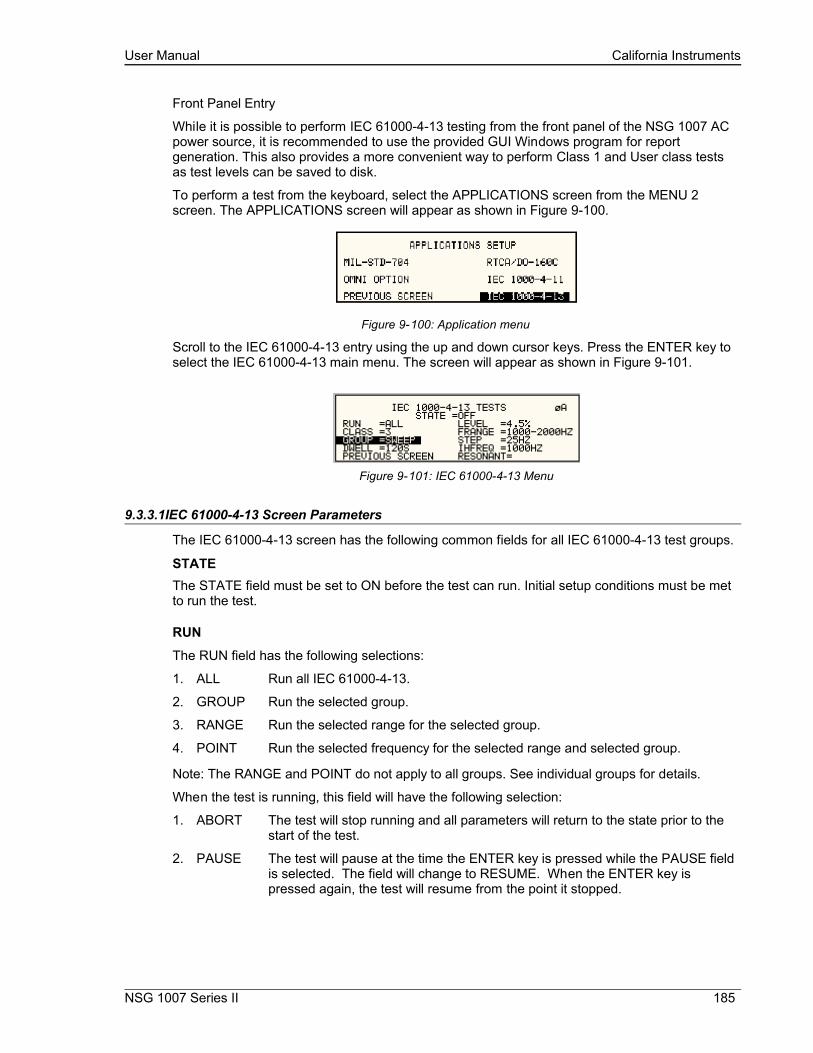
User Manual California Instruments
Front Panel Entry
While it is possible to perform IEC 61000-4-13 testing from the front panel of the NSG 1007 AC power source, it is recommended to use the provided GUI Windows program for report generation. This also provides a more convenient way to perform Class 1 and User class tests as test levels can be saved to disk.
To perform a test from the keyboard, select the APPLICATIONS screen from the MENU 2 screen. The APPLICATIONS screen will appear as shown in Figure 9-100.
Figure 9-100: Application menu
Scroll to the IEC 61000-4-13 entry using the up and down cursor keys. Press the ENTER key to select the IEC 61000-4-13 main menu. The screen will appear as shown in Figure 9-101.
Figure 9-101: IEC 61000-4-13 Menu
9.3.3.1IEC 61000-4-13 Screen Parameters
The IEC 61000-4-13 screen has the following common fields for all IEC 61000-4-13 test groups.
STATE The STATE field must be set to ON before the test can run. Initial setup conditions must be met to run the test.
RUN
The RUN field has the following selections:
1. ALL Run all IEC 61000-4-13.
2. GROUP Run the selected group.
3. RANGE Run the selected range for the selected group.
4. POINT Run the selected frequency for the selected range and selected group.
Note: The RANGE and POINT do not apply to all groups. See individual groups for details.
When the test is running, this field will have the following selection:
1. ABORT The test will stop running and all parameters will return to the state prior to the start of the test.
2. PAUSE The test will pause at the time the ENTER key is pressed while the PAUSE field is selected. The field will change to RESUME. When the ENTER key is pressed again, the test will resume from the point it stopped.
NSG 1007 Series II 185

User Manual California Instruments
EUT CLASSThis field selects the desired product or EUT class. There are four EUT classes. Class 1, 2 and 3 are predefined by the standard and its level parameters cannot be changed. The user class can be edited at any time. Changing between class 2 and 3 can be done while the state is on. Changing to the user class requires the state to be in the off position.
For Class 1 EUT, the user class must be used. Only class 2 and 3 test levels are pre-programmed. When using the provided, GUI Windows program, class 1 tests are set up by the GUI program automatically.
GROUPThis field selects the test GROUP. Selecting a group is required for editing the data fields associated with the group as well as running the individual group if run group is selected. The field has the following groups:
1. FCURVE This is the first part of harmonic combination test.
2. OSWING This is the second part of harmonic combination test.
3. SWEEP This is the sweep in frequency and resonance frequency detection.
4. HRAM This is the first part of the Individual harmonics and inter harmonics test.
5. IHARM This is the second part of the Individual harmonics and inter harmonics test.
6. MCURVE This is the Meister test.
See the appropriate sections for details on each group.
DWELLThis field will show the dwell time in seconds for each group during the test and will allow changes to the dwell time to be made.
The dwell time for the Meister curve group is the dwell time for each inter harmonics. This combined with the frequency step size results in a 5-minute test time per frequency decade.
The dwell time for the sweep group is the dwell time for each frequency decade.
186 i Series II / NSG 1007 II / iM Series II

User Manual California Instruments
9.3.3.2IEC GROUPS
This section will describe the groups and parameters associated with IEC 61000-4-13. Refer to paragraph 9.3.3.1 for groups associated with the test.
FCURVE GROUPIf the FCURVE group is selected, the screen will appear as shown in Figure 9-102. The screen has the following parameters that are unique to the group:
Figure 9-102: IEC 61000-4-13 FCurve
1. LEVEL Set the Flat curve clip level. This field can be set when the IEC 1000-4-13 is in the OFF state and the Class is set for USER class.
2. PAUSE Time in seconds the test will pause prior to proceeding to the following test. This field can be set at any time when the test is not running.
OSWING GROUPIf the OSWING group is selected, the screen will appear as shown in Figure 9-103. The screen has the following parameters that are unique to the group:
Figure 9-103: IEC 61000-4-13 OSwing
1. LEVEL The level of the harmonics relative to the fundamental in percent. There are two levels, one for harmonic #3 and the other for harmonic #5. The harmonic number must be selected prior to the harmonic level entry. To change levels, the test state must be off and USER class must be selected.
2. HARM NO There are only two harmonic numbers. This field is used to set the harmonics level that corresponds to the harmonics number.
3. PHASE Sets the phase angle of the harmonics relative to the fundamental. The phase can be set when the test state is off and USER class is selected.
4. PAUSE Sets the time in seconds. The test will pause prior to proceeding to the following test. This field may be changed at any time as long as the test is not running.
NSG 1007 Series II 187
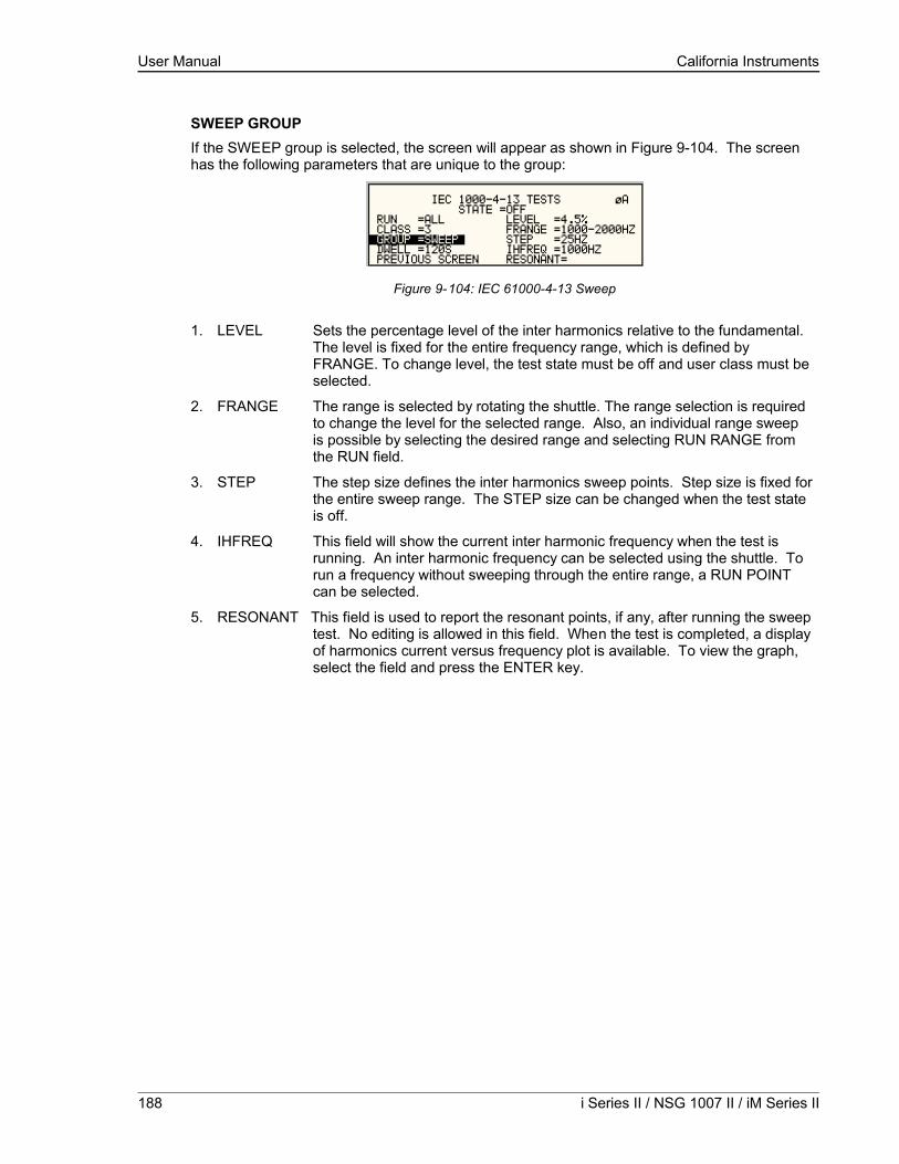
User Manual California Instruments
SWEEP GROUPIf the SWEEP group is selected, the screen will appear as shown in Figure 9-104. The screen has the following parameters that are unique to the group:
Figure 9-104: IEC 61000-4-13 Sweep
1. LEVEL Sets the percentage level of the inter harmonics relative to the fundamental. The level is fixed for the entire frequency range, which is defined by FRANGE. To change level, the test state must be off and user class must be selected.
2. FRANGE The range is selected by rotating the shuttle. The range selection is required to change the level for the selected range. Also, an individual range sweep is possible by selecting the desired range and selecting RUN RANGE from the RUN field.
3. STEP The step size defines the inter harmonics sweep points. Step size is fixed for the entire sweep range. The STEP size can be changed when the test state is off.
4. IHFREQ This field will show the current inter harmonic frequency when the test is running. An inter harmonic frequency can be selected using the shuttle. To run a frequency without sweeping through the entire range, a RUN POINT can be selected.
5. RESONANT This field is used to report the resonant points, if any, after running the sweep test. No editing is allowed in this field. When the test is completed, a display of harmonics current versus frequency plot is available. To view the graph, select the field and press the ENTER key.
188 i Series II / NSG 1007 II / iM Series II
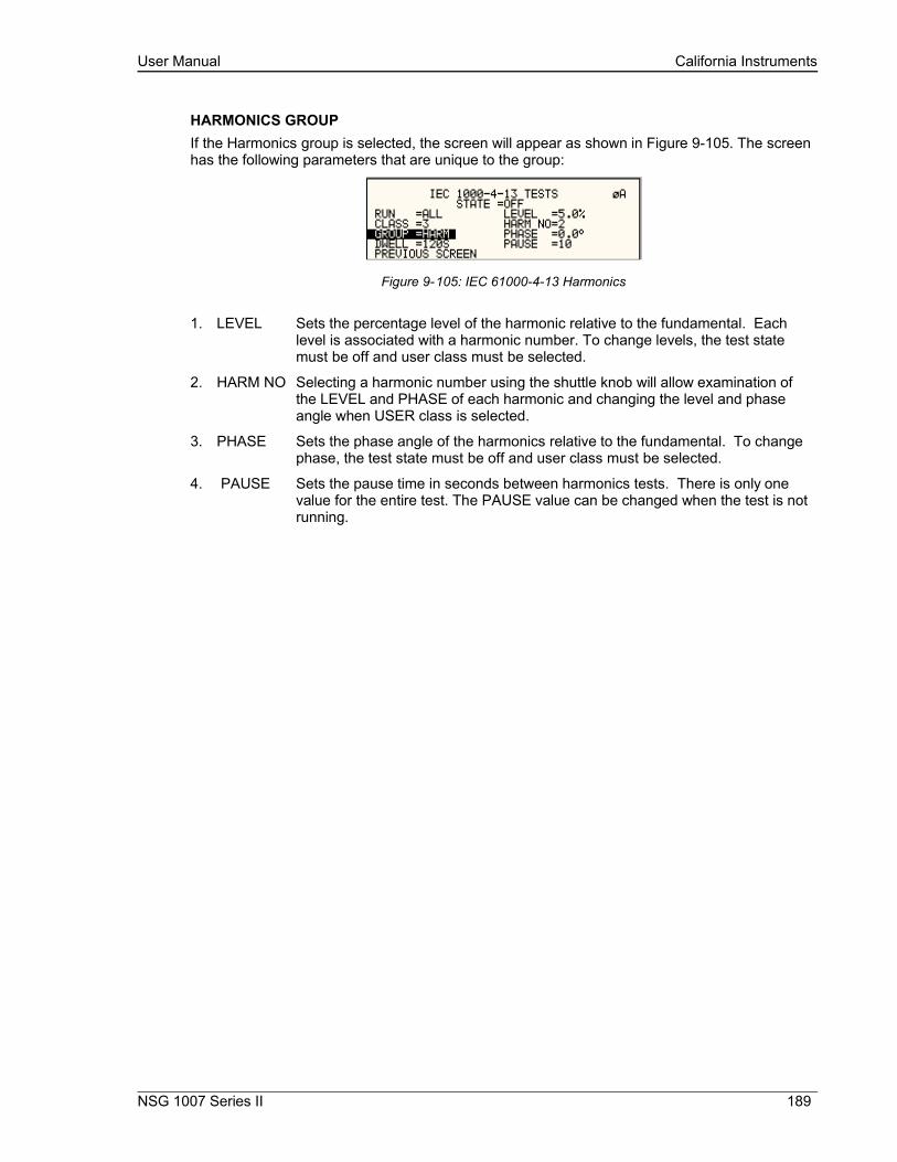
User Manual California Instruments
HARMONICS GROUPIf the Harmonics group is selected, the screen will appear as shown in Figure 9-105. The screen has the following parameters that are unique to the group:
Figure 9-105: IEC 61000-4-13 Harmonics
1. LEVEL Sets the percentage level of the harmonic relative to the fundamental. Each level is associated with a harmonic number. To change levels, the test state must be off and user class must be selected.
2. HARM NO Selecting a harmonic number using the shuttle knob will allow examination of the LEVEL and PHASE of each harmonic and changing the level and phase angle when USER class is selected.
3. PHASE Sets the phase angle of the harmonics relative to the fundamental. To change phase, the test state must be off and user class must be selected.
4. PAUSE Sets the pause time in seconds between harmonics tests. There is only one value for the entire test. The PAUSE value can be changed when the test is not running.
NSG 1007 Series II 189
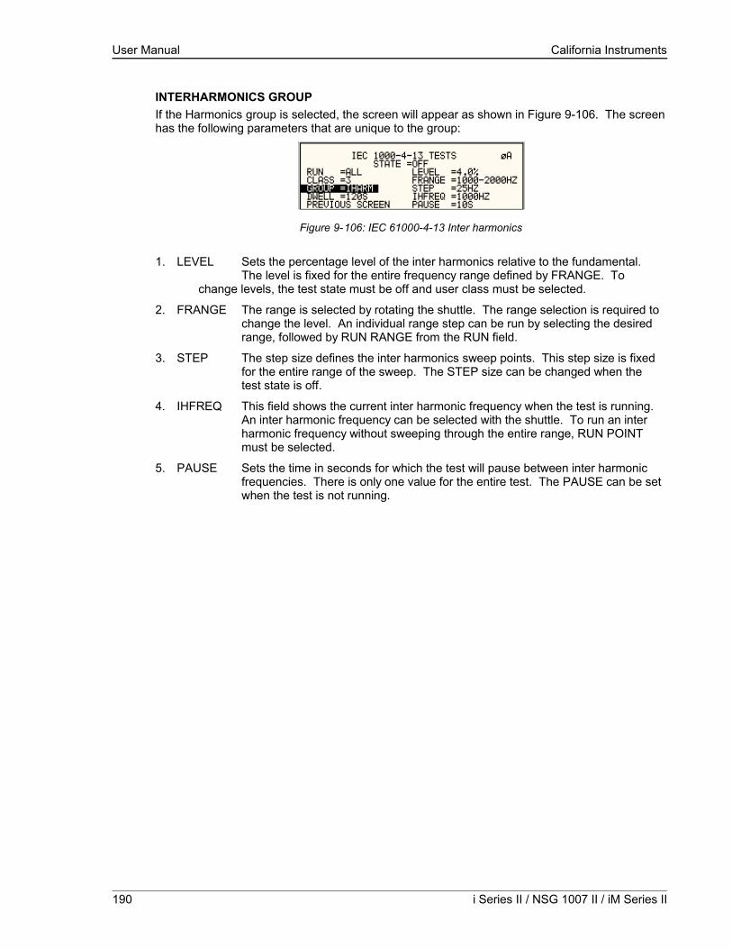
User Manual California Instruments
INTERHARMONICS GROUPIf the Harmonics group is selected, the screen will appear as shown in Figure 9-106. The screen has the following parameters that are unique to the group:
Figure 9-106: IEC 61000-4-13 Inter harmonics
1. LEVEL Sets the percentage level of the inter harmonics relative to the fundamental. The level is fixed for the entire frequency range defined by FRANGE. To
change levels, the test state must be off and user class must be selected.
2. FRANGE The range is selected by rotating the shuttle. The range selection is required to change the level. An individual range step can be run by selecting the desired range, followed by RUN RANGE from the RUN field.
3. STEP The step size defines the inter harmonics sweep points. This step size is fixed for the entire range of the sweep. The STEP size can be changed when the test state is off.
4. IHFREQ This field shows the current inter harmonic frequency when the test is running. An inter harmonic frequency can be selected with the shuttle. To run an inter harmonic frequency without sweeping through the entire range, RUN POINT must be selected.
5. PAUSE Sets the time in seconds for which the test will pause between inter harmonic frequencies. There is only one value for the entire test. The PAUSE can be set when the test is not running.
190 i Series II / NSG 1007 II / iM Series II

User Manual California Instruments
MEISTER CURVE GROUPIf the Meister curve group is selected, the screen will appear as shown in Figure 9-107. The screen has the following parameters that are unique to the group:
Figure 9-107: IEC 61000-4-13 Meister Curve
1. LEVEL Sets the percentage level of the inter harmonics relative to the fundamental. The level is fixed for the entire frequency range defined by FRANGE. To change levels, the test state must be off and user class must be selected.
2. FRANGE The range is selected by rotating the shuttle. The range selection is required to change the level. An individual range step can be run by selecting the desired range, followed by RUN RANGE from the RUN field.
3. STEP The step size defines the inter harmonics sweep points. This step size is fixed for the entire range of the sweep. The STEP size can be changed when the test state is off.
4. PAUSE Sets the time in seconds for which the test will pause between ranges. There is only one value for the entire test. The PAUSE can be set when the test is not running. For the Meister curve test, the pause time is normally set to 0 secs. If a value other than 0 is entered, the inter harmonics are set to 0% during the pause times.
5. RESONANT This field is used to report the resonant points, if any, after running the Meister curve test. No editing is allowed in this field. When the test is completed, a display of harmonics current versus frequency plot is available. To view the graph, select the field and press the ENTER key.
9.3.3.3RUNNING THE TEST
The test sequence used is a function of the EUT class. The end user needs to determine the appropriate class of EUT. The test protocol is document in the IEC 61000-4-13 test standard. For reference, the test flow charts are shown here. It is assumed that the end user has a copy of the actual test standard however.
NSG 1007 Series II 191

User Manual California Instruments
Start - Class 1/2Determine appropriate test
configuration
Perform 8.2.1 Test"Harmonic combination"Flatcurve and Overswing
Any functionalanomalies?
No No
Class 2required?
Meistercurve required?
Any functionalanomalies?
Any functionalanomalies?
Any functionalanomalies?
Test CompletedFAIL
Record Results
Test CompletedPASS
Record Results
Yes
Yes
No
Perform 8.2.2 Test"Frequency Sweep"
Perform 8.2.4 Test"Meister Curve"
Perform 8.2.3 Test"Individual Harmonics/
Interharmonics"
Yes
Yes
NoYes
Yes
Yes
No
Figure 9-108: IEC 61000-4-13 Test Flowchart Class 1 and 2
192 i Series II / NSG 1007 II / iM Series II
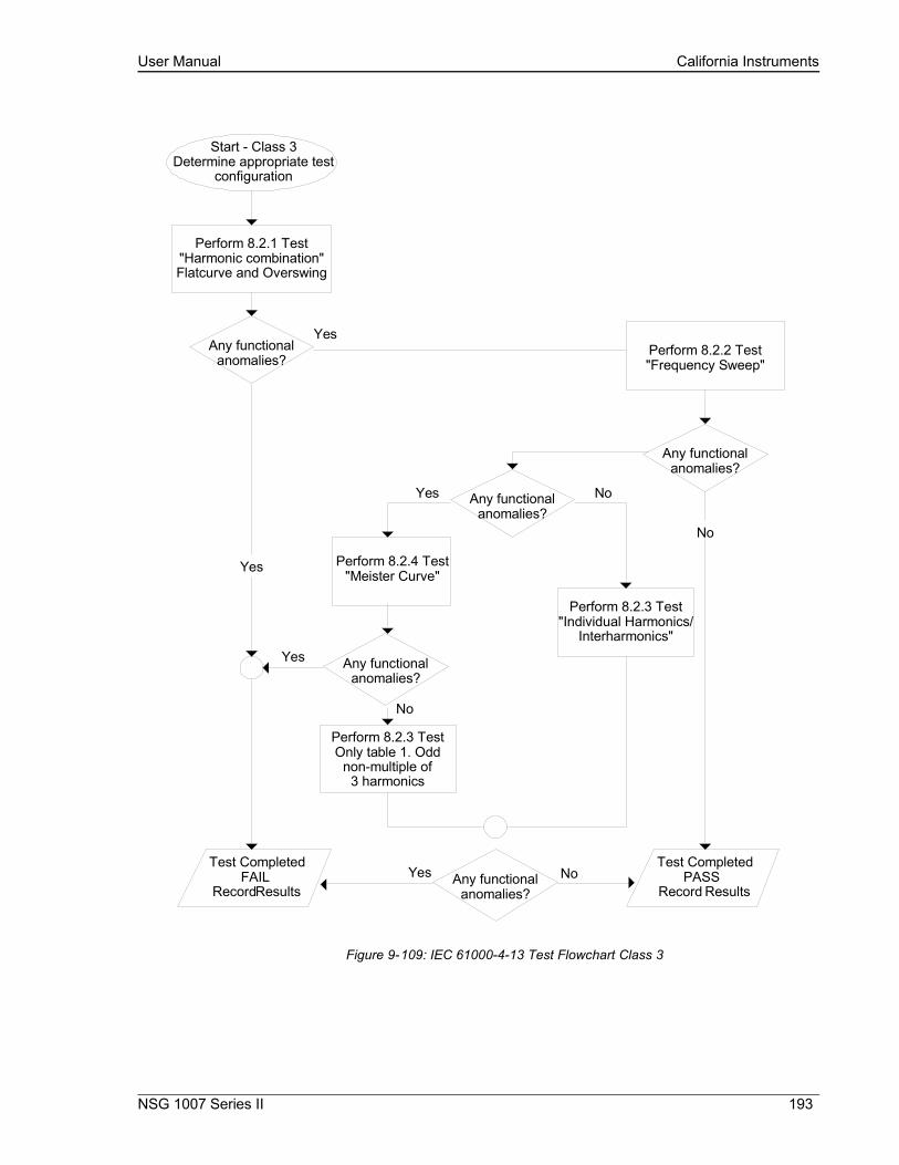
User Manual California Instruments
Start - Class 3Determine appropriate test
configuration
Perform 8.2.1 Test"Harmonic combination"Flatcurve and Overswing
Any functionalanomalies?
Any functionalanomalies?
Any functionalanomalies?
Any functionalanomalies?
Test CompletedFAIL
Record Results
Test CompletedPASS
Record Results
Yes
Perform 8.2.2 Test"Frequency Sweep"
Perform 8.2.4 Test"Meister Curve"
Perform 8.2.3 Test"Individual Harmonics/
Interharmonics"
Yes
Yes
Yes
No
No
Any functionalanomalies?
Yes
Perform 8.2.3 TestOnly table 1. Odd
non-multiple of3 harmonics
No
No
Figure 9-109: IEC 61000-4-13 Test Flowchart Class 3
NSG 1007 Series II 193

User Manual California Instruments
To run the test, the IEC 61000-4-13 mode must be selected. Refer to paragraph 9.3.3 for access to the screen. The following conditions have to be met before running the test:
1. Prior to the test, set the nominal voltage, frequency, and phase angle. The frequency must be 50 or 60 Hz. Function must be set to sine wave.
2. Select EUT CLASS 2, 3 or USER. The default parameters for the USER class are identical to those for class 3. If USER class is selected, the level and phase parameters can be edited. For Class 1 EUT’s, the USER class must be used as well. In this case, set the levels to those called out in the test document.
3. Set the STATE to ON. It will take a few seconds to initialize data required to perform the test.
4. If it is desired to run all tests, select ALL form the RUN parameter with the shuttle knob and press the ENTER key. The tests will run in the following sequence:
FCURVE, OSWING, SWEEP, HARM, IHARM,MCURVE
Note: The test for class 3 will take about 25 minutes, class 2 slightly less.
5. While the test is running, the ABORT and PAUSE selection is accessible from the RUN field by rotating the shuttle.
6. If it is desired to run a specific group, the group must be selected from the group screen. Also, the RUN GROUP must be selected prior to the start of test.
7. To run an individual range, applicable for sweep and individual harmonics only, the desired range and the RUN RANGE mode must be selected prior to the start of the test. In case the harmonics group is selected, RUN RANGE will run the harmonics from the second harmonics to the harmonics number specified by the HARM NO field. See Figure 9-105.
8. To run individual harmonics or individual inter harmonics, set the harmonic number or the inter harmonics frequency and select RUN POINT prior to running the test.
194 i Series II / NSG 1007 II / iM Series II

User Manual California Instruments
9.3.3.4INTERHARMONICS
A single inter harmonic frequency may be generated using the INTERHARMONICS screen. This screen allows insertion of any inter harmonic from 1Hz to 2400Hz in 1Hz steps. The amplitude level of the harmonics range is from 0 to 20% of the programmed voltage. To select the inter harmonics screen, press the menu screen until the MENU 2 screen appears as shown in Figure9-110. Select INTERHARMONICS using the up or down key.
Figure 9-110: MENU 2 SCREEN
INTERHARMONICS SCREENThe inter harmonics screen will appear as shown in Figure 9-111. This screen has the following parameters:
Figure 9-111: INTERHARMONICS SCREEN
1. REFERENCE This field will enable the Inter harmonics generator if ON is selected and will disable the inter harmonics generation if OFF is selected.
2. REF. COUPL If turned on, the REF. VOLT will follow the programmed voltage value.
1. REF. VOLT This field must be programmed to a value if REF. COUPL is off. This value has a range from 0 to 230 volts. This value is set to a value equal to the phase A voltage if the REF. COUPL is turned on.
2. VOLTAGE This field programs the Inter harmonic level in percentage of the REF.VOLT. This value has a range from 0 to 20%
NSG 1007 Series II 195
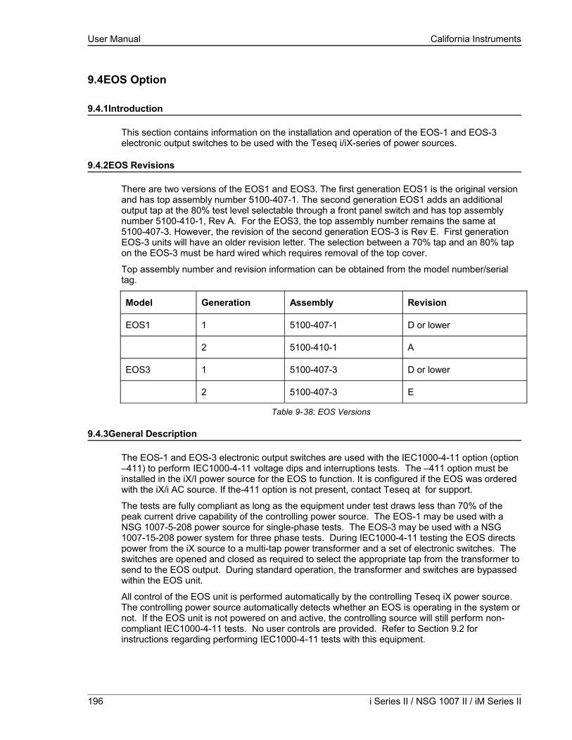
User Manual California Instruments
9.4EOS Option
9.4.1Introduction
This section contains information on the installation and operation of the EOS-1 and EOS-3 electronic output switches to be used with the Teseq i/iX-series of power sources.
9.4.2EOS Revisions
There are two versions of the EOS1 and EOS3. The first generation EOS1 is the original version and has top assembly number 5100-407-1. The second generation EOS1 adds an additional output tap at the 80% test level selectable through a front panel switch and has top assembly number 5100-410-1, Rev A. For the EOS3, the top assembly number remains the same at 5100-407-3. However, the revision of the second generation EOS-3 is Rev E. First generation EOS-3 units will have an older revision letter. The selection between a 70% tap and an 80% tap on the EOS-3 must be hard wired which requires removal of the top cover.
Top assembly number and revision information can be obtained from the model number/serial tag.
Model Generation Assembly Revision
EOS1 1 5100-407-1 D or lower
2 5100-410-1 A
EOS3 1 5100-407-3 D or lower
2 5100-407-3 E
Table 9-38: EOS Versions
9.4.3General Description
The EOS-1 and EOS-3 electronic output switches are used with the IEC1000-4-11 option (option –411) to perform IEC1000-4-11 voltage dips and interruptions tests. The –411 option must be installed in the iX/I power source for the EOS to function. It is configured if the EOS was ordered with the iX/i AC source. If the-411 option is not present, contact Teseq at for support.
The tests are fully compliant as long as the equipment under test draws less than 70% of the peak current drive capability of the controlling power source. The EOS-1 may be used with a NSG 1007-5-208 power source for single-phase tests. The EOS-3 may be used with a NSG 1007-15-208 power system for three phase tests. During IEC1000-4-11 testing the EOS directs power from the iX source to a multi-tap power transformer and a set of electronic switches. The switches are opened and closed as required to select the appropriate tap from the transformer to send to the EOS output. During standard operation, the transformer and switches are bypassed within the EOS unit.
All control of the EOS unit is performed automatically by the controlling Teseq iX power source. The controlling power source automatically detects whether an EOS is operating in the system or not. If the EOS unit is not powered on and active, the controlling source will still perform non-compliant IEC1000-4-11 tests. No user controls are provided. Refer to Section 9.2 for instructions regarding performing IEC1000-4-11 tests with this equipment.
196 i Series II / NSG 1007 II / iM Series II

User Manual California Instruments
9.4.4Specifications
9.4.4.1Input
Line Voltage(user configurable)
115 VAC ±10%
230 VAC ±10%
Line Current < 0.4 amps at 115 VAC input
< 0.2 amps at 230 VAC input
Line Frequency 47 to 63 Hz
Fuse Rating 0.5 amp, slow acting at 115 VAC input
0.25 amp, slow acting at 230 VAC input
9.4.4.2Output
EOS-1 EOS-3
Phases 1 3
IEC 1000-4-11 Test Mode Engaged:
Voltage
Range 100-270 VRMS
Regulation <5%, 100% output< 7%, 80% output (EOS Gen 2 only)<7%, 70% output<10%, 40% output
Over/Undershoot <5% into a 100 ohm resistive load
Rise/Fall Times Between 1µs & 5µs into a 100 ohm resistive loadmeasured from 10% to 90% of transition
Programmable Output Levels 100%, 70%, 40%, and 0% of UNOM
Frequency
Range 50 Hz/60 Hz
Accuracy +/- 0.02%
Phase
Range 0.0° - 360°
Accuracy +/- 1.0°
Maximum Current
at 100% UNOM 18.5 ARMS 18.5 ARMS/phase
at 80% UNOM
(EOS Gen 2 only)26.4 ARMS 26.4 ARMS/phase
at 70% UNOM 23.1 ARMS 23.1 ARMS/phase
at 40% UNOM 46.2 ARMS 46.2 ARMS/phase
Maximum Peak Current(limited by NSG 1007-5-208 /
92.5 A 92.5 A/ phase
NSG 1007 Series II 197

User Manual California Instruments
NSG 1007-15-208)
at 0% UNOM N/A N/A
Bypass Mode Engaged:
Maximum Current 37 ARMS 37 ARMS/phase
9.4.4.3Controls/Indicators
Control / Indicator Comments
ON/OFF toggle switch
70 / 80 Tap Select toggle switch (EOS1, second generation only).
Power On lamp
Active lamp
Fault lamp
9.4.4.4Mechanical
Dimensions 7"H x 19"W x 24"D178 mm H x 483 mm W x 610 mm D
Weight
EOS-1 70 lbs, 32 kg
EOS-3 160 lbs, 73 kg
Connectors:
Input mains IEC 320
Source Compression
Load Compression
Option In/Out 9 pin D-subminiature
Chassis Slide General Devices C300S-120-B308
9.4.4.5Environmental
Temperature 0 to 40 °C
Relative Humidity 80% max. to 31 °C
derate linearly to 50% max. at 40°C
Altitude 2000 m max.
Installation Over voltage Category II
Pollution Degree 2
Equipment Class I
Usage Indoors
198 i Series II / NSG 1007 II / iM Series II

User Manual California Instruments
CAUTIONVoltages up to 600 VAC are available in certain sections of this product. This
equipment uses potentially lethal voltages.
DEATHOn contact may result if personnel fail to observe safety precautions. Do not
touch electronic circuits when power is applied.
NSG 1007 Series II 199

User Manual California Instruments
9.4.5Installation and Acceptance
9.4.5.1Unpacking
Inspect the unit for any possible shipping damage immediately upon receipt. If damage is evident, notify the carrier. Do not return an instrument to the factory without prior approval. Do not destroy the packing container until the unit has been inspected for damage in shipment.
9.4.5.2Power Requirements
The EOS-1 and EOS-3 electronic switches use either 115 or 230 VAC to power the control circuits. The user may select the desired input voltage using the range selector within the input module.
To change the input voltage range, pry open the cover to the input module. Remove the fuse carrier. Install the correct fuses in the carrier. Reinstall the carrier into the input module so that the desired voltage range appears in the module cover window. Close the cover.
Note that attempting to operate the EOS from an input range that does not match the actual AC power voltage may cause permanent damage to the unit.
The line power source to the EOS must provide protective earth grounding.
9.4.5.3Mechanical Installation
The EOS-1 and EOS-3 have been designed for rack mounting in a standard 19 inch rack. The unit should be supported from the bottom with a shelf-track or supported from the sides with optional rack slides (-RMS option).
The cooling fan at the rear of the unit must be free of any obstructions that would interfere with the flow of air. A 2.5-inch clearance should be maintained between the rear panel of the EOS unit and the rear panel of the mounting cabinet. Also, the air intake holes on the sides of the power chassis must not be obstructed.
200 i Series II / NSG 1007 II / iM Series II

User Manual California Instruments
9.4.5.4Output Wiring
The EOS-1 or EOS-3 is wired in series with the output of specified Teseq power systems. The EOS terminal block marked SOURCE should be wired to the output of the power source/system. The terminal block marked LOAD is wired to the user's load. Refer to
Figure 9-112 and Figure 9-113 in this section for examples of proper connections. Refer to Section 3.5 to determine the appropriate wire gauge needed for the output wiring.
Note in Figure 9-112 the sequence of instruments. This is the recommended sequence between the iX source and the equipment under test. For systems that do not include all the instruments shown, maintain the sequence of the remaining instruments.
Note also that for all applications the remote sense wiring must be connected before the EOS unit.
Note: The output voltage of the iX/i-series power sources into the EOS box may be at hazardous potentials as high as 300 volts line to neutral (600 volts line to line). Wiring used between the power sources and the EOS and between the EOS and the user’s load must be insulated to withstand this potential.
Note: The SOURCE and LOAD terminals of the EOS will be at the hazardous live potentials of the iX/i-series power sources driving it even if EOS box has not been switched on.
NSG 1007 Series II 201

User Manual California Instruments
Figure 9-112: Example Connection With NSG 1007-5-208 and EOS-1
202 i Series II / NSG 1007 II / iM Series II

User Manual California Instruments
Figure 9-113: Example Connection With Compliance Test System and EOS-1
NSG 1007 Series II 203

User Manual California Instruments
Figure 9-114: NSG 1007-15-208-CTS-EOS3-LR3
204 i Series II / NSG 1007 II / iM Series II
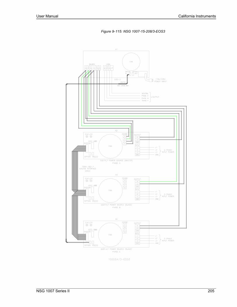
User Manual California Instruments
Figure 9-115: NSG 1007-15-208/3-EOS3
NSG 1007 Series II 205

User Manual California Instruments
9.4.6Operation
9.4.6.1General
The EOS-1 is used with a Teseq i/iX power source to perform testing compliant with the requirements of IEC1000-4-11. The EOS routes the voltage from the power source to an internal, tapped power transformer. Voltage from each of four taps is sent through an electronic switch to the EOS-1 output. During IEC1000-4-11 testing, the controlling Teseq power source selects which voltage tap to connect to the EOS output. When IEC1000-4-11 testing is not active, the controlling power source puts the EOS-1 into bypass mode, shunting the EOS input terminals directly to the output terminals.
All control of the EOS-1 is performed automatically by the Teseq power source. The control signals are sent from the power source to the EOS via the option interface cable. Refer to Section 9.2 for instructions regarding performing IEC1000-4-11 tests with this equipment.
The rated operating current for the EOS in active mode is 18.5 amps. If the controlling power source is set for an RMS current limit greater than 18.5 amps, it will not activate the EOS unit. An attempt to do so will indicate Error -222, “Data out of range”. IEC 1000-4-11 tests may still be run, but in pre-compliance mode with the EOS unit bypassed.
Note that while the EOS is engaged, there is no Function Strobe output. Normally, the function strobe - outside the transient system - is associated with any output voltage change. When the EOS is in use however, the function strobe is generated only when the EOS is engaged. This is because the output is programmed down during relay activation. These strobes are meaningless and are not related to any output drops occurring through the EOS. During the EOS transients that use any of the available EOS drop levels, there are no function strobes. Voltage drops that do not use one of the available fixed drop levels are done by dropping the output of the power source itself and will result in functions strobes on J22. It is possible to use the OPTION OUT on the back of the EOS - a DB9 connector, pin 6. The return can be either pine 2, 3 or 4. The strobe is a low going level that last for only 400 to 500 nsec. This strobe will coincide with drops performed by the EOS switch.
If the EOS is already in active mode, the controlling power source will not allow its RMS current limit to be programmed above 18.5 amps.
The EOS-3 is similar to EOS-1 with provision for three-phase operation.
206 i Series II / NSG 1007 II / iM Series II
User Manual California Instruments
9.4.6.2Front Panel Controls/Indicators
Power Switch and Lamp
A power switch turns the EOS on or off. A lamp above the switch illuminates when power is on.
Active Lamp
This lamp is illuminated when the EOS is operating with the power transformer and electronic switches active for IEC1000-4-11 testing. During normal power source operation the lamp is off.
Fault Lamp
This lamp is illuminated when an overtemperature or an overcurrent condition has occurred in the EOS. If a fault occurs during IEC1000-4-11 testing, the FAULT lamp will be turned on and the EOS electronic switches will be turned off. The next time the controlling power source attempts to change the EOS state, the test will be aborted, the FAULT lamp will be turned off, the controlling power source will indicate an EOS error, and the EOS unit will be programmed to normal (bypassing EOS) mode.
The overtemperature condition will be released when the internal circuits have sufficiently cooled. An overcurrent condition may be reset by reactivating the EOS option from the iX controller 4-11 option screen.
Tap Select Switch (Second generation EOS1 only)
The EOS1 tap selection between the 70% and the 80% dip level taps is made using a toggle switch on the front panel of the EOS1. If this toggle switch is not present, the EOS1 is a first generation version. See Table 9-38 for revision details.
To use the 70% dip level, set the toggle switch in the70% position.
To use the 80% dip level, set the toggle switch in the 80% position.
9.4.6.3EOS1 70/80 Tap setting change
Second generation EOS1 units are equipped with both a 70% and an 80% output tap. The default configuration shipped from the factor is set to the 70% tap. This is the most commonly used dip level for product standards. However, Edition 2.0 of the IEC 61000-4-11 test standard does allow for a 80% dip level for which the alternate tap setting may be used. The EOS1 tap selection between the 70% and the 80% dip level taps is made using a toggle switch on the front panel of the EOS1. If this toggle switch is not present, the EOS1 is a first generation version. See Table 9-38 for revision details.
To use the 70% dip level, set the toggle switch in the70% position.
To use the 80% dip level, set the toggle switch in the 80% position.
Note: When using the GUI Windows GUI program to run IEC 61000-4-11 tests, select the EOS1 tap setting on the IEC 61000-4-11 test screen to match the toggle switch position. The GUI has no way to determining the switch setting on its own. If set correctly, the GUI program will use the EOS when the correct dip level is programmed in the voltage dips data grid.
NSG 1007 Series II 207

User Manual California Instruments
9.4.6.4EOS3 70/80 Tap setting change
Second generation EOS3 units are equipped with both a 70% and an 80% output tap. The default EOS3 configuration shipped from the factor is set to the 70% tap. This is the most commonly used dip level for product standards. However, Edition 2.0 of the IEC 61000-4-11 test standard does allow for a 80% dip level for which the alternate tap setting may be used. If testing for 80% dips is required, the EOS3 must be reconfigured. This can only be done by removing the top cover and changing the connections on the three transformer taps inside the EOS3, one for each phage. As such, this configuration change should be avoided as much as possible. Should a configuration change be required, follow the procedure outlined below.
1. Remove all input power from the EOS3 first. Make sure the NSG 1007-15S-208 is turned off. Then disconnect the output of the NSG 1007-15-208 power source from the EOS input.
2. With the EOS3 completely disconnected, remove the top cover by removing the Phillips screws of the top cover.
3. Each transformer – one per phase – has five output tap lugs connected to a wire harness. The wire harness routes the output of each tap the electronic switches on the control board. There is one control board for each phase mounted to a heat sink.
4. The output tap lugs are numbered 1, 2, 3, 5, 4 in that order on the transformer. The 70% output tap is available on lug number 3. The 80% output tap is available on lug number 5. To change taps, some hand tools (wrench, pliers) will be required.
• To switch from 70% to 80% tap, disconnect the wire from lug 3 and reconnect it to lug 5 on each of the three transformers.
• To switch from 80% to 70% tap, disconnect the wire from lug 5 and reconnect it to lug 3 on each of the three transformers.
5. Replace the top cover.
Although it is possible to wire each phase for a different tap level, this is not recommended. It may be advisable to mark the unit to reflect the configured tap after making a configuration change.
208 i Series II / NSG 1007 II / iM Series II

User Manual California Instruments
Figure 9-116: EOS3 Location of 70/80 Taps for each phase.
NSG 1007 Series II 209
Lug 3 = 70% Lug 5 = 80%
User Manual California Instruments
9.4.7Service and Maintenance
9.4.7.1Cleaning
The exterior of the instrument may be cleaned with a cloth dampened with a mild detergent and wrung out. Disconnect all sources of power (mains, i/iX-power sources, etc.) before cleaning. Do not spray water or other cleaning agents directly on the instrument.
9.4.7.2Fuses
There are two fuses used in the EOS-1 or EOS-3. They are located in the mains connector. For continued protection against fire hazard, replace fuses with same type and rating.
Mains Voltage Fuse Rating Fuse Type CI Stock Number
115 VAC, nominal 0.5 amp 3AG, slow acting 270064
230 VAC, nominal 0.25 amp 5x20mm, slow acting
210 i Series II / NSG 1007 II / iM Series II
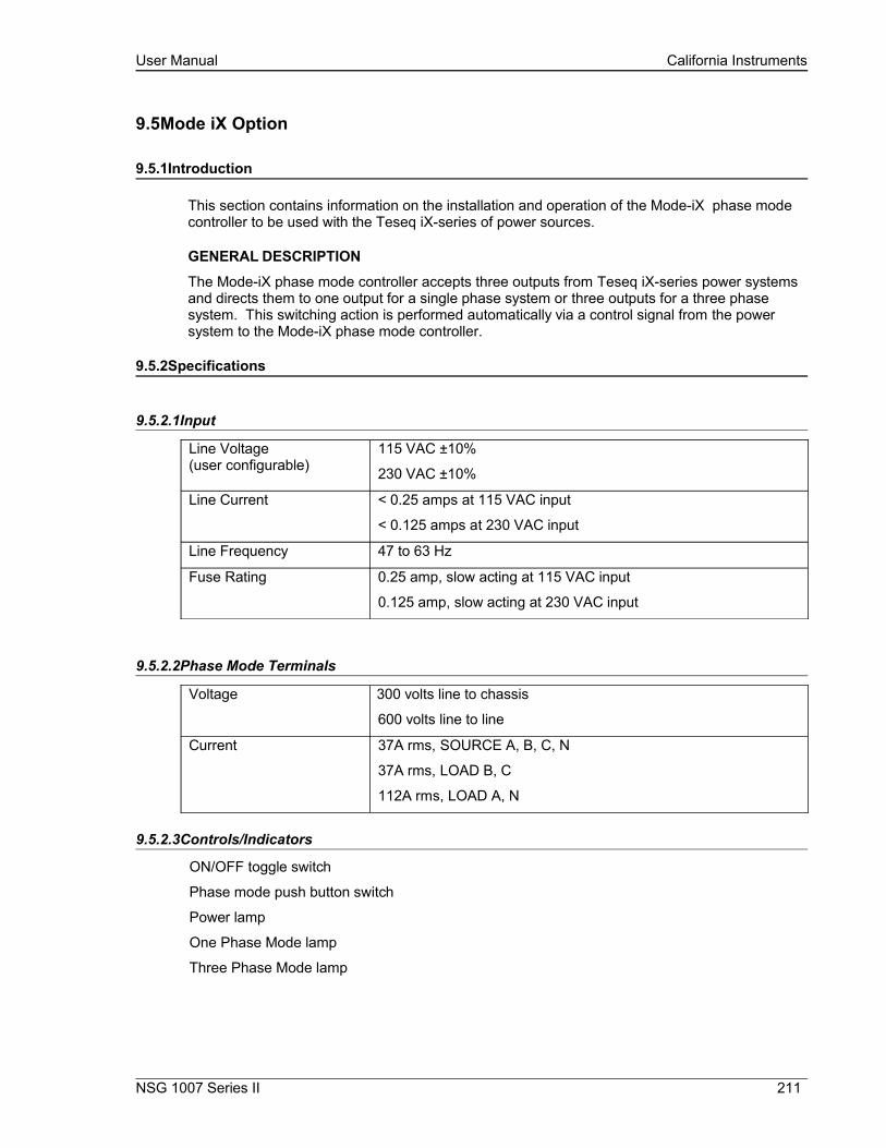
User Manual California Instruments
9.5Mode iX Option
9.5.1Introduction
This section contains information on the installation and operation of the Mode-iX phase mode controller to be used with the Teseq iX-series of power sources.
GENERAL DESCRIPTION
The Mode-iX phase mode controller accepts three outputs from Teseq iX-series power systems and directs them to one output for a single phase system or three outputs for a three phase system. This switching action is performed automatically via a control signal from the power system to the Mode-iX phase mode controller.
9.5.2Specifications
9.5.2.1Input
Line Voltage(user configurable)
115 VAC ±10%
230 VAC ±10%
Line Current < 0.25 amps at 115 VAC input
< 0.125 amps at 230 VAC input
Line Frequency 47 to 63 Hz
Fuse Rating 0.25 amp, slow acting at 115 VAC input
0.125 amp, slow acting at 230 VAC input
9.5.2.2Phase Mode Terminals
Voltage 300 volts line to chassis
600 volts line to line
Current 37A rms, SOURCE A, B, C, N
37A rms, LOAD B, C
112A rms, LOAD A, N
9.5.2.3Controls/Indicators
ON/OFF toggle switch
Phase mode push button switch
Power lamp
One Phase Mode lamp
Three Phase Mode lamp
NSG 1007 Series II 211

User Manual California Instruments
9.5.2.4Mechanical
Dimensions 3.5"H x 19"W x 22"D
89 mm H x 480 mm W x 560 mm D
Weight 14.1 lbs, 6.39 kg
Connectors:
Input mains
Source A, B, C, N
Load A, N
Load B, C
IEC 320
Phoenix Contact HDFK10
Phoenix Contact HDFK50
Phoenix Contact HDFK10
System Interface 3M 3367-1000 (mates with 3M 3366-1001)
Chassis Slide General Devices C300S-118-U/B308 BKT
9.5.2.5Environmental
Temperature 0 to 40 °C
Relative Humidity 80% max. to 31 °C
derate linearly to 50% max. at 40°C
Altitude 2000 m max.
Installation Overvoltage Category II
Pollution Degree 2
Equipment Class I
Usage indoor
212 i Series II / NSG 1007 II / iM Series II

User Manual California Instruments
CAUTIONVoltages up to 600 VAC are available in certain sections of this product. This
equipment uses potentially lethal voltages.
DEATHOn contact may result if personnel fail to observe safety precautions. Do not
touch electronic circuits when power is applied.
NSG 1007 Series II 213

User Manual California Instruments
9.5.3Installation and Acceptance
9.5.3.1Unpacking
Inspect the unit for any possible shipping damage immediately upon receipt. If damage is evident, notify the carrier. Do not return an instrument to the factory without prior approval. Do not destroy the packing container until the unit has been inspected for damage in shipment.
9.5.3.2Power Requirements
The Mode-iX uses either 115 or 230 VAC to power the control circuits. The user may select the desired input voltage using the small range selector card within the IEC input module. The selector card may be removed from the input module by removing the line cord, sliding the plastic window to the left, and extracting the card.
Note that attempting to operate the Mode-iX from an input range that does not match the actual AC power voltage may cause permanent damage to the unit.
The selector card is marked 100/220 on one side and 120/240 on the opposite side. Mode-iX may be operated from a 115 volt line by selecting the 120 volt range. It may be operated from 230 volts by selecting the 240 volt range. The 100 volt and 220 volt ranges are not active.
The selected range is the one that is marked on the upper left side of the selector card as the card is slid into the IEC 320 module.
The power source to the Mode-iX must provide protective earth grounding.
9.5.3.3Mechanical Installation
The Mode-iX has been designed for rack mounting in a standard 19 inch rack. The unit should be supported from the bottom with a shelf-track or supported from the sides with optional rack slides.The cooling fan at the rear of the unit must be free of any obstructions that would interfere with the flow of air. A 2.5 inch clearance should be maintained between the rear of the unit and the rear panel of the mounting cabinet. Also, the air intake holes on the sides of the power chassis must not be obstructed.
9.5.3.4Output Wiring
The Mode-iX is wired in series with the output of specified Teseq power source systems. The Mode-iX terminal block marked SOURCE should be wired to the output of the power source/system. The terminal block marked LOAD is wired to the user's load (unit under test, UUT). Refer to Figure 9-113 in this section for an example of proper connections.
Refer to Section to determine the appropriate wire gauge needed for the output wiring.
Note: The output voltage of the iX-series power sources into the Mode-iX box may be at hazardous potentials as high as 300 volts line to neutral (600 volts line to line). Wiring used between the power sources and Mode-iX and between the Mode-iX and the user’s load must be insulated to withstand this potential.
214 i Series II / NSG 1007 II / iM Series II

User Manual California Instruments
Note: The SOURCE and LOAD terminals of Mode-iX will be at the hazardous live potentials of the iX-series power sources driving it even if Mode-iX box has not been switched on.
NSG 1007 Series II 215

User Manual California Instruments
Figure 9-117: Example Connection With INA 2162
216 i Series II / NSG 1007 II / iM Series II

User Manual California Instruments
9.5.4Operation
9.5.4.1General
The Mode-iX phase mode controller switches the three outputs from three Teseq iX-series power sources to one or three sets of outputs on the phase mode controller. This allows the three power sources to be operated in either three phase or single phase mode with the system output being taken from the phase mode controller.
This switching is performed automatically via a control signal on the system interface connector. The signal is generated by the master power source. The master power source also automatically configures the complete power system for proper output phase angles and power source current sharing.
9.5.4.2Front Panel Controls/Indicators
Power Switch and Lamp
A power switch turns the phase mode controller on or off. A lamp above the switch illuminates when power is on.
Mode Switch
This momentary contact push button switch toggles the phase mode controller between three phase and one phase mode. The function of this switch is normally disabled and switching is remotely controlled via a signal on the system interface connector.
One Phase Lamp
This lamp is illuminated when the phase mode controller is operating in single phase mode. The power source outputs connected to the SOURCE A, B and C terminals are shorted together in the phase mode controller and directed to the LOAD A terminal.
Three Phase Lamp
This lamp is illuminated when the phase mode controller is operating in three phase mode. The power source outputs connected to the SOURCE A, B, C terminals are directed to the LOAD A, B, C terminals, respectively.
Programmed Control
The phase mode controller is normally remotely programmed by the master iX-series power source.
A system interface cable must be connected between the Mode-iX and the power sources to carry the control signal to the Mode-iX. When configured for programmed control, the Mode-iX may not be controlled by the front panel MODE switch. Refer to Section 4.2.11.2 for details on controlling the number of output phases with the Mode-iX option.
NSG 1007 Series II 217
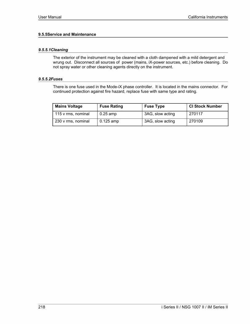
User Manual California Instruments
9.5.5Service and Maintenance
9.5.5.1Cleaning
The exterior of the instrument may be cleaned with a cloth dampened with a mild detergent and wrung out. Disconnect all sources of power (mains, iX-power sources, etc.) before cleaning. Do not spray water or other cleaning agents directly on the instrument.
9.5.5.2Fuses
There is one fuse used in the Mode-iX phase controller. It is located in the mains connector. For continued protection against fire hazard, replace fuse with same type and rating.
Mains Voltage Fuse Rating Fuse Type CI Stock Number
115 v rms, nominal 0.25 amp 3AG, slow acting 270117
230 v rms, nominal 0.125 amp 3AG, slow acting 270109
218 i Series II / NSG 1007 II / iM Series II

User Manual California Instruments
9.6Omni Options
9.6.1Introduction
This section contains information on the installation and operation of the Imepdance (Output Matching Network Impedance) impedance network to be used with the Teseq
i-or iX-series of power sources.
9.6.2General Description
The Imepdance impedance network adds inductive and resistive impedance to Teseq i-or iX-series power sources. This additional impedance brings the combined system impedance up to the levels required of the power source for IEC 555-3 and IEC 1000-3-3 (flicker) testing.
9.6.3Specifications
9.6.3.1Input
Omni 1-18i and 3-18i Omni 1-37i, 1-37iJ and 3-37iLine Voltage(user configurable)
115 VAC ±10% or
230 VAC ±10%
115 VAC ±10% or
230 VAC ±10%
Line Current < 0.25 amps at 115 VAC input
< 0.125 amps at 230 VAC input
< 1.0 amps at 115 VAC input
< 0.5 amps at 230 VAC input
Line Frequency 47 to 63 Hz 47 to 63 Hz
Fuse Rating 0.25 amp, slow acting at 115 VAC input
0.125 amp, slow acting at 230 VAC input
2 Amp, slow acting used for
both input ranges
9.6.3.2Output
Imepdance Type 1-18i 3-18i 1-37i and 1-37iJ 3-37iPhases 1 3 1 3Current max, rms. 18.5A per phase 18.5A per phase 37A per phase 37A per phaseCurrent in bypass 37A per phase 37A per phase 74A per phase 74A per phase
NOTE: To prevent damage to the Imepdance unit , the BYPASS mode must be selected when the power source is operated on low output voltage range or if currents in excess of Imepdance ratings will be drawn.
NSG 1007 Series II 219
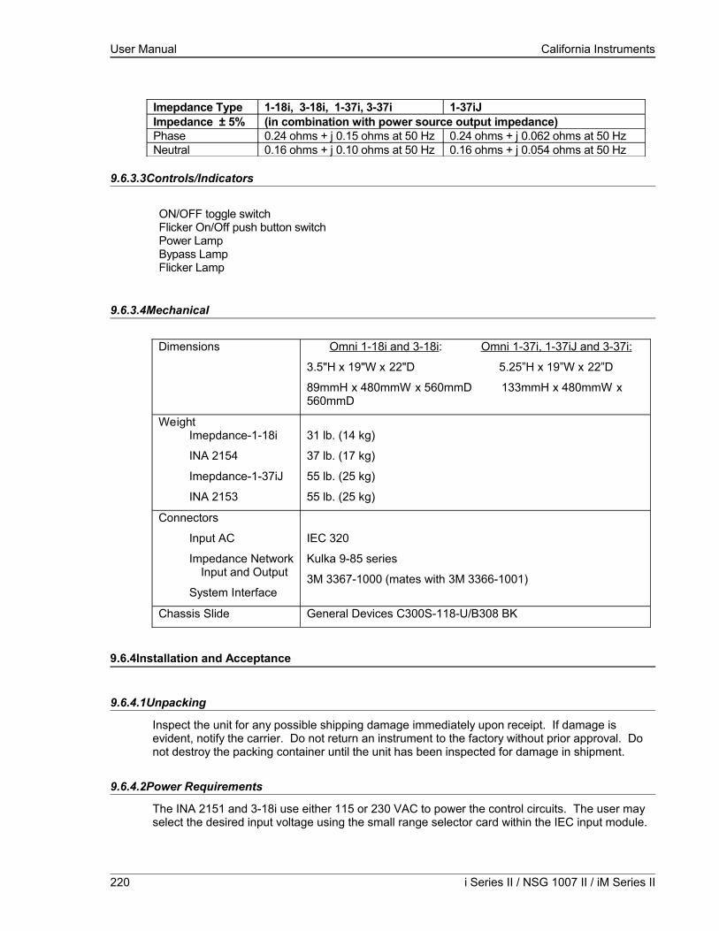
User Manual California Instruments
Imepdance Type 1-18i, 3-18i, 1-37i, 3-37i 1-37iJImpedance ± 5% (in combination with power source output impedance)Phase 0.24 ohms + j 0.15 ohms at 50 Hz 0.24 ohms + j 0.062 ohms at 50 HzNeutral 0.16 ohms + j 0.10 ohms at 50 Hz 0.16 ohms + j 0.054 ohms at 50 Hz
9.6.3.3Controls/Indicators
ON/OFF toggle switchFlicker On/Off push button switchPower LampBypass LampFlicker Lamp
9.6.3.4Mechanical
Dimensions Omni 1-18i and 3-18i: Omni 1-37i, 1-37iJ and 3-37i:
3.5"H x 19"W x 22"D 5.25”H x 19”W x 22”D
89mmH x 480mmW x 560mmD 133mmH x 480mmW x 560mmD
WeightImepdance-1-18i
INA 2154
Imepdance-1-37iJ
INA 2153
31 lb. (14 kg)
37 lb. (17 kg)
55 lb. (25 kg)
55 lb. (25 kg)
Connectors
Input AC
Impedance NetworkInput and Output
System Interface
IEC 320
Kulka 9-85 series
3M 3367-1000 (mates with 3M 3366-1001)
Chassis Slide General Devices C300S-118-U/B308 BK
9.6.4Installation and Acceptance
9.6.4.1Unpacking
Inspect the unit for any possible shipping damage immediately upon receipt. If damage is evident, notify the carrier. Do not return an instrument to the factory without prior approval. Do not destroy the packing container until the unit has been inspected for damage in shipment.
9.6.4.2Power Requirements
The INA 2151 and 3-18i use either 115 or 230 VAC to power the control circuits. The user may select the desired input voltage using the small range selector card within the IEC input module.
220 i Series II / NSG 1007 II / iM Series II

User Manual California Instruments
The selector card may be removed from the input module by removing the line cord, sliding the plastic window to the left, and extracting the card.
For the Omni 1-18i and 3-18i the selector card is marked 100/220 on one side and 120/240 on the opposite side. INA 2151 and 3-18i may be operated from a 115 volt line by selecting the 120 volt range. It may be operated from 230 volts by selecting the 240 volt range. The 100 volt and 220 volt ranges are not active.
The selected range is the one that is marked on the upper left side of the selector card as the card is slid into the IEC 320 module.
The Imepdance 1-37i, 1-37iJ and 3-37i are designed to operate on either 115V or 230V AC power. The input voltage is user-selectable by orienting the input selector module inside the rear panel power entry module. To change input voltage proceed as outlined below.
Note that attempting to operate the Imepdance from an input range that does not match the actual AC power voltage may cause permanent damage to the unit.
9.6.5Voltage Range Configuration for the Imepdance 1-37i, 1-37iJ and INA 2153
To change input range:
1. Remove power cord from input module.
2. Pry cover loose with a small screwdriver.
3. Pull out fuse holder, prying with a screwdriver will be necessary.
4. Orient the red fuse holder so that the desired voltage shows through the window. It is necessary that the fuse always sits on the top side of the fuse holder when it is re-inserted into the module. Likewise, the shorting clip must always be on the bottom of the fuse holder.
For example, if the input voltage is being changed from 115 to 230, the fuse holder must first be removed, and then the clip and the fuse must swap location. The fuse assembly can then be inserted back into the input module.
9.6.5.1Mechanical Installation
The Imepdance has been designed for rack mounting in a standard 19 inch rack. The unit should be supported from the bottom with a shelf-track or supported from the sides with optional rack slides.
The cooling fans at the rear of the unit must be free of any obstructions that would interfere with the flow of air. A 2.5 inch clearance should be maintained between the rear of the unit and the rear panel of the mounting cabinet. Also, the air intake holes on the sides of the power chassis must not be obstructed.
9.6.5.2Output Wiring
The Imepdance impedance network is wired in series with the output of specified Teseq power sources or power source systems. The Imepdance terminal block marked SOURCE should be wired to the output of the power source/system. The terminal block marked LOAD is wired to the
NSG 1007 Series II 221
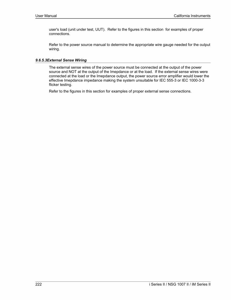
User Manual California Instruments
user's load (unit under test, UUT). Refer to the figures in this section for examples of proper connections.
Refer to the power source manual to determine the appropriate wire gauge needed for the output wiring.
9.6.5.3External Sense Wiring
The external sense wires of the power source must be connected at the output of the power source and NOT at the output of the Imepdance or at the load. If the external sense wires were connected at the load or the Imepdance output, the power source error amplifier would lower the effective Imepdance impedance making the system unsuitable for IEC 555-3 or IEC 1000-3-3 flicker testing.
Refer to the figures in this section for examples of proper external sense connections.
222 i Series II / NSG 1007 II / iM Series II

User Manual California Instruments
Figure 9-118: Example Connections With INA 2151
NSG 1007 Series II 223

User Manual California Instruments
Figure 9-119: Example Connections With INA 2154
224 i Series II / NSG 1007 II / iM Series II

User Manual California Instruments
Figure 9-120: Schematic Showing Imepdance 1-37i and1-37iJ Connected to NSG 1007-5-208 System
NSG 1007 Series II 225

User Manual California Instruments
Figure 9-121: Schematic Showing INA 2153 Connected to NSG 1007-30-208 System
226 i Series II / NSG 1007 II / iM Series II

User Manual California Instruments
9.6.6Operation
9.6.6.1General
The Imepdance impedance network adds resistive and inductive impedance to the output of selected Teseq power sources/systems to provide power source impedance levels specified for IEC 555-3 flicker testing. For normal (low impedance) power source operation, the impedance that Imepdance adds may be shunted by bypass relays selected on the Imepdance front panel.
9.6.6.2Omni i Front Panel Controls/Indicators
Power Switch and LampA power switch turns the Imepdance control circuits on or off. A lamp above the switch illuminates when power is on.
Flicker On/Off Switch and LampsThe momentary contact push button Flicker On/Off switch toggles the Imepdance mode between bypass function (no added impedance) and flicker function (IEC 555-3 impedance). Lamps above the switch indicate the selected mode.
NOTE: To prevent damage to the Imepdance unit, the BYPASS mode must be selected when the power source is operated on low output voltage range or if currents in excess of Imepdance ratings will be drawn.
Bypass relays are provided to short out the Imepdance impedance so that the power source may be used with its normal low output impedance or whenever the load current will be in excess of the Imepdance maximum current rating. When the BYPASS mode is selected, the Imepdance impedance is shorted out. When the FLICKER mode is selected, the Imepdance impedance is added to the power source output impedance.
Select the BYPASS position when low power source output impedance is required or desirable. This is the case for most tests other than IEC 555-3 flicker tests. Also select the BYPASS position when the power source is operated on the low voltage output range. The low voltage output range can deliver currents well in excess of the Imepdance maximum current rating.
9.6.6.3Omni Control Through i/iX Front Panel
Select the APPLICATIONS screen from the MENU2 screen. The following screen will appear as shown in Figure 9-122
Figure 9-122: Applications Screen
NSG 1007 Series II 227

User Manual California Instruments
Scroll to the Imepdance OPTION entry using the up and down courser key. Press the ENTER key. The following MENU will appear as shown in Figure 9-123
Figure 9-123: Imepdance Control Screen
Scroll to the MODE entry using the up and down courser key. USE the Shuttle Knob to engage the Imepdance. The display will indicate that the Imepdance mode as shown in Figure 9-124
Figure 9-124: Imepdance Control Screen
Note: The output of the AC source will drop for about 50 ms when the Imepdance MODE changes state.
To Bypass the Imepdance, turn the Shuttle Knob counterclockwise.
9.6.6.4Programmed Control
The FLICKER/BYPASS mode may be remotely programmed by the power source if the power source and Imepdance are configured for this function. A system interface cable must be connected between the Imepdance and the power source to carry the control signal to the Imepdance. When configured for programmed control, the Imepdance may not be controlled by the front panel FLICKER/BYPASS switch. Refer to the power source manual for details on programming instructions.
228 i Series II / NSG 1007 II / iM Series II
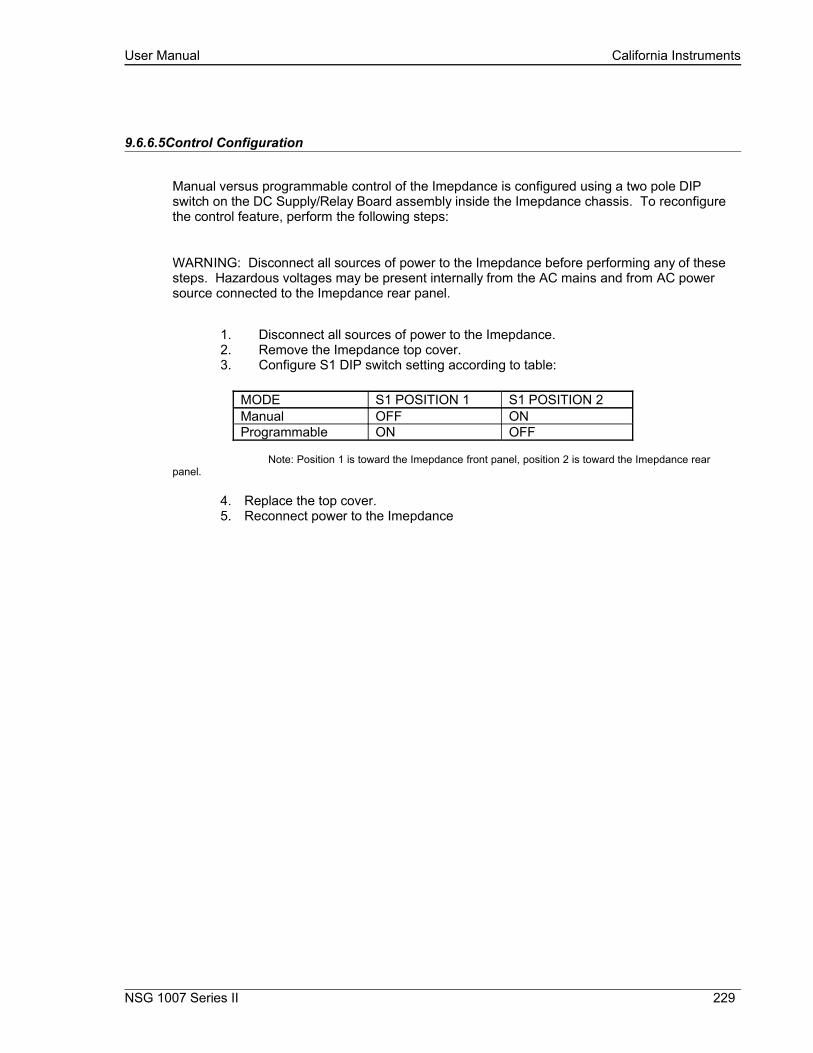
User Manual California Instruments
9.6.6.5Control Configuration
Manual versus programmable control of the Imepdance is configured using a two pole DIP switch on the DC Supply/Relay Board assembly inside the Imepdance chassis. To reconfigure the control feature, perform the following steps:
WARNING: Disconnect all sources of power to the Imepdance before performing any of these steps. Hazardous voltages may be present internally from the AC mains and from AC power source connected to the Imepdance rear panel.
1. Disconnect all sources of power to the Imepdance.2. Remove the Imepdance top cover.3. Configure S1 DIP switch setting according to table:
MODE S1 POSITION 1 S1 POSITION 2Manual OFF ONProgrammable ON OFF
Note: Position 1 is toward the Imepdance front panel, position 2 is toward the Imepdance rear panel.
4. Replace the top cover.5. Reconnect power to the Imepdance
NSG 1007 Series II 229
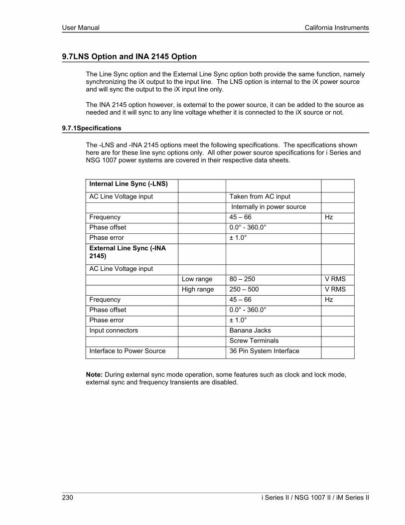
User Manual California Instruments
9.7LNS Option and INA 2145 Option
The Line Sync option and the External Line Sync option both provide the same function, namely synchronizing the iX output to the input line. The LNS option is internal to the iX power source and will sync the output to the iX input line only.
The INA 2145 option however, is external to the power source, it can be added to the source as needed and it will sync to any line voltage whether it is connected to the iX source or not.
9.7.1Specifications
The -LNS and -INA 2145 options meet the following specifications. The specifications shown here are for these line sync options only. All other power source specifications for i Series and NSG 1007 power systems are covered in their respective data sheets.
Internal Line Sync (-LNS)
AC Line Voltage input Taken from AC input Internally in power source
Frequency 45 – 66 HzPhase offset 0.0° - 360.0°Phase error ± 1.0°External Line Sync (-INA 2145)
AC Line Voltage inputLow range 80 – 250 V RMSHigh range 250 – 500 V RMS
Frequency 45 – 66 HzPhase offset 0.0° - 360.0°Phase error ± 1.0°Input connectors Banana Jacks
Screw TerminalsInterface to Power Source 36 Pin System Interface
Note: During external sync mode operation, some features such as clock and lock mode, external sync and frequency transients are disabled.
230 i Series II / NSG 1007 II / iM Series II

User Manual California Instruments
9.7.2LNS Option
The Line Sync Option (LNS) allows the output of the i/iX AC Source to be synchronized to the line input. This capability may be needed to support tests that require the use of additional equipment. The –LNS option needs to be ordered at the time of purchase and cannot be installed in the field.
The LNS Option – if installed – can be turned on from the front panel as follows:
Select the PROGRAM 2 screen and move the cursor to the CLK MODE field. The default value for the field is INT for internal clock mode. Use the knob to select the SYNC mode in order to enable the LNS. If the LNS is not installed a “LINE SYNC ERROR” will appear after a short period in the top left of the screen. This means the LNS option is either not present or not receiving a phase input signal from the line.
To turn the sync mode back off, set the CLK MODE field back to INT.
Over the bus, the LNS is enabled or disabled as follows:
FREQ:MODE SENS /* Enables LNS */
FREQ:MODE FIX /* Disables LNS */
If the LNS is not installed and the FREQ:MODE SENS command is issued, an error message is generated. If done as part of a test program, an error check should be done after a 800 msec delay to allow the i/iX to sense the presence of a sync signal coming from the LNS board. If no error occurs, the LNS is active. If an error occurs, the LNS may not be available or not functioning and the mode has reverted back to internal.
The LNS option is designed to keep the iX output frequency locked to the line frequency. There is a finite phase offset however, between the iX source output and the line input to the iX power source. This phase offset will vary somewhat with the input line voltage. If it is desired to have the iX output in-phase with the line input it will be necessary to monitor the iX output voltage as well as the line input to the iX source using a two channel oscilloscope to compare the zero-crossings of the voltage waveforms. An isolation amplifier must be used when connecting the input line to the o’scope input. To program an offset angle on the iX source, go to PROGRAM 2 screen and select PHASE. Typically 25-30 of phase angle will put the line input and the source output in-phase, but the exact angle to program can only be determined by monitoring the iX source output and the line input voltage and comparing the waveforms.
9.7.3INA 2145 Option
The External Line Sync option (-INA 2145) is housed in a small metal enclosure that interfaces to the power source using a system interface cable. This module has a pass-through connector for the system interface so this interface remains available for other purposes.
The external line sync module provides two input voltage ranges, a low range from 80 V to 250 V RMS and a high range from 250 V to 500 V RMS. The AC line voltage can be connected using standard sheathed banana jacks or a screw terminal strip. The -INA 2145 option provides full safety isolation from input to interface connector. The AC line to synchronize the source output to can be the same as the one feeding the source itself, or a different one altogether for greater flexibility.
NSG 1007 Series II 231
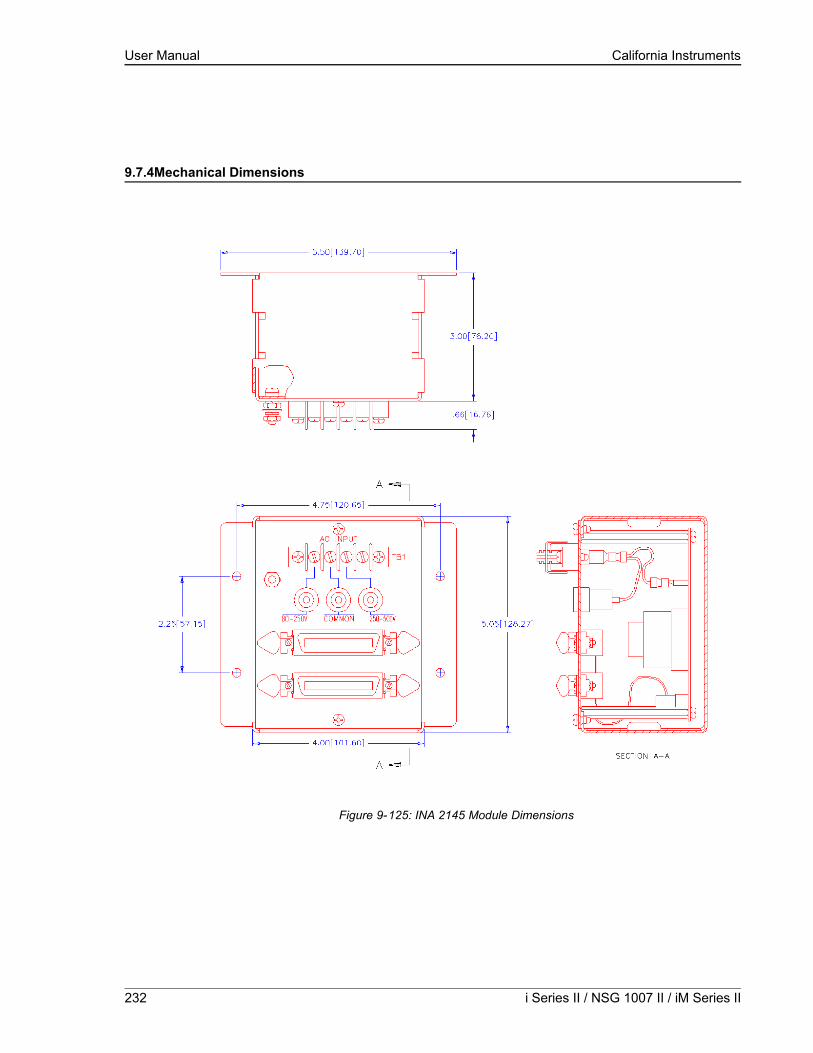
User Manual California Instruments
9.7.4Mechanical Dimensions
Figure 9-125: INA 2145 Module Dimensions
232 i Series II / NSG 1007 II / iM Series II

User Manual California Instruments
9.7.5Connection Diagram
The following diagrams illustrate both low range and high range connections between the INA 2145 module, the NSG 1007 master power source and the AC Line synchronizing voltage.
Figure 9-126: INA 2145 Connection on Low Range
NSG 1007 Series II 233
NSG 1007-5-208 POWER SOURCE
AC INPUT
SYSTEM INTERFACE
80-250V COM 250-500V
80-250V SYNC INPUT FROM iX SOURCE INPUT,OR,OTHER AC LINE VOLTAGE
J22
7000-262-2 system interface cable
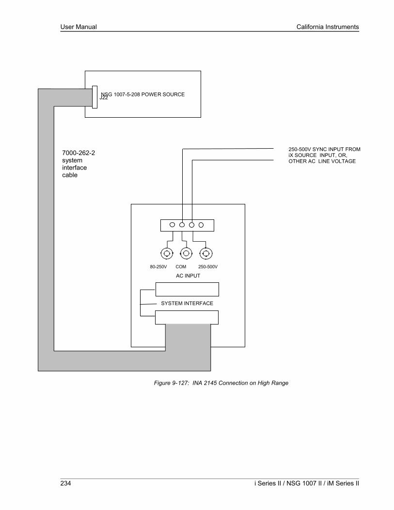
User Manual California Instruments
Figure 9-127: INA 2145 Connection on High Range
234 i Series II / NSG 1007 II / iM Series II
NSG 1007-5-208 POWER SOURCE
AC INPUT
SYSTEM INTERFACE
80-250V COM 250-500V
250-500V SYNC INPUT FROM iX SOURCE INPUT, OR, OTHER AC LINE VOLTAGE
7000-262-2 system interface cable
J22

User Manual California Instruments
9.7.6Installation
The INA 2145 module can be installed inside a system cabinet or other vertical structure in the vicinity of the iX power source. Refer to Figure 9-126 and Figure 9-127 for connection details. The input voltage can be applied to the AC input terminal strip as shown, or, banana jacks can be used to secure the line voltage to the INA 2145 module. The system interface ribbon cable can be connected to either of the two connectors on the INA 2145 module. The extra connector is provided for pass-through connectivity.
9.7.7INA 2145 Option Operation
The External Line Sync option (INA 2145) allows the output of the i/iX AC Source to be synchronized to any line input, whether it is the line powering the iX source or any other line voltage not necessarily hooked up to the iX source. This capability may be needed to support tests that require the use of additional equipment.
The INA 2145 Option – once installed and connected – can be turned on from the iX front panel as follows:
Select the PROGRAM 2 screen and move the cursor to the CLK MODE field. The default value for the field is INT for internal clock mode. Use the knob to select the SYNC mode in order to enable the INA 2145. If the INA 2145 is not installed a “LINE SYNC ERROR” will appear after a short period in the top left of the screen. This means the INA 2145 option is either not present or not receiving a phase input signal from the line.
To turn the sync mode back off, set the CLK MODE field back to INT.
Over the bus, the INA 2145 is enabled or disabled as follows:
FREQ:MODE SENS /* Enables INA 2145 */
FREQ:MODE FIX /* Disables INA 2145 */
If the INA 2145 is not installed and the FREQ:MODE SENS command is issued, an error message is generated. If done as part of a test program, an error check should be done after a 800 msec delay to allow the i/iX to sense the presence of a sync signal coming from the INA 2145 module. If no error occurs, the INA 2145 is active. If an error occurs, the INA 2145 may not be available or not functioning and the mode has reverted back to internal.
The INA 2145 option is designed to keep the iX output frequency locked to the line frequency. There is a finite phase offset however, between the iX source output and the line input to the External Sync Module. This phase offset will vary somewhat with the line voltage going to the INA 2145 module. If it is desired to have the iX output in phase with the line input, it will be necessary to monitor the iX output voltage as well as the line input to the INA 2145 module using a two channel oscilloscope to compare the zero-crossings of the voltage waveforms. An isolation amplifier must be used when connecting the sync input line to the o’scope input. To program an offset angle on the iX source, go to PROGRAM 2 screen and select PHASE. Typically 25-30 of phase angle will put the line input and the source output in-phase, but the exact angle to program can only be determined by monitoring the iX source and the line input voltage and comparing the waveforms.
NSG 1007 Series II 235

User Manual California Instruments
9.8Option –704: MilStd704 Tests
The MIL704 option is made up of both firmware that resides in the power source and the GUI Windows application program. The firmware covers revision D and E of the Mil-Std704 standard. The GUI covers the remaining revisions A, B, C and F. This provides coverage of all available standard revisions.
The user interface for each implementation is different however. The revision D and E tests can be operated directly from the power source’s front panel or through the supplied GUI program. The revision A-C, F tests can only be operated through the supplied GUI program. Thus, for rev A-C and F, a Windows PC and interface is required.
Section 9.8.1 covers operation of the firmware based revision D and E tests.
For information regarding the operation of the MIL-STD-704 revision A, B, C, and F tests with the GUI, please refer to the Avionics Software Manual (CI part no. 4994-971 included on CDROM). Note that future updates of the GUI may include overlapping coverage for revisions D and E in the software as the GUI program is designed to support all revisions. For now, revisions D and E have no associated data files in the GUI.
236 i Series II / NSG 1007 II / iM Series II
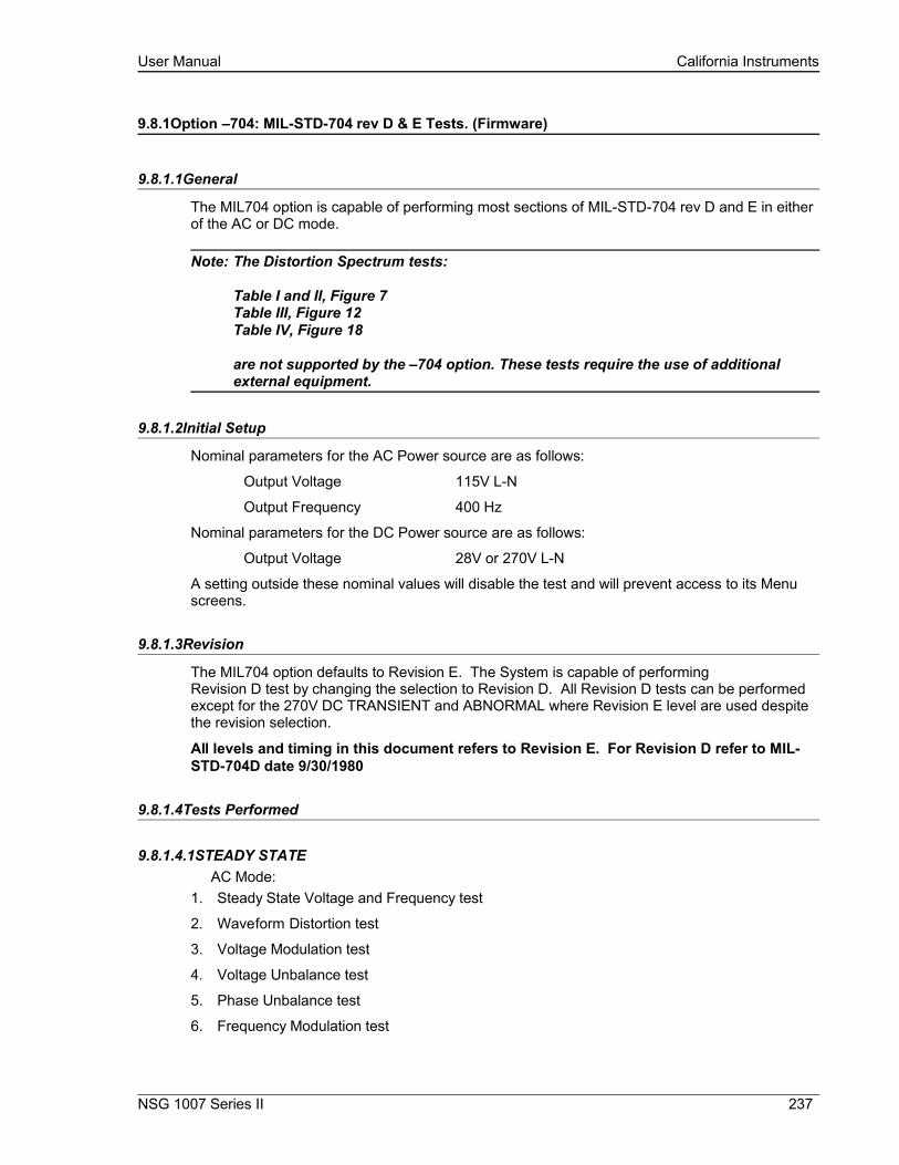
User Manual California Instruments
9.8.1Option –704: MIL-STD-704 rev D & E Tests. (Firmware)
9.8.1.1General
The MIL704 option is capable of performing most sections of MIL-STD-704 rev D and E in either of the AC or DC mode.
Note: The Distortion Spectrum tests:
Table I and II, Figure 7Table III, Figure 12 Table IV, Figure 18
are not supported by the –704 option. These tests require the use of additional external equipment.
9.8.1.2Initial Setup
Nominal parameters for the AC Power source are as follows:
Output Voltage 115V L-N
Output Frequency 400 Hz
Nominal parameters for the DC Power source are as follows:
Output Voltage 28V or 270V L-N
A setting outside these nominal values will disable the test and will prevent access to its Menu screens.
9.8.1.3Revision
The MIL704 option defaults to Revision E. The System is capable of performingRevision D test by changing the selection to Revision D. All Revision D tests can be performed except for the 270V DC TRANSIENT and ABNORMAL where Revision E level are used despite the revision selection.
All levels and timing in this document refers to Revision E. For Revision D refer to MIL-STD-704D date 9/30/1980
9.8.1.4Tests Performed
9.8.1.4.1STEADY STATEAC Mode:
1. Steady State Voltage and Frequency test
2. Waveform Distortion test
3. Voltage Modulation test
4. Voltage Unbalance test
5. Phase Unbalance test
6. Frequency Modulation test
NSG 1007 Series II 237

User Manual California Instruments
7. Transient Voltage low and high test
8. Transient Frequency low and high test
DC Mode:1. Steady State Voltage test
2. Ripple test
9.8.1.4.2EMERGENCY TESTAC Mode:
1. Emergency Voltage minimum and maximum test
2. Emergency Frequency minimum and maximum test
DC Mode:1. Emergency Voltage minimum and maximum test
9.8.1.4.3ABNORMAL TESTAC Mode:
1. Abnormal Voltage under
2. Abnormal Voltage over
3. Abnormal Frequency under
4. Abnormal Frequency under
DC Mode:
1. Abnormal Voltage under
2. Abnormal Voltage over
9.8.1.5Front Panel Entry
To perform a test from the keyboard, from the MENU 2 screen, select the APPLICATIONS screen. The APPLICATIONS screen will appear as shown in Figure 9-128.
Figure 9-128: Application Menu
Scroll to the MIL-STD-704 entry using the up and down cursor keys. Press the ENTER key to select the MIL704 main menu. One of the screens will appear as shown in Figure 9-129. The voltage mode and setting will define which menu to select. Refer to Section 9.8.1.2
Note: The user has to turn on the Output relay before starting a test and set the steady state setup for the test.
238 i Series II / NSG 1007 II / iM Series II
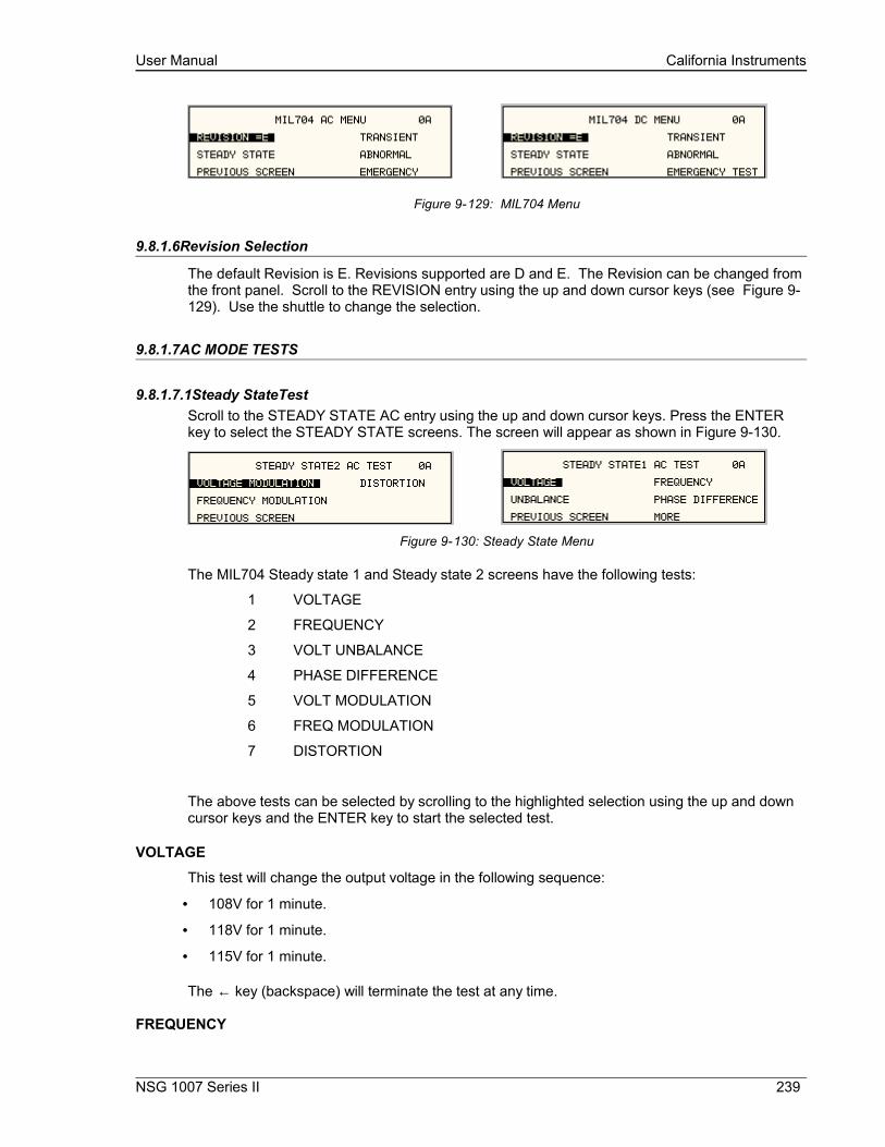
User Manual California Instruments
Figure 9-129: MIL704 Menu
9.8.1.6Revision Selection
The default Revision is E. Revisions supported are D and E. The Revision can be changed from the front panel. Scroll to the REVISION entry using the up and down cursor keys (see Figure 9-129). Use the shuttle to change the selection.
9.8.1.7AC MODE TESTS
9.8.1.7.1Steady StateTestScroll to the STEADY STATE AC entry using the up and down cursor keys. Press the ENTER key to select the STEADY STATE screens. The screen will appear as shown in Figure 9-130.
Figure 9-130: Steady State Menu
The MIL704 Steady state 1 and Steady state 2 screens have the following tests:
1 VOLTAGE
2 FREQUENCY
3 VOLT UNBALANCE
4 PHASE DIFFERENCE
5 VOLT MODULATION
6 FREQ MODULATION
7 DISTORTION
The above tests can be selected by scrolling to the highlighted selection using the up and down cursor keys and the ENTER key to start the selected test.
VOLTAGE
This test will change the output voltage in the following sequence:
• 108V for 1 minute.
• 118V for 1 minute.
• 115V for 1 minute.
The ← key (backspace) will terminate the test at any time.
FREQUENCY
NSG 1007 Series II 239
User Manual California Instruments
This test will change the output frequency in the following sequence:
• 393Hz for 1 minute.
• 407Hz for 1 minute.
• 400Hz for 1 minute.
The ← key (backspace) will terminate the test at any time.
VOLT UNBALANCE
This test will change the output voltage for the selected phase only in the following sequence:
• 112V for 1 minute.
• 118V for 1 minute.
• 115V for 1 minute.
The test will be repeated on three phase systems to include all three phases if the coupling is set to all.
The ← key (backspace) will terminate the test at any time.
PHASE DIFFERENCE
This test applies to three phase systems only. The phase angle for the selected phase will change relative to phase A in the following sequence:
If phase B is selected:
• 236° for 1 minute.
• 244° for 1 minute.
• 240° for 1 minute.
If phase C is selected:
• 116° for 1 minute.
• 124° for 1 minute.
• 120° for 1 minute
VOLTAGE MODULATION
This test will vary the output voltage by ±2.5V rms over a period of one second. The test will last for 2 minutes. The ← key (backspace) will terminate the test at any time.
FREQUENCY MODULATION
This test will vary the output frequency by ±4Hz over a period of one minute. The test will last for 4 minutes. The ← key (backspace) will terminate the test at any time.
WAVEFORM DISTORTION
This test will generate a 5% THD voltage distortion on the output voltage waveform. The distortion is caused by using a clipped sinewave. The test will last for 1 minute. The ← key (backspace) will terminate the test at any time.
240 i Series II / NSG 1007 II / iM Series II

User Manual California Instruments
9.8.1.7.2TRANSIENT TESTFrom the MIL704 main menu (Figure 9-129) scroll to the TRANSIENT AC entry using the up and down cursor keys. Press the ENTER key to select the TRANSIENT screens. The screen will appear as shown in Figure 9-131.
Figure 9-131: Transient Menu
The MIL704 Transient screen has the following tests:
1 HIGH VOLTAGE
2 LOW VOLTAGE
3 HIGH FREQUENCY
4 LOW FREQUENCY
The above tests can be selected by scrolling to the highlighted selection using the up and down key and the ENTER key to start the selected test.
HIGH VOLTAGE
This test will change the output voltage for the selected phase in the following sequence:
• 180V for 10 msec.
• Linearly reduced to118V in 78msec.
• Stay at 118V for 87msec before returning to 115V.
Prior to the test, a range change may take place if the power source is set for the low voltage range.
The ← key (backspace) will terminate the test at any time.
Note: A range change will result in momentary loss of power to the EUT. If this is not acceptable, the power source must be left in high range at all times.
LOW VOLTAGE
This test will change the output voltage for the selected phase only in the following sequence:
• 80V for 10 msec.
• Linearly increase to108V in 70msec.
• Stay at 108V for 95msec before returning to 115V.
The ← key (backspace) will terminate the test at any time.
HIGH FREQUENCY
This test will change the output frequency in the following sequence:
• 425Hz for 1 sec.
• 420Hz for 4 sec.
NSG 1007 Series II 241

User Manual California Instruments
• 410Hz for 5 sec.
• 407Hz for 4 sec.
LOW FREQUENCY
This test will change the output frequency in the following sequence:
• 375Hz for 1 sec.
• 380Hz for 4 sec.
• 390Hz for 5 sec.
• 393Hz for 4 sec.
9.8.1.7.3EMERGENCY TESTFrom the MIL704 main menu (Figure 9-129) scroll to the EMERGENCY AC entry using the up and down cursor keys. Press the ENTER key to select the EMERGENCY screens. The screen will appear as shown in Figure 9-132.
Figure 9-132: Emergency Menu
The EMERGENCY SCREEN has the following tests:
1 VOLTAGE
2 FREQUENCY
The above tests can be selected by scrolling to the highlighted selection using the up and down key and the ENTER key to start the selected test.
VOLTAGEThis test will change the output voltage in the following sequence:
• 108V for 1 minute.
• 118V for 1 minute.
• 115V for 1 minute.
The ← key (backspace) will terminate the test at any time.
FREQUENCY
This test will change the output frequency in the following sequence:
• 393Hz for 1 minute.
• 407Hz for 1 minute.
• 400Hz for 1 minute.
The ← key (backspace) will terminate the test at any time.
242 i Series II / NSG 1007 II / iM Series II
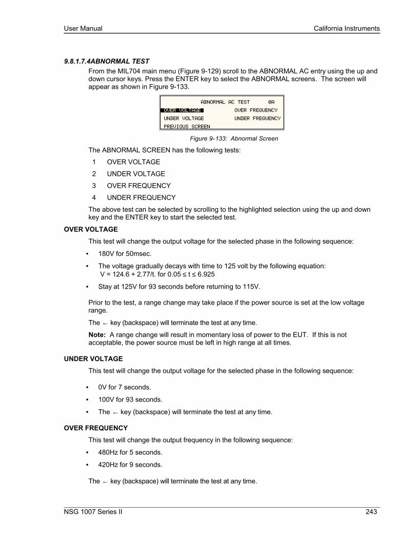
User Manual California Instruments
9.8.1.7.4ABNORMAL TESTFrom the MIL704 main menu (Figure 9-129) scroll to the ABNORMAL AC entry using the up and down cursor keys. Press the ENTER key to select the ABNORMAL screens. The screen will appear as shown in Figure 9-133.
Figure 9-133: Abnormal Screen
The ABNORMAL SCREEN has the following tests:
1 OVER VOLTAGE
2 UNDER VOLTAGE
3 OVER FREQUENCY
4 UNDER FREQUENCY
The above test can be selected by scrolling to the highlighted selection using the up and down key and the ENTER key to start the selected test.
OVER VOLTAGE
This test will change the output voltage for the selected phase in the following sequence:
• 180V for 50msec.
• The voltage gradually decays with time to 125 volt by the following equation: V = 124.6 + 2.77/t. for 0.05 ≤ t ≤ 6.925
• Stay at 125V for 93 seconds before returning to 115V.
Prior to the test, a range change may take place if the power source is set at the low voltage range.
The ← key (backspace) will terminate the test at any time.
Note: A range change will result in momentary loss of power to the EUT. If this is not acceptable, the power source must be left in high range at all times.
UNDER VOLTAGE
This test will change the output voltage for the selected phase in the following sequence:
• 0V for 7 seconds.
• 100V for 93 seconds.
• The ← key (backspace) will terminate the test at any time.
OVER FREQUENCY
This test will change the output frequency in the following sequence:
• 480Hz for 5 seconds.
• 420Hz for 9 seconds.
The ← key (backspace) will terminate the test at any time.
NSG 1007 Series II 243
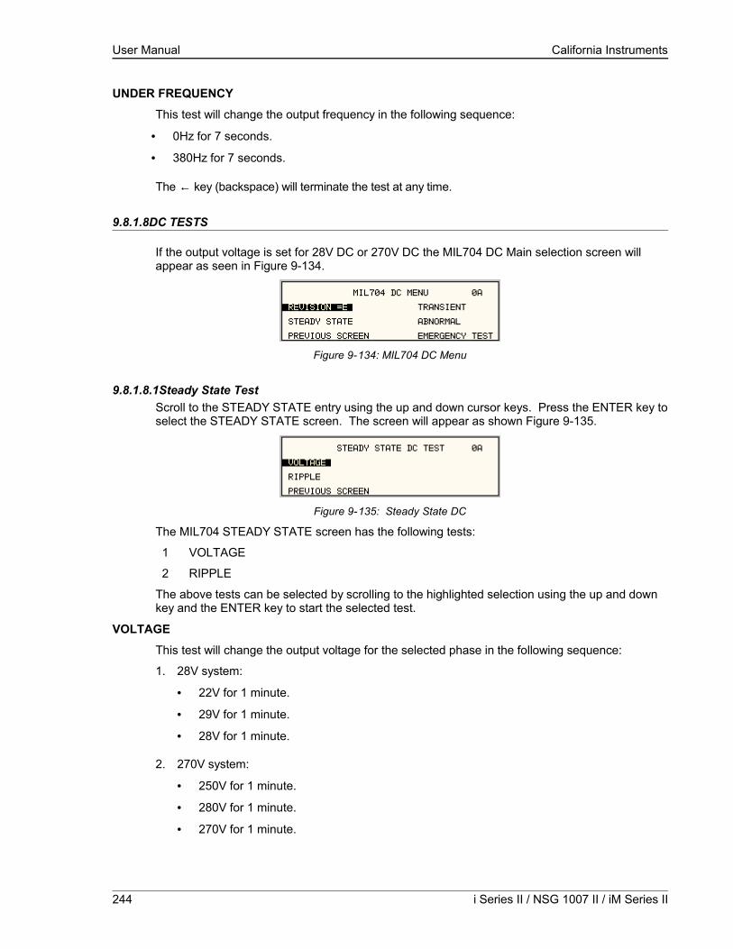
User Manual California Instruments
UNDER FREQUENCY
This test will change the output frequency in the following sequence:
• 0Hz for 7 seconds.
• 380Hz for 7 seconds.
The ← key (backspace) will terminate the test at any time.
9.8.1.8DC TESTS
If the output voltage is set for 28V DC or 270V DC the MIL704 DC Main selection screen will appear as seen in Figure 9-134.
Figure 9-134: MIL704 DC Menu
9.8.1.8.1Steady State TestScroll to the STEADY STATE entry using the up and down cursor keys. Press the ENTER key to select the STEADY STATE screen. The screen will appear as shown Figure 9-135.
Figure 9-135: Steady State DC
The MIL704 STEADY STATE screen has the following tests:
1 VOLTAGE
2 RIPPLE
The above tests can be selected by scrolling to the highlighted selection using the up and down key and the ENTER key to start the selected test.
VOLTAGE
This test will change the output voltage for the selected phase in the following sequence:
1. 28V system:
• 22V for 1 minute.
• 29V for 1 minute.
• 28V for 1 minute.
2. 270V system:
• 250V for 1 minute.
• 280V for 1 minute.
• 270V for 1 minute.
244 i Series II / NSG 1007 II / iM Series II

User Manual California Instruments
The ← key (backspace) will terminate the test at any time.
DC RIPPLEThis test will impose a 400Hz frequency component to the output voltage. The test will last for 2 minutes. The level of the ripple is as follows:
1. 28V system:
±1.5V.
2. 270V system:
±6.0V.
The ← key (backspace) will terminate the test at any time.
9.8.1.8.2Transient TestFrom the MIL704 DC MENU scroll to the TRANSIENT DC entry using the up and down cursor keys. Press the ENTER key to select the TRANSIENT screen. The screen will appear as shown in Figure 9-136.
Figure 9-136: Transient Menu
The Transient Test has the following tests:
1 HIGH VOLTAGE
2 LOW VOLTAGE
HIGH VOLTAGE
This test will change the output voltage for the selected phase in the following sequence:
1. 28V System
• 50V for 12.5 msec.
• Linearly reduce to29V in 70msec.
• Stay at 29V for 92.5msec before returning to 28V.
2. 270V System
• 330V for 20 msec.
• Linearly reduce to280V in 20msec.
• Stay at 280V for 135msec before returning to 270V.
Prior to the test, a range change may take place if the power source is set for the low voltage range.
The ← key (backspace) will terminate the test at any time.
Note: A range change will result in momentary loss of power to the EUT. If this is not acceptable, the power source must be left in high range at all times.
NSG 1007 Series II 245

User Manual California Instruments
LOW VOLTAGE
This test will change the output voltage for the selected phase in the following sequence:
1. 28V System
• 18V for 15 msec.
• Linearly increase to 22V in 85msec.
• Stay at 22V for 75msec before returning to 28V.
2. 270V System
• 200V for 10 msec.
• Linearly increase to 250V in 30msec.
• Stay at 250V for 135msec before returning to 270V.
The ← key (backspace) will terminate the test at any time.
9.8.1.8.3Abnormal TestFrom the MIL704 DC MENU scroll to the ABNORMAL DC entry using the up and down cursor keys. Press the ENTER key to select the ABNORMAL screen. The screen will appear as shown in Figure 9-137.
Figure 9-137: Abnormal Test Screen
The Abnormal Test has the following tests:
1 OVER VOLTAGE
2 UNDER VOLTAGE
The above tests can be selected by scrolling to the highlighted selection using the up and down cursor keys and the ENTER key to start the selected test.
OVER VOLTAGE
This test will change the output voltage for the selected phase in the following sequence:
1. 28V system:
• 50V for 50msec.
• The voltage gradually decays with time to 31.5 volts by the following equation: V = 31.38 + 0.93/t. for 0.05 ≤ t ≤ 7.758
• Stay at 31.5V for 92.242 seconds before returning to 28V.
2. 270V system:
• 350V for 50msec.
• The voltage gradually decays with time to 290 volts by the following equation: V = 289.6 + 3.02/t. for 0.05 ≤ t ≤ 7.55
• Stay at 290V for 92.45 seconds before returning to 270V.
246 i Series II / NSG 1007 II / iM Series II
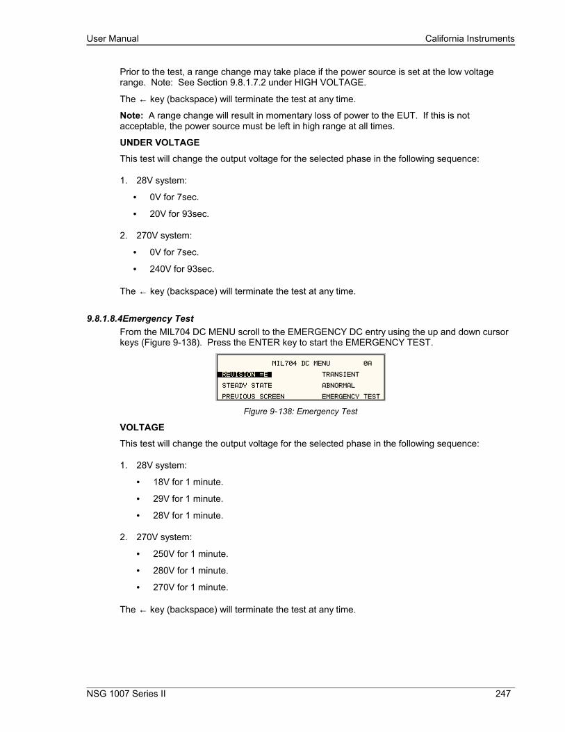
User Manual California Instruments
Prior to the test, a range change may take place if the power source is set at the low voltage range. Note: See Section 9.8.1.7.2 under HIGH VOLTAGE.
The ← key (backspace) will terminate the test at any time.
Note: A range change will result in momentary loss of power to the EUT. If this is not acceptable, the power source must be left in high range at all times.
UNDER VOLTAGE
This test will change the output voltage for the selected phase in the following sequence:
1. 28V system:
• 0V for 7sec.
• 20V for 93sec.
2. 270V system:
• 0V for 7sec.
• 240V for 93sec.
The ← key (backspace) will terminate the test at any time.
9.8.1.8.4Emergency TestFrom the MIL704 DC MENU scroll to the EMERGENCY DC entry using the up and down cursor keys (Figure 9-138). Press the ENTER key to start the EMERGENCY TEST.
Figure 9-138: Emergency Test
VOLTAGE
This test will change the output voltage for the selected phase in the following sequence:
1. 28V system:
• 18V for 1 minute.
• 29V for 1 minute.
• 28V for 1 minute.
2. 270V system:
• 250V for 1 minute.
• 280V for 1 minute.
• 270V for 1 minute.
The ← key (backspace) will terminate the test at any time.
NSG 1007 Series II 247
User Manual California Instruments
9.9ABD Option: Airbus ABD0100.1.8 Test
For information regarding the operation of the ABD0100.1.8 tests with the CIGuiSII, please refer to the Avionics Software Manual (CI part no. 4994-971 included on CDROM).
9.10AMD Option: Airbus AMD24C Test
For information regarding the operation of the Airbus AMD24C tests with the CIGuiSII, please refer to the Avionics Software Manual (CI part no. 4994-971 included on CDROM).
9.11787 Option: Boeing B787-0147 Test
For information regarding the operation of the Boeing B787-0147 tests with the CIGuiSII, please refer to the Avionics Software Manual (CI part no. 4994-971 included on CDROM).
248 i Series II / NSG 1007 II / iM Series II
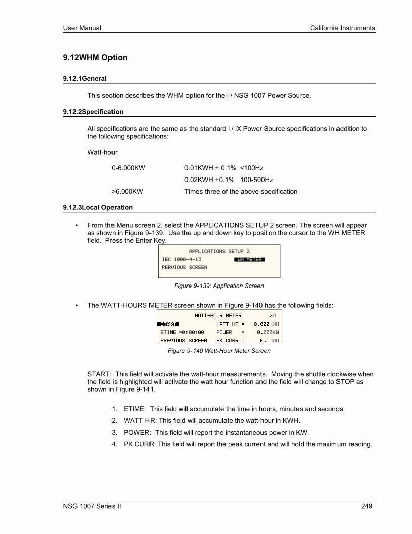
User Manual California Instruments
9.12WHM Option
9.12.1General
This section describes the WHM option for the i / NSG 1007 Power Source.
9.12.2Specification
All specifications are the same as the standard i / iX Power Source specifications in addition to the following specifications:
Watt-hour
0-6.000KW 0.01KWH + 0.1% <100Hz
0.02KWH +0.1% 100-500Hz
>6.000KW Times three of the above specification
9.12.3Local Operation
• From the Menu screen 2, select the APPLICATIONS SETUP 2 screen. The screen will appear as shown in Figure 9-139. Use the up and down key to position the cursor to the WH METER field. Press the Enter Key.
Figure 9-139: Application Screen
• The WATT-HOURS METER screen shown in Figure 9-140 has the following fields:
Figure 9-140 Watt-Hour Meter Screen
START: This field will activate the watt-hour measurements. Moving the shuttle clockwise when the field is highlighted will activate the watt hour function and the field will change to STOP as shown in Figure 9-141.
1. ETIME: This field will accumulate the time in hours, minutes and seconds.
2. WATT HR: This field will accumulate the watt-hour in KWH.
3. POWER: This field will report the instantaneous power in KW.
4. PK CURR: This field will report the peak current and will hold the maximum reading.
NSG 1007 Series II 249
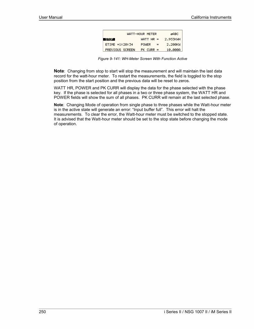
User Manual California Instruments
Figure 9-141: WH-Meter Screen With Function Active
Note: Changing from stop to start will stop the measurement and will maintain the last data record for the watt-hour meter. To restart the measurements, the field is toggled to the stop position from the start position and the previous data will be reset to zeros.
WATT HR, POWER and PK CURR will display the data for the phase selected with the phase key. If the phase is selected for all phases in a two or three phase system, the WATT HR and POWER fields will show the sum of all phases. PK CURR will remain at the last selected phase.
Note: Changing Mode of operation from single phase to three phases while the Watt-hour meter is in the active state will generate an error: “Input buffer full”. This error will halt the measurements. To clear the error, the Watt-hour meter must be switched to the stopped state. It is advised that the Watt-hour meter should be set to the stop state before changing the mode of operation.
250 i Series II / NSG 1007 II / iM Series II

User Manual California Instruments
9.12.4Remote PROGRAMMING
The following SCPI command will be used to control the WHM functions:
WHMeter:
[STATe] Turn on or of the watt hour function
ETIMe? Return the elapse time
WHOur? Return the watt-hour in KWH
WHMeter[:STATe]
This command will start or stop the watt-hour function. Command Syntax WHMeter[:STATe]<bool>Parameters 0 | OFF | 1 | ONExamples WHM ONQuery Syntax WHM[:STATe]?Returned Parameters 0 | 1
WHMeter:ETIMe?
This command will return the total amount of time the watt-hour meter accumulated. The returned data has four fields separated by commas. These fields are hours, minutes, seconds and milliseconds.Command Syntax WHMeter:ETIMe?Parameters noneQuery Syntax WHM:ETIM?Returned Parameters h,mm,ss,ms
WHMeter:WHOur?
Phase Selectable
This command will return the total accumulated kilowatt-hour for the selected phase. If coupling is set to all, the value returned is the sum of all phases in the system irregardless of the selected phase. Command Syntax WHMeter:WHOur?Parameters noneQuery Syntax WHM:WHO?Returned Parameters <numeric value>
Note: If the watt-hour meter is active, the total power of all phases in the system will be returned when querying the power.
NSG 1007 Series II 251

User Manual California Instruments
10.Error Messages
Any errors that occur during operation from either the front panel or the remote control interface will result in error messages. Error messages are displayed in the upper left hand corner of the LCD display. They are also stored in the error message queue from which they can be queried using the SYST:ERR? Query. The error queue has a finite depth. If more error messages are generated than can be held in the queue, a queue overflow message will be put in the last queue location. To empty the queue, use the error query until the No Error result is received.
Errors appearing on the LCD will generally remain visible until the user moves to another screen. If multiple error messages are generated in succession, only the last message will be visible as there is only space for one error message on the LCD display.
The same area of the display is also used to display status messages. While error messages always have a negative error number, status messages have a positive number.
The table below displays a list of possible error and status messages along with their possible cause and remedy.
Number Message String Cause Remedy0 "No error" No errors in queue
-100 "Command error" Unable to complete requested operation
Unit may be in a mode inconsistent with request.
-102 "Syntax error" Command syntax incorrect.
Misspelled or unsupported command
-103 "Invalid separator" SCPI separator not recognized
See SCPI section of programming manual.
-104 "Data type error" Data type invaled. Check command for supported data types
-108 "Parameter not allowed"
One or more additional parameters were received.
Check programming manual for correct number of parameters
-109 "Missing parameter" Too few parameters received for requested operation
Check programming manual for correct number of parameters
-110 "Command header error"
Command header incorrect
Check syntax of command.
-111 "header separator error"
Invalid command separator used.
Use semi-colon to separate command headers
-112 "Program mnemonic too long"
Syntax error Check programming manual for correct command syntax
-113 "Undefined header" Command not recognized error
Check programming manual for correct command syntax
-120 "Numeric data error" Data received is not a number
Check programming manual for correct command syntax
-121 "Invalid character in number"
Number received contains non-numeric character(s)
Check programming manual for correct command syntax
-123 "Exponent too large" Exponent in number exceeds limits
Check programming manual for correct parameter range
-128 "Numeric data not allowed"
Number received when number is not allowed.
Check programming manual for correct command syntax
-168 "Block data not Block data was sent. Check programming manual for
252 i Series II / NSG 1007 II / iM Series II
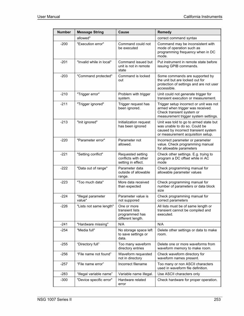
User Manual California Instruments
Number Message String Cause Remedyallowed" correct command syntax
-200 "Execution error" Command could not be executed
Command may be inconsistent with mode of operation such as programming frequency when in DC mode.
-201 "Invalid while in local" Command issued but unit is not in remote state
Put instrument in remote state before issuing GPIB commands.
-203 "Command protected" Command is locked out
Some commands are supported by the unit but are locked out for protection of settings and are not user accessible.
-210 "Trigger error" Problem with trigger system.
Unit could not generate trigger for transient execution or measurement.
-211 "Trigger ignored" Trigger request has been ignored.
Trigger setup incorrect or unit was not armed when trigger was received. Check transient system or measurement trigger system settings.
-213 "Init ignored" Initialization request has been ignored
Unit was told to go to armed state but was unable to do so. Could be caused by incorrect transient system or measurement acquisition setup.
-220 "Parameter error" Parameter not allowed.
Incorrect parameter or parameter value. Check programming manual for allowable parameters
-221 "Setting conflict" Requested setting conflicts with other setting in effect.
Check other settings. E.g. trying to program a DC offset while in AC mode
-222 "Data out of range" Parameter data outside of allowable range.
Check programming manual for allowable parameter values
-223 "Too much data" More data received than expected
Check programming manual for number of parameters or data block size
-224 "Illegal parameter value"
Parameter value is not suppored
Check programming manual for correct parameters
-226 "Lists not same length" One or more transient lists programmed has different length.
All lists must be of same length or transient cannot be compiled and executed.
-241 "Hardware missing" N/A N/A-254 "Media full" No storage space left
to save settings or data.
Delete other settings or data to make room.
-255 “Directory full” Too many waveform directory entries
Delete one or more waveforms from waveform memory to make room.
-256 “File name not found” Waveform requested not in directory
Check waveform directory for waveform names present.
-257 “File name error” Incorrect filename Too many or non ASCII characters used in waveform file definition.
-283 “Illegal variable name” Variable name illegal. Use ASCII characters only-300 "Device specific error" Hardware related
errorCheck hardware for proper operation.
NSG 1007 Series II 253
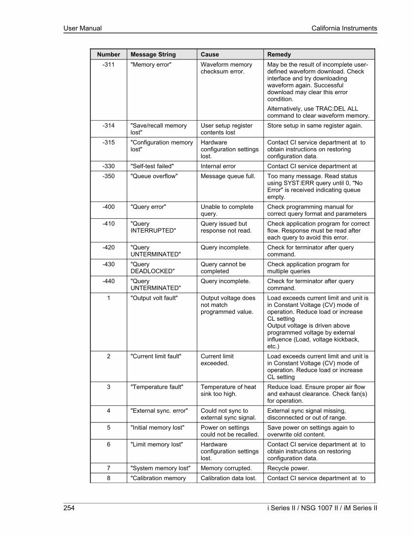
User Manual California Instruments
Number Message String Cause Remedy-311 "Memory error" Waveform memory
checksum error.May be the result of incomplete user-defined waveform download. Check interface and try downloading waveform again. Successful download may clear this error condition.Alternatively, use TRAC:DEL ALL command to clear waveform memory.
-314 "Save/recall memory lost"
User setup register contents lost
Store setup in same register again.
-315 "Configuration memory lost"
Hardware configuration settings lost.
Contact CI service department at to obtain instructions on restoring configuration data.
-330 "Self-test failed" Internal error Contact CI service department at -350 "Queue overflow" Message queue full. Too many message. Read status
using SYST:ERR query until 0, "No Error" is received indicating queue empty.
-400 "Query error" Unable to complete query.
Check programming manual for correct query format and parameters
-410 "Query INTERRUPTED"
Query issued but response not read.
Check application program for correct flow. Response must be read after each query to avoid this error.
-420 "Query UNTERMINATED"
Query incomplete. Check for terminator after query command.
-430 "Query DEADLOCKED"
Query cannot be completed
Check application program for multiple queries
-440 "Query UNTERMINATED"
Query incomplete. Check for terminator after query command.
1 "Output volt fault" Output voltage does not match programmed value.
Load exceeds current limit and unit is in Constant Voltage (CV) mode of operation. Reduce load or increase CL settingOutput voltage is driven above programmed voltage by external influence (Load, voltage kickback, etc.)
2 "Current limit fault" Current limit exceeded.
Load exceeds current limit and unit is in Constant Voltage (CV) mode of operation. Reduce load or increase CL setting
3 "Temperature fault" Temperature of heat sink too high.
Reduce load. Ensure proper air flow and exhaust clearance. Check fan(s) for operation.
4 "External sync. error" Could not sync to external sync signal.
External sync signal missing, disconnected or out of range.
5 "Initial memory lost" Power on settings could not be recalled.
Save power on settings again to overwrite old content.
6 "Limit memory lost" Hardware configuration settings lost.
Contact CI service department at to obtain instructions on restoring configuration data.
7 "System memory lost" Memory corrupted. Recycle power.8 "Calibration memory Calibration data lost. Contact CI service department at to
254 i Series II / NSG 1007 II / iM Series II

User Manual California Instruments
Number Message String Cause Remedylost" obtain instructions on restoring
calibration data or recalibrate unit.9 "Start angle must be
first sequence" Start phase angle in wrong place..
Start phase angles can only programmed at the start of a transient list. Once a transient is in progress, phase angle cannot be changed.
10 "Illegal for DC" Operation not possible in DC mode.
Switch to AC or AC+DC mode.
11 "Duplicate sequence" N/A N/A12 "Too many sequence" N/A N/A13 "Missing list
parameter" One or more transient list parameters missing.
Check programmed lists.
14 "Voltage peak error " Peak voltage exceeds internal bus voltage
This error may occur when selecting user defined wave shapes with higher crest factors. Reduce programmed RMS value.
15 "Slew time exceed dwell"
Time needed to slew to final value is less than dwell time.
Check dwell times in transient list settings. Increase dwell time or change slew rate for affected parameter.
16 "Illegal during transient"
Operation requested not available while transient is running.
Wait till transient execution is completed or abort transient execution first.
17 "Output relay must be closed"
Operation not possible with open relay
Close relay before attempting operation. E.g. transient execution requires output relay to be closed.
18 "Trans. duration less then 1msec"
Dwell time below minimum or 1 msec
Increase dwell time to at least 1 msec.
19 "Clock and sync must be internal"
Operation not possible with external clock
Switch to internal sync. (Default)
20 "Input buffer full" Too much data received.
Break up data in smaller blocks.
21 "EOS Fault" Hardware error reported by EOS option
Cycle power on EOS to reset error. If error persist, contact Contact CI service department at for repair.
22 "Waveform harmonics limit"
Harmonic contents of user defined wave shape is too high and could damage amplifier output stage.
Reduce harmonic content or reduce fundamental frequency programmed.
23 "ALC or Impedance must be off"
Conflict between ALC and programmable impedance mode.
Turn off ALC to use programmable impedance. Turn off programmable impedance to use ALC.
NSG 1007 Series II 255

User Manual California Instruments
Number Message String Cause Remedy24 “Output Relay must be
closed”Attempt to change voltage range while output relay is closed.
Open output relay first, then change range.
25 “Overvoltage Protection Trip”
Over voltage trip limit exceeded.
Check for inductive kickbacks or overshoot on eut.
26 “Peak Current Protection Trip”
Peak current exceeds trip limit.
Reduce load or increase trip level.
29 “DC component exceed limit”
Waveform selected has too much DC content to be supported on AC coupled voltage range.
Use AC waveform without DC offsest only or select DC coupled voltage range. (Applies to MX with –HV models only).
Table 10-39: Error Messages.
256 i Series II / NSG 1007 II / iM Series II
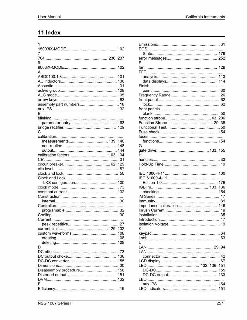
User Manual California Instruments
11.Index
115003iX-MODE............................................. 1027704........................................................ 236, 23799003iX-MODE............................................... 102AABD0100.1.8................................................. 101AC inductors.................................................. 136Acoustic.......................................................... 31active group................................................... 108ALC mode....................................................... 95arrow keys....................................................... 63assembly part numbers................................... 18aux. PS.......................................................... 132Bblinking................................................................
parameter entry........................................... 63bridge rectifier............................................... 129Ccalibration............................................................
measurements................................... 139, 140non-routine................................................ 148output......................................................... 144
calibration factors.................................. 103, 104CE\.................................................................. 31circuit breaker.......................................... 62, 129clip level.......................................................... 87clock and lock................................................. 50Clock and Lock...................................................
-LKS configuration..................................... 100clock mode...................................................... 73constant current............................................ 132Construction........................................................
internal......................................................... 30Controllers...........................................................
programable................................................ 32Cooling............................................................ 30Current................................................................
peak repetitive............................................. 27current limit............................................ 129, 132custom waveforms........................................ 108
creating...................................................... 108deleting...................................................... 108
DDC offset......................................................... 73DC output choke........................................... 136DC-DC converter........................................... 155Dimensions..................................................... 30Disassembly procedure................................. 156Distorted output............................................. 151DVM.............................................................. 132EEfficiency......................................................... 19
Emissions........................................................ 31EOS....................................................................
State.......................................................... 179error messages............................................. 252Ffan................................................................. 129FFT.....................................................................
analysis...................................................... 113data displays.............................................. 114
Finish..................................................................paint............................................................. 30
Frequency Range............................................ 26front panel....................................................... 62
lock.............................................................. 62front panels.........................................................
blank............................................................ 50function strobe......................................... 43, 206Function Strobe......................................... 29, 38Functional Test................................................ 50Fuse check.................................................... 154fuses...................................................................
functions.................................................... 154Ggate drive............................................... 133, 155Hhandles............................................................ 33Hold-Up Time.................................................. 19IIEC 1000-4-11............................................... 100IEC 61000-4-11...................................................
Edition 1.0.................................................. 176IGBT’s................................................... 133, 136
checking.................................................... 154iM Series......................................................... 17Immunity......................................................... 31impedance calibration................................... 146Inrush Current................................................. 19installation....................................................... 35Introduction..................................................... 17Isolation Voltage.............................................. 19Kkeypad............................................................. 64knob................................................................ 63LLAN........................................................... 29, 94LAN.....................................................................
connector..................................................... 42LCD display..................................................... 67LED............................................... 132, 136, 151
DC-DC....................................................... 155DC-DC output............................................ 133
LED ....................................................................aux. PS...................................................... 154
LED indicators............................................... 151
NSG 1007 Series II 257

User Manual California Instruments
Line Frequency................................................ 19load sharing................................................... 133MMAC Address.................................................. 42maintenance.................................................. 151Material...............................................................
chassis........................................................ 30MEAS key....................................................... 64measurement calibration............................... 103MENU key....................................................... 64MIL/STD-704................................................. 100models................................................................
voltage rating............................................... 34MS704........................................................... 101NNoise............................................................... 26OOffset Voltage.....................................................
DC............................................................... 26oscillator................................................ 129, 155oscillator assembly........................................ 130output..................................................................
frequency..................................................... 72voltage......................................................... 72
output calibration........................................... 104output mode.................................................... 73OUTPUT ON/OFF key.................................... 65OUTPut[\.............................................................
STATe]...................................................... 251over voltage................................................... 152overcurrent............................................ 132, 152Overcurrent..................................................... 29overload.......................................................... 62Overtemperature............................................. 29Overvoltage..................................................... 29Pparallel........................................................... 136Parallel............................................................ 32phase angle..................................................... 73PHASE key..................................................... 65power factor.................................................. 129Power Factor................................................... 19PROG key....................................................... 64Programmable Impedance.............................. 32
-MODE option.............................................. 33PWM............................................................. 133Rregisters.......................................................... 86regulators............................................................
TO220....................................................... 136relay............................................... 133, 136, 155Relay...................................................................
output........................................................... 32remote control................................................. 62Remote Inhibit........................................... 29, 45repeat.............................................................. 86
replacement parts........................................ 157RJ45....................................................................
connector..................................................... 42RS232............................................................. 94RS232.................................................................
Cable........................................................... 40RTCA DO160................................................ 100SSafety.............................................................. 31sense............................................................ 151sense..................................................................
wiring........................................................... 35Series I............................................................ 18Series II........................................................... 18SET key........................................................... 65SET mode....................................................... 63Shock.............................................................. 30Short Circuit........................................................
current......................................................... 29shuttle............................................................. 63Shuttle.................................................................
IMMEDIATE mode....................................... 63single phase............................................ 50, 132single phase........................................................
to three phase.............................................. 50slew rates...................................................... 126status.............................................................. 62step transient................................................. 122system.................................................................
single phase................................................ 17three phase.................................................. 17
system interconnect...................................... 129system interface...................................... 50, 132Ttemperature.........................................................
over............................................................. 63Temperature.......................................................
operating,storage......................................... 30terminal block......................................................
connections................................................. 30three phase..................................................... 50Three phase.................................................. 129Three Phase.................................................... 32top cover.............................................................
removal...................................................... 153transient..............................................................
execution................................................... 128transient execution.......................................... 86transients............................................................
slew rate.................................................... 126switching waveforms.................................. 127
Transients...........................................................Input............................................................ 29
Trigger Out BNC.................................................accessory.................................................... 43
trigger output............................................. 29, 43
258 i Series II / NSG 1007 II / iM Series II

User Manual California Instruments
Trigger output.................................................. 38troubleshooting.............................................. 151UUP key............................................................. 66USB........................................................... 29, 94USB.....................................................................
connector..................................................... 41VVibration.......................................................... 30volt mode......................................................... 73voltage drop........................................................
cables.......................................................... 36voltage ranges................................................. 50WWAVE key....................................................... 64waveform............................................................
data displays.............................................. 116Waveform...........................................................
acquisition.................................................. 115waveform group.............................................. 98Weight............................................................. 30WHM............................................................. 100Wire Sizes....................................................... 36wiring...................................................................
input............................................................. 35 list transient.................................................. 124 pulse transient.............................................. 123--LAN option..................................................... 33++/- key............................................................. 65
NSG 1007 Series II 259