NPTG and NaPTAN Schema Guide.
211
Department for Transport NPTG - Nation Public Transport Gazetteer & NaPTAN - National Public Transport Access Node database http://www.dft.gov.uk/naptan NPTG and NaPTAN Schema Guide. NaPTAN & NPTG v2.4
-
Upload
khangminh22 -
Category
Documents
-
view
0 -
download
0
Transcript of NPTG and NaPTAN Schema Guide.

Department for Transport
NPTG - Nation Public Transport Gazetteer &
NaPTAN - National Public Transport Access Node database
http://www.dft.gov.uk/naptan
NPTG and NaPTAN Schema Guide.
NaPTAN & NPTG v2.4

Department for Transport NPTG and NaPTAN Schema Guide
Preamble Contents
NaPTANSchemaGuide-2.4-v0.57.doc Page 2 of 210 © Crown Copyright 2001-2012
Version History Schema Version Date Audience 2.0a 0.1 Preliminary Draft 03 04 2004 RM Internal 2.0c 0.24 Revise Bay 30 08 2004 NJSK Review 2.0 0.31 Corrections to csv & modification attributes 10 03 2005 NJSK Issued 2.0 0.33 Errata NPTG Disco, clarify common name guidance 16 05 2005 NJSK Issued 2.0 0.35 Tram as MET, Character set use, errata 01 07 2005 NJSK Issued 2.0 0.36 Clarify use of NPTG Locality & Stop Areas, versions 04 08 2005 NJSK Issued 2.1 0.37 Make street & Landmark optional. Cover 2.1 05 09 2005 NJSK Issued 2.1 0.38 Support AnnotatedCoachRef on -street stops 08 09 2005 NJSK Issued 2.1 0.39 Update UML Diagrams 18 09 2005 NJSK Issued 2.1 0.40 Clarify Use of Ampersand 10 10 2005 NJSK Issued 2.1 0.41 Update Trunk Localities, Met process 10 10 2005 NJSK Issued 2.1 0.42 Correct Errata in tables 26 01 2006 NJSK Issued 2.1 0.43 Add notes on change detection. Add ITSO use of NaPTAN,
corrections. Correct Stop area rename 15.11.2006, 10.07.2007
NJSK Issued
2.2 Add archived status 29.08.2007 NJSK Review 2.4a 0.48 Revise diagrams and other 2.4 changes 10.02.2010 NJSK Review 2.4a 0.48-2 Revise XML diagrams and other TXC 2.4 changes 19.03.2010 NJSK Review 2.4a 0.48-3 Textual review and some other changes 22.03.2010 RS Review 2.4a 0.48-4 Corrections and add NorthernIreland 25.03.2010 NJSK NJSK 2.4a 0.49 Corrections 25.04.2010 NJSK Consult 2.4b 0.50 Corrections 15.06.2010 NJSK Consult 2.4b 0.52 Update private stop description to use flag (drop BCP) 16.09.2010 NJSK Issued 2.4b 0.53 Add extra stop types for Cable car etc 19.10.2010 NJSK Issued 2.4b 0.54 Clarify bearing, Fix typos 30.11.2010 NJSK Review 2.4 0.56 Update Diagramns, Issue as 2.4 30.12.2010 NJSK Issued 2.4 0.57 Clarify guidance on stations refs 04.01.2012 NJSK Issued
Prepared By:
Prepared For:
centaurconsulting.co.uk Centaur Consulting Limited Surrey Technology Centre Surrey Research Park Guildford, Surrey, GU2 7YG Email: [email protected]
www.Kizoom.com Kizoom Ltd Buchanan House 24-30 Holborn, London EC1n 2HS Email: [email protected] Tel: +44 (0)20 7539 2000
Transport Direct, Department for Transport
55 Victoria Street London, SW1H 0EU
© Crown Copyright 2000-2010
The content in this document may be reproduced free of charge in any format or media without requiring specific permission, subject to the NaPTAN Terms & Conditions of use, viewable at http://www.naptan.org.uk. This is subject to the material not being used in a derogatory manner or in a misleading context. The source of the material must be acknowledged as Crown Copyright and the title of the content must be included when being reproduced as part of another publication or service.

Department for Transport NPTG and NaPTAN Schema Guide
Preamble Contents
NaPTANSchemaGuide-2.4-v0.57.doc Page 3 of 210 © Crown Copyright 2001-2012
CONTENTS Section Page
1 INTRODUCTION _________________________________________ 13
1.1 NPTG Components 13 1.2 NaPTAN Components 13 1.3 NPTG and NaPTAN Users 13 1.4 Motivation 14 1.5 Antecedents 14 1.6 Document Structure 15 1.7 Intellectual Property Rights 15
1.7.1 NPTG and NaPTAN Schema 15 1.7.2 NPTG Database 16 1.7.3 NaPTAN Database 16
1.8 Versioning 16 1.9 Changes in Releases 16
1.9.1 Standardisation 2.0 16 1.9.2 Functional Enhancements 2.0 17 1.9.3 Name Changes in Release 2.0 17 1.9.4 Changes in Release 2.1 17 1.9.5 Changes in Release 2.2 17 1.9.6 Changes in Release 2.3a 18 1.9.7 Changes in Release 2.4 18
1.10 Content Not Covered by NaPTAN 18 1.11 Evolving NPTG and NaPTAN 18 1.12 Naming Conventions 20 1.13 Presentation Conventions 20
1.13.1 XML Elements in Text 20 1.13.2 UML Diagrams 21 1.13.3 XML Structure Diagrams 21
1.14 Related Transport Information Standards 22 1.15 Acknowledgments 23
2 INTRODUCTION TO NAPTAN AND THE NPTG ________________ 25
2.1 The Purpose of the National Public Transport Gazetteer 25 2.1.1 The NPTG Database 25 2.1.2 The NPTG XML Schemas 25 2.1.3 The NPTG CSV Exchange Format 25
2.2 The Purpose of NaPTAN 25 2.2.1 NaPTAN Identifiers 25 2.2.2 The NaPTAN Database 26 2.2.3 The NaPTAN XML Schema 26 2.2.4 The NaPTAN CSV Exchange Format 26 2.2.5 NaPTAN Process 26
2.3 How are NPTG and NaPTAN used? 27 2.3.1 Scenario #1: Compilation and Distribution of NPTG Data 27 2.3.2 Scenario #2: Gathering and Distribution of NaPTAN Stop Data 27 2.3.3 Scenario #3: Exchange of NaPTAN Data within TransXChange 28 2.3.4 Scenario #4: Using NPTG and NaPTAN Data in a Place Finder 28 2.3.5 Scenario #5: Using NPTG and NaPTAN Data in a Stop Finder 29 2.3.6 Scenario #6: Using NaPTAN Data for real-time departures 29
2.4 Document Validation 29

Department for Transport NPTG and NaPTAN Schema Guide
Preamble Contents
NaPTANSchemaGuide-2.4-v0.57.doc Page 4 of 210 © Crown Copyright 2001-2012
3 SHORT TOUR OF THE NPTG AND NAPTAN REFERENCE MODELS31
3.1 The National Gazetteer Model 31 3.1.1 Topographical Elements 31 3.1.2 Administrative Elements 33 3.1.3 NPTG Element Hierarchies 36
3.2 Populating the National Gazetteer 41 3.2.1 Choosing Administrative Areas 41 3.2.2 Choosing NPTG Districts 41 3.2.3 Choosing & Grouping NPTG Localities 41 3.2.4 Naming NPTG Localities 42 3.2.5 Geocoding NPTG Localities - Locations 45
3.3 The NaPTAN Model 46 3.3.1 Overview of NaPTAN Model 46 3.3.2 NaPTAN Stop Point & Stop Area Types 49
3.4 NaPTAN Element Hierarchies 54 3.5 Populating the NaPTAN Database 56
3.5.1 Choosing NaPTAN Points 56 3.5.2 Allocating an AtcoCode for a NaPTAN Stop Point 58 3.5.3 Allocating NaPTAN (SMS) Codes for NaPTAN Stop Points 58 3.5.4 Choosing NaPTAN Stop Areas 59 3.5.5 The Naming of Stop Points and Stop Areas 60 3.5.6 Bus Stop Naming Styles 62 3.5.7 Naming Of Particular Types of Stop 65 3.5.8 Naming of Stop Areas 65 3.5.9 The Classifying of Bus Stops and Other PTANs 65 3.5.10 Associating Stop Points and Stop Areas with NPTG Localities 66 3.5.11 Geocoding of Stop Points - Location 66
3.6 NPTG Discovery Model 70 3.6.1 Overview of NPTG Discovery Model 70 3.6.2 Informational Service Elements 70 3.6.3 Service Discovery 73
3.7 Summary of NPTG and NaPTAN Entities and Identifiers 75 3.7.1 Private codes 75
4 SCHEMAS ______________________________________________ 77
5 NPTG SCHEMA, STRUCTURE AND ELEMENTS _______________ 78
5.1 NationalPublicTransportGazetteer Root Element 78 5.1.1 NationalPublicTransportGazetteer Element Attributes 78 5.1.2 NationalPublicTransportGazetteer Child Elements 78
5.2 Region Element 80 5.3 AdministrativeArea Element 80 5.4 NPTG Locality Element 83
5.4.1 Identification 83 5.4.2 Associations 83 5.4.3 Other classifications 83
5.5 NPTG Locality / Descriptor Element 84 5.6 NPTG District Element 85 5.7 PlusbusZone Element 85
6 NAPTAN SCHEMA, STRUCTURE AND ELEMENTS_____________ 87
6.1 NaPTAN Root Element 87

Department for Transport NPTG and NaPTAN Schema Guide
Preamble Contents
NaPTANSchemaGuide-2.4-v0.57.doc Page 5 of 210 © Crown Copyright 2001-2012
6.1.1 NaPTAN Element Attributes 87 6.1.2 NaPTAN Child Elements 88
6.2 StopPoint Element 88 6.2.1 Identifiers 88 6.2.2 Classifiers 88 6.2.3 Associations 88 6.2.4 Other Information 89
6.3 StopPoint Subelements 90 6.3.1 StopIdentifierGroup 90 6.3.2 Descriptor Element 91 6.3.3 Additional Descriptors 92 6.3.4 Place Element 92 6.3.5 StopClassification Element 93
StopClassification / On-Street Elements 95 6.3.6 StopPoint / StopClassification / On-Street Bus Element 95 6.3.7 On-Street Taxi Element 98 6.3.8 On-Street Car Element (+NaPTAN v2.4 98
6.4 StopClassification / Off-Street Elements 98 6.4.1 Off-Street Air Element 98 6.4.2 Off-Street Ferry Element 99 6.4.3 Off-Street Rail Element 100 6.4.4 Off-Street Metro Element 100 6.4.5 Off-Street BusAndCoach Element 101 6.4.6 Off-Street Telecabine (Lift & CableCar) Element (+NaPTAN v2.4)102
6.5 StopAvailability Element 103 6.6 StopArea Element 104
7 NPTG DISCOVERY SCHEMA, STRUCTURE AND ELEMENTS ___ 106
7.1 NptgDiscovery Root Element 106 7.1.1 NptgDiscovery Element Attributes 106 7.1.2 NptgDiscovery Child Elements 107
7.2 WebApplication Element 108 7.2.1 UsedBy Element 109
7.3 TrustedServer Element 110 7.4 AdjacentRegionPoint Element 111 7.5 CallCentre Element 112
7.5.1 Availability Element 113 7.5.2 Day Types Element 113 7.5.3 Holiday Types Element 114 7.5.4 OpeningHours Element 115 7.5.5 TelephoneContactStructure Element 116
7.6 TrunkLocality Element 116
8 COMMON SCHEMA ELEMENTS ___________________________ 117
8.1 Duration Simple Type 117 8.2 Location Element 117 8.3 Bearing Element 118
9 NAPTAN EXAMPLES ____________________________________ 120
9.1 Example 1: Poles Both Sides of the Road with One Landmark 121 9.1.1 NaPTAN StopArea Definition: Example 1 122 9.1.2 NaPTAN StopPoint Definitions: Example 1 122
Department for Transport NPTG and NaPTAN Schema Guide
Preamble Contents
NaPTANSchemaGuide-2.4-v0.57.doc Page 6 of 210 © Crown Copyright 2001-2012
9.1.3 Names in Context 122 9.2 Example 2: Poles Both Sides with Different Common Names and Landmarks 123
9.2.1 NaPTAN StopArea Definitions: Example 2 124 9.2.2 NaPTAN StopPoint Definitions: Example 2 124 9.2.3 Names in Context 125
9.3 Example 3: Pole One Side Only with Landmark 126 9.3.1 NaPTAN StopArea Definitions: Example 3 127 9.3.2 NaPTAN StopPoint Definitions: Example 3 127 9.3.3 Names in Context 128
9.4 Example 4: Unmarked Bus Stop on One Side of a Road with No Landmark 129 9.4.1 NaPTAN StopPoint Definition: Example 4 130 9.4.2 Names in Context 130
9.5 Example 5: Bus Interchange 131 9.5.1 NaPTAN StopArea Definition: Example 5 132 9.5.2 NaPTAN StopPoint Definitions: Example 5 132 9.5.3 Names in Context 132
9.6 Example 6: Hail & Ride Stop Sections 133 9.6.1 NaPTAN StopPoint Definition: Example 6 134 9.6.2 Names in Context 134
9.7 Example 7: Flexible Service Stop Zones 135 9.7.1 NaPTAN StopPoint Definitions: Example 7 136 9.7.2 Names in Context 136
9.8 Example 8: Railway Station with Bus and Taxi 137 9.8.1 NaPTAN StopArea Definitions: Example 8 139 9.8.2 NaPTAN StopPoint Definitions: Example 8 139 9.8.3 Names in Context 140
9.9 Example 9: Metro Station with Bus & Light Rail 141 9.9.1 NaPTAN StopArea Definitions: Example 9 144 9.9.2 NaPTAN StopPoint Definitions: Example 9 144 9.9.3 Names in Context 145
9.10 Example 10: Bus Station with Bays 146 9.10.1 NaPTAN StopArea Definitions: Example 10 148 9.10.2 NaPTAN StopPoint Definitions: Example 10 148 9.10.3 Names in Context 149
9.11 Example 11: Major Airport 150
10 NAMING & CODING CONVENTIONS________________________ 153
10.1 Naming of Elements 153 10.1.1 Use of Camel Case 153 10.1.2 Use of Standard Name Suffixes 153 10.1.3 Meaningful Names 153 10.1.4 Standardised Terminology 154 10.1.5 Semantically Significant Order 154
10.2 Typing of Elements 154 10.3 Element Constraints 154 10.4 Use of Attributes 154 10.5 Implementation of Model Relationships 155 10.6 Data Rights attribute 155
11 VERSIONING ___________________________________________ 156
11.1 Version Numbering Convention 156 11.2 Resource Versions 156

Department for Transport NPTG and NaPTAN Schema Guide
Preamble Contents
NaPTANSchemaGuide-2.4-v0.57.doc Page 7 of 210 © Crown Copyright 2001-2012
11.2.1 Schema URI version 156 11.2.2 Namespace URI version 156 11.2.3 Schema Version 156 11.2.4 Package Versions 157 11.2.5 Data Element Version 157 11.2.6 Use of the Status Attribute 158 11.2.7 Detecting Changes on Different systems - The NaPTAN Distributed Data process 161 11.2.8 Summary of Use of Data Version Attributes 163 11.2.9 Referential Integrity of references 163
11.3 Packages 165 11.3.1 NPTG Package & Model Dependencies 165 11.3.2 NPTG Discovery Package & Model Dependencies 166 11.3.3 NaPTAN Package & Model Dependencies 167
12 RELATION TO OTHER STANDARDS _______________________ 169
12.1 Transmodel Compliance 169 12.1.1 Transmodel Terminology 169
12.2 ITSO Interoperability 170
13 NATIONAL LANGUAGE SUPPORT _________________________ 171
13.1 Text Content Types 171 13.1.1 Use of Structured Text 171 13.1.2 Use of Free Text 171 13.1.3 Use of Aliased Free Text 171
14 INTEGRITY RULES ______________________________________ 172
14.1 NPTG Integrity Rules 172 14.1.1 Syntactic Integrity Rules 172 14.1.2 Semantic Integrity Rules 173
14.2 NPTG Discovery Integrity Rules 173 14.2.1 Syntactic Integrity Rules 173 14.2.2 Semantic Integrity Rules 173
14.3 NaPTAN Integrity Rules 174 14.3.1 Syntactic Integrity Rules 174 14.3.2 Semantic Integrity Rules 174
15 APPENDICES __________________________________________ 177
15.1 2.0 Changes Since 1.1 177 15.2 2.1 Changes Since 2.0 177 15.3 References 178
15.3.2 JourneyWeb 178 15.4 Standard Abbreviations for Topographical Features 181
15.4.1 Terms for Relationship 181 15.4.2 Topographical Features 181 15.4.3 Common Acronyms 181 15.4.4 Common Adjectives 181
15.5 NPTG CSV Exchange Formats 182 15.5.1 NPTG CSV 1.2 CSV Format Overview [Deprecated] 183 15.5.2 NPTG CSV 2.1 CSV Format Overview 184 15.5.3 NPTG Discovery CSV 2.1 CSV Format Overview 185
15.6 NPTG: CSV Files 185

Department for Transport NPTG and NaPTAN Schema Guide
Preamble Contents
NaPTANSchemaGuide-2.4-v0.57.doc Page 8 of 210 © Crown Copyright 2001-2012
15.6.1 NPTG: Regions CSV table 186 15.6.2 NPTG: AdminAreas CSV table 186 15.6.3 NPTG: District CSV table 186 15.6.4 NPTG: Locality CSV table* 187 15.6.5 NPTG: LocalityAlternativeNames CSV table* 187 15.6.6 NPTG: LocalityHierarchy CSV table* 188 15.6.7 NPTG: AdjacentLocalities CSV table+ 188 15.6.8 NPTG Plusbuszones CSV table+ 188 15.6.9 NPTG PlusbuszonesMapping CSV table+ 188
15.7 NPTG Discovery: CSV Files 188 15.7.1 NPTG Discovery: AdjacentRegionPoints CSV table+ 188 15.7.2 NPTG Discovery: CallCentres CSV table+ 189 15.7.3 NPTG Discovery: CallCentresAreas CSV table+ 189 15.7.4 NPTG Discovery: TrustedServer CSV table + 189 15.7.5 NPTG Discovery: WebApplications CSV table + 190 15.7.6 NPTG Discovery: WebAppCapabilities CSV table + 190 15.7.7 NPTG Discovery: RegionApplications CSV table + 190 15.7.8 NPTG Discovery: AdminAreaApplications CSV table + 190 15.7.9 NPTG Discovery: LocalityApplications CSV table + 190 15.7.10 NPTG Discovery: StopPointApplications CSV table + 191
15.8 NAPTAN CSV Format 191 15.8.1 NaPTAN 1.1 CSV Exchange Format Overview 192 15.8.2 NaPTAN 2.1 CSV Exchange Format Overview 193
15.9 NaPTAN: CSV Files 194 15.9.1 NaPTAN: StopPoint CSV table 194 15.9.2 NaPTAN: Hail & Ride CSV Table 195 15.9.3 NaPTAN: Flexible CSV Table 195 15.9.4 NaPTAN: AlternativeDescriptor Table 195 15.9.5 NaPTAN: StopLocalities Table 196 15.9.6 NaPTAN: StopAvailabilities Table 196 15.9.7 NaPTAN: StopsInStopArea Table 196 15.9.8 NaPTAN: AirReferences Table 196 15.9.9 NaPTAN: RailReferences Table 197 15.9.10 NaPTAN: FerryReferences Table 197 15.9.11 NaPTAN: MetroReferences Table 197 15.9.12 NaPTAN: CoachReferences Table 197 15.9.13 NaPTAN: LocalityMainAccessPoints Table 198 15.9.14 NaPTAN: StopPlusBusZones Table 198 15.9.15 NaPTAN: StopAreas (Groups Table) 198 15.9.16 NaPTAN: StopAreaHierarchy Table 198
15.10 Common CSV Types 200 15.11 ATCO & AdministrativeArea Codes 201 15.12 Index 203
List of Figures Figure 1-1 – Name changes in NaPTAN 2.0 .................................................................................... 17 Figure 1-2 – Support of Exchange formats for 1.x and 2.x ................................................................ 20 Figure 1-3 – XML Spy Diagram: Sequence ...................................................................................... 21 Figure 1-4 – XML Spy Diagram: Choice ........................................................................................... 22 Figure 1-5 – XML Spy Diagram: Multiplicity ...................................................................................... 22 Figure 3-1 – UML Diagram of NPTG Model: Introduction.................................................................. 31 Figure 3-2 – UML Diagram of NPTG Locality Model ......................................................................... 32 Figure 3-3 – UML Diagram of NPTG Administrative Model: Overview .............................................. 33 Figure 3-4 – UML Diagram of Main NPTG Model: Further elements ................................................. 34 Figure 3-5 – UML Diagram of Main NPTG Model: Detail .................................................................. 35

Department for Transport NPTG and NaPTAN Schema Guide
Preamble Contents
NaPTANSchemaGuide-2.4-v0.57.doc Page 9 of 210 © Crown Copyright 2001-2012
Figure 3-6 – UML Diagram of NPTG Locality Element Hierarchy ...................................................... 36 Figure 3-7 – UML Diagram of Administrative Element Hierarchy ...................................................... 36 Figure 3-8 – UML Diagram of Locality Data types ............................................................................ 37 Figure 3-9 – UML Diagram of Administrative Data types .................................................................. 38 Figure 3-10 – UML Diagram of Location Data Types ........................................................................ 39 Figure 3-11 – UML Diagram of NaPT Utility Data Types ................................................................... 39 Figure 3-12 – UML Diagram of APD Address Data Types ................................................................ 40 Figure 3-13 – Example: Locality Hierarchy ....................................................................................... 42 Figure 3-14 – UML Diagram of primary NaPTAN elements .............................................................. 46 Figure 3-15 – UML Diagram of NaPTAN Model: Overview ............................................................... 47 Figure 3-16 – UML Diagram of NaPTAN Model: Detail ..................................................................... 48 Figure 3-17 – UML Diagram of NaPTAN Stop Types ....................................................................... 50 Figure 3-18 – UML Diagram of NaPTAN Off-Street Stop Point Types............................................... 52 Figure 3-19 – UML Diagram of NaPTAN On-Street Stop Point Types............................................... 53 Figure 3-20 – UML Diagram of NaPTAN Stop Hierarchy .................................................................. 54 Figure 3-21 – UML Diagram of NaPTAN Data types ........................................................................ 55 Figure 3-22 – Example of Stop Names in a List................................................................................ 68 Figure 3-23 – Example of Ambiguous Place Names ......................................................................... 68 Figure 3-24 – UML Diagram of Discovery Model: Overview .............................................................. 71 Figure 3-25 – UML Diagram of Discovery Model: Detail ................................................................... 72 Figure 3-26 – UML Diagram of Coverage Model .............................................................................. 73 Figure 3-27 – UML Diagram of NPTG Discovery Hierarchy .............................................................. 74 Figure 5-1 – NTPG Schema Overview ............................................................................................. 79 Figure 5-2 – NationalPublicTransportGazetteer Root Element.......................................................... 79 Figure 5-3 – Region Element ........................................................................................................... 80 Figure 5-4 – AdministrativeArea Element ......................................................................................... 82 Figure 5-5 – NptgLocality Element ................................................................................................... 84 Figure 5-6 – Locality / Descriptor Element ........................................................................................ 85 Figure 5-7 – NptgDistrict Element .................................................................................................... 85 Figure 5-8 – PlusbusZone Element .................................................................................................. 86 Figure 6-1 – UML Diagram of NaPTAN Schema .............................................................................. 87 Figure 6-2 – NaPTAN Root Element ................................................................................................ 88 Figure 6-3 – StopPoint Element ....................................................................................................... 90 Figure 6-4 – StopIdentifierGroup Element ........................................................................................ 91 Figure 6-5 – Descriptor Element ...................................................................................................... 92 Figure 6-6 – Place Element ............................................................................................................. 93 Figure 6-7 – StopClassification Element........................................................................................... 95 Figure 6-8 – OnStreet / Bus Element ............................................................................................... 96 Figure 6-9 – OnStreet / Bus / MarkedPoint Element ......................................................................... 96 Figure 6-10 – OnStreet / Bus / UnmarkedPoint Element ................................................................... 97 Figure 6-11 – OnStreet / Bus / HailAndRideSection Element ............................................................ 97 Figure 6-12 – OnStreet / Bus / FlexibleZone Element ....................................................................... 97 Figure 6-13 – OnStreet / Taxi Element ............................................................................................. 98 Figure 6-14 – OnStreet / Taxi Element ............................................................................................. 98 Figure 6-15 – OffStreet / Air Element ............................................................................................... 99 Figure 6-16 – OffStreet / Ferry Element ........................................................................................... 99 Figure 6-17 – RailExchange Element ............................................................................................. 100 Figure 6-18 – OffStreet / Metro Element......................................................................................... 101 Figure 6-19 – OffStreet / Coach Element ....................................................................................... 102 Figure 6-20 – OffStreet / Telecabine Element ................................................................................ 103 Figure 6-21 – History Element ....................................................................................................... 104 Figure 6-22 – StopArea Element .................................................................................................... 105 Figure 7-1 – UML Diagram of the NPTG Discovery Schema .......................................................... 107 Figure 7-2 – NptgDiscovery Root Element ..................................................................................... 108 Figure 7-3 – WebApplication Element ............................................................................................ 109

Department for Transport NPTG and NaPTAN Schema Guide
Preamble Contents
NaPTANSchemaGuide-2.4-v0.57.doc Page 10 of 210 © Crown Copyright 2001-2012
Figure 7-4 – UsedBy Element ........................................................................................................ 110 Figure 7-5 – TrustedServer Element .............................................................................................. 111 Figure 7-6 – AdjacentRegionPoint Element .................................................................................... 111 Figure 7-7 – CallCentre Element .................................................................................................... 112 Figure 7-8 – CallCentre / Availability Element ................................................................................ 113 Figure 7-9 – DayTypes Element..................................................................................................... 114 Figure 7-10 – HolidayTypes Element ............................................................................................. 115 Figure 7-11 – OpeningHours Element ............................................................................................ 116 Figure 7-12 – PrimaryTelephoneNumber Element.......................................................................... 116 Figure 7-13 – TrunkLocality Element.............................................................................................. 117 Figure 8-1 – Location Element ....................................................................................................... 118 Figure 8-2 – Bearing Element ........................................................................................................ 119 Figure 9-1 – Example 1: Poles Both Sides of the Road with One Landmark ................................... 121 Figure 9-2 – Example 1: Stop Hierarchy for Cosham Health Centre ............................................... 121 Figure 9-3 – Example 2: Poles Both Sides with Different Common Names ..................................... 123 Figure 9-4 – Example 2: Street Names in Central Cosham............................................................. 124 Figure 9-5 – Example 2: Stop Hierarchy for Cosham Fire & Police Stations ................................... 124 Figure 9-6 – Example 3: Pole, One Side Only with Landmark......................................................... 126 Figure 9-7 – Example 3: Blacko Village map .................................................................................. 127 Figure 9-8 – Example 3: Stop Hierarchy for Blacko Rising Sun ...................................................... 127 Figure 9-9 – Example 4: Bus Stop on One Side of a Road with No Landmark ................................ 129 Figure 9-10 – Example 4: Stop Hierarchy for Tilmore Gardens ....................................................... 129 Figure 9-11 – Example 5: Bus Interchange .................................................................................... 131 Figure 9-12 – Example 5: Stop Hierarchy for Brighton Old Steine................................................... 132 Figure 9-13 – Example 6: Hail & Ride ............................................................................................ 133 Figure 9-14 – Example 6: Stop Hierarchy for Newhaven Hail & Ride .............................................. 133 Figure 9-15 – Example 7: Flexible Zones ....................................................................................... 135 Figure 9-16 – Example 5: Stop Hierarchy for Lincoln Flexible Service ............................................ 136 Figure 9-17 – Example 8: Railway Station Interchange. ................................................................. 137 Figure 9-18 – Example 9: Stop Hierarchy for Farnham Station ....................................................... 138 Figure 9-19 – Example 9: Bank Tube Lines.................................................................................... 141 Figure 9-20 – Example 9: Bank Station Street Area ....................................................................... 141 Figure 9-21 – Example 9: Stop Hierarchy for Bank Underground Station ........................................ 143 Figure 9-22 – Example 9: Bank Underground Station – Stops in Area ............................................ 143 Figure 9-23 – Example 10: Aylesbury Bus Station .......................................................................... 146 Figure 9-24 – Example 10: Stop Hierarchy for Aylesbury Bus Station ............................................. 147 Figure 9-25 – Example 11a: Partial Stop Hierarchy for Heathrow Airport Terminals 123 ................. 151 Figure 9-26 – Example 11b: Partial Stop Hierarchy for Heathrow Terminal 4 .................................. 152 Figure 11-1 – UML Model of Element Versions .............................................................................. 157 Figure 11-2 – Status element: State Transitions ............................................................................. 159 Figure 11-3 – Modification element State Transitions ..................................................................... 159 Figure 11-4 – StopValidity State Transitions................................................................................... 160 Figure 11-5 – NPTG Packages ...................................................................................................... 165 Figure 11-6 – NPTG Models .......................................................................................................... 165 Figure 11-7 – NPTG Discovery Packages ...................................................................................... 166 Figure 11-8 – NPTG Discovery Models .......................................................................................... 166 Figure 11-9 – NaPTAN Packages .................................................................................................. 167 Figure 11-10 – NaPTAN Model Dependencies ............................................................................... 168 Figure 15-1 – Diagram of National Gazetteer 1.2 CSV Tables ........................................................ 183 Figure 15-2 – Diagram of National Gazetteer 2.1 CSV Tables ........................................................ 184 Figure 15-3 – Diagram NPTG Discovery CSV 2.1 CSV Tables ....................................................... 185 Figure 15-4 – Diagram of NaPTAN 1.1 CSV Tables ....................................................................... 192 Figure 15-5 – Diagram of NaPTAN 2.1 CSV Tables ....................................................................... 193

Department for Transport NPTG and NaPTAN Schema Guide
Preamble Contents
NaPTANSchemaGuide-2.4-v0.57.doc Page 11 of 210 © Crown Copyright 2001-2012
List of Tables Table 3-1 – Example of Qualified Locality Names ............................................................................ 42 Table 3-2 – Characters that are invalid in NPTG & NaPTAN Place and Common Names ................. 43 Table 3-3 – Characters Not To Be Used in NPTG & NaPTAN Place and Common Names ............... 43 Table 3-4 – English Locality Names without any Preposition that are Hyphenated ............................ 44 Table 3-5 – Hyphenation of Prepositions & Articles in NPTG Locality Names ................................... 44 Table 3-6 – Combining Stop Point & Stop Area Classifications ......................................................... 51 Table 3-7 – Precedence of StopArea Types ..................................................................................... 60 Table 3-8 – Examples of Preferred Stop Names .............................................................................. 61 Table 3-9 – Example Preferred Form for Rail Station Names ........................................................... 62 Table 3-10 – Example Name Elements ............................................................................................ 62 Table 3-11 – Ways of Deriving Names from Descriptors .................................................................. 62 Table 3-12 – Preferred Phrases to Use in Indicator .......................................................................... 64 Table 3-13 – Stop Point Location Types........................................................................................... 67 Table 3-14 – Main Entities of the NPTG & NaPTAN Models ............................................................. 75 Table 5-1 – Allowed Values for Country ........................................................................................... 80 Table 5-2 – Allowed Values for SourceLocalityType ......................................................................... 83 Table 5-3 – Allowed Values for LocalityClassification ....................................................................... 83 Table 5-4 – Allowed Values for Plusbus zones ................................................................................. 85 Table 6-1 – Allowed Values for StopType ........................................................................................ 94 Table 6-2 – Allowed Values for BusStopType .................................................................................. 95 Table 6-3 – Allowed Values for TimingStatus ................................................................................... 96 Table 6-4 – Allowed Values for StopArea Classification ................................................................. 104 Table 7-1 – Allowed Values for WebApplicationClassification ......................................................... 108 Table 8-1 – Allowed Values for StopPoint / Descriptor /Bearing ...................................................... 119 Table 9-1 – Example 10: Stop Notes for Aylesbury Bus Station ...................................................... 147 Table 10-1 – NaPTAN Attributes .................................................................................................... 155 Table 11-1 – NPTG and NaPTAN Document Version Attributes ..................................................... 157 Table 11-2 – Entity Change Tracking & Status Attributes ............................................................... 158 Table 11-3 – Tracked Data Elements ............................................................................................. 161 Table 11-4 – Change Attribute Groups ........................................................................................... 161 Table 11-5 – Data Element Change Versioning Principles.............................................................. 163 Table 11-6 – NaPTAN 2.0 Module Names ..................................................................................... 169 Table 12-1 – Comparison of Key Transmodel Terms ..................................................................... 170 Table 13-1 – Elements That May Contain Natural Language Free Text .......................................... 171 Table 14-1 – Severity Codes for Semantic Integrity Rules .............................................................. 172 Table 14-2 – NPTG Syntactic Integrity Rules ................................................................................. 173 Table 14-3 – NPTG Semantic Integrity Rules ................................................................................. 173 Table 14-4 – NPTG Discovery Syntactic Integrity Rules ................................................................. 173 Table 14-5 – NPTG Discovery Semantic Integrity Rules ................................................................. 174 Table 14-6 – NaPTAN Syntactic Integrity Rules ............................................................................. 174 Table 14-7 – NaPTAN Semantic Integrity Rules ............................................................................. 176 Table 15-1 – NPTG CSV files ........................................................................................................ 186 Table 15-2 – NPTG: Region.csv Content ....................................................................................... 186 Table 15-3 – NPTG: Admin.csv Content ........................................................................................ 186 Table 15-4 – NPTG: District.csv Content ........................................................................................ 187 Table 15-5 – NPTG: Localities.csv Content .................................................................................... 187 Table 15-6 – NPTG: LocalityAlternativeNames.csv Content ........................................................... 187 Table 15-7 – NPTG: LocalityHierarchy.csv Content ........................................................................ 188 Table 15-8 – NPTG: AdjacentLocalities.csv Content ...................................................................... 188 Table 15-9 – NPTG: PlusbusZones.csv Content ............................................................................ 188 Table 15-10 – NPTG: PlusbusMappings.csv Content ..................................................................... 188 Table 15-11 – NPTG: AdjacentRegionPoints.csv Content .............................................................. 189 Table 15-12 – NPTG: CallCentres.csv Content .............................................................................. 189 Table 15-13 – NPTG: CallCentres.csv Content .............................................................................. 189

Department for Transport NPTG and NaPTAN Schema Guide
Preamble Contents
NaPTANSchemaGuide-2.4-v0.57.doc Page 12 of 210 © Crown Copyright 2001-2012
Table 15-14 – NPTG: TrustedServer.csv Content .......................................................................... 190 Table 15-15 – NPTG: WebApplications.csv Content ...................................................................... 190 Table 15-16 – NPTG: WebAppCapabilities.csv Content ................................................................. 190 Table 15-17 – NPTG: RegionApplications.csv Content................................................................... 190 Table 15-18 – NPTG: AdminAreaApplications.csv Content ............................................................ 190 Table 15-19 – NPTG: LocalityApplications.csv Content .................................................................. 191 Table 15-20 – NPTG: StopPointApplications.csv Content .............................................................. 191 Table 15-21 – NaPTAN CSV files .................................................................................................. 194 Table 15-22 – NaPTAN: Stops.csv Content ................................................................................... 195 Table 15-23 – NaPTAN: HailRide.csv Content ............................................................................... 195 Table 15-24 – NaPTAN: Flexible.csv Content ................................................................................ 195 Table 15-25 – NaPTAN: AlternativeDescriptor.csv Content ............................................................ 196 Table 15-26 – NaPTAN: StopLocalities.csv Content ....................................................................... 196 Table 15-27 – NaPTAN: StopAvailabilities.csv Content .................................................................. 196 Table 15-28 – NaPTAN: StopsInStopArea.csv Content .................................................................. 196 Table 15-29 – NaPTAN: AirReferences.csv Content ...................................................................... 197 Table 15-30 – NaPTAN: RailReferences.csv Content .................................................................... 197 Table 15-31 – NaPTAN: FerryReferences.csv Content .................................................................. 197 Table 15-32 – NaPTAN: MetroReferences.csv Content .................................................................. 197 Table 15-33 – NaPTAN: CoachReferences.csv Content ................................................................ 198 Table 15-34 – NaPTAN: LocalityMainAccessPoints.csv Content .................................................... 198 Table 15-35 – NaPTAN: StopPlusBusZones.csv Content ............................................................... 198 Table 15-36 – NaPTAN: StopAreas.csv Content ............................................................................ 198 Table 15-37 – NaPTAN: StopAreaHierarchy.csv Content ............................................................... 199 Table 15-38 – Common NPTG and NaPTAN CSV Data Types ...................................................... 200

Department for Transport NaPTAN Schema User Guide Part I Introduction and Overview
NaPTANSchemaGuide-2.4-v0.57.doc Page 13 of 210 © Crown Copyright 2001-2012
1 INTRODUCTION
The National Public Transport Access Nodes (NaPTAN) database is a UK nationwide system for uniquely identifying all the points of access to public transport in the UK. NaPTAN seeks to provide a comprehensive data set of all of the stopping places used by public transport services. The National Public Transport Gazetteer (NPTG) provides a topographic database of towns and settlements in the UK, and is used by the NaPTAN dataset to associate Public Transport Access Nodes (PTANS) with localities. NPTG and NaPTAN together enable computerised public transport information systems to provide stop finding and referencing capabilities using consistent, meaningful names for places and stops. The points of the NaPTAN system provide a coherent national framework of reference for integrating all kinds of public transport data including journey planning and real-time information. Both NaPTAN and the NPTG can be exchanged as XML documents; this document is a guide to the NaPTAN and NPTG XML schemas which describe those documents. The schemas are available at a website at http://www.naptan.org.uk, which also provides additional information and resources. This is a revised version of the Schema Guide covering NaPTAN & NPTG 2.4, released in 2010 to coincide with release 2.4 of TransXChange. For a summary of modifications see Section 1.9.6 below.
1.1 NPTG Components
The NPTG consists of the following elements: 1. A standard set of names for UK places and settlements, together with a method for assigning
topographic names so as to be suitable for journey planning and other computer based information services.
2. A division of the UK into administrative areas to manage public transport access node and other data, and the identification of services supporting it.
3. A pair of XML Schemas for describing the NPTG & NPTG Discovery data when it is exchanged as XML documents.
4. An alternative exchange format for exchanging NPTG data as CSV files. 5. A database of all the settlements in the UK, compiled to the standard that can be exported
into the prescribed formats.
1.2 NaPTAN Components
NaPTAN consists of the following elements: 1. A standard method for identifying and describing access points to public transport. 2. An XML Schema for describing the NaPTAN data when it is exchanged as XML documents. 3. An alternative exchange format for exchanging stop data as CSV files. 4. A process for gathering information about changes to stop data and compiling it into the
central database. 5. A database of all the access points in the UK, compiled to the standard that can be exported
into the prescribed formats. The NaPTAN database is maintained centrally under contract to the Department for Transport.
1.3 NPTG and NaPTAN Users
NPTG and NaPTAN data users include: � Traveline – the National Passenger Transport Information System. � Transport Direct Portal.

Department for Transport NaPTAN Schema User Guide Part I Introduction and Overview
NaPTANSchemaGuide-2.4-v0.57.doc Page 14 of 210 © Crown Copyright 2001-2012
� Bus Service Operators. � Traffic Area Offices. � Local Authorities. � Passenger Transport Executives. � Scheduling System Suppliers. � Journey Planning System Suppliers. � Real Time Information Systems Suppliers. � Electronic Fare management systems and Smartcards (ITSO) � Mapping and Map-information Information System Suppliers. � Point of interest databases. � Tourism Industry. � Estate Agents.
The NaPTAN stop database is fundamental for TransXChange, the UK system for recording schedules as XML documents for electronic registration of bus services. NaPTAN is also fundamental to JourneyWeb, the UK national distributed journey planning protocol. Note that the appropriate naming of localities and stops is an important consideration for providing effective place and stop finding in on-line journey planners, and some guidance on this subject is included in this document.
1.4 Motivation
This NPTG and NaPTAN XML Schema Guide is intended to provide a technical overview and reference manual to the NPTG and NaPTAN Schemas for system developers, data providers and other users of NaPTAN and the NPTG. It includes guidelines on the naming of stops and stop areas so that data is effectively labelled for use in journey planning engines. The guide provides, in particular, a description of the NaPTAN and NPTG XML schemas, both of which are encoded as W3C XML xsd schemas. Note that detailed documentation of individual schema elements is provided as annotations within the schemas. Software tools such as XML SPY can be used to explore the structure and details of the schema.
1.5 Antecedents
Version 1.0 of NaPTAN was originally developed by WSAtkins for Transport Direct under contract to the UK Department for Transport. It built on earlier stop numbering systems used by the Association of Transport Coordinating Officers (ATCO). A subsequent update 1.1 in October 2003, also managed by WSAtkins, comprised a revision to the coding of stations to simplify the use of NaPTAN codes by journey planners. NaPTAN version 2.0, a revision in 2004 of the standard, managed by Carl Bro with technical development by Kizoom, had as its main functional change the harmonisation of NaPTAN with other public transport schemas and government standards for XML schemas. NaPTAN 2.0 included a new documentation set, including this guide, drawing on the NaPTAN specification v1.0 produced by WSAtkins on behalf of the Department for Transport (see 15.3), and the ‘Creation of National Public Transport Gazetteer (NPTG) Guidance Notes – Version 6 (1 June 2002)’. A slightly revised version of the 1.1 schema was introduced as 1.3 to ease migration to 2.0. The term ‘1.x’ is used to refer collectively to the 1.0 and other prior versions NaPTAN version 2.1 was a very minor update to version 2.0 to relax the requirement to provide Landmark and Street elements for all descriptors. 2.1 should be fully backwards compatible with 2.1 in all other respects. It is accompanied by a 1.4 version of the earlier 1.x schema.

Department for Transport NaPTAN Schema User Guide Part I Introduction and Overview
NaPTANSchemaGuide-2.4-v0.57.doc Page 15 of 210 © Crown Copyright 2001-2012
NaPTAN version 2.2 was a minor update to version 2.1 to add an archive status for element change management. V2.2 should be fully backwards compatible with 2.1 in all other respects. Version 2.3 added a new stop type for bus/coach stops in private locations. NaPTAN & NPTG version 2.4 is a minor update to version 2.2 to add some stop type and relax some constraints on certain data types and support for private stops. It coincides with release 2.4 of TransXChange. V2.4 of NaPTAN & NPTG should be fully backwards compatible with 2.2 in all other respects. It has been internally restructured into smaller component packages to facilitate maintenance and correspondence with Transmodel/NeTEx. This document has been reviewed and updated where necessary with the release of version 2.4. The term ‘2.x’ is used to refer collectively to the 2.0, 2.1, 2.2, 2.3 and 2.4 versions. The NPTG and NaPTAN 2.x XML schemas reference common GovTalk XML type definitions, in particular those shared by other UK Public Transport XML schema that use NaPTAN, such as JourneyWeb and TransXChange.
1.6 Document Structure
The NPTG and NaPTAN Schema Guide is organised as follows: Part I – Overview. The chapters in Part I are intended to give a summary of the basic concepts and purpose of NPTG and NaPTAN.
� NPTG and NaPTAN Overview. � NPTG and NaPTAN Models.
Part II – Schema Elements The chapters in Part II provide a detailed account of the schema elements:
� NPTG Schema. � NaPTAN Schema.
Part III – NPTG and NaPTAN Examples The chapters in Part III provide some examples for creating correct NaPTAN stop definitions. Part IV – Technical Annexes The chapters in Part IV provide technical details on various aspects of NPTG and NaPTAN documents and technology.
� Technical Annexes. o Versioning. o National Language Support.
� Reference Appendixes. � Reference Annexes.
o NaPTAN CSV exchange format.
1.7 Intellectual Property Rights
1.7.1 NPTG and NaPTAN Schema
The NPTG and NaPTAN Schemas are Crown Copyright, managed by the UK Department for Transport. The schemas may be used without charge. The NPTG and NaPTAN Schemas may reference other Schemas that are also Crown Copyright, or that are owned by Associate Members of the UK Government GovTalk initiative.

Department for Transport NaPTAN Schema User Guide Part I Introduction and Overview
NaPTANSchemaGuide-2.4-v0.57.doc Page 16 of 210 © Crown Copyright 2001-2012
Anyone who wishes to reproduce the Schemas in any format must acknowledge the source and state that the Schemas are the copyright of the named Associate Member or Crown Copyright, as appropriate. The permission to reproduce does not extend to any Schema or parts of Schema which are specifically identified as being the copyright of anyone who is not a Member or Associate Member. Permission to reproduce these Schema or parts of these Schemas must be obtained from the identified copyright holders.
The designated owner of the NPTG and NaPTAN schemas for GovTalk is:
NaPTAN, Transport Direct Team, Department for Transport, 55 Victoria Street London, SW1H 0EU
1.7.2 NPTG Database
Rights in the NPTG database are separate from rights in the NPTG Schema. The NPTG Database is Crown Copyright. Use of the NPTG data is subject to licence by the Department for Transport. Public Sector and Commercial Licences are available. Fees may be charged for Commercial Licences. Anyone who wishes to use the NPTG data must acknowledge the source and state that the data is Crown Copyright in accordance with the licence conditions.
1.7.3 NaPTAN Database
Rights in the NaPTAN database are separate from rights in the NaPTAN Schema. The NaPTAN Database is Crown Copyright. Use of the NaPTAN data is subject to licence by the Department for Transport. Public Sector and Commercial Licences are available. Fees may be charged for Commercial Licences. Anyone who wishes to use the NaPTAN data must acknowledge the source and state that the data is Crown Copyright in accordance with the licence conditions.
1.8 Versioning
A strict versioning system is used for the NPTG and NaPTAN schemas, following e-Gif principles. This has been made explicit since Version 2.0 of NaPTAN, and is explained in Section 11.1.
1.9 Changes in Releases
The primary objective of release 2.0 of NaPTAN was to systemise the XML schema and model so as to facilitate the interoperability of NPTG and NaPTAN with other UK standards.
1.9.1 Standardisation 2.0
Harmonising changes included: � Adding coverage of NPTG entities in an additional, interoperating XML schema. � Harmonising with NaPT types and with GovTalk standard types. � Applying e-GIF and XML best practice principles. � Support for WGS84 coordinates. � Systemising National Language support. � Harmonising entity modification version numbers and timestamps.

Department for Transport NaPTAN Schema User Guide Part I Introduction and Overview
NaPTANSchemaGuide-2.4-v0.57.doc Page 17 of 210 © Crown Copyright 2001-2012
� Adding support for flexible zone stops.
1.9.2 Functional Enhancements 2.0
In addition a number of changes were included to address issues arising from experience with version 1.1. These included:
� Introduction of explicit name qualifiers so that locality and stop names can be made unique as required within different scopes. A short name to use as a qualifier was added to administrative area.
� An explicit relationship between NPTG district and administrative area. � Restrictions on the allowed character set for name elements. � Further guidance on naming styles so as to obtain unique names. � Addition of an explicit delete pending status. � Addition of a short common name to stop point, with maximum length set by administrative
area. � Extension of alternative stop name element to become an alternative descriptor element that
includes indicator, street and landmark. � Addition of an availability element including both validity periods for stops, and a transfer
relationship to allow for the moving of stops. � Separation of concept of locality centre and main or central stop for locality. � Addition of an optional adjacency relationship for localities.
1.9.3 Name Changes in Release 2.0
One of the consequences of harmonisation was that a number of fundamental NaPTAN elements are renamed to bring them in line with Transmodel and/or the other UK Public Transport schemas. We summarise the main name changes here:
Name v1.1 Name in v2.0 NPTG, NaPTAN Area AdministrativeArea NPTG, NaPTAN NatGaz /Id NptgLocalityCode NaPTAN Stop StopPoint NaPTAN StopGroup StopArea NaPTAN ATCOCode AtcoCode NaPTAN SMSNumber NaptanCode NaPTAN Direction Bearing NaPTAN BusStopType StopClassification/Bus/ NaPTAN BusRegistrationStatus TimingStatus NPTG ExchangePointGroup MainPoint NPTG AirExchangePoint AnnotatedAirRef NPTG CoachExchangePoint AnnotatedCoachRef NPTG RailExchangePoint AnnotatedRailRef NPTG Discovery AREP AdjacentRegionPoint
Figure 1-1 – Name changes in NaPTAN 2.0
1.9.4 Changes in Release 2.1
� In release 2.1 the Landmark and Street elements were made optional. � AnnotatedCoachRef was added to all types of on street bus and coach stop. � AnnotatedCoachRef may also include an operator code.
1.9.5 Changes in Release 2.2
� Allowed an additional "archived" status. � - [NPTG_Discovery] Added TrunkLocality. � - [NPTG_Discovery] Corrected version No.

Department for Transport NaPTAN Schema User Guide Part I Introduction and Overview
NaPTANSchemaGuide-2.4-v0.57.doc Page 18 of 210 © Crown Copyright 2001-2012
1.9.6 Changes in Release 2.3a
� Diagrams revised and more detail added. � NaPT _stop-V2.1 added new Public flag on stops (replacing previous proposition for a BCP
stop type).
1.9.7 Changes in Release 2.4
Changes in 2.4 are limited to syntactic changes. No database changes are required.
� Functional - PTIC-008 NaPT _stop-v2.4 Constraints on NPTG NaPTAN code AlphaPrefix relaxed
to allow 1 for London and to relax constraints on codes for use in London and Yorkshire
- NaPT _types-v2.1 Constraints on PrivateCode relaxed from NMTOKEN to string. - PTIC-075 NPTG updates: Add Northern Ireland & Eire to country enums NPTG
Discovery: Support multiple regions per call centre. Add SIRI & other service types. - Stop types added for Cable Lifts & Car setDown to enable London 2012 Olympics.
� Technical - All UML diagrams converted to EA format and revised, Correction to the data. - All XML diagrams updated to show types. - All Example diagrams corrected and updated. - Internally restructuring to small modular packages corresponding to the Transmodel /
NeTEx structure. This facilitates mapping between standards and further evolution of NaPTAN. Should not have an effect on the resulting aggregated document.
1.10 Content Not Covered by NaPTAN
NaPTAN focus on PTAN information and does not currently cover interchange times, or interchange paths. An additional future schema is planned that will extend the NaPTAN model with interchange details.
1.11 Evolving NPTG and NaPTAN
The NPTG and NaPTAN database represents a major investment in the preparation and management of a significant volume of nationwide data by many different stakeholders. It is critical that there is a straightforward upgrade path between each release of the Standards that preserves this content.
� Where possible full document compatibility is achieved, that is, an existing document prom a previous release that does not make use of new features) will validate against the new schema without any change other than updating the version number.
� Although sometimes new features require changes to the schema that remove strict programmatic compatibility, a principle of ‘Full Data Compatibility’ is followed, that is, all existing NPTG and NaPTAN data can be re-expressed into the revised format (both XML and CSV) without manual editing. In practice this means that where new elements are introduced it must always be possible to assign a default value with which to populate them, and where new constraints are proposed (for example on the allowed characters in stop names) a data checking and cleansing process must be implemented too.
We note that NaPTAN 2.1 introduced improved versioning mechanisms to assist with the concurrent support of both XML and CSV schemas at different version levels. Figure 1-2 shows the approach for supporting concurrent operation, so that different users may schedule their upgrade to new versions at different times.
� The previous 1.1 data environment supported 1. The XML import and export of NaPTAN 1.1 documents. 2. The CSV import and export of NaPTAN 1.1 documents. 3. The one-line editing and CSV export of NPTG 1.1 documents.

Department for Transport NaPTAN Schema User Guide Part I Introduction and Overview
NaPTANSchemaGuide-2.4-v0.57.doc Page 19 of 210 © Crown Copyright 2001-2012
� The current 2.x data environment supports: 1. The XML import and export of NaPTAN 2.x documents. 2. The CSV export of NaPTAN 2.x documents. 3. The translation of CSV NaPTAN 2.x documents into NaPTAN XML format for import. 4. The XML import and export of NPTG 2.x documents. 5. The CSV export of NPTG 2.x documents. 6. The XML import and export of NPTG Discovery 2.x documents. 7. The CSV export of NPTG Discovery 2.x documents.
� In addition the 2.x environment still supports (for a finite period) 1. The XML export of NaPTAN 1.1 documents. 2. The CSV export of NaPTAN 1.1 documents. 3. The translation of CSV NaPTAN 1.1 documents into NaPTAN 2.x XML for import. 4. The CSV export of NPTG 1.1 documents. 5. The translation of CSV NPTG 1.1 documents into NPTG 2.x XML for import.
The NPTG and NaPTAN 1.1 data set included name data that needed revising to meet the more specific guidelines and constraints in 1.2. This process has now been completed. The NaPTAN 1.1 format is now deprecated and all relevant database management systems should be using v2.2 or later.

Department for Transport NaPTAN Schema User Guide Part I Introduction and Overview
NaPTANSchemaGuide-2.4-v0.57.doc Page 20 of 210 © Crown Copyright 2001-2012
Figure 1-2 – Support of Exchange formats for 1.x and 2.x
1.12 Naming Conventions
Systematic Naming conventions are used for schema elements. These are described in Section 11.
1.13 Presentation Conventions
Consistent conventions are used throughout this Guide to present software artefacts.
1.13.1 XML Elements in Text
NaPTAN and NPTG use the XML Schema Language (See http://www.w3.org/TR/xmlschema-0/, http://www.w3.org/TR/xmlschema-1/ and http://www.w3.org/TR/xmlschema-2/), and its terminology, such as “element”, “attribute”, “sequence” and “choice” to formally describe its data structures. Throughout this NPTG and NaPTAN Schema Guide:
� XML elements are shown in bold italic type, for example the StopPoint element. � XML attributes are shown in bold, for example MappingSystem. � Containment of a subelement by another element is shown by a forward slash, for example
StopPoint / AtcoCode.
Department for Transport NaPTAN Schema User Guide Part I Introduction and Overview
NaPTANSchemaGuide-2.4-v0.57.doc Page 21 of 210 © Crown Copyright 2001-2012
1.13.2 UML Diagrams
Unified Modelling Language (UML) notation is used for class and instance diagrams to show the formal structure of the NPTG and NaPTAN conceptual models; the diagrams express structure in terms of classes, connected by association, aggregation and inheritance relationships, corresponding to the semantics available in XML’s built-in reference and extension mechanisms. UML notation uses well known conventions for showing the navigability, multiplicity, and optionality of model elements and relationships. For NPTG and NaPTAN, we refine the standard UML conventions by the systematic use of colour, in particular:
� Network topology elements are shown in diagrams in green (for example, StopPoint, StopArea).
� Administrative related elements are shown in pink (for example, AdministrativeArea, Region).
� Topographical elements are shown in olive, for example (for example, NptgLocality, NptgDistrict).
Different levels of detail are shown in the UML diagrams; introductory diagrams omit details and provide a high level overview; model diagrams show detailed attributes including physical attributes used to implement relationships; hierarchical views show the supertypes of objects; supporting diagrams show the low level data types used in the model diagrams. Since we are depicting a physical model, in detailed diagrams we also indicate the attributes used to implement relationships.
1.13.3 XML Structure Diagrams
XML Spy (from Altova GmbH) structure diagrams are used extensively in the detailed schema description to illustrate the containment structure of XML schema fragments. Each XML element is shown as a solid box. Use of a complex data type is shown by a dashed box. The presence of attributes is indicated by a ‘+. Since a common set of metadata attributes is used for first class objects, we do not generally show the attributes, though they may be listed in the accompanying documentation, using a convention of including the attribute name in the element comment prefixed by an 'at' sign (‘@’), for example ‘@lang’. .
1.13.3.1Element Structure – Sequence
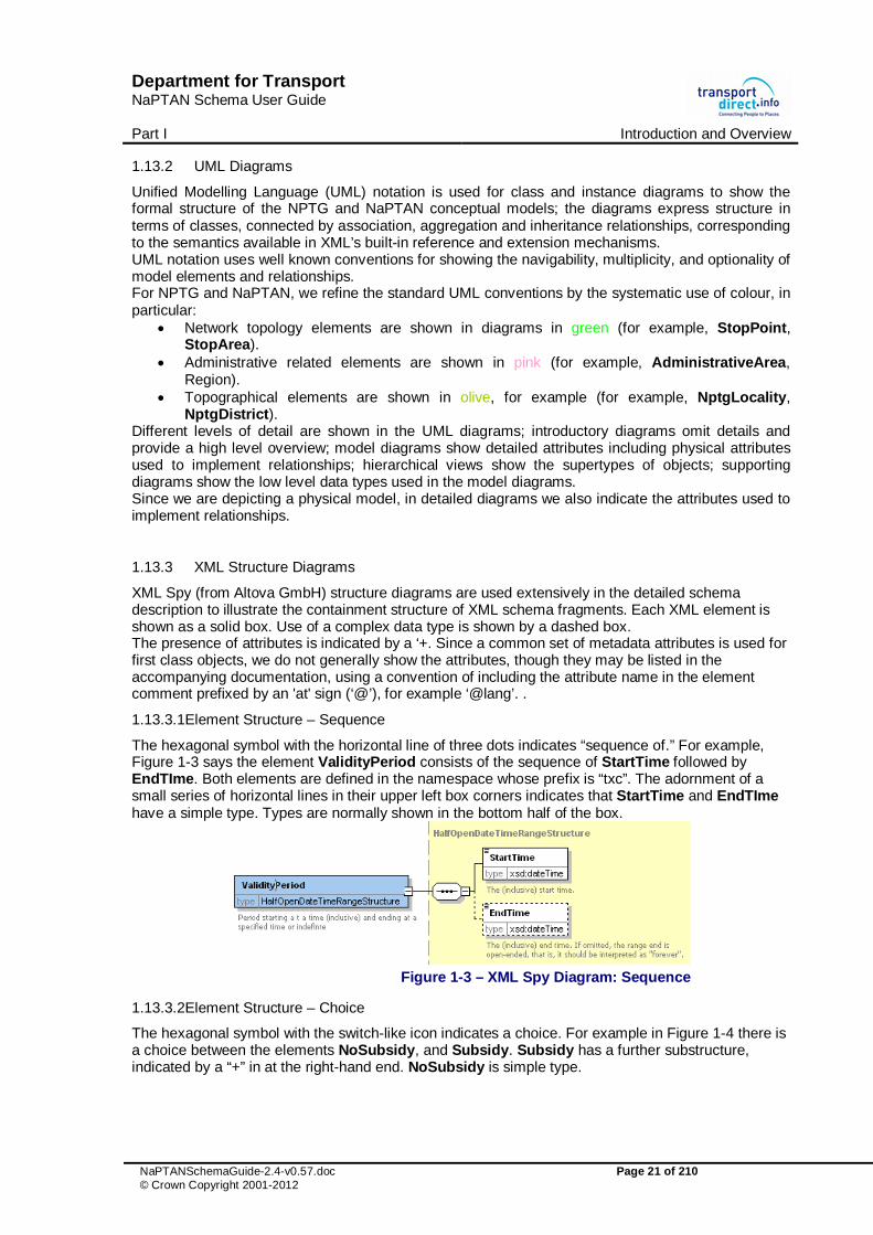
The hexagonal symbol with the horizontal line of three dots indicates “sequence of.” For example, Figure 1-3 says the element ValidityPeriod consists of the sequence of StartTime followed by EndTIme. Both elements are defined in the namespace whose prefix is “txc”. The adornment of a small series of horizontal lines in their upper left box corners indicates that StartTime and EndTIme have a simple type. Types are normally shown in the bottom half of the box.
Figure 1-3 – XML Spy Diagram: Sequence
1.13.3.2Element Structure – Choice
The hexagonal symbol with the switch-like icon indicates a choice. For example in Figure 1-4 there is a choice between the elements NoSubsidy, and Subsidy. Subsidy has a further substructure, indicated by a “+” in at the right-hand end. NoSubsidy is simple type.

Department for Transport NaPTAN Schema User Guide Part I Introduction and Overview
NaPTANSchemaGuide-2.4-v0.57.doc Page 22 of 210 © Crown Copyright 2001-2012
Figure 1-4 – XML Spy Diagram: Choice
1.13.3.3Multiplicity and Optionality
Whether elements are required or optional, and the multiplicity (cardinality) of elements is indicated by adornments as follows:
� A fine dashed line on the connecting line and surrounding box indicates an element is optional. For example, in Figure 1-5; FlexibleZones and Description.
� A solid line indicates a mandatory element. For example, in Figure 1-5; StopPointRef. � A number adornment indicates a multiplicity other than one. ‘Many’ is indicated by an infinity
sign ∞. Thus, for example in Figure 1-5, there may be zero or one Activity instances per StopUsage, but there can be between one and many StopUsages per FlexibleZone.
Figure 1-5 – XML Spy Diagram: Multiplicity
1.14 Related Transport Information Standards
NPTG and NaPTAN are XML based standards and are compatible with the following standards for public transport information:
� ATCO-CIF: ATCO-CIF is a general purpose interchange format for common elements of timetable information. NaPTAN is an evolution of the stop identification system from ATCO.
� TransXChange: TransXChange is a UK national data standard for the interchange of bus
route and timetable information, intended as a successor to ATCO-CIF. The standard is sponsored by the UK Department for Transport, and is mandated by the Traffic Area Network (TAN) for the electronic registration of UK bus services with Traffic Area Offices (TAO) within the Vehicle and Operator Services Agency (VOSA), and Local Authorities. TransXChange 2.x is harmonised with NaPTAN 2.x.

Department for Transport NaPTAN Schema User Guide Part I Introduction and Overview
NaPTANSchemaGuide-2.4-v0.57.doc Page 23 of 210 © Crown Copyright 2001-2012
� Transmodel: Transmodel is an abstract reference model of the data of interest to organisations providing transport related information systems. It has resulted from several European Commission sponsored projects. NaPTAN can be related to Transmodel concepts and terminology. Since the development of NaPTAN Transmodel has been further evolved by the addition of a detailed stop model IFOPT (Identification of Fixed Objects) drawing on NaPTAN and the experience of other European nations. This is being consolidated into an XML format NeTEX (Network exchange). A transformation to allow the expression of NaPTAN data in NeTEx is intended
� JourneyWeb: JourneyWeb is an XML protocol allowing distributed journey planning. The
protocol is a UK national de facto standard sponsored by the UK Department for Transport and is being used in the Transport Direct Portal to provide contiguous distributed journey planning across the whole of Great Britain.
� SIRI: The Service Interface for Realtime Information is a standard for the exchange of real
time bus information between systems which was developed by TC278 WG3 of CEN with UK participation sponsored by the DfT, originally through the UK Real Time Interest Group, and now PTIC. SIRI services that reference stops, such as the SIRI Stop Monitoring Service (SIRI-SM), can reference NaPTAN stop points.
� UK Geocoding References: For geospatial references the NaPTAN data set hold OSGR
Grid references – the Easting and Northing, with support for both UK Mainland and Irish grids. In release 2.x the schema supports the exchange of WGS84 coordinates as an alternative.
1.15 Acknowledgments
The original Schema Guide for version 2.0 of NaPTAN was prepared by the Kizoom (Nick Knowles, Tom White) and Carlbro (Richard Mejia, Paul Robinson) teams under direction of Roger Slevin of the Department for Transport. It included revised examples and appendixes from the original NaPTAN specification prepared by WSAtkins, and examples from ‘Modelling stops – Usage of NPTG and NaPTAN in the South East Enquiry Management System’, a paper produced by MDV gmbh. Schema, introduction, modelling and technical sections were provided by Kizoom. We thank Dr Hans-Joachim Mentz of MDV for his examples, comments and material on stop naming. Thanks also to John Gallagher (Thales), Dean Garraghty (Trandata), Kieren Holmes (Cap Gemini), Paul Houghton (Trandata), Peter Miller (ACIS), Mike Ness (WSAtkins), John Prince (SYPTE), Richard Shaw (WSAtkins), Dr Martin Siczkowski (WYPTE), Roger Dennis (Trapsoft) and other ATCO and RTIG members for their comments, corrections and other feedback. Version 2.1 of NaPTAN accompanied version 2.1 of TransXChange and was prepared to by the Kizoom (Nick Knowles, Tom White) and Carlbro (Richard Mejia, Paul Robinson) teams under direction of Roger Slevin of the Department for Transport. Version 2.4 accompanied version 2.4 of TransXChange and was prepared by the Kizoom (Nick Knowles) and Centaur (Mark Cartwright) teams with guidance from Roger Slevin and Chris Gibbard of the Department for Transport.


Department for Transport NaPTAN Schema User Guide Part I Introduction and Overview
NaPTANSchemaGuide-2.4-v0.57.doc Page 25 of 210 © Crown Copyright 2001-2012
2 INTRODUCTION TO NAPTAN AND THE NPTG
2.1 The Purpose of the National Public Transport Gazetteer
NaPTAN depends closely on the National Public Transport Gazetteer (NPTG). The NPTG provides a model of all UK cities, towns and settlements to which people might wish to travel, or which they might wish to use to describe the places to which they wish to travel. Every NaPTAN stop is assigned to a NPTG locality. This association has two main purposes:
1. It allows stops to be related to the topographical area in which they lie, so that a wide variety of user search functions can be supported to find travel destinations and travel access points.
2. It allows stops to be related to the computer systems which provide coverage for the stop, for example for journey planning or real time information, so that services can be provisioned automatically.
Not all NPTG localities, however, have stops associated with them. The Gazetteer seeks to present a comprehensive list of UK localities as known to the public, regardless of whether transport services are available within a given locality.
2.1.1 The NPTG Database
The NPTG database holds a current data set of all UK towns and settlements, organised within a topographical hierarchy. The NPTG database is maintained centrally by Thales Information Systems under contract to the Department for Transport.
2.1.2 The NPTG XML Schemas
NPTG data is described by two related XML schemas. (i) The main NPTG Schema, (ii) The NPTG Discovery schema, relating NPTG entities to available services. The schemas can be used to describe NPTG data when exchanging it between systems as XML documents. The schemas can be used with software tools to check that documents are correctly formatted and contain the required content.
2.1.3 The NPTG CSV Exchange Format
NPTG data can also be distributed to systems in Comma Separated Variable (CSV) format, as well as XML documents. The NPTG CSV exchange format uses a format, recorded in Appendix 15.5.
2.2 The Purpose of NaPTAN
NaPTAN seeks to assemble and maintain a single source of information on the location and naming of bus stops and other public transport access nodes. NaPTAN includes the following main elements:
2.2.1 NaPTAN Identifiers
NaPTAN stop point identifiers are a systematic way of identifying all UK points of access to public transport. Stops are submitted by administrative area authorities to a central service which consolidates the stops and distributes them back to users.
� Every UK station, coach terminus, airport, ferry terminal, bus stop, etc is allocated at least one unique NaPTAN stop point with its own identifier.
� For large interchanges and termini, NaPTAN points identify the entrances from the public thoroughfare – one identifier is distinguished as the main entrance. A second point may be used to designate the ‘transport side’ – airside, berth or platform area.
For every NaPTAN stop there are two associated NaPTAN identifiers, each unique within the UK: � The AtcoCode: A twelve character NaPTAN identifier intended for use in computer systems. � The NaptanCode: A short (seven or eight digit) identifier suitable for displaying on stops and
referring to the stop in public facing systems. This has been designed to be suitable for use

Department for Transport NaPTAN Schema User Guide Part I Introduction and Overview
NaPTANSchemaGuide-2.4-v0.57.doc Page 26 of 210 © Crown Copyright 2001-2012
in SMS and other delivery channels requiring direct reference to a stop identifier by the public. In most areas it uses a character set optimised for a mobile device keypad.
2.2.2 The NaPTAN Database
The NaPTAN database holds a current copy of all UK stops and their descriptions. Stops are submitted by Public Transport Authorities (Metropolitan, County and Unitary) to a central authority which validates and aggregates the stop point data and returns it back to consumer systems. The NaPTAN database is maintained centrally by Thales Information Systems, under contract to the Department for Transport.
2.2.3 The NaPTAN XML Schema
NaPTAN data is described by a NaPTAN XML Schema. The schema can be used to describe NaPTAN data when exchanging it between systems as XML documents. The schema describes the content model: not only the elements and Datatypes, but also the rules for combining them. The schema can be used with software tools to check that documents are correctly formatted and have the required content.
The XML documents themselves can be exchanged by different transport mechanisms, for example, FTP, email or http. It should be emphasised that the NPTG and NaPTAN schemas are a standard format for data exchange, and not a specific software program or a dynamic protocol. NaPTAN is intended to enable local and national user communities to build systems that can share information correctly, cheaply and efficiently, but does not prescribe detailed error handling or other data processing details.
2.2.4 The NaPTAN CSV Exchange Format
NaPTAN data can also be distributed to systems in CSV format, as well as XML documents. The NaPTAN CSV exchange format uses a format recorded in Appendix 15.8.
2.2.5 NaPTAN Process
Gathering, collating and maintaining a large, volatile data set such as that of UK PTANS requires an agreed workflow and process for a large number of different bodies to work together, in both the public and private sectors. NaPTAN includes an overall workflow and tools, with specific organisations being charged with specific roles in the overall process. NaPTAN also prescribes a set of rules for describing stops when populating the NaPTAN textual descriptions elements.

Department for Transport NaPTAN Schema User Guide Part I Introduction and Overview
NaPTANSchemaGuide-2.4-v0.57.doc Page 27 of 210 © Crown Copyright 2001-2012
2.3 How are NPTG and NaPTAN used?
The most common use of NPTG and NaPTAN data – to support the exchange of bus timetables - may involve the exchange of three different data sets:
� Exchange of the NPTG Gazetteer data.
� Exchange of the NaPTAN stops which reference NPTG data.
� Exchange of TransXChange documents which reference NaPTAN stops and NPTG localities, and which may also contain interim local definitions of NaPTAN stops.
A further common use of NPTG and NaPTAN data is to provide place and stop finding functions in journey planners and other on-line enquiry services. Typical scenarios for the use of NPTG and NaPTAN are as follows:
2.3.1 Scenario #1: Compilation and Distribution of NPTG Data
1. Compilation The NPTG database has been compiled centrally by the Department for Transport, from the input of local editors who use the on-line NPTG editor to submit locality definitions. It is updated and reissued continually to the Transport Authorities and other users as an XML file (and also as csv tables). Some data elements may be added centrally – for example Plusbus Zones. NPTG documents must validate against a stated version of the NPTG schema. If necessary, the same content could be exported and distributed in multiple versions at different schema version levels at the same time. 2. Distribution The XML document of the NPTG content (& or csv files) are distributed. The documents are available to authorised users to download from Thales Information Systems at http://www.dft.gov.uk/public-transportdatamanagement. Users may specify the format (XML or CSV) and the version level (e.g. 1.1 or 2.1) that they wish to download. 3. Use Each authority or other user imports the NPTG document into their system, using the version number to determine the appropriate schema level to use. The import application updates the user’s version of the NPTG data with the changes in the update. Note that individual entities such as localities have version numbers, so it is possible to hold multiple versions of data for the same entity in a client database if desired.
2.3.2 Scenario #2: Gathering and Distribution of NaPTAN Stop Data
1. Data Preparation The responsible party for preparing NaPTAN stop data for a given administrative area prepares an updated version of the stop data for that area. Stop points reference NPTG localities. 2. Data Export The NaPTAN stop data set for the whole administrative area is exported as an XML document (formerly as a csv file) following a named version of the NaPTAN schema. Each administrative area should only export nodes contained within its administrative area boundaries, ignoring nodes outside its boundaries that are ‘owned’ by another authority. Only the latest revision of each entity should be exported. 3. Data Transmission The XML document is sent to the central organisation responsible for concentrating NaPTAN data (Thales Information Systems). 4. Data Concentration

Department for Transport NaPTAN Schema User Guide Part I Introduction and Overview
NaPTANSchemaGuide-2.4-v0.57.doc Page 28 of 210 © Crown Copyright 2001-2012
The stop data is imported into the NaPTAN database, using the schema level indicated in the document to interpret the content. Note that records are never removed from the database, simple flagged as deleted or suspended if out of use. When a replacement set of stops for a whole area is imported, an error report will be produced detailing any nodes that were in the database previously but are not in the imported file. This error report will be sent back to the supplier of the data so that they can discover where the records have gone. The ‘lost’ nodes will be kept in the NaPTAN database with a ‘pending’ delete Status. 5. Data Export NaPTAN data for the country is exported as an XML document conforming to the NaPTAN schema. The data is also available as csv files. There are separate files:
� For the whole country. � For each administrative area. As of March 2010 there are currently 146
administrative areas (including 5 which are national mode-based areas).
The files are available from Thales Information Systems at http://www.dft.gov.uk/public-transportdatamanagement/DataUser_Home.aspx. Users may specify (i) the area (all or area code(s)), (ii) the format (XML or CSV) and (iii) the version level (e.g. 1.1 or 2.1) that they wish to download. 6. Data Import Each authority or other user downloads and imports the NaPTAN document into their system, using the version number to determine the appropriate schema level to use.
2.3.3 Scenario #3: Exchange of NaPTAN Data within TransXChange
1. Data Preparation Users prepare bus schedules including, if necessary, any stop definitions for new NaPTAN stop points that are required. An AtcoCode is obtained for each new stop from the relevant local Transport Authority. 2. Data Export The bus schedules are exported as XML documents in TransXChange format, and may include (i) local definitions of new NaPTAN stop points and stop areas, as well as (ii) references to existing NaPTAN stop points and stop areas. The schedules may be published using the TransXChange publisher; NaPTAN stop names will be used to identify the stops. The NPTG Administrative Areas and NPTG Localities referenced by any new local stop definitions must exist in the NPTG. 3. Data Use The importing application imports the TransXChange documents, and resolves the stops against its NaPTAN database. Stops are reconciled according to their NaPTAN AtcoCode identifiers, and the interim definitions used for any new stops that are not yet defined in the application’s current copy of the distributed NaPTAN database. For most applications (for example schedule registration with a Traffic Area Office), any reference to an existing stop that is not found in the NaPTAN database is an error.
2.3.4 Scenario #4: Using NPTG and NaPTAN Data in a Place Finder
One of the common uses that a public transport information system, such as a journey planner, will wish to make of data is to provide users with a means to find origin destination places by a variety of different strategies. For example:
o By NPTG locality name. o By NPTG locality name &/or transport mode. o By NPTG locality name & NPTG sub locality. o By Map location (or post code).

Department for Transport NaPTAN Schema User Guide Part I Introduction and Overview
NaPTANSchemaGuide-2.4-v0.57.doc Page 29 of 210 © Crown Copyright 2001-2012
Journey planning engines will use the NPTG and NaPTAN data sets to build a place model. It is therefore important to have names that are authoritative and descriptive, and in particular that are comprised of content that can be used to distinguish a target place from other places that are similar in name and/or location. It is also important to geocode stops with their correct spatial location, as well as to annotate PTANs and localities by semantic relationships, so that powerful ‘fuzzy’ search functions can be provided, and so that the engines can aggregate very similar stops in a locality into a single ‘place’ within the user interface. The role of NaPTAN is to provide data that can be transformed correctly and unambiguously into the different presentations of stop names needed by software user interfaces, but not to prescribe or preclude specific presentation formats. The requirements to fulfil this role are discussed further later on.
2.3.5 Scenario #5: Using NPTG and NaPTAN Data in a Stop Finder
Another common use that public transport information systems, in particular Automatic Vehicle Location (AVL) systems, may wish to make of NPTG and NaPTAN data is to provide users a means to find stop points by a variety of different strategies. In this case the ability to discriminate every individual stop is important: (as opposed to aggregating a number of stops into a ‘place’).
o By name, and/or transport mode. o By name and NPTG locality and /or transport mode. o By NaPTAN identifier. o By NPTG locality and /or transport mode. o By NPTG locality and NPTG sub locality. o By address. o By map location (or post code).
It is therefore important to have stop names that are descriptive, and in particular that distinguish them from similar instances in a locality. The requirements to do this are discussed later.
2.3.6 Scenario #6: Using NaPTAN Data for real-time departures
Stop Identifiers may be used to provide a common reference framework for exchanging data between Automatic Vehicle Location (AVL) systems and web, mobile and sign distribution channels. The stop point identifier can be used to identify individual points.
2.4 Document Validation
To be valid NPTG or NaPTAN data, XML documents must satisfy two levels of validity criteria:
1. Well-formedness and validity: Documents must parse and validate against the NPTG or NaPTAN schemas, including all the integrity constraints coded within the schema, such as for key uniqueness and reference and for conformance of values to data types. Validation is typically done by the built-in capabilities of standard software tools using the specification provided by the schema and does not require additional programming.
2. Correctness: Documents must satisfy additional processing rules and constraints that are
not enforceable in the XML of the schema, but which can be applied by an application importing the data. A number of data integrity rules are specified in this document in sections 14.2.2 and 14.3.2., and are also mentioned as annotations in the schema. Typically these rules cover additional complex processing or uniqueness constraints that cannot readily be expressed using XML’s built-in mechanisms.


Department for Transport NaPTAN Schema User Guide Part I Introduction and Overview
NaPTANSchemaGuide-2.4-v0.57.doc Page 31 of 210 © Crown Copyright 2001-2012
3 SHORT TOUR OF THE NPTG AND NAPTAN REFERENCE MODELS
In this chapter we provide a summary of the physical data models underlying (i) the NPTG and (ii) the NaPTAN schemas. Both are relatively simple models with a small number of entities. The physical model is presented as UML diagrams, with different levels of details
� Top level elements � Detailed elements with attributes
The diagrams are intended to show how relations and composite objects are serialised as XML: the model therefore includes the attributes used to implement relationships by reference and by containment.
3.1 The National Gazetteer Model
Figure 3-1 introduces, in UML class diagram notation, the fundamental elements of the NPTG schema. The elements of the NPTG model fall into two main groups:
� Topographical. � Administrative.
class NPTG Model Intro
Administrativ eArea
NptgLocality
Region
NptgDistrict
Name: NPTG Model IntroAuthor: nickkVersion: 1.0Created: 04/02/2010 10:46:09Updated: 15/02/2010 13:34:29
(c) 2001-2009 Crown Copyright
0..*
region
1
0..*
administered by1
0..*
administered by0..1
0..*
is part of
0..1
0..*
districts
Figure 3-1 – UML Diagram of NPTG Model: Introduction
3.1.1 Topographical Elements
The fundamental entity of the NPTG is the NptgLocality, which represents a UK city, suburb, district, village, town or other settlement, for example, ‘Holborn’, ‘Cardiff’, ‘North Wootton, Somerset’ or ‘Barnsbury, Islington’.
� Localities can be organised into hierarchies using an ‘is part of’ relationship. o The ‘is part of’ relationship implies that the contained element is inside its parent
element. o An arbitrary number of levels may be used, though currently at most three levels are
used in practice. Parent references should not be cyclic, that is a locality should not be part of itself, directly or indirectly. ,
o A parent element will not necessarily be uniformly divided into children: typically there may be additional children covering town centres and areas significant for travel. Other areas may be more sparsely covered.

Department for Transport NaPTAN Schema User Guide Part I Introduction and Overview
NaPTANSchemaGuide-2.4-v0.57.doc Page 32 of 210 © Crown Copyright 2001-2012
o Localities may overlap. Localities may be used to describe geographically fuzzy areas like ‘The West End’ or ‘South Bank’.
� Each NptgLocality has a Location, specifying the geospatial coordinates, ideally at 1m precision, of a central point for the locality.
� Each NptgLocality has a name and an optional short name which can be used to qualify other names. Each NptgLocality may have multiple AlternativeDescriptor instances, each specifying alternative names for the locality. For example, Swansea’ has an alternative common name of ‘Abertawe’ where the alternative name is being used for a bilingual (Welsh) variant of its name.
� Each NptgLocality is associated with a single AdministrativeArea, representing a Metropolitan PTE, a Shire County or a Shire Unitary Authority (the authority with transport responsibilities).
� Each NptgLocality can also be associated with an NptgDistrict, a subdivision of AdministrativeArea.
o The district specifies the Local Authority to which the NptgLocality belongs. A district will correspond to governmental district, thus be a Borough, District or Metropolitan Borough of the UK.
o For each AdministrativeArea that is a Shire or Metropolitan County, there is an NptgDistrict for each subdivision of the administrative area.
Figure 3-2 elaborates, in UML class diagram notation, the elements of the NPTG Locality Model to show attributes and ancillary elements.
class NPTG Locality Model
LocationModel::Location
Longitude: LongitudeType [0..1]Latitude: LatitudeType [0..1]GridType: GridTypeEnumEasting: EastingTypeNorthing: NorthingType
«PK»Id: IdType
VersionedObject
NptgLocality
SourceLocal ityType: Local itySourceEnumLocali tyClassi fication: NptgLocalityClassifcationEnum [0..1]
«PK»NptgLocali tyCode: NptgLocali tyCodeType
«contained»Descriptor: DescriptorAlternativeDescriptors: Descriptor [0..*]Location: LocationAdjacentLocalities: NptgLocal i tyRef* [0..*]
«FK»AdministrativeAreaRef: AdministrativeAreaCodeType*NptgDistrictRef: DistrictCodeType*
Versionable
Name: NPTG Locality ModelAuthor: nickkVersion: 1.0Created: 04/02/2010 11:18:28Updated: 31/12/2010 11:26:57
VersionedChi ld
Descriptor
Locali tyName: Multil ingualStringShortName: Multi lingualString [0..1]Quali fy: Qual i fier
Versionable
«enumeration»NptgLocalitySupport::
LocalityClassifcationEnum
ci tysuburbtownvi l lagehamleturbanCentreplaceOfInterestotherunrecorded
Qualifier
QualifierName: Multi lingualString [0..1]
«FK»NptgLocali tyRef: NptgLocalityCodeType* [0..1]NptgDistrictRef: DistrictCodeType* [0..1]
«enumeration»NptgLocalitySupport::
SourceLocalityTypeEnum
UUSPaCoLoDWDLOCPARREDISLAdd
(c) 2001-2010 Crown Copyright
VersionedChi ld
«reference»NptgLocalitySupport::NptgLocalityRef
«FK»LocalityRef: NptgLocal i tyCodeType*
Versionable
VersionedObject
NptgAdministrativeModel::AdministrativeArea
VersionedObject
NptgAdministrativ eModel::NptgDistrict
is at
0..*
administered by
1
0..*
administered by
0..1
0..*
is part of
0..1
0..* adjacent to
0..1
0..*
alternative descriptors
qualifier
qualifier
0..*1
0..*
districts
Figure 3-2 – UML Diagram of NPTG Locality Model

Department for Transport NaPTAN Schema User Guide Part I Introduction and Overview
NaPTANSchemaGuide-2.4-v0.57.doc Page 33 of 210 © Crown Copyright 2001-2012
3.1.2 Administrative Elements
Figure 3-3 introduces, in UML class diagram notation, the elements of the NPTG Administrative Model, which assign responsibility for managing locality data:
� Great Britain is divided into Traveline Region instances. � Every Region contains a number of AdministrativeArea instances. � Each NptgLocality and NptgDistrict belongs to a specific AdministrativeArea. � Great Britain also contains a number of PlusbusZone instances. These are Tariff zones for
the PlusBus scheme.
class National Public Transport Gazetteer Ov erv iew
Administra tiv eArea
NptgLocality
PluzBusZone
Location
Region
NptgDistrict
Nam e: National Publ ic T ransport Gazetteer OverviewAuthor: n ickkVersion: 1 .0Created: 17/09/2009 15:42:38Updated: 15/02/2010 11:38:31
(c ) 2001-2010 Crow n Copyright
is at
0..*
reg ion
1
0 ..*
adm ini stered by
10..*
districts
0 ..*
adm ini ste red by
0..1
0..*
is part of
0..1
0 ..*
adjacent to
0..1
Figure 3-3 – UML Diagram of NPTG Administrative Model: Overview

Department for Transport NaPTAN Schema User Guide Part I Introduction and Overview
NaPTANSchemaGuide-2.4-v0.57.doc Page 34 of 210 © Crown Copyright 2001-2012
Figure 3-4 elaborates the same elements as in Figure 3-3 with some further detail showing additional child elements of AdministrativeAreas.
class NPTG Model
(c) 2001-2010 Crown Copyright
Location
VersionedObject
PluzBusZone
VersionedObject
NptgLocality
VersionedObject
AdministrativeArea
VersionedChild
ClearDownRange
VersionedObject
NptgDistrict
VersionedObject
Region
VersionedChild
AlphaPrefix
«enumeration»CountryEnum
EnglandScotlandWalesGBNorthernIrelandUKEire
ContactTelephone VersionedChild
Descriptor
Versionable
«enumeration»LocalityClassifcationEnum
citysuburbtownvillagehamleturbanCentreplaceOfInterestotherunrecorded
Qualifier
Name: NPTG ModelAuthor: nickkVersion: 1.0Created: 08/02/2010 20:17:48Updated: 15/02/2010 13:34:34
0..*adjacent to
0..1
0..*
alternative descriptors0..*
prefixes
0..*
districts
0..*
region1
is at
0..*
is part of0..1 0..*
administered by
0..1
0..*
administered by
1
0..*
ranges
Figure 3-4 – UML Diagram of Main NPTG Model: Further elements

Department for Transport NaPTAN Schema User Guide Part I Introduction and Overview
NaPTANSchemaGuide-2.4-v0.57.doc Page 35 of 210 © Crown Copyright 2001-2012
Figure 3-5 shows the same elements as in Figure 3-4 with further detail as to the properties of individual entities.
class NPTG Administrative Model
(c) 2001-2010 Crown Copyright
LocationModel::Location
VersionedObject
PluzBusZone
Name: Multi l ingualStringCountry: CountryEnum
«contained»Mapping: Location [0..*]
«PK»PlusBusZoneCode: PlusBusZoneCodeType
Versionable
VersionedObject
NptgLocalityModel::NptgLocality
SourceLocali tyType: LocalitySourceEnumLocalityClassification: NptgLocali tyClassifcationEnum [0..1]
«PK»NptgLocali tyCode: NptgLocalityCodeType
«contained»Descriptor: DescriptorAlternativeDescriptors: Descriptor [0..*]Location: LocationAdjacentLocali ties: NptgLocali tyRef* [0..*]
«FK»AdministrativeAreaRef: AdministrativeAreaCodeType*NptgDistrictRef: DistrictCodeType*
Versionable
VersionedObject
Administrativ eArea
Name: Multi l ingualStringShortName: Multi l ingualString [0..1]MaximumLengthForShortName: integer [0..1]National: boolean [0..1]ContactEmai l: EmailType [0..1]ContactTelephone: ContactTelephone [0..1]
«PK»AdministrativeAreaCode: AdministrativeAreaCodeType
«AK»AtcoAreaCode: AtcoAreaCodeType
«contained»NptgDistricts: NptgDistrict [0..*]NaptanPrefixes: AlphaPrefix [0..*]CleardownRange: AlphaPrefix [0..*]
Versionable
Name: NPTG Administrative ModelAuthor: nickkVersion: 1.0Created: 17/09/2009 16:31:38Updated: 31/12/2010 11:24:15
VersionedChild
ClearDow nRange
CleardownStart: integerCleardownEnd: integer
VersionedObject
NptgDistrict
Name: Multi l ingualStringVersionable
VersionedObject
Region
Name: Multi l ingualStringCountry: CountryEnum
«PK»RegionCode: RegionCodeType
«contained»AdministrativeAreas: AdministrativeArea [0..*]
Versionable
VersionedChild
AlphaPrefix
AlphaPrefix: normalizedString
«enumeration»NptgAdministrativ eSupport::
CountryEnum
EnglandScotlandWalesGBNorthernIrelandUKEire
UtilityTypesModel::ContactTelephone
TelNationalNumber: PhoneNumberTypeTelExtensionNumber: TelephoneExtensionTypeTelCountryCode: TelCountryCodeType
VersionedChild
NptgLocalityModel::Descriptor
Locali tyName: Multil ingualStringShortName: Multil ingualString [0..1]Quali fy: Quali fier
Versionable
«enumeration»NptgLocalitySupport::
LocalityClassifcationEnum
citysuburbtownvil lagehamleturbanCentreplaceOfInterestotherunrecorded
«enumeration»NptgLocalitySupport::
SourceLocalityTypeEnum
UUSPaCoLoDWDLOCPARREDISLAdd
0..*
is part of
0..1
0..*
alternative descriptors
0..*
prefixes
0..*
districts
0..*
ranges
0..*
adjacent to
0..1
is at
0..*
administered by
0..1
0..*
administered by
1
0..*
region1
Figure 3-5 – UML Diagram of Main NPTG Model: Detail

Department for Transport NaPTAN Schema User Guide Part I Introduction and Overview
NaPTANSchemaGuide-2.4-v0.57.doc Page 36 of 210 © Crown Copyright 2001-2012
3.1.3 NPTG Element Hierarchies
3.1.3.1NPTG Locality Element Hierarchy
Figure 3-6 shows the Class Hierarchy for the NPTG Locality Elements. NptgLocality is a versioned element. NptgLocalityRef & Descriptor are child elements.
class NPTG Locality Model Hierarchy
(c) 2001-2010 Crown Copyright
NptgLocality
+ SourceLocalityType: Local itySourceEnum+ LocalityClassification: NptgLocalityClassifcationEnum [0..1]
«PK»+ NptgLocalityCode: NptgLocal ityCodeType
«contained»~ Descriptor: Descriptor- AlternativeDescriptors: Descriptor [0..*]~ Location: Location- AdjacentLocal ities: NptgLocalityRef* [0..*]
«FK»# AdministrativeAreaRef: AdministrativeAreaCodeType*# NptgDistrictRef: DistrictCodeType*
Name: NPTG Locality Model HierarchyAuthor: nickkVersion: 1.0Created: 10/02/2010 11:22:26Updated: 31/12/2010 11:27:44
Descriptor
+ Local ityName: Multil ingualString+ ShortName: Multil ingualString [0..1]+ Quali fy: Qualifier
Qualifier
+ QualifierName: Multil ingualString [0..1]
«FK»# NptgLocalityRef: NptgLocalityCodeType* [0..1]# NptgDistrictRef: DistrictCodeType* [0..1]
VersioningModel::VersionedObj ect VersioningModel::VersionedChild
«reference»NptgLocalitySupport::NptgLocalityRef
«FK»# Local ityRef: NptgLocal ityCodeType*
Figure 3-6 – UML Diagram of NPTG Locality Element Hierarchy
3.1.3.2NPTG Administrative Element Hierarchy
Figure 3-7 shows the Class Hierarchy for the NPTG Administrative Elements. Region, AdministrativeArea, NptgDistrict and PlusBusZone are versioned elements. CleardownRange & AlphaPrefix are child elements.
class NPTG Administrativ e Model Hierarchy
(c) 2001-2010 Crow n Copyright
PluzBusZone
+ Name: Multi lingualString+ Country: CountryEnum
«contained»- Mapping: Location [0..*]
«PK»+ PlusBusZoneCode: PlusBusZoneCodeType
Administrativ eArea
+ Name: Multi l ingualString+ ShortName: Multi l ingualString [0..1]+ MaximumLengthForShortName: integer [0..1]+ National: boolean [0..1]+ ContactEmail: EmailType [0..1]+ ContactTelephone: ContactTelephone [0..1]
«PK»+ AdministrativeAreaCode: AdministrativeAreaCodeType
«AK»+ AtcoAreaCode: AtcoAreaCodeType
«contained»- NptgDistricts: NptgDistrict [0..*]- NaptanPrefixes: AlphaPrefix [0..*]- CleardownRange: AlphaPrefix [0..*]
Name: NPTG Administrative Model HierarchyAuthor: nickkVersion: 1.0Created: 08/02/2010 20:38:23Updated: 31/12/2010 12:05:48
ClearDow nRange
+ CleardownStart: integer+ CleardownEnd: integer
NptgDistrict
+ Name: Multi l ingualString
Region
+ Name: Multi l ingualString+ Country: CountryEnum
«PK»+ RegionCode: RegionCodeType
«contained»# AdministrativeAreas: AdministrativeArea [0..*]
AlphaPrefix
+ AlphaPrefix: normalizedString
VersioningModel::VersionedObject
VersioningModel::VersionedChild
«reference»NptgAdministrativ eSupport::
AdministrationAreaRef
# AdminArea: AdministrativeAreaCodeType*
«reference»NptgAdministrativ eSupport::PlusbusZoneRef
«FK»# PlusbusZoneRef: PlusbusZoneCodeType*
Figure 3-7 – UML Diagram of Administrative Element Hierarchy

Department for Transport NaPTAN Schema User Guide Part I Introduction and Overview
NaPTANSchemaGuide-2.4-v0.57.doc Page 37 of 210 © Crown Copyright 2001-2012
3.1.3.3NPTG Locality Data Types
Figure 3-8 shows the data types used in the locality elements in Figure 3-2 and elsewhere. class NPTG Locality Support
Name: NPTG Locali ty SupportAuthor: nickkVersion: 1.0Created: 01/03/2010 15:21:16Updated: 01/03/2010 15:23:57
(c) 2001-2010 Crown Copyright
«unique identifier»NptgLocalityCodeType
«enumeration»LocalityClassifcationEnum
ci tysuburbtownvi llagehamleturbanCentreplaceOfInterestotherunrecorded
«enumeration»SourceLocalityTypeEnum
UUSPaCoLoDWDLOCPARREDISLAdd
VersioningModel::VersionedChild
«reference»NptgLocalityRef
AdminArea: NptgLocal i tyCodeType
token
«XSDsimpleType»XSDDatatypes::NMTOKEN
Figure 3-8 – UML Diagram of Locality Data types
3.1.3.4NPTG Administrative Data Types
Figure 3-9 shows the data types used in the administrative elements in Figure 3-5 and elsewhere.

Department for Transport NaPTAN Schema User Guide Part I Introduction and Overview
NaPTANSchemaGuide-2.4-v0.57.doc Page 38 of 210 © Crown Copyright 2001-2012
class NPTG Administrative Support
«unique identifier»NaptanAlphaPrefixType
constraints{Max length three. '1' or three char prefix}x}
Name: NPTG Administrative SupportAuthor: nickkVersion: 1.0Created: 17/09/2009 16:12:21Updated: 26/03/2010 12:00:58
(c) 2001-2010 Crown Copyright
«unique identifier»RegionCodeType
constraints{restricted Code list}t}
«unique identifier»AtcoAreaCodeType
constraints{Restricted Code list}t}
«unique identifier»AdministrativeAreaCodeType
constraints{restricted code set}t}
«unique identifier»NptgDistrictCodeType
«enumeration»CountryEnum
EnglandScotlandWalesGBNorthernIrelandUKEire
«unique identifier»CallCentreCodeType
«unique identifier»PlusbusZoneCodeType
«unique identifier»RegionShortCodeType
constraints{Max 2}2}
«enumeration»UkLanguageEnum
ENCYGAGD
«reference»AdministrationAreaRef
AdminArea: AdministrativeAreaCodeType
VersioningModel::VersionedChild
token
«XSDsimpleType»XSDDatatypes::NMTOKEN
«reference»PlusbusZoneRef
«FK»PlusbusZoneRef: PlusbusZoneCodeType
«reference»RegionRef
«FK»RegionRef: RegionCodeType
Figure 3-9 – UML Diagram of Administrative Data types
3.1.3.5NaPT Location Data Types
Figure 3-10 shows the reusable Location data types used for a geospatial point in Figure 3-5 and elsewhere.

Department for Transport NaPTAN Schema User Guide Part I Introduction and Overview
NaPTANSchemaGuide-2.4-v0.57.doc Page 39 of 210 © Crown Copyright 2001-2012
class Location Types Package
Name: Location Types PackageAuthor: nickkVersion: 1.0Created: 10/02/2010 11:36:47Updated: 01/03/2010 13:29:45
Location
Longi tude: LongitudeTypeLatitude: Lati tudeTypeGridType: GridTypeEnumEasting: EastingTypeNorthing: NorthingType
«PK»Id: IdType
«enumeration»CompassBearingEnum
NNWWSWSSEENE
«enumeration»LocationSystemEnum
GridWGS84
GisFeature
«dataType»LatitudeType
«dataType»LongitudeType
«dataType»LocationIdentifier
(c) 2001-2010 Crown Copyright
«dataType»CoordinatesType
Figure 3-10 – UML Diagram of Location Data Types
3.1.3.6Utility Data Types
Figure 3-12 shows the reusable Address data types used in Figure 3-5 and elsewhere.
class Utility Types Package
«dataType»EmailType
«dataType»PhoneNumberType
«dataType»PostCodeType
«dataType»UtilityXmlPackage::MultilingualString
- Language: language
«dataType»NationalPhoneNumberType
«dataType»TelephoneCountryCodeType
«dataType»TelephoneExtensionType
Name: Util ity Types PackageAuthor: nickkVersion: 1.0Created: 12/06/2009 09:18:09Updated: 20/02/2010 04:37:46
(c) 2001-2009 Crown Copyright
anySimpleType
«XSDsimpleType»XSDDatatypes::string
«XSDsimpleType»XSDDatatypes::normalizedString
token
«XSDsimpleType»XSDDatatypes::language
NMTOKEN
«unique identifier»IdType
Figure 3-11 – UML Diagram of NaPT Utility Data Types
3.1.3.7APD Data Types
3.1.3.8Address Data Types
Figure 3-12 shows the reusable Address data types used in Figure 3-5 and elsewhere.

Department for Transport NaPTAN Schema User Guide Part I Introduction and Overview
NaPTANSchemaGuide-2.4-v0.57.doc Page 40 of 210 © Crown Copyright 2001-2012
class ApdTypesPackage
«data type»UkPostalAddress
Line1: normalizedString [2..5]PostCode: PostCodeType [0..1]
«data type»TelephoneNumberType
TelNationalNumber: normalizedStringTelExtensionNumber: PostCodeTypeTelCountryCode: PostCodeType
UkPostCodeType
Name: ApdTypesPackageAuthor: nickkVersion: 1.0Created: 09/02/2010 10:53:06Updated: 15/02/2010 13:34:26 (c) 2001-2010
Crown Copyright
Figure 3-12 – UML Diagram of APD Address Data Types

Department for Transport NaPTAN Schema User Guide Part I Introduction and Overview
NaPTANSchemaGuide-2.4-v0.57.doc Page 41 of 210 © Crown Copyright 2001-2012
3.2 Populating the National Gazetteer
The NPTG provides a structured model for describing the topography of the UK in a format that is useful for computer systems. When entering data into the NPTG model, care needs to taken in choosing, naming and grouping localities so as populate the model in a way that accurately reflects the way real-world places are named and perceived by humans, and also so that the relationships between them are useful for the intended computational purposes.
3.2.1 Choosing Administrative Areas
There should be an NPTG administrative area for every English, Scottish and Welsh County, including metropolitan counties such as Greater London and Greater Manchester, and every Shire Unitary authority. These are the country’s local transport authorities.
� There are currently 146 administrative areas. � There are also two special administrative areas for National Rail and National Coach Data.
Names of Administrative Areas should be unique within the NPTG database. A short name can be associated with each area, to use when distinguishing localities from different areas that have the same name. An ampersand symbol (‘&’) should be used in the naming of administrative areas in preference to the word “and”, so that the word “and” can be used in downstream systems to logically connect two or more such administrative areas without ambiguity (for example. ‘Bath & North East Somerset’ and ‘North Somerset’).
3.2.2 Choosing NPTG Districts
There should be an NPTG District for the following: � Every Metropolitan District Council. � Every Shire District Council.
The name should be the same as the local authority name, without the descriptive suffix (i.e. ‘Council’, ‘District Council’, ‘Borough Council’, ‘City Council’, ‘London Borough of’ etc). For example, ‘Eden’ for ‘Eden District Council’, ‘Haringey’ for ’London Borough of Haringey’, ’Manchester’ for ’Manchester City Council’. Those Administrative Areas which are shire unitary authorities do not have a district. There are currently 274 NPTG Districts. Names of Districts should be unique within the UK.
3.2.3 Choosing & Grouping NPTG Localities
3.2.3.1 Localities
A locality represents a topographic area, that is, a named settlement. There should be a locality for: � Every City. � Every Town. � Every Suburb or District. � Every Village. � Every Hamlet.
3.2.3.2 Town and City Centre Localities
You may choose also to add localities to represent specifically the centre or other important area of a town or city: in this case the city name should be the qualifier. For example, ‘Southampton City Centre)’ and ‘Shirley Town Centre’ in the example in Figure 3-13. ‘Town Centre’ or ‘City Centre’ is preferred as a naming phrase rather than simply ‘Centre’ so as to distinguish the locality from those Sports and Leisure Centres and other Points of Interest that have Centre in their name (e.g. ‘The Sobell Centre’). Creation of a settlement centre area is recommended for settlements that themselves have child localities within them.

Department for Transport NaPTAN Schema User Guide Part I Introduction and Overview
NaPTANSchemaGuide-2.4-v0.57.doc Page 42 of 210 © Crown Copyright 2001-2012
3.2.3.3 Places of Interest versus Localities
Localities should not normally be created for places that are simply points of interest, for example ‘Wembley Stadium’; data for such places will be covered by a Point of Interest from a point of interest database such as PointX. However, it may occasionally be appropriate to add a locality for a point of interest that is also in effect a destination locality (i.e. with potentially many otherwise unrelated access points), not covered by other locality definitions, in particular if no part of the name overlaps with the locality. Thus, for example, one might include ’Blenheim Palace’ which is in Woodstock, but exclude ’Harlech Castle’, because ’Harlech” will already exist as a locality, and will appear in search results.
3.2.3.4 Locality Hierarchies
Lower level localities should have their parent locality specified. Typically three levels of hierarchy should suffice for most localities. For example, Figure 3-13 shows a hierarchy for part of the Southampton area.
Figure 3-13 – Example: Locality Hierarchy
3.2.4 Naming NPTG Localities
Where there are two places with the same name within the UK, you should set the ’Qualifier’ property of the NPTG locality, so that the fully qualified name of each locality is unique within the UK. For example, ‘Gillingham (Kent)’ and ‘Gillingham (Dorset)’ are both named ‘Gillingham’, but have different qualifiers – ‘Kent’ and ‘Dorset’ respectively. When appropriate, journey planners and other applications will append the qualifier to the locality name so as to distinguish the two instances.
For example Table 3-1 shows how names might be derived for two different ’Gillingham’ instances.
Locality Name
Qualifier Qualified Name - Derived
Gillingham Kent Gillingham (Kent). Gillingham Dorset Gillingham (Dorset).
Table 3-1 – Example of Qualified Locality Names
3.2.4.1 General Rules for the Names of NPTG Localities
The following general rules should be applied to naming NPTG localities:

Department for Transport NaPTAN Schema User Guide Part I Introduction and Overview
NaPTANSchemaGuide-2.4-v0.57.doc Page 43 of 210 © Crown Copyright 2001-2012
� Capitalization: The preferred style of locality names, in NPTG is ‘title case’, that is, lower case with the first letter of each significant word in upper case, for example, ‘Milton Keynes’, ‘Up-Mudford’. Prepositions and articles within a name should be in lower case; ‘Cley-next-the-Sea’, not ‘Cley Next The Sea’. Similarly; ‘Isle of Man’, ‘Slyne-with-Hest’, ‘Kirkby-in-Furness’. Prepositions and articles derived from Latin or other languages should not be capitalised either; ‘St George's-super-Ely’, Poulton-le-Fylde. Additional considerations apply to the capitalisation of Welsh names to follow preferred Welsh usage.
� Character Set: Only uppercase and lower case letters should be used in locality names. Accented characters are permitted. Hyphens may be used within names, for example ‘Hutton-le-Hole’, as may apostrophes, for example ‘St Margarets’ and ampersands, for example ‘Bat & Ball’.
o Specifically the use of digits, non alphabetic characters, and any punctuation characters other than apostrophes and hyphens should be avoided in common names and locality names. Numbers should be spelt out e.g. 'Seven Sisters’, not '7 Sisters'. Certain characters are forbidden in names by the NaPTAN schema; in particular commas and the other characters in Table 3-2 should not be used as their use in a NaPTAN document will render it invalid.
Character Name Why character is reserved. , Comma Used as separator for qualifier [ Left Square Bracket Used to format output ] Right Square Bracket Used to format output { Left Brace Used to format output t } Right Brace Used to format output ^ Caret Inappropriate = Equals Inappropriate @ at Inappropriate : colon May be used to format output ; semicolon May be used to format output # hash Input expression $ Dollar Input expression £ Pound Inappropriate ? Question mark Inappropriate mood % Percent Input expression
Table 3-2 – Characters that are invalid in NPTG & NaPTAN Place and Common Names
o The use of certain other non-alphabetic characters is also strongly discouraged. . Further automatic validation to prevent the use of other inappropriate characters (see Table 3-3) may be added to the schema in future.
Character Name Why character is discouraged. + plus Input expression < Left than Used to format output > Greater than Used to format output « Left guillemot Used to format output » Right guillemot Used to format output \ Back slash Better to use alternative name / Forward slash Better to use alternative name | at Better to use alternative name ~ tilde Inappropriate _ underscore Inappropriate ¬ hash Input expression
Table 3-3 – Characters Not To Be Used in NPTG & NaPTAN Place and Common Names
� Use of Brackets: In NaPTAN 1.x round brackets were used to wrap a qualifier within a name, for example ‘The Knap (Vale of Glamorgan)’; in NPTG 2.x the qualifier should not be included in the locality name as it should be held separately in the Qualifier element. If it is needed in the presentation of a name it can be appended automatically and the brackets supplied by the formatter.
� Use of Numbers: Numbers should be written out as words, for example ‘Seven Oaks’, not ‘7 Oaks’.

Department for Transport NaPTAN Schema User Guide Part I Introduction and Overview
NaPTANSchemaGuide-2.4-v0.57.doc Page 44 of 210 © Crown Copyright 2001-2012
� Hyphenation: Names should be hyphenated according to the preferred form of native usage. In British place names, hyphenation occurs in two circumstances:
o Proper nouns, for example, ‘Dudington-Fineshade’, ‘Lawton-Gate’. Hyphenation of two proper nouns is common in Welsh names, but rare in English place names – for a full list of the latter see Table 3-4.
Lawton-Gate Up-Mudford Knight-Ley Edge-End Lane-End Over-ross
Pen-Alt Pentre-Jack Thing-Hill Stone-Edge Batch Touchen-End Lockington-Hemington
Duddington-Fineshade Stowey-Sutton Norton-Radstock Banchory-Devenick Buchanhaven-Catto Leochel-Cushnie
Clachan-Seil Lower Maes-Coed Windy-Yett
Table 3-4 – English Locality Names without any Preposition that are Hyphenated
� Some British place names contain hyphenated prepositions and/or articles, for example ‘ ‘Lilford-cum-Wigestead’, ‘Hinton-in-the-Hedges, ‘Laughton-en-le-Morthen’, ‘Rhyd-y-Pandy’, ‘Ty’n-twr’, ‘Praze-an-Beeble’. Where there is a choice of usage, the hyphenated form is preferred, according to the style of the Times Gazetteer. See Table 3-5.
lang Preposition Example Hyphenate FIX a Hook-a-Gate always ok at Cross-at-Hand, Stratford atte Bowe always ok by Middleton-by-Youlgreave always fix cum Shingay-cum-Wendy, Haversham-cum-Little Linford always fix de la Ashby-de-la-Zouch always fix le, la, en le Poulton-le-Fylde, Laughton-en-le-Morthen, Sturton-le-Steeple always fix In / In the Hinton-in-the-Hedges; Sandside (Kirby-in-Furness)
St Just-in-Roseland always
next Wells-next-the-Sea always of Isle of Dogs never ok on / on the Frisby-on-the-Wreak, Northwood (Stoke-on--Trent), Lydford-on-Fosse by usage sub Westbury-sub-Mendip always fix super Weston-super-Mare always fix the East-the-Water by usage to Come-to-Good always ok upon Oldbury-upon-Severn always under Weston-under-Lizard always up Up-Mudford always ok with Slyne-with-Hest, Little Eccleston-with-Larbreck always fix cy ar Llanfihangel-ar-Arth by usage cy y Pant-y-Gog, Pen-bont-rhyd-y-beddau by usage cy yr Ty'n-yr-eithin by usage
Table 3-5 – Hyphenation of Prepositions & Articles in NPTG Locality Names
� Use of Periods: Full stops must not be used within names, for example use just ‘St’ rather than ‘St.’; do not put a final period on names.
� Use of Commas: Commas must not be used within names, as commas are conventionally used by presentation programs to indicate the concatenation of discrete elements when formatting names.
� Use of Hyphens: Hyphens should be used around prepositions for example ‘Kirkby-in-Furness’, not ‘Kirkby in Furness’. See section 3.5.11.1 below.
� Use of Apostrophes: Apostrophes should be used in line with the preferred local practice. For example, “Robinson’s End”, “Cross o' th' Hands”, “Tolleshunt D’Arcy”, “Blo’norton”, “Ty’n-y-groes”.
� Use of Articles: For those English place names that include the English definite article (‘The’) before the name, the article should be included in the locality name, before the proper noun, for example ‘The Maltings’, not ‘Maltings, The’. An alternative name without the article may also be included; for example ‘The Chuckery’, + ‘Chuckery’; ‘The Dunks’, + ‘Dunks’, however most search engines will allow for the article.
� Use of Ampersand: ‘&’ is preferred to ‘and’ for a conjunction, for example, ‘Bat & Ball rather than ‘Bat and Ball’. However use of a conjunction in a locality name is usually an indication of a missing locality. A locality is an singular concept and any locality name that joins two or more separate designations should be broken down into the two or more component

Department for Transport NaPTAN Schema User Guide Part I Introduction and Overview
NaPTANSchemaGuide-2.4-v0.57.doc Page 45 of 210 © Crown Copyright 2001-2012
localities which contain an Ampersand (‘&’) or the word “and” should be reviewed and revised to remove the use of the conjunction.
� Use of Abbreviations: Abbreviations should be avoided in locality names, for example ‘Great Missenden’ and not ‘Gt Missenden’ unless length limitations require their use (Location names in the NPTG database can be up to 48 characters long. Standard abbreviations are given in 15.4. Two exceptions to this are (i) the abbreviation for ‘Saint’, where ‘St’ should always be used, for example ‘St Quivox’, or ‘Ilketshall St John’. (ii) the abbreviation ‘nr’ should be used rather than ‘near’, for instance ‘Frogmore (near King’s Walden)’.
� Use of Acronyms: Acronyms should not be separated by a period, for example. ‘RAF’, ‘HQ’, not ’R.A.F.’, ‘H.Q’.’
� Spacing: Words should be single spaced, without leading or trailing blanks. � Use of Forward Slash The uses of slash in locality names to denote alternatives is not
acceptable – if there is an alternative then a separate record should be created to specify the alternative descriptor.
3.2.5 Geocoding NPTG Localities - Locations
Every NPTG locality has a set of spatial coordinates at 1m precision, specified by a Location element. The point should be in a public area at the ‘business’ centre of the locality on a road open to all traffic, and might correspond to the position of a particular centrally located PTAN. NPTG supports the use of either or both Ordnance Survey grid location coordinates and WGS location coordinates. When submitting NPTG Localities, only OS grid coordinates need be given. The distributed NPTG localities will include both OS Grid and WGS 84 Coordinates.

Department for Transport NaPTAN Schema User Guide Part I Introduction and Overview
NaPTANSchemaGuide-2.4-v0.57.doc Page 46 of 210 © Crown Copyright 2001-2012
3.3 The NaPTAN Model
3.3.1 Overview of NaPTAN Model
The NaPTAN schema builds on the NPTG schema, to define Public Transport Access nodes (i.e. stops) for all modes of transport. Figure 3-14 shows, in UML class diagram notation, the main elements of the NaPTAN schema. The two fundamental entities of the NaPTAN schema are StopPoint and StopArea. These can both be associated with an AdministrativeArea. A StopPoint is associated with an NptgLocality.
class NaPTAN Stop Model Intro
NptgLocality
AdministrativeArea
StopPoint
StopArea
Name: NaPTAN Stop Model IntroAuthor: nickkVersion: 1.0Created: 04/02/2010 11:32:27Updated: 02/03/2010 10:49:51
(c) 2001-2010 Crow n Copyright StopAv ailability
0..*
administered by
1
0..*
is part of
0..1
0..*
adjacent to
0..10..*
administered by
1
0..*
is in
1
member of 0..*
areas
included in0..*
0..*
administered by
1
0
part of
0..1
0..*
valid
Figure 3-14 – UML Diagram of primary NaPTAN elements
Figure 3-15 elaborates, in UML class diagram notation, the main elements of the NaPTAN schema. A StopPoint represents a point of access to public transport, for any mode of travel – bus, rail, air, taxi, etc – including bus stops, stations, and ferry ports.
� The type of PTAN is described by a StopClassification – this is described further in the next section.
� The StopPoint embeds a Descriptor element, which groups the textual elements used to describe and name the stop systematically. A StopPoint may also have multiple AlternativeDescriptor instances by which it is known; alternate descriptors may also be used to provide bilingual names.
� Every StopPoint has a Place element, which describes its Location (geocode) and other information about the locality in which it is situated.
o Every StopPoint is assigned to a primary NptgLocality element, which describes the settlement within which it is sited. The primary locality should always be the most specific available: for example in the hierarchy in Figure 3-13, a stop in ‘Upper Shirley’ should use the more specific ‘Upper Shirley’ rather than its parent ‘Shirley’, or grandparent; ‘Southampton’.
o A StopPoint may optionally also be assigned to additional adjacent NptgLocality instances which are nearby. For flexible zones and for hail-and-ride sections which have an extended footprint (i.e. are not just single points), the stop should be

Department for Transport NaPTAN Schema User Guide Part I Introduction and Overview
NaPTANSchemaGuide-2.4-v0.57.doc Page 47 of 210 © Crown Copyright 2001-2012
assigned to a primary locality, but may also be associated with additional localities in which it lies, or which it serves by proximity.
o Those few StopPoint which represent the main points of access to public transport for a locality (a bus station, railway station, or port) may be assigned as a Main Access point for a locality in a separate association with the NptgLocality element to that of the primary locality. See separate concept of a TrunkLocality in Section 7.6
A StopArea represents a grouping of related stop points. Stop areas may themselves be grouped hierarchically into larger stop areas using an ‘is part of’ relationship.
� A StopArea has a Location (geocode) and other descriptive elements. � Every StopPoint and StopArea must belong to an NPTG AdministrativeArea, which is
responsible for managing it and its data. A StopArea may belong to a different AdministrativeArea from that of some of the stop points it contains.
� The StopArea is considered to be associated with all the NPTG localities (and alternative localities) of its member stops. Different stops in a given stop area may belong to different NptgLocality instances. Normally the stops of a stop area will belong to the same NptgLocality, but it is possible that the stops may be in different NPTG localities that are either adjacent to each other, or contained within one or the other (that is, hierarchically, related through an ‘is part of’ association, either directly or indirectly).
class NaPTAN Stop Model Ov erv iew
VersionedObject
NptgLocality
VersionedObject
Administrativ eArea
VersionedObject
StopPoint
Place VersionedObject
PluzBusZone
VersionedObject
StopArea
Location
VersionedChild
Descriptor
VersionedChild
StopAv ailability
Name: NaPTAN Stop Model OverviewAuthor: nickkVersion: 1.0Created: 20/11/2005 00:00:00Updated: 19/02/2010 15:24:53
(c) 2001-2010 Crown Copyright
StopClassification
0..*
main access points
0..* 0..*
valid
names
0..*
alternative descriptors
at
is at
at
0
part of
0..1
1
classification
0..*
administered by
1
0..*
locality
1alternative locali ties
0..*
member of
0..* areas
included in0..*
0..*is in
1 0..*
zones
0..*
0..*
administered by
1
0..*
adjacent to
0..10..*
is part of
0..1
0..*
administered by1
Figure 3-15 – UML Diagram of NaPTAN Model: Overview
Figure 3-16 shows the same elements as in Figure 3-15, with further detail as to the organisational elements of the schema, and the properties of individual entities.

Department for Transport NaPTAN Schema User Guide Part I Introduction and Overview
NaPTANSchemaGuide-2.4-v0.57.doc Page 48 of 210 © Crown Copyright 2001-2012
class NaPTAN Stop Model
VersionedObject
NptgLocalityModel::NptgLocality
VersionedObject
NptgAdministrativ eModel::AdministrativeArea
VersionedObject
StopModel::StopPoint
Notes: Multi l ingualString [0..1]Public: boolean [0..1]
«PK»AtcoCode: AtcoCodeType
«AK»PlateCode: PlateCodeType [0..1]CleardownCode: CleardownCodeType [0..1]PrivateCode: PrivateCodeType [0..1]
«contained»Descriptor: DescriptorPlace: PlaceStopClassification: StopClassificationAlternativeDescriptors: Descriptor [0..*]StopAreas: StopAreaRef [0..*]PlusBusZones: PlusBusZoneRef* [0..*]StopAvailabil i ty: StopVal idi ty [0..*]
«FK»AdministrativeAreaRef: AdministrativeAreaCodeType*FormerStopPointRef: AtcoCodeType* [0..1]
StopModel::Place
Suburb: Multil ingualStringTown: Multi lingualStringLocal ityCentre: boolean [0..1]
«FK»NptgLocal ityRef: NptgLocali tyCodeType*
«contained»AlternativeNptgLocali ties: NptgLocali tyRef* [0..*]MainNptgLocali ties: NptgLocali tyRef* [0..*]Location: Location
VersionedObject
NptgAdministrativeModel::PluzBusZone
VersionedObject
StopModel::StopArea
Name: Multi lingualStringStopAreaType: StopAreaTypeEnum
«PK»StopAreaCode: StopAreaType
«AK»PrivateCode: NMTOKEN [0..1]
«FK»ParentAreaRef: StopAreaType* [0..1]AdministrativeAreaRef: AdministrativeAreaCodeType*
«contained»Location: Location
LocationModel::Location
Longitude: LongitudeType [0..1]Latitude: LatitudeType [0..1]GridType: GridTypeEnumEasting: EastingTypeNorthing: NorthingType
«PK»Id: IdType
VersionedChi ld
StopModel::Descriptor
CommonName: Multil ingualStringShortCommonName: Multi lingualString [0..1]Landmark: Multi lingualString [0..1]Street: Multil ingualString [0..1]Crossing: Multil ingualString [0..1]Indicator: Multi lingualString [0..1]
VersionedChi ld
StopModel::StopAvailability
DateRange: HalfOpenDateRangeActive: EmptyType [0..1]Suspended: EmptyType [0..1]Transferred: EmptyType [0..1]Note: Multi lingualString
Versionable
Name: NaPTAN Stop ModelAuthor: nickkVersion: 1.0Created: 17/09/2009 13:36:38Updated: 31/12/2010 12:06:44
(c) 2001-2010 Crow n Copyright
«enumeration»NptgAdministrativeSupport::
CountryEnum
EnglandScotlandWalesGBNorthernIrelandUKEire
VersionedChi ld
«reference»StopModelSupport::StopAreaRef
«FK»StopAreaRef: StopAreaCodeType*
Versionable
«enumeration»StopModelSupport::
StopAreaClassificationEnum
pairedOnStreetBusStops = GPBSclusteredOnStreetBusStops = GCLSairportBui lding = GAIRbusOrCoachStation = GBCSferryTerminalOrDockBuilding = GTMUtramnMetroOrUndergroundStation = GRLSmultimodalInterchange = GMLTotherStructure = GOTHcoachCoverage = GCCH
VersionedChi ld
«reference»NptgLocalitySupport::NptgLocalityRef
«FK»Locali tyRef: NptgLocal i tyCodeType*
Versionable
StopClassificationModel::StopClassification
VersionedChild
«reference»NptgAdministrativeSupport::
PlusbusZoneRef
«FK»PlusbusZoneRef: PlusbusZoneCodeType*
Versionable
0..*
areas
is at
at
0..*
alternative descriptors
0
part of
0..1
0..*
valid
0..*
area
1
0..*
1
ma 0..*
main locali ties
0..*
alternative Locali ties
1
classi fication
0..*
zone
1
names
0..*
is part of
0..1
0..*
adjacent to
0..1
0..*
created from
0..10..*
administered by
1
at
0..*
is in
1
0..*
administered by
1
0..*
local ity
1
0..*
administered by
1
0..*
zones
0..*
Figure 3-16 – UML Diagram of NaPTAN Model: Detail

Department for Transport NaPTAN Schema User Guide Part I Introduction and Overview
NaPTANSchemaGuide-2.4-v0.57.doc Page 49 of 210 © Crown Copyright 2001-2012
3.3.2 NaPTAN Stop Point & Stop Area Types
3.3.2.1 Stop Point Types
There are a number of different types of StopPoint in the NaPTAN schema, some of which, for example bus stops, require additional details to be specified. Figure 3-18 and Figure 3-19 show, in UML class diagram notation, the NaPTAN stop type hierarchy, organised under the StopClassification element. Stops are organised into OnStreet and OffStreet types:
� OffStreet types represent stations and airports and other interchange facilities. For each mode of transport (Air, Bus, Ferry, Metro and Rail), an off-street stop point type may be either: Tram stops are also treated as stations.
o An Entrance representing a physical point of access to the facility (the nature of this will depend on mode).
o An AccessArea, that is the general air-side, dockside or platform interchange area. Note that a more detailed model of interchange structure is planned for the future that will refine this area.
o A Bay, Gate or Platform element, used to represent the physical access point within the Interchange Building.
o For bus and coach stations, a VariableBay can be used to indicate a stop point that is allocated to different bays at different times.
Additionally, optional AnnotatedAirRef, AnnotatedCoachRef, AnnotatedRailRef, AnnotatedFerryRef and AnnotatedMetroRef elements can be used to hold mode-specific codes to associate NaPTAN data with other reference systems.
� OnStreet types represent points on streets, grouped by transport mode (Bus and Taxi). o For OnStreet / Bus stop points (also covering coach), additional subelements may
be required depending on type, for example FlexibleZone and HailAndRideSection instances describe details about flexible zone and hail and ride stops respectively.
StopPoint also has a single valued element, the StopType, which contains a three character code classifying the stop. Figure 3-17 shows a summary of NaPTAN stop types.

Department for Transport NaPTAN Schema User Guide Part I Introduction and Overview
NaPTANSchemaGuide-2.4-v0.57.doc Page 50 of 210 © Crown Copyright 2001-2012
class NaPTAN Stop Classification Overv iew
VersionedObject
StopPoint
StopClassification
OffStreet
OnStreet
Air
VersionedObject
StopArea«enumeration»
StopAreaClassificationEnum
pairedOnStreetBusStops = GPBSclusteredOnStreetBusStops = GCLSairportBuilding = GAIRbusOrCoachStation = GBCSferryTerminalOrDockBuilding = GTMUtramnMetroOrUndergroundStation = GRLSmultimodalInterchange = GMLTotherStructure = GOTHcoachCoverage = GCCH
Ferry Rail
Entrance[AIR]
BusAndCoach
Name: NaPTAN Stop Classification OverviewAuthor: nickkVersion: 1.0Created: 17/09/2009 19:39:11Updated: 31/12/2010 10:57:02
«enumeration»StopTypeEnum
busCoachTramStopOnStreet = BCTbusCoachTramStationBay = BCSbusCoachTramStationVariableBay = BCQbusCoachAccess = BSTbusCoachStationEntrance = BCEbusCoachPrivate = BCPrailPlatform = RPLYrailAccess = RLYrailStationEntrance = RSEtramMetroOrUndergroundPlatform = PLTtramMetroOrUndergroundAccess = METtramMetroOrUndergroundEntrance = TMUferryOrPortAccess = FERferryTerminalDockEntrance = FTDtaxiRank = TXRsharedTaxiRank = STRairportEntrance = AIRairAccessArea = GAT
AccessArea[GAT]
VersionedChi ld
AnnotatedAirRef
Entrance[FTD]Entrance[RSE] Entrance[BCE]
Metro
Entrance[TMU]
Platform[RPL]
AccessArea[FER]AccessArea[RLY]
Berth[FBT]
VersionedChi ld
AnnotatedFerryRefVersionedChild
AnnotatedRailRef
VersionedChi ld
AnnotatedCoachRef
AccessArea[MET]AccessArea[BST
VersionedChi ld
AnnotatedMetroRef
Platform[PLT]Bay[BCS]
VariableBay[BCQ]
Bus
TimingStatus: T imingStatusEnum
Taxi
VersionedChi ld
BusStopType
«enumeration»BusStopTypeEnum
Hai lAndRide = HARFlexible = FLXMarked = MRKCustom = CUS
MarkedPoint[MKD] UnmarkedPoint[CUS] HailAndRideSection[HAR] FlexibleZone[FLX]
TaxiRank[TXR]
SharedTaxi[SHR]
BusCoachTramPublic[BCT]BusCoachTramPublicPriv ate[BCP]
(c) 2001-2010 Crown Copyright
Telecabine
Entrance[LSE]
AccessArea[LCB]
Platform[LPL]
Car
SetDown[CAR]
0..1
translate
0..*
translate
0..*
translate
0..*
translate
member of 0..*
areasincluded in
0..*
1
classification
0
part of
0..1
0..1
translate
Figure 3-17 – UML Diagram of NaPTAN Stop Types

Department for Transport NaPTAN Schema User Guide Part I Introduction and Overview
NaPTANSchemaGuide-2.4-v0.57.doc Page 51 of 210 © Crown Copyright 2001-2012
3.3.2.2 Stop Area Types
StopArea instances are also classified by transport mode – including some multimodal stop area types to combine stops of different modes.
� Each StopArea has a four character StopAreaType code, classifying the area type; stop points of a particular type may be associated with stop areas of particular types. Table 3-6 shows the relationship between StopPoint classification elements (and StopType codes) and stop area classifications.
Stop Point Type Stop Area Group Mode Description Entrance Access
Area Bay / Pole Sub
Type Primary Area
Off Street
Air Airport AIR GAT -- GAIR Ferry Ferry / Port FTD FER FBT -- GFTD Rail Rail Station RSE RLY RPL -- GRLS Metro & Tram
Metro Station TMU MET PLT -- GTMU
Bus & Coach
Bus or Coach Station
BCE BST BCQ MKD GBCS - - BCS MKD
Tele-cabine
Lift or Cable Car station (+v2.4)
LSE L LCB LPL GLCB
On Street
Bus Bus Coach on Street
- --
BCT MKD
GBPS, GCLS, GCCH BCT CUS BCT HAR BCT FLX
Taxi Taxi Rank TXR -- -- -- Car Pick up and
set down area SDA -- -- --
Table 3-6 – Combining Stop Point & Stop Area Classifications
Figure 3-18 shows further details for NaPTAN off-street stop types.

Department for Transport NaPTAN Schema User Guide Part I Introduction and Overview
NaPTANSchemaGuide-2.4-v0.57.doc Page 52 of 210 © Crown Copyright 2001-2012
class NaPTAN Off Street Stop Classification Model
(c) 2001-2010 Crown Copyright
VersionedObject
StopPointStopClassification
OffStreet
Air
AnnotatedAirRef: AnnotatedAirRef [0..1]
Ferry
AnnotatedFerryRef: AnnotatedFerryRef [0..1]
Rail
AnnotatedRailRef: AnnotatedRai lRef [0..1]
Entrance[AIR] BusAndCoach
AnnotatedCoachRef: AnnotatedCoachRef [0..1]
Name: NaPTAN Off Street Stop Classification ModelAuthor: nickkVersion: 1.0Created: 17/09/2009 20:58:04Updated: 31/12/2010 15:30:37
AccessArea[GAT]
VersionedChild
AnnotatedAirRef
Name: Mul tilingualString [0..1]Location: Location [0..1]
«PK»IataCode: IataCodeType
Versionable
Entrance[FTD]
Entrance[RSE]
Entrance[BCE]
Metro
AnnotatedMetroRef: AnnotatedMetroRef [0..1]
Entrance[TMU]
Platform[RPL]
AccessArea[FER]
AccessArea[RLY]
Berth[FBT]
VersionedChi ld
AnnotatedFerryRef
Name: MultilingualString [0..1]Location: Location [0..1]
«PK»FerryCode: FerryPortCodeType
Versionable
VersionedChild
AnnotatedRailRef
Name: Multi lingualStringLocation: Location
«PK»TiplocCode: T iplocCodeType
«AK»CrsCode: CrsCodeType
Versionable
VersionedChi ld
AnnotatedCoachRef
Name: Mul tilingualStringLocation: LocationLongName: Multi lingualString
«PK»OperatorRef: OperatorCodeTypeCoachRef: NationalCoachCodeType
Versionable
AccessArea[MET]AccessArea[BST
VersionedChild
AnnotatedMetroRef
Name: Multi lingualStringLocation: Location
«PK»MetroCode: MetroCodeType
Versionable
Platform[PLT]
Bay[BCS]
TimingStatus: T imingStatusEnum
VariableBay[BCQ]
TimingStatus: T imingStatusEnum
«enumeration»TimingStatusEnum
principlePoint = PPTtimeInfoPoint = TIPprincipleTimingPoint = PTPother = OTH
Telecabine
Entrance[LSE]
AccessArea[LCB]
Platform[LPL]
0..1
translate
0..*
translate
0..*
translate
0..*
translate
1
classification
0..1
translate
Figure 3-18 – UML Diagram of NaPTAN Off-Street Stop Point Types
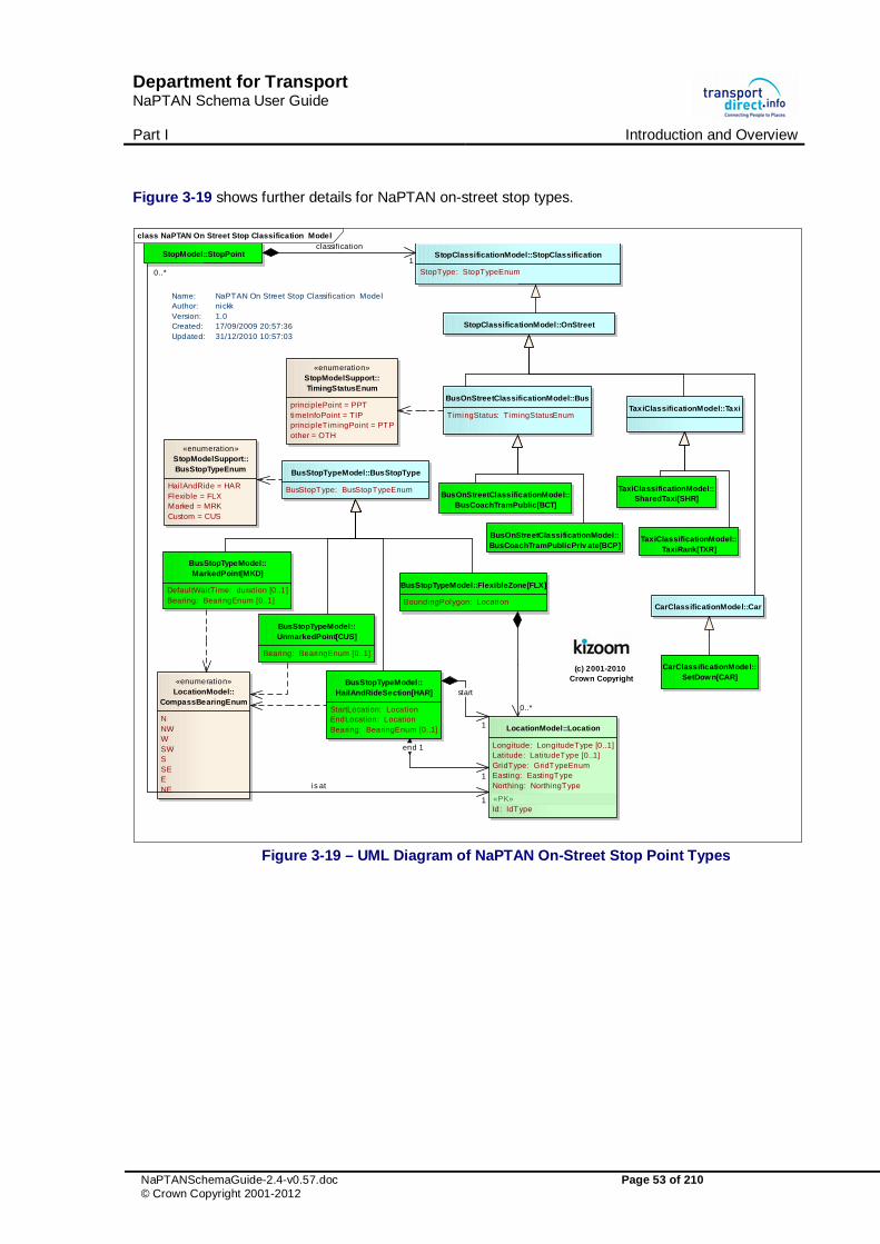
Department for Transport NaPTAN Schema User Guide Part I Introduction and Overview
NaPTANSchemaGuide-2.4-v0.57.doc Page 53 of 210 © Crown Copyright 2001-2012
Figure 3-19 shows further details for NaPTAN on-street stop types.
class NaPTAN On Street Stop Classification Model
(c) 2001-2010 Crown Copyright
StopClassificationModel::StopClassification
StopType: StopTypeEnum
StopClassificationModel::OnStreet
BusOnStreetClassificationModel::Bus
TimingStatus: TimingStatusEnumTaxiClassificationModel::Taxi
BusStopTypeModel::BusStopType
BusStopType: BusStopTypeEnum
«enumeration»StopModelSupport::BusStopTypeEnum
Hai lAndRide = HARFlexible = FLXMarked = MRKCustom = CUS
BusStopTypeModel::MarkedPoint[MKD]
DefaultWaitTime: duration [0..1]Bearing: BearingEnum [0..1]
BusStopTypeModel::UnmarkedPoint[CUS]
Bearing: BearingEnum [0..1]
BusStopTypeModel::HailAndRideSection[HAR]
StartLocation: LocationEndLocation: LocationBearing: BearingEnum [0..1]
BusStopTypeModel::FlexibleZone[FLX]
BoundingPolygon: Location
TaxiClassificationModel::TaxiRank[TXR]
TaxiClassificationModel::SharedTaxi[SHR]BusOnStreetClassificationModel::
BusCoachTramPublic[BCT]
BusOnStreetClassificationModel::BusCoachTramPublicPriv ate[BCP]
Name: NaPTAN On Street Stop Classification ModelAuthor: nickkVersion: 1.0Created: 17/09/2009 20:57:36Updated: 31/12/2010 10:57:03
«enumeration»StopModelSupport::TimingStatusEnum
principlePoint = PPTtimeInfoPoint = TIPprincipleTimingPoint = PTPother = OTH
StopModel::StopPoint
«enumeration»LocationModel::
CompassBearingEnum
NNWWSWSSEENE
LocationModel::Location
Longitude: LongitudeType [0..1]Latitude: Lati tudeType [0..1]GridType: GridTypeEnumEasting: EastingTypeNorthing: NorthingType
«PK»Id: IdType
CarClassificationModel::Car
CarClassificationModel::SetDown[CAR]
1
start
1
end 1
0..*
is at
1
0..*
1
classification
Figure 3-19 – UML Diagram of NaPTAN On-Street Stop Point Types

Department for Transport NaPTAN Schema User Guide Part I Introduction and Overview
NaPTANSchemaGuide-2.4-v0.57.doc Page 54 of 210 © Crown Copyright 2001-2012
3.4 NaPTAN Element Hierarchies
3.4.1.1NaPTAN Stop Element Hierarchy
Figure 3-20 shows the Class Hierarchy for the NaPTAN stop elements. StopPoint & Stop Area are versioned elements. StopAvailability, StopAreaRef & Descriptor are child elements.
class NaPTAN Stop Hierarchy
StopModel::StopPoint
+ Notes: Multi l ingualString [0..1]+ Public: boolean [0..1]
«PK»+ AtcoCode: AtcoCodeType
«AK»+ PlateCode: PlateCodeType [0..1]+ CleardownCode: CleardownCodeType [0..1]+ PrivateCode: PrivateCodeType [0..1]
«contained»~ Descriptor: Descriptor~ Place: Place~ StopClassification: StopClassification- AlternativeDescriptors: Descriptor [0..*]- StopAreas: StopAreaRef [0..*]- PlusBusZones: PlusBusZoneRef* [0..*]- StopAvailabi li ty: StopValidity [0..*]
«FK»# AdministrativeAreaRef: AdministrativeAreaCodeType*# FormerStopPointRef: AtcoCodeType* [0..1]
StopModel::Place
+ Suburb: Multi l ingualString+ Town: Multi l ingualString+ Locali tyCentre: boolean [0..1]
«FK»# NptgLocali tyRef: NptgLocali tyCodeType*
«contained»- AlternativeNptgLocali ties: NptgLocali tyRef* [0..*]- MainNptgLocali ties: NptgLocali tyRef* [0..*]~ Location: Location
StopModel::StopArea
+ Name: Multil ingualString+ StopAreaType: StopAreaTypeEnum
«PK»+ StopAreaCode: StopAreaType
«AK»+ PrivateCode: NMTOKEN [0..1]
«FK»# ParentAreaRef: StopAreaType* [0..1]# AdministrativeAreaRef: AdministrativeAreaCodeType*
«contained»~ Location: Location
StopModel::Descriptor
+ CommonName: Multil ingualString+ ShortCommonName: Multi l ingualString [0..1]+ Landmark: Multi l ingualString [0..1]+ Street: Multi l ingualString [0..1]+ Crossing: Multi l ingualString [0..1]+ Indicator: Multi lingualString [0..1]
StopModel::StopAv ailability
+ DateRange: HalfOpenDateRange+ Active: EmptyType [0..1]+ Suspended: EmptyType [0..1]+ Transferred: EmptyType [0..1]+ Note: Multi lingualString
Name: NaPTAN Stop HierarchyAuthor: nickkVersion: 1.0Created: 08/02/2010 20:48:20Updated: 31/12/2010 12:07:09
(c) 2001-2010 Crow n Copyright
«reference»StopModelSupport::StopAreaRef
«FK»# StopAreaRef: StopAreaCodeType*
StopClassificationModel::StopClassification
VersioningModel::VersionedObject VersioningModel::VersionedChild
BusStopTypeModel::BusStopType
+ BusStopType: BusStopTypeEnum
Figure 3-20 – UML Diagram of NaPTAN Stop Hierarchy

Department for Transport NaPTAN Schema User Guide Part I Introduction and Overview
NaPTANSchemaGuide-2.4-v0.57.doc Page 55 of 210 © Crown Copyright 2001-2012
3.4.1.2NaPTAN Data Types
Figure 3-21 shows the data types used in the NaPTAN elements that are additional to those of NPTG.
class NaPTAN Stop Model Support
(c) 2001-2010 Crow n Copyright
«enumeration»BusStopTypeEnum
HailAndRide = HARFlexible = FLXMarked = MRKCustom = CUS
Name: NaPTAN Stop Model Support Author: nickkVersion: 1.0Created: 10/02/2010 11:04:10Updated: 19/02/2010 15:21:25
«enumeration»TimingStatusEnum
principlePoint = PPTtimeInfoPoint = TIPprincipleTimingPoint = PTPother = OTH
«enumeration»StopTypeEnum
busCoachTramStopOnStreet = BCTbusCoachTramStationBay = BCSbusCoachTramStationVariableBay = BCQbusCoachAccess = BSTbusCoachStationEntrance = BCEbusCoachPrivate = BCPrai lPlatform = RPLYrai lAccess = RLYrai lStationEntrance = RSEtramMetroOrUndergroundPlatform = PLTtramMetroOrUndergroundAccess = METtramMetroOrUndergroundEntrance = TMUferryOrPortAccess = FERferryTerminalDockEntrance = FTDtaxiRank = TXRsharedTaxiRank = STRairportEntrance = AIRairAccessArea = GAT
«enumeration»StopAreaClassificationEnum
pairedOnStreetBusStops = GPBSclusteredOnStreetBusStops = GCLSairportBuilding = GAIRbusOrCoachStation = GBCSferryTerminalOrDockBuilding = GTMUtramnMetroOrUndergroundStation = GRLSmultimodalInterchange = GMLTotherStructure = GOTHcoachCoverage = GCCH
«unique identi fier»IataCodeType
«unique identi fi ...CrsCodeType
«unique identi f...MetroCodeType
«unique identi fier»NationalFerryPortCodeType
«unique identi fier»NationalCoachCodeType
«unique identi f...TiplocCodeType
«unique identi fier»AtcoCodeType
constraints{Area Prefix + 0 + Unique Code}e}
«unique identifier»CleardownCodeType
«unique identifier»NaptanCodeType
constraints{Must begin with prefix.}.}{Max length 3 + 5}5}
«unique identi fier»StopAreaCodeType
constraints{Area Prefix + G + Unique Code}e}
«unique identifier»PlateCodeType
token
«XSDsimpleType»XSDDatatypes::NMTOKEN
nonNegativeInteger
«XSDsimpleType»XSDDatatypes::positiv eInteger
string
«XSDsimpleType»XSDDatatypes::normalizedString
Figure 3-21 – UML Diagram of NaPTAN Data types

Department for Transport NaPTAN Schema User Guide Part I Introduction and Overview
NaPTANSchemaGuide-2.4-v0.57.doc Page 56 of 210 © Crown Copyright 2001-2012
3.5 Populating the NaPTAN Database
When entering data into the NaPTAN model, as for the National Gazetteer, care needs to be taken in choosing, naming and grouping stops and stop areas so as to populate the model in a way that accurately reflects the way real-world places are perceived by users, and so that the relationships described between them are useful for the intended computational purposes. Consideration should be given to how locality name and stop name complement each other, as they may often be used in combination. For example, when applications such as journey planners present lists of stop names for users to choose from, the locality name may be combined with the stop name to give an appropriate context within which to recognise the stop, e.g. to distinguish ‘Cosham, High Street’ from ‘Farnham, High Street’. Furthermore, in order to simply the choosing of destinations for users, for some applications’ engines may aggregate a number of separate but physically related stops into a single ‘place’, using stop name, location and semantic information from the underlying NaPTAN data to derive the appropriate associations. See the examples in Chapter 8.3 for some illustrations. Another consideration is who is responsible for allocating different types of stops. Most stops are allocated and managed strictly by the administrative area of the topographical region within which they lie.
� Certain types of stops, notably rail, metro, ferry and air access areas, are issued centrally by special administrative areas with a national scope, such as for National Rail and National Metro, as indicated by a National subelement on the Administrative Area - such areas also have AtcoCode values beginning with ‘9nn’).
� Where the boundary goes down the middle of the road, an agreement may be made between neighbouring authorities that stops on both sides of the road will be controlled by a single authority, just as highway maintenance on that road is done normally by one of the two relevant authorities, by agreement.
3.5.1 Choosing NaPTAN Points
Table 3-6 above shows the various NaPTAN stop types. On-Street PTANS are represented as points:
� For individual on-street Bus Stops (also Coach Stops), there should be a NaPTAN Bus stop point for every physical stop; even if a stop is the unmarked pair to another stop, it should always have its own separate NaPTAN identifier and definition (of type ‘BCT’ located at its physical position.
o StopArea elements are used to group individual poles into larger groupings such as pairings (of type ‘GBPS’) and on-street clusters (of type ‘GCLS’) (see below).
� For Coach Stops, a StopArea of type ‘GCCH’ can be used to associate the stop with Coach Service coverage. ‘GCCH’ stop areas have a stop area code (900G) and are allocated centrally. .
� For Taxi Ranks, there should be a NaPTAN stop point for the head of the taxi rank, of type Taxi (‘TXR’), or SharedTaxi (‘STR’) if an official taxi sharing scheme operates from the rank.
For stations, termini and other interchange facilities, there should be an individual NaPTAN stop point for each “entrance” from the public thoroughfare to the facility, and another AccessArea stop point instance for the “access side”: All stops should have the same CommonName, with a different Indicator value to distinguish them if necessary.
� For Airports: For each terminal, there should be a NaPTAN Entrance point for each main area of check-in desks (of type ‘AIR’), and another single AccessArea point to represent the “air-side” (of type ‘GAT’). Entrance records are provided by the relevant Local Administrative Area.
o A StopArea element (of type ‘GAIR’) should be used to group the air entrances, access area, and any other connecting stop points such as taxi ranks and individual bus stops around the terminal.
o The Access Area (‘GAT) points will be provided centrally (they will have identifiers beginning with 920) and do not need to be provided by other administrative areas.
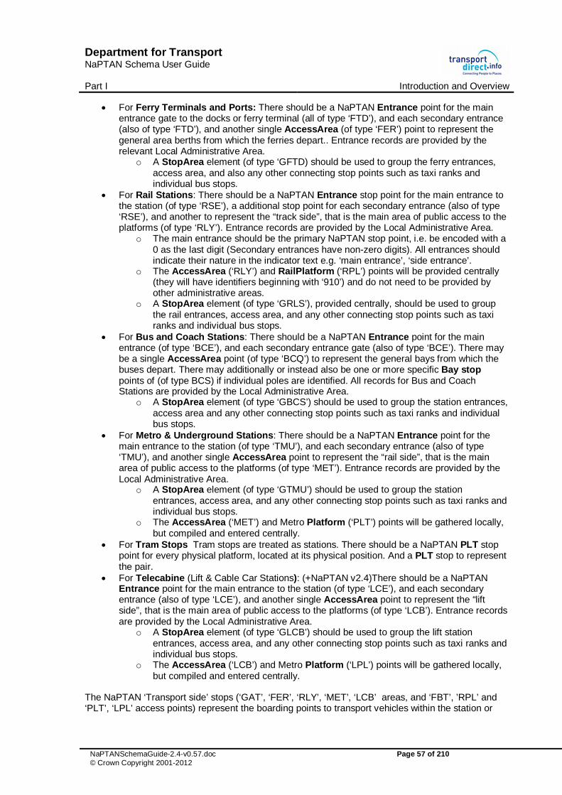
Department for Transport NaPTAN Schema User Guide Part I Introduction and Overview
NaPTANSchemaGuide-2.4-v0.57.doc Page 57 of 210 © Crown Copyright 2001-2012
� For Ferry Terminals and Ports: There should be a NaPTAN Entrance point for the main entrance gate to the docks or ferry terminal (all of type ‘FTD’), and each secondary entrance (also of type ‘FTD’), and another single AccessArea (of type ‘FER’) point to represent the general area berths from which the ferries depart.. Entrance records are provided by the relevant Local Administrative Area.
o A StopArea element (of type ‘GFTD) should be used to group the ferry entrances, access area, and also any other connecting stop points such as taxi ranks and individual bus stops.
� For Rail Stations: There should be a NaPTAN Entrance stop point for the main entrance to the station (of type ‘RSE’), a additional stop point for each secondary entrance (also of type ‘RSE’), and another to represent the “track side”, that is the main area of public access to the platforms (of type ‘RLY’). Entrance records are provided by the Local Administrative Area.
o The main entrance should be the primary NaPTAN stop point, i.e. be encoded with a 0 as the last digit (Secondary entrances have non-zero digits). All entrances should indicate their nature in the indicator text e.g. ‘main entrance’, ‘side entrance’.
o The AccessArea (‘RLY’) and RailPlatform (‘RPL’) points will be provided centrally (they will have identifiers beginning with ‘910’) and do not need to be provided by other administrative areas.
o A StopArea element (of type ‘GRLS’), provided centrally, should be used to group the rail entrances, access area, and any other connecting stop points such as taxi ranks and individual bus stops.
� For Bus and Coach Stations: There should be a NaPTAN Entrance point for the main entrance (of type ‘BCE’), and each secondary entrance gate (also of type ‘BCE’). There may be a single AccessArea point (of type ‘BCQ’) to represent the general bays from which the buses depart. There may additionally or instead also be one or more specific Bay stop points of (of type BCS) if individual poles are identified. All records for Bus and Coach Stations are provided by the Local Administrative Area.
o A StopArea element (of type ‘GBCS’) should be used to group the station entrances, access area and any other connecting stop points such as taxi ranks and individual bus stops.
� For Metro & Underground Stations: There should be a NaPTAN Entrance point for the main entrance to the station (of type ‘TMU’), and each secondary entrance (also of type ‘TMU’), and another single AccessArea point to represent the “rail side”, that is the main area of public access to the platforms (of type ‘MET’). Entrance records are provided by the Local Administrative Area.
o A StopArea element (of type ‘GTMU’) should be used to group the station entrances, access area, and any other connecting stop points such as taxi ranks and individual bus stops.
o The AccessArea (‘MET’) and Metro Platform (‘PLT’) points will be gathered locally, but compiled and entered centrally.
� For Tram Stops Tram stops are treated as stations. There should be a NaPTAN PLT stop point for every physical platform, located at its physical position. And a PLT stop to represent the pair.
� For Telecabine (Lift & Cable Car Stations): (+NaPTAN v2.4)There should be a NaPTAN Entrance point for the main entrance to the station (of type ‘LCE’), and each secondary entrance (also of type ‘LCE’), and another single AccessArea point to represent the “lift side”, that is the main area of public access to the platforms (of type ‘LCB’). Entrance records are provided by the Local Administrative Area.
o A StopArea element (of type ‘GLCB’) should be used to group the lift station entrances, access area, and any other connecting stop points such as taxi ranks and individual bus stops.
o The AccessArea (‘LCB’) and Metro Platform (‘LPL’) points will be gathered locally, but compiled and entered centrally.
The NaPTAN ‘Transport side’ stops (‘GAT’, ‘FER’, ‘RLY’, ‘MET’, ‘LCB’ areas, and ‘FBT’, ’RPL’ and ‘PLT’, ‘LPL’ access points) represent the boarding points to transport vehicles within the station or

Department for Transport NaPTAN Schema User Guide Part I Introduction and Overview
NaPTANSchemaGuide-2.4-v0.57.doc Page 58 of 210 © Crown Copyright 2001-2012
interchange building. At present FTD can also be used in the absence of FBT elements at Ferry Terminals.
3.5.2 Allocating an AtcoCode for a NaPTAN Stop Point
The AtcoCode is intended to be unique for a given stop point within the UK. The number can be regarded as an arbitrary Universal Identifier, though in practice the prefix part is reserved to specific ranges so as to manage the distributed concurrent allocation of unique codes by different stakeholders. The AtcoCode has a general form of: Database prefix [3] + Flag [1] + Local reference [up to 8 alphameric characters], where:
1. The Database prefix is the AtcoAreaCode of the AdministrativeArea responsible for managing the stop (which includes special values for rail stations, coach locations, ferry ports and airports).
2. The Flag normally has a value of ‘0’. Historically ‘1’ was used to encode stops belonging to another administrative area – this is not now needed so its use within NaPTAN 2 constitutes an error.
3. Local reference is an identifier of the stop, unique within the scope of the AtcoAreaCode. o Rail Station Entrances. The designated form is ‘AAA0XXXXXXXn’ where AAA
comprises the AtcoAreaCode, ‘0’ is a fixed flag, XXXXXXX is the Railtrack TIPLOC code (generally alphabetic, capitalised, up to seven characters) for the station, and n is a zero character for the main entrance, and a sequence number for the other entrances. For example, ‘4000FARNHAM0’, ‘4000FARNHAM1’’.
o Coach Station Entrances. The preferred form of number for Coach station entrances is AAA0YYYYYn where is the AtcoAreaCode of the AdministrativeArea responsible for managing the stop, ‘0’ is a fixed flag, YYYYY is the National Coach code (5 digit numeric) for the coach station, and n is a zero character for the main entrance and a sequence number for the other entrances.
o Transport side Access Areas. The stop point codes of the ‘Transport side’ stops (GAT, FER, MET, RLY, and FBT, RPL, PLT) are assigned centrally from special national prefixes ranges beginning with ‘9’. The numbers of all other points begin with a local area prefix. For example, ‘4000FARNHAM0’.
o OnStreet Stops. The preferred form of numbers for on-street stops is AAA0YYYYYYYY where AAA is the AtcoAreaCode of the AdministrativeArea responsible for managing the stop.’0’ is a fixed flag. YYYYYYYY is a unique locally-allocated code of up to 8 alpha-numeric characters
3.5.3 Allocating NaPTAN (SMS) Codes for NaPTAN Stop Points
NaPTAN allows a short code to be specified for each stop, the NaptanCode. This is intended as a unique reference for use in public facing systems such as SMS and web query apps. The NaPTAN short code is distinct from the ATCO code (the latter is in effect a system identifier). A NaptanCode can only be used once and cannot be reused.
3.5.3.1Mandatory NaPTAN Code features
In order to achieve nationwide uniqueness, a NaptanCode has a systematic structure.
� Codes are made up of an area prefix and a suffix, ensuring they are unique at a national level.
� Each Prefix is unique within the UK and assigned to a specific area. � The prefixes are normally three characters (See table at end) but London is treated as a
special case and uses a single digit - ‘1’. Codes should be displayed with their prefixes so that they can be disambiguated on a national level.

Department for Transport NaPTAN Schema User Guide Part I Introduction and Overview
NaPTANSchemaGuide-2.4-v0.57.doc Page 59 of 210 © Crown Copyright 2001-2012
3.5.3.2Optional NaptanCode features
For usability on the keypad of a Mobile device, a number of additional constraints are recommended and Codes issued for most areas of the country follow these rules. However these are optional:
Rationale
R1 Avoid repeating sequences of digits with a number, so that no two consecutive characters/digits require the same key
(e.g. ‘leibaba’, or ‘16747’, but not ‘leiaabbcc’ or ‘1-22334)’.
Avoids common keying errors
R2 Avoid the use of ‘0’ or ‘1’ in numbers (except for the London prefix).
e.g. ‘472913’, but not ‘101010’.
Avoids common keying errors and confusion between 0/O and 1/l
R3 Present codes as alpha8 [1] characters synonyms rather than numbers (this requires adherence to R2).
(In Scotland numeric rendering is generally used, in UK alpha8)
E.g. 234, ‘leiadh’, rather than ‘lei234’.
Easier on a mixed keypad
R4 Meaningful letters are chosen for the prefix three digits that indicate area.
E.g. Lei=Leicester, man= Manchester etc.
More memorable
R5 Codes may be of variable length. But should be between five and seven characters including prefix
More memorable
1. The Alpha8 characters are the eight letters shown first on a mobile keypad (adgjmptw). Thus for example '234, 'adh', 'bfi' and 'ceg' (and any other permutation of abc + def + ghi) all encode the same number. The use of zero is avoided.
3.5.4 Choosing NaPTAN Stop Areas
The choice and naming of NaPTAN stop areas is closely related to the choice of stop points, and the names of related NaPTAN stop points and stop areas generally should be the same. StopArea instances should only be used to group stops that constitute a localised interchange in easy walking distance, such as a bus bay, or a pair of opposite bus stops, or the various access points around a rail station. Stop areas must not be used to group stops in a wide area arbitrarily. For example, a stop area must not be used to create a general stop grouping for all the stops of a town centre; instead a NPTG locality for the town centre should be used, and one or more of the stop groups and or stop points be associated with the NPTG locality. As a general rule, a StopArea should not group stop points that are more than 250m apart. Stop areas may be nested in hierarchies to build up a simple interchange description. Stop area names should correspond to the main stop points. For example, the ‘Farnham Rail Station’ stop area might include subsidiary bus and stop areas, each containing various stop pairs near the station. In principle there should be a stop area:
� For every pair of on-street bus poles (GPBS).

Department for Transport NaPTAN Schema User Guide Part I Introduction and Overview
NaPTANSchemaGuide-2.4-v0.57.doc Page 60 of 210 © Crown Copyright 2001-2012
� For every cluster of on-street bus poles (GCLS). � For every airport (GAIR). � For every ferry terminal or port (GFTD). � For every rail station (GRLS). � For every bus or coach station (GBCS). � For every metro station (GTMU). � For every coach service association (GCCH). � For every lift or cable car station service (GLCB).
The StopArea for the main travel mode can be used as a parent for the stop areas of subsidiary modes, for example the airport mode can contain a stop area for a rail station that serves the airport. For a complex interchange, stop areas should be organised into a hierarchy. For example, an Airport might contain child stop areas for its Rail and Metro stations, and several for its bus stops. When assembling StopArea instances into a hierarchy, the parent area should be chosen using the relative rankings shown in Table 3-7.
Code Type Ranking Off Street
GAIR Airport 1 GFTD Ferry / Port 2 GRLS Rail Station 3 GTMU Metro Station 4 GBCS Bus or Coach Station 5 GLCB Lift or Cable Car Station 6
GCCH Coach Stop 7 On Street
GCLS On-street Bus / Coach stop cluster (more than two stops in the same general location).
8
GPBS On-street Bus/ Coach stop pair 9
Table 3-7 – Precedence of StopArea Types �Note that in many cases, additional StopArea instances may be inferred by automated processes that augment the manually created NaPTAN stop data, for example grouping stop points by (i) by spatial proximity of location, and/or or (ii) semantic similarity of stop point, street name or other descriptor, together with (iii) transport mode. In practice these derived groupings may either be instantiated as actual StopArea instances in a database used by the journey planner, or be dynamically recomputed every time a search is made. For some interchanges, notably rail stations, there may be multiple stop areas describing different parts of the same station (or two different encodings of the same station for historic reasons). If this is the case they should be organised hierarchically with one of them chosen as the “main” root station and others as subsidiary (i.e. not using circular references with each one being part of the other).
3.5.5 The Naming of Stop Points and Stop Areas
The allocation of effective names to public transport access points is an important aspect of NaPTAN’s purpose. Whilst rail stations and airports generally have well known names, some types of PTAN, in particular bus stops, do not always have obvious or intuitive names. The NaPTAN StopPoint element provides a number of ‘descriptor’ subelements for specifying text descriptions of stops, and NaPTAN sets guidelines for populating the elements in a consistent way that will result in useful name phrases in applications, i.e. that enable the use of text based searches to find the stop. See also the examples given later in Part III. StopPoint descriptors may include:
� A CommonName. The simple name for the stop. ‘Simple’ means that qualifiers such as the locality or street name should not be included as a component part of the CommonName - See ‘Descriptor Atomicity’ below and further comments below. A street name by itself may however be used as the complete simple CommonName of the stop, if that is the most appropriate concept (see "Street Style" later below). Thus for example, a CommonName of

Department for Transport NaPTAN Schema User Guide Part I Introduction and Overview
NaPTANSchemaGuide-2.4-v0.57.doc Page 61 of 210 © Crown Copyright 2001-2012
"Opp St Mary's Upper Street Islington" is non-conformant because it repeats data that is already contained by the other atomic descriptor elements.
� Assuming a Landmark style of naming - i.e. that “St Mary's” is the best simple name by which users can recognise the stop, a more conformant representation would be: CommonName: “St Mary's”; Landmark: “St Mary's”; Indicator: “Opp”; Street : “Upper Street”; NptgLocality: “Islington” – which contains all the information necessary to create a label of "Opp St Mary's, Upper Street, Islington" if needed, but also allows other presentation forms.
� Assuming a Street style of naming - i.e. that “'Upper Street” is the best simple name, a more conformant representation would be: CommonName: “Upper Street”; Landmark: “St Mary's”; Indicator: “Opp 27”; Street: “Upper Street”; NptgLocality: “Islington”. The nearest Landmark should be shown in the data; for example ‘Red Lion Public House’. The nearest cross-street (Crossing) may also be used as the CommonName, for example: ‘Folly Lane’.
� An Indicator phrase, giving the relationship of the stop to the entity used as the common name, for example ‘o/s’ i.e. outside, ‘behind’, etc.. The Landmark, Street or CommonName should not be repeated in the Indicator, as this breaks the principle of descriptor ‘atomicity’ (see below). Thus, if the CommonName is ‘Red Lion’, the Indicator should say just ‘‘o/s’, and not ‘Red Lion (o/s)’ or ‘o/s ‘Red Lion’. Stop numbers, Bay Numbers, etc are also relevant values for the Indicator.
� The name of the Street on which the stop point lies. The street should always be specified as it provides an alternative search value for finding the stop, and also can provide additional context with which to recognize the stop in stop finders.
� Where both a Point of Interest Landmark and a Crossing are useful for identifying the stop, the nearest intersection may be given separately using the Crossing element.
Additional elements useful for describing the stop include: � The compass Bearing towards which the vehicle is pointing when proceeding down the
street past the stop. For example: ‘SW’. � Other descriptive Notes about the stop point. These are not public facing – they provide
information only to users of the database.
3.5.5.1 Stop Name Uniqueness
NaPTAN StopPoint name phrases should be unique within their NptgLocality (including any parent or grandparent locality); that is the combination of CommonName and Indicator elements should be unique. The descriptor elements that make up stop names should be chosen so that when combined as a ‘name phrase’, they make a meaningful name that uniquely identifies the stop. The following is one possible order of combination:
<locality> (locality qualifier), <common name> (<indicator>) Table 3-8 shows some examples of preferred forms CommonName Indicator Locality Qualifier Preferred full name Red Lion o/s Blacko - Blacko, Red Lion (o/s) Health Centre opp Cosham - Cosham, Health Centre (opp) Tilford Road - Farnham - Farnham, Tilford Road Woolworths opp Gillingham Kent Gillingham (Kent), Woolworths (opp)
Table 3-8 – Examples of Preferred Stop Names
3.5.5.2 Descriptor ‘Atomicity’
The different descriptor elements may be combined by applications into name phrases in different ways in different circumstances (see discussion in section 3.5.11.1). Thus the Landmark, Street and Indicator elements should avoid repeating the same proper nouns as content, as this results in verbose and unintelligible compound name phrases: such as ‘o/s Red Lion Red Lion (o/s)’.

Department for Transport NaPTAN Schema User Guide Part I Introduction and Overview
NaPTANSchemaGuide-2.4-v0.57.doc Page 62 of 210 © Crown Copyright 2001-2012
Similarly, common names should not include the NptgLocality / Name or NptgLocality / Qualifier name unnecessarily, as again this leads to unhelpful descriptive name phrases when the elements are combined. For example, unnecessary repetition might result in ‘Gillingham (Kent), Woolworths Gillingham Kent (opp).’ In the case of rail stations and other termini, it is often the case that the locality name is included in the formally adopted common name (Table 3-9).
CommonName Indicator Locality Qualifier Preferred full name Farnham Rail Station Farnham - Farnham, Farnham Rail Station
Table 3-9 – Example Preferred Form for Rail Station Names As an illustration, Table 3-10 shows some example name elements for a stop; Table 3-11 shows some of the different ways that an application might choose to create name phrases from the elements.
Element Value NPTG Locality AdministrativeArea / ShortName: Lancs
NptgLocality / Name: Blacko Stop Descriptors CommonName: Red Lion
Landmark: Red Lion Indicator: Opp
Table 3-10 – Example Name Elements
Possible Derived Names Red Lion
Red Lion (opp) Blacko, Red Lion Blacko (Lancs), Red Lion Blacko, Red Lion (opp) Blacko (Lancs), Red Lion (opp) Gisburn Road, Red Lion Gisburn Road, Red Lion (opp) Blacko, Gisburn Road, Red Lion Blacko (Lancs), Gisburn Road, Red Lion Blacko, Gisburn Road, Red Lion (opp) Blacko (Lancs), Gisburn Road, Red Lion (opp) Red Lion, Blacko Red Lion, Blacko (Lancs) Red Lion (opp), Blacko Red Lion (opp), Blacko (Lancs) Red Lion, Gisburn Road, Blacko Red Lion, Gisburn Road, Blacko (Lancs) Red Lion (opp), Gisburn Road, Blacko Red Lion (opp), Gisburn Road, Blacko (Lancs)
Table 3-11 – Ways of Deriving Names from Descriptors
3.5.6 Bus Stop Naming Styles
Where there is not an established name for a stop point, a new CommonName should be issued. When devising bus stop names, consideration should be given to the finding of the stop by name or partial name in computer-based stop finders; the choice of the best actual common name depends on how the stop name needs to be distinguished from other nearby stops, so that in practice any of the following naming styles may be appropriate:
1 Locality Style: Name the stop after the locality it serves, for example ‘Little Gidding Centre’. In some cases the actual stop name will be a generic name like Town Centre’. Use of the locality name as a CommonName should generally be avoided, as it is not very specific or informative and does not necessarily help users locate the stop with the locality. It is better to use a landmark (e.g. "The Poets Arms") or crossing name (e.g. "High Street") within the locality. The NptgLocality name can, of course, always be associated with the stop and used in names if appropriate to the context (e.g. "The Poets Arms, Little Gidding").

Department for Transport NaPTAN Schema User Guide Part I Introduction and Overview
NaPTANSchemaGuide-2.4-v0.57.doc Page 63 of 210 © Crown Copyright 2001-2012
2 Landmark Style: Name the stop after the landmark or point of interest it serves, for example ‘ ‘British Museum’, ‘Town Centre’, ‘St Trinian’s School’, ‘Boots’, if necessary giving the relation to the landmark as the Indicator. For example, ‘British Museum’ + ‘O/s’. The landmark may also be the street or crossing name, but a Street must also be given. This is a preferred style as it helps users relate stops to their surroundings.
3 If there is no obvious landmark, the name of a road on which the stop lies may be appropriate as long as there is only one set of stops on that road.
3.1 Street Style: If the road is short, and has only a single stop or pair of stops, in the street then the name of the road the stop is on may be appropriate as a CommonName if there is no other obvious style. This should be with an Indicator such as a house number, for example ‘o/s 34’.
3.2 Crossing Style: For a longer road on which there are two or more pairs or clusters of stops, then common names based on the nearest cross-street or a landmark are to be preferred, without the name of the road on which they are located (as this is available if needed from the Street). The Indicator should be set to ‘nr’ or ‘adj’ for a stop on the same side of the road, ‘opp’ for a stop on the other side of the road. This is a preferred style as it helps users relate stops to their surroundings. The use of the Crossing rather than the Street name as the CommonName is preferable as it allows the future addition of more stops in the same street without ambiguity.
4 Particular Style: Give the stop a name that does not follow any of the above styles because of some other local usage: for example: ‘Rail Replacement Services’. This approach should only be used in exceptional circumstances.
3.5.6.1General Rules for the Names of Stop Points
The following general rules should be applied to stop Common Names and other textual stop descriptor elements:
� Capitalization: The preferred style of stop names, place names and street names in NaPTAN is ‘title case’, that is lower case with the first letter of each significant word in upper case, for example, ‘Milton Keynes’. Prepositions and articles within a name should be in lower case ‘Isle of Man’, ‘Hole-in-the-Wall Lying-in Hospital’. ‘Kirkby-in-Furness High Street’, ‘Cley-next-the-Sea’, not ‘Cley Next The Sea’. Prepositions and articles derived from Latin or other languages should not be capitalised either; ‘St George's-super-Ely’, ‘Poulton-le-Fylde’.
� Character Set: Only uppercase and lower case letters should be used. Specifically the use of digits, non alphabetic characters, and any punctuation characters other than apostrophes, hyphens and ampersands should be avoided in names. Numbers should be spelt out e.g. 'Seven Sisters’, not '7 Sisters'. The characters in Table 3-2 must not be used as they are disallowed by the schema. The characters in Table 3-3 should not be used but are not currently excluded by the schema. Note that non-letter characters such as ampersand (‘&’will need to be encoded as XML entities (e.g. &) within XML content.
� Hyphenation: Names should be hyphenated according to the preferred form of usage by residents, for example, ‘Dudington-Fineshade’, ‘Lawton-Gate’. Prepositions in some British place names are hyphenated, for example. ‘Lilford-cum-Wigestead’, ‘Hinton-In-the-Hedges, ‘Laughton-en-le-Morthen’, ‘Rhyd-y-Pandy’, ‘Ty’n-twr’. Where there is a choice of usage the hyphenated form is preferred.
� Use of Periods: Full stops must not be used within names. For example, use just ‘St’ rather than ‘St.’; do not put a final period on names.
� Use of Commas: Commas must not be used within names as they are conventionally used to indicate concatenation of elements when formatting names. See section 3.5.11.1 below.
� Apostrophes: Apostrophes should be used in accordance with the preferred local usage, and be consistent with the locality name. For example, “Robinson’s end”, ““Cross o' th' Hands”, “St Mary’s”, “Top o' th' Knowl High Street”.
� Indicator phrases: Standard terms of relation should be used in the content of Indicator. See Table 3-12 for details of preferred values for Indicator.
Group Indicator term source normalised

Department for Transport NaPTAN Schema User Guide Part I Introduction and Overview
NaPTANSchemaGuide-2.4-v0.57.doc Page 64 of 210 © Crown Copyright 2001-2012
Relation (should appear in front of common-name)
opposite opp opp outside o/s o/s adjacent adj adj near nr nr behind inside by in at on just before just after corner of
Description (should appear after common-name)
corner cnr cnr drt Stop stance stand bay platform entrance main entrance side entrance front entrance back entrance rear entrance north entrance N entrance east entrance E entrance south entrance S entrance west entrance W entrance north east entrance NE entrance NE entrance north west entrance NW entrance NW entrance south east entrance SE entrance SE entrance south west entrance SW entrance SW entrance N entrance E entrance S entrance W entrance arrivals departures Northbound N-bound N-bound Southbound S-bound S-bound Eastbound E-bound E-bound Westbound W-bound W-bound NE-bound NW-bound SW-bound SE-bound
Table 3-12 – Preferred Phrases to Use in Indicator
The words “Stop”, “stand”, “stance”, “bay”, “platform”, “entrance” can be followed by an alphanumeric string to allow for Stop codes e.g. A, 1, A1, 1A, 23, FG, AB27, etc ... with the

Department for Transport NaPTAN Schema User Guide Part I Introduction and Overview
NaPTANSchemaGuide-2.4-v0.57.doc Page 65 of 210 © Crown Copyright 2001-2012
numeric part limited to one or two digits and the alpha part to one or two characters either before or after the numeric – all in an unbroken string (of up to 4 characters).
Words which indicate a relationship (nr, opp, o/s, adj, at etc) can be followed by an alphanumeric string to allow for house numbers (e.g. opp 23, o/s 76a). In this case the numeric component should permit values to 9999, with or without a single following alpha character.
In output systems, stops which have an indicator in NaPTAN which does not match one of the preferred values (including those which do not have an indicator where one is required) should be given a normalised indicator based on the value of the bearing for the Stop – so in this situation a Stop with a bearing of “N” will have a normalised indicator of “N-bound”.
� Use of Ampersand: The ampersand character ‘&’ is preferred to the word ‘and’ as a conjunction, for example, ‘Bat & Ball’.
� Use of Abbreviations: Abbreviations should be avoided, for example ‘Great Missenden’ and not ‘Gt Missenden’, ’North Wootton’ not ‘N.Wootton’. The exception to this is the prefix for ‘Saint’, where ‘St’ should always be used, without a full stop, for example ‘St Ives’, ‘Ilketshall St John’. Although names and other text descriptors in the NaPTAN database can be up to 48 characters long, it is preferable if they can be kept to less than 24 characters.
o Where needed, standardised abbreviations should be used. See Appendix 15.4. � Spacing: Words should be single spaced. � Use of forward Slash: The uses of forward or backwards slashes or vertical bars in stop
common names to denote alternatives must be avoided. Alternative names should be specified explicitly as separate descriptor entries.
� Stop types : A stop type should not be referred to in either the CommonName or the Indicator for a stop. If a stop is a Hail-and-Ride (HAR), an unmarked (CUS) or a flexible zone (FLX) stop type, then this information is available from the stop type field and it is for output systems to interpret this data and to add to its display (Hail-and-Ride), (unmarked) or (Demand Responsive Zone) as relevant ... or whatever else might be appropriate to the specific output system.
3.5.7 Naming Of Particular Types of Stop
3.5.7.1 Naming of Rail Stations
Rail station names should include the suffix phrase ‘Rail Station’ in their names, for example, ‘Ashwell & Morden Rail Station’. Rail station names should use the definitive names used on the National Rail Website http://www.nationalrail.co.uk/.
3.5.7.2 Naming of Airports
Airport stops should have the word ‘Airport’ or ‘Terminal’ in their name, for example, ‘Southampton Airport’; ‘Heathrow Terminal 1’ + ‘London Heathrow Terminal 1’.
Airport names should be the definitive IATA name. Other names may be specified as alternative names.
3.5.8 Naming of Stop Areas
Stop area names should be the same as the common names of the main stops in the stop area.
3.5.9 The Classifying of Bus Stops and Other PTANs
The NaPTAN model provides a number of ways of classifying the stop:

Department for Transport NaPTAN Schema User Guide Part I Introduction and Overview
NaPTANSchemaGuide-2.4-v0.57.doc Page 66 of 210 © Crown Copyright 2001-2012
� Whether the stop is active or inactive. See discussion in 11.2.6.The modes of transport it supports (bus, rail etc).
� For bus stop point there are additional attributes: o Whether the stop is marked or not (For example many rural bus stops are not). o Whether it is normally a timing point in a schedule.
3.5.10 Associating Stop Points and Stop Areas with NPTG Localities
Every StopPoint has a primary NptgLocality within which it is situated. The NPTG locality specified for a stop point or stop area should be the most specific (i.e. the most precise as to area) available. For example, use a suburb of a city in preference to the whole city. In addition StopPoint instances may also be associated with a number of alternative NptgLocality instances Certain major StopPoint instances may further be associated with particular NptgLocality instances as the main stop points for the locality; for example, the rail stations. Main stop points are normally central, but do not have to be physically contained within the immediate locality – for example the rail station for Norwich is a main stop for the town, but is not located at the centre. The Town and/or Suburb on the Place element of a StopPoint should only be specified if they differ from the names of the NPTG locality specified for the StopPoint. If they are the same, they will be derived automatically through the reference. The association of stop areas with an NptgLocality is indirect – through the associations of the StopPoint instances within the StopArea. All stop points in a stop area should be associated with the same primary NPTG locality, and also have similar associations as the other stops for any alternative localities.
3.5.11 Geocoding of Stop Points - Location
All NaPTAN StopPoint instances have a geocode, i.e. a spatial Location associated with them that specifies their map coordinates.
� The NaPTAN database uses OS Grid coordinates and data should be submitted geocoded with Grid coordinates.
� The NaPTAN schema supports the exchange of stops with both WGS 84 and grid co-ordinates, and both are provided in the distributed data.
The usage of location depends on the stop point classification (see Table 3-13); for on-street points and off-street entrance points, the location should be an exact single point of the doorway or pole. For logical stops representing a zone or access area, the location should be a central point chosen to give a sensible visualisation of the area on a map; and depending on type, may also be accompanied by a more detailed description of the coordinates, as for example for a hail and ride section. Group Type Sub
Type Description Shape Location
On Street
Bus BCT, MKD On-street Bus / Coach Stop. Point 2.0 CUS Custom / Unmarked stop Point 2.0 HAR Hail & Ride zone. Line Centre of
line 2.0
FLX Flexible Zone. Polygon Centre of area
2.0
BCS Bus / Coach bay / stand / stance within Bus / Coach Stations.
Point 2.0
Taxi TXR Taxi Rank (head of). Point 2.0 STR Shared Taxi Rank (head of Point 2.0
Car SDA Setdown and Pick up Area Point Centre of area
2.4
Off Street
Entrance AIR Airport Entrance. Point 2.0 FTD Ferry Terminal / Dock Entrance. Point 2.0 TMU Tram / Metro / Underground Entrance. Point 2.0 RSE Rail Station Entrance. ). Point 2.0

Department for Transport NaPTAN Schema User Guide Part I Introduction and Overview
NaPTANSchemaGuide-2.4-v0.57.doc Page 67 of 210 © Crown Copyright 2001-2012
BCE Bus / Coach Station Entrance. Point 2.0 LCE liftOrCableCarStationEntrance Point 2.4
Access Area
GAT Airport Interchange Area.. Point Centre of area
2.0
BST Bus / Coach Station Interchange Area. Point Centre of area
2.0
FER Ferry or Port Interchange Area. Point Centre of area
2.0
MET Underground or Metro Interchange Area.. Point Centre of area
2.0
RLY Railway Interchange Area. . Point Centre of area
2.0
LCB liftOrCableCarAccessArea Point 2.4 Bay / Platform
FBT Ferry Terminal / Dock Berth. Point 2.0 RPL Rail Platform. Point 2.0 PLT Underground or Metro Interchange Platform.. Point 2.0 BCS Bus / Coach bay / stand / stance within Bus / Coach
Stations. Point 2.0
BCQ Bus / Coach Station Variable Bay. Point 2.1 LPL liftOrCableCarPlatform Point 2.4
Table 3-13 – Stop Point Location Types
3.5.11.1Considerations for Effective Naming of Stops in Journey Planners:
Some useful insight into the effective naming of stops can be obtained by considering how stop names are used in the software interfaces that interact with end users, as for example in a journey planner stop or place finder.
3.5.11.2 Presentation of Stop Names in Disambiguation Lists
When displayed in lists in place finders, stop names will typically be prefixed by a locality name in order to provide users a context within which to recognise the common name, and to distinguish the stop name from other similar names. For example, if you enter ‘High Street’ without a town name, there might be many possible candidates, so the locality may be added as a prefix, ‘Oxford, High Street’. When displayed in a list in a user interface, disambiguated names will normally have a general format that is made up of several elements: {NPTG Locality Name (+Optional Locality Qualifier)}+ {Stop Common Name} {Stop Indicator} Note however, that different application user interfaces may vary the order in which they use to combine the elements into a ‘name phrase’ for presentation; for example the order ‘Stop Name + Locality Name + Stop type’ may also be used, or in other circumstance the locality name and/or qualifier may be omitted; for example on a map, where the context is already given. Figure 3-22 shows an example from the South East region journey planner using Locality Name + Stop Name for bus stop points (with ‘stop’ appended on the end. Thus for instance, the ‘Packhorse’ StopPoint in the NptgLocality ‘Gerrards Cross’ would appear as: ‘Gerrards Cross, Packhorse (stop)’. Note the example demonstrates the use of fuzzy phonetic matching to tolerate common types of spelling errors in the enquiry input (‘gerrods cross’).

Department for Transport NaPTAN Schema User Guide Part I Introduction and Overview
NaPTANSchemaGuide-2.4-v0.57.doc Page 68 of 210 © Crown Copyright 2001-2012
From the SELTA region journey planner stop finder, Courtesy MDV
Figure 3-22 – Example of Stop Names in a List The locality qualifier can be used in applications if the locality needs to be distinguished from other similarly named localities. For example, the ‘Packhorse’ StopPoint in the NptgLocality ‘Ashford would appear as: ‘Ashford (Kent), Packhorse (stop)’’. The use of hyphens can facilitate the intelligibility of names, for example ‘Sutton-on-the-Forest, Huby’ is slightly easier to read and recognise than ‘Sutton on the Forest, Huby’. The avoidance of embedded commas in names is especially important; ‘On the Forest, Sutton, Huby’ is considerably harder to interpret. Similarly trailing articles as in ‘Dunks, The, High Street, The’ give rise to difficulties. As a further example, Figure 3-23 shows the results of using a place name of ‘Church End’ in the Transport Direct Portal Journey planner – the various instances are distinguished by both a qualifier and an administrative area.
From the Transport Direct Portal Journey Planner – Atos Origin.
Figure 3-23 – Example of Ambiguous Place Names
3.5.11.3 Matching of Stop Names by Stop & Location Finders
When processing input search strings, stop finders will generally:

Department for Transport NaPTAN Schema User Guide Part I Introduction and Overview
NaPTANSchemaGuide-2.4-v0.57.doc Page 69 of 210 © Crown Copyright 2001-2012
� Use specific special characters as delimiters (for example comma to mark the end of a locality), or commands (for example ‘*’ for wildcard).
� Ignore extra spaces in names. � Ignore hyphens and apostrophes. � Ignore the difference between upper and lower case. � Understand some common abbreviations. � Support fuzzy and partial searches, and tolerate some common types of typing and spelling
errors.
3.5.11.4 Implications for Stop Naming
We note some particular implications of the use of stop names in software user interfaces for the naming of stops:
� It is preferable if the stop common name does not repeat the locality name unnecessarily -- so as to avoid for example the informationally redundant ‘Gerrards Cross, Gerrards Cross Packhorse’. Applications may always themselves add in the locality if appropriate. However, where the locality name is an integral part of the name, for example ‘Tonbridge School’, or ‘Farnham Rail Station’, it should be used, even though this might result in some repetition (e.g. Tonbridge, Tonbridge School or ‘Farnham, Farnham Rail Station’).
� The inclusion of separators such as commas in stop names generally makes them harder to interpret in lists.
� Lists may include stops of different types, so including a type phrase (‘Rail Station’, ‘Airport’, ‘Coach Station’) for stop type other than bus stops helps users.
� Simple names (‘Boots’, ‘St Mary’s Church’, ‘Hospital’, ‘High Street’), are preferred to composite names (‘Boots High Street’, ‘St Mary’s Church Fenham Green’ ‘Hospital -Furlong Road’‘, ‘High Street Bus Station’). Again applications may always themselves add in the locality or other context if appropriate. Where there are two or more stops on the same road, then common names based on the nearest cross-street or a landmark are to be preferred, without the name of the road on which they are located - since this can be obtained from the Street element of the database.
� As an exception to this rule it is however useful to include the town name in the names of Rail stations.
� The assigning of correct NPTG localities is very important. � The consistent use of capitalisation and hyphenation improves intelligibility. Names held in
the NPTG database should be in a definitive form and consistent style. � The preferred way of populating NaPTAN name elements is so as to lead to easily
recognizable names when the descriptor elements are combined by applications into a name phrase in a particular order. The preferred order is ‘NptgLocality (Qualifier), Common Name (Indicator)’. In choosing names it is helpful (i) to test them by concatenating the elements in the suggested order and considering the resulting name phrase for sense, and (ii) to compare the name phrase to those of adjacent stops to see if they are helpful in distinguishing the stop from the others.
3.5.11.5Implications for NPTG Locality Naming
Similarly considerations apply to the naming of NPTG Localities: � Names should generally be the simple name of the locality. � It is useful to create distinct elements to represent the central areas of towns and cities. For
the names of Town and City Centres, it is useful to include the Town name as part of the name, e.g. ‘Shirley Town Centre’, ‘Winchester City Centre’.
� Consideration should be give as to whether a Locality name is unique within the UK, and if it is not, a qualifier should be added.

Department for Transport NaPTAN Schema User Guide Part I Introduction and Overview
NaPTANSchemaGuide-2.4-v0.57.doc Page 70 of 210 © Crown Copyright 2001-2012
3.6 NPTG Discovery Model
3.6.1 Overview of NPTG Discovery Model
The NPTG Discovery schema provides information for and about various types of public transport travel information system services and covering NPTG localities. It uses the NPTG topography to provide a coverage model to relate available web services to NaPTAN stops. Discovery can work in two directions:
1. Coverage Discovery: A means of finding out the stops covered by the services available for a give localities or administrative area.
2. Service Discovery: A means of finding out the services that cover a specific stop, locality, or administrative area.
3.6.2 Informational Service Elements
Figure 3-24 shows, in UML class diagram notation, the main elements of the NPTG Discovery schema. The coverage elements provide a basic directory of public transport information services available to cover localities.
� The WebApplications container element holds instances of: o WebApplication, A specific capability. Web services may be associated with any or
all of a specific Locality, an AdministrativeArea or a whole Region. See discussion under coverage later.
� The TrustedServers container element holds instances of: o TrustedServer: An access point to a web service.
� The CallCentres container element holds instances of: o CallCentre: A call service providing voice information services for an area.
� The TrunkLocalities container element holds instances of: o TrunkLocality: A geographical grouping of stops as relevant for trunk access
associated also with an NptgLocality. Distributed Journey Planning information includes
� AdjacentRegionExchangePoints are pairings of NaPTAN points between regions to guide journey planners that use the JourneyWeb protocol. They distinguish the significant points on the boundaries of travel information areas that journey planners using the JourneyWeb protocol need to recognise.

Department for Transport NaPTAN Schema User Guide Part I Introduction and Overview
NaPTANSchemaGuide-2.4-v0.57.doc Page 71 of 210 © Crown Copyright 2001-2012
class NPTG Discovery Model Intro
AdministrativeArea
NptgLocality
Region
Name: NPTG Discovery Model IntroAuthor: nickkVersion: 1.0Created: 15/02/2010 12:31:53Updated: 15/02/2010 14:09:24
(c) 2001-2010 Crown Copyright
CallCentre
TrunkLocality
StopPoint
StopArea
AdjacentRegionPoint
WebApplication
TrustedServer
UsedBy0..*
provided by
1
0
part of
0..1
0..*
is in
1
0..*
adjacent to
0..1
0..*
is part of
0..1
0..*
administered by1
0..*
region
1
+memberof0..*
areas+includedin
0..*
0..*
default centre
1
0..*administered by
1
0..*
localities0..1
0..*
points
0..*
0..*areas
0..*
0..*
0..*
region
1
0..*
covers
0..*
0..*
covers
0..* 0..*
covers
0..*
0..*
call centres
Figure 3-24 – UML Diagram of Discovery Model: Overview
Figure 3-25 shows the same elements as in Figure 3-24, with further detail as to the organisational elements of the schema and the properties of individual entities.

Department for Transport NaPTAN Schema User Guide Part I Introduction and Overview
NaPTANSchemaGuide-2.4-v0.57.doc Page 72 of 210 © Crown Copyright 2001-2012
class NPTG Discovery Model
VersionedObject
NptgAdministrativ eModel::Administrativ eArea
VersionedObject
NptgLocalityModel::NptgLocality
VersionedObject
NptgAdministrativeModel::Region
Name: NPTG Discovery Model Author: nickkVersion: 1.0Created: 15/02/2010 12:50:06Updated: 31/12/2010 11:20:00
(c) 2001-2010 Crown Copyright
VersionedObject
NptgDiscov eryModel::CallCentre
Name: Mul tilingualStringPublicTelephone: PhoneNumberTypeDirectTelephone: PhoneNumberType [0..1]Notes: MultilingualString [0..1]ContactName: string [0..1]
«PK»CallCentreCode: CallCentreCodeType
«FK»RegionRef: RegionCodeType*
«contained»AdministrativeAreaRefs: AdministrativeAreaRef* [0..*]Avai labili ty: Availabil ity
VersionedObject
NptgDiscoveryModel::TrunkLocality
Name: Mul tilingualString [0..1]
«FK»NptgLocalityRef: NptgLocalityCode*
«contained»StopPointRefs: StopPointRef* [0..*]StopAreaRefs: StopAreaRef* [0..*]Location: Location
«PK»TrunkLocali tyCode: TrunkLocali tyCodeType
VersionedObject
StopModel::StopPoint
VersionedObject
StopModel::StopArea
VersionedObject
NptgDiscov eryModel::Adj acentRegion
«PK»StopPointRef: AtcoCodeType*FromRegionRef: RegionCodeType*ToRegionRef: RegionCodeType
«contained»Location: location [0..1]
VersionedObject
NptgDiscoveryModel::WebApplication
WebApplicationClassification: WebApplicationClassificationEnumCapabil ityClassi fication: string [0..*]Staging: stringDescription: stringUrl : anyUriVersion: string
«PK»WebApplicationCode: WebApplicationCodeType
«contained»UsedBy: UsedBy
VersionedObject
NptgDiscoveryModel::TrustedServer
FirstIp: ipAddressLastIp: ipAddress
«PK»SystemCode: normalizedString
NptgDiscoveryModel::UsedBy
«contained»RegionRefs: RegionRef* [0..*]AdministrativeAreaRefs: AdministrativeAreaRef* [0..*]NptgLocali tyRefs: NptgLocal ityRef* [0..*]StopPointRefs: StopPointRef* [0..*]
LocationModel::Location
Longi tude: LongitudeType [0..1]Latitude: LatitudeType [0..1]GridType: GridTypeEnumEasting: EastingTypeNorthing: NorthingType
«PK»Id: IdType
VersionedChi ld
NptgDiscov eryModel::Av ailability
DayTypes: DayTypesEnumHolidayTypes: HolidayTypes
«contained»OpeningHours: OpeningHours [0..*]
NptgDiscov eryModel::OpeningHours
TwentyFourHours: EmptyType [0..1]OpenPeriod: ClosedTimeRange [0..*]Unavailable: EmptyType [0..1]
«contained»HolidayTypes: HolidayTypes [0..1]
HolidayTypesModel::HolidayTypes
Hol iday: HoldayTypeEnum [0..1]OtherPublicHolidaye: OtherHol iday [0..*]EarlyRunOfffDays: EmptyType [0..1]
0..*
administered by
1
0..*other regions
0..*
is in
1
memberof0..*
areas
includedin
0..*
0..*
areas
0..*
0..*
locali ties0..1
0..*
default centre1
0..*call centres
0..*
region
1
0..*
administered by1
0..*
is part of
0..1
0..*
adjacent to
0..1
0..*points
0..*
0..*
covers
0..*
at
is at
0..*
is at
1
0..*
covers
0..*
0..*
covers
0..*
0..*
provided by1
0..*
region
1
0..*
Figure 3-25 – UML Diagram of Discovery Model: Detail

Department for Transport NaPTAN Schema User Guide Part I Introduction and Overview
NaPTANSchemaGuide-2.4-v0.57.doc Page 73 of 210 © Crown Copyright 2001-2012
3.6.3 Service Discovery
The coverage model makes it possible to associate Web Services of a particular type with specific NaPTAN stops. See Figure 3-26. The association can be done at different levels, for example:
� Individual Localities. � Administrative Areas. � Regions.
Since (i) Every stop point knows its NPTG Locality; (ii) Every NPTG Locality knows its AdministrativeArea, and; (iii) Every Administrative Area knows its region, it is possible to find the appropriate services that cover a particular stop.
class NPTG Discov ery Cov erage
NptgAdministrativ eModel::AdministrativeArea
NptgLocalityModel::NptgLocality
NptgAdministrativ eModel::RegionName: NPTG Discovery CoverageAuthor: nickkVersion: 1.0Created: 15/02/2010 14:00:09Updated: 15/02/2010 14:09:24
(c) 2001-2010 Crown Copyright
StopModel::StopPoint
WebApplicationUsedBy
Coverage is found by looking up the most specific reference to a web service that can be found.
References are hierarchical:
(a) NotgLocality (Most Specific)
(b) AdministrativeArea
(c) Region (Least Specific)
0..*
covers
0..*
0..*
covers
0..*
0..*
covers
0..*
0..*
is in
1
0..*
region1
0..*
administered by
1
Figure 3-26 – UML Diagram of Coverage Model

Department for Transport NaPTAN Schema User Guide Part I Introduction and Overview
NaPTANSchemaGuide-2.4-v0.57.doc Page 74 of 210 © Crown Copyright 2001-2012
3.6.3.1NPTG DIscovery Element Hierarchy
Figure 3-27 shows the Class Hierarchy for the Discovery Element Elements. StopPoint & Stop Area are versioned elements. StopAvailability, StopAreaRef & Descriptor are child elements.
class NPTG Discov ery Hierarchy
Name: NPTG Discovery HierarchyAuthor: nickkVersion: 1.0Created: 15/02/2010 13:35:10Updated: 31/12/2010 12:06:52(c) 2001-2010
Crow n Copyright
NptgDiscov eryModel::CallCentre
+ Name: Multi l ingualString+ PublicTelephone: PhoneNumberType+ DirectTelephone: PhoneNumberType [0..1]+ Notes: Multi lingualString [0..1]+ ContactName: string [0..1]
«PK»+ CallCentreCode: Cal lCentreCodeType
«FK»# RegionRef: RegionCodeType*
«contained»- AdministrativeAreaRefs: AdministrativeAreaRef* [0..*]~ Availabi li ty: Availabi l ity
NptgDiscoveryModel::TrunkLocality
+ Name: Multi lingualString [0..1]
«FK»# NptgLocali tyRef: NptgLocalityCode*
«contained»- StopPointRefs: StopPointRef* [0..*]- StopAreaRefs: StopAreaRef* [0..*]~ Location: Location
«PK»+ TrunkLocali tyCode: TrunkLocali tyCodeType
NptgDiscoveryModel::AdjacentRegion
«PK»# StopPointRef: AtcoCodeType*# FromRegionRef: RegionCodeType*# ToRegionRef: RegionCodeType
«contained»~ Location: location [0..1]
NptgDiscoveryModel::WebApplication
+ WebAppl icationClassification: WebApplicationClassificationEnum+ Capabi l ityClassi fication: string [0..*]+ Staging: string+ Description: string+ Url : anyUri+ Version: string
«PK»+ WebAppl icationCode: WebApplicationCodeType
«contained»~ UsedBy: UsedBy
NptgDiscov eryModel::TrustedServ er
+ FirstIp: ipAddress+ LastIp: ipAddress
«PK»+ SystemCode: normal izedString
NptgDiscoveryModel::UsedBy
«contained»- RegionRefs: RegionRef* [0..*]- AdministrativeAreaRefs: AdministrativeAreaRef* [0..*]- NptgLocal ityRefs: NptgLocal i tyRef* [0..*]- StopPointRefs: StopPointRef* [0..*]
VersioningModel::VersionedObject
NptgDiscoveryModel::Availability
+ DayTypes: DayTypesEnum+ HolidayTypes: HolidayTypes
«contained»~ OpeningHours: OpeningHours [0..*]
VersioningModel::VersionedChild
Figure 3-27 – UML Diagram of NPTG Discovery Hierarchy

Department for Transport NaPTAN Schema User Guide Part I Introduction and Overview
NaPTANSchemaGuide-2.4-v0.57.doc Page 75 of 210 © Crown Copyright 2001-2012
3.7 Summary of NPTG and NaPTAN Entities and Identifiers
Table 3-14 summarises the main entities of the NPTG and NaPTAN models. It also shows the identifiers used for each element and their scope (which in all cases must be unique within a document). The elements fall into three scope groups:
� External Codes forming part of well defined national data systems (‘A’). For example the AtcoCode, as defined in the NaPTAN data set. External codes are modelled as elements.
� External Codes forming part of arbitrary data systems. (‘B’). External codes are modelled as XML elements, and their names generally end in either ‘Code’ or ‘Number’.
� Internal Identifiers used to identify objects locally within a document (‘C’). Internal identifiers are modelled as an id attribute on the entity element.
The uniqueness scope of identifiers is formally defined by XML keyref constraints. See ‘Integrity Rules’ in Section 14. Entity Identifier Type Req-
uired Name Has
Private Code
Scope
NPTG Region Element R RegionCode No A-National AdministrativeArea Element R AdministrativeAreaCode No A-National NptgDistrict Element R NptgDistrictCode No B-National NptgLocality Element R NptgLocalityCode Yes A-National PlusbusZone Element R PlusbusZone Code No A-National
NPTG Discovery
CallCentre Element R CallCentreCode No B-National AdjacentRegionPoint Attribute R AtcoCode No A-National WebApplication Element O SystemCode No B-National TrustedServer Element O SystemCode No B-National TrunkLocality Element O TrunkLocalityCode No B-National
NaPTAN StopPoint Element R AtcoCode Yes A-National Element O NaptanCode A-National Element O CleardownCode A-National
StopArea Element R StopAreaCode Yes A-National Location Attribute O id No C-Document
Table 3-14 – Main Entities of the NPTG & NaPTAN Models
3.7.1 Private codes
For a few semantically significant elements in NaPTAN, an additional PrivateCode element is supported. The PrivateCode facilitates the general purpose exchange of data in NaPTAN format, as instances can be annotated with the alternative identifier, so as to allow the unambiguous reconciliation of element identity between different computer systems on a round trip exchange. For example localities might be annotated with their OS TOID. Table 3-14 also indicates the elements that can have a PrivateCode. The PrivateCode element is intended for general use of stop definitions for example in TransXChange general documents– it is ignored on NaPTAN submissions.


Department for Transport NPTG and NaPTAN Schema Guide
Part II Schemas
NaPTANSchemaGuide-2.4-v0.57.doc Page 77 of 210 © Crown Copyright 2001-2012
4 SCHEMAS
The following sections present the NPTG and NaPTAN schema elements in detail.
5. NPTG Schema 6. NaPTAN Schema 7. NPTG Discovery Schema 8. Common Schema Elements & Types

Department for Transport NPTG and NaPTAN Schema Guide
Part II Schemas
NaPTANSchemaGuide-2.4-v0.57.doc Page 78 of 210 © Crown Copyright 2001-2012
5 NPTG SCHEMA, STRUCTURE AND ELEMENTS
The NPTG XML schema (Figure 5-1) describes the cities towns and localities of the UK as a model of XML elements, contained within a NationalPublicTransportGazetteer root element.
5.1 NationalPublicTransportGazetteer Root Element
5.1.1 NationalPublicTransportGazetteer Element Attributes
The NationalPublicTransportGazetteer element uses the NaPT standard schema attributes for versioning, and also has standard attributes to indicate the default data reference systems used:
� Versioning o CreationDateTime: Timestamp of document creation date and time. o ModificationDateTime: Timestamp of document last modification date and time. o FileName: Name of file containing the document. (If the document is renamed after
creation this will not change). o Modification: Nature of change: new, revision. For NPTG documents this will
always be ’revision’. Individual elements within the document may be ’new’. o RevisionNumber: Optional sequence number for versioning overall document
content. Each subsequent issue of the NPTG data should have a higher number than the previous one.
o SchemaVersion: Schema version identifier used for the document content model. � Data Reference
o xml:lang: Default language of document. ISO language identifier. Default is English (en). Other significant value is (cy Welsh)
o LocationSystem: Data system to use for location coordinate references within the document: WGS84 or Grid. Grid is used for collecting the NPTG and NaPTAN datasets.
5.1.2 NationalPublicTransportGazetteer Child Elements
The NationalPublicTransportGazetteer element (Figure 5-2) contains the following child elements, each of which is described in more detail later in this document:
� Regions: A collection of Region elements. The Region is used to organise other AdministrativeArea and District elements.
� NptgLocalities: A collection of NptgLocality elements used to model UK settlements. � PlusbusZones: A collection of PlusbusZone elements used to model UK Plusbus fare
zones.

Department for Transport NPTG and NaPTAN Schema Guide
Part II Schemas
NaPTANSchemaGuide-2.4-v0.57.doc Page 79 of 210 © Crown Copyright 2001-2012
class NPTG Schema Ov erv iew
VersionedObject
NptgLocality
VersionedObject
Administrativ eArea
VersionedObject
PluzBusZone
Name: NPTG Schema OverviewAuthor: nickkVersion: 1.0Created: 18/09/2009 14:31:47Updated: 13/03/2010 16:41:18
(c) 2001-2010 Crow n Copyright
«enumeratio...ModificationEnum
newdeleterevisearchivedelta
«XML root»NationalPublicTransportGazetteer
lang: langCreationDateTime: dateTimeModificationDateTime: dateTimeModification: ModificationEnumRevisionNumber: stringFileName: anyURISchemaVersion: NMTOKENLocationSystem: LocationSystemEnum
«contained»Regions: Region [0..*]NptgLocali ties: NptgLocali ty [0..*]PlusbusZones: PlusbusZone [0..*]
VersionedObject
NptgDistrict
VersionedObject
Region«enumeration»
LocationSystemEnum
GridWGS84
0..*
administered by
1
0..*administered by
0..1
0..*
0..*
region
1
0..*
0..*
districts
0..*
Figure 5-1 – NTPG Schema Overview
Figure 5-2 – NationalPublicTransportGazetteer Root Element

Department for Transport NPTG and NaPTAN Schema Guide
Part II Schemas
NaPTANSchemaGuide-2.4-v0.57.doc Page 80 of 210 © Crown Copyright 2001-2012
5.2 Region Element
A Region represents an area of the country covered by a single Traveline region. Regions break the UK down into non-overlapping zones, and are themselves broken down into administrative areas. The Region element (Figure 5-3) comprises:
� RegionCode: Unique NPTG code for Region. � Name: Name of Region. � Country: Country within which the Region lies. See Table 5-1.
Value Description Great Britain
UK
England England Y Y Scotland Scotland Y Y Wales Wales Y Y GreatBritain United Kingdom (can be used for global data) Y Y NorthernIreland Northern Ireland N Y UK United Kingdom (can be used for global data) N N Eire Eire (use for connecting stops) N N
Table 5-1 – Allowed Values for Country
� AdministrativeAreas: Administrative Areas making up the region. See AdministrativeArea below.
Figure 5-3 – Region Element
5.3 AdministrativeArea Element
An AdministrativeArea (Figure 5-4) is an area of the country within a Traveline region that manages the NPTG localities and NaPTAN stops for that area.
� AdministrativeAreaCode: Unique NPTG identifier for AdministrativeArea. Note this is distinct from the AtcoAreaCode.
� AtcoAreaCode: Prefix to use on all stops points and stop areas for AdministrativeArea. � Name: Text Name in a specified language, indicated by an xml:lang attribute. Names are
restricted to the NaPTAN naming character set. � ShortName: Concise text name to use when the AdministrativeArea name is used as a
qualifier. For example ‘E Yorks might be the short name for ‘East Riding of Yorkshire’. � NptgDistricts: A collection of NptgDistrict elements used to model UK organisational
districts.

Department for Transport NPTG and NaPTAN Schema Guide
Part II Schemas
NaPTANSchemaGuide-2.4-v0.57.doc Page 81 of 210 © Crown Copyright 2001-2012
� MaximumLengthForShortNames: Some areas have a processing restriction on the name of stops for use in various systems. This value sets the limit for the area (Zero means same length as CommonName). StopPoint/Descriptor / ShortCommonName instance values must not exceed this length.
� National: Whether AdministrativeArea administers stops nationally, or only for its own geographical area (the default). For areas that issue stop types nationally (the '9nn' admin areas) this should be set to true.
� NaptanPrefixes: Collection of zero, one or several AlphaPrefix elements describing the ’SMS’ stop prefixes reserved for the area for use in NaptanCode instances. Typically these are chosen to have a mnemonic relationship to the area name. For example, ’sur’ =’Surrey’, ’lei’=’Leicester’.
� Either three characters of the form ‘a-z’ or three digits (not beginning with 0 or 1) � or ‘1’ : London
� CleardownRange: Inclusive range of cleardown numbers reserved for the area for use in StopCleardownCode instances.
� CleardownStart: Start number of Range. � CleardownEnd: End number of range.
� ContactEmail: Administrative contact email for data queries. Should be a general address rather than an individual.
� ContactTelephone: Administrative contact telephone for data queries.

Department for Transport NPTG and NaPTAN Schema Guide
Part II Schemas
NaPTANSchemaGuide-2.4-v0.57.doc Page 82 of 210 © Crown Copyright 2001-2012
Figure 5-4 – AdministrativeArea Element

Department for Transport NPTG and NaPTAN Schema Guide
Part II Schemas
NaPTANSchemaGuide-2.4-v0.57.doc Page 83 of 210 © Crown Copyright 2001-2012
5.4 NPTG Locality Element
An NptgLocality (Figure 5-5) represents a named UK settlement, that is, a village, town or city. Each locality has both an identifier and a definitive name that is unique and unambiguous.
5.4.1 Identification
� NptgLocalityCode: Unique identifier of the NptgLocality. � Descriptor: Text description in a specified language, indicated by an xml:lang attribute. � AlternativeDescriptors: One or more alternative Descriptor elements may be specified.
The name may either be an alias, for example, ‘Newcastle’ for ‘Newcastle-on-Tyne’, or a translation in a specified language. For example, lang=en, name=‘Carnarvon’, as an alternative name for the common name of lang=cy, name=‘ ‘Caernarfon’.
5.4.2 Associations
� ParentNptgLocalityRef: An NptgLocality may reference one other NptgLocality as its parent. It may itself be referenced by several children. Cyclic dependencies are not allowed, that is a locality must not be its own ancestor, either direct or indirect.
� AdministrativeAreaRef: NPTG AdministrativeArea responsible for managing stop. � NptgDistrictRef: An NptgDistrictRef with which the locality is associated.
5.4.3 Other classifications
� SourceLocalityType: The type of locality in the original source material used to compile the NPTG. The classification is an annotation that indicates the origin of the locality data; see Table 5-2. The source material for NPTG was taken originally from the Index of Place Names compiled by ONS (and its Scottish equivalent).
Value Description Notes Add New entry in the National Gazetteer Co Community Wales only Lo Locality Other locality LOC Scottish Locality Scotland only Pa Parish not Wales PAR Scottish Parish Scotland only Isl Island U Urban Area US Urban Sub Area DWD Scottish District Ward Scotland only RED Scottish Registered Electoral District Scotland only
Table 5-2 – Allowed Values for SourceLocalityType
� LocalityClassification: NPTG classification of locality as a type of settlement. See Table 5-3. Classification implies a hierarchy of containment: each classification type has a ranking associated with it. Lower level elements may specify same or higher level elements as their parents on a ParentNptgLocalityRef, but not vice versa. Thus a city may contain a suburb, but a suburb may not contain a city.
Value Name Ranking city Locality is a city. 1 town Locality is a town. 2 suburb Locality is an urban sub-area. 2 urbanCentre Locality is a city centre or town centre zone of another town or city locality. 3 village Locality is a village. 3 hamlet Locality is a hamlet. 4 placeOfInterest Locality is a place of interest whose name is distinct from another locality. 4 other Locality is none of the other types. 2 unrecorded Locality type is not yet specified. 3
Table 5-3 – Allowed Values for LocalityClassification

Department for Transport NPTG and NaPTAN Schema Guide
Part II Schemas
NaPTANSchemaGuide-2.4-v0.57.doc Page 84 of 210 © Crown Copyright 2001-2012
� Location: Specifies a spatial point corresponding to the centre of the locality. See Location element above.
� Extensions. Placeholder to allow user defined extensions.
Figure 5-5 – NptgLocality Element
5.5 NPTG Locality / Descriptor Element
A Locality Descriptor (Figure 5-6) provides a textual description of a locality. � LocalityName: Unique NPTG name of the locality. Should be a valid place name subject to
the same restrictions on characters as a NaPTAN CommonName.. � ShortName: Short name for the locality. � Qualify: Whether the name is qualified, and if so by what other
o QualifierName: Whether the name is qualified, and if so by what other name. For example, LocalityName ‘Church End’ + QualifierName Flummox would result in � Church End (Flummox)

Department for Transport NPTG and NaPTAN Schema Guide
Part II Schemas
NaPTANSchemaGuide-2.4-v0.57.doc Page 85 of 210 © Crown Copyright 2001-2012
In addition, you may give information about the qualifying scope: this should be the most specific context within which the name should be distinguished.
o NptgLocalityRef: A locality nominated as the source of the QualifierName. o NptgDistrictRef: A district nominated as the source of the QualifierName.
Figure 5-6 – Locality / Descriptor Element
5.6 NPTG District Element
An NptgDistrict (Figure 5-7) represents a Metropolitan or Shire District authority, that is, a city, borough or district council.
� NptgDistrictCode: Unique NPTG identifier of the district. � Name: Text description in a specified language, indicated by a lang attribute.
Figure 5-7 – NptgDistrict Element
5.7 PlusbusZone Element
A PlusbusZone (Figure 5-8) represents a Plusbus fare zone. Plusbus Zone information will normally be added centrally and redistributed.
� PlusbusZoneCode: Unique identifier of the zone (usually the TIPLOC of the principle station in the zone).
� Name: Text description in a specified language, indicated by a lang attribute. � Country: The country of the PlusbusZone. See Table 5-4.
Value Name England England Northern Ireland Northern Ireland Scotland Scotland Wales Wales UK UK
Table 5-4 – Allowed Values for Plusbus zones
� Mapping: A sequential collection of Location points describing the bounding polygon, in which the last point links to the first point to complete the polygon..

Department for Transport NPTG and NaPTAN Schema Guide
Part II Schemas
NaPTANSchemaGuide-2.4-v0.57.doc Page 86 of 210 © Crown Copyright 2001-2012
Figure 5-8 – PlusbusZone Element

Department for Transport NPTG and NaPTAN Schema Guide
Part II Schemas
NaPTANSchemaGuide-2.4-v0.57.doc Page 87 of 210 © Crown Copyright 2001-2012
6 NAPTAN SCHEMA, STRUCTURE AND ELEMENTS
NaPTAN XML schema (Figure 6-1) describes bus stops and other public stop points as a model of XML elements, contained within a NaPTAN root element. It references entities defined in the NPTG schema.
class NaPTAN Schema
NaPTAN Stop Model
NPTG Package
VersionedObject
NptgLocality
VersionedObject
Administrativ eArea
VersionedObject
StopPoint
Place
VersionedObject
PluzBusZone
VersionedObject
StopArea
Name: NaPTAN SchemaAuthor: nickkVersion: 1.0Created: 18/09/2009 14:08:03Updated: 13/03/2010 16:37:50
(c) 2001-2010 Crown Copyright
«XML root»NaPTAN
lang: langCreationDateTime: dateTimeModificationDateTime: dateTimeModification: ModifcationEnumRevisionNumber: stringFileName: anyURISchemaVersion: NMTOKENLocationSystem: LocationSystemEnum
«contained»StopPoints: StopPoint [0..*]StopAreas: StopArea [0..*]
«enumeratio...ModificationEnum
newdeleterevisearchivedelta
«enumeration»LocationSystemEnum
GridWGS84
member of 0..*areas
included in0..*
0
part of
0..1
0..*stop areas
0..*
administered by
1
0..*
main access points
0..*
alternative localities0..*
0..*
administered by
1
0..*
stop points
0..*is in
1
0..*
zones
0..*
0..*
administered by
1
0..*
locality1
Figure 6-1 – UML Diagram of NaPTAN Schema
6.1 NaPTAN Root Element
6.1.1 NaPTAN Element Attributes
The NaPTAN root element uses the NaPT standard schema attributes for versioning, and also has standard attributes to indicate the default data reference systems used (Since these are attributes they are not shown in the Diagram): See discussion of versioning later on in section 11.2.
� Versioning o CreationDateTime: Timestamp of document creation date and time. o ModificationDateTime: Timestamp of document last modification date, and time. o FileName: Name of file containing the document as created. (If the document is
renamed this will not change). o Modification: Nature of change: new, revision. Normally ’revision’. Other possible
values are delete or archive. o RevisionNumber: Optional sequence number for versioning overall document
content. o SchemaVersion: Schema version identifier used for the document content model.
� Data Reference o Xml:lang: Default language of document. ISO language identifier. Default is English. o LocationSystem: Data system to use for location coordinate references within the
document: WGS84 or Grid. Normally Grid is used.

Department for Transport NPTG and NaPTAN Schema Guide
Part II Schemas
NaPTANSchemaGuide-2.4-v0.57.doc Page 88 of 210 © Crown Copyright 2001-2012
6.1.2 NaPTAN Child Elements
The NaPTAN root element (Figure 6-2) comprises the following child elements: � StopPoints: A collection of StopPoint elements defining individual PTANS. See below. � StopAreas: A collection of StopArea elements to group stop points. See later.
Figure 6-2 – NaPTAN Root Element
6.2 StopPoint Element
A NaPTAN StopPoint (Figure 6-3) describes an access point to public transport and comprises the following elements.
6.2.1 Identifiers
The identifiers of a StopPoint provide a number of alternative ways of uniquely identifying the stop in different contexts. The AtcoCode is the primary key: other identifiers are optional aliases.
� AtcoCode: Unique NaPTAN system identifier of StopPoint. Codes are unique within the NaPTAN database for Great Britain. AtcoCode instances normally have the form a0b, where 'a' is the three digit AtcoAreaCode (Note that some additional values are used, for example ‘910 Network Rail’), 0 is fixed, and b is an arbitrary unique alphanumeric code of up to eight characters.
� StopIdentifierGroup: Groups together alternative unique identifiers of a StopPoint. See below.
6.2.2 Classifiers
The classifiers of a StopPoint provide structured elements for describing a stop and its properties: � Descriptor: Elements concerned with the naming of the stop point. See Below � AlternativeDescriptor: Elements concerned with the alternative naming of the stop point.
See Below � Place: Description of location and NPTG locality of stop point. See below. � StopClassification: Type of stop – See below.
6.2.3 Associations
The associations of a StopPoint allow it to be linked to other types of NPTG and NaPTAN entities. The associated entity (e.g. StopArea, AdministrativeArea, PlusbusZone) should be active and valid at the time the association is created. If the associated entity is subsequently made inactive, the association (if not explicitly removed as well) is also considered to be inactive and may be ignored.

Department for Transport NPTG and NaPTAN Schema Guide
Part II Schemas
NaPTANSchemaGuide-2.4-v0.57.doc Page 89 of 210 © Crown Copyright 2001-2012
� StopAreas: A collection of StopAreaRef instances identifying any StopArea elements with which the StopPoint is associated. The StopArea may be in a different administrative area to that of the StopPoint itself.
o Note that this association can also be used to derive the locality of the StopArea. The StopArea is considered to be associated with all the NPTG localities (and alternative localities) of its member StopPoint instances. Different stop points in a given stop area may belong to different NPTG localities. Normally the stop points of a StopArea will belong to the same or descendent NPTG localities, but it is possible that the stops may be in different NPTG localities that are either adjacent or descendent to each other.
� AdministrativeAreaRef: NPTG AdministrativeArea responsible for managing stop. � PlusbusZones: A collection of PlusbusZoneRef instances identifying any PlusbusZone
elements with which the StopPoint is associated.
6.2.4 Other Information
Other properties of a StopPoint describe it further. � Notes: Any notes about the PTAN. Notes should be use in particular to describe why a stop
has been designated as deleted. � Public: Whether stop is for use by general public. Default is true (+Naptan v2.4) Default is
true. � The StopAvailability element defines when the stop is available for use. See below.
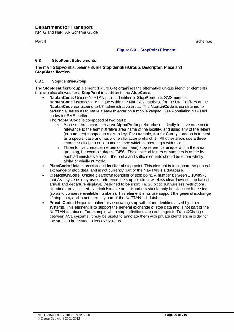
Department for Transport NPTG and NaPTAN Schema Guide
Part II Schemas
NaPTANSchemaGuide-2.4-v0.57.doc Page 90 of 210 © Crown Copyright 2001-2012
Figure 6-3 – StopPoint Element
6.3 StopPoint Subelements
The main StopPoint subelements are StopIdentifierGroup, Descriptor, Place and StopClassification.
6.3.1 StopIdentifierGroup
The StopIdentifierGroup element (Figure 6-4) organises the alternative unique identifier elements that are also allowed for a StopPoint in addition to the AtcoCode.
� NaptanCode: Unique NaPTAN public identifier of StopPoint, i.e. SMS number. NaptanCode instances are unique within the NaPTAN database for the UK. Prefixes of the NaptanCode correspond to UK administrative areas. The NaptanCode is constrained to certain values so as to make it easy to enter on a mobile keypad. See Populating NaPTAN codes for SMS earlier. The NaptanCode is composed of two parts:
o A one or three character area AlphaPrefix prefix, chosen ideally to have mnemonic relevance to the administrative area name of the locality, and using any of the letters (or numbers) mapped to a given key. For example, sur for Surrey. London is treated as a special case and has a one character prefix of ‘1’. All other areas use a three character all alpha or all numeric code which cannot begin with 0 or 1.
o Three to five character (letters or numbers) stop reference unique within the area grouping, for example dagm, ‘7456’. The choice of letters or numbers is made by each administrative area – the prefix and suffix elements should be either wholly alpha or wholly numeric.
� PlateCode: Unique asset code identifier of stop point. This element is to support the general exchange of stop data, and is not currently part of the NaPTAN 1.1 database.
� CleardownCode: Unique cleardown identifier of stop point. A number between 1 1048575 that AVL systems may use to reference the stop for direct wireless cleardown of stop based arrival and departure displays. Designed to be short. i.e. 20 bit to suit wireless restrictions. Numbers are allocated by administrative area. Numbers should only be allocated if needed (so as to conserve available numbers). This element is for use support the general exchange of stop data, and is not currently part of the NaPTAN 1.1 database.
� PrivateCode: Unique identifier for associating stop with other identifiers used by other systems. This element is to support the general exchange of stop data and is not part of the NaPTAN database. For example when stop definitions are exchanged in TransXChange between AVL systems, it may be useful to annotate them with private identifiers in order for the stops to be related to legacy systems.

Department for Transport NPTG and NaPTAN Schema Guide
Part II Schemas
NaPTANSchemaGuide-2.4-v0.57.doc Page 91 of 210 © Crown Copyright 2001-2012
Figure 6-4 – StopIdentifierGroup Element
6.3.2 Descriptor Element
6.3.2.1 Base Descriptors
The Descriptor element (Figure 6-5) groups elements concerned with the naming of the stop point. See also discussion under Naming Stops earlier in this guide.
� CommonName: Name of the stop area, with xml:lang attribute. � ShortCommonName: A short version of the common name, compacted to fit within the
specified length limit for the stop’s administrative area, as specified by the AdministrativeArea / MaximumLengthForShortNames. A ShortCommonName only needs to be specified if it is different from the CommonName.
� Landmark: Text describing any adjacent landmark that can be used to distinguish stop. The landmark may be a building or destination, or a crossing name or street name (in which case it should also be specified under Street, or may be specified under Crossing).
� Street: Name of street where the stop point of Place is. This must still be given even if the stop is named after the street.
� Crossing: The nearest street crossing to the stop. Desirable to give if known. If the crossing is also the landmark, or may be omitted
� Indicator: Indicative description of the relative position of the stop, See examples for guidance on choice of descriptive phrases for indicator and landmark.

Department for Transport NPTG and NaPTAN Schema Guide
Part II Schemas
NaPTANSchemaGuide-2.4-v0.57.doc Page 92 of 210 © Crown Copyright 2001-2012
Figure 6-5 – Descriptor Element
6.3.3 Additional Descriptors
� AlternativeDescriptors: Any alternative names of the stop, each as a subsidiary Descriptor element with modification attributes, and a set of base descriptor contents.
6.3.4 Place Element
A Place element (Figure 6-6) describes where a StopPoint is, and also associates it with an NptgLocality.
� NptgLocality: Each Place must specify the primary NPTG locality that the stop point is sited within, using an NptgLocalityRef (i.e. the NptgLocalityCode). The locality should be the most specific available, for example, use the suburb rather than the city.
� AlternativeNptgLocalities: In addition, other localities may be associated with the Place. Collection of NptgLocalityRef instances.. The StopArea is considered to be associated with all the NPTG localities (and alternative localities) of its member stops.
� MainNptgLocalities: In addition, other localities may be associated with the Place. Collection of NptgLocalityRef instances.. The StopArea is considered to be associated with all the NPTG localities (and alternative localities) of its member stops.
� Suburb: Name of suburb where the Place is. � Town: Name of town where stop point of the Place is. � LocalityCentre: Whether the stop point of the Place is at the centre of a town or not. A value
of ‘true’ indicates that the stop is one of the central stops in the NptgLocality, and that a journey enquiry to the locality could sensibly start or end at this stop. More than one stop point can be designated as a locality centre for a given NptgLocality.
� Location: Spatial coordinates of the Place. o Note that for Hail & Ride stops, the location will be the OS Grid Easting and Northing
of the central anchor point of a Hail-and-Ride section.

Department for Transport NPTG and NaPTAN Schema Guide
Part II Schemas
NaPTANSchemaGuide-2.4-v0.57.doc Page 93 of 210 © Crown Copyright 2001-2012
Figure 6-6 – Place Element
6.3.5 StopClassification Element
A StopClassification element (Figure 6-7) describes the type of stop point, and any additional details associated with the specific stop type
� StopType: Type of stop: one of a limited number of values that summarises the stop type. See Table 6-1. Each StopType corresponds to a particular combination of StopClassification subelements (and as such is informationally redundant, but is retained for compatibility with NaPTAN 1.1). For example, BCT is the same as OnStreet / Bus stop classification. Most stop types are issued by individual Administrative areas. Some types, shown with the relevant numeric prefix of the National Area in the Nat column, are issued centrally by administrative areas that have a National scope.
Value Long Value Description Nat Mode Type BCT busCoachTrolleyStopOnStreet
(busCoachTramStopOnStreet is supported as a deprecated value)
On-street Bus / Coach / Trolley Stop.
-- On street
BusCoach MarkedPoint -- UnmarkedPoint -- HailAndRide -- FlexibleZone
TXR taxiRank Taxi Rank (head of). -- Taxi TaxiRank STR sharedTaxiRank Shared Taxi Rank
(head of). -- Shared
TaxiRank SDA carSetDownPickUpArea Set down area -- Car Platform AIR airportEntrance Airport Entrance. -- Off
street Air Entrance
GAT airAccessArea Airport Interchange Area.
920 AccessArea
FTD ferryTerminalDockEntrance Ferry Terminal / Dock Entrance.
-- Ferry / Ship
Entrance
FER ferryOrPortAccess Ferry or Port Interchange Area
930 AccessArea
FBT ferryOrPortBerth Ferry or Port Berth 930 Berth

Department for Transport NPTG and NaPTAN Schema Guide
Part II Schemas
NaPTANSchemaGuide-2.4-v0.57.doc Page 94 of 210 © Crown Copyright 2001-2012
RSE railStationEntrance Rail Station Entrance. -- Rail Entrance RLY railAccess Railway Interchange
Area. 910 AccessArea
RPL railPlatform Railway Platform . 910 Platform TMU tramMetroUndergroundEntrance Tram / Metro /
Underground Entrance. -- Tram /
Metro Entrance
MET tramMetroUndergroundAccess Underground or Metro Interchange Area
940 AccessArea
PLT tramMetroUndergroundPlatform Underground or Metro platform
940
Platform
LCE liftOrCableCarStationEntrance Lift / Cable Car Entrance.
-- Telecabine Entrance
LCB liftOrCableCarAccessArea Lift / Cable Car Area -- AccessArea LPL carSetDownPickUpArea Lift / Cable Car
platform -- Platform
BCE busCoachStationEntrance Bus / Coach Station Entrance.
-- BusCoach Entrance
BST busCoachAccess Bus Coach Station Access Area.
900 AccessArea
BCS busCoachTrolleyStationBay (busCoachTramStationBay is supported as a deprecated value)
Bus / Coach bay / stand / stance within Bus / Coach Stations.
-- Bay
BCQ busCoachTrolleyStation-VariableBay (busCoachTramStationVariable-Bay is supported as a deprecated value)
Bus Coach Station Variable Bay.
-- VariableBay
Table 6-1 – Allowed Values for StopType
� OnStreet: Grouping of on-street stop types. Divided into two groups. See below. o Bus: On-street bus & coach and trolley stops. o Taxi: Taxi ranks. o Car: Set Down and Pick up point (+NaPTAN v2.4)
� OffStreet: Grouping of off-street stop types. o Air: Airport terminal PTANs. o BusAndCoach: Bus & Coach Station PTANs. o Ferry: Ferry or Dock PTANs. o Metro: Metro, Underground or Tram Station Stops. o Rail: Rail Station PTANs. o Telecabine: Lift and Cable car PTANs (+NaPTAN v2.4)

Department for Transport NPTG and NaPTAN Schema Guide
Part II Schemas
NaPTANSchemaGuide-2.4-v0.57.doc Page 95 of 210 © Crown Copyright 2001-2012
Figure 6-7 – StopClassification Element
StopClassification / On-Street Elements
6.3.6 StopPoint / StopClassification / On-Street Bus Element
The Bus element (Figure 6-8) describes information about a stop point that is specific only to on-street bus coach or trolley stops (i.e. ’BCT’ stops), and comprises:
� BusStopType: Classification of stop. See Table 6-2. Values must correspond to the BusStopClassificationGroup choice.
Value Description Bus PTAN subtype MKD marked Marked (pole, shelter etc) Point MarkedPoint CUS custom Custom (unmarked, or only marked on road) Point UnmarkedPoint HAR hailAndRide Hail & Ride – requires Hail & Ride sub-record Line HailAndRideSection FLX flexible Flexible zone – Flexible Zone sub-record Polygon FlexibleZone
Table 6-2 – Allowed Values for BusStopType
� TimingStatus: Expected status of the bus stop in bus service registrations. See Table 6-3. Normally each journey pattern or vehicle journey of a TransXChange bus schedule will specify the specific timing status for the stop usage by an actual service that visits the stop. This is a default value that can be used to assist with the population of multiple services.
Value Description PTP Principal and time info point. TIP Time Info Point. PPT Principal Point. OTH Other Bus Stop.

Department for Transport NPTG and NaPTAN Schema Guide
Part II Schemas
NaPTANSchemaGuide-2.4-v0.57.doc Page 96 of 210 © Crown Copyright 2001-2012
Table 6-3 – Allowed Values for TimingStatus
� BusStopClassificationGroup: The stop must be one of the following subtypes: o MarkedPoint: Stop is a marked point. o UnmarkedPoint: Stop is unmarked. o HailAndRideSection: Stop is a Hail & Ride stop. See below. o FlexibleZone: Stop is a flexible service zone.
AnnotatedCoachRef: Associates NaPTAN stop point with one or more a coach references. See 6.4.5: below
Figure 6-8 – OnStreet / Bus Element
6.3.6.1 On-Street Bus MarkedPoint Element
The MarkedPoint element (Figure 6-9) describes the properties of a marked on-street bus, coach or trolley stop. (Stop type ‘BCT-MKD’)).
� DefaultWaitTime: Default time to wait at the bus stop – See Duration common type. Normally each journey pattern or vehicle journey of a TransXChange bus schedule will specify the specific wait time for an actual service that visits the stop. This is a default value that can be used to assist with the population of multiple services.
� Bearing: Direction in which a vehicle is pointing when stopped at the stopping point on the road. See Bearing element type in Common Schema Elements.
Figure 6-9 – OnStreet / Bus / MarkedPoint Element

Department for Transport NPTG and NaPTAN Schema Guide
Part II Schemas
NaPTANSchemaGuide-2.4-v0.57.doc Page 97 of 210 © Crown Copyright 2001-2012
6.3.6.2 On-Street Bus MarkedPoint Element
The UnmarkedPoint element (Figure 6-9) describes the properties of an unmarked on-street bus, coach or trolley stop. (Stop type ‘BCT-CUS’) .
� Bearing: Direction in which a vehicle is pointing when stopped at the stopping point on the road. See Bearing element type in Common Schema Elements.
Figure 6-10 – OnStreet / Bus / UnmarkedPoint Element
6.3.6.3 On-Street Bus HailAndRideSection Element
The HailAndRide element (Figure 6-11) describes the properties of a Hail-and-Ride stop section. (Stop type ‘BCT-HAR’).
� StartPoint: Location on-street at which section starts. � EndPoint: Location on-street at which section ends. � Bearing: Direction in which a vehicle is pointing when stopped at the anchor point of the
section. See Bearing element type in Common Schema Elements.
Figure 6-11 – OnStreet / Bus / HailAndRideSection Element
6.3.6.4 On-Street Bus FlexibleZone Element
The FlexibleZone element (Figure 6-12) describes the properties of a flexible service stop zone. (Stop type ‘BCT-FLX’)).
� Location: One or more location elements listed sequentially, describing the polygon bounding the flexible zone.
Figure 6-12 – OnStreet / Bus / FlexibleZone Element
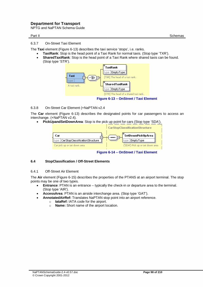
Department for Transport NPTG and NaPTAN Schema Guide
Part II Schemas
NaPTANSchemaGuide-2.4-v0.57.doc Page 98 of 210 © Crown Copyright 2001-2012
6.3.7 On-Street Taxi Element
The Taxi element (Figure 6-13) describes the taxi service ‘stops’, i.e. ranks. � TaxiRank: Stop is the head point of a Taxi Rank for normal taxis. (Stop type ‘TXR’). � SharedTaxiRank: Stop is the head point of a Taxi Rank where shared taxis can be found.
(Stop type ‘STR’).
Figure 6-13 – OnStreet / Taxi Element
6.3.8 On-Street Car Element (+NaPTAN v2.4
The Car element (Figure 6-13) describes the designated points for car passengers to access an interchange. (+NaPTAN v2.4).
� PickUpandSetDownArea: Stop is the pick up point for cars (Stop type ‘SDA’).
Figure 6-14 – OnStreet / Taxi Element
6.4 StopClassification / Off-Street Elements
6.4.1 Off-Street Air Element
The Air element (Figure 6-15) describes the properties of the PTANS at an airport terminal. The stop points may be one of two types.
� Entrance: PTAN is an entrance – typically the check-in or departure area to the terminal. (Stop type ‘AIR’).
� AccessArea: PTAN is an airside interchange area. (Stop type ‘GAT’). � AnnotatedAirRef: Translates NaPTAN stop point into an airport reference.
o IataRef: IATA code for the airport. o Name: Short name of the airport location.

Department for Transport NPTG and NaPTAN Schema Guide
Part II Schemas
NaPTANSchemaGuide-2.4-v0.57.doc Page 99 of 210 © Crown Copyright 2001-2012
Figure 6-15 – OffStreet / Air Element
6.4.2 Off-Street Ferry Element
The Ferry element (Figure 6-16) describes the properties of the PTANS at ferry port or dock. The stop points may be one of two types.
� Entrance: PTAN is an entrance – typically the entrance to the harbour area. (Stop type ‘FTD’).
� AccessArea: PTAN is an interchange area within the harbour – typically the main area of ship berths. (Stop type ‘FER’).
� Berth: PTAN is a berth within the harbour from which a boat is boarded. (Stop type ‘FBT’). � AnnotatedFerryRef: Translates NaPTAN stop point into a ferry port reference:
o FerryRef: Reference to the National Ferry/Port code of the ferry harbour or port. o Name: Short name of the ferry harbour or port. o Location: Optional Location of the ferry harbour or port.
Figure 6-16 – OffStreet / Ferry Element

Department for Transport NPTG and NaPTAN Schema Guide
Part II Schemas
NaPTANSchemaGuide-2.4-v0.57.doc Page 100 of 210 © Crown Copyright 2001-2012
6.4.3 Off-Street Rail Element
The Rail element (Figure 6-17) describes the properties of the PTANS at a railway station. The stop points may be one of two types.
� Entrance: PTAN is an entrance – typically the entrance to the station. (Stop type ‘RSE). � AccessArea: PTAN is an interchange area within the station – typically the main area of
platforms. (Stop type ‘RLY’). � Platform: A specific platform within the station. (Stop type ‘RPL’). � AnnotatedRailRef: Translates a NaPTAN stop point into the location coding system used by
rail systems. May be more than one per NaPTAN point. o TiplocRef: Reference to the National Timing Point Location (TIPLOC) code of the
station or rail-related location (locations other than stations may also have TIPLOCS). Alphanumeric code.
o CrsRef: Reference to the National Computer Reservation System (CRS) code of the station. CRS codes are short three or four letter mnemonic codes for each station.
o StationName: Text name of the station. o Location: Optional Location of the station.
Figure 6-17 – RailExchange Element
6.4.4 Off-Street Metro Element
The Metro element (Figure 6-18) describes the properties of the PTANS at a metro, light rail, or underground station. The stop points may be one of two types.
� Entrance: PTAN is an entrance – typically the entrance to the station. (Stop type ‘TMU’). � AccessArea: PTAN is an interchange area within the building – typically the main area of
platforms. (Stop type ‘MET’). � Platform: A specific platform within the station. (Stop type ‘PLT’). � AnnotatedMetroRef: Translates NaPTAN stop point into a metro station reference:
o MetroRef: Reference to the National Metro/ code of the station location. o Name: Short name of the metro station. o Location: Optional Location of the metro station.

Department for Transport NPTG and NaPTAN Schema Guide
Part II Schemas
NaPTANSchemaGuide-2.4-v0.57.doc Page 101 of 210 © Crown Copyright 2001-2012
Figure 6-18 – OffStreet / Metro Element
6.4.5 Off-Street BusAndCoach Element
A BusAndCoach element (Figure 6-19) describes the properties of the PTANS at a bus or coach station. The stop points may be one of two types.
� Entrance: PTAN is an entrance – typically the entrance to the station. (Stop type ‘BCE’). � AccessArea: PTAN is an unspecified bay in the general interchange area. The default
TimingStatus of the stop may be specified. See Table 6-3. Services may use variable stop allocations to allocate. (Stop type ‘BST’).
� Bay: PTAN is a specific bay (Stop type ‘BCS’). o The default TimingStatus of the stop may be specified. See Table 6-3.
� VariableBay: PTAN is a variable bay. (Stop type ‘BCQ’). A variable bay indicates that the bus may be assigned to a different bay at run time.
o The default TimingStatus of the stop may be specified. See Table 6-3. � AnnotatedCoachRef: Translates NaPTAN stop point into a coach station reference:
o OperatorRef: Reference to the operator code of the coach operator. o CoachRef: Unique identifier for the coach Stop Point used by a coach company.
(Normally from the Nationally unique range including for example stop codes used by the National Express Group). .
o Name: Short name of the coach location. o LongName: Long name of the coach location. o Location: Optional Location of the coach location.

Department for Transport NPTG and NaPTAN Schema Guide
Part II Schemas
NaPTANSchemaGuide-2.4-v0.57.doc Page 102 of 210 © Crown Copyright 2001-2012
Figure 6-19 – OffStreet / Coach Element
6.4.6 Off-Street Telecabine (Lift & CableCar) Element (+NaPTAN v2.4)
The Telecabine element (Figure 6-18) describes the properties of the PTANS at a lift, or cable car station. The stop points may be one of two types. (+NaPTAN v2.4
� Entrance: PTAN is an entrance – typically the entrance to the lift station. (Stop type ‘LCE’). � AccessArea: PTAN is an interchange area within the lift station – typically the main area of
platforms. (Stop type ‘LCB’). � Platform: A specific platform within the lift station. (Stop type ‘LPL’).

Department for Transport NPTG and NaPTAN Schema Guide
Part II Schemas
NaPTANSchemaGuide-2.4-v0.57.doc Page 103 of 210 © Crown Copyright 2001-2012
Figure 6-20 – OffStreet / Telecabine Element
6.5 StopAvailability Element
The StopAvailability element (Figure 6-21) specifies when the stop is available for use. It comprises one or more StopValidity instances, ordered in order of their start dates. Each StopValidity instance comprises:
� A DateRange: Period for which status applies o StartDate: Date from which the specified stop validity status applies o EndDate: Date at which status ceases to apply. If omitted, state continues
indefinitely or until the StartDate of the next Validity. A status: one of the following:
� Active: Stop is active at its current location. � Suspended: Stop is suspended from use. � Transferred: Stop is suspended from use and activity transferred to the stop indicated by the
StopPointRef. The referenced stop should be different to the current stop. � Note: Any explanation accompanying the validity period.
Note that the Status attribute on StopPoint should correspond with any stop validity in effect at the time of export. If no explicit stop validity is present, the stop is assumed to have an implicit validity in effect indefinitely, as indicated by the stop’s Status attribute: if the StopPoint / Status is ‘active’, the validity status will be Active, if the StopPoint / Status is ‘Inactive’ it will be Suspended. From v2.4 the interpretation of StopAvailability is revised to ensure that a stop which may be currently suspended or transferred remains available to be used as a substantive stop point in the registration of a bus service. So StopAvailability is now associated with an ACTive stop – and it is an ACTive stop, therefore, that can be suspended or transferred (but remains ACTive in each case). StopAvailability has no effect on a stop which is already marked as DELeted.

Department for Transport NPTG and NaPTAN Schema Guide
Part II Schemas
NaPTANSchemaGuide-2.4-v0.57.doc Page 104 of 210 © Crown Copyright 2001-2012
Figure 6-21 – History Element
6.6 StopArea Element
A StopArea (Figure 6-22) groups stops. A StopArea comprises the following elements: � StopAreaCode: Unique NaPTAN system identifier of stop area. � PrivateCode: Unique identifier with which to associate a NaPTAN StopArea with other
identifiers used by other systems. This element is to support the general exchange of stop data, and is not part of the NaPTAN database. For example when StopArea definitions are exchanged in TransXChange or for AVL systems, it may be useful to annotate them with private identifiers.
� ParentAreaRef: Code of parent StopArea. Stop areas may be organised into a hierarchy (see earlier discussion of the NaPTAN model). Each StopArea can have a single parent, which may in turn have a parent and further ancestors. Each StopArea can be referenced as a parent by many other stop areas, i.e. have many children, each of which may have further descendants. References must not be cyclic, i.e. a StopArea cannot be its own ancestor or descendant.
� Name: Name of the StopArea. � AdministrativeAreaRef: NPTG AdministrativeArea responsible for managing stop area. � StopAreaType: Type of StopArea. See Table 6-4.
Value Description Use GAIR Airport Building. 1.0 GFTD Ferry Terminal or Dock Building 1.0 GRLS Rail Station. 1.0 GTMU Tram / Metro / Underground Station. 1.0 GBCS Bus / Coach Station. 1.0 GCCH Coach Service Coverage 2.0 GCLS On-street Bus / Coach / Trolley stops cluster (more than
two stops in the same general location). 1.0
GLCB Lift or Cable car station + v2.4 GPBS On-street Bus/ Coach / Trolley stop pair (one in each
direction). 1.0
(GMLT) Multimode Interchange DEPRECATED 2.0 (GOTH) Other Interchange. DEPRECATED 2.0
Table 6-4 – Allowed Values for StopArea Classification
� Location: Spatial location of the centre of the area.

Department for Transport NPTG and NaPTAN Schema Guide
Part II Schemas
NaPTANSchemaGuide-2.4-v0.57.doc Page 105 of 210 © Crown Copyright 2001-2012
o Location is given as point with an optional approximate precision to indicate the StopArea size. An exact polygon of the StopArea’s boundaries is not provided. The StopArea can be considered to include at least the area defined by the Place / Location points all of its own immediate StopPoint member instances.
o In addition to this Location, the StopArea is considered to be associated with all the NPTG localities (and alternative localities) of its member stops. This is a derived relationship. Different stops in a given stop area may belong to different NptgLocality instances, although it is best to avoid this if possible..
Figure 6-22 – StopArea Element

Department for Transport NPTG and NaPTAN Schema Guide
Part II Schemas
NaPTANSchemaGuide-2.4-v0.57.doc Page 106 of 210 © Crown Copyright 2001-2012
7 NPTG DISCOVERY SCHEMA, STRUCTURE AND ELEMENTS
NPTG Discovery XML schema (Figure 7-1) describes web services associated with NPTG entities as a model of XML elements, contained within an NptgDiscovery root element. It references entities defined in the NPTG schema.
7.1 NptgDiscovery Root Element
7.1.1 NptgDiscovery Element Attributes
The NptgDiscovery root element uses the NaPT standard schema attributes for versioning, and also has standard attributes to indicate the default data reference systems used: See discussion of versioning later on.
� Versioning o CreationDateTime: Timestamp of document creation date and time. o ModificationDateTime: Timestamp of document last modification date, and time. o FileName: Name of file containing the document as created. (If the document is
renamed this will not change). o Modification: Nature of change: new, revision. Normally ’revision’. Other possible
values are delete or archive. o RevisionNumber: Optional sequence number for versioning overall document
content. o SchemaVersion: Schema version identifier used for the document content model.
� Data Reference o Xml:lang: Default language of document. ISO language identifier. Default is English. o LocationSystem: Data system to use for location coordinate references within the
document: WGS84 or Grid. Normally Grid is used.

Department for Transport NPTG and NaPTAN Schema Guide
Part II Schemas
NaPTANSchemaGuide-2.4-v0.57.doc Page 107 of 210 © Crown Copyright 2001-2012
class NPTG Discovery Schema
NaPTAN Stop Model
VersionedObject
NptgAdministrativeModel::AdministrativeArea
VersionedObject
NptgLocalityModel::NptgLocality
Name: NPTG Discovery SchemaAuthor: nickkVersion: 1.0Created: 15/02/2010 13:21:44Updated: 15/02/2010 13:34:45
(c) 2001-2010 Crown Copyright
VersionedObject
NptgDiscoveryModel::CallCentre
VersionedObject
NptgDiscoveryModel::TrunkLocality
VersionedObject
StopModel::StopPoint
VersionedObject
StopModel::StopArea
VersionedObject
NptgDiscoveryModel::AdjacentRegionPoint
VersionedObject
NptgDiscoveryModel::WebApplication
VersionedObject
NptgDiscoveryModel::TrustedServer
NptgDiscoveryModel::UsedBy
«enumeration»VersioningPackage::ModificationEnum
newdeleterevisearchive
«enumeration»LocalityPackage::
LocationSystemEnum
GridWGS84
«XML root»NptgDiscovery
lang: langCreationDateTime: dateTimeModificationDateTime: dateTimeModification: ModifcationEnumRevisionNumber: stringFileName: anyURISchemaVersion: NMTOKENLocationSystem: LocationSystemEnum
NPTG Package Dependencies
0..*
0
part of
0..1
0..*
is in
1
0..*
administered by
1
0..*
administered by
1
0..*
administered by
1
0..*
provided by
1
0..*
localities
0..1
memberof
0..*
areas
includedin
0..*
0..*
areas0..*
0..*
covers
0..*
0..*
covers
0..*
0..*administered by
1
0..*
points
0..*
Figure 7-1 – UML Diagram of the NPTG Discovery Schema
7.1.2 NptgDiscovery Child Elements
The NptgDiscovery element (Figure 7-2) contains the following child elements, each of which is described in more detail later in this document:
� CallCentres: A collection of CallCentre elements, used to represent available voice information services.
� WebApplications: A collection of WebApplication elements, used to represent available on-line information services.
� TrustedServers: A collection of TrustedServer elements, used to represent available access points to information services.

Department for Transport NPTG and NaPTAN Schema Guide
Part II Schemas
NaPTANSchemaGuide-2.4-v0.57.doc Page 108 of 210 © Crown Copyright 2001-2012
� AdjacentRegionPoints: A collection of AdjacentRegionPoints used to define shared boundary points between regions for journey planning purposes.
� TrunkLocalities: A collection of TrunkLocality elements used to define access points to the Trunk network for journey planning purposes.
Figure 7-2 – NptgDiscovery Root Element
7.2 WebApplication Element
A WebApplication (Figure 5-7) represents an available system resource. � WebApplicationCode: Unique identifier of the service. � WebApplicationClassification: Classifier of the service. See Table 7-1.
Value Description JourneyWeb Supports JourneyWeb Protocol RtigXml Supports RtigXml Protocol Traveline Online WWW Journey Planner Departures Online WWW Stop Departures SIRI Supports SIRI for real-time information NeTEx Supports NeTEX Protocol (in the future) Other Other unspecified service
Table 7-1 – Allowed Values for WebApplicationClassification
� CapabilityClassification: Capability string. � Description: Description of application. � Staging: Whether service is for demo, test, or production. � Version: Version number of service. � URL: URL with which to access the service.

Department for Transport NPTG and NaPTAN Schema Guide
Part II Schemas
NaPTANSchemaGuide-2.4-v0.57.doc Page 109 of 210 © Crown Copyright 2001-2012
Figure 7-3 – WebApplication Element
7.2.1 UsedBy Element
A UsedBy (Figure 5-7) associates an available system resource with an NPTG or NaPTAN entity. � RegionRefs: Regions associated with service. Collection of RegionRef instances. � AdministrativeAreaRefs: Administrative Areas associated with service, if different from
Region. Collection of AdministrativeAreaRef instances. � NptgLocalityRefs: NPTG Localities associated with service, if different from Administrative
Area. Collection of NptgLocalityRef instances. � StopPointRefs: Stops associated with service, if different from NPTG Locality. Collection of
StopPointRef instances.

Department for Transport NPTG and NaPTAN Schema Guide
Part II Schemas
NaPTANSchemaGuide-2.4-v0.57.doc Page 110 of 210 © Crown Copyright 2001-2012
Figure 7-4 – UsedBy Element
7.3 TrustedServer Element
A TrustedServer (Figure 7-5) represents a point of access to the web services described by WebApplication instances.
� ServerCode: Unique identifier of the district. � IpAddressRange: Range of IP addresses of access point.
o FirstIp: First IP number in range. Standard internet address got example, 212.04.123.17.
o LastIp: Last IP number in range.

Department for Transport NPTG and NaPTAN Schema Guide
Part II Schemas
NaPTANSchemaGuide-2.4-v0.57.doc Page 111 of 210 © Crown Copyright 2001-2012
Figure 7-5 – TrustedServer Element
7.4 AdjacentRegionPoint Element
An AdjacentRegionPoint (Figure 7-6) is a different type of exchange point, and are used to establish shared boundary points for journey planning purposes. AdjacentRegionPoint instances are grouped within an AdjacentRegionPoints container. Each point comprises:
� StopPointRef: NaPTAN system identifier, i.e. AtcoCode of exchange point. � FromRegionRef: Identifier of Region that shares point with Region identified by
ToRegionRef. � ToRegionRef: Identifier of Region that shares point with Region identified by
FromRegionRef: � Location: Spatial coordinates of point.
Figure 7-6 – AdjacentRegionPoint Element

Department for Transport NPTG and NaPTAN Schema Guide
Part II Schemas
NaPTANSchemaGuide-2.4-v0.57.doc Page 112 of 210 © Crown Copyright 2001-2012
7.5 CallCentre Element
A CallCentre element (Figure 7-7) represents a call centre providing travel information about a Region or Regions
� CallCentreCode: Unique NPTG code for CallCentre. � Name: Name of call centre. � RegionRef: Identifier of region of CallCentre. � AdditionalRegions: Additional regions that the CallCentre. . � AdministrativeArea: References to One or more AdministrativeArea covered by call
centre. � Availability: Opening hours for call centre. See Availability Below � PublicTelephone: Public telephone contact number for call centre. See
TelephoneContactStructure below. � DirectTelephone: Ex-directory telephone contact number for call centre. See
TelephoneContactStructure below. � ContactEmail: Email contact address for call centre. � Notes: Notes attached to call centre.
Figure 7-7 – CallCentre Element

Department for Transport NPTG and NaPTAN Schema Guide
Part II Schemas
NaPTANSchemaGuide-2.4-v0.57.doc Page 113 of 210 © Crown Copyright 2001-2012
7.5.1 Availability Element
The Availability element (Figure 7-8) specifies when the call centre is open. It comprises: � Open: One or more opening times for the call centre. Each time consist of a day type and an
OpeningHours. � DayTypes the days when the call centre is open. See DayTypes. � Season: Any seasons for which specified opening hours apply – if none, all seasons.
One or more of Spring, Summer, Autumn, Winter. � HolidayTypes the holiday days when the call centre is open. See HolidayTypes.
� Note: Text description of availability.
Figure 7-8 – CallCentre / Availability Element
7.5.2 Day Types Element
The DayTypes element (Figure 7-9) specifies the days when a service is available or not available (e.g. when a call centre is open). It comprises named day types and day type combinations.
� Monday, Tuesday, Wednesday, Thursday, Friday, Saturday, Sunday. � NotMonday, NotTuesday, NotWednesday, NotThursday, NotFriday, NotSaturday,
Sunday. � MondayToFriday, MondayToSaturday, MondayToSunday, Weekend.

Department for Transport NPTG and NaPTAN Schema Guide
Part II Schemas
NaPTANSchemaGuide-2.4-v0.57.doc Page 114 of 210 © Crown Copyright 2001-2012
Figure 7-9 – DayTypes Element
7.5.3 Holiday Types Element
The HolidayTypes element (Figure 7-10) specifies the holiday days when a service is available or not available (e.g. when a call centre is open). It comprises named day and day combinations:
� Christmas, BoxingDay, NewYearsDay, Jan2ndScotland, StAndrewsDay � ChristmasEve, NewYearsEve, � DisplacementHolidays � ChristmasDayHoliday, BoxingDayHoliday, NewYearsDayHoliday,
Jan2ndScotlandDayHoliday, StAndrewsDayHoliday, � GoodFriday, EasterMonday, MayDay, AugustBankHoliday, Spring Bank,
AugustBankHolidayNotScotland. � AllBankHolidays, AllBankHolidaysExceptChristmas, HolidayMondays � Other PublicHoliday:
� Description: Description of holiday. � Date: Date of other holiday.

Department for Transport NPTG and NaPTAN Schema Guide
Part II Schemas
NaPTANSchemaGuide-2.4-v0.57.doc Page 115 of 210 © Crown Copyright 2001-2012
Figure 7-10 – HolidayTypes Element
7.5.4 OpeningHours Element
The OpeningHours element (Figure 7-11) specifies the times of day when a service is available or not available (e.g. when a call centre is open). It comprises:
� TwentyFourHours: Call centre is open all the time on the specified day. � OpenPeriod: Period of opening the specified day; StartTime to EndTime. � Unavailable: Call centre is not open at all on the specified day.

Department for Transport NPTG and NaPTAN Schema Guide
Part II Schemas
NaPTANSchemaGuide-2.4-v0.57.doc Page 116 of 210 © Crown Copyright 2001-2012
Figure 7-11 – OpeningHours Element
7.5.5 TelephoneContactStructure Element
The TelephoneContactStructure element (Figure 7-12) specifies telephone number details. It comprises:
� TelNationalNumber: Full telephone number. � TelExtensionNumber: Extension suffix. � TelCountryCode: Two character country prefix.
Figure 7-12 – PrimaryTelephoneNumber Element
7.6 TrunkLocality Element
A TrunkLocality element (Figure 7-7) represents a geographical grouping of stops relevant for making trunk journeys. It can be used by Journey Planners to find the trunk access points for a place.
� TrunkLocality Code: Unique NPTG code for TrunkLocality. � Name: Optional name of TrunkLocality if different from that of the associated NptgLocality. � Location: Location of TrunkLocality. Optional geospatial Location of TrunkLocality if
different from that of the associated NptgLocality. � NptgLocalityRef: Reference to an NptgLocality instance associated with TrunkLocality. � NptgStopPointRefs: References to one or more StopPoint instances grouped by the
TrunkLocality. � StopPointRef: Identifier of a StopPoint grouped by the TrunkLocality.

Department for Transport NPTG and NaPTAN Schema Guide
Part II Schemas
NaPTANSchemaGuide-2.4-v0.57.doc Page 117 of 210 © Crown Copyright 2001-2012
Figure 7-13 – TrunkLocality Element
8 COMMON SCHEMA ELEMENTS
Some elements and types are common to a number of different elements in the NPTG and NaPTAN schemas. These are described here.
8.1 Duration Simple Type
The Duration simple type is used to specify a relative time in minutes and seconds. It uses a standard W3C type. Times are encodes in the form PT999M99S, for example, ‘PT12M22S’ to denote twelve minutes and twelve seconds. The seconds may be omitted, thus PT99M, for example, or PT5M or PT3H12M.
8.2 Location Element
The Location element (Figure 8-1) describes the spatial position of a stop. Coordinates may be specified in Grid or WGS84 formats, or both. The primary coordinates used can be indicated by the LocationSystem value (Grid or WGS84) specified on the NaPTAN & NationalPublicTransportGazetteer document root elements. Location coordinates must be supplied for all elements in the specified primary coordinates and may optionally be provided in the other system as well. NaPTAN data should be submitted in Grid format. NaPTAN data will normally be distributed in both formats.

Department for Transport NPTG and NaPTAN Schema Guide
Part II Schemas
NaPTANSchemaGuide-2.4-v0.57.doc Page 118 of 210 © Crown Copyright 2001-2012
If Grid coordinates are provided:
� GridType: Nominated grid system e.g. UKOS or IrishOS; UKOS is assumed by default. � Easting: Easting grid coordinates of stop. � Northing: Northing grid coordinates of stop.
If WGS84 coordinates are provided: � Latitude: Latitude of stop in WGS84 coordinates. � Longitude: Longitude of stop in WGS84 coordinates.]
If both Grid and WGS84 coordinates are specified, then an additional Translation tag must be specified around both coordinate groups. This is needed to avoid undecidable condition in some strict XML parsers.
Figure 8-1 – Location Element
8.3 Bearing Element
The Bearing element (Figure 8-2) describes a relative direction. � CompassPoint: Compass direction. See Table 8-1. Eight point compass bearing (N, S, E, W
etc). Suitable for creating a simple text description to passengers. � Degrees: Direction in degrees 0-360. 0 is North. This allows a precise additional bearing to
be given for use in some applications. If present, should be consistent with the CompassPoint enumeration which will be an approximation of the exact bearing ). Note however that this correspondence is not validated or enforced by the Thales import processes). Bearing only needs to be populated if the degree values are different from the cardinal point values (i.e. if it is other than 0, 45, 90, 135, 180, 225, 270, 315 degrees),

Department for Transport NPTG and NaPTAN Schema Guide
Part II Schemas
NaPTANSchemaGuide-2.4-v0.57.doc Page 119 of 210 © Crown Copyright 2001-2012
Value Description
N North NW North-West W West SW South-West S South SE South-East E East NE North-East
Table 8-1 – Allowed Values for StopPoint / Descriptor /Bearing
Figure 8-2 – Bearing Element

Department for Transport NPTG and NaPTAN Schema Guide
Part III Examples
NaPTANSchemaGuide-2.4-v0.57.doc Page 120 of 210 © Crown Copyright 2001-2012
9 NAPTAN EXAMPLES
The following examples are intended to illustrate the naming and grouping of stops. Examples 1-6 were taken originally from the NaPTAN Specification v1.0 but have been updated. The examples used have been chosen to reflect the common occurrences and naming ‘styles’ of PTANs:
1. A bus stop on each side of a road, with only one landmark. 2. A bus stop on each side of a road, each with a different landmark. 3. A bus stop on one side of the road, with a recognisable landmark. 4. A bus stop one side of a road, with no landmark. 5. A bus ‘Interchange’ or on-street group of bus stops. 6. A bus ‘Hail & Ride’ section or route. 7. A bus ‘Flexible’ stop zone. 8. A metro station and light rail interchange. 9. A railway station with surrounding stops. 10. A major airport with rail, coach, metro, taxi and bus interchanges.
Each example includes a detailed map and a location map, from which one can judge how important the area served is, and how one has to describe each stop. Most of the examples include stop areas to group stop points as an interchange comprising several stop points. Although correct in their application of NaPTAN principles, these examples are for illustrative purposes only and not be regarded as the definitive NaPTAN stop details for the stops shown. Note that AtcoCode and the NPTG code for an AdministrativeArea are different. In the examples generally both are shown together with the text name of the area in the form AtcoCode (NptgAdminAreaCode) � Name, for example ‘199 (44)�Portsmouth’.

Department for Transport NPTG and NaPTAN Schema Guide
Part III Examples
NaPTANSchemaGuide-2.4-v0.57.doc Page 121 of 210 © Crown Copyright 2001-2012
9.1 Example 1: Poles Both Sides of the Road with One Landmark
Map taken from City of Portsmouth publication Public Transport Maps
Figure 9-1 – Example 1: Poles Both Sides of the Road with One Landmark In Figure 9-1, there are two stops, on either side of the road in a small town, ‘Cosham’, with the ‘Health Centre’ as the nearest landmark.
� Both stops are named after the Landmark, with different indicators. � The two stops are linked as a pair with a stop area called Health Centre’ of type ‘GBPS’
(Paired On-Street Bus). � Neither stop is considered to be at the centre of the locality. � The two stops have been agreed as Principal Timing Points between the local authority and
the bus operators. Figure 9-2 shows the stop hierarchy – with the single stop area and the pair of stops.
Figure 9-2 – Example 1: Stop Hierarchy for Cosham Health Centre

Department for Transport NPTG and NaPTAN Schema Guide
Part III Examples
NaPTANSchemaGuide-2.4-v0.57.doc Page 122 of 210 © Crown Copyright 2001-2012
9.1.1 NaPTAN StopArea Definition: Example 1
Element Subelement Stop Area StopAreaCode 199G98765431 StopArea / Name Health Centre StopAreaType GPBS (Paired on street bus) Location Grid Type UKOS
Easting 466312 Northing 105510
ParentAreaRef -- AdministrativeArea 199 (44)�Portsmouth Change Attributes CreationDateTime 2004-04-14T14:20:00-05:00
ModificationDateTime 2004-04-14T14:20:00-05:00 Modification new RevisionNumber 0
Status Active
9.1.2 NaPTAN StopPoint Definitions: Example 1
Stop Points Element Subelement East Side Stop West Side Stop AtcoCode 199012345677 199012345676 NaptanCode porpapa pormama Location GridType UKOS UKOS
Easting 466315 466310 Northing 105515 105505
Descriptor CommonName Health Centre Health Centre Short CommonName Health Ctr Health Ctr Landmark Health Centre Health Centre Street Northern Road Northern Road Crossing -- -- Indicator o/s opp
Bearing CompassPoint S N Place NptgLocalityRef E0040717�Cosham [NPTG] E0040717�Cosham [NPTG]
Town -- -- Suburb -- -- LocalityCentre N N
StopClassification StopType BCT (On-street bus) BCT (On-street bus) Bus BusStopType MKD (Marked) MKD (Marked)
TimingStatus PTP (Principal Timing point) PTP (Principal Timing point) DefaultWaitTime 0 0
Notes -- -- *StopAreaRefs StopAreaRef 199G98765431� Health Centre 199G98765431� Health Centre AdministrativeArea 199 (44)�Portsmouth [NPTG] 199 (44)�Portsmouth [NPTG]
9.1.3 Names in Context
Depending on application and the other data present, the stop names might appear variously in context in a finder as follows:
� �Cosham, Health Centre � �Cosham, Health Centre (o/s) � �Cosham, Health Centre (opp) � �Cosham, Northern Road - Health Centre � �Cosham, Northern Road - Health Centre (o/s) � �Cosham, Northern Road - Health Centre (opp) � �Cosham,, o/s Health Centre, on Northern Road � �Cosham,, opp Health Centre (on Northern Road)

Department for Transport NPTG and NaPTAN Schema Guide
Part III Examples
NaPTANSchemaGuide-2.4-v0.57.doc Page 123 of 210 © Crown Copyright 2001-2012
9.2 Example 2: Poles Both Sides with Different Common Names and Landmarks
Map taken from City of Portsmouth publication Public Transport Maps
Figure 9-3 – Example 2: Poles Both Sides with Different Common Names In Figure 9-3 there are two stops on either side of the road in ‘Cosham’; one outside the police station and the other outside the fire station. The names Police Station and Fire Station are used interchangeably by the public for the location.
� Each stop could be named after the landmark on its respective side of the road, with alternative common names to relate the stop to the other landmark. However, the preferred option is that one of the names is applied to the StopArea and as the CommonName for both of the stops – and the other of the names is used as an alternative name for all of the records.
� The two stops are grouped as a pair using a stop area of type ‘GBPS’ (Paired On-Street Bus). One of the Landmarks - ‘Fire Station’ – is used as the stop area name.
� The stops are considered to serve the centre of the locality, ‘Cosham’. � The nearest cross-street is Wootton Street. � The two stops have been agreed as a Time Info Point between the local authority and the
bus operators.

Department for Transport NPTG and NaPTAN Schema Guide
Part III Examples
NaPTANSchemaGuide-2.4-v0.57.doc Page 124 of 210 © Crown Copyright 2001-2012
� Figure 9-4 – Example 2: Street Names in Central Cosham
Figure 9-5 – Example 2: Stop Hierarchy for Cosham Fire & Police Stations
9.2.1 NaPTAN StopArea Definitions: Example 2
Element Subelement Stop Area StopAreaCode 199G98765432 StopArea / Name Fire Station AlternativeNames Name Police Station StopAreaType GPBS (Paired on-street bus) Location Grid Type UKOS
Easting 466370 Northing 105847
ParentAreaRef -- AdministrativeArea 199 (44) �Portsmouth [NPTG]
9.2.2 NaPTAN StopPoint Definitions: Example 2
Stop Points Element Subelement Eastbound Stop Westbound Stop AtcoCode 199012345678 199012345679 NaptanCode porgaga porpaw Descriptor CommonName Fire Station Fire Station
Landmark Fire Station Fire Station Street Wayte Street Wayte Street Crossing Northern Road Northern Road Indicator o/s opp
*AlternativeDescriptor
CommonName Police Station Police Station Landmark Police Station Police Station Street Wayte Street Wayte Street Crossing Wootton Street Wootton Street Indicator opp o/s

Department for Transport NPTG and NaPTAN Schema Guide
Part III Examples
NaPTANSchemaGuide-2.4-v0.57.doc Page 125 of 210 © Crown Copyright 2001-2012
Bearing CompassPoint E W Place
NptgLocalityRef E0040717�Cosham E0040717�Cosham Town -- -- Suburb -- -- LocalityCentre Y Y
Location GridType UKOS UKOS Easting 466375 466365 Northing 105850 105845
StopClassification StopType BCT (On-street bus) BCT (On-street bus) Bus BusStopType MKD (Marked) MKD (Marked)
TimingStatus TIP (Time info point) TIP (Time info point) DefaultWaitTime 0 0
Notes -- -- *StopAreaRefs StopAreaRef 199G98765432� Fire Station 199G98765432� Fire Station AdministrativeArea 199 (44)�Portsmouth [NPTG] 199 (44)�Portsmouth [NPTG]
9.2.3 Names in Context
Depending on the application and the other stops data present, the stop names might appear variously in context in a finder as follows:
� �Cosham, Fire Station (pair) � �Cosham, Fire Station (o/s) � �Cosham, Fire Station (opp) � �Cosham, Police Station (pair) � �Cosham, Police Station (opp) � �Cosham, Police Station (o/s) � �Cosham, WayteStreet - Police Station (opp) � �Cosham, O/s WayteStreet - Police Station (opp) � �Cosham, o/s Fire Station (on Wayte Street) {SMS: porgaga]

Department for Transport NPTG and NaPTAN Schema Guide
Part III Examples
NaPTANSchemaGuide-2.4-v0.57.doc Page 126 of 210 © Crown Copyright 2001-2012
9.3 Example 3: Pole One Side Only with Landmark
Map taken from Lancashire publication Burnley Bus Map & Guide
Figure 9-6 – Example 3: Pole, One Side Only with Landmark In Figure 9-6, the stop is a single pole on one side of the road, outside ‘The Rising Sun’ public house in the village of ‘Blacko’, which serves for both directions. As can be seen in Figure 9-7,there are no nearby cross streets, so the location can best be described by the pub as a landmark:
� Two stops are defined, even though there is physically only one pole. One is of type BCT-MKD, the other of type BCT-CUS.
� The two stops are linked as a pair by a ‘GPBS’ stop area. � The stops are neither principal timing points, nor time info points.

Department for Transport NPTG and NaPTAN Schema Guide
Part III Examples
NaPTANSchemaGuide-2.4-v0.57.doc Page 127 of 210 © Crown Copyright 2001-2012
Figure 9-7 – Example 3: Blacko Village map
Figure 9-8 – Example 3: Stop Hierarchy for Blacko Rising Sun
9.3.1 NaPTAN StopArea Definitions: Example 3
Element Subelement Value StopAreaCode 250G98765431 StopArea / Name Rising Sun StopAreaType GPBS (Paired on-street bus) Location GridType UKOS
Easting 387497 Northing 442100
ParentAreaRef -- AdministrativeArea 250 (62) �Lancashire [NPTG]
9.3.2 NaPTAN StopPoint Definitions: Example 3
Stop Points Element Subelement Marked Side Unmarked Side AtcoCode 250012345678 250012345679 NaptanCode landaga lanamam Descriptor CommonName Rising Sun Rising Sun
Landmark Rising Sun Inn Rising Sun Inn

Department for Transport NPTG and NaPTAN Schema Guide
Part III Examples
NaPTANSchemaGuide-2.4-v0.57.doc Page 128 of 210 © Crown Copyright 2001-2012
Street Gisburn Road Gisburn Road Indicator o/s opp Bearing SE NW
Place NptgLocalityRef E0047463�Blacko E0047463�Blacko Town Suburb -- -- LocalityCentre N N
Location GridType UKOS UKOS Easting 387500 387495 Northing 442100 442100
StopClassification StopType BCT (On street bus) BCT (On-street bus) Bus BusStopType MKD (Marked) CUS (Custom)
TimingStatus OTH OTH DefaultWaitTime 0 0
Notes -- -- *StopAreaRefs StopAreaRef 250G98765431� Rising Sun 250G98765431� Rising Sun AdministrativeArea 250 (62)�Lancashire [NPTG] 250 (62)�Lancashire [NPTG]
9.3.3 Names in Context
Depending on the application and the other stops data present, the stop names might appear variously in context stop finders as follows:
o �Blacko, Rising Sun (pair). o �Blacko, Rising Sun (o/s). o �Blacko, Rising Sun (opp). o �Blacko, Gisburn Road - Rising Sun (o/s). o �Blacko, Gisburn Road - Rising Sun (opp). o �Blacko, o/s Rising Sun (on Gisburn Road)

Department for Transport NPTG and NaPTAN Schema Guide
Part III Examples
NaPTANSchemaGuide-2.4-v0.57.doc Page 129 of 210 © Crown Copyright 2001-2012
9.4 Example 4: Unmarked Bus Stop on One Side of a Road with No Landmark
Map taken from Hampshire CC publication Connections – Petersfield
Figure 9-9 – Example 4: Bus Stop on One Side of a Road with No Landmark In Figure 9-9, ‘Tilmore Gardens’ is a low frequency stop in a quiet housing estate, with no other stops nearby.
� The stop is named after the street, and is an unmarked stop. � There are no nearby road junctions or distinguishing landmarks, so the Landmark element is
left blank. � ‘o/s 57’ is used as an Indicator value to show where in the street the stop is found. � This stop does not form part of any stop area. � The stop is not a principal timing point nor a time info point. � Between 10/07/2005 and 08/08/2005 the stop will be moved temporarily to another stop in
the adjacent Monks Orchard street. ‘Tilmore Garden’ has a StopAvailability of suspended during this period; both ‘Tilmore Gardens’ and ‘Monks Orchard’ have an active status.
Figure 9-10 – Example 4: Stop Hierarchy for Tilmore Gardens

Department for Transport NPTG and NaPTAN Schema Guide
Part III Examples
NaPTANSchemaGuide-2.4-v0.57.doc Page 130 of 210 © Crown Copyright 2001-2012
9.4.1 NaPTAN StopPoint Definition: Example 4
Stop Point Element Subelement Tilmore Gardens Monks Orchard AtcoCode 190012345671 190012345675 NaptanCode hamamat Descriptor CommonName Tilmore Gardens Monks Orchard
Landmark Tilmore Gardens Tilmore Gardens Street Tilmore Gardens Monks Orchard Indicator o/s 57 o/s 22
Bearing CompassPoint SW SE Place NptgLocalityRef E0046774�Petersfield E0046774�Petersfield
Town -- -- Suburb -- -- LocalityCentre N N
Location GridType UKOS UKOS Easting 474506 474306 Northing 124867 124997
StopClassification StopType BCT (On-street bus) BCT (On-street bus) Bus BusStopType CUS (Custom) CUS (Custom)
TimingStatus OTH OTH WaitTime 0 0
Notes -- -- *StopAreaRefs StopAreaRef -- -- AdministrativeArea 190�(52) �Hampshire [NPTG] 190�(52) �Hampshire [NPTG] StopAvailability StopValidity
DateRange / StartDate 10/07/2005 10/07/2005 DateRange / EndDate 08/08/2005 08/08/2005 Status Suspended Active Transferred 190012345675
9.4.2 Names in Context
Depending on the application and the other stops data present, the stop name might appear variously in context in a finder as follows:
o � Petersfield, Tilmore Gardens (o/s 57) o �Petersfield. o/s 57 Tilmore Gardens (on Tilmore Gardens)

Department for Transport NPTG and NaPTAN Schema Guide
Part III Examples
NaPTANSchemaGuide-2.4-v0.57.doc Page 131 of 210 © Crown Copyright 2001-2012
9.5 Example 5: Bus Interchange
Map taken from Brighton & Hove Bus Company publication Bus Times
Figure 9-11 – Example 5: Bus Interchange In Figure 9-11, based on the Royal Pavilion area of Brighton Town Centre, stops ‘D’, ‘E’ and ‘F’ comprise an on-street clustered ‘GCLS’ stop area with individually identified poles. Depending on the pattern of bus turning movements at the junction of ‘Old Steine’ and ‘Castle Square’, stops ‘T’, ‘U’ and ‘V’ and even ‘G’, ‘H’, & ‘J’ could also be included in the stop area. Similarly, other stop areas could be used to group other stop clusters such as ‘A’, ‘B’, ‘C’, ‘Y’, ‘X’, ‘W’. A single stop area probably should not be used, as the stops at the extremities (e.g. A and M) are more than 250m apart, and do not constitute an obvious interchange: the general association of all the stops with a common NPTG locality of Brighton Town Centre may suffice to indicate a degree of relatedness. Alternatively a further stop area containing this and other adjacent stop areas may be required.
� A stop area is defined for the interchange, and the three stops are assigned to it. � The stops are all Principal Timing Points.
Figure 9-12 shows a stop hierarchy – with a stop area and three stops.

Department for Transport NPTG and NaPTAN Schema Guide
Part III Examples
NaPTANSchemaGuide-2.4-v0.57.doc Page 132 of 210 © Crown Copyright 2001-2012
Figure 9-12 – Example 5: Stop Hierarchy for Brighton Old Steine
9.5.1 NaPTAN StopArea Definition: Example 5
Element Subelement Stop Area StopAreaCode 149G98765432 StopArea / Name Old Steine StopAreaType GCLS (Clustered on-street bus) Location GridType UKOS
Easting 531210 Northing 105485
ParentAreaRef -- AdministrativeArea 149 (8)�Brighton & Hove [NPTG]
9.5.2 NaPTAN StopPoint Definitions: Example 5
Stop Points Element Subelement Stop D Stop E Stop F AtcoCode 149012345677 149012345678 149012345679 NaptanCode briwaga briwagd briwagg Descriptor CommonName Old Steine Old Steine Old Steine
Landmark Royal Pavilion Royal Pavilion Royal Pavilion Street Old Steine Old Steine Old Steine Indicator Stop D Stop E Stop G
Bearing CompassPoint NE NE NE Place NptgLocalityRef E0057155�
Brighton E0057155� Brighton
E0057155� Brighton
Town -- -- -- Suburb -- -- -- LocalityCentre Y Y Y
Location GridType UKOS UKOS UKOS Easting 531205 531210 531215 Northing 105475 105485 105495
StopClassification StopType BCT (On-street bus) BCT (On-street bus) BCT (On-street bus) Bus BusStopType MKD (Marked) MKD (Marked) MKD (Marked)
TimingStatus PTP (Principal Timing Point) PTP (Principal Timing Point) PTP (Principal Timing Point)
DefaultWaitTime 0 0 0 Notes -- -- -- *StopAreaRefs StopAreaRef 149G98765432� Old Steine 149G98765432� Old Steine 149G98765432� Old
Steine AdministrativeArea 149 (8)�Brighton & Hove
[NPTG] 149 (8)�Brighton & Hove [NPTG]
149 (8)�Brighton & Hove [NPTG]
9.5.3 Names in Context
Depending on the application and the other stops data present, the stop names might appear variously in context in a finder as follows:
o � Brighton, Old Steine, Stop D o � Brighton, Old Steine, Stop E o � Brighton, Old Steine, Stop F

Department for Transport NPTG and NaPTAN Schema Guide
Part III Examples
NaPTANSchemaGuide-2.4-v0.57.doc Page 133 of 210 © Crown Copyright 2001-2012
9.6 Example 6: Hail & Ride Stop Sections
Map taken from East Sussex publication Bus Timetables
Figure 9-13 – Example 6: Hail & Ride To name the zones covered by Hail & Ride services, a NaPTAN stop point entry is required for each road on the Hail & Ride section. In the example in Figure 9-13, Hail & Ride sections are defined for ‘Northdown Road’, and ‘Fort Road’, with a time info point bus stop on Gibbon Road.
� Each Hail & Ride entry corresponds to a section of the Hail & Ride route, so there are two Hail & Ride entries with a StopClassification of HailAndRide (HAR).
� Each Hail & Ride stop point has HailAndRide / Start and End elements. � Hail & Ride and regular bus stop entries can be mixed; there is also one regular bus stop
entry. � Gibbon Road is a time info point.
Note that if the ‘Gibbon Road’ had been a Hail & Ride road as well, it would be represented by two Hail & Ride sections, one each side of the marked stop in ‘Gibbon Road.’
Figure 9-14 – Example 6: Stop Hierarchy for Newhaven Hail & Ride

Department for Transport NPTG and NaPTAN Schema Guide
Part III Examples
NaPTANSchemaGuide-2.4-v0.57.doc Page 134 of 210 © Crown Copyright 2001-2012
9.6.1 NaPTAN StopPoint Definition: Example 6
Stop Points Element Subelement Gibbon Road Stop Northdown Road Fort Road AtcoCode 140012345670 140012345678 140012345673 NaptanCode brimgdt brimgpdt brigaga Descriptor CommonName Gibbon Road Northdown Road Fort Road
Landmark Gibbon Road Newhaven Downs Hospital
Station
Street Gibbon Road Northdown Road Fort Road Indicator E-bound W-bound N-bound NamingStyle Street Street Street
Bearing CompassPoint E SW N Place NptgLocalityRef E0046047�Newhaven E0046047�Newhaven E0046047�Newhaven
Town -- -- -- Suburb -- -- -- LocalityCentre N N N
Location GridType UKOS UKOS UKOS Easting 543975 543915 544528 Northing 100555 100785 100858
StopClassification StopType BCT (On-street bus) BCT (On-street bus) BCT (On-street bus) OnStreet / Bus BusStopType MKD (Marked) HAR (Hail & Ride) HAR (Hail & Ride)
TimingStatus TIP (Timing Info Point) OTH OTH DefaultWaitTime 0 0 0
HailAndRide / Start GridType UKOS UKOS Easting 544300 544536 Northing 101000 100516
HailAndRide / End Grid Type UKOS UKOS Easting 543531 544520 Northing 100571 101200
Notes -- -- -- *StopAreaRefs StopAreaRef -- -- -- AdministrativeArea 140 (79) �East Sussex 140 (79) �East Sussex 140 (79) �East Sussex
9.6.2 Names in Context
Depending on the application and the other stops data present, the stop names might appear variously in context in a finder as follows (where Hail-and-Ride is added by the output system because the stop concerned is of stop type HAR):
o � Newhaven, Gibbon Road, E-bound o � Newhaven, Northdown Road (Hail-and-Ride), W-bound o � Newhaven, Fort Road (Hail-and-Ride), N-bound

Department for Transport NPTG and NaPTAN Schema Guide
Part III Examples
NaPTANSchemaGuide-2.4-v0.57.doc Page 135 of 210 © Crown Copyright 2001-2012
9.7 Example 7: Flexible Service Stop Zones
Figure 9-15 – Example 7: Flexible Zones
Flexible services may have two types of stops: flexible zones and fixed stops. To name the zones covered by flexible services, a NaPTAN stop point is required for each flexible zone. In the example there are three flexible zones shown. The location attribute corresponds to the centre of the zone:
� Flexible zone stops (‘FLX’) are defined for ‘Nettleham, ‘Sudbrook’ and ‘Cherry Willingham’, o The ‘Cherry Willingham’ area falls into two different NPTG localities so the stop is
assigned to the main zone, Cherry Willingham’, but has the other zone ‘Reepham’ specified as an alternative NPTG locality, so that it will also be in the gazetteer as an available transport service for the Reepham area.
o For each zone, a bounding polygon is defined. This does not necessarily have to be rectangular – normally it will not be!
� In addition, three fixed stops are defined in ‘Washingborough’ and ‘Heighington’. � No stop areas are needed.
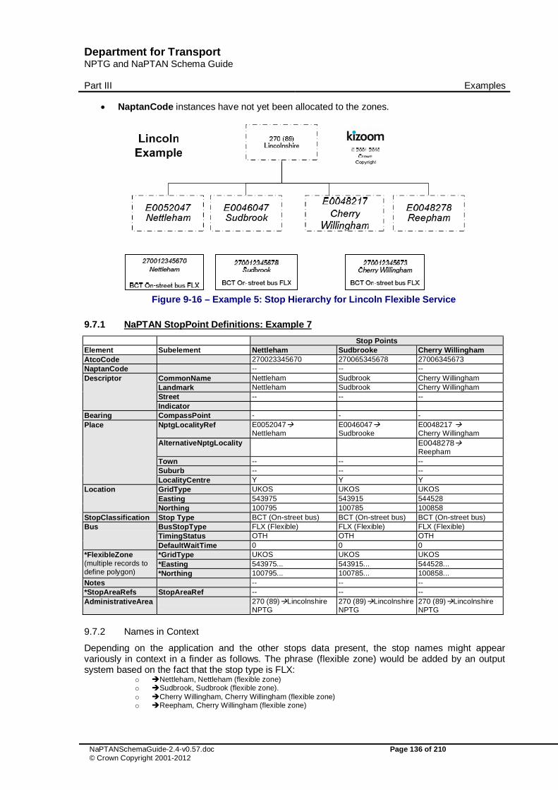
Department for Transport NPTG and NaPTAN Schema Guide
Part III Examples
NaPTANSchemaGuide-2.4-v0.57.doc Page 136 of 210 © Crown Copyright 2001-2012
� NaptanCode instances have not yet been allocated to the zones.
Figure 9-16 – Example 5: Stop Hierarchy for Lincoln Flexible Service
9.7.1 NaPTAN StopPoint Definitions: Example 7
Stop Points Element Subelement Nettleham Sudbrooke Cherry Willingham AtcoCode 270023345670 270065345678 27006345673 NaptanCode -- -- -- Descriptor CommonName Nettleham Sudbrook Cherry Willingham
Landmark Nettleham Sudbrook Cherry Willingham Street -- -- -- Indicator
Bearing CompassPoint - - - Place NptgLocalityRef E0052047�
Nettleham E0046047� Sudbrooke
E0048217 � Cherry Willingham
AlternativeNptgLocality E0048278� Reepham
Town -- -- -- Suburb -- -- -- LocalityCentre Y Y Y
Location GridType UKOS UKOS UKOS Easting 543975 543915 544528 Northing 100795 100785 100858
StopClassification Stop Type BCT (On-street bus) BCT (On-street bus) BCT (On-street bus) Bus BusStopType FLX (Flexible) FLX (Flexible) FLX (Flexible)
TimingStatus OTH OTH OTH DefaultWaitTime 0 0 0
*FlexibleZone (multiple records to define polygon)
*GridType UKOS UKOS UKOS *Easting 543975... 543915... 544528... *Northing 100795... 100785... 100858...
Notes -- -- -- *StopAreaRefs StopAreaRef -- -- -- AdministrativeArea 270 (89)�Lincolnshire
NPTG 270 (89)�Lincolnshire NPTG
270 (89)�Lincolnshire NPTG
9.7.2 Names in Context
Depending on the application and the other stops data present, the stop names might appear variously in context in a finder as follows. The phrase (flexible zone) would be added by an output system based on the fact that the stop type is FLX:
o �Nettleham, Nettleham (flexible zone) o �Sudbrook, Sudbrook (flexible zone). o �Cherry Willingham, Cherry Willingham (flexible zone) o �Reepham, Cherry Willingham (flexible zone)

Department for Transport NPTG and NaPTAN Schema Guide
Part III Examples
NaPTANSchemaGuide-2.4-v0.57.doc Page 137 of 210 © Crown Copyright 2001-2012
9.8 Example 8: Railway Station with Bus and Taxi
Map courtesy of Dr Hans Mentz, MDV from SELTA region data
Figure 9-17 – Example 8: Railway Station Interchange. Railway stations are usually not only stop points in their own right, but also important interchange points. In NaPTAN a station always consists of at least of two points; a track area, and a main entrance, and very often includes also one or more adjacent bus stops and a taxi rank. Figure 9-17 shows an example for ‘Farnham Station’; there are three pairs of bus stops in the vicinity which can usefully be associated with the station. Note that the Stop Area for the station Group is created centrally as part of the 910 data set, and so has a different AtcoAreaCode to the other groups.
� Rail - ‘GRLS’’ � Farnham Rail Station – Access Area ‘RLY’ � Farnham Rail Station – Main Entrance on Station Approach ‘RSE’. � Farnham Rail Station – Tilford Road Entrance ‘RSE’.
� Bus � ‘Station Approach’ Pair - ‘GPBS’’
o Station Approach East o Station Approach West
� ‘Waverley Lane’ Pair - ‘GPBS’ o Waverley Lane, E-bound. o Waverley Lane, W-bound
� ‘Tilford Road’ Pair - ‘GPBS’ o Tilford Road, S-bound o Tilford Road, N-bound
� Taxi o Farnham Rail Station – Taxi Rank ‘TXR’
Figure 9-18 shows a possible hierarchy - a stop area is used for each group of stops, and a Rail Station stop area (GRLS) clusters the whole ensemble.

Department for Transport NPTG and NaPTAN Schema Guide
Part III Examples
NaPTANSchemaGuide-2.4-v0.57.doc Page 138 of 210 © Crown Copyright 2001-2012
Figure 9-18 – Example 9: Stop Hierarchy for Farnham Station
NOTE: the 9100FARNHAM RLY element is the Access Area – the logical location for a passenger using the station. If the station is a major interchange, this would be where interchange takes place. If the station is mainly used for boarding and alighting, the main booking hall or its equivalent, inside the station entrance, would be appropriate. Note the GRLS and the RLY elements have national prefixes (910) and are managed nationally; all other elements have local prefixes (400 in this case) and are managed locally.

Department for Transport NPTG and NaPTAN Schema Guide
Part III Examples
NaPTANSchemaGuide-2.4-v0.57.doc Page 139 of 210 © Crown Copyright 2001-2012
9.8.1 NaPTAN StopArea Definitions: Example 8
Stop Areas Element Subelement Rail Bus Pair 1 Bus Pair 2 Bus Pair 3 StopAreaCode 910GFARNHAM 400G98765433 400G9876544 400G98765435 StopArea / Name Farnham Rail
Station Station Approach
Tilford Road Waverley Lane
StopArea Classification
GRLS Rail Station
GPBS On-street bus
GPBS On-street bus
GPBS On-street bus
Location Grid Type UKOS UKOS UKOS UKOS Easting 466312 466312 466412 466512 Northing 105510 105511 105519 105510
ParentAreaRef -- 400GFARNHAM 400GFARNHAM 400GFARNHAM Administrative Area
910 (NR) �National Rail
400 (102) �Surrey
400 (102) �Surrey
400 (102) �Surrey
9.8.2 NaPTAN StopPoint Definitions: Example 8
9.8.2.1 Rail Station Stop Points
Stop Points Element Subelement Main Entrance Side Entrance AccessArea AtcoCode 4000FARNHAM0 4000FARNHAM1 9100FARNHAM NaptanCode Descriptor CommonName Farnham Rail Station Farnham Rail Station Farnham Rail
Station Landmark Station Station Station Street Station Approach Tilford Road Station Approach
Indicator Main Entrance Side Entrance Bearing CompassPoint -- -- -- Place NptgLocalityRef E0040817�
Farnham (Surrey) E0040817� Farnham (Surrey)
E0040817� Farnham (Surrey)
Town -- -- -- Suburb -- -- -- LocalityCentre Y Y Y
Location GridType UKOS UKOS UKOS Easting 466315 466316 466310 Northing 105515 105518 105505
StopClassification StopType RSE RSE RLY Bus BusStopType -- -- --
TimingStatus -- -- -- DefaultWaitTime -- -- --
Notes -- -- -- *StopAreaRefs StopAreaRef 400GFARNHAM �
Farnham Rail Station 400GFARNHAM � Farnham Rail Station
400GFARNHAM � Farnham Rail Station
AdministrativeArea 400 (102)�Surrey 400 (102)�Surrey 910 (NR) �National Rail
9.8.2.2 Bus Stop Points- #1
Stop Points Element Subelement Tilford Road a Tilford Road b Waverley Lane a Waverley Lane b AtcoCode 40004411419a 40004411419b 40004411300a 40004411300b NaptanCode surpadgm surpjadw surpwdgm surpjwdw Descriptor CommonName Tilford Road Tilford Road Waverley Lane Waverley Lane
Landmark Station Station Station Station Street Tilford Road Tilford Road Station Hill Station Hill
Indicator N-bound S-bound E-bound W-bound Bearing CompassPoint NW SE E W Place NptgLocalityRef E0040817�
Farnham (Surrey)
E0040817� Farnham (Surrey)
E0040817� Farnham (Surrey)
E0040817� Farnham (Surrey)
Town Farnham Farnham Farnham Farnham

Department for Transport NPTG and NaPTAN Schema Guide
Part III Examples
NaPTANSchemaGuide-2.4-v0.57.doc Page 140 of 210 © Crown Copyright 2001-2012
Suburb -- -- -- -- LocalityCentre N N N N
Location GridType UKOS UKOS UKOS UKOS Easting 466315 466310 466315 466310 Northing 105515 105505 105615 105605
StopClassification StopType BCT (On-street bus)
BCT (On-street bus) BCT (On-street bus)
BCT (On-street bus)
Bus BusStopType MKD (Marked) MKD (Marked) MKD (Marked) MKD (Marked) TimingStatus TIP (Time info
point) TIP (Time info point) TIP (Time info
point) TIP (Time info point)
DefaultWaitTime 0 0 0 0 Notes -- -- -- -- *StopAreaRefs StopAreaRef 400G98765432
� 400G98765432� 400G98765432� 400G98765432�
AdministrativeArea 400 (102)�Surrey
400 (102)�Surrey 400 (102)�Surrey 400 (102)�Surrey
9.8.2.3 Bus Stop Points- #2
Stop Points Element Subelement Station Approach a Station Approach b AtcoCode 40004411338a 40004411338b NaptanCode surpadgm surpjadw Location GridType UKOS UKOS
Easting 466315 466310 Northing 105515 105505
Descriptor CommonName Station Approach East Station Approach West Landmark Station Station Street Station Approach Station Approach Indicator on on
Bearing CompassPoint S N Place NptgLocalityRef E0040817�
Farnham (Surrey) E0040817� Farnham (Surrey)
Street Station Approach Station Approach Town Farnham Farnham Suburb -- -- LocalityCentre N N
StopClassification BCT (On-street bus) BCT (On-street bus) BusStop BusStopType MKD (Marked) MKD (Marked)
TimingStatus TIP (Time info point) TIP (Time info point) DefaultWaitTime 0 0
Notes -- -- *StopAreaRefs StopAreaRef 400G98765433� 400G98765433� AdministrativeArea 400 (102)�Surrey 400 (102)�Surrey
9.8.3 Names in Context
Depending on the application and the other stops data present, the stop names might appear variously in context in a finder as follows
� �‘Farnham, Farnham Rail Station � �‘Farnham, Farnham Rail Station, Tilford Road � �‘Farnham, on Station Approach East � �‘Farnham, on Station Approach West � �‘Farnham, Waverley Lane, E-bound � �‘Farnham, Waverley LaneW-bound � �‘Farnham, Tilford Road,S-bound � �’Farnham, Tilford Road, N-bound

Department for Transport NPTG and NaPTAN Schema Guide
Part III Examples
NaPTANSchemaGuide-2.4-v0.57.doc Page 141 of 210 © Crown Copyright 2001-2012
9.9 Example 9: Metro Station with Bus & Light Rail
Source Transport for London Journey Planner MDV gmbh
Figure 9-19 – Example 9: Bank Tube Lines
Source Transport for London Journey Planner, MDV gmbh.
Figure 9-20 – Example 9: Bank Station Street Area This example considers ‘Bank’ underground station in the ‘City of London’, which connects two tube lines (‘Northern’ and ‘Central’) the ‘Waterloo and City’ (Figure 9-19) with the Docklands Light Railway. There are several bus stops in the vicinity Figure 9-20. However not all the bus stop areas are considered to be part of an interchange with Bank Station. There is a walkable tunnel connection with ‘Monument’ underground station.
� Metro - ‘GTMU’ � Bank – 10 different entrances ‘TMU’. � Bank - four ‘PLT’ platform areas � Bank – DLR Access Area. (‘MET’)
� Bus

Department for Transport NPTG and NaPTAN Schema Guide
Part III Examples
NaPTANSchemaGuide-2.4-v0.57.doc Page 142 of 210 © Crown Copyright 2001-2012
� ‘Bank’ Cluster - ‘GCLS’’ o Bank, stop C o Bank. stop F o Bank, stop R o Bank, stop S
� ‘Princes Street’ Pair - ‘GPBS’ o ‘Princes Street at Bank, stop A’. o ‘Princes Street at Bank, stop B’.
� ‘Bank Station L M’ Pair - ‘GPBS’’ o ‘Bank Station L M, stop K’. o ‘Bank Station L M, stop L’.
� ‘Bank Temple of Mithras’ Cluster - ‘GCLS’’ o ‘Bank Temple of Mithras, stop H’. o ‘Bank Temple of Mithras, stop J’. o ‘Bank Temple of Mithras, stop JA’.
Figure 9-21 and Figure 9-22 show a possible stop hierarchy - a ‘GTMU’ stop area is used for the tube station and a ‘GBPS’ or ‘GCLS’ stop area for each group of bus stops. The GTMU stop area is used as a parent for the Bank GCLS Bus cluster as this is deemed to be close enough to Bank Underground Station to constitute an interchange. This example shows that judgement must be exercised as to which stops constitute a true interchange.
The model in this case has only four PLT elements for the Underground station – each represents a platform used for travel in both directions. This is legacy data – ideally each platform EDGE should now be coded as a separate PLT element so that they can each have the public-facing indicator (Platform 1 or A, etc)
The link to Monument creates an entrance to ‘Bank’ station, located at the Monument (and vice versa). The entrances should be at the same location to create direct connectivity (if supported); otherwise a walk link is needed, which is outside the scope of NaPTAN.

Department for Transport NPTG and NaPTAN Schema Guide
Part III Examples
NaPTANSchemaGuide-2.4-v0.57.doc Page 143 of 210 © Crown Copyright 2001-2012
Figure 9-21 – Example 9: Stop Hierarchy for Bank Underground Station
Figure 9-22 – Example 9: Bank Underground Station – Stops in Area

Department for Transport NPTG and NaPTAN Schema Guide
Part III Examples
NaPTANSchemaGuide-2.4-v0.57.doc Page 144 of 210 © Crown Copyright 2001-2012
9.9.1 NaPTAN StopArea Definitions: Example 9
Stop Areas Element Subelement Metro Bus Pair 1 Bus Pair 2 Bus Cluster 3 Bus Cluster 4 StopAreaCode 940G
ZZLUBNK 490G 98765433 490G 9876544 490G 9876549 490G 98765435
StopArea / Name
Bank Station Princes Street at Bank
Bank Station LM
Bank Bank Temple Of Mithras
StopArea Classification
GTMU Metro Station
GPBS On-street bus
GPBS On-street bus
GCLS On-street bus
GCLS On-street bus
Location Grid Type UKOS UKOS UKOS UKOS UKOS Easting 532711 532660 532537 532774 532560 Northing 181112 181209 181139 181173 181053
ParentAreaRef 940G ZZLUBNK
940GZZLUBNK 940GZZLUBNK
940GZZLUBNK 940GZZLUBNK
Administrative Area
940(MET)�Metro National
490 (82)�Greater London
490 (82)�Greater London
490 (82)�Greater London
490 (82)�Greater London
9.9.2 NaPTAN StopPoint Definitions: Example 9
9.9.2.1 Metro Stop Points: Common Values
Element Subelement Common Values Descriptor Landmark -- Place NptgLocalityRef E0057722� City of London
AlternativeNptgLocalityRef N0065149� Bank Town -- Suburb -- LocalityCentre Y
*StopAreaRefs StopAreaRef 940G98765431�Bank Station 490G98765433� Bank
AdministrativeArea 490 (82)�Greater London
9.9.2.2 Metro Stop Points: Stops
AtcoCode Stop Type
Bus Stop Type CommonName Landmark Street Indicator Bearing Status Bank
9400ZZLUBNK0 PLT -- Bank Bank Cornhill DLR 1 -- ACT Y
9400 ZZLUBNK 1 PLT -- Bank Bank Cornhill Under-
ground 1 -- ACT Y
9400 ZZLUBNK 2 PLT -- Bank Bank Cornhill Under-
ground 2 -- ACT Y
9400 ZZLUBNK 3 PLT -- Bank- Bank Cornhill Under-
ground 3 -- ACT Y
9400 ZZLUBNK 4 PLT -- Bank Bank Cornhill Under-
ground 4 -- ACT Y
9400 ZZLUBNK 5 PLT -- Bank Bank Cornhill Under-
ground 5 -- ACT Y
4900 ZZLUBNK0 TMU -- Bank Mansion
House
Queen Victoria Street
Entrance 1 -- ACT
Y
4900 ZZLUBNK1 TMU -- Bank Mansion
House Poultry Entrance
2 -- ACT Y
4900 ZZLUBNK2 TMU -- Bank Mansion
House
Queen Victoria Street
Entrance 3 -- ACT
Y
4900 ZZLUBNK3 TMU -- Bank Royal
Exchange Cornhill Entrance 4 -- ACT Y
4900 ZZLUBNK4 TMU -- Bank Mansion
House King William Street
Entrance 5 -- ACT Y
4900 ZZLUBNK5 TMU -- Bank Mansion
House King William Street
Entrance 6 -- ACT Y
4900 TMU -- Bank Bank Of Threadneedle Entrance -- ACT Y

Department for Transport NPTG and NaPTAN Schema Guide
Part III Examples
NaPTANSchemaGuide-2.4-v0.57.doc Page 145 of 210 © Crown Copyright 2001-2012
ZZLUBNK6 England Street 7 4900 ZZLUBNK7 TMU -- Bank Bank Of
England Threadneedle Street
Entrance 8 -- ACT Y
4900 ZZLUBNK8 TMU -- Bank Mansion
House Lombard Street
Entrance 9 -- ACT
Y
4900 ZZLUBNK9 TMU -- Bank Mansion
House King William Street
Entrance 10 -- ACT Y
4900 ZZLUBNKa TMU -- Bank Mansion
House King William Street
Entrance 11 -- ACT Y
4900 ZZLUBNKb TMU -- Bank Monument King William
Street Entrance 12 -- ACT Y
490000013C BCT MKD Bank Bank Of England
Threadneedle Street Stop C E ACT Y
490000013F BCT MKD Bank Mansion House
King William Street Stop F S ACT
Y
490000013R BCT MKD Bank Royal Exchange
Cornhill Stop R E ACT Y
490000013S BCT MKD Bank Royal Exchange Cornhill Stop S W ACT Y
490007596K BCT MKD Bank Station L M
Mansion House Cheapside Stop K W ACT N
490007596L BCT MKD Bank Station L M
Mansion House Poultry Stop L E ACT N
490011218A BCT MKD Princes Street / Bank
Bank Of England
Princes Street
Stop A N ACT N
490011218B BCT MKD Princes Street / Bank
Bank Of England
Princes Street Stop B S ACT N
490011218N BCT MKD Princes Street / Bank
Bank Of England
Princes Street Stop N N DEL N
490011218P BCT MKD Princes Street / Bank
Bank Of England
Princes Street Stop P S DEL N
490013195H BCT MKD Bank / Temple Of Mithras
Temple of Mithras
Queen Victoria Street
Stop H E ACT N
490013195J BCT MKD Bank / Temple Of Mithras
Temple of Mithras
Queen Victoria Street
Stop J W ACT N
490013195JA BCT MKD Bank / Temple Of Mithras
Temple of Mithras
Queen Victoria Street
Stop JA W ACT N
9.9.3 Names in Context
Depending on the application and the other stops data present, some of the stop names might appear variously in context in a finder as follows:
� �‘City Of London, Bank Temple Of Mithras’ � �‘City Of London, Princes Street at Bank’ �

Department for Transport NPTG and NaPTAN Schema Guide
Part III Examples
NaPTANSchemaGuide-2.4-v0.57.doc Page 146 of 210 © Crown Copyright 2001-2012
9.10 Example 10: Bus Station with Bays
From Bucks Pindar Journey Planner web site, Digital cartography by FWT
Figure 9-23 – Example 10: Aylesbury Bus Station This example models Aylesbury Bus Station which has 12 Bays – see Figure 9-23.
� A stop area of type GBCS is used to represent the station. � There is a ’BCE’. stop for the pedestrian entrance. � Each bay has its own NaPTAN stop of type ‘BCS’. � If variable bay allocation is needed, there is a variable bay stop of type BCQ which can be
used when no specific bay is assigned in advance. There are notes attached to each stop.
Destination 1 Bicester Road (Rural Services) 2 Town Services to Quarrendon, Haydon Hill and Elmhurst 3 Wendover Road Services 4 Town Services to Southcourt, Walton Court, Hawkslade Farm and Stoke Mandeville Hospital 5 Town Services to Fairford Leys and Southcourt 6 Services to Stoke Mandeville, Princes Risborough, High Wycombe and Reading 7 Tring Road Services to Luton, Hemel and Watford 8 Town Services to Broughton and Bedgrove 9 Services to Haddenham, Thame and Oxford 10 Services to Leighton Buzzard, Bletchley and Milton Keynes 11 Services to Watermead, Winslow and Buckingham 12 Certain school journeys, early morning and late evening departures

Department for Transport NPTG and NaPTAN Schema Guide
Part III Examples
NaPTANSchemaGuide-2.4-v0.57.doc Page 147 of 210 © Crown Copyright 2001-2012
Table 9-1 – Example 10: Stop Notes for Aylesbury Bus Station
Aylesbury Bus StationExample
E0000348 Aylesbury
400 (70)Buckinghamshire
400G98765431Aylesbury Bus
Station
40000004651Aylesbury Bus Station
BCE Main Entrance
40000004664Aylesbury Bus Station
Entrance 2BCE Entrance
40000004651Aylesbury Bus Station
Bay 1BCS Off Street Stop MKD
40000004665Aylesbury Bus Station
StandsBST Stands
40000004652Aylesbury Bus Station
Bay 2BCS Off Street Stop
40000004658Aylesbury Bus Station
Bay 8BCS Off Street Stop MKD
40000004657Aylesbury Bus Station
Bay 7BCS Off Street Stop MKD
40000004653Aylesbury Bus Station
Bay 3BCS Off Street Stop MKD
40000004659Aylesbury Bus Station
Bay 9BCS Off Street Stop MKD
40000004654Aylesbury Bus Station
Bay 4BCS Off Street Stop MKD
40000004660Aylesbury Bus Station
Bay 10BCS Off Street Stop MKD
40000004655Aylesbury Bus Station
Bay 5BCS Off Street Stop MKD
40000004661Aylesbury Bus Station
Bay 11BCS Off Street Stop MKD
40000004656Aylesbury Bus Station
Bay 6BCS Off Street Stop MKD
40000004662Aylesbury Bus Station
Bay 12BCS Off Street Stop MKD
40000004663Aylesbury Bus
Station
BCQ Variable Bay
© 2001-2010 Crown
Copyright
Figure 9-24 – Example 10: Stop Hierarchy for Aylesbury Bus Station

Department for Transport NPTG and NaPTAN Schema Guide
Part III Examples
NaPTANSchemaGuide-2.4-v0.57.doc Page 148 of 210 © Crown Copyright 2001-2012
9.10.1 NaPTAN StopArea Definitions: Example 10
StopARea Element Subelement Bus StopAreaCode 400G98765431 StopArea / Name Aylesbury Bus Station StopAreaType GBCS Bus Station Location Grid Type UKOS
Easting 481879 Northing 213593
ParentAreaRef -- AdministrativeArea
9.10.2 NaPTAN StopPoint Definitions: Example 10
9.10.2.1 Bus Station Stop Points: Common Values Example 10
Element Subelement Common Values Descriptor Landmark Bus Station Place NptgLocalityRef E0000348� Aylesbury Town Centre
Town Suburb Street Great Western Street Landmark Bus Station LocalityCentre Y
*StopAreaRefs StopAreaRef 400G98765431� Aylesbury Bus Station AdministrativeArea 400 (70)�Buckinghamshire
9.10.2.2 Bus Station Stop Points: Example 10
AtcoCode Stop Type
Bus Stop Type Easting Northing CommonName Indicator
Timing Status Status
40000004650 BCE 481881 213599 Aylesbury Bus Station Entrance ACT
40000004651 BCS MKD 481881 213599 Aylesbury Bus Station Bay 1 PTP ACT
40000004652 BCS MKD 481883 213597 Aylesbury Bus Station Bay 2 PTP ACT
40000004653 BCS MKD 481884 213595 Aylesbury Bus Station Bay 3 PTP ACT
40000004654 BCS MKD 481885 213589 Aylesbury Bus Station Bay 4 PTP ACT
40000004655 BCS MKD 481881 213585 Aylesbury Bus Station Bay 5 PTP ACT
40000004656 BCS MKD 481879 213587 Aylesbury Bus Station Bay 6 PTP ACT
40000004657 BCS MKD 481877 213589 Aylesbury Bus Station Bay 7 PTP ACT
40000004658 BCS MKD 481875 213591 Aylesbury Bus Station Bay 8 PTP ACT
40000004659 BCS MKD 481873 213593 Aylesbury Bus Station Bay 9 PTP ACT
40000004660 BCS MKD 481871 213595 Aylesbury Bus Station Bay 10 PTP ACT
40000004661 BCS MKD 481869 213597 Aylesbury Bus Station Bay 11 PTP ACT
40000004662 BCS MKD 481896 213605 Aylesbury Bus Station Bay 12 PTP ACT
40000046633 BCQ MKD 481884 213595 Aylesbury Bus Station Departures PTP ACT
AtcoCode Note
40000004651 Bicester Road (Rural Services)
40000004652 Town Services to Quarrendon, Haydon Hill and Elmhurst
40000004653 Wendover Road Services
40000004654 Town Services to Southcourt, Walton Court, Hawkslade Farm and Stoke Mandeville Hospital
40000004655 Town Services to Fairford Leys and Southcourt

Department for Transport NPTG and NaPTAN Schema Guide
Part III Examples
NaPTANSchemaGuide-2.4-v0.57.doc Page 149 of 210 © Crown Copyright 2001-2012
40000004656 Services to Stoke Mandeville, Princes Risborough, High Wycombe and Reading
40000004657 Tring Road Services to Luton, Hemel and Watford
40000004658 Town Services to Broughton and Bedgrove
40000004659 Services to Haddenham, Thame and Oxford
40000004660 Services to Leighton Buzzard, Bletchley and Milton Keynes
40000004661 Services to Watermead, Winslow and Buckingham
40000004662 Certain school journeys, early morning and late evening departures
9.10.3 Names in Context
Depending on the application and the other stops data present, some of the stop names might appear variously in context in a finder as follows:
� �‘Aylesbury, Bus Station, Bay 1 � �‘Aylesbury, Bus Station, Bay 5 � �‘Aylesbury, Bus Station, Bay 8 � �‘Aylesbury, Bus Station, departures {representing the BCQ stop]

Department for Transport NPTG and NaPTAN Schema Guide
Part III Examples
NaPTANSchemaGuide-2.4-v0.57.doc Page 150 of 210 © Crown Copyright 2001-2012
9.11 Example 11: Major Airport
NOTE : This example describes Heathrow as it was several years ago (that is, before the addition of Terminal 5 and the closure of Terminal 2). but it still reflects the relevant principles for constructing a large interchange – Major Airports are typically especially complex interchange points. We consider an example in summary below.
� There are two physically separate termini groups for Heathrow, with separate access by public transport: ’Heathrow Airport’ and ’Heathrow Terminal 4’.’
o ’Heathrow Airport’ contains sub areas for ’Terminal 1’, ’Terminal 2’, ’Terminal 3’, ’ Terminal 123 Underground Station’, ‘Terminal 123 Heathrow Express Station’, ’ Terminal 123 Bus Station’, ‘Terminal 123 Coach Station’, and a number of bus and coach stops and taxi ranks.
o ’Heathrow Terminal 4’ contains sub areas for ’Underground Station’, ’Heathrow Express Station’ and a number of bus and coach stops and taxi ranks.
To model this in NaPTAN we might use:
� An NptgLocality ’Heathrow’ to which all of the stops and stop areas can be assigned. � Each of the four Terminals can be represented in NaPTAN by a StopArea that groups the
various public entrances to each Terminal Building. � For ’Heathrow Airport’ a ‘GAIR’ group is used to group terminals1, 2 and 3.
o The ’Underground Station’ for ’Heathrow Terminal 123’ can be represented by a ‘GTMU’ StopArea that groups the sub-surface entrances to the station.
o The ’Heathrow Express Station’ for ’Heathrow Terminal 123’ can be represented by a ‘GRLS’ StopArea that groups the sub-surface entrances to the rail station.
o The Coach station for ’Heathrow Central’ can be represented by a GBCS’ StopArea that groups the individual bays in the coach station (adjacent to Terminal 3).
o The Bus Station for ’Heathrow Central’ can be represented by a StopArea that groups the individual stops/bays in the bus station and the bus station entrances.
o Outside each terminal there are a number of bus and coach stops used by local and rail-link buses. These are not considered part of the Terminal groupings as they are marked stops on the airport road network.
� For the ’Terminal 4’ area, a similar set of mode stop areas. o The ’Underground Station’ for ’Terminal 4’ can be represented by a StopArea that
groups the sub-surface entrances to the station. o The ’Heathrow Express Station’ for ’Terminal 4’ can be represented by a StopArea
that groups the sub-surface entrances to the rail station.
Figure 9-25 and Figure 9-26 show a partial stop hierarchy for Heathrow.

Department for Transport NPTG and NaPTAN Schema Guide
Part III Examples
NaPTANSchemaGuide-2.4-v0.57.doc Page 151 of 210 © Crown Copyright 2001-2012
Figure 9-25 – Example 11a: Partial Stop Hierarchy for Heathrow Airport Terminals 123

Department for Transport NPTG and NaPTAN Schema Guide
Part III Examples
NaPTANSchemaGuide-2.4-v0.57.doc Page 152 of 210 © Crown Copyright 2001-2012
Figure 9-26 – Example 11b: Partial Stop Hierarchy for Heathrow Terminal 4

Department for Transport NPTG and NaPTAN Schema Guide
Annex Appendixes
NaPTANSchemaGuide-2.4-v0.57.doc Page 153 of 210 © Crown Copyright 2001-2012
10 NAMING & CODING CONVENTIONS
Systematic naming conventions and a consistent coding style are used in the NPTG and NaPTAN 2.x schemas; these conventions are summarised in this section.
10.1 Naming of Elements
NPTG and NaPTAN follow consistent principles for naming schema elements:
10.1.1 Use of Camel Case
Camel case is used for all names in the XML schema: � Upper camel case is used for elements and attributes for example StopArea, HailAndRide. � Lower case is however used for two standard attributes: xml:lang, and id, in line with
established W3C usage. � Lower camel case is used for enumerated text values, for example ‘saturdayMorning’. � Acronyms are treated as words for capitalisation, thus TanCode, not TANCode. This is one
point where we follow common best practice but diverge from e-gif. Treating acronyms as words allows for a uniform parsing of names to derive their components, and avoids ambiguity on case of contiguous acronyms, for example TANAPD vs. TanApd, or one letter words contiguous with an acronym, for example DialATAN vs. DialATan.
10.1.2 Use of Standard Name Suffixes NaPTAN, NPTG and NaPT schema element, type and attribute names have been revised along consistent principles:
� All simple types end with the suffix ‘Type’. � All complex types end with ‘Structure’. � All enumerations end with ‘Enumeration’. � All groups end with ‘Group’. � Externally referenced identifiers of entities are generally suffixed with ‘Code’ (and
represented as elements). � Internally referenced identifiers are generally suffixed with ‘id’ (and represented as
attributes). � Elements representing references to other entities are suffixed with ‘Ref’. (These are either
Code or id data types) � Externally referenced classifiers of entities are generally suffixed with ‘Classification’ (rather
than say ‘Type’). For example StopClassification � Externally referenced names of entities are generally suffixed with ‘Name’. If the context is
readily apparent they may be called just Name. � Natural Language text descriptions of entities are generally termed ‘Description’.
10.1.3 Meaningful Names
Several other consistent naming principles are followed: � Abbreviations are generally avoided – for example ‘Operation’ is preferred to ‘Op’. � A container element representing a one-to-many relationship is in the plural; for example,
StopPoints contains one or more StopPoint elements. � We avoid repeating the name of the parent element as an adjective in individual child
elements, except for certain semantically important elements where it is helpful to do so. Thus for example, Author contains Title, Position, Forename, Surname, not AuthorTitle, AuthorPosition, AuthorName, AuthorSurname. An exception to this rule is for Code elements, for example Area / AreaCode and not Area / Code.
� We avoid the use in domain elements names of terms that have strong software connotations: o The suffixes ‘Type’ and ‘Group’ are avoided in element names except for internal
schema elements.

Department for Transport NPTG and NaPTAN Schema Guide
Annex Appendixes
NaPTANSchemaGuide-2.4-v0.57.doc Page 154 of 210 © Crown Copyright 2001-2012
10.1.4 Standardised Terminology An attempt has been made to use the appropriate Transmodel term wherever appropriate. For example StopPoint rather than Stop, StopArea rather than StopGroup,
10.1.5 Semantically Significant Order Several principles are used to order subelements at any given level:
� When declaring elements within a parent, subelements are placed in a consistent general order according to the nature of their role as follows: a. Elements that identify the entity, such as codes or numbers. b. Elements that describe the element in text, such as names or descriptions. c. Principle associations of the entity with other entities. d. Elements that classify the entity. e. Elements describing other properties of the entity.
� Where there is an inherent temporal order, elements are placed in temporal sequence, for example ’StartDate’ before ’EndDate’.
10.2 Typing of Elements
Some general principles are used for typing values.
� Explicit, specific types are used wherever possible, for example Duration: � Complex types are declared for all significant compound elements. � Internally referenced identifiers are generally of type NMTOKEN, or an extension. � Elements whose content is a text string in a national language are of type
NaturalLanguageStringStructure.
10.3 Element Constraints
Some general principles are used for constraining values.
� Mandatory Elements are normally populated. XML constraints are usually specified to ensure mandatory elements are populated, for example strings should contain at least one character.
� Optional elements not empty: Where alternative structures are available, the absence of an element is not relied upon to infer meaning. Instead an empty element or attribute value is used to make the condition explicit, or there is a default value defined that can be assumed. This principle has been generally been followed for new and remodelled features.
10.4 Use of Attributes
In NPTG and NaPTAN, XML element attributes are generally used only for metadata, that is, data about data, such as data version tracking, to identify the data reference systems used, or to provide internal instance identifiers. Table 10-1 summarises the attributes used in NPTG and NaPTAN.
Group Element Attribute ver Document Version
NaPTAN, NPTG, NptgDIscovery root elements.
CreationDateTime 2.0 ModificationDateTime 1.2 FileName 2.0 Modification 2.0 RevisionNumber 2.0 SchemaVersion 1.2 ChangesSince 2.4
Entity Version StopPoint, StopArea, NptgLocality, NptgDistrict, Region, AdministrativeArea, CallCentre, WebApplication
CreationDateTime 2.0 ModificationDateTime 1.2 FileName 2.0 Modification 2.0 Status 1.2 RevisionNumber 2.0
dataRights All of the above DataRightRef 2.4 Id Location Id 1.2

Department for Transport NPTG and NaPTAN Schema Guide
Annex Appendixes
NaPTANSchemaGuide-2.4-v0.57.doc Page 155 of 210 © Crown Copyright 2001-2012
Data Location Precision 1.2 NaPTAN, NPTG LocationSystem 2.0
Language Text elements: Name, Description, etc. See section on National Language Support
xml:lang 2.0
Table 10-1 – NaPTAN Attributes
10.5 Implementation of Model Relationships
In NPTG and NaPTAN, some stylistic conventions are used to make clear the mapping of the reference model relationships into the XML schema.
� All significant entities have a uniquely scoped identifier (always an element named xxxCode or xxxNumber, or an id attribute).
� Relationships are implemented by placing a reference to the identifier as a foreign key on the referencing element (shown by the navigability arrow in UML diagrams). The reference has the form xxxRef. For example, StopPoint is identified by an AtcoCode, and is referenced in relationships by a StopPointRef.
� Container elements are generally used for significant one-to-many relationships, with a name derived from the plural name of the contained or referenced element, for example:
o To implement the aggregation relation of stops within NaPTAN, the StopPoints element contains a collection of StopPoint instances.
o To implement the reference relationship of alternative localities from StopPoint to The StopPoint /AlternativeLocalities container element contains a collection of NptgLocalityRef instances.
10.6 Data Rights attribute
A new attribute DataRightRef is added in release 2.4 This allows each entity to be associated with a data right element to specify IPR & conditions of use. This is for use with the TransXChange 2.4 Schema – see the 2.4 Schema guide.

Department for Transport NPTG and NaPTAN Schema Guide
Annex Appendixes
NaPTANSchemaGuide-2.4-v0.57.doc Page 156 of 210 © Crown Copyright 2001-2012
11 VERSIONING
NPTG and NaPTAN schemas and documents are versioned so as to manage change in a distributed computational environment, and in particular to allow inter-operability of concurrent versions at different levels. 11.1 Version Numbering Convention NPTG and NaPTAN schemas follow the e-Gif convention for version numbering.
� Released schema Version numbers have the form n.m, (e.g. 3.1).
� Drafts have the form n.mx (e.g. 3.1a).
� The main version number (n) will be incremented when the change from the previous version of the schema will cause existing documents to fail to validate. For example if a new mandatory element is added.
� The minor version number (m) will be incremented when the change to the schema will allow existing documents to continue to validate. However some new documents may fail to validate against the old version (for example, if a new optional element is added).
� The draft version number (x) indicates that the version is still under discussion and may be subject to further changes. Generally it will be incremented to indicate a material change to a previous release or previous draft. Intermediate drafts will usually be withdrawn once they are superseded.
11.2 Resource Versions
11.2.1 Schema URI version
In line with W3C practice, a separate directory and URL will be used for each version of the schema; the schema name will remain the same. For example:
http://www.naptan.org.uk/schemas/2.1/NaPTAN.xsd http://www.naptan.org.uk/schemas/2.1/NPTG.xsd http://www.naptan.org.uk/schemas/2.1/NPTG_Discovery.xsd
And: http://www. naptan.org.uk/schemas/2.4/ NaPTAN.xsd http://www.naptan.org.uk/schemas/2.4/NPTG.xsd http://www.naptan.org.uk/schemas/2.4/NPTG_Discovery.xsd
Different versions of the NaPTAN schema will coexist at the same time. Older versions will be deprecated and then be dropped altogether after a period.
11.2.2 Namespace URI version The following unversioned URI will be used for the NPTG and NaPTAN namespace. This is in line with the e-GIF mandate that namespace URI must not be versioned.
http://www. naptan.org.uk/schemas/
11.2.3 Schema Version In each XML instance document conforming to NaPTAN or NPTG, the root element (i.e. NaPTAN and NationalPublicTransportGazetteer) has a SchemaVersion attribute that is populated to indicate the schema version, as recommended by e-GIF. This allows any application which processes the document to decide how to handle the document. See Table 11-1. A standard set of metadata attributes to track the document is also included:

Department for Transport NPTG and NaPTAN Schema Guide
Annex Appendixes
NaPTANSchemaGuide-2.4-v0.57.doc Page 157 of 210 © Crown Copyright 2001-2012
Attributes Value CreationDateTime Date and Time stamp ModificationDateTime Date and Time stamp Modification Nature of modification: one of new, delete, revise ModificationNumber Sequentially incrementing number SchemaVersion Schema Version number
Table 11-1 – NPTG and NaPTAN Document Version Attributes
11.2.4 Package Versions
NPTG and NaPTAN embed a number of common type definition packages that are shared with other UK standards. For convenience, a separate copy of the common packages is distributed with each standard. The individual package files are given version numbers in line with the e-GIF system in order to ensure the correct version is used. This number is only incremented if the package changes and so may vary from package to package and be different from the overall schema number. For example, for the shared NaPT stop definition types file might be called NaPT_stop-v1-0.xsd. It is distributed in NaPTAN 2.1 as:
� http://www.naptan.org.uk/schemas/2.1/napt/NaPT_stop-v2-0.xsd
And if updated in NaPTAN 2.4 as: � http://www.naptan.org.uk/schemas/2.4/napt/NaPT_stop-v2-1.xsd
11.2.5 Data Element Version Data element versioning indicates the version level of the content of a particular individual item of data. See Figure 11-1.
class Versioning Model
«interface»Versionable
CreationDateTime: dateTimeModificationDateTime: dateTimeModification: ModifcationEnumRevisionNumber: stringStatus: StatusEnum
«enumeratio...ModificationEnum
newdeleterevisearchive
«enumeratio...StatusEnum
activeinactivepending
Name: Versioning ModelAuthor: nickkVersion: 1.0Created: 17/09/2009 15:52:33Updated: 17/02/2010 19:49:44
(c) 2001-2010 Crown Copyright
VersionedObject VersionedChild
VersionAttributes
CreationDateTime: dateTime [0..1]ModificationDateTime: dateTime [0..1]Modification: ModificationEnum [0..1]RevisionNumber: RevisionNumberType [0..1]Status: StatusEnum [0..1]ChangedBy: normalizedString [0..1]
Figure 11-1 – UML Model of Element Versions

Department for Transport NPTG and NaPTAN Schema Guide
Annex Appendixes
NaPTANSchemaGuide-2.4-v0.57.doc Page 158 of 210 © Crown Copyright 2001-2012
Most significant entities in NPTG and NaPTAN have optional change attributes on them including a modification date and revision number that can be used to specify their data version level. See Table 11-2. Change Attributes
Type Use Introduced
Creation-DateTime
Date and Time stamp in ISO format.
Should be set when the entity is first created, and not subsequently be changed.
2.0
Modification-DateTime
Date and Time stamp in ISO format
Should be changed every time an entity is changed, that is when any of its immediate attributes or any of its child entities are changed. May be omitted if Modification is new, i.e. if same as CreationDateTime otherwise must be specified.
1.2
Modification Nature of modification: one of new, delete, revise, archive
The Modification status should be set as follows: � New - If this is the first version of the element instance, created for
the first time. An entity continues to have a status of new until it is revised. The creation date can be used to detect a recent addition.
� Revise - If an existing element instance is being updated, or any of its child elements that are not themselves versioned are being updated, added, or deleted. Once an element is marked as revise it will continue to be so unless it is marked as deleted, i.e. should not ever revert to new. If no value is specified, revise will be assumed.
� Delete - If the element is being rendered inactive. Records marked as deleted should continue to be exported in subsequent data exchanges. It is possible to reactivate deleted stops: a reactivated stop has a status of revise, (not new).
� Archive – If the element is archived. It will be held in the central database and the NaPTAN identifiers reserved (Both AtcoCode and NaptanCode), but will be excluded from exports.
2.0
RevisionNumber Sequentially incrementing number
The RevisionNumber an instance should be incremented (and its Modification value set to ’revised’), if any of its element values, attribute values or contained values are modified by the Originating system. � New entities should have a revision number of 0. � Only the Issuer should increment this number The RevisionNumber of an instance should not be changed if there is no change to the data values or children of an element.
2.0
Status Active | Inactive | Pending.
Indicates whether after the modification the element will be considered active, inactive, or pending, (i.e. inactive subject to verification) Stops and Stop Areas are not deleted from the NaPTAN database; instead they are given a status of inactive - see Data Deprecation.
1.2, 2.0
Table 11-2 – Entity Change Tracking & Status Attributes
11.2.6 Use of the Status Attribute
11.2.6.1Data Deprecation
As a general principle, referenced entities such as localities, stop points and stop areas will not be deleted from the NPTG and NaPTAN databases, merely deprecated. This will uphold the referential integrity of systems that use the data. StopPoint and StopArea instances in the NaPTAN database may have one of three states, as indicated by the Status attribute:
� ‘Active’: Stop is either in use or available to be used. � ‘Inactive’: Stop is in database but is marked as ‘inactive’ and is not currently in use or
available for use. If the StopAvailability (see 6.5) has been used to transfer or suspend the stop for the period within which the data is published, the status of the stop must be ‘active’. This represents a change of interpretation with release 2.4 – and ensures that stops remain available for Bus Service Registration and other purposes whilst it is temporarily suspended or transferred.
� ‘Pending’ delete: Stop is missing, or flagged as deleted from the most recent data upload, and may be in process of being made inactive. Will continue to be exported as if ‘active’ until status is clarified.

Department for Transport NPTG and NaPTAN Schema Guide
Annex Appendixes
NaPTANSchemaGuide-2.4-v0.57.doc Page 159 of 210 © Crown Copyright 2001-2012
However for practical reasons very old and unused stop data may occasionally be archived once it has been ascertained that it is no longer referenced by any currently active system (there may still be legacy data references).This may happen in particular for example where an entire area is assigned to a different code. See Modification element. Archive data will be omitted from the export. Archived stop identifiers will not be recycled. Figure 11-2 and Figure 11-3 show the processing states for NaPTAN elements. Note that there are cross-constraints between the two states.
� An active element may have a Modification attribute value only of new or revise. � Only an inactive element may have a Modification attribute value of delete or archive.
stm Version Status States
Active
Pending
Inactiv e
Initial
Name: Version Status StatesAuthor: nickkVersion: 1.0Created: 01/03/2010 17:36:03Updated: 01/03/2010 17:41:16 (c) 2001-2010
Crown Copyright
Figure 11-2 – Status element: State Transitions
stm Modification States
Name: Modification StatesAuthor: nickkVersion: 1.0Created: 01/03/2010 17:42:22Updated: 01/03/2010 17:48:17
(c) 2001-2010 Crown Copyright
Ini tial
Rev ise
New
Delete
Archiv e
Final
Figure 11-3 – Modification element State Transitions
11.2.6.2Interaction of Status with References to elements
Where an association is used to link two elements (for example for a StopPoint’s StopArea, AdministrativeArea, or PlusbusZone). the associated entity should be ‘active’ at the time the

Department for Transport NPTG and NaPTAN Schema Guide
Annex Appendixes
NaPTANSchemaGuide-2.4-v0.57.doc Page 160 of 210 © Crown Copyright 2001-2012
association is created. If the associated entity is subsequently made ‘inactive’, the association (if not explicitly removed as well) is also considered to be ‘inactive’ and may be ignored.
11.2.6.3Interaction of Status with StopValidity
The Modification and Status elements are general change management attributes found on all elements. The StopValidity element is an additional status element found only on StopPoint elements. A stop may also have a StopValidity of Active, Suspended, or Transferred as specified by the StopValidity that applies at the period specified for the individual StopValidity. The StopValidity states and transitions are shown in Figure 11-4. The StopValidity is independent of the ‘Status’ attribute - though normally it is only useful to specify a StopValidity for an active stop. (Note that TXC v 2.4 revises the interpretation of the interaction with Status – previous to TXC v2.4 the status was required to match the StopValidity at the time of export).
stm Stop Validity States
Name: Stop Validity StatesAuthor: nickkVersion: 1.0Created: 01/03/2010 17:47:47Updated: 01/03/2010 17:50:11
(c) 2001-2010 Crown Copyright
Initial
Activ e
Suspended
Transferred
Figure 11-4 – StopValidity State Transitions
11.2.6.4Elements Which can be change tracked
The NaPTAN and NPTG entities which can be change tracked are shown in Table 11-3. For some of these a creation date must always be given (indicated by an ‘R’); for others, all the modification attributes are optional in the schema. Entity Type Versioning Creation
date NaPTAN NaPTAN Root SchemaVersion. R NPTG NationalPublicTransportGazetteer Root SchemaVersion. R
NaPTAN
StopPoint Entity Change Attributes + Status
R
StopArea Entity Change Attributes + Status.
R
StopPoint / AlternativeDescriptor Child Change Attributes. R StopPoint / StopAreaRef Ref Change Attributes. O StopPoint / PlusbusRef Ref Change Attributes. O StopPoint / AlternativerNptgLocalityRef Ref Change Attributes. O StopPoint / MainStopForNptgLocalityRef Ref Change Attributes. O StopPoint / HailAndRide Child Change Attributes. O StopPoint / FlexibleZone Child Change Attributes. O StopPoint / Marked Child Change Attributes. O StopPoint / Unmarked Child Change Attributes. O

Department for Transport NPTG and NaPTAN Schema Guide
Annex Appendixes
NaPTANSchemaGuide-2.4-v0.57.doc Page 161 of 210 © Crown Copyright 2001-2012
StopPoint / StopValidity Child Change Attributes. O StopPoint / AnnotatedAirRef Child Change Attributes. O StopPoint / AnnotatedFerryRef Child Change Attributes. O StopPoint / AnnotatedMetroRef Child Change Attributes. O StopPoint / AnnotatedRailRef Child Change Attributes. O StopPoint / AnnotatedCoachRef Child Change Attributes. O
NPTG
Region Entity Change Attributes. R AdministrativeArea Entity Change Attributes. R NptgLocality Entity Change Attributes. R NptgLocality / ParentLocalityRef Ref Change Attributes. O NptgLocality / AlternativeDescriptor Child Change Attributes. O NptgLocality / AdjacentLocalityRef Ref Change Attributes. O AdministrativeArea / NptgDistrict Ent Change Attributes. O
NPTG Discovery
CallCentre Ent Change Attributes. O WebApplication Ent Change Attributes. O WebApplication / RegionRef Ref Change Attributes. O WebApplication / AdminAreaRef Ref Change Attributes. O WebApplication / NptgLocalityRef Ref Change Attributes. O WebApplication / StopPointRef Ref Change Attributes. O TrustedServer Entity Change Attributes. O AdjacentRegion (ExchangePoint) Entity Change Attributes. O
TrunkLocality Entity Change Attributes. O
Table 11-3 – Tracked Data Elements
11.2.6.5Schema Enforcement of Required Change Attributes
In the NaPTAN schema the attributes are defined by two different attribute groups, as shown in Table 11-3 above. For elements indicated by an ‘R’ in Table 11-3, a CreationDateTime is required, for the other entities a CreationDateTime is optional. If a CreationDateTime is not present, it is assumed to be the same as for the parent. Table 11-4 summarises
Change Attributes Entity Other CreationDateTime R O ModificationDateTime O O Modification O O RevisionNumber O O Status O O
Table 11-4 – Change Attribute Groups As a general principle, referenced entities such as localities, stop points and stop areas will not be deleted from the NPTG and NaPTAN databases, merely deprecated. StopPoint and StopArea instances in the NaPTAN database may have one of three states, as indicated by the Status attribute:
11.2.7 Detecting Changes on Different systems - The NaPTAN Distributed Data process
The NaPTAN workflow is a distributed collaborative process: data is originated on different systems then merged and propagated to other systems. As a result different version of data be extant on different systems at the same time. Furthermore in some circumstances changes to the same data may be made in parallel on separate systems which then subsequently need reconciling. The main NaPTAN data process typically involves three participant roles: (i) Data Originator (PTEs. Local Authorities and other organisations acting as Administrative Areas); (ii) Data Distributor (Thales & NaPTAN Database) and; (iii) Data Consumer (Journey Planners and other systems).
� Data Origination is carried out by a large number of stakeholders, who collect and maintain stop data and then publish and submit it to the Distributor.

Department for Transport NPTG and NaPTAN Schema Guide
Annex Appendixes
NaPTANSchemaGuide-2.4-v0.57.doc Page 162 of 210 © Crown Copyright 2001-2012
� Data Distribution is carried out as a central service by Thales. The Distributor may augment the data, for example translating coordinates. The distributor republishes the data to send it to consumers.
� Data Consumption involves downloading the data from NaPTAN.
The roles of Originator and Consumer can be combined - thus an organisation may update its own data set with data returned by the distributor. When communicating sets of stop data, it is also possible for the central distribution step to be bypassed – for example an Originator may give a set of stop data directly to a Data Consumer, or a TransXChange Schema containing embedded NaPTAN data. In the normal processing cycle for NaPTAN data, stop data is gathered and edited on a system of the Originating organisation, then exported to the central database as a NaPTAN document where it is integrated and then redistributed as a new NaPTAN document, both to the Originator and to other organisations. The submitting system (or indeed any other consumer of NaPTAN data) therefore may wish to have an efficient way of determining whether any of the returning data elements have changed - and so are in need of reconciliation with other changes that have been made locally on it in the meantime since the last export. The change attributes allow the importing system to determine whether an element has changed without needing to compare the many individual attributes and children of an individual element instance. The modificationDateTime, together with the revisionNumber provides an effective indication that a change has occurred.
� Whenever the Originator of the data changes a value of an element, it should update the modificationDateTime and the revisionNumber of that element.
� Whenever a participant other than the Originator changes a value of an element, it should update the modificationDateTime but not the RevisionNumber of that element.
11.2.7.1Detecting Change when re-importing to an Originating System
An Originating system re-importing data may therefore deduce the following: � If the revisionNumber for an element instance is lower, (it should never be higher) than the
values in the importing system, the data is an earlier instance and can be ignored. � If the revisionNumber and the modificationDateTime for an element instance are the same
as the values the importing system holds, the content should already be the same and no reconciliation is needed.
� If the revisionNumber is the same as the value the importing system holds but the ModificationDateTime is different, the data has been augmented or modified by another system: the detailed differences for that element can be examined on a value by value basis and accepted or rejected.
11.2.7.2Detecting Change when re-importing to an another System
Any other (i.e. non-originating) Distributor or Consumer system importing data may deduce the following:
� If the revisionNumber for an element instance is lower than the value in the importing system, the data is an earlier instance and can be ignored.
� If the revisionNumber for an element instance is higher than the value in the importing system, the data is a later instance and should be used to update the consumer’s content. (Note that this policy assumes that any other intervening third party changes should be discarded in favour of the new official version – other more elaborate reconciliation policies could be used if the application wishes).

Department for Transport NPTG and NaPTAN Schema Guide
Annex Appendixes
NaPTANSchemaGuide-2.4-v0.57.doc Page 163 of 210 © Crown Copyright 2001-2012
� If the revisionNumber and the modificationDateTime for an element instance are the same as the values the importing system holds, the system’s data is already current and no reconciliation is needed.
� If the revisionNumber is the same as the value the importing system holds, but the modificationDateTime is different, the data has been augmented or modified by another system: the differences can be examined on a value by value basis and accepted or rejected.
11.2.7.3Edge cases not currently covered
We note that the above scheme should be adequate for current NaPTAN workflow, but it is not completely foolproof: if two intermediate (i.e. non Originating systems) happened to make different changes to the same element instance of a given revisionNumber at exactly the same modificationDateTime, a consuming system that assumed equivalence between subsequent imports would be in error.
11.2.8 Summary of Use of Data Version Attributes
The set of principles to follow in using the change attributes is summarised in Table 11-5. Principle 1 The CreationDateTime of a data instance must be set by the Issuer (i.e. Originating Administrative Area) when
an element is created and never subsequently be altered. 2 The RevisionNumber of a data instance is set only by the issuer, i.e. originating Administrative Area. It should
be set to zero for a new instance and be incremented serially for subsequent updates. 3 The RevisionNumber of a data instance is only incremented monotonically (i.e. upwards by one or more at a
time) 4 The RevisionNumber and ModificationDateTime of a data instance must be changed every time a data value
of an element instance is changed by an Issuer i.e. Originating Administrative Area. 5 The ModificationDateTime (but not the RevisionNumber) must be changed to the current timestamp every
time a data value is changed by a party other than an Issuer (e.g. Thales when correcting default values). The current ModificationDateTime number should be shown every time the data is published.
6 If a child element instance is marked as changed, its parent must also be marked as changed. 7 If a child element instance is added, it should be marked as new, and its parent must also be marked as
changed. 8 If the values of an element instance have not changed, its RevisionNumber and ModificationDateTime must
not be changed. 9 The ModificationDateTime must be later than the CreationDateTime. The ModificationDateTime associated
with a higher RevisionNumber must be later than that of any earlier revision number for the same element instance.
10 In a NaPTAN or NPTG document, the root instance should be treated as a parent of all other instances: if the child instances have been altered or added since the last export, the RevisionNumber and ModificationDateTime on the root instance should reflect the change.
11 Provided the above are followed, the RevisionNumber + ModificationDateTime can be used together to compare any two versions of an element instance for difference. If they are both identical then their contents will be the same.
12 In order to avoid loss or corruption of change attribute data, data submitted by the issuer (i.e. Originating Administrative Area) should be in NaPTAN v2.x format.
13 The Modification attribute value of newly created elements should be new. The value of modified elements should be revise. The value of deleted elements should be delete. The value of archived elements should be archive.
Table 11-5 – Data Element Change Versioning Principles.
11.2.9 Referential Integrity of references
In order to serialise NaPTAN data for exchange in an XML file, associations between different entities are output as references. For example, if a StopPoint is in a StopArea, it will have a StopAreaRef instance referencing the identifier of that StopArea. Each reference has individual change attributes. allowing each association instance to be individually change-tracked and/or be marked as inactive. If either the referenced or referencing entity is marked as inactive, then the associations also become inactive:

Department for Transport NPTG and NaPTAN Schema Guide
Annex Appendixes
NaPTANSchemaGuide-2.4-v0.57.doc Page 164 of 210 © Crown Copyright 2001-2012
1. If a parent element containing outward references is marked as inactive, then its outward references are also considered inactive - and should also be marked as inactive. . For example, if a StopPoint is marked as inactive, then all of its child StopAreaRef instances should be considered as inactive.
2. If the referenced element is marked as inactive, then any references to it should also be treated as inactive. For example, if a StopArea is marked as inactive, then any StopAreaRef held in another StopPoint should be considered as inactive, even if they have not been explicitly marked as such.
An application that holds a NaPTAN data set in a model may choose either to cascade inactivation changes automatically, or to prevent deletion until they have been done

Department for Transport NPTG and NaPTAN Schema Guide
Annex Appendixes
NaPTANSchemaGuide-2.4-v0.57.doc Page 165 of 210 © Crown Copyright 2001-2012
11.3 Packages
The NPTG and NaPTAN schemas are modularised into a number of packages, with a strict linear dependency. See Figure 11-5 to Figure 11-6.
11.3.1 NPTG Package & Model Dependencies
pkg NPTG Package Dependencies
(c) 2001-2010 Crown Copyright
(from NaPT XSD Common Framework)
Name:Package:Version:Author:
NPTG Package DependenciesNPTG XSD Physical Model1.0nickk
Figure 11-5 – NPTG Packages
pkg NPTG Model Dependencies
(from NaPtFrameworkComponents)
(from NaPtFrameworkComponents)
(from NptgModelPackage)
(c) 2001-2010 Crown Copyright
Figure 11-6 – NPTG Models

Department for Transport NPTG and NaPTAN Schema Guide
Annex Appendixes
NaPTANSchemaGuide-2.4-v0.57.doc Page 166 of 210 © Crown Copyright 2001-2012
11.3.2 NPTG Discovery Package & Model Dependencies
pkg NPTG Discov ery Package Dependencies
(c) 2001-2010 Crown Copyright
(from NaPT XSD Common Framework)
«merge»
Name:Package:Version:Author:
NPTG Discovery Package DependenciesNPTG Discovery Physical model1.0nickk
Figure 11-7 – NPTG Discovery Packages
Figure 11-8 – NPTG Discovery Models

Department for Transport NPTG and NaPTAN Schema Guide
Annex Appendixes
NaPTANSchemaGuide-2.4-v0.57.doc Page 167 of 210 © Crown Copyright 2001-2012
11.3.3 NaPTAN Package & Model Dependencies
The NaPTAN schema is modularised into a number of packages, with a strict linear dependency. See Figure 11-9 & Figure 11-10.
Figure 11-9 – NaPTAN Packages

Department for Transport NPTG and NaPTAN Schema Guide
Annex Appendixes
NaPTANSchemaGuide-2.4-v0.57.doc Page 168 of 210 © Crown Copyright 2001-2012
Figure 11-10 – NaPTAN Model Dependencies

Department for Transport NPTG and NaPTAN Schema Guide
Annex Appendixes
NaPTANSchemaGuide-2.4-v0.57.doc Page 169 of 210 © Crown Copyright 2001-2012
The schemas are organised according to package group (see Table 11-6). NPTG and NaPTAN schemas are placed in the root folder; prerequisite shared schemas are placed in subfolders (\apd and \napt). folder Schemas Contents NaPTAN root NaPTAN.xsd Terminal schema for NaPTAN. Renamed in 2.0. NPTG root NPTG.xsd Terminal schema for NPTG use. New in 2.0. NPTG Discovery
root NPTG_discovery.xsd Terminal schema for NPTG discovery use.
New in 2.0.
NPTG \nptg NaPT_administrative_support-vN.N.xsd
Base data types for NPTG administration model
Modularised in 2.4
\nptg NaPT_administrative -vN.N.xsd NPTG administrative model Modularised in 2.4 \nptg NaPT_locality_support-vN.N.xsd Base data types for NPTG locality
model Modularised in 2.4
\nptg NaPT_locality -vN.N.xsd NPTG locality model Modularised in 2.4 \nptg NaPT_discovery_adjacentPoints-
vN.N.xsd NPTG discovery adjacent region model
Modularised in 2.4
\nptg NaPT_discovery_applications-vN.N.xsd
NPTG discovery application model Modularised in 2.4
NaPT \napt NaPT_dates-vN.N.xsd Date and time period type declarations shared with other NaPT schema.
New in 2.0.
\napt NaPT_dayTypes-vN.N.xsd Common day types shared with other NaPT schema.
Modularised in 2.4
\napt NaPT_location-vN.N.xsd Geographic type declarations shared with other NaPT schema.
New in 2.0.
\napt NaPT_modes-vN.N.xsd Vehicle mode type declarations shared with other NaPT schema.
Modularised in 2.4
\napt NaPT_utility_types-vN.N.xsd Low level application Type declarations shared with other NaPT schema.
Modularised in 2.4
\napt NaPT_utility_xml-vN.N.xsd Common low level xml types shared with other NaPT schema..
Modularised in 2.4
\napt NaPT_versioningAttributes-vN.N.xsd
Common versioning types shared with other NaPT schema.
Modularised in 2.4
NaPTAN \napt NaPT_stop-vN.N.xsd NaPTAN Stop model shared with other NaPT schema.
Modularised in 2.4
\napt NaPT_stopArea-vN.N.xsd NaPTAN Stop Area model shared with other NaPT schema.
Modularised in 2.4
Apd (Govtalk)
\apd AddressTypes-v1-3.xsd UK address types. Referenced in 2.0 \apd CommonSimpleTypes.xsd UK simple types. Referenced in 2.0
W3C \xml XML.xsd Standard definitions of types. Referenced in 2.0
Table 11-6 – NaPTAN 2.0 Module Names
12 RELATION TO OTHER STANDARDS
12.1 Transmodel Compliance
12.1.1 Transmodel Terminology
NaPTAN is based on Transmodel, a general abstract model for describing public transport information systems and uses Transmodel terminology where possible. NaPTAN’s model of interchange points precedes work to extend Transmodel to describe physical interchanges – IFOPT (Identification of Fixed Objects in Public Transport). A straightforward conceptual equivalence between NaPTAN and the IFOPT model can be established.

Department for Transport NPTG and NaPTAN Schema Guide
Annex Appendixes
NaPTANSchemaGuide-2.4-v0.57.doc Page 170 of 210 © Crown Copyright 2001-2012
In Transmodel, a SCHEDULED STOP POINT is a point of access to transport identified in a timetable. IFOPT refines Transmodel 5.1 to add a physical model that describes a distinct model of the interchange (note, however, that although the physical interchange is in reality a different concept, in practice often it will have the same identifier as the SCHEDULED STOP POINT). The IFOPT model comprises a STOP PLACE and its physical components: a QUAY (any point of access to transport such as a platform), an ACCESS SPACE (an area within an interchange other than a QUAY, similar to a NaPTAN AccessArea) and an ENTRANCE (similar to a NaPTAN entrance) The equivalences between some key NaPTAN elements and their corresponding Transmodel concepts are shown in Table 12-1.
Transmodel/IFOPT NPTG and NaPTAN v2.x Previously NaPTAN v1.x ACTIVITY Activity DIRECTION Direction JourneyDirection LOCATION Location (Geocode) LOCATING SYSTEM LocatingSystem -- STOP PLACE Stop Area QUAY (SCHEDULED STOP POINT)
StopPoint : Platform, On street stop, Berth, Gateway, etc
Stop
ACCESS SPACE StopPoint: AccessArea ENTRANCE StopPoint: Entrance STOP AREA StopArea StopCluster TIMING POINT StopPoint with a timing status TARIFF ZONE PlusbusZone --
Table 12-1 – Comparison of Key Transmodel Terms Most NaPTAN stop types (on-street bus and trolley stops, off-street platforms, berths, airport gates, taxi ranks, etc) are QUAYs. Note however that NaPTAN also includes station Entrances and AccessArea nodes of an interchange as stop points – In IFOPT these are distinguished as separate object types (but they are all Stop Place Components).
12.2 ITSO Interoperability
NaPTAN identifiers may be used as stop identifiers in ITSO conformant cards in either of two formats:
- the 12 byte AtcoCode - the 8 character NaptanCode: this will be stored in 4 bytes using the numeric form for each
character,

Department for Transport NPTG and NaPTAN Schema Guide
Annex Appendixes
NaPTANSchemaGuide-2.4-v0.57.doc Page 171 of 210 © Crown Copyright 2001-2012
13 NATIONAL LANGUAGE SUPPORT
NaPTAN is enabled to allow the coding of schemas in different National Languages, such as Welsh.
13.1 Text Content Types
The textual data of a NaPTAN document falls into three different categories: � Structured Text: National Language translations of fixed encoded NaPTAN values, and
terminology, for example ‘Stop’, ‘Locality’, ‘Principal timing point’. � Free Text: The contents of data elements that can be specified as text, for example area
names, locality names and stop notes. � Aliased Free Text: For certain entities, the use of alternate names is explicitly modelled in
the schema. For example, a stop point can have a common name and several alternative names, allowing for bilingualism.
13.1.1 Use of Structured Text An overall xml:lang attribute is specified at the schema level. This specifies the default language for the data, i.e. the default implied language that is to be used to publish the data. It defaults to English (en). Welsh is indicated by (cy)
� Translations are established for the different fixed elements.
13.1.2 Use of Free Text Elements which may contain free text in a natural language (Table 13-1), such as Welsh or English, are typed NaturalLanguageString and have an xml:lang language attribute to indicate the language of the text.
� English is assumed if no attribute is specified. � The provision of alternative names for a stop in different languages is covered by NaPTAN,
which allows for multiple alternative names. � Note that although the schema imposes no limit on the length of names, the NaPTAN
database currently restricts names to a maximum of 48 characters.
13.1.3 Use of Aliased Free Text Entities which are aliased may in effect have names in a number of different languages, as they allow multiple instances of a name subelement, each having an xml:lang language attribute to indicate the language in which it is expressed. Thus for example a stop might have its default name in Welsh, with an alternative in English.
� English is assumed if no xml:lang attribute is specified. Group Element Alias NaPTAN
Database length limit
Alias in Version
NPTG NptgLocality Name AlternativeDescriptor/ Name 48 2.x NptgDistrict Name No 48 Region Name No 48 CallCentre Name No 48 AdministrativeArea Name No 48
NaPTAN StopPoint Descriptor / CommonName
AlternativeDescriptor / CommonName
48 1.x
Descriptor / ShortName
AlternativeDescriptor / ShortName 2.x0
Descriptor / Indicator AlternativeDescriptor / Indicator 48 2.x Descriptor / Landmark AlternativeDescriptor / Landmark 48 2.x Descriptor / Street AlternativeDescriptor / Street 48 2.x Place / Suburb No 48 Place / Town No 48 Note No *
StopArea Name No 48
Table 13-1 – Elements That May Contain Natural Language Free Text

Department for Transport NPTG and NaPTAN Schema Guide
Annex Appendixes
NaPTANSchemaGuide-2.4-v0.57.doc Page 172 of 210 © Crown Copyright 2001-2012
14 INTEGRITY RULES
This section describes the integrity checks that should be applied to NPTG and NaPTAN data. For each schema these are divided in Syntactic and Semantic rules.
� Syntactic Rules: XML’s inbuilt mechanisms, including Keyrefs, are used in the NPTG and NaPTAN schemas to enforce a number of basic integrity checks of data within NPTG and NaPTAN documents, including enforcing uniqueness. A document must satisfy these constraints, or it is not well formed and will not be processed further by applications. � Data types are specified for dates, times, durations and other common data types. � Restricted values are enforced by enumerations – see individual tables of allowed values
under the schema guide entry for constrained elements. � Some additional rules for encoding formatted elements are enforced by regular
expressions. � Semantic Rules: Additional integrity rules that apply to interpreting NPTG & NPTG XML
documents. These rules need to be applied by applications parsing a NPTG document. These are subdivided into two categories: � Intrinsic Constraints (Int) – Consistency checks that can be applied without reference to
external data. For many of these, a sensible recovery action can be taken. � Extrinsic Constraints (Ext) – Checks of data values that require reference to an external
source. Whether these need to be applied depends on the availability of the relevant data sets, and the purpose of the application
Semantic rules are assigned a severity (see Table 14-1) that indicates the likely action that an application (such as the TransXChange Publisher) will take if the rule is not satisfied.
Severity Meaning Action 1 Fundamental Inconsistency – Schedule cannot be
interpreted. accurately Report as serious error. Reject for registration.
2 Inconsistency – Default Remedial action possible, but statutory Registration requires clarification.
Report, apply remedy automatically. Reject for registration.
3 Inconsistency – Default Remedial action possible. Report, apply remedy automatically. 4 Data reference does not exist in external source. Report as missing. 5 Ancillary data reference does not exist. Report as missing. 6 Minor data inconsistency. Report, leave uncorrected.
Table 14-1 – Severity Codes for Semantic Integrity Rules
14.1 NPTG Integrity Rules
14.1.1 Syntactic Integrity Rules
Table 14-2 shows XML enforced integrity checks of data within a NPTG document, including uniqueness.
Group Element # Scope Reference Code Scope
RegionCode C1 Codes of Region declarations must be unique within NPTG document (& NPTG database).
RegionRef instances must reference a valid definition of a Region.
AdministrativeArea-Code
C2 Codes of AdministrativeArea declarations must be unique within NPTG document (& NPTG database).
AdministrativeAreaRef instances must reference a valid definition of an AdministrativeArea.
NptgDistrict C3 Codes of NptgDistrict declarations must be unique within NPTG document. (& NPTG database).
NptgDistrictRef instances must reference a valid definition of an NptgLocality.
NptgLocality C4 Codes of NptgLocality declarations must be unique within NPTG document (& NPTG database).
NptgLocalityRef instances must reference a valid definition of an NptgLocality

Department for Transport NPTG and NaPTAN Schema Guide
Annex Appendixes
NaPTANSchemaGuide-2.4-v0.57.doc Page 173 of 210 © Crown Copyright 2001-2012
PlusbusZone Codes of PlusbusZone declarations must be unique within NPTG document (& NPTG database).
AlternativeName / Name
N1 Alternative Names for a given element must be unique for parent element
Cyclic ParentLocalityRef X1 NptgLocality must not reference itself.
Table 14-2 – NPTG Syntactic Integrity Rules
14.1.2 Semantic Integrity Rules
Table 14-5 shows additional integrity rules that apply to interpreting NPTG XML documents. These rules need to be applied by applications parsing a NPTG document.
Group # Rule Name Description Recommended Error Handling
Transitive relationships
X2 ParentLocalityRef NptgLocality ‘Is part of’ relationship should not be cyclic.
Ext 2 Ignore
Name uniqueness
M1 Region name uniqueness
Region names should be unique within NPTG.
Ext 2
M2 AdministrativeArea name uniqueness
AdministrativeArea names should be unique within NPTG.
Ext 2
M3 AdministrativeArea / ShortName uniqueness
Full qualified AdministrativeArea short names should be unique within NPTG.
Ext 2
M4 NptgDistrict name uniqueness
NptgDistrict names should be unique within NPTG.
Ext 2
M5 Qualified Locality / Name uniqueness
Full qualified Locality names should be unique within NPTG.
Ext 2
Table 14-3 – NPTG Semantic Integrity Rules
14.2 NPTG Discovery Integrity Rules
14.2.1 Syntactic Integrity Rules
Table 14-4 shows XML enforced integrity checks of data within a NPTG Discovery document, including uniqueness.
Group Element # Scope Reference Code Scope
WebApplication C1 Codes of WebApplication declarations must be unique within NPTG document
WebApplication Ref instances must reference a valid definition of a WebApplication.
CallCentreCode Codes of CallCentre declarations must be unique within NPTG document. (& NPTG database).
CallCentre Ref instances must reference a valid definition of a CallCentre.
Table 14-4 – NPTG Discovery Syntactic Integrity Rules
14.2.2 Semantic Integrity Rules
Table 14-5 shows additional integrity rules that apply to interpreting NPTG Discovery XML documents. These rules need to be applied by applications parsing a NPTG document.
Group # Rule Name Description Cat Sev Recommended Error Handling
References R1 RegionRef Region Instances referenced through a RegionRef must exist in NPTG database.
Ext 2 reject
R2 NptgLocalityRef NptgLocality Instances Ext 2 report

Department for Transport NPTG and NaPTAN Schema Guide
Annex Appendixes
NaPTANSchemaGuide-2.4-v0.57.doc Page 174 of 210 © Crown Copyright 2001-2012
referenced through an NptgLocalityRef must exist in the NPTG database.
R3 AdministrativeAreaRef AdministrativeArea Instances referenced through an AdministrativeAreaRef must exist in NPTG database.
Ext 2 report
R4 StopPointRef StopPoint Instances referenced through a StopPointRef (for example from an AdjacentRegionPoint) must exist in NaPTAN database.
Ext 2 report
Table 14-5 – NPTG Discovery Semantic Integrity Rules
14.3 NaPTAN Integrity Rules
14.3.1 Syntactic Integrity Rules
Table 14-6 shows XML enforced integrity checks of data within a NaPTAN document, including uniqueness.
Group Element # Scope Reference Versions VersionNumber V1 Version number of child should
not be greater than that of parent element.
ModificationDate V2 ModificationDate of child should not be later than that of parent
Code Scope
AtcoCode C1 Codes of StopPoint declarations must be unique within NaPTAN document.
StopAreaCode C2 Codes of StopArea (Cluster) declarations must be unique within NaPTAN document.
AlternativeName / Name
N1 Alternative Names for a given element must be unique
Cyclic StopAreaParentRef X1 StopArea must not reference itself through a StopAreaParentRef, either directly or indirectly. See also X2 for indirect references.
Single reference
StopArea Unique Reference
U1 StopArea must only be referenced by a given StopPoint once.
NptgLocality Unique Reference
U2 StopPoint must only reference a given NptgLocality through an Alternative / NptgLocalityRef once.
Table 14-6 – NaPTAN Syntactic Integrity Rules
14.3.2 Semantic Integrity Rules
Transitive relationships
X2 ParentLocalityRef NptgLocality ‘Is part of’ relationship should not be cyclic.
Ext 2 Ignore
Table 14-7 shows additional integrity rules that apply to interpreting NaPTAN XML documents. These rules need to be applied by applications parsing NaPTAN documents.
Group # Rule Name Description Cat Sev Recommended Error Handling
NPTG refs
T3 NPTG Localities NPTG Localities referenced by StopPoint and StopArea instances
Ext 1 Reject

Department for Transport NPTG and NaPTAN Schema Guide
Annex Appendixes
NaPTANSchemaGuide-2.4-v0.57.doc Page 175 of 210 © Crown Copyright 2001-2012
through an NptgLocalityRef must exist in NPTG database.
T4 NPTG Administrative Areas
NPTG Administrative Areas referenced by StopPoint and StopArea instances through an AdministrativeAreaRef must exist in NPTG database.
Ext 1 Reject
T5 NPTG PlusbusZones NPTG Plusbus zones referenced by StopPoint instances through a PlusbusZoneRef must exist in NPTG database.
Ext 4 Report
S1 NPTG Locality Status NPTG Localities referenced by active StopPoint and StopArea instances through an NptgLocalityRef or Alternative reference should be active.
Ext 3 Report
S2 NPTG Administrative Area Status
NPTG Administrative Areas referenced by active StopPoint and StopArea instances through an AdministrativeAreaRef should be active.
Ext 3 Report
S3 NPTG Plusbus Status
Plusbus zones referenced by active StopPoint instances through a PlusbusZoneRef should be active.
Ext 4 Report, Ignore link
NaPTAN N1 NaPTAN Stop Identifiers.
Stops defined as new should not exist in NaPTAN database, or be defined locally
Ext 6 Report
Stops defined as revised should exist in NaPTAN database, or be defined locally
Ext 6 Report
N2 NaPTAN Stop Area Identifiers.
StopArea instances referenced by a StopPoint / StopAreaRef in a document must either exist in NaPTAN database or be defined in document.
Ext 3 Ignore
N4 NaPTAN Stop types StopType value should correspond to OnStreet or OffStreet subtype.
Int 3 Use OnStreet or OffStreet element in preference
N3 ShortCommonName length.
StopPoint / ShortCommonName should not exceed limit set by and for Administrative Area
Int 3 Truncate & Report
N4 Qualified CommonName uniqueness
Full qualified stop names should be unique with Name within national context
Ext 4 Report
X2 Stop Area hierarchy Stop area hierarchy relationship should not be cyclic. StopArea referenced by StopArea / ParentRef should not be parent or ancestor of StopArea. See also X1 for self-references.
Ext 3 Report, ignore
S5 NaPTAN Stop Point StopArea Status
NaPTAN Stop Areas referenced by active StopPoint instances through a StopAreaRef should be active.
Ext 4 Report
S6 NaPTAN StopArea parent Status
Parent Stop Areas referenced by active StopArea instances through a StopArea / ParentRef should be active.
Ext 4 Report
E3 TiplocCode TiplocCode of AnnotatedRailRef should be valid TIPLOC.
Ext 4 Report
E4 CoachCode CoachCode of AnnotatedCoachRef should be valid National Coach code.
Ext 4 Report
E5 IataCode IataCode of AnnotatedAirRef declarations should be valid IATA airport code.
Ext 4 Report
E6 FerryCode FerryCode of AnnotatedFerryRef declarations should be valid ferry port airport code.
Ext 4 Report

Department for Transport NPTG and NaPTAN Schema Guide
Annex Appendixes
NaPTANSchemaGuide-2.4-v0.57.doc Page 176 of 210 © Crown Copyright 2001-2012
Table 14-7 – NaPTAN Semantic Integrity Rules

Department for Transport NPTG and NaPTAN Schema Guide
Annex Appendixes
NaPTANSchemaGuide-2.4-v0.57.doc Page 177 of 210 © Crown Copyright 2001-2012
15 APPENDICES
15.1 2.0 Changes Since 1.1
The following table summarises the changes to NaPTAN included in Version 2.0, compared with Version 1.0:
� Addition of NPTG elements to a new schema. � [NaPTAN good practice] Use of AlternateName rather than whole element. � Renamed ATCOCode�AtcoCode,
o Stop �StopPoint, o StopRef�StopPointRef, o StopGroup� StopArea. o SMSNumber�NaptanCode, o AreaCode � StopAreaCode, o AreaType�StopAreaType, o BusRegistrationStatus�TimingStatus
� [NaPTAN Transmodel] Renamed Stop/ Place / Direction to be Bearing to avoid confusion with the direction of a vehicle journey.
� [NaPTAN] Renamed Locality element to be Place, to be Transmodel compliant, and to avoid confusion with NptgLocality, and Location.
� [NPTG modularisation] Moved StopPoint and StopArea structures to NaPT schema. � [NAPT harmonisation] Suburb, Town, Street made Natural Language Types � [NPTG harmonisation] Move NPTG AdministrativeAreaCode type to individual stop points. Add
AdministrativeAreaRef to StopPoint and StopArea. � [NaPTAN harmonisation] Added optional CreationDateTime, and standardised ModificationDateTime to
modification details group attributes. Added to additional entities. � [NAPT geographic] Add WGS geocode support. WGS84 types added to NaPT geographic. Added LocationSystem
attribute to schema root. Modify Location to support both. � [NPTG modularisation] Moved Country from AdministrativeArea to Region. Note also that each
AdministrativeArea must belong to a region, so this means a national region will be required to support national AdministrativeArea.
� [NPTG modularisation] Add AdministrativeArea to NptgDistrict. � [NaPTAN modularisation] Moved Location element to be within Place. � [NPTG] Model WebApplication as separate element classifications. � [NPTG] Move ExchangePoints to NaPTAN. � [NPTG Discovery] Move Call centres, Region and AREPS. [NPTG Discovery] � [NPTG] Add SMS prefixes to AdministrativeArea. � [NPTG] Add ShortName to AdministrativeArea. � [NAPTAN] Add FLX BusStopType, add CCH StopType. � [NaPTAN] Group CommonName, Street, Indicator, Landmark within a Descriptor Element. � [NaPTAN] Rename and extend StopPoint AlternativeName to be AlternativeDescriptor, with CommonName,
Street, Indicator, and Landmark. � [NaPTAN] Add ShortCommonName to StopPoint / Descriptor. Add MaximumLengthForShortNames to
AdministrativeArea � [NPTG] Add Plusbus zones. �
CSV Renamed fields to match XML schema element names CSV add fields for additional elements, including lang & mod types CSV Reorganise
15.2 2.1 Changes Since 2.0
The following table summarises the changes to NaPTAN included in Version 2.1, compared with Version 2.0:
� NaPT_stop Landmark and Street elements made .optional. � NaPT_stop AnnotatedStopRef supported on OnStreet/Bus � NaPT_stop OperatorRef added to AnnotatedStopRef.

Department for Transport NPTG and NaPTAN Schema Guide
Annex Appendixes
NaPTANSchemaGuide-2.4-v0.57.doc Page 178 of 210 © Crown Copyright 2001-2012
15.3 References
15.3.1.1Transport Domain
TransXChange
TransXChange is a UK Department for Transport sponsored protocol, which defines a national data standard for the interchange of bus route registration, route and timetable information between operators, the Traffic Area Offices, Local Authorities and Passenger Transport Executives, and Traveline – the National Passenger Transport Information System. http://www.transxchange.dft.gov.uk/ TransXChange XML Schema 2.4
(http://www.transxchange.dft.gov.uk/ 2010 March Centaur/ Kizoom
Nick Knowles Department for Transport
TransXChange Schema Guide 2.4 http://www.transxchange.org.uk/
2010 March Centaur/ Kizoom Nick Knowles
NaPTAN
National Public Transport Access Nodes (NaPTAN) Database. NaPTAN seeks to assemble and maintain a single source of information on the location and naming of bus stops and other public transport access nodes in England, Wales and Scotland. http://www.traveline.org.uk/naptan/ UK Department for Transport
Integrated Transport CREATING THE JOURNEYWEB NETWORK Deliverable Number 04-5 NaPTAN Specification v1.0 National Public Transport Access Nodes (NaPTAN) Database http://www.traveline.org.uk/naptan/naptan-4.5-Specification-v1.0b97.doc
2002 Nov
WS Atkins
PROJECT 783, TRANSPORT DIRECT NAPTAN HOSTING, NAPTAN - UPLOADING DATA P78324003 Issue 1 Draft A
28 October 2003 Thales
15.3.2 JourneyWeb JourneyWeb is a UK Department for Transport sponsored protocol which defines a national data standard for the dynamic interchange of transport information, including journey plans, and timetables. It is used by the Transport Direct Portal project. JW UK Department for Transport
JourneyWeb 3.0b Schema GUIDE http://www.kizoom.com/standards/journeyweb/schema/schemas.htm
2004 Jan Kizoom
Transmodel CEN TC 278
Transmodel is a European Union sponsored abstract standard for describing Public Transport Information Systems. Transmodel French Ministry for Transport
REFERENCE DATA MODEL FOR PUBLIC TRANSPORT
[CEN01] CEN TC278, Reference Data Model For Public Transport, ENV12896 revised, June 2001.
2004 Jan CEN

Department for Transport NPTG and NaPTAN Schema Guide
Annex Appendixes
NaPTANSchemaGuide-2.4-v0.57.doc Page 179 of 210 © Crown Copyright 2001-2012
[CEN97] CEN TC278, Road Transport and Traffic Telematics - Public Transport -Reference Data Model, prENV 12896, May 1997
http://www.Transmodel.org IFOPT Road traffic and transport telematics — Public transport —
Identification of fixed objects in public transport CEN/TC 278 CEN TC 278 WI 00278207
2007 Dec CEN
SIRI CEN TC 278
SIRI Public transport — Service interface for real-time information relating to public transport operations — Part 1: Context & Framework: CEN/TS 00278181-1, — Part 2: Communications Infrastructure CEN/TS 00278181-2, — Part 3: Functional service interfaces: CEN/TS 00278181-3
2008 Jan CEN
15.3.2.2Software & General
XML Schema
http://www.w3.org/XML/Schema XML Schema Part 0: Primer
http://www.w3.org/TR/2001/REC-xmlschema-0-20010502/ 2001 May 2 David C. Fallside
XML Schema Part 1: Structures http://www.w3.org/TR/2001/REC-xmlschema-1-20010502/
2001 May 2 Various
XML Schema Part 2: Datatypes http://www.w3.org/TR/2001/REC-xmlschema-2-20010502/
2001 May 2 Paul V. Biron and Ashok Malhotra
ISO Time Formats
D ISO 8601 Date and Time Formats
http://www.w3.org/TR/xmlschema-2/ – isoformats 2001 May 2 W3C Various
ISO8601:2000(E) Data elements and interchange formats – Information interchange – Representation of dates and times Second edition 2000-12-15 http://lists.ebxml.org/archives/ebxml-core/200104/pdf00005.pdf
2000 Dec 15 Louis Visser
WGS 1984 Location Referencing
World Geodetic Standard 1984
http://www.wgs84.com/ W3C Various
ISO 639-1 Names of Languages
ISO 639-1:2001. Code for the representation of the names of languages
http://www.oasis-open.org/cover/iso639a.html Infoterm
Rfc 1766 Tags for the Identification of Languages
rfc1766 – Tags for the Identification of Languages
http://www.ietf.org/rfc/rfc1766.txt Infoterm

Department for Transport NPTG and NaPTAN Schema Guide
Annex Appendixes
NaPTANSchemaGuide-2.4-v0.57.doc Page 180 of 210 © Crown Copyright 2001-2012
GovTalk XML Coding Standards
Office of the e-Envoy
Schema Guidelines Best Practice Advice Version 2 http://www.govtalk.gov.uk/documents/Schema Guidelines 2.doc
2002 Oct 12 Paul Spencer
e-Government Metadata Standard e-GMS 1.0 http://www.govtalk.gov.uk/documents/e-Government_Metadata_Standard_v1.pdf
2002 Apr Office of e-Envoy

Department for Transport NPTG and NaPTAN Schema Guide
Annex Appendixes
NaPTANSchemaGuide-2.4-v0.57.doc Page 181 of 210 © Crown Copyright 2001-2012
15.4 Standard Abbreviations for Topographical Features
The following standard abbreviations for topographical features and other terms are preferred. They should be used only where it is essential that the full name be abbreviated (to meet constraints of field-lengths in a database, for instance).
15.4.1 Terms for Relationship
Relationship Abbreviation Adjacent Adj Near Nr Opposite Opp Outside O/s Great Gt
Greater Gtr Little Lt Upper Upr Middle Mdl Lower Lwr East E
West W North N South S Saint St (1)
15.4.2 Topographical Features
Topographical Feature
Abbreviation
Alley Al Approach App
Arcade Arc Avenue Ave, Av Back Bk Boulevard Bvd Bridge Bri Broadway Bway Buildings Bldgs Bungalows Bglws Business Bsns Causeway Cswy Centre Ctr Church Chu, Ch Churchyard Chyd Circle Circ Circus Ccus Close Clo, Cl College Col Common Comn Corner Cnr Cottages Cotts Court Ct Courtyard Ctyd
Crescent Cres Cross-roads Xrds Drive Dri, Dr Drove Dro Embankment Embkmt Esplanade Espl Estate Est Gardens Gdns Gate Ga Green Grn, Gn Grove Gro Heights Hts Hospital Hosp Industrial Ind Infirmary Inf Interchange Intc Junction Jct Lane Ln, La Manor Mnr Mansions Mans Market Mkt Mews Mws Mosque Msq Mount Mt Orchard Orch Palace Pal Parade Pde
Park Pk Passage Pass Place Pl Police Station Pol Stn Precinct Prec Promenade Prom Quadrant Quad Road Rd Roundabout Rdbt Square Sq Stairs Strs Station Stn Steps Stps Street St (1) Subway Sub Synagogue Syng Terrace Ter, Terr Temple Tmpl Trading Trdg Turn Tn View Vw Villas Vs Walk Wlk Way Wy Yard Yd
(1) St as prefix means ‘Saint’. St as suffix means ‘Street’.
15.4.3 Common Acronyms
Term Abbreviation Football Club FC Her Majesty’s Prison
HMP
Post Office PO Public House PH Royal Air Force RAF
15.4.4 Common Adjectives
Adjective Abbreviation National Ntl
British Brt Royal Ryl
Scottish Sct

Department for Transport NPTG and NaPTAN Schema Guide
Annex Appendixes
NaPTANSchemaGuide-2.4-v0.57.doc Page 182 of 210 © Crown Copyright 2001-2012
15.5 NPTG CSV Exchange Formats
This appendix describes the NPTG CSV exchange format. It presents: � A diagram of the NPTG 1.2 tables and their interrelationships. � A diagram of the revised NPTG 2.1 tables and their interrelationships. � A list of the NPTG CSV table names. � Detailed descriptions of the contents of each NPTG CSV table.
For comparison purposes, Figure 15-1 shows the previous data fields and relationships between each of the CSV exchange tables in the NPTG for Version 1.2. The following conventions are used:
� NaPTAN elements are shown shaded in green. For example, ‘NaPTAN Point’. � Fields deprecated in 1.1 have a ‘–‘against them. For example ‘Exchange Point ID-‘. � Derived Fields are shown in brackets. For example, ‘(Lon)’ � Required fields are shown in bold. � Primary keys are indicated by a PK. Foreign keys by a FK.
Figure 15-2 shows the data fields and relationships between each of the CSV exchange tables in the NPTG for Version 2.1 Figure 15-3 shows the data fields and relationships between each of the CSV exchange tables in the NPTG Discovery for Version 2.1; the tables have been partitioned between the two schemas and some tables have been moved to the NaPTAN schema. The same conventions are used. In addition:
� NPTG 2.x schema element names are used as the field names. � Fields added in 2.0 have a ‘+’ against them. For example ‘LocalityClassification+’. � Fields whose types have been revised have a * against them – this is restricted to revising
Date to be a DateTime. Fields whose enums values are not marked. Summary of differences
� RailExchange, CoachExchange, Air Exchange moved to NaPTAN as AnnotatedRailRef. � CallCentre and Region Traveline URLS AREP moved to NPTG Discovery � PlusbusZones added. � Relationship between � ShortName added, � Entity modification attributes standardised. � Language attributes added

Department for Transport NPTG and NaPTAN Schema Guide
Annex Appendixes
NaPTANSchemaGuide-2.4-v0.57.doc Page 183 of 210 © Crown Copyright 2001-2012
15.5.1 NPTG CSV 1.2 CSV Format Overview [Deprecated]
Figure 15-1 – Diagram of National Gazetteer 1.2 CSV Tables

Department for Transport NPTG and NaPTAN Schema Guide
Annex Appendixes
NaPTANSchemaGuide-2.4-v0.57.doc Page 184 of 210 © Crown Copyright 2001-2012
15.5.2 NPTG CSV 2.1 CSV Format Overview
Figure 15-2 – Diagram of National Gazetteer 2.1 CSV Tables

Department for Transport NPTG and NaPTAN Schema Guide
Annex Appendixes
NaPTANSchemaGuide-2.4-v0.57.doc Page 185 of 210 © Crown Copyright 2001-2012
15.5.3 NPTG Discovery CSV 2.1 CSV Format Overview
Figure 15-3 – Diagram NPTG Discovery CSV 2.1 CSV Tables
15.6 NPTG: CSV Files
Group Content File name Old File Name Version NPTG Admin Regions Regions.csv Traveline Regions.csv 1.0
Administrative Areas AdminAreas.csv AdminAreas.csv 1.0 NPTG Districts Districts.csv District.csv 1.0
Locality NPTG Localities Localities.csv Localities.csv 1.0

Department for Transport NPTG and NaPTAN Schema Guide
Annex Appendixes
NaPTANSchemaGuide-2.4-v0.57.doc Page 186 of 210 © Crown Copyright 2001-2012
Alternative Locality Names LocalityAlternativeNames.csv AlternateNames.csv 1.0 Locality Hierarchy LocalityHierarchy.csv Hierarchy.csv 1.0 Adjacent Localities AdjacentLocality.csv -- 2.0+
Plusbus Plusbus zones PlusbusZones.csv -- 2.0+ Plusbus zone boundaries PlusbusMapping.csv -- 2.0+
NPTG Discovery
Exchange Adjacent Region Points AREPs.csv AREPs.csv 1.0 Resource Trusted Servers TrustedServers.csv TrustedClients.csv 1.0*
Call Centres CallCentres.csv CallCentres.csv 1.0 Call Centres Areas CallCentresAreas.csv CallCentresAreas.csv 2.0 WebApplications WebApplications.csv (Regions.csv) 2.0+ WebApplications for Region RegionWebApplications.csv -- 2.0+ WebApplications for Area AdminAreaWebApplications.csv -- 2.0+ WebApplications for Locality LocalityWebApplications.csv -- 2.0+ WebApplications for Stop StopWebApplications.csv -- 2.0+
Table 15-1 – NPTG CSV files Each CSV file must contain a header row containing the corresponding field names for each file. Some derived fields are only present in exports from the NaPTAN database. If these derived fields are included in data intended for import into the database they will simply be ignored.
15.6.1 NPTG: Regions CSV table
Parent Element CSV Field /Element Old CSV Field Name Mandatory Type Size V Locality RegionCode Region ID Yes FK 8 1.0 Locality RegionName LocalityName Derived nlString 48 1.0 RegionName RegionNameLang new No xml:language 2 +2.0 Locality CreationDateTime Date of Issue Yes xsd:dateTime 25 1.0 * Locality ModificationDateTime Date of Last Change No xsd:dateTime 25 1.0 * Locality RevisionNumber Issue Version No revision 5 1.0 * Locality Modification new No new | del | rev 3 +2.0
Table 15-2 – NPTG: Region.csv Content
15.6.2 NPTG: AdminAreas CSV table
Parent Element CSV Field /Element Old CSV Field Name Mandatory Type Size V AdminArea AdministrativeAreaCode Admin Area ID Yes PK 8 1.0 AdminArea AtcoAreaCode Atco Code Yes code +2.0 AdminArea AreaName LocalityName Derived nlString 48 1.0 AreaName AreaNameLang new No xml:language 2 +2.0 AdminArea ShortName n new Derived nlString 48 +2.0 AdminArea ShortNameLang new No xml:language 2 +2.0 AdminArea Country same Yes enum 3 1.0 AdminArea RegionCode Region ID Yes FK 8 1.0 AdminArea Maximum
LengthForShortNames No xsd:positive-integer 3 +2.0
AdminArea National new No xsd:boolean 1 +2.0 AdminArea ContactEmail Email for contact No apd:email * +2.0 AdminArea ContactTelephone PhoneNo for contact No apd:phone 20 +2.0 AdminArea CreationDateTime Date of Issue Yes xsd:dateTime 25 1.0 * AdminArea ModificationDateTime Date of Last Change No xsd:dateTime 25 1.0 * AdminArea RevisionNumber Issue Version No revision 5 1.0 * AdminArea Modification new No enum 3 +2.0
Table 15-3 – NPTG: Admin.csv Content Note: Administrative Area Cleardown Prefixes and NaptanCode prefixes may only be exchanged in XML
15.6.3 NPTG: District CSV table
Parent Element CSV Field /Element Old CSV Field Name Mandator
y Type Size V
District DistrictCode District ID Yes PK 8 1.0 District DistrictName Name Yes PK 48 1.0

Department for Transport NPTG and NaPTAN Schema Guide
Annex Appendixes
NaPTANSchemaGuide-2.4-v0.57.doc Page 187 of 210 © Crown Copyright 2001-2012
Parent Element CSV Field /Element Old CSV Field Name Mandator
y Type Size V
DistrictName DistrictLang new No xml:language 2 +2.0 District AdministrativeAreaCode new Yes FK 8 +2.0 District CreationDateTime Date of Issue No xsd:dateTime 25 1.0 * District ModificationDateTime Date of Last Change No xsd:dateTime 25 +2.0 District RevisionNumber Issue Version No revision 5 1.0 * District Modification new No enum 3 +2.0
Table 15-4 – NPTG: District.csv Content
15.6.4 NPTG: Locality CSV table*
Parent Element CSV Field /Element Old CSV Field Name Mandator
y Type Size V
Locality NptgLocalityCode NatGazID Yes PK 8 1.0 Locality LocalityName LocalityName Yes placeName 48 1.0 LocalityName LocalityNameLang new No enum 2 +2.0 Locality ShortName new Derived placeName 48 +2.0 ShortName ShortNameLang new No xml:language 2 +2.0 Locality QualifierName new No placeName 48 +2.0 QualifierName QualifierNameLang new No xml:language 2 +2.0 Locality QualifierLocalityRef new No FK 8 +2.0 Locality QualifierDistrictRef new No FK 8 +2.0 Locality AdministrativeAreaCode Admin Area ID Yes FK 8 1.0 Locality NptgDistrictCode District ID Yes FK 8 1.0 Locality SourceLocalityType LocalityType Yes enum 3 1.0 Location GridType new No enum 1 +2.0 Location Easting same Yes easting 6 1.0 Location Northing same Yes northing 7 1.0 Location Longitude new Derived lon +2.0 Location Latitude new Derived lat +2.0 Locality CreationDateTime Date of Issue Yes xsd:dateTime 25 1.0* Locality ModificationDateTime Date of Last Change No xsd:dateTime 25 1.0 * Locality RevisionNumber Issue Version No revision 5 1.0 Locality Modification new No enum 3 +2.0
Table 15-5 – NPTG: Localities.csv Content
15.6.5 NPTG: LocalityAlternativeNames CSV table*
Parent Element CSV Field /Element Old CSV Field Name
Mandatory Type Size
AltLocality NptgLocalityCode Parent ID Yes PK, FK 8 1.0 Locality OldNptgLocalityCode- Alternate ID No FK 8 --1.0 AltLocality LocalityName LocalityName Yes placeName 48 1.0 LocalityName LocalityNameLang new No xml:language 2 +2.0 AltLocality ShortName new Derived placeName 48 +2.0 AltLocality ShortNameLang new No xml:language 2 +2.0 AltLocality QualifierName new No placeName 48 +2.0 QualifierName QualifierNameLang new No xml:language 2 +2.0 AltLocality QualifierLocalityRef new No FK 8 +2.0 AltLocality QualifierDistrictRef new No FK 8 +2.0 AltLocality CreationDateTime Date of Issue No xsd:dateTime 25 1.0 * AltLocality ModificationDateTime Date of Last Change No xsd:dateTime 25 1.0 * AltLocality RevisionNumber Issue Version No revision 5 1.0 * AltLocality Modification new No enum 3 +2.0
Table 15-6 – NPTG: LocalityAlternativeNames.csv Content

Department for Transport NPTG and NaPTAN Schema Guide
Annex Appendixes
NaPTANSchemaGuide-2.4-v0.57.doc Page 188 of 210 © Crown Copyright 2001-2012
15.6.6 NPTG: LocalityHierarchy CSV table*
Parent Element CSV Field /Element Old CSV Field Name Mandator
y Type Size
Hierarchy ParentNptgLocalityCode Parent ID Yes PK, FK 8 1.0 Hierarchy ChildNptgLocalityCode Child ID Yes PK, FK 8 1.0 Hierarchy CreationDateTime Date of Issue Yes xsd:dateTime 25 1.0 * Hierarchy ModificationDateTime Date of Last Change No xsd:dateTime 25 1.0 * Hierarchy RevisionNumber Issue Version No revision 5 1.0 * Hierarchy Modification new No enum 3 +2.0
Table 15-7 – NPTG: LocalityHierarchy.csv Content
15.6.7 NPTG: AdjacentLocalities CSV table+
Parent Element CSV Field /Element Old CSV Field Name Mandator
y Type Size
Locality NptgLocalityCode new Yes PK, FK 8 +2.0 Locality AdjacentNptgLocalityCode new Yes PK, FK 8 +2.0 Locality CreationDateTime new Yes xsd:dateTime 25 +2.0 Locality ModificationDateTime new No xsd:dateTime 25 +2.0 Locality RevisionNumber new No revision 5 +2.0 Locality Modification new No enum 3 +2.0
Table 15-8 – NPTG: AdjacentLocalities.csv Content
15.6.8 NPTG Plusbuszones CSV table+
Parent Element CSV Field /Element Old CSV Field Name Mandator
y Type Size
PlusbusZone PlusbusZoneCode new Yes PK 12 +2.0 PlusbusZone Name new Yes nlString 48 +2.0 Name NameLang new No xml:language 2 +2.0 PlusbusZone Country new Yes enum 8 +2.0 PlusbusZone CreationDateTime new Yes xsd:dateTime 25 +2.0 PlusbusZone ModificationDateTime new No xsd:dateTime 25 +2.0 PlusbusZone RevisionNumber new No revision 5 +2.0 PlusbusZone Modification new No enum 3 +2.0
Table 15-9 – NPTG: PlusbusZones.csv Content
15.6.9 NPTG PlusbuszonesMapping CSV table+
Parent Element CSV Field /Element Old CSV Field Name Mandator
y Type Size
Mapping PlusbusZoneCode new Yes PK 12 +2.0 Mapping Sequence new Yes integer int +2.0 Location GridType new No enum 1 +2.0 Location Easting new Yes easting 6 +2.0 Location Northing new Yes northing 7 +2.0 Mapping CreationDateTime new Yes xsd:dateTime 25 +2.0 Mapping ModificationDateTime new No xsd:dateTime 25 +2.0 Mapping RevisionNumber new No revision 5 +2.0 Mapping Modification new No enum 3 +2.0
Table 15-10 – NPTG: PlusbusMappings.csv Content
15.7 NPTG Discovery: CSV Files
15.7.1 NPTG Discovery: AdjacentRegionPoints CSV table+
Parent Element CSV Field /Element Old CSV Field Name
Mandatory Type Size
Arep AtcoCode ATCOCode Yes PK 12 1.0

Department for Transport NPTG and NaPTAN Schema Guide
Annex Appendixes
NaPTANSchemaGuide-2.4-v0.57.doc Page 189 of 210 © Crown Copyright 2001-2012
Parent Element CSV Field /Element Old CSV Field Name Mandator
y Type Size
Arep FromRegionCode Yes PK, FK 8 1.0 Arep ToRegionCode Yes PK, FK 8 1.0 Location (GridType) new No enum 1 +2.0 Location (Easting) same Yes easting 6 1.0 Location (Northing) same Yes northing 7 1.0 Arep CreationDateTime Date of Issue No xsd:dateTime 25 1.0 Arep ModificationDateTime new No xsd:dateTime 25 +2.0 Arep RevisionNumber Issue Version No revision 5 1.0 Arep Modification new No enum 3 +2.0
Table 15-11 – NPTG: AdjacentRegionPoints.csv Content
15.7.2 NPTG Discovery: CallCentres CSV table+
Parent Element CSV Field /Element Old CSV Field Name
Mandatory Type Size
CallCentre CallCentreCode ATCOCode Yes PK 12 1.0 CallCentre RegionCode Yes PK, FK 8 1.0 CallCentre Name Yes nlString 48 +2.0 Name NameLang new No xml:language 2 +2.0 CallCentre PublicTelephonee new Yes phone 18 +2.0 CallCentre DirectTelephone same No phone 18 1.0 CallCentre Notes new No xsd:string 3 +2.0 CallCentre CreationDateTime Date of Issue No xsd:dateTime 25 1.0 CallCentre ModificationDateTime new No xsd:dateTime 25 +2.0 CallCentre RevisionNumber Issue Version No revision 5 1.0 CallCentre Modification new No enum 3 +2.0
Table 15-12 – NPTG: CallCentres.csv Content
Call centre availability / opening hours can only be exchanged in XML
15.7.3 NPTG Discovery: CallCentresAreas CSV table+
Parent Element CSV Field /Element Old CSV Field Name Mandator
y Type Size
CallCentreArea CallCentreCode new Yes PK 12 1.0 CallCentreArea AdministrativeAreaCodee new Yes PK, FK 8 1.0 CallCentreArea CreationDateTime new No xsd:dateTime 25 1.0 CallCentreArea ModificationDateTime new No xsd:dateTime 25 +2.0 CallCentreArea RevisionNumber new No revision 5 1.0 CallCentreArea Modification new No enum 3 +2.0
Table 15-13 – NPTG: CallCentres.csv Content
15.7.4 NPTG Discovery: TrustedServer CSV table +
Parent Element CSV Field /Element Old CSV Field Name Mandatory
Type Size V
TrustedServer ServerCode Yes PK 20 +2.0 TrustedServer FirstIP Yes xsd:NMTOKEN 16 +2.0 TrustedServer LastIP Yes xsd:NMTOKEN 16 +2.0 TrustedServer Description No xsd:string 20 1.0 TrustedServer CreationDateTime Date of Issue No xsd:dateTime 25 +2.0 TrustedServer ModificationDateTime Date of Last Change No xsd:dateTime 25 +2.0 TrustedServer RevisionNumber Issue Version No typed 5 +2.0 TrustedServer Modification new No enum 3 +2.0

Department for Transport NPTG and NaPTAN Schema Guide
Annex Appendixes
NaPTANSchemaGuide-2.4-v0.57.doc Page 190 of 210 © Crown Copyright 2001-2012
Table 15-14 – NPTG: TrustedServer.csv Content
15.7.5 NPTG Discovery: WebApplications CSV table +
Parent Element CSV Field /Element Old CSV Field Name Mandatory
Type Size V
WebApp WebApplicationCode new Yes PK (NMTOKEN) 20 +2.0 WebApp Version new Yes PK (String) 20 +2.0 WebApp WebApplicationClassification new No xsd:string 20 +2.0 WebApp Description new No xsd:string 50 +2.0 WebApp Staging new No xsd:string 50 +2.0 WebApp ServerCode new No FK 20 +2.0 WebApp WebApplication URL JWV ersion No xsd:string 20 1.0 WebApp CreationDateTime Date of Issue No xsd:dateTime 25 1.0 * WebApp ModificationDateTime Date of Last Change No xsd:dateTime 25 1.0 * WebApp RevisionNumber Issue Version No typed 5 1.0 * WebApp Modification new No enum 3 +2.0
Table 15-15 – NPTG: WebApplications.csv Content
15.7.6 NPTG Discovery: WebAppCapabilities CSV table +
Parent Element CSV Field /Element Old CSV Field Name Mandatory
Type Size V
WebAppCap WebApplicationCode new Yes PK, FK 8 +2.0 WebAppCap Version new Yes PK, FK 20 +2.0 WebAppCap CapabilityCode new Yes PK 8 +2.0 WebAppCap CreationDateTime new No xsd:dateTime 25 1.0 * WebAppCap ModificationDateTime new No xsd:dateTime 25 1.0 * WebAppCap RevisionNumber new No typed 5 1.0 * WebAppCap Modification new No enum 3 +2.0
Table 15-16 – NPTG: WebAppCapabilities.csv Content
15.7.7 NPTG Discovery: RegionApplications CSV table +
Parent Element CSV Field /Element Old CSV Field Name Mandatory
Type Size V
RegionApp RegionCode new Yes PK, FK 8 1.0 RegionApp WebApplicationCode new Yes PK, FK 8 +2.0 RegionApp Version new Yes PK, FK 20 +2.0 RegionApp CreationDateTime new No xsd:dateTime 25 +2.0 RegionApp ModificationDateTime new No xsd:dateTime 25 +2.0 RegionApp RevisionNumber new No typed 5 +2.0 RegionApp Modification new No enum 3 +2.0
Table 15-17 – NPTG: RegionApplications.csv Content
15.7.8 NPTG Discovery: AdminAreaApplications CSV table +
Parent Element CSV Field /Element Old CSV Field Name Mandatory
Type Size V
AdminApp AdministrativeAreaCode new Yes PK, FK 3 +2.0 AdminApp WebApplicationCode new Yes PK, FK 10 +2.0 AdminApp Version new Yes PK, FK 20 +2.0 AdminApp CreationDateTime new Yes xsd:dateTime 25 +2.0 AdminApp ModificationDateTime new No xsd:dateTime 25 +2.0 AdminApp RevisionNumber new No typed 5 +2.0 AdminApp Modification new No enum 3 +2.0
Table 15-18 – NPTG: AdminAreaApplications.csv Content
15.7.9 NPTG Discovery: LocalityApplications CSV table +
Parent Element CSV Field /Element Old CSV Field Name Mandatory
Type Size V

Department for Transport NPTG and NaPTAN Schema Guide
Annex Appendixes
NaPTANSchemaGuide-2.4-v0.57.doc Page 191 of 210 © Crown Copyright 2001-2012
Parent Element CSV Field /Element Old CSV Field Name Mandatory
Type Size V
LocalityApp NptgLocalityCode new Yes PK, FK 8 +2.0 LocalityApp WebApplicationCode new Yes PK, FK 10 +2.0 LocalityApp Version new Yes PK, FK 20 +2.0 LocalityApp CreationDateTime new No xsd:dateTime 25 +2.0 LocalityApp ModificationDateTime new No xsd:dateTime 25 +2.0 LocalityApp RevisionNumber new No typed 5 +2.0 LocalityApp Modification new No enum 3 +2.0
Table 15-19 – NPTG: LocalityApplications.csv Content
15.7.10 NPTG Discovery: StopPointApplications CSV table +
Parent Element CSV Field /Element Old CSV Field Name Mandatory
Type Size V
StopPointApp AtcoCode new Yes PK, FK 12 +2.0 StopPointApp WebApplicationCode new Yes PK, FK 10 +2.0 StopPointApp Version new Yes PK, FK 20 +2.0 StopPointApp CreationDateTime new No xsd:dateTime 25 +2.0 StopPointApp ModificationDateTime new No xsd:dateTime 25 +2.0 StopPointApp RevisionNumber new No typed 5 +2.0 StopPointApp Modification new No enum 3 +2.0
Table 15-20 – NPTG: StopPointApplications.csv Content
15.8 NAPTAN CSV Format
This appendix describes the NaPTAN CSV exchange format. It presents: � A diagram of the NaPTAN 1.2 CSV tables and their interrelationships. � A diagram of the revised NaPTAN 2.1 CSV tables and their interrelationships. � A list of the NaPTAN CSV table names. � Detailed descriptions of the contents of each NaPTAN CSV table.
Figure 15-4 shows the previous data fields and relationships between each of the csv exchange tables in the NaPTAN 1.2 format.
� NaPTAN elements are shown shaded in green. For example, ‘Nat Gaz’. � Fields deprecated in 1.1 have a ‘–‘ against them. � Derived Fields are shown in brackets. For example, ‘(Lon)’ � Required fields are shown in bold. � Primary keys are indicated by a ‘PK’. Foreign keys by an ‘FK’.
Figure 15-5 shows the data fields and relationships between each of the CSV exchange tables in the NaPTAN 2.1 format. The same conventions are used. In addition:
� NaPTAN 2.x schema element names are used as the field names. � Fields added in 2.0 have a ‘+’ against them. For example ‘Language+’. � Fields whose types have been revised have a * against them – this is restricted to revising
Date to be a DateTime. Fields whose enums values are not marked.

Department for Transport NPTG and NaPTAN Schema Guide
Annex Appendixes
NaPTANSchemaGuide-2.4-v0.57.doc Page 192 of 210 © Crown Copyright 2001-2012
15.8.1 NaPTAN 1.1 CSV Exchange Format Overview
Figure 15-4 shows the previous data fields and relationships between each of the csv exchange tables in the NaPTAN for 1.2
Figure 15-4 – Diagram of NaPTAN 1.1 CSV Tables

Department for Transport NPTG and NaPTAN Schema Guide
Annex Appendixes
NaPTANSchemaGuide-2.4-v0.57.doc Page 193 of 210 © Crown Copyright 2001-2012
15.8.2 NaPTAN 2.1 CSV Exchange Format Overview
Figure 15-5 – Diagram of NaPTAN 2.1 CSV Tables

Department for Transport NPTG and NaPTAN Schema Guide
Annex Appendixes
NaPTANSchemaGuide-2.4-v0.57.doc Page 194 of 210 © Crown Copyright 2001-2012
15.9 NaPTAN: CSV Files
Content New Name Old File name Version
Stop Point
Stop Point Stops.csv Stops.csv Basic 1.0 Alternative Stop Names AlternativeDescriptors.csv AltNames.csv Basic 1.0 Additional Gazetteer Entries StopLocalities.csv AltNatGaz.csv Basic 1.0 Stop Availability StopAvailability.csv Basic +2.0 Hail & Ride Stop Details HailRide.csv HailRide.csv Basic 1.0 Flexible Stop Details Flexible.csv Basic +2.0 Air Reference AirReferences.csv Air Exchange.csv Full NPTG 1.0 Ferry Reference Ferry References.csv Full +2.0 Rail Reference RailReferences.csv Rail Exchange.csv Full NPTG 1.0 Metro Reference MetroReferences.csv Full +2.0 Coach Reference CoachReferences.csv Coach Exchange.csv Full NPTG 1.0 Main Stop Points for Locality LocalityMainAccessPoints.csv Full +2.0 Stop Plusbus Zones StopPlusbusZones.csv Full +2.0
Stop Area
Stop Area StopAreas.csv Groups.csv Basic 1.0 Stops in Stop Area StopsInArea.csv StopsInGroup.csv Basic 1.0 Stop Area Hierarchy AreaHierarchy.csv GroupsInGroup.csv Basic 1.0
Table 15-21 – NaPTAN CSV files Table 15-21 Shows the NaPTAN 2.0 CSV files. Each CSV file must contain a header row containing the corresponding field names for each file. Some derived fields are only present in exports from the NaPTAN database. If these derived fields are included in data intended for import into the database they will simply be ignored.
15.9.1 NaPTAN: StopPoint CSV table
Parent Element CSV Field /Element Old CSV Field Name Mandatory Type Size V StopPoint AtcoCode ATCOCode Yes PK 12 1.0
Identifiers NaptanCode SMSNumber No AK 12 1.0 PlateCode new No nmtojen 12 2.0 CleardownCode new No int 10 +2.0
Descriptor
CommonName same Yes placeName 48 1.0 CommonNameLang+ new No xml:language 2 +2.0 ShortCommonName new No placeName 48 +2.0 ShortCommonNameLang+ new No xml:language 2 +2.0 Landmark same No (2.1) name 48 1.0 LandmarkLang+ new No xml:language 2 +2.0 Street same No (2.1) placeName 48 1.0 StreetLang+ new No xml:language 2 +2.0 Crossing new No placeName 48 +2.0 CrossingLang+ new No xml:language 2 +2.0 Indicator Identifier No placeName 48 1.0 IndicatorLang+ new No xml:language 2 +2.0 Bearing Direction Yes bearing 2 1.0
Place NptgLocalityCode NatGazID Yes FK 8 1.0 --derived LocalityName NatGazLocality Derived placeName 48 1.0 --derived ParentLocalityName ParentNatGazLocality Derived placeName 48 1.0 --derived GrandParentLocalityName NatGazLocality Derived placeName 48 1.0 Place Town same No placeName 48 1.0 TownLang+ new No xml:language 2 +2.0 Place Suburb same No placeName 48 1.0 SuburbLang+ new No xml:language 2 +2.0 StopPoint LocalityCentre same Yes xsd:boolean 1 *1.0 Place GridType same No gridType 1 1.0 Place Easting same Yes easting 6 1.0 Place Northing same Yes northing 7 1.0 --derived Longitude lon Derived longitude 1.0 --derived Latitude lat Derived latitude 1.0 StopPoint StopType StopType Yes enum 3 1.0 Bus BusStopType BusStopType No enum 3 1.0 Bus TimingStatus BusRegistrationStatus No enum 3 1.0 Bus DefaultWaitTime DefaultWaitTime No duration

Department for Transport NPTG and NaPTAN Schema Guide
Annex Appendixes
NaPTANSchemaGuide-2.4-v0.57.doc Page 195 of 210 © Crown Copyright 2001-2012
Parent Element CSV Field /Element Old CSV Field Name Mandatory Type Size V StopPoint Notes same No nlString * 1.0 StopPoint NotesLang+ new No xml:language 2 +2.0 StopPoint AdministrativeAreaCode+ new Yes FK 8 +2.0 StopPoint CreationDateTime+ new Yes xsd:dateTime 10 +2.0 StopPoint ModificationDateTime LastChanged No xsd:dateTime 10 *1.0 StopPoint RevisionNumber+ new No revision 5 +2.0 StopPoint Modification RecordStatus No modification 3 1.0 StopPoint Status RecordStatus No enum 3 1.0
Table 15-22 – NaPTAN: Stops.csv Content (1) FLX stop type is added to BusStopType. (2) PEN (Pending) status is added to Status.
15.9.2 NaPTAN: Hail & Ride CSV Table
Parent Element Transfer Field Old CSV Field Name Mandatory
Type Size
HailAndRideSection AtcoCode ATCOCode Yes PK, FK 12 1.0
StartPoint StartGridType same Yes gridType 1 1.0 StartEasting same Yes easting 6 1.0 StartNorthing same Yes northing 7 1.0
EndPoint EndGridType same Yes gridType 1 1.0 EndEasting same Yes easting 6 1.0 EndNorthing same Yes northing 7 1.0
HailAndRideSection CreationDateTime new No xsd:dateTime 10 +2.0 HailAndRideSection ModificationDateTime new No xsd:dateTime 10 +2.0 HailAndRideSection RevisionNumber new No revision 5 +2.0 HailAndRideSection Modification+ new No modification 3 +2.0
Table 15-23 – NaPTAN: HailRide.csv Content
15.9.3 NaPTAN: Flexible CSV Table
Parent Element Transfer Field Old CSV Field Name Mandatory
Type Size V
FlexibleZone AtcoCode new Yes PK, FK 12 2.0 FlexibleZone Sequence new Yes xsd:integer 5 2.0 Location GridType new Yes gridType 1 2.0 Location Easting new Yes easting 6 2.0 Location Northing new Yes northing 7 2.0 FlexibleZone CreationDateTime new No xsd:dateTime 10 +2.0 FlexibleZone ModificationDateTime new No xsd:dateTime 10 +2.0 FlexibleZone RevisionNumber new No revision 5 +2.0 FlexibleZone Modification+ new No modification 3 +2.0
Table 15-24 – NaPTAN: Flexible.csv Content
15.9.4 NaPTAN: AlternativeDescriptor Table
Parent Element Transfer Field Old CSV Field Name Mandatory
Type Size V
Descriptor AtcoCode ATCOCode Yes PK, FK 12 1.0 Descriptor CommonName same Yes placeName 48 1.0 CommonName CommonNameLang+ new No xml:language 2 +2.0 Descriptor ShortName same Yes placeName 48 1.0 ShortName ShortCommonNameLang+ new No xml:language 2 +2.0 Descriptor Landmark same No (2.1) placeName 48 1.0 LandMark LandmarkLang+ new No xml:language 2 +2.0 Descriptor Street same No (2.1) placeName 48 1.0 Street StreetLang+ new No xml:language 2 +2.0 Descriptor Crossing same Yes placeName 48 +2.0 Crossing CrossingLang+ new No xml:language 2 +2.0 Descriptor Indicator Identifier Yes placeName 48 1.0 Indicator IndicatorLang+ new No xml:language 2 +2.0 Descriptor CreationDateTime new Yes xsd:dateTime 10 +2.0

Department for Transport NPTG and NaPTAN Schema Guide
Annex Appendixes
NaPTANSchemaGuide-2.4-v0.57.doc Page 196 of 210 © Crown Copyright 2001-2012
Descriptor ModificationDateTime new No xsd:dateTime 10 +2.0 Descriptor RevisionNumber new No revision 5 +2.0 Descriptor Modification+ new No modification 3 +2.0
Table 15-25 – NaPTAN: AlternativeDescriptor.csv Content
15.9.5 NaPTAN: StopLocalities Table
Parent Element Transfer Field Old CSV Field Name Mandatory
Type Size V
AltLocalities AtcoCode ATCOCode Yes PK, FK 12 1.0 AltLocalities NptgLocalityCode NatGazID Yes PK, FK 8 1.0 --derived (LocalityName) NatGazLocality Derived placeName 48 1.0 --derived (ParentLocalityName) ParentNatGazLocality Derived placeName 48 1.0 --derived (GrandParent-
LocalityName) NatGazLocality Derived placeName 48 1.0
AltLocalities CreationDateTime new No xsd:dateTime 10 +2.0 AltLocalities ModificationDateTime new No xsd:dateTime 10 +2.0 AltLocalities RevisionNumber new No revision 5 +2.0 AltLocalities Modification+ new No modification 3 +2.0
Table 15-26 – NaPTAN: StopLocalities.csv Content
15.9.6 NaPTAN: StopAvailabilities Table
Parent Element Transfer Field Old CSV Field Name
Mandatory
Type Size V
StopAvailability AtcoCode new Yes PK, FK 12 +2.0 StopAvailability StartDate new Yes PK, xsd:date 8 +2.0 StopAvailability EndDate new No xsd:date 8 +2.0 StopAvailability
AvailabilityStatus new
Yes Enum (Active | Suspended | Transferred)
48 +2.0
StopAvailability Note new No nlString * +2.0 Note NoteLang+ new No language 2 +2.0 StopAvailability TransferStopAtcoCode new No FK 12 +2.0 StopAvailability CreationDateTime new No xsd:dateTime 10 +2.0 StopAvailability ModificationDateTime new No xsd:dateTime 10 +2.0 StopAvailability RevisionNumber new No revision 5 +2.0 StopAvailability Modification+ new No modification 3 +2.0
Table 15-27 – NaPTAN: StopAvailabilities.csv Content
15.9.7 NaPTAN: StopsInStopArea Table
Parent Element Transfer Field Old CSV Field Name Mandatory
Type Size V
StopAreaRef StopAreaCode GroupID Yes PK, FK 12 1.0 StopAreaRef AtcoCode ATCOCode Yes PK, FK 12 1.0 StopAreaRef CreationDateTime+ new No xsd:dateTime 10 +2.0 StopAreaRef ModificationDateTime+ new No xsd:dateTime 10 +2.0 StopAreaRef RevisionNumber+ new No revision 5 +2.0 StopAreaRef Modification+ new No modification 3 +2.0
Table 15-28 – NaPTAN: StopsInStopArea.csv Content
15.9.8 NaPTAN: AirReferences Table
Parent Element Transfer Field Old CSV Field Name
Mandatory Type Size V
AirReference AtcoCode new Yes PK, FK 12 +2.0 AirReference IataCode new Yes code 12 +2.0 AirReference Name same No nlString 48 1.0 Name NameLang new Yes enum 2 +2.0 AirReference CreationDateTime new No xsd:dateTime 10 1.0* AirReference ModificationDateTime new No xsd:dateTime 10 +2.0 AirReference RevisionNumber new No revision 5 1.0*

Department for Transport NPTG and NaPTAN Schema Guide
Annex Appendixes
NaPTANSchemaGuide-2.4-v0.57.doc Page 197 of 210 © Crown Copyright 2001-2012
AirReference Modification+ new No modification 3 +2.0
Table 15-29 – NaPTAN: AirReferences.csv Content
15.9.9 NaPTAN: RailReferences Table
Parent Element Transfer Field Old CSV Field Name
Mandatory Type Size V
RailReference AtcoCode new Yes PK, FK 12 +2.0 RailReference TiplocCode Tiploc Code Yes code 12 1.0 RailReference CrsCode Crs Code No code 5 1.0 RailReference StationName Station Name No nlString 48 1.0 StationName StationNameLang+ new No xml:language 2 +2.0 Location GridType new No gridType 1 +2.0 Location Easting same Yes easting 6 1.0 Location Northing same Yes northing 7 1.0 RailReference CreationDateTime new No xsd:dateTime 10 1.0* RailReference ModificationDateTime new No xsd:dateTime 10 +2.0 RailReference RevisionNumber new No revision 5 1.0* RailReference Modification+ new No modification 3 +2.0
Table 15-30 – NaPTAN: RailReferences.csv Content
15.9.10 NaPTAN: FerryReferences Table
Parent Element Transfer Field Old CSV Field Name
Mandatory Type Size V
FerryReference AtcoCode+ new Yes PK, FK 12 +2.0 FerryReference FerryCode new Yes PK, Code 12 +2.0 FerryReference Name same No nlString 48 +2.0 Name NameLang+ new Yes enum 2 +2.0 Location GridType+ new No gridType 1 +2.0 Location Easting same Yes easting 6 +2.0 Location Northing same Yes northing 7 +2.0 FerryReference CreationDateTime new No xsd:dateTime 10 +2.0 FerryReference ModificationDateTime new No xsd:dateTime 10 +2.0 FerryReference RevisionNumber new No revision 5 +2.0 FerryReference Modification+ new No modification 3 +2.0
Table 15-31 – NaPTAN: FerryReferences.csv Content
15.9.11 NaPTAN: MetroReferences Table
Parent Element Transfer Field Old CSV Field Name
Mandatory Type Size V
MetroRef AtcoCode+ new Yes PK, FK 12 +2.0 MetroRef MetroCode new Yes PK, Code 12 +2.0 MetroRef Name same No nlString 48 +2.0 Name NameLang+ new Yes enum 2 +2.0 Location GridType+ new No gridType 1 +2.0 Location Easting same Yes easting 6 +2.0 Location Northing same Yes northing 7 +2.0 MetroRef CreationDateTime new No xsd:dateTime 10 +2.0 MetroRef ModificationDateTime new No xsd:dateTime 10 +2.0 MetroRef RevisionNumber new No revision 5 +2.0 MetroRef Modification+ new No modification 3 +2.0
Table 15-32 – NaPTAN: MetroReferences.csv Content
15.9.12 NaPTAN: CoachReferences Table
Parent Element Transfer Field Old CSV Field Name
Mandatory Type Size V
CoachRef AtcoCode+ new Yes PK, FK 12 +2.0 CoachRef OperatorCode new No code 12 +2.1 CoachRef NationalCoachCode new Yes PK, Code 12 1.0 CoachRef Name same No nlString 48 1.0

Department for Transport NPTG and NaPTAN Schema Guide
Annex Appendixes
NaPTANSchemaGuide-2.4-v0.57.doc Page 198 of 210 © Crown Copyright 2001-2012
Name NameLang+ new Yes enum 2 +2.0 CoachRef LongName new No nlString 48 1.0 LongName LongNameLang+ new No xml:language 2 +2.0 Location GridType+ new No gridType 1 +2.0 Location Easting same Yes easting 6 1.0 Location Northing same Yes northing 7 1.0 CoachRef CreationDateTime new No dateTime 10 1.0* CoachRef ModificationDateTime new No dateTime 10 +2.0 CoachRef RevisionNumber new No revision 5 1.0* CoachRef Modification+ new No modification 3 +2.0
Table 15-33 – NaPTAN: CoachReferences.csv Content
15.9.13 NaPTAN: LocalityMainAccessPoints Table
Parent Element Transfer Field Old CSV Field Name Mandatory
Type Size V
MainAcces AtcoCode new Yes PK, FK 12 +2.0 MainAcces NptgLocalityCode new Yes PK, FK 8 +2.0 MainAcces CreationDateTime new No xsd:dateTime 10 +2.0 MainAcces ModificationDateTime new No xsd:dateTime 10 +2.0 MainAcces RevisionNumber new No revision 5 +2.0 MainAcces Modification+ new No modification 3 +2.0
Table 15-34 – NaPTAN: LocalityMainAccessPoints.csv Content
15.9.14 NaPTAN: StopPlusBusZones Table
Parent Element Transfer Field Old CSV Field Name Mandatory
Type Size V
StopPlusbusZone AtcoCode new Yes PK, FK 12 +2.0 StopPlusbusZone PlusbusZoneCode new Yes PK, FK 10 +2.0 StopPlusbusZone CreationDateTime new No xsd:dateTime 10 +2.0 StopPlusbusZone ModificationDateTime new No xsd:dateTime 10 +2.0 StopPlusbusZone RevisionNumber new No revision 5 +2.0 StopPlusbusZone Modification+ new No modification 3 +2.0
Table 15-35 – NaPTAN: StopPlusBusZones.csv Content
15.9.15 NaPTAN: StopAreas (Groups Table)
Parent Element Transfer Field Old CSV Field Name Mandatory
Type Size
V
StopArea StopAreaCode GroupID Yes PK 12 1.0 StopArea Name GroupName Yes placeName 48 1.0 Name NameLang+ new No xml:language 2 +2.0 StopArea AdministrativeAreaCode+ new Yes FK 8 +2.0 StopArea StopAreaType Type Yes enum (1) 4 1.0 Location GridType same No gridType 1 1.0 Location Easting same Yes easting 6 1.0 Location Northing same Yes northing 7 1.0 StopArea CreationDateTime+ new Yes xsd:dateTime 10 +2.0 StopArea ModificationDateTime LastChanged No xsd:dateTime 10 1.0 StopArea RevisionNumber+ new No revision 5 +2.0 StopArea Modification+ new No modification 3 +2.0 StopPoint Status new No enum 3 +2.0
Table 15-36 – NaPTAN: StopAreas.csv Content (1) StopAreaType values as for XML schema. (2) GCCH added to StopAreaType.
15.9.16 NaPTAN: StopAreaHierarchy Table
Parent Element Transfer Field Old CSV Field Name Mandatory
Type Size V
ParentStopArea ParentStopAreaCode ParentID Yes PK, FK 12 1.0

Department for Transport NPTG and NaPTAN Schema Guide
Annex Appendixes
NaPTANSchemaGuide-2.4-v0.57.doc Page 199 of 210 © Crown Copyright 2001-2012
ParentStopArea ChildStopAreaCode ChildID Yes PK, FK 12 1.0 ParentStopArea CreationDateTime+ new No xsd:dateTime 10 +2.0 ParentStopArea ModificationDateTime LastChanged No xsd:dateTime 10 +2.0 ParentStopArea RevisionNumber+ new No revision 5 +2.0 ParentStopArea Modification+ new No modification 3 +2.0
Table 15-37 – NaPTAN: StopAreaHierarchy.csv Content

Department for Transport NPTG and NaPTAN Schema Guide
Annex Appendixes
NaPTANSchemaGuide-2.4-v0.57.doc Page 200 of 210 © Crown Copyright 2001-2012
15.10 Common CSV Types
The NaPTAN and NPTG CSV schemas use a only a small number of common data types. These are documented in Table 15-38. Note that csv GridType enumerations are changed in 2.0 to follow the 2.0 XML – Blank or UKOS denotes UK grid (1.1 OSGR), IrishOS denotes Irish Grid (Irish Grid letter)
Data Type Size
Default Value
Notes Example V
placeName 48
-- Extension of Natural language string. Not empty. Only characters, letters accents and ! ’ - / permitted.
Westward Ho! 1.0*
nlString * -- Natural language string. Not empty.
Associated with a language field. 1.0
xsd:string * -- Any character Hello world? 1.0* xsd:dateTime 15
?? -- Yyyy-mm-ddThh:mm:ss:nn:zz ISO format 2004-12-17T09:30:47-
05:00 1.0*
xml:language 2 en ISO types en or cy en 1.0 gridType 1 U Blank or U = UkOS | I = IrishOS U 1.0 easting 6 0 OS easting 505000 1.0 northing 7 0 OS northing 185000 1.0 longitude 8 0 WGS 84 longitude 1.0 latitude 8 0 WGS 84 latitude 1.0 bearing 2 Enum of S | SE | SW | N | NE | NW | E | W | S 1.0 BearingDegrees 2 0-360 48 2.0+ apd:email * aa@bbb [email protected] 2.0+ apd:phone 18 Apd type country + code + extension +442072699890 2.0+ ipAddress 15 999.999.999.999 196.168.0.1 2.0+ revision 5 0 Integer incrementing 00045 1.0 modification 3 revised new = new | del = deleted | rev = revised | (1) rev 1.0* status 3 OTH act = Active, pen = Pending, del = Inactive act 1.0* code Used for codes – no embedded blanks
Table 15-38 – Common NPTG and NaPTAN CSV Data Types

Department for Transport NPTG and NaPTAN Schema Guide
Annex Appendixes
NaPTANSchemaGuide-2.4-v0.57.doc Page 201 of 210 © Crown Copyright 2001-2012
15.11 ATCO & AdministrativeArea Codes
ATCO Code
Admin Area Name
Trave-ine Rgn Ctry
Admin Area
639 Aberdeen S Sct 111
630 Aberdeenshire S Sct 112
649 Angus S Sct 113
607 Argyll & Bute S Sct 114
18 Bath & North East Somerset SW Eng 1
20 Bedford SE Eng 69
258 Blackburn with Darwen NW Eng 2
259 Blackpool NW Eng 3
532 Blaenau Gwent W Wal 4
129 Bournemouth SW Eng 5
38 Bracknell Forest SE Eng 6
551 Bridgend W Wal 7
149 Brighton and Hove SE Eng 8
10 Bristol SW Eng 9
40 Buckinghamshire SE Eng 70
554 Caerphilly W Wal 10
50 Cambridgeshire EA Eng 71
571 Cardiff W Wal 11
522 Carmarthenshire W Wal 12
21 Central Bedfordshire SE Eng 151
523 Ceredigion W Wal 13
60 Cheshire East NW Eng 72
61 Cheshire West & Chester NW Eng 152
668 Clackmannanshire S Sct 116
513 Conwy W Wal 14
80 Cornwall SW Eng 73
90 Cumbria NE Eng 74
76 Darlington NE Eng 15
511 Denbighshire W Wal 16
109 Derby EM Eng 17
100 Derbyshire EM Eng 75
110 Devon SW Eng 76
120 Dorset SW Eng 77
680 Dumfries & Galloway S Sct 118
640 Dundee S Sct 119
130 Durham NE Eng 78
618 East Ayrshire S Sct 120
611 East Dunbartonshire S Sct 121
627 East Lothian S Sct 122
612 East Renfrewshire S Sct 123
220 East Riding of Yorkshire Y Eng 18
140 East Sussex SE Eng 79
620 Edinburgh S Sct 124
150 Essex SE Eng 80
111 Exeter * SW Eng 153
669 Falkirk S Sct 125
650 Fife S Sct 126
512 Flintshire W Wal 19
609 Glasgow S Sct 127
160 Gloucestershire SW Eng 81
490 Greater London L Eng 82
180 Greater Manchester NW Eng 83
540 Gwynedd W Wal 20
68 Halton NW Eng 21
190 Hampshire SW Eng 84
75 Hartlepool NE Eng 22
209 Herefordshire WM Eng 23
210 Hertfordshire SE Eng 85
670 Highland S Sct 128
613 Inverclyde S Sct 129
541 Isle of Anglesey W Wal 24
230 Isle of Wight SE Eng 25
240 Kent SE Eng 86
229 Kingston upon Hull Y Eng 26
250 Lancashire NW Eng 87
269 Leicester EM Eng 27
260 Leicestershire EM Eng 88
270 Lincolnshire EM Eng 89
29 Luton SE Eng 28
249 Medway SE Eng 29
280 Merseyside NW Eng 90
553 Merthyr Tydfil W Wal 30
79 Middlesbrough NE Eng 31
628 Midlothian S Sct 130
49 Milton Keynes SE Eng 32
533 Monmouthshire W Wal 33
638 Moray S Sct 131
920 National - National Air GB GB 145
900 National - National Coach GB GB 143
930 National - National Ferry GB GB 146

Department for Transport NPTG and NaPTAN Schema Guide
Annex Appendixes
NaPTANSchemaGuide-2.4-v0.57.doc Page 202 of 210 © Crown Copyright 2001-2012
910 National - National Rail GB GB 110
910 National - National Rail GB GB 144
940 National - National Tram GB GB 147
582 Neath Port Talbot W Wal 34
531 Newport W Wal 35
290 Norfolk EA Eng 91
617 North Ayrshire S Sct 132
228 North East Lincolnshire EM Eng 36
616 North Lanarkshire S Sct 133
227 North Lincolnshire EM Eng 37
19 North Somerset SW Eng 38 291 Norwich *
SW Eng 154
320 North Yorkshire Y Eng 92
300 Northamptonshire EM Eng 93
310 Northumberland NE Eng 94
339 Nottingham EM Eng 39
330 Nottinghamshire EM Eng 95
602 Orkney Islands S Sct 134
340 Oxfordshire SE Eng 96
521 Pembrokeshire W Wal 40
648 Perth & Kinross S Sct 135
59 Peterborough EM Eng 41
118 Plymouth SW Eng 42
128 Poole SW Eng 43
199 Portsmouth SW Eng 44
561 Powys W Wal 45
39 Reading SE Eng 46
78 Redcar & Cleveland NE Eng 47
614 Renfrewshire S Sct 136
552 Rhondda Cynon Taff W Wal 48
268 Rutland EM Eng 49
690 Scottish Borders S Sct 115
603 Shetland Islands S Sct 137
350 Shropshire WM Eng 97
37 Slough SE Eng 50
360 Somerset SW Eng 98
619 South Ayrshire S Sct 138
17 South Gloucestershire SW Eng 51
615 South Lanarkshire S Sct 139
370 South Yorkshire Y Eng 99
198 Southampton SW Eng 52
158 Southend-on-Sea SE Eng 53
380 Staffordshire WM Eng 100
660 Stirling S Sct 140
77 Stockton-on-Tees NE Eng 54
389 Stoke-on-Trent WM Eng 55
390 Suffolk EA Eng 101
400 Surrey SE Eng 102
581 Swansea W Wal 56
468 Swindon SW Eng 57
359 Telford & Wrekin WM Eng 58
159 Thurrock SE Eng 59
119 Torbay SW Eng 60
534 Torfaen W Wal 61
410 Tyne & Wear NE Eng 103
572 Vale of Glamorgan W Wal 62
69 Warrington NW Eng 63
420 Warwickshire WM Eng 104
30 West Berkshire SE Eng 64
608 West Dunbartonshire S Sct 117
629 West Lothian S Sct 141
430 West Midlands WM Eng 105
440 West Sussex SE Eng 106
450 West Yorkshire Y Eng 107
601 Western Isles S Sct 142
460 Wiltshire SW Eng 108
36 Windsor & Maidenhead SE Eng 65
35 Wokingham SE Eng 66
200 Worcestershire WM Eng 109
514 Wrexham W Wal 67
329 York Y Eng 68
* : TABLE ALREADY INCLUDES EXETER AND NORWICH FROM APRIL 2011

Department for Transport NPTG and NaPTAN Schema Guide
Annex Appendixes
NaPTANSchemaGuide-2.4-v0.57.doc Page 203 of 210 © Crown Copyright 2001-2012
15.12 Index
& In Stop Names, 67
910 National Code, 83, 90
920 National Code, 58
940 Metro prefix, 95
Abbreviations NPTG Locality Names, 47 Standard list, 185 Use in Stop Names, 67
Access Areas Transport, 60
AccessArea Air, 58 Airport, 100 Bus & Coach, 59, 103 Ferry, 59 Ferry Port, 101 Metro, 59, 102, 104 NaPTAN Model, 51 Rail, 59, 102
Acronyms NPTG Locality Names, 47
Active status, 160 Status, 160 Stop Status, 67 Stop Validity Status, 105 Versioning, 162
AddressTypes-v1-3.xsd Package, 172
Adjacent Localities CSV, 192
Adjacent Region Points CSV, 192
AdjacentLocality.csv Table, 190
AdjacentLocalityRefr Change Attributes, 163
AdjacentRegionExchangePoint Change Attributes, 163
AdjacentRegionExchangePoints Discovery Model, 72
AdjacentRegionPoint NPTG DIscovery Element, 113
AdjacentRegionPoints Element, 110
AdminAreas.csv Table, 189
administrative area, 28 Administrative area
Export, 28 Administrative Area
ATCO codes, 60 Boundaries, 58 Choosing, 43 Stop Types, 95
AdministrativeArea Change Attributes, 163 Element, 82 NaPTAN Model, 49 NPTG Locality, 85 NPTG Model, 34 NptgLocality Model, 32 Region Element, 82
Stop points, 91 AdministrativeAreaCode
Element, 82 Uniqueness, 175
AdministrativeAreaName Uniqueness, 176
AdministrativeAreaRef NaPTAN element, 91 NaPTAN Integrity, 178 NPTG Discovery, 177 Stop Areas, 106 WebApplication, 111
AdministrativeAreas CSV, 190
Air Air Entrance Stop Type, 95 NaPTAN Model, 51 Off-Street Stop Classification,
100 AIR
Airport Entrance Stop Type, 68, 95
Stop Point Type, 53, 58 Airport
Example, 152 Airport
Names, 67 Stop Area, 62 Stop Areas, 62 Stop Points, 58
Airport Terminal Entrances, 100
Airport Entrance Stop Type, 68
Airport Interchange Stop Type, 68, 69
AlphaPrefix Element, 83 NaptanCode, 92
AlternativeDescriptor Change Attributes, 162, 163 CSV, 199 NaPTAN Model, 48 NPTG Locality, 85 NptgLocality, 32 Stop Point, 94
AlternativeName NaPTAN Integrity, 177
AlternativeName / Name Uniqueness, 176
AlternativeNptgLocalities Stop Point, 94
AlternativerNptgLocalityRef Change Attributes, 162
Ampersand Administrative Areas, 43
AnnotatedAirRef Change Attributes, 163
AnnotatedAirRef Element, 100 NaPTAN Model, 51
AnnotatedCoachRef Change Attributes, 163
AnnotatedCoachRef Element, 103 Element, on-street, 98 NaPTAN Model, 51
AnnotatedFerryRef Change Attributes, 163
AnnotatedFerryRef Element, 101 NaPTAN Model, 51
AnnotatedMetroRef Change Attributes, 163
AnnotatedMetroRef Element, 102 NaPTAN Model, 51
AnnotatedRailRef Change Attributes, 163
AnnotatedRailRef Element, 102 NaPTAN Model, 51
Apostrophes In Stop Names, 65 NPTG Locality Names, 46
Articles NPTG Locality Names, 46
Associations Status, 162
AtcoAreaCode Administrative Area element, 82 Stop Point, 90
ATCO-CIF Standards, 22
AtcoCode Allocating, 60 Identifiers, 25, 77 NaPTAN Integrity, 177 NaPTAN Stop Point, 90
Atomicity Principle Stop Names, 63
Availability. See Stop Availability CallCentre, 114, 115
Bay Bus & Coach, 103 NaPTAN Model, 51
BCE Bus & Coach Station Entrance
Stop Type, 68 Example, 148 Stop Point Type, 53, 59
BCQ Stop Point Type, 53, 59 Variable Bus Stop Type, 95 Variable Stop Type, 69
BCS Bus & Coach Station Stop
Type, 69, 95 Bus and Coach Station Bus
Stop Type, 68 Example, 148 Stop Point Type, 53
BCT Bus Coach Stop Type, 95 Stop Point Type, 53
Bearing Bus Stop Points, 98 Element, 120 Hail & Ride Section, 99 Stop Naming, 63
Berth Ferry Port, 101
Borough NptgLocality, 32

Department for Transport NPTG and NaPTAN Schema Guide
Annex Appendixes
NaPTANSchemaGuide-2.4-v0.57.doc Page 204 of 210 © Crown Copyright 2001-2012
Brackets NPTG Locality Names, 45
BST Bus & Coach Access Stop
Type, 95 Stop Point Type, 53
Bus NaPTAN Model, 51 On-Street, 51 Stop Type, 68, 95
Bus & Coach Station Stop type, 69
Bus and Coach Station Stop Points, 59
Bus Entrance Stop Type, 68
Bus Interchange Example, 133
Bus or Coach Station Stop Area, 62
Bus Station Example, 148
Bus Stop Example both sides, different
names, 123, 125 Example one side only, 131 Example one side only,
landmark, 128 Bus Stop
Names, 64 Bus Stop
Hail & Ride, 135 Bus Stop
Flexible Zones, 137 BusAndCoach
Off-Street Stop Classification, 103
BusCoach Bus & Coach Stop
Classification, 95 BusStopClassificationGroup
Group, 98 Call Centre
AreasCSV, 193 CSV, 193
CallCentre Change Attributes, 163 Element, 109 NPTG Discovery Element, 114
CallCentreCode Identifiers, 77 Uniqueness, 176
CallCentreRef CallCentre, 114
CallCentres Discovery Model, 72
Camel Case Conventions, 155
CapabilityClassification NPTG Discovery Element, 110
Capitalization NPTG Locality, 45 Stop Names, 65
Carl Bro NaPTAN Development, 14
Change Attributes NPTG Schema, 80
Changes Release 2.1, 17, 18
Character Set
Allowed values, 45 Forbidden values, 45 Forbidden values, 45 NPTG Locality Name, 86 Stop Names, 65
Choosing Stop Names, 58 City
NPTG Settlement, 85 City Centre
NPTG Locality, 43 CleardownCode
Identifiers, 77 NaPTAN element, 92
CleardownRange Element, 83
Coach National Codes, 60 Stop Area, 62 Stop Points, 58 Stop Type, 68
Coach Reference Stop Point, 98
Coach station Stop Point, 103
Coach Station Entrances, 60
Coach Station Entrance Stop Type, 68
CoachCode NaPTAN Integrity, 178
CoachRef Element, 103
Comma Separated Variable. See CSV
Commas In Stop Names, 65
Commercial Licences, 16 Common Name
Presentation, 69 CommonName
Maximum Length, 83 Naming, 62 Stop Point descriptor, 93
CommonSimpleTypes.xsd Package, 172
CompassPoint Bearing, 120
ContactEmail Administrative Area, 83
ContactTelephone Administrative Area, 83
Cosham Example, 123
Country Plusbus, 87 Region element, 82
Coverage Discovery Model, 72
CreationDateTime Attribute, 156 Change Attribute, 160, 163 Discovery Schema, 108 NaPTAN Schema, 89 NPTG Schema, 80 Schema attribute, 159
Crossing In Bus Stop Names, 65 NaPTAN descriptor element, 93 Stop Naming, 63
Crown Copyright
NaPTAN IPR, 15 CRS
See. See CrsRef CrsRef
Rail Stop Point, 102 CSV
Exchange format, 186 NaPTAN, 26 NaPTAN Data Migration, 18 NPTG, 25
CUS Bus Stop Point Type, 53 Custom Bus Stop Type, 68
Custom Bus Stop CUS, 68
Data Export Process, 28
Data Import Process, 28
Data Migration Overview, 18
Data types Common, 175 CSV, 204 principles, 156
DateRange Stop Validity, 105
DayTypes Call Centres, 115
DefaultWaitTime NaPTAN Element, 98
Degrees Bearing, 120
Delete Modification, 160
Department for Transport IPR, 16 JourneyWeb, 182 NaPTAN, 13 TransModel, 182 TransXChange, 182
Descriptor NaPTAN Model, 48 NaPTAN Stop Point, 90, 93 NPTG Locality, 85 Stop Area, 62 Stop Names, 63
DirectTelephone CallCentre, 114
Disambiguation Stop Names, 69
Discovery. See NPTG Discovery District
NPTG, 85 Districts.csv
Table, 189 Document
File name, 80 Duration
Data type, 119 Easting
Location, 120 Email
Transport of Schemas, 26 EndPoint
Hail & Ride Section, 99 Entrance
Air, 58 Airport, 100 Bus, 59

Department for Transport NPTG and NaPTAN Schema Guide
Annex Appendixes
NaPTANSchemaGuide-2.4-v0.57.doc Page 205 of 210 © Crown Copyright 2001-2012
Bus & Coach, 103 Ferry Port, 101 Metro, 59, 102, 104 NaPTAN Model, 51 Rail, 59, 102 Stop Point Type, 59
Example Airport, 152 Bus Interchange, 133 Bus Station with Bays, 148 Bus Stop on One Side of a
Road with No Landmark, 131
Flexible Zones, 137 Hail & Ride, 135 Metro Station, 143 Pole One Side Only with
Landmark, 128 Poles Both Sides of the Road
with Different Common Names, 125
Poles Both Sides of the Road with One Landmark, 123
Rail Station, 139 Examples
Introduction, 122 FBT
Stop Point Type, 53 FER
Stop Point Type, 53 Ferry
NaPTAN Model, 51 Off-Street Stop Classification,
101 Stop Area, 62 Stop Points, 59
FerryCode NaPTAN Integrity, 178
FerryRef Element, 101
FileName Attribute, 156 Discovery Schema, 108 NaPTAN Schema, 89 NPTG Schema, 80
Flexible Bus Stop Type, 68
Flexible Stop CSV, 199
Flexible Zones Example, 137
FlexibleZone Change Attributes, 162
FlexibleZone Bus Stop Classification, 99 FlexibleZone Bus Stop Type,
95, 97 NaPTAN Model, 51
FLX Bus Stop Point Type, 53 Flexible Bus Stop Type, 68
FLX’ Example, 137
FromRegionRef AdjacentRegionPoints, 113
FTD Ferry Entrance Stop Type, 68 Ferry Terminal Coach Stop
Type, 95 Stop Point Type, 53, 59
FTP Transport of Schemas, 26
GAIR Airport Stop Area, 62 Stop Area Type, 53, 58, 106
GAT Air Access Area Stop Type, 95 Airport Interchange Stop Type,
68, 69 Stop Point Type, 53, 58
GBCS Example, 148 Stop Area, 62 Stop Area Type, 53, 59, 106
GBPS Example, 123, 125 Stop Area Type, 53, 106
GCCH Coach Stop Area, 62 Guidance, 58 Stop Area Type, 53, 106
GCLS Example, 133 Guidance, 58 Stop Area, 62 Stop Area Type, 53, 106
geocode. See Location Geocoding
NPTG Localities, 47 GFTD
Ferry Stop Area, 62 Stop Area Type, 53, 59, 106
GMLT Deprecated Stop Area Type,
106 GOTH
Deprecated Stop Area Type, 106
GovTalk IPR, 15 NaPTAN, 15 Reference, 184
GPBS Example, 139 On-street Pole Bus Stop Area,
61 Grid
Standards, 23 GridType
Location, 120 GRLS
Example, 139 Rail Station Stop Area, 62 Stop Area Type, 53, 59, 106
GTMU Example, 143 Stop Area Type, 53, 59, 106 Tram Metro Underground Stop
Area, 62 Guidance
NaPTAN Stop Names, 58 NPTG Names, 43
Hail & Ride Example, 135
Hail & Ride Bus Stop, 68 Coordinates, 68 Location, 94
Hail & Ride CSV, 199
HailAndRide Change Attributes, 162
HailAndRide Bus Stop Classification, 99 Hail & Ride Bus Stop Type, 95,
97 HailAndRideSection
NaPTAN Model, 51 Hamlet
NPTG Settlement, 85 HAR
Bus Stop Point Type, 53 Example, 135 Hail & Ride Bus Stop Type, 68,
95, 97 Hierarchy
CSV, 190 Locality, 44 Stop Areas, 62
HolidayTypes Call Centres, 115
http Transport of Schemas, 26
Hyphenation Locality Names, 46 Stop Names, 65
IATA AIrport Names, 67
IataCode NaPTAN Integrity, 178
IataRef Element, 100
id attribute, 77
Id Attribute, 156
Identifiers NaPTAN stop point, 92 StopPoint, 90
Inactive, 160 Status, 160 Stop Status, 105
Indicator Naming Styles, 65 NaPTAN descriptor element, 93 Presentation, 69 Stop Naming, 63
Integrity checks NapTAN, 175 NaPTAN, 177 NPTG, 175 NPTG Discovery, 176
Intellectual Property Rights NaPTAN & NPTG, 15
IpAddressRange TrustedServer, 112
ISO 639-1 reference, 183
Journey Planner Stop Names, 69 Use Case, 28
Journey Planning Suppliers, 14
JourneyWeb Adjacent Regions, 72 NaPTAN, 14 Reference, 182 Standards, 23
Kizoom NaPTAN Development, 14

Department for Transport NPTG and NaPTAN Schema Guide
Annex Appendixes
NaPTANSchemaGuide-2.4-v0.57.doc Page 206 of 210 © Crown Copyright 2001-2012
Landmark NaPTAN descriptor element, 93 Stop naming, 63
Language NPTG Schema, 80
Languages Standards, 183
Latitude Location, 120
Localities.csv Table, 189
Locality Main Point of Access, 49 NPTG, 31
Locality Hierarchy CSV, 192
LocalityAlternativeNames.csv Table, 190
LocalityApplications CSV, 194
LocalityCentre Main Point of Access, 94 NaPTAN Place element, 94
LocalityClassification NPTG Element, 85
LocalityHierarchy.csv Table, 190
LocalityName NPTG Descriptor, 86
Location AdjacentRegionPoints, 113 Coach Station, 103 Coordinates, 68 Data type, 119 Ferry Port, 101 Flexible Zone, 99 Hail & Ride, 99 Identifiers, 77 Metro Station, 102 NaPTAN Model, 48 NaPTAN Place element, 94 NPTG Locality, 86 NptgLocality, 32 Plusbus zones, 87 Rail Stations, 102 Stop Area, 106 StopPoint, 68
LocationSystem, 119 Attribute, 157 Discovery Schema, 108 NaPTAN Schema, 89 NPTG Schema, 80
Longitude Location, 120
LongName Coach Station, 103
lusbusZones.csv Table, 190
Main Point of Access, 49 Main points of access
NaPTAN Model, 49 MainStopForNptgLocalityRef
Change Attributes, 162 Map
Coordinates, 68 Map-information
NaPTAN, 14 Mapping
Plusbus Eelement, 87 Marked
Bus Stop, 67 MarkedPoint
Bus Stop Classification, 98 Marked Point Bus Stop Type,
95, 97 MaximumLengthForShortNames
Administrative Area, 83 Stop point names, 93
MET Example, 143 Metro Interchange Area Stop
Type, 95 Stop Point Type, 53, 59
Metro NaPTAN Model, 51 Off-Street Stop Classification,
102 Metro & Underground Station
Stop Points, 59 Metro Entrance
Stop Type, 68 Metro Platform
Stop Type, 69 Metro Station
Example, 143 Metro Station
Stop Area, 62 Metropolitan PTE
NptgLocality, 32 MetroRef
Identifier, 102 MKD
Bus Stop Type, 53 Marked Bus Stop Type, 68
Mobile device NaptanCode, 26
Mode NaPTAN Model, 51
Model NaPTAN, 48 NaPTAN UML, 50 NPTG Discovery, 72 NPTG UML, 31, 32, 34
modes of transport, 67 Modification
Attribute, 156 Change Attribute, 160, 163 Discovery Schema, 108 NaPTAN Schema, 89 NPTG Schema, 80 Schema attribute, 159 Versioning, 160
ModificationDateTime Attribute, 156 Change Attribute, 160, 163 Discovery Schema, 108 NaPTAN Schema, 89 NPTG Schema, 80 Schema attribute, 159 Versioning, 164
ModificationNumber Schema attribute, 159
Name Administrative Area, 82 Airport, 100 CallCentre, 114 Coach Station, 103 Ferry Port, 101 Metro Station, 102 NPTG District, 87
Plusbus Zone, 87 Stop Area, 106 TrunkLocality, 118
Name Changes Release 2.x, 17
Names Alternative, 94 Of Stops, 62 StopPoint Descriptors, 93
Naming conventions NaPTAN & NPTG, 155
Naming Conventions Identifiers, 77
NaPT_common.xsd package, 172
NaPT_dates.xsd Package, 172
NaPT_geographic.xsd Package, 172
NaPT_stops.xsd Package, 172
NaPT_topography.xsd mark, 172
NaPTAN CSV, 13 Database, 13 Integrity checks, 177 Process, 13 Schema, 13
NaPTAN Components, 13 Introduction, 13
NaPTAN IPR, 15
NaPTAN Release 2.x changes, 16
NaPTAN Data Migration from 1.x, 18
NaPTAN Purpose, 25
NaPTAN Identifiers, 25
NaPTAN Database, 26
NaPTAN Schema, 26
NaPTAN CSV, 26
NaPTAN Data exchange, 27
NaPTAN Data Model, 48
NaPTAN Populating Guidance, 58
NaPTAN Stop Areas, 62
NaPTAN Stop Names, 62
NaPTAN Schema, 89
NaPTAN Element, 89
NaPTAN 1.1 CSV, 196
NaPTAN 2.1 CSV, 197
NaPTAN Database IPR, 16
NaPTAN Prefix Discovery Model, 72

Department for Transport NPTG and NaPTAN Schema Guide
Annex Appendixes
NaPTANSchemaGuide-2.4-v0.57.doc Page 207 of 210 © Crown Copyright 2001-2012
NaPTAN.xsd Package, 172 Schema, 172
NaptanCode Identifiers, 25 NaPTAN element, 92 Prefix range, 83
NaptanCoe Identifiers, 77
National Administrative Areas, 58 Element, 83 Stop Point Area, 95
National Coach Code, 60
National Code, 59 national language
ISO639-1, 183 Rfc1766, 183
National Language support NaPTAN, 16
National Languages, 174 National Public Transport
Gazetteer. See NPTG NationalPublicTransportGazetteer
Schema, 80 NaturalLanguageString
Data Type, 174 NaturalLanguageStringStructure
Data type, 156 New
Modification, 160 Northing
Location, 120 Note
CallCentre Availabilit, 115 Stop Validity Status, 105
Notes CallCentre, 114 NaPTAN element, 91 Stop Naming, 63
NPTG Components, 13 CSV, 13, 25 CSV 1.2, 186 Data Exchange. See Data Migration from 1.x, 18 Database, 13, 25 Integrity checks, 175 Introduction, 13 Model, 31 Populating Guidance, 43 Purpose, 25 Schema, 25, 80 Schemas, 13, 25 Topographical Model, 31 UML Diagram, 34
NPTG & NaPTAN Packages, 167, 170
NPTG & NaPTAN Schema Guide Organisation, 15
NPTG & NaPTAN XML Schema Guide Motivation, 14
NPTG CSV 1.2, 187 2.1, 188 Discovery 2.1, 189
NPTG Database IPR, 16
NPTG Discovery CSV, 192 Integrity checks, 176 Model, 72 Purpose, 25 Schema, 108
NPTG District Choosing, 43
NPTG Locality Choosing, 43 CSV, 191 Geocoding, 47 Hierarchy, 44 Naming, 44 Qualifier, 44
NPTG Locality Name Stop Names, 63, 69
NPTG Locality Names Abbreviations, 47 Acronyms, 47 Apostrophes, 46 Articles, 46 Brackets, 45 Hyphenation, 46
NPTG.xsd Package, 172 Schema, 172
NPTG_discovery.xsd Package, 172
NPTG_Discovery.xsd Schema, 172
NptgDiscovery element, 109 Element, 108
NptgDistrict Administrative Area, 82 Change Attributes, 163 Element, 87 NPTG Model, 34 NptgLocality, 32 Uniqueness, 175, 176
NptgDistrictCode Element, 87
NptgDistrictRef Element, 85, 87
NptgLocality Change Attributes, 163 Definition, 31 Element, 85 Hierarchy, 31 NaPTAN Integrity, 177 NaPTAN Model, 48 Overview, 80 Primary, 68 Stop Areas, 49, 107 Stop Points, 94 Topographical Model, 31 Uniqueness, 175
NptgLocalityCode NPTG Element, 85
NptgLocalityRef TrunkLocality, 118
NptgLocalityRef Element, 87 Stop Point, 94 WebApplication, 111
NptgLocalityRef NaPTAN Integrity, 177
NptgStopPointRef TrunkLocality, 118
NptgStopPointRef WebApplication, 111
Off-street Entrance points, 68
OffStreet NaPTAN Model, 51 Stop Classification, 95 Stop Point, 96
On-street Stops, 68
OnStreet NaPTAN Model, 51 Stop Classification, 95 Stop Point, 96
On-street Bus MKD, 68
On-street Cluster Bus Stop Area, 62
On-street Pair Stop Area, 62
OperatorRef Element, 103
OS Grid Location, 94, 119 Location Schema, 80
OS Grid coordinates NaPTAN database, 68
OS TOID Annotation, 77
OSGR Standards, 23
Packages BPTG & NaPTAN, 167
Paired On-Street Bus Example, 123
ParentAreaRef Stop Area, 106
ParentLocalityRef Change Attributes, 163
ParentLocalityRef Cyclic references, 176
ParentNptgLocalityRef Element, 85
ParentRef NaPTAN Integrity, 178
Passenger Transport Executives NaPTAN, 14
Pending, 160 Status, 160
Period In Stop Names, 65
Place NaPTAN element, 90, 94 NaPTAN Model, 48
Place Of Interest NPTG Settlement, 85
Places of Interest NPTG Locality, 44
PlateCode NaPTAN element, 92
Platform Metro, 102, 104 NaPTAN Model, 51 Rail, 102
PLT Example, 143 Stop Point Type, 53 Stop Point Type Allocation, 59 Tram Metro Underground
Platform Stop Type, 69

Department for Transport NPTG and NaPTAN Schema Guide
Annex Appendixes
NaPTANSchemaGuide-2.4-v0.57.doc Page 208 of 210 © Crown Copyright 2001-2012
Underground or Metro Platform Stop Type, 95
Plusbus zones CSV, 192
PlusbusZone Element, 87 Identifiers, 77 NPTG Model, 34 Overview, 80 Stop points, 91 Uniqueness, 176
PlusbusZoneRef NaPTAN element, 91 NaPTAN Integrity, 178
Point of interest NaPTAN, 14
Point of Interest NPTG Locality, 44
PointX NPTG Locality, 44
Port. See Ferry Position
WGS 84, 183 Precision
Attribute, 157 Principal Point
Stop Classification, 97 PrivateCode
Identifiers, 77 NaPTAN element, 92 Stop Area, 106
PTAN See Stop point, 58
PTP Principle TIming Point, 97
PublicTelephone CallCentre, 114
Qualifier NPTG Locality, 44, 86 Stop Names, 63
QualifierName NPTG Element, 86
Rail Off-Street Stop Classification,
102 Rail, 51
Rail station Stop areas, 62
Rail Station Example, 139
Rail Station Stop Area, 62 Stop Point, 102 Stop Points, 59
Rail Station Entrance Stop Type, 68
Rail Stations Names, 67
Real Time Information System NaPTAN, 14
Region AdjacentRegionPoints, 113 Change Attributes, 163 Element, 82 NPTG Model, 34 Overview, 80 Uniqueness, 176
RegionApplications CSV, 194
RegionCode
Element, 82 Uniqueness, 175
RegionRef NPTG Discovery, 176 WebApplication, 111
Regions CSV, 190 Discovery Model, 75
Regions.csv Table, 189
Relationships Implementation, 157
Revise Modification, 160
RevisionNumber Attribute, 156 Change Attribute, 160, 163 Discovery Schema, 108 NaPTAN Schema, 89 NPTG Schema, 80 Versioning, 160
Rfc 1766 national language, 183
RLY Stop Point Type, 53, 59
RPL Rail Platform Stop Type, 69 Stop Point Type, 53, 59
RSE Rail Entrance Stop Type, 95 Station Entrance Stop Type, 68 Stop Point Type, 53, 59
Schema Copyright, 15 NaPTAN, 26 NPTG, 25 Versioning, 16 XML, 13, 14
Schemas W3C reference, 183
SchemaVersion Attribute, 156 Discovery Schema, 108 NaPTAN Schema, 89 NPTG Schema, 80 Schema attribute, 159
Season Call Centres, 115
Separators Stop Names, 71
ServerCode TrustedServer, 112
Service Discovery, 72
Severity Errors, 175
Shared Taxi Rank Stop Type, 95
Shared Taxi Stop Type, 68
SharedTaxiRank On-Street Stop Classification,
100 Shire
NptgLocality, 32 ShortCommonName
Maximum length, 83 NaPTAN Integrity, 178 Stop Point Descriptor, 93
ShortName
Administrative Area, 82 NPTG Locality, 86
Slash In Stop Names, 67
SMS NaPTAN code, 92 NaptanCode, 26
SourceLocalityType Element, 85
South East region Journey Planner, 69
Spatial Location. See Location Staging
NPTG Discovery WebApplication, 110
Stance. See BCS Standards
Govtalk, 184 ISO Time, 183 TransXChange, 182 W3C schema, 183 WGS 84, 183
StartPoint Hair & Ride Section, 99
StationName Rail Stop Point, 102
Status Attribute, 156 Change Attribute, 160, 163 In Associations, 162 NaPTAN Integrity, 178 Stop Point, 105
Stop area Choosing names, 61
Stop Area Airport Example, 152 Bus Station Example, 148 Example Rail Station, 139 Naming, 67
Stop Area Types NaPTAN Model, 53
Stop Classification UML Diagram, 55
Stop finder Stop names, 69
Stop Name Maximum Length, 83
Stop Names Capitalization, 65 Hyphenation, 65 Permitted Characters, 65 Presentation, 63 Separators, 71 Use of Abbreviations, 67 Use of Ampersand, 67 Use of spaces, 67
Stop Point Discovery, 72 NaPTAN, 58 Types, 95 Validity Periods, 105
Stop Points Naming, 62
StopArea Air, 58 Change Attributes, 162 Ferry, 59 Hierarchy, 62 Location, 49 NaPTAN element, 106

Department for Transport NPTG and NaPTAN Schema Guide
Annex Appendixes
NaPTANSchemaGuide-2.4-v0.57.doc Page 209 of 210 © Crown Copyright 2001-2012
NaPTAN Element, 90 NaPTAN Integrity, 177 NaPTAN Model, 48 NptgLocality, 49, 107 Rail, 59 Stop points, 91 Types, 53
StopAreaCode NaPTAN Integrity, 177 Stop Area identifier, 106
StopAreaParentRef NaPTAN Integrity, 177
StopAreaRef Change Attributes, 162 NaPTAN Integrity, 178
StopAreaRef NaPTAN element, 91
StopAreaType NaPTAN Model, 53 Stop Area Classification, 106
StopAvailabilities CSV, 200
StopAvailability NaPTAN element, 91 NaPTAN Stop Point, 105 Statuses, 160
StopClassification NaPTAN element, 90, 95 NaPTAN Model, 48, 51
StopIdentifierGroup NaPTAN Stop Point, 90 StopPoint element, 92
StopPoint TrunkLocality, 118
StopPoint Model, 72 NaPTAN element, 90 NaPTAN Model, 48 Types, 51
StopPoint Change Attributes, 162
StopPoint CSV, 198
StopPointRef AdjacentRegionPoints, 113 NaPTAN Integrity, 178 NPTG Discovery, 177
StopType NaPTAN element, 95 NaPTAN Model, 51 Stop Areas, 53
StopValidity Change Attributes, 163
StopValidity NaPTAN Stop Point, 105 Versioning, 162
STR Guidance, 58 Shared Taxi Rank Stop Type,
68 Stop Point Type, 53
Street NaPTAN descriptor element, 93 Stop Naming, 63
Suburb NaPTAN place element, 94 NPTG Settlement, 85 StopPoint, 68
Suspended Stop Validity Status, 105
Taxi NaPTAN Model, 51 On-Street Stop Classification,
100 Stop Point, 58 Stop Type, 68
TaxiRank Stop Type, 95
TelCountryCode Element, 118
TelephoneContactStructure Structure, 118
TelExtensionNumber Element, 118
TelNationalNumber Element, 118
Thales Information Systems Data management, 27
Thales Plc NaPTAN database, 26
Time Formats ISO 8601, 183 Standards, 183
Time Info Point Stop Classification, 97
Times CallCentre Availability, 115
Timing point Bus Stop, 67
TimingStatus Bus & Coach point, 103 Stop Point, 97
TIPLOC NaPTAN Codes, 60 Rail identifier, 102
TiplocCode NaPTAN Integrity, 178
TiplocRef Rail Stop Point, 102
TMU Example, 143 Stop Point Type, 53, 59 Tram Metro Underground
Entrance Stop Type, 68 Tram Metro Underground Stop
Type, 95 Topographical Model
NPTG, 31 ToRegionRef
AdjacentRegionPoints, 113 Tourism
NaPTAN, 14 Town
NaPTAN place element, 94 NPTG Locality, 43 NPTG Settlement, 85 StopPoint, 68
Town Centre Stop Point, 94
Traffic Area Offices NaPTAN, 14
Tram Stop Points, 59
Tram Entrance Stop Type, 68
Transferred Stop Validity Status, 105
Translation Location, 120
TransModel
Reference, 182 Standards, 23 Terminology, 172
Transport Direct Portal Journey Planner, 70 NaPTAN, 13
Transport Direct Project IPR, 16
TransXChange Default Wait Times, 98 PrivateCode, 92 References, 182 Standards, 22 Stop Areas, 106 Use case, 28
Traveline NaPTAN, 13 Regions, 34
TrunkLocalities Discovery Model, 72 Element, 110
TrunkLocality NPTG Discovery Element, 118
TrustedServer Change Attributes, 163 CSV, 193 Element, 109 NPTG Discovery Element, 112
TrustedServers Discovery Model, 72
TXR Guidance, 58 Stop Point Type, 53 Taxi Rank Type, 95 Taxi Stop Type, 68
UML Diagram NaPTAN Model, 49 Notations, 21 NPTG Discovery Model, 72 NPTG Model, 34 Stop Classification, 55
Underground. See Metro, See Metro Off-Street Stop Classification,
102 Underground Entrance
Stop Type, 68 Underground Platform
Stop Type, 69 Unified Modelling Language
(UML). See UML Unique name
Locality, 86 Uniqueness
NPTG, 175 Unitary Authority
NptgLocality, 32 UnmarkedPoint
Bus Stop Classification, 99 Unmarked Point Bus Stop Type,
95, 97 Uppercase
NPTG Locality, 45 URL
WebApplication Element, 110 Use Cases
NaPTAN & NPTG, 27 NaPTAN Compilation and
Distribution, 27

Department for Transport NPTG and NaPTAN Schema Guide
Annex Appendixes
NaPTANSchemaGuide-2.4-v0.57.doc Page 210 of 210 © Crown Copyright 2001-2012
NaPTAN Gathering and Distribution, 27
NaPTAN Place Finder, 28 NaPTAN Stop Finder, 29 NaPTAN TransXChange use,
28 UsedBy
WebApplication, 111 User interface
Stop Names, 69 Validation
XML, 29 Variable Bus & Coach
Stop Type, 69 VariableBay
Bus & Coach, 103 Stop Type, 95
Version NaPTAN Schema, 89 Schema, 80 WebApplication Element, 110
Version numbering, 158 Versioning
NaPTAN & NPTG, 16 Revision number, 80
Versions Overview, 158
Vertical bar In Stop Names, 67
Village
NPTG Settlement, 85 W3C
reference, 183 Schemas, 14
Web Services Discovery Model, 72
WebAppCapabilities CSV, 194
WebApplication Change Attributes, 163 Element, 109 NPTG Discovery Element, 110 Uniqueness, 176
WebApplicationAdminAreaRef Change Attributes, 163
WebApplicationClassification NPTG Discovery Element, 110
WebApplicationCode NPTG Discovery Element, 110
WebApplicationLocalityRef Change Attributes, 163
WebApplicationRegionRef Change Attributes, 163
WebApplications Discovery Model, 72
WebApplicationStopPointRef Change Attributes, 163
Welsh NaPTAN, 174
WGS 84
Location, 68, 119 Location System, 80 NaPTAN, 16 NaPTAN Root, 89 NPTG DIscovery Root, 108 reference, 183 Standards, 23
World Geodetic Standard. See WGS 84
WSAtkins NaPTAN development, 14
XML Correctness, 29 Naming Conventions, 20 NaPTAN Data Migration, 18 Notations, 21 Validation, 29 Well-formedness, 29 Well-Validation, 29
XML.xsd Package, 172
xml:lang Attribute, 157
xml:lang: NaPTAN Schema, 89 NPTG Schema, 80
xsd files, 172 NaPTAN, 14

�����������������������������������������������������������������������������������������������������������������������������������������������������������������������������������������������������������������