Non-linear analysis of RC masonry-infilled frames using the ...
22
Vol.:(0123456789) Bulletin of Earthquake Engineering https://doi.org/10.1007/s10518-019-00580-w 1 3 ORIGINAL RESEARCH Non‑linear analysis of RC masonry‑infilled frames using the SLaMA method: part 1—mechanical interpretation of the infill/frame interaction and formulation of the procedure Roberto Gentile 1 · Stefano Pampanin 2 · Domenico Raffaele 3 · Giuseppina Uva 3 Received: 11 June 2018 / Accepted: 11 February 2019 © The Author(s) 2019 Abstract The simple lateral mechanism analysis (SLaMA) is an analytical method to assess the force–displacement capacity curve of Reinforced Concrete (RC) structures composed of frames, cantilever walls or dual wall/frame systems. The current version of the method was proposed in the 2017 New Zealand guidelines for the seismic assessment (NZSEE in New Zealand Society for Earthquake Engineering, the seismic assessment of existing build- ings—technical guidelines for engineering assessments, Wellington, 2017). Regarding frame structures, the possible influence of infill walls is currently considered locally with checks on the RC members. However, it is universally known that infills have a major effect on the global capacity curve of the frame. In this paper, a comprehensive SLaMA method for infilled frames is proposed, which allows considering the influence of the infills on the global force–displacement curve without any numerical algorithm. The extended SLaMA method is herein formalised and it is validated in a companion paper (part 2) through an extensive parametric analysis. The extended SLaMA is based on the possibility to sepa- rately calculate the base shear contributions of the frame and the infills, in turn based on global equilibrium considerations. Such considerations also allow defining a novel pro- cedure to post-process the results of pushover or time-history analyses where infills are modelled as diagonal struts, or to interpret experimental tests. This allows, within a sin- gle numerical analysis, to decouple the frame and infills contributions to the base-shear capacity. The decoupling procedure is herein demonstrated for an ideal two-storey, one-bay masonry-infilled frame with different infills configurations. Keywords Seismic assessment · Displacement-based assessment · Reinforced concrete · Infilled frame structures · Infill/frame interaction * Roberto Gentile [email protected] 1 Institute for Risk and Disaster Reduction, University College London, London, UK 2 Department of Structural and Geotechnical Engineering, University of Rome “La Sapienza”, Rome, Italy 3 Department of Civil, Environmental and Landscape, Building Engineering and Chemistry, Polytechnic University of Bari, Bari, Italy
-
Upload
khangminh22 -
Category
Documents
-
view
2 -
download
0
Transcript of Non-linear analysis of RC masonry-infilled frames using the ...
Vol.:(0123456789)
Bulletin of Earthquake Engineeringhttps://doi.org/10.1007/s10518-019-00580-w
1 3
ORIGINAL RESEARCH
Non‑linear analysis of RC masonry‑infilled frames using the SLaMA method: part 1—mechanical interpretation of the infill/frame interaction and formulation of the procedure
Roberto Gentile1 · Stefano Pampanin2 · Domenico Raffaele3 · Giuseppina Uva3
Received: 11 June 2018 / Accepted: 11 February 2019 © The Author(s) 2019
AbstractThe simple lateral mechanism analysis (SLaMA) is an analytical method to assess the force–displacement capacity curve of Reinforced Concrete (RC) structures composed of frames, cantilever walls or dual wall/frame systems. The current version of the method was proposed in the 2017 New Zealand guidelines for the seismic assessment (NZSEE in New Zealand Society for Earthquake Engineering, the seismic assessment of existing build-ings—technical guidelines for engineering assessments, Wellington, 2017). Regarding frame structures, the possible influence of infill walls is currently considered locally with checks on the RC members. However, it is universally known that infills have a major effect on the global capacity curve of the frame. In this paper, a comprehensive SLaMA method for infilled frames is proposed, which allows considering the influence of the infills on the global force–displacement curve without any numerical algorithm. The extended SLaMA method is herein formalised and it is validated in a companion paper (part 2) through an extensive parametric analysis. The extended SLaMA is based on the possibility to sepa-rately calculate the base shear contributions of the frame and the infills, in turn based on global equilibrium considerations. Such considerations also allow defining a novel pro-cedure to post-process the results of pushover or time-history analyses where infills are modelled as diagonal struts, or to interpret experimental tests. This allows, within a sin-gle numerical analysis, to decouple the frame and infills contributions to the base-shear capacity. The decoupling procedure is herein demonstrated for an ideal two-storey, one-bay masonry-infilled frame with different infills configurations.
Keywords Seismic assessment · Displacement-based assessment · Reinforced concrete · Infilled frame structures · Infill/frame interaction
* Roberto Gentile [email protected]
1 Institute for Risk and Disaster Reduction, University College London, London, UK2 Department of Structural and Geotechnical Engineering, University of Rome “La Sapienza”,
Rome, Italy3 Department of Civil, Environmental and Landscape, Building Engineering and Chemistry,
Polytechnic University of Bari, Bari, Italy

Bulletin of Earthquake Engineering
1 3
1 Introduction
The determination of the structural capacity is paramount for the seismic assessment of existing buildings. Typically, this goal is pursued adopting non-linear static procedures (pushover), which require less computational cost and user effort with respect to non-linear dynamic ones. It is acknowledged that non-linear numerical analyses are the most refined tools for the seismic assessment of existing buildings. However, the accuracy of such methods relies on the ability to properly capture the failure mechanism of the structure. For this reason, reliable seismic assessment procedures are needed to allow the simple identification of the potential structural weaknesses and their influence on the overall building capacity. To this extent, the New Zealand Society for Earthquake Engineering (NZSEE 2017), provides an analytical tool to capture the behaviour of RC frames, cantilever walls and dual wall/frame systems and identify their potential struc-tural weaknesses: the Simple Lateral Mechanism Analysis, namely SLaMA.
This method originates from literature works focused on the interaction between the members that compose RC structures (Priestley and Calvi 1991; Park 1995; Priestley 1997). More details about SLaMA can be found in NZSEE (2017), Del Vecchio et al. (2017, 2018a) and Gentile (2017), together with its full historical background. In the same works, the original SLaMA procedure is validated through the application to a real RC case study building subjected to a strong earthquake, comparing the results to the observed damage. In Gentile et al. (2019a), a revised procedure for RC bare frames was proposed and validated through an extensive parametric study. In Gentile et al. (2017a), it was proposed to use SLaMA as a tool to test the reliability of numerical pushover analyses carried out with commercial software.
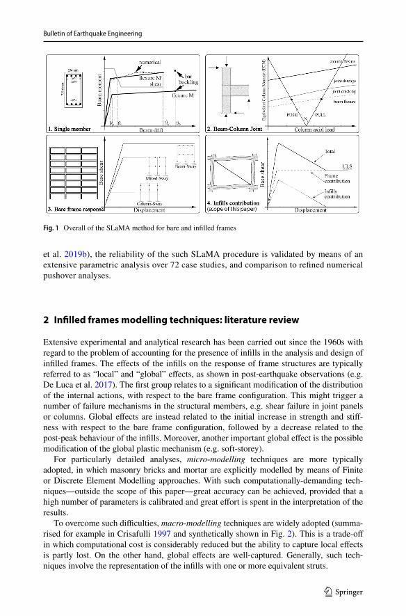
In the current version of SLaMA, the possible influence of infill walls within infilled frames can be considered only at local level, with checks on the RC members. However, global effects are not captured, including significant modifications on strength, stiffness and displacement ductility (Crisafulli et al. 2000; Del Vecchio et al. 2018b). In general, this might significantly change the outcome of a seismic assessment based on a non-linear static capacity curve (particularly for the Serviceability Limit State, SLS). In this paper, a SLaMA procedure is proposed which extends the capabilities of the existing SLaMA for bare frames, allowing to comprehensively include the in-plane contribution of the infills on the non-linear capacity curve of masonry-infilled RC frames (Fig. 1). Although particularly important, the out-of-plane response of the infills is outside the scope of this paper, and requires further investigations.
The extended SLaMA is based on the possibility to separately calculate the base shear contributions of the frame and the infills, made possible by considerations on global equilibrium. Such considerations also allow to define a novel decoupling pro-cedure to post-process the results of pushover or time history analyses, where infills are modelled as single or multiple diagonal struts. Rather than separately analyse the bare and infilled configurations, this procedure can be used to decouple—or disaggre-gate—the frame and infills contribution to the global base shear capacity within a single numerical analysis. Hence, after a literature review on the available infill macro-models, the decoupling procedure for numerical analyses is demonstrated through the pusho-ver analyses of an ideal two-storey one-bay frame, considering different infill configura-tions, i.e. uniformly infilled or pilotis.
The completely-analytical SLaMA procedure for masonry-infilled RC infilled frames is therefore presented on a step-by-step basis. In a companion paper (Gentile
Bulletin of Earthquake Engineering
1 3
et al. 2019b), the reliability of the such SLaMA procedure is validated by means of an extensive parametric analysis over 72 case studies, and comparison to refined numerical pushover analyses.
2 Infilled frames modelling techniques: literature review
Extensive experimental and analytical research has been carried out since the 1960s with regard to the problem of accounting for the presence of infills in the analysis and design of infilled frames. The effects of the infills on the response of frame structures are typically referred to as “local” and “global” effects, as shown in post-earthquake observations (e.g. De Luca et al. 2017). The first group relates to a significant modification of the distribution of the internal actions, with respect to the bare frame configuration. This might trigger a number of failure mechanisms in the structural members, e.g. shear failure in joint panels or columns. Global effects are instead related to the initial increase in strength and stiff-ness with respect to the bare frame configuration, followed by a decrease related to the post-peak behaviour of the infills. Moreover, another important global effect is the possible modification of the global plastic mechanism (e.g. soft-storey).
For particularly detailed analyses, micro-modelling techniques are more typically adopted, in which masonry bricks and mortar are explicitly modelled by means of Finite or Discrete Element Modelling approaches. With such computationally-demanding tech-niques—outside the scope of this paper—great accuracy can be achieved, provided that a high number of parameters is calibrated and great effort is spent in the interpretation of the results.
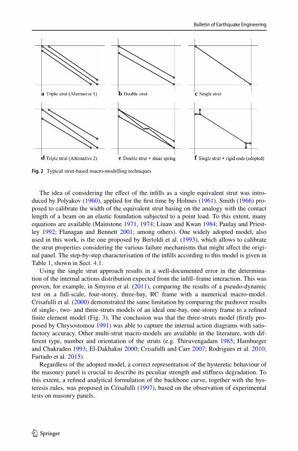
To overcome such difficulties, macro-modelling techniques are widely adopted (summa-rised for example in Crisafulli 1997 and synthetically shown in Fig. 2). This is a trade-off in which computational cost is considerably reduced but the ability to capture local effects is partly lost. On the other hand, global effects are well-captured. Generally, such tech-niques involve the representation of the infills with one or more equivalent struts.
Fig. 1 Overall of the SLaMA method for bare and infilled frames
Bulletin of Earthquake Engineering
1 3
The idea of considering the effect of the infills as a single equivalent strut was intro-duced by Polyakov (1960), applied for the first time by Holmes (1961). Smith (1966) pro-posed to calibrate the width of the equivalent strut basing on the analogy with the contact length of a beam on an elastic foundation subjected to a point load. To this extent, many equations are available (Mainstone 1971, 1974; Liuaw and Kwan 1984; Paulay and Priest-ley 1992; Flanagan and Bennett 2001; among others). One widely adopted model, also used in this work, is the one proposed by Bertoldi et al. (1993), which allows to calibrate the strut properties considering the various failure mechanisms that might affect the origi-nal panel. The step-by-step characterisation of the infills according to this model is given in Table 1, shown in Sect. 4.1.
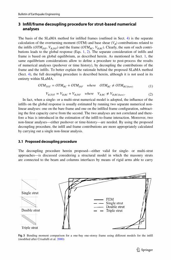
Using the single strut approach results in a well-documented error in the determina-tion of the internal actions distribution expected from the infill–frame interaction. This was proven, for example, in Smyrou et al. (2011), comparing the results of a pseudo-dynamic test on a full-scale, four-storey, three-bay, RC frame with a numerical macro-model. Crisafulli et al. (2000) demonstrated the same limitation by comparing the pushover results of single-, two- and three-struts models of an ideal one-bay, one-storey frame to a refined finite element model (Fig. 3). The conclusion was that the three-struts model (firstly pro-posed by Chrysostomou 1991) was able to capture the internal action diagrams with satis-factory accuracy. Other multi-strut macro-models are available in the literature, with dif-ferent type, number and orientation of the struts (e.g. Thiruvengadam 1985; Hamburger and Chakradeo 1993; El-Dakhakni 2000; Crisafulli and Carr 2007; Rodrigues et al. 2010; Furtado et al. 2015).
Regardless of the adopted model, a correct representation of the hysteretic behaviour of the masonry panel is crucial to describe its peculiar strength and stiffness degradation. To this extent, a refined analytical formulation of the backbone curve, together with the hys-teresis rules, was proposed in Crisafulli (1997), based on the observation of experimental tests on masonry panels.
Fig. 2 Typical strut-based macro-modelling techniques
Bulletin of Earthquake Engineering
1 3
3 Infill/frame decoupling procedure for strut‑based numerical analyses
The basis of the SLaMA method for infilled frames (outlined in Sect. 4) is the separate calculation of the overturning moment (OTM) and base shear (VB) contributions related to the infills (OTMINF, VB,INF) and the frame (OTMRC, VB,RC). Clearly, the sum of such contri-butions leads to the global response (Eqs. 1, 2). The separate consideration of infills and frame is based on global equilibrium, as described herein. As mentioned in Sect. 1, the same equilibrium considerations allow to define a procedure to post-process the results of numerical analyses (pushover or time history), by decoupling the contributions of the frame and the infills. To better explain the rationale behind the proposed SLaMA method (Sect. 4), the full decoupling procedure is described herein, although it is not used in its entirety within SLaMA.
In fact, when a single- or a multi-strut numerical model is adopted, the influence of the infills on the global response is usually estimated by running two separate numerical non-linear analyses: one on the bare frame and one on the infilled frame configuration, subtract-ing the first capacity curve from the second. The two analyses are not correlated and there-fore a bias is introduced in the estimation of the infill-to-frame interaction. Moreover, two non-linear analyses—either pushover or time-history—are needed. By using the proposed decoupling procedure, the infill and frame contributions are more appropriately calculated by carrying out a single non-linear analysis.
3.1 Proposed decoupling procedure
The decoupling procedure herein proposed—either valid for single- or multi-strut approaches—is discussed considering a structural model in which the masonry struts are connected to the beam and columns interfaces by means of rigid arms able to carry
(1)OTMTOT = OTMRC + OTMINF where OTMRC ≠ OTMRC(bare)
(2)VB,TOT = VB,RC + VB,INF where VB,RC ≠ VB,RC(bare).
Fig. 3 Bending moment comparison for a one-bay one-storey frame using different models for the infill (modified after Crisafulli et al. 2000)
Bulletin of Earthquake Engineering
1 3
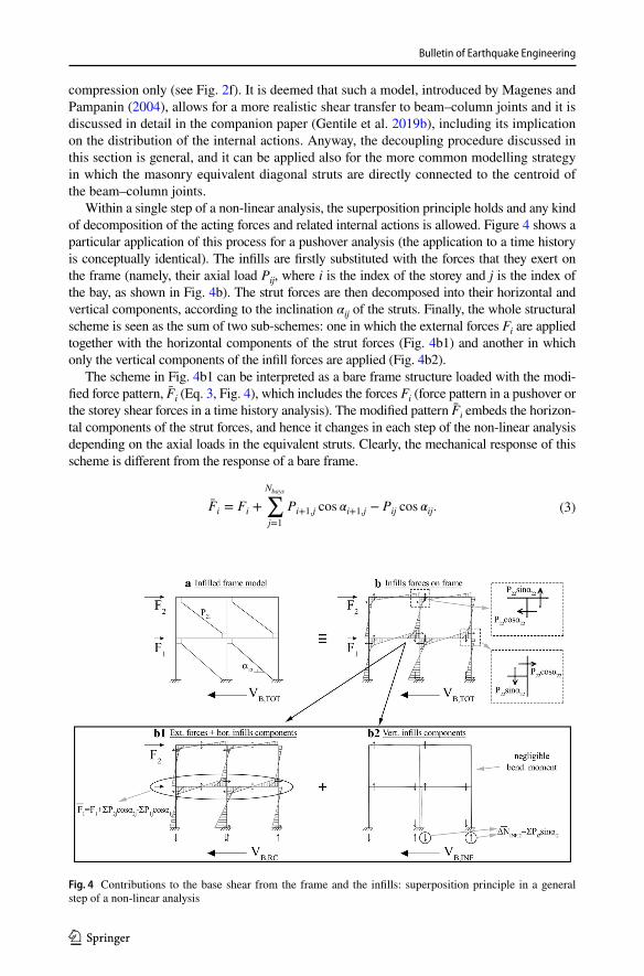
compression only (see Fig. 2f). It is deemed that such a model, introduced by Magenes and Pampanin (2004), allows for a more realistic shear transfer to beam–column joints and it is discussed in detail in the companion paper (Gentile et al. 2019b), including its implication on the distribution of the internal actions. Anyway, the decoupling procedure discussed in this section is general, and it can be applied also for the more common modelling strategy in which the masonry equivalent diagonal struts are directly connected to the centroid of the beam–column joints.
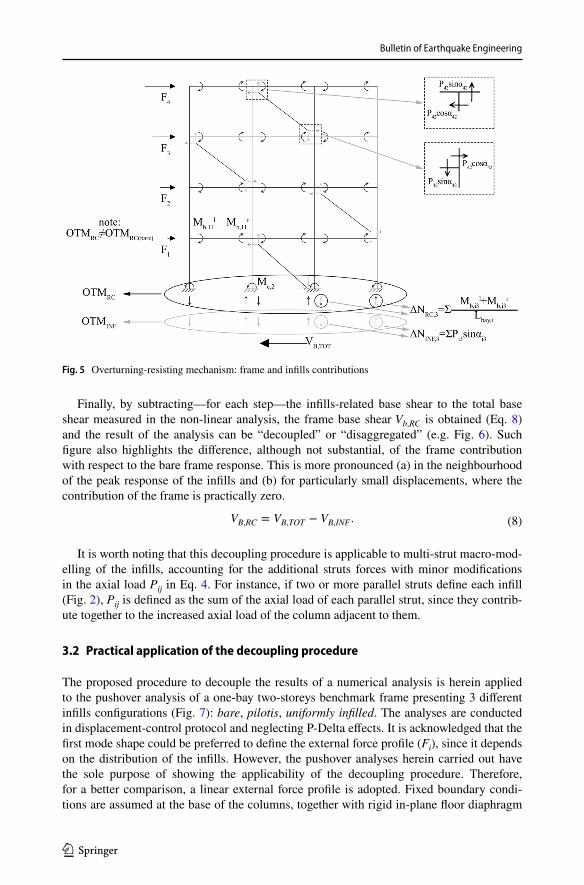
Within a single step of a non-linear analysis, the superposition principle holds and any kind of decomposition of the acting forces and related internal actions is allowed. Figure 4 shows a particular application of this process for a pushover analysis (the application to a time history is conceptually identical). The infills are firstly substituted with the forces that they exert on the frame (namely, their axial load Pij, where i is the index of the storey and j is the index of the bay, as shown in Fig. 4b). The strut forces are then decomposed into their horizontal and vertical components, according to the inclination αij of the struts. Finally, the whole structural scheme is seen as the sum of two sub-schemes: one in which the external forces Fi are applied together with the horizontal components of the strut forces (Fig. 4b1) and another in which only the vertical components of the infill forces are applied (Fig. 4b2).
The scheme in Fig. 4b1 can be interpreted as a bare frame structure loaded with the modi-fied force pattern, F̄i (Eq. 3, Fig. 4), which includes the forces Fi (force pattern in a pushover or the storey shear forces in a time history analysis). The modified pattern F̄i embeds the horizon-tal components of the strut forces, and hence it changes in each step of the non-linear analysis depending on the axial loads in the equivalent struts. Clearly, the mechanical response of this scheme is different from the response of a bare frame.
(3)F̄i = Fi +
Nbays∑j=1
Pi+1,j cos 𝛼i+1,j − Pij cos 𝛼ij.
Fig. 4 Contributions to the base shear from the frame and the infills: superposition principle in a general step of a non-linear analysis
Bulletin of Earthquake Engineering
1 3
The last scheme (Fig. 4b2), in which only the vertical components of the strut forces are applied, allows calculating the influence of the infills in resisting the overturning moment. In particular, the vertical components of the strut forces become shear for the beams and, in turn, axial load for the columns (ΔNinf,j). This creates the tension–compression couples that contribute in resisting the overturning moment due to the applied external forces Fi, calculated with Eq. 4, where Lbay,j is the length of the jth bay and Pij is the strut force at ith storey, bay jth. Internal actions related to the vertical components of the strut forces (in particular, shear and bending moment) can theoretically influence the above-mentioned overturning-resisting mechanism. However, such internal actions are deemed to be negligible, and therefore this effect it is not considered. This applies also if the equivalent struts are directly connected to the centroid of the beam–column joints.
This overturning-resisting mechanism works in addition to the typical mechanism of a bare frame (Eq. 5) i.e. the base column moments Mc,j plus the tension–compression couples com-ing from the sum of the beam shears Vb,ij = (Ml
b,ij + Mrb,ij)/Lbay,j, where Ml
b,ij and Mrb,ij are the
beam moments in the left and right end sections. In Eq. 5, Mc,j, Mlb,ij and Mr
b,ij are the moment in the columns and the beams measured at a given (and general) value of the global displace-ment. Figure 5 shows the overturning-resisting mechanism for a general configuration of the frame and a general distribution of the infills. However, the above-mentioned modified force pattern affects the internal actions distribution on the frame members and, as a result, the lat-ter overturning-resisting mechanism is modified with respect to the behaviour of a bare frame (OTMRC ≠ OTMRC(bare)).
Given the amount of overturning moment resisted by the infills, the related base shear
contribution is calculated according to Eq. 6, where H* is the position of the resultant of the external forces that produces the same global over turning moment (Eq. 7, in which Hi is the height of the ith storey, measured from the foundation). The height H*, also meas-ured from the foundation, can be easily calculated for each step of the non-linear analysis, since the value of the external forces Fi is known.
where
(4)OTMINF =
Nbays∑j=1
Lbay,jΔNINF,j =
Nfloors∑i=1
Nbays∑i=1
Lbay,jPij sin �ij.
(5)OTMRC =
Ncols∑j=1
Mc,j +
Nfloors∑i=1
Nbays∑i=1
Vb,ijLbay,j.
(6)VB,INF =OTMINF
H∗
(7)H∗ =
∑i FiHi∑i Fi
.
Bulletin of Earthquake Engineering
1 3
Finally, by subtracting—for each step—the infills-related base shear to the total base shear measured in the non-linear analysis, the frame base shear Vb,RC is obtained (Eq. 8) and the result of the analysis can be “decoupled” or “disaggregated” (e.g. Fig. 6). Such figure also highlights the difference, although not substantial, of the frame contribution with respect to the bare frame response. This is more pronounced (a) in the neighbourhood of the peak response of the infills and (b) for particularly small displacements, where the contribution of the frame is practically zero.
It is worth noting that this decoupling procedure is applicable to multi-strut macro-mod-
elling of the infills, accounting for the additional struts forces with minor modifications in the axial load Pij in Eq. 4. For instance, if two or more parallel struts define each infill (Fig. 2), Pij is defined as the sum of the axial load of each parallel strut, since they contrib-ute together to the increased axial load of the column adjacent to them.
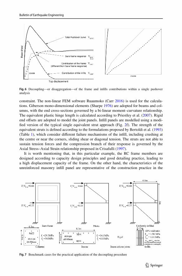
3.2 Practical application of the decoupling procedure
The proposed procedure to decouple the results of a numerical analysis is herein applied to the pushover analysis of a one-bay two-storeys benchmark frame presenting 3 different infills configurations (Fig. 7): bare, pilotis, uniformly infilled. The analyses are conducted in displacement-control protocol and neglecting P-Delta effects. It is acknowledged that the first mode shape could be preferred to define the external force profile (Fi), since it depends on the distribution of the infills. However, the pushover analyses herein carried out have the sole purpose of showing the applicability of the decoupling procedure. Therefore, for a better comparison, a linear external force profile is adopted. Fixed boundary condi-tions are assumed at the base of the columns, together with rigid in-plane floor diaphragm
(8)VB,RC = VB,TOT − VB,INF .
Fig. 5 Overturning-resisting mechanism: frame and infills contributions
Bulletin of Earthquake Engineering
1 3
constraint. The non-linear FEM software Ruaumoko (Carr 2016) is used for the calcula-tions. Giberson mono-dimensional elements (Sharpe 1976) are adopted for beams and col-umns, with the end cross-sections governed by a bi-linear moment–curvature relationship. The equivalent plastic hinge length is calculated according to Priestley et al. (2007). Rigid end offsets are adopted to model the joint panels. Infill panels are modelled using a modi-fied version of the typical single equivalent strut approach (Fig. 2f). The strength of the equivalent struts is defined according to the formulations proposed by Bertoldi et al. (1993) (Table 1), which consider different failure mechanisms of the infill, including crushing at the centre or near the corners, sliding shear or diagonal tension. The struts are not able to sustain tension forces and the compression branch of their response is governed by the Axial Stress–Axial Strain relationship proposed in Crisafulli (1997).
It is worth mentioning that, in this particular example, the RC frame members are designed according to capacity design principles and good detailing practice, leading to a high displacement capacity of the frame. On the other hand, the characteristics of the unreinforced masonry infill panel are representative of the construction practice in the
Fig. 6 Decoupling—or disaggregation—of the frame and infills contributions within a single pushover analysis
Fig. 7 Benchmark cases for the practical application of the decoupling procedure
Bulletin of Earthquake Engineering
1 3
Mediterranean area (Morandi et al. 2011). It is worth mentioning that more details for both RC and infill members can be found in Gentile et al. (2018).
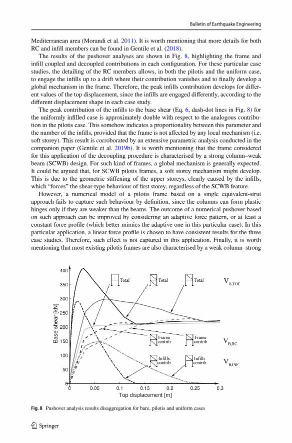
The results of the pushover analyses are shown in Fig. 8, highlighting the frame and infill coupled and decoupled contributions in each configuration. For these particular case studies, the detailing of the RC members allows, in both the pilotis and the uniform case, to engage the infills up to a drift where their contribution vanishes and to finally develop a global mechanism in the frame. Therefore, the peak infills contribution develops for differ-ent values of the top displacement, since the infills are engaged differently, according to the different displacement shape in each case study.
The peak contribution of the infills to the base shear (Eq. 6, dash-dot lines in Fig. 8) for the uniformly infilled case is approximately double with respect to the analogous contribu-tion in the pilotis case. This somehow indicates a proportionality between this parameter and the number of the infills, provided that the frame is not affected by any local mechanism (i.e. soft storey). This result is corroborated by an extensive parametric analysis conducted in the companion paper (Gentile et al. 2019b). It is worth mentioning that the frame considered for this application of the decoupling procedure is characterised by a strong column–weak beam (SCWB) design. For such kind of frames, a global mechanism is generally expected. It could be argued that, for SCWB pilotis frames, a soft storey mechanism might develop. This is due to the geometric stiffening of the upper storeys, clearly caused by the infills, which “forces” the shear-type behaviour of first storey, regardless of the SCWB feature.
However, a numerical model of a pilotis frame based on a single equivalent-strut approach fails to capture such behaviour by definition, since the columns can form plastic hinges only if they are weaker than the beams. The outcome of a numerical pushover based on such approach can be improved by considering an adaptive force pattern, or at least a constant force profile (which better mimics the adaptive one in this particular case). In this particular application, a linear force profile is chosen to have consistent results for the three case studies. Therefore, such effect is not captured in this application. Finally, it is worth mentioning that most existing pilotis frames are also characterised by a weak column–strong
Fig. 8 Pushover analysis results disaggregation for bare, pilotis and uniform cases
Bulletin of Earthquake Engineering
1 3
beam feature, which clearly leads to a soft-storey plastic mechanism at the first storey. By adopting SLaMA, rather than a numerically-based pushover, the soft-storey plastic mecha-nism in pilotis frames can be captured explicitly adopting the “Column–Sway” procedure (as described in Sect. 4.3).
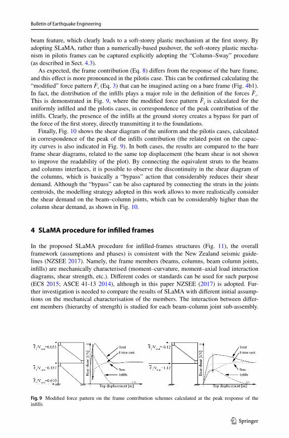
As expected, the frame contribution (Eq. 8) differs from the response of the bare frame, and this effect is more pronounced in the pilotis case. This can be confirmed calculating the “modified” force pattern F̄i (Eq. 3) that can be imagined acting on a bare frame (Fig. 4b1). In fact, the distribution of the infills plays a major role in the definition of the forces F̄i . This is demonstrated in Fig. 9, where the modified force pattern F̄i is calculated for the uniformly infilled and the pilotis cases, in correspondence of the peak contribution of the infills. Clearly, the presence of the infills at the ground storey creates a bypass for part of the force of the first storey, directly transmitting it to the foundations.
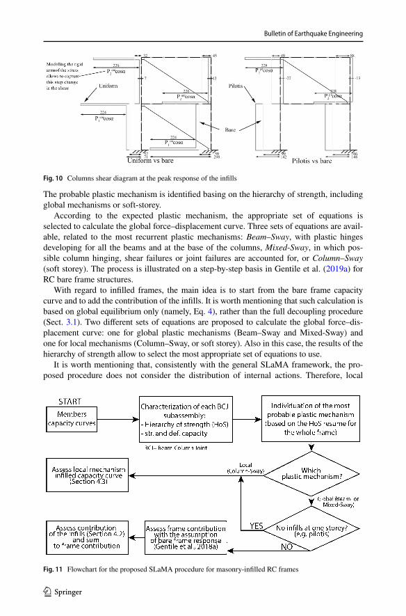
Finally, Fig. 10 shows the shear diagram of the uniform and the pilotis cases, calculated in correspondence of the peak of the infills contribution (the related point on the capac-ity curves is also indicated in Fig. 9). In both cases, the results are compared to the bare frame shear diagrams, related to the same top displacement (the beam shear is not shown to improve the readability of the plot). By connecting the equivalent struts to the beams and columns interfaces, it is possible to observe the discontinuity in the shear diagram of the columns, which is basically a “bypass” action that considerably reduces their shear demand. Although the “bypass” can be also captured by connecting the struts in the joints centroids, the modelling strategy adopted in this work allows to more realistically consider the shear demand on the beam–column joints, which can be considerably higher than the column shear demand, as shown in Fig. 10.
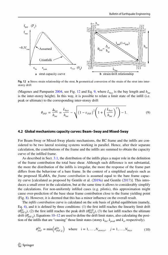
4 SLaMA procedure for infilled frames
In the proposed SLaMA procedure for infilled-frames structures (Fig. 11), the overall framework (assumptions and phases) is consistent with the New Zealand seismic guide-lines (NZSEE 2017). Namely, the frame members (beams, columns, beam column joints, infills) are mechanically characterised (moment–curvature, moment–axial load interaction diagrams, shear strength, etc.). Different codes or standards can be used for such purpose (EC8 2015; ASCE 41-13 2014), although in this paper NZSEE (2017) is adopted. Fur-ther investigation is needed to compare the results of SLaMA with different initial assump-tions on the mechanical characterisation of the members. The interaction between differ-ent members (hierarchy of strength) is studied for each beam–column joint sub-assembly.
Fig. 9 Modified force pattern on the frame contribution schemes calculated at the peak response of the infills
Bulletin of Earthquake Engineering
1 3
The probable plastic mechanism is identified basing on the hierarchy of strength, including global mechanisms or soft-storey.
According to the expected plastic mechanism, the appropriate set of equations is selected to calculate the global force–displacement curve. Three sets of equations are avail-able, related to the most recurrent plastic mechanisms: Beam–Sway, with plastic hinges developing for all the beams and at the base of the columns, Mixed-Sway, in which pos-sible column hinging, shear failures or joint failures are accounted for, or Column–Sway (soft storey). The process is illustrated on a step-by-step basis in Gentile et al. (2019a) for RC bare frame structures.
With regard to infilled frames, the main idea is to start from the bare frame capacity curve and to add the contribution of the infills. It is worth mentioning that such calculation is based on global equilibrium only (namely, Eq. 4), rather than the full decoupling procedure (Sect. 3.1). Two different sets of equations are proposed to calculate the global force–dis-placement curve: one for global plastic mechanisms (Beam–Sway and Mixed-Sway) and one for local mechanisms (Column–Sway, or soft storey). Also in this case, the results of the hierarchy of strength allow to select the most appropriate set of equations to use.
It is worth mentioning that, consistently with the general SLaMA framework, the pro-posed procedure does not consider the distribution of internal actions. Therefore, local
Fig. 10 Columns shear diagram at the peak response of the infills
Fig. 11 Flowchart for the proposed SLaMA procedure for masonry-infilled RC frames

Bulletin of Earthquake Engineering
1 3
effects related to the infills are not expressly considered, and in turn it is not possible to capture possible changes of the plastic mechanism related to such phenomena. As typically done with numerical analyses based on a single-strut macro-model, local effects are con-sidered by post-processing the global results.
4.1 Mechanical characterisation of the infills
Regardless of the adopted set of equations to calculate the capacity curve, depending on the expected plastic mechanism, the mechanical characterisation of the infills is needed, in terms of shear versus inter-storey drift of the equivalent struts. Among others, the for-mulation proposed by Bertoldi et al. (1993) is chosen in this work because of its ability to consider different collapse modes of the infill. This model is summarised in Table 1 [and described on a step-by-step basis in Gentile (2017)]. After calculating the infill strength for the different failure modes (σwi), the final strength of the equivalent strut is set equal to fm = min
(�wi
).
The effect of openings can be accounted for reducing the strength/stiffness of the equiv-alent struts using a calibrated reduction factor. Further investigations are needed to cali-brate/validate the use of reduction factors in SLaMA, therefore no particular suggestion is made. It is worth noting that other capacity models can be used, without restrictions for the overall SLaMA procedure.
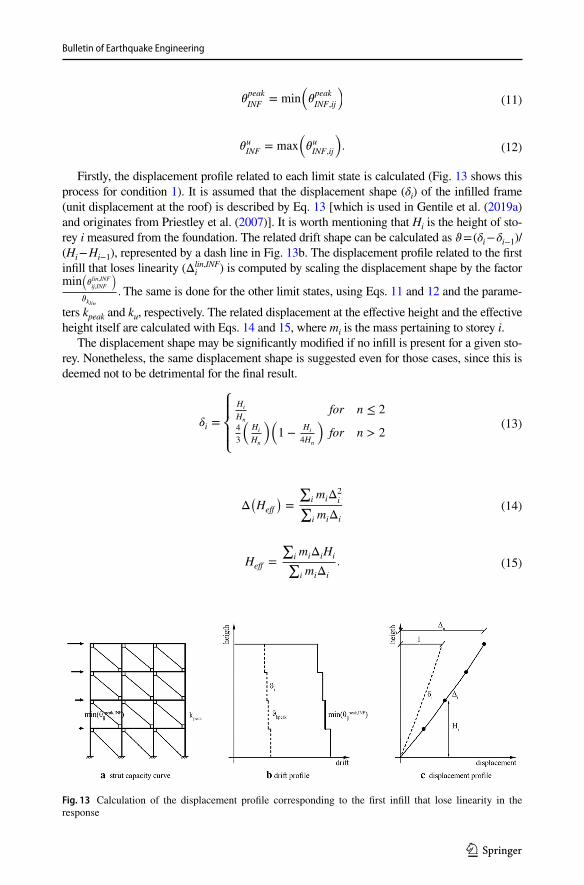
For the characterisation of the stress–strain envelope of the struts, a simplification of the backbone curve proposed by Crisafulli (1997) is chosen (Fig. 12). For the sake of simplic-ity, the behaviour of the equivalent strut is defined by a three-branch linear curve character-ised by a point at one-third of the strain at peak stress (end of the linear branch), the peak and the ultimate point. As an approximation, the strut axial load (or stress) correspond-ing to one-third of the strain at peak stress is considered equal to half the peak axial load (or stress). Typical values of the strain corresponding to the peak stress in the strut range between 0.002 and 0.004 (Magenes and Pampanin 2004) while the ultimate strain ranges between 5 and 10 times the strain at peak stress (Crisafulli 1997). Finally, the strain in the strut ɛINF is converted into inter-storey drift, θINF, by means of geometric conditions
Table 1 Summary of the Bertoldi et al. (1993) model for the characterisation of the infills
Where α is the inclination of the strut; Ewv, Ewh and Ewθ are the vertical, horizontal and inclined moduli of elasticity of the masonry; G is the shear modulus of the masonry; υ is the Poisson modulus of the masonry; tw is the thickness of the masonry; hw and dw are the height and the diagonal of the infill; Ec and Ic are the modulus of elasticity and the moment of inertia of the columns adjacent to the infill; λ is the relative stiff-ness factor; hint is the inter-storey height; bw is the width of the equivalent strut; fwv is the vertical compres-sive strength of the masonry; σv is the vertical compressive stress on the infill due to gravity loads; fws is the shear strength of the masonry; σw1,2,3,4 are the compression to the centre, compression to the corners, sliding shear and diagonal cracking strengths of the infill panel
Ew� =
(cos4 �
Ewh
+sin
4�
Ewv
+ cos2 � sin2�
(1
G− 2
�
Ewv
))−1�w1 =
1.16fwv tan�
K1+K2�hint
� = 4
√Ew� twsin(2�)
4EcIchw
�w2 =1.2fwv sin � cos �
K1�h−0.12int
K2�h0.88
int
λhint < 3.14 3.14 < λhint < 7.85 λhint > 7.85 �w3 =(1.2 sin �+0.45 cos �)fwv+0.3�v
bw∕dw
K1 1.3 0.707 0.47K2 − 0.178 0.01 0.04bw
dw=
K1
�hint+ K2 �w4 =
0.6fws+0.3�v
bw∕dw
Bulletin of Earthquake Engineering
1 3
(Magenes and Pampanin 2004, see Fig. 12 and Eq. 9, where Lbay is the bay length and hint is the inter-storey height). In this way, it is possible to relate a limit state of the infill (i.e. peak or ultimate) to the corresponding inter-storey drift
4.2 Global mechanisms capacity curves: Beam–Sway and Mixed‑Sway
For Beam-Sway or Mixed-Sway plastic mechanisms, the RC frame and the infills are con-sidered to be two lateral resisting systems working in parallel. Hence, after their separate calculation, the contributions of the frame and the infills are summed to obtain the capacity curve of the infilled frame.
As described in Sect. 3.1, the distribution of the infills plays a major role in the definition of the frame contribution the total base shear. Although such difference is not substantial, the more the distribution of the infills is irregular, the more the response of the frame part differs from the behaviour of a bare frame. In the context of a simplified analysis such as the proposed SLaMA, the frame contribution is assumed equal to the bare frame capac-ity curve [calculated as proposed by Gentile et al. (2019a) and Gentile (2017)]. This intro-duces a small error in the calculation, but at the same time it allows to considerably simplify the calculations. For non-uniformly infilled cases (e.g. pilotis), this approximation might cause over-prediction of the base shear frame contribution close to the frame yielding point (Fig. 8). However, it is deemed that this has a minor influence on the overall result.
The infills contribution curve is calculated on the sole basis of global equilibrium (namely, Eq. 4), and it is defined by three conditions: (1) the first infill reaches the linearity limit drift (θlin
INF,ij), (2) the first infill reaches the peak drift (θpeakINF,ij), (3) the last infill reaches the ultimate
drift (θuINF,ij). Equations 10–12 are used to define the drift limit states, also calculating the posi-
tion of the infills that are “causing” those limit states (storey klin, kpeak and ku, respectively).
(9)�INF =Δint
hint=
Lbay
hint−
√√√√(1 − �INF
)2(1 +
(Lbay
hint
)2)
− 1.
(10)�linINF
= min
(�linINF,ij
)where i = 1,… ,Nstoreys, j = 1,… ,Nbays
Fig. 12 a Stress strain relationship of the strut, b geometrical conversion of the strain of the strut into inter-storey drift
Bulletin of Earthquake Engineering
1 3
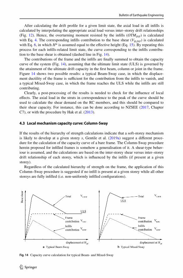
Firstly, the displacement profile related to each limit state is calculated (Fig. 13 shows this process for condition 1). It is assumed that the displacement shape (δi) of the infilled frame (unit displacement at the roof) is described by Eq. 13 [which is used in Gentile et al. (2019a) and originates from Priestley et al. (2007)]. It is worth mentioning that Hi is the height of sto-rey i measured from the foundation. The related drift shape can be calculated as ϑ = (δi − δi−1)/(Hi − Hi−1), represented by a dash line in Fig. 13b. The displacement profile related to the first infill that loses linearity (Δi
lin,INF) is computed by scaling the displacement shape by the factor min
(�lin,INF
ij,INF
)
�klin
. The same is done for the other limit states, using Eqs. 11 and 12 and the parame-
ters kpeak and ku, respectively. The related displacement at the effective height and the effective height itself are calculated with Eqs. 14 and 15, where mi is the mass pertaining to storey i.
The displacement shape may be significantly modified if no infill is present for a given sto-rey. Nonetheless, the same displacement shape is suggested even for those cases, since this is deemed not to be detrimental for the final result.
(11)�peak
INF= min
(�peak
INF,ij
)
(12)�uINF
= max
(�uINF,ij
).
(13)𝛿i =
⎧⎪⎨⎪⎩
Hi
Hn
for n ≤ 2
4
3
�Hi
Hn
��1 −
Hi
4Hn
�for n > 2
(14)Δ�Heff
�=
∑i miΔ
2
i∑i miΔi
(15)Heff =
∑i miΔiHi∑i miΔi
.
Fig. 13 Calculation of the displacement profile corresponding to the first infill that lose linearity in the response
Bulletin of Earthquake Engineering
1 3
After calculating the drift profile for a given limit state, the axial load in all infills is calculated by interpolating the appropriate axial load versus inter–storey drift relationships (Fig. 12). Hence, the overturning moment resisted by the infills (OTMINF) is calculated with Eq. 4. The corresponding infills contribution to the base shear (VB,INF) is calculated with Eq. 6, in which H* is assumed equal to the effective height (Eq. 15). By repeating this process for each infills-related limit state, the curve corresponding to the infills contribu-tion to the base shear is obtained (dashed line in Fig. 14).
The contributions of the frame and the infills are finally summed to obtain the capacity curve of the system (Fig. 14), assuming that the ultimate limit state (ULS) is governed by the attainment of the ultimate drift capacity in the first beam, column or joint in the frame. Figure 14 shows two possible results: a typical Beam-Sway case, in which the displace-ment ductility of the frame is sufficient for the contribution from the infills to vanish, and a typical Mixed-Sway case, in which the frame reaches the ULS while the infills are still contributing.
Clearly, a post-processing of the results is needed to check for the influence of local effects. The axial load in the struts in correspondence to the peak of the curve should be used to calculate the shear demand on the RC members, and this should be compared to their shear capacity. For instance, this can be done according to NZSEE (2017, Chapter C7), or with the procedure by Hak et al. (2013).
4.3 Local mechanism capacity curve: Column‑Sway
If the results of the hierarchy of strength calculations indicate that a soft-storey mechanism is likely to develop at a given storey s, Gentile et al. (2019a) suggest a different proce-dure for the calculation of the capacity curve of a bare frame. The Column-Sway procedure herein proposed for infilled frames is somehow a generalisation of it. A shear-type behav-iour is assumed, and the calculations are based on the inter-storey shear versus inter–storey drift relationship of each storey, which is influenced by the infills (if present at a given storey).
Regardless of the calculated hierarchy of strength on the frame, the application of this Column–Sway procedure is suggested if no infill is present at a given storey while all other storeys are fully infilled (i.e. non-uniformly infilled configurations).
Fig. 14 Capacity curve calculation for typical Beam- and Mixed-Sway
Bulletin of Earthquake Engineering
1 3
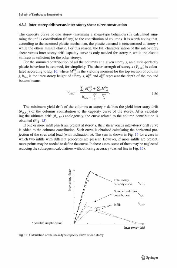
4.3.1 Inter‑storey drift versus inter‑storey shear curve construction
The capacity curve of one storey (assuming a shear-type behaviour) is calculated sum-ming the infills contribution (if any) to the contribution of columns. It is worth noting that, according to the assumed plastic mechanism, the plastic demand is concentrated at storey s while the others remain elastic. For this reason, the full characterisation of the inter-storey shear versus inter-storey drift capacity curve is only needed for storey s, while the elastic stiffness is sufficient for the other storeys.
For the summed contribution of all the columns at a given storey s, an elastic-perfectly plastic behaviour is assumed, for simplicity. The shear strength of storey s (Vs,RC) is calcu-lated according to Eq. 16, where Mtop
cyj is the yielding moment for the top section of column
j, hints is the inter-storey height of storey s, hbtop and hb
bot represent the depth of the top and bottom beams.
The minimum yield drift of the columns at storey s defines the yield inter-story drift ( �sy,RC ) of the columns contribution to the capacity curve of the storey. After calculat-ing the ultimate drift ( �su,RC ) analogously, the curve related to the column contribution is obtained (Fig. 15).
If one or more infill panels are present at storey s, their shear versus inter-storey drift curve is added to the columns contribution. Such curve is obtained calculating the horizontal pro-jection of the strut axial load (with inclination α). The sum is shown in Fig. 15 for a case in which two infills with different properties are present. However, if more infills are present, more points may be needed to define the curve. In these cases, some of them may be neglected reducing the subsequent calculations without losing accuracy (dashed line in Fig. 15).
(16)Vs,RC =
∑j M
top
cyj+∑
j Mbotcyj
hints −htop
b
2−
hbotb
2
.
Fig. 15 Calculation of the shear-type capacity curve of one storey
Bulletin of Earthquake Engineering
1 3
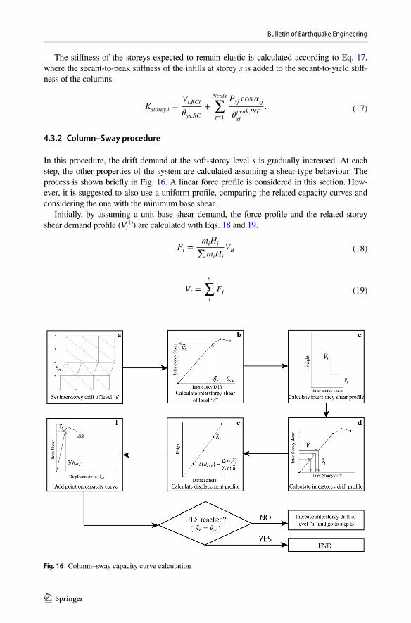
The stiffness of the storeys expected to remain elastic is calculated according to Eq. 17, where the secant-to-peak stiffness of the infills at storey s is added to the secant-to-yield stiff-ness of the columns.
4.3.2 Column–Sway procedure
In this procedure, the drift demand at the soft-storey level s is gradually increased. At each step, the other properties of the system are calculated assuming a shear-type behaviour. The process is shown briefly in Fig. 16. A linear force profile is considered in this section. How-ever, it is suggested to also use a uniform profile, comparing the related capacity curves and considering the one with the minimum base shear.
Initially, by assuming a unit base shear demand, the force profile and the related storey shear demand profile (Vi
(1)) are calculated with Eqs. 18 and 19.
(17)Kstorey,i =Vi,RCi
�ys,RC
+
Ncols∑j=1
Psj cos �sj
�peak,INF
sj
.
(18)Fi =miHi∑miHi
VB
(19)Vi =
n∑i
Fi.
Fig. 16 Column–sway capacity curve calculation
Bulletin of Earthquake Engineering
1 3
The inter-storey drift demand at storey s ( ̄𝜃s ) is set equal to the first point in the related inter-storey shear versus inter-storey drift curve and the corresponding shear is considered ( ̄Vs ). The related base shear ( ̄VB ) is calculated amplifying the unit storey shear demand through Eq. 20 while the storey shear profile ( ̄Vi ) is calculated according to Eq. 21. The drift profile ( ̄𝜃i ) is calculated with Eq. 22. The displacement profile ( ̄Δi ) is obtained recur-sively according to Eq. 23 while Eq. 14 allows the calculation of the displacement at the effective height, Δ̄
(Heff
) . The pair
[Δ̄(Heff
), V̄B
] defines the first point of the global capacity
curve. The full global capacity curve is calculated repeating this process for all the points that define the inter-storey shear versus inter-storey drift of storey s. It is worth mentioning that the procedure proposed in Sect. 3 might be used for each point of the capacity curve to disaggregate the frame and infills contributions. Moreover, shear failures on the columns due to the infill-induced shear demand should be checked by post-processing the results of the analysis as described in Sect. 4.2
5 Conclusions
In the assessment of existing RC structures, non-linear numerical analysis is deemed the most refined approach. However, reliable seismic assessment procedures are needed to allow the simple identification of the potential structural weaknesses and their influence on the overall building capacity. In this paper, a novel procedure to calculate the non-linear force–displacement curve of masonry-infilled RC frames is proposed within the frame-work of the Simple Lateral Mechanism Analysis (SLaMA). With respect to the existing SLaMA procedure, this allows to explicitly consider the effects of the infills on the global force–displacement capacity curve. The method allows to have a first estimation of the lat-eral response of infilled-frames considering both global or local mechanisms, capturing the most probable failure mechanisms of the structural members (beams, columns, joint panels, infills). No computer-based numerical model is needed, since the calculations can be simply implemented in a spreadsheet.
The method is based on the separate calculation of the frame and infills contributions to the total base shear, in turn based solely on global equilibrium considerations. Such con-sideration also led to the proposal of a mechanically-based post-processing procedure, for numerical pushover or time history analyses, to decouple the infill and frame contributions to the overturning moment of infilled frames modelled with single- or multi strut macro-modelling techniques. The contributions from frame and infills to the total capacity curve can be decoupled on the basis of a single numerical analysis of the infilled frame, rather
(20)V̄B =V̄s
V(1)s
(21)V̄i = V̄BV(1)
i
(22)�̄�i =V̄i
Kstorey,i
(23)Δ̄i = Δ̄i−1 + �̄�i
(Hi − Hi−1
).
Bulletin of Earthquake Engineering
1 3
than running two separate analyses (on the bare and infilled configurations). Such proce-dure can be also used to interpret the results of experimental tests. The decoupling proce-dure is demonstrated for an ideal two-storey, one-bay masonry-infilled frame with different infills configurations.
The proposed SLaMA procedure for masonry-infilled RC frames is herein formalised and described in detail. Depending on the identified plastic mechanism, based on hierarchy of strength calculations, an appropriate set of equations is used to calculate the contribution of the infills to the global force–displacement curve. Two sets of equations are given: one for global plastic mechanisms (Beam-Sway or Mixed-Sway), one soft storey type behav-iour (Column-Sway). The SLaMA framework allows to have an analytical, mechanically-based first estimation, compared to a refined numerical one, of the force–displacement curve of RC structures. With particular reference to the consideration of the infills contri-bution in masonry-infilled RC frames, the suggested method shows the same limitations expected for a numerical pushover analysis based on the single equivalent strut approach. The proposed SLaMA procedure is validated in a companion paper (part 2) through an extensive parametric analysis and comparison with refined numerical pushover results.
Acknowledgements This study was performed in the framework of the “SAFER Concrete Technology” and “Advancements in Engineering Guidelines and Standards” Projects, funded by the New Zealand Natural Hazard Research Platform (NHRP) and of the PE 2014–2018 joint program DPC (Italian Department of Civil Protection)—ReLUIS (Laboratories University Network of Seismic Engineering).
Open Access This article is distributed under the terms of the Creative Commons Attribution 4.0 Interna-tional License (http://creat iveco mmons .org/licen ses/by/4.0/), which permits unrestricted use, distribution, and reproduction in any medium, provided you give appropriate credit to the original author(s) and the source, provide a link to the Creative Commons license, and indicate if changes were made.
References
ASCE 41–13 (2014) Seismic evaluation and retrofit of existing buildings. American Society of Civil Engineer and Structural Engineering Institute, Reston
Bertoldi SH, Decanini LD, Gavarini C (1993) Telai tamponati soggetti ad azione sismica, un modello semplificato: confronto sperimentale e numerico. In: Proceedings of the VI Italian conference on seismic engineering (ANIDIS), Perugia (in Italian)
Carr AJ (2016) RUAUMOKO2D—the maori god of volcanoes and earthquakes. Inelastic Analysis Finite Element Program, Christchurch
Chrysostomou CZ (1991) Effects of degrading infill walls on the non-linear seismic response of two-dimensional steel frames. Cornell University, Ithaca
Crisafulli FJ (1997) Seismic behaviour of reinforced concrete structures with masonry infills. PhD thesis, Department of Civil Engineering and Natural Resources, University of Canterbury, Christchurch
Crisafulli FJ, Carr AJ (2007) Proposed macro-model for the analysis of infilled frame structures. Bull N Z Soc Earthq Eng 40(2):69–77
Crisafulli F, Carr A, Park R (2000) Analytical modelling of infilled frame structures—a general review. Bull N Z Soc Earthq Eng 33(1):30–47
De Luca F, Woods GED, Galasso C, D’Ayala D (2017) RC infilled building performance against the evi-dence of the 2016 EEFIT Central Italy post-earthquake reconnaissance mission: empirical fragili-ties and comparison with the FAST method. Bull Earthq Eng 16:1–27
Del Vecchio C, Gentile R, Pampanin S (2017) The simple lateral mechanism analysis (SLaMA) for the seismic performance assessment of a case study building damaged in the 2011 Christchurch earth-quake. Research report N. 2016-02, University of Canterbury, Christchurch
Del Vecchio C, Gentile R, Di Ludovico M, Uva G, Pampanin S (2018a) Implementation and validation of the simple lateral mechanism analysis (SLaMA) for the seismic performance assessment of a damaged case study building. J Earthq Eng 17:1–32
Bulletin of Earthquake Engineering
1 3
Del Vecchio C, Di Ludovico M, Pampanin S, Prota A (2018b) Repair costs of existing RC buildings damaged by the l’Aquila earthquake and comparison with FEMA P-58 predictions. Earthq Spectra 34(1):237–263
EC8 (2015) European Committee for Standardisation. Eurocode 8: design of structures for earthquake resistance. Part 3: strengthening and repair of buildings
El-Dakhakni WW (2000) Non-linear finite element modelling of concrete masonry-infilled steel frame. Drexel University, Philadelphia
Flanagan RD, Bennett RM (2001) In-plane analysis of masonry infill materials. Pract Period Struct Des Constr 6(4):176–182
Furtado A et al (2015) Simplified macro-model for infill masonry walls considering the out-of-plane behaviour. Earthq Eng Struct Dynam 45:507–524
Gentile R (2017) Extension, refinement and validation of the simple lateral mechanism analysis (SLaMA) for the seismic assessment of RC structures. PhD thesis, Department of Civil, Envi-ronmental and Landscape, Building Engineering and Chemistry, Polytechnic University of Bari, Bari
Gentile R, Del Vecchio C, Pampanin S (2017a) Seismic assessment of a RC case study building using the simple lateral mechanism analysis, SLaMA, method. In: 6th ECCOMAS thematic conference on computational methods in structural dynamics and earthquake engineering, Rhodes Island, 15–17 June 2017
Gentile R, Uva G, Pampanin S (2018c) Mechanical interpretation of infills-to-frame interaction: con-tributions to the global base shear for strut-based frame models. In: 16th European conference on earthquake engineering (16ECEE), Thessaloniki, 18–21 June 2018
Gentile R, Del Vecchio C, Pampanin S, Raffaele D, Uva G (2019a) Refinement and validation of the simple lateral mechanism analysis (SLaMA) procedure for RC bare frames. J Earthq Eng. https ://doi.org/10.1080/13632 469.2018.15603 77
Gentile R, Pampanin S, Raffaele D, Uva G (2019b) Non-linear analysis of RC masonry-infilled frames using the SLaMA method. Part 2: parametric analysis and validation of the procedure. Bull Earthq Eng (in press)
Hak S, Morandi P, Magenes G (2013) Damage control of masonry infills in seismic design. Technical report, European Centre for Training and Research in Earthquake Engineering, EUCENTRE, Pavia
Hamburger RO, Chakradeo AS (1993) Methodology for seismic-capacity evaluation of steel-frame buildings with infill unreinforced masonry. In: National earthquake conference. Central US Earth-quake Consortium, Memphis, pp 173–191
Holmes M (1961) Steel frames with brickwork and concrete infilling. ICE Proc 19(4):473–478Liuaw TC, Kwan KH (1984) Nonlinear behaviour of non-integral infilled frames. Comput Struct
18:551–560Magenes G, Pampanin S (2004) Seismic response of gravity-load design frames with masonry infills. In:
13th world conference on earthquake engineeringMainstone RJ (1971) On the stiffnesses and strengths of infilled frames. ICE Proc 4:57–90Mainstone RJ (1974) Supplementary note on the stiffness and strengths of infilled frames. ICE ProcMorandi P, Hak S, Magenes G (2011) Comportamento sismico delle tamponature in laterizio in telai
in C. A.: definizione dei livelli prestazionali e calibrazione di un modello numerico. In: XIV Con-vegno ‘l’ingegneria sismica in Italia’ (ANIDIS) (in Italian)
NZSEE (2017) New Zealand Society for Earthquake Engineering, the seismic assessment of existing buildings—technical guidelines for engineering assessments, Wellington
Park R (1995) A static force-based procedure for the seismic assessment of existing reinforced concrete moment resisting frames. Bull N Z Soc Earthq Eng 30(3):213–226
Paulay T, Priestley MJN (1992) Seismic design of reinforced concrete and masonry buildings. Wiley, New York
Polyakov SV (1960) On the interaction between masonry filler walls and enclosing frame when loading in the plane of the wall. Translation in earthquake engineering, Earthquake Engineering Research Institute (EERI), San Francisco, pp 36–42
Priestley MJN (1997) Displacement-based seismic assessment of reinforced concrete buildings. J Earthq Eng 1(1):157–192
Priestley MJN, Calvi G (1991) Towards a capacity-design assessment procedure for reinforced concrete frames. Earthq Spectra 7(3):413–437
Priestley MJN, Calvi GM, Kowalsky MJ (2007) Displacement-based seismic design of structures. IUSS Press, Pavia
Rodrigues H, Varum H, Costa A (2010) Simplified macro-model for infill masonry panels. J Earthq Eng 14(3):390–416

Bulletin of Earthquake Engineering
1 3
Sharpe RD (1976) The seismic response of inelastic structures. PhD thesis, Department of Civil Engi-neering, University of Canterbury, Christchurch
Smith BS (1966) Behavior of square infilled frames. J Struct Div 92(1):381–403Smyrou E et al (2011) Implementation and verification of a masonry panel model for nonlinear dynamic
analysis of infilled RC frames. Bull Earthq Eng 9(5):1519–1534Thiruvengadam V (1985) On the natural frequencies of infilled frames. Earthq Eng Struct Dynam
13(3):401–419
Publisher’s Note Springer Nature remains neutral with regard to jurisdictional claims in published maps and institutional affiliations.