NEW YORK STATE SUPERFUND CONtRAet
292
I rv V .^- ' t: ,^. DATE: September^998 ^^>o«rS'^^ Prepared for: r Dejpqrtmerit of EnvlronhlentaS Conservdtioh NEW YORK STATE SUPERFUND C O N t R A e t Rernedial Investigdtiph R^epdrt Volume II rApp^ndlces^^^^ • ^ :.s- ;"••' ' \ \ : . /•' •''' ]- \ • ,-;;'Site N4.;366023 V :V; "'^../, •„% /: > '''y Work Assignment No. D002676-25.2 , > ~N: SDMS Document 103390 - ' • \ . : \~-,- / yA. i "\ 50'Wpif Roaci. Aibdny,. New ,Y,prk 12233 John Cdhiii, Coirirhissioner • /•• Y<< Division o' En'vironrrientarRenieciiation* . M i c h a e U . 0''Toole,'^Jr.,. P.E,,/D/recfo,'^ " Bv: Ixavvier/Matusky St Ske[ '•V-'-: 360382^
-
Upload
khangminh22 -
Category
Documents
-
view
1 -
download
0
Transcript of NEW YORK STATE SUPERFUND CONtRAet

I r v
V
. ^ - ' t:
,^.
DATE: Sep tember^998
^^>o«rS'^^
Prepared for:
r Dejpqrtmerit of EnvlronhlentaS Conservdtioh
NEW YORK STATE SUPERFUND CONtRAet
Rernedia l Invest igdt iph R^epdrt Volume II rApp^ndlces^^^^
• ^ :.s- ;"••' ' \ \ : . / • ' • ' ' ' ] - \ • ,-;;'Site N4.;366023 V :V; "'^../, •„%
/ : > ' ' 'y Work Ass ignment No. D002676-25.2
, >
~N: SDMS Document
103390 - ' • \ .
: \~-,-
/ yA.
i
"\
50'Wpif Roaci. Aibdny,. New ,Y,prk 12233 John Cdhiii, Coirirhissioner • /•• Y<<
Division o ' En'vironrrientarRenieciiation* . M ichaeU. 0''Toole,'^Jr.,. P.E,,/D/recfo,'^ "
Bv: Ixavvier/Matusky St Ske[
' • V - ' - :
360382^

I
V NEW YORK STATE SUPERFUND STANDBY CONTRACT
REMEDIAL INVESTIGATION REPORT
VOLUME n APPENDICES A to E and H to M
MOHONK ROAD INDUSTRIAL PLANT SITE fflGH FALLS, ULSTER COUNTY
Site I.D. No. 3-56-023
Work Assignment No. D002676-25.2
P Prepared for:
New York State Department of Environmental Conservation 50 Wolf Road, Albany, New York 12233
John Cahill, Commissioner
Division of Environmental Remediation Michael J. O'Toole, Jr., P.E., Director
September 1998
LAWLER, MATUSKY & SKELLY ENGINEERS LLP Environmental Science & Engineering Consultants
One Blue Hill Plaza Pearl River, New York 10965
kBw/650253/MRIPRmAPPF/HS15846/08/18/98 15:49 PrOJCCt N O . 6 5 0 - 2 5 3
300383

I
K
I
APPENDIX A
3<M^3ai

Date: I'^X-'H
Site: l^kVi^K llecLA Operation:
STATION No.
/HWfiw-3
I K ^ ^ ^
^ ^
t^^A^i
l A J l - ^
SAMPLE DEPTH
(ft)
iwf*-^
~l-(o
<«VCM|
5or(W
SorW<^
TOTAL DEPTH
(ft)
/ /<>
LAWLER, MATUSKY & SKELLY ENGINEICRS FIELD DATA SHEET FOR SURFACE WATER/LF,ACHATE
J o b N o : 6 ) f i b - c ^
pHNo:- a > - ^ Therm. No: eH£€>^fLtL Turbidity Meter No:SMSB!C' P^H9L Velocity Meter No: —*— Cond. Meter No._
TIME (HHMM)
/35^
H 4 5
/US'
/7;u>
/ s r r
TEMP (°C)
3%.-»^
15.5
io.7
^ • ^
2( .7
pH
( •7
1 0
C3
t^
7.7
COND. (/unhos/
cm)
^ ( M ^
^n
OH 5
o^
U2T
TURB. (NTUs)
;ro
3
.s
>/Ootf
FLOW MEAS.
A/A
^(k
/r A(
*/ ft
SAMPLE BOITLES
SAMPLE PARAMKl'ERS
I.
; ' • •
. ;Ji'
_•
. ,
BOT. Nos.
SAMPLE PARAMETERS
BOT. Nos.
iiiiiiiiiiiiiiiii
COMMENTS
i
• ' . . .
)
£88008

I
V
p
I
APPENDIX B
300386

I
V
f I
PAGE: I REPORT OF TEST PIT: X ? - 0 \ PROJECT:"7^.(..wfc R.^l JZJ.^ i r . -g l P / c ^ . ^
CUENT:^>/V:S t^gC DATE; (a-ZO-IT-CONTRACTOR: A M J ^ . ^ A ^ y r
EQUIPMENT: ELEVATION/DATUM:
^^ - " ^ ' ^ ^
DEPTH
(ft)
1
2
3
4
5
6
7
8
9
10
11
12
13
14
15
16
SAMPLE
NUMBER
/^Krro\-os
AHirPol'03L
/^KtPoi'Q^
/^RrPo\-oi
DEPTH
AkdTT Ul*4.5 G.5'
10'
I/.5-
GROUNDWATER DATE TIME DEPTH
NOT ENCOUNTERED
PHOTOGRAPH TAKEN
HNU/OVA
o,c> pp^
a.5 a.o
2 0 . 0 to. o 15.0
3too. o
6o,o (oO.O
10.0
lo-o (oO.O
-?.o. p/«rt
DESCRIPTION
Fvya,! Oo(dr
l5fow.»J Tli^L .StMi^y g ; l t .
T.t>. e ' f' -o^
TEST PIT PLAN
NORTH
OBSERVER; J ^ , , ^ - n . , , , ^ ^ JOB NUMBER: 4 S O i 5 /
PROPORTIONS
TRACE LITTLE SOME AND
0-10% 10-20% 20-35% 35-50%
SCALE:
Lawler, Matusky &>Skelly Engineers b o b ' ' ' n\,
3O0387
REPORT OF TEST PIT: ' T F - 0 : L PAGE: PROJECT; A ? . h . ^ y R ^ c J ^ t J o s h . ^ J P U t / , ^ o - ,
C U E N T ; ^ 7 y 3 6 £ C DATE: <<7 ' ^ ' 9 ? FRACTOR: AA^*J~:CC^ y4o-ta,r lUIPMENT: C A T ?/<L
CONTRACTOR: EQUIPMENT:
ELEVATION/DATUM:
DEPTH
(ft)
1
2
3
4
5
6
7
8
9
10
11
12
13
14
15
16
SAMPLE
NUMBER DEPTH
GROUNDWATER
DATE TIME DEPTH
NOT ENCOUNTERED
PHOTOGRAPH TAKEN S
HNU 1 ^
1 -0 pp/-\
> / o o o
IO
3
'y^.>«.
DESCRIPTION
CfU^^NcA. 5*-<!>^l*
fcc*-»^ »t'\V, A»*«.^-«** :«v
i n A ^ *-••
>«^^
< W ^ , VMO"
TEST PIT PLAN
W!W""""
I NORTH
OBSERVER: 3 ^ : ^ ^ . ^ ^ ^ ^ JOB NUMBER: ^5035/
PROPORTIONS
TRACE LITTLE SOME AND
0-10% 10-20% 20-35% 35-50%
SCALE:
• i
300388 .,w....u .i • O
Lawler, Matusky & Skelly Engineers
I

I \
REPORT OF TEST PIT; PROJECT;
CUENT; CONTRACTOR
EQUIPMENT: ELEVATION/DATUM
M V ^ O ^ DATE:
PAGE: l_
DEPTH
(ft)
1
2
3
4
5
6
7
8
9
10
11
12
13
14
15
16
SAMPLE
NUMBER
WITP0\*©1
DEPTH
^>o
GROUNDWATER DATE TIME DEPTH
NOT ENCOUNTERED
PHOTOGRAPH TAKEN
HNUXOVA
»v^A.
DESCRIPTION
I S f ^ «AV , U^V ^•-c * * ^ .
T D € ^ 6 .c '
TEST PIT PLAN
il ' ^ I-
t NORTH
OBSERVER: : S V ^ f / J b o r ^ | JOB NUMBER;^c>.j,^|
PROPORTIONS
TRACE LITTLE SOME AND
0-10% 10-20% 20-35% 35-50%
SCALE;
Lawler, Matusky & Skelly Engineers
. 300389

REPORT OF TEST PIT: (Ajctr -o4 PAGE: PROJECT: .MeVv>AK V.J^A T^gL>arrJ pU^f •
CLIENT; J/\.t,ti\z<L DATE: 7 - ^ - ^ 7
!
"——• • • v Va V\^^ CONTRACTOR: h/>.iirct^^ (Xo... cry
POIIIDMPKIT' V - l i i r i V EQUIPMENT; r,<V OtS L ELEVATION/DATUM;
DEPTH
(ft)
1
2
4
5
11
12
13
14
15
SAIV
NUMBER
0*<"VfOH-Od-
flf^lttf'OM-oV
PLE
DEPTH
5-0 S-^
M,§ * K
GROUNDWATER DATE TIME DEPTH
NOT ENCOUNTERED
PHOTOGRAPH TAKEN
H N U / ^ ^
O o
o . : i .
O.X
o . ' \
) DESCRIPTION
CMv*v»v-dk Wov./^ <I>HM CU>( ^ ^ ^ ; j IASEJ-. ccHjVci, « , ^ W>AJi»ri, ^ , 3 |
<^fOos| c l - \ . > | , ' - xsC&f
"^ixr^ovA a/v U A i ^ ^ , H-€ -i't-
*
TEST PIT PLAN
, _ \ ^ , _
4 > | ^ ^ ^
'i^^B f
NORTH
OBSERVER: ^ ^ ^ ^ 4 l V A L / t . - J
JOB NUMBER:^^^ca^l
Ul
IS
»-ec
i
PROPORTIONS
TRACE 0-10% LITTLE 10-20% SOME 20-35% AND 35-50%
SCALE:
I
^
{ u 3«»0390
Lawler, Matusky & Skelly Engineers
I

I
V
p
REPORT OF TEST PIT: />?gT/Q-0 S PROJECT: i ^ o b a ^ L - ^ S a s L - S i a i i ^ i i k i k L J S b i i i .
CUENT; A;V6AG<^ DATE;
PAGE: l_
CONTRACTOR: ft^^;^^ IV. 1-3^'^^7
EQUIPMENT; UV - 3ic; L ELEVATION/DATUM:
a^^jjc.
DEPTH
(ft)
' 2
5
S
7
9
10
— 11
12
13
14
IS
16
SAM
NUMBER
(rv(CtPb^-0\
PLE DEPTH
3-S
GROUNDWATER DATE TIME DEPTH
NOT ENCOUNTERED
PHOTOGRAPH TAKEN
HNU/6V^ v_y
C)l«ici.
DESCRIPTION
fcrt»-«^ 6 . \ V « I A U ^ .Ci«--N.\r«.\ ^ A V I ^ ^ V ^
THi ^ (p,o CV.
-
TEST PIT PLAN
^ . ^ ' ^ r^
'' i T
NORTH
<
OBSERVER: :5iv^'tWiV^l, J ^ JOB NUMBER:(^a^^
Ui
ec
i
PROPORTIONS
TRACE 0-10% LITTLE 10-20% SOME 20-35% AND 35-50%
SCALE;
Lawler, Matusky & Skelly Engineers
' 3 0 0 3 9 1

REPORT OF TEST PIT;(V\^TP-0(^ PROJECT; (V\oVv^t;. ft^-vJi r.^.ftj...\r;c.\ P\.^\-
PAGE:
CUENT: mVAQgC CONTRACTOR; ( \ j ^ r :£ao_
EQUIPMENT: C^T -?>>&L ELEVATION/DATUM:
J S ^ DATE: 7 - ; ^ ' ^ ?
an.
DEPTH
(ft)
1
2
3
4
5
6
7
8
9
10
11
12
13
14
15
16
SAMPLE
NUMBER
(VjtcTpofc-ov
p»p.tpow-c?*
DEPTH
i.-o
t-o
GROUNDWATER DATE TIME DEPTH
NOT ENCOUNTERED
PHOTOGRAPH TAKEN
HNU/0
0 3 -l-o
/ . ^
/-S
o.X
^ //;AA
DESCRIPTION
? i i / i / A»i«- r^otipy^tt co^ An ( ^ i > / j
TO ^ ^--e^^Jv '
TEST PIT PLAN
NORTH?
flri^CVi V.M4.
OBSERVER; X V ^ ^ a ^ y v U ^ / ^ JOB NUMBER; (^5;)' ^)
PROPORTIONS
TRACE LITTLE SOME AND
0-10% 10-20% 20-35% 35-50%
SCALE:
I
y
300392 i..c:tjon8'.;
Lawler, Matusky & Skelly Engineers
I

I
V
p
REPORT OF TEST PIT; n ( t \ p - o i PAGE:_ PROJECT: r^W^W fte^A ^UJlJ<.-\-rv.V f\-vA>
CUENT: jgyL^OGC DATE: " ? ^ J L - ^ T CONTRACTOR: BtAcrv..^ fto^jor-
EQUIPMENT: CAT -"31^ L ELEVATION/DATUM;
DEPTH
(ft)
1
2
3
4
5
6
7
8
9
10
11
12
13
14
15
16
SAMPLE
NUMBER
fO(VTfcn-o'>
DEPTH
J L S .
GROUNDWATER DATE TIME DEPTH
NOT ENCOUNTERED
PHOTOGRAPH TAKEN
HNU/PV DESCRIPTION
P;p, «-\ \.0 ^V fee-.6.
'^'fr-^ a-'S -C^.
TEST PIT PLAN
^
NORTH
OBSERVER; 3 ^ / ^ ^ U a r ^ l j r . ?r
JOB NUMBER; g^Q., ^^ | SCALE;
PROPORTIONS
TRACE LITTLE SOME AND
0-10% 10-20% 20-35% 35-50%
Lawler, Matusky & jSk^lY Engineers
^ ( ? 3 9 3

REPORT OF TEST PIT: y t l L x ^ t A PAGE: PROJECT: (V^Vv,vV. fl.o^ T../vJUAr>„\ PU-V
CUENT; CONTRACTOR: 3 ; ; S ^ Z E ^
DATE; 7 - a - m
EQUIPMENT; C ^ T - ^ i S L ELEVATION/DATUM:
DEPTH
(ft)
1
2
3
4
5
6
7
8
9
10
11
12
13
14
15
16
SAMPLE
NUMBER
f^R'Tfo^-o\
DEPTH
MO
GROUNDWATER DATE TIME DEPTH
NOT ENCOUNTERED
PHOTOGRAPH TAKEN
H N U ^ V ^
o-$
DESCRIPTION
\ r \>oA<<Ur . r ^^ iV . ^<?f)px. U^ \ :
TO ©- MvO-J5t
TEST PIT PLAN
NORTH
OBSERVER: , ^ , U ^ . . , L . . JOBNUMBER:^g'^.^^l
PROPORTIONS
TRACE UTTLE SOME AND
0-10% 10-20% 20-35% 35-50%
SCALE:
I
y
300394 Lawler, Matusky & Skelly Engineers
I

I
V
n
r I
REPORT OF TEST PIT: (f W'K -€f\
PROJECT: MftS^aLjk^k^ks^L-Lk^L CUENT: u y h m c .
PAGE: I
CONTRACTOR: P\r^r^^^^ f\.j^er DATE: I ' ^ - ^ O
EQUIPMENT: CAT-5151 ELEVATION/DATUM:
DEPTH
(ft)
1 —
2
3
4
8
12
13
14
IS
16
SAMPLE
NUMBER
md-tf oq -o V,
DEPTH
^ S
GROUNDWATER DATE TIME DEPTH
NOT ENCOUNTERED
PHOTOGRAPH TAKEN
HNuravX^
M-o
^^o
feO
a^*
^ DESCRIPTION
(br<»- -« fc4\-l C^A\^ t r cA^ i t i
- t ^ A VOOJV-*^.S. f ^ l h ) - .
«itx,^*a.\ pcttK WU-^ f^f*. C ^ ^ P ¥ )
TQCB Go e-r
•
'
TEST PIT PLAN
, _ ^ _
y i
ul 1
'n ' ^ 1 NORTH
' , On.v, Ivw. 6^^^^\
OBSERVER:-^^^\^^ ^ , ^ ^ 1 JOBNUMBER:|^^.a^v
1-ec
1
PROPORTIONS
TRACE 0-10% UTTLE 10-20% SOME 20-35% AND 35-50%
SCALE:
Lawler, Matusky A^SkeUy Engineers
"300395

I V
APPENDIX C
I 30039S

1 i L w 1 1 1 1 1 1 1 B 1 1 t 1 1 1 • t
1 ^ F 1 1
LMS T * » * x r > . • 1
Tes i D o n n g i-og Project Name: Mohonk Road Industrial Plant Client: NYSDEC Driller: Aquifer Drilling and Testing Drilling Method: Casing 10" Air/ Rock 6" Air Boring Location: Canal Property Coordinates: Logged By: John Thomburg Mon
g
2 -
4
6
8
10
12
14
16
18
20
22
24
26
28
30
32
34
36
38
Boring No.: MRMW-08B
Sheet 1 of 3 Project No.: 650-253 Date: Start 7/14/97
Finish 7/19/97 Total Depth: 100' Depth To Water: 35.73' Surface Elevation: Hole Diameter: 10" /6"
toring Instrument(s): OVA E ilowsO nSamp
b
4er
1 1 D:
'
1 ?
Il f l
...
Classification Of Material f -fine and-35-50% m - medium some - 20-35% c-coarse little-10-20%
trace-0-10%
Brown f sandy silt
Brown silty clay , some f sand, little gravel, moist
Lt. grey silty clay, little f sand, little gravel Grey silt, little fine sand
Boulder, white quartzite Grey sand, and gravel, little silt, moist
Wet @ 38'
Remarks
k^mm^
LMS g
40
42
44
46
48
50
52
54
56
58
60
62
64
66
68
70
72
74
76
78
80
82
84
T*»«, ^ j . n m . . . 1
Tes i D o n n g i-og Blows On Sampler
t b
i 1 ?
c ^ II
Classincation Of Material f -fine and-35-50% m - medium some - 20-35% c-coarse little-10-20%
trace-0-10%
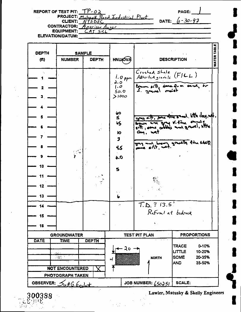
Boring No.: MRMW-08B | |
Sheet 2 of 3 Project No.: 650-253 j ^
White orthoquartzite
Fractured @ 78'
Fractured @ 81', softer rock, lighter grey
Remarks ^ V
1
Very hard 30 min./ • ft.
10" casing to 48' 6" casing @ 48' V
11
i
#
1 '; cfis(d§338 I

I
V
p
f I
LMS
t
86
88
90
92
94
96
98
100
T»»* -. X r ^ • •
Tes i D o n n g Log Blows On Sampler
t Ki
I b *-*
1
1 |l II Classincation Of Material
f -fine ; ;, j and - 35-50% m-medium ^ some-20-35% c-coarse little-10-20%
trace-0-10%
Boring No.: MRMW-08B
Sheet 3 of 3 Project No.: 650-253
Fractured @ 91'-92', more H2O
Total Depth @ 100.0'
Remarks
Total H2O 10-15 gpm
3Qe39a

LMS i r ^ ^ t -A. r ^ • I
Tes i D o n n g i_og Project Name: Mohonk Road Industrial Plant Client: NYSDEC Driller: American Auger Drilling Method: Casing 10" Mud / Rock 6" Air Boring Location: Jackson Property Coordinates: Logged By: John Thomburg
Boring No.: MRMW-OgS •
Sheet 1 of 4 Project No.: 650-253 4% Date: Start 8/12/97 J .
Finish 8/14/97 w T Total Depth: 145' • Depth To Water: 29.21' H Surface Elevation: Hole Diameter: 10" /6" |
Monitoring Instrument(s): OVA T
t
2
4
6
8
10
12
14
16
18
20
22
24
26
28
30
32
34
36
38
6
2
3
ilowsO
Ki
5
2
3
nSamr
b
• r -
4
3
4
rier
b
3
3
4
a:
0.8
1.3
1.8
If 1 ^ W Q ;
Classification Of Material f -fine and-35-50% m - medium some - 20-35% c-coarse little-10-20%
trace-0-10%
Brown f - c sand, little silt, trace c gravel, wet
@ 20.3' grey silt, some clay, trace f sand, wet
Grey silty clay, trace f sand, wet
1
^ II Overtaurden M lithology from T MRMW-09 1
1 11 1 # 1
^ 1
HI 11 11 ir U 1 1 J l
1 11 :
1 f i 1 I i
J ^ 1
T i 300,400

I
V
p
e t
LMS
1 o
40
42
44
46
48
50
52
54
56
58
60
62
64
66
68
70
72
74
76
78
80
82
84
T^^ * -A. r^ • •
Tes i D o n n g L.og Blows On Sampler
t
2
2
50/3
Ki
1
3
b
1
3
l 2
4
i S a:
2
2
il Classification Of Material
f -fine and-35-50% m - medium some - 20-35% c-coarse little -10-20%
a^f,j;i.trace-0-10%
Boring No.: MRMW-09B
Sheet 2 of 4 Project No.: 650-253
Grey silty f - c sand, and gravel
Remarks
Hit hard gravel @ 54'
^^^^^0^1

LMS g
86
88
90
92
94
96
98
100
102
104
106
108
110
112
114
116
118
120
122
124
126
128
130
T # * t -..X r * m _ _ • Tebi Dor ing L.og
Blows On Sampler
5? b
{M
Z b
t an
I.? II Classification Of Material
f -fine and-35-50% m - medium some - 20-35% c-coarse little-10-20%
trace-0-10%
Boring No.: MRMW-09B |
Sheet 3 of 4 Project No.: 650-253 H
White orthoquartzite
Remarks ^ T
6" casing set @ 95' 8/13//97 JI
ii
i 1 Replaced broken
|{jp^'2

I
p
I
LMS g
132
134
136
138
140
142
144
146
T ^ « , A. r > • 1 i
TeSi D o n n g i-og Blows On Sampler
t KI b 1
>
8 ^ o:
1 g
j l t l Classification Of Material
f -fine and-35-50% m - medium some - 20-35% c-coarse little-10-20%
« i,.J,trace-0-10%
Boring No.: MRMW-09B
Sheet 4 of 4 Project No.: 650-253
Total Depth @ 145'
Remarks
Total H2O 4-5 gpm
^Wi04i3-

LMS T^*»^ ^ A . P ^ . • I
Test D o n n g i-og Project Name: Mohonk Road Industrial Plant Client: NYSDEC Driller: Aquifer Drilling and Testing pri l l ing Method: Casing 10" Air / Rock 6" Air Boring Location: Douglas Hunt Property Coordinates: Logged By: John Thomburg
Boring No.: MRMW-10B I
Sheet 1 of 3 F Project No.: 650-253 j | Date: Start 7/18/97 J
Finish 7/19/97 tf^ Total Depth: 100' ^ Depth To Water: 38.71' W Surface Elevation: \ Hole Diameter: 10" /6" •
Monitoring Instrument(s): OVA P
g
2
4
6
8
10
12
14
16
18
20
22
24
26
28
30
32
34
36
38
E 3lowsO nSamp
b
Iter
1 ? P g o:
t l 11
Classification Of Material f -fine and-35-50% m - medium some - 20-35% c-coarse littte-10-20%
trace-0-10%
Brown silt, some clay, little f - m sand, little gravel, moist
White orthoquartzite
Fractured @ 35' - 35.5'
1
Remarks ' r
1
t '• 1 f I 1
Jl m
10" casing to 24' • 6" casing @ 24' P
1 J %
1 f b
iSMW
I LMS g
40
42
44
46
48
50
52
54
56
58
60
62
64
66
68
70
72
74
76
78
80
82
84
T * * * -. J . r^ • I •
Tes i Dor ing i-og Blows On Sampter
t b 1 § ^
o:
1.? g a: w ^
Classification Of Material r -fine and-35-50% m - medium some - 20-35% c-coarse littte-10-20%
p i ; irace-0-10%
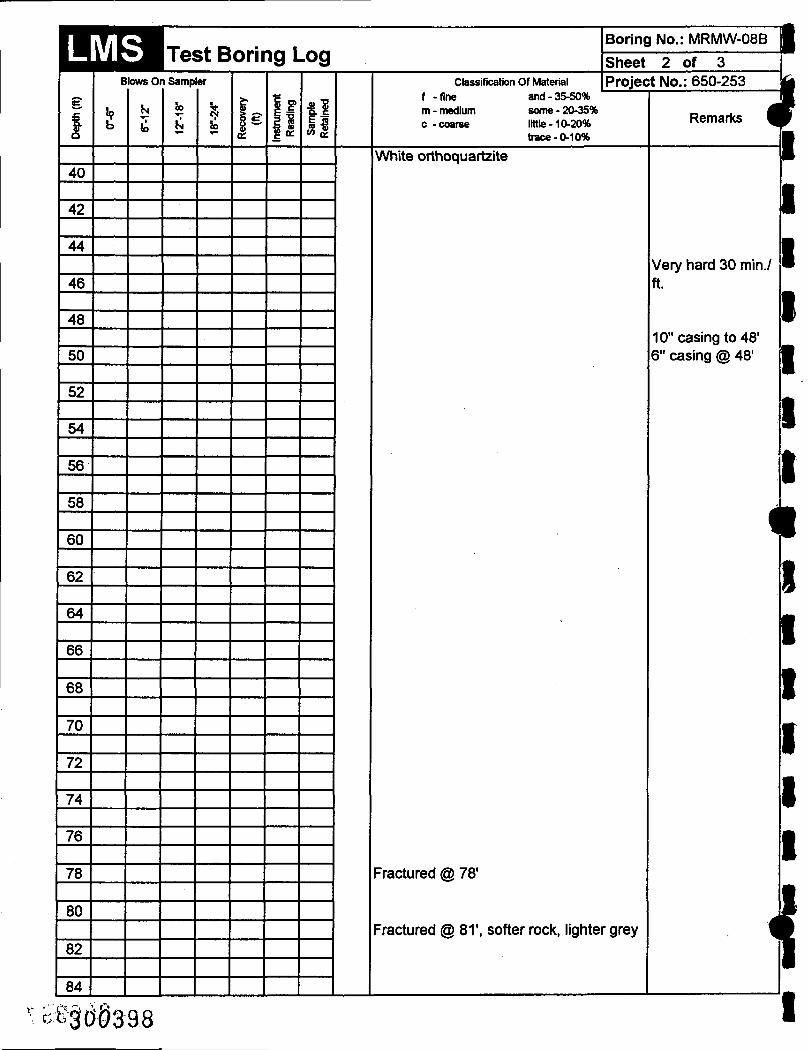
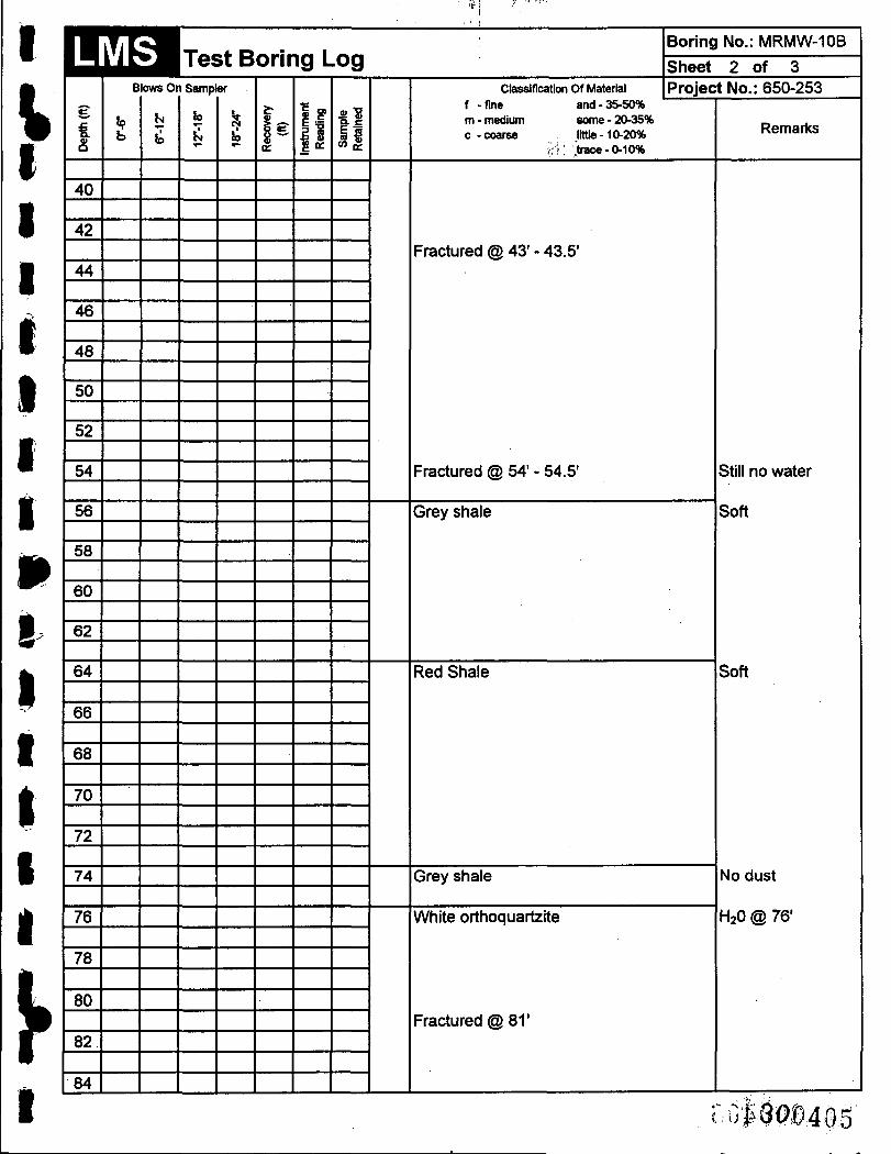
Boring No.: MRMW-1 OB
Sheet 2 of 3 Project No.: 650-253
Fractured @ 43' - 43.5'
Fractured @ 54' - 54.5'
Grey shale
Red Shale
Grey shale
White orthoquartzite
Fractured @ 81'
Remarks
Still no water
Soft
Soft
No dust
H2O @ 76'
r.Gi.#04:G.5'

LMS g
86
88
90
92
94
96
98
100
T r * » ^ - X r^ • - •
Tesi cor ing L.og Blows On Sampter
b K. b 1 i S
g o:
f l
.
Classification Of Material f -fine and-35-50% m - medium some - 20-35% c-coarse llttte-10-20%
trace-0-10%
Boring No.: MRMW-1 OB |
Sheet 3 of 3 Project No.: 650-253 m
Total Depth @ 100'
Remarks ^ B
J C 1
ai^9^'^©406

I
r I
LMS T*»»_ ^ A . W ^ . • •
Tesi Donng i-og Project Name: Mohonk Road Industrial Plant Client: NYSDEC Driller: American Auger Drilling Method: Casing 10" Mud / Rock 6" Air ;• {:A Boring Location: Richards Property Coordinates: Logged By: John Thomburg Mon
g
2
4
6
8
10
12
14
16
18
20
22
24
26
28
30
32
34
36
38
Boring No.: MRMW-1 IB
Sheet 1 of 5 Project No.: 650-253 Date: Start 8/18/97
Finish 8/26/97 Total Depth: 181' Depth To Water: 16.82' Surface Elevation: Hole Diameter: 10" /6"
toring Instrument(s): OVA E
t
28
50/5
50/3
50
MowsO
36
50/4
nSamp
b
50
ler
50/4
•
1.3
0.3
0
| f t l 11
Classification Of Material f -fine and-35-50% m - medium some - 20-35% c-coarse llttte-10-20%
trace-0-10%
Brown clayey silt, little f - c sand, little f -c gravel
Grey clayey silt
Grey silty f sand, and gravel, little clay
Remarks
Overburden lithology from MRMW-11
Stone in shoe of sampler
mmho7

LMS g
40
42
44
46
48
50
52
54
56
58
60
62
64
66
68
70
72
74
76
78
80
82
84
T.«»»_ ^ A l - k m •
Tesi Donng i-og Blows On Sampter
J? b
(>4
I b
i p g a:
t l Classification Of Material
f -fine and-35-50% m - medium some - 20-35% c-coarse littte-10-20%
trace-0-10%
Boring No.: MRMW-118
Sheet 2 of 5 Project No.: 650-253
White orthoquartzite
Remarks ^
6" casing @ 49'
1 i
1 1 1 1 1 t
-
^ 1 ^ w
1
^ t i \
^
4 L 1 m -.
:oeW8408 I

I
»
/
LMS g
86
88
90
92
94
96
98
100
102
104
106
108
110
112
114
116
118
120
1??
124
126
128
130
X o k « i . n% •
Test D o n n g i-og ' : Blows On Sampter
^ b
b a:
I.? i |
Ctessification Of Material f -fine and-35-50% m - medium some - 20-35% c-coarse littte-10-20%
trace-0-10%
Boring No.: MRMW-11B
Sheet 3 of 5 Project No.: 650-253
Remarks
kkmm M

ILMS
1 o
132
134
136
138
140
142
144
146
148
150
152
154
156
158
160
162
164
166
168
170
172
174
176
T * * t J . ^
T e S i D u r i n g L.og Blows On Sampler
t hi
b
b g b
Q: g a: II
Classification Of Material f -fine and-35-50% m - medium some - 20-35% c-coarse littte-10-20%
trace-0-10%
Boring No.: MRMW-118
Sheet 4 of 5 Project No.: 650-253
1
Remarks ^
A
1
1 I
1
P
• A.
• -
•
• i ^
w ^
^
«
#
M
i
• J '1 •
P iL ^
• i ^ -
3P@)4§0

I
p
LMS g
178
180
182
T^%» -A. r > • I
TeSi D o n n g i-og , , Blows On Sampler
t Ki b
1 ^^ b P g o:
41 11
Ctessification Of Material f -fine and-35-50% m - medium some - 20-35% c-coarse llttte-10-20%
trace-0-10%
Boring No.: MRMW-11B
Sheet 5 of 5 Project No.: 650-253
Fractured® 177'-180'
Total Depth © 1 8 1 '
Remarks
Blowing out about 50 gpm of H2O
Stopped drilling because of high yeild
J: MO i l l

LMS T*»«^ ^ A r « . I
Tebi D o n n g i.og Project Name: Mohonk Road Industrial Plant Client: NYSDEC Driller: Aquifer Drilling and Testing Drilling Method: Casing 10" Air / Rock 6" Air Boring Location: South end of Murphy Property Coordinates: Logged By: John Thomburg
Boring No.: MRMW-128 |
Sheet 1 of 5 Project No.: 650-253 i | Date: Start 7/18/97 M
Finish 8/21/97 ^ Total Depth: 200' • Depth To Water: 18.30- W Surface Elevation: Hole Diameter: 10" /6" •
Monitoring Instrument(s): OVA ^
g
2
4
6
8
10
12
14
16
18
20
22
24
26
28
30
32
34
36
38
JlowsO nSamF
b
g b i ^ II 1 » g o:
CO ^
Ctessification Of Material f -fine and-35-50% m - medium some - 20-35% c-coarse little-10-20%
trace-0-10%
White orthoquartzite
Small Fracture @ 33', trace water
Fractured @ 36' Brown soft wet zone @ 37.5' Hole yeilding free water @ 38'
1
Remarks Y
I I I 1 f L 1 1 k 1 r n i II
Set 6" casing @
18' I l 11 II II
II i 1 I I , ^
1 P L 1
^ % 1
— • — m
\1
^§t^t)ll2

I V
p
f
LMS g
40
42
44
46
48
50
52
54
56
58
60
62
64
66
68
70
72
74
76
78
80
82
84
T** * ..A r^ • I
TeSi D o n n g L.og Blows On Sampter
i Z b
g b a: P
t l Ctessification Of Material
f -fine and-35-50% m - medium some - 20-35% c-coarse little-10-20%
trace-0-10%
Boring No.: MRMW-12B
Sheet 2 of 5 Project No.: 650-253
Fractured @ 38.5' - 39.0', hole yielding approximately 10 gpm
Small fractures at 68' and 69', water turned white, no increase in volume of water
Remarks
Stopped© 51'for the day 7/22/97
Bit became locked in hole after reaming down from 34' 7/24/97
Bit destroyed 7/23/97
Stopped @ 80' for day 7/25/97
^M&ii 3

LMS g
86
88
90
92
94
96
98
100
102
104
106
108
110
112
114
116
118
120
122
124
126
128
130
T***-..A r^ m • T e S i D o n n g u o g
Blows On Sampler
t Z b 1 8 &
•
g K
f l w a:
Ctessification Of Material f -fine and-35-50% m - medium some - 20-35% c-coarse little-10-20%
trace-0-10%
Boring No.: MRMW-12B |
Sheet 3 of 5 Project No.: 650-253 m
Possible fracture, green quartzite zone
Remarks ^ P
Pullled rods, bit ^ wasted 7/28/97 •
Bit wasted 7/29/97 T ^
ft 1 [:;|:$P|14

1 m
1 1 1 1 1 1 9 li 1 1 1 1 1 1 1 L ft J r 1
LMS
t
132
134
136
138
140
142
144
146
148
150
152
154
156
158
160
162
164
166
168
170
172
174
176
T * » t >A r s • . . .^ • l e S L D u r i n g L.og
Blows On Sampler
r Ki
\z b
-Q:
| . E t l II
1 Classification or Material f -fine ,and-35-50% m-medium j'^'some-20-35% c-coarse lltUe-10-20%
trace-0-10%
Boring No.: MRMW-12B
Sheet 4 of 5 Project No.: 650-253
.
Remarks
I & If so Of 15

LMS g
178
180
182
184
186
188
190
192
194
196
198
200
T,#*.», _ X P ^ • I
Tes i Dor ing i_og Btews On Sampler
i
. .. .- 1
KI
Z b
g 1 a:
1 g P g Q: II
Classification Of Material f -fine and-35-50% m - medium some - 20-35% c -cnarse littte-10-20%
trace-0-10%
Boring No.: MRMW-12B
Sheet 5 of 5 Project No.: 650-253
Total Depth @ 200'
1
Remarks ^
1 m
m
J «
m.
9
A w
!• w ^
wm
^
^ ^
I t '
m '•T
tt
i ^J
4l I •
ywrn I

I
P
LMS T#*» M. r%. • _ • TeSL D u r i n g i . o g
Project Name: Mohonk Road Industrial Plant , :, i4 Client: NYSDEC Driller: American Auger Drilling Method: Casing 10" Mud / Rock 6" Air Boring Location: Jasinski (Dalton) Property Coordinates: Logged By: John Thomburg
Boring No.: MRMW-13B
Sheet 1 of 5 Project No.: 650-253 Date: Start 8/14/97
Finish 8/26/97 Total Depth: 200' Depth To Water: 0' Surface Elevation: Hole Diameter: 10" /6"
Monitoring Instrument(s): OVA
E
2
4
6
8
10
12
14 ^
16
18
20
22
24
26
28
30
32
34
36
38
i 3lowsO
z
'
nSamp
b
g
ler
1, Q:
If •g o:
f l Ctessification Of Material
f -fine and-35-50% m - nwdium some - 20-35% c-coarse llttte-10-20%
trace-0-10%
Brown silty day, little f sand wet @ 2'
Grey clayey silt, some f - c gravel, moist
Remarks
Started from ADT auger hole 8/4/97
O i i r '3t3p'417

LMS g
40
42
44
46
48
50
52
54
56
58
60
62
64
66
68
70
72
74
76
78
80
82
84
T ^ * , A r^ • 1
Tes i D o n n g i-og Blows On Sampter
t z b g 1 1 ?
P g K
t l P
Ctessification Of Material f -fine and-35-50% m - medium some - 20-35% c-coarse littte-10-20%
trace-0-10%
Boring No.: MRMW-138
Sheet 2 of 5 Project No.: 650-253
•
Red Shale, and clay
Red shale, and f - c sandy clay
Grey shale
Remarks V
1
Drilling mud tumed red
Set casing @ 78' 8/14/97 .
i
I
I
rM^iQ^lS

I V
p
I
LMS g
86
88
90
92
94
96
98
100
102
104
106
108
110
112
114
116
118
120
122
124
126
128
130
T « k « _ • - •
Tesi Donng L.og Blows On Sampler
t Ki
z b g 1 i E
a:
1 g P g K
t l P
• •
Ctessification Of Material f -fine S and-35-50% m - medium some • 20-35% c-coarse littte-10-20%
trace-0-10%
Boring No.: MRMW-138
Sheet 3 of 5 Project No.: 650-253
White orthoquartzite
Remarks
sMm^

LMS g
132
134
136
138
140
142
144
146
148
150
152
154
156
158
160
162
164
166
168
170
172
174
176
T*»»_ ^A r^ • I
Tes i D o n n g i_og Blows On Sampler
t U b
b g 1 1 S P f l
Ctessification Of Material f -fine and-35-50% m - medium some - 20-35% c-coarse little-10-20%
trace-0-10%
Boring No.: MRMW-138
Sheet 4 of 5 Project No.: 650-253
Remarks ^
Termintaed hole (®
1 i
1 1 1 1 1 1
ISO'8/19/97 i ^
Completed remaining 50' 8/26/97
•
1 1 1 L r 1 1 n •
ۥ m
M I)'&4l0

I
I
LMS g
178
180
182
184
186
188
190
192
194
196
198
200
T ^ s ^ j . r > • I
TeSi Dur ing uog Blows On Sampter
9 b z
b b 1 "
g o:
t l 11
Classificatioh Of Material f -fine and-35-50% m - medium some - 20-35% c-coarse llttte-10-20%
trace-0-10%
Boring No.: MRMW-138
Sheet 5 of 5 Project No.: 650-253
Approximately 3" void @ 196', well began yeilding - 150 gpm
Total Depth @ 200'
Remarks
• ?f<^fl^42J
LMS T t ^ L . m.M. a . • _ • l e s i D u r i n g i . u g
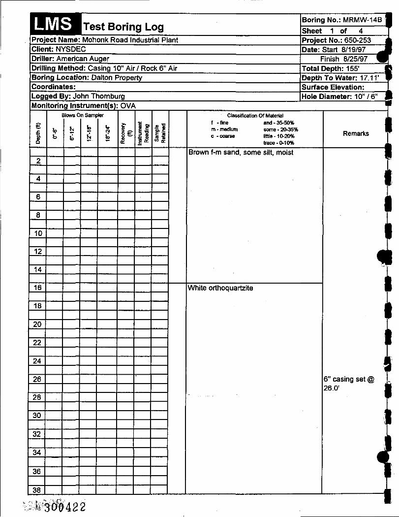
Project Name: Mohonk Road Industrial Plant Client: NYSDEC Driller: American Auger Drilling Method: Casing 10" Air / Rock 6" Air Boring Location: Dalton Property Coordinates: Logged By: John Thomburg
Boring No.: MRMW-14B |
Sheet 1 of 4 T Project No.: 650-253 ^ Date: Start 8/19/97 J
Finish 8/25/97 M ~ Total Depth: 155' fi Depth To Water: 17.11' • Surface Elevation: 1 Hole Diameter: 10" /6" m
Monitoring Instrument(s): OVA ^
g
2
4
6
8
10
12
14
16
18
20
22
24
26
28
30
32
34
36
38
1
t
Slows 0
Z
nSamF
b g
>ter
1.1" W £
Ctessification Of Material f -fine and-35-50% m - medium some - 20-35% c-coarse littte-10-20%
trace-0-10%
Brown f-m sand, some silt, moist
White orthoquartzite
1
Remarks r
MM y i
6" casing set @ 26.0' i i
1 vl i h 1 t i
%
1 <I
mM ($A22

I /I
LMS g
40
42
44
46 -
48
50
52
54
56
58
60
62
64
66
68
70
72
74
76
78
80
82
84
TT-*.*-A. r ^ m •
Tes i Do rmg i-og Blows On Sampter
t z b I 8 ^
oc
Is l l
. ...
tl il
Ctessification Of Material f -fine i and-35-50% m - medium some - 20-35% c-coarse llttte-10-20%
b-ace-0-10%
Boring No.: MRMW-14B
Sheet 2 of 4 Project No.: 650-253
-
Remarks
Hole dry after recovering over weekend

LMS g
86
88
90
92
94
96
98
100
102
104
106
108
110
112
114
116
118
120
122
124
126
128
130
• f ^ A ^ • - •
Tesi Dormg Log Blows On Sampter
t Ki
z b 1 ig 1 8 g oc
t l Ctessification Of Material
f -fine and-35-50% m - medium some - 20-35% c -coarse littte-10-20%
trace-0-10%
Boring No.: MRMW-148
Sheet 3 of 4 Project No.: 650-253
Remarks ^
^
H
i
Five fracture zones between 80'-100', no water
U
1 1 1 1 1 n
' ^ 1 • ^
. 1 •
. i i 1 m '
1 1 i h w •
^•i0^A

I
I
LMS
1
132
134
136
138
140
142
144
146
148
150
152
154
f ^ r ^ A r% m •
Tes i Do rmg i^og i " Blows On Sampter
t ht
z b g i 1 £
oc
.
1 ?
| l t l
Ctessification Of Material f -fine and-35-50% m - medium some - 20-35% c-coarse littte-10-20%
trace-0-10%
Boring No.: MRMW-148
Sheet 4 of 4 Project No.: 650-253
Total Depth @ 155'
Remarks
• -
cswm

LMS T « * , - i . r ^ . • 1
Tes i Dur ing i.ug Project Name: Mohonk Road Industrial Plant Client: NYSDEC Driller: American Auger Drilling Method: 4" Spin Boring Location: Richards Property Coordinates: Logged By: John Thomburg
Boring No.: MRMW-11 1
Sheet 1 of 2 Project No.: 650-253 j Date: Start 8/15/97 J
Finish 8/18/97 W Total Depth: 39.0' | Depth To Water: 10.67' ll Surface Elevation: Hole Diameter: 4" |
Monitoring Instrument(s): OVA T
g
2
4
6
8
10
12
14
16
18
20
22
24
26
28
30
32
34
36
38
i
28
50/5
50/3
50
}|0WS0
Z
36
50/4
nSamF
b
g
50
>ter
I
50/4
ac
-
1.3
0.3
0
| l tl i 1
Classification Of Material f -fine and-35-50% m - medium sonne - 20-35% c-coarse llttte-10-20%
trace-0-10%
Brown clayey silt, little f-c sand, little f-c gravel
Grey clayey silt
Grey silty f sand, and gravel, little clay
1
Remarks
ll 1 I I
il 1
^ 1 i|
Mud tums grey @ 1 17.0'
Lost circulation, 1 water flowing up ADT hole, well holefl abandoned and 1 new one offset
1 ^
' 2
1 J i| 1 1
,ca<0iQt4;26

I
V I
f
LMS g
40
,
T*»« mA r^ •
T e S i D u r i n g i . u g Blows On Sampter
t z b 1
•
•
a:
1.? u
tl il
Ctessification b f Material f -fine and-35-50% m - medium some - 20-35% c-coarse littte-10-20%
trace-0-10%
Boring No.: MRMW-11
Sheet 2 of 2 Project No.: 650-253
White orthoquartzite Total Depth @ 39.0'
Remarks
• 3 < 0 4 2^7

LMS T<* ._ ^ A r ^ . • i
Tes i Dur ing i-ug Project Name: Mohonk Road Industrial Plant Client: NYSDEC Driller: American Auger Drilling Method: 4" Spin Boring Location: Jackson Property Coordinates: Logged By: John Thomburg
Boring No.: MRMW-09 •
Sheet 1 of 3 Project No.: 650-253 i • Date: Start 8/12/97 J
Finish 8/13/97 V Total Depth: 88' J Depth To Water: 22.42' 1 Surface Elevation: Hole Diameter: 4" •
Monitoring Instrument(s): OVA ^
g
2
4
6
8
10
12
14
16
18
20
22
24
26
28
30
32
34
36
38
E
6
2
3
)lowsO
z
5
2
3
nSamp
b
g
4
3
4
Iter
1
3
3
4
on
0.8
1.3
1.8
l l l l t l 11
Ctessification Of Material f -fine and-35-50% m-medium some-20-35% c-coarse littte-10-20%
tiBce-0-10%
Brown f-c sand, little silt, trace c gravel, wet
20.3' grey silt, some day, trace f sand, wet
Grey silty clay, trace f sand, wet
Remarks
I I No cuttings from • ADT auger hole 8/4/97 , -
' 1
^ 1 ^
Cuttings begin to • surface
1 J % 1
•• ^ 1
-3.|<>i4|8

1 • V
1 " ~
1 ] r •
LMS g
0)
O
40
42
44
46
48
50
52
54
56
58
60
62
64
66
68
70
72
74
76
78
80
82
84
T*^»-A r^ • • TeS i D u r i n g L^ug i#f
Blows On Sampter
t
2
2
50/3
K V
i ;
1
3
b
g
1
3
>9
1 2
4
i oc
2.0
2.0
1 ?
|1 tl Ctesslficatten Of Material
f -fine and-35-50% m - medium some - 20-35% c-coarse littte-10-20%
trace-0-10%
Boring No.: MRMW-09
Sheet 2 of 3 Project No.: 650-253
Last .2' little f-c sand, shale fragment (angular), wet
r boulder® 65'
Grey silty f-c sand, and gravel
Remarks
Hit gravel© 54'
American Auger drilling in offset boring
r..T.>AO^'l

LMS g
86
88
T ^ k » - A n • I
TeSi Dur ing Lug Blows On Sampler
b z b
b oc
1 ? 11
o. c E s m 'S OT K
'
Ctessification Of Material f -fine and-35-50% m - medium some - 20-35% c-coarse littte-10-20%
fa?ce-0-10%
Boring No.: MRMW-09
Sheet 3 of 3 Project No.: 650-253
Bedrock @ 88' Total Depth @ 88'
Remarks f
•
1 1 1
•
M •
•
•
•
•
^H
'
. "
_
_
n
• U 1 i 1
m ( 1 ^ ^
m
kim i I

I
l l MONITORING WELL COMPLETION LOG
PROJECT NUMBER:
(b So-3i 53 PROJECT NAME;
fWJlAbnW <U.^ XJloArUl M IA^M.U} ' ^<!) CLIENT:
A)vf oer LOCATION:
DATE DRILLED:
IMH-m DATE DEVELOPED:
-h'?'?-? WELL CONSTRUCTION COMPLETED;
779'97 DEVELOPING METHOD;
^
MANHOLE COVER
ROYER TYPE CAP
< ^ CONCRETE
- 6Hn. STEEL CASING
DEPTH
BEDROCK
/00.6 DEPTH
INSPECTOR: 1 ^ \
DRILLING CONTRACTOR
EOF\iELL; • » ^ ^ ' ' ^
fetjtreck STATIC WATER LEVEL:
MEASURING POINT:
Toe TOTAL DEPTH OF WELL:
^ '? '9? l O t . O J6-S
TOTAL DEPTH OF BORING:
LOCKING CASING : D NO s YES KEY NO:
NOTES: ^ 0 ^ ^ y X ^ ,
\M^^i\z\ LAWLER, MATUSKY & SKELLY ENGINEERS LLP
30043r

MONITORING WELL COMPLETION LOG ?RC.'ECT.NU.«S£S
PROJECT NA.Me;
KoWrsk ^<MA loAos\rX'^ PUnJ-WELUNo.;
^G$O"<^^0
Mf i jhU ' 9 CUENT:
msoc^c LOCAr.ON:
CATS ORIIXEO: OATEOEVELOPEO:
^ • < ? 7 > - ? 7 WEU. CONSTRUCTION CCMPt£TED:
Oe/B.OPING METHOD:
AV / ^'^\^r
I P^OTECTTVE CASING sLEVAHON
CASING ELEVATION
GRACE ELEVATION
fa 5:v
2Lo
NOT TO SCALE
INSPECTCR;
^<3l^^ ^ ^ f A U ORILUNG CCNTRACTOR; Ca-
•CF-.1-E--L; <S TYPECF AE-J.;
0»%«-V>tr«,»< STATIC WATER LEVEL;
t j i j i . ; ^ MEASURING POINT:
DATE.
TOTAL DEPTH OF WELU g-J7v9'7
TOTAL DEPTH OP BORING:
^ ^ Aci\ e -fif ^ < DRILLING METHOD OIAMETC.R: r
TYPE;
CASING:
(:^.'h Gt&t'«^
•y^***/
SAMPLING METHOD OIAMET£.=t
FALU
2f RISER PIPE LEFT IN PLACE
TYPe
WBGMT: t i 4^.
/^o INTERVAL:
/<? -<^A MATERIAL:
DIAMETER;
L LENGTW:
m • io .(4-
JOINTJYpe •(T.TYpe
SCREEN M A T E H I A L :
^l /C-INTERVAL
7j'f> -fr STRATIGRAPHIC UNITS SCREENED:
7 iRAPHIC
DIAMETER;
SH'ih SLOT SIZE:
o.&io FILTER PACK
GRACE;
SANK A •/o
GRAVEL:
AMCUN-
»g°f
NATURAL
INTERVAL; •
^ - ? < 1^^
"^^'^' AX;J> Sfo^: NOTES:
CHECK APPUCA8LE
Portland Cement
Bentonite Slurry
Bentcnite .Pellets
Other
INTERVAL;
6 ' 6 S i^/ NTEHVAL-
INTERVAL;
I N T E ^ A U
AMOUNT:
AMOUNT:
^W AMOUNT:
AMOUNT.
LOCKING CASiNG; 1_J NO • ( j j j YES KEY NO:
IBy^Lcj LAWLER, MATUSKY & SKELLY ENGINEERS T I

I
V MONITORING WELL COMPLETION LOG
PROJECT NUMBER:
PROJECT NAME:
CLIENT:
IVyk/vW ( l ^ ^ XutcloArxctl f \J \ ' WELL No.:
(oSO'3Lf>ji
^ J J H o J ' 9S
MXsoec LOCATION:
DATE DRILLED:
&'10^-t-7 DATE DEVELOPED: WELL CONSTRUCTION COMPLETED;
DEVELOPING METHOD;
A\f /
T
ROYER TYPE CAP
OVERBURDEN
6-in. STEEL CASING
i6.«
«\«.o' DEPTH
\H5.o" DEPTH
NSPECTOR;
•C^ayv^ \ ^ » f A.%</ DRILLING CONTRACTOR: lONl
TYPE OF WELL:. ^ ^ t \ 9 P k ^ Aoe»i~
^
ft*Art)fck STATIC WATER LEVEL:
3<^s MEASURING POINT:
g ' ; ? 7 - 7 ^ TOTAL DEPTH OF WELL:
lis A ^ TOTAL DEPTH OF BORING:
1 1 ^ ' LOCKING CASING: d l NO H YES KEY NO:
NOTES: Ago H-S ^ ^ ^
300433
(IJi^S^ LAWLER, MATUSKY & SKELLY ENGINEERS LLP

MONITORING WELL COMPLETION LOG PROJECT NUMBER:
6SQ"«;ig> PROJECT NAME:
CLIENT:
LOCATION;
WELL No.;
^ A t C J - / 0 / i
I
DATE DRILLED;
7-/^-9-^ DEVELOPING METHOD;
DATE DEVELOPED; WELL CONSTRUCTION COMPLETED;
7 - / y -97
( f.lr^
/ r \ r /o^>ftf^^^^vp^'A^
{—4
ROYER TYPE CAP
<-* OVERBURDEN
6-in. STEEL CASING
JM: DEPTH
M ^ DEPTH
BEDROCK
lco>o' DEPTH
INSPECTOR:
DRILLING COUTRACTQR;
TYPE OF WEU:
j ^a f ^ t ,V STATIC WATER LEVEL;
3<.tS MEASURING POINT:
T'K-
DATE:
7-^7-9? TOTAL DEPTH OF WELL;
/<Po.b 4f-TOTAL DEPTH OF BORING;
/00.0 -/f
LOCKING CASING: • NO - ^ YES KEY NO:
NOTES:
306434 Hl^i^Si LAWLER. MATUSKY & SKELLY ENGINEERS LLP

I MONrrORING WELL COMPLETION LOG
PROJECT NU.MSS??
PROJECT NA.MI
IKQWAIL ( i ^ j i i v ^U r r ^ l <f W.f WELL No.:
loSo'^S-^
M M O - th CJENT:
A J Y ^ Q ^ LOCATION:
CATHORIIJLEO:
•S'/^'?-? OEVELOPING ».fETHOa:
DATE DEVELOPED:
9->i7>«r7 WELL CONSTRUCTION COMPLETED:
' ^n-TP
PROTECriVE CASING ELEVATION
NOTES:
r I
A8o
2*.o
3ro
NOT TO SCALE
INSPECTCl
T Y P E C F A e u . ^
^ ORILUNG CCNTRACTOR:
/^/»€lrfOKA » luc»< r
STATIC WATER LEVEU
/ A . O MEASURING POINT:
DATE.
TOTAL DEPTH OF WELL; '^'^?'J9
a<•o-^^^ I y t . o / f TOTAL DEPTH OP BORING;
DRILLING METHOD
OIAMETE.%
TYPE:
CASING: 5 ^ < J * J t
% -
H -K^f SAMPLING METHOD
OIAMETE.%
<^-*A. FALU
30-i. RISER PIPE LEFT IN PLACE
TYP£ . ,
WBGHT:
i fo INTERVAL;
i ^^Jr MATERIAL
OIAWETES; p\fc
LENGTH:
3 0 - ^ f JOINT TYPE
SCREEN
INTERVAL;
"^•9- a ^ iP>v STRATIGRAPHIC UNITS SCREENED:
MATSRIAU
f\iC DIAMETER:
^ • » A SLOT SIZE:
C>.C>\0
FILTER PACK GRADE:
SANQ;
V
40 GRAVEL NATURAL
AMOUNT;
^A. INTERVAL
^"'- '° ' fc.^UJU.vl L j > \ K y A f
CHECK APPUCABLE
Portland Cement
Bentonite Slunn/
Bentonite Pellets
Other
K . / "
INTERVAL
6- l^ -Pt INTERVAU
INTERVAL
INTE.'^VAL
AMOUNT;
AMOUNT:
AMOUNT:
AMOUNT.
LOCKING CASING: I I NO ^ YES KEY NO:
f i r r a LAWLER, MATUSKY & SKELLY ENGINEERS Ll
3#435

MONITORING WELL COMPLETION LOG PROJECT NUMBER;
PROJECT NAME:
/*i>Lk & ^ TnJd^..^/ fL^-dSO-SS'S
WELL No.;
/^AJtCAj - I f B
I
CLIENT:
J\/YSt?gc LOCATION;
DATE DRILLED;
^ ' \^ - r r DATE DEVELOPED;
g '^ -y-n^ WELL CONSTRUCTION COMPLETED:
DEVELOPING METHOD:
C^V^rpvlihpvi^e^
L
ROYER TYPE CAP
OVERBURDEN
6-in. STEEL CASING
^XH DEPTH
DEPTH I4?f
BEDROCK
DEPTH in -^
INSPECTOR;
DRILUNG CONTRACTOR; ^ C M ftW^AQs)/
TYPE OF WELL ft<*vQf'%CH^ A v i y r
ft«Ar«fc'^ STATIC WATER LEVEL;
H 15 MEASURING POINT;
Toe
DATE:
^ • ^ ? ' 17 TOTAL DEPTH OF WELL: TOTAL DEPTH OF BORING:
m -Pf ^ i l 1^(41- (kSrS LOCKING CASING: NO D i YES KEY NO:
NOTES: ^ W 5o^^/K 9 IV
\
I ,;^|,aQ,e;43G H^Tj^jj LAWLER, MATUSKY & SKELLY ENGINEERS LLP

I MONITORING WELL COMPLETION LOG
PROJECT NUMBER:
PROJECT NAME;
ff\^\L (UA Ui.iJyVJ PWt 6 5 0 ' d ^ 3
WELL No.;
/ ^ / f U " JB.6 CLIENT;
0Y<>X)6C LOCATION:
DATE DRILLED:
7 ' 1 '"M DATE DEVELOPED: WELL CONSTRUCTION COMPLETED:
DEVELOPING METHOD;
ftXr t>v3fti^yoA>y\fv^
f
BPECTOR
ROYER TYPE CAP
OVERBURDEN
6-in. STEEL CASING
io. DEPTH
DEPTH t«.o
BEDROCK
aoQ-H DEPTH
.3)»w\ |UM''<VI( DRILUNG CONTFtACTOR: ^
TYPE OF WELL; ELL;> I V
(bJ/ W STATIC WATER LEVEL:
/ i e>6^ MEASURING POINT;
DATE;
TOTAL DEPTH OF WELL: 'i'M'f7
;PTH OF WELL; I TOTAL DEPTH OF BORING;
LOCKING CASING : D NO 21 YES KEY NO:
NOTES: •w»-V 10 :if*- & j t 5 '
I H k ^ i ^ LAWLER, MATUSKY & SKELLY«ENG|NE^RS LLP

MONITORING WELL COMPLETION LOG I PROJECT NUMBER:
PROJECT NAME
CLIENT
LOCATION:.
WELL No.;
45s'air3 /^^/noJ-fSn
I
i DATE DRILLED:
^MH-^^ DATE DEVELOPED;
DEVELOPING METHOD;
g ' A 5 - ? 7 WELL CONSTRUCTION COMPLETED:
g-J^6'?-7
MANHOLE COVER
ROYER TYPE CAP
* f - CONCRETE
OVERBURDEN
6-in. STEEL CASING
INSPECTOR;
DRILUNG CONTRACTOR:
C5Ej.x^ ^ ^ N ^ ^ ^
TYPE OF WEU: AfN^rW^ i ^ ^ * ^ (^»cXroc>k
STATIC WATEBLEV^L: ,
Un MEASURING POINT; .
TOC,
DATE:
<-^?>'77 TOTAL DEPTH OF WELL: TOTAL DEPTH OF BORING:
?» -H^^ aoc^ 4 J ^ 6 ^ C
DEPTH
7<.o DEPTH
BEDROCK
I DEPTH
LOCKING CASING: ^ NO Q^ VES KEY NO:
NOTES: /«o ^ ^ Q , \ ^ ^ .
300438 \ n i \ \ z \ LAWLER, MATUSKY & SKELLY ENGINEERS LLP
I

I
V MONITORING WELL COMPLETION LOG
PROJECT NUMBER;
^ S o - S L S J PROJECT NAME;
Mp^k /l^J t^^^t;^ /fnJ /9l^pl0i-lif& CUENT;
^ y . ^ n £ c LOCATION:
DATE DRILLED;
^M'^^-?? DATE DEVELOPED;
•9-i-r-i7 WELL CONSTRUCTION COMPLETED;
^ - x ^ ' 9 ' r DEVELOPING METHOD;
I
& * 1 6-in. STEEL CASING
MANHOLE COVER
ROYER TYPE CAP
CONCRETE
DEPTH
^ ^ DEPTH
BEDROCK
INSPECTOR:
Sck^ ^»^fcu/-3 DRILUNG CONTRACTOR;
TYPE OF WELL
3NTRACT0R;
: L L - ' •
A^rtK/i STATIC WATER LEVEL
as. 05 MEASURING POINT;
roc
DATE:
5 '»?>*»7 TOTAL DEPTH OF WELL
ISS 4 t TOTAL DEPTH OF BORING:
LOCKING CASING: CU NO S ] YES KEY NO:
NOTES:
I S S ^ DEPTH
300439
H k ^ i ^ LAWLER, MATUSKY & SKELLY ENGIMEgRSQ-LP

CO
o
o CO
TABLE 1
STATIC WATER LEVEL Mohonk Road Industrial Plant Site No. 356023
2/18/98
Reference Pt Elev.
INTERFACE WELLS MRMW-1 MRMW-2 MRMW-3 MRMW-4 MRMW-5
(333.94) (336.32) (337.67) (329.21) (324.91)
OVERBURDEN WELLS MRMW-9 MRMW-11
(247.77) (282.43)
BEDROCK WELLS MRMW-IB MRMW-5B MRMW-6B MRMW-7B MRMW-SB MRMW-9B MRMW-1 OB MRMW-1 IB MRMW-12B MRMW-1 SB MRMW-14B
(333.53) (325.30) (323.95) (313.93) (159.68) (248.21) (225.64) (281.72) (258.20) (221.93) (156.67)
PRIVATE WELLS PW-1
PW-2 Lichensky Williams Jasinski Cothem
(334.08) (338.95) floor (338.75) floor (325.16) (328.41) (337.63) (219.99)
SWL 11/96
7.62 18.02 6.96 5.21 5.37
ELEV. H2O
11/96
326.32 318.30 330.71 324.00 319.54
SWL 5/97
5.90 14.36 5.59 4.63 9.76
37.14 20.43 33.05 21.39
ELEV. HjO 5/97
328.04 321.96 332.08 324.58 315.15
296.39 304.87 290.90 292.54
SWL 9/97
22.42 10.67
58.23 28.48 51.47 41.26 35.73 29.21 38.71 16.82 18.30
0 17.11
ELEV. HTO
mT
225.35 271.76
275.30 296.82 272.48 272.67 123.95 219.00 186.93 264.90 239.90 221.93 139.56
SWL 10/97
12.94
15.31 7.55 16.13
55.46 28.77 50.19 39.47
65.55 64.67 53.2 47.8
ELEV, H2O
10«7
321.00
322.36 321.66 308.78
278.07 296.53 273.76 274.46
273.40 273.99 271.96 280.61
SWL 12^7
7.12 11.55 8.27 4.02 9.83
-22' 3.58
43.33 21.66 38.48 28.03 32.61 38.21 26.92 4.14 12.25
0 9.72
46.5 34.8 51.2 50.1
EL£V, H,0
12«7
326.82 324.77 329.40 325.19 315.08
•r225.75 278.85
290.20 303.64 285.47 285.90 127.07 210.00 198.72 277.58 245.95 221.93 146.95
278.66 293.61 286.43 169.89
3 B;\STATIC.XLS Sh««(1 2/1>/9S 3:46:51 PM*

': r
I ^
MONITORING VVELLCOMPL PROJECT NUMBER:
PROJECT NAME;
CLIENT:
Mli.^t( R..J WELL No
LOCATION: Ali^hfX.
/ ^ R M I J J ' / / C
DATE DRILLED
/ ^ R l P n^r-S.-ilL ^ U t - :MJ J ^ ' . U
DEVELOPING METHOD: Vv^A-/y-yr
DATE DEVELOPED:
V-i2V-yy a At ^ . ' c k a ^ J k P r o p e r i y
WELL CONSTrtUCTlC*! COMPILED:
. V
,"C
:'t>.
M:
/ iNSparc
V'^! OVERBURDEN
^
ROYER TYPE CAP
V - :
6-ln. STEEL CASING
ii._^?2LJj DEPTH
MLiu-DEPTH
lr- ' ' 'Ji
BEDROCK
DEPTH w
DRILLING CONTRACTOR: lACTOR: ^ = 3
TYPE OF WELL / t ^ g ^ / r ^ ^ A^iyU^ -f h:4cL, '^
STATIC WATER LEVEL SxiAf^^ 17£
MEASURING POINT:
DATE:
TOTAL DEPTH OF WELL ' ^ t / ' fe
. . . . . , — _ , „ , , . , . „ . , . , . i u i « i . u c r i n u r v v t L L : TOTAL DEPTH OF BORIN TOTAL DEPTH OF BORING:
LOCKING CASING: O NO ^ YES KEY NO:
NOTES:
30044J « i y
ITCg^ LAWLER, MATUSKY & SKELLY; ENGINEERS LLP

MONITORING WELL COMPLETION LOG PROJECT NUMBER:
PROJECT NAME;
/^A,. ,K ia,..j_
<k£n-3..^'/ WELL No.:
/^KAW' £ k .
I
CLIENT:
AlHSb^C LOCATION:
•D: DATE DEVEOiPED: ' ' / WELL CONSTRUCTION COMPLETED; DATE DRILLED;
H'd<)H'l3-1t J : ' / WELL CONSTRUCTION COMPLETED;
DEVELOPING METHOD;
- ^ t / ^At# J-S i U c
j ^ , f H n
ROYER TYPE CAP
' « i
• i
OVERBURDEN
6-in. STEEL CASING
' i • i
.\ j . r 1-, DEPTH
: DEPTH 13' b i
BEDROCK
^.t
sX /Ai ' fcy
DEPTH
INSPECTOR:
DRILLING CONTRACTOR: ^ L , i t ^ T ^ . I ./^
^
TYPE OF WEa: /iM/L^.r.^^ JJu^tL/- t Jbliti^U
-Bt-JratLJC ^
STATIC WATER LEVEL:
^ ^ . % ' MEASURING POINT:
DATE;
y-z^'ftr TOTAL DEPTH OF W E L L TOTAL DEPTH OF BORING:
LOCKING CASING : n NO ^ YES KEY NO:
NOTES:
•I
pOt^p Wbuf l o S i : cLttrt'ric. oL^UL.Io^AU>vrt
300442 H J i k ^ LAWLER, MATUSKY & SKELLY ENGINEERS LLP

I (MONITORING WELL COMPLETION LOG PROJECT NUMBER;
PROJECT NAME:
CLIENT; / ^ o k o A i d R a a . J
0 - 0 . 5 ^ WELL No.:
/y'^sb^c MKMl/i - '^R
LOCATION;
DATE DRILLED:
DEVELOPING METHOD:
• I , • . DATE DEVELOPED: •
f I
I /SNSPECTOI
WELL CONSTRUCTION COMPLETED:
I
ROYER TYPE CAP
OVERBURDEN
6-ln. STEEL CASING
DRILUNG CONTRACTOR:
TYPE OF WELL:
" "^ A - " J •
STATIC WATER LEVEL D(>J. .,rK
»i^-/(.' MEASURING POINT:
DATE:
TOTAL DEPTH OF WELL i^f i>'f^
LOCKING CASING: Q NO ^ YES KEY
TOTAL DEPTH OF BORING:
NO:
NOTES:
300443
Hi^iW LAWLER, MATUSKY & SKELLY ENGINEERS LLP

I PROJECT NUMBER:
PROJECT NAME:
CLIE^a: Aloh^^K ^.^4
WELL No.: 63b".j-5</
LOCATION: A/'/^Dec
/I^AllJ - JiTfl
DATE DRILLED; U \ l ! I ^ O ^ * DATE DEVELOPED: , , ^ ^ I WELL CONSTRUCTION COMPLETED;
OEVELOPING METHOD:
H'JLl /c f 'S i i i -^ f
j^ub, V-^V-^^
' A l g . / ^ *
?4'
'nl • v ^ , . 1
f7;Ae. i f t \ J i A S l
==r
«~;
ROYER TYPE CAP
• OVERBURDEN
s
>
6-in. STEEL CASING
DEPTH
DEPTH MJu
BEDROCK
/VA ^ DEPTH ! i *
...>.^w....<.^rw...... i u i / M . u c r i M O I - w t L L TOTAL DEPTH OF BORING:
iPEC INSPECTOR:
DRILUNG CONTRACTOR: !:TOR- I '
TYPE OF WEU:
STATIC WATER LEVEL: ^tLJfo<J(
MEASURING POINT: Il3d
DATE:
TOTAL DEPTH OF WELL '4'^^'tt
I — ' • • Z 3
LOCKING CASING: Q NO ^ YES KEY NO:
TOTAL DEPTH OF BORING:
NOTES:
Vd•^ /\/tuLu.5iAry
drrlltr ctfotH yi*.iA sf 7-/0 f M.
300444 fI7iT=^ LAWLER, MATUSKY & SKELLY ENGINEERS LLP

I
^
APPENDIX D
300445

I
K D a t e : ^ - > g t - ^
Crew: c\r/f^<~ J o b N o : f ^ ^ < ; C - ^ ^
Site: /Vll^XP
LAWLER, MATUSKY & SKELLY ENGINEERS
WELL DEVELOPMENT LOG
WELL No^}g0Cc>- •S'/S
pH Meter: C/'-ZyS
Cond. Meter: j 7 g ^ - 7 a -
Therm: Q ^ c - I L U
Turb. Meter://|t.^..<y?/
r I
ii;-: TlME:::iI:
<D«or>
D?A<
O^vOO
tooo / /3o
/ a i / 3
/^o.c:
Iiii SWL :
36. n 3^. •?
—
—
—
^ P ^ n^s
•
GAL. ^ PURGED'
( ^
. pH
^ ^
7.Y -7.1^
7 . ^ -z.tf
7.Y
'" TEMP. (•C)
/ ^ ^
/o.*/ /0.r( 1^-6 /A./^
/3-V
'
SP. COND. Ol mhos/cm)
55"0
S^H So^ 5V0
5 5 6 5^7
TURB. (NTUJ)
>aoo Aso-^ ^oo y-
^ S o - l o ^lo
COMMGNTS
^/<^ ^ f / H , < u / ^ csJsr-
-
1 1 1
Depth of Well: Start:. End:
"^^mu^p,

I
Date: > J - ^ 7 ' ^ 7
Crew: : j ^
Job No: feSo-^SO
Site: f^fiXf
] LAWLER, MATUSKY & SKELLY ENGINEERS
WELL DEVELOPMENT LOG
WELL N o . / ^ / ^ i ^ - 7
pH Meter: < - / / 5 " "
Cond. Met t r -^£ jC- i^
Th^tm: 0 ^ ^ ISC
Turb. Meter://*^ -<30/
r II • 1 ^
••• T I M E
Otf^C
GFyt.H
OS 0-7
astq
G^n o^s1 loiS lo^n I02% fo^i
Depth of V
;:::;;:;.v.;-;<:fi:«
SWL
d^.9L
Ad-a. ^ . o 5-0.5
^y.«3 7'f.a Sb.?^
^a^7 S7.3
=7 .5
^ell: S
GAL.~ PURGED'
d) 6 /o / . ^
3o
aL5 3 0 o<; ^ ^
tart:
. pH
7.H - ) . ^
"'-1 7.(*,
?-5
^-5 i-$ ^ - 7
-3-0
' TEMP. . CC)
IS.H
M 7 is:^ /*/-7 />s:7 i ^a /G-3 / t ^ r7.o
End:
SP. COND. Oi mhos/cm)
a 5-5 r a$^
a«/ty
asif7 ^ V 5^7
^ 5 a 3a. 1(a<^
TURB. (NTUs)'
c^oof :iod V-
;too + Oao :^
/ /y i/x ?o
300 f-
Ooo f
COMMENTS
1 ^ * / / l^-t ^^rf
/
1
1 1
l |
r
,_.|3a|447 \
I

I
V Date: 2>^JL7'*^7
Crew: t ^ T
JobNo:/^.^0^^<;3
>ite: PWOAIL
LAWLER, MATUSKY & SKELLY ENGINEERS
WELL DEVELOPMENT LOG
WELL lio.^MUM "^^
pH Meter: - / / ^
Cond. Meter:/^^7y(^
Therm: Q S C - T L C
Turb. Meter^/jy.QCt
.••:•:>••;:••;••:•:>•;!:•: : : ! ; : ;•;•:•::•
TJME
CS^L ©^03.
0<\0<\
CR)<:
Oiaq a^J> lOOH
iOCft
ICG'i mi UoH llxi i m i l H l IdCCL
\^n im
SWL .
30.^5 —
1 ^ ^ ^ Z P i
n<9 foo,^ f D ^ n
no>'Y
V i t l /a^.7 /as 5 /<9^.X
\3^.%
l<3( 5 (3^.6 /33./
n«.5
GAL. PURGED'
O 60
\oo \ ^ o
3ioo
aso 3oo
3 5 0
Moo 'i.<.o ^ o
5ftD
fcoo loSO
7 0 0
750
£xDo
•
yii i^^fyy!,: ; .
MMpil'yi^''
^ \
9.K
^1 -?JO
•7~S
l . O
%Z 1^1
^ \
7? 7-0 6.6
5 |
7^o
S ^
7^1
^-?
' TEMP. . CC)
/ ^ . 7
/a.7
I3>a. /3.J.
W.3 /S.O
'V7
/6?-7 M.7 /3 .J a/ /v .^ D 2
/3.3
/5 . * /
/J . - /
l u . ^
SP. COND. (;(mhos/cm)
507 3'30
a^^t a^'^/. 9 7 5 3177
c i O j l
3L^7
Q9t?
a*?7 a^<9
3 /0 3L9;
^ ' ^T
2^« a ; a ^
TURB. (NTUs)
5(30/-
9^00 f
^ 0 0 /•
/ OO /•
pU)d t
aoo f
aob f d.00 f-
Too f-
doo r
,)oot Aoo-h
AOOi-
aoo + ^ 0 0 +
^ 0 0 t
^ 0 0 4
COMMGNTS
1 1 )
Depth of Well: Start:. End:
i-'S

I
Date: 1 - ^ ^ - q i
Crew: c r & ~ p
Job No: ^60-^515:?
Site: /r}/l/yJC4)
] LAWLER, MATUSKY & SKELLY ENGINEERS
•• T I M E
ims U 0 5 \9La<D
lawi?
I 3 D ^
\32»o
IHOO
•
Depth of V
P 9- \
SWL
0«s\S 5"?. 5 $
6\v3<:
^ 0 ^
6752
b'2-/ '^
?o.a«/
^ell: S
i
GAL. ^ PURGED'
0 (oQ
100 ^ (So 100
B.SO 3 0 c
'tan:
pH
T3 7."&
7.7 7.6 7 0 ^ 0
7S
WELL DEVELOPMENT LOG
TEMP. . CO
^5-5-
/.9-9 /v.^ /3,t
/Ac?
/A-3
/ 5 . I
End:
SP. COND. (;i mhos/cm)
^ m
:^3^ ^^?
<i57 P ^ 7 X^l
B^IS
TURB. (NTUs)
^ 0
r?o 55-(cO
zs 2 0
/o
•
^ pH Meter: < ^ ~ / / 5
Cond. Meter:^i£^-f2Z
Therm: / ) £ C - TLC
Turb. Meter:/C>fj -CD/
COMMENTS
9 ' ^
|ba 1
1
\
'

I
V Date: ^ . j y j ^ q - f
Crew: 3 ^
Job No: < ^ { ^ - ^ i
Site: //IfiXP
LAWLER, MATUSKY & SKELLY ENGINEERS
WELL DEVELOPMENT LOG
WELL liQ.{>l£MiJ-If
pH Meter: ^ - / / 5
Cond. Meter:,^-7^c
Therm: Qi^C'TlO
Turb. Meter: {JlS-Oo]
TIME
D « 0 7
o ^ i x 0%-x.(,
0 ^ 7
/ 6 / ^
' 5<?5
/ 7 ^
17*^5
:;is:ii-:i|::::::ii
S W L - :
/ 2 . 0 -
-
fr,(>
3 7 . (
3 ? - ^ ,
: PURGED
0
. ^
io
0
7 S[
WM$-4-3
5.a. 6 f ^9
. ^
5 (b • -
—
" TEMP. . CO
n \ u.o ld.^5 Ih.-l
—
(?0.|
cfcO —
SP. COND. (ttmhos/cm)
uus 5 0 ^
^99
3 ^ ^
—
^V^
—
TURB. (NTUs)
/ € /
CU?«P f-
;ioo -
^ 0 -h
.—
^ 0 0 f
^ 0 ^
COMMGNTS
Cfi,l<aJ c(r>i r
«-<37-^7 / ^ 9 < ^ A J L i
fia^ G(/^* l/«3ry . i / j X
/7rs, /
1
' ^
1
Depth of Well: Start:, End:
3O0450
Daie:-a'p7-^7 Crew: j r
Job N o : ^ 5 0 'a.<i^
Site: /?7/eXJO
J LAWLER, MATUSKY & SKELLY ENGINEERS
'SMII
isn I53H ISJ<f
LKH'
155^ iGoi l (aOl
iblH Ic9.l l^2.<i
lC ')5 /4Y^
16 59
l l Q o
l7o^
1713
>7l9 1 7 2 ^
[131^
ilHO i ? H ^
MS; . 1 1 ^
Depth of W\
300^
^ifc:;?::;.!?:??:;
•:.--SWL:I
^ I I S
^ ^
^3-0 \
9 >i i i ( ^
.PS-i'^
aw.i as. ax ^^-3? Xw? AH-5
A*f 1
^H.'J^t
av3«. Ji'/.V7 •^^^57
<**f- 5
a*/. 71 H^c 9.7. « |
^tay A1,Q
r s-.o
^ell: S
L i t
^ GAL. PURGED'
0
S O
loo
l 5 o aoo 3L50
3 o o 3 5 0
Vc?0
*/5o .r<?o
S 5 o
b o o
f^So
l e o l € o
%CiP
"i^o ^ £ > C
^ ^ J >
/Od?0
10 ^ a
tart:
. pH
Svl
• ^ ' ^
"7-^
' 7 ^
7 . 7
7 . 0
^ - ^
^ . ' ^
% ( ,
5 s 6 c?
5 ^ V-f
'/'f ^•Y 5^^
^ f ScO
^ n 5-3
/ ^ f ^
C^o
WELL DEVELOPMENT LOG
WELL liQ/>^/^fHl/)'/fS
'TEMP. CO
1^.0
n - H /3.2.
\ 3 . X
(3 J 13.-8
(3 -0
13.1
13 .0
/A.^
/Y.o /<9-7 /3.V
/Vc? 13. X
/3. / /5.C?
/a.9 /3.q / ^ 7
ya^7 / 3 -3
End:
SP. COND. (;«mhos/cm)
JTc LS
5 0 5 5oc
513
5lf
5 o C
S \ S
511
S o s 5 0 7
5 i i ^
511 3 0 7
6-13
5/c?
5 0 5
5 / 9 5::>9-
5-//
5-/7
:r// ^/o
TURB. (NTUs)
,3oOf.
c^O +
>J3C +
7 0
3<i
5ro 3 0
^ c 3 0
J o
A 3
^ 1
d s 3 3
n 2V
^Cb
n H f
/ ?
/.? 7
pH Meter: ^>fY/5' '
Cond. Meter:^^,7j!^
Therm: J j^c-TLC
Turb. Meter : /^^ ,^ /
COMMENTS
4 ^
•
.
4
P

f"*?'
I
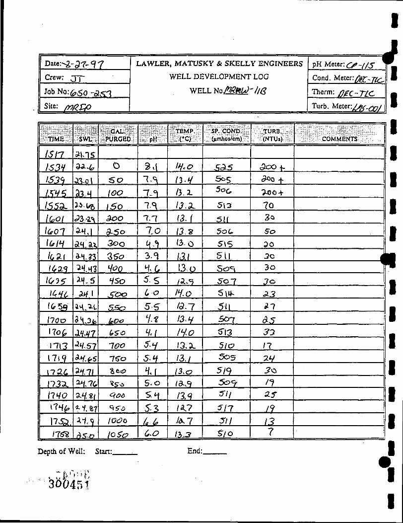
V Date: t - ^ 6 0 - ^ 7
Crew: JX_ Job No: 6 $ " 0 - J ^ ' 7
Site: ^ p X i P
LAWLER, MATUSKY & SKELLY ENGINEERS
WELL DEVELOPMENT LOG
WELL N o / M ^ 7 ^ 6
pH Mt t t r . ^^ - i / s
Cond. Meter:/^.-;-^^
Therm: pfU-TLC^
Turb. Meter:^^(;y^)
V
TIME
0 7 9 L X
0 7 3 S
\ 0 \ ^
10 3i*
(o. lo
/o37
IDM3
l 05o
los-fc lioz 1/0^
/ / / 6
//aa
5
SWL
/?.f,5
/f^55
3/coa
<?/.£)?
aa. j oia-7 w / ^3W 23-7 0117 ^V,;i pv .y
•ZV- i.
GAL. PURGED'
0
^ 0
/ O O
/So aoo Q-SO
3 u o
Z J O l/OO
<iSo
5oo
5 5 0
. pH
7.5 77^
7.5 7 5 7.y
7'V ^Y " -r 7.3 7 f 7-5
7-^
"TEMP. CO
/ 6 - ^
/ iV /c^v9
/o).?
/P.-g / i . 3
/ .?0
/ ^ . ^
/.2^4,
/a.7 / . ^ - ^
/ 3 . 0
SP. COND. 0< mhos/cm)
.T/ C,
5ao 5-_?o ^ 0
5 ^ 0
SJ io
5cLO
5/a 5r/4 5"o8
>s-/3 3~c?9
= ^ = = s
TURB, (NTUs)
^ 0
Vo n I I
10
7 6 3 .9
:k
2.
3
COMMENTS
1
j
1
Depth of Well: Start:. End:.
ecib^ifirs.

Date: ^ - ^ ^ ^ c ^ y
Crew: - ^ r
Job No: 6 s r o - a 5 3
Site: / ^ / C r r
] LAWLER, M A T U S K Y & S K E L L Y E N G I N E E
TIME
/309
Oso
/03Y
^^y^
//>S7
Depth of ^
{3D 04
SWL
-?». 5S
79-7t
f<?.07 /37 .A5
(^ell: 5
53
^ GAL. PURGED'
o 3 o
10 105
t aa :
. pH
^ . 0
?>-(
St.D
WELL DEVELOPMENT LOG
WELL No/^/lAlLO-lS/^
TEMP. C O
/^6 16.-7 no
End:
SP. COND. 0«ml)Oj/cm)
757 ^¥S H ^
'•'
TURB. (NTUs)
70 .ro 6 0
RS pH Meter: ( ^ Y / S '
Cond. Meter: ^> ;2c .
Therm: / ] ^ ^ r L C
Turb. Meter./^~ooi
COMMENTS
bell r)ry 1 /
W U S-& rJ ! rcco^^MSj dst^rrsCcl,^
fiAjr^J lb u ^ l l ^
«1 ^ A^ c?-r-/
^ - . i / / / b ^ 1^0
-L ^ o c - ^ ^ iu , l /
t^luvs^ - f S O d h ^ J J r
1
j
i
w
im W
^H
\

I !i Date; ^ - - ^7 -^ -7
Crew: ISL. Job No: ( a S ^ - B - ^
Site: (nftXO
LAWLER, MATUSKY & SKELLY ENGINEERS
WELL DEVELOPMENT" LOG
WELLNo.(!lftM-V%
pH Meter: C^^// j^
Cond. Metery^ 7 7 ^
Therm: ^ c T c L
Turb. Meter:^^^^ QO\
TIME
07A.5
0 730
G I X * ^
07(^_^
O^Mo
f ' H 3
•
.;iswL-'i
—
—
—
•
i i l G A L l i i l iPUJiGEd.?.;
— • •
^
—
' -
• -
r-
•
'
1 ^ 1 ' p H ••:•'••'•
H'^ 6^1 t .X
^ t
6J <^-^f
' TEMP.
\X-S
\ \ ^ \
WrZ
\ ( .7 ] h ^ ( ^
SP. COND. (;< mhos/cm)
.37-2
..^-^-s . :^5 .J?rr •29^2.
1-e.<-?
TURB. (NTUs)
cte h ^ 0 +
'Xod> +
d to i -
f ^^
/ O S
COMMENTS
lkueJDjf.\r ^ M /VA A I C \J
i 1
•
1
1
Depth of Well: Start: End:.
ge»<^l5 i

I
Date: - £ - ^ 6 - ^ 7
Crew: :ST
Job No: fcS0-a53
Site: ^ R T f i
LAWLER, MATUSKY & SKELLY ENGINEERS
WELL DEVELOPMENT LOG
W E L L N o . < ^ ^ i J - / ^
pH Uttt t ' .cp ' /L^
Cond. Meter:/^^(-_-;g-^
Therm: ^ ^ - ^ 7 2 ^ < -
Turb. Meter: ^ / 2 ^ - < » ;
• TIME
\ a L S ^
\AS^
lSo4 I3\a WbM \5Xi
\33\
• |
Depth of V
.;yswi?^i;
M^CS.
ci.^.5b
fi t^ *f«{^2.
//7'?3^
/v^~ •
/ell: 5
; - 'GAL. ; PURGED'
0 S O
loo I S O
a*i'0
;tart:
• • • : : - - - - i : - ; ' - ' : ' : ^ " • • • • . : : • ; . •••:••>••;•;•>•• ' ; : :•:- .- . :• .••;••
: ;•:-: ; : : ;•:•:•:-:>••-:•: . .:>•
«: pH :
7.7
7.6 1 5 7,«
l ^
"TEMP. , . CC)
/ 7 - /
/^-s-/^-g
/^,y /.^7
" ' •
-
End:
SP. COND. 0« mhos/cm)
HHt H3H isi t / ^
S^9 f
TURB, (NTUs)
5*0
>o
So TO
€o
. . • • ^ ' \ ^ ^
COMMENTS
(^11 rf^ f 7 ,
^
i
1
j

I
\ Date: "9 • 3 . 7 ^ 7 7
Crew: Tr Job No: ^ 5 b - 3 ^
Site: / 9 / ^ / 9
LAWLER, MATUSKY & SKELLY ENGINEERS
WELL DEVELOPMENT LOG
WELL N o M A J ' / j ^ A
pH Meter: ( y - f / ' y
Cond. Meter^fe:. -j^^
Turb. Meter: • 2 ^ Q)f
r I
••• TIME
lfff<j
% ^
IfflfO
mj /€oo
SWL.
55^05
^ H ^ ^ . (
/SD.^f
/ f 5 .
':"GAL.''r^ ^PURGED'
o ^o fao I50
Too
-^, pH
^ ' ^
7<;
7 T 7ccD
^•y
•iTEMP.ii
/ • ! ? - /
i s . i fS-l I7 .0 112
SP. COND. ()«mhos/cm)
. ^ 7 377 V^J ^ 0 ^
¥ / S
TURB, (NTUs)
' 3 }
( 5 / 2 .
•2.0
j^s-
--
COMMENTS
1
Depth of Well: Start- End:
xMMi^

pate: If^^q-ff^ Crew: ^ ^
Job No: ( o £ 0 ' ^ t f
Site: Z^l^A^y^ fc^
LAWLER , MATUSKY & SKELLY ENGINEERS
WELL DEVELOPMENT LOG
WELL No./*1/^MIV-i/C •
pHMetcr: H ^ ^ J i F • •• r " * ' f = - = ' — •
Cond. Metcr:)^3<5«[ J[
Therm: V^X J ^ ^ ^
Turb. Meter: | ^ / ^ ^ | •
1 .:. sCWi'^vU^r-:
b T J M E ^ -
[09-A?-d59-3dj
b^v^ b^^o 6^00
|<53H6'
O^dio
J ^ 3 ^
07V(5 o?5o p?d6' p? /o k?9^d J936
•
Depth of V
.VswL ;
/.?5 /V:<^^
5.fo5
^y.?V
/V.3A
5T.n 63.T5L
^.?S 6?.??? ?b.?^ ?/.?^ ?;,?v ?^.?;! ^ . ^
^ell: S
iJPURGUtJ^
PVi r n.3
/ « <
^ ? ^ 3(>l
tHif ^ i ? -fcDtJL
6 1 * : ^ ^ ^
t ^ ? -f o ^ f^T-
pu^p r 1
tart;
I ^ H ; ^
>\p JA
% ^
?>3 ?/2. ?.;i ?.^ •? .5 ?.(? ?--3 ^ , 3 ^ . ;L
? ' 3 ^ - Z " > . /
< #
• • i : . y . . . • . •• • • '
|??TEMP%
a -/ 6 . ^
^ . S ' 7/.0-ll.o lis III I l6 ' / / . /
/ / . ^
/ A ^ //.4^ /^.O
//.3
<? ^ f
End:
:SsPHco.Ni:^ :^( /«ni i^o^rnM
^oo" 65* 5 5 ? ^ 3 . ^ 55^ SS^ SS(o S i £ S(o^
S U ^6V S<fo S^f y ^ f ^69
3^
,
.^'#rURB.;Q:i; ^ ;f<NTUs) ' ;•
>Aoo ^3 Sb ?^
^ ^
?^ Gr S9 ^ ( >
46 3 $ 3C>
3 5 •
1
1 f
1
*
Ml^^^lcOMMENJ^^^^:;^ |
J'^a.i I S S ^ . ^ . 1
^ / / J ^ ^ c . 1 *J^ 1 •
ATTfc.<- . ^ u n a - 1 " • " ' • ^
J ' ,* / l*/^jf,. km J / — • • • i ^ B
1 d^
11 1
tt#»4S7 r-v
I

I
w Date : / / . ^ t />^ ;^
Crew: ^ ^ ^
Job No: (oSo^^Si f
Site: A J O L J / H . ^t^Ji
LAWLER, MATUSKY & SKELLY ENGINEERS • * • • ? ? •
WELL DEVELOPMENT LOG
WELL Nc / f^ /HiV '^ / l f f •
pH ^ etcr:
Cond. Meter:y^f Joffo
Therm: YifX ^ 0 0
Turb. Meter:ji^y yj g.
P
\i^n IH£ )k6A-
iXth
1 ^ l i s s
13).S iSdiS 133^
isnr isrs
\ms IHW
t H ^
•
• ' •
•
/f.3/7
?^?3 5V.3«
\^%f^ r o J l
b^lA foiSo
(o%H6
6*r?-^ . b S
1-1,66
n37 H$<f ' m ih'H
• •
,
.=
:?.PURCUb!?5'
p U i ^
r T
k ^ 3 o o
K-hucJC (A
^ 3 ^ l - \3 ; t«€ ^6,3
f^"^ 70 1 J
/ o y r ' | i 6 J
/JL3^
/3 I3
r>uAuO o-
I - . -
I -
f^H:M^
^ * y /
7:^ ?.f
: - -Z+t
?.' TiV ?*^ T-'V ?.5 ?.^ ?.«/
?.v^ ?.i^ ?.3
^ ( ^
•s^TEMP.m^;
4i:(*t)p^
5? /?A
/3.r vj.-?
- ^ i e i
y3.? /^.r /^.'? /3.0
/ / . . ^
\^M U.^ i m i i r IhS '
. Hits
:^SP;^C0ND^:^f ^O 'n i l i o ^ rn i l ?
' & » < —J
6V0
^5A
O ^ / / / * ^ "^
6 ^ ^
Q>IS
( D I ^
6,23
66/
G/3 M U\ (ptl .
S9^
• •
.^'l>rURB.:V;:5 OV-f{NTUs) : ?•
> ^ 0 d
> - i d £ >
s» ««.-t i6o
^ A o o
>;L6Q
> d i O t i
> ; i f l f l
^^AOA
>duoe i
>^Sie>e>
> k 0 6
>«Aoo
><i<?d 1
/
/
'
• ' = ^ v^^COM M ENrrS^«J>^ .!:."
i<*.ry tJouJtr - h rsu i j / \ l l ' t [
(1 ' /I .
V - t r ^ ^ t X
y/*./V S^t . /HOfn^.
/ r r n . r . < u r » ^ -
l o i i af-fi'AJtLS
s i ; n (oh o f f}^/i.&
Depth of Well: Start: End:
^

Date: I / ^ K Q - ^ ^
Cfcw: J > ( S ^
Job No: h 5 0 ' d S t f
Site:/t^^/,^J^ R.^d
LAWLER, MATUSKY & SKELLY ENGINEERS
WELL DEVELOPMENT LOG
WELLNo./*!^K/ '5i^
pH Mater: f^fljg ^ Cond. Meter: iSJSoob
Therm: / ^ St^c T u XJ, . V y 5 0 f c Turb. Meter: pRrz/ 'c
«r
^•TIME;^y :?PURGlfD::&' #ffpW:# l |TEMP|i! ••.Ji>V-., - : • '.v S*^. ^:(!•C)?:t^r
• ^ . ^SP; CO:ND;?;f ^•N^rURB.;:^:; ;f<NTUs)":: :'?^^«C0MMENJS^«1:^ ^ '
A^LL ^.to ix Av .ifL?! J£0 /AT; ;S££.
Agi. pl?.5g iiii. 3i3 JL^ 5?o il J ^ ' * A ^
BQS_ ail. AifO i iJL IL2. M£_ J3 d'OK'T
J^l£_ 30. n 3 ^ 0 . ?.3 A l ^fi. A ^ cl<A.r
JIM. 36.3S Hto hi. J U J&3L 13 jCJiAi 1^3$ 36.i6 600 ii_ M_ S9JL Ih. y;vU ^ ^J4//J^.5e^. ] ! •$& 3o.y/ ^^o 1 ^ IL3. J!?k ^ . 0 Ckaj ; P'^f A itir iSUi£ Ccffyo-c
.U/ l ! f- :^zf^c^ (g ^ D ^ J I A L . ^ Wtf.// - c //<\( /i Vo :fr;f ^
i Z.J!8
M £ , ALIU M. //.JL JIL J l . pUf C Ofi<S. ?tf ' ^ f
/^/.f a ; i ^ iAiJL ?,5 iZiiL i 2 ^ y!tJJ t Syj/^fstt..
lo^s Si9J^ JJiJO. ?,5 iZrl. 636 16 xi £&£.
ioUSL ^3;£L 3Q>O ^JL / / .y m / 6 / X i * A ^
/<?y.^ ;i9.^ .iffo. ^.y i z ^ ii2_ 6i V efz/r S j ^ j / d ' l . u ,
fOS£ ^SJl. (oOO f .5 M . (o53 cJtar Ro£_ 36 j r >AC) l i iL //.r iii i f i /^<i
p v M p j y ^ //p?-
Depth of Well: Start:. End:.
;3i»i.sS)

t
Date: H - I ^ ' t f ^
Crew: ^SJL. Job No: Q,£ci'^Stf
Site: /^oL^J<: Z ^
LAWLER, MATUSKY & SKELLY ENGINEERS
WELL DEVELOPMENT LOG
WELLNo..^fi^|V-?J^ •
pH Mstcr: p^ef A Cond. Metcr:tCr5^^
Therm: tor 5 t f^ T T T T Afyst€c Turb. Meter: t^T-ffd
»
//V;L \ \S '9L
;A^T;L
\^)2.
l^ct l
U3^ I k ^ l
ic(j^:t
l3ox /3^2 I3f^
\}3SA \ N 6 ^
i /Vii H 3 0
m k HSC>
I6(ib
oiswi, ;;
^£.i(i
3$^S
3?.ito 37t3r
3 .5r/
HoX^ ifi:6o
y/.^ ^/.?-/ V .ao
V^.V *fk.ipo
^3.00
¥3.i<f'
33^C^
i .%i^ a?./?-a^.fd
; | t . G A ^ ; ^ iJPURGUb^-
—
i 0 6
^ a a 3Aa 1406
S60
h 6 6
9oo ^ c o / O O O
l^LOO
l3oo NSo 1^60
i I
• •
^.v ^ • Y 7.y ? .s 7.S ?.>• ?.y ?.v ?.v ;z.i-^•y ?-y ?.r ?.Y
?o . . . \vLCC
t^EMP^
//.? / / . / •
lf.d ; i : / //.7 / / . /
Ihc,
II.L
I f f /a.v i : i3 U.l 1^,6 //.r
^i/ie^rs-/
l|sP ;Cb:NDfi:
^3(; jr/? Sif cl?f jr//
5 ^ ^ s/i S l ^ 5/3 J-/^ ^-/jr
5/V 1 Si^
Sld<
,
.V^#rURB:;-^:5 ^ ;; <NTUs) --:"
9^ >^oo
^ ^ a a >koa >Aoo ^1
>dLOa
Gs 31-s-c 3 3 ^ /
J 3 «;^A
r
/
j
•
':"5;fU' iC0MMENTS/ :«J:iV :;-
PvM^ «iv ViVW /fttfVi
AarKjLT b r ^ * ^ ] S,'l4-y
lUk-f-k-r hft^t^tJ
\ f ! B ^ \ d : j j » lOmtkAJK 1
«T"Te.r" ^ n r » »
AtUcA c^Uar^r-
A f ^ t , ^ .jforma.
A H i W .S 'o rm^
pOMp e^&^ l* fK
Depth of Well: Start: End:
a^300460

\
m APPENDIX E
3O04G1

I
V Date: 9-Iz-f 7 Crew: ^ > r r l f i r . &
Job No: ^St)- ,0^^:§
Project: M / ^ I P
Project Site: ^ / / ^
WELL SAMPLING LOG
METERS
Temp:
pH:
Cond:
Turb:
TLC # 8
:?c/
r / c v/>? /JK^mc O^T
6 / M H
USED
-/.<r..
f?.3^
WeliroNo:/V\,LK^ , ^
Well Condition: Q c s ^
Well Depth/Diameter: /ol-3 / ^ "
Well Casing Type: ^ ' ^^c-
Screened Interval: t^^^^-^
Casing Ht/Lock No: x
Reference Pt: Toe
Depth to Water (DTW): r^-^^
Water Column; HtA^ol: 7 T / / / S &
Purge Est: 5^
DTW Before Sampling: (ffc?-3/
Sample Date/Time(s): ^i- [i.-'^'J f n ' ^ ^
Sampling Method: Wf<>- b ^ ' K
Sampling Depth(s): -^oc
DTW After Sampling: (,^.o6
Sampling Observations:
Chain-of-Custody No(s):
Analytical Lab(s):
Purge Date/Tune(s): ^_/^,<?7
Purge Method: ^ ( v ,
Depth(s): ' ^
Rates (gpm): . z C '
Purged Volume: 7,0
DIW After Purging: iP «-v
Yield Rate: ( l ^ - ' S .
Purge Observations:
PURGE CHEMISTRIES
//GO ' ) 3 2 ^
SAMPLE CHEMISTRIES Temp.
C O oH
Start j T A _ ^ -^
End / t . | ^ . ' ^
Sp.
Cond.
"l?o
770
Turb.
f"
^ 6
SAMPLE ANALYSES
Inv. Parameters No.
Pres. Meth.
Filt. (Y/N^
VOL. TEMP.
pH SP.
COND. TURB.
• .: • .'..'-.
1' ' j y ^
r t
0 ) 0
do
>V^i" ^ y . iW-t' 6-5 IpL.x < -9"
Comments:
Crew, Chief Signature:
& / / T U V
Sfz-% T ^
)>Ze)o ; > x » 0 >'2.O0
>-2<s<'
Air Temp: Weather Conditions:
Date:
.
30O4BZ

WELL SAMPLING LOG
Date: 9 u T . ' ' i 7
Crew: T$rT/g:^t/
Job No:.
Project:_
(p<ro -Zi-3
j - \ M P
Project Site: C^^ lLr
Temp:
pH:
Cond:
Turb:
METERS USED
T L C T^-s
7^1 1 TZr :^ S> ' A.n'.<DiFc^ r?/n~/T>c-
< ^ ' / ^ f 3 ^
I
Well ID No: (VK^nW'^O
Well Condition: G>9«><Jl
Well Depth/Diameter: 3c.. i / 3-f-.^
Well Casing Type: "i" pv <_
Screened Interval: . rDcX
Casing Ht/Lock No:
Reference Pt: TPc_
Depth to Water (DTW): ^.fi>
Water Column; HtAi'ol: 1 . 7 ^ / p . . 3 3
Purge Est: . ^
Purge Date/Time(s): °[-\\f\^{ U i o - / (J<i
Purge Method: •W-CC -'o'- lv,
D e p t h ( s ) : c ^ • - ; 'h: ^
Rates (gpm): • ' i ,<' ''yjy-' ';•*".
Purged Volume: 'H <<'
DTW After Purging: 2 t • "7 •. -
Yield Rate: Z 5 ^ ^
Purge Observations:
DTW Before Sampling: 2.^. (» "5
Sample Date/Time(s): 9 - f? - f *? / / ^ 3 o
Sampling Method: fi>fav-t^/v,
Sampling Depth(s): T< <
DTW After Sampling: ^ ' r ' S /
Sampling Observations:
Chain-6f-Custody No(s):
Analytical Lab(s):
Suet
End
SAMPLE CHEMISTRIES Temp. Sp.
C O PH Cond. Turb.
(•^•H C-1 i i ^ ^ : r
/?-0 7-) ^Z^ «?6
SAMPLE ANALYSES
Inv. ' Pres. Filt. Parameters No. Meth. fY/N>
n
VOL.
PURGE CHEMISTRIES TEMP J!C1 JEBL
SP. COND. TURB.
t
0 i5-<» ^ d o '{ "<.5 Cf ( ^ - y
?'/- n ^ Comments:
^ r 1-1-7 . 0 J-o -t.a
5^2 <.< 2 (,WO & l b 'i
* S o S's S 5
5 Air Temp: Weather Conditions
,a.vi3€n463
Crew Chief Signature: Date:
%
I

t
V
p
WELL SAMPLING LOG
Date: 9 - ( S ~ - ? 7
Crew: - T ^ T /^fCjf
Job No: / ^ < ^ - - 2 ^ ^ ^
Project: / ^ ( ^ i f
Project Site: f^tJllLq
Well ID No: ^ 5?
Well Condition: " ^ o ^
Well Depth/Diameter:3-.Vi/ lo^-g
Well Casing Type: 3 - P^^
Screened Interval: t-J)i-cc.'^
Casing Ht/Lock No:
Reference Pt: -xxsu
Depth to Water (DTW): S"\.M7
Water Column; HtA^ol: S°-3S^| : i .M7
Purge Est: 5 5 - K
Purge Date/Time(s): *? - ' sr- ? 7 /^tfj-- /5'j<?
Purge Method: W^^IM
Deptfa(s): '-M
Rates (gpm): ' " ^
Purged Volume: 5"$ ";)=<.( .
DI'NV After Purging: ^ 3 , , ^ ; j .
Yield Rate: L-
Purge Observations:
PURGE CHEMISTRIES
VOL. TEMP.
_EH_
SP. COND. Ttms.
o
\ ^
'>o
3 o
4o 5<>
Comm« 5 s
\3-T W-S \U Ci-2.
\S.6 '4.3
j n t s : ( ^ ^
5-I t-^ ( ..u
. (c-6 fc-5 T ^
7.S
fe2Z ^CO
(^^i^-
lp7l (PT5' 7 o J--
t < t ^
4 5--o'=>
^° 3 0
^ o
IS
s o \S
METERS USED
Temp: T L C i ^ ^
pH: ^ ^
OMM T ^ C : ^ ' S Turb: A^K^ /)^C O ^ T - I ^ c -
DTW Before Sampling: 5^/ • <* ^
Sample Date/Time(s): <7 - ' ^ - ^ " / ^ ' ^ ^
Sampling Method: .J-^- &—I'M
Sampling Depth(s): t-trc
DTW After Sampling: s~/<'! "
Sampling Observations:
Chain-of-Custody No(s):
Analytical Lab(s):
SAMPLE CHEMISTRIES
Suit
End
Parameters
Temp.
C O pH
/^/•s- /.^ h . f <o.\
Sp. Cond. Turb.
C-yf, G
(^n 7 - .
SAMPLE ANALYSES
Inv. ; No.
Pres. Filt. Meth. (Yim
Air Temp: 6o ^ - V ^ Weather Conditions: S'u/->'j
cSiS^I^^^^^ B4-
Crew Chief Signature: Date:

WELL SAMPLING LOG
Date: ? ' L ^ - 9 7
Crew: -X^T/UL^
Job No:
Project:
(s<^-x<r^ /^^\?
Project Site: ^ ^ / i e .
Well ID No: 7 ^
Well Condition: '^r^
Well Depth/Diameter: lo\.<^ /3 '"^ '^-
Well Casing Type: 3 " pv/'
Screened Interval: i ^ r c c ^
Casing Ht/Lock No:
Reference Pt: x c ^
Depth to Water (DTW): 4\.3-(>
Water Column; Ht/Vol: t 'O .VMyi l . ^ s
Purge Est: G t °vci|.
Purge Date/Time(s): '^-(r-'^i 16-Vo - 1 ' ' ^ ^
Purge Method: fcu^lvi *
Depth(s): *-^
Rates (gpm): .'^^''
Purged Volume: t,7
Dl'vV .After Purging: ;^J;j-j 5'. -..
Yield Rate: h ® S .
Purge Observations:
METERS USED
Temp:
p H : _
TLC ^ ^
C^\\{ Cond:_
Turb:
TL<- t^-^ J
/yK</?/^C' {)f^T- )^c.
\ ^ / ^ /J3,J^
DTW Before Sampling: '~\ '^ ' ^ ^
Sample Date/Time(s): ^ - j T - ^ i j H ' ^ o
Sampling Method: rf^.C^^I^
Sampling Depth(s): n'<^
DTW After Sampling: y / - ? /
Sampling Observations:
Chain-of-Custody No(s):
Analytical Lab(s):
SAMPLE CHEMISTRIES
Suit
End
Parameters
Temp.
C O PH
/ l - ^ l i
l \ 3 7.1
Sp.
Cond.
s r i i r-z-t.
SAMPLE ANALYSES
Inv. No.
Pres. Meth.
Turb.
Jj_ t r . .•:: .
Filt. fY/N^
«t
VOL.
PURGE CHEMISTRIES TEMP.
C O pH SP.
COND. TURB. n-<=(
.^/^^ Comments: '
{^•^o
:;,1ft3' l465
G.«
Cl ( ^ b l
1©^
YI
t,o / 3 . ^ 7 2 <|5"' / -^
Air Temp: ^'-^ .-'TO Weather Conditions: SOA^V/
Crew Chief Signature: Date:

WELL SAMPLING LOG
V Date:_
Crew: • % ^
?7 -VL-C IVI^U
Job No:__^£^:: i2£2_
Project: M O ^ ^ P
Project Site:_C£vv^£.
Temp:_
p H : _
Cond:.
Turb:
METERS USED
T(^<^t
• ^
<i c " S /u '<jp/i'<r. M T - / f : c .
:CL^ /9^3W
P
Well ID No: t^Oi>^
Well Condition: vj*^
Well Depth/Diameter: / o z - f i ' y A '
Well Casing Type: b"'f^c^
Screened Interval: 6>***
Casing Ht/Lock No: U"^ ^ ^ / / " ^
Reference Pt: fTjc-
Depth to Water (DTW): 3 S . 7 3
Water Column; Ht/Vol: i t . t i . y ^ ' ^
Purge Est: Zso
Purge Date/Time(s): f -^- f7
Purge Method: H'*>»V* "'**f
Depth(s): aJUL
Rates (gpm): Wc **
Purged Volume: Jeb
Dl"vV After Purging: "V ^ ' ^ .*
Yield Rate: L-M-H
Purge Observations:
1^5 - ?5«'
DTW Before Sampling: 5 t . 1 /
Sample Date/Time(s): 1-^-17
Sampling Method: Vi'P-t*^ IM-'IM
Sampling Depth(s): ta*'
DTW After Sampling: ^G-TJ
Sampling Observations:
Chain-of-Custody No(s):
Analytical Lab(s):
SAMPLE CHEMISTRIES
/o jo
Suit
End
Cx
Temp.
C O
//•f o.-^
P H
7-^ 1-7
Sp. Cond. Turb.
yo7 jf.o H ^ 9 ' ' l i . H
SAMPLE ANALYSES
Parameters Inv. NQ.
Pres. Filt. Meth. (Y/N-)
^
I
VOL.
PURGE CHEMISTRIES TEMP.
__CCL P H SP.
COND.
0 (Z'S
fH K.O
/ f o /0 .7
Comments:
u,r 7 . / 7 . 2 -t . 3 7'*(
Crew Chief Signature:,
TURB.
<i .%
5 ^
Air Temp: Weather Conditions
7. J
V.3
Date:
3004B9

WELL SAMPLING LOG
Date: ^ - ^ 9 7
Crew: rT ^VtnA^*^ ) / . jJj/Uc^
^<D ]Vl Job No:.
Project:_
Project Site: ri cuX cv*.
M S ^
Temp:
p H : _
METERS USED
TLC i ^ ^
^ o / T i ^ . ^ ^ Cond:__
Turb: /^y^aic-. 0(lT~,^(L
'<//y /17.^Y
4
Well ID NO: (WfLftvUl-**V
Well Condition: |Jtv»
Well Depth/Diameter: V t ^ / 3- *
Well Casing Type: WC ^ckA* ^^
Screened Interval: 7^ r- ^ 1 ^ ^
Casing Ht/Lock No:
Reference Pt: "p2?C*
Depdi to Water (DTW): A ^ . f ) .
Water Column; Ht/Vol: (^^ -jt //C. c>
Purge Est: t/i J* / .
Purge Date/Time(s): ' \ -^ ' '^ ' ' /
Purge Method: v*V '»** '*^
Depth(s): A ^
Rates (gpm): ' ^ ^ •
Purged Volume: (1^ <^<( v
Dl'vV After Purging: l \ t . \T' .
Yield Rate: (L )M-H
Purge Observations:
DTW Before Sampling: 2 5 : f^
Sample Date/Time(s): 9- tO ' 7 ' > j / i ^ U S
Sampling Method: +\ /o>- U - W
Sampling Depth(s): <o'^
DTW After Sampling: j o , i /x
Sampling Observations:
Chain-of-Custody No(s):
Analytical Lab(s):
SAMPLE CHEMISTRIES Temp. Sp.
C O P H Cond.
sun /9 . l f SiO -^>3
End / 3 . 0 ^ . 0 J 2 7
SAMPLE ANALYSES
Inv. Pres. Parameters No. Meth.
Turb.
^IS
""?
Filt. fY/N)
m
ov
^
VOL.
PURGE CHEMISTRIES TEMP.
pH SP.
COND. TURB.
"•y 7.t' Comments:
*)7«^
< / * . 3
(if "1.0^ y
JPV I . IO ' I I
300467
1/.3 %•( a^^ 7 x
Air Temp: Weather Conditions:
Crew Chief Signature: Date:
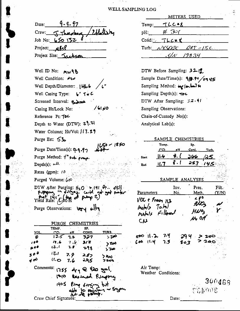
WELL SAMPLING LOG
V ^ ? > f 7 • Date:_
Crew:
Job No: (o^O \'SZ^
Project: ^ f ^ f
Project Site: < . ^L«;tfK
Temp:_
p H . _
Cond:
Turb:
METERS USED
-XCc t. ^ ^ r Tt-<^M-
yu r</?/ r /7 ie r^ / sc 4/A^ / f8 3 ^
! »
^
Well ID No: /^^w^^
Well Condition: i X^
Well Depth/Diameter: . | t i t . t
Well Casing Type: W' 1"*^:
Screened Interval: ^.^ocib
Casing Ht/Lock No: /^ifiO
Reference Pt: "^tc
Depth to Water (DTW): 1 ^ ^ ^
Water Column; HtfVol: / / 7. S ?
Purge Est: 6'5»>
Purge Date/Time(s): Cf-Vf"7 J4^*f^
Purge Method: y^jiA. pt*^.
Depth(s): *-^
Rates (gpm): /o
Purged Volume: (pOO
DTNV ./ fter Purging: f ^Q >-l*ll ^ f-- /f»\l
Purge Observations: \/npj •*vH
PURGE CHEMISTRIES .
VOL. TEMP. JC:S. BH.
SP. COND.
V 4 9 0
> • •
5^* H ^
i 3 . r n.* / t . 4 7.(<
<a . ' 7.ff
/^./ ;,.p <'-0 7,^
3P7 3 / 2 •x-lt ; i ^ ? i » ^
TtreB.
Comments: ^^^^ *V^ Q «UD - - l .
Crew Chief Signature: ' '
DTW Before Sampling: 33-fJ^
Sample Date/Time(s): ^ { $ ' ^ ' * / 6 t ^ $
Sampling Method: i^l»\lotSiu
Sampling Depth(s): -rac
DTW After Sampling: 3 2 . 4 /
Sampling Observations:
Chain-of-Custody No(s):
Analytical Lab(s):
SAMPLE CHEMISTRIES Temp.
C O pH
Sp. Cond. Turb.
Surt
End if.7 ^- ^ ^^7 / y ^
SAMPLE ANALYSES
Parameters Inv. No.
Pres. Meth.
Filt. (Y/N)
/kj%6 To>»A Y
1 3 > l o o
Air Temp: Weather Conditions:
3on4ecj
Date:

WELL SAMPLING LOG
Date: f S t ^ ^ 7
Crew: -x'-LTftMi
Job No:_
Project:
G ^ ' -z-^^l
/H (2-ir
Project Site: U ^ ^ f
Well ID No: P^M-^ ' \ 0 b
Well Condition: \j^J^
Well Depth/Diameter: iQ^.H^/ ^'\**
Well Casing Type: (,.\^ -74C 6A*« I
Screened Interval: fce-wif
Casing Ht/Lock No: 4 . / 663Cr
Reference '?v.'10L-
Depth to Water (DTW): S-^-TJ
Water Column; HtfVol: (, 3 --? V / 1 r • ^
Purge Est: "S*^
Purge Date/Time(s): «t-^.i7/ /2;2o- l"S»3
Purge Method: *T " s^'o*--'/''^
D e p t h ( s ) : 'etA-'^'--- '\---y.M:'---^~:. '--^--^-y
Rates (gpm): /o • / /*•
Purged Volume: ^5 6
Dr\V After Purging: V7
Yield Rate: I ^ H
Purge Observations:
METERS USED
Temp:_
p H : _
T i C 7 ^ y
^ ':^^/ Cond: 7 7 CS ^ ^ B
Turb: A/k^aSc, JORT -/Sci
6/y(/ / ^ ? ^
^
DTW Before Sampling: 3 "^ . ' ?^
Sample Date/Time(s): <^-/<?'?7////5
Sampling Method: *.<4(B^ iy'*.'*?'^
Sampling Depdi(s): l o O
DTW After Sampling: A/o.^3
Sampling Observations:
Chain-of-Custody No(s):
Analytical Lab(s):
SAMPLE CHEI Temp.
C O P H
Sutt ll>-1 *1 .3
End A).Z 7-V
^STRIES Sp.
Cond.
•z-/?
^(t
SAMPLE ANALYSES
Inv. Parameters No.
Pres. Meth.
Turb.
fy Si^.y-.<...,
y'yi'''-
Filt. rY/N^
«r
PURGE CHEMISTRIES
VOL. TEMP.
CO SP.
COND.
300469 Crew Chief Signature:
TxmB. 0
f 0 0
i 9 0 X* 0
/ » . 3 y-*- ; i > y / / .O ^ . c * / /
/ / . z i>.o fcU
/ ^ / ' ' • ^ A i b
Comments:
iih'^'^m *^\ Art ® ^ S :rl»
7f
>eoo
yr.r
a ^ //. e. I'S «#»
a #/ ^ ^ 3
Ore ( ^ ' ^ f - ^ *^ *Wo^ 5 a ^ .
Air Temp: Weather Conditions:
Date:
\

WELL SAMPLING LOG
P
Date: f . If - ^-J
Crew: -f^f/^/^Y Job No:.
Project:_
{,Cb- z.^^-^
ifoMi-Project S i t e : _ n , i f e U j l _ _
Well ID No: M ^ ' - ^ ' <
Well Condition: A/**-*
Well Depth/Diameter: 'fa-St
Well Casing Type: 2'" ^ <>
Screened Interval:
Casing Ht/Lock No:
Reference Pt: T' ^^
Depth to Water (DTW): ' -^"^
Water Column; Ht/Vol:
Purge Est: ' ^ ^
Purge Date/Time(s):*^-ll-f'?
Purge Method: W4i\tv
Depth(s): jA
Rates (gpm): • "^^
Purged Volume: -zv
D1"\V .-\fter Purging: ^ ^
Yield Rate: L-M-H
Purge Observations: ^x^ Q . ^ " ^
PURGE CHEMISTRIES
oM<-17.30
VOL. TEMP.
CO PH SP.
COND. TURB.
t) 5
ID
17.^
\%0
Comments:
,of4 7.1'
,7-5 7.7-
D
> 1 *
METERS USED
Temp: T L C # - g
pH: : . 3 0 r
Cond: TLC ^ ^
Turb: / / Y : ^ m C QKT- ISC
,<//^ /fyjy
DTW Before Sampling:
rO
f . 7 0
Sample Daten'ime(s): 9 - ' ^ ' " ' i / f^^^
Sampling Method: f s ^<^ d ^ ' l t ^
Sampling Depth(s): TCTZ-
DTW After Sampling: 1^1- ^
Sampling Observations:
Chain-of-Custody No(s):
Analytical Lab(s):
SAMPLE CHEMISTRIES Temp. Sp.
C O PH Cond.
sun n \ 7 Sr ^ 7 7
End / S ' - / 0 - 1 < ( ^
Turb.
• 2 0
7 ^ /
SAMPLE ANALYSES
Inv. ' Pres. Parameters No. Meth.
Filt. fY/N")
Sk5
7 . 3 5 -0 M -
- 6 ^ , . Air Temp: tU^L to Weather Conditions:
C X A - ^ ' *
^'iSpl^TO
Crew Chief Signature: Date:

WELL SAMPLING LOG
METERS USED
Date:__5rM2_ Crew: - j g r / f c t C H
Temp:_
p H : _
TLC ^ ^ rs-^ f
Job No: 6.<t>'3L<-\
Project: r^^ . t .p
Project Site:_R;§aaS£sLs
Well p No: K | , | W UO
Well Condition: <i^s^
Well Depth/Diameter: ^ i '^^ ( ^
Well Casing Type: 6 " T - «=-
Screened Interval; W - *"" *-
Casing Ht/Lock No:
Reference Pt: -TC^A
Depth to Water pTW): 1<«.<J
Water Column; Ht/Vol: - - ' ^ ^ / S r a .
Purge Est: 7?<^
Cond:_
Turb:
TLC ->¥ ^
^y r^ /2 sc 0 / Z T ~ l ^ C
^ A / / F ? 3 V
DTW Before Sampling: / ?• " "
Sample Date/Time(s): ^ - / / - ? 7 f3i C^
Sampling Method: |l<H*vv.t»A^^V.
Sampling Depth(s): ' f o ^
DTW After Sampling: /i/. ^
Sampling Observations:
Chain-of-Custody No(s):
Analytical Lab(s):
Purge Date/Time(s): t-y/-f7
Purge Method: *('"-t«C
Depth(s): oA
Rates (gpm): j ^
Purged Volume: ^'^
D1"NV .After Purging: -2^1.0^.
1,0 3° ^ n-^>5
Sun
End
SAMPLE CHEMISTRIES Temp.
C O
M i^.-j.
pH
7.7-r.i-
Sp.
Cond.
0i Turb.
If ^ j f 1 ) ^
SAMPLE ANALYSES
Parameters Inv. No.
' Pres. Meth.
. . . - ' . . •
. • • - ' .
Filt. fY/N)
%
Yield Rate: L-M-©
Purge
VOL.
0
1 ' ^
Comn
Observations:
PURGE CHEMISTRIES TEMP. SP.
C O PH C O N D .
/7.*/ 7.2> r / ^ n H ( ^ . T - s-'^ }7,f O ' ? 5-^5"
TURB.
> ? « > 0
5-3 7 /
lents:
6«^ ^ « ^
^5Z)
i 1
n-1 ] Z - 0
7'<r -7.0
7 . 0 7 .D
l o
(\ir Temp: ; 4 ^ U Weather Conditions:
r;2r ^ ; ? j
(i4i/^
/ ^
\ ^ 1 3
9 1
AD ( J L O •UOC f~-uA- ^ W*
&fW^1l Crew Chief Signature: Date:

I WELL SAMPLING LOG
V
p
Date:_
Crew:
' \ - ~ lO ' ^7
^f^x/ULi i f Job No:.
Project:_
65^-3-^3 A\^^(^
Project Site: / ,i<-r}U^<
Well ID No: \(i t<U - \ ^ <&
Well Condition: AJ i i-*
Well Depth/Diameter>.l«» / *" Vt^-*
Well Casing Type: L " s U ^ T ^ d .^*t. .
Screened Interval: S»j>- ft>tJL.
Casing Ht/Lock No:
Reference Pt: r^^
Depth to Water (DTW): \ ^ . ;>Ci
Water Column; Ht/Vol: \<^\r\/45«-/
Purge Est: -^>^
Purge Date/Time(s):?-/o-*f 7 ^YS^" ^ ^
Purge Method: 1'** 6<o#>W ««*f
Depth(s): i^o
Rates (gpm): ^
Purged Volume; "^"Vlj
Dl'vV .After Purging: v\ ,A^ , •..
Yield Rate: L - ^ f g )
Purge Observations:
METERS USED
Temp:
pH:
Cohd: .
Turb:
JLC ^ i ? J o r
nr. Tfz ^K^/7^c m r - Z ^ r
. J / ^ / ^ . " l i /
\ \ DTW Before Sampling: V<
Sample Date/Time(s): '\-10'*\n
Sampling Method: - ^ ^ " ^ ^
Sampling Depth(s): <6 ^
DTW After Sampling: A®'4'>
Sampling Observations:
Chain-of-Custody No(s):
Analytical Lab(s):
\ ^ ^
SAMPLE CHEMISTRIES Temp.
C O pH
Sun I t - t 7.0
End ^2. 3 C . }
Sp.
Cond.
J ^ fFo
Turb.
^5 . z^
SAMPLE ANALYSES
Inv. Parameters No.
Pres. Meth.
Filt. fY/N^
VOL.
PURGE CHEMISTRIES TEMP.
_ £ ! Q _ _PH SP.
COND. Tires. O
m Comments:
^0b HO
1^0
(bOO U,4 (^«ir?3 <?-
^ . %
6.f 6 ^
« H 7
(.A
s;i^ r^ i ^35-^2.y /05 $ ^ ^
[ - ?
H.3 3.3 ;i
a 3
^ 0 ^ n-v| .«» r s a -
Air Temp: Weather Conditions:
t-"
30047I
Crew Chief Signature: Date:

\V ^
WELL SAMPLING LOG
Date: H-jQ-'M
Crew: t ^ s r / ^ t ^ i /
Job No: Lf^O' iC^
Project: M\ O-K^
Project Site: -^^ <• LA-£. ^
Well ID No: !VV|LVMA)- Q » 5
Well Condition: }J^^
Well Depth/Diameter: -- -o* /^ . ^ A .
Well Casing Type: ( (X- c W ( t f r C
Screened Interval: lx^f«/-
Casing Ht/Lock No: / W ^ ' '^^<'
Reference Pt:-r'5<^
Depth to Water (DTW): Q /^r4*«>*'^ -^-^^
Water Column; Ht/Vol: ~ 2/w> / 3£70
Purge Est: " ^
Purge Date/Time(s): /(
Purge Method: - ^ p
Depth(s): »^
Rates (gpm): / <^
Purged Volume:
DTW Aitev Purging:
Yield Rate: L - M ®
Purge Observations:
;,A-»P*^
' ^ .
o ^
<?//« - < } / . <
; : - ; ; ; - ' " : : . . • - : ;
^4e«^,V^^•-
PURGE CHEMISTRIES TEMP.
VOL. C O P H
SP. COND. TURB.
U a -| .> "OX &n
METERS USED I Temp:.
p H . _
/ L C ^ g
./'9-Cond:.
Turb:
77: C / ^ ^ 4 ^/^ /^.y
DTW Before Sampling: ?ur f-c.i: ^ <3-W^^
Sample Date/Time(s): 5 ' / / - 1 " / / S'^ '
Sampling Method: f-t^- So- l H
Sampling Depth(s): T o * ^
DTW After Sampling: •s-r-ZLcv - a...s.\-u«-'
Sampling Observations:
Chain-of-Custody No(s):
Analytical Lab(s):
SAMPLE CHEMISTRIES
y \
Sun
End
Temp. C O
n. f \Z-{
pH
7 7 .
7-^
Sp.
Cond.
?rr 3f ?
SAMPLE ANALYSES
Parameters Inv. No.
Pres. Meth.
Turb.
r ^
Filt. (Y/N)
< «
0^
o
Comments: Ul H p A W,^ <Z-?'v
^^m^i^:^^^^ / . . V . ^ s .
Crew Chief Signature:.
Air Temp: Weather Conditions:
Date:

I
V I I I I i t I
p
I
I i
'f
WELL SAMPLING LOG
Date:_X%J^_ j7 Crew: ^ - r t w « c » L i ^ l^.l^J(!^\u
^ Job No: ( , ^ Xl'^"
Project: A U U . ^ I2i X ^ . PU>^V-
Project Site:L!^Vg^
Well IDNo:MM«-)/y6
Well Condition: h/ti*» J^)
Well Depdi/Diameter: t ^ i ^ ^ *
Well Casing Type: r*Uv{ T ^ C
Screened Interval: 6*^»»^
Casing Ht/Lock No: CX n ^ / ^ « ^
Reference Pt: T©^
Depth to Water (DTW): 17.ll
Water Column; Ht/Vol: ^ \ M y / i o n
Purge Est: 4 X i '
Purge Date/Time(s): ?•?*' ^
Purge Method: Ay*»W*»n*«tW<.- f—f
Depth(s): / .tfO ,
Rates (gpm): -• t 4 ^
Purged Volume: ^ '^ ' '^ ' i ^ '"^^
D1"\V .After Purging: ^ • • ' ^ 7 . . «Ary..
Yield Rate: L-M-H
Purge Observations:
PURGE CHEMISTRIES
^ . j ^ - y r V V
VOL. TEMP.
__CCL. PH SP.
COND. TURB.
60 /2-r
/5» (5.«>
6.^
7.0
Comments: ^ - i -q i f««^* <VY 1 5 ^ ^
METERS USED
Temp:
pH:
Cdhdi.
•TLC * t
^t .lLc»Tl
Turb:y^««^^ T ^ >*..fc. b ^ T -
^/jJ l U Z Y
DTW Before Sampling: \ ' % . ^
Samph
Sampl
Sampl
I Date/Time(s): 1»Vf7
y ^ c
/5«o
ng Method: ^^*ivt - ^ c r ^
ng Depth(s): t*c
DTW After Sampling: \\.%l
Sampli ng Observations:
Chain-of-Custody No(s):
Analytical Lab(s):
Sun
End
SAMPLE CHEMISTRIES Temp. Sp.
C O P H Cond.
l f . d 7.2. */t^ (7..T n . o Vzy
SAMPLE ANALYSES
Inv. Pres. Parameters No. Meth.
Tutb.
i ?
5-2~y
FUt. (Y/N)
Air Temp: t ^ Weather Conditions: i iW*f
mn 3004'? /f
Crew Chief Signature: Date: \..-'-

WELL SAMPLING LOG
Date: '-N^ Crew: C n /li Job No: 6,SO - Z ^ S
Project: Mj^rP
Project Site:
WelllD N o : n R H U J - 0 {
Well Condition: < J ^
Well Depth/Diameter: 1=1 iO-g / z "
Well Casing Type: Z " P^C '^^ Ho
Screened Interval: t^.t1ou-x lO '
Casing Ht/Lock No: Z . l .^oTOC- '^'LSZ.
Reference Pt: T06 ir\o\cW
Depth to Water (DTW): 1.17,
Water Column; Ht/Vol: ^ l^ / z
Purge Est: 6
1
Purge Date/Time(s): i"L / 3 / 'i 7
Purge Method: U .«Oy B^.l v
Depth(s): £^tv/e Vol.
Rates (gpm): .T;^-
Purged Volume: T . "S"
Dr\V After Purging: lOc-
Yield Rate: @-M-H
Purge Observations:
PURGE CHEMISTRIES
VOL. TEMP.
—CO- JElL SP.
COND. TURB.
- ; . • • .
\a t^
o ; " > ' '
o 1
z 3 ^(
' ^ . M loA 10.n l l . l l l .o
Comments:
Or^ C-V
' / . B ^ . j C l r J j ^ V
^A 4.1 (i-z; 6.7. *6.^
4 * S .5
\70«l T'^oO
< ^ 6 ^ > Z O O
Temp:
pH:
Cond:
Turb:
METERS USED
! ) E C ~ 5 U ^ .
C f ~ M / iOe6--s<io . .. n;rsoe:6 Oier ( c
S/A/ ^'JI^B-/
DTW Before Sampling: 10^6
Sample Date/Time(s): i z / t ^ / l7 0*^00
Sampling Method: DC«.I.I<V^
Sampling Depth(s): To >-v
DTW After Sampling: \\,16Z
Sampling Observations:
Chain-of-Custody No(s):
Analytical Lab(s):
SAMPLE CHEMISTRIES Temp. C O
sun lO^li
End / 0 . 7
P H
6.d 6.0
Sp.
Cond. Turb.
IZ4€ 11
/"2.'?7 > 2 o o
SAMPLE ANALYSES
Parameters Inv. No.
Pres. Filt. Meth. ( Y m
V06
Cli<j'
4\5 li.'^
.14 ^!.^ . ToA, 1>> ix^- I t
Air Temp: lO' iP Weather Conditions: S^AA
^
Crew Chief Signature: Date:
4 I I I
I f I
I I
I I
i
1

WELL SAMPLING LOG
Date: \z. /i/ai Crew: Z l / C H
Job No: 6 9 D - i S X
Project: H ^ T P
Project Site:
Temp:
pH:
Cond:
Turb:
METERS USED
T L C -^11 .
cMz f U C -y-K
Aj^^oec in^T '7c s/(\J l^l^^H
Well ID No: n(2.nuJ -o \ ( fe
Well Condition: ^ooo
Well Depth/Diameter:-10 L5"' / %"
Well Casing Type: p \ /C
Screened Interval: ^J^ioc^k
Casing Ht/Lock No: I' *\ " Z 5 2.
Reference Pt: T^C
Depth to Water (DTW): M"S.^^
Water Column; Ht/Vol: -^ S%' {-T-K
Purge Est: 4 3
Purge Daten'ime(s): I'l.lHJ^"!
Purge Method: H=i.A B^VIVIA
Depth(s): ^v\.We. C(A,
Rates (gpm): .2,5"
Purged Volume: 6 3
D1"\V After Purging: ^ 1 ^ *
Yield Rate: (^M-H
Purge Observations:
104<^-1-5^0
7
DTW Before Sampling: 1G -H^
Sample Date/Time(s): [Z. j^i^ ' l
Sampling Method: IS<HII«^
Sampling Depth(s): TOC
DTW After Sampling: "-l<6 - "^2.
Sampling Observations:
Chain-of-Custody No(s):
Analytical Lab(s):
SAMPLE CHEMISTRIES
l$-HS"
Sun
End
Temp.
C O
^ . ^
/(P.'T
P H
^.1
^.4
Sp-
Cond. Turb.
S2.7 ^
8 ^ (^:-
SAMPLE ANALYSES
Parameters Inv. Nd.
' Pres. Filt. Meth. ( Y m
\joc
CiU- /l4o(f
VOL.
PURGE CHEMISTRIES TEMP.
C O j H .
SP. COND. TURB.
0 IVv-z. 10 fc-^ ZO 11.7. 30 10 .n SO 10.^ ? 0 K?.^ Comments:
4.5-4-M 6 4 — —
—
" n . IS^-^i^i
i^TtJ -$H6 - ^ ^ ^
i>^S
70 >2/)0
• i t J 60 so sa
^3 lo.i)
.B ^Co.^
Air Temp: k ^ " f Weather Conditions: ClC/^O.
-HO-
•:i
30047t
- ' 'T
i ^
CO
Crew Chief Signature:. Date:

WELL SAMPLING LOG
Date: fT., (llri Crew:_3l/ClK
Job No: ^SQ- 'Z-S^
Project: H R l l P
Project Site:.
Well ID No: ( ^ ^ ( ^ U O - O ^
Well Condition: e.oo^
Well Depth/Diameter: Z l.dZ. / Z_"
Well Casing Type: Z " O\JL. ' ^ l MO rK+ef(^ce
Screened Interval: ^ | O V . A 1 0 '
Casing Ht/Lock No: "2..^ •?>7S2_
Reference Pt: \ 0 C
Depth to Water (DTW): \ [ S 5
Water Column; Ht/Vol: K ' / 6
Purge Est: 11J
Purge Date/Time(s): IT-f-^jI'li
Purge Method: Wa.v%(y tM^irvy
Depth^): ^AivJe c b l . • '
Rates (gpm): i ^ 5 ^
Purged Volume: 1 ^
D I W After Purging: Qcy^
Yield Rate: d^M-H
lSSO-1610
(i), Purge Observations:
PURGE CHEMISTRIES
VOL. TEMP. _CCL P H
SP. COND. TURB
METERS USED
Temp: t B C ~ 5 6 0
pH:. cp-H Cond:.
Turb:
CEC-S60
/u't^ibec ORI is-c
3/M. I ^H^^
DTW Before Sampling: l O r S l
Sample Date/Time(s): I Z / M / 1 7 O ' i o a
Sampling Method: P^^A^ l&o.ii'Acj
Sampling Depth(s): tO(-J
DTW After Sampling: i s " . 7 . 7
Sampling Observations:
Chain-of-Custody No(s):
Analytical Lab(s):
SAMPLE CHEMISTRIES
Sun
End
Temp.
C O
ll,L)
11.
sp- . P H Cond. Turb.
t,, S't-i S^o
T2. S U M:6 •
SAMPLE ANALYSES
Parameters Inv. ' Pres. Filt. Nci. Meth. (Y/N)
• H61 •
• * - — ' • " .
Q l ^ \orH-
t ^
• ; i r^ CO
O 6 6
*6 ^ 17.
I7.fe 17.6 IZ.7 11.6 1-Z.-5 | 7 v O
Comments:
C\^)
[y^ c.V
f5^M ^^
Crew Chief Sig
7a fc.6 4.6' ^.6 *6.4 6.7
4 IT
nature:
? 7 ^ , S ^ 5-1 6 -^ 'bS" S 7 ? ^ '71
V':--
17 >zoc> >2,^0 . • 17.
72.0O . yux^
. < • . : " ' '
Air Temp: M O T Weather Conditioi
Da
I I I i 1 I
I I I / • • A
I I I

i
I
I I I P I I I I
I
WELL SAMPLING LOG
Date:.
Crew:
i Z 14±L METERS USED
:sT/dn Temp:
PH:_
TL6 -^U C e - 17_
Job No: 6 9 0 - ^ ' S ' B
Project: H R J vP
Cond:
Turb:
T L 6 « = ^ U
A/I^SPeC 0(?T tS'C
Project Site:. ^ /A / /^-S^K
W e l l I D N o : n < ^ ' ^ ^ - 0 ^
Well Condition: e,aah. CVNO Uci:)
Well Depth/Diameter: Zl . 'bO / z "
Well Casing Type: f^C
Screened Interval: ftoi-iov-v l^
Casing Ht/Lock No: Z . U S '
Reference Pt: TC>C
Depth to Water (DTW): '6.'2-7
Water Column; Ht/Vol: ' "^- i l /"^.C
Purge Est: ' ^^o
Purge Date/Time(s): \ Z h / l 7 ^^170 ~ (0 36
Purge Method: D'^vler
Depth(s): €.rt.\ue co[.
Rates (gpm): .Z.5"
Purged Volume:^ IO
DTW Before Sampling: fOvH%
Sample Date/Time(s): ( 7 . / H / ' ^ 7
Sampling Method: Dc<.aer
Sampling Depth(s): Toou*
DTW After Sampling: IU74
7,-2.H6 [ f ^ «'-<:«v Sampling Observations:
Chain-of-Custody No(s):
Analytical Lab(s):
o'fe^.O
•^s
DIW After Purging: Dr J
SAMPLE Temp.
S u n " ^ J
End ' 0 . 0
CHEMISTRIES Sp.
P H Cond.
6 . ^ ^ 2 - l D
C.^ 7.-7.70
Turb.
IH
t^ ;
SAMPLE ANALYSES
Parameters Inv. Pres. Nd. Meth.
Filt. fY/N^
Yield Rate: L-M-H
Purge Observations:
{JUC
CiKJ'
H a
Aic^oH Hiyo^
PURGE CHEMISTRIES
VOL. TEMP. JIQ.
O lOlO
/Oi6
J H _ SP.
COND. TURB.
4 H
7.V 7 ^
IH13 9
l > 6 •7 ZOO ' KO.
6iO
7.S
^
7.0 7.1
H %6,^^^o;'t. T^^lO
Conmients
a 6 ID
Air Temp: 7 . 5 " Weather Conditions: %/\<-1
300478 Crew Chief Signature: Date:

I
I i I I I I p I? I I
WELL SAMPLING LOG
Date: iT. bHi Crew:_^_l_Jc«H_
Job No: 6 9 0 -"2-^3
Project: H ^ I P
Project Site:.
WelllD No: n ^ M « ; < - 0 4
Well Condition: aooa
Well Depth/Diameter: •2_V.M.7 / z "
Well Casing Type: pv/C
Screened Interval: ftat+or^ 1^
Casing Ht/Lock No: 1 s^ I Z ^ Z
Reference Pt: TOC
Depth to Water (DTW): 4 , o Z
Water Column; Ht/Vol: n,M.S / ^
Purge Est: I 2 .
Purge Date/Time(s): l7./'5/'^7 il 00 - U^o
Purge Method: 6 - A e r i b o S - l ^ l ^
Depth(s): £^au€. -iisL : : ;-:v ^
Rates (gpm): . t ^ T . ' v.- ;-'';;/: 'if: 'y::- .•::':
Purged Volume: ^
DI'NV .After Purging: IC^M . : • :•.
Yield Rate: (1^M-H
Purge Observations: SVCONC, ^^oLc^^f c ^ c
Temp:
pH:
Cond:
Turb:
METERS USED TL^ * ll . cp - i ^ cP-^ ILO "^W
rt/Vs O t c 0f2T ( S ^
^Iw I^S^9
DTW Before Sampling: ' \ .0 'L
Sample Date/Time(s): i"2./w «t7
Sampling Method: <^, ler
Sampling Depth(s): TOu>
DTW After Sampling: / O . K ; ^
Sampling Observations:
Chain-of-Custody No(s):
Analytical Lab(s):
SAMPLE CHEMISTRIES
Sun
End
Temp.
C O
<&.6
^ . 7
Sp. pH Cond. Turb.
7.0 ^ ^ 0 7.0
7 .0 %%^ 762 .
SAMPLE ANALYSES
Parameters Inv. ' Pres. Filt. No. Meth. ( Y m
I t 1
VOL.
PURGE CHEMISTRIES TEMP.
CO JBH_ SP.
COND. TtJRB.
o i,^
^^^ 10.4
4 ^ 5 . l U l .
Comments:
0<^
7.1 ,7.1
<\.'r 6 0 . ^ ^
Q^3
^^7 g|g.
, . ' ^ . ' • .
Te»v\p
7 . 5 10.6
, 1 ^
6<i!>
Air Temp: ^ 5 ° F Weather Conditions: Po-f ''- c l o .
CO
o
Crew Chief Signature: Date:

WELL SAMPLING LOG
Date: • 7_ aivL Crew: '^y / c i ^ Job No: 6 9 0 - ^ 9 S
Project: n d T P
Project Site:
Well ID No: n(2-nk; - 0 5
Well Condition: goo^
Well Depth/Diameter: 1770 / z "
Well Casing Type: ^ iC.
Screened Interval: ft<3rtio»^ l^
Casing Ht/Lock No: 7 .n 5 1>2 5 1
Reference Pt: TOC
Depth to Water (DTW): ^ . ' ^^
Water Column; Ht/Vol: 7,'=67 / z . O
Purge Est: 6>
Purge Date/Time(s): ("2-/"5/'\7
Purge Method: €>c..ae./
Deptfa(s): £^-\vie c:c> .
Rates (gpm): ^Z'?;
Purged Volume: H.'^
D1~NV .After Purging: ^ r ^
Yield Rate: (^M-H
1/45- iz io /6LO~ | t3o
Purge Observations:
PURGE CHEMISTRIES
VOL. TEMP.
JESL SP.
COND. TtntB.
METERS USED
Temp:
pH:_
0 B C ~ 5 6 O
ce~-i
I
Cond:.
Turb:
Q^(L - 56Q
/1/'fSK)£C Oi^r t 9 6
5//U H1>S^
DTW Before Sampling: ^ . 7 3
Sample Date/Tirae(s): I V ^ / '^'^ ^ ' ^^^
Sampling Method: (^t^A^r
Sampling Depth(s): Toc^
DTW After Sampling: U .HI
Sampling Observations:
Chain-of-Custody No(s):
Analytical Lab(s):
SAMPLE CHEMISTRIES Temp.
C O
n.z ^ '5
pH
61^
6.q
Sp. Cond. Turb.
^H^ <6M
^•56 %7^
SAMPLE ANALYSES
Parameters Inv. Nd,
Pres. Filt. Meth. (Y/N)
m
ci/u-
/4C( /4(l;o^
. ; • " - - . • • .
0 CD
0 10.3 4.^ ?"><
7..5 . A.T. , ^.'V -3 -77
^,5 1-7 C A 4^1 Comments:
H-ZO S ^ L 15.6^ -;
Crew Chief Signature:
n o
^ 5 'y^cc>-
. - • • • • • • •
• ' • . • ' • . • • ' : - ' "
Air Temp: "^"S^P Weather Conditions: S^AOH
Date:
-
-
\

I
l»
t
WELL SAMPLING LOG
Date: \ 7 . ( ^ Crew: :^7 [ c n
Job N Q ' . _ ^ S O ^ : J : ^ ^
Project: Hg-TP
Project Site:.
"? 2.5-2.
Well ID No: ^IR. fHtJ - O S ^
Well Condition: c^oc^y
Well Depth/Diameter: - ^34 / ^ '
Well Casing Type: pv/C
Screened Interval: Gje^rocK
Casing Ht/Lock No: ^- ' ' ' ^
Reference Pt: TOC
Depth to Water (DTW): 7. \ .6 4
Water Column; Ht/Vol: 14 / ^ ' 7 .
Purge Est: l s
Purge Date/Time(s): I z / ^ /^ 1 U 3 0 ~ 17 S 5
Purge Method: t\<kA ^ . l
Depth(s): £^+^f€. coV
Rates (gpm): . Z 5
Purged Volume: 14
DIW After Purging: 7 7 .o "Z.
Yield Rate: h - U @
Purge Observations:
PURGE CHEMISTRIES
VOL. TEMP.
CO P H SP.
COND. TtmB.
O t^'^ B 11.5 4 iz .3 ^ 1 1 . ^
«7 1-2..3 15 /1.7 Comments:
4.4 C..7 : QTi
j ^ n 4.M 4.5
^ ^ 5 ^ ^ 4 ^ 5 ^ 5 5 'HS 4 /^ 417
, '3 7 3
- I'h^ GO V^ T-i
METERS USED
Temp:...iQ£<:--9^0
pH: C ? ~ ^
Cond: 0£"(^ - S 4 0
Turb: AV/YSQgC iC t T /SC
s//(y /n^-s^
("Soo
:/
DTW Before Sampling: Z z . o Z .
Sample Date/Time(s): ^H^l'^~[
Sampling Method: W&^ 'SwV
Sampling Depth(s):TOo.>'
DTW After Sampling: Z ^ . 10
Sampling Observations:
Chain-of-Custody No(s):
Analytical Lab(s):
SAMPLE CHEMISTRIES
S u n
End
Parameters
Temp.
C O
an IL'=6
P H
(;.«5
^.5
Sp.
Cond.
cn 4(^
SAMPLE ANALYSES
,.. ,
Inv. N6.
Pres. Meth:
Turb.
" 1
Z4>;-
. • • • • j v - • • • • v - . - . V
FUt. (Ym
\jbC
l < ^ ^ ^ C^~
• • W L V
MiWO^
iM^ot
Air Temp: Ho''{^ Weather Conditions: S^A.
: J GO
Crew Chief Signature: Date:
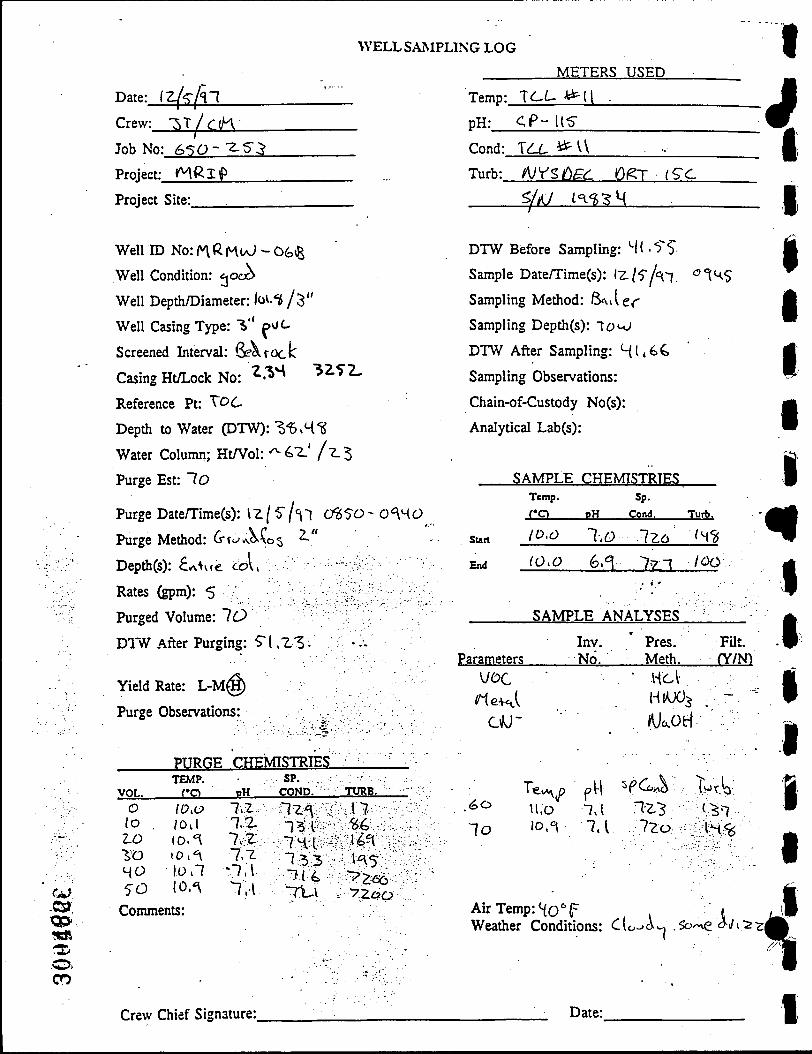
WELL SAMPLING LOG
Date: iz( f -l Crew: • 3 T / ^ ( K
Job No: 6 5 0 - - ^ 5 ^
Project:_jMRl£.
Project Site:.
METERS USED
Temp:
pH:
Cond:
Turb:
I C L ^ ( l .
< P - U 5
xa^^^\ • -NYZdE(L (Of T {£C
^/i^J t ^ ^ S H
I 4
Well ID No: / ^ R M I O - 06(E
Well Condition: ^oa^
Well Depth/Diameter: lov.1 / 3 "
Well Casing Type: 7.'' ^v/L
Screened Interval: 6eoirock
Casing Ht/Lock No: '^^'^ 3 Z 5 2 .
Reference Pt: t O C
Depth to Water (DTW): l ^ b A ^
Water Column; HtA^ol: -^ 47.' / "L^
Purge Est: 7 o
Purge Date/Time(s): l z / 5 / ^ T C ^ 5 0 - 0 ^ 4 0
Purge Method: 4-ti-'«vo.\os ^
Depth(s): £AV{e col,
Rates (gpm): 5
Purged Volume: 76^
DTW After Purging: 51 . Z 3 . ?; •.;-
Yield Rate: L - M ^
Purge Observations: -- • V •
DTW Before Sampling: 4( . 5 5
Sample Date/Time(s): l2./5/'=l7 ' ' I ^ S
Sampling Method: 6«..ier
Sampling Depth(s): To«-o
DTW After Sampling: 4 l , 4 C
Sampling Observations:
Chain-of-Custody No(s):
Analytical Lab(s):
SAMPLE CHEMISTRIES
Sun
End
Parameters
Temp.
C O
lo,o
(0,O
Sp.
pH Cond.
T,o 7Z6
GA 7 7 7
SAMPLE ANALYSES
Inv. ' Pres. No. Meth.
Turb.
74<^
/OOv
• • • • : / • • : . < : • ; . ' •
FUt. fY/N)
•I
Hcl-
*U^oti
00
VOL.
PURGE CHEMISTRIES TEMP.
CO PH SP.
COND. O 10,0
l o . /Oil Z-O 10. =1 i o 1 0 . ^
HO 10.7 5-0 lo.'^
Comments:
7.Z 7 Z 7 7-l.-L
*7,l 7.1
7 ^ 1 7 H I 7 ^ 3 ">(4 77.1
TtntB
17 S4 14?(
K 5
y z o o
. 6 0
7o U.D 7,1 77,3 t ^ ^ 10A 7.1 7Zo . IM^
Air Temp: H O T , . " t Weather Conditions: C(o-'A^ .Sb/v e d-i/i- -;
Crew Chief Signature: Date:

I
I I I I I
I p
I I I t I I r
WELL SAMPLING LOG
Date: lz/4/^47
Crew: T j c n Job No: 450-"2-5 ^
Project: ntfi.T P
Project Site:
Well ID No: (^^Z.MuJ-onB
Well Condition: ^ocA
Well Depth/Diameter: lOO' / ^ "
WeU Casing Type: 1" pv/^
Screened Interval: 6eo-cc>ck
Casing Ht/Lock No: Z X "57.5Z
Reference Pt: TOC
Depth to Water (DTW): Z1$,oS
Water Column; Ht/Vol:-^73'/•2-7
Purge Est: 5J I
Purge Date/Time(s): 1"2./H/ '17 177.0-IfeBo
Purge Method: I-LA.6 B^v\.\rtQ
D e p t h ( s ) : L H ' ^ Z ^ •• • • ^ - ' - • • • • • ^ • •^ - y^^^^^
Rates (gpm): i7-5/ ' . •' v.•;--:.'--;/;'-i:: :'/ r..••.:;'•:-
Purged Volume: "^l
D17/ After Purging: 'Zli, < "g. ; •.-.
Yield Rate: L - M ^
Purge Observations:
PURGE CHEMISTRIES "
VOL. TEMP.
P H
SP. COND. TURB.
O 15 ^o 45 GO IS-
10.0
^ 7
^ 7
7 4 7 4
7,4
HX7 517. 5 7 1 , 5 2 . 5 5^<l> 5-5"7.
15-7 0
'?.5
Comments:
/v/ute". Alofvu c\jitK r\o(tv\c\ 5<<-vy\pk
Crew Chief Signature:
METERS USED
Tenip:.
pH:
f^C- '^UP.
dP-M Cond:
Turb:
Q£C-54c>
/UV<>Og^ 0/^T (5C
5/A/ K'g^H
DTW Before Sampling: 2«g.SLg
Sample Date/Time(s): iT-f^l'^'l
Sampling Method: "•3<H..Ur
Sampling Depth(s): Tou;
DTW After Sampling: ' Z ' \ . 0 0
Sampling Observations:
Chain-of-Custody No(s):
Analytical Lab(s):
Sun
End
SAMPLE Temp.
C O
4 .7
^ .4
CHEMISTRIES Sp.
pH Cond.
7.4 SM 7 .4 S7:4
SAMPLE ANALYSES
Parameters Inv. ' Pres. No. Meth.
Turb.
16
_lii
FUt. (Ym
-fe-v
VOC
c iu -
\ C/vvD
^7 7 4
HCl H1UO3
%Co l ' ^<^ S^V 14
Air Temp: 4 0 " F Weather Conditions: 5 ' - 'a AI
iooi coo (OiAr\
Date:

WELL SAMPLING LOG
METERS USED
Date: iz^z^cp
Crew:__^X^^jn_
Job No: feTO-Z-alt
Project: MR I P
Project Site:
Well ID No: nRM«A^ - 0 D 6
Well Condition: ^ooO
Well Depth/Diameter: loo' / 6 "
Well Casing Type: 6" ^Ucl SCVTOCIS
Screened Interval: 4 ^ ' - ( o o '
Casing Ht/Lock No: ^ L s k t*-o f\A M ^ ^
Reference Pt: TOL
Depth to Water (DTW): ^7..41
Water Column; Ht/Vol:'*-6^'//07.
Purge Est: S(0
Purge Date/Time(s): i7/xy<l7
Purge Method: (ffoivo^^os ?-'
Depth(s): ^ 5 '
Rates (gpm): 4
Purged Volume: l lO
D1"NV .After Purging: "s.S'.tJZ-
Yield Rate: L-M@
Purge Observations: *x»\vr oAor
PURGE CHEMISTRIES
VOL. TEMP.
CO PH SP.
COND. TURB. o 'VA
loo <\.4 150 %s -LOO <(.5-2.^0 H.T 30Ci '^.^ Comments:
4.4 7 3 7M 7 4 74 ^•4
544 4*\6 H1I4 4*\n 430 ST4
ILH 4 .0 7 .K \v4 1.7. M
Temp: T^-C •»/!
pH: 4P-1Z J Cond:.
Turb:
1CL,*^1\
n/vsna^ rtjgr (^<: 5//1/ /^-$4^
DTW Before Sampling: ^5.54
Sample Date/Time(s): I z / z A l i $ ^
3 Sampling Method:/Jl^^ 6^J„
Sampling Depth(s): TOcJ
DTW After Sampling: B'^.40
Sampling Observations:
Chain-of-Custody No(s):
Analytical Lab(s):
SAMPLE CHEMISTRIES
iTHO-l&SO
.y:i-:^yP-p':-f --^ ^ ' -••-y: :
ssiiyS"§ . ' • • •
Temp.
f-q
Sun ^ | 4
End ^ . S .
pH
H.{
%."<
Sp.
Cond. Turb.
^74 ^ 5
lOL "iC J y
SAMPLE ANALYSES
Parameters Inv. No.
Pres. FUt. Meth. fY/N")
^
U6C
/neU /UoH
Air Temp: • $ S T Weather Conditions: Sw v "1 1 ->^Vs . (
1 Crew Chief Signature: Date:

I
I I I I I f
I
WELL SAMPLING LOG
Date: IZ^i/<7
Crew: Cif^/^T
Job No: C<;o •Z<;-^
Project: Hg^Tf
Project Site:
WelllD No: i^R/^«N^-0<\
Well Condition: O60>
WeU Depth/Diameter: ^ ' ^ •^ / ' ^
Well Casing Type: f ^ ^ ' '^^ ^ ^
Screened Interval: fie?t+«vv lO'
Casing Ht/Lock No: ^v'Z-H ^i"*^*^
Reference Pt: TOC
Depth to Water (DTW): -^T-Z,
Water Column; HtA^ol:"' ** / - 1 5
Purge Est: 4 ^
Purge Date/Time(s): IT./i/^ '^
Purge Method: 4t^A^f^^ Z" 1515 /^:oO
Depth(s): 160' o.A c»p 7 - , "
Rates (gpm): ^
Purged Volume:
"
Z5 DTW .After Purging: (),•
Yield Rate: (L)M-H
Purge Observations:
PURGE TEMP.
VOL. CO
0 '\,l 5 7.6
7 0 ^.4
Comments:
-
:3
'4
CHEMISTRIES
PH
76
^ 7.4
Oc ^r Z S
Crew Chief Signature:
SP. COND.
Z\^ Z 2 J P
, '--
'y ' • •
' . ' •
; e . - ^ ' . - ' . ' : • ; ; . •
TURB.
5-,3
|7Z \02,
'
METERS USED
Temp:. O B C - 5 6 0
pH: C(P--4
Cond:.
Turb:
D E C - 5 * 6 0
yUrsApc Df r <^^ 5/A; 141^^4
DTW Before Sampling: Z^.41
Sample Date/Time(s): Iz/z/*l7 O 50
Sampling Method: l4aA o vvVi. .*
Sampling Depth(s): 1o<-0
DTW After Sampling: 1 ^ . 7 7
Sampling Observations:
Chain-of-Custody No(s):
Analytical Lab(s):
Sun
End
SAMPLE CHEMISTRIES Temp.
C O oH
% ^ $.2.
11.5 %P
Sp.
Cond.
2-42.
2-43
SAMPLE ANALYSES
Inv. Parameters No.
Pres. Meth.
Turb.
1 ^
t lO y
••' 'y.-.JyT^-
FUt. (Ym
Mac
Air Temp: "i?* {= Weather Conditions: LJiA 1
CO
Date:

•ofe
o CO
WELL SAMPLING LOG I Date: \zhl%l Crew: ?>T/4IK\
Job No: 4 5 0 - 7 . 5 7
Project: M^ X P
Project Site:.
Well ID No: ^ve./vvKJ -c-^ft
Well Condition: c aoS-w f i t
Well Depth/Diameter: ' ^ ^ - ^ ( ^
Well Casing Type: (Sr^rock
Screened Interval: ^ 5 - / 4 C '
Casing Ht/Lock No: 7.-2.7 6 v^o
Reference Pt: TOO
Depth to Water (DTW): 3^.Zl
Water Column; Ht/Vol: ^10<\I^I(^S
Purge Est: 50O
Purge Date/Time(s): 17/1 |<n l"5v5'-150^
Purge Method: 6T«/-^»to$ 2."
Depth(s): Ux>' ^ ^ \jfi y
Rates (gpm): S'.^'.yr'y^
Purged Volume: SCO
DTW After Purging: Si!), 5 Z • ^ • -'•
Yield Rate: L - M ^
Purge Observations:
PURGE CHEMISTRIES
VOL. TEMP.
CO .£H_ SP.
COND. TtmB.
0 i c s 100 <\n 100 4.7 ^^0 4.4 4oo 4.4 500 1.4 Comments:
76 71. 7.Z
.7.3 7.4 7.4
Z43 164 7.1 «& Z « 4 7.^1 7.41
5-4 7.1
VO^i
i l
METERS USED
Temp:.
p H : _
/ ^ F C - 5 6 0
cP--t V Cond:
Turb:
Oec- s(>o AJ^dEL Qgr t 5 c
^ ^ ^I^SH
DTW Before Sampling: \ % , l C
Sample Date/Time(s):lx/z/'\-j I715
Sampling Method: t^anV 6«.ii(Ac
Sampling Depth(s):TO«^
DTW After Sampling: 3*^67^
Sampling Observations:
Chain-of-Custody No(s):
Analytical Lab(s):
SAMPLE Temp.
C O
Sun 15-3
End "iH
CHEMISTRIES Sp.
oH Cond.
1.^ 7H3
4 . ^ 73^4
Turb.
7.?
SV
SAMPLE ANALYSES
Parameters Inv. ' Pres. No. Meth.
FUt. fY/N")
VOC
Meul CiM"
WO5
t I I I I I I
I i I I f
Air Temp: ^ r T Weather Conditions: CJi^-s
Crew Chief Signature: Date:

I
f I I I 1 I I p
I a
WELL SAMPLING LOG
Date: 17. /lAi METERS USED
Crew: •si/cn Temp:
p H : _
' 0 £ C - ? 6 o .
cp-4 Job No: 4sO--^ -5 3
Project: K ( ^ l P
Cond: C i e c - S ^ O
Turb: lUYC^PC (^ygt I ^ C
Project Site:. >/t\) M ^ ^
Well ID No: MR K u J - l o £
Well Condition: e.<?oov
Well Depth/Diameter: \ o o ' j(>"
Well Casing Type: 6 " l ^ C s u j
Screened Interval: <^A<o^'^
Casing Ht/Lock No: L " " O 5 ^ 4
Reference Pt: TOC
Depth to Water (DTW): Z 6 . 4 ^
Water Column; HtA^ol: ^ ^ V /l^^S
Purge Est: "SZS"
Purge Date/Time(s): \ 2-/S' /H 7 1050 - I U<9
Purge Method: 4fo/\j>Vo$ Z-"
D e p t h ( s ) : £ . / v V < € -•£><A:, ••.:\-y' '•y•'•^•';-yy•:^' '\^••
JL^tSS ( g p m ) : S •./•:••.• : . y : y •
Purged Volume: "^7.5"
DTW After Purging: 4 ^ - 4) ; . . .
DTW Before Sampling: 44. SO
Sample Date/Time(s): 12-/$"/<! 1 Vl^o
Sampling Method: GuvUi-
Sampling Depth(s): 7ot.>J
DTW After Sampling: 4 7 , 5 0
Sampling Observations: C^OO^VA
Chain-of-Custody No(s):
Analytical Lab(s):
SAMPLE Temp.
C O
Sun 4 .7
End i O
CHEMISTRIES
pH
4,4 4.Z
Sp. Cond. Turb.
7§<& >ZOQ
ziS > ^ ^ . ' . i f
SAMPLE ANALYSES
Parameters Inv. Nd.
Pres. FUt. Meth. fY/N)
Yield Rate: L - M ®
Purge Observations:
VOL. O
50 lOO 1 5 0 ZOO Z5D
PURGE TEMP.
C O ^.i$ (0.4 lO.B 10.3 10.-T 10.4
Conunents:
: • •
• • • . • .'•••• - y . ^ . y
: CHEMISTRIES
P H
4.4 4.4 4.5 4.4 ts 1 , \
SP. COND.
•i-73 Z 0 4 • Z.14 7 5 4 -Z 4 4 7 7 4
' • : • ' • : i y - ' ' • ••• •:• •
TURB.
\Z.
45 y i p o -7-LOO-
-/ZJOO
\I(X^
CVO"
^ ^ O 10.7
7>Z5 10.'i
^
Air Temp: "-{0
7-2. 7 . 7
" ^
• HCl
Ai.oH
SpCt«i To^lo
T-1iC "86 z-b-L 44
Weather Conditions: Vjer -. c i o ^ s fKH-\MA£viu\u
30048f Crew Chief Signature: Date:
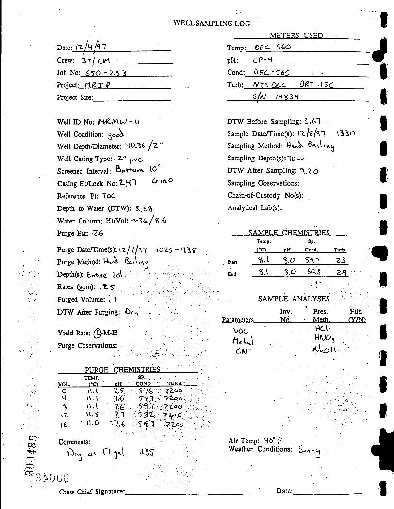
WELL SAMPLING LOG
Date: ( z / 4 / 4 7 m Crew: 3 l | ' c i n
Job No: 4SO - Z 'a^
Project: r1<g I P
Project Site:.
Well ID No: t ^ ^ ^ - \l
Well Condition: 5 006
Well Depth/Diameter: 40.14 / z "
Well Casing Type: 2." pv/c
Screened Interval: R>O++O/A \ 0
Casing Ht/Lock No:^H'^ ^ '*^^
Reference Pt: ToC
Depth to Water (DTW): ^.S1)
Water Column; Ht/Vol: '^36./"g.4
Purge Est: Z 4
Purge Date/Time(s): 12-/w I'M '0Z5'-i\,"S5
Purge Method: l-lti-^ feavU^^
Depth^): £rAvie cA. -Vvv: ^
Rates (gpm): . Z 5 > . '
Purged Volume: j l
DIW After Purging: Cif-x ; •'•
Yield Rate: @-M-H
Purge Observations:
PURGE CHEMISTRIES "
VOL. TEMP.
C O P H
SP. COND. TURB.
. - ' - • • • : ' .
oc ^ ^
^~...'' CT5 -v
0 vi.v 7 S 4 u . l 7.4 IS U.l 74" iZ H.f 7.T Ife 11.0 -7.4
Comments:
^..^ cv n 3 1
^OOG . •
s-?t. 5<S7, 54 7 5 ' g i 5 ^ 7
ii^s-
7 i O O
yzoo ."y-Loo y i . 0 0 >Zoo
-
• - ' " ^ • . ; ' - !
METERS USED
Temp:
pH:
Cond:
Turb:
0fc-c-S6O .
CP-4
^£•6-56^3
N r ^ ( ^ c O^T [SC
^ / N i<\'iilH
1
DTW Before Sampling: "?>,47
Sample Date/Time(s): 17/s-A7 l ^ ^ O
Sampling Method: Ws. V fe^ilii\Cj
Sampling Depth(s):1o<-->
DTW After Sampling: 4 . 1 o
Sampling Observations:
Chain-of-Custody No(s):
Analytical Lab(s):
SAMPLE CHEMISTRIES
Sun
End
Temp.
C O
%A
% . \
Sp.
P H Cond.
%0 547
^.0 60 J
Turb.
Z i
Z4:
SAMPLE ANALYSES
Parameters Inv. Pres. No. Meth.
FUt.
(Ym
n
VOC
C W
v^cv H»UO^
Air Temp: 40° f Weather Conditions: S-'f\(\
' ^
Crew Chief Signature: Date:

I V
WELL SAMPLING LOG
Date: lZ/s /4~i l h Crew: I T jC tA
Job No: 4 S O - Z S 3
Project: t4<^IP
Project Site:
Temp:
pH:
Cond:
Turb:
METERS USED
, 0 £ C - 5 4 O .
C P - 4
D £ C - 5 6 0 . -
'V/VSiDec 0(^T (S-C
sA/ ( 4 ^ 3 4
p
Wen ID No: H i ^ i K > ^ - U(3
Well Condition: aocA
Well Depth /Diameter :^ l$s76" g]^^^^^^*" ^
Well Casing Type: 4" 7*C
Screened Interval: <Sew-rock
Casing Ht/Lock No: \ «4V 6 ^A6
Reference Pt: TOC
Depth to Water (DTW): M.lM
Water Column; Ht/Vol: ^\•^ ' \ / 2 , C ^
Purge Est: $ 0 o
Purge Datenrime(s): \ T - l ^ h l I'Z-^O - 1 5 4 5
Purge Method: Z " 6foA.a\c>s
Depth(s): 1 5 0 ' ; - ;•; ;
Rates (gpm): 5 ^ | g , ^ •
Purged Volume: ^ O O
D1"\V After Purging: 4 . 0 4 . -.-.
Yield Rate: L-M
DTW Before Sampling: 4 . 0 4
Sample Date/Time(s): \-z.[s h~]
Sampling Method: Gesvler
Sampling Depth(s): I S " '
DTW After Sampling: ^ . 5 $ "
Sampling Observations:
Chain-of-Custody No(s):
Analytical Lab(s):
SAMPLE CHEMISTRIES
i r ^ r
Sun
End
Parameters
Temp.
C O
1(5.4
l o . \
p H
4.S
4.4
Sp.
Cond.
S-.2.1
S ^ T
SAMPLE ANALYSES
Inv. No.
Pres. Meth.
Turb.
^ 0
^ i : : •
FUt. (Y/N)
Purge Observations: KeAcA
c * 0 '
BC\ V\ /05
Mo.OH
f ,V
PURGE CHEMISTRIES
VOL. TEMP. J!CL -EH.
SP. COND.
O 4.«1 | o o lo.'S 1.00 10 . t •^oo 10.3 HOO . 10.S" ^ 0 0 <0-^ L o o ^c?-^ «0D ^ - 3
Comments:
t . l (..4 7 . i fe.4
. fo.S t . 7 4 . 4 4 . 4
Crew Chief Signature:
TURB. 5 5 S 5-L4 5Z.7 ' ^ ^ ^ S 3 0 5 U 5"Z15 ?•%«>
^ 3 "is
. ^ZOCi
' ,7ZOO
zu . 10 I Z 6 ,0 Air Temp: 4o'='F
Weather Conditions: Rft.x^ •n
Date:
3004gq

WELL SAMPLING LOG i Date: IT^-Lfjl
Crew: ^T^CM
Job No: 4 ' 5 ' 0 -Z5 .^
Project: M<gl P
Project Site:.
Wen ID No:f4Ru; - l"2.ft
Well Condition: Aoob
Well Depth/Diameter: Zoo' /^ "
Well Casing Type: ^ \ , ^
Screened Interval:Op«.^ Udle ^ ' i ' l o o '
Casing Ht/Lock No: 7 . H ^ 't^o
Reference Pt:TOC
Depth to Water (DTW): IZ..Z5
Water Column; Ht/Vol:'^ IHO/-i.$5"
Purge Est:<i50
Purge Date/Time(s): i-E,/z,/l7 ^470 - I'SJo
Purge Method: <rtJA\os Z"
Depth(s): 150 ^ A i p
Rates (gpm): $"
Purged Volume: <4$"0
D1'\V .After Purging: l"S444 •
Yield Rate: L-M®
Purge Observations:
METERS USED
Temp:
pH:_
D E C - 5 4 6
a-^ i Cond: r>P,Z - 5 4 0
Turb: /l/'t5 Qgd QgT
^
i S j ^ t 4 ^ S ^
VS^O
DTW Before Sampling: l"5.4H
Sample Date/Time(s): I z / z / t l
Sampling Method: BaiUr
Sampling Depth(s): TOM;
DTW After Sampling: ("5.47
Sampling Observations: Tv (b X» ^o \tov\ o ' * ^ ^ '
Chain-of-Custody No(s)
Analytical Lab(s):
SAMPLE CHEMISTRIES
Sun
End
Temp.
C O
4.4
^ . ^
P H
4.^ (>.%
Sp.
Cond.
SK
•^Gf,
Turb.
^5 St:
. - i f
SAMPLE ANALYSES
Parameters Inv. No.
Pres. Meth.
FUt. (Y/N)
il
PURGE CHEMISTRIES
VOL. TEMP.
_ I ! C L pH SP.
COND.
' - 7 " •
0
0 0 7
0 lo.' (00 10-H Z o o 10.4 3 0 0 10.1 S o o /<?,4 S-00 (0 ."S Comments:
6.4 6.6 6.5' fc,1
7 . 0 1.0
'S\lo ^ ( 4
52.1 5-2.3 5 n 5-7:1
i:^?ofe Crew Chief Signature:
TURB.
77 1 5 Z.3
4,4 1.1
fecc; 7 0 0
$ ^ '^SO
Te*. p io,v 10,0 (0 .1 1 0 . ^
prt 7 0
r.o 1.0 T.O
Sp COA.<)
rzz 5 ^ ?2,1. ^ z i
i^^b
1.0.
7&^ 4).$ 0.6
Air Temp: I S " ^ Weather Conditions: %,
1 7 o^^S o r (<o(<^M
Date:

I WELL SAMPLING LOG
Date: (z/(('i7
Crew: ^ T / f > ^
Job No: 4<^n--2.5-^
Project: Hd-lP
Project Site:
Temp:
pH:
Cond:
Turb:
METERS USED
J L L -^^^ •
CP-4
r a . ^11 ft/VsAGc r>eT i5c
S/A/ n<i!iH
fib
/ '
Well ID No: M ^ K M J - I ^ ^
Well Condition: < oaS
Well Depth/Diameter: ^ lOO' j ^ '
WeU Casing Type: 6 " T V6 **eeV
Screened Interval: oe^fOCjK
Casing Ht/Lock No: ^L<,1\ t \oJ*^ ^^"^
Reference Pt: TOC
Depth to Water (DTW):O.0 a.* s o r W
Water Column; miVoV.-ZOO 1 ^ ^0^
Purge Est: ^ 1 5
Purge DatenLime(s): l z / i / \ 7 - • i z / s / l ^
Purge Method: /V^ -A I'WN woe(l \L>.. \,> Z-5
Depth(s): O.O av «.><.| c<
Rates (gpm): Z-'J
Purged Volume:'*' io,i;oo
D1"\V After Purging: 6 , 0 ej-. $^/'Uc€
Yield Rate: L < ^
Purge Observations:
DTW Before Sampling: ^-O -. <sofi« c<
Sample Date/Time(s): '•Z./4(<i-7 15"20
Sampling Method: O.p bt^ct<v
Sampling Depth(s): ^ .0 o-f ^wrv^c^
DTW After Sampling: O.O « v «iv)f(<;v.f«?
luck^tl^ampling Observations:
Chain-of-Custody No(s):
Analytical Lab(s):
7 ^
SAMPLE CHEMISTRIES
S u n
End
Temp.
C O
(O.H
10."^
oH
45 (i.5
Sp.
Cond.
So 4 ^ • ^ < 5 i
Turb.
5 H-. ;
SAMPLE ANALYSES
Parameters Inv. N6.
Pres. Meth.
FUt. c{m
PURGE CHEMISTRIES
VOL. TEMP.
CO - E H .
SP. COND. TURB.
f Comments:
/4;a«^«v^ o ie ,l ..^<, o ^ f ^ - « r ^ 'z/i/'i?
fiiuv^ 4iW«o Vc» pof< e tV-;^lC Vt/C
Crew Chief Signature:.
Air Temp: Weather Conditions:
Date:
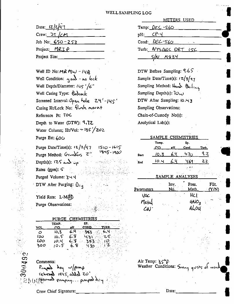
WELL SAMPLING LOG
Date:.
Crew:
lz/z^47 ^T/^M
Job No: 4 5 6 - Z 5.^
Project: f1<Z.I <P
Project Site:
WeU ID No: m<R l^kJ ~ / 4 g
Well Condition: <\0(^ -no ^ct:
Well Depth/Diameter: l u s ' l ^ "
Well Casing Type: fi-r^rock
Screened Interval: (9 c* M e Z . 4 ' - / 4 5 '
Casing Ht/Lock No: ^Lsk <»\o ( f•
Reference Pt: TOC
Depth to Water (DTW): 4,7Z,
Water Column; Ht/Vol: '^S" '/zoz
Purge Est: 40O
Purge Date/Time(s): (z/2./^7
Purge Method: 6TJ.^AC«S Z "
Depth(s): IZ5 a.JS^ \ja
Rates (gpm): 5
Purged Volume: "SM4
Dl'vV .After Purging: Or^
1510-/6(5-^%>^S' 1406)
- > • ' .
0 0 0
Yield Rate: L-M@
Purge Observations:
PURGE CHEMISTRIES TEMP. SP. .
VOL. CO PH COND.
0 10.5 ^^ M i ^ ioo 10,5 C.^ K-i\v i.00 10 M 4;5 "S-g^r: ^ 0 0 / 0 . 5 4.1^ 43b
Comments:
TURB. .4,4v • .
\IV(?; .'y':y: •:-7Z .•;?•..
•. B b i } ^ t ' i r n d ^ ^ d r s p i f u : , . . . p<Av\ peo>dv( 7
Crew Chief Signature:
Temp:
pH:
Cond:
Turb:
METERS USED
DEC-S40
4P-4 0£^-56o
A/Vsn^c D^T C C
S/AJ /^9-?4
I
DTW Before Sampling: 4 . 4 9
Sample Date/Time(s): i-z^/^U-j
Sampling Method: Mec-wS ^{^^
Sampling Depth(s): IOH-)
DTW After Sampling: {O.H3
Sampling Observations:
Chain-of-Custody No(s):
Analytical Lab(s):
SAMPLE CHEMISTRIES Temp.
C O
sun /0.5
End 1 0 . H
PH
^ • H 4.4
Sp. Cond.
47o
H:6'\
Turb.
iz Z3
• i f
SAMPLE ANALYSES ^
Parameters Inv. No.
Pres. Meth.
FUt. (Ym
O K ) '
Wcl
Air Temp: ^5-^f Weather Conditions: ^^^.^ aO->y o\
1 Date: f

I WELL SAMPLING LOG
Date: l^/5747 Crew: cn j ^ \ Job No: 4 S 0 - Z 5 ^
Project: r i ^ l P
Project Site:
METERS USED
Temp:
p H : _
Cond:.
Turb:
WeU ID No: rt(2P«Aj-0'2.
Wen Condition: - ^ ,^^ , \^ -j-o^ ;
Well Depth/Diameter:- n C <r i Kay\ hoc J r\t»vOW$
Well Casing Type:-
Screened Interval:—
Casing Ht/Lock Nor-
Reference Pt: —
Depth to Water (DTW):-
Water Colunm; Ht/Vol:—
Purge Est: ^
Purge Date/Time(s):'-
Purge Method: -
Depth(s):~
Rates (gpm): -
Purged Volume: —
D1"\V After Purging:^
Yield Rate: L-M-H
Purge Observations: • • . • . . • • • • . ' • &
PURGE CHEMISTRIES
DTW Before Sampling: -
Sample Date/Time(s): i z | 5 / t 7
Sampling Method: -
Sampling Depth(s): ~
DTW After Sampling: -
Sampling Observations: —
Chain-of-Custody No(s): ~
Analytical Lab(s):
SAMPLE CHEMISTRIES
l5lO
Temp.
C O
Sp.
P H Cond. Turb.
Sun
End ; , • • . . • • . ' ; •
SAMPLE ANALYSES "
Parameters
VJOC
Inv. ' Pres. FUt. N 6 . Meth. (Ym
VOL. TEMP.
_ElL SP.
COND. TURB.
r I
Comments: .
Crew Chief Signature: _ _ _ _ _
Air Temp: Weather Conditions:
Date:
CO.
v.>-
^

(X
O CO
V- 'J I:
wmmmBiimmmmm WELL SAMPLING LOG
Date: ^ - ^ . o - T ^
Crew: -56^^ £ ^
Job No: G5tf ' ^ 5 ' f
Project: /»^ / P
Project Site:.
Well ID No: AlKMvO- /3
Well Condition: 4o£.cL
Well Depth/Diameter: iOo V 3 ' '
Well Casing Type: ^l^ci.
Screened Interval:
Casing Ht/Lock No:
Reference Pt: Top of- Cx^/iw^
Depdi to Water (DTW): 3^»«/7 '
Water Column; Ht/Vol: ,©7^«/ ^ =)
Purge Est: ?oL _2>4
Purge Date/Time(s): r/zo/'?? T ^ ° ^
Purge Method: ^'''^-9
Depth(s): 4l(
Rates (gpm): fi.^^pA-
Purged Volume: : ; (.,
DTW After Purging: ^f,^^
Yield Rate: ^ M - H
Purge Observations:
PURGE CHEMISTRIES
3 . - J . < ^ - i 4 . 3 roV~^.$.bUL
VOL. TEMP.
PH SP.AuV/cn
COND. TURB. 6 T U >
0
HO 15-^
Comments:
Crew Chief Signature: y^K:eP^'~y/J.
7 o l.o 7.1 7.1
/.OlSk
O.'IJLC)
o55iX
?• / MO
(i>0,7t7
METERS USED
Temp:. / - (S ^ y ^ ?
pH: p H r t ^ 4 r ^ /
Cond:.
Turb:
T/LC ^ / ^ /i/y.5x ;r<f A ^ r - z ^ c
- 4 ^ j^-g^y
DTW Before Sampling: ^V^?^ '
Sample Date/Time(s): ^ - d i O - t t / l l A o
Sampling Method: Tzflo^ 6b.Ur
Sampling Depth(s): f-tfy» e-foc/uA^
DTW After Sampling: W - ?-f '
Sampling Observations:
Chain-of-Custody No(s):
Analytical Lab(s): ^£bJ54 L A B M 6 T '
SAMPLE CHEMISTRIES Temp.
C O
Sun /3.3
End IX.b
Sp.
oH Cond. Tuib.
t,f /f fc 4.0 6.? .9/3 q . ^
SAMPLE ANALYSES
Parameters Inv. Pres. Filt. No. Meth. ( Y m
V6/t >JC/ y
Air Temp: Weather Conditions: ^ v . ^ ^ h ^ A . , ^ / ^ n
Date- S ^ l O - ^

WELLSAMPLING LOG
1 ' - " ' ' ° "
Moat Qo d )l4meter: I ' J .6^ /^
Type: f / C
Interval: ^ 5 p . ^ ^ ^ g ' H t n ^ c k No:
* ? P 4 ^ ^ i f ^ c n c e Pt:
I ."" Watcr Column; HtA^oI:
1.- --m. i-^eO^/ lO^C.1
- f o c ^ - ' o X ' (>>i':
Est: ^ ^ ^ C L /
.Purge Date/Time(s): ^ - A o ' l i l
Piirge Method: 5oOju^f.,,-|iL ^v^ a />« -/i.-
pith(s): //f
Rates (gpm):
Purged Volume; 1|
DTW After Purging: X^^f
Yield Rate: (l^M-H
Purge Observations:
PURGE CHEMISTRIES
i ' " ' «^y
VOL. TEMP.
C O PH COND. Tims. 3j«/ /^-;i ?,3 .^/<^ ^«^co
11.3 -1 Hf,.*/ ^ .3 ."Jf-i >aoo
MF.TERS USED
Temp: - T L C j ^ I d
PH: CAI ^CTA^S pHTe,^ / -^
Cond: T L C j ^ y 4 ?
Turb:
DTW Before Sampling: ^f.i/^
Sample Date/Time(s): 5-o?/-^f / /.^'y^
Sampling Method: T^'o/o hcJtjLf
Sampling Depth(s): -tej> Jr c.glv'- -
DTW After Sampling: ^^ y ^ '
Sampling Observations: v i y •^^>' ' -^r^^a^s.p^/cQ^ Chain-of-Custody No(s):
Analytical Lab(s): ^ ^ ^ ^ /^rf i^^r
SAMPLE CHEMISTRIES
Sun
End
Temp.
CC)
/^.o [LY
P H
•?.\ ^.3
Sp.
Cond.
.3?/ ,>?/
SAMPLE ANALYSES
Parameters
VOA
Inv. No.
Pres. Meth.
Tuib.
y?. ?-Y
Q
Filt. (Y/N)
^
Comments: ^ , 0
n , , «. I /• N AurTemp: T^ Dtw'M d y ofTi.v' " T-s*"./ (Ioo»'/oi/) Weather Conditions: BwU^ J>f « ft;.« oflu- »/ 4jaf. (ljco-i 3.e ^e"^ kor^'d
Crew Chief Signatui , ^ 4 - ^ ^ > ^ ^ ' Date: ^ - a / ^ ^ g ^
CO
o
o C O •

WELLSAMPLING LOG
Date: ^/ .^l / / '?^
Crew: S 6 ^ , £ 4
Job No: 4 r ^ - ' 3 5 4
Proiect: M ^ \ P
Project Site:
METERS USED
Temp: 7"ZC. ^ IO
pH: A/l -n<-l-^ ^
Cond: T L C ^ \n
Turb: AjyShf^r. h k T \^C.
S/AJ 7 f?-3V
V
\
S//0
WeHID No: / IRAAW--^-^
Well Condition: (jee.-L
Well Depth/Diameter: 3H ^hf'i,
Well Casing Type: K ^
Screened Interval: ^ ' ^
Casing Ht/Lock No: A^^ ' ^
Reference Pt: 7cij> J^Co.^,.^
Depth to Water (DTW): "^l-Oi"
Water Column; Ht/Vol: 'A'/'-l-^'^tl
Purge Est: jijo^i
Purge Date/Time(s): €h\\'={%I\o-o:>f . ^ i / i ^
Purge Method: H«."l ^'^'tX
Depth(s): /VW
Rates (gpm): C'.S-
Purged Volume: Z^"^'
DTW After Purging: Z3 ,?^
Yield Rate: @-M-H
Purge Observations: VOC KT K cLe v
DTW Before Sampling: A3.,0^ '
Sample Date/Time(s): S - ^ l ' 9 s l Ihoa
Sampling Method: "Tt/fic^ boJ i j^
Sampling Depth(s): 4o/> o-f co /y/uv^
DTW After Sampling: ^ J.o^ '
Sampling Observations: u/-v"'<,r cla*^
Chain-of-Custody No(s):
Analytical Lab(s): R ^ C R A Z/hg^^T^
SAMPLE Temp.
CC)
Sun IQ.H
End / / . .3
CHEMISTRIES
oH
7J 7.1
Sp.
Cond. Turb.
,.<03 ?
.-^/^ -3 (
SAMPLE ANALYSES
Parameters Inv. No,
Pres. FUt. Meth. (Ym
S/oA }\C\ Af
'... *.'
CO
PURGE CHEMISTRIES
VOL. TEMP.
C O PH SP.
COND.
15.4 7-.-S
Comments:
Crew Chief Signature:
o . r fp
TtmB.
2 ^ .
7-
.A^J.
Air Temp: ^ Sb** Weather Conditions: t^ctr>^^ficrr^-tl
Date: ^ 3 / - 11:
I

I
V WELLSAMPLING LOG
Date: ^ - ^ Z - f g
Crew: J?<?^ ^ 5
Job No:
Project:.
Project Site:.
G$0-A$i/ / ^RxP
METERS USED
Temp: 7^/.C =it I n
pH: p / l -n>c.A^ A
Cond:
Turb:
T 7 C 4 r / / .
S / A / /5?f7y
WeU ID No: /^^/^vvJ-5K
Well Condition: /Jl^J
Well Depth/Diameter: / J ^ Y4 "
Well Casing Type: /-f^^f
Screened Interval:
Casing Ht/Lock No:
Reference Pt: Top c^ Ccxsi>
Depth to Water (DTW): .;t6'4L5'
Water Column; Ht/Vol: ff. .5'.^/ / 4 ? _s <r.)
Purge Est: ^HS'^^,i
Purge Date/Time(s): ^-;^)_^x / /VcLT
Purge Method: i ' - , '
Depth(s): /oojit
Rates (gpm): 3o p.v.
Purged Volume: ^ o>«s.
DTW After Purging: z?,i^
Yield Rate: L-^H
Purge Observations: , , „ «
DTW Before Sampling: ^7.(oO •-'--
Sample Date/Time(s): 5/?t (4 ?[ '7*^*
Sampling Method: ^»^\
Sampling Depth(s): Z o o fv
DTW After Sampling: —
Sampling Observations:
Chain-of-Custody No(s):
Analytical Lab(s): J^f jf/l L^^uCT
SAMPLE CHEMISTRIES Temp.
CC)
SUrt /J. /
End / C . S '
Sp. P H Cond.
l-.dL . ^ / 3
^.( .5r3_
Turb.
!(>
^ 0
SAMPLE ANALYSES
Parameters Inv. Pres. No. Meth.
Filt. (Y/N)
AiL-fc/5
A J
A /
PURGE CHEMISTRIES
f I
VOL. TEMP.
C O pH SP.
COND.
0
)0& It. r
n.3 ISO UA •iS'o 3 0 0
eo _ _mments: cX!
A.r / / . 5
7 6
7.2.
7.7.
7-(
Crew Chief Signature:
1 6 0 ^
. to ' /
.601-
TURB.
/O
3 I
I
.(ooi:, —
^7.;!? 2-7.6r
.•^:^.fr
Air Temp: '^ ^ ^ Weather Conditions: /^e.^r/^ ^i^^y
r ^ / ^ ' Date:_^il^/l£Sl

WELLSAMPLING LOG
i^/M45^ Date:__
Crew:_—^0^, ^^
Job No: ^ 5 b - 7 5 4
Project: AlRTT- Project Site:.
Temp:
p H : _
Cond:.
Turb:
METERS USED
7 -LC ^ / n
f^J^T.f^-t r A / z c ^ In
A/^6t>f^r . DRy-l£c^ S / / \ i }Q'R^U
1
4
CO
. &s
WeU ID No: paRrnio-^B
Well Condition: ^ooJ*
WeU Depth/Diameter: /GC> ft:/JhT, 3,.
Well Casing Type: V < c.
Screened Interval:
Casing Ht/Lock No: 3SfS'
Reference Pt: T o e
Depth to Water (DTW): i 'y, / 3
Water Column; Ht/Vol: ^ s - ^ . ? ? ^ / ^ ^ ^^
Purge Est: -^^^«. \
Purge Date/Time(s): ^/^o/'ts//^^^ -+° ' <>«
Purge Method: Vo.—v, trv-Wftj ^ M
Depth(s): \J^r\^J)
Rates (gpm): ; ,3LS^,^ 4« (,oo.i^p^
Purged Volume; T-S f so-i
DTW After Purging: 43..P5-
Yield Rate: ^-M-H
Purge Observations: ^.o^^^.^dU^
PURGE CHEMISTRIES
VOL. TEMP.
C O PH SP.
COND. TURB.
k .S.1 '^.7 d,0^ej
355*1 «-%^i
W,/
JC.O / H . I
Comments: tz.\
?-(, (7-533 7 . r C.S-3X
7,5- 0 . 4 ^ r
35
1/
i /I .05'
13.5-5-
'/P.70
DTW Before Sampling: 54>i l l .35 .o?
Sample Date/Time(s): S^ao-'F^/^i/o f i
Sampling Method: Tlf/;^ 6^7^^ ' T - '
Sampling Depth(s): ^ ^ „-/^c^^^^ -i
DTW After Sampling: 3^, /^ •
Sampling Observations: .; •
Chain-of-Custody No(s):
Analytical Lab(s): ^ ^ ^ ^ ^ ^ ^ ^
SAMPLE CHEMISTRIES Temp.
C O
Sp.
Cond.
SUrt t3.^i$S ^ ? . 3 .U3 h
End / i ? M ^ ; S 7 3 .fey? /a
SAMPLE ANALYSES
Parameters Inv. No.
Pres. Meth.
FUt.
Vo/\ Hci
Air Temp: _ - . m ^ ' ' „ .i-im*-Weather Conditions: lOw-^, Ho^'^gfo.?%>
V u C-"
m ' ^ • •
Crew Chief Signature: .^"{^t^ 'cj^ ^sajs^*.
Date:J^^^0l£2i " ^ ^ ^ " " • * : : • >
^
I

I
V WELLSAMPLING LOG
Date:_
Crew:
j '-^^^-n Set • j r
Job No:
Project:
Project Site:.
Well ID No: / 4 E A \ W - 7 g
Well Condition: (xcccl Well Depth/Diameter: ) OO / 3
Well Casing Type: pVO
Screened Interval:
Casing Ht/Lock No:
Reference Pt: 4 . |> cf' O- fJ'
Depth to Water (DTW): .*U-<W ' o(.5-0?
Water Column; Ht/Vol: "^^.^1^h^,^ ^c^
Purge Est: ^ ^ ^ c j
Purge DateA-imeCs): ^ - ^^ * "^^/^^^^ ' '^^'-^
Purge Method: ^ .^u^/w/s.'^^ f''**v)
Depth(s): c . l(
Rates (gpm): jT^p.-/^
Purged Volume: ^ ^ S ' s " !
DTW After Purging: ^'X. 15
Yield Rate: L-M
Purge Observations:
METERS USED
Tempi.
p H : _
'LC^I(^ pH l?Mr ( .
Cond:.
Turb:
TLC^ir-> A/Y<;ishr. Jb^r i^c
57/^ /^5?V
DTW Before Sampling: X'S-15
Sample Date/Time(s): S-'d^^-q^ I h S S
Sampling Method: Tt^/o,j voiif-f'
Sampling Depth(s): \.tp erf ( lvt*-t>
DTW After Sampling: ^ ^ . . 3 3 '
Sampling Observations:
Chain-of-Custody No(s):
Analytical Lab(s): R t C ^ / LAB^^ r
SAMPLE CHEMISTRIES
Sun
End
•
Parameters
Temp.
C O
Ic.i K^.
• oH
^ ' \
^ . %
Sp.
Cond.
,5 i .^
, u SAMPLE ANALYSES
Inv, No.
Pres. Meth.
Turb.
IPv 9L5-
Filt. CY/N)
VoA hci Al
PURGE CHEMISTRIES
VOL M TEMP.
C O -E.H.
SP. /AV/t/H COND. TimB.
15 }c, y
So /o.if
Comments:
fo /O^
G.7 7.0 7./
7.1
7--9.
7.&^
Crew Chief Sijmature:
. ^ O
.53Lf
. - 1 ^
>Rco
/*a :i5 / > If
'3 J 3
^ - ^
Air Temp: 55 Weather Conditions:
f.^^yrhrju^zy 3 0 0 4 ® cu-|-V*>
'fc#-^.

o . i n
CO
.>*SfeDate:
.5l^Crew:
TimmTfiTT ' "
/ - 3 i - q g
WELLSAMPLING LOG
S^C LS
Lho'^^H. ^^ifJob No:
^^groiect: /^RX^
Iftoject Site:.
^^^Mell ID No: n^fWS- 7K
^iVel l Condition: AtW
" ^ ^ / e l l Depth/Diameter: /fd V G "
"iwell Casing Type: j j V ^ |
I JScreened Interval: xv///j
'- Casing Ht/Lock No:
Reference Pt: 4i<,f> ^ ccfu^ /^a.vii
Depth to Water (DTW): ^ . 5 /
Water Column; Ht/Vol: / ^V-Vt /^3^
Purge Est: (o 9 (j ^(,
Purge Date/Tirae(s):/-ai-?^/ O ^ Q ^ M $
Purge Method: Jv ^ui. fu f, .
Depth(s): a//
Rates (gpm): a.5 gp.-. - 3.o j f/
Purged Volume: "T'OOor,/
DTW After Purging: ^(^, JQ
Yield Rate: L-@-H
Purge Observations:
PURGE CHEMISTRIES
SrVVOL.
mo TEMP.
C O pH
.MiiComments
/A/
71
7 T 7.5
7-3 > .5 ^•5
COND. TURK -^W*-
>ac4
13 6
f
9 7 S'
at. 95
1 .7?
Temp:
pH:
Cond:
Turb:
METERS USED
T7-C#/4> p / / 7^<-/-ir c) V L C ^ / < O
AJY^D^C. P ^ T IJ5C.
.<//v/ /?^.?4^
DTW Before Sampling: ^ 4 , ^ 9 -
Sample Date/Time(s): S-Zl-'i?]16 V.^
Sampling Method: ~faJ'/ctJ 1>CJ'(A-^
Sampling Depth(s): -f^« ^/^ COIO/^JJ
DTW After Sampling: ^ K J . - ^ * / '
Sampling Observations:
Chain-of-Custody No(s):
Analytical Lab(s): R^C^A ^>tfi /^/^T"
Sun
End
SAMPLE Temp.
CC)
\U l u
, CHEMISTRIES Sp.
oH Cond. Turb.
?..5 .^<l/> ^ o ?>i - .H%K ^
SAMPLE ANALYSES
Parameters Inv. Pres. FUt. No. Meth. (Y/N)
\Jo^ Hci y^A/Oj
A /
Air Temp: ."T S" Weather Conditions:
/l//co -Xr/wy -^ UJc rM
^ ^ & w Chief Signature: ^ j i r J \ Z ^ P o S ( - ^ Date: S ^ < k l ^ T l T
iT
I

i
^
WELLSAMPLING LOG
g-^^ - y ^ Date:_
Prpwr ^Gsf. J T
Job Nn- (n^O -(?-5"^
Project: A A ^ X F
Project Site: .
Well ID No: Al R/AvJ - S'B
Well Condition: Q c o \ ,
Well Depth/Diameter: )(>o' l b "
Well Casing Type: . . 5 " ^ /
Screened Interval:
Casing Ht/Lock No: fiojl> A.-^.
Reference Pt: -lop *r(- c ^ - ' ^
Depth to Water (DTW): 3 3 • l 3 '
Water Column; Ht/Vol: bb,%l-/lio_^
Purge Est: 3 o ^ ^ ^ /
Purge Date/Time(s): . f - a t - 7 i /j3,o
Purge Method: 4. SMir^n/ti^ «<;...«
Depth(s): <t"
Rates (gpm): - ^
Purged Volume: 3 0 O
DTW After Purging: '35. .^'5'
Yield Rate: L-M-®
Purge Observations: ^ ^r j
M E T E R S TT.<;Fn
Temp:.
pH:
T L C ZJ^/.
Cond:.
Turb:
• f ILa^hi. T L C ^ t / n
Al^j6hhC. t^Rri6C, S/y J m ^ t i
DTW Before Sampling: 3 5 ' . S S
Sample Date/Time(s): , i -P^-fS / / y i o
Sampling Method: T - i*' *!«"'' '''
Sampling Depth(s): \.op a^ Cohr^fJ
DTW After Samplmg: 3f,(j~}'
Sampling Observations:
Chain-of-Custody No(s):
Analytical Lab(s): ^4:;?£t L ^ B a j ^ T
SAMPLE Temp.
CC)
sun i^-^
End 1 1 ^
CHEMISTRIES •* Sp .
pH Cond.
?.7 .V .?
7-4 .VD?"
Turb.
/3
f
SAMPLE ANALYSES
Parameters Inv. Pres. No. Meth.
FUt. fY/N)
\/oA Hc( A/'
PURGE CHEMISTRIES SP.rt 'V/i^
VOL. TEMP.
CC) PH COND.
£?
^"0
/SO
;5.?
'3.../
•Aod - H.3 Comments:
Joo )%.? .
?.7
7,fc
,-555
Crew
.dov")
TURB.
^ • " ^ f
4
n
3 Air Temp: ^ S ' - S o ' Weather Conditions:
r u ^ c ,
Chief S i g n a t u r e : ^ ^ - i ^ ^ - y j . ^ ~ y < ^ Date: ^ - ^ ( O ' - ' 9 K

••:.-0 » CO
WELLSAMPLING LOG I Date: Az22zlE-rr.w: ^H T^r s e e Job No:.
Project:_
6 5 0 - ^ 5 ^
AlRjP Project Site:
WeHID No: /^ /J /a l / - ' ? !?
WeU Condition: (?< o<5t
Well Depth/Diameter: /»/5 / (p'
Well Casing Type: ^Cp^^/
Screened Interval:
Casing Ht/Lock No:
Reference Pt: -lof <r» co. ,'.jfl
Depth to Water (DTW): ^7, ^ ^ '
Water Column; HtA^ol: H S . B ^ / i ^ 3
Purge Est: 5'°U)_^^/.
Purge Date/Time(s):^.^- i ^ , f j j / - |6 (o
Purge Method: A''5-tff. A^ y) '
Depth(s): «/f
Rates (gpm): ^ 5jp/vv
Purged Volume: (poo
DTW After Purging: 54 -" 7
Yield Rate: L-^-H ^
Purge Observations: Y^t«-^ <tV b . M : „ : ^
PURGE CHEMISTRIES
VOL. TEMP.
C O J & . SP.
COND. TURB.
O
Comments/ i j .
U(50 Yl.^
7 ^
n.o
- 7 . 1
7 . \
:i4)
13 ^b
17
METERS USED
Temp:.
pH:
Tic ^in
Cond:.
Turb:
/ /n^-frrO J LC :fl^/n
AfV.<i.bf^r. b^T- f5 r . . S / A / /9g_^V
DTW Before Sampling: 3 *S • 75
Sample Date/Time(s): V?-^ /^^ ' ^ ' ^ ^
Sampling Method: ~T^(o^ ^.-."Ivi
Sampling Depth(s): To'-'
DTW After Sampling: ?7.>'?
Sampling Observations: ^ ^ ^ ^
Chain-of-Custody No(s):
Analytical Lab(s): A.o»r^ Li^i.-i-
SAMPLE CHEMISTRIES Temp.
CC)
sun IJ.fi
Eha i3M
P H
?-v tz
Sp.
Cond.
;2.vv
J V J L
Turb.
S&
63
SAMPLE ANALYSES
Parameters Inv. No.
Pres. Meth.
FUt. fY/N)
V<9/\ /yc/ /v
Air Temp: .:S'u,t*jy o^^ warr^ Weather Conditions: cka^ct af~rTj-h
y ^ ^ .
^ O ' ^ S "
Date: ^ - ^ ^ H Y
f c f r f ^ \ 3 ^ ^

I •—" • " • ' " r ~ ~ * ' "
ll WELLSAMPLING LOG
Date: S-MrJH Crew: ^ ^ ^
Job No:.
Project:_
—r ( Q S O ' 3 L S ^
/^PvrP Project Site:.
WeU ID No: /V1/^AVW- l o b
Well Condition: (^oecL,
Well Depth/Diameter: f O O / b ' ^
Well Casing Type: -^fji^l
Screened Interval: ^ l A
Casing Ht/Lock No:
Reference Pt: -{a P cn Co-^ ' - '^ ^ v H :
Depth to Water (DTW): 5 9 . V^ '
Water Column; Ht/Vol: ? - i . G o / / o t j<t
Purge Est: 3 3 0 ^^ , | /
Purge Date/Time(s): S -kq^^v
Purge Method: ^ ^ Sijij-y^:i(^ ^ , 1 , ^ ^ ,
Depth(s): ftl{
Rates (gpm): G
Purged Volume; H^
DTW After Purging:
Yield Rate: L-@-H
Purge Observations:
<g-}o - o f v ^ "
\,<L
METERS TISF.n
Temp:.
p H : _
Cond:_
Turb:
TIC ^ / n
T L C 4f= )n
DTW Before Sampling: , 4 ? ^ ' ^ ^ ^ V^ r i - "
Sample Date/Time(s): • r - ^ ' J - 9 \ /ooo
Sampling Method: - r ^ f - l « ^ ^ / t i
Sampling Depth(s): T*»«-
DTW After Sampling: ^y^.^ 3*
Sampling Observations:
Chain-of-Custody No(s):
Analytical Lab(s): Rtc^, :^ i .AB'^eT
SAMPLE Temp.
coi
Sun'^S E«a'- 11.t
CHEMISTRIES
P H
7-3r 7-/
Sp.
Cond.
/'Jr / 7 4
Turb.
>2oo
> - 2 « 0
SAMPLE ANALYSES
Parameters Inv. No.
Pres. Meth.
FUt. (Y/N)
\ /o^ /fc/ V
o-
VOL.
(
PURGE CHEMISTRIES SP. W/^A TEMP.
CO pH COND. TURB.
0
5 0
;cfO
15'-7^^ V.nmm
n.o 1 1 . 0 >
\ \ .%
\ \ .5
p.nte*
^.9-V5 7.5-7.V n .6
.au .1^5
O' i^ .
211
14^
Id
^2^ 56 T r t |0
2 S ^
o r c - ^
n.4 / | .7
^/.7
;2 . /
7 .5-7 . 5 -
7 ^
7-5-'
Air Temp: * S 5 - 9 o Weather Conditions:
Ci(.7
I JO
> zoo
ceo }^ot -f- hvAxJ^- C
- • a n
yi^_ CO
Crew Chief Signature
m

rT ' -~ - i ' f ' - " ^ "—f ~.~,, 1
::f
IO
WELLSAMPLING LOG
METERS USED
Date: r'-^a - y-f Crew: -^GC fC6
Temp:.
p H : _
T~LC 4^ in
Job No: i rSO-^^^
Project: A>^XP Cond:
Turb:
J ^ W T P ^ d A ^
TLO^ j ^ /^ Aii^hcr.c. r^RTi^c.
Project Site: j T / y /9i< .94
WeU ID No: A^f^//\(/^^ f /0
WeU Condition: ^^,Ji
Well Depth/Diameter: /?/'/(."'
Well Casing Type: S^n,i
Screened Interval:
Casing Ht/Lock No:
Reference Pt: Grc^M^ i'jrrA.a,
Depth to Water (DTW):+ I. 'S'9 ' ^ i , f : c „ )
Water Column; HtA^ol: \ ^ \ ' ' J ^1 -X^c . \ .
Purge Est: - \{i> r^ \
Purge Date/Time(s): i-ac-y^ MS- )^io
Purge Method: ooi^ uitl C»^-bjr.^^ tW v/c -f/.w:.
Depth(s): All ''P'" '* '"'= ' "
Rates (gpm): '^ <5.5^cl//^i'»/
Purged Volume: "'Z' iO ^<i| oc' if +«.k..j.j e -f cc p
DTW After Purging: +/.'8^^ C«»4i?'>^)
Yield Rate: (^M-H
Purge Observations:
PURGE CHEMISTIUES _ '
DTW Before Sampling: 4rii.T.c-^
Sample Date/Time(s): J'-.^CJ •-??//9.^^
Sampling Method: T&^^^ 6.,.-U-r-
Sampling Depth(s): -hf. -f- cc/. 'Kjf-A/
D T W After Sampling: /t-rA^r^v'
Sampling Observations: J* *"-
Chain-of-Custody No(s):
Analytical Lab(s): ^ £ c ^ / \ U^Br^^f
l/^/V Jo^fle . iTvs^ r
Sun
End
SAMPLE Temp.
C O
N J I3.5r
CHEMISTRIES
P H
?- 7 . ^
S p . ' « < ^ .
Cond.
.537-
'$VF
SAMPLE ANALYSES
Parameters Inv. No.
Pres. Meth.
Turb.
/^.s-4<c?
FUt. (Y/N)
VOA Hcc A /
VOL. TEMP.
C O pH SP.
COND. TURB.
T^:A. y^o-t /"^tAiOiT^.-
Comments: " l i -t« ;a+-f/,.
Air Temp: ^ S " Weather Conditions:
Crew Chief Signature: ^ ^ A ^ ^ ^ _ _ U ^ J J S : ; ^
' J i < ^ ^ . 6 <;p/s^
Date: ^--^ Ao - ?g"

I
\
WELLSAMPLING LOG
Date:
Crew:
Job No:
Project:
Project
.507 J6(b6.
(o96
- ? S C^ -^5<4
/MR4:P
Site:
Cond:
Turb:
METERS USED
Temp: 77, C # 10
pH: .hi-To^^:i
WeU ID No: M K M I A / - / / c
Well Condition: / l / 6 ^
WeU Depth/Diameter: 91910'/^ ' '
Well Casing Type: ^ a ^ \
Screened Interval: -
Casing Ht/Lock No:
Reference Pt: 'iof <^ ' f s'-*^
Depth to Water PTW): 3-(?^ '
Water Column; Ht/Vol: ^ H,. 5 ^ / 5 ^ 5 ^^ /
Purge Est: Cfq.^ ^ ^ 1
Purge Date/Time(s): S - ^ ' ^ ' i r I l^Ui" Si ' i i
Purge Method: ol <»fc P U I ^
Depthfs): < \6o '
Rates (gpm): fo^^^
Purged Volume: Jcoo ^^|^
DTW After Purging: \^^-^,$'^
Yield Rate: L-M-^
Purge Observations:
DTW Before Sampling: 9-7^
Sample Date/Time(s): V^V' i^ / 14 3o
Sampling Method: Ttf/t.j t^ii^r-
Sampling Depth(s): -4,^ ^ OOI M KJ
DTW After Sampling: S^Hl.^
Sampling Observations:
Chain-of-Custody No(s):
Analytical Lab(s): R^c^A; L A ^ ^ ^ Y
SAMPLE CHEMISTRIES Temp. Sp.
CC) P H Cond.
sun !J.S ~kl . S ^ ^
End 'W.V %5 m
Tuib.
a w
SAMPLE ANALYSES
Inv. Pres. Parameters No. Meth.
FUt. fY/N)
VoA Hc\ /
PURGE CHEMISTRIES
L
VOL. TEMP.
CQ oH SP.
COND. TURB.
75©
7 00
I f .U
/3.3
7c y
•4 J O 1-5.4 G- ' 5^9 ^5. i$o 14.1 7.3 »5'^5 ^ ^
TOO /*/.o :^ 3 iVfo / >
Comments: . - X W x - r ^ ^ ^ ' ^ ^ ' ^ ^ ^ « ^ Air Temp: ^-^-^ Weather Conditions
Crew Chief Signature: ^^tfc j f -^ < ^ ^ ^
u ^
Date:
r/r «
, 5 A"?'
/o
t71.
300505'

WELLSAMPLING LOG
Date: ^ - ^ ^ - y ? ?
Crew: ^ ( y C . T^H
Job No:.
Project:_
^^6 'X^iJ-A l K X P
Project Site:.
Temp:.
p H : _
Cond:
Turb:
METERS USF.n
r^i^c=itir^ // h<-}-r a
^ . C i t j O
1
J
CD
o CO'
WeU ID No: /^Ry\W- /XB
Well Condition: QtaJi
Well Depth/Diameter: 3L0CI*^/G "
Well Casing Type: S^JuJ
Screened Interval: / /'A
Casing Ht/Lock No:
Reference Pt: T CCvS/r-TS AAsWK-
Depth to Water (DTW): 13,1/4 '
Water Column; Ht/Vol: 15^ .5^ ' l ^ ' ^ o
Purge Est: <^//©
Purge Date/Time(s): 5-A^-qr^/^^^.
Purge Method: V' ^oi. poAy
Depth(s): O'l' . /^o '
Rates (gpm): h ^ f^
Purged Volume: -v t^O^oX-
DTW After Purging: ^^,51^ '
Yield Rate: L-M-§
Purge Observations:
PURGE CHEMISTRIES
^^ft,Tfl.r Qjut.<r
VOL. TEMP.
CQ . E H .
SP.'-^T/iT'^ COND. TURB.
0
\^0 •ZOO
/t-a
7.^
Comments: C?oo n . y
% ^ /3.T.
.3U
>'/^?
.5 '95
DTW Before Sampling: I b 3 ¥
Sample Date/Time(s): ^ - 9 . ? - ^ / H ' i S
Samplmg Method: Tyiot i ^Cf'^yT
Sampling Depth(s): -iop o"^ Col ,y^^
DTW After Samplmg: ^X^^3 '
Sampling Observations:
Chain-of-Custody No(s):
Analytical Lab(s): f?^cM LAB>/O^X
SAMPLE CHEMISTRIES Temp. Sp.
CO oH Cond.
sun ^'i.^ 6.tr . ^ n End \H.O T ^ . l ,0t^/
Turb.
A^ \t
SAMPLE ANALYSES
Inv. Pres. Parameters No. Meth.
FUt. (Y/N)
Mo^ Hci V
13
Air Temp: ^ 5 -^ , Weather Conditions:
Chief . Signature; ve^^Cfef**^' K/^^*-T8sssrv.^w.^.^a*3*
1 g^•-. .^5^

I WELLSAMPLING LOG
METERS USED
Date:
Crew:
Job No:.
Project:_
.f'^^T-g
(D^O'3^5'1
Temp:.
p H : _
TLC ijrir)
MK.^'
Cond:.
Turb:
^ fi Tf_ - ^ a
TLc^ 4t /Q WV. />/gC- ORTl^C.
Project Site:. _5://N/ / ? ? 3 V
ii
^ p ^ W d l l D N o : / V l ^ W - 1 3 ^
^ ^ ^ ^ Well Condition: GcoJ<
" ' ^^^ fe " Well Depth/Diameter: ^ 0 ^ ' / ^ '
Well Casing Type: fi-ij^\
Screened Interval:
Casing Ht/Lock No:
Reference Pt:
Depth to Water (DTW): •f'^.^<l «.(c/a.-/cc («r4x$f.v.)
Water Column; Ht/Vol: ^0S ' /^O '9 ,S '
Purge Est: -^OTC^ 9 ^ 5 "
Purge Date/Time(s): S '-do-ff/f ioo - f^^o
Purge Method: OP/V txi, // (" «WA^.-<W ^
Depth(s): '*'/l
Rates (gpm): - / . ^ j / * . ^
Purged Volume: '/'?50jci,| f/fow/^)
DTW After Purging: +;j.a'J U^^t-*?c Csrht/.-^)
Yield Rate: L-M-g)
Purge Observations:
PURGE CHEMISTRIES
• j ' i f j
DTW Before Sampling: " <?-' f'
Sample Date/Time(s): ^£i.o~ft/IG'/O
Samplmg Method: T .-Flo^ U : u r
Sampling Depth(s): -/b^ c / c a l u ^ ^
DTW After Sampling: •/'oj.Ji.*}''
Sampling Observations:
Chain-of-Custody No(s):
Analytical Lab(s): ^ ^ ^ ^ l^ABy^fT
SAMPLE CHEMISTRIES Temp.
C O
Sun ^ ^ t
End /V.</
Sp.
oH Cond. Turb.
7.7 .v<?/ ;).«r
;^;5' ..3?.r J. 3
SAMPLE ANALYSES
Parameters Inv. Pres. FUt. No. Meth. fY/N)
VoA //o/ / i /
VOL. TEMP.
C O P H
SP. COND. TURB.
b d ^<rt -kk^
Comments: JT-J
i/ow/.v^ we.//
' ^ ' ^ r t A ^ V f / V ^ r o 6 6 e w - .S'(Let,\
Crew Chief Signature: ^^ f^^y^^^ t^^ . .
Air Temp: f S ' Weather Conditions:
7>ioAiJjtr«V^//i*^''*' Kc+ -f- JT«M..'C(.
300507
;/v»
ca
f'T)
J
DaB:_J^£krf£l.

jfaiiiiBfffT"^"""
WELLSAMPLING LOG 1 Date:.
Crew:
^ ' ^ ( r . - f ^
3^£4r Job No:_
Project:_
Project Site:.
b^o-B^3jL A A ^ X P
Well ID No: A ^/^ W - /«/ B
Well Condition: ^-ootl
Well Depth/Diameter: ] £ ^ ' A "'
Well Casing Type: ^-/u^l
Screened Interval:
Casing Ht/Lock No:
Reference Pt: -^co <s( ^c^si^-
Depth to Water (DTW): / l . i / 5 '
Water Column; Ht/Vol: f'/3.57/a^l5 ct)
Purge Est: (DSO (Kc,\
Purge Date/Tune(s): 5 /^^^% tO>'^-\\^0
Purge Method: . ^ub. i>.jr e
Depth(s): c ll
Rates (gpm): S
Purged Volume; ' ^ ^ ^
DTW After Purging: (jlry Q / HfO
Yield Rate: U
Purge Observations:
PURGE CHEMISTRIES
VOL.
OCT
LO «> O -
CO
0 ioo
Soo
TEMP. C Q PH
SP. AiTl/C^ COND. TURB.
I3.>1
7-0
7.3
/ t
^6 P ( Comments:
METERS IISFD
Temp:.
p H : _ . i ( < ^ ^ i o
Cond:.
Turb:
f i4n.<.A.f <»• «F T L Q . ^ 1 6
• 5/yv/ \ ^ V 3 ^
DTW Before Sampling: / il. V ^ '
Sample Date/Time(s): S-i^-^^lfSlS
Sampling Method: Tiiff',J b^lfi^f
Sampling Depth(s): .^.^ J ^ C/O/HX/
DTW After Sampling:
Sampling Observations: lon ftr cfg^r
Chain-of-Custody No(s):
Analytical Lab(s): ^EcxA" LAScJcT
SAMPLE CHEMISTRIES Temp.
C O j H _
Sp.
Cond. Turb.
Sun
End
SAMPLE ANALYSES
Parameters Inv. No.
Pres. Meth.
Filt. fY/N)
Vo/V W:/ / /
H I . r n Air Temp: ^G' fyi' vK f f> 5\\ Wwl Af^ig^j vaj ~ ?--3- -t-Weather Conditions:
fyir^fJ. c ^ Y ^ " '10 "tfr^a-l ^ ^ / ^ ^ 3 ' / f i A a \ , - ^ - ^ ^ J^ VOCVIAO
Crew Chief Signature:. .^d^.j: nafft! , 0 - A ^ - ^ 7

I
V
p
WELLSAMPLING LOG
Date: S ' ^ ^ ' ^ ^ Crew: ."^d?/f j T T
Job No:.
Project:.
6^0- ^.^y A l ^ X P
Project Site:
Well ID No: /^K/^^-^ \ ^ ^
Well Condition: /\j(i\^i
Well Depth/Diameter: ) I 4 ^ I ^
Well Casing Type: JS--^^ /c^t^ kci^^
Screened Interval:
Casing Ht/Lock No:
Reference Pt: -t^P "^ C ' ^
Depth to Water (DTW): d0.3l "•
Water Column; Ht/Vol: ' 3 | . & ' { y / ^ 3
Purge Est: ^ ' ^ ^ j c.}
Purge Date/Time(s): S/'^s/f^
Purge Method: 4 5i>{, Pi-v-vA
Depth(s): yt/)
Rates (gpm): S'^f^
Purged Volume: ^ $ 0 e ^ /
DTW After Purging: iJ^^£j ^
Yield Rate: L-M-]g
Purge Observations:
f jc t I ^
METERS USED
Temp:
pH._
Tec i^/o pH- l^/^-fr^
Cond:.
Turb:
7^^<^-^/f?
DTW Before Sampling: y S . S / '
Sample Date/Time(s): ^ • A i 9 ^ / /•:)-fS^
Sampling Method: ~^i//o^ i^ 'Ur
Sampling Depth(s): t o f erf Co/uyHAJ
DTW After Sampling: 3 t / ,o7 ^
Sampling Observations: c/c^u^ ^^CLhr 'a ' ^i^c^
Chain-of-Custody No(s):
Analytical Lab(s): ^EC^A l A M - ^ T ^
SAMPLE CHEMISTRIES
sun
End
Temp.
CC)
h^t If.^
pH
/o-V
« ^
Sp.
Cond.
. 65 / -.5bs=-
SAMPLE ANALYSES
Parameters Inv. No.
Pres. Meth.
Tuib .
>2GCS
J/O
FUt. (Y/N)
VoA UC\ Al
PURGE CHEMISTRIES
V
VOL. TEMP.
_ f ! C ) _ P H
SP. / H T ^ ^
COND. TURB.
0 /0<5
Voo //, (f> Comments: -5^3 //.-?
/5.7-
/^'JL
^-5
7.5 7-3
^V>7
l>o?^
70
V3 at
/3 i ^
\35 Air Temp: 7 ^ Weather Conditions
Crew Chief Signature: , ^'^^$:^Pit^J,. ^ ^ y r J : ^ ^
^, .r^y 30050H
Date: ^ - 9 . ^ ~ 9 ^

I
w
APPENDIX H
300510

V TABLE H-1
Mohonk Road Industrial Plant 650-253
CONCENTRATION-TOXICITY SCREENING FOR CONTAMINANTS OF CONCERN On-site Groundwater
CO
CD CO
ANALYTe
NONCARCINOGENIC VOCs: 1,1-Dichloroethylene 1,2-Dichloroethylene 1,1-Dichloroethane 1,1,1-Trichloroethane Trichloroethylene
CARCINOGENIC VOCs: 1,1-Dichloroethylene Trichloroethylene
MAXIMUM CONCE^rrRATiON DETECTED (*tig/kg)
2200 16
250 19000 2500
• " ' ' •
2200 2500
SIOPE FACTOR*
(«ig/kg/da¥f
.-
---
6.0E-01 i 1.1E-02W
REFERENCE DOSE^
(mg/kg/d3y>
9.0E-03 i 2.0E-02 i 1.0E-01 h 2:0E-02 e 6.0E-03 e
! • --
CHEMICAL SCORE
mi
244444 800
2500 950000 416667
1320 28
I^ELATlVg RISK
mn
0.1514 0.0005 0.0015 0.5884 0.2581
0.9796 0.0204
Slope factor based on ingestion unit risl< unless othenvise noted. Source: EPA's Integrated Risk Information System (IRIS) or the Health Effects Assessment Summary Tables (HEAST) Report, FY-1995. Chronic RfD for ingestion used unless othenvise noted. Source: EPA's Integrated Risk Information System (IRIS) or the Health Effects Assessment Summary Tables (HEAST) Report, FY-1995. EPA-ECAO Regional Support provisional value. Value v/ithdravi/n from HEAST. Value withdrawn from IRIS.
- Value withdran fom IRIS or HEAST!
Disk No.: \\Lms-srvr1\data\HazWasteUOBS\600\65a-253\RISK\CONCTOX.XLS on.gw 8/19/98 4:02:37 PM+

CO
c i j i V- •••.
^ /•AT)
TABLE H-2
Mohonk Road Industrial Plant 650-253
CONCENTRATION-TOXICITY SCREENING FOR CONTAMINANTS OF CONCERN Off-Site Groundwater (Prior to GAC Filtering)
ANAiVTE
NONCARCINOGENIC VOCs: 1,1-Dichloroethylene 1,1-Dichloroethane 1,1,1-Trichloroethane Trichloroethylene
CARCINOGENIC VOCs: 1,1-Dichloroethylene Trichloroethylene
MAXIMUM oo^iOBmmxiOH DETECmO (wg/kg)
150 80 840 40
150 40
SLOPE FACTOR'
(fli8/k8/dayy^
--
; ; : -1
6.0E-01 i 1.1E-02W
REFERENCE DOSE''
(mg^g/0ay>
9.0E-03 i 1.0E-01 h 2.0E-02 e 6.0E-03 e
--
CHEMiCAL 6CORE
(Ri)
16667 800
42000 6667
90 0.44
RELATIVE RISK Rl/Rt
0.2520 0.0121 0.6351 0.1008
0.9951 0.0049
a - Slope factor based on ingestion unit risk unless othenvise noted. Source: EPA's Integrated Risk Information System (IRIS) or the Health Effects Assessment Summary Tables (HEAST) Report, FY-1995.
b - Chronic RfD for ingestion used unless othenvise noted. Source: EPA's Integrated Risk Information System (IRIS) or the Health Effects Assessment Summary Tables (HEAST) Report, FY-1995.
e - EPA-ECAO Regional Support provisional value. , h - Value wnthdravm from HEAST. I - Value withdrawn from IRIS.
Disk No.: \M.ms-srvr1\data\HazWasteUOBS\600\650-253\RISK\CONCTOX.XLS off.flw-nofilt 8/19/98 4:03:22 PM+
Jl

V TABLE H-3
Mohonk Road Industrial Plant 650-253
CONCENTRATION-TOXICITY SCREENING FOR CONTAMINANTS OF CONCERN SUBSURFACE SOIL (ALL GROUPS COMBINED)
OJ ->w-
- r ' ' ^ - " m a ^
a t <u>>4
^
•h- --'
r=..p
CJ >.».. o c^
ANALytE
NONCARCINOGENIC VOCs: 1,1-Dichloroethane 1,1,2-Trichloroethane 1,2-Dichioroethylene 1,1,1-Trichloroethane Trichloroethylene Tetrachloroethylene Ethylbenzene Xylene
CARCINOGENIC VOCs: 1,1,2-Trichloroethane Trichloroethylene Tetrachloroethylene
MAXIMUM COHCEtlTRATIOH DETECTED (matm
1.3 0.002 0.75 1.1 0.1 14 41
210
0.002 0.1629
14
SLOPE FACTOR"
Cmg/kg/dayr'
--------
5.6E-02 i 1.1E-02d,w
5.6E-02 i
REFERENCE DOSE''
imm/dm
1.0E-01 h 4.0E-03 i 9.0E-03
2.0E-02 e 6.0E-03 e 4.0E-03 i 2.9E-01 i 2.0E+00 i
--"
CHE*4ICAL SCORE
m^
13.0 0.5 83 55 17
3500 143 105
0.0001 0.0018 0.7840
RBiATW^ RISK Rl/Rt
0.0033 0.0001 0.0213 0.0140 0.0043 0.8936 0.0366 0.0268
0.0001 0.0023 0.9976
a - Slope factor based on ingestion unit risk unless otherwise noted. Source: EPA's Integrated Risk Information System (IRIS) or the Health Effects Assessment Summary Tables (HEAST) Report, FY-1995.
b - Chronic RfD for ingestion used unless othenwise noted. Source: EPA's Integrated Risk Infomiation System (IRIS) or the Health Effects Assessment Summary Tables (HEAST) Report, FY-1995.
d - Slope factor or RfD based on oral ingestion, e - EPA-ECAO Regional Support provisional value. I - Value writhdrawn from IRIS,
w - Value withdrawn from IRIS or HEAST.
Disk No.: \\Lms-srvr1\data\HazWaste\JOBS\600\65O-2S3\RISIflCONCTOX.XLS soils 8/19/98 4:03:59 PM+

TABLE H-4 I
Mohonk Road Industrial Plant Site. 650-253 J GROUNDWATER (On-Site) (Values that were not detected above the detection limit of 5 jxg/L are displayed as 2.5 ug/L.)
1,1-Dichloroethylene 2.5 2.5 2.5 2.5
2200
200 12 49
1,1,1 -Trichloroethane 2.5 2.5 28 230
19000 51
1800 72
930 28
Trichloroethylene 2.5 2.5 2.5 41
2500
110 2.5 15
1,1-Dichlomethylene
Mean Standard Error Median Mode Standard Deviation Sample Variance Kurtosis Skewness Range Minimum Maximum Sum Count Confidence Level(95.0%)
247.80 217.78
3.50 2.50
688.68 474282.96
9.78 3.12
2197.50 2.50
2200.00 2478.00
10.00 492.65
1,1,1-Trichloroethane
Mean Standard Error Median Mode Standard Deviation Sample Variance Kurtosis Skewness Range Minimum Maximum Sum Count Confidence Level(95.0%)
2214.40 1874.19
61.50 2.50
5926.70 35125721
9.73 3.11
18997.50 2.50
19000.00 22144.00
10.00 4239.71
Trichloroethylene
Mean Standard Enror Median Mode Standard Deviation Sample Variance Kurtosis Skewness Range Minimum Maximum Sum Count Confidence Level(95.0%)
297.78 275.53
4.00 2.50
826.59 683250
8.95 2.99
2497.50 2.50
2500.00 2680.00
9.00 635.37
300514
Disk No.': \€ms-srvr1\data\HazV\/asteUOBS\600\650-253\RISK\AVECALC.XLS on.aw 8/19/98 4:04:52 PM+
•i •

I TABLE H-5 (Page l'of 4)
w Mohonk Road Industrial Pari^ 650-253
GROUNDWATER (Off-site, prior to GAC filters) (Values that were not detected above the detection limit of 5 ig/L are displayed as 2.5 ug/L.) (Monitoring well data are listed prior to residential well data).
f
1,1-Dichloroethylene 2.5 2.5 2.5 2.5 2.5 52 1
2.5 2.5 2.5 2.5 150 22 15
120 45 25 70 27 35 23 95 4
2.5 11 3
2.5 13 19 6 2
2.5 2.5 6 3 29 2.5 70 110 2 2 21
1,1-Dichloroethane 2.5 2.5 2.5 2.5 2.5 33 2
2.5
2.5 2.5 30 23 5 35 10 2.5 10 5 9 6 80 7
2.5 6 11 2.5 14 14 7 3
0.9 2.5 4
2.5 24 1
20 30 7 3 10
NS
1,1,1-Trichloroethane 2.5 2.5 2.5 2.5 2.5 300. 5
2.5 2.5 0.6 50
840 25 110 410 180 170 610 95 100 160 460 11 5
44 2.5 2
2.5 2.5 2.5 6 4 7
25 13 92 9
390 160 0.7 1
2.5 'T- T f . ','\ r
Disk No.: \\Lms-srvr1Vdata\HazWasteUOBS\600\650-253\RISKVAVECALC.XLS off.^w-nofilt 8/19/98 4:05:26 PM-r
I 30i!5.15

78
0.9 60
12 10 21 38 27 25 10 42 11 10 2.5 29 11 23 15 10 15 2.5
2.5
TABLE H-5 (Page 2 of 4)
12 71 2.5
0.9 15
20 26 33 51 43 35 16 43 10
32
33 24 19 24 2.5 1.6 2.5
24 220 11 15 2.5 240 2.5
14 13 16 20 12 56 21 47 2.5 55 56 60 11 13 11 2.5 10 2.5 2.5
I
J
1,1-Dichloroethylene
Mean Standard Error Median Mode Standard Deviation Sample Variance Kurtosis Skewness Range Minimum Maximum Sum Count Confidence Level(95.0%)
21.23 3.59
10.00 2.50
30.25 914.88
6.00 2.40
149.10 0.90
150.00 1507.40
71.00 7.16
1,1-Dichloroethane 1,1,1-Trichloroethane
Mean Standard Enror Median Mode Standard Deviation Sample Variance Kurtosis Skewness Range Minimum Maximum Sum Count Confidence Level(95.0%)
14.22 1.95 6.50 2.50
16.35 267.30
4.37 1.95
79.10 0.90
80.00 995.40
70.00 3.90
Mean Standard Error Median Mode Standard Deviation Sample Variance Kurtosis Skewness Range Minimum Maximum Sum Count Confidence Level(95.0%)
74.24 17.89 11.00 2.50
150.75 22725.77
11.22 3.16
839.40 0.60
840.00 5271.30
71.00 35.68
300516
Disk No.: A\Lms-stvr1\(iata\HazWasteUOBS\600\650-253\RISKWVECALC.XLS off.flw-nofilt 8/19»8 4:05:26 PM+
^
I

I TABLE H-5 (Page 3 of 4)
V
f
Trichloroethylene 2.5 2.5 2.5 2.5 2.5 21 2.5 2.5
2.5 2.5 40 2
2.5 15 2.5 2.5 20 5 7 12 15 2.5 2.5 1
2.5 2.5 2.5 2.5 2.5 2.5 2.5 2.5 2.5 2.5 2
2.5 2.5 15 2.5 2.5 2.5
NS
Disk No.: \\Lms-srvr1Wata\HazWasteUOBS\600\850-253\RISIOAVECALC.XLS off.flw-nofilt 8/19/98 4:05:26 PM+
I
9 r p i j o r \ . f I . Vf "--' \ J i,^.
3005.17
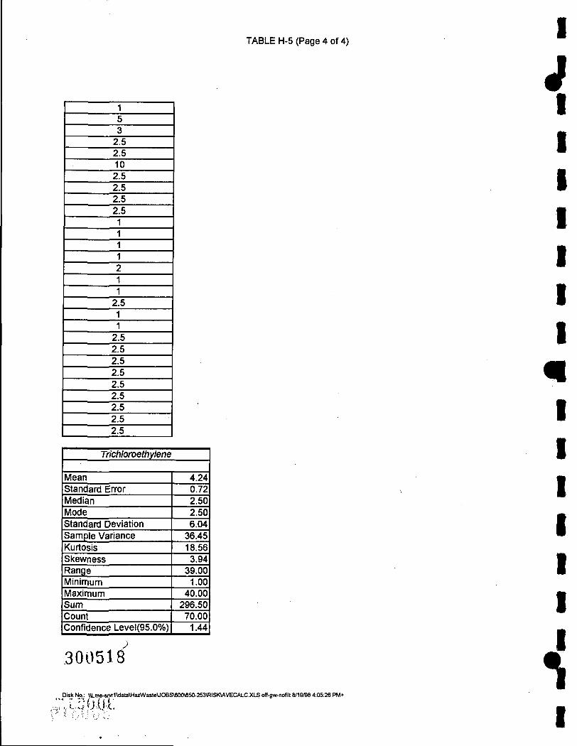
TABLE H-5 (Page 4 of 4) I
y 2.5 2.5 10 2.5 2.5 2.5 2.5
2.5
2.5 2.5 2.5 2.5 2.5 2.5 2.5 2.5 2.5
Trichloroethylene
Mean Standard Error Median Mode Standard Deviation Sample Variance Kurtosis Skewness Range Minimum Maximum Sum Count Confidence Level(95.0%)
4.24 0.72 2.50 2.50 6.04
36.45 18.56 3.94
39.00 1.00
40.00 296.50 70.00
1.44
300518
Disk No.: \\Lms-srvr1\data\HazVI/asteUOBS\600V650-253\RISK\AVECALC.XLS off.gw-nofilt 8/19/98 4:05:26 PM+ \
I

I
V
r I
TABLE H-6 (Page 1 of 2)
Mohonk Road Industrial Plant 650-253
SUBSURFACE SOILS (Samples that had contaminants that were not detected as displayed as half of the allowable soil concentration as given in TAGM 40-46, Jan 1994)!
1,2-Dichloroethylene 0.15 0.15 0.15 0.15 0.75 0.15 0.2 0.03 0.071 0.001 0.15 0.15 0.15 0.15
1,1,1-Trichloroethane 0.4 1.1
0.014 0.4 0.4 0.4
0.002 0.024 0.053 0.003 0.059
0.4 0.4 0.4
0.007 0.4 0.4
0.098 0.034 0.019
0.4 0.4 0.4 0.4
0.002 0.004 0.01 0.003 0.063
Tetrachloroethylene 0.7 0.7 0.7 4.3 5.7 0.7 0.24 4.6
0.057 0.007
0.7 0.7 0.7 0.7
0.0171 0.7 0.7 0.7 0.7 0.7 0.7 0.7
0.0016 0.7
1,2-Dichloroethylene
Mean Standard Error Median Mode Standard Deviation Sample Variance Kurtosis Skewness Range Minimum Maximum Sum Count Confidence Level(95.0%)
0.172 0.047 0.150 0.150 0.175 0.031
10.890 3.084 0.749 0.001 0.750 2.402
14.000 0.101
1,1,1-Trichloroethane
Mean Standard Error Median Mode Standard Deviation Sample Variance Kurtosis Skewness Range Minimum Maximum Sum Count Confidence Level(95.0%)
0.231 0.047 0.098 0.400 0.251 0.063 3.434 1.414 1.098 0.002 1.100 6.695
29.000 0.096
Tetrachloroethylene
Mean Standard Error Median Mode Standard Deviation Sample Variance Kurtosis Skewness Range Minimum Maximum Sum ^ Count Confidence Level(95.0%)
1.088 0.306 0.700 0.700 1.498 2.244 4.604 2.372 5.698 0.002 5.700
26.123 24.000 0.633
Disk No.: \\Lms-srvr1\data\HazWasteUOBS\600\65O-253\RISK\AVECALC.XLS soils 8/19/98 4:07:33 PM+
3005 J €| :;S;aoof'

TABLE H-6 (Page 2 of 2) I
J Ethylbenzene
2.75 2.75 2.75 2.75 0.008 2.75 2.75 0.012 2.75 0.005 2.75 25
0.041 2.75 0.002 2.75 41
2.75 2.75 2.75 2.75 2.75 2.75 2.75 2.75
Xylene 0.003 0.6 0.6 0.6
0.014 0.6 0.6
0.047 0.6
0.032 0.6 150 0.3
0.004 0.013 0.002 210 0.6 0.6 0.6 0.6 0.6 0.6 0.6 0.6
Ethylbenzene
Mean Standard Error Median Mode Standard Deviation Sample Variance Kurtosis Skewness Range Minimum Maximum Sum Count Confidence Level(95.0%)
4.623 1.783 2.750 2.750 8.916
79.495 12.898 3.578
40.998 0.002
41.000 115.568 25.000
3.680
Xylene
Mean Standard Error Median Mode Standard Deviation Sample Variance Kurtosis Skewness Range Minimum Maximum Sum Count Confidence Level(95.0%)
14.777 10.095 0.600 0.600
50.476 2547.783
11.327 3.467
209.998 0.002
210.000 369.415 25.000 20.835 n
Disk No.: \\Lms-sivr1\data\HazV\/asteUOBS\600«50-253\RISK\AVECALC2.XLS soils 8/19/98 4:08:26 PM+
300520 I

I
V
li
r I
TABLE H-7
Mohonk Road Industrial Plant 650-253
CALCULATION OF VOCs VOLATILIZING IN A HOT SHOWER INHALATION EXPOSURE (ON-SITE)
1,1-DCE 1,1,1-TCA TCE* Concentration in groundwater (mg/1) Henry's constant (about gS'F) Conversion factor (1000 l/m^
Concentration in air (mg/m^ 715.34 4184.88 346.08
• - The concentrations of cis- and trans- DCE are not known, therefore the Henry's constant for trans-DCE was used Isecause it was more conservative.
** - Concentration is the 95% upper confidence limit on the arithmetric average, as calculated In Table H-4.
0.493 1.451 1000
4.24 0.987 1000
0.635 0.545 1000
Disk No.: \\Lms-sivr1\data\HazW^asteUOBS\600\650-253\RISK\AIRCONC.XLS on-site 8/19/98 4:10:25 PM+
!:^g008
30052]

TABLE H-8
Mohonk Road Industrial Plant 650-253
CALCULATION OF VOCs VOLATILIZING IN A HOT SHOWER INHALATION EXPOSURE (OFF-SITE)
1,1-DCE 1,1-DCA 1,1,1-TCA TCE* Concentration in groundwater (mg/1) Henry's constant (about 95°F) Conversion factor (1000 l/m')
Concentration in air (mg/m^ 10.45 1.25 35.24 0.76
* - The concentrations of cis- and trans- DCE are not known, therefore the Henry's constant for trans-DCE was used because it was more consenrative.
** - Concentration is the 95% upper confidence limit on the arithmetric average, as calculated in Table H-5.
i
y 0.0072 1.451 1000
0.0039 0.321 1000
0.0357 0.987 1000
0.0014 0.545 1000
il
300522
^ Disk No.: \\Lms-srvr1\data\HazWastBUOBS\600\650-2S3\RISKUMRCONC.XLS off-sita 8/19/98 4:10:52 PM+
. •• x ' i y i • • J ' " - - ' I

V TABLE H-9 (Page 1 of 2)
- Mohonk Road Industrial Plant 650-253
CALCULATION OF VOCs VOLATILIZING FROM ON-SITE SUBSURFACE SOILS (DURING CONSTRUCTION) INHALATION EXPOSURE (ON-SITE)
Surface Soil Volalitization Factor (VSss): Eqn. 1: [(2*W*ps)/(U3i,*53,)]*[(Ds^^*H)/«x*(0.„+K3*Ps+H*e3s))]*'^'^*1000 or Eqn. 2: [(W*Ps*d)/(U3,*53ir.t)]*1000 whichever is less.
Where: Q eff D*'*(eas'^/eTV(D'™'/n)*(e,^eT^)*i coo
(but the second factor [(D*"/H)*(0ys/&r^)] is negligible compared to the first.) D'"= diffusion coefficient in air (cm /s) 9as = volumetric air content in vadose zone soils (cm^ air/cm^ soil) d = lower depth of surficial soil zone (cm) 6T^total soil porosity (cm^ pore space/cm^ soil) 6ws = volumetric water coefficient in vadose zone soils (cm^ water/cm^ soil) H = Henry's Law constant (cm' water / cm' air) W = width of source area parallel to wind (cm) Ps = soil bulk density (g soil/cm' soil) Uair = wind speed above groundwater surface in ambient mixing zone (cm/s) 5air = ambient air mixing zone height (cm) TC = 3 . 1 4
T = averaging time for vapor flux (s) ^ Ks= soil water sorption coefficient (g water/g soil) = (foc)*(koc) foe = fraction organic carbon koc = organic carbon normalized soil-water partition coefficient
for organic compounds; average value was used
1,2-DCE' 1,1,1-TCA PCE Ethylbenzene Xylene diffusion coefficient in air (cm'/s) 0.0707 0.0780 0.0720 0.0750 0.0720 Henry's Law constant 0.229 0.763 0.709 0.3180 0.2480
iCp soil-water partition coefficient (g water/g soil) 44 110 317 228 271
^ ' 1
V.
Default Value
chemical specific 0.26
0.38 0.12
chemical specific 1500 cm
1.7 g/cm 225 cm/s 200 cm 3.14
31600000 sec
0.01 chemical specific
time is averaged over 1 year for an on-site construction worker ( ^ ' where applicable, values for trans 1,2-DCE were used.
/C;«>-
Disk No.: \\Lms-sivr1\data\Ha2WasteUO8S\600V6S0-2S3\RISIOAIRCONC.XLS solQ 8/19/98 4:11:20 P M *
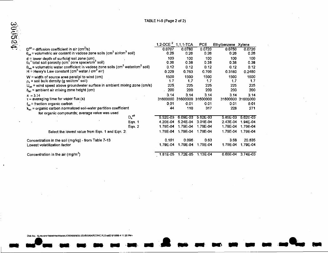
CO,
n. TABLE H-9 (Page 2 of 2)
D'''= diffusion coefficient In air (cm'/s) Gas = volumetric air content in vadose zone soils (cm air/cm soil) d = lower depth of surficial soil zone (cm) 9T^ total soil porosity (cm' pore space/cm soil) 9ws = volumetric water coefficient in vadose zone soils (cm' water/cm' soil) H = Henry's Law constant (cm' water / cm' air) W = width of source area parallel to wind (cm) Ps = soil bulk density (g soil/cm soil) Uair = wind speed above groundwater surface in ambient mixing zone (cm/s) 8air = ambient air mixing zone height (cm) jc = 3 . 1 4 X = averaging time for vapor flux (s) foe = fraction organic carbon koe = organic carbon normalized soil-water partition coefficient
for organic compounds; average value was used Ds*" Eqn. 1 Eqn. 2
Select the lowest value from Eqn. 1 and Eqn. 2:
Concentration in the soil (mg/kg) - from Table 7-13 Lowest volatilization factor
1,2-DCE' 0.0707 0.26
100 0.38 0.12 0.229
1500 1.7 225 200 3.14
31600000 0.01 44
S.S2e-03 4.20E-04 1.79E-04
1.79E-04
0.101 1.79E-04
1,1,1-TCA 0.0780 0.26
100 0.38 0.12 0.763
1500 1.7 225 200 3.14
31600000 0.01 110
6.09^-03 5.24E-04 1.79E-04
1.79E-04
0.096 1.79E-04
PCE 0.0720 0.26
100 0.38 0.12 0.709
1500 1.7 225 200 3.14
31600000 0.01 317
5.6it03 3.01 E-04 1.79E-04
1.79E-04
0.63 1.79E-04
Ethylbenzene 0.0750 0.26
100 0.38 0.12
0.3180
1500 1.7 225 200 3.14
31600000 0.01 228
5.65t03 2.43E-04 1.79E-04
1.79E-04
3.68 1.79E-04
Xylene 0.0720 0.26
100 0.38 0.12
0.2480
1500 1.7 225 200 3.14
31600000 0.01 271
S.62d-03 1.94E-04 1.79E-04
1.79E-04
20.835 1.79E-04
Concentration in the air (mg/m') 1.81E-05 1.72E-05 1.13E-04 6.60E-04 3.74E-03
Disk No.: \\Lms-stvr1\data\Ha2Waste\JOBS\600\650.253«ISKWIRCONCJ(LS s d C 8/19/98 4:11:20 PM+
M

o o CJl'
V TABLE H-10
Mohonk Road Industrial Plant 650-253
EXPOSURE ASSESSMENT CALCULATIONS Ingestion of Chemicals in On-site Drinking Water
Current Land Use Scenario (Adult Worker)
Intake = C W x I R x E F x E D BWxAT
Noncarcinogenic:
1.1-DCE 1,1.1-TCA TCE CW - contaminant concentration in water (mg/liter) IR - ingestion rate (liters/day) EF - exposure frequency (days/year) ED - exposure duration (years) BW - body weight (kg) AT - averaging time (period over which exposure is averaged - days)
Intake (mg/kg-day): 0.0017 0.0149 0.0022
Carcinogenic:
0.493 1 90 30 70
10,950
4.24 1 90 30 70
10,950
0.635 1 90 30 70
10,950
1,1-DCE TCE CW - contaminant concentration in water (mg/liter) IR - ingestion rate (liters/day) EF - exposure frequency (days/year) ED - exposure duration (years) BW - body weight (kg) AT - averaging time (period over which exposure is averaged - days)
0.493 1 90 30 70
25,550
0.635 1 90 30 70
25.550
Intake (mg/kg-day): 0.0007 0.0010
Disk No.: \\Lms-sivr1Wata\HazWasteUOBS\600\650-253\RISK\EXPCALC.XLS current<n.gw 8/21/98 11:41:20 AM+

V ff
TABLE H-11 (Pagel of 6)
Mohonk Road Industrial Plant 650-253
EXPOSURE ASSESSMENT CALCULATIONS Inhalation of Volatilized Chemicals (off-site)
Current Land Use Scenario (Child 1 to 6 years old)
Intake = CA x IR x ET x EF x ED BWxAT
•V
Noncarcinogenic:
-CA - contaminant concentration in air (mg/m^ IR - inhalation rate (m'/hr) ET - exposure time (hours/day) EF - exposure frequency (days/year) ED - exposure duration (years) BW - body weight (kg) AT - averaging time (period over which exposure is averaged - days)
Intake (mg/kg-hr):
1,1-DCE 10.45 0.833 0.6 365 6 15
2,190
0.3483
1.1-DCA 1:25
0.833 0.6 365 6 15
2,190
0.0417
1.1,1-TCA 35.24 0.833 0.6 365 6 15
2,190
1.1747
TCE 0.76 0.833 0.6 365 6 15
2,190
0.0253
Carcinogenic:
CA - contaminant concentration in air (mg/m^) IR - inhalation rate (m'/hr) ET - exposure time (hours/day) EF - exposure frequency (days/year) ED - exposure duration (years) BW - body weight (kg) AT - averaging time (period over which exposure is averaged - days)
1,1-DCE TCE 10.45 0.833 0.6 365 6 15
25,550
0.76 0.833 0.6 365 6 15
25,550
CO - ' ' Intake (mg/kg-hr): 0.0299 0.0022
Disk No.: \\Lms-stvr1Wata\HazWastBUOBS\600\650-253\RISK^EXPCALC.XLS curTent^3ff.gw 8/21/98 11:48:32 AM+

. - TABLE H-11 (Page 2 of 6)
T ^ EXPOSURE ASSESSMENT CALCULATIONS r o Inhalation of Volatilized Chemicals (off-site) ' - ^ Current Land Use Scenario
(Adult)
Intake = CA x IR x ET x EF x ED BWxAT
Noncarcinogenic:
CA - contaminant concentration in air (mg/m') IR - inhalation rate (mVhr) ET - exposure time (hours/day) EF - exposure frequency (days/year) ED - exposure duration (years) BW - body weight (kg) AT - averaging time (period over which exposure is averaged - days)
1,1-DCE 1,1-DCA 1,1,1-TCA TCE 10.45 0.833 0.6 365 30 70
10,950
1.25 0.833 0.6 365 30 70
10,950
35.24 0.833 0.6 365 30 70
10,950
0.76 0.833 0.6 365 30 70
10,950
Intake (mg/kg-hr): 0.0746 0.0089 0.2517 0.0054
Carcinogenic:
CA - contaminant concentration in air (mg/m') IR - inhalation rate (m'/hr) ET - exposure time (hours/day) EF - exposure frequency (days/year) ED - exposure duration (years) BW - body weight (kg) AT - averaging time (period over which exposure is averaged - days)
1,1-DCE TCE 10.45 0.833 0.6 365 30 70
25.550
0.76 0.833 0.6 365 30 70
25,550
Intake (mg/kg-hr): 0.0320 0.0023
ms-srvr1\data\HazWaste\JOBS\600V650-253\RISKVEXPCALC.XLS current^>ff.gw 8/21/98 11:. l:46:32AM'i' ^ ^

«
TABLE H-11 (Page 3 of 6)
EXPOSURE ASSESSMENT CALCULATIONS Ingestion of Chemicals in Off-site Drinking Water
Current Land Use Scenario (Child 1 to 6 years old)
Intake = CW x IR x EF x ED BW X AT
1,1-DCE 1.1-DCA 1,1.1-TCA TCE 0.0072 2 350 6 15
2,190
0.0039 2 350 6 15
2,190
0.0357 2 350 6 15
2,190
0.0014 2 350 6 15
2,190
Noncarcinogenic:
CW - contaminant concentration in water (mg/liter) IR - ingestion rate (liters/day) EF - exposure frequency (days/year) ED - exposure duration (years) BW - body weight (kg) AT - averaging time (period over which exposure is averaged - days)
Intake (mg/kg-day): 9.21 E-04 4.99E-04 4.56E-03 1.79E-04
Carcinogenic: 1.1-DCE TCE
CW - contaminant concentration in water (mg/liter) IR - ingestion rate (liters/day) EF - exposure frequency (days/year) ED - exposure duration (years) BW - body weight (kg) AT - averaging time (period over which exposure is averaged - days)
Intake (mg/kg-day): 7.89E-05 1.53E-05
•'•.vO
r,ia_, •
m •" "
Disk No.: \\Lms-srvr1\data\HazWasleUOBS\600\650-253\RISKVEXPCALC.XLS currentoff.gw 8/21/98 11:46:32 AM+
0.0072 2 350 6 15
25.550
0.0014 2 350 6 15
25.550

TABLE H-11 (Page 4 of 6)
CO
^ EXPOSURE ASSESSMENT CALCULATIONS <J3 Ingestion of Chemicals in Off-site Drinking Water
Current Land Use Scenario (Adult)
Intake = CW x IR x EF x ED BWxAT
1.1-DCE 1,1-DCA 1,1.1-TCA TCE 0.0072 2 350 30 70
10.950
0.0039 2 350 30 70
10,950
0.0357 2 350 30 70
10,950
0.0014 2 350 30 70
10,950
Noncarcinogenic:
CW - contaminant concentration in water (mg/liter) IR - ingestion rate (liters/day) EF - exposure frequency (days/year) ED - exposure duration (years) BW - body weight (kg) AT - averaging time (period over which exposure is averaged - days)
Intake (mg/kg-day): 1.97E-04 1.07E-04 9.78E-04 3.84E-05
Carcinogenic: 1,1-DCE TCE
CW - contaminant concentration in water (mg/liter) IR - ingestion rate (liters/day) EF - exposure frequency (days/year) ED - exposure duration (years) BW - body weight (kg) AT - averaging time (period over which exposure is averaged - days)
Intake (mg/kg-day): 8.45E-05 1.64E-05
0.0072 2 350 30 70
25,550
0.0014 2 350 30 70
25.550
Disk NoJlLms-sivr1\data\Ha2WasteUOBS\600\650-253\RISK\EXPCALC.XLS currentKiff-gw 8/21/98 11:46:32 AM+
4

w TABLE H-11 (Page 5 of 6)
EXPOSURE ASSESSMENT CALCULATIONS Dermal Contact with Chemicals in Off-site Groundwater
Current Land Use Scenario (Children. 1 to 6 years old)
Intake = CW x SA x PC x ET x EF x ED x CF BWxAT
Noncarcinogenic:
CW - contaminant concentration in water (mg/liter) SA - skin surface area available for contact (cm^) PC - chemical-specific dermal permeablility constant (cm/hr) ET - exposure time (hours/day) EF - exposure frequency (days/year) ED - exposure duration (years) CF - volumetric conversion factor for water (1 liter/1000 cm"') BW - body weight (kg) AT - averaging time (period over which exposure is averaged - days)
1,1-DCE 1.1-DCA 1.1,1-TCA TCE
3 \
0.0072 7,195
1.60E-02 0.2 365 6
0.001 15
2,190
0.0039 7,195
8.90E-03 0.2 365 6
0.001 15
2.190
0.0357 7.195
1.70E-02 0.2 365 6
0.001 15
2.190
0.0014 7.195
1.60E-02 0.2 365 6
0.001 15
2.190
Carcinogenic:
Intake (mg/kg-day): 1.11E-05 3.33E-06 5.82E-05 2.15E-06
1.1-DCE TCE
CO o
CJl
CD
CW - contaminant concentration in water (mg/liter) SA - skin surface area available for contact (cm^) PC - chemical-specific dermal permeablility constant (cm/hr) ET - exposure time (hours/day) EF - exposure frequency (days/year) ED - exposure duration (years) CF - volumetric conversion factor for water (1 liter /1000 cm^) IVV - body weight (kg) S i t - averaging time (period over which exposure is averaged - days)
( • • " ' . :
; ^ Intake (mg/kg-day): .
0.0072 7,195
1.60E-02 0.2 365 6
0.001 15
25.550
9.47E-07
0.0014 7.195
1.60E-02 0.2 365 6
0.001 15
25,550
1.84E-07
Disk No.: \\Lms-srvr1\data\HarWasteUOBS\600\650-253\RISK\EXPCALC.XLS current^)ff-gw 8/21/9811:46:32 AM+

'••-D^ C J l
TABLE H-11 (Page 6 Of 6)
as
^ EXPOSURE ASSESSMENT CALCULATIONS , .^ Dermal Contact with Chemicals in Off-site Groundwater
Current Land Use Scenario (Adult)
Intake = CW x SA x PC x ET x EF x ED x CF BW X AT
Noncarcinogenic:
CW - contaminant concentration in water (mg/liter) SA - skin surface area available for contact (cm^) PC - chemical-specific dermal permeablility constant (cm/hr) ET - exposure time (hours/day) EF - exposure frequency (days/year) ED - exposure duration (years) CF - volumetric conversion factor for water (1 liter /1000 cm^) BW - body weight (kg) AT - averaging time (period over which exposure is averaged - days)
1.1-DCE 1,1-DCA 1,1.1-TCA TCE 0.0072
18,150 1.60E-02 0.2 365 30
0.001 70
10,950
0.0039
18,150 8.90E-03
0.2 365 30
0.001 70
10.950
0.0357
18,150 1.70E-02 0.2 365 30
0.001 70
10.950
0.0014
18,150 1.60E-02 0.2 365
, 30 0.001 70
10,950
Carcinogenic:
CW - contaminant concentration in water (mg/liter) SA - skin surface area available for contact (cm^) PC - chemical-specific dermal permeablility constant (cm/hr) ET - exposure time (hours/day) EF - exposure frequency (days/year) ED - exposure duration (years) CF - volumetric conversion factor for water (1 liter /1000 cm^) BW - body weight (kg) AT - averaging time (period over which exposure is averaged - days)
Intake (mg/kg-day): 5.97E-06 1.80E-06 3.15E-05 1.16E-06
1,1-DCE TCE 0.0072
18.150 1.60E-02 0.2 365 30
0.001 70
25.550
0.0014
18.150 1.60E-02 0.2 365 30
0.001 70
25,550
Intake (mg/kg-day): 2.56E-06 4.98E-07
,ms-srvr1\data\Ha2WasteUOBS\600\650-253\RISKVEXPCALC.XLS current^)ff-gw 8/21/98 11:46:32 AM+
M
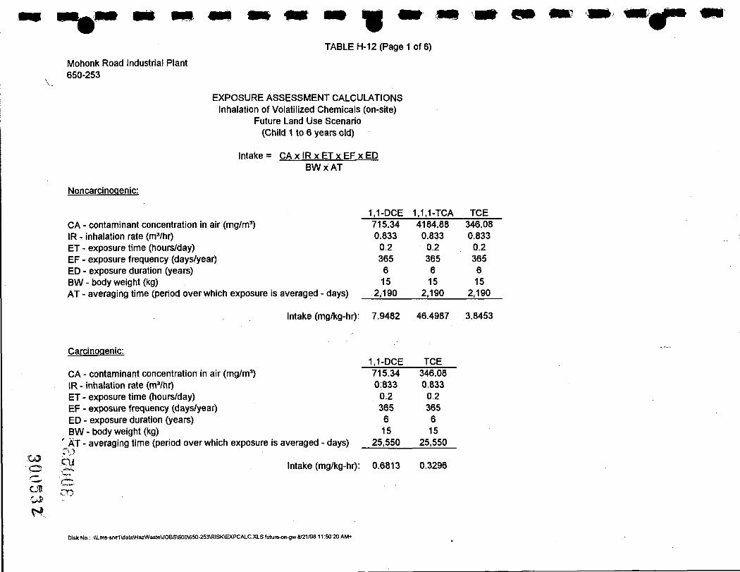
CJI
m TABLE H-12 (Pagel of 6)
Mohonk Road Industrial Plant 650-253
EXPOSURE ASSESSMENT CALCULATIONS Inhalation of Volatilized Chemicals (on-site)
Future Land Use Scenario (Child 1 to 6 years old)
Intake = CA x IR x ET x EF x ED BW X AT
Noncarcinogenic:
CA - contaminant concentration in air (mg/m') IR - inhalation rate (m'/hr) ET - exposure time (hours/day) EF - exposure frequency (days/year) ED - exposure duration (years) BW - body weight (kg) AT - averaging time (period over which exposure is averaged - days)
1,1-DCE 1,1.1-TCA TCE 715.34 0.833 0.2 365 6 15
2,190
4184.88 0.833 0.2 365 6 15
2,190
346.08 0.833 0.2 365 6 15
2,190
Carcinogenic:
Intake (mg/kg-hr): 7.9482 46.4987 3.8453
1.1-DCE TCE 715.34 0:833 0.2 365 6 15
25,550
346.08 0.833 0.2 365 6 15
25,550
CA - contaminant concentration in air (mg/m') IR - inhalation rate (m'/hr) ET - exposure time (hours/day) EF - exposure frequency (days/year) ED - exposure duration (years) BW - body weight (kg)
' AIT - averaging time (period over which exposure is averaged - days)
^ Intake (mg/kg-hr): 0.6813 0.3296
CT!)
Disk No.: \\Ltns-srvr1Vdata\HazWaste\JOBS\600\650-253\RISK\EXPCALC.XLS future.on-gw 8/21/98 11:50:20 AM+

TABLE H-12 (Page 2 of 6)
' . ^ . CJO
^ rz , EXPOSURE ASSESSMENT CALCULATIONS ' r ^ CJl Inhalation of Volatilized Chemicals (on-site)
CO Future Land Use Scenario ^ ^ (Adult)
Intake = CA x IR x ET x EF x ED BWxAT
Noncarcinogenic:
CA - contaminant concentration in air (mg/m') IR - inhalation rate (m'/hr) ET - exposure time (hours/day) EF - exposure frequency (days/year) ED - exposure duration (years) BW - body weight (kg) AT - averaging time (period over which exposure is averaged - days)
1,1-DCE 1,1,1-TCA TCE 715.34 0.833 0.2 365 30 70
10,950
4184.88 0.833 0.2 365 30 70
10,950
346.08 0.833 0.2 365 30 70
10,950
Intake (mg/kg-hr): 1.7032 9.9640 , 0.8240
Carcinogenic:
CA - contaminant concentration in air (mg/m') IR - inhalation rate (m'/hr) ET - exposure time (hours/day) EF - exposure frequency (days/year) ED - exposure duration (years) BW - body weight (kg) AT - averaging time (period over which exposure is averaged - days)
1,1-DCE TCE 715.34 0.833 0.2 365 30 70
25,550
346.08 0.833 0.2 365 30 70
25,550
Intake (mg/kg-hr): 0.7299 0.3531
D i s k N ^ ^ |\Lms-srvr1\data\HazV>/asteUOBS\600\650-253\RISK\EXPCALC.XLSfuture-on.gw 8/21/9811:50:20 AM+

CO
CO
«
TABLE H-12 (Page 3 of 6)
EXPOSURE ASSESSMENT CALCULATIONS Ingestion of Chemicals in On-site Drinking Water
Future Land Use Scenario (Child 1 to 6 years old)
Intake = C W x I R x E F x E D BW X AT
Noncarcinogenic:
1,1-DCE 1.1,1-TCA TCE 0.493 2 350 6 15
2,190
4.24 2 350 6 15
2.190
0.635 2 350 6 15
2,190
CW - contaminant concentration in water (mg/liter) IR - ingestion rate (liters/day) EF - exposure frequency (days/year) ED - exposure duration (years) BW - body weight (kg) AT - averaging time (period over which exposure is averaged - days)
Intake (mg/kg-day): 6.30E-02 5.42E-01 8.12E-02
Carcinogenic: 1,1-DCE TCE
CW - contaminant concentration in water (mg/liter) IR - ingestion rate (liters/day) EF - exposure frequency (days/year) ED - exposure duration (years) BW - body weight (kg) AT - averaging time (period over which exposure is averaged - days)
Intake (mg/kg-day): 5.40E-03 6.96E-03
0.493 2 350 6 15
25.550
0.635 2 350 6 15
25,550
OJ
Disk No.: \\Lms-srvr1\data\HazWaste\JOBS\600\650-253\RISK\EXPCALC.XLS future-on-gw 8/21/98 11:50:20 AM+

TABLE H-12 (Page 4 of 6)
CD
cn CO e j l EXPOSURE ASSESSMENT CALCULATIONS
Ingestion of Chemicals in On-site Drinking Water Future Land Use Scenario
(Adult)
Intake = CW x IR x EF x ED BWxAT
Noncarcinogenic:
CW - contaminant concentration in water (mg/liter) IR - ingestion rate (liters/day) EF - exposure frequency (days/year) ED - exposure duration (years) BW - body weight (kg) AT - averaging time (period over which exposure is averaged - days)
Intake (mg/kg-day):
Carcinogenic:
CW - contaminant concentration in water (mg/liter) IR - ingestion rate (liters/day) EF - exposure frequency (days/year) ED - exposure duration (years) BW - body weight (kg) AT - averaging time (period over which exposure is averaged - days)
Intake (mg/kg-day):
1,1-DCE 1.1,1-TCA TCE 0.493 2 350 30 70
10,950
1.35E-02
1,1-DCE 0.493 2 ; 350 30 70
25,550
5.79E-03
4.24 2 350 30 70
10,950
1.16E-01
TCE 0.635 2 350 30 70
25,550
7.46E-03
0.635 2 350 30 70
10,950
1.74E-02
Disk No.: \\Lms-sivr1\dataVHazWasteUOBS\600\650-253\RISK\EXPCALC.XLS futureon^gw 8/21/98 11:50:20 AM+ m

TABLE H-12 (Page 5 of 6)
EXPOSURE ASSESSMENT CALCULATIONS Dermal Contact with Chemicals in On-site Groundwater
Future Land Use Scenario (Children, 1 to 6 years old)
Intake = CW x SA x PC x ET x EF x ED x CF BWxAT
Noncarcinogenic:
1,1-DCE 1.1.1-TCA TCE CW - contaminant concentration in water (mg/liter) SA - skin surface area available for contact (cm^) PC - chemical-specific dermal pemieablility constant (cm/hr) ET - exposure time (hours/day) EF - exposure frequency (days/year) ED - exposure duration (years) CF - volumetric conversion factor for water (1 liter /1000 cm^) BW - body weight (kg) AT - averaging time (period over which exposure is averaged - days)
0.493 7,195
1.60E-02 0.2 365 6
0.001 15
2,190
4.24 7,195
1.70E-02 0.2 365 6
0.001 15
2,190
0.635 7.195
1.60E-02 0.2 365 6
0.001 15
2,190
Carcinogenic:
Intake (mg/kg-day): 7.57E-04 6.91 E-03 9.75E-04
1,1-DCE TCE CW - contaminant concentration in water (mg/liter) SA - skin surface area available for contact (cm^) PC - chemical-specific dermal permeablility constant (cm/hr) ET - exposure time (hours/day) EF - exposure frequency (days/year) ED - exposure duration (years) CF - volumetric conversion factor for water (1 liter /1000 cm^)
~ ^ BW - body weight (kg) ^ ' M - averaging time (period over which exposure is averaged - days)
•CT £ ' ^ ^ : Intake (mg/kg-day): 6.49E-05 8.35E-05
CD
Disk No.: VVLms-sml\data\Ha2Waste\JOBS\600\650-253\RISK\EXPCALC.XLS future^)n.gw 8/21/9811:50:20 AM+
0.493 7,195
1.60E-02 0.2 365 6
0.001 15
25,550
0.635 7,195
1.60E-02 0.2 365 6
0.001 15
25,550

I l l
TABLE H-12 (Page 6 of 6) CO O
r ^ EXPOSURE ASSESSMENT CALCULATIONS „ 4 Dermal Contact with Chemicals in On-site Groundwater
Future Land Use Scenario (Adult)
Intake = CW x SA x PC x ET x EF x ED x CF BWxAT
Noncarcinogenic:
1,1-DCE 1,1,1-TCA TCE CW - contaminant concentration in water (mg/liter) SA - skin surface area available for contact (cm^) PC - chemical-specific dermal permeablility constant (cm/hr) ET - exposure time (hours/day) EF - exposure frequency (days/year) ED - exposure duration (years) CF - volumetric conversion factor for water (1 liter /1000 cm^) BW - body weight (kg)
0.493
18,150 1.60E-02 0.2 365 30
0.001 70
10,950
4.24
18.150 1.70E-02 0.2 365 30
0.001 70
10,950
0.635
18.150 1.60E-02 0.2 365 30
0.001 70
10,950
Carcinogenic:
CW - contaminant concentration in water (mg/liter) SA - skin surface area available for contact (cm^) PC - chemical-specific dermal permeablility constant (cm/hr) ET - exposure time (hours/day) EF - exposure frequency (days/year) ED - exposure duration (years) CF - volumetric conversion factor for water (1 liter /1000 cm^) BW - body weight (kg) AT - averaging time (period over which exposure is averaged - days)
Intake (mg/kg-day): 4.09E-04 3.74E-03 5.27E-04
1.1-DCE TCE 0.493
18,150 1.60E-02 0.2 365 30
0.001 70
25,550
0.635
18,150 1.60E-02 0.2 365 30
0.001 70
25,550
Intake (mg/kg-day): 1.75E-04 2.26E-04
Disk No.: \\Lms-srvr1\data\HazWastBUOBS\600\650-253\RISKVEXPCALC.XLS (uture^)n.gw 8/21/98 11:50:20 AM+
M

m TABLE H-13 (Pagel of 3)
Mohonk Road Industrial Plant 650-253
EXPOSURE ASSESSMENT CALCULATIONS Inhalation of Volatilized Chemicals (on-site)
Future Land Use Scenario (Adult wori<er)
Intake = CA x IR x ET x EF x ED BW X AT
Noncarcinogenic:
CA - contaminant concentration in air (mg/m') IR - inhalation rate (m'/hr) ET - exposure time (hours/day) EF - exposure frequency (days/year) ED - exposure duration (years) BW - body weight (kg) AT - averaging time (period over which exposure is averaged ^ eraged - days)
Intake (mg/kg-hr):
1,2-DCE 1.81E-05
0.417 7.5 45 1
70 365
9.96E-08
1,1,1-TCA 1.72E-05
0.417 7.5 45 1
70 365
9.47E-08
PCE 1.13E-04
0.417 7.5 45 1
70 365
6.22E-07
Ethylbenzene 6.60E-04
0.417 7.5 45 1
70 365
3.63E-06
Xylene 3.74E-03
0.417 7.5 45 1
70 365
2.06E-05
C'i CO"^
ccro
CO CO
Carcinogenic:
CA - contaminant concentration in air (mg/m*) IR - inhalation rate (m'/hr) ET - exposure time (hours/day) EF - exposure frequency (days/year) ED - exposure duration (years) BW - body weight (kg) AT - averaging time (period over which exposure is averaged • days)
Intake (mg/kg-hr):
PCE 1.13E-04
0.417 7.5 45 1
70 25,550
8.88E-09
Disk No.: V\Lms-sivr1\data\Ha2WasteUOBS\600\65b-253\RISK\EXPCALC.XLS fuhire-bn-soll2 8/20/98 11:56:42 AM+

Cd 'Co
cn CO CO
Mohonk Road Industrial Plant 650-253
TABLE H-13 (Page 2 of 3)
EXPOSURE ASSESSMENT CALCULATIONS Ingestion of Chemicals in Subsurface Soils
Future Land Use Scenario (Adult woriter)
Intake = CS x IR x EF x ED BWxAT
Noncarcinogenic:
CS - contaminant concentration in soil (mg/kg) IR - ingestion rate (mg/kg) EF - exposure frequency (days/year) ED - exposure duration (years) BW - body weight (kg) AT - averaging time (period over which exposure is averaged
1.2-DCE 1.1.1-TCA PCE Ethylbenzene Xylene 1.01 E-01 100 45 1 70 365
9.60E-02 100 45 1 70 365
6.30E-01 100 45 1 70 365
3.68E+00 100 45 1 70 365
2.08E+01 100 45 1 70 365 days)
Intake (mg/kg-day): 1.78E-02 1.69E-02 1.11 E-01 6.48E-01 3.66E+00
Carcinogenic:
CS - contaminant concentration in soil (mg/kg) IR - ingestion rate (mg/day) EF - exposure frequency (days/year) ED - exposure duration (years) BW - body weight (kg) AT - averaging time (period over which exposure is averaged days)
PCE 6.30E-01
100 45 1
70 25,550
Intake (mg/kg-day): 1.59E-03
Disk N ^ ^ i i is-srvr1\data\Ha2Waste\JOBS\600\650-253\RISKVEXPCALC.XLS future.on-soil2 8/20/98 11:56: S6:42 AM+ { ^ ^

V TABLE H-13 (Page 3 of 3)
EXPOSURE ASSESSMENT CALCULATIONS Dermal Contact with Chemicals in Subsurface Soil
Future Land Use Scenario (Adult worker)
Intake = CS x CF x SA x AF x ABS x EF x ED BW X AT
Noncarcinogenic:
CS - contaminant concentration in soil (mg/kg) CF - conversion factor (10"^ kg/mg) SA - skin surface area available for contact (cm^) AF - soil to skin adherence factor (mg/cm^) ABS - absorption factor (unitless) EF - exposure frequency (days/year) ED - exposure duration (years) BW - body weight (kg) AT - averaging time (period over which exposure is averaged - days)
Intake (mg/kg-day): Carcinogenic:
CS - contaminant concentration in soil (mg/kg) CF - conversion factor (10"® kg/mg) SA - skin surface area available for contact (cm^) _ AF - soil to skin adherence factor (mg/cm^) ABS - absorption factor (unitless) EF - exposure frequency (days/year) ED - exposure duration (years)
CO BW - body weight (kg) CI? AT - averaging time (period over which exposure is averaged - days)
^ ^ Intake (mg/kg-day): 4.97E-09
O
Disk No.: WLms-stvr1\dataVHa2Waste\JOBS\600\650-253\RISK\EXPCALC.XLS future^)n-soil2 8/21/98 11:52:28 AM+
1,2-DCE 0.101
1.00E-06 3120
1 0.10 45 1
70 365
5.55E-08
PCE 0.633
1.00E-06 3120
1 0.10 45 1
70 25,550
1,1,1-TCA 0.096
1.00E-06 3120
1 0.10 45 1
70 365
5.28E-08
PCE 0.633
1.00E-06 3120
1 0.10 45 1
70 365
3.48E-07
Ethylbenzene 3.68
1.00E-06 3120
1 0.10 45 1
70 365
2.02E-06
Xylene 20.835
1.00E-06 3120
1 0.10 45 1
70 365
1.14E-05

CO
o 4 ^
V TABLE H-14 (Page 1 of 6)
Mohonk Road Industrial Plant 650-253
EXPOSURE ASSESSMENT CALCULATIONS Inhalation of Volatilized Chemicals (off-site)
Future Land Use Scenario (Child 1 to 6 years old)
Intake = CA x IR x ET x EF x ED BWxAT
Noncarcinogenic:
CA - contaminant concentration in air (mg/m') IR - inhalation rate (m'/hr) ET - exposure time (hours/day) EF - exposure frequency (days/year) ED - exposure duration (years) BW - body weight (kg) AT - averaging time (period over which exposure is averaged - days)
1,1-DCE 1,1-DCE 1,1,1-TCA TCE 10.45 0.833 0.2 365 6 15
2,190
1.25 0.833 0.2 365 6 15
2,190
35.24 0.833 0.2 365 6 15
2,190
0.76 0.833 0.2 365 6 15
2,190
Intake (mg/kg-hr): 0.1161 0.0139 0.3916 0.0084
Carcinogenic: 1.1-DCE TCE
CA - contaminant concentration in air (mg/m') IR - inhalation rate (m'/hr) ET - exposure time (hours/day) EF - exposure frequency (days/year) ED - exposure duration (years) BW - body weight (kg) AT - averaging time (period over which exposure is averaged - days)
10.45 0.833 0.2 365 6 15
25,550
0.76 0.833 0.2 365 6 15
25,550
Intake (mg/kg-hr): 0.0100 0.0007
Disk No.: \\Lms-sm1\data\HazWaste\JOBS\600\650-253\RISK\EXPCALC.XLS future<iff-gw 8/21/98 12:13:08 PM+

TABLE H-14 (Page 2 of 6)
CO CD
o o n EXPOSURE ASSESSMENT CALCULATIONS ^ Inhalation of Volatilized Chemicals (off-site) (sji; Future Land Use Scenario
(Adult) Intake = CAx I R x E T x E F x E D
BW X AT
Noncarcinogenic:
CA - contaminant concentration in air (mg/m') IR - inhalation rate (m'/hr) ET - exposure time (hours/day) EF - exposure frequency (days/year) ED - exposure duration (years) BW - body weight (kg) AT - averaging time (period over which exposure is averaged - days)
1,1-DCE 1,1-DCA 1.1,1-TCA TCE 10.45 0.833 0.2 365 30 70
10,950
1.25 0.833 0.2 365 30 70
10.950
35.24 0.833 0.2 365 30 70
10,950
0.76 0.833 0.2 365 30 70
10,950
Intake (mg/kg-hr): 0.0249 0.0030 0.0839 0.0018
Carcinogenic:
CA - contaminant concentration in air (mg/m') IR - inhalation rate (m'/hr) ET - exposure time (hours/day) EF - exposure frequency (days/year) ED - exposure duration (years) BW - body weight (kg) AT - averaging time (period over which exposure is averaged - days)
1,1-DCE TCE 10.45 0.833 0.2 365 30 70
25,550
0.76 0.833 0.2 365 30 70
25,550
Intake (mg/kg-hr): 0.0107 0.0008
Disk l^«|Lms-sivr1\data\HatWasteUOBS\60Q\650-253\RISK\EXPCALC.XLS firtUfe-off.gw 8/21/98 12:13:08 PM+ ^ ^ ^

CO
o cn
- 1 -TABLE H-14 (Page 3 of 6)
EXPOSURE ASSESSMENT CALCULATIONS Ingestion of Chemicals in Off-site Drinking Water
Future Land Use Scenario (Child 1 to 6 years old)
Intake = C W x I R x E F x E D BWxAT
1,1-DCE 1,1-DCA 1,1,1-TCA TCE 0.0072 2 350 6 15
2,190
0.0039 2 350 6 15
2,190
0.0357 2 350 6 15
2,190
0.0014 2 350 6 15
2,190
Noncarcinogenic:
CW - contaminant concentration in water (mg/liter) IR - ingestion rate (liters/day) EF - exposure frequency (days/year) ED - exposure duration (years) BW - body weight (kg) AT - averaging time (period over which exposure is averaged - days)
Intake (mg/kg-day): 9.21 E-04 4.99E-04 4.56E-03 1.79E-04
Carcinogenic: 1,1-DCE TCE
CW - contaminant concentration in water (mg/liter) IR - ingestion rate (liters/day) EF - exposure frequency (days/year) ED - exposure duration (years) BW - body weight (kg) AT - averaging time (period over which exposure is averaged - days)
Intake (mg/kg-day): 7.89E-05 1.53E-05
C"0
Disk No.: WLnis-srvr1\data\HazWasteV)OBS\600\650-253\RISK\EXPCALC.XLS future^)ff.gw 8/21/98 12:13:08 PM*
0.0072 2 350 6 15
25,550
0.0014 2 350 6 15
25.550
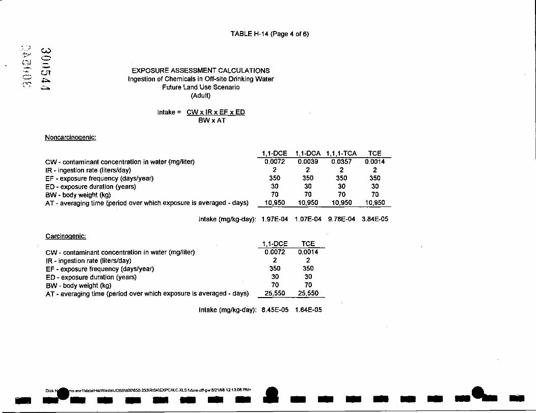
TABLE H-14 (Page 4 of 6)
• « • - > '
a i «3.1. .
^ • S -
f f f \
^
CO v ^ ^
• 1 1 1 ' *
cn 4i». '4^
EXPOSURE ASSESSMENT CALCULATIONS Ingestion of Chemicals in Off-site Drinking Water
Future Land Use Scenario (Adult)
Intake = CW x IR x EF x ED BW X AT
Noncarcinogenic:
CW - contaminant concentration in water (mg/liter) IR - ingestion rate (liters/day) EF - exposure frequency (days/year) ED - exposure duration (years) BW - body weight (kg) AT - averaging time (period over which exposure is averaged - days)
Intake (mg/kg-day):
Carcinogenic:
CW - contaminant concentration in water (mg/liter) IR - ingestion rate (liters/day) EF - exposure frequency (days/year) ED - exposure duration (years) BW - body weight (kg) AT - averaging time (period over which exposure is averaged - days)
Intake (mg/kg-day):
1.1-DCE 0.0072
2 350 30 70
10,950
1.97E-04
1,1-DCE 0.0072
2 350 30 70
25,550
8.45E-05
1,1-DCA 0.0039
2 350 30 70
10,950
1.07E-04
TCE 0.0014
2 350 30 70
25.550
1.64E-05
1.1,1-TCA 0.0357
2 350 30 70
10,950
9.78E-04
TCE 0.0014
2 350 30 70
10,950
3.84E-05
Disk N^^ns-sivr1\data\Ha2WasteUOBS«X)\650-253\RISKCXPCALC.XLS future.off.gw 8C1/98 12:13:08 PH/I+ ^ ^

TABLE H-14 (Page 5 of 6)
EXPOSURE ASSESSMENT CALCULATIONS Dermal Contact with Chemicals in Off-site Groundwater
Future Land Use Scenario (Children. 1 to 6 years old)
Intake = CW x SA x PC x ET x EF x ED x CF BWxAT
Noncarcinogenic:
1.1-DCE 1.1-DCA 1.1,1-TCA TCE CW - contaminant concentration in water (mg/liter) SA - skin surface area available for contact (cm^) PC - chemical-specific dermal pemieablility constant (cm/hr) ET - exposure time (hours/day) EF - exposure frequency (days/year) ED - exposure duration (years) CF - volumetric conversion factor for water (1 liter /1000 cm^) BW - body weight (kg) AT - averaging time (period over which exposure is averaged - days)
0.0072 7,195
1.60E-02 0.2 365 6
0.001 15
2,190
0.0039 7.195
8.90E-03 0.2 365 6
0.001 15
2,190
0.0357 7,195
1.70E-02 0.2
, 365 6
0.001 15
2,190
0.0014 7,195
1.60E-02 0.2 365 6
0.001 15
2,190
Carcinogenic:
CW - contaminant concentration in water (mg/liter) SA - skin surface area available for contact (cm^)
Intake (mg/kg-day): 1.11E-05 3.33E-06 5.82E-05 2.15E-
1,1-DCE TCE
PC - chemical-specific dermal permeablility constant (cm/hr) ET - exposure time (hours/day) EF - exposure frequency (days/year) ED - exposure duration (years)
, • 2 CF - volumetric conversion factor for water (1 liter /1000 cm^) Q I J V BW - body weight (kg) Q>-^j AT - averaging time (period over which exposure is averaged - days) ,—«. » C n r ; Intake (mg/kg-day): 9.47E-07 1.84E-07 ^ : T ) •
o n • '
Disk No.: \\Lms-sivr1\data\HazWasteUOBS\600\650-253\RISKVEXPCALC.XLS fiiture^)ff.gw 8/21/98 12:13:08 PM+
0.0072 7,195
1.60E-02 0.2 365 6
0.001 15
25,550
0.0014 7,195
1.60E-02 0.2 365 6
0.001 15
25,550

TABLE H-14 (Page 6 of 6)
. f o j ^ EXPOSURE ASSESSMENT CALCULATIONS C'l^O Dermal Contact with Chemicals in Off-site Groundwater • C C Future Land Use Scenario CCn (Adult)
^ Intake = CW x SA x PC x ET x EF x ED x CF BWxAT
Noncarcinogenic:
CW - contaminant concentration in water (mg/liter) SA - skin surface area available for contact (cm^) PC - chemical-specific dermal permeablility constant (cm/hr) ET - exposure time (hours/day) EF - exposure frequency (days/year) ED - exposure duration (years) CF - volumetric conversion factor for water (1 liter /1000 cm^) BW - body weight (kg) AT - averaging time (period over which exposure is averaged - days)
1,1-DCE 1,1-DCA 1,1,1-TCA TCE 0.0072
18,150 1.60E-02 0.2 365 30
0.001 70
10,950
0.0039
18,150 8.90E-03
0.2 365 30
0.001 70
10,950
0.0357
18,150 1.70E-02 0.2 365 30
0.001 70
10,950
0.0014
18,150 1.60E-02 0.2 365 30
0.001 70
10,950
Carcinogenic:
CW - contaminant concentration in water (mg/liter) SA - skin surface area available for contact (cm^) PC - chemical-specific dermal permeablility constant (cm/hr) ET - exposure time (hours/day) EF - exposure frequency (days/year) ED - exposure duration (years) CF - volumetric conversion factor for water (1 liter /1000 cm^) BW - body weight (kg) AT - averaging time (period over which exposure is averaged - days)
Intake (mg/kg-day): 5.97E-06 1.80E-06 3.15E-05 1.16E-06
1,1-DCE TCE 0.0072
18,150 1.60E-02 0.2 365 30
0.001 70
25,550
0.0014
18,150 1.60E-02 0.2 365 30
0.001 70
25,550
Intake (mg/kg-day): 2.56E-06 4.98E-07
iS.srvr1\data\Ha2Waste\JOBS\600\650-: 600\6S0-253VRISKVEXPCALC.XLS future^off-gw 8/21/98 12:13:08 PM* ^ ^ .

I
V
f I
APPENDIX I
300S47

I
r
United Sta tes Depar tment of the Interior FISH AND WILDLIFE SERVICE
3817 Luker Road Cortland, New York 13045 i «..j^ a. . . «
Lawler, Matusky & Skeffy Engineers LLP
July 21. 1997 JUL 2 5 1997
Mr, Stephen M. Seymour Project Scientist Lawler, Matusky & Skelly Engineers LLP One Blue Hill Plaza P.O. Box 1509 Pearl River, NY 10965
Dear Mr. Seymour:
This responds to yovu: letters of July 2 & 10, 1997, requesting information on the presence of endangered or threatened species in the vicinity of:
1. The Mohonk Road Industrial Site #356023 in the Town of High Falls, Ulster County, New York, and
2. The Graney Gardens Subdivision in the Town of Orangetown, Rockland County, New York.
Except for occasional transient individuals, no Federally listed or proposed endangered or threatened species under our jurisdiction are known to exist in the project impact area. Therefore, no Biological Assessment or further Section 7 consultation under the Endangered Species Act (87 Stat. 884, as amended; 16 U.S.C. 1531 et seq.) is required with the U.S. Fish and Wildlife Service (Service). Should project plans change, or if additional information on listed or proposed species becomes available, this determination may be reconsidered.
The above comments pertaining to endangered species imder our jurisdiction are provided pursuant to the Endangered Species Act. This response does not preclude additional Service comments under the Fish and Wildlife Coordination Act or other legislation.
For additional information on fish and wildlife resources or State-listed species, we suggest you contact:
New York State Department New York State Department of Enviroiraiental Conservation of Environmental Conservation
Regions Wildlife Resomrces Center - InformationServ. 21 South Putt Comers Road New York Natural Heritage Program New Paltz, NY 12561-1676 700 Troy-Schenectady Road (914)256-3000 Latham, NY 12110-2400
(518) 783-3932
I 300548

I
The Service's National Wetlands Inventory (NWI) map is not yet available for the Mohonk Lake Quadrangle. Any wetlands which may be impacted by the project should be identified and described by the project sponsor using methods suitable for Federal regulatory purposes. The NWI map of the Nyack Quadrangle is available and may show wetlands in the project vicinity. However, while the NWI maps are reasonably accurate, they should not be used in lieu of field surveys for determining the presence of wetlands or delineating wetland boundaries for Federal regulatory purposes.
Work in certain waters and wetlands of the United States may require a permit from the U.S. Army Corps of Engineers (Corps). If a permit is required, in reviewing the application pursuant to the Fish and Wildlife Coordination Act, the Service may concur, with or without stipulations, or recommend denial of the permit depending upon the potential adverse impacts on fish and wildlife resources associated with project implementation. The need for a Corps permit may be determined by contacting Mr. Joseph Seebode, Chief, Regulatory Branch, U.S. Army Corps of Engineers, 26 Federal Plaza, New York, NY 10278 (telephone: [212] 264-3996).
If you require additional information please contact Michael Stoll at (607) 753-9334.
Sincerely, .
J
^"^her ry W. Morgan Field Supervisor
cc: NYSDEC, New Paltz, NY (Compliance Services) NYSDEC, Latham, NY COE, New York, NY
300549 \
I
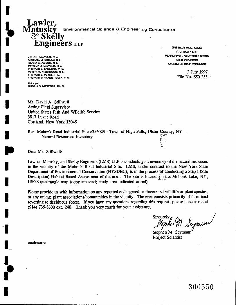
I
k Lawler^ j W L H t l l S k V Environmental Science & Engineering Consultants
Sf Skelly Engineers LLP
JOHN R LAWLER. R E. MICHAEL J. SKELLY. R E. KARIIS/1 A. ABOQO. R E. PATRICK J. LAWLER. RE. THOMAS L. ENGLERT. P .E. PETER M. McGROOOY. R E. THOMAS E. PEASE. R E. THOMAS B. VANDERBEEK. R E.
Principal SUSAN 6. METZGER, Ph.O.
ONE BLUE HIU. PLAZA
R • . BOX 1509
PEARL RIVER. NEW YORK 10985
(9141 735 .8300
FACSIMILE (914) 735-7468
2 July 1997 File No. 650-253
Mr. David A. Stillwell Acting Field Sijpervisor United States Fish And Wildlife Service 3817 Luker Road Cortland, New York 13045
Re: Mohonk Road Industrial Site #356023 - Town of High Falls, Ulster County, NY Natural Resources Inventory f'^[
Dear Mr. Stillwell:
Lawler, Matusky, and Skelly Engineers (LMS) LLP is conducting an inventory ofthe natural resources in the vicinity of the Mohonk Road Industrial Site. LMS, under contract, to the New York State Department of Environmental Conservation (NYSDEC), is in the process of conducting a Step I (Site Description) Habitat-Based Assessment of the area. The site is located n the Mohonk Lake, NY, USGS quadrangle map (copy attached; study area indicated in red).
Please provide us with information on any reported endangered or threatened wildlife or plant species, or any unique plant associations/communities in the vicinity. The area consists primarily of farm land reverting to deciduous forest. If you have any questions regarding this request, please contact me at (914) 735-8300 ext. 240. Thank you very much for your assistance.
Sincerely
Stephen M. Seymour Project Scientist
enclosures
f I 300550

I
V New York State Department of Environmental Conservation Wildlife Resources Center 700 Troy-Schenectady Road Latham, New York 12110-2400 (518) 783-3932
John P. CahiU Commissioner
December 12, 1997
Stephen M. Seymour Lawler Matusky & Skelly Engineers One Blue Hill Plaza PO Box 1509 Pearl River, NY 10965
Lawler, Matusky & Skelly Engineers LLP
DEC 1 8 b o /
Dear Mr. Seymour:
In reply to your letter of November 26th, we enclose Breeding Bird Atlas data for the area identified on your enclosed map, plus half-mile radius.
If we can be of any fiirther assistance, please do not hesitate to contact our office.
Sincerely,
Teresa Mackey NY Natural Heritage Program Information Services
Enc.
f I
300551

PAGE : 1 BLOCK : 5662B NEW YORK STATE BREEDING BIRD ATLAS
COMPLETE BLOCK LISTING
NORTH : 4630000 - NYTH COORDINATES IN METERS SOUTH : 4625000 EAST : 575000 WEST : 570000
1) Ulster Co. - Marbletown 55%
3) Ulster Co. - New Paltz 26%
JURISDICTION (COUNTY-TOWN/CITY,PERCENT) ---2) Ulster Co. - Rosendale 19%
COMMON NAME
Mallard Turkey Vulture Cooper's Hawk Red-tailed Hawk Broad-winged Hawk American Kestrel Ruffed Grouse Ring-necked Pheasant Wild Turkey American Woodcock
Rock Dove Mourning Dove Yellow-billed Cuckoo Black-billed Cuckoo Great Horned Owl
Barred Owl Whip-poor-will Chimney Swift Ruby-throated Hunmingbird
Northern flicker Pileated Woodpecker Red-bellied Woodpecker
Hairy Woodpecker Downy Woodpecker
Eastern Kingbird Great Crested Flycatcher Eastern.-Phoebe _, .
•' 1 > i i »
SCIENTIFIC NAME
Anas platyrhynchos
Cathartes aura
Accipiter cooperii
Buteo jamaicensis
Buteo platypterus
Falco sparverius
Bonasa umbel Ius
Phasianus colchicus
Meleagris gallopavo
Scolopax minor
Colimba livia
Zenaida macroura
Coccyzus americanus
Coccyius erythropthalmus
Bubo virginianus
Strix varia
Caprimulgus vociferus
Chaetura pelagica
Archilochus colubris
Colaptes auratus
Dryocopus pileatus
Melanerpes carolinus
Picoides viUosus
Pi COides pubescens
Tyrannus tyrannus
Myiarchus crinitus
Sayornis phoebe
BREED
ING CODE
T2 XI XI XI XI FL UN XI T2 D2 XI NE S2
S2 S2
S2 S2 XI
T2 D2 S2
82 S2 XI T2 S2 NE
YEAR
82 81
82 81 81
81 81
81 82 81 81
82 81 81
82 81 81
82 82 81
82 82 81 81 82 82 82
NEW YORK
LEGAL
STATUS
Game Species
Protected
Protected-Special Concern
Protected
Protected
Protected
Game Species
Game Species
Game Species
Game Species
Unprotected
Protected
Protected
Protected
Protected
Protected
Protected
Protected
Protected
Protected
Protected
Protected
Protected
Protected
Protected
Protected
Protected
NATURAL
HERITAGE
PROGRAM
STATE RANK
S5 S4 S4 S5 S5 S5 S5 SE S5 S5 SE 35
S5 S5 S5 S5 S4
S5 S5
S5 S5 S5 S5 S5 S5 S5 85
6^2008

U:\>.
300553
PAGE BLOCK : 5662B
NEW YORK STATE BREEDING BIRD ATLAS
COMPLETE BLOCK LISTING
Least Flycatcher
Eastern Wood-Pewee
Tree Swallow
Northern Rough-winged Swallow
Barn Swallow
Blue Jay
American Crow
Black-capped Chickadee
Tufted Titmouse
White-breasted Nuthatch
Brown Creeper
House Wren
Northern Mockingbird
Gray Catbird
Brown Thrasher
American Robin
Wood Thrush
Hermit Thrush
Veery
Eastern Bluebird
Blue-gray Gnatcatcher
Cedar Waxwing
European Starling
Yellow-throated Vireo
Solitary Vireo
Red-eyed Vireo
Black-and-white Warbler
Worm-eating Warbler
Golden-winged Warbler
Blue-winged Warbler
Nashville Warbler
Yellow Warbler
Black-throated Blue Warbler
Yellow-rumped Warbler
Black-throated Green Warbler
Blackburnian Warbler
Chestnut-sided Warbler
Prairie Warbler
Empidonax minimus
Contopus virens
Tachycineta bicolor
Stelgidopteryx serripennis
Hirundo rustica
Cyanocitta cristata
Corvus brachyrhynchos
Parus atricapillus
Parus bicolor
Sitta carolinensis
Certhia americana
Troglodytes aedon
Minus polyglottos
Dunetella carolinensis
Toxostoma rufum
Turdus migratorius
Hylocichla musteline
Catharus guttatus
Catharus fuscescens
Sialia sialis
Polioptila caerulea
BombycUla cedrorum
Sturnus vulgaris
Vireo flavifrons
Vireo solitarius
Vireo olivaceus
Hniotilta varia
Helmitheros vermivorus
Vermivora chrysoptera
Vermivora pinus
Vermivora ruficapilla
Dendroica petechia
Oendroica caerulescens
Dendroica coronata
Oendroica virens
Dendroica fusca
Dendroica pensylvanica
Dendroica discolor
S2
82
UN
T2
UN
B2
82
XI
T2
D2
XI
NY
T2
N2
XI
NE
82
XI
XI
ON
NE
XI
B2
82
XI
UN
S2
82
S2
82
82
N2
82
82
82
XI
XI
82
81
82
82
82
82
82
82
81
82
82
81
82
82
82
81
82
82
82
82
82
82
81
82
82
81
82
82
82
82
81 82
82
81
82
81
81
81
81
Protected
Protected
Protected
Protected
Protected
Protected
Game Species
Protected
Protected
Protected
Protected
Protected
Protected
Protected
Protected
Protected
Protected
Protected
Protected
Protected-Special Concern
Protected
Protected
Unprotected
Protected
Protected
Protected
Protected
Protected
Protected
Protected
Protected
Protected
Protected
Protected
Protected
Protected
Protected
Protected
85
85
85
S5
85
S5
85
S5
85
85
85
S5
S5
S5
85
85
85
85
S5
85
85
85
SE
85
85
85
85
84
84
85
85
85
85
85
85
85
85
85

PAGE : 3 BLOCK : 5662B
NEW YORK STATE BREEDING BIRD ATLAS
COMPLETE BLOCK LISTING
Ovenbi rd
Louisiana Waterthrush
Common Yellowthroat
Canada Warbler
American Redstart
House Sparrow
Bobolink
Red-winged Blackbird
Northern Oriole
Common Crackle
Brown-headed Cowbird
Scarlet Tanager
Northern Cardinal
Rose-breasted Grosbeak
Indigo Bunting
Purple Finch
House Finch
American Goldfinch
Rufous-sided Towhee
Dark-eyed Junco
Chipping Sparrow
Field Sparrow
Song Sparrow
Seiurus aurocapillus
Seiurus motacilla
Geothlypis trichas
Wilsonia canadensis
Setophaga ruticilla
Passer domesticus
Dolichonyx oryzivorus
Agelaius phoeniceus
Icterus galbula
Quiscalus quiscula
Molothrus ater
Pi range olivacea
Cardinal is cardinal is
Pheucticus ludovicianus
Passerine cyanea
Carpodacus purpureus
Carpodacus mexicanus
Carduelis tristis
Pipilo erythrophthalmus
Junco hyemalis
Spizella passerina
Spizella pusilla
Helospiza melodia
NE NE
FY XI
82 82 XI D2
UN 82 02 82
T2 T2 82 S2 S2 FL 82 XI B2 UN S2
82
82 82 81 81
81 82
82 85 81 82 82 81 82
81 82 82 82 81 81 82 81 81
Protected
Protected
Protected
Protected
Protected
Unprotected
Protected
Protected
Protected
Protected
Protected
Protected
Protected
Protected
Protected
Protected
Protected
Protected
Protected
Protected
Protected
Protected
Protected
85
85
S5
85
85
SE
85
85
85
85
85
85
85
85
85
85
SE
85
S5
85
85
85
85
CO
cn in

I
I Lawler^
] N ^ 3 . t U S k V Environmental Science & Engineering Consultants
W Skelly Engineers LLP
J O H N R LAWLER. R E. MICHAEL J . SKELLY, R E. KARIVI A. ABOOO. R E. PATRICK J . LAWLER. R E. THOMAS L. ENGLERT. P .E. PETER M. McGROOOY. R E. THOMAS E. PEASE. R E. THOMAS B. VANDERBEEK. R E.
Pr incipal SUSAN 6 . METZGER, Ph .O .
ONE BLUE HILL P L A Z A
P. O. BOX 1 5 0 g
PEARL f l lVER, N E W YOOK 1 0 9 8 5
1914) 7 3 5 - 8 3 0 0
FACSIMILE 1914) 7 3 5 - 7 4 8 8
26 November 1997 File No. 650-253
Ms. Jean Petrusiak Information Services New York Natural Heritage Program New York State Department of Environmental Conservation 700 Troy-Schenectady Road Latham, New York 12110-2400
Re: Mohonk Road Industrial Site #356023 Natural Resources Inventory
Town of High Falls, Ulster County, NY
Dear Ms. Petrusiak:
Lawler, Matusky, and Skelly Engineers LLP (LMS) is conducting an inventory of the natural resources in the vicinity of the Mohonk Road Industrial Site. LMS, under contract to NYSDEC, is in the process of conducting a Step I (Site Description) Habitat-Based Assessment ofthe area. The site is located on the Mohonk Lake, NY USGS quadrangle map (copy attached; study area indicated in red).
Please provide us with the Breeding Bird Atlas results for the half-mile radius surrounding the project site. We obtained information on reported endangered and threatened wildlife and significant habitats from your office in a request dated 2 July 1997. The area consists primarily of farm land reverting to deciduous forest. If you have any questions regarding this request, please contact me at (914) 735-8300 ext. 240. Thank you very much for your assistance.
Sincerely
Stephen M. Seymour Project Scientist
D u r ^
enclosure
^
I 3 005,"is

I
V
r
New York State Department of Environmental Conservation Wildlife Resources Center 700 Troy-Schenectady Road Latham, NY 12110-2400
John p. Cahill ComniissiaiMr
(518)783-3932 July 17, 1997
„ , J^wler , Matusky & Stephen M Seymour Sk^fy Englneore LLP Lawler, Matusky & Skelly Engineers .. One Blue Hill Plaza, PO Box 1509 •'*'»• 2 t t997 Pearl River, NY 10965
Dear Mr. Seymour:
We have reviewed the New York Natural Heritage Program files with respect to your request for biological information conceming an inventory ofthe Natural Resources in the vicinity ofthe Mohonk Road Industrial Site, area as indicated on your enclosed map, located in the Tovm of High Falls, Ulster County, New York State.
Enclosed is a computer printout covering the area you requested to be reviewed by our staflF. The information contained in this report is considered sensitive and may not be released to the public without permission firom the New York Natural Heritage Program.
Our files are continually grov^ng as new habitats and occurrences of rare species and communities are discovered. In most cases, site-specific or comprehensive surveys for plant and animal occurrences have not been conducted. For these reasons, we can only provide data which have been assembled fi-om our files. We carmot provide a definitive statement on the presence or absence of species, habitats or natural communities. This information should not be substituted for on-site surveys that may be required for environmental assessment.
This response applies only to known occurrences of rare animals and/or significant wildlife habitats. You should contact our regional ofiBce, Division of Regulatory Affairs, at the address enclosed for information regarding any regulated areas or permits that may be required (e.g., regulated wetlands) under State Law.
If this proposed project is still active one year fi-om now we recommend that you contact us again so that we may update this response.
Sincerely,
B J . . ^ L 2 M ^
I
Deborah L. Albert Information Services NY Natural Heritage Program
Encs. cc: Reg. 3, Wildlife Mgr.
Reg. 3, Fisheries Mgr. , Peter Nye, ESU,Delmar ) C ^ ^
30()55B

IR2 page 1 BIOLOGICAL AMD CONSERVATION DATA SYSTEM - ELEMENT OCCURRENCE REPORT, 16 JUL 1997
Prepared by N.Y.S.D.E.C. Natural Heritage Program, Latham New York
(This report contains sensitive information which should be treated in a sensitive manner. Refer to the users guide for explanation of codes and ranks.)
* COUNTY
& TOWN
* ULSTER
MARBLETOWN
ROSENDALE
2 Records Processed
USGS TOPO MAP/ PREC- LAST EO
LAT. & LONG. ISIOH SEEN RANK SCIENTIFIC AND COMMON NAME
M 1970 F CLEHMYS HUHLENBERGII
BOG TURTLE
M 1980 E GEUH VIRGINIANUM
ROUGH AVENS
ELEMENT TYPE
REPTILE
VASCULAR PLANT
NY US HERITAGE
STATUS STATUS RANKS OFFICE USE OFFICE USE
E C G3 E8U
82
U G5
81
4107472 1
4107471 1
CO O
c7i Zfl
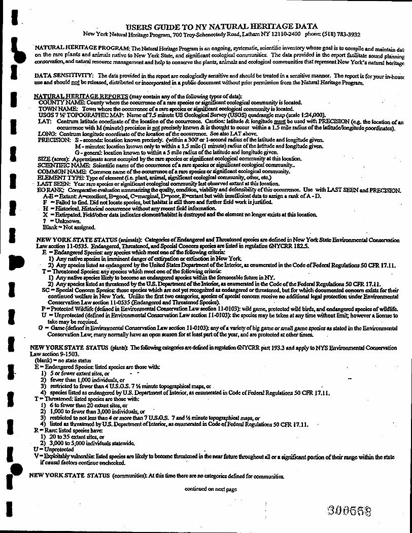
I USERS GUIDE TO NY NATURAL HERITAGE DATA
New York Natural Heritage Program. 700 Troy-Schenectady Road, Latham NY 12110-2400 phone: (518) 783-3932
NATORAl, HERITAGE PROGRAM: TheNatucal Heritage Program is an ongoing, systematic, scientific inventoiy whose goal is to compile and maintain dat on the rare plants and animals native to New York State, and significant ecological communities. The data prowded in tiie report facilitate sound planning conservation, and natural resource management and help to conserve the plants, animals and ecological communities that r^resent New York's natural heritage
DATA S E N S m v n Y : The data provided in the report are ecological^ sensitive and should be treated in a sensitive manner. The rqx)rt is for your ir^housc use and should QOt be released, distributed or incorporated in a public document without prior permission from the Natural Heritage Pit^ram.
ftATtlRAL HERrPAGE REPORTS (may contain any ofthe following ^qpes of data): COUNTY NAME: 0>unty where the oocuncnce of a niie species or agnlficant oook^cal coinmunity is located. TOWN NAME: Town >^eretiicoccunenoeofani«q)ocies or agnificant ecological community is located. USOS 7 Vi'TOPOGRAPHIC MAP: Name of7.S minute US Gcok^cal Survey (IJSGS) quadrangle map (scale 1:24,000). LAT: Coitrum latitude ooordinate ofthe location ofthe oocurrenoe. Caution: latitude & lon^tude must be used with PRECISION (e.g. the location of an
oocuneiKe with M (minute) preciaon is i!o{ prectseiy known & is thought to occur within a U mile radius ofthe latitude/longitude coordinates). LONG: Centrum longitude coordinate of thclocatioa of the oocurrenca See also LAT above. PRECISION: S - seconds: location known prcdsely. (within a 300" or I-«ocond radius ofthe latitude and longitude gjiven.
M - minutes: location known only to within a 1.S mile (1 minute) radius ofthe latitude and k>ngitude given. G • gertcral: location known to within a S mile radius ofthe latitude and longitude given.
SIZE (acres): Apptx>>dmate acres occupied by the rare qjedes or significant ecological community at this k)cation. SQENUHCNAME: Sctenfific name ofthe occurrence ofaiate species or st^iificantecolc^'cal community-COMMONNAME: Common name ofthe occunenoeofa rare speoes or sgnifieantcoologMal community. ELEMHTT TYPE: Type of clement (Le. plant, animal, qgnificant eeolQ^cal community, other, etc.) LAST SEEN: Year rare species or significant coologiMl community last observed extant at this location. EORy^QC: Comparative mluation summarizing the quality, condition, viability and defensibility of this occurrence. Use with LAST SEEN and PRECISION.
A-E •• Extant A^exodlent, B^ood, C-marginal, I>poor. E-vxtant but with insuOicient data to assign a rank of A - O. F -Failed to find.IM not k>cateq>ecies,buthalHtat ISstnitheteand further fidd work bjustified. H •• Historical Historical occurrence \«thout ariy recent field infonnation. X -Extirpated. Field/other data indicates ekment/habitatkdcstn^ed and the dement no kmgeracists at this kx»tion. 7 -Unkiiown. Blank •• Not asdgned.
NEW VORK STATE STATUS (animals): Cathodes of Endangered and Threatened tpodes are defined in New Yoric State Environmental Conservation Law section 11-0S3S. Endangered, Threatened, and SpeddConoeniq>eda are listed b regulation 6NYCRRI82J.
E -£ndangeredSpedes:anyq>ecieswhichineetoaeofthefolk»ui^criteria: 1) Any native spodes in imminent dangerofcxtifpation or extinction in New York. 2) Any q>ectes listed as mdangercd by the United States Dq>attinent ofthe Interior, as enumerated in the Code ofFederal Regulations 50 C F R I 7 . I L
T •• Thrntened Spedes: ariy species which meet one of the following criteria: 1) Any native spedes likdy to become an endangered qwcies witiiin fte foreseeable future in NY. 2) Anyqiedes listed as thiodened by the U.S.Dcpai1inentoflheIntetior,as enumerated in thcCodeoftheFodeialRegulatioasSO CFR 17.11.
SC — Spedal Concem Spedes: those spedes which are not yet recognized as eiidangered or threatetied, but for which doMitnenttd coiioern continued welfare in New York. Uniike the first two cat^oties, spoaes of qKcial concem reodve no additional legal protection imder Enwonmcntal Conservation Law section 11-053S (Endangered aitd Threatened Spedes).
P -Protected Wildlife (defined in Eniraronmental Conservation Law section 11-0103): wild game, protected wild birds, and endangered spedes of wildlife. U - Unprotected (defined in Environmental Conservation Law section 11-0I03): the spedes may be taken at any time without Gmit; however a license to
take may be required. O - Ganie(de&ied in Ennnonmental Conservation Law section 11-0103): any ofa variety of big game or small game spedes «s stated in the Environmental
Conservation Law, many normally have an open season for at least part ofthe year, and are protected at other times.
NEWYORKSTATE STATUS (plants): The foOowing categories are defined in regulation 6NYCRR part 193J and appty to NYS Environmental Conservation Law section 9-IS03.
(blank) - no state status E - Endangered Spedes: listed spedes are those with:
1) 5 or fewer extant sites, or - * 2) fewer than 1,000 individuals, or ~ 3) restricted to fewer than 4 U.S.G.S. 7'/i minute topographical maps, or 4) spedesIistodasendangeredbyU.S.DepartmentofIhterior,8senumeratedinCodeofFederalRegulationsS0CFR 17.11.
T — Threatened: listed species are those with: 1) 6 to fewer than 20 extant ates, or 2) 1.000 to fewer tiun 3,000 individuals, or 3) restricted to not less than 4 or more than 7 U.S>O.S. 7 and i4 minute top(>graphica] maps, or 4) listodasthreatBnedbyU.S.DepartmentofIntefior,ascnunietBtBdinCodeofFederBlRegulationsSOCFR 17.11.
R - Rare: listed qKdes have: 1) 20 to 35 extant sites, or 2) 3,000 to 5,000 individuals statevndc.
U-Unprotected V - ^qilohabty vulneraUc fisted q>edes arc iikdy to beoonw threatened in the near future throughout aU or t agnificant p o t t ^
if causal factors continue unchecked.
NEWYORKSTATE STATUS (communities): At this time there are no categories defined for communities.
continued on next page
im

O O .
page 2 Users Guide to Natural Heritage Data •
FEDERAL STATUS (plants and animals): The categories of federal status are defined by the United States Department ofthe Interior as part ofthe 1974 " Endangered Species Act (see Code of Federal Regulations 50 CFR 17). The spedes listed under this law are enumerated in the Federal Register vol. 50, no. 188. pp. 39526-39527.
(blank) - No Federal Endangered Spedes Act status. LE"- The taxon is formally listed as endangered. LT - The taxon is formally listed as tiueatened. LELT — The taxon is formally listed as endangered in part of its range ani threatened in other parts. PE - The taxon is proposed as endangered. PT - The taxon is proposed as threatened. CI - Candidate, cat^ory 1 - There is sufficient information to list the taxon as endangered or threatened. C2 - Candidate, category 2 • The taxon may be appropriate for listing but more data are needed. 3A - The taxon considered extinct by the U. S. Fish and Wildlife Service (USFWS). 3B - The taxon is no longer considered taxonomically distinct by the USFWS and thus is not appropriate for listing. 3C - The taxon has been shown to be more abundanC widespread, or better protected than previously thought and therefore not in need of official listing. • - The taxon is possibly extinct ** -The taxon is thought to be extinct in the wild but extant in cultivation. Additional codes: (C2NL) - Heritage code indicating that the taxon i ^ candidate in some areas, not listed in other areas. (E/SA) - Heritage code indicating that the taxon is endangered because of antilarity of appearance to other endangered spedes or subspedes.
FEDERAL STATUS (ecological communities): At tfiis time fliere are no federal status categories defined for ecological communities.
GLOBAL AND STATE RANKS (animals, plants, ecological communities and otfiers): Each dement has a global and state rank as determined by the NY Natural Heritage Program. These ranis cany no legal weight The global rank reflects the rarity ofthe dement throughout the worid and the state rank reflects the rarity within New Yoric State. Infraspcdfic taxa are also assigned a taxon rank to reflect the infhispcdfic taxon's rank throughout the worid.
QLOBALlWfK: . . Gl - Critically imperiled globally because of extreme rarity (5 or fewer occurrences), or very few remaining acres, or miles of stream) or especially vulnerable
to cxtincti'on because of some factor of its biology. G2 - Imperiled globally because of rarity (6 - 20 occurrences, or few remaining acres, or miles of stream) or very vulnerable to extinction throughout its range
because of other factors. - Qi -Either rare and local throughout its range (21 to 100 occurrences), or found locally (even abundantly at some of its locations) in a restricted range (e.g. a
physiographic regionX or vulnerable to extinction throughout its range because of other factors. 04 - ApfMuently secure globally, though it may be quite rare in parts of its range, eqiedally at the periphery. 05 - Demonstrably secure gk>baUy, though it may be quite tare in parts of its range, especially at the periphery. OH - Historically known, with the expectation that it nught be rediscovered. GX - Spedes bdieved to be extinct GU - Status unknown.
STATE RANK: 51 - Typically 5 or fewer occurrences, very few remaining individuals, acres, or miles of stream, or some factor of its biology making it especially vulnerable
in New York State. 52 - Typicafly 6 to 20 oocurrenoes, few remaining individuals, acres, or miles of stream, or factora demonstrably making it very vulnerable in New York State. 53 - Typically 21 to IOO occurrences, limited acreage, or miles of stream in New York State. 54 - Apparentiy secure in New York State. . 55 - Demonstrably secure in New York State. SH - Historically known from New York State, but not seen in the past 15 years. SX—Apparently extirpated fivm New York State. SA - Acddental or casual in the state. SE - Exotic, not native to New Yoric Stele. SP - Element potentially occurs in the stete but there are no occurrences reported. SR - Reported in the state but without persuadve documentetion. SU - Status unknown. TAXON (1) RANK: The T-ranks (Tl - T5) are defined the same way the Global ranks (Gl - G5) are but the T-rank only refera to the rarity ofthe subspedfic
taxon of the spedes as a whole. Tl through T5 - See Global Rank definitions above. Q — Indicates a question exists whether or not the taxon is a good taxonomic entity. 7 •• Indicates a question exists about the rank.
OFFICE USE: Information for use by the Natural Heritage Program.
SIGNIFICANT HABITAT DATABASE REPORTS (Use of this database is slowly bdng discontinued ts the data is integrated into Heritage databases) REPORT ID: Significant habitat file code. NAME OF AREA: Site name where the agnificant habitat is located. TYPE OF AREA- Type of significant habitat COUNTY/TOWN OR CFTY: County and town where the agnificant habitat b located. QUADRANGLR' Nome ofthe USGS 15 minute topographic map where the significant habitat is kx»tcd. LATITUDE: Latitude coordinate (degrees, nunutes, seconds) for the k>cation of the significant habitat LONGITUDE: Longitude ooordinate for the kication ofthe agnificant habitat
7/22/96 c:\datareq\systcm\usetguid
\
I

I NEW YORK STATE DEPARTMENT OF ENVIRONMENTAL CONSERVATION
DIVISION OF ENVIRONMENTAL PERMITS REGIONAL OFFICES
REGION COUNTIES NAME ADDRESS AND PHONE NO
Region 1 Nassau Sufifolk
Robert Cireene Permit Administrator
Loop Road, Bldg. 40 SUNY Stony Brook, NY 11790-2356 (516)444-0365
Region 2 New York City (jeorge Danskin Permit Administrator
Hunters Point Plaza 4740 21st Street Long Island City, NY 11101-5407 (718)482-4997
Region 3
Region 4
Regions
Region 6
Region?
Regions
Region 9
I
Dutchess Orange Putnam Rockland, Sullivan Ulster, Westchester
Margaret Duke Permit Administrator
William J. Clarke Permit Administrator
Albany (Columbia Delaware Greene, Montgomery, Otsego Rensselaer, Schenectady, Schoharie
Clinton Essex Franklin Fulton, Hamilton Saratoga, Warren, Washington
Richard WUd Permit Administrator
Herkimer Jefferson Lewis Oneida, SL Lawrence
Randy Vaas Permit Administrator
Broome Cayuga • Chenango Cortland, Madison, Onondaga Oswego, Tioga, Tompkins
Ralph Manna, Jr. Permit Administrator
Chemung G^iesee Livingston Monroe, Ontario, Orleans Schityler, Seneca, Steuben Wayne, Yates
Albert Butkas Permit Administrator
Allegany Cattaraugus Chautauqua Bie, Niagara, Wyoming
Steven Doleski Permit Administrator
21 South Putt Comers Road New Paltz, NY 12561-1696 (914)256-3059
1150 N. Westcott Road Schenectady. NY 12306-2014 (518)357-2234
Route 86 Ray Brook, NY 12977 (518)897-1234
State Office Building 317 Washington Street Watertown,NY 13601 (315)785-2246 '
615 Erie Blvd. West Syracuse, NY 13204-2400 (315)426-7439
6274 East Avon-Lima Road Avon, NY 14414 (716)226-2466
270 Michigan Avenue Buffalo, NY 14203-2999 (716) 851-7165
300560

I
^
Lawler^ j V ^ H t l l S k V Environmental Science & Engineering Consultants
W Skelly Engineers LLP
J O H N R LAWLER. P. E. MICHAEL J . SKELLY. R E. K A R I M A. ABOOO. R E. PATRICK J . LAWLER. R E. T H O M A S L. ENGLERT. P .E. PETER M. McGROODV. R E. T H O M A S E. PEASE. R E. T H O M A S 8 . VANDERBEEK. R E.
Pr incipal SUSAN G. METZGER. Ph .O.
ONE BLUE H I U P L A Z A
R O. BOX 1509
PEARL RIVER. tMEW YORK 1 0 9 B S
(S14) 735 .8300
FACSIMILE 1914] 735-74B6
2 July 1997 File No. 650-253
Ms. Nancy Davis-Ricci Information Services New York Natural Heritage Program New York State Department of Environmental Conservation 700 Troy-Schenectady Road Latham, New York 12110-2400
Re: Mohonk Road Industrial Site #356023 - Town of High Falls, Ulster County, NY Natural Resources Inventory
Dear Ms. Davis-Ricci:
Lawler, Matusky, and Skelly Engineers (LMS) LLP is conducting an inventory ofthe natural resources in the vicinity ofthe Mohonk Road Industrial Site. LMS, under contract to NYSDEC, is in the process of conducting a Step I (Site Description) Habitat-Based Assessment ofthe area. The site is located on the Mohonk Lake, NY USGS quadrangle map (copy attached; study area indicated in red).
Please provide us with information on any reported endangered or threatened wildlife or plant species, or any imique plant associations/communities in the vicinity. The area consists primarily of farm land revenmg to deciduous forest. If you have any questions regarding this request, please contact me at (914) 735-8300 ext. 240. Thank you very much for your assistance.
Sincerely
Stephen M. Seymour Project Scientist
enclosures
^
I 300561

I
p APPENDIX J
J» I 3005R2

I
li
r I
7 ^ rJ, >»' ^•^g »"-
^ t * 9
?v*r.
^
- i ! _ : • IS - ^ 4 Photo 1. Test pit along east side of underground tank exposing covers. (7-3-97)
Photo 2. Trenching at underground tank to locate laterals. Note distribution box near center of trench. (7-3-97)
3005B3
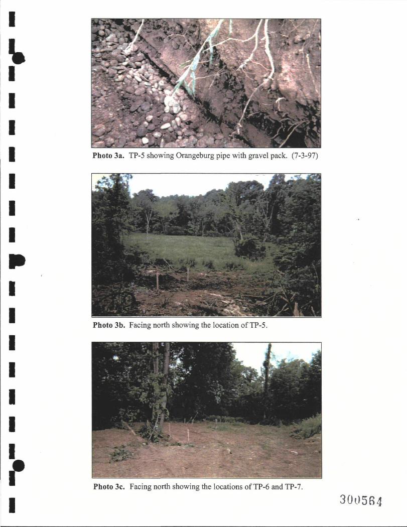
I u
Photo 3a. TP-5 showing Orangeburg pipe with gravel pack. (7-3-97)
Photo 3b. Facing north showing the location of TP-5.
f I
Photo 3c. Facing north showing the locations of TP-6 and TP-7.
300584

I
^
Photo 4. North side of building with stakes showing exit points of drain lines. (7-3-
f Photo 5. Trenching on south side of building to locate suspected drain lines. (7-3-97)
I 3005G5

I
^
Photo 6. Loading dock test pit showing perforated PVC drain pipe. (8-26-97)
f I
Photo 7. Orangeburg pipe (upper) and iron pipe (lower) in septic tank installation excavation. (8-18-97)
3005nR

I
K
Photo 8. Hand auger location MRHA-02 adjacent to floor drain. (10-29-97)
Photo 9a. Surface water sampling. (7-31-97)
3005B7

i
K f'V^'«^.v--^:-+-
- • ^ ^ • ^ ^ -
Photo 9b. Surface water sampling. (7-31-97)
Photo 10. Cistem with cover removed for sampling. (7-31 -97)
f I
3005B8

I
K
Photo 11a. Air drilling with Cantera rig. (7-22-97)
Photo l i b . Air drilling with Cantera rig. (7-22-97)
f I
3005B9

I
^
Photo 12. Air dnlling with Ingersol-Rand drill rig. (8-12-97)
Photo 13. Example of spin casing. (8-18-97)
r I 300570

I
^
Photo 14. Drilling fluid emerging from adjacent casing. (8-18-97)
Photo 15. Example of drag bit. (8-18-97)
r I 300571

I
^
Photo 16a. Confined space entry at MRPW-02.
Photo 16b. Existing well pump removal. (7-23-97)
r I 30O572

I
V \
;
\
-i
" ^^1
• A R 1 }
*
WM ^w2^K^K<< \ w ^ H
Ri^ 'v^^^^^^^H^^^^I
^ jmn
H^l
^^^^^^^^^^^^^^^^^^^^H
d^^^^^KiKL Photo 16c. Existing well pump removal. (7-23-97)
P h o t o n . MRPW-02 packer testing setup. (8-22-97)
r I 300573
I
V
p APPENDIX K
I

I
V
p
I
HAGER-RICHTER GEOSCIENCE, INC.
BOREHOLE GEOPHYSICAL LOGGING MOHONK ROAD INDUSTRIAL PLANT
ULSTER COUNTY, NEW YORK
Preparedfor:
Lawler, Matusky & Skelly Engineers LLP One Blue Hill Plaza PO Box 1509 Pearl River, New York 10965
Prepared by:
Hager-Richter Geoscience, Inc. 8 Industrial Way D-10 Salem, New Hampshire 03079
FUe 97J41 November, 1997
300575^

I
I Borehole Geophysical Logging HAGER-RICHTER Mohonk Road Industrial Plant Site GEOSCIENCE INC High Falls. New York ' •
EXECUTIVE SUMMARY
Hager-Richter Geoscience, Inc. was retained by Lawler, Matusky & Skelly Engineers LLP (LMS) of Pearl River, New York to provide borehole geophysical logging services in bedrock wells at the Mohonk Road Industrial Plant site in High Falls, New York. The borehole geophysical logging is part of an envirorunental investigation by LMS for New York State Department of Envirormiental Conservation.
The logging program consisted of borehole fluid resistivity (FRES), dual temperature, caliper, and borehole color video logs. The objective ofthe geophysical borehole logging was to determine the depth of productive fractures and flow zones in the wells.
The logging operations were conducted on September 22-26,1997. The logs are interpreted as indicating the presence of productive fractures or fracture zones in all wells, and •their depths are given in the Report.
P
'"300578

Borehole Geophysical Logging HAGER-RICHTER Mohonk Road Industrial Plant GEOSCIENCE INC High Falls. New York '
I
TABLE OF CONTENTS
Executive Summary i
Table of Contents ii
1. Introduction 1
2. Principles and Equipment 2 2.1 Borehole Geophysical Logging
2.1.1 Borehole Fluid Resistivity Log 2.1.2 Temperature and Dual Temperature Logs 2.1.3 Caliper Log
2.2 Borehole Video Logging
3. Procedures 4 3.1 General 3.2 Data Acquisition 3.3 Data Processing 3.4 Data Interpretation
4. Results 7
5. Conclusions 11
6. Limitations ; 12
LIST OF FIGURES
1. General location of Site. 2. Site sketch plan.
u

I
V
p
Borehole Geophysical Logging HAGER-RICHTER Mohonk Road Industrial Plant GEOSCIENCE, INC. High Falls. New York
LIST OF TABLES
1 Log Interpretation For Well MRMW-8B 2 Log Interpretation For Well MRMW-9B 3 Log Interpretation For Well MRMW-lOB 4 Log Interpretation For Well MRMW-1 IB 5 Log Interpretation For Well MRMW-12B 6 Log Interpretation For Well MRMW-13B 7 Log Interpretation For Well MRMW-14B 8 Log Interpretation For Well PW-2
LIST OF LOGS
MRMW-8B MRMW-9B MRMW-lOB MRMW-llB MRMW-12B MRMW-13B MRMW-14B PW-2
r I
Ul
30057B

I
I
p
Borehole Geophysical Logging HAGER-RICHTER Mohonk Road Industrial Plant GEOSCIENCE, INC. High Falls. New York
1. INTRODUCTION
Hager-Richter Geoscience, Inc. was retained by Lawler, Matusky & Skelly Engineers LLP (LMS) of Pearl River, New York to provide borehole geophysical logging services in bedrock wells at the Mohonk Road Industrial Plant site in High Falls, New York. The objective ofthe geophysical borehole logging was to determine the depth of productive fractures and flow zones in the wells.
The Site is located at 186 Mohonk Road near the hamlet of High Falls, New York. Figure 1 is a site location map, and Figure 2 is a site sketch plan that shows the approximate location of the wells logged for this Report. The logging program was specified by LMS, and consisted of borehole fluid resistivity (FRES), dual temperature, caliper, and borehole color video logs. The objective ofthe geophysical borehole logging was to determine the depth of productive fractures and flow zones in the wells.
The LMS Boring Logs record the bedrock intersected by the wells as mainly orthoquartzite with interbedded shales and clays.
Jonathon Puliafico of Hager-Richter conducted the logging operations on September 22-26,1997. The project was coordinated with Mr. John Thomburg and Ms. Edith Holister of LMS. Mr. Michael J. Komoroske, P.E., of New York State Department of Environmental Conservation, observed some ofthe field operations. Data analysis and interpretation were completed at the Hager-Richter offices. Original data and field notes reside in the Hager-Richter files and will be retained for a minimum of three years.
;:2SJHg?H

Borehole Geophysical Logging HAGER-RICHTER Mohonk Road Industrial Plant GEOSCIENCE INC High Falls. New York '
2. EQUIPMENT AND PRINCIPLES
2.1 Borehole Geophysical Logging
A Mount Sopris MGX II logging system was used for the borehole geophysical logging survey. Data are recorded in digital form in the field in a portable computer, and are processed in the office using LOGSHELL, a software program provided by Mount Sopris as a part ofthe MGX II system.
2.1.1 Borehole Fluid Resistivity Log. This log provides data on the variation of the electrical resistivity of the borehole fluid as a function of depth, and can be used to estimate the quality of the water. It can also assist in the detection of productive fractures and fracture zones provided that it is ran in conjunction with a dual temperature log.
The measuring concept is simple, and the MGX II uses a Wenner array. The geometry of the borehole version of the Wenner array is similar to that of the Wenner array used to measure the resistivity of soils from the surface. The Wenner array uses two voltage electrodes and two current electrodes, with the four electrodes spaced equally. The array is arranged in a cell that is shielded electrically from the borehole wall so that only the fluid resistivity is measured. The cell is open at top and bottom, and the borehole fluid passes through the cell as the sonde is lowered or raised in the well.
2.1.2 Temperature and Dual Temperature Logs. The MGX II logging system measures temperature with a resolution of 0.1 °C and an accuracy of at least 1 %. The temperature is logged at an interval of 0.1 foot from the static water level to the bottom ofthe well, at a logging speed of 10 to 12 feet/minute. The temperature sensor is a semiconductor device for which the voltage output is linearly related to temperature.
Temperature logs are Usefiil for several purposes, including the determination of temperature at a particular depth, detecting water movement into, or out of, the borehole, detecting changes in physical properties, and detecting/^roc/wc/ive fractures. However, the temperature must be allowed to stabilize at or near the equilibrium temperature in order to be useful for all of these purposes, except for the determination ofthe water entering the well and possibly the determination ofthe entry depth for most ofthe water.
In order to detect productive fi^ctures, two logs are required—hence the name of "dual temperature" log. One log is run at equilibrium conditions (the well should remain undisturbed
!i'i®J0S80
I
m
f

I
^
»
f
Borehole Geophysical Logging HAGER-RICHTER Mohonk Road Industrial Plant GEOSCIENCE. INC. High Falls. New York
for several days) and one nm after removing water from the well, either by pumping or bailing. The amount removed depends on the diameter ofthe well and, to some extent, on the depth and recharge rate. The concept is to remove enough water to lower the water level approximately 20 feet in shallow wells to 50 feet in deeper wells if there were no inflow. Most wells produce at least some water during the tune required to remove the water and set up the equipment to ran the second temperature log. Therefore, at the time of ranning the second temperature log, the actual displacement of the water colunm may be somewhat less than the 20 to 50 feet. Many wells recover completely, and the static water level is about the same for the two temperature logs. The vertical movement of water in the well causes the temperature of the water at most depths above the point of entry to differ from the formation temperature. Because this difference will decrease with time, the second temperature log should be logged again within a few hours for most wells. Comparison of the two temperature logs shows where water enters the well.
2.L3 Caliper Log. The caliper log measures the average borehole diameter as a fiinction of depth. The MGX II equipment is a three arm system that measures the diameter of the borehole. A borehole video log that is acquired after the caliper log is acquired will often show the path of the arms on the borehole wall. Reproducibility of the caliper log is generally good. The caliper log is used to locate fractures (whether or not the fracmres are productive) and to help in the interpretation of other logs.
2.2 Borehole Video Logging
The borehole video system was Geo VISION™ model GE0VCM3. This unit is a portable downhole video camera system, and consists of a downhole color camera, VCR with monitor for recording the images, and a hand operated winch. The camera depth is displayed in the video image on the monitor and recorded on the VCR, and all depths are in units of feet. Power is supplied by a 12 volt battery or a DC generator. The camera equipped with a ring light source is 2.5" diameter, but with other light sources is sufficiently small to be used in 2" PVC casing. The VCR records on 8 nrni tape and displays images on a 4" LCD monitor in real time. The cable is 750 ft long, and can be extended to 1000 ft.
During logging operations, we observed the LCD monitor as the camera was lowered into the well. We examined and recorded features of interest on several passes ofthe camera or while the camera was stopped at a particular depth.
1 iiOiOiSJ'

Borehole Geophysical Logging HAGER-RICHTER Mohonk Road Industrial Plant GEOSCIENCE INC High Falls. New York ~
t
3. PROCEDURES
3.1 General
This section describes the procedures used in the field to acquire data and in the office to process and interpret the data for this project.
3.2 Data Acquisition
The sequence of operations in each well was the following: • acquire initial temperature and borehole fluid resistivity logs • acquire borehole video log • pump approximately 50 gallons of water from well • acquire second temperature and borehole fluid resistivity logs • acquire caliper log
Each type of log was always run in the same direction; namely, temperatiu-e, borehole fluid ^ V resistivity, and borehole video logs were acquired with the sonde descending into a well and caliper logs were acquired with the sonde ascending in a well.
Data were acquired at 0.1 foot intervals and a logging speed of about 10 feet/minute for all geophysical logs except the borehole video logs. The borehole video log produces an image of the borehole wall that is continuous with depth.
In both the borehole video system and the MGX n system, depth is measured with a calibrated wheel over which the cable passes, an encoder, and associated electronics and software. Slippage can occur in either system, resulting in errors in the recorded depth. Such errors can cause uncertainty in correlating features recorded in the video log with their expected expressions in any of the other logs. There are two routine checks that minimize the uncertainty. During the field operations, the depths measured at the beginning and end of a logging ran for some fiducial depth—commonly ground level and top of casing—are compared, and any difference is noted for later adjustment. The other check is to compare the video depth of anything for which the expression in another log can be identified with confidence, such as the bottom of casing. For the following reasons, however, the checks do not always allow adjustment ofthe depths: (1) The object may not be recognizable in the video log, particularly for wells with poor visibility. (2) The expected expression in the MGX n logs may be missing or spread over too large an interval to be useful. (3) Even though slippage in a system
%
mi^2 I

I
V
p
Borehole Geophysical Logging ' HAGER-RICHTER Mohonk Road Industrial Plant GEOSCIENCE, INC. High Falls. New York
can be recognized, the depth at which the slippage occurred may not be recoverable. For the logs acquired for this project, the difference between the beginning and end fiducial for the MGX n logs was less than 0.1 ft, and for the borehole video logs was less than about 1 'A feet (excepting MRMW-12B which slipped 29 ft during ascent). A comparison of the depths for features recorded in the MGX n logs with those recorded in the video logs shows typical differences of one to two feet (3 ft in MRMW-llB). Thus, for the video log interpretation in Table 2 we show the depths "as recorded" and also show the geophysical log depths separately.
The MGX II logging sondes are attached to the logging cable with a waterproof coimector that contains an 0-ring. With each change of sonde, those 0-rings are lubricated with Dow Coming® Compound 4, a silicone based compound.
After each log was completed at the Site, the equipment was decontaminated with the following procedure: each tool and the downhole portion of the cable were washed using Aiconox soap and rinsed with distilled water. Natural sponges or cotton rags were used.
3.3 Data Processing
The geophysical log data were processed with LOGSHELL version 2.2, software provided by Mount Sopris as part ofthe MGX II system. The same software controls the MGX II unit during data acquisition and stores the data in a PC in ASCII format. The processing consists mainly in selecting scales, wrapping parameters, filters, and the physical layout ofthe various fracks.
3.4 Data Interpretation
The interpretation of borehole logs is a topic that requires extensive sections in texts' on borehole logging, and reference is made to them for a general discussion. In this section, we shall briefly state any special considerations for the interpretation of the logs for this project. As noted in the Introduction, the primary objective of this project was to determine the depth of fractures in the wells, paTticularly productive fractures. Accordingly, the interpretation emphasized those aspects.
^ See, for example: JR Hearst, PH Nelson 1985, Well Logging for Physical Properties, McGraw-Hill, 571 pp; WS Keys 1988, Borehole Geophysics Applied to Ground-Water Investigations, USGS OFR 87-539, 305 pp; GB Asquith, CR Gibson 1982, Basic Well Log Analysis for Geologists, AAPG, 216 pp.
i,'ih?a m^m82

Borehole Geophysical Logging HAGER-RICHTER Mohonk Road Industrial Plant GEOSCIENCE INC High Falls. New York '•
I
Fractures. Fractures can be inferred to be present on the basis of one or more of the following:
• the borehole video log shows a feamre that looks like a fracture; • the caliper log records an enlargement of the borehole diameter over a short
depth interval; • the borehole fluid resistivity log records a change in value of the borehole fluid
resistivity over a short depth interval.
Some, if not most, ofthe criteria for the detection of a fracture require a "judgement call," and different log analysts will not necessarily always make the same call. Hence, some ofthe features that are identified as fractiu-es in the Results section may not be fractures at all. As the clarity of the featiu"e in the borehole video log increases and the number ofthe criteria that coincide increase, the confidence ofthe interpretation also increases.
Productive Fractures. The fractures in a non-flowing well identified on the basis described above can be inferred to be productive on the basis of one or more of the following:
• comparison of the temperature logs before and after pumping shows an interval m m of constant temperature associated with a fracture or fracture zone with the temperature equal to the temperature at the fracture or fracture zone before pumping;
• comparison of the borehole fluid resistivity logs before and after pumping shows an interval of resistivity associated with a fracture or fracture zone with the resistivity equal to the resistivity at the fracture or fracture zone before pumping;
• the borehole fluid resistivity log shows a change in value over a short depth interval.
For a flowing well, productive fractiures/fracture zones can be recognized by the temperamre and/or borehole fluid resistivity as a function of depth. The values should be constant, or at least nearly constant at depths less than the depth ofthe productive fracture or fracture zone.
'•Msm4

I
I I I I I I i
I I t f t 1 I
I
Borehole Geophysical Logging HAGER-RICHTER Mohonk Road Industrial Plant GEOSCIENCE, INC. High Falls. New York '
4. RESULTS
The borehole geophysical logs are given in the Appendix, and one (1) copy of the borehole video logs is submitted with this Report. Tables 1 through 8 give the integrated interpretation of all logs, including the video log, for each well. In this section, we shall not repeat the information that is given in the tables, but shall discuss only selected items and difficulties of some interpretations.
The caliper log and borehole video record show enlargements of the borehole at the bottom of the casing for most of the wells. We assume that the enlargements are due to the drilling process, but at least some of them may coincide with fractures. The caliper log shows the enlargements, but the tables do not indicate they are interpreted as fractures.
Comparison of the caliper logs with the LMS Boring Logs reveals that many borehole enlargements coincide with the depths at which the Boring Logs record clays or shales. We were not able to determine whether a fracture also coincided with such changes in lithology, and, although the tables indicate that a fracture may be present at such depths, the tables also note the presence of the clay and/or shale.
As noted in the Introduction, the LMS Boring Logs indicate that the main bedrock type intersected by the wells logged for this project is orthoquartzite. This rock type has very high thermal conductivity compared to other commonly occurring rock types , and the high thermal conductivity through its effects on the temperature logs causes two problems for the interpretation of the dual temperature logs. One such problem is the change of equilibrium temperature with depth. Large changes are desirable for the procedure. However, the equilibrium thermal gradients over areas the size of the project site are controlled primarily by the thermal conductivity of the subsurface rock; high conductivity produces low thermal gradient and vice versa. The thermal gradients for most of the wells logged for this project are
^Clark, 1966, Section 21, Thermal Conductivity, in Clark (editor), 1966, Handbook of Physical Constants, The Geological Society of America, Memoir 97, reported a value for quartzite of 15 mcal/cm sec °C. Horai and Simmons, 1969, Thermal Conductivity of Rock-Forming Minerals, Earth and Planetary Science Letters, vol 6, 359-368, reported a value for a quartz aggregate with zero porosity of 18 mcal/cm sec °C. These values are 3 to 4 times the thermal conductivities of clays and shales.

Borehole Geophysical Logging HAGER-RICHTER Mohonk Road Industrial Plant GEOSCIENCE INC High Falls. New York '
MRMW-8B. The temperamre log acquired after pumping approximately 50 gallons of water shows a peak centered at approximately 55 ft, with a maximum temperamre of 11.78 "C. The difference between the first and second temperature logs is zero over the interval 62 ft - TD, and non-zero for 42-62 ft. It is likely that the fracture at 62 ft produced some of the recharge and that the fracture at 59-61 produced most of the recharge.
The observation that the maximiun temperature of the peak at 55 ft is 11.78°C requires that water of about that temperature to have entered the well during the recharge period. On the basis of the initial temperature log, however, water at such temperature occurs only at depths of about 40 ft, some 15 feet shallower. Thus, the fracture system that provided the recharge water for well MRMW-8B must be connected closely through fractures and soil to water at about 40 ft depth.
The FRES log indicates minor fluid production at 97 ft.
MRMW-9B. The initial temperamre log shows a constant temperature from 100 to about 140 ft. The difference temperature log shows a difference in the two temperatures from about 96 ft to shallower depths. The FRES log indicates the recharge water enters the well through the fracture at 112 ft. However, because the equilibrium temperature is constjmt over the interval 100 to about 140 ft, the recharge water could enter through any, or any combination, ofthe fractures in that interval. The dual temperature method cannot identify the particular fracture or fractures in this case.
I
I i
small. The second such problem is that the change of temperature at depths less than the depth of the entry of the recharge water decays rapidly, and it is the change of temperature between equilibrium conditions and those immediately after pumping that is the basis of recognizing the water entry points in the well. Although the second temperature log was acquired immediately _ after cessation of pumping and removal of the pump from the well, the temperamres had • decayed significantly before the logs were acquired, making the interpretation difficult.
I 1 t I I I I t I
MRMW-lOB. The temperature and FRES logs suggest that the recharge water enters the • • well at about 88 ft. Although the Caliper log does not show a fracture at this depth, the borehole video reveals a vertical fracture at that depth, demonstrating the value ofthe video log for an t l integrated interpretation. ~
The FRES log indicates minor fluid production at 61, 63-64, 71, and 74 ft (video • depths). *
MRMW-llB. The dual temperattire method is not applicable to determining the j |
n 3'0d586 I

I
I I I I I I i ii t I I I t I
I
Borehole Geophysical Logging . HAGER-RICHTER Mohonk Road Industrial Plant GEOSCIENCE INC High Falls. New York ' '•
productive fracture(s) in MRMW-1 IB because the temperature changes very little throughout the interval from the casing bottom to total depth, 0.14 °C in 126 ft or 0.11 "C/lOO ft. Therefore, we are not able to identify the productive fracture(s) in this well.
The temperature profile—small gradient from 50 to 180 ft and rapid increase of temperamre from about 50 ft to water level—is suggestive of flow from the bottom of the well to 50 ft. We note that the thermal gradient in MRMW-13B, a flowing well at the time of logging, is 0.09 °C/100 ft. The similarity ofthe two thermal gradients is also suggestive of flow.
MRMW-12B. The equilibrium temperature log for this well has the classic shape for equilibrium temperature profiles in the northeastem US; namely a large thermal gradient near surface, a temperature minimum at a deptii of 50 to 100 ft, and a smaller thermal gradient for depths grater than the depth of the minimum. The dual temperature logs indicate that the fractures at 37, 39, and 43 ft provide most of the recharge water, and the fluid resistivity log acquired after pumping suggests that a small amount of water entered the well through the fracture at 50 ft.
The FRES log indicates minor fluid production at 491^ and 54Vi-55Vi, and a large production at 37 ft (CAL depths).
MRMW-13B. This well was flowing at an estimated rate of a few gallons per minute at the time of logging. Therefore, only single, not dual, temperature and borehole fluid resistivity logs were acquired. For a flowdng well, the temperature and fluid resistivity should change very little in the interval with flowdng fluid. The change of temperature can be calculated if the flow rate, equilibrium temperature as a fimction of depth, and thermal conductivity ofthe rock as a function of depth are known. Low flow rates and low thermal conductivity and low equilibrium thermal gradient all tend to produce a low thermal gradient in the flowing fluid.
The low and nearly constant thermal gradient over the interval TD - surface for this well, 0.09 °C/100 ft, and the presence ofthe set of large fractures at 190-194 ft are interpreted as showing that the fractures at 190-194 ft are productive.
MRMW-14B. The equilibrium temperature log for this well also has the classic shape for equilibrium temperature profiles in the northeastem US, and the thermal minimum occurs at a depth of 56 ft. The fracture providing the recharge water is readily identified on the basis of the second fluid resistivity log at 86 ft, a classic log, in fact, for such identification. The FRES log also indicates minor fluid production at 144 ft.
3005,8.' 3dpi-! .Ot

J Borehole Geophysical Logging HAGER-RICHTER Mohonk Road Industrial Plant GEOSCIENCE INC High Falls. New York '
PW-2. Fractures at two different depths appear to be productive, 118 (video depth) and _ 125 (CAL depth). The fracture at 118 ft was recognized only in the video image, and shows the I value ofthe video image for interpretation.
The maximum temperature ofthe recharge water at about 118 ft is slightly higher than the equilibrium temperature ofthe water in the logged interval shown on the log. However, it is about the same as the temperature of water at a depth of about 50 ft, inferred on the basis of exfrapolation ofthe logged temperatures to that depth. Thus, it appears that at least some ofthe recharge water entering the well at 118 ft was resident at a depth of about 50 ft before pumping, requiring a close connection between the fracture at 118 ft and the fracture(s) at 50 ft.
The FRES log indicates minor fluid production at 93, 94, 103-10^1, 149-152 and 178 (video depths).
10
300588
I I f I I
s I I I t I
I

I K
p
f 1
Borehole Geophysical Logging HAGER-RICHTER Mohonk Road Industrial Plant GEOSCIENCE INC High Falls. New York
5. CONCLUSIONS
The Dual Temperature, Borehole Fluid Resistivity, Caliper, and borehole video logs for the bedrock wells at the wells at the Mohonk Road Industrial Plant located in High Falls, New York are interpreted as follows:
• Fractures are present in all wells.
• One or more fractures in each well are productive.
mmm

Borehole Geophysical Logging , HAGER-RICHTER Mohonk Road Industrial Plant GEOSCIENCE INC High Falls. New York ' '
I
6. LIMITATIONS
This report was prepared for the exclusive use of Lawler, Matusky «& Skelly Engineers LLP (client) and its client. Any use by any third party of this Report or any information, documents, records, data, interpretations, advice or opinions given to the Client by Hager-Richter Geoscience, Inc. in the performance of its work shall be at such third party's own risk and without any liability to Hager-Richter Geoscience, Inc.
Hager-Richter Geoscience, Inc. has performed its professional services, obtained its findings, and made its conclusions in accordance with generally accepted and customary principles and practices in the field of geophysics. No other warranty, either expressed or implied, is made. Hager-Richter Geoscience, Inc. is not responsible for the independent conclusions, opinions, or recommendations made by others based on the information, geophysical da.ta, and interpretations presented in this report.
This geophysical siuA'ey included a limited set of data obtained at tlie project Site and was conducted with limited knowledge ofthe Site and its subsurface conditions. Hager-Richter ^ ^ Geoscience, Inc. does not assume responsibility for the acciu-acy of information that was provided ^ H to us by others about the Site and its subsurface conditions. The findings provided by Hager-Richter Geoscience, Inc. are based solely on the information described in tliis dociunent. The conclusions drawTi from this investigation are considered reliable; however, there may exist localized variations in subsurface conditions that have not been completely defined at this time. It should be noted that our conclusions might be modified if subsurface conditions were better delineated wdth additional subsurface exploration including, but not limited to, coring and laboratory testing.
300^9^0
12 ^
I

I
r I
^ ^ r - r ' ^ - b . y '••• / y
,,ix-/ '
» . • I T "
_> 'X'
{ / ' W / <is. / . /T<^^^
•^': '-> f ! / T , y / ^ ^%-f t
MmTC.s Htyfk/.^"^.^ •'//.'J-;H^-^^'- (MwTf^inyyi::..^^
SCALE (miles)
1/2
QUADRANGLE LOCATION
soasp BASE MAP HICH FAU.S. N.Y. USGS TOPOGRAPHIC OUADANGLES
N
t I I
Figure 1 General Site Location
Mohonk Road Industrial Plant High Fails, New York a/
File 97J41 November, -I;997
HAGER-RICHTER GEOSCIENCE, INC Salem, New Hampshire

0:1 10
o CO
?A::-::
1000 ft
'Jiliiyjii I APPROXIMATE SCALE
IN FEET
gk Proposed additional off-site monitoring well
'BASE PLAN PROVIDED BY LAWLER, MATUSKY le SKELLY ENGINEERS.
Figure 2 Site Sketch Plan
Mohonk Road Industrial Plant High Falls, New York
File 97J41 November, 199
HAGER-RICHTER GEOSCIENCE, INC. Salem, New Hampshire
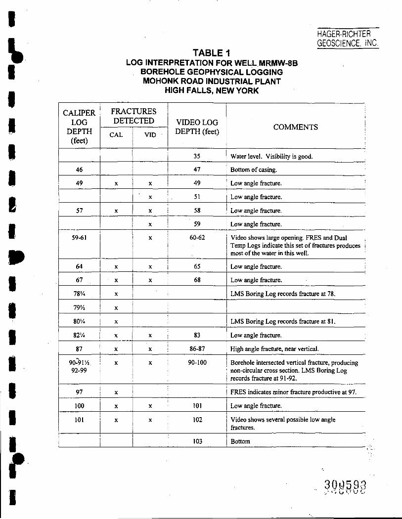
I
V I
f I
HAGER-RICHTER GEOSCIENCE, INC.
TABLE 1 LOG INTERPRETATION FOR WELL MRMW-8B
BOREHOLE GEOPHYSICAL LOGGING MOHONK ROAD INDUSTRIAL PLANT
HIGH FALLS, NEW YORK
CALIPER LOG
DEPTH (feet)
46
49
57
59-61
64
67
78'/«
79'/2
80'/4
82'/4
87
90-""9r/j 92-99
97
100
101
FRACTURES DETECIED
CAL
X
X
X
X
X
X
X
X
X
X
X
x
X
VID
VIDEO LOG DEPTH (feet)
1 35
i 47
X 49
' X 51
X i 58
X 59
X 60-62
X 65 1
X 68
>
\
I
X 83
X 86-87
X 90-100 •
• :
X 101
X 102
i
COMMENTS
Water level. Visibility is good.
Bottom of casing.
Low angle fracture.
Low angle fracture.
Low angle fracture.
Low angle fracture.
Video shows large opening. FRES and Dual Temp Logs indicate this set of fractures produces \ most of the water in this well.
Low angle fracture.
Low angle fracture.
LMS Boring Log records fracture at 78.
•
LMS Boring Log records fracture at 81.
Low angle fracture.
High angle fracture, near vertical.
Borehole intersected vertical fracture, producing non-circular cross section. LMS Boring Log records fracture at 91 -92.
FRES indicates minor fracture productive at 97.
Low angle fracture.
Video shows several possible low angle fi^ctures.
: i 103 Bottom
30j:)^9e •.,• ' * b I* u c

'mm
HAGER-RICHTER GEOSCIENCE. INC
TABLE 2 LOG INTERPRETATION FOR WELL MRMW-9B
BOREHOLE GEOPHYSICAL LOGGING MOHONK ROAD INDUSTRIAL PLANT
HIGH FALLS, NEWYORK
I
1 i CALIPER
LOG DEPTH
(feet)
1 . 93'/2
9514
' 97
99^ '
106
110
i invi !
i 1
i
IITA •
FRACTURES DETECTED
CAL
X
X
VID
X
VIDEO LOG DEPTH (feet)
32
94
1 t 1 i
' j i
! - x
X
X
X
101
j
X 113-114
: i
1 X
^
X
129
130
136
COMMENTS
Water level. Visibility is very poor.
Bottom of casing
Orientation not determinable.
Several possible fractures, orientation not determinable. Dual Temp and FRES logs indicate these fractures may be productive. Note that any ofthe fi^ctures from 99V2 to 140 may be productive and the method cannot identify particular fractures.
Low angle fi^cture.
Orientation not determinable.
Orientation not determinable.
i 141%
!
i X
X
i X 1 X
i
i
138
140
143-144
145
Orientation not determinable.
Orientation not determinable.
Several possible fractures, orientation not determinable.
Bottom
1 !
! i 1 i 1 i
^
I

I
\
f
HAGER-RICHTER GEOSCIENCE, INC,
TABLE 3 LOG INTERPRETATION FOR WELL MRMW-1 OB
BOREHOLE GEOPHYSICAL LOGGING MOHONK ROAD INDUSTRIAL PLANT
HIGH FALLS, NEWYORK
CALIPER LOG
DEPTH (feet)
24
36
38
•
52-58
62'/2
71
73
78
81'/4
FRACTURES DETECTED
CAL 1 j
1 !
i
X !
X
i
X !
1
X
X
X
X
X
VID
X
X
X
X
X
X
X
X
X
X
X
X
X
X
X
X
VIDEO LOG DEPTH (feet)
25
25
27
34
37
39
39'/2
45-48
54-58
61
63-64
71
74
79
82
83
88
i
COMMENTS
Bottom of casing.
Low angle fi^cture.
.
Water level. Visibility is excellant.
Low angle fracture N45E, 70NW. LMS Boring Log records fracture at 35-35.5. i
1 Low angle fracture. j
N45E, 70SE
Several possible low angle tinctures. \ LMS Boring Log records fracture at 43- { 43.5. j
Several possible fractures, orientation not .1 determinable. LMS Boring Log records fracture at 54-54.5. '[
Low angle fracture. FRES indicates this fracture slightly productive.
Several possible fractures, N80W, 45S. FRES indicates this fracture slightly productive.
N90E, SOS. FRES indicates this fracture slightly productive.
Orientation not determinable. FRES indicates this fracture slightly productive.
N85E, 50S
LMS Boring Log records fracture at 81.
Low angle fracture.
Dual Temp and FRES logs indicate this low angle fracture is productive.
I aiisii

HAGER-RICHTER GEOSCIENCE, INC
TABLE 3 LOG INTERPRETATION FOR WELL MRMW-1 OB
BOREHOLE GEOPHYSICAL LOGGING MOHONK ROAD INDUSTRIAL PLANT
HIGH FALLS, NEW YORK
I
CALIPER LOG
DEPTH (feet)
FRACTURED DETECIED
CAL !
! !
j
VID I
X
X
X
X
VIDEO LOG DEPTH (feet)
89
90
93
94
101
COMMENTS
Low angle fracture.
Low angle fracture.
Low angle fracture.
Low angle fracture.
Bottom
1 ' 1 . ^ 1
- 1 : !
1 ^ i j ' i . '•
1 . 1 : 1
I i • ;
i J '
• j -
; j i
: ! ' ' : ! i
: 1 ^ •
; I • :
: : ;
• ! • ' 1
' i ^ :
^
3ii)®®g I

I
k
f
HAGER-RICHTER GEOSCIENCE, INC.
TABLE 4 LOG INTERPRETATION FOR WELL MRMW-1 IB
BOREHOLE GEOPHYSICAL LOGGING MOHONK ROAD INDUSTRIAL PLANT
HIGH FALLS, NEWYORK
CALIPER LOG
DEPTH (feet)
49
50'/2
51'72-56
7574
80'/4
83'/4
93
96
98'/2
107
113'/2
114
FRACTURED 1 DETECIED 1
CAL
X
X
X
X
X
X
X
X
X
X
X
VID
1
VIDEO LOG DEPTH (feet)
10
1 46 i
i X
X 1
X i
i
X i 1
X !
!
53-59
67
69
73
79
83-84 1
1
X
X
94
96-97
i
COMMENTS
1
Water level. Visibility is poor. i
Bottom of casing.
Several fractures, orientation not determinable.
Low angle fracture.
Possible fracture, orientation not determinable.
Low angle, tincture. i
Possible fracture, orientation not determinable. !
Several fractures, orientation not determinable.
Orientation not determinable.
Several low angle fractures. Large fracture at 97, orientation not determinable.
; ; •
X
X
X
1
X
X
X
102
103
109
110
111
112
Low angle fracture.
Low angle fracture.
Low angle fracture.
Low angle fracture.
Low angle fracture.
Low angle fracture.
! 1 i
I

300598
HAGER-RICHTER GEOSCIENCE, INC.
TABLE 4 LOG INTERPRETATION FOR WELL MRMW-1 IB
BOREHOLE GEOPHYSICAL LOGGING MOHONK ROAD INDUSTRIAL PLANT
HIGH FALLS, NEW YORK
I
CALIPER LOG
DEPTH (feet)
116-118
125-131
134-136
154
157-164
l59"/2
FRACTURES DETECTED | VIDEO LOG
CAL
X
X
X
X
X
^jp i DEPTH (feet) i
'
i
X 126
X L 129
X 133
X 134
X 142
X 143
X 144
X 146
X 147
COMMENTS
Low angle fracture.
Low angle fracture.
Low angle fracture.
Low angle fracture.
Possible high angle fracture, orientation not determinable.
Orientation not determinable.
Possible high angle fracture, orientation not determinable.
Possible high angle fracture, orientation not determinable.
Low angle fhicture. ; !
X 149 1 Several low angle fractures.
X 150-153 Several fractures, orientation not determinable.
; 1 1
X 156-158 i Several low angle fi^ctures.
X X 158 1 Fracture zone with large fracture, orientation not determinable.
171 X
176
177
X
X 160-162 Several low angle tinctures.
; 1
X i 174 Orientation not determinable.
X 175 Low angle fracture. LMS Boring Log records fracture at 177-180.
179 Bottom \
I

• V
r
HAGER-RICHTER GEOSCIENCE, INC.
TABLE 5 LOG INTERPRETATION FOR WELL MRMW-12B
BOREHOLE GEOPHYSICAL LOiSGING MOHONK ROAD INDUSTRIAL PLANT
HIGH FALLS, NEW YORK
CALIPER LOG
DEPTH (feet)
17'/2
26
27
. ,
35-43
FRACTURES i DETECTED i VIDEO LOG
CAL
X
X
X
!
49'/2 X
1
54'/2-55'/2
.
X
64% 1 X i
1 i
1 i
\
1
108 1 1 1
yjp j DEPTH (feet)
i
15
19
X 28
X 29
X 33
X 37-46
X 49
X 52
X : 55
57
X 63
X 68
COMMENTS
Water level. Visibility is good.
Bottom of casing.
Low angle fracture.
Low angle fracture.
Low angle fracture. LMS Boring Log records small fracture at 33.
Several low angle fractures, large fractures at 37 and 39 ft (CAL Depths). LMS Boring log records fracture at 36.0, soft zone at 37.5-38.0, fracture at 38.5-39.0. Several fractures are productive per Dual Temp and FRES.
Low angle fracture.
Low angle fracture. FRES indicates this tincture slightly productive.
NIOE, 30W
Several possible fractures, orientation not determinable. FRES indicates this fracture slightly productive.
Low angle fracture.
Productive fracture.
Orientation not determinable. LMS Boring Log records small fracture at 68.
X : 69 I Low angle fracture. LMS Boring Log records small fracture at 69.
X 100
X 101
X 102
Low angle fracture.
Several low angle fractures.
Low angle fracture
\ 112 Low angle fracture.
I mBB:!

TABLE 5 LOG INTERPRETATION FOR WELL MRMW-12B
BOREHOLE GEOPHYSICAL LOGGING MOHONK ROAD INDUSTRIAL PLANT
HIGH FALLS, NEWYORK
HAGER-RICHTER GEOSCIENCE, INC.
I
i CALIPER
LOG \ DEPTH 1 (feet)
114%
142%
157
FRACTURES DETECIED
CAL
X
X
X
•
i 177%-178%
(
X
: j
; i
i • i
1 1
' 1 I i
i i
; i
^ 1 i i ;
! 1
: • i
VID
X
X
VIDEO LOG DEPTH (feet)
119
122
1
COMMENTS i
j
Low angle fhicture. i
; Low angle fracture.
! ''
X
X
X
158
159
160
; Low angle fracture.
I Low angle fracture.
Low angle fracture.
1
X
•
185-186
206
i
1 Several low angle fractures.
I Bottom
1 i 1 ]
i '.
i 1
• j . i
1 i
1
! i i i
1 :
t
1 : i :
i ! ^
mm I

I
V
f
HAGER-RICHTER GEOSCIENCE, INC.
TABLE 6 LOG INTERPRETATION FOR WELL MRMW-13B
BOREHOLE GEOPHYSICAL LOGGING MOHONK ROAD INDUSTRIAL PLANT
HIGH FALLS, NEW YORK
CALIPER FRACTURES LOG DETECTED
^EP™ • CAL (feet) : ^ ^
VID
VIDEO LOG DEPTH (feet) COMMENTS
This well was flowing when logged.
79 X
88 X
97-100'/2 X
105 X
116-118 X
135 X
1
'
183 X
188 X
189-lD X
X
X
79
80
Bottom of casing. Visibility is excellent.
Orientation not determinable. 1 1
X j 89 Orientation not determinable. i ' ' X 1 96-101 Several low angle fractures.
X i 106 i Low angle fractures.
X 1 114-123 Several possible fractures.
X
X
X
, X
X
135 i Low angle fractures.
138 Low angle fiactures.
143 Low angle fractures.
150 Low angle fractures.
156 Low angle fiactures. 1 i
X 1 160 i Low angle fractures.
X 175 : Low angle fractures.
i X i 187 Low angle fractures.
X 191-ID Fracture zone. Orientation of fractures not 1 , determinable. This fracture zone productive.
: LMS Boring log records approximate 3 ft. • void at 196, well began making ~150 gpm.
197 ' Bottom ; • •
i I
•
I mtmt

mm • . K"> K' V C
HAGER-RICHTER GEOSCIENCE, INC.
TABLE 7 LOG INTERPRETATION FOR WELL MRMW-14B
BOREHOLE GEOPHYSICAL LOGGING MOHONK ROAD INDUSTRIAL PLANT
HIGH FALLS, NEW YORK
I
i CALIPER 1 LOG j DEPTH 1 (feet) !
I 26
38
• 62
63'/4
•;
84-88
;
i 116'/2
FRACTURES DETECTED
CAL
X
X
X
X
VID
1 ~
VIDEO LOG DEPTH (feet)
14
26 i 1
X
X
X
X
X
X
X
" < •
X
I X i X
X
X
55
62
63
76
83-88
101
102
110-112
114
118
121
124
1
1
COMMENTS 1
Water level. Visibility is poor.
Bottom of casing. Visibility is good.
1
:
Fracture zone with several large low angle fractures. This fiacture zone is productive. LMS Boring Log records five fracture zones j between 80-100ft, no water. FRES flow at 86. i
Low angle fracture.
Low angle fiacture.
Several low angle fractures.
Near vertical fracture.
Low angle tincture.
Low angle fracture.
Low angle fracture.
128 Low angle fiacture.
144 X
X
X
X
X
X
132
134-144
136
141
144
Low angle fracture.
High angle fiacture, near vertical. ;
Low angle fracture.
Low angle fiacture.
Low angle fracture. FRES indicates this fracture slightly productive.
%
I

I
\ TABLE 7
LOG INTERPRETATION FOR WELL MRMW-14B BOREHOLE GEOPHYSICAL LOC3GING MOHONK ROAD INDUSTRIAL PLANT
HIGH FALLS, NEWYORK
HAGER-RICHTER GEOSCIENCE, INC,
CALIPER ^ LOG : DEPTH
(feet)
150
FRACTURES ; DELECTED | VIDEO LOG
CAL I VID 1 DEPTH (feet) • j
X 146-147
X ! X i 150
1 ; 1 \ i i 1 5 5 •
! i
•. i . ! ' '
j ;
•
'•• . I : '.
i 1
' ! 1 ! 1 • ;
1 ' :
j 1 •
COMMENTS
Several low angle fractures.
Low angle fracture. •
Bottom
•
f I ^•W08(t3

TABLES LOG INTERPRETATION FOR WELL PW-2
BOREHOLE GEOPHYSICAL LOGGING MOHONK ROAD INDUSTRIAL PLANT
HIGH FALLS, NEW YORK
HAGER-RICHTER GEOSCIENCE, INC.
CALIPER i LOG
DEPTH (feet)
FRACTURES DETECTED
CAL
17'/2
19%
20
23
23'/4
26
31
34
35
36%
X
X
X
X
X
X
X
X
X
X
';
42
44'/4
48'/2-51
X
X
X
53'/2-139
60'/2 X
68
77'/2
X
X
i
VID
X
X
VIDEO LOG DEPTH (feet)
•
8
18
19
COMMENTS
•
Bottom of casing. 1
Two low angle fiactures.
High angle fracture, near vertical. 1 1
; 1
• |
X 24
i
X
X
X
X
X
X
X
X
34
35
36
38
39
43
44
48-52
;
Low angle fracture.
i
Low angle fracture.
Low angle fracture.
Low angle fracture.
Low angle fracture. •
Low angle fracture.
Low angle fracture.
Low angle fracture.
Several low angle fractures.
Very rough wall.
X
X
X
X
X
61
64
67
69
78-79
85
Minor water on low angle fracture surface.
Low angle fracture.
Water level.
Low angle fiacture.
Several low angle fhictures.
Low angle fiacture.
I
J I I I I I I I
I I I I I I I
3.0,060,4 ^
•

HAGER-RICHTER GEOSCIENCE. INC.
i»
TABLE 8 LOG INTERPRETATION FOR WELL PW.2
BOREHOLE GEOPHYSICAL LOGGING MOHONK ROAD INDUSTRIAL PLANT
HIGH FALLS, NEW YORK
CAMPER LOG
DEPTH (feet)
92
FRACTURES DETECTED
CAL
X
•
102'/« X
125-129 X
142'/2 X
-
158'/2-Bottom
159'/2-178
X
X
VID
X
X
X
X
X
X
X
VIDEO LOG DEPTH (feet)
93
94
103-104
118
126-130
134
COMMENTS
Low angle fracture. FRES indicates this fracture \ slightly productive.
Low angle fracture. FRES indicates this fracture : slightly productive.
Several low angle fractures. FRES indicates this fracture slightly productive.
Low angle fracture, probably productive.
Several low angle fractures. Fracture at 125 (CAL Depth) is probably productive.
Low angle firacture. 1
i '[
149-152
•
Near vertical fracture. FRES indicates this fracture slightly productive.
1 1 j Highly fractured.
X 159 Several low angle fractures.
i
i
172% X
178 X
^
i
i
X
X
X
160-165
168
171-174
. High angle fracture, near vertical.
'• High angle fracture, near vertical.
i High angle fracture, near vertical.
1
X
X
X
X
176
178
180
184
189
I Low angle fracture.
: Low angle fracture. FRES indicates this fracture : slightly productive.
; Low angle fracture.
i Low angle fracture,
1 Bottom. • 1 i • •
1 ! 1 : . '
I 300BOS

HAGER-RICHTER GEOSCIENCE, INC
w^. 8 INDUSTRIAL WTTir. UNIT D-1 O
SALEM. NH 03079
PHONE: 603 8 9 3 - 9 9 4 4
FAX: 603 8 9 3 - 8 3 1 3
Caliper
Dual Terrperature
WELL: MRMW-8B
PROJECT: Mohonk Road Industr ia l Plant DATE: Septen-ber 24 , 1 9 9 7
CLIENT: Lawler. Matusky. & Skel ly Engineers LLP H-R FILE: 97J41
LOCATION OF WELL: High Fql/s ELEVATION: unknown
STATE: NY COUNTY: Ulster LOG DATUM: Ground Level
INSTRUMENTATION: ML Sopris MGX II CUENT TD: unknown
LOGGING GEOPHYSICI ST: Jonathon Puliaf ico H-R TD: N / A
CLIENT REP: Karen Wright STATIC WATER LEVEL: 34.6 feet
DRILLING CONTRACTOR: unknown DEPTH OF BEDROCK: unknown
COMMENTS: CASING DIAMETER: 6.25 Inch ID
(-
g7J4t MOHONK ROAD INDUSTRIAL PLANT MRMW-8B
11 Degrees C Tenperoture 1
T 2 • ^ . Tenperoture Diff
•^"^5.5 ^ ' " " " D e g r e e " ' " Caliper
-6.5--^
Ten-perature 1 11 Degrees C 12 5.5
Caliper Inches 7.5
Terrperature 2_ . ' 'Degfees'C Y l ' ^
1^.-. i \ „ -"CCn ^ TennperatureDiff , "^"-6.5" DegreeVC" "6.5"'"^
97J41 MOHONK ROAD INDUSTRIAL PLANT MRMW-8B
CO O

CO
o
-a
HAGER-RICHTER GEOSCIENCE, IMC:
rRI AL WAY, t 8 I NDUSTRI AL WAY, UNI T D-1 0
SALEM, NH 03079
PHONE: 603 8 9 3 - 9 9 4 4
FAX: 603 893 -831 3
Caliper
Dual Fluid Resist iv i ty
WELL : M R M W - S B
P R O J E C T : Mohonk R o a d i n d u s t r i a l : P l a n t D A T E : Septen±>er 2 4 . 1 9 9 7
C L I E N T : L a w l e r , M a t u s k y , . &: S k e l l y E n g i n e e r s L L P H - R F I L E : 9 7 J 4 1
LOCATION OF WELL; High Falls ELEVATION: unknown
STATE: NY COUNTY: Ulster LOG DATUM: Ground Level
INSTRUMENTATION: Mt. Sopris MGX II . CLIENT TD: unknown
LOGGING GEOPHYSI CI ST: Jonathon Puli of I CO H-R TD: N / A
CLIENT REP: Karen Wright ; STATIC WATER LEVEL: 34.6 feet
DRILLING CONTRACTOR: unknown DEPTH OF BEDROCK: unknown
COMMENTS: CASING DIAMETER: 6.25 Inch ID
97J41 MOHONK ROAD INDUSTRIAL PLANT MRMW-8B
25
\25
Fluid Resisti_vjty_2_ s. ohrn-m ' 35
Fluid Resistivity 1 ohnv-m 35
^ Fluid Resistivity Diff ,, ^-"2.-0""""'"ohrFm '•"'"•'2;0"'^ 1 Caliper
Inches
cz>
- ^
7.5
f 25
Fluid Resistivity 1 Caliper ohm-m 35 5.5 Inches 75
,_ _ _ Fluid Resistivity 2 _ v. ^ Fluid R_e_sistivity Diff ^ "^"-2.0" 'ohrrTm "ZO"'
97J41 MOHONK ROAD INDUSTRIAL PLANT MRMW-8B

HAGER-RICHTER GEOSCIENCE, INC. •
a INDUSTRIAL ^ M UNI T D-1 0
SALEMi Nrt b.3079
PHONE: 603 893--99-M:
FAX: 603 8 9 3 - 3 3 1 3
Col i per
Dual Fluid Resi.st ivjty
WELL: MRMW--9B
P R O J E C T : M o h o n k R o a d I n d u s t r i a l P l a n t D A T E : S e p t e i r b e r 2 4 , 1 9 9 7
C L I E N T : L a w l e r , M a t u s k y , & S k e l l y E n g i n e e r s L L P H - R F I L E : 97J4.1
LOCATION OF WELL: High Falls ELEVATION: unknown
STATE: NY COUNTY: Ulster LOG DATUM: Ground Leve l '
INSTRUMENTATION: Mt. Sopris MGX II CLIENT TD; unknov/n
LOGGING QEOPHYSICIST: Jonothon Pul ia f ico H-R TD: N / A
CLIENT REP: Karen Wright STATIC WATER LEVEL: 30.9 feet
DRILLING CONTRACTOR: unknown DEPTH OF BEDROCK: unknown
COMMENTS: CASING DIAMETER; 6 :125 , lnch lD
CO

HAGER-RICHTER GEOSCIENCE, INC
8 INDUSTRIAL W ^ » N I T D-1 0 SALEM, NH 03079
PHOhE: 603 893-9944 FAX: 603 893-8313
Caliper Dual Terrperature
WELL: MRMW-9B
PROJECT: Mohonk Road Indust r ia l Plant DATE: Septen*>er 24 . 1 9 9 7
CLIENT: Lawler. Matusky , & Ske l l y Engineers LLP H -R FILE: 97J41
LOCATION OF WELL: High Falls ELEVATION: unknown
STATE: NY COUNTY Ulster LOG DATUM: Ground Level
INSTRUMENTATION: Mt. Sopris MGX II CLIENT TD: unknown
LOGGING GEOPHYSI CI ST: Jonathon Puliafico H-R TD: N/A
CLIENT REP: Karen Wright STATIC WATER LEVEL: 30.9 feet
DRILLING CONTRACTOR; unknown DEPTH OF BEDROCK: unknown
COMMENTS: CASING DIAMETER: 6.1 25 Inch ID
g7J41 MOHONK ROAD INDUSTRIAL PLANT -MRMW-gB
11 Terrperature 2 _ _ -
""Degrees'C T 5 ' ^ Tenrperoture 1
:^ Terrperature Diff ^ ' ^ • -a5 ' ' " "Deg reesC ' 'O.S"'^
Coll per
11 Terrperature 2 _ _ _ ,.
"Oegrees'C VS'^ ^ Tenperoture D[f f ^ •^•-0.5' OegreeVcT 'dS"'^
97J41 MOHONK ROAD INDUSTRIAL PLANT MRMW-9B
^ ^ ( ^ ^

CO
o
O
HAGER-RICHTER GEOSCIENCE, INC.
8 INDUSTRiAL^^Yi UNIT D-1 0
SALEM, NH 03079
PHONE: 603 8 9 3 - 9 9 4 4
FAX; 603 8 9 3 - 8 3 1 3
Caliper
Dual Fluid Resist iv i ty
WELL: MRMW- lOB
PROJECT: Mohonk Road Industr ia l Plant DATE: Septen±>er 24 , 1 9 9 7
CLIENT: Lawler, Matusky , Ac Skel ly Engineers LLP H-R FILE: 97J41
LOCATION OF WELL: High Falls ELEVATION: unknown
STATE: NY COUNTY: Ulster LOG DATUM: Ground Level
INSTRUMENTATION: Mt. Sopris MGX II CLIENT TD: unknown
LOGGING GEOPHYSI CI ST: Jonathon Puliaf ico . H^R TD: N / A
CLIENT REP: Karen Wr^ight STATIC WATER LEVEL: 32.5 feet
DRILLING CONTRACTOR: unknown DEPTH OF BEDROCK: unknown
COMMENTS: CASING DIAMETER: 6.2 Inch ID
.97J41. MOHONK RGAD INDUSTRIAL PLANT MRMW-lOB
Flui_d Resistivity 2 ^ if '^'"''^ Resistivity Diff ^ " 4 0 " " " ' " ohm^m ' 140"^ "^'-IZO ohfrPm" 20" '
Fluid Resistivity 1 Caliper

HAGER-RICHTER GEOSCIENCE, INC.
a I N D U S T R I AL v m f ; UNI T D-1 O
SALEM, NH 03079
PHONE: 603 8 9 3 - 9 9 4 4
FAX: 603 8 9 3 - 8 3 1 3
Caliper
Dual Terrperature
WELL : M R M W - l O B
P R O J E C T : Mohonk R o a d I n d u s t r i a l P l a n t D A T E : S i sp te r rbe r 2 4 , T 9 9 7
CLIENT: Lawler, Matusky, &c Skel ly Engineers LLP H-R FILE: 97J41
LOCATION OF WELL: High Falls ELEVATION: unknown
STATE: NY COUNTY: Ulster LOG DATUM: Ground Level
INSTRUMENTATION: ML Sopris MGX II CLIENT TD: unknown
LOGGING GEOPHYSI CI ST: Jonathon Puliaf ico H-R TD: N / A
CUENT REP: Karen Wright STATIC WATER LEVEL: 32.5 feet
DRILLING CONTRACTOR: unknown DEPTH OF BEDROCK: unknown
COMMENTS: CASING DIAMETER: 6.2 Inch ID
^ _ Terrperature_2
97J.41 MOHONK ROAD INDUSTRIAL PLANT MRMW-1 OB
Degre
TenTJerature 1
12 ^ Terrperature Diff _>, • - a s " " " ' De'g7e"es" C";" ' " " " "6.5" ''^
Caliper
CO O
cr>

I 'uyH^Li^^i^i^^iv ^ ^ ^ GEOSCIENCUNC. T 1 PROJECT: Mohonk Rood Industrial Plant
CUENT: Lawler, Matusky, Sc Skelly Engineers
LOCATION OF WELL: High Foi ls
STATE: NY COUNTY: Ulster
INSTRUMENTATION: Mt. Sopr is MGX II
LOGGING GEOPHYSICIST: Jonathon Pu l ia f i co
CLIENT REP: Koren Wright
DRILLING CONTRACTOR; unknown
COMMENTS:
|M, N H ^ ^ I •3 89:^^m i i 8 9 3 - 8 3 1 3
1 C ^ d w r p e r c ^ ^ M
WELL: MRMW-l lB
D A T E : S e p t e n r b e r 2 2 , 1 9 9 7
L L P H - R F I L E : 9 7 J 4 1
ELEVATION: unknown
LOG DATUM: Ground Level
CLIENT TD; unknown
H-R,TD: N / A
STATIC. WATER LEVEL: 1 2.6 teet
DEPTH OF BEDROCK: unknown
CASING DIAMETER; 6 .125 Inch ID
—
97J41 MOHONK ROAD INDUSTRIAL PLANT MRMW-11 B
11.5 Terrperature 2 ^
'""Oegrees'C """ 'ii'S'^ Tennperoture 1
^ Terrperature Diff ^ '^"-a5''""'0egree3''C" '6.5"''
Coll per
o
11.5 Degrees C 13.5 ^ TerTper_G_tijre_2 i. .y..y^
Degrees C I3.5; .
97J41 MOHONK ROAD INDUSTRIAL-PLANT ,MRMW-11B
Inches |. TemperolureDiff ^ " - 6 S Deg7ee¥C" 'Q 'S '
cn

"bL^Bf/IL^W., I ^ w ^^w<:
CO
o
i l^H-S3lHH|cLL W-11
PROJECT: Mohonk Rood Indus t r ia l P lant DATE: Septen* .e r 2 2 . 1 9 9 7
CLIENT: Lawler , Matusky , & Ske l l y Engineers LLP H - R FILE: 97J4-1
LOCATION OF WELL: High Falls ELEVATION: unkribwri
STATE; NY COUNTY: Ulster LOG DATUM: Ground Level
INSTRUMENTATION: ML Sopris MGX 11 CUENT TD; unknown
LOGGING GEOPHYSICIST: Jonathon Puliafico H-R TD: N/A
CLIENT REP: Karen Wright STATIC WATER LEVEL! 1 2.6 feet
DRILLING CONTRACTOR: unknown DEPTH OF BEDROCK: unknown
COMMENTS: CASING DIAMETER: 6.1 25 Inch ID

HAGER-RICHTER GEOSCIENCE, INC.
a INDUSTRIAL WAY. UNIT D-1 O
SALEM. NH 0.3079
PHONE: 603 8 9 3 - 9 9 4 4
FAX: 603 8 9 3 - 3 3 1 3
Caliper Dual TenTDeroture
WELL: M R M W - 1 2B
PROJECT: . Mohonk R o a d I n d u s t r i a l P l a n t D ATE : S e p t e r r b e r 2 3 , 1 9 9 7
CL IENT : L o w l e r . M a t u s k y , & S k e l l y E n g i n e e r s L L P H - R F I L E : 9 7 J 4 1
LOCATION OF WELL: High Falls . ELEVATION; unknown
STATE: NY COUNTY: Lister LQr. DATUM; Ground Level
INSTRUMENTATION; ML Sopris MGX II CLIENT TD; unknown
LOGGING GEOPHYSICIST: Jonothon Puliaf ico H-R TD: N /A
CLIENT REP: Karen Wright STATIC WATER LEVEL: 14.2 feet
DRILLING CONTRACTOR; unknown DEPTH OF BEDROCK: unknown
COMMENTS: CASING DIAMETEK: 6.ZO Ux;h ID
CO
o CD

HAGER-RICHTER GEOSCIENCE, INC.
W^PKUT 8 INDUSTRIAL W ^ P P J l T D-1 O
SALEM, NH 03079
PHONE; 603 8 9 3 - 9 9 4 4
FAX; 603 8 9 3 - 8 3 1 3
Caliper
Dud Fluid Resist iv i ty
WELL: MRMW-1 2B
P R O J E C T ; Mohonk R o a d I n d u s t r i a l P l a n t D ATE : S e p t e n - b e r 2 3 , 1 9 9 7
C L I E N T : L a w l e r , M a t u s k y . & S k e l l y E n g i n e e r s L L P H - R F I L E : 9 7 J 4 1
LOCATION OF WELL: High Foils ELEVATION; unknown
STATE: NY COUNTY; Uster LOG DATUM: Ground Level
INSTRUMENTATION Mt. Sopris MGX II CLIENT TD; unknown
LOGGING GEOPHYSICIST; Jonathon Puli of i CO H-R TD: N /A
CLIENT REP: Karen Wright STATIC WATER LEVEL: 14.2 feet
DRILLING CONTRACTOR: unknown DEPTH OF BEDROCK: unknown
COMMENTS: CASING DIAMETER; 6.25 Inch ID
CO
o / — •

HAGER-RICHTER GEOSCIENCE, INC
W ( S 1 1 M T SROUSTRIAL W ( ^ W M l T . p - 1 0
SALEM. NH 03079
i-HON!;: 603 8 9 3 - 9 9 4 4
FAX; 603 8 9 3 - 8 3 1 3
Caliper
Tenperoture
Fluid Resist iv i ty
WELL : M R M W - 1 3B
PROJECT: Mohonk R o a d I n d u s t r i a l P l an t DATE; Sep ten -be r 2 4 , 1 9 9 7
CL IENT ; Lov^ler. M a t u s k y . &c S k e l l y E n g i n e e r s L L P H - R F I L E ; 9 7 J 4 1
LOCATION OF WELL: High Foils ELEVATION; unknown
S T A T E ; NY COUNTY: U l s t e r LOG DATUM: G o u n d L e v e l
INSTRUMENTATION: M l . S o p r i s MGX II C L I E N T TD: u n k n o w n
LOGGING GEOPHYSICIST ; J o n o t h o n P u l i a f i c o H - R TD; N / A
C L I E N T REP: K e r e n W r i g h t S T A T I C WATER LEVEL : A r t e s i a n
DRILL ING CONTRACTOR: u n k n o w n D E P T H O F BEDROCK; u n k n o w n
COMMENTS; CASING DIAMETER; 6 , 2 5 , l n c h l D
97J41 MOHONK ROAD INDUSTRIAL PLANT MRMW-1 3B
35 .ii'yi^J???'A'!Ylb'. — •!(
ohm-m 37 Tenperoture
12 Degrees C 13 5.5 Coliper Inches 7.5
O
0 4 O
o
, . : O J
C3
CD
O CD
CO
o
NO CD
C-J -
O
»
SM.
o
CD CD
o .
CO o
C-
Temperoture Degrees C 15 • 5 . 5 -
.-Coliper •Inches 7 5
. fJ l ' i??J??l 'A ' i ^L 'X - - —--- . - •s; ohm-m Sf
97J41 MOHONK ROAD INDUSTRIAL PLANT MRMW-1 3B
CD
cr?

^EOSCIENGE, INC. ^ S A ^ ^ ^ I H O.
FAX: 603 8 9 3 -
Du
W E L L : M R M W - 1 4 B
P R O J E C T : M o h o n k R o a d I n d u s t r i a l P l a n t D A T E : S e p t e n r b e r 2 5 , 1 9 9 7
C L I E N T : L a w l e r , M a t u s k y , & S k e l l y E n g i n e e r s L L P H - R F I L E : 9 7 J 4 1
LOCATION OF WELL: Higfi Falls ELEVATION: unknown
STATE: NY COUNTY: Ulster LOG DATUM: Ground Level
INSTRUMENTATION: Mt. Sopris MGX II CLIENT TO: unknown
LOGGING GEOPHYSICIST: Jonathon Pul iaf ico H-R TD: N / A
CLIENT REP: Koren Wright STATIC WATER LEVEL: 13.3 feet
DRILLING CONTRACTOR: unknown DEPTH OF BEDROCK: unknown
COMMENTS: CASING DIAMETER: 6.1 25 Inch ID
CO
o r — •
« > ^
- . 1 .
97J41 MOHONK ROAD INDUSTRIAL PLANT MRMW-1 4B

GEOSCIENC N C E . I ^ ' ^^WoNE: ^^TO9 TON£:^!^TO93-'
FAX: 603893 -
'^^^•il
W E L L ; M R M W - 1 4 B
P R O J E C T : Mohonk R o d d I n d u s t r i a l P l a n t D A T E : S e p t e n i a e r 2 5 , 1 9 9 7
C L I E N T : L a w l e r , M a t u s k y , & S k e l l y E n g i n e e r s . L L P H - R F I L E : 9 7 J 4 1
LOCATION OF WELL: High Falls ELEVATION: unknown
STATE: NY : COUNTY: Ulster LOG DATUM: Ground Level
. INSTRUMENTATION: Mt /Sopr is MGX II CLIENT TD: unknown
LOGGING GEOPHYSICIST: Jonathon Pul iaf ico H-R TD. N / A
CLIENT REP: Karen Wright STATIC WATER LEVEL: 1 3.3 f e e t
DRILLING CONTRACTOR: unknown DEPTH OF BEDROCK: unknown
;GOMMENTS: CASING DIAMETER: 6.1 25 Inch ID
97J4T MOHONK ROAD INDUSTRIAL PLANT MRMW-1 4B
12 Terrperature 2 y,
""Degrees'C T3"^
Terrperature 1
^ TefrperqtureOiff • -6.2' Deg7ee¥ C" ' 0 2 '
Caliper
... _ Terrperature Diff i 1 - :.0 2" Degree's" C" '02 "-
g7J41. MOHONK ROAD INDUSTRIAL PLANT MRMW-T4B
CO
Oo

(WER'WCH^ GEOSCIENCE. INC.
I ^HI^ IAL flH|^T SA^HvlHi
PHONE: ^ ^ 8 9 3 r
)Tof [ ia 103079
893-9944 FAX; 603 893-8313
coi iHH m
Duel Terrperature
WELL: P W - 2 PROJECT: Mohonk Rood Industr ia l Plant DATE: Septen-ber 23 , r 9 9 7
CLIENT: Lawler, Matusky . & Skel ly Engineers LLP H-R FILE; 97J41
LOCATION OF WELL: High Foils ELEVATION: unknown
STATE: NY COUNTY; Ulster LOG DATUM; Top of Concrete
INSTRUMENTATION: ML Sopris MGX II CLIENT TD: ijhknown
LOGGING GEOPHYSICIST; Jonathon Puliafico H-R TD: N/A
CLIENT REP: Karen Wright STATIC WATER LEVEL: 65.9 feet
Df^LLING CONTRACTOR; unknown DEPTH OF BEDROCK: unknown
COMMENTS: CASING DIAMETER: 6 Inch ID
CO
o
•CO.

- -n. m .GS^'Rlffl'ER" GEOSCIENCE, INC.
S T F S I H V Y
P H O N ^ e C
jvY, u f < ^ m o | E M . fJH 03079
' 6 0 3 8 9 3 - 9 9 4 4
FAX: 6 0 3 8 9 3 - 8 3 1 3
Dual F lu id Res is t i v i t y
W E L L : P W - 2
P R O J E C T : M o h o n k R o o d I n d u s t r i a l P l a n t D A T E : S e p t e n * e r 2 3 , 1 9 9 7
C L I E N T : L a w l e r , M a t u s k y , & S k e l l y E n g i n e e r s L L P H-^R F I L E : 9 7 J 4 1
LOCATION OF WELL: High Falls ELEVATION: unknown
STATE: NY COUNTY: Ulster LOG DATUM: Top of Concrete
INSTRUMENTATION: ML Sopr is MGX II CLIENT TD: uhlinown
LOGGING GEOPHYSICIST: Jonathan Puli of ico H-R TD: N / A
CLIENT REP; Karen Wright STATIC WATER LEVEL: 65.9 feet
DRILLING CONTRACTOR: unknown DEPTH OF BEDROCK: unknown
COMMENTS; CASING DIAMETER; 6 Inch ID
97J41 MOHONK ROAD INDUSTRIAL PLANT PW-2
10
10
Fluid Resistivity 2 . ohm^m "'3i5
Fluid Resistivity 1
l. Fluid Resistivity Diff ., '^"-2.6" 'ohrfwfT ' i o " ' '
ohm-m 30 5.5 Coliper Inches 7.5
Fluid Resistivity 1 )0 ohm-m 30 5.5
Caliper Inches 75
Fluid Resist iv i ty 2 ^ f ^^'"'^ Resist iv i ty Diff __ ^ T o ' ' ' ^'rr^'rr^ " " " 3 ' 0 " ^ *• - Z ' O ' " ' " o h m - m 2.0 ^
97J41 MOHONK ROAD INDUSTRIAL PLANT PW-2
CO
o
CD
I
f
APPENDIX L
I 300621

I
I Data Set: A:\MRPW02.AQT Title: Mohonk Road Pump Test PW-02 Date: 02/26/98 Time: 15:16:06
PROJECT INFORMATION
Company: LMS Engineers Client: NYSDEC Project: 650-253 Location: High Falls, Ulster County Test Date: 6 October 1997 Test Well: PW-02
AQUIFER DATA
Saturated Thickness: 200. ft Anisotropy Ratio (Kz/Kr): 1.
PUMPING WELL DATA
Number of pumping wells: 1
Pumping Well No. 1: MRPW-02
m 1^ Location: Y Location:
1.014E+04ft 1.501E+04ft
No. of pumping periods: 168
Time (mir 0.
0.03 0.05 0.07 0.08 0.1
0.13 0.15 0.17 0.18 0.22 0.3
0.38 0.47 0.58 0.67 0.75 0.83 0.92
i) Rate (cu. ft/min) 0.
2.14 2.14 2.14 2.14 2.14 2.14 2.14 2.14 2.14 2.14 2.14 2.14 2.14 2.14 2.14 2.14 2.14 2.14
Pumping Period Data Time (min)
29.67 31.67 33.67 35.67 37.67 42.67 47.67 52.67 57.67 62.67 67.67 72.67 77.67 82.67 87.67 97.67 107.7 117.7 127.7
Rate (cu. ft/min) 2.14 2.14 2.14 2.14 2.14 2.14 2.14 2.14 2.14 2.14 2.14 2.14 2.14 2.14 2.14 2.14 2.14 2.14 2.14
Time (min) 1047.7 1077.7 1107.7 1137.7 1167.7 1197.7 1227.7 1257.7 1287.7 1317.7 1347.7 1377.7 1407.7 1437.7 1467.7 1497.7 1527.7 1557.7 1587.7
Rate (cu. ft/min) 2.14 2.14 2.14 2.14 2.14 2.14 2.14 2.14 2.14 2.14 2.14 2.14 2.14 2.14 2.14 2.14 2.14 2.14 2.14

Time (min) 1.02 1.1 1.2
1.33 1.5
1.67 1.83 2.
2.17 2.33 2.5
2.67 3.17 3.67 4.17 4.67 5.17 5.67 6.17 6.67 7.17 7.67 8.67 9.67 10.67 11.67 12.67 13.67 14.67 15.67 16.67 17.67 19.67 21.67
Rate (cu. ft/min) 2.14 2.14 2.14 2.14 2.14 2.14 2.14 2.14 2.14 2.14 2.14 2.14 2.14 2.14 2.14 2.14 2.14 2.14 2.14 2.14 2.14 2.14 2.14 2.14 2.14 2.14 2.14 2.14 2.14 2.14 2.14 2.14 2.14 2.14
Time (min) 137.7 147.7 157.7 167.7 177.7 187.7 207.7 227.7 247.7 267.7 287.7 307.7 327.7 347.7 367.7 387.7 417.7 447.7 477.7 507.7 537.7 567.7 597.7 627.7 657.7 687.7 717.7 747.7 777.7 807.7 837.7 867.7 897.7 927.7
Rate (cu. ft/min) 2.14 2.14 2.14 2.14 2.14 2.14 2.14 2.14 2.14 ^ 2.14 2.14 2.14 2.14 2.14 2.14 2.14 2.14 2.14 2.14 2.14 2.14 2.14 2.14 2.14 2.14 2.14 2.14 2.14 2.14 2.14 2.14 2.14 2.14 2.14
Time (min) 1617.7 1647.7 1677.7 1707.7 1737.7 1767.7 1797.7 1827.7 1857.7 1887.7 1917.7 1947.7 1977.7 2007.7 2037.7 2067.7 2097.7 2127.7 2157.7 2187.7 2217.7 2247.7 2277.7 2307.7 2337.7 2367.7 2397.7 2427.7 2457.7 2487.7 2517.7 2547.7 2577.7 2607.7
Rate (cu. ft/min) 2.14 2.14 2.14 2.14 2.14 2.14 2.14 2.14 2.14 2.14 2.14 2.14 2.14 2.14 2.14 2.14 2.14 2.14 2.14 2.14 2.14 2.14 2.14 2.14 2.14 2.14 2.14 2.14 2.14 2.14 2.14 2.14 2.14 2.14
I
23.67 2.14 957.7 2.14 2637.7 2.14 25.67 2.14 987.7 2.14 2667.7 2.14 27.67 2.14 1017.7 2.14 2697.7 2.14
OBSERVATION WELL DATA
Number of observation wells: 6
Observation Well No. 1: MRPW-01
X Location: 1.021E+04ft Y Location: 1.467E+04ft
No. of observations: 65
-S:iM623
m
Observation Data

I Time (min) Displacement (ft) Time (min) Displacement (ft) Time (min) Displacement (ft)
12. 16. 18. 30. 40. 50. 60. 90. 120. 150. 177. 225. 240. 270. 300. 330. 360. 395. 425. 480. 545. 605.
0.02 665. 0.07 725. 0.13 785. 0.3 845. 0.5 905. 0.73 960. 0.9 1020. 1.47 1200., 1.95 1316. 2.38 1395. 2.65 1470. 3.2 1569.
3.35 1665. 3.7 1764. 3.9 1860. 4.2 1990.
4.45 2105. 4.65 2220. 4.85 2340. 5.2 2460. 5.6 2580.
5.75 2725.
bbservation Well No. 2: MRMW-07
X Location: Y Location:
1.052E+04ft 1.439E+04ft
6. 6.48 6.72 6.9
7.16 7.43 7.87 8.24 8.74 •9.
9.15 9.38 9.62 9.78 9.97 10.3
10.55 10.65 10.87 11.06 11.22 11.41
2726^ M 2727. '' 2728. 2742. 2753. 2760. 2765. 2775. 2787. 2809. 2839. 2845. 2870. 2936. 3023. 3086. 3142. 3232. 3321. 3412. 4104.
11.33 11.51 11.57 11.45 11.34 11.21 11.12 11.05 10.77 10.5
10.07 10.
9.76 9.05 8.42
8. 7.6
7.09 6.91 6.58 4.96
No. of observations: 31
Observation Data Time (min) Displacement (ft) Time (min) Displacement (ft) Time (min) Displacement (ft)
P
87. 169. 287. 355. 420. 485. 550. 610. 670. 730. 790.
0.11 850. 0.48 910. 1.12 970. 1.47 1030. 1.79 1090. 2.1 1150.
2.38 1210. 2.62 1327. 2.87 1398. 3.11 1474. 3.31 1572.
Observation Well No. 3: Lischensky
IX Location: Y Location:
1.003E+04ft 1.518E+04ft
3.53 3.72 3.91 4.09 4.27 4.45 4.62 4.97 5.18 5.37 5.59
1661. 1769. 1865. 1995. 2100. 2220. 2340. 2460. 2580.
5.77 5.97 6.15 6.42 6.62 6.83 7.02 7.24 7.42
No. of observations: 32 3 0 0 G 2 / 1

Observation Data
I
Time (min) Displacement (ft) 2.
29. 31. 33. 39. 51. 60. 70. 76. 79. 98.
0.3 1.3 0.8 0.6 0.4 0.6 0.7 1.1 2. 1.7 1.7
Time (min) Displacement (ft) Time (min) Displacement (ft) 104. 141. 186. 260. 268. 304. 370. 440. 495. 795. 861.
Observation Well No. 4: MRMW-1 B
X Location: Y Location:
9955. ft 1.482E+04ft
1.8 2.3 3.2 3.6 3.9 4.
4.9 5.1 5.3 8.45 8.62
940. 1011. 1070. 1210. 1350. 1450. 1570. 1690. 1815. 1930.
8.87 8.88 9.03 10.41 10.06 9.95 9.72 9.97 10.27 10.3
No. of observations: 91
Time (min) Displacement (ft) 157.7 -167.7 177.7 187.7 207.7 227.7 247.7 267.7 287.7 307.7 327.7 347.7 367.7 387.7 417.7 447.7 477.7 507.7 537.7 567.7 597.7 627.7 657.7 687.7 717.7 747.7
^^4^oe 30062
0.0214 0.0373 0.0604 0.0734 0.115 0.169 0.241 0.328 0.417 0.488 0.57
0.671 0.779 0.88 1.14 1.36 1.52 1.68 1.81 1.94 2.06 2.17 2.3
2.45 2.57 2.68 2.79
5
Observation Data Time (min) Displacement (ft) Time (min
927.7 957.7 987.7 1017.7 1047.7 1077.7 1107.7 1137.7 1167.7 1197.7 1227.7 1257.7 1287.7 1317.7 1347.7 1377.7 1407.7 1437.7 1467.7 1497.7 1527.7 1557.7 1587.7 1617.7 1647.7 1677.7 1707.7
3.25 3.34 3.41 3.49 3.58 3.72 3.82 3.9
3.98 4.2 4.4
4.51 4.6
4.73 4.82 4.87 4.92 4.94 4.99 5.04 5.07 5.12 5.16 5.2 5.23 5.26 5.32
1857.7 1887.7 1917.7 1947.7 1977.7 2007.7 2037.7 2067.7 2097.7 2127.7 2157.7 2187.7 2217.7 2247.7 2277.7 2307.7 2337.7 2367.7 2397.7 2427.7 2457.7 2487.7 2517.7 2547.7 2577.7 2607.7 2637.7
) Displacement (ft) 5.62 5.68 5.75 5.82 5.89 5.96 6.02 6.1
6.18 6.23 6.27 6.34 6.41 6.48 6.54 6.59 6.65 6.71 6.77 6.82 6.87 7.04 7.21 7.28 7.32 7.37 7.75
1 f

I Time (min) Displacement (ft) Time (min) Displacement (ft) Time (min) Displacement (ft)
807.7 2.88 1737.7 5.38 2667.7.-s 7.98 837.7 2.97 1767.7 5.42 2697:7' 8.07 867.7 3.06 1797.7 5.49 897.7 3.16 1827.7 5.55
Observation Well No. 5: MRMW-5B
X Location: 1.046E+04ft Y Location: 1.5E+04ft
No. of observations: 11
Observation Data Time (min) Displacement (ft) Time (min) Displacement (ft) Time (min) Displacement (ft)
42.67 0.00136 777.7 0.224 1857.7 0.325 447.7 0.0548 957.7 0.274 1977.7 0.377 537.7 0.114 1197.7 0.326 2337.7 0.439 657.7 0.172 1677.7 0.271
Observation Well No. 6: MRMW-6
P X Location: 1.026E+04ft
Location: 1.516E+04ft
No. of observations: 99
f
Observation Data Time (min) Displacement (ft) Time (min) Displacement (ft)
23.67 0.0597 447.7 31.67 0.125 477.7 37.67 0.182 507.7 42.67 0.233 537.7 52.67 0.331 567.7 57.67 0.385 597.7 62.67 0.437 627.7 67.67 0.49 657.7 72.67 0.543 687.7 77.67 0.594 717.7 82.67 0.652 747.7 87.67 0.711 777.7 97.67 0.832 807.7 107.7 0.923 837.7 117.7 1.01 867.7 127.7 1.1 897.7 137.7 1.17 927.7 147.7 1.26 957.7 157.7 1.35 987.7 167.7 1.42 1017.7 177.7 1.51 1047.7 187.7 1.59 1077.7
3.38 3.57 3.75 3.91 4.07 4.22 4.35 4.52 4.65 4.77 4.9 5.02 5.15 5.27 5.38 5.5 5.6 5.7 5.8
5.91 6.01 6.09
Time (min] 1467.7 1497.7 1527.7 1557.7 1587.7 1647.7 1707.7 1767.7 1797.7 1827.7 1857.7 1887.7 1917.7 1947.7 1977.7 2007.7 2067.7 2097.7 2127.7 2157.7 2187.7 2217.7
Displacement (ft) 7.18 7.24 7.3
7.36 7.47 7.55 7.65 7.76 7.83 7.94
8. 8.09 8.17 8.24 8.31 8.38 8.49 8.55 8.61 8.66 8.71 8.77
^3it626

I Time (min) Displacement (ft)
207.7 1.72 227.7 1.85 247.7 1.97 267.7 2.11 287.7 2.24 307.7 2.36 327.7 2.51 347.7 2.69 367.7 2.84 387.7 2.98 417.7 3.19
SOLUTION
Aquifer Model: Confined Solution Method: Theis
Time (min) Displacement (ft) 1107.7 6.18 1137.7 1167.7 1197.7 1227.7 1257.7 1287.7 1317.7 1347.7 1377.7 1407.7
VISUAL ESTIMATION RESULTS
Estimated Parameters
Parameter Estimate T 110.9 ft' S 0.000219
2/day
AUTOMATIC ESTIMATION RESULTS
Estimated Parameters
Parameter Estimate T 110.9 S 0.000219
Parameter Correlations
T S T 1.00 -0.90 S -0.90 1.00
Residual Statistics
for weighted residuals
Std. Enror 8.305
3.09E-05
•
Sum of Squares.... 1565.4 ft^ Variance 4.787 ft^ Std. Deviation 2.188 ft
6.27 6.35 6.46 6.56 6.65 6.75 6.83 6.9 7.01 7.1
ft2/day
Time (min) Displacement (ft) 2247.7 8.82 2307.7 2337.7 2367.7 2427.7 2487.7 2547.7 2577.7 2607.7 2637.7 2667.7
8.92 8.97 9.03 9.12 9.22 9.3
9.36 9.43 9.48 9.61
•
m
Mean 0.03694 ft No. of Residuals . . . 329. No. of Estimates . . . 2
o n O'hfAK^^rj 9 ty
1

c E o Q. CO
b
100.
10.
0.1
0.01
0.001
1.E-04 0.01 0.1 1. 10. 100.
Time (min)
1000. 1.E+04
MOHONK ROAD PUMP TEST PW-02
Data Set: A:\MRPW02.AQT Date: 02/26/98 Time: 15:12:21
PROJECT INFORMATION
Company: LMS Engineers Client: NYSDEC Project: 650-253 Test Location: High Falls, Ulster County Test Well: PW-02 Test Date: 6 October 1997
SOLUTION
Aquifer Model: Confined Solution Method: Theis
T = 110.9 ft^/day S = 0.000219
AQUIFER DATA
Saturated Thickness: 200. ft Anisotropy Ratio (Kz/Kr): 1
WELL DATA
Well Name MRPW-02
Pumping Wells X(ft)
1.014E+004 Y(ft)
1.501E+004
Observation Wells
,-v r^ /"i '
Well Name D MRPW-01 * MRMW-07 o Lischensky ^MRMW-IB o MRMW-5B o MRMW-6
X(ft) 1.021 E+004 1.052E+004 1.003E+004
9955 1.046E+004 1.026E+004
Y(ft) 1.467E+004 1.439E+004 1.518E+004 1.482E+004 1.5E+004
1.516E+004
829008

3<m29 100.
10.
c
E 8 0.1 ro a. 0)
'^ 0.01
0.001
1 F n4
= ' ' ' -
I
-
I
-1 . C . - \ JH
0.01 0.1 1
Saturated Thickness: 200. ft
Well Name MRPW-02
-
/ 1
/ ^ z
j : ^ / -= 1 I
1 ] 10. 100. 1000. 1.E+04
Time (min)
MOHONK ROAD PUMP TEST PW-02
Data Set: A:\MRPW02.AQT Date: 03/18/98 Time: 16:01:57
PROJECT INFORMATION
Company: LMS Engineers Client: NYSDEC Project: 650-253 Test Location: High Falls, Ulster County Test Well: PW-02 Test Date: 6 October 1997
SOLUTION
Aquifer Model: Confined Solution Method: Theis T = 48.27 ft^/day S = 0.0008011
AQUIFER DATA
Anisotropy Ratio (Kz/Kr): 1
WELL DATA
Pumping Wells Observation Wells X (ft) ! Y (ft)
1.014E+004 1.501 E+004 : ; Well Name X(ft)
I- MRMW-IB 9955 i
•
Y(ft) 1.482E+004

1 0 0 . E—I I I nrw^ r—rTTTTTr|—i i i uun—i t i uuu—i i i uuu 1 i i i mi
10.
c 0) E o i2 (0
b
0.1
0.01
0.001
1 E - 0 4 ' I ' l l mil I I I I mil I I I I mil I I I 111 ll I I I I I mil i i
0.01 0.1 1. 10. 100. 1000. 1.E+04
Time (min)
MOHONK ROAD PUMP TEST PW-02
Data Set: A:\MRPW02.AQT Date: 03/18/98 Time: 16:17:27
PROJECT INFORMATION
Company: LMS Engineers Client: NYSDEC Project: 650-253 Test Location: High Falls, Ulster County Test Well: PW-02 Test Date: 6 October 1997
SOLUTION
Aquifer Model: Confined Solution Method: Theis T = 445.6 ft^/day S = 0.006291
AQUIFER DATA
Saturated Thickness: 200. ft Anisotropy Ratio (Kz/Kr): V
WELL DATA
Well Name MRPW-02
Pumping Wells X(ft)
1.014E+004 Y(ft)
1.501 E+004
Observation Wells Well Name - MRMW-5B
X(ft) 1.046E+004
Y(ft) 1.5E+004
c \fiHiJ^M 08^008

1 0 0 . E—I—I I I iMJi 1 M I m i l — I I I I mil 1—I I I mil 1—i i i i ini 1 i i 111n
10.
c (D
E o i5 a. u>
b
0.1
0.01
0.001
1.E-04 -I I I I mil I I I I mil I I 11 mil U i 11 mil i i 11 i i i i l
0.01 0.1 1. 10. 100. 1000. 1.E+04
Time (min)
MOHONK ROAD PUMP TEST PW-02
Data Set: A:\MRPW02.AQT Date: 02/26/98 Time: 15:06:25
PROJECT INFORMATION
Company: LMS Engineers Client: NYSDEC Project: 650-253 Test Location: High Falls, Ulster County Test Well: PW-02 Test Date: 6 October 1997
SOLUTION
Aquifer Model: Confined Sblution Method: Theis
T = 65.31 ft^/day S = 0.0006305
AQUIFER DATA
Saturated Thickness: 200. ft Anisotropy Ratio (Kz/Kr): ly.
WELL DATA
Well Name MRPW-02
Pumping Wells X(ft)
1.014E+004 Y(ft)
1.501 E+004
Observation Wells Well Name D MRMW-6
X(ft) 1.026E+004
Y(ft) 1.516E+004

100. I—I I I imi[
10. r
c E o i5 CL
b
1. r
0.1 r
0.01 =
0.001 r
I M I m i l I I I 11iiij I I 11 m i l I I 11II r] 1 I I 111 It
1 E - 0 4 I I I I mil I I I I mil I I it mil i < < imil ' < < I i i i i i i i i
0.01 0.1 1. 10. 100. 1000. 1.E+04
Time (min)
MOHONK ROAD PUMP TEST PW-02
Data Set: A:\MRPW02.AQT Date: 02/26/98 Time: 14:38:38
PROJECT INFORMATION
Company: LMS Engineers Client: NYSDEC Project: 650-253 Test Location: High Falls, Ulster County Test Well: PW-02 Test Date: 6 October 1997
SOLUTION
Aquifer Model: Confined Solution Method: Theis
T = 92.71 ft^/day S = 7.98E-05
AQUIFER DATA
Saturated Thickness: 200. ft Anisotropy Ratio (Kz/Kr): jL
WELL DATA
Well Name MRPW-02
Pumping Wells X(ft)
1.014E+004 Y(ft)
1.501E+004
Observation Wells Well Name o MRPW-01
X(ft) 1.021 E+004
Y(ft) 1.467E+004
n f j f> • '!• J
589008

300633
c E (U o va a. tn
0.001 r
1 E - 0 4 ' ' ' ' " " " I I I m i l l I I I l l l l l l I i i i i i i H i I I I l l l l l l I I I l l l l l l
0.01 0.1 1. 10. 100. 1000. 1.E+04
Time (min)
MOHONK ROAD PUMP TEST PW-02
Data Set: A:\MRPW02.AQT Date: 02/26/98 Time: 14:34:25
PROJECT INFORMATION
Company: LMS Engineers Client: NYSDEC Project: 650-253 Test Location: High Falls, Ulster County Test Well: PW-02 Test Date: 6 October 1997
SOLUTION
Aquifer Model: Confined Solution Method: Theis
T = 59.46 ft^/day S = 8.356E-05
AQUIFER DATA
Saturated Thickness: 200. ft Anisotropy Ratio (Kz/Kr): 1
WELL DATA
Well Name MRPW-02
Pumping Wells X(ft)
1.014E+004 Y(ft)
1.501 E+004 Well Name ^ MRMW-07
Observation Wells X(ft)
1.052E+004 Y(ft)
1.439E+004

c a> E 0) o iS a. w b 0.01 r
0.001
1.E-04 0.01 0.1 1. 10. 100. 1000. 1.E+04
Time (min)
MOHONK ROAD PUMP TEST PW-02
Data Set: A:\MRPW02.AQT Date: 02/25/98 Time: 09:04:22
PROJECT INFORMATION
Company: LMS Engineers Client: NYSDEC Project: 650-253 Test Location: High Falls, Ulster County Test Well: PW-02 Test Date: 6 October 1997
SOLUTION
Aquifer Model: Confined Solution Method: Theis
T = 66.08 ft^/day S = 0.0002824
AQUIFER DATA
Saturated Thickness: 200. ft Anisotropy Ratio (Kz/Kr): 1
•' . i WELL DATA
r'.j
;h.Well Name : :MRPW-02
Pumping Wells X(ft)
1.014E+004 Y(ft)
1.501 E+004
Observation Wells Well Name o Lischensky
X(ft) 1.003E+004
Y(ft) 1.518E+004
^89008

0 >
CO
WATER LEVEL FLUCTUATIONS FIELD DATA SHEET PAGE: / OF
SrrE: U l j ^ ^ / ^ ADDRESS: COUNTY: [ j h t ' t / ' STATE f ^ J
DATE: H O ' ^ ' f ' DRILLER: 7 MEASURED BY: )Vl I T T , ' ~ ^ ^
I
J OBS. WELL: PUMPED WELL f ^ - ^ ^ DISTANCE FROM PUMPED WELL
TIME DATA
PUMP ON: DATE: Id '7' tlTIME:
PUMP OFF: DATE: TIME:
WATER LEVEL DATA DISCHARGE DATA
STATIC WATER LEVEL PUMPING RATE:
MEASURING POINT HOW MEASURED: - 7 l S i Q > \ j K c / u 6 € / - ^ " T ^ P ^ ELEVATION
DATE:
I k ^ V H ^
/ ^ . -S 'T ;
JM-Ir
TIME:
^ 7 ^ l^yjy,!,,..
(*l^t^
' o^?(J
TAPE
HELD:
TAPE
WbC: D.T.W. BAROMblER
?'i.«<6 ^o.-ox-
^*\'W IHAH
RAINFALL
O &
r> »
WEATHER CONDmONS
S^AZ/Oy - 7<3 *
P t l . 5 5 3 ' '
Qhu^vy- ^.^'^
CleAr ^ 6 *
300635

I-
V L a w l e r , M a t u s k y & S k e l l y E n g i n e e r s
Environmental Science & Engineering Consultants One Blue Hill Plaza
Pearl River. New York 10965 Page -i-o'd=i
t/^m-'^^ • 5 / 1 ^ - ,^.i'l/l^^^v^olT^^
WeU No. WeU Owner V
Job No.
fl>e>fcboydk.Ki WeU Location
Pump Setting
start Of Teat
Caaing Length
End Of Teat
Pumping WeU
Depth Of Wett
Aquifer
Pumping Rate
7 Screen Depth
Meaauring Point Height Of Measuring Point Distance From. Pumping WeU
10. e,
Date & Time
|07'^^<^''V
a ' L ^ 13^ (. 1534 I LSS
/ ^ . ^
l9 ' (n> %Q '• O S '
zi ; ic> 7.7 0 5 ^ 3 ; ' ( 5
.O.O / o
' ? ! f O
^ X o X
O-bo^
o^os O.fo< o^tb ItSO J 3 U
t
.
•.
Held Wet D.T.W. a
I6.SI
^S.3d
i^.V
IS^T I5:'?-! 153^
/b^;>l /^'.5r /5,37 |S,' ,6 1^,19
/ i ' j v
/ ^ • , 3 r
' ^ • ? , h
'5 3& /5'.;5fc
'^"•,?f.
.^.3^
\1>'V\ »4.Sfe
,o6
Q
. -
Remarka
•
^ 1 ^ C l . A M { ^
•
Notea
\ s \ ' . Z',
300636

• • A , ••
'?mjl
L a w l e r , M a t u s k y & S k e l l y E n g i n e e r s Environmental Science & Engineering Consultants
One Blue Hil/ Plaza
1
Wl<i WeU No.
Pump Setting
Pearl River. N
WeUO\
WeU Location
Caaing Length
start Of Teat End Of Teat
\ 0 ' ^
31 3 ^
2^
9w Yor
wner
D
k 10965 / >:2 ^ Paofl / Of ^ ^
Job No. B
Aquifer
Pumping WeU Pumping Rate
1 epth Of WeU Screen Depth "
Meaauring Point Height Of Meaauring Point
Date & Time
10.7,^7 ^ J 1
»i l^•.->n
\ ^ ^ ^
I S ^ ^ IQ Ss f^.OO
{U3 10',(0 L\ \ I0
') J; \ 0 ^ % J o
c?a 10 0 ^ / f y
0^-1 0
O-K iO
0 ^ \ 0
^ i 1 0
0 ( t \ i^
O l l C O j < P ^
16 /S
t
»
Held Wet D.T.W.
i'i.HI-
yi.s'i' ?. ^ ^ , 5 1 t/D, 4 4/.z^ •/Afy ^/.g5 HWi 'n:5H VZ.I&
^^.7^ b.co ' i i i q
%:^1^ u^ 'tJ.^M
^^1> Cii^.Oj
vv.vv
'fv.^^
8
Lf.U
I S
.3S
.23
. 7 -
. 1 ^
JS
. 1 ^
•2-1
0
, -
Diatance From. Pumping WeU |
. Remarks |
c h A ^ i ^ ^ c ^ S ^ ^
T- ( |
•
'1
-T^hil -5 1 As= .55 ^ Hoves
1
Notes
300637 3Saof)e •

I Pogo_?lOf.
Well No. Well Owner ^ 1 Job No.
1 1 , '
[ ^ lO
4 t
M
At
^
^
k
•
Dote a Tlnrw
i9'%f\'r i \ t
J'S\Z.
m»\\ /fcxH / T i o s
toi^ VKTO nooa
- 'O^oo o^oo f 'GsOC?
0 5 3 0 0 B 3
o t i i
o^3a
n^H 0^ ^ s
ft* Dw
o%T)
o^s-?
0-8^-^
© 2 ^ ^
(?*M|
omi 0 " ^ ^ 6^V<
O^MS
O t ^ ^
Q i L ^
OSoo (5^/<:;>
r}*l2.o
6<\%<^
\«>oo \0 iO
/-^
t
^
1 z ^
^ ^
i&
1 ft ? »0 n
IZ
13
1 ^ •
^
20 l-S
S v^ ^o h o
qrd? l-^c?
^ / f i ^ ^
Held
' ' lA<•^v /
Wet ^ ^ ^ /
D.T.W.
as.^^ 15.«^fc SS/i.» v * ; . ^
^^ r r2
«fS.81
c
3
S. *)
^(..01
Hfr"^
^('^V'^ ^z -?/
V r?=?
^-/f t)T)f
t7./M
f l ^ lH n»^ HT\H
q i . i i
H7,i5
^.16
^TlS
H r i ^
M7,!(p
»^1.\t,
M7,)v, W7, / i .
H7.lt,
m.n ^7,/I
47,1=
V7.3d
H7- ::4
( H i t S7.iO H7.1^
,
^^-5"- 7 7^5' A ^
. 1 ^ . 1 .
0 Remarks
5 ^ + J S 3 « S.S<^
, 1 Ow« l ± 1 . U-f^^
^ j l c r r U...-c.>i..,j>^\i '
'
• - '
« « '•
rcaooe 300638

NiMAX)-0^ Weil No.
HHiiS:^^ Wen Owner
Pogo j j 2 _ 0 f -
Job No.
Dote B Th»
noT-\ X O Q
1335" 1H57 i ^^g--Hrtf i ' lZ f
^ O O V
'O l<?
« S
\
6 1 --2.10
^ $
3^3 ^/^V 5ti H=>2-
7 H ^ 145^
H1T
^'^mm ^.
•
-
Held
;
Wet
Ht,.T,
i L M
'
D.T.W
HI-0^
^t.<\c ^ ( > . < ^
s
• •
¥^.:Rl ^ ^
i m t i<'ftj ts^ VY-sa 4H.H
•
• -
'
• •
.
.
0
.
Remarks
i , t / f / 9 7
1 i
L
p • i 1 1 • 1 1 H 1 1 1
• 1
• :
il 7 i i l
1 11 l i I I f T
1 •1
1 1 • 1
•
1
[
300633 I

1^ L a w l e r , M a t u s k y & S k e l l y E n g i n e e r s
Envirx)nmental Science & Engineering Consultants One Blue Hill Plaza
Pearl River. New York 10965 Page l-ofiL
irtg-Pu -O/ <>\c. ^ t•?(i tA t£6-2ei WeU No. WeU Owner Job No.
DQl -f B M %OMT^C
Wett Locatton
7 Pw-dt Pump Setting Caaing Length
Start Of Teat
• Meaauring Point
End Of Teat
Pumping WeU
Depth Of Wett
Aquifer
Pumping Rate
Screen Depth
Height Of Measurina Point Diatance From. Pumping WeU
1 ^
<tr v.-*-
>? . ^
\y
Date & Time
(d '7 .1? '^ :3^
n:«t
/ h A X
M;*3
ir.oi^
11 :o^
! l :Ol ,
)):'n i r . c S
l i : <^ ' i
/ / .' / c
/ / . ' t l
/ / . ' / • J -
J ( : f 3
>/.'/y
/A: / ^
i r .h
. n-f-J
(/••/&
I I ' 1
t
»
••
Held
•
Wet D.T.W.
feSSS"
^ & 6 #
(.r,sr fcr-rr
fcrxr
for,i-^
i^r^r t r r -Sy
^r^r b ^ X T
f l
U
/ '
(^.S-'T
&sr.r]
^•CioD
C^.uo
uc.ut-
^ C S
i ,(Q%
Cs.(,»
a O
. '
Remarka
•
.
Notes SiVsi)Ec Ate-l-e. Q j
300640:

Well No.
S ^ ^ Poge-2_Of. I
Well Owner Job No.
\
l i .
'y 1 ;«
• ; » ) .
' - ^ • - ^
.
• — i
CD — 1
CO
Dote S ThM
n'>z> } / -3^ If-.40
M'.S't) ta'.{jt>
12.-50
i^'-e& 1^:30
' / 3 5 7 /v.vr l-TrfiO / S - : ^ IL:6t>
/ t : 3 o n:<^ n:35 1(9 : oS " f V. £05 2 D : O ^
z-r-oS 1 1 1 0 ^
2 3 : o ^ 7 OOO s
C>/6<?
Oao5 o 3 o o
0S6O OSoO
ogoo
0 1 t o
o 3 S ^ 1 /0/5 //SO
/3d<J ;vV5 ifez'l
1
—
-
Held
•
Wet D.T.W.
C^.ts 6S.{^5r
<.fe.ojir lr,t.2« (i t..*!?
a -btSb
^•7.?5 iS.zo 62,7^ ^."i*?
t . ^ i 'T'V.f ^,7,5" ' O.so I 6 .m 1 0 ^ 0
h.lS 7I.|^ 71.30
Vi.ss 72.03
1
ia.3.1
7 .W5
?fliT|
7ii?-'»? 73.10
p . f l 73. M§
73.1^ 1H.21
7V.S5
7y.7 7V.15 75.1^ 75.55
s
«?.1$
\
aiv
.
AS
J?-
•39
' 1 5
. Z H
r t L
,XZ .
'3V
^^H . l U
0
r
Remorks ^
1 1
' • I 1 • 1 1 f 1 1 • 1
m 7
k 1 1 i 1 1 • 1 t 1 1 1 • 1 II 11 • • 11 J l T 1 . l b * <Mj>>« M»vri$ 1 •
T.pi'^Q? \
^ i I

I
r I
Well No.
Date a TkTM
'.o-'i.-'ii/mo i ^ i o T^'Lo^
r Oryoo Oloo f>«(oo
0 feCO
OUS
\0'*\ ' 'M 09»S\
-•
t
R
1
1
-^
•<
5
Held
E.Cdi/«
h 1 5 *? 10 I X
i^ iu-f7 l?l -ZO 2 ^ a^ ^c 7.3 l o
35
Wet
Ry
S -.H .fl-:. .
Pogo-3.0f
Wen Owner Job No.
D.T.W.
^ P ^
"TTTJ
15,37
7^85
s
7t.lC •7(?,f)^0
Ip.M^
7^'i'l 76-r 7 7t'ifc
7i.&^ -n.ot n-vz. 77.1^ 77.»1
77. ^
77.11
n.»i 77*11 77rl2
7?f^ T2»>1 77.10 77.0^
7 7 . ^ T'^.^g
7 .'«0 7t,*iB i t .1$ 7i».^
76.«5 7t.7fe»
.
-
-
Q
•
Remarks
)
T . '^ .*
0 ' •
30064a

?v;>'<. Well No.
S'.t£. Well Owner
Pogo y Of.
i^ga-z^J Job No.
CD
O CO
Dole a TVn* < Laf i~M
m± /o *^* / i z o o /37J7 I H l ^ ( < % p
\ l o O 1^3. • Z o » 0
e n 3 *
-z^^ ^5Z-
^ 0 50
^ Ul -
8t i\H
\7J^
iV5 ^ l l
2 1 ^
%i cJlT-
5^;^ r n ^ 5 ^ i37*i
-
^ b l d . ^ ^"V^ i -
•
D.T.w:
7t.t^ 76.^0
7^.51 76.0S
75.42 74.6$
T^ .S l 7»<.6& 7'i<|1 n s K "^^./r
7;?-^/ l?-Y( 7Z'IS
7b.ir7
- ^ ^
*
•
.
• V - '
. . ^ »
"
Q
-
Remarks '
1 1 ' • • • •
" x
5fru;+ck ^c> cJiocV-. i f l i S ^ M '%'-.,
V
£J(,ti. SUUJ 1
I I
1 i,l«n%
| >
1 ^ i 1
• i
* 1 ^^^4iJ08

I" L a w l e r , M a t u s k y & S k e l l y E n g i n e e r s
Environmental Science & Engineering Consultants One Blue Hill Plaza
Pearl River. New York 10965 \ Page JL Of.
WeU No. WeU Owner
ll^ AtLoxit ^ ' •^ 'L i \ Job No.
g^-clfe^V^
M. WeU Location
7 Pump Setting Caaing Length Pumping WeU
Aquifer
Ji2_
Start Of Teat End Of Teat
Measuring Point
Depth Of WeU
Pumping Rate
Screen Depth
Height Of Measuring Point Distance From. Pumping WeU
I
Date & Time
16'7''tM/l \o\fe
Mi^-L^
lm3> i ' 'K^^ 1 u\\
IU2_
I \ l l ^ 1 / ^ ^
n - L ^ n-bl i/3S / 57 i l ^ l
;z.<3iO
12-10 / z / 4
1 a\'^ \ ) t 3 % [ »^VL/
i I'b'Z'l \
1 t
^
•'
Held j Wet
'
D.T.W.
Sl.3u
6^5 : 5 ' ^ ^
55.Z 5i,.7-SSJ
53-1 tss.-z. 51. ^ SV.5 5^.^ 5 <S 55.^ 53."i
5^-7 SV.:^ SS.-z.
54.1 5V.^
55'^
8
55/5
^
Q
. - 1
Remarlta
SV«Ppe^ d^y&tt \}^\MJL.
iia<Me.
I P.qsVAfti- KOCJAAA
l\i/5 ^ N ^
O L ^ V J ^ ^
• ^^
.:-;'M
t -'" .
Notes ^ M T ^ ^'.;- ,
A ^ c r tfv^-S ^ N 6 ' - .- y
6 jcc ( casi'A^') f
' . - ^ . •
i-»/-s
300644
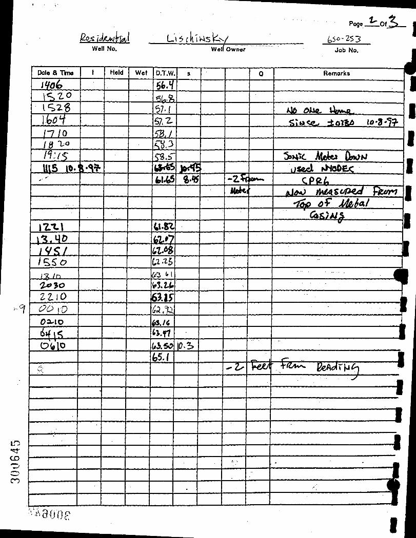
Pogo Jlo,S-fe ikM f\a\
"1
t n .<^.
CD
n
Well No.
Date a Time
i ¥o^
V S ^ ^ I S 2 6 lUV / • 7 / 0
/ a ' «> /Iv^: 1^5 10.
i Z I - l I'^.MD yv.<:/ /S5<:? /-x / h
^ 3 o ZZ iO i::?6> )Q
O X I O
d v f ^ ^ O(* l0
. >"S
•
t
\ ^ ^
•
Held Wet
L'\5fki
D.T.W.
6fc.f 'iiffT.^r
^I ' i 57. Z
5B,/ SK.3 ^ . b "
(^k^ U.(3
U.SZ
w.^7 a.^ U-^5 6 3 <'i
i'lZ.fc
6>.lf ( ,%i ^s./< tj.r? ai.50 (,5 J
VAsl^v / ^5^-253 Welf Owner Job No.
s
J«K<* ft.v
• •
|0.S
.
-
0
-Z5f i«*^ Mekr
^ V
f. •'
•n 1
Renjorks
/J& dJUft- VWCL
5;tiACe^ ±oXklb ID-3-"79-
^ H V . Mek> (WKi i7$acl hHo&£<
CPe^ ^^.O /MAZtJf^^ fco^
- 7 ^ ^ ^ ^ M / ' (A^)Al%
' fl ^ 1
1 • l l
1 1
foe/t' t/z>i-v ^ ^ r M ^ •
1 1
1 1 • • i • 1
I
•^^300P I
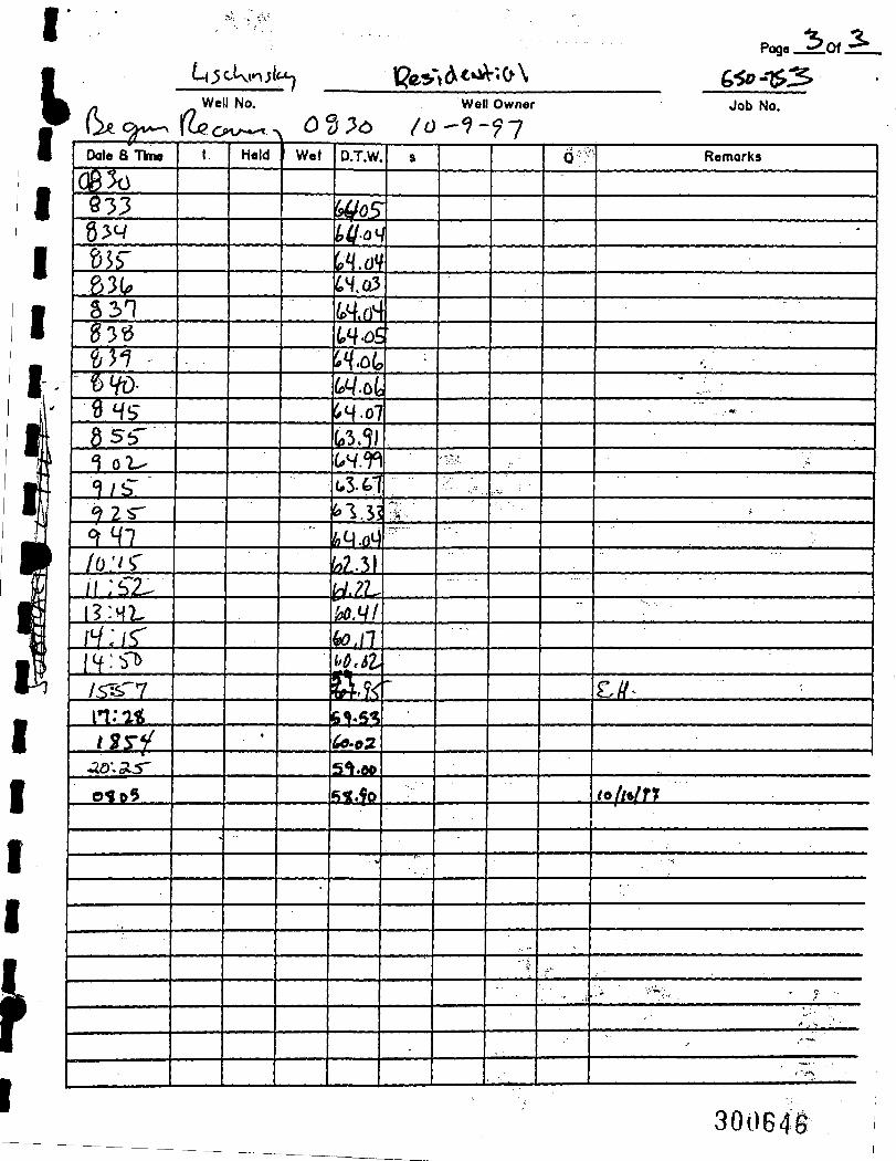
I 5o,3.
iii2ibl!2£t l?e»»(^^^«C^\ Poge ' ^ O t
^
./
1 • '
' - 1
•s ^
Hr K
m ¥
A t m
1 1 • 1 1 I
1 *
\ J J i C ^
Date a TbM
0 8 ^ 533 g^q &sr 63(^ 5 31 ^3^5 ^ > 1 •
t) VO-9HS-8 5^-^ o 2 ^ ^/sT ^ 2 S ^ ^ q ? /O ' /S " /CSZ.. I? :H7. f ^ : rC 1H: VT> /.^"V n;i^ /^s-f
<2.0\SiS'
o^i>5
Well No.
t
-
Held
o^;5<i>
Wet
•
• * '
•
D.T.W.
^ / o ^ yiloH
P^.oV CW.G3
W,rri t,^^£ W.04, 6> .o4 (i4o7 (p3.^) i.H.r\ (•3X1 ^1.51 ^ .(?M w.; ! ici.?l' 'AH( ^ . ( 1 i 'd.st
%^.K §^5^ ^ ' 0 2
5*t.W fi5C.?0
• V
/ o 9
.y.'. '
"
.
WeU Owner
..
.-;.
•
' *
(^.TV
.f-
• ?
Job No.
Remarks
-
' • . •
**
- • « •
,-
C//^
(oft^fn
• • <
> ' . . • '•^v:. J . , - •
f* . V • ' -
,"-
. \*
30064a

f\ ,iif
L a w l e r , M a t u s k y & S k e l l y E n g i n e e r s Environmental Science & Engineering Consultants
One Blue Hill Plaza Pearl River. New/ York 10965
I
WeU No
1^1 iKd^MAi fel. Page / -Of ±J
WeU Owner
I9)?- iknoixt 70'3-6-2«3.»D6
HA WeU Locatk>n
7 Pl^)-<5 2-Pump Setting
Start Of Teat
- tap oV CcS"'*^^
Measuring Point
Caaing Length
End Of Test
Pumping WeU /
Job No.
Aquifer
Pumping Rate
: ^ ^ ^ Depth Of WeU Screen Depth
Height Of Measuring Point Distance From. Pumping WeU
CD
O CO
1 Date & Time
I l0-7.<1^/&<i, i
) ( t ^
! il^>i
j i o ^
U l b
[ 1 1 1 = ? -1 ll'2.1
t -Z-W
//3V
^W^ 1 //5Z-//5§
' \ ^ . \ 1 ^
1 *' ''' \i.Va . f ^ ^ 3
: /v^^ 1 \^^^ 1 \ h 6 ^ 1
1 (7 (5 \ I0.U> 1
t
"'•'
.»
•'1
Held Wet
'' .'
D.T.W.
h%> k 'M 5o,o
iHq.(D
\ ^ ' ^
H8.^
H'i't' 66, e>
5fl,6
^o.(o
50'4
50/4 a)'2 SD.i 1 50. b S2.3 5(*^
•^^-^ SU % 3 \ HLt 1
1 B
•
'
1 0
, - 1
Remarks |
WinA/ JL- 1
1 1 j f l
. ^ m
T T 1 f h 1
Z fUof !•«• rt Wrci^ . 1
1
Notes 55^" )^ yy\£4gr IJvH^ 1/4 h'^ Casm<^
•i J . r'd'OOf G

I ' la tsar.
i L a w l e r , M a t u s k y & S k e l l y E n g i n e e r s
Environmental Science & Engineering Consultants One Blue Hill Plaza
Pearl River. Nevy/ York 10965 / / Page J . Of ' .
^ f W K ^ * \D\l\Adm<^ . ftv^v^y WeU No, WeU Owner
m AOW>\A\ 10 '%'^-1/^-Z^O
JUA. WeU Locatton
^7
Pump Setting Casing Length
:ic^ start Of Teat End Of Teat
Pumping WeU
Depth Of WeU
Job No.
Aquifer
\h p*/\ PumpHng Rate
Screen Depth
Meaauring Point Height Of Meaauring Point Diatance From. Pumping WeU
1 Date & Time
Id ' l -^^lo^ 116%
1 l \ l ^ ' l \ ^ < o
1 1 ^ ^
n.\z n M \
1 /S-Z.M No3
\ i-b^b \ U o ^
t l ^ ' ' ' ^ -! t 3 ' l 3
t
j
-
Held Wet
•
1 D.T.W.
b.i k?.- H'2'S
w k/ '' u - ^ f f j . ^ *f&-5 v^'^ ^ « ' ^
il ^ 1 . ( t8-8
.
1 a
•
1 0
I - ' I
1 Remarka
^/o tfM^ UtM^*—
1
Iti+U ^rz-Mo e W c o + j
. . . . . 1
Notes 3yMf<^ j / lJrer HuhiA Ttf\J S'^ (A^Ti^a 4 - -
- i " * - ,
300648

L a w l e r , M a t u s k y & S k e l l y E n g i n e e r s Environmental Science & Engineering Consultants
One Blue Hill Plaza
I Pearl River. New York 10965
Page. -Of. ^ ^ 4
.0^
o CO
lIKiii WeU No.
Pump Setting
WeU Owner
WeU Locatkjn
US
Job No. 0
Aquifer
Casing Length Pumping WeU Pumping Rate
t Start Of Test End Of Test Depth Of WeU Screen Depth *
Tip ci? ?*ki..\ Measuring Point
Date & Time
O^lfc o<^20
t
4 ^
1 ^
^
\ ^
ffT io J.<J
^ • ^
*t(? ^
\p6
^ uo
Held
65
^
7 0
Wet D.T.W.
J7.S3 ^1.7
rt.l 11-1
ft-l
« . /
/'T.p^
ar/ i i J^ fli'i> i%fr,? n^SD
22.^
22.^0 22.' 2
Height Of Measuring Point Distance From. Pumping WeB •
a
/1-^7
0
5^7f« . ^ •
. -
Remarka |
S»P*^ ! i5«X f 1
J B U I 1 1 • 1
(A)4«r LjLi>tl ^ *,t^-m* U
c ( j : r ^ ..*/> . •
cKllMea (VU^fttS 1 cF/w;u • /)*i«sM ^o \5 5 f ^ -rcO 4 « : i : » i ^ Te^S^r 1
>s - i . o i CF./yV\'ifl> •
Notes ^iS^T^yl ' t 4 a cou^-iol ^ 1 ^ M>*^ HfxS fu J v^;v3tjOP
t q . s s
1

I Pogo J t o f J r i
VMfl^MiU»-»l^ WV&DEC Well No.
( ^ ^ $ Well Owner Job No.
I
Date a T V M
»•'
• • "
t
l « i
0 ^ \^io
i'l r 1" »^H <M4»
1 bG
1^7 it?2) A^^l 170 >t G /^T 7V\ izo 22LS
a3S e
/
z. 3-
V s •
10
16 zO
3 6 H ^
Held
72-77 «7
„ . .
Hr> n iPcc^
.
Wet
•e^4 t»e'/2^
D.T.W.
.a ^^ i ^ ' i
zt.i2 Z«b-.\"Z-
2^»1f ' %XL 2C.*H Z6.Sy 26.?^ 2«.t^ v\.^o 21 TZ
tO.oV ?l.'2-t
3 Z U
V'^^ -0'^ S .%H
3</.20
-
n.03 2S.5Z
? f < i 27.5^
27.*{8 •e^.ay
-z-s.ifc
2V,i^
^S.$^
s
.
J
.
- - •
6 \S
|5
.
Remarks
•iiucce?><sG.dL ^loM - t ^
-ZS.5 qLiM • 3.i^tf/a',)4
^ 5 SHiAVx •^-'5^ cF/>A;Ki
^1 'boTyW\ ^ S.T-^ ^^ M>rt
Tcni i i^ = i(>'t+
-J
•
' t ' •«.
"•J-
."••
r v ,
r 30065di

Well No.
Pog« Of, I WeU Owner
Date a Time
^p/tf/?7 g^ao
1
4. I.
l\;»»>/fe£
2 5,'Sf
T^»»' t^ Job No.
Wet
U '/a x4Ja
D.T.W,
;2r.t( 2 i l d ^£1W
Ij^.g^
"V^ W ' . 7 , • ' i f cmorks
f--/ r>r-
itdll Zi ^-^f
.i. 2^.4/
2 fe : ^ / * a^i^X
JU. i l V<fit M. ^
3i_J3_ a j t .<»
ak: i> JL /"^ ifr.C
mx 5 ^ gTg?f ifr»< SS «r3iI2
/pf 7 S?
/ f t l -O Co ^3J1. l l d k
iQi^T. 4Z.
io2JL il i S ^ 23JL1
/oaV 6V S LSJL as: ^S aJLi££ A4 46 a ^ : : ^ A2 ^7 2 1 ^ X 6^ n^ i £.f & i ^
. i ^ 7 ^ j ^ y ?
:tttt
7/
r-T ^
J L l -75
7^
/filil 11
^ | . g >
H j i X
21xll 21i2£t 1 £ ^ a i ^
t

Well No. WeU Owner
Poge
Job No.
lb. I k
p
.f** r 1
>
I
1 f
Date a ThM
»*'
t
/©:*{/
^
r 1 *
^r ^
f i .
n W^H n o t
"f i f
IIHT-I IPM
izi7
\ ' i ^ ia5^
mi «Jf1
(7 n j »
s ^ WA.5
l>5« i1 l<
H< f f
/y^r rr/^
Held
P, ^ 3
« ^
^7
61
^1
^3
^ 1 ^
1 1 16*/
101
(IH
i l l (M-Z^
I t ^
\ 7. I<a'l
^n ^31 rbi • z s ^
n$ ZH-O
Wet D.T.W.
,Ttf.7l
W «
M t <
^r«' ii-n ?t-x^
2?.'J<
111 -Vf
T t . - f l
2? .7*? 3 * . * / 3o.a(
V f ? ? i ' /.ol
5 H . ^
^ . »
?;^-»fe 3f/^S
5^'^;^
j f .??
^f t f v;?
j.r-»y Zf-$f
' iHii 3S.J7 5>.?T
32,r?i
^ i - * l ^ 2/ .D0
3o.s-r
s
-
Q Remarks
7f7~^ .'f • '
^.oru/tJ j f t i A i ^ A C ^ > » l ' ^ k . » . 4 « i .
-
30065a

V 100.
10.
g 0.1 c E o jg Q. m
0.01
Q 0.001 =
1.E-04 -
1.E-05
1.E-06
I I I l l l l l l 1 I I l l l l l j 1 I I IIIMj 1 I I l l l l l j 1 I I m i l l 1 I I Mll l j 1 I Il l lUd
11 mi l ' ' " i i ' i l I I I m i l l I ' ' " ' I I I I I ' l l l l l l I I l l l l l l ! — I I I I I
0.001 0.01 0.1 1. 10. 100. 1000. 1.E+04
Time (min)
MOHONK ROAD PUMP TEST MRMW-11B
Data Set: C:\MYD0CU~1\M0H0NK\PUMPTE~1\AQTES0L\AMW7B.A Date: 06/17/98 Time: 16:08:41
SOLUTION
Aquifer Model: Confined Solution Mettiod: Theis T = 0.04759 fl2/min S = 5.662E-05
AQUIFER DATA
Saturated Thickness: 200. fl Anisotropy Ratio (Kz/Kr): 1^
05x - j l '
WELL DATA
Well Name MRMW-11B
Pumping Wells X(ft)
0 Y(ft)
0
Observation Wells Well Name - MRMW-7B
X(ft) -1229
Y(ft) -394

100.
10.
£ 0.1
0.01
c a> E 0) o JO Q.
S 0.001
1.E-04
1.E-05
1.E-06
I I I i i i iM—I I I mi l l—I I I l l l l l l—I I I l l l l l j—I I I l l l l l j—I I I l l l l l j—I I I i i i u
I I " " I I I ' I I I I ' I ' i i i ' i l I I i l i i i i l I I i i i i i i l I I l l l l l l
0.001 0.01 0.1 1. 10. 100. 1000. 1.E+04
Time (min)
MOHONK ROAD PUMP TEST MRMW-1 IB
Data Set: C:\MYDOCU~1\MOHONK\PUMPTE~1\AQTESOL\AMW6B.A Date: 06/17/98 Time: 16:09:03
SOLUTION
Aquifer Model: Confined Solution Method: Theis T = 0.05454 ft^/min S = 0.0002071
AQUIFER DATA
Saturated Thickness: 200. ft Anisotropy Ratio (Kz/Kr): j ^
WELL DATA
Well Name MRMW-11B
Pumping Wells X(ft)
0 Y(ft)
0
Observation Wells Well Name n MRMW-6B
X(ft) -455
Y(ft) -654

100.
10.
S 0.1
0.01
c
E O
JS Q.
S 0.001
1.E-04 -
1.E-05
1.E-06
I I i i i i i i |— I I i i i i i i |—I I i i i i i i |—I I i i i i i i | — i i i [—I I i i i i i i |—I I IIIII
t t I m i l I I I I m i l I I I I l i t 11 I I I l l l l l l
0.001 0.01 0.1 1. 10.
Time (min)
100. 1000. 1.E+04
MOHONK ROAD PUMP TEST MRMW-11B
Data Set: C:\MYDOCU~1\MOHONK\PUMPTE~1\AQTESOL\AMW5R.A Date: 06/22/98 Time: 16:19:33
SOLUTION
Aquifer Model: Confined Solution Method: Theis T = 0.08129 ft^/min S = 0.0001151
AQUIFER DATA
Saturated Thickness: 200. ft Anisotropy Ratio (Kz/Kr): 1.
(TCJI
WELL DATA
Well Name MRMW-1 IB
Pumping Wells X(ft)
0 Y(ft)
0
Observation Wells Well Name ° MRMW-5R
X(ft) -559
Y(ft) -411

CO. J
• CTiCS
100.
10.
s I I i i i i i i {—I I I i i i i i {—I I i i i i i i j— I I i i i i i i |—I I I i i i i i |—I I i i i i i i |—I I u n a
S 0.1
i 0.01 o jg Q.
S 0.001
1.E-04
1.E-05
1.E-06 ' I I I I I m i l l I I I m i l l I I t m i l l i I i i i i i i l i i i i l i i l l i i m i n
0.001 0.01 0.1 1. 10. 100. 1000. 1.E+04
Time (min)
MOHONK ROAD PUMP TEST MRMW-1 IB
Data Set: C:\MYDOCU~1\MOHONK\PUMPTE~1\AQTESOLV\MW7R.A Date: 06/22/98 Time: 16:19:39
SOLUTION
Aquifer Model: Confined Solution Method: Theis T = 0.06544 ft^/min S = 5.428E-05
AQUIFER DATA
Saturated Thickness: 200. ft Anisotropy Ratio (Kz/Kr): 1^
WELL DATA
Well Name MRMW-11B
Pumping Wells X(ft)
0 Y(ft)
0
Observation Wells Well Name ° MRMW-7R
X(ft) -1239
Y(ft) -398

too.
10.
£ 0.1
c 0) E o (0 Q. b
0.01
0.001
1.E-04 r
1.E-05 -
I I I l l l l l { 1 I I l l l l l j 1 I I l l l l l | 1 I I l l l l l l 1 I I l l l l l l 1 I l l l l l l l — I I I I I IU
1 . E - 0 6 I I 11 mi l l—I I l l l l l l l I I l l l l l l l ' ' I i i ' i ' l • ' ' l l l l l l I I ll ' ' I
0.001 0.01 0.1 1. 10. 100. 1000. 1.E+04
Time (min)
MOHONK ROAD PUMP TEST MRMW-1 IB
Data Set: C:\MYD0CU~1\M0H0NK\PUMPTE~1\AQTES0LV\MW1' Date: 06/22/98 Time: 16:17:45
SOLUTION
Aquifer Model: Confined Solution Method: Theis
T = 0.07379 fl2/min S = 2.055
AQUIFER DATA
Saturated Thickness: 200. ft Anisotropy Ratio (Kz/Kr): 1^
•CL>
CD
WELL DATA
Well Name MRMW-11B
Pumping Wells X(ft)
0 Y(ft)
0
Observation Wells Well Name * MRMW-11
X(ft) -4.035
Y(ft) -9.011

100.
10.
c <D
E Q> O CO
1.
g 0.1 r
0.01 -
CL
5 0.001
1.E-04
1.E-05
1.E-06
I I I l l l l l j 1 I I l l l l l | 1 I I l l l l l j 1 I I l l l l l j 1 I I l l l l l j 1 I I l l l l l j 1 I I I I IB
liL m i l l I ' I I l l l l l l l I I ' " " ' •- ' . J ' l i i i l I I l l l l l l l
0.001 0.01 0.1 1. 10. 100. 1000. 1.E+04
Time (min)
MOHONK ROAD PUMP TEST MRMW-11B
Data Set: C:\MYDOCU~1\MOHONK\PUMPTE~1\AQTESOLV\MW1B.A Date: 06/17/98 Time: 16:09:58
SOLUTION
Aquifer Model: Confined Solution Method: Theis T = 0.04319 ft2/min S = 0.0001427
AQUIFER DATA
Saturated Thickness: 200. ft Anisotropy Ratio (Kz/Kr): 1.
WELL DATA
Well Name MRMW-11B
Pumping Wells X(ft)
0 Y(ft)
0
Observation Wells Well Name ° MRMW-IB
X(ft) -796
Y(ft) -956

100.
10.
= 1 1 1 IIIMj 1 I I l l l l l | 1 I I l l l l l j 1 I I l l l l l j 1 I I l l l l l j 1 I l l l l l l j 1 I I I I I I
c E o
JO CL M
0.1
0.01
S 0.001
1.E-04
1.E-05
1.E-06 I I ll ' ' I i i l ' l l L. m i l " I • I I I I I I I
0.001 0.01 0.1 1. 10. 100. 1000. 1.E+04
Time (min)
MOHONK ROAD PUMP TEST MRMW-11B
Data Set: C:\MYDOCU~1\MOHONK\PUMPTE~1\AQTESOL\ALICHSKY Date: 06/17/98 Time: 16:07:52
SOLUTION
Aquifer Model: Confined Solution Method: Theis T = 0.04207 ft2/min S = 0.0001047
AQUIFER DATA
Saturated Thickness: 200. ft Anisotropy Ratio (Kz/Kr): 1
OX;: mi-.
WELL DATA
Well Name MRMW-1 IB
Pumping Wells X(ft)
0 Y(ft)
0
Observation Wells Well Name o Lichensky
X(ft) -439
Y(ft) -879

100.
10.
1.
£ 0.1 ^ c E o
JO CL
^ 0.001
0.01 -
1.E-04
1.E-05 -
1.E-06
•| I I m i l l—I I I l l l l l j—I I I m i l l—I I I m i l l— i i i i i i i i j—i i i m i i j— i i i I I I M
I I l l l l l l l I I l l l l l l l I " l l I I I m i l I 1 1 1 Mi l l I I I I M i l l I I I I M i l
0.001 0.01 0.1 1. 10. 100. 1000. 1.E+04
Time (min)
MOHONK ROAD PUMP TEST MRMW-11B
Data Set: C:\MYDOCU~1\MOHONK\PUMPTE~1\AQTESOL\AMW1 Date: 06/17/98 Time: 16:07:59
SOLUTION
Aquifer Model: Confined Solution Method: Theis
T = 0.0563 ft^/min S = 5.725E-05
AQUIFER DATA
Saturated Thickness: 200. ft Anisotropy Ratio (Kz/Kr): 1.
WELL DATA
Pumping Wells Observation Wells Well Name MRMW-11B
X(ft) 0
Y(ft) 0
Well Name ° MRMW-1 IC
X(ft) -97.25
Y(ft) -162.4

100. I—I I I l l l l l j — I I I l l l l l j — I I I l l l l l j — I I I i i i i i | — I I I l l l l l j — I I I l l l l l j — I I m m
E ^ h »
c ^ % o <0 Q.
S
10.
1.
0.1
0.01
0.001
1.E-04
1.E-05 -
1 . E - 0 6 I I I I Mill! I I I mi l l I I l l l l l l l • ' m in i ' ' ' I i i i ' i l ' I I I • I " " I
0.001 0.01 0.1 1. 10. 100. 1000. 1.E+04
Time (min)
MOHONK ROAD PUMP TEST MRMW-11B
Data Set: C:\MYDOCU~1\MOHONK\PUMPTE~1\AQTESOL\AKEMPEL Date: 06/17/98 Time: 16:03:39
SOLUTION
Aquifer Model: Confined Solution Method: Theis
T = 0.152 ft2/min S = 0.002186
AQUIFER DATA
Saturated Thickness: 200. ft Anisotropy Ratio (Kz/Kr): 1.
oo;.
GO.
WELL DATA
Pumping Wells Observation Wells Well Name MRMW-11B
X(ft) 0
Y(ft) 0
Well Name * Kempels
X(ft) 75
Y(ft) 200

CO
o 100.
10.
1.
0.1
0.01
001 b-
E-04 r
E-05 -
E-06
I I I l l l l l j—I I I mi i j—I I I l l l l l j—I I I l l l l l j—I I l l l l l l j— I I l l l l l l j—I I I mu
III I I ' l l l l l l ll I I I
0.001 0.01 0.1 1. 10. 100. 1000. 1.E+0^
MOHONK ROAD PUMP TEST MRMW-1 IB
Data set: C : \ M Y D 0 C U ~ 1 \ M 0 H 0 N K \ P U M P T E ~ 1 \ A Q T E S 0 L V \ M W 1 2 B . A Q T Date: 06/22/98 Time: 16:19:18
SOLUTION
Aquifer Model: Confined Solution Method: Theis T = 0.2181 ft2/min 8 = 0.001166
Time (min)
AQUIFER DATA
Saturated Thickness: 200. ft Anisotropy Ratio (Kz/Kr): ^
WELL DATA
Well Name MRMW-1 1 B
Pumping Wells X(ft)
0 Y(ft)
0
Observation Wells Well Name ° MRMW-12B
X(ft) 536
Y(ft) 651

i
c E
8 to a. m
I I l l l l l l l — I 11 mi l l—I I l l l l l l l — I 11 l l l l l l—I 11 l l l l l l—I I l l l l l l l—I I iMiH 100.
10.
i.
0.1
0.01
0.001
1.E-04
1.E-05
1.E-06 '—' ' """I—I I lllllll ll I I l l l l l l l I I m m
0.001 0.01 0.1 1. 10.
Time (min)
100. 1000. 1.E+04
MOHONK ROAD PUMP TEST MRMW-11B
Data Set: C:\MYDOCU~1\MOHONK\PUMPTE~1\AQTESOLV\RICHAR Date: 06/17/98 Time: 16:08:14
PROJECT INFORMATION
Company: LMS Engineers Client: NYSDEC Project: 650-254 Test Location: High Falls. Ulster County Test Well: MRMW-1 IB Test Date: 26 April 1998
SOLUTION
Aquifer Model: Confined Solution Method: Theis T = 0.0642 ft^/min S = 5.001 E-05
AQUIFER DATA
Saturated Thickness: 200. ft Anisotropy Ratio (Kz/Kr): V.
CO o o
CO
WELL DATA
Pumping Wells Observation Wells Well Name MRMW-1 IB
X(ft) 0
Y(ft) 0
Well Name » Richards
X(ft) -177.2
Y(ft) -12.36

I
p APPENDIX M
I 300664
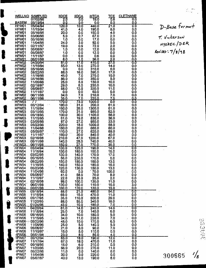
WELLNO SAMPLED
BASEM HFW01
^ HFW01 i HFW01 ^ HFW01
HFW01 1 HFW01
HFW01 HFW01
\ HFW01 i! HFW01
HFW01 HFW02
1 HFW02 [ HFW02 ' HFW02
HFW02 1 HFW02 1 HFW02 P HFW02
HFW02 m HFW02 1 HFW02 1 HFW02
HFWQ3 A HFW03 1 HFW03 m HFW03
HFW03 ^ HFW03 i HFW03 • HFW03
HFW03 — HFW03 i f t HFW03 • ^ HFW03 ^ HFW03 . HFW03 . m HFW04 m HFW04
HFW04 ^ HFW04 ^ HFW04 m HFW04 ^ HFW04
HFWG4 m HFW04 • HFW04 • HFW04
HFW04 A HFW04 . m HFW05 W HFW05
HFW05 A HFW05 1 HFW05 • HFW06 ^ HFW06 ^ HFW06 V HFW06 # HFWOB-- ,HFW06 -- HFW06
m -IFW06 m. HFWOS A | HFW07 W HFW07 • HFW07 • HFW07
^FW07 HFW07
• ^FW07
07/02/96 05/19/94 05/04/94 11/15/94 05/16/95 03/06/96 05/16/96 11/04/96 02/11/97 05/08/97 05/08/97 11/11/97 06/01/98 04/20/94 11/15/94 05/16/95 08/22/95 11/16/95 05/16/96 11/05/96 02/18/97 05/08/97 11/11/97 06/11/98 06/11/98 / /
05/12/94 11/16/94 03/10/95 05/18/95 11/15/95 03/05/96 05/??/96 11/04/96 05/09/97 11/11/97 02/18/98 06/11/98 06/11/98 05/04/94 11/16/94 03/02/95 05/16/95 08/??/95 11/18/95 05/23/96 11/04/96 05/06/97 11/10/97 02/18/98 06/01/98 06/01/98 05/19/94 11/16/94 05/17/95 11/20/95 01/24/96 04/20/94 11/16/94 05/16/95 11/15/95
-05/22/96 11/06/96 05/06/97 11/10/97 06/01/98 05/12/94 11/17/94 05/18/95 11/20/95 05/??/96 11/04/96 05/07/97
IIDCE 2.0 0.0
120.0 41.0 20.0
5.0 1.0
24.0 19.0 1.0 1.0 0.0 8.0
81.0 55.0
0.0 88.0 45.0 86.0 25.0 29.0 58.0
0.0 34.0 35.0
170.0 180.0 150.0 170.0 100.0 61.0 97.0
220.0 150.0 110.0 150.0 210.0 140.0 150.0 130.0 130.0 130.0 56.0
150.0 140.0 120.0 60.0 41.0 22.0 99.0
130.0 160.0 88.0 69.0 35.0 88.0 43.0 61.0 25.0 34.0 34.0 48.0 25.0 21.0 15.0 23.0 65.0 67.0 15.0 56.0 11.0 30.0 43.0
IIDCA 0.0 OO
10.0 4.0 0.0 0.7 0.0 3.0 0.9 0.0 0.0 0.0 1.0
17.0 13.0 0.0
16.0 7.0 0.0 5.0 6.0
12.0 0.0 7.0 7.0
73.0 31.0 26.0 31.0 30.0 19.0 27.0 18.0 20.0 27.0 30.0 47.0 28.0 27.0
120.0 180.0 140.0 230.0 190.0 150.0 130.0
0.0 58.0 23.0
100.0 150.0 170.0 21.0 15.0
110.0 55.0 10.0 14.0 7.0
10.0 11.0 10.0 5.0 8.0 5.0 8.0
18.0 19.0 6.0
20.0 0.0 0.0
13.0
IIITCA 19.0 0.0
440.0 190.0 150.0 67.0 17.0 92.0 72.0 12.0 12.0 0.6
36.0 410.0 270.0 310.0 390.0 270.0 350.0 130.0 230.0 320.0
50.0 210.0 220.0
1000.0 200.0
1300.0 980.0
1100.0 830.0 950.0
1000.0 660.0 620.0 840.0
1200.0 740.0 770.0 190.0 150.0 170.0 170.0 160.0 180.0 150.0 '70.0
70.0 25.0
130.0 110.O 130.0 480.0 470.0 500.0 340.0 180.0 240.0 140.0 180.0 230.0 170.0 140.0 90.0
110.0 85.0
190.0 470.0 210.0 270.0 140.0 220.0 190.0
TCE 0.6 0.0
21.0 8.0 4.0 2.0 0.0 5.0 2.0 0.0 0.0 0.0 2.0
27.0 14.0 0.0
17.0 10.0 5.0
10.0 10.0 11.0 0.0 7.0 7.0 0.0
61.0 61.0 62.0 56.0 36.0 33.0 58.0 60.0 69.0 40.0 67.0 40.0 35.0 14.0 15.0 17.0 0.0
13.0 15.0 13.0
100.0 8.0 2.0
11.0 15.0 15.0 54.0 11.0 29.0 16.0 7.0
14.0 6.0 5.0 7.0 6.0 5.0 7.0 0.0 4.0
12.0 11.0 0.0
11.0 0.0 0.0 6.0
CLETHANE 0.0 0.0 0.0 0.0 0.0 0.0 0.0 0.0 0.0 0.0 0.0 0.0 0.0 0.0 0.0 0.0 0.0 0.0 0.0 0.0 0.0 0.0 0.0 0.0 0.0 0.0 0.0 0.0 0.0 0.0 0.0 0.0 0.0 0.0 0.0 0.0 0.0 0.0 0.0 0.6 0.0 0.0 0.0 0.0 0.0 0.0 0.0 0.0 0.0 0.0 3.0 0.0 0.0 0.0 0.0 0.0 0.0 0.0 0.0 0.0 0.0 0.0 0.0 0.0 0.0 0.0 0.0 0.0 0.0 0.0 0.0 0.0 0.0
r-
"D-St^se, Tor/»i
T. \/ickers^/0
f jysie<^/v£R
hyf'»50\l/'il*\Z
300665 '8

HFW07 HFW07 HFWOS HFWOS HFWOS HFWOS HFWOS HFWOS HFWOS HFWOS HFWOS HFW09 HFW09 HFW09 HFW09 HFW09 HFW09 HFW09 HFW09 HFW09 HFW09 HFW09 HFwns HFW10 HFW10 HFW10 HFW10 HFW10 HFW10 HFW10 HFW10 HFW10 HFW10 HFW10 HFW10 HFW10 HFW10 HFW10 HFW10 HFW10 HFW10 HFW10 HFW11 HFW11 HFW11 HFW11 HFW11 HFW11 HFW11 HFW11 HFW11 HFW12 HFW12 HFW12 HFW12 HFW12 HFW12 HFW12 HFW12 HFW13 HFW13 HFW14 HFW14 HFW14 HFW14
CD HFW14 CO HFW14 Cb HFW14 ^ HFW14 X HFW15 ^ HFW15 ^ HFW15
HFW15 HFW15 HFW15 HFW15-
11/10/97 06/08/98 06/12/94 11/29/94 05/16/95 11/13/95 05/22/96 11/06/96 05/07/97 11/10/97 06/11/98 05/19/94 11/15/94 03/02/95 05/16/95 11/13/95 11/15/95 05/16/96 11/07/96 05/08/97 11/11/97 06/08/98 06/08/9R / /
05/12/94 11/17/94 03/02/95 06/19/95 07/11/95 08/03/95 11/13/95 03/05/96 05/16/96 09/18/96 11/05/96 02/11/97 05/07/97 08/20/97 08/20/97 11/12/97 02/18/98 06/03/98 05/19/94 11/15/94 05/16/95 11/20/95 05/21/96 11/05/96 05/07/97 11/10/97 06/08/98 05/12/94 11/17/94 11/13/95 05/16/96 11/06/96 05/06/97 11/11/97 06/01/98 05/12/S4 11/12/97 05/19/94 11/18/94 05/16/95 11/15/95 05/21/96 11/05/96 06/02/98 06/02/98 05/19/94 11/29/94 05/18/95 11/20/95 05/21/96 11/04/96
3 05/06/97'; p
120.0 33.0 93.0 50.0 24.0 73.0 53.0 65.0 96.0 45.0 26.0 67.0 50.0
120.0 10.0 33.0 21.0 56.0 45.0 73.0 -25.0 54.0 58.0 98.0 61.0 36.0 71.0
110.0 240.0
57.0 51.0 40.0 87.0
110.0 50.0 60.0 98.0
130.0 250.0 70.0 86.0 77.0 78.0 18.0 13;0 26.0 23.0 28.0 16.0 27.0 25.0 66.0 20.0
7.0 11.0 12.0 . 18.0 35.0
28.0 23.0 54.0 47.0
0.0 6.0 4.0
20.O 100.0 82.0 54.0 28.0
7.0 36.0 27.0 30.0 20.0
35.0 11.0 26.0 12.0 4.0
24.0 18.0 20.0 33.0 10.0 10.0 9.5 8.0
130.0 11.0 7.0 2.0 0.0
15.0 0.0 0.0 7.0 8.0
23.0 9.8
13.0 19.0 24.0
150.0 15.0 18.0 12.0 0.0
19.0 10.0 7.0
22.0 30.0 0.0
10.0 0.0
15.0 6.6 4.0 3.0 6.0 3.0 6.0 3.0 5.0 6.0 7.0 4.0
37.0 1.0 2.0 4.0 9.0 4.0 7.1 6.0 8.2
18.0 0.0 0.9 1.0
12.0 28.0 23.0
0.0 7.0 5.0
15.0 10.0 0.0 5.0
410.0 140.0 130.0 310.0 430.0 500.0 290.0 290.0 360.0 180.0 88.0
4S0.0 280.0 630.0 530.0 420.0 190.0 450.0 420.0 460.0 170.0 260.0 310.0 680.0 160.0 650.0 530.0 520.0
4700.0 420.0 420.0 480.0 540.0 500.0 410.0 400.0 600.0 680.0
1300.0 610.0 530.0 450.0 140.0 97.0
100.0 140.0 80.0 75.0 45.0 95.0
110.0 120.0 140.0 180.0 77.0 50.0 76.0
200.0 73.0
330.0 160.0
0.0 400.0 220.0
38.0 26.0
110.0 480.0 330.0 200.0 250.0 120.0 230.0 140.0 180.0 82.0
15.0 0.0
22.0 7.0
15.0 16.0 10.0 15.0 18.0 0.0 4.0
14.0 6.0
19.0 14.0 20.0
3.0 0.0 5.0
12.0 0.0 6.0 9.0
35.0 38.0 20.0 26.0 36.0
270.0 39.0 13.0 17.0 12.0 37.0 30.0
0.0 31.0 42.0
0.0 20.0 24.0 20.0 11.0 5.0 3.0 6.0 2.0 7.0 3.0 5.0 5.0 9.0 5.0 7.0 1.0 3.0 6.0 7.0 4.0
10.0 12.0 8.4
17.0 0.0 4.0 1.0
12.0 17.0 18.0 6.2 0.0 0.0 8.0 5.0 0.0 7.0
0.0 nn 0.0 0.0 0.0 0.0 0.0 0.0 0.0 0.0 0.0 0.0 0.0 0.0 0.0 0.0 0.0 0.0 0.0 0.0 0.0 0.0 0.0 0.0 0.0 0.0 0.0 0.0 0.0 0.0 0.0 0.0 0.0 0.0 0.0 0.0 0.0 0.0 0.0 0.0 0.0 0.0 u.u 0.0 0.0 0.0 0.0 0.0 0.0 0.0 0.0 0.0 0.0 0.0 0.0 0.0 0.0 0.0 0.0 0.0 0.0 0.0 0.0 0.0 0.0 0.0 0.0 0.0 0.0 0.0 0.0 0.0 0.0 0.0 0.0 0.0
9 i J l
M w
^ m w ^
• 1 M m \ 1 • i i i v*l

I
I t I I t r p I I i t I I
HFW15 HFW15 HFW16 HFW16 HFW16 HFW16 HFW16 HFW16 HFW16 HFW16 HFW16 HFW16 HFW17 HFW17 HFW17
FW17 HFW17
FW17 HFW17 HFW17 HFW17 HFW17 HFW18 HFW18 HFW1S HFW1S HFW18 HFW18 HFW18 HFW18 HFW1S HFW19 HPA'19 HFW19 HFW19 HFW19 HFW19 HFW19 HFW19 HFW19 HFW19 HFW20 HFW20 HFW20 HFW20 HFW20 HFW20 HFW20 HFW20 HFW20 HFW21 HFW21 HFW21 HFW21 HFW21 HFW21 HFW21 HFW21 HFW21 HFW22 HFW22 HFW22 HFW22 HFW22 HFW22 HFW22 HFW22 HFW22 HFW23 HFW23 HFW23 HFW23 HFW23 HFW23 HFW23 HFW23
11/10/97 06/02/98 05/19/94 11/17/94 05/18/95 11/14/95 05/22/96 11/06/96 02/11/97 05/06/97 11/11/97 06/10/98
95.0 30.0
80.0 9.0
04/20/94 11/15/94 05/26/95 08/22/95 11/16/95 05/23/96 11/05/96 05/08/97 11/11/97 06/02/98 05/18/94 11/18/94 05/16/95 11/14/95 05/29/96 11/05/96 05/07/97 11/12/97 06/03/98 05/19/94 11/16/94 05/17/95 05/17/95 11/15/95 05/29/96 11/05/96 05/06/97 11/11/97 06/01/98 05/1S/94 11/15/94 05/16/95 05/20/95 11/20/95 11/04/96 05/08/97 11/10/97 06/01/98 05/12/94 11/16/94 05/16/95 11/13/95 05/23/96 11/05/96 05/08/97 11/13/97 06/01/98 05/19/94 11/29/94 05/17/95 11/20/95 05/29/96 11/04/96 05/06/97 11/11/97 06/01/98 05/12/94 11/29/94 05/16/95 11/14/95 05/29/96 11/07/96 05/07/97 08/20/97
11.0 13.0 0.5 2.0 1.0 0.5 2.0 4.0 5.0
"TOT 18.0 22.0 2.0 5.0 3.0 4.0 3.0 7.0 8.0
460.0 120.0
52.0 27.0
2.0 4.0 4.0 3.0 3.0
11.0 9.0
15.0 4;0
0.0 0.0 0.0 0.0 0.0 0.0 0.0 0.0 0.0
25.0 55.0 0.0
41.0 0.0 6.0 2.0 1.0 0.0 7.0
5.7 14.0 0.0
11.0 0.0 0.0 0.6 0.0 0.0 1.0
120.0 330.0 210.0 260.0
7.0 28.0 17.0 4.0 5.0
35.0 54:0 17.0 0.0
12.0 20.0
6.0 15.0 11.0 9.0
2.0 0.0 0.0 1.0 1.0 2.0 7.0 3.0 5.0
6.0 0.0 5.0 7.0 4.0 8.0 6.0 7.0
•53" 2.0 3.0 7.0 2.0 4.0 4.0 0.0 0.0
6.0 0.0 0.0 6.0 8.0 9.0
12.0 11.0 13.0
T2Dir 120.0
0.0 69.0 84.0 33.0 61.0 44.0 32.0
9.6 19.0 0.0
15.0 0.0 0.0 0.8 0.0 0.0 2.0
T7" 6.0 0.0 0.0 2.0 6.0 3.0
11.0 0.0
11.0
4.0 0.0 3.0 3.0 2.0 2.0 0.0 0.0
"TS" 2.0 2.0 1.0 6.0 4.0
10.0 13.0 7.0
1.0 0.6 0.8 0.6 1.0 0.0 0.0 0.0
T O T 20.0 23.0
3.0 12.0 14.0 12.0 19.0 19.0
4.0 5.0 5.0 7.0 6.0
11.0 14.0 11.0
-7Sir 25.0 26.0 26.0 21.0 21.0 22.0
2.0 0.0
inr 0.0 0.0 0.0 0.0 OiO 0:0 0.0 0.0 0.0
"8X 1.0 0.8 2.0 0.9 1.0 2.0 0.0 2.0
"3:5-0.6 0.0 0.0 0.6 1.0 0.0 0.0 0.0 inr 0.0 0.0 0.0 0.0 0.0 0.0 0.0 0.0
TTD" 15.0 15.0 4.0 9.0 9.0 8.0
14.0 14.0
inr 0.0 0.0 0.0 0.0 0.0 0.0 0.0 0.0 5.7
4.0 0.0 0.0 5.0 6.0
12.0 6.0
7.9 13.0 0.0 0.0 9.0 9.0
10.0 13.0
4.0 0.0 0.0 4.0 8.0 0.0 1.0
UJT 0.0 0.0 0.0 0.0 0.0 0.0 0.0 0.0
Tro~ 0.0 0.0 0.0 0.0 0.0 0.0 0.0
0.0 0.0
0.0 0.0 0.0 0.0 0.0 0.0 0.0 0.0 0.0 0.0 0.0 0.0 0.0 0.0 0.0 0.0 0.0 0.0 0.0
inr 0.0 0.0 0.0 0.0 0.0 0.0 0.0 0.0 inr 0.0 0.0 0.0 0.0 0.0 0.0 0.0 0.0 0.0 UJT 0.0 0.0 0.0 0.0 0.0 0.0 0.0 0.0
TOT 0.0 0.0 0.0 0.0 0.0 0.0 0.0 0.0
uxr 0.0 0.0 0.0 0.0 0.0 0.0 0.0 0.0 inr 0.0 0.0 0.0 0.0 0.0 0.0 0.0 300667 ^ 8

HFW23 HFW23 HFW24 HFW24 HFW24 HFW24 HFW24 HFW24 HFW24 HFW24 HFW24 HFW25 HFW25 HFW25 HFW25 HFW25 HFW25 HFW25 HFW25 MRA/95 HFW26 HFW26 HFW26 HFW26 HFW26 HFW26 HFW26 HFW26 HFW26 HFW27 HFW27 HFW27 HFW27 HFW27 HFW27 HFW27 HFW27 HFW27 HFW2S HFW2S HFW28 HFW2S HFW28 HFW2S HFW28 HFW2S HFW28 HFW28 HFW29 HFW29 HFW29 HFW29 HFW29 HFW29 HFW29 HFW29 HFW29 HFW30 HFW30 HFW30 HFW30 HFW30 HFW30 HFW30 HFW30
CO HFW30 r n HFW30
)06l
xx
x|
"rX HFW31 < ^ HFW31
HFW31 HFW31 HFW31 HFW31'.
11/12/97 06/02/98 05/19/94 11/16/94 05/19/95 11/20/95 05/23/96 11/05/96 05/07/97 11/11/97 06/02/98 05/19/94 11/29/94 05/18/95 11/16/95 05/21/96 11/11/96 05/06/97 11/10/97 06/02/9fl 05/18/94 11/16/94 05/18/95 11/21/95 05/23/96 11/06/96 05/08/97 11/11/97 06/03/98 05/25/94 11/29/94 05/18/95 11/16/95 05/22/96 11/04/96 05/07/97 11/11/97 06/02/98 05/25/94 11/15/94 05/18/95 05/18/95 11/15/95 05/21/96 11/06/96 05/06/97 11/10/97 06/02/98 05/25/94 11/29/94 05/18/95 11/14/95 05/21/96 11/05/96 05/06/97 11/11/97 0fi/09/9fi 05/25/94 11/16/94 05/22/95 11/14/95 05/29/96 11/04/96 05/07/97 11/11/97 06/08/98 06/08/98 05/25/94 11/29/94 05/16/95 11/13/95 05/22/96 11/06/96 05/07/97 08/20/97
^08^0/97
6.0 6.0 2.b 2.0
17.0 1.0 2.0 4.0 7.0 2.0 6.0 6.8 0.0 0.0 0.0 0.0 0.9 0.0 0.0 7.0 0.0 0.0 0.0 0.0 0.5 0.0 3.0 0.0 1.0
11.0 12.0 0.0 3.0 8.0
10.0 10.0 6.0 9.0 5.3 8.0 5.0 0.0 4.0 6.0 5.0 6.0 3.0 5.0
52.0 12.0 12.0 37.0 22.0 15.0 8.0
29.0 31 n 13.0 9.0
30.0 2.0
17.0 18.0 9.0 0.0
46.0 49.0 69.0 48.0 16.0 26.0 46.0 50.0 96.0 50.0 93.0
7.0 1.0 5.9 4.0
22.0 4.0 4.0 5.0 6.0 3.0 7.0 4.0 0.0 0.0 0.0 0.0 0.0 0.0 0.9 2.0 0.0 0.0 0.0 0.0 0.0 0.0 0.0 0.0 0.0 3.6 4.0 0.0 8.0 4.0 3.0 7.0 4.0 3.0 1.8 2.0 2.0 0.0 2.0 1.0 1.0 2.0 0.0 2.0
22.0 7.0
18.0 24.0 18.0 20.0
7.0 24.0 90 n
5.0 6.0
10.0 2.0 6.0 6.0 4.0 1.0
10.0 12.0 19.0 15.0 4.0
16.0 0.0
10.0 29.0 14.0 15.0
0.0 0.0 9.7 8.0
15.0 8.0 8.0
11.0 11.0 6.0
13.0 0.0 2.0 2.0 0.0 0.0 4.0 0.0 4.0
27.0 6.8 8.0 6.0 6.0 7.0
10.0 12.0 7.0
13.0 60.0 58.0 41.0 18.0 39.0 35.0 37.0 25.0 34.0 34.0 51.0 35.0
0.0 32.0 31.0 31.0 24.0 13.0 20.0
120.0 60.0
100.0 169.0 91.0 90.0 26.0 92.0 P 9 n 92.0 94.0
230.0 28.0
220.0 89.0 55.0
9.0 240.0 300.0 140.0 240.0 320.0 390.0 250.0 290.0 390.0 220.0 300.0
0.0 0.0 0.0 0.0 0.0 0.0 0.0 0.0 0.0 0.0 OO 0.0 0.0 0.0 0.0 0.0 0.0 0.0 0.0 1.0 0.0 0.0 0.0 0.0 0.0 0.0 0.0 0.0 0.0 1.4 2.0 0.0 0.0 2.0 2.0 1.0 0.0 1.0 0.8 1.0 0.0 0.0 1.0 0.0 1.0 2.0 0.0 0.0
27.0 0.5 1.0 3.0 2.0 0.0 0.0 2.0 •^n 3.0 3.0
14.0 1.0 7.0 6.0 2.0 0.0
10.0 15.0 16.0 11.0 0.0
14.0 0.0
10.0 19.0 10.0 0.0
•
0.0 6.0 0.0 0.0 0.0 0.0 0.0 0.0 0.0 0.0 0.0 0.0 0.0 0.0 0.0 0.0 0.0 0.0 0.0 0.0 0.0 0.0 0.0 0.0 0.0 0.0 0.0 0.0 0.0 0.0 0.0 0.0 0.0 0.0 0.0 0.0 0.0 0.0 0.0 0.0 0.0 0.0 0.0 0.0 0.0 0.0 0.0 0.0 0.0 0.0 0.0 0.0 0.0 0.0 0.0 0.0 nn 0.0 0.0 0.0 0.0 0.0 0.0 0.0 0.0 0.0 0.0 0.0 0.0 0.0 0.0 0.0 0.0 0.0 0.0 0.0
I
I I i t I
j I
I I I t I I

I
I I I I I I I p I I I I I t
HFW31 HFW31 HFW32 HFW32 HFW32 HFW32 HFW32 HFW32 HFW32 HFW32 HFW32
11/10/97 06/11/98 05/25/94 11/29/94 06/12/95 11/13/95 05/23/96 11/04/96 05/06/97 11/10/97 06/08/98
HFW33 HFW33 HFW33 HFW33 HFW33 HFW33 HFW33 HFW33 HFW33 HFW34 HFW34 HFW34 HFW34 HFW34 HFW34 HFW34 HFW34 HFW34 HFW34 HFW34 HFW34 HFW34 HFW34
05/25/94 11/16/94 05/16/95 11/13/95 05/20/96 11/04/96 05/07/97 11/10/97 06/08/98
Hl-W3b HFW35 HFW35 HFW35 HFW35 HFW35 HFW35 HFW35 HFW35 HFW35 HFW35 HFW35 HFW35 HFW35 HFW36 HFW36 HFW36 HFW36 HFW36 HFW36 HFW36 HFW36 HFW37 HFW37 HFW37 HFW37 HFW37 HFW37 HFW37 HFW37 HFW37 HFW38 HFW38 HFW3S HFW38 HFW38 HFW38 HFW38 HFW3S HFW3S HFW3S HFW3S
06/02/94 11/29/94 03/21/95 05/17/95 08/22/95 11/20/95 03/05/96 05/23/96 11/04/96 02/11/97 05/07/97 08/20/97 11/11/97 06/02/98 06/02/94 11/29/94 03/21/95 05/17/95 08/22/95 11/14/95 03/06/96 05/23/96 11/06/96 05/08/97 08/20/97 11/12/97 02/18/98 06/04/98 06/02/94 11/15/94 05/18/95 11/20/95 11/11/96 05/08/97 11/10/97 06/08/98 06/02/94 11/29/94 05/18/95 01/24/96 05/29/96 02/11/97 05/06/97 11/11/97 06/08/98 06/02/94 11/29/94 05/18/95 11/15/95 12/14/95 05/29/96 11/07/96 05/07/97 11/10/97 06/03/98 06/10/98
70.0 41.0
"Tinr 61.0 47.0 46.0 33.0 30.0 20.0'
110.0 33.0
20.0 14.0
8.3 0.9 0.6 0.0 2.0 2.0 4.0 2.0
JLQ. 30.0
8.0 0.0
11.0 10.0 11.0 4.0
24.0 0.0
28.0 23.0 16.0 2.0
20.0
0.0 0.0 5.0 6.0 4.0 8.0 9.0 7.0
.5JL
2.9 5.0 0.6 2.0 1.0 3.0 2.0 0.7
13.0 0.0
16.0 13.0 9:o 0.0
13.0 14.0 13.0 20.0 21.0 14.0 31.0
21.0 4.0 7.0 7.0 7.0 6.0 3.0 6.0 3.0
12.0 9.0 9.0 3.0 9.0
120.0 56.0 77.0 67.0 52.0 69.0 54.0 59.0 3.0
85.0 89.0 57.0
1.0 71.0
0.0 0.6 0.0 0.0 0.0 0.0 0.0 0.0
JUL
21.0 11.0 9.0
11.0 10.0 6.0 5.0 6.0 7.0
10.0 11.0 10.0 32.0 11.0
0.0 0.0 0.0 0.0 0.0 0.0 0.0 0.0 0.0 0.0 0.0 8.0
13.0 0.0
8.6 0.0 2.0 2.0 1.0 2.0 1.0 0.8
30.0 3.0 3.0 2.0 0.0
- 2 S L 0.0 0.0 0.0 0.0 0.0 0.0 0.0 0.0 0.0 0.0 0.0 0.0 0.0 0.0
9.0 8.0
11.0 3.0 5.0 9.0 9.0 7.0
T5ir 48.0 31.0 65.0 39.0 40.0 33.0 78.0 66.0
7.1 6.0 5.0 7.0 8.0
10.0 12.0 10.0
1.0 270.0
0.0 25.0
5.0 80.0 78.0
4.0 12.0 29.0
28.0 14.0 18.0 24.0 21.0 21.0 71.0 62.0
62.0 54.0 79.0 16.0 16.0 33.0 24.0 25.0
3.6 1.0 2.0 0.0 0.5 0.0 0.0 0.0
"23ir 0.0
66.0 0.0 4.0 2.0
39.0 23.0
0.0 9.0 8.0
160.0 250.0 240.0 270.0 250.0 240.0 130.0 220.0 130.0 1/U.U
12.0 1000.0
0.0 99.0 38.0
500.0 400.0
11.0 22.0
130.0
9.0 8.0
12.0 7.0 9.0
11.0 5.0 4.0
40.U 0.0
95.0 0.0 5.0 2.0
27.0 15.0 3.0 0.0 6.0
0.0 0.0
0.0 0.0 0.0 0.0 0.0 0.0 0.0
JLQ_ 0.0 0.0 0.0 0.0 0.0 0.0 0.0 0.0
JUL 0.0 0.0 0.0 0.0 0.0 0.0 0.0 0.0 0.0 0.0 0.0 0.0 0.0
JLQ. 0.0 0.0 0.0 0.0 0.0 0.0 0.0 0.0 0.0 0.0 0.0 0.0 0.0
12.0 0:0 0.0 0.0 0.0 0.0 0.0 0.0 0.0
"TOT 0.0 0.0 0.0 0.0 0.0 0.0 0.0 0.0
uxr 0.0 0.0 0.0 0.0 0.0 0.0 0.0 0.0 0.0 0.0
300669 £/

HFW39 HFW39 HFW39 HFW39 HFW39 HFW39 HFW39 HFW39 HFW40 HFW40 HFW40 HFW40 HFW40 HFW40 HFW40 HFW40 HFW40 HFW41 HFW41 HFW41 HFW41 HFW41 HFW41 HFW41 HFW41 HFW41 HFW41 HFW41 HFW42 HFW42 HFW42 HFW42 HFW42 HFW42 HFW42 HFW42 HFW42 HFW43 HFW43 HFW43 HFW43 HFW43 HFW43 HFW43 HFW43 HFW43 HFW44 HFW44 HFW44 HFW44 HFW44 HFW44 HFW44 HFW44 HFW45 HFW45 HFW45 HFW45 HFW45 HFW45 HFW45 HFW45 HFW45
~ ^ HFW46 ! HFW46 1 HFW46 1 HFW46
CJ HFW46 T ^ HFW46 CD HFW46 - « HFW46 X . : HFW46 ^ HFW47 ^ ^ HFW47
1 HFW47. HFW47:«
06/02/94 11/16/94 05/17/95 11/13/95 05/27/96 11/06/96 05/08/97 11/10/97 06/02/64 11/29/94 05/17/95 11/14/95 05/21/96 11/07/96 05/07/97 11/12/97 06/03/98 06/08/94 11/16/94 03/02/95 05/17/95 11/14/95 05/21/96 11/07/96 05/07/97 11/11/97 06/09/98 06/09/98 06/02/94 11/29/94 05/17/95 11/14/95 05/22/96 11/06/96 05/07/97 11/12/97 06/09/98 06/06/94 11/16/94 05/19/95 11/16/95 07/11/96 11/07/96 05/07/97 11/12/97 06/03/98 06/06/94 11/15/94 05/19/95 11/16/95 11/11/96 05/06/97 11/12/97 06/03/98 06/06/94 11/17/94 05/18/95 11/16/95 05/29/96 11/06/96 05/06/97 11/12/97 06/04/98 06/06/94 11/17/94 05/18/95 11/16/95 05/29/96 11/05/96 05/08/97 11/10/97 06/04/98 06/06/94 05/18/95
-.08/22/95 S03/b6/96
0.0 1.0 6.0 1.0 3.0 3.0 5.0 5.0 4.2 1.0 0.0 0.0 0.9 1.0 2.0 0.9 5.0
65.0 85.0 79.0 86.0 86.0 25.0 55.0 77.0 60.0 67.0 56.0 4.9 3.0 0.0 3.0 4.0 2.0 6.0 4.0 6.0 7.7 6.0 0.0 6.0 6.0 6.0 6.0
12.0 13.0 6.7 2.0 0.0 5.0 1.0 0.0
10.0 13.0 9.4 2.0 4.0 5.0 4.0 8.0
10.0 21.0 14.0 15.0 21.0 22.0 20.0 21.0 20.0 23.0 38.0 27.0 17.0 10.0 17.0 7.0
11.0 1.0 5.0 2.0 3.0 4.0 7.0 5.0 6.1 2.0 0.0 1.0 0.6 1.0 0.0 0.9 3.0
31.0 22.0 22.0 20.0 18.0 0.0
15.0 12.0 15.0 16.0 12.0 13.0 5.0 0.0 6.0 5.0 2.0 7.0 5.0 6.0
10.0 13.0 13.0 15.0 10.0 10.0 10.0 20.0 23.0
7.6 5.0 0.0
14.0 5.0 3.0
26.0 18.0 13.0 8.0 9.0
18.0 9.0
13.0 13.0 33.0 22.0 35.0 42.0 39.0 39.0 41.0 34.0 59.0 51.0 37.0 41.0 33.0 39.0 0.0
39.0 9.0
17.0 8.0 8.0
11.0 12.0 15.0 0.0 0.0 0.0 0.0 0.0 0.0 2.0 0.0 0.0
140.0 330.0 290.0 300.0 340.0 200.0 235.0 260.0 240.0 220.0 170.0
0.7 0.0 0.0 0.0 0.0 0.0 0.0 0.0 0 0 5.4 6.0 9.0 8.0 6.0 6.0 4.0 8.0 8.0 3.5 1.0 0.0 6.0 0.8 0.0 6.0
10.0 7.2 3.0 3.0
10.0 4.0 8.0 7.0
14.0 90
18.0 18.0 18.0 19.0 14.0 12.0 17.0 13.0 15.0 20.0 12.0 15.0 16.0
4.0 0.0 0.0 0.0 0.0 0.0 0.0 0.0 0.0 0.0 0.0 0.0 0.0 0.0 0.0 0.0 0.0
25.0 15.0 14.0 16.0 14.0 0.0
10.0 10.0 10.0 10.0 7.0 0.0 0.0 0.0 0.0 0.0 0.0 0.0 0.0 nn 0.0 0.0 0.0 0.0 0.0 0.0 0.0 0.0 0.0 0.0 0.0 0.0 0.0 0.0 0.0 0.0 0.0 0.0 0.0 0.0 0.0 0.0 0.0 0.0 0.0 nn 0.0 0.0 0.0 0.0 0.0 0.0 0.0 0.0 0.0 0.0 0.0 0.0 0.0
0.0 0.0 0.0 0.0 0.0 0.0 0.0 0.0 0.0 0.0 0.0 0.0 0.0 0.0 0.0 0.0 5 0 0.0 0.0 0.0 0.0 0.0 0.0 0.0 0.0 0.0 0.0 00 0.0 0.0 0.0 0.0 0.0 0.0 0.0 0.0 0,0 0.0 0.0 0.0 0.0 0.0 0.0 0.0 0.0 0.0 0.0 0.0 0.0 0.0 0.0 0.0 0.0 0.0 0.0 0.0 0.0 0.0 0.0 0.0 0.0 0.0 nn 0.0 0.0 0.0 0.0 0.0 0.0 0.0 0.0 0.0 0.0 0.0 0.0 0.0
I
%

• HFW47 1 ft -L m W H
1 -y
1 -
M ^ h 9 ^ ^ j t
B J:
1 Jt
• I JL % ^ 1 m IB ' 1
^FW47 FW47 FW47 FW47 FW4S FW48 FW4S FW4S
HFW4S HFW48 iFW4S FW4S FW48 FW49 FW49 FW49 FW49 FW49 FW49 FW49 FW49 FW50 FW50 FW50 FW50
tFW50 1FW50 4FW50 1FW50 1FW50 HFW51 ^FW51 tFW51 iFW51 <FW51 tFW51 tFW51 1FW51 ^^A/51 1FW52 tFW52 ^FW52 tFW52 tFW52 <FW52 tFW52 1FW53 tFW53 1FW53 1FW53 1FW53 1FW53 tFW53 tFW53 tFW53 1FW54 FW54 FW54 FW54 FW54 FW54 FW54 FWS4 FW55 FW55 FW55 FW55 FW55 FW55 FW55 FW55 FW55 FW56 FW56 FW56
05/23/96 11/04/96 05/06/97 11/10/97 06/04/98 06/06/94 11/29/94 05/18/95 11/20/95 05/22/96 11/05/96 05/06/97 11/12/97 06/03/98 06/06/94 11/29/94 05/18/95 11/21/95 05/21/96 11/06/96 05/07/97 11/10/97 06/01/S4 11/17/94 05/17/95 11/14/95 05/23/96 11/06/96 05/06/97 11/10/97 06/10/98 06/06/94 11/15/94 05/17/95 11/14/95 05/23/96 11/07/96 05/07/97 11/11/97 06/03/98 06/01/94 11/14/95 05/29/96 11/05/96 05/07/97 11/12/97 06/03/98 06/01/94 11/16/94 05/18/95 11/15/95 05/29/96 11/05/96 05/07/97 11/12/97 06/04/98 06/72/94 11/29/94 05/17/95 11/21/95 05/29/96 11/04/96 05/08/97 11/10/97 11/29/94 05/19/95 08/22/95 11/20/95 05/22/96 11/04/96 05/09/97 11/12/97 06/09/98 11/28/94 05/17/95 11/15/95
25.0 18.0 13.0 27.0 19.0 13.0 11.0 8.0 . 9.0 9.0
14.0 7.0
25.0 13.0 lO.O 4.0 0.0 0.9 9.0 6.0
10.0 10.0 8.6
21.0 26.0 25.0 24.0 13.0 11.0 42.0 29.0 16.0 17.0 23.0 15.0 15.0 11.0 8.0
11.0 23.0
6.9 8.0
19.0 9.0
16.0 10.0 9.0 0.0 0.0 0.0 0.0 0.0 0.0 0.0 0.0 0.0
61.0 13.0 31.0 32.0 20.0 43.0 37.0 29 0 18.0 35.0 39.0 38.0 15.0 5.0
22.0 11.0 22.0 4.4
11.0 8.0
47.0 47.0 23.0 43.0 33.0 30.0 25.0 19.0 20.0 19.0 19.0 12.0 35.0 15.0 22.0 16.0 8.0 • 9.0
18.0 17.0 15.0 16.0 12.0 32.0 26.0 26.0 23.0 15.0 14.0 43.0 33.0 17.0 16.0 20.0 15.0 13.0 12.0 7.0
10.0 14.0 4.4 4.0 6.0 4.0 7.0 6.0 5.0 5.7 2.0 1.0 2.0 2.0 2.0 3.0 4.0 7.0
25.0 12.0 24.0 20.0 24.0 24.0 25.0 32.0
9.0 16.0 15.0 11.0 8.0
10.0 9.0 6.0
13.0 9.4
17.0 21.0
14.0 16.0 10.0 16.0 12.0 19.0 16.0 13.0 15.0 13.0 16.0 9.0
20.0 18.0 13.0 10.0 8.0 6.0
11.0 13.0 12.0 12.0 18.0 63.0 50.0 58.0 31.0 27.0 20.0 56.0 47.0 61.0 47.0 26.0 46.0 27.0 27.0
5.0 21.0 31.0 11.0 61.0 78.0 47.0 68.0 47.0 36.0
0.0 0.0 0.0 0.0 0.0 0.0 0.0 0.0 0.0
210.0 88.0
130.0 110.0 140.0 85.0
140.0 55.0
150.0 370.0 250.0 180.0 98.0 60.0
120.0 56.0 81.0 19.0 34.0 39.0
0.0 0.0 1.0 0.0 0.0 0.0 0.0 0.0 0.0 0.0 0.0 0.0 0.0 0.0 0.0 0.0 0.0 0.0 0.0 0.0 0.0 0.0 0.0 2.0 2.0 2.0 0.0 1.0 2.0 2.0 2.0 0.0 1.0 0.0 1.0 0.0 0.0 2.0 0.0 1.0 0.0 2.0 3.0 3.0 3.0 0.0 1.0 0.0 0.0 0.0 0.0 0.0 0.0 0.0 0.0 0.0 0.0 1.0 3.0 1.0 0.0 3.0 1.0 0.0 6.0 0.0
10.0 8.0 4.0 0.0 4.0 1.0 2.0 0.0 0.0 0.0
0.0 0.0 0.0 0.0 0.0 0.0 0.0 0.0 0.0 0.0 0.0 0.0 0.0 0.0 0.0 0.0 0.0 0.0 0.0 0.0 0.0 0.0 0.0 0.0 0.0 0.0 0.0 0.0 0.0 0.0 0.0 0.0 0.0 0.0 0.0 0.0 0.0 0.0 0.0 2.0 0.0 0.0 0.0 0.0 0.0 0.0 0.0 0.0 0.0 0.0 0.0 0.0 0.0 0.0 0.0 0.0 0.0 0.0 0.0 0.0 0.0 0.0 0.0 0.0 0.0 0.0 0.0 0.0 0.0 0.0 0.0 0.0 0.0 0.0 0.0 0.0
300fiJ<l0C Vs

HFW56 HFW56 HFW56 HFW56 HFW56 HFW57 HFW57 HFW57 HFW57 HFW57 HFW57 HFW57 HFW57 HFW57 HFW5S HFW58 HFW5S HFW5S HFW58 HFW58 HFW5S HFW5S HFW59 HFW59 HFW59 HFW59 HFW59 HFW59 HFW59 HFW60 HFW60 HFW60 HFW60 HFW60 HFW60 HFW60 HRAffiO HFW61 HFW61 HFW61 HFW61 HFW61 HFW61 HFW61 HFW61 HFW62 HFW62 HFW62 HFW62 HFW62 HFW62 HFW62 HFW63 HFW63 HFW63 HFW63 HFW63 HFW63 HFW64 HFW64 HFW64 HFW64 HFW64 HFW64 HFWfi4 HFW65 HFW66 C E H KITCH O.TAP O.TAP O.TAP
05/22/96 11/07/96 05/08/97 11/12/97 06/08/98 11/28/94 05/17/95 11/15/95 05/21/96 11/04/96 11/12/97 11/12/97 02/18/98 06/04/98 12/07/94 05/18/95 01/18/96 05/29/96 11/05/96 05/08/97 11/11/97 06/09/98 05/17/95 11/15/95 05/29/96 11/06/96 05/06/97 11/10/97 06/11/98 05/19/94 05/17/95 11/21/95 05/29/96 11/05/96 05/08/97 11/12/97 nR/n4/98 05/19/94 05/18/95 11/15/95 05/29/96 11/06/96 05/06/97 11/10/97 06/10/98 04/20/94 05/17/95 11/15/95 05/20/96 11/07/96 05/06/97 11/10/97 11/16/95 05/22/96 11/07/96 05/08/97 11/12/97 06/10/98 11/16/95 05/21/96 11/07/96 11/07/96 05/08/97 11/12/97 06/09/98 06/09/98 06/11/98 05/19/94 05/19/94 04/20/94 05/19/94 05/19/94
30D?'f208
21.0 12.0 14.0 23.0 20.0 3.2 0.0 1.0 0.8 1.0 5.0 5.0 4.0 6.0 6.2 2.0 0.0 3.0 6.0 6.0
10.0 14.0 0.0 6.0 2.0 6.0 8.0
15.0 14.0
1.3 0.0 0.0 1.0 4.0 7.0 8.0 9 0 0.0 1.0 4.0 0.0 0.5 0.0 0.0
13.0 1.3 0.0 0.0 0.0 0.0 0.0 0.0 0.0 0.0 0.0 0.0 4.0 3.0 0.9 0.0 2.0 0.0 4.0 2.0 6 0 6.0 6.0 0.0 0.0 0.0 0.0 0.0
26.0 21.0 22.0 33.0 31.0 6.7 0.0 4.0 3.0 5.0
12.0 12.0 17.0 14.0 12.0 8.0 3.0 9.0
12.0 10.0 19.0 23.0
0.0 11.0 7.0 9.0
10.0 24.0 21.0
1.8 0.0 1.0 6.0 9.0
10.0 16.0 4 n 0.0 6.0
11.0 1.0 2.0 2.0 0.0
20.0 0.9 0.0 0.0 0.0 0.6 1.0 0.0 0.0 0.0 0.5 1.0 6.0 4.0 3.0 1.0 4.0 0.0 6.0 5.0
10.0 0.0 6.0 0.0 0.0 •• 0.0 0.0 0.0
56.0 37.0 38.0 60.0 44.0
0.0 0.0 0.0 0.0 0.5 0.0 0.0 1.0 1.0 6.5 4.0 2.0 6.0 8.0 8.0
13.0 17.0 0.0 8.0 3.0 6.0 5.0
11.0 1 0 0 0.0 0.0 0.0 6.0 6.0 7.0
10.0 1 n 0.0 5.0 6.0 0.0 0.0 0.0 0.0
17.0 0.5 0.0 0.0 0.0 0.0 0.0 0.0 0.0 0.0 0.0 0.0 0.0 0.0 2.0 1.0 2.0 0.0 4.0 2.0 5.0
42.0 0.0 0.0 0.0 0.0 0.9 0.0
0.0 0.0 0.0 0.0 0.0 0.0 0.0 0.0 0.0 0.0 0.0 0.0 0.0 0 0 0.0 0.0 0.0 0.0 0.0 0.0 0.0 0 0 0.0 0.0 0.0 0.0 0.0 0.0 nn 0.0 0.0 0.0 0.0 0.0 0.0 0.0 nn 0.0 0.0 0.0 0.0 0.0 0.0 0.0 0.0 0.5 0.0 0.0 0.0 0.0 0.0 0.0 0.0 0.0 0.0 0.0 0.0 0.0 0.0 0.0 0.0 0.0 0.0 0.0 0.0 0.0 0.0 0.0 0.0 0.0 0.0 0.0
0.0 0.0 0.0 0.0 0.0 0.0 0.0 0.0 0.0 0.0 0.0 0.0 0.0 4.0 0.0 0.0 0.0 0.0 0.0 0.0 0.0 1.0 0.0 0.0 0.0 0.0 0.0 0.0 OO 0.0 0.0 0.0 0.0 0.0 0.0 0.0 n n 0.0 0.0 0.0 0.0 0.0 0.0 0.0 0.0 0.0 0.0 0.0 0.0 0.0 0.0 0.0 0.0 0.0 0.0 0.0 0.0 0.0 0.0 0.0 0.0 0.0 0.0 0.0 0.0 0.0 0.0 0.0 o.u 0.0 0.0 0.0
I
J

I
V
9
I
3!SJkJSL
i
eg
c
I X
V* -
o
3
o
V I
Hfw-a
MFW4
HFW.4
MfW4
HFW.«
MFVV.T
MFW.»
MFW.«
HFW.10
MFWn
HFWIJ
HFW-IJ
HfW.U
HFW.1«
HfW.17
HFW-li
HfW.19
HFW-20
MFW.at
HFW.2J
HFW-JJ
HFW-J4
HFW.3S
HFW-Je
HFW-I7
HFW.2«
HFW.»
HFW.30
MFW41
HFW-S2
HFVW3
HFVM4
HFW.3S
HFW-M
HFWJ7
HFVM«
HFWJ8
HPAMQ
HFVM-41
HFW.4J
l »VM3
HFW-M
HFW-4S
HFVtM«
HFW.47
HP/M»
HFVV 49
HFWSO
HFVM1
HFVMJ
HFVV.S3
HFW44
H F W «
HFWSe
HFV«7
MFW.S*
MFW.S*
W W « )
HFW.«1
H F W «
HFW43
HFW*4
HFW«S
HFW^e
J1»B1_ A J S Z L
M i I M l I ndi I 0*41 Wd« I w«» I Ktf I nm
J L . w I < J a.
» - H j a a 100 «i MC i » no MO tM
jaa ee U£_U2_«L 41 .jQ m
-i! LL8 M 80 w {a__ia ta. j a .
_S2_
J l .
J i .
J 5 .
_3SL
«
12
0»
4«
17
13
« » i» 2L j a U U l!L -US a .
Ja j3_
J9 JS 2L M
M 110 »1 »? W J2_ n J i . 16
_37 11 12 1« M 17
NS NS NS NS NS NS n \ N3
7 JS « . NS J L
» 20
H OS
c»wtimw«m cyn««nira<i»flW«J
.Ul
..K. J L J j &
J !1__J0.
to t j
23 12 12 IS
0 «
CS
10 to
12 IS 2»
2« SO 70
4g
41
57 80 X 20
0 «
21 24 23 20
13
NS
31 7a
270 2»
12
a» SS 77
20 27
27
13
NS
28
IS
2»
23
37
21
0 8
22
J4. JL
- ! i .
J L
NS
JCL
.£&. JL . -12.
J 4
.SiL
J L JU. J L
J L
JL.
08
NS
J L
IS
13
J L
IS
22
UW> J U l
J L JJL u 10
J L
J L J L J£L
J L
J L
j a . J L
t j
08
NS
J L
08
1«
22
10
t «
18
NS
12
08
.ML
J L J L J L NS
J L J L
»
NS
NS
l i L
J L J L NS
J U
M
J iS . JJL
J L
J L
12
NS
20
NS
12
28
20
^ 10
28
IS
20
0.8
20
to
NS
08
J L
JiS. J L
29 20
2«
10
21
IS
10
24
10
47
17
12
71
12
17
OS
82
23
22
IS
^ 23
J I L J f i . JZL J2SL J S . J2L J ] L J 2 L J J L J 9 L J3L
J t L JJL JIL J1£L
m A S S L
;j.liS£L -Ul
J2L J3S.
- i ts .
180
JJL J3L JJL
J L JiS.
NS
400
J3L
. ^ 330
120
25
.m 100
NS
.£0.
J £ .
J I L
08
2W
0 6
250
12
330
J* l , J2L J2L JSL j s a . -420
140
JJL
J2L
.UL
.!& j ^
.IJL JSL .UL .'JL .2S. JSL j a L
80
J A
JXL JSL J f f i . NS
140
j aa . J8S. J21 410
j a . J L 140
20
too
230
320
220
08
too
TS
240
17
300
170
26
a*
'LL
;;20
75
SO
110
180
SiLJBiL
J2L
.m. J L NL
ISO
JSS. 4 «
800
78
NS
NS
82
J L
jsa.
NS
ilL 410
180
170
810
100
180
NS
440
JSil
J2L j a jafl. JU
JdL
J l . J L
J A
J L J L
J i . 140
JL J K 450
110
NS
330
120
17
21
SO
MO
250
55
.130
2 X
NS i 14
280
210
22
12
37
24
SS
390
13
02
3»Q .
0 7
27
240
J L
NL
08
NS
SOO
235
0.8
12
27
89
130
400
12
280
IS
240
17
10
27
27
47
85
37
0 5
E
20
120
13
16
170
I L
J L
JJL
M l
10
JS l £lL.-BdL J L
J L
J L
20
NS
08
0 5
IS
10
J L J L
NS
J L J L n
J iL
J L J L
30
NS
u
J I &
j i L
J L J L
NS
JJi.
08
NS
20
21
47
CO
47
NS
08
NS
10
J U I
j a .
n
J L
J L NS
IS
IS
OS
NS
27
NS
10
Hd.8
J L j a .
J L
0
0
0
0
0
0
0
1
0
1
4
3
10
7
8
0
10
,.,mi^4
JiL. Ui Mi 1537
47$
568
2«1
867
37S
344
724
124
178
rrVAlUCl
482
265
81
418
147
14
268
7
35
21
14
2
S
76
62
7SS
112
314
S7S
6 5
68
24
•8
335
13
11
3
452
• 25
11
13 '
81
•VALUEI
52
30
120
81
•VALUEI
2
114
183
0
0
0
0
0
0
0
0
0
K* I K** 1 »*« ' "^ • "<« I »<T I M
401
1286
486
1574
228
231
473
S«5
690
I X
17 8
WAIUEI
220
120
63
210
0
0
298
7.8
36
0
54
2
6
41
42
131
284
340
304
6.2
142
27
97
285
1431
28
0
422
0
22
0
17
79
SS
40
16
104
99
OVALUEl
1
186
421
«2
0
14
0
0
12
0
0
0
0
2«7
424
613
216
SOS
178
231
fVAlue i
4SS
26S
45
7
8S
S
242
8
7
0
13
2
6
29
3S
235
33
446
433
8
0
B8
IS
26
•VALUEI
133
11
1
4S8
9
SO
25
33
7«
•VALUB
SI
ISS
111
w 7S
2
163
24S
66
S
s 2S
1
21
0
0
SS
ao* 44 t«
1IS8
41}
270
234
151
371
806
63S
108
80
•VAIUCI
3 ]
183
11
34
114
17
34
14
21
18
16
2
8
53
38
133
2S0
296
217
7
0
90
IS
•VALUB
S20
47
14
2
225
S
22
10
17
76
•8
41
36
n 55
106
2
184
125
m 4
22
12
13
1
0
0
2
124
i n 8«0
241
•VALUEI
ITS
280
360
485
SOO
116
87
•VALUEI
154
210
8
20
45
14
27
11
23
23
20
S
10
50
38
125
l i s
360
240
13
0
36
21
30
•VALUEI
646
18
2
315
4
22
7
2S
68
81
49
36
54
50
«3
2
155
75
70
7
28
21
IS
3
1
1
10
\% 401
« M
177
•VALUCI
128
252
807
845
781
87
104
•VALUEI
•VALUEI
118
8
5
86
M
24
23
20
17
24
0
15
SS
34
41
70
534
115
15
0
124
23
S2
ISS
516
24
4
3SS
13
20
3
90
SS
47
28
37
. 47
. 32
S4
3
203
' 155
74
8
30
23
24
2
1
1
14
\ M
1060
l i
•VALUCI
1 »
680
236
ISS
710
132
151
201
•VALUEI
650
23
8
61
14
2
27
33
13
11
5
7
35
16
147
10
480
315
10
0
6
31
45
374
18
25
; • 2
325
S
40
42
68
102
66
80
38
143
42
63
3
l i e
74
114
so 42
50
0
34
0
10
•
^ • * i -
wm
300673
44
348
• M
tn •VALUEI
130
180
138
131
562
146
98
•VALU61
453
163
22
45
44
2S
4
20
11
13
26
17
14
47
11
155
104
212
180
8
0
102
42
42
263
173
43
8
252
12
44
41
45
78
84
44
•VALUB
111
49
51
7
•VALUEI
118
95
21
54
45
.7
SO.
•VALUei
7
21
48
13