New developments in variable radius gears using constant pressure angle teeth
18
1 New Developments in Variable Radius Gears Using Constant Pressure Angle Teeth G.A. Danieli * Dipartimento di Meccanica - Università degli Studi della Calabria , D. Mundo 87030 Arcavacata di Rende (CS) – Italia Abstract The purpose of this work is the presentation of a new methodology which greatly increases the contact ratio between the teeth of non-circular gears, using a pressure angle constant for any given tooth, but variable from one to the next. At first an algorithm is proposed to obtain the kinematic synthesis of a pair of variable radius gears, generating a prescribed law of motion. Then, the concept of constant pressure angle non- circular helical gears is introduced and a method to generate a CAD representation proposed. Such gears insure a more progressive meshing, with a softer and less noisy working. In addition, a greater load capacity and duration are obtained. Keywords: Variable Radius Gears, Helical Gears, Constant Pressure Angle Gears 1 Introduction The paper presents new results of a research on variable radius gears, as defined by the equation also presented in a previous paper [1], and patented under Italian law [2], which describes the meshing of teeth working under a constant pressure angle. Although variable radius gears are not very diffuse, they are essential for automatic equipment in printing presses, textile industry, packaging machines, quick-return mechanisms, pumps, flow meters, flying shears and other applications where there is a need for speed variation control during the working cycle if a purely mechanical system is desired [3, 4]. Recently Emura and Arakawa extended the use of elliptical gears to steering mechanisms [5], while Dooner implemented a software package to generate non circular gears and proposed their use to reduce torque and speed fluctuations in rotating shafts [6, 7]. Except for the case of elliptical gears, until now, variable radius gears are limited in their diffusion due to production costs and the lack of generalised knowledge about production methodology, resulting in the fact that only few people have the know-how necessary for design * e-mail address: [email protected] ; tel.+39-0984-494824 – Fax.+39-0984-494673; address: Dipartimento di Meccanica – Ponte P. Bucci, 87036 Arcavacata di Rende (Cs) Italy
Transcript of New developments in variable radius gears using constant pressure angle teeth
1
New Developments in Variable Radius Gears Using Constant Pressure Angle Teeth
G.A. Danieli*
Dipartimento di Meccanica - Università degli Studi della Calabria , D. Mundo
87030 Arcavacata di Rende (CS) – Italia
Abstract
The purpose of this work is the presentation of a new methodology which greatly increases the
contact ratio between the teeth of non-circular gears, using a pressure angle constant for any
given tooth, but variable from one to the next.
At first an algorithm is proposed to obtain the kinematic synthesis of a pair of variable radius
gears, generating a prescribed law of motion. Then, the concept of constant pressure angle non-
circular helical gears is introduced and a method to generate a CAD representation proposed.
Such gears insure a more progressive meshing, with a softer and less noisy working. In
addition, a greater load capacity and duration are obtained.
Keywords: Variable Radius Gears, Helical Gears, Constant Pressure Angle Gears
1 Introduction
The paper presents new results of a research on variable radius gears, as defined by the
equation also presented in a previous paper [1], and patented under Italian law [2], which
describes the meshing of teeth working under a constant pressure angle.
Although variable radius gears are not very diffuse, they are essential for automatic equipment
in printing presses, textile industry, packaging machines, quick-return mechanisms, pumps, flow
meters, flying shears and other applications where there is a need for speed variation control
during the working cycle if a purely mechanical system is desired [3, 4]. Recently Emura and
Arakawa extended the use of elliptical gears to steering mechanisms [5], while Dooner
implemented a software package to generate non circular gears and proposed their use to reduce
torque and speed fluctuations in rotating shafts [6, 7].
Except for the case of elliptical gears, until now, variable radius gears are limited in their
diffusion due to production costs and the lack of generalised knowledge about production
methodology, resulting in the fact that only few people have the know-how necessary for design
*e-mail address: [email protected]; tel.+39-0984-494824 – Fax.+39-0984-494673; address: Dipartimento di Meccanica – Ponte P. Bucci, 87036 Arcavacata di Rende (Cs) Italy
2
and manufacture. Up to the present, few studies have been devoted to this argument, and some
methods have been developed to design and to analyze undercutting in elliptical gear tooth
profiles, generated by rack cutters [8] or shaper cutters [9, 10]. All of these methods use a cutter
moving without sliding on a pitch line, but the commonly used approaches are the contact line
method [11] and the envelope method [12].
The aim of the research here presented was to acquire the ability to design and produce
strange-looking gears such as the ones designed and built by Doege et al. [13], but using the
present methodology, which should allow the entire project to be examined from every point of
view via software before actually building the gears. A brief summary of the derivation of the
differential equation describing meshing of constant pressure angle non-circular gears is then
presented.
Since the aim was generality, a criterion had first to be found to determine the pitch lines that,
coupled to a crank and rod arrangement, would cause the speed of the small end of the connecting
rod to move following a predetermined velocity law. For this reason, the first goal was to develop
methods to easily determine the pitch lines and the general criteria they have to obey to. The
kinematic analysis of non circular pitch lines, coupled to a crank and rod arrangement, has been
implemented, using methodologies previously reported by Litvin [14] and others [15, 16]. Thus a
brief summary is given in the second paragraph, where pitch lines similar to those of Doege [13]
are also shown, and by which high speed during the return stroke is obtained. This procedure is
not fully automated, since it relies on the ability of the designer to solve some continuity
problems on the pitch line determination. However, a good level of automation was reached.
Once determined the pitch lines, during tooth profile generation along these curves, severe
problems regarding the contact ratio were encountered, due to the particular shape of these pitch
lines. This led to the development of the work actually shown in the next section, where the idea
to vary the pressure angle from one tooth to the next (but keeping it constant over the entire
tooth) is presented.
In order to increase the contact ratio, particularly severe in non-circular gears, a procedure to
design variable radius helical gears was invented and patents applied for [17, 18]. This is
described, and the effect of both variable pressure angle application and helical construction on
the contact ratio is presented. Finally, two matching helical gears were designed applying the
method outlined in this paper, and built using a rapid prototyping machine.
2 Analytical Determination of Meshing of Constant Pressure angle Profiles
3
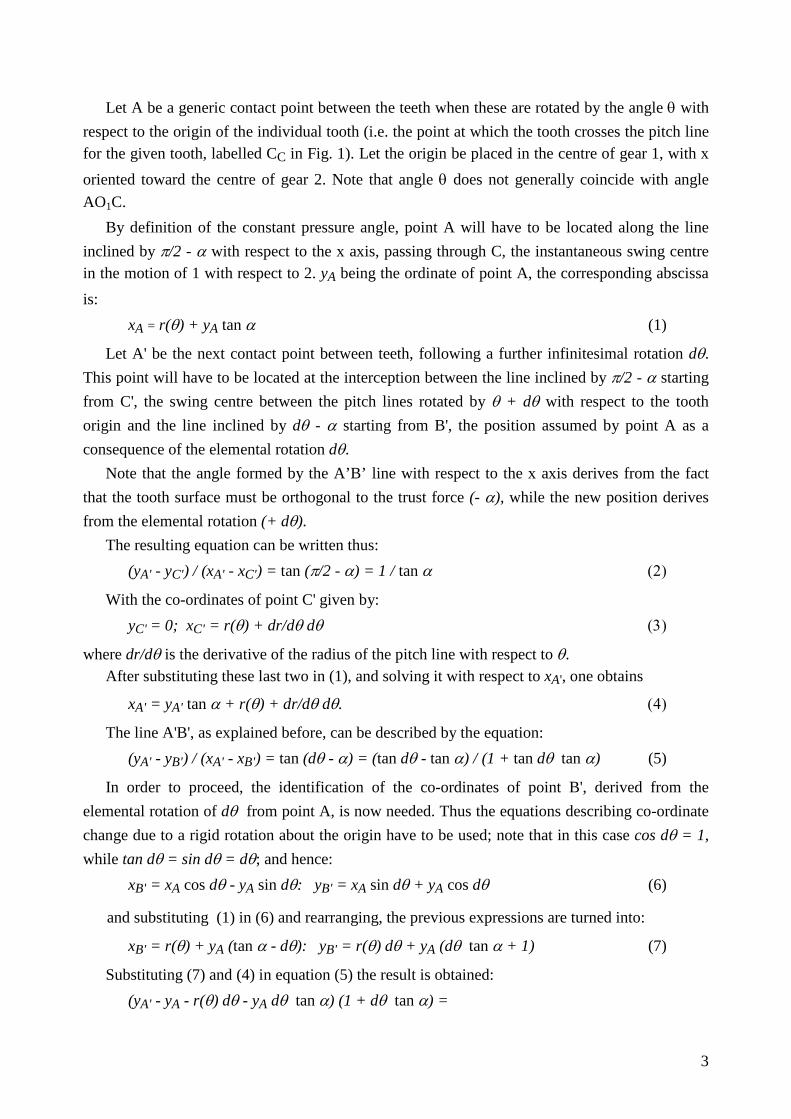
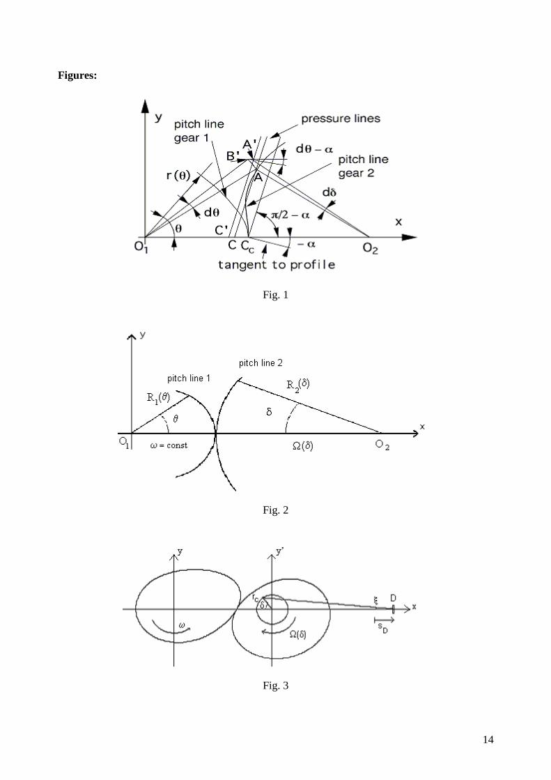
Let A be a generic contact point between the teeth when these are rotated by the angle θ with respect to the origin of the individual tooth (i.e. the point at which the tooth crosses the pitch line for the given tooth, labelled CC in Fig. 1). Let the origin be placed in the centre of gear 1, with x oriented toward the centre of gear 2. Note that angle θ does not generally coincide with angle AO1C.
By definition of the constant pressure angle, point A will have to be located along the line inclined by π/2 - α with respect to the x axis, passing through C, the instantaneous swing centre in the motion of 1 with respect to 2. yA being the ordinate of point A, the corresponding abscissa is:
xA = r(θ) + yA tan α (1)
Let A' be the next contact point between teeth, following a further infinitesimal rotation dθ. This point will have to be located at the interception between the line inclined by π/2 - α starting from C', the swing centre between the pitch lines rotated by θ + dθ with respect to the tooth origin and the line inclined by dθ - α starting from B', the position assumed by point A as a consequence of the elemental rotation dθ.
Note that the angle formed by the A’B’ line with respect to the x axis derives from the fact that the tooth surface must be orthogonal to the trust force (- α), while the new position derives from the elemental rotation (+ dθ).
The resulting equation can be written thus: (yA' - yC') / (xA' - xC') = tan (π/2 - α) = 1 / tan α (2)
With the co-ordinates of point C' given by: yC' = 0; xC' = r(θ) + dr/dθ dθ (3)
where dr/dθ is the derivative of the radius of the pitch line with respect to θ. After substituting these last two in (1), and solving it with respect to xA', one obtains
xA' = yA' tan α + r(θ) + dr/dθ dθ. (4)
The line A'B', as explained before, can be described by the equation: (yA' - yB') / (xA' - xB') = tan (dθ - α) = (tan dθ - tan α) / (1 + tan dθ tan α) (5)
In order to proceed, the identification of the co-ordinates of point B', derived from the elemental rotation of dθ from point A, is now needed. Thus the equations describing co-ordinate change due to a rigid rotation about the origin have to be used; note that in this case cos dθ = 1, while tan dθ = sin dθ = dθ; and hence:
xB' = xA cos dθ - yA sin dθ: yB' = xA sin dθ + yA cos dθ (6)
and substituting (1) in (6) and rearranging, the previous expressions are turned into:
xB' = r(θ) + yA (tan α - dθ): yB' = r(θ) dθ + yA (dθ tan α + 1) (7)
Substituting (7) and (4) in equation (5) the result is obtained: (yA' - yA - r(θ) dθ - yA dθ tan α) (1 + dθ tan α) =
4
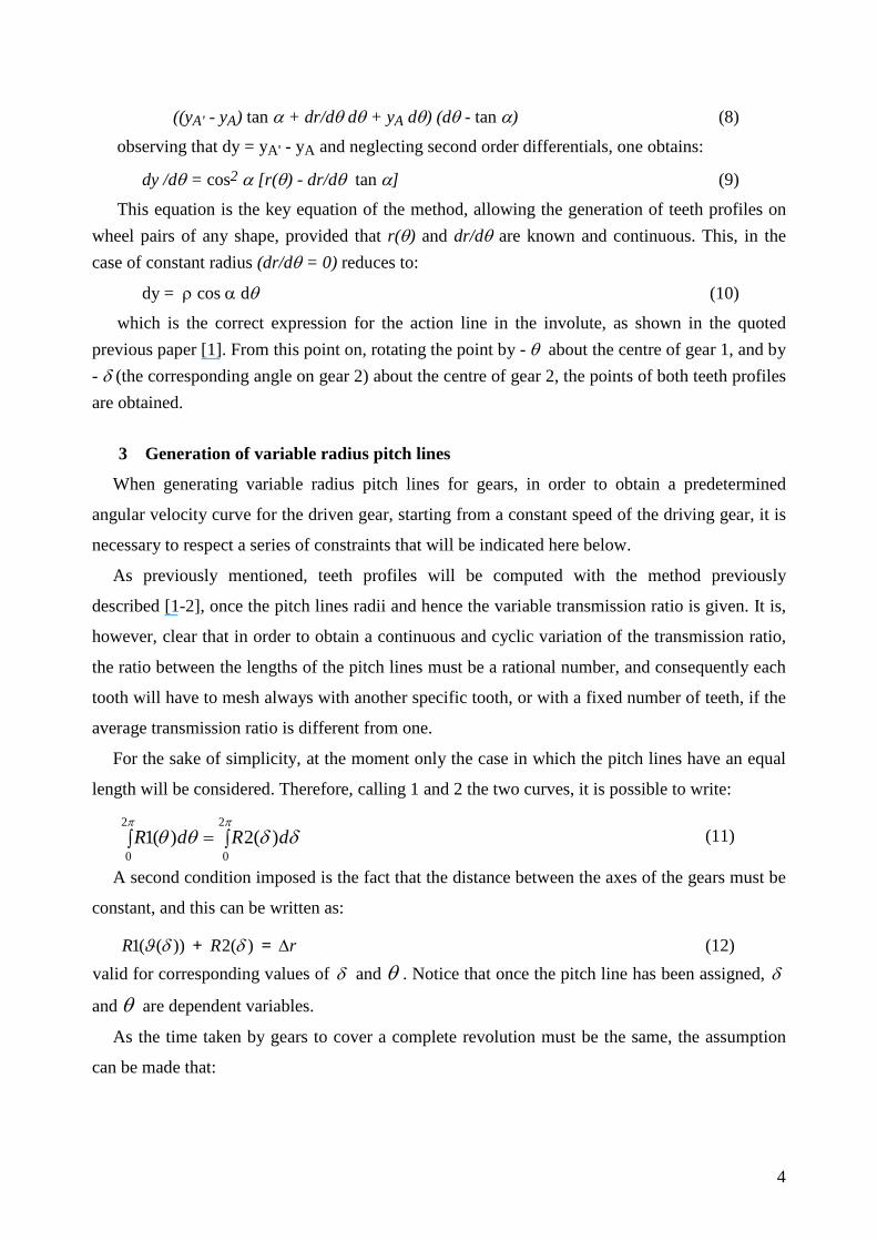
((yA' - yA) tan α + dr/dθ dθ + yA dθ) (dθ - tan α) (8)
observing that dy = yA' - yA and neglecting second order differentials, one obtains:
dy /dθ = cos2 α [r(θ) - dr/dθ tan α] (9)
This equation is the key equation of the method, allowing the generation of teeth profiles on wheel pairs of any shape, provided that r(θ) and dr/dθ are known and continuous. This, in the case of constant radius (dr/dθ = 0) reduces to:
dy = ρ cos α dθ (10)
which is the correct expression for the action line in the involute, as shown in the quoted previous paper [1]. From this point on, rotating the point by - θ about the centre of gear 1, and by - δ (the corresponding angle on gear 2) about the centre of gear 2, the points of both teeth profiles are obtained.
3 Generation of variable radius pitch lines
When generating variable radius pitch lines for gears, in order to obtain a predetermined
angular velocity curve for the driven gear, starting from a constant speed of the driving gear, it is
necessary to respect a series of constraints that will be indicated here below.
As previously mentioned, teeth profiles will be computed with the method previously
described [1-2], once the pitch lines radii and hence the variable transmission ratio is given. It is,
however, clear that in order to obtain a continuous and cyclic variation of the transmission ratio,
the ratio between the lengths of the pitch lines must be a rational number, and consequently each
tooth will have to mesh always with another specific tooth, or with a fixed number of teeth, if the
average transmission ratio is different from one.
For the sake of simplicity, at the moment only the case in which the pitch lines have an equal
length will be considered. Therefore, calling 1 and 2 the two curves, it is possible to write:
∫=∫ππ
δδθθ2
0
2
0)(2)(1 dRdR (11)
A second condition imposed is the fact that the distance between the axes of the gears must be
constant, and this can be written as:
))((1 δϑR + )(2 δR = r∆ (12) valid for corresponding values of δ and θ . Notice that once the pitch line has been assigned, δ
and θ are dependent variables.
As the time taken by gears to cover a complete revolution must be the same, the assumption
can be made that:
5
( ) δδ
θω
π πddT ∫ ∫ Ω
==2
'0
2
0
11 (13)
By manipulating this equation a basic condition for the building of variable radius gears can be
written as:
2)(
1 )(
2
0
2
0∫∫ ==
Ω
ππ
πδδτ
δδ
ω dd (14)
while it results that:
( ) πθθτπ
22
0=∫ d (15)
In addition, since a certain law of variation of the angular speed is given to gear 2 (or of the
transmission ratio τ), while assuming angular speed of the driving gear to be constant,
rearranging the equation one obtains:
Tdπ
θθ
πω π2
)(
22
0
=∫
Ω
= (16)
where T is the period of rotation of both gear 2 and gear 1. Note that, if the previous
expression is integrated only over a limited angle, the equation is obtained:
( ) θθ
ωδϑ
d∫Ω
=0
1 (17)
which represents the relation between angle δ and angle θ as shown in fig. 2.
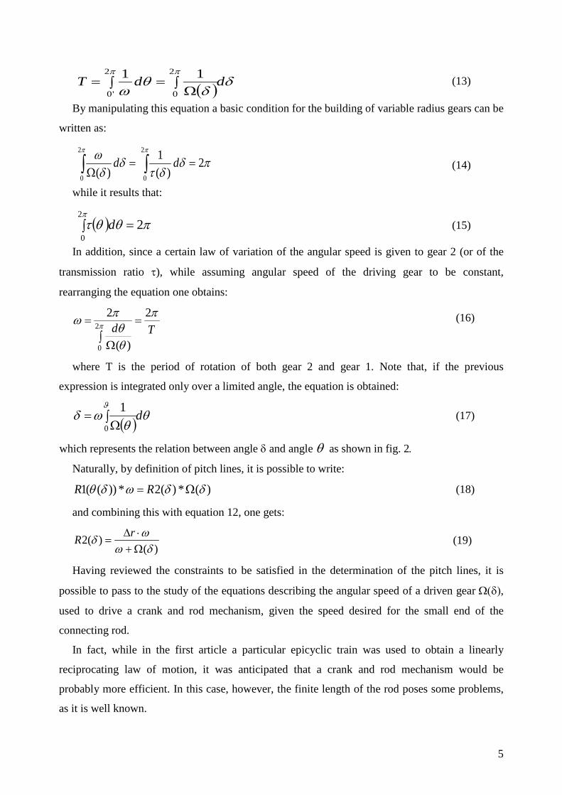
Naturally, by definition of pitch lines, it is possible to write:
)(*)(2*))((1 δδωδθ Ω= RR (18)
and combining this with equation 12, one gets:
)()(2
δωωδ
Ω+⋅∆
=rR (19)
Having reviewed the constraints to be satisfied in the determination of the pitch lines, it is
possible to pass to the study of the equations describing the angular speed of a driven gear Ω(δ),
used to drive a crank and rod mechanism, given the speed desired for the small end of the
connecting rod.
In fact, while in the first article a particular epicyclic train was used to obtain a linearly
reciprocating law of motion, it was anticipated that a crank and rod mechanism would be
probably more efficient. In this case, however, the finite length of the rod poses some problems,
as it is well known.
6
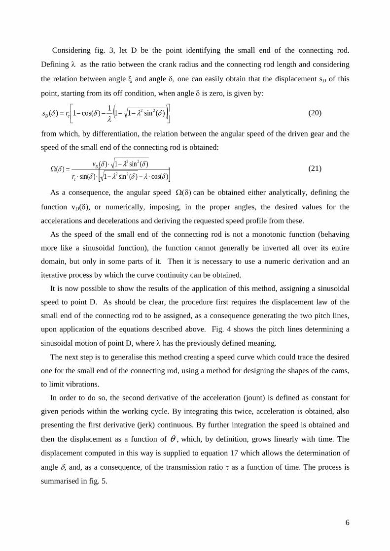
Considering fig. 3, let D be the point identifying the small end of the connecting rod.
Defining λ as the ratio between the crank radius and the connecting rod length and considering
the relation between angle ξ and angle δ, one can easily obtain that the displacement sD of this
point, starting from its off condition, when angle δ is zero, is given by:
( )
−−−−= )(sin111)cos(1)( 22 δλ
λδδ cD rs (20)
from which, by differentiation, the relation between the angular speed of the driven gear and the
speed of the small end of the connecting rod is obtained:
[ ])cos()(sin1)sin(
)(sin1)()(
22
22
δλδλδ
δλδδ
⋅−−⋅⋅
−⋅=Ω
c
D
rv (21)
As a consequence, the angular speed Ω(δ) can be obtained either analytically, defining the
function vD(δ), or numerically, imposing, in the proper angles, the desired values for the
accelerations and decelerations and deriving the requested speed profile from these.
As the speed of the small end of the connecting rod is not a monotonic function (behaving
more like a sinusoidal function), the function cannot generally be inverted all over its entire
domain, but only in some parts of it. Then it is necessary to use a numeric derivation and an
iterative process by which the curve continuity can be obtained.
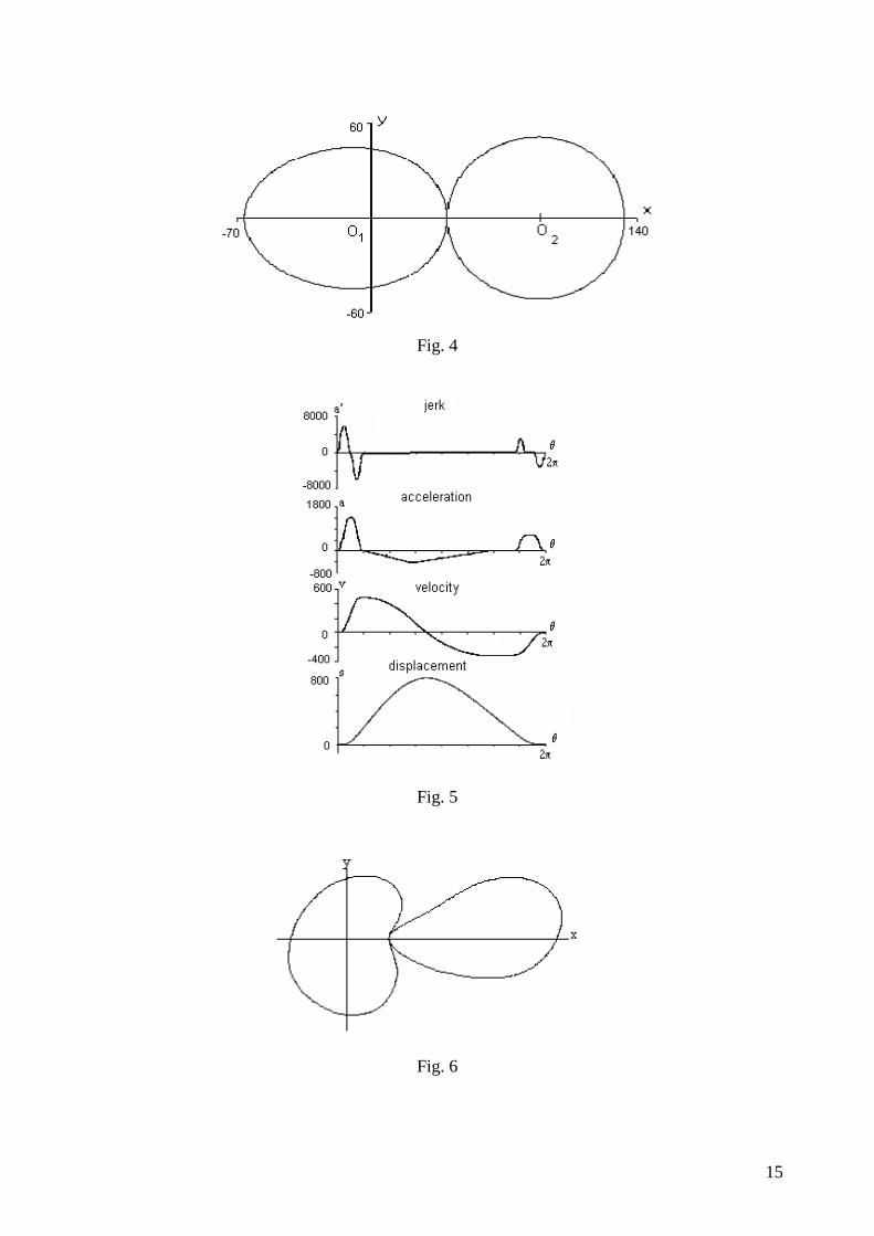
It is now possible to show the results of the application of this method, assigning a sinusoidal
speed to point D. As should be clear, the procedure first requires the displacement law of the
small end of the connecting rod to be assigned, as a consequence generating the two pitch lines,
upon application of the equations described above. Fig. 4 shows the pitch lines determining a
sinusoidal motion of point D, where λ has the previously defined meaning.
The next step is to generalise this method creating a speed curve which could trace the desired
one for the small end of the connecting rod, using a method for designing the shapes of the cams,
to limit vibrations.
In order to do so, the second derivative of the acceleration (jount) is defined as constant for
given periods within the working cycle. By integrating this twice, acceleration is obtained, also
presenting the first derivative (jerk) continuous. By further integration the speed is obtained and
then the displacement as a function of θ , which, by definition, grows linearly with time. The
displacement computed in this way is supplied to equation 17 which allows the determination of
angle δ, and, as a consequence, of the transmission ratio τ as a function of time. The process is
summarised in fig. 5.
7
It’s obvious that the previously defined conditions are necessary for the gears to be able to
describe the requested motion, but they do not guarantee that the gears obtained are regular and
able to mesh. Thus, all the controls explained in the first part of this paragraph have to be applied.
Figure 6 finally shows the results of the Doege-like pitch lines, as obtained by a procedure which
uses the formula described above to generate the desired velocity curve [13].
4 Generation of the teeth profiles.
As previously shown, once the r(θ) function is known, it is possible to generate both the right
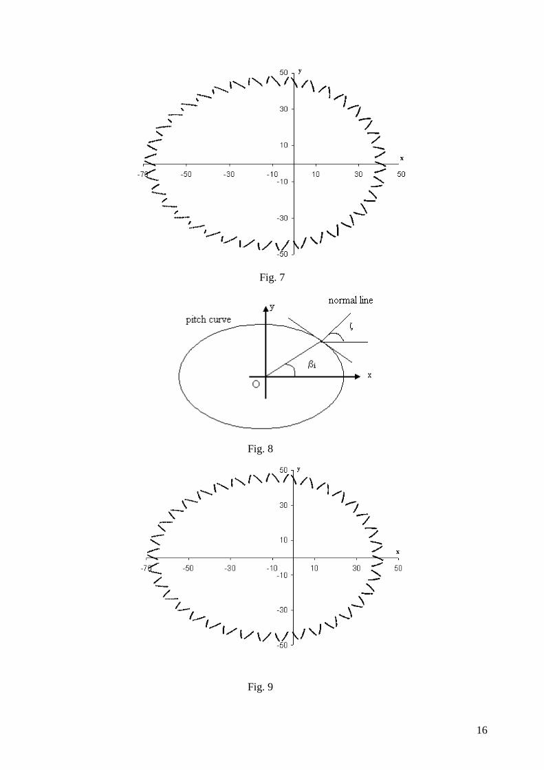
and the left profile of each tooth. Fig. 7 shows the calculated points of the teeth profiles, with
respect to one of the pitch lines represented in fig. 4 and with a constant pressure angle α=26°. In
this application both meshing gears have 36 teeth.
Because of the non-circular shape of the pitch lines, it can be noted that there are critical
conditions in which the procedure gives one or a few points per tooth. In order to obtain a better
determination of teeth profiles, a subroutine was introduced that calculates the angle between the
actual normal line to the pitch line and the horizontal axis, which is equal to the angle that the
tangent line makes with the vertical axis (Fig. 8).
Evaluating the difference between this angle and the one characteristic of a circular pitch line
(βir,l and ζ in fig. 8), a value to correct, by addition or subtraction, the inclination of the pressure
line is obtained. As a consequence, the pressure angle is assumed as constant within a certain
tooth, but it varies from tooth to tooth, being instead constant the pressure angle measured from
the tangent to the pitch line at the intersection point with the tooth profile [19].
It is clear that two meshing teeth on different gears must have the same pressure angle value,
and so they will receive the same correction.
Fig. 9 shows the teeth profiles generated starting from the same pitch line, but with the
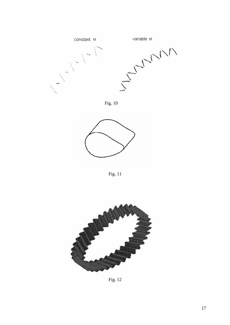
correction described above. The average pressure angle value is α=26. Fig. 10 shows an enlarged
image of some teeth presenting the integration points obtained with the two methods, and the
advantage is evident. In fact, since the integration interval is constant, more points present on a
tooth profile means more transmission duration. Since the modified pressure angle causes more
points to be present on one side of the tooth, where they were fewer, and less points on the other
side, where there were even too many, equilibrating the number of points between the two tooth
profiles, then the situation is judged preferable.
Naturally, the improvements deriving from the correction of the pressure line inclination are
particularly evident when the pitch lines are very different from a circular shape, as a greater
8
number of points belonging to the teeth profile is obtained, causing therefore an increment in the
contact ratio.
5 Helical Gears
If the teeth of a gear develop according to a spiral shape around a cylinder, the gear is defined
as helical. The main characteristic of such gears is that the teeth mesh progressively with a softer
and less noisy meshing. In addition, they can transmit a greater load and have a longer life.
Helical gears can be considered as consisting of a great number of thin cylindrical gears rigidly
rotated, thus creating a spiral along the gear axis.
The previous description is not valid for variable radius gears, as the solid built starting from
the pitch line would not be a cylinder if applying the rules previously described. In fact, if the
elemental step should be rigidly rotated, an irregular volume would be obtained. Also a
theoretical error is evident, as along the same meshing line, points with different transmission
ratios would be found, thus having different tangential speeds.
The primitive volume that must generate the variable radius gear has to be obtained by
extrusion of the pitch line (fig. 11), and the teeth must envelop this volume, with a spiral shape
giving the same benefits of traditional helical gears. This is obtained by moving the point of
initial tooth integration along the pitch line, determining a series of tooth profiles, all being
characterised by the same pressure angle. In order to achieve this goal, the basic method of tooth
profile generation is repeated many times with a starting point of integration shifted of a certain
angle along the primitive. As a consequence, a suitable number of sections of each gear with a
plane normal to the axis of rotation is obtained. By enveloping these sections both sides of each
tooth are determined, thus generating profiles which develop along a helical shape.
To calculate the offset angle value (difference between the integration starting angles on two
consecutive sections), it is necessary to assign the helix angle and to establish their distance. The
former is a design parameter whose value has to be chosen according to dynamic considerations,
while the latter must guarantee the best compromise between need for definition of the teeth
lateral surface and reduced computational weight. Once chosen this angular increment on the
driving gear, the corresponding value on the driven gear must be computed. In fact, for both
traditional and variable radius gears, the meshing profiles must have opposite helical directions.
The value of rotation that the second gear must receive is not generally equal to the one of the
first gear, as in this case the ratio arc / angle is not constant like with circular gears. Using the
same angle, with the opposite value, the detachment of the primitives would be obtained. Thus
9
the length of the arc was calculated, defined on the first gear pitch line by the new integration
starting point, and then the corresponding angle belonging to the second gear was evaluated.
Fig. 12 shows forty-three sections spaced out in a uniform way along the gear thickness. The
distance between the extreme sections identifies the gear thickness. Since a helix angle of 25
degrees and a thickness of 20 mm were chosen as design parameters, an offset angle of 0.00567
radiants between the first tooth starting points on two consecutive sections was imposed. The
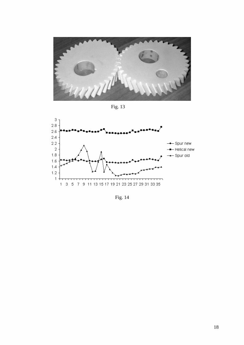
three-dimensional representation of the gears was generated by a CAD program, PRO-
ENGINEER, and the resulting solid was supplied to a rapid prototyping machine that "created"
the gears shown in fig. 13.
In order to show the improvements obtained with the methods described in the previous
paragraphs, an ad hoc formula has been introduced to evaluate the contact ratio:
( )2
1,,1 +− ∆+∆−∆
∆=
iiiii
irc
θθθ
θ (22)
where ∆θi is the primitive rotational angle variation from the beginning to the end of the contact
along the ith tooth, while ∆θi-1,i corresponds to variation from the beginning of meshing on the ith
tooth and the end on the i-1th one (zone in which there is a double contact between teeth) and
similarly ∆θi,i+1 from beginning on the i+1th tooth and the end on the ith one.
Fig. 14 shows the comparison of the contact ratio relative to the gears depicted in figg. 7, 9
and 13. As can be seen, the new approach, characterised by the variable pressure angle seems less
satisfactory, in terms of contact ratio, than the previous one in a small portion of the gear, thus
proving that the chosen basic pressure angle value is not optimal under this point of view in that
region. The helical gear is, as obvious, the best solution, as the contact ratio pattern is shifted
upwards of an about constant value of one with respect to corresponding spur gears.
CONCLUSION
The paper shows the actual results of the research developed at Calabria University on non-
circular gears. Though the study case presented in this paper is relative to a pair of elliptical pitch
lines, the method allows to build any helical gear, thanks to the procedure which varies the
pressure angle according to the local primitive shape. Moreover, if it is very stimulating to find a
solution for the problem of generating helical gears of non circular shape, on the other hand a
long way is expecting the researcher before he is able to instruct a numerical control milling
machine to actually build them. Also the effect of mounting the gears at the wrong distance, the
10
resistance of the teeth, and the effect of vibrations will have to be investigated, both theoretically
and experimentally.
However, if the work ahead is impressive, the work done so far is equally important, since
now it is clear that the building of helical non-circular gears is feasible on primitives of any
shape.
Nomenclature:
α pressure angle
βil,r value of θ at which the left or right profile of the i-th tooth crosses the pitch line
γil,r value of δ at which the left or right profile of the i-th tooth crosses the pitch line
δ rotational angle on gear 2
θ rotational angle on gear 1
ζ angle between the normal to the pitch line and the horizontal axis
λ ratio between the crank radius and the connecting rod length
ξ angle of inclination of the rod with respect to the line joining the centres
ρ radius of the base circle of a constant radius gear
τ instantaneous value of the transmission ratio between (constant or non-constant) radius
gears
ω speed of the driving gear
Ω speed of the driven gear
A actual mesh point
A' next mesh point
B' point obtained from a rigid rotation dθ of point A
Cc point in which the profile of the tooth crosses the pitch line (initial point of tooth profile
generation)
C actual contact point between pitch lines when teeth are in contact in A
C' actual contact point between pitch lines when teeth are in contact in A'
cr contact ratio
D point representing the centre of the small end of the rod
∆r distance between the axes of the two gears
O1 absolute centre of rotation of the pitch line of gear 1
11
O2 absolute centre of rotation of the pitch line of gear 2
nz number of teeth
r radius of the pitch line
rc crank radius
REFERENCES
1. Danieli, G.A., 2000, "Analytical Description of Meshing of Constant Pressure Angle Teeth
Profiles on a Variable Radius Gear and its Applications", Journal of Mechanical Design,
ASME Transactions,Vol. 122, pp. 123-129
2. Danieli, G.A. "Profilo di un Dente ad Angolo di Spinta Costante per Ruote a Primitiva
Generalizzata e Relative Applicazioni", Italian Patent Application No. CS96A00010,
deposited 25/7/96 granted 23/10/00, No. 1303048.
3. Anonymous, 1972, “Elliptical Gears are Back and More Versatile than Ever”, Product
Engineering, pp.34-38
4. Chironis, N.P., 1965, “Mechanisms, linkages, and mechanical controls”, New York,
McGraw-Hill
5. Emura, T. and Arakawa, A., 1992, “A New Steering Mechanism Using Non Circular
Gears” JSME International Journal, Series III, Vol.35, No.4, pp.604-610
6. Dooner, D. B.,1997, “Use of Non-circular Gears to Reduce Torque and Speed Fluctuations
in Rotating Shafts” ASME Journal of Mechanical Design, Vol.119, pp.299-306
7. Dooner, D. B., and Seireg, A., 1995, “The Kinematic Geometry of Gearing”, John Wiley
and Sons, Inc., New York
8. Chang, S.L., and Tsay, C.B., and Wu, L.I., 1996, “Mathematical Model and Undercutting
Analysis of Elliptical Gears Generated by Rack Cutters”, Mechanism and Machine Theory,
Vol.31, No.37, pp.879-890
12
9. Chang, S.L., and Tsay, C.B., 1998, “Computerized Tooth Profile Generation and Undercut
Analysis of Noncircular Gears Manufactured With Shaper Cutters”, Journal of Mechanical
Design, ASME Transactions,Vol. 120, pp. 92-99
10. Bair, B.W., 2002, “Computerized Tooth Profile Generation of Elliptical Gears
Manufactured by Shaper Cutters”, Journal of Materials Processing Technology, Vol. 122,
pp. 139-147
11. Litvin, F.L., and Tsay, C.B., 1985, ”Helical Gears with Circular Arc Teeth: Simulation of
Conditions of Meshing and Bearing Contact”, ASME Journal of Mechanisms,
Transmissions and Automation in Design, Vol.107, pp.556-564
12. Tsay, C.B., and Hwang, G:S:, 1994, “Application of the Theory of the Envelope to the
Determination of Camoid Profiles with Translating Followers”, ASME Journal of
Mechanical Design, Vol.116, pp.320-325
13. Doege, E. and Hindersmann, M., "Optimised Kinematics of Mechanical presses with
Noncircular Gears", Annals of the CIBP, Vol. 46/1/97, pp.213-216
14. Litvin, F., 1994, "Gears Geometry and Applied Theory", Prentice Hall, New Jersey
15. Figliolini, G., Lanni, C., and Ceccarelli, M., 2000, "On Kinematic Synthesis of Non-
Circular Gears", Proceedings of the International Conference on Gearing, Transmission,
and Mechanical Systems, Nottingham 2000, pp.283-292
16. Tong, S.H., and Yang, D.C.H., 1998, “Generation of Noncircular Pitch Curves”, ASME
Journal of Mechanical Design, Vol.120, pp.337-341
17. Danieli, G.A. "Ruote dentate elicoidali a raggio variabile e ad angolo di spinta costante",
Italian Patent Application No. CS99A0019, deposited 15/12/99
18. Danieli, G.A. Variable radius helical gears", PCT/IT00/00524 of 15/12/2000, WO
01/4469/3 of June the 6th 2001
13
19. Lozzi, A., 2000, “Non-circular gears-graphic generation of involutes and base outlines”,
IMechE, Vol.214, pp.411-422
Figure Captions
Fig. 1 Schematic representation of the tooth mesh for constant pressure angle on variable
radius gears
Fig. 2 Schematic representation of the two pitch lines
Fig. 3 Schematic representation of the investigated mechanism
Fig. 4 Pitch lines for λ=0.5 and r=100 mm, generating sinusoidal motion of point D
Fig. 5 Velocity profile determination through integration of the second derivative of the
acceleration
Fig. 6 Pitch lines of the Doege – like gears
Fig. 7 Teeth profiles with constant pressure angle (nz=36, =26° and r=100 mm)
Fig. 8 Schematic representation of the scheme to calculate correction
Fig. 9 Teeth profiles with pressure angle varying from tooth to tooth
Fig. 10 Blow up of the tooth profiles in the case of constant pressure angle and variable
pressure angle
Fig. 11 Three dimensional primitive for a variable radius gear
Fig. 12 Representation of tooth profiles for helical gears
Fig. 13 Variable radius helical gears built by a rapid prototyping machine
Fig. 14 Contact ratio for the gears represented in figg. 7, 9 and 13
14
Figures:
Fig. 1
Fig. 2
Fig. 3
15
Fig. 4
Fig. 5
Fig. 6
16
Fig. 7
Fig. 8
Fig. 9
17
Fig. 10
Fig. 11
Fig. 12
18
Fig. 13
Fig. 14