Network Function Virtualization over Cloud-Cloud Computing ...
40
Chapter Network Function Virtualization over Cloud-Cloud Computing as Business Continuity Solution Wagdy Anis Aziz, Eduard Babulak and David Al-Dabass Abstract Cloud computing provides resources by using virtualization technology and a pay-as-you-go cost model. Network Functions Virtualization (NFV) is a concept, which promises to grant network operators the required flexibility to quickly develop and provision new network functions and services, which can be hosted in the cloud. However, cloud computing is subject to failures which emphasizes the need to address user’ s availability requirements. Availability refers to the cloud uptime and the cloud capability to operate continuously. Providing highly available services in cloud computing is essential for maintaining customer confidence and satisfaction and preventing revenue losses. Different techniques can be implemented to increase the system’ s availability and assure business continuity. This chapter covers cloud computing as business continuity solution and cloud service availability. This chapter also covers the causes of service unavailability and the impact due to service unavailability. Further, this chapter covers various ways to achieve the required cloud service availability. Keywords: Cloud Computing, Business Continuity (BC), Disaster Recovery (DR), Network Functions Virtualization (NFV), Virtual Machine (VM), High Availability, Failover, Private Cloud, Hybrid Cloud, Public Cloud, Recovery Time Objective (RTO), Recovery Point Objective (RPO), IaaS, Paas, Saas, DRaaS 1. Introduction Cloud computing service outage can seriously affect workloads of enterprise systems and consumer data and applications [1, 2]. Several (e.g. the VM failure of Heroku hosted on Amazon EC2 in 2011) or even human (human error or burglary). It can lead to significant financial losses or even endanger human lives [3]. Amazon cloud services unavailability resulted in data loss of many high-profile sites and serious business issues for hundreds of IT managers. Furthermore, according to the CRN reports, the 10 biggest cloud service failures of 2017, including IBM’ s cloud infrastructure failure on January 26, Facebook on February 24, Amazon Web Ser- vices on February 28, Microsoft Azure on March 16, Microsoft Office 365 on March 21 and etc., caused production data loss, and prevented customers from accessing their accounts, services, projects, and critical data for a very long duration. In addi- tion, credibility of cloud providers took a hit because of these service failures [4]. The business continuity (BC) is important for service providers to deliver services to consumers in accordance with the SLAs. When building cloud 1
-
Upload
khangminh22 -
Category
Documents
-
view
1 -
download
0
Transcript of Network Function Virtualization over Cloud-Cloud Computing ...
Chapter
Network Function Virtualizationover Cloud-Cloud Computing asBusiness Continuity SolutionWagdy Anis Aziz, Eduard Babulak and David Al-Dabass
Abstract
Cloud computing provides resources by using virtualization technology and apay-as-you-go cost model. Network Functions Virtualization (NFV) is a concept,which promises to grant network operators the required flexibility to quicklydevelop and provision new network functions and services, which can be hosted inthe cloud. However, cloud computing is subject to failures which emphasizes theneed to address user’s availability requirements. Availability refers to the clouduptime and the cloud capability to operate continuously. Providing highly availableservices in cloud computing is essential for maintaining customer confidence andsatisfaction and preventing revenue losses. Different techniques can beimplemented to increase the system’s availability and assure business continuity.This chapter covers cloud computing as business continuity solution and cloudservice availability. This chapter also covers the causes of service unavailability andthe impact due to service unavailability. Further, this chapter covers various waysto achieve the required cloud service availability.
Keywords: Cloud Computing, Business Continuity (BC), Disaster Recovery (DR),Network Functions Virtualization (NFV), Virtual Machine (VM), HighAvailability, Failover, Private Cloud, Hybrid Cloud, Public Cloud, Recovery TimeObjective (RTO), Recovery Point Objective (RPO), IaaS, Paas, Saas, DRaaS
1. Introduction
Cloud computing service outage can seriously affect workloads of enterprisesystems and consumer data and applications [1, 2]. Several (e.g. the VM failure ofHeroku hosted on Amazon EC2 in 2011) or even human (human error or burglary).It can lead to significant financial losses or even endanger human lives [3]. Amazoncloud services unavailability resulted in data loss of many high-profile sites andserious business issues for hundreds of IT managers. Furthermore, according to theCRN reports, the 10 biggest cloud service failures of 2017, including IBM’s cloudinfrastructure failure on January 26, Facebook on February 24, AmazonWeb Ser-vices on February 28, Microsoft Azure on March 16, Microsoft Office 365 on March21 and etc., caused production data loss, and prevented customers from accessingtheir accounts, services, projects, and critical data for a very long duration. In addi-tion, credibility of cloud providers took a hit because of these service failures [4].
The business continuity (BC) is important for service providers to deliverservices to consumers in accordance with the SLAs. When building cloud
1

infrastructure, business continuity process must be defined to meet the availabilityrequirement of their services. In a cloud environment, it is important that BCprocesses should support all the layers; physical, virtual, control, orchestration, andservice to provide uninterrupted services to the consumers. The BC processes areautomated through orchestration to reduce the manual intervention, for example ifa service requires VM backup for every 6 hours, then backing up VM is scheduledautomatically every 6 hours [5].
Disaster Recovery (DR) is the coordinated process of restoring IT infrastructure,including data that is required to support ongoing cloud services, after a natural orhuman-induced disaster occurs. The basic underlying concept of DR is to have asecondary data center or site (DR site) and at a pre-planned level of operationalreadiness when an outage happens at the primary data center. Expensive servicedisruption can result from disasters, both manmade and natural. To prevent failurein a Cloud Service Provider (CSPs) system, 2 different disaster recovery models(DR) have been proposed: the first being the Traditional model, and 2nd beingcloud-based, � where the first is usable with both the dedicated and sharedapproach. The relevant model is chosen by customers using cost and speed as thedetermining factors. On the other hand, in the dedicated approach a customer isassigned an infrastructure leading to a higher speed and therefore cost. At the otherend of the spectrum the shared model, often referred to as the DistributedApproach, multiple users are assigned a given infrastructure, which results in acheaper outlay but leads to a lower recovery speed.
2. Background
2.1 Cloud computing
Cloud computing is storing, accessing, and managing huge data and softwareapplications over the Internet. Access to data is protected by firewalls. Users are stillusing their computers to access the cloud-hosted data/applications. The differencelies in the fact that these data/applications use no or little the storage and computeresources of these computers since they are running in the cloud.
Cloud computing provides the context of offering virtualized computingresources and services in a shared and scalable environment through the network. Abig percentage of global IT firms and governmental entities have incorporated cloudservices for a multitude of purposes such as those related to mission-orientedapplications and thus sensitive data. In order to provide full-support for theseapplications and their sensitive data, it is vital to include ample provision of envi-ronments that incorporate dependable cloud computing.
The National Institute of Standards and Technology (NIST) in SP 800-145, NISTspecifies that a cloud infrastructure should have the five essential characteristicslisted below:
• On-demand self-service
• Broad network access
• Resource pooling
• Rapid elasticity
• Measured service
2
Digital Service Platforms

NIST also specifies three primary cloud deployment models:
• Public
• Private
• Hybrid
As well as three primary cloud service models:
• Infrastructure as a Service (IaaS)
• Platform as a Service (PaaS)
• Software as a Service (SaaS)
2.2 Essential characteristics
2.2.1 On-demand self-service
In cloud computing, users have the ability to provision any IT resource that theyrequire on demand from a cloud, whenever they want. Self-service means that theconsumers themselves carry out all the activities required to provision the cloudresource.
To enable on-demand self-service, a cloud provider maintains a self-service portal,which allows consumers to view and order cloud services. The cloud provider pub-lishes a service catalog on the self-service portal. The service catalog lists items, suchas service offerings, service prices, service functions, request processes, and so on.
2.2.2 Broad network access
Consumers access cloud services on any client/endpoint device from anywhereover a network, such as the Internet or an organization’s private network.
2.2.3 Resource pooling
The provider’s computing resources are pooled to serve multiple consumersusing a multi-tenant model, with different physical and virtual resources dynami-cally assigned and re-assigned according to consumer demand. Usually, end-usershave no knowledge about the exact location of the resources they may want toaccess, but they may be able to specify location at a higher level of abstraction (e.g.,country, state, or datacenter). Examples of such resources include storage,processing, memory, and network bandwidth.
2.2.4 Rapid elasticity
Rapid elasticity refers to the ability for consumers to quickly request, receive,and later release as many resources as needed. The characteristic of rapid elasticitygives consumers the impression that unlimited IT resources can be provisioned atany given time. It enables consumers (in few minutes) to adapt to the variations inworkloads by quickly and dynamically expanding (scaling outward) or reducing(scaling inward) IT resources, and to proportionately maintain the requiredperformance level.
3
Network Function Virtualization over Cloud-Cloud Computing as Business Continuity SolutionDOI: http://dx.doi.org/10.5772/intechopen.97369

2.2.5 Measured service
A cloud infrastructure has a metering system that generates bills for the con-sumers based on the services used by them. The metering system continuouslymonitors resource usage per consumer and provides reports on resource utilization.For example, the metering system monitors utilization of processor time, networkbandwidth, and storage capacity.
2.3 Cloud deployment models
A cloud deployment model specifies how a cloud infrastructure is built, man-aged, and accessed. Each cloud deployment model may be used for any of the cloudservice models: IaaS, PaaS, and SaaS. The different deployment models present anumber of tradeoffs in terms of control, scale, cost, and availability of resources.
2.3.1 Public cloud
A public cloud is a cloud infrastructure deployed by a provider to offer cloudservices to the general public and/or organizations over the Internet. In the publiccloud model, there may be multiple tenants (consumers) who share common cloudresources. A provider typically has default service levels for all consumers of thepublic cloud. The provider may migrate a consumer’s workload at any time and toany location. Some providers may optionally provide features that enable a con-sumer to configure their account with specific location restrictions. Public cloudservices may be free, subscription-based or provided on a pay-per-use model.Figure 1 below illustrates a generic public cloud that is available to enterprises andto individuals.
2.3.2 Private cloud
A cloud infrastructure that is configured for a particular organization’s sole use istermed private cloud. Departments and business units within an organization relyon network services implemented on a private cloud for dedicated to consumers.Generally, organizations are likely to avoid the adoption of public clouds as they areused by the public to access their facilities over the Internet. A private cloud offersorganizations a greater degree of privacy, and control over the cloud infrastructure,applications, and data. There are two variants of a private cloud:
Figure 1.A generic public cloud available to enterprises and individuals.
4
Digital Service Platforms
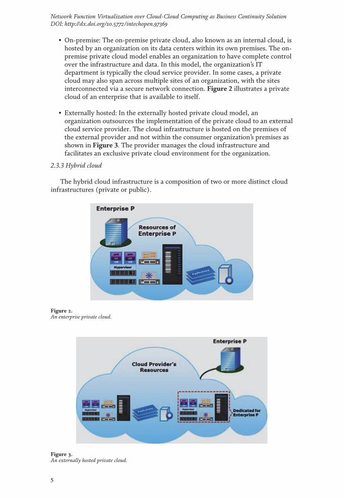
• On-premise: The on-premise private cloud, also known as an internal cloud, ishosted by an organization on its data centers within its own premises. The on-premise private cloud model enables an organization to have complete controlover the infrastructure and data. In this model, the organization’s ITdepartment is typically the cloud service provider. In some cases, a privatecloud may also span across multiple sites of an organization, with the sitesinterconnected via a secure network connection. Figure 2 illustrates a privatecloud of an enterprise that is available to itself.
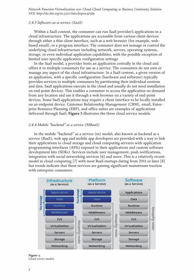
• Externally hosted: In the externally hosted private cloud model, anorganization outsources the implementation of the private cloud to an externalcloud service provider. The cloud infrastructure is hosted on the premises ofthe external provider and not within the consumer organization’s premises asshown in Figure 3. The provider manages the cloud infrastructure andfacilitates an exclusive private cloud environment for the organization.
2.3.3 Hybrid cloud
The hybrid cloud infrastructure is a composition of two or more distinct cloudinfrastructures (private or public).
Figure 2.An enterprise private cloud.
Figure 3.An externally hosted private cloud.
5
Network Function Virtualization over Cloud-Cloud Computing as Business Continuity SolutionDOI: http://dx.doi.org/10.5772/intechopen.97369

In a hybrid cloud environment, the component clouds are combined with openor proprietary technology, interoperable standards, architectures, protocols, dataformats; application programming interfaces (APIs), and so on. Figure 4 illustratesa hybrid cloud that is composed of an on-premise private cloud deployed by anenterprise and a public cloud serving enterprise and individual consumers.
2.4 Cloud service models
2.4.1 Infrastructure-as-a-service (IaaS)
An end-user can access processing, storage, network resources hosted in a cloudinfrastructure. The end-user can in particular run a multitude of software packages,which encompass a variety of applications as well as operating systems. The under-lying infrastructure of the cloud is not managed or controlled by the consumer buthe/she may have control over deployed applications, storage and operating systems,which may involve, for example in firewalls, a restricted use of specific componentsin the network.
IT resources such as storage capacity, network bandwidth and computing sys-tems, may be hired by Consumers, for example in the IaaS model, from a CloudService Providers (CSP). The cloud service provider deploys and manages theunderlying cloud infrastructure. While software, such as operating system (OS),database, and applications on the cloud resources, can be deployed and configuredby Consumers.
In some organizations IaaS users are typically IT system administrators. In suchcases, internal implementation of IaaS can even be carried out by the organization,with support given by the IaaS to its IT to manage the resources and services. Insuch examples the 2 options of Subscription-based or Resource-based (according toresource usage) can be implemented for IaaS pricing.
The IaaS provider pools the underlying IT resources and they are shared bymultiple consumers through a multi-tenant model.
2.4.2 Platform-as-a-service (PaaS)
The capability provided to the consumer is the deployment of consumer-createdor acquired applications created by means of programming languages, libraries,services, and tools supported by the PaaS provider. The consumer does not manageor control the underlying cloud infrastructure, including network, servers, operat-ing systems, or storage, but has control over the deployed applications and possiblythe configuration settings for the application-hosting environment.
Figure 4.A hybrid cloud composed of an on-premise private cloud and a public cloud.
6
Digital Service Platforms
2.4.3 Software-as-a-service (SaaS)
Within a SaaS context, the consumer can run SaaS provider’s applications in acloud infrastructure. The applications are accessible from various client devicesthrough either a thin client interface, such as a web browser (for example, web-based email), or a program interface. The consumer does not manage or control theunderlying cloud infrastructure including network, servers, operating systems,storage, or even individual application capabilities, with the possible exception oflimited user-specific application configuration settings.
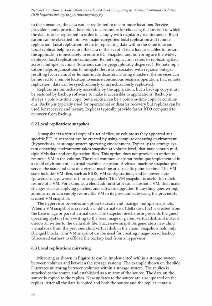
In the SaaS model, a provider hosts an application centrally in the cloud andoffers it to multiple consumers for use as a service. The consumers do not own ormanage any aspect of the cloud infrastructure. In a SaaS context, a given version ofan application, with a specific configuration (hardware and software) typicallyprovides services to multiple consumers by partitioning their individual sessionsand data. SaaS applications execute in the cloud and usually do not need installationon end-point devices. This enables a consumer to access the application on demandfrom any location and use it through a web browser on a variety of end-pointdevices. Some SaaS applications may require a client interface to be locally installedon an endpoint device. Customer Relationship Management (CRM), email, Enter-prise Resource Planning (ERP), and office suites are examples of applicationsdelivered through SaaS. Figure 5 illustrates the three cloud service models.
2.4.4 Mobile “backend” as a service (MBaaS)
In the mobile “backend” as a service (m) model, also known as backend as aservice (BaaS), web app and mobile app developers are provided with a way to linktheir applications to cloud storage and cloud computing services with applicationprogramming interfaces (APIs) exposed to their applications and custom softwaredevelopment kits (SDKs). Services include user management, push notifications,integration with social networking services [6] and more. This is a relatively recentmodel in cloud computing [7] with most BaaS startups dating from 2011 or later [8]but trends indicate that these services are gaining significant mainstream tractionwith enterprise consumers.
Figure 5.Cloud service models.
7
Network Function Virtualization over Cloud-Cloud Computing as Business Continuity SolutionDOI: http://dx.doi.org/10.5772/intechopen.97369

2.4.5 Serverless computing
Serverless computing is a cloud computing code execution model in which thecloud provider fully manages starting and stopping virtual machines as necessary toserve requests, and requests are billed by an abstract measure of the resourcesrequired to satisfy the request, rather than per virtual machine, per hour [9].Despite the name, it does not actually involve running code without servers [9].Serverless computing is so named because the business or person that owns thesystem does not have to purchase, rent or provision servers or virtual machines forthe back-end code to run on.
2.4.6 Function as a service (FaaS)
Function as a service (FaaS) is a service-hosted remote procedure call thatleverages serverless computing to enable the deployment of individual functions inthe cloud that run in response to events. FaaS is included under the broader termserverless computing, but the terms may also be used interchangeably [10].
2.5 Actors in cloud computing
Five roles in cloud environments are described in the NIST Cloud ComputingStandards Roadmap document. These five participating actors are the cloud pro-vider, the cloud consumer, the cloud broker, the cloud carrier and the cloud auditor.Table 1 presents the definitions of these actors [4].
2.6 Network functions virtualization telco cloud
2.6.1 History
A group of network service providers at the Software-Defined networking(SDN) and OpenFlow World Congress in October 2012, originally presented theNetwork Functions Virtualization (NFV) concept (11). These service providersaimed to simplify and speed up the process of adding new network functions orapplications.
Cloud Role Definition (see also ref. [11])
Consumer Any individual person or organization that has a business relationship with cloudproviders and consumes available services.
Provider Any individual entity or organization which is responsible for making servicesavailable and providing computing resources to cloud consumers
Broker An IT entity that provides an entry for managing performance and QoS of cloudcomputing services. In addition, it helps cloud providers and consumers withmanagement of service negotiations.
Auditor A party that can provide an independent evaluation of cloud services provided bycloud providers in terms of performance, security and privacy impact, informationsystem operations and etc. in the cloud environments.
Carrier An intermediary party that provides access and connectivity to consumers through anyaccess devices such as networks. Cloud carrier transports services from a cloudprovider to cloud consumers.
Table 1.The five actors in cloud computing environment.
8
Digital Service Platforms

2.6.2 Definition
NFV is set of techniques that virtualize network functions that are traditionallysupported on proprietary, dedicated hardware, such as traffic forwarding orEvolved Packet Core (EPC) capabilities. With NFV, functions like routing, loadbalancing and firewalls are hosted in virtual machines (VM) or in OS containers.Virtualized Network Functions (VNF), are an essential component of the NFVarchitecture, as shown in the Figure 6 below from ETSI NFV [12]. Multiple VNFscan be added to a standard server and can then be monitored and controlled by ahypervisor. ETSI NFV [12].
2.6.3 Features
Because NFV architecture virtualizes network functions that are thus supportedon commodity hardware, network managers can add, move, or change networkfunctions at the server level during a provisioning process. If a VNF running on avirtual machine requires more bandwidth, for example, the decision to scale ormove a VNF is to be taken by NFV management and orchestration functions thatcan move the virtual machine to another physical server or provision anothervirtual machine on the original server to handle part of the load. Having thisflexibility allows an IT department to respond in a more agile manner to changingbusiness goals and network service demands.
2.6.4 Benefits
While NFV can benefit enterprises, service providers have a more immediateuse case for it. Many see NFV’s potential to improve scalability and better utilizenetwork resources. If a customer requests a new function, for example, NFVenables the service provider to add the said function by configuring it in a virtualmachine without upgrading or buying new hardware.
Figure 6.Components of NFV architecture.
9
Network Function Virtualization over Cloud-Cloud Computing as Business Continuity SolutionDOI: http://dx.doi.org/10.5772/intechopen.97369

Basic NFV benefits also include reduced power consumption and increased theamiable physical space, since NFV eliminates the need for specific hardware appli-ances. NFV can then help reduce both operational and capital expenditures.
2.6.5 Cloud-native architecture is the foundation of 5G innovation
Through persistent effort and determination, Telecom operators areimplementing a digital transformation to create a better digital world. To provideenterprises and individuals with a real time, on demand, all online experiencerequires an end-to-end (E2E) coordinated architecture featuring agile, automatic,and intelligent operation during each phase. The comprehensive cloud adaptation ofnetworks, operation systems, and services is a prerequisite for this much-anticipated digital transformation.
In existing networks, operators have gradually used SDN and NFV to implementICT network hardware virtualization, but retain a conventional operational modeland software architecture. 5G networks require continuous innovation throughcloud adoption to customize network functions and enable on-demand networkdefinition and implementation and automatic O&M.
Physical networks are constructed based on DCs to pool hardware resources(including part of RAN and core network devices), which maximizes resourceutilization.
The “All Cloud” strategy is an illuminated exploration into hardware resourcepools, distributed software architecture, and automatic deployment. Operatorstransform networks using a network architecture based on data center (DC) inwhich all functions and service applications are running on the cloud DC, referredto as a Cloud-Native architecture.
In the 5G era, a single network infrastructure can meet diversified servicerequirements. Cloud-Native E2E network architecture has the following attributes:
• Provides logically independent network slicing on a single networkinfrastructure to meet diversified service requirements and provides DC-basedcloud architecture to support various application scenarios.
• Uses CloudRAN to reconstruct radio access networks (RAN) to providemassive connections of multiple standards and implement on-demanddeployment of RAN functions required by 5G.
• Simplifies core network architecture to implement on demand configuration ofnetwork functions through control and user plane separation, component-based functions, and unified database management.
• Implements automatic network slicing service generation, maintenance, andtermination for various services to reduce operating expenses through agilenetwork O&M.
3. Cloud computing for business continuity
Business continuity is a set of processes that includes all activities that a businessmust perform to mitigate the impact of service outage. BC entails preparing for,responding to, and recovering from a system outage that adversely affects businessoperations. It describes the processes and procedures a service provider establishesto ensure that essential functions can continue during and after a disaster. Business
10
Digital Service Platforms

continuity prevents interruption of mission-critical services, and reestablishes theimpacted services as swiftly and smoothly as possible by using an automated pro-cess. BC involves proactive measures, such as business impact analysis, risk assess-ment, building resilient IT infrastructure, deploying data protection solutions(backup and replication). It also involves reactive countermeasures, such as disasterrecovery, to be invoked in the event of a service failure. Disaster recovery (DR) isthe coordinated process of restoring IT infrastructure, including data that isrequired to support ongoing cloud services, after a natural or human-induceddisaster occurs. The basic underlying concept of DR is to have a secondary datacenter or site (DR site) and at a pre-planned level of operational readiness when anoutage happens at the primary data center.
Cloud service availability refers to the ability of a cloud service to perform itsagreed function according to business requirements and customer expectationsduring its operation. Cloud service providers need to design and build their infra-structure to maximize the availability of the service, while minimizing the impact ofan outage on consumers. Cloud service availability depends primarily on the reli-ability of the cloud infrastructure (compute, storage, and network) components,business applications that are used to create cloud services, and the availability ofdata. The time between two outages, whether scheduled or unscheduled, is com-monly referred as uptime, because the service is available during this time. Con-versely, the time elapsed during an outage (from the moment a service becomesunavailable to the moment it is restored) is referred to as downtime. A simplemathematical expression of service availability is based on the agreed service timeand the downtime.
Service availability %ð Þ ¼ Agreed service time� DowntimeAgreed service time
(1)
Agreed service time is the period where the service is supposed to be available. Forexample, if a service is offered to a consumer from 9 am to 5 pm Monday to Friday,then the agreed service time would be 8 x 5 = 40 hours per week. If this servicesuffered 2 hours of downtime during that week, it would have an availability of 95%.
In a cloud environment, a service provider publishes the availability of a servicein the SLA. For example, if the service is agreed to be available for 99.999 percent(also referred to as five 9 s availability) then the allowable service downtime peryear is approximately 5 minutes. Therefore, it is important for the service providerto identify the causes of service failure, and analyze its impact to the business.
3.1 Causes of cloud service unavailability
This section listed some of the key causes of service unavailability. Data centerfailure is not the only cause of service failure. Poor application design or resourceconfiguration errors can also lead to service outage. For example, if the web portal isdown for some reason, then the services are inaccessible to the consumers, whichleads to service unavailability. Even unavailability of data due to several factors(data corruption and human error) also leads to service unavailability. A cloudservice might also cease to function due to an outage of the dependent services.Perhaps even more impactful on the availability are the outages that are required asa part of the normal course of doing business. The IT department is routinelyrequired to take on activities such as refreshing the data center infrastructure,migration, running routine maintenance or even relocating to a new data center.Any of these activities can have its own significant and negative impact on serviceavailability.
11
Network Function Virtualization over Cloud-Cloud Computing as Business Continuity SolutionDOI: http://dx.doi.org/10.5772/intechopen.97369

In general, the outages can be broadly categorized into planned and unplannedoutages. Planned outages may include installation and maintenance of new hard-ware, software upgrades or patches, performing application and data restores,facility operations (renovation and construction), and migration. Unplanned out-ages include failure caused by human errors, database corruption, failure of physi-cal and virtual components, and natural or human-made disasters.
3.2 Impact of cloud service unavailability
Cloud service unavailability or service outage results in loss of productivity, lossof revenue, poor financial performance, and damages to reputation. Loss of revenueincludes direct loss, compensatory payments, future revenue loss, billing loss, andinvestment loss. Damages to reputations may result in a loss of confidence orcredibility with customers, suppliers, financial markets, banks, and business part-ners. Other possible consequences of service outage include the cost of additionalrented equipment, overtime, and extra shipping.
3.3 Methods to achieve required cloud service availability
With the aim of meeting the required service availability, the service providershould build a resilient cloud infrastructure. Building a resilient cloud infrastructurerequires the following high availability solutions:
• Deploying redundancy at both the cloud infrastructure component level andthe site (data center) level to avoid single point of failure
• Deploying data protection solutions such as backup and replication
• Implementing automated cloud service failover
• Architecting resilient cloud applications
For example when a disaster occurred at one of the service provider’s datacenter, then BC triggers the DR process. This process typically involves both oper-ational personnel and automated procedure in order to reactivate the service(application) at a functioning data center. This requires the transfer of applicationusers, data, and services to the new data center. This involves the use of redundantinfrastructure across different geographic locations, live migration, backup, andreplication solutions.
4. Building fault tolerance cloud infrastructure
This section covers the key fault tolerance mechanisms at the cloud infrastruc-ture component level and covers the concept of service availability zones. Thissection also covers automated service failover across zones along with zone config-urations such as active/active and active/passive.
4.1 Single points of failure (SPOF)
Highly available infrastructures are typically configured without single points offailure as shown in Figure 7 to ensure that individual component failures do not
12
Digital Service Platforms

result in service outages. The general method to avoid single points of failure is toprovide redundant components for each necessary resource, so that a service cancontinue with the available resource even if a component fails. Service providermay also create multiple service availability zones to avoid single points of failure atdata center level.
Usually, each zone is isolated from others, so that the failure of one zone wouldnot impact the other zones. It is also important to have high availability mechanismsthat enable automated service failover within and across the zones in the event ofcomponent failure, data loss, or disaster.
N + 1 redundancy is a common form of fault tolerance mechanism that ensuresservice availability in the event of a component failure. A set of N components hasat least one standby component. This is typically implemented as an active/passivearrangement, as the additional component does not actively participate in theservice operations. The standby component is active only if any one of the activecomponents fails. N + 1 redundancy with active/active component configuration isalso available. In such cases, the standby component remains active in the serviceoperation even if all other components are fully functional. For example, if active/active configuration is implemented at the site level, then a cloud service is fullydeployed in both the sites. The load for this cloud service is balanced between thesites. If one of the site is down, the available site would manage the serviceoperations and manage the workload.
4.2 Avoiding single points of failure
Single points of failure can be avoided by implementing fault tolerancemechanisms such as redundancy:
• Implement redundancy at component level: (i) Compute, (ii) Storage, (iii)Network.
• Implement multiple service availability zones: (i) Avoids single points offailure at data center (site) level, (ii) Enable service failover globally.
It is important to have high availability mechanisms that enable automatedservice failover.
Figure 7.Single Point of Failure.
13
Network Function Virtualization over Cloud-Cloud Computing as Business Continuity SolutionDOI: http://dx.doi.org/10.5772/intechopen.97369

4.3 Implementing redundancy at component level
The underlying cloud infrastructure components (compute, storage, and net-work) should be highly available and single points of failure at component levelshould be avoided. The example shown in Figure 8 represents an infrastructuredesigned to mitigate the single points of failure at component level. Single points offailure at the compute level can be avoided by implementing redundant computesystems in a clustered configuration. Single points of failure at the network level canbe avoided via path and node redundancy and various fault tolerance protocols.Multiple independent paths can be configured between nodes so that if a compo-nent along the main path fails, traffic is rerouted along another.
The key techniques for protecting storage from single points of failure are RAID,erasure coding techniques, dynamic disk sparing, and configuring redundant stor-age system components. Many storage systems also support redundant array inde-pendent nodes (RAIN) architecture to improve the fault tolerance. The followingslides will discuss the various fault tolerance mechanisms as listed on the slide toavoid single points of failure at the component level.
4.4 Implementing multiple service availability zones
An important high availability design best practice in a cloud environment is tocreate service availability zones. A service availability zone is a location with its ownset of resources and isolated from other zones to avoid that a failure in one zone willnot impact other zones. A zone can be a part of a data center or may even becomprised of the whole data center. This provides redundant cloud computingfacilities on which applications or services can be deployed. Service providers typ-ically deploy multiple zones within a data center (to run multiple instances of aservice), so that if one of the zone incurs outage due to some reasons, then theservice can be failed over to the other zone. They also deploy multiple zones acrossgeographically dispersed data centers (to run multiple instances of a service), sothat the service can survive even if the failure is at the data center level. It is alsoimportant that there should be a mechanism that allows seamless (automated)failover of services running in one zone to another.
Figure 8.Implementing Redundancy at Component Level.
14
Digital Service Platforms

To ensure robust and consistent failover in case of a failure, automated servicefailover capabilities are highly desirable to meet stringent service levels. This isbecause manual steps are often error prone and may take considerable time toimplement. Automated failover also provides a reduced RTO when compared to themanual process. A failover process also depends upon other capabilities, includingreplication and live migration capabilities, and reliable network infrastructurebetween the zones. The following slides will demonstrate the active/passive andactive/active zone configurations, where the zones are in different remote locations.
Figure 9 shows an example of active/passive zone configuration. In this sce-nario, all the traffic goes to the active zone (primary zone) only and the storage isreplicated from the primary zone to the secondary zone. Typically in an active/passive deployment, only the primary zone has deployed cloud service applications.When a disaster occurs, the service is failed over to the secondary zone. The onlyrequirement is to start the application instances in the secondary zone and thetraffic is rerouted to this location.
In some active/passive implementation, both the primary and secondary zonehave services running, however only the primary zone is actively handling requestsfrom the consumers. If the primary zone goes down, the service is failed over to thesecondary zone and all the requests are rerouted. This implementation providesfaster restore of a service (very low RTO).
Figure 10 shows an example of implementing active/active configuration acrossdata centers (zones), and the VMs running at both the zones collectively offer thesame service. In this case, both the zones are active, running simultaneously, han-dling consumers requests and the storage is replicated between the zones. Thereshould be a mechanism in place to synchronize the data between the two zones. Ifone of the zone fails, the service is failed over to the other active zone. The key pointto be noted here is until the primary zone is restored, the secondary zone may havea sudden increase in workload.
So, it is important to initiate additional instances to handle the workload atsecondary zone. The active/active design gives the fastest recovery time.
Figure 9.Active/Passive Zone Configuration.
15
Network Function Virtualization over Cloud-Cloud Computing as Business Continuity SolutionDOI: http://dx.doi.org/10.5772/intechopen.97369

The figure details the underlying techniques such as live migration of VMs usingstretched cluster, which enables continues availability of service in the event ofcompute, storage, and zone (site) failure.
5. Data protection solution: backup
This section covers an introduction to backup and recovery as well as a review ofthe backup requirements in a cloud environment. This lesson also covers guest-leveland image-level backup methods. Further, this section covers backup as a service,backup service deployment options, and deduplication for backup environment.
5.1 Data protection overview
Like protecting the infrastructure components (compute, storage, and net-work), it is also critical for organizations to protect the data by making copies of itso that it is available for restoring the service even if the original data is no longeravailable. Typically organizations implement data protection solution in order toprotect the data from accidentally deleting files, application crashes, data corrup-tion, and disaster. Data should be protected at local location and as well as to aremote location to ensure the availability of service. For example, when a service isfailed over to other zone (data center), the data should be available at the destina-tion in order to successfully failover the service to minimize the impact to theservice.
One challenge to data protection that remains unchanged is determining the“right” amount of protection required for each data set. A “tiered approach” to dataprotection takes into account the importance of the data. Individual applications orservices and associated data sets have different business values, require differentdata protection strategies. As a result, a well-executed data protection infrastructureshould be implemented by a service provider to offer a choice of cost effectiveoptions to meet the various tiers of protection needed. In a tiered approach, dataand applications (services) are allocated to categories (tiers) depending on theirimportance. For example, mission critical services are tier 1, important but less
Figure 10.Active/Active Zone Configuration.
16
Digital Service Platforms

time-critical services are tier 2, and non-critical services are tier 3. Using tiers,resources and data protection techniques can be applied more cost effectively tomeet the more stringent requirements of critical services while less expensiveapproaches are used for the other tiers. The two key data protection solutionswidely implemented are backup and replication.
5.2 Backup and recovery
A backup is an additional copy of production data, created and retained for thesole purpose of recovering the lost or corrupted data. With the growing businessand the regulatory demands for data storage, retention, and availability, cloudservice providers face the task of backing up an ever-increasing amount of data.This task becomes more challenging with the growth of data, reduced IT budgets,and less time available for taking backups. Moreover, service providers need fastbackup and recovery of data to meet their service level agreements. The amount ofdata loss and downtime that a business can endure in terms of RPO and RTO are theprimary considerations in selecting and implementing a specific backup strategy.RPO specifies the time interval between two backups. For example, if a servicerequires an RPO of 24 hours, the data need to be backed up every 24 hours. RTOrelates to the time taken by the recovery process. To meet the defined RTO, theservice provider should choose the appropriate backup media or backup target tominimize the recovery time. For example, a restore from tapes takes longer tocomplete than a restore from disks. Service providers need to evaluate the variousbackup methods along with their recovery considerations and retention require-ments to implement a successful backup and recovery solution in a cloudenvironment.
5.3 Backup requirements in a cloud environment
In a cloud environment, applications typically run on VMs. Multiple VMs arehosted on single or clustered physical compute systems. The virtualized computesystem environment is typically managed from a management server, which pro-vides a centralized management console for managing the environment. The inte-gration of backup application with the management server of virtualizedenvironment is required. Advanced backup methods require the backup applicationto obtain a view of the virtualized environment and send configuration commandsrelated to backup to the management server. The backup may be performed eitherfile-by-file or as an image. Similarly, recovery requires either/both file level recov-ery and/or full VM recovery from the image. Cloud services have different avail-ability requirement and that would affect the backup strategy. For example, if theconsumer chose a higher backup service level (e.g. platinum) for their VMinstances, then the backup would happen more frequently, have a lower RTO, andalso have longer term retention when compared to lower-level service tiers. Typi-cally, cloud environment has large volume of redundant data. Backing up of redun-dant data would significantly affect the backup window and increase the operatingexpenditure. Service provider needs to consider deduplication techniques to over-come these challenges. It is also important to ensure that most of the backup andrecovery operations need to be automated.
5.4 Backup as a service
The unprecedented growth in data volume confronting today’s IT organizationschallenges not only IT management and budgets, but also all aspects of data
17
Network Function Virtualization over Cloud-Cloud Computing as Business Continuity SolutionDOI: http://dx.doi.org/10.5772/intechopen.97369

protection. The complexity of the data environment, exemplified by the prolifera-tion and dynamism of virtual machines, constantly outpaces existing data backupplans. Deployment of a new backup solution takes weeks of planning, justification,procurement, and setup. Some organizations find the traditional on-premise backupapproach inadequate to the challenge.
Service providers offer backup as a service that enables an organization toreduce its backup management overhead. It also enables the individual consumer toperform backup and recovery anytime, from anywhere, using a network connec-tion. Backup as a service enables enterprises to procure backup services on-demand.Consumers do not need to invest in capital equipment in order to implement andmanage their backup infrastructure. Many organizations’ remote and branch officeshave limited or no backup in place. Mobile workers represent a particular riskbecause of the increased possibility of lost or stolen machines. Backing up to cloudensures regular and automated backups for these sites and workers who lack localIT staff, or who lack the time to perform and maintain regular backups.
5.5 Backup service deployment options
There are three common backup service deployment options that a cloud serviceproviders offer to their consumers. These deployment options are:
• Local backup service (Managed backup service): This option is suitable when acloud service provider is already providing some form of cloud services(example: compute services) to the consumers. The service provider maychoose to offer backup services to the consumers, helping protect consumer’sdata that is being hosted in the cloud.
• Replicated backup service: This is an option where a consumer performsbackup at their local site but does not want to either own or manage or incurthe expense of a remote site for disaster recovery purposes. For suchconsumers, a cloud service provider offers replicated backup service thatreplicates backup data to a remote disaster recovery site.
• Remote backup service: In this option, consumers do not perform any backupat their local site. Instead, their data is transferred over a network to a backupinfrastructure managed by the cloud service provider.
6. Data protection solution: replication
This section covers the replication and its types. This section also covers localreplication methods such as snapshot and mirroring. This section further coversremote replication methods such as synchronous and asynchronous remote replica-tions along with continuous data protection (CDP). Finally, this lesson covers areplication use case, Disaster Recovery as a Service (DRaaS).
6.1 Introduction to replication
It is necessary for cloud service providers to protect mission-critical data andminimize the risk of service disruption. If a local outage or disaster occurs, fasterdata and VM restore, and restart is essential to ensure business continuity. One ofthe ways to ensure BC is replication, which is the process of creating an exact copy(replica) of the data. These replica copies are used for restore and restart services ifdata loss occurs. Based on the availability requirements for the service being offered
18
Digital Service Platforms
to the consumer, the data can be replicated to one or more locations. Serviceprovider should provide the option to consumers for choosing the location to whichthe data is to be replicated in order to comply with regulatory requirements. Repli-cation can be classified into two major categories: local replication and remotereplication. Local replication refers to replicating data within the same location.Local replicas help to restore the data in the event of data loss or enables to restartthe application immediately to ensure BC. Snapshot and mirroring are the widelydeployed local replication techniques. Remote replication refers to replicating dataacross multiple locations (locations can be geographically dispersed). Remote repli-cation helps organizations to mitigate the risks associated with regional outagesresulting from natural or human-made disasters. During disasters, the services canbe moved to a remote location to ensure continuous business operation. In a remotereplication, data can be synchronously or asynchronously replicated.
Replicas are immediately accessible by the application, but a backup copy mustbe restored by backup software to make it accessible to applications. Backup isalways a point-in-time copy, but a replica can be a point-in-time copy or continu-ous. Backup is typically used for operational or disaster recovery but replicas can beused for recovery and restart. Replicas typically provide faster RTO compared torecovery from backup.
6.2 Local replication: snapshot
A snapshot is a virtual copy of a set of files, or volume as they appeared at aspecific PIT. A snapshot can be created by using compute operating environment(hypervisor), or storage system operating environment. Typically the storage sys-tem operating environment takes snapshot at volume level, that may contain mul-tiple VMs data and configuration files. This option does not provide an option torestore a VM in the volume. The most common snapshot technique implemented ina cloud environment is virtual machine snapshot. A virtual machine snapshot pre-serves the state and data of a virtual machine at a specific point-in-time. The VMstate includes VM files, such as BIOS, VM configurations, and its power state(powered-on, powered-off, or suspended). This VM snapshot is useful for quickrestore of a VM. For example, a cloud administrator can snapshot a VM, then makechanges such as applying patches, and software upgrades. If anything goes wrong,administrator can simply restore the VM to its previous state using the previouslycreated VM snapshot.
The hypervisor provides an option to create and manage multiple snapshots.When a VM snapshot is created, a child virtual disk (delta disk file) is created fromthe base image or parent virtual disk. The snapshot mechanism prevents the guestoperating system from writing to the base image or parent virtual disk and insteaddirects all writes to the delta disk file. Successive snapshots generate a new childvirtual disk from the previous child virtual disk in the chain. Snapshots hold onlychanged blocks. This VM snapshot can be used for creating image-based backup(discussed earlier) to offload the backup load from a hypervisor.
6.3 Local replication: mirroring
Mirroring as shown in Figure 11 can be implemented within a storage systembetween volumes and between the storage systems. The example shown on the slideillustrates mirroring between volumes within a storage system. The replica isattached to the source and established as a mirror of the source. The data on thesource is copied to the replica. New updates to the source are also updated on thereplica. After all the data is copied and both the source and the replica contain
19
Network Function Virtualization over Cloud-Cloud Computing as Business Continuity SolutionDOI: http://dx.doi.org/10.5772/intechopen.97369

identical data, the replica can be considered as a mirror of the source. While thereplica is attached to the source, it remains unavailable to any other computesystem. However, the compute system continues to access the source. After thesynchronization is complete, the replica can be detached from the source and madeavailable for other business operations such as backup and testing. If the sourcevolume is not available due to some reason, the replica enables to restart the serviceinstance on it or restores the data to the source volume to make it available foroperations.
6.4 Remote replication: synchronous
Synchronous replication as shown in Figure 12 provides near zero RPO wherethe replica is identical to the source at all times.
In synchronous replication, writes must be committed to the source and theremote replica (or target) prior to acknowledging “write complete” to the compute
Figure 11.Local Replication: Mirroring.
Figure 12.Remote Replication: Synchronous.
20
Digital Service Platforms

system. Additional writes on the source cannot occur until each preceding write hasbeen completed and acknowledged. This ensures that data is identical on the sourceand the replica at all times. Further, writes are transmitted to the remote site exactlyin the order in which they are received at the source. Therefore, write ordering ismaintained. The figure on the slide illustrates an example of synchronous remotereplication. Data can be replicated synchronously across multiple sites. If the pri-mary zone is unavailable due to disaster, then the service can be restarted immedi-ately in other zone to meet the required SLA.
Application response time is increased with synchronous remote replicationbecause writes must be committed on both the source and the target before sendingthe “write complete” acknowledgment to the compute system. The degree ofimpact on response time depends primarily on the distance and the network band-width between sites. If the bandwidth provided for synchronous remote replicationis less than the maximum write workload, there will be times during the day whenthe response time might be excessively elongated, causing applications to time out.The distances over which synchronous replication can be deployed depend on theapplication’s capability to tolerate the extensions in response time. Typically syn-chronous remote replication is deployed for distances less than 200 KM (125 miles)between the two sites.
6.5 Remote replication: asynchronous
It is important for a service provider to replicate data across geographical locationsin order to mitigate the risk involved during disaster. If the data is replicated (syn-chronously) between zones and the disaster strikes, then there would be a chance thatboth the zones may be impacted. This leads to data loss and service outage. Replicat-ing data across zones which are 1000s of KM apart would help service provider toface any disaster. If a disaster strikes at one of the regions then the data would still beavailable in another region and the service could move to the location.
In asynchronous remote replication as shown in Figure 13, a write from acomputer system is committed to the source and immediately acknowledged to thecompute system.
It enables replication of data over distances of up to several thousand kilometersbetween the primary zone and the secondary zones (remote locations). Asynchro-nous replication also mitigates the impact to the application’s response time becausethe writes are acknowledged immediately to the compute system. In this case, therequired bandwidth can be provisioned equal to or greater than the average writeworkload. Data can be buffered during times when the bandwidth is insufficientand moved later to the remote zones. Therefore, adequate buffer capacity should beprovisioned. RPO depends on the size of the buffer, the available network
Figure 13.Remote replication: asynchronous.
21
Network Function Virtualization over Cloud-Cloud Computing as Business Continuity SolutionDOI: http://dx.doi.org/10.5772/intechopen.97369
bandwidth, and the write workload to the source. Asynchronous replicationimplementations can take advantage of locality of reference (repeated writes to thesame location). If the same location is written multiple times in the buffer prior totransmission to the remote zones, only the final version of the data is transmitted.This feature conserves link bandwidth.
6.6 Advanced replication solution: continuous data protection (CDP)
Mission-critical applications running on computer systems often require instantand unlimited data recovery points. Traditional data protection technologies offer alimited number of recovery points. If data loss occurs, the system can be rolled backonly to the last available recovery point. Mirroring offers continuous replication;however, if logical corruption occurs to the production data, the error might prop-agate to the mirror, which makes the replica unusable. Ideally, CDP provides theability to restore data to any previous point-in-time images (PIT). It enables thiscapability by tracking all the changes to the production devices and maintainingconsistent point-in-time images. CDP enables one to perform operational recovery(protection against human errors, data corruption, and virus attacks) through localreplication and disaster recovery through remote replication. CDP minimizes bothRPO and RTO. In CDP, data changes are continuously captured and stored in aseparate location from the primary storage. With CDP, recovery from data corrup-tion poses no problem because it allows going back to any PIT image prior to thedata corruption incident.
6.7 Replication use case: disaster recovery-as-a-service (DRaaS)
Facing an increased reliance on IT and the ever-present threat of natural or man-made disasters, organizations need to rely on business continuity processes tomitigate the impact of service disruptions. Traditional disaster recovery methodsoften require buying and maintaining a complete set of IT resources at secondarydata centers that matches the business-critical systems at the primary data center.This includes sufficient storage to house a complete copy of all of the enterprise’sbusiness data by regularly replicating production data on the mirror systems atsecondary site. This may be a complex process and expensive solution for a signif-icant number of organizations.
Disaster Recovery-as-a-Service (DRaaS) has emerged as a solution to strengthenthe portfolio of a cloud service provider, while offering a viable DR solution toconsumer organizations. The cloud service provider assumes the responsibility forproviding resources to enable organizations to continue running their IT services inthe event of a disaster. From a consumer’s perspective, having a DR site in the cloudreduces the need for data center space and IT infrastructure, which leads to signif-icant cost reductions, and eliminates the need for upfront capital expenditure.Resources at the service provider can be dedicated to the consumer or they can beshared. The service provider should design, implement, and document a DRaaSsolution specific to the customer’s infrastructure. They must conduct an initialrecovery test with the consumer to validate complete understanding of the require-ments and documentation of the correct, expected recovery procedures.
For enterprises, the main goal of DR is business continuity, which implies theability to resume services after a disruption. The Recovery Time Objective (RTO)and Recovery Point Objective (RPO) are two important parameters that all recov-ery mechanisms to improve. RTO is the time duration between disruption until theservice is restored, and RPO denotes the maximum amount of tolerable data loss
22
Digital Service Platforms

that can be afforded after a disaster. By minimizing RTO and RPO, business conti-nuity can be achieved.
Failover delays consist of five steps depending on the level of backup [13]:
S1: Hardware setupS2: OS initiation timeS3: Application initiation timeS4: Data/process state restoration timeS5: IP forwarding time
Therefore, RPO and RTO can be defined as:The Recovery Time Objective (RTO)The Recovery Point Objective (RPO)
PRO∝1Fb
(2)
Where Fb is Frequency of backup
RTO ¼ fraction of PROþXS5
S1
T j (3)
During normal production operations as shown in Figure 14, IT services run atthe consumer’s production data center. Replication of data occurs from the consumerproduction environment to the service provider’s location over the network. Typi-cally when replication occurs, the data is encrypted and compressed at the productionenvironment to improve the security of data and reduce the network bandwidthrequirements. Typically during normal operating conditions, a DRaaS implementa-tion may only need a small share of resources to synchronize the application data andVM configurations from the consumer’s site to the cloud. The full set of resourcesrequired to run the application in the cloud is consumed only if a disaster occurs.
In the event of a business disruption or disaster as shown in Figure 15, thebusiness operations will failover to the provider’s infrastructure as shown in thefigure on the slide. In such a case, users at the consumer organization are redirectedto the cloud.
For applications or groups of applications that require restart in a specific order,a sequence is worked out during the initial cloud setup for the consumer andrecorded in the disaster recovery plan. Typically VMs are allocated from a pool ofcompute resources located in the provider’s location.
Returning business operations back to the consumer’s production environmentis referred to as failback. This requires replicating the updated data from the cloudrepository back to in-house production systems before resuming the normal
Figure 14.DRaaS – Normal Production Operation.
23
Network Function Virtualization over Cloud-Cloud Computing as Business Continuity SolutionDOI: http://dx.doi.org/10.5772/intechopen.97369
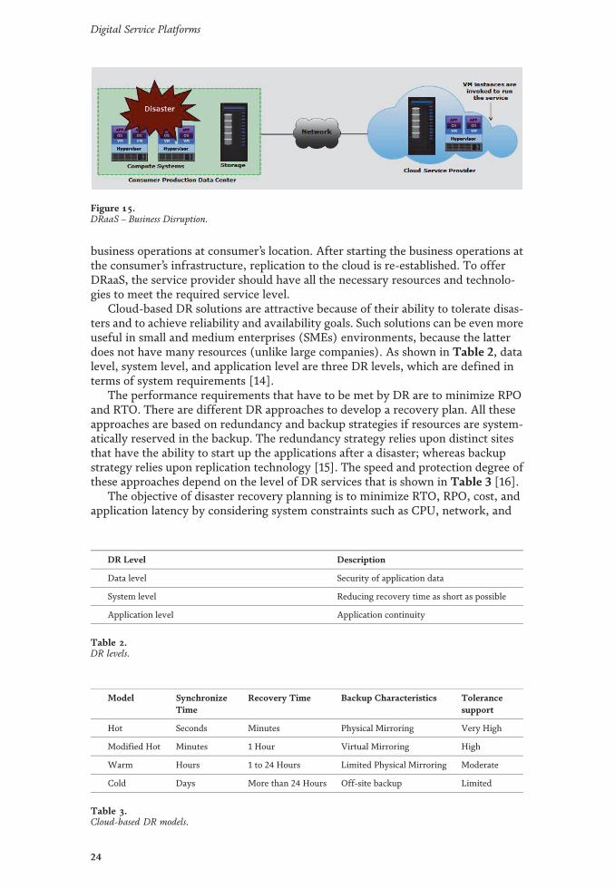
business operations at consumer’s location. After starting the business operations atthe consumer’s infrastructure, replication to the cloud is re-established. To offerDRaaS, the service provider should have all the necessary resources and technolo-gies to meet the required service level.
Cloud-based DR solutions are attractive because of their ability to tolerate disas-ters and to achieve reliability and availability goals. Such solutions can be even moreuseful in small and medium enterprises (SMEs) environments, because the latterdoes not have many resources (unlike large companies). As shown in Table 2, datalevel, system level, and application level are three DR levels, which are defined interms of system requirements [14].
The performance requirements that have to be met by DR are to minimize RPOand RTO. There are different DR approaches to develop a recovery plan. All theseapproaches are based on redundancy and backup strategies if resources are system-atically reserved in the backup. The redundancy strategy relies upon distinct sitesthat have the ability to start up the applications after a disaster; whereas backupstrategy relies upon replication technology [15]. The speed and protection degree ofthese approaches depend on the level of DR services that is shown in Table 3 [16].
The objective of disaster recovery planning is to minimize RTO, RPO, cost, andapplication latency by considering system constraints such as CPU, network, and
Figure 15.DRaaS – Business Disruption.
DR Level Description
Data level Security of application data
System level Reducing recovery time as short as possible
Application level Application continuity
Table 2.DR levels.
Model SynchronizeTime
Recovery Time Backup Characteristics Tolerancesupport
Hot Seconds Minutes Physical Mirroring Very High
Modified Hot Minutes 1 Hour Virtual Mirroring High
Warm Hours 1 to 24 Hours Limited Physical Mirroring Moderate
Cold Days More than 24 Hours Off-site backup Limited
Table 3.Cloud-based DR models.
24
Digital Service Platforms

storage requirements. DR recovery planning can be considered as an optimizationproblem. DR plans include at least two phases:
• Matching Phase: In this phase, several candidate DR solutions are matchedagainst the requirements to minimize RPO and RTO) of any data container, (adata container means a data set with identical DR requirements).
• Plan composition phase: Selecting an optimal DR solution which can minimizecost with respect to required latency for each data container.
6.8 Disaster recovery-as-a-service (DRaaS) challenges
In this section, we investigate some common DRaaS challenges in cloud envi-ronments.
6.8.1 Cost
One of the main factors to choose cloud as a DRaaS is its price. CSPs always seekcheaper ways to provide recovery mechanisms by minimizing different costs.
6.8.2 Replication latency
DRaaS depends on the replication process to create backups. Current replicationstrategies are divided into two categories: synchronous and asynchronous. How-ever, they both have certain advantages and disadvantages. Synchronized replica-tion, guarantees excellent RPO and RTO, but is dear and might affect systemperformance because of over-optimization. This problem is incredibly bad formulti-tier web applications because it can greatly increase the trip Time (RRR)between the first and backup sites. On the choice hand, the backup model adoptedwith asynchronous replication is cheaper and also the system has fewer problems,but the standard of the DRaaS is reduced. Thus, the transaction between costs, theperformance of the system and replication latency is an undeniable challenge incloud disaster solutions.
6.8.3 Data storage
Business database storage is one of the problems of enterprises that can be solvedby cloud services. By increasing cloud usage in business and market, enterprisesneed to store huge amounts of data on cloud-based storage. Instead of conventionaldata storage devices, cloud storage service can save money and is more flexible. Tosatisfy applications and to guarantee the security of data, computing has to bedistributed but storage has to be centralized. Therefore, storage a single pointof failure and data loss are critical challenges to store data in cloud serviceproviders [17].
6.8.4 Lack of redundancy
When a disaster happens, the primary site becomes unavailable and the backupsite has to be activated to replace the primary site. It is a serious threat to thesystem. This issue is temporary and will be removed once the primary site isrecovered.
25
Network Function Virtualization over Cloud-Cloud Computing as Business Continuity SolutionDOI: http://dx.doi.org/10.5772/intechopen.97369

6.8.5 Failure
The early detection failure time significantly affects the recovery time of thesystem, so it is important to detect and report rapid and accurate DRaaS failure. Onthe other hand, in many backup sites there is a big question: How to separatenetwork failures and service interruptions.
6.8.6 Security
As mentioned earlier, disaster can be created by nature or can be man-made. Thecyber-terrorist attack is one of the most man-made disasters that can occur for avariety of reasons. In this case, protecting and restoring important data will be thefocus of the DRaaS programs other than system restoration [18].
6.9 Disaster recovery-as-a-service (DRaaS) solutions
In this section we discuss some DRaaS solutions that can address the problemsand challenges raised by cloud-based DR.
6.9.1 Local backup
A solution to the dependency problem has been proposed in [19]. A LocalBackup can be deployed on the side of customers to control data and to get backupof both data and even complete application on local storage. Local storage are oftenupdated through a secured channel. By this technique, migration between CSPs andmigration from public to private clouds, and from private to public clouds is possi-ble. In the event of a disaster, local backups can provide the services that used to beprovided by the CSP.
6.9.2 Geographical redundancy and backup (GRB)
Geographical Redundancy can be used in a traditional context. Two cloud zonesmirror each other [17]. If one zone gets down, then the zone will be on and providethe services. A module monitors the zones to detect disaster.
Another research [20] has been proposed proposes a method to select optimallocations for multiple backups. The number of places is decided based on the natureof the application and service priority. Distance and bandwidth are two factors tosettle on the simplest sites. However, this work neglects some critical factors such asthe capacity of mirror sites and the number of node sources that can be hosted ineach location.
6.9.3 Inter-private cloud storage (IPCS)
According to the Storage Networking Industry Association (SNIA), at least threebackup locations are necessary for business data storage. Users’ data should bestored in three different geographical locations: Servers, Local Backup Servers(LBS) and Remote Backup Server (RBS) [21].
6.9.4 Resource management
Hybrid clouds consist of many different hardware and software. In cloud-basedenterprises, all business data are stored in storage resources of the cloud. Therefore,data protection, safety and recovery are critical in these environments. Data
26
Digital Service Platforms

protection is challenged when the data that has been processed at the primary hosthas not been stored in the backup host yet. There are three solutions for datarecovery purposes [22]:
• Using fastest disk technology in the event of a disaster for data replication
• Prediction and replacement of risky devices: Some important factors such aspower consumption, heat dissipation, and carbon footprint and data criticality(stored on each disk) can be calculated for a specific period
6.9.5 Pipelined replication
This replication technique [23] aims to gain both the performance of asynchro-nous replication and the consistency of sync replication. In synchronous replication,processing cannot continue until replication is completed at the backup site.Whereas, in asynchronous replication, after storing data in the local storage theprocess can be started.
6.9.6 Dual-role operation
To maximize resource usage, [24] introduces a technique which enables a host tooperate as the primary host for some applications and to be the backup host forsome other applications. In this architecture, clients send their requests to thebackup host first, then the backup host transmits those requests to the primary host.After processing, the primary host sends a log to the backup and eventually repliesto the clients. When a failure happens, the primary host becomes unavailable, andthe backup host has to handle the requests sent to the failed host. However, thistechnique cannot guarantee a good service restoration by itself, because the backupsite must share the resources between the requests that are directly sent to it and theredirected requests.
6.10 Disaster recovery-as-a-service (DRaaS) platforms
In this section some DRaaS systems are briefly introduced. In addition, benefitsand weaknesses of each system are discussed.
6.10.1 Second site
The Second Site [25] is a disaster tolerance as a service system cloud. Thisplatform is intended to cope three challenges: Reducing RPO, failure detection, andservice restoration. Using a backup site: There is a geographically separated backupsite that allows replicating groups of virtual machines through Internet links.
6.10.2 Distributed
Cloud System Architecture: In [26] the authors present a cloud architecture thatprovides high dependability of the system based on severe redundancy. The archi-tecture is composed of multiple datacenters that are geographically separated fromeach other. Each datacenter includes VMs are active in physical. To perform DR,there is a backup server that stores a copy of each VM. In the case of a disaster,which makes a datacenter unavailable, the backup site transmits VM copies toanother datacenter. Although this system architecture is expensive, it highlyincreases the dependability which can be adequate for (IaaS clouds. In addition, the
27
Network Function Virtualization over Cloud-Cloud Computing as Business Continuity SolutionDOI: http://dx.doi.org/10.5772/intechopen.97369

aforementioned paper describes a hierarchical approach to model cloud systemsbased on dependability metrics as well as disaster occurrence using the StatisticPetri Net approach.
6.11 Disaster recovery-as-a-service (DRaaS) open issues and future directions
In the previous sections, we described the main properties and challenges ofDRaaS systems. However, some issues still require more effort to reach a level ofDRaaS mechanisms in cloud computing.
6.11.1 Maximizing resource utilization
Cloud customers pay for DRaaS resources only after a disaster happens. How-ever, these resources must always be available whenever they are needed. Therevenue of the DRaaS servers is less. Therefore, CSPs need solutions to increaseboth the usage and the revenue of DRaaS servers while guaranteeing the availabilityof DRaaS services.
6.11.2 Correlated failures
Disasters that affect a specific area can lead to vast service interruption, andconsequently, many customers have to be recovered by CSPs. In this case, it ispossible that related servers cannot handle all the customers’ requests. Therefore, itcan be critical to multiplex customers’ data of the same area in different servers.One major challenge in this case is how to distribute customers’ traffic and databetween cloud servers to minimize correlated failure risks with respect to requiredQoS for each server and also cloud SLAs [14].
6.11.3 Failover and failback procedures
In the event of a disaster, the failover procedure excludes failed resources andredirects workloads to a secondary site. Client-transparent procedures and fast IPfailover requirements are two main challenges raised by this context. On the otherhand, the cloud environment recovers from the disaster, application control has tobe reverted to the original site. For this purpose, bidirectional state replication mustbe supported by the DRaaS mechanism. A portion of data may be lost because of thedisaster in the primary site and new data will be created in the backup site. There-fore, one major challenge is how to determine new and old data which must beresynchronized to the primary site [24].
6.11.4 Disaster monitoring
In the case of a disaster, the sooner the failure is detected in either the primarysite or the backup site, the better RTO. So, the challenge is how should the status ofcloud be monitored and how a disaster can be detected as soon as possible [27].
6.11.5 Resource scheduling
The number of cloud-based services is increasing day by day and so hasincreased the complexity of cloud infrastructures. Hence, resource scheduling is acritical issue in modern cloud environments. This issue is more crucial for cloud-base platforms since they face unpredictable incoming traffic and have to consider a
28
Digital Service Platforms
variety of catastrophic situations. Building on this, more efficient resource schedul-ing techniques are needed in order for current DRaaS platforms to be optimized.
7. Application resiliency for cloud
This section covers the overview of resilient cloud application. This section alsocovers the key design strategies for application resiliency and monitoring applica-tions for availability.
7.1 Resilient cloud applications overview
The cloud infrastructures are typically built on a large number of commoditysystems to achieve scalability and keep hardware costs down. In this environment,it is assumed that some components will fail. Therefore, in the design of a cloudapplication the failure of individual resources often has to be anticipated to ensurean acceptable availability of the application. For existing applications, the code hasto be rewritten to make them “cloud-ready” i.e., the application should have therequired scalability and resiliency. A reliable application is able to properly managethe failure of one or more modules and continue operating properly. If a failedoperation is retried a few milliseconds later, the operation may succeed. These typesof error conditions are called as transient faults. Fault resilient applications havelogic to detect and handle transient fault conditions to avoid application downtime.Key application design strategies for improving availability:
• Graceful degradation of application functionality
• Retry logic in application code
• Persistent application state model
• Event-driven processing
7.2 Graceful degradation of application functionality
Graceful degradation of application functionality refers to the ability of anapplication to maintain limited functionality even when some of the components,modules, or supporting services are not available. A well designed application orservice typically uses a collection of loosely coupled modules that communicatewith each other. The purpose of graceful degradation of application functionality isto prevent the complete failure of a business application or service. For example,consider an e-commerce application that consists of modules such as product cata-log, shopping cart, order status, order submission, and order processing. Assumethat the payment gateway is unavailable due to some problem. It is impossible forthe order processing module of the application to continue. If the application orservice is not designed to handle this scenario, the entire application might gooffline. However, in this same scenario, it is possible that the product catalogmodule can still be available to consumers to view the product catalog. Also, theapplication could allow to place the order and move it into shopping cart. Thisprovides the ability to process the orders when the payment gateway is available orafter failing over to a secondary payment gateway.
29
Network Function Virtualization over Cloud-Cloud Computing as Business Continuity SolutionDOI: http://dx.doi.org/10.5772/intechopen.97369

7.3 Retry logic in application code
A key mechanism in a highly available application design is to implement retrylogic within a code to handle service that is temporarily down. When applicationsuse other cloud-based services, errors can occur because of temporary conditionssuch as intermittent service, infrastructure-level faults, or network issues. Veryoften, this form of problem can be solved by retrying the operation a few millisec-onds later, and the operation may succeed. The simplest form of transient faulthandling is to implement this retry logic in the application itself. To implement thisretry logic in an application, it is important to detect and identify that particularexception which is likely to be caused by a transient fault condition. Also, a retrystrategy must be defined to state how many retries can be attempted before decid-ing that the fault is not transient and define what the intervals should be betweenthe retries. The logic will typically attempt to execute the action(s) a certain num-ber of times, registering an error, and utilizing a secondary service if the faultcontinues.
7.4 Persistent application state model and event-driven processing
In a stateful application model, the session state information of an application(for example user ID, selected products in a shopping cart, and so on) is usuallystored in compute system memory. However, the information stored in the mem-ory can be lost if there is an outage with the compute system where the applicationruns. In a persistent application state model, the state information are stored out ofthe memory and usually stored in a repository (database). If a VM running theapplication instance fails, the state information is still available in the repository. Anew application instance is created on another VM which can access the stateinformation from the database and resume the processing.
In a tightly integrated application environment, user requests are processed by aparticular application instance running on a server through synchronous calls. Ifthat particular application instance is down, the user request will not be processed.For cloud applications, an important strategy for high availability design is to insertuser requests into a queue and code applications to read requests from the queue(asynchronously) instead of synchronous calls. This allows multiple applicationsinstances to process requests from the queue. This also enables adding multipleapplication instances to process the workload much faster to improve performance.Further, if an application instance is lost, the impact is minimal, which could be asingle request or transaction. The remaining requests in the queue continue to bedistributed to other available instances. For example, in an e-commerce application,simultaneous requests from multiple users, for placing orders, are loaded into aqueue and the application instances running on multiple servers process the orders(asynchronously).
7.5 Monitoring application availability
A specialized monitoring tool can be implemented to monitor the availability ofapplication instances that runs on VMs. This tool adds a layer of application aware-ness to the core high availability functionality offered by compute virtualizationtechnology. The monitoring tool communicates directly with VM managementsoftware and conveys the application health status in the form of an applicationheartbeat. This allows the high availability functionality of a VM managementsoftware to automatically restart a VM instance if the application heartbeat is notreceived within a specified interval. Under normal circumstance, the resources that
30
Digital Service Platforms

comprise an application are continuously monitored at a given interval to ensureproper operation. If the monitoring of a resource detects a failure, the tool attemptsto restart the application within the VM. The number of attempts that will be madeto restart an application is configurable by the administrator. If the application doesnot restart successfully, the tool communicates to high availability functionality of aVM management software through API in order to trigger a reboot of the VM. Theapplication is restarted as part of this reboot process. This integration between theapplication monitoring tool and the VM high availability solutions protects VMs, aswell as the applications that run inside them.
8. Solutions and recommendations
To create a disaster recovery solution, an alternative location must be preparedto be able to recover a datacenter at failure occurring and the business can continueto run.. As a proof of concept of this solution, Microsoft Azure is used. MicrosoftAzure is the public cloud to offer Disaster Recovery solution for applications run-ning on Infrastructure as a Service (IaaS) by replicating VMs into another regioneven failure occurs on region level. The second proposed solution is a way ofimplementing highly available virtualized network element using Microsoft Win-dows Server and Microsoft System Center tools called High Availability Solutionover Hybrid Cloud Using Failover Clustering Feature.
8.1 The first solution: network function virtualization over cloud-disasterrecovery solution
Cloud Computing is making big inroads into companies today. Smaller busi-nesses are taking advantage of Microsoft cloud services like Windows Azure tomigrate their line-of business applications and services to the cloud instead ofhosting them on-premises. The reasons for doing this include greater scalability,improved agility, and cost savings. Large enterprises tend to be more conservativewith regards to new technologies mainly because of the high costs involved inwidespread rollout of new service models and integrating them with existing orga-nization’s datacenter infrastructure.
Disaster recovery (DR) is an area of security planning that aims to protect anorganization from the effects of significant disastrous events. It allows an organiza-tion to maintain or quickly resume mission-critical functions following a disaster.
Network & Mobile organizations require features that enable data backup orautomate the restoring of an environment, while incurring minimal downtime. Thisallows organizations to maintain the necessary levels of productivity.
Network & Mobile organizations require features that enable data backup orautomate the restoring of an environment, while incurring minimal downtime. Thisallows organizations to maintain the necessary levels of productivity.
Microsoft System Center has components that enable Network & Mobile orga-nizations to back-up their data and automate the recovery process. The componentsused in this solution are Data Protection Manager (DPM) and Orchestrator.
Cloud computing is making big inroads into companies today. Smaller busi-nesses are taking advantage of Microsoft cloud services like Windows Azure tomigrate their line-of business applications and services to the cloud instead ofhosting them on-premises.
The reasons for doing this include greater scalability, improved agility, and costsavings. Large enterprises tend to be more conservative with regards to new tech-nologies mainly because of the high costs involved in widespread rollout of new
31
Network Function Virtualization over Cloud-Cloud Computing as Business Continuity SolutionDOI: http://dx.doi.org/10.5772/intechopen.97369

service models and integrating them with existing organization’s datacenter infra-structure.
Windows Azure Pack is designed to help large enterprises overcome theseobstacles by providing a straightforward path for implementing hybrid solutionsthat embraces both the modern datacenter and cloud-hosting providers.
Microsoft Windows Azure Pack brings Windows Azure technologies to privatecloud integrating Windows Server, System Center to offer a self-service portal andcloud services. Microsoft Windows Azure Pack is now the preferred interface forprivate cloud environments. A hybrid cloud solution helps enterprises transformtheir current infrastructure to public cloud to achieve cost effectiveness. Withadvanced offloads, acceleration, virtualization, and advanced scale-out storage fea-tures, this reference architecture provides the most efficient, multi-tenant cloudthat is built on top of Windows Azure Pack. Building on a familiar foundation ofWindows Server and System Center, the hybrid cloud platform offers a flexible andfamiliar solution for enterprises to deliver business agility through self-provisioningand automation of resources.
The objective of this project is creating a hybrid cloud with Microsoft SystemCenter 2016 and Windows Azure Pack (WAP) for storage management service.
A storage cloud can help the business units become more agile and dynamic tomeet the fluctuating resource demands of their clients. Storage cloud also helps thelarger organization to implement a pay-per-use model to accurately track andrecover infrastructure costs across the business units.
In this solution, the software components required for deploying WindowsAzure Pack (WAP) are downloaded and installed. Microsoft System Center 2016components are downloaded and installed. The System Center Virtual MachineManager (VMM), Operation Manger (OM), Service Manager (SM) and Orchestra-tor (ORCH) are configured and integrated for delivering self-service and automa-tion. The problem of limited and shared storage owned by most of enterprises canbe addressed by renting large storage from public cloud provider.
The scenario for deploying a hybrid cloud solution for enterprises to overcomethis problem is introduced in this project. The tenant portal of WAP is configured tobe a web portal interface for the users to request the services by himself. The servicesare pre-configured by admin portal WAP and accessed by the users through WAPtenant portal. Admin portal of WAP allows administrator managing clouds over aweb browser. This tool also allows to enabling self-service and automation for endusers in order to create virtual machines inside clouds. This solution introduces forenterprises to ensure the continuity of the service that is provided to the users byusing a hybrid cloud solution of this project for managing the allocated storage [28].
The solution is based on 2 sites and one Public Cloud, Site 1 is the maindatacenter which has the services such as Database Servers (VMs), Site 2 is the hotdisaster recovery site which it has all equipment needed to receive the recovereddata, The Public Cloud has the resources essential for the recovery process itselfwhich are DPM and VMM. The user can be a mobile phone, computer or any otherdevice that can connect to the network.
Backups are typically performed on a daily basis to ensure necessary data reten-tion at a single location, for the single purpose of copying data. Disaster recoveryrequires the determination of the RTO (recovery time objective) in order to desig-nate the maximum amount of time the business can be without IT systems post-disaster. Traditionally, the ability to meet a given RTO requires at least one dupli-cate of the IT infrastructure in a secondary location to allow for replication betweenthe production and DR site.
Disaster recovery is the process of failing over your primary environment to analternate environment that is capable of sustaining your business continuity.
32
Digital Service Platforms

Backups are useful for immediate access in the event of the need to restore adocument but does not facilitate the failover of your total environment should yourinfrastructure become compromised. They also do not include the physicalresources required to bring them online.
A backup is simply a copy of data intended to be restored to the original source.DR requires a separate production environment where the data can live. All aspectsof the current environment should be considered, including physical resources,software, connectivity and security.
Planning a backup routine is relatively simple, since typically the only goalsare to meet the RPO (recovery point objective) and data retention requirements.A complete disaster recovery strategy requires additional planning, includingdetermining which systems are considered mission critical, creating a recoveryorder and communication process, and most importantly, a way to perform avalid test the overall benefits and importance of a DR plan are to mitigate riskand downtime, maintain compliance and avoid outages. Backups serve asimpler purpose. Make sure you know which solution makes sense for yourbusiness needs.
In normal situation, Customer can access their service through Microsoft Win-dows Azure Pack (WAP) portal from site1. System Center Data Protection Manager(DPM) makes a backup for site1 Virtual Machines (VMs). System Center Orches-trator (ORCH) operates a runbook for DPM to take recovery points of(VMs) ofsite1 to reduce any failure down-time Then, ORCH operates a runbook for SystemCenter Virtual Machine Manager (VMM) to live migrate virtual machines of site 1.In a scheduled loop, ORCH operates a runbook for DPM to take recovery points ofVMs of site1 as shown in Figure 16.
In a Disaster situation of site1, System Center Operation Manager (OM) detectsfailure of site1 and sends failure alert to ORCH. ORCH senses failure alerts, thenrunbooks is running automatically and operates DPM to perform a recovery for thebacked up site1 and add the last recovery points taken. So that, our customer canaccess site 2 and find their service up, with decreased down-time as shown inFigure 17.
Setups (Installation), there are common Prerequisite for all of System CenterProducts which is SQL Database if we want a database for each product to storeconfiguration files on them.
Figure 16.Normal Case.
33
Network Function Virtualization over Cloud-Cloud Computing as Business Continuity SolutionDOI: http://dx.doi.org/10.5772/intechopen.97369

8.2 The second solution: high availability solution over hybrid cloud usingfailover clustering feature
This solution is mainly concerned with two complementary aspects, NetworkFunction Virtualization (NFV) followed by Hybrid cloud computing. Initially,virtualization of administrative components on premise of a company took place,such as Active Directory Domain Services (ADDS), System Center tools and ServiceProvider Foundation (SPF). Then we virtualized the Private Branch Exchange(PBX), the network function we are concerned with (NFV), by installing Elastixsoftware on a virtual machine. This network function is one of the most importantservices adopted by various entities such as mobile operators. Thus, one of its mainconcerns is high availability. The availability of a system at time ‘t’ is referred to asthe probability that the system is up and functional correctly at that instance intime.
In our solution, we planned to achieve highly available voice service usingFailover Cluster feature on Windows Server 2012. This is achieved by having anytwo identical nodes, a primary and a secondary one. Rather than having both nodeson premises of the company which may be not as cost efficient and may also be lesssafe since it is subjected to the same kind of failures on premise, we decided to havethe secondary node on Microsoft Azure public cloud. This is called hybrid cloudcomputing.
In conclusion, the voice service is always running on the primary node on pre-mises as long as there are no failures. In case of a critical failure directly affectingthe voice service, its virtual machine would be migrated automatically to the sec-ondary node on Azure’s public cloud with minimum delay and not affecting the call.And thus, the voice service is proved to be highly available maintaining customer’sconfidence and preventing revenue losses (Figure 18).
The solution provides high availability for a VNF of a mobile operator, which is aVirtual Machine with cloud PBX-Elastix-installed on it as a proof of concept.Figure 19 shows the topology of the project, which is a hybrid cloud. The on-premises part (private) represents the mobile operator and Microsoft Azure part(public) is the cloud service provider that provides a secondary failover cluster nodeas a part of a tenant plan. So when the Elastix server fails on premise, the Elastixservice (virtual machine) is transferred to the cluster node in Microsoft Azure,making Elastix highly available [29].
Figure 17.Disaster Response.
34
Digital Service Platforms
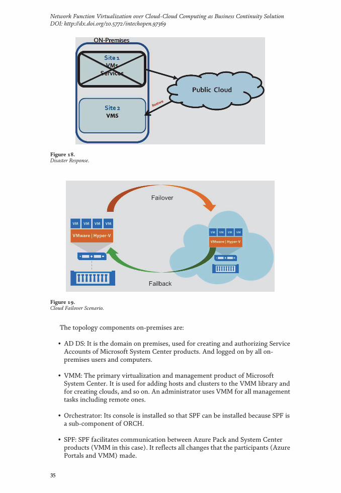
The topology components on-premises are:
• AD DS: It is the domain on premises, used for creating and authorizing ServiceAccounts of Microsoft System Center products. And logged on by all on-premises users and computers.
• VMM: The primary virtualization and management product of MicrosoftSystem Center. It is used for adding hosts and clusters to the VMM library andfor creating clouds, and so on. An administrator uses VMM for all managementtasks including remote ones.
• Orchestrator: Its console is installed so that SPF can be installed because SPF isa sub-component of ORCH.
• SPF: SPF facilitates communication between Azure Pack and System Centerproducts (VMM in this case). It reflects all changes that the participants (AzurePortals and VMM) made.
Figure 19.Cloud Failover Scenario.
Figure 18.Disaster Response.
35
Network Function Virtualization over Cloud-Cloud Computing as Business Continuity SolutionDOI: http://dx.doi.org/10.5772/intechopen.97369

• Azure Admin Portal: This portal is managed by the on-premises ITadministrators and is where user accounts and plans are created, and whereresources are assigned to on-premises tenants through linking the users(tenants) with the plans.
• Azure Tenant Portal: This portal is used by tenants, the on-premises employeesin this case. Tenants can view the services available to them and configure theirown environment, such as deploying and managing VMs using the tenantportal.
• Failover Cluster Node 1: This is the on-premises node (primary node) of theFailover Cluster which has the virtual machine of Elastix on it along with otherVNFs.
The additional components at Microsoft Azure are:
• Microsoft System Center: It is a suite of systems management products. Thecore products are: VMM, ORCH, SM, OM and DPM. They help IT build reliableand manageable systems and better automate processes.
• Azure Tenant Portal: This portal is used by azure subscribers; azure subscriberscan be individual users or enterprises. In this case the mobile operator is atenant assigned to a plan created by Microsoft Azure’s Admin portal.
• Failover Cluster Node 2: The secondary public node of the Failover Clusterwhich Elastix virtual machine is migrated to and which takes over if node 1ofthe on-premise fails.
• SMB: Provides cluster nodes with a shared access to shared storage files.
Zoiper application is installed on the subscribers’ mobile phones to make VoIPcalls. Using Elastix web portal, a SIP extension is created for each subscriber to beable to create their own accounts on Zoiper (Figure 20).
Figure 20.Network Topology of the Project.
36
Digital Service Platforms

Initially, a call is initiated between the two subscribers through Zoiper. The twosubscribers will access the Elastix server deployed on the on-premises node asdemonstrated in Figure 21.
In the case of failure of the on-premise node (primary node) while the call isongoing, the Elastix virtual machine will be migrated to the Microsoft Azure node(secondary node), which now becomes the primary node. The Elastix virtualmachine will continue running on the Microsoft Azure node by accessing SMBstorage as demonstrated in Figure 22.
During the migration process, the downtime ranges from 2 to 3 seconds, whichis barely recognizable by the user, and then the call proceeds normally. And thus,the voice service using Elastix is proved to be highly available. When the on-premises node is up again, the Elastix virtual machine will be manually migratedusing the Failover Cluster Manager.
The overall goal of this solution is providing high availability solution for avirtualized network element using hybrid cloud computing. This will improve theperformance of cloud services. Moreover, reduce the downtime of a service, which
Figure 22.The Call after Primary node failure.
Figure 21.The Call before Primary node failure.
37
Network Function Virtualization over Cloud-Cloud Computing as Business Continuity SolutionDOI: http://dx.doi.org/10.5772/intechopen.97369

would otherwise degrade the performance. This paper focused on conducting thesolution using Failover cluster feature along with Microsoft System Center tools.Failures that might occur include but are not restricted to the following: networkvulnerability, human mistakes, server, storage or power failures and need to beavoided.
As a conclusion, the cloud will remain subject to failure and failures can occur inthe cloud as well as the IT traditional environment. Thus, high availability cannot beensured, but it can be increased and improved, by avoiding common system failuresthrough the implementation of different solutions and techniques..
9. Conclusion
This chapter covered the importance of business continuity in a cloud environ-ment and how business continuity enables to achieve the required service availabil-ity. First, we briefly introduced cloud computing, including background,properties, advantages and challenges. This chapter also covered various faulttolerance mechanisms for cloud infrastructure to eliminate single points of failure.This chapter further covered data protection solutions such as backup and replica-tion. Then, we discussed the details of DRaaS approaches. In addition, we alsoderived the main challenges of DRaaS mechanisms and proposed solutions toovercome them. Furthermore, the main DRaaS platforms are discussed, followed byopen issues and future directions in the field of DRaaS mechanisms. Finally, thischapter also covered the key design strategies for cloud application resiliency.
Finally and as a proof of concept of cloud DR solutions, Microsoft Azure is used.Microsoft Azure is the public cloud to offer Disaster Recovery solution for applica-tions running on Infrastructure as a Service (IaaS) by replicating VMs into anotherregion even failure occurs on region level. The second proposed solution is a way ofimplementing highly available virtualized network element using MicrosoftWindows Server and Microsoft System Center tools called High Availability Solu-tion over Hybrid Cloud Using Failover Clustering Feature. The two solutions weresuccessfully implemented and provided high performance and excellent results.
Author details
Wagdy Anis Aziz1, Eduard Babulak2* and David Al-Dabass3
1 Ain Shams University Faculty of Engineering/Orange, Egypt
2 National Science Foundation, USA
3 Nottingham Trent University, England
*Address all correspondence to: [email protected]
©2021 TheAuthor(s). Licensee IntechOpen. This chapter is distributed under the termsof theCreativeCommonsAttribution License (http://creativecommons.org/licenses/by/3.0),which permits unrestricted use, distribution, and reproduction in anymedium,provided the original work is properly cited.
38
Digital Service Platforms

References
[1] Reid, S., Kicker, H., Matzke, P.,Bartels, A., & Lisserman, M. (2011).Sizing the cloud. Technical report.Retrieved from http://www.forrester.com-/E-/Sizing+The+Cloud/fulltext/RES58161objectid=RES58161
[2] White paper. (2013). UK CloudAdaption and Trends. Retrieved fromhttp://cloudindustryforum.org/white-papers/uk-cloud-adoption-and-trends-for-2013
[3] Kashiwazaki, H. (2012). Practicaluses of cloud computing services in aJapanese university of the arts againstaftermath of the 2011 Tohokuearthquake. Proceedings of the ACMSIGUCCS 40th annual conference onSpecial interest group on universityand college computing services(pp. 49-52).
[4]Mesbahi, Rahmani and Hosseinzadeh(2018). Reliability and high availabilityin cloud computing environments: areference roadmap.
[5] EMC Corporation (2014). Module:Business Continuity.
[6] Carney, Michael (2013-06-24)."AnyPresence partners with Heroku tobeef up its enterprise mBaaS offering".Pando Daily. Retrieved 24 June 2013.
[7] Alex Williams (11 October 2012)."Kii Cloud Opens Doors For MobileDeveloper PlatformWith 25 Million EndUsers". TechCrunch. Retrieved 16October 2012.
[8] Dan Rowinski (9 November 2011)."Mobile Backend As A Service ParseRaises $5.5 Million in Series A Funding".ReadWrite. Retrieved 23 October 2012.
[9] Miller, Ron (24 Nov 2015). "AWSLambda Makes Serverless ApplicationsA Reality". TechCrunch. Retrieved 10July 2016.
[10] Sbarski, Peter (2017-05-04).Serverless Architectures on AWS:Withexamples using AWS Lambda (1st ed.).Manning Publications. ISBN9781617293825.
[11] Arean, O. (2013). Disaster recoveryin the cloud. Network Security, 9, 5-7.http://dx.doi.org/10.1016/S1353-4858(13)70101-6
[12] ETSI NFV (https://www.etsi.org/technologies/nfv)
[13] Alhazmi, O. H., & Malaiya, Y. K.(2013). Evaluating disaster recoveryplans using the cloud. Reliability andMaintainability Symposium (RAMS),IEEE Proceedings-Annual (pp. 1-6).http://dx.doi.org/10.1109/RAMS.2013.6517700
[14]Wood, T., Cecchet, E., &Ramakrishnan, K. K. (2010). Disasterrecovery as a cloud service: Economicbenefits & deployment challenges. 2ndUSENIX Workshop on Hot Topics inCloud Computing (pp. 1-7).
[15] Lwin, T. T., & Thein, T. (2009).High Availability Cluster System forLocal Disaster Recovery with MarkovModeling Approach. International Jounalof Computer Science Issues, 6(2), 25-32.Error! Hyperlink reference not valid.
[16] Guster, D., & Lee, O. F. (2011).Enhancing the Disaster Recovery PlanThrough Virtualization. Journal ofInformation Technology Research, 4(4), 18-40. http://dx.doi.org/10.4018/jitr.2011100102 IBM white paper.(2012). Virtualizing disaster recoveryusing cloud computing, IBM globaltechnology services.
[17] Pokharel, M., Lee, S., & Park, J. S.(2010). Disaster Recovery for SystemArchitecture using Cloud Computing.10th IEEE/IPSJ International Symposium
39
Network Function Virtualization over Cloud-Cloud Computing as Business Continuity SolutionDOI: http://dx.doi.org/10.5772/intechopen.97369
on Applications and the Internet (SAINT)(pp. 304-307).
[18] C. Bucur and E. Babulak, "Securityvalidation testing environment in thecloud," 2019 IEEE InternationalConference on Big Data (Big Data), LosAngeles, CA, USA, 2019, pp. 4240-4247,doi: 10.1109/BigData47090.2019.9006202.
[19] Javaraiah, V. (2011). Backup forcloud and disaster recovery forconsumers and SMBs. IEEE 5thInternational Conference on AdvancedNetworks and TelecommunicationSystems (ANTS) (pp. 1-3). http://dx.doi.org/10.1109/ANTS.2011.6163671
[20] Khan, J. I., & Tahboub, O. Y.(2011). Peer-to-Peer Enterprise DataBackup over a Ren Cloud. IEEE 8th
International Conference on InformationTechnology: New Generations (ITNG)(pp. 959-964). http://dx.doi.org/10.1109/ITNG.2011.164
[21] Jian-hua, Z., & Nan, Z. (2011).Cloud Computing-based Data Storageand Disaster Recovery. IEEEInternational Conference on FutureComputer Science and Education(ICFCSE), (pp. 629-632). http://dx.doi.org/10.1109/ICFCSE.2011.157
[22] Patil, S. R., Shiraguppi, R. M., Jain,B. P., & Eda, S. (2012). Methodology forUsage of Emerging Disk to AmeliorateHybrid Storage Clouds. IEEEInternational Conference on CloudComputing in Emerging Markets (CCEM)(pp.1-5). http://dx.doi.org/10.1109/CCEM.2012.6354615
[23] Wood, T., Lagar-Cavilla, H. A.,Ramakrishnan, K. K., Shenoy, P., & Vander Merwe, J. (2011). PipeCloud: usingcausality to overcome speed-of-lightdelays in cloud-based disaster recovery.2nd ACM Symposium on CloudComputing. http://dx.doi.org/10.1145/2038916.2038933
[24] Aghdaie, N., & Tamir, Y. (2003).Fast transparent failover for reliableweb service. 15th IASTED InternationalConference on Parallel and DistributedComputing and Systems (PDCS)(pp. 757- 762).
[25] Rajagopalan, S., Cully, B., Connor,R. O., &Warfield, A. (2012).SecondSite: disaster tolerance as aservice. ACM SIGPLAN Notices, 47(7),97-107. http://dx.doi.org/10.1145/2365864.2151039.
[26] Silva, B., Maciel, P., Tavares, E., &Zimmermann, A. (2013). Dependabilitymodels for designing disaster tolerantcloud computing systems. 43rd AnnualIEEE/IFIP International Conference onDependable Systems and Networks (DSN)(pp.1-6). http://dx.doi.org/10.1109/DSN.2013.6575323
[27] Aceto, G., Botta, A., Donato, W., &Pescape, A. (2013). Cloud monitoring: Asurvey. Computer Networks, 57(9),2093-2915. http://dx.doi.org/10.1016/j.comnet.2013.04.001
[28] Wagdy A. Aziz et al: NetworkFunction Virtualization Over Cloud -Disaster Recovery Solution Over HybridCloud, ijssst.info/Vol-21/No-4/paper15
[29] Wagdy A. Aziz et al: High Availability Solution Over Hybrid Cloud UsingFailover Clustering Feature, ijssst.info/Vol-21/No-4/paper16
40
Digital Service Platforms