Adaptive, Model-based Cloud Computing Security Management
312
Adaptive, Model-based Cloud Computing Security Management By Mohamed Almorsy A thesis submitted in fulfillment of the requirements for the degree of Doctor of Philosophy in Computer Science 2014
-
Upload
khangminh22 -
Category
Documents
-
view
2 -
download
0
Transcript of Adaptive, Model-based Cloud Computing Security Management

Adaptive, Model-based Cloud
Computing Security Management
By
Mohamed Almorsy
A thesis submitted in fulfillment of the requirements for the degree of
Doctor of Philosophy in
Computer Science
2014

ii
Abstract
The cloud computing model introduces a new paradigm shift in computing platforms with
highly scalable, distributed, and shared computing resources. However, despite the potential
cost savings and revenues reaped by adopting the cloud model, it still has a set of open issues
that impacts its wide adoption. Security is at the top of these issues. In addition to the traditional
technology-related problems, the cloud model introduces a set of new and critical security
problems including loss-of-control, lack-of-trust, data isolation, and tenants’ security controls’
integration. These security problems are not mitigated yet by the existing cloud platforms.
Cloud security solutions should take into consideration that it is hard to get cloud tenants and
service providers to manually customize their shared cloud services’ security. Moreover, the set
of a cloud service tenants usually emerges at real-time. Each service tenant usually has a set of
security requirements which changes over time to reflect new risks and business objectives.
In this research, we have successfully invented a new cloud computing security management
platform addressing these security problems. The invented security platform depends on
capturing cloud platform, services and security specification details using a set of novel system
and security mega-models. Cloud stakeholders use these models to specify their assets-security
requirements. Then, our platform automates the integration of these requirements within target
services at runtime.
Identifying security requirements that need to be satisfied requires deep experience with
system and security to pinpoint possible threats, vulnerabilities, and attacks. This is even worse
when adopting the cloud model where services are publicly accessible to malicious users who
could exploit services’ vulnerabilities and flaws to breach tenants’ security. Our platform
delivers a novel, extensible, and online signature-based security analysis service that automates
services’ security analysis. The outcomes of the analysis service are feed into our security-
patching component.
Furthermore, given that tenants do not have direct control on their outsource shared cloud-
services, our platform provides a new security monitoring service that automatically realizes
tenants’ security metrics, used in assessing services’ security status, into security probes and
automatically deploys, collects, and analyzes probes’ generated measurements.
We evaluated each component of our platform using a set of benchmark applications. Then,
we conducted three case studies using our platform in mitigating three key cloud security
problems. The evaluation results are very supportive and demonstrate that our platform
successfully automated the security management of the shared, multi-tenant cloud services.

iii
Acknowledgement
I am deeply grateful to my lovely wife Amani Ibrahim, for her love, understanding,
encouragement, sacrifice and help. I am also grateful for my parents for raising me up, teaching
me to be a good person, and supporting me throughout my studies.
I sincerely express my deepest gratitude to my coordinate supervisor, Professor John
Grundy, for his supervision and continuous encouragement throughout my PhD study. Without
his consistent support, I would not have been able to complete this research project. The first
year was really tough and I got many rejections. He kept encouraging and supporting me until I
succeed to come up with a good stuff that easily got accepted. He is indeed “a good mentor and
a helpful friend”.
I thank Prof. Jun Han for his sincere advices and feedback whenever I ask him for this. He is
really a very helpful and supportive supervisor.
Finally, I thank Swinburne University of Technology and the Faculty of Information and
Communication Technologies for offering me a full research scholarship throughout my
doctoral program. I also thank the Research Committee of the Faculty of Information and
Communication Technologies for research publication funding support and for providing me
with financial support to attend conferences.

iv
Declaration
This thesis contains no material which has been accepted for the award of any other degree or
diploma, except where due reference is made in the text of the thesis. To the best of my
knowledge, this thesis contains no material previously published or written by another person
except where due reference is made in the text of the thesis.
Mohamed Almorsy

v
List of Publications
During my PhD project, I have managed to publish a bunch of peer-reviewed conference and
journal papers as well as a book chapter that support our analysis, findings and contributions.
[1] Mohamed Almorsy, John Grundy, and Amani Ibrahim, “Adaptable, model-driven
security engineering for SaaS cloud-based applications”, International Journal of
Automated Software Engineering, Volume 29, September 2013.
[2] Mohamed Almorsy, John Grundy, and Amani Ibrahim, “Adaptive Security
Management in SaaS Applications”, Security, Privacy and Trust in Cloud Systems,
Springer.
[3] Mohamed Almorsy, John Grundy, and Amani Ibrahim, “Automated Software
Architecture Security Risk Analysis Using Formalized Signatures", 2013 IEEE/ACM
International Conference on Software Engineering (ICSE 2013), San Franciso, May
2013, IEEE CS Press.
[4] Mohamed Almorsy, John C. Grundy, Amani S. Ibrahim, “MDSE@R: Model-Driven
Security Engineering at Runtime”, 4th International Symposium on Cyberspace Safety
and Security (CSS 2012), Dec 12-13 2012, Melbourne, Australia.
[5] Mohamed Almorsy, John C. Grundy, Amani S. Ibrahim, “VAM-aaS: Online Cloud
Services Security Vulnerability Analysis and Mitigation-as-a-Service”, The 13th
International Conference on Web Information System Engineering (WISE 2012), Nov
28-30 2012, Paphos, Cyprus, Springer.
[6] Mohamed Almorsy, John C. Grundy, Amani S. Ibrahim, “Supporting Automated
Vulnerability Analysis using Formalized Vulnerability Signatures", 27th IEEE/ACM
International Conference on Automated Software Engineering (ASE 2012), Sept 3-7
2012, Essen, Germany, ACM Press.
[7] Mohamed Almorsy, John C. Grundy, Amani S. Ibrahim, “Supporting Automated
Software Re-Engineering Using "Re-Aspects”, 27th IEEE/ACM International
Conference on Automated Software Engineering (ASE 2012), Sept 3-7 2012, Essen,
Germany, ACM Press.
[8] Mohamed Almorsy, John Grundy and Amani S. Ibrahim, “TOSSMA: A Tenant-
Oriented SaaS Security Management Architecture", 5th IEEE Conference on Cloud
Computing (CLOUD 2012), IEEE CS Press, Waikiki, Hawai, USA, June 24-29 2012.
[9] Mohamed Almorsy, John Grundy and Amani S. Ibrahim, “SMURF: Supporting
Multi-tenancy Using Re-Aspects Framework", 17th IEEE International Conference on

vi
Engineering of Complex Computer Systems (ICECCS 2012), Paris, France, July 2012,
IEEE CS Press.
[10] Mohamed Almorsy, John Grundy and Amani S. Ibrahim, “Collaboration-Based
Cloud Computing Security Management Framework", In Proceedings of 2011 IEEE
International Conference on Cloud Computing (CLOUD 2011), Washington DC, USA
on 4 – 9 July, 2011, IEEE.
[11] Mohamed Almorsy, John Grundy Ingo and Mueller, “An analysis of the cloud
computing security problem", In Proceedings of the 2010 Asia Pacific Cloud Workshop
2010 (co-located with APSEC2010), Sydney, Nov 30 2010.
The following publications, which I am a co-author, have been published during my candidature
as a part of my collaboration with colleagues in our research group.
[1] Amani S. Ibrahim, John C. Grundy, James Hamlyn-Harris, Mohamed Almorsy,
“DIGGER: Identifying Operating System Dynamic Kernel Objects for Run-time
Security Analysis", International Journal on Internet and Distributed Computing
Systems (IJIDCS).
[2] Amani S. Ibrahim, John C. Grundy, James Hamlyn-Harris, Mohamed Almorsy,
“Identifying OS Kernel Runtime Objects for Run-time Security Analysis",
6th International Conference on Network and System Security (NSS 2012), Nov 21-23
2012, Wu Yi Shan, Fujian, China, Springer.
[3] Amani S. Ibrahim, John C. Grundy, James Hamlyn-Harris, Mohamed Almorsy,
“Operating System Kernel Data Disambiguation to Support Security Analysis",
6th International Conference on Network and System Security (NSS 2012), Nov 21-23
2012, Wu Yi Shan, Fujian, China, Springer.
[4] Amani S. Ibrahim, John C. Grundy, James Hamlyn-Harris, Mohamed Almorsy,
“Supporting Operating System Kernel Data Disambiguation using Points-to Analysis",
27th IEEE/ACM International Conference on Automated Software Engineering (ASE
2012), Sept 3-7 2012, Essen, Germany, ACM Press.
[5] Amani S. Ibrahim, James Hamlyn-Harris, John Grundy and Mohamed Almorsy,
“Supporting Virtualizaion-Aware Security Solutions using a Systematic Approach to
Overcome the Semantic Gap", 5th IEEE Conference on Cloud Computing (CLOUD
2012), IEEE CS Press, Waikiki, Hawai, USA, June 24-29 2012.
[6] Amani S. Ibrahim, James Hamlyn-Harris, John Grundy and Mohamed Almorsy,
“CloudSec: A Security Monitoring Appliance for Virtual Machines in the IaaS Cloud
Model", 5th International Conference on Network and System Security (NSS 2011),
Milan, Italy on 6 – 8 September, 2011.

vii
Table of Contents
ABSTRACT ........................................................................................................................................ II
ACKNOWLEDGEMENT ..................................................................................................................... III
DECLARATION ................................................................................................................................. IV
LIST OF PUBLICATIONS ..................................................................................................................... V
TABLE OF CONTENTS...................................................................................................................... VII
LIST OF FIGURES............................................................................................................................ XIV
LIST OF TABLES ........................................................................................................................... XVIII
INTRODUCTION........................................................................................................ 3 CHAPTER 1
1.1 Motivating Scenario ............................................................................................................... 7
1.2 Research Roadmap ................................................................................................................. 9
1.3 Key Contributions ................................................................................................................. 12
1.4 Thesis Structure .................................................................................................................... 15
CLOUD COMPUTING SECURITY PROBLEM ...............................................................19 CHAPTER 2
2.1 Introduction .......................................................................................................................... 19
2.2 Cloud Security Analysis ......................................................................................................... 21
2.2.1 Deployment Models Security Implications .................................................................. 21
2.2.2 Cloud Architecture Security Implications .................................................................... 23
2.2.3 Cloud Stakeholders Security Implications ................................................................... 24
2.2.4 Cloud Characteristics Security Implications ................................................................. 25
2.2.4.1 Multi-tenancy Security Implications ......................................................................................25
2.2.4.2 Elasticity Security Implication ................................................................................................26
2.2.5 Service Delivery Models Security Implications ............................................................ 27
2.2.5.1 IaaS Security Issues ................................................................................................................27
2.2.5.2 PaaS Security Issues ...............................................................................................................28
2.2.5.3 SaaS Security Issues ...............................................................................................................29
2.2.5.4 Cloud Management Security Issues .......................................................................................30
2.2.5.5 Cloud Access Methods Security Issues ...................................................................................30
2.3 Cloud Computing Security Enablers ..................................................................................... 30
2.3.1 Identity Federation and Access Management ............................................................. 30
2.3.2 Data Cryptography ....................................................................................................... 31
2.3.3 Secure Cloud Software Development Lifecycle ........................................................... 31
2.3.4 Security Performance Tradeoff ................................................................................... 32

viii
2.3.5 Security Management ..................................................................................................32
2.4 Chapter Summary .................................................................................................................33
RELATED WORK ...................................................................................................... 35 CHAPTER 3
3.1 Introduction ..........................................................................................................................36
3.2 Security Management ...........................................................................................................37
3.2.1 Security Management Standards .................................................................................38
3.2.1.1 NIST-FISMA Standard ............................................................................................................. 38
3.2.1.2 ISO27000 Standard ................................................................................................................ 39
3.2.1.3 Differences between NIST-FISMA and ISO27000 ................................................................... 41
3.2.1.4 Security Management Standards and Cloud Computing ....................................................... 41
3.2.2 Security Management Systems ....................................................................................42
3.2.2.1 Policy-based Security Management ....................................................................................... 42
3.2.2.2 Ontology-based Security Management ................................................................................. 43
3.2.2.3 Model-based Security Management ...................................................................................... 44
3.2.2.4 Security and Service Level Agreement ................................................................................... 44
3.2.3 Information Security and Risk Management ...............................................................45
3.3 Security Analysis ...................................................................................................................46
3.3.1 Security Risk Analysis ...................................................................................................46
3.3.2 Architecture Security Analysis ......................................................................................47
3.3.2.1 Scenario-based Analysis ......................................................................................................... 48
3.3.2.2 Metrics-based Analysis .......................................................................................................... 49
3.3.3 Security Vulnerability Analysis .....................................................................................50
3.3.3.1 Static Vulnerability Analysis ................................................................................................... 50
3.3.3.2 Dynamic Vulnerability Analysis .............................................................................................. 51
3.3.3.3 Hybrid Vulnerability Analysis ................................................................................................. 52
3.4 Security Engineering .............................................................................................................52
3.4.1 Design-time Security Engineering ................................................................................53
3.4.1.1 Early-stage Security Engineering ............................................................................................ 53
3.4.1.2 Later-stage Security Engineering ........................................................................................... 54
3.4.1.3 Security Engineering Processes .............................................................................................. 56
3.4.1.4 Widely Deployed Security Platforms ...................................................................................... 56
3.4.2 Adaptive Application Security ......................................................................................57
3.4.3 Multi-tenancy Security Engineering .............................................................................58
3.5 Security Re-engineering ........................................................................................................59
3.5.1 Security Retrofitting Approaches .................................................................................60
3.5.2 Software Maintenance .................................................................................................60
3.5.3 Dynamic System Updating ...........................................................................................62
3.5.4 Concept Location Techniques ......................................................................................63
3.6 Security Measurement and Metrics .....................................................................................63

ix
3.6.1 Security Monitoring ..................................................................................................... 64
3.6.2 SLA Monitoring ............................................................................................................ 66
3.6.3 Requirements Monitoring ........................................................................................... 67
3.6.4 Security Metrics Specification Languages .................................................................... 67
3.7 Research Gaps Summary ...................................................................................................... 68
ADAPTIVE, MODEL-BASED CLOUD COMPUTING SECURITY MANAGEMENT ............73 CHAPTER 4
4.1 Introduction .......................................................................................................................... 73
4.2 Autonomic Computing and MAPE-K Model ......................................................................... 74
4.2.1 Monitoring Component ............................................................................................... 75
4.2.2 Analysis component .................................................................................................... 76
4.2.3 Planning and Execution components .......................................................................... 77
4.2.3.1 Architectural/Design Patterns ................................................................................................77
4.2.3.2 Middleware-Based Approaches .............................................................................................78
4.3 Adaptive, Model-based Cloud Security Management – “Big Picture” ................................. 79
4.4 Approach Evaluation ............................................................................................................ 83
4.4.1 Benchmark Applications .............................................................................................. 83
4.4.2 Evaluation Metrics ....................................................................................................... 84
4.5 Chapter Summary ................................................................................................................. 85
ALIGNING SECURITY STANDARDS WITH CLOUD COMPUTING MODEL ....................87 CHAPTER 5
5.1 Introduction .......................................................................................................................... 87
5.2 Rethinking In Security Management .................................................................................... 90
5.3 Aligning NIST-FISMA with Cloud Computing ........................................................................ 93
5.3.1 Service Security Categorization ................................................................................... 93
5.3.2 Security Control Selection ........................................................................................... 94
5.3.2.1 Service Security Risk Assessment ...........................................................................................94
5.3.2.2 Security Controls Baseline Tailoring Process ..........................................................................95
5.3.3 Security Controls Implementation ............................................................................... 96
5.3.4 Security Controls Assessment ...................................................................................... 96
5.3.5 Service Authorization .................................................................................................. 96
5.3.6 Monitoring Security Controls Effectiveness ................................................................ 97
5.4 Security Automation............................................................................................................. 97
5.5 Cloud Security Framework Architecture .............................................................................. 99
5.6 Usage Example ................................................................................................................... 100
5.6.1 Registering Cloud Services ......................................................................................... 101
5.6.2 Service Security Categorization ................................................................................. 103
5.6.3 Security Controls Selection ........................................................................................ 103
5.6.3.1 Service Risk Assessment .......................................................................................................103

x
5.6.3.2 Security Controls Baseline Tailoring ..................................................................................... 104
5.6.4 Security Controls Implementation and Assessment ................................................. 105
5.6.5 Service Authorization ................................................................................................ 106
5.6.6 Monitoring Security Controls Effectiveness .............................................................. 106
5.7 Discussion .......................................................................................................................... 107
5.8 Chapter Summary .............................................................................................................. 108
CLOUD APPLICATIONS SECURITY ENGINEERING ................................................... 109 CHAPTER 6
6.1 Introduction ....................................................................................................................... 109
6.2 Key Requirements and Challenges ..................................................................................... 112
6.3 MDSE@R ............................................................................................................................ 113
6.3.1 Modeling Service and Security Details ...................................................................... 115
6.3.1.1 Service Description Model (SDM) ........................................................................................ 115
6.3.1.2 Service Security Specification Model (SSM) ......................................................................... 116
6.3.1.3 Tenant Service Description Model (TSDM) .......................................................................... 116
6.3.1.4 Tenant Security Specification Model (TSSM) ....................................................................... 116
6.3.2 Weaving Service and Security Models ...................................................................... 117
6.3.3 Enforcing Specified Security on Target Application Entities ..................................... 118
6.3.3.1 Update Live Service Interceptors’ Document ...................................................................... 118
6.3.3.2 Update Live Security Specification Document ..................................................................... 119
6.3.3.3 Update Tenant Accessible Resources Document ................................................................. 119
6.3.3.4 Update the System Container .............................................................................................. 119
6.3.3.5 Security Enforcement Point – SEP ........................................................................................ 121
6.3.4 Testing the Service-Security Integration ................................................................... 121
6.4 Usage Example ................................................................................................................... 123
6.4.1 Model Galactic System Description .......................................................................... 123
6.4.2 Model SwinSoft Security ........................................................................................... 124
6.4.3 Weave Galactic SDM and Security SSM .................................................................... 125
6.4.4 On-boarding Swinburne and Auckland Tenants........................................................ 130
6.4.5 Managing Swinburne and Auckland Security ............................................................ 131
6.5 MDSE@R Architecture and Implementation ..................................................................... 131
6.5.1 MDSE@R Platform Architecture Details ................................................................... 131
6.5.2 SecDSVL: Security Domain Specific Visual Language ................................................ 134
6.5.2.1 Enterprise Assets ................................................................................................................. 135
6.5.2.2 Security Objectives............................................................................................................... 135
6.5.2.3 Risk, Threats, Attacks, and Vulnerabilities ........................................................................... 135
6.5.2.4 Security Requirements ......................................................................................................... 136
6.5.2.5 Security Architecture ........................................................................................................... 136
6.5.2.6 Security Controls .................................................................................................................. 136
6.6 Evaluation .......................................................................................................................... 136

xi
6.6.1 Experimental Evaluation Setup.................................................................................. 137
6.6.2 Evaluation Results ...................................................................................................... 137
6.6.3 SecDSVL Evaluation ................................................................................................... 139
6.6.4 User Evaluation .......................................................................................................... 140
6.6.5 Performance evaluation ............................................................................................ 140
6.6.5.1 Runtime Performance Overhead .........................................................................................140
6.6.5.2 Security Adaptation Overhead .............................................................................................142
6.7 Discussion ........................................................................................................................... 142
6.8 Chapter Summary ............................................................................................................... 145
CLOUD APPLICATIONS SECURITY REENGINEERING ................................................ 147 CHAPTER 7
7.1 Introduction ........................................................................................................................ 147
7.2 Motivating Examples .......................................................................................................... 150
7.3 Change Request Management Process .............................................................................. 152
7.4 Reengineering Aspects - “Re-Aspects” ............................................................................... 154
7.5 Change Impact Analysis ...................................................................................................... 155
7.5.1 Code Snippet Signature Designator ........................................................................... 156
7.5.2 Semantic OCL-based Signature Designator ............................................................... 157
7.5.2.1 Object Constraint Language (OCL) .......................................................................................157
7.5.2.2 System Description Meta-model ..........................................................................................158
7.5.3 Code Snippet or OCL Semantic Signatures ................................................................ 159
7.5.4 Generating Change Set .............................................................................................. 160
7.5.5 Generating Impact Set ............................................................................................... 160
7.5.5.1 Impact Set Using Dependency Relations ..............................................................................160
7.5.5.2 Containment-based and Heuristic-based Impact Set ...........................................................161
7.6 Change Propagation ........................................................................................................... 162
7.7 SMART: A Re-aspect Engineering Tool ............................................................................... 164
7.8 Usage Example ................................................................................................................... 170
7.9 Evaluation ........................................................................................................................... 173
7.10 Discussion ........................................................................................................................... 175
7.11 Chapter Summary ............................................................................................................... 176
CLOUD APPLICATIONS SECURITY ANALYSIS .......................................................... 179 CHAPTER 8
8.1 Introduction ........................................................................................................................ 179
8.2 Security Analysis ................................................................................................................. 181
8.2.1 Architecture Security Threat Analysis ........................................................................ 182
8.2.1.1 Examples of Security Attack Scenarios .................................................................................182
8.2.1.2 Examples of Architecture Security Assessment Metrics ......................................................183
8.2.2 Vulnerability Analysis................................................................................................. 185

xii
8.2.2.1 Analysis of Security Vulnerabilities ...................................................................................... 187
8.3 Signature-based Security Analysis ..................................................................................... 189
8.3.1 Security Weakness Definition Schema ...................................................................... 189
8.3.2 Weakness Signature Specification ............................................................................ 191
8.3.2.1 System Description Meta-Model ......................................................................................... 191
8.3.2.2 Examples of OCL-based Weaknesses Signatures ................................................................. 192
8.3.3 Signature-based Security Analysis Tool ..................................................................... 195
8.4 Implementation ................................................................................................................. 198
8.5 Evaluation .......................................................................................................................... 201
8.5.1 Evaluation Setup ....................................................................................................... 201
8.5.2 Experimental Results ................................................................................................. 202
8.5.2.1 Architecture Security Risk Analysis ...................................................................................... 202
8.5.2.2 Vulnerability Analysis Result ................................................................................................ 205
8.6 Chapter Summary .............................................................................................................. 210
CLOUD APPLICATIONS SECURITY MONITORING ................................................... 211 CHAPTER 9
9.1 Introduction ....................................................................................................................... 212
9.2 Security Monitoring Process .............................................................................................. 214
9.3 Unified Security Monitoring Platform ................................................................................ 215
9.3.1 Security Metric Definition Schema ............................................................................ 216
9.3.2 Security Metric Signature Specification .................................................................... 218
9.3.3 Derived Security Metrics ........................................................................................... 219
9.3.4 Examples of Security Metrics Signatures .................................................................. 219
9.4 Security monitoring platform ............................................................................................ 221
9.5 Implementation ................................................................................................................. 223
9.6 Evaluation .......................................................................................................................... 224
9.6.1 Expressiveness and Usability ..................................................................................... 224
9.6.2 Approach Soundness ................................................................................................. 227
9.6.3 Performance Overhead ............................................................................................. 228
9.7 Discussion .......................................................................................................................... 229
9.8 Chapter Summary .............................................................................................................. 231
CASE STUDIES ....................................................................................................... 235 CHAPTER 10
10.1 Case Study No.1: Online Automated Cloud Applications Security Virtual Patching .......... 236
10.1.1 Introduction .............................................................................................................. 236
10.1.2 VAM-aaS .................................................................................................................... 238
10.1.2.1 Vulnerability Definition Schema .......................................................................................... 238
10.1.2.2 OCL-based Vulnerability Analysis ......................................................................................... 240
10.1.2.3 Vulnerability Mitigation ....................................................................................................... 241
xiii
10.1.3 Experimental Evaluation ............................................................................................ 241
10.1.4 Discussion .................................................................................................................. 243
10.2 Case Study No. 2: Supporting Multi-tenancy Reengineering using Re-aspects .................. 245
10.2.1 Introduction ............................................................................................................... 245
10.2.2 Multi-tenancy Requirements Analysis ....................................................................... 246
10.2.2.1 Multi-tenant Data Model .....................................................................................................246
10.2.2.2 Application Layers ................................................................................................................248
10.2.2.3 Non-Functional Requirements .............................................................................................249
10.2.2.4 Tenant On-boarding and Metadata service .........................................................................250
10.2.3 Experimental Results ................................................................................................. 252
10.2.4 Discussion .................................................................................................................. 253
10.3 Case Study No.3: Supporting Multi-tenancy Reengineering using Re-aspects .................. 254
10.3.1 Case Study Flow ......................................................................................................... 254
10.3.2 LitwareHR .................................................................................................................. 255
10.3.3 LitwareHR – SDM and SSM ........................................................................................ 256
10.3.4 Security Analysis ........................................................................................................ 260
10.3.5 LitwareHR – Security Re-engineering ........................................................................ 260
10.3.6 LitwareHR - Security Engineering .............................................................................. 263
10.3.7 LitwareHR - Security Monitoring ............................................................................... 265
10.4 Chapter Summary ............................................................................................................... 267
CONCLUSIONS AND FUTURE WORK ...................................................................... 269 CHAPTER 11
11.1 Key Addressed Security Problems ...................................................................................... 269
11.2 Key Contributions ............................................................................................................... 270
11.3 Key Limitations ................................................................................................................... 272
11.4 Future Work ....................................................................................................................... 274
REFERENCES.................................................................................................................................. 277
xiv
List of Figures
Figure 1-1. Motivating scenario use-case diagram ....................................................... 7
Figure 1-2. Thesis structure ........................................................................................ 16
Figure 2-1. Key factors contributing to the cloud computing security ....................... 21
Figure 2-2. Cloud service delivery and deployment models ...................................... 22
Figure 2-3. Cloud computing model layers ................................................................ 23
Figure 2-4. Cloud multi-tenancy models .................................................................. 25
Figure 3-1. Relevant research areas to the cloud security management problem ..... 35
Figure 3-2. NIST-FISMA main phases, flow, and standards ..................................... 38
Figure 3-3. ISO27000 main phases, flow, and standards .......................................... 40
Figure 3-4. Comparison of responsibility matrix between on-premise and cloud .... 42
Figure 3-5. Relationship between ISMS and ISRM ................................................... 45
Figure 3-6. Event Calculus Model [190] .................................................................... 67
Figure 4-1. Autonomic computing model [209] ........................................................ 74
Figure 4-2. A concept diagram of our joint-collaboration cloud security management
......................................................................................................................................... 79
Figure 4-3. General Approach ....................................................................................80
Figure 4-4. A high-level architecture of our security management approach ........... 81
Figure 5-1. Information security management system phases .................................. 90
Figure 5-2. Alignment of NIST-FISMA standard with the cloud model.................... 94
Figure 5-3. Adopted security automation standards and relationships .................... 97
Figure 5-4. Our collaboration-based cloud security management architecture ........ 99
Figure 5-5. SwinSoft is registering their Galactic ERP service with GreenCloud ..... 101
Figure 5-6. Registering a service by Swinburne (top) and Auckland (bottom) ........ 101
Figure 5-7. Security controls registration ................................................................ 102
Figure 5-8. Security controls baseline with controls’ status .................................... 102
Figure 5-9. Service reported vulnerabilities - integrated with NVD ........................ 104

xv
Figure 5-10. Examples of Auckland security management plan .............................. 105
Figure 5-11. Sample of Swinburne security status report ........................................ 106
Figure 6-1. Process flow of MDSE@R ....................................................................... 114
Figure 6-2. Overview of MDSE@R approach ........................................................... 114
Figure 6-3. Possible service-security models weaving .............................................. 117
Figure 6-4. Our new UML profile.............................................................................. 117
Figure 6-5. Our proposed common security interface ............................................. 120
Figure 6-6. Example of the generated security integration test cases ..................... 120
Figure 6-7. Sequence diagram of a user request to critical service entity ................ 123
Figure 6-8. Galactic service description model (SDM) ............................................ 126
Figure 6-9. Galactic service security specification model (SSM) ............................. 127
Figure 6-10. Swinburne security specification model .............................................. 128
Figure 6-11. Examples of the interceptors and security specification files .............. 129
Figure 6-12. Code snippet from MDSE@R security enforcement point .................. 129
Figure 6-13. A snapshot of MDSE@R security test cases firing log ......................... 130
Figure 6-14. MDSE@R architecture ......................................................................... 132
Figure 6-15. SecDSVL meta-model .......................................................................... 134
Figure 6-16. SecDSVL usability level of agreement .................................................. 141
Figure 6-17. MDSE@R platform average performance overhead ............................ 141
Figure 6-18. Cryptography scenario between MDSE@R and tenants' security
controls.......................................................................................................................... 144
Figure 7-1. Possible system modifications and their impact on system entities ...... 148
Figure 7-2. Examples of code modification snippets ................................................ 151
Figure 7-3. Our simplified change request management process ............................ 153
Figure 7-4. Re-aspect Syntax .................................................................................... 154
Figure 7-5. Code snippet re-aspect template ........................................................... 156
Figure 7-6. OCL expression format and example .....................................................157
Figure 7-7. System description meta-model ............................................................ 159

xvi
Figure 7-8. Control and Data flow analysis, local impact analysis .......................... 162
Figure 7-9. SMART tool architecture ....................................................................... 164
Figure 7-10. A snapshot of the SMRT signature locator .......................................... 167
Figure 7-11. Syntactical code snippet matching algorithm ...................................... 169
Figure 7-12. Semantic OCL signatures matching algorithm .................................... 170
Figure 7-13. A snapshot of Galactic class diagram ................................................... 170
Figure 7-14. A snapshot of the Galactic security model ............................................ 171
Figure 7-15. Req. 1 – Security disabling – re-aspects model .................................... 171
Figure 7-16. Req. 2 – Vulnerable code – re-aspects model ....................................... 171
Figure 7-17. Req. 2 re-aspects semantic signatures ..................................................173
Figure 7-18. Re-aspects approach performance evaluation (in seconds) .................173
Figure 8-1. A code snippet vulnerable to SQL Injection attack ............................... 185
Figure 8-2. A code snippet vulnerable to authentication bypass ............................. 185
Figure 8-3. A code snippet vulnerable to improper authorization .......................... 185
Figure 8-4. An overview of the host-system-component relations .......................... 188
Figure 8-5. Weakness definition schema ................................................................. 189
Figure 8-6. Signature-based security analysis tool .................................................. 196
Figure 8-7. Security analysis signature locaotor UI ................................................. 199
Figure 8-8. Architecture of our signature-based static analysis ............................. 200
Figure 8-9. Sample user-defined OCL function for taint-data ............................... 200
Figure 8-10. Sample of the platform profile for ASP.NET ...................................... 200
Figure 8-11. Example of radar chart of benchmark applications ............................. 205
Figure 8-12. Performance of the security analysis component ................................ 205
Figure 8-13. Achieved precision, recall, F-measure rates ........................................ 207
Figure 8-14. Performance of approach per vulnerability ......................................... 207
Figure 9-1. Security metrics realization phases ....................................................... 215
Figure 9-2. Security metric definition schema ......................................................... 216
Figure 9-3. Our system description meta-model ..................................................... 219

xvii
Figure 9-4. Security monitoring platform architecture ........................................... 221
Figure 9-5. Snapshots from our security monitoring tool ....................................... 225
Figure 9-6. Performance overhead grouped by monitoring stage ........................... 228
Figure 10-1. Average time to fix security vulnerabilities (in days) ........................... 237
Figure 10-2. VAM-aaS Key components, relations and possible interactions ......... 238
Figure 10-3. OCL-based vulnerability analysis component .....................................240
Figure 10-4. Vulnerability Mitigation Component ..................................................240
Figure 10-5 Effectiveness of the security mitigation component ............................. 242
Figure 10-6. Performance overhead of the security mitigation component ............ 242
Figure 10-7. Example of modifications in the data access layer .............................. 249
Figure 10-8. Examples of required modifications in application logic layers ......... 249
Figure 10-9. Steps and relations of case study ......................................................... 255
Figure 10-10. A simplified LitwareHR usage example ............................................. 256
Figure 10-11. LitwareHR feature model ................................................................... 257
Figure 10-12. LitwareHR architecture...................................................................... 258
Figure 10-13. LitwareHR security architecture ........................................................ 259
Figure 10-14. A part of LitwareHR class diagram .................................................... 261
Figure 10-15. Base security metrics' status and trend overtime .............................. 265
Figure 10-16. Derived security metrics' status and trend overtime ......................... 265

xviii
List of Tables
Table 3-1. Key research areas, efforts, and gaps ........................................................ 71
Table 4-1. Summary of benchmark applications statistics ........................................ 84
Table 4-2. Evaluation results classification ............................................................... 84
Table 5-1. Alignment of NIST-FISMA standard with the cloud computing model ... 91
Table 5-2. Formats and examples of the adopted security standards ....................... 97
Table 6-1. Security controls used by service provider, Swinburne, Auckland ......... 138
Table 6-2. Validating MDSE@R against Group-1 and Group-2 applications ......... 138
Table 6-3. Comparison between SecDSVL and existing efforts ............................... 139
Table 7-1. List of possible operations in OCL ............................................................ 157
Table 7-2. Samples of Re-aspect signatures as OCL expressions ............................ 158
Table 7-3. Samples of impact analysis signatures using OCL signatures ................. 161
Table 7-4. Samples of code modification advices..................................................... 162
Table 7-5. Part of system modification patterns and related Impacts ..................... 166
Table 7-6. Re-aspects change analysis effectiveness ................................................. 177
Table 7-7. Re-aspects impact analysis and change propagation effectiveness ......... 177
Table 8-1. Examples of OCL-specified weaknesses signatures and metrics ............ 193
Table 8-2. Results of our OCL-based architecture security analysis ....................... 203
Table 8-3. Results of our OCL-based security vulnerability analysis ..................... 208
Table 9-1. Examples of OCL-specified security metrics signatures ......................... 219
Table 9-2. Examples of derived security metrics ..................................................... 221
Table 9-3. Comparison between metrics specification languages ........................... 226
Table 9-4. Security monitoring evaluation results ................................................... 230
Table 9-5. Performance overhead of our security monitoring platform .................. 230
Table 10-1. Examples of vulnerability mitigation actions ........................................ 240
Table 10-2. Results of VAM-aaS vulnerability mitigation component .................... 242
Table 10-3. Multi-tenancy change requests organized by architecture layer .......... 250

xix
Table 10-4. List of re-aspects signatures for modifications in Table 10-3 ............... 251
Table 10-5. Evaluation results of our approach on the benchmark applications .... 252
Table 10-6. LitwareHR found vulnerabilities and threats ....................................... 262
Table 10-7. LitwareHR security reengineering re-aspects ....................................... 262
Table 10-8. Tenants' security control ....................................................................... 262
Table 10-9. Tenants' security-system mappings ...................................................... 264
Table 10-10. Security metrics' mitigation actions .................................................... 266
Table 10-11. Security metrics' status ........................................................................ 266


Part 1
Problem Analysis


Page 3
Chapter 1
Introduction
The cloud computing model [2] introduces a new generation of computing platforms with more
emphasis on increasing business benefits and reducing IT infrastructure cost. This model is
leading IT industry towards new service models that can utilize resource virtualization, service
outsourcing, and the pay-per-use payment model [3]. The cloud model introduces a win-win
solution for both cloud providers and service providers, and service consumers. Service
consumers can scale their resources up and down at runtime utilizing the cloud elasticity feature
which enables consumers to allocate and de-allocate resources on the fly. On the other hand,
service providers can optimize cost and resource utilization through the cloud multi-tenancy
feature which enables providers to co-locate different service consumers (tenants) to share the
same service instance.
Securing such dynamic, virtualized, and multi-tenant platforms and services is a big
challenge [4]. Our analysis of the cloud computing model shows a set of key factors that
complicate the cloud computing security problem and need to be addressed by cloud security
solutions. These factors include: First, the cloud model has different stakeholders (cloud
platform provider, cloud service provider, and cloud consumer) involved in securing the cloud
platform, the cloud hosted services, and tenants’ data. Each stakeholder owns a piece of
information required in developing the service security model. Moreover, each stakeholder may
have their own security requirements that should be supported by the same service instance, in
case of multi-tenancy. Second, outsourcing assets to be hosted on the cloud without tenants’
involvement in securing these assets raises the loss-of-control problem (tenants do not have
control on the security enforced on their cloud hosted assets) and lack-of-trust problem (tenants
do not trust that the claimed security level by service providers is actually applied). Third, the
key cloud characteristics - multi-tenancy and elasticity - have negative impact on the cloud
security. Multi-tenancy increases tenants concerns about the security isolation between different
tenants’ assets that are co-located on the same cloud service instance. Elasticity increases
tenants concerns about the elasticity of the operated security to cover newly allocated resources.
Fourth, the cloud model itself has a complex layered architecture (servers and infrastructure,
hypervisor, virtual machines, platforms, services, and applications) with long dependency stack.
Each layer has a set of security issues, inherited from the underlying technology used by the
cloud model, as well as a set of deployed security controls. This in turn complicates the

Chapter 1: Introduction
Page 4
management task of such huge number of cloud services and heterogeneous security solutions.
Fifth, the cloud model introduces different service delivery models. Each service model has
different possible deployment models and security controls to be used which complicates the
development of standard security models for each service delivery model.
Delivering a secure cloud platform requires addressing these factors with a consistent and
comprehensive model. From our analysis of the cloud model, we figured out that the current
cloud security model considers security as a crosscutting concern while each cloud layer and
service has to enforce and manage their security individually. The cloud model lacks a strong
security management platform that can address the large amount of the cloud-hosted services,
security controls deployed, stakeholders involved with the cloud platform, constantly changing
security requirements of different tenants, multi-tenancy and elasticity problems, loss of control
and the lack of trust problems raised by cloud tenants.
The main responsibility of any security management framework as defined by ISO27000 [5]
and NIST-FISMA [1] standards is to help in capturing and defining assets’ security
specifications, enforcing specified security, and monitoring and improving security to meet
target security objectives. Although, this mission is obvious, we did not find relevant efforts that
help in fulfilling these tasks consistently. Moreover, we have figured out major gaps and
limitations in these existing efforts when projected on the cloud computing model and its related
security challenges. Below we summarize some of these limitations. A detailed discussion of
the existing, relevant efforts is introduced in the related work chapter 3.
– Security Management Process: Existing security management standards that represent the
basis for adoption by any security management system, such as ISO27000 [5], NIST-FISMA
[1], do not fit well with the cloud model. This is because they assume that the owner of the
assets to be secured has full control over the security management process of these assets.
Thus, outsourcing IT assets and sharing of cloud resources between different tenants are hard
to address by these standards. Furthermore, the existing security management frameworks,
such as POSTIF: Policy-based security management [6], Ontology-based management [7],
hybrid approach of both [16], and model-based security management [8], focus mainly on
automating the configuration of heterogeneous security controls. This is in contrast to
addressing the early phases of the security management process, such as how to capture
security requirements and how to extract and report feedback on system security status.
Moreover, the integration of the deployed security controls within target IT systems (cloud
services in our case) is not addressed and currently done manually. This is not feasible in the
cloud model where we have potentially hundreds of stakeholders with different security
requirements.

Chapter 1: Introduction
Page 5
– Security Specification Phase: The specific security requirements to be enforced by a security
management system arise from the stakeholder security objectives that must be satisfied by
the target IT systems. Refining security objectives into security requirements and policies is
done using risk assessment approaches. Existing risk assessment and management
frameworks, such as OCTAVE [9], CORAS [10], Saripalli [11], Xuan [12] Shirlei et al [13],
focus on the manual process of identifying security risks, threats and proposing mitigation
solutions. Although some tools do exist, they focus on the documentation and modeling of
the identified risks rather than automation of the identification process. Automation is a key
requirement in cloud computing security because of the cloud complexities discussed above.
The security risk assessment process involves vulnerability analysis, threat analysis, and
attack analysis. Existing vulnerability analysis efforts that help in identifying security flaws
and bugs focus on specific vulnerability types e.g. SQL Injection or Cross Site Scripting
(XSS) attacks. However, the cloud model is publicly accessible to end-users who may be
malicious users. Moreover, even one of the cloud service tenants may be a malicious attacker
who has high privileged permissions to exploit more complex vulnerabilities. Thus, there is a
need for an online and comprehensive security analysis approach.
– Security Enforcement Phase: Enforcing the identified security requirements is done through
the security engineering process. Existing security engineering efforts usually focus on
design time security engineering [14-16] where security requirements are captured during the
system development, by service providers, and are not expected to change at runtime. On the
other hand, adaptive application security has been investigated in some research [17] [18,
19]. These approaches mainly focus on low level details, including in-memory objects
update, or deliver adaptive security solutions/architectures only for specific security
objectives, such as delivering adaptive access control mechanisms [20]. Some security
engineering approaches for Service-Oriented Architecture (SOA) applications exist. Such
efforts depend on the nature of SOA-based applications which is not the prominent
architecture of cloud applications (mainly web applications). Multi-tenant security efforts
[21] help in specifying and realizing security requirements on cloud web-based applications
composed of web services. Each application instance, customized for a specific tenant, is
deployed on a separate Virtual Machine (VM). They assume that web applications are
composed of web services only. Security is maintained through using separate VMs for each
tenant. Approaches to extend applications’ capabilities to support multi-tenancy do exist as
well [22-26]. These efforts mostly focus on extending existing application security
capabilities and on handling the isolation security problem. Enabling multi-tenant security
engineering “tenant-oriented security”, to the best of our knowledge, has not been addressed.

Chapter 1: Introduction
Page 6
– Security Monitoring Phase: Confirming that the operated security is effective and efficient is
a very important phase in the security management process. This becomes crucial and
complicated under the cloud computing model, given that service consumers (tenants) do not
have control on their cloud-assets. Existing efforts in the security monitoring area [27-31]
either support security monitoring using controls log-based measurements (lagging security
metrics) which is not efficient for proactive security, or support manually specified and
collected security measurements which cannot be used with cloud outsourced assets. We
could not find an easy to use formalized language that could help in capturing customized
(user-defined) dynamic, runtime security metrics. Most of the existing efforts are either too
formal such as Event-Calculus [190], or domain-specific such as [203, 204, 205]. Automated
security metrics’ realization including monitoring (injecting necessary probes at relevant
components) and analysis of the generated security measurements are not supported.
In this thesis, we introduce a novel, adaptive, model-based, and multi-tenant cloud
computing security management framework addressing these new cloud computing security
challenges and mitigating gaps found in the existing relevant security management efforts. Our
solution is adaptive to cope with the dynamic nature of both the security problem (requirements
change according to current security status and risk) and the cloud model (cloud services and
their tenants change over time). It is model-based to work on abstract level away from the
underlying platform or target service details. Our approach is based on extending the boundaries
of the cloud consumers and providers’ security management processes to include their cloud
hosted services and cloud platforms respectively. This means that stakeholders can go through
the security management process for their cloud hosted assets as if they have been hosted inside
enterprise perimeters. Moreover, they can use the same security specifications, security
enforcement, and monitoring and improvement approaches used internally and thus mitigate the
loss-of-control and the lack-of-trust problems arise from adopting the cloud model. Our
framework can be deployed on cloud platforms and used to manage the security of deployed
services for corresponding service tenants. As none of the cloud stakeholders possess the
information required to secure a given service, we base our approach on joint-collaboration
between different cloud stakeholders in securing their cloud-hosted assets.
We evaluated each component of our cloud security management platform separately using a
set of benchmark applications and a set of soundness and completeness metrics whenever
applicable (introduce in chapter 4). Furthermore, we have conducted three case studies to
evaluate different parts of the platform (two or more components) in addressing specific cloud
security problems. The first case study targets automated, online patching of services’ reported
vulnerabilities (virtual patching) using the enforcement component and analysis component.
The second case study targets facilitating addressing multi-tenant security isolation problem

Chapter 1: Introduction
Page 7
when migrating legacy applications for the cloud computing – to support multi-tenancy. The
third case study addresses a complete multi-tenant security management cycle using our security
management platform. The evaluation results were very supportive and demonstrate that our
platform successfully automated the security management process of the shared, multi-tenant
cloud-hosted services.
1.1 Motivating Scenario
In this section, we introduce a simple motivating scenario, shown in Figure 1-1, which we wish
to satisfy using our research. Although this scenario is a typical scenario that most probably exit
in any cloud platform hosting Software-as-a-Service applications, it still cannot be satisfied
neither by the existing security management nor security engineering efforts.
Get Currency-Now
Build Workflow
Galactic ERP
Execute Batch processing
SWIN
SOFT
SWIN
SOFT GREEN CLOUD
BLUE CLOUD
SWINMARKET
Figure 1-1. Motivating scenario use-case diagram
Consider SwinSoft, a virtual software house focusing on developing business applications,
has developed their new enterprise resources planning (ERP) product. The code name of this
product is Galactic. This product is developed as a web-based, multi-tenant, cloud application.
SwinSoft has decided to host Galactic on a SaaS cloud platform delivered by GreenCloud.
During the development of Galactic, SwinSoft has decided to use external third-party services to
speed up their application development and reduce the time to market. These services include:
– Build Workflow Service: This is a customizable workflow engine that enables different
tenants to model their business processes. This service is developed by GreenCloud and
deployed on their cloud platform.
– Get Currency-Now Service: This is an online service that retrieves current and historical
currency exchange rates. This service is also developed by GreenCloud and deployed on
their cloud platform.
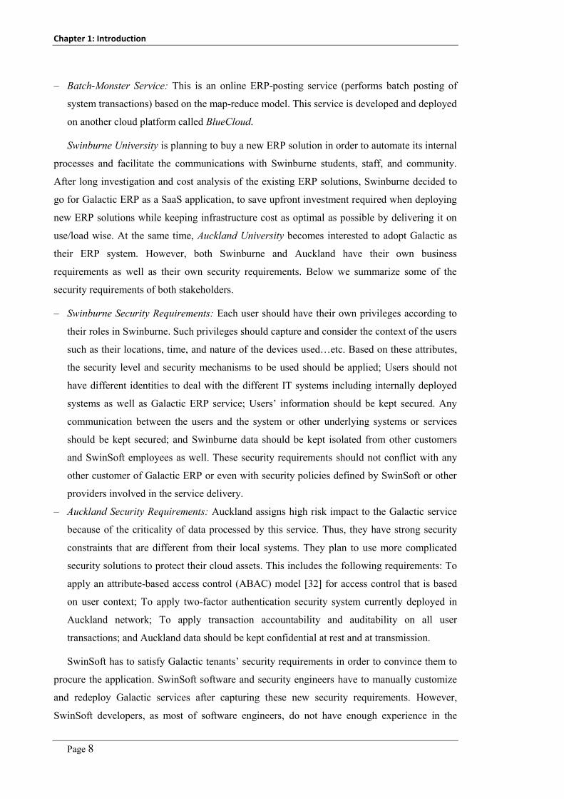
Chapter 1: Introduction
Page 8
– Batch-Monster Service: This is an online ERP-posting service (performs batch posting of
system transactions) based on the map-reduce model. This service is developed and deployed
on another cloud platform called BlueCloud.
Swinburne University is planning to buy a new ERP solution in order to automate its internal
processes and facilitate the communications with Swinburne students, staff, and community.
After long investigation and cost analysis of the existing ERP solutions, Swinburne decided to
go for Galactic ERP as a SaaS application, to save upfront investment required when deploying
new ERP solutions while keeping infrastructure cost as optimal as possible by delivering it on
use/load wise. At the same time, Auckland University becomes interested to adopt Galactic as
their ERP system. However, both Swinburne and Auckland have their own business
requirements as well as their own security requirements. Below we summarize some of the
security requirements of both stakeholders.
– Swinburne Security Requirements: Each user should have their own privileges according to
their roles in Swinburne. Such privileges should capture and consider the context of the users
such as their locations, time, and nature of the devices used…etc. Based on these attributes,
the security level and security mechanisms to be used should be applied; Users should not
have different identities to deal with the different IT systems including internally deployed
systems as well as Galactic ERP service; Users’ information should be kept secured. Any
communication between the users and the system or other underlying systems or services
should be kept secured; and Swinburne data should be kept isolated from other customers
and SwinSoft employees as well. These security requirements should not conflict with any
other customer of Galactic ERP or even with security policies defined by SwinSoft or other
providers involved in the service delivery.
– Auckland Security Requirements: Auckland assigns high risk impact to the Galactic service
because of the criticality of data processed by this service. Thus, they have strong security
constraints that are different from their local systems. They plan to use more complicated
security solutions to protect their cloud assets. This includes the following requirements: To
apply an attribute-based access control (ABAC) model [32] for access control that is based
on user context; To apply two-factor authentication security system currently deployed in
Auckland network; To apply transaction accountability and auditability on all user
transactions; and Auckland data should be kept confidential at rest and at transmission.
SwinSoft has to satisfy Galactic tenants’ security requirements in order to convince them to
procure the application. SwinSoft software and security engineers have to manually customize
and redeploy Galactic services after capturing these new security requirements. However,
SwinSoft developers, as most of software engineers, do not have enough experience in the

Chapter 1: Introduction
Page 9
security engineering area. So they face many problems developing tenants’ security
requirements inside their delivered applications and services.
SwinMarket, a new Galactic tenant, becomes also interested to use Galactic point-of-sale
system to operate in their stores. Galactic should be integrated with the SwinMarket systems that
automate their internal business process including General Ledger and Purchasing systems. This
means that SwinSoft has to revisit Galactic application security requirements to incorporate
SwinMarket security needs.
Few months later, Swinburne has decided to change their security requirements to match
their new business needs. Moreover, Auckland has decided to change their security
requirements in order to address new security threats found in Galactic and may result in
breaching their assets confidentiality. This means that SwinSoft development team has to revisit
those tenants’ operated security with relevant change requests.
SwinSoft is now looking for a security management and engineering approach that could help
them in capturing and enforcing different tenants’ security requirements rather than the current
methodologies that deliver one set of application security not linked to different service tenants’
security requirements. Moreover, they are looking for an approach that helps in modifying
security requirements of a given tenant independent of the other tenants. This approach should
support registering new tenants who can apply their security requirements at runtime without a
need for service customizations. It is highly recommended that the proposed approach is a
configuration-based rather than customization-based to avoid delays in modifications, being
overwhelmed with change requests, and improve service availability.
1.2 Research Roadmap
To deliver our cloud security management platform, we have adopted an iterative approach
where each iteration is supported with a prototype as a proof-of-concept. Working iterative
helped to keep adding components to the proposed platform, each new component addresses
one of the research questions/gaps. The order of iterations reflect the logical dependencies
between the research gaps we found in the area of cloud computing security management.
Below we discuss details of our research project roadmap.
First, we investigated the existing efforts in the area of the cloud computing security to
identify the existing research problems, research gaps, and setting the research scope. We
published results of our detailed analysis of the cloud computing security problem in [4].
Second, we projected the existing security management standards including ISO27000 [5]
and NIST-FISMA [1], and security management efforts on the cloud computing model using

Chapter 1: Introduction
Page 10
the requirements and challenges we identified in the first milestone. A practical solution to the
cloud computing security management problem must conform to the existing security standard.
Thus the objective of this step was to assess the existing security standards when applied to the
cloud computing model. We selected NIST-FISMA security management standard (as one of
the two main security management standards). The standard does not target securing outsourced
services, thus we had to adapt NIST-FISMA standard to fit with the cloud model. Our revised
cloud-aligned NIST-FISMA standard is based on improving the collaboration of the cloud
stakeholders in delivering the whole platform and service security model. We developed a
simple prototype based on the modified model, and verified it using the motivating scenario
discussed above (published in [33]). The rest of our platform is aligned with the revised
NIST_FISMA standard.
Third, once we confirmed that our modified cloud security model works well with the cloud
model, we started to work on every task of the security management process (specifying,
enforcing, and monitoring security) to see how we can improve or automate and re-integrate
with our developed framework. We started with the security enforcement step because it
represents the core of the whole security process, whereas a failure to automate, implies
rejecting the hypothesis (that we can deliver automated cloud security management) we are
trying to prove in this project. Assuming that we succeeded in capturing the set of security
objectives of each tenant, how can we enable services to support enforcing these multi-tenant
security requirements? To do this we investigated the existing security engineering, adaptive
application security, and multi-tenant SaaS engineering approaches. These efforts do not
support multi-tenancy security engineering, fully adaptive security, or runtime integration of
third-party security controls. We proposed a new approach for security engineering, MDSE@R.
In MDSE@R, service providers should deliver a service description model that captures their
services’ details (called a Service Description Model – SDM) as part of their service delivery
package. Customer security engineers develop their security specification model (SSM) that
captures all security objectives, requirements, etc. MDSE@R then weaves both models together
at runtime and reflects the resultant weaved system-security model onto the running system
using dynamic-weaving Aspect-Oriented Programming - AOP. We validated MDSE@R with a
set of open source applications from our benchmark set discussed above. The results show that
MDSE@R successfully used in capturing different sets of security requirements and realization
controls, and correctly integrating these security controls within target system entities. The
results were published in CSS2012 [34]. As an extension of this approach we modified
MDSE@R to fit with the multi-tenancy problem – i.e. to support enforcing different sets of
security requirements at runtime. TOSSMA is a tenant-oriented SaaS security management
architecture that supports capturing and enforcing different security requirements, for different
Chapter 1: Introduction
Page 11
tenants, on the same service instance at runtime. TOSSMA was validated on the same set of
open source applications. Results were published in CLOUD2012 [35].
Fourth, MDSE@R helps adding security at runtime for new and existing applications, but
for existing applications with built-in security, the new injected security capabilities may result
in conflicts with the already built-in security capabilities. Thus, we have to introduce a pre-
processing step where the existing, built-in security capabilities are re-engineered. This may
include modifying, replacing and disabling existing security. We investigated existing system
and security maintenance, and retrofitting approaches. A limited work was introduced in this
area. A reasonable justification of this is that once a model-driven engineering approach was
used in developing the application, the maintenance task will mainly relay on updating existing
models. Moreover, addressing security as an afterthought is always claimed to be a bad practice
[36]. Existing efforts do not help enough in automating security reengineering tasks, as most of
these efforts focus on using aspect-oriented programming (AOP) to deliver dynamic system
updating through replacing existing methods with updated versions [37]. We propose a new
approach that helps in reengineering system and security whatever was the information
available including system models, source code or at the worst case system binaries are only
available. Our approach is based on a new concept we introduced “Re-aspect” – Reengineering
aspects – which extends the AOP with more flexible signature specification constructs (to
capture signature of code entities to be modified) and more supported actions (delete, inject,
modify, and replace). Re-aspect advice encapsulates code to inject (in case of replace or insert
re-aspect) or code to be used in system modification (in case of modify re-aspect). We validated
our approach on the same set of open source web applications. The results show that “Re-
aspects” is sound enough in automating the software security retrofitting process. We
documented our approach and results and published it in ASE2012 and ICECCS2012 [38, 39]
Fifth, a key source of security requirements is the security analysis task that pinpoints service
security issues. Moreover, given a system either secured or not, how can we verify that it is not
still vulnerable to known weaknesses or vulnerabilities. Existing techniques focus on specific
types of weaknesses such as SQL Injection, OS Command Injection, XSS, etc. These techniques
use static analysis, dynamic analysis, string based analysis, runtime analysis, or hybrid
approaches. These efforts are not comprehensive enough to cover a wide - range of
vulnerabilities. Conducting vulnerability analysis of the services before hosting on the cloud or
getting tenants to use it is an important task that helps in reducing the risk of tenants’ data
breaching. Moreover, such efforts are not extensible enough to address new vulnerabilities that
emerge at runtime. Having an online vulnerability analysis is a key requirement of the cloud
computing security problem. To deliver a comprehensive and extensible approach, we

Chapter 1: Introduction
Page 12
developed a formal weakness/vulnerability specification approach independent of the service
implementation or details of the programming language used (currently, vulnerabilities are
specified informally e.g. in CWE database). In our approach, vulnerability signatures are
specified in Object Constraint Language (OCL). We have developed a source code vulnerability
analysis extension that receives the source code of the service under test along with the
vulnerabilities’ signatures. It generates a list of found vulnerabilities in the source code along
with the entities that match the specified vulnerabilities’ signatures. We have evaluated our
approach in capturing definitions of the top ten weaknesses published by the Open Web
Application Security Project – OWASP [40], and in analyzing a set of benchmark applications
using these signatures. The evaluation results show that our online security analysis tool has
high precision and recall rates. This means that we can depend on it in analyzing SaaS
applications against possible vulnerabilities and attacks. Our approach along with the evaluation
results have been published in ASE2012 [41]. We then extended this approach to support not
only source code analysis (vulnerability analysis) but also system architecture and design
artifacts (threat and risk analysis). This extension along with the evaluation results have been
published in ICSE2013 [42].
Sixth, given the set of security objectives, identified vulnerabilities, and enforced security
controls, how to confirm that the system is now secure enough, meets the specified security
objectives, and blocks the possible security attacks. Security monitoring is a very raw field
where a very limited amount of research has been done so far. Existing efforts do not help in
automated security monitoring. They mostly help in developing manual security metrics or
manual collection of security measures. We have developed a general approach that captures
security metrics in general signatures as OCL invariants. These metrics definitions are used to
generate required security probes. These probes are integrated within the target services using
AOP that intercept service execution and extract values of different attributes of the services to
be evaluated. The collected measures are sent back to analysis service that analyze such
measures and generates the corresponding metric values. The evaluation results show that our
approach is successful in capturing different categories of security metrics, automating the
generation and deployment of security probes, and analyzing the generated measurements. This
approach along with the evaluation results are submitted to ASE2014.
1.3 Key Contributions
In this research, we have introduced a set of solutions to address relevant security problems that
arise from the adoption of the cloud computing model. Below we summarize the key
contributions we have achieved in the area of cloud computing security management.

Chapter 1: Introduction
Page 13
A novel alignment of one of the existing security management standards (NIST-FISMA
standard) to fit with the cloud computing model and its new application service hosting model
(multi-tenancy model) [33]. Existing security management standards focus on enterprise
security management where assets are fully owned and controlled by the customers. On the
other hand, cloud consumers do not have control on their outsourced cloud assets, especially in
the SaaS applications. Thus, existing security management standards do not fit well with the
cloud computing model. Our proposed security management standards-to-cloud computing
alignment is based on improving the joint-collaboration between different cloud stakeholders
where each stakeholder participates with the piece of information they own about the cloud
model or the hosted services. Our proposed alignment is introduced in Chapter 5.
A novel, integrated, and multi-tenant cloud computing security management model and
platform. Our security management platform, to the best of our knowledge, represents the first
proposal of a security management platform for the cloud computing model that address the
loss-of-control and lack-of-trust problems taking into consideration the multi-tenancy
dimension. Our security management model is based on NIST-FISMA standard as one of the
two main security management standards. Our aim is to be comprehensive enough to cover
most of the tasks done by security experts during the security management process. To the best
of our knowledge, this is the first proposal of multi-tenant security management platform that
operates as a cloud service shared among all cloud stakeholders including service tenants and
service providers.
A novel, model-driven, tenant-oriented security engineering approach [34, 35]. We introduce
a novel multi-tenant, model-driven security engineering at runtime approach (we call
MDSE@R). Given cloud services are shared among different tenants who have their own
security requirements, the service-oriented security engineering approaches (a service can
reflect one set of security requirements that are captured during design time) are no longer
suitable to satisfy tenants’ needs. We introduce a tenant-oriented security engineering approach
that enables different tenants to manage (define security, enforce security, and monitor security)
their service instances’ security at runtime without a need for service customization. MDSE@R
introduces a comprehensive system description mega-model (SDM) that captures all system
details (this model is developed by service providers using UML) and security specification
mega-model - SSM (that captures each tenant’s security details, developed by each service
tenant using our SecDSVL). The SSM is based on a deep analysis of the main entities and tasks
existing in security management standards. We developed SecDSVL, a security domain-specific
visual language, to help security engineers and administrators in developing security
specification models. MDSE@R also introduces a common security interface that helps in

Chapter 1: Introduction
Page 14
integrating third-party security controls with the target IT assets at runtime. Security vendors
need to develop one adaptor for their security services that complies with our common security
interface. Thus, they do not need to develop different adaptors for different cloud services. Our
proposed MDSE@R approach is introduced in Chapter 6.
An extensible online cloud services’ security analysis service [41, 42]. We introduce a
security analysis service that can analyse service architecture, design, source code, and binaries
to identify the existing security design flaws and bugs. The key contributions of our novel
security analysis service are: integrated security analysis throughout different service artifacts
including architecture, design and code; the security analysis service is extensible, thus we can
add different security analysis mechanisms without a need to modify the underlying platform;
and security analysis is signature-based, thus any vulnerability, threat, or system design security
metric could be easily specified and verified against the system without a need to develop new
plugins. This helps to support online analysis for known and unknown vulnerabilities that arise
at runtime as far as a signature of such vulnerabilities exist. Our proposed security analysis
approach is introduced in Chapter 8.
An extensible and automated cloud applications’ security monitoring service. The main
contribution of our novel security monitoring service is that we did not develop a predefined set
of security metrics. Service users can define their own security metrics to be used in diagnosing
the security status of their IT assets. The security monitoring service uses these metrics
signatures (definitions) to generate and deploy required security probes that are responsible for
collecting required measurements from the target cloud services. Moreover, it uses these
signatures in generating metric evaluation expressions to be used in analyzing collected security
measurements and generating metric values. Our security monitoring approach is introduced in
Chapter 9.
A novel approach to help migrating legacy applications to the cloud and disabling hardcoded
security functionalities [38, 39]. In order to help in managing services security using MDSE@R
we may need to disable the existing security APIs and functions in a legacy application. To do
this we introduce a novel system and security reengineering approach using a new concept
called reengineering aspects “Re-aspects”. This new concept helps in capturing system
modification details including the signature of system entities to modify, actions to apply,
advice(s) or code to use in realizing this change. Our re-aspects engine uses these details to
realize the captured change request details. This approach is supported with two signature
specification approaches including code-snippets signatures and OCL-based signatures. We
have used re-aspects to address two other problems: the patching/mitigation of reported
vulnerabilities and in migrating legacy applications that are not designed with multi-tenancy in

Chapter 1: Introduction
Page 15
mind to support cloud computing multi-tenancy. Our proposed security reengineering approach
is introduced in Chapter 7.
An automated vulnerability virtual patching approach [43]. This approach is based on
integrating MDSE@R and vulnerability analysis service. The reported vulnerabilities by the
vulnerability analysis service are fed in MDSE@R to inject relevant security controls (as
vulnerability mitigation actions) at critical (vulnerable) system entities. Our proposed virtual
patching approach is introduced in Chapter 10 as a case study.
1.4 Thesis Structure
This thesis deals with cloud computing security management problem taking into consideration
the loss-of-control, lack-of-trust, and multi-tenant security problems that arise from the adoption
of the cloud computing model. In this thesis we introduce our solution to address these
problems. Our solution is based on an adaptive, model-based cloud computing security
management approach that enables tenants to extend their security capabilities to include cloud
hosted assets. By this approach tenants can define their security requirements, their security
controls, and security metrics and attributes they want to follow up. The thesis structure is
depicted in Figure 1-2. The thesis is divided into three parts. Part (1) gives an overview of the
cloud computing model, the key security problems and challenges arise from the adoption of the
cloud model, and the key limitations of the existing research efforts. Part (2) gives details of our
solution – the adaptive, model-based cloud computing security management approach. Part (3)
gives details of the case studies we conducted to evaluate our approach and the key conclusions,
limitations and future work.
In Chapter 2, we introduce a detailed analysis of the cloud computing security problem. We
tried to identify different the key factors that really contribute to the cloud computing security
problems and should be addressed by any cloud computing security solution. These factors
include cloud characteristics (multi-tenancy and elasticity), cloud architecture, underlying
technologies, and service delivery models used.
In Chapter 3, we give a comprehensive literature review of the main relevant research areas
related to our research problem, including cloud computing, security management, security
engineering, security engineering, security analysis, and security monitoring. We summarize the
key efforts done in each area, key limitations of these efforts, and key gaps compared to the
security problems and issues of the cloud computing model that we need to address in our
research project.

Chapter 1: Introduction
Page 16
• Chapter 1: Introduction
• Chapter 2: Cloud Computing Security Problem
• Chapter 3: Related Work
Part 1: Problem Analysis
• Chapter 4: General Approach
• Chapter 5: Aligning Security Management Standards with Cloud Model
• Chapter 6: Cloud Applications’ Security Engineering
• Chapter 7: Cloud Applications’ Security Reengineering
• Chapter 8: Cloud Applications’ Security Analysis
• Chapter 9: Cloud Applications’ Security Monitoring
Part 2: Adaptive, Model-based Security Management
• Chapter 10: Case Studies
• Chapter 11: Conclusion and Future Work
Part 3: Evaluation
Figure 1-2. Thesis structure
In Chapter 4, we introduce the main idea of our security management platform which is the
autonomic computing model (MAPE-K). We also describe the “big picture” of our platform,
our solution high-level architecture, and the main components of the security management
platform.
In Chapter 5, we describe how we aligned one of the main security management standards
(NIST-FISMA standard) to fit with the cloud computing model and how we attested the
proposed model with a prototype with a simplified version of our motivating example.
In Chapter 6, we describe our security enforcement approach developed as model-driven,
multi-tenant security engineering at runtime approach (MDSE@R). The proposed approach
enables each tenant to manage their assets security using security specification models that
capture their security details using SecDSVL (security domain-0specific visual language). Then,
MDSE@R realizes these security models using aspect-oriented programming. We introduce a
detailed evaluation of our MDSE@R approach, including SecDSVL usability evaluation, usage,
example, and a set of benchmark applications.
In Chapter 7, we present our security reengineering approach and our new change request
realization concept “reengineering aspects” re-aspects. MDSE@R helps in injecting tenants’
security requirements at runtime; however, it does not help with applications that have built-in
security functions or APIs. We give details of the reengineering aspects concept, how re-aspects

Chapter 1: Introduction
Page 17
help in impact analysis and change propagation as main steps of the software reengineering and
maintenance. We describe a detailed evaluation of our security reengineering approach on a set
of benchmark applications and a set of security related change requests.
In Chapter 8, we present our novel, online signature-based security analysis approach. This
approach is based on capturing signatures of weaknesses, vulnerabilities, attacks’ signatures,
and security metrics using formalized signatures developed with Object Constraint Language
(OCL). These signatures are automatically transformed into C# code that is used to analyse the
applications/services source code to pinpoint matched entities. We introduce a detailed
evaluation of our approach and developed prototype.
In Chapter 9, we introduce our novel security monitoring approach using formalized security
metrics schema with metric signature specification approach based on OCL. We describe our
underlying security monitoring platform that is responsible for transforming these security
metrics into a set of security probes to be deployed into system entities, collecting
measurements from the system status attributes, and in analyzing the collected measurements
using the specified security metrics’ signature after being transformed into C# code.
In Chapter 10, we present a set of case studies that we have conducted in order to evaluate
our proposed cloud security engineering approach. We describe three case studies where each
case study assesses the application of the platform or parts of the platform in a specific cloud
security problem. The first case study addresses the problem of online virtual patching of the
newly reported security vulnerabilities. The second case study addresses the problem of
migrating legacy applications to fit with the cloud model (mainly the isolation of different
tenants’ data). The third case study shows the application of our platform in realizing a full
security management cycle of a SaaS application with different tenants.
In Chapter 11, we summarize the key problems we addressed throughout our research
project, summarize key contributions of the research project introduced in this thesis, the main
limitations of our platform, and future tasks that we plan to address.


Page 19
Chapter 2
Cloud Computing Security Problem
In this chapter we discuss the key factors, we figure out from our analysis, contributing to the
complication of the security problem under the cloud computing umbrella i.e. we address the
question why security is different and more challenging in cloud computing than for other kinds
of computing domains? Such factors need to be addressed by cloud security solution that targets
security issues in the cloud computing model. This chapter is organised as follows. In Section 1,
we give a general introduction of the cloud computing model and why cloud computing security
is ranked as one of the top concerns when adopting the cloud model. In Section 2, we discuss
the implications of different factors on the security of the cloud model. In Section3, we discuss
the key enablers that can help addressing these cloud computing security problems.
2.1 Introduction
The cloud computing model provides the next generation of internet-based, highly scalable
distributed computing systems in which computational resources are offered 'as a service' [2].
The cloud model is based on the pay-as-you-go payment model where tenants – users of the
cloud-hosted software applications – pay only for the amount of resources they use. Tenants can
expand or shrink their resources on the fly according to current needs [44].
The cloud model has motivated industry and academia to host a wide spectrum of
applications ranging from high computationally intensive scientific or business applications
down to light-weight services. The cloud model also helps in addressing the “long tail market”
for small and medium enterprises (SMEs) [67]. This is because it does not require large upfront
investment in IT infrastructure, software licenses, and other computing infrastructure.
Moreover, governments and other organizations have become more interested in the
possibilities of using cloud computing to reduce IT costs and increase capabilities and
reachability (availability and accessibility) of their delivered services. According to a recent
Gartner survey [45] on cloud computing revenues, the cloud market was worth USD 68 Billion
in 2010 and will reach USD 148 Billion by 2014. These revenues imply that cloud computing is
a promising computational platform. Despite the potential benefits of improved reliability,
quality, cost savings and increased revenues that can be gained from the cloud computing
model, a major downside is that it increases malicious attackers’ interest and ability to find
applications and platforms vulnerabilities to exploit.
Chapter 2: Cloud Computing Security Problem
Page 20
This is because of the increased availability and public accessibility of such applications on
the internet. In addition, the cloud model is still not mature enough [46] - there are a lot of open
issues that impact the model creditability and pervasiveness from the cloud consumers’
perspective. For example, vendor lock-in, multi-tenancy and isolation, data placement and
management, service portability, elasticity engines, SLA management, and cloud security are
well-known open research problems [46-48].
From the cloud consumers’ perspective, security is a major concern that hampers the
adoption of the cloud computing model [49]. This is due to, among other reasons: First,
enterprises outsource the security management of their cloud-hosted assets to a third party
(cloud provider) that hosts their IT assets. This results in the well-known loss-of-control
problem [50], where cloud consumers do not have security control over their outsourced assets.
Second, different tenants’ assets co-exist at the same location and using the same software
service instance. Tenants are unaware of the soundness of operated service security and what
security controls are actually used to secure tenants’ data and ensuring no data privacy breach.
Third, the lack of security guarantees in the Service Level Agreements (SLAs) between cloud
consumers and cloud providers. Most existing SLAs focus on reliability, availability and
performance quality of service attributes, rather than security [51]. Fourth, hosting this set of
valuable assets on publicly accessible infrastructure increases the interest and ability of attackers
to exploit vulnerabilities in the cloud platform or the hosted services to achieve malicious
benefits, such as compromising one tenant’s data to another tenant who may be a competitor.
From the cloud providers’ perspective, security requires a lot of expenditure (e.g. security
solutions’ licenses) and resources (security is a resource intensive aspect). Moreover, security is
a difficult problem to master due to its complexity (as we illustrate later in this chapter). The
cloud provider does not know what software the tenants are running which may introduce
security risks to the platform. On the other hand, ignoring or delaying security in the cloud
computing roadmap will violate the expected revenues stated above. Thus, cloud providers have
to understand consumers’ concerns mentioned above and seek out new security solutions that
resolve such concerns. In order to deliver a security engineering and management approach that
helps addressing the security problems arise from the adoption of the cloud computing model,
we have to gain a deep understanding of the cloud computing model to understand the key
factors and root causes that should be addressed by any security engineering or management
approach that address the cloud computing model. This is what we are discussing in the next
sections.

Chapter 2: Cloud Computing Security Problem
Page 21
2.2 Cloud Security Analysis
In this Section we summarize the existing challenges and issues involved in the cloud
computing security problem. We have grouped these issues, as shown in Figure 2-1, into
architecture-related issues, service delivery model-related issues, cloud characteristic-related
issues, cloud deployment models-related issues, and cloud stakeholder-related issues. Our
objective is to identify the weak points in the cloud model by highlighting their root causes.
This helps us in formulating our research problem, key challenges and requirements that we
should address in our approach.
Cloud Characteristics
Long Dependency Stack
Service Delivery Models Different Possible Deployments
Different Stakeholders
Cloud Computing Model
Figure 2-1. Key factors contributing to the cloud computing security
2.2.1 Deployment Models Security Implications
The cloud computing model has three different service delivery models and three possible
deployment models [2] including: Private Cloud: a cloud platform that is dedicated for specific
enterprise(s). This is usually deployed within enterprise network perimeter and enterprise IT
department has full control on the cloud platform. The main objective of this model is to remove
customers’ concerns about the security of their cloud hosted assets on the expense of increasing
IT infrastructure cost; Public Cloud: a cloud platform available to public users to register and
use the available infrastructure and resources over the internet. Tenants use cloud resources
using pay-as-you-go payment model; and Hybrid Cloud: a combination of private cloud
platform that can extend to use resources on a public cloud platform.
Of these three models, public clouds are the most vulnerable deployment models because
they are available for public users to host their services. Those users may be malicious users or
services. In this case, we grant high privileges to malicious users who can exploit more
advanced and complicated vulnerabilities to breach the security of not only one tenant data but
other cloud tenants’ as well. Thus, we need to have an online security analysis tool that can
automatically check and pinpoint any vulnerabilities in the shared, multi-tenant cloud
application. Moreover, we need to enable tenants in securing their assets as hard as they see.

Chapter 2: Cloud Computing Security Problem
Page 22
Cloud Physical Infrastructure
Infrastructure-as-a-Service
Platform-as-a-Service
Software-as-a-Service
Figure 2-2. Cloud service delivery and deployment models
The cloud model introduces three basic service delivery models, as illustrated in Figure 2-2.
These service delivery models deliver different types of services for different types of cloud
tenants. Here, we summarize these models and their security implication: Infrastructure-as-a-
Service (IaaS): in this service delivery model, cloud providers deliver computational resources,
storage and network as internet-based services. This service model is based on virtualization
technology – i.e. deploying a special software “hypervisor” [52] on top of the infrastructure,
which enables creation of different virtual machines that share the same physical server.
Amazon EC2 is the most familiar IaaS platform; Platform-as-a-Service (PaaS): In this service
delivery model, cloud providers deliver platforms, tools and other business services that enable
customers to develop, deploy, and manage their own applications, without installing any of
these platforms or support tools on their local machines. The PaaS model may be hosted on top
of IaaS model or on top of the cloud infrastructures directly. Google Apps and Microsoft
Windows Azure are the most well-known PaaS providers; and Software-as-a-Service (SaaS): in
this service delivery model, cloud providers deliver applications hosted on the cloud
infrastructure as internet-based services for end users, without requiring installing the
applications on the customers’ network. This model may be hosted on top of PaaS, IaaS or
directly hosted on cloud infrastructure. Salesforce.com CRM is an example of a well-known
SaaS platform.
Each service delivery model has different possible implementations, as shown in Figure 2-2
and discussed above. This complicates the development of standard security model for each
service delivery model. Moreover, these models may co-exist on one cloud platform leading to
further complication of the security management process. These service delivery models are
based on existing technologies such as web applications, service-oriented architecture, and
virtualization technologies which already suffer from security problems. Of these different
service delivery models, SaaS model is the weakest model where most of the attacks target to
breach the model security. In this project, we focus mainly on the SaaS model. However, this

Chapter 2: Cloud Computing Security Problem
Page 23
work could be applied easily on the PaaS model (mainly web services). We plan to wave the
work we have done in this research with work done in our research group on IaaS model.
2.2.2 Cloud Architecture Security Implications
The cloud computing model depends on a deep stack of inter-dependent layers of objects (VMs,
APIs, Services and Applications), as shown in Figure 2-3, where the functionality of a higher
layer depends on lower platform layers. The IaaS model covers cloud physical infrastructure
(storage, networks and servers), virtualization layer (hypervisors), and virtualized resources
layer (VMs, virtual storage, virtual networks). The PaaS model covers the platform layers (such
as application servers, web servers, IDEs, and other tools), and APIs and services layers. The
PaaS model depends on the virtualization of resources as delivered by IaaS. The SaaS model
covers applications and services offered as a service for end users. The SaaS layer depends on a
layer of platforms to host the services and a layer of virtualization to optimize resources
utilization when delivering services to multiple tenants.
Clo
ud
Man
agem
ent
SaaS Applications
PaaS Applications
Hosting Services
Virtualized Resources
Virtualization Platform
Cloud Infrastructure
Figure 2-3. Cloud computing model layers
This deep dependency stack of cloud objects complicates the cloud security problem as the
security of each object or cloud layer depends on the security of the lower objects/layers.
Furthermore, any breach to any cloud objects will impact the security of the whole cloud
platform. Each cloud layer/object has a set of security requirements and vulnerabilities so it
requires a set of security controls to deliver secured services. This results in a huge number of
security controls that need to be managed. Moreover, managing such heterogeneous security
controls to meet security needs is a complex task, taking into account conflicts among the
security requirements and among security controls at each layer. This may result in an
inconsistent security model. Hence, a unified security control management module is required.

Chapter 2: Cloud Computing Security Problem
Page 24
This module should coordinate and integrate among the various layers’ security controls based
on security needs.
2.2.3 Cloud Stakeholders Security Implications
The cloud computing model has different involved stakeholders, including: cloud provider (an
entity that delivers infrastructures to the cloud consumers), service provider (an entity that uses
the cloud infrastructure to deliver applications or services to end users), and service consumer
(an entity that rents and uses services hosted on the cloud infrastructure). Each stakeholder has
their own security management systems and processes; each one has their own expectations
(requirements) and capabilities (delivered) from/to other stakeholders; and each one owns a
piece of information that could help in building a complete security model. This leads to:
– A set of security requirements that need to be defined on a shared service/resource by
different service tenants that may conflict with each other. Thus security configurations of
each service need to be maintained and enforced at the tenant level instead of the currently
used model – i.e. on the service level model. At runtime the system should support the
possibility of security requirements updating based on current tenants’ needs to mitigate
new risks;
– Providers and consumers need to negotiate and agree on the specified security properties.
However, no standard security specification notations are currently available that can be
used by all of the cloud stakeholders to represent and reason about their offered or required
security properties (currently only availability, reliability and performance attributes are
supported); and
– Each stakeholder has their own security management processes used to define their assets,
expected risks and their impacts, and how to mitigate such risks. Adopting the cloud model
results in an inherent “loss of control” by both involved parties - cloud providers are now
not aware of the contents and security requirements of services hosted on their
infrastructures; and cloud consumers who are not able to control security on neither their
assets security nor other services sharing the same resources. Security SLA management
frameworks represent a part of the solution related to security properties specification,
enforcement and monitoring. However, current SLAs still do not cover security attributes in
their specifications [51]. Moreover, SLAs are high level contracts where the details of the
security policies, security controls and how to change them at runtime are not clearly stated,
enforced or monitored.
Furthermore, cloud providers are faced with a lot of changes on security requirements while
having a huge number of security controls deployed that need to be reconfigured in accordance

Chapter 2: Cloud Computing Security Problem
Page 25
with security requirements’ changes. This further complicates the cloud providers’ security
administrators’ tasks. Transparency of what security is enforced, what risks exist, and what
breaches occur on the cloud platform and the hosted services must exist among cloud providers
and consumers. This is what is called “trust but verify” - TBV [53], where cloud consumers
should trust in their providers in the meanwhile cloud providers should deliver tools to help
consumers in verifying and monitoring their enforced security.
2.2.4 Cloud Characteristics Security Implications
To achieve efficient utilization of resources, cloud providers need to increase their resource
utilization while minimizing cost. At the same time consumers need to use resources as much as
they require while being able to increase or decrease resource consumption based on actual
demands. The cloud computing model meets such needs via a win-win solution delivered by
two key cloud characteristics: multi-tenancy and elasticity. Both characteristics turn out to have
serious implications on cloud model security as we discuss below.
1 2
3
Instance A Instance BInstance B Instance Instance Instance
Instance InstanceInstance
Tenant Loader BalancerInstance
4
Figure 2-4. Cloud multi-tenancy models
2.2.4.1 Multi-tenancy Security Implications
Multi-tenancy implies sharing of computational resources, storage, services, and applications
with other tenants. The concept of “multi-tenancy” actually has different realization approaches,
as shown in Figure 2-4.
In approach 1, each tenant has their own dedicated instance with their own customizations
(customization may include special development to meet customer needs). In approach 2, each
tenant uses a dedicated instance, like approach 1, while all instances are the same but with

Chapter 2: Cloud Computing Security Problem
Page 26
different configurations (configurations represent adjustments of application parameters or
interfaces to meet specific tenant needs). In approach 3, all tenants share the same instance with
runtime configuration (the application is divided into core application components and extra
components that are loaded based on the current tenant requests – similar to SalesForce.com). In
approach 4, tenants are directed to a load balancer that redirects tenants’ requests to a suitable
instance according to current work load. Approaches 3 and 4 are the most risky models from the
security perspective as service tenants become coexisting on the same process, memory, and
hardware. This sharing of resources may violate the confidentiality of tenants’ IT assets which
leads to the need for secure multi-tenancy. Secure multi-tenancy has two key requirements as
discussed below.
- Secure Isolation and Location Transparency: Maintaining isolation between tenants’ data (at
rest, processing and during transmission) and location transparency where tenants have no
knowledge or control over the specific location of their resources to avoid planned attacks
that attempt to co-locate with the victim assets [54]. In some cloud platforms, tenants can
specify high level policies on data location such as country or region level. In IaaS, isolation
should consider VMs’ storage, processing, memory, cache memories, and networks. In PaaS,
isolation should achieve isolation among running services and APIs’ calls. In SaaS, isolation
should achieve isolate among transactions carried out on the same instance by different
tenants and also tenants’ data at rest and processing.
- Security Engineering of Multi-Tenant Services: Different tenants of the cloud services have
their own business requirements as well as security requirements that they are keen to
enforce on their cloud hosted assets and data. Although the current cloud computing model
does support the capture of different business requirements (through the different multi-
tenancy models discussed above), there is little or no support to capture or reflect different
sets of security requirements for different tenants. This becomes more complicated when we
know that different tenants with different requirements usually emerge at runtime. Moreover,
tenant security requirements can change at runtime to reflect their business needs and current
security risks that they consider.
2.2.4.2 Elasticity Security Implication
Elasticity implies being able to scale up or down resources assigned to services based on the
current demands. Scaling up and down of a tenant allocated resources gives the opportunity for
other tenants to use the victim tenant’s previously assigned resources. This may lead to
confidentiality issues. For example, if tenant A has scaled down so she releases resources, these
resources are now assigned to tenant B who in turn might use it to deduce the previous contents
of tenant A.

Chapter 2: Cloud Computing Security Problem
Page 27
Moreover, elasticity usually depends on a service placement engine that maintains a list of
the available resources from the provider’s offered resources pool. This list is used to allocate
resources to cloud services. Such placement engines should incorporate cloud consumers’
security and legal requirements such as avoid placing competitors services on the same server,
data location should be within the tenants’ country boundaries. Placement engines may include
a migration strategy where services are migrated from physical host to another in order to meet
demands and efficient utilization of the resources. This migration strategy should take into
account the same set of tenants’ security constraints. Furthermore, security requirements defined
by service consumers should be migrated with the service and initiates a process to enforce
security requirements on the new environment, as defined by cloud consumers, and updates the
current cloud security model.
2.2.5 Service Delivery Models Security Implications
We summarize the key security issues and vulnerabilities for each cloud service delivery model.
Some of these issues fall under the responsibility of cloud providers, while others are the
responsibility of cloud consumers.
2.2.5.1 IaaS Security Issues
Below we discuss the key security issues in each component of the IaaS service delivery model:
– Hypervisor Security: a hypervisor is the “virtualizer” that maps from physical resources to
virtualized resources and vice versa. It is the main controller of any access to the physical
server resources by VMs. Any compromise of the hypervisor violates the security of the
VMs because all VMs operations become traced unencrypted. Hypervisor security is the
responsibility of cloud platform provider.
– VM Security: This involves securing virtual machines’ operating systems and workloads
from common security threats that affect traditional physical servers, such as malware and
viruses, using traditional or cloud-oriented security solutions. The VM’s security is the
responsibility of cloud consumers. Each cloud consumer can use their own security controls
based on their needs, expected risk level, and their own security management process.
However, the security of the cloud platform from a given VM is the responsibility of the
platform provider. This requires a new model for security controls that can work from the
virtualization layer (at the hypervisor level). This new model is called virtualization-aware
security solutions [55, 56].
– Securing VM-Images Repository: unlike physical servers, VMs are still at risk even when
they are offline. VM images can be compromised by injecting malicious codes in the VM
Chapter 2: Cloud Computing Security Problem
Page 28
file or even stole the VM file itself. Securing the VM images repository is the responsibility
of cloud providers. Another issue related to VM templates is that such templates may retain
the original owner (creator) information that may be incorrectly accessed by a new
consumer.
– Virtual Network Security: Sharing network infrastructure among different tenants within the
same server (using a vSwitch - Virtual Switches represent networking entities connecting
Virtual Machines in a virtual network at layer 2 [52]) or in the physical networks increases
the possibility to exploit vulnerabilities in DNS servers, DHCP, IP protocol vulnerabilities,
or even the vSwitch software. This may result in network-based VM attacks.
– Securing VM Boundaries: VMs have virtual boundaries compared with physical server ones.
VMs that co-exist on the same physical server share the same CPU, Memory, I/O, network
interface cards, and others (i.e. there is no physical isolation among VM resources). Securing
VM boundaries is the responsibility of the cloud provider.
2.2.5.2 PaaS Security Issues
The key security issues in each component of the IaaS service delivery model are:
– SOA Related Security Issues: the PaaS model is based on the service-oriented Architecture
(SOA) model. This leads to inheriting all the security issues that exist in the SOA domain.
These issues include Denial-of-Service (DOS) attacks, Man-in-the-middle attacks, web
services and XML-related attacks, replay attacks, dictionary attacks, injection attacks and
input validation related attacks [57]. Applying security mechanisms such as mutual
authentication, authorization and WS-Security standards [58] is important to secure the cloud
services. This task is a shared responsibility among cloud providers, service providers and
consumers.
– API Security: PaaS may offer APIs that deliver management functions such as business
functions, security functions, application management, etc. Such APIs should be provided
with security controls and standards implemented, such as OAuth [59] (open identity
protocol that help in authorizing third-party applications when accessing web services using
HTTP protocol), to enforce consistent authentication and authorization on calls to such APIs.
Moreover, there is a need for the isolation of APIs in memory. This issue is the responsibility
of service providers. Maintaining isolation between the different tenants’ data accessed by
the same service is another key security problem that should be considered by the service
provider.
Chapter 2: Cloud Computing Security Problem
Page 29
2.2.5.3 SaaS Security Issues
In the SaaS model enforcing and maintaining security is a shared responsibility among the cloud
providers and service providers (software vendors). The SaaS model inherits the security issues
discussed in the previous two models as it is built on top of one or both of them as well as data
security (data locality, integrity, segregation, access, confidentiality, backups) and network
security.
Web applications represent the dominant deployment model for SaaS applications. Web
applications represent 63% of the total reported vulnerabilities over the last three years [60].
Thus, SaaS applications to be hosted on the cloud infrastructure should be continuously
validated and scanned for vulnerabilities using web application scanners. Such scanners should
be online and up to date with the recently discovered vulnerabilities and attack paths maintained
in the Common Weaknesses Enumeration (CWE – a database of the well-known software
weaknesses that documents a detailed description of the weaknesses, mitigation actions,
prevention actions, etc.). Results (vulnerabilities found) should be recorded in the National
Vulnerability Database (NVD – a database of the reported vulnerabilities in every well-known
software system along with other vulnerability details such as criticality, exploitability, etc).
Getting security experts to analyze every service on the cloud is a very challenging task. Thus
vulnerability scanners should deliver high precision (small false positives) and recall (small
false negative) rates and support automated analysis without any human intervention. This
requires formalizing the existing vulnerability definition databases in terms of vulnerability
signature, categorization, preconditions, consequences, mitigation action, and so forth.
Automating vulnerability mitigation is another key requirement in securing SaaS services.
Vulnerability mitigation actions should be formalized to ease the automated realization of such
actions using different sets of security controls “virtual patching” [43]. The web application
firewall is a well-known example of vulnerability mitigation controls that should be in place to
mitigate discovered vulnerabilities (examining HTTP requests and responses for applications
specific vulnerabilities). As a reference to assess such vulnerability scanners and mitigation
controls, we can use the top ten vulnerabilities reported by Open Web Application Security
Project (OWSAP) [40] according to the number of reported vulnerabilities every year. Such
vulnerabilities include injection attacks (SQL injection, OS command injection, XML
injection), cross site scripting attacks (Input validation) weaknesses, improper authorization
attacks, and so forth. We will explain these vulnerabilities in more detail in the security analysis
chapter.
Chapter 2: Cloud Computing Security Problem
Page 30
2.2.5.4 Cloud Management Security Issues
The Cloud Management Layer (CML) is the “microkernel” that can be extended to incorporate
and coordinate different components. The CML components include SLA management, service
monitoring, billing, elasticity, IaaS, PaaS, SaaS services registry, and security management of
the cloud. This layer is very critical since any vulnerability or security breach of this layer will
result in an adversary who has got access control, like an administrator, over the whole cloud
platform. This layer offers a set of APIs and services to be used by client applications to
integrate with the cloud platform. This means that the same security issues of the PaaS model
apply to the CML layer as well.
2.2.5.5 Cloud Access Methods Security Issues
Cloud computing is based on exposing resources over the internet. These resources can be
accessed through (1) web browsers (HTTP/HTTPS), in case of web applications - SaaS; (2)
SOAP, REST and RPC Protocols, in case of web services and APIs – PaaS and CML APIs; (3)
remote connections, VPN and FTP in case of VMs and storage services – IaaS. Security
controls should target vulnerabilities related to these protocols to protect data transferred
between the cloud platform and cloud consumers such as Man-In-The-Middle attack.
2.3 Cloud Computing Security Enablers
Via our review of current cloud security issues we have determined a set of key security
enablers that should be improved by the cloud computing community to mitigate the issues
discussed above. Some of these factors are considered parts of security controls’ must have
features and the rest are related to the security management platform itself which is built to be
adaptive to incorporate possible security controls.
2.3.1 Identity Federation and Access Management
Identity is at the core of any security aware system. It allows users, services, servers, clouds,
and any other entities to be recognized by systems and other parties. Identity consists of a set of
claims and information associated with a specific entity [61]. This information is relevant based
on the context. An identity management system should not disclose user personal information
“privacy”. Cloud platforms should deliver or support a robust and consistent identity
management system. This system should cover all cloud objects (servers, VMs, services,
applications, operations) and cloud users with corresponding identity context information. It
should include: identity provisioning and de-provisioning, identity information privacy, identity
linking, identity mapping, identity federation, identity attributes federation, single sign on,

Chapter 2: Cloud Computing Security Problem
Page 31
authentication and authorization. Such system should adopt existing standards, such as SPML,
SAML, OAuth, and XACML, to securely federate identities among interacting entities within
different domains and cloud platforms.
2.3.2 Data Cryptography
Confidentiality is one of the key security requirements when adopting the cloud computing
model to host enterprise assets. Encryption is the main solution to the confidentiality objective,
for data, processes and communications. Different problems arise in the cryptography area from
the adoption of the cloud model:
– Format-Preserving Encryption [62]: Due to the lack of trust problem between the cloud
stakeholders (consumer does not trust the service provider or the cloud provider),
cryptography security requirements are increasing where one might encrypt every single
field in customers’ data at transmission and at rest. Data stored on the cloud and processed
by services and applications then have a different format. Thus, we need to use format-
preserving encryption – e.g. encrypting integer data should result in integer as well to be able
to store in the database.
– Homo-Morphic Encryption [63]: The lack-of-trust and possibility of malicious insiders
(cloud platform administrators who have access to servers memory) add a new cryptography
requirement to keep data encrypted even at processing time (in memory). This means that
cloud services and applications should be able to process such encrypted data – i.e. data will
not be decrypted at any time on the cloud platform.
– Key Management [64]: Encryption algorithms are either symmetric key-based or
asymmetric are key-based. Both encryption approaches have a major problem related to
encryption key management - i.e. how to securely generate, store, access and exchange
secrete keys. Moreover, PaaS requires application keys for all APIs and service calls from
other applications. The applications’ keys must be maintained securely along with all other
credentials required by the application to be able to access such APIs.
2.3.3 Secure Cloud Software Development Lifecycle
Integrating security engineering into the software development lifecycle [65, 66] - includes
elicitation of the security requirements, threat modeling, augmentation of security requirements
to the systems models and the generated code consequently. Engineering cloud-based
applications should involve a revolution in the lifecycles and tools used to build secure systems
[67]. The PaaS provides a set of reusable security enabling components to help developing
secure cloud-based applications. Also security engineering of the cloud-based application
Chapter 2: Cloud Computing Security Problem
Page 32
should change to meet new security requirements imposed on such systems. Applications
should support adaptive security (avoiding hardcoded security) to be able to meet vast range of
consumers’ security requirements. Adaptive application security is based on externalizing and
delegating the security enforcement and applications security management to the cloud security
management, service provider and tenant security controls.
2.3.4 Security Performance Tradeoff
The cloud computing model is based on delivering services using SLAs. SLAs should cover
objectives related to performance, reliability, and also security. SLAs also define penalties that
will be applied in case of SLA violation. Delivering high security level, as one of the SLA
objectives, means consuming much more resources that impact on the performance objective.
The more adopted security tools and mechanism, the worst the impact on the performance of the
underlying services. Cloud management should consider the trade-off between security and
performance using utility functions for security and performance (least security unless stated
otherwise). Moreover, we should focus on delivering adaptive security where security controls
configurations are based on the current and expected threat level and considering other
tradeoffs.
2.3.5 Security Management
The large number of cloud stakeholders, the deep dependency stack, and the large number of
services deployed on the cloud platform, and the huge number of security controls to deliver
security requirements, complicate the cloud computing security management task. A cloud
security management platform should support capturing and consolidating security requirements
and policies, specifications; security controls’ configurations according to the policies specified;
and monitoring and feedback from the cloud platform and services, and security controls to the
security management and the cloud stakeholders.
When consumers use applications that depend on services from different clouds, they need to
maintain their security requirements enforced on both clouds and in between. The same case
occurs when multiple clouds integrate together to deliver a bigger pool of resources or
integrated services, their security requirements need to be federated and enforced on different
involved cloud platforms. Given that the cloud management layer has to manage performance,
reliability, availability, elasticity - resource allocation, etc., a good design for this layer is to use
the kernel design pattern where different components delivering different functionalities are
easily integrated. This means that the security management module should function as a plug-in
for the cloud management layer.

Chapter 2: Cloud Computing Security Problem
Page 33
2.4 Chapter Summary
The cloud computing model is a very promising computing model for service providers, cloud
providers, and cloud consumers. However, in order to best utilize the model we need to block
the existing security holes. Based on the details explained above, we can summarize the cloud
security problem as follows:
– Some of the security problems are inherited from the technologies used, such as
virtualization, SOA, and web applications.
– Multi-tenancy and isolation are major dimensions in the cloud security problem that require
a vertical solution from the SaaS layer down to physical infrastructure (to develop physical
alike boundaries among tenants instead of the virtual boundaries currently applied).
– Security management is very critical to control and manage this number of requirements and
controls.
– The cloud model should have a holistic security wrapper, such that any access to any object
on the cloud platform should pass through security components first.
Based on this discussion, we recommend that cloud computing security solutions should:
– Focus on the problem abstraction, using model-based approaches to capture different
security views and link such views in a holistic cloud security model.
– Be inherent in the cloud architecture where delivered mechanisms (such as elasticity
engines) and APIs should provide flexible/extensible security interfaces.
– Support for multi-tenancy, where each user can see only their security configurations,
elasticity, to scale up and down based on the current context.
– Support integration and coordination with other security controls at different layers to deliver
integrated security.
– Be adaptable to meet continuous environment changes and stakeholder needs.
In this research project, our objective is to mitigate the loss-of-control and lack-of-trust
problems that arise from the adoption of the cloud computing model by both providers and
consumers. This is realized by getting cloud consumers involved in securing their cloud hosted
assets. This includes: (i) defining security requirements; (ii) enforcing security using different
sets of security controls either deployed on the cloud platform, in their network perimeter, or on
another cloud platform; and (iii) monitoring and improving enforced security according to the
current security status of the cloud hosted assets and new business and security needs.


Page 35
Chapter 3
Related Work
In this chapter, we review, analyze, and summarize the key existing efforts in different research
areas relevant to our research problem, cloud computing security management, and our
proposed solution, adaptive, model-based security management model for the cloud computing
model. This chapter is organized as follows. In Section 1, we give an overview of the research
areas we cover in our state-of-the-art analysis. In Section 2, we review the related work in the
area of security management standards and frameworks. In Section 3, we review the related
work in the area of security analysis. In Section 4, we review the related work in the area of
security engineering, multi-tenant and adaptive security. In Section 5, we review the related
work in the area of security and software re-engineering. In Section 6, we review the related
work in the area of security measurement and metrics. This also covers relevant efforts from the
service-level agreement and software requirements monitoring areas. In Section 7, we
summarize the key limitations, we identified in these areas that are either relevant to the
research problem and target solution.
Cloud Computing Security
Management
Cloud Computing
Security Management
Security Analysis
Security Engineering
Security
Re-engineering
Security Measurements
and Metrics
Figure 3-1. Relevant research areas to the cloud security management problem

Chapter 3: Related Work
Page 36
3.1 Introduction
The main responsibility of a security management system is to help security administrators and
engineers in capturing and defining IT assets’ security, enforcing specified security details,
monitoring the security status of these assets, and improving assets’ security to meet target
security objectives. These security objectives may change overtime according to business needs.
This thus implies changing related security requirements, policies, controls and security control
configurations. As we stated in our analysis of the cloud computing security problem (Chapter
2), it is too hard to depend on manual approaches that require deep involvement of stakeholders
(cloud providers, service providers or service consumers) to deliver the aimed security level.
Thus, any cloud computing security management approach must focus on automating these
security management tasks including defining security, enforcing security, and monitoring and
improving security. A cloud computing security management approach must address the loss-
of-control and lack-of-trust problems because it is the best place to incorporate cloud
consumers’ security. It also should take into consideration multi-tenancy, as a key factor
contributing to the cloud computing security problem. This because multi-tenancy has a big
impact on how to capture, enforce, and monitoring tasks. For example, instead of working only
with one set of security requirements, with multi-tenancy we have different sets of security
requirements for different tenants. These need to be captured, enforced, and monitored on a
shared service instance.
We have determined four main relevant research areas to our research problem (cloud
computing security management), including the security management area, security analysis,
security engineering, and security monitoring. Two more areas are also relevant to our research
problem, cloud computing security as the underlying problem domain, and security
reengineering/retrofitting. The latter is required when addressing cloud services with built-in
security capabilities that hamper (conflict) with the adoption of our security management
platform in automating service security management. Below we discuss the key points and
questions that we need to get answers for in each research area in order to specify what efforts
could help building our cloud computing security management approach.
- Cloud Computing Area: We need to study the cloud computing model details and determine
what factors contribute to the cloud computing security problem? What are the key
requirements that should be addressed when developing such a security management model
for the cloud computing model? This part was discussed in detail in our analysis of the cloud
computing security problem (Chapter 2). Thus, we are not going to discuss it again here.
- Security Management Area: We need to study what are the existing security management
standards? What are the bases and assumptions that these standards are built on? What are

Chapter 3: Related Work
Page 37
the existing security management systems? What are the core models and paradigms adopted
in developing these systems? What are the key problems and limitations of these security
management standards and systems when applied to the cloud computing model?
- Security Analysis Area: What are the main security analysis tasks? What are the main
security vulnerabilities’ repositories? What are the existing web applications security
analysis efforts? What vulnerability categories are covered by these efforts? What are the
main limitations of these efforts? How far do these efforts support automation of the security
analysis tasks? How are these efforts extensible to support discovery of existing as well as
new vulnerabilities that emerge at runtime?
- Security Engineering Area: We need to capture, inject, and update cloud services’ security
for different tenants at runtime taking into consideration different multi-tenancy models. We
need to study what are the existing security engineering efforts? What are the key limitations
of these efforts that arise from applying these techniques on cloud-hosted services? How do
these efforts fit with the cloud computing multi-tenancy requirements? How much
automation do these efforts provide to facilitate the automated integration of security with
cloud services?
- Security Reengineering (Retrofitting) Area: We need to modify legacy applications’ security
capabilities. Thus, we need to study what are the existing security reengineering (retrofitting)
efforts? What are the key limitations of these efforts that arise from applying these
techniques to the cloud services? How much automation is possible with these approaches to
facilitate the modification of software systems and realizing new system modifications?
- Security Monitoring Area: What security monitoring platforms do exist? How extensible
these platforms in terms of security metrics specification and realization? How easy these
security metrics could be specified? How these platforms fit with the cloud and multi-
tenancy model? How can we capture different tenants’ security metrics, and how can we
realize these metrics? How can we plug in security probes that collect measurements
required to assess the security status specified by different tenants?
3.2 Security Management
The area of security management is one of the core areas in IT security where all enterprise IT
systems and operated security controls are aligned and integrated together. We have determined
two key groups of efforts in this area: security management standards, and security management
systems. The first group focuses on defining standard processes that should be followed when
developing enterprise security model. The latter one focuses on how to help security
administrators with their IT security management tasks.

Chapter 3: Related Work
Page 38
3.2.1 Security Management Standards
Information security management systems (ISMS) are defined as systems that deliver a holistic
“model for establishing, implementing, operating, monitoring, reviewing, maintaining and
improving the protection of information assets” [1, 5, 68]. We have identified two key security
management standards. The first one is the Federal Information Security Management Act
introduced by the National Institute of Standards and Technology - NIST-FISMA [1]. The
second is the International Organization for Standardization and the International Electro-
technical Commission - ISO/IEC – ISO27000 [5]. Below we summarize these two standards
highlighting the main assumptions and bases for each one.
Categorize Information Systems
FIPS199
Select Security Controls
FIPS200 / SP800-53
Controls Implementation
SP800-70
Security Assessment
SP800-53A
Security Authorization
SP800-37
Security Monitoring
NIST SP 800-137
Figure 3-2. NIST-FISMA main phases, flow, and standards
3.2.1.1 NIST-FISMA Standard
This was originally declared as an e-Government Act in 2002 [1]. The first phase of the FISMA
implementation project was planned to run from 2003 to 2012. The FISMA standard delivers a
set of guidelines to be used in developing agency-wide security management program that helps
in categorizing information systems, capturing security objectives, enforcing specified security,
and monitoring the security status of agency assets. The FISMA standard includes a set of
guidelines and standards that help implementing the enterprise information security
management program as follows:
– FIPS199: Federal Information Processing Standards199 (FIPS199) standard for categorizing
information and information systems by mission impact. It focus on how to assess the impact

Chapter 3: Related Work
Page 39
of a security breach of one or more of the security objectives (including confidentiality,
availability, and reliability) assigned to a given information system.
– FIPS200: A standard that defines a minimum set of security requirements that should be
applied on information and information systems. Based on the security categorization of a
given information system (in FIPS199), a set of minimum security requirements and security
controls is selected from multiple sets of predefined security control baselines – i.e. if an
information system is assigned a low security impact, this means that the low impact security
requirements and controls baseline is selected. This set represents the minimum security
capabilities that enterprise security engineers need to implement. This standard also includes
applying security risk analysis that may result in a new set of security requirements that
should be incorporated with standard set of security controls to be applied.
– SP800-70: A standard to help security administrators in selecting appropriate security
controls for information systems. Different information systems may have different natures
that may require using specific rather than enterprise-wide, common security controls. The
objective of this standard is to guide the selection process of security controls specific to
certain information systems and controls to be used enterprise-wide.
– SP800-53A: A guidance for assessing security controls in information systems and
determining security controls’ effectiveness. This guideline defines how to select security
controls to be assessed, method of the assessment, metrics that could be used, and how the
assessment could be conducted.
– SP800-37: A standard for the security authorization of information systems. This guideline
specifies who should be responsible for authorizing the security management plan developed
and how the identified risks are addressed /mitigated.
– SP800-137: A standard for monitoring the security controls and the security authorization of
information systems. This guideline defines for each security controls’ family (FISMA
standard divides the security controls into a set of 17 security controls families), a set of
security metrics that should be measured in the course of monitoring the security status of
enterprise IT systems, frequency, nature of the metric, formula, unit of measure, etc.
3.2.1.2 ISO27000 Standard
The ISO27000 standard [5, 69] provides a model to guide the definition and operation of
information systems security management process. The ISO27000 targets all types of
organizations other than federal agencies as intended in the FISMA standard. The ISO27000
standard has a series of security standards that address different areas in the information systems
security management framework as follows:

Chapter 3: Related Work
Page 40
<Plan>
Establish ISMS
ISO27001/ISO27005
<Do>
Implement and Operate
ISO27002/ISO27003
<Check>
Monitor and Review
ISO27004
<Act>
Maintain and Improve
ISO27007/ISO27005
Figure 3-3. ISO27000 main phases, flow, and standards
– ISO27001: This standard gives an overview of the specification of any ISMS based on the
ISO27000 standard. It discusses how ISO27000 standard is aligned with the Plan-Do-Check-
Act (PDCA) management model. Moreover, It summarizes the key terminologies exist in the
security management area and gives a summary of security controls’ objectives that should
be operated.
– ISO27002: This standard focuses on security controls’ implementation guidance to help
organizations during the ISMS implementation, reviewing and authorization phases. It
covers how these phases could be done to address different targets or categories of security
including human resources, physical security, communication security, access control,
information systems, etc. This is similar to the security controls’ families introduced in the
NIST-FISMA standard and the security requirements families introduced in the Common
Criteria model for software security evaluation [70].
– ISO27003: This standard gives guidance and details on implementing different ISMS phases
including plan, do, check, and act (PDCA) phases.
– ISO27004: This standard addresses and defines the ISMS measurements and metrics that
could be used, stakeholders involved and their responsibilities, measurement operations, data
analytics of the measurement results, and further improvement actions that could be taken in
case of security deviations.
– ISO27005: This standard addresses the security risk management process. It details the
proposed methodology for information security risk management including risk analysis,
treatment, and acceptance.

Chapter 3: Related Work
Page 41
– ISO27006: This standard provides guidelines to help organizations in the accreditation
process of the ISMS ISO27000 certification. It documents the key requirements that should
be satisfied and how it could be addressed.
3.2.1.3 Differences between NIST-FISMA and ISO27000
We have determined multiple similarities and discrepancies between ISO27000 and NIST-
FISMA standards [71, 72]. The similarities between both standards include the general
approach, phases of security management, complexity of both standards to implement and
satisfy, relatively similar concepts, risk management activities, list of security controls (NIST
specifies links to ISO27000 security controls). On the other hand, we found a set of differences
between both as well. NIST-FISMA targets federal agencies while ISO27000 target commercial
organizations; however, we did not figure out problems to apply NIST as a security
management standard to commercial organizations. NIST-FISMA focuses mainly on one or
more IT systems. The ISO27000 has organizational-wide focus. NIST uses the IT systems
categorization to set the security controls baseline to apply (as a default set) while ISO27000
assumes that the set of security controls provided in the standard are available to be picked up
and used according to the situation. In our opinion, this helps in the security controls selection
phase by minimizing the scope of security controls to select from (minimize the possibility of
error or missing security). This security controls baseline could be customized later, according
to the identified and assessed risks. In this thesis we base our approach on NIST-FISMA.
3.2.1.4 Security Management Standards and Cloud Computing
Both ISO27000 and NIST-FISMA standards assume that the asset (IT system) owner has full
control over the security management process – i.e. assets are mostly hosted internally inside
their network perimeter or at least they can specify and monitor the security of their assets if
hosted on a service provider. Thus, both standards, with their current specifications, do not fit
well with the cloud computing model. Nor do they fit well with the multi-tenancy model, where
tenants do not have any control on their outsourced assets. This is shown in the responsibility
matrix summarized in Figure 3-4. Here, service consumers do not have any participation in
securing their cloud services – this is a well-known security problem in the cloud computing
model “loss-of-control” problem. Multi-tenancy adds a new complex dimension to the security
problem. These security management standards are not designed taking into consideration the
service sharing concept introduced by multi-tenancy – i.e. how to capture, enforce, and monitor
service security status for different tenants given that these security requirements may change
overtime. In addition, the set of service tenants evolves at runtime. New tenants may register to
use the service at runtime. At the same time, other tenants may unregister from the service.

Chapter 3: Related Work
Page 42
Network
Storage
Servers
Virtualization
OS
Middleware
Data
Applications
Network
Storage
Servers
Virtualization
OS
Middleware
Data
Applications
Network
Storage
Servers
Virtualization
OS
Middleware
Data
Applications
Network
Storage
Servers
Virtualization
OS
Middleware
Data
Applications
On Premises Cloud computing
Serv
ice
Pro
vid
erSe
rvic
e C
on
sum
er
IaaS PaaS SaaS
Serv
ice
Pro
vid
erC
on
sum
er
Serv
ice
Pro
vid
er
Res
ou
rces
ow
ner
Figure 3-4. Comparison of responsibility matrix between on-premise and cloud
3.2.2 Security Management Systems
The area of security management systems has lot of efforts even though relatively few efforts
deliver full implementation of the security management process. Many focus on detailing
security management standards (ISO and NIST) [69, 73]. The rest of these efforts that introduce
a working security management approach could be categorized as policy-based, ontology-based,
and model-based approach. Below we summarize many of these key efforts.
3.2.2.1 Policy-based Security Management
The adoption of security policies as a high-level mean to capture security controls’
configurations has been widely used in the area of information security management to
automate the security controls’ configuration process. These efforts focus on how to capture
different types of security policies using security policy specification languages such as [74-76]
and how to automate the configuration of different heterogeneous security controls developed
by different security vendors.
POSTIF [77] is a security management framework that focuses on automated configuration
of different heterogeneous security controls in order to realize the specified security policies.
The framework is based on the common information model (CIM) introduced by the DMTF
[78]. The proposed framework focuses mainly on automation of intrusion detection systems’
configurations. The security policies are used to specify high-level security controls’
configurations. We could not find implementation details of this approach.
Faheem et al [79, 80] introduce an abstract multi-agent based system for managing network
security policies. The proposed framework is made of three layers: the core security policies
layer that captures different security policies; the multi-agent layer that has a set of interacting

Chapter 3: Related Work
Page 43
agents that collaborate to refine the specified security policies into security controls’
configurations; and security products layer which is a layer of enterprise deployed security
controls. Their case study was on an intrusion detection system developed internally in their
research labs. The proposed framework is based on mobile agents that have severe problems
with security. In giving permission to software entities to move around in the enterprise network
increases the possibility of the exposure of malicious activities (malwares and Trojan horses).
3.2.2.2 Ontology-based Security Management
The ontology concept has been frequently used in the information security management domain
as a mean to formalize the concepts, entities, and relationships existing in this domain [81].
Bellow we summarize some of the key trials in this area.
Tsoumas et al [7] introduce an ontology-based information systems security management
system. They built their own risk analysis security ontology based on the common information
model (CIM) [78]. They map the IT asset concept (the core entity in security risk management)
to the CIM CIM_ManagedElement concept. This in turn simplifies the enforcement and
monitoring process. After linking assets to risks, they developed countermeasures ontology and
then linked this to threats that each countermeasure can help in resolving. The countermeasures’
ontology is as follows: CM_ID, Target (asset), subject (the enforcer of the countermeasure),
countermeasure group, countermeasure sub groups, actions (that the countermeasure can take),
constraints (time, location, subject), type (managerial, operational, technical), security attributes
to preserve (security objectives like confidentiality, integrity,...etc), type of control (protective,
defective, or corrective), risk mitigation factor (low, medium, high), and control purpose
(security, audit). This also simplified the adoption of the Web-based enterprise management
standard (WBEM) [82] introduced by the Distributed Management Task Force (DMTF)
organization to address the distributed nature of systems management problem (including
security management). The captured enterprise security knowledge is then converted into
ponder-based policies [75] (Ponder is a security policy specification language) that are used
mainly for defining access control policies.
Xu et al [83] introduce a hybrid network security management approach based on policy-
based management and ontology-based management. The ontology is used to help in reasoning
about specified security policies while applying the policy-based PDP and PEP management
model (PDP: policy definition point; PEP: policy enforcement point) for security policies
enforcement. Each agent deployed on a host can communicate with other network agents
sharing the same ontology to reason about the operated security policies.
Chapter 3: Related Work
Page 44
Uszok et al [84] introduce a security management architecture based on KAoS policies
language. The architecture has three main layers: (i) policy specification layer represented by a
user interface where security administrators can define their own security problems; (ii) policy
reasoning layer; (iii) policy enforcement layer (guards). The policy specification is based on an
extensible ontology to recognize domain specific concepts. KAoS can help in defining
authorization and obligation policies. The reasoning layer takes into account issues like
precedence, temporal conditions, historical states, policy triggers, and context information. For
the policy enforcement layer, the authors developed guards (agents) to be deployed for
applications. These agents cache the policies and act as PDP for the applications. In case of any
security event raised by the application using Action Instance Description (AID), a java object
encapsulates event details; the guard decides the correct action based on the cached policies.
These guards can be extended to monitor application status using AID entities.
3.2.2.3 Model-based Security Management
Albuquerque et al [8] introduce a security management approach based on the model-based
management model. The authors introduce a hierarchical system model which represents the IT
systems on three abstract, interrelated levels: (i) roles and objects which summarize details of
the who of the stakeholders and what assets to be secured; (ii) subjects and resources which
summarize users or services and resources; and (iii) diagram of abstract systems which capture
the system building blocks. The high-level security policies are mapped on the highest system
model and automatically refined down with the refined system models to generate the low-level
security policies. Similar work was introduced by Lang et al [85], OpenPMF - Open Policy
Management Framework, a model-driven security management approach based on model-
driven security.
3.2.2.4 Security and Service Level Agreement
As a result of outsourcing IT assets for hosting on third-party platforms, an increasing need for
security SLA emerge; however, we have found most of the existing SLA efforts focus on
capturing SLA terms related to performance, reliability, and availability. The area of security
SLA is relatively hard to approach because no one will be able to prove a certain security level
to negotiate and agree on with the customers. However, no one would like to announce security
breaches on their platforms because this will impact their reputation. Shirlei et al [13]
introduced a proposal for security SLA (Sec-SLA) which capture customers’ security
requirements in terms of security metrics that could be regularly measured, analysed, and
reported for customers.

Chapter 3: Related Work
Page 45
3.2.3 Information Security and Risk Management
From the discussion above, we conclude that existing security management standards target
mainly enterprise assets’ security management where tenants own and control the existing
infrastructure, network, and applications. Thus, they do not help with services’ outsourcing.
They also do not take into consideration the multi-tenancy and how to capture and enforce
different tenants’ security requirements. Existing security management systems focus mainly on
(i) how to capture security details using policies directly, using ontology, or using models; (ii)
how to convert these security details (requirements) into security policies; (iii) and how to map
these polices into security controls’ configurations. Thus, it is clear that the monitoring and
feedback components of the security management process are missing in these efforts.
From our analysis of the security management area and existing security management
systems and standards, we have figured out a misunderstanding in some of the concepts related
to ISMSs. Mainly, we found a mix between the security management and the security risk
management. We have investigated the differences and relationships between the ISMS and
ISRMS (Information Security Risk Management Systems). The ISRMSs focus on risk
identification, treatment, acceptance, communication, and monitoring and reviewing. This is in
comparison to the ISMS we discussed above shows that the ISRMS is a part of the ISMS as we
show in Figure 3-5. Implementing security controls specified in the risk mitigation actions,
integrating security controls with the target IT systems, developing and deploying security
probes are the other key phases of an ISMS.
Security Risk Management
Enterprise Security Objectives
Security Controls Implementation
Security Monitoring
Secu
rity
sta
tus
Fee
db
ack
Enterprise IT Assets
Risk Identification
Risk Evaluation
Risk Treatment
Security Requirements
Figure 3-5. Relationship between ISMS and ISRM

Chapter 3: Related Work
Page 46
3.3 Security Analysis
The security analysis task is one of the very complicated tasks in both security engineering and
management domains. The security analysis task includes threat analysis, security vulnerability
analysis, and security attack analysis. These tasks are integrated together while conducting
security analysis. The output of the security analysis tasks represents the main source of security
requirements to be realized by any ISMS. A key limitation of the existing security risk analysis
efforts is that they mainly focus on introducing a risk analysis methodology to be followed by
security administrators or at the maximum help in the documentation and assessment process.
They do not help in automating the security risk analysis. Thus, we had to investigate in other
security analysis areas that contribute to the security analysis including architecture risk analysis
that helps in identifying security threats in a given software system, and security vulnerability
analysis that helps in identifying system security vulnerabilities. Both constitute the main
sources of information required to build a complete security risk model. Below we discuss effort
in these three main areas.
3.3.1 Security Risk Analysis
Security risk analysis is one of the key steps in the ISMSs. The main target of the security risk
analysis task is to identify possible threats and attacks against a target IT system, that need to be
secured, and could be exploited by attack agents to breach systems’ security. Then, security
experts use these vulnerabilities to develop the possible threats and attack graphs that could be
fired by attackers against systems. The outcome of the security risk analysis task is used to
develop risk treatment plan where security experts specify how to mitigate or prevent the
identified risks. These treatment plans contain a set of security requirements that need to be
enforced in order to mitigate reported risks and meet customers’ security objectives.
The existing security risk analysis and assessment efforts can be categorized into two main
categories: tool-based analysis and workshop-based analysis [9]. The tool-based analysis
approaches introduce toolsets that help in capturing enterprise assets and security details and
automatically conduct the security risk analysis task. In the workshop-based analysis, the
stakeholders conduct brainstorming and interviewing sessions. Another possible categorization
of the security risk analysis methods is either qualitative or quantitative. The latter category uses
mathematical formulas to assess identified risks while the earlier depends on subjective
assessment bands (high, medium, low). Syalim et al [86] introduce a comparison between four
key security analysis methodologies including Mehari, Magerit, NIST800-30 and Microsoft’s
security management. The key limitation of the security risk analysis efforts is the focus on
introducing a risk analysis methodology to be followed by security administrators or at the

Chapter 3: Related Work
Page 47
maximum help in the documentation and assessment process. Thus, they do not help in
automating the security risk analysis. Below we discuss key security risk analysis efforts:
Operationally Critical Threat, Asset and Vulnerability Evaluation (OCTAVE) [9] is a
workshop-based risk assessment approach. OCTAVE has three main phases. Each phase has a
set of processes and activities. First, the security analysis team builds a repository of critical
enterprise assets. Next, they develop a threat profile for these assets. Then, the security analysis
team performs vulnerability analysis of the key components related to the critical assets.
Finally, this team performs impact and probability evaluation of the identified threats on critical
assets. Furthermore, they develop protection plan to mitigate, reduce, and prevent the identified
risks.
Information Security Risk Analysis Method (ISRAM) is a seven-step quantitative risk
analysis approach based on conducting surveys that contain questions about risk factors (type of
attachment, number of emails, number of files to be downloaded per day) to help in assessing
the likelihood and impact of the given list of risks.
Construct a platform for Risk Analysis of Security Critical Systems (CORAS) [10] is a
model-based method for security risk analysis. The security analysis team conducts an initial
risk analysis to identify initial list of threats and vulnerabilities. This is followed by a deeper
analysis by the security team. A brainstorming workshop is conducted to identify any unwanted
security incidents. This is followed by another risk estimation workshop to estimate the
likelihood of the identified risks. Finally, they conduct a workshop to develop risk treatment
plan including a cost-benefit analysis.
Saripalli [11] [87] introduces different security risk analysis methods for the cloud
computing model adopting the existing security management standards such as ISO27000.
However, they consider applying these standards from the service (cloud platform) provider
perspective not from the cloud consumers’ perspective. Moreover, these efforts did not consider
hosting of external services that have been developed by other service providers where the cloud
platform provider does not have any information about their security issues.
In summary, the existing security risk analysis efforts focus mainly on how to conduct and
document the outcomes of the security risk analysis process through a set of well-defined steps,
some with tool support. However, they do not help in automating the analysis process itself.
3.3.2 Architecture Security Analysis
Existing efforts in architecture security risk analysis can be categorized into two main groups:
scenario-based approaches and metrics-based approaches. Both have limitations related to

Chapter 3: Related Work
Page 48
approach formality in describing metrics or scenarios, extensibility to capture new metrics or
scenarios to be assessed, and in automating the architecture risk analysis process. A key notice
from the existing efforts is that they focus mostly on scenario-based analysis. A possible
justification of this tendency is that developing security metrics is a hard problem. However, it
limits the capabilities of the approach compared to user-defined or tool-supported scenarios.
3.3.2.1 Scenario-based Analysis
Kazman et al. [88], Dobrica et al. [89], and Babar et al [90] introduce comprehensive software
architecture analysis methods for different milestones of the software architecture development.
They introduce a set of criteria that can be used in developing or evaluating an architecture
analysis method including identification of the goals, properties under examination, analysis
support, and analysis outcomes. Babar et al. compare and contrast eight different existing
architecture analysis approaches. A common weakness of all these approaches is the lack of
extensible tool support.
Kazman et al. [91] introduce architecture trade-off analysis model, ATAM, to identify trade-
offs between quality attributes of a given system and report sensitivity points in its architecture.
The approach is based on collaboration of stakeholders to define scenarios to be used in
evaluating different architectures. The analysis is expected to be done manually.
Faniyi et al. [92] extend the ATAM approach to support architecture analysis in
unpredictable environments such as cloud computing platforms. They improve the scenario
elicitation process using security testing with implied scenarios (unanticipated scenarios of
components’ interactions). This generates potential scenarios that may lead to security attacks.
Although this improved the scenario elicitation process, it still requires manual analysis. A
further extension to our signature-based architecture security analysis approach could be to
integrate this approach as a source of attack and metrics signatures’ specifications.
Halkidis et al. [93] introduce an architectural risk analysis approach based on locating the
existing security patterns in the architecture of system under test using architecture annotation.
Then, they use Microsoft STRIDE model [94] to generate a set of possible attacks along with
their likelihood. These security attacks can be mitigated using security patterns. Thus, the lack
of specific security patterns in a given system architecture means possibility of violating certain
security objectives in the underlying system architecture. However, their approach does not
support developing custom security scenarios to be analyzed in the target system.
Admodisastro et al. [95] introduce a scenario-driven architectural analysis approach for
black-box component-based systems. Their analysis framework is extensible to support
different pluggable analyzers that perform structure checking, quality checking, and

Chapter 3: Related Work
Page 49
conformance checking. However, their proposed framework is high-level and lacks details of its
realization system.
Alkussayer et al. [96, 97] introduce a scenario-based security evaluation framework of
software architecture. They use mappings between security goals and requirements, security
patterns, and security threats to identify security scenarios used in evaluating (and may be
improving) a given system architecture.
3.3.2.2 Metrics-based Analysis
Metrics-based analysis techniques focus on developing a set of security metrics that could be
used in assessing the security strength of a given software system architecture against possible
attacks and how far a given attack impacts system operation.
Antonino et al. [98] introduce an indicator-based approach to evaluate architecture-level
security in Service-Oriented Architecture (SOA). They use reverse engineering to extract
security-relevant facts. Then, they use system-independent indicators and a knowledgebase
maintaining a list of security goals and indicators relevant for each security goal. Although the
approach is extensible, it does not support automated security analysis. Sant’anna et al. [99]
describe a concern-driven quantitative framework for assessing architecture modularity. They
introduce a set of predefined modularity metrics that are used to assess a given system
architecture.
Alshammari et al. [100, 101] introduce a hierarchical security assessment model for object-
oriented programs. They define a set of dependent metrics that capture security attributes of a
given system. The proposed metrics are well organized; however, they are not extensible (i.e.
are predefined metrics). They also do not consider security architecture-level details.
Heyman et al. [102] introduce an approach to identify security metrics to measure or assess
based on mapping user security requirements on security objectives. For each security objective,
they define security patterns that are expected to satisfy such objectives. Each security pattern
has a set of security metrics that are satisfied by a pattern. The metrics specification approach is
informal so it does not enable automating the analysis phase.
Sohr et al. [103] describe an architecture-centric security analysis approach. They reverse
engineer system architecture from source code using the Bauhaus tool. Then, they perform
manual analysis to identify security flaws existing in the given system architecture.
Liu et al. [104] introduce a service-oriented framework to analyze attack-ability of a given
software. They develop a new language to capture system architecture and security details.

Chapter 3: Related Work
Page 50
Using this model, they defined a set of built-in security metrics to assess the security
architecture of a given system.
In summary, the existing architecture security analysis efforts requires deep involvement
from the security experts in specify possible attack scenarios as well as analyzing the software
architecture searching for matched entities. The metrics-based efforts depends on a set of
predefined, well-known metrics, which in most of the time require manual analysis.
3.3.3 Security Vulnerability Analysis
Existing efforts in vulnerability analysis can be categorized according to the analysis
mechanism used into static analysis, dynamic analysis, and hybrid analysis based approaches.
Most of these efforts are designed to analyse against specific vulnerability types mainly SQL
Injection attacks and Cross-Site Scripting as the most frequently reported vulnerabilities.
Jimenez et al. [105] review various software vulnerability prevention and detection techniques.
Broadly, static program analysis techniques work on the source code level. This includes pattern
matching that searches for a given pattern inside software source code - e.g. calls to specific
functions. Data flow and taint analysis helps identifying data coming from untrusted sources to
mark as tainted i.e. should not be used before being sanitized or filtered. Model checking can
detect vulnerabilities based on extracting a system model from the source code and developing a
set of constraints on the model that should not occur. An issue is that model checking
approaches often suffer from a state explosion problem and generate only a counterexample.
Dynamic analysis techniques analyze a system as a black box, avoiding being overwhelmed
with system details. Fuzzy testing provides random data as input to the application in order to
determine if the application can handle it correctly or not. Dynamic techniques are however
limited in code coverage.
3.3.3.1 Static Vulnerability Analysis
NIST [106] is conducting a security analysis tools assessment project (SAMATE). A part of this
project is to specify a set of weaknesses that any source code security analysis approach should
support including SQL Injection, Cross-Site Scripting, OS Command Injection, etc. They have
also developed a set of test cases that help in assessing the capabilities of a security analysis tool
in discovering such vulnerabilities.
Halfond et al. [107] introduce a new SQL Injection vulnerability identification technique
based on positive tainting. They identify “trusted” strings in an application and only these
trusted strings are allowed to be used as parts of an SQL query, such as keywords or operators.

Chapter 3: Related Work
Page 51
Lei et al. [108] trace the memory size of buffer-related variables and instrument the code
with corresponding constraint assertions before the potential vulnerable points by constraint
based analysis. They used model checking to test for the reachability of the injected constraints.
Dasgupta et al. [109] introduce a framework for analyzing database application binaries to
automatically identify security, correctness and performance problems especially SQLI
vulnerabilities. They adopt data and control flow analysis techniques to extract SQL statements,
parameters, tables and conditions and finally analyze such details to identify SQLI
vulnerabilities.
Martin et al [110, 111] introduce a program query language PQL that can be used to capture
definition of program queries that are capable to identify security errors or vulnerabilities. PQL
query is a pattern to be matched on execution traces. They focus on Java-based applications and
define signatures in terms of code snippets. This limits their capabilities in locating
vulnerabilities’ instances that match semantically but not syntactically.
Wassermann et al. [112] introduce an approach to find XSS vulnerabilities based on
formalizing security policies based on W3C recommendation. They conduct a string-taint
analysis using context free grammars to represent sets of possible string values. They then
enforce these security policies that guarantee that the generated web pages include no untrusted
scripts. Jovanovic et al. [113] introduce a static analysis tool for detecting web application
vulnerabilities. They adopt flow-sensitive, inter-procedural and context-sensitive data flow
analysis. They target identifying XSS vulnerabilities only.
Ganesh et al [114, 115] introduce a string constraint solver to check if a given string can
have a substring with a given set of constraints. They use this technique to conduct white box
and dynamic testing to verify if a given system is vulnerable to SQLI attacks using strings
generated by the string constraint solver.
3.3.3.2 Dynamic Vulnerability Analysis
Bau et al [116] perform an analysis of the black-box web vulnerability scanners. They
conducted an evaluation of a set of eight leading commercial tools to assess the supported
classes of vulnerabilities and their effectiveness against these target vulnerabilities. A key
conclusion of their analysis is that all these tools have low detection rates of advanced (second-
order) XSS and SQLI. The average percentage of discovered vulnerabilities equals 53%. The
analysis shows that these tools achieve 87% in session management vulnerabilities and 45% in
the cross-site scripting vulnerabilities.
Kals et al [117] introduce a black-box vulnerability scanner that scans websites for the
presence of exploitable SQLI and XSS vulnerabilities. They do not depend on a vulnerability
Chapter 3: Related Work
Page 52
signature database, but they require attacks to be implemented as classes that satisfy certain
software interfaces. Thus such attacks can be called from their vulnerability scanner.
Weinberger et al [118, 119] introduce an analysis of a set of 14 frameworks that provide
XSS sanitization techniques. They identify a set of limitations in these efforts including lack of
context-sensitive sanitization that result in developing customized sanitizer. Such sanitizers
need to be validated for their correctness, and resistance to client-side code “DOM-based XSS”.
Felmetsger et al [60] use an approach for automated logic vulnerabilities detection in web
applications. They depend on inferring system specifications of a web application’s logic by
analyzing system execution traces. They then use model checking to identify specification
violations. The extraction of security properties’ specifications to be validated is a key
limitation in this approach. Moreover, they assume that these traces represent correct system
behavior, which is not always correct (system bugs may result in incorrect/inconsistent traces).
3.3.3.3 Hybrid Vulnerability Analysis
Monga et al [120] introduce a hybrid analysis framework that blends static and dynamic
approaches to detect vulnerabilities in web applications. The application code is translated into
an intermediate model. This static model is filtered to focus only on dangerous statements. This
reduces model size where dynamic analysis will be conducted, mitigating the performance
overhead of the dynamic taint analysis approach. This approach, as most taint analysis
approaches (either static or dynamic), targets only injection-related vulnerabilities. Balzarotti et
al [121] introduce composition of static and dynamic analysis approaches “Saner” to help
validating sanitization functions (addressing the input validation related attacks) in web
applications. The static analysis is used to identify sensitive source and sink methods. The
dynamic analysis component is used to analyse suspected paths only.
In summary, the existing security vulnerability analysis efforts focus on specific vulnerability
types such as SQLI, XSS, etc. These efforts are not generally extensible enough to support
analysis against new attacks. Existing vulnerability signatures such as those in the National
Vulnerability Database (NVD) and Common Weaknesses Enumeration Database (CWE) are
informal which hamper their adoption in developing automated vulnerability analysis tools.
3.4 Security Engineering
Existing security engineering efforts focus on capturing and enforcing security requirements at
design time, supporting adaptive security, and multi-tenant security engineering. On the other
hand, most industrial efforts focus on delivering security platforms that can help software
developers in implementing their security requirements using readymade standard security

Chapter 3: Related Work
Page 53
algorithms and mechanisms. Some of the key limitations with the existing security engineering
efforts include: (i) these efforts focus mainly on design-time security engineering – i.e. how to
capture and enforce security requirements during software development phase; (ii) limited
support to dynamic and adaptive security and require design-time preparation; and (iii) no
support for multi-tenancy, most of the existing efforts focus on getting services (including cloud
services) to reflect one set of security requirements without considering different tenants’
security requirements. Benjamin et al [122] introduce a detailed survey of the existing security
engineering efforts; however they did not highlight limitations of these approaches.
3.4.1 Design-time Security Engineering
Software security engineering aims to develop secure systems that remain dependable in the
face of attacks [123]. Security engineering activities include: identifying security objectives that
systems should satisfy; identifying security risks that threaten system operation; elicitation of
security requirements that should be enforced on the system to achieve the expected security
level; developing security architectures and designs that deliver the security requirements and
integrates with the operational environment; and developing, deploying and enforcing the
developed or purchased security controls. Below, we summarize the key efforts in the security
engineering area.
3.4.1.1 Early-stage Security Engineering
The early-stage security engineering approaches focus mainly on security requirements
engineering including security requirements elicitation, capturing, modelling, analysing, and
validation at design time from the specified security objectives or security risks. Below we
discuss some of the key existing security requirements engineering efforts.
Knowledge Acquisition in automated Specification (KAoS) [124] is a goal-oriented
requirements engineering approach. KAoS uses formal methods for models analysis [125].
KAoS was extended to capture security requirements [16] in terms of obstacles to stakeholders’
goals. Obstacles are defined in terms of conditions that when satisfied will prevent certain goals
from being achieved. This is helpful in understanding the system goals in details but it results in
coupling security goals with system goals.
Secure i* [126, 127] introduces a methodology based on the i* (agent-oriented requirements
modelling) framework to address the security and privacy requirements. The secure i* focuses
on identifying security requirements through analysing relationships between users, attackers,
and agents of both parties. This analysis process has seven steps organized in three phases of
security analysis as follows: (i) attacker analysis focuses on identifying potential system abusers
Chapter 3: Related Work
Page 54
and malicious intents; (ii) dependency vulnerability analysis helps in detecting vulnerabilities
according to the organizational relationships among stakeholders; (iii) countermeasure analysis
focus on addressing and mitigating the vulnerabilities and threats identified in previous steps.
Secure TROPOS [128-130] is an extension of the TROPOS requirements engineering
approach that is based on the goal-oriented requirements engineering paradigm. TROPOS was
initially developed for agent-oriented security engineering (AOSE). TROPOS introduces a set
of models to capture the system actors (actors’ model) and their corresponding goals (goal
model: hard goals represent the actor functional requirements and soft-goals represent the actor
non-functional requirements). These goals are iteratively decomposed into sub-goals until these
sub-goals are refined into tasks, plans, and resources. Secure TROPOS is used to capture
security requirements during the software requirements analysis. Secure TROPOS was
appended with new notations. These included: (i) security constraints: restriction related to
certain security issue like: privacy, integrity...etc.; (ii) security dependency: this adds constraints
for the dependencies that may exist between actors to achieve their own goals and defines what
each one expects from the other about the security of supplied or required goals; and (iii)
security entities: are extensions of the TROPOS notations of entities like goals, tasks, and
resources as follows: secure goal: means that the actor has some soft-goal related to security (no
details on how to achieve) this goal will be achieved through a secure task; secure task: is a task
that represents a particular way of satisfying a secure goal; secure resource: is an informational
entity that‘s related to the security of the system; and secure capability: means the capability of
an actor to achieve a secure goal. In our SecDSVL (Chapter 6) we capture these security details
in abstract level and at runtime.
Misuse cases [131, 132] capture use cases that the system should allow side by side with the
use cases that the system should not allow which may harm the system or the stakeholders
operations or security. The misuse cases focus on the interactions between the system and
malicious users. This helps in developing the system expecting security threats and drives the
development of security use cases.
3.4.1.2 Later-stage Security Engineering
Efforts in this area focus on how to map security requirements (identified in the previous stage)
on system design entities at design time and how to help in generating secure and security code
specified. Below we summarize the key efforts in this area organized according to the approach
used or the underlying software system architecture and technology used.
UMLsec [14, 133, 134] is one of the first model-driven security engineering efforts. UMLsec
extends UML specification with a UML profile that provides stereotypes to be used in
annotating system design elements with security intentions and requirements. UMLsec provides
Chapter 3: Related Work
Page 55
a comprehensive UML profile but it was developed mainly for use during the design phase.
Moreover, UMLsec contains stereotypes for predefined security requirements (such as secrecy,
secure dependency, critical, fair-exchange, no up-flow, no down-flow, guarded entity) to help in
security analysis and security generation. UMLsec is supported with a formalized security
analysis mechanism that takes the system models with the specified security annotations and
performs model checking. UMLsec [135] has recently got a simplified extension to help in
secure code generation.
SecureUML [15] provides UML-based language for modeling role-based access control
(RBAC) policies and authorization constraints of the model-driven engineering approaches.
This approach is still tightly coupled with system design models. SecureUML defines a set of
vocabulary that represents RBAC concepts such as roles, role permissions and user-assigned
roles.
Satoh et al. [136] provides end-to-end security through the adoption of model-driven security
using the UML2.0 service profile. Security analysts add security intents (representing security
patterns) as stereotypes for the UML service model. Then, this is used to guide the generation of
the security policies. It also works on securing service composition using pattern-based by
introducing rules to define the relationships among services using patterns. Shiroma et al [137]
introduce a security engineering approach merging model driven security engineering with
patterns-based security. The proposed approach works on system class diagrams as input along
with the required security patterns. It uses model transformation techniques (mainly ATL - atlas
transformation language) to update the system class diagrams with the suitable security patterns
applied. This process can be repeated many times during the modeling phase. One point to be
noticed is that the developers need to be aware of the order of security patterns to be applied
(i.e. authentication then authorization, then…)
Delessy et al. [138] introduce a theoretical framework to align security patterns with
modeling of SOA systems. The approach is based on a security patterns map divided into two
groups: (i) abstraction patterns that deliver security for SOA without any implementation
dependencies; and (ii) realization patterns that deliver security solutions for web services’
implementation. It appends meta-models for the security patterns on the abstract and concrete
levels of models. Thus, architects become able to develop their SOA models (platform
independent) including security patterns attribute. Then generate the concrete models (platform
dependent web services) including the realization security patterns. Similar work introduced by
[139] to use security patterns in capturing security requirements and enforcement using patterns.
Hafner et al. [140] introduce the concept of security-as-a-service (SeAAS) where a set of key
security controls are grouped and delivered as a service to be used by different web-based
Chapter 3: Related Work
Page 56
applications and services. It is based on outsourcing security tasks to be done by the SeAAS
component. Security services are registered with SeAAS and then it becomes available for
consumers and customers to access whenever needed. A key problem of the SeAAS is that it
introduces a single point of failure and a bottleneck in the network. Moreover, it did not provide
any interface where third-party security controls can implement to support integration with the
SeAAS component. The SECTET project [141] focuses on the business-to-business
collaborations (such as workflows) where security need to be incorporated between both parties.
The solution was to model security requirements (mainly RBAC policies) at high-level and
merged with the business requirements using SECTET-PL [142]. These modeled security
requirements are then used to automate the generation of implementation and configuration of
the realization security services using WS-Security as the target applications are assumed to be
SOA-oriented.
3.4.1.3 Security Engineering Processes
Different proposals have been developed trying to align and incorporate security engineering
activities with the software development lifecycle. These processes such as Security Quality
Requirements Engineering (SQUARE) [65], SREP [143] and Microsoft SDL specify the steps
to follow during software engineering process to capture, model, and implement system security
requirements. Such processes are aligned with system development processes. They focus on
engineering security at design time making assumption about the expected operational
environment of the application under development. This leads to lot of difficulties when
integrating such systems and their implemented security with the operational environment
security as software systems depend on their built-in security controls.
3.4.1.4 Widely Deployed Security Platforms
We have determined different industrial security platforms that have been developed to help
software engineers realizing security requirements through a set of provided security functions
and mechanisms that the software engineers can select from. Microsoft has introduced more
advanced extensible security model - Windows Identity Foundation (WIF) [144] to enable
service providers delivering applications with extensible security. It requires service providers
to use and implement certain interfaces in system implementation. The Java Spring framework
has a security framework – Acegi [145]. It implements a set of security controls for identity
management, authentication, and authorization. However, these platforms require developers’
involvement in writing integration code between their applications and such security platforms.
The resultant software systems are tightly coupled with these platforms’ capabilities and
mechanisms. Moreover, using different third-party security controls requires updating the
system source code to add necessary integration code.

Chapter 3: Related Work
Page 57
3.4.2 Adaptive Application Security
Several research efforts try to enable systems to adapt their security capabilities at runtime.
Elkhodary et al. [146] survey adaptive security systems. Extensible Security Infrastructure [17]
is a framework that enables systems to support adaptive authorization enforcement through
updating in memory authorization policy objects with new low level C code policies. It requires
developing wrappers for every system resource that catch calls to such resource and check
authorization policies. Strata Security API [18] where systems are hosted on a strata virtual
machine which enables interception of system execution at instruction level based on user
security policies. The framework does not support securing distributed systems and it focuses
on low level policies specified in C code.
The SERENITY project [19, 147, 148] enables provisioning of appropriate security and
dependability mechanisms for Ambient Intelligence (AI) systems at runtime. The SERENITY
framework supports: definition of security requirements in order to enable a requirements-
driven selection of appropriate security mechanisms within integration schemes at run-time;
provide mechanisms for monitoring security at run-time and dynamically react to threats,
breaches of security, or context changes; and integrating security solutions, monitoring, and
reaction mechanisms in a common framework. SERENITY attributes are specified on system
components at design time. At runtime, the framework links serenity-aware systems to the
appropriate security and dependability patterns. SERENITY does not support dynamic or
runtime adaptation for new unanticipated security requirements neither adding security to
system entities that was not secured before and become critical points.
Morin et al. [149] propose a security-driven and model-based dynamic adaptation approach
to adapt applications’ enforced access control policies in accordance to changes in application
context – i.e. applying context-aware access control policies. Engineers define security policies
that take into consideration context information. Whenever the system context changes, the
proposed approach updates the system architecture to enforce the suitable security policies.
Mouelhi et al. [7] introduce a model-driven security engineering approach to specify and
enforce system access control policies at design time based on AOP-static weaving. These
adaptive approaches require design time preparation (to manually write integration code or to
use specific platform or architecture). They also support only limited security objectives, such
as access control. Unanticipated security requirements are not supported. No validation that the
target system (after adaptation) correctly enforces security as specified.
Chapter 3: Related Work
Page 58
3.4.3 Multi-tenancy Security Engineering
The area of multi-tenant SaaS applications’ security engineering is relatively new. Existing
multi-tenancy security solutions from industry and academia are still under development.
Michael et al. [150] discuss the limitations of security solutions proposed by different
commercial cloud platforms. Salesforce.com has introduced a simplified solution to support
their CRM integration with tenants’ security solutions. They focus on the Identity and Access
Management (IAM) area only. Tenants who are interested in integrating with Salesforce.com
have to implement web services interfaces with predefined signatures in order to integrate with
Salesforce.com.
Enabling applications to support multi-tenancy either during application development or by
adapting existing web applications to support multi-tenancy has been investigated by [151-154].
Cai et al. [22, 23] propose an approach to transform existing web applications into multi-tenant
SaaS applications. They focus on the isolation problem by analyzing applications to identify the
possible isolation points that should be handled by the application developers.
Guo et al. [24] developed a multi-tenancy enabling framework. The framework supports a
set of common services that provide security isolation, performance isolation, etc. Their security
isolation pattern considers the case of different security requirements for different tenants while
still using a predefined, built-in, set of security controls. It depends on the tenant’s
administration staff to manually configure security policies and map their users and roles to the
application predefined roles.
Pervez et al. [25] developed a SaaS architecture that supports multi-tenancy, security and
load dissemination. The architecture is based on a set of services that provide routing, logging,
security. Their proposed security service delivers predefined authentication and authorization
mechanisms. No control by service consumers on the security mechanisms used. No isolation is
provided between the authentication and authorization data of different tenants.
Xu et al. [26] propose a new hierarchical access control model for the SaaS model. Their
model adds higher levels to the access control policy hierarchy to be able to capture new roles
such as service providers’ administrators (super and regional) and tenants’ administrators.
Service provider administrators delegate the authorization to the tenants’ administrators to grant
access rights to their corresponding resources.
Zhong et al. [155] propose a framework that tackles the trust problem between service
consumers, service providers and cloud providers on being able to inspect or modify data under
processing in memory. Their framework delivers a trusted execution environment based on
encrypting and decrypting data before and after processing inside the execution environment

Chapter 3: Related Work
Page 59
while protecting the computing module from being access from outside the execution
environment.
Menzel et al. [156, 157] propose a model-driven platform to compose SaaS applications as a
set of services. Their approach focuses on enabling cloud consumers to compose their system
instances and define their security requirements to be enforced on the composed web services.
However, tenants’ instances must be deployed on separate VMs and there is no means to update
or reconfigure the defined security except manual. These efforts deliver security using specific
solutions and architectures. However, they do not give tenants any type of control on their
assets’ security; do not support multi-tenant security; and do not support runtime enforcement or
updating of enforced security.
In summary, the existing efforts in this area focus mainly on design time security engineering
which is not feasible in multi-tenant cloud-based applications where tenants’ security
requirements are not known at design time. The existing adaptive security engineering efforts
require deep design time preparation, which is mostly not feasible for legacy applications.
Moreover, the existing multi-tenant security engineering efforts do not consider the possibilities
of integrating tenant third-party security controls at runtime.
3.5 Security Re-engineering
Although a lot of security engineering approaches and techniques do exist as we discussed in
the last section, the efforts introduced in the area of security re-engineering and retrofitting are
relatively limited. This comes, based on our understanding, from the assumption that security
should not be considered as an afterthought and should be considered from the early system
development phases. Thus, research and industry efforts focus mainly on how to help software
and security engineers in capturing and documenting security in system design artifacts and how
to enforce using model-driven engineering approaches. Security maintenance is implicitly
supported throughout updating design time system or security models. In the real world, system
delivery plans are dominated by developing business features that should be delivered. This
leads to systems that miss customers expected or required security capabilities. These existing
legacy systems lack models (either system or security or both) that could be used to conduct the
reengineering process. The maintenance or reengineering of such systems is hardly supported
by existing security (re)engineering approaches. Below we summarize the key efforts we found
in relevant research areas including security retrofitting, software maintenance and change
impact analysis, dynamic software updating, and concept location areas.

Chapter 3: Related Work
Page 60
3.5.1 Security Retrofitting Approaches
Research efforts in the security retrofiting area focus on how to update software systems in
order to extend their security capabilities or mitigate security issues. Al Abdulkarim et al [158]
discussed the limitations and drawbacks of applying the security retrofitting techniques
including cost and time problems, technicality problems, issues related to the software
architecture and design security flaws.
Hafiz et al. [159, 160] propose a security on demand approach which is based on a
developed catalog of security-oriented program transformations to extend or retrofit system
security with new security patterns that have been proved to be effective and efficient in
mitigating specific system security vulnerabilities. These program transformations include
adding policy enforcement point, single access point, authentication enforcer, perimeter filter,
decorated filter and more. A key problem with this approach is that it depends on predefined
transformations that are hard to extend especially by software engineers.
Ganapathy et al. [161, 162] propose an approach to retrofit legacy systems with authorization
security policies. They used concept analysis techniques (locating system entities using certain
signatures) to find fingerprints of security-sensitive operations performed by system under
analysis. Fingerprints are defined in terms of data structures (such as window, client, input,
Event, Font) that we would like to secure their access and the set of APIs that represent the
security sensitive operations. The results represent a set of candidate joinpoints where we can
operate the well-known “reference monitor” authorization mechanism.
Padraig et al. [163] present a practical tool to inject security features that defend against low-
level software attacks into system binaries. The authors focus on cases where the system source
code is not available to system customers. The proposed approach focuses on handling buffer
overflow related attacks for both memory heap and stack.
Welch et al. [164] introduce a security reengineering approach based on java reflection
concept. Their security reengineering approach is based on introducing three meta-objects that
are responsible for authentication, authorization, and communication confidentiality. These
meta-objects are weaved with the system objects using java reflection. However, this approach
focuses only on adding predefined types of security attributes and do not address modifying
systems to block reported security vulnerabilities.
3.5.2 Software Maintenance
Another key area that could be used in addressing the security reengineering problem is the
software maintenance and reengineering. System reengineering “preventive maintenance” [165]

Chapter 3: Related Work
Page 61
targets improving system structure to easily understand and help in reducing cost of future
system maintenance. The re-engineering process includes activities such as source code
translation, reverse engineering, program structure improvement, and program modularization.
System maintenance [166] includes any post-delivery modification to existing software.
Runtime system adaptation is similar to system maintenance where we can handle post-delivery
“unanticipated” requirements, but this should happen while the system is running. These
concepts target adding, removing, replacing or modifying a system feature or structure either at
design time or at runtime. Engineering approaches that depend on aspect-oriented software
development enable systems to extend, may be replace, system functionality even at runtime but
they do not support leaving out certain patterns that may be buggy, unsafe or insecure.
Software maintenance requires deep understanding of target applications in order to analyse
the impact of a given system modification on other system entities “change impact analysis”.
Existing software maintenance efforts focus mainly on facilitating the impact analysis task as a
crucial part of change realization [167]. Specifying which entities to be changed and
propagating changes to the target system are not often considered. Many existing impact
analysis approaches assume that the entities to be modified – the “change set” - are known
beforehand. Thus, they usually focus on identifying entities – the “impact set” - that will be
impacted by modifying entities included in the change set.
Xiaobing et al. [168] introduce a static analysis approach to identify the impact set of a given
change request based on the change type (modify, add and delete) and the entity to be modified
(class, method, attribute). They construct a dependency graph of system classes, methods, and
members (OOCMDG). Given an entity with change type CT, then using the OOCMDG and a
set of impact rules they define the other impacted entities in a given application. Types of
changes are limited to classes and methods. Statement-level modifications are not considered.
The types of modifications required on the identified impact set are not known. Petrenko et al.
[169] introduce an interactive process to improve the precision of the identified impact analysis
using variable granularity analysis guided by developers. The proposed approach depends on
developers’ deep involvement during the impact analysis process to control the precision of the
change set.
Hassan et al. [170, 171] introduce an adaptive change impact analysis approach based on
adaptive change propagation heuristics. The approach combines different heuristics-based
approaches including history-based impact analysis (given a change request to modify entity
(A), what are the entities that are often modified with); containment-based impact analysis
(modifying entity (A) means other entities in the same container may be changed as well.
Container may be a component or a source file); call-use-depends impact analysis (uses the

Chapter 3: Related Work
Page 62
dependency graph to identify entities that refer to the modified entity); code ownership impact
analysis (modifying entity (A) will return other entities that are owned by the same developer).
The best heuristics table maintains for each entity in the system, the best heuristics approach
that helps in conducting more accurate impact analysis. However, the approach did not explain
how these best heuristics are automatically selected and updated at runtime.
It is worth mentioning here that we could not find relevant work that addresses the change
propagation as the next step of the software maintenance problem. The system refactoring area
has a similar scope to maintenance but with limited system modification, focusing on
identifying code regions to be refactored – i.e. “bad smells”. Some of the refactoring problems
include how to specify and locate code snippets to be refactored, and updating system models to
maintain consistency between the updated (refactored) source code and system models [24].
Wloka et al [172] introduce an aspect-aware refactoring approach where refactoring takes into
account updating the defined aspects and pointcuts model. Most refactoring tools identify
known refactoring patterns [173]. They depend on user involvement to define syntactic bad
smells or use aspect mining tools to propose candidates that need to be refactored.
3.5.3 Dynamic System Updating
Dynamic system updating efforts aim to facilitate system updates at runtime. Such efforts have
been used also in adding new features and updating system at runtime. Most of these efforts are
based on the aspect oriented programming concept. Existing AOP languages e.g. AspectJ
support two types of crosscutting concerns: dynamic crosscutting concerns that impact system
behaviour by injecting code “advice” to run at well-defined points (normally limited to updating
methods – removing, modifying and replacing); and static crosscutting concerns that impact the
static structure and signature of program entities (normally limited to adding new declarations
and methods, rather than modifying existing system entities like classes, methods and fields).
These are key limitations in adopting AOP for software reengineering and maintenance.
Pukall et al. [174] introduce an approach using AOP HotSwaping and object wrapping. It is
based on role-based adaptation. Given a system change (adaptation), the involved entities are
categorized into caller and callee. The callee is extended by a wrapper class. The caller method
is replaced with a new method that uses the new wrapper class. The approach suffer from:
memory and performance impact on the updated system; out of synchronization with the
original source code; requires modifying the callers in all classes (at runtime); and has limited
support for class hierarchy change.
Villazon et al. [175] introduce an approach to support runtime adaptation based on AspectJ -
HotWave (Hotswap and reWave) – as an aspect weaver. This approach is limited to dynamic
Chapter 3: Related Work
Page 63
AOP and static crosscuts are not supported. Nicorra et al [176] introduced PROSE, an AOP-
based code replacement approach. PROSE does not support schema changes, or “inter-type
declarations” such as the replacing of a method, and does not allow the addition of new class
members (i.e., methods, fields) in the original code.
3.5.4 Concept Location Techniques
Concept location techniques help in identifying and locating source code blocks that realize a
given system feature or concept. This area is also relevant to our security reengineering problem
where we need to locate code blocks with certain signatures as we going to explain in next
chapters. Efforts in capturing code signatures include point-cut designators, feature location, and
aspect mining. Feature location is a key step in system reengineering and maintenance to
understand the target system and identifying implemented features. Feature location approaches
can be categorized into static-based, dynamic-based, and runtime-based approaches. Below we
summarize the key efforts in the area of concept location:
Reiss [177], Shepherd et al [178], Marcus et al [179] use natural language and ontology-
based queries and information retrieval approaches in searching source code looking for certain
concepts. The adoption of natural language impacts approach accuracy and soundness.
Poshyvanyk et al [180] use AI techniques e.g. decision making and uncertainty to locate system
features. These help in understanding target systems but they do not assure high soundness, a
key requirement in system maintenance [181]. Zhang et al [182] introduce PRISM to help
extracting aspects. It is similar to our signature approach while it has limited signature
specification capabilities.
In summary, the existing software and security re-engineering efforts require deep
understanding and involvement of the software and security engineers to effect a given system
modification. Many focus on retrofitting an application with specific security patterns using
tools with a set of predefined patterns and modification steps required to realize such patterns.
Furthermore, the existing signature matching efforts are not formal enough to help in
automating the software analysis process.
3.6 Security Measurement and Metrics
There is no mean that could be used to help proving that a given system is completely (100%)
secure [183]. Security is like a game between the security officers and malicious users – mind-
against-mind. This means that there is no limit to attackers’ malicious actions to breach assets’
security. Thus, it is definitely hard to show that the system is secure against existing as well as
new security vulnerabilities. Security metrics represent a good solution to the security
Chapter 3: Related Work
Page 64
assessment problem. Different types of security metrics do exist either offline security metrics
such as comparing system security with other systems, how many vulnerabilities found, attack
surface, planned attacks reported, strength of the applied security controls; and online security
metrics that assess the current security status and how the operated security is capable to defend
against different attacks. NIST [184] characterizes security metrics into three types as follows:
– Implementation Metrics: These metrics are intended to demonstrate progress in
implementing information security solutions and related policies and procedures;
– Effectiveness and Efficiency Metrics: These metrics are intended to monitor if the
implemented security controls are implemented correctly, operating as intended and meet the
desired outcomes. Effectiveness focuses on the robustness of the security controls while
efficiency focuses on the capability of the security controls to mitigate the security
objectives;
– Impact Measures: These are used to articulate the impact of IT security on enterprise
mission including cost savings and public trust.
System monitoring approaches can be categorized into external monitoring which resides in
the system infrastructure and collects measure from the interactions between the system and its
underlying infrastructure; or internal monitoring which depends on instrumenting the system
binaries or source code with monitoring code snippets that can collect measurement related to
certain internal system events. Below we summarize key efforts in relevant areas including
security monitoring, SLA monitoring, software requirements monitoring, and metric
specification languages.
3.6.1 Security Monitoring
Existing efforts in information security monitoring focus on proposing guidelines or processes
to be followed when defining metrics or collecting measurements. Chandra et al. [27] introduce
a methodology to help in identifying the required security metrics in a given system. This
methodology has a set of steps to follow including: specifying metric requirements, identify
vulnerabilities, identifying software characteristics, analysing security model, categorizing
security metrics, specifying security metric measures, designing metric development process,
developing security metrics, and finalizing metrics suite. Similar efforts introduced for the cloud
computing model in [185].
Savola et al. [28-31, 186] introduce an iterative process for security metrics development
based on a set of refinements of system security requirements down to the set of on-line and off-
line security metrics to be applied. These security metrics are categorized by related security
objective (authentication, authorization, confidentiality, integrity and availability).

Chapter 3: Related Work
Page 65
Muñoz et al. [187] introduce a cloud computing dynamic monitoring architecture for the
security attributes along with a language to capture monitoring rules. The proposed architecture
is made up of three main layers: the local application surveillance (LAS) which collects
measures from each application instance in virtual execution environment; intra-platform
surveillance (IPS) which collects measurements of different LAS elements and start analysing
them to detect violations occurred from the interactions with other systems on the same virtual
machine or different virtual machines; and global application surveillance (GAS) which
analyses the results of different IPS for every specific application (taking into consideration its
different instances). The key problem of this approach is that it focuses on how to help the
service provider administrator but it did not consider the involvement of the service tenants in
developing and enforcing their own security metrics. Moreover, the new proposed language is
hard to learn and use in developing complex metrics.
The SERENITY Project [188, 189] introduced the EVEREST security monitoring platform.
The SERENITY framework helps adding security patterns to systems at runtime (given that
these systems have been already prepared at design time to integrate with SERENITY). The
main objective of the EVEREST security monitoring platform is to assess the conditions of the
operation of the security pattern realization components when integrated with the target system
at runtime. These conditions are specified as a set of Event-Calculus [190] (first-order temporal
formal language) assertion rules within the security and dependability patterns. When a security
pattern is selected, the specified rules are fed into EVEREST to make sure that they are satisfied
by events collected from the system at runtime. A key problem with this approach is that the
event calculus is hard to develop by service tenants. An extension of this approach was
introduced in the area of SLA management as we going to discuss in the next subsection.
Lorenzoli et al. [191] introduce an extension of this framework (EVEREST+) that helps in
delivering SLA violation prediction capabilities based on the measurements and results got from
the EVEREST framework. Similar work introduced by Spanoudakis et al [192]. They introduce
a security monitoring approach based on event-calculus captured as parameterized monitoring
patterns classified based on the related security objectives confidentiality, integrity and
availability.
Patzina et al. [193] introduce an approach that targets automatic generation of security
monitors. The approach is based on using Live Sequence Charts (LSCs) by system developers
to capture use and misuse cases of the system. These LSCs are translated into monitor petri nets
(MPNs) dialect (a modified definition of petri nets). These MPNs are then used to generate the
required security monitors. Although the authors claimed that the introduction of MPNs
simplified the generation of the security monitors, we see that this step adds more complication

Chapter 3: Related Work
Page 66
and overhead to the process. Using LSCs directly could help to automatically generate security
monitors.
3.6.2 SLA Monitoring
The service level agreement (SLA) management becomes a very important research area with
the wide-adoption of the service outsourcing for hosting on external third-party platforms (such
as the cloud computing model) where customers do not have control on such services. This
increases the need to measure the quality of the delivered services (QOS) in terms of
performance, availability, reliability, security, and so forth. The service providers and
consumers conduct SLAs that define the QOS attributes that should be guaranteed by the
service provider and penalties to be applied on the service provider in case of any violation to
any of these QOS terms. Hence, it is very important to monitor the QOS terms specified in order
to take proactive actions before such violations occur or corrective actions in case of such
violations happened. However, we could not find efforts in the area of SLA that focus on how to
specify, monitor, and enforce security SLA terms. Below, we summarize some of the key
relevant SLA efforts we determined in this area.
Skene et al. [194-197] introduce a SLA specification language, SLang, to help in capturing
SLA terms (including performance, reliability, and throughput) developed in UML. The SLang
is supported with OCL that helps in capturing SLA constraints (invariants) that are used in
assessing the satisfaction or violation of the specified service level agreements. They used the
timed automaton to help in detecting violation of these SLA terms. This automaton is
automatically generated from the specified OCL signatures.
Michlmyar et al. [198, 199] introduce a comprehensive QOS monitoring approach that is
based on both client and server side monitoring of the QOS attributes. The proposed approach
was integrated with the VRESCo platform (a runtime environment for SOA-based computing).
They have developed their own SLA specification schema that is used in developing SLA terms
in XML. The approach depends on the nature of the web service to deploy interceptors of
requests and responses and trigger the QOS monitoring component.
Comuzzi et al. [200] introduce an approach for monitoring SLA terms as a part of the
SLA@SOI project that targets developing SLA management framework for the cloud
computing model. The proposed approach is based on the EVEREST monitoring framework.
This uses event-calculus to express rules and patterns of interest that should be monitored. Thus
a part of the proposed solution is to extract from the SLA terms patterns to be monitored
expressed in event-calculus. The proposed approach is event-based. Measurements are sent to
reasoning component to assess possible violations of the specified SLA terms. Similar efforts

Chapter 3: Related Work
Page 67
[186] were introduced in the area of service selection that take into consideration different QOS
attributes when selecting between different services.
3.6.3 Requirements Monitoring
Efforts in this area focus on how to monitor and gather measurements of the software system
execution to assess whether the specified requirements are satisfied or not. Most of the existing
efforts in this area depend on goal-oriented requirements engineering approaches, such as
KAOS, where system requirements are formally expressed as refinements of high-level goals
and then these formalizations are used to guide the generation of low-level requirement
monitoring code that helps assessing the satisfy-ability of system requirements.
Lahmar et al [201] introduce a new non-functional properties monitoring approach based on
component transformation that transform component into monitor-able components delivering
both polling and subscription monitoring models. Each component defines the set of required
properties. These properties must be offered by the referenced components. Therefore, the
proposed approach uses these required properties to extend these referenced components with
monitoring components as extensions to deliver these properties.
Ramirez et al [202] introduce an adaptive requirements monitoring approach that tries to
address the performance overhead incurred from the application of extensive system
monitoring. This is done using the application of configurable (adaptable) monitoring
components with adaptable monitoring frequency “adaptive sampling”. These can be turned on
and off according to the current utility functions specified, in order to assess violations of the
requirements satisfaction as well as the accuracy and cost of the monitoring components.
LogicalMachinery
Initially and Happens
What happens when
What actions do
Initiates and Terminates
HoldsAt
What’s true when
Figure 3-6. Event Calculus Model [190]
3.6.4 Security Metrics Specification Languages
Event-Calculus-Assertions [190] is a first-order predicate calculus that is used to develop formal
specification/model and reason about system properties that could be specified in terms of a set
Chapter 3: Related Work
Page 68
of events and their effects. The occurrence of these events impacts the satisfaction of specified
system properties. Event calculus, as shown in Figure 3-6, is based on two basic constructs
events and fluents. Event represents something that occurs at a specific point in time. An event
may result in a change in the status. This state is represents by fluents. EC has a set of predicates
that represent occurrence of an event (Happens), start hold of a fluent (Initiates), termination of
the hold of a fluent (Terminates), fluent terminates between t1 and t2 (Clipped), and fluent holds
at time t1 (HoldsAt).
The Performance Metric Specification Language (PMSL) [203, 204] is developed to capture
high-level user-defined parallel-systems performance metrics. Metrics developed by the PMSL
are fed in the G-PM performance analysis tool. PMSL is a declarative functional language.
PMSL does not support control flow or state altering constructs. The PMSL provides a couple
of set operations and aggregation functions. The list of measurable objects to be monitored is
limited to predefined list defined and built-in the PMSL.
The Goanna Metric Specification Language (GMSL) [205] is developed to assess programs
source code quality using a set of user-defined static source code metrics. Metrics specified are
evaluated against source code AST using a model-checker. The grammar of the GMSL is based
on Extended Backus Naur Form (EBNF) and supported with a set of aggregation functions.
In summary, the existing security and requirements monitoring efforts introduce proposed
methodologies and processes to be followed in developing security metrics required in
assessing the security of a given system. Relevant efforts in the requirements’ monitoring focus
on verification of certain system properties at runtime using formal mathematical languages
such event calculus. Moreover, the existing metrics’ specification efforts are either formal
(hard to use) or domain specific (does not help in specifying customized security metrics).
3.7 Research Gaps Summary
In this chapter we have reviewed, analyzed, and summarized the key efforts, we found, in
research areas relevant to the research problem we address in this thesis “cloud computing
security management”. Table 3-1 summarizes the key research branches in each area, key facts,
and the main research gaps in these efforts project on the research problem.
- Security Management Area: The area of security management has different security
management standards NIST-FISMA and ISO27000. Both are not designed for security
management of outsourced cloud assets that are out of the asset owner control and shared
with different tenants. Moreover, it has different information security management systems
(ISMS); however, these efforts focus mainly on refining security objectives down to
requirements and security policies, and automating the configuration of security controls

Chapter 3: Related Work
Page 69
using these security policies. They do not address the multi-tenancy problem. Moreover,
these efforts did not address the security monitoring and improvement aspects. Furthermore,
some of these efforts depend on manual involvement of engineers which is very hard to have
in case of cloud-hosted assets. Another key limitation of these efforts is that they do not
consider integration of the operated security controls with the target IT systems (usually
done manually). In this research project, we consider the security controls’ configuration as
out of scope for two reasons: (i) it is already covered by existing efforts; and (ii) we consider
the case where different tenants may operate their own controls which may be out of control.
- Security Analysis Area: We have figured out hundreds of research efforts in this area either
as risk management and assessment, architecture risk analysis, and vulnerability analysis.
These efforts focus mainly on how to conduct and document outcomes of the security risk
analysis process. Thus, we assume that this part of the security management process is out of
scope in this project – i.e. security engineers can use any of these approaches during the
security risk analysis process. However, we expect that the final outcome is to be modeled in
our tool. The existing architecture risk analysis and vulnerability analysis efforts focus on
specific, well-known threats, attacks, and vulnerabilities such as man-in-the-middle and
injection attacks, attack surface and compartmentalization metrics, SQLI vulnerabilities,
XSS, OS Command Injection, Input sanitization. Furthermore, there is no online analysis
tool that can investigate for new vulnerabilities without a need for new security patches that
may take weeks to be installed. This is very critical for cloud applications as they are mostly
publicly accessible for end-users who may use these vulnerabilities to breach applications
and data security.
- Security Engineering Area: The area of security engineering has so many approaches and
methodologies, and relatively few efforts in the area of adaptive security engineering. The
key limitations we found in this area with regard to our research problem are: they focus
mainly on design time security engineering which is not feasible in multi-tenant cloud
applications where tenants’ security requirements become known at runtime. Moreover,
these requirements are highly expected to change as a consequence of business and security
changes. The existing adaptive security engineering efforts require deep design time
preparation, which is mostly not feasible for legacy applications. Moreover, these efforts do
not address the problem of integrating third-party security controls (at runtime) with the
target application.
- Security Retrofitting Area: The area of software and security re-engineering has relatively
few efforts. Most of these efforts require deep understanding and involvement of software
and security engineers. Many focus on retrofitting an application with specific security
patterns using tools with built-in patterns and modification steps required to realize such

Chapter 3: Related Work
Page 70
patterns. Furthermore, the existing signature matching efforts are either not formal enough or
work on function level signatures only (such as pointcut in AOP).
- Security Monitoring Area: The area of security monitoring is relatively new. Most of these
efforts still proposing methodologies and processes to be followed in developing security
metrics required in assessing the security of a given system. Relevant efforts in the
requirements’ monitoring focus on verification of certain system properties or invariants at
runtime using event calculus for example. Event calculus is hard to use, and still limited
when writing security metrics that perform aggregation functionalities. Furthermore, these
efforts do not consider the multi-tenancy dimension – i.e. how to define, develop probes,
deploy, and analyze results of different metrics for different tenants.

Chapter 3: Related Work
Page 71
Table 3-1. Key research areas, efforts, and gaps
Area Existing Efforts Limitations
Security
Management
- Security Management Standards
- Security Management Framework
- No Multi-tenancy Support
- Security integration within IT system is limited
- Focus mainly on security controls’ configuration, no monitoring nor feedback
Defining
Security
- Risk analysis tools
- Architecture Risk Analysis
- Security Vulnerability Analysis
- Mainly focus on risk documentation
- Limited to specific vulnerability or attack types
- No support for online security analysis
Enforcing
Security
- Design time security Engineering
- Multi-tenant Security Engineering
- Adaptive Security Engineering
- Focus on design time security engineering
- Adaptation requires design time preparation
- Adaptive approaches depend on specific architecture and technologies (SOA,
CBSE)
Monitoring
Security
- Security Monitoring Framework
- Requirements Monitoring
- SLA Monitoring
- Security Metrics’ specification languages
- Security monitoring approaches deliver methodologies; no tool support.
- Requirements monitoring approaches depend on formalized event-calculus;
hard to express by engineers and service consumers.
- Approaches depend on system events are limited to reactive actions
- No formal and familiar metrics specification language.

Part 2
Adaptive, Model-based Cloud
Computing Security Management

Page 73
Chapter 4
Adaptive, Model-based Cloud Computing
Security Management
In chapter 2 we have discussed key security challenges in the cloud computing model, and in
chapter 3 we reviewed and identified research gaps in relevant areas. The conclusion was that
the cloud computing model lacks a strong security management framework that can handle the
large number of cloud services and security solutions and takes into consideration the multi-
tenancy and elasticity, lack-of-trust and loss-of-control, and multiple stakeholders involved with
the cloud model. Moreover, we concluded that the existing efforts are limited and do not fit well
with the cloud computing security problem. In this chapter, we introduce the core idea of our
approach and the big picture of the developed solution. This chapter is organized as follows. In
Section 2 we introduce an overview of the IBM MAPE-K autonomic computing model as the
reference model for our approach. In Section 3 we introduce the big picture of our approach,
including the core idea, high-level architecture and main components.
4.1 Introduction
The cloud computing model is a good example of an adaptive computing platform. Computing
resources utilized by different services and different tenants can be scaled up or down according
to the current needs that are usually captured as a set of constraints, rules or utility functions that
specify when to adapt the allocated resources. Different frameworks in both industry and
academy [3, 194, 206] are currently under development to help adapting allocated resources
according to predefined constraints. This dynamic nature of the cloud computing model along
with the sharing of resources between tenants and public accessibility of the cloud platform
reinforce the need for platforms that can change their operated security at runtime according to
the current security risks and business objectives. The current cloud computing platform’s
security is still far from adaptive-ness – i.e. how to get cloud services to deliver multi-tenant,
adaptive security has not been considered with an applicable solution yet. In this chapter, we
discuss how to deliver a security management platform that can extend cloud computing
platform with the core infrastructure components required to deliver multi-tenant, adaptive, and
model-based cloud computing security. We base our approach on the IBM autonomic
computing platform [207] with a slight modification, which is the ultimate goal of the adaptive
computing models including cloud computing.
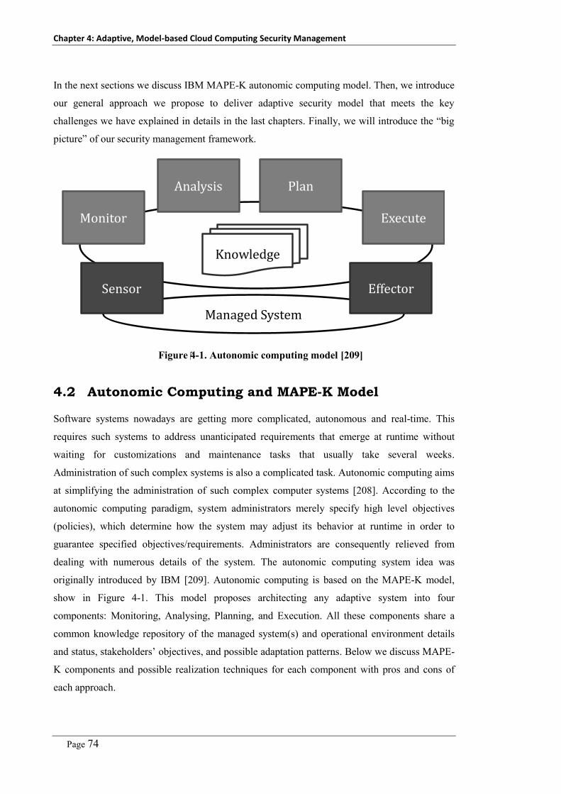
Chapter 4: Adaptive, Model-based Cloud Computing Security Management
Page 74
In the next sections we discuss IBM MAPE-K autonomic computing model. Then, we introduce
our general approach we propose to deliver adaptive security model that meets the key
challenges we have explained in details in the last chapters. Finally, we will introduce the “big
picture” of our security management framework.
Managed System
Sensor Effector
Monitor
Analysis Plan
Execute
Knowledge
Figure 4-1. Autonomic computing model [209]
4.2 Autonomic Computing and MAPE-K Model
Software systems nowadays are getting more complicated, autonomous and real-time. This
requires such systems to address unanticipated requirements that emerge at runtime without
waiting for customizations and maintenance tasks that usually take several weeks.
Administration of such complex systems is also a complicated task. Autonomic computing aims
at simplifying the administration of such complex computer systems [208]. According to the
autonomic computing paradigm, system administrators merely specify high level objectives
(policies), which determine how the system may adjust its behavior at runtime in order to
guarantee specified objectives/requirements. Administrators are consequently relieved from
dealing with numerous details of the system. The autonomic computing system idea was
originally introduced by IBM [209]. Autonomic computing is based on the MAPE-K model,
show in Figure 4-1. This model proposes architecting any adaptive system into four
components: Monitoring, Analysing, Planning, and Execution. All these components share a
common knowledge repository of the managed system(s) and operational environment details
and status, stakeholders’ objectives, and possible adaptation patterns. Below we discuss MAPE-
K components and possible realization techniques for each component with pros and cons of
each approach.

Chapter 4: Adaptive, Model-based Cloud Computing Security Management
Page 75
4.2.1 Monitoring Component
The first phase of any adaptive or autonomic system is to monitor the underlying system and its
context. The main responsibility of the monitoring component is to collect the context and the
managed system’s status information from the available sensors and filter collected information
from irrelevant information. These measurements are fed into the analysis module to reason
about the current system status and take predictive or corrective actions. Most of the monitoring
efforts can be categorized as [207]:
– Sensor interface: this pattern is based on defining a specific interface to be used by all
system types (classes/objects) that sense the current status of the environment. This approach
is applicable when adaptive-ness is considered when designing the managed system itself.
– Publisher/subscriber “middleware”: this pattern assumes that we have context-provider or
broker that publishes some context information and each adaptive system needs to register its
interest in any of the available events or context domains. Thus, when new information is
available, the publisher calls a certain function or fires a specific event. This approach is
applicable when data is used by multiple clients and system adaptation requires information
about its context.
– Logging: this approach depends on collecting execution traces that reflect certain system
events in log files or logging database (audit trial) for further analysis by the analysis
component. A key problem with this pattern is that it leads to lagging measurements not real-
time measurements. Thus it fits more with the mitigation and recovery purposes.
– Profiling: a library of APIs that can be used to develop profiling tools used to monitor the
events that arise within the system host – e.g. Java VM runtime tools, and Microsoft .NET
profiler. This is interesting when dealing with monitoring of the interactions between the
system and the underlying platform.
– Reflection: the adaptation system uses reflection to read information about the objects
existing in its environment without having to alter its implementation. This approach is
interesting when adding monitoring as afterthought or addressing an existing legacy system.
We use this approach in the monitoring component of our security management platform.
– Management protocols: different protocols are existing related to the area of monitoring and
serve different domains such as performance, manageability, etc. as follows: first, the
application response measurement (ARM) [210] defines a set of APIs that can be used
within application or its transactions in order to define the performance of certain application
transactions. Second, web-based enterprise management (WBEM) [82] is a new standard
developed by DMTF. WBEM is based on CIM: The common information model (CIM) [78]
as a reference for the manageable objects; XML to represent data communications among
Chapter 4: Adaptive, Model-based Cloud Computing Security Management
Page 76
management and manageable objects; and HTTP to transfer the data among parties. Third,
Simple Network Management Protocol (SNMP) is based on deploying monitoring agents
(SNMP agents) on each managed device; SNMP Manager collects data from these agents;
and the web server that hosts the management application (interface) to be used by the
administrators. Fourth, Java management framework (JMX) was developed to help
developing distributed management applications. The framework has three levels: (i)
Instrumentation Level: this is responsible for the managed objects (MBeans) that define a
standard interface to reflect set of functions (static or dynamic); (ii) agent level: this is the
MBean server that delivers a registry of the MBean that allows clients to discover
information and execute actions on MBeans; and (iii) remote management: this is the client
of layer. It can communicate with the MBeans server through APIs.
Before we start developing a monitoring component, we need to answer a set of questions
including: what are the QOS attributes to be monitored, what system objects to monitor,
monitoring frequency for each object, required redundancy (avoid failure and noise), how to
secure monitored data and avoid spams and attacks on it, and how to relate data monitored to
business objectives (goals) in order to trigger the corresponding adaptation actions.
4.2.2 Analysis component
The analysis component receives the monitored data from the monitoring component for
analysis in order to understand the current system status. Monitored data may be filtered to
remove any noise or redundancy. Also correlation or aggregation of the monitored data may
exist to formulate meaningful information about the underlying context or system behavior.
This information is usually expressed in terms of metrics of interest. These metrics may assess
system during design time using system models or at runtime using some utility functions
imposed on the system. The analysis component in most of the time is merged with either the
monitoring component or with the decision and planning component. Below, we discuss the
most common ways in developing analysis components.
- Rule-Based: The monitored data or (metrics of interest calculated from such monitored data)
are traced against a set of rules that define constraints (upper and lower bounds) [211, 212].
In case that any rule violated (in some cases fired), then a set of symptoms are reported. Such
reported symptoms are linked to certain mitigation actions. We use this approach in our
security monitoring approach.
- Symptoms Database (Case-Based Reasoning): The logic of the analysis is formatted as
symptoms. The current situation (case) is compared with the cases database. Then, the best
matched case is retrieved and the related solutions or actions are applied. Other artificial
Chapter 4: Adaptive, Model-based Cloud Computing Security Management
Page 77
intelligent approaches such as neural networks, decision trees, and Game theory could be
used to analyze system status against stakeholders’ defined desired objectives.
- Model-Based: A lot of work has been introduced in this area [213, 214]. It is based on
maintaining a model of the system and/or its operational environment (context). This model
is updated with the monitored data. Then the current system model is: (i) Compared with the
target model and the differences are used to guide the adaptation planning and execution
steps; (ii) Validated against set of rules or constraints defined, so in case of rules violation,
the system will take corrective actions; (iii) Used to activate a set of components. Each
component has a set of rules, in case that these rules are matched then the component is
integrated with the target system model to reflect current needs.
- Artificial Intelligent and Adaptive Learning: These methods use a set of artificial intelligent
methods and rules generated through supervised learning [215] and applied as normal
behavior rules. Any abnormal activities are used to retrain the analyzer.
- Regression Analysis: This is a statistical approach to help in investigating and understanding
the relationships between variables [216]. This is usually used in ascertaining the causal
impact of some variables on others. This is usually followed by statistical significance
analysis to make sure that the estimated relationships are close to the truth. Regression
analysis includes: linear regression and non-linear regression based on the nature of the
dataset; interpolation: prediction within the range of the given data; or extrapolation:
prediction out of the range of the given data.
4.2.3 Planning and Execution components
Given the system status and found deviations pinpointed and reported by the analysis
component(s), the planning component generates a sequence of actions to be applied on the
underlying system and/or managed objects (may be the current system environment as well) in
order to adapt system behavior and meet the specified objectives (either as policies or as utility
functions). The execution component should update the system behavior or structure
accordingly and the underlying effectors should reflect such changes on the managed objects as
well. Below we discuss a set of approaches that could help in realizing new changes.
4.2.3.1 Architectural/Design Patterns
Software architectural patterns help in expressing the fundamental structure (main components
and their relationships) of the software systems [217]. It provides a set of predefined
subsystems, responsibilities, and guidelines for organizing the relationships between them.
Below is a list of patterns that could be used in with such approach:

Chapter 4: Adaptive, Model-based Cloud Computing Security Management
Page 78
– Decorator Pattern [218]: Helps in extending the responsibilities of an object, independent of
other class objects, dynamically instead of using sub classing and also in cases where sub
classing is not feasible (sealed or final class). However, this pattern requires design time
preparation to use it. The decorator pattern is realized by introducing a decorator class that
wraps/encloses the original class. The decorator class conforms to the interface of the
original class and delegate calls to the enclosed class object.
– Microkernel Pattern [217]: The microkernel architectural pattern best fits with the design of
adaptive systems that target addressing unanticipated requirements at runtime. The
microkernel enables plugging in and out system features/components and facilitating the
communication between these components. However, this pattern requires design time
preparation of the software architecture under development.
– Interception Pattern [219]: The interceptor pattern helps in updating system behavior and
capabilities at runtime according to the incoming request and its context information. The
beauty of this pattern is that such update is realized without a need to modify the existing
code, design time preparation, or even details of the application. Furthermore, it does not
affect the current system features. Interceptor pattern usually developed with three
components: Interceptor interface which defines the operations which are executed by a
Dispatcher in specific events e.g. at the beginning or at the end of a request processing;
Dispatcher is the class or method that is called by the interceptor to perform required
actions. The interception is done in different possible ways e.g. the interceptor could call
Dispatchers prioritized in a user-defined order; and Context is a data object that maintains
context information either from the request or the current system status e.g. transaction id,
caller, passed in parameters. The context object is sent to the interception handler. The
context object details (data items) may be different from one interceptor to another according
to the handler functionality. We use this pattern in our security monitoring and execution
components as we discuss in chapter 6 and chapter 9.
4.2.3.2 Middleware-Based Approaches
The execution is implemented in the middleware layer so application does not need to be aware
of the nature of the effectors (this is mostly used in distributed applications) [207, 220]. The
middleware may implement one of the mentioned herein solutions to deliver its functionality:
– Mobile Agents [80]: A mobile agent is a composition of computer software and data which is
able to migrate (move) from one computer to another autonomously and continue its
execution on the destination computer. They can be used as communicators/ negotiators with
existing applications/security solutions. Thus, we can deploy different mobile agent for
different task or different application interface or methodology of interaction and reasoning.

Chapter 4: Adaptive, Model-based Cloud Computing Security Management
Page 79
– Reflection Pattern [217]: The reflection architectural pattern helps in changing structure and
behavior of software systems dynamically. It supports both type structure (e.g. extending
classes) and function calls adaptation. The reflection pattern has two parts: a meta-level
which provides information about system properties including structure and behavior; and a
base-level which includes application logic itself. Its implementation builds on the meta-
level. Changes are usually done on the meta-level. This is subsequently reflected on base-
level components’ behavior.
– Dynamic Aspect Weaving [221]: Dynamic weaving focus on the ability to apply, replace or
remove an aspect while the software system is running (in contrast with the static aspect
weaving at development time). Dynamic aspect weaving includes: (i) Load-time weaving:
Byte code transformations at class loader level (Subclass the Java class loader or replace it);
(ii) JIT compiler weaving: Byte code unaltered but alteration takes place when JIT compiler
is employed; (iii) Code Splicing: Weaving changes on running native code. Native code is
replaced with branch to external function (known as jump-return hooks). Replaced code
appended at the end of external function. Jump back to instruction after spliced location.
CC – Security management process CP – Security management process
Collaboration-based Security management framework
Define
EnforceImprove
Define
EnforceImprove
Define
EnforceImprove
Figure 4-2. A concept diagram of our joint-collaboration cloud security management
4.3 Adaptive, Model-based Cloud Security Management –
“Big Picture”
To satisfy the identified requirements and research gaps (questions) relevant to the cloud
computing security problem as discussed in Chapters 2 and 3, we propose a novel approach
based on extending the boundaries of the cloud consumers and providers’ security management
processes to include their cloud hosted services and cloud platforms respectively. This means
that stakeholders can go through the security management process on their cloud hosted assets
as if they have been hosting these assets inside their enterprise perimeters, as shown in

Chapter 4: Adaptive, Model-based Cloud Computing Security Management
Page 80
Figure 4-2. Moreover, they can use the same security specifications, security enforcement and
monitoring and improvement approaches used internally and thus mitigate the loss-of-control
and the lack-of-trust problems arise from adopting the cloud model. To deliver such capabilities,
our framework has to introduce novel approaches to support capturing security requirements
(including automated security analysis), enforcing security controls (through an automated
security engineering approach), and monitoring the security of the hosted services (using
automated security monitoring approach). Our framework should be deployed on cloud
platforms where IT assets are located and used to manage the security of deployed services for
corresponding tenants. Because none of the cloud stakeholders possesses the information
required to secure a given service (going through the whole security management process), we
adopt a joint-collaboration between cloud stakeholders in securing their cloud-hosted assets.
Another obstacle to achieve this goal is that it is very hard to get the cloud consumers to have
administrative access to the cloud platforms (may be malicious users) to manage the security of
their assets by hand. Thus, we had to base our approach on abstract models that capture details
of the cloud platform, services, and security. Our platform then takes the responsibility to
realize these security specifications.
Security Model
Service Model
Cloud Model
System
Cloud Platform
Cloud Services
Security Solutions
Enfo
rcemen
tFeed
bac
k
Figure 4-3. General Approach
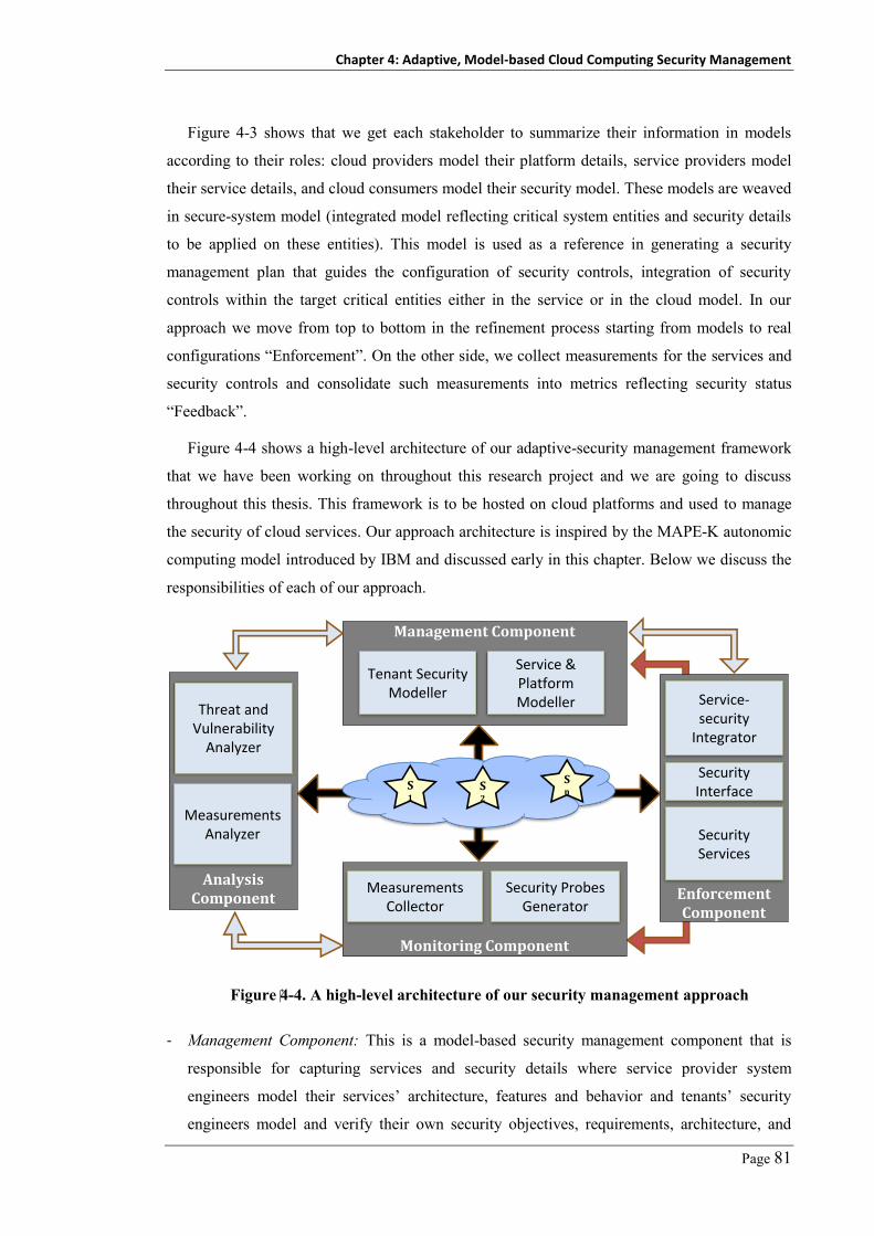
Chapter 4: Adaptive, Model-based Cloud Computing Security Management
Page 81
Figure 4-3 shows that we get each stakeholder to summarize their information in models
according to their roles: cloud providers model their platform details, service providers model
their service details, and cloud consumers model their security model. These models are weaved
in secure-system model (integrated model reflecting critical system entities and security details
to be applied on these entities). This model is used as a reference in generating a security
management plan that guides the configuration of security controls, integration of security
controls within the target critical entities either in the service or in the cloud model. In our
approach we move from top to bottom in the refinement process starting from models to real
configurations “Enforcement”. On the other side, we collect measurements for the services and
security controls and consolidate such measurements into metrics reflecting security status
“Feedback”.
Figure 4-4 shows a high-level architecture of our adaptive-security management framework
that we have been working on throughout this research project and we are going to discuss
throughout this thesis. This framework is to be hosted on cloud platforms and used to manage
the security of cloud services. Our approach architecture is inspired by the MAPE-K autonomic
computing model introduced by IBM and discussed early in this chapter. Below we discuss the
responsibilities of each of our approach.
Analysis Component
Measurements Analyzer
Threat and Vulnerability
Analyzer
S1
Management Component
Service & Platform Modeller
Tenant Security Modeller
Enforcement Component
Service-security
Integrator
Monitoring Component
Security ProbesGenerator
Measurements Collector
S2
Sn
Security Services
Security Interface
Figure 4-4. A high-level architecture of our security management approach
- Management Component: This is a model-based security management component that is
responsible for capturing services and security details where service provider system
engineers model their services’ architecture, features and behavior and tenants’ security
engineers model and verify their own security objectives, requirements, architecture, and

Chapter 4: Adaptive, Model-based Cloud Computing Security Management
Page 82
metrics. Both models are then weaved together in a tenant secure-system model that guides
the next steps of security enforcement and monitoring. This component represents the
MAPE-K planning component where users define the policies or utility functions to be used
to manage system adaptation.
- Enforcement Component: This component is responsible for integrating specified security
details, modeled by different service tenants, with the target cloud services. The existing
security management efforts, discussed in the related work chapter, focus mainly on
automating security controls’ configuration process. Thus, this point is out of our research
scope. Actually, another reason is that these security controls may be deployed outside the
cloud platform (inside tenant’s network perimeter). Thus, our focus in this component is to
support flexible integration of the security controls within the target cloud services. A
common security interface was developed to facilitate the integration task. This interface
defines a set of functionalities to be realized by the security vendors through a common
security controls’ adaptor. This enables security controls to easily integrate with our
enforcement component which integrates with cloud services. This component represents the
execute component in the MAPE-K model.
- Monitoring Component: This component is responsible for generating required security
probes according to tenants’ specified metrics (captured in the management layer). These
probes are then deployed into the cloud services to capture system behavior and generate
corresponding measurements/traces. Moreover, this component is responsible for collecting
the measurements generated by these probes (according to metrics specified frequencies) and
passing such measurements to the analysis component.
- Analysis Component: The analysis component is responsible for two main tasks: performing
security analysis of the cloud services including vulnerability and threat analysis. The
analysis component analyses the deployed services and their architectures to identify
possible flaws and existing security bugs. This helps security engineers from both sides in
developing their security models. Moreover, such issues are delegated to the security
management component in order to incorporate in the security status reports for tenants as
well as dynamically updating the security controls deployed to block the reported security
issues. The analysis component also analyses the measurements reported by the monitoring
component against a set of predefined metrics’ stable ranges – e.g. number of incorrect user
authentications per day should be less than 3 trials, so the analysis component should analyse
the reported measures of incorrect authentications. This may also include taking corrective
actions to defend against such probable attack. This represents the analysis component in the
MAPE-K autonomic computing model.

Chapter 4: Adaptive, Model-based Cloud Computing Security Management
Page 83
4.4 Approach Evaluation
We have evaluated our approach using both experimental evaluation of each separate
component and case studies from the cloud computing model using two or more components of
our platform. In this section, we summarize the set of benchmark applications and set of
evaluation metrics that we use throughout the thesis to evaluate the performance of our
proposed platform components in terms of soundness, accuracy, and time. We introduce this
here to avoid repetition in the next chapters. Below we summarize these benchmark applications
and the evaluation metrics used.
4.4.1 Benchmark Applications
We have selected a set of real-world, large, widely-used, and commercial open source web
applications developed using ASP.NET (currently we have a .NET parser) as our benchmark to
evaluate our approach components including: the security engineering (chapter 6), security
reengineering (chapter 7), security analysis (chapter 8), and security monitoring (chapter 9). In
this section we introduce details of these benchmark applications. The other chapters reference
this section in their evaluation sections.
The benchmark includes the following applications: (i) Galactic-ERP: An ERP system
developed internally in our group for testing purposes. (ii) PetShop: A well-known reference e-
Commerce application. (iii) SplendidCRM: An open source CRM that is developed with the
same capabilities of the well-known open source SugarCRM system. It has been downloaded
more than 400 times. (iv) KOOBOO: An open source enterprise content management system
(CMS) used in developing websites. It has been downloaded more than 2000 times. (v)
BlogEngine: An open source ASP.NET 4.0 blogging engine. It has been downloaded more than
46000 times. (vi) BugTracer: An open-source, web-based bug tracking and general purpose
issue tracking application. It has been downloaded more than 500 times. (vii) NopCommerce:
An open-source eCommerce solution. It has more than 10 releases. (viii) Webgoat: A security
testing web-based application developed by OWSAP [40] for security analysis and testing
purposes. This application is used mainly in the evaluation of the security analysis component.
Except for Galactic, we do not have any previous experience with these applications. Table 4-1
shows a summary of these benchmark applications including number of downloads (which
reflects how the applications are widely-used), size of the application in kilo-lines of code
(KLOC), number of files, components, classes, methods, and time to build abstract syntax tree.

Chapter 4: Adaptive, Model-based Cloud Computing Security Management
Page 84
Table 4-1. Summary of benchmark applications statistics
Benchmark Downloads KLOC Files Components Classes Methods AST
Time
Galactic – 16.2 99 2 101 473 187
PetShop – 7.8 15 25 40 55 51
SplendidCRM > 400 245 816 2 6177 6107 765
KOOBOO > 2,000 112 1178 6 7851 5083 78
BlogEngine > 46,000 25.7 151 13 258 616 163
BugTracer > 500 10 19 8 298 223 93
NopCommerce > 10 Rel. 442 3781 7 5127 9110 484
* Webgoat - 15 105 2 125 165 150
Table 4-2. Evaluation results classification
Actual Issue
Yes No
Reported As Issue Yes TP FN
No FP TN
Equation 1
Equation 2
Equation 3
Equation 4
4.4.2 Evaluation Metrics
To assess the effectiveness of our proposed components such as the security analysis, security
re-engineering, and security monitoring components, we used a set of evaluation metrics to
measure the soundness and completeness of the proposed technique. These metrics are precision
rate, recall rate, false alarm rate, and F-measure. These metrics are based on the validity of the
reported outcomes compared to the actual system status. Table 4-2 shows the different

Chapter 4: Adaptive, Model-based Cloud Computing Security Management
Page 85
combinations of reported outcomes and actual outcomes as follows: True positive – TP: valid
outcome, the tool reported as an issue and it turns out to be actual issue; False positive – FP:
invalid outcome, the tool reported as an issue although it is not an actual issue; False negative –
FN: missed case, it is an actual issue, but the tool missed it; True Negative –TN: it is not an
actual issue, and the tool did not report it. We next provide our definition of these metrics as
used in our experiments. The precision metric is used to assess the soundness of the approach.
A high precision rate means that the approach returns more valid results (true positive - TP)
than invalid results (false positive - FP). Thus the maximum precision is achieved when no false
positives (see Equation 1). The recall metric is used to assess the completeness of our approach.
A high recall means that the approach returns most of the valid results (true positive - TP) than
missed valid results (false negative - FN), see Equation 2. The low false alarm rate means how
much invalid results reported by the tool compared to the total invalid results. The F-measure
metric combines both precision and recall. It is used to measure the overall effectiveness of our
approach (weighted harmonic mean). This metric depends on the importance of the recall rate
and the precision rate, e.g. if we are interested in higher precision (more valid vulnerabilities)
then we will give precision factor high weight, and vice-versa. We assume that the precision
rate and recall rate are equally important, Equation 4.
4.5 Chapter Summary
In this chapter, we introduced a quick overview of the autonomic computing model introduced
by IBM (MAPE-K model) and key techniques that could be used in realizing MAPE-K. Then
we introduced the general idea of our approach which is based on getting cloud stakeholders
involved in securing their assets through a joint-collaboration based approach. Finally, we
introduced the big picture of our approach – the adaptive model-based security management
framework. We explained our general approach and its main components. We discussed the
main functionalities of every component of our proposed framework that we are going to
discuss in detail. In chapter 5 we introduce our solution to align the existing security
management standards to fit with the cloud computing model. In chapter 6 we discuss the
security management and enforcement components using a novel model-driven security
engineering at runtime approach. In chapter 7 we introduce how to address re-engineer legacy
system that are already developed with built-in security capabilities to be managed by our
security management platform. In chapter 8 we discuss one part of the analysis component
which is a static security analysis. This is based on a novel security analysis approach based on
formalizing security analysis signature as well as an extensible security analysis tool support. In
chapter 9 we introduce monitoring component which covers how to capture metrics, generate
probes, and collect measurements as well as analyzing the collected security measurements.


Page 87
Chapter 5
Aligning Security Standards with Cloud
Computing Model
To build our adaptive model-based cloud computing security management approach we
introduced in the last chapter, we found it very crucial to base such an approach on a well-
known and well-defined security management standard, such as ISO27000 or NIST-FISMA.
However, such security management standards are far from covering the full complexity of the
cloud computing model we discussed in the early chapters mainly multi-tenancy and
outsourcing of IT assets. In this chapter, we introduce our proposed alignment of the NIST-
FISMA standard to fit with the cloud computing model. This enables cloud providers and
consumers to better maintain their security management processes on cloud platforms and cloud
hosted services.
Our new framework is based on improving collaboration between cloud providers, service
providers and service consumers in managing the security of the cloud platform and the hosted
services. It is built on top of a number of security standards that assist in automating the security
management process. We have developed a proof of concept of our framework using .NET and
deployed it on a testbed cloud platform. We have evaluated the framework by managing the
security of a multi-tenant SaaS application exemplar discussed in Chapter 1.
This chapter is organized as follows. In Section 1 we highlight the existing trials to adopt
security management standards to fit with the cloud model. We also highlight the key
requirements and challenges that need to be satisfied by any proposed cloud security
management platform. Section 2 discusses our refined security management model. Section 3
explains how we aligned NIST-FISMA standard to fit with the cloud model. Section 4
summarizes the key security automation standards we adopted in our prototype. Section 5
outlines our prototype framework we developed based on aligned NIST-FISMA model. Section
6 introduces a usage example of the developed framework.
5.1 Introduction
Although much research into cloud services security engineering has been undertaken [4, 21,
61, 150, 155, 157, 222, 223], most of these efforts focus on the cloud-based services offered as

Chapter 5: Aligning Security Management Standards with Cloud Computing Model
Page 88
web services. Such efforts have investigated capturing security requirements and generating
corresponding WS-Security configurations. However, they pay no attention to the underlying
platform security or the other cloud service delivery models such as SaaS [21]. They also do not
address the impact of the multi-tenancy feature introduced by the cloud model on the security of
the cloud delivered services even in the case of web services.
From our analysis of the cloud security problem we have identifieid a set of key challenges
including: Each stakeholder has their own security management process (SMP) that they want
to maintain/extend to the cloud hosted assets; No stakeholder can individually maintain the
whole security process of the cloud services because none of them has the full information
required to manage security and each one has a different perspective; Multi-tenancy requires
maintaining different security profiles for each tenant on the same service instance; No Security
SLA is available that can be used to maintain agreements related to cloud assets security; The
existing standards such as ISO27000 and FISMA do not map well to the cloud model because
these standards consider the SMP from the platform/asset owner not from a Service Provider
perspective.
We have also highlighted a set of Key requirements that need to be satisfied by an
information security management system targeting the cloud computing model. This includes:
Enable cloud consumers to specify their security requirements on the cloud hosted assets and
the underlying cloud platform; Enable cloud consumers to monitor their assets security status
and the underlying platform security status as well; Support multi-tenancy where different
tenants can maintain their SMP with strong isolation of data; Aligned with on one of the
existing security management standards that are already adhered by the cloud consumers and
cloud providers.
Two new community projects are trying to tackle the cloud consumers trust problem by
introducing a list of best practices and checklists that could help cloud providers or cloud
consumers such as CSA - GRC project [222], or by aligning existing security standards to the
cloud model such as NIST FedRAMP [224]. The focus of both projects is to obtain cloud
consumers trust by assessing and authorizing the cloud platforms. In the FedRAMP project, a
cloud provider claims supported security level. A certifying authority, certified by the
FedRAMP providers - NIST, audits the cloud provider claimed security level. Each cloud
consumer specifies their expected security level. The certifying authority matches cloud
consumers’ requirements and providers’ capabilities and assures it. However, this proposed
solution by FedRAMP project lacks customizability of the platform-provided security from the
cloud consumer perspective – i.e. it does assume that the cloud consumers will use the security
provided by the cloud platform provider as it is. Moreover, adaptation of the provided security

Chapter 5: Aligning Security Management Standards with Cloud Computing Model
Page 89
is not possible. This also limits the Return of Investment (ROI) of the cloud providers as they
become limited to certain security level assessed by the certifying authority. Finally, the
proposed security model by this project assumes that the cloud provider is the service provider
(like in Amazon AWS or Salesforce.com). However, this is not always the case in cloud
computing platforms.
In the Security Registry project introduced by Cloud Security Alliance (CSA), a list of
security controls to be operated by a cloud provider is introduced, and a checklist to guide
consumers assessing a cloud platform security before adopting the platform. However, such
assessment and awareness do not mean to have a real operating security. Neither loss-of-control
nor lack-of-trust problems have been mitigated. These projects lack the consumers’ involvement
in specifying their security requirements and managing their SMP. The NIST project fits better
with cloud providers who deliver their own services only. This is because they need to have a
deep understanding of the cloud hosted services to be secured.
To address these shortcomings we introduce a novel approach that tackles both the loss-of-
control and lack-of-trust problems by enabling cloud consumers to extend their security
management process (SMP) to cover cloud hosted assets. Our approach introduces a new cloud
security management framework based on aligning the NIST-FISMA standard [225], as one of
the main security management standards, to fit with the cloud architectural model. The
information required to put the NIST standard into effect is not possessed by one party. Thus we
improve collaboration among the key cloud stakeholders to share such required information.
Getting cloud consumers involved in every step of the SMP of their assets mitigates claims of
losing trust and control. Our approach also mitigates the loss of control claimed by the cloud
providers for the hosted services that are developed by other parties. Being based on a security
management standard our approach enables both parties to get or maintain their security
certifications. Moreover, this helps in assuring that we can cover the majority of the activities
done during the security management process. Our approach helps stakeholders to work
together to address the following issues:
– What are the security requirements needed to protect a cloud hosted service given that the
service is used by different tenants at the same time?
– What are the appropriate security controls that mitigate the service adoption risks and who
has the authority to select such controls?
– Are the selected controls available on the cloud platform or we will/can use third party
controls?
– What are the security metrics required to measure the security status of our cloud-hosted
services?

Chapter 5: Aligning Security Management Standards with Cloud Computing Model
Page 90
To validate our proposed alignment, we developed a prototype of our collaboration-based
cloud security management approach and deployed it on a cloud platform hosting a SaaS
application (Galactic ERP service). We evaluated the approach by securing the ERP service
assuming that the cloud platform has multiple tenants sharing the same cloud application. Each
tenant has their own security requirements and security management process.
`
Figure 5-1. Information security management system phases
5.2 Rethinking In Security Management
Information security management systems (ISMS) are defined in ISO27000 as [5] “systems that
provide a model for establishing, implementing, operating, monitoring, reviewing, maintaining
and improving the protection of information assets.”. From analyzing both ISO27000 and
NIST-FISMA standards, we define a security management system to have three key phases:
defining security, enforcing security, and monitoring and improving security as shown in
Figure 5-1. First, Defining Security Requirements: this phase covers tasks/efforts required to:
identify security goals/objectives that the ISMS should satisfy and deliver, conducting risk
analysis and assessment to identify existing risks within the system scope, and detailing
objectives/risks into detailed security requirements and security policies. Second, Enforcing
Security Requirements: this phase covers efforts required to: identify security controls to be
used, and implementing and configuring such controls based on the specified security
requirements. Third, Monitoring and Improving Security: this phase includes: monitoring the
current security status of the implemented security controls, analyzing the measured security
status to identify existing security issues, and maintaining and improving the current security
controls. In this research project we addressed most of the tasks in these three phases with
approaches that help facilitating and automating as much as possible and needed. Our holistic
approach is based on our refined model of the security management process (define, enforce,
monitor and improve) shown in the above figure.
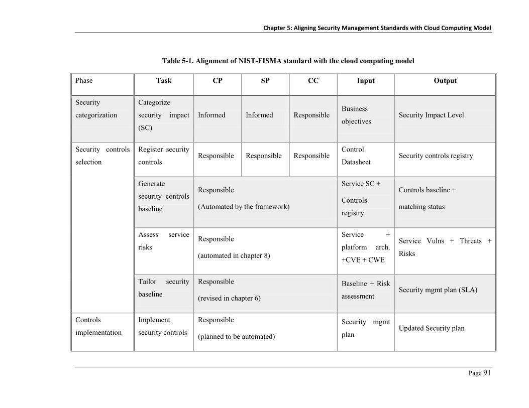
Chapter 5: Aligning Security Management Standards with Cloud Computing Model
Page 91
Table 5-1. Alignment of NIST-FISMA standard with the cloud computing model
Phase Task CP SP CC Input Output
Security
categorization
Categorize
security impact
(SC)
Informed Informed Responsible Business
objectives Security Impact Level
Security controls
selection
Register security
controls Responsible Responsible Responsible
Control
Datasheet Security controls registry
Generate
security controls
baseline
Responsible
(Automated by the framework)
Service SC +
Controls
registry
Controls baseline +
matching status
Assess service
risks Responsible
(automated in chapter 8)
Service +
platform arch.
+CVE + CWE
Service Vulns + Threats +
Risks
Tailor security
baseline
Responsible
(revised in chapter 6)
Baseline + Risk
assessment Security mgmt plan (SLA)
Controls
implementation
Implement
security controls
Responsible
(planned to be automated)
Security mgmt
plan Updated Security plan

Chapter 5: Aligning Security Management Standards with Cloud Computing Model
Page 92
Security
assessment
Define security
metrics Responsible
Security
objective Security assessment plan
Assess security
status
Rsponsible
(Automated by the framework)
Security
assessment plan assessment report
Service
authorization
Authorize
service Informed Informed Responsible
Security plan +
assessment
report
Service authorization
document
Security
monitoring
Monitor security
status
Responsible
(Automated by the framework and revised in
chapter 9)
Security
assessment plan Security status report
Chapter 5: Aligning Security Management Standards with Cloud Computing Model
Page 93
5.3 Aligning NIST-FISMA with Cloud Computing
The Federal Information Security Management Act (FISMA) standard [1] defines a framework
for managing the security of information and information systems that support the operations of
the agencies. The framework has six main phases including: service security categorization,
security controls selection, security controls implementation, security controls assessment,
service authorization, and security monitoring. In order to align this standard with the cloud
computing model, we have studied each phase, activity, and task to understand the main inputs,
processing, and outcomes. Then we studied the cloud computing responsibility matrix – i.e. who
can or is allowed to do what. Based on these two inputs we restructured the NIST-FISMA
standard responsibility matrix to make sure that the relevant stakeholder (who owns the
information required to fulfill a given task) is allocated as the main responsible for such task
while getting other stakeholders informed about the activities being done. Table 5-1 and
Figure 5-2 summarize for each phase in the security management standard, how we aligned
FISMA to fit with the cloud model in terms of reorganizing the responsibility matrix among
cloud stakeholders based on who knows what.
5.3.1 Service Security Categorization
Each service (SJ) on the cloud platform could be used by different tenants. Each service tenant
(Ti) owns their information only in the shared service (SJ). The tenant is the only stakeholder
who can decide/change the impact of a possible loss of confidentiality, integrity and availability
on their business objectives. Each tenant may assign different impact levels (Low, Medium, or
High) to possible security breaches on their information. In FedRAMP [4], the cloud provider
(CP) specifies the security categorization of services delivered on their cloud platform.
However, this is not sufficient as the CP does not have sufficient knowledge about the impact of
information security breaches on their tenants’ business objectives. Our approach enables cloud
consumers (CCs) to be involved in specifying the security categorization of their information.
Moreover, our approach enables both scenarios where we can consider the security
categorization (SC) per tenant (tenant-oriented security -as in Equation 1) or per service
(service-oriented security - as in Equation 2).
In the service-oriented security model, a cloud service can reflect one set of security
requirements/controls per time, the security categorization of the service is calculated as the
maximum of all tenants’ categorizations. On the other hand, the tenant-oriented security model
gets services to reflect each tenant security requirements as if no one else is using the service.

Chapter 5: Aligning Security Management Standards with Cloud Computing Model
Page 94
SC (Ti) = [(Confidentiality, impact), (Integrity, impact), (Availability, impact)],
Impact [Low, Medium, High] Eq. (1)
SC (S j) = [(Confidentiality, Max ( Ti (impact)), (Integrity, Max ( Ti (impact)),
(Availability, Max ( Ti (impact))] Eq. (2)
Security Categorization
S: CPE
R: CCsSecurity Controls
SelectionS: CVE/CWE/CAPEC
R: AllControls
ImplementationS: CCE
R: All
Security Monitoring
S: -
R: All
Service Authorization
S: -
R: CCs
Security Assessment
S: -
R: CCs & CPs
R: Responsible Stakeholder S: Security Automation Standard
Figure 5-2. Alignment of NIST-FISMA standard with the cloud model
5.3.2 Security Control Selection
The selection of security controls to be implemented in protecting tenants’ assets has two steps:
First, baseline security controls selection. The FISMA standard provides a catalogue of security
control templates categorized into three baselines (low, medium and high). Based on the
security categorization of the service, specified by service tenants in the first step, the platform
should automatically select the initial baseline of controls that are expected to provide the
required level of security specified by tenants. Second, tailoring of the security controls
baseline. Stakeholders should tailor the security controls baseline identified in the first step to
cover the service possible vulnerabilities, threats, risks and the other environmental factors as
discussed below.
5.3.2.1 Service Security Risk Assessment
In this step, stakeholders should conduct security risk assessment to identify service
vulnerabilities, threats, attacks, and risks that may require special security handling – i.e.
customization of the security controls’ baseline that have been selected in step (a) according to
service security categorization. This includes:

Chapter 5: Aligning Security Management Standards with Cloud Computing Model
Page 95
– Vulnerabilities Identification: This step requires being aware of the service and the
operational environment architecture. We consider the involvement of the service provider
(SP) who knows the internal structure of the provided service and the CP who knows the
cloud platform architecture in order to fulfill this task. The main outcome of this step is a
list of security vulnerabilities that should be patched.
– Threats Identification: The possible threats, threat sources and capabilities on a given
service can be identified by collaboration among the SPs, CPs, and CCs. CCs are involved
as they have the knowledge about their assets’ value and could know who may be a source
of security breaches.
At the end of this phase, the cloud service stakeholders will have a list of threats, attacks, and
vulnerabilities that they should try to mitigate to prevent such possible security breaches. These
tasks will be automated in our platform as discussed in Chapter 8.
5.3.2.2 Security Controls Baseline Tailoring Process
Based on the risk assessment process, the selected security controls baseline can be tailored to
mitigate new risks and fit with the new environment conditions, as follows:
– Scoping of the Security Controls: In this step all stakeholders should be involved in
selecting security controls to be operated. This includes: (i) Identification of the common
security controls; the cloud stakeholders decide which security controls in the baseline they
plan to replace with a common security control (either provided by the CPs or by the CCs).
A common security control is a control that is shared among multiple services; (ii)
Identification of the critical and non-critical system components; the SPs and CCs should
define which components are critical to enforce security on it and which are non-critical
(may be because they are already in a trusted zone) so no possible security breaches; and
(iii) Identification of the technology and environment related security controls that are used
whenever required such as wireless network security controls.
– Compensating Security Controls: Whenever the stakeholders find that one or more of the
security controls in the tailored baseline do not fit with their environmental conditions or are
not available (may be cost wise), they may decide to replace such controls with another
compensating security control.
– Set Security Controls Parameters: The last step in the baseline tailoring process is the
security controls’ parameters configuration, such as minimum password length, maximum
number of unsuccessful logins, etc. This is done by collaboration between the CPs and CCs.
All these details are captured by cloud stakeholders in a model-based approach, as we
discuss in Chapter 6. The outcome of this phase is a security management plan that

Chapter 5: Aligning Security Management Standards with Cloud Computing Model
Page 96
documents service security categorization, risks, vulnerabilities, and the tailored security
controls baseline with the specified security configurations.
5.3.3 Security Controls Implementation
This phase focuses on implementation of the security controls that have been tailored in the
previous step. In the original NIST-FISMA standard, this is the sole responsibility of the service
owner. Thus this need to be aligned with the new responsibilities we have got in the cloud
model. The security plan for each tenant describes the security controls to be implemented by
each involved stakeholder based on the security control category (common for all services or
service-specific control). The common security controls implementation is the responsibility of
the common control provider who is most probably be the CPs. Tenant specific security controls
are the responsibility of the service tenants. The service-specific security controls
implementation is the responsibility of the SPs. Each stakeholder must document the security
controls implementation and configuration details in the security management plan.
5.3.4 Security Controls Assessment
Security controls assessment is required to make sure that the security controls implemented are
functioning properly and meet the security objectives specified. This step includes developing a
security assessment plan that defines security controls to be assessed, assessment methods to be
used, and security metrics to be used with each security control. The results of the assessment
process are documented in a security assessment report. This step may result in going back to
the previous steps in case of deficiency in the controls implemented or continuing with the next
steps. The security controls assessment is a shared responsibility of all cloud stakeholders. Each
one should develop the metrics they would like to use in assessing the security status of their
cloud assets. The framework tries to automate the assessment process by analysing the log files
of the security controls operated.
5.3.5 Service Authorization
This step represents the formal acceptance of the stakeholders on the identified risks involved in
the adoption of the service and the agreed on mitigations. We consider the security plan and
security assessment plan to be used as the security SLA among the involved parties. These plans
reflect mostly all the information required to assess the security properties of a given cloud
service and responsibility of each involved stakeholder towards other stakeholders.

Chapter 5: Aligning Security Management Standards with Cloud Computing Model
Page 97
5.3.6 Monitoring Security Controls Effectiveness
The CPs should provide security monitoring tools to help the CCs in monitoring the security
status of their assets. The monitoring tools should have the capability to capture the required
security metrics and report the collected measures in a security status report either event-based
or periodic-based. The results of the monitoring process may require re-entering the SMP to
handle new unanticipated changes. For now we consider our log-based monitoring component
as a tool to help addressing this task. Later in chapter 9, we are going to discuss our refined and
automated security monitoring approach.
5.4 Security Automation
After aligning the FISMA standard with the cloud model we adopted a set of existing security
standards to help improving the framework automation and its integration with the existing
security capabilities, as shown in Figure 5-3 and Table 5-2. These security standards include:
1..*
0..*
Vuln. product
has v
ulns
.0..*
Con
fig. P
rod
has configuration
0..*
1..*
related attacksuse weak.
1..*
0..*
rela
ted
wea
knes
s rela
ted
vuln
s.
(CVE)Vulnerability
(CWE)Weakness
(CAPEC)Attack
(CPE)Product/Service
(CCE)Control Configuration
0..*
Figure 5-3. Adopted security automation standards and relationships
Table 5-2. Formats and examples of the adopted security standards
Standard Format Example
CPE cpe:/ [part] : [vendor] : [product] : [version] : [update] : [edition] : [language]
cpe:/a:SWINSOFT: Galactic:1.0: update1:pro:en-us
CVE CVE-Year-SerialNumber CVE-2010-0249
CWE CWE-SerialNumber CWE-441
CAPEC CAPEC-SerialNumber CAPEC-113
CCE CCE-softwareID-SerialNumber CCE-17743-6

Chapter 5: Aligning Security Management Standards with Cloud Computing Model
Page 98
– Common Platform Enumeration (CPE) [226]: The CPE provides a structured naming
schema for IT systems including hardware, operating systems and applications. We use the
CPE as the naming convention of the cloud platform components and services. This helps in
sharing the same service name with other cloud platforms and with the existing
vulnerabilities databases – e.g. The National Vulnerability Database - NVD [227]. The
format of the CPE consists of constant “CPE”, part which may be (application, OS,
network), software vendor, product name, used version, service pack, edition, and language.
– Common Weakness Enumeration (CWE) and Common Attack Pattern Enumeration and
Classification (CAPEC) [226]: The CWE provides a catalogue of the community recognized
software weaknesses. The CAPEC provides a catalogue of the common attack patterns. Each
attack pattern provides a description of the attack scenario, likelihood, knowledge required
and possible mitigations. We use the CWE and CAPEC as a reference for the cloud
stakeholders during the vulnerabilities identification phase.
– Common Vulnerability and Exposure (CVE) [226]: The CVE provides a dictionary of the
common vulnerabilities with a reference to the set of the vulnerable products (encoded in the
CPE). It also offers vulnerability scoring that reflects the severity of the vulnerability. We
use the CVE to retrieve the know vulnerabilities discovered in the service or the platform
under investigation. Thus, in this version of our implementation we depend on security
experts to identify and report any possible vulnerability in the National Vulnerability
Database (NVD) using CVE format. In the next chapters we will introduce our new online
security analysis approach that completely automates this task. This will also help in case of
new vulnerabilities that are not reported in the NVD yet or in case of using cloud services
that do not have CPE ID to be used in retrieving relevant vulnerabilities.
– Common Configuration Enumeration (CCE) [226]: The CCE provides a structured and
unique naming to systems’ configuration statements so that systems can communicate and
understand such configurations. We use the CCE in the security controls implementation
phase. Instead of configuring security controls manually, the administrators can assign
values to security control templates’ parameters. Our framework uses these configurations in
managing the selected security controls. This point is out of scope for this project as we
discussed previously. We are not concerned with how to automate the security controls’
configuration because many platforms and frameworks do exist that help in this.
Figure 5-3 shows the relationships between these security automation standards. This helps
in understanding why we selected such standards and where they actually fit. At the center of
the model we have the CPE. This CPE is referenced in retrieving vulnerabilities from the CVE
and controls’ configurations in CCE. The CVE is linked to the common weaknesses in the

Chapter 5: Aligning Security Management Standards with Cloud Computing Model
Page 99
CWE. The attacks recorded in the CAPEC repository is based on exploiting known weakness
recorded in CWE repository.
5.5 Cloud Security Framework Architecture
Our initial framework architecture consists of three main layers: a management layer, an
enforcement layer, and a feedback layer. These layers, shown in Figure 5-4, represent the
realization of the ISMS phases we described in previous sections.
Configurations
Management Layer
Security Metrics
Manager
Security
Categorization
Collaboration Risk
Assessment
Security Controls
Manager
Multi-Tenant
Security Plan
Multi-Tenant
Status Report
Enforcement Layer
Planning Implementation
Feedback Layer
Monitoring Analysis
Security Management
Repository
Security
Controls Logs
Security
Controls
Cloud
Platform
Security Status Security Requirements
Measurements
Figure 5-4. Our collaboration-based cloud security management architecture
- Management Layer: This layer is responsible for capturing security specifications of the CPs,
SPs, and CCs. It consists of: (a) The security categorization service used by the hosted
services’ tenants to specify security categorization of their information maintained by the
cloud services; (b) The collaborative risk assessment service where all the cloud platform
stakeholders participate in the risk assessment process with the knowledge they possess; (c)
The security controls manager service is used to register security controls, their mappings to
the FISMA security controls’ templates, and their log files structure and locations; (d) The
security metrics manager service is used by the cloud stakeholders to register security
metrics they need to measure about the platform security; (e) The multi-tenant security plan
(SLA) viewer service is used to reflect the tenant security agreement. This shows the tenant-
service security categorization, vulnerabilities, threats, risks, the selected mitigation controls
and the required metrics; (f) The multi-tenant security status viewer which reflects the
current values of the security metrics and their trends.

Chapter 5: Aligning Security Management Standards with Cloud Computing Model
Page 100
- Enforcement Layer: This layer is responsible for security planning and security controls
selection based on the identified risks. The selected security controls are documented in the
security management plan. The implementation service then uses this plan for maintaining
security control configuration parameters and the mapping of such parameters to the
corresponding security controls. This service does not address the integration of security
controls with the target cloud services. Later in Chapter 6, we will introduce our security
integration approach.
- Feedback Layer: This layer has two key services: the monitoring service which is
responsible for collecting measures defined in the security metrics manager and storing it in
the security management repository to be used by the analysis service and by the multi-
tenant security status reporting service. The analysis service analyses the collected measures
to make sure that the system is operating within the defined boundaries for each metric. If
there is a deviation from the predefined limits, the analysis service will give alerts to update
the current configurations. This service only supports log-based metrics. Moreover, there is
no support for possible mitigation actions. The reported measurements can only visualized
for the stakeholders in regular security status reports.
5.6 Usage Example
To demonstrate the capabilities of our cloud computing security framework and our prototype
tool implementing this framework we revisit the motivating example from Chapter 1, a cloud
based ERP system “Galactic” used by Swinburne and Auckland (CCs), developed by SwinSoft
(SP), and deployed on the GreenCloud (CP). The two tenants using the Galactic ERP services,
Swinburne and Auckland, are still concerned about their assets’ security on the cloud. Both
have their own SMP and their own security requirements to be enforced on their cloud assets.
First, the service provider registers the service on the cloud computing platform service
registry. This enables tenants to search and register to use the service. Then, each registered
tenant will get permission to access the security management portal. Each tenant will be
required to define the security categorization of the service from their perspective. Next, cloud
stakeholders should start registering their security controls that they would like to use. This
requires mapping such controls to the NIST-FISMA standard template. After this, cloud
stakeholders should collaborate to identify the possible threats and existing security
vulnerabilities. This should guide the security controls’ tailoring process. The platform helps
stakeholders to find out which security controls are missing – i.e. exist in the standard as must
have, and do not have realization security control specified by any of the service stakeholders.
Finally, service tenants define the security metrics they would like to monitor or follow up. The

Chapter 5: Aligning Security Management Standards with Cloud Computing Model
Page 101
platform keeps track of these metrics and analyzes the security controls’ log files on regular
basis to extract the specified information usually in terms of aggregation functions on monitored
or logged data. Below we show how the cloud computing-aligned security management process
works supported with snapshots from our security management platform.
5.6.1 Registering Cloud Services
The first step in our example is to register Galactic ERP service in the cloud platform service
repository so that it can be discovered/used by the CCs. This step could be done either by
SwinSoft or by the GreenCloud. In this step we use the CPE standard name as the service ID, as
shown in Figure 5-5. To register a service, first we search by service name or service CPE ID in
the set of registered services. If found, just select it from the found matches to register the
service. Otherwise, insert service details as a new record to the service repository. Once the
service was registered, cloud consumers can register to use it. A new tenant, Auckland, can
register their interest in using the Galactic service. Then Auckland will be granted a permission
to manage the security of his information maintained by Galactic service. The same is done by
Swinburne, as shown in Figure 5-6. Now Auckland and Swinburne can use our platform to
manage the security of their assets.
Figure 5-5. SwinSoft is registering their Galactic ERP service with GreenCloud
Figure 5-6. Registering a service by Swinburne (top) and Auckland (bottom)

Chapter 5: Aligning Security Management Standards with Cloud Computing Model
Page 102
Figure 5-7. Security controls registration
Figure 5-8. Securitycon trolsba seline with controls’st atus
Mas
ter r
ecor
d
Det
ail

Chapter 5: Aligning Security Management Standards with Cloud Computing Model
Page 103
5.6.2 Service Security Categorization
The Swinburne security administrator specifies the impact level of losing the confidentiality,
integrity, and availability of their data maintained by the Galactic ERP service, as shown in
Figure 5-6(top). The same should be done by Auckland security administrator, as shown in
Figure 5-6(bottom). Whenever a new tenant registers their interest in a service and defines their
security categorization of data processed by the service (or any of the existing tenants update his
security categorization), the platform updates the overall service security categorization with the
maximum value as per equation1, discussed in the process alignment section.
5.6.3 Security Controls Selection
GreenCloud as a cloud provider already publishes their security controls database. Swinburne
and Auckland can register their own security controls using the security controls manager
service. Based on the security categorization step, our framework generates the security
controls’ templates baseline. Then stakeholders should start registering their security controls
and their features and link such features to security controls’ baseline as shown in Figure 5-7.
The registration of a security control should specify master data including control name,
category, control family, location and schema of the log file. Moreover, each registration should
map security control features to the NIST-FISMA standard security control template (as in the
detail section of Figure 5-7). Our prototype helps in identifying security controls’ templates that
are: satisfied (matches one of the registered security controls), missing (does not match
registered security controls), or duplicate (more than one matched control), as shown in
Figure 5-8. This figure shows that in the access control family, the control number (14) which is
“Permitted Actions without Identification or Authentication”, enhancement number (1) which is
“Permitted Actions Should Be Limited to The Limit That Service Business Needs” is missing. So
that stakeholders can highlight this problem and work on it or simply accept this problem. The
same with the security control (17) which is “Remote Access” has got duplicated security
controls defined that satisfy the same template from the baseline which by analysis turned out to
be a mistake in the registration of security control done by a stakeholder. This helps
stakeholders in revising the status of the security controls to be operated on their services.
5.6.3.1 Service Risk Assessment
Galactic vulnerabilities are identified for the first time by SwinSoft with the help of GreenCloud
who knows the architecture of the service and the hosting cloud platform. Both SwinSoft and
GreenCloud have the responsibility to maintain the service vulnerabilities list up to date. The
framework enables to synchronize the service vulnerabilities with the community vulnerabilities

Chapter 5: Aligning Security Management Standards with Cloud Computing Model
Page 104
database – NVD, as shown in Figure 5-9. This figure shows the list of found vulnerabilities.
Users can click on “Use known vulnerabilities in NVD” to synchronize the list with the least
recently reported vulnerabilities. Stakeholders can link on CVE-ID to navigate to the full
detailed version of the vulnerability on the NVD website. Each cloud consumer – Swinburne
and Auckland – should review the defined threats and risks on Galactic and append any missing
threats. The framework integrates with the CWE and CAPEC databases to help stakeholders in
identifying possible vulnerabilities whenever the service does not have vulnerabilities recorded
in the NVD.
Figure 5-9. Service reported vulnerabilities - integrated with NVD
5.6.3.2 Security Controls Baseline Tailoring
The service tenants decide which security controls in the baseline they plan to replace with
common security controls provided by the cloud provider or the service tenants, as shown in
Figure 5-8. Stakeholders can edit the registered security control mapping to another control or
they can delete any mapping all together. SwinSoft, Auckland, and Swinburne should also
select the critical service components that must be secured. Swinburne and Auckland define
their security controls’ parameter configurations. The security controls provided by the cloud
platform can only be reviewed.
The final outcome of this step is a security management plan that documents the service
security categorization (either from the tenant perspective or from the service perspective),
found vulnerabilities, expected threats, risks, and the tailored security controls to mitigate the
identified possible security breaches, as shown in Figure 5-10.

Chapter 5: Aligning Security Management Standards with Cloud Computing Model
Page 105
Figure 5-10. Examples of Auckland security management plan
5.6.4 Security Controls Implementation and Assessment
Each stakeholder implements the security controls under their responsibility as stated in the
security management plan and the security controls configurations as specified in the previous
step. In case of Galactic ERP, Swinburne should implement and configure their Swin-
Authenticator, Swin-Antivirus, and Swin-IPS security controls. The same should be done by
Auckland using their security controls. The controls to be assessed and the objectives of the
assessment are defined by GreenCloud, Auckland and Swinburne and documented in the tenant
security assessment plan. The execution of such plan, the assessment process, should be
conducted by a third party. Our framework helps in assessing security controls status when
using security controls that integrate with our framework (the framework can understand and
read their log files/database structure). The outcome of the assessment phase is a security
assessment report. An example of the metrics to be used in assessing service security is shown
in Figure 5-10 – e.g. in the last section “login activity” metric.

Chapter 5: Aligning Security Management Standards with Cloud Computing Model
Page 106
5.6.5 Service Authorization
Swinburne and Auckland give their formal acceptance of the security plan, assessment plan, and
the assessment reports. This acceptance represents the authorization decision to use Galactic by
the cloud consumers.
Figure 5-11. Sample of Swinburne security status report
5.6.6 Monitoring Security Controls Effectiveness
The framework collects the defined security metrics as per the assessment plan of each tenant
and generates regular security status reports to the intended cloud stakeholders. A report shows
the metrics status and trends, as shown in Figure 5-11. This report shows that the number of
login activities is increasing which may be a reason for normal workload or malicious attacker
trying to break the authentication service. The unsuccessful logins metric helps in deciding
which scenario may be most likely to happen. In this case the unsuccessful logins metric is
increasing as well which means that someone is trying to login to the system and does not have
a correct password. The procedure we went through in the example above should be applied not
only on cloud services but also on the cloud platform itself. In this case the cloud provider uses
our framework to manage the platform security from a consumer perspective.

Chapter 5: Aligning Security Management Standards with Cloud Computing Model
Page 107
5.7 Discussion
Our approach provides a security management process; a set of security automation standards to
help in automating the security management process; integration with known threats,
vulnerabilities, and weakness databases; and a log-based security metrics monitoring and
analysis tool. Our approach is based on joint-collaboration between all stakeholders, allowing
different stakeholders to develop a mutually-satisfying security model. It addresses the multi-
tenancy nature of shared cloud-hosted services when tenants have different security
requirements and different SMPs. This is achieved by maintaining and managing multiple
security profiles with multiple security controls on the same service. Such controls are delivered
by different security vendors. This enables managing traceability between controls, the
identified risks and identifies what are the risks still not mitigated.
Based on our proposed security management model, each cloud service has two possible
scenarios: Either to let each tenant to go through the whole SMP as if she is the only user of the
service (tenant-based SMP) or to accumulate all tenants’ security requirements on a given
service and maintain the security management process on the service level (service-based). The
later scenario is more straight forward because cloud stakeholders collaborate together to secure
the cloud platform and their services with one set of security requirements. The former scenario
gives the service tenants more control in securing their cloud hosted asset but it has the
following problems: (i) the current multi-tenancy feature delivered by the cloud services enables
tenants to customize service functionality but it does not enable tenants to customize service
security capabilities; (ii) the underlying cloud platform infrastructure, such as OS, does not
support for multi-tenancy, so we cannot install multiple anti-viruses or anti-malware systems on
the same OS while being able to configure each one to monitor specific memory process for a
certain user. One solution may be to use a VM for each tenant as in [21]. This work around may
not be applicable if the service is not designed for individual instances usage or if the cloud
platform does not support VM technology.
Whenever the service tenants are not interested in following the security standards or require
a light-weight version of our approach, they can just specify their service security categorization
level. Based on this, the rest of the other activities will be completed using the default settings.
Another variation of our framework is to enable cloud providers to deliver predefined security
profiles to be applied on cloud services – i.e. a cloud service X is available with three different
security profiles (low, medium, high). Thus, service tenants can select the suitable profile based
on their security needs.
The key limitations of this version of the platform are: (i) lack of automated integration
capability of security controls specified with the target cloud services (currently need to be done

Chapter 5: Aligning Security Management Standards with Cloud Computing Model
Page 108
manually). This issue is addressed in chapter (6) by our model-driven security engineering at
runtime approach; (ii) although the platform do support service-level and tenant-level security,
the current implementation of cloud applications (SaaS applications) only supports service-level
security. This issue is addressed in chapter (6) as well; (iii) the service security analysis is
currently done manually or using different existing tools. We introduce an automated, online,
signature-based security analysis approach that can cover wide-range of attacks and extensible
enough to address new attacks without a need for patches or customizations. This approach is
introduced in chapter (8); (iv) The provided monitoring capabilities is based on security
controls’ log files. This leads to lagging metrics that need to wait until the situation occurs. We
address this problem with a unified monitoring platform that is easy to extend to capture
different types of security metrics. This issue is address in chapter (9).
5.8 Chapter Summary
In this chapter we introduced a novel alignment of the well-known NIST-FISMA security
management standard to fit with the cloud computing model. Based on our alignment, we
developed a collaboration-based security management framework for the cloud computing
model. We utilize the existing security automation efforts such as CPE, CWE, CVE and
CAPEC to facilitate the cloud services security management process (SMP). We have validated
our framework by using it to model and secure a multi-tenant SaaS application with two
different tenants. The framework can be used by cloud providers to manage their cloud
platforms security, by cloud consumers to manage their cloud-hosted assets security, and as a
security-as-a-service tool to help cloud consumers in outsourcing their internal SMP for hosting
on cloud platforms. In the next chapters, we address the limitations (discussed above) of the
solution we introduced in this chapter taking into consideration the multi-tenancy, automation,
and extensibility of the task as much as possible.

Page 109
Chapter 6
Cloud Applications Security Engineering
In the last chapter we introduced our proposed alignment, along with the prototype platform, of
the NIST-FISMA standard with the cloud computing model. In this chapter, we address and
mitigate two of the key limitations of this approach which are the lack of automated security
controls integration, and lack of multi-tenancy support – i.e. getting cloud services to reflect
different sets of security requirements for different tenants at runtime. We introduce our new
security engineering approach to help in automating the integration of tenants’ security needs
with cloud services at runtime without getting software developers involved in realizing suh
customizations. Our approach is based on modeling service description details (by the service
provider) and security specification details (by service tenants). These models are then used to
integrate and manage service security from the different tenants’ perspective. This chapter is
organised as follows. In Section 1 we give an overview of the problem and research questions
we are trying to address along with a summary of the existing efforts. In Section 2 we
summarize the key challenges and requirements that must be satisfied by a multi-tenant security
engineering approach. Section 3 provides details of our model-driven security engineering at
runtime approach (MDSE@R). Section 4 describes a usage example of our MDSE@R
framework and toolset. Section 5 describes our platform architecture and implementation
details. Section 6 presents evaluation results of MDSE@R. Section 7 discusses the key strengths
and weaknesses of MDSE@R.
6.1 Introduction
Supporting multi-tenancy places more requirements on service providers. They now have to
develop or reengineer their systems to support multi-tenancy and to ensure tenants' data
isolation. Multi-tenancy also increases service tenants' concerns about the security of their
outsourced, cloud-hosted assets that are now shared with other tenants – who may be either
competitors or malicious users. In addition, the range of actual SaaS tenants usually becomes
known only after applications have been delivered and thus the range of service tenants is
highly dynamic. Tenants may register and unregister from the service at runtime. Service
tenants often have different security requirements that evolve at runtime based on their current
business objectives and security risks. Existing application security models poorly fit with this
dynamic, run-time evolving model as they focus mainly on design time security engineering.

Chapter 6: Cloud Applications Security Engineering
Page 110
Service providers are in bad need of a new security engineering approach that addresses these
challenges.
Existing traditional security engineering approaches, such as KAoS [16, 228], Secure i*
[126], and Secure TROPOS [128, 130] focus on identifying, capturing, and modelling security
objectives and requirements at requirements elicitation time. Others including UMLsec [14,
134], secureUML [15] focus on mapping these security requirements onto application design
entities (classes, methods, interactions) at design time. These security engineering approaches
typically result in: applications with fixed security as it is based on one set of predefined
security requirements; built-in security as it is usually integrated with system design which
means that security related code will be mixed with system code; limited integration with third
party security controls because they most of the time are not considered at design time; and very
limited flexibility in terms of adaptation and integration with the security management systems
operating in the software target operational environment because such environments are usually
not known at design time. Moreover, most of such approaches do not support changing
application security at runtime to address new unanticipated security risks or new tenant
security needs. From the cloud computing and multi-tenancy perspective, these approaches
could help in solving the tenants’ data isolation problem (i.e. how to prevent tenants from
accessing other tenants’ data). However, such efforts are not extensible to support different
tenants’ security engineering – i.e. how to capture and enforce different tenants’ security
requirements at runtime.
Adaptive security engineering has been investigated in [19, 146, 229]. However most focus
on low-level details or limited to specific security properties – e.g. adaptive architecture-level
access control mechanism [20]. These efforts require preparing applications at design time to
support runtime adaptation. Thus, these efforts cannot be readily adapted to deliver multi-
tenant SaaS applications’ security engineering. In addition, their actual run-time re-
configuration capabilities are still limited.
New research efforts in securing multi-tenant SaaS applications have focused on:
(re)engineering multi-tenant SaaS applications to extend their security capabilities – e.g.
authentication, authorization, and encryption [22, 153, 230, 231]; maintaining isolation
between different tenants’ data [155, 223, 232]; and developing security controls and
architectures that deliver SaaS application security (e.g. access control) taking into account
multi-tenancy [26, 233-235]. Most of those efforts depend on or still lead to built-in, or
predefined, security architectures for SaaS applications. Thus, tackling the loss of control
concerns raised by cloud consumers - i.e. capturing and enforcing tenants' security requirements
Chapter 6: Cloud Applications Security Engineering
Page 111
and integration of SaaS applications with tenants’ security infrastructure – have not been
addressed before.
Two key research gaps in the multi-tenant applications’ security engineering area are lack of
adaptable security support and lack of multi-tenant security support – i.e. to support capturing
and enforcing different tenants’ security requirements at runtime without a need to conduct
application or service maintenance. We capture these gaps in the following research questions
that we address by our new MDSE@R approach explained in this chapter:
– How can we effectively capture important details about different services at different levels
of abstraction? And how to make it available for tenants to add their security requirements?
– How can we capture different tenants’ security requirements for different service entities at
different levels of abstraction?
– How can we enforce these different sets of security requirements for different tenants’ on
any arbitrary application or service entity at runtime?
– How can we verify that critical entities correctly enforce specified security needs?
– How can all of these tasks be achieved dynamically and at runtime without a need for
frequent service code customization?
In this chapter, we introduce our novel approach called MDSE@R (Model-Driven Security
Engineering at Runtime) for multi-tenant cloud-based applications. MDSE@R supports
capturing, enforcing, and verifying different tenants’ and service providers’ security
requirements at runtime without a need to modify or customize the underlying application or
service – i.e. it works with both existing and new SaaS applications. Our approach is based on
enabling cloud application security engineering to be conducted at runtime instead of at design
time. This is facilitated by externalizing security from the target applications and services. Thus
both application and security can evolve at runtime. On the other hand, we automate the
integration of security requirements and controls within any service entity that is marked as
security critical. The list of critical service entities emerges at runtime based on tenants’ current
security risks and security requirements.
When using MDSE@R, service providers have to deliver a service description model (SDM)
as a part of each application or service delivery package. The SDM is a mega-model (a model
that contains a set of models and a set of relations between these models [236]) that contains
details of the application or service features, architecture, classes, etc. Furthermore, they deliver
a security specification model (SSM). The SSM is a mega-model that contains details of the
security they already deliver and enforce on application entities (features, components, etc.).
Security controls are not built into the developed application. They rather are implemented and
deployed externally and weaved with the secured application and service entities at runtime.

Chapter 6: Cloud Applications Security Engineering
Page 112
Thus such controls can be modified, updated, or disabled at runtime without modifying the
target application. Moreover, different sets of these security controls can be enforced at runtime
by different tenants and on different services. For applications with built-in security we have
introduced a quick security retrofitting approach discussed in Chapter 7.
During the provisioning of a new tenant, the service provider either creates an instance of the
cloud application or configures a shared instance to disable or enable certain features for the
new tenant. They also have to create a copy of the service description and service security
models for the new tenant. Tenant service description model (TSDM) is a copy of the SDM
updated with tenant procured features. Tenants can specify their security details using their copy
of the SSM. This copy is called the tenant security specification model (TSSM). Tenants can
add new security controls or disable/replace/modify the existing security controls (these
modifications are also modelled at runtime). These updates are automatically reflected on the
target application or service using MDSE@R. The service provider can specify certain security
controls as mandatory. This means that such controls cannot be disabled or modified by the
application or service tenants. This is very important in enforcing, for example, security
isolation controls. Getting tenants involved in managing their assets’ security helps in reducing
the lack-of-trust and mitigating the loss-of-control problem. We have validated our approach on
a set of significant open source benchmark applications. We have conducted a security adaption
evaluation, performance evaluation and user evaluation of our approach and prototype platform.
These are described later in this chapter.
6.2 Key Requirements and Challenges
The analysis of the motivating scenario in Chapter 1 and details of the existing efforts discussed
above identifies the following challenges: (i) Security requirements differ from one tenant to
another; Each tenant's security requirements may change over time based on current operational
environment security and business objectives; (ii) Overall application security should support
integration with each tenant's security controls in order to achieve coherent security solutions;
and (iii) New security vulnerabilities may be discovered in a SaaS application at any point in
time. These vulnerabilities need to be patched as soon as possible to prevent attacks that can
exploit such vulnerabilities.
Using traditional security engineering techniques would require the application provider to
conduct a lot of application maintenance to deliver application patches that block vulnerabilities
and adapt the application to every new customer’s needs. Multiple versions of the application,
one for each tenant and with substantial differing security enforcement embedded in the
application, would have to be maintained.

Chapter 6: Cloud Applications Security Engineering
Page 113
A new security engineering approach that addresses these challenges is needed. Such a
security engineering approach should: (i) Enable each tenant to specify and enforce their own
security requirements based on their current security needs; (ii) Security should be applied to
any arbitrary application or service entity. No predefined application or service security
interception points should be specified at design time. This means that it should support
interception of calls to any service method once declared as critical; (iii) Security specification
should be supported at different levels of abstraction based on the customers’ experience, scale
and engineers’ capabilities; and (iv) Integration of security with application or service entities
should be supported at different levels of granularity, from the application as one unit to a
specific application method. Integration should be supported with third-party security controls.
This should support the application or service and security specifications to be reconfigured at
both design time and runtime.
6.3 MDSE@R
MDSE@R approach enables service tenants to be involved in securing their cloud hosted assets.
This helps in mitigating the loss-of-control problem arises from the adoption of cloud services.
As a consequence of getting tenants involved, a single service instance must support capturing
and enforcing different sets of security requirements for different tenants as they become known
and as they evolve at runtime. We name this model "tenant-oriented security", compared to the
traditional model of “service-oriented security” where a service instance reflects only one set of
security controls captured by the service provider at design time. Tenant-oriented security may
require integrating cloud services with security controls deployed on or out of the cloud
platform. MDSE@R is based on two key concepts: externalizing security management and
enforcement tasks from the application or service to be secured while being able to wrap the
application or service and intercept calls to any arbitrary critical application or service entity at
runtime using dynamic weaving AOP; and Model-Driven Engineering (MDE), using Domain-
Specific Visual Language (DSVL) models to capture application or service security properties
at different levels of abstraction. Moreover, we automate the generation of security controls’
integration code rather than hand-coding of bespoke solutions.
Figure 6-1 shows the basic flow of MDSE@R to support multi-tenant security engineering.
Service providers develop a detailed service description model (SDM). Then, they develop a
security specification model (SSM) capturing all security details that they deliver in their cloud
services. Once a service tenant registers to use the service, they will get a copy of the service
SDM and SSM. Tenants can then use these models to manage their instances and develop their

Chapter 6: Cloud Applications Security Engineering
Page 114
security needs. At the same time, service providers can use service SDM and SSM models to
update and manage service security.
Figure 6-1. Process flow of MDSE@R
Figure 6-2. Overview of MDSE@R approach
Figure 6-2 gives an overview of the MDSE@R approach to support multi-tenant security
engineering and tenants’ security management at runtime. After capturing application and
security models (steps 1 and 2), tenants application instances and their security details (steps 3
and 4) and mapping security details on system details, the MDSE@R platform realizes such
modelled changes using interceptors and dynamic aspect-oriented programming approach (steps
5, 6, 7, and 8) that injects security handlers into the target application entities (components,
classes, and methods) to be secured using tenants’ specified security controls as we discuss
below.

Chapter 6: Cloud Applications Security Engineering
Page 115
6.3.1 Modeling Service and Security Details
In this phase, stakeholders from both the service providers and tenants develop different models
capturing details of the service, tenant instance, service security, and tenants' security.
6.3.1.1 Service Description Model (SDM)
A detailed service description model (SDM) is delivered by the service provider (a detailed
example is introduced in the usage example section) as a part of the service delivery package
which also contains service binaries and any other deployment packages. The SDM captures
various details of the target application or service including system features (we use a simplified
version of the UML use case diagram to capture system features), system architecture (using
UML component diagrams), system classes (using UML class diagrams), system behaviour
(using UML sequence diagrams), and system deployment (using UML deployment diagrams).
These models cover most of the perspectives that may be required in securing a given system.
These models are usually developed during system development stage. Not all these models are
mandatory. Cloud stakeholders may need to specify security on system entities (using system
components and/or classes models), on system status (using system behaviour model), on
hosting nodes (using system deployment model), or on external system interactions (using
system context model). Moreover, they may specify their security requirements on a coarse-
grained level (using system features and components models), or on a fine-grain (using system
class diagrams). Maintaining service SDM synchronized and up to date with the running service
instance may introduce overhead and headache on service providers. However, recent efforts in
models@runtime synchronization techniques [236, 237] help in maintaining SDM consistent
with service instance. Some of the application or service description details, specifically the
system class diagrams, can be reverse-engineered if not available from the target application or
service binaries or even from the service source code. We developed a new UML profile to
extend UML models used in the SDM with necessary attributes that help in: Capturing relations
between different system entities in different models – e.g. a feature entity in the service
features model with its related components in the service component model, and a service
component entity with its related classes in the class diagram. This part of the profile helps in
propagating security modelled and mapped a at coarse-grain level to system and security lower
entities; and Capturing security concepts/attributes (security objectives, requirements, controls,
etc.) mapped to the SDM entities – e.g. what security requirements specified on a given service
feature or service component. This helps in security enforcement and models weaving as we
discuss later.

Chapter 6: Cloud Applications Security Engineering
Page 116
6.3.1.2 Service Security Specification Model (SSM)
A second part of the service delivery package is the service security specification model. The
SSM is a set of models developed and managed by the service provider security engineers to
specify the security requirements or controls that the service providers enforce and operate on
their services (a detailed example is introduced in the usage example section). It provides the
details required during the security engineering process including: security goals and objectives;
security risks and threats; security requirements; security architecture for the operational
environment; and security controls to be enforced. These models capture different levels of
abstractions. The key mandatory model in the security specification models set is the security
controls model. It is required in generating the security integration code.
6.3.1.3 Tenant Service Description Model (TSDM)
The TSDM model describes system features, architecture and classes available for a tenant T. It
is usually different from one tenant to another. It depends on the multi-tenancy model adopted
by the service provider in customizing tenant instance or configuring a single shared service
instance. At tenant provisioning time, an initial TSDM is copied from the system SDM. Then
the TSDM is updated to reflect the current tenant's service instance details. The tenant system
administrator can use this model later to turn features on/off at runtime. The TSDM helps in two
scenarios: To customize or configure the system based on tenant requirements – e.g. tenant T is
permitted to use certain features that she registered for. The service provider uses the tenant
initial TSDM and delete other system features that are not required. The same approach can be
used in both cases either the tenant has a separate instance or share the same instance with other
tenants. Still the model@runtime synchronization techniques can be used to keep the TSDM
synchronized with the running tenant instance; and to capture tenants’ security requirements on
their instance scope – i.e. security to be applied on instance features, components, methods, etc.
6.3.1.4 Tenant Security Specification Model (TSSM)
The TSSM model is the tenant copy of the service SSM, an example is shown in Figure 6-10
(details are explained in the usage example). It describes security objectives, requirements,
architecture, design, and controls that the service tenants have and want to enforce on their
cloud-hosted assets. This may include authentication, authorization controls, auditing,
encryption, etc. that tenants use in their internal sites or even from other security vendors.
Tenants may decide to continue using the same security provided by the service provider or
rather prefer to use their security controls. However, tenants will not be able to disable security
controls that the service provider has marked as mandatory in the service SSM. This helps to
avoid disabling critical security controls such as tenants’ data isolation control provided by the

Chapter 6: Cloud Applications Security Engineering
Page 117
service provider. This model can be used by tenants to manage security of multiple cloud-hosted
applications – i.e. to provide a single security model to manage all enterprise outsourced
services.
Security Risks
Security Design
System Classes
System Model
System Features
System Behaviour
System Architecture
System Deployment
Security Model
Security Objectives
Security Architecture
Security Requirements
Security Controls
Security Domain System Domain
1..*
1..*
Figure 6-3. Possible service-security models weaving
Figure 6-4. Our new UML profile
6.3.2 Weaving Service and Security Models
MDSE@R has two mapping levels: Mapping service SSM model entities to service SDM
model entities; and Mapping service TSSM model entities to service TSDM model entities. The
first type of mapping is developed and managed by the service provider at design time,
deployment time, or even at runtime to reflect new needs. Whenever the service provider
discovers a security problem – such as a new vulnerability, or has a new security requirement –
they can update or mitigate it on the service security specification model and then map these
new updates on the service description model. Such mapping is directly reflected on the tenants'

Chapter 6: Cloud Applications Security Engineering
Page 118
models. The second mapping type is developed and managed by the service tenant at runtime.
Both mappings can be modified at runtime to reflect new security needs or business objectives.
MDSE@R supports many-to-many mapping between the (tenant) service description model
entities and (tenant) security specification model (SSM) entities, as shown in Figure 6-3. This is
supported by our UML profile which extends every service description concept – i.e. feature,
component, class, method, host, connection, etc. with a set of security attributes – i.e. security
objectives, requirements, services and controls (see Figure 6-4 for UML profile diagram, details
are available in the implementation section). Using drag-and-drop between the SSM and SDM
entities, SSM entity will be added as an attribute value, based on the dragged SSM entity, to the
selected SDM entity – i.e. if the tenant drag an authentication security control and drop it on a
system class, this means that all the methods in this class must use this authentication security
control. One or more security entities (security objective, requirement and/or control) can be
mapped to one or more service model entity (feature, component, class or method). Mapping a
security concept on an abstract service entity – e.g. a system feature – implies a delegation of
the same security concept to the concrete entities e.g. the feature realization classes and
methods. This is facilitated using our UML profile which helps in managing traceability
between application and service entities. Moreover, mapping an abstract security concept – e.g.
a security objective to a service entity - e.g. a class - implies mapping all security requirements,
services, and controls that realize this security objective to that class and its methods. Any
application or service entity that has a security mapping is called a critical service entity.
6.3.3 Enforcing Specified Security on Target Application Entities
In the previous steps, both security details and critical application or service entities emerge at
runtime. MDSE@R automates the realization task of the specified security requirements on
critical application or service entities without the involvement of security or application
engineers. This helps both parties to easily update their application and security capabilities to
meet their needs. Moreover, this helps avoiding inconsistency problem that arise from updating
application security realizations without reflecting updates on application and security models.
Whenever the service provider or service tenant develops a new mapping or updates an existing
mapping between an SSM entity and an SDM entity, the underlying MDSE@R platform
propagates these changes as discussed below.
6.3.3.1 Update Live Service Interceptors’ Document
This document maintains a list of the application security critical entities (CP - an application or
service entity that has security attributes mapped on it) where security controls should be
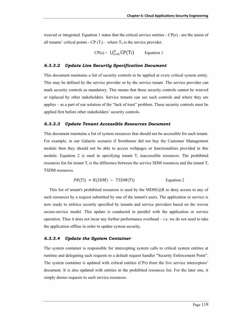
Chapter 6: Cloud Applications Security Engineering
Page 119
weaved or integrated. Equation 1 states that the critical service entities - CP(s) - are the union of
all tenants’ critical points - CP (Ti) – where T0 is the service provider.
CP(s) = ⋃ Equation 1
6.3.3.2 Update Live Security Specification Document
This document maintains a list of security controls to be applied at every critical system entity.
This may be defined by the service provider or by the service tenant. The service provider can
mark security controls as mandatory. This means that these security controls cannot be weaved
or replaced by other stakeholders. Service tenants can see such controls and where they are
applies – as a part of our solution of the “lack of trust” problem. These security controls must be
applied first before other stakeholders’ security controls.
6.3.3.3 Update Tenant Accessible Resources Document
This document maintains a list of system resources that should not be accessible for each tenant.
For example, in our Galactic scenario if Swinburne did not buy the Customer Management
module then they should not be able to access webpages or functionalities provided in this
module. Equation 2 is used in specifying tenant Ti inaccessible resources. The prohibited
resources list for tenant Ti is the difference between the service SDM resources and the tenant Ti
TSDM resources.
Equation 2
This list of tenant's prohibited resources is used by the MDSE@R to deny access to any of
such resources by a request submitted by one of the tenant's users. The application or service is
now ready to enforce security specified by tenants and service providers based on the woven
secure-service model. This update is conducted in parallel with the application or service
operation. Thus it does not incur any further performance overhead – i.e. we do not need to take
the application offline in order to update system security.
6.3.3.4 Update the System Container
The system container is responsible for intercepting system calls to critical system entities at
runtime and delegating such requests to a default request handler "Security Enforcement Point”.
The system container is updated with critical entities (CPs) from the live service interceptors’
document. It is also updated with entities in the prohibited resources list. For the later one, it
simply denies requests to such service resources.

Chapter 6: Cloud Applications Security Engineering
Page 120
Figure 6-5. Our proposed common security interface
Figure 6-6. Example of the generated security integration test cases

Chapter 6: Cloud Applications Security Engineering
Page 121
6.3.3.5 Security Enforcement Point – SEP
A key objective of MDSE@R is to avoid being tightly coupled with specific security controls,
specific security vendor, and specific security platform (Java security manager, spring acegi
framework, Microsoft Windows Identity Foundations, etc.). It also aims to keep developers and
administrators from being too deeply involved in integrating security controls with a target
system that often results in inconsistent security being enforced on different systems. We have
developed a common security interface for every security attribute (authentication,
authorization, auditing, encryption, etc). This interface, shown in Figure 6-5, specifies interface
functions and signatures that each security control expects/requires in order to perform their
tasks – e.g. AuthenitcateUser function should authenticate the user and return the set of claims
including user identity, credentials, roles, and permissions. A security or service vendor must
implement this interface in their connector or adapter to support integration with MDSE@R.
The sequence of calling/executing these methods is controlled by the SEP and depends on
security attributes mapped on the critical point being intercepted. This helps security vendors
develop one connector that - using MDSE@R - can be integrated with all target
applications/services.
So far we have prepared the system to intercept requests to critical methods via the system
container and have prepared security controls to be communicated using the common security
interface. The SEP works as a bridge between the system container and the deployed security
controls. SEP queries the security specification document for controls to enforce at every
intercepted request. It then initiates calls (using the security interface) to the designated security
controls’ clients or connectors. Moreover, the SEP assigns results returned by such controls to
the system context e.g. an authentication control returns userID of the requesting user after
being authenticated. The SEP creates an Identity object from this userID and assigns it to the
current thread’ user identity attribute. Thus a secured application can work normally as if it has
authenticated the user by itself. An application may use such information in its operations e.g. to
insert a record in the database, it uses the user identity to set the "enteredBy” database field.
6.3.4 Testing the Service-Security Integration
Before allowing the developed specifications and mappings to be applied to live cloud services,
MDSE@R conducts security testing to verify that the target service is correctly enforcing the
tenants and service providers’ specified security needs. We assume that the reused security
controls are already tested by the security vendors. Thus, our testing task focuses on verifying
that the security controls are now being correctly integrated within specified critical system
entities as required. To automate this step, we use the live interceptors’ document and the

Chapter 6: Cloud Applications Security Engineering
Page 122
security specification document to generate a set of test cases (scripts) for each critical entity –
i.e. each critical entity will have a set of test cases according to the security specified on it (from
the security specification document). Each test case verifies that a security control C is correctly
integrated within the critical entity E. An example is shown in Figure 6-6. As this figure shows,
we have GetCustomers method of the CustomerBLL class is marked as a critical point. This
critical point has a set of security controls mapped on it including authorize users before
executing this method. Thus, the security testing service generates a test case that calls this
method and check the resultant system security context (after calls - actual results) against the
expected results. In the backend, the SEP is converted in debug mode which let the SEP to raise
exceptions if a security control call failed. The testing framework (we use the nUnit framework,
discussed in the implementation section) fires these test cases and generates a log of the test
cases’ firing results to the tenant/service provider security engineers showing the failed test
cases, the critical entities, and the failed to integrate security controls.
Figure 6-6 shows a sequence diagram describing a user requesting resource X, from a service operated by MDSE@R. In this scenario we have several interacting entities including
user, webserver, MDSE@R system container, SEP, security services and the application
resource. Once the web server receives a request (1) submitted by a user to access resource X, it
delegates the request to the system container (2) along with the user’s tenantID T. The system
container queries the live service interceptors’ document (3) to decide if the resource requested
is marked as "critical” or not either by the tenant or by the service provider. If the resource is
critical (4), the system container delegates the request to the security enforcement point (5). The
SEP queries the security specification document (6) for the required security controls to be
enforced on the requested resource by the user’s tenant or by the service provider. This is an
ordered list of security controls to be activated by the SEP. The SEP loops through the retrieved
security controls list. Using the standard security interface, the SEP generates requests to the
security controls required according to their type (7). After each security control call, the SEP
updates the current threat security context (8). This includes update the execution context with
current user identity, set of claims and roles. Finally, the SEP returns to the system container a
recommendation to either proceed with the request or to deny it. If appropriate, the system
container then forwards the request to the target resource (9) or else returns an appropriate
security exception to the caller. If the tenant defined security properties or controls to be applied
on system responses – e.g. to encrypt the response body, the system container intercepts such
responses, applies security controls (through the SEP), and then forward the updated response
back to the client.

Chapter 6: Cloud Applications Security Engineering
Page 123
:User :SystemContainer:WebServer :SEP :SecService (S)
Access resource XAccess(X, T)
IsCritical(X,T)
:ResourceX
EnforceSec(X,T)opt
[X is critical]
GetRequiredSec(X,T)
ApplySec(CurrConetxt)
CheckCurrentSecContext()
<<return>>
UpdateSecContext()
<<return>>X
Xopt
[ X is not criticalOr X is secured]
Access(X, T)
<<results>>
XXX
<<results>>
X
Loop
[security controls list]
12
3
4
56
7
8
9
Figure 6-7. Sequence diagram of a user request to critical service entity
6.4 Usage Example
We introduce a usage example to show how the service provider and tenants can collaborate
together using MDSE@R and its provided platform toolsets to manage security of their services
at runtime. Moreover, we highlight the key stakeholders involved in the security engineering
process along with their responsibilities and expected outcomes of every step. We use our
motivating example discussed in details in chapter 1, the Galactic application developed by
SwinSoft and procured by Swinburne and Auckland. SwinSoft wants to adapt its application
security at runtime to block security holes and vulnerabilities that have been discovered at
runtime. Moreover, two tenants (Swinburne and Auckland) using Galactic are worried about the
security of their assets and have their own, different security requirements to be enforced on
their Galactic ERP application instance(s). We illustrate our usage example using toolset screen
dumps.
6.4.1 Model Galactic System Description
This task is done during or after the system is developed. SwinSoft, the service provider,
decides the level of application details to provide to their tenants in Galactic SDM.
Figure 6-8(a) shows that SwinSoft SDM captures the description of system features including
customer, employee and order management features (Figure 6-8(a)), system architecture details

Chapter 6: Cloud Applications Security Engineering
Page 124
including presentation, business and data access layers (Figure 6-8(b)), system classes including
CustomerBLL, OrderBLL, EmployeeBLL (Figure 6-8(c)), and system deployment including
web server, application server, and database server (Figure 6-8(d)). SwinSoft uses our UML
profile (Figure 6-4) to capture dependences and relationships between system features and
components, and system components/classes. This model will be used as a reference by
SwinSoft system and security engineers. No tenant is allowed to have write access to the
Galactic SDM or its details.
6.4.2 Model SwinSoft Security
This task is conducted by SwinSoft (the service provider) security engineers at the system
deployment phase. This model is usually updated during their recurring security management
process to reflect new risks. In this scenario, SwinSoft security engineers document SwinSoft
security objectives that must be satisfied by Galactic system (Figure 6-9(A)). It includes system
availability, data integrity, accountability objectives. This model is revised frequently to
incorporate emerging changes in SwinSoft security objectives. Security engineers then use this
model as a reference in developing system security requirements. They refine these security
objectives in terms of security requirements that must be implemented by Galactic system,
developing a security requirements model.
Figure 6-9(B) shows a part of the security requirements model focusing on AuthenticateUser
as a security requirement identified as a refinement of the data confidentiality and integrity
security objectives. The security requirements model keeps track of the security requirements
and their links back to the high level security objectives. SwinSoft security engineers next
develop a detailed security architecture including services and security mechanisms to be used
in securing Galactic.
Figure 6-9(C) shows the main security zones (represent as big boxes - containers) that cover
Galactic deployment environment including security management zone, web servers’ zone, and
enterprise network zone. A network zone means that there is a firewall with an intrusion
prevention system deployed. It also shows the allocation of IT systems, including Galactic in
these zones. The security architecture also shows the security services, security mechanisms and
standards that should be deployed. SwinSoft security engineers finally specify the security
controls (i.e. the real implementations) for the security services modelled in the security
architecture model.
Figure 6-9(D) shows the key security controls selected by security engineers as a realization
of their security requirements. This includes SwinValidator as an input validation control,
ESAPI.AccessController as an authorization control, and SecurityIsolator as a multi-tenancy

Chapter 6: Cloud Applications Security Engineering
Page 125
isolation and access controller security control. Each security control entity defined in the
security controls model specifies its family including authentication, authorization, audit,
cryptography, and audit. This helps in deciding the suitable API interface to be called in order to
use this control. It also helps in sequencing (ordering) the requests to be issued by the SEP to
secure a given system critical point. Each security control should define the deployment URL of
its connector. This is also required by the SEP when issuing requests to such controls. Each
security specification model maintains traceability information to parent model entities.
Figure 6-9(E) shows mappings specified between security entities and system entities. In this
example we specify that SecurityIsolator realizes the "TenantsDataIsolation” requirement.
Whenever MDSE@R finds a system entity with a mapped security requirement
TenantsDataIsolation it adds SecurityIsolator as its realization control – i.e. an SecurityIsolator
check will run before the entity is accessed e.g. before a method is called or a module is loaded.
SwinSoft security engineers have to mark mandatory security controls that their tenants cannot
modify or disable.
6.4.3 Weave Galactic SDM and Security SSM
After SwinSoft system and security engineers have completed the development of Galactic
SDM and security SSM, SwinSoft security engineers should specify/map security attributes (in
terms of objectives, requirements and controls) on Galactic system specification details (in
terms of features, components, classes). This is achieved by drag and drop of security attributes
on system entities. Thus, system features, structure, and behaviour can dynamically and at
runtime reflect different levels of security based on the currently mapped security attributes on
it. Figure 6-9(E) shows a part of Galactic component diagram where PresentationLayer, a UML
component entity, is extended with security objectives, requirements and controls
compartments. In this example the security engineers have specified TenantsDataIsolation as
one of the security requirement to be enforced on the PresentationLayer component (1). Such a
requirement is achieved indirectly using SecurityIsolator control (2). MDSE@R uses the
security attributes mapped to system entities to generate the full set of methods’ call
interceptors, as in Figure 6-11(1) (system interceptors document), and application or service
entities’ required security controls, as in Figure 6-11(2) (security specification document).
Chapter 6: Cloud Applications Security Engineering
Page 126
Figure 6-8. Galactic service description model (SDM)

Chapter 6: Cloud Applications Security Engineering
Page 127
Figure 6-9. Galactic service security specification model (SSM)

Chapter 6: Cloud Applications Security Engineering
Page 128
Figure 6-10. Swinburne security specification model

Chapter 6: Cloud Applications Security Engineering
Page 129
. . . <extension type="Interception" /> <register type="PresentationLayer.CustomerBLL, PresentationLayer "> . . . <interception> <policy name="PolicyCustomersBLL"> <matchingRule name="MatchingRuleCustomersBLL“ Type="MemberNameMatchingRule"> <constructor> <param name="nameToMatch" value="GetCustomers" /> <param name="nameToMatch" value="GetCustomerByName" /> <callHandler name="callhandlerCustBLL“ type="SecurityCallHandler, SecurityKernel"> . . .
A
<systemlevel> <componentlevel> . . . <classlevel> <objectname> . . . <methodlevel> . . . < ObjectName> GetCustomers </ObjectName> <Authentication_Method>Forms</Authentication_Method> <Authorization_Method>RBAC_Impersonate</Authorization_Method> . . .
B
Figure 6-11. Examples of the interceptors and security specification files
public IMethodReturn Invoke( IMethodInvocation input, GetNextHandlerDelegate getNext) { EntitySecurity entity = LoadMethodSecurityAttributes(input.MethodName); if (entity == null || entity.HasSecurityRequirements() == false) { return getNext().Invoke(input, getNext); } //Check for logging if (entity.GetLoggingMethod() != LoggingMethod.None) { SecurityInterfaceLogging obj = new Type.GetType(entity. entity.GetInputValidationMethod()); obj.Log(Datetime.Now, input.Method.MethodName); } //Check for Input Validation if ( entity.GetInputValidationMethod() != InputValidationMethod.None ) { SecurityInterfaceInputValidation obj = new Type.GetType(entity.GetInputValidationMethod()); } //Check for Authentication if (entity.GetAuthenticationMethod() != AuthenticationMethod.None) { if(CurrentThread.CurrentPrincipal == null) { SecurityInterfaceInputValidation obj = new Type.GetType(entity.GetAuthenticationMethod()); obj.AuthenitcateUser(); } } //Check for Authorization if ( entity.GetAuthorizationMethod() != AuthorizationMethod.None ) { . . . } }
Figure 6-12. Code snippet from MDSE@R security enforcement point

Chapter 6: Cloud Applications Security Engineering
Page 130
Once security has been specified and interceptors and configurations generated, MDSE@R
verifies that the system is correctly enforcing security as specified. MDSE@R generates and
fires a set of required security integration test cases. Our test case generator uses the system
interceptors and security specification documents to generate a set of test cases for each method
listed in the interception document. An example of a generated test case is shown in Figure 6-6.
This contains a set of security assertions (one for each security attribute specified on a given
system entity). During the firing phase, the security enforcement point is instrumented with
logging transactions to reflect the calling method, called security control, and the returned
values. Security engineers should check the security test cases firing log, an example is shown
in Figure 6-13, to verify that no errors introduced during the security controls integration with
Galactic entities. After SwinSoft security engineers have checked the MDSE@R Security
testing service log files and make sure that no integration errors have been introduced, they can
publish their updated Galactic security model for their tenants.
Figure 6-13. A snapshot of MDSE@R security test cases firing log
6.4.4 On-boarding Swinburne and Auckland Tenants
During the tenants on-boarding process (preparing the service to be used by a new tenant),
SwinSoft system engineers/admins start to customize/configure Galactic instance for tenant
based on their requirements and purchased modules. Depending on the adopted multi-tenancy
model, they may register new features or components as well. The final Swinburne or Auckland
TSDM is similar to Galactic SDM in Figure 6-8. Swinburne and Auckland system
administrators can update their own tenants’ TSDMs to reflect any further system
customization, such as enabling or disabling sub-features such as calculate overtime, nightshifts,
and vacations in the Employee Management module. This TSDM is used by Swinburne security
engineers to define and map required security on it. Moreover, any updates done by SwinSoft or
Swinburne on their TSDMs are reflected on the prohibited resources list (Eq. 2)

Chapter 6: Cloud Applications Security Engineering
Page 131
6.4.5 Managing Swinburne and Auckland Security
Swinburne and Auckland security engineers go through the same process as SwinSoft did when
specifying their security requirements and controls. Each tenant can customize their TSSM as
far as they want and as frequent as required. For example, in Figure 6-10 Swinburne engineers
have specified that LDAP "realizes” the AuthenticateUser requirement. Whenever MDSE@R
finds a system entity with a mapped security requirement AuthenticateUser it adds LDAP as its
realization control i.e. an LDAP authentication check will run before the entity is accessed - e.g.
before a method is called or a module loaded. This applies to the CustomerBLL class methods,
Figure 6-10 (1). However, Swinburne security engineers have a different requirement for the
GetCustomers method - the requester should be authenticated using Forms-based authentication
instead, Figure 6-10(2). Auckland can specify their specific requirements, context, and security
controls based on their specific needs. This results in quite different generated security
enforcement controls. Both Swinburne and Auckland security engineers can modify the security
specifications while their Galactic application is in use. MDSE@R platform updates
interceptors in the target systems and enforces changes to the security specification for each
system as required. For example, the Swinburne Galactic security model can be updated with a
single sign-on security authentication component and these updates are directly applied on the
running Galactic instance.
6.5 MDSE@R Architecture and Implementation
The architecture of MDSE@R platform is shown in Figure 6-14. This is designed as a cloud
Platform-as-a-Service (PaaS) that can manage multiple SaaS applications hosted on the same
platform. MDSE@R consists of system and security specification modellers, models and
security controls specifications repositories, system container to intercept request, testing
services and security enforcement point.
6.5.1 MDSE@R Platform Architecture Details
System Description Modeller (1) is developed as an extension of Microsoft Visual Studio 2010
modeller with an UML profile (Figure 6-4) to enable system engineers modelling their systems’
details with different perspectives including system features, components, deployment, and
classes. The UML profile, as shown in Figure 6-4, defines stereotypes and attributes to maintain
the track back and forward relations between entities from different models. This includes
related features stereotype extending system components’ entities; system components
stereotype extending system classes’ entities. Moreover, a set of security attributes to maintain
the security concepts including objectives, requirements and controls mapped to every system

Chapter 6: Cloud Applications Security Engineering
Page 132
entity. The minimum level of details expected from the system provider is the system
deployment model. MDSE@R can use this model to reverse engineer system classes and
methods using .NET Reflections in case of system binaries only available. We use .NET parsers
to extract classes and methods from system source code by analysing the generated AST files.
Figure 6-14. MDSE@R architecture
Security Specification Modeller – SecDSVL (2) is also developed as a Microsoft Visual
Studio 2010 plug-in. It enables service providers and tenants, represented by their security
engineers, to specify the security attributes and capabilities that must be enforced on the service
and/or its operational environment. Figure 6-15 shows the meta-model of the MDSE@R
SecDSVL which captures security details developed during the security management process.
We will discuss SecDSVL details in the next Section.
Models Repository (3) is a shared repository to maintain models developed either by the
system engineers or the security engineers. This repository also maintains the live system
interceptors’ document and security specification document. An example of these documents is
shown in Figure 6-11. This example shows a sample of the Galactic interceptors’ document
generated from the specified security-system mapping. It informs the system container to

Chapter 6: Cloud Applications Security Engineering
Page 133
intercept GetCstomerByName and GetCustomers methods (1); a sample of Swinburne security
specification file defining the security controls to be enforced on every intercepted point (2).
Security Controls Database (4) is a database of the available and registered security patterns
and controls. It can be extended by the service providers or by a third party security provider. A
security control must implement certain APIs defined by the security enforcement point in order
to be able to integrate with the target system security standard interface. Having a single
enforcement point with a predefined security interface for each security controls family enables
security providers to integrate with systems without having to redevelop adopters for every
system. We adopted OWASP Enterprise Security API (ESAPI) library [238] as our security
controls database. It provides a set of authentication, authorization, encryption, etc. controls that
we used in testing our approach.
System Container (5) used to support run-time security enforcement. MDSE@R uses a
combined dependency injection and dynamic-weaving AOP approach. Whenever a client or
application component sends a request to any critical system component method, this request is
intercepted by the system container. The system container supports wrapping of both new
developments and existing systems. For new development, SwinSoft system engineers should
use the Unity application block delivered by Microsoft PnP team to support intercepting any
arbitrary class entity. Unity supports dynamic runtime injection of interceptors on methods,
attributes and class constructors. For existing systems we adopted Yiihaw AOP, where we can
modify application binaries (dll and exe files) and add security aspects at any arbitrary system
method (we add a call to our security enforcement point). For component level interception, we
can use httpModules to add interceptors on the component level.
Security Test Case Generator (6) uses the NUnit testing framework to partially automate
security controls and system integration testing. We developed a test case generator library,
using test cases template, to generate a set of security test cases for authentication,
authorization, input validation, and cryptography for every enforcement point defined in the
interceptors’ document. MDSE@R uses nUnit library to fire the generated test cases and notify
security engineers via test case execution result logs.
At runtime, whenever a request for a system resource is received (7), the system container
checks for the requested method in the live interceptors’ document. If a matching found, the
system container delegates this request with the given parameters to the security enforcement
point (8). Figure 6-12 shows a sample of the security enforcement point API that injects the
necessary security control calls before and after application code is run for different security
attributes. Security Enforcement Point (9) is a class library that is developed to act as the default
interception handler and the mediator between the system and the security controls. Whenever a

Chapter 6: Cloud Applications Security Engineering
Page 134
request for a target application operation is received, it checks the system security specification
document to enforce the particular system security controls required. It then invokes such
security controls through APIs published in the security control database (4). The security
enforcement point validates a request via the appropriate security control(s) specified, e.g.
imposes authentication, authorization, encryption or decryption of message contents. The
validated request is then propagated to the target system method for execution (10).
Figure 6-15. SecDSVL meta-model
6.5.2 SecDSVL: Security Domain Specific Visual Language
SecDSVL provides a mega-model using visual notations to be used by security engineers in
managing IT systems’ security. To develop SecDSVL, we studied the existing security
management standards (including NIST, ISO27000) details and come up with a comprehensive
security meta-model that captures all relevant details, as summarized in SecDSVL meta-model
Figure 6-15 and discussed below:

Chapter 6: Cloud Applications Security Engineering
Page 135
6.5.2.1 Enterprise Assets
The first step in the security management process is the identification of existing IT assets that
need to be secured. We capture enterprise assets in an asset model. This model captures all
enterprise assets along with their categories i.e. information systems, physical assets or business
value - and interrelationships. We use UML models to capture assets’ detailed descriptions as
discussed in the system description model. Stakeholders need to assign security categorization
for every modelled asset. This categorization depends on the asset assigned criticality level.
6.5.2.2 Security Objectives
Enterprise top management defines key security goals, objectives, and losses of breaching
assets’ security. These objectives are captured in a security objectives model. Objectives may be
specified per asset– i.e. objectives are mapped to the corresponding asset, or enterprise-wide
thus a given security objective could be mapped to many assets. Possible relationships between
objectives include: composition – a security objective is made up of sub-objectives; dependency
– a security objective depends on other security objectives in order to be satisfied/achieved.
Availability, integrity, confidentiality, and accountability are the key security objective
categories [239]. Each security objective is assigned an importance level. This indicates the
impact of the failure to meet such objective as a result of security breach – e.g. impact of
breaching asset confidentiality may be high, moderate, or low. A security objective may be
assigned realization security strategy including preventive, detective, and recovery strategies.
6.5.2.3 Risk, Threats, Attacks, and Vulnerabilities
Security engineers conduct risk analysis on critical enterprise assets to identify possible threats
on a given asset, and likelihood and impact of such threats. This also may include performing
vulnerability analysis to identify inherent flaws that may be exploited by threat agents while
attack the system. These security details are captured in a security risk model. This may be
developed per asset – i.e. for each enterprise asset we develop risk model capturing risks, threats
and attacks, or enterprise-wide risk model capturing all possible risks, threats and attacks and
map such items onto different assets. Threats should be linked with the source threat agents and
to the exploited vulnerabilities. Vulnerabilities should be mapped to the vulnerable assets.
Security risks map identified threats to the breached security objectives – i.e. a risk is a violation
of a security objective through a possible threat. For each risk, we should specify the probability
that a given threat can be exploited and the impact of exploiting such a threat by a threat agent.

Chapter 6: Cloud Applications Security Engineering
Page 136
6.5.2.4 Security Requirements
Security requirements are the treatments to be taken by security engineers in order to mitigate or
avoid the identified threats. Security requirements are captured in a security requirements
model. For each specified security objective and identified security risk, we may define a set of
security requirements e.g. “the system should not grant access to a resource X unless the user is
authorized by the user name and password”. NIST [240] has 18 Security requirements family
including audit, communication, cryptography, data protection, identification and
authentication, privacy, etc.
6.5.2.5 Security Architecture
Security architects use the given security requirements model to develop a security architecture
model. This model captures planned behaviour and structure of enterprise security. It shows
how and where security controls and enterprise assets are positioned. Moreover, it captures how
these security controls are integrated with other enterprise assets. A security architecture model
includes identifying security zones (domain) in the enterprise operational environment including
uncontrolled, controlled, restricted, and managed zones. Security architects define the security
services that will be deployed or used in every zone. These services include authentication,
authorization, cryptography, audit, etc. these services may also specify the mechanism or
standard that should be provided by every security service e.g. cryptography should use AES
instead of DES, authorization should use LDAP and SSO instead of forms-based authentication
or Microsoft membership security.
6.5.2.6 Security Controls
Security administrators specify security controls that realize security services specified in the
security architecture model. These security controls are captured in a security controls model.
This model includes for every security control, the configurations to be applied on it. Moreover,
each security control entity should specify the security control family. Thus, we can load
configurations from the Common Configuration Enumeration (CCE) database [241].
6.6 Evaluation
In this section we summarize some of the experiments we have performed to assess the
soundness and scalability of our MDSE@R approach in:
– Capturing descriptions of different real systems and different security details for both
service providers and tenants;

Chapter 6: Cloud Applications Security Engineering
Page 137
– Propagating security attributes on different system entities (features, components, classes,
and methods);
– Enforcing unanticipated security requirements that emerge at runtime including
authentication, authorization, auditing, etc. at runtime with an acceptable performance
overhead;
– Validating that security controls are correctly integrated with the target entities.
– Usability of our SecDSVL language?
We divided the benchmark set (the set of applications discussed in Chapter 4) into two
groups: Group-1 has two applications including Galactic ERP and PetShop. Both applications
have been modified to adopt the Unity application block as the system container. Group-2 has
the other five open source web applications including Splendid, KOOBOO CMS,
NopCommerce, BlogEngine, BugTracer, and TinyERP. For this group we use Yiihaw
framework as the system container to inject interceptors into system binaries. Except for
Galactic, we do not have any previous experience with these applications.
6.6.1 Experimental Evaluation Setup
Using MDSE@R, we developed three security specification models (SSM) with security
objectives, requirements, and controls as described in Figure 6-9 and Figure 6-10. One model for
service provider and two other models were copied from it and modified to reflect two security
requirements sets. We specified security requirements and controls for authentication,
authorization, input validation, logging and cryptography as shown in Table 6-1.
We used MDSE@R to model the system description (SDMs) for applications in Group-1, as
we know the details of these systems – i.e. we can develop a complete SDM including system
features, components, classes, etc. For Group-2, we used system deployment diagram for these
applications and used reverse engineering to extract systems’ class diagrams from their binaries.
Thus for applications in Group-1 we should be able to map security to system features,
components, classes, methods. However, in Group-2 we should be able to specify security on
component, class, and method levels only because these are the only available models (features
cannot reverse engineered from system source code or binaries so far).
6.6.2 Evaluation Results
Table 6-2 shows security attributes that MDSE@R succeeds in capturing and enforcing at
runtime, including authentication, authorization, input sanitization, auditing and cryptography.
This represents most common security attributes. Table 6-2 also shows that MSDE@R
succeeded in mapping and enforcing these security attributes on systems in both Group-1 and

Chapter 6: Cloud Applications Security Engineering
Page 138
Group-2 with different levels of system abstractions (F: feature, C: component, S: class, and M:
method). Note that for Group-2 applications we do not have a system feature model to map and
enforce security on this level. The enforcement of cryptography has a limitation with Group-2
applications especially when securing methods. This is because it requires that the caller and
callee expect parameters of type String. To address this problem, we used format-preserving
encryption (FPE) techniques [62]. The output of these techniques is in the same format (type) of
the input - i.e. if the input to encrypt is of type integer then the output is of the same type.
Table 6-1. Security controls used by service provider, Swinburne, Auckland
Sec. Attribute SwinSoft Ctls Swinburne Ctls Auckland Ctls
Authentication ESAPI Forms-based LDAP
Authorization ESAPI Forms-based LDAP
I/P santization ESAPI SwinFirewall –
Audit ESAPI PrivateAuditor PrivateAuditor
Cryptography ESAPI DES AES
Sec. Isolation ESAPI – –
Table 6-2. Validating MDSE@R against Group-1 and Group-2 applications
BenchmarkApplications
Security Attributes
Authn Authz. I/P Valid. Audit Crypto.
Gro
up-1
Galactic F, C, S, M
PetShop F, C, S, M
Gro
up-2
SplendidCRM C, S, M (C, S, M)*
KOOBOO CMS C, S, M (C, S, M)*
NopCommerce C, S, M (C, S, M)*
BlogEngine C, S, M (C, S, M)*
BugTracer C, S, M (C, S, M)*
TinyERP C, S, M (C, S, M)*

Chapter 6: Cloud Applications Security Engineering
Page 139
6.6.3 SecDSVL Evaluation
We have evaluated SecDSVL capabilities in capturing different kinds of enterprise security
details with different levels of abstractions in comparison with the existing security
management, risk management, and security engineering approaches. Table 6-3 shows
SecDSVL compared to a range of other existing security modeling techniques based on their
documented capabilities in Chapter 3 (related work). Table 6-3 shows that none of the existing
approaches provides a comprehensive security model that covers every aspect in the security
management process. Security management approaches (ISO27000, NIST-FISMA) focus on
assets, risks, threats, and mitigation controls. Risk management approaches (OCTAVE,
CORAS) focus on similar areas except for security controls. Early stage security engineering
efforts (KAOS, i*, Tropos) focus on security objectives and requirements. Later-stage security
engineering efforts (UMLsec, SecureUML) focus on security requirements, mapping and
integration with target systems.
Table 6-3. Comparison between SecDSVL and existing efforts
Approach 1 2 3 4 5 6 7 8 9 10
Misuse case X X √ √ √ X X X X X
UMLSec X X X X ● X ● X X ●
SecureUML X X X X ● X ● X X ●
KAOS X √ ● √ √ X X X X X
i* X √ ● √ √ X X X X X
Tropos X √ ● √ √ X X X X X
CORAS √ ● √ √ X X X X ● ●
OCTAVE √ ● √ √ X X X X ● X
FISMA √ √ √ √ X X X √ √ X
ISO27000 √ √ √ √ X X X √ √ X
SecDSVL √ √ √ √ √ √ √ √ √ √
[1] Assets Model, [2] Security Objective, [3] Security Threats and Vulnerabilities, [4] Security
Risks, [5] Security Requirements, [6] Security Architecture, [7] Design, [8] Security Controls,
[9] Traceability, [10] Mapping between systems and security models
√: Fully Supported ● : Partially supported X : Not supported
Chapter 6: Cloud Applications Security Engineering
Page 140
6.6.4 User Evaluation
We carried out a preliminary user evaluation of our tools and platform to assess MDSE@R
approach and platform usability. We had seven post-graduate researchers, not involved in the
development of our MDSE@R approach, to use our developed tools and platform after
receiving an hour training session on the tool and platform features. We asked them to explore
several MDSE@R system and security DSVL specifications of the PetShop and Galactic
applications. Then we asked them to perform updates on these models and to modify the
security specification models at run-time. We conducted a basic usability survey to gain their
feedback on our DSVL, modelling tools, and the security enforcement platform. The results
show that they successfully understood and updated security models for the target systems.
They gave positive feedback about the overall approach and the tool usability, and the
capabilities in managing system security, as shown in Figure 6-16 (1: Strongly disagree to 5:
Strongly agree). A key recommendation was to use more expressive icons in the security DSVL
rather than just boxes.
6.6.5 Performance evaluation
In this section, we discuss the performance evaluation of MDSE@R platform in two key areas:
runtime performance overhead of the MDSE@R platform on the secured system; and the offline
system security adaptation overhead.
6.6.5.1 Runtime Performance Overhead
The runtime performance overhead of MDSE@R equals time taken to intercept requests, plus
time spent by the security enforcement module in querying the security requirements repository
to be enforced on the intercepted point, plus time spent in calling the security controls specified.
The time spent by security controls themselves we do not factor in, as this needs to be spent
whether using our approach or as hard-coded security solutions. Arguably, traditional
approaches may incur some of these other time penalties as well e.g. checking authenticated
user access controls or generating audit checkpoint information to log.
Figure 6-17 shows the time required (in msec) by MDSE@R to process a request for systems
with different numbers of concurrent users and different number of system entities that have
been marked as critical. Experiments were conducted on a Core2Duo desktop PC with 4GB
Memory. The maximum performance overhead we got for a system with 10000 CPs defined
and having 100 users concurrently sending requests equals 140msec. This performance
considers efficient memory utilization as interceptors and security specification documents are
loaded as needed. Significantly better performance could probably be achieved by caching these

Chapter 6: Cloud Applications Security Engineering
Page 141
MDSE@R models in memory and using a hash table data structure to enable faster search.
Moreover, using replicas of the MDSE@R platform on different servers and for different
applications will result in further improvement of the approach performance overhead.
Figure 6-16. SecDSVL usability level of agreement
Figure 6-17. MDSE@R platform average performance overhead

Chapter 6: Cloud Applications Security Engineering
Page 142
6.6.5.2 Security Adaptation Overhead
We have measured the adaptation delay incurred by MDSE@R in order to realize a single
simple mapping between a security entity and a system entity – e.g. system methods. This
overhead equals on average 3 seconds. This represents the time taken to update the security
interceptors and security specification documents and time to generate and fire the required
integration test case(s). This is an offline task and so does not impact the performance of the
running system instance.
6.7 Discussion
MDSE@R approach promotes multi-tenancy security engineering from design time to runtime.
This is based on externalizing security engineering activities including capturing objectives,
requirements controls, and realization from the target system implementation. This permits both
security (to be enforced) and critical system entities (to be secured) to evolve at runtime
(supporting adaptive security at runtime). Moreover, it enables enforcing different security
requirements’ sets for different tenants who are not known at design time. We name this as
"tenant-oriented security" compared to the traditional service-oriented security where a service
can reflect only one set of security requirements usually captured by service provider at design
time. One may argue that our approach may lead to a more open and vulnerable system as we
did not consider security engineering during design time. Our argument is that at design time
security engineering is often done by security non-experts and this is a leading reason why we
still discover a lot of vulnerabilities in systems. Moreover, service providers can still perform
security engineering during design time using MDSE@R. The service provider delivers both the
SDM and SSM to their tenants for further customization. This also helps small tenants or
tenants who are satisfied with the delivered security.
A key benefit reaped from MDSE@R approach is supporting model-based security
management. Tenant security requirements, architecture and controls are maintained and
enforced through a set of centralized TSSMs instead of low level scattered configurations and
code that lack consistency and are difficult to modify. A tenant can have a single TSSM for all
of their IT systems that captures all of their security specifications and can be updated anytime
to reflect his new configurations. Thus any update to their TSSM will be reflected on all IT
systems that use MDSE@R platform. We developed one security model and used it with
different systems. Each system enforces the security mapped to its entities. Moreover, any
update to the security model results in updating all systems linked to it. This is a key issue in
environments where multiple applications must enforce the same security requirements. Having
one place to manage security reduces the probability of errors, delays, and inconsistencies.

Chapter 6: Cloud Applications Security Engineering
Page 143
Moreover, automating the propagation of security changes to underlying systems simplifies the
enterprise security management process.
The selection of the level of details to apply security on depends on the criticality of the
system. In some situations, we may intercept calls to the presentation layer only (webserver)
while considering the other layers secured by default (not publicly accessible). In other cases,
such as integration with a certain web service or using third party component, we may need to
have security enforced at the method level (for certain methods only).
Security and performance trade-off is another dilemma to consider. The more security
validations and checks the more resources required. This impacts application performance. This
should be included as a part of the Service Level Agreement (SLA) with the tenants. We plan to
extend our generated test cases to include performance tests, allowing MDSE@R provider to
assess the overhead of new security configurations in terms of cost and to help both providers
and tenants to optimize the security level enforced. MDSE@R helps in engineering security into
systems at runtime, while the security controls’ configuration and administration should be
managed by security administrators. Moreover, MDSE@R does not support defining business
rules at runtime – e.g. employee should not be able to retrieve customers’ records of type VIP.
The target system should have this rule while MDSE@R will provide the current user
roles/permissions as returned by the tenant security access control.
Security isolation between different tenants’ data is a very critical requirement in
engineering security of a multi-tenant SaaS application. Although multi-tenancy security
isolation is out of the project scope, the MDSE@R can help in addressing the security isolation
problem. Security isolation controls, that simply perform authorization of the tenants supplied
inputs, are added to the service SSM as a mandatory security control to be applied before
proceeding with any given request. Thus no tenant can access other tenants’ data by providing
malicious inputs. However, the service providers have to perform the data filtration when
loading/storing data from/to the application database.
Currently the communication (request/ response) between the MDSE@R and tenants’
security controls is not encrypted. Thus, the key management itself does not fall directly under
the responsibility of MDSE@R. However, MDSE@R is responsible for issuing requests for
cryptography security controls to encrypt or decrypt tenants’ data as specified in their security
specification model. Such security controls have to know where to get the cryptography keys for
example. If the encryption of these communication messages is also a requirement, we can use a
PKI as an extension of the MDSE@R to manage cryptography keys used for secure
communication, as shown in Figure 6-18. This would be used by MDSE@R to get tenants’
public keys to be used in encrypting communications with tenant’s controls.

Chapter 6: Cloud Applications Security Engineering
Page 144
Figure 6-18. Cryptography scenario between MDSE@R and tenants' security controls
The multi-tenant security engineering of existing services (extending system security
capabilities) has three possible scenarios: Systems that already have their SDMs, we can use
MDSE@R directly to specify and enforce multi-tenant security at runtime; Systems without
SDMs, we reverse engineer parts of system models (specifically the class diagram) using
MDSE@R. Then we can use MDSE@R to engineer required system security; and Systems with
built-in security, in this case we can use MDSE@R to add new security capabilities only.
MDSE@R cannot itself help modifying or disabling existing security. In chapter 7, we
introduce our approach (reengineering aspects – re-aspects) to support disabling of existing
security methods and partial code using modified AOP techniques.
In cloud computing model, most of the services are publicly accessible to end users who may
be malicious users. Those users may try to exploit services’ vulnerabilities to breach data
security. Thus, it is very important to operate a security service that can easily mitigate such
vulnerabilities at runtime without any delays to develop security patches. MDSE@R could be
used in automating such vulnerability mitigation process. Reported vulnerabilities will be used
to extract the critical points that need to be secured. A set of mitigation actions that should be
applied to mitigate the reported vulnerability will be used to integrate required security controls
within the vulnerable points at runtime. We will discuss this case in more details in the case
studies chapter (chapter 10).
Chapter 6: Cloud Applications Security Engineering
Page 145
6.8 Chapter Summary
MDSE@R is a new model-driven approach to dynamically engineering security for multi-tenant
SaaS applications at runtime. Our approach is based on using a set of multi-level service
description models (SDM), developed by service providers, to describe different perspectives of
their applications or services; a set of security specification models (SSM), developed by the
service provider, to capture security objectives, requirements and environment security controls
using Domain-Specific Visual Languages. Then, tenants can customize their copies of the SDM
and SSM to reflect their application or service and security configurations. MDSE@R then
bridges the gap between these two specifications through merging of the service and security
models for both service provider and service tenants into a joint service security model.
MDSE@R uses dynamic injection of security enforcement interceptors and code into the target
application or service to enforce the security specified. Security specifications are thus
externalized and loosely coupled with application specifications, enabling both the application
and security specification to evolve.
It also allows sharing of security specification models among different applications "model-
based security management". Security controls can be integrated with MDSE@R (which was
implicitly integrated with the tenant service) by implementing a standard security interface we
introduced. We have developed a set of modelling tools and a prototype of MDSE@R. We have
successfully validated our approach by applying it to a set of benchmark applications, most of
them open source, successfully modelling and enforcing a range of security needs on these
applications. We performed a user evaluation of our toolset that demonstrates that it is readily
usable by a technical audience but with little security engineering background. We assessed the
performance overheads of using our current prototype of MDSE@R. It has a performance
overhead ranging from 0.13msec up to 140msec per request for each critical application or
service entity. MDSE@R has adaptation delay of 3 seconds for each simple mapping between
SSM and SDM. This represents time to update interceptors and security specification
documents as well as generating and firing security test cases.


Page 147
Chapter 7
Cloud Applications Security
Reengineering
In the last chapter we introduced our multi-tenant security engineering at runtime approach,
MDSE@R, to enable cloud services to reflect different sets of security requirements for
different tenants that emerge at runtime. However, MDSE@R does not help in case of cloud
services that have been originally developed with built-in security capabilities (functions).
MDSE@R helps in adding new security capabilities. Such new capabilities may conflict with
existing service security capabilities. In this chapter we introduce a new security reengineering
(retrofitting) approach that is used as a preprocessing step to help in disabling services’ built-in
security as well as mitigating system security vulnerabilities found in such services that may be
reported by a security analysis service (we introduce our approach in chapter 8). Our approach
is based on Reengineering-Aspects “Re-aspects” as a new concept we introduce to address and
capture the complex details involved in fulfilling such security reengineering tasks. This chapter
is organised as follows. Section 1 introduces an overview of software reengineering and key
limitation of the existing efforts. Section 2 introduces some motivating examples that we may
face during the security reengineering process. Section 3 provides an overview of the normal
change request management process that should be followed when conducting system
maintenance task. Section 4 provides an overview of our re-aspects concept. Section 5 describes
how re-aspects concept helps automating the change impact analysis task. Section 6 describes
how re-aspects concept helps automating change propagation task. Section 7 discusses,
SMART, our reengineering tool based on the re-aspects concepts along with the key
implementation details. Section 8 discusses a usage example that shows how SMART tool
works. Section 9 describes evaluation experiments of our approach. Section 10 discusses
strengths and weaknesses and areas for further research.
7.1 Introduction
Software systems are usually exposed to extensive changes and evolution after deployment.
This might be to address quality problems (e.g. fixing bugs), performance problems (e.g. too
slow), make use of new APIs or integrate with new systems (e.g. change system to use
company-wide LDAP authentication for single sign-on from a custom ID/password system), or
to fix security problems (e.g. found to be vulnerable to SQL Injection attack).

Chapter 7: Cloud Applications Security Reengineering
Page 148
These maintenance activities represent up to 80% of the total system cost and effort [242].
System re-engineering is concerned with system understanding, organization, and migration
[165]. System maintenance [166] is concerned with post-delivery modifications to an existing
system in order to address new issues. These can be small spot-patches to major revision of
system architecture and codebase. Dynamic runtime adaptation is more a limited approach and
is sometimes used to handle post-delivery “unanticipated” requirements made while the system
is running [37, 174, 243]. System reengineering, refactoring and maintenance are concerned
with removing, modifying and replacing existing features as well as adding new system features
at design time. This requires: (i) capturing new features or modifications of existing features;
(ii) locating system entities that must be modified; (iii) locating system entities that is impacted
by this modification and should be modified; and (iv) propagating or reflecting the required
modification on the whole system.
A
B C
A
B
A
B C
A
B D
A
B C
A
B
A
B C
A
B C
Befo
reA
fter
Remove Feature
ReplaceFeature
Modify Feature
AddFeature
CD
Figure 7-1. Possible system modifications and their impact on system entities
Figure 7-1 illustrates possible system modifications (types of change requests): (i) a feature
is removed (e.g. code taken away); (ii) a feature is replaced (e.g. old code replaced by new
code); (iii) a feature is modified (some old code replaced by changed code); and (iv) a feature is
added (new code is inserted into old code). In these scenarios, other features may be impacted –
e.g. the removal of feature C requires updating dependent features (A, B). This figure also
highlights a key problem which is that realizing a given system modification on a specific
feature (added, removed, modified, or replaced) requires modifying other related system
features that integrates (interacts or uses) the modified system feature. Below we discuss some
of the relevant efforts related to how we realize system modification/updating.
Existing system reengineering approaches focus on understanding the target system and
locating implemented features [177, 178, 181, 244], discovering implemented design patterns
[245], aspects mining [182], understanding source code evolution between different system
versions [246], applying system restructuring [247]. These efforts are limited in their
expressiveness and identification precision, as most of them are targeted to help program
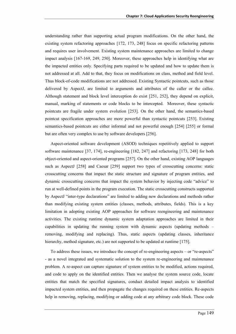
Chapter 7: Cloud Applications Security Reengineering
Page 149
understanding rather than supporting actual program modifications. On the other hand, the
existing system refactoring approaches [172, 173, 248] focus on specific refactoring patterns
and requires user involvement. Existing system maintenance approaches are limited to change
impact analysis [167-169, 249, 250]. Moreover, these approaches help in identifying what are
the impacted entities only. Specifying parts required to be updated and how to update them is
not addressed at all. Add to that, they focus on modifications on class, method and field level.
Thus block-of-code modifications are not addressed. Existing Syntactic pointcuts, such as those
delivered by AspectJ, are limited to arguments and attributes of the caller or the callee.
Although statement and block level interception do exist [251, 252], they depend on explicit,
manual, marking of statements or code blocks to be intercepted. Moreover, these syntactic
pointcuts are fragile under system evolution [253]. On the other hand, the semantics-based
pointcut specification approaches are more powerful than syntactic pointcuts [253]. Existing
semantics-based pointcuts are either informal and not powerful enough [254] [255] or formal
but are often very complex to use by software developers [256].
Aspect-oriented software development (ASOD) techniques repetitively applied to support
software maintenance [37, 174], re-engineering [182, 247] and refactoring [173, 248] for both
object-oriented and aspect-oriented programs [257]. On the other hand, existing AOP languages
such as AspectJ [258] and Caesar [259] support two types of crosscutting concerns: static
crosscutting concerns that impact the static structure and signature of program entities, and
dynamic crosscutting concerns that impact the system behavior by injecting code “advice” to
run at well-defined points in the program execution. The static crosscutting constructs supported
by AspectJ “inter-type declarations” are limited to adding new declarations and methods rather
than modifying existing system entities (classes, methods, attributes, fields). This is a key
limitation in adopting existing AOP approaches for software reengineering and maintenance
activities. The existing runtime dynamic system adaptation approaches are limited in their
capabilities in updating the running system with dynamic aspects (updating methods –
removing, modifying and replacing). Thus, static aspects (updating classes, inheritance
hierarchy, method signature, etc.) are not supported to be updated at runtime [175].
To address these issues, we introduce the concept of re-engineering aspects – or “re-aspects”
- as a novel integrated and systematic solution to the system re-engineering and maintenance
problem. A re-aspect can capture signature of system entities to be modified, actions required,
and code to apply on the identified entities. Then we analyse the system source code, locate
entities that match the specified signatures, conduct detailed impact analysis to identified
impacted system entities, and then propagate the changes required on these entities. Re-aspects
help in removing, replacing, modifying or adding code at any arbitrary code block. These code

Chapter 7: Cloud Applications Security Reengineering
Page 150
blocks may have a heterogeneous and complicated signature that is more complex than can be
expressed using existing AOP approaches. Changes supported to be made on a target system
include removing declarations, method calls, sets of lines of code, or whole methods, etc. We
introduce two novel signature designators to help capturing formal and flexible semantic
signature expressions as well as flexible syntactic signatures.
Using the re-aspect de-weaving and replacement concept, we have developed a supporting
model-driven application reengineering tool, SMART. SMART captures a set of required target
system changes as re-aspects. These re-aspects are mapped to target system entities as a set of
change requests. SMART applies these change requests and updates the source code as
appropriate. We have validated SMART on our set of benchmark applications introduced in
Chapter 4.
7.2 Motivating Examples
Figure 7-2 shows example code snippets that need to be modified to satisfy different change
requests for a security retrofitting task (modifying application security capabilities). These code
snippets are excerpted from Galactic – our research project motivating example; a web-based
ERP system developed using .NET. These examples also show possible system modifications
for these change requests, the code with grey shading - i.e. required re-engineering of the
original code to address raised issues.
bool updateCustomerBalance(string custID, decimal nBalance) { if(!AuthenitcateUser( username, password)) return false; if(!AuthorzUser(username, "updateCustBalance")) return false; LogTrx(username, dateTime.Now, "updateCustomerBalance"); Customer customer = Customers.getCustomerByID(custID); customer.Balance = nBalance; Customers.SaveChanges(); LogTrx(username, dateTime.Now, "updateCustBalance done");
}
if( Request.Cookies["Loggedin"] != true ) { if(!AuthenticateUser(Request.Params["username"], Request.Params["password"] ) ) throw new Exception("Invalid user"); } DoAdministration();
A
B

Chapter 7: Cloud Applications Security Reengineering
Page 151
bool updateSalary(string userID, strig password, string staffID, decimal nSalary) {
IDManager idm = IDManager.getIDManager();
if(idm.CheckAccessOk(userid, password, "updateSalary") {
Staff staff = Staff.getStaffByID(staffID);
staff.Salary = nSalary;
staff.SaveChanges();
}
else {
throw new BadAccessExcption("user is not authorized");
}
}
if( !AuthenticateUser( Request.Params["username"],
Request.Params["password"] ) )
throw new Exception("Invalid user");
if( !AuthorizeUser( Thread.CurrentPrincipal,
(new StakeFrame()).GetMethod().Name,
(new StakeFrame()).GetMethod().GetParameters() ) )
throw new Exception("User is not auhorized");
updateCustomerBalance(Request.QueryString["cID"], nBalance);
Inputsanitizer( (new StakeFrame()).GetMethod().GetParameters() );
string query = "SELECT * FROM USERS WHERE UserID = '"
+ EncodeForSQL(username)
+ "' AND password = '"
+ EncodeForSQL(password) + "'";
void public onbtnSave_Click(….) {
string TenantID = Session[“TenantID”];
BusinessLayer.UpdateCustomerBalance(TenantID,…);
…
}
Figure 7-2. Examples of code modification snippets
C
D
E
F

Chapter 7: Cloud Applications Security Reengineering
Page 152
Figure 7-2-A, we have old security function calls throughout the codebase that we want to
disable in order to integrate the application with the customer environment security controls.
Customer security engineers want to replace this with a declarative security e.g. attribute-based
webserver security – through configuration files. We need to update every method that has this
shaded code and delete these obsolete lines of code, or replace, modify, insert this shaded code.
In Figure 7-2-B, the code is vulnerable to authentication bypassing attack as it depends on
user inputs (stored in a cookie) to check if the user is logged-in or not. If the user is not logged-
in, they will be authenticated using “AuthenitcateUser” function. A malicious user can modify
the cookie file to bypass the authentication process. One possible mitigation problem is to
replace checks on user cookies with a session variable managed by web server.
Figure 7-2-C, we have a more complicated example where we need to modify the method
signature (parameters) to remove the userID and password parameters. Moreover, relevant code
using these parameters should be removed.
Figure 7-2-D shows code vulnerable to improper authorization attack as user inputs are not
authorized before being used. A malicious user can pass invalid data to retrieve information
they are not authorized to see. A possible mitigation is to authorize every user input before
using within the system. This is done by modifying the old code to do this checking i.e.
injecting code to perform request authorization and input data authorization.
In Figure 7-2-E we have code that uses user inputs directly in SQL statements without
sanitization. A malicious user may enter data to execute unauthorized commands. A possible
mitigation to this problem is to conduct input sanitization before constructing the SQL statement
or precede references to user inputs with encoding functions. This requires inserting code, at
statement level, to carry out the checking of user inputs used in dynamically SQL statements.
In Figure 7-2-F shows a code snippet from the presentation layer (webpage) that must be
modified to inject code that retrieves tenantID session variable. Moreover, we need to modify
business functions to pass in tenantID parameter.
7.3 Change Request Management Process
In order to develop a realistic solution to the software systems (security) reengineering, we
studied how software vendors realize such system modifications. We figured out that any
software house operates a change request management process that defines and manages how
software systems could be changed. Developers frequently receive change requests (CR) from
customers, marketing and sales teams, and application implementers. These require them to
modify, disable or add new features to one of their delivered systems. The change request

Chapter 7: Cloud Applications Security Reengineering
Page 153
management process is initiated once a new CR is received or as planned in the project. This
process is conducted to determine and document expected impacts of the CR on system artifacts
including requirements, architecture, design, and source code. This helps in estimating cost and
effort required to realize the given change request.
Initial analysis
Impact AnalysisChange
Propagation
Change Set
Impact Set
Change Verification
Updated System
System Artifacts
Figure 7-3. Our simplified change request management process
The change request management process, as shown in Figure 7-3, starts with assigning the
CR to a development team to conduct an initial impact analysis. The results of the initial impact
analysis are maintained in a “change set”. This task is usually broken down into subtasks that
are assigned to different stakeholders (business analyst, software architect, designer, developer,
and tester). Each item in the change set may be removed, modified, replaced, or new code,
model entity, or test case injected. Next, a deeper analysis is then conducted by stakeholders to
develop the “impact set” which includes items to be impacted by changes to entities in the
“change set”. Both sets are used to assess the time and cost required to effect the change.
Thirdly, software stakeholders propagate the specified system modifications on target system
entities including system requirements, architecture, design, source code, and test cases. Finally,
stakeholders have to verify the changes made using appropriate reviews and test suites.
This software maintenance process is challenging as different system entities at different
abstraction levels may need modifying; code may be developed with different programming
languages; and a change may touch code parts with different syntactical format (variable name,
conditions’ order, format) that perform the same function. An effective approach that facilitates
system maintenance activities requires: capturing complex code signatures ranged from a class
name down to a block of code; locating change set for the required modifications; identifying
impacted system entities; propagating the required modifications on the target system source
code and models; support abstract signatures’ definition and analysis. In this chapter we focus
on supporting automation of the first three tasks in the change management process. Testing can
also be automated using the change and impact sets, checking pre and post conditions that must
be satisfied by modified entities (this needs to be specified by re-aspects’ developers). However,

Chapter 7: Cloud Applications Security Reengineering
Page 154
we also test that the modifications introduced did not break the validity and integrity of the final
system executable file.
7.4 Reengineering Aspects - “Re-Aspects”
The reengineering aspects (“re-aspects”) concept is motivated by the change request
management process we discussed above. The relevant information required to realize a given
change request is consolidated in a re-aspect. Then, using our re-aspects engine, we automate
the change impact analysis required and change propagation of system modifications. Re-
aspects concept is inspired by traditional AOP, but aimed at supporting system re-engineering
and maintenance. In re-engineering, an existing application has code scattered throughout its
codebase that we need to remove, replace, modify, or add additional code to, in order to effect
the desired changes. In fact, we want to identify such code blocks, sometimes disabling them,
sometimes replacing, sometimes selectively modifying, and sometimes inserting new code into
them. Such code blocks can be coarse-grain (classes and methods) or fine-grain (lines of code).
Moreover, these blocks may have different formats, structures or even programming languages.
This leads us to the concept of re-engineering aspects, or “re-aspects”. A re-aspect is analogous
to the “aspect” in traditional AOP excepting that signatures are more complicated and more
actions could be applied on matched source code blocks in the target system.
Re-aspect ::= s:[Sign] a:[Action] d:[Advice] i:[Impact ]
Sign ::= NULL | st:SignType se: [Signature Expr] | Sign Sign
SigType ::= code-snippet | OCL-expression
Action ::= at:ActionType
Action Type ::= Delete | Modify | Replace | Inject
Impact ::= NULL | Re-aspectDef | Impact
Figure 7-4. Re-aspect Syntax
Each re-aspect has signature, action, advice, and impact parts. The syntax of re-aspects is
shown in Figure 7-4. A re-aspect signature(s) captures invariants that describe footprints of the
target system entities that should be deleted/modified/replaced or into which new code is
inserted. These may be a line of code, whole method, or a class. A re-aspect instance is a
specific system entity that matches a given re-aspect signature. A re-aspect instance maintains
its specific context information – i.e. location, parent entity, children, etc. The set of re-aspect
instances represent the change set. A re-aspect action specifies what to do on each matching
entity. A re-aspect impact represents the re-aspect that handles system entities impacted by a
given system modification. This may be entities that are directly impacted by the modification –

Chapter 7: Cloud Applications Security Reengineering
Page 155
i.e. after modifying a method name; all methods that call this method should be updated.
Moreover, the re-aspect developer can define signatures of other entities that should be modified
as well e.g. methods in the same component, methods that have specific signature, etc. These
are called heuristics-based impact analysis. We categorize possible system re-aspects into four
types according to specified re-aspect action:
– Adding re-aspect (used in situations similar to Figure 7-2-D): this is a conventional aspect
like what traditional AOP can deliver. Code to be injected is specified in a separate advice
that is weaved with the target system at a given re-aspect instance. Unlike many existing
AOP techniques it has capabilities to add to any static code structure (including new
method, field, and lines-of-code) to system entities.
– Deletion re-aspect, or “anti-aspect” (used in situations similar to Figure 7-2-A): this is a
special case re-aspect that has only signature and no advices. The identified re-aspect
instances, e.g. classes, code blocks, are removed from the target system.
– Replacing re-aspect (used in situations similar to Figure 7-2-C): this re-aspect is a
combination of deletion and adding re-aspects. It includes signature of code to be removed
and an advice specifying new code to be added.
– Modifying re-aspect (used in situations similar to Figure 7-2-B): this is the most
complicated re-aspect. It allows a developer to specify selective deletion, reordering, or
addition of new elements into matched code instances. For example, the problem in
Figure 7-2-B should be mitigated using a modifying re-aspect. It receives the identified re-
aspect instance (an Abstract Syntax Tree - AST node) as input parameter. At weaving time
we call the modifying aspect script on each identified instance. The returned, modified AST
is used to replace the original sub-tree.
7.5 Change Impact Analysis
The software reengineering and maintenance domain requires expressive and accurate signature
specification approach to identify target system structures on which to apply changes. Exiting
impact analysis efforts assume that the software developer knows exactly what entities need to
be modified in order to satisfy the system modification request. However, in re-aspects, we start
one step earlier to help developers build the change set (entities that need to be modified). This
is facilitated through the specification of signatures of entities that should be modified in the
target system. Using these same signatures we can locate entities that will be impacted by
specified modifications. Re-aspects’ signatures are specified using a hybrid approach that
delivers flexible syntactical code signature specification and semantic Object Constraint

Chapter 7: Cloud Applications Security Reengineering
Page 156
Language (OCL)-based signature specification. Below we introduce our proposed signature
specification approaches.
7.5.1 Code Snippet Signature Designator
Re-aspects’ developers can specify flexible code snippets as a re-aspect signature i.e. a pattern
to match parts of the target system that needs to be modified. Developers can use the code
snippet template shown in Figure 7-5. To avoid fragility problems related to using lexical
pattern matching [178], or being specific to code written in specific programming language, our
code snippet signature matching algorithm works on source code abstract syntax tree (AST). A
“Dummy” keyword acts as a ‘*’-like wild card in regular expressions (we cannot parse or
compile code with * in C#). For example, using myClassDummy instead of Dummy for a class
name means the developer wants to locate classes that start with ‘myClass’ in any namespace
with any contents. If a developer is assured in which namespace the code match is expected they
can modify the Dummy namespace (line 2). The same applies with class name - a class name
can be specified or leave it as “Dummy” (line 4), and for method names (line 6). Signatures can
be matched with code blocks inside method body. A developer can specify a code block to
locate regardless where this block is located. If they do not know details of the code block, they
use “Dummy” (line 8). This indicates that all statements in the method body will be ignored
until a match between the target method statements and the next statement in the signature is
found (A = Dummy). Same applies to control statements (if, while, …).
1 //update namespace or class with specific name if any
2 namespace Dummy {
3 class Dummy {
4 // update method modifier, return type or
5 // name for specific method signatures
6 public void Dummy () {
7 // update method body in case of code block re-aspect
8 A = Dummy;
9 if (Dummy) {
10 }
11 } // end of Dummy Method
12 } // end of Dummy Class
13 } // end of Dummy Namespace
Figure 7-5. Code snippet re-aspect template

Chapter 7: Cloud Applications Security Reengineering
Page 157
7.5.2 Semantic OCL-based Signature Designator
To support semantic re-aspect signatures we use the Object Constraint Language (OCL) as a
signature definition language. Below we summarize some of the key features of the OCL and
explain how we succeed in using OCL to capture signatures of system entities to be located in
different software artifacts.
Syntax Example
package PackageName
context TargetEntity
inv InvariantName: OCL expression endpackage
package SecurityTesting
context Class
inv PublicMethods:
self.Methods->select(M | M.IsPublic = ‘true’) endpackage
Figure 7-6. OCL expression format and example
Table 7-1. List of possible operations in OCL
OCL Operation Description
Exists check if the given collection of elements contains elements that satisfy a given expression
ForAll Is used to check if the given collection of elements satisfies (all) a given expression
Select Returns all elements in a given collection that satisfy a given expression.
Reject Returns all elements in a given collection that does not satisfy a given expression.
Iterate Iterate on all elements in a given collection checking for satisfaction of a given expression
Sequence Returns a sequence of elements that satisfy specific Type T
First, Last Returns the first/last element in a collection
Intersection Returns a collection containing all elements of a given collection A contained by B
7.5.2.1 Object Constraint Language (OCL)
OCL is a declarative, formal language that helps in specifying rules with “invariant conditions”
that should be satisfied in a given model or in query expressions over objects in such model
[179]. OCL was developed to overcome the problem of specifying such constraints using
natural languages which lead to ambiguity problems. Thus, OCL was introduced as a formal

Chapter 7: Cloud Applications Security Reengineering
Page 158
language that can capture such signatures in a formal way. Unlike traditional formal languages
such as linear temporal logic (LTL)) and computational tree logic (CTL) that heavily depend on
mathematics and hard for many software engineers to use in writing invariant expressions; OCL
uses a more familiar and easy to use syntax and semantics to capture such signatures. OCL
expressions are declarative i.e. they have no side-effects on the target systems. Figure 7-6 shows
the basic syntax of an OCL expression. OCL expressions (invariants) are usually consolidated
in packages. Each invariant should have a context entity that specifies where this invariant
should be applied. Moreover, the context attribute is used to load the entity properties and
operations that could be used in the specified signature. OCL is supported with many functions
that could be used in defining invariant expressions. Table 7-1 shows some examples of the key
functions supported by OCL. OCL is also an extensible language. Thus, we can use common
expressions as base expressions (base functions) to create complex expressions to be used in
developing more complex invariants.
7.5.2.2 System Description Meta-model
We developed a system description meta-model, shown in Figure 7-7, that captures all entities
in any object oriented programming-based system including component, class, instance,
method, inputs, input sources, control statements, etc. It also reflects key attributes and relations
between these entities. Moreover, it can be extended to capture more system details such as
platform APIs, or more abstract system entities and relations such as security APIs and system
or security models.
This model is used in validating OCL re-aspect signatures and in generating code to look for
matches in target system entities. Table 7-2 shows examples of re-aspect OCL-based signatures
at different levels of abstraction: (a) a signature that specifies all public methods that belong to
classes derived from ASP.NET Page class; (b) a signature that specifies all methods that call
EXEC_SQL function; (c) a signature that specifies all public classes that implement the
customer management system feature.
Table 7-2. Samples of Re-aspect signatures as OCL expressions
A Context Method inv PresentationLayerPublicMethods: self.IsPublic = true and self.Class.BaseClass = “Page”
B Context Method inv MethodsMayContainSQLInjection: self.Body.Contains(stmt:MethodCall | stmt.MethodName = “EXEC_SQL”)
C Context Class inv MethodsImplementCustMgmtFeature: self.IsPublic = true and self.RelatedFeature = “CustomerManagement”

Chapter 7: Cloud Applications Security Reengineering
Page 159
Figure 7-7. System description meta-model
7.5.3 Code Snippet or OCL Semantic Signatures
The selection between using code snippet or OCL when specifying re-aspect signatures depends
on the type of entities that we want to retrieve, experience with the software, and re-aspects’
developers skills. OCL can support more abstract/semantic signatures such as retrieve list of
methods that use methods from other components. Another example for OCL signatures is
retrieving all methods that use user inputs in calling critical functions without sanitization (SQL
Inject attacks), etc. Capturing these signatures using code snippet is more complicated. On the

Chapter 7: Cloud Applications Security Reengineering
Page 160
other hand, some signatures for code blocks with specific structure can be easily captured using
code snippet approach. For example, retrieve all classes that start with a prefix or postfix or call
specific methods. This signature is easier in code snippet than OCL.
7.5.4 Generating Change Set
The list of entities to be modified in order to effect a given system modification is generated
using re-aspect signatures specified as either a code snippet or as an OCL signature. We have
developed two algorithms (discussed in the implementation section) that analyse system source
code to retrieve the change set. Algorithm 1 (for code snippet signatures) traverses the AST of
the source code and re-aspect signature looking for matching sequences (taking into
consideration the dummy nodes). Algorithm 2 generates a system model from the system source
code that confirms to our system description meta-model. Then, it generates C# code from this
OCL signature. The C# code analyses the generated system model looking for matched entities
that satisfy the specified conditions.
7.5.5 Generating Impact Set
In traditional AOP we have code to be injected encapsulated as a self-contained advice, separate
from the target joinpoint itself and executed as separate method call before/after/around the
joinpoint. Thus no impact analysis is required. However, re-aspects handle more complex
scenarios as we modify existing code parts that have similar signature but different structure and
format and are located in different places. Thus any system modification requires a detailed
impact analysis to identify other system entities that should be updated, other than the identified
re-aspect instances, as part of code modification. Many efforts do exist in this area using
heuristic rules, use-dependency relations, structural containment relation, or even hybrid
techniques [260]. However, a key limitation of these efforts is that they do not deliver high
soundness and completeness. Moreover, they do not support customizable user-defined impact
analysis techniques that retrieve impacted entities with different relations with entities that
belong to the change set. Re-aspects does support defining such customizable variations using
OCL to capture signatures (techniques) to be used in retrieving such entities. Examples of
supported impact analysis techniques are discussed below.
7.5.5.1 Impact Set Using Dependency Relations
For each re-aspect instance (in the change set) we compute a corresponding impact set based on
the re-aspect instance type (class, method, property, field, line-of-code). Any given code

Chapter 7: Cloud Applications Security Reengineering
Page 161
modification will have either local impact (on the method level) or global impact (other system
entities will be impacted) based on the re-aspect instance as follows:
Table 7-3. Samples of impact analysis signatures using OCL signatures
A Context Method inv GetImpactedMethodsforMethod: Self.Contains(S:MethodCall|
S.MethodName = “ModifiedMethod”) B Context Method inv GetImpactedMethodsforClass:
Self.Contains( S:NewObj | S.ClassType = “ModifiedClass”) C Context Method inv GetImpactedMethodsContainment:
Self.Statements.Contains(S:NewObj | S.ClassType = ModifiedPropert.Class) D Context Method inv GetImpactedMethodsContainment:
Self.Class = ModifiedMethod.Class
– Block-of-Code: if the re-aspect instance is a block-of-code, including declarations,
assignments, control statements, then it will have local impact only – i.e. it will impact other
code blocks in the same method, but it will not impact other entities, thus the corresponding
impact set is empty.
– Method: if the re-aspect instance is a method, then it will have a global impact. To compute
the impact set, we locate methods and properties that contain method calls to the modified
method. Table 7-3(a) shows the signature used to identify method impact set.
– Class: if the re-aspect instance is a class, then it has a global impact. The change impact set
contains all methods that have identifiers of this class; properties of this type or have
identifier of this type; fields of this class type; and classes that have this class as base class.
Table 7-3(b) shows a sample signature used to identify class impact set.
– Property: if the re-aspect instance is a property, then it has a global impact. To compute the
change impact set, we locate all methods that have this property in any expression statement
– e.g. assignment, call, if condition, loops. Table 7-3(c) shows a sample signature used to
identify property impact set.
7.5.5.2 Containment-based and Heuristic-based Impact Set
Different impact set identification techniques can be supported using our OCL-based signatures.
For example, the containment-based approaches focus on retrieving entities that are co-located
in the same component with the modified entities. Table 7-3-D shows a simple OCL signature
that can retrieve such entities. Heuristic-based approaches focus on capturing patterns of system
modifications from history or relations between system entities. To support these approaches,
we have to modify our system description meta-model to capture source code versioning
information. Then, we can develop OCL signatures that retrieve entities that are usually

Chapter 7: Cloud Applications Security Reengineering
Page 162
modified together. Re-aspect developers will need to write impact analysis signatures once and
then use them as templates to retrieve impact set of every system modification.
Table 7-4. Samples of code modification advices
Re-aspect type Advice
A Modify Method Signature Method.Parameters.Add(new Parameter(“TenantID”, “Guid”)
B Inject code to extract TenantID string currentTenatID=Session[“TenantID”];
C Modify Method Invocation InvocationExpression.Argument.Add(new IdentifierExpression(currentTenatID));
D Inject code to add TenantID Param
db.AddInParameter(command, "tenantId", DbType.Guid, tenantId);
Figure 7-8. Control and Data flow analysis, local impact analysis
7.6 Change Propagation
Automating the change propagation phase in software reengineering and maintenance is very
challenging. Refactoring techniques do apply some code modifications. However, these
techniques depend on the nature of refactoring problem where predefined templates are used to
identify bad smells and fix such code snippets using code modifications [172]. The change
propagation of a given system modification depends on the re-aspect type (action) - to insert,
delete, replace, or modify code of the located re-aspect instance.
To avoid inconsistency problems that may arise from repetitive updating of system source
code and to support different system components that may be developed with different
programming languages, we conduct change propagation on system source code ASTs. Then,
we generate the final code version from the updated AST. Comments are saved when parsing
source code to the AST and re-inserted in the re-generated source code. Entities in the impact

Chapter 7: Cloud Applications Security Reengineering
Page 163
set are updated using the re-aspect impact part. Table 7-4 shows examples of re-aspect advices
and their corresponding actions from the multi-tenancy reengineering domain, we are going to
discuss in the case studies chapter. In Table 7-4(a) we have a modification advice that adds
tenantID parameter of type GUID to a method signature. In Table 7-4(b) we have an inserting
advice that has a block-of-code to be injected. In Table 7-4(c) we have modification advice that
adds a parameter to the method call. Table 7-4(d) we have an injection advice that injects a new
code block to a method at the matched location. It is worth noting that the modifying re-aspect
requires that the advice is developed as code to be used in modifying the system entities AST.
Moreover, we do not have advices for deletion re-aspects because it only deletes code with no
update. Finally, the replacing and injection re-aspects have the same advices except that a
replacing re-aspect has a pre-weaving step that deletes matched entities.
Whenever a system modification requires updating a method body, confirming that changes
do not cause cascading problems is an extremely hard problem in general and requires a deep
understanding of the logic behind the code block. Here we focus on confirming that the added,
removed, replaced, or modified code does not break the data flow or the control flow between
the blocks before and after the modified block, as shown in Figure 7-8. Data flow analysis
(DFA) helps in confirming that the required data for the modified block is available from
previous blocks and that the next blocks in the same method still have the required data items
(Figure 7-8 - cases 1, 2, 3). In case 1, we removed a block of code (block A). This means that
we need to make sure that data required to execute block B3 still available. In case 2, we are
interested in adding block A, so it is important to make sure that data required by block A is
already available from the previous blocks. The control flow analysis (CFA) helps in
confirming that the modification does not lead to unreachable code (case 4).
We can use re-aspects at the model level as well as code level, to support model-driven
engineering practices. Identified change set and impact set can be used to highlight (using
different format – e.g. color) system UML model entities that must be modified (change set) and
entities that should be modified (impact set). Developers can then update the target system
models to effect required changes. Using model-driven engineering, they can propagate such
changes on system source code level. Developers can continue to use re-aspect’s code change
propagation component. Updates are applied on code entities in the change and impact sets.
Updated source code could be used to update back and synchronize system model entities. This
helps in resolving the source code and models inconsistency problem that arise from frequent
code updates that are often not reflected on system models.
Chapter 7: Cloud Applications Security Reengineering
Page 164
7.7 SMART: A Re-aspect Engineering Tool
In order to support re-engineering with re-aspects, we have developed SMART (Supporting
Model-driven Application Reengineering with Re-Aspects). We outline the key components of
SMART as shown in Figure 7-9and its usage in re-aspects-based re-engineering as below:
Re-aspect Engine
Change Propagator
Impact Analyser
Re-aspect Locator
AST Generator
Target Code Base
Source Code Base
Re
-asp
ect
Mo
del
ler
Per
spec
tive
Mo
del
ler
1
4
5
6
3 2
Figure 7-9. SMART tool architecture
Given the system codebase, SMART extracts system abstract representation as shown in
Figure 7-9(1). Using a set of different programming languages parsers, we can build an abstract
syntax tree (AST) of the input program codebase. We use AST as a program representation
because it is a quick, straight forward transformation and still maintains all necessary
information about the source code. In the meanwhile, it leaves out unnecessary details related to
formatting and grammar details. Moreover, we can easily regenerate the same code from a given
AST which is still required in the change propagation phase. SMART generates a system class
diagram from the generated AST. This class diagram helps easing the next steps for the re-
aspects developers. We use NReFactory, an existing .NET parser, which supports VB.NET and
C#. We developed a class library to transform generated AST into a more abstract
representation that conforms to our system description model Figure 7-7.
Software engineers develop different perspective models to be used in the change
management process, as shown in Figure 7-9(2). This step is optional in our proposed re-
engineering process. However, it is crucial for two reasons: First, to help specifying re-aspects’
signatures that take into consideration different system perspectives – e.g. get all methods that
realize a given system feature, included in a given test case or belongs to a certain system
component. Second, to identify possible system entities that will be impacted as a result of a
given change request – e.g. disabling a system function may require updating the system test
cases to drop related test cases or even drop a system feature at all. Possible system perspectives

Chapter 7: Cloud Applications Security Reengineering
Page 165
include system description models (SDM, Chapter 6) such as features model, system security
model, system test cases, etc. Developing a perspective-aware reengineering and refactoring
tools, that avoids inconsistency problems between the updated code and system models, is an
open research challenge in the system reengineering field [154]. SMART system perspectives
modeler is extensible. Developers can define a perspective meta-model, develop a parser to
parse perspective models (or scripts – e.g. test case script or configuration files) and start
creating and linking instances of system perspectives with source code entities modeled as
system class diagram entities – e.g. marking classes or methods that deliver a certain feature.
System engineers specify system modifications they want to carry out on the target system
using re-aspects, as shown in Figure 7-9(3). For each required system modification, system
engineers develop a set of re-aspects that delete, replace, modify, or insert code at different
places with different signatures. Developers have two options: (i) to use SMART modification
guide, set of extensible patterns we developed, based on our analysis, and shown in Table 7-5,
to facilitate the re-aspect specification process. This will save time in developing re-aspects and
at the same time avoid fragile and incomplete signatures; or (ii) to specify re-aspects manually.
In this case, the system engineers first specify where they want to touch the source code using
re-aspects’ signatures. This may be a code snippet written in one of the supported programming
languages (currently C# or VB.NET) or using OCL constraints. Next, they need to define the set
of modifications (advices) to be applied on the identified re-aspect’ instances. Finally, system
engineers specify actions (link advices with signatures) to be applied on each matching entity.
This includes replace, modify, inject with suitable conditions – e.g. apply this action on all
identified instances that within method X but for method Y apply different actions.
Given the source code, perspectives models, and re-aspects model, SMART starts locating
re-aspects’ instances as shown in Figure 7-9(4). Given the re-aspect definitions, SMART checks
the aspect signature type first. If the signature is a code snippet it traverses the source code AST
looking for matches to the given re-aspect signature. Otherwise, OCL-based, it generates a
corresponding re-aspect check class (in C#) that implements the OCL specified constraints. This
class parses the system description model (extracted from the source code) to identify entities
with matching signatures.

Chapter 7: Cloud Applications Security Reengineering
Page 166
Table 7-5. Part of system modification patterns and related Impacts
Lev
el
ID Modification Re-aspect Signature Action Advice Impact
(By ID)
Cla
ss
1 Delete class parent self.ClassName == “MyClass” Modify self.BaseClass == “” 5, 11
2 Decrease Accessibility or Add Static modifier
self.ClassName == “MyClass” Modify self.Modifier.Add(“New Modifier”)
self.Modifier.Remove(“Old Modifier”) 9
3 Change Class Name self.ClassName == “MyClass” Modify self.ClassName==”NewClassName” 10
Met
hod
4 Delete a method self.MethodName==”MyMethod” Delete self.Class.Methods.Delete(MyMethod) 11
5 Change method signature self.MethodName==”MyMethod” Modify self.Modifier.Remove(“virtual”) -
6 Add static self.MethodName==”MyMethod” Modify self.Modifier.Add(“static”) 12
7 Change return type self.MethodName==”MyMethod” Modify self.Returntype == “New Type” 13
8 Add Parameter self.MethodName==”MyMethod” Modify Self.Parameters.Add(new Parameter(…))
Stat
emen
t
9 Delete Class Instance Body.Contains(Createobj(“MyClass”)) Delete
Loca
l Im
pact
10 Modify Class Instance Body.Contains(Createobj (“MyClass”)) Replace Modify
new NewClassName(…) self.TypeReference = “NewClassName”
11 Delete Method Call Body.Contains(InvocExpr (“MyMthd”)) Delete If self.ReturnType = void Then Delete Else Replace with null
12 Modify to call static mthd Body.Contains(InvocExpr (“MyMthd”)) Modify Self.ReferenceType= “MyClass.MyMethod”
13 Modify Called Method Return Type
Body.Contains(InvocExpr(“MyMthd”)) Replace NewReturnType t = MyMethod(…)

Chapter 7: Cloud Applications Security Reengineering
Page 167
Figure 7-10. A snapshot of the SMRT signature locator
1 2
3 4
5
Target code in VB.Net Anti-aspect in C#

Chapter 7: Cloud Applications Security Reengineering
Page 168
Figure 7-9 shows a snapshot of the re-aspect locator with GUI interface. Given the system
source code (1), re-aspects definition (2), the re-aspect locator parses the system source code (3)
and generates the corresponding AST. Then the locator parses the supplied re-aspect and
generates the corresponding AST as well. Finally the locator traverses system AST searching
for matches against re-aspects AST using either code snippet matching algorithm (algorithm 1)
or OCL matching algorithm (algorithm 2, after converting the AST into abstract system model)
and generates a list of identified re-aspect instances (5). The selection between these matching
algorithms depends on re-aspect signature type. If it is code snippet then apply algorithm 1, else
apply algorithm 2.
- Algorithm 1: The aspect locator, shown in Figure 7-11, traverses the input source code AST
and the input re-aspect code snippet AST looking for matches. The matching takes into
consideration the node hierarchy in both the signature and the system code. It iterates
through the source code AST comparing with the signature AST treating the dummy
constructs as “do not care” nodes in the AST.
- Algorithm 2: Is based on compiling and validating the given OCL signature, shown in
Figure 7-12, using an OCL parser against the system meta-model from Figure 7-7. Then we
generate C# class from the given re-aspect OCL signature. This class performs checks on
system entities to locate entities that match the specified constraints that have been converted
into set of conditions in C#.
Given the outcomes of the re-aspect signature locator, the impact analysis component,
Figure 7-9(5), traverses the AST looking for nodes that depend or use any of the modified
system entities using impact analysis signatures as in Table 7-3, and matching algorithm 2
shown in Figure 7-12. The results of the impact analysis component are system impacted
entities as in Table 7-5 - the impact analysis column. The identified modifications are added to
the re-aspect impacted entities to be considered in the re-aspect enforcement phase.
Given the identified instances of the current re-aspect, SMART executes the specified
actions for the given re-aspects including injecting code (adding re-aspect), removing code
(anti-aspect), replacing code (replacing re-aspect), or executing the aspect code (modifying-re-
aspect), as shown in Figure 7-9(6). The re-aspect enforcer compiles the resultant code to make
sure that no compilation errors have been introduced. The code injected by the enforcer depends
on the target system entity language not on the aspect language – e.g. if the aspect defined in C#
and one of the system components is written in VB.NET, the generated code will be in C# for
all places except for the VB.NET component. Then, SMART updates the system AST, class and
perspectives diagrams with the realized modifications including deleting/adding classes,

Chapter 7: Cloud Applications Security Reengineering
Page 169
methods. Steps 3-6 should be repeated for every change request. These steps comprise the same
scenario followed by any developer when implementing a given change request.
Figure 7-11. Syntactical code snippet matching algorithm
Procedure CheckNodes Set SigAST = Call Generate signature AST
Set StartNode = codeAST.CurrentNode CheckNodes: //Recursively traverse the source code AST IF code-AST.CurrNode = NULL THEN Exit Dummy = True IF SigAST.CurrentNode.Contains("dummy") == True DummyStatement = True END IF IF (codeAST.CurrNode.Type == SigAST.CurrNode.Type) OR (Dummy = True AND codeAST.CurrNode = SigAST.NextNode) THEN BEGIN Result = Call CompareNodes(codeAST.CurrNode, SigAST.CurrNode) IF Result = True THEN //Nodes are equal BEGIN Set codeAST.CurrNode = codeAST.NextNode Set SigAST.CurrNode = SigAST.NextNode END IF ELSE IF Result = False THEN BEGIN Set StartNode = StartNode.NextNode Set codeAST.CurrNode = StartNode.NextNode Set sigAST.CurrNode = SigAST.Root END IF GOTO CheckNodes END IF ELSE BEGIN Set codeAST.CurrNode = codeAST.NextNode Set StartNode = codeAST.CurrNode GOTO CheckNodes END IF

Chapter 7: Cloud Applications Security Reengineering
Page 170
SigAST = Call ParseOCL(OCLSig)
SigClass = Call GenerateC#(SigAST)
SigInstance = Call CreateInstance(SigClass)
SystemModel = Call ExtractSystemModel(codeAST)
Foreach entity in SystemModel DO
IF entity.Type == SigClass.ContextType THEN
BEGIN
Var Output = SigInstance.InvariantName_Test(entity)
MatchesList = Output.ToList()
END IF
Figure 7-12. Semantic OCL signatures matching algorithm
7.8 Usage Example
To demonstrate re-aspects and SMART capabilities, we apply it on Galactic application,
introduced in Chapter 1, and security reengineering examples described in Section 2. SwinSoft
engineers were given a set of change requests and security vulnerabilities/bugs to correct in
Galactic. The list of change requests required to be realized includes: disabling built-in security
controls, and solving the set of reported security bugs/vulnerabilities reported by Auckland,
including SQL injection vulnerability and incorrect authorization approach. We illustrate this
security reengineering scenario via screen dumps from SMART tool.
Figure 7-13. A snapshot of Galactic class diagram

Chapter 7: Cloud Applications Security Reengineering
Page 171
Figure 7-14. A snapshot of the Galactic security model
<code snippet>LogTransaction(Dummy)
<anti-aspect>Logging disable aspect
Signature
<replacing re-aspect>Authn-Authz disabling aspect
Signature
<code snippet>AuthenticateUser(Dummy)
<code snippet>AuthenticateUser(Dummy)
Figure 7-15. Req. 1 – Security disabling – re-aspects model
<OCL>Improper Authorization Signature
<OCL>Authentication Bypass Signature
<OCL>SQL Injection Signature
<adding re-aspect>SQL Injection
<adding re-aspect>Improper Authorization
<adding re-aspect>Authentication Bypass
Signature
SignatureSignature
Figure 7-16. Req. 2 – Vulnerable code – re-aspects model
1. Model System Diagrams: Given Galactic codebase, SMART loads and parses the source
code and generates the corresponding AST. Using this AST, SMART builds a class diagram
reflecting all classes, methods, attributes and relationships defined in Galactic – in
Figure 7-13.
2. Model System perspectives: SwinSoft engineers upload system UML models they are going
to use in their change request implementation process or they want to include in the impact
analysis phase. Here we model Galactic security APIs in a system security model, as shown

Chapter 7: Cloud Applications Security Reengineering
Page 172
in Figure 7-14. This model is used as a reference in specifying re-aspects’ signatures. Each
entity in the security model shows the security control name, APIs, and the security control
family.
3. Model Re-aspects: SwinSoft system engineers then model changes discussed in section
2 in terms of re-aspects model as shown in Figure 7-15 and Figure 7-16. Here we consider
two requirements: disabling a set of built-in security controls; and patching a set of reported
vulnerabilities as discussed in section 2. For requirement 1, security engineers determined
three security controls (authentication, authorization and logging) need modification. These
security controls changes are defined by three re-aspects’ signatures. These signatures are
defined as code snippets with only one line of code “security_fn_name (dummy-params)” –
e.g. AuthenitcateUser(Dummy), developers may use an OCL signature instead. Next,
security engineers identified two situations to take out the built-in security functions.
Security functions used in If-Else statements, the security function call is replaced with
“true”, and security controls that are used in a simple method invocation (such as logging).
In this case we just de-weave. For requirement 2, SwinSoft has been notified with three
vulnerabilities in Galactic including improper authorization, authentication bypass, and
SQLI shown in Figure 7-2. SwinSoft Security engineers figured out that it is better to
describe these vulnerabilities in OCL – as shown in Figure 7-17. The authentication bypass
re-aspect signature is defined as “any If-Else statement that contains a user input and the If-
Else body has an invocation expression to the authentication API”. For this re-aspect we
need to modify this vulnerable code as shown in Figure 7-2. The improper authorization is
defined as “any statement that uses user input without being checked by the authorization
API”. Finally SQL injection re-aspect is defined as “any statement that contains SQL
keywords and uses user inputs”. For the later re-aspects we need to inject input sanitizer and
authorization function call at each re-aspect instance.
4. Locating Re-aspects: As shown in Figure 7-10, given the system AST and a re-aspect
definition, the re-aspect locator parses the supplied re-aspect signature using SMART
registered language parsers (C#, VB.NET and OCL parser) and generates the corresponding
AST as well. Finally the locator traverses system AST searching for matches against re-
aspects AST using either algorithm 1 or algorithm 2 and generates a list of found re-aspects
instances (5).
5. Applying System Modifications: At each identified re-aspect instances, SMART checks the
modeled actions on each re-aspect signature and their conditions (if any), and then it
executes the linked aspects (advices). The resultant code is shown in Figure 7-2 with gray
background.

Chapter 7: Cloud Applications Security Reengineering
Page 173
Conext Method inv AuthenticationBypass:
MethodBody.Select( stmt: IfElseStatement | Stmt.Condition.Contains(Method.Inputs)
AND Stmt.Body.Contains (s : InvocationExpression | s.Method.IsSecurityFunction == true
AND s.Method.SecurityFamily = "Authentication")
inv ImproperAuthorization: MethodBody.Select ( stmt : Expression |
( (stmt.Contains(Self.Parameters) OR stmt.Contains(UserInputs)) AND NOT
MethodBody.Exists(s : InvocationExpression | S.Method.IsSecurityFunction == true And S.Method.SecurityFamily == "Authorization"
And S.Params.Contains(UserInputs)
AND S.Params.Contains(self.Parameters)) )
inv SQLInjection: MethodBody.Exists ( stmt:AssignmentStmt | stmt.RightPart.Contains("select") And stmt.RightPart.Contains(Method.Inputs))
Figure 7-17. Req. 2 re-aspects semantic signatures
0
500
1000
1500
2000
2500
3000
3500
4000
4500
5000
Re-aspect (1)
Re-aspect (10)
Re-aspect (50)
Re-aspect (100)
Figure 7-18. Re-aspects approach performance evaluation (in seconds)
7.9 Evaluation
We performed several evaluation experiments to assess the capabilities of our re-aspects toolset
for change impact analysis and change propagation tasks. We have selected four applications of
our benchmark applications introduced in Chapter 4. These applications include Galactic ERP,
SplendidCRM, KOOBOO, and NopCommerce. To evaluate our approach, we developed a set
of three re-aspects from the security reengineering domain including: (CR1) legacy security
APIs disabling (Figure 7-2-A); (CR2) authentication bypassing mitigation (Figure 7-2-B); and
(CR3) improper authorization mitigation (Figure 7-2-D).

Chapter 7: Cloud Applications Security Reengineering
Page 174
To assess the effectiveness of our approach in software reengineering and maintenance using
re-aspects, we use a set of metrics to measure the soundness and completeness as discussed in
Chapter 4. From our experiments, as shown in Table 7-6, the average precision of the change set
using code snippet is (89%) and the recall value is (92%). The OCL-based signatures achieved
Precision (96%) and recall (97%). We see that the OCL-based signatures are capable of
capturing more semantic signatures than code snippets. However the code snippet is useful with
some rigid well-defined signatures such as get methods in specific layer with specific signature.
The heuristics-based approach (here we use file containment as a heuristic rule) achieved
average precision of (48%) and recall (50%). This was expected as the assumption that
modifying a method in a file or component implies that other methods in this file should be
modified is not usually valid. From the figures we conclude that OCL signatures outperform
other approaches. However, accuracy of retrieved results depends heavily on the soundness of
the specified signatures.
The results of the impact set generation, Table 7-7, were fair enough. Our approach achieved
precision rate (85%) and recall rate (87%) percentages. Security reengineering change requests
that we have selected did not have global impact (only modification in the method body). We
used other change requests from the multi-tenancy reengineering domain (discussed in Chapter
10, case study 2). Thus, their impact sets where empty. OCL supports this task as well as it
enables querying system source code in the AST to accurately retrieve dependent entities to be
impacted by given changes. These results can be further improved by developing more sound
OCL-based impact set signatures. The dependency-based approach is extensible as it is built on
top of OCL. This means that we can develop more signatures for entities that should be
retrieved in impact sets.
The evaluation of change propagation was different. We count how many entities
successfully updated from the given entities in the change and impact sets. The results of
change propagation were good enough with average success rate (89%). However, it heavily
depends on the re-aspect developer to define correct advices that will be applied on the system
entities according to the re-aspect action type. The precision and recall of existing efforts such
as [261] were (28%) and (74%) respectively. In [168], metrics were around (50%) and (90%)
respectively. In [167], metrics of the best reported effort (40%) and (50%), respectively.
Figure 7-18 shows some performance evaluation results. Numbers of re-aspects range from 1
re-aspect to 100 re-aspects. We used a desktop PC with core2Duo and 4GB memory. The time
required to locate possible instances of a given re-aspect depends on the system size (KLOC).
Re-aspects take on average 0.2 sec. to check 1 KLOC for a given re-aspect. The time required

Chapter 7: Cloud Applications Security Reengineering
Page 175
for re-aspect modification depends on amount of code included in re-aspect advice and what is
to be done as a re-aspect action.
7.10 Discussion
Re-aspects were inspired by traditional AOP code injection concept, but provide more possible
actions – delete, replace or modify - needed for re-engineering. Re-aspects’ signatures are
highly flexible and specified on abstract code structures to capture syntactical code snippets,
avoiding fragility factors including spaces, comments, new lines, specific variable or parameters
names, variable code blocks sizes, and language syntax. Re-aspects’ signatures can also capture
abstract target system signatures, such as features, architecture, design and testing entities using
OCL expressions. OCL-based signatures also allow capturing semantic expressions.
From experiments we found that we need to use a hybrid approach between a heuristics-
based and dependency-based approach to develop an impact set. This gives a more
comprehensive approach that can capture entities that have a variety of relations with the
entities to be changed. A Key issue with re-aspect signatures is how to ensure that developers
have written the correct signature definition for the target system entities they want to locate and
change. This is, of course, also an issue for conventional AOP aspect specification and
debugging too. Currently we provide a re-aspect locator UI to help developers in writing and
testing their signatures. Thus, they can review the signature located entities before proceeding
with the change propagation step.
Code updating usually suffers from code dependency problems where the existing code
depends on code parts that we have been modifying, replacing or deleting. We have identified
two key cases for dependency analysis. When changing an entity interface e.g. changing a
method name from M1 to M2, we impact other system entities i.e. have a “global impact”.
Existing efforts identify entities that need to be modified – e.g. methods that call method M1. In
our approach we support further analysis by generating signatures of entities to be modified e.g.
as we renamed M1 to M2, we generate another re-aspect with signature specifying location of
all method invocations to M1. Thus using the re-aspect locator we pinpoint not only the entities
to change but also specific lines of code to be updated in every entity. Code required for update
may be complex such as adding new method parameter. This requires developers to specify how
to obtain the new argument in every updated method call. When changing a method body we
use existing techniques of control flow and data flow analysis to make sure that the resultant
code is still consistent. Moreover, we compile the resultant code to make sure that no
compilation errors have been introduced during the reengineering process. The resultant binary

Chapter 7: Cloud Applications Security Reengineering
Page 176
files are verified by PEVerify. Ultimately, we still depend on testing tools to make sure that the
updated application functions as required.
7.11 Chapter Summary
We introduced a novel solution, the re-engineering aspect or “re-aspect”, to help with two
key tasks: disabling built-in security capabilities of the cloud-services as a preprocessing step
before applying MDSE@R for security engineering; and patching of the reported security
vulnerabilities in cloud services. Re-aspects are inspired by traditional AOP but capture richer
details required for system modifications. They include rich signatures to identify target system
entities that need to be modified, actions to apply on located matches, including take away (de-
weaving), replace, modify or insert new code, and code to update matched entities. A key
strength of re-aspects comes from the signature specification. Re-aspects support flexible
signature specification approaches using syntactical code snippet templates and formal OCL-
based signatures. We have developed a prototype tool that supports software reengineering
including locating code entities to change, conducting impact analysis, and automated code
updates. We validated the effectiveness of our approach in locating system entities to be
modified and propagating changes using a set of open source .NET benchmark applications.
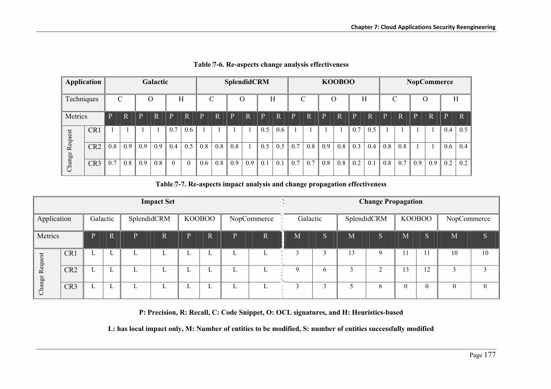
Chapter 7: Cloud Applications Security Reengineering
Page 177
Table 7-6. Re-aspects change analysis effectiveness
Application Galactic SplendidCRM KOOBOO NopCommerce
Techniques C O H C O H C O H C O H
Metrics P R P R P R P R P R P R P R P R P R P R P R P R
Cha
nge
Req
uest
CR1 1 1 1 1 0.7 0.6 1 1 1 1 0.5 0.6 1 1 1 1 0.7 0.5 1 1 1 1 0.4 0.5
CR2 0.8 0.9 0.9 0.9 0.4 0.5 0.8 0.8 0.8 1 0.5 0.5 0.7 0.8 0.9 0.8 0.3 0.4 0.8 0.8 1 1 0.6 0.4
CR3 0.7 0.8 0.9 0.8 0 0 0.6 0.8 0.9 0.9 0.1 0.1 0.7 0.7 0.8 0.8 0.2 0.1 0.8 0.7 0.9 0.9 0.2 0.2
Table 7-7. Re-aspects impact analysis and change propagation effectiveness
Impact Set Change Propagation
Application Galactic SplendidCRM KOOBOO NopCommerce Galactic SplendidCRM KOOBOO NopCommerce
Metrics P R P R P R P R M S M S M S M S
Cha
nge
Req
uest
CR1 L L L L L L L L 3 3 13 9 11 11 10 10
CR2 L L L L L L L L 9 6 3 2 13 12 3 3
CR3 L L L L L L L L 3 3 5 6 0 0 0 0
P: Precision, R: Recall, C: Code Snippet, O: OCL signatures, and H: Heuristics-based
L: has local impact only, M: Number of entities to be modified, S: number of entities successfully modified


Page 179
Chapter 8
Cloud Applications Security Analysis
In this chapter, we discuss the key security analysis tasks and challenges when applied to cloud
computing applications and how we address these challenges in our new online security analysis
approach. This chapter is organised as follows. In Section 1, we give a general introduction of
the software systems’ security analysis problem and how this becomes more complicated under
the cloud computing umbrella. In Section 2, we discuss key security analysis tasks with few
examples of each subtask. In Section 3, we introduce our comprehensive, extensible cloud
application security analysis approach. In Section 4, we describe implementation details of our
approach. In Section 5, we summarize the experimental evaluation results.
8.1 Introduction
Although the adoption of publicly accessible cloud computing platforms to host IT systems
helps customers to minimize cost and increase availability and reachability of their applications,
it has serious implications on their applications’ security. Hackers can easily exploit
vulnerabilities in such publically accessible services. Moreover, some hackers may become
legitimate tenants of the shared cloud services which enable them to exploit more advanced and
complicated vulnerabilities that require higher privileges. In addition, the number of newly
identified and reported application vulnerabilities is increasing rapidly. Delays in discovering
and mitigating such vulnerabilities increase the probability of successful application attacks and
security breach.
Web applications are the prominent application delivery model used in cloud computing to
deliver SaaS applications. Web applications do not require client deployment or configuration,
and can be centrally updated and managed. However, web application vulnerabilities continue
to make up the largest percentage of the total reported vulnerabilities in software applications.
Web applications vulnerabilities constitute 63% on average of the total reported vulnerabilities
[60]. Of these reported vulnerabilities, well-known vulnerabilities such as Cross-Site Scripting
(XSS) represents 28%, while SQL Injection (SQLI) vulnerabilities represent 20%. These figures
mean that web applications are the weakest link in the cloud computing model where many
security breaches may be exploited.
From our investigation of the cloud computing model, cloud services, their security
problems, and existing industrial and academic efforts, we have reached a conclusion that it is
Chapter 8: Cloud Applications Security Analysis
Page 180
very important to have an online security analysis service. Such a service can help different
cloud stakeholders in analyzing and mitigating against existing (known) as well as new (i.e.
never seen before) security flaws and vulnerabilities before attackers do. However, security
analysis is a very complicated and time consuming task. It usually takes place at different stages
of the software lifecycle starting from the development phase, deployment, and at runtime. In
each of these stages, we have different artifacts to verify (system models, security models,
source code, and software binaries) and different techniques (black-box, white-box, dynamic
analysis, static analysis) that are applicable at each stage.
From our analysis we have categorized the security analysis task into three subtasks: threat
analysis, which is conducted in the early stage of software development and focuses on
identifying the security flaws resulting from the adoption of specific platforms, patterns, or
languages; vulnerability analysis, which is conducted during software development given the
source code is available or after the software delivery using the software binaries; and attack
analysis, which is conducted using software security and deployment models to identify
possible attack vectors that exploit existing vulnerabilities either in the software or its
operational environment.
Security flaws, bugs, and attacks reported by different security analysis tasks are usually
recorded in commonly available databases, such as vulnerabilities’ databases - NVD [262] or
CVEdetails.com [263]. Specifications of classes of possible vulnerabilities (known as
weaknesses) are already maintained in the Common Weaknesses Enumeration (CWE) database.
Possible attack patterns are already maintained in the Common Attack Patterns Enumeration
and Classification (CAPEC) database. Both databases are used as a reference framework by
application developers, deployment engineers and security engineers to help identifying
possible weaknesses and attacks on the software under analysis. A key problem with both CWE
and CAPEC is that recorded vulnerabilities and attacks are specified informally. This leads to
adoption of manual security analysis done by security experts using some of their helping tools
developed by different security vendors. Such tools are usually based on the security vendors’
understanding of security vulnerabilities, threats, and attacks. Commercial vulnerability
scanners such as IBM AppScan, HP Web inspect, Cenzic, McAfee focus on black-box
vulnerability analysis [116] (where few knowledge about the target software is required) to
avoid being limited to specific programming languages or platforms. However, none of these
scanners cover all known vulnerability types [116]. These tools cover no more than 47% of the
known vulnerabilities. To achieve good results and high accuracy in the vulnerability analysis
mission, multiple scanners should be applied [116]. On the other hand, most existing research
efforts [113, 114, 117, 121, 264] tend to focus on specific vulnerability, threat, or attack types.

Chapter 8: Cloud Applications Security Analysis
Page 181
Thus, addressing new vulnerabilities or threats is often not possible with these approaches. Most
of existing vulnerability analysis efforts, for example, focus on SQLI [107, 109, 115], XSS
[113, 115, 265], or input sanitization [118, 119, 121] using static analysis with different
variations [108, 109, 112, 113, 264], dynamic analysis [116, 117, 265, 266], or hybrid
techniques of static and dynamic analysis [111, 121, 264, 267].
From our analysis of both industrial and academic efforts, we have reached a conclusion that
the root cause of the security analysis problem lies in the vulnerability, threat and attack
definitions and not in introducing new analysis techniques, as most of the existing approaches
use similar techniques in various combinations. Moreover, the various existing vulnerability and
attack databases, while useful, cannot be directly utilized by security analysis tools due to their
informality.
We determined that different security analysis tasks, including vulnerability analysis, attack
analysis and threat analysis, can be facilitated given that a formalized weakness definition
exists. In our approach discussed in this chapter focus on the following open research questions:
– What details do we need to capture to fully describe a given security flaw and
vulnerability?
– How can we formalize the signatures of such security flaws and vulnerabilities?
– How can we effectively use such formal specifications in automating the security analysis
process?
– How can we enable different tenants to specify and analyze their cloud services security?
In the next sections we introduce an analysis of the well-known security issues (attacks and
vulnerabilities). Then we introduce our new approach to address the research questions
specified above. Finally, we discuss the limitations of our approach and future extensions.
8.2 Security Analysis
In this section we analyze some of the frequently reported security flaws and vulnerabilities in
software systems. However, this is neither a comprehensive nor a complete list of all possible
attack scenarios or security vulnerabilities. The main objective from this analysis is to show
details of such security flaws/bugs and discuss proposed signatures that we can use to locate
such flaws/bugs in the software under analysis. The example signatures discussed in this section
are not meant to be complete. Security experts might need to develop more detailed signatures
to use in analyzing systems using our signature-based security analysis approach.
Chapter 8: Cloud Applications Security Analysis
Page 182
8.2.1 Architecture Security Threat Analysis
Assessing software architecture security risks is usually conducted either using attack scenarios-
based approaches [92, 96, 97, 268] or using architecture assessment metrics [92, 93, 98, 103,
139]. Developing security attack scenarios to be used in assessing software architecture is a key
task in scenario-based architecture analysis approaches. However, it requires deep knowledge of
the security domain, which is usually not feasible for software engineers. Microsoft introduced
STRIDE model [94] (Spoofing, Tampering, Reputation, Integrity, Denial-of-Service, and
Elevation-of-Privilege) that defines a framework that gives guidance in identifying such security
scenarios. Microsoft has introduced further refinements on this model (EOP Card Game) to
simplify the threat identification process [269]. However, this approach still depends heavily on
engineers’ experience to analyze the architecture of the software under test. Recently, a new
community effort, CAPEC, introduces a reference repository that can be used in assessing
systems’ security. It provides a comprehensive list of possible attack patterns that are frequently
used to breach systems’ security. However, CAPEC is not yet formalized enough for use in
automated architecture security analysis tools. Below we discuss a few of the key patterns that
currently exist in these repositories. Then we show how we have succeeded in developing
formal signatures of these attacks using our signature specification approach. We note that these
attacks may have other signatures and specifications when it comes to source code level analysis
(bugs) i.e. for vulnerability analysis.
8.2.1.1 Examples of Security Attack Scenarios
We summarize some of the key attack scenarios that may be used in assessing architecture
security of software systems. More attacks can be found in the CAPEC database. Later we will
show how we have developed formalized signatures of such attack scenarios.
- Man-in-the-Middle Attack (MITM): In this attack, the attacker intercepts communications
between two components or two parties. The attacker makes independent connections with
the victims and relays messages between them, making them believe that they are talking
directly to each other. How to decide that the software under analysis is vulnerable to such
attack? A signature of such attack is to check if the system has any unsecure connection
between two communicating components, or if the components communicate in an untrusted
zone without security authentication applied.
- Denial of Service Attack (DOS): This attack aims to make a system or one of its key
resources unavailable for legitimate users. DOS attacks have different formats and different
signatures. Some use invalid inputs or big sized inputs. Others overwhelm the system with a
tremendous number of requests. Possible signatures of such attack include: (i) a publicly

Chapter 8: Cloud Applications Security Analysis
Page 183
accessible component that does not use input validation control (or application firewall) to
validate incoming requests, or (ii) a public interface that does not implement appropriate
authentication control to filter malicious or unauthenticated requests.
- Data Tampering Attack: An attacker can tamper with data at rest (storage), in transmission,
or during processing if data is manipulated as plaintext. Possible signatures of these attacks
include: (i) a system with one or more components that operate in an untrusted host
(malicious insider); (ii) data communicated between components or to a client in plaintext,
or (iii) absence of appropriate security authorization controls on user accessible components.
- Injection Attack: These attacks use the lack of input validation to pass in malicious inputs
that can be used to gain higher privileges, modify data, or get the system to crash. There are
different types of injection attacks including SQL Injection, OS Command Injection, and
XML Injection attacks. The key signature of such attacks is that system components do not
apply suitable input filtration on user inputs or on inputs from other untrusted components.
8.2.1.2 Examples of Architecture Security Assessment Metrics
Developing security metrics to be used in assessing security strength of a software system’s
architecture is also a very complicated task. Different security metrics exist with different scope
of applicability. Below we discuss some well-known metrics that are used in assessing system
architecture security soundness based on software and security architectural structures.
System Architecture Security Metrics. These metrics help in assessing the security
soundness of the software architecture itself. Examples of these metrics include attack surface
metric [270], total public classified attributes and methods [101], critical super-classes
proportion, least privilege, and least common mechanisms [271]. These metrics can be used to
assess the exposure, exploitability, and attack-ability of the software system given its
architecture, design, and source code details. New architectural patterns such as multi-tenancy
require new security metrics that can assess tenants’ data isolation, security elasticity, etc.
Examples of such metrics are:
– Attack Surface Metric [270]: This metric has been frequently used in assessing different
system versions from the security perspective. It measures the proportion of the system
accessible to public users which an attacker can exploit to attack the system. This can be
measured as the number of system methods that receive data from the software environment,
number of methods that return data to the software environment, number of communication
channels, and number of untrusted data items. The larger the attack surface value, the more
potentially insecure the system.

Chapter 8: Cloud Applications Security Analysis
Page 184
– Compartmentalization Metric [271]: Compartmentalization means that a system and its
components run in different compartments, isolated from each other. Thus, the compromise
of any of these components does not impact the others. This metric can be measured as the
number of independent components that the system is based on to deliver its function and do
not trust each other - i.e. components authenticate and authorize requests and calls coming
from other system components. The higher the compartmentalization value, the more secure
the system. However, higher compartmentalisation usually has higher performance
overheads and system complexity.
– Least Privilege Metric [271]: This metric states that each component or user should be
granted the minimal privileges required to complete their tasks. This metric can be assessed
from two perspectives: from the security controls perspective we can review users’ granted
privileges – i.e. security permissions. From the architectural analysis perspective this can be
assessed as how a system is broken down to minimal possible actions i.e. the number of
components that can access critical data. The smaller the value, the more secure the system.
– Fail Securely Metric [271]: The system does not disclose any data that should not be
disclosed ordinarily at system failure state. This includes system data as well as data about
the system in case of exceptions. This metric can be evaluated from the security control
responses – i.e. how the control behaves in case it fails to operate. From the system
architecture perspective, we can assess it as the number of critical attributes and methods that
can be accessed in a given component. The smaller the metric value, the likely more secure
the component in case of failure.
Security Architecture Metrics. These metrics help in assessing the security architecture
and mechanisms used in securing a target system. Security mechanisms include: security
functions and components, security patterns, and security controls. NIST [271] introduced a set
of design principles that should be adopted in developing secure systems. These principles
include: layered security; simplicity of the security design; protect information while it is being
processed, in transit, and in storage; and never trust external inputs. Examples of metrics that
can be used to judge such characteristics include:
– Defence-in-depth (layered security) Metric: This metric verifies that security controls are
used appropriately at different points in the system chain including network security, host
security, and application security. Components that have critical data should employ
security controls in the network, host, and component layer. To assess this metric we need
to capture system architecture and deployment models as well as the security architecture
model. Then we can calculate the ratio of components with critical data that apply the
layered security principle compared to the total number of critical components.

Chapter 8: Cloud Applications Security Analysis
Page 185
– Isolation Metric: This assesses the level of security isolation between system components.
This means getting privileges to a component does not imply accessibility of other co-
located components. This metric can be assessed using system architecture and deployment
models. Components marked as confidential should not be co-located with non-
confidential (public) components. Methods that are not marked as confidential should not
have access to confidential attributes or methods.
public bool LogUser(string username, string password) { … string query = “SELECT username FROM Users WHERE UserID =‘” username “ ‘ AND Password = ‘” + password + “’”; … }
Figure 8-1. A code snippet vulnerable to SQL Injection attack
if( Request.Cookies["Loggedin"] != true ) { if(!AuthenticateUser(Request.Params["username"], Request.Params["password"] ) ) throw new Exception("Invalid user"); } DoAdministrativeTask();
Figure 8-2. A code snippet vulnerable to authentication bypass
if(!AuthenticateUser(Request.Params["username"], Request.Params["password"] ) ) throw new Exception("Invalid user"); updateCustomerBalance(Request.QueryString["custID"], nBalance);
Figure 8-3. A code snippet vulnerable to improper authorization
8.2.2 Vulnerability Analysis
Security vulnerability analysis is usually conducted on either software binaries or source
code. Before we discuss how we formalize software system vulnerability definitions, we give an
overview of the OWSAP Top 10 web application vulnerabilities. OWSAP (Open Web Security
Application Project) is a community effort to define and share knowledge about web application
security approaches. We discuss these Top 10 vulnerabilities and signatures that we deduced
from the vulnerabilities recorded in NVD and CWE. These signatures are used by our
vulnerability analysis tool; however, they can be further revised by experts to get more accurate
results.
- Injection Flaws: This type of vulnerability includes several well-known attacks intended to
compromise application inputs in order to gain control or modify data, such as SQLI, OS
Command Injection, LDAP query injection, and XPath query injection. All arise from input
validation problems. “All external inputs are untrusted” is a well-known security principal

Chapter 8: Cloud Applications Security Analysis
Page 186
[271] that should be realized in securing systems. These vulnerabilities occur whenever the
system under analysis trusts inputs from users (first order injection) or from a repository
(stored or second order injection) and uses it to build dynamic queries that run Operating
System or database commands without sufficient input sanitization or validation. An attacker
can use this type of vulnerabilities to execute malicious commands or gain privileged access
to the system under attack. Figure 8-1 shows code vulnerable to SQLI. For example, a
password argument of the form “’ OR (1=1) OR ‘’=‘” allows access to any specified
username e.g. ‘admin’ or ‘root’. The signature of these vulnerabilities is a dynamic query
statement that uses external inputs without proper sanitization.
- Cross-Site Scripting Flaws: This is a two-step vulnerability. First, an attacker uses the
application to store malicious data. Whenever a victim sends a request to resource X, the
web server responds with data containing “malicious code” without being encoded. This
malicious code executes on the victim browser causing disclosure of their confidential
information to the attacker. This vulnerability type may be from stored data (e.g. from a
database) or reflected (from user input). This is a very common attack in applications that
use user inputs for search or discussions. The signature of these vulnerabilities is to call
output functions using external or stored inputs without sanitization or encoding.
- Broken Authentication and Session Management Flaws: This is a common problem with
security authentication. It includes attacks such as: authentication bypassing via external
inputs (depend on external input to decide whether to conduct authentication or not on the
received request); authentication checking not included in critical functions; using hard-
coded credentials; using an easy to guess password; or session timeouts not set or checked.
This enables unauthenticated users to maliciously access and use system resources.
Figure 8-2 shows a code-snippet vulnerable to improper authentication attack, where a user
can modify their cookie to bypass the authentication check. The signature of these
vulnerabilities is that every publicly accessible function should not trust external inputs to
bypass (by conditional statement) triggering the authentication function.
- Insecure Direct Object Reference Flaws: Authenticated users can send malicious inputs to
access unauthorized data. Figure 8-3 shows an example where an attacker sends custID =
XYZ instead of custID = ABC. This enables the attacker to access other customers’ data.
The signature of these vulnerabilities is that user inputs are not authorized before use in
business functions. This is a very critical problem in multi-tenant SaaS applications where
different tenants sharing the same service instance should not be able to request data of other
tenants.
- Cross-Site Request Forgery (CSRF) Flaws: An attacker deceives an authorized user by
sending a forged request to the user’s application to perform malicious actions. This attack

Chapter 8: Cloud Applications Security Analysis
Page 187
requires the victim to have a valid session or cookie with the application (already
authorized). The signature of these vulnerabilities is that requests’ origins are not validated
or that responses are usually predictable or have fixed URL format. It is usually difficult to
identify CSRF using static analysis because it is usually managed externally by the web
server.
- Security Misconfiguration Flaws: The system is not securely configured. This includes
exposing information through exceptions; a system executing with higher privileges than it
requires; system files are accessible to unauthenticated users; or resources have
misconfigured permissions. Some of these vulnerabilities can be discovered from the
exception handlers whether they expose system details or not. Others need to be examined
by application responses for unauthorized actions using dynamic analysis.
- Invalidated Redirect and Forward Flaws: The application redirects requests to a target URL
that is concatenated from user inputs “Response.Redirect(userInput)”. This type of
vulnerability is similar to the injection vulnerabilities where web redirect functions use
external inputs to build the redirect URL.
- Failure to Restrict URL Access Flaws: An application does not perform access control on
resources or URLs. These vulnerabilities can be easily examined by checking webpage
methods for authorization function calls. Dynamic analysis is required to check application
responses for unauthorized URLs.
- Insufficient Transport Layer Protection Flaws: Sensitive data including credentials and
customer data are transmitted in plain text. The signature of these vulnerabilities is that
output data are transmitted without passing through appropriate encryption functions.
Dynamic analysis is required to examine responses if protection is done on transportation
layer.
8.2.2.1 Analysis of Security Vulnerabilities
A given software system, whether desktop, web, or embedded, needs to run on a hosting service
– e.g. web server, operating system, virtual server, etc., as shown in Figure 8-4. A hosting
service provides a set of APIs that the hosted system can use to read inputs from possible input
sources (users, files, memory, database, etc.) or write outputs to possible output targets. Any
vulnerability in the hosting service implies that an attacker can control inputs and/or outputs of
the target system. The hosting media is a place where the hosted system runs – e.g. a process in
case of web server, or memory in case of operating systems. If the hosting media was breached,
it may be used to control the hosted system inputs, outputs, or even processing (overriding
kernel data using buffer overflow). However, these entities are out of the software system
control.

Chapter 8: Cloud Applications Security Analysis
Page 188
Function Storage Channel
Component
Hosting Media
Hosting Service
E
P/S/T
X
(a) (b)
Figure 8-4. An overview of the host-system-component relations
Any target system is composed of a set of components. These components may be
subsystems, composite components, or simple components. System components may be hosted
on the same hosting service instance or different instances (different servers). In the latter case,
they have to communicate through communication channels, which may be unsecure (an
attacker may eavesdrop, or intercept messages). A system component may be an active
component, a component that can take actions or perform operations such as system functions.
Active components are able to secure themselves and their processed data – e.g. by
authenticating users, authorizing users, encrypting data, etc. Alternatively, a passive component
is a component that cannot take actions to protect or change data it maintains, such as storage
components (databases and files – we are not talking here about the DBMSs, these are hosting
software systems) or transmission components (communication channels). Passive components
cannot secure themselves e.g. a file or table cannot enforce security access on its contents by
itself. They depend on other components, such as the hosting service (OS, DBMS), or active
system components to manage and secure such components. This is a big open issue in data
security area – i.e. data leakage protection - where confidentiality of data moving between
different applications with different security levels may be threatened. Both active and passive
components might be breached by the hosting service e.g. read data in memory, files, or when it
is on communication channels.
Each component, regardless of its type, has a set of entry points (E) and set of exit, output
points (X), and is used in processing (P), storage (S), or as a communication channel (T). These
entry and exit points can be compromised by an attacker who has control on the hosting service
to read/write/modify/delete the data. Usually the number of entry points and exit points – the
“attack surface” - is used as a security metric when assessing systems security. Furthermore, an
active component may have vulnerabilities related to inputs (input validation - input coming
from a user passing by the hosting service), outputs (output validation and exceptions – outputs
may depend on malicious or modified inputs or passed through a vulnerable hosting service), or
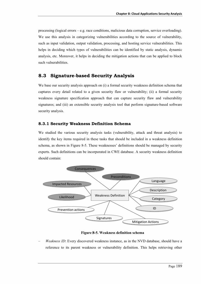
Chapter 8: Cloud Applications Security Analysis
Page 189
processing (logical errors – e.g. race conditions, malicious data corruption, service overloading).
We use this analysis in categorizing vulnerabilities according to the source of vulnerability,
such as input validation, output validation, processing, and hosting service vulnerabilities. This
helps in deciding which types of vulnerabilities can be identified by static analysis, dynamic
analysis, etc. Moreover, it helps in deciding the mitigation actions that can be applied to block
such vulnerabilities.
8.3 Signature-based Security Analysis
We base our security analysis approach on (i) a formal security weakness definition schema that
captures every detail related to a given security flaw or vulnerability; (ii) a formal security
weakness signature specification approach that can capture security flaw and vulnerability
signatures; and (iii) an extensible security analysis tool that perform signature-based software
security analysis.
8.3.1 Security Weakness Definition Schema
We studied the various security analysis tasks (vulnerability, attack and threat analysis) to
identify the key items required in these tasks that should be included in a weakness definition
schema, as shown in Figure 8-5. These weaknesses’ definitions should be managed by security
experts. Such definitions can be incorporated in CWE database. A security weakness definition
should contain:
Weakness Definition
Language
Description
Category
ID
Preconditions
Consequences
Likelihood
Impacted Resources
Signatures
Prevention actions
Mitigation Actions
Figure 8-5. Weakness definition schema
– Weakness ID: Every discovered weakness instance, as in the NVD database, should have a
reference to its parent weakness or vulnerability definition. This helps retrieving other

Chapter 8: Cloud Applications Security Analysis
Page 190
vulnerability details e.g. preconditions, consequences from the vulnerability definition
stored in the CWE database.
– Weakness Category: Many categorization-schemas for software weaknesses do exist. Each
categorization schema helps understanding weaknesses from a specific point of view e.g.
developers or researchers. A categorization based on the root cause or source of the
weakness, as shown in Figure 8-4, helps in deciding which technique is suitable to perform
analysis, mitigation, and avoidance. We categorize vulnerabilities as input validation-
related, processing logic-related, output validation-related, hosting service related, hosting
media-related, communication channel-related, storage-related, and security control-related
vulnerabilities.
– Language/Platform: Specifies enumeration of language(s) that a given weakness applies to
- i.e. many languages C, C++, C#, Java. have language-specific weaknesses such as buffer
overflow, sandbox breaching, etc. We also use this to describe the technology or
architecture paradigm inherent with the weakness - e.g. client-server, web-based, service-
oriented, or multi-tier, along with the underlying environment e.g. web server, client,
application server, database server. This helps in threat analysis to identify possible
weaknesses that may exist and start taking precautions to avoid such vulnerabilities.
– Preconditions: This attribute helps in both vulnerability analysis and attack analysis.
Preconditions are a list of the capabilities that an attacker should possess, or the list of
system configurations that need to be present in order to exploit such vulnerability e.g. to
exploit a specific vulnerability, an attacker might have to have root access, user access,
remote root access, public access, etc.
– Consequences: If a given vulnerability is exploited, what will be the benefits achieved by
the attacker e.g. disclosure of system information, invalid processing, invalid results,
execute an unauthorized function, elevate permission, bypass security, system crash, or
Denial-of-Service. This can be used to analyze against planned attacks e.g. exploiting
vulnerability V1 will give the attacker a set X of privileges. These privileges may be one of
the preconditions to exploit vulnerability V2. The consequence of V2 may be the actual
goal of the attacker.
– Impacted Resources: This specifies the resources that will be impacted if the given
vulnerability is exploited including memory, configuration files, registry, customer data,
credentials, cryptography keys.
– Likelihood: The probability that the given weakness is exploited by an attacker may be low,
medium, or high. This depends on the complexity of the given vulnerability and attacker
capabilities as defined in the vulnerability preconditions.

Chapter 8: Cloud Applications Security Analysis
Page 191
– Vulnerability Signature: A weakness signature describes constraints, invariants and
patterns that when matched in a target system it means it is likely to suffer from the given
weakness. This may be signature of software architecture or code snippets, or signature of
system response for requests with specific signatures. Every single weakness may have
different signatures that capture different forms (attack scenarios), or that are applicable
with different weakness analysis techniques.
– Prevention: A list of precautions to be followed or checked during code review. These
might be rules to check during system development or deployment; combinations of
architectures; languages and platforms to use or to avoid.
– Mitigations: A list of actions that specify how we can modify the vulnerable system entities
to block a discovered weakness. This may require modification of the vulnerable code
parts; changing system configurations; or even changing system or security architecture.
8.3.2 Weakness Signature Specification
To address the different types of security analysis, we use a signature-based approach where the
signatures of weaknesses to be analyzed are captured as invariants or constraints to be matched
against appropriate target system artifacts. These artifacts may be lines of code, partial
class/method signatures, architectural structures, or other suitable system models. In our
approach, we use the Object Constraint Language (OCL) to specify such signatures (We
introduced an overview of OCL in chapter 7, section 7.5.2).
8.3.2.1 System Description Meta-Model
To support specifying and validating software architecture and source code weaknesses’
signatures, we have developed a system-description meta-model, shown in Figure 7-7
(discussed in chapter 7)Error! Reference source not found.. This model is inspired from our
nalysis of security weaknesses and vulnerabilities as discussed in Section 8.2. It captures the
main entities in an object-oriented program including:
– Architecture Concepts: Such as components, components’ interfaces, communication
channels, storage, hosting service (web server), deployment descriptors (configuration files),
deployment packages, etc.
– Source Code Concepts: Including classes, instances, inputs, input sources, output, output
targets, methods, method body, method parameters, method statements e.g. if-else
statements, loops, new objects, etc.
– Security Concepts: Such as authentication, authorization, access control, input validation,
auditing, cryptography and key management, and output encoder controls.

Chapter 8: Cloud Applications Security Analysis
Page 192
Each entity in the model has a set of attributes such as component name, class name, method
name, accessibility, variable name, variable type, method call name, arguments, etc. This
enables specifying OCL-based weakness and vulnerability signatures on different system
entities other than source code such as deployment descriptors, hosting services, storage, output
targets, or input sources. Of course, this requires developing different parsers other than source
code parsers that can read such system description details.
A security analysis tool needs to have different profiles for different languages and platforms
(ASP.NET, PHP, C#, Java, etc.). Thus weaknesses with signatures containing input source or
output targets, security authentication, authorization, sanitization controls and other functions
can be interpreted differently based on the platform or programming language used. If the
system uses custom sanitization or security functions, developers have to mark their security
functions in the resulting system model or add it to the platform profile member functions.
8.3.2.2 Examples of OCL-based Weaknesses Signatures
Table 8-1 shows example architecture attack scenarios, metrics, and vulnerabilities signatures
specified in OCL using our system description meta-model, as shown in Figure 7-7. Each entry
shows weakens or attack name, description, and signature. Before we discuss these signatures, it
is worth mentioning that these signatures can be further improved to incorporate system design
details and even more source code details, if available. The second point is that these signatures
should be developed by security experts (captured in a knowledge base), while software
developers can further extend such signatures using customized and user-defined scenario and
metric signatures.
A key problem with these signatures is that they do not consider security solutions applied
beyond the system source code. For example, a system might be using proxies to filter SQL
queries or be using security controls deployed on the web server such as an http handler.
However, these can be modeled by appending a dynamic signature forming a sequence of OCL
constraints to be checked on system responses to malicious requests. Another workaround is to
use the information available from system architecture to check for these scenarios. Another
issue is that we may have different signatures with different complexities for the same
vulnerability. We expect security experts to develop strong and complete signatures. Weak
signatures mean more false positives, which may annoy developers, or more false negatives,
which harm customers. However, weak signatures can sometimes be much easier to find and
computationally inexpensive to locate matches compared to complex ones.

Chapter 8: Cloud Applications Security Analysis
Page 193
Table 8-1. Examples of OCL-specified weaknesses signatures and metrics
Man-in-the-middle attack
Any two components that communicate through an unencrypted channel and one or both of them operate in an untrusted zone or do not apply cryptography controls on their communicated messages.
context System inv MITM: self.components->select(C1|C1.DeploymentZoneType = 'Untrusted' and self.components.exists(C2 | C2.Channels->exists(Ch | Ch.TargetComponent = C1 and Ch.EncryptionCtlDeployed = false) and C1.EncryptionControlDeployed = false and C2.EncryptionControlDeployed = false))
Denial-of-service attack
Any publicly accessible component that does not operate input sanitization control (or application firewall), and does not have authentication control.
context System inv DOS: self.components->select(C1|C1.DeploymentZoneType = 'Untrusted' and C1.AuthenticationControlDeployed = false and (C1.InputSanitizationControlDeployed = false or C1.Host.Network.FirewallControlDeployed= false))
Data tampering attack
Any component that is deployed on an untrusted host (malicious insider) or zone, sends data in plain text, or does not operate authorization control.
context System inv DataTampering: self.components->select(C1|C1.DeploymentZoneType = 'Untrusted' and self.components.exists(C2 | C2.Channels->exists(Ch | Ch.TargetComponent = C1 and Ch.EncryptionControlDeployed = false) and C1.EncryptionControlDeployed = false and C2.EncryptionControlDeployed = false))
Attack Surface metric
Number of the functions defined in the provided interfaces of the public system components and number of functions defined in the required interfaces of the system public components that are used by other components.
context System inv AttackSurface: self.components->select(C1| C1. DeploymentZoneType = 'Untrusted')->collect(C2 | C2.Functions)->size()
Compartmentalization Metric
Number of architecture components that apply authentication and authorization controls on incoming requests and calls (work independent and do not trust other system components).
context System inv Compartmentalization:
self.components->select(C | C.AuthenticationCtlDeployed = true
and C.AuthorizationControlDeployed = true)->size()

Chapter 8: Cloud Applications Security Analysis
Page 194
Fail securely Metric
The average of critical methods and attributes in each system component.
context System inv FailSecurely: self.components->collect(C | C.Functions->select( F | F.IsCritical = true)->size())->sum()/ self.components->collect(C |C.Functions->select( F | F.IsCritical = true)->size())->siz()
Defense in depth Metric
The ratio of critical components that have layered security compared to the total number of critical components in the system.
context System inv Defense-in-depth: self.select( C | C.IsCritical= true and C.AuthenticationControlDeployed = true and C.AuthorizationControlDeployed = true and C.CryptographyControlDeployed = true and C.Host.AuthenticationControlDeployed = true and C. Host.AuthorizationControlDeployed = true and C. Host.CryptographyControl = true)->size() / self.select( C | C.IsCritical = true)->size()
SQLI Vulnerability
Any method that has method call statement “S” where the callee function is “ExecuteQuery” and one of the parameters passed to it is previously assigned to untrusted identifier coming from one of the input sources. This initial signature can be revised to incorporate taint analysis checking. Taint analysis can be defined as an OCL function that adds every variable assigned to a user input parameter to a suspected list. In this case, we update the vulnerability signature to use “Method.SuspectedList().Contains(X)” instead of X.Contains(InputSource)”.
context Method inv SQLI: Method.Contains( S : MethodCall | S.FnName = “ExecuteQuery”
and S.Arguments.Contains( X : IdentifierExpression | X.Contains(InputSource)))
XSS vulnerability
Any method statement “S” of type assignment statement where left part is of type “output target” e.g. text, label, grid, etc. and right part uses input from the tainted input sources.
context Method inv XSS: Method.Contains(S : AssignmentStatement | S.RightPart.Contains(InputSource)
And S.LeftPart.Contains(OutputTarget))
Authentication Bypass Vulnerability
Any public method that has statement “S” of type “method call” where the callee method is marked as authentication function while this method call can be skipped using user input as part of the bypassing condition.
context Method inv ImproperAuthentication: Method.IsPublic == true And Method.Contains( S : MethodCall | S.IsAuthenitcationFn == true And S.Parent == IFElseStmt And S.Parent.Condition.Contains(InputSource))

Chapter 8: Cloud Applications Security Analysis
Page 195
Improper Authorization Vulnerability
Any public method that has statement “S” of type “expression” – i.e. any statement - where “S” uses data X without being sanitized, authorized, or simply taint data (Method.SuspectedList().Contains(X) == true).
context Method inv ImproperAuthorization: Method.IsPublic == true
And Method.Contains( S : Expression | S.Contains(X: InputSource | X.IsSanitized == False Or X.IsAuthorized == False)
8.3.3 Signature-based Security Analysis Tool
After formalizing security attack scenarios, metrics signatures, and vulnerability signatures
using OCL, an OCL-based analyzer component is used to perform the security analysis of the
target system and its security details to locate and evaluate the specified security scenarios
vulnerabilities, and metrics. This includes system source code, system design, architecture, and
security models. Figure 8-6 shows the architecture of the analysis component. Figure 8-6(a)
shows the main components of our analyzer, including the signature locator interface.
Figure 8-6(b) shows different possible signature locators that can be plugged into our security
analysis tool. This list is extensible to incorporate new customized signature locators. Below we
discuss details of each component in the security analysis tool.
- System Model: Instead of using only the system architecture model to capture and apply
security metrics, we use our proposed system description model – SDM explained in details
with examples in the security engineering chapter (chapter 6). This model is developed by
software engineers using UML to describe the details of the software system under analysis.
The system SDM should cover system features (using use case diagrams), system
architecture (using component diagrams), system classes (using class diagrams), system
behavior (using sequence diagrams), and system deployment (using deployment diagrams).
These models cover most of the perspectives that may be required in analysing system
architecture security soundness. However, not all these models are mandatory for the
analysis. It depends on the system engineers and which attack scenarios or metrics they want
to evaluate or make it available for their tenants to evaluate or analyze – i.e. software
engineers, during their analysis, may start with an initial system architecture and then
develop system design to include in their analysis. Later, they may incorporate system source
code. Some of these system description details, for example class diagrams, sequence
diagrams, can be reverse-engineered from source code, if not available – e.g. in case of
legacy systems.
- Source Code Abstract Program Representation: To try and avoid signatures being overly
specific to programs written in a specific programming language or with a specific coding
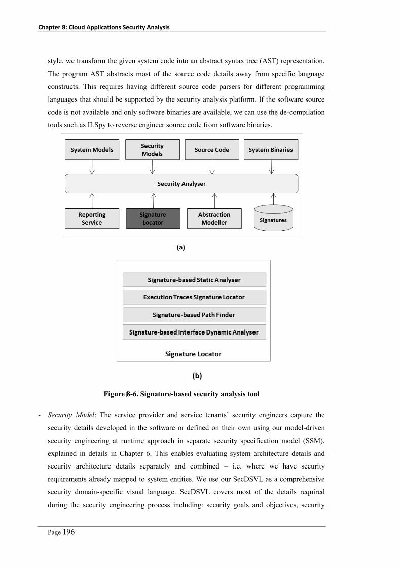
Chapter 8: Cloud Applications Security Analysis
Page 196
style, we transform the given system code into an abstract syntax tree (AST) representation.
The program AST abstracts most of the source code details away from specific language
constructs. This requires having different source code parsers for different programming
languages that should be supported by the security analysis platform. If the software source
code is not available and only software binaries are available, we can use the de-compilation
tools such as ILSpy to reverse engineer source code from software binaries.
-
Figure 8-6. Signature-based security analysis tool
- Security Model: The service provider and service tenants’ security engineers capture the
security details developed in the software or defined on their own using our model-driven
security engineering at runtime approach in separate security specification model (SSM),
explained in details in Chapter 6. This enables evaluating system architecture details and
security architecture details separately and combined – i.e. where we have security
requirements already mapped to system entities. We use our SecDSVL as a comprehensive
security domain-specific visual language. SecDSVL covers most of the details required
during the security engineering process including: security goals and objectives, security

Chapter 8: Cloud Applications Security Analysis
Page 197
risks and threats, security requirements, security architecture for the operational environment
and security controls and patterns to be enforced. Not all these models are mandatory to use.
Engineers decide which models they need to check or incorporate in their security analysis.
- Abstraction Modeler: The system description meta-model captures all the concepts and
entities around the system and security details we have explained above along with the
relations between them. As discussed earlier, this model helps in validating specified
signatures and in generating analyzers that will pinpoint these signatures in the software
under test. To consolidate different system details in one model as described in the system
description model we do System-and-Security model reconstruction covering system,
security, and security-system mappings (specified using our UML profile, discussed in
chapter 6). The UML profile extends UML models with attributes for: (i) relations between
different system entities in different models – e.g. a feature entity in a feature model with its
related components in the component model and a component entity with its related classes
in the class diagram; and (ii) security entities (objectives, requirements, controls) mapped on
system entities. The source code AST is transformed into more abstract representation that
summarizes AST nodes into abstract system description model.
- Signature Locator: This is the main component in our security analysis tool. It receives the
system and security details, security scenarios, vulnerabilities, and metrics signatures to be
evaluated, platform profiles, and generates a list of the found potential flaws, vulnerabilities,
security holes, and security measures. Our security analysis tool is developed to support
different types of analysis techniques including static analysis, white-box analysis and
dynamic analysis. The signature locator is designed to support extensibility in terms of new
analysis techniques that can easily plugged-in. However, in our research project we focus on
the static signature locator that can analyze the architecture and source code details statically.
- Static Signature Locator: This component loads OCL-based weaknesses and metrics from
the signatures database and compiles these signatures into runtime analysis modules (using
OCL_2_C# transformation that generates C# code from these signatures). These generated
analysis modules analyze the fed in system and security models and locate entities that
match the specified signatures and calculate measurements specified.
- Execution Traces Signature Locator: An execution trace signature locator works on the
execution traces collected from the execution of the software – i.e. logs of the system
functions’ calls along with the arguments’ values used. These execution logs attributes are
already abstracted in the system description model. Thus security experts can specify
signatures on such execution traces attributes. This signature locator works in the same
approach like the static signature locator – i.e. it generates the corresponding C# analysis
module that analyses the software model.

Chapter 8: Cloud Applications Security Analysis
Page 198
- Dynamic Signature Locator: A dynamic signature locator depends on two key attributes of
the software entities (including components, classes, and methods). These attributes are
requests and responses. Each of these attributes has sub-attributes including request time,
values, requester, response time, values, etc. Security experts use these two attributes to
specify signatures of the malicious requests that satisfy specific vulnerabilities or attacks –
e.g. use “’ or 1 =1” as a part of the query string or the http request sent to the server. The
dynamic vulnerability analysis component uses such signatures to generate malicious
requests. Then, the signature locator analyses the software responses looking for flaws in the
software responses. More details are available in the security monitoring work in chapter 9.
8.4 Implementation
To help in developing and testing weaknesses scenarios, metrics and vulnerability signatures,
we have developed a GUI, as shown in Figure 8-7, where security experts can write OCL
expressions, check it for syntax errors, semantic errors (i.e. concepts, attributes, navigations
specified), and test the specified signatures on sample data provided by the tool users. We use
an existing OCL parser [272] to parse and validate signatures against our system description
model. Once validated, signatures are stored in the signatures database.
To parse the given program source code and generate the corresponding Abstract Syntax
Tree (AST), we use existing .NET parser NReFactory Library, which supports parsing VB.NET
and C#. For software systems developed in C, we have used pycparser (a parser written in
python). As a further extension, we plan to incorporate parser for PhP and Java to enable
parsing programs written in these languages as well. For software systems with executable or
binaries only available, we use existing de-compilation tool ILSPY to generate source code from
binaries. This is currently supported for C# and VB.NET only. This generated source code will
be parsed using NReFactory library.
For the system and security models, we assume that all these models will be captured either
using our own system and security modelers developed using Microsoft Visual Studio
(discussed in chapter 6) or by using system models (in UML) developed by any third-party
modeling tool represented in XMI (XML Metadata Interchange).
We have developed a class library to transform the generated source code AST into a more
abstract (summarized) representation as specified in our system description meta-model (shown
in Error! Reference source not found.). This reduces its size and complexity to reflect only
ecessary details required in signatures’ matching. Our class library takes the system and security
models (in XML format) and appends them to the system description model. The output of this
class library is a complete model with all software system and security details.
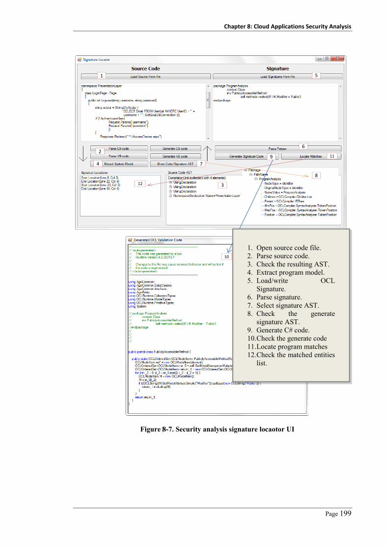
Chapter 8: Cloud Applications Security Analysis
Page 199
1
2
3
4
5
6
7
8
9
10
11
12
Figure 8-7. Security analysis signature locaotor UI
1. Open source code file. 2. Parse source code. 3. Check the resulting AST. 4. Extract program model. 5. Load/write OCL
Signature. 6. Parse signature. 7. Select signature AST. 8. Check the generate
signature AST. 9. Generate C# code. 10. Check the generate code 11. Locate program matches 12. Check the matched entities
list.

Chapter 8: Cloud Applications Security Analysis
Page 200
Program Representation 1
AST
Program Representation
……
……
Signature-based Static Signature Locator
OCL Functions
Platform Profile
Weakness Signatures
(OCL)
Vulnerability List
Program Source
Figure 8-8. Architecture of our signature-based static analysis
Context Method::SuspectedList(): Collection(Identifier)
Let userInputs: Collection(Identifier) = Method. Parameters
Post:
result = Method.Body->select(stmt:AssignmentStmt |
RightPart.Contains(userInputs)->select(id: IdentifierExp))
Figure 8-9. Sample user-defined OCL function for taint-data
<Profile platform="ASP.Net">
<InputSources>
<Source> Web.HttpRequest.get_QueryString</Source>
<Source>Web.HttpRequest.get_Cookies</Source>
</InputSources>
<OutputTargets>
<Target>System.Web.HttpResponse.Write</Target>
<Target> UI.WebControls.TextBox.set_Text</Target>
<Target> WebControls.HyperLink.set_NavigateUrl</Target>
</OutputTargets>
</Profile>
Figure 8-10. Sample of the platform profile for ASP.NET
The signature locator manager is developed as a class loader; it reads the list of registered
signature locators from a configuration file. According to the weakness signature type, it loads
the corresponding signature locator (static, dynamic, etc.) to start analyzing the system
description model. New signature locators can be developed and registered with the security
analysis manager. Any signature locator has access to the system description details (as a
model) as well as the signatures repository. We have developed a signature-based static analysis
component, as shown in Figure 8-8. This component translates the signatures expressed in OCL
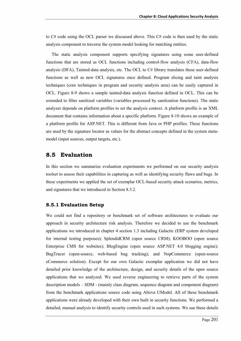
Chapter 8: Cloud Applications Security Analysis
Page 201
to C# code using the OCL parser we discussed above. This C# code is then used by the static
analysis component to traverse the system model looking for matching entities.
The static analysis component supports specifying signatures using some user-defined
functions that are stored as OCL functions including control-flow analysis (CFA), data-flow
analysis (DFA), Tainted-data analysis, etc. The OCL to C# library translates these user-defined
functions as well as new OCL signatures once defined. Program slicing and taint analysis
techniques (core techniques in program and security analysis area) can be easily captured in
OCL. Figure 8-9 shows a sample tainted-data analysis function defined in OCL. This can be
extended to filter sanitized variables (variables processed by sanitization functions). The static
analyzer depends on platform profiles to set the analysis context. A platform profile is an XML
document that contains information about a specific platform. Figure 8-10 shows an example of
a platform profile for ASP.NET. This is different from Java or PHP profiles. These functions
are used by the signature locator as values for the abstract concepts defined in the system meta-
model (input sources, output targets, etc.).
8.5 Evaluation
In this section we summarize evaluation experiments we performed on our security analysis
toolset to assess their capabilities in capturing as well as identifying security flaws and bugs. In
these experiments we applied the set of exemplar OCL-based security attack scenarios, metrics,
and signatures that we introduced in Section 8.3.2.
8.5.1 Evaluation Setup
We could not find a repository or benchmark set of software architectures to evaluate our
approach in security architecture risk analysis. Therefore we decided to use the benchmark
applications we introduced in chapter 4 section 1.3 including Galactic (ERP system developed
for internal testing purposes); SplendidCRM (open source CRM); KOOBOO (open source
Enterprise CMS for websites); BlogEngine (open source ASP.NET 4.0 blogging engine);
BugTracer (open-source, web-based bug tracking); and NopCommerce (open-source
eCommerce solution). Except for our own Galactic exemplar application we did not have
detailed prior knowledge of the architecture, design, and security details of the open source
applications that we analyzed. We used reverse engineering to retrieve parts of the system
description models – SDM - (mainly class diagram, sequence diagram and component diagram)
from the benchmark applications source code using Altova UModel. All of these benchmark
applications were already developed with their own built in security functions. We performed a
detailed, manual analysis to identify security controls used in such systems. We use these details

Chapter 8: Cloud Applications Security Analysis
Page 202
to develop benchmark applications security specification models and where they currently
applied mappings between security entities and system entities. In our evaluation, we used a set
of effectiveness evaluation metrics including precision and recall discussed in chapter 4.
8.5.2 Experimental Results
8.5.2.1 Architecture Security Risk Analysis
Table 8-2 is divided into two parts: security attack scenarios, and security metrics. Columns
represent the benchmark applications. Rows represent security flaws and metrics. We
summarize for each application and each attack scenario or security metric analyzed the number
of discovered flaws or the metric measured value, number of false positives (our prototype
reported as a flaw but it is not), and number of false negatives (a flaw, but missed by our
prototype). Moreover, for each security scenario or security metric we indicate using (↑ and ↓)
whether it is recommended to minimize or maximize the reported instances. If the indicator is
(↑), it means that the higher the metric value, the more secure the architecture. The (↓) indicator
means that the lower the metric value, the more secure the architecture.
Table 8-2 summarizes the results of our experiments in security scenarios and security
metrics analysis and evaluation. From our experiments we found that our approach achieves on
average a (90%) precision over both security scenarios analysis and security metrics
measurement. This means that in every reported (100) scenario instances (90) scenarios are
valid scenarios. It also has an average (89%) recall rate. This means that in every reported (100)
scenario instances approximately (11) scenarios are not actual cases. These values depend on
the soundness of the scenarios and the metrics’ signatures used to detect them.
Table 8-2 shows that the man-in-the-middle attack is the most frequent attack in the
benchmark applications. We also found a number of injection attack vulnerabilities that include
SQL Injection, OS Command Injection, XPath Injection attacks. The denial-of-service attack
was the least frequent attack. When we compare these results with OWSAP TOP10
vulnerabilities, we found that they reflect closely the same ranking where injection attacks are
ranked number (1) common vulnerability in web applications according to OWSAP Top10.
However, from these experiments and our analysis we note that, simple totaling of the
security metrics has no sensible meaning as they have different units (some count, others use
average or ratio). Although security metrics are helpful in comparing two different architectures
for the same system (trade-off analysis); they are misleading as they depend on the application
scale.

Chapter 8: Cloud Applications Security Analysis
Page 203
Table 8-2. Results of our OCL-based architecture security analysis
Scenario / Metric Galactic SplendidCRM KOOBOO BlogEngine BugTracer NopCommerce Total
***** Security Scenarios *****
Man-in-The-Middle (↓)
D 1 1 4 8 3 5 22
FP 0 0 0 1 0 0 1
FN 0 0 0 1 0 1 2
Denial of Service (↓)
D 1 1 3 2 1 2 10
FP 0 0 0 0 0 1 1
FN 0 0 0 1 1 0 2
Data Tampering (↓)
D 1 1 3 5 3 3 16
FP 0 0 0 2 0 0 2
FN 0 0 1 0 1 0 2
Injection Attack (↓)
D 2 1 3 5 4 3 18
FP 0 0 1 1 0 1 3
FN 0 1 1 1 0 0 3
Total
D 5 4 13 20 11 13 66
FP 0 0 1 4 0 2 7
FN 0 1 2 3 2 1 9
Average Precision = 90% Average Recall = 87% F-Measure = 88%

Chapter 8: Cloud Applications Security Analysis
Page 204
***** Security Metrics *****
Attack Surface (↓)
M 8 11 17 23 18 24 101
FP 1 2 2 1 2 4 12
FN 0 0 1 3 2 1 7
Compartmental-ization (↑)
M 1 1 3 3 4 3 14
FP 0 0 0 0 1 0 1
FN 0 0 1 1 0 0 2
Fail Securely (↓)
M 0.3 0.2 0.5 0.5 0.4 0.6 -
FP 2 1 0 0 0 1 4
FN 1 0 0 0 1 1 3
Defence-in-Depth (↑)
M 0.5 0.5 0.8 0.4 0.3 0.5 -
FP 0 1 0 0 1 0 2
FN 0 2 0 1 0 1 4
Average Precision = 91% Average Recall = 89% F-Measure = 90%

Chapter 8: Cloud Applications Security Analysis
Page 205
-5
3
11
19
Man-in-The-Middle
Denial of Service
Data Tampering
Injection Attack
Attack Surface
Compartmentalization
Fail Securely
Defence-in-Depth
[1]
[3]
[4]
Figure 8-11. Example of radar chart of benchmark applications
0
50
100
150
200
250
1 2 3 4 5 6
Defense-in-depth
Isolation
Least privilege
Compartmental-ization
Attack Surface Metric
System criticality
Figure 8-12. Performance of the security analysis component
Regarding the performance of our approach, Figure 8-12 shows the time (in seconds)
required to analyze the benchmark applications’ architectures to assessing specified security
attack scenarios and metrics using the given set of scenarios and signatures Table 8-1. It is clear
that the defense-in-depth metric takes much more time to identify than other metrics. The
system criticality takes the lowest time. This is because the time required estimating a given
security metric expression depends on the complexity of the specified OCL signature
(transformed into C# code) and system size.
8.5.2.2 Vulnerability Analysis Result
Table 8-3 summarizes the results of our experiments in source code vulnerability analysis
applied on the set of open source benchmark suite against seven of the OWASP Top10 web
applications vulnerabilities. The other three vulnerabilities could not be specified using static
signatures (i.e. could not be analyzed using static program analysis). These vulnerabilities are

Chapter 8: Cloud Applications Security Analysis
Page 206
security misconfiguration because it requires developing XML parser that can extract entities in
the system configuration file and then we can apply signatures on these entities; insecure
communication because it requires dynamic signatures; and insecure cryptographic storage
because it requires dynamic signatures.
Table 8-3 summarizes, for each application and each vulnerability analyzed, the total time
taken, number of found vulnerability instances in the codebase, FPs (analyzer thought
vulnerability but there is not on manual analysis), and FNs (manual code analysis indicates a
vulnerability but our tool did not discover it). Table 8-3 shows that SQLI represents the most
frequent vulnerability in all applications, then the cross-site reference forgery (CSRF)
vulnerability. After that, cross-site scripting (XSS) and authorization bypassing vulnerabilities
are relatively equal in frequency. These results mostly (in terms of ratios) conform to the
ranking reported by OWSAP2010. Table 8-3 also shows the number of vulnerabilities identified
per application. It is clear that nopCommerce and KOOBOO are the most vulnerable
applications in our benchmark suite using these vulnerability signatures. However, if we
consider the application size factor, we see that the ratio of vulnerabilities discovered compared
to application size is about equal. Moreover, some applications such as BlogEngine use
Microsoft membership for access control, which eliminates the authentication bypassing
vulnerabilities.
Figure 8-13 shows the precision, recall, and F-measure rates for each vulnerability type. This
chart shows that we achieve a high precision rate for most of the vulnerability types. The
precision metric is on average (93%). This means that for each identified (100) vulnerabilities
we have (7) false positives. This chart also shows a good recall rate, although it is relatively
lower than precision rate we achieved. The recall metric is on average (82%). This means that in
every (100) vulnerability instances, we can correctly identify (82) and we missed (18) instances.
This value could be improved if we use a hybrid dynamic and static analysis approach. The
overall effectiveness of our vulnerability analysis approach (F-measure) is around (87%). A key
result from this chart is that the recall metric is higher in SQLI, XSS, Information disclosure,
and URL redirection than in the other vulnerabilities. This justifies our initial supposition that
although we succeeded in developing a static signature for these signatures (CSRF, improper
authorization and authentication bypass), it is difficult to achieve a high correct detection rate
without also utilizing complementary dynamic analysis techniques.
Figure 8-14 shows the time (in seconds) required to analyze the benchmark applications to
locate the existing vulnerabilities’ instances for the given set of vulnerability signatures. It is
clear that the SQLI vulnerability takes much more time to identify than XSS and authorization
bypassing. The authentication bypass takes the lowest time. This is because the time required to
identify a given vulnerability depends on number and complexity of specified OCL signatures.
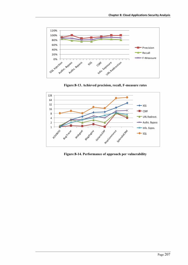
Chapter 8: Cloud Applications Security Analysis
Page 207
0%
20%
40%
60%
80%
100%
120%
Precision
Recall
F-Measure
Figure 8-13. Achieved precision, recall, F-measure rates
1
2
4
8
16
32
64
128
XSS
CSRF
URL Redirect.
Authz. Bypass
Info. Expos.
SQL
Figure 8-14. Performance of approach per vulnerability

Chapter 8: Cloud Applications Security Analysis
Page 208
Table 8-3. Results of our OCL-based security vulnerability analysis
Security Issue Galactic SplendidCRM KOOBOO BlogEngine BugTracer NopCommerce Webgoat Total
SQLI
D 2 12 14 3 9 19 8 67
FP 0 2 2 0 0 2 0 6
FN 0 2 2 1 3 1 1 10
Authentication
Bypass
D 2 2 1 0 0 0 2 7
FP 0 0 0 0 0 0 0 0
FN 0 0 0 0 1 0 1 2
Improper
Authorization
D 2 3 11 4 0 0 3 23
FP 1 0 2 0 0 0 0 3
FN 0 0 2 0 2 3 0 7
XSS
D 3 5 10 2 0 4 5 29
FP 0 1 1 0 0 0 1 3
FN 1 2 2 1 2 1 0 9
CSRF
D 5 6 13 10 0 12 3 49
FP 1 0 1 0 0 1 0 3
FN 0 1 2 0 4 1 0 8

Chapter 8: Cloud Applications Security Analysis
Page 209
Info.
Expo.
D 3 0 0 10 0 0 3 16
FP 0 0 0 0 0 0 0 0
FN 0 0 0 0 2 1 0 3
URL
Redirect
D 1 0 2 8 0 6 0 17
FP 0 0 0 0 0 0 0 0
FN 0 0 0 0 3 1 0 4
Total
D 18 28 51 37 9 41 24 208
FP 2 3 6 0 0 3 1 15
FN 1 5 8 2 17 8 2 43

Chapter 8: Cloud Applications Security Analysis
Page 210
8.6 Chapter Summary
In this chapter we introduced a new security analysis approach. Unlike other existing
approaches, ours is signature-based where the security flaws, attacks, vulnerabilities, and
metrics are captured as a set of declarative invariants. When matched, our approach confirms
the existence or absence of the given security flaw in the software under test. We summarized
the key subtasks involved in the security analysis e.g. architecture security threat and threat
analysis, attack analysis and vulnerability analysis. We gave examples of such flaws and
vulnerabilities along with our proposed signatures for such flaws/bugs. We summarized the
experimental evaluation we did to assess the effectiveness of our approach. These experiments
show that our approach can easily analyze software systems against a set of vulnerabilities and
metrics that never seen before, given that we can formulate signatures of such vulnerabilities or
metrics using OCL. Moreover, the experiments show that our approach has a high precision and
recall rates for both architecture risk analysis and system source code vulnerability analysis.
Finally, some of the existing vulnerabilities could be expressed as static signatures, while other
need to be specified in terms of dynamic signatures that can be analyzed using dynamic analysis
of the system under test.

Page 211
Chapter 9
Cloud Applications Security Monitoring
In previous chapters we introduced our approaches to help stakeholders in analyzing their
services security to identify threats against their assets security objectives. We also introduced
an approach to help in modeling and enforcing security requirements and controls according to
current needs and how these security capabilities could be changed at runtime to reflect or
incorporate new needs. In this chapter, we discuss how cloud stakeholders can assess the
strength and stability of their enforced security controls, where we might need to add security
controls, and where we may need to change deployed security controls with stronger security
controls. It is impossible to assess complex software systems and prove that they meet tenants’
absolute level of required security. However, developing relevant and practical security metrics
that help in abstracting and visualizing system security status is an alternative solution. Security
monitoring is the task of quantifying security using appropriate metrics to help in taking
corrective actions on the identified security weaknesses. Another key aspect of security
monitoring is detecting possible trends of system security status, which helps in taking proactive
actions. Most existing efforts focus on developing security metrics depend on formal languages
to capture properties to be assessed. Such efforts usually require design-time preparation to
support monitoring of system security properties. Our unified monitoring approach enables
enterprise security engineers to specify, update, and remove their security metrics at runtime,
without any design time preparation. Our developed platform is responsible for automatic
conversion of these security metrics’ specifications into security probes and integration of these
metrics within target enterprise IT systems at runtime. Measurements collected are fed into an
analysis component that applies aggregation functions, visualizes metrics, and reports
deviations from expected behaviors, indicating possible vulnerability to attack. We have
validated our approach expressiveness, usability, soundness, and performance overhead. This
chapter is organized as follows. Section 1 gives overview of the security monitoring problem
and key limitations of the existing efforts. Section 2 discusses details of our unified security
monitoring approach. Section 3 discusses architecture and implementation of underlying
security monitoring platform. Section 5 summarizes implementation details of our approach.
Section 6 summarizes the experimental evaluation results. Section 7 discusses capabilities,
limitations, and future work.

Chapter 9: Cloud Applications Security Monitoring
Page 212
9.1 Introduction
Monitoring software systems behaviour is a crucial source of information reflecting details of
the executing system and its operational environment. These information are used in assessing
the satisfaction of system requirements [201, 202, 273], discovering and reporting any system
violations [191, 194], and adapting system behaviour and structure based on current system
context [213] (in case of context-aware and adaptive systems) or through proactive or corrective
actions that involve modifying the system or its operational environment [274].
One of the key attributes that we usually want to monitor is the security status of the
executing system and how it behaves if under attack. Although the area of security monitoring
is not new [275], there is currently no way to prove that a given system is (100%) secure [183].
Using subjective and qualitative approaches usually requires deep involvement of security
experts and is thus usually error prone, time-consuming and difficult to repeat. Security metrics
represent a more quantitative basis for security assurance [275].
There is different categorization of system (and security) monitoring approaches including:
(i) real-time and log-based monitoring; and (ii) active and passive monitoring. Real-time
monitoring approaches focus on reporting the current system status while the system is
executing. On the other hand, log-based approaches focus on using system generated logs and
execution traces to analyse system behavior after events have happened. Active monitoring
efforts intercept system execution to collect necessary measures. Active monitoring blocks
system execution or put it on hold until the monitoring platform verifies the received request is
not an attack. In contrast, passive monitoring efforts focus on collecting measures
asynchronously and cannot take actions on current system requests, but instead inform longer-
term corrective measures.
The area of security metrics (assessing system security using quantitative measures rather
than qualitative measures) is relatively new area [275]. It is challenging in that there is not an
“absolute” level of security [183] – i.e. it is too hard, or mostly impossible, to prove that a given
system is 100% secure. Developing meaningful, relevant, and practical security metrics that
help in abstracting and visualizing system security status is not an easy task. In our literature
review we found relatively few efforts in the area of security monitoring. However, we did find
a number of related efforts in different areas such as requirements monitoring, runtime
verification, and SLA management.
Most existing efforts in the dynamic security metrics and security monitoring area focus on
providing guidelines and frameworks that help in conducting security metrics development and
analysis processes [28-31, 187]. Using such subjective and qualitative approaches usually

Chapter 9: Cloud Applications Security Monitoring
Page 213
requires deep involvement of security experts and again tends to be both time-consuming and
error prone. A number of related efforts have been made in the service level agreement (SLA)
monitoring and management area. These efforts depend on the idea that SLAs are usually
limited in properties to be assessed and thus predefined templates could be used. Moreover,
most of the SLA measurements can be extracted from the hosting service – e.g. service
performance usually measured at the webserver level. Software requirements monitoring efforts
are also relevant to our research, though they focus on assessing certain system properties
(usually developed in event-calculus) that are validated against system execution traces. Jansen
et al [275] introduce a set of security metrics that could be used to assess system security status.
A key problem with these efforts that limits the automation and extensibility of the security
monitoring tools is that they depend on informal metrics’ definitions. Thus, security experts
have to be involved in developing required monitoring tools.
The formality, familiarity, and extensibility of the language used in developing security
properties and metrics to be monitored are key issues in the security monitoring area. In order to
facilitate the automation of the monitoring and analysis tasks, most existing efforts use formal
languages to capture these properties, such as Event-Calculus [188, 191]. The Event-Calculus is
a formalism based on first order logic that helps in representing events and effects [190]. Thus,
most of the existing monitoring efforts are event-based – i.e. they depend on the occurrence of
specific events in the system. Moreover, such languages are hard to use by software developers,
security engineers, and security administrators. New easier domain specific languages have
been introduced to help in capturing system metrics and properties to be monitored and assessed
[203, 205]; however they do not help with security metrics and properties.
In our research, we focus mainly on the security metrics and monitoring of software systems’
security status. We do not consider collecting measures of other security solutions such as
vulnerability assessment tools or patch management tools, etc. Moreover, we do not address the
managerial or implementation security metrics. We have defined four key research questions we
need to address in order to tackle the security monitoring problem under the cloud computing
umbrella:
– What details do we need to capture to fully describe a given security metric?
– How can we formalize the signatures of such security metrics?
– How can we effectively use such formal specifications in automating the security
monitoring process?
– How can we enable different tenants to specify and notified with their cloud services
security status?

Chapter 9: Cloud Applications Security Monitoring
Page 214
In the next sections we introduce our security monitoring approach and its underlying
security monitoring platform. Our approach is based on using OCL as a formal language to
express and specify formalized security metrics’ signatures. Based on these metrics’ signatures
we generate security probes, deploy at the critical system points, and generate security analysis
procedures/functions that inspect the collected security measures, and generate security status
reports summarizing metrics’ updates. We discuss the key evaluation experiments we did so far
to assess the capabilities of our approach in capturing metrics’ definitions, collecting measures
and analyzing collected measured, and performance overhead of our approach. Finally, we
discuss the limitations of our approach and future work.
9.2 Security Monitoring Process
Before we introduce our refined security monitoring process, it is worth mentioning different
categorization of security metrics. In our approach we focus on dynamic security metrics only;
however, the other metrics still could be supported as we will discuss later. Security metrics are
usually categorized as:
- Static and Dynamic Metrics: Static metrics assess static system structure properties such as
system architecture security [98], system design security [101], security quality of the system
source code [205]. We have addressed this type of security metrics in our security analysis
Chapter 8. On the other hand, dynamic security metrics focus on assessing dynamic security
properties of the system behaviour such as reported attacks, found runtime vulnerabilities
[183, 276].
- Technical, Operational, and Management Metrics [277]: Operational metrics cover risk
assessment metrics, time to patch vulnerabilities, number of stakeholders committed to tasks,
and other day-to-day activities. Technical metrics cover numbers of vulnerabilities and
threats reported by security analysis tools. Management metrics focus on measuring the
effectiveness of the organisational security programs and processes.
- Implementation, Effectiveness and Efficiency, and Impact metrics [275]: Implementation
metrics focus on progress achieved in the implementation of enterprise security program.
The effectiveness and efficiency metrics focus on how the deployed and followed security
programs achieve the defined goals and provide the required protection and how efficient
they are in terms of cost. The impact metrics focus on how the operated security systems
help in achieving organization missions.
From our understanding of the security monitoring area, we highlighted three main tasks that
must be addressed by any software security monitoring platform as shown in Figure 9-1:

Chapter 9: Cloud Applications Security Monitoring
Page 215
Develop Security Metrics
Collect Security
Measurement
Analyse, Report
Security Metrics
Figure 9-1. Security metrics realization phases
- Developing Security Metrics: In this phase, key stakeholders including management and
security engineers define what metrics they need to measure about their software systems
behaviour. This task is usually guided by the stakeholders’ goals (in case of security metric,
this should be the security objectives such as confidentiality, integrity, accountability, and
availability). This also includes more details about metrics’ definitions including
frequency, owner (responsible person), unit of measure, etc.
- Collecting Measurements: This phase focuses on how to refine the metrics specified into
necessary security probes (captors) that can collect raw measurements (system events) with
necessary details. Moreover, it focuses on how to deploy these probes in an optimized way
to reduce the performance overhead of the monitoring task. It also focuses on how to
reason and control probes to turn on and off, at what time, and the suitable measurements
rate according to system current system behaviour – adaptive monitoring.
- Analysing Measurements and Improving Metrics: Once the raw measurements have been
collected, the analysis phase starts tracing any deviations or violations of the specified
system metrics’ normal boundaries. Further actions may be required to modify the
specified metrics, or adding new metrics if needed. Analysing these measurements may
range from applying simple set of rules to using some artificial intelligence techniques such
as game theory, case-based reasoning, or fuzzy logic.
9.3 Unified Security Monitoring Platform
In chapter 8 we introduced an OCL-based static security analysis approach supported with a
toolset. Our approach is based on capturing security vulnerabilities and flaws signatures as OCL
invariants. These expressions are used in conducting security analysis of program artifacts
including architecture models, source code, and binaries to identify matches to OCL-specified

Chapter 9: Cloud Applications Security Monitoring
Page 216
signatures. Our approach succeeded in locating static vulnerabilities with high precision and
accuracy rates. In this chapter, we further extend this work to support runtime security
monitoring and dynamic security metrics.
We base our SaaS applications security monitoring approach on (i) a comprehensive security
metric definition schema that captures every detail related to a given security metric. This
security metric definition schema includes a formalized security metric signature specification
approach to help in capturing security metric’s signatures; (ii) externalizing security monitoring
and measurement from the target application(s), such that the application and security
monitoring could be easily changed without a need for customizations; and (iii) automating
security monitoring probes’ generation and deployment at runtime using metric’s attributes.
Stakeholders including service tenants and service providers specify the security metrics they
are interested to measure in their cloud services as a part of their security specification model
(SSM) introduce in Chapter 6.
9.3.1 Security Metric Definition Schema
We studied the key attributes that could be required in developing security metrics and come up
with a security metric definition schema covering all possible attributes, as shown in Figure 9-2.
Managing security metrics’ definitions repository is the responsibility of the cloud service and
platform stakeholders. Our security metric definition schema contains:
Metric Definition
SignatureFrequency
Description
ID
Attributes
Minimum Value
Corrective Actions
Maximum Value
Related Objectives
Metric Category
Related Systems
Figure 9-2. Security metric definition schema
– Metric ID: Every security metric should have a reference ID that helps in linking collected
measurements generated or collected from system(s) together. It also helps in uninstalling
security probes whenever the metric is no longer needed.
– Metric Category: This attribute helps in categorizing enterprise security metrics into e.g.
operational metrics, management metrics, static metrics, dynamic metrics, etc.

Chapter 9: Cloud Applications Security Monitoring
Page 217
– Metric Description: This describes the security metric to be evaluated. This description is
used as a part of the security configuration, status reporting and for reviewing.
– Metric Related Security Objectives: Each security metric should be linked to one or more of
enterprise security objectives that need to be assessed using the security metric. This is also
helpful when assessing satisfaction of security objectives or highlighting issues with
security objectives.
– Metric Related Systems: Enterprise security officers may be interested in applying different
security metrics on different systems. This attribute helps in deciding which enterprise
software systems this metric applies on.
– Metric Signature: The security metric signature specifies the metric formula, property, rule,
or expression to be evaluated. The metric signature helps in identifying which service
objects or security controls to monitor and what aggregation functions to apply e.g.
minimum, maximum, average, top, last, etc. These metrics’ signatures should be extensible
enough to capture different stakeholders’ metrics of interest. We use OCL in our framework
to describe security metric signatures.
– Metric Attributes: Each metric has a list of relevant attributes to be set by the metric user.
These attributes should be calculated by the monitoring platform when generating a new
measurement – i.e. whenever the software system receives a request to access resource X,
the monitoring platform generates a new measurement record. The attributes to be included
in the measurement record should be extensible to support user defined attributes. These
attributes depend on the planned usage of the metric collected measurements. Some of the
key metric attributes to be included in every measurement include: Metric ID, Timestamp,
Source of the measurement (method name, component name, system name, etc.), and
identity of the system user at time of measurement. Other user-defined metric attributes
(such as method input parameters, variables, etc.) should be easy to add, to metric
definition, and collect by the security monitoring platform.
– Metric Frequency: Each security metric definition should include the measurement
frequency required. This may be every X-hours, X-days, X-weeks, X-months, and so on.
The results collected by security monitoring probes are grouped, evaluated, and
consolidated in a security status report to the security metric owner.
– Minimum-Maximum Values: Each security metric should have the minimum and maximum
values that define valid boundaries of the security metric. Whenever the security metric
value becomes (or is forecasted to be) below the minimum value or above the security
metric maximum value, security alerts should be reported to the security metric owner.
– Corrective Actions: Security officers may decide to specify a set of corrective actions to be
fired automatically when the current security metric comes below or above the security

Chapter 9: Cloud Applications Security Monitoring
Page 218
metric boundaries specified above. In our framework, these actions are realized by a set of
model-based configuration specifications as we introduced in [43].
9.3.2 Security Metric Signature Specification
A key problem that limits the capabilities of the existing security monitoring efforts is the lack
of security metric specification language that could be used in capturing security metrics’
details. This problem impacts the whole security monitoring process as it usually requires
manual involvement to help developing and deploying required security probes that measure
and collect required system properties. In our approach, we use Object Constraint Language
(OCL) to specify such security metrics signatures. We use OCL as a well-known, extensible,
and formal language to specify semantic signatures of security metrics. To support specifying
and validating OCL-based signatures, we have reused the system-description meta-model
introduced in the previous chapters and shown in Figure 9-3. The system description meta-
model captures system and security details from the high-level objectives down to the source
code entities and realization security controls. This model captures main entities in an object-
oriented system including components, deployment package, hosting services (web server),
storage, communication channels, classes, instances, inputs, input sources, output, output
targets, methods, method body, method statements e.g. if-else statements, loops, new objects,
objects interactions, etc. Moreover, it captures security concepts such as security objectives,
requirements, architecture, zones, mechanisms, authentication, authorization, audit controls, etc.
Each entity has a set of attributes such as component name, provider, platform used, class name,
accessibility, method name, accessibility, variable name, variable type, method name, etc.
However, these features and concepts represent static details of the application. To capture
the behavior properties of the application and its entities, we extended the system description
meta-model with two concepts (request and response) along with the details involved with such
concepts according to the system entity – i.e. both requests and responses are linked to the
application level, component level, class, method level, security entities. We have defined a set
of attributes related to requests and responses such as input parameters, class and object status,
sender, receiver, timestamp, etc. These attributes are defined in an XML file. Thus, it is easy to
extend according to current needs. This requires specifying how to get request/response new
attribute value. The system description meta-model is also extensible to incorporate new
concepts that need to be analyzed with the same concept.

Chapter 9: Cloud Applications Security Monitoring
Page 219
Figure 9-3. Our system description meta-model
9.3.3 Derived Security Metrics
Developing complex metrics is always a requirement in any monitoring and analysis domain.
To support capturing more complicated security metrics that make use of the deployed security
metrics, we incorporate stakeholders’ specified security metrics into our system description
meta-model. This in turn means that we can use these metrics as if they were system entities and
attributes in developing more complicated metrics. Table 9-2 shows examples of derived
security metrics based on base security metrics introduced in Table 9-1.
9.3.4 Examples of Security Metrics Signatures
Table 9-1 shows some security metrics’ signatures specified in OCL using our system
description meta-model, shown in Figure 9-3. Before we discuss these signatures, it is worth
mentioning that these signatures can be further improved to incorporate different tenants’
security metrics requirements.
Table 9-1. Examples of OCL-specified security metrics signatures
Authenticated Requests Metric
This metric measures the ratio of system requests against number of requests that have been received by the security authentication control. The higher the ratio, the more secured (authenticated) the system.

Chapter 9: Cloud Applications Security Monitoring
Page 220
context System inv AuthenticatedRequests:
self.AuthenticationControl.Requests->select()->count()/
self.Request->select()->count()
Authentic Requests Metric
This metric measures the ratio of invalid authentication requests out of the total number of requests received by the security authentication control. Any increase in this ratio reflects the possibility of being under attack to break the application operated authentication control. Some corrective actions may be to incorporate a more complicate (second stage) authentication control to block such attacks. Furthermore, we may add the user IP to the authentication control black list.
context System inv AuthenticRequests:
self.AuthenticationControl.Response->select(R | R.IsValid = false)->count()/ self.AuthenticationControl.Request->select()->count()
Last(10) Requests to Authorization Control Metric
This metric is used to take a random sample of the recent requests sent to the authorization security control. This metric could be used by system administrators to check the details (e.g. identity of requesters) of requests sent to the authorization security control after certain period of the day – e.g. out of the working hours.
context System inv Last10AuthzCtl:
self.AuthorizationControl.Requests->select()->Last(10)
Top(10) Request to Authentication Control By Admin Account Metric
This metric could be used by the management to check how frequent administrators login to the system in the last period, this metric could be detailed as well to reflect details of these requests sent to the system such as time of these requests, source (IP of the request).
context System inv Top10AuthnCtl:
self.AuthenticationControl.Responses->select(R | R.UserID = ‘Admin’).count()
Mean Time Between Unauthentic Request Metric
This metric helps in assessing the average time between consecutive unauthentic requests that have been reported by the authentication control. A high metric value means more stable and secure the underlying system.
context System inv MTBUnauthenticRequests:
self.AuthenticationControl.Responses->select(R | R.IsValid = false)-> differences(‘Measurementtime’)-> sum() / self.AuthenticationControl.Responses->select(R | R.IsValid = false)-> count()
Logging Activities
This metric helps in assessing the ratio of logging activities generated by the monitored system
context System inv LoggingActivities:
self.Auditor.Requests->select()->count / self.Requests->select()-> count()

Chapter 9: Cloud Applications Security Monitoring
Page 221
Table 9-2. Examples of derived security metrics
Authenticated Requests Metric Trend
This security metric helps in assessing the trend of metric values over a period of time. Here, we apply it on the authenticated requests metric. This helps in figuring out whether there is an increasing or decreasing trend in the number of unauthenticated requests or not.
context System inv Authenticated RequestsTrend:
self.AuthenticatedRequests.Differences(‘AuthenticatedRequests’)->sum()/
self.AuthenticatedRequests-> count()
Security Metric over Multiple Systems This metric helps in following up the security status over multiple systems/services. Here, we apply it on the average of mean time between unauthentic requests over multiple systems.
context System inv MTBUROverSystems:
self.MTBUnauthenticRequests->sum()/ self.MTBUnauthenticRequests->count()
9.4 Security monitoring platform
After formalizing security metrics specification, we need to develop the underlying security
monitoring platform which is responsible for realizing these metrics and reporting the
measurements collected to the corresponding metrics’ authors. We have figured out five key
challenges we need to address in our security monitoring platform:
….Service 1 Service 2 Service n
Met
ric
Spec
ific
atio
n
Probe Manager
Probe Generator
System Wrapper
Measures Analysis Rep
ort
ing
serv
ice
Met
rics
’ Def
init
ion
s an
d M
easu
rem
ents
Probe Probe ProbeProbe
Figure 9-4. Security monitoring platform architecture
Chapter 9: Cloud Applications Security Monitoring
Page 222
– Security probes: How to extract entities to be monitored given the specified metric OCL?
– How to deploy these security probes within the target system at the specified system
entities?
– How to extract metrics’ values from the generated security measurements?
– How to enable/disable security metrics (in case they are no longer used)?
– How to fire security metrics’ analysis service according to metrics’ frequencies?
To address these challenges, our security monitoring platform is designed to be extensible in
supporting new security metrics, new measurement attributes, and new entities to monitor
without a need for patching or maintenance. The architecture of the security monitoring
platform shown in Figure 9-4 and is discussed below.
- Security Metrics Specification: This is a UI where security officers can develop their security
metrics including the metric signature and corrective action specifications. These metrics are
validated against the system description meta-model discussed above. Once validated, the
metric is registered in the metrics repository that is managed by our monitoring platform.
- Probe Manager: Once a security metric is added or updated in the metrics repository, the
security probe manager does the following: (i) Triggers the probe generator component to
generate security probes that collect required measures with corresponding attributes; (ii)
Deploys the generated security probes within the system using system wrapper component
and removes deployed probes if the metric is no longer required; and (iii) Adds a new entry
in the metrics analysis service timer according to the metric specified frequency. This is
responsible for triggering the metric analysis service regularly to analyze new measurements.
- Probe Generator: The main responsibility of the probe generator is to extract security probes
from a given metric definition. The probe generator extracts: (i) entities to be monitored
from the metric signature OCL expression (the context section of the signature); (ii)
attributes to monitor from the attribute list of the metric; (iii) what requests/responses to
monitor (probe filter) from the metric signature OCL expression (conditions part – e.g. only
unauthentic requests). Given a security metric signature “self.Authenitcation
Control.Request…”, will result in a security probe to be deployed in the system
authentication control to intercept and report requests to the authentication control.
Moreover, to optimize the performance of the probes’ reported measurements; we extract the
specified conditions in the security metric signature to use in filtering which requests to
report and log. Measurements generated by a security probe include attributes defined on the
security metric e.g. Metric ID, timestamp, inputs, outputs, user identity, host IP address. The
outcome of the probe generator is a probe class that is managed by the probe manager.
- System Wrapper: The system wrapper is responsible for injecting interceptors (using
dynamic aspect-oriented programming - AOP) within the target system/service at runtime at

Chapter 9: Cloud Applications Security Monitoring
Page 223
the critical points (system entities that have security metrics defined on them). The list of
critical points is managed by the probe manager. The system wrapper supports two modes of
interception: synchronous where the system is intercepted and put on hold until the security
analysis service confirmation (this helps in active monitoring tasks, such as introduction
prevention systems or application firewalls) or asynchronous to reduce the performance
overhead (passive monitoring). The system wrapper that we have implemented currently
supports intercepting requests at the system level, component level, and method level, which
is adequate for our goal of the security monitoring and analysis. However, we plan to extend
this system wrapper to intercept requests on a block of code level (i.e. blocks of code with a
specific signature pattern). This increases the usability of our approach in deep security
analysis and in addressing different QoS attributes other than security.
- Metrics Analysis Service: The analysis service parses the specified security metric signature
developed in OCL and generates a C# analysis class. These security analysis classes are
loaded at runtime according to the metric frequency that is registered (by the probe manager)
in the security metrics analysis and timing service. These security analysis classes check the
measurements repository for metric collected measures. These measures are then analyzed
and aggregated. The outputs of this analysis service are sent back to the repository for further
use by other metrics (e.g. by other derived metrics), for historical analysis, and for the
reporting service that use these metrics’ values to generate status reports.
- Reporting Service: this takes the aggregated results stored in the repository for the target
system and provides a set of visualizations for security and systems engineers. Currently a
set of tabular and chart visualizations are supported and accessed via a web page. A further
extension of our platform is to provide security officers with a visual designer where they
can specify how they want these metrics to be visualized [278].
9.5 Implementation
We briefly describe some implementation details of our automated, formal security monitoring
and analysis tool. First, we developed a UI component, show in Figure 9-5, to assist security
experts in developing their security metrics definitions and signatured using OCL (Figure 9-5-
A). This provides security metric specification and signature editing including checking validity
of OCL expressions (Figure 9-5-B and Figure 9-5-C) and testing of specifications on sample
measurements. We use an existing OCL parser [279] to parse and validate signatures against our
system description model. Once validated, the metric definition and signature is stored in the
signatures database. Second, we developed an OCL-to-C# translator library that transforms the
developed metrics’ signatures into C# analysis classes. Each class has a single static method that
accesses the metrics’ and measurement repository and applies the C# code on these

Chapter 9: Cloud Applications Security Monitoring
Page 224
measurements (Figure 9-5-D). Third, we developed a probe generator library that analyses
OCL-based metric definitions and extracts a list of attributes and list of entities to monitor. Both
lists are used by a probe class template to generate the metric probe class. These are currently
C# implementations that can be deployed at run-time against the target software system. Fourth,
we reused our system wrapper, introduced in Chapter 6, to help in injecting security probes at
the critical system entities. To support runtime system interception, our platform combines both
dependency injection and dynamic-weaving AOP approaches.
The system wrapper supports wrapping of both new developments and existing systems. For
new development, we use the Microsoft Unity application block delivered by Microsoft PnP
team to support intercepting any arbitrary system entity. Unity supports dynamic runtime
injection of interceptors on methods, attributes and class constructors using system
configurations. For existing systems we adopted Yiihaw AOP tool to modify application
binaries (dll and exe files) by adding security aspects at any arbitrary system entity. In the latter
case, we add a call to our system wrapper. The communication between the system wrapper and
security measurements repository are implemented using Microsoft Windows Communication
Foundation (WCF) based services. Figure 9-5-E shows a sample security status report showing
metrics’ values and trends.
9.6 Evaluation
In this section we summarize our evaluation experiments we performed to assess the capabilities
of our approach in capturing, generating, deploying, collecting measures, and analyzing security
metrics details. We apply the OCL-based security metrics signatures as illustrated in Section 3.
We defined three aspects to address in our approach evaluation. This includes expressiveness
and usability, soundness and effectiveness of the approach, and performance overhead. These
aspects are discussed in the next subsections.
9.6.1 Expressiveness and Usability
In this experiment, we assess the expressiveness and usability of our security metrics
specification language in capturing definitions of different security metrics. These range from
simple counting of raw measures collected from certain system entities up to complicated
security metrics that incorporate results from different base metrics. We decided that the best
approach to assess the expressiveness of our approach was to use it in capturing definitions and
signatures of a set of benchmark security metrics. However, we unfortunately could not find
such benchmarks. Currently there is a new project led by OWASP [276] to come up with
critical security metrics to be used in assessing web-based software systems.

Chapter 9: Cloud Applications Security Monitoring
Page 225
A
B
C
D
E
Figure 9-5. Snapshots from our security monitoring tool

Chapter 9: Cloud Applications Security Monitoring
Page 226
Table 9-3. Comparison between metrics specification languages
*: Feature supported through language extensions
Criteria EC-Assertions Our Language PMSL GMSL
Applications Reasoning and verification of system
properties
System properties + Metrics
specification and evaluation
Parallel systems performance
metrics
Static program quality
metrics
Supported Features Events, properties, relations Declarative, properties,
relations, set theory
Declarative, Functional, Built-
in attributes and metrics,
statistical fns.
Declarative, built-in code
analysis functions.
Boolean connectives *
Quantifiers *
Modalities * Not Required
Temporal Events *
Preconditions *
Post conditions
Complexity
User-Extensibility
Limitations No aggregation functions, no
historical data
No control flow, no alterable
state Work on source code AST

Chapter 9: Cloud Applications Security Monitoring
Page 227
To find a workaround to this problem, we have compared our approach expressiveness and
usability with different system properties and metrics specification languages including the Event
calculus with different extensions as explained in [190], PMSL (performance metrics specification
language) [203] , GMSL (Goanna Metric Specification Language) [205]. Details of these metrics’
and properties’ specification languages are covered in the related work chapter. Table 9-3 shows
that our OCL-based security metrics’ specification language is more rich and expressive in
developing different types of metrics. The main observations from this comparison are: the usability
(complexity feature) and extensibility of our language compared to others mainly event Calculus.
Another key feature is the support of aggregation functions that are mainly used in data reduction
and extraction of meaningful metrics from the collected measurements.
9.6.2 Approach Soundness
In these experiments, we assess our approach accuracy and soundness in two key points: the
security probes automatic generation from the security metrics’ signatures; and analysis results of
the security analysis service which is based on metrics’ signatures. Other relevant points to be
evaluated include the deployment of generated security probes (this depends on the MDSE@R
system wrapper component which is based on Microsoft application blocks), and the extraction of
security measurements from current system requests and status (this depends on accuracy of the
user defined attributes and expressions specified to extract such attributes). Thus, we focus on the
generation of security probes and evaluation of metrics’ expressions.
A key problem we faced in this experiment is that we need to consider different variables related
to system usage and our security monitoring soundness including number of concurrent users,
number of requests per second, number of malicious requests sent to the software system, and
system entities to be accessed. A possible solution is to conduct a set of planned experiments with
different sets of variables’ values to assess the security monitoring platform. In our evaluation, we
have used a random number generator to generate random numbers for each of experiment variables
– i.e. number of users, requests, etc. At every time step, we generate a random number that is used
to represent number of concurrent users. Then we generate a random number for the number of
requests to be issued for each concurrent user. The same applies for each experiment variable. For
system entities to be accessed, we generated a hash map of system entities with IDs. Based on the
generated random number we retrieve the system entity to be requested.
Table 9-4 shows the experimental evaluation results of our platform on GalacticERP service (our
motivating example) using a set of four security metrics shown in Table 9-1. We have done three
consecutive trials (time steps). For each experiment we assessed our platform capability in
generating security probes (column “P”), generating metric evaluation expression (column “E”),
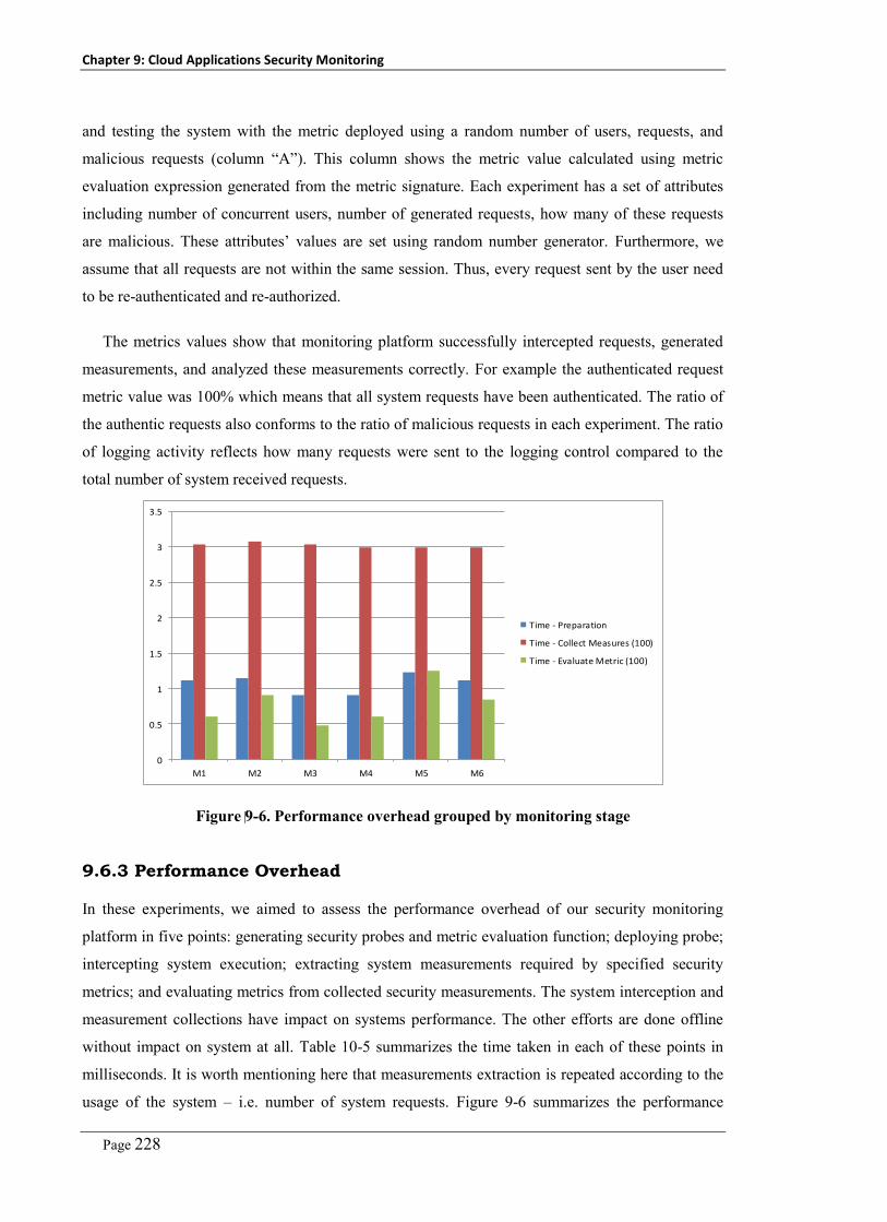
Chapter 9: Cloud Applications Security Monitoring
Page 228
and testing the system with the metric deployed using a random number of users, requests, and
malicious requests (column “A”). This column shows the metric value calculated using metric
evaluation expression generated from the metric signature. Each experiment has a set of attributes
including number of concurrent users, number of generated requests, how many of these requests
are malicious. These attributes’ values are set using random number generator. Furthermore, we
assume that all requests are not within the same session. Thus, every request sent by the user need
to be re-authenticated and re-authorized.
The metrics values show that monitoring platform successfully intercepted requests, generated
measurements, and analyzed these measurements correctly. For example the authenticated request
metric value was 100% which means that all system requests have been authenticated. The ratio of
the authentic requests also conforms to the ratio of malicious requests in each experiment. The ratio
of logging activity reflects how many requests were sent to the logging control compared to the
total number of system received requests.
0
0.5
1
1.5
2
2.5
3
3.5
M1 M2 M3 M4 M5 M6
Time - Preparation
Time - Collect Measures (100)
Time - Evaluate Metric (100)
Figure 9-6. Performance overhead grouped by monitoring stage
9.6.3 Performance Overhead
In these experiments, we aimed to assess the performance overhead of our security monitoring
platform in five points: generating security probes and metric evaluation function; deploying probe;
intercepting system execution; extracting system measurements required by specified security
metrics; and evaluating metrics from collected security measurements. The system interception and
measurement collections have impact on systems performance. The other efforts are done offline
without impact on system at all. Table 10-5 summarizes the time taken in each of these points in
milliseconds. It is worth mentioning here that measurements extraction is repeated according to the
usage of the system – i.e. number of system requests. Figure 9-6 summarizes the performance

Chapter 9: Cloud Applications Security Monitoring
Page 229
overhead incurred in the metric preparation step, measurement collection, and metric evaluation.
We measure the performance overhead of the measurement collection with 100 system requests.
The same with the metric evaluation, the input to the evaluation function is (100) measurements.
The time displayed is scaled using (log10) for visualization.
9.7 Discussion
We introduce a security monitoring approach that helps in automating the realization and analysis
of security metrics. Our approach is based on adoption of OCL supported with a system description
meta-model to help in capture security metrics’ signatures. Our platform uses these signatures to
generate probes, deploy probes at critical system entities, and generate security analysis classes that
analyse probes’ generated measurements. We have evaluated the approach expressiveness,
usability, soundness and performance overhead.
Extensibility to support automation of operational and managerial security metrics: enterprises
usually have different systems other than IT systems (either used for operational or managerial
purposes) where security engineers would like to assess their security level as well. Moreover,
different security systems are usually operated in these enterprises where security engineers would
like to aggregate their reported results. A possible way to address this issue in our approach is to
add those systems’ logs to our measurements repository. This enables security engineers to develop
operational and managerial security metrics [275] that work on these measurements. A possibility
for automation is also feasible given that we can develop adaptors that integrate such systems with
our security management platform.
A key further extension of our approach is to develop an automated adaptive security approach
that uses the results of the security monitoring platform along with the corrective actions to address
reported deviations from the normal behavior of the system. Furthermore, we plan to extend our
platform with more abstract metric specification language (may be based on natural language or
using model-driven techniques) to help security engineers in developing metrics without a need to
learn new languages. This will require development of a parser that can extract metric signatures (in
OCL) from such abstract definitions.
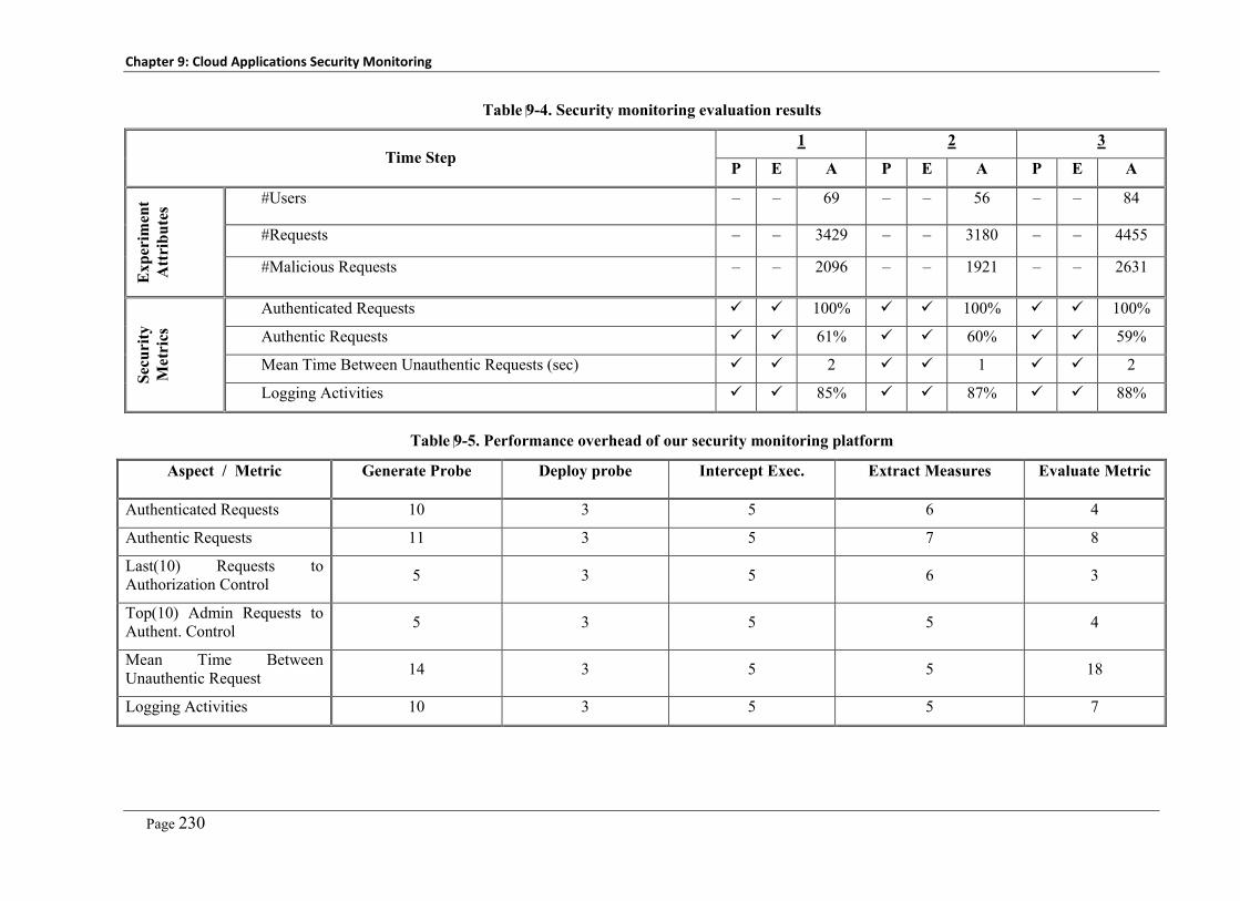
Chapter 9: Cloud Applications Security Monitoring
Page 230
Table 9-4. Security monitoring evaluation results
Time Step 1 2 3
P E A P E A P E A E
xper
imen
t A
ttri
bute
s #Users – – 69 – – 56 – – 84
#Requests – – 3429 – – 3180 – – 4455
#Malicious Requests – – 2096 – – 1921 – – 2631
Secu
rity
M
etri
cs
Authenticated Requests 100% 100% 100%
Authentic Requests 61% 60% 59%
Mean Time Between Unauthentic Requests (sec) 2 1 2
Logging Activities 85% 87% 88%
Table 9-5. Performance overhead of our security monitoring platform
Aspect / Metric Generate Probe Deploy probe Intercept Exec. Extract Measures Evaluate Metric
Authenticated Requests 10 3 5 6 4
Authentic Requests 11 3 5 7 8
Last(10) Requests to Authorization Control 5 3 5 6 3
Top(10) Admin Requests to Authent. Control 5 3 5 5 4
Mean Time Between Unauthentic Request 14 3 5 5 18
Logging Activities 10 3 5 5 7

Chapter 9: Cloud Applications Security Monitoring
Page 231
9.8 Chapter Summary
In this chapter we introduced our new security monitoring approach that we developed to complete
a full security management cycle, after previously defining security (security analysis and security
models) and enforcing security (security engineering and retrofitting). The security monitoring
component covers the security dynamic analysis part. The security monitoring approach is based on
the same concept used in the system security analysis and security retrofitting which is to abstract
system details in a system description meta-model and using OCL to develop security metrics’
signatures (invariants and constraints) on this abstract level. Using our extension of the OCL parser
we extract security probes and conditions to apply. Furthermore, we extract the security
measurements’ analysis module that analyse and summarize collected metric measurements. We
have evaluated our approach expressiveness, soundness, and performance overhead.


Part 3
Case Studies


Page 235
Chapter 10
Case Studies
Throughout this thesis, we have explained in detail how our model-based cloud computing security
management approach works and how we evaluated each component individually. In this chapter
we introduce a set of case studies as a part of evaluating our platform. We have selected three
different security problems that arise from the adoption of the cloud computing model. These
problems are critical, and represent hot research areas in the cloud computing area. Moreover, our
approach to address these case studies depend on using multiple components from our platform.
This also justifies why we introduce these case studies in a separate chapter and not as an integrated
part of the approach chapters (5-9):
– Case Study No.1: Online Automated Cloud Applications Security Virtual Patching: This case
study addresses the problem of public accessibility of the cloud platform which increases the
potential of being under attack and exploiting cloud services vulnerabilities. To address this
problem we introduce VAM-aaS as a comprehensive and integrated solution composed of the
vulnerability analysis and MDSE@R components of our security management platform. This
enables VAM-aaS to work as an online vulnerability analysis and mitigation service that keeps
analyzing cloud services looking for vulnerabilities. Whenever a new vulnerability is found a
set of agreed on actions are applied to block such new security hole.
– Case Study No.2: Supporting Multi-tenancy Reengineering using Re-aspects: This case study
addresses the security isolation problem that arises from adopting cloud computing model.
Getting tenants to share the same service instance means that we have to filter data they can
access which is specific to them and according to their assigned roles and permissions. To
address this problem we introduce SMURF as an easy to use tool to help reengineering legacy
applications to support multi-tenancy.
– Case Study No.3: Supporting Multi-tenancy Reengineering using Re-aspects: This case study
addresses the whole problem of getting cloud services to reflect different sets of security
requirements for different tenants and getting these sets to be changed at runtime. Moreover, it
addresses how to adapt security requirements according to current security status. Finally, to
incorporate security controls relevant to mitigate specific vulnerabilities. This case study covers
the whole process of tenant-oriented cloud services security management.

Chapter 10: Case Studies
Page 236
10.1 Case Study No.1: Online Automated Cloud Applications
Security Virtual Patching
However, the potential benefits reaped from the adoption of the cloud computing model, these are
threatened by the public accessibility of the cloud-hosted services and sharing of resources among
different tenants. This increases the possibility of malicious service attacks. Existing cloud
platforms do not provide a means to validate the security of the offered cloud services. Moreover,
the public accessibility of cloud services increases the potential for exploitation of newly discovered
vulnerabilities that usually take a long time to discover and to mitigate. We introduce VAM-aaS,
Vulnerability Analysis and Mitigation as-a-Service, as a novel, integrated, and online cloud-based
security vulnerability analysis and mitigation service. VAM-aaS performs online service analysis to
pinpoint new vulnerabilities/weaknesses. It then uses this information to generate security control
integration scripts to block these discovered security holes at runtime. Our approach is based on the
vulnerability signature and mitigation-actions specification approach discussed in Chapter 8. This
case study is organized as follows. Section 1 explains why automated vulnerability mitigation
becomes a key requirement. In Section 2, we introduce our approach and the proposed VAM-aaS
architecture details. In Section 3, we summarize evaluation results from evaluating our approach.
10.1.1 Introduction
The cloud model is based on service outsourcing for hosting on third-party platforms outside of the
enterprise network perimeter. However, the cloud model also introduces new opportunities for
attackers to exploit the publicly accessible valuable cloud services. Adopting the multi-tenancy
model increases the exploitability of service vulnerabilities because one of the service tenements
(who has been granted privileged access on the cloud service) may be malicious users. This means
that they can exploit complicated vulnerabilities that require higher privileges rather than being a
public user. Moreover, the number of newly discovered vulnerabilities is increasing rapidly. Web
applications (the prominent application delivery model used in SaaS applications) continue to make
up the largest percentage (63%) of the total reported vulnerabilities [60].
Commercial vulnerability scanners such as IBM-AppScan, HP-Web inspect, McAfee tools focus
mainly on black-box vulnerability analysis to avoid being limited to specific programming language
or platform. However, none of these scanners cover all known vulnerability types [116]. On the
other hand, existing research efforts [60, 109-111, 113, 117] focus on discovering specific
vulnerability types including SQLI [107, 115], XSS [112, 115, 118], or input sanitization [119, 121]
using static analysis [114, 117], dynamic analysis [115], or hybrid techniques [120, 264].
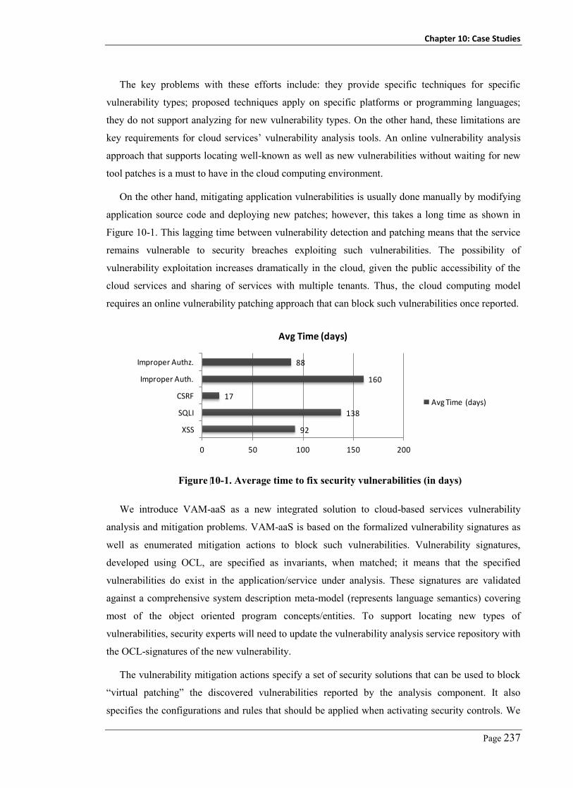
Chapter 10: Case Studies
Page 237
The key problems with these efforts include: they provide specific techniques for specific
vulnerability types; proposed techniques apply on specific platforms or programming languages;
they do not support analyzing for new vulnerability types. On the other hand, these limitations are
key requirements for cloud services’ vulnerability analysis tools. An online vulnerability analysis
approach that supports locating well-known as well as new vulnerabilities without waiting for new
tool patches is a must to have in the cloud computing environment.
On the other hand, mitigating application vulnerabilities is usually done manually by modifying
application source code and deploying new patches; however, this takes a long time as shown in
Figure 10-1. This lagging time between vulnerability detection and patching means that the service
remains vulnerable to security breaches exploiting such vulnerabilities. The possibility of
vulnerability exploitation increases dramatically in the cloud, given the public accessibility of the
cloud services and sharing of services with multiple tenants. Thus, the cloud computing model
requires an online vulnerability patching approach that can block such vulnerabilities once reported.
92
138
17
160
88
0 50 100 150 200
XSS
SQLI
CSRF
Improper Auth.
Improper Authz.
Avg Time (days)
Avg Time (days)
Figure 10-1. Average time to fix security vulnerabilities (in days)
We introduce VAM-aaS as a new integrated solution to cloud-based services vulnerability
analysis and mitigation problems. VAM-aaS is based on the formalized vulnerability signatures as
well as enumerated mitigation actions to block such vulnerabilities. Vulnerability signatures,
developed using OCL, are specified as invariants, when matched; it means that the specified
vulnerabilities do exist in the application/service under analysis. These signatures are validated
against a comprehensive system description meta-model (represents language semantics) covering
most of the object oriented program concepts/entities. To support locating new types of
vulnerabilities, security experts will need to update the vulnerability analysis service repository with
the OCL-signatures of the new vulnerability.
The vulnerability mitigation actions specify a set of security solutions that can be used to block
“virtual patching” the discovered vulnerabilities reported by the analysis component. It also
specifies the configurations and rules that should be applied when activating security controls. We
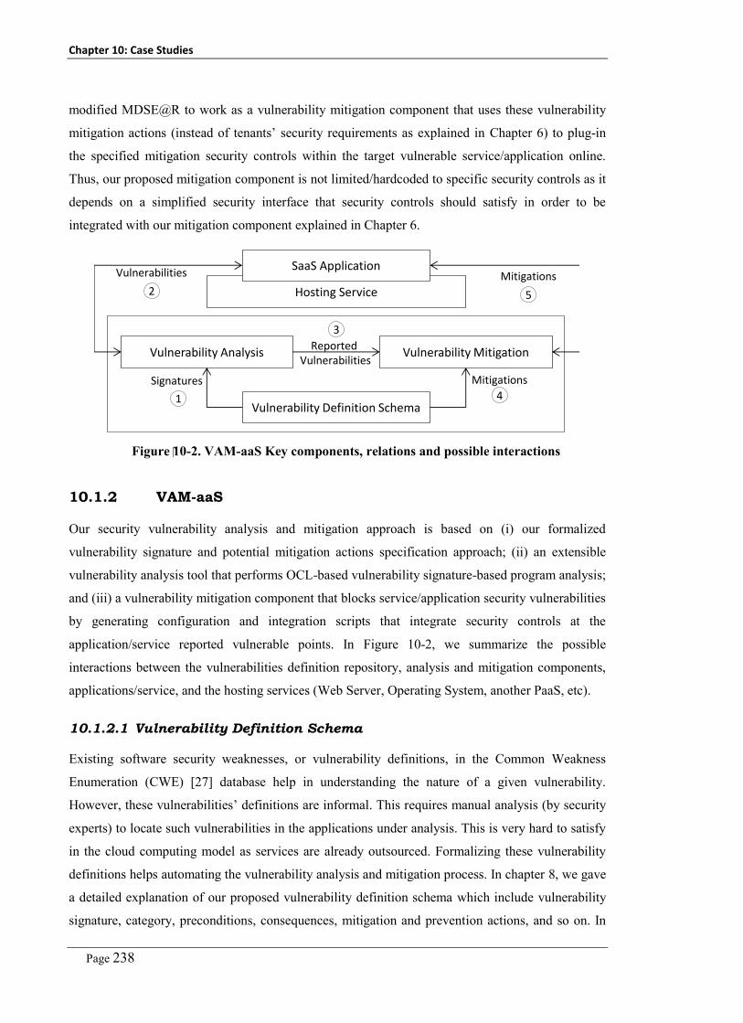
Chapter 10: Case Studies
Page 238
modified MDSE@R to work as a vulnerability mitigation component that uses these vulnerability
mitigation actions (instead of tenants’ security requirements as explained in Chapter 6) to plug-in
the specified mitigation security controls within the target vulnerable service/application online.
Thus, our proposed mitigation component is not limited/hardcoded to specific security controls as it
depends on a simplified security interface that security controls should satisfy in order to be
integrated with our mitigation component explained in Chapter 6.
Hosting Service
Vulnerability Analysis Vulnerability Mitigation
Vulnerability Definition Schema
Reported Vulnerabilities
Signatures Mitigations
SaaS ApplicationVulnerabilities Mitigations
2 5
3
1 4
Figure 10-2. VAM-aaS Key components, relations and possible interactions
10.1.2 VAM-aaS
Our security vulnerability analysis and mitigation approach is based on (i) our formalized
vulnerability signature and potential mitigation actions specification approach; (ii) an extensible
vulnerability analysis tool that performs OCL-based vulnerability signature-based program analysis;
and (iii) a vulnerability mitigation component that blocks service/application security vulnerabilities
by generating configuration and integration scripts that integrate security controls at the
application/service reported vulnerable points. In Figure 10-2, we summarize the possible
interactions between the vulnerabilities definition repository, analysis and mitigation components,
applications/service, and the hosting services (Web Server, Operating System, another PaaS, etc).
10.1.2.1 Vulnerability Definition Schema
Existing software security weaknesses, or vulnerability definitions, in the Common Weakness
Enumeration (CWE) [27] database help in understanding the nature of a given vulnerability.
However, these vulnerabilities’ definitions are informal. This requires manual analysis (by security
experts) to locate such vulnerabilities in the applications under analysis. This is very hard to satisfy
in the cloud computing model as services are already outsourced. Formalizing these vulnerability
definitions helps automating the vulnerability analysis and mitigation process. In chapter 8, we gave
a detailed explanation of our proposed vulnerability definition schema which include vulnerability
signature, category, preconditions, consequences, mitigation and prevention actions, and so on. In
Chapter 10: Case Studies
Page 239
this case study we focus on the vulnerability signature specification and vulnerability mitigation
actions attributes in a given vulnerability definition.
As we explained before, a formal vulnerability signature should be specified on an abstract level
far from the source code and programming language details, enabling locating of possible
vulnerability instances in different programs written in different programming languages. We use
Object Constraint Language (OCL) as a well-known, extensible, and formal language to specify
semantic rather than syntactical signatures of security weaknesses. To support specifying and
validating OCL-based vulnerabilities’ signatures, we have developed a system-description meta-
model. It captures the main entities in any object-oriented program and relationships between them
including components, classes, instances, inputs, input sources, output, output targets, methods,
method bodies, statements e.g. if-else statements, loops, new objects, etc. Each entity has a set of
attributes such as method name, accessibility, variable name, variable type, method call name. This
model helps conducting semantic analysis of the specified vulnerability signatures.
Discovered application/service security vulnerabilities can be mitigated in different approaches
including: modifying application source code to block the identified problems (patches); however,
this solution is hard to adopt in the cloud model as it may take long time to deliver patched version
as shown in Figure 10-1. A quick solution is to use Web application firewall (WAF) to filter
requests/responses that exploit such vulnerabilities; however, WAF has many limitations including
it does not help in output validation, cryptography storage, and mitigating improper authorization.
We introduce a new approach that supports integration of different security controls including
identity management, authentication controls, authorization controls, input validation, output
encoding, WAF, cryptography controls, etc. Each vulnerability definition has a set of mitigation
actions that specify how to mitigate such vulnerability. Each mitigation action defines a security
control type/family to be used in mitigating the related vulnerability, its required configurations,
and application/service entity where the security control will be integrated with (hosting service
including web servers or operating systems, components, classes, and methods). Thus, a reported
SQLI vulnerability in a method (M) that belongs to component (C) can be mitigated by adding input
sanitization control (Z) on component (C) that filter out SQL keyword from every single request to
the method (M).
Table 10-1 shows examples of mitigation actions for some of the well-known security
vulnerabilities. These actions should be specified in XML and included as a part of the formalized
vulnerability definition. In Chapter 8 we introduced a set of proposed signatures that could be used
to identify vulnerabilities in a given service/application.

Chapter 10: Case Studies
Page 240
Table 10-1. Examples of vulnerability mitigation actions
Vulnerability Security Control Entity Level
SQLI Input sanitization Method level
XSS Input encoding Component level
Authn. Bypass WAF Component level
Improper Authz. Authorization Method Level
10.1.2.2 OCL-based Vulnerability Analysis
Given that vulnerability signatures become now formally specified using OCL, the static
vulnerability analysis component simply traverses the given program looking for code snippets with
matches to the given vulnerabilities’ signatures. The architecture of our formal and scalable static
vulnerability analysis component, as shown in Figure 10-3, is already explained in Chapter 8.
Program Representation 1
AST
Program Representation
……
……
Signature Locator
OCL Functions
Platform Profile
Weakness Signatures
(OCL)
Vulnerability List
Prog
ram
Sou
rce
Figure 10-3. OCL-based vulnerability analysis component
Appli
catio
n Application Interceptors Document
Security Kernel
Security Specification Document
Appli
catio
n W
rappe
r Vulnerability Mitigation Manager
OCL-based Vulnerability Analysis Component
Vulnerability Definition Schema
Mitigation ActionsDiscovered Vulnerabilities
Secu
rity S
ervice
s
1 2
4 5
3
6
7
8
Figure 10-4. Vulnerability Mitigation Component

Chapter 10: Case Studies
Page 241
10.1.2.3 Vulnerability Mitigation
The analysis component outputs a list of the newly discovered vulnerabilities in each of the cloud
hosted SaaS applications (Figure 10-4-1). Each entry in this list has a service/application vulnerable
entity (method, class, or component) along with the list of discovered vulnerabilities. Given this list
of vulnerabilities, the security vulnerability mitigation manager queries the vulnerability definition
schema database (Figure 10-4-2) to retrieve the appropriate actions to be taken in order to mitigate
each of such reported vulnerabilities. Examples of the retrieved actions are shown in Table 10-1.
Using these two lists (vulnerable entities and mitigation actions), the vulnerability mitigation
manager (Figure 10-4-3) decides the patching level (component level, class level, or method level)
using e.g. HttpModules, object interceptor using dependency injection, or method level interception
using dynamic weaving AOP respectively. These details are maintained in a security specification
document for each application (Figure 10-4). Moreover, the mitigation manager uses the registered
security services’ properties to decide which security service realizes what security control type
specified in the mitigation action – e.g. the identity and access management control is currently (on
this platform) realized by identity manager. Finally, the vulnerability mitigation manager updates
the security specification document (Figure 10-4-5) with the list of actual security services to be
triggered whenever the application receives request to every vulnerable resource. The application
wrapper (Figure 10-4-6) is responsible for intercepting requests to entities specified in the
application interceptors’ document – i.e. vulnerable entities. These requests will be redirected to the
security kernel (Figure 10-4-7). The security kernel queries the security specification document to
get the security controls/services to be enforced to patch the requested resource. Then, it generates
calls/requests to these security services (Figure 10-4-8). When these services return, the security
kernel returns the control back to the called resource. This is a bit modified version of MDSE@R to
replace secure-system model that is developed by service provider and tenants with vulnerability
list and reference vulnerability definition repository.
10.1.3 Experimental Evaluation
The key objectives of our evaluation experiments are to assess the soundness of our VAM-aaS in
capturing different vulnerabilities’ signatures, detecting these vulnerabilities in given applications,
and in mitigating them. We apply the OCL-based vulnerability signatures examples and mitigation
actions discussed in Chapter 8. We used the full set of benchmark applications (discussed in chapter
4) applied in the security analysis task as explained in Chapter 8. To assess the effectiveness of our
approach we use the same evaluation metrics including precision, recall and f-measure to measure
our approach soundness and completeness. The results of evaluating our analysis component
applied on benchmark suite to identify four of the Top10 web applications vulnerabilities
(OWSAP2010) are already presented in Chapter 8 for the security analysis part.

Chapter 10: Case Studies
Page 242
Table 10-2. Results of VAM-aaS vulnerability mitigation component
App SQLI XSS Authn. Bypass Improper Authz.
TP FP FN TP FP FN TP FP FN TP FP FN
Galactic 2 1 0 4 1 0 4 0 0 2 1 0
Splendid 14 0 0 7 1 0 3 2 0 3 0 0
KOOBOO 14 2 0 10 3 0 4 1 0 12 0 0
BlogEngine 4 0 0 4 2 0 0 0 0 4 2 0
BugTracer 10 0 0 1 0 0 4 1 0 1 1 0
NopCommerce 19 0 0 5 0 0 0 0 0 1 0 0
Webgoat 9 0 0 5 1 0 4 2 0 3 1 0
Total 72 3 0 36 8 0 19 8 0 30 5 0
0.00%
20.00%
40.00%
60.00%
80.00%
100.00%
120.00%
Precision
Recall
F-Meas.
Figure 10-5 Effectiveness of the security mitigation component
0
2 0
4 0
6 0
8 0
1 0 0
1 2 0
1 4 0
1 6 0
1 5 1 0 5 0 1 0 0 3 5 0 5 0 0 1 0 00 5 0 00 1 0 00 0
1 0 U s e r s
5 0 U s e r s
1 0 0 U s e rs
No. CPs
Tim
e in
mse
c
Figure 10-6. Performance overhead of the security mitigation component

Chapter 10: Case Studies
Page 243
Table 10-2 summarizes our experiments’ results applied on benchmark suite to mitigate the
vulnerabilities reported by the vulnerability analysis component. It shows the number of TP, FP,
and FN. A key observation from this table is that the mitigation component does not have false
negatives which means that no missing points that has not been mitigated.
Figure 10-5 shows precision, recall, and F-measure for the mitigation component, we have
incorporated the results returned from the analysis component with the FN missed vulnerabilities.
Although the recall rate is (100%) which means that we did not miss any of the specified
mitigations, we have an average of (85%) precision – i.e. high FP - as we may secure entities that
have no security problem. This depends on the accuracy of the specified mitigation actions.
Figure 10-6 shows the performance overhead of the mitigation component with different
numbers of concurrent users and numbers of critical/vulnerable points (on a Core2Duo desktop PC
with 4GB Memory). The performance overhead equals the time spent by the security kernel to
query security specification document and get security controls to be employed in securing
intercepted point, and time spent in calling these security controls. The time spent by the security
controls themselves we do not factor in, as this needs to be spent whether using our approach or
traditional hard-coded security. Performance can be further improved using replicas of the
mitigation component with different services and platforms.
10.1.4 Discussion
We developed a formal vulnerability definition schema including vulnerability signature and
mitigation actions, extensible vulnerability analyzer based on the proposed signature specification
schema and applied on abstract program representation, and a vulnerability mitigation approach
based on dynamic and runtime injection of security controls into vulnerable entities. Using OCL
allows adoption of existing validation and query parsing tools. Using abstract representation helps
generalizing and abstracting the security analysis task from specific programming languages or
platform details. It also helps making the approach more scalable for larger applications. Use of a
common security interface helps integrating different security controls without a need to develop
new system-security control connectors.
From our experiments with mitigation actions and security controls integration, we found that
although using web application firewalls is a straight forward solution, it is not always a feasible
option to block all discovered vulnerabilities. The selection of the entity level to apply security
controls on (application level, component level, method level, etc.) impacts the application
performance – i.e. instead of securing only vulnerable methods, we intercept and secure (add more
calls) the whole component requests. A key point that worth mentioning is that the administration of

Chapter 10: Case Studies
Page 244
security controls should be managed by the service/cloud provider administrators. Our focus is
integrating controls within vulnerable entities.
Our vulnerability mitigation component works online without a need for manual integration with
the applications/services under its management. The overhead added by the mitigation action can be
easily saved if the service developers worked out a new service patch. In this case, the vulnerability
analysis component will not report such vulnerability. Thus, the mitigation component will not
inject security controls. Our experimental results show that the OCL-based analysis tool achieves
(90%) precision rate and (92%) recall rate while our mitigation component achieves (100%) recall
and (85%) precision rate.

Chapter 10: Case Studies
Page 245
10.2 Case Study No. 2: Supporting Multi-tenancy
Reengineering using Re-aspects
In this case study, we address the multi-tenancy reengineering problem that obstacles service
providers from adopting the cloud computing model to host their applications. One of the key issues
that must be addressed in multi-tenancy reengineering is how to support security isolation between
different tenants’ data. To address this problem, we have applied our reengineering aspects “re-
aspects” concept to help in this task. This case study is organized as follows. In Section 1, we
discuss an overview of the multi-tenancy reengineering and security isolation problem. In Section 2
we introduce an analysis of the SaaS multi-tenancy reengineering requirements. Section 3 goes
through usage example. Section 4 shows our experimental evaluation results and discusses
implications of our approach.
10.2.1 Introduction
Multi-tenancy helps in delivering services including infrastructure, platform and software that can
be shared between different tenants. In the IaaS model, multi-tenancy is achieved through using
hypervisors that virtualize the server resources. Thus the Operating System itself does not need to
be modified. Moreover, each customer has a separate instance (VM). However, In the SaaS model,
multi-tenancy has different possible deployment models including a separate instance for each
tenant up to a single instance for multiple tenants. The later deployment model is definitely the
optimal model. However, it requires the SaaS application to handle multi-tenancy and tenants
isolation themselves.
Supporting multi-tenancy requires the SaaS application to support capturing, processing and
storing data of different tenants in the same application instance. Moreover, the SaaS application
should maintain security and performance isolation between its tenants. This requires considering
multi-tenancy as a key requirement from the early stages of the system development process. Many
of the existing well-known, large-scale business applications that are widely used nowadays are
locked-in a high cost business model. This prohibits them from targeting/servicing the “long-tail-
market”. Thus, it becomes a business need to migrate such applications to support multi-tenancy.
Migration of such applications to support multi-tenancy is a very complicated task as it requires a
deep understanding of the application. Moreover, multiple system modifications are required to be
delivered. This requires revising/updating almost all system modules.
Existing multi-tenancy efforts focus either on extending applications to support multi-tenancy by
wrapping a single-tenant application with a platform that manages the multi-tenancy dimension [22-
24, 230, 232, 280]. The same approach has been followed in industrial efforts as well [281]. Using
these approaches, applications are locked-in to cloud platforms that have such multi-tenancy

Chapter 10: Case Studies
Page 246
platform hosted. Moreover, features such as user interface customization, application model
extension, etc. will not be available for tenants if the original applications do not support them.
Limited efforts targeted conducting real reengineering of applications to support multi-tenancy
[282, 283]. These efforts focus only on providing a systematic process to be followed by system
engineers to support multi-tenancy. They do not provide tool support to facilitate process.
Our multi-tenancy reengineering approach is based on reengineering-aspects “Re-Aspects”
concept where a given system modification (change request) details are captured as a re-aspect. A
re-aspect includes a signature of code snippets to be modified; action to be applied on identified
code matches (instances of these signatures) include inserting, modifying, replacing, or deleting
code parts; and code to modify, replace or insert. We conduct a thorough analysis of the multi-
tenancy pattern for web applications and come up with a set of key requirements/modifications that
should be addressed at the database, data access layer, business logic layer, and presentation layer.
Moreover, we studied the requirements for security and performance isolation.
We developed a set of modification patterns that system engineers can use when reengineering
their applications to support multi-tenancy. Given these modifications specified as re-aspects, we
analyse the system source code to identify code snippets that match specified re-aspect’s signatures,
and then it performs impact analysis to identify matched entities that need to be modified to realize
the given modifications. Finally, we use the specified re-aspect actions to update the identified
matches.
10.2.2 Multi-tenancy Requirements Analysis
We introduce an analysis of the potential modifications that may be required when reengineering an
application to support multi-tenancy. We project our analysis to a typical architecture of a web
application explaining what need to be added, modified, replaced, or deleted during the process of
supporting multi-tenancy. This analysis is also helpful for service providers who plan to develop
new multi-tenant SaaS application. Service providers have to make their own decisions based on
their application architecture and the multi-tenancy paradigm they plan to adopt including single-
instance single tenant, multiple-instance multiple-tenant, and single-instance multiple-tenant.
10.2.2.1 Multi-tenant Data Model
The multi-tenant application’s database has different possible architecture models. The service
provider has to select between these architecture models based on the isolation level they plan to
deliver, scalability of the application, number of tables, expected sizes of the data tables, and impact
on system performance. These architecture models include [13]:
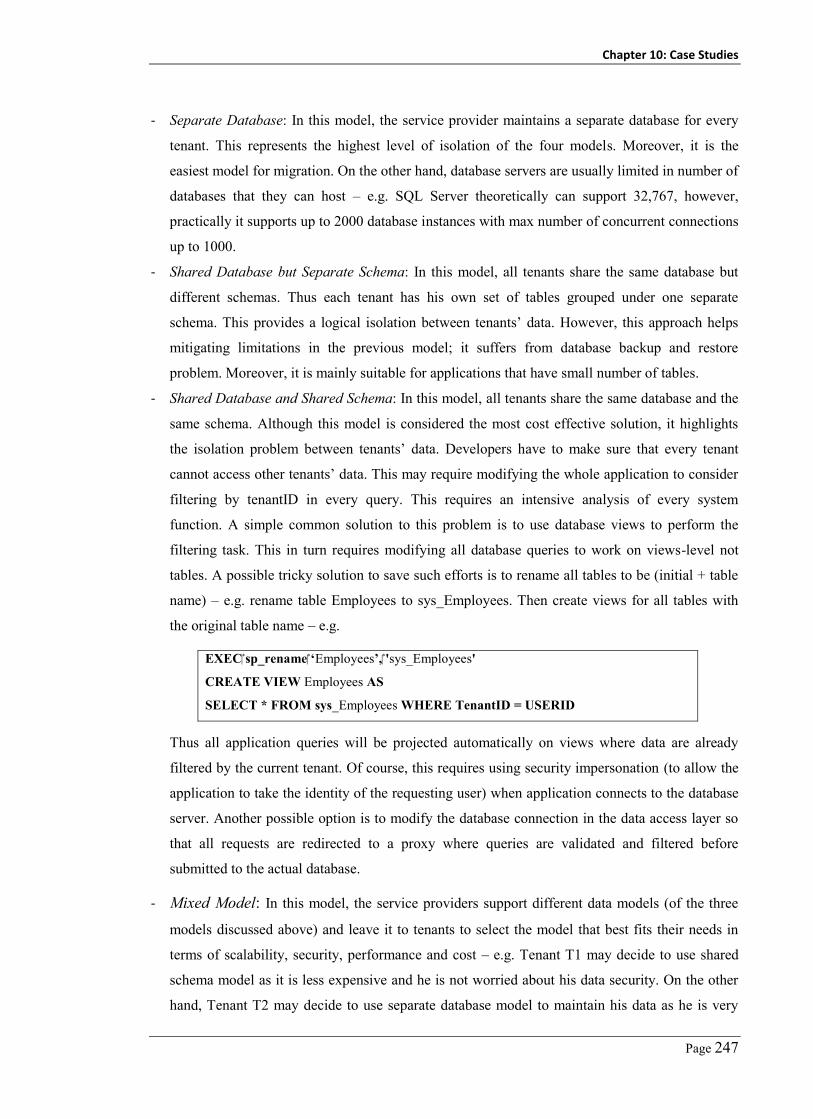
Chapter 10: Case Studies
Page 247
- Separate Database: In this model, the service provider maintains a separate database for every
tenant. This represents the highest level of isolation of the four models. Moreover, it is the
easiest model for migration. On the other hand, database servers are usually limited in number of
databases that they can host – e.g. SQL Server theoretically can support 32,767, however,
practically it supports up to 2000 database instances with max number of concurrent connections
up to 1000.
- Shared Database but Separate Schema: In this model, all tenants share the same database but
different schemas. Thus each tenant has his own set of tables grouped under one separate
schema. This provides a logical isolation between tenants’ data. However, this approach helps
mitigating limitations in the previous model; it suffers from database backup and restore
problem. Moreover, it is mainly suitable for applications that have small number of tables.
- Shared Database and Shared Schema: In this model, all tenants share the same database and the
same schema. Although this model is considered the most cost effective solution, it highlights
the isolation problem between tenants’ data. Developers have to make sure that every tenant
cannot access other tenants’ data. This may require modifying the whole application to consider
filtering by tenantID in every query. This requires an intensive analysis of every system
function. A simple common solution to this problem is to use database views to perform the
filtering task. This in turn requires modifying all database queries to work on views-level not
tables. A possible tricky solution to save such efforts is to rename all tables to be (initial + table
name) – e.g. rename table Employees to sys_Employees. Then create views for all tables with
the original table name – e.g.
EXEC sp_rename ‘Employees’, 'sys_Employees'
CREATE VIEW Employees AS
SELECT * FROM sys_Employees WHERE TenantID = USERID
Thus all application queries will be projected automatically on views where data are already
filtered by the current tenant. Of course, this requires using security impersonation (to allow the
application to take the identity of the requesting user) when application connects to the database
server. Another possible option is to modify the database connection in the data access layer so
that all requests are redirected to a proxy where queries are validated and filtered before
submitted to the actual database.
- Mixed Model: In this model, the service providers support different data models (of the three
models discussed above) and leave it to tenants to select the model that best fits their needs in
terms of scalability, security, performance and cost – e.g. Tenant T1 may decide to use shared
schema model as it is less expensive and he is not worried about his data security. On the other
hand, Tenant T2 may decide to use separate database model to maintain his data as he is very

Chapter 10: Case Studies
Page 248
keen about his data security. From the service provider perspective, this model (mixed-model)
requires to support the three data models. Hence, service providers should conduct cost-benefit
analysis (market share gained against cost) before delivering this model. Based on requesting
user’s tenant, the system (data access layer) should either connect to the shared database or to
the tenant separate database.
Another issue that should be considered when architecting application data model is how to
enable data model extensibility – i.e. every tenant may have special fields or data items that they
need to maintain for every operation (record). This is straight forward when maintaining separate
database or separate schema per tenant. However, it still has to be propagated to the next layers.
There are different approaches to realize the data model extensibility including: pre-allocated fields
where service providers define a set of dummy columns in every table they expect that their tenants
may need to extend; Name-value pairs where the service provider defines one or more table to
maintain other tables extensions. This table structure will look like (TableID, TenantID,
attributeName, attributeValue); and XML extension column where every table has a predefined
column of type XML where tenant extension columns can be maintained as one entity that can be
saved and loaded. The selection of the database model and the model extensibility to adopt, impacts
the modifications required in the next layers/tiers.
10.2.2.2 Application Layers
In data access and business logic layers we need to modify public methods’ signatures to expect
tenantID as a parameter. Methods’ bodies should be modified as well to process the tenantID – e.g.
adding tenantID to database queries, file access commands, database connection strings, loading
business rules, loading and initializing workflow engine based on current tenant. TenantID is
usually propagated from the presentation layer to these layers. Both the data access layer and the
business logic layer should handle custom fields (data model extension) based on the model adopted
in the data model. This includes handling load, store, and query of these custom fields. Business
objects’ classes should be modified to include tenant’s specific data members.
In the presentation layer we have a set of potential modifications including user interface
customization and branding (e.g. company logo, styles, themes, etc.), adding TenantID to session
state, modifying calls to business logic layer functions to pass tenantID, modifying used business
objects to set/get tenantID. Moreover, the presentation layer should support displaying different
custom fields based on the current requesting user’s tenant

Chapter 10: Case Studies
Page 249
using (DbCommand command = db.GetStoredProcCommand("dbo.GetEntityDefFields")) {
db.AddInParameter(command, "tenantId", DbType.Guid, tenantId);
db.AddInParameter(command, "entityDefName", DbType.String, entityDefName);
using (IDataReader reader = db.ExecuteReader(command))
}
Figure 10-7. Example of modifications in the data access layer
Figure 10-8. Examples of required modifications in application logic layers
10.2.2.3 Non-Functional Requirements
A multi-tenant application has to be scalable to support the potential number of tenants and their
workloads. This requires the service providers to deploy their application on web farms and
clusters. SaaS SLAs usually capture tenants’ security, performance, availability, and reliability
objectives requirements that should be satisfied by the SaaS application. This resulted in issues
related to how to maintain performance isolation where the execution flow of a given tenant should
not be impacted by other tenants’. Load balancers with performance controllers can help in solving
this problem. However, it requires applications to be stateless. SaaS applications should maintain
session information either on client side or on a shared server that is accessible to all other servers
in this cluster.
Security is another nonfunctional requirement that should be addressed. A SaaS application
should support customizing applications to support tenants’ security “tenant-oriented security”. This
can be achieved by externalizing the security from the multi-tenant system by calling a standard
library that performs authentication, authorization, etc. based on tenants’ requirements and security
controls. This enables every tenant to use his security controls – e.g. to use his LDAP server to
authenticate and authorize users.

Chapter 10: Case Studies
Page 250
Table 10-3. Multi-tenancy change requests organized by architecture layer
Layer Change Request
Presentation
Layer
1. All web pages should load layout, localization and menus based on
requesting tenant.
2. Entity extension fields should be loaded based on current tenant.
3. Every page grid-view column, user control should be enabled based on user
security customization for current user’s tenant.
4. All business functions should receive tenantID param.
5. Set tenantID field for every business entity created in the presentation or the
business logic layer.
6. All entities display pages should include the tenant defined custom fields.
7. All entity insert/edit pages should include the tenants’ defined custom
fields.
Business
Layer
8. All workflow definitions should filter by tenantID.
9. Update web services to have tenantID param.
10. Update all business functions to have tenantID param.
Data Access 11. All SQL queries should filter by tenantID.
12. All Linq queries should filter by tenantID.
13. All stored procedures should have parameter tenantID.
14. All business entities should have extra attribute of tenantID.
Database 15. Update all database tables with tenantID column.
16. Add new table for tenants’ data.
QOS 17. User Authentication and Authorization should be done through the
customer security controls, if any.
18. Support Load balancing and meet tenants’ SLA.
10.2.2.4 Tenant On-boarding and Metadata service
The registration of a new tenant should be managed by a separate tenant administration service
(may be an extension of an existing system administration module). This includes batches to restore
a new database instance of the system template if the “separate DB” model is applied, or create a
new schema with necessary tables. This module should also enable specifying security permissions
for users, roles, screens and controls. It may also include screens’ customization and localization.
The metadata service is a key module in a multi-tenant application. It helps tenants and service
providers to customize (branding) the application to match tenants’ business needs. This includes

Chapter 10: Case Studies
Page 251
customizing the user interface text, fields, visibility, and security capabilities, customizing the
business workflow, business rules, and custom fields. Table 10-3 shows a summary of the
modifications required in reengineering a given system to support multi-tenancy grouped by the
application layer where each modification applied. Table 10-4 shows the re-aspects’ signatures
required to located entities to be modified in relation to the modifications specified in Table 10-3.
Table 10-4. List of re-aspects signatures for modifications in Table 10-3
CR Change Request Signature
1 Context Method inv loadMethods: self.Class.GetBaseType() = “Page” AND self.Name = “Page_Load”
2 Context Method inv fieldExtension: self.Class.GetBaseType() = “Page” AND self.Name = “Page_Load” AND self.Contains(s : IfElseStatement | s.condition = “Page.IsPostBack”
3 Context Method inv fieldSecurity: self.Class.GetBaseType() = “Page” AND self.Name = “Page_Load” AND self.Contains(s : IfElseStatement | s.condition = “Page.IsPostBack”)
4 Context Method inv businessfns: self.Contains(s : InvocationExpression | s.fnName.Contains(“BusinessLayer”) )
5 Context Method inv businessentity: self.contains(s : newObjectStatement | s.ClassName = “businessentity”)
6 Context Method inv fieldExtension: self.Class.GetBaseType() = “Page” AND self.Name = “Page_Load” AND self.Contains(s : IfElseStatement | s.condition = “Page.IsPostBack”)
7 Context Method inv fieldExtension: self.Class.GetBaseType() = “Page” AND self.Name = “Page_Load” AND self.Contains(s : IfElseStatement | s.condition = “Page.IsPostBack”)
8 Context Method inv wrkflwfns: self.Class.Component = “Workflow”
9 Context Method inv webservicemethods: self.Class.GetBaseType() = “Webservice”
10 Context Method inv businesfns: self.Class.Component = “BusinessLayer”
11 Context Method inv sqlqueries: self.Contains(s: InvocationExpression | s.fnName = “ExecuteScalar” OR “ExecuteQuery”)
12 Context Method inv Linqqueries: self.Contains(s: QueryExpression)
13 Context Method inv sqlqueries: self.Contains(s: InvocationExpression | s.fnName = “ExecuteScalar” OR “ExecuteQuery”
14 Context Class inv businessentityDef: self.ClassName = “businessentity”
15, 16 DB script
17 Context Method inv sqlqueries: self.Contains(s: InvocationExpression | s.fnName = “Redirect” AND TargetObject = “Response” AND Arguments.Contains(“Login.aspx”)
18 Context Class inv sessionmgmt: self.GetBaseClassType() = “IHttpModule”
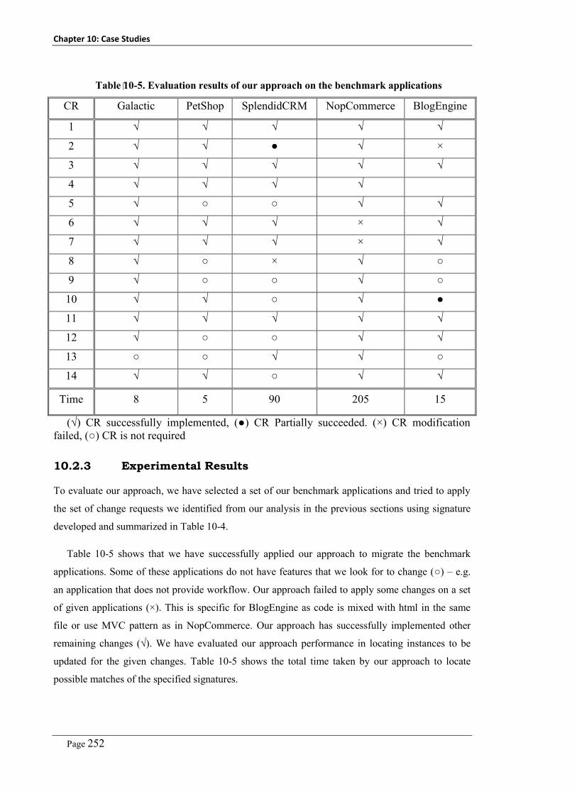
Chapter 10: Case Studies
Page 252
Table 10-5. Evaluation results of our approach on the benchmark applications
CR Galactic PetShop SplendidCRM NopCommerce BlogEngine
1 √ √ √ √ √
2 √ √ ● √ ×
3 √ √ √ √ √
4 √ √ √ √
5 √ ○ ○ √ √
6 √ √ √ × √
7 √ √ √ × √
8 √ ○ × √ ○
9 √ ○ ○ √ ○
10 √ √ ○ √ ●
11 √ √ √ √ √
12 √ ○ ○ √ √
13 ○ ○ √ √ ○
14 √ √ ○ √ √
Time 8 5 90 205 15
(√) CR successfully implemented, (●) CR Partially succeeded. (×) CR modification failed, (○) CR is not required
10.2.3 Experimental Results
To evaluate our approach, we have selected a set of our benchmark applications and tried to apply
the set of change requests we identified from our analysis in the previous sections using signature
developed and summarized in Table 10-4.
Table 10-5 shows that we have successfully applied our approach to migrate the benchmark
applications. Some of these applications do not have features that we look for to change (○) – e.g.
an application that does not provide workflow. Our approach failed to apply some changes on a set
of given applications (×). This is specific for BlogEngine as code is mixed with html in the same
file or use MVC pattern as in NopCommerce. Our approach has successfully implemented other
remaining changes (√). We have evaluated our approach performance in locating instances to be
updated for the given changes. Table 10-5 shows the total time taken by our approach to locate
possible matches of the specified signatures.

Chapter 10: Case Studies
Page 253
10.2.4 Discussion
We introduced a new multi-tenancy reengineering approach that helps software engineers in
migrating their applications to support multi-tenancy. Our re-aspects concept helps automating the
program analysis and system updating (change propagation) phases using re-aspects. Software
engineers model their modifications to be applied on the target application in terms of reengineering
aspects. A re-aspect capture the signature of system entities to be modified in terms of OCL
constraints; actions to be applied including insert, replace, modify, and delete; and code to apply.
Our approach then uses these re-aspects’ signatures to locate system entities to be modified and
applying the actions specified for each re-aspect. We have developed a set of modifications that
may be required to reengineer a given application to multi-tenancy. We used these modifications’
set in validating our approach against a set of five benchmark applications. Our approach
successfully helped in upgrading these applications to support multi-tenancy.

Chapter 10: Case Studies
Page 254
10.3 Case Study No.3: Supporting Multi-tenancy
Reengineering using Re-aspects
We conclude this thesis with a case study that illustrates how the full platform components integrate
together to deliver model-driven, multi-tenant, adaptive security management for cloud computing
at runtime. To explain how our platform works, we start with an open source multi-tenant SaaS
application, LitwareHR, developed by Microsoft to be used as a sample multi-tenant application.
LitwareHR is a single instance multi-tenant SaaS Human Resources Recruiting SaaS application.
This case study is organized as follows. In Section 1, we introduce the details of this case study and
what scenario we are going to follow during our case study. In Section 2, we give details of the
LitwareHR as our example SaaS application. In Section 3, we discuss the system description and
security specification models that we will depend on through the whole case study. In Section 4, we
introduce details and outcomes of the security analysis task. In Section 5, we explain how we
reengineer LitwareHR to disable the built-in security capabilities of the system. In Section 6, we
introduce different security models developed by different tenants of the service and how we
integrate them using MDSE@R. In Section 7, we introduce a set of security metrics we want to
follow up to conform the security status of our service assets and key mitigation actions.
10.3.1 Case Study Flow
Figure 10-9 shows the main steps, and possible relationships, that we are going to go throw in this
case study. We possibly have two cycles: (1) security analysis, retrofitting, and patching, and (2)
security management process. The first cycle starts with a deep security analysis task. This task
should be a recurring and online task. The identified/reported vulnerabilities could be patched by
modifying the system to patch such vulnerabilities using re-aspects engine, or could be patched
using the MDSE@R “virtual patching”. The reengineering task could be applied as well whenever
we apply our approach on an existing system with built-in security capabilities.
The security management process (2) starts with defining security by service tenants. Then, the
captured security details are realized using MDSE@R. Finally, the operated tenants’ security is then
monitored using our security monitoring approach. The results are fed back to the security
management component to report and update the specification of security to be operated. In this
case study, we start with cycle (1) as a preprocessing step – i.e. to identify and patch existing
vulnerabilities and also to disable the built in security capabilities. Then, we show how the normal
security management process goes including capturing tenants’ security requirements, enforcing
tenants’ security, and finally monitoring service security status.

Chapter 10: Case Studies
Page 255
Security
Analysis
Defining Security
Enforcing Security
Monitoring Security
Security
Reengineering
Security
Analysis
1
2
Figure 10-9. Steps and relations of case study
10.3.2 LitwareHR
LitwareHR is a sample multi-tenant SaaS application developed by Microsoft architecture strategy
team to be used as guidelines for software vendors and developers who plan to develop SaaS
applications. LitwareHR is based on a single-instance multi-tenant model where all tenants share
the same service instance. LitwareHR uses a set of best practices in architecting and designing
scalable and extensible software systems. Moreover, it uses a set of new technologies that help in
developing such kind of applications. The main business delivered by LitwareHR is a recruitment
management process which represents a key role of the HR department in any company. LitwareHR
enables different tenants (companies) to outsource their recruitment process for third party cloud
platform hosting LitwareHR to fulfill their business. LitwareHR has two key components: public
site (that is used by applicants and employees to search and apply for jobs), and private site (that is
used by employees to customize the application business, UI, and security).
LitwareHR comes with a usage example, Figure 10-10, where two tenants Contoso (retail shoe
chain) and Fabrikam (music school) adopt the software where each tenant has their own business
requirements (workflow, and data), UI (styles, logo, etc.), and security requirements (authentication,
authorization). However, the LitwareHR does not enable using tenants’ security controls. Those
tenants are satisfied with the security requirements delivered by LitwareHR. We have added two
new tenants to the usage example, Swinburne and Swine Market. Both tenants have their own
security requirements and controls to be applied on their outsourced assets as we are going to
discuss in the security engineering section later in this case study.

Chapter 10: Case Studies
Page 256
Authenticated accessConfiguration & Post jobs
Private site
Web Interface
Unauthenticated accessSearch & Apply for jobs
Web APIs
Public site
Web Interface
Internet
Music SchoolRetail Shoe Chain
Operational Platform
“Internal” SaaS Hosting PlatformProvisioning (try before buy)
Billing (not implemented)
Swinburne University
SwineMarket
Figure 10-10. A simplified LitwareHR usage example
10.3.3 LitwareHR – SDM and SSM
Before we conduct security analysis, reengineering, or multi-tenant security engineering we need to
develop system and security specification models that we can use in these tasks. However, we do
not have any previous experience with LitwareHR. Thus, we had to spend some time (2 days) to
understand the architecture and implementation details in order to figure out the delivered system
functionalities. Fortunately, we found a set of system architecture diagrams that helped with this
task. We deployed the application and used it for a couple of days in order to understand the whole
set of provided LitwareHR features. Below we show and discuss the system and security details of
the LitwareHR.
- LitwareHR Features: LitwareHR delivers a set of features that are related to HR recruitment
process and a set of helping features related to the multi-tenancy concept and how to address the
configurability of tenants’ instances, as shown in Figure 10-11 (we developed from our
understanding of LitwareHR). The main features delivered by LitwareHR includes: manage
tenant instance (this includes customize look-and-feel, customize data-model, and customize
workflow); manage tenant security (this includes mange roles, users and permissions);
manage tenant recruitment (this includes posting jobs, searching for jobs, applying for jobs);
and application evaluation (this includes interview, negotiation, acceptance, and rejection).
LitwareHR is delivered with built-in security capabilities for authentication, authorization and
secure communication channels for security critical capabilities.

Chapter 10: Case Studies
Page 257
Litw
areH
R
Cus
tom
ize
Wo
rkfl
ow
Man
age
Secu
rity
Man
age
Use
rs
Man
age
Ro
les
Man
age
Rec
ruit
men
t
Sear
ch
Jobs
App
ly f
or
Job
App
lican
t Ev
alua
tio
n
Inte
rvie
wA
ccep
tanc
e
Post
Jo
b Rej
ecti
on
Man
age
Tena
nt
Cus
tom
ize
Dat
amo
del
Neg
oti
atio
n
Man
age
Perm
issi
ons
Cus
tom
ize
Inte
rfac
e
Figure 10-11. LitwareHR feature model

Chapter 10: Case Studies
Page 258
Service Layer
Shp.Runtime.Contracts
Shp.Runtime.Services
App.Workflows.Contracts
App.Workflows.Services
App.Workflows DataAcess Block
Definition of service and data
contracts
Portfolio.Host
Presentation Layer
PublicApp.WebUX PrivateApp.WebUX
PublicApp.Presenters PrivateApp.Presenters
Portfolio.Gateways
Company.Website
CompanyWeb.Presenters
Figure 10-12. LitwareHR architecture

Chapter 10: Case Studies
Page 259
Security
Shp.Security.BrokeredSenderShp.Security.BrokeredReceiver
Presentation Layer
PublicApp.WebUX
PrivateApp.WebUX
Service Layer
Portfolio.Host
Authorization.Host Authentication.Host
Figure 10-13. LitwareHR security architecture
- LitwareHR Architecture and Deployment: Figure 10-12 (provided by LitwareHR application
developers) shows the LitwareHR architecture components with security components used. The
LitwareHRWebsite component is the service provider website (published on the cloud platform)
where tenants can register to use the LitwareHR service. This website is used to create separate
copies of the public and private sites (as we will see later) and add required entries in the
tenants’ database and LitwareHR active directory that is used to authenticate and authorize
tenants and their users. The publicApp website is used to post jobs, search and apply for jobs,
and update applicants’ recruitment process status according to tenant workflow. The privateApp
website is used to configure the application according to tenant needs in terms of UI, security,
data-model, and workflows. The Gateway component provides implementation of all
functionalities used in the privateApp and publicApp components. In fact, the responsibility of
the Gateway component is to delegate request from the presentation layer to the actual
components/services in the business and services layer so that the presentation layer does not
need to know how and who delivers the required functionality. The contracts component defines
functionality interfaces that should be realized by business services. This contract is referenced
by the presentation layer components to avoid being tightly coupled with the realization services
(binding is done using configuration scripts). The services component delivers the realization
services that implement the actual business functionalities used. The services component uses
the Microsoft application blocks “Enterprise Library” to deliver the data access layer using the
“DataAccess” block.

Chapter 10: Case Studies
Page 260
- LitwareHR Class Diagram: Figure 10-14 shows a part of the LitwareHR class diagram we
extracted using reverse engineering of the system source code using Altova UModel toolset. We
have grouped some of these classes that are related together such as classes used in the contracts
component (1); classes related to workflow entities (2); classes related to authentication service
(3); and classes related to the presentation view and presenter classes (4).
- LitwareHR Security: Figure 10-13 shows the main security components used by LitwareHR to
deliver secure communication channels and interactions between LitwareHR components/layers
and these security components. The main security components of LitwareHR are:
BrokeredSender; BrokeredReceiver; authenticationHost; AuthorizationHost. These components
are used to generate security tokens (BrokeredSender – in this case the presentation layer) and
validate security token (BrokeredReceiver – services layer). Actually, the LitwareHR has other
security components that are developed as part of the LitwareHR including ASP.NET custom
membership feature that is used in authenticating and authorizing users in the publicApp
component; and authentication and authorization services that are delivered by services
component.
10.3.4 Security Analysis
The first step in our case study is to conduct a security analysis of the LitwareHR application to
pinpoint the existing system security threats and vulnerabilities that we should mitigate. The
objective of this task is to mitigate as much vulnerabilities as possible before publishing
LitwareHR. Later on, the security analysis service will work online with the cloud services to report
the existence of any new vulnerability. To fulfill this task we studied the LitwareHR system and
security details covered in the last section. The list of vulnerabilities to test LitwareHR against is the
list of threats and vulnerabilities we discussed in the security analysis chapter. Table 10-6
summarizes the list of threats and vulnerabilities we found in LitwareHR.
10.3.5 LitwareHR – Security Re-engineering
The objective of this security reengineering task is twofold: (i) to reengineer LitwareHR in order to
disable the built-in security capabilities to start using MDSE@R in managing LitwareHR multi-
tenant security; and (ii) to mitigate the reported vulnerabilities and threats from the previous task.
To disable the LitwareHR developed security we have figured out three security properties that we
need to address: secure communication, authentication, and authorization. For the secure
communication, we have come up with two possible solutions: the first one requires modifying
different parts of the system by adding new methods to contracts (interfaces) used in the unsecure
communication and their realizations. At the same time, removing these methods from the
interfaces used in secure communication channels.
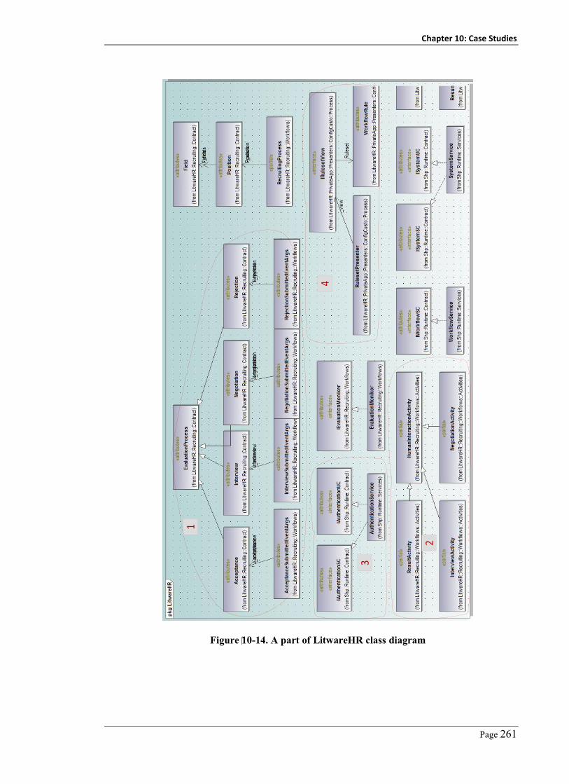
Chapter 10: Case Studies
Page 261
1
2
3
4
Figure 10-14. A part of LitwareHR class diagram

Chapter 10: Case Studies
Page 262
Table 10-6. LitwareHR found vulnerabilities and threats
Type Name Number/value
Attack scenarios
and metrics
Man-in-The-Middle (↓) 0
Denial of Service (↓) 2
Data Tampering (↓) 2
Injection Attack (↓) 3
Attack Surface (↓) 12
Compartmentalization (↑) 3
Fail Securely (↓) 11
Security
Vulnerabilities
SQLI 3
Authentication Bypass 0
Improper Authorization 3
XSS 3
CSRF 6
Table 10-7. LitwareHR security reengineering re-aspects
Re-aspect Signature Re-aspect Action Re-aspect Advice
AuthenticationGateway.GetUsers Replace Session[“TenantUsers”]
AuthenticationGateway.GetRoles Replace Session[“TenantRoles”]
Table 10-8. Tenants' security control
Security Attribute Contoso Fabrikam Swinburne Swine
Authentication LitwareHR LitwareHR Forms-based LDAP
Authorization LitwareHR LitwareHR Forms-based LDAP
I/Psan tization – – – Private Sanitization
Audit – – Private Auditor Private Auditor
Cryptography LitwareHR LitwareHR DES AES
Chapter 10: Case Studies
Page 263
The second solution, which we applied, is modifying the system configurations by removing the
details of security controls configurations used in the encrypted communication. For the
authentication and authorization properties, we have figured out that these properties are based on
security authentication and authorization controls. Again modifying websites configurations helped
to get rid of these security controls. We also found that authentication and authorization controls are
used in internal business functions such as workflow roles and users. To address these problems, we
have developed re-aspects to modify the LitwareHR source code to replace calls to these
authentication/authorization functions with access to session variables that maintain list of roles and
permissions that are set when the user login or requested from the source of security controls. We
found 14 functions in the authentication service and 5 functions in the authorization service. We
have categorized changes required to update system authentication and authorization into three
categories as follows. Table 10-7 summarizes re-aspects’ details required to update LitwareHR
with modifications we just explained now.
- Functions that are used in managing tenants’ accounts including adding, removing, updating,
deleting tenants, users and roles. We do not need to modify this part. It could still be used for
tenants who do not have new security requirements as we will see in the MDSE@R step.
- Functions used to authenticate and authorize users for certain actions (calls to these functions
should be left out). If the tenant does not want to change the system security capabilities, we will
inject system security controls using MDSE@R. A good point of the LitwareHR is that it is
mostly based on configurations. Authentication and authorization functions are integrated with
the system using configuration functions. Thus, we removed these configurations and will use
MDSE@R to integrate them at runtime whenever needed.
- Functions used in business functions. These functions should be replaced with session-based. To
do this task, we have used our re-aspects approach to modify the system source code. Here we
depend on MDSE@R to fill in these session variables.
10.3.6 LitwareHR - Security Engineering
Now we come to the runtime multi-tenant security engineering task. The first step here is to deliver
a system description model (SDM) that capture system features, architecture, deployment, and
design details. Figure 10-11, Figure 10-12, Figure 10-13, and Figure 10-14 show the SDM and SSM
models of the LitwareHR application. These models should have been delivered by LitwareHR
service providers. However, in our case study, we could not have all these models because the
system was developed beforehand. Thus, we developed some of these models manually by
analyzing the system source code. The other part was developed using reverse engineering
techniques. Next, service tenants (in this case study we have Contoso and Fabrikam) start
developing (and updating whenever needed) their security specification models to define their

Chapter 10: Case Studies
Page 264
security objectives, requirements, architecture, and controls. As a future work of our approach, we
plan to develop a client extension of MDSE@R where tenants can download the service SDM
model locally – i.e. inside their network perimeter – where they can develop their security model
and perform security-to-system mappings. These mapping are then refined locally – i.e. refining
mapping of high-level security concepts, such as security objectives, or high-level system entities,
such as system components, into security controls and system methods - and sent back to the
MDSE@R platform to update the live system and security specification documents. Thus tenants
can keep their security specification models confidential from hosting on the cloud platform.
In the security engineering chapter 6, we have validated in details the flexibility of MDSE@R to
manage traceability of security details from high-level to detailed-level security (security objectives
to security controls), managing traceability of system details using our UML profile (features to
methods), and the many-to-many mappings between tenants’ SSMs and system SDM. Here we
focus mainly on the key (mandatory) security diagrams required to realize tenants’ security (the
tenant security controls model).
Table 10-8 shows LitwareHR tenants’ security controls models. We consider in our usage
example including Contoso, Fabrikam, Swinburne, and Swin Market. From the usage example, both
Contoso and Fabrikam would like to apply the same set of security controls, while Swinburne and
Swin Market would like to apply different security requirements. The key problem with the
selection of these security controls to apply in our case study is that we have to develop adaptors for
these controls that implement our common security interface introduced in MDSE@R chapter and
integrates with these security controls. Thus, we reused the security controls we applied in the
MDSE@R Chapter. Table 10-9 summarizes mappings done by each tenant between the selected
security controls and system entities on the architecture level.
Table 10-9. Tenants' security-system mappings
Security
Attribute Contoso Fabrikam Swinburne Swin Market
Authentication Presentation
layer Presentation
layer Presentation layer Presentation + Services layer
Authorization Presentation
layer Presentation
layer Presentation + Services layer
Presentation + Services layer
I/Psan tization – – – Presentation
Audit – – Presentation + Services layer
Presentation + Services layer
Cryptography Communication
channels Communication
channels Presentation + Services layer
Presentation + Services layer

Chapter 10: Case Studies
Page 265
10.3.7 LitwareHR - Security Monitoring
We reuse the set of security metrics we defined in the security metrics and monitoring chapter (such
as Authenticated Requests, Authentic Requests, Last(10) Requests to Authorization Control,
Top(10) Request to Authentication Control By Admin Account, Mean Time Between Unauthentic
Request, etc.) as the set of security metrics to be applied on the LitwareHR instance in this case
study. For each tenant we use random number generator to control number of concurrent users per
tenant, number of requests per tenant(s), number of malicious requests. As a further evaluation of
the security management platform, we have defined a set of mitigation actions to be applied in case
of security metrics’ violations detected as shown in Table 10-10. The possible set of actions to be
taken could range from simple alerts up to getting system offline or even analyzing collected
measures and trying to detect root causes. However, our delivered platform capabilities, so far, is
limited to mitigation actions that could be applied by the MDSE@R enforcement component. A
future work in this point is to develop mitigation actions specification language with the associated
mitigation actions realization components. Table 10-11shows the behavior (values of different
metrics) of the LitwareHR when applying randomly generated requests (experiment attributes) at
different time steps. Figure 10-15 and Figure 10-16 show the trend of the security metrics we have
been monitoring.
0
0.2
0.4
0.6
0.8
1
1.2
1 2 3 4 5 6 7 8 9 10
Authenticated Requests
Authentic Requests
Logging Activities
Figure 10-15. Base security metrics' status and trend overtime
Figure 10-16. Derived security metrics' status and trend overtime
0
2
4
6
1 2 3 4 5 6 7 8 9 10
Mean Time BetweenUnauthentic Requests(sec)
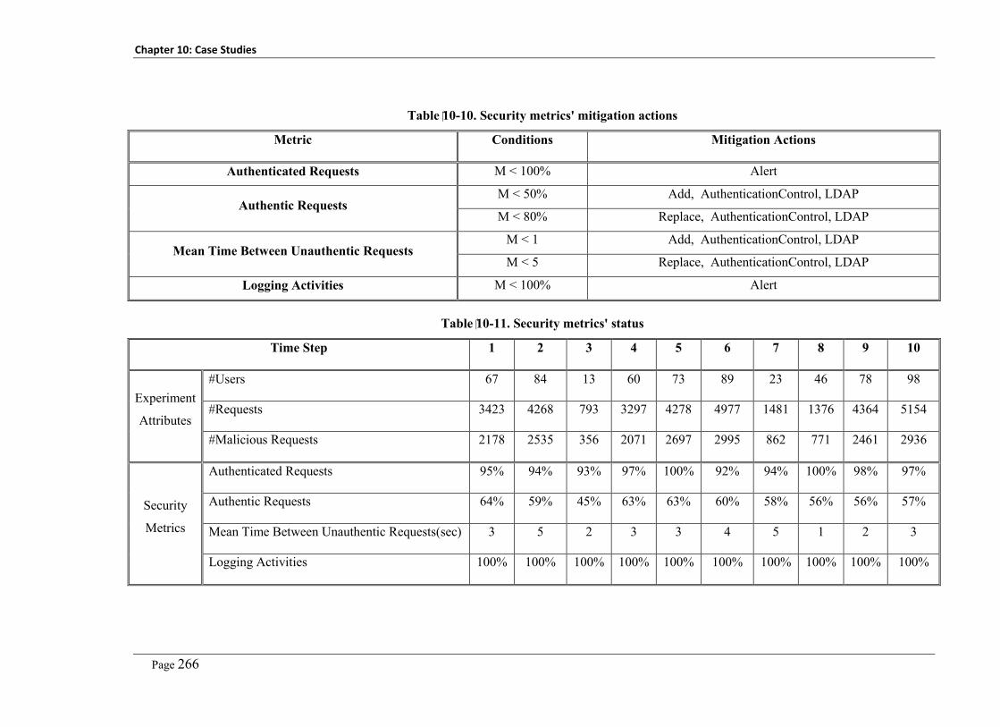
Chapter 10: Case Studies
Page 266
Table 10-10. Security metrics' mitigation actions
Metric Conditions Mitigation Actions
Authenticated Requests M < 100% Alert
Authentic Requests M < 50% Add, AuthenticationControl, LDAP
M < 80% Replace, AuthenticationControl, LDAP
Mean Time Between Unauthentic Requests M < 1 Add, AuthenticationControl, LDAP
M < 5 Replace, AuthenticationControl, LDAP
Logging Activities M < 100% Alert
Table 10-11. Security metrics' status
Time Step 1 2 3 4 5 6 7 8 9 10
Experiment
Attributes
#Users 67 84 13 60 73 89 23 46 78 98
#Requests 3423 4268 793 3297 4278 4977 1481 1376 4364 5154
#Malicious Requests 2178 2535 356 2071 2697 2995 862 771 2461 2936
Security
Metrics
Authenticated Requests 95% 94% 93% 97% 100% 92% 94% 100% 98% 97%
Authentic Requests 64% 59% 45% 63% 63% 60% 58% 56% 56% 57%
Mean Time Between Unauthentic Requests(sec) 3 5 2 3 3 4 5 1 2 3
Logging Activities 100% 100% 100% 100% 100% 100% 100% 100% 100% 100%

Chapter 10: Case Studies
Page 267
10.4 Chapter Summary
In this chapter, we introduced three case studies we conducted to assess our platform
components and integrations between platform components. The first case study addresses the
automated virtual patching of reported vulnerabilities by our online vulnerability analysis and
MDSE@R security enforcement component. Thus, this case study addresses integration
between security analysis and mitigation components. The second case study addresses
application of our reengineering aspects component in migrating applications to support multi-
tenancy as a key task, beside the security reengineering, in the preprocessing phase before
adopting the cloud computing model. The third case study shows the whole security
management process for different tenants applied on a SaaS application developed as a sample
multi-tenant application. One of the key areas that still need to improve is the mitigation actions
that could be applied with the current metrics’ values. Currently we support only mitigation
actions that are linked to the security enforcement component which may be adding extra
security control, replacing existing security control, or removing an existing security control to a
new or already secured system entity at runtime. Further actions could be updating operated
security controls’ configurations, analyzing root causes of the reported problem (deviation from
the expected behavior), or even taking system offline until further administrative actions are
taken. This may require developing an extension of our OCL-based language to capture such
invariants and metrics.


Page 269
Chapter 11
Conclusions and Future Work
In this chapter we summarize the key problems we addressed in our research project; key
observations we found throughout the project; key contributions we achieved; key limitations
we figured out in our approach and solutions; and key future work tasks that we plan to work on
as extension of the work introduced in this project and explained throughout this thesis.
11.1 Key Addressed Security Problems
In this research project we addressed a set of important security problems in the cloud
computing domain. This set of problems was identified from our initial cloud computing
security problem analysis that we completed in our first milestone [4]. Below we summarize
this set of problems that we addressed in our research project.
We addressed the Loss-of-Control Security Problem. This is one of the top ranked cloud
consumers’ security concerns about the cloud computing model. This problem arises from three
key factors: Outsourcing IT assets for hosting on third-party cloud platform; The new
responsibility matrix of the cloud computing model that puts cloud consumers out of control
over their assets (e.g. SaaS model); And lack of support to integrate cloud consumers’ security
controls’ with cloud services taking into consideration those different tenants may be sharing
the same service instance.
We addressed the Lack-of-Trust Problem. This is one of the top ranked cloud consumers’
security concerns about the adoption of the cloud computing model. This problem arises from:
The lack of feedback about the operated security, security breaches, and any relevant security
status; Cloud consumers do not trust that the cloud providers really enforce the specified
security controls; lack of security terms in the service level agreements between the cloud
provider, service provider, and cloud consumers; and cloud consumers do not trust that the
cloud provider administrators do not breach their assets security at rest, at processing, or at
transmission.
We addressed the tenants’ Security Integration Problem. Different tenants have their own
security requirements, policies and controls that they operate internally in their network
perimeter. These security controls should be integrated with their cloud-hosted assets as well.
Currently this is not supported by default. Service providers have to prepare a certain interface
or connectors to enable tenants in integrating their controls. Moreover, these tenants’ security
Chapter 11: Conclusions and Future Work
Page 270
requirements could be easily changed at runtime to address new security risks and threats. New
service tenants can register to use the service and apply their security requirements. Existing
tenants can unregister from the service. Those tenants should not be able to access or use the
service anymore.
We addressed the security problems arise from the public accessibility of cloud services.
Cloud-hosted services are publicly accessible to end users who may be malicious users.
Moreover, the cloud services are shared among different tenants. One of those tenants may be
malicious tenant or a competitor who wants to breach other tenants’ security. The key problem
of service sharing is that malicious users are granted high privilege and permissions to perform
more administrative actions. This increases the possibility to exploit more complicated
vulnerabilities and to perform planned attacks. On the other hand, depending on traditional
service patching approaches (through the use of service maintenance) takes a long time that
increases the probability of being under attack by exploiting the reported service vulnerabilities.
We addressed the tenants’ data isolation problem. Supporting multi-tenancy requires cloud
applications to support capturing, processing and storing data of different tenants on the same
application instance. Thus these applications must maintain isolation between different tenants’
data. Many of the existing well-known business applications that are widely used nowadays are
locked-in a high cost business model. This prohibits them from targeting/servicing.
11.2 Key Contributions
In this research project we have introduced a set of solutions to address security problems arise
from the adoption of the cloud computing model summarized in the previous section. Bellow
we summarize the key contributions we did in the cloud computing and security management
area.
We introduced a novel alignment of the NIST-FISMA standard to fit with the cloud
computing model. The existing security management standards are not developed taking into
consideration the multi-tenancy, sharing of cloud services, and outsourcing of the tenants’ assets
out of their network perimeter. Our proposed alignment is based on the joint-collaboration
between different cloud stakeholders (cloud providers, service providers, and cloud consumers)
in securing cloud platforms and services. To deliver this new alignment, we studied the standard
activities and tasks. Then, we developed a new responsibility matrix that shows who is
responsible to fulfill a given task and who are informed with these results. We also introduced a
web-based security management prototype to help in assessing our proposed alignment.
We introduced a novel security management platform for the cloud computing model based
on the use of model-based management concept to overcome the problem of manual

Chapter 11: Conclusions and Future Work
Page 271
customization and engineering efforts required to manage the target cloud-hosted services. The
model-based management is based on automating realization and configuration of the software
systems and security controls based on abstract system and security models. This approach best
fits with the cloud model as we cannot grant service consumers admin privileges to customize
or modify shared cloud services. Our security management model enables realization of both
manual security adaptation through updating system and security models as well as automated
security adaptation through specification of recovery and mitigation actions in case of reported
security vulnerabilities or deviations from the expected behaviors. The proposed model is based
on one of the key security management standards (NIST-FISMA standard) after aligning it to fit
with the cloud computing model. This helps in getting tenants and providers to keep their
security management processes including their cloud hosted assets easily aligned with the
security management standards using our cloud computing security management model.
We introduced a novel security modelling domain-specific visual language SecDSVL to be
used in capturing and modelling their security details. SecDSVL is based on a deep analysis of
the main entities and tasks existing in security management standards (mainly NIST-FISMA
standard). SecDSVL is made of 5 main models including security objectives model, security
requirements, security risks ad threats, security architecture and design, and security controls
model. SecDSVL is designed with the loosely coupling concept where each model addresses
specific perspective of the security management process that usually done by certain process
stakeholders.
We invented a novel, model-driven, tenant-oriented security engineering model compared
with the existing traditional design time, service-oriented, security engineering efforts. We
introduced multi-tenant, model-driven security engineering at runtime approach (MDSE@R).
Our approach enables different cloud and service tenants to manage (define, enforce, and
monitor) their service instances’ security at runtime without a need for service customizations.
MDSE@R introduces a comprehensive system description model (SDM) that captures all
system details (this model is developed by service providers using UML) and security
specification model (SSM) that captures each tenant’s security details (this model is developed
by service tenants using SecDSVL). MDSE@R introduces a common security interface that
helps in integrating third-party security controls with the target IT assets at runtime. Security
vendors need to develop their security services’ adaptor to comply with this security interface.
Thus, they do not need to develop different adaptors for different services.
We developed an extensible online security analysis service. We introduced a security
analysis service that can analyze service architecture, design, source code, and binaries to
identify the existing security design flaws and bugs. The key contributions of the security
analysis service are: integrated security analysis throughout different service artifacts including

Chapter 11: Conclusions and Future Work
Page 272
architecture, design and code; the security analysis service is extensible, thus we can add
different security analysis mechanisms without a need to modify the underlying platform; and
security analysis is signature-based, thus any vulnerability, threat, or system design security
metric could be easily specified and verified against the system without a need for new plugins.
This helps to support online analysis for known and unknown vulnerabilities that arise at
runtime as far as a signature of such vulnerability exists.
We invented a new, extensible security monitoring service. The main contribution of this
security monitoring service is that we did not develop a predefined set of security metrics.
Service users can define their own security metrics they wanted to use in diagnosing the security
status of their cloud assets. The security monitoring service uses these metrics signatures
(definitions) to generate and deploy required security probes that will be responsible for
collecting required measurements from the target cloud assets. Moreover, it uses these
signatures in generating metric evaluation expressions that will be used in analysing the
collected measurements and generating metric values.
We invented a new pre-processing tool to help migrating legacy applications to the cloud
and disabling pre-existing, hardcoded security functionalities. In order to help managing
services security using MDSE@R we need to disable the existing security APIs and functions.
We introduce a novel system and security reengineering approach using a new concept called
reengineering aspects “Re-aspects”. This new concept helps in capturing system modification
details including signature of system entities to modify, actions to apply, advice(s) or code to
use in realizing this change. The re-aspects engine uses these details to realize the captured
change request details. This approach is supported with two signature specification approaches
including code-snippets signatures and OCL-based signatures. We used re-aspects in two
problems: the patching/mitigation of reported vulnerabilities and in migrating legacy
applications that are not designed with multi-tenancy in mind to support cloud multi-tenancy.
We invented a new, automated vulnerability virtual patching approach. This is an integration
of the MDSE@R and vulnerability analysis service. This approach provides an automated
virtual patching where reported vulnerabilities are fed in MDSE@R to inject specified security
controls (as specified in the vulnerability mitigation actions) at the critical (vulnerable) system
entities at runtime without waiting for patches that usually take several weeks.
11.3 Key Limitations
In this section we summarize the key limitations that we determined out in our proposed
solutions and contributions we explained throughout this thesis. Below we summarize these
limitations grouped by the corresponding approach or contribution.

Chapter 11: Conclusions and Future Work
Page 273
MDSE@R does not help in realizing security requirements that should be enforced on the
cloud services’ underlying platforms (e.g. webservers) and operating systems (in case of
separate VMs). Moreover, MDSE@R currently does not support security engineering of
applications developed by languages other than .NET languages because of the currently used
system wrapper. We plan to develop further wrappers for systems developed with Java and
scripting languages.
The current signature locator implements static signature analysis of the software source
code and system architecture. This helps in identifying certain types of security vulnerabilities
that have strong signatures in source code. Other vulnerabilities related to dynamic analysis
such as cross site reference forgery (CSRF) could not be addressed with high accuracy using the
static analysis. It is worth mentioning here that our security analysis platform is already
developed with such possible extensions in mind.
Another problem with our security analysis approach is that applications using dynamic
integration of security controls using aspect-oriented programming will result in high false
positives as we cannot trace the existence of security controls’ calls in the system source code.
The same applies with applications that depend on the hosting platform (webserver) deployed
security controls. Furthermore, applications with obfuscated binaries are hard to analyze (given
that we do not have access to the source code) because we cannot reflect source code from
system binaries using the existing reflection techniques.
The accuracy of the security analysis results depends on the specified vulnerabilities, attacks,
and metrics’ signatures. This justifies our assumption that such signatures should be developed
by security experts. As a possible improvement to this problem, we plan to develop an artificial
intelligent extension that can analyze reported vulnerabilities in the National Vulnerabilities
Database (NVD) and come up with the security vulnerabilities’ signatures that represent such
vulnerabilities.
The current implementation of the security monitoring approach supports only security
metrics but not security properties (policies). Moreover, the current approach is limited in terms
of the mitigation actions that could be applied to the capabilities provided by the security
enforcement component (MDSE@R). Thus any further analysis or mitigation actions still not
supported.
The currently used probe generator technology (Roslyn Scripting APIs) result in security
probes with high performance overhead because we compile and run security probe code at
runtime. We are currently investigating in how to integrate newly generated security probes
with the system wrapper without a need to perform online compilation.

Chapter 11: Conclusions and Future Work
Page 274
Our security reengineering approach does not help with system modifications that have
hierarchical impact on system entities – i.e. modifying entity A requires modifying B and C,
modifying B and C requires modifying D, E, and F. our reengineering approach (re-aspects)
supports only one level of the impacted entities. This can be addressed by extending impact re-
aspect to be a complete re-aspect. But this will increase developers’ involvement.
The accuracy of the located entities to be modified, entities that will be impacted, and
validity of the applied modification actions by a given system modification depends on the
signature specified by the re-aspects developer.
Applications with obfuscated binaries are hard to reengineer because we cannot reverse
engineer source code from system binaries using existing reflection techniques.
11.4 Future Work
In this thesis we have introduced an adaptive, model-based cloud computing security
management approach. Our proposed approach focused on delivering a platform that helps
enforcing different sets of security requirements for different tenants that arise at runtime. We
take the single-instance multi-tenant Software-as-a-Service service delivery model as the main
model to be addressed by our approach. This is because it represents the most complicated
service delivery model. The work we did with the software-as-a-service service delivery model
can easily be applied on the platform-as-a-service service delivery model. Below we summarize
future extensions in the proposed approach in general and in specific components of the
delivered platform:
We plan to extend our security management platform to include managing security of the
Infrastructure-as-a-service service delivery model. This helps tenants to extend their security
management capabilities to manage security of their cloud virtual infrastructure (mainly virtual
machines). This enables our security management platform to deliver comprehensive cloud
computing security management platform that could be used to manage cloud platform security
whatever the service delivery model(s) delivered by the cloud platform. It enables mitigating the
cloud consumers’ lack-of-trust problems completely. Moreover, it enables cloud providers to
integrate their security management platforms (used to manage the cloud platform security) with
our platform in one comprehensive and integrated model. A further key point is the adoption of
homo-morphic encryption where tenants’ data are not even decrypted while being processed on
the cloud platform. This helps in addressing concerns related to malicious insiders – i.e. cloud
platform administrators who are expected to have access to the hosting server memory, storage,
and network.

Chapter 11: Conclusions and Future Work
Page 275
We plan to extend our vulnerability analysis platform to support not only static analysis but
also dynamic analysis. This dynamic analysis will be mostly dependent on the security
monitoring platform with a test case generation service. The analysis of application responses
should be automated according to vulnerability specified signature. The security vulnerability
analysis platform is designed with extensibility in mind. Thus, we will not need to modify its
design. We will need to develop the dynamic analysis component as a plugin to be registered
and triggered by the vulnerability analysis platform according to the type of the vulnerability
signature (static or dynamic signature).
We plan to extend the security monitoring platform with mitigation action and analysis
specification language. The objective of this extension is to provide a formal and familiar
language to help in developing expressions that could be used in identifying root causes of
possible system deviations from the normal behavior specified by service tenants. Moreover,
this could help in specifying and applying more complicated mitigation actions on the service or
its underlying platform such as replacing one of the service components with a more secure one,
using components from another service provider in case of mash up applications, or extending
the operated security with more complicated controls.
We plan to conduct multiple large scale industrial case studies with different industrial cloud
platform providers, service providers and a set of SaaS applications hosted on different cloud
platforms and shared among different tenants. We also plan to contact different security vendors
who deliver cloud-based security services (authentication, authorization, etc.) to get involved in
developing a common security interface that facilitates integrating security controls with the
target cloud services.

Page 277
References
[1] National Institute of standards and technology (NIST), "The Federal Information Security Management Act (FISMA)," Washington: U.S. Government Printing, 2002, http://csrc.nist.gov/drivers/documents/FISMA-final.pdf, Accessed on August 2010.
[2] P. Mell and T. Grance, "The NIST Definition of Cloud Computing," 2009, http://www.wheresmyserver.co.nz/storage/media/faq-files/cloud-def-v15.pdf, Accessed April 2010.
[3] R. Buyya, C. Yeo, and S. Venugopal, "Market-Oriented Cloud Computing: Vision, Hype, and Reality for Delivering IT Services as Computing Utilities," in Proc. of 9th IEEE/ACM International Symposium on Cluster Computing and the Grid 2008, p. 1.
[4] M. Almorsy, J. Grundy, and I. Mueller, "An analysis of the cloud computing security problem," in Proc. 2010 Asia Pacific Cloud Workshop, Colocated with APSEC, Sydney, Australia, 2010.
[5] International Organization for Standardization (ISO), "ISO/IEC 27000 - Information technology - Security techniques - Information security management systems - Overview and vocabulary," ISO/IEC 27001:2005(E), 2009, http://webstore.iec.ch/preview/info_isoiec27000%7Bed1.0%7Den.pdf, Accessed On July 2010.
[6] C. Basile, A. Lioy, G. M. Perez, F. J. G. Clemente, and A. F. G. Skarmeta, "POSITIF: A Policy-Based Security Management System," in Eighth IEEE International Workshop on Policies for Distributed Systems and Networks, 2007. POLICY '07, 2007, pp. 280-280.
[7] B. Tsoumas and D. Gritzalis, "Towards an Ontology-based Security Management," presented at the Proc. of 20th International Conference on Advanced Information Networking and Applications - Volume 01, 2006.
[8] J. P. d. Albuquerque, H. Krumm, and P. L. d. Geus, "Model-based management of security services in complex network environments," in IEEE Network Operations and Management Symposium, Salvador, Bahia, 2008, pp. 1031-1036.
[9] P. Marek and J. Paulina, "The OCTAVE methodology as a risk analysis tool for business resources," in Proc. of The 2006 International Multiconference Computer Science and Information Technology, 2006.
[10] R. Fredriksen, M. Kristiansen, B. Gran, and K. Stølen, "The CORAS Framework for a Model-Based Risk Management Process," in Computer Safety, Reliability and Security. vol. 2434, S. Anderson, M. Felici, and S. Bologna, Eds., ed: Springer Berlin / Heidelberg, 2002, pp. 39-53.
[11] P. Saripalli and B. Walters, "QUIRC: A Quantitative Impact and Risk Assessment Framework for Cloud Security," in 2010 IEEE 3rd International Conference on Cloud Computing (CLOUD), 2010, pp. 280-288.
[12] Z. Xuan, N. Wuwong, L. Hao, and Z. Xuejie, "Information Security Risk Management Framework for the Cloud Computing Environments," in 2010 IEEE 10th International Conference on Computer and Information Technology (CIT), , 2010, pp. 1328-1334.
[13] S. A. d. Chaves, C. B. Westphall, and F. R. Lamin, "SLA Perspective in Security Management for Cloud Computing," in Proc. of The 6th International Conference on Networking and Services, Cancun, Mexico, 2010, pp. 212-217.
[14] J. Jürjens, "Towards Development of Secure Systems Using UMLsec," in Fundamental Approaches to Software Engineering. vol. 2029, ed: Springer Berlin Heidelberg, 2001, pp. 187-200.
[15] T. Lodderstedt, D. Basin, and J. Doser, "SecureUML: A UML-Based Modeling Language for Model-Driven Security," in Proc. of The 5th International Conference on The Unified Modeling Language, Dresden, Germany, 2002, pp. 426-441.

References
Page 278
[16] A. Lamsweerde, S. Brohez, and e. al, "System Goals to Intruder Anti-Goals: Attack Generation and Resolution for Security Requirements Engineering," in Proc. of the RE’03 Workshop on Requirements for High Assurance Systems, Monterey, 2003, pp. 49-56.
[17] B. Hashii, S. Malabarba, R. Pandey, and e. al, "Supporting reconfigurable security policies for mobile programs," in Proc. of the 9th international World Wide Web conference on Computer networks, Amsterdam, The Netherlands, 2000, pp. 77-93.
[18] K. Scott, N. Kumar, S. Velusamy, and e. al, "Retargetable and reconfigurable software dynamic translation," in proc. of the international symposium on Code generation and optimization, San Francisco, California, 2003.
[19] F. Sanchez-Cid, and A. Mana, "SERENITY Pattern-Based Software Development Life-Cycle," in 19th International Workshop on Database and Expert Systems Application, 2008, pp. 305-309.
[20] B. Morin, T. Mouelhi, and F. Fleurey, "Security-driven model-based dynamic adaptation," in Proc. of the IEEE/ACM International Conference on Automated software engineering, Antwerp, Belgium, 2010.
[21] M. Menzel, R. Warschofsky, I. Thomas, C. Willems, and C. Meinel, "The Service Security Lab: A Model-Driven Platform to Compose and Explore Service Security in the Cloud," in 2010 6th World Congress on Services (SERVICES-1), 2010, pp. 115-122.
[22] H. Cai, N. Wang, and M. J. Zhou, "A Transparent Approach of Enabling SaaS Multi-tenancy in the Cloud," in 2010 6th World Congress on Services (SERVICES-1), 2010, pp. 40-47.
[23] H. Cai, K. Zhang, M. J. Zhou, W. Gong, J. J. Cai, and X. S. Mao, "An End-to-End Methodology and Toolkit for Fine Granularity SaaS-ization," in Proc. of The IEEE International Conference on Cloud Computing, 2009, pp. 101-108.
[24] C. J. Guo, W. Sun, Y. Huang, Z. H. Wang, and B. Gao, "A Framework for Native Multi-Tenancy Application Development and Management," in Proc. of The 4th IEEE International Conference on Enterprise Computing, E-Commerce, and E-Services, 2007, pp. 551-558.
[25] Z. Pervez, S. Lee, and Y.-K. Lee, "Multi-tenant, secure, load disseminated SaaS architecture," in Proc. of 12th international conference on Advanced communication technology, Gangwon-Do, South Korea, 2010, pp. 214-219.
[26] J. Xu, T. Jinglei, H. Dongjian, Z. Linsen, C. Lin, and N. Fang, "Research and implementation on access control of management-type SaaS," in Proc. of The The 2nd IEEE International Conference on Information Management and Engineering (ICIME), 2010, pp. 388-392.
[27] S. Chandra and R. A. Khan, "Software security metric identification framework (SSM)," in Proc. of the International Conference on Advances in Computing, Communication and Control, Mumbai, India, 2009, pp. 725-731.
[28] R. M. Savola and H. Abie, "Development of security metrics for a distributed messaging system," in Proc. of The 2009 International Conference on Application of Information and Communication Technologies, 2009, pp. 1-6.
[29] R. M. Savola and H. Abie, "Identification of Basic Measurable Security Components for a Distributed Messaging System," in Proc. of the 2009 Third International Conference on Emerging Security Information, Systems and Technologies, 2009.
[30] R. M. Savola and P. Heinonen, "Security-Measurability-Enhancing Mechanisms for a Distributed Adaptive Security Monitoring System," in Proc. of The 2010 4th International Conference on Emerging Security Information Systems and Technologies (SECURWARE), 2010, pp. 25-34.
[31] R. M. Savola and P. Heinonen, "A visualization and modeling tool for security metrics and measurements management," in Proc. of 2011 Conference Information Security South Africa (ISSA), 2011, pp. 1-8.
[32] X. Jin, R. Krishnan, and R. Sandhu, "A unified attribute-based access control model covering DAC, MAC and RBAC," in Proc. of the 26th Annual IFIP WG 11.3
References
Page 279
conference on Data and Applications Security and Privacy, Paris, France, 2012, pp. 41-55.
[33] M. Almorsy, J. Grundy and A. S. Ibrahim, "Collaboration-Based Cloud Computing Security Management Framework," in Proc. of 2011 IEEE International Conference on Cloud Computing (CLOUD 2011), Washington DC, USA, 2010, pp. 364 - 371.
[34] M. Almorsy, J. Grundy, and A. S. Ibrahim, "MDSE@R: Model-Driven Security Engineering at Runtime," in Proc. of the 4th International Symposium on Cyberspace Safety and Security, Melbourne, Australia, 2012.
[35] M. Almorsy, J. Grundy, and A. S. Ibrahim, "TOSSMA: Tenant-Oriented SaaS Applications Security Management Architecture," in Proc. of The 5th International Conference on Cloud Computing, Hawaii, USA, 2012, pp. 981- 988.
[36] C. S. Jr., L. A. Wahsheh, A. Ahmad, J. M. Graham, C. V. Hinds, A. T. Williams, and S. J. DeLoatch, "Software Security: The Dangerous Afterthought," in Proc. of The 2012 Ninth International Conference on Information Technology: New Generations (ITNG), 2012, pp. 815-818.
[37] S. C. Previtali and T. R. Gross, "Aspect-based dynamic software updating: a model and its empirical evaluation," in Proc. of 10th international conference on Aspect-oriented software development, Porto de Galinhas, Brazil, 2011, pp. 105-116.
[38] M. Almorsy, J. Grundy, and A. S. Ibrahim, "SMURF: Supporting Multi-tenancy Using Re-aspects Framework," in Proc. of The 17th International Conference on Engineering of Complex Computer Systems (ICECCS), 2012, pp. 361-370.
[39] M. Almorsy, J. Grundy, and A. S. Ibrahim, "Supporting automated software re-engineering using re-aspects," in Proc. of 27th IEEE/ACM International Conference on Automated Software Engineering, Essen, Germany, 2012.
[40] OWASP. (2010). The Ten Most Critical Web Application Security Vulnerabilities. Available: http://www.owasp.org/index.php/OWASP_Top_Ten_Project
[41] M. Almorsy, J. Grundy, and A. S. Ibrahim, "Supporting automated vulnerability analysis using formalized vulnerability signatures," in Proc. of 27th IEEE/ACM International Conference on Automated Software Engineering, Essen, Germany, 2012.
[42] M. Almorsy, J. Grundy, and A. S. Ibrahim, "Automated Software Architecture Security Risk Analysis Using Formalized Signatures," in Proc. of The 36th International Conference of Software Engineering, San Francisco, 2013, pp. 300-309.
[43] M. Almorsy, J. Grundy, and A. Ibrahim, "VAM-aaS: Online Cloud Services Security Vulnerability Analysis and Mitigation-as-a-Service," in Web Information Systems Engineering - WISE 2012, X. S. Wang, I. Cruz, A. Delis, and G. Huang, Eds., ed: Springer Berlin Heidelberg, 2012, pp. 411-425.
[44] Lamia Youseff, Maria Butrico and Dilma Da Silva, "Toward a Unified Ontology of Cloud Computing," in Grid Computing Environments Workshop, Austin, TX, 2008, pp. 1-10.
[45] F. Gens, R. P. Mahowald, and R. L. Villars. (2009). IDC Cloud Computing 2010. [46] Cloud Computing Use Case Discussion Group, "Cloud Computing Use Cases," White
Paper, 2010, Accessed on May 2010. [47] European Network and Information Security Agency (ENISA), "Cloud computing:
benefits, risks and recommendations for information security," 2009, http://www.enisa.europa.eu/act/rm/files/deliverables/cloud-computing-risk-assessment, Accessed On July 2010.
[48] Q. Zhang, L. Cheng, and R. Boutaba, "Cloud computing: state-of-the-art and research challenges," Journal of Internet Services and Applications, vol. 1, pp. 7-18, 2010/05/01 2010.
[49] B. R. Kandukuri, R. Paturi, and A. Rakshit, "Cloud Security Issues," in Proc. of the 2009 IEEE International Conference on Services Computing, 2009, pp. 517-520.
[50] F. Lombardi and R. Di Pietro, "Secure virtualization for cloud computing," Journal of Network and Computer Applications, vol. 34, pp. 1113-1122, 2011.
References
Page 280
[51] K. Bernsmed, M. G. Jaatun, P. H. Meland, and A. Undheim, "Security SLAs for Federated Cloud Services," in Proc. of The 2011 Sixth International Conference on Availability, Reliability and Security (ARES), 2011, pp. 202-209.
[52] A. Ibrahim, J. Hamlyn-Harris, and J. Grundy, "Emerging Security Challenges of Cloud Virtual Infrastructure " in Proc. of The Asia Pacific Cloud Workshop (co-located with apsec2010), Sydney, Australia, 2010.
[53] D. K. Holstein and K. Stouffer, "Trust but Verify Critical Infrastructure Cyber Security Solutions," in Proc. of 43rd Hawaii International Conference on System Sciences (HICSS), 2010, pp. 1-8.
[54] T. Ristenpart, E. Tromer, H. Shacham, and S. Savage, "Hey, you, get off of my cloud: exploring information leakage in third-party compute clouds," in Proc. of the 16th ACM conference on Computer and communications security, Chicago, Illinois, USA, 2009.
[55] A. S. Ibrahim, J. Hamlyn-Harris, J. Grundy, and M. Almorsy, "Supporting Virtualization-Aware Security Solutions Using a Systematic Approach to Overcome the Semantic Gap," in Proc. of The 2012 IEEE 5th International Conference on Cloud Computing (CLOUD), 2012, pp. 836-843.
[56] W. Dawoud, I. Takouna, and C. Meinel, "Infrastructure as a service security: Challenges and solutions," in Proc. of The 7th International Conference on Informatics and Systems, Cairo, Eypt, 2010, pp. 1-8.
[57] M. Jensen, N. Gruschka, R. Herkenhoner, and N. Luttenberger, "SOA and Web Services: New Technologies, New Standards - New Attacks," in Proc. of The 5th European Conference on Web Services, 2007, pp. 35-44.
[58] Z. Wenjun, "Integrated Security Framework for Secure Web Services," in 2010 Third International Symposium on Intelligent Information Technology and Security Informatics (IITSI), 2010, pp. 178-183.
[59] W. Bin, H. H. Yuan, L. X. Xi, and X. J. Min, "Open Identity Management Framework for SaaS Ecosystem," in Proc. of The 2009 IEEE International Conference on e-Business Engineering, 2009, pp. 512-517.
[60] V. Felmetsger, L. Cavedon, C. Kruegel, and G. Vigna, "Toward automated detection of logic vulnerabilities in web applications," in Proc. of 19th USENIX conference on Security, Washington, DC, 2010, pp. 10–10.
[61] P. Angin, B. Bhargava, R. Ranchal, N. Singh, M. Linderman, L. B. Othmane, and L. Lilien, "An Entity-Centric Approach for Privacy and Identity Management in Cloud Computing," in 2010 29th IEEE Symposium on Reliable Distributed Systems, 2010, pp. 177-183.
[62] M. Bellare, T. Ristenpart, P. Rogaway, and T. Stegers, "Format-Preserving Encryption," in Selected Areas in Cryptography. vol. 5867, M. Jacobson, Jr., V. Rijmen, and R. Safavi-Naini, Eds., ed: Springer Berlin Heidelberg, 2009, pp. 295-312.
[63] Z. Brakerski and V. Vaikuntanathan, "Efficient Fully Homomorphic Encryption from (Standard) LWE," in 2011 IEEE 52nd Annual Symposium on Foundations of Computer Science (FOCS), 2011, pp. 97-106.
[64] D. Yum and P. Lee, "Identity-Based Cryptography in Public Key Management," in Public Key Infrastructure. vol. 3093, S. Katsikas, S. Gritzalis, and J. López, Eds., ed: Springer Berlin Heidelberg, 2004, pp. 71-84.
[65] N. Mead, T Stehney, "Security quality requirements engineering (SQUARE) methodology," in Proc. of 2005 workshop on Software engineering for secure systems and building trustworthy applications, Missouri, 2005.
[66] W. D. Yu and K. Le, "Towards a Secure Software Development Lifecycle with SQUARE+R," in Proc. of IEEE 36th Annual Computer Software and Applications Conference Workshops (COMPSACW), 2012, pp. 565-570.
[67] C. S. A. (CSA), " Top Threats to Cloud Computing V1.0,", URL: https://cloudsecurityalliance.org/topthreats/csathreats.v1.0.pdf, Accessed March, 2010.
[68] E. Humphreys, "Information security management standards: Compliance, governance and risk management," Information Security Technical Report, vol. 13, pp. 247-255, 2008.

References
Page 281
[69] A. Tsohou, S. Kokolakis, C. Lambrinoudakis, and S. Gritzalis, "Information Systems Security Management: A Review and a Classification of the ISO Standards," in Next Generation Society. Technological and Legal Issues. vol. 26, A. Sideridis and C. Patrikakis, Eds., ed: Springer Berlin Heidelberg, 2010, pp. 220-235.
[70] Common Criteria for Information Technology Security Evaluation, "Part 1: Introduction and general model, Version 3.1," 2006, http://www.commoncriteriaportal.org/files/ccfiles/CCPART1V3.1R1.pdf, Accessed on August 2010.
[71] F. Pattinson, "Security Assurance: Contrasting FISMA and ISO/IEC 27001," 2011, Available: http://www.atsec.com/downloads/documents/FISMA_27001.pdf, Accessed May 2012
[72] C. Gikas, "A General Comparison of FISMA, HIPAA, ISO 27000 and PCI-DSS Standards," Inf. Sec. J.: A Global Perspective, vol. 19, pp. 132-141, 2010.
[73] M. Siponen and R. Willison, "Information security management standards: Problems and solutions," Information & Management, vol. 46, pp. 267-270, 2009.
[74] M. Al-Morsy and H. Faheem, "A new standard security policy language," IEEE Potentials, vol. 28, pp. 19-26, 2009.
[75] N. Damianou, N. Dulay, E. Lupu, and M. Sloman, "The Ponder Policy Specification Language," in Proc. the International Workshop on Policies for Distributed Systems and Networks, 2001.
[76] J. Lobo, R. Bhatia, and S. Naqvi, "A policy description language," in Proc. of the sixteenth national conference on Artificial intelligence and the eleventh Innovative applications of artificial intelligence conference innovative applications of artificial intelligence, Orlando, Florida, United States, 1999.
[77] C. Basile, A. Lioy, G. M. Perez, and F. J. G. Clemente, "POSITIF: A Policy-Based Security Management System," in Proc. of 8th IEEE International Workshop on Policies for Distributed Systems and Networks Bologna, 2007, pp. 280-280.
[78] D. M. T. F.-. DMTF. (2011, July 2012). Common Information Model - CIM Schemas Version 2.31.0. Available: http://dmtf.org/standards/cim
[79] H. M. Faheem, "A multiagent-based approach for managing security policy," in Proc. of The Second IFIP International Conference on Wireless and Optical Communications Networks, 2005, pp. 351-356.
[80] M. Almorsy and H. M. Faheem, "A Multi-agent based Framework for Managing Security Policy," in Proc. of The 18th International Conference on Computer Theory and Applications (ICCTA 2008), Alexandria, Egypt, 2008.
[81] J. López de Vergara, A. Guerrero, V. Villagrá, and J. Berrocal, "Ontology-Based Network Management: Study Cases and Lessons Learned," Journal of Network and Systems Management, vol. 17, pp. 234-254, 2009/09/01 2009.
[82] J. P. Thompson, "Web-based enterprise management architecture," IEEE Communications Magazine, vol. 36, pp. 80-86, 1998.
[83] X. Hui, X. Xue, X. Debao, and L. Xuejiao, "Towards Automation for Pervasive Network Security Management Using an Integration of Ontology-Based and Policy-Based Approaches," in Proc. of The 3rd International Conference on Innovative Computing Information and Control, Dalian, Liaoning, 2008, pp. 87-87.
[84] A. Uszok, J. M. Bradshaw, J. Lott, M. Breedy, L. Bunch, P. Feltovich, M. Johnson, and J. Hyuckchul, "New Developments in Ontology-Based Policy Management: Increasing the Practicality and Comprehensiveness of KAoS," in Proc. of The 2008 IEEE Workshop on Policies for Distributed Systems and Networks, 2008, pp. 145-152.
[85] R. S. Ulrich Lang, "Model driven security management: Making security management manageable in complex distributed systems," in proc. of The Modeling Security Workshop in Association with MODELS, Toulouse, France, 2008.
[86] A. Syalim, Y. Hori, and K. Sakurai, "Comparison of Risk Analysis Methods: Mehari, Magerit, NIST800-30 and Microsoft's Security Management Guide," in Proc. of The 2009 International Conference on Availability, Reliability and Security, 2009, pp. 726-731.

References
Page 282
[87] K. Djemame, D. J. Armstrong, M. Kiran, and M. Jiang, "A Risk Assessment Framework and Software Toolkit for Cloud Service Ecosystems," in Proc. of The 2nd International Conference on Cloud Computing, GRIDs, and Virtualization, Rome, Italy, 2011, pp. pp. 119 - 126.
[88] R. Kazman, L. Bass, M. Klein, T. Lattanze, and L. Northrop, "A Basis for Analyzing Software Architecture Analysis Methods," Software Quality Journal, vol. 13, pp. 329-355, 2005.
[89] L. Dobrica and E. Niemela, "A survey on software architecture analysis methods," IEEE Transactions on Software Engineering, vol. 28, pp. 638-653, 2002.
[90] M. A. Babar, L. Zhu, and R. Jeffery, "A framework for classifying and comparing software architecture evaluation methods," in Proc. of the 2004 Australian Software Engineering Conference, 2004, pp. 309-318.
[91] P. Clements, R. Kazman, and M. Klein, Evaluating software architectures: methods and case studies: Addison-Wesley Reading, 2002.
[92] F. Faniyi, R. Bahsoon, A. Evans, and R. Kazman, "Evaluating Security Properties of Architectures in Unpredictable Environments: A Case for Cloud," in Proc. of 9th Working IEEE/IFIP Conference on Software Architecture, 2011, pp. 127-136.
[93] S. T. Halkidis, N. Tsantalis, A. Chatzigeorgiou, and G. Stephanides, "Architectural Risk Analysis of Software Systems Based on Security Patterns," IEEE Transactions on Dependable and Secure Computing, vol. 5, pp. 129-142, 2008.
[94] M. Abi-Antoun and J. r. M. Barnes, "STRIDE-based security model in Acme," Technical Report CMU-ISR-10-106, Carnegie Mellon Univ., 2010.
[95] N. Admodisastro and G. Kotonya, "An architecture analysis approach for supporting black-box software development," in Proc. of the 5th European conference on Software architecture, Essen, Germany, 2011, pp. 180-189.
[96] A. Alkussayer and W. H. Allen, "A scenario-based framework for the security evaluation of software architecture," in Proc. 3rd IEEE International Conference on Computer Science and Information Technology, 2010, pp. 687-695.
[97] A. Alkussayer and W. H. Allen, "Security risk analysis of software architecture based on AHP," in Proc. 7th International Conference on Networked Computing, 2011, pp. 60-67.
[98] P. Antonino, S. Duszynski, C. Jung, and M. Rudolph, "Indicator-based architecture-level security evaluation in a service-oriented environment," in Proc. of the Fourth European Conference on Software Architecture, Copenhagen, Denmark, 2010.
[99] C. Sant’Anna, E. Figueiredo, A. Garcia, and C. J. P. Lucena, "On the Modularity Assessment of Software Architectures: Do my architectural concerns count?," in 6th International Workshop on Aspect-Oriented Software Development, Vancouver, British Columbia, 2007, pp. 183-192.
[100] B. Alshammari, C. Fidge, and D. Corney, "A Hierarchical Security Assessment Model for Object-Oriented Programs," in Proc. of The 11th International Conference on Quality Software (QSIC), 2011, pp. 218-227.
[101] B. Alshammari, C. Fidge, and D. Corney, "Security Metrics for Object-Oriented Class Designs," in Proc. 9th International Conference on Quality Software, 2009, pp. 11-20.
[102] T. Heyman, R. Scandariato, C. Huygens, and W. Joosen, "Using Security Patterns to Combine Security Metrics," in Proc. of The 3rd International Conference on Availability, Reliability and Security, 2008, pp. 1156-1163.
[103] K. Sohr and B. Berger, "Idea: towards architecture-centric security analysis of software," in Proc. the 2nd international conference on Engineering Secure Software and Systems, Pisa, Italy, 2010.
[104] Y. Liu, I. Traore, and A. M. Hoole, "A Service-Oriented Framework for Quantitative Security Analysis of Software Architectures," in Proc. IEEE 2008 Asia-Pacific Services Computing Conference, 2008, pp. 1231-1238.
[105] A. M. Willy Jimenez, Ana Cavalli "Software Vulnarabilities, Prevention and Detection Methods: A Reviw," in Proc. of 2009 European Workshop on Security in Model Driven Architecture, Enschede, The Netherlands, 2009, p. 6—13.

References
Page 283
[106] NIST, "Source Code Security Analysis Tool Functional Specification Version 1.1," URL:http://samate.nist.gov/docs/source_code_security_analysis_spec_SP500-268_v1.1.pdf, May 2007, Accessed 2011.
[107] W. G. J. Halfond, A. Orso, and P. Manolios, "Using positive tainting and syntax-aware evaluation to counter SQL injection attacks," in Proc. of 14th ACM SIGSOFT international symposium on Foundations of software engineering, Oregon, USA, 2006, pp. 175-185.
[108] W. Lei, Z. Qiang, and Z. PengChao, "Automated Detection of Code Vulnerabilities Based on Program Analysis and Model Checking," in Proc. of 8th IEEE International Working Conference on Source Code Analysis and Manipulation, 2008, pp. 165-173.
[109] A. Dasgupta, V. Narasayya, and M. Syamala, "A Static Analysis Framework for Database Applications," in Proc. of 2009 IEEE International Conference on Data Engineering, 2009, pp. 1403-1414.
[110] M. Martin, B. Livshits, and M. S. Lam, "Finding application errors and security flaws using PQL: a program query language," in Proc. of the 20th annual ACM SIGPLAN conference on Object-oriented programming, systems, languages, and applications CA, USA, 2005, pp. 365-383.
[111] M. S. Lam, M. Martin, B. Livshits, and J. Whaley, "Securing web applications with static and dynamic information flow tracking," in Proc. of 2008 ACM SIGPLAN symposium on Partial evaluation and semantics-based program manipulation, California, USA, 2008, pp. 3-12.
[112] G. Wassermann and Z. Su, "Static detection of cross-site scripting vulnerabilities," in Proc. of 30th international conference on Software engineering, Leipzig, Germany, 2008, pp. 171-180.
[113] N. Jovanovic, C. Kruegel, and E. Kirda, "Pixy: a static analysis tool for detecting Web application vulnerabilities," in Proc. of 2006 IEEE Symposium on Security and Privacy, 2006, pp. 258-263.
[114] V. Ganesh, A. Kieżun, S. Artzi, P. J. Guo, P. Hooimeijer, and M. Ernst, "HAMPI: a string solver for testing, analysis and vulnerability detection," in Proc. of 23rd international conference on Computer aided verification, Snowbird, UT, 2011, pp. 1-19.
[115] A. Kieyzun, P. J. Guo, K. Jayaraman, and M. D. Ernst, "Automatic creation of SQL Injection and cross-site scripting attacks," in Proc. of 31st International Conference on Software Engineering, 2009, pp. 199-209.
[116] J. Bau, E. Bursztein, D. Gupta, and J. Mitchell, "State of the Art: Automated Black-Box Web Application Vulnerability Testing," in Proc. of 2010 IEEE Symposium on Security and Privacy, 2010, pp. 332-345.
[117] S. Kals, E. Kirda, C. Kruegel, and N. Jovanovic, "SecuBat: a web vulnerability scanner," in Proc. of 15th international conference on World Wide Web, Edinburgh, Scotland, 2006.
[118] J. Weinberger, P. Saxena, D. Akhawe, M. Finifter, R. Shin, and D. Song, "A systematic analysis of XSS sanitization in web application frameworks," in Proc. of 16th European conference on Research in computer security, Leuven, Belgium, 2011, pp. 150-171.
[119] P. Hooimeijer, B. Livshits, D. Molnar, P. Saxena, and M. Veanes, "Fast and precise sanitizer analysis with BEK," in Proc. of 20th USENIX conference on Security, San Francisco, CA, 2011.
[120] M. Monga, R. Paleari, and E. Passerini, "A hybrid analysis framework for detecting web application vulnerabilities," in Proc. of 2009 ICSE Workshop on Software Engineering for Secure Systems, 2009.
[121] D. Balzarotti, M. Cova, V. Felmetsger, N. Jovanovic, E. Kirda, C. Kruegel, and G. Vigna, "Saner: Composing Static and Dynamic Analysis to Validate Sanitization in Web Applications," in Proc. of 2008 IEEE Symposium on Security and Privacy, 2008, pp. 387-401.
[122] B. Fabian, S. Gürses, M. Heisel, T. Santen, and H. Schmidt, "A comparison of security requirements engineering methods," Requirements Engineering, vol. 15, pp. 7-40, 2010.
References
Page 284
[123] R. Anderson, Security Engineering: A Guide to Building Dependable Distributed Systems: John Wiley and Sons, 2001.
[124] A. Dardenne, A. v. Lamsweerde, and S. Fickas, "Goal-directed requirements acquisition," in proc. of The Sixth International Workshop on Software Specification and Design, 1993.
[125] H. S. F. Al-Subaie and T. S. E. Maibaum, "Evaluating the Effectiveness of a Goal-Oriented Requirements Engineering Method, " in proc. of Fourth International Workshop on Comparative Evaluation in Requirements, pp.8-19, 2006.
[126] L. Liu, E. Yu, and J. Mylopoulos, "Secure ¡* : Engineering Secure Software Systems through Social Analysis," International Journal of Software and Informatics, vol. Vol.3, pp. 89-120, 2009.
[127] L. Liu, E. Yu, and J. Mylopoulos, "Security and Privacy Requirements Analysis within a Social Setting," in Proc. of The Requirements Engineering Conference, 2003.
[128] H. Mouratidis, and P. Giorgini, "Secure Tropos: A security-oriented Extension of the Tropos Methodology," International Journal of Software Engineering and knowledge Engineering, 2007.
[129] H. Mouratidis and J. Jurjens, "From goal-driven security requirements engineering to secure design," International Journal of Intelligent Systems, vol. 25, pp. 813-840, 2010.
[130] R. Matulevičius, N. Mayer, H. Mouratidis, E. Dubois, P. Heymans, and N. Genon, "Adapting Secure Tropos for Security Risk Management in the Early Phases of Information Systems Development," in Proc. of the 20th international conference on Advanced Information Systems Engineering, 2008, pp. 541-555.
[131] G. Sindre, and A. Opdahl, "Eliciting security requirements with misuse cases," Requir. Eng., vol. 10, pp. 34-44, 2005.
[132] D. G. Firesmith, "Security Use Cases," JOURNAL OF OBJECT TECHNOLOGY, vol. Vol. 2, No. 3, pp. pp. 53-64, 2003.
[133] J. Jurjens, J. Schreck, and Y. Yu, "Automated Analysis of Permission-Based Security using UMLsec," in Proc. of 11th international conference on Fundamental approaches to software engineering 2008, pp. pp. 292 - 295.
[134] J. Jürjens, "UMLsec: Extending UML for Secure Systems Development," in Proc. of the 5th International Conference on The Unified Modeling Language, 2002.
[135] L. Montrieux, J. Jurjens, C. B. Haley, Y. Yu, P.-Y. Schobbens, and H. Toussaint, "Tool support for code generation from a UMLsec property," in Proc. of The 2010 IEEE/ACM international conference on Automated software engineering, Antwerp, Belgium, 2010.
[136] F. Satoh, Y. Nakamura, N. K. Mukhi, M. Tatsubori, and K. Ono, "Methodology and Tools for End-to-End SOA Security Configurations," in Proc. of IEEE Congress on Services - Part I, 2008, pp. 307-314.
[137] Y. Shiroma, H. Washizaki, Y. Fukazawa, and A. Kubo, "Model-Driven Security Patterns Application Based on Dependences among Patterns," in Proc. of The International Conference on Availability, Reliability, and Security. , Krakow 2010, pp. 555-559.
[138] N. A. Delessy and E. B. Fernandez, "A Pattern-Driven Security Process for SOA Applications," in Proc. of The Third International Conference on Availability, Reliability and Security, 2008, pp. 416-421.
[139] M. Schnjakin, M. Menzel, and C. Meinel, "A pattern-driven security advisor for service-oriented architectures," in Proc. of 2009 ACM workshop on Secure web services, Chicago, Illinois, USA, 2009.
[140] M. Hafner, M. Memon, and R. Breu, "SeAAS - A Reference Architecture for Security Services in SOA " Journal of Universal Computer Science, vol. vol. 15, pp. 2916-2936, 2009.
[141] M. Alam, "Model Driven Security Engineering for the Realization of Dynamic Security Requirements in Collaborative Systems," in Models in Software Engineering. vol. 4364, T. Kühne, Ed., ed: Springer Berlin / Heidelberg, 2007, pp. 278-287.

References
Page 285
[142] M. Alam, R. Breu, and M. Hafner, "Modeling permissions in a (U/X)ML world," in Proc. of The First International Conference on Availability, Reliability and Security, 2006, p. 8 pp.
[143] M. Daniel, F. Eduardo, P., Mario, "Applying a Security Requirements Engineering Process," in Computer Security – ESORICS 2006. vol. 4189, ed: Springer Berlin / Heidelberg, 2006, pp. 192-206.
[144] V. Bertocci, Programming Windows Identity Foundation: Microsoft Press, 2010. [145] L. Peng and Y. Zhao-lin, "Analysis and extension of authentication and authorization of
Acegi security framework on spring," Computer Engineering and Design, 2007. [146] A. Elkhodary and J. Whittle, "A Survey of Approaches to Adaptive Application
Security," in Int. Workshop on Software Engineering for Adaptive and Self-Managing Systems, 2007, pp. 1-16.
[147] F. Sanchez-Cid and A. Mana, "Patterns for Automated Management of Security and Dependability Solutions," in Proc. of the 18th International Conference on Database and Expert Systems Applications, 2007.
[148] A. Benameur, S. Fenet, A. Saidane, and S. K. Sinha, "A Pattern-Based General Security Framework: An eBusiness Case Study," in Proc. of The 11th IEEE International Conference on High Performance Computing and Communications, 2009, pp. 339-346.
[149] Brice Morin, Tejeddine Mouelhi, Franck Fleurey, Yves Le Traon, Olivier Barais, and Jean-Marc Jézéquel, "Security-Driven Model-Based Dynamic Adaptation," in Proc. of 25nd IEEE/ACM International Conference on Automated Software Engineering, Antwerp, Belgium, 2010.
[150] M. Brock and A. Goscinski, "Toward a Framework for Cloud Security Algorithms and Architectures for Parallel Processing." vol. 6082, C.-H. Hsu, L. Yang, J. Park, and S.-S. Yeo, Eds., ed: Springer Berlin / Heidelberg, 2010, pp. 254-263.
[151] R. Mietzner, F. Leymann, and M. P. Papazoglou, "Defining Composite Configurable SaaS Application Packages Using SCA, Variability Descriptors and Multi-tenancy Patterns," in Proc. of The 3rd International Conference on Internet and Web Applications and Services, 2008, pp. 156-161.
[152] D. Wang, Y. Zhang, B. Zhang, and Y. Liu, "Research and Implementation of a New SaaS Service Execution Mechanism with Multi-Tenancy Support," in Proc. of the 2009 First IEEE International Conference on Information Science and Engineering, 2009, pp. 336-339.
[153] X. Zhang, B. Shen, X. Tang, and W. Chen, "From isolated tenancy hosted application to multi-tenancy: Toward a systematic migration method for web application," in Proc. of The 2010 IEEE International Conference on Software Engineering and Service Sciences (ICSESS), 2010, pp. 209-212.
[154] R. Chinchani, A. Iyer, H. Ngo, and S. Upadhyaya, "A target-centric formal model for insider threat and more," Technical Report 2004-16, University of Buffalo, US2004.
[155] C. Zhong, J. Zhang, Y. Xia, and H. Yu, "Construction of a Trusted SaaS Platform," in Proc. of Fifth IEEE International Symposium on Service Oriented System Engineering (SOSE), 2010, pp. 244-251.
[156] M. Menzel, R. Warschofsky, I. Thomas, C. Willems, and C. Meinel, "The Service Security Lab: A Model-Driven Platform to Compose and Explore Service Security in the Cloud," in Proc. of The 6th World Congress on Services, 2010, pp. 115-122.
[157] M. Menzel and C. Meinel, "SecureSOA Modelling Security Requirements for Service-Oriented Architectures," in Proc. of The 2010 IEEE International Conference on Services Computing (SCC), 2010.
[158] L. A. Abdulkarim and Z. Lukszo, "Information security implementation difficulties in critical infrastructures: Smart metering case," in Proc. of The International Conference on Networking, Sensing and Control, 2010, pp. 715-720.
[159] M. Hafiz and R. E. Johnson, "Improving perimeter security with security-oriented program transformations," in ICSE Workshop on Software Engineering for Secure Systems, 2009, pp. 61-67.

References
Page 286
[160] M. Hafiz and R. E. Johnson, "Security-oriented program transformations," in Proc. of 5th Annual Workshop on Cyber Security and Information Intelligence Research: Cyber Security and Information Intelligence Challenges and Strategies, Oak Ridge, Tennessee, 2009.
[161] V. Ganapathy, D. King, T. Jaeger, and S. Jha, "Mining Security-Sensitive Operations in Legacy Code Using Concept Analysis," in Proc. of the 29th international conference on Software Engineering, 2007.
[162] V. Ganapathy, T. Jaeger, and S. Jha, "Retrofitting legacy code for authorization policy enforcement," in 2006 IEEE Symposium on Security and Privacy, 2006, pp. 15 pp.-229.
[163] P. O’Sullivan, K. Anand, A. Kothan, M. Smithson, R. Barua, and A. D. Keromytis, "Retrofitting Security in COTS Software with Binary Rewriting," in Proc. of the 26th IFIP International Information Security Conference (SEC), Lucerne, Switzerland, 2011.
[164] I. S. WELCH and R. J. STROUD, "Re-engineering Security as a Crosscutting Concern," The Computer Journal, vol. 46, pp. PP. 578-589, 2003.
[165] R. S. Pressman, Software Engineering – A Practitioner’s Approach, Sixth Edition ed.: McGraw-Hill, New York, NY, 2005.
[166] G. Canfora and A. Cimitile, in Software maintenance. Handbook of Software Engineering and Knowledge Engineering, ed: World Scientific: River Edge NJ, 2001; 1:91–120., 2001.
[167] S. Lehnert, "A Taxonomy for Software Change Impact Analysis," in In Proc. of 12th International Workshop on Principles of Software Evolution, Szeged, Hungary, 2011.
[168] S. Xiaobing, L. Bixin, T. Chuanqi, W. Wanzhi, and Z. Sai, "Change Impact Analysis Based on a Taxonomy of Change Types," in Proc. of IEEE 34th Annual Computer Software and Applications Conference (COMPSAC), 2010, pp. 373-382.
[169] M. Petrenko and V. Rajlich, "Variable granularity for improving precision of impact analysis," in Proc. of IEEE 17th International Conference on Program Comprehension, 2009, pp. 10-19.
[170] H. Malik and A. E. Hassan, "Supporting software evolution using adaptive change propagation heuristics," in Proc. of The 2008 IEEE International Conference on Software Maintenance, 2008, pp. 177-186.
[171] G. M. K. Selim, L. Barbour, S. Weiyi, B. Adams, A. E. Hassan, and Z. Ying, "Studying the Impact of Clones on Software Defects," in Proc. of The 17th Working Conference on Reverse Engineering (WCRE), 2010, pp. 13-21.
[172] J. Wloka, R. Hirschfeld, and J. Hnsel, "Tool-supported refactoring of aspect-oriented programs," in Proc. of 7th international conference on Aspect-oriented software development, Brussels, Belgium, 2008, pp. 132-143.
[173] M. P. Monteiro and J. M. Fernandes, "An illustrative example of refactoring object-oriented source code with aspect-oriented mechanisms," Softw. Pract. Exper., vol. 38, pp. 361-396, 2008.
[174] M. Pukall, C. Kastner, and G. Saake, "Towards Unanticipated Runtime Adaptation of Java Applications," in Proc. of the 2008 15th Asia-Pacific Software Engineering Conference, 2008, pp. 85-92.
[175] A. Villazon, W. Binder, D. Ansaloni, and P. Moret, "Advanced runtime adaptation for Java," in Proc. of 8th international conference on Generative programming and component engineering, Colorado, USA, 2009, pp. 85-94.
[176] A. Nicoara, G. Alonso, and T. Roscoe, "Controlled, systematic, and efficient code replacement for running java programs," in Proc. of 3rd ACM SIGOPS/EuroSys European Conference on Computer Systems, Glasgow, Scotland UK, 2008, pp. 233-246.
[177] S. P. Reiss, "Semantics-based code search," in Proc. of 31st International Conference on Software Engineering, 2009, pp. 243-253.
[178] D. Shepherd, Z. P. Fry, E. Hill, L. Pollock, and K. Vijay-Shanker, "Using natural language program analysis to locate and understand action-oriented concerns," in Proc. of 6th international conference on Aspect-oriented software development, Vancouver, Canada, 2007, pp. 212-224.

References
Page 287
[179] M. V. Cengarle and A. Knapp, "OCL 1.4/5 vs. 2.0 Expressions Formal semantics and expressiveness," Software and Systems Modeling, vol. 3, pp. 9-30, 2004.
[180] N. Heintze and O. Tardieu, "Ultra-fast aliasing analysis using CLA: a million lines of C code in a second," in Proc. of ACM SIGPLAN 2001 conference on Programming language design and implementation, Snowbird, USA, 2001, pp. 254-263.
[181] A. Marcus, V. Rajlich, J. Buchta, M. Petrenko, and A. Sergeyev, "Static techniques for concept location in object-oriented code," in Proc. of 13th International Workshop on Program Comprehension, 2005, pp. 33-42.
[182] C. Zhang and H.-A. Jacobsen, "PRISM is research in aSpect mining," in Proc. of 19th annual ACM SIGPLAN conference on Object-oriented programming systems, languages, and applications, Vancouver, CANADA, 2004, pp. 20-21.
[183] S. Stolfo, S. M. Bellovin, and D. Evans, "Measuring Security," Security & Privacy, IEEE, vol. 9, pp. 60-65, 2011.
[184] M. S. Elizabeth Chew, Kevin Stine, Nadya Bartol, et al, "Performance Measuremenet Guide for Information Security " National Institute of Standards and Technology2008.
[185] J. Bayuk, "Cloud security metrics," in Proc. of 6th International Conference on System of Systems Engineering (SoSE), 2011, pp. 341-345.
[186] A. Evesti, E. Ovaska, and R. Savola, "From Security Modelling to Run-time Security Monitoring," in Proc. of The Security in Model-Driven Architecture Workshop, Enschede, Netherlands, , 2009.
[187] A. Muñoz, J. Gonzalez, and A. Maña, "A Performance-Oriented Monitoring System for Security Properties in Cloud Computing Applications," The Computer Journal, vol. 55, pp. PP. 979-994, 2012.
[188] G. Spanoudakis, C. Kloukinas, and K. Mahbub, "The SERENITY Runtime Monitoring Framework," Security and Dependability for Ambient Intelligence, Information Security, vol. 45, pp. pp. 213-238, 2009.
[189] T. Tsigkritis, G. Spanoudakis, C. Kloukinas, and D. Lorenzoli, "Diagnosis and Threat Detection Capabilities of the SERENITY Monitoring Framework," in Security and Dependability for Ambient Intelligence. vol. 45, S. Kokolakis, A. M. Gómez, and G. Spanoudakis, Eds., ed: Springer US, 2009, pp. 239-271.
[190] I. Cervesato, M. Franceschet, and A. Montanari, "A guided tour through some extensions of the Event Calculus," Computational Intelligence, vol. 16, pp. 307–347, 2000.
[191] D. Lorenzoli and G. Spanoudakis, "EVEREST+: run-time SLA violations prediction," presented at the Proceedings of the 5th International Workshop on Middleware for Service Oriented Computing, Bangalore, India, 2010.
[192] G. Spanoudakis, C. Kloukinas, and K. Androutsopoulos, "Towards security monitoring patterns," presented at the Proceedings of the 2007 ACM symposium on Applied computing, Seoul, Korea, 2007.
[193] L. Patzina, S. Patzina, T. Piper, A. Schand, "Monitor petri nets for security monitoring," in Proc. of The International Workshop on Security and Dependability for Resource Constrained Embedded Systems, Vienna, Austria, 2010.
[194] F. Raimondi, J. Skene, and W. Emmerich, "Efficient online monitoring of web-service SLAs," in Proc. of The 16th ACM SIGSOFT International Symposium on Foundations of software engineering, Atlanta, Georgia, 2008.
[195] Davide Lamanna, James Skene and Wolfgang Emmerich, "SLAng: a language for defining service level agreements," in The Ninth IEEE Workshop on Future Trends of Distributed Computing Systems, London, UK 2003, pp. 100-106.
[196] J. Skene, D. D. Lamanna, and W. Emmerich, "Precise Service Level Agreements," in Proc. of the 26th International Conference on Software Engineering, 2004, pp. 179-188.
[197] J. Skene, F. Raimondi, and W. Emmerich, "Service-Level Agreements for Electronic Services," IEEE Transactions on Software Engineering, vol. 36, pp. 288-304, 2010.
[198] A. Michlmayr, F. Rosenberg, P. Leitner, and S. Dustdar, "Comprehensive QoS monitoring of Web services and event-based SLA violation detection," in Proc. of the

References
Page 288
4th International Workshop on Middleware for Service Oriented Computing, Urbana Champaign, Illinois, 2009.
[199] P. Leitner, A. Michlmayr, F. Rosenberg, and S. Dustdar, "Monitoring, Prediction and Prevention of SLA Violations in Composite Services," in Proc. of The 2010 IEEE International Conference on Web Services (ICWS), 2010, pp. 369-376.
[200] M. Comuzzi, C. Kotsokalis, G. Spanoudakis, and R. Yahyapour, "Establishing and Monitoring SLAs in Complex Service Based Systems," in Proc. of the 2009 IEEE International Conference on Web Services, 2009, pp. 783-790.
[201] I. Ben Lahmar, H. Mukhtar, and D. Belaid, "Monitoring of Non-functional Requirements Using Dynamic Transformation of Components," in Proc. of The 2010 Sixth International Conference on Networking and Services (ICNS), 2010, pp. 61-66.
[202] A. J. Ramirez, B. H. C. Cheng, and P. K. McKinley, "Adaptive monitoring of software requirements," in Proc. of First International Workshop on [email protected] (RE@RunTime), 2010, pp. 41-50.
[203] B. Baliś, M. Bubak, W. Funika, R. Wismüller, M. Radecki, T. Szepieniec, T. Arodź, and M. Kurdziel, "Performance Evaluation and Monitoring of Interactive Grid Applications," in Recent Advances in Parallel Virtual Machine and Message Passing Interface. vol. 3241, D. Kranzlmüller, P. Kacsuk, and J. Dongarra, Eds., ed: Springer Berlin Heidelberg, 2004, pp. 345-352.
[204] R. Wismüller, M. Bubak, and W. Funika, "High-Level Application Specific Performance Analysis Using the G-PM Tool," in Recent Advances in Parallel Virtual Machine and Message Passing Interface. vol. 3666, B. Martino, D. Kranzlmüller, and J. Dongarra, Eds., ed: Springer Berlin Heidelberg, 2005, pp. 317-324.
[205] A. Vogelsang, A. Fehnker, R. Huuck, and W. Reif, "Software metrics in static program analysis," in Proc. of the 12th international conference on Formal engineering methods and software engineering, Shanghai, China, 2010, pp. 485-500.
[206] W. Iqbal, M. Dailey, and D. Carrera, "SLA-Driven Adaptive Resource Management for Web Applications on a Heterogeneous Compute Cloud," in Proc. of the 1st International Conference on Cloud Computing, Beijing, China, 2009, pp. 243-253.
[207] M. Salehie and L. Tahvildari, "Self-adaptive software: Landscape and research challenges," ACM Trans. Auton. Adapt. Syst., vol. 4, pp. 1-42, 2009.
[208] J. O. Kephart, "Research challenges of autonomic computing," in Proc. of The 27th International Conference on Software Engineering, 2005, pp. 15-22.
[209] I. A. computing, " Autonomic Computing: IBM's perspective on the state of information technology," 2001.
[210] J. V. Elarde and G. B. Brewster, "Performance analysis of application response measurement (ARM) version 2.0 measurement agent software implementations," in Proc. of The 2000 IEEE International Performance, Computing, and Communications Conference, 2000, pp. 190-198.
[211] M. Hussein, J. Han, J. Yu, and A. Colman, "Enabling Runtime Evolution of Context-aware Adaptive Services," in Proc. of The 10th International Conference on Services Computing, Santa Clara Marriott, CA, USA, 2013.
[212] I. Lanese, A. Bucchiarone, and F. Montesi, "A Framework for Rule-Based Dynamic Adaptation," in Trustworthly Global Computing. vol. 6084, M. Wirsing, M. Hofmann, and A. Rauschmayer, Eds., ed: Springer Berlin Heidelberg, 2010, pp. 284-300.
[213] Roland Reichle, Mohammad Ullah Khan and Kurt Geihs, "How to combine parameter and compositional adaptation in the modelling of self-adaptive applications," in PIK - Praxis der Informationsverarbeitung und Kommunikation - Special Issue: Modelling of Self-Organizing Systems, 2008.
[214] M. Hussein, J. Yu, J. Han, and A. Colman, "Scenario-Driven Development of Context-Aware Adaptive Web Services," in Web Information Systems Engineering - WISE 2012. vol. 7651, X. S. Wang, I. Cruz, A. Delis, and G. Huang, Eds., ed: Springer Berlin Heidelberg, 2012, pp. 228-242.

References
Page 289
[215] B. Pernici and S. H. Siadat, "Selection of Service Adaptation Strategies Based on Fuzzy Logic," in Proc. of 2011 IEEE World Congress on Services (SERVICES), 2011, pp. 99-106.
[216] A. Sykes, An introduction to regression analysis: Law School, University of Chicago, 1993, URL: http://www.law.uchicago.edu/files/files/20.Sykes_.Regression.pdf
[217] P. Avgeriou and U. Zdun, "Architectural patterns revisited – a pattern language," in Proc. of 10th European Conference on Pattern Languages of Programs, Irsee, Germany, 2005, pp. 1--39.
[218] E. Gamma, R. Helm, R. Johnson, and J. Vlissides, Design patterns: Elements of reusable object-oriented software vol. 49, 1995.
[219] DailyDev.org. (2007). Interceptor Design Pattern. Available: http://bosy.dailydev.org/2007/04/interceptor-design-pattern.html
[220] A. Mourad, H. Geir, E. Frank, K. MohammadUllah, F. Rolf, and R. Roland, "A Component-Based Planning Framework for Adaptive Systems," in On the Move to Meaningful Internet Systems 2006: CoopIS, DOA, GADA, and ODBASE. vol. 4276, R. Meersman and Z. Tari, Eds., ed: Springer Berlin Heidelberg, 2006, pp. 1686-1704.
[221] A. Popovici, T. Gross, and G. Alonso, "Dynamic weaving for aspect-oriented programming," in Proc. of The 1st international conference on Aspect-oriented software development, Enschede, The Netherlands, 2002, pp. 141-147.
[222] Cloud Security Alliance Group (CSA) (2010, Dec 2010). Cloud Security Alliance GRC Stack. Available: http://www.cloudsecurityalliance.org/grcstack.html
[223] Z. Pervez, S. Lee, and Y.-K. Lee, "Multi-Tenant, Secure, Load Disseminated SaaS Architecture," in Proc. of The 2010 The 12th International Conference on Advanced Communication Technology (ICACT), 2010, pp. 214-219.
[224] FedRAMP, URL: http://www.gsa.gov/portal/category/102371, Accessed May 2011. [225] NIST. Standards for Security Categorization of Federal Information and Information
Systems. FIPS 199, URL: http://csrc.nist.gov/publications/fips/fips199/FIPS-PUB-199-final.pdf, Accessed August 2011.
[226] Mitre Corporation. Making Security Measurable, URL: http://measurablesecurity.mitre.org/, Accessed April 2011.
[227] National Institute of Standards and Technology - NIST. (Dec 2010). National Vulnerabilities Database Home. Available: http://nvd.nist.gov/
[228] A. v. Lamsweerde, Requirements Engineering: From System Goals to UML Models to Software Specifications. : Wiley, Mar. 2009.
[229] D. Serrano, J. F. Ruiz, A. Munoz, A. Mana, A. Armenteros, and B. G. N. Crespo, "Development of Applications Based on Security Patterns," in Proc. of The 2nd International Conference on Dependability, 2009, pp. 111-116.
[230] C. P. Bezemer, A. Zaidman, B. Platzbeecker, T. Hurkmans, and A. t. Hart, "Enabling multi-tenancy: An industrial experience report," in Proc. of The 2010 IEEE International Conference on Software Maintenance (ICSM), 2010, pp. 1-8.
[231] Wei Sun, Xin Zhang, Chang Jie Guo, Pei Sun, and Hui Su, "Software as a Service: Configuration and Customization Perspectives," in Proc. of IEEE Congress on Services Part II, 2008, pp. 18-25.
[232] T. Kwok, T. Nguyen, and L. Lam, "A Software as a Service with Multi-tenancy Support for an Electronic Contract Management Application," in Proc. of The 2008 IEEE International Conference on Services Computing, 2008, pp. 179-186.
[233] Chen Danwei, Huang Xiuli and Ren Xunyi, "Access Control of Cloud Service Based on UCON," in Cloud Computing. vol. 5931, M. Jaatun, G. Zhao, and C. Rong, Eds., ed: Springer Berlin / Heidelberg, 2009, pp. 559-564.
[234] J. M. A. Calero, N. Edwards, J. Kirschnick, L. Wilcock, and M. Wray, "Toward a Multi-Tenancy Authorization System for Cloud Services," Security & Privacy, IEEE, vol. 8, pp. 48-55, 2010.
[235] S. Y. Luokai Hu, Xiangyang Jia and Kai Zhao, "Towards an Approach of Semantic Access Control for Cloud Computing," in Cloud Computing. vol. 5931, M. Jaatun, G. Zhao, and C. Rong, Eds., ed: Springer Berlin / Heidelberg, 2009, pp. 145-156.

References
Page 290
[236] T. Vogel, A. Seibel, and H. Giese, "The role of models and megamodels at runtime," in Proc. of the 2010 international conference on Models in software engineering, Oslo, Norway, 2010.
[237] G. Blair, N. Bencomo, and R. B. France, "Models@ run.time," Computer, vol. 42, pp. 22-27, 2009.
[238] OWASP. Enterprise Security API. Available: http://esapi.org/ [239] NIST, "Underlying Technical Models for Information Technology Security," 2001,
http://csrc.nist.gov/publications/nistpubs/800-33/sp800-33.pdf, Accessed on June 2010. [240] NIST, "Risk Management Guide for Information Technology Systems," 2002,
http://csrc.nist.gov/publications/nistpubs/800-30/sp800-30.pdf, Accessed on une 2010. [241] NIST, Common Configration Enumeration. Available: http://nvd.nist.gov/cce.cfm [242] S. Thummalapenta, L. Cerulo, L. Aversano, and M. D. Penta, "An empirical study on
the maintenance of source code clones," Empirical Softw. Engg., vol. 15, pp. 1-34, 2010.
[243] M. Pukall, N. Siegmund, and W. Cazzola, "Feature-oriented runtime adaptation," in Proc. of 2009 ESEC/FSE workshop on Software integration and evolution @ runtime, Amsterdam, Netherlands, 2009, pp. 33-36.
[244] F. Asadi, M. D. Penta, G. Antoniol, and Y.-G. e. Gu´eh´eneuc, "A Heuristic-Based Approach to Identify Concepts in Execution Traces," in Proc. of The 14th European Conference on Software Maintenance and Reengineering (CSMR), 2010, pp. 31-40.
[245] M. L. Bernardi and G. A. Di Lucca, "Model-driven detection of Design Patterns," in Proc. of The 2010 IEEE International Conference on Software Maintenance (ICSM), 2010, pp. 1-5.
[246] I. Neamtiu, J. S. Foster, and M. Hicks, "Understanding source code evolution using abstract syntax tree matching," in Proc. of 2005 international workshop on Mining software repositories, St. Louis, Missouri, 2005, pp. 1-5.
[247] V. C. Garcia, D. Lucredio, and A. F. d. Prado, "Towards an Approach for Aspect-Oriented Software Reengineering," in Proc. of 7th International Conference on Enterprise Information Systems (ICEIS’2005), Miami, USA, 2005.
[248] P. Anbalagan and T. Xie, "Clamp: automated joinpoint clustering and pointcut mining in aspect-oriented refactoring," SIGSOFT Softw. Eng. Notes, vol. 31, pp. 1-2, 2006.
[249] Z. Sai, G. Zhongxian, L. Yu, and Z. Jianjun, "Change impact analysis for AspectJ programs," in Proc. of IEEE 2008 International Conference on Software Maintenance, 2008, pp. 87-96.
[250] J. Jasz, A. Beszedes, T. Gyimothy, and V. Rajlich, "Static Execute After/Before as a replacement of traditional software dependencies," in Proc. of The 2008 IEEE International Conference on Software Maintenance, 2008, pp. 137-146.
[251] M. E. Aho, "Statement annotations for Fine-grained advising. ," in Proc. the 2006 ECOOP Workshop on Reflection, AOP and Meta-Data for Software Evolution, 2006.
[252] E. Bodden, "Closure joinpoints: block joinpoints without surprises," in Proc. of the 10th international conference on Aspect-oriented software development, Porto de Galinhas, Brazil, 2011, pp. 117-128.
[253] R. Chitchyan, P. Greenwood, A. Sampaio, A. Rashid, A. Garcia, and L. F. d. Silva, "Semantic vs. syntactic compositions in aspect-oriented requirements engineering: an empirical study," in Proc. of The 8th ACM international conference on Aspect-oriented software development, Charlottesville, Virginia, USA, 2009, pp. 149-160.
[254] M. Eichberg, M. Mezini, and K. Ostermann, "Pointcuts as Functional Queries Programming Languages and Systems." vol. 3302, W.-N. Chin, Ed., ed: Springer Berlin / Heidelberg, 2004, pp. 366-381.
[255] P. Avgustinov, E. Hajiyev, N. Ongkingco, O. d. Moor, D. Sereni, J. Tibble, and M. Verbaere, "Semantics of static pointcuts in aspectJ," in Proc. of the 34th annual ACM SIGPLAN-SIGACT symposium on Principles of programming languages, Nice, France, 2007.

References
Page 291
[256] D. Alhadidi, A. Boukhtouta, N. Belblidia, M. Debbabi, and P. Bhattacharya, "The dataflow pointcut: a formal and practical framework," in Proc. of 8th ACM international conference on Aspect-oriented software development, Charlottesville, Virginia, USA, 2009.
[257] R. Khatchadourian, P. Greenwood, A. Rashid, and X. Guoqing, "Pointcut Rejuvenation: Recovering Pointcut Expressions in Evolving Aspect-Oriented Software," in Proc. of the 24th IEEE/ACM International Conference on Automated Software Engineering, 2009, pp. 575-579.
[258] G. Kiczales, E. Hilsdale, J. Hugunin, M. Kersten, J. Palm, and W. G. Griswold, "An Overview of AspectJ," in Proc. of the 15th European Conference on Object-Oriented Programming, 2001.
[259] M. Mezini and K. Ostermann, "Conquering aspects with Caesar," presented at the Proc. of the 2nd international conference on Aspect-oriented software development, Boston, Massachusetts, 2003.
[260] H. Malik and A. E. Hassan, "Supporting software evolution using adaptive change propagation heuristics," in Proc. of The IEEE International Conference on Software Maintenance, 2008.
[261] Microsoft FxCop. Available: http://msdn.microsoft.com/en-us/library/bb429476.aspx [262] NIST, National Vulnerability Database (NVD). Available: http://nvd.nist.gov/home.cfm [263] CVE Security Vulnerability Database. Available: http://cvedetails.com [264] R. Zhang, S. Huang, Z. Qi, and H. Guan, "Static program analysis assisted dynamic
taint tracking for software vulnerability discovery," Computers & Mathematics with Application, vol. 63, pp. 469-480, 2012.
[265] P. Bisht and V. Venkatakrishnan, "XSS-GUARD: Precise Dynamic Prevention of Cross-Site Scripting Attacks," in Detection of Intrusions and Malware, and Vulnerability Assessment. vol. 5137 ed: Springer Berlin / Heidelberg, 2008, pp. 23-43.
[266] F. Elizabeth and O. Vadim, "Web Application Scanners: Definitions and Functions," in Proc. of 40th Annual Hawaii International Conference on System Sciences, 2007, pp. 280b-280b.
[267] P. Vogt, F. Nentwich, N. Jovanovic, E. Kirda, C. Kruegel, and G. Vigna., "Cross-Site Scripting Prevention with Dynamic Data Tainting and Static Analysis " in Proc. of Network and Distributed System Security Symposium, San Diego, CA, 2007.
[268] M. Abi-Antoun and J. M. Barnes, "Analyzing security architectures," in Proc. of the IEEE/ACM international conference on Automated software engineering, Antwerp, Belgium, 2010, pp. 3-12.
[269] A. Shostack, "Elevation of Privilege: Drawing Developers into Threat Modeling.", URL: http://www.microsoft.com/en-us/download/details.aspx?id=20303
[270] P. K. Manadhata and J. M. Wing, "An Attack Surface Metric," IEEE Transactions on Software Engineering, vol. 37, pp. 371-386, 2011.
[271] G. Stoneburner, C. Hayden, and A. Feringa, "Engineering Principles for Information Technology Security (A Baseline for Achieving Security), Revision A " NIST2004.
[272] T. Levendovszky, L. Lengyel, G. Mezei, and H. Charaf, "A Systematic Approach to Metamodeling Environments and Model Transformation Systems in VMTS," Electronic Notes in Theoretical Computer Science, vol. 127, pp. 65-75, 2005.
[273] T. i. Holmes, E. Mulo, U. Zdun, and S. Dustdar, "Model-Aware Monitoring of SOAs for Compliance Service Engineering," in Service Engineering, S. Dustdar and F. Li, Eds., ed: Springer, 2011, pp. 117-136.
[274] A. Amin, L. Grunske, and A. Colman, "An automated approach to forecasting QoS attributes based on linear and non-linear time series modeling," in Proc. of the 27th IEEE/ACM International Conference on Automated Software Engineering, Essen, Germany, 2012, pp. 130-139.
[275] W. Jansen, "Directions in Security Metrics Research," NIST2009, URL: http://csrc.nist.gov/publications/nistir/ir7564/nistir-7564_metrics-research.pdf.

References
Page 292
[276] OWASP, "Monitor security metrics," URL: https://www.owasp.org/index.php/Monitor_ security_metrics, 2006
[277] R. M. Savola, "Towards a taxonomy for information security metrics," in Proc. of the 2007 ACM workshop on Quality of protection, Alexandria, Virginia, USA, 2007.
[278] I. Avazpour and J. Grundy, "CONVErT: A framework for complex model visualisation and transformation," in 2012 IEEE Symposium on Visual Languages and Human-Centric Computing (VL/HCC), 2012, pp. 237-238.
[279] T. a. Vajk, G. Mezei, and T. e. Levendovszky, "An Incremental OCL Compiler for Modelling Environments," In Electronic Communications of the EASST, vol. Volume 15: OCL Concepts and Tools., 2008.
[280] J. W. Dunhui Yu, Bo Hu, Jianxiao Liu, Liang-Jie Zhang,, "A Practical Architecture of Cloudification of Legacy Applications," in Proc. of IEEE World Congress on Services (SERVICES), 2011, pp. 17-24.
[281] I. developerWorks. Convert your web application to a multi-tenant SaaS solution. URL: http://www.ibm.com/developerworks/cloud/library/cl-ultitenantsaas/index.html?ca=drs-
[282] Z. Xuesong, S. Beijun, T. Xucheng, and C. Wei, "From isolated tenancy hosted application to multi-tenancy: Toward a systematic migration method for web application," in Proc. of The 2010 IEEE International Conference on Software Engineering and Service Sciences (ICSESS), 2010, pp. 209-212.
[283] N. Sakamoto, "Construction of Saas-Based e-Learning system in Japan," FUJITSU Sci. Tech. Journal, vol. 45, pp. 290-298, 2006.