NEC® Code Changes - Leviton
128
$5 00 Includes Expert Commentary on Over 50 Code Changes • New Health Care Requirements • Surge Protection Updates • New Arc Fault Code (AFCI) • Expanded GFCI Standards National Electrical Code ® text used with permission of National Fire Protection Association ©2014 NFPA NEC ® Code Changes 2014 The Captain Code ® Guide to
-
Upload
khangminh22 -
Category
Documents
-
view
0 -
download
0
Transcript of NEC® Code Changes - Leviton

$500
Includes Expert Commentary on Over 50 Code Changes• New Health Care Requirements• Surge Protection Updates• New Arc Fault Code (AFCI) • Expanded GFCI Standards
National Electrical Code® text used with permission of National Fire Protection Association ©2014 NFPA
NEC® Code Changes2014The Captain Code ® Guide to


3
IntroductionThe National Electrical Code® (NEC®) and the
contents of this Pocket Guide are intended for
qualified electrical and low-voltage professionals
with an existing understanding of electrical
theory, terminology and safety practices. This
includes electrical inspectors, electricians,
electrical engineers and other similarly qualified
professionals. This Pocket Guide is intended to be
used with the National Electrical Code and not as
a replacement for it. Obtain the 2014 NFPA 70®
to ensure compliance.
Use of NEC® Text Material taken from the National Electrical Code® is reproduced with permission of the National Fire Protection Association, copyright © 2013 NFPA. This reprinted material is not the complete and official position of the NFPA on the reference subject, which is represented solely by the standard in its entirety. That standard can be accessed at www.nfpa.org/70
National Electrical Code® and NEC® are registered trademarks of the National Fire Protection Association, Inc., Quincy MA 02169

4
Sustainability
Education
Vertical Market Legend
Healthcare
Institutional
Commercial/Industrial
Entertainment
Residential
Recreational
Global (Applies to all applications)
Vertical market icons appear to help identify and categorize specific code changes
Scope, Purpose and Cautions
This Guide was developed to convey the primary changes to the 2014 NEC when compared to the 2011 NEC. This enables electrical and low-voltage professionals to keep informed and stay in Code compliance from one Code cycle to the next. Articles covered primarily relate to Wiring Devices and Communications Systems with limited discussion of Over-Current Protection, Raceways, Wires, Luminaries, Emerging Markets and other mainstream requirements.
Note: Leviton Manufacturing Company assumes no responsibility for interpretation or application of this publication and its contents.
Hospitality
Text Legend
Category Color/Style
Summary of Change Standard black text
Actual NEC text from NFPA 70 Serif-style font within green box Expert analysis Standard black text
New NEC text for 2014 Shaded serif-style font within green box Leviton commentary Insights from Leviton Manufacturing are in green text
Leviton Solutions Leviton solutions which address applicable code articles are in blue text

5
Vertical Market
Code Article
Subject Description
PageNumber
Code Wide Revision
Voltage ThresholdsIncreased from 600 to 1000 Volts
9
110.25 Disconnecting Means 10
200.4(A) and (B)
Neutral Conductors 12
210.4(D)
Grouping Conductors Multiwire Branch Circuits
14
210.8(A)(7)
GFCI Protection Around Dwelling Unit Sinks, Including Kitchen Sinks
15
210.8(A)(9)
GFCI Protection for Receptacles Around Dwelling Unit Shower Stalls and Bathtubs
17
210.8(A)(10)
GFCI Protection in Dwelling Unit Laundry Areas
19
210.8(B)(3) GFCI Protection for Receptacles on Rooftops
20
210.8(B)(8)
GFCI Protection for Receptacles in Garages, Service Areas and Similar Areas
22
210.8(D)
GFCI Protection for Kitchen Dishwasher Branch Circuit
23
210.12(A)
Arc-Fault Circuit Interrupter ProtectionAFCI Receptacle Allowances
24
210.12(A)
Arc-Fault Circuit-Interrupter Protection in Kitchens and Laundry Areas
28
210.12(B)
AFCI ProtectionBranch Circuit Extensions and Modifications
30
210.12(C)
AFCI Protection Required in Dormitories
31
210.17 Electric Vehicle Individual Branch Circuit
33
210.52(E)(3)
Receptacles on Decks,Porches and Balconies
35
Table of Contents

6
Application Icon (s)
Code (Article)
Subject Description
PageNumber
210.52(G)
Receptacles in Garages, Basements and Accessory Buildings
37
210.64 Receptacle Required for Service Equipment
39
225.36 & 225.38
Disconnect TypeBuilding or Structure Supplied by Feeder(s) or Branch Circuit
41
240.21(B)(1)(1)b
Taps Not Over 10 Feet Long Exception For Surge Protective Devices
42
250.130(C)(4)
Equipment Grounding Conductor Extensions
45
310.15(B)(7)
Conductor Size for Dwelling Services and FeedersAmpacities for Conductors
47
314.25 Covers and CanopiesOutlet, Device, Pull and Junction Boxes — Correct Screws Required
48
404.2(C)
Switches Controlling Lighting Neutral Conductor at Switch Point
50
404.8(C)
Multipole Switches Not Permitted for Use on More Than One Circuit Unless Listed for That Purpose
55
404.10(B)
Mounting Snap SwitchesMust Use Correct Screws
55
406.3(E)
Marking for Controlled Receptacle
57
406.4(D)
AFCI and GFCI Replacement Receptacles
58
406.5 Mounting ReceptaclesCorrect Screws Required
60
406.5(E) & (F)
Receptacles in the Face-Up Position
61
406.9(B)(1)
Receptacles in Wet Locations Must have While-In-Use Covers Listed as “Extra-Duty”
63
406.12 Tamper-Resistant Receptacle Exemptions
64
Table of Contents

7
Application Icon (s)
Code (Article)
Subject Description
PageNumber
422.5 GFCI’s for Appliances Must Be Readily Accessible
67
422.23 Tire Inflation and Vacuum MachinesGFCI Protection Required
68
517.16 Isolated Ground Receptacles Not Allowed in Patient Care Areas, but Permitted in Other Areas of Health Care Facilities
69
517.18(A)
General Care Locations Within Health Care Facilities Critical Branch Receptacles Must Have Distinctive Color or Marking
71
517.18(B)
General Care Locations Within Health Care FacilitiesNumber of Receptacles Increased
73
517.18(C)
Tamper-Resistant Receptacles in General Care Pediatric Locations
75
517.19(B)
Critical Care Locations Within Health Care FacilitiesNumber of Receptacles Increased
76
517.19(C)
Operating Rooms Within Health Care FacilitiesNumber of Receptacles Increased
78
517.41(E)
Energized Receptacles in Nursing Homes and Limited Care Facilities Must Have Illuminated Face or Indicator Light
80
551.71 Quantity and Types of Receptacles at RV Parks
84
600.6(A)(1)
Disconnect Required at Point Where Circuit Enters Sign
87
625 Reorganization and Expansion of Article 625 Covering Electric Vehicle Supply Equipment (EVSE)
90
625.44 Electric Vehicle Supply Equipment Connections
91
646 Modular Data Centers 94

8
Application Icon (s)
Code (Article)
Subject Description
PageNumber
680.21(C)
GFCI Protection for Single-Phase Pool Pump Motors
98
680.22(A)(1)
Required Receptacles Near All Pools — Not Just Dwelling Unit Pools
99
680.22(A)(2)
Pool Pump Receptacle No Longer Required to be Locking Type
99
694.7(E)
GFCI Protection for Wind Turbine Maintenance Receptacles
102
700.8 Surge Protection Devices Required for Emergency Systems
104
702.7(C)
Warning Sign at Power Inlet Being Fed by Generator
105
702.12(B)
Separate Disconnect Not Required for Small Outdoor Generators
107
750 Energy Management Systems
108
800.2 & 800.12
Communications Raceway Used as Innerduct
111
800.24, 770.24, 820.24, 830.24
Low Smoke Nonmetallic Cable Ties Required for Communications Circuits in Plenums
112
800.179(G), 725.179(F), 760.179(F), 770.179(E)
Fire Resistive Listing Requirements for Critical Communication Circuit Cables
114
800.180, 770.180, 810.7, 820.180, 830.180, 840.180
Listed Grounding Devices Required for Communication Circuits Where Grounding is Required
116
810.6 Grounding of Antenna Lead-in Protectors
117
Table of Contents

9
2014 NEC® Code-Wide Revisions
Voltage Thresholds — Increased from 600 Volts to 1000 Volts
The NEC Correlating Committee reactivated the High Voltage Task Group for the 2014 NEC development process and provided a specific assignment to review the entire NEC and submit proposals that raise the 600-volt threshold to 1000 volts. The reason behind this global effort relates primarily to some output circuits from renewable energy sources often exceeding the 600-volt level. The problem is significant enough that the NEC Correlating Committee determined the need to consider proposing increasing the long-standing 600-volt threshold to 1000 volts, Code wide. The Task Group submitted proposals to each technical committee to consider and act on in the 2014 NEC development cycle. As these proposals were addressed by each committee, it became clear that many proposed revisions would have no impact, and were accepted. However, some technical committees determined these proposed changes would require substantial work that would require much more time and research to complete than the 2014 cycle would permit, accordingly they rejected the proposals. The result in the 2014 NEC is that in many rules, where the voltage level was previously 600 volts, it has been changed to 1000 volts. The NEC Correlating Committee understands that these revisions are necessary as the industry is evolving, however, concedes this project is extensive and will extend into the 2017 NEC cycle and perhaps beyond. The assigned High Voltage Task Group also continues to be active in incorporating many other new medium and high voltage requirements throughout the NEC to close gaps and incorporate adequate NEC provisions for those installations and systems that are no longer governed by the National Electrical Safety Code® (NESC®) or applicable Utility Regulations. Wiring and equipment installed on the line side of the service point is typically not covered by the NEC, while electrical installations on the load side of the service point are usually covered by the NEC.

10
New
110.25 Lockable Disconnecting Means
Change Summary • A new section 110.25 titled Lockable Disconnecting Means and exception have been added to Part I of Article 110. The new section consolidates the provisions for lockable disconnecting means into one location
• Previous NEC requirements that dealt with lockable disconnecting means will now reference 110.25 for consistency and uniform application of the requirements
NEC® Text
110.25 Lockable Disconnecting Means.Where a disconnecting means is required to be lockableopen elsewhere in this Code, it shall be capable ofbeing locked in the open position. The provisions for locking shall remain in place with or without the lock installed.Exception: Cord-and-plug connection locking provisions shall not be required to remain in place without the lock installed.
Copyright© 2013 National Fire Protection Association(See NEC for complete text)
Expert Analysis Section 110.25 resulted from work of the Usability Task Group assigned by the NEC Correlating Committee. Requirements for disconnecting means to be lockable in the open position existed in numerous sections in previous NEC editions. This new section consolidates identical requirements for disconnecting means required to be “capable of being locked in the open position” in a single section for clarity. This new section is intended to facilitate a lockout tag-out scenario consistently. It is equally important to ensure that the means for placing the lock remain in place with installed equipment. The concepts included in the proposal provided correlation throughout the NEC with respect to the capability of placing a lock on a disconnecting means to secure it in the open position. To effectively correlate these requirements Code-wide, the Task Group developed companion proposals that removed all existing lockable disconnecting means provisions and replace them with a reference to 110.25. Action by Code Making Panel-1 on Comment 1-76 results in an exception that relaxes

THE FUTURE IS ON®
powerswitch®
mechanical interlocks
Switch to Safe & Convenient Power Control
Safety disconnect switch and receptacle housed in a non-metallic watertight enclosure
OSHA compliant safety interlock feature prevents connecting or disconnecting under load
NEMA and non-NEMA locking receptacles or IEC 60309 pin and sleeve configurations
Learn more about reliable Industrial power control at leviton.com/powerswitch

12
the requirements for cord-and-plug connection locking means where the provisions for adding a lock would not have to remain with the cord cap or attachment plug when the lock is not installed.
Safety Disconnect SwitchesLeviton offers a full line of Enclosed Safety Disconnect Switches for every application, including the PowerSwitch Enclosed Safety Disconnect Switch Product Line: DS and EDSR Series
• The DS Series of 30 Amp to 100 Amp, fused and non-fused enclosed switches
• The EDSR Series which brings a 30 Amp, non-fused safety disconnect switch and NEMA locking receptacle into the same enclosure for easier installation and maintenance
Heavy Duty Enclosed Safety Disconnect Switches cut power to the circuit for equipment servicing and are designed to withstand higher short circuit currents than manual motor controllers. Watertight and dust-tight, PowerSwitch Safety Disconnect Switches are the ideal choice for process environments with particulate laden air, outdoor exposure, or requiring water washdowns.
Shown with LockSafety Disconnect Group
Revision
200.4(A) & (B) Neutral Conductors
Change Summary • If more than one neutral is in the same enclosure, grounded and ungrounded conductors of the same circuit must be grouped

13
• Two exceptions relax grouping requirements for cables if the grouping is obvious and for un-spliced loops in conduit bodies or boxes
• This section now includes subdivision (B) Multiple Circuits and is arranged in a list format
NEC® Text
200.4 Neutral Conductors. Neutral conductors shall be installed in accordance with 200.4(A) and (B).(A) Installation. (See NEC text)
(B) Multiple Circuits. Where more than one neutral conductor associated with different circuits is in an enclosure, grounded circuit conductors of each circuit shall be identified or grouped to correspond with the ungrounded…(See NEC text)
Exception No. 1: The requirement for grouping or identifying shall not apply if the branch-circuit or feeder conductors enter from…(See NEC text)
Exception No. 2: The requirement for grouping or identifying shall not apply where branch-circuit conductors pass though…(See NEC text)
Copyright© 2013 National Fire Protection Association(See NEC for complete text)
Expert Analysis This section has been revised into a list format and has been expanded to require grouping or identification where multiple circuits with neutral(s) are installed in the same enclosure(s). The grouping or identification must be accomplished using suitable identification means, cable ties, or similar means at least once in the enclosure to establish grouping of neutral conductors with their associated ungrounded conductors of the circuit(s). Two exceptions have also been added to (B). Exception No.

14
1 relaxes the grouping requirement for cables where the cable installation makes the grouping obvious. Exception No. 2 relaxes the grouping requirement for un-spliced loops in conduit bodies or boxes as provided in 314.16(B)(1). This revision results in an enhancement for identifying neutral conductors with their corresponding ungrounded circuit conductors enhancing safety and the quality of multiple branch circuit installations within the same enclosure(s).
Revision
210.4(D) Grouping Conductors — Multiwire Branch Circuits
Change Summary • The revision provides additional relief from the grouping requirements in 210.4(D)
• The words “or if the conductors are identified at their terminations with numbered wire markers corresponding to the appropriate circuit number” have been added to this exception
• These circuit numbers must be marked on corresponding common neutral conductor of a multiwire branch circuit at their terminations
NEC® Text
210.4 Multiwire Branch Circuits. (A) through (C)...(See NEC text)
(D) Grouping. The ungrounded and grounded circuit conductors of each multiwire branch circuit shall be grouped by cable ties or similar means in at least one location within the panelboard or other point of origination. Exception: The requirement for grouping shall not apply if the circuit enters from a cable or raceway unique to the circuit that makes the grouping obvious or if the conductors are identified at their terminations with numbered wire markers corresponding to the appropriate circuit number.
Copyright© 2013 National Fire Protection Association(See NEC for complete text)
Expert Analysis The revision to this exception provides another practical means to qualify for relief from the general multiwire branch circuit grouping requirements of 210.4(D). Information in the substantiation indicated that multiwire branch circuit conductors in commercial and industrial occupancies are often installed and identified

15
with numeric wire markers on each individual conductor (typically adjacent to the circuit breaker and neutral bar). Although the existing code requirement is adequate to accomplish grouping, this additional method is superior to the use of tape or cable tie bundling since those methods are often obscured by other conductors in a crowded panelboard gutter space. By installing the wire marker near the termination point, its corresponding multiwire branch circuit numbers will be readily evident. It should be noted that the Code currently does not require that branch circuits be identified by circuit number. The various identification means for branch circuits is provided in 210.5(C)(2). The exception previously only relaxed this rule where the grouping of a multiwire branch circuit was obvious. The new text added to the exception provides another practical example of where the grouping can be easily achieved by installers and compliance can be more readily determined by electrical inspectors.
Revision
210.8(A)(7) GFCI Protection for Receptacles Around Dwelling Unit Sinks, Including Kitchen Sinks
Change Summary • GFCI protection required for receptacles located within 1.8m (6 feet) of sinks in dwelling units
• The words “located in areas other than kitchens” was removed from the Article 210.8 (A)(7) of the NEC for 2014

16
• This change means that all receptacles within 6’ of kitchen sinks, including receptacles for garbage disposals, refrigerators and other appliances, must be GFCI protected
NEC® Text
210.8 Ground-Fault Circuit-Interrupter Protection for Personnel (A) Dwelling Units. All 125-volt, single-phase, 15- and 20-ampere receptacles installed in the locations specified in 210.8(A)(1) through (10) shall have ground-fault circuit-interrupter protection for personnel. (7) Sinks — where receptacles are installed within 1.8 m (6 ft) of the outside edge of the sink
Copyright© 2013 National Fire Protection Association(See NEC for complete text)
Expert AnalysisBy removing the words “located in areas other than kitchens”, Article 210.8(A)(7) requires that all receptacles located within 6’ of sinks be GFCI protected. This includes receptacles for garbage disposals and other appliances. In the 2011 NEC, kitchen receptacle requirements was largely covered by Article 210.8(A)(6) which only required GFCI protection for receptacles that served a kitchen countertop, so garbage disposals and other similar appliance receptacles were excluded. Now the 2014 makes it clear in 210.8(A)(7) that all receptacles within 6’ of kitchen sinks must be GFCI protected. It is important to note that these receptacles must be readily accessible. It is unclear if a receptacle located inside a cabinet could be considered readily accessible. The definition of Readily Accessible in Article 100 of the NEC indicates the receptacle must be capable of being reached quickly without using tools, ladders, or climb over or remove obstacles. This call would be up to the Authority Having Jurisdiction (AHJ).
GFCI ProtectionLeviton SmartlockPro® GFCIs offer unmatched reliability and safety in any application.
• Slimmest profile GFCI on the market today
• Available with Tamper- Resistant protection
• Available with Weather-Resistant protection
• Available in Heavy Duty Hospital and Commercial Spec Grade in 15 and 20 Amp configurations

17
• Available with 6” leads and modular connection configurations
• Available NAFTA Compliant for Buy America Act
• Available in many popular colors
GFCI Receptacle Group
New
210.8(A)(9) GFCI Protection for Receptacles Around Dwelling Unit Shower Stalls and Bathtubs
Change Summary • GFCI protection requirements for dwelling units have been expanded
• A new list item (9) dealing with bathtubs and shower stalls has been added to 210.8(A)
• GFCI protection is required for receptacles installed within 1.8 m (6 ft) of the outside edge of a bathtub or shower stall in residential occupancies
NEC® Text
210.8 Ground-Fault Circuit-Interrupter Protection for Personnel (A) Dwelling Units. All 125-volt, single-phase, 15- and 20-ampere receptacles installed in the locations specified in 210.8(A)(1) through (10) shall have ground-fault circuit-interrupter protection for personnel. (9) Bathtubs or shower stalls — Where receptacles are installed within 1.8 m (6 ft) of the outside edge of the bathtub or shower stall.
Copyright© 2013 National Fire Protection Association(See NEC for complete text)

18
Expert AnalysisAction by Code Making Panel-2 results in a new requirement for GFCI protection for receptacles located within 6 feet of the outside edge of a bathtub or shower stall. Information in the substantiation indicated that this new requirement would mirror that found in 680.71 for hydromassage tubs. This is a logical provision since sometimes bathtubs or shower stalls are not always located in an area that meets the NEC definition of a bathroom. Consequently under previous NEC rules, any 125-volt, 15- or 20-ampere, single-phase receptacle installed in those areas would not require GFCI protection. Many of these areas may have tile or other conductive surfaces and possibly floors that are considered grounded surfaces. This presents a serious danger to a person getting out of the tub or shower, who is soaking wet and is likely to use a non-GFCI protected receptacle. This new list item (9) closes this gap for GFCI protection requirements within 6 feet of tubs and showers that are not in bathrooms or bathroom areas. This new requirement will provide a better level of safety for residential occupants and improve enforcement capabilities for inspectors requiring GFCI protection for such receptacles when no Code text previously existed.
GFCI ProtectionIn bathroom environments customers often prefer Leviton’s SmartlockPro® X7592 and X7892 combination GFCI’s because it offers a built-in Guide Light for safety in the dark.
This combination device is ideal for installation in homes, hotels, health care facilities and anywhere GFCI protection is required or mandated. A photo sensor turns the energy-efficient, long-life LED ON and OFF. Pilot light versions provide easy to see indication of power availability, and are ideal for basements and garages where power is supplied to sump pumps or appliances. Also available in Hospital Grade and select Decora® colors X7592-W

19
New
210.8(A)(10) GFCI Protection for Receptacles in Dwelling Unit Laundry Areas
Change Summary • GFCI protection requirements for dwelling units have been expanded
• A new list item (10) dealing with laundry areas has been added to 210.8(A)
• GFCI protection is required for receptacles installed laundry areas of dwelling units
NEC® Text
210.8 Ground-Fault Circuit-Interrupter Protection for Personnel (A) Dwelling Units. All 125-volt, single-phase, 15- and 20-ampere receptacles installed in the locations specified in 210.8(A)(1) through (10) shall have ground-fault circuit-interrupter protection for personnel. (10) Laundry Areas
Copyright© 2013 National Fire Protection Association
(See NEC for complete text)
Expert Analysis Action by Code Making Panel-2 results in a ground-fault circuit-interrupter protection (GFCI) requirement for receptacles installed in laundry areas. This change incorporates a new list item (10) in this section that requires GFCI protection for 125-volt, 15- and 20-ampere, single-phase receptacles installed in laundry areas. It should be noted that the word “area” is used in list item (10) rather than “room” which necessitates judgment by the authority having jurisdiction as to what constitutes a laundry area. If the laundry equipment is installed in a designated laundry room, all 125-volt, 15- and 20-ampere, single-phase receptacles installed in that room would not require GFCI protection, just those located in the laundry area. Obviously if the room is small enough all receptacles would require the GFCI protection. In the panel statement to Comment 2-23, CMP-2 indicated that laundry areas involve electrical appliances and water with a resulting increased risk of electric shock. The panel’s action to require GFCI protection of receptacles in laundry areas addresses this

20
increased risk and is consistent with the GFCI protection of other receptacles in areas near water. It should also be understood that this GFCI protection is required for receptacles in the laundry area, not for appliance(s) for laundry use.
New
210.8(B)(3) GFCI Protection for Receptacles on Rooftops — Exception No. 1 to (3): Accessibility
Change Summary • GFCI receptacles for non-dwelling rooftops only have to be readily accessible from the rooftop
• A new Exception No. 1 to list item (3) has been added to this section
• Previous exceptions Nos. 1 and 2 have been renumbered accordingly as Exception No. 2 to list items (3) and (4) and Exception No. 3 to list item (4)
NEC® Text
210.8 Ground-Fault Circuit-Interrupter Protection for Personnel (B) Other Than Dwelling Units. All 125-volt, single-phase, 15- and 20-ampere receptacles installed in the locations specified in 210.8(B)(1) through (8) shall have ground-fault circuit-interrupter protection for personnel. (3) Rooftops

21
Exception No. 1 to (3): Receptacles on rooftops shall not be required to be readily accessible other than from the rooftop.
Exception No. 2 to (3) and (4): Receptacles that are not readily accessible and are supplied by a branch circuit dedicated to electric snow-melting, deicing, or pipeline…(See NEC text)
Exception No. 3 to (4): In industrial establishments only, where the conditions of maintenance and supervision ensure that only qualified personnel are involved,...(See NEC text)
Copyright© 2013 National Fire Protection Association(See NEC for complete text)
Expert Analysis In the 2011 NEC development process, Section 210.8 was revised to require the GFCI receptacles required by 210.8(A) through (C) be readily accessible. GFCI receptacles installed on rooftops in accordance with 210.8(B)(3) and 210.63 could be considered as not readily accessible by definition, subject to interpretation. Information in the substantiation indicated that unless rooftop(s) on a building, other than a dwelling unit(s), is provided with a permanent ladder for rooftop access, GFCI receptacle(s) installed on the rooftop do not necessarily meet the readily accessible requirement as written. The exception provides practical relief from the readily accessible requirement while maintaining the ready access to the GFCI device from rooftop locations where it is most likely necessary, such as for rooftop service personnel.
Weather-Resistant GFCI ReceptaclesRooftops are among the harshest environments that wiring devices are subject to. Leviton’s SmartlockPro® Weather-Resistant (WR) GFCI receptacles are up to the challenge!
Our large selection includes outdoor grade versions that are also tamper-resistant. All are UL Listed weather-resistant to comply with Section 406.9(B)(1) of the National Electrical Code®. Constructed with UV stabilized engineering thermoplastic for high cold impact resistance, the devices feature stainless steel straps and mounting screws. Rain or shine, Leviton offers products to meet all your outdoor needs.
*Important: Covers must be used with WR GFCI receptacles in damp or wet locations per NEC Section 406.9(B)(1).
WT899

22
Revision
210.8(B)(8) GFCI Protection of Receptacles in Garages, Service Areas and Similar AreasChange Summary • The revision expands the GFCI requirements of this section to all garages, service bays, and similar areas except for vehicle exhibition halls and showrooms• List item (8) has been revised by removing the list of items for which receptacles could be used since it was not inclusive• The words “other than vehicle exhibition halls and showrooms” have been added
NEC® Text
210.8 Ground-Fault Circuit-Interrupter Protection for Personnel (B) Other Than Dwelling Units. All 125-volt, single-phase, 15- and 20-ampere receptacles installed in the locations specified in 210.8(B)(1) through (8) shall have ground-fault circuit-interrupter protection for personnel. (8) Garages, service bays, and similar areas other than vehicle exhibition halls and showrooms. Copyright© 2013 National Fire Protection Association
(See NEC for complete text
Expert Analysis List item (8) has been revised to become more enforceable and provide more complete GFCI protection requirements for all 125-volt, single-phase, 15- and 20-ampere receptacles installed in garages, service bays, and similar areas in other than dwelling units. The 2011 NEC limited GFCI protection to areas where electric hand tools, diagnostic equipment, etc. are used. Information provided in the substantiation for the 2014 change indicated that many commercial garages have receptacles installed for purposes other than the use of hand tools. In geographical areas that experience winter, many garages for cars, trucks and busses have 125-volt, 15- or 20-ampere, single-phase receptacles installed at each stall for electric engine block heaters or even for level 1 electric vehicle chargers. Cord-and-plug connected engine block heaters may not be listed and therefore not subject to the maximum

23
leakage current requirement standard for appliances when these receptacles are not GFCI protected. The frame of the vehicle can possibly become energized during a ground fault condition, posing an electric shock hazard to personnel. Action on Comment 2-27 provides the necessary relief for vehicle exhibition halls and showrooms of automobile dealers. This revision provides needed clarification for designers, installers and inspectors relative to the applicability of GFCI requirements in this rule.
New
210.8(D) GFCI Protection for Kitchen Dishwasher Branch Circuit
Change Summary • Requirements for GFCI protection in dwelling unit kitchens have been expanded
• Outlets supplying dishwashers are required to be GFCI protected
• A new subdivision (D) titled Kitchen Dishwasher Branch Circuit has been added to 210.8
NEC® Text
210.8 Ground-Fault Circuit-Interrupter Protection for Personnel (D) Kitchen Dishwasher Branch Circuit. GFCI protection shall be provided for outlets that supply dishwashers installed in dwelling unit locations. Copyright© 2013 National Fire Protection Association
(See NEC for complete text)

24
Expert Analysis This new requirement expands the ground-fault circuit interrupter protection that must be installed in dwelling units, specifically- GFCI protection for outlets supplying dishwashers. An interesting issue with this change is that the title of the subdivision (D) is Kitchen Dishwasher Branch Circuits, which would indicate that entire branch circuit should be protected, but the text indicates that the outlets supplying dishwashers shall be GFCI protected. The significance here is if the dishwasher is directly wired to the branch circuit, the entire branch circuit must be GFCI protected. If the dishwasher is cord-and-plug connected, it appears as though a properly rated GFCI outlet device could be installed to meet this new requirement.
Revision
210.12(A) Arc-Fault Circuit Interrupter Protection — Outlet Branch Circuit (OBC) AFCI Receptacle Allowances
Change Summary • This revision provides more options to achieve AFCI protection of the entire branch circuit by allowing OBC AFCI receptacles under specific conditions provided in list items (1) through (6) of this section.
• OBC AFCI Receptacles allowed with standard NM type cable as long as conditions are met
• Section 210.12(A) has been revised and expanded to provide multiple methods of providing AFCI protection for branch circuits in dwelling units
• This revision results from information provided in several UL research reports on the subject

25
NEC® Text
210.12 Arc-Fault Circuit-Interrupter Protection…(See NEC text) (A) Dwelling Units. All 120-volt, single phase, 15- and 20-ampere branch circuits supplying outlets or devices... (See NEC text)…shall be protected by any of the means described in 210.12(A)(1) through (6): (1) A listed combination-type arc-fault circuit…(See NEC text) (2) A listed branch/feeder-type AFCI installed …(See NEC text) (3) A listed supplemental arc protection circuit breaker… in combination with a listed outlet branch-circuit type arc-fault circuit interrupter…(See NEC text) (4) A listed outlet branch-circuit type arc-fault circuit interrupter installed at the first outlet on the branch-circuit in combination with a listed branch-circuit overcurrent protective device where all the following conditions are met: a. The branch-circuit wiring shall be continuous from the branch circuit overcurrent device to the outlet branch-circuit arc-fault circuit interrupter. b. The maximum length of the branch circuit wiring from the branch-circuit overcurrent device to the first outlet shall not exceed 15.2m (50’) for a 14 AWG conductor or 21.3 m (70 ft) for a 12 AWG conductor. c. The first outlet box in the branch circuit shall be marked to indicate that it is the first outlet of the circuit. d. The combination of the branch-circuit overcurrent device and the outlet branch-circuit AFCI shall be identified as meeting the requirements for a system combination-type AFCI and shall be listed as such. (5) If RMC, IMC, EMT, Type MC, or steel-armored Type AC cables meeting the requirements of 250.118… (See NEC text) (6) Where a listed metal or nonmetallic conduit or tubing… (See NEC text) Exception: Where an individual branch circuit to a fire alarm…(See NEC text) Copyright© 2013 National Fire Protection Association
(See NEC for complete text)
Expert Analysis Code Making Panel-2 (CMP-2) continued its work on Proposal 2-153 that was held in the 2011 cycle. The proposal sought to permit the use of outlet branch-circuit type AFCI protection (Receptacles) at the first outlet in a branch circuit, under restrictive conditions. Action by CMP-2 on Proposal 2-92 and others, in addition to actions on Comments 2-46 and 2-52, and others, results in acceptance of this concept in the 2014 NEC.

26
This revision expands the types of arc-fault circuit interrupter protective devices and specific conditions associated with each application. The expansion results from information obtained in UL Fact Finding Study titled Evaluation of Run Length and Available Current on Breaker Ability to Mitigate Parallel Arcing Faults. List items (2) through (6) provide specific allowances for using arc-fault circuit interrupter protection in device-type configurations (Receptacles) and under specific conditions stated within each list item. List items (3) and (4) have specific conditions including a length limitation based on wire size used, aligning with the fact finding study. The information contained in former exceptions 1 and 2 have been incorporated into list items (5) and (6) in this section.
Leviton Comment At the time the 2014 NEC was issued and the printing of this Pocket Guide, there was no agency standard available to allow for a system combination-type AFCI listing per the condition identified in 210.12(A)(4)(d).
It should be noted that the CMP-2 added the words “or devices” to include AFCI protection for all outlets and devices in areas that require AFCI protection. So if a device in that protected area controls a load outside of that protected area, it too would effectively need AFCI protection.
Allowable AFCI Installation Scenarios
Listed Combination-Type AFCI Breaker
Listed Branch/Feeder-Type AFCI Breaker
Listed Supplemental Arc-Protection Circuit Breaker
Listed Branch Circuit Overcurrent Device
The combination of Branch Circuit Overcurrent Device and OBC AFCI Receptacle shall be identified and listed as system combination-type AFCI.
Limited Distances
Limited Distances
Listed OBC AFCI Outlet Device
Listed OBC AFCI Outlet Device
Listed OBC AFCI Outlet Device

THE FUTURE IS ON®
The new SmartlockPro® Outlet Branch Circuit
(OBC) Arc-Fault Circuit Interrupter (AFCI) Outlet
is designed to identify potentially dangerous
arc-faults and respond by interrupting power to
help prevent arc-faults that may lead to a fire.
Leviton OBC AFCIs are the smart solution for
improved home electrical safety. Please visit
leviton.com/afci for more information.
The Industry’s First AFCI Outlet

28
OBC AFCI Receptacle ProtectionElectrical professionals and homeowners alike have been waiting for a viable alternative to AFCI circuit breakers. Leviton has the answer… Introducing the Industry’s First AFCI Receptacle — Leviton’s SmartlockPro® Outlet Branch Circuit AFCI Receptacle.
Receptacle based AFCI protection offers many advantages including:
• TEST and RESET buttons similar to traditional GFCI receptacles. This translates into greater acceptance of the technology and a more user-friendly platform
• Meets or exceeds UL requirements for tripping time on both series and parallel arcs
• Device design reduces nuisance tripping
• Impact-resistant thermoplastic cover and body
• Superior resistance to electrical surges and over-voltages
• Blank face AFCI available for protection of lighting and other loads
AFTR1-GY AFTR1-W AFTR1-Brown
Revision
210.12(A) Arc-Fault Circuit-Interrupter Protection in Kitchens and Laundry Areas
Change Summary • This section has been revised to require arc-fault circuit interrupters to be installed in readily accessible locations

29
• Subdivision (A) now recognizes arc-fault circuit interrupter protection requirements have been expanded to kitchens and laundry areas. This change also adds requirements for AFCI protection for devices in required area that supply or control outlets outside of these areas. An example would be a switch in the living room that controls an outside light. This previously was not required to be protected.
• List items (1) through (6) provide the acceptable methods of accomplishing the branch circuit arc-fault protection requirements and associated conditions (See page 25 in this Pocket Guide for list items)
NEC® Text
210.12 Arc-Fault Circuit-Interrupter Protection. Arc-fault circuit-interrupter protection shall be provided as required in 210.12(A), (B) and (C). The arc-fault circuit interrupter shall be installed in a readily accessible location. (A) Dwelling Units. All 120-volt, single phase, 15- and 20-ampere branch circuits supplying outlets or devices installed in dwelling unit kitchens, family rooms, dining rooms, living rooms, parlors, libraries, dens, bedrooms, sunrooms, recreation rooms, closets, hallways laundry areas, or similar rooms or areas shall be protected by any of the means described in 210.12(A)(1) through (6): (See page 25 in this Pocket Guide and the actual NEC NFPA 70 text for list items 1 through 6 and the exception)…
Copyright© 2013 National Fire Protection Association(See NEC for complete text)
Expert Analysis Arc-fault circuit interrupters whether of the outlet device types or circuit breakers shall be installed in readily accessible locations. The reasons mirror the readily accessible requirements for ground-fault circuit interrupters (GFCIs) accepted in the 2011 NEC development process. Ready access is required for occupants and service personnel to test periodically as required by the manufacturer and to determine that a trip has occurred and initiate troubleshooting procedures prior to resetting. Proposal 2-82a sought to expand the AFCI protection requirements throughout the dwelling unit, but action on Proposals 2-80 and 2-82a continues to expand AFCI protection only incrementally to include kitchens and laundry areas in the 2014 edition. The rooms and areas where AFCI protection is required are intended to mirror the rooms and areas

30
New
210.12(B) AFCI Protection — Branch Circuit Extensions and Modifications Change Summary
• A new exception provides reasonable relaxation of AFCI protection for existing branch circuits that are moved or lengthened but no additional outlets are installed
• A new exception has been added to subdivision (B)
• AFCI protection is not required if the extension is not longer than 6 feet and does not include any devices or outlets.
NEC® Text
210.12 Arc-Fault Circuit-Interrupter Protection…(See NEC text)
(B)BranchCircuitExtensionsorModifications— Dwelling Units. In any of the areas specified in 210.12(A), where branch-circuit wiring is modified, replaced, or extended, the branch circuit shall be protected by one of the following: (1) A listed combination-type AFCI located at the origin of the branch circuit (2) A listed outlet branch-circuit type AFCI located at the first receptacle outlet of the existing branch circuit Exception: AFCI protection shall not be required where the extension of the existing conductors is not more than 1.8 m (6 ft.) and does not include any additional outlets or devices…(See NEC text) Copyright© 2013 National Fire Protection Association
(See NEC for complete text)
Expert Analysis The new exception to 210.12(B) provides a reasonable level of relief from having to provide AFCI protection for the entire branch circuit even if no additional outlets or devices are added. Information in the substantiation addressed service changes or relocating a panelboard and the branch circuit has to be moved or slightly lengthened to accomplish the work. Having to apply the AFCI requirements specified in (B) in these scenarios can create undue hardship for owners and electrical contractors in that such requirements can cause the entire branch circuit to have to be replaced.
provided in 210.52(A). Subdivision (A) has also been revised by adding list items (1) through (6) that provide various methods of providing arc-fault circuit interrupter protection specified in this section.

31
The reason is that some existing branch circuits were installed as 3-wire home runs with a shared neutral. Some AFCI protective devices require a branch circuit without a shared neutral. The exception provides the needed relief for installers and inspectors, but is restrictive in that the modification cannot include adding any outlets or devices and must be accomplished within a 6 foot length. As indicated in affirmative ballot statements to this proposal, this new exception will promote more uniform interpretation and application of AFCI requirements to branch circuit modifications or extensions.
New
210.12(C) AFCI Protection Required in Dormitories
Change Summary • The AFCI protection requirements are expanded to outlets installed in dormitory unit bedrooms, living rooms, hallways, closets, and similar rooms
• A new subdivision (C) titled Dormitory Units has been added to 210.12
• This new subdivision continues the incremental expansion of AFCI protection for dwelling units
NEC® Text
210.12 Arc-Fault Circuit-Interrupter Protection…(See NEC text)
(C) Dormitory Units. All 120-Volt, single phase, 15- and 20-ampere branch circuits supplying outlets installed in dormitory unit bedrooms, living rooms, hallways, closets, and similar rooms shall be protected by a listed arc-fault circuit interrupter meeting the requirements of 210.12(A)(1) through (6) as appropriate. (See page 25 in this Pocket Guide and the actual NEC NFPA 70 text for list items 1 through 6 and the exception)…
Copyright© 2013 National Fire Protection Association
(See NEC for complete text)
Expert Analysis This new subdivision (C) in 210.12 extends the AFCI protection requirements to branch circuits supplying outlets installed in dormitory unit bedrooms, living rooms, hallways, closets, and similar rooms. Information included in the proposal drew the comparison between occupants

32
in dwelling units and habitants living in dormitories. The same conditions that warrant AFCI protection in dwelling units also exist in these types of living quarters for students. Substantiation with Comment 2-37 provided references to statistical comparisons between fires in dwelling units and dormitories and provided the justification needed to require AFCI protection in dormitories. Additionally, the submitter emphasized the changes and evolution taking place in dormitory properties themselves. In the past, dormitories typically did not have kitchens in the individual units. Today, dormitories often closely resemble apartment buildings with suite style apartments that include kitchens and many of the same features found in dwelling units as defined. The result is a requirement for AFCI protection by a listed arc-fault circuit interrupter meeting the requirements of 210.12(A)(1) through (6) as appropriate.
Leviton CommentDormitories present unique challenges for AFCI protection. Quite often people living in these quarters do not have access to breaker panels to conduct monthly test/reset procedures to ensure the devices are functioning properly. For this reason AFCI Receptacles can be very advantageous in dormitories and similar dwelling areas. Since receptacles can be reset at point of use, they are a convenient and preferred method of AFCI protection among inhabitants and facility personnel. Leviton AFCI Receptacles for Every Application• Automatically tests the AFCI every time the RESET button is depressed; the AFCI will not reset if the AFCI circuit is not functioning properly
• By blocking reset of the AFCI if protection has been compromised, the SmartlockPro® OBC AFCI reduces the

33
possibility of end-users incorrectly assuming that a reset AFCI is providing protection when its functionality has been compromised
• A line-load reversal diagnostic feature is provided which prevents the AFCI from being reset and stops power from being fed to the AFCI receptacle face or through to downstream devices; a green LED indicator on the AFCI’s face also illuminates to alert the installer when the AFCI is Line/Load miss-wired
• TR symbol indicates the device’s compliance with the latest NEC® requirements for tamper-resistant receptacles in residences, childcare facilities, dormitories and other areas
• Device design reduces nuisance tripping
• Impact-resistant thermoplastic cover and body
• Superior resistance to electrical surges and over-voltages
• Terminals allow for easy wiring options — back and side wire capable
• Compatible with all Decora® devices and wallplates; available in select color
AFTR1- 15 Amp AFCI Receptacle
AFTR2 - 20 Amp AFCI Receptacle
AFRBF Blank Face AFCI Device
New
210.17 Electric Vehicle Individual Branch Circuit
Change Summary • New section requires an outlet installed for electric vehicle charging loads be provided with a separate (individual) branch circuit
• A new Section 210.17 titled Electric Vehicle Branch Circuit has been added to Article 210

34
• The revision aligns with the load profile requirements for electric vehicle supply equipment (EVSE) and correlates with Sections 210.19(A)(1) and 210.23
NEC® Text
210.17 Electric Vehicle Branch Circuit. An outlet(s) installed for the purpose of charging electric vehicles shall be supplied by a separate branch circuit. This circuit shall have no other outlets. Informational Note. See 625.2 for the definition of Electric Vehicle. (See NEC text)
Copyright© 2013 National Fire Protection Association(See NEC for complete text)
Expert Analysis This new section provides clear requirements for installing separate (individual) branch circuits for electric vehicle supply equipment (EVSE) where necessary for vehicle charging. Charging loads associated with electric vehicle supply equipment are continuous duty loads. Generally, these loads shall not exceed 80 percent or the conductor capacity or 80 percent of the rating of the branch circuit overcurrent device. The current load profiles of levels 1 and 2 electric vehicle supply equipment are such that in order to comply with 210.19(A)(1), 210.20(A)(1) and 625.40, individual branch circuits must be installed. This rule applies even to branch circuits used for cord-and-plug connected types of EVSE. As required in 625.5, electric vehicle supply equipment is required to be listed. The installation instructions with this equipment typically require connection to an individual branch circuit. This new section in Article 210 provides users with more specific individual branch circuit requirements that apply to occupancies where electric vehicle supply equipment is installed and used.
Charging Station Pre-Wire KitsLeviton introduces our ground-breaking Evr-Green® Home Charging Station Pre-Wire System. An industry first, this revolutionary concept enables you to prepare and prewire homes for electric vehicles and home charging stations without purchasing the more costly charger. Once installed, all the end-user has to do is hang the Evr-Green® Home Charging Station on the mounting bracket; plug it in, and they are ready to charge!

35
Make sure you share this idea with Builders that you work with. It can make the homes you build more saleable.
EVK05-M50 Amp Configuration
EVK02-M20 Amp Configuration
Revision
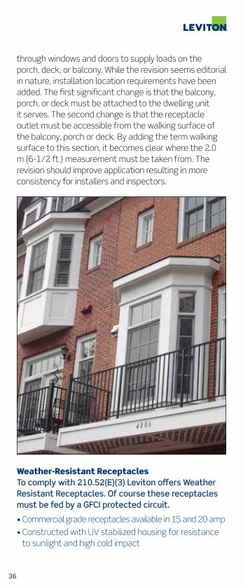
210.52(E)(3) Receptacles on Decks, Porches and Balconies
Change Summary • The revision clarifies that the balcony, deck, or porch must be attached to the dwelling unit
• As revised the required receptacle outlet must be accessible from the balcony, deck, or porch walking surface
• List item (3) in 210.52(E) has been revised for clarity and more uniform application
NEC® Text
210.52 Dwelling Unit Receptacle Outlets…(See NEC text)
(E) Outdoor Outlets…(See NEC text) (3) Balconies, Decks, and Porches. Balconies, decks, and porches that are attached to the dwelling unit and are accessible from inside the dwelling unit shall have at least one receptacle outlet accessible from the balcony, deck, or porch. The receptacle outlet shall not be located more than 2.0 m (6 1/2 ft) above the balcony, deck, or porch walking surface. Copyright© 2013 National Fire Protection Association
(See NEC for complete text)
Expert Analysis This section deals with the requirements for a receptacle outlet installation at balconies, porches and decks to discourage misuse of cords, such as running them
36
through windows and doors to supply loads on the porch, deck, or balcony. While the revision seems editorial in nature, installation location requirements have been added. The first significant change is that the balcony, porch, or deck must be attached to the dwelling unit it serves. The second change is that the receptacle outlet must be accessible from the walking surface of the balcony, porch or deck. By adding the term walking surface to this section, it becomes clear where the 2.0 m (6-1/2 ft.) measurement must be taken from. The revision should improve application resulting in more consistency for installers and inspectors.
Weather-Resistant ReceptaclesTo comply with 210.52(E)(3) Leviton offers Weather Resistant Receptacles. Of course these receptacles must be fed by a GFCI protected circuit.
• Commercial grade receptacles available in 15 and 20 amp
• Constructed with UV stabilized housing for resistance to sunlight and high cold impact

37
W5320 TWR15-WTWR20-GY WBR20-Y
• Corrosion resistant straps and mounting screws.
• Rain or shine, Leviton offers products to meet all your outdoor needs
Revision
210.52(G) Receptacles in Garages, Basements and Accessory Buildings
Change Summary • This section has been renumbered into a list of three items:
(1) garages
(2) accessory buildings
(3) basements
• List item (1) has been revised with more specific requirements for receptacle outlets in garages
• The branch circuit can supply no outlet outside of the garage and at least one receptacle outlet is required in each vehicle space
NEC® Text
210.52 Dwelling Unit Receptacle Outlets…(See NEC text) (G) Basement, Garages, and Accessory Buildings. For a one-family dwelling, at least one receptacle outlet shall be installed in the areas specified in 210.52(G) (1) through (3). These receptacles shall be in addition to receptacles required for specific equipment. (1) Garages. In each attached garage and in each detached garage with electric power. The branch circuit supplying this

38
receptacle(s) shall not supply outlets outside of the garage. At least one receptacle outlet shall be installed for each car space. (2) Accessory Buildings. In each accessory building with electric power. (3) Basements. In each separate unfinished portion of a basement. Copyright© 2013 National Fire Protection Association
(See NEC for complete text)
Expert Analysis This section as revised, improves usability and clarity of the receptacle outlet requirements for attached and detached garages for dwelling units. The requirements for receptacle outlets in attached and detached garages of dwelling units have been expanded and become more restrictive. The branch circuit supplying garage receptacle(s) is not permitted to supply any outlets outside the garage. Another new requirement is that at least one receptacle must be provided for each vehicle space of the attached or detached garage. In other words, a one-car garage requires at least one receptacle installed in that single vehicle space. For a two-car garage, at least two receptacles must be installed, one in each vehicle space. The exact location for the receptacle outlets in these vehicle spaces is not specified. This section continues to exclude any outlets that are installed for special equipment such as welders, central vacuum equipment, electric vehicle supply equipment, and so forth. As required in 210.8(A)(2), ground-fault circuit interrupter protection is required for these receptacle outlets.

39
New
210.64 Receptacle Required for Service Equipment
Change Summary • At least one 125-volt, single-phase, 15- or 20-ampere rated receptacle outlet shall be installed within 50 feet of service equipment
• A new 210.64 titled Electrical Service Areas has been added to Article 210
• By exception, one- and two-family dwelling units are exempt from the rule
NEC® Text
210.64 Electrical Service Areas. At least one 125-volt, single-phase, 15- or 20-ampere rated receptacle outlet shall be installed within 15 m (50 ft) of the electrical service equipment. Exception: The receptacle outlet shall not be required to be installed in one- and two-family dwellings.
Copyright© 2013 National Fire Protection Association(See NEC for complete text)
Expert Analysis This new section requires at least one 125-volt, single-phase 15- or 20-ampere rated receptacle outlet to be installed within 50 feet of service equipment. Although many engineered designs often specified a receptacle outlet in these locations, it was never a requirement of the NEC. Information provided in the substantiation

40
indicated that this change was proposed for the same reason that a receptacle is required for servicing HVAC equipment as provided in 210.63. These receptacles are often needed for connecting portable electrical data acquisition equipment for the essential and qualitative analysis of the electrical system along with testing and servicing the electrical equipment. Presently, to accomplish the connection of such instruments and other tools, extension cords are run through doors, windows, or other openings throughout the building and often connected to non-GFCI protected receptacles creating other hazards for personnel. This new section is an improvement in the NEC and an enhancement in safety for personnel. It should be noted that this general requirement does not specify that these required receptacles be protected by ground-fault circuit interrupter (GFCI) protection. The GFCI requirements in 210.8 would apply to receptacles required by this section if they are installed in locations specified in 210.8.
Surge Protective Devices for Service Equipment In areas where sensitive electronic equipment is utilized, Leviton recommends the use of a Type 3 Surge Protection Receptacle.
Leviton’s Surge Protection Devices can be used individually or as part of a coordinated application strategy to protect sensitive electronic equipment, in industrial, commercial and residential locations. Damaging voltage transients are diverted away from sensitive micro circuitry, providing protection against catastrophic failure, costly downtime and data disruptions. UL 1449 Compliant.
• Available in many colors. Blue pictured here because many tech professionals associate the blue color with clean power
5280 (15 Amp) Surge Protective Receptacle

41
Revision, Deletion
225.36 & 225.38 Disconnect Type — Building or Structure Supplied by Feeder(s) or Branch Circuit
Change Summary • The title of this section has been changed from “Suitable for Service Equipment” to “Types”
• The types of acceptable disconnects are provided in addition to other disconnecting means that are approved
• Generally, the disconnecting means no longer has to be suitable for use as service equipment unless installed to meet the provisions in 250.32(B) Exception.
NEC® Text
225.36 Type. The disconnecting means specified in 225.31 shall be comprised of a circuit breaker, molded case switch, general-use switch, snap switch or other approved means. Where applied in accordance with 250.32(B). Exception, the disconnecting means shall be suitable for use as service equipment. Copyright© 2013 National Fire Protection Association
(See NEC for complete text)
Expert Analysis The revision in 225.36 this cycle removes the exception that allowed 3-way and 4-way switches for residential disconnects on outbuildings and garages. This revision also expands the provisions to all occupancies, not just residential occupancies. The substantiation indicated the intention of disallowing three-way switch loops is clear because they do not disconnect all ungrounded conductors and there is no clear indication of the “Off” position as required in article 225.38(D). This revision also removes the suitable for use as service equipment (SUSE) requirement, which involves greater internal spacing, grounding provisions, and so forth. These are only justified in instances where there is a true service exposure, with no overcurrent protection ahead of the equipment. The principal wiring difference for SUSE ratings is that identified in the original 2011 NEC proposal 4-46, namely, that a re-grounding provision must be incorporated. The requirements in 225.38

42
can be satisfied using a snap switch equipped with the requisite poles provided on the device. Therefore, the exception to 225.38 has also been deleted because its only purpose was to allow 3-way and 4-way switch loops.
Revision
240.21(B)(1)(1)b. Taps Not Over 10 Feet Long — Exception For Surge Protective Devices
Change Summary • A new exception has been added covering SPDs and other similar devices only if in accordance with manufacturer’s instructions
• The revision clarifies what type of equipment the tap conductors must terminate in
• The words “equipment containing an overcurrent” have been added in front of the word “device(s)” in B
NEC® Text
240.21 Location in Circuit…(See NEC text)
(B) Feeder Taps. (See NEC text)
(1) Taps Not over 3 m (10 ft) Long. ...(See NEC text) (1) The ampacity of the tap conductors is a. Not less than...(See NEC text) b. Not less than the rating of the equipment containing an overcurrent device(s) supplied by the tap conductors or not less than the rating of the overcurrent protective device at the termination of the tap conductors. Exception to b: Where listed equipment, such as surge protective device(s) (SPDs), is provided with specific instructions on minimum conductor sizing,

43
the ampacity of the tap conductors supplying that equipment shall be permitted to be determined based on the manufacturer’s instructions.
Copyright© 2013 National Fire Protection Association
(See NEC for complete text)
Expert Analysis This section now clarifies what was meant by the word “device” as previously used in b. Information providedin the substantiation indicated that The word “device” should be replaced with more descriptive terms since the definition of device is, “A unit of an electrical system that carries or controls electric energy as its principal function.” Though obviously not intended by 240.24(B)(1)(1) b, the broad definition of device includes wire and other conductors such as busway. Revising the section to reference equipment containing overcurrent device(s) narrows the application of the section beyond what the previous wording literally meant. Action by Code Making Panel-10 on Comment 10-14 also refines the exception and expands it slightly to apply to surge protective devices (SPDs) and other similar equipment that may be connected by a tap in accordance with the provisions of this section. The revision and new exception improve clarity and promote more consistent application of the 10-foot tap rules. Similar revisions have also been incorporated into 240.21(C)(2) which addresses transformer secondary conductors.

44
Leviton Comment Article 240.21(B)(1)(1)b accommodates the use of Surge Protection Devices (SPDs). Type 2 SPDs would typically be the type of device associated with this Code article.
Explanation of the different levels of surge protection and their applications:
Type 1 SPD for the supply side of service entrance. Leviton offers several options including the 55240-ASA and 50240-MSA secondary surge arrestors. Type 2 SPDs are typically service entrance SPD panels or branch circuit SPD panels that are connected on the load side of the service disconnect overcurrent device (main service panel). Leviton offers several options including the 52120-7CS.
Type 3 SPD’s are typically surge receptacles or cord connected point-of use devices. Leviton offers a complete assortment in duplex, quad and 6-plex in many styles and colors.
Type 4 SPDs are component assemblies consisting of one or more Type 5 components together with a disconnect (integral or external) or a means of complying with the limited current tests in UL 1449.
51020-DIN 3800-DIN 3800-OWM
T7280-W T7380-T S1000-PTC
37120-007 52120-7CS
50240-MSA 55240-ASA

45
Type 5 SPDs: Discrete component surge suppressors connected by its leads or provided with an enclosure with mounting means and wiring terminations.
Type 1 and Type 2 SPDs shunt external surges that originate from utilities or disturbances outside the home or facility. Type 2 SPDs can protect for both internal and external surges when located at the branch. Type 3 SPDs can shunt surges that originated internally within the home or facility. So a comprehensive strategy for surge protection typically involves a Type 1 or Type 2 SPD and also a Type 3 SPD at point of use.
New
250.130(C)(4) Equipment Grounding Conductor Extensions
Change Summary • An additional sixth provision was added to Article 250.130(C) for supplying an Equipment Grounding Conductor (ECG) to convert non grounded receptacles into grounded receptacles, and for branch circuit extensions where a ground was not originally present
• This additional provision allows connection to an ECG that is part of another branch circuit which originates from the enclosure that the circuit for the receptacle or circuit originates
• This sixth provision is found in Article 250.130(C)(4)
NEC® Text
250.130 Equipment Grounding Conductor Connections (C) Nongrounding Receptacle Replacement or Branch Circuit Extensions. The equipment grounding conductor of a grounding-type receptacle or a branch circuit extension shall be permitted to be connected to any of the following: (4) An equipment grounding conductor that is part of another branch circuit that originates from the enclosure where the branch circuit for the receptacle or branch circuit originates. Copyright© 2013 National Fire Protection Association
(See NEC for complete text)
Expert Analysis This additional provision brings the number of ways to add a ground to an existing circuit to six.

46
They are as follows: (1) All accessible locations on the grounding electrode system according to Article 250.50.
(2) All accessible locations on the grounding electrode conductor.
(3) Connection to equipment ground terminal bar housed in the enclosure where the receptacle branch circuit or the branch circuit originates.
(4) An equipment grounding conductor that is part of another branch circuit that originates from the enclosure where the branch circuit for the receptacle or branch circuit originates.
(5) On grounded systems, the ground service conductor in the service equipment enclosure.
(6) On ungrounded systems, the ground terminal bar in the service equipment enclosure.
Leviton Comment Leviton makes duplex receptacles with and without grounding conductors.
Receptacles without ground hole (cat #223) are for replacement receptacles where a grounding conductor does not exist. Article 250.130(C)(4) identifies ways to convert ungrounded circuits to grounded circuits and enable the use of these grounded receptacles.
223 Non Grounding Receptacle
T5320 Grounded Receptacle

47
Revision
310.15(B)(7) Conductor Size for Dwelling Services and Feeders — Ampacities for Conductors
Change Summary • An 83 percent multiplier is provided for calculating ampacity for feeders and service conductors supplying dwelling units, if the conditions of this section are met
• Table 310.15(B)(7) has been deleted and Section 310.15(B)(7) has been revised and restructured into a list format
• A new informational note references a new Annex (D7) where an example calculation is provided
NEC® Text
310.15 Ampacities for Conductors Rated 0-2000 Volts (B) Tables…(See NEC text)
(7) 120/240-Volt, Single-Phase Dwelling Services and Feeders. For one-family dwellings and the individual dwelling units of two-family and multifamily dwellings, service and feeder conductors supplied by a single-phase, 120/240-volt system shall be permitted be sized in accordance with 310.15(B)(7)(1) through (4). (1) For a service rated 100 through 400 A…(See NEC text) …not less than 83% of the service rating. (2) For a feeder rated 100 through 400 A…(See NEC text) …not less than 83% of the feeder rating. (3) In no case shall a feeder for an individual dwelling unit be required to have an ampacity greater than that specified in 310.15(B)(7)(1) or(2). (4) Grounded conductors…(See NEC text) Copyright© 2013 National Fire Protection Association
(See NEC for complete text)
Expert Analysis This section has been restructured into a list format and an 83 percent multiplier has replaced Table 310.15(B)(7). It was determined during the Sixteenth NFPA Annual Meeting that 84 percent was used to establish the aluminum residential service conductor size. However, the 84 percent factor resulted in larger sizes for some conductors compared to the sizes in the 2011 NEC. Therefore an 83 percent multiplier was selected to maintain consistency with the sizes in the 2011 NEC Table 310.15(B)(7). Code Making Panel-6 also analyzed

48
Revision
314.25 Covers and Canopies — Outlet, Device, Pull and Junction Boxes — Correct Screws Required
Change Summary • Screws for covers or attaching equipment to boxes shall be compatible and have matching machine threads or be in accordance with the manufacturer’s instructions
• Drywall screws and other screws are not permitted to be used with boxes unless otherwise listed for use with those types
• A new last sentence has been added to 314.25
the existing Table 310.15(B)(7) values and determined that the conductor sizes provided were equivalent to those if a 0.83 multiplier was applied to each service ampere rating. The resulting conductor size ends up the same as existing values in Table 310.15(B)(7), if the same conductor types and installation conditions are applied. Informational Note No. 1 clarifies that adjustment and correction factors apply depending on conditions of use. Informational Note No. 2 references a useful Annex (D7) that provides an example of applying the 83 percent factor. This revision eliminates the need for defining the term “main power feeder” in 310.15(B)(7), which reduces confusion considerably. These revisions enhance usability and clarity of this section and provide for more consistent application for qualifying dwelling service and feeder conductors.

49
NEC® Text
314.25 Covers and Canopies. In completed installations, each box shall have a cover, faceplate, lampholder, or luminaire canopy, except where the installation complies with 410.24(B). Screws used for the purpose of attaching covers, or other equipment, to the box shall be either machine screws matching the thread gauge or size that is integral to the box or shall be in accordance with the manufacturer’s instructions. Copyright© 2013 National Fire Protection Association
(See NEC for complete text)
Expert Analysis This section requires that each box have a cover, faceplate, lampholder, or luminaire canopy, except where the installation complies with 410.24(B). A new second sentence specifies that screws used for attaching covers, or other equipment to the box, shall be either machine screws matching the thread gauge or size integral to the box or be in accordance with the manufacturer’s instructions. Use of drywall screws and other screws that are not intended for fastening luminaires or other equipment to boxes is not acceptable and can result in damage to the box and inadequate support of the equipment. Manufacturer’s installation instructions cover this in most cases for listed boxes and equipment, but having the additional text will help clarify this requirement. Code Making Panel-9 incorporated the concepts into the additional sentence but also accounted for nonmetallic outlet boxes and product standards that allow the use of thread forming screws for the attachment of covers provided they meet the performance requirements cited in the applicable standard. This type of screw is typically used with nonmetallic junction boxes and provided with the box. The revision clarifies that drywall screws and other inappropriate screws are not permitted for use with boxes unless otherwise listed for that use.

50
Revision/Reorganize/New
404.2(C) Switches Controlling Lighting — Neutral Conductor at Switch Point
Change Summary • New list item (3) relaxes the grounded conductor requirement at switches with integral enclosures
• New list item (5) relaxes the grounded conductor requirement in locations where multiple switches control the same lighting load
• This section has been restructured into a list format and the former exception has been incorporated into positive text
NEC® Text
404.2 Switch Connections (C) Switches Controlling Lighting Loads The grounded circuit conductor for the controlled lighting circuit shall be provided at the location where switches control lighting loads that are supplied by a grounded general-purpose branch circuit for other than the following: 1. Where conductors enter the box enclosing the switch through a raceway…(See NEC text) 2. Where the box enclosing the switch is accessible… (See NEC text)…without removing finish materials 3. Where snap switches with integral enclosures comply with 300.15(E) 4. Where a switch does not serve a habitable room or bathroom 5. Where multiple switch locations control the same lighting load such that the entire floor area of the room or space is visible from the single or combined switch locations 6. Where lighting in the area is controlled by automatic means 7. Where a switch controls a receptacle load Copyright© 2013 National Fire Protection Association
(See NEC for complete text)
Expert Analysis This section generally requires a grounded conductor at lighting load switch locations. There are now seven conditions allowing relief from installing a grounded conductor at the switch box. List items (1) and (2) reflect the provisions of previous Exception and conditions (1) and (2) to 404.2(C). List item (3) reflects the concept provided in Proposal 9-87 to exempt switches with

THE FUTURE IS ON®
Universal SensorsComplete New Line Great New Look!
Our new Universal Sensors seamlessly control all types of light sources.
Our versatile universal sensors control new lighting sources with a discreet profile appropriate for any room. Energy savings is as simple as replacing a standard switch with a Leviton motion sensor. Visit leviton.com/sensors for more information on these sensors and other smart choices.

52
integral enclosures that comply with 300.15(E). List items (4), (5), (6), and (7) reflect concepts provided in Proposal 9-89. Grounded conductors are no longer required at locations in non-habitable rooms and in common locations where multiple switches control the same lighting load, such as where 3-way and 4-way switches are installed, in locations where the lighting is controlled by automatic means, and at switches that control receptacles. In cases where 3-way or 4-way switches are installed, the grounded conductor is required at only one of the switch box locations as long as entire space is visible from all switch locations. Code Making Panel-9 acted favorable to not requiring a grounded conductor in rooms that are not habitable, such as closets as this is overly restrictive. The revision clarifies the requirements while providing practical relief consistent with the substantiation.
Switch ControllingInstalling neutrals at switch locations is a good idea because it enables switch boxes to be compatible with all of today’s and tomorrows advanced lighting and automation options.
Most of Leviton’s Universal Sensor Line doesn’t require neutral conductors. They are available with and without dimming capability and are available in single pole and 3-way configurations. They are identified as “Universal” because they are engineered to be compatible with todays advanced lighting sources including LED, CFL and incandescent/halogen.

THE FUTURE IS ON®
Solution.
Challenge.
Universal Dimmers... The Smart Solution to Your Challenge. Our new Universal Dimmers are designed to work
with incandescent, dimmable LED and dimmable
CFL bulbs. Universal Dimmers provide full-range
dimming, smooth start-up and the perfect balance
of energy-savings and ambiance. Visit us at
leviton.com/universal for more information.

54
• Available in Automatic-ON or Manual-ON models (Occupancy and Vacancy Sensors)
• Controls up to 150W LED, 150W CFL or 600W incandescent/halogen loads
• Provides 180° Field of View, 900 sq. ft. coverage; perfect for use in large areas such as basements, garages and living rooms
• Low profile design blends in with walls for a discreet appearance
• Ambient light sensitivity prevents occupancy sensors from switching the lights ON when there is ample natural sunlight
• Adjustable delayed OFF time for effective energy management
• Screw terminals for easier installation
• Uses passive infrared (PIR) detection technology
• CA Title 20 Compliant, meeting the California code of regulation Title 20, required February 1, 2013
• Vacancy sensors are CA Title 24 Compliant
• Contemporary styling in line with Leviton’s Decora® line of wiring devices and compatible with Decora® screwless wallplates
• Comes packaged with three colors: White, Ivory, and Light Almond; color change kits are available
IPV05IPVD6-1LZ

55
Revision
404.8(C) Multipole Snap Switches Not Permitted for Use on More Than One Circuit Unless Listed and Marked for That Purpose
Change Summary
• Multipole snap switches must not be fed from more than a single circuit unless the switch is listed and marked as a 2-circuit or 3-circuit switch
• The 2011 NEC allowed for more than a single circuit as long as the switch was not rated less than the system voltage. This allowance was removed for 2014
NEC® Text
404.8 Accessibility and Grouping (C) Multipole Snap Switches. A multipole, general-use snap switch shall not be permitted to be fed from more than a single circuit unless it is listed and marked as a two-circuit or three-circuit switch. Copyright© 2013 National Fire Protection Association
(See NEC for complete text)
Expert Analysis Text was removed from Article 404.8(C) that permitted Multipole switches to be fed from two and three circuits as long as the switch rating was not less than the system voltage. The 2014 NEC still allows Multipole switches to be fed from two and three circuits, but the switch must be listed and marked for the application.
Revision
404.10(B) Mounting Snap Switches — Must Use Correct Screws
Change Summary • Screws for snap switches must be either machine screws matching the thread gauge or size that is integral to the box• Fastening means that are in accordance with the manufacturer’s installation instructions are acceptable• A new last sentence has been added to this section to address snap switch fastener screws

56
NEC® Text
404.10 Mounting of Snap Switches. (A) Surface Type. …(See NEC text) (B) Box Mounted. Flush-type snap switches mounted in boxes that are set back of the finished surface as permitted in 314.20 shall be installed so that the extension plaster ears are seated against the surface. Flush-type…(See NEC text) …the box. Screws used for the purpose of attaching a snap switch to a box shall be of the type provided with a listed snap switch, or shall be machine screws having 32 threads per inch or part of listed assemblies or systems, in accordance with the manufacturer’s instructions. Copyright© 2013 National Fire Protection Association
(See NEC for complete text)
Expert Analysis This section addresses switches in flush box installations and requires the mounting yoke or strap of the switch to be seated against the box or plaster ring. A new last sentence specifies that screws used for attaching snap switches to the box, shall be either machine screws matching the thread gauge or size integral to the boxor be in accordance with the manufacturer’s instructions. Use of drywall screws and other screws that are not intended for fastening snap switches or other equipment to boxes is not acceptable and can result in damage to the box and inadequate fastening of the device. Manufacturer’s installation instructions cover this in most cases for listed boxes and equipment, but the additional text helps clarify this requirement. Code Making Panel-9 incorporated the proposed concepts into the additional sentence and accounted for nonmetallic outlet boxes and product standards that might recognize use thread forming screws for attachment of snap switches provided they meet the performance requirements in the applicable standard. This type of screw is typically used with nonmetallic boxes and is often supplied with the box. Drywall screws and other inappropriate screws are not permitted for usein fastening snap switches to boxes or plaster rings.
SwitchesLeviton offers a broad selection of industrial, commercial and residential switches, with current ratings from 15 amps up to 100 amps. Switch varieties include single-

57
Toggle SwitchDecora® Switch
New
406.3(E) Marking for Controlled Receptacle
Change Summary • A new subdivision (E) titled Controlled Receptacle Marking, Exception, and associated figure have been added to 406.3
• This requirement applies to receptacles controlled by building automation or energy management systems
• A specific power symbol marking must be applied to nonlocking type, all 125-volt, 15- and 20-ampere automatically controlled receptacle outlets and be visible after installation
NEC® Text
406.3 Receptacle Rating and Type. (A) Through (D). …(See NEC text) (E) Controlled Receptacle Marking. All nonlocking-type, 125-volt, 15- and 20-ampere receptacles that are controlled by an automatic control device, or that incorporate control features that remove power from the outlet for the purpose of energy management or building automation, shall be marked with the symbol shown in Figure 406.3(E) and located on the controlled receptacle outlet where visible after installation. Exception: The marking is not required for receptacles controlled by a wall switch that provide the required room lighting outlets as permitted by 210.70.
Copyright© 2013 National Fire Protection Association
(See NEC for complete text)
pole, double-pole, three-way, four-way, lighted handle, pilot light, locking, maintained and momentary contact, motor starter, safety-disconnect and Decora® designer-styled devices.

58
Figure 406.3(E) Controlled Receptacle Marking Symbol
Expert Analysis Multiple performance requirements included in the energy codes can drive installation requirements in the NEC. Building automation systems and energy management systems can automatically control loads connected through receptacles. This provision places a specific marking requirement for controlled receptacle outlets, except switch-controlled receptacle outlets in accordance with 210.70. Although the exact location of the marking is not provided, however a specific universal power symbol must be provided at the receptacle outlet. This can be interpreted to mean marking the receptacle face or the faceplate for the receptacle outlet, which would both meet the intent as currently written. A new figure 406.3(E) is provided in this section to promote consistent identification for these receptacle outlets. The substantiation indicated energy management codes that are currently being widely adopted such as ASHRAE 90.1 and could require that up to 50 percent of 125-volt, 15- and 20-ampere receptacles be automatically controlled. The automatic control could be by an energy management system, timer, or sensor. Occupants should know which receptacle outlets are automatically controlled to avoid cord-and plug-connected loads from being unintentionally turned on or off which raises safety concerns as well as inconvenience. It is important to readily identify receptacle outlets that are automatically energized.
Revision
406.4(D) AFCI and GFCI Replacement Receptacles
Change Summary • All AFCI and GFCI outlet devices installed as replacements are required to be readily accessible

59
• The revision clarifies that ready access is required to perform required periodic testing and response to tripped conditions
• A new last sentence has been added to 406.4(D) addressing receptacle replacements NEC® Text
406.4 General Installation Requirements…(See NEC text)
(D) Replacements. Replacement of receptacles shall comply with 406.4(D)(1) through (D)(6), as applicable. Arc-fault circuit-interrupter type and ground-fault circuit-interrupter type receptacles shall be installed in a readily accessible location. DefinitionofReadilyAccessiblefromArticle100: Accessible, Readily (Readily Accessible). Capable of being reached quickly for operation, renewal, or inspections without requiring those to whom ready access is requisite to actions such as to use tools, to climb over or remove obstacles, or to resort to portable ladders, and so forth.
Copyright© 2013 National Fire Protection Association(See NEC for complete text)
Expert Analysis Ground-fault circuit-interrupter (GFCI) devices and now arc-fault circuit interrupter (AFCI) devices are both required to be readily accessible as provided in Article 210. This revision aligns the readily accessible requirement for AFCI and GFCI devices covered in 210.8(A) and (B) with the rules for replacement AFCI and GFCI devices required by 406.4(D). While it is clear that ready access is required for AFCI and GFCI installations, there were no such provisions for replacements, but the same needs exist. Justification for the ready access is primarily related to occupant or user accessibility to exercise the monthly testing and reset features of the device. Arc-fault circuit-interrupter protection and GFCI protection can be accomplished by circuit breaker types, or receptacle device types which have the same test and reset features and requirements for monthly testing. Accessibility to these replacement protective devices should not be different than the ready access required for newly installed GFCI and AFCI devices. This revision also promotes consistency with the listing requirements for these devices that specify monthly testing and resetting operations which facilitates ready access.

60
AFCI ReceptaclesLeviton AFCI receptacles are the preferred solution when replacing receptacles in areas that require AFCI protection.
• Slim Design
• Impact-Resistant
• Patented Reset Lockout
• Tamper-Resistant Shutters
• Terminals Withstand High-Torque
• Standard Self-Ground Clip
• Back and Side Wire (External Back Wire Clamp)
• Dual Function Indicator Light
• Meets latest UL Requirements
• 15 and 20 Amp Models Available
• Colors: White, Ivory, Light Almond, Gray, Black or Brown
AFTR1-W AFCI Receptacle
Revision
406.5 Mounting Receptacles — Correct Screws Required
Change Summary • Screws for receptacles must be either 6-32 machine screws matching the thread gauge or size that is integral to the box or part of a listed assembly or system
• Fastening means in accordance with manufacturer’s installation instructions are acceptable
• The first sentence has been revised and a new last sentence has been added to this section
NEC® Text
406.5 Receptacle Mounting Receptacles shall be mounted in identified boxes or assemblies. The boxes or assemblies shall be securely fastened in place unless otherwise permitted elsewhere in this Code. Screws used for the purpose of attaching receptacles to a box shall be of the type provided with a listed receptacle, or shall be machine screws having 32 threads per inch or part of listed assemblies or systems, in accordance with the manufacturer’s instructions. Copyright© 2013 National Fire Protection Association
(See NEC for complete text)

61
Expert Analysis The first sentence of this section has been revised to require receptacles be fastened to identified boxes or assemblies. A new last sentence specifies that screws used for attaching receptacles to the box be machine screws of 32 threads per inch, or part of a listed assembly or system. Use of drywall screws and other screws that are not intended for fastening receptacles or other equipment to boxes is unacceptable and can result in damage to boxes and inadequate fastening of devices. Manufacturer’s installation instructions usually cover this in most cases for listed boxes and equipment, but the additional text helps clarify this requirement. Listed boxes or assemblies could specify use of thread-forming screws in nonmetallic outlet boxes and applicable product standards might recognize use thread forming screws for attachment of receptacles provided they meet the performance requirements in the applicable standard. This type of screw is typically used with nonmetallic boxes and is supplied with the box. Section 110.3(B) covers this in the requirement to install devices in accordance with any instructions provided in the listing or labeling. Drywall screws and other inappropriate screws are not permitted for use in fastening receptacles to boxes or plaster rings.
Revision, New
406.5(E) & (F) Receptacles in the Face-Up Position in Countertops and Similar Surfaces
Change Summary • Receptacles installed in seating areas or similar surfaces are not permitted in the face-up position unless the installation meets one of list items (1) through (4)
• Subdivision (E) has been revised and expanded to all occupancies and 210.8 GFCI protection applies
• Subdivision (F) is new and titled Receptacles in Seating Areas or Similar Surfaces
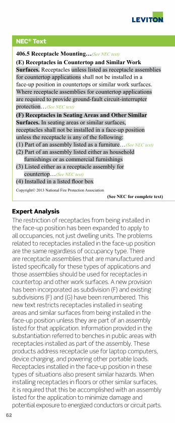
62
NEC® Text
406.5 Receptacle Mounting…(See NEC text)
(E) Receptacles in Countertop and Similar Work Surfaces. Receptacles unless listed as receptacle assemblies for countertop applications shall not be installed in a face-up position in countertops or similar work surfaces. Where receptacle assemblies for countertop applications are required to provide ground-fault circuit-interrupter protection…(See NEC text) (F) Receptacles in Seating Areas and Other Similar Surfaces. In seating areas or similar surfaces, receptacles shall not be installed in a face-up position unless the receptacle is any of the following: (1) Part of an assembly listed as a furniture…(See NEC text) (2) Part of an assembly listed either as household furnishings or as commercial furnishings (3) Listed either as a receptacle assembly for countertop…(See NEC text) (4) Installed in a listed floor box Copyright© 2013 National Fire Protection Association
(See NEC for complete text)
Expert Analysis The restriction of receptacles from being installed in the face-up position has been expanded to apply to all occupancies, not just dwelling units. The problems related to receptacles installed in the face-up position are the same regardless of occupancy type. There are receptacle assemblies that are manufactured and listed specifically for these types of applications and those assemblies should be used for receptacles in countertop and other work surfaces. A new provision has been incorporated as subdivision (F) and existing subdivisions (F) and (G) have been renumbered. This new text restricts receptacles installed in seating areas and similar surfaces from being installed in the face-up position unless they are part of an assembly listed for that application. Information provided in the substantiation referred to benches in public areas with receptacles installed as part of the assembly. These products address receptacle use for laptop computers, device charging, and powering other portable loads. Receptacles installed in the face-up position in these types of situations also present similar hazards. When installing receptacles in floors or other similar surfaces, it is required that this be accomplished with an assembly listed for the application to minimize damage and potential exposure to energized conductors or circuit parts.

63
Revision
406.9(B)(1) Receptacles in Wet Locations Must Have While-In-Use Covers Listed as “Extra-Duty”
Change Summary • Listed and identified extra duty receptacle covers (While-In-Use Covers) are required for all 15- and 20-ampere, 125- and 250-volt receptacles installed in a wet location
• The words “other than one- and two-family dwellings” have been removed from this section
• The text related to how the receptacle outlet is supported has also been removed from this section NEC® Text
406.9 Receptacles in Damp or Wet Locations (B) Wet Locations (1) Receptacles of 15 and 20 Amperes in a Wet Location. Receptacles of 15 and 20 amperes installed in a wet location shall have an enclosure that is weatherproof whether or not the attachment plug cap is inserted. An outlet box hood installed for this purpose shall be listed and shall be identified as “extra-duty.” All 15- and 20- ampere, 125- and 250-volt nonlocking-type receptacles shall be listed weather-resistant type. Copyright© 2013 National Fire Protection Association
(See NEC for complete text)
Expert Analysis This section has been revised and expanded in application to all occupancies and is no longer limited to just one- and two-family dwellings. The extra duty required strength and performance of while-in-use covers are not unique to just dwelling units. The substantiation in Proposal 18-37 clearly and simply emphasized that the support of receptacle outlets in wet locations had nothing to do with the requirements for extra duty receptacle while-in-use covers. As revised, this requirement now applies to all receptacle outlet boxes installed in wet locations, no longer limited to just those installed and supported at grade locations. Prior to this revision, the extra duty in-use cover was only required at locations of receptacles mounted on posts or other structures installed from grade and remote

64
from buildings. The revision promotes consistency in the requirement for listed while-in-use receptacle outlet hoods that are identified as extra duty. Multiple types of extra duty while-in-use covers are produced that can meet this requirement. The revised Code text does not specify that these hood covers be metallic types, only that they be listed and identified as extra duty.
Leviton Extra Duty While-in-Use CoversBuilt to withstand the elements and tough enough to comply with 406.9(B)(1) for “Extra-Duty”.
• Accommodates Decora® GFCI devices and adapter plates are included for duplex and single receptacles
• Heavy-duty gasket protects from moisture and adds to ease of installation
• Includes two inserts to cover cord openings to prevent insects and debris from entering the cover
• Safety lock feature
5981-UGY 5980-UCL5980-UGY 5981-UCL
Revision, Reorganize
406.12 Tamper-Resistant Receptacle Exemptions
Change Summary • The previous exception to 406.12 now applies to dwelling units, guest rooms of hotels and motels, and child care facilities
• These revisions improve consistency in the requirements and exceptions for tamper resistant receptacles

65
• Sections 406.13 and 406.14 have been incorporated as subdivisions (B) and (C) in 406.12 See illustration below for specific exemptions
NEC® Text
406.12 Tamper-Resistant Receptacles. Tamper-resistant receptacles shall be installed as specified in 406.12(A) through (C). (A) Dwelling Units. In all areas specified in 210.52, all nonlocking-type 125-volt, 15- and 20-ampere receptacles shall be listed tamper-resistant receptacles. (B) Guest Rooms and Guest Suites of Hotels and Motels. All nonlocking-type 125-volt, 15- and 20-ampere receptacles located in guest rooms and guest suites of hotels and motels shall be listed tamper-resistant receptacles. (C) Child Care Facilities. In all child care facilities, all nonlocking-type 125-volt, 15- and 20-ampere receptacles shall be listed tamper-resistant receptacles. Exception to (A), (B), and (C): Receptacles in the following locations shall not be shall not be required to be tamper resistant…(See illustration below)
Copyright© 2013 National Fire Protection Association
(See NEC for complete text)
Expert AnalysisIn the 2011 NEC, new requirements were added to Article 406 that specified installing tamper-resistant receptacles in child care facilities and in the guest rooms and guest suites of hotels and motels. Since Articles 406.12, 406.13, and 406.14 all dealt with requirements for tamper-resistant receptacles, it was

66
logical to combine the rules into a single section. As a result, 406.13 and 406.14 have been incorporated into 406.12 and subdivided accordingly. The other significant change addressing consistency is the placement and applicability of the former exception to 406.12. This exception exempts receptacles from having to be tamper resistant if the receptacles meet any of four conditions. As revised, this exception now applies to subdivisions (A), (B), and (C). As revised, the requirements for tamper-resistant receptacles for various occupancies are now all addressed in one section with the same receptacle exceptions for all occupancies. No technical revisions have been added to this section.
Tamper-Resistant ReceptaclesLeviton offers a full assortment of Tamper-Resistant (TR) receptacles in Duplex, Decora®, GFCI and other configurations.
Features Include:
• Shutter mechanism inside the receptacle blocks access to the contacts unless a two-prong plug is inserted, helping insure that hairpins, keys, etc., will be locked-out
• Available in quickwire, sidewire and self-grounding
• Many colors to choose from

67
New
422.5 GFCI’s For Appliances Must Be Readily Accessible
Change Summary• A new section 422.5 titled Ground-Fault Circuit- Interrupter (GFCI) Protection has been added to Part I of Article 422
• GFCI protective devices installed for appliances covered by Article 422 must be readily accessible
• The new requirement aligns with the readily accessible requirements for GFCI devices in 210.8
NEC® Text
Article 422 Appliances 422.5 Ground-Fault Circuit-Interrupter (GFCI) Protection. The device providing GFCI protection required in this article shall be readily accessible. DefinitionofReadilyAccessiblefromArticle100: Accessible, Readily (Readily Accessible). Capable of being reached quickly for operation, renewal, or inspections without requiring those to whom ready access is requisite to actions such as to use tools, to climb over or remove obstacles, or to resort to portable ladders, and so forth.
Copyright© 2013 National Fire Protection Association(See NEC for complete text)
Expert Analysis This new section provides a general requirement that ground-fault circuit-interrupter (GFCI) protection installed for appliances is required to be readily accessible. The substantiation indicated manufacturers of GFCI protective devices routinely require that the GFCI device be tested not less often than monthly to ensure it is providing the life-safety protection intended. The GFCI device must be located in a readily accessible location to facilitate this periodic testing and also any troubleshooting process that may be required to determine why a device has tripped. An identical requirement that the GFCI devices be located in a readily accessible location was incorporated into 210.8 for the 2011 NEC. Identical accessibility must also be provided for the appliances requiring GFCI protection in Article 422 because the problem is the same. Previously it was contended that unless the GFCI protection was provided to meet the requirements in 210.8, that ready access was not required. Ready access is required for GFCI

68
protection installed for appliances as required in Article 422. The added section will clarify for installers and Code enforcers that the readily accessible rule for GFCIs installed for appliances is intended to be the same as for any GFCI installed in accordance with 210.8.
New
422.23 Tire Inflation and Vacuum Machines — GFCI Protection Required
Change Summary • A new 422.23 titled Tire Inflation and Automotive Vacuum Machines has been added to Article 422
• Any tire inflation equipment or vacuum machine for public use must be protected by ground-fault circuit- interrupter (GFCI) protection for personnel
• The GFCI protection (circuit breaker or outlet device) is required to be readily accessible
NEC® Text
422.23TireInflationandAutomotiveVacuumMachines. Tire inflation machines and automotive vacuum machines provided for public use shall be protected by a ground-fault circuit-interrupter. Copyright© 2013 National Fire Protection Association
(See NEC for complete text)
Expert Analysis Public vacuums and tire inflation stations are installed in multiple locations such as at motor fuel dispensing facilities, service centers, and car wash facilities, and so forth. Ground-fault circuit-interrupter (GFCI) protection provides effective shock and electrocution protection for persons. The substantiation for this new requirement included a report of an electrical shock incident that occurred while a person was using a tire inflation machine. The substantiation also indicated that tire inflation and vacuum machines are located in commercial establishments and are heavily used by the public. The equipment is often exposed to rain, snow, and puddles of accumulated standing water and are usually misused to the point of deterioration and failure. Abused, deteriorated electrical equipment combined with a wet environment is a condition that contributes

69
to the increased risk of an electrical shock and electrocution hazards. Over the years, GFCI’s have demonstrated their value in preventing electrocution in exactly these conditions. Action by Code Making Panel-17 results in this new GFCI requirement enhancing protection for the public from shock and electrocution. The GFCI devices required by this section must be readily accessible.
Revision
517.16 Isolated Ground Receptacles Not Allowed in Patient Care Areas, but Permitted in Other Areas of Health Care Facilities
Change Summary • The 2014 NEC continues to prohibit the use of Isolated Ground Receptacles in patient care areas. However they are permitted outside of these patient care areas within a health care facility
• Examples of areas that Isolated Ground receptacles are permitted are nurse monitoring stations and other similar areas
• Article 517.16 was entirely rewritten to reflect this change

70
NEC® Text
517.16 Use of Isolated Ground Receptacles. An isolated ground receptacle shall not be installed within a patient care vicinity. [99:6.3.2.2.7.1(B)] Copyright© 2013 National Fire Protection Association
(See NEC for complete text)
Expert AnalysisThe way the 2011 NEC was written, isolated ground receptacles were no longer permitted in any part of a health care facility. The reason for this was because the NFPA felt that the use of isolated ground receptacles would not assure the equipment grounding conductor redundancy requirements of Article 517.13(A) and (B) for wiring methods within a patient care area. An unintended consequence of this action was that isolated ground receptacles were also not permitted in other areas within health care facilities outside of patient care areas. Isolated ground receptacles can provide benefits for sensitive equipment like critical care monitors at nurse stations and other similar areas. The NFPA has recognized the flaw in limiting the use of isolated ground receptacles and now the 2014 NEC allows isolated ground receptacles outside of patient care areas within health care facilities.
Isolated Ground ReceptaclesLeviton makes isolated ground receptacles in many grades for different applications and power requirements.
• Available in Industrial Grade and Hospital Grade
• Available in Duplex, Decora®, Locking and various NEMA configurations

71
16262-IGR 2620-IG 8280-IGB 5374-IG MT830-IG
• Tamper-Resistant available
• Modular Lev-Lok® configuration available.
• Isolated Ground available for 15, 20, 30, 50 and 60 Amps, and 125, 250 voltage configurations
• Many colors available
Revision
517.18(A) General Care Areas in Health Care Facilities — Patient Bed Locations — Critical Branch Receptacles Must Have Distinctive Color or Marking
Change Summary • Receptacles or cover plates supplied by the critical branch must have a distinctive color or marking to be readily identifiable
• These receptacles must also indicate the panelboard and branch-circuit number that supplies them
• The term “emergency system” was removed from Article 517. So effectively, 1 of the 2 circuits supplying these locations now must be from the critical branch
NEC® Text
517.18 General Care Areas (A) Patient Bed Location. Each patient bed location shall be supplied by at least two branch circuits, one from the critical branch and one from the normal system. All branch circuits from the normal system shall originate in the same panelboard. The electrical receptacles or the cover plate for the electrical receptacles supplied from the critical branch shall have a distinctive color or marking so as to be readily identifiable and shall also indicate the

72
panelboard and branch-circuit number supplying them. Branch circuits serving patient bed locations shall not be part of a multiwire branch circuit. Copyright© 2013 National Fire Protection Association
(See NEC for complete text)
Expert Analysis This change was initiated to align distinctive marking and circuit identification requirements within Article 517.18(A) of the NFPA 70, with articles found in NFPA 99 “The Health Care Facilities Code”.
By removing the term “emergency system”, Article 517.18(A) not only aligns with articles in NFPA 99, it also eliminates any confusion between NFPA 70 Articles 517.18 (A) and NFPA 70 Article 700.
Custom Wallplate MessagesLeviton offers custom order engraved and hot stamped Wallplates in many materials, configurations and colors with the message of your choice.
• Up to 12 gangs in size and many configurations
• Available in nylon, brass, stainless, painted steel, aluminum or chrome
• Standard and custom metal wallplates can be engraved, and standard nylon wallplates can be hot stamped
• Message can be horizontal or vertical
• Ordering form and details available in Leviton catalog
80409-REW 84001-E40 80703-RE

73
Revision
517.18(B) General Care Locations Within Health Care Facilities — Number of Receptacles Increased
Change Summary • The minimum number of receptacles required in a general care patient bed location has increased to eight
• These receptacles are required to be listed and identified as “hospital grade” and connected to an insulated copper equipment grounding conductor
• The first sentence in 517.18(B) has been revised by changing the word “four” to “eight”
NEC® Text
517.18 General Care Areas (B) Patient Bed Location Receptacles. Each patient bed location shall be provided with a minimum of eight receptacles. They shall be permitted to be of the single, duplex, or quadruplex type or any combination of the three. All receptacles shall be listed “hospital grade” and shall be so identified. The grounding terminal of each receptacle shall be connected to an insulated copper equipment grounding conductor sized in accordance with Table 250.122. Copyright© 2013 National Fire Protection Association
(See NEC for complete text)
Expert Analysis The minimum number of receptacles required in a general care patient bed location has been four for several years. This revision increases the minimum number required to align with the NFPA 99 standard. Advances in medical technology have resulted in more medial appliances and equipment being utilized in general care patient bed locations to provide necessary care. The NFPA 99-2012 Health Care Facilities Code has been revised by increasing the number of receptacles in general patient care bed locations. This revision in 517.18(B) aligns with Section 6.3.2.2.6.2 (A) of NFPA 99. A minimum of eight receptacles must now be installed in general care patient bed locations and they must be listed “hospital grade” and so identified. The equipment grounding conductor connected to the grounding terminal of these receptacles is required to be insulated, copper and sized in accordance with Table

74
250.122. Each general care patient bed location must be provided with a minimum of two branch circuits, one from the normal system and one from the critical branch. All normal system branch circuits must originate from the same panelboard. This revision brings the 2014 NEC current with NFPA 99-2012 relative to the minimum number of receptacles required at general care patient bed location.
Hospital Grade ReceptaclesFor patient care areas Leviton offers Extra Heavy-Duty Hospital Grade Receptacles.
Exclusive nickel-plated brass, staked on, self-grounding clip will never fall off
Power Indication™ meets UL498 Hospital Grade identification requirements and offers visual confirmation that the device is energized
Back and side-wire grounding terminal for quick ground installation
Extra Heavy-Duty, triple-wipe, nickel-plated brass “T” contacts for superior contact and conductivity
Exclusive triple combination #10-32 nickel-plated brass terminal screws, straight slot, Phillips #2, Robertson #1 for excellent torque

75
Revision
517.18(C) Tamper-Resistant Receptacles in General Care Pediatric Locations
Change Summary • Section 517.18(C) has been revised to align with the requirement in NFPA 99, Section 6.3.2.2.6.2(F)
• The revision results in correlation with NFPA 99 incorporating extracted material in this section
• The revisions clarifies that the tamper-resistant receptacle requirements apply to designated general care pediatric locations and not patient care areas
NEC® Text
517.18 General Care Areas (C) Designated General Care Pediatric Locations. Receptacles that are located within the patient rooms, bathrooms, playrooms, and activity rooms of pediatric units, other than nurseries, shall be listed tamper-resistant or shall employ a listed tamper-resistant cover. [99: 6.3.2.2.6.2(F)] Copyright© 2013 National Fire Protection Association
(See NEC for complete text)
Expert AnalysisThe health care requirements in Article 517 must correlate and not conflict with the provisions in NFPA 99, the Health Care Facilities Code. This revision in 517.18(C) is required as the new text is now extracted directly from NFPA 99 and is followed with the NFPA 99 Section in brackets. Receptacles covered by this requirement are those installed in patient rooms, bathrooms, playrooms, and activity rooms of pediatric units, other than nurseries of designated general care locations. The revisions, as compared to the previous requirement, are that the tamper-resistant receptacles are only required in designated general care pediatric locations and not specifically in the patient care areas. It should be noted that the term patient room is still included in this requirement, and patient care could be administered within a patient room. As in the previous edition, these requirements can be accomplished by installing either a listed tamper-resistant receptacle(s), or a listed tamper-resistant cover. The governing body of the health care facility is typically responsible for designation of patient

76
care rooms, spaces, or areas in health care facilities. This revision aligns the NEC with NFPA 99 relative to locations where receptacles must be tamper-resistant because of the normal presence of children.
Revision
517.19(B) Critical Care Locations Within Health Care Facilities — Number of Receptacles Increased
Change Summary • Section 517.19(B)(1) has been revised by changing the word “six” to “fourteen”
• The minimum number of receptacles required in a critical care patient bed location has increased to fourteen
• These receptacles are required to be listed and identified as “hospital grade” and connected to an insulated copper equipment grounding conductor
NEC® Text
517.19 Critical Care Areas (B) Patient Bed Location Receptacles. (1) Minimum Number and Supply. Each patient bed location shall be provided with a minimum of 14 receptacles, at least of which shall be connected to either of the following: (1) The normal system branch circuit required in 517.19(A). (2) A critical branch circuit supplied by a different transfer switch than the other receptacles at the same patient bed location. Copyright© 2013 National Fire Protection Association
(See NEC for complete text)
Expert Analysis The minimum number of receptacles required in a critical care patient bed location has been six for several years. This revision increases the minimum number required to align with the NFPA 99 standard. Advances in medical technology have resulted in more medical appliances and equipment being utilized in critical care patient bed locations to provide necessary care. NFPA 99-2012 Health Care Facilities Code has been revised by increasing the number of receptacles in critical patient

77
care bed locations. This revision aligns 517.19(B)(1) with Section 6.3.2.2.6.2 (B) of NFPA 99. A minimum of fourteen receptacles must be installed in patient bed locations in critical care areas and they must be listed “hospital grade” and so identified. The equipment grounding conductor connected to the grounding terminal of these receptacles is required to be insulated, copper. At least one of the fourteen receptacles shall be connected to either the normal system branch circuit required in 517.19(A), or a critical branch circuit supplied by a different transfer switch than the other receptacles at the same patient bed location. The other revision in this section in list item (2) removes the term essential branch and replaces it with “critical branch.”
4-IN-1 ReceptaclesLeviton offers hospital “4-IN-1” receptacles in Hospital Grade, Hospital Grade Isolated Ground and Hospital Grade Surge Protection.
• Terminal wiring screws fit inside a standard single gang wallbox
• Available in 15A-125V and 20A-250V configurations

78
• Impact resistant nylon cover and base for strength and resistance to chemicals and corrosives
• Easy-to-read voltage and amperage rating molded into face
• Available in several colors, including red
8480-I 8490-IGB 8480-R
New
517.19(C) Operating Rooms Within Health Care Facilities — Number of Receptacles Increased
Change Summary • New subdivision (C) titled Operating Room Receptacles was added to 517.19 and the balance of the section renumbered accordingly
• The minimum number of receptacles required is increased from six to thirty-six
• The revision provides direction on which system branch to which the receptacles must be connected and that they be “hospital grade” type
NEC® Text
517.19 Critical Care Areas (C) Operating Room Receptacles. (1) Minimum Number and Supply. Each operating room shall be provided with a minimum of 36 receptacles, at least 12 of which shall be connected to either of the following: (1) The normal system branch circuit required in 517.19(A) (2) A critical branch circuit supplied by a different transfer switch than the other receptacles at the same location (2) Receptacle Requirements. The receptacles required

79
in C(517.19)(1) shall be permitted to be of the single or duplex types or a combination of both. All receptacles, shall be listed hospital grade and so identified. The grounding terminal…(See NEC text)
Copyright© 2013 National Fire Protection Association
(See NEC for complete text)
Expert AnalysisHealth care and advances in medical technology have resulted in significantly more medical appliances and equipment that are utilized in operating rooms to administer necessary care. NFPA 99-2012 Health Care Facilities Code has been revised by increasing the number of receptacles in patient care locations of health care facilities, including operating rooms. This revision aligns the NEC with Section 6.3.2.2.6.2 of NFPA 99. New subdivision (C) has been added to require operating rooms be provided with a minimum of thirty-six receptacles and they must be listed “hospital grade” and so identified. The equipment grounding conductor connected to the grounding terminal of these receptacles is required to be insulated, copper, and must be connected to the reference grounding point typically provided in isolated power systems equipment that serve operating rooms. At least twelve of these receptacles are required to be connected to either the normal system branch circuit required in 517.19(A) or critical branch circuit supplied by a different transfer switch than the other receptacles serving the same operation room. The NEC was previously silent on this issue other than to require six receptacles in a critical care patient bed location, a defined term in 517.2.

80
Lev-Lok® Surge Protective ReceptaclesLeviton’s revolutionary modular wiring device family has now been expanded to include Surge Protective Receptacles. Available in both Commercial and Hospital Grades, you can protect sensitive electronic equipment throughout your facility.
The Lev-Lok® Surge Receptacles feature tamper-resistant shutters preventing incidental contact with energized outlets making these devices the perfect fit for healthcare facilities, educational institutions, as well as hospitality.
MT828-B
Revision
517.41(E) Energized Receptacles in Nursing Home and Limited Health Care Facilities Must Have Illuminated Face or Indicator Light
Change Summary • The requirement for an illuminated face or other indicator light applies to receptacles in the essential electrical systems for nursing homes and limited care facilities
• Nonlocking-type, 125-volt, 15- and 20-ampere receptacles must have an illuminated face or an indicator light
• A new second sentence has been added to 517.41(E)
NEC® Text
517.41 Essential Electrical Systems (E)ReceptacleIdentification. The cover plates for the electrical receptacles or the electrical receptacles themselves supplied from the essential electrical system shall have a distinctive color or marking so as to be readily identifiable. [99:6.4.2.2.6.2(C)] Nonlocking-type, 125-volt, 15- and 20-ampere receptacles shall have an illuminated face or an indicator light to indicate that there is power to the receptacle. Copyright© 2013 National Fire Protection Association
(See NEC for complete text)

THE FUTURE IS ON®
Visit leviton.com/surge to learn how transient voltages can damage your bottom line
Are You Protected?
Surge Protective Devices (SPDs)
To safeguard emergency systems, Article 700.8 of the NEC dictates surge protection for emergency systems, switchboards and panelboards.
Surge protective devices maximize facility uptime and minimize equipment lifecycle costs
Leviton offers a complete line of UL 1449 listed SPDs for industrial use

82
Expert Analysis The 2011 NEC indicated that receptacles supplied from the essential electrical system of a nursing home, or limited care facility must be clearly identified to insure that vital equipment and instrumentation continue to function in the event of power interruption. However, there was no requirement of indicating that these receptacles were supplying power to equipment. This section has been revised to require an energized indication. Information provided in the substantiation stated that the distinctive color or marking only identifies receptacles connected to the essential electrical system. An illuminated receptacle is ready evidence that the receptacle is providing power for essential loads. The increased visibility of an illuminated receptacle also helps ensure that the energized receptacle can be quickly accessed in an emergency situation, especially when power failures result in diminished illumination by that portion of the patient care location that may not be illuminated by connection to the emergency system. Furthermore, reliance solely on some distinctive color in an emergency situation may be ineffective for personnel who are colorblind. This revision is also significant in that the number of receptacles required in these patient bed locations has increased substantially. The requirement for indicating the energized or de-energized state of receptacles is even more essential.
Hospital Grade ReceptaclesLeviton offers Hospital Grade receptacles with illuminated face
• Available in 15A and 20A, 125V configurations
• Self-Grounding
• Nickel Plated Brass Strap
• Power indication meets UL498 Hospital Grade identification requirements
• Available in Lev-Lok® modular configurations
M8300-ILR

THE FUTURE IS ON®
Our USB Charger Devices provide smart solutions
for charging today’s electronic devices while our
adapter-free charging means quick, convenient
power without counter-top clutter. With Leviton
USB Charger Devices, you’ll spend less time
charging devices and more time enjoying them.
Visit us at leviton.com/USB to learn more.
USB Charger Devices
USB Charger with 15/20A Duplex Receptacle
4-Port USB Charger
USB Charger 15/20A Single TR Receptacle

84
Revision
551.71 Quantity and Types of Receptacles at RV Parks
Change Summary• Every recreational vehicle site equipped with a 50-ampere receptacle is now required to be equipped with a 30-ampere, 125-volt receptacle
• This eliminates the use of “cheater cords” by campers to connect their 30-ampere cords to the 50-ampere power supply
• The electrical loads for modern recreational vehicles often demand a 30-ampere, 125-volt receptacle outlet
NEC® Text
VI Recreational Vehicle Parks 551.71 Type Receptacles Provided. Every recreational vehicle site with electrical supply shall be equipped with at least one 20-ampere, 125-volt receptacle. A minimum of 20 percent of all recreational vehicle sites, with electrical supply, shall each be equipped with a 50-ampere, 125/250- volt receptacle conforming to the configuration as identified in Figure 551.46(C)(1). Every recreational vehicle site equipped with a 50-ampere receptacle shall also be equipped with a 30-ampere, 125-volt receptacle conforming to Figure 551.46(C)(1). These electrical supplies shall be permitted to include additional receptacles that have configurations in accordance with 551.81. A minimum of 70 percent of all recreational vehicle sites with electrical supply shall each be equipped with a 30-ampere, 125-volt receptacle conforming to Figure 551.46(C)(1)…(See NEC text) Copyright© 2013 National Fire Protection Association
(See NEC for complete text)
Expert AnalysisIn the past, every recreational vehicle (RV) site with an electrical supply was supplied with at least one 125-volt, 20-ampere receptacle outlet, and a minimum of 70 percent of RV sites were required to be equipped with a 30-ampere, 125-volt receptacle, while 20 percent of the sites were required to be equipped with a 50-ampere, 125/250-volt receptacle outlet. The problem was that the individual power posts that offer the 50-ampere, 125/250 volt receptacle, wasn’t required to also offer the 30-ampere, 125-volt receptacle. Many modern RVs are manufactured with 30-ampere, 125-volt

THE FUTURE IS ON®
Watertight Done Right.
Patented multi-point sealing system
High-performance TPV exterior liquid barrier
Corrosion-resistant components ensure
long-lasting performance
wetguard®
plugs & connectors
Please visit leviton.com/wetguard for more smart products and solutions.

86
requirements. To facilitate these 30-ampere connections on 50-ampere RV site power posts, many campers were being sold “cheater” cords that adapt their 30-ampere, 125-volt RV supply cord to the 50-ampere, 125/250-volt recreational vehicle site receptacles. Since these “cheater” cords are never an acceptable solution, action by Code Making Panel-19 results in a requirement for an additional 30-ampere 125-volt receptacle at the same RV sites where 50-ampere 125/250-volt receptacles are required. This new addition of one 30-ampere, 125-volt receptacle where previously only a 50-ampere, 125/250-volt receptacle was in place, will be an equitable solution for the camper as well as campground owner. Although this action eliminates the need for “cheater” cords in newly wired recreational vehicle parks of the future, it does not generally impact existing parks. Generally NEC changes impact only new or upgraded RV parks or RV sites, but electrical professionals are encouraged to advocate for these safety upgrades.
RV ReceptaclesFor RV connection, Leviton offers catalog number 7313, 30 Amp, 125 Volt, NEMA TT-30R, 2P, 3W, Flush Mount Receptacle.
Built of durable thermoplastic, Leviton Power Receptacles come equipped with heavy-gauge, double-wire copper alloy contacts. To ensure correct and speedy wiring, terminals have ID markings. Flush mount receptacles fit Leviton’s wide range of 2.15”-diameter wallplates and mounting hardware is included. 7313

87
New, Revision
600.6(A)(1) Disconnect Required at Point Where Circuit Enters Sign
Change Summary• Section 600.6(A)(1) is a significant worker safety issue requiring a sign disconnect where the circuit(s) enter the sign enclosure or pole
• This safety-driven change simplifies worker compliance with both NFPA 70E and OSHA rules
• A new 600.6(A)(1) has been added to 600.6(A) and previous subdivisions (1) and (2) have been changed to (2) and (3)
NEC® Text
600.6 Disconnects. Each sign and outline lighting system, feeder circuit or branch circuit supplying a sign, …(See NEC text ) (A) Location. (1) At Point of Entry to a Sign Enclosure. The disconnect shall be located at the point the feeder circuit or branch circuit(s) supplying a sign or outline lighting system enters a sign enclosure or a pole in accordance with 600.5(C)(3) and shall disconnect all wiring where it enters the enclosure of the sign or pole. Exception: A disconnect shall not be required for branch or feeder circuits passing through the sign where enclosed in a Chapter 3 listed raceway.
Copyright© 2013 National Fire Protection Association
(See NEC for complete text)
Expert AnalysisThe substantiation for this change points to a need for additional electrical safeguards for sign workers. In reality, sign supply conductors are often installed within a sign enclosure and run to the supply side of the randomly located disconnect mounted on the sign. These line-side supply conductors located within the sign enclosure remain energized whether or not the sign disconnect is turned off. Only the conductors from the load-side of the sign disconnect to the sign supply terminals are de-energized when the disconnect is opened. This practice exposes sign worker(s) to serious electrical hazards. Previous installation requirements did not specifically require all ungrounded conductors to be de-energized before entering a sign body or enclosure.

88
Now, this new requirement of 600.6(A)(1) specifically requires the disconnecting means to be located at the point the feeder circuit or branch circuit(s) supplying a sign enters the sign enclosure or a supporting pole. Furthermore, the disconnecting means must disconnect all wiring where it enters the enclosure of the sign or pole. However, a practical and limited exception provides latitude to permit energized conductors within a sign only if they are installed using a Chapter 3 wiring method.
Outdoor SwitchingLeviton offers a unique solution for outdoor switching with catalog number COVER-S. This switch cover can actuate any traditional 15A-40A toggle switch including Manual Motor Starters.
• Mounts in any FD or FS Box and can accommodate multi-gang applications
• Provides NEMA (4, 4X and 12) and IEC (IP 66) watertight protection for indoor and outdoor environments in critical application areas that are routinely subject to moisture, vapor, dirt, mud and other contaminant exposure, including high-pressure washdown
• Leviton offers a variety of covers, including this industry exclusive toggle switch cover, blank cover plates and covers to 15A, 20A and 30A single receptacles
• Easily operated with wet and/or gloved hands, and provides OSHA compliant lockout/tagout capabilities
COVER-S
FDBX3 FDBX2 FDBX1

THE FUTURE IS ON®
Industry Exclusive!wetguard® Watertight Toggle Switch Covers
IP66, NEMA 4 & 4X - usable with all 15A-40A Toggle Switches including Manual Motor Starters
Robust design - Impact and chemical resistant PBT cover
Integrated lockout handle meets OSHA safety regulations
Fits any FS/FD mount box
Visit us at leviton.com/wetguardcover to compare us to the competition.
The only IEC & NEMA watertight rated toggle switch cover
LIFETIME— LIMITED —
WARRANTY

90
Reorganize
Article 625 Reorganization and Expansion of Article 625 Covering Electric Vehicle Supply Equipment (EVSE)
Change Summary • Article 625 has been reorganized to provide a more logical layout and consistency with other articles in Chapter 6
• New Informational Note No. 2 has been added following 625.1 and references UL 2594-2013 Standard for Electric Vehicle Supply Equipment
• Part II has been re-identified as Equipment Construction and Part III has been identified as Installation
NEC® Text
Article 625 Electric Vehicle Charging System I. General 625.1 Scope. The provisions of this article cover the electrical conductors and equipment external to an electric vehicle that connect an electric vehicle to a supply of electricity…(See NEC text) Informational Note No. 2: UL 2594-2013, Standard for Electric Vehicle Supply Equipment, is a safety standard for electric vehicle supply equipment. UL 2202-2009, Standard for Electric Vehicle Charging System Equipment, is a safety standard for electric vehicle charging equipment.
II. Equipment Construction. …(See NEC text) III. Installation. …(See NEC text) Copyright© 2013 National Fire Protection Association
(See NEC for complete text)
Expert Analysis Electric vehicle production and corresponding charging infrastructure have substantially increased in the last few years. To meet these needs, Article 625 has been reorganized and updated providing a practical layout and improved usability of present day electrical requirements. Also, as needed revisions and requirements were provided to accommodate evolving electric vehicle charging equipment technology. The scope was revised to include inductive charging systems and technology. A new informational note was added following the article scope and specifically references UL 2594-2013, Standard for Electric Vehicle Supply

91
Equipment, and UL 2202-2009, Standard for Electric Vehicle Charging System Equipment. This note identifies the correct product safety standards to which this equipment is evaluated, tested and certified. The article parts have been rearranged for consistency and where necessary, the sections within those parts have been relocated and re-identified for clarity and usability. Various technical revisions were also incorporated into Article 625 as a result of two 2011 Tentative Interim Amendments (TIAs) and other proposals accepted by Code Making Panel-12. This updated arrangement should simplify application of the various electric vehicle charging requirements for specifying designers and engineers, installers, and Code enforcers.
Revision, Relocate
625.44 Electric Vehicle Supply Equipment Connections
Change Summary • The revision clarifies that Level 2 EVSE is permitted to be direct wired or cord- and plug-connected in accordance with 625.17(B)(1) through (4)
• Former 625.13 has been relocated to 625.44 and revised based on approved TIA 11-2 (SC 11-10-4/TIA 1037)

92
• Subdivision (A) covers cord-connected 125-volt electric vehicle supply equipment and (B) covers all others
NEC® Text
625.44 Electric Vehicle Supply Equipment Connection Electric vehicle supply equipment shall be permitted to be cord- and plug-connected to the premises wiring system in accordance with one of the following: (A) Connections to 125-Volt, Single-Phase, 15- and 20-Ampere Receptacle Outlets. Electric vehicle supply equipment intended for connection to nonlocking, 2-pole, 3-wire grounding-type receptacle outlets rated at 125 V, single phase, 15 and 20 amperes or from a supply of less than 50 volts dc. (B) Connections to Other Receptacle Outlets. Electric vehicle supply equipment that is rated 250 V maximum and complying with all of the following: (1) It is intended for connection to nonlocking, 2 pole, 3-wire and 3-pole, 4-wire, grounding type receptacle outlets rated not more than 50 amperes. (2) EVSE is fastened in place to facilitate any of the following: a. Ready removal for interchange b. Facilitation of maintenance and repair c. Repositioning of portable, moveable, or EVSE fastened in place. (3) Power-supply cord length for electric vehicle supply equipment fastened in place is limited to 1.8 m (6 ft). (4) Receptacles are located to avoid physical damage to the flexible cord. All other electric vehicle supply equipment shall be permanently wired and fastened in place to the supporting surface, a wall, a pole, or other structure. The electric vehicle supply equipment shall have no exposed live parts. Copyright© 2013 National Fire Protection Association
(See NEC for complete text)
Expert Analysis Part III of Article 625 covers electric vehicle supply equipment installations. In the 2011 NEC, there was confusion as to which EVSE was permitted to be cord-and-plug-connected and which units had to be direct wired to the individual branch circuit. The problem was significant enough to trigger a Tentative Interim Amendment TIA 11-2 (SC 11-10-4/TIA 1037) that provided the necessary clarification. As required by the NFPA Regulations Governing Committee Projects, the TIA was introduced as a proposal during the 2014 NEC

THE FUTURE IS ON®
Comprehensive Security
& Automation solutions
for commercial and
residential applications,
accessible from
anywhere on your
phone, tablet or laptop,
with NO monthly fees.
Visit www.leviton.com/automation to learn more.
There is the new Here

94
Evr-Green® Group
development process. The result expanded provisions covering requirements for EVSE connections for both direct-wired types and cord-and-plug connected types. It should be noted that the EVSE is required to be listed and as such, should include installation instructions that provide the alternatives for direct connection or cord connection based on the listing of the product. Proposal 12-52 resulted in reorganization of Article 625 and the result is a relocation of 625.13 to 625.44 in Part III of the article. The revision not only improves usability, it addresses concerns expressed by EVSE manufacturers during the 2011 NEC cycle. The revision clarifies that EVSE above 125 volts but not exceeding 250 volts is permitted to be direct wired or cord-and-plug connected to an individual branch circuit where listed and identified.
The Evr-Green® Product LineLeviton offers a complete solution for residential, commercial and public plug-in electric vehicle (PEV) charging: the Evr-Green® line of electrical vehicle supply equipment (EVSE). Our Evr-Green® products are compliant with all industry standards and compatible with all major auto manufacturers’ electric vehicles (SAE J1772 compliant).
New
Article 646 Modular Data Centers
Change Summary • A new Article 646 titled Modular Data Centers has been added to Chapter 6
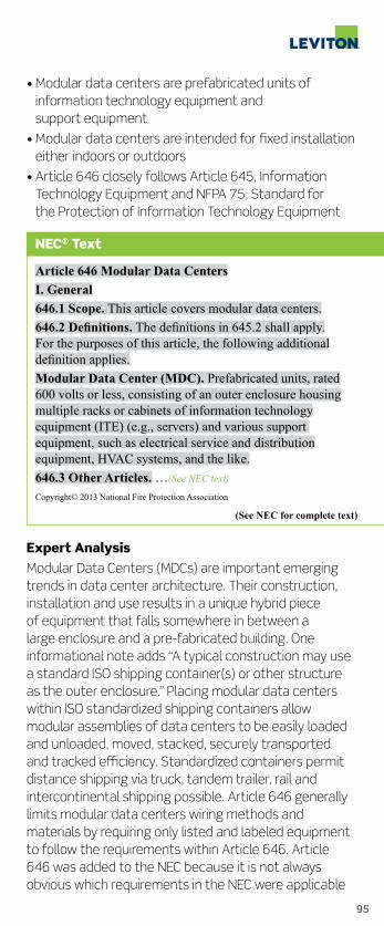
95
• Modular data centers are prefabricated units of information technology equipment and support equipment
• Modular data centers are intended for fixed installation either indoors or outdoors
• Article 646 closely follows Article 645, Information Technology Equipment and NFPA 75, Standard for the Protection of Information Technology Equipment
NEC® Text
Article 646 Modular Data Centers I. General 646.1 Scope. This article covers modular data centers. 646.2Definitions. The definitions in 645.2 shall apply. For the purposes of this article, the following additional definition applies. Modular Data Center (MDC). Prefabricated units, rated 600 volts or less, consisting of an outer enclosure housing multiple racks or cabinets of information technology equipment (ITE) (e.g., servers) and various support equipment, such as electrical service and distribution equipment, HVAC systems, and the like. 646.3 Other Articles. …(See NEC text)
Copyright© 2013 National Fire Protection Association
(See NEC for complete text)
Expert AnalysisModular Data Centers (MDCs) are important emerging trends in data center architecture. Their construction, installation and use results in a unique hybrid piece of equipment that falls somewhere in between a large enclosure and a pre-fabricated building. One informational note adds “A typical construction may use a standard ISO shipping container(s) or other structure as the outer enclosure.” Placing modular data centers within ISO standardized shipping containers allow modular assemblies of data centers to be easily loaded and unloaded, moved, stacked, securely transported and tracked efficiency. Standardized containers permit distance shipping via truck, tandem trailer, rail and intercontinental shipping possible. Article 646 generally limits modular data centers wiring methods and materials by requiring only listed and labeled equipment to follow the requirements within Article 646. Article 646 was added to the NEC because it is not always obvious which requirements in the NEC were applicable

96
Data Center
or how they should be applied, given the complexity, customization and scalability of modular data centers. This new article provides requirements that enhance safety, support the design and development of safe products and provide clarity for installers, end users and Authorities Having Jurisdiction (AHJs).
Leviton’s Data Center Solutions.Performance. Cost containment. Energy efficiency. Security. Rack density. Virtualization. Rapid deployment. And, of course, reliability. Data centers have numerous priorities, all of them crucial to successful data management. Look to the leader in network infrastructure to ensure you meet your customers’ data center requirements.
Look to the Experts in Data Center InfrastructureLeviton provides connectivity and power infrastructure solutions for some of the most advanced data centers and applications in the world. Our field-terminated, pre-terminated, and plug-n-play fiber solutions greatly improve infrastructure flexibility and minimize installation time and system downtime. Many products are fully customizable for any architecture through our exclusive make-to-order (MTO) program.
Leviton Data Center DesignOur data center design and specifications team provide technical support, including design, layout, elevations, pathways, and specifications, customized to each installation. Email Leviton’s data center team at [email protected]

THE FUTURE IS ON®
See What’s WattKnowledge is power. Power costs money.
Therefore, knowledge of power usage will
make you money. Now there’s a smart choice.
From commercial MDU’s to multi-building
campuses and manufacturing applications,
VerifEye™ accurately allocates costs and bills
tenants. Visit www.leviton.com/verifeye to
learn why ROI means “Rewards of Information”.
Smart Submetering Solutions
verifEyetm

98
Revision
680.21(C) GFCI Protection for Single-Phase Pool Pump Motors
Change Summary• The phrase “rated 15 or 20 amperes,” has been deleted from this section
• All single–phase 120-volt through 240-volt outlets supplying pool motors must have GFCI protection for personnel regardless of their ampere rating
• These requirements apply to both receptacle connected and directly connected pool pump motors
NEC® Text
680.21 Motors. (A) Wiring Methods. …(See NEC text)
(B) Double Insulated Pool Pumps. …(See NEC text)
(C) GFCI Protection. Outlets supplying pool pump motors connected to single-phase, 120-volt through 240-volt branch circuits, whether by receptacle or by direct connection, shall be provided with ground-fault circuit-interrupter protection for personnel. Copyright© 2013 National Fire Protection Association
(See NEC for complete text)
Expert AnalysisThis section no longer addresses a specific ampere rating for a single–phase 120 volt through 240 volt motor. Therefore, all single-phase 120 volt through 240 volt pool pump motors of any amperage, must be provided with ground-fault circuit-interrupter protection for personnel. According to the substantiation of the proposal, a single 1.5 HP, 230 volt pool pump motor would be permitted to be installed on a 25 ampere branch circuit without GFCI protection whereas a 1 HP 230 volt motor would require a 20 ampere overcurrent device in addition to ground-fault circuit-interrupter protection for personnel. The substantiation continues by asking the simple question “If there is a shock hazard potential for 20 ampere branch circuits feeding pool pump motors, doesn’t the same shock hazard apply to 25 ampere branch circuits or any size branch circuits feeding single-phase pool pump motors?” The Code making panel accepted this proposal without a statement.

99
Revision
680.22(A)(1) Required Receptacles Near All Pools — Not Just Dwelling Unit Pools
Change Summary• The words “Dwelling Unit” were removed and now the rule applies to all permanently installed pools
• At least one 125 Volt, 15 or 20 Amp receptacle must be located not less than 1.83 m (6 ft) from, and not more than 6.0 m (20 ft) from the inside wall of the pool.
• That required receptacle shall not be more than 2.0 m (6 ft, 6 in) above grade
• Required Receptacle must be GFCI protected
NEC® Text
680.22 Lighting, Receptacles, and Equipment (A) Receptacles. (1) Required Receptacle Location. Where a permanently installed pool is installed, no fewer than one 125-volt, 15 or 20-ampere receptacle on a general-purpose branch circuit shall be located not less than 1.83 m (6 ft) from, and not more than 6.0 m (20 ft) from, the inside wall of the pool. This receptacle shall be located not more than 2.0 m (6 ft 6 in.) above the floor, platform, or grade level serving the pool. Copyright© 2013 National Fire Protection Association
(See NEC for complete text)
Significance of the ChangeThe receptacle requirements were expanded for all permanently installed pools, not just dwelling unit pools.
Revision
680.22(A)(2) Pool Pump Receptacle
Change Summary• 680.22(A)(2) list item “(2) Employ a locking configuration”, has been deleted.
• Removing this locking configuration from 680.22(A)(2) matches existing requirements of Other Receptacles, Location not less than 6 feet from pool in 680.22(A)(3)
• Single receptacles of the grounding type and provided

100
with GFCI protection for personnel are now considered sufficient safety measures for these locations
NEC® Text
680.22 Lighting, Receptacles, and Equipment (A) Receptacles. (2) Circulation and Sanitation System, Location. Receptacles that provide power for water-pump motors or for other loads directly related to the circulation and sanitation system shall be located at least 3.0 m (10 ft) from the inside walls of the pool, or not less than 1.83 m (6 ft) from the inside walls of the pool if they meet all of the following conditions: (1) Consist of single receptacles (2) Are of the grounding type (3) Have GFCI protection Copyright© 2013 National Fire Protection Association
(See NEC for complete text)
Expert AnalysisFor the 2011 NEC, when wiring permanently installed swimming pools, receptacles outlets located for water-pump motors or other loads directly related to pool circulation, that are located less than 6 feet from the inside walls of the pool are required to be single receptacles of the grounding-type, have GFCI protection for personnel and be of the locking type. For the 2014 NEC, these receptacles are no longer required to be of the locking type. A proposal noted that similar outlets located less than 6 feet from the pool did have the same requirements except they did not have a locking configuration. The submitter presented a question to

THE FUTURE IS ON®
Slim is in. Introducing SmartlockPro® Slim GFCI Outlets At Leviton, smart choices are easy to make.
Our SmartlockPro® GFCI has the slimmest profile
on the market, using up to 25% less space in
the wallbox versus other GFCIs. This shallower
design means it’s easier to install. Built with
Leviton’s patented lock-out feature, it delivers
the highest level of safety and protection of
any GFCI product available today. Please visit
leviton.com/gfci for more information.

102
Revision
694.7(E) GFCI Protection for Wind Turbine Maintenance Receptacles
Change Summary• A new last sentence requires all 125-volt, single phase, 15- and 20-ampere receptacles installed for maintenance of the wind turbine to have GFCI protection for personnel
• This new requirement provides protection from shock for maintenance personnel at wind electric systems
• The NEC continues to expand the use of ground-fault circuit-interrupter protection of personnel
NEC® Text
694.7 Installation…(See NEC text)
(E) Receptacles. A receptacle shall be permitted to be supplied by a wind electric system branch or feeder circuit for maintenance or data acquisition use. Receptacles shall be protected with an overcurrent device with a rating not to exceed the current rating of the receptacle. All 125-volt, single phase, 15- and 20-ampere receptacles installed for maintenance of the wind turbine shall have ground-fault circuit-interrupter protection for personnel. Copyright© 2013 National Fire Protection Association
(See NEC for complete text)
Expert AnalysisSection 210.8(B)(4) already requires all 125-volt, 15- or 20-ampere receptacles installed outdoors to be ground-fault circuit-interrupter (GFCI) protected. Without including an indoor requirement, 125-volt, 15- or 20-ampere receptacles installed inside for maintenance of the wind turbine would be exempt from being GFCI protected as it is not outdoors. For the 2014 NEC, a new last sentence in 694.7(E) requires all 125-volt, single phase, 15- and 20-ampere receptacles installed for maintenance of the wind turbine to have GFCI protection for personnel. This change ensures all 125-volt, 15- or 20-receptacles installed indoors for wind turbine
Code Making Panel-17 asking why is a receptacle for a circulation or sanitation system required to have the restriction of a locking configuration. The panel accepted the recommendation. NEC Code Making Panels are not required to provide a response for a panel action of Accept.

103
maintenance be provided with GFCI protection for personnel. Examples may include a building installed near the wind turbine for the associated inverter as well as maintenance receptacles inside the tower. Often overlooked is the 210.8 requirement that all ground-fault circuit-interrupters, whether reset at the circuit breaker location, or on the receptacle itself, must be at a readily-accessible location. Extending GFCI protection into other areas where maintenance personnel will be using power tools or other maintenance related powered equipment is prudent. Installers and designers have provided GFCI protection in many areas for years, but GFCI protection for these areas is now required.
Leviton SmartlockPro® Slim Series GFCIs Install in Any Electrical BoxWhen it comes to GFCI installation, size really does matter. That’s why we’ve trimmed the profile of our industry-leading SmartlockPro® GFCI receptacle to fit into any wallbox, even shallow ones. The new slim series GFCI has all the advanced lockout features of traditional SmartlockPro® devices, with added benefits that make installation easy for electricians and experienced DIY’ers.
Takes up to 25% less space in the wallbox vs. other GFCIs
Typical GFCI New SmartlockPro® Slim GFCI

104
New
700.8 Surge Protection Devices Required for Emergency Systems
Change Summary• Surge protective devices (SPD’s) are required to be installed in or on all switchboards and panelboards of emergency systems
• Surge protective devices and products must be listed
• Requiring SPD’s ensures emergency electrical distribution systems will continue to deliver reliable power to vital life safety loads in the event of a power surge
NEC® Text
700.8 Surge Protection. A listed SPD shall be installed in or on all emergency systems switchboards and panelboards. Copyright© 2013 National Fire Protection Association
(See NEC for complete text)
Expert AnalysisSurge protective devices or SPD’s are covered by the NEC in Article 285 Surge-Protective Devices (SPD’s), 1000 volts or Less; by Underwriters Laboratories in UL 1449, Standard for Surge Protective Devices 3rd Edition and by IEEE in C62.41 IEEE Recommended Practice for Surge Voltages in Low-Voltage AC Power Circuits. For the 2014 NEC, Section 700.8 now requires that a voltage surge protective device must be installed in or on each emergency system switchboard and panelboard. The proper type and rating of the SPD must be suitable for the application. This requirement helps ensure that emergency electrical distribution systems will continue to deliver reliable power to vital life safety loads in the event of a power surge. Surges resulting from lightning strikes or due to various sources within an electrical system, such as switching of power electronic devices, can destroy both the electrical distribution equipment and the loads it supplies. Electrical equipment damage can be from a single lightning strike nearby or the accumulative effects of multiple voltage surges from sources within an electrical system.

105
74120-7M3
Type 2 Modular Surge Protective DevicesLeviton’s 74000 and 75000 Series panel mounted surge protective devices provide seven-mode protection in WYE-configured, 3-phase AC systems. Designed for most industrial and commercial environments with critical operations, these panels offer complete protection at the building entrance and distribution panel.
New
702.7(C) Warning Sign at Power Inlet That is Fed by Generator
Change Summary• New Section 702.7(C) requires a warning sign at the power inlet of a portable generator used as an optional standby system
• Exact warning sign language is provided for both bonded neutral and floating neutral connections specific to the portable generator used
• Section 702.7(C) requires a label and 110.21 provides the general requirements for all labels
NEC® Text
702.7 Signs (C) Power Inlet. Where a power inlet is used for a temporary connection to a portable generator, a warning sign shall be placed near the inlet to indicate the type of derived system that the system is capable of based on the wiring of the transfer equipment. The sign shall display one of the following warnings:

106
WARNING: FOR CONNECTION OF A SEPARATELY DERIVED
(BONDED NEUTRAL) SYSTEM ONLY or WARNING: FOR CONNECTION OF A NONSEPARATELY DERIVED
(FLOATING NEUTRAL) SYSTEM ONLY Copyright© 2013 National Fire Protection Association
(See NEC for complete text)
Expert AnalysisArticle 702 covers optional standby systems, which are those systems intended to supply power to public or private facilities or property where life safety does not depend on the performance of the system. Optional standby systems are intended to supply on-site generated power to selected loads either automatically or manually. The use of portable generators to supply standby power for these systems is permitted. The portable generators are not normally part of an electrical inspection, nor are they subject to inspection when an owner purchases a new one. Depending on the specific type of transfer equipment installed, this can lead to dangerous situations such as paralleling grounded currents on both the equipment grounding conductor and the grounded conductor or to cases where the system does not benefit from a system bonding conductor or one that acts as such. Therefore, safety signage at the portable generator inlet location is a necessary part of the safety requirements. This signage notifying the user that the power inlet requires either

107
2715 WP2 Open WP2 Closed
generator bonding or generator floating neutral based on the wiring of the transfer equipment within the property.
Temporary PowerLeviton offers Temporary Power solutions for every application and specification including a full line of flanged power inlets and weather-resistant covers.
New
702.12(B) Separate Disconnect Not Required for Small Outdoor Generators
Change Summary • An outdoor portable generator, 15 kW or less, supplying an optional standby system does not require a separate disconnecting means, provided a flanged inlet or other cord and plug type connection is used
• However, 445.18 clearly requires that the engine driving the portable generator to be capable of being readily shut down NEC® Text
702.12 Outdoor Generator Sets. (A) Permanently Installed Generators and Portable Generators Greater Than 15 kW. …(See NEC text) (B) Portable Generators 15 kW or Less. Where a portable generator, rated 15 kW or less, is installed using a flanged inlet or other cord-and-plug-type connection, a disconnecting means shall not be required where ungrounded conductors serve or pass through a building or structure. Copyright© 2013 National Fire Protection Association
(See NEC for complete text)

108
New
Article 750 Energy Management Systems
Change Summary • New Article 750, Energy Management Systems defines and controls building systems while protecting the safety concerns of the NEC or building codes
Expert AnalysisDuring past Code Making Panel-13 deliberations that added portable generators to the scope of Article 702, a small portable generator connected by means of a flanged inlet and a flexible cord was not considered with regard to a disconnecting means at the building or other structure supplied and as required by 225.31. Small portable generators (mostly residential) are often installed without a disconnecting means where a flanged inlet and flexible cord is used as the connection means. During the last Code cycle, Code Making Panel-13 embraced this concept in the panel statement for Proposal 13-257. At that time, the panel noted, “A suitable disconnecting device is always available with a portable generator – the act of shutting it down.” Revising this section to specifically permit a cord and plug connection to serve as a disconnecting means for portable generators 15 kW or less brings the requirements in line with typical installation practices of today without sacrificing safety. But remember, according to generator requirements of 445.18, the engine driving this 15 kW or less portable generator must be capable of being readily shut down.

109
• With the application of the Smart Grid, premises energy management systems must be compatible with NEC safety concerns
• Article 750 provides a safe and systematic approach for load shedding and disconnection of power
NEC® Text
Article 750 Energy Management Systems. 750.1 Scope. This article applies to the installation and operation of energy management systems. Informational Note: Performance provisions in other codes establish prescriptive requirements that may further restrict the requirements contained in this article.
750.2Definitions. …(See NEC text) 750.20 Alternate Power Sources. …(See NEC text)
750.30 Load Management. Energy management systems shall be permitted to monitor and control electrical loads unless restricted in accordance with 750.30(A) through (C). (A) Load Shedding Controls. …(See NEC text) (B) Disconnection of Power. …(See NEC text) (C) Capacity of Branch Circuit, Feeder, or Service. … (See NEC text) 750.50 Field Markings. …(See NEC text) Copyright© 2013 National Fire Protection Association
(See NEC for complete text)
Expert AnalysisNew Article 750, Energy Management Systems, was the work of the Smart Grid Task Group. Energy Management has become common place in today’s electrical infrastructure through the control of utilization equipment, energy storage and power production. Yet, limited consideration is found in installation standards in actively managing these systems as a means to reduce energy cost or support peak power needs as it relates to a broader electrical infrastructure demand. Energy Management has two basic aspects, monitoring the system and controlling some portions of the system. These two basic elements must be separated in order to permit an energy management system to monitor and possibly restrict those areas of control that would adversely impact the electrical system or personal safety. The most important aspect here is to make sure an overall energy management system does not override a system specific to preventing load shedding of alternate

110
power sources for fire pumps and emergency systems. Certain energy management systems become critical to ensure safety. For example, turning off ventilation systems for hazardous (classified) material, or a moving walkway causing someone to fall, are examples of where load management controls need to be restricted.
VerifEye™ Submetering Solutions
Easily measure power consumption with VerifEye™ Submetering Solutions so you can manage energy usage smarter:
• Identify how energy is used in order to implement energy saving programs
• Receive accurate detail of energy use and demand from a specific circuit or a specific area to a complete building or complex
• Discover energy saving opportunities with energy cost center analysis, budgetary accountability and precise cost allocation
• Most cost-effective tool to gain LEED points and achieve green building initiatives
VerifEye™ Submetering: How it Works
Energy Monitoring Hub (EMH)
User Interface BMO 2.0 Energy
Manager Software
Leviton Energy Manager
Data Center

111
New
800.2 & 800.12 Communications Raceway Used as Innerduct
Change Summary• The new definition of inner duct is based on TIA and BICI dictionaries
• Also new, listed communications raceways, including general-purpose, riser and plenum types, are permitted to be used as innerduct and placed within Chapter 3 raceways
• These innerduct requirements include permission to use communications raceway as innerduct
NEC® Text
800.2Definitions…(See NEC text)
Innerduct. A nonmetallic raceway placed within a larger raceway. 800.12 Innerduct. Listed plenum communications raceway, listed riser communications raceway, and listed general- purpose communications raceway selected in accordance with the provisions of Table 800.154(b) shall be permitted to be installed as innerduct in any type of listed raceway permitted in Chapter 3. Copyright© 2013 National Fire Protection Association
(See NEC for complete text)
Expert AnalysisFor this Code cycle, Code Making Panel-16 submitted a group of coordinated proposals to align definitions and requirements within Chapter 8. First, a new definition of Innerduct was added to 800.2. This definition is based on information from other technical dictionaries of the Telecommunications Industry Association (TIA) and Building Industry Consulting Service International, Inc. (BICSI). The new definition of Innerduct correlates with the new installation permissions and requirements of 800.12, Innerducts. Section 800.12 now permits listed general-purpose, riser and plenum types of innerduct to be used and installed within any listed raceways permitted in Chapter 3, Wiring Methods. In addition, communications raceways, which are clearly permitted to be used as innerduct, are already available as general-purpose, riser and plenum types raceways. For this NEC change cycle and covered earlier in Article 100, the definition of communications raceway was expanded

112
New
800.24, 770.24, 820.24 & 830.24 Low Smoke Nonmetallic Cable Ties Required for Communications Circuits in Plenums
Change Summary • Code Making Panel-16 added a new last sentence to 800.24, 770.24, 820.24 and 830.24
• It requires nonmetallic cable ties and other nonmetallic accessories be listed as having low smoke and heat release properties when used in spaces used for environmental air (Plenums)
• This complies with NFPA 90A, Standard for the Installation of Air-Conditioning and Ventilating Systems
NEC® Text
800.24 Mechanical Execution of Work. Communications circuits and equipment shall be installed in a neat and workmanlike manner. Cables installed exposed on…(See NEC text)…will not be damaged by normal building use. Such cables shall be secured by hardware, including straps, staples, cable ties, hangers, or similar fittings designed and installed so as not to damage the cable. The installation shall also conform to 300.4(D) and 300.11. Nonmetallic cable ties and other nonmetallic cable accessories used to secure and support cables in other spaces used for environmental air (plenums) shall be listed as having low smoke and heat release properties. Copyright© 2013 National Fire Protection Association
(See NEC for complete text)
and moved from Article 800 into Article 100 since it now applies to both Chapter 7 and Chapter 8 wiring.

113
Leviton Comment Articles 820.24, 770.24, 820.24 and 830.24 were grouped together because the intent of these articles is very much the same (low smoke cable accessories in plenum areas). This grouping makes for a quicker and more user-friendly read of this Pocket Guide. However there are some variances in text. Please reference the 2014 NEC Text for exact language.
Expert AnalysisThe NFPA Standards Council has assigned primary responsibility for combustibles, located within air handling spaces, to the Technical Committee on Air-Conditioning and the Standard, NFPA 90A, Standard for the Installation of Air-Conditioning and Ventilating Systems. Presently, NFPA 90A-2012 has requirements for cable ties in ceiling cavity plenums located in 4.3.11.2.6.5 and for raised floor plenums located in 4.3.11.5.5.6. Both of these sections require that all electrical equipment with combustible enclosures, including their assemblies and accessories, cable ties, and other discrete products, shall be permitted in the ceiling cavity plenum and raised floor plenums only where listed according to ANSI/UL 2043, Standard for Safety Fire Test for Heat and Visible Smoke Release for Discrete Products and Their Accessories Installed in Air-Handling Spaces. These air-handling spaces are called “Other Spaces Used for Environmental Air (Plenums)” in NEC 300.22(C). To comply with NFPA 90A, CMP-16 approved a new last sentence be added to 800.24 (and to 770.24, 820.24 and 830.24) requiring nonmetallic cable ties and other nonmetallic accessories to be listed as having low smoke and heat release properties. This action, and the action in 300.22(C)(1), brings the NEC in compliance and correlation with NFPA 90A.
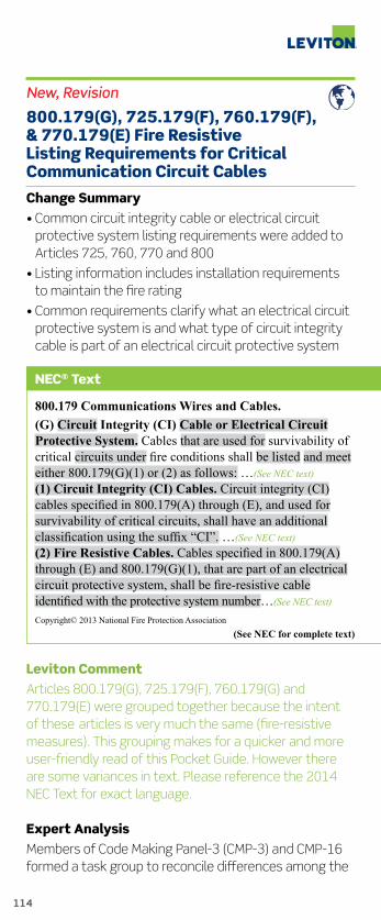
114
New, Revision
800.179(G), 725.179(F), 760.179(F), & 770.179(E) Fire Resistive Listing Requirements for Critical Communication Circuit Cables
Change Summary • Common circuit integrity cable or electrical circuit protective system listing requirements were added to Articles 725, 760, 770 and 800
• Listing information includes installation requirements to maintain the fire rating
• Common requirements clarify what an electrical circuit protective system is and what type of circuit integrity cable is part of an electrical circuit protective system
NEC® Text
800.179 Communications Wires and Cables. (G) Circuit Integrity (CI) Cable or Electrical Circuit Protective System. Cables that are used for survivability of critical circuits under fire conditions shall be listed and meet either 800.179(G)(1) or (2) as follows: …(See NEC text) (1) Circuit Integrity (CI) Cables. Circuit integrity (CI) cables specified in 800.179(A) through (E), and used for survivability of critical circuits, shall have an additional classification using the suffix “CI”. …(See NEC text) (2) Fire Resistive Cables. Cables specified in 800.179(A) through (E) and 800.179(G)(1), that are part of an electrical circuit protective system, shall be fire-resistive cable identified with the protective system number…(See NEC text) Copyright© 2013 National Fire Protection Association
(See NEC for complete text)
Leviton Comment Articles 800.179(G), 725.179(F), 760.179(G) and 770.179(E) were grouped together because the intent of these articles is very much the same (fire-resistive measures). This grouping makes for a quicker and more user-friendly read of this Pocket Guide. However there are some variances in text. Please reference the 2014 NEC Text for exact language.
Expert AnalysisMembers of Code Making Panel-3 (CMP-3) and CMP-16 formed a task group to reconcile differences among the

115
various listing requirements of Circuit Integrity (CI) cable and Electrical Circuit Protective System installed for protection of circuits used within Articles 725, 760, 770 and 800. The exact NEC references include 800.179(G), 725.179(F), 760.179(F), and 770.179(E). The task group first agreed that common listing requirements be placed within each article as appropriate, then acted to ensure each article relied on common definitions and finally made certain that only these common listing requirements would be used to revise existing requirements or to become new requirements where necessary within each of the four articles. Revisions in Articles 725 and 760 included replacements actions such as “… suitable for use…” were deleted and the word “used” was added. The phrase “… installed in accordance with the listing of the protective system…” and the term “listed” was added to ensure proper installation and compliance with product standard and 110.3(B). New sections were added to Articles 770 and 800 allowing for their specific differences.
Network InfrastructureLeviton Network Solutions supports commercial and residential networks around the globe with an unparalleled selection of high-performance network infrastructure products and systems. From the server room to the living room, our proven end-to-end performance keeps people connected.
Fire barrier

116
New
800.180, 770.180, 810.7, 820.180, 830.180, & 840.180 Listed Grounding Devices Required for Communications Circuits Where Grounding is Required
Change Summary• For the 2014 NEC, a single section was added to Articles 770, 800, 810, 820, 830 and 840
• The common requirement is the use of listed devices or devices which are a part of listed equipment to achieve grounding and bonding connections
• Except for Article 810, common numbering was used with the remaining proposals
NEC® Text
800.180 Grounding Devices. Where bonding or grounding is required, devices used to connect a shield, a sheath, or non–current-carrying metallic members of a cable to a bonding conductor or grounding electrode conductor shall be listed or be part of listed equipment. Copyright© 2013 National Fire Protection Association
(See NEC for complete text)
Leviton Comment: Articles 800.180, 770.180, 810.7, 820.180, 830.180 and 840.180 were grouped together because the intent of these articles is very much the same (listed grounding conductor). This grouping makes for a quicker and more user-friendly read of this Pocket Guide. However there are some variances in text. Please reference the 2014 NEC Text for exact language.
Expert AnalysisSection 90.3 permits Chapter 8 to stand alone and is not subject to the requirements of Chapters 1 through 7. When it comes to grounding and bonding, in some instances, this can be a serious issue especially where grounding requirements are different or nonexistent. Although requirements exist that specify when grounding or bonding of a shield, sheath or non–current-carrying metallic members of a cable is required, there was no requirement that devices used should be listed, which can result in poor connections due to questionable

117
installation methods (e.g. wrapping the conductor around a cable sheath) or employing devices that do not have sufficient strength to maintain a solid connection or use materials unsuitable for the application.
Therefore the panel decided to require listed devices to ensure the connection meets construction and performance criteria necessary for reliable bonding and grounding. Listed devices or grounding devices that are part of listed equipment comply with UL 467, Grounding and Bonding Equipment. Except for Article 810, common numbering (xxx.180) was selected and aligned with proposals submitted for Articles 770, 800, 820, 830 and 840.
New
810.6 Grounding of Antenna Lead-In Protectors
Change Summary • Antenna Lead-In Protectors, where used, shall be grounded using a bonding conductor or a grounding electrode conductor installed in accordance with 810.21(F)
• It must be a listed device and suitable for the cable used
NEC® Text
810.6 Antenna Lead-In Protectors. Where an antenna lead-in surge protector is installed, it shall be listed as being suitable for limiting surges on the cable that connects the antenna to the receiver/transmitter electronics and shall be connected between the conductors and the grounded shield or other ground connection. The antenna lead-in protector shall be grounded using a bonding conductor or a grounding electrode conductor installed in accordance with 810.21(F). Informational Note: For requirements covering protectors for antenna lead-in conductors, refer to UL Subject 497E, Outline of Investigation for Protectors for Antenna Lead-In Conductors.
Copyright© 2013 National Fire Protection Association
(See NEC for complete text)
Expert AnalysisArticle 810 covers wiring requirements for radio and television receiving equipment, including digital satellite receiving equipment for television signals, wiring for

118
amateur radio equipment and citizens band (CB) radio equipment. Soon it may apply to outdoor WIFI and other data broadcast, receiving and antenna equipment. Where this equipment uses exterior antennas, there is a danger of bringing lightning and other atmospheric related surges into the building, which in many cases result in a fire. This new section deals with antenna lead-in protectors. These devices may be subject to high energy lightning surges in the range of 5-50 kA or higher. Listing and compliance with appropriate requirements ensure that the protector can withstand these surges without introducing a risk of fire or personal injury (from explosions) and the protector will continue to provide surge protection after being subjected to various environmental and surge conditions that may be expected in an typical installation.

Get with the Code Online
Visit captaincode.leviton.com to see how you can keep up with the code
Browse by Article Number, Application or Related Product
Search by Keyword, Article Number, Application, etc.
See NEC Adoption by State, Videos, Links, Promotions and More
Register for the Captain Code® Online Guide to the 2014 NEC® Changes

120
Leviton GFCI Devices Application Chart
NEC ArticleNumbers
Application Applicable GFCI Cat. No.
210.8 (A) Dwelling units,bathrooms, garages, outdoors, crawl spaces, unfinished basements, kitchens, near laundry, utility, wet bar sinks and boathouses
X7299X7599S7599WT599X7592
T7591X7899S7899WT899X7892
210.8 (B) Other than dwelling units,bathrooms, kitchens, rooftops, outdoors and near sinks
N7599S7599WR599
N7899S7899WR899
210.8 (C) Boat hoists WT599WR599
WT899WR899
210.8 (D) Dwelling units,kitchen dishwashers
X7599S7599
X7899S7899
210.52 (E) Dwelling units, outdoor receptacles
WT599 WT899
210.52 (G) Dwelling units,garages, basements and accessory buildings
X7599S7599X7592
X7899S7899X7892
406.4 (D) Replacement receptacles
S7599 X7599WT599WR599X7592
S7899 X7899 WT899 WR899 X7892
406.12 Tamper-resistantreceptacles
S7599 X7599WT599X7592
S7899 X7899 WT899 X7892

Endorsed by the Swiss Energy Management Army
Imagine, one smart tool that performs every
energy management function from daylight
harvesting to occupancy and vacancy sensing
to full range dimming. Visit leviton.com/sensors
to learn all about this great new line.
THE FUTURE IS ON®

122
Leviton GFCI Devices Application Chart
NEC ArticleNumbers
Application Applicable GFCI Cat. No.
422.23 Tire inflation and vacuum machines
N7599S7599WR599
N7899S7899WR899
422.51 Vending machines,outlet supplying vending machines manufactured before 1/1/05
N7599S7599WR599
N7899S7899WR899
422.52 Electric drinking fountains
N7599S7599WR599
N7899S7899WR899
511.12 Commercial garages, repair and storage
N7599S7599
N7899S7899
513.12 Aircraft hangars N7599S7599
N7899S7899
517.20 Health care facilities,wet procedure locations
N7599-HGN7599-HFM7599-HG
N7899-HGN7899-HFM7899-HG
518.3 (B) Temporary wiring in exhibition halls
16693GFA15PB101GFM1516694
16793GFA20PB103GFM2016794
525.23 Carnivals circuses and fairs
WR599GFA15GFM151669316793PB101
WR899GFA20GFM201669416794PB103
547.5 (G) Agricultural buildings
N7599S7599WR599
N7899S7899WR899
550.13 (B)550.32 (E)
Mobile homes, manufactured homes and mobile parks
N7599S7599WR599
N7899S7899WR899

123
Leviton GFCI Devices Application Chart
NEC ArticleNumbers
Application Applicable GFCI Cat. No.
551.40 (C)551.41 (C)
Recreational vehicles and recreational vehicle parks
N7599S7599WR599
N7899S7899WR899
552.41(C) Park trailers N7599S7599WR599
N7899S7899WR899
555.19 (B) Marinas and boat yards
WR599 WR899
590.6 Temporary installations on construction sites
16693GFA15PB101GFM1516694
16793GFA20PB103GFM2016794
620.85 Elevators, escalators and moving walkways
N7599S7599WR599
N7899S7899WR899
682.15 Natural and artificially made bodies of water
16693GFA15WR599GFM151669316793PB101
16793GFA20WR899GFM201669416794PB103
694.7 (E) Wind turbine N7599S7599WR599
N7899S7899WR899

124
Leviton GFCI Devices Product Line
Combination SmartlockPro® GFCI with Switch • 15A-125V and 20A-125V • Great for Bathrooms, Hotels and Similar Areas
SmartlockPro® GFCI with LED Guide Light • 15A-125V and 20A-125V • Great for Bathrooms, Hotels, Garages, Basements and Similar Areas
SmartlockPro® Hospital GFCI Receptacles• 15A-125V and 20A-125V• Tamper-Resistant Available• NAFTA Compliant Versions Available• LevLok® Modular Configurations Available
SmartlockPro® Self-Test GFCI • Performs a Self-Test Every Fifteen Minutes. If the Self-Test Detects any Condition that would Indicate GFCI Protection Might be Compromised, Visual and Audible Indicators Provide an Alert• 15A-125V and 20A-125V• Tamper-Resistant Available
SmartlockPro® Receptacles Are also available with:• Factory Connected Leads• Lev-Lok® Modular Connections
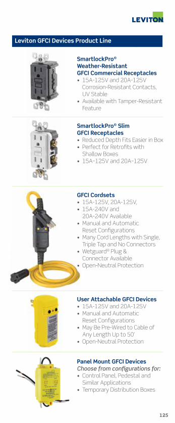
125
Leviton GFCI Devices Product Line
SmartlockPro® Weather-Resistant GFCI Commercial Receptacles• 15A-125V and 20A-125V Corrosion-Resistant Contacts, UV Stable• Available with Tamper-Resistant Feature
SmartlockPro® Slim GFCI Receptacles• Reduced Depth Fits Easier in Box• Perfect for Retrofits with Shallow Boxes• 15A–125V and 20A–125V
GFCI Cordsets• 15A-125V, 20A-125V, • 15A-240V and 20A-240V Available• Manual and Automatic Reset Configurations• Many Cord Lengths with Single, Triple Tap and No Connectors• Wetguard® Plug & Connector Available• Open-Neutral Protection
User Attachable GFCI Devices• 15A-125V and 20A-125V • Manual and Automatic Reset Configurations • May Be Pre-Wired to Cable of Any Length Up to 50’• Open-Neutral Protection
Panel Mount GFCI DevicesChoose from configurations for: • Control Panel, Pedestal and Similar Applications• Temporary Distribution Boxes

126
Credits: Source of the text/illustrations used in this Pocket Guide: The technical material for this publication is used with the permission of the National Joint Apprenticeship and Training Committee for the Electrical Industry.
The finest and most highly trained electrical workers in the country receive their training through local joint apprenticeship training committees utilizing the standardized education programs developed by the National Joint Apprenticeship and Training Committee for the Electrical Industry, supporting both the National Electrical
Contractors Associations (NECA) and International Brotherhood of Electrical Workers (IBEW).
Visit Leviton’s Contractor ConnectionDiscover all the tools, resources and information developed for electrical and low-voltage installation professionals:• Information on Contractor Programs — Network Solutions Contractor Program — Vizia RF+ Certified Installer Program• NEC Code Connection• Contractor Promotional Tools• Training Resources• Support Channels• Subscription Link for Leviton’s e-Newsletter — Promotional opportunities — Webinar Invitations — New Product Announcements• Much More!
www.Leviton.com/Contractor

ez-LearnRegister Today for FREE and EZ Training
Get the training you need for free. From basic theory to technical product training, it’s all there and it’s all free, more than 35 courses including:
(AFCI) Receptacle Training
Electric Vehicle Supply Equipment
Essentials of Electrical Theory
Essentials of Lighting Control
Fundamentals of Occupancy Sensors
Ground Fault Circuit Interrupters
Hospital Grade Guide Light GFCI Receptacles
Lev-Lok® Modular Receptacle System
Surge and Surge Protective Devices
Visit leviton.com/ezlearn to register

128
Leviton Manufacturing Co., Inc.201 N Service Rd, Melville, NY 11747Telephone: 1-800-323-8920 • Fax: 1-800-832-9538 Tech Line (7:00AM-7:30PM E.S.T. Monday-Friday): 1-800-824-3005
Leviton Manufacturing of Canada, Ltd.165 Hymus Blvd, Pointe-Claire, QC H9R 1E9Telephone: 1-800-469-7890 • Fax: 1-800-563-1853
Leviton S. de R.L. de C.V. Lago Tana 43, Col. Huichapan, Miguel Hidalgo, CP 11290 México DFTelephone: (+52) 55-5082-1040 • Fax: (+52) 55-5386-1797 • www.leviton.com.mx
Visit our Website at: www.leviton.com© 2014 Leviton Manufacturing Co., Inc. All rights reserved. Subject to change without notice.Leviton assumes no responsibility for interpretation or application of this Pocket Guide’s contents.
G-9173
NEC® Code Changes2014The Captain Code® Guide to