NATIONAL MANUAL OF GOOD PRACTICE FOR BIOSOLIDS Chapter 15 -Biosolids Incineration Systems
16
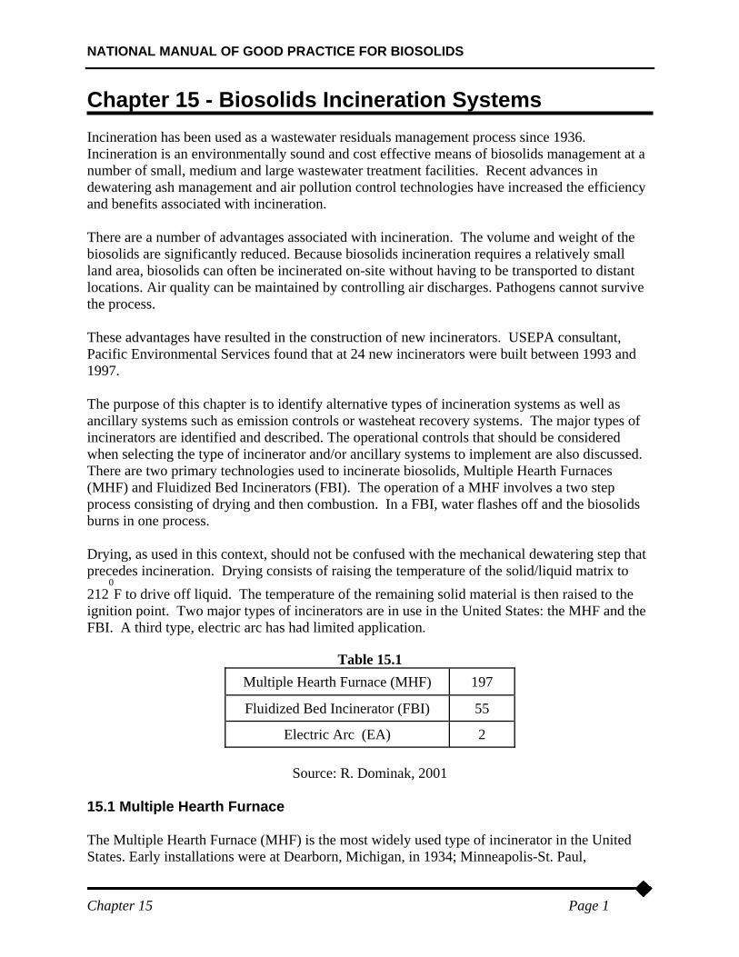
NATIONAL MANUAL OF GOOD PRACTICE FOR BIOSOLIDS Chapter 15 Page 1 Chapter 15 - Biosolids Incineration Systems Incineration has been used as a wastewater residuals management process since 1936. Incineration is an environmentally sound and cost effective means of biosolids management at a number of small, medium and large wastewater treatment facilities. Recent advances in dewatering ash management and air pollution control technologies have increased the efficiency and benefits associated with incineration. There are a number of advantages associated with incineration. The volume and weight of the biosolids are significantly reduced. Because biosolids incineration requires a relatively small land area, biosolids can often be incinerated on-site without having to be transported to distant locations. Air quality can be maintained by controlling air discharges. Pathogens cannot survive the process. These advantages have resulted in the construction of new incinerators. USEPA consultant, Pacific Environmental Services found that at 24 new incinerators were built between 1993 and 1997. The purpose of this chapter is to identify alternative types of incineration systems as well as ancillary systems such as emission controls or wasteheat recovery systems. The major types of incinerators are identified and described. The operational controls that should be considered when selecting the type of incinerator and/or ancillary systems to implement are also discussed. There are two primary technologies used to incinerate biosolids, Multiple Hearth Furnaces (MHF) and Fluidized Bed Incinerators (FBI). The operation of a MHF involves a two step process consisting of drying and then combustion. In a FBI, water flashes off and the biosolids burns in one process. Drying, as used in this context, should not be confused with the mechanical dewatering step that precedes incineration. Drying consists of raising the temperature of the solid/liquid matrix to 212 0 F to drive off liquid. The temperature of the remaining solid material is then raised to the ignition point. Two major types of incinerators are in use in the United States: the MHF and the FBI. A third type, electric arc has had limited application. Table 15.1 Multiple Hearth Furnace (MHF) 197 Fluidized Bed Incinerator (FBI) 55 Electric Arc (EA) 2 Source: R. Dominak, 2001 15.1 Multiple Hearth Furnace The Multiple Hearth Furnace (MHF) is the most widely used type of incinerator in the United States. Early installations were at Dearborn, Michigan, in 1934; Minneapolis-St. Paul,
Transcript of NATIONAL MANUAL OF GOOD PRACTICE FOR BIOSOLIDS Chapter 15 -Biosolids Incineration Systems
NATIONAL MANUAL OF GOOD PRACTICE FOR BIOSOLIDS
Chapter 15 Page 1
Chapter 15 - Biosolids Incineration Systems Incineration has been used as a wastewater residuals management process since 1936. Incineration is an environmentally sound and cost effective means of biosolids management at a number of small, medium and large wastewater treatment facilities. Recent advances in dewatering ash management and air pollution control technologies have increased the efficiency and benefits associated with incineration. There are a number of advantages associated with incineration. The volume and weight of the biosolids are significantly reduced. Because biosolids incineration requires a relatively small land area, biosolids can often be incinerated on-site without having to be transported to distant locations. Air quality can be maintained by controlling air discharges. Pathogens cannot survive the process. These advantages have resulted in the construction of new incinerators. USEPA consultant, Pacific Environmental Services found that at 24 new incinerators were built between 1993 and 1997. The purpose of this chapter is to identify alternative types of incineration systems as well as ancillary systems such as emission controls or wasteheat recovery systems. The major types of incinerators are identified and described. The operational controls that should be considered when selecting the type of incinerator and/or ancillary systems to implement are also discussed. There are two primary technologies used to incinerate biosolids, Multiple Hearth Furnaces (MHF) and Fluidized Bed Incinerators (FBI). The operation of a MHF involves a two step process consisting of drying and then combustion. In a FBI, water flashes off and the biosolids burns in one process. Drying, as used in this context, should not be confused with the mechanical dewatering step that precedes incineration. Drying consists of raising the temperature of the solid/liquid matrix to 212
0F to drive off liquid. The temperature of the remaining solid material is then raised to the
ignition point. Two major types of incinerators are in use in the United States: the MHF and the FBI. A third type, electric arc has had limited application.
Table 15.1 Multiple Hearth Furnace (MHF) 197
Fluidized Bed Incinerator (FBI) 55
Electric Arc (EA) 2
Source: R. Dominak, 2001 15.1 Multiple Hearth Furnace The Multiple Hearth Furnace (MHF) is the most widely used type of incinerator in the United States. Early installations were at Dearborn, Michigan, in 1934; Minneapolis-St. Paul,
NATIONAL MANUAL OF GOOD PRACTICE FOR BIOSOLIDS
Chapter 15 Page 2
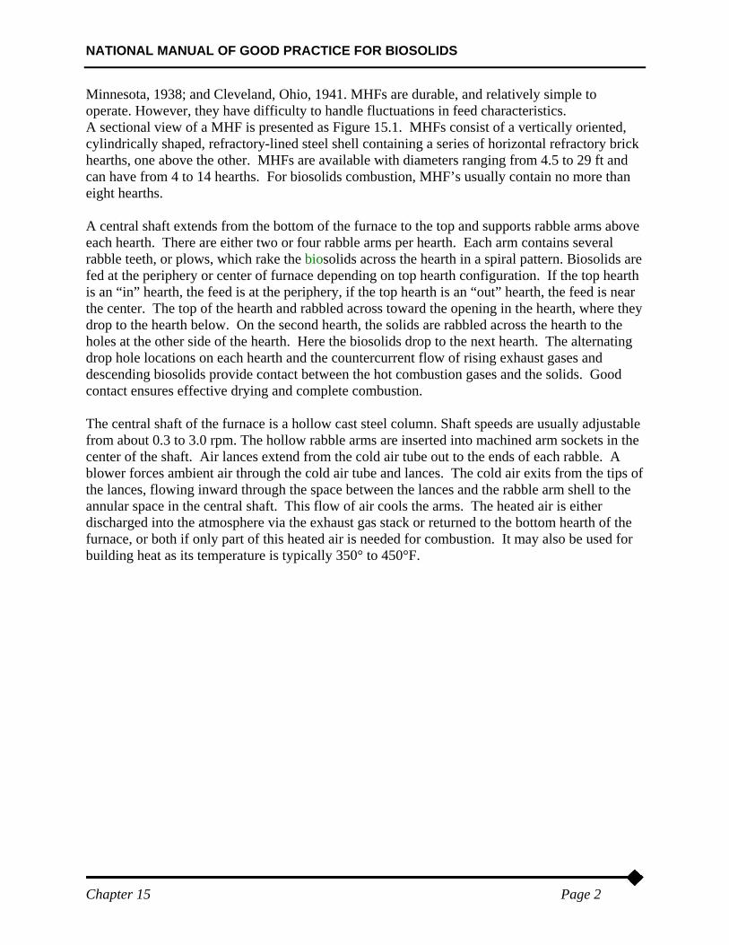
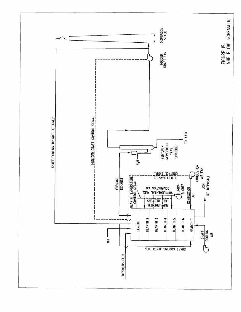
Minnesota, 1938; and Cleveland, Ohio, 1941. MHFs are durable, and relatively simple to operate. However, they have difficulty to handle fluctuations in feed characteristics. A sectional view of a MHF is presented as Figure 15.1. MHFs consist of a vertically oriented, cylindrically shaped, refractory-lined steel shell containing a series of horizontal refractory brick hearths, one above the other. MHFs are available with diameters ranging from 4.5 to 29 ft and can have from 4 to 14 hearths. For biosolids combustion, MHF’s usually contain no more than eight hearths. A central shaft extends from the bottom of the furnace to the top and supports rabble arms above each hearth. There are either two or four rabble arms per hearth. Each arm contains several rabble teeth, or plows, which rake the biosolids across the hearth in a spiral pattern. Biosolids are fed at the periphery or center of furnace depending on top hearth configuration. If the top hearth is an “in” hearth, the feed is at the periphery, if the top hearth is an “out” hearth, the feed is near the center. The top of the hearth and rabbled across toward the opening in the hearth, where they drop to the hearth below. On the second hearth, the solids are rabbled across the hearth to the holes at the other side of the hearth. Here the biosolids drop to the next hearth. The alternating drop hole locations on each hearth and the countercurrent flow of rising exhaust gases and descending biosolids provide contact between the hot combustion gases and the solids. Good contact ensures effective drying and complete combustion. The central shaft of the furnace is a hollow cast steel column. Shaft speeds are usually adjustable from about 0.3 to 3.0 rpm. The hollow rabble arms are inserted into machined arm sockets in the center of the shaft. Air lances extend from the cold air tube out to the ends of each rabble. A blower forces ambient air through the cold air tube and lances. The cold air exits from the tips of the lances, flowing inward through the space between the lances and the rabble arm shell to the annular space in the central shaft. This flow of air cools the arms. The heated air is either discharged into the atmosphere via the exhaust gas stack or returned to the bottom hearth of the furnace, or both if only part of this heated air is needed for combustion. It may also be used for building heat as its temperature is typically 350° to 450°F.
NATIONAL MANUAL OF GOOD PRACTICE FOR BIOSOLIDS
Chapter 15 Page 3
NATIONAL MANUAL OF GOOD PRACTICE FOR BIOSOLIDS
Chapter 15 Page 4
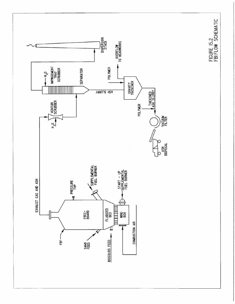
MHFs can be divided into four zones. The first, which consists of the upper hearths, is the drying zone. Most of the water is evaporated in the drying zone. The second, generally consisting of the central hearths, is the combustion zone. In this zone, the majority of combustibles are burned, and the temperature reaches 1,400° to 1,700°F. The third, is the fixed carbon burning zone, where the remaining carbon is oxidized into carbon dioxide. The fourth, includes the lowest hearths and is the cooling zone, where ash is cooled by the incoming combustion air. The sequence of these zones is always the same, but the number of hearths in each zone is dependent on the quality of the feed, the design of the furnace, and the operational conditions. The zone transition often occurs partway across the hearth. Autogenous combustion occurs when the heating value of solids is sufficient to dry and ignite the material. When the heating value of the solids is insufficient to sustain autogenous combustion, the additional heat required is supplied by firing supplemental fuel in burners located at various points in the furnace wall. Burners may operate either continuously or intermittently and on any selected hearths. (USEPA 1979) 15.2 Fluidized Bed Incinerator Fluidized Bed Incinerators (FBI) are a vertically oriented, cylindrically shaped, refractory-lined steel shell that contain a sand bed and fluidized air diffusers called tuyeres. Experience and hardware developed by FBI manufacturers in the metallurgical and chemical industries have been applied in the combustion of biosolids. The FBI is normally available in sizes from 9 to 34 ft in diameter. The sand bed in a FBI is approximately 3.5’ft thick and sits on a refractory-lined or metal grid. This grid contains tuyeres through which air is injected into the furnace at a pressure of 3 to 5 psig to fluidize the bed. The bed expands to approximately 200 percent of its at-rest volume. The temperature of the bed is controlled between 1,400° and 1,500°F by injecting fuel into the sand bed. In some installations, a water spray system in the bed is used to control the furnace temperature. A sectional view of a FBI is presented as Figure 15.2. The incinerator is a single chamber unit in which both drying and combustion occur in a fluidized sand bed. The residence time within the combustion zone is several seconds at 1,400° to 1,500°F. Ash is carried out the top of the furnace and is removed by air pollution control devices, usually Venturi/Impingement Tray scrubbers. Sand carried out with the ash must be replaced. Sand losses are typically 5 percent of the bed volume for every 300 hours of operation. Feed to the furnace is introduced either above or directly into the bed. Airflow in the furnace is determined by several factors. Fluidizing and combustion air must be sufficient to expand the bed to a proper density yet low enough to prevent the biosolids from rising to and floating on top of the bed. Too much air blows sand and products of incomplete combustion into the off-gases. This depletes the stored heat energy and increases fuel consumption unnecessarily. Minimum oxygen requirements must be met to assure complete oxidation of all combustible biosolids. Temperatures must be sufficiently high to assure complete deodorizing but low enough to protect the refractory, heat exchanger, and flue gas ducting and to prevent slag formation.
NATIONAL MANUAL OF GOOD PRACTICE FOR BIOSOLIDS
Chapter 15 Page 5
The quantity of excess air is maintained in the range of 20 to 45 percent of the quantity required for combustion to minimize fuel cost. FBIs operate at much lower excess air rates than typical MHF operations. This results in a greater heat efficiency of the fluidized-bed system at similar exit temperatures. There are two basic process configurations for the FBI. In one design, the fluidizing air passes through a heat exchanger, or recuperator, prior to injection into the combustion chamber. This arrangement is known as a hot windbox (HWB) design. In the other design, the fluidizing air is injected directly into the furnace. This arrangement is known as the cold windbox (CWB) design. The first arrangement increases the thermal efficiency of the process by using the exhaust gases to preheat the incoming combustion air but adds substantial capital costs.
NATIONAL MANUAL OF GOOD PRACTICE FOR BIOSOLIDS
Chapter 15 Page 6
NATIONAL MANUAL OF GOOD PRACTICE FOR BIOSOLIDS
Chapter 15 Page 7
Mixing in the fluidized bed assures rapid and uniform distribution of fuel and air and consequently good heat transfer and combustion. The bed itself provides substantial heat capacity, which helps to reduce short-term temperature fluctuations that may result from varying feed heating values. This heat storage capacity also enables quicker startup, if the shutdown period has been short. Organic particles remain in the sand bed until they are reduced to mineral ash. The mixing of the bed comminutes the ash material, minimizing the buildup of clinkers. The resulting fine ash is constantly stripped from the bed by the upflowing gases. The FBI is relatively simple to operate, has a minimum of mechanical components, and typically has a slightly lower capital cost than the MHF. Experience indicates that although the capital cost for the fluid bed incinerators may be slightly lower than the multiple hearth furnaces, the cost of ash system, which requires thickening and dewatering, results in comparable capital costs. Normal operation of the FBI results in exhaust temperatures in excess of 1,400°F. Because the exhaust gases are exposed to this temperature for several seconds, odors and carbonyl and unburned hydrocarbon emissions are minimal. This results in the ability to meet hydrocarbon emission regulations without the use of an afterburner. 15.3 Critical Control Points / Operational Controls The previous sections described the major options available to incinerate biosolids and other wastewater treatment residuals. Selection and design of the system that best meets the needs of an agency is dependent on many factors. The relative importance of each of these factors will vary. For example, being able to accommodate short term shut downs may be important at one location while accommodating fluctuations in feed biosolids characteristics may be the driving factor at another location. This section identifies and discusses some of the controls that should be considered in selecting, implementing and operating a biosolids incinerator. The list is not exhaustive. Entities considering a biosolids incinerator should develop qualified teams to identify and evaluate site specific control points. This may be accomplished by retaining the services of experienced consultants, obtaining information from incinerator manufacturers, and conducting site visits and interviews with operators of incinerators throughout the country. The controls discussed included:
• Operating Schedule • Moisture Content • Conditioning Agents • Metals Concentration • Grit, Screenings And Scum • Energy Content • Supplemental Energy Requirements • Ash Management • Emission Controls
Operating Schedule The operating schedule of the wastewater treatment facility and solids handling train must be
NATIONAL MANUAL OF GOOD PRACTICE FOR BIOSOLIDS
Chapter 15 Page 8
considered when selecting any biosolids management technology. The operating schedule becomes particularly important when incineration is being considered. All thermal processes are best suited to continuous operation. MHFs require long operating periods and are typically shut down only when maintenance or repair is needed. Startup fuel requirements and the extended time needed to bring the hearths and internal equipment in an MHF up to temperature make intermittent operations impractical. Generally the temperature is maintained at “hot standby”, usually 427°C (800°F), during loading stoppages of up to a few days. FBIs are better suited to short term shutdowns because the hot bed acts as a thermal reservoir. This allows for relatively quick start-ups following one or two days of down time. Significantly longer periods are required for start-up once the bed has cooled down. The decision to implement incineration is often coupled with a commitment to staff the facility 24 hours per day, seven days per week. Fluidized bed incinerators do have the ability to be operated in an intermittent basis. Consideration must be given to biosolids management train operating schedules if adequate cake storage is not available to permit continuous operation of the incinerator with intermittent operation of the dewatering equipment. Moisture Content Moisture content of the biosolids is one of the key characteristics that impacts the capacity of the incinerator and the demand for supplemental fuel. Traditionally, combined primary and waste activated solids are dewatered to between 16 and 30 percent solids using technologies such as centrifuges and belt filter presses. Dewatering to this solids concentration means that for every pound of solids to be incinerated, there are 3 to 5.25 pounds of water that must be evaporated. Incineration is most fuel efficient when the solids burn autogenously, without the need for supplemental fuel for combustion. This usually occurs when the solids concentration of the cake entering the unit is greater than about 28 percent. A thermal dryer can be used to further dewater the biosolids. Biosolids dryers can produce a product with a sufficient solids concentration to burn autogenously. Recently, conductive, or indirect, dryers have been used to enhance incineration. The indirect dryers transfer heat to the biosolids by conduction through a metallic surface. The surface may be the wall of the dryer, hollow screws, paddles or disks. The interior of the heat transfer surface is usually heated with hot oil or steam. Because the heating medium is not in direct contact with the biosolids, there is a lower volume of off-gases to treat when compared with direct drying. The Buffalo Sewer Authority has used an indirect dryer to successfully “scalp” a portio of their dewatered solids as they are transferred from the dewatering equipment to the MHFs. The dryer increases a portion of the solids from between 18 and 20 percent solids to approximately 40 percent solids. This increase has made a significant impact on the operation of their incinerators, increasing capacity on a dry weight basis and reducing the amount of supplemental fuel required. While reducing the overall fuel requirement, the authority has found the indirect dryer to be a high maintenance piece of equipment.
NATIONAL MANUAL OF GOOD PRACTICE FOR BIOSOLIDS
Chapter 15 Page 9
The energy savings realized by increasing the solids concentration above the traditional range must be carefully weighed against the extra costs incurred in the dewatering and thermal drying processes and the materials handling problems that are often associated with very dry biosolids. The handling and storage of dried biosolids can result in dust and explosion potential. Conditioning Agents The choice of conditioning agents for wastewater treatment and biosolids thickening and dewatering operations can have a very large impact on the operation of the incinerator. Inorganic chemicals such as aluminum salts, iron salts and lime are often used in both the liquid treatment and solids management trains at wastewater treatment facilities. These chemicals can increase the weight of the dewatered cake that requires disposal by 20 to 50 percent or more when compared with organic conditioning agents such as polymer. This means that additional heat is required to raise the temperature of the mass to combustion temperature. In addition, the quantity of ash requiring disposal may be increased by 50 to 150 percent when compared with facilities that rely primarily on organic conditioning agents. The use of polymers to enhance dewatering, results in a drier cake without the addition of solids.
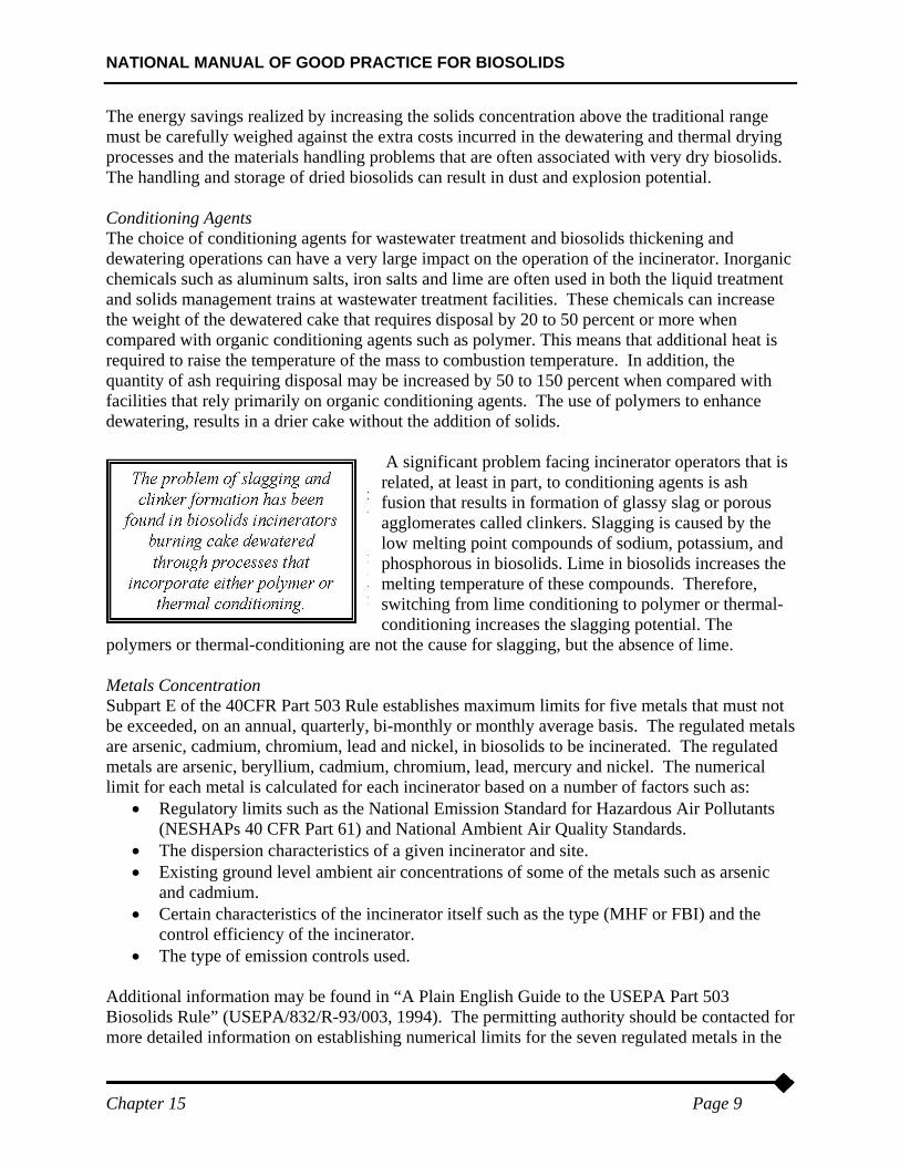
A significant problem facing incinerator operators that is related, at least in part, to conditioning agents is ash fusion that results in formation of glassy slag or porous agglomerates called clinkers. Slagging is caused by the low melting point compounds of sodium, potassium, and phosphorous in biosolids. Lime in biosolids increases the melting temperature of these compounds. Therefore, switching from lime conditioning to polymer or thermal-conditioning increases the slagging potential. The
polymers or thermal-conditioning are not the cause for slagging, but the absence of lime. Metals Concentration Subpart E of the 40CFR Part 503 Rule establishes maximum limits for five metals that must not be exceeded, on an annual, quarterly, bi-monthly or monthly average basis. The regulated metals are arsenic, cadmium, chromium, lead and nickel, in biosolids to be incinerated. The regulated metals are arsenic, beryllium, cadmium, chromium, lead, mercury and nickel. The numerical limit for each metal is calculated for each incinerator based on a number of factors such as:
• Regulatory limits such as the National Emission Standard for Hazardous Air Pollutants (NESHAPs 40 CFR Part 61) and National Ambient Air Quality Standards.
• The dispersion characteristics of a given incinerator and site. • Existing ground level ambient air concentrations of some of the metals such as arsenic
and cadmium. • Certain characteristics of the incinerator itself such as the type (MHF or FBI) and the
control efficiency of the incinerator. • The type of emission controls used.
Additional information may be found in “A Plain English Guide to the USEPA Part 503 Biosolids Rule” (USEPA/832/R-93/003, 1994). The permitting authority should be contacted for more detailed information on establishing numerical limits for the seven regulated metals in the
NATIONAL MANUAL OF GOOD PRACTICE FOR BIOSOLIDS
Chapter 15 Page 10
feed biosolids for an incinerator. Grit, Screenings and Scum When selecting the primary means of biosolids management, it is important to plan for the disposal of other residuals generated by the wastewater treatment process. Incinerators sometimes process grit, screenings and scum, however, each material presents unique challenges as summarized below:
• Grit often contains fairly large quantities of organics and is relatively dry, making it acceptable for incineration if other means of disposal are not available. The extremely abrasive nature of grit can cause erosion of incinerators and associated conveyance systems.
• Screenings tend to clog feed mechanisms and should be preprocessed before incineration. Preprocessing may consist of sorting to remove large inorganic objects and shredding to reduce particle size.
• Scum and grease are very difficult to handle because of their adhesive properties; however, they have a very high heating value. In addition to materials handling problems, scum can cause hot spots in the incinerator and damage refractory linings.
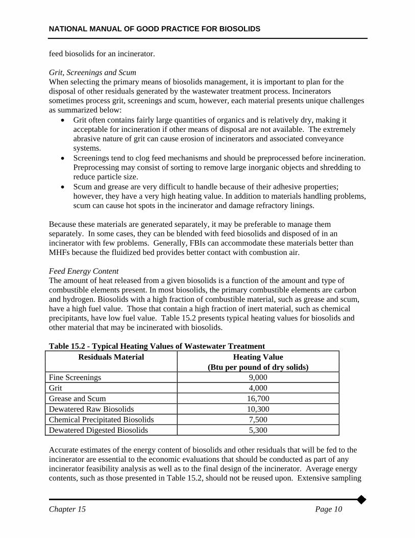
Because these materials are generated separately, it may be preferable to manage them separately. In some cases, they can be blended with feed biosolids and disposed of in an incinerator with few problems. Generally, FBIs can accommodate these materials better than MHFs because the fluidized bed provides better contact with combustion air. Feed Energy Content The amount of heat released from a given biosolids is a function of the amount and type of combustible elements present. In most biosolids, the primary combustible elements are carbon and hydrogen. Biosolids with a high fraction of combustible material, such as grease and scum, have a high fuel value. Those that contain a high fraction of inert material, such as chemical precipitants, have low fuel value. Table 15.2 presents typical heating values for biosolids and other material that may be incinerated with biosolids. Table 15.2 - Typical Heating Values of Wastewater Treatment
Residuals Material Heating Value (Btu per pound of dry solids) Fine Screenings 9,000 Grit 4,000 Grease and Scum 16,700 Dewatered Raw Biosolids 10,300 Chemical Precipitated Biosolids 7,500 Dewatered Digested Biosolids 5,300 Accurate estimates of the energy content of biosolids and other residuals that will be fed to the incinerator are essential to the economic evaluations that should be conducted as part of any incinerator feasibility analysis as well as to the final design of the incinerator. Average energy contents, such as those presented in Table 15.2, should not be reused upon. Extensive sampling
NATIONAL MANUAL OF GOOD PRACTICE FOR BIOSOLIDS
Chapter 15 Page 11
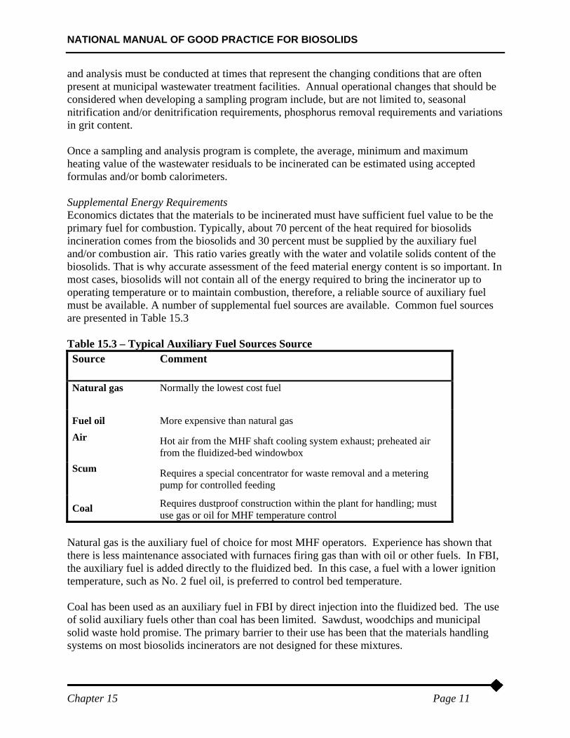
and analysis must be conducted at times that represent the changing conditions that are often present at municipal wastewater treatment facilities. Annual operational changes that should be considered when developing a sampling program include, but are not limited to, seasonal nitrification and/or denitrification requirements, phosphorus removal requirements and variations in grit content. Once a sampling and analysis program is complete, the average, minimum and maximum heating value of the wastewater residuals to be incinerated can be estimated using accepted formulas and/or bomb calorimeters. Supplemental Energy Requirements Economics dictates that the materials to be incinerated must have sufficient fuel value to be the primary fuel for combustion. Typically, about 70 percent of the heat required for biosolids incineration comes from the biosolids and 30 percent must be supplied by the auxiliary fuel and/or combustion air. This ratio varies greatly with the water and volatile solids content of the biosolids. That is why accurate assessment of the feed material energy content is so important. In most cases, biosolids will not contain all of the energy required to bring the incinerator up to operating temperature or to maintain combustion, therefore, a reliable source of auxiliary fuel must be available. A number of supplemental fuel sources are available. Common fuel sources are presented in Table 15.3 Table 15.3 – Typical Auxiliary Fuel Sources Source Source Comment
Natural gas Normally the lowest cost fuel
Fuel oil More expensive than natural gas Air Hot air from the MHF shaft cooling system exhaust; preheated air
from the fluidized-bed windowbox Scum Requires a special concentrator for waste removal and a metering
pump for controlled feeding
Coal Requires dustproof construction within the plant for handling; must use gas or oil for MHF temperature control
Natural gas is the auxiliary fuel of choice for most MHF operators. Experience has shown that there is less maintenance associated with furnaces firing gas than with oil or other fuels. In FBI, the auxiliary fuel is added directly to the fluidized bed. In this case, a fuel with a lower ignition temperature, such as No. 2 fuel oil, is preferred to control bed temperature. Coal has been used as an auxiliary fuel in FBI by direct injection into the fluidized bed. The use of solid auxiliary fuels other than coal has been limited. Sawdust, woodchips and municipal solid waste hold promise. The primary barrier to their use has been that the materials handling systems on most biosolids incinerators are not designed for these mixtures.
NATIONAL MANUAL OF GOOD PRACTICE FOR BIOSOLIDS
Chapter 15 Page 12
Information on the feed material and subsequent auxiliary fuel requirement is not always available when selecting equipment. If specific information is not available, specify various possible modes of plant operation. Decide on factors that impact auxiliary fuel usage such as minimum and maximum furnace exhaust temperature. Heat and material balances should be prepared for each operating mode. A summary table should indicate minimum and maximum values of the following items:
• Combustion air requirement - mass flow and volume rate • Shaft cooling air recycle • Ambient air • Auxiliary fuel requirement • Auxiliary fuel combustion air requirement • Furnace exhaust flue gas volume
Consideration must also be given to the design of the auxilary burners, especially in an MHF. Slag can build up in a MHF whenever the local temperature exceeds the fusion temperature of the biosolids. Closed-register burners have excellent secondary air mixing, resulting in flame temperature of about 2,000
0
F and less slagging. Ash Management While incineration provides the greatest volume reduction of all biosolids management techniques, there is still a significant quantity of ash to be managed. The quantity of ash generated is essentially equal to the inert fraction of the feed material and generally ranges from 400 to 800 pounds per dry ton of biosolids incinerated, not including grit. Factors impacting the quantity of ash generated include the degree of inflow/infiltration (I/I) in the collection system; the effectiveness of the grit removal system at the wastewater treatment facility; and the types of conditioning agents used in wastewater treatment and biosolids conditioning. The type of incinerator has some impact on the characteristics of the ash generated. In a FBI, the ash is collected wet after being exposed to temperatures of 1,500
0
to 1,6000
F. In an MHF, the ash is collected dry after being exposed to temperatures of 1,200
0
to 1,4000
F in the lower hearths of the incinerator. Planning must be conducted for the management of ash as part of the alternative selection process and final design. A more detailed discussion of ash management is provided in Chapter 18. Emission Controls Air emissions are a major criteria to consider during the evaluation and implementation of an incineration system. Emissions from incineration and typical controls are discussed in detail in Chapter 17 - Emissions. It is recommended that the emissions and associated air pollution control devices be considered when evaluating alternatives. Waste Heat Recovery Incinerators use large quantities of fuel and electricity that ultimately produce heat, much of which is wasted either to the atmosphere or to water. Many types of equipment have been
NATIONAL MANUAL OF GOOD PRACTICE FOR BIOSOLIDS
Chapter 15 Page 13
developed to reuse some of this waste heat. Waste heat recovery can reduce a facility's dependence on auxiliary fuel and, in some cases, reduce emissions. The first fluidized bed unit for biosolids combustion was built at Lynwood, Washington. This small CWB unit with no internal heat recovery went into operation in 1965. Later the original unit was replaced with a larger incinerator. The development of the HWB air preheating unit occurred in the mid-1960s. This provided improved thermal efficiency and increased system unit capacity when combusting dewatered primary plus secondary biosolids. Energy recovery in one form or another is being practiced in the majority of the installed units by combustion air preheating, steam generation, or hot water economizers. Preheating the incoming air from 70° to 1,000°F can yield a reduction in fuel costs of approximately 60 percent. Air preheating equipment costs can represent 15 percent of the system cost; therefore, a careful economic analysis is needed to determine cost-effectiveness for a given situation to determine if the extra cost of the recuperator is justified. The first use of waste heat boilers for energy recovery in fluidized bed combustion of wastewater treatment facility biosolids took place in 1968. The exhaust gases are cooled to about 350°F in the waste heat boiler. This gas cooling makes it possible to use the bag filters and electrostatic precipitators, as well as wet scrubbers for exhaust gas cleaning as necessary to meet air quality standards. The ability to recover heat energy from an incinerator is impacted by temperature; the higher the temperature of the exhaust gas, the higher the quality or value. Most waste-heat-recovery devices transfer heat from a high-temperature effluent stream to a lower-temperature input stream. They can either increase the temperature of the input stream, or change the input stream from a liquid to a vapor, as in a boiler. All these devices can be broadly categorized as heat exchangers. Waste heat can also be utilized by passing hot gases or steam through a turbine, to generate electricity or to drive mechanical equipment. Heat recovery equipment must take into account temperature and pressure ranges, corrosiveness of the effluent and input streams, presence of materials that could foul the heat exchange surfaces, and thermal cycling. Extreme values of any of these may dictate the use of special materials and design, resulting in high implementation costs. Waste-Heat Boilers Waste heat boilers are typically water tube boilers in which hot exhaust gases pass over a number of parallel tubes containing water. The water is vaporized and collected in a steam drum for distribution to a steam load. Capacities range from less than a thousand to almost a million cubic feet per minute of exhaust gas. In the 1970's several MHF's were installed with the finned-tube wasteheat boilers. The wasteheat failed due to the plugging of fins with ash and ultimately corrosion. Only water tube boilers are currently used. The pressure and rate of steam production depend on the temperature and flow rate of the hot gases and the efficiency of the boiler. If the waste heat in the exhaust gases is insufficient to generate the required process steam, it is sometimes possible to add
NATIONAL MANUAL OF GOOD PRACTICE FOR BIOSOLIDS
Chapter 15 Page 14
auxiliary burners which burn fuel in the waste-heat boiler or to add an after-burner. Waste-heat boilers have the advantage of being less expensive than installing a new combustion boiler because they need no burners; their disadvantage is that they are large and, in retrofits, it may be difficult to implement. (Industrial Heat Recovery Strategies, PG&E) Field monitoring can be used to verify potential applications for waste-heat recovery; the following list contains a number of the characteristics that should be considered.
• Quantity, temperature, duration and moisture content of the source. The higher the values, the more heat available
• Proximity to the source • Relationship of availability of heat at the source to the need • Where significant volumes of steam are sent through pressure-reducing valves (PRV), it
may be possible to replace the PRV with a steam turbine to extract work. To the extent possible, the turbine should match the steam requirements of the process.
• Turbines should be sized for the minimum steam load so that they can operate most of the time; excess process steam can be passed through a PRV in parallel with the turbine.
• The proximity of waste-heat uses influences total energy savings, due to heat loss in transit from the source, and any energy required to move the fluid.
• Latent heat from the condensation of moisture in exhaust gas can be significant, but condensation is often undesirable due to the potential for corrosion down-stream of the heat-recovery device. (PG&E)
• Reviewing process input and output characteristics will help in estimating possible energy savings from waste-heat recovery. Characteristics include:
• The greater the temperature, flow rate and moisture content, the greater the quantity of heat in the stream.
• The closer the waste-heat uses the greater the total energy savings. • Latent heat from the condensation of moisture in exhaust gas can be significant. • Condensation is often corrosion down-stream of the heat-recovery device.
Flow streams that provide large energy savings generally also result in increased implementation costs. Larger flows require larger heat exchangers and higher temperatures may require special materials. Usually energy savings will more than offset the additional cost. Other considerations related to implementation include:
• Special materials to address corrosive effluent streams will increase cost without increasing energy savings.
• If the source and use are separated, the cost of piping, ductwork, pumps and/or fans to deliver the recovered heat will increase costs.
• Heat exchangers conserve fuel and their original cost is relatively modest, but they may involve significant other expenditures. For example, combustion air preheat may require high-temperature burners, larger combustion air ducts with expansion/contraction fittings and cold air lines for cooling the burners.
As with waste-heat boilers, potential energy savings must be carefully considered. If electricity is generated, electrical demand will be reduced by the generated kW. If mechanical energy is generated, electrical savings will equal the kW and kWh that would have been consumed by any replaced electrical equipment, less electricity consumed by the ancillary equipment.
NATIONAL MANUAL OF GOOD PRACTICE FOR BIOSOLIDS
Chapter 15 Page 15
A series of tests were conducted on a MHF equipped with an exhaust gas to air heat exchanger for preheating the combustion air to the 700° to 900°F range. Performance was monitored with and without the use of preheated air. The general findings from these tests include:
• The use of preheated combustion air significantly reduced auxiliary fuel consumption (40 to 50 percent) within a top hearth or afterburner temperature range of 900° to 1250°F;
• The NOx emission rates were reduced when using preheated air while operating within the top hearth/afterburner temperature test range;
• The use of preheated air reduced the total exhaust gas flow rate for a given top hearth or afterburner exit gas temperature due to the reduction in combustion products resulting from reduced auxiliary fuel combustion; and
• The use of the heat exchanger demonstrated that lower average NOx emission rates and THC emissions below the 100 ppmv limit contained in the Part 503 Rule could be achieved at moderate top hearth/afterburner temperatures in the range of 950° to 1050°F.
NATIONAL MANUAL OF GOOD PRACTICE FOR BIOSOLIDS
Chapter 15 Page 16
References Dominak, R.P., (February, 2001), "Current Practices and Future Direction for Biosolids Incinerators”, Proceedings of the Residuals and Biosolids Management Conference, February, Goldstick & Thumann, EMBIE, Ky, D., Mullen, J. and Mayrose, D., (February, 2000), “A Comparison of Fluid Bed and Multiple Hearth Biosolids Incineration”, 14
th
annual Residuals and Biosolids Management Conference Pacific Gas &Electric “Industrial Heat-Recovery Strategies” Saint, W. W., (July, 1996), “Thermal Dewatering of Biosolids at Bird Island STP, Buffalo, NY”, ES&E United States Environmental Protection Agency, (September, 1979), “Process Design Manual for Sludge Treatment and Disposal”, (USEPA 625/1-79-011) United States Environmental Protection Agency, (September, 1994), “A Plain English Guide to the USEPA Part 503 Biosolids Rule”, (USEPA/832/R-93/003) Water Environment Federation, (1992), “Sludge Incineration: Thermal Destruction of Residues”, (MOP FD-19)