N68C-GS FX_N68C-S FX_QIG_ASR.p65 - ASRock
176
1 ASRock N68C-GS FX / N68C-S FX Motherboard English English English English English Copyright Notice: Copyright Notice: Copyright Notice: Copyright Notice: Copyright Notice: No part of this installation guide may be reproduced, transcribed, transmitted, or trans- lated in any language, in any form or by any means, except duplication of documen- tation by the purchaser for backup purpose, without written consent of ASRock Inc. Products and corporate names appearing in this guide may or may not be registered trademarks or copyrights of their respective companies, and are used only for identifica- tion or explanation and to the owners’ benefit, without intent to infringe. Disclaimer: Disclaimer: Disclaimer: Disclaimer: Disclaimer: Specifications and information contained in this guide are furnished for informational use only and subject to change without notice, and should not be constructed as a commitment by ASRock. ASRock assumes no responsibility for any errors or omissions that may appear in this guide. With respect to the contents of this guide, ASRock does not provide warranty of any kind, either expressed or implied, including but not limited to the implied warranties or conditions of merchantability or fitness for a particular purpose. In no event shall ASRock, its directors, officers, employees, or agents be liable for any indirect, special, incidental, or consequential damages (including damages for loss of profits, loss of business, loss of data, interruption of business and the like), even if ASRock has been advised of the possibility of such damages arising from any defect or error in the guide or product. This device complies with Part 15 of the FCC Rules. Operation is subject to the following two conditions: (1) this device may not cause harmful interference, and (2) this device must accept any interference received, including interference that may cause undesired operation. Published December 2011 Copyright©2011 ASRock INC. All rights reserved. CALIFORNIA, USA ONLY The Lithium battery adopted on this motherboard contains Perchlorate, a toxic substance controlled in Perchlorate Best Management Practices (BMP) regulations passed by the California Legislature. When you discard the Lithium battery in California, USA, please follow the related regulations in advance. “Perchlorate Material-special handling may apply, see www .dtsc.ca.gov/hazardouswa ste/perchlorate” ASRock Website: http://www.asrock.com
-
Upload
khangminh22 -
Category
Documents
-
view
0 -
download
0
Transcript of N68C-GS FX_N68C-S FX_QIG_ASR.p65 - ASRock

11111ASRock N68C-GS FX / N68C-S FX Motherboard
Eng
lish
Eng
lish
Eng
lish
Eng
lish
Eng
lish
Copyright Notice:Copyright Notice:Copyright Notice:Copyright Notice:Copyright Notice:No part of this installation guide may be reproduced, transcribed, transmitted, or trans-lated in any language, in any form or by any means, except duplication of documen-tation by the purchaser for backup purpose, without written consent of ASRock Inc.Products and corporate names appearing in this guide may or may not be registeredtrademarks or copyrights of their respective companies, and are used only for identifica-tion or explanation and to the owners’ benefit, without intent to infringe.
Disclaimer:Disclaimer:Disclaimer:Disclaimer:Disclaimer:Specifications and information contained in this guide are furnished for informationaluse only and subject to change without notice, and should not be constructed as acommitment by ASRock. ASRock assumes no responsibility for any errors or omissionsthat may appear in this guide.With respect to the contents of this guide, ASRock does not provide warranty of any kind,either expressed or implied, including but not limited to the implied warranties orconditions of merchantability or fitness for a particular purpose. In no event shallASRock, its directors, officers, employees, or agents be liable for any indirect, special,incidental, or consequential damages (including damages for loss of profits, loss ofbusiness, loss of data, interruption of business and the like), even if ASRock has beenadvised of the possibility of such damages arising from any defect or error in the guideor product.
This device complies with Part 15 of the FCC Rules. Operation is subject to thefollowing two conditions:(1) this device may not cause harmful interference, and(2) this device must accept any interference received, including interference that
may cause undesired operation.
Published December 2011Copyright©2011 ASRock INC. All rights reserved.
CALIFORNIA, USA ONLYThe Lithium battery adopted on this motherboard contains Perchlorate, a toxicsubstance controlled in Perchlorate Best Management Practices (BMP) regulationspassed by the California Legislature. When you discard the Lithium battery inCalifornia, USA, please follow the related regulations in advance.“Perchlorate Material-special handling may apply, seewww.dtsc.ca.gov/hazardouswaste/perchlorate”
ASRock Website: http://www.asrock.com

22222ASRock N68C-GS FX / N68C-S FX Motherboard
Eng
lishEn
glish
Eng
lishEn
glish
Eng
lish
Motherboard LayoutMotherboard LayoutMotherboard LayoutMotherboard LayoutMotherboard Layout(N68C(N68C(N68C(N68C(N68C-----GS FX / N68CGS FX / N68CGS FX / N68CGS FX / N68CGS FX / N68C-S FX)-S FX)-S FX)-S FX)-S FX)
1 PS2_USB_PWR1 Jumper 16 USB 2.0 Header (USB8_9, Blue) 2 CPU Fan Connector (CPU_FAN1) 17 USB 2.0 Header (USB6_7, Blue) 3 ATX 12V Power Connector (ATX12V1) 18 USB 2.0 Header (USB4_5, Blue) 4 CPU Heatsink Retention Module 19 Chassis Speaker Header 5 AMD CPU Socket (SPEAKER 1, White) 6 2 x 240-pin DDR2 DIMM Slots 20 System Panel Header (PANEL1, White)
(Dual Channel: DDRII_1, DDRII_2; Yellow) 21 Chassis Fan Connector (CHA_FAN1) 7 2 x 240-pin DDR3 DIMM Slots 22 Clear CMOS Jumper (CLRCMOS1)
(Dual Channel: DDR3_A1, DDR3_B1; Blue) 23 Print Port Header (LPT1, Purple) 8 ATX Power Connector (ATXPWR1) 24 Floppy Connector (FLOPPY1) 9 Primary IDE Connector (IDE1, Blue) 25 Power Fan Connector (PWR_FAN1)10 Primary SATAII Connector (SATAII_1 (PORT 0.0)) 26 Internal Audio Connector: CD1 (White)11 Third SATAII Connector (SATAII_3 (PORT 1.0)) 27 Front Panel Audio Header12 Fourth SATAII Connector (SATAII_4 (PORT 1.1)) (HD_AUDIO1, White)13 Secondary SATAII Connector 28 PCI Slots (PCI1- 2)
(SATAII_2 (PORT 0.1)) 29 PCI Express x16 Slot (PCIE2)14 SPI Flash Memory (8Mb) 30 PCI Express x1 Slot (PCIE1)15 USB_PWR2 Jumper 31 NVIDIA GeForce 7025 / nForce 630a

33333ASRock N68C-GS FX / N68C-S FX Motherboard
Eng
lish
Eng
lish
Eng
lish
Eng
lish
Eng
lish
I/O PI/O PI/O PI/O PI/O Panel (N68Canel (N68Canel (N68Canel (N68Canel (N68C-----GS FX)GS FX)GS FX)GS FX)GS FX)
1 PS/2 Mouse Port (Green) 6 USB 2.0 Ports (USB01) * 2 RJ-45 Port 7 USB 2.0 Ports (USB23)
3 Line In (Light Blue) 8 VGA Port4 Front Speaker (Lime) 9 COM Port5 Microphone (Pink) 10 PS/2 Keyboard Port (Purple)
To enable Multi-Streaming function, you need to connect a front panel audio cable to the front panel audio header. After restarting your computer, you will find “VIA HD Audio Deck” tool on your system. Please follow below instructions according to the OS you install. For Windows® XP / XP 64-bit OS: Please click “VIA HD Audio Deck” icon , and click “Speaker”. Then you are allowed to
select “2 Channel” or “4 Channel”. Click “Power” to save your change. For Windows® 7 / 7 64-bit / VistaTM / VistaTM 64-bit OS: Please click “VIA HD Audio Deck” icon , and click “Advanced Options” on the left side
on the bottom. In “Advanced Options” screen, select “Independent Headphone”, and click “OK” to save your change.
* There are two LED next to the LAN port. Please refer to the table below for the LAN port LED indications.
LAN Port LED Indications Activity/Link LED SPEED LEDStatus Description Status DescriptionOff No Activity Off 10Mbps connectionBlinking Data Activity Orange 100Mbps connection
Green 1Gbps connectionLAN Port
ACT/LINK LED
SPEED LED
44444ASRock N68C-GS FX / N68C-S FX Motherboard
Eng
lishEn
glish
Eng
lishEn
glish
Eng
lish
I/O PI/O PI/O PI/O PI/O Panel (N68Canel (N68Canel (N68Canel (N68Canel (N68C-S FX)-S FX)-S FX)-S FX)-S FX)
1 PS/2 Mouse Port (Green) 6 USB 2.0 Ports (USB01) * 2 RJ-45 Port 7 USB 2.0 Ports (USB23)
3 Line In (Light Blue) 8 VGA Port4 Front Speaker (Lime) 9 COM Port5 Microphone (Pink) 10 PS/2 Keyboard Port (Purple)
To enable Multi-Streaming function, you need to connect a front panel audio cable to the front panel audio header. After restarting your computer, you will find “VIA HD Audio Deck” tool on your system. Please follow below instructions according to the OS you install. For Windows® XP / XP 64-bit OS: Please click “VIA HD Audio Deck” icon , and click “Speaker”. Then you are allowed to
select “2 Channel” or “4 Channel”. Click “Power” to save your change. For Windows® 7 / 7 64-bit / VistaTM / VistaTM 64-bit OS: Please click “VIA HD Audio Deck” icon , and click “Advanced Options” on the left side
on the bottom. In “Advanced Options” screen, select “Independent Headphone”, and click “OK” to save your change.
LAN Port
ACT/LINK LED
SPEED LED
* There are two LED next to the LAN port. Please refer to the table below for the LAN port LED indications.
LAN Port LED Indications Activity/Link LED SPEED LEDStatus Description Status DescriptionOff No Activity Off 10Mbps connectionBlinking Data Activity Green or 100Mbps connection
Orange
55555ASRock N68C-GS FX / N68C-S FX Motherboard
1.1.1.1.1. IntroductionIntroductionIntroductionIntroductionIntroductionThank you for purchasing ASRock N68C-GS FX / N68C-S FX motherboard, a reliablemotherboard produced under ASRock’s consistently stringent quality control. It deliversexcellent performance with robust design conforming to ASRock’s commitment to qual-ity and endurance.In this manual, chapter 1 and 2 contain introduction of the motherboard and step-by-stepguide to the hardware installation. Chapter 3 and 4 contain the configuration guide toBIOS setup and information of the Support CD.
Because the motherboard specifications and the BIOS software mightbe updated, the content of this manual will be subject to change withoutnotice. In case any modifications of this manual occur, the updatedversion will be available on ASRock website without further notice. Youmay find the latest VGA cards and CPU support lists on ASRock websiteas well. ASRock website http://www.asrock.comIf you require technical support related to this motherboard, please visitour website for specific information about the model you are using.www.asrock.com/support/index.asp
1.11 .11 .11 .11 .1 PPPPPackackackackackage Contentsage Contentsage Contentsage Contentsage ContentsOne ASRock N68C-GS FX / N68C-S FX Motherboard
(Micro ATX Form Factor: 9.6-in x 8.2-in, 24.4 cm x 20.8 cm)One ASRock N68C-GS FX / N68C-S FX Quick Installation GuideOne ASRock N68C-GS FX / N68C-S FX Support CDTwo Serial ATA (SATA) Data Cables (Optional)One I/O Panel Shield
Eng
lish
Eng
lish
Eng
lish
Eng
lish
Eng
lish

66666ASRock N68C-GS FX / N68C-S FX Motherboard
Eng
lishEn
glish
Eng
lishEn
glish
Eng
lish
1 .21 .21 .21 .21 .2 SpecificationsSpecificationsSpecificationsSpecificationsSpecifications
Platform - Micro ATX Form Factor: 9.6-in x 8.2-in, 24.4 cm x 20.8 cm CPU - Support for Socket AM3+ processors (see CAUTION 1)
- Support for AM3 processors: AMD PhenomTM II X6 / X4 / X3 / X2 (except 920 / 940) / Athlon II X4 / X3 / X2 / Sempron processors- Support for Socket AM2+ / AM2 processors: AMD PhenomTM
FX / Phenom / Athlon 64 FX / Athlon 64 X2 Dual-Core / Athlon X2 Dual-Core / Athlon 64 / Sempron processor- Supports 8-Core CPU- Supports UCC feature (Unlock CPU Core) (see CAUTION 2)- Supports AMD’s Cool ‘n’ QuietTM Technology- FSB 1000 MHz (2.0 GT/s)- Supports Untied Overclocking Technology (see CAUTION 3)- Supports Hyper-Transport Technology
Chipset - NVIDIA® GeForce 7025 / nForce 630a Memory - Dual Channel DDR3/DDR2 Memory Technology
(see CAUTION 4)- 2 x DDR3 DIMM slots- Support DDR3 1600/1333/1066/800 non-ECC, un-buffered memory (see CAUTION 5)- Max. capacity of system memory: 8GB (see CAUTION 6)- 2 x DDR2 DIMM slots- Support DDR2 1066/800/667/533 non-ECC, un-buffered memory (see CAUTION 7)- Max. capacity of system memory: 8GB (see CAUTION 6)
Expansion Slot - 1 x PCI Express x16 slot- 1 x PCI Express x1 slot- 2 x PCI slots
Graphics - Integrated NVIDIA® GeForce 7025 graphics- DX9.0 VGA, Pixel Shader 3.0- Max. shared memory 256MB (see CAUTION 8)- Supports D-Sub with max. resolution up to 1920x1440 @ 60Hz
Audio - 5.1 CH HD Audio (VIA® VT1705 Audio Codec) LAN - N68C-GS FX
Realtek Giga PHY RTL8211CL, speed 10/100/1000 Mb/s- N68C-S FX Realtek PHY RTL8201EL, speed 10/100 Mb/s- Supports Wake-On-LAN

77777ASRock N68C-GS FX / N68C-S FX Motherboard
Eng
lish
Eng
lish
Eng
lish
Eng
lish
Eng
lish
- Supports PXE Rear Panel I/O I/O Panel
- 1 x PS/2 Mouse Port- 1 x PS/2 Keyboard Port- 1 x Serial Port: COM1- 1 x VGA Port- 4 x Ready-to-Use USB 2.0 Ports- 1 x RJ-45 LAN Port with LED (ACT/LINK LED and SPEED LED)- HD Audio Jack: Line in / Front Speaker / Microphone
Connector - 4 x SATA2 3.0Gb/s connectors, support RAID (RAID 0, RAID 1, RAID 0+1, RAID 5, JBOD), NCQ and “Hot Plug” functions (see CAUTION 9)- 1 x ATA133 IDE connector (supports 2 x IDE devices)- 1 x Floppy connector- 1 x Print Port header- CPU/Chassis/Power FAN connector- 24 pin ATX power connector- 4 pin 12V power connector- CD in header- Front panel audio header- 3 x USB 2.0 headers (support 6 USB 2.0 ports)
BIOS Feature - 8Mb AMI Legal BIOS- Supports “Plug and Play”- ACPI 1.1 Compliance Wake Up Events- Supports jumperfree- SMBIOS 2.3.1 Support- CPU, VCCM, NB Voltage Multi-adjustment
Support CD - Drivers, Utilities, AntiVirus Software (Trial Version), CyberLink MediaEspresso 6.5 Trial, ASRock Software Suite (CyberLink DVD Suite - OEM and Trial; Creative Sound Blaster X-Fi MB - Trial; ASRock MAGIX Multimedia Suite - OEM)
Unique Feature - ASRock OC Tuner (see CAUTION 10)- ASRock Intelligent Energy Saver (see CAUTION 11)- ASRock Instant Boot- ASRock Instant Flash (see CAUTION 12)- ASRock OC DNA (see CAUTION 13)- ASRock APP Charger (see CAUTION 14)- ASRock SmartView (see CAUTION 15)- ASRock XFast USB (see CAUTION 16)- ASRock XFast LAN (see CAUTION 17)- Hybrid Booster:
- CPU Frequency Stepless Control (see CAUTION 18)
88888ASRock N68C-GS FX / N68C-S FX Motherboard
Eng
lishEn
glish
Eng
lishEn
glish
Eng
lish
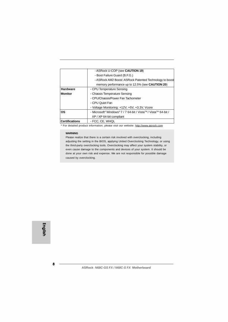
WARNINGPlease realize that there is a certain risk involved with overclocking, includingadjusting the setting in the BIOS, applying Untied Overclocking Technology, or usingthe third-party overclocking tools. Overclocking may affect your system stability, oreven cause damage to the components and devices of your system. It should bedone at your own risk and expense. We are not responsible for possible damagecaused by overclocking.
- ASRock U-COP (see CAUTION 19)- Boot Failure Guard (B.F.G.)- ASRock AM2 Boost: ASRock Patented Technology to boost memory performance up to 12.5% (see CAUTION 20)
Hardware - CPU Temperature Sensing Monitor - Chassis Temperature Sensing
- CPU/Chassis/Power Fan Tachometer- CPU Quiet Fan- Voltage Monitoring: +12V, +5V, +3.3V, Vcore
OS - Microsoft® Windows® 7 / 7 64-bit / VistaTM / VistaTM 64-bit / XP / XP 64-bit compliant
Certifications - FCC, CE, WHQL * For detailed product information, please visit our website: http://www.asrock.com
99999ASRock N68C-GS FX / N68C-S FX Motherboard
Eng
lish
Eng
lish
Eng
lish
Eng
lish
Eng
lish
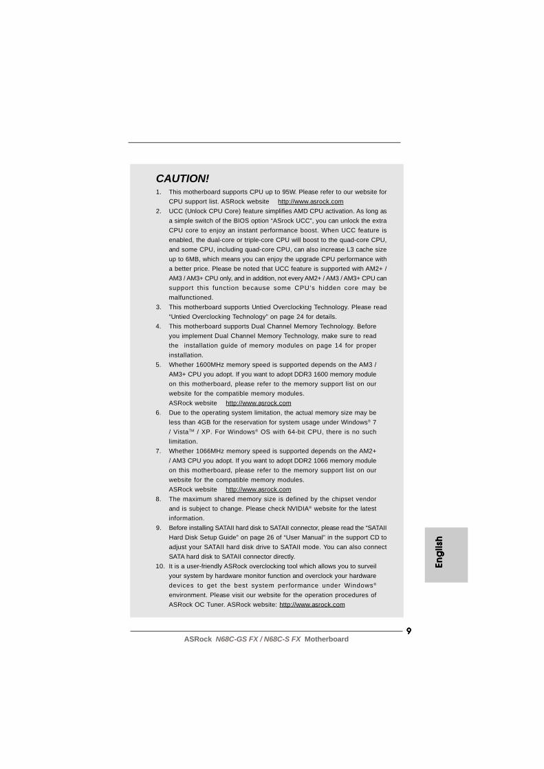
CAUTION!1. This motherboard supports CPU up to 95W. Please refer to our website for
CPU support list. ASRock website http://www.asrock.com2. UCC (Unlock CPU Core) feature simplifies AMD CPU activation. As long as
a simple switch of the BIOS option “ASrock UCC”, you can unlock the extraCPU core to enjoy an instant performance boost. When UCC feature isenabled, the dual-core or triple-core CPU will boost to the quad-core CPU,and some CPU, including quad-core CPU, can also increase L3 cache sizeup to 6MB, which means you can enjoy the upgrade CPU performance witha better price. Please be noted that UCC feature is supported with AM2+ /AM3 / AM3+ CPU only, and in addition, not every AM2+ / AM3 / AM3+ CPU cansupport this function because some CPU’s hidden core may bemalfunctioned.
3. This motherboard supports Untied Overclocking Technology. Please read“Untied Overclocking Technology” on page 24 for details.
4. This motherboard supports Dual Channel Memory Technology. Beforeyou implement Dual Channel Memory Technology, make sure to readthe installation guide of memory modules on page 14 for properinstallation.
5. Whether 1600MHz memory speed is supported depends on the AM3 /AM3+ CPU you adopt. If you want to adopt DDR3 1600 memory moduleon this motherboard, please refer to the memory support list on ourwebsite for the compatible memory modules.ASRock website http://www.asrock.com
6. Due to the operating system limitation, the actual memory size may beless than 4GB for the reservation for system usage under Windows® 7/ VistaTM / XP. For Windows® OS with 64-bit CPU, there is no suchlimitation.
7. Whether 1066MHz memory speed is supported depends on the AM2+/ AM3 CPU you adopt. If you want to adopt DDR2 1066 memory moduleon this motherboard, please refer to the memory support list on ourwebsite for the compatible memory modules.ASRock website http://www.asrock.com
8. The maximum shared memory size is defined by the chipset vendorand is subject to change. Please check NVIDIA® website for the latestinformation.
9. Before installing SATAII hard disk to SATAII connector, please read the “SATAIIHard Disk Setup Guide” on page 26 of “User Manual” in the support CD toadjust your SATAII hard disk drive to SATAII mode. You can also connectSATA hard disk to SATAII connector directly.
10. It is a user-friendly ASRock overclocking tool which allows you to surveilyour system by hardware monitor function and overclock your hardwaredevices to get the best system performance under Windows®
environment. Please visit our website for the operation procedures ofASRock OC Tuner. ASRock website: http://www.asrock.com
1 01 01 01 01 0ASRock N68C-GS FX / N68C-S FX Motherboard
Eng
lishEn
glish
Eng
lishEn
glish
Eng
lish
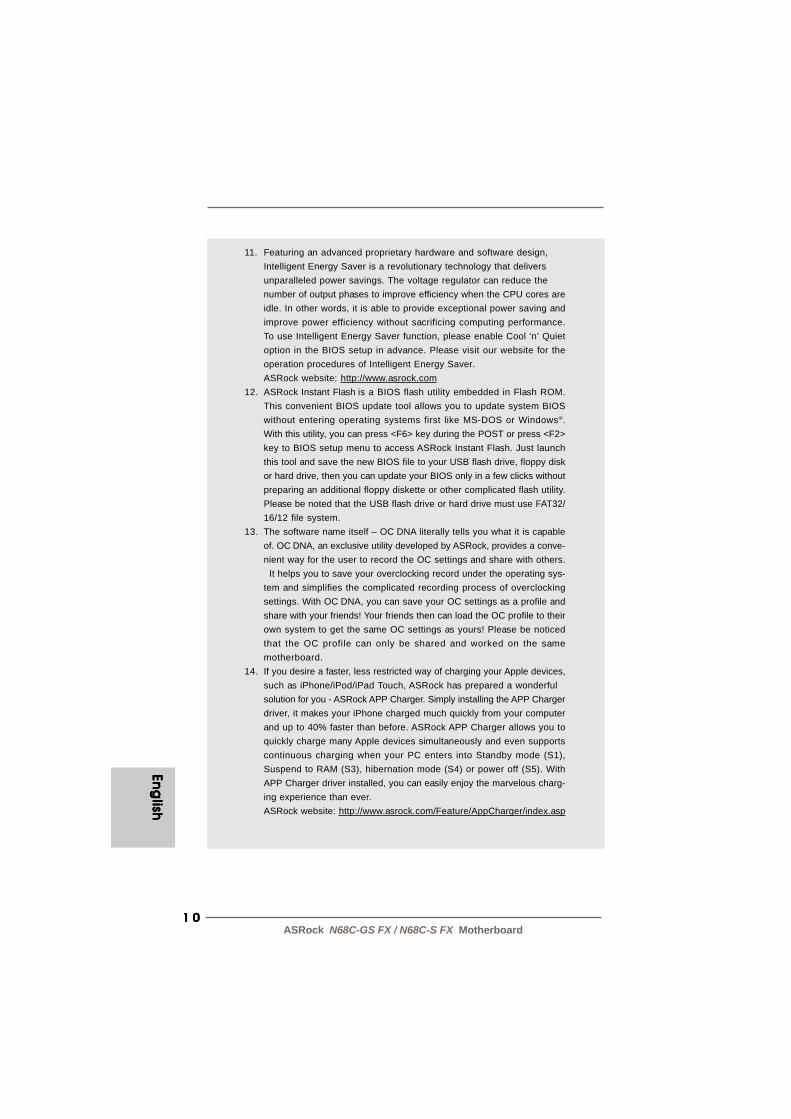
11. Featuring an advanced proprietary hardware and software design,Intelligent Energy Saver is a revolutionary technology that deliversunparalleled power savings. The voltage regulator can reduce thenumber of output phases to improve efficiency when the CPU cores areidle. In other words, it is able to provide exceptional power saving andimprove power efficiency without sacrificing computing performance.To use Intelligent Energy Saver function, please enable Cool ‘n’ Quietoption in the BIOS setup in advance. Please visit our website for theoperation procedures of Intelligent Energy Saver.ASRock website: http://www.asrock.com
12. ASRock Instant Flash is a BIOS flash utility embedded in Flash ROM.This convenient BIOS update tool allows you to update system BIOSwithout entering operating systems first like MS-DOS or Windows®.With this utility, you can press <F6> key during the POST or press <F2>key to BIOS setup menu to access ASRock Instant Flash. Just launchthis tool and save the new BIOS file to your USB flash drive, floppy diskor hard drive, then you can update your BIOS only in a few clicks withoutpreparing an additional floppy diskette or other complicated flash utility.Please be noted that the USB flash drive or hard drive must use FAT32/16/12 file system.
13. The software name itself – OC DNA literally tells you what it is capableof. OC DNA, an exclusive utility developed by ASRock, provides a conve-nient way for the user to record the OC settings and share with others. It helps you to save your overclocking record under the operating sys-tem and simplifies the complicated recording process of overclockingsettings. With OC DNA, you can save your OC settings as a profile andshare with your friends! Your friends then can load the OC profile to theirown system to get the same OC settings as yours! Please be noticedthat the OC profile can only be shared and worked on the samemotherboard.
14. If you desire a faster, less restricted way of charging your Apple devices,such as iPhone/iPod/iPad Touch, ASRock has prepared a wonderfulsolution for you - ASRock APP Charger. Simply installing the APP Chargerdriver, it makes your iPhone charged much quickly from your computerand up to 40% faster than before. ASRock APP Charger allows you toquickly charge many Apple devices simultaneously and even supportscontinuous charging when your PC enters into Standby mode (S1),Suspend to RAM (S3), hibernation mode (S4) or power off (S5). WithAPP Charger driver installed, you can easily enjoy the marvelous charg-ing experience than ever.ASRock website: http://www.asrock.com/Feature/AppCharger/index.asp

1 11 11 11 11 1ASRock N68C-GS FX / N68C-S FX Motherboard
15. SmartView, a new function of internet browser, is the smart start pagefor IE that combines your most visited web sites, your history, yourFacebook friends and your real-time newsfeed into an enhanced viewfor a more personal Internet experience. ASRock motherboards areexclusively equipped with the SmartView utility that helps you keep intouch with friends on-the-go. To use SmartView feature, please makesure your OS version is Windows® 7 / 7 64 bit / VistaTM / VistaTM 64 bit,and your browser version is IE8.ASRock website: http://www.asrock.com/Feature/SmartView/index.asp
16. ASRock XFast USB can boost USB storage device performance. Theperformance may depend on the property of the device.
17. ASRock XFast LAN provides a faster internet access, which includesbelow benefits. LAN Application Prioritization: You can configure yourapplication priority ideally and/or add new programs. Lower Latency inGame: After setting online game priority higher, it can lower the latencyin game. Traffic Shaping: You can watch Youtube HD video and down-load files simultaneously. Real-Time Analysis of Your Data: With thestatus window, you can easily recognize which data streams you arecurrently transferring.
18. Although this motherboard offers stepless control, it is not recom-mended to perform over-clocking. Frequencies other than the recom-mended CPU bus frequencies may cause the instability of the systemor damage the CPU.
19. While CPU overheat is detected, the system will automatically shutdown.Before you resume the system, please check if the CPU fan on themotherboard functions properly and unplug the power cord, then plug itback again. To improve heat dissipation, remember to spray thermalgrease between the CPU and the heatsink when you install the PCsystem.
20. This motherboard supports ASRock AM2 Boost overclocking technology. Ifyou enable this function in the BIOS setup, the memory performance willimprove up to 12.5%, but the effect still depends on the AM2 CPU youadopt. Enabling this function will overclock the chipset/CPU reference clock.However, we can not guarantee the system stability for all CPU/DRAMconfigurations. If your system is unstable after AM2 Boost function is enabled,it may not be applicative to your system. You may choose to disable thisfunction for keeping the stability of your system.
Eng
lish
Eng
lish
Eng
lish
Eng
lish
Eng
lish

1 21 21 21 21 2ASRock N68C-GS FX / N68C-S FX Motherboard
2.2.2.2.2. InstallationInstallationInstallationInstallationInstallationThis is a Micro ATX form factor (9.6-in x 8.2-in, 24.4 cm x 20.8 cm) motherboard.Before you install the motherboard, study the configuration of your chassis to en-sure that the motherboard fits into it.
Pre-installation PrecautionsPre-installation PrecautionsPre-installation PrecautionsPre-installation PrecautionsPre-installation PrecautionsTake note of the following precautions before you install motherboardcomponents or change any motherboard settings.
Before you install or remove any component, ensure that thepower is switched off or the power cord is detached from thepower supply. Failure to do so may cause severe damage to themotherboard, peripherals, and/or components.
1. Unplug the power cord from the wall socket before touching anycomponent.
2. To avoid damaging the motherboard components due to staticelectricity, NEVER place your motherboard directly on the carpet orthe like. Also remember to use a grounded wrist strap or touch asafety grounded object before you handle components.
3. Hold components by the edges and do not touch the ICs.4. Whenever you uninstall any component, place it on a grounded anti-
static pad or in the bag that comes with the component.5. When placing screws into the screw holes to secure the motherboard
to the chassis, please do not over-tighten the screws! Doing so maydamage the motherboard.
Eng
lishEn
glish
Eng
lishEn
glish
Eng
lish

1 31 31 31 31 3ASRock N68C-GS FX / N68C-S FX Motherboard
Eng
lish
Eng
lish
Eng
lish
Eng
lish
Eng
lish
2 .12 .12 .12 .12 .1 CPU InstallationCPU InstallationCPU InstallationCPU InstallationCPU InstallationStep 1. Unlock the socket by lifting the lever up to a 90o angle.Step 2. Position the CPU directly above the socket such that the CPU corner with
the golden triangle matches the socket corner with a small triangle.Step 3. Carefully insert the CPU into the socket until it fits in place.
The CPU fits only in one correct orientation. DO NOT force the CPUinto the socket to avoid bending of the pins.
Step 4. When the CPU is in place, press it firmly on the socket while you pushdown the socket lever to secure the CPU. The lever clicks on the side tabto indicate that it is locked.
2.22.22.22.22.2 Installation of CPU Fan and HeatsinkInstallation of CPU Fan and HeatsinkInstallation of CPU Fan and HeatsinkInstallation of CPU Fan and HeatsinkInstallation of CPU Fan and Heatsink
After you install the CPU into this motherboard, it is necessary to install alarger heatsink and cooling fan to dissipate heat. You also need to spraythermal grease between the CPU and the heatsink to improve heatdissipation. Make sure that the CPU and the heatsink are securely fas-tened and in good contact with each other. Then connect the CPU fan tothe CPU FAN connector (CPU_FAN1, see Page 2, No. 2). For properinstallation, please kindly refer to the instruction manuals of the CPU fanand the heatsink.
Lever 90° Up
CPU Golden Triangle
Socker Corner Small Triangle
STEP 1:
Lift Up The Socket Lever
STEP 2 / STEP 3:Match The CPU Golden TriangleTo The Socket Corner SmallTriangle
STEP 4:Push Down And LockThe Socket Lever

1 41 41 41 41 4ASRock N68C-GS FX / N68C-S FX Motherboard
Eng
lishEn
glish
Eng
lishEn
glish
Eng
lish
1. If you want to install two memory modules, for optimal compatibil-ity and reliability, it is recommended to install them in the slots ofthe same color. In other words, install them in the set of blue slots(DDR3_A1 and DDR3_B1), or in the set of yellow slots (DDRII_1and DDRII_2).
2. If only one memory module is installed in the DIMM slot on thismotherboard, it is unable to activate the Dual Channel MemoryTechnology.
3. It is not allowed to install a DDR3 memory module into DDR2 slotor install a DDR2 memory module into DDR3 slot; otherwise, thismotherboard and DIMM may be damaged.
4. DDR2 and DDR3 memory modules cannot be installed on thismotherboard at the same time.
5. DDR3 memory module is only supported by installing AM3/AM3+CPU. DDR2 memory module is only supported by installing AM2/AM2+/AM3 CPU.
2.3 Installation of Memor2.3 Installation of Memor2.3 Installation of Memor2.3 Installation of Memor2.3 Installation of Memory Modules (DIMM)y Modules (DIMM)y Modules (DIMM)y Modules (DIMM)y Modules (DIMM)This motherboard provides two 240-pin DDR2 (Double Data Rate 2) DIMM slots andtwo 240-pin DDR3 (Double Data Rate 3) DIMM slots, and supports Dual ChannelMemory Technology. For dual channel configuration, you always need to installidentical (the same brand, speed, size and chip-type) DDR2/DDR3 DIMM pair inthe slots of the same color. In other words, you have to install identical DDR2DIMM pair in Dual Channel (DDRII_1 and DDRII_2; Yellow slots; see p.2 No.6), oridentical DDR3 DIMM pair in Dual Channel (DDR3_A1 and DDR3_B1; Blue slots;see p.2 No.7), so that Dual Channel Memory Technology can be activated. You mayrefer to the Dual Channel Memory Configuration Table below.
DDR3_A1 DDR3_B1 (Blue Slot) (Blue Slot)
2 memory modules SS SS2 memory modules DS DS
Dual Channel DDR3 Memory Configurations (DS: Double Side, SS: Single Side)
DDRII_1 DDRII_2 (Yellow Slot) (Yellow Slot)
2 memory modules SS SS2 memory modules DS DS
Dual Channel DDR2 Memory Configurations (DS: Double Side, SS: Single Side)

1 51 51 51 51 5ASRock N68C-GS FX / N68C-S FX Motherboard
Eng
lish
Eng
lish
Eng
lish
Eng
lish
Eng
lish
Installing a DIMMInstalling a DIMMInstalling a DIMMInstalling a DIMMInstalling a DIMM
Please make sure to disconnect power supply before adding orremoving DIMMs or the system components.
Step 1. Unlock a DIMM slot by pressing the retaining clips outward.Step 2. Align a DIMM on the slot such that the notch on the DIMM matches the break
on the slot.
The DIMM only fits in one correct orientation. It will cause permanentdamage to the motherboard and the DIMM if you force the DIMM into the slotat incorrect orientation.
Step 3. Firmly insert the DIMM into the slot until the retaining clips at both ends fullysnap back in place and the DIMM is properly seated.

1 61 61 61 61 6ASRock N68C-GS FX / N68C-S FX Motherboard
Eng
lishEn
glish
Eng
lishEn
glish
Eng
lish
2.4 Expansion Slots (PCI and PCI Express Slots)2.4 Expansion Slots (PCI and PCI Express Slots)2.4 Expansion Slots (PCI and PCI Express Slots)2.4 Expansion Slots (PCI and PCI Express Slots)2.4 Expansion Slots (PCI and PCI Express Slots)There are 2 PCI slots and 2 PCI Express slots on this motherboard.PCI slots: PCI slots are used to install expansion cards that have the 32-bit PCI
interface.PCIE slots: PCIE1 (PCIE x1 slot) is used for PCI Express cards with x1 lane width
cards, such as Gigabit LAN card, SATA2 card, etc.PCIE2 (PCIE x16 slot) is used for PCI Express cards with x16 lanewidth graphics cards.
Installing an expansion cardInstalling an expansion cardInstalling an expansion cardInstalling an expansion cardInstalling an expansion cardStep 1. Before installing the expansion card, please make sure that the power
supply is switched off or the power cord is unplugged. Please read thedocumentation of the expansion card and make necessary hardwaresettings for the card before you start the installation.
Step 2. Remove the bracket facing the slot that you intend to use. Keep the screwsfor later use.
Step 3. Align the card connector with the slot and press firmly until the card iscompletely seated on the slot.
Step 4. Fasten the card to the chassis with screws.
1 71 71 71 71 7ASRock N68C-GS FX / N68C-S FX Motherboard
Eng
lish
Eng
lish
Eng
lish
Eng
lish
Eng
lish
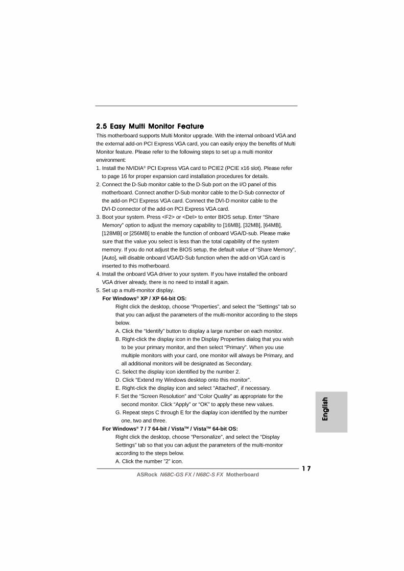
2.5 Easy Multi Monitor Feature2.5 Easy Multi Monitor Feature2.5 Easy Multi Monitor Feature2.5 Easy Multi Monitor Feature2.5 Easy Multi Monitor FeatureThis motherboard supports Multi Monitor upgrade. With the internal onboard VGA andthe external add-on PCI Express VGA card, you can easily enjoy the benefits of MultiMonitor feature. Please refer to the following steps to set up a multi monitorenvironment:1. Install the NVIDIA® PCI Express VGA card to PCIE2 (PCIE x16 slot). Please refer to page 16 for proper expansion card installation procedures for details.2. Connect the D-Sub monitor cable to the D-Sub port on the I/O panel of this motherboard. Connect another D-Sub monitor cable to the D-Sub connector of the add-on PCI Express VGA card. Connect the DVI-D monitor cable to the DVI-D connector of the add-on PCI Express VGA card.3. Boot your system. Press <F2> or <Del> to enter BIOS setup. Enter “Share Memory” option to adjust the memory capability to [16MB], [32MB], [64MB], [128MB] or [256MB] to enable the function of onboard VGA/D-sub. Please make sure that the value you select is less than the total capability of the system memory. If you do not adjust the BIOS setup, the default value of “Share Memory”, [Auto], will disable onboard VGA/D-Sub function when the add-on VGA card is inserted to this motherboard.4. Install the onboard VGA driver to your system. If you have installed the onboard VGA driver already, there is no need to install it again.5. Set up a multi-monitor display. For Windows® XP / XP 64-bit OS:
Right click the desktop, choose “Properties”, and select the “Settings” tab sothat you can adjust the parameters of the multi-monitor according to the stepsbelow.A. Click the “Identify” button to display a large number on each monitor.B. Right-click the display icon in the Display Properties dialog that you wish to be your primary monitor, and then select “Primary”. When you use multiple monitors with your card, one monitor will always be Primary, and all additional monitors will be designated as Secondary.C. Select the display icon identified by the number 2.D. Click “Extend my Windows desktop onto this monitor”.E. Right-click the display icon and select “Attached”, if necessary.F. Set the “Screen Resolution” and “Color Quality” as appropriate for the second monitor. Click “Apply” or “OK” to apply these new values.G. Repeat steps C through E for the diaplay icon identified by the number one, two and three.
For Windows® 7 / 7 64-bit / VistaTM / VistaTM 64-bit OS:Right click the desktop, choose “Personalize”, and select the “DisplaySettings” tab so that you can adjust the parameters of the multi-monitoraccording to the steps below.A. Click the number ”2” icon.

1 81 81 81 81 8ASRock N68C-GS FX / N68C-S FX Motherboard
Eng
lishEn
glish
Eng
lishEn
glish
Eng
lish
B. Click the items “This is my main monitor” and “Extend the desktop onto this monitor”.C. Click “OK” to save your change.D. Repeat steps A through C for the display icon identified by the number one, two and three.
6. Use Multi Monitor feature. Click and drag the display icons to positions representing the physical setup of your monitors that you would like to use. The placement of display icons determines how you move items from one monitor to another.

1 91 91 91 91 9ASRock N68C-GS FX / N68C-S FX Motherboard
Eng
lish
Eng
lish
Eng
lish
Eng
lish
Eng
lish
OpenShort
2.62.62.62.62.6 Jumpers SetupJumpers SetupJumpers SetupJumpers SetupJumpers SetupThe illustration shows how jumpers aresetup. When the jumper cap is placed onpins, the jumper is “Short”. If no jumper capis placed on pins, the jumper is “Open”. Theillustration shows a 3-pin jumper whose pin1and pin2 are “Short” when jumper cap isplaced on these 2 pins.Jumper SettingPS2_USB_PWR1 Short pin2, pin3 to enable(see p.2, No. 1) +5VSB (standby) for PS/2 or
USB01/23 wake up events.Note: To select +5VSB, it requires 2 Amp and higher standby current provided by
power supply.
USB_PWR2 Short pin2, pin3 to enable(see p.2, No. 15) +5VSB (standby) for
USB4_5/6_7/8_9 wake upevents.
Note: To select +5VSB, it requires 2 Amp and higher standby current provided bypower supply.
Clear CMOS Jumper(CLRCMOS1)
(see p.2, No. 22)
Note: CLRCMOS1 allows you to clear the data in CMOS. The data in CMOS includessystem setup information such as system password, date, time, and systemsetup parameters. To clear and reset the system parameters to default setup,please turn off the computer and unplug the power cord from the powersupply. After waiting for 15 seconds, use a jumper cap to short pin2 and pin3
Clear CMOSDefault
2 02 02 02 02 0ASRock N68C-GS FX / N68C-S FX Motherboard
Eng
lishEn
glish
Eng
lishEn
glish
Eng
lish
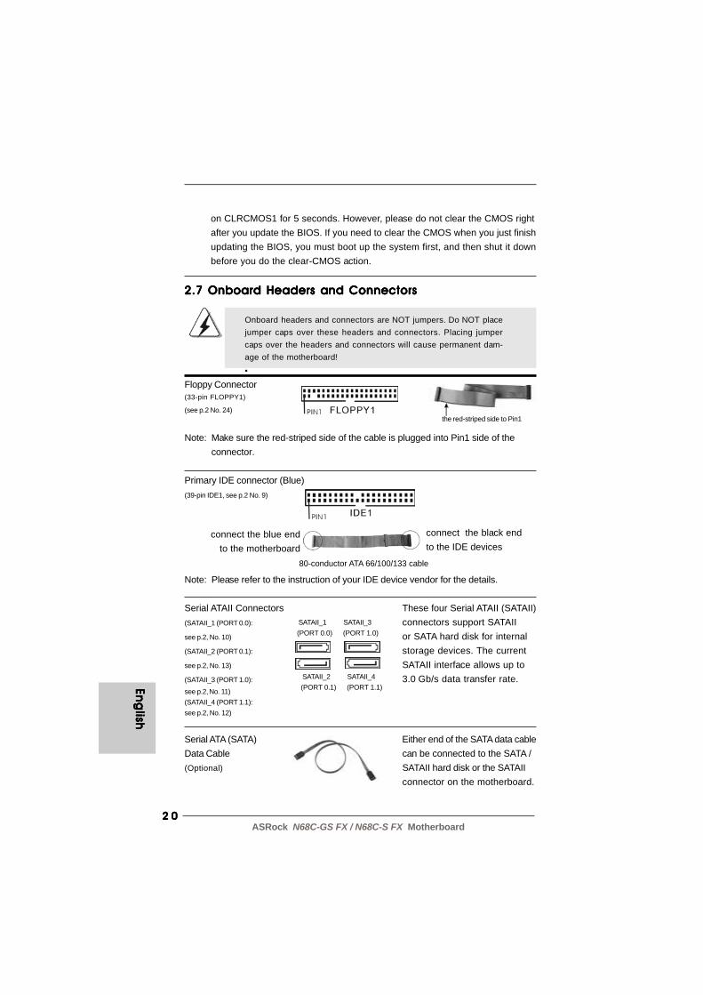
connect the black endto the IDE devices
connect the blue endto the motherboard
80-conductor ATA 66/100/133 cable
the red-striped side to Pin1
2.7 Onboard Headers and Connectors2.7 Onboard Headers and Connectors2.7 Onboard Headers and Connectors2.7 Onboard Headers and Connectors2.7 Onboard Headers and Connectors
Onboard headers and connectors are NOT jumpers. Do NOT placejumper caps over these headers and connectors. Placing jumpercaps over the headers and connectors will cause permanent dam-age of the motherboard!•
Floppy Connector(33-pin FLOPPY1)
(see p.2 No. 24)
Note: Make sure the red-striped side of the cable is plugged into Pin1 side of theconnector.
Primary IDE connector (Blue)(39-pin IDE1, see p.2 No. 9)
Note: Please refer to the instruction of your IDE device vendor for the details.
Serial ATAII Connectors These four Serial ATAII (SATAII)(SATAII_1 (PORT 0.0): connectors support SATAIIsee p.2, No. 10) or SATA hard disk for internal(SATAII_2 (PORT 0.1): storage devices. The currentsee p.2, No. 13) SATAII interface allows up to(SATAII_3 (PORT 1.0): 3.0 Gb/s data transfer rate.see p.2, No. 11)(SATAII_4 (PORT 1.1):see p.2, No. 12)
Serial ATA (SATA) Either end of the SATA data cableData Cable can be connected to the SATA /(Optional) SATAII hard disk or the SATAII
connector on the motherboard.
SATAII_1 SATAII_3(PORT 0.0) (PORT 1.0)
SATAII_2 SATAII_4(PORT 0.1) (PORT 1.1)
on CLRCMOS1 for 5 seconds. However, please do not clear the CMOS rightafter you update the BIOS. If you need to clear the CMOS when you just finishupdating the BIOS, you must boot up the system first, and then shut it downbefore you do the clear-CMOS action.

2 12 12 12 12 1ASRock N68C-GS FX / N68C-S FX Motherboard
CD1
USB 2.0 Headers Besides four default USB 2.0(9-pin USB8_9) ports on the I/O panel, there are(see p.2 No. 16) three USB 2.0 headers on this
motherboard. Each USB 2.0header can support two USB2.0 ports.
(9-pin USB6_7)(see p.2 No. 17)
(9-pin USB4_5)(see p.2 No. 18)
Front Panel Audio Header This is an interface for the front(9-pin HD_AUDIO1) panel audio cable that allows(see p.2, No. 27) convenient connection and
control of audio devices.
Internal Audio Connectors This connector allows you(4-pin CD1) to receive stereo audio input(CD1: see p.2 No. 26) from sound sources such as
a CD-ROM, DVD-ROM, TVtuner card, or MPEG card.
CD
-L
GN
D
GN
D
CD
-R
1. High Definition Audio supports Jack Sensing, but the panel wire on the chassis must support HDA to function correctly. Please follow the
instruction in our manual and chassis manual to install your system.2. If you use AC’97 audio panel, please install it to the front panel audio header as below: A. Connect Mic_IN (MIC) to MIC2_L. B. Connect Audio_R (RIN) to OUT2_R and Audio_L (LIN) to OUT2_L.
Print Port Header This is an interface for print(25-pin LPT1) port cable that allows(see p.2 No. 23) convenient connection of printer
devices.
Eng
lish
Eng
lish
Eng
lish
Eng
lish
Eng
lish

2 22 22 22 22 2ASRock N68C-GS FX / N68C-S FX Motherboard
Eng
lishEn
glish
Eng
lishEn
glish
Eng
lish
C. Connect Ground (GND) to Ground (GND). D. MIC_RET and OUT_RET are for HD audio panel only. You don’t need to connect them for AC’97 audio panel.
Chassis Speaker Header Please connect the chassis(4-pin SPEAKER 1) speaker to this header.(see p.2 No. 19)
Chassis and Power Fan Connectors Please connect the fan cables(3-pin CHA_FAN1) to the fan connectors and(see p.2 No. 21) match the black wire to the
ground pin.
(3-pin PWR_FAN1)(see p.2 No. 25)
System Panel Header This header accommodates(9-pin PANEL1) several system front panel(see p.2 No. 20) functions.
CPU Fan Connector Please connect the CPU fan(4-pin CPU_FAN1) cable to this connector and(see p.2 No. 2) match the black wire to the
ground pin.
ATX Power Connector Please connect an ATX power(24-pin ATXPWR1) supply to this connector.(see p.2 No. 8)
Though this motherboard provides 4-Pin CPU fan (Quiet Fan) support, the 3-Pin CPU fan still can work successfully even without the fan speed control function. If you plan to connect the 3-Pin CPU fan to the CPU fan connector on this motherboard, please connect it to Pin 1-3.
3-Pin Fan Installation
Pin 1-3 Connected
12
1
24
13
4 3 2 1

2 32 32 32 32 3ASRock N68C-GS FX / N68C-S FX Motherboard
ATX 12V Power Connector Please note that it is necessary(4-pin ATX12V1) to connect a power supply with(see p.2 No. 3) ATX 12V plug to this connector.
Failing to do so will cause powerup failure.
20-Pin ATX Power Supply Installation
Though this motherboard provides 24-pin ATX power connector, it can still work if you adopt a traditional 20-pin ATX power supply. To use the 20-pin ATX power supply, please plug your power supply along with Pin 1 and Pin 13.
12
1
24
13
Eng
lish
Eng
lish
Eng
lish
Eng
lish
Eng
lish
o

2 42 42 42 42 4ASRock N68C-GS FX / N68C-S FX Motherboard
Eng
lishEn
glish
Eng
lishEn
glish
Eng
lish
2.82.82.82.82.8 Driver Installation GuideDriver Installation GuideDriver Installation GuideDriver Installation GuideDriver Installation GuideTo install the drivers to your system, please insert the support CD to your opticaldrive first. Then, the drivers compatible to your system can be auto-detected andlisted on the support CD driver page. Please follow the order from up to bottomside to install those required drivers. Therefore, the drivers you install can workproperly.
2.92.92.92.92.9 Installing WindowsInstalling WindowsInstalling WindowsInstalling WindowsInstalling Windows®®®®® 7 / 7 64-bit / Vista 7 / 7 64-bit / Vista 7 / 7 64-bit / Vista 7 / 7 64-bit / Vista 7 / 7 64-bit / VistaTMTMTMTMTM / / / / /
VistaVistaVistaVistaVistaTMTMTMTMTM 64-bit / XP / XP 64-bit Without RAID Functions 64-bit / XP / XP 64-bit Without RAID Functions 64-bit / XP / XP 64-bit Without RAID Functions 64-bit / XP / XP 64-bit Without RAID Functions 64-bit / XP / XP 64-bit Without RAID FunctionsIf you just want to install Windows® 7 / 7 64-bit / VistaTM / VistaTM 64-bit / XP / XP64-bit on your SATA / SATAII HDDs without RAID functions, you don’t have to make aSATA / SATAII driver diskette. Besides, there is no need for you to change the BIOSsetting. You can start to install Windows® 7 / 7 64-bit / VistaTM / VistaTM 64-bit / XP / XP64-bit on your system directly.
2.102.102.102.102.10 Installing WindowsInstalling WindowsInstalling WindowsInstalling WindowsInstalling Windows®®®®® 7 / 7 64-bit / Vista 7 / 7 64-bit / Vista 7 / 7 64-bit / Vista 7 / 7 64-bit / Vista 7 / 7 64-bit / VistaTMTMTMTMTM / / / / /
VistaVistaVistaVistaVistaTMTMTMTMTM 64-bit / XP / XP 64-bit With RAID Functions 64-bit / XP / XP 64-bit With RAID Functions 64-bit / XP / XP 64-bit With RAID Functions 64-bit / XP / XP 64-bit With RAID Functions 64-bit / XP / XP 64-bit With RAID FunctionsIf you want to install Windows® 7 / 7 64-bit / VistaTM / VistaTM 64-bit / XP / XP 64-bit onyour SATA / SATAII HDDs with RAID functions, please refer to the document at thefollowing path in the Support CD for detailed procedures:..\ RAID Installation Guide
2.112.112.112.112.11 Untied Overclocking TUntied Overclocking TUntied Overclocking TUntied Overclocking TUntied Overclocking TechnologyechnologyechnologyechnologyechnologyThis motherboard supports Untied Overclocking Technology, which means duringoverclocking, FSB enjoys better margin due to fixed PCI / PCIE buses. Before youenable Untied Overclocking function, please enter “Overclock Mode” option of BIOSsetup to set the selection from [Auto] to [CPU, PCIE, Async.]. Therefore, CPU FSB isuntied during overclocking, but PCI / PCIE buses are in the fixed mode so that FSB canoperate under a more stable overclocking environment.
Please refer to the warning on page 8 for the possible overclocking risk beforeyou apply Untied Overclocking Technology.

2 52 52 52 52 5ASRock N68C-GS FX / N68C-S FX Motherboard
3. BIOS Information3. BIOS Information3. BIOS Information3. BIOS Information3. BIOS InformationThe Flash Memory on the motherboard stores BIOS Setup Utility. When you start upthe computer, please press <F2> during the Power-On-Self-Test (POST) to enterBIOS Setup utility; otherwise, POST continues with its test routines. If you wish toenter BIOS Setup after POST, please restart the system by pressing <Ctl> + <Alt> +<Delete>, or pressing the reset button on the system chassis. The BIOS Setupprogram is designed to be user-friendly. It is a menu-driven program, which allowsyou to scroll through its various sub-menus and to select among the predeterminedchoices. For the detailed information about BIOS Setup, please refer to the UserManual (PDF file) contained in the Support CD.
4. Sof4. Sof4. Sof4. Sof4. Software Supportware Supportware Supportware Supportware Support CD informationt CD informationt CD informationt CD informationt CD informationThis motherboard supports various Microsoft® Windows® operating systems: 7 /7 64-bit / VistaTM / VistaTM 64-bit / XP / XP 64-bit. The Support CD that came with themotherboard contains necessary drivers and useful utilities that will enhancemotherboard features. To begin using the Support CD, insert the CD into your CD-ROM drive. It will display the Main Menu automatically if “AUTORUN” is enabled inyour computer. If the Main Menu does not appear automatically, locate and double-click on the file “ASSETUP.EXE” from the “BIN” folder in the Support CD to display themenus.
Eng
lish
Eng
lish
Eng
lish
Eng
lish
Eng
lish
2 62 62 62 62 6ASRock N68C-GS FX / N68C-S FX Motherboard
De
utsc
hD
eu
tsch
De
utsc
hD
eu
tsch
De
utsc
h
1. Einführung1. Einführung1. Einführung1. Einführung1. EinführungWir danken Ihnen für den Kauf des ASRock N68C-GS FX / N68C-S FX Motherboard, einzuverlässiges Produkt, welches unter den ständigen, strengen Qualitätskontrollen vonASRock gefertigt wurde. Es bietet Ihnen exzellente Leistung und robustes Design, gemäßder Verpflichtung von ASRock zu Qualität und Halbarkeit.Diese Schnellinstallationsanleitung führt in das Motherboard und die schrittweiseInstallation ein. Details über das Motherboard finden Sie in der Bedienungsanleitungauf der Support-CD.
Da sich Motherboard-Spezifikationen und BIOS-Software verändernkönnen, kann der Inhalt dieses Handbuches ebenfalls jederzeit geändertwerden. Für den Fall, dass sich Änderungen an diesem Handbuchergeben, wird eine neue Version auf der ASRock-Website, ohne weitereAnkündigung, verfügbar sein. Die neuesten Grafikkarten und unterstütztenCPUs sind auch auf der ASRock-Website aufgelistet.ASRock-Website: http://www.asrock.comWenn Sie technische Unterstützung zu Ihrem Motherboard oder spezifischeInformationen zu Ihrem Modell benötigen, besuchen Sie bitte unsereWebseite:www.asrock.com/support/index.asp
1.1 KartoninhaltASRock N68C-GS FX / N68C-S FX Motherboard
(Micro ATX-Formfaktor: 24.4 cm x 20.8 cm; 9.6 Zoll x 8.2 Zoll)ASRock N68C-GS FX / N68C-S FX SchnellinstallationsanleitungASRock N68C-GS FX / N68C-S FX Support-CDZwei Seriell-ATA- (SATA) Datenkabel (Option)Ein I/O Shield
2 72 72 72 72 7ASRock N68C-GS FX / N68C-S FX Motherboard
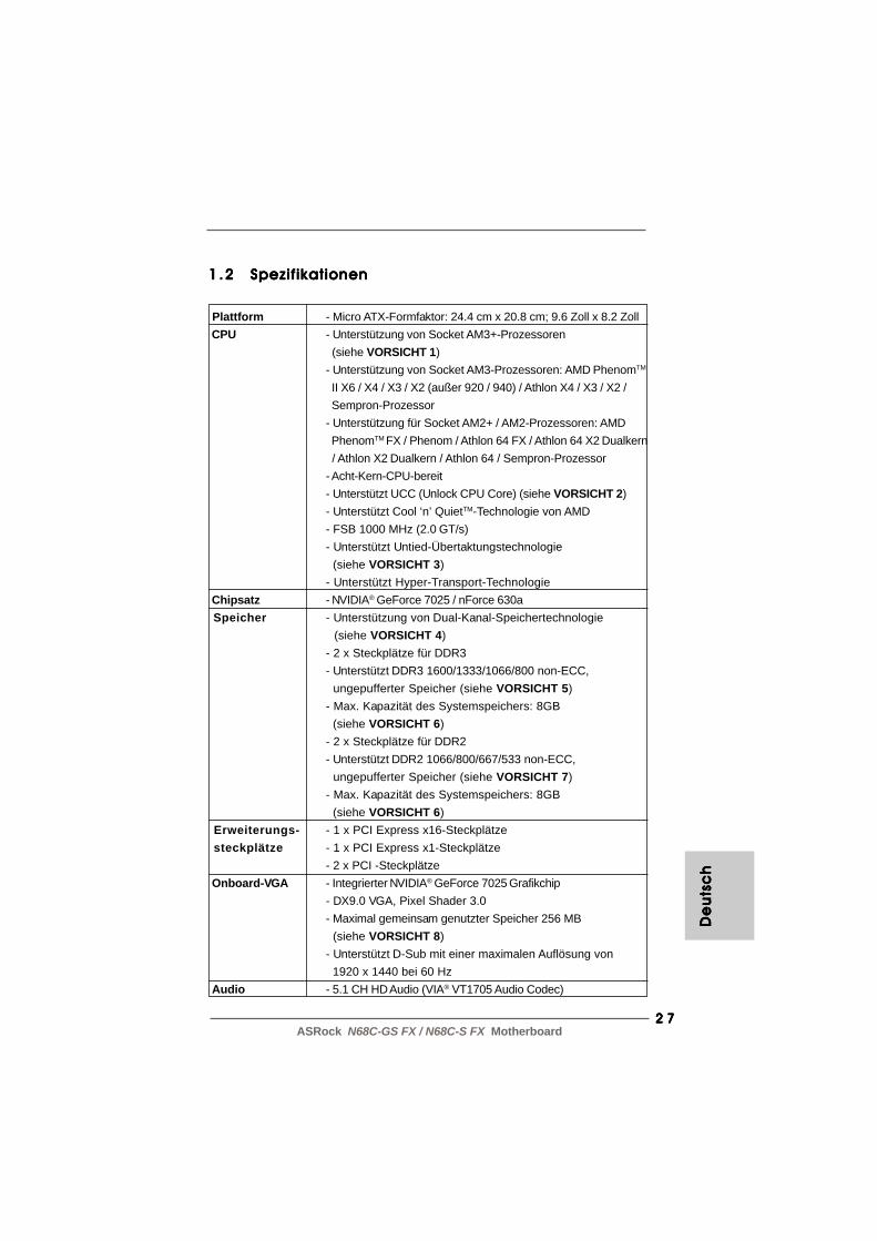
1.21 .21 .21 .21 .2 Spezif ikationenSpezif ikationenSpezif ikationenSpezif ikationenSpezif ikationen
Plattform - Micro ATX-Formfaktor: 24.4 cm x 20.8 cm; 9.6 Zoll x 8.2 Zoll CPU - Unterstützung von Socket AM3+-Prozessoren
(siehe VORSICHT 1)- Unterstützung von Socket AM3-Prozessoren: AMD PhenomTM
II X6 / X4 / X3 / X2 (außer 920 / 940) / Athlon X4 / X3 / X2 / Sempron-Prozessor- Unterstützung für Socket AM2+ / AM2-Prozessoren: AMD PhenomTM FX / Phenom / Athlon 64 FX / Athlon 64 X2 Dualkern / Athlon X2 Dualkern / Athlon 64 / Sempron-Prozessor- Acht-Kern-CPU-bereit- Unterstützt UCC (Unlock CPU Core) (siehe VORSICHT 2)- Unterstützt Cool ‘n’ QuietTM-Technologie von AMD- FSB 1000 MHz (2.0 GT/s)- Unterstützt Untied-Übertaktungstechnologie (siehe VORSICHT 3)- Unterstützt Hyper-Transport-Technologie
Chipsatz - NVIDIA® GeForce 7025 / nForce 630a Speicher - Unterstützung von Dual-Kanal-Speichertechnologie
(siehe VORSICHT 4)- 2 x Steckplätze für DDR3- Unterstützt DDR3 1600/1333/1066/800 non-ECC, ungepufferter Speicher (siehe VORSICHT 5)- Max. Kapazität des Systemspeichers: 8GB (siehe VORSICHT 6)- 2 x Steckplätze für DDR2- Unterstützt DDR2 1066/800/667/533 non-ECC, ungepufferter Speicher (siehe VORSICHT 7)- Max. Kapazität des Systemspeichers: 8GB (siehe VORSICHT 6)
Erweiterungs- - 1 x PCI Express x16-Steckplätze steckplätze - 1 x PCI Express x1-Steckplätze
- 2 x PCI -Steckplätze Onboard-VGA - Integrierter NVIDIA® GeForce 7025 Grafikchip
- DX9.0 VGA, Pixel Shader 3.0- Maximal gemeinsam genutzter Speicher 256 MB (siehe VORSICHT 8)- Unterstützt D-Sub mit einer maximalen Auflösung von 1920 x 1440 bei 60 Hz
Audio - 5.1 CH HD Audio (VIA® VT1705 Audio Codec)
De
uts
ch
De
uts
ch
De
uts
ch
De
uts
ch
De
uts
ch

2 82 82 82 82 8ASRock N68C-GS FX / N68C-S FX Motherboard
De
utsc
hD
eu
tsch
De
utsc
hD
eu
tsch
De
utsc
h
LAN - N68C-GS FX Realtek Giga PHY RTL8211CL, speed 10/100/1000 Mb/s- N68C-S FX Realtek PHY RTL8201EL, speed 10/100 Mb/s- Unterstützt Wake-On-LAN- Unterstützt PXE
E/A-Anschlüsse I/O Panel an der - 1 x PS/2-Mausanschluss Rückseite - 1 x PS/2-Tastaturanschluss
- 1 x Serieller port: COM 1- 1 x VGA port- 4 x Standard-USB 2.0-Anschlüsse- 1 x RJ-45 LAN Port mit LED (ACT/LINK LED und SPEED LED)- Audioanschlüsse: Line In / Line Out / Mikrofon
Anschlüsse - 4 x SATA2-Anschlüsse, unterstützt bis 3.0 Gb/s Datenübertragungsrate, unterstützt RAID (RAID 0, RAID 1, RAID 0+1, RAID 5, JBOD), NCQ und “Hot Plug” Funktionen (siehe VORSICHT 9)- 1 x ATA133 IDE-Anschlüsse (Unterstützt bis 2 IDE-Geräte)- 1 x FDD-Anschlüsse- 1 x Druckerport-Anschlussleiste- CPU/Gehäuse/Stromlüfter-Anschluss- 24-pin ATX-Netz-Header- 4-pin anschluss für 12V-ATX-Netzteil- Interne Audio-Anschlüsse- Anschluss für Audio auf der Gehäusevorderseite- 3 x USB 2.0-Anschlüsse (Unterstützung 6 zusätzlicher USB 2.0-Anschlüsse)
BIOS - 8Mb AMI BIOS- AMI legal BIOS mit Unterstützung für “Plug and Play”- ACPI 1.1-Weckfunktionen- JumperFree-Modus- SMBIOS 2.3.1- CPU, VCCM, NB Stromspannung Multianpassung
Support-CD - Pilotes, utilitaires, logiciel anti-virus (version d’évaluation), CyberLink MediaEspresso 6.5 Trial, Suite logicielle ASRock (CyberLink DVD Suite et Version OEM et d’essai; Creative Sound Blaster X-Fi MB - Testversion; ASRock MAGIX-Multimedia-Suite - OEM)

2 92 92 92 92 9ASRock N68C-GS FX / N68C-S FX Motherboard
WARNUNGBeachten Sie bitte, dass Overclocking, einschließlich der Einstellung im BIOS, Anwendender Untied Overclocking-Technologie oder Verwenden von Overclocking-Werkzeugen vonDritten, mit einem gewissen Risiko behaftet ist. Overclocking kann sich nachteilig auf dieStabilität Ihres Systems auswirken oder sogar Komponenten und Geräte Ihres Systemsbeschädigen. Es geschieht dann auf eigene Gefahr und auf Ihre Kosten. Wir übernehmenkeine Verantwortung für mögliche Schäden, die aufgrund von Overclocking verursachtwurden.
Einzigartige - ASRock OC Tuner (siehe VORSICHT 10) Eigenschaft - ASRock Intelligent Energy Saver (Intelligente
Energiesparfunktion) (siehe VORSICHT 11)- ASRock Sofortstart- ASRock Instant Flash (siehe VORSICHT 12)- ASRock OC DNA (siehe VORSICHT 13)- ASRock APP Charger (siehe VORSICHT 14)- ASRock SmartView (siehe VORSICHT 15)- ASRock XFast USB (siehe VORSICHT 16)- ASRock XFast LAN (siehe VORSICHT 17)- Hybrid Booster:
- Schrittloser CPU-Frequenz-Kontrolle (siehe VORSICHT 18)- ASRock U-COP (siehe VORSICHT 19)- Boot Failure Guard (B.F.G. – Systemstartfehlerschutz)- ASRock AM2 Boost: ASRocks patentgeschützte Technologie zur Erhöhung der Arbeitsspeicherleistung um bis zu 12,5% (siehe VORSICHT 20)
Hardware Monitor - CPU-Temperatursensor- Motherboardtemperaturerkennung- Drehzahlmessung für CPU/Gehäuse/Stromlüfter- CPU-Lüftergeräuschdämpfung- Spannungsüberwachung: +12V, +5V, +3.3V, Vcore
Betriebssysteme - Unterstützt Microsoft® Windows® 7 / 7 64-Bit / VistaTM / VistaTM 64-Bit / XP / XP 64-Bit
Zertifizierungen - FCC, CE, WHQL * Für die ausführliche Produktinformation, besuchen Sie bitte unsere Website: http://www.asrock.com
De
uts
ch
De
uts
ch
De
uts
ch
De
uts
ch
De
uts
ch
3 03 03 03 03 0ASRock N68C-GS FX / N68C-S FX Motherboard
De
utsc
hD
eu
tsch
De
utsc
hD
eu
tsch
De
utsc
h
VORSICHT!1. Dieses Motherboard unterstützt CPUs bis 95W. Auf unserer Website
finden Sie eine Liste mit unterstützten CPUs.ASRock-Internetseite: http://www.asrock.com
2. Die UCC-Funktion (Unlock CPU Core; zu Deutsch: CPU-Kern freigeben)vereinfacht die AMD-CPU-Aktivierung. Zur Freigabe des zusätzlichen CPU-Kerns müssen Sie lediglich die BIOS-Option „ASRock UCC“ umschalten –schon profitieren Sie von einem Leistungsschub. Wenn die UCC-Funktionaktiviert ist, rüstet die Dual-Core- oder Triple-Core-CPU auf eine Quad-Core-CPU auf – einige CPUs (inklusive Quad-Core) können zudem die L3-Cache-Größe auf bis zu 6 MB anheben; das bedeutet verbesserte CPU-Leistung zu einem geringeren Preis. Bitte beachten Sie, dass die UCC-Funktion nur bei AM2+ / AM3 / AM3+-CPUs einsetzbar ist; dieUnterstützung besteht jedoch aufgrund möglicher Fehlfunktionen desverborgenen Kerns einiger CPUs auch nicht zwangsläufig bei jederAM2+ / AM3 / AM3+-CPU.
3. Dieses Motherboard unterstützt die Untied-Übertaktungstechnologie.Unter “Entkoppelte Übertaktungstechnologie” auf Seite 24 finden Siedetaillierte Informationen.
4. Dieses Motherboard unterstützt Dual-Kanal-Speichertechnologie. VorImplementierung der Dual-Kanal-Speichertechnologie müssen Sie dieInstallationsanleitung für die Speichermodule auf Seite 14 zwecksrichtigerInstallation gelesen haben.
5. Ob die Speichergeschwindigkeit 1600 MHz unterstützt wird, hängt vonder von Ihnen eingesetzten AM3 / AM3+-CPU ab. Schauen Sie bitte aufunseren Internetseiten in der Liste mit unterstützten Speichermodulennach, wenn Sie DDR3 1600-Speichermodule einsetzen möchten.ASRock-Internetseite: http://www.asrock.com
6. Durch Betriebssystem-Einschränkungen kann die tatsächlicheSpeichergröße weniger als 4 GB betragen, da unter Windows® 7 / Vista™/ XP etwas Speicher zur Nutzung durch das System reserviert wird.Unter Windows® OS mit 64-Bit-CPU besteht diese Einschränkung nicht.
7. Ob die Speichergeschwindigkeit 1066 MHz unterstützt wird, hängt vonder von Ihnen eingesetzten AM2+ / AM3-CPU ab. Schauen Sie bitte aufunseren Internetseiten in der Liste mit unterstützten Speichermodulennach, wenn Sie DDR2 1066-Speichermodule einsetzen möchten.ASRock-Internetseite: http://www.asrock.com
8. Die Maximalspeichergröße ist von den Chipshändler definiert undumgetauscht. Bitte überprüfen Sie NVIDIA® website für die neulicheInformation.
9. Vor Installation der SATAII-Festplatte an den SATAII-Anschluss lesenSie bitte “Setup-Anleitung für SATAII-Festplatte” auf Seite 26 der“Bedienungsanleitung” auf der Support-CD, um Ihre SATAII-Festplattedem SATAII-Modus anzugleichen. Sie können die SATA-Festplatteauch direkt mit dem SATAII-Anschluss verbinden.
3 13 13 13 13 1ASRock N68C-GS FX / N68C-S FX Motherboard
10. Es ist ein benutzerfreundlicher ASRock Übertaktenswerkzeug, daserlaubt, dass Sie Ihr System durch den Hardware-Monitor Funktion zuüberblicken und Ihre Hardware-Geräte übertakten, um die besteSystemleistung unter der Windows® Umgebung zu erreichen. BesuchenSie bitte unsere Website für die Operationsverfahren von ASRock OCTuner. ASRock-Website: http://www.asrock.com
11. Mit einer eigenen, modernen Hardware und speziellemSoftwaredesign, bietet der Intelligent Energy Saver eine revolutionäreTechnologie zur bisher unerreichten Energieeinsparung. EinSpannungsregler kann die Anzahl von Ausgangsphasen zurEffektivitätsverbessserung reduzieren, wenn sich die CPU imLeerlauf befindet. Mit anderen Worten: Sie genießenaußergewöhnliche Energieeinsparung und verbessertenWirkungsgrad ohne Leistungseinschränkungen. Wenn Sie dieIntelligent Energy Saver-Funktion nutzen möchten, aktivieren Sie zuvordie „Cool ‘n’ Quiet“-Option im BIOS. Weitere Bedienungshinweisezum Intelligent Energy Saver finden Sie auf unseren Internetseiten.ASRock-Internetseite: http://www.asrock.com
12. ASRock Instant Flash ist ein im Flash-ROM eingebettetes BIOS-Flash-Programm. Mithilfe dieses praktischen BIOS-Aktualisierungswerkzeugskönnen Sie das System-BIOS aktualisieren, ohne dafür zuerstBetriebssysteme wie MS-DOS oder Windows® aufrufen zu müssen. Mitdiesem Programm bekommen Sie durch Drücken der <F6>-Tastewährend des POST-Vorgangs oder durch Drücken der <F2>-Taste imBIOS-Setup-Menü Zugang zu ASRock Instant Flash. Sie brauchendieses Werkzeug einfach nur zu starten und die neue BIOS-Datei aufIhrem USB-Flash-Laufwerk, Diskettenlaufwerk oder der Festplatte zuspeichern, und schon können Sie Ihr BIOS mit nur wenigenKlickvorgängen ohne Bereitstellung einer zusätzlichen Diskette odereines anderen komplizierten Flash-Programms aktualisieren. AchtenSie darauf, dass das USB-Flash-Laufwerk oder die Festplatte dasDateisystem FAT32/16/12 benutzen muss.
13. Allein der Name – OC DNA* – beschreibt es wörtlich, was dieSoftware zu leisten vermag. OC DNA ist ein von ASRock exklusiventwickeltes Dienstprogramm, das Nutzern eine bequemeMöglichkeit bietet, Übertaktungseinstellungen aufzuzeichnen und sieAnderen mitzuteilen. Es hilft Ihnen, Ihre Übertaktungsaufzeichnung imBetriebssystem zu speichern und vereinfacht den kompliziertenAufzeichnungsvorgang von Übertaktungseinstellungen. Mit OC DNAkönnen Sie Ihre Übertaktungseinstellungen als Profil abspeichernund Ihren Freunden zugänglich machen! Ihre Freunde können danndas Übertaktungsprofil auf ihren eigenen Systemen laden, umdieselben Übertaktungseinstellungen. Mit OC DNA können Sie IhreÜbertaktungseinstellungen als Profil abspeichern und IhrenFreunden zugänglich machen! Ihre Freunde können dann dasÜbertaktungsprofil auf ihren eigenen Systemen laden, um dieselben
De
uts
ch
De
uts
ch
De
uts
ch
De
uts
ch
De
uts
ch

3 23 23 23 23 2ASRock N68C-GS FX / N68C-S FX Motherboard
De
utsc
hD
eu
tsch
De
utsc
hD
eu
tsch
De
utsc
h
Übertaktungseinstellungen wie Sie zu erhalten! Beachten Sie bitte,dass das Übertaktungsprofil nur bei einem identischen Motherboardgemeinsam genutzt und funktionsfähig gemacht werden kann.Übertaktungseinstellungen wie Sie zu erhalten! Beachten Sie bitte, dassdas Übertaktungsprofil nur bei einem identischen Motherboardgemeinsam genutzt und funktionsfähig gemacht werden kann.
14. Wenn Sie nach einer schnelleren, weniger eingeschränktenMöglichkeit zur Aufladung Ihrer Apple-Geräte (z. B. iPhone/iPad/iPodtouch) suchen, bietet ASRock Ihnen eine wunderbare Lösung – denASRock APP Charger. Installieren Sie einfach den ASRock APPCharger-Treiber; dadurch lädt sich Ihr iPhone wesentlich schnellerüber einen Computer auf – genaugenommen bis zu 40 % schnellerals zuvor. Der ASRock APP Charger ermöglicht Ihnen die schnelleAufladung mehrerer Apple-Geräte gleichzeitig; der Ladevorgang wirdsogar dann fortgesetzt, wenn der PC den Ruhezustand (S1),Suspend to RAM-Modus (S3) oder Tiefschlafmodus (S4) aufruft oderausgeschaltet wird (S5). Nach der Installation des APP Charger-Treibers können Sie im Handumdrehen das großartigsteLadeerlebnis überhaupt genießen. ASRock-Webseite: http://www.asrock.com/Feature/AppCharger/index.asp
15. SmartView, eine neue Internetbrowserfunktion, ist eine intelligenteIE-Startseite, die meist besuchte Internetseiten, Ihren Browserverlauf,Facebook-Freunde und Nachrichten in Echtzeit miteinanderkombiniert: In einer speziellen Ansicht, die das Internet nochangenehmer und aufre-gender macht. ASRock-Motherboards werdenexklusiv mit der Smart-View-Software geliefert, die auch dafur sorgt,dass Sie immer mit Ihren Freunden in Verbindung bleiben. DieSmartView-Funktionen konnen Sie mit den Windows®-Betriebssystemen 7 / 7, 64 Bit / VistaTM / VistaTM 64 Bit und demInternet Explorer ab Version 8 nutzen. ASRock-Website: http://www.asrock.com/Feature/SmartView/index.asp
16. ASRocks XFast USB dient der Steigerung der Leistungsfähigkeit IhrerUSB-Speichergeräte. Die Leistung kann je nach Eigenschaften desGerätes variieren.
17. ASRock XFast LAN bietet einen schnelleren Internetzugang mit dennachfolgenden Vorteilen. LAN-Anwendungspriorisierung: Hiermit kon-fi gurieren Sie auf ideale Weise Ihre Anwendungsprioritat und/oderfugen neue Programme hinzu. Niedrigere Latenzzeit bei Spielen: NachEinstel-lung einer hoheren Online-Gameprioritat kann hiermit dieLatenzzeit bei Spielen herabgesetzt werden.Datenverkehrsgestaltung: Sie konnen Youtube-Videos in HD anzeigenund gleichzeitig Dateien herunterladen. Echtzeitanalyse Ihrer Daten:Uber das Statusfenster konnen Sie schnell ermitteln, welcheDatenstrome zur Zeit ubertragen werden.
3 33 33 33 33 3ASRock N68C-GS FX / N68C-S FX Motherboard
De
uts
ch
De
uts
ch
De
uts
ch
De
uts
ch
De
uts
ch
18. Obwohl dieses Motherboard stufenlose Steuerung bietet, wirdOverclocking nicht empfohlen. Frequenzen, die von den empfohlenenCPU-Busfrequenzen abweichen, können Instabilität des Systemsverursachen oder die CPU beschädigen.
19. Wird eine Überhitzung der CPU registriert, führt das System einenautomatischen Shutdown durch. Bevor Sie das System neu starten,prüfen Sie bitte, ob der CPU-Lüfter am Motherboard richtig funktioniert,und stecken Sie bitte den Stromkabelstecker aus und dann wieder ein.Um die Wärmeableitung zu verbessern, bitte nicht vergessen, etwasWärmeleitpaste zwischen CPU und Kühlkörper zu sprühen.
20. Dieses Motherboard unterstützt die ASRock AM2 BoostÜbertaktungstechnologie. Wenn Sie diese Funktion im BIOS-Setupaktivieren, wird die Arbeitsspeicherleistung um bis zu 12,5% gesteigert.Die Wirkung hängt aber von der verwendeten AM2 CPU ab. DieseFunktion übertaktet die Standardfrequenz des Chipsatz und der CPU.Dennoch gewähren wir die Systemstabilität nicht bei allen CPU/DRAM-Konfigurationen. Wird Ihr System nach dem Aktivieren der AM2 Boost-Funktion unstabil, dann ist diese Funktion wahrscheinlich nicht für IhrSystem geeignet. Sie können diese Funktion deaktivieren, um dieStabilität Ihres System zu bewahren.

3 43 43 43 43 4ASRock N68C-GS FX / N68C-S FX Motherboard
De
utsc
hD
eu
tsch
De
utsc
hD
eu
tsch
De
utsc
h
Gebrückt Offen
CMOSlöschen
Default-Einstellung
1.3 Einstellung der Jumper1.3 Einstellung der Jumper1.3 Einstellung der Jumper1.3 Einstellung der Jumper1.3 Einstellung der JumperDie Abbildung verdeutlicht, wie Jumpergesetzt werden. Werden Pins durchJumperkappen verdeckt, ist der Jumper“gebrückt”. Werden keine Pins durchJumperkappen verdeckt, ist der Jumper“offen”. Die Abbildung zeigt einen 3-PinJumper dessen Pin1 und Pin2 “gebrückt” sind,bzw. es befindet sich eine Jumper-Kappeauf diesen beiden Pins.
Jumper EinstellunPS2_USB_PWR1 Überbrücken Sie Pin2, Pin3, um(siehe S.2, No. 1) +5VSB (Standby) zu setzen
und die PS/2 oder USB01/23-Weckfunktionen zu aktivieren.
Hinweis: Um +5VSB nutzen zu können, muss das Netzteil auf dieser Leitung 2Aoder mehr leisten können.
USB_PWR2 Überbrücken Sie Pin2, Pin3, um(siehe S.2, No. 15) +5VSB (Standby) zu setzen
und die USB4_5/6_7/8_9-Weckfunktionen zu aktivieren.
Hinweis: Um +5VSB nutzen zu können, muss das Netzteil auf dieser Leitung 2Aoder mehr leisten können.
CMOS löschen(CLRCMOS1, 3-Pin jumper)(siehe S.2, No. 22)
Hinweis: CLRCMOS1 erlaubt Ihnen das Löschen der CMOS-Daten. Diesebeinhalten das System-Passwort, Datum, Zeit und die verschiedenenBIOS-Parameter. Um die Systemparameter zu löschen und auf dieWerkseinstellung zurückzusetzen, schalten Sie bitte den Computer abund entfernen das Stromkabel. Benutzen Sie eine Jumperkappe, um diePin 2 und Pin 3 an CLRCMOS1 für 5 Sekunden kurzzuschließen. Bittevergessen Sie nicht, den Jumper wieder zu entfernen, nachdem dasCMOS gelöscht wurde. Bitte vergessen Sie nicht, den Jumper wieder zuentfernen, nachdem das CMOS gelöscht wurde. Wenn Sie den CMOS-Inhalt gleich nach dem Aktualisieren des BIOS löschen müssen, müssenSie zuerst das System starten und dann wieder ausschalten, bevor Sieden CMOS-Inhalt löschen.
3 53 53 53 53 5ASRock N68C-GS FX / N68C-S FX Motherboard
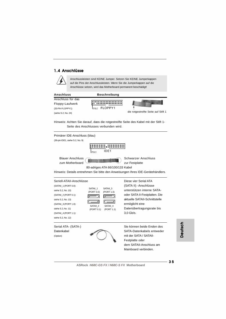
1.4 Anschlüsse1.4 Anschlüsse1.4 Anschlüsse1.4 Anschlüsse1.4 Anschlüsse
Anschlussleisten sind KEINE Jumper. Setzen Sie KEINE Jumperkappenauf die Pins der Anschlussleisten. Wenn Sie die Jumperkappen auf dieAnschlüsse setzen, wird das Motherboard permanent beschädigt!
Anschluss BeschreibungAnschluss für dasFloppy-Laufwerk(33-Pin FLOPPY1)
(siehe S.2, No. 24)
Hinweis: Achten Sie darauf, dass die rotgestreifte Seite des Kabel mit der Stift 1-Seite des Anschlusses verbunden wird.
Primärer IDE-Anschluss (blau)(39-pin IDE1, siehe S.2, No. 9)
Blauer Anschluss Schwarzer Anschlusszum Motherboard zur Festplatte
80-adriges ATA 66/100/133 KabelHinweis: Details entnehmen Sie bitte den Anweisungen Ihres IDE-Gerätehändlers.
Seriell-ATAII-Anschlüsse(SATAII_1 (PORT 0.0):
siehe S.2, No. 10)
(SATAII_2 (PORT 0.1):
siehe S.2, No. 13)
(SATAII_3 (PORT 1.0):
siehe S.2, No. 11)
(SATAII_4 (PORT 1.1):
siehe S.2, No. 12)
Serial ATA- (SATA-) Sie können beide Enden desDatenkabel SATA-Datenkabels entweder(Option) mit der SATA / SATAII-
Festplatte oderdem SATAII-Anschluss amMainboard verbinden.
die rotgestreifte Seite auf Stift 1
Diese vier Serial ATA(SATA II) -Anschlüsseunterstützen interne SATA-oder SATA II-Festplatten. Dieaktuelle SATAII-Schnittstelleermöglicht eineDatenübertragungsrate bis3,0 Gb/s.
SATAII_1 SATAII_3(PORT 0.0) (PORT 1.0)
SATAII_2 SATAII_4(PORT 0.1) (PORT 1.1)
De
uts
ch
De
uts
ch
De
uts
ch
De
uts
ch
De
uts
ch
3 63 63 63 63 6ASRock N68C-GS FX / N68C-S FX Motherboard
De
utsc
hD
eu
tsch
De
utsc
hD
eu
tsch
De
utsc
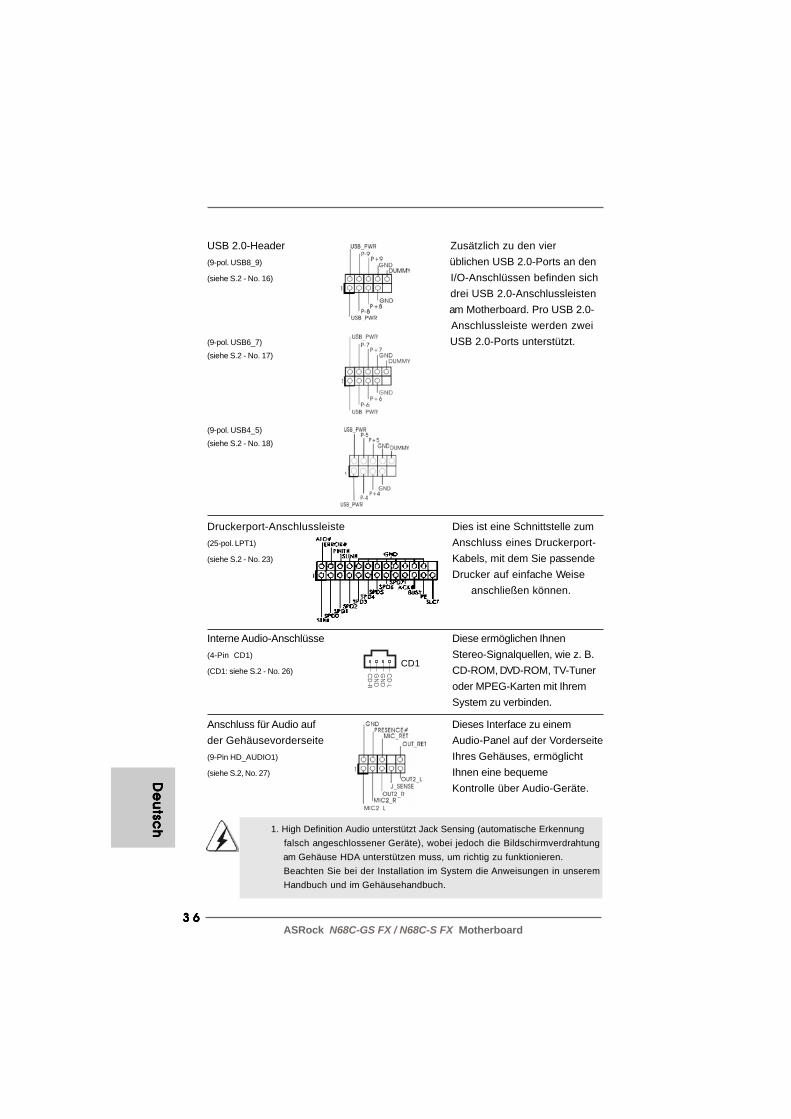
h 1. High Definition Audio unterstützt Jack Sensing (automatische Erkennung falsch angeschlossener Geräte), wobei jedoch die Bildschirmverdrahtung am Gehäuse HDA unterstützen muss, um richtig zu funktionieren. Beachten Sie bei der Installation im System die Anweisungen in unserem Handbuch und im Gehäusehandbuch.
USB 2.0-Header Zusätzlich zu den vier(9-pol. USB8_9) üblichen USB 2.0-Ports an den(siehe S.2 - No. 16) I/O-Anschlüssen befinden sich
drei USB 2.0-Anschlussleisten am Motherboard. Pro USB 2.0- Anschlussleiste werden zwei
(9-pol. USB6_7) USB 2.0-Ports unterstützt.(siehe S.2 - No. 17)
(9-pol. USB4_5)
(siehe S.2 - No. 18)
Interne Audio-Anschlüsse Diese ermöglichen Ihnen(4-Pin CD1) Stereo-Signalquellen, wie z. B.(CD1: siehe S.2 - No. 26) CD-ROM, DVD-ROM, TV-Tuner
oder MPEG-Karten mit IhremSystem zu verbinden.
Anschluss für Audio auf Dieses Interface zu einemder Gehäusevorderseite Audio-Panel auf der Vorderseite(9-Pin HD_AUDIO1) Ihres Gehäuses, ermöglicht(siehe S.2, No. 27) Ihnen eine bequeme
Kontrolle über Audio-Geräte.
CD
-L
GN
D
GN
D
CD
-R
CD1
Druckerport-Anschlussleiste Dies ist eine Schnittstelle zum(25-pol. LPT1) Anschluss eines Druckerport-(siehe S.2 - No. 23) Kabels, mit dem Sie passende
Drucker auf einfache Weiseanschließen können.

3 73 73 73 73 7ASRock N68C-GS FX / N68C-S FX Motherboard
System Panel Anschluss Dieser Anschluss ist für die(9-Pin PANEL1) verschiedenen Funktionen der(siehe S.2, No. 20) Gehäusefront.
2. Wenn Sie die AC’97-Audioleiste verwenden, installieren Sie diese wie nachstehend beschrieben an der Front-Audioanschlussleiste: A. Schließen Sie Mic_IN (MIC) an MIC2_L an. B. Schließen Sie Audio_R (RIN) an OUT2_R und Audio_L (LIN) an OUT2_L an. C. Schließen Sie Ground (GND) an Ground (GND) an. D. MIC_RET und OUT_RET sind nur für den HD-Audioanschluss gedacht. Diese Anschlüsse müssen nicht an die AC’97-Audioleiste angeschlossen werden.
CPU-Lüfteranschluss Verbinden Sie das CPU -(4-pin CPU_FAN1) Lüfterkabel mit diesem(siehe S.2, No. 2) Anschluss und passen Sie den
schwarzen Draht demErdungsstift an.
4 3 2 1
Gehäuse- und Stromlüfteranschlüsse Verbinden Sie die Lüfterkabel(3-pin CHA_FAN1) mit den Lüfteranschlüssen,(siehe S.2, No. 21) wobei der schwarze Draht an
den Schutzleiterstift(3-pin PWR_FAN1) angeschlossenwird.(siehe S.2, No. 25)
Gehäuselautsprecher-Header Schließen Sie den(4-pin SPEAKER1) Gehäuselautsprecher an(siehe S.2, No. 19) diesen Header an.
De
uts
ch
De
uts
ch
De
uts
ch
De
uts
ch
De
uts
ch
3 83 83 83 83 8ASRock N68C-GS FX / N68C-S FX Motherboard
De
utsc
hD
eu
tsch
De
utsc
hD
eu
tsch
De
utsc
h
12
1
24
13
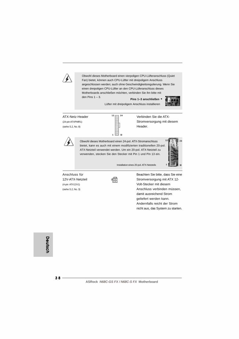
Obwohl dieses Motherboard einen vierpoligen CPU-Lüfteranschluss (QuietFan) bietet, können auch CPU-Lüfter mit dreipoligem Anschlussangeschlossen werden; auch ohne Geschwindigkeitsregulierung. Wenn Sieeinen dreipoligen CPU-Lüfter an den CPU-Lüferanschluss diesesMotherboards anschließen möchten, verbinden Sie ihn bitte mitden Pins 1 – 3.
Pins 1–3 anschließen
Lüfter mit dreipoligem Anschluss installieren
ATX-Netz-Header Verbinden Sie die ATX-(24-pin ATXPWR1) Stromversorgung mit diesem(siehe S.2, No. 8) Header.
Installation eines 20-pol. ATX-Netzteils
Obwohl dieses Motherboard einen 24-pol. ATX-Stromanschlussbietet, kann es auch mit einem modifizierten traditionellen 20-pol.ATX-Netzteil verwendet werden. Um ein 20-pol. ATX-Netzteil zuverwenden, stecken Sie den Stecker mit Pin 1 und Pin 13 ein.
Anschluss für Beachten Sie bitte, dass Sie eine12V-ATX-Netzteil Stromversorgung mit ATX 12-(4-pin ATX12V1) Volt-Stecker mit diesem(siehe S.2, No. 3) Anschluss verbinden müssen,
damit ausreichend Stromgeliefert werden kann.Andernfalls reicht der Stromnicht aus, das System zu starten.
12
1
24
13

3 93 93 93 93 9ASRock N68C-GS FX / N68C-S FX Motherboard
2. BIOS-Information2. BIOS-Information2. BIOS-Information2. BIOS-Information2. BIOS-InformationDas Flash Memory dieses Motherboards speichert das Setup-Utility. Drücken Sie<F2> während des POST (Power-On-Self-Test) um ins Setup zu gelangen, ansonstenwerden die Testroutinen weiter abgearbeitet. Wenn Sie ins Setup gelangen wollen,nachdem der POST durchgeführt wurde, müssen Sie das System über dieTastenkombination <Ctrl> + <Alt> + <Delete> oder den Reset-Knopf auf derGehäusevorderseite, neu starten. Natürlich können Sie einen Neustart auchdurchführen, indem Sie das System kurz ab- und danach wieder anschalten.Das Setup-Programm ist für eine bequeme Bedienung entwickelt worden. Es istein menügesteuertes Programm, in dem Sie durch unterschiedliche Untermenüsscrollen und die vorab festgelegten Optionen auswählen können. Für detaillierteInformationen zum BIOS-Setup, siehe bitte das Benutzerhandbuch (PDF Datei) aufder Support CD.
3. Software Support CD information3. Software Support CD information3. Software Support CD information3. Software Support CD information3. Software Support CD informationDieses Motherboard unterstützt eine Reiche von Microsoft® Windows®
Betriebssystemen: 7 / 7 64-Bit / VistaTM / VistaTM 64-Bit / XP / XP 64-Bit. Die IhremMotherboard beigefügte Support-CD enthält hilfreiche Software, Treiber undHilfsprogramme, mit denen Sie die Funktionen Ihres Motherboards verbessernkönnen Legen Sie die Support-CD zunächst in Ihr CD-ROM-Laufwerk ein. DerWillkommensbildschirm mit den Installationsmenüs der CD wird automatischaufgerufen, wenn Sie die “Autorun”-Funktion Ihres Systems aktiviert haben.Erscheint der Wilkommensbildschirm nicht, so “doppelklicken” Sie bitte auf das FileASSETUP.EXE im BIN-Verzeichnis der Support-CD, um die Menüs aufzurufen. DasSetup-Programm soll es Ihnen so leicht wie möglich machen. Es ist menügesteuert,d.h. Sie können in den verschiedenen Untermenüs Ihre Auswahl treffen und dieProgramme werden dann automatisch installiert.
De
uts
ch
De
uts
ch
De
uts
ch
De
uts
ch
De
uts
ch

4 04 04 04 04 0ASRock N68C-GS FX / N68C-S FX Motherboard
Fran
ça
isFra
nç
ais
Fran
ça
isFra
nç
ais
Fran
ça
is
1. Introduction1. Introduction1. Introduction1. Introduction1. IntroductionMerci pour votre achat d’une carte mère ASRock N68C-GS FX / N68C-S FX, une cartemère très fiable produite selon les critères de qualité rigoureux de ASRock. Elle offre desperformances excellentes et une conception robuste conformément à l’engagementd’ASRock sur la qualité et la fiabilité au long terme.Ce Guide d’installation rapide présente la carte mère et constitue un guided’installation pas à pas. Des informations plus détaillées concernant la carte mèrepourront être trouvées dans le manuel l’utilisateur qui se trouve sur le CDd’assistance.
Les spécifications de la carte mère et le BIOS ayant pu être mis àjour, le contenu de ce manuel est sujet à des changements sansnotification. Au cas où n’importe qu’elle modification intervenait sur cemanuel, la version mise à jour serait disponible sur le site webASRock sans nouvel avis. Vous trouverez les listes de prise encharge des cartes VGA et CPU également sur le site Web ASRock.Site web ASRock, http://www.asrock.comSi vous avez besoin de support technique en relation avec cette cartemère, veuillez consulter notre site Web pour de plus amplesinformations particulières au modèle que vous utilisez.www.asrock.com/support/index.asp
1.11.11.11.11.1 Contenu du paquetContenu du paquetContenu du paquetContenu du paquetContenu du paquetCarte mère ASRock N68C-GS FX / N68C-S FX
(Facteur de forme Micro ATX: 9.6 pouces x 8.2 pouces, 24.4 cm x 20.8 cm)Guide d’installation rapide ASRock N68C-GS FX / N68C-S FXCD de soutien ASRock N68C-GS FX / N68C-S FXDeux câble de données Serial ATA (SATA) (Optionnelle)Un écran I/O

4 14 14 14 14 1ASRock N68C-GS FX / N68C-S FX Motherboard
1.21 .21 .21 .21 .2 SpécificationsSpécificationsSpécificationsSpécificationsSpécifications
Format - Facteur de forme Micro ATX: 9.6 pouces x 8.2 pouces, 24.4 cm x 20.8 cm
CPU - Prise en charge des processeurs sur socket AM3+ (voir ATTENTION 1)- Prise en charge des processeurs sur socket AM3: Processeur PhenomTM II X6 / X4 / X3 / X2 (sauf 920 / 940) / Athlon II X4 / X3 / X2 / Sempron d’AMD- Prise en charge des processeurs Socket AM2+ / AM2: AMD PhenomTM FX / Phenom / Athlon 64 FX / Athlon 64 X2 Dual-Core / Athlon X2 Dual-Core / Athlon 64 / processeur Sempron- Prêt pour processeurs Huit-Core- Supporte UCC (Unlock CPU Core) (voir ATTENTION 2)
- Supporte la technologie Cool ‘n’ Quiet™ d’AMD- FSB 1000 MHz (2.0 GT/s)- Prend en charge la technologie Untied Overclocking
(voir ATTENTION 3)- Prise en charge de la technologie Hyper Transport
Chipsets - NVIDIA® GeForce 7025 / nForce 630a Mémoire - Compatible avec la Technologie de Mémoire à Canal Double
(voir ATTENTION 4)- 2 x slots DIMM DDR3- Supporter DDR3 1600/1333/1066/800 non-ECC, sans amortissement mémoire (voir ATTENTION 5)- Capacité maxi de mémoire système: 8GB (voir ATTENTION 6)- 2 x slots DIMM DDR2- Supporter DDR2 1066/800/667/533 non-ECC, sans amortissement mémoire (voir ATTENTION 7)- Capacité maxi de mémoire système: 8GB (voir ATTENTION 6)
Slot d’extension - 1 x slot PCI Express x16- 1 x slot PCI Express x1- 2 x slots PCI
VGA sur carte - NVIDIA® graphique GeForce 7025 intégré- VGA DX9.0, nuanceur de pixels 3.0- mémoire partagée max 256MB (voir ATTENTION 8)- Prend en charge le D-Sub avec une résolution maximale jusqu’à 1920x1440 @ 60Hz
Audio - 5.1 Son haute définition de CH (codec audio VIA® VT1705)
Fra
nFr
an
Fra
nFr
an
Fra
nç
ais
ça
isç
ais
ça
isç
ais

4 24 24 24 24 2ASRock N68C-GS FX / N68C-S FX Motherboard
Fran
ça
isFra
nç
ais
Fran
ça
isFra
nç
ais
Fran
ça
is
LAN - N68C-GS FX Realtek Giga PHY RTL8211CL, vitesse 10/100/1000 Mb/s- N68C-S FX Realtek PHY RTL8201EL, vitesse 10/100 Mb/s- Support du Wake-On-LAN- Support du PXE
Panneau arrière I/O Panel E/S - 1 x port souris PS/2
- 1 x port clavier PS/2- 1 x port série: COM 1- 1 x port VGA- 4 x ports USB 2.0 par défaut- 1 x port LAN RJ-45 avec LED (ACT/LED CLIGNOTANTE et LED VITESSE)- Jack audio: entrée ligne / sortie ligne / microphone
Connecteurs - 4 x connecteurs SATA2, prennent en charge un taux de transfert de données pouvant aller jusqu’à 3.0Go/s,
supporte RAID (RAID 0, RAID 1, RAID 0+1, RAID 5, JBOD), NCQ et “Hot-Plug” (Connexion à chaud)
(voir ATTENTION 9)- 1 x ATA133 IDE connecteurs (prend en charge jusqu’à 2 périphériques IDE)- 1 x Port Disquette- 1 x embase de port d’impression- Connecteur pour ventilateur de CPU/Châssis/Ventilateur- br. 24 connecteur d’alimentation ATX- br. 4 connecteur d’alimentation 12V ATX- Connecteurs audio internes- Connecteur audio panneau avant- 3 x En-tête USB 2.0 (prendre en charge 6 ports USB 2.0 supplémentaires)
BIOS - 8Mb BIOS AMI- BIOS AMI- Support du “Plug and Play”- Compatible pour événements de réveil ACPI 1.1- Gestion jumperless- Support SMBIOS 2.3.1- CPU, VCCM, NB Tension Multi-ajustement

4 34 34 34 34 3ASRock N68C-GS FX / N68C-S FX Motherboard
ATTENTIONIl est important que vous réalisiez qu’il y a un certain risque à effectuer l’overclocking, ycompris ajuster les réglages du BIOS, appliquer la technologie Untied Overclocking, ouutiliser des outils de tiers pour l’overclocking. L’overclocking peut affecter la stabilité devotre système, ou même causer des dommages aux composants et dispositifs de votresystème. Si vous le faites, c’est à vos frais et vos propres risques. Nous ne sommespas responsables des dommages possibles causés par l’overclocking.
CD d’assistance - Pilotes, utilitaires, logiciel anti-virus (version d’évaluation), CyberLink MediaEspresso 6.5 Trial, Suite logicielle ASRock (CyberLink DVD Suite et Version OEM et d’essai; Creative Sound Blaster X-Fi MB - Version d’essai; Suite multimédia ASRock MAGIX - OEM)
Caractéristique - Tuner ASRock OC (voir ATTENTION 10) unique - ASRock Économiseur d’énergie intelligent
(voir ATTENTION 11)- ASRock l'Instant Boot- ASRock Instant Flash (voir ATTENTION 12)- ASRock OC DNA (voir ATTENTION 13)- Chargeur ASRock APP (voir ATTENTION 14)- ASRock SmartView (voir ATTENTION 15)- ASRock XFast USB (voir ATTENTION 16)- ASRock XFast LAN (voir ATTENTION 17)- L’accélérateur hybride:
- Contrôle direct de la fréquence CPU (voir ATTENTION 18)- ASRock U-COP (voir ATTENTION 19)- Garde d’échec au démarrage (B.F.G.)- ASRock AM2 Boost: Technologie brevetée par ASRock pour augmenter les performances mémoire jusqu’à 12,5% (voir ATTENTION 20)
Surveillance - Contrôle de la température CPU système - Mesure de température de la carte mère
- Tachéomètre ventilateur CPU/Châssis/Ventilateur- Ventilateur silencieux d’unité centrale- Monitoring de la tension: +12V, +5V, +3.3V, Vcore
OS - Microsoft® Windows® 7 / 7 64-bit / VistaTM / VistaTM 64-bit / XP / XP 64-bit
Certifications - FCC, CE, WHQL * Pour de plus amples informations sur les produits, s’il vous plaît visitez notre site web: http://www.asrock.com
Fra
nFr
an
Fra
nFr
an
Fra
nç
ais
ça
isç
ais
ça
isç
ais

4 44 44 44 44 4ASRock N68C-GS FX / N68C-S FX Motherboard
Fran
ça
isFra
nç
ais
Fran
ça
isFra
nç
ais
Fran
ça
is
ATTENTION!1. Cette carte mère prend en charge les CPU jusqu’à 95W. Veuillez
vous référer à notre site Web pour la liste des CPU pris en charge.Site Web ASRock http://www.asrock.com
2. La fonction UCC (Unlock CPU Core : Déverrouillage du coeur duprocesseur) permet de simplifier l’activation des processeurs AMD. Ilvous suffit de sélectionner dans le BIOS l’option « ASRock UCC », etvous pouvez déverrouiller le coeur du processeur pour profiterinstantanément de performances renforcées. Lorsque la fonction UCCest activée, le processeur à double ou à triple coeur sera renforcée defaçon à fonctionner comme processeur à quatre coeurs, et pourcertains processeurs, notamment les processeurs quad-core, la taille ducache L3 sera aussi augmentée pour passer à 6 Mo, ce qui signifie quevous pourrez améliorer les performances du processeur à plus faiblecoût. Veuillez noter que la fonction UCC est prise en charge uniquementavec les processeurs AM2+ / AM3 / AM3+, et en outre, tous lesprocesseurs AM2+ / AM3 / AM3+ ne prennent pas cette fonction encharge car certains coeurs cachés de processeurs risquent dedysfonctionner.
3. Cette carte mère prend en charge la technologie Untied Overclocking.Veuillez lire “La technologie de surcadençage à la volée” à la page 24pour plus d’informations.
4. Cette carte mère supporte la Technologie de Mémoire à Canal Double.Avant d’intégrer la Technologie de Mémoire à Canal Double, assurez-vous de bien lire le guide d’installation des modules mémoire en page14 pour réaliser une installation correcte.
5. La prise en charge de fréquences de mémoire de 1600MHz dépenddu CPU AM3 / AM3+ que vous choisissez. Si vous choisissez desbarrettes de mémoire DDR3 1600 sur cette carte mère, veuillez vousréférer à la liste des mémoires prises en charge sur notre site Webpour connaître barrettes de mémoire compatibles.Site Web ASRock http://www.asrock.com
6. Du fait des limites du système d’exploitation, la taille mémoire réelleréservée au système pourra être inférieure à 4 Go sous Windows® 7 /VistaTM / XP. Avec Windows® OS avec CPU 64 bits, il n’y a pas ce genrede limitation.
7. La prise en charge de fréquences de mémoire de 1066MHz dépenddu CPU AM2+ / AM3 que vous choisissez. Si vous choisissez desbarrettes de mémoire DDR2 1066 sur cette carte mère, veuillez vousréférer à la liste des mémoires prises en charge sur notre site Webpour connaître barrettes de mémoire compatibles.Site Web ASRock http://www.asrock.com
8. La dimension maximum du memoire partage est definie par le vendeurde jeu de puces et est sujet de changer. Veuillez verifier la NVIDIA®
website pour les informations recentes SVP.
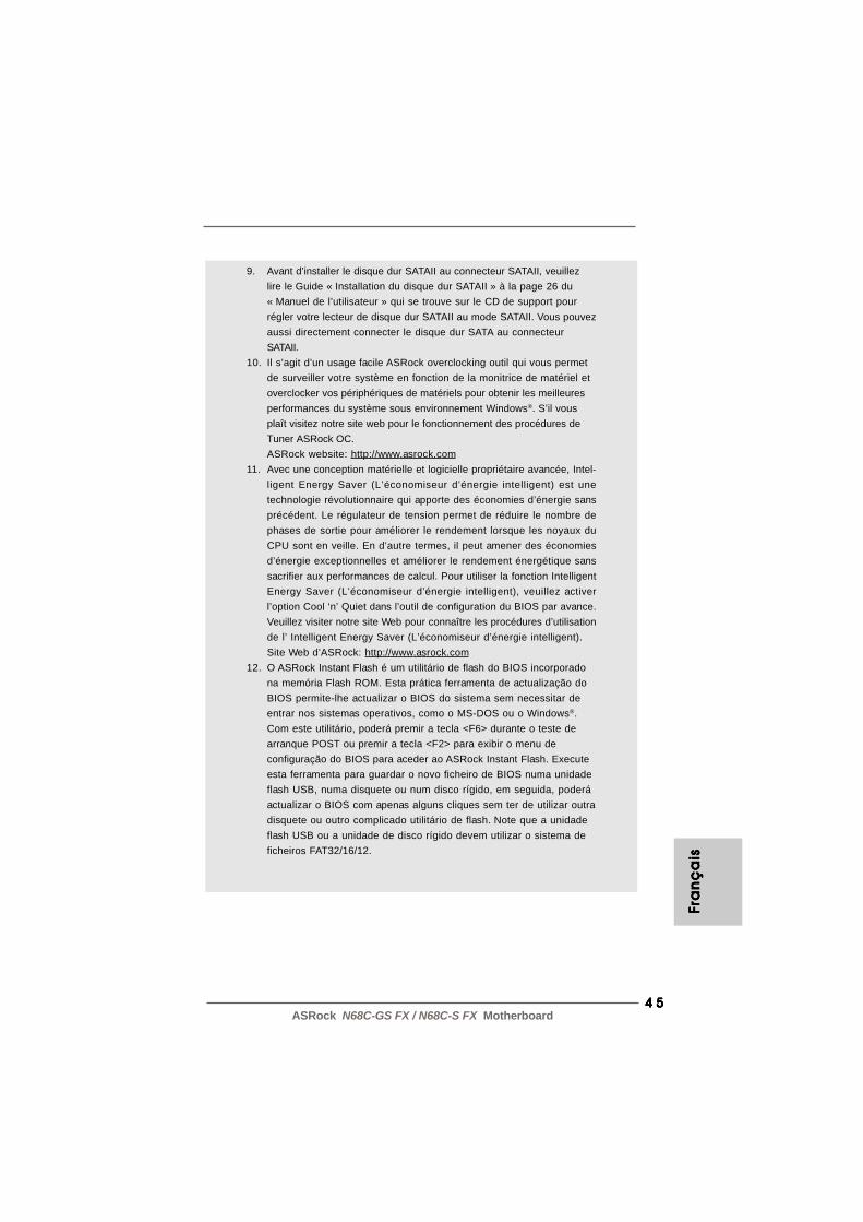
4 54 54 54 54 5ASRock N68C-GS FX / N68C-S FX Motherboard
FFFF F ra
nra
nra
nra
nra
nç
ais
ça
isç
ais
ça
isç
ais
9. Avant d’installer le disque dur SATAII au connecteur SATAII, veuillezlire le Guide « Installation du disque dur SATAII » à la page 26 du« Manuel de l’utilisateur » qui se trouve sur le CD de support pourrégler votre lecteur de disque dur SATAII au mode SATAII. Vous pouvezaussi directement connecter le disque dur SATA au connecteurSATAII.
10. Il s’agit d’un usage facile ASRock overclocking outil qui vous permetde surveiller votre système en fonction de la monitrice de matériel etoverclocker vos périphériques de matériels pour obtenir les meilleuresperformances du système sous environnement Windows®. S’il vousplaît visitez notre site web pour le fonctionnement des procédures deTuner ASRock OC.ASRock website: http://www.asrock.com
11. Avec une conception matérielle et logicielle propriétaire avancée, Intel-ligent Energy Saver (L’économiseur d’énergie intelligent) est unetechnologie révolutionnaire qui apporte des économies d’énergie sansprécédent. Le régulateur de tension permet de réduire le nombre dephases de sortie pour améliorer le rendement lorsque les noyaux duCPU sont en veille. En d’autre termes, il peut amener des économiesd’énergie exceptionnelles et améliorer le rendement énergétique sanssacrifier aux performances de calcul. Pour utiliser la fonction IntelligentEnergy Saver (L’économiseur d’énergie intelligent), veuillez activerl’option Cool ‘n’ Quiet dans l’outil de configuration du BIOS par avance.Veuillez visiter notre site Web pour connaître les procédures d’utilisationde l’ Intelligent Energy Saver (L’économiseur d’énergie intelligent).Site Web d’ASRock: http://www.asrock.com
12. O ASRock Instant Flash é um utilitário de flash do BIOS incorporadona memória Flash ROM. Esta prática ferramenta de actualização doBIOS permite-lhe actualizar o BIOS do sistema sem necessitar deentrar nos sistemas operativos, como o MS-DOS ou o Windows®.Com este utilitário, poderá premir a tecla <F6> durante o teste dearranque POST ou premir a tecla <F2> para exibir o menu deconfiguração do BIOS para aceder ao ASRock Instant Flash. Executeesta ferramenta para guardar o novo ficheiro de BIOS numa unidadeflash USB, numa disquete ou num disco rígido, em seguida, poderáactualizar o BIOS com apenas alguns cliques sem ter de utilizar outradisquete ou outro complicado utilitário de flash. Note que a unidadeflash USB ou a unidade de disco rígido devem utilizar o sistema deficheiros FAT32/16/12.

4 64 64 64 64 6ASRock N68C-GS FX / N68C-S FX Motherboard
Fran
ça
isFra
nç
ais
Fran
ça
isFra
nç
ais
Fran
ça
is
13. Le nom même du logiciel – OC DNA vous indique littéralement cedont il est capable. OC DNA, utilitaire exclusif développé par ASRock,offre une façon pratique pour l’utilisateur d’enregistrer lesparamètres d’overclockage et de les partager avec d’autres. Il vousaide à enregistrer votre overclockage sous le système d’exploitationet simplifie le processus compliqué d’enregistrement desparamètres d’overclockage. Avec OC DNA , vous pouvez enregistrervos réglages d’overclockage en tant que profil et les partager avecvos amis ! Vos amis peuvent alors charger le profil d’overclockagesur leur propre système pour obtenir les mêmes réglagesd’overclockage que les vôtres ! Veuillez noter que le profild’overclockage peut être partagé et utilisé uniquement sur la mêmecarte mère.
14. Si vous désirez un moyen plus rapide et moins contraignant derecharger vos appareils Apple tels que iPhone/iPod/iPad Touch,ASRock a préparé pour vous la solution idéale - le chargeur ASRockAPP. Il suffit d’installer le pilote du chargeur APP, et vous pourrezrecharger rapidement votre iPhone à partir de votre ordinateur,jusqu’à 40% plus vite qu’avant. Le chargeur ASRock APP vous permetde charger rapidement et simultanément plusieurs appareils Apple,et le chargement continu est même pris en charge lorsque le PCpasse en mode Veille (S1), Suspension à la RAM (S3), hibernation(S4) ou hors tension (S5). Lorsque le pilote du chargeur APP estinstallé, vous découvrez un mode de mise en charge tout à fait inédit.Site web ASRock : http://www.asrock.com/Feature/AppCharger/index.asp
15. SmartView, nouvelle fonction pour les navigateurs Internet, est unepage de démarrage intelligente pour IE qui combine vos sites web lesplus visités, votre historique, vos amis Facebook et vos fils d’actualitéen temps réel, le tout sous forme d’affichage évolué, pour une expérienceInternet plus personnelle. Les cartes mères ASRock sont équipées del’utilitaire SmartView qui vous aide à garder le contact avec vos prochesà tout moment. Pour utiliser la fonction SmartView, veuillez vous assurer que votre système d’exploitation est Windows® 7 / 7 64 bits /VistaTM ou VistaTM 64 bits, et que la version de votre navigateur est IE8.Site web ASRock : http://www.asrock.com/Feature/SmartView/index.asp
16. ASRock XFast USB permet d’améliorer les performances de votrepériphérique de stockage USB. Les performances réelles dépendentdes propriétés du périphérique.
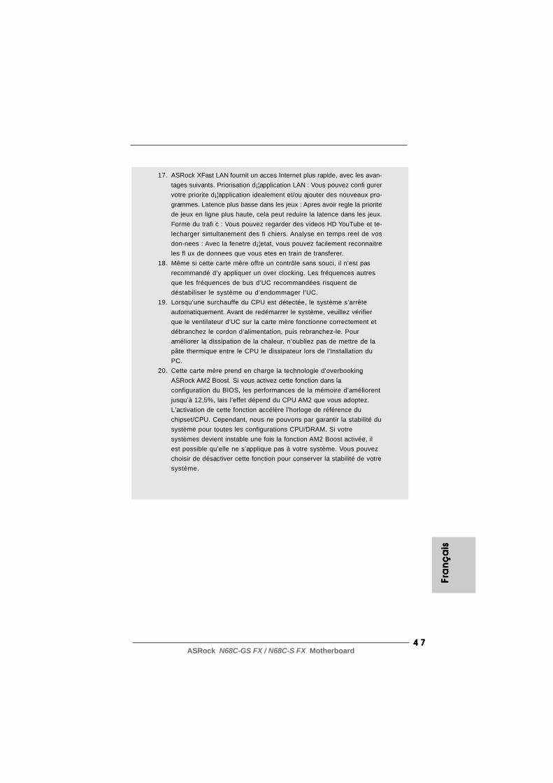
4 74 74 74 74 7ASRock N68C-GS FX / N68C-S FX Motherboard
Fra
nFr
an
Fra
nFr
an
Fra
nç
ais
ça
isç
ais
ça
isç
ais
17. ASRock XFast LAN fournit un acces Internet plus rapide, avec les avan-tages suivants. Priorisation d¡¦application LAN : Vous pouvez confi gurervotre priorite d¡¦application idealement et/ou ajouter des nouveaux pro-grammes. Latence plus basse dans les jeux : Apres avoir regle la prioritede jeux en ligne plus haute, cela peut reduire la latence dans les jeux.Forme du trafi c : Vous pouvez regarder des videos HD YouTube et te-lecharger simultanement des fi chiers. Analyse en temps reel de vosdon-nees : Avec la fenetre d¡¦etat, vous pouvez facilement reconnaitreles fl ux de donnees que vous etes en train de transferer.
18. Même si cette carte mère offre un contrôle sans souci, il n’est pasrecommandé d’y appliquer un over clocking. Les fréquences autresque les fréquences de bus d’UC recommandées risquent dedéstabiliser le système ou d’endommager l’UC.
19. Lorsqu’une surchauffe du CPU est détectée, le système s’arrêteautomatiquement. Avant de redémarrer le système, veuillez vérifierque le ventilateur d’UC sur la carte mère fonctionne correctement etdébranchez le cordon d’alimentation, puis rebranchez-le. Pouraméliorer la dissipation de la chaleur, n’oubliez pas de mettre de lapâte thermique entre le CPU le dissipateur lors de l’installation duPC.
20. Cette carte mère prend en charge la technologie d’overbookingASRock AM2 Boost. Si vous activez cette fonction dans laconfiguration du BIOS, les performances de la mémoire d’améliorentjusqu’à 12,5%, lais l’effet dépend du CPU AM2 que vous adoptez.L’activation de cette fonction accélère l’horloge de référence duchipset/CPU. Cependant, nous ne pouvons par garantir la stabilité dusystème pour toutes les configurations CPU/DRAM. Si votresystèmes devient instable une fois la fonction AM2 Boost activée, ilest possible qu’elle ne s’applique pas à votre système. Vous pouvezchoisir de désactiver cette fonction pour conserver la stabilité de votresystème.
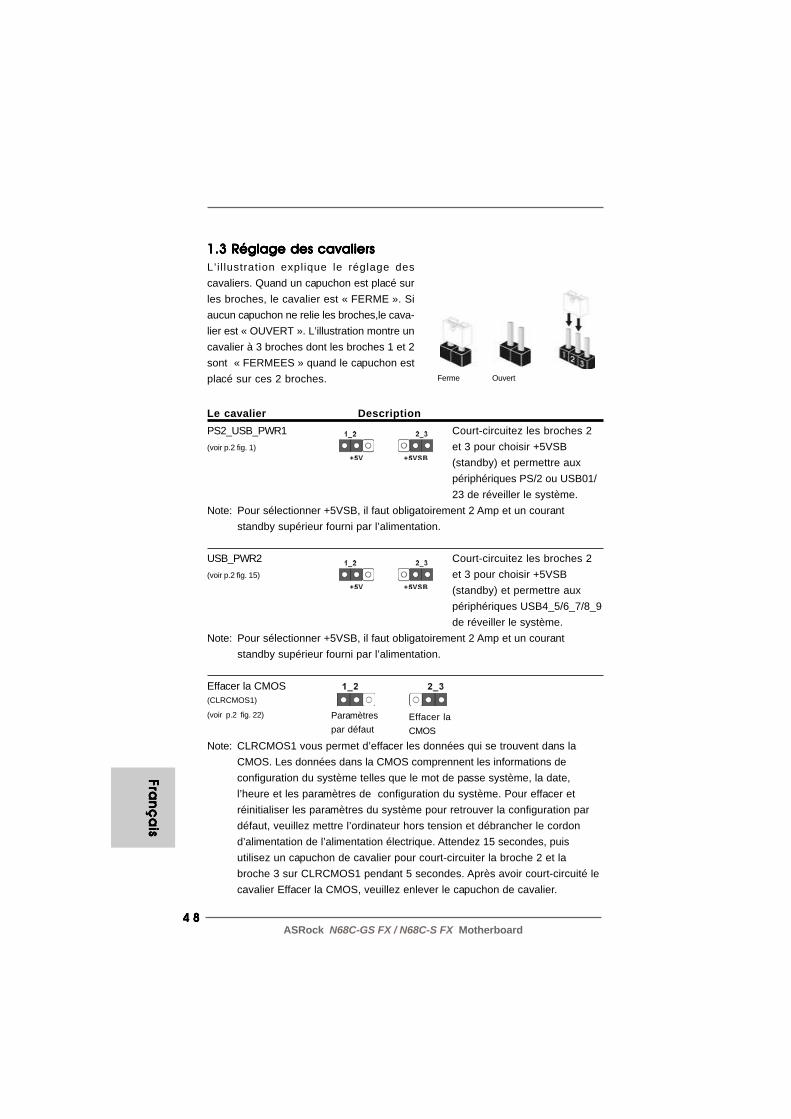
4 84 84 84 84 8ASRock N68C-GS FX / N68C-S FX Motherboard
Fran
ça
isFra
nç
ais
Fran
ça
isFra
nç
ais
Fran
ça
is
1.3 Réglage des cavaliers1.3 Réglage des cavaliers1.3 Réglage des cavaliers1.3 Réglage des cavaliers1.3 Réglage des cavaliersL’i l lustration explique le réglage descavaliers. Quand un capuchon est placé surles broches, le cavalier est « FERME ». Siaucun capuchon ne relie les broches,le cava-lier est « OUVERT ». L’illustration montre uncavalier à 3 broches dont les broches 1 et 2sont « FERMEES » quand le capuchon estplacé sur ces 2 broches.
Le cavalier DescriptionPS2_USB_PWR1 Court-circuitez les broches 2(voir p.2 fig. 1) et 3 pour choisir +5VSB
(standby) et permettre auxpériphériques PS/2 ou USB01/23 de réveiller le système.
Note: Pour sélectionner +5VSB, il faut obligatoirement 2 Amp et un courantstandby supérieur fourni par l’alimentation.
USB_PWR2 Court-circuitez les broches 2(voir p.2 fig. 15) et 3 pour choisir +5VSB
(standby) et permettre auxpériphériques USB4_5/6_7/8_9de réveiller le système.
Note: Pour sélectionner +5VSB, il faut obligatoirement 2 Amp et un courantstandby supérieur fourni par l’alimentation.
Effacer la CMOS(CLRCMOS1)
(voir p.2 fig. 22)
Note: CLRCMOS1 vous permet d’effacer les données qui se trouvent dans laCMOS. Les données dans la CMOS comprennent les informations deconfiguration du système telles que le mot de passe système, la date,l’heure et les paramètres de configuration du système. Pour effacer etréinitialiser les paramètres du système pour retrouver la configuration pardéfaut, veuillez mettre l’ordinateur hors tension et débrancher le cordond’alimentation de l’alimentation électrique. Attendez 15 secondes, puisutilisez un capuchon de cavalier pour court-circuiter la broche 2 et labroche 3 sur CLRCMOS1 pendant 5 secondes. Après avoir court-circuité lecavalier Effacer la CMOS, veuillez enlever le capuchon de cavalier.
Paramètrespar défaut
Ferme Ouvert
Effacer laCMOS

4 94 94 94 94 9ASRock N68C-GS FX / N68C-S FX Motherboard
le côté avec fil rouge côté Broche1
1.4 Connecteurs1.4 Connecteurs1.4 Connecteurs1.4 Connecteurs1.4 Connecteurs
Les connecteurs NE SONT PAS des cavaliers. NE PLACEZ AUCUNcapuchon sur ces connecteurs. Poser les bouchons pour cavaliersaudessus des connecteurs provoquera des dommages irrémédiables à lacarte mère!
Les connecteurs DescriptionConnecteur du lecteurde disquette(FLOPPY1 br. 33)
(voir p.2 fig. 24)
Note: Assurez-vous que le côté avec fil rouge du câble est bien branché sur lecôté Broche1 du connecteur.
Connecteur IDE primaire (bleu)(IDE1 br. 39, voir p.2 No. 9)
connecteur bleu connecteur noir vers la carte mère vers le disque dur
Câble ATA 66/100/133 80 conducteurs
Note: Veuillez vous reporter aux instructions du fabricant de votre IDE périphériquepour les détails.
Connecteurs Série ATAII Ces quatre connecteurs Serial(SATAII_1 (PORT 0.0): ATA (SATAII) prennent en charge voir p.2 fig. 10) les disques durs SATA ou SATAII(SATAII_2 (PORT 0.1): pour les dispositifs de stockage voir p.2 fig. 13) interne. L’interface SATAII(SATAII_3 (PORT 1.0): actuelle permet des taux voir p.2 fig. 11) transferts de données pouvant(SATAII_4 (PORT 1.1): aller jusqu’à 3,0 Go/s. voir p.2 fig. 12)
Câble de données L’une des deux extrémités duSérie ATA (SATA) câble de données SATA peut(en option) être connectée au disque dur
SATA / SATAIIou au connecteurSATAII sur la carte mère.
SATAII_1 SATAII_3(PORT 0.0) (PORT 1.0)
SATAII_2 SATAII_4(PORT 0.1) (PORT 1.1)
Fra
nFr
an
Fra
nFr
an
Fra
nç
ais
ça
isç
ais
ça
isç
ais

5 05 05 05 05 0ASRock N68C-GS FX / N68C-S FX Motherboard
Fran
ça
isFra
nç
ais
Fran
ça
isFra
nç
ais
Fran
ça
is 1. L’audio à haute définition (HDA) prend en charge la détection de fiche, mais le fil de panneau sur le châssis doit prendre en charge le HDA pour fonctionner correctement. Veuillez suivre les instructions dans notre manuel et le manuel de châssis afin installer votre système.2. Si vous utilisez le panneau audio AC’97, installez-le sur l’adaptateur audio du panneau avant conformément à la procédure ci-dessous :
En-tête USB 2.0 A côté des quatre ports USB(USB8_9 br.9) 2.0 par défaut sur le panneau(voir p.2 No. 16) E/S, il y a trois embases USB
2.0 sur cette carte mère.Chaque embase USB 2.0 peutprendre en charge 2 ports USB
(USB6_7 br.9) 2.0.(voir p.2 No. 17)
(USB4_5 br.9)(voir p.2 No. 18)
Connecteurs audio internes Ils vous permettent de gérer des(CD1 br. 4) entrées audio à partir de sources(CD1: voir p.2 fig. 26) stéréo comme un CD-ROM,
DVD-ROM, un tuner TV ou unecarte MPEG.
Connecteurs audio internes Ils vous permettent de gérer des(CD1 br. 4) entrées audio à partir de sources(CD1: voir p.2 fig. 27) stéréo comme un CD-ROM,
DVD-ROM, un tuner TV ou unecarte MPEG.
CD
-L
GN
D
GN
D
CD
-R
CD1
Embase de port d’impression AIl s’agit d’une interface pour le(LPT1 25 broches) câble du port d’impression, qui(voir p.2 No. 23) permet le raccordement
pratique de périphériquesd’impression.
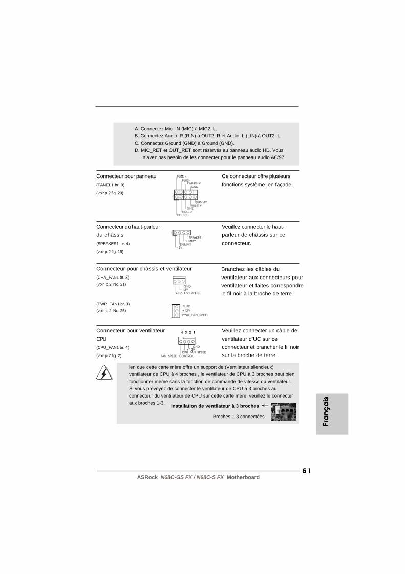
5 15 15 15 15 1ASRock N68C-GS FX / N68C-S FX Motherboard
Connecteur du haut-parleur Veuillez connecter le haut-du châssis parleur de châssis sur ce(SPEAKER1 br. 4) connecteur.(voir p.2 fig. 19)
Connecteur pour panneau Ce connecteur offre plusieurs(PANEL1 br. 9) fonctions système en façade.(voir p.2 fig. 20)
A. Connectez Mic_IN (MIC) à MIC2_L. B. Connectez Audio_R (RIN) à OUT2_R et Audio_L (LIN) à OUT2_L. C. Connectez Ground (GND) à Ground (GND). D. MIC_RET et OUT_RET sont réservés au panneau audio HD. Vous n’avez pas besoin de les connecter pour le panneau audio AC’97.
Connecteur pour ventilateur Veuillez connecter un câble deCPU ventilateur d’UC sur ce(CPU_FAN1 br. 4) connecteur et brancher le fil noir(voir p.2 fig. 2) sur la broche de terre.
ien que cette carte mère offre un support de (Ventilateur silencieux)ventilateur de CPU à 4 broches , le ventilateur de CPU à 3 broches peut bienfonctionner même sans la fonction de commande de vitesse du ventilateur.Si vous prévoyez de connecter le ventilateur de CPU à 3 broches auconnecteur du ventilateur de CPU sur cette carte mère, veuillez le connecteraux broches 1-3. Installation de ventilateur à 3 broches
Broches 1-3 connectées
4 3 2 1
Connecteur pour châssis et ventilateur(CHA_FAN1 br. 3)
(voir p.2 No. 21)
(PWR_FAN1 br. 3)
(voir p.2 No. 25)
Branchez les câbles duventilateur aux connecteurs pourventilateur et faites correspondrele fil noir à la broche de terre.
Fra
nFr
an
Fra
nFr
an
Fra
nç
ais
ça
isç
ais
ça
isç
ais

5 25 25 25 25 2ASRock N68C-GS FX / N68C-S FX Motherboard
Fran
ça
isFra
nç
ais
Fran
ça
isFra
nç
ais
Fran
ça
is
20-Installation de l’alimentation électrique ATX
Bien que cette carte mère fournisse un connecteur decourant ATX 24 broches, elle peut encore fonctionner si vousadopter une alimentation traditionnelle ATX 20 broches. Pourutiliser une alimentation ATX 20 broches, branchez àl’alimentation électrique ainsi qu’aux broches 1 et 13.
12
1
24
13
Connecteur d’alimentation Veuillez noter qu’il est nécessaire12V ATX de connecter une unité(ATX12V1 br. 4) d’alimentation électrique avec(voir p.2 fig. 3) prise ATX 12V sur ce
connecteur afin d’avoir unealimentation suffisante. Faute dequoi, il ne sera pas possible demettre sous tension.
Connecteur d’alimentation ATX Veuillez connecter une unité(ATXPWR1 br. 24) d’alimentation ATX sur ce(voir p.2 fig. 8) connecteur.
12
1
24
13

5 35 35 35 35 3ASRock N68C-GS FX / N68C-S FX Motherboard
2. Informations sur le BIOS2. Informations sur le BIOS2. Informations sur le BIOS2. Informations sur le BIOS2. Informations sur le BIOSLa puce Flash Memory sur la carte mère stocke le Setup du BIOS. Lorsque vousdémarrez l’ordinateur, veuillez presser <F2> pendant le POST (Power-On-Self-Test) pour entrer dans le BIOS; sinon, le POST continue ses tests de routine. Sivous désirez entrer dans le BIOS après le POST, veuillez redémarrer le systèmeen pressant <Ctl> + <Alt> + <Suppr>, ou en pressant le bouton de reset sur leboîtier du système. Vous pouvez également redémarrer en éteignant le système eten le rallumant. L’utilitaire d’installation du BIOS est conçu pour être convivial. C’estun programme piloté par menu, qui vous permet de faire défiler par ses diverssous-menus et de choisir parmi les choix prédéterminés. Pour des informationsdétaillées sur le BIOS, veuillez consulter le Guide de l’utilisateur (fichier PDF) dansle CD technique.
3. Informations sur le CD de support3. Informations sur le CD de support3. Informations sur le CD de support3. Informations sur le CD de support3. Informations sur le CD de supportCette carte mère supporte divers systèmes d’exploitation Microsoft® Windows®:7 / 7 64-bits / VistaTM / VistaTM 64 bits / XP / XP 64-bits. Le CD technique livré aveccette carte mère contient les pilotes et les utilitaires nécessaires pour améliorer lesfonctions de la carte mère. Pour utiliser le CD technique, insérez-le dans le lecteurde CD-ROM. Le Menu principal s’affiche automatiquement si “AUTORUN” est activédans votre ordinateur. Si le Menu principal n’apparaît pas automatiquement,localisez dans le CD technique le fichier “ASSETUP.EXE” dans le dossier BIN etdouble-cliquez dessus pour afficher les menus.
Fra
nFr
an
Fra
nFr
an
Fra
nç
ais
ça
isç
ais
ça
isç
ais

5 45 45 45 45 4ASRock N68C-GS FX / N68C-S FX Motherboard
Italia
no
Italia
no
Italia
no
Italia
no
Italia
no
1. IntroduzioneGrazie per aver scelto una scheda madre ASRock N68C-GS FX / N68C-S FX, unascheda madre affidabile prodotta secondo i severi criteri di qualità ASRock. Le prestazionieccellenti e il design robusto si conformano all’impegno di ASRock nella ricerca dellaqualità e della resistenza. Questa Guida Rapida all’Installazione contiene l’introduzionealla motherboard e la guida passo-passo all’installazione. Informazioni più dettagliatesulla motherboard si possono trovare nel manuale per l’utente presente nel CD di supporto.
Le specifiche della scheda madre e il software del BIOS possonoessere aggiornati, pertanto il contenuto di questo manuale puòsubire variazioni senza preavviso. Nel caso in cui questo manuale siamodificato, la versione aggiornata sarà disponibile sul sito diASRock senza altro avviso. Sul sito ASRock si possono anche trovarele più recenti schede VGA e gli elenchi di CPU supportate.ASRock website http://www.asrock.comSe si necessita dell’assistenza tecnica per questa scheda madre,visitare il nostro sito per informazioni specifiche sul modello che sista usando.www.asrock.com/support/index.asp
1.11.11.11.11.1 Contenuto della confezioneContenuto della confezioneContenuto della confezioneContenuto della confezioneContenuto della confezioneScheda madre ASRock N68C-GS FX / N68C-S FX
(Micro ATX Form Factor: 9.6-in x 8.2-in, 24.4 cm x 20.8 cm)Guida di installazione rapida ASRock N68C-GS FX / N68C-S FXCD di supporto ASRock N68C-GS FX / N68C-S FXDue cavo dati Serial ATA (SATA) (Opzionale)Un I/O Shield
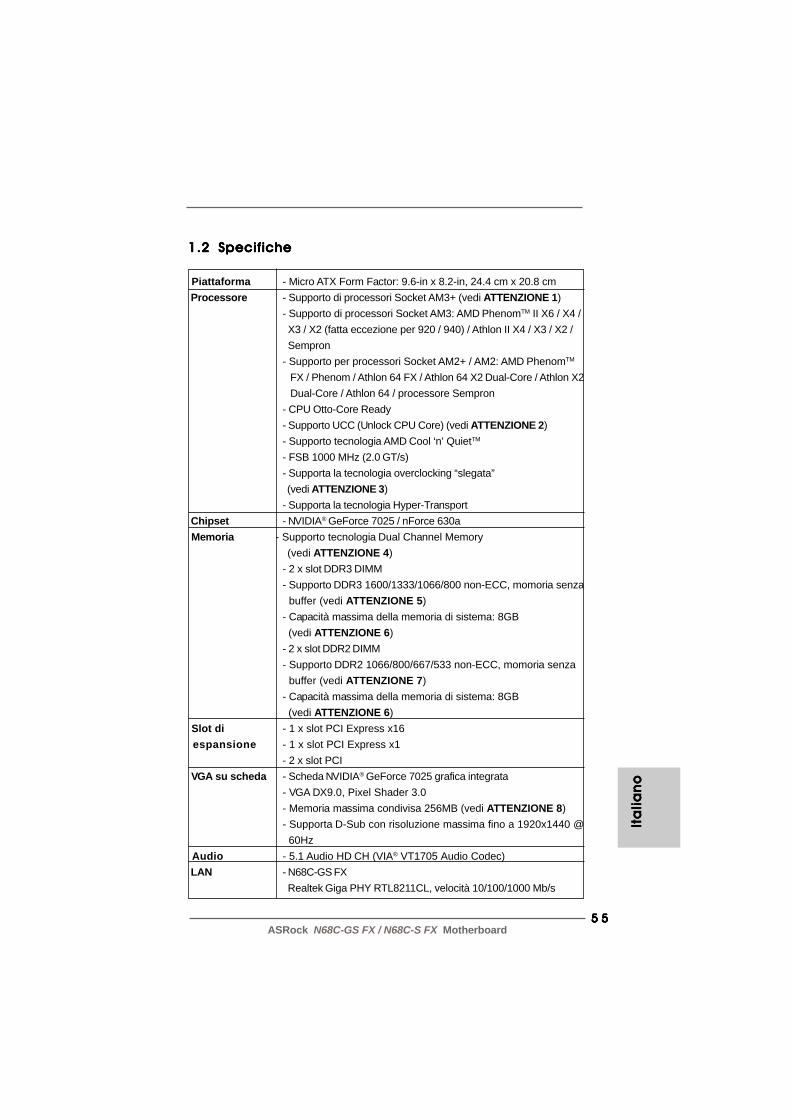
5 55 55 55 55 5ASRock N68C-GS FX / N68C-S FX Motherboard
1.21.21.21.21.2 SpecificheSpecificheSpecificheSpecificheSpecifiche
Piattaforma - Micro ATX Form Factor: 9.6-in x 8.2-in, 24.4 cm x 20.8 cm Processore - Supporto di processori Socket AM3+ (vedi ATTENZIONE 1)
- Supporto di processori Socket AM3: AMD PhenomTM II X6 / X4 / X3 / X2 (fatta eccezione per 920 / 940) / Athlon II X4 / X3 / X2 / Sempron- Supporto per processori Socket AM2+ / AM2: AMD PhenomTM
FX / Phenom / Athlon 64 FX / Athlon 64 X2 Dual-Core / Athlon X2 Dual-Core / Athlon 64 / processore Sempron- CPU Otto-Core Ready- Supporto UCC (Unlock CPU Core) (vedi ATTENZIONE 2)- Supporto tecnologia AMD Cool ‘n’ QuietTM
- FSB 1000 MHz (2.0 GT/s)- Supporta la tecnologia overclocking “slegata” (vedi ATTENZIONE 3)- Supporta la tecnologia Hyper-Transport
Chipset - NVIDIA® GeForce 7025 / nForce 630a Memoria - Supporto tecnologia Dual Channel Memory (vedi ATTENZIONE 4)
- 2 x slot DDR3 DIMM- Supporto DDR3 1600/1333/1066/800 non-ECC, momoria senza buffer (vedi ATTENZIONE 5)- Capacità massima della memoria di sistema: 8GB (vedi ATTENZIONE 6)- 2 x slot DDR2 DIMM- Supporto DDR2 1066/800/667/533 non-ECC, momoria senza buffer (vedi ATTENZIONE 7)- Capacità massima della memoria di sistema: 8GB (vedi ATTENZIONE 6)
Slot di - 1 x slot PCI Express x16 espansione - 1 x slot PCI Express x1
- 2 x slot PCI VGA su scheda - Scheda NVIDIA® GeForce 7025 grafica integrata
- VGA DX9.0, Pixel Shader 3.0- Memoria massima condivisa 256MB (vedi ATTENZIONE 8)- Supporta D-Sub con risoluzione massima fino a 1920x1440 @ 60Hz
Audio - 5.1 Audio HD CH (VIA® VT1705 Audio Codec) LAN - N68C-GS FX
Realtek Giga PHY RTL8211CL, velocità 10/100/1000 Mb/s
Ita
lian
oIt
alia
no
Ita
lian
oIt
alia
no
Ita
lian
o

5 65 65 65 65 6ASRock N68C-GS FX / N68C-S FX Motherboard
Italia
no
Italia
no
Italia
no
Italia
no
Italia
no
- N68C-S FX Realtek PHY RTL8201EL, velocità 10/100 Mb/s- Supporta Wake-On-LAN- Supporta PXE
Pannello I/O Panel posteriore - 1 x Porta PS/2 per mouse I/O - 1 x Porta PS/2 per tastiera
- 1 x Porta COM- 1 x Porta VGA- 4 x porte USB 2.0 già integrate- 1 x porte LAN RJ-45 con LED (LED azione/collegamento e LED velocità)- Audio Jack: Line In / Line Out / Microfono
Connettori - 4 x connettori SATA2 3.0Go/s, sopporta RAID (RAID 0, RAID 1, RAID 0+1, RAID 5, JBOD), NCQ e “Collegamento a caldo” (vedi ATTENZIONE 9)- 1 x connettori ATA133 IDE (supporta fino a 2 dispositivi IDE)- 1 x porta Floppy- 1 x Collettore porta stampante- Connettore CPU/Chassis/Alimentazione ventola- 24-pin collettore alimentazione ATX- 4-pin connettore ATX 12V- Connettori audio interni- Connettore audio sul pannello frontale- 3 x Collettore USB 2.0 (supporta 6 porte USB 2.0)
BIOS - 8Mb AMI BIOS- Suppor AMI legal BIOS- Supporta “Plug and Play”- Compatibile con ACPI 1.1 wake up events- Supporta jumperfree- Supporta SMBIOS 2.3.1- Regolazione multi-voltaggio CPU, VCCM, NB
CD di - Driver, Utilità, Software AntiVirus (versione di prova), CyberLink supporto MediaEspresso 6.5 Trial, Suite software ASRock (Suite CyberLink
DVD OEM e Versione demo; Creative Sound Blaster X-Fi MB - Versione demo; Suite multimediale ASRock MAGIX - OEM)
Caratteristi- - Sintonizzatore ASRock OC (vedi ATTENZIONE 10) ca speciale - ASRock Intelligent Energy Saver (ASRock Risparmio intelligente
dell’energia) (vedi ATTENZIONE 11)- ASRock Instant Boot- ASRock Instant Flash (vedi ATTENZIONE 12)- ASRock OC DNA (vedi ATTENZIONE 13)
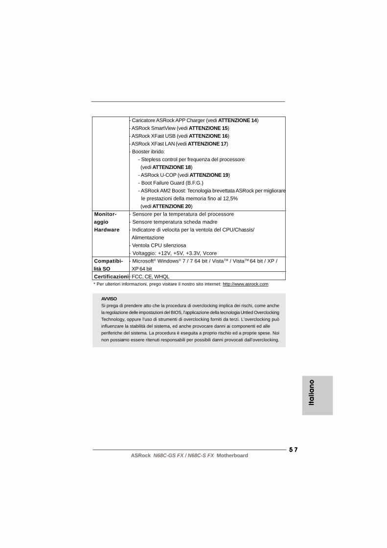
5 75 75 75 75 7ASRock N68C-GS FX / N68C-S FX Motherboard
AVVISOSi prega di prendere atto che la procedura di overclocking implica dei rischi, come anchela regolazione delle impostazioni del BIOS, l’applicazione della tecnologia Untied OverclockingTechnology, oppure l’uso di strumenti di overclocking forniti da terzi. L’overclocking puòinfluenzare la stabilità del sistema, ed anche provocare danni ai componenti ed alleperiferiche del sistema. La procedura è eseguita a proprio rischio ed a proprie spese. Noinon possiamo essere ritenuti responsabili per possibili danni provocati dall’overclocking.
- Caricatore ASRock APP Charger (vedi ATTENZIONE 14)- ASRock SmartView (vedi ATTENZIONE 15)- ASRock XFast USB (vedi ATTENZIONE 16)- ASRock XFast LAN (vedi ATTENZIONE 17)- Booster ibrido:
- Stepless control per frequenza del processore (vedi ATTENZIONE 18)- ASRock U-COP (vedi ATTENZIONE 19)- Boot Failure Guard (B.F.G.)- ASRock AM2 Boost: Tecnologia brevettata ASRock per migliorare le prestazioni della memoria fino al 12,5% (vedi ATTENZIONE 20)
Monitor- - Sensore per la temperatura del processore aggio - Sensore temperatura scheda madre Hardware - Indicatore di velocita per la ventola del CPU/Chassis/
Alimentazione- Ventola CPU silenziosa- Voltaggio: +12V, +5V, +3.3V, Vcore
Compatibi- - Microsoft® Windows® 7 / 7 64 bit / VistaTM / VistaTM 64 bit / XP / lità SO XP 64 bit Certificazioni- FCC, CE, WHQL * Per ulteriori informazioni, prego visitare il nostro sito internet: http://www.asrock.com
Ita
lian
oIt
alia
no
Ita
lian
oIt
alia
no
Ita
lian
o
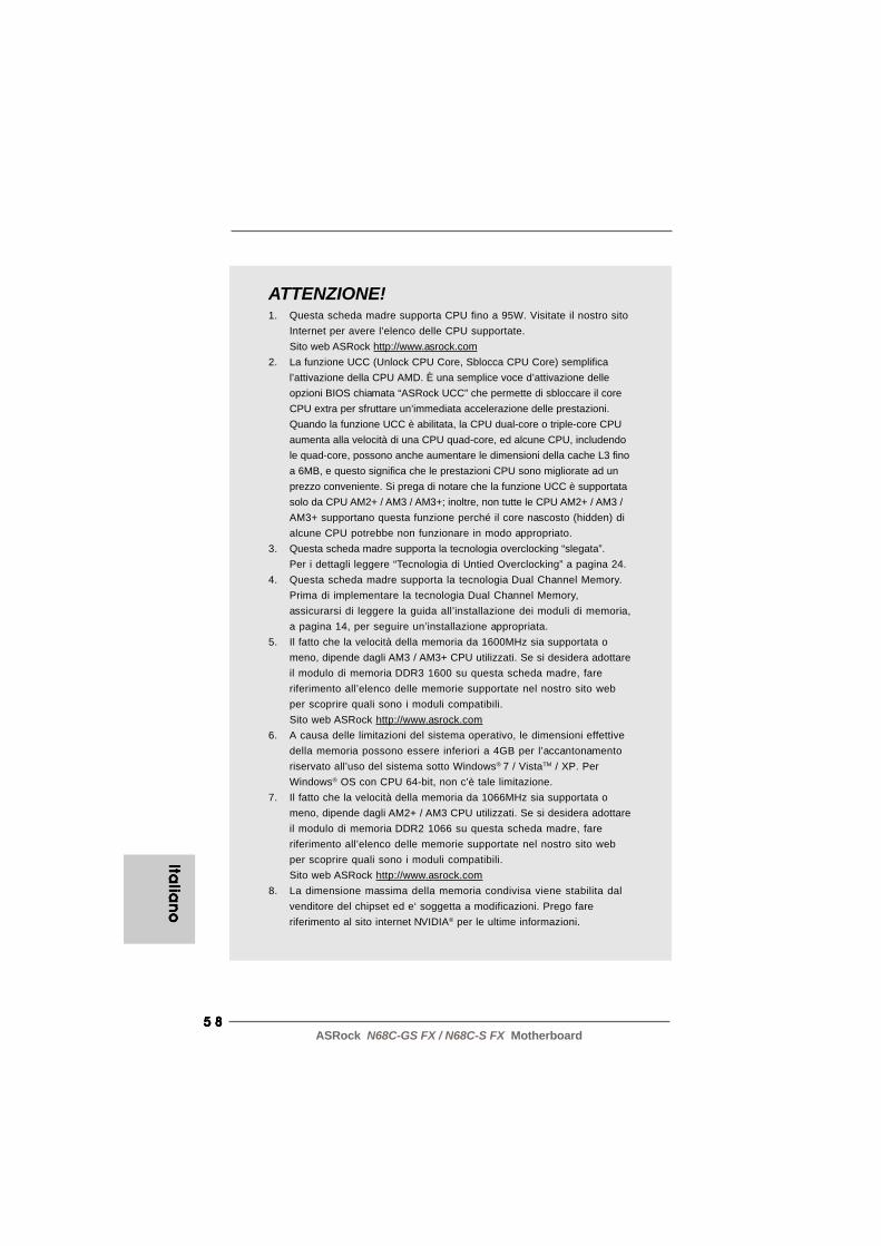
5 85 85 85 85 8ASRock N68C-GS FX / N68C-S FX Motherboard
Italia
no
Italia
no
Italia
no
Italia
no
Italia
no
ATTENZIONE!1. Questa scheda madre supporta CPU fino a 95W. Visitate il nostro sito
Internet per avere l’elenco delle CPU supportate.Sito web ASRock http://www.asrock.com
2. La funzione UCC (Unlock CPU Core, Sblocca CPU Core) semplifical’attivazione della CPU AMD. È una semplice voce d’attivazione delleopzioni BIOS chiamata “ASRock UCC” che permette di sbloccare il coreCPU extra per sfruttare un’immediata accelerazione delle prestazioni.Quando la funzione UCC è abilitata, la CPU dual-core o triple-core CPUaumenta alla velocità di una CPU quad-core, ed alcune CPU, includendole quad-core, possono anche aumentare le dimensioni della cache L3 finoa 6MB, e questo significa che le prestazioni CPU sono migliorate ad unprezzo conveniente. Si prega di notare che la funzione UCC è supportatasolo da CPU AM2+ / AM3 / AM3+; inoltre, non tutte le CPU AM2+ / AM3 /AM3+ supportano questa funzione perché il core nascosto (hidden) dialcune CPU potrebbe non funzionare in modo appropriato.
3. Questa scheda madre supporta la tecnologia overclocking “slegata”.Per i dettagli leggere “Tecnologia di Untied Overclocking” a pagina 24.
4. Questa scheda madre supporta la tecnologia Dual Channel Memory.Prima di implementare la tecnologia Dual Channel Memory,assicurarsi di leggere la guida all’installazione dei moduli di memoria,a pagina 14, per seguire un’installazione appropriata.
5. Il fatto che la velocità della memoria da 1600MHz sia supportata omeno, dipende dagli AM3 / AM3+ CPU utilizzati. Se si desidera adottareil modulo di memoria DDR3 1600 su questa scheda madre, fareriferimento all’elenco delle memorie supportate nel nostro sito webper scoprire quali sono i moduli compatibili.Sito web ASRock http://www.asrock.com
6. A causa delle limitazioni del sistema operativo, le dimensioni effettivedella memoria possono essere inferiori a 4GB per l’accantonamentoriservato all’uso del sistema sotto Windows® 7 / VistaTM / XP. PerWindows® OS con CPU 64-bit, non c’è tale limitazione.
7. Il fatto che la velocità della memoria da 1066MHz sia supportata omeno, dipende dagli AM2+ / AM3 CPU utilizzati. Se si desidera adottareil modulo di memoria DDR2 1066 su questa scheda madre, fareriferimento all’elenco delle memorie supportate nel nostro sito webper scoprire quali sono i moduli compatibili.Sito web ASRock http://www.asrock.com
8. La dimensione massima della memoria condivisa viene stabilita dalvenditore del chipset ed e‘ soggetta a modificazioni. Prego fareriferimento al sito internet NVIDIA® per le ultime informazioni.

5 95 95 95 95 9ASRock N68C-GS FX / N68C-S FX Motherboard
Ita
lia
no
Ita
lia
no
Ita
lia
no
Ita
lia
no
Ita
lia
no
9. Prima di installare il disco rigido SATAII con il connettore SATAII,leggere la “Guida per la configurazione del disco rigido SATAII” apagina 26 del “Manuale utente” nel CD in dotazione in modo da poterpredisporre il disco rigido SATAII per la modalità SATAII. È anchepossibile connettere il disco rigido SATA direttamente al connettoreSATAII.
10. Si tratta di uno strumento di sicronizzazione ASRock di face uso ingrado di implementare il controllo del sistema tramite la funzione dihardware monitor e sincronizzare le Vostre unita‘ hardware perottenere la migliore prestazione in Windows®. Prego visitare il nostrosito Internet per ulteriori dettagli circa l‘uso del Sintonizzatore ASRockOC. ASRock website: http://www.asrock.com
11. Grazie ad un innovative hardware proprietario ed alla progettazionespecifica del software, Intelligent Energy Saver (Risparmio intelligentedell’energia), è una tecnologia rivoluzionaria che consente di realizzarerisparmi energetici senza pari. Il regolatore di tensione è in grado diridurre il numero di fasi in uscita in modo da migliorare l’efficienzaquando i nuclei della CPU sono inattivi. In alter parole, permette direalizzare risparmi energetica senza pari e di migliorare l’efficienzaenergetica senza ridurre le prestazioni del computer. Per usare lafunzione Intelligent Energy Saver (Risparmio intelligentedell’energia), attivare l’opzione Cool ‘n’ Quiet nella configurazioneavanzata del BIOS. Si prega di visitare il nostro sito Internet per leprocedure di funzionamento dell’Intelligent Energy Saver (Risparmiointelligente dell’energia).Sito Internet di ASRock: http://www.asrock.com
12. ASRock Instant Flash è una utilità Flash BIOS integrata nella FlashROM. Questo comodo strumento d’aggiornamento del BIOS permettedi aggiornare il sistema BIOS senza accedere a sistemi operativi comeMS-DOS or Windows®. Con questa utilità, si può premere il tasto <F6>durante il POST, oppure il tasto <F2> nel menu BIOS per accedere adASRock Instant Flash. Avviare questo strumento e salvare il nuovo fileBIOS nell’unità Flash USB, dischetto (disco floppy) o disco rigido; poi sipuò aggiornare il BIOS con pochi clic, senza preparare altri dischetti(dischi floppy) o altre complicate utilità Flash. Si prega di notare chel’unità Flash USB o il disco rigido devono usare il File System FAT32/16/12.
13. Il nome stesso del software – OC DNA – dice di cosa è capace. OCDNA, una utilità esclusiva sviluppata da ASRock, fornisce un modocomodo per registrare le impostazioni OC e condividerle con gli altri.Aiuta a salvare le registrazioni di overclocking nel sistema operativo esemplifica la complicata procedura di registrazione delle impostazionidi overclocking. Con OC DNA, puoi salvare le impostazioni OC comeun profilo da condividere con gli amici! I tuoi amici possono scaricare ilprofilo OC sul loro sistema operativo per ottenere le tue stesseimpostazioni OC! Si prega di notare che il profilo OC può esserecondiviso e modificato solo sulla stessa scheda madre.
6 06 06 06 06 0ASRock N68C-GS FX / N68C-S FX Motherboard
Italia
no
Italia
no
Italia
no
Italia
no
Italia
no
14. Se vuoi un modo rapido e indipendente per caricare i dispositivi Apple,come iPhone/iPod/iPad Touch, ASRock ha preparato una soluzionemeravigliosa: ASRock APP Charger. Basta installare il driver APPCharger per caricare l’iPhone più rapidamente rispetto al computer,con una velocità maggiore del 40%. ASRock APP Charger permette dicaricare simultaneamente molti dispositivi Apple in modo rapido esupporta anche il caricamento continuato quando il PC accede allamodalità di Standby (S1), Sospensione su RAM (S3), Ibernazione (S4)o Spegnimento (S5). Una volta installato il driver APP Charger siotterranno prodigi e comodità mai avuti prima.Sito ASRock: http://www.asrock.com/Feature/AppCharger/index.asp
15. SmartView, una nuova funzione del browser Internet, è la paginad’avvio intuitiva di IE che combina i siti visitati più spesso, lacronologia, gli amici di Facebook ed i Feed News in tempo reale inuna veduta migliorata per un’esperienza più personale di Internet. Leschede madre ASRock hanno in dotazione esclusiva l’utilitàSmartView che aiuta a stare in contatto con gli amici mentre si è inmovimento. Per usare la funzione SmartView, assicurarsi che laversione del sistema operativo sia Windows® 7 / 7 64 bit / VistaTM /VistaTM 64 bit e che la versione del browser sia IE8.Sito ASRock: http://www.asrock.com/Feature/SmartView/index.asp
16. ASRock XFast USB può accelerare le prestazioni del dispositivod’archiviazione USB. Le prestazioni dipendono dalle proprietà deldispositivo.
17. ASRock XFast LAN offre un accesso a Internet piu veloce, checompren-de i seguenti benefi ci. Priorita alle applicazioni LAN: epossibile confi gu-rare la priorita assegnata alle applicazioni in modoideale e/o aggiungere nuovi programmi. Minore latenza nei giochi:dopo avere impostato la priorita dei giochi su un livello piu alto, lalatenza dei giochi puo essere minore. Confi gurazione del traffi co: epossibile seguire video HD su Youtube e scaricare fi lecontemporaneamente. Analisi in tempo reale dei dati: grazie alla finestra di stato, e possibile riconoscere con facilita quali dati sistanno trasferendo in streaming.
18. Anche se questa motherboard offre il controllo stepless, non siconsiglia di effettuare l’overclocking. L’uso di frequenze diverse daquelle raccomandate per il bus CPU possono provocare l’instabilitàdel sistema o danneggiare la CPU.
19. Se il processore si surriscalda, il sistema si chiude automaticamente.Prima di riavviare il sistema, assicurarsi che la ventolina CPU dellascheda madre funzioni correttamente; scollegare e ricollegare il cavod’alimentazione. Per migliorare la dissipazione del calore, ricordare diapplicare l’apposita pasta siliconica tra il processore e il dissipatorequando si installa il sistema.
6 16 16 16 16 1ASRock N68C-GS FX / N68C-S FX Motherboard
Ita
lian
oIt
alia
no
Ita
lian
oIt
alia
no
Ita
lian
o
20. Questa scheda madre supporta la tecnologia di overclocking ASRockAM2 Boost. Se si abilita questa funzione nel Setup del BIOS, leprestazioni della memoria miglioreranno fino al 12,5%, per gli effettidipendono sempre dalla CPU AM2 che si adotta. Abilitare questafunzione provocherà l’overclock della frequenza di case del chipset/CPU. Tuttavia, non possiamo garantire la stabilità del sistema per tuttele configurazioni CPU/DRAM. Se il sistema è instabile dopo avereabilitato la funzione AM2 Boost, significa che la funzione non è adatta alsistema. Si può scegliere di disabilitare la funzione per mantenere lastabilità del sistema.
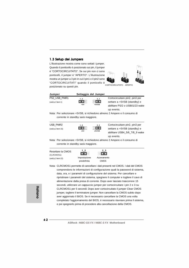
6 26 26 26 26 2ASRock N68C-GS FX / N68C-S FX Motherboard
Italia
no
Italia
no
Italia
no
Italia
no
Italia
no
CORTOCIRCUITATO APERTO
1.3 Setup dei Jumpers1.3 Setup dei Jumpers1.3 Setup dei Jumpers1.3 Setup dei Jumpers1.3 Setup dei JumpersL’illustrazione mostra come sono settati i jumper.Quando il ponticello è posizionato sui pin, il jumperè “CORTOCIRCUITATO”. Se sui pin non ci sonoponticelli, il jumper è “APERTO”. L’illustrazionemostra un jumper a 3 pin in cui il pin1 e il pin2 sono“CORTOCIRCUITATI” quando il ponticello èposizionato su questi pin.
Jumper Settaggio del JumperPS2_USB_PWR1 Cortocircuitare pin2, pin3 per(vedi p.2 item 1) settare a +5VSB (standby) e
abilitare PS/2 o USB01/23 wakeup events.
Nota: Per selezionare +5VSB, si richiedono almeno 2 Ampere e il consumo dicorrente in standby sarà maggiore.
USB_PWR2 Cortocircuitare pin2, pin3 per(vedi p.2 item 15) settare a +5VSB (standby) e
abilitare USB4_5/6_7/8_9 wakeup events.
Nota: Per selezionare +5VSB, si richiedono almeno 2 Ampere e il consumo dicorrente in standby sarà maggiore.
Resettare la CMOS(CLRCMOS1)
(vedi p.2 item 22)
Nota: CLRCMOS1 permette di cancellare i dati presenti nel CMOS. I dati del CMOScomprendono le informazioni di configurazione quali la password di sistema,data, ora, e i parametri di configurazione del sistema. Per cancellare eripristinare i parametri del sistema, spegnere il computer e togliere il cavo dialimentazione dalla presa di corrente. Dopo aver lasciato trascorrere 15secondi, utilizzare un cappuccio jumper per cortocircuitare i pin 2 e 3 suCLRCMOS1 per 5 secondi. Dopo aver cortocircuitato il jumper Clear CMOSjumper, togliere il terminatore jumper. Non cancellare la CMOS subito dopoaver aggiornato il BIOS. Se è necessario cancellare la CMOS una voltacompletato l’aggiornamento del BIOS, è necessario riavviare prima il sistema,e poi spegnerlo prima di procedere alla cancellazione della CMOS.
AzzeramentoCMOS
Impostazionepredefinita

6 36 36 36 36 3ASRock N68C-GS FX / N68C-S FX Motherboard
Lato del Pin1 con la striscia rossa
1.4 Connettori1.4 Connettori1.4 Connettori1.4 Connettori1.4 Connettori
I connettori NON sono jumpers. NON COLLOCARE i ponticelli suiconnettori. Installando dei cappucci a ponticello sui connettori sicauseranno danni permanenti alla scheda madre!
Connettori Descrizione dei connettoriConnettore delFloppy disk(33-pin FLOPPY1)(vedi p.2 item 24)
Nota: Assicurarsi che il lato del cavo con la striscia rossa sia inserito nel lato Pin1del connettore.
Connettore IDE primario (blu)(39-pin IDE1, vedi p.2 Nr. 9)
Connettore blu Connettore neroalla schedamadre all’hard disk drive
Cavo ATA 66/100/133 a 80 PinNota: Fate riferimento alle istruzioni del produttore del dispositivo IDE per maggiori
dettagli.
Connettori Serial ATAII Questi quattro connettori Serial(SATAII_1 (PORT 0.0): ATA (SATAII) supportano levedi p.2 Nr. 10) periferiche di archiviazione(SATAII_2 (PORT 0.1): HD SATA o SATAII per levedi p.2 Nr. 13) funzioni di archiviazione(SATAII_3 (PORT 1.0): interna. ATAII (SATAII) suppo-vedi p.2 Nr. 11) rtano cavi SATAII per dispositivi(SATAII_4 (PORT 1.1): di memoria interni. L’interfacciavedi p.2 Nr. 12) SATAII attuale permette velocità
di trasferimento dati fino a3.0 Gb/s.
Cavi dati Serial ATA (SATA) Entrambe le estremità del cavo(Opzionale) dati SATA possono collegarsi
all’hard disk SATA / SATAII o alconnettore SATAII sulla schedamadre.
SATAII_1 SATAII_3(PORT 0.0) (PORT 1.0)
SATAII_2 SATAII_4(PORT 0.1) (PORT 1.1)
Ita
lian
oIt
alia
no
Ita
lian
oIt
alia
no
Ita
lian
o
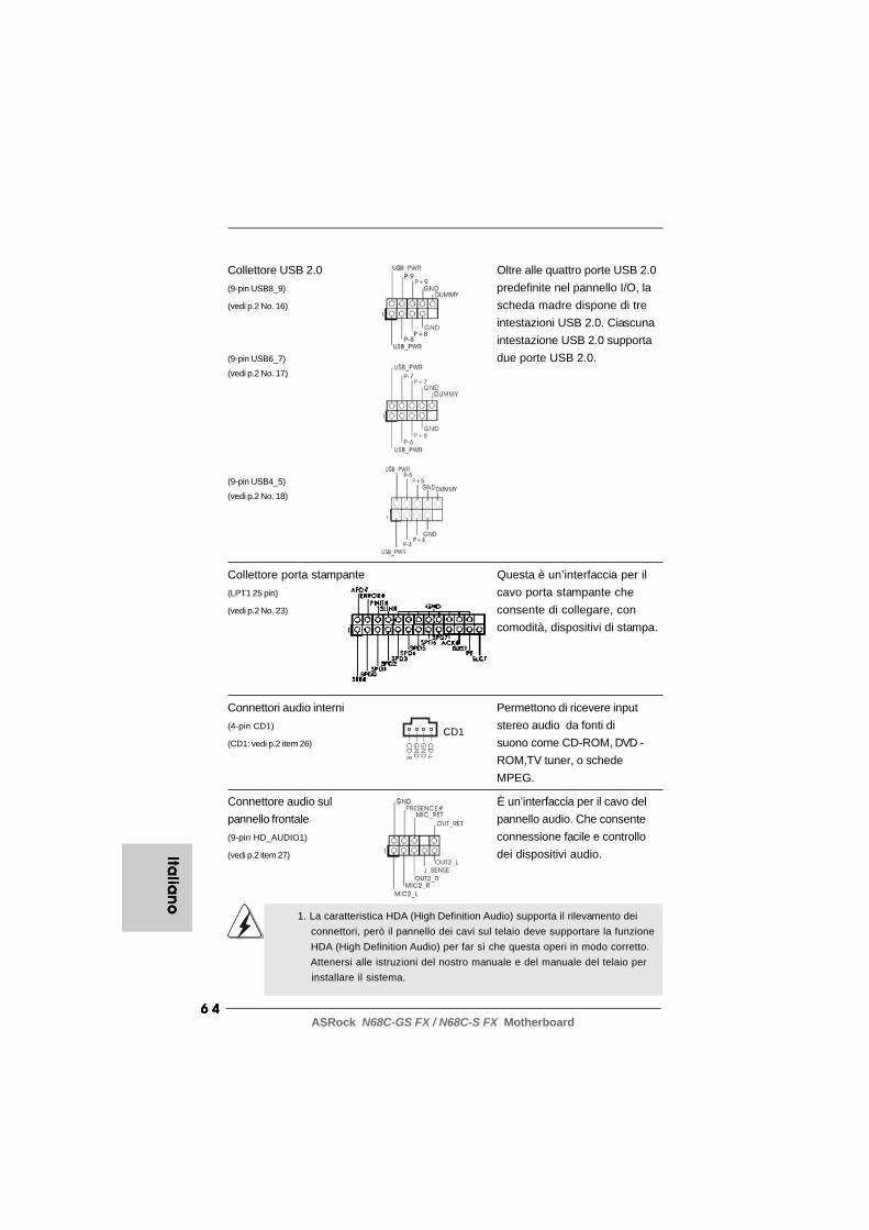
6 46 46 46 46 4ASRock N68C-GS FX / N68C-S FX Motherboard
Italia
no
Italia
no
Italia
no
Italia
no
Italia
no
1. La caratteristica HDA (High Definition Audio) supporta il rilevamento dei connettori, però il pannello dei cavi sul telaio deve supportare la funzione HDA (High Definition Audio) per far sì che questa operi in modo corretto. Attenersi alle istruzioni del nostro manuale e del manuale del telaio per installare il sistema.
Connettori audio interni Permettono di ricevere input(4-pin CD1) stereo audio da fonti di(CD1: vedi p.2 item 26) suono come CD-ROM, DVD -
ROM,TV tuner, o schedeMPEG.
Connettore audio sul È un’interfaccia per il cavo delpannello frontale pannello audio. Che consente(9-pin HD_AUDIO1) connessione facile e controllo(vedi p.2 item 27) dei dispositivi audio.
Collettore USB 2.0 Oltre alle quattro porte USB 2.0(9-pin USB8_9) predefinite nel pannello I/O, la(vedi p.2 No. 16) scheda madre dispone di tre
intestazioni USB 2.0. Ciascunaintestazione USB 2.0 supporta
(9-pin USB6_7) due porte USB 2.0.(vedi p.2 No. 17)
(9-pin USB4_5)
(vedi p.2 No. 18)
CD
-L
GN
D
GN
D
CD
-R
CD1
Collettore porta stampante Questa è un’interfaccia per il(LPT1 25 pin) cavo porta stampante che(vedi p.2 No. 23) consente di collegare, con
comodità, dispositivi di stampa.

6 56 56 56 56 5ASRock N68C-GS FX / N68C-S FX Motherboard
Connettore del panello Questo connettore accogliefrontale diverse funzioni del pannello(9-pin PANEL1) frontale.(vedi p.2 item 20)
Collettore casse telaio Collegare le casse del telaio a(4-pin SPEAKER1) questo collettore.(vedi p.2 item 19)
2. Se si utilizza un pannello audio AC’97, installarlo nell’intestazione audio del pannello anteriore, come indicato di seguito: A. Collegare Mic_IN (MIC) a MIC2_L. B. Collegare Audio_R (RIN) a OUT2_R e Audio_L (LIN) ad OUT2_L. C. Collegare Ground (GND) a Ground (GND). D. MIC_RET e OUT_RET sono solo per il pannello audio HD. Non è necessario collegarli per il pannello audio AC’97.
Connettore ventolina CPU Collegare il cavo della ventolina(4-pin CPU_FAN1) CPU a questo connettore e far(vedi p.2 item 2) combaciare il filo nero al pin
terra.
4 3 2 1
Sebbene la presente scheda madre disponga di un supporto per ventolaCPU a 4 piedini (ventola silenziosa), la ventola CPU a 3 piedini è in grado difunzionare anche senza la funzione di controllo della velocità della ventola.Se si intende collegare la ventola CPU a 3 piedini al connettore della ventolaCPU su questa scheda madre, collegarla ai piedini 1-3.
Piedini 1-3 collegati
Installazione della ventola a 3 piedini
Collettori Chassis ed alimentazione ventola Collegare i cavi della ventola ai(3-pin CHA_FAN1) corrispondenti connettori(vedi p.2 Nr. 21) facendo combaciare il cavo
nero col pin di terra.(3-pin PWR_FAN1)
(vedi p.2 Nr. 25)
Ita
lian
oIt
alia
no
Ita
lian
oIt
alia
no
Ita
lian
o

6 66 66 66 66 6ASRock N68C-GS FX / N68C-S FX Motherboard
Italia
no
Italia
no
Italia
no
Italia
no
Italia
no
Collettore alimentazione ATX Collegare la sorgente(24-pin ATXPWR1) d’alimentazione ATX a questo(vedi p.2 item 8) collettore.
Installazione dell’alimentatore ATX a 20 pin
Con questa scheda madre, c’è in dotazione un connettoreelettrico ATX a 24 pin, ma può funzionare lo stesso se siadotta un alimentatore ATX a 20 pin. Per usare l’alimentatoreATX a 20 pin, collegare l’alimentatore con il Pin 1 e il Pin 13.
12
1
24
13
12
1
24
13
Connettore ATX 12V È necessario collegare una(4-pin ATX12V1) alimentazione con spinotto da(vedi p.2 item 3) 12V ATX a questo connettore
in modo che possa fornireenergia sufficiente. In casocontrario l’unità non si avvia.

6 76 76 76 76 7ASRock N68C-GS FX / N68C-S FX Motherboard
2. Informazioni sul BIOS2. Informazioni sul BIOS2. Informazioni sul BIOS2. Informazioni sul BIOS2. Informazioni sul BIOSLa Flash Memory sulla scheda madre contiene le Setup Utility. Quando si avvia ilcomputer, premi <F2> durante il Power-On-Self-Test (POST) della Setup utility delBIOS; altrimenti, POST continua con i suoi test di routine. Per entrare il BIOS Setupdopo il POST, riavvia il sistema premendo <Ctl> + <Alt> + <Delete>, o premi il tastodi reset sullo chassis del sistema. El BIOS Setup Utility es diseñádo “user-friendly”.Es un programa guido al menu, es decir, puede enrollarse a sus varios su-menuesy elegir las opciones predeterminadas. Per informazioni più dettagliate circa ilSetup del BIOS, fare riferimento al Manuale dell’Utente (PDF file) contenuto nel cddi supporto.
3. Software di supporto e informazioni3. Software di supporto e informazioni3. Software di supporto e informazioni3. Software di supporto e informazioni3. Software di supporto e informazioni su CD su CD su CD su CD su CDQuesta scheda madre supporta vari sistemi operativi Microsoft® Windows®: 7 / 764 bit / VistaTM / VistaTM 64-bit / XP / XP 64-bit. Il CD di supporto a corredo dellascheda madre contiene i driver e utilità necessari a potenziare le caratteristichedella scheda. Inserire il CD di supporto nel lettore CD-ROM. Se la funzione“AUTORUN” è attivata nel computer, apparirà automaticamente il Menù principale.Se il Menù principale non appare automaticamente, posizionarsi sul file ASSETUP.EXE nel CESTINO del CD di supporto e cliccare due volte per visualizzare i menù.
Ita
lian
oIt
alia
no
Ita
lian
oIt
alia
no
Ita
lian
o
6 86 86 86 86 8ASRock N68C-GS FX / N68C-S FX Motherboard
Espa
ño
lEsp
añ
ol
Espa
ño
lEsp
añ
ol
Espa
ño
l
1. Introducción1. Introducción1. Introducción1. Introducción1. IntroducciónGracias por su compra de ASRock N68C-GS FX / N68C-S FX placa madre, una placade confianza producida bajo el control de calidad estricto y persistente. La placa madreprovee realización excelente con un diseño robusto conforme al compromiso de calidady resistencia de ASRock.Esta Guía rápida de instalación contiene una introducción a la placa base y una guíade instalación paso a paso. Puede encontrar una información más detallada sobre laplaca base en el manual de usuario incluido en el CD de soporte.
Porque las especificaciones de la placa madre y el software de BIOSpodrían ser actualizados, el contenido de este manual puede sercambiado sin aviso. En caso de cualquier modificación de este manual,la versión actualizada estará disponible en el website de ASRock sinprevio aviso. También encontrará las listas de las últimas tarjetas VGA yCPU soportadas en la página web de ASRock.Website de ASRock http://www.asrock.comSi necesita asistencia técnica en relación con esta placa base, visitenuestra página web con el número de modelo específico de su placa.www.asrock.com/support/index.asp
1.11 .11 .11 .11 .1 Contenido de la cajaContenido de la cajaContenido de la cajaContenido de la cajaContenido de la cajaPlaca base ASRock N68C-GS FX / N68C-S FX
(Factor forma Micro ATX: 24,4 cm x 20,8 cm, 9,6” x 8,2”)Guía de instalación rápida de ASRock N68C-GS FX / N68C-S FXCD de soporte de ASRock N68C-GS FX / N68C-S FXDos Cable de Datos Serial ATA (SATA) (Opcional)Una protección I/O
6 96 96 96 96 9ASRock N68C-GS FX / N68C-S FX Motherboard
1.21 .21 .21 .21 .2 EspecificaciónEspecificaciónEspecificaciónEspecificaciónEspecificación
Plataforma - Factor forma Micro ATX: 24,4 cm x 20,8 cm, 9,6” x 8,2” Procesador - Compatibilidad con procesadores con conector AM3+
(vea ATENCIÓN 1)- Compatibilidad con procesadores con conector AM3: procesador AMD PhenomTM II X6 / X4 / X3 / X2 (excepto 920 / 940) / Athlon II X4 / X3 / X2 / Sempron- Soporte para procesadores con zócalo AM2+ y AM2: AMD PhenomTM FX, Phenom, Athlon 64 FX, Athlon 64 X2 Dual-Core, Athlon X2 Dual-Core, Athlon 64 y procesador Sempron- Compatible con CPU de ocho núcleo- Con soporte UCC (Unlock CPU Core) (vea ATENCIÓN 2)- Con soporte para tecnología Cool ‘n’ QuietTM de AMD- FSB 1000 MHz (2.0 GT/s)- Admite tecnología de aumento de velocidad liberada
(vea ATENCIÓN 3)- Soporta Tecnología de Hiper-Transporte
Chipset - NVIDIA® GeForce 7025 / nForce 630a Memoria - Soporte de Tecnología de Memoria de Doble Canal
(ver ATENCIÓN 4)- 2 x DDR3 DIMM slots- Apoya DDR3 1600/1333/1066/800 non-ECC, memoria de un-buffered (vea ATENCIÓN 5)- Máxima capacidad de la memoria del sistema: 8GB (vea ATENCIÓN 6)- 2 x DDR2 DIMM slots- Apoya DDR2 1066/800/667/533 non-ECC, memoria de un-buffered (vea ATENCIÓN 7)- Máxima capacidad de la memoria del sistema: 8GB (vea ATENCIÓN 6)
Ranuras de - 1 x ranura PCI Express x16 Expansión - 1 x ranuras PCI Express x1
- 2 x ranuras PCI VGA OnBoard - Tarjeta gráfica integrada GeForce 7025 de NVIDIA®
- VGA DX9.0, Sombreador de Píxeles 3.0- 256MB de Memoria máxima compartida (vea ATENCIÓN 8)- Admite D-Sub con una resolución máxima de 1920x1440 a 60 Hz
Audio - Sonido HD de 5.1 Canales (Códec de sonido VIA® VT1705) LAN - N68C-GS FX
Realtek Giga PHY RTL8211CL, velocidad 10/100/1000 Mb/s
Esp
añ
ol
Esp
añ
ol
Esp
añ
ol
Esp
añ
ol
Esp
añ
ol

7 07 07 07 07 0ASRock N68C-GS FX / N68C-S FX Motherboard
Espa
ño
lEsp
añ
ol
Espa
ño
lEsp
añ
ol
Espa
ño
l
- N68C-S FX Realtek PHY RTL8201EL, velocidad 10/100 Mb/s- Soporta Wake-On-LAN- Soporta PXE
Entrada/Salida I/O Panel de Panel - 1 x puerto de ratón PS/2 Trasero - 1 x puerto de teclado PS/2
- 1 x puerto serial: COM1- 1 x Puerto VGA- 4 x puertos USB 2.0 predeterminados- 1 x Puerto LAN RJ-45 con LED (LED de ACCIÓN/ENLACE y LED de VELOCIDAD)- Audio Jack: Line In / Line Out / Micrófono
Conectores - 4 x conexiones SATA2, admiten una velocidad de transferencia de datos de hasta 3,0Gb/s, soporta RAID (RAID 0, RAID 1, RAID 0+1, RAID 5, JBOD), NCQ y “Conexión en caliente” (vea ATENCIÓN 9)- 1 x ATA133 conexiones IDE (admite hasta 2 dispositivos IDE)- 1 x puerto Floppy- 1 x cabecera de puerto de impresora- Conector de ventilador de CPU / chasis / alimentacion- 24-pin cabezal de alimentación ATX- 4-pin conector de ATX 12V power- Conector de Audio Interno- Conector de audio de panel frontal- 3 x Cabezal USB 2.0 (admite 6 puertos USB 2.0 adicionales)
BIOS - 8Mb AMI BIOS- AMI legal BIOS- Soporta “Plug and Play”- ACPI 1.1 compliance wake up events- Soporta “jumper free setup”- Soporta SMBIOS 2.3.1- Múltiple ajuste de CPU, VCCM, NB Voltage
CD de soport - Controladores, utilidades, software de antivirus (versión de prueba), Prueba de CyberLink MediaEspresso 6.5, conjunto de aplicaciones ASRock (CyberLink DVD Suite - OEM y versión de prueba; Creative Sound Blaster X-Fi MB - versión de prueba; Conjunto multimedia ASRock MAGIX - OEM)
Característica - Sintonizador de ASRock OC (vea ATENCIÓN 10) Única - ASRock Administrador de energía inteligente
(vea ATENCIÓN 11)

7 17 17 17 17 1ASRock N68C-GS FX / N68C-S FX Motherboard
ADVERTENCIATenga en cuenta que hay un cierto riesgo implícito en las operaciones de aumento de lavelocidad del reloj, incluido el ajuste del BIOS, aplicando la tecnología de aumento develocidad liberada o utilizando las herramientas de aumento de velocidad de otrosfabricantes. El aumento de la velocidad puede afectar a la estabilidad del sistema e,incluso, dañar los componentes y dispositivos del sistema. Esta operación se deberealizar bajo su propia responsabilidad y Ud. debe asumir los costos. No asumimosninguna responsabilidad por los posibles daños causados por el aumento de la velocidaddel reloj.
- ASRock Instant Boot- ASRock Instant Flash (vea ATENCIÓN 12)- ASRock OC DNA (vea ATENCIÓN 13)- ASRock APP Charger (vea ATENCIÓN 14)- ASRock SmartView (vea ATENCIÓN 15)- ASRock XFast USB (vea ATENCIÓN 16)- ASRock XFast LAN (vea ATENCIÓN 17)- Amplificador Híbrido:
- Stepless control de frecuencia de CPU (vea ATENCIÓN 18)- ASRock U-COP (vea ATENCIÓN 19)- Protección de Falla de Inicio (B.F.G..)- ASRock AM2 Boost: tecnología patentada de ASRock que permite mejorar el rendimiento de la memoria hasta en un 12,5% (vea ATENCIÓN 20)
Monitor Hardware - Sensibilidad a la temperatura del procesador- Sensibilidad a la temperatura de la placa madre- Taquimetros de los ventiladores del procesador y del CPU / chasis / alimentacion- Ventilador silencioso para procesador- Monitor de Voltaje: +12V, +5V, +3.3V, Vcore
OS - En conformidad con Microsoft® Windows® 7 / 7 64 bits / VistaTM / VistaTM 64 bits / XP / XP 64 bits
Certificaciones - FCC, CE, WHQL * Para más información sobre los productos, por favor visite nuestro sitio web: http://www.asrock.com
Esp
añ
ol
Esp
añ
ol
Esp
añ
ol
Esp
añ
ol
Esp
añ
ol

7 27 27 27 27 2ASRock N68C-GS FX / N68C-S FX Motherboard
Espa
ño
lEsp
añ
ol
Espa
ño
lEsp
añ
ol
Espa
ño
l
ATENCIÓN!1. Esta placa base es compatible con una CPU de hasta 95W. Por favor,
consulte nuestro sitio web para conocer la lista de compatibilidad deCPUs. Sitio Web de ASRock: http://www.asrock.com
2. La función UCC (Unlock CPU Core, desbloquear núcleo la CPU) simplificala activación de una CPU AMD. Con sólo activar la opción “ASRock UCC”en el BIOS, es posible desbloquear el núcleo de CPU adicional y disfrutarde un aumento de rendimiento instantáneo. La activación de la funciónUCC permite elevar la potencia de una CPU de doble o triple núcleo a unnivel equivalente al de una CPU de cuádruple núcleo y, en el caso dealgunas CPUs, entre ellas las CPUs de cuádruple núcleo, aumentar eltamaño de la memoria caché L3 hasta 6 MB, lo cual le permitirá disfrutar deuna CPU de mayor rendimiento a un precio más económico. Recuerdeque la función UCC sólo es compatible con CPUs AM2+ / AM3 / AM3+ yque, además, no todas las CPUs AM2+ / AM3 AM3+ admiten esta funcióndebido a que el núcleo oculto de algunas CPUs puede provocar erroresde funcionamiento.
3. Esta placa base admite la tecnología de aumento de velocidad liberada.Por favor lea “Tecnología de Forzado de Reloj (Overclocking) norelacionado” en la página 24 para obtener detalles.
4. Esta placa base soporta Tecnología de Memoria de Doble Canal. Antesde implementar la Tecnología de Memoria de Doble Canal, asegúresede leer la guía de instalación de módulos de memoria en la página 14para su correcta instalación.
5. Que la velocidad de memoria de 1600 MHz se admita o no se admita,depende de la configuración AM3 / AM3+ Procesador que adopte. Sidesea adoptar el módulo de memoria DDR3 1600 en esta placa base,consulte la lista de compatibilidad de memorias en nuestro sitio Webpara obtener los módulos de memoria compatibles. Sitio Web deASRock: http://www.asrock.com
6. Debido a las limitaciones del sistema, el tamaño real de la memoriadebe ser inferior a 4GB para que el sistema pueda funcionar bajoWindows® 7 / VistaTM / XP. Para equipos con Windows® OS con CPU de64-bit, no existe dicha limitación.
7. Que la velocidad de memoria de 1066 MHz se admita o no se admita,depende de la configuración AM2+ / AM3 Procesador que adopte. Sidesea adoptar el módulo de memoria DDR2 1066 en esta placa base,consulte la lista de compatibilidad de memorias en nuestro sitio Webpara obtener los módulos de memoria compatibles.Sitio Web de ASRock: http://www.asrock.com
8. El tamaño de la memoria compartido máximo es definido por elvendedor del chipset y está conforme al cambio. Por favorcompruebe el Web site de NVIDIA® para la información más última.
7 37 37 37 37 3ASRock N68C-GS FX / N68C-S FX Motherboard
Esp
añ
ol
Esp
añ
ol
Esp
añ
ol
Esp
añ
ol
Esp
añ
ol
9. Antes de instalar un disco duro SATAII en el conector SATAII, consulte lasección “Guía de instalación de discos duros SATAII” en la página 26del “Manual de usuario” que se incluye en el CD de soporte paraconfigurar su disco duro SATAII en modo SATAII. También puede conectarun disco duro SATA directamente al conector SATAII.
10. Es una herramienta de overclocking de ASRock de usuario-fácil quele permite a supervisar su sistema por la función de monitor dehardware y overclock sus dispositivos de hardware para obtener elmejor funcionamiento del sistema bajo el entorno de Windows®. Porfavor visite nuestro sitio web para los procedimientos de operaciónde Sintonizador de ASRock OC.Sitio web de ASRock: http://www.asrock.com
11. Gracias a su avanzado hardware de propietario y diseño de software,Intelligent Energy Saver (Economizador de energía inteligente) esuna revolucionaria tecnología que ofrece un ahorro de energía sinigual. El regulador de voltaje permite reducir el número de fases desalida para mejorar la eficiencia cuando los núcleos de la CPUestán inactivos. En otras palabras, permite ofrecer un ahorroexcepcional de energía y mejorar la eficiencia energética sinsacrificar el rendimiento del equipo. Para utilizar la función IntelligentEnergy Saver (Economizador de energía inteligente) , active la opciónCool ‘n’ Quiet en la configuración de BIOS. Visite nuestro sitio webpara conocer los procedimientos de uso de Intelligent Energy Saver(Economizador de energía inteligente).Sitio web de ASRock: http://www.asrock.com
12. ASRock Instant Flash es una utilidad de programación del BIOS que seencuentra almacenada en la memoria Flash ROM. Esta sencillaherramienta de actualización de BIOS le permitirá actualizar el BIOS delsistema sin necesidad de acceder a ningún sistema operativo, comoMS-DOS o Windows®. Gracias a esta utilidad, sólo necesitará pulsar<F6> durante la fase POST o pulsar <F2> para acceder al menú deconfiguración del BIOS y a la utilidad ASRock Instant Flash. Ejecute estaherramienta y guarde el archivo correspondiente al sistema BIOS nuevoen su unidad flash USB, unidad de disco flexible o disco duro parapoder actualizar el BIOS con sólo pulsar un par de botones, sinnecesidad de preparar un disco flexible adicional ni utilizar complicadasutilidades de programación. Recuerde que la unidad flash USB o discoduro utilizado debe disponer del sistema de archivos FAT32/16/12.
7 47 47 47 47 4ASRock N68C-GS FX / N68C-S FX Motherboard
Espa
ño
lEsp
añ
ol
Espa
ño
lEsp
añ
ol
Espa
ño
l
13. El nombre del propio software, OC DNA, indica con claridad aquello delo que es capaz. OC DNA, una exclusiva utilidad desarrollada porASRock, representa para el usuario una forma cómoda de grabar suconfiguración de OC y compartirla con otras personas. Esta utilidad lepermitirá guardar sus registros de aceleración en el sistema operativoy simplificar el complicado proceso de grabación de la configuraciónde aceleración. ¡Gracias a OC DNA podrá guardar su configuración deOC como perfil y compartirlo con sus amigos! ¡Sus amigos podráncargar entonces el perfil de OC en su propio sistema y disfrutar de laconfiguración de OC creada por usted! Recuerde que el perfil de OCcreado sólo funcionará en placas base similares, por lo que sólo podrácompartirlo con usuarios que cuenten con la misma placa base queusted.
14. Si desea una forma más rápida y menos limitada de cargar susdispositivos de Apple; como por ejemplo iPhone, iPod o iPad Touch,ASRock ha creado una fantástica solución para usted: ASRock APPCharger. Simplemente mediante la instalación del controlador de APPCharger, podrá cargar su iPhone de forma mucho más rápida queantes, hasta un 40%, desde su equipo. ASRock APP Charger le permitecargar de forma rápida muchos dispositivos de Apple simultáneamentee incluso podrá continuar la carga cuando su PC entre en modo deespera (S1), suspendido en RAM (S3), modo de hibernación (S4) o seapague (S5). Una vez instalado el controlador de APP Charger, podrádisfrutar fácilmente de una fantástica carga sin precedentes. Sitio webde ASRock: http://www.asrock.com/Feature/AppCharger/index.asp
15. SmartView, una nueva función el explorador de Internet, es la páginade inicio inteligente para IE que combina los sitios Web más visitados,su historial, sus amigos de Facebook y su fuente de noticias en unavista mejorada para disfrutar de una experiencia en Internet máspersonal. Las placas base ASRock están exclusivamente equipadascon la utilidad SmartView que le ayuda a seguir en contacto con susamigos sobre la marcha. Para utilizar la función SmartView asegúresede que la versión de su sistema operativo es Windows® 7 / 7 64 bits /VistaTM / VistaTM 64 bits y que la versión de su explorador es IE8. SitioWeb de ASRock: http://www.asrock.com/Feature/SmartView/index.asp
16. ASRock XFast USB puede aumentar el rendimiento de los dispositivosde almacenamiento USB. El rendimiento depende de las propiedadesdel dispositivo.

7 57 57 57 57 5ASRock N68C-GS FX / N68C-S FX Motherboard
Esp
añ
ol
Esp
añ
ol
Esp
añ
ol
Esp
añ
ol
Esp
añ
ol
17. ASRock XFast LAN proporciona un acceso a Internet mas rapido, queincluye las ventajas que se indican a continuacion. Priorizacion deaplicaciones LAN: Puede confi gurar la prioridad de las aplicaciones deforma ideal y/o agregar nuevos programas. Menor latencia en losjuegos: Despues de aumentar la prioridad de los juegos en linea, sepuede reducir la latencia en los mismos. Gestionar el trafi co: Puedever video en alta defi nicion de Youtube y descargar archivossimultaneamente. Analisis de sus datos en tiempo real: Con la ventanade estado, puede reconocer facilmente que transmisiones ensecuencias se estan trans-fi riendo actualmente.
18. Aunque esta placa base ofrece un control complete, no esrecomendable forzar la velocidad. Las frecuencias de bus de la CPUdistintas a las recomendadas pueden causar inestabilidad en elsistema o dañar la CPU.
19. Cuando la temperatura de CPU está sobre-elevada, el sistema va aapagarse automaticamente. Antes de reanudar el sistema, compruebesi el ventilador de la CPU de la placa base funciona apropiadamente ydesconecte el cable de alimentación, a continuación, vuelva a conectarlo.Para mejorar la disipación de calor, acuérdese de aplicar thermal greaseentre el procesador y el disipador de calor cuando usted instala elsistema de PC.
20. Esta placa base admite la tecnología ASRock AM2 Boost para aumentode la velocidad del reloj. Si habilita esta función en la configuración delBIOS, el rendimiento de la memoria mejorará hasta en un 12,5%, peroseguirá dependiendo del procesador AM2 que adopte. Al activar estafunción, la velocidad del reloj de referencia del conjunto de chips y delprocesador aumentará. No obstante, no podemos garantizar laestabilidad del sistema para todas las configuraciones de procesadory memoria DRAM. Si el sistema se comporta de forma inestabledespués de habilitar la función AM2 Boost, es posible que dicha funciónno se pueda aplicar a aquél. Si lo desea, puede deshabilitar la funciónpara mantener la estabilidad del sistema.

7 67 67 67 67 6ASRock N68C-GS FX / N68C-S FX Motherboard
Espa
ño
lEsp
añ
ol
Espa
ño
lEsp
añ
ol
Espa
ño
l
1.3 Setup de Jumpers1.3 Setup de Jumpers1.3 Setup de Jumpers1.3 Setup de Jumpers1.3 Setup de JumpersLa ilustración muestra como los jumpers sonconfigurados. Cuando haya un jumper-capsobre los pins, se dice gue el jumper está“Short”. No habiendo jumper cap sobre lospins, el jumper está “Open”. La ilustraciónmuesta un jumper de 3 pins cuyo pin 1 y pin2 están “Short”.
Jumper Setting DescripciónPS2_USB_PWR1 Ponga en cortocircuito pin 2,(vea p.2, No. 1) pin 3 para habilitar +5VSB
(standby) para PS/2 o USB01/23 wake up events.
Atención: Para elegir +5VSB, se necesita corriente mas que 2 Amp proveida por lafuente de electricidad.
USB_PWR2 Ponga en cortocircuito pin 2,(vea p.2, No. 15) pin 3 para habilitar +5VSB
(standby) para USB4_5/6_7/8_9 wake up events.
Atención: Para elegir +5VSB, se necesita corriente mas que 2 Amp proveida por lafuente de electricidad.
Limpiar CMOS(CLRCMOS1, jumper de 3 pins)
(ver p.2, No. 22)
Atención: CLRCMOS1 permite que Usted limpie los datos en CMOS. Los datos enCMOS incluyen informaciones de la configuración del sistema, tales comola contraseña del sistema, fecha, tiempo, y parámetros de la configuracióndel sistema. Para limpiar y reconfigurar los parametros del sistema a laconfiguración de la fábrica, por favor apague el computador y desconecteel cable de la fuente de electricidad, utilice una cubierta de jumper paraaislar las agujas pin2 y pin3 en CLRCMOS1 durante 5 segundos. Porfavor acuérdase de quitar el jumper cap después de limpiar el COMS. Porfavor acuérdase de quitar el jumper cap después de limpiar el COMS. Sinecesita borrar la CMOS cuando acabe de finalizar la actualización de laBIOS, debe arrancar primero el sistema y, a continuación, apagarlo antes derealizar la acción de borrado de CMOS.
Short Open
Valor predeterminado Restablecimiento dela CMOS
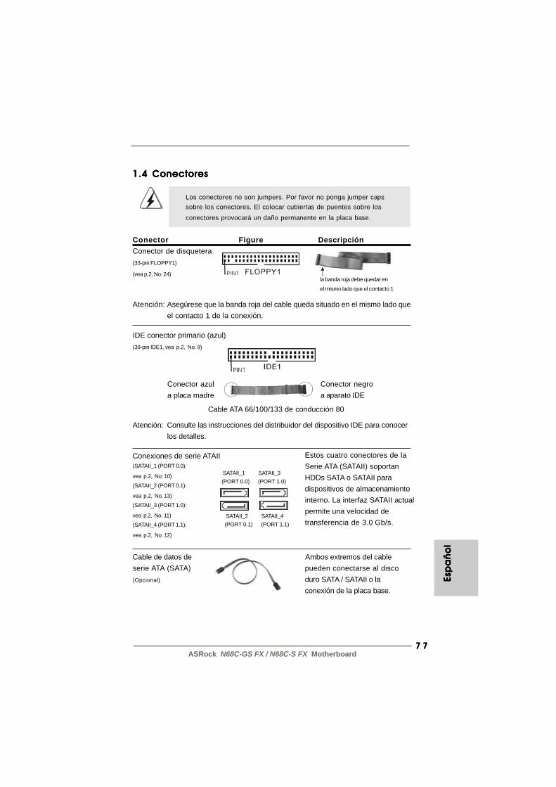
7 77 77 77 77 7ASRock N68C-GS FX / N68C-S FX Motherboard
1.4 Conectores1.4 Conectores1.4 Conectores1.4 Conectores1.4 Conectores
Los conectores no son jumpers. Por favor no ponga jumper capssobre los conectores. El colocar cubiertas de puentes sobre losconectores provocará un daño permanente en la placa base.
Conector Figure DescripciónConector de disquetera(33-pin FLOPPY1)
(vea p.2, No. 24)
Atención: Asegúrese que la banda roja del cable queda situado en el mismo lado queel contacto 1 de la conexión.
IDE conector primario (azul)(39-pin IDE1, vea p.2, No. 9)
Atención: Consulte las instrucciones del distribuidor del dispositivo IDE para conocerlos detalles.
Conexiones de serie ATAII(SATAII_1 (PORT 0.0):
vea p.2, No. 10)
(SATAII_2 (PORT 0.1):
vea p.2, No. 13)
(SATAII_3 (PORT 1.0):
vea p.2, No. 11)
(SATAII_4 (PORT 1.1):
vea p.2, No. 12)
Cable de datos de Ambos extremos del cableserie ATA (SATA) pueden conectarse al disco(Opcional) duro SATA / SATAII o la
conexión de la placa base.
la banda roja debe quedar en
el mismo lado que el contacto 1
Estos cuatro conectores de laSerie ATA (SATAII) soportanHDDs SATA o SATAII paradispositivos de almacenamientointerno. La interfaz SATAII actualpermite una velocidad detransferencia de 3.0 Gb/s.
Conector azula placa madre
Conector negroa aparato IDE
Cable ATA 66/100/133 de conducción 80
SATAII_1 SATAII_3(PORT 0.0) (PORT 1.0)
SATAII_2 SATAII_4(PORT 0.1) (PORT 1.1)
Esp
añ
ol
Esp
añ
ol
Esp
añ
ol
Esp
añ
ol
Esp
añ
ol

7 87 87 87 87 8ASRock N68C-GS FX / N68C-S FX Motherboard
Espa
ño
lEsp
añ
ol
Espa
ño
lEsp
añ
ol
Espa
ño
l
Cabezal USB 2.0 Además de cuatro puertos(9-pin USB8_9) USB 2.0 predeterminados en el(ver p.2, No. 16) panel de E/S, hay tres bases
de conexiones USB 2.0 en esta placa base. Cada una de
(9-pin USB6_7) estas bases de conexiones(ver p.2, No. 17) admite dos puertos USB 2.0.
(9-pin USB4_5)(ver p.2, No. 18)
Conector de Audio Interno Permite recepción de input(4-pin CD1) audio de fuente sónica como(CD1: vea p.2, No. 26) CD-ROM, DVD-ROM, TV tuner,
o tarjeta MPEG.
Conector de audio de panel Este es una interface parafrontal cable de audio de panel frontal(9-pin HD_AUDIO1) que permite conexión y control(vea p.2, No. 27) conveniente de apparatos de
Audio.
CD
-L
GN
D
GN
D
CD
-R
CD1
Cabecera de puerto de impresora Esta es una interfaz de puerto(LPT1 de 25 terminales) para cable de impresora que(vea p.2, N. 23) permite conectar cómodamente
dispositivos de impresión.
1. El Audio de Alta Definición soporta la detección de conector, pero el cable de panel en el chasis debe soportar HDA para operar correctamente. Por favor, siga las instrucciones en nuestro manual y en el manual de chasis para instalar su sistema.2. Si utiliza el panel de sonido AC’97, instálelo en la cabecera de sonido del panel frontal de la siguiente manera:
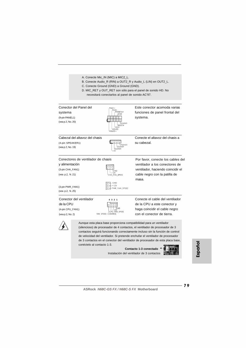
7 97 97 97 97 9ASRock N68C-GS FX / N68C-S FX Motherboard
Conector del Panel del Este conector acomoda variassystema funciones de panel frontal del(9-pin PANEL1) systema.(vea p.2, No. 20)
Cabezal del altavoz del chasis Conecte el altavoz del chasis a(4-pin SPEAKER1) su cabezal.(vea p.2, No. 19)
A. Conecte Mic_IN (MIC) a MIC2_L. B. Conecte Audio_R (RIN) a OUT2_R y Audio_L (LIN) en OUT2_L. C. Conecte Ground (GND) a Ground (GND). D. MIC_RET y OUT_RET son sólo para el panel de sonido HD. No necesitará conectarlos al panel de sonido AC’97.
Por favor, conecte los cables delventilador a los conectores deventilador, haciendo coincidir elcable negro con la patilla demasa.
Conectores de ventilador de chasisy alimentación(3-pin CHA_FAN1)
(vea p.2, N. 21)
(3-pin PWR_FAN1)
(vea p.2, N. 25)
Aunque esta placa base proporciona compatibilidad para un ventilador(silencioso) de procesador de 4 contactos, el ventilador de procesador de 3contactos seguirá funcionando correctamente incluso sin la función de controlde velocidad del ventilador. Si pretende enchufar el ventilador de procesadorde 3 contactos en el conector del ventilador de procesador de esta placa base,conéctelo al contacto 1-3.
Contacto 1-3 conectadoInstalación del ventilador de 3 contactos
Conector del ventilador Conecte el cable del ventiladorde la CPU de la CPU a este conector y(4-pin CPU_FAN1) haga coincidir el cable negro(vea p.2, No. 2) con el conector de tierra.
4 3 2 1Es
pa
ño
lEs
pa
ño
lEs
pa
ño
lEs
pa
ño
lEs
pa
ño
l

8 08 08 08 08 0ASRock N68C-GS FX / N68C-S FX Motherboard
Espa
ño
lEsp
añ
ol
Espa
ño
lEsp
añ
ol
Espa
ño
l
Cabezal de alimentación ATX Conecte la fuente de(24-pin ATXPWR1) alimentación ATX a su cabezal.(vea p.2, No. 8)
Instalación de una Fuente de Alimentación ATX de 20 Pins
A pesar de que esta placa base incluye in conector dealimentación ATX de 24 pins, ésta puede funcionar inclusosi utiliza una fuente de alimentación ATX de 20 pins tradicional.Para usar una fuente de alimentación ATX de 20 pins, por favor,conecte su fuente de alimentación usando los Pins 1 y 13.
12
1
24
13
12
1
24
13
Conector de ATX 12V power Tenga en cuenta que es(4-pin ATX12V1) necesario conectar este(vea p.2, No. 3) conector a una toma de corriente
con el enchufe ATX 12V, demodo que proporcione suficienteelectricidad. De lo contrario nose podrá encender.
8 18 18 18 18 1ASRock N68C-GS FX / N68C-S FX Motherboard
2. BIOS Información2. BIOS Información2. BIOS Información2. BIOS Información2. BIOS InformaciónEl Flash Memory de la placa madre deposita SETUP Utility. Durante el Power-Up(POST) apriete <F2> para entrar en la BIOS. Sí usted no oprime ninguna tecla, elPOST continúa con sus rutinas de prueba. Si usted desea entrar en la BIOS despuésdel POST, por favor reinicie el sistema apretando <Ctl> + <Alt> + <Borrar>, oapretando el botón Reset en el panel del ordenador. El programa SETUP estadiseñado a ser lo mas fácil posible. Es un programa guiado al menu, es decir, puedeenrollarse a sus varios sub-menues y elegir las opciones predeterminadas. Parainformación detallada sobre como configurar la BIOS, por favor refiérase al Manual delUsuario (archivo PDF) contenido en el CD.
3.Información de Software Support CD3.Información de Software Support CD3.Información de Software Support CD3.Información de Software Support CD3.Información de Software Support CDEsta placa-base soporta diversos tipos de sistema operativo Windows®: 7 / 7 64 bits/ VistaTM / VistaTM 64 bits / XP / XP 64 bits El CD de instalación que acompaña la placa-base trae todos los drivers y programas utilitarios para instalar y configurar la placa-base. Para iniciar la instalación, ponga el CD en el lector de CD y se desplegará elMenú Principal automáticamente si «AUTORUN» está habilitado en su computadora.Si el Menú Principal no aparece automáticamente, localice y doble-pulse en el archivoASSETUP.EXE para iniciar la instalación.
Esp
añ
ol
Esp
añ
ol
Esp
añ
ol
Esp
añ
ol
Esp
añ
ol

8 28 28 28 28 2ASRock N68C-GS FX / N68C-S FX Motherboard
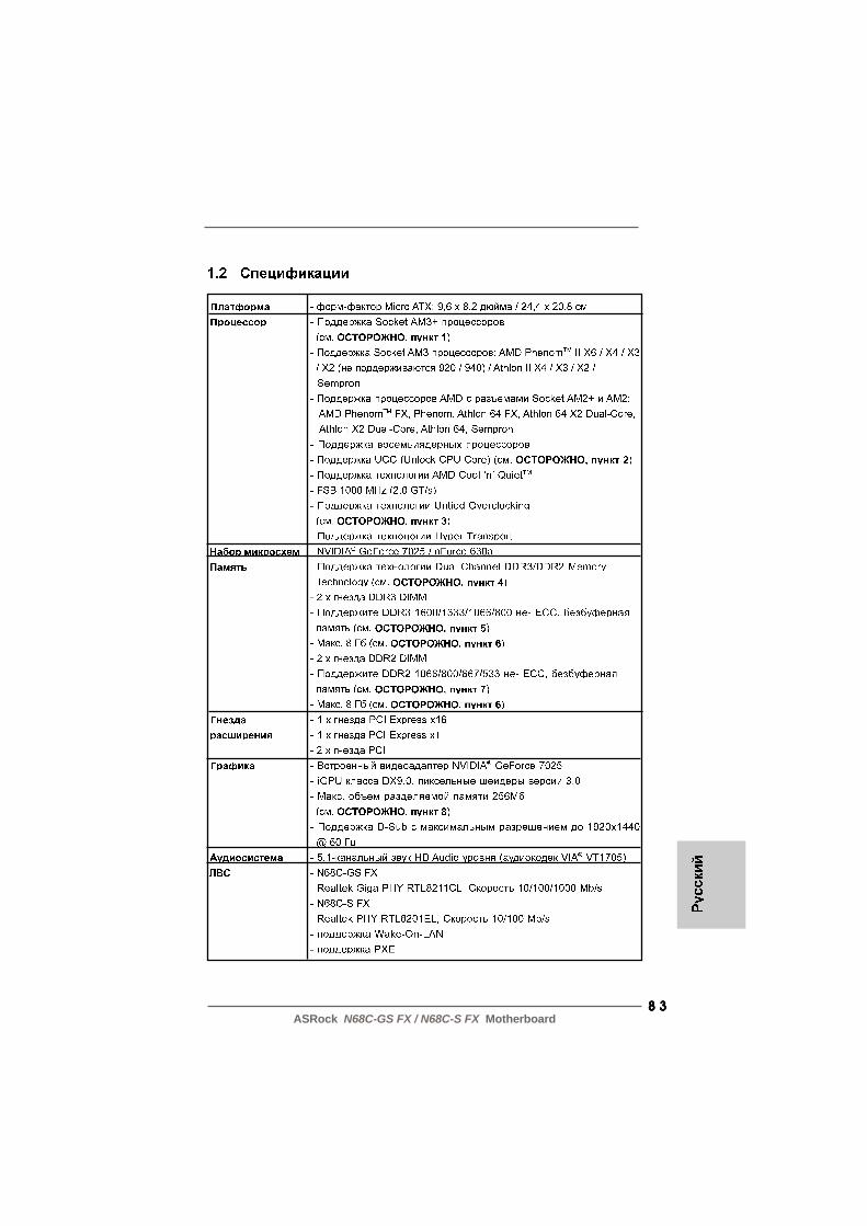
8 38 38 38 38 3ASRock N68C-GS FX / N68C-S FX Motherboard

8 48 48 48 48 4ASRock N68C-GS FX / N68C-S FX Motherboard

8 58 58 58 58 5ASRock N68C-GS FX / N68C-S FX Motherboard

8 68 68 68 68 6ASRock N68C-GS FX / N68C-S FX Motherboard
8 78 78 78 78 7ASRock N68C-GS FX / N68C-S FX Motherboard
8 88 88 88 88 8ASRock N68C-GS FX / N68C-S FX Motherboard
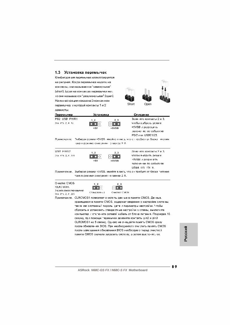
8 98 98 98 98 9ASRock N68C-GS FX / N68C-S FX Motherboard
Short Open
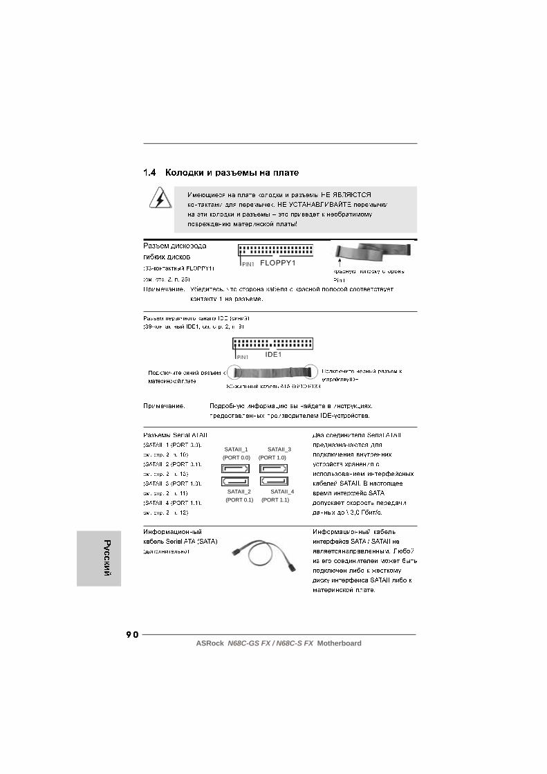
9 09 09 09 09 0ASRock N68C-GS FX / N68C-S FX Motherboard
SATAII_1 SATAII_3(PORT 0.0) (PORT 1.0)
SATAII_2 SATAII_4(PORT 0.1) (PORT 1.1)

9 19 19 19 19 1ASRock N68C-GS FX / N68C-S FX Motherboard
CD
-L
GN
D
GN
D
CD
-R
CD1
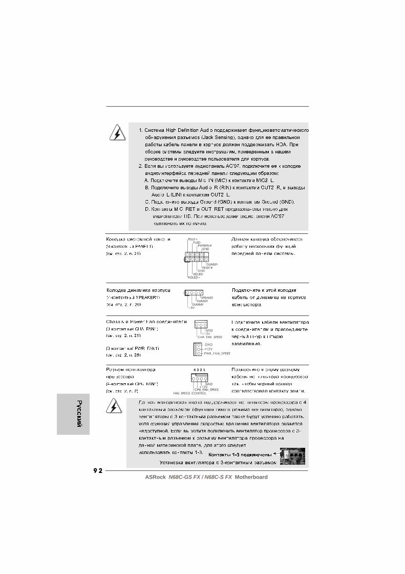
9 29 29 29 29 2ASRock N68C-GS FX / N68C-S FX Motherboard
4 3 2 1

9 39 39 39 39 3ASRock N68C-GS FX / N68C-S FX Motherboard
12
1
24
13
12
1
24
13
9 49 49 49 49 4ASRock N68C-GS FX / N68C-S FX Motherboard
9 59 59 59 59 5ASRock N68C-GS FX / N68C-S FX Motherboard
1. Introdução1. Introdução1. Introdução1. Introdução1. IntroduçãoGratos por comprar nossa placa–mãe N68C-GS FX / N68C-S FX, um produto confiávelfeito com ASRock um estrito controle de qualidade consistente. Com um excelentedesempenho, essa placa é dotada de um projeto robusto que atende a ASRock decompromisso com a qualidade e durabilidade.Este Guia de Instalação Rápida apresenta a placa-mãe e o guia de instalaçãopasso a passo. Mais informações detalhadas sobre a placa-mãe podem serencontradas no manual do usuário do CD de suporte.
Porque as especificações da placa mãe e o software de BIOS poderiam seratualizados, o conteúdo deste manual pode ser cambiado sem aviso. Em caso dequalquer modificação deste manual, a versão atualizada estará disponível nowebsite de ASRock sem prévio aviso. Pode também encontrar as listas das maisrecentes placas VGA e das CPUs suportadas no site da web da ASRock.
Website de ASRock http://www.asrock.comSe precisar de apoio técnico em relação a este placa-mãe, por favor visite o nossosítio da internet para informação específica acerca do modelo que está a utilizar.www.asrock.com/support/index.asp
1.1 Este pacote contém1.1 Este pacote contém1.1 Este pacote contém1.1 Este pacote contém1.1 Este pacote contémPlaca-mãe ASRock N68C-GS FX / N68C-S FX
(Formato Micro ATX: 9,6 pol. x 8,2 pol., 24,4 cm x 20,8 cm)Guia de instalação rápida da ASRock N68C-GS FX / N68C-S FXCD de suporte da placa ASRock N68C-GS FX / N68C-S FXDois cabo de dados ATA Serial (SATA) (Opcional)Uma proteção I/O
Port
ug
uê
sPo
rtu
gu
ês
Port
ug
uê
sPo
rtu
gu
ês
Port
ug
uê
s

9 69 69 69 69 6ASRock N68C-GS FX / N68C-S FX Motherboard
Portu
gu
ês
Portu
gu
ês
Portu
gu
ês
Portu
gu
ês
Portu
gu
ês
1.2 Especificações1.2 Especificações1.2 Especificações1.2 Especificações1.2 Especificações
Plataforma - Formato Micro ATX: 9,6 pol. x 8,2 pol., 24,4 cm x 20,8 cm CPU - Suporte para processadores Socket AM3+ (veja o AVISO 1)
- Suporte para processadores AM3: Processador AMD PhenomTM II X6 / X4 / X3 / X2 (exceto 920 / 940) / Athlon II X4 / X3 / X2 / Sempron- Suporte para processadores Socket AM2+ / AM2: Processador AMD PhenomTM FX / Phenom / Athlon 64 FX / Athlon 64 X2 Dual-Core / Athlon X2 Dual-Core / Athlon 64 / Sempron- Preparado para CPU de oito núcleos- Suporta UCC (Unlock CPU Core) (veja o AVISO 2)- Suporta a tecnologia AMD Cool ‘n’ QuietTM
- FSB de 1000 MHz (2,0 GT/s)- Suporta a tecnologia Untied Overclocking (veja o AVISO 3)- Suporta a tecnologia Hyper-Transport
Chipsets - NVIDIA® GeForce 7025 / nForce 630a Memória - Suporte à tecnologia de memória de duplo canal
(veja o AVISO 4)- 2 x slots de DDR3 DIMM- Suporte para memória não intermédia DDR3 1600/1333/ 1066/800, não ECC (veja o AVISO 5)- Capacidade máxima de memória do sistema: 8GB (veja o AVISO 6)- 2 x slots de DDR2 DIMM- Suporte para memória não intermédia DDR2 1066/800/ 667/533, não ECC (veja o AVISO 7)- Capacidade máxima de memória do sistema: 8GB (veja o AVISO 6)
Slots de Expansão - 1 x slot de PCI Express x16- 1 x slot de PCI Express x1- 2 x slots de PCI
VGA integrado - Placa gráfica GeForce 7025 da NVIDIA®
- VGA DX9.0, Pixel Shader 3.0- Memória partilhada máxima 256MB (veja o AVISO 8)- Suporta D-Sub com resolução máxima até 1920x1440 @ 60Hz
Áudio - Áudio de alta definição de canal 5.1 (Codec de áudio VIA® VT1705)
LAN - N68C-GS FX Realtek Giga PHY RTL8211CL,

9 79 79 79 79 7ASRock N68C-GS FX / N68C-S FX Motherboard
velocidade 10/100/1000 Mb/s- N68C-S FX Realtek PHY RTL8201EL, velocidade 10/100 Mb/s- Suporta Wake-On-LAN- Suporta PXE
Entrada/Saída I/O Panel pelo painel - 1 x porta para mouse PS/2 traseiro - 1 x porta para teclado PS/2
- 1 x porta COM1- 1 x porta VGA- 4 x portas USB 2.0 padrão- 1 x porta LAN RJ-45 com LED (LED ACT/LIG e LED VELOCIDADE)
Conectores - 4 x conectores SATA2, suporte a taxa de transferência de dados de até 3,0 Gb/s, suporte RAID (RAID 0, RAID 1, RAID 0+1, RAID 5, JBOD), NCQ e “conexão a quente” (veja o AVISO 9)- 1 x conectores ATA133 IDE (suporta até 2 dispositivos IDE)- 1 x porta para disquete- 1 x Conector de Porta de Impressão- Conector do ventilador da CPU/chassis/energia- Conector de força do ATX de 24 pinos- Conector ATX 12 V de 4 pinos- Conectores internos de áudio- Conector Áudio do painel frontal- 3 x cabezal USB 2.0 (suportar 6 portas USB 2.0 adicionais)
BIOS - 8Mb BIOS AMI- BIOS AMI- Suporta dispositivos “Plug and Play”- ACPI 1.1 atendendo a eventos de “wake up”- Suporta dispositivos sem jumper- Suporte para SMBIOS 2.3.1- CPU, VCCM, NB Voltage Multi-adjustment
CD de suporte - Controladores, utilitários, software antivírus (Experimentacao Versao), CyberLink MediaEspresso 6.5 versão de demonstração, conjunto de programas da ASRock (CyberLink DVD Suite - OEM e versão de demonstração; Creative Sound Blaster X-Fi MB - versão de demonstração; ASRock MAGIX Multimedia Suite - OEM)
Port
ug
uê
sPo
rtu
gu
ês
Port
ug
uê
sPo
rtu
gu
ês
Port
ug
uê
s
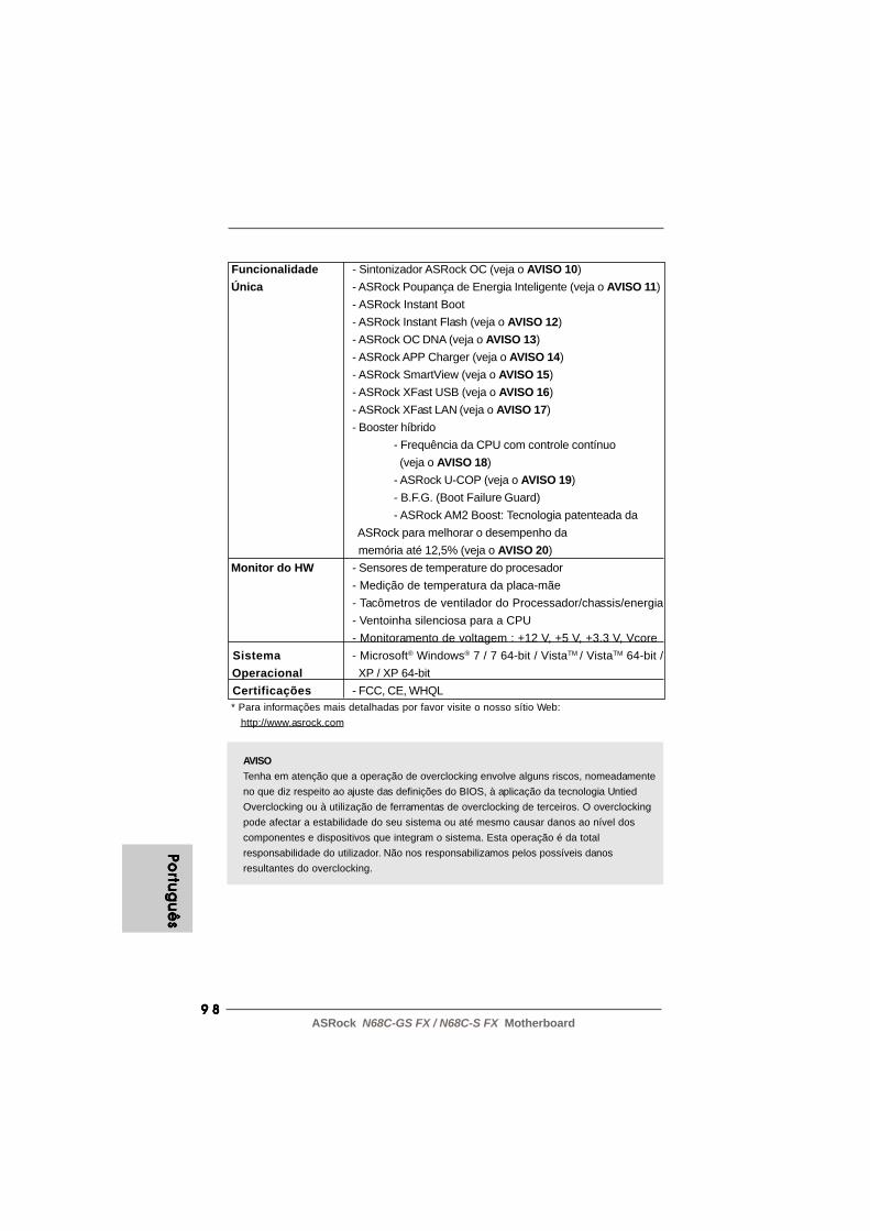
9 89 89 89 89 8ASRock N68C-GS FX / N68C-S FX Motherboard
Portu
gu
ês
Portu
gu
ês
Portu
gu
ês
Portu
gu
ês
Portu
gu
ês
AVISOTenha em atenção que a operação de overclocking envolve alguns riscos, nomeadamenteno que diz respeito ao ajuste das definições do BIOS, à aplicação da tecnologia UntiedOverclocking ou à utilização de ferramentas de overclocking de terceiros. O overclockingpode afectar a estabilidade do seu sistema ou até mesmo causar danos ao nível doscomponentes e dispositivos que integram o sistema. Esta operação é da totalresponsabilidade do utilizador. Não nos responsabilizamos pelos possíveis danosresultantes do overclocking.
Funcionalidade - Sintonizador ASRock OC (veja o AVISO 10) Única - ASRock Poupança de Energia Inteligente (veja o AVISO 11)
- ASRock Instant Boot- ASRock Instant Flash (veja o AVISO 12)- ASRock OC DNA (veja o AVISO 13)- ASRock APP Charger (veja o AVISO 14)- ASRock SmartView (veja o AVISO 15)- ASRock XFast USB (veja o AVISO 16)- ASRock XFast LAN (veja o AVISO 17)- Booster híbrido
- Frequência da CPU com controle contínuo (veja o AVISO 18)- ASRock U-COP (veja o AVISO 19)- B.F.G. (Boot Failure Guard)- ASRock AM2 Boost: Tecnologia patenteada da
ASRock para melhorar o desempenho da memória até 12,5% (veja o AVISO 20)
Monitor do HW - Sensores de temperature do procesador- Medição de temperatura da placa-mãe- Tacômetros de ventilador do Processador/chassis/energia- Ventoinha silenciosa para a CPU- Monitoramento de voltagem : +12 V, +5 V, +3.3 V, Vcore
Sistema - Microsoft® Windows® 7 / 7 64-bit / VistaTM / VistaTM 64-bit / Operacional XP / XP 64-bit Certificações - FCC, CE, WHQL * Para informações mais detalhadas por favor visite o nosso sítio Web: http://www.asrock.com
9 99 99 99 99 9ASRock N68C-GS FX / N68C-S FX Motherboard
AVISO!1. Esta placa-mãe suporta CPUs até 95W. Consulte por favor o nosso
sítio Web para obter uma lista de CPUs suportados.Web site da ASRock http://www.asrock.com
2. A função UCC (Unlock CPU Core, Desbloquear Core de CPU)simplifica a activação da CPU AMD. Basta activar a opção “ASRockUCC” do BIOS para poder desbloquear o núcleo extra da CPU econseguir um aumento instantâneo de desempenho. Quando a funçãoUCC estiver activada, a CPU dual-core ou triple-core irá aumentar paraCPU quad-core e, algumas CPU, incluindo CPU quad-core, podemtambém aumentar o tamanho da cache L3 até 6MB, o que significa quepoderá conseguir um aumento de desempenho do CPU a um preçomais reduzido. Tenha em atenção que a função UCC é suportadaapenas por CPU AM2+ / AM3 / AM3+ e nem todas as CPU AM2+ / AM3 /AM3+ suportam esta função, pois o núcleo oculto de algumas CPUpoderá não funcionar correctamente.
3. Esta placa principal suporta a tecnologia Untied Overclocking. Consultea secção “Tecnologia Untied Overclocking” na página 24 para maisinformações.
4. Esta placa-mãe suporta a tecnologia de memória de duplo canal.Antes de implementar a tecnologia de memória de duplo canal,certifique-se de ler o guia de instalação dos módulos de memóriana página 14 para a instalação correta.
5. O suporte de uma memória com uma velocidade de 1600 MHzdepende da CPU AM3 / AM3+ que adoptar. Se quiser adoptar ummódulo de memória DDR3 1600 para utilização com esta placaprincipal, consulte a lista de memória suportada no nosso web sitepara saber quais os módulos de memória compatíveis.Web site da ASRock http://www.asrock.com
6. Devido às limitações do sistema operativo, o tamanho real damemória pode ser inferior a 4 GB uma vez que uma parte destaestá reservada para utilização pelo sistema operativo no âmbito doWindows® 7 / VistaTM / XP. No caso da CPU de 64 bits doWindows® OS, esta limitação não existe.
7. O suporte de uma memória com uma velocidade de 1066 MHzdepende da CPU AM2+ / AM3 que adoptar. Se quiser adoptar ummódulo de memória DDR2 1066 para utilização com esta placaprincipal, consulte a lista de memória suportada no nosso web sitepara saber quais os módulos de memória compatíveis.Web site da ASRock http://www.asrock.com
8. O máximo tamanho de memória compartilhada é definido porvendedor de chipset e é sujeito a mudar. Verifique o NVIDIA® websitepara a última informação.
Port
ug
uê
sPo
rtu
gu
ês
Port
ug
uê
sPo
rtu
gu
ês
Port
ug
uê
s

100100100100100ASRock N68C-GS FX / N68C-S FX Motherboard
Portu
gu
ês
Portu
gu
ês
Portu
gu
ês
Portu
gu
ês
Portu
gu
ês
9. Antes de instalar o disco duro SATAII no conector SATAII, por favor leiao “Guia de Instalação do Disco duro SATAII” na página 26 do Manualdo Usuário no CD de suporte, para definir a sua unidade de discoduro SATAII com o modo SATAII. Também pode ligar directamente odisco duro SATA ao conector SATAII.
10. É uma ferramenta de overclocking da ASRock fácil de utilizar que lhepermite vigiar i seu sistema via a função de monitorização de hardwaree proceder ao overclock dos dispositivos de hardware para obter omelhor desempenho em ambiente Windows®. Por favor visite o nossosítio Web para conhecer os procedimentos de funcionamento doSintonizador ASRock OC.Sítio Web da ASRock: http://www.asrock.com
11. Com um hardware de propriedades e concepção de softwareavançadas, a Intelligent Energy Saver é uma tecnologiarevolucionária que proporciona poupanças de energia inéditas. Oregulador de voltagem pode reduzir o número de fases de saídapara melhorar a eficiência quando os núcleos do CPU estãoinactivos. Por outras palavras, pode providenciar uma excepcionalpoupança de energia e melhorar a eficiência energética semsacrificar o desempenho. Para utilizar a função Poupança deEnergia, por favor active a opção Cool ‘n’ Quiet na configuração daBIOS primeiro. Por favor visite o nosso sítio Web para conhecer osprocedimentos de funcionamento da Poupança de EnergiaInteligente. Sítio Web da ASRock: http://www.asrock.com
12. ASRock Instant Flash est un utilitaire de flash du BIOS flash intégrédans la ROM Flash. Cet outil pratique de mise à jour du BIOS vouspermet de mettre à jour le BIOS du système sans entrer d’aborddans un système d’exploitation tel que MS-DOS ou Windows®. Aveccet utilitaire, vous pouvez appuyer sur la touche <F6> pendant lePOST ou sur la touche <F2> durant le menu de configuration du BIOSpour accéder à ASRock Instant Flash. Lancez simplement cet outil etenregistrez le nouveau fichier BIOS sur votre lecteur flash USB, surune disquette ou un disque, avant de pouvoir mettre à jour votre BIOSen quelques clics seulement, sans préparer de disquettesupplémentaire ni d’autre utilitaire flash compliqué. Veuillez noterque le lecteur flash USB ou le disque dur doit utiliser le système defichiers FAT32/16/12.
13. O próprio nome do software – OC DNA diz-lhe literalmente aquilo deque é capaz. OC DNA, um utilitário exclusivo desenvolvido pelaASRock, proporciona uma forma conveniente para o utilizador gravaras definições OC e partilhar com outros. Ajuda-o a guardar o seuregisto de “overclocking” (aumento da frequência do processador)no sistema operativo e simplifica o complexo processo de gravaçãodas definições de “overclocking”. Com OC DNA, pode guardar assuas definições OC como perfil e partilhá-las com os seus amigos!Depois, os seus amigos podem carregar o perfil OC no seu próprio
101101101101101ASRock N68C-GS FX / N68C-S FX Motherboard
sistema para obter as mesmas definições OC que você tem! Porfavor, tenha em conta que o perfil OC só pode ser partilhado etrabalhado na mesma placa-mãe.
14. Se procura uma forma mais rápida e com menos restrições de carregaros seus dispositivos Apple, incluindo iPhone/iPod/iPad Touch, a ASRockoferece-lhe uma maravilhosa solução - o ASRock APP Charger. Bastainstalar o controlador APP Charger e o seu iPhone irá carregar muitomais rapidamente no seu computador - até 40% mais rápido. O ASRockAPP Charger permite-lhe carregar diversos dispositivos Applesimultaneamente e suporta até o carregamento contínuo quando o seuPC entrar no modo de Suspensão (S1), Suspender para a RAM (S3),modo de hibernação (S4) ou encerramento (S5). Com o controladorAPP Charger instalado, pode desfrutar facilmente da mais incrívelexperiência de carregamento de sempre.Página Web da ASRock: http://www.asrock.com/Feature/AppCharger/index.asp
15. O SmartView, uma nova função para navegadores de Internet, é umapágina inicial inteligente para o IE que combina os seus sites maisvisitados, o seu histórico, os seus amigos do Facebook e o seunewsfeed em tempo real numa página avançada para oferecer umaexperiência de Internet mais pessoal. As placas principais da ASRockestão equipadas exclusivamente com o utilitário SmartView que lhepermite manter-se facilmente em contacto com os seus amigos. Parautilizar a funcionalidade SmartView, certifique-se de que a sua versãode SO é Windows® 7 / 7 64 bit / VistaTM / VistaTM 64 bit, e que a versão doseu navegador é IE8. Página Web da ASRock: http://www.asrock.com/Feature/SmartView/index.asp
16. O ASRock XFast USB pode aumentar a velocidade dos dispositivosde armazenamento USB. A velocidade poderá depender daspropriedades dos dispositivos.
17. A ASRock XFast LAN proporciona um acesso à Internet mais rápido,que inclui os benefícios abaixo. Prioritização de Aplicações LAN: Outilizador pode configurar a prioridade da aplicação de forma ideal e/ou pode adicionar novos programas. Menor Latência nos Jogos:Depois de definir maior prioridade para o jogo on-line, pode baixar alatência no jogo. Traffic Shaping: Pode assistir a vídeos do Youtubeem HD e transferir ficheiros em simultâneo. Análise em tempo realdos seus dados: Com a janela de estado, pode reconhecerfacilmente os fluxos de dados das suas transferências actuais.
18. Apesar de esta placa-mãe oferecer controle continuamente variável,não se recomenda efetuar over-clock. Freqüências de barramentodiferentes das recomendadas para a CPU podem provocarinstabilidade do sistema ou danos à CPU. Po
rtu
gu
ês
Port
ug
uê
sPo
rtu
gu
ês
Port
ug
uê
sPo
rtu
gu
ês

102102102102102ASRock N68C-GS FX / N68C-S FX Motherboard
Portu
gu
ês
Portu
gu
ês
Portu
gu
ês
Portu
gu
ês
Portu
gu
ês
19. Assim que se detecta um superaquecimento na CPU, o sistema sedesliga automaticamente e o botão de energia do chassis ficainativo.Cheque o ventilador da CPU na placa–mãe, para verificar seestá funcionando corretamente antes de religar o sistema. Paramelhorar a dissipação de calor, lembre-se de aplicar o material deinterface térmica entre o processador e o dissipador de calor.
20. Esta placa principal suporta a tecnologia de overclocking ASRockAM2 Boost. Se activar esta função na configuração do BIOS, odesempenho da memória sofrerá um melhoramento até 12,5%, noentanto tal dependerá da CPU AM2 que adoptar. A activação destafunção irá fazer o overclocking do chipset/do relógio de referência daCPU. No entanto, não podemos garantir a estabilidade do sistemapara todas as configurações CPU/DRAM. Se o seu sistema ficarinstável após a activação da função AM2 Boost é porque estatecnologia pode não se aplicar ao seu sistema. Para manter aestabilidade do sistema, pode desactivar esta função.
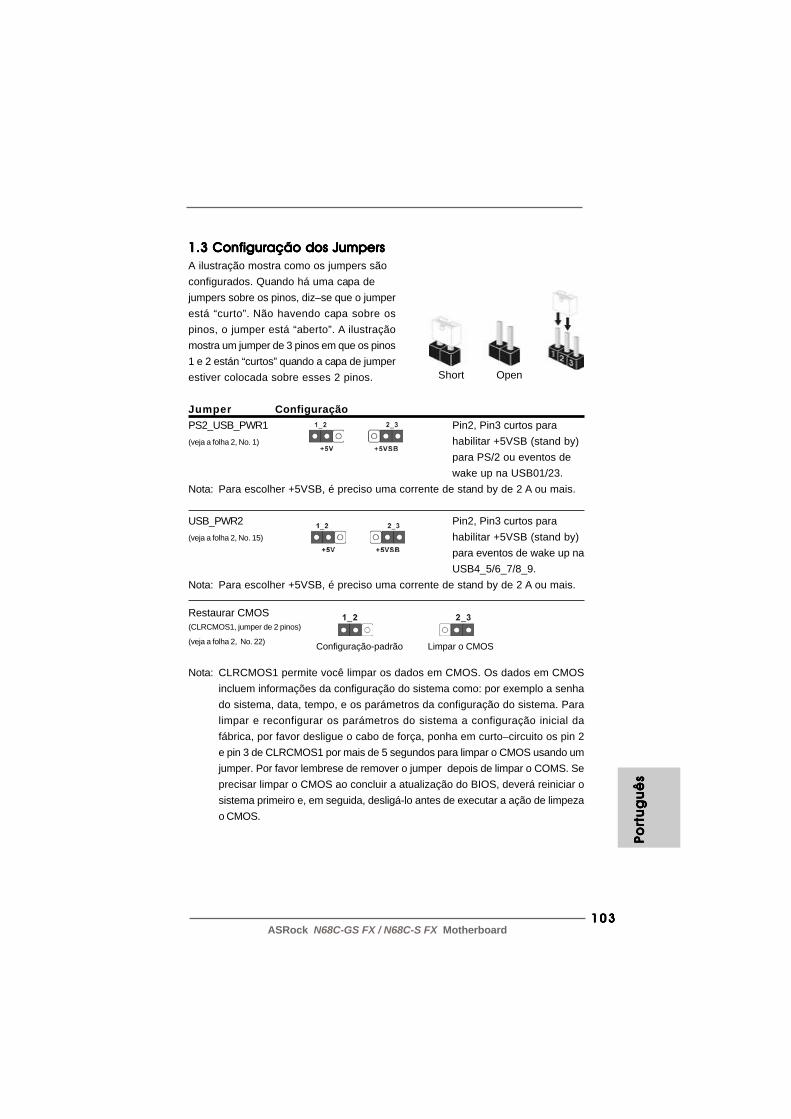
103103103103103ASRock N68C-GS FX / N68C-S FX Motherboard
Port
ug
uê
sPo
rtu
gu
ês
Port
ug
uê
sPo
rtu
gu
ês
Port
ug
uê
s
1.3 Configuração dos Jumpers1.3 Configuração dos Jumpers1.3 Configuração dos Jumpers1.3 Configuração dos Jumpers1.3 Configuração dos JumpersA ilustração mostra como os jumpers sãoconfigurados. Quando há uma capa dejumpers sobre os pinos, diz–se que o jumperestá “curto”. Não havendo capa sobre ospinos, o jumper está “aberto”. A ilustraçãomostra um jumper de 3 pinos em que os pinos1 e 2 están “curtos” quando a capa de jumperestiver colocada sobre esses 2 pinos.
Jumper ConfiguraçãoPS2_USB_PWR1 Pin2, Pin3 curtos para(veja a folha 2, No. 1) habilitar +5VSB (stand by)
para PS/2 ou eventos dewake up na USB01/23.
Nota: Para escolher +5VSB, é preciso uma corrente de stand by de 2 A ou mais.
USB_PWR2 Pin2, Pin3 curtos para(veja a folha 2, No. 15) habilitar +5VSB (stand by)
para eventos de wake up naUSB4_5/6_7/8_9.
Nota: Para escolher +5VSB, é preciso uma corrente de stand by de 2 A ou mais.
Restaurar CMOS(CLRCMOS1, jumper de 2 pinos)
(veja a folha 2, No. 22)
Nota: CLRCMOS1 permite você limpar os dados em CMOS. Os dados em CMOSincluem informações da configuração do sistema como: por exemplo a senhado sistema, data, tempo, e os parámetros da configuração do sistema. Paralimpar e reconfigurar os parámetros do sistema a configuração inicial dafábrica, por favor desligue o cabo de força, ponha em curto–circuito os pin 2e pin 3 de CLRCMOS1 por mais de 5 segundos para limpar o CMOS usando umjumper. Por favor lembrese de remover o jumper depois de limpar o COMS. Seprecisar limpar o CMOS ao concluir a atualização do BIOS, deverá reiniciar osistema primeiro e, em seguida, desligá-lo antes de executar a ação de limpezao CMOS.
Short Open
Configuração-padrão Limpar o CMOS

104104104104104ASRock N68C-GS FX / N68C-S FX Motherboard
Portu
gu
ês
Portu
gu
ês
Portu
gu
ês
Portu
gu
ês
Portu
gu
ês
1.4 Conectores1.4 Conectores1.4 Conectores1.4 Conectores1.4 Conectores
Os conectores NÃO SÃO jumpers. NÃO coloque capas de jumper sobreestes conectores. A colocação de pontos de jumper sobre os conectorescausará danos irreversíveis à placa-mãe.
Conector Figura DescriçãoConector FDD(FLOPPY 1, 33 pinos)
(veja a folha 2, No. 24)
Nota: Certifique-se de que o lado com listras vermelhas no cabo seja conectado aolado Pino 1 do conector.
Conector primário (Azul)(IDE1 de 39 pinos, veja a folha 2, No. 9)
Ligue esta ponta (azul) Ligue esta ponta (preta)à placa–mãe aos dispositivos IDE
Cabo ATA 66/100/133 de 80 condutoresNota: Para detalhes, consulte as instruções do fornecedor do seu dispositivo
IDE.
Conectores ATAII Serial Estes quatro conectores Serial(SATAII_1 (PORT 0.0): ATA (SATAII) suportamveja a folha 2, No. 10) unidades de disco rígido SATA(SATAII_2 (PORT 0.1): ou SATAII como dispositivos deveja a folha 2, No. 13) armazenamento internos. A(SATAII_3 (PORT 1.0): atual interface SATAII permiteveja a folha 2, No. 11) uma taxa de transferência de(SATAII_4 (PORT 1.1): dados de até 3.0 Gb/s.veja a folha 2, No. 12)
Cabo de dados Tanto a saída do cabo de SerialATA (SATA) dados SATA pode ser(opcional) conectado ao disco rígido
SATA / SATAII quanto oconector SATAII na placa mãe.
o lado com listras vermelhas para o Pino 1
SATAII_1 SATAII_3(PORT 0.0) (PORT 1.0)
SATAII_2 SATAII_4(PORT 0.1) (PORT 1.1)

105105105105105ASRock N68C-GS FX / N68C-S FX Motherboard
Conectores internos de áudio Estes conectores permitem(CD1 de 4 pinos) que se receba entrada de(CD1: veja a floha 2, No. 26) áudio em estéreo de fontes
de áudio como CD-ROM,DVD-ROM, placa sintonizadorade TV ou placa MPEG.
Cabezal USB 2.0 Além das quatro portas USB(USB8_9 de 9 pinos) 2.0 por defeito no painel de(veja a folha 2, No. 16) entrada/saída, há tres
ligações USB 2.0 nesta placa-mãe. Cada ligação USB 2.0pode suportar duas portas USB
(USB6_7 de 9 pinos) 2.0.(veja a folha 2, No. 17)
(USB4_5 de 9 pinos)
(veja a folha 2, No. 18)
Conector Áudio do painel Esta é uma interface para ofrontal cabo de áudio no painel frontal,(HD_AUDIO1 de 9 pinos) que permite uma conexão e(veja a folha 2, No. 27) controle convenientes dos
dispositivos de áudio.
CD
-L
GN
D
GN
D
CD
-R
CD1
1. Áudio de elevada definição que suporta a sensibilidade da tomada, mas o fio do painel existente no chassis tem de suportar HDA para funcionar correctamente. Siga s instruções que aparecem no manual e no manual do chassis para instalar o sistema.
Conector de Porta de Impressão Esta é uma interface para um(LPT1 de 25 pinos) cabo de porta de impressão(veja a folha 2, No. 23) que permite uma ligação
prática para dispositivos deimpressão.
Port
ug
uê
sPo
rtu
gu
ês
Port
ug
uê
sPo
rtu
gu
ês
Port
ug
uê
s

106106106106106ASRock N68C-GS FX / N68C-S FX Motherboard
Portu
gu
ês
Portu
gu
ês
Portu
gu
ês
Portu
gu
ês
Portu
gu
ês
Conector do sistema no Este conector acomodapainel diversas funções de(PANEL1 de 9 pinos) sistema no painel frontal.(veja a folha 2, No. 20)
Conector do alto-falante Ligue o alto-falante do chassi dochassi neste conector.(SPEAKER1 de 4 pinos)
(veja a folha 2, No. 19)
2. Se utilizar o painel de áudio AC’97, instale-o no cabeçalho de áudio do painel frontal, como a figura abaixo mostra: A. Ligue o Mic_IN (MIC) ao MIC2_L. B. Ligue o Audio_R (RIN) ao OUT2_R e o Audio_L (LIN) ao OUT2_L. C. Ligue o Ground (GND) ao Ground (GND). D. MIC_RET e OUT_RET são apenas para o painel de áudio HD. Não necessita de os ligar para o painel de áudio AC’97.
Conector do ventilador do Ligue o cabo do ventilador nestechassis e energia conector, coincidindo o fio preto(CHA_FAN1 de 3 pinos) com o pino de aterramento.(veja a folha 2, No. 21)
(PWR_FAN1 de 3 pinos)(veja a folha 2, No. 25)
Conector do ventilador da Ligue o cabo do ventilador daCPU CPU, coincidindo o fio preto com(CPU_FAN1 de 4 pinos) o pino de aterramento.(veja a folha 2, No. 2)
Apesar de esta placa-mãe possuir 4 apoios para uma ventoinha de CPU(Ventoinha silenciosa), uma ventoinha de 3 pinos para CPU poderá funcionarmesmo sem a função de controlo de velocidade da ventoinha. Se pretenderligar uma ventoinha de 3 pinos para CPU ao conector de ventoinha do CPUnesta placa-mãe, por favor, ligue-a aos pinos 1-3.
Instalação de Ventoinha de 3 pinos
Pinos 1-3 ligados
4 3 2 1
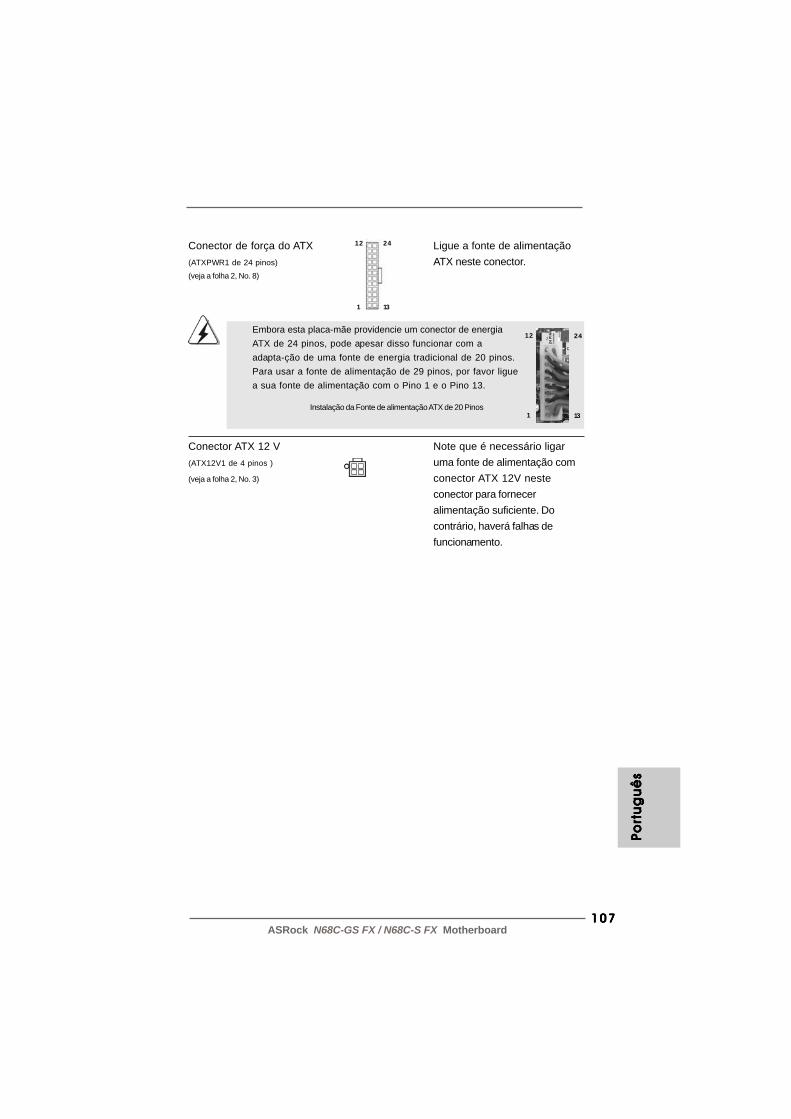
107107107107107ASRock N68C-GS FX / N68C-S FX Motherboard
Conector de força do ATX Ligue a fonte de alimentação(ATXPWR1 de 24 pinos) ATX neste conector.(veja a folha 2, No. 8)
12
1
24
13
Conector ATX 12 V Note que é necessário ligar(ATX12V1 de 4 pinos ) uma fonte de alimentação com(veja a folha 2, No. 3) conector ATX 12V neste
conector para forneceralimentação suficiente. Docontrário, haverá falhas defuncionamento.
Embora esta placa-mãe providencie um conector de energiaATX de 24 pinos, pode apesar disso funcionar com aadapta-ção de uma fonte de energia tradicional de 20 pinos.Para usar a fonte de alimentação de 29 pinos, por favor liguea sua fonte de alimentação com o Pino 1 e o Pino 13.
24
13Instalação da Fonte de alimentação ATX de 20 Pinos
12
1
Port
ug
uê
sPo
rtu
gu
ês
Port
ug
uê
sPo
rtu
gu
ês
Port
ug
uê
s

108108108108108ASRock N68C-GS FX / N68C-S FX Motherboard
2. Informações da BIOS2. Informações da BIOS2. Informações da BIOS2. Informações da BIOS2. Informações da BIOSA Memória Flash da placa–mãe armazena o utilitário de configuração da BIOS.Quando você ligar o computador, pressione < F2 > durante a inicialização (POST)para entrar nas configurações da BIOS; caso contrário o POST continua com suasrotinas de teste. Caso você queira entrar nas configurações da BIOS após o POST,reinicie o sistema pressionando <Ctrl> + <Alt> +<Del>, ou pressionando a tecla dereset no gabinete. Também se pode reinicializar desligando a máquina e ligando–anovamente. Para informações mais detalhadas sobre a configuração da BIOS,consulte o manual do usuário (em pdf) contido no CD de instalação.
3. Informações do CD de Suporte3. Informações do CD de Suporte3. Informações do CD de Suporte3. Informações do CD de Suporte3. Informações do CD de SuporteEsta placa Mãe suporta vários sistemas operacionais: Microsoft® Windows®: 7 / 7 de64 bits / VistaTM / VistaTM de 64 bits / XP / XP de 64 bits. O CD de instalação queacompanha a placa Mãe contem: drivers e utilitários necessários para um melhordesempenho da placa Mãe. Para começar a usar o CD de instalação, introduza o CDna leitora de CD-ROM do computador. Automaticamente iniciará o menu principal,casa o “AUTORUN” esteja ativado. Se o menu principal não aparecer automaticamente,explore o CD e execute o “ASSETUP.EXE” localizado na pasta “BIN”.
Portu
gu
ês
Portu
gu
ês
Portu
gu
ês
Portu
gu
ês
Portu
gu
ês

109109109109109ASRock N68C-GS FX / N68C-S FX Motherboard
Türk
çe
Türk
çe
Türk
çe
Türk
çe
Türk
çe

110110110110110ASRock N68C-GS FX / N68C-S FX Motherboard
Türkç
eTü
rkçe
Türkç
eTü
rkçe
Türkç
e
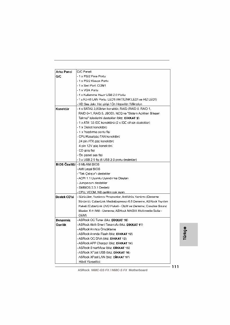
111111111111111ASRock N68C-GS FX / N68C-S FX Motherboard
Türk
çe
Türk
çe
Türk
çe
Türk
çe
Türk
çe
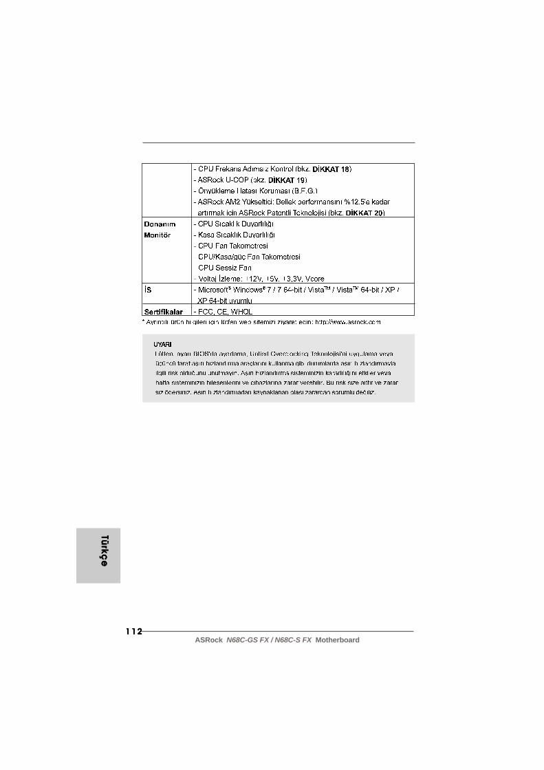
112112112112112ASRock N68C-GS FX / N68C-S FX Motherboard
Türkç
eTü
rkçe
Türkç
eTü
rkçe
Türkç
e
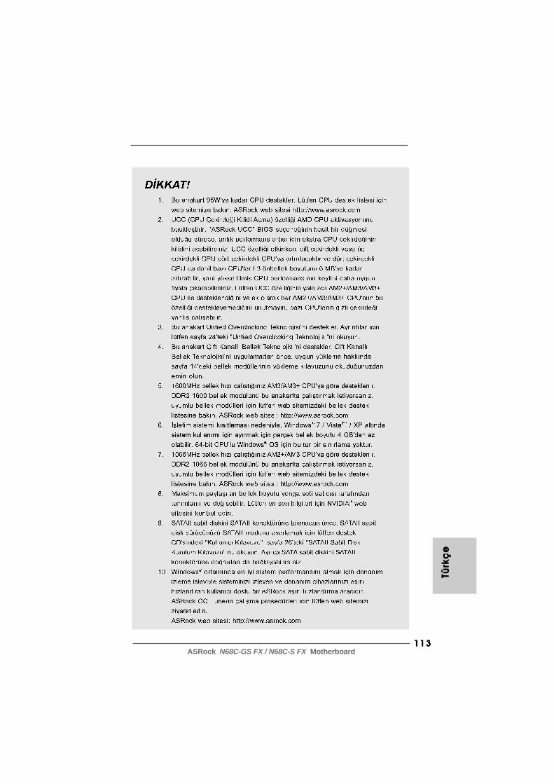
113113113113113ASRock N68C-GS FX / N68C-S FX Motherboard
Türk
çe
Türk
çe
Türk
çe
Türk
çe
Türk
çe
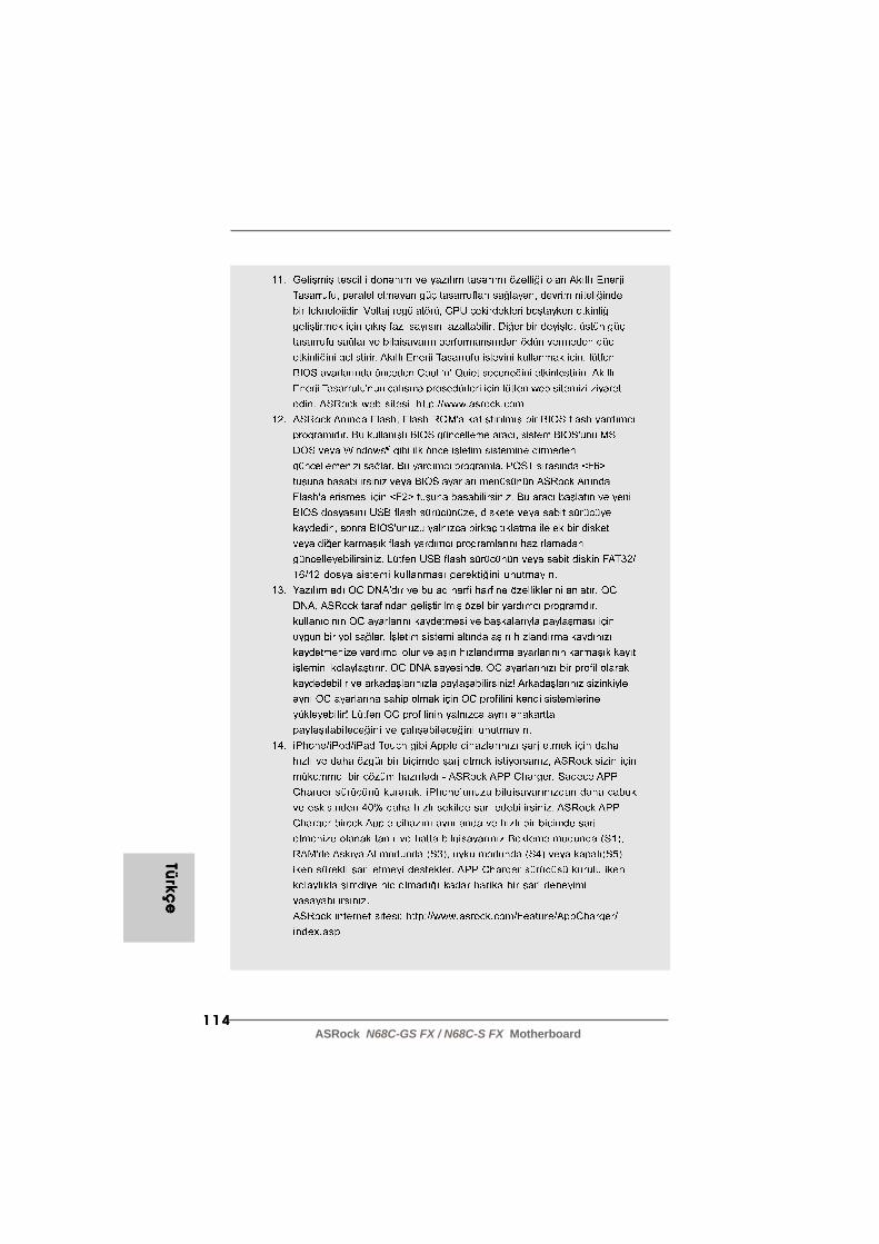
114114114114114ASRock N68C-GS FX / N68C-S FX Motherboard
Türkç
eTü
rkçe
Türkç
eTü
rkçe
Türkç
e

115115115115115ASRock N68C-GS FX / N68C-S FX Motherboard
Türk
çe
Türk
çe
Türk
çe
Türk
çe
Türk
çe
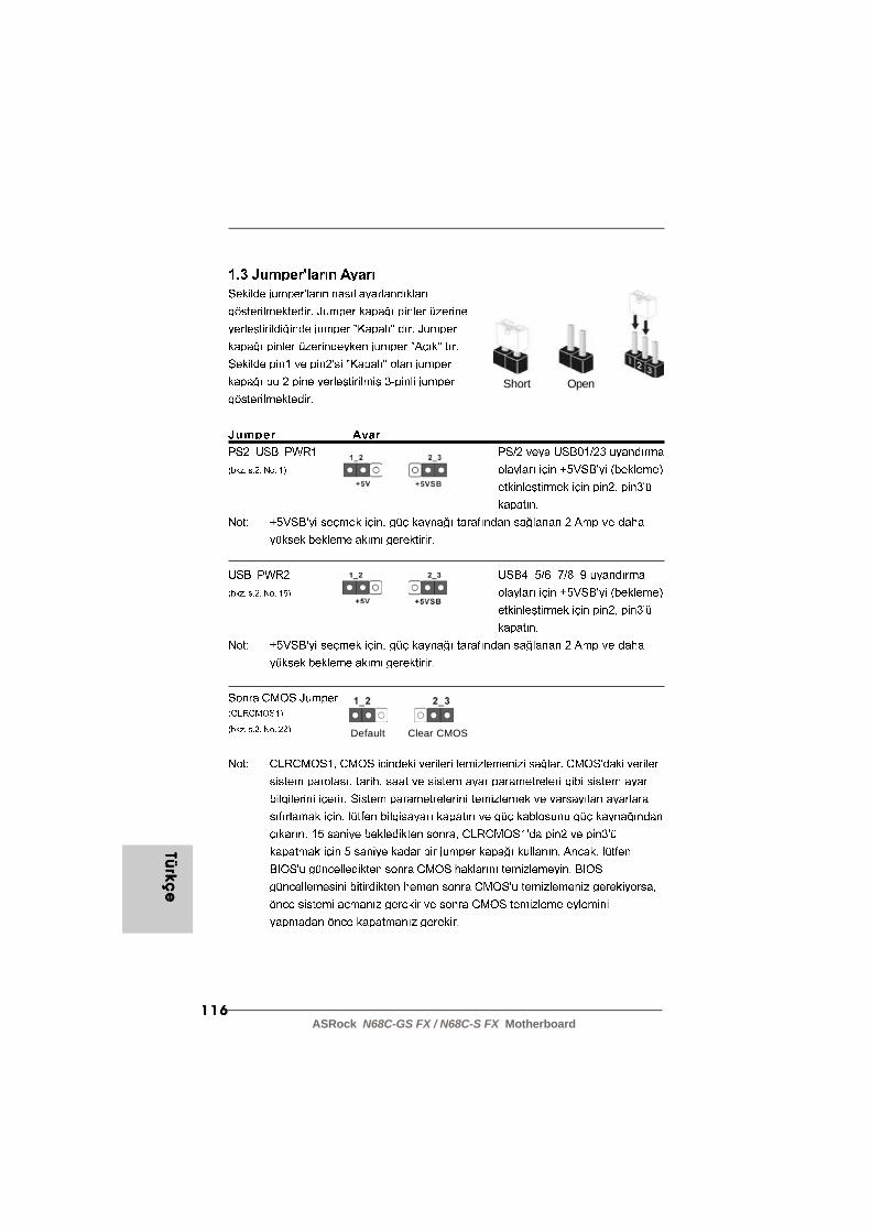
116116116116116ASRock N68C-GS FX / N68C-S FX Motherboard
OpenShort
Clear CMOSDefault
Türkç
eTü
rkçe
Türkç
eTü
rkçe
Türkç
e
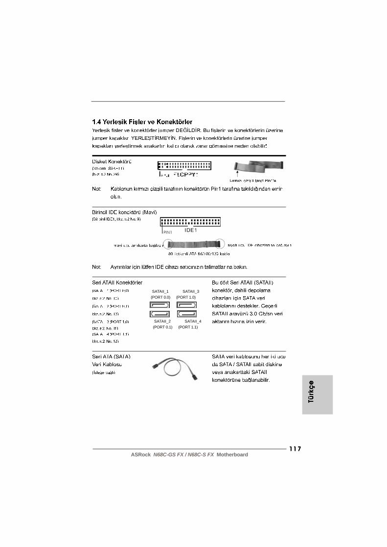
117117117117117ASRock N68C-GS FX / N68C-S FX Motherboard
Türk
çe
Türk
çe
Türk
çe
Türk
çe
Türk
çe
SATAII_1 SATAII_3(PORT 0.0) (PORT 1.0)
SATAII_2 SATAII_4(PORT 0.1) (PORT 1.1)
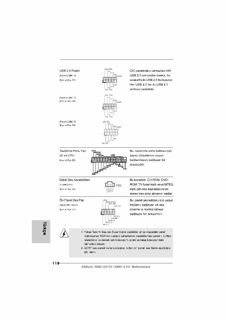
118118118118118ASRock N68C-GS FX / N68C-S FX Motherboard
Türkç
eTü
rkçe
Türkç
eTü
rkçe
Türkç
e
CD
-L
GN
D
GN
D
CD
-R
CD1

119119119119119ASRock N68C-GS FX / N68C-S FX Motherboard
Türk
çe
Türk
çe
Türk
çe
Türk
çe
Türk
çe
12
1
24
13
4 3 2 1

120120120120120ASRock N68C-GS FX / N68C-S FX Motherboard
Türkç
eTü
rkçe
Türkç
eTü
rkçe
Türkç
e
12
1
24
13

121121121121121ASRock N68C-GS FX / N68C-S FX Motherboard
Türk
çe
Türk
çe
Türk
çe
Türk
çe
Türk
çe
122122122122122ASRock N68C-GS FX / N68C-S FX Motherboard

123123123123123ASRock N68C-GS FX / N68C-S FX Motherboard
‘ ’
®
®
®

124124124124124ASRock N68C-GS FX / N68C-S FX Motherboard
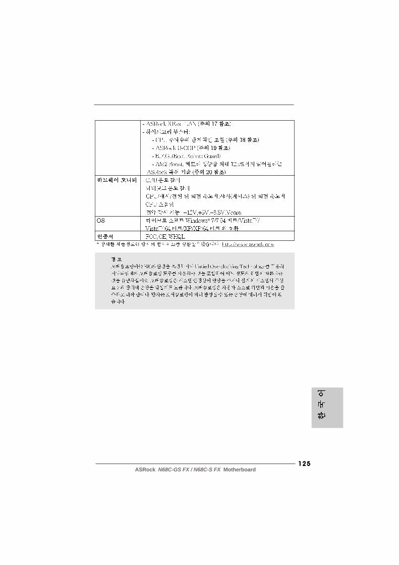
125125125125125ASRock N68C-GS FX / N68C-S FX Motherboard
®
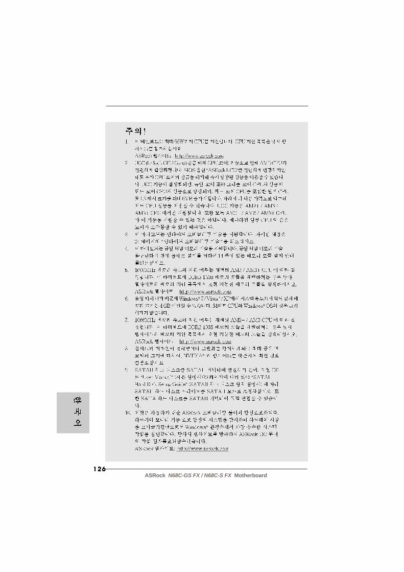
126126126126126ASRock N68C-GS FX / N68C-S FX Motherboard
“ ”
“ ”
®
®
®
“ ” “”
®

127127127127127ASRock N68C-GS FX / N68C-S FX Motherboard
®

128128128128128ASRock N68C-GS FX / N68C-S FX Motherboard
®

129129129129129ASRock N68C-GS FX / N68C-S FX Motherboard
“ ”“ ”
“ ”
“ ”
“ ”
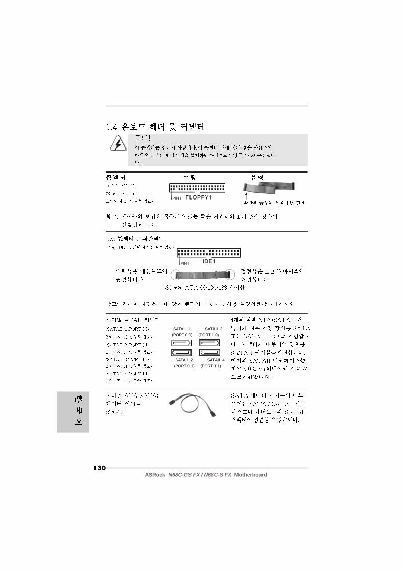
130130130130130ASRock N68C-GS FX / N68C-S FX Motherboard
SATAII_1 SATAII_3(PORT 0.0) (PORT 1.0)
SATAII_2 SATAII_4(PORT 0.1) (PORT 1.1)

131131131131131ASRock N68C-GS FX / N68C-S FX Motherboard
CD
-L
GN
D
GN
D
CD
-R
CD1

132132132132132ASRock N68C-GS FX / N68C-S FX Motherboard
4 3 2 1

133133133133133ASRock N68C-GS FX / N68C-S FX Motherboard
12
1
24
13
12
1
24
13
134134134134134ASRock N68C-GS FX / N68C-S FX Motherboard
“ ”
“ ”
\ \
135135135135135ASRock N68C-GS FX / N68C-S FX Motherboard
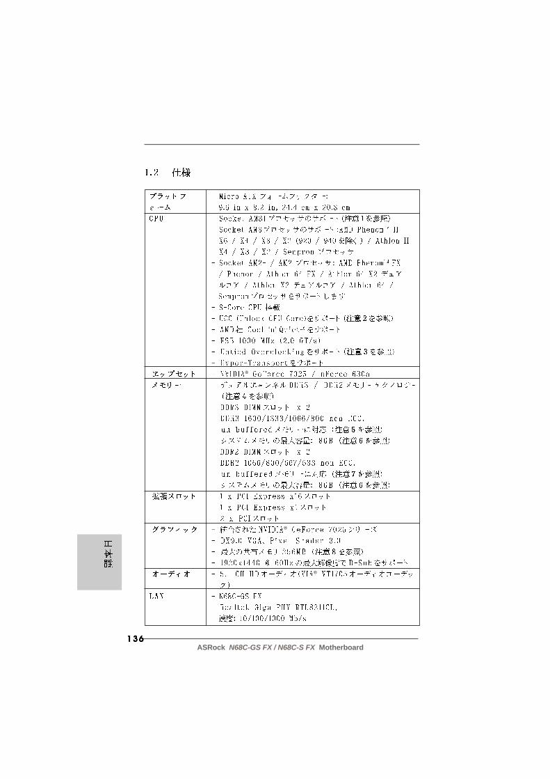
136136136136136ASRock N68C-GS FX / N68C-S FX Motherboard
‘ ’
®
®
®

137137137137137ASRock N68C-GS FX / N68C-S FX Motherboard
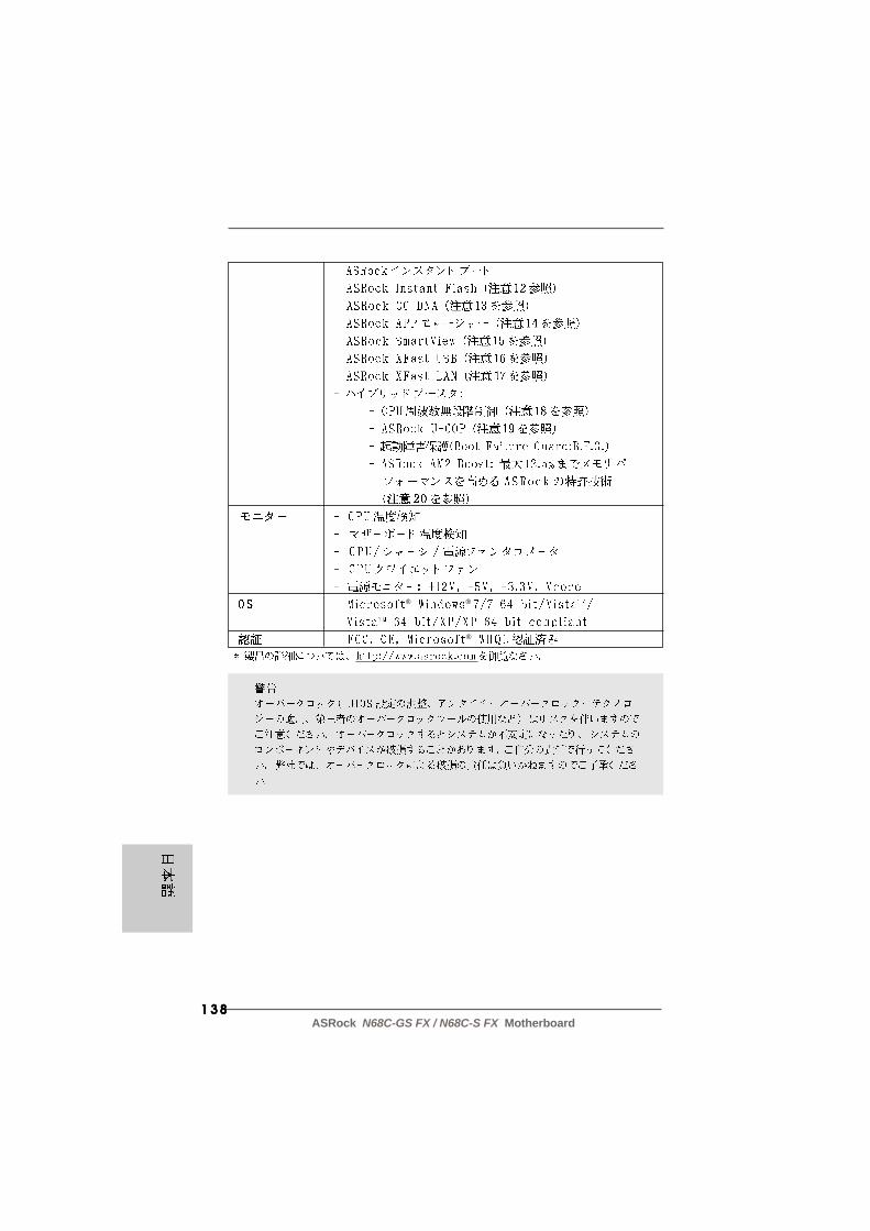
138138138138138ASRock N68C-GS FX / N68C-S FX Motherboard
® ®
®

139139139139139ASRock N68C-GS FX / N68C-S FX Motherboard
“ ”
®
®
®
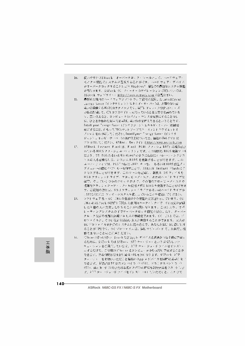
140140140140140ASRock N68C-GS FX / N68C-S FX Motherboard
®
®
–

141141141141141ASRock N68C-GS FX / N68C-S FX Motherboard
®

142142142142142ASRock N68C-GS FX / N68C-S FX Motherboard
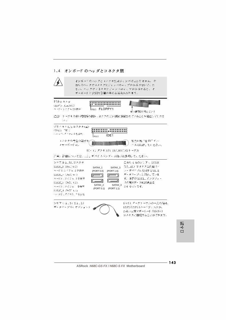
143143143143143ASRock N68C-GS FX / N68C-S FX Motherboard
SATAII_1 SATAII_3(PORT 0.0) (PORT 1.0)
SATAII_2 SATAII_4(PORT 0.1) (PORT 1.1)

144144144144144ASRock N68C-GS FX / N68C-S FX Motherboard
CD
-L
GN
D
GN
D
CD
-R
CD1

145145145145145ASRock N68C-GS FX / N68C-S FX Motherboard
4 3 2 1

146146146146146ASRock N68C-GS FX / N68C-S FX Motherboard
12
1
24
13
12
1
24
13
147147147147147ASRock N68C-GS FX / N68C-S FX Motherboard
® ® TM
TM
148148148148148ASRock N68C-GS FX / N68C-S FX Motherboard

149149149149149ASRock N68C-GS FX / N68C-S FX Motherboard
‘ ’ ™
®
®
®

150150150150150ASRock N68C-GS FX / N68C-S FX Motherboard

151151151151151ASRock N68C-GS FX / N68C-S FX Motherboard
® ®

152152152152152ASRock N68C-GS FX / N68C-S FX Motherboard
® ®
®
®
®

153153153153153ASRock N68C-GS FX / N68C-S FX Motherboard
®

154154154154154ASRock N68C-GS FX / N68C-S FX Motherboard

155155155155155ASRock N68C-GS FX / N68C-S FX Motherboard
SATAII_1 SATAII_3(PORT 0.0) (PORT 1.0)
SATAII_2 SATAII_4(PORT 0.1) (PORT 1.1)

156156156156156ASRock N68C-GS FX / N68C-S FX Motherboard
CD
-L
GN
D
GN
D
CD
-R
CD1

157157157157157ASRock N68C-GS FX / N68C-S FX Motherboard
12
1
24
13
12
1
24
13
4 3 2 1

158158158158158ASRock N68C-GS FX / N68C-S FX Motherboard

159159159159159ASRock N68C-GS FX / N68C-S FX Motherboard
® ®
160160160160160ASRock N68C-GS FX / N68C-S FX Motherboard
X O O O O O
X O O O O O
O:
X:

161161161161161ASRock N68C-GS FX / N68C-S FX Motherboard

162162162162162ASRock N68C-GS FX / N68C-S FX Motherboard
®
®
®

163163163163163ASRock N68C-GS FX / N68C-S FX Motherboard

164164164164164ASRock N68C-GS FX / N68C-S FX Motherboard
® ®

165165165165165ASRock N68C-GS FX / N68C-S FX Motherboard
®
®
®
®
®
166166166166166ASRock N68C-GS FX / N68C-S FX Motherboard
®
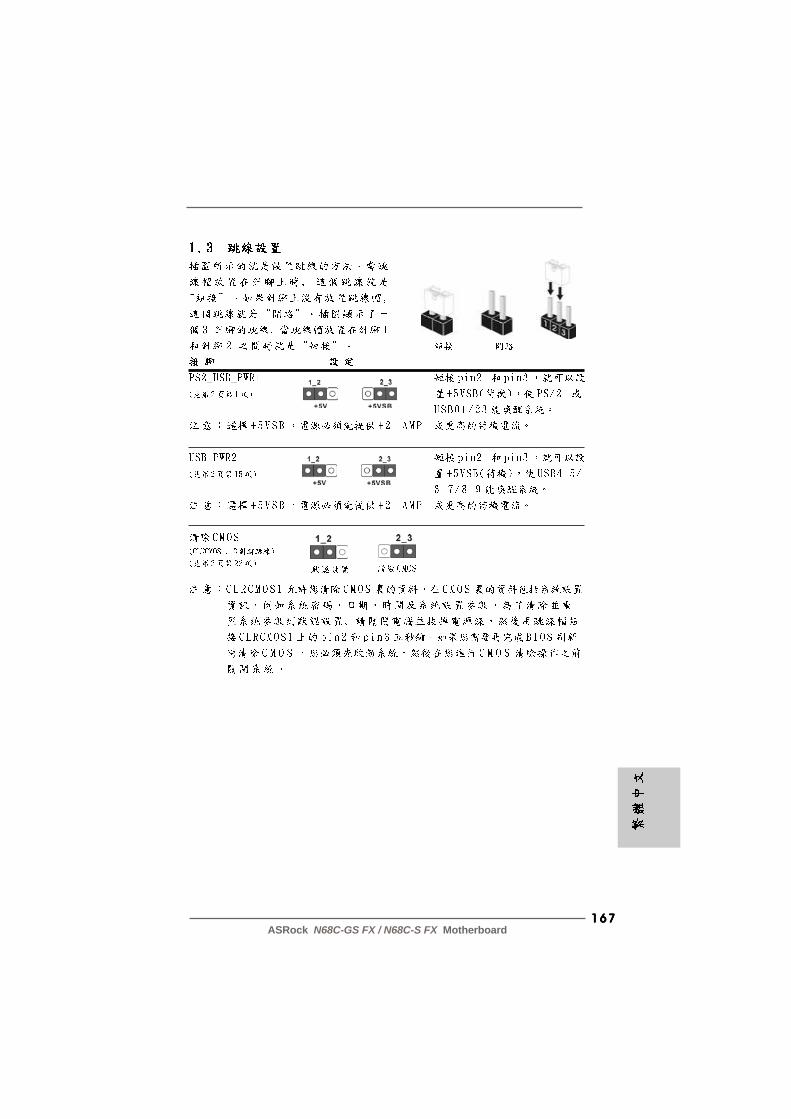
167167167167167ASRock N68C-GS FX / N68C-S FX Motherboard

168168168168168ASRock N68C-GS FX / N68C-S FX Motherboard
SATAII_1 SATAII_3(PORT 0.0) (PORT 1.0)
SATAII_2 SATAII_4(PORT 0.1) (PORT 1.1)
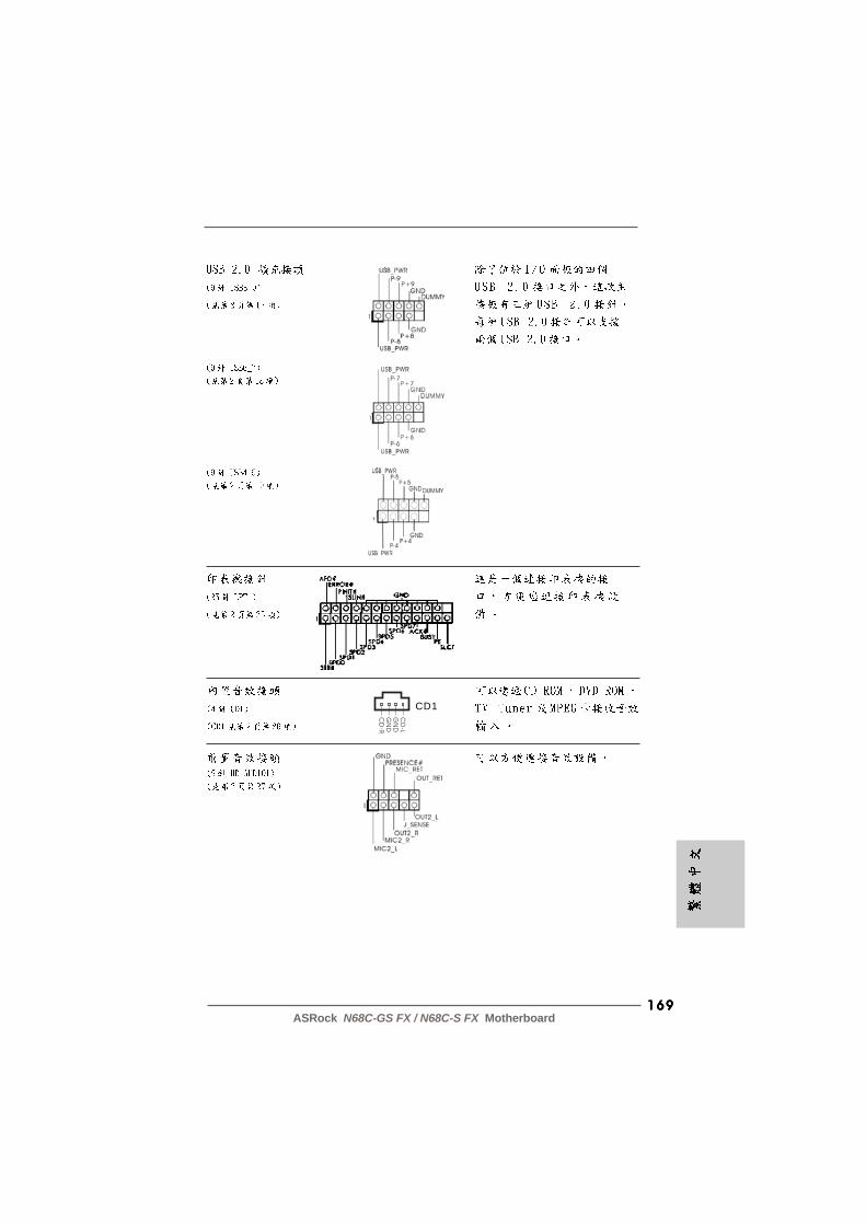
169169169169169ASRock N68C-GS FX / N68C-S FX Motherboard
CD
-L
GN
D
GN
D
CD
-R
CD1
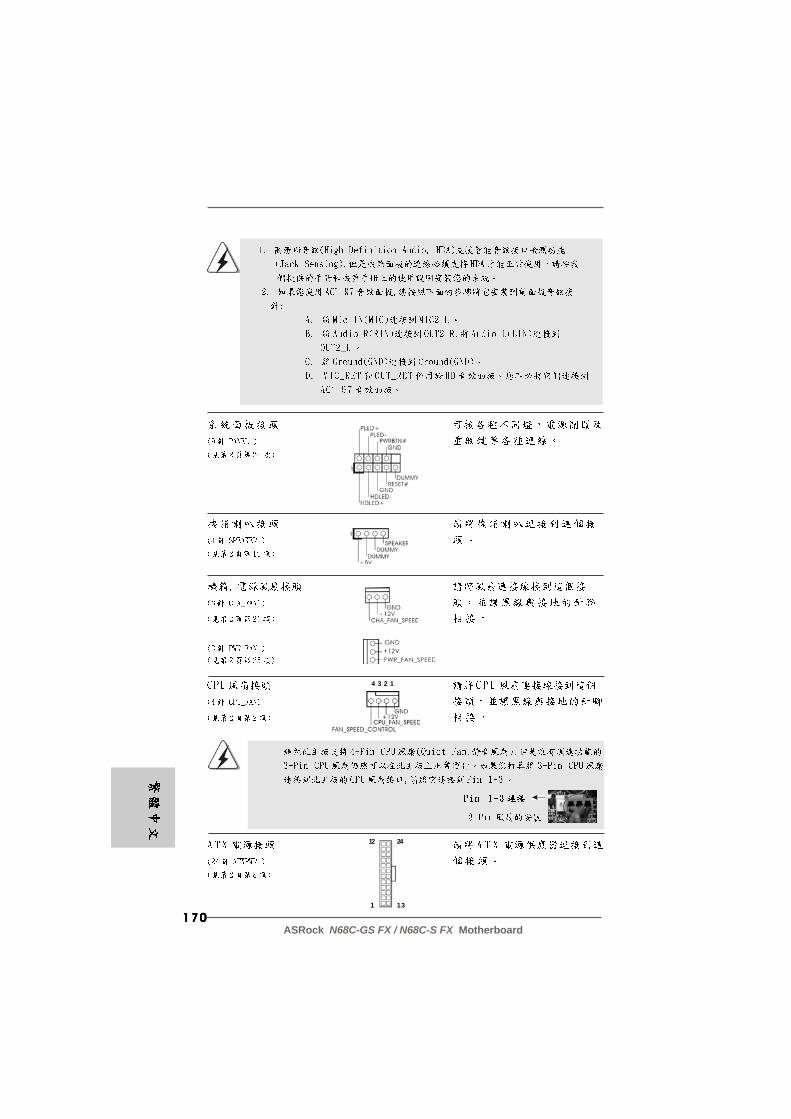
170170170170170ASRock N68C-GS FX / N68C-S FX Motherboard
12
1
24
13
4 3 2 1
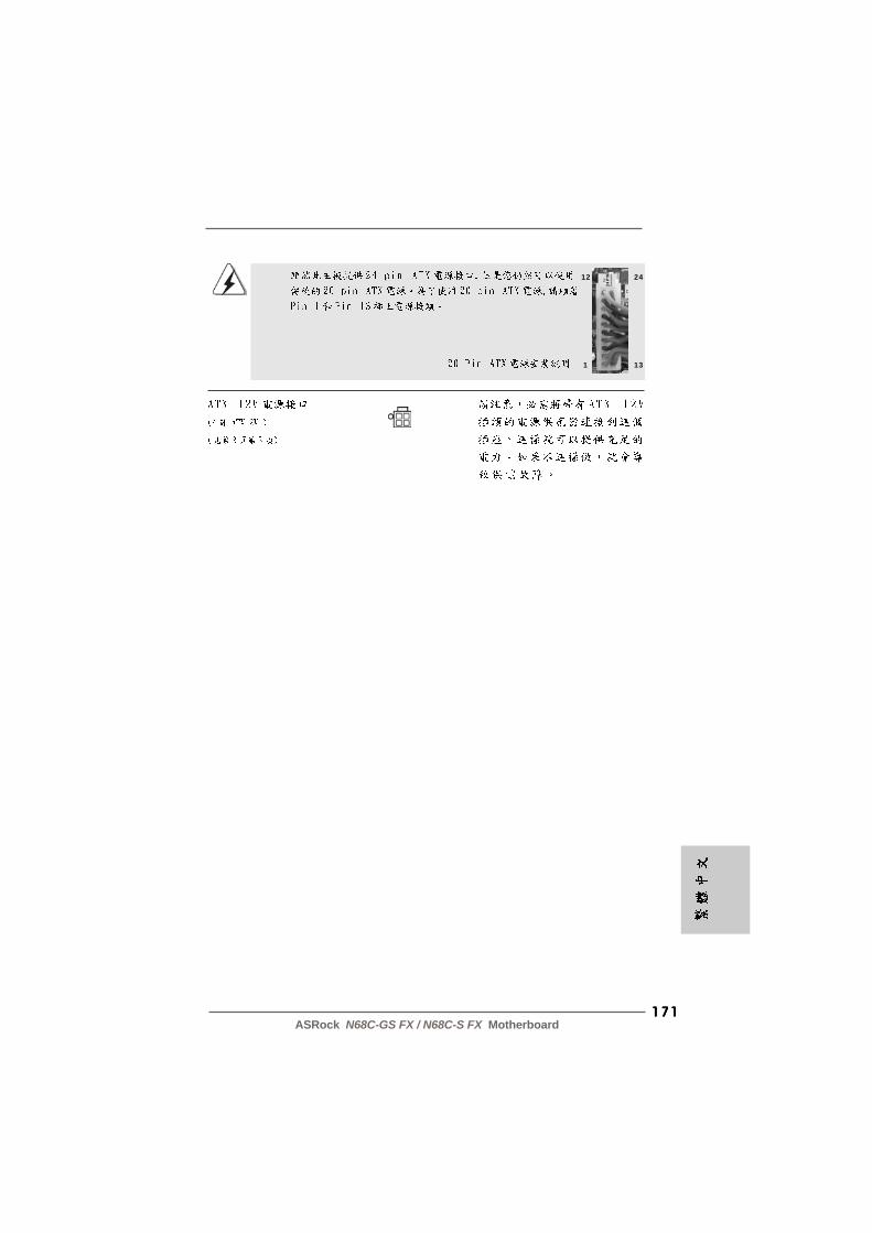
171171171171171ASRock N68C-GS FX / N68C-S FX Motherboard
12
1
24
13

172172172172172ASRock N68C-GS FX / N68C-S FX Motherboard
® ® ®

173173173173173ASRock N68C-GS FX / N68C-S FX Motherboard
1. P1. P1. P1. P1. PenjelasanenjelasanenjelasanenjelasanenjelasanTerimakasih untuk membeli papan induk penghasilan kontrol kualitas keras terus-menerus ASRock’s yang dapat dipercaya. Dia dapat menyajikan pertunjukan baikdengan bentuknya sesuai dengan janji kualitas dan ketahanan ASRock’s.Buku Pedoman Instalasi Cepat ini mengandung perkenalan papan induk dan instalasilangkah-demi-langkah. Informasi lebih terperinci tentang papan induk ini dapat dilihatdalam buku tangan pemakai dalam Support CD.
Karena spesifikasi papan induk dan software BIOS barangkali dapatdiperbarui, isi dalam buku pedoman ini akan mengikuti perubahan tanpaperingatan. Dalam kondisi terjadinya modifikasi buku pedoman ini, versibaru akan diperlihatkan dalam website ASRock tanpa peringatan lebih. Andadapat mendapatkan kartukartu yang paling baru dan daftar bantuan CPUpada website ASRock.Website ASRock http://www.asrock.com
1.1 Isi P1.1 Isi P1.1 Isi P1.1 Isi P1.1 Isi PakakakakaketetetetetPapan Induk N68C-GS FX/ N68C-S FX ASRock (Faktor Form Mikro ATX: 9.6-in x 8.2-in, 24.4 cm x 20.8 cm)Pemimpin Instalasi Cepat N68C-GS FX/ N68C-S FX ASRockSupport CD N68C-GS FX/ N68C-S FX ASRock2 x Kabel satu serial Data ATA (SATA) (bebas-pilih)1 x Satu Pelindung I/O
Ba
ha
saB
ah
asa
Ba
ha
saB
ah
asa
Ba
ha
saIn
do
ne
sia
Ind
on
esi
aIn
do
ne
sia
Ind
on
esi
aIn
do
ne
sia

174174174174174ASRock N68C-GS FX / N68C-S FX Motherboard
Ba
ha
saB
ah
asa
Ba
ha
saB
ah
asa
Ba
ha
saIn
do
ne
siaIn
do
ne
siaIn
do
ne
siaIn
do
ne
siaIn
do
ne
sia
1 .21 .21 .21 .21 .2 Spesif ikasiSpesif ikasiSpesif ikasiSpesif ikasiSpesif ikasi
Podium - Faktor Form Mikro ATX: 9.6-in x 8.2-in, 24.4 cm x 20.8 cm CPU - Stopkontak AM3+
- Stopkontak AM3 untuk AMD PhenomTM II X6 / X4 / X3 / X2 (kecuali 920 / 940) / Athlon II X4 / X3 / X2 / Sempron processor- Stopkontak AM2+ / AM2 untuk AMD PhenomTM FX / Phenom / Athlon 64FX / Athlon 64 X2 Dual-Core / Athlon X2 Dual-Core / Athlon X2 Dual-Core / Athlon 64 / Sempron processor- Dukungan CPUT Delapan Inti- Menggunakan Teknologi UCC (Unlock CPU Core)- Dapat digunakan AM’s Cool ‘n’ QuietTM Technology- FSB 1000 MHz (2.0 GT/s)- Menggunakan Teknologi Untied Overclocking- Dapat digunakan Hyper-Transport Technology
Grup Chip - NVIDIA® GeForce 7025 / nForce 630a Ingatan - Teknologi ingatan DDR3/DDR2 dwisaluran
- 2 x Alur DDR3 DIMM- Menggunakan DDR3 1600/1333/1066/800- Kapasitas paling banyak: 8GB- 2 x Alur DDR2 DIMM- Menggunakan DDR2 1066/800/667/533- Kapasitas paling banyak: 8GB
Alur Ekspansi - 1 x PCI Express x16 slot- 1 x PCI Express x1 slot- 2 x Alur PCI
Diagram - Integrated NVIDIA® GeForce 7025 graphics- DX9.0 VGA, Pixel Shader 3.0- Ingatan sama Max. 256MB- Mendukung D-Sub dengan resolusi maksimal hingga 1920x1440 @ 60Hz
Audio - 5.1 CH HD Audio (VIA® VT1705 Audio Codec) LAN - N68C-GS FX
Realtek Giga PHY RTL8211CL, Kecepatan 10/100/1000 Mb/s- N68C-S FX Realtek PHY RTL8201EL, Kecepatan 10/100 Mb/s- Menggunakan Wake-On-LAN- Menggunakan PXE
Papan Belakang I/O Panel I/O - 1 x Port Mouse PS/2
- 1 x Port Keyboard PS/2

175175175175175ASRock N68C-GS FX / N68C-S FX Motherboard
- 1 x Port Serial: COM1- 1 x Port VGA- 4 x Port USB 2.0 siap-dipakai- 1 x RJ-45 LAN Port LED (ACT/LINK LED dan SPEED LED)- HD Audio Jack: Line in/Penyuara Depan/mikropon
Penghubung - 4 x penghubung SATA2 3.0Gb/s, dapat digunakan RAID (RAID 0, RAID 1, RAID 0+1, RAID 5, JBOD), NCQ dan fungsi fungsi “Hot Plug”- 1 x Penghubung ATA133 IDE (menggunakan perlengkapan 2 x IDE)- 1 x Penghubung Floppy- 1 x port header Print- Penghubung KIPAS CPU/Casis/Power- Penghubung power 24 pin ATX- Penghubung power 4 pin 12V- CD dalam header- Penghubung audio panel dapan- 3 x USB 2.0 header (menggunakan 6 port USB 2.0)
Ciri-ciri BIOS - 8Mb AMI BIOS- AMI Legal BIOS- Menggunakan “Plug and Play”- ACPI 1.1 Compliance Wake Up Events- Menggunakan jumperfree- Penyokong AMBIOS 2.3.1- Penyesuaian berbagai tegangan CPU, VCCM, NB
Sokongan CD - Driver, Utilitas, Perangkat Lunak Anti Virus (Versi Percobaan), CyberLink MediaEspresso 6.5 Trial, ASRock Software Suite (CyberLink DVD Suite - OEM dan Trial; Creative Sound Blaster X-Fi MB - Trial; ASRock MAGIX Multimedia Suite - OEM)
Fitur Unik - ASRock OC Tuner- ASRock Penghemat Energi Pintar- ASRock Instant Boot- ASRock Instant Flash- ASRock OC DNA- ASRock APP Charger- ASRock SmartView- ASRock XFast USB- ASRock XFast LAN- Hybrid Booster:
- Kontrol tanpa langkah Frekwensi CPU- ASRock U-COP- Penjaga kegagalan input (B.F.G.)
Ba
ha
saB
ah
asa
Ba
ha
saB
ah
asa
Ba
ha
saIn
do
ne
sia
Ind
on
esi
aIn
do
ne
sia
Ind
on
esi
aIn
do
ne
sia
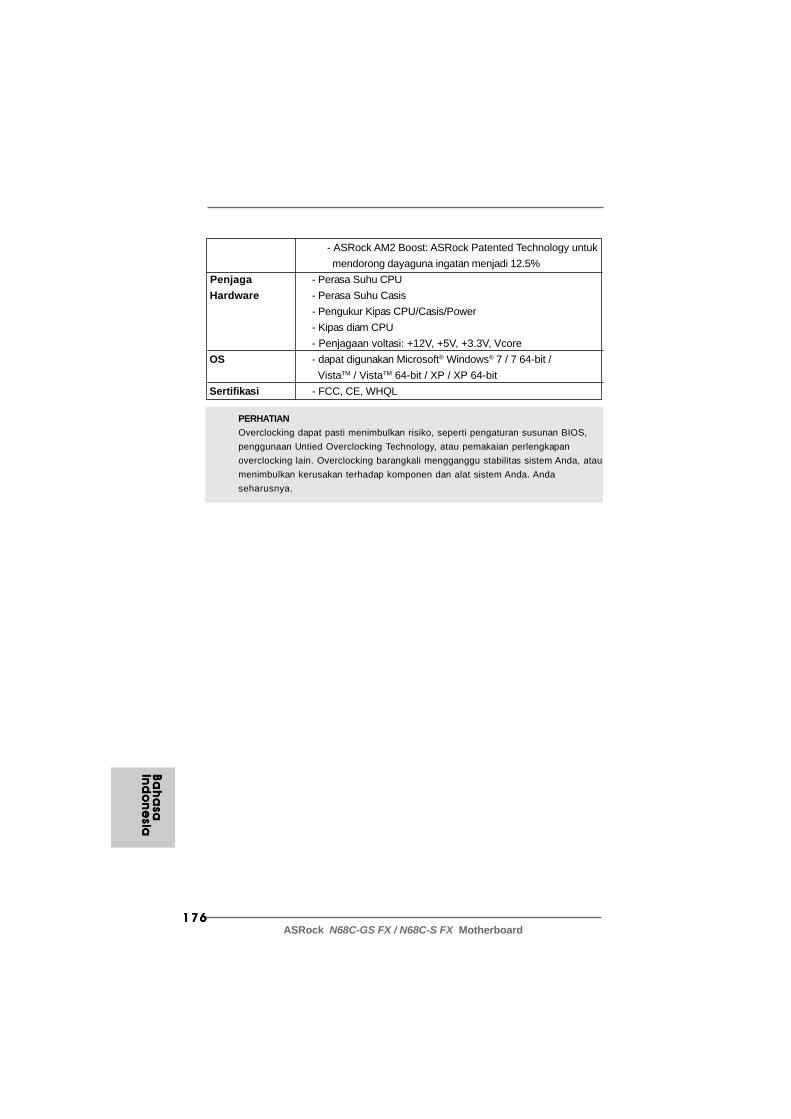
176176176176176ASRock N68C-GS FX / N68C-S FX Motherboard
PERHATIANOverclocking dapat pasti menimbulkan risiko, seperti pengaturan susunan BIOS,penggunaan Untied Overclocking Technology, atau pemakaian perlengkapanoverclocking lain. Overclocking barangkali mengganggu stabilitas sistem Anda, ataumenimbulkan kerusakan terhadap komponen dan alat sistem Anda. Andaseharusnya.
- ASRock AM2 Boost: ASRock Patented Technology untuk mendorong dayaguna ingatan menjadi 12.5%
Penjaga - Perasa Suhu CPU Hardware - Perasa Suhu Casis
- Pengukur Kipas CPU/Casis/Power- Kipas diam CPU- Penjagaan voltasi: +12V, +5V, +3.3V, Vcore
OS - dapat digunakan Microsoft® Windows® 7 / 7 64-bit / VistaTM / VistaTM 64-bit / XP / XP 64-bit
Sertifikasi - FCC, CE, WHQL
Ba
ha
saB
ah
asa
Ba
ha
saB
ah
asa
Ba
ha
saIn
do
ne
siaIn
do
ne
siaIn
do
ne
siaIn
do
ne
siaIn
do
ne
sia