MyLab SAFETY AND STANDARDS
50
Rev. 14 November 2020 MyLab SAFETY AND STANDARDS 141004300
-
Upload
khangminh22 -
Category
Documents
-
view
0 -
download
0
Transcript of MyLab SAFETY AND STANDARDS

Rev. 14
November 2020
MyLab
SAFETY AND STANDARDS
141004300

MyLab - S A F E T Y A N D S T A N D A R D S
ii

MyLab - S A F E T Y A N D S T A N D A R D S
Introduction
WARNING In this manual a WARNING pertains to possible injuries to the patient and/or the operator.
CAUTION A CAUTION describes the precautions which are necessary to protect theequipment.
Be sure that you understand and observe each of the cautions and warnings.
Keep the manual with equipment for future reference.
iii

MyLab - S A F E T Y A N D S T A N D A R D S
iv

MyLab - S A F E T Y A N D S T A N D A R D S
SAFETY
AN
D
STAN
DA
RD
S
Table of Contents1 Operator’s Safety ............................................................................... 1-1
Installation Requirements ..................................................................................1-1Electrical Safety ...................................................................................................1-1Wireless safety .....................................................................................................1-2Environmental Safety.........................................................................................1-2
Information about Reusing/Recycling.......................................................1-2Exam Waste....................................................................................................1-3
Moving the Equipment......................................................................................1-3Explosive Hazard................................................................................................1-4Probes ...................................................................................................................1-4Biocompatibility and Infection Control ..........................................................1-6Repetitive Strain Injury ......................................................................................1-6Working with Video Display.............................................................................1-6Wireless.................................................................................................................1-7Wireless Requirements .......................................................................................1-8Device Modifications .......................................................................................1-14
2 Patient’s Safety ..................................................................................2-1Electrical Safety ...................................................................................................2-1Electromagnetic Compatibility .........................................................................2-2
Electro-Surgical Devices (ESUs) ...........................................................2-2Biocompatibility and Infection Control ..........................................................2-3
Items in Contact with Patient......................................................................2-3Latex Sensitive Patient ..................................................................................2-3
Probes Superficial Temperature .......................................................................2-3Ultrasound Safety................................................................................................2-4
Introduction ...................................................................................................2-4Clinical Safety .................................................................................................2-4Ultrasound Bioeffects ...................................................................................2-5On-screen Real-Time Acoustic Output Display.......................................2-5The Mechanical Index ..................................................................................2-6The Thermal Index .......................................................................................2-7Acoustic Output Display..............................................................................2-7The Output Display ......................................................................................2-8The Output Default Settings .......................................................................2-8Methodology and Accuracy of Display......................................................2-8Maximum Acoustic Output .........................................................................2-9Acoustic Output Controls..........................................................................2-10
Controls Which Directly Affect the Intensity ...................................2-10Controls Which Indirectly Affect the Intensity.................................2-10
Implementing ALARA with MyLab.........................................................2-12
v
MyLab - S A F E T Y A N D S T A N D A R D S
SAFETY
AN
D
STAN
DA
RD
S
Which Index When................................................................................2-12Acoustic Output Tables..............................................................................2-13British Medical Ultrasound Society (BMUS) recommendation ...........2-13
Exposure time.........................................................................................2-13Stationary probe .....................................................................................2-14Probe self-heating ..................................................................................2-14
Glossary and Definition of Terms .................................................................2-14“In Situ” Intensities Calculations ..............................................................2-14Definition of Terms ....................................................................................2-15Indices Equations ........................................................................................2-16Symbols Used in Indices Equations .........................................................2-17
3 Devices Standards .............................................................................3-1Medical Device Directive ..................................................................................3-1Medical Electrical Equipment Standard ..........................................................3-1Electromagnetic Compatibility .........................................................................3-1
Users in the United States of America..................................................3-2Users in Australia .....................................................................................3-2
Biocompatibility ..................................................................................................3-2Acoustic Output..................................................................................................3-2Peripherals Standard Requirements .................................................................3-3
Safety ...............................................................................................................3-3Electromagnetic Compatibility....................................................................3-3
4 Device Labels ....................................................................................4-1Equipment Labels...............................................................................................4-1Packaging Labels .................................................................................................4-6
vi

MyLab - S A F E T Y A N D S T A N D A R D S Chapter
1SA
FETY A
ND
STA
ND
AR
DS
1-Operator’s SafetyInstallation Requirements
GS The “Getting Started” manual provides detailed instructions to correctly install andconnect your specific MyLab model. The same manual also contains all informationon the recommended peripherals that may be connected to the system.
If help is needed, Esaote personnel will be glad to provide the necessary assistanceto install the system.
WARNING An incorrect installation of the system may cause hazards for the operator.Carefully follow the instructions given in MyLab “Getting Started” manualto install the device.
Electrical SafetyThe equipment label, placed on the rear panel, specifies the device electricalrequirements. Incorrect connections to the main power may compromise theelectrical safety of the system.
Observe the following warnings for maximum safety.
WARNING Electrical shock hazard. Do not remove the system or the monitor cover.Refer servicing and internal adjustments to qualified Esaote personnelonly.
WARNING Always turn the equipment off before cleaning it.
Observe these precautions to prevent damage to your system.
CAUTION To prevent further damage to your system and the accessories, turn thepower off if the system does not start up correctly.
1 - 1

MyLab - S A F E T Y A N D S T A N D A R D S
CAUTION If your system incorporates an LCD and/or a touchscreen, remember thatthe screen is fragile and must be treated accordingly.
Wireless safetyThe following safety precautions should be observed:
If the equipment is not installed and used in accordance withthe instructions, the equipment may cause harmfulinterference to radio communications.
Do not hold the equipment very close to the body whiletransmitting. A minimum distance of 20 cm (8 inches) ormore should be maintained.
Use in specific environments:
the use of wireless devices in hazardous locations islimited by the constraints posed by the safety directive ofsuch environments,
the use of wireless devices in hospitals is restricted to thelimits set forth by each hospital.
There are restrictions for usage in the EU countries. The equipment can beoperated indoors in European countries without restrictions. See Chapter 3,Device Standard.
CAUTION The equipment is capable of operating at 100mW across the whole of thefrequency band (2400-2483.5 MHz).
Environmental SafetyInformation about Reusing/Recycling
This symbol identifies a recyclable component. Depending on the size of therecyclable component, Esaote prints on it this symbol and the indication of thematerial it is made of.
In this system, packing materials are reusable and recyclable; the casings of thesystem and the monitor (plastics) and most of the cart components (plastics) arealso recyclable.
1 - 2

MyLab - S A F E T Y A N D S T A N D A R D S
SAFETY
AN
D
STAN
DA
RD
S
GS Refer to the MyLab “Getting Started” manual for any additional information onspecial waste that has to be disposed of according to local regulations.
Exam Waste
Consider any exam waste as potentially infectious and dispose of it accordingly
Moving the Equipment GS MyLab systems are designed to be easily moved by the operator. However, due to
the equipment weight, assistance could be needed during transportation. TheMyLab “Getting Started” manual details the weight and dimensions of eachconfiguration.
MyLab products can be classified as portable and mobile:
Portable means that the system is equipped with a handle,whose size and weight allow it to be used to carry the system.The term “portable” is always used with this meaning inthese manuals.
A mobile model or configuration is equipped with wheelsallowing to carry the system from one room to another. Theterm “mobile” is always used with this meaning in thesemanuals.
Portable The console can be carried directly by its handle; observe the followingprecautions:
make sure the console is turned off,
if built-in, make sure the system screen is secured before andduring transportation,
disconnect any cable or item (probes, ECG cable) attached tothe system,
should the console need to be put on the ground, lay it flat,
secure the system in a flat position, if transporting it in avehicle.
Mobile Configuration
The MyLab system complies with EN60601-1: it is not unbalanced by a 10°inclination. Observe the following precautions when transporting the system:
1 - 3

MyLab - S A F E T Y A N D S T A N D A R D S
make sure the system is turned off,
unlock the cart’s wheels before moving the system,
avoid unnecessary shocks to the system when rolling it overdoor jambs or in and out of elevators,
when transporting the system with the probes attached, makesure the cables are not dragging on the floor and that theprobes are properly positioned in the cart’s probe holder,
always use the handle to move the system. Never push thesystem from its sides.
Transportation in Vehicle
Observe the following precautions when transporting the system in a vehicle:
disconnect any cable or item (for example probes, ECGcable) attached to the system and place the probes in theircases,
a portable model should be packed in the original shipmentcase (or other protective devices as available through Esaote)during transportation,
for mobile systems, make sure the cart wheels are blockedand the cart secured during transportation.
Explosive Hazard
WARNING The equipment is not suitable for use in the presence of a flammableanaesthetic mixture with air, oxygen or nitrous oxide. Do not use thesystem in the presence of flammable anaesthetics. Explosion is a hazardunder such conditions.
Probes GS and AO Use only Esaote approved probes with the equipment. The MyLab “Getting
Started” manual lists the probes which can be connected to the system. The MyLab“Advanced Operations” manual explains system related special features, whenapplicable.
PC The “Probes and Consumables” manual treats all aspects concerning probecleaning and disinfecting.
1 - 4

MyLab - S A F E T Y A N D S T A N D A R D S
SAFETY
AN
D
STAN
DA
RD
S
WARNING Damage caused by dropping a probe, striking it against another object,pinching, kinking or twisting the cable are not covered by the warranty.
If a probe is dropped or suffered an impact against another object, do notuse it until an electrical leakage current measurement test hasdemonstrated that the electrical safety has not been compromised.
Do not immerse the entire probe in liquid to clean it. The probe is notwatertight and immersion may compromise the electrical safety features ofthe probe.
Observe these precautions to prevent damage to your system
CAUTION Never expose the probes to gas, heat or liquid sterilization procedures.These methods can permanently damage the probe.
Do not connect or disconnect an active probe during live scanning; thesystem must be in freeze mode or turned off to connect or disconnect aprobe.
Carefully follow the “Probes and Consumables” manual instructions toclean or disinfect a probe.
1 - 5

MyLab - S A F E T Y A N D S T A N D A R D S
Biocompatibility and Infection Control PC Probes and electrodes intended to be used on intact skin have very limited
probabilities to propagate infections; basic procedures as described in the “Probesand Consumables” manual are sufficient for infection control.
Endocavity and transesophageal probes require specific cleaning and disinfectingprocedures. See the “Probes and Consumables” manual for complete details onthese procedures.
Repetitive Strain InjuryIn the category of occupational diseases, musculoskeletal disorders have beenreported by the clinical literature1 as a result of repetitive scanning. Thesemusculoskeletal disorders are also referred to as Repetitive Strain Injury (RSI). Toprevent the risk of RSI, it has been recommended:
to maintain a balanced position while scanning,
not to grip the probe with excessive force,
to take work breaks to allow muscles to relax,
to introduce routine exercises such as gentle passivestretching.
Working with Video DisplayScanning can require long sessions in front of a screen. Consequently visualproblems such as eyestrain and irritation can result2. Visual discomfort is reducedwhen the following recommendations are observed:
orientate the display so that it can be comfortably observedwhile scanning,
take rest breaks after a long scanning session.
1. Necas M. “Musculoskeletal symptomatology and Ripetitive Strain Injuries in Diagnostic Medical Sonographers”, Journal of Diagnostic Medical Sonography 12, p. 266-273, 1996Pike I, Russo A., Berkowitz J et al. “the prevalence of musculoskeletal disorders among Diagnostic Medical Sonographers”, Journal of Diagnostic Medical Sonog-raphy 13, p. 219-227, 1997
2. See for example OSHA 3092 “Working safely with video terminals display” 1997
1 - 6

MyLab - S A F E T Y A N D S T A N D A R D S
SAFETY
AN
D
STAN
DA
RD
S
WirelessMyLab can be equipped with built-in or optional wireless capability:
MyLab complies with the Radio Equipment Directive 2014/53/EU and is CEmarked.
MyLab is a device in Class 2 according to RED Directive.
Model Wireless
MyLab 6 eHD Built-in
MyLab 6 eXP Built-in
MyLab 7 eHD Built-in
MyLab 7 eXP Built-in
MyLab 8 Family Optional
MyLab 9 Family Built-in
MyLabOne Built-in
MyLabAlpha Built-in
MyLabGamma Built-in
MyLabSix Built-in
MyLabSix CrystaLine Built-in
MyLabSeven Built-in
MyLabX5 Built-in
MyLabX6 Built-in
MyLabX7 Family Built-in
MyLabX8 Family Built-in
MyLab XPro80 Built-in
MyLabSigma Built-in
MyLabOmega Built-in
MyLab XPro30 Built-in
MyLabSigma elite Built-in
MyLabDelta Built-in
MyLabTwice Optional
MyLabClass Optional
MyLabEight Optional
MyLabEight eXP Optional
1 - 7

MyLab - S A F E T Y A N D S T A N D A R D S
If MyLab is equipped with wireless capability, be informed that:
whenever the system is used in a hospital, the use of wirelessdevices might be restricted.
wireless devices can operate in European countries withoutrestrictions indoor. Refer to local regulations for furtherinformation.
Indoor use only in the frequency range of 5150-5350 MHz.
WARNING The use of wireless devices might be restricted in certain locations: alwaysverify local regulations before using them.
Wireless RequirementsThe presence of one of the following labels indicates that MyLab is equipped withbuilt-in wireless capability:
1 - 8

MyLab - S A F E T Y A N D S T A N D A R D S
SAFETY
AN
D
STAN
DA
RD
S
1 - 9

MyLab - S A F E T Y A N D S T A N D A R D S
WARNING This device generates and radiates radio-frequency energy. A minimumbody-to-antenna distance of 20 cm must be maintained when the device isinstalled and operated. The antennas are located on the MyLab systemswhere indicated by the red circle in the next figures.
Fig. 1-1: Wire less antenna posi t ion on MyLabOne
1 - 10

MyLab - S A F E T Y A N D S T A N D A R D S
SAFETY
AN
D
STAN
DA
RD
S
Fig. 1-2: Wire less antenna posi t ion on MyLabAlpha, MyLabOmega and MyLab XPro30,
Fig. 1-3: Wire less antenna posi t ion on MyLabGamma, MyLabSigma and MyLabSigma el i te
Fig . 1-4: Wire less antenna posi t ion on MyLabSeven, MyLab 7 eHD, MyLab 7 eXP, MyLabX6, MyLabX7 Family (both r ight and le f t edges)
1 - 11

MyLab - S A F E T Y A N D S T A N D A R D S
Fig. 1-5: Wire less antenna posi t ion on MyLabSix, MyLabSix CrystaLine,MyLab 6 eHD, MyLab 6 eXP, MyLabX5
Fig. 1-6: Wire less antenna posi t ion on MyLabDelta
1 - 12

MyLab - S A F E T Y A N D S T A N D A R D S
SAFETY
AN
D
STAN
DA
RD
S
Fig. 1-7: Wire less antenna posi t ion on MyLab 9 and MyLab 9eXP
Fig. 1-8: Wire less antenna posi t ion on MyLabX8 Family and MyLab XPro80
1 - 13

MyLab - S A F E T Y A N D S T A N D A R D S
Device ModificationsEsaote is not responsible for any unauthorized modification of equipment(including cables) and/or probes.
WARNING Do not modify any Esaote equipment without authorization. Always referto Esaote personnel for authorized modifications of the device.
If the equipment has been modified, appropriate inspections and testingmust be carried out to ensure the continued safe use of the equipment.
1 - 14
MyLab - S A F E T Y A N D S T A N D A R D S Chapter
2SA
FETY A
ND
STA
ND
AR
DS
2-Patient’s SafetyElectrical SafetyObserve the following warnings for maximum safety.
WARNING The system must be properly grounded to prevent shock hazards.Protection is provided by grounding the chassis with a three-wire cable andplug; the system must also be powered through a properly groundedreceptacle.
Do not replace the system fuses with different types from those specified bythe MyLab “Getting Started” manual.
Mobile configurations provide insulated plugs and connectors to manageoptional hard copy devices (VTR, printers). Follow the instructions in the“Getting Started” manual to install such a device. Incorrect connectionsmay compromise the electrical safety of the system.
If the operator plans to use hard-copy devices with a portable model, readand carefully follow the instructions in the “Getting Started” manual toinstall such devices. Incorrect connections or use of peripherals withimproper safety characteristics may compromise the electrical safety of thesystem.
MyLab models are not watertight and provide a class IP(X)0 degree ofprotection to liquids; do not expose the system to rain or moisture. Avoidplacing liquid containers on the system.
Remove probes and electrocardiography leads from patient contact beforeapplying a high voltage defibrillation pulse.
MyLab systems use high frequency signals. Pacemakers could interfere withthese signals. The user should be aware of this minimal potential hazardand immediately turn the system off if interference with the pacemakeroperation is noted or suspected.
2 - 1

MyLab - S A F E T Y A N D S T A N D A R D S
While using the system in combination with high frequency devices (likeelectro-surgical devices), be aware that a failure in the surgical device or adamage to the transducer lens can cause electro-surgical currents that canburn the patient. Thoroughly check the system and the probe beforeapplying HF surgical currents to the patient. Disconnect the probe whennot imaging.
Electromagnetic CompatibilityUltrasound systems require special precautions regarding EMC and must beinstalled and put into service according to the provided information.
Sensitivity to interference is more noticeable in Doppler modes.
Ultrasound systems are designed to generate and receive radiofrequency (RF)energy and are, therefore, susceptible to other RF sources. As an example, othermedical devices, information technology products or TV/radio transmitters maycause interference with the ultrasound system.
In the presence of RF interference, the physician must evaluate the imagedegradation and its diagnostic impact.
WARNING Portable and mobile RF communication equipment may causeinterference with the ultrasound system. Do not use these devices inproximity of ultrasound equipment.
Use of accessories and cables other than those specified in the MyLab“Getting Started” manual may result in increased emission or decreasedimmunity of the system.
The “Getting Started” manual provides the table with equipment distance requirements.
If an ultrasound system causes interferences (which can be identified by turning thesystem off and on) with other devices, the user could try to solve the problem by:
relocating the system,
increasing the distance from other devices,
powering the ultrasound system from an outlet differentfrom the one of the interfering device,
contacting Esaote Service personnel for help.
Electro-Surgical Devices (ESUs)Electro-surgical devices or other devices that introduce radiofrequencyelectromagnetic fields or currents into the patient may interfere with the ultrasound
2 - 2

MyLab - S A F E T Y A N D S T A N D A R D S
SAFETY
AN
D
STAN
DA
RD
S
image. An electro-surgical device in use during ultrasound imaging will grosslyaffect the 2D image and render Doppler modalities useless.
Biocompatibility and Infection Control PC Before each exam properly clean the probes. Refer to the “Probes and
Consumables” manual for further details on cleaning and disinfecting probes, kitsand electrodes.
Items in Contact with Patient
Esaote probes and electrodes materials that are in contact with the patient havebeen proved to comply with EN ISO 10993 “Biocompatibility TestsRequirements”, according to their intended use. No negative reactions to thesematerials have been reported.
Latex Sensitive Patient
The USA Food and Drug Administration (FDA) has issued an alert on productscomposed of latex, because of reports of severe allergic reactions.
WARNING The probe protective covers used during the patient exam are usually madeof latex. Carefully read the protective cover package labeling to check thematerial used. Be certain to identify latex sensitive patients before startingthe exam. Serious allergic reactions to latex have been reported and the usershould be ready to react accordingly (for further information refer to theFDA Medical Alert, March 29, 1991, “Allergic Reactions to Latex-Containing Medical Devices”). For additional information in the U.S.A.,refer to FDA Medical Alert MDA91-1.
Probes Superficial TemperatureMyLab has been designed to keep the probes superficial temperature within thelimits defined by the IEC 60601-2-37 standard (43°C). Esaote recommends tofreeze the system at the end of the exam by pressing the FREEZE key to avoid anyprobe overheating. The system will automatically be frozen if left inactive for a fewminutes.
Note
Esaote probes do NOT contain latex.
2 - 3

MyLab - S A F E T Y A N D S T A N D A R D S
The “System Data” section, enclosed in the operator’s manual disk, reports themaximum temperature on the probe surface. Before starting the examination, readthe “Maximum Probe Temperature” table to identify the probes whose maximumsurface temperature can exceed 41 °C.
Ultrasound SafetyIntroduction
Esaote has adopted the more recent requirements and recommendationsestablished by the USA Food and Drug Administration and by the AmericanInstitute of Medicine and Biology. MyLab is equipped with the Acoustic OutputDisplay feature to provide the user with real time, on-line information on theactual power of the system. The following sections describe the rationale of thismethodology. Esaote recommends the use of the ALARA principle (see below),which is extensively covered in this manual.
Clinical Safety
Refer to the glossary at the end of this chapter for specific terms.
In the USA, in more than three decades of use, there has been no report of injuryto patients or operators from medical ultrasound equipment.
The ALARA (As Low As Reasonably Achievable) principle is the guideline forprudent use: during an exam, the user should use for the shortest duration the leastamount of acoustic output to obtain the necessary clinical information fordiagnostic purposes.
GSMyLab “Getting Started” manual provides data about the acoustic power.
American Institute for Ultrasound in Medicine(AIUM) Statement on Clinical Safety: October 1982,Revised March 1983, October 1983 and March 1997.
Diagnostic ultrasound has been in use for over 25 years. Given itsknown benefits and recognized efficacy for medical diagnosis,including use during human pregnancy, the American Institute ofUltrasound in Medicine herein addresses the clinical safety of suchuse:
No confirmed biological effects on patients or instrument operators caused byexposure at intensities typical of present diagnostic ultrasound instruments havebeen reported. Although the possibility exists that such biological effects may beidentified in the future, current data indicate that the benefits to patients derivingfrom the prudent use of diagnostic ultrasound outweigh the risks, if any, that maybe present.
2 - 4

MyLab - S A F E T Y A N D S T A N D A R D S
SAFETY
AN
D
STAN
DA
RD
S
Ultrasound Bioeffects
Although diagnostic ultrasound has an excellent history of safety, it has beenknown for a long time that ultrasound, at certain levels, can alter biological systems.The AIUM Bioeffects Committee describes two fundamental mechanisms bywhich ultrasound may induce biological effects: non-thermal or mechanicalmechanisms1 and thermal effects.
Non-thermal bioeffects, also referred to as mechanical bioeffects, seem to becaused by the tissue alternate expansion and contraction induced when ultrasoundpressure waves pass through or near gas. The majority of these non-thermalinteractions, also known as cavitation, deal with the generation, growth, vibration,and possible collapse of microbubbles within the tissue. The occurrence ofcavitation depends on a number of factors, such as the ultrasonic pressure andfrequency, the ultrasonic field (focused or unfocused, pulsed or continuous), thenature and state of the tissue and boundaries. Mechanical bioeffects are a thresholdphenomenon, occurring only when a certain level of output is exceeded. However,the threshold level varies depending on the tissue. The potential for mechanicaleffects is thought to increase as peak rarefactional pressure increases, but todecrease as the ultrasound frequency increases.
Although there have been no adverse mechanical bioeffects in humans fromdiagnostic ultrasound exposure, it is not possible to specify thresholds at whichcavitation will occur in mammals.
Thermal bioeffect is the rise in temperature of tissue when exposed to acousticenergy. The acoustic energy is absorbed by body tissue; absorption is theconversion of this energy into heat. If the rate of energy deposition in a particularregion exceeds the ability to dissipate the heat, the local temperature will rise. Therise in temperature will depend on the amount of energy, the volume of exposure,and the thermal characteristics of the tissue.
On-screen Real-Time Acoustic Output Display
Until recently, application-specific output limits2 established by the USA Food andDrug Administration (FDA) and the user's knowledge of equipment controls andpatient body characteristics have been the means of minimizing exposure. Now,more information is available through a new feature, named the Acoustic OutputDisplay. The output display provides users with information that can be specifically
1. American Institute of Ultrasound in Medicine Bioeffects Comittee “Bioeffects Consider-ations for the Safety of Diagnostic Ultrasound”; J:Ultrasound Med, 1988, 7 Suppl.
MECHANICAL
BIOEFFECTS
“Cavitation” phenomenon
THERMAL
BIOEFFECTS
Rise in temperature of tissue exposed to acoustic energy.
2. Also known as the pre-amendments limits, those values were established on the basis of acoustic output of equipment on the market before 1976.
2 - 5

MyLab - S A F E T Y A N D S T A N D A R D S
applied to ALARA. It eliminates some of the guesswork and provides both anindication of what may actually be happening within the patient (i.e. the potentialfor bioeffects), and what occurs when system control settings are changed. Thismakes it possible for the user to get the best image possible while following theALARA principle and thus to maximize the benefits/risks ratio.
MyLab incorporates a real-time acoustic output display according to the AIUM1/NEMA2 “Standard for Real-Time Display of Thermal and Mechanical AcousticOutput Indices on Diagnostic Ultrasound Equipment” publication, adopted in1992 by both institutions. This output display standard is intended to provideon-screen display of these two indices, which are related to ultrasound thermal andcavitation mechanisms, to assist the user in making informed risk (i.e. patientexposure)/benefit (diagnostically useful information) decisions. Considering thetype of exam, patient conditions and the case study level of difficulty, the systemoperator decides how much acoustic output to apply for obtaining diagnosticallyuseful information for the patient; the thermal and mechanical indices real-timedisplay is intended to provide information to the system operator throughout theexamination so that exposure of the patient to ultrasound can be reasonablyminimized while maximizing diagnostic information.
For systems with an output display, the FDA currently regulates only themaximum output. MyLab system has been designed to automatically default theproper range of intensity levels for a particular application. However, within thelimits, the user may override the application specific limits, if clinically required.The user is responsible for being aware of the output level that is being used. TheMyLab real time output display provides the user with relative information aboutthe intensity level.
The Mechanical Index
The Mechanical Index (MI) is defined as the peak rarefactional pressure in MPa(derated by a tissue attenuation coefficient of 0.3dB/cm/MHz) divided by thesquare root of the probe central frequency in MHz.
With the MI, the user can keep the potential for mechanical bioeffects as low asreasonably achievable while obtaining diagnostically adequate images. The higherthe index, the larger the potential. However, there is not a level to indicate thatbioeffect is actually occurring: the index is not intended to give an “alarm” but touse it to implement the ALARA principle.
ODS
Thermal and Mechanical Indices display to assist in making informed risk/benefit decisions.
1. American Institute for Ultrasound in Medicine.2. National Electric Manufacturers Association.
MI
Estimates mechanical bioeffects.
2 - 6

MyLab - S A F E T Y A N D S T A N D A R D S
SAFETY
AN
D
STAN
DA
RD
S
The Thermal Index
The purpose of the Thermal Index (TI) is to keep the user aware of conditions thatmay lead to a temperature rise under certain defined assumptions. It is the ratiobetween the total acoustic power to the power required to raise tissue temperatureby 1°C, estimated on thermal models. There are currently three thermal indices(each based on a specific thermal model) used to estimate temperature rise whetherat the surface, within the tissues, or at the point where the ultrasound is focusingon bone:
1. The Soft Tissue Thermal Index (TIS) provides information on tempera-ture increase within soft homogeneous tissue.
2. The Cranial Bone Thermal Index (TIC) indicates temperature increase of bone at or near the surface, as may occur during a cranial exam.
3. The Bone Thermal Index (TIB) provides information on temperature increase of bone at or near the focus after the beam has passed through soft tissue.
As with the Mechanical Index, the thermal indices are relative indicator oftemperature rise: a higher value represents a higher temperature rise; they indicatethat the possibility for an increase in temperature exists and they provide a relativemagnitude that can be used to implement ALARA.
Acoustic Output Display
The acoustic output indices are displayed during live scanning to the right of thescreen, together with the transmit power setting.
Indices are displayed in 01.1 increments.
The following abbreviations are used:
The output display is organized to provide meaningful information to implementALARA without “distracting” the user with unnecessary data. During the entry ofthe patient ID, the user is provided with a choice of applications (Cardio, Vascular,
TI
Relates to temperature rise.
Index Abbreviation
Soft Tissue Thermal Index TIS
Bone Thermal Index TIC
Bone Thermal Index TIB
Mechanical Index MI
2 - 7

MyLab - S A F E T Y A N D S T A N D A R D S
OB, etc.); depending on the selection, the system will default the appropriateindices.
.
The Output Display
In combined modes (ex.: 2D+Doppler), the indices will show the highest value between the two modes.
The following table shows the indices used for each clinical application. Indices aredisplayed in 0.1 increments.
The Output Default Settings
System default settings depend upon the probe, the mode of operation and theapplication which is selected during the patient ID procedure. The MyLab defaultsthe transmit power to obtain output levels that are below the historic Ispta limitsestablished by the FDA for the selected application.
Methodology and Accuracy of Display
The displayed indices values must be interpreted as relative information to help theuser to achieve the ALARA principle.
Initial data are derived from laboratory measurements based on the AIUMstandard. Then the indices are calculated beginning from these measurementsaccording to the AIUM/NEMA “Standard for Real-Time Display of Thermal andMechanical Acoustic Output Indices on Diagnostic Ultrasound Equipment”
Note
Index values below 0.4 are NOT displayed by this system.
To optimize ALARA, index values equal or higher than 0.4 aredisplayed even if the maximal index value does not exceed 1.0.
Application MI TIS TIB TIC
OB/Fetal Yes Yes Yes No
Neonatala
a. Includes Neonatal Head studies
Yes Yes Yes Yes
Adult Cephalic Yes Yes No Yes
All others Yes Yes Yesb
b. Only when TIB≠TIS
No
2 - 8

MyLab - S A F E T Y A N D S T A N D A R D S
SAFETY
AN
D
STAN
DA
RD
S
publication. Many of the assumptions used for measurements and calculation areconservative in nature. The measured water tank values are derated using theconservative attenuation coefficient established by the standard (0.3 dB/cm/MHz). Over-estimation of actual in-situ exposures is thus part of the calculationprocess.
A number of factors influence the estimation of the accuracy of the displayedindices, the most significant ones being the variability between probes and thelaboratory measurements accuracy (hydrophone, operator, algorithms, etc.) itself,while variability of the system pulsar and efficiency is a minor contributor.
The accuracy estimate, based on the variability range of probes and systems, andon the inherent modeling and measurements errors, is 15% for the MI and 30%for TI indices; this accuracy estimate does not consider errors in/or caused bymeasuring with the AIUM standard.
Maximum Acoustic Output
This system does not use the historic FDA limits for Isppa and Imax, but ratherthe MI, which is now considered a better relative indicator of non-thermalbioeffect mechanisms. The maximum MI is below 1.9; the FDA has recognizedthis value as equivalent to pre-amendments Isppa limits. The maximum output forIspta is limited to the pre-amendments FDA limit for peripheral vascularapplications (720 mW/cm2).
Other application limits have been established as per this table:
The maximum output for a given probe can be less than the system limit, since themaximum depends on various elements (for example crystal efficiency, mode ofoperation).
INDICES
ACCURACY
Accuracy: 15% for the MI
30% for the TI
MAXIMUM
OUTPUT
MI < 1.9
Ispta<720 mW/cm2
ApplicationPreamendments Ispta
Limits (mW/cm2)MyLab Maximum
(mW/cm2)
OB/Fetal 94 430
Cardiac 430 720
Pediatric 94 430
Peripheral Vascular 430 720
Other 94 720
2 - 9

MyLab - S A F E T Y A N D S T A N D A R D S
Acoustic Output Controls
Control features may be divided into three categories:
1. controls which directly affect the intensity (direct controls),
2. controls which indirectly affect the intensity (indirect controls),
3. controls, which do not affect the intensity, such as the gains and the pro-cessing curves.
Controls Which Directly Affect the IntensityThis category includes two system controls:
the application selection, which establishes the appropriaterange of intensities (see maximum output section); theapplication also establishes the indices to be displayed;
the POWER control, which allows an increase or decrease inthe output intensity within the range of the selectedapplication. This parameter will affect both the MI and theTI values.
Controls Which Indirectly Affect the IntensityThis category includes controls, which change several aspects of the transmittedultrasonic field rather than the intensity. Intensity is affected because of the fieldvariations. Each mode has its own pulse repetition frequency (PRF) and intensitylevel; moreover, for each mode, a number of parameters will indirectly affect thetransmitted field.
2D The MI may increase whenever the PRF is decreased, i.e. when the field of view isincreased.
MyLab allows the user to set the transmit focal point which will affect both indicesby varying the beam profile. Generally, higher MI's and TI's will occur with closerfocal points. If more than one transmit focal point is activated, MI and TI valueswill each correspond to the zone with the largest value. In addition, all systemprobes can image at two frequencies; both indices are usually different, dependingon the probe bandwidth.
DIRECT
CONTROLS
the application
the power
INDIRECT
CONTROLS
PRF
Focal Point
Frequency
CFM Process
Sample VolumeNote
The TI index display depends on the application and on the mode.
2 - 10

MyLab - S A F E T Y A N D S T A N D A R D S
SAFETY
AN
D
STAN
DA
RD
S
Tissue Enhancement Image (TEI)
The same controls described for 2D affect the acoustic output. Because the tissueresponse is a non-linear phenomenon, this modality usually requires higheracoustic outputs than conventional imaging. While using this mode, the MI isyour primary concern; a deeper transmit focal point helps to keep the MI value aslow as possible.
M-Mode In M-Mode, the transmitted field is only affected by the transmit focal point andthe frequency. If M-Mode is displayed with 2D and the 2D is updated, the systemmay show the latter mode MI (and TI if available) if higher.
Color Flow Mapping (CFM)
The MI is primarily dependent on 2D settings, i.e. the depth (which will determinethe 2D and color PRF) and the transmit focal point. The MI may also be increasedby a decrease in the color PRF.
The TI may be increased by increasing the color CFM. Increasing the color framerate may increase the TI while decreasing the MI. Finally, probes can provide colorat two frequencies; the outcome in terms of transmitted field is marginal and largelyunpredictable.
Tissue Velocity Mapping (TVM)
This mode optimizes CFM settings in order to image the movement of tissue, thusthe same controls described for 2D-CFM affect the acoustic outputs.
Pulsed Wave Doppler (PW)
In PW, the sample volume depth automatically sets the Doppler PRF and the focalpoint. Deeper sample volumes will cause lower PRF; the MI may, however, notincrease since the focal point is far, while the TI is generally reduced. The TI may,however, change if the sample volume size is varied. This factor accounts generallyfor a MI modification.
Tissue Velocity (TV) The TV Doppler optimizes your settings to analyse tissue motion.
Finally, most probes provide Doppler at two frequencies; the outcome in terms oftransmitted field is marginal and largely unpredictable.
Continuous Wave Doppler (CW)
In CW, the only “variable” factor is the Doppler frequency. As stated before, mostprobes provide Doppler at two frequencies; the outcome in terms of transmittedfield is marginal and largely unpredictable. The user can vary the spectral velocityrange; this does NOT, however, change the system’s PRF.
Note
In Doppler modes, if the tracings are displayed with an updated 2D,the 2D values are used if higher than the Doppler indices.
2 - 11

MyLab - S A F E T Y A N D S T A N D A R D S
Implementing ALARA with MyLab
Prudent use implies that during an exam the user should use for the shortest timethe least amount of acoustic output to obtain the necessary clinical information fordiagnostic purposes. In other words, the goal is to keep the TI and the MI indicesas low as possible for the shortest time while obtaining the necessary clinicalinformation.
This section does not cover the patient and technique factors, which may influencethe indices such as the patient body size, the tissue perfusion characteristics, thepresence or the absence of fluid, etc.
ALARA Guidelines Select the appropriate application when you enter the patientdata.
Depending on the patient characteristics and the type ofexam, select the appropriate probe and frequency.
Use the system capabilities to preset the MyLab system todefault each mode according to your needs or specificapplications; this will reduce the need for real timeinteractions and help to quickly obtain useful images, thusreducing ultrasound exposure.
Start scanning with a low output level and optimize thefocusing, the gains and all other system adjustments; if this isnot adequate for diagnostic purposes, then increase theoutput level. In cardiac studies, use Tissue EnhancementImaging if acoustic noise is affecting the images’ readability.
Use the output display feature to guide your settings;remember that the indices do not consider TIME exposure:the higher your indices, the shorter the patient exposureshould be.
Which Index WhenIn cardiac, vascular, abdominal and small organs examinations, MI is the primary concern in imaging modes, while the TIS is the principle index in Doppler.
In cardiac, vascular and general purpose (abdominal, small organ,musculoskeletal) exams, the system displays the TIS in addition to the MI. Inimaging and CFM modes, the primary concern is in keeping the “cavitation”predictor as low as possible. You can minimize the MI by reducing the power tothe lowest possible level, and adjusting the TGC and general gain controls. Use thetransmit focal point to enhance resolution and sensitivity in the area of interest: thismay increase the MI, but because of the enhanced sensitivity, you may be able to
GSSee the “Getting Started” manual for your system.
2 - 12

MyLab - S A F E T Y A N D S T A N D A R D S
SAFETY
AN
D
STAN
DA
RD
S
reduce the transmit power, thus reducing the MI. Decreasing the imaging depth aslow as possible may allow the system to increase the PRF and thus reduce the MI.
In Doppler modes, if you are working with a 2D + Doppler display, the MI willshow the 2D value (because it is higher than the Doppler one) and the DopplerTIS; the latter parameter should be your primary concern: the MI value reflects theenergy to which the patient is exposed only for a minimal time, i.e. between everysweep. You may want however to remember that whenever varying the Dopplerspeed: increasing the speed will cause the 2D to be refreshed more often. You mayeventually freeze the 2D or switch to a full screen mode; however, this willprobably increase the time to actually find the desired signal, and therefore theexposure time.
In OB, the TIB should be considered when scanning a second or third trimester fetus, while the TIS is more reliable for earlier exams.
In OB exams, this system displays both the MI and the TIB in imaging and CFMmodes. While the MI will remain your primary concern in those modes, you shouldalso consider the TIB in imaging a second or third trimester fetus as a conservativeestimate of the actual temperature rise. In PW Doppler, the latter value is theprimary parameter to consider for second or third trimesters pregnancies while theTIS is a more reliable indicator for earlier exams. The general guidelines alreadyexpressed for the previous exams remain valid.
The TIB is a better predictor during neonatal head studies, while the TIC is more significant in adult transcranial studies.
For Neonatal Head studies, the MI and the TIB may be significant in imagingand CFM modes, while the MI and both TIS and TIB are displayed for Dopplermodes. Because of the chance of focusing near the base of the skull, the TIBshould be conservatively considered the ideal thermal index. As usual the MI is theprimary concern in imaging modes, and the TIB in Doppler. The generalguidelines expressed above are valid. In Adult Cephalic, because of the skull, theTIC is considered the most significant index for this application. The generalguidelines expressed above are valid.
Acoustic Output Tables
According to the IEC61157 and EN 60601-2-37, the acoustic output tables givethe acoustic output data for each probe in every operating mode. These tables arein the MyLab Operator Manuals disk.
British Medical Ultrasound Society (BMUS) recommendation
Exposure timeThe overall examination times should be kept as short as necessary to produce auseful diagnostic result.
2 - 13

MyLab - S A F E T Y A N D S T A N D A R D S
Stationary probeThe probe should not be held in a fixed position for any longer than necessary, andshould be removed from the patient whenever there is no need for a real-timeimage or spectral Doppler acquisition. For example, using the freeze frame or cineloop facilities allows images to be reviewed and discussed without continuing theexposure.
Probe self-heatingEndo-cavitary probes (e.g. vaginal, rectal or esophageal probes) should not be usedif there is noticeable self-heating of the probe when operating in air. This appliesto any probe, but particular care should be taken if trans-vaginal probes are to beused to investigate a pregnancy during the first 10 weeks after LM.
Glossary and Definition of Terms“In Situ” Intensities Calculations
The intensity measurements made in water in the laboratory must be derated to reflect the effects of attenuation.
When determining the possible effects of the ultrasound beam on tissue, theintensity encountered at the tissue site must be calculated. Because of attenuationof the beam within the body, the intensity at the tissue site (“in situ”) may be 10 to100 times less than if it was measured at the same location in water. The amountof attenuation from experience by an ultrasound beam as it travels through thebody tissue is determined by three factors:
1. Type of tissue along the beam path,
2. Frequency of the ultrasound energy,
3. Distance covered by the beam.
In order to achieve a conservative approximation of attenuation due to these threefactors, the FDA requires the application of the following formula:
Id is the estimated “in situ” intensity at the tissue site,
Iw is the intensity measured in water at a distance “z”,measured in cm,
a is the attenuation coefficient1 expressed in dB/cm/MHz,
Id = Iw exp (-0.23 a f z )
1. As per the FDA, this coefficient is equal to 0.3dB/cm/MHz
2 - 14

MyLab - S A F E T Y A N D S T A N D A R D S
SAFETY
AN
D
STAN
DA
RD
S
f is the acoustic frequency in MHz of the ultrasound beam.
Definition of Terms
The acoustic intensity generated by an ultrasound probe is usually described asfollows:
Ispta The Spatial Peak Time Average Intensity is an ultrasound intensity averaged overtime at the point in the acoustic field where the pulse average intensity is atmaximum.
Isppa The Spatial Peak Pulse Average Intensity is an ultrasound intensity averaged overthe pulse transmission time at a point in the acoustic field where the pulse averageintensity is at maximum.
Imax The Maximum Intensity is an average intensity during the half-cycle with thegreatest amplitude during the pulse.
Mechanical Index The Mechanical Index is defined as the peak rarefactional pressure in MPa (deratedby a tissue attenuation coefficient of 0.3 dB/cm/MHz) divided by the square rootof the probe central frequency in MHz.
Thermal Index The Thermal Index is the ratio between the acoustic power and the power requiredto raise tissue temperature by 1°C, estimated on thermal models.
Peak Rarefactional Pressure
The peak rarefactional pressure (pr in MPa) is the temporal peak rarefactionalpressure amplitude at a specified point.
Pulse Intensity Integral
The Pulse Intensity Integral (PII) is the time integral of instantaneous velocity forany specific point and for any specific pulse, integrated over the time in which theenvelope of acoustic pressure or the envelope of hydrophone signal for the specificpulse is non-zero. It is equal to the energy fluence per pulse.
2 - 15

MyLab - S A F E T Y A N D S T A N D A R D S
Indices Equations
Parameter EquationSoft Tissue at Surface
TIS (scanneda)
TIB (scanneda)
a. The scanned mode (or autoscanning) is the electronic or mechanical steering of successive ultrasonic pulses or series of pulses, through at least two dimensions.
Large Aperture (Aaprt> 1 cm2)
TIS (unscannedb)
b. The unscanned mode (or nonautoscanning) is the emission of ultrasonic pulses in a single direction, where scanning in more than one direction would require moving the transducer assembly manually.
Small Aperture (Aaprt 1 cm2)
TIS (unscannedb)
Bone at Focus TIB (unscannedb)
where zB.3 is the depth that maximizes
W.3(z)ITA.3(z), or, equivalently, the depth of
ISPTAB.3.Bone at Surface TIC
Mechanical Index (MI)
where pr.3(zsp) is the peak rarefactional pressure (in
MPa) derated by 0.3dBcm-1MHz-1 to the point on the beam axis zsp where pulse intensity integral
(PII.3) is maximum, and fC is the center frequency
(in MHz).
W01
210---------
fc----------
maxz zbp min W.3 z ITA.3 z 1cm2;
210fc
--------------------------------------------------------------------------------------------------------------
W0
210---------
fc---------
minW.3 ZB.3 ITA.3 zB.3
50-------------------------------------------------------
W..3 zB.3 4 4
------------------------;
Wo
40Deq---------------
pr.3 zsp
fc
--------------------
2 - 16

MyLab - S A F E T Y A N D S T A N D A R D S
SAFETY
AN
D
STAN
DA
RD
S
Symbols Used in Indices Equations
Symbol Definition
Aaprt (cm2) Active aperture area
deq(z) (cm) Equivalent beam diameter
Deq (cm) Equivalent aperture diameter
fc (MHz) Center frequency.
ISPTAB.3 (mW/cm2) Equivalent to the spatial peak temporal average
derated (0.6 dBcm-1MHz-1) intensity ITA.3 (z) (mW/cm2) Temporal average intensity derated to depth z
W0 (mW) Time average acoustic power at sourceW01 (mW) Time average acoustic power at the source emitted
from the central centimeter of the active apertureW.3 (z) (mW) Time average acoustic power derated to depth z
(mW/cm) Acoustic power per unit linear length (for example of a linear array)
z (cm) Depth from the surface along the beam axiszbp (cm) Break point depth (minimum depth for intensity
measurements in the TIS (unscanned) models)zbp = 1.5Deq
zB.3 (cm) Depth of the maximum temperature rise in the bone at focus model
pr.3(zsp) Peak rarefactional pressure (in MPa) derated by 0.3
dBcm-1MHz-1 to the point on the beam axis zsp
where pulse intensity integral (PII.3) is maximum
4W.3 z ITA.3 z -----------------------
4Aaprt
----------------
2 - 17

MyLab - S A F E T Y A N D S T A N D A R D S
2 - 18

MyLab - S A F E T Y A N D S T A N D A R D S Chapter
3SA
FETY A
ND
STA
ND
AR
DS
3-Devices StandardsMedical Device DirectiveThis system complies with the Medical Device Directive (MDD) 93/42/EEC andits amendments 2007/47/EEC, according to which Esaote has classified thisdevice as a Class IIa device.
Medical Electrical Equipment StandardAs defined in EN60601-1 (IEC Standard 60601-1, Safety of Medical ElectricalEquipment), MyLab models are classified as Class I, with applied parts of type B orBF (probes), and of Type CF (ECG).
These devices also comply with the EN 60601-2-37 (IEC 60601-2-37) “Particularrequirements for the basic safety and essential performance of ultrasonic medicaldiagnostic and monitoring equipment”.
Electromagnetic Compatibility GS Each MyLab model complies with the EN60601-1-2 (Electromagnetic
Compatibility). Refer to the MyLab “Getting Started” manual for theelectromagnetic emissions classification of the devices and electromagneticimmunity compliance levels.
Equipment within the scope of Sub-Class 22, but also capable of operating at 100mW across the whole of the frequency band (2400-2483.5 MHz), are not to beconsidered as Class 1 devices. They can be operated in EU without restrictionsindoors.
Note for U.S. Customers
U.S. Federal Law restricts these devices to sale, distribution and useby or on the order of a physician.
3 - 1

MyLab - S A F E T Y A N D S T A N D A R D S
Users in the United States of AmericaThis equipment contains radio modules fully compliant with CFR47 Part 15 Sub.C (under FCC Rules). This equipment meets the requirements of CFR47 Part 18(under FCC rules). Please note that the FCC logo is placed on the rear side of theenclosure.
Users in AustraliaThis equipment meets the requirements of the AS/NZS 4268:2008 standard,which is mandatory for Wi-Fi and Bluetooth equipment in Australia (C-tickregistration). Please note that the C-tick logo is placed on the rear side of theenclosure.
BiocompatibilityThe probe and electrode materials that are in contact with patients, comply withthe applicable requirements of EN ISO 10993-1, according to their intended use.No negative reactions to these materials have been reported.
Acoustic OutputMyLab global maximum acoustic output doesn’t exceed the FDA pre-amendmentupper limits (refer to “Information for Manufacturers Seeking MarketingClearance of Diagnostic Ultrasound Systems and Transducers”, issued onSeptember 2008).
3 - 2

MyLab - S A F E T Y A N D S T A N D A R D S
SAFETY
AN
D
STAN
DA
RD
S
Peripherals Standard RequirementsWhen peripherals are connected to an ultrasound system, they become part of amedical system. Therefore they must comply with the below mentioned standardsto maintain the overall system conformity.
Safety
Electromagnetic Compatibility
Refer to the “Getting Started” manual to know how to safely connect peripheralsto your MyLab.
The peripheral device must: meet the EN60601-1 OR in accordance with EN60601-1-1:
• the device must meet the applicable safety standards for its category
• the device must be powered through an isolation transformer designed for medical applications.
The peripheral device must:
• meet the EN55011 or EN55022 emission limits, according to the environment where the system is used and
• meet the EN50082-1 or EN61000-6-1 immunity requirements.
3 - 3

MyLab - S A F E T Y A N D S T A N D A R D S
3 - 4

MyLab - S A F E T Y A N D S T A N D A R D S Chapter
4SA
FETY A
ND
STA
ND
AR
DS
4-Device LabelsMyLab devices use the EN60601-1 safety symbols for medical electronic devices toclassify a connection or to warn of any potential hazard.
The following tables describe the labels that may be used on the equipment and thepackaging.
Equipment Labels
Symbol Explanation
On (Mains Power)a
In some cases a green light replaces this symbol
Off (Mains Power)b
Stand-by (Mains Power)
Fuse
Type CF applied part
Type B applied part
Type BF applied part
4 - 1

MyLab - S A F E T Y A N D S T A N D A R D S
Equipotential connection(not present on MyLabAlpha, MyLabGamma, MyLabOmega,
MyLabSigma)
Dangerous Voltage(not present on MyLabAlpha, MyLabGamma, MyLabOmega,
MyLabSigma)
This symbol generically means “Caution”. Consult the appropriate sections of user manuals.
General Warning
Operating instructions.This symbol indicates to carefully read the user manuals.
Operating instructions.This symbol advises to carefully read the user manuals.
Device contains radio module fully compliant with CFR47 Part 15 Sub.C (under FCC rules).
Device meets requirements of CFR47 Part 18 (under FCC rules).
Separate collection for electrical and electronic equipment.This symbol indicates to dispose of the equipment as special waste
according to the applicable local regulations.
IP
This symbol indicates the degree of protection provided by the enclosure per IEC 60529.
IPX1: Protected against vertically falling water drops.IPX7: Protected against the effects of temporary immersion in
water.IPX8: Protected against the effects of continuous immersion in
water.
Symbol Explanation
4 - 2

MyLab - S A F E T Y A N D S T A N D A R D S
SAFETY
AN
D
STAN
DA
RD
S
MOD. Device model
REF Device part number
SN Device serial number
Date of manufacture.The date is located adjacent to the symbol.
Manufacturer.The date of manufacture can be combined with this symbol.
CE Mark of Conformity
Product certified by CSA for U.S. and Canadian markets
Data matrix barcode (UDI compliance)
USB connection
USB 3.0 connection
Symbol Explanation
4 - 3

MyLab - S A F E T Y A N D S T A N D A R D S
HDMI connection
VGA connection
DVI connection
Headphone connection
Microphone connection
ECG connection
Output connection
Input connection
Combined Input/Output connection
Symbol Explanation
4 - 4

MyLab - S A F E T Y A N D S T A N D A R D S
SAFETY
AN
D
STAN
DA
RD
S
LAN connection
Direct current
Alternating current
Radio frequency signal
Esaote logo
a. Not available on MyLab Alpha, MyLab Gamma, MyLabOmega, MyLab-Sigma, MyLab XPro30, MyLabSigma elite.
b. Not available on MyLab Alpha, MyLab Gamma, MyLabOmega, MyLab-Sigma, MyLab XPro30, MyLabSigma elite.
Symbol Explanation
4 - 5
MyLab - S A F E T Y A N D S T A N D A R D S
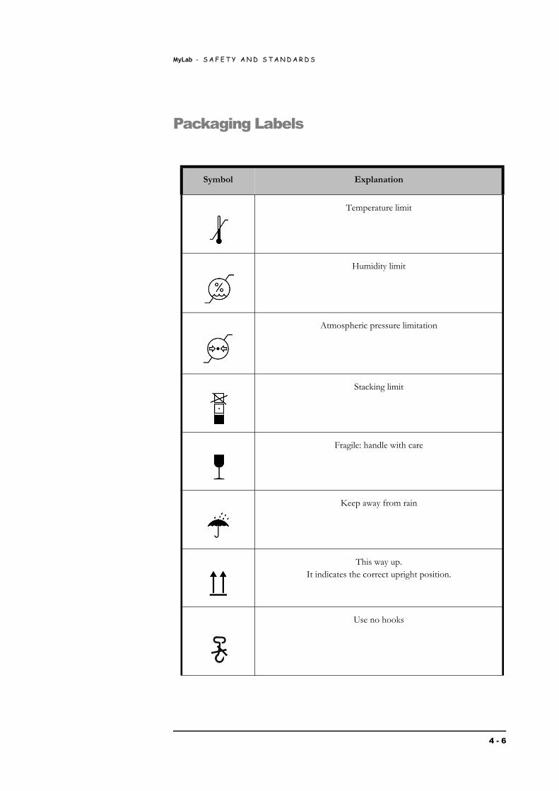
Packaging Labels
Symbol Explanation
Temperature limit
Humidity limit
Atmospheric pressure limitation
Stacking limit
Fragile: handle with care
Keep away from rain
This way up.It indicates the correct upright position.
Use no hooks
4 - 6

MyLab - S A F E T Y A N D S T A N D A R D S
SAFETY
AN
D
STAN
DA
RD
S
Recycling material
Recycling material.The packaging material complies with the RESY requirements.
Symbol Explanation
4 - 7

MyLab - S A F E T Y A N D S T A N D A R D S
4 - 8