MULTIBAND CPW-FED TRIANGLE-SHAPED MONOPOLE ANTENNA FOR WIRELESS APPLICATIONS
8
Progress In Electromagnetics Research, PIER 70, 329–336, 2007 MULTIBAND CPW-FED TRIANGLE-SHAPED MONOPOLE ANTENNA FOR WIRELESS APPLICATIONS Y. Song, Y.-C. Jiao, G. Zhao, and F.-S. Zhang National Laboratory of Antennas and Microwave Technology Xidian University Xi’an, Shaanxi 710071, P. R. China Abstract—A multiband CPW-fed triangle-shaped monopole antenna for wireless applications covering 2.4- and 5GHz WLAN bands and 3.4 GHz WIMAX band in IEEE 802.16 is proposed. Prototype of the proposed antenna have been constructed and tested. The experimental results show that the antenna can provide two separate impedance bandwidths of 140 MHz (about 5.8% centered at 2.43 GHz) and 3100 MHz (about 61.4% centered at 4.91 GHz), which meet the required bandwidths specification of 2.4/5 GHz WLAN and 3.4 GHz WIMAX standard. Good omnidirectional radiation in the desired frequency bands has been achieved. The proposed antenna with relatively low profile is suitable for multiband wireless applications. 1. INTRODUCTION Recently, wireless communications have been developed widely and rapidly, which leads to a great demand in designing low-profile, and multiband antennas for mobile terminals [7,8]. Many antennas, such as the CPW-fed antennas and slot-loaded monopole antennas, with dual-band characteristics for wireless applications have been reported [3–6]. However, there is a limit of these antennas to obtain the wideband characteristic especially at 5 GHz band for both WLAN and WIMAX applications operating simultaneously at 5.2, 5.8 and 3.5 GHz, respectively [3, 4]. In this paper, we propose a novel multiband CPW-fed triangle- shaped planar antenna covering the operating bands of both WLAN in IEEE 802.11 b/a/g at 2.4 GHz (2400–2484 MHz), 5.2 GHz (5150–5350 MHz) and 5.8 GHz (5725–5825 MHz) and Worldwide Interoperability for Microwave Access (WIMAX) based on IEEE
-
Upload
independent -
Category
Documents
-
view
2 -
download
0
Transcript of MULTIBAND CPW-FED TRIANGLE-SHAPED MONOPOLE ANTENNA FOR WIRELESS APPLICATIONS
Progress In Electromagnetics Research, PIER 70, 329–336, 2007
MULTIBAND CPW-FED TRIANGLE-SHAPEDMONOPOLE ANTENNA FOR WIRELESSAPPLICATIONS
Y. Song, Y.-C. Jiao, G. Zhao, and F.-S. Zhang
National Laboratory of Antennas and Microwave TechnologyXidian UniversityXi’an, Shaanxi 710071, P. R. China
Abstract—A multiband CPW-fed triangle-shaped monopole antennafor wireless applications covering 2.4- and 5 GHz WLAN bands and3.4 GHz WIMAX band in IEEE 802.16 is proposed. Prototypeof the proposed antenna have been constructed and tested. Theexperimental results show that the antenna can provide two separateimpedance bandwidths of 140 MHz (about 5.8% centered at 2.43 GHz)and 3100 MHz (about 61.4% centered at 4.91 GHz), which meet therequired bandwidths specification of 2.4/5 GHz WLAN and 3.4 GHzWIMAX standard. Good omnidirectional radiation in the desiredfrequency bands has been achieved. The proposed antenna withrelatively low profile is suitable for multiband wireless applications.
1. INTRODUCTION
Recently, wireless communications have been developed widely andrapidly, which leads to a great demand in designing low-profile, andmultiband antennas for mobile terminals [7, 8]. Many antennas, suchas the CPW-fed antennas and slot-loaded monopole antennas, withdual-band characteristics for wireless applications have been reported[3–6]. However, there is a limit of these antennas to obtain thewideband characteristic especially at 5 GHz band for both WLAN andWIMAX applications operating simultaneously at 5.2, 5.8 and 3.5 GHz,respectively [3, 4].
In this paper, we propose a novel multiband CPW-fed triangle-shaped planar antenna covering the operating bands of bothWLAN in IEEE 802.11 b/a/g at 2.4 GHz (2400–2484 MHz), 5.2 GHz(5150–5350 MHz) and 5.8 GHz (5725–5825 MHz) and WorldwideInteroperability for Microwave Access (WIMAX) based on IEEE

330 Song et al.
802.16 at 3.4 GHz (3400–3600 MHz). The proposed antenna wassimulated using Ansoft High Frequency Structure Simulator (HFSS),and the prototype of the antenna was constructed and tested. Byadjusting the dimensions of the stubs in the patch, broad impedancebandwidth and good radiation characteristics suitable for WLAN andWIMAX can be achieved in the upper frequency band. Details ofthe antenna design and the experimental results are presented anddiscussed.
2. ANTENNA DESIGN
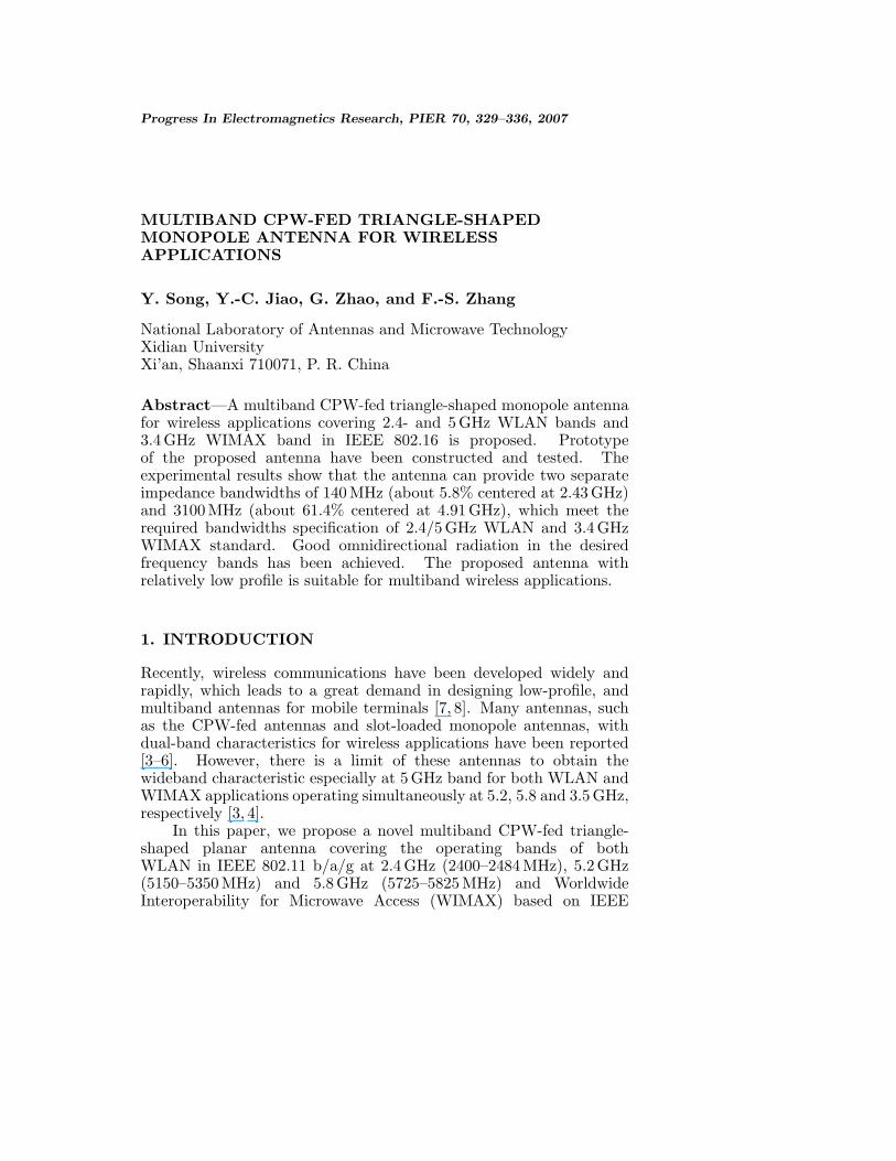
Fig. 1 shows the geometry of the proposed triangle-shaped planarantenna for multiband operation. The antenna is symmetrical withrespect to the longitudinal direction. The dimensions of the antennaincluded the feed structure are 35× 24 mm2 designed for both WLANand WIMAX, on a substrate of thickness of 1.6 mm and the dielectricconstant of the inexpensive FR4 substrate is εr = 4.4. A 50Ω CPWtransmission line, which consists of a signal strip width of 2 mm and agap distance of 0.25 mm between the single strip and the coplanarground plane, is used for feeding the antenna. The basis of theradiating element of the antenna is a modified triangle-shaped patchmonopole, which has the dimensions shown in the Fig. 1(c), and isconnected at the end of the CPW feed line with a spacing of 1.2 mmfrom the edge of the ground plane. The modified ground plane isused to achieve broad bandwidth. It should be noted that the cross-shaped strip within the top of the patch and another strips around theground, denoted as S1 and S2, will affect on the impedance matchingof the proposed antenna, the influence will also be discussed in thefollowing section. The major effect of the inserted triangular slit inthe patch is to produce another current path operating at 5-GHz band,and thus a new resonant frequency is excited. In this geometry of theprototype antenna on the z-axis symmetry, the resonant path length(B-C-D-E) is set 30.8 mm close to 0.25λ at 2.44 GHz, the slot length(I-C-D-E-F) is about 26.6 mm corresponding to 0.33λ at 3.7 GHz, andthe slit dimension (A-B-G-H) is 15.5 mm which approximates 0.29λ at5.7 GHz. The photograph of the antenna is shown in Fig. 2.
3. RESULTS AND DISCUSSION
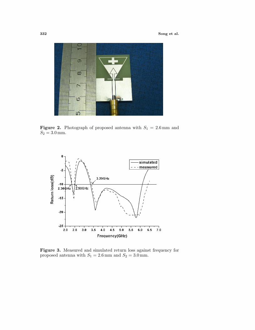
A prototype based on the design was fabricated and measured withWILTRON-37269A Vector Network Analyzer. The measured andsimulated return losses of the antenna are shown in Fig. 3. It is clearlyseen that the lower frequency band is about 140 MHz from 2.36 to

Progress In Electromagnetics Research, PIER 70, 2007 331
Figure 1. Geometry and dimensions of proposed antenna: (a) Topview; (b) Side view; (c) Detailed dimensions of the radiation element.
332 Song et al.
Figure 2. Photograph of proposed antenna with S1 = 2.6 mm andS2 = 3.0 mm.
Figure 3. Measured and simulated return loss against frequency forproposed antenna with S1 = 2.6 mm and S2 = 3.0 mm.

Progress In Electromagnetics Research, PIER 70, 2007 333
Figure 4. Measured return loss against frequency for proposedantenna with various length S1, S2 = 3.7 mm (other parameters arethe same as in Fig. 1).
Figure 5. Measured return loss against frequency for proposedantenna with various length S2, S1 = 2.6 mm (other parameters arethe same as in Fig. 1).
334 Song et al.
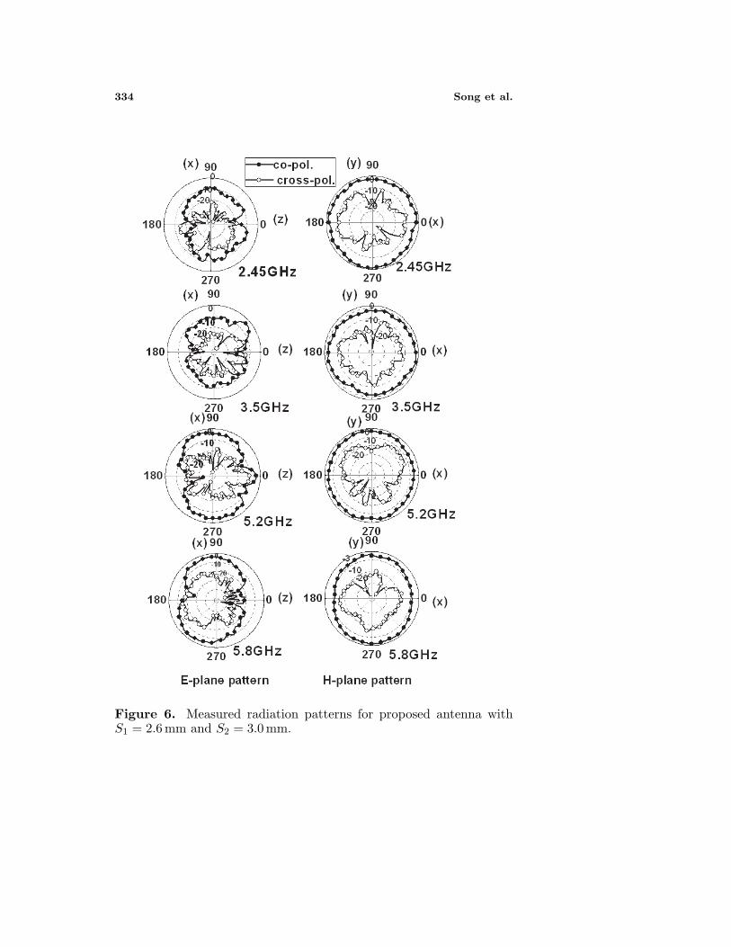
Figure 6. Measured radiation patterns for proposed antenna withS1 = 2.6 mm and S2 = 3.0 mm.

Progress In Electromagnetics Research, PIER 70, 2007 335
2.50 GHz for S11 < −10 dB, which meets the bandwidth requirementfor 2.4 GHz WLAN operation. As for the higher frequency band, thebroad bandwidth obtained is 3100 MHz (3.40–6.41 GHz), or 61.4% withrespect to the center frequency of 4.91 GHz, which is formed by tworesonating modes close to each other and covers both the 5 GHz WLANbands and the 3.4 GHz WIMAX band in IEEE 802.16. Fig. 4 showsthe tuning effect of varying the stub length as S1 = 2.6, 2.4 and2.2 mm with a fixed S2 of 3.7 mm. It is clearly found that, the firsttwo resonance frequencies increase with the length of the strip (S1)reduced while the third resonance frequency is almost not affected. Asfor varying the strip length S2 to be 3.7, 3.5 and 3 mm (S1 = 2.6 mm), itcan be seen from Fig. 5 that with reducing length S2, the bandwidth forthe upper band increases while the bandwidth of the lower band changeslightly. For the first two resonant frequencies, to decrease the length ofS1 will shorten effective current path of the second resonant frequencyand also degrade the electromagnetic coupling effect which affects thefirst resonant frequency between S1 and the trapezoid-shaped ring atthe top of the antenna, so as to move the resonant frequencies at3.75 GHz and 2.4 GHz to higher frequencies slightly. For the thirdresonance frequency, it also increases with the effective current path(A-B-G-H) reduced.
The radiation characteristics of the proposed antenna are alsoinvestigated, and the measured radiation patterns of both E-planepattern and H-plane pattern at 2.45, 3.5, 5.2 and 5.8 GHz are depictedin Fig. 6. The measured results show that the radiation patterns ofthe antenna are broadside and bidirectional in the E-plane and almostomnidirectional in the H-plane. The measured peak gains for theproposed antenna are 2.14, 2.54, 3.59 and 3.05 dBi at 2.43, 3.5, 5.2and 5.8 GHz, respectively.
4. CONCLUSION
A novel single-layer triangle-shaped planar antenna based on a 50ΩCPW-fed structure operating in both the WLAN communicationscovering the 2.4, 5.2, and 5.8 GHz bands and 3.4 GHz WIMAXapplication has been presented. Adjustable strips are used to enhancethe bandwidth, and consequently a wide-band operation is obtainedin the higher frequency band. A large operating bandwidth of 61.4%has been demonstrated. In addition, the measured radiation patternsin H-plane pattern are of a nearly omnidirectional characteristic atoperating frequencies. Therefore, this antenna is a good candidate formultiband communication applications.

336 Song et al.
REFERENCES
1. Wong, K. L., Planar Antennas for Wireless Communications,John Wiley & Sons, Inc., 2003.
2. Chen, S.-B., Y.-C. Jiao, F.-S. Zhang, and Q.-Z. Liu, “Modified T-shaped planar monopole antenna for multiband operation,” IEEETransactions on Microwave Theory and Techniques, Vol. 54, No. 8,3267–3270, August 2006.
3. Liu, W.-C. and C,-F. Hsu, “Dual-band CPW-fed Y-shapedmonopole antenna for PCS/WLAN application,” Electron. Lett.,Vol. 41, No. 18, 390–391, 2005.
4. Liu, W. C., “Broadband dual-frequency meandered CPW-fedmonopole antenna,” Electron. Lett., Vol. 40, 1319–1320, 2004.
5. Li, J. Y., J. L. Guo, Y. B. Gan, and Q. Z. Liu, “The tri-bandperformance of sleeve dipole antenna,” Journal of ElectromagneticWaves and Applications, Vol. 19, 2081–2092, 2005.
6. Shams, K. M. Z., M. Ali, H. S. Hwang, “A planar inductivelycoupled bow-tie slot antenna for WLAN application,” Journal ofElectromagnetic Waves and Applications, Vol. 20, 861–871, 2006.
7. Rao, A. and R. Sebak, “T-shaped microstrip feeding technique fora dual annnular slot antenna,” Journal of Electromagnetic Wavesand Applications, Vol. 19, 605–614, 2005.
8. Guo, Y., B. Gan, and Q. Z. Liu, “The tri-band performance ofsleeve dipole antenna,” Journal of Electromagnetic Waves andApplications, Vol. 19, 2081–2092, 2005.