MUAP-13002, Revision 1, US-APWR Evaluation and Design ...
236
US-APWR Evaluation and Design Enhancement to Incorporate MUAP-13002 (R1) Lessons Learned from TEPCO's Fukushima Dai-ichi Nuclear Power Station Accident Mitsubishi Heavy Industries, LTD. US-APWR Evaluation and Design Enhancement to Incorporate Lessons Learned from TEPCO's Fukushima Dai-ichi Nuclear Power Station Accident September 2013 © 2013 Mitsubishi Heavy Industries, Ltd. All Rights Reserved SRI Excluded Version
-
Upload
khangminh22 -
Category
Documents
-
view
1 -
download
0
Transcript of MUAP-13002, Revision 1, US-APWR Evaluation and Design ...
US-APWR Evaluation and Design Enhancement to Incorporate MUAP-13002 (R1) Lessons Learned from TEPCO's Fukushima Dai-ichi Nuclear Power Station Accident
Mitsubishi Heavy Industries, LTD.
US-APWR Evaluation and Design Enhancement to
Incorporate Lessons Learned from TEPCO's
Fukushima Dai-ichi Nuclear Power Station
Accident
September 2013
© 2013 Mitsubishi Heavy Industries, Ltd. All Rights Reserved
SRI Excluded Version
US-APWR Evaluation and Design Enhancement to Incorporate MUAP-13002 (R1) Lessons Learned from TEPCO's Fukushima Dai-ichi Nuclear Power Station Accident
Mitsubishi Heavy Industries, LTD.
Revision History
Revision Page Description
0 All First Issue
1 All
MHI responses to DCD RAI 1029-7076, 1043-7175 and 1048-7204, DCD Revision 4, RCOLA FSAR Rev.3 UTR 2, and NRC comments on MUAP-13002 Revision 0 expressed at the public meeting held on April 29, 2013 are incorporated. Document description strategy was changed to focus on description of design features for Fukushima lessons-learned, instead of design changes from US-APWR DCD Revision 3. Descriptions of programmatic issues were deleted from Chapter 6 to focus on the design features. Changes for clarification and editorial improvement were incorporated throughout the document. Following sections were substantially revised, deleted or moved to the appendices based on the above factors: 5.1.1, 5.1.2, 5.1.4, 5.2, 5.3.11, 5.4, 6.1, 6.2, 6.3, 6.4, 6.5, 6.6, 6.7.2, 6.7.3, 6.8.1, 6.10.1, 6.10.2, 6.11. In addition, Appendix 1 was deleted, and Appendices 3 and 4 were created to describe the AAC seismic testing plan and impact of Fukushima-related features on the PRA, respectively. Appendix 5 was added to accommodate detailed description of the containment analyses.

US-APWR Evaluation and Design Enhancement to Incorporate MUAP-13002 (R1) Lessons Learned from TEPCO's Fukushima Dai-ichi Nuclear Power Station Accident
Mitsubishi Heavy Industries, LTD.
© 2013
MITSUBISHI HEAVY INDUSTRIES, LTD. All Rights Reserved
This document has been prepared by Mitsubishi Heavy Industries, Ltd. (“MHI”) in connection with the U.S. Nuclear Regulatory Commission’s (“NRC”) licensing review of MHI’s US-APWR nuclear power plant design. No right to disclose, use or copy any of the information in this document, other than by the NRC and its contractors in support of the licensing review of the US-APWR, is authorized without the express written permission of MHI. This document contains technology information and intellectual property relating to the US-APWR and it is delivered to the NRC on the express condition that it not be disclosed, copied or reproduced in whole or in part, or used for the benefit of anyone other than MHI without the express written permission of MHI, except as set forth in the previous paragraph. This document is protected by the laws of Japan, U.S. copyright law, international treaties and conventions, and the applicable laws of any country where it is being used.
Mitsubishi Heavy Industries, Ltd. 16-5, Konan 2-chome, Minato-ku
Tokyo 108-8215 Japan

US-APWR Evaluation and Design Enhancement to Incorporate MUAP-13002 (R1) Lessons Learned from TEPCO's Fukushima Dai-ichi Nuclear Power Station Accident
Mitsubishi Heavy Industries, LTD. i
Abstract This report summarizes strategies and design enhancements of US-APWR to incorporate lessons learned from the accidents at TEPCO’s Fukushima Dai-ichi Nuclear Power Station after the Great Tohoku Earthquake and the Tsunami which hit the station on March 11, 2011 and the requirements/recommendations issued after the disaster by the US NRC.

US-APWR Evaluation and Design Enhancement to Incorporate MUAP-13002 (R1) Lessons Learned from TEPCO's Fukushima Dai-ichi Nuclear Power Station Accident
Mitsubishi Heavy Industries, LTD. ii
Table of Contents List of Tables vi List of Figures vii List of Acronyms viii 1.0 INTRODUCTION 1 2.0 PURPOSE 2 3.0 SCOPE 3 4.0 REGULATORY RECOMMENDATIONS AND REQUIREMENTS 4 5.0 STRATEGIES TO ACTION ITEMS FROM FUKUSHIMA DAI-ICHI EVENTS 28 5.1 Tier 1 Items 28
5.1.1 Recommendation 2.1 (Seismic Reevaluation) 28 5.1.2 Recommendations 4.1 and 4.2 28 5.1.3 Recommendation 7.1 41 5.1.4 Recommendation 8 44 5.1.5 Recommendation 9.3 (Staffing and Communications) 45
5.2 Tier 2 Items 104 5.2.1 Recommendations 7.2, 7.3, 7.4, 7.5 104
5.2.1.1 Recommendation 7.2 104 5.2.1.2 Recommendation 7.3 104 5.2.1.3 Recommendation 7.4 104 5.2.1.4 Recommendation 7.5 104
5.2.2 Recommendation 9.3 (Other than Staffing, Communications, ERDS Capability) 104 5.3 Others (Items which are not directly applied to US-APWR and Tier 3) 105
5.3.1 Recommendation 2.1 Flooding Reevaluation 105 5.3.2 Recommendation 2.1 Other External Events 105 5.3.3 Recommendation 2.2 Ten-Year Confirmation of Seismic and Flooding Hazards 105 5.3.4 Recommendation 2.3 Seismic and Flood Walkdowns 105 5.3.5 Recommendation 3 Potential Enhancements to the Capability to Prevent or
Mitigate Seismically-Induced Fires and Floods (Long-Term Evaluation) 105 5.3.6 Recommendation 5.1 Including AR1 Filtered Vent 106 5.3.7 Recommendation 5.2 Reliable Hardened Vents for Other Containment Designs
(Long-Term Evaluation) 106

US-APWR Evaluation and Design Enhancement to Incorporate MUAP-13002 (R1) Lessons Learned from TEPCO's Fukushima Dai-ichi Nuclear Power Station Accident
Mitsubishi Heavy Industries, LTD. iii
5.3.8 Recommendation 6 Hydrogen Control and Mitigation Inside Containment or in Other Buildings 106
5.3.9 Recommendation 9.1 Emergency Preparedness (EP) Enhancements for Prolonged SBO and Multiunit Events 106
5.3.10 Recommendation 9.2 Emergency Preparedness (EP) Enhancements for Prolonged SBO and Multiunit Events 106
5.3.11 Recommendation 9.3 ERDS Capability 107 5.3.12 Recommendation 10 Additional EP Topics for Prolonged SBO and
Multiunit Events 107 5.3.13 Recommendation 11 EP Topics for Decision-Making, Radiation Monitoring,
and Public Education 107 5.3.14 Recommendation 12.1 Reactor Oversight Process Modifications to Reflect
the Recommended Defense-in-Depth Framework 107 5.3.15 Recommendation 12.2 Staff Training on Severe Accidents and
Resident Inspector Training on SAMGs 107 5.3.16 Additional Recommendation 3 (EPZ) 107 5.3.17 Additional Recommendation 4 (KI) 108 5.3.18 Additional Recommendation 5 (Dry Cask Storage) 108
5.4 Deleted 109 5.5 References 110 6.0 DESIGN FEATURES TO INCORPORATE FUKUSHIMA LESSONS-LEARNED 111 6.1 BDB Flood Protection 111
6.1.1 Design Feature Description 111 6.1.2 Design Basis 111 6.1.3 Compliance with NRC Recommendations 112 6.1.4 DCD Description 112 6.1.5 Combined License Information 113 6.1.6 References 113
6.2 Deleted 119 6.3 RCP No. 2 Seal Performance 120
6.3.1 Design Feature Description of RCP Seal under SBO Condition 120 6.3.2 Seal Performance Based on Test Result 120 6.3.3 Compliance with NRC Recommendations 121 6.3.4 DCD Description 121 6.3.5 Combined License Information 121

US-APWR Evaluation and Design Enhancement to Incorporate MUAP-13002 (R1) Lessons Learned from TEPCO's Fukushima Dai-ichi Nuclear Power Station Accident
Mitsubishi Heavy Industries, LTD. iv
6.3.6 References 121 6.4 Electric Power Supply System 122
6.4.1 AAC Power System 122 6.4.1.1 Design Features 122 6.4.1.2 Design Basis 125
6.4.2 I&C Power Supply System Design 131 6.4.2.1 Design Features 131 6.4.2.2 Design Basis 133
6.4.3 Compliance with NRC Recommendations 134 6.4.4 DCD Description 134 6.4.5 Combined License Information 134 6.4.6 References 134
6.5 Alternate Suction to CHP 135 6.5.1 Design Features 135 6.5.2 Design Basis 135 6.5.3 Compliance with NRC Recommendations 136 6.5.4 DCD Description 137 6.5.5 Combined License Information 137 6.5.6 References 137
6.6 Alternate UHS 139 6.6.1 Design Features 139 6.6.2 Design Basis 140 6.6.3 DCD Description 141 6.6.4 Combined License Information 142 6.6.5 References 142
6.7 SFP 144 6.7.1 SFP Water Level Instrumentation 144
6.7.1.1 Design Features 144 6.7.1.2 Design Basis 144 6.7.1.3 Compliance with NRC Recommendations 145 6.7.1.4 DCD Description 147 6.7.1.5 Combined License Information 147 6.7.1.6 References 147
6.7.2 Deleted 149 6.7.3 SFP Makeup Line and Spray Line 150

US-APWR Evaluation and Design Enhancement to Incorporate MUAP-13002 (R1) Lessons Learned from TEPCO's Fukushima Dai-ichi Nuclear Power Station Accident
Mitsubishi Heavy Industries, LTD. v
6.7.3.1 Design Features 150 6.7.3.2 Design Basis 152 6.7.3.3 Compliance with NRC Recommendations 152 6.7.3.4 DCD Description 152 6.7.3.5 Combined License Information 153 6.7.3.6 References 153
6.8 EFWS 154 6.8.1 EFW Pit Makeup 154
6.8.1.1 Design Features 154 6.8.1.2 Design Basis 156 6.8.1.3 Compliance with NRC Recommendations 156 6.8.1.4 DCD Description 156 6.8.1.5 Combined License Information 157 6.8.1.6 References 157
6.8.2 Automatic Opening of EFWS Header Tie-Line Valves 158 6.8.2.1 Design Features 158 6.8.2.2 Design Basis 158 6.8.2.3 Compliance with NRC Recommendations 158 6.8.2.4 DCD Description 160 6.8.2.5 Combined License Information 160 6.8.2.6 References 160
6.9 Deleted 161 6.10 Emergency Preparedness 162
6.10.1 Plant Communication Systems 162 6.10.1.1 Communication Systems Power Source 162
6.10.1.1.1 Design Features 162 6.10.1.1.2 Design Basis 165 6.10.1.1.3 Compliance with NRC Recommendations 165
6.10.1.2 Plant Communication Systems Equipment 165 6.10.1.2.1 Design Features 165 6.10.1.2.2 Design Basis 168 6.10.1.2.3 Compliance with NRC Recommendations 168
6.10.1.3 DCD Description 168 6.10.1.4 Combined License Information 169 6.10.1.5 References 169

US-APWR Evaluation and Design Enhancement to Incorporate MUAP-13002 (R1) Lessons Learned from TEPCO's Fukushima Dai-ichi Nuclear Power Station Accident
Mitsubishi Heavy Industries, LTD. vi
6.10.2 Deleted 170 6.11 Deleted 171 7.0 CONCLUSION 172 Appendix 1 Deleted 173 Appendix 2 Supporting Analyses Results for the Operational Strategy for Core Cooling 174 Appendix 3 AAC GTG Seismic Capability Confirmation Plan 182 Appendix 4 Impact of Design and Program Changes on PRA 191 Appendix 5 Containment Thermal-Hydraulic Analysis 197

US-APWR Evaluation and Design Enhancement to Incorporate MUAP-13002 (R1) Lessons Learned from TEPCO's Fukushima Dai-ichi Nuclear Power Station Accident
Mitsubishi Heavy Industries, LTD. vii
List of Tables Table 4-1 Post-Fukushima NRC Recommendations and Requirements 5 Table 5.1.2-1 US-APWR FLEX Capability Summary 46 Table 5.1.2-2 Conformance with JLD-ISG-2012-01 Rev. 0 50 Table 5.1.2-3 Conformance to NEI 12-06 Rev. 0 (Part 1) 55 Table 5.1.2-4 Conformance with NEI 12-06 Rev. 0 (Part 2) 80 Table 5.1.2-5 Sequence of Events for Core Cooling 85 Table 5.1.3-1 Conformance with NEI 12-02 Rev. 1 87 Table 6.4.1-1 Electrical Load Distribution – AAC GTG 126 Table A2-1 Time Sequence for Supporting Analyses 178 Table A3-1 Screening Table on AAC GTG’s Components 185 Table A4-1 Qualitative Impact on PRA 194 Table A5-1 Analysis conditions 199 Table A5-2 POS Assumption Considered in the US-APWR LPSD PRA 201 Table A5-3 Plant Conditions Assumed in Evaluations for POS 4-2 and 4-3 203
US-APWR Evaluation and Design Enhancement to Incorporate MUAP-13002 (R1) Lessons Learned from TEPCO's Fukushima Dai-ichi Nuclear Power Station Accident
Mitsubishi Heavy Industries, LTD. viii
List of Figures Figure 5.1.2-1 Core Cooling Timeline 101 Figure 5.1.2-2 Alternate UHS 102 Figure 5.1.3-1 SFP Water Level Setpoints 103 Figure 6.4.1-1 AC Power Supply from AAC GTG (Phase 1) 127 Figure 6.4.1-2 AC Power Supply from AAC GTG (Phase 2) 128 Figure 6.4.1-3 AC Power Supply from AAC GTG (Phase 3) 129 Figure 6.4.1-4 Alternate UHS Power Supply 130 Figure 6.4.2-1 PSMS Power Supply Configuration 132 Figure 6.5-1 Alternate Suction of Charging Pump Conceptual Diagram 138 Figure 6.6-1 Alternate UHS 143 Figure 6.7.1-1 SFP Water Level Setpoints and Compliance with EA-12-051 and NEI 12-02 148 Figure 6.7.3-1 SFP Makeup Line and Spray Line 151 Figure 6.8.1-1 EFW Pit Makeup Line 155 Figure 6.8.2-1 Logic for Automatic Opening of EFWS Header Tie-Line Valves 159 Figure 6.10.1-1 Communication Systems Power Supply Configuration 164 Figure 6.10.1-2 Plant Telephone System with Satellite Telephone Link 167 Figure A2-1 RCS Pressure versus Time 179 Figure A2-2 RCS Temperature versus Time 179 Figure A2-3 Steam Generator Pressure versus Time 180 Figure A2-4 Pressurizer Water Level versus Time 180 Figure A2-5 Steam Generator Water Level versus Time 181 Figure A5-1 Containment Pressure (Mode 1) 200 Figure A5-2 Containment Temperature (Mode 1) 200 Figure A5-3 RCS Inventory during Mid-loop Operation and Refueling with Key Activities 205 Figure A5-4 RCS and SG Configuration Assumed during POS 4-1 206 Figure A5-5 RCS and SG Configuration Assumed during POS 4-2 207 Figure A5-6 RCS and SG Configuration Assumed during POS 4-3 208 Figure A5-7 Status of Heat Removal Functions Assumed in Each Phase for
Mode 5 and 6 209 Figure A5-8 Containment Pressure for POS 4-2 213 Figure A5-9 Containment Temperature for POS 4-2 213

US-APWR Evaluation and Design Enhancement to Incorporate MUAP-13002 (R1) Lessons Learned from TEPCO's Fukushima Dai-ichi Nuclear Power Station Accident
Mitsubishi Heavy Industries, LTD. ix
Figure A5-10 RWSP Water Level for POS 4-2 214 Figure A5-11 RWSP Water Temperature for POS 4-2 214 Figure A5-12 Containment Pressure for POS 4-3 216 Figure A5-13 Containment Temperature for POS 4-3 216 Figure A5-14 RWSP Water Level for POS 4-3 217 Figure A5-15 RWSP Water Temperature for POS 4-3 217

US-APWR Evaluation and Design Enhancement to Incorporate MUAP-13002 (R1) Lessons Learned from TEPCO's Fukushima Dai-ichi Nuclear Power Station Accident
Mitsubishi Heavy Industries, LTD. x
List of Acronyms and Abbreviations
AAC alternate alternating current A/B auxiliary building ac alternating current ACC accumulator ACRS Advisory Committee on Reactor Safeguards AFW auxiliary feedwater AHU air handling unit ANPR advanced notice of proposed rulemaking ANS American Nuclear Society ANSI American National Standards Institute AOP abnormal operating procedure APWR advanced pressurized water reactor AR additional requirement ATS automatic transfer switch BDB beyond design basis BDBEE beyond-design-basis external event BWR boiling water reactor CAV cumulative absolute velocity CCW component cooling water CCWS component cooling water system CDF core damage frequency CEUS central and eastern United States CEUS-SSC CEUS seismic source characterization CFR Code of Federal Regulations CHP charging pump COL combined operating license COLA Combined License Application CP construction permit CSS containment spray system C/T cooling tower CVCS chemical and volume control system

US-APWR Evaluation and Design Enhancement to Incorporate MUAP-13002 (R1) Lessons Learned from TEPCO's Fukushima Dai-ichi Nuclear Power Station Accident
Mitsubishi Heavy Industries, LTD. xi
C/V containment vessel DBA design basis accident dc direct current DCD design control document DWST demineralized water storage tank EA enforcement action ECCS emergency core cooling system ECC/CS emergency core cooling and containment spray ECU essential chiller unit ECWS essential chilled water system EDMG extensive damage mitigation guideline EFW emergency feedwater EFWP emergency feedwater pump EFWS emergency feedwater system ELAP extended loss of ac power EOP emergency operating procedure EP emergency preparedness EPRI Electric Power Research Institute EPZ emergency planning zone ERDS emergency response data system ESP early site permit ESW essential service water ESWS essential service water system FEM finite element method FEMA Federal Emergency Management Agency FIRS foundation input response spectra FLEX diverse and flexible coping strategies FSAR final safety analysis report FSG FLEX support guideline FSS fire protection water supply system GMRS ground motion response spectra GTG gas turbine generator HCVS hardened containment venting system HVAC heating, ventilation and air conditioning Hx heat exchanger

US-APWR Evaluation and Design Enhancement to Incorporate MUAP-13002 (R1) Lessons Learned from TEPCO's Fukushima Dai-ichi Nuclear Power Station Accident
Mitsubishi Heavy Industries, LTD. xii
I&C instrumentation and control IBR incorporated by reference ISCP integrated seismic closure plan ISG interim staff guidance ISRS in-structure response spectra IPEEE independent plant evaluation for external events KI potassium iodide LOCA loss of coolant accident LOOP loss of offsite power LPSD low-power and shutdown MCC motor control center MCP main coolant pipe MCR main control room M/D motor driven MHI Mitsubishi Heavy Industries, LTD. MSDV main steam depressurization valve MS/FW main steam and feedwater MSSV main steam safety valve MV medium voltage NEI Nuclear Energy Institute ECWS essential chilled water system NPP nuclear power plant NPSH net positive suction head NRC Nuclear Regulatory Commission NS non-seismic NTTF Near-Term Task Force NQA nuclear quality assurance PABX private automatic branch telephone exchange PA/PL public address system/page PMF probable maximum flood PMWS primary makeup water system PRA probabilistic risk assessment PRS plant radio system PS/B power source building PSHA probabilistic seismic hazard analysis

US-APWR Evaluation and Design Enhancement to Incorporate MUAP-13002 (R1) Lessons Learned from TEPCO's Fukushima Dai-ichi Nuclear Power Station Accident
Mitsubishi Heavy Industries, LTD. xiii
PSMS protection and safety monitoring system PWR pressurized water reactor PZR pressurizer QA quality assurance R/B reactor building RAI request for additional information RAT reserve auxiliary transformer RCPB reactor coolant pressure boundary RCP reactor coolant pump RCS reactor coolant system RG regulatory guide RHR residual heat removal RHRS residual heat removal system ROP reactor oversight process RSC remote shutdown console RV reactor vessel RWSAT refueling water storage auxiliary tank RWSP refueling water storage pit RWRP refueling water recirculation pump SAMG severe accident management guidelines SAT systematic approach to training SBO station blackout SCI seismic category I SDV safety depressurization valve SE safety evaluation SFP spent fuel pit/pool SFPSS spent fuel pool scoping study SG steam generator SI safety injection SMA seismic margin analysis SPTS sound powered telephone system SSC structure, system and component SSE safe shutdown earthquake TEPCO Tokyo Electric Power Company T/B turbine building

US-APWR Evaluation and Design Enhancement to Incorporate MUAP-13002 (R1) Lessons Learned from TEPCO's Fukushima Dai-ichi Nuclear Power Station Accident
Mitsubishi Heavy Industries, LTD. xiv
T/D turbine driven TSC technical support center UAT unit auxiliary transformer UHS ultimate heat sink UNSCEAR United Nations Scientific Committee on the Effects of Atomic Radiation UPS uninterruptible power supply VDU visual display unit

US-APWR Evaluation and Design Enhancement to Incorporate MUAP-13002 (R1) Lessons Learned from TEPCO's Fukushima Dai-ichi Nuclear Power Station Accident
Mitsubishi Heavy Industries, LTD. 1
1.0 INTRODUCTION The March 11, 2011 earthquake and subsequent tsunami off the Pacific coast of Japan (“Great Tohoku Earthquake”) exceeded the seismic and tsunami design bases of the Fukushima Dai-ichi Nuclear Power Plant. The event resulted in major damage at the site. Subsequent evaluation by regulatory and industry experts resulted in insights that nuclear plants should have additional capability to withstand “beyond design basis” events. This capability would enhance protection against accidents resulting from natural phenomena, mitigate the consequences of such accidents, and enhance emergency preparedness. It reflects a “diverse and flexible” coping strategy to increase the defense-in-depth safety principle that has long been a foundation of the commercial nuclear power industry. Mitsubishi Heavy Industries, Ltd. (MHI) has evaluated post-Fukushima insights in terms of its US Advanced Pressurized Water Reactor (US-APWR) design, which is currently in the design certification process. This report provides the results of that evaluation. Sections 2.0 and 3.0 summarize the purpose and scope, respectively. Section 4.0 summarizes applicable regulatory requirements and the potential effect on current US-APWR licensing documentation. Section 5.0 provides technical description of how the US-APWR addresses post-Fukushima insights. Section 6.0 identifies design changes and their impact on DCD and R-COLA. The impact on the probabilistic risk assessment (PRA) is also addressed in Section 6.0. Section 7.0 provides the report’s overall conclusion. Appendices are provided to summarize i) the analysis of core cooling for 72 hrs after a loss of all AC power with simultaneous loss of normal access to the ultimate heat sink (UHS) due to a beyond-design-basis (BDB) external event, ii) AAC GTG seismic confirmation plan and iii) Impact of design changes incorporated into the US-APWR.

US-APWR Evaluation and Design Enhancement to Incorporate MUAP-13002 (R1) Lessons Learned from TEPCO's Fukushima Dai-ichi Nuclear Power Station Accident
Mitsubishi Heavy Industries, LTD. 2
2.0 PURPOSE The purpose of this report is to address requirements and guidance provided by the U.S. Nuclear Regulatory Commission (NRC) in a series of Commission papers (SECY), NRC Orders (provided via Enforcement Actions, EA) and interim staff guidance (ISG) after the Fukushima event. In addition, industry initiatives identified by the Nuclear Energy Institute (NEI) have been considered in the development of this report. The requirements which are applicable to the MHI designed US-APWR are summarized in Table 4-1.

US-APWR Evaluation and Design Enhancement to Incorporate MUAP-13002 (R1) Lessons Learned from TEPCO's Fukushima Dai-ichi Nuclear Power Station Accident
Mitsubishi Heavy Industries, LTD. 3
3.0 SCOPE This report dispositions insights and lessons from the Fukushima event that can be addressed at the design stage of the US-APWR and the US-APWR design features that are relied upon to facilitate reactor safety when a beyond-design-basis event occurs. The report also focusses on the design features to conform to the NRC recommendations / requirements. This document also summarizes Combined Operating License (COL) items associated with insights from the Fukushima event. Potential changes from proposed rulemaking that are scheduled to occur after the US-APWR design certification are outside of the scope of this report.

US-APWR Evaluation and Design Enhancement to Incorporate MUAP-13002 (R1) Lessons Learned from TEPCO's Fukushima Dai-ichi Nuclear Power Station Accident
Mitsubishi Heavy Industries, LTD. 4
4.0 REGULATORY RECOMMENDATIONS AND REQUIREMENTS This chapter addresses post-Fukushima NRC recommendations/requirements and actions by MHI, including COL items, for each recommendation and requirement. The following post-Fukushima NRC recommendations/requirements are addressed:
• SECY-11-0093, Recommendations for Enhancing Reactor Safety in the 21st Century, The Near-Term Task Force Review of Insights from the Fukushima Dai-ichi Accident (NTTF Recommendations)
• SECY-11-0137, Prioritization of Recommended Actions to be Taken in Response to Fukushima Lessons Learned
• SECY-12-0025, Proposed Orders and Requests for Information in Response to Lessons Learned from Japan’s March 11, 2011, Great Tohoku Earthquake and Tsunami
• SECY-12-0095, Tier 3 Program Plans and 6-Month Status Update in Response to Lessons Learned from Japan’s March 11, 2011, Great Tohoku Earthquake and Subsequent Tsunami
• NRC Order EA-12-049, Order Modifying Licenses with Regard to Requirements for Mitigation Strategies for Beyond-Design-Basis External Events
• NRC Order EA-12-051, Reliable Spent Fuel Pool Instrumentation Table 4-1 provides a cross reference to where in this report MHI actions to address the recommendations specified in the above NRC documents are described. This table also lists those DCD sections that are being changed to address the recommendations and provides a brief summary of applicable actions for each recommendation. The post-Fukushima NRC recommendations that are not applicable to either the US-APWR DCD or COL applicant(s) are also identified in this table.
The most updated NRC requirements/policies as of June 30, 2013 are summarized in this table. This includes any specific NRC requirements/policies that have been issued after the publication of the NTTF Recommendations.

US-APWR Evaluation and Design Enhancement to Incorporate MUAP-13002 (R1) Lessons Learned from TEPCO's Fukushima Dai-ichi Nuclear Power Station Accident
Mitsubishi Heavy Industries, LTD. 5
Table 4-1 Post-Fukushima NRC Recommendations and Requirements (Sheet of 23) NTTF Rec. No
NRC Recommendations / Requirements in SECY-11-0093, SECY-11-0137, SECY-12-0025,
SECY-12-0095, EA-12-049, EA-12-051
US-APWR Design Features
DCD Section
COL Action
Note
General _ New Reactor Designs
The staff intends to begin interactions with new reactor stakeholders in the near term to allow sufficient opportunity for design certification applicants and design certification renewal applicants to address recommended design-related safety enhancements prior to completion of the staff’s review. The staff will encourage reactor vendors to provide enhanced safety features and safety margins consistent with the Commission policy on advanced reactors.
See following pages
See following pages
See following pages
SECY-11- 0137
_ Design Certifications and Combined Licenses For design certifications and combined license applications submitted under 10 CFR Part 52 that are currently under active staff review, the staff plans to assure that the Commission-approved Fukushima actions are addressed prior to certification or licensing. To date, the staff has met with AREVA and MHI to understand their plans for incorporating changes into their respective designs to effectively address the design-related Fukushima items. The staff will also request all COL applicants to provide the information required by the orders and request for information letters described in this paper, as applicable, through the review process. New reactor and operating reactor staff are coordinating their regulatory positions to assure that the resolutions proposed by new reactor design certification and combined license applicants are not in conflict with those proposed and accepted by the staff for operating reactors.
See following pages
See following pages
See following pages
SECY-12- 0025
1

US-APWR Evaluation and Design Enhancement to Incorporate MUAP-13002 (R1) Lessons Learned from TEPCO's Fukushima Dai-ichi Nuclear Power Station Accident
Mitsubishi Heavy Industries, LTD. 6
Table 4-1 Post-Fukushima NRC Recommendations and Requirements (Sheet of 23) NTTF Rec. No
NRC Recommendations / Requirements in SECY-11-0093, SECY-11-0137, SECY-12-0025,
SECY-12-0095, EA-12-049, EA-12-051
US-APWR Design Features
DCD Section
COL Action
Note
Tier 1 (Actions to be taken without delay)
2.1 Seismic Reevaluation a) Evaluate the potential impacts of the newly released Central and Eastern United States Seismic Source Characterization (CEUS-SSC) model, with potential local and regional refinements as identified in the CEUS-SSC model, on the seismic hazard curves and the site-specific ground motion response spectra (GMRS)/foundation input response spectra (FIRS). For re-calculation of the probabilistic seismic hazard analysis (PSHA), please follow either the cumulative absolute velocity (CAV) filter or minimum magnitude specifications outlined in Attachment 1 to Seismic Enclosure 1 of the March 12, 2012 letter "Request for information pursuant to Title 10 of the Code of Federal Regulations 50.54(f) regarding Recommendations 2.1, 2.3, and 9.3, of the near-term task force review of insights from the Fukushima Dai-ichi accident." (ML12053A340). b) In your response, please identify the method you selected from the above choices to perform the evaluation. Modify and submit the site-specific GMRS and FIRS changes, as necessary, given the evaluation performed in part (a) above. Provide the basis supporting your position.
COL applicants responsibility
N/A
COL applicant has evaluated CEUS- SSC
Tier 1 RCOLA RAI 261-6527
2

US-APWR Evaluation and Design Enhancement to Incorporate MUAP-13002 (R1) Lessons Learned from TEPCO's Fukushima Dai-ichi Nuclear Power Station Accident
Mitsubishi Heavy Industries, LTD. 7
Table 4-1 Post-Fukushima NRC Recommendations and Requirements (Sheet of 23) NTTF Rec. No
NRC Recommendations / Requirements in SECY-11-0093, SECY-11-0137, SECY-12-0025,
SECY-12-0095, EA-12-049, EA-12-051
US-APWR Design Features
DCD Section
COL Action
Note
Flooding Reevaluation • Perform a reevaluation of all appropriate external flooding
sources, including the effects from local intense precipitation on the site, probable maximum flood (PMF) on stream and rivers, storm surges, seiches, tsunami, and dam failures. It is requested that the reevaluation apply present-day regulatory guidance and methodologies being used for ESP and COL reviews including current techniques, software, and methods used in present-day standard engineering practice to develop the flood hazard.
N/A
N/A
N/A
Tier 1 Request for information via 50.54 (f) letter This request is not applied to COL holders.
2.3 Seismic Walkdowns • Perform seismic walkdowns in order to identify and address
plant specific degraded, non-conforming, or unanalyzed conditions and verify the adequacy of strategies, monitoring, and maintenance programs such that the nuclear power plant can respond to external events. The walkdown will verify current plant configuration with the current licensing basis, verify the adequacy of current strategies, maintenance plans, and identify degraded, non-conforming, or unanalyzed conditions.
N/A
N/A
N/A
Tier 1 Request for information via 50.54 (f) letter This request is not applied to COL holders.
Flooding Walkdowns • Perform flood protection walkdowns using an NRC-endorsed
walkdown methodology, • Identify and address plant-specific degraded, non-conforming,
or unanalyzed conditions as well as cliff-edge effects through
N/A
N/A
N/A
Tier 1 Request for information via 50.54 (f) letter
3

US-APWR Evaluation and Design Enhancement to Incorporate MUAP-13002 (R1) Lessons Learned from TEPCO's Fukushima Dai-ichi Nuclear Power Station Accident
Mitsubishi Heavy Industries, LTD. 8
Table 4-1 Post-Fukushima NRC Recommendations and Requirements (Sheet of 23) NTTF Rec. No
NRC Recommendations / Requirements in SECY-11-0093, SECY-11-0137, SECY-12-0025,
SECY-12-0095, EA-12-049, EA-12-051
US-APWR Design Features
DCD Section
COL Action
Note
the corrective action program and consider these findings in the Recommendation 2.1 hazard evaluations, as appropriate,
• Identify any other actions taken or planned to further enhance the site flood protection,
• Verify the adequacy of programs, monitoring and maintenance for protection features, and,
• Report to the NRC the results of the walkdowns and corrective actions taken or planned.
This request is not applied to COL holders.
4.1 Station Blackout (SBO) (NTTF Recommendations) Initiate rulemaking to revise 10 CFR 50.63 to require each operating and new reactor licensee to (1) establish a minimum coping time of 8 hours for a loss of all ac power, (2) establish the equipment, procedures, and training necessary to implement an “extended loss of all ac” coping time of 72 hours for core and spent fuel pool cooling and for reactor coolant system and primary containment integrity as needed, and (3) preplan and prestage offsite resources to support uninterrupted core and spent fuel pool cooling, and reactor coolant system and containment integrity as needed, including the ability to deliver the equipment to the site in the time period allowed for extended coping, under conditions involving significant degradation of offsite transportation infrastructure associated with significant natural disasters.
See NTTF Rec. No. 4.2
See NTTF Rec. No. 4.2
See NTTF Rec. No. 4.2
Tier 1 SECY-11- 0137
4

US-APWR Evaluation and Design Enhancement to Incorporate MUAP-13002 (R1) Lessons Learned from TEPCO's Fukushima Dai-ichi Nuclear Power Station Accident
Mitsubishi Heavy Industries, LTD. 9
Table 4-1 Post-Fukushima NRC Recommendations and Requirements (Sheet of 23) NTTF Rec. No
NRC Recommendations / Requirements in SECY-11-0093, SECY-11-0137, SECY-12-0025,
SECY-12-0095, EA-12-049, EA-12-051
US-APWR Design Features
DCD Section
COL Action
Note
4.2
Mitigation Strategies for Beyond-Design-Basis External Events (EA-12-049) (1) Licensees shall develop, implement, and maintain guidance
and strategies to maintain or restore core cooling, containment and SFP cooling capabilities following a beyond-design-basis external event.
(2) These strategies must be capable of mitigating a
simultaneous loss of all alternating current (ac) power and loss of normal access to the ultimate heat sink and have adequate capacity to address challenges to core cooling, containment, and SFP cooling capabilities at all units on a site subject to this Order.
(3) Licensees must provide reasonable protection for the
associated equipment from external events. Such protection must demonstrate that there is adequate capacity to address challenges to core cooling, containment, and SFP cooling capabilities at all units on a site subject to this Order.
(4) Licensees must be capable of implementing the strategies in
all modes. (5) Full compliance shall include procedures, guidance, training,
and acquisition, staging, or installing of equipment needed for the strategies.
BDB external flood protection Designates BDB external flood protection of site-specific SSCs as COL item
Tier 2 3.4.1.2 3.4.1.5 Table 3K-2 Fig. 3K-1 Fig. 3K-3 Tier 1 Table 2.2-5 Fig.2.2-14 Fig.2.2-16
Respond to COLA RAI 269-6929 COL Item
Tier 1 EA-12-049 BDB mitigation regulatory basis document issued DCD RAI 974-6924 DCD RAI 1029-7076 DCD RAI 1043-7175 RCOLA RAI 269-6929
AAC GTG seismic Capability
Tier 2 8.4.1.1
NA
RCP No. 2 seal capability
Tier 2 5.4.1.3.1
N/A
AAC power supply system capability
Tier 2 Fig.8.1-1 8.3.1.1.1 8.3.1.1.2.2 8.3.1.1.2.4 8.3.1.1.8 Table 8.3.1-1 Table 8.3.1-5 Table 8.3.1-6 Fig. 8.3.1-1 Fig. 8.3.1-2 8.4.1.1 8.4.1.3
IBR
5

US-APWR Evaluation and Design Enhancement to Incorporate MUAP-13002 (R1) Lessons Learned from TEPCO's Fukushima Dai-ichi Nuclear Power Station Accident
Mitsubishi Heavy Industries, LTD. 10
Table 4-1 Post-Fukushima NRC Recommendations and Requirements (Sheet of 23) NTTF Rec. No
NRC Recommendations / Requirements in SECY-11-0093, SECY-11-0137, SECY-12-0025,
SECY-12-0095, EA-12-049, EA-12-051
US-APWR Design Features
DCD Section
COL Action
Note
8.4.1.4 8.4.2.1.2 8.4.2.2 Tier 1 Fig. 2.6.1-1 2.6.5.1 Table 2.6.5-1
I&C power supply system capability
Tier 2 7.1.1.10 7.1.4.1.2.2 7.1.4.2.2.2 Fig.7.1-4 Fig.7.1-5 7.2.3.2 7.3.3.2 7.4.3.1 8.1.3.1 Fig.8.1-1 8.3.1.1.2.1 8.3.1.1.6 8.3.1.2.2 8.3.2.1.1 8.3.2.2.2 Table 8.3.1-9 Table 8.3.2-1 Fig. 8.3.1-3
IBR
6

US-APWR Evaluation and Design Enhancement to Incorporate MUAP-13002 (R1) Lessons Learned from TEPCO's Fukushima Dai-ichi Nuclear Power Station Accident
Mitsubishi Heavy Industries, LTD. 11
Table 4-1 Post-Fukushima NRC Recommendations and Requirements (Sheet of 23) NTTF Rec. No
NRC Recommendations / Requirements in SECY-11-0093, SECY-11-0137, SECY-12-0025,
SECY-12-0095, EA-12-049, EA-12-051
US-APWR Design Features
DCD Section
COL Action
Note
Tier 1 Table 2.6.3-1 Table 2.6.3-2 Fig.2.6.3-1
Alternate suction to CHP
Tier 2 9.3.4.2.1 9.3.4.2.6.1 Fig.9.3.4-1 Tier 1 Fig. 2.4.6-1
IBR
Alternate UHS - Connection
between non-ECWS and CHP/Seal Water Hx/ECU
- Connections for non-ECWS C/T makeup
- Non-ECWS C/T seismic analysis
Tier 2 9.2.1.2.1 9.2.2.2.2.5 9.2.7.2.2 9.2.7.2.2.1.4 Fig. 9.2.1-1 Fig. 9.2.2-1 Fig. 9.2.7-2 9.3.4.2.6.7 Tier 1 Fig. 2.7.3.1-1 Fig. 2.7.3.3-1 2.7.3.6.1
IBR
7

US-APWR Evaluation and Design Enhancement to Incorporate MUAP-13002 (R1) Lessons Learned from TEPCO's Fukushima Dai-ichi Nuclear Power Station Accident
Mitsubishi Heavy Industries, LTD. 12
Table 4-1 Post-Fukushima NRC Recommendations and Requirements (Sheet of 23) NTTF Rec. No
NRC Recommendations / Requirements in SECY-11-0093, SECY-11-0137, SECY-12-0025,
SECY-12-0095, EA-12-049, EA-12-051
US-APWR Design Features
DCD Section
COL Action
Note
SFP diverse makeup line and spray line seismic category
Tier 2 Table 3.2-2 9.1.3.2 9.1.3.3.2 Fig. 9.1.3-1
IBR
Connections for EFW pit makeup
Tier 2 10.4.9.2.1 Fig.10.4.9-1
IBR
Automatic opening of EFWS header tie-line valves
Tier 2 Fig.10.4.9-1
IBR
Designates site-specific mitigation strategies, including procedures, guidance and training as COL item
N/A
COL Item
5.1 Reliable Hardened Vents for Mark I and Mark II containments Boiling-Water Reactor (BWR) Mark I and Mark II containments shall have a reliable hardened vent to remove decay heat and maintain control of containment pressure within acceptable limits following events that result in the loss of active containment heat removal capability or prolonged Station Blackout (SBO). The hardened vent system shall be accessible and operable under a range of plant conditions, including a prolonged SBO and inadequate containment cooling.
N/A N/A N/A
8

US-APWR Evaluation and Design Enhancement to Incorporate MUAP-13002 (R1) Lessons Learned from TEPCO's Fukushima Dai-ichi Nuclear Power Station Accident
Mitsubishi Heavy Industries, LTD. 13
Table 4-1 Post-Fukushima NRC Recommendations and Requirements (Sheet of 23) NTTF Rec. No
NRC Recommendations / Requirements in SECY-11-0093, SECY-11-0137, SECY-12-0025,
SECY-12-0095, EA-12-049, EA-12-051
US-APWR Design Features
DCD Section
COL Action
Note
7.1 SFP Instrumentation (EA-12-051 to COL Holders) Licensee requires reliable indication of the water level in associated spent fuel storage pools capable of supporting identification of the following pool water level conditions by trained personnel: (1) level that is adequate to support operation of the normal fuel pool cooling system, (2) level that is adequate to provide substantial radiation shielding for a person standing on the spent fuel pool operating deck, and (3) level where fuel remains covered and actions to implement make-up water addition should no longer be deferred. 1. The spent fuel pool level instrumentation shall include the
following design features:
1.1 Arrangement: The spent fuel pool level instrument channels shall be arranged in a manner that provides reasonable protection of the level indication function against missiles that may result from damage to the structure over the spent fuel pool. This protection may be provided by locating the safety-related instruments to maintain instrument channel separation within the spent fuel pool area, and to utilize inherent shielding from missiles provided by existing recesses and corners in the spent fuel pool structure.
1.2 Qualification: The level instrument channels shall be
reliable at temperature, humidity, and radiation levels consistent with the spent fuel pool water at saturation conditions for an extended period.
SFP level instrumentation enhancement - Two wide range
and narrow range safety-grade level instrumentation
- Comply with
requirements on arrangement, qualification, power supply, accuracy and display
Tier 2 Table 1.9.5-6 Table 3D-2 9.1.3.5.4 Fig. 9.1.3-1 Tier 1 Table 2.7.6.3-1 Table 2.7.6.3-3
IBR
Tier 1 EA-12-051 DCD RAI 944-6516 RCOLA RAI 261-6527
9

US-APWR Evaluation and Design Enhancement to Incorporate MUAP-13002 (R1) Lessons Learned from TEPCO's Fukushima Dai-ichi Nuclear Power Station Accident
Mitsubishi Heavy Industries, LTD. 14
Table 4-1 Post-Fukushima NRC Recommendations and Requirements (Sheet of 23) NTTF Rec. No
NRC Recommendations / Requirements in SECY-11-0093, SECY-11-0137, SECY-12-0025,
SECY-12-0095, EA-12-049, EA-12-051
US-APWR Design Features
DCD Section
COL Action
Note
1.3 Power supplies: Instrumentation channels shall provide
for power connections from sources independent of the plant alternating current (ac) and direct current (dc) power distribution systems, such as portable generators or replaceable batteries. Power supply designs should provide for quick and accessible connection of sources independent of the plant ac and dc power distribution systems. On-site generators used as an alternate power source and replaceable batteries used for instrument channel power shall have sufficient capacity to maintain the level indication function until offsite resource availability is reasonably assured.
1.4 Accuracy: The instrument shall maintain its designed
accuracy following a power interruption or change in power source without recalibration.
1.5 Display: The display shall provide on-demand or
continuous indication of spent fuel pool water level.
2. The spent fuel pool instrumentation shall be maintained available and reliable through appropriate development and implementation of a training program. Personnel shall be trained in the use and the provision of alternate power to the safety-related level instrument channels.
Designates SFP instrumentation procedures, training and testing and calibration as COL item
NA COL Item Same as above
10

US-APWR Evaluation and Design Enhancement to Incorporate MUAP-13002 (R1) Lessons Learned from TEPCO's Fukushima Dai-ichi Nuclear Power Station Accident
Mitsubishi Heavy Industries, LTD. 15
Table 4-1 Post-Fukushima NRC Recommendations and Requirements (Sheet of 23) NTTF Rec. No
NRC Recommendations / Requirements in SECY-11-0093, SECY-11-0137, SECY-12-0025,
SECY-12-0095, EA-12-049, EA-12-051
US-APWR Design Features
DCD Section
COL Action
Note
8
Strengthening and integration of emergency operating procedures, severe accident management guidelines (SAMGs), and extensive damage mitigation guidelines (NTTF Recommendations) 1. Order licensees to modify the EOP technical guidelines
(required by Supplement 1, “Requirements for Emergency Response Capability,” to NUREG-0737, issued January 1983 (GL 82-33), to (1) include EOPs, SAMGs, and EDMGs in an integrated manner, (2) specify clear command and control strategies for their implementation, and (3) stipulate appropriate qualification and training for those who make decisions during emergencies.
2. Modify Section 5.0, “Administrative Controls,” of the Standard
Technical Specifications for each operating reactor design to reference the approved EOP technical guidelines for that plant design.
3. Order licensees to modify each plant’s technical
specifications to conform to the above changes. 4. Initiate rulemaking to require more realistic, hands-on training
and exercises on SAMGs and EDMGs for all staff expected to implement the strategies and those licensee staff expected to make decisions during emergencies, including emergency coordinators and emergency directors.
Designates strengthening and integration of EOP/SAMG/EDMG as COL item
NA
COL Item
Tier 1
11

US-APWR Evaluation and Design Enhancement to Incorporate MUAP-13002 (R1) Lessons Learned from TEPCO's Fukushima Dai-ichi Nuclear Power Station Accident
Mitsubishi Heavy Industries, LTD. 16
Table 4-1 Post-Fukushima NRC Recommendations and Requirements (Sheet of 23) NTTF Rec. No
NRC Recommendations / Requirements in SECY-11-0093, SECY-11-0137, SECY-12-0025,
SECY-12-0095, EA-12-049, EA-12-051
US-APWR Design Features
DCD Section
COL Action
Note
9.3
Emergency Preparedness (SECY-12-0025, DCD RAI 644-6516) Communications 1. Provide an assessment of the current communications
systems and equipment used during an emergency event to identify any enhancements that may be needed to ensure communications are maintained during a large scale natural event meeting the conditions described above. The assessment should: • Identify any planned or potential improvements to existing
on-site communications systems and their required normal and/or backup power supplies,
• Identify any planned or potential improvements to existing offsite communications systems and their required normal and/or backup power supplies,
• Provide a description of any new communications system(s) or technologies that will be deployed based upon the assumed conditions described above, and
• Provide a description of how the new and/or improved systems and power supplies will be able to provide for communications during a loss of all ac power,
2. Describe any interim actions that have been taken or are
planned to be taken to enhance existing communications systems power supplies until the communications assessment and the resulting actions are complete,
3. Provide an implementation schedule of the time needed to
conduct and implement the results of the communications assessment.
Power supply to on-site communication system and satellite link Designates off-site communication system evaluation as COL item
Tier 2 9.5.2.1.1 9.5.2.2.2.4 9.5.2.2.3 9.5.2.6
IBR and COL Item
Tier 1 SECY-12- 0025 DCD RAI 944-6516 RCOLA RAI 261-6527
12

US-APWR Evaluation and Design Enhancement to Incorporate MUAP-13002 (R1) Lessons Learned from TEPCO's Fukushima Dai-ichi Nuclear Power Station Accident
Mitsubishi Heavy Industries, LTD. 17
Table 4-1 Post-Fukushima NRC Recommendations and Requirements (Sheet of 23) NTTF Rec. No
NRC Recommendations / Requirements in SECY-11-0093, SECY-11-0137, SECY-12-0025,
SECY-12-0095, EA-12-049, EA-12-051
US-APWR Design Features
DCD Section
COL Action
Note
Staffing 1. Provide an assessment of the on-site and augmented staff
needed to respond to a large scale natural event meeting the conditions described above. This assessment should include a discussion of the on-site and augmented staff available to implement the strategies as discussed in the emergency plan and/or described in plant operating procedures. The following functions are requested to be assessed: • How on-site staff will move back-up equipment (e.g.,
pumps, generators) from alternate on-site storage facilities to repair locations at each reactor as described in the order regarding the NTTF Recommendation 4.2. It is requested that consideration be given to the major functional areas of NUREG-0654, Table B-1 such as plant operations and assessment of operational aspects, emergency direction and control, notification/ communication, radiological accident assessment, and support of operational accident assessment, as appropriate.
• New staff or functions identified as a result of the assessment.
• Collateral duties (personnel not being prevented from timely performance of their assigned functions).
2. Provide an implementation schedule of the time needed to
conduct the on-site and augmented staffing assessment. If any modifications are determined to be appropriate, please include in the schedule the time to implement the changes.
3. Identify how the augmented staff would be notified given
degraded communications capabilities.
N/A
N/A
COL Item
Tier 1 SECY-12- 0025 DCD RAI 644-6516 R-COLA RAI 261-6527
13

US-APWR Evaluation and Design Enhancement to Incorporate MUAP-13002 (R1) Lessons Learned from TEPCO's Fukushima Dai-ichi Nuclear Power Station Accident
Mitsubishi Heavy Industries, LTD. 18
Table 4-1 Post-Fukushima NRC Recommendations and Requirements (Sheet of 23) NTTF Rec. No
NRC Recommendations / Requirements in SECY-11-0093, SECY-11-0137, SECY-12-0025,
SECY-12-0095, EA-12-049, EA-12-051
US-APWR Design Features
DCD Section
COL Action
Note
4. Identify the methods of access (e.g., roadways, navigable bodies of water and dockage, airlift, etc.) to the site that are expected to be available after a widespread large scale natural event.
5. Identify any interim actions that have been taken or are
planned prior to the completion of the staffing assessment. 6. Identify changes that have been made or will be made to your
emergency plan regarding the on-shift or augmented staffing changes necessary to respond to a loss of all ac power, multi-unit event, including any new or revised agreements with offsite resource providers (e.g., staffing, equipment, transportation, etc.).
_ Filtration of Containment Vents The staff is considering requiring the filtration of containment vents to reduce the spread of radioactive contamination during a beyond-design-basis event. The staff plans to provide the Commission a notation vote paper on these policy issues in July 2012. At this time, the staff is proposing regulatory action to require that all operating BWR facilities with Mark I and Mark II containments have a reliable hardened venting capability, without filters, for events that can lead to core damage.
N/A
N/A
N/A
SECY-12- 0025
14

US-APWR Evaluation and Design Enhancement to Incorporate MUAP-13002 (R1) Lessons Learned from TEPCO's Fukushima Dai-ichi Nuclear Power Station Accident
Mitsubishi Heavy Industries, LTD. 19
Table 4-1 Post-Fukushima NRC Recommendations and Requirements (Sheet of 23) NTTF Rec. No
NRC Recommendations / Requirements in SECY-11-0093, SECY-11-0137, SECY-12-0025,
SECY-12-0095, EA-12-049, EA-12-051
US-APWR Design Features
DCD Section
COL Action
Note
_ Loss of Ultimate Heat Sink (SECY-12-0025) 1. Include UHS systems in the reevaluation and walkdowns of
site-specific seismic and flooding hazards using the methodology described in SECY-11-0137, and identify actions that have been taken, or are planned, to address plant-specific issues associated with the updated seismic and flooding hazards in conjunction with the resolution of NTTF Recommendations 2.1 and 2.3.
N/A
N/A
N/A
Tier 1 Added to Tier 1 in SECY-12- 0025
2. Incorporate the loss of UHS as a design assumption in the resolution of station blackout rulemaking activities in conjunction with the resolution of NTTF Recommendation 4.1.
Same as for NTTF Rec. No. 4.2
Same as for NTTF Rec. No. 4.2
Same as for NTTF Rec. No. 4.2
3. Provide mitigating measures for beyond-design-basis external events to also include a loss of access to the normal UHS in conjunction with the resolution of NTTF Recommendation 4.2.
Same as for NTTF Rec. No. 4.2
Same as for NTTF Rec. 4.2
Same as for NTTF Rec. No. 4.2
4. Include UHS systems in the reevaluation of site-specific natural external hazards, and identify actions that have been taken, or are planned, to address plant-specific issues associated with the updated hazards in conjunction with the resolution of the new Tier 2 Recommendation 2.1 activity described in Enclosure 3, “Other Natural External Hazards.”
N/A N/A N/A
15

US-APWR Evaluation and Design Enhancement to Incorporate MUAP-13002 (R1) Lessons Learned from TEPCO's Fukushima Dai-ichi Nuclear Power Station Accident
Mitsubishi Heavy Industries, LTD. 20
Table 4-1 Post-Fukushima NRC Recommendations and Requirements (Sheet of 23) NTTF Rec. No
NRC Recommendations / Requirements in SECY-11-0093, SECY-11-0137, SECY-12-0025,
SECY-12-0095, EA-12-049, EA-12-051
US-APWR Design Features
DCD Section
COL Action
Note
Tier 2 (Actions do not require long-term study and can be initiated when sufficient technical information and applicable resources become available.)
2.1
Other External Events Protections (SECY-12-0025) 1. Continue stakeholder interactions to discuss the technical
basis and acceptance criteria for conducting a reevaluation of site-specific external natural hazards. These interactions will also help to define guidelines for the application of current regulatory guidance and methodologies being used for early site permit and combined license reviews to the reevaluation of hazards at operating reactors.
2. Develop and issue a request for information to licensees pursuant to 10 CFR 50.54(f) to (1) reevaluate site-specific external natural hazards using the methodology discussed in Item 1 above, and (2) identify actions that have been taken, or are planned, to address plant-specific issues associated with the updated natural external hazards (including potential changes to the licensing or design basis of a plant).
3. Evaluate licensee responses and take appropriate regulatory action to resolve issues associated with updated site-specific natural external hazards.
N/A
No action
N/A
Tier 2 Added to Tier 2 in SECY-12- 0025
16

US-APWR Evaluation and Design Enhancement to Incorporate MUAP-13002 (R1) Lessons Learned from TEPCO's Fukushima Dai-ichi Nuclear Power Station Accident
Mitsubishi Heavy Industries, LTD. 21
Table 4-1 Post-Fukushima NRC Recommendations and Requirements (Sheet of 23) NTTF Rec. No
NRC Recommendations / Requirements in SECY-11-0093, SECY-11-0137, SECY-12-0025,
SECY-12-0095, EA-12-049, EA-12-051
US-APWR Design Features
DCD Section
COL Action
Note
7 SFP Makeup Capability (NTTF 7.2, 7.3, 7.4, and 7.5) (NTTF Recommendations) 7.2 Order licensees to provide safety-related ac electrical power
for the spent fuel pool makeup system.
AC power for the refueling water pumps in the SFP make up system is supplied from Class 1E buses.
Table 3.2-2 9.1.3.2
IBR
Tier 2
7.3 Order licensees to revise their technical specifications to address requirements to have one train of on-site emergency electrical power operable for spent fuel pool makeup and spent fuel pool instrumentation when there is irradiated fuel in the spent fuel pool, regardless of the operational mode of the reactor.
N/A N/A N/A Tier 2
7.4 Order licensees to have an installed seismically qualified means to spray water into the spent fuel pools, including an easily accessible connection to supply the water (e.g., using a portable pump or pumper truck) at grade outside the building.
SFP diverse makeup lines and spray lines are designed to withstand a SSE.
Tier 2 Table 3.2-2 9.1.3.2 9.1.3.3.2 Fig.9.1.3-1
IBR Tier 2
7.5 Initiate rulemaking or licensing activities or both to require the actions related to the spent fuel pool described in detailed recommendations 7.1–7.4.
N/A N/A N/A Tier 2
17

US-APWR Evaluation and Design Enhancement to Incorporate MUAP-13002 (R1) Lessons Learned from TEPCO's Fukushima Dai-ichi Nuclear Power Station Accident
Mitsubishi Heavy Industries, LTD. 22
Table 4-1 Post-Fukushima NRC Recommendations and Requirements (Sheet of 23) NTTF Rec. No
NRC Recommendations / Requirements in SECY-11-0093, SECY-11-0137, SECY-12-0025,
SECY-12-0095, EA-12-049, EA-12-051
US-APWR Design Features
DCD Section
COL Action
Note
9.3 Emergency preparedness regulatory actions (the remaining portions of Recommendation 9.3, with the exception of Emergency Response Data System (ERDS) capability addressed in Tier 3) 1. Engage stakeholders to inform the development of acceptance criteria for the licensee examination of planning standard elements related to the recommendations, and 2. Develop and issue an order to address those changes necessary in emergency plans to ensure adequate response to SBO and multiunit events specific to (1) adding guidance to the emergency plan that documents how to perform a multiunit dose assessment, (2) conduct periodic training and exercises for multiunit and prolonged SBO scenarios, (3) practice (simulate) the identification and acquisition of offsite resources, to the extent possible, and (4) ensure that EP equipment and facilities are sufficient for dealing with multiunit and prolonged SBO scenarios.
N/A
N/A
COL item
Tier 2
18

US-APWR Evaluation and Design Enhancement to Incorporate MUAP-13002 (R1) Lessons Learned from TEPCO's Fukushima Dai-ichi Nuclear Power Station Accident
Mitsubishi Heavy Industries, LTD. 23
Table 4-1 Post-Fukushima NRC Recommendations and Requirements (Sheet of 23) NTTF Rec. No
NRC Recommendations / Requirements in SECY-11-0093, SECY-11-0137, SECY-12-0025,
SECY-12-0095, EA-12-049, EA-12-051
US-APWR Design Features
DCD Section
COL Action
Note
Tier 3 (Those NTTF Recommendations that require further staff study to support a regulatory action) 2.2 Ten-year confirmation of seismic and flooding hazards
(dependent on Recommendation 2.1) Initiate rulemaking to require licensees to confirm seismic hazards and flooding hazards every 10 years and address any new and significant information. If necessary, update the design basis for SSCs important to safety to protect against the updated hazards.
N/A N/A N/A Tier 3
3 Potential enhancements to the capability to prevent or mitigate seismically-induced fires and floods (long-term evaluation) The Task Force recommends, as part of the longer term review, that the NRC evaluate potential enhancements to the capability to prevent or mitigate seismically induced fires and floods.
N/A N/A N/A Tier 3
5.2 Reliable hardened vents for other containment designs (long-term evaluation) Reevaluate the need for hardened vents for other containment designs, considering the insights from the Fukushima accident. Depending on the outcome of the reevaluation, appropriate regulatory action should be taken for any containment designs requiring hardened vents.
N/A N/A N/A Tier 3
6 Hydrogen control and mitigation inside containment or in other buildings (long-term evaluation)
N/A N/A N/A Tier 3
19

US-APWR Evaluation and Design Enhancement to Incorporate MUAP-13002 (R1) Lessons Learned from TEPCO's Fukushima Dai-ichi Nuclear Power Station Accident
Mitsubishi Heavy Industries, LTD. 24
Table 4-1 Post-Fukushima NRC Recommendations and Requirements (Sheet of 23) NTTF Rec. No
NRC Recommendations / Requirements in SECY-11-0093, SECY-11-0137, SECY-12-0025,
SECY-12-0095, EA-12-049, EA-12-051
US-APWR Design Features
DCD Section
COL Action
Note
The Task Force recommends, as part of the longer term review, that the NRC identify insights about hydrogen control and mitigation inside containment or in other buildings as additional information is revealed through further study of the Fukushima Dai-ichi accident.
9.1 9.2
Emergency preparedness (EP) enhancements for prolonged SBO and multiunit events (dependent on availability of critical skill sets) 9.1 Initiate rulemaking to require EP enhancements for multiunit
events in the following areas: • personnel and staffing • dose assessment capability • training and exercises • equipment and facilities 9.2 Initiate rulemaking to require EP enhancements for prolonged
SBO in the following areas: • communications capability • ERDS capability • training and exercises • equipment and facilities
N/A N/A N/A Tier 3
9.3 ERDS capability (related to long-term evaluation Recommendation 10) Order licensees to do the following until rulemaking is complete:
• Maintain ERDS capability throughout the accident.
Power supply capability to plant communication systems
9.5.2.1.1 9.5.2.6
N/A Tier 3
20

US-APWR Evaluation and Design Enhancement to Incorporate MUAP-13002 (R1) Lessons Learned from TEPCO's Fukushima Dai-ichi Nuclear Power Station Accident
Mitsubishi Heavy Industries, LTD. 25
Table 4-1 Post-Fukushima NRC Recommendations and Requirements (Sheet of 23) NTTF Rec. No
NRC Recommendations / Requirements in SECY-11-0093, SECY-11-0137, SECY-12-0025,
SECY-12-0095, EA-12-049, EA-12-051
US-APWR Design Features
DCD Section
COL Action
Note
10 Additional EP topics for prolonged SBO and multiunit events (long-term evaluation) 10.1 Analyze current protective equipment requirements for
emergency responders and guidance based upon insights from the accident at Fukushima.
10.2 Evaluate the command and control structure and the qualifications of decision-makers to ensure that the proper level of authority and oversight exists in the correct facility for a long-term SBO or multiunit accident or both.
• Concepts such as whether decision-making authority is in the correct location (i.e., at the facility), whether currently licensed operators need to be integral to the ERO outside of the control room (i.e., in the TSC), and whether licensee emergency directors should have a formal “license” qualification for severe accident management.
10.3 Evaluate ERDS to do the following:
• Determine an alternate method (e.g., via satellite) to transmit ERDS data that does not rely on hardwired infrastructure that could be unavailable during a severe natural disaster.
• Determine whether the data set currently being received from each site is sufficient for modern assessment needs.
• Determine whether ERDS should be required to transmit continuously so that no operator action is needed during an emergency.
N/A N/A N/A Tier 3
21

US-APWR Evaluation and Design Enhancement to Incorporate MUAP-13002 (R1) Lessons Learned from TEPCO's Fukushima Dai-ichi Nuclear Power Station Accident
Mitsubishi Heavy Industries, LTD. 26
Table 4-1 Post-Fukushima NRC Recommendations and Requirements (Sheet of 23) NTTF Rec. No
NRC Recommendations / Requirements in SECY-11-0093, SECY-11-0137, SECY-12-0025,
SECY-12-0095, EA-12-049, EA-12-051
US-APWR Design Features
DCD Section
COL Action
Note
11 EP topics for decision-making, radiation monitoring, and public education (long-term evaluation) 11.1 Study whether enhanced on-site emergency response
resources are necessary to support the effective implementation of the licensees’ emergency plans, including the ability to deliver the equipment to the site under conditions involving significant natural events where degradation of offsite infrastructure or competing priorities for response resources could delay or prevent the arrival of offsite aid.
11.2 Work with FEMA, States, and other external stakeholders to evaluate insights from the implementation of EP at Fukushima to identify potential enhancements to the U.S. decision-making framework, including the concepts of recovery and reentry.
11.3 Study the efficacy of real-time radiation monitoring on-site and within the EPZs (including consideration of ac independence and real-time availability on the Internet).
11.4 Conduct training, in coordination with the appropriate Federal partners, on radiation, radiation safety, and the appropriate use of KI in the local community around each nuclear power plant.
N/A N/A N/A Tier 3
22

US-APWR Evaluation and Design Enhancement to Incorporate MUAP-13002 (R1) Lessons Learned from TEPCO's Fukushima Dai-ichi Nuclear Power Station Accident
Mitsubishi Heavy Industries, LTD. 27
Table 4-1 Post-Fukushima NRC Recommendations and Requirements (Sheet of 23) NTTF Rec. No
NRC Recommendations / Requirements in SECY-11-0093, SECY-11-0137, SECY-12-0025,
SECY-12-0095, EA-12-049, EA-12-051
US-APWR Design Features
DCD Section
COL Action
Note
12.1 Reactor Oversight Process modifications to reflect the recommended defense-in-depth framework (dependent on Recommendation 1) Expand the scope of the annual reactor oversight process (ROP) self-assessment and biennial ROP realignment to more fully include defense-in-depth considerations.
N/A N/A N/A Tier 3
12.2 Staff Training on Severe Accidents and Resident Inspector Training on SAMGs (dependent on Recommendation 8) Enhance NRC staff training on severe accidents, including training resident inspectors on SAMGs.
N/A N/A N/A Tier 3
23

US-APWR Evaluation and Design Enhancement to Incorporate MUAP-13002 (R1) Lessons Learned from TEPCO's Fukushima Dai-ichi Nuclear Power Station Accident
Mitsubishi Heavy Industries, LTD. 28
5.0 STRATEGIES TO ACTION ITEMS FROM FUKUSHIMA DAI-ICHI EVENTS 5.1 Tier 1 Items 5.1.1 Recommendation 2.1 (Seismic Reevaluation) Action to respond to this recommendation is the responsibility of the COL applicants. COL item COL 1.9(2)-2 is identified in the DCD Section 1.9 specifying that the COL applicants are to address evaluation of site-specific external hazards.
5.1.2 Recommendations 4.1 and 4.2 5.1.2.1 Introduction This section summarizes the US-APWR mitigation strategies for beyond-design-basis (BDB) external event (with loss of all ac power and simultaneous loss of normal access to the UHS). The purpose of establishing the baseline coping capability is to maintain core cooling, SFP cooling and containment functions. NTTF Recommendation 4 (Reference 5.5-1) recommends that all operating and new reactor designs enhance SBO mitigation capability for beyond-design-basis external events. Recommendation 4.1 outlines minimum coping times for SBO events. Recommendation 4.2 recommends that licensees provide reasonable protection from beyond design-basis external events and add any additional equipment necessary to address multiunit events. This report addresses both Recommendation 4.1 and 4.2 through the baseline coping strategies discussed below. The core cooling safety function includes maintaining core cooling, RCS inventory, RCS boration and key reactor instrumentation. The containment heat removal safety function includes maintaining containment pressure control, heat removal and key containment instrumentation. The SFP cooling safety function includes maintaining SFP cooling and key SFP instrumentation.

US-APWR Evaluation and Design Enhancement to Incorporate MUAP-13002 (R1) Lessons Learned from TEPCO's Fukushima Dai-ichi Nuclear Power Station Accident
Mitsubishi Heavy Industries, LTD. 29
5.1.2.2 Core Cooling Baseline Coping Capability (Modes 1-4) This subsection addresses, the baseline coping and mitigation capability for an extended loss of all ac power (ELAP) and simultaneous loss of normal access to the ultimate heat sink (UHS) after a BDB external event during Modes 1 to 4, while operational strategies for core cooling for an ELAP / loss of normal access to the UHS during Modes 5 and 6 are addressed in Subsection 5.1.2.3.3, Operational Strategy for Core Cooling (Modes 5, 6). The guidance for developing, implementing and maintaining mitigation strategies from JLD-ISG-2012-01 (Reference 5.5-5) and the methodology to establish baseline coping capability from NEI 12-06 (Reference 5.5-6) were considered in developing the US-APWR baseline coping capability. The US-APWR baseline coping capability assumes an ELAP / loss of normal access to the UHS after a BDB external event. Installed plant equipment, on-site portable resources and off-site resources will be utilized for the baseline coping capability. US-APWR mitigation strategies for the BDB external event, when simultaneous loss of all ac power and loss of normal access to the UHS are assumed, follows the three-phase approach as requested in Order EA-12-049 (Reference 5.5-4), with an initial response phase using installed equipment, a transition phase using portable equipment and consumables to provide core and spent fuel pool (SFP) cooling and maintain the containment functions, and a third phase of indefinite sustainment of these functions using off-site resources. The following is the sequence of US-APWR operational strategy for core cooling after a BDB external event with simultaneous loss of all ac power and a loss of normal access to the UHS. Initiating Event: (t = 0 hr) The initiating event is assumed to be a loss of off-site power (LOOP) followed by loss of all ac power due to a beyond-design-basis external event. It is also assumed that normal access to the UHS is unavailable. Phase 1: Assessment of event and coping with installed plant equipment (0-8 hrs)
Phase 1-a: Assessment of the event (0-1 hr) MHI assumes that the MCR operators may require up to 1 hr to assess plant conditions and to evaluate equipment and system availability, and identify the event as an SBO associated with a

US-APWR Evaluation and Design Enhancement to Incorporate MUAP-13002 (R1) Lessons Learned from TEPCO's Fukushima Dai-ichi Nuclear Power Station Accident
Mitsubishi Heavy Industries, LTD. 30
loss of normal access to the UHS. Therefore, operator actions and/or non-permanent equipment are not credited during the first hour following the initiating event. The MCR operator may take mitigative actions prior to Phase 1-b, but these actions are not credited during Phase 1-a.
Phase 1-b: Coping with installed plant equipment (1 hr – 8 hrs) Installed plant equipment is used for coping. Minimum operator action is required both from the MCR and the field to monitor plant conditions and to prepare for the next phase. By 8 hrs after the initiating event, operators will take initial actions to prepare for the next phase when dc batteries could be depleted and the RCP No. 2 seal integrity could be endangered.
Phase 2: Coping with installed plant equipment and on-site portable resources (8 hrs – 7 days)
Both installed plant equipment and onsite portable resources will be used. Both MCR and field operator actions are required for the core cooling and for preparing for Phase 3, as described in the operational strategies for core cooling and SFP cooling.
Phase 3: Coping with both installed plant equipment and off-site resources in addition to on-site
equipment (after 7 days) By 7 days after the BDB external event, off-site resources can be assumed to be available for long term coping with the effects of the BDB external event.
Throughout the entire period after a BDB external event with simultaneous loss of all ac power and loss of normal access to the UHS, containment functions of the US-APWR, i.e. containment isolation and confinement of radioactive materials will be maintained without any design enhancement or short-term operator actions in Phase 1 or 2. 5.1.2.3 Operational Strategy for Core Cooling
This section outlines the operational strategy to maintain core cooling functions after the BDB external event with simultaneous loss of all ac power and loss of normal access to the UHS. The timeline of events is shown in Figure 5.1.2-1. A sequence of events is tabulated in Table 5.1.2-5.

US-APWR Evaluation and Design Enhancement to Incorporate MUAP-13002 (R1) Lessons Learned from TEPCO's Fukushima Dai-ichi Nuclear Power Station Accident
Mitsubishi Heavy Industries, LTD. 31
5.1.2.3.1 Operational Strategy for Core Cooling (Modes 1-4) Phase 1-a During the Phase 1-a, two turbine-driven emergency feed water pumps (T/D EFW Pumps) automatically start to provide core cooling through the steam generators (SGs). Two emergency feedwater pits (EFW pits) supply water to the T/D EFW pumps, and steam generated in the SGs is released through the main steam safety valves (MSSVs). Class 1E batteries supply dc power to essential I&C equipment, including the EFWS, to control the plant. The reactor coolant pump (RCP) No. 2 seal integrity is maintained during this period without seal injection water supply or component cooling water supply to the RCP thermal barrier heat exchanger. Operators will determine the availability of systems and equipment, evaluate plant conditions and identify the event as an SBO with loss of normal access to the UHS. Phase 1-b Throughout Phase 1, the EFW pits continue to supply water to the T/D EFW pumps for core cooling and steam is released through the MSSVs. The Class 1E batteries continuously supply power to essential I&C equipment for at least 8 hrs and no load shedding is required during this period. The RCP No. 2 seal integrity is maintained for at least 8 hrs without seal injection water supply or component cooling water supply to the RCP thermal barrier heat exchanger. For the majority of the Phase 1 coping period, operators will prepare for the next phase when dc batteries could be depleted and RCP seal integrity could be endangered. During Phase 1-a and Phase 1-b, loss of all ac power including AAC is assumed. To prepare for Phase 2, operators will connect an alternate ac gas turbine generator (AAC GTG) to the Class 1E power system by t=8 hrs. An AAC GTG can be assumed be used from t=8 hrs after the SBO following the BDB external event because of the following reasons: (1) The US-APWR is equipped with two AAC GTGs which are diverse from the Class 1E GTGs in
manufacturer, size and starting mechanism. (2) The AAC GTGs are cooled by air not by water, thus the ultimate heat sink (UHS) and
associated cooling systems are not necessary for operation. The GTG room air supply system provides ventilation/cooling air from the atmosphere to the GTG room. The HVAC for the GTG room is independent of the essential chilled water system (ECWS) which cools other rooms

US-APWR Evaluation and Design Enhancement to Incorporate MUAP-13002 (R1) Lessons Learned from TEPCO's Fukushima Dai-ichi Nuclear Power Station Accident
Mitsubishi Heavy Industries, LTD. 32
with safety-related components. This design enables the GTGs to remain operational even with the ELAP and simultaneous loss of normal access to the UHS.(3) The power source buildings (PS/Bs) where the AAC GTGs are installed are protected from beyond-design-base external flooding as described in Section 6.1 of this report.
(4) The PS/Bs are seismic Category I buildings. In addition, confirmation of seismic capability of the AAC will be conducted as shown in Section 6.2 of this report.
(5) Since the AAC GTGs are installed inside of the PS/Bs, which are seismic Category I, they are protected from tornados or hurricanes.
(6) The two AAC GTGs are physically separated by being located in different buildings. (7) The ac and dc power distribution systems which supply power to essential equipment to
mitigate the BDB external event are also installed inside of the PS/Bs and the reactor buildings (R/Bs) which are protected from external events.
(8) Eight (8) hrs is a sufficient period of time for operators to connect an AAC GTG to the Class 1E ac power supply system.
(9) Due to the attributes described above, MHI believes that providing ac power supply using the AAC is more reliable than ac power supply using portable equipment as set forth in NEI 12-06.
By t=8 hrs, operators will also prepare the alternative UHS (non-essential chiller and associated connections to the component cooling water systems (CCWS) and to the essential service water systems (ESWS)) to supply cooling water to equipment essential for core cooling. The system configuration of the alternative UHS is shown in Figure 5.1.2-2. To prepare the alternate UHS, operators will start a non-essential chilled water system cooling towers fan and a non-essential chilled water system condenser water pump after closing the CCW isolation valves and essential chilled water system (ECWS) isolation valves and opening the non-essential chilled water system isolation valves, to supply cooling water to the charging pump (CHP), the seal water heat exchanger and the essential chiller units. Then, operators will start a CHP to inject cooling water to the RCP seals and to make-up borated water to the RCS from the refueling water storage pit (RWSP) after alignment of the ac power supply from an AAC GTG. In addition, the fire service water supply system (FSS) can be used to provide cooling water to the CHP, if available. Phase 2

US-APWR Evaluation and Design Enhancement to Incorporate MUAP-13002 (R1) Lessons Learned from TEPCO's Fukushima Dai-ichi Nuclear Power Station Accident
Mitsubishi Heavy Industries, LTD. 33
During Phase 2, the T/D EFW Pumps, the SGs and the main steam depressurization valves (MSDVs) are to be used for RCS cooling. The EFW pits continue to supply water to the SGs using the T/D EFW pumps. As the AAC GTGs are available from 8 hrs after an SBO caused by the BDB external event but normal access to the UHS is not available, essential HVAC systems (an Essential Chiller Unit Area AHU fan, a CHP area AHU Fan, a MCR AHU Fan, and a Class 1E Electrical Room AHU Fan) are re-started during the Phase 2. Operators will operate the MSDVs to accelerate the reactor cooling system (RCS) cool down, the EFW flow control valves to maintain SG level and an SDV to support depressurization of the RCS. The RCS is cooled down to and maintained in hot shutdown (Mode 4) during rest of the Phase 2. Throughout Phase 2, RCP seal integrity is maintained by the seal injection water supplied by a CHP powered by an AAC and cooled by the alternate UHS started prior to t=8 hrs. Around 11 hrs after event initiation, RCS pressure decreases to the setpoint to initiate the accumulators (ACCs) to automatically inject 4000 ppm borated water to RCS for RCS boration and RCS inventory make-up. The MCR operator will isolate the ACC injection when RCS pressure reaches approximately 1.4 MPa (200 psig) to prevent fill-up of the pressurizer (Pzr). Around 14 hrs after event initiation, the EFW pits inventory will be depleted. By the time, the suction of the T/D EFW pumps will require re-alignment from the EFW pits to the demineralized water storage tank (DWST), if it is available. If the DWST is not available, the EFW pits can be refilled with water from the UHS water inventory by using an on-site portable water pump. The non-essential chiller cooling tower (Alternate UHS) may require make-up and can be refilled with water from the DWST, if available, by using an on-site portable pump. If the DWST is unavailable, an on-site portable pump will be used to make up the non-essential chiller cooling tower from the UHS water inventory. Near the end of Phase 2 (around 7 days), an AAC fuel tank may require re-filling by using on-site or off-site portable equipment. Phase 3 During the Phase 3, the T/D EFW pumps, SGs and MSDVs are used for RCS cooling as in Phase 2. The EFW pits which were refilled during the Phase 2 continue to supply water to the T/D EFW pumps.

US-APWR Evaluation and Design Enhancement to Incorporate MUAP-13002 (R1) Lessons Learned from TEPCO's Fukushima Dai-ichi Nuclear Power Station Accident
Mitsubishi Heavy Industries, LTD. 34
If the T/D EFW pumps are no longer available, a M/D EFW pump will be used for RCS cooling. Similar to Phase 2, operators will manipulate the MSDVs to control RCS cooling and the EFW flow control valves to maintain SG level. The EFW pits should be periodically refilled from the UHS water inventory using a portable pump or from an off-site portable water source. The non-essential chilled water system cooling tower can be supplied make-up water from the UHS water inventory using a portable pump or from an off-site portable water sources. While the T/D EFW pump and the M/D EFW pump are used as a primary means to supply water to the SGs, a self-powered portable pump can also be used as a secondary means to supply water to the SGs for decay heat removal during Phase 3 to maintain the RCS temperature. 5.1.2.3.2 Supporting Analyses for the Operational Strategy for Core Cooling (Modes 1-4) Supporting analyses for the operational strategy for core cooling in the first 72 hrs following an SBO associated with loss of normal access to the UHS have been performed for Modes 1-4 using M-RELAP5 (the safety analysis code used in DCD Chapter15) to confirm the plant response according to the operational strategy for core cooling described in Section 5.1.2. Acceptance Criteria The following acceptance criteria based on NEI 12-06 Section 3.2.1 (Reference 5.5-6) are applied to the supporting analyses for the operational strategy for core cooling during the first 72 hours following the SBO.
・ Core cooling is maintained. ・ No fuel failures. In addition, the following specific acceptance criteria are used in order to ensure the general criteria in NEI 12-06 Section 3.2.1 are met for the analysis. ・ RCS pressure boundary and main steam system pressure boundary is maintained (within
120% of the design pressure corresponding to postulated accident pressure boundary criterion used in the safety analysis).
・ Long-term subcriticality.

US-APWR Evaluation and Design Enhancement to Incorporate MUAP-13002 (R1) Lessons Learned from TEPCO's Fukushima Dai-ichi Nuclear Power Station Accident
Mitsubishi Heavy Industries, LTD. 35
Major Analysis Conditions The major analysis conditions are selected according to NEI 12-06 Section 3.2.1 (Reference 5.5-6) and are as follows: ・ Rated power operation with no uncertainty for system parameters is assumed as the plant initial
operating conditions.
・ The initiating event is assumed to be a LOOP followed by loss of Class 1E emergency ac power and loss of all non-Class 1E alternate ac power. No additional events or failures are assumed to occur immediately prior to or during the event, including security events.
・ The reactor is assumed to be tripped automatically by the low reactor coolant pump speed signal.
・ The main steam system valves are assumed to actuate automatically to maintain the decay heat removal function operable as designed.
・ RCP seal leakage is conservatively assumed to be constant at 1.0 m3/h per RCP (4.4 gpm per RCP, 17.6 gpm per four RCPs) independent of RCS pressure and temperature with respect to core cooling.
・ The T/D EFW pumps are assumed to start automatically. ・ Decay heat: ANSI/ANS-5.1-1979 using the best estimate values with no uncertainty ・ Operator action to support RCS cooldown using the MSDVs is assumed from 8 hrs after the
SBO based on the mitigation strategy timeline described in Section 5.1.2.3.1.
・ The operator controlled RCS cooldown rate is assumed to be 50 oF/h. ・ A charging pump (CHP) is assumed to supply the borated water for RCS makeup at 8.0 m3/h
(35 gpm) after 8 hrs. After accumulator actuation occurs, the flow rate is assumed to be reduced to 4.0 m3/h (18 gpm).
・ Accumulators are assumed to automatically inject borated water into the RCS. Conclusion The analyses demonstrate that core cooling is sufficiently maintained for the first 72 hrs following the initiation of the SBO as shown in Appendix 2. The summary of supporting analyses results is as follows:
・ The RCS flow decreases prior to the reactor trip, resulting in a decrease in DNBR. However, the DNBR remains above the 95/95 DNBR design limit. Therefore, no fuel failure is predicted.
・ RCP seal leakage and RCS coolant shrinkage due to RCS cooldown decreases RCS volumetric inventory. However, borated water is injected from the accumulators to ensure RCS inventory for core cooling.

US-APWR Evaluation and Design Enhancement to Incorporate MUAP-13002 (R1) Lessons Learned from TEPCO's Fukushima Dai-ichi Nuclear Power Station Accident
Mitsubishi Heavy Industries, LTD. 36
・ SG inventory is maintained by the T/D-EFW pump for core cooling through SG heat removal. ・ RCS pressure boundary and main steam system pressure boundary is maintained (within
120% of the design pressure).
・ The volume of total integrated accumulator injection is sufficient to borate the RCS to maintain subcriticality even at the Mode 5 RCS temperature.
5.1.2.3.3 Operational Strategy for Core Cooling (Modes 5, 6) (1) ELAP / Loss of normal access to the UHS when SGs are available The same operation strategies for Modes 1-4 as stated in Subsection 5.1.2.3.1 are applicable to core cooling for ELAP / loss of normal access to the UHS after a BDB external event occurred in Mode 5 when the steam generators (SGs) are available. (2) ELAP / Loss of normal access to the UHS when SGs are not available The strategies described in Subsection 5.1.2.3.1for Modes 1-4 are not be applicable to provide core cooling when the SGs are unavailable during Modes 5 and 6. Among the several possible phases in Modes 5 and 6, the phase that should be specially considered is the RCS mid-loop operation, when water inventory in the RCS is the minimum. DCD Chapter 19 has addressed this mode of operation and labeled it as POS 4-2 and POS 4-3 depending on the status of the pressurizer safety valves and the SG nozzle dams. The US-APWR operational strategies for core cooling for the BDB external event during the mid-loop operation when the SGs are not available are as follows: 1) Connect an AAC GTG power system, which automatically starts upon an SBO signal, to a Class
1E bus within 1 hour after initiation of an SBO. 2) Makeup water from the RWSP or the refueling water storage auxiliary tank (RWSAT) if available,
to the reactor cooling system (RCS) using a charging pump (CHP), while venting steam through RCS openings, such as a pressurizer manway and SG manways.
3) Before starting the containment depressurization operation after 72 hours from the onset of BDB
external event, connect a self-powered portable pump to one of connection flanges at the RHR system and switch the core cooling from the CHP to this alternate pump. This is because the
US-APWR Evaluation and Design Enhancement to Incorporate MUAP-13002 (R1) Lessons Learned from TEPCO's Fukushima Dai-ichi Nuclear Power Station Accident
Mitsubishi Heavy Industries, LTD. 37
net positive suction head (NPSH) available for a charging pump may become insufficient when containment is depressurized.
Containment thermal-hydraulic analyses in Modes 5 and 6 described in Subsection 5.1.2.5.2 and in Appendix 5 of this report are based on these operational strategies for core cooling. 5.1.2.4 Operational Strategy for SFP Cooling after BDB External Event 5.1.2.4.1 Operational Strategy During Phase 1 through Phase 3 of the mitigation of the loss of all ac power and loss of normal access to the UHS after a beyond-design-basis external event, SFP cooling is monitored by enhanced SFP level instrumentation, which is described in Section 5.1.3 of this report. During Phases 2 and 3, the SFP will be refilled with water from the RWSP by using a refueling water recirculation pump (safety-grade) powered by an AAC GTG, or with water from the UHS water inventory, or a portable water source using a self-powered portable pump via two SFP make-up lines or two SFP spray lines. In addition, FSS can be used for SFP makeup water through the stand pipe on either side of the SFP, if available. 5.1.2.4.2 Supporting Analyses SFP decay heat removal capacity has been evaluated to confirm that SFP cooling can be continued when the ac power source is disabled, i.e., during ELAP / loss of normal access to the UHS after a beyond-design-basis (BDB) external event. Evaluation Conditions NEI 12-06 Section 3.2.1.6 (Reference 5.5-6) defines the following SFP conditions as general criteria and baseline assumptions for SFP conditions:
・ All boundaries of the SFP are intact, including the liner, gates, transfer canals, etc. ・ Although sloshing may occur during a seismic event, the initial loss of SFP inventory does not
preclude access to the refueling deck around the pool.
・ SFP cooling system is intact, including attached piping. ・ SFP heat load assumes the maximum design basis heat load. Additional imposed conditions are as follows:

US-APWR Evaluation and Design Enhancement to Incorporate MUAP-13002 (R1) Lessons Learned from TEPCO's Fukushima Dai-ichi Nuclear Power Station Accident
Mitsubishi Heavy Industries, LTD. 38
・ The evaluation of decay heat removal capacity is performed considering both SFP water sensible heat and SFP water latent heat capacity.
・ ORIGEN2 is used for decay heat. ・ Initial heat load is assumed to be at its peak, after reactor shutdown when the fuel offloading is
completed, as described in DCD Tier 2 Section 9.1.3.2.2.2.
・ Initial SFP temperature is assumed at the maximum during refueling operation, 120 oF. ・ Initial SFP water level is assumed at normal water level. ・ SFP inventory makeup starts when the water level reaches Level 2 as defined in Section 6.7.1
of this technical report.
・ The total fuel inventory stored in the SFP is assumed to be five half core offloads prior to the final offload in addition to the final full core offload.
・ The evaporation occurring before boiling is not accounted for this calculation due to the fact that the evaporation prior to boiling is negligible.
・ Water inventories: The water inventory above TOP of fuel : 981 m3 (34,600 ft3) The water inventory below TOP of fuel : 532 m3 (18,800 ft3) Total SFP inventory : 1513 m3 (53,400 ft3)
Evaluation Results ・ SFP water will not boil until after 5 hrs based on SFP inventory sensible heat capacity. ・ Continued SFP heat removal is possible for 37 hrs based on the SFP latent heat capacity
before the top of the fuel is exposed.
・ SFP water level will drop to Level 2 at25 hrs after the BDB external event at which time the operators will start SFP makeup as stated in the 1st paragraph of this subsection.
Conclusion The evaluation results above demonstrate that sufficient decay heat removal capacity is possible for 37 hrs after the BDB external event, based on the SFP sensible and latent heat capacities, and external makeup water is not required until 25 hrs after the onset of the event. 5.1.2.5 Containment Function No special means are necessary for the US-APWR to maintain containment integrity, even after a BDB external event with simultaneous loss of all ac power (ELAP) and loss of normal access to the UHS within 7 days for Modes 1-4 operations and 3 days for Modes 5 and 6 operations. All the

US-APWR Evaluation and Design Enhancement to Incorporate MUAP-13002 (R1) Lessons Learned from TEPCO's Fukushima Dai-ichi Nuclear Power Station Accident
Mitsubishi Heavy Industries, LTD. 39
containment isolation valves are to be closed by the PSMS when the conditions for the containment isolation phase A or phase B are met, because power for the PSMS and containment isolation valves are maintained throughout the event. Containment internal pressure is maintained below its ultimate capability as addressed in the DCD Tier 2 Chapter 19, because no major pipe breaks are postulated inside the containment. 5.1.2.5.1 Containment Isolation Containment isolation can be accomplished on the containment isolation phase A or phase B signal, because power to the protection and safety monitoring system (PSMS) and to the containment isolation valves is maintained throughout the event, as described below: (1) Power to each division of the PSMS is supplied by a Class 1E dc battery in each division up to t=8 hrs, and by the AAC GTGs after 8 hrs. (2) Power to all the motor-driven containment isolation valves, both dc-powered and ac-powered, are available after t=8 hrs when the AAC GTGs are connected to the relevant Class 1E ac bus. By t=8 hrs, containment isolation is not required because pipe breaks are not postulated inside containment during the event. 5.1.2.5.2 Containment Pressure During the course of the event, containment internal pressure can be maintained below its ultimate pressure for any operational conditions (i.e. Modes 1 to 6 defined in the DCD Ch. 16 Technical Specifications.) Containment thermal-hydraulic analyses are performed as shown in Appendix 5 to demonstrate that the containment integrity is maintained in the event of ELAP with simultaneous loss of normal access to the UHS. These analyses are subject to all operational conditions including at-power operations and low-power and shutdown (LPSD) operations. The SGs may be isolated and the RCS pressure boundary may be open to containment atmosphere during LPSD operations, and therefore the containment thermal-hydraulic behavior is different from the at-power operations. Additional mitigation activities are required to cope with the LPSD operations, so that those specific activities are also described in Appendix 5.

US-APWR Evaluation and Design Enhancement to Incorporate MUAP-13002 (R1) Lessons Learned from TEPCO's Fukushima Dai-ichi Nuclear Power Station Accident
Mitsubishi Heavy Industries, LTD. 40
5.1.2.6 Conformance with EA-12-049, JLD-ISG-2012-01 and NEI 12-06 Conformance with EA 12-049 (Reference 5.5-4), JLD-ISG-2012-01 (Reference 5.5-5) and NEI 12-06 (Reference 5.5-6), which JLD-ISG-2012-01 has endorsed, is described in Table 5.1.2-1, Table 5.1.2-2, Table 5.1.2-3 and Table 5.1.2-4. For site-specific strategies to mitigate a beyond-design-basis external event, COL item COL 1.9(2) is identified in DCD Section 1.9 specifying that COL applicants address the site-specific strategies to mitigate a beyond-design-basis external event per the guidance in NRC Order EA 12-049, including but not limited to 1) evaluation of site-specific external hazards, 2) protection of portable equipment, 3) acquisition, staging or installing of equipment, 4) maintenance and testing of portable equipment, and 5) procedures and guidance and training on mitigation of BDB external events. 5.1.2.7 Design Features to Support Operational Strategies for Recommendations 4.1 and
4.2 Design features to support the operational strategies for mitigation of the beyond-design-basis external events are addressed in Chapter 6 of this report. 5.1.2.8 Summary of US-APWR Mitigation Capability for BDB External Events The US-APWR baseline capability is sufficient to support most of the safety functions of core cooling, containment function and SFP cooling after the beyond-design-basis (BDB) external events with simultaneous loss of all ac power and loss of normal access to the UHS. However, certain portable equipment stored on-site or off-site shall be utilized to support the mitigation. A summary of the US-APWR mitigation capability for BDB external events is described in Table 5.1.2-1 which is based on the NEI 12-06 (Reference 5.5-6) FLEX capability matrix table. This table outlines baseline and FLEX capabilities of the US-APWR used to maintain safety functions of core cooling, containment and SFP cooling.
US-APWR Evaluation and Design Enhancement to Incorporate MUAP-13002 (R1) Lessons Learned from TEPCO's Fukushima Dai-ichi Nuclear Power Station Accident
Mitsubishi Heavy Industries, LTD. 41
5.1.3 Recommendation 7.1 5.1.3.1 Introduction In accordance with NRC Order EA-12-051 to COL holder sites (Reference 5.5-7), which is also discussed in SECY-12-0025 (Reference 5.5-2), two sets of wide range and two sets of narrow range safety-related SFP level instrumentations are provided to monitor (1) level to support operation of the normal fuel pool cooling system, (2) level to provide substantial radiation shielding, and (3) level to confirm water coverage over the spent fuels to support make-up water operation, as needed. See Figure 5.1.3-1 for the SFP water level instrumentation of the US-APWR.
5.1.3.2 Basic Strategies a. The following additional design features are provided with the safety-related instrument:
• Seismic and environmental qualification of the instruments • Independent power supplies • Electrical isolation and physical separation between instrument channels • Display in the control room • Routine calibration and testing
b. The spent fuel pool level instrumentations will include the following design features:
• Arrangement: The spent fuel pool level instrument channels are arranged in a manner that provides reasonable protection of the level indication function against missiles that may result from damage to the structure over the spent fuel pool. This protection may be provided by locating the safety-related instruments to maintain instrument channel separation within the spent fuel pool area, and to utilize inherent shielding from missiles provided by existing recesses and corners in the spent fuel pool structure. (EA-12-051 No. 1.1)
• Qualification: Level instrument channels shall be ensured to provide reliable operation under the postulated environmental conditions (humidity, pressure, temperature, spray, etc.) in the SFP and ambient area for an extended period of time. (EA-12-051 No. 1.2)
• Accuracy: The instrument will maintain its designed accuracy following a power interruption or change in power source without recalibration. (EA-12-051 No. 1.4)
• Display: The display will provide on-demand or continuous indication of spent fuel pool water level in the MCR and RSC. (EA-12-051 No. 1.5)

US-APWR Evaluation and Design Enhancement to Incorporate MUAP-13002 (R1) Lessons Learned from TEPCO's Fukushima Dai-ichi Nuclear Power Station Accident
Mitsubishi Heavy Industries, LTD. 42
c. The US-APWR will not incorporate portable dc sources into the design whereas the NRC Order EA-12-051 requests COL holders to provide for power connections from sources independent of the plant power distribution systems as shown below. The US-APWR design has sufficient battery reserves to support up to an 8 hr period after the BDB external event without load shedding that will be supplemented by the AAC GTGs beyond the 8 hour coping period. The AACs are capable of supplying power to the SFP instrumentation.
“1.3 Power supplies: Instrumentation channels shall provide for power connections from sources independent of the plant alternating current (ac) and direct current (dc) power distribution systems, such as portable generators or replaceable batteries. Power supply designs should provide for quick and accessible connection of sources independent of the plant ac and dc power distribution systems. On-site generators used as an alternate power source and replaceable batteries used for instrument channel power shall have sufficient capacity to maintain the level indication function until offsite resource availability is reasonably assured.”
d. COL item COL 1.9(4) is identified in DCD Chapter 1 specifying that COL applicants must address item 2 of EA-12-051: “the spent fuel pool instrumentation shall be maintained available and reliable through appropriate development and implementation of the following programs: • Training: Personnel shall be trained in the use and the provision for alternate power to the
safety-related level instrument channels. • Procedures: Procedures shall be established and maintained for the testing, calibration, and
use of the safety-related level instrument channels. • Testing and Calibration: Processes shall be established and maintained for scheduling and
implementing necessary testing and calibration of the safety-related level instrument channels to maintain the instrument channels at the design accuracy.
5.1.3.3 Conformance with Regulatory Recommendations a. Conformance with NEI 12-02, “Industry Guidance for Compliance with NRC Order EA-12-051,
To Modify Licenses with Regard to Reliable Spent Fuel Pool Instrumentation”, Revision 1 (Reference 5.5-9), which the NRC has endorsed in JLD-ISG-2012-03, Revision 0 (Reference 5.5-8), is summarized in Table 5.1.3-1.

US-APWR Evaluation and Design Enhancement to Incorporate MUAP-13002 (R1) Lessons Learned from TEPCO's Fukushima Dai-ichi Nuclear Power Station Accident
Mitsubishi Heavy Industries, LTD. 43
b. SFP decay heat removal capacity is evaluated for compliance with NEI 12-06 Section 3.2.1.6, and summarized in Section 5.1.2.4.2 of this technical report.

US-APWR Evaluation and Design Enhancement to Incorporate MUAP-13002 (R1) Lessons Learned from TEPCO's Fukushima Dai-ichi Nuclear Power Station Accident
Mitsubishi Heavy Industries, LTD. 44
5.1.4 Recommendation 8 Actions to respond this recommendation are the responsibility of COL applicants. COL item COL 1.9(5) is identified in DCD Section 1.9 specifying that COL applicants address the strengthening and integration of the EOP/SAMG/EDMG as addressed in SECY-12-0025.

US-APWR Evaluation and Design Enhancement to Incorporate MUAP-13002 (R1) Lessons Learned from TEPCO's Fukushima Dai-ichi Nuclear Power Station Accident
Mitsubishi Heavy Industries, LTD. 45
5.1.5 Recommendation 9.3 (Staffing and Communications) 5.1.5.1 Recommendation 9.3 (Communications) Considering the request for additional information (DCD RAI 944-6516, RCOLA RAI 261-6527) on NTTF Recommendation 9.3 (Reference 5.5-13), "provisions for enhancing emergency preparedness" depicted in Enclosure 5 to SECY-12-0025 (Reference 5.5-10) and NEI 12-01(Reference 5.5-11), the following design features are incorporated into the on-site plant communication system to enhance emergency preparedness for a beyond-design-basis (BDB) external event associated with simultaneous loss of all ac power and loss of normal access to the ultimate heat sink (UHS), in addition to the existing design features of the station communication system: 1. A BDB external event UPS including an automatic transfer switch and a ride-through UPS 2. A satellite telephone link Regarding off-site communications, COL item COL 1.9(6) is identified in DCD Section 1.9 specifying that COL applicants address the off-site communication requirements specified in Enclosure 5 to SECY-12-0025. 5.1.5.2 Recommendation 9.3 (Staffing) COL applicants who construct a US-APWR are responsible for conducting staffing evaluations for the unit in response to the emergency planning staffing provisions of Recommendation 9.3. COL item COL 1.9(7) is identified in DCD Section 1.9 specifying that COL applicants address the staffing evaluations for the unit, considering the requested functions described in Recommendation 9.3, items 1 through 4 and 6 (Reference 5.5-1), including those related to NTTF Recommendation 4.2.

US-APWR Evaluation and Design Enhancement to Incorporate MUAP-13002 (R1) Lessons Learned from TEPCO's Fukushima Dai-ichi Nuclear Power Station Accident
Mitsubishi Heavy Industries, LTD. 46
Table 5.1.2-1 US-APWR FLEX Capability Summary (Sheet of 4)
Safety Function Method Baseline Capability FLEX Equipment Core Cooling Core Cooling
(SGs available) • EFWS-SG-
MSSV/MSDV • Sustained source of
water
• Use of installed equipment (EFWS-SG-MSSV/MSDV) for initial coping
• Use of alternate water supply (DWST), if available
• Connection at EFW pit for portable pump to supply water from the UHS water inventory
• On-site self-powered portable pump to makeup EFW pits, hoses, couplings
• On-site self-powered portable pump to directly supply water to SG in a depressurized condition as a backup of T/D and M/D EFW pumps
Core Cooling (Modes 5 and 6, SG unavailable)
• Provide borated RCS makeup
• Makeup RCS with borated water from the RWSP, or RWSAT if available, using a CHP
• Vent steam through RCS vent • Diverse RCS makeup connections
at RHRS for a portable pump
• On-site self-powered portable pump to makeup RCS with borated water (this pump can be shared with on-site self-powered portable pump for SGs), hoses, couplings
RCS Inventory/ Boration
• Low leak RCP seals • Provide borated RCS
makeup
• Low-leak RCP seals, cooled by seal water injection by a CHP
• CVCS Makeup and Accumulators for boration
• CVCS seal water injection • Suction piping from RWSP and
emergency letdown line to RWSP
• None
1

US-APWR Evaluation and Design Enhancement to Incorporate MUAP-13002 (R1) Lessons Learned from TEPCO's Fukushima Dai-ichi Nuclear Power Station Accident
Mitsubishi Heavy Industries, LTD. 47
Table 5.1.2-1 US-APWR FLEX Capability Summary (Sheet of 4)
Safety Function Method Baseline Capability FLEX Equipment Key Reactor Instrumentation
• SG water level • SG pressure • EFW pit water level • RCS pressure • RCS temperature • Pzr water level
• Instruments powered by Class 1E dc bus
• None
Containment Containment Pressure Control/Heat Removal
• Containment structure
• Large dry containment • None
Key Containment Instrumentation
• Containment pressure • Instruments powered by Class 1E dc bus
• None
SFP Cooling SFP Cooling • SFP makeup • Use of installed equipment (RWSP and refueling water recirculation pump)
• Diverse makeup lines and SFP spray lines
• FSS stand pipes, if available • UHS water inventory • Vent pathway for steam &
condensate from the SFP
• On-site self-powered portable pump to makeup SFP, hoses, couplings
2

US-APWR Evaluation and Design Enhancement to Incorporate MUAP-13002 (R1) Lessons Learned from TEPCO's Fukushima Dai-ichi Nuclear Power Station Accident
Mitsubishi Heavy Industries, LTD. 48
Table 5.1.2-1 US-APWR FLEX Capability Summary (Sheet of 4)
Safety Function Method Baseline Capability FLEX Equipment SFP Instruments
• SFP level instrumentation
• Two sets of wide range safety-related continuous SFP level instruments
• Two sets of narrow range safety-related continuous SFP level instruments
• None
Support Function
ac power • Alternate ac power source
• ac distribution system
• AAC and ac distribution system installed in PS/B*and R/B* * Seismic Cat. I and enhanced
flood protection
• None
dc power • Alternate ac power source via battery charger
• dc distribution system
• AAC and dc distribution system installed in PS/B*and R/B* * Seismic Cat. I and enhanced
flood protection
• None
Cooling Water for Components
• Alternate UHS • Non- ECWS C/T installed on A/B roof (seismic cat. II and flood protection)
• Connection to ESWS for essential chillers and to CCWS for CHPs and seal water heat exchanger
• Connection at non-ECWS C/T for self-powered portable pump
• FSS for CHP
• On-site self-powered portable pump to makeup non- ECWS C/T , hoses, couplings
3

US-APWR Evaluation and Design Enhancement to Incorporate MUAP-13002 (R1) Lessons Learned from TEPCO's Fukushima Dai-ichi Nuclear Power Station Accident
Mitsubishi Heavy Industries, LTD. 49
Table 5.1.2-1 US-APWR FLEX Capability Summary (Sheet of 4)
Safety Function Method Baseline Capability FLEX Equipment HVAC • HVAC system for MCR,
Essential Chiller Unit Area, Charging Pump Area, Class 1E Electrical Room and M/D EFWP Room
• HVAC system for MCR, Essential Chiller Unit Area, Charging Pump Area, Class 1E Electrical Room and M/D EFWP Room
• None
Lighting • Emergency lighting systems
• Class1E emergency lighting powered by Class 1E 125 V dc system
• Emergency lighting with self-contained battery
• None
Communication • Communication systems
• Plant communication systems (PA/PL, PABX w/Satellite Link, SPTS, PRS )
• None
Fuel oil • Portable fuel oil system
• Connection for fuel oil refill • External resources
Makeup Water • Makeup water source • DWST, if available • UHS water inventory
• See the FLEX equipment for core cooling, SFP cooling and cooling water for components
• External water sources
4

US-APWR Evaluation and Design Enhancement to Incorporate MUAP-13002 (R1) Lessons Learned from TEPCO's Fukushima Dai-ichi Nuclear Power Station Accident
Mitsubishi Heavy Industries, LTD. 50
Table 5.1.2-2 Conformance with JLD-ISG-2012-01 Rev. 0 (Sheet of 5)
JLD-ISG-2012-01 Rev. 0 US-APWR Section Summary
1.0 Evaluation of External Hazards
NEI 12-06, Section 4 discusses the overall methodology for evaluating the impact of the hazards, discussed in Section 5.0 through 9.0, on the deployment of the strategies to meet the baseline coping capability.
Conformance. The COL applicants are responsible for assessing the site specific external hazards in accordance with the guidance. See further detail in Table 5.1.2-3, “Conformance with NEI 12-06”, Section 4, and Sections 5 through 9 (COL 1.9(2)).
2.0 Phased Approach
Order EA-12-049 requires a three-phase approach to mitigating beyond-design-basis events, with an initial response phase using installed equipment, a transition phase using portable equipment and consumables to provide core and spent fuel pool (SFP) cooling and maintain the containment functions, and a third phase of indefinite sustainment of these functions using offsite resources. Maintenance of core and SFP cooling and containment functions requires overlap between the initiating times for the phases with the duration for which each licensee can perform the prior phases. The NRC staff recognizes that for certain beyond-design-basis external events, the damage state could prevent maintenance of key safety functions using the equipment intended for particular phases. Under such circumstances, prompt initiation of the follow-on phases to restore core and SFP cooling and containment functions is appropriate. If fuel damage occurs, the Severe Accident Management Guidelines should be used as guidance.
Conformance
2.1 Initial Response Phase
The initial response phase will be accomplished using installed equipment. Licensees should establish and maintain current estimates of their capabilities to maintain core and SFP cooling and containment functions assuming a loss of alternate current
Conformance.
1

US-APWR Evaluation and Design Enhancement to Incorporate MUAP-13002 (R1) Lessons Learned from TEPCO's Fukushima Dai-ichi Nuclear Power Station Accident
Mitsubishi Heavy Industries, LTD. 51
Table 5.1.2-2 Conformance with JLD-ISG-2012-01 Rev. 0 (Sheet of 5)
JLD-ISG-2012-01 Rev. 0 US-APWR Section Summary
(ac) electric power to the essential and nonessential switchgear buses except for those fed by station batteries through inverters. This estimate provides the time period in which the licensee should be able to initiate the transition phase and maintain or restore the key safety functions using portable on-site equipment. This estimate should be considered in selecting the storage locations for that equipment and the prioritization of resources to initiate their use.
2.2 Transition Phase
The transition phase will be accomplished using portable equipment stored on-site. The strategies for this phase must be capable of maintaining core cooling, containment, and spent fuel pool cooling capabilities (following their restoration, if applicable) from the time they are implemented until they can be supplemented by offsite resources in the final phase. The duration of the transition phase should provide sufficient overlap with both the initial and final phases to account for the time it takes to install equipment and for uncertainties.
Conformance.
2.3 Final Phase The final phase will be accomplished using the portable equipment stored on-site augmented with additional equipment and consumables obtained from off-site.
Conformance.
2

US-APWR Evaluation and Design Enhancement to Incorporate MUAP-13002 (R1) Lessons Learned from TEPCO's Fukushima Dai-ichi Nuclear Power Station Accident
Mitsubishi Heavy Industries, LTD. 52
Table 5.1.2-2 Conformance with JLD-ISG-2012-01 Rev. 0 (Sheet of 5)
JLD-ISG-2012-01 Rev. 0 US-APWR Section Summary
3.0 Core Cooling Strategies
The first set of strategies necessary to meet the requirements of Order EA-12-049 addresses challenges to core cooling. Core cooling must be accomplished in all three phases described in the Order. The purpose of these strategies is to provide a means of cooling the core in order to prevent fuel damage.
Conformance.
4.0 Spent Fuel Pool Cooling Strategies
The second set of strategies necessary to meet the requirements of Order EA-12-049 addresses challenges to SFP cooling. SFP cooling must be accomplished in all three phases described in the Order. The purpose of these strategies is to provide alternate means of cooling the spent fuel in order to prevent fuel damage. Licensees must consider all loading conditions relevant to their SFP, including a maximum core offload.
Conformance.
5.0 Containment Function Strategies
The third group of strategies and guidance necessary to meet the requirements of Order EA-12- 049 addresses challenges to the containment functions. Containment functions must be accomplished in all three phases described in the Order.
Conformance No special means are necessary to maintain the function of containing radioactive materials within the containment, even after a BDB external event with simultaneous loss of all ac power and loss of normal access to the UHS. All the containment isolation valves can be closed by the PSMS when the conditions for the containment isolation phase A or phase B are met. Containment internal pressure is maintained below its design pressure.
3

US-APWR Evaluation and Design Enhancement to Incorporate MUAP-13002 (R1) Lessons Learned from TEPCO's Fukushima Dai-ichi Nuclear Power Station Accident
Mitsubishi Heavy Industries, LTD. 53
Table 5.1.2-2 Conformance with JLD-ISG-2012-01 Rev. 0 (Sheet of 5)
JLD-ISG-2012-01 Rev. 0 US-APWR Section Summary
5.1 Removal of Heat from Containment (Pressure Control)
Beyond-design-basis external events such as a prolonged SBO or loss of normal access to the ultimate heat sink could result in a long-term loss of containment heat removal. The goal of this strategy is to relieve pressure from the containment in such an event.
Conformance During the course of the event, containment internal pressure is maintained below its design pressure for at least 7 days because the US-APWR is equipped with a large dry containment and no major pipe breaks are postulated inside the containment. By spray of UHS water, external resources or the fire service water, if available, the containment can be maintained below the containment ultimate pressure.
6.0 Programmatic Controls
N/A N/A
6.1 Equipment Protection, Storage, and Deployment
Storage locations chosen for the equipment must provide protection from external events as necessary to allow the equipment to perform its function without loss of capability. In addition, the licensee must provide a means to bring the equipment to the connection point under those conditions in time to initiate the strategy prior to expiration of the estimated capability to maintain core and spent fuel pool cooling and containment functions in the initial response phase. Staff Position: NEI 12-06 provides an acceptable method to provide reasonable protection, storage, and deployment of the equipment associated with Order EA-12-049.
Conformance. The COL applicants are responsible for deploying the portable equipment based on their site-specific configuration (COL 1.9(2)).
4

US-APWR Evaluation and Design Enhancement to Incorporate MUAP-13002 (R1) Lessons Learned from TEPCO's Fukushima Dai-ichi Nuclear Power Station Accident
Mitsubishi Heavy Industries, LTD. 54
Table 5.1.2-2 Conformance with JLD-ISG-2012-01 Rev. 0 (Sheet of 5)
JLD-ISG-2012-01 Rev. 0 US-APWR Section Summary
6.2 Equipment Quality
Staff Position: NEI 12-06 provides an acceptable method to control the quality of equipment associated with Order EA-12-049 with the following clarifications. 1. Installed structures, systems and components pursuant to 10 CFR 50.63(a) should continue to meet the augmented quality guidelines of Regulatory Guide 1.155, “Station Blackout.” 2. Development of maintenance and testing programs for the portable equipment responsive to Order EA-12-049, following the guidelines of NEI 12-06 and standard industry processes for ensuring equipment reliability, provides an acceptable method to reasonably assure the equipment will be functional. 3. In the absence of consensus standards specifically developed for these mitigating strategies, a licensee’s conformance to consensus standards developed for similar emergency uses, such as those of the National Fire Protection Association for fire protection equipment, provides an acceptable method to reasonably assure the equipment will be functional.
Conformance. The COL applicants are responsible for developing maintenance and testing programs for the portable equipment (COL 1.9(2)).
7.0 Guidance for AP1000 Design
Appendix F of NEI 12-06 provides specific guidance for licensees with reactors of the AP1000 design on how to satisfy provisions of Order EA-12-049, Attachment 3, for the final phase (for sufficient offsite resources to sustain functions indefinitely).
Not applicable to the US-APWR.
5

US-APWR Evaluation and Design Enhancement to Incorporate MUAP-13002 (R1) Lessons Learned from TEPCO's Fukushima Dai-ichi Nuclear Power Station Accident
Mitsubishi Heavy Industries, LTD. 55
Table 5.1.2-3 Conformance to NEI 12-06 Rev. 0 (Part 1) (Sheet of 25)
NEI 12-06 Rev. 0 US-APWR Section Summary
1.0 Introduction This guide outlines the process to be used by licensees, Construction Permit (CP) holders, and Combined License (COL) holders to define and deploy strategies that will enhance their ability to cope with conditions resulting from beyond-design-basis external events.
This is an introduction of the guidance and compliance is not a requirement.
1.1 Background Omitted
N/A
1.2 Purpose Omitted
N/A
1.3 Objectives and Guiding Principles
The objective of FLEX is to establish an indefinite coping capability to prevent damage to the fuel in the reactor and spent fuel pools and to maintain the containment function by using installed equipment, on-site portable equipment, and pre-staged off-site resources. This capability will address both an ELAP (i.e., loss of off-site power, emergency diesel generators but not the loss of ac power to buses fed by station batteries through inverters) and a LUHS (loss of ultimate heat sink) which could arise following external events that are within the existing design basis with additional failures and conditions that could arise from a beyond-design-basis external event. Since the beyond-design-basis regime is essentially unlimited, plant features and insights from beyond-design-basis evaluations are used, where feasible, to inform coping strategies. The underlying strategies for coping with these conditions involve a three-phase approach: 1) Initially cope by relying on installed plant equipment.
Conformance. Strategies of the US-APWR have been developed to establish an indefinite coping capability to prevent damage to the fuel in the reactor and spent fuel pools and to maintain the containment function by using installed equipment, onsite portable equipment, and pre-staged off-site resources. ELAP / loss of normal access to the UHS have been assumed for the development of the strategies. However, it has been postulated that two alternate ac gas turbine generators (AAC GTGs) could be used from 8 hrs after the event initiation due to the robustness of the US-APWR design. When developing the strategies, a few design enhancements have been taken into account since the US-APWR is at its design stage. A three-phase approach has been used as
1

US-APWR Evaluation and Design Enhancement to Incorporate MUAP-13002 (R1) Lessons Learned from TEPCO's Fukushima Dai-ichi Nuclear Power Station Accident
Mitsubishi Heavy Industries, LTD. 56
Table 5.1.2-3 Conformance to NEI 12-06 Rev. 0 (Part 1) (Sheet of 25)
NEI 12-06 Rev. 0 US-APWR Section Summary
2) Transition from installed plant equipment to on-site FLEX equipment. 3) Obtain additional capability and redundancy from off-site equipment until power, water, and coolant injection systems are restored or commissioned. Plant-specific analyses will determine the duration of each phase. Recovery of the damaged plant is beyond the scope of FLEX capabilities as the specific actions and capabilities will be a function of the specific condition of the plant and these conditions cannot be known in advance. To the extent practical, generic thermal hydraulic analyses will be developed to support plant-specific decision-making. Justification for the duration of each phase will address the on-site availability of equipment, the resources necessary to deploy the equipment consistent with the required timeline, anticipated site conditions following the beyond-design-basis external event, and the ability of the local infrastructure to enable delivery of equipment and resources from off-site.
suggested in NEI-12-06. US-APWR generic thermal hydraulic analyses of the RCS, SFP thermal analyses and containment thermal hydraulic analyses have been performed to support the strategies and have been described in this technical report.
1.4 Relationship to Other Tier 1 Requirements
Omitted N/A
1.5 Applicability This guidance document is applicable to operating reactors, construction permit holders, and COL holders and addresses the development of mitigation strategies for beyond-design-basis external events.
Conformance. This guidance is applied to the US-APWR design certification except for the provisions for which the COL applicants are responsible (COL 1.9(2)).
2
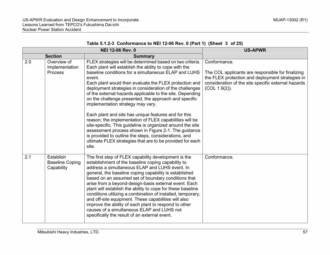
US-APWR Evaluation and Design Enhancement to Incorporate MUAP-13002 (R1) Lessons Learned from TEPCO's Fukushima Dai-ichi Nuclear Power Station Accident
Mitsubishi Heavy Industries, LTD. 57
Table 5.1.2-3 Conformance to NEI 12-06 Rev. 0 (Part 1) (Sheet of 25)
NEI 12-06 Rev. 0 US-APWR Section Summary
2.0 Overview of Implementation Process
FLEX strategies will be determined based on two criteria. Each plant will establish the ability to cope with the baseline conditions for a simultaneous ELAP and LUHS event. Each plant would then evaluate the FLEX protection and deployment strategies in consideration of the challenges of the external hazards applicable to the site. Depending on the challenge presented, the approach and specific implementation strategy may vary. Each plant and site has unique features and for this reason, the implementation of FLEX capabilities will be site-specific. This guideline is organized around the site assessment process shown in Figure 2-1. The guidance is provided to outline the steps, considerations, and ultimate FLEX strategies that are to be provided for each site.
Conformance. The COL applicants are responsible for finalizing the FLEX protection and deployment strategies in consideration of the site specific external hazards (COL 1.9(2)).
2.1 Establish Baseline Coping Capability
The first step of FLEX capability development is the establishment of the baseline coping capability to address a simultaneous ELAP and LUHS event. In general, the baseline coping capability is established based on an assumed set of boundary conditions that arise from a beyond-design-basis external event. Each plant will establish the ability to cope for these baseline conditions utilizing a combination of installed, temporary, and off-site equipment. These capabilities will also improve the ability of each plant to respond to other causes of a simultaneous ELAP and LUHS not specifically the result of an external event.
Conformance.
3

US-APWR Evaluation and Design Enhancement to Incorporate MUAP-13002 (R1) Lessons Learned from TEPCO's Fukushima Dai-ichi Nuclear Power Station Accident
Mitsubishi Heavy Industries, LTD. 58
Table 5.1.2-3 Conformance to NEI 12-06 Rev. 0 (Part 1) (Sheet of 25)
NEI 12-06 Rev. 0 US-APWR Section Summary
2.2 Determine Applicable External Hazards
This step of the site assessment process involves the evaluation of the external hazards that are considered credible to a particular site. For the purposes of this assessment, external hazards have been grouped into five classes to help further focus the effort: • seismic events • external flooding • storms such as hurricanes, high winds, and tornadoes • extreme snow, ice, and cold • extreme heat Each plant will evaluate the applicability of these hazards and, where applicable, address the implementation considerations associated with each. These considerations include: • protection of FLEX equipment • deployment of FLEX equipment • procedural interfaces • utilization of off-site resources
The COL applicants are responsible for conducting the evaluation of the site specific external hazards in accordance with the guidance (COL 1.9(2)).
2.3 Define Site-Specific FLEX Strategies
This step involves the consideration of the hazards that are applicable to the site, in order to establish the best overall strategy for the deployment of FLEX capabilities for beyond-design-basis conditions. Considering the external hazards applicable to the site, the FLEX mitigation equipment should be stored in a location or locations such that it is reasonably protected such that no one external event can reasonably fail the site FLEX capability. Reasonable protection can be provided for example, through provision of multiple sets
Conformance. The COL applicants are responsible for defining the site specific FLEX strategies (COL 1.9(2)).
4

US-APWR Evaluation and Design Enhancement to Incorporate MUAP-13002 (R1) Lessons Learned from TEPCO's Fukushima Dai-ichi Nuclear Power Station Accident
Mitsubishi Heavy Industries, LTD. 59
Table 5.1.2-3 Conformance to NEI 12-06 Rev. 0 (Part 1) (Sheet of 25)
NEI 12-06 Rev. 0 US-APWR Section Summary
of portable on-site equipment stored in diverse locations or through storage in structures designed to reasonably protect from applicable external events. The process for defining the full extent of the FLEX coping capability is described in Section 10.
2.4 Programmatic Controls
The programmatic controls for implementation of FLEX include: • quality attributes • equipment design • equipment storage • procedure guidance • maintenance and testing • training • staffing • configuration control Procedures and guidance to support deployment and implementation including interfaces to EOPs, special event procedures, abnormal event procedures, and system operating procedures, will be coordinated within the site procedural framework.
Conformance. The COL applicants are responsible for establishing the programmatic controls for implementation of FLEX and to coordinate them within the site procedural framework (COL 1.9(2)).
2.5 Synchronization with Off-site Resources
The timely provision of effective off-site resources will need to be coordinated by the site and will depend on the plant-specific analysis and strategies for coping with the effects of the beyond-design-basis external event. Arrangements will need to be established by each site for the off-site equipment and resources that will be required for the off-site phase.
Conformance. The COL applicants are responsible for arranging the off-site equipment and resources that required for the off-site phase based on the US-APWR baseline strategies (COL 1.9(2)).
5

US-APWR Evaluation and Design Enhancement to Incorporate MUAP-13002 (R1) Lessons Learned from TEPCO's Fukushima Dai-ichi Nuclear Power Station Accident
Mitsubishi Heavy Industries, LTD. 60
Table 5.1.2-3 Conformance to NEI 12-06 Rev. 0 (Part 1) (Sheet of 25)
NEI 12-06 Rev. 0 US-APWR Section Summary
The off-site response interfaces for FLEX capabilities are described in Section 12.
3 Step 1: Establish Baseline Coping Capability
See below. See below.
3.1 Purpose Omitted.
N/A
3.2 Performance Attributes
See below. See below.
3.2.1 General Criteria and Baseline Assumptions
See below. See below.
3.2.1.1 General Criteria Procedures and equipment relied upon should ensure that satisfactory performance of necessary fuel cooling and containment functions are maintained. A simultaneous ELAP and LUHS challenges both core cooling and spent fuel pool cooling due to interruption of normal ac powered system operations. For a PWR, an additional requirement is to keep the fuel in the reactor covered. For both PWRs and BWRs, the requirement is to keep fuel in the spent fuel pool covered. The conditions considered herein are beyond-design-basis. Consequently, it is not possible to bind all essential inputs to these evaluations.
Conformance.
6
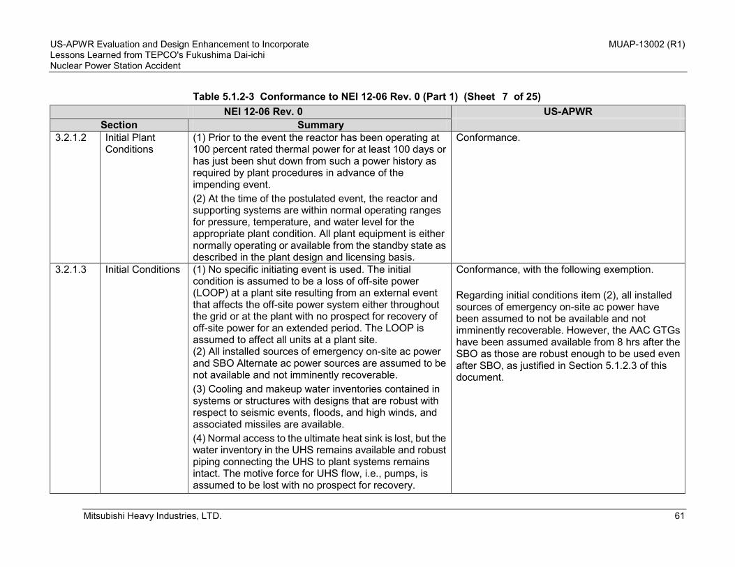
US-APWR Evaluation and Design Enhancement to Incorporate MUAP-13002 (R1) Lessons Learned from TEPCO's Fukushima Dai-ichi Nuclear Power Station Accident
Mitsubishi Heavy Industries, LTD. 61
Table 5.1.2-3 Conformance to NEI 12-06 Rev. 0 (Part 1) (Sheet of 25)
NEI 12-06 Rev. 0 US-APWR Section Summary
3.2.1.2 Initial Plant Conditions
(1) Prior to the event the reactor has been operating at 100 percent rated thermal power for at least 100 days or has just been shut down from such a power history as required by plant procedures in advance of the impending event. (2) At the time of the postulated event, the reactor and supporting systems are within normal operating ranges for pressure, temperature, and water level for the appropriate plant condition. All plant equipment is either normally operating or available from the standby state as described in the plant design and licensing basis.
Conformance.
3.2.1.3 Initial Conditions (1) No specific initiating event is used. The initial condition is assumed to be a loss of off-site power (LOOP) at a plant site resulting from an external event that affects the off-site power system either throughout the grid or at the plant with no prospect for recovery of off-site power for an extended period. The LOOP is assumed to affect all units at a plant site. (2) All installed sources of emergency on-site ac power and SBO Alternate ac power sources are assumed to be not available and not imminently recoverable. (3) Cooling and makeup water inventories contained in systems or structures with designs that are robust with respect to seismic events, floods, and high winds, and associated missiles are available. (4) Normal access to the ultimate heat sink is lost, but the water inventory in the UHS remains available and robust piping connecting the UHS to plant systems remains intact. The motive force for UHS flow, i.e., pumps, is assumed to be lost with no prospect for recovery.
Conformance, with the following exemption. Regarding initial conditions item (2), all installed sources of emergency on-site ac power have been assumed to not be available and not imminently recoverable. However, the AAC GTGs have been assumed available from 8 hrs after the SBO as those are robust enough to be used even after SBO, as justified in Section 5.1.2.3 of this document.
7
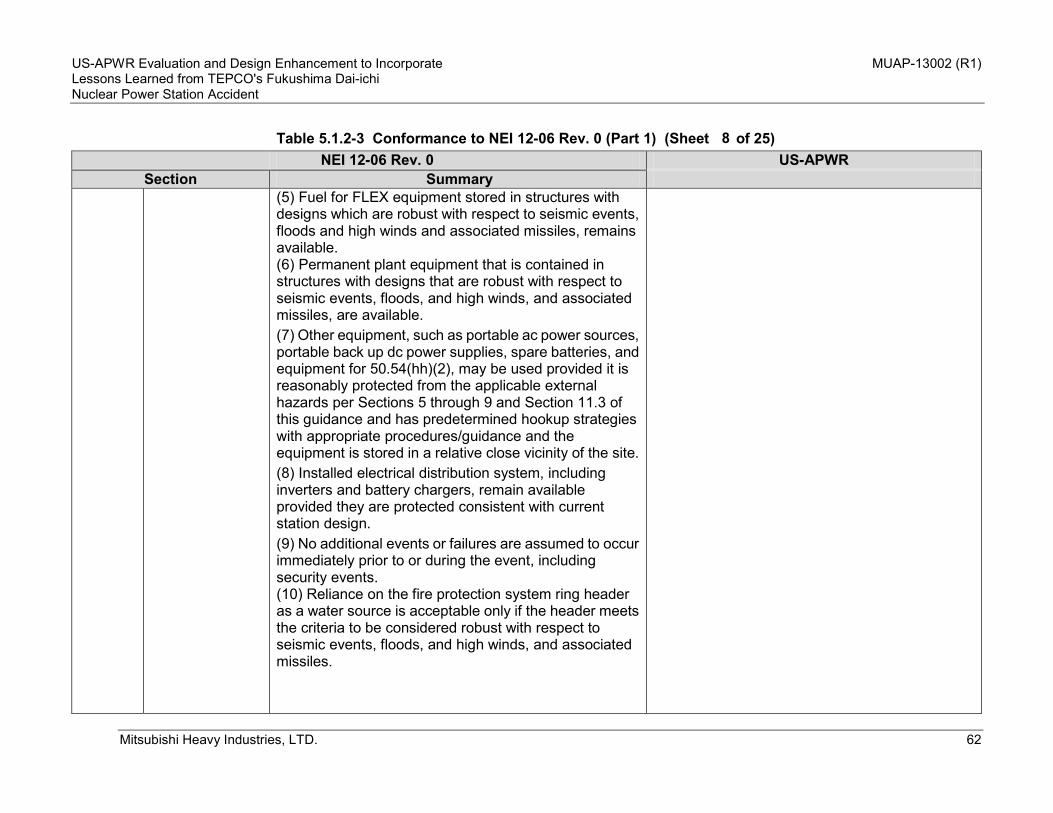
US-APWR Evaluation and Design Enhancement to Incorporate MUAP-13002 (R1) Lessons Learned from TEPCO's Fukushima Dai-ichi Nuclear Power Station Accident
Mitsubishi Heavy Industries, LTD. 62
Table 5.1.2-3 Conformance to NEI 12-06 Rev. 0 (Part 1) (Sheet of 25)
NEI 12-06 Rev. 0 US-APWR Section Summary
(5) Fuel for FLEX equipment stored in structures with designs which are robust with respect to seismic events, floods and high winds and associated missiles, remains available. (6) Permanent plant equipment that is contained in structures with designs that are robust with respect to seismic events, floods, and high winds, and associated missiles, are available. (7) Other equipment, such as portable ac power sources, portable back up dc power supplies, spare batteries, and equipment for 50.54(hh)(2), may be used provided it is reasonably protected from the applicable external hazards per Sections 5 through 9 and Section 11.3 of this guidance and has predetermined hookup strategies with appropriate procedures/guidance and the equipment is stored in a relative close vicinity of the site. (8) Installed electrical distribution system, including inverters and battery chargers, remain available provided they are protected consistent with current station design. (9) No additional events or failures are assumed to occur immediately prior to or during the event, including security events. (10) Reliance on the fire protection system ring header as a water source is acceptable only if the header meets the criteria to be considered robust with respect to seismic events, floods, and high winds, and associated missiles.
8

US-APWR Evaluation and Design Enhancement to Incorporate MUAP-13002 (R1) Lessons Learned from TEPCO's Fukushima Dai-ichi Nuclear Power Station Accident
Mitsubishi Heavy Industries, LTD. 63
Table 5.1.2-3 Conformance to NEI 12-06 Rev. 0 (Part 1) (Sheet of 25)
NEI 12-06 Rev. 0 US-APWR Section Summary
3.2.1.4 Reactor Transient
Additional boundary conditions: (1) Following the loss of all ac power, the reactor automatically trips and all rods are inserted. (2) The main steam system valves (such as main steam isolation valves, turbine stops, atmospheric dumps, etc.), necessary to maintain decay heat removal functions operate as designed. (3) Safety/Relief Valves (S/RVs) or Power Operated Relief Valves (PORVs) initially operate in a normal manner if conditions in the RCS so require. Normal valve reseating is also assumed. (4) No independent failures, other than those causing the ELAP/LUHS event, are assumed to occur in the course of the transient.
Conformance.
3.2.1.5 Reactor Coolant Inventory Loss
Sources of expected PWR reactor coolant inventory loss include: (1) normal system leakage (2) losses from letdown unless automatically isolated or until isolation is procedurally directed (3) losses due to reactor coolant pump seal leakage (rate is dependent on the RCP seal design)
Conformance.
3.2.1.6 SFP Conditions Initial conditions: (1) All boundaries of the SFP are intact, including the liner, gates, transfer canals, etc. (2) Although sloshing may occur during a seismic event, the initial loss of SFP inventory does not preclude access to the refueling deck around the pool.
Conformance.
9

US-APWR Evaluation and Design Enhancement to Incorporate MUAP-13002 (R1) Lessons Learned from TEPCO's Fukushima Dai-ichi Nuclear Power Station Accident
Mitsubishi Heavy Industries, LTD. 64
Table 5.1.2-3 Conformance to NEI 12-06 Rev. 0 (Part 1) (Sheet of 25)
NEI 12-06 Rev. 0 US-APWR Section Summary
(3) SFP cooling system is intact, including attached piping. (4) SFP heat load assumes the maximum design basis heat load for the site.
3.2.1.7 Event Response Actions
Event response actions follow the command and control of the existing procedures and guidance based on the underlying symptoms that result from the event. The priority for the plant response is to utilize systems or equipment that provides the highest probability for success. Other site impacts as a result of the event would be addressed according to plant priorities and resource availability. The FLEX strategy relies upon the following principles: 1) Initially cope by relying on installed plant equipment. 2) Transition from installed plant equipment to on-site FLEX equipment. 3) Obtain additional capability and redundancy from off-site resources until power, water, and coolant injection systems are restored or commissioned. 4) Response actions will be prioritized based on available equipment, resources, and time constraints. The initial coping response actions can be performed by available site personnel post-event. 5) Transition from installed plant equipment to on-site FLEX equipment may involve on-site, off-site, or recalled personnel as justified by plant-specific evaluation. 6) Strategies that have a time constraint to be successful
Conformance.
10

US-APWR Evaluation and Design Enhancement to Incorporate MUAP-13002 (R1) Lessons Learned from TEPCO's Fukushima Dai-ichi Nuclear Power Station Accident
Mitsubishi Heavy Industries, LTD. 65
Table 5.1.2-3 Conformance to NEI 12-06 Rev. 0 (Part 1) (Sheet of 25)
NEI 12-06 Rev. 0 US-APWR Section Summary
should be identified and a basis provided that the time can reasonably be met.
3.2.1.8 Effects of Loss of Ventilations
The effects of loss of HVAC in an extended loss of ac power event can be addressed consistent with NUMARC 87-00 [Ref. 8] or by plant-specific thermal hydraulic calculations, e.g., GOTHIC calculations.
Not applicable to the US-APWR. The US-APWR baseline strategies intend to resume ventilation for areas containing permanent coping equipment during Phase 2 (t=8 hrs – t=7 days), if necessary.
3.2.1.9 Personnel Accessibility
Areas requiring personnel access should be evaluated to ensure that conditions will support the actions required by the plant-specific strategy for responding to the event.
Conformance. The US-APWR baseline strategies intend to resume ventilation for areas containing permanent coping equipment during Phase 2 (t=8 hrs – t=7 days), if necessary.
3.2.1.10 Instrumentation and Controls
Actions specified in plant procedures/guidance for loss of ac power are predicated on use of instrumentation and controls powered by station batteries. In order to extend battery life, a minimum set of parameters necessary to support strategy implementation should be defined. The parameters selected must be able to demonstrate the success of the strategies at maintaining the key safety functions as well as indicate imminent or actual core damage to facilitate a decision to manage the response to the event within the Emergency Operating Procedures and FLEX Support Guidelines or within the SAMGs. Typically, these parameters would include the following: • SG Level
Conformance. The design enhancement shown in this technical report enables all the necessary I&C equipment to perform the mitigating strategies including SG water level, main steam pressure, reactor coolant pressure, reactor coolant temperature, containment pressure, SFP water level and pressurizer water level are powered throughout the course of the coping actions for BDB external event. No load shedding is required for the US-APWR.
11

US-APWR Evaluation and Design Enhancement to Incorporate MUAP-13002 (R1) Lessons Learned from TEPCO's Fukushima Dai-ichi Nuclear Power Station Accident
Mitsubishi Heavy Industries, LTD. 66
Table 5.1.2-3 Conformance to NEI 12-06 Rev. 0 (Part 1) (Sheet of 25)
NEI 12-06 Rev. 0 US-APWR Section Summary
• SG Pressure • RCS Pressure • RCS Temperature • Containment Pressure • SFP Level
3.2.1.11 Containment Isolation Valves
It is assumed that the containment isolation actions delineated in current station blackout coping capabilities is sufficient.
Conformance. For the US-APWR, containment isolation will not be necessary for Phase 1 or Phase 2.
3.2.2 Minimum Baseline Capabilities
Each site should establish the minimum coping capabilities consistent with unit-specific evaluation of the potential impacts and responses to an ELAP and LUHS. In general, this coping can be thought of as occurring in three phases: • Phase 1: Cope relying on installed plant equipment. • Phase 2: Transition from installed plant equipment to on-site FLEX equipment. • Phase 3: Obtain additional capability and redundancy from off-site equipment until power, water, and coolant injection systems are restored or commissioned. In order to support the objective of an indefinite coping capability, each plant will be expected to establish capabilities consistent with Table 3-2 (PWRs). The following guidelines are provided to support the development of guidance to cope with the existing set of plant operating procedures/guidance:
Conformance, with the following exemption. The COL applicants are responsible for developing FLEX guidance to cope with the plant operating procedures/ guidance considering the guidance described in the NEI 12-06 (COL 1.9(2)).
12

US-APWR Evaluation and Design Enhancement to Incorporate MUAP-13002 (R1) Lessons Learned from TEPCO's Fukushima Dai-ichi Nuclear Power Station Accident
Mitsubishi Heavy Industries, LTD. 67
Table 5.1.2-3 Conformance to NEI 12-06 Rev. 0 (Part 1) (Sheet of 25)
NEI 12-06 Rev. 0 US-APWR Section Summary
(1) Plant procedures/guidance should identify site-specific actions necessary to restore ac power to essential loads. If an Alternate ac (AAC) power source is available it should be started as soon as possible. If not, actions should be taken to secure existing equipment alignments and provide an alternate power source as soon as possible based on relative plant priorities. (2) Plant procedures/guidance should recognize the importance of AFW/HPCI/RCIC/IC during the early stages of the event and direct the operators to invest appropriate attention to assuring its initiation and continued, reliable operation throughout the transient since this ensures decay heat removal. (3) Plant procedures/guidance should specify actions necessary to assure that equipment functionality can be maintained (including support systems or alternate method) in an ELAP/LUHS or can perform without ac power or normal access to the UHS. (4) Plant procedures/guidance should identify the sources of potential reactor inventory loss, and specify actions to prevent or limit significant loss. (5) Plant procedures/guidance should ensure that a flow path is promptly established for makeup flow to the steam generator/nuclear boiler and identify backup water sources in order of intended use. Additionally, plant procedures/guidance should specify clear criteria for transferring to the next preferred source of water. (6) Plant procedures/guidance should identify loads that need to be stripped from the plant dc buses (both Class 1E and non-Class 1E) for the purpose of conserving dc power.
13

US-APWR Evaluation and Design Enhancement to Incorporate MUAP-13002 (R1) Lessons Learned from TEPCO's Fukushima Dai-ichi Nuclear Power Station Accident
Mitsubishi Heavy Industries, LTD. 68
Table 5.1.2-3 Conformance to NEI 12-06 Rev. 0 (Part 1) (Sheet of 25)
NEI 12-06 Rev. 0 US-APWR Section Summary
(7) Plant procedures/guidance should specify actions to permit appropriate containment isolation and safe shutdown valve operations while ac power is unavailable. (8) Plant procedures/guidance should identify the portable lighting (e.g., flashlights or headlamps) and communications systems necessary for ingress and egress to plant areas required for deployment of FLEX strategies. (9) Plant procedures/guidance should consider the effects of ac power loss on area access, as well as the need to gain entry to the Protected Area and internal locked areas where remote equipment operation is necessary. (10) Plant procedures/guidance should consider loss of ventilation effects on specific energized equipment necessary for shutdown (e.g., those containing internal electrical power supplies or other local heat sources that may be energized or present in an ELAP. (11) Plant procedures/guidance should consider accessibility requirements at locations where operators will be required to perform local manual operations. (12) Plant procedures/guidance should consider loss of heat tracing effects for equipment required to cope with an ELAP. Alternate steps, if needed, should be identified to supplement planned action. (13) Use of portable equipment, e.g., portable power supplies, portable pumps, etc., can extend plant coping capability. The procedures/guidance for implementation of these portable systems should address the transitions from installed sources to portable are available as well
14

US-APWR Evaluation and Design Enhancement to Incorporate MUAP-13002 (R1) Lessons Learned from TEPCO's Fukushima Dai-ichi Nuclear Power Station Accident
Mitsubishi Heavy Industries, LTD. 69
Table 5.1.2-3 Conformance to NEI 12-06 Rev. 0 (Part 1) (Sheet of 25)
NEI 12-06 Rev. 0 US-APWR Section Summary
as to address delivery capabilities. (14) Procedures/guidance should address the appropriate monitoring and makeup options to the SFP.
3.3 Consideration in Utilizing Off-Site Resources
Once the analysis determines the equipment requirements for extended coping, the licensee should obtain the required on-site equipment and ensure appropriate arrangements are in place to obtain the necessary off-site equipment including its deployment at the site in the time required by the analysis. The site will need to identify staging area(s) for receipt of the equipment and a means to transport the off-site equipment to the deployment location. It is expected that the licensee will ensure the off-site resource organization will be able to provide the resources that will be necessary to support the extended coping duration. A list of possible off-site equipment is provided in Section 12. In addition, the licensee will need to ensure standard connectors for electrical and mechanical equipment compatible with the site connections are provided.
Conformance, with the following exemptions. Necessary off-site equipment has been identified for the standard US-APWR design. The COL applicants are to ensure appropriate arrangements are in-place by the start of initial fuel loading (COL 1.9(2)). The COL applicants are to identify the staging area(s) for receipt of the equipment and a means to transport the off-site equipment to the deployment location and to ensure the off-site resource organization is able to provide the resources that are necessary to support the extended coping duration (COL 1.9(2)). A list of possible off-site equipment is provided in Table 5.1.2-1 of this report. In addition, the US-APWR plant is equipped with standard connections for the necessary off-site equipment as shown in Chapter 6 of this report.
4 STEP 2: Determine Applicable Extreme External Hazards
See below. See below.
15

US-APWR Evaluation and Design Enhancement to Incorporate MUAP-13002 (R1) Lessons Learned from TEPCO's Fukushima Dai-ichi Nuclear Power Station Accident
Mitsubishi Heavy Industries, LTD. 70
Table 5.1.2-3 Conformance to NEI 12-06 Rev. 0 (Part 1) (Sheet of 25)
NEI 12-06 Rev. 0 US-APWR Section Summary
5 STEP 2A: Assess Seismic Impact
The FLEX deployment strategy will address seismic hazards at all sites.
This is outside the scope of the standard design. The COL applicants are responsible for conducting the assessment according to the guidance and the FLEX equipment needs to be stored in a building reasonably protected against SSE (COL 1.9(2)).
6 STEP 2B: Assess External Flooding Impact
Plants that are not dry sites will perform the next two steps of the flood-induced challenge evaluation.
This is outside the scope of the standard design. The COL applicants are responsible for conducting the assessment according to the guidance and the FLEX equipment needs to be stored in a building reasonably protected against SSE (COL 1.9(2)).
7 STEP 2C: Assess Impact of Severe Storms with High Winds
The evaluation of high wind-induced challenges has three parts. The first part is determining whether the site is potentially susceptible to different high wind conditions. The second part is the characterization of the applicable high wind threat. The third part is the application of the high wind threat characterization to the protection and deployment of FLEX strategies.
This is outside the scope of the standard design. The COL applicants are responsible for conducting the assessment according to the guidance based on the site characteristics. FLEX equipment shall be stored in a building reasonably protected from high wind hazards (COL 1.9(2)).
8
STEP 2D: Assess Impact of Snow, Ice and Extreme Cold
All sites should consider the temperature ranges and weather conditions for their site in storing and deploying their FLEX equipment.
This is outside the scope of the standard design. The COL applicants are responsible for conducting the assessment according to the guidance (COL 1.9(2)).
16
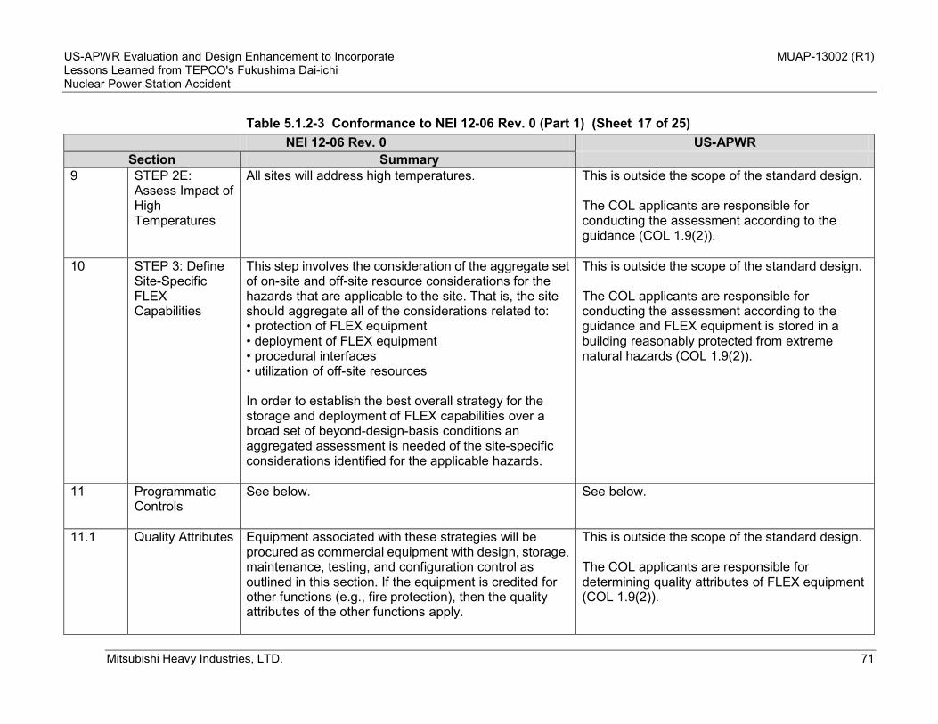
US-APWR Evaluation and Design Enhancement to Incorporate MUAP-13002 (R1) Lessons Learned from TEPCO's Fukushima Dai-ichi Nuclear Power Station Accident
Mitsubishi Heavy Industries, LTD. 71
Table 5.1.2-3 Conformance to NEI 12-06 Rev. 0 (Part 1) (Sheet of 25)
NEI 12-06 Rev. 0 US-APWR Section Summary
9 STEP 2E: Assess Impact of High Temperatures
All sites will address high temperatures. This is outside the scope of the standard design. The COL applicants are responsible for conducting the assessment according to the guidance (COL 1.9(2)).
10 STEP 3: Define Site-Specific FLEX Capabilities
This step involves the consideration of the aggregate set of on-site and off-site resource considerations for the hazards that are applicable to the site. That is, the site should aggregate all of the considerations related to: • protection of FLEX equipment • deployment of FLEX equipment • procedural interfaces • utilization of off-site resources In order to establish the best overall strategy for the storage and deployment of FLEX capabilities over a broad set of beyond-design-basis conditions an aggregated assessment is needed of the site-specific considerations identified for the applicable hazards.
This is outside the scope of the standard design. The COL applicants are responsible for conducting the assessment according to the guidance and FLEX equipment is stored in a building reasonably protected from extreme natural hazards (COL 1.9(2)).
11 Programmatic Controls
See below. See below.
11.1 Quality Attributes Equipment associated with these strategies will be procured as commercial equipment with design, storage, maintenance, testing, and configuration control as outlined in this section. If the equipment is credited for other functions (e.g., fire protection), then the quality attributes of the other functions apply.
This is outside the scope of the standard design. The COL applicants are responsible for determining quality attributes of FLEX equipment (COL 1.9(2)).
17
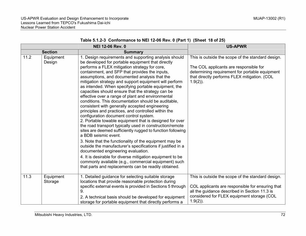
US-APWR Evaluation and Design Enhancement to Incorporate MUAP-13002 (R1) Lessons Learned from TEPCO's Fukushima Dai-ichi Nuclear Power Station Accident
Mitsubishi Heavy Industries, LTD. 72
Table 5.1.2-3 Conformance to NEI 12-06 Rev. 0 (Part 1) (Sheet of 25)
NEI 12-06 Rev. 0 US-APWR Section Summary
11.2 Equipment Design
1. Design requirements and supporting analysis should be developed for portable equipment that directly performs a FLEX mitigation strategy for core, containment, and SFP that provides the inputs, assumptions, and documented analysis that the mitigation strategy and support equipment will perform as intended. When specifying portable equipment, the capacities should ensure that the strategy can be effective over a range of plant and environmental conditions. This documentation should be auditable, consistent with generally accepted engineering principles and practices, and controlled within the configuration document control system. 2. Portable towable equipment that is designed for over the road transport typically used in construction/remote sites are deemed sufficiently rugged to function following a BDB seismic event. 3. Note that the functionality of the equipment may be outside the manufacturer’s specifications if justified in a documented engineering evaluation. 4. It is desirable for diverse mitigation equipment to be commonly available (e.g., commercial equipment) such that parts and replacements can be readily obtained.
This is outside the scope of the standard design. The COL applicants are responsible for determining requirement for portable equipment that directly performs FLEX mitigation. (COL 1.9(2)).
11.3 Equipment Storage
1. Detailed guidance for selecting suitable storage locations that provide reasonable protection during specific external events is provided in Sections 5 through 9. 2. A technical basis should be developed for equipment storage for portable equipment that directly performs a
This is outside the scope of the standard design. COL applicants are responsible for ensuring that all the guidance described in Section 11.3 is considered for FLEX equipment storage (COL 1.9(2)).
18

US-APWR Evaluation and Design Enhancement to Incorporate MUAP-13002 (R1) Lessons Learned from TEPCO's Fukushima Dai-ichi Nuclear Power Station Accident
Mitsubishi Heavy Industries, LTD. 73
Table 5.1.2-3 Conformance to NEI 12-06 Rev. 0 (Part 1) (Sheet of 25)
NEI 12-06 Rev. 0 US-APWR Section Summary
FLEX mitigation strategy for core, containment, and SFP that provides the inputs, assumptions, and documented basis that the mitigation strategy and support equipment will be reasonably protected from applicable external events such that the equipment could be operated in place, if applicable, or moved to its deployment locations. This basis should be auditable, consistent with generally accepted engineering principles, and controlled within the configuration document control system. 3. FLEX mitigation equipment should be stored in a location or locations informed by evaluations performed per Sections 5 through 9 such that no one external event can reasonably fail the site FLEX capability. 4. Different FLEX equipment can be credited for independent events. 5. Consideration should be given to the transport from the storage area following the external event recognizing that external events can result in obstacles restricting normal pathways for movement. 6. If portable FLEX equipment is pre-staged such that it minimizes the time delay and burden of hook-up following an external event, then the equipment should be evaluated to not have an adverse effect on existing SSCs and the primary connection point should be as close to the intended point of supply as possible, e.g., a staged power supply to recharge batteries should be connected as close to the battery charger as practicable to maintain diversity and minimize the reliance on other installed equipment.
19

US-APWR Evaluation and Design Enhancement to Incorporate MUAP-13002 (R1) Lessons Learned from TEPCO's Fukushima Dai-ichi Nuclear Power Station Accident
Mitsubishi Heavy Industries, LTD. 74
Table 5.1.2-3 Conformance to NEI 12-06 Rev. 0 (Part 1) (Sheet of 25)
NEI 12-06 Rev. 0 US-APWR Section Summary
11.4 Procedure Guidance
See below. See below.
11.4.1 Objectives The purpose of this section is to describe the procedural approach for the implementation of diverse and flexible (FLEX) strategies. This approach includes appropriate interfaces between the various accident mitigation procedures so that overall strategies are coherent and comprehensive. This approach is intended to provide guidance for responding to BDBEE events while minimizing the need for invoking 50.54 (x).
Not applicable. This paragraph describes the objectives of the guidance and compliance with this section is not a requirement.
11.4.2 Operating Procedure Hierarchy
1. The existing hierarchy for operating plant procedures remains relatively unchanged with the following exceptions: a. A new group of FSG for implementation of FLEX strategies will be created. b. Existing AOPs and EOPs will be revised to the extent necessary to include appropriate portions or reference to FSG. 2. Where FLEX strategies rely on permanently installed equipment, changes may be required to AOPs and EOPs. 3. Transition from the current procedure structure to the modified procedure structure that incorporates the FLEX strategies is illustrated in Figure 11-1.
This is outside the scope of the standard design. The COL applicants are responsible for organizing the operating procedure hierarchy (COL 1.9(2)).
20

US-APWR Evaluation and Design Enhancement to Incorporate MUAP-13002 (R1) Lessons Learned from TEPCO's Fukushima Dai-ichi Nuclear Power Station Accident
Mitsubishi Heavy Industries, LTD. 75
Table 5.1.2-3 Conformance to NEI 12-06 Rev. 0 (Part 1) (Sheet of 25)
NEI 12-06 Rev. 0 US-APWR Section Summary
11.4.3 Development Guidance for FSGs
The inability to predict actual plant conditions that require the use of FLEX equipment makes it impossible to provide specific procedural guidance. As such, the FSG will provide guidance that can be employed for a variety of conditions.
This is outside the scope of the standard design. The COL applicants are responsible for developing EOP and FSG that can be employed for a variety of conditions (COL 1.9(2), COL 1.9(5)).
11.4.4 Regulatory Screening/ Evaluations
NEI 96-07, revision 1, and NEI 97-04, revision 1 should be used to evaluate the changes to existing procedures as well as to the FSG to determine the need for prior NRC approval. Changes to procedures (EOPs or FSGs) that perform actions in response events that exceed a site's design basis should, per the guidance and examples provided in NEI 96-07, Rev. 1, screen out. Therefore, procedure steps which recognize the beyond-design-basis ELAP/LUHS has occurred and which direct actions to ensure core cooling, SFP cooling, or containment integrity should not require prior NRC approval.
This is outside the scope of the standard design. The COL applicants are responsible for developing EOP and FSG prior to the initial fuel loading (COL 1.9(2), COL 1.9(5)).
11.5 Maintenance and Testing
1. FLEX mitigation equipment should be initially tested or other reasonable means used to verify performance conforms to the limiting FLEX requirements. Validation of source manufacturer quality is not required. 2. Portable equipment that directly performs a FLEX mitigation strategy for the core, containment, or SFP should be subject to maintenance and testing guidance provided in INPO AP 913, Equipment Reliability Process, to verify proper function. The maintenance program should ensure that the FLEX equipment reliability is being achieved. Standard industry templates (e.g., EPRI) and associated bases will be developed to
This is outside the scope of the standard design. The COL applicants will follow NEI 12-06 in this section (COL 1.9(2)).
21

US-APWR Evaluation and Design Enhancement to Incorporate MUAP-13002 (R1) Lessons Learned from TEPCO's Fukushima Dai-ichi Nuclear Power Station Accident
Mitsubishi Heavy Industries, LTD. 76
Table 5.1.2-3 Conformance to NEI 12-06 Rev. 0 (Part 1) (Sheet of 25)
NEI 12-06 Rev. 0 US-APWR Section Summary
define specific maintenance and testing. 3. The unavailability of equipment and applicable connections that directly performs a FLEX mitigation strategy for core, containment, and SFP should be managed such that risk to mitigating strategy capability is minimized.
11.6 Training 1. Programs and controls should be established to assure personnel proficiency in the mitigation of beyond-design-basis events is developed and maintained. These programs and controls should be implemented in accordance with an accepted training process. 2. Periodic training should be provided to site emergency response leaders on beyond-design-basis emergency response strategies and implementing guidelines. Operator training for beyond-design-basis event accident mitigation should not be given undue weight in comparison with other training requirements. The testing/evaluation of Operator knowledge and skills in this area should be similarly weighted. 3. Personnel assigned to direct the execution of mitigation strategies for beyond-design-basis events will receive necessary training to ensure familiarity with the associated tasks, considering available job aids, instructions, and mitigating strategy time constraints. 4. “ANSI/ANS 3.5, Nuclear Power Plant Simulators for use in Operator Training” certification of simulator fidelity (if used) is considered to be sufficient for the initial stages of the beyond-design-basis external event scenario until the current capability of the simulator
This is outside the scope of the standard design. The COL applicants are responsible for establishing the training program and controls where the guidance in this section is considered (COL 1.9(2)).
22

US-APWR Evaluation and Design Enhancement to Incorporate MUAP-13002 (R1) Lessons Learned from TEPCO's Fukushima Dai-ichi Nuclear Power Station Accident
Mitsubishi Heavy Industries, LTD. 77
Table 5.1.2-3 Conformance to NEI 12-06 Rev. 0 (Part 1) (Sheet of 25)
NEI 12-06 Rev. 0 US-APWR Section Summary
model is exceeded. Full scope simulator models will not be upgraded to accommodate FLEX training or drills. 5. Where appropriate, the integrated FLEX drills should be organized on a team or crew basis and conducted periodically; with all time-sensitive actions to be evaluated over a period of not more than eight years. It is not the intent to connect to or operate permanently installed equipment during these drills and demonstrations.
11.7 Staffing 1. On-site staff are at site administrative minimum shift staffing levels, (minimum staffing may include additional staffing that is procedurally brought on-site in advance of a predicted external event, e.g., hurricane). 2. No independent, concurrent events, e.g., no active security threat, and 3. All personnel on-site are available to support site response.
This is outside the scope of the standard design. The COL applicants are responsible for on-site staffing (COL 1.9(2)).
11.8 Configuration Control
1. The FLEX strategies and basis will be maintained in an overall program document. This program document will also contain a historical record of previous strategies and the basis for changes. The document will also contain the basis for the ongoing maintenance and testing programs chosen for the FLEX equipment. 2. Existing plant configuration control procedures will be modified to ensure that changes to the plant design, physical plant layout, roads, buildings, and miscellaneous structures will not adversely impact the approved FLEX strategies.
This is outside the scope of the standard design. The control of the plant configuration control procedure/program is the responsibility of the COL applicants/licensee (COL 1.9(2)).
23

US-APWR Evaluation and Design Enhancement to Incorporate MUAP-13002 (R1) Lessons Learned from TEPCO's Fukushima Dai-ichi Nuclear Power Station Accident
Mitsubishi Heavy Industries, LTD. 78
Table 5.1.2-3 Conformance to NEI 12-06 Rev. 0 (Part 1) (Sheet of 25)
NEI 12-06 Rev. 0 US-APWR Section Summary
3. Changes to FLEX strategies may be made without prior NRC approval.
12 Off-Site Resources
See below. See below.
12.1 Synchronization with Off-site Resources
Arrangements will need to be established by each site addressing the scope of equipment that will be required for the off-site phase, as well as the maintenance and delivery provisions for such equipment.
This is outside the scope of the standard design. The COL applicants are responsible for establishing arrangements of off-site resources based on site-specific FLEX strategies (COL 1.9(2), COL 1.9(5)).
12.2 Minimum Capabilities of Off-site Resources
Each site will establish a means to ensure the necessary resources will be available from off-site. Considerations that should be included in establishing this capability include: 1) A capability to obtain equipment and commodities to sustain and backup the site’s coping strategies. 2) Off-site equipment procurement, maintenance, testing, calibration, storage, and control. 3) A provision to inspect and audit the contractual agreements to reasonably assure the capabilities to deploy the FLEX strategies including unannounced random inspections by the Nuclear Regulatory Commission. 4) Provisions to ensure that no single external event will preclude the capability to supply the needed resources to the plant site. 5) Provisions to ensure that the off-site capability can be maintained for the life of the plant.
This is o the scope of the standard design. The COL applicants are responsible for establishing a means to ensure the necessary resources are available from off-site considering the guidance in NEI 12-06 (COL 1.9(2), COL 1.9(5)).
24

US-APWR Evaluation and Design Enhancement to Incorporate MUAP-13002 (R1) Lessons Learned from TEPCO's Fukushima Dai-ichi Nuclear Power Station Accident
Mitsubishi Heavy Industries, LTD. 79
Table 5.1.2-3 Conformance to NEI 12-06 Rev. 0 (Part 1) (Sheet of 25)
NEI 12-06 Rev. 0 US-APWR Section Summary
6) Provisions to revise the required supplied equipment due to changes in the FLEX strategies or plant equipment or equipment obsolescence. 7) The appropriate standard mechanical and electrical connections need to be specified. 8) Provisions to ensure that the periodic maintenance, periodic maintenance schedule, testing, and calibration of off-site equipment are comparable/ consistent with that of similar on-site FLEX equipment. 9) Provisions to ensure that equipment determined to be unavailable/non-operational during maintenance or testing is either restored to operational status or replaced with appropriate alternate equipment within 90 days. 10) Provision to ensure that reasonable supplies of spare parts for the off-site equipment are readily available if needed. The intent of this provision is to reduce the likelihood of extended equipment maintenance (requiring in excess of 90 days for returning the equipment to operational status).
13 Submittal Guidance
Reporting requirements are established in accordance with NRC Order EA-12-049 Order Modifying Licenses with Regard to Requirements for Mitigation Strategies for Beyond-Design-Basis External Events.
N/A
14 References Omitted
N/A
25

US-APWR Evaluation and Design Enhancement to Incorporate MUAP-13002 (R1) Lessons Learned from TEPCO's Fukushima Dai-ichi Nuclear Power Station Accident
Mitsubishi Heavy Industries, LTD. 80
Table 5.1.2-4 Conformance with NEI 12-06 Rev. 0 (Part 2) (Sheet of 5) NEI 12-06 Rev. 0 Guidance Table D-1 US-APWR
Safety Function Method Performance Attributes
Core Cooling & Heat Removal (SG available)
AFW/EFW • Extend installed coping capability through procedural enhancements (e.g., load shedding), provision of portable battery chargers and other power supplies. • Objective is to provide extended baseline coping capability with installed equipment. • Procedures/guidance to include local manual initiation of ac-independent AFW/EFW pumps consistent with NEI 06-12.
Conformance. • Robust Class 1E batteries and AAC GTGs are used to supply power to coping equipment for a BDB external event. • EFW pumps provide extended baseline coping capability. • FSG includes local manual initiation of ac-independent EFW pumps consistent with NEI 06-12.
Core Cooling & Heat Removal (SG available)
Depressurize SG for Makeup with Portable Injection Source
• Primary and alternate injection points are required to establish capability to inject through separate divisions/trains, i.e., should not have both connections in one division/train. • Makeup paths supply required SGs • SG makeup rate should exceed decay heat levels at time of planned deployment in order to support restoring SG water level, e.g., 200* gpm. • Analysis should demonstrate that the guidance and equipment for combined SG depressurization and makeup capability supports continued core cooling.
Conformance. • One injection point for the A-EFW supply line and one for the D-EFW supply line are provided. • Portable SG makeup pumps with more than 200 gpm capacity will be pre-staged at the site. • Analysis will be performed by the COL applicants when the FSG is developed.
1

US-APWR Evaluation and Design Enhancement to Incorporate MUAP-13002 (R1) Lessons Learned from TEPCO's Fukushima Dai-ichi Nuclear Power Station Accident
Mitsubishi Heavy Industries, LTD. 81
Table 5.1.2-4 Conformance with NEI 12-06 Rev. 0 (Part 2) (Sheet of 5) NEI 12-06 Rev. 0 Guidance Table D-1 US-APWR
Safety Function Method Performance Attributes
Core Cooling & Heat Removal (SG available)
Sustained Source of Water
• Water source sufficient to supply water indefinitely including consideration of concurrent makeup or spray of SFP.
Conformance. UHS water inventory has sufficient water volume to maintain core cooling for over 30 days.
RCS Inventory Control/Long-Term Subcriticality
Low Leak RCP Seals and/or borated high pressure RCS makeup required
• Makeup capability to maintain core cooling*. • Sufficient letdown to support required makeup and ensure subcriticality*. *Note: subject to generic or plant specific analysis
Conformance. A CHP with suction from the RWSP and AACs are used for RCS inventory controls and long-term subcriticality
Core Cooling and Heat Removal (Modes 5 and 6, SG unavailable)
All Plants provide means to provide borated RCS makeup ** ** Note: There may be short periods of time during Modes 5 & 6 where plant configuration may preclude use of this strategy.
• Diverse injection points or methods are required to establish capability to inject through separate divisions/trains, i.e., should not have both connections in one division/train. • Connection to RCS for makeup should be capable of flow rates sufficient for simultaneous core heat removal and boron flushing (combined makeup flow exceeding 300* gpm).
Conformance. A CHP is used for makeup borated water to the RCS from the RWSP. Diverse RCS makeup connections for a portable pump are provided. A portable SG makeup pump can be used for the RCS makeup.
2

US-APWR Evaluation and Design Enhancement to Incorporate MUAP-13002 (R1) Lessons Learned from TEPCO's Fukushima Dai-ichi Nuclear Power Station Accident
Mitsubishi Heavy Industries, LTD. 82
Table 5.1.2-4 Conformance with NEI 12-06 Rev. 0 (Part 2) (Sheet of 5) NEI 12-06 Rev. 0 Guidance Table D-1 US-APWR
Safety Function Method Performance Attributes
• On-site pump (portable or installed) for RCS makeup. This can be the SG makeup pump since both will not be required at same time. • In order to address the requirement for diversity, if re-powering of installed charging pumps is used for this function, then either (a) multiple power connection points should be provided to the charging pump, or (b) provide a single power supply connection point for the charging pump and a single connection point for a portable makeup pump. *Note: subject to generic or plant specific analysis
Source of borated water could be an on-site tank, or could be provided by off-site resources.
Conformance. The RWSP is used as a source of borated water.
Key Reactor Parameters
SG level SG pressure RCS pressure RCS temperature
• Identify instruments to be relied upon, including control room and field instruments • Depending on strategy employed, additional parameters may be required.
Conformance. The following key parameters are provided: • SG water level • Main steam line pressure • Reactor coolant pressure • Reactor coolant temperature • EFW pit water level • Pressurizer water level
3

US-APWR Evaluation and Design Enhancement to Incorporate MUAP-13002 (R1) Lessons Learned from TEPCO's Fukushima Dai-ichi Nuclear Power Station Accident
Mitsubishi Heavy Industries, LTD. 83
Table 5.1.2-4 Conformance with NEI 12-06 Rev. 0 (Part 2) (Sheet of 5) NEI 12-06 Rev. 0 Guidance Table D-1 US-APWR
Safety Function Method Performance Attributes
Containment Function
Containment Spray
Due to the long-term nature of this function, the connection does not need to be a permanent modification. However, if a temporary connection, e.g., via valve bonnet, then this should be pre-identified.
Conformance. Permanent connection from the fire protection system to the containment spray system can be used, if available. When the fire protection system is not available a temporary connection will be prepared.
Key Containment Parameters
Containment Pressure
Identify instruments to be relied upon, including control room and field instruments
Conformance. The following parameter is provided: • Containment pressure
Spent Fuel Cooling
Makeup with Portable Injection Source (makeup via hoses on refuel floor)
Minimum makeup rate must be capable of exceeding boil-off rate for the boundary conditions described in Section 3.2.1.6.
Conformance.
Makeup with Portable Injection Source (makeup via connection to SFP cooling piping or other alternate location)
Minimum makeup rate must be capable of exceeding boil-off rate for the boundary conditions described in Section 3.2.1.6.
Conformance. Makeup capacity of 500 gpm through a diverse makeup line is available.
4

US-APWR Evaluation and Design Enhancement to Incorporate MUAP-13002 (R1) Lessons Learned from TEPCO's Fukushima Dai-ichi Nuclear Power Station Accident
Mitsubishi Heavy Industries, LTD. 84
Table 5.1.2-4 Conformance with NEI 12-06 Rev. 0 (Part 2) (Sheet of 5) NEI 12-06 Rev. 0 Guidance Table D-1 US-APWR
Safety Function Method Performance Attributes
Makeup with Portable Injection Source (Vent pathway for steam & condensate from SFP)
Plant-specific strategy should be considered as needed
Conformance. The doors between the SFP area and the A/B will be opened if necessary as a vent pathway for steam & condensate from the SFP.
Makeup with Portable Injection Source (spray capability via portable monitor nozzles from refueling floor using portable pump)
Minimum of 200 gpm per unit to the pool or 250 gpm per unit if overspray occurs consistent with 10 CFR 50.54(hh)(2). This capability is not required for sites that have SFPs that cannot be drained.
Conformance. Makeup capacity of at least 200 gpm through the spray line is available.
SFP parameters SFP level Per EA 12-051
Conformance. The following parameter is monitored: • SFP water level instruments
(narrow-range and wide-range)
5

US-APWR Evaluation and Design Enhancement to Incorporate MUAP-13002 (R1) Lessons Learned from TEPCO's Fukushima Dai-ichi Nuclear Power Station Accident
Mitsubishi Heavy Industries, LTD. 85
Table 5.1.2-5 Sequence of Events for Core Cooling (Sheet 1 of 2)
Event Time Description of Why the Time is Reasonably Achievable Reference
Initiating event 0 NA NA
Automatic Turbine Driven EFW pumps start
1 minutes EFW pumps automatically start upon receipt of a PSMS signal.
Appendix 2
Automatic EFW tie-line opens 5 minutes Automatic logic is added to open the EFW tie line valves.
Appendix 2
Connect a AAC to Class 1E power system
By 8 hrs This can be achieved by using permanently installed equipment.
Also, procedures and training will be established by the COL applicant so that necessary operational activities can be conducted in a timely manner.
5.1.2.3
Start the alternate UHS By 8hrs Same description as above 5.1.2.3
Start a CHP By 8hrs Same description as above 5.1.2.3
Start essential HVAC systems
8 hrs Same description as above 5.1.2.3
Start manual RCS cooldown with MSDVs
8hrs Same description as above Appendix 2
Accumulator injection begins Approx. 11 hrs Confirmed by the supporting analysis.
Appendix 2

US-APWR Evaluation and Design Enhancement to Incorporate MUAP-13002 (R1) Lessons Learned from TEPCO's Fukushima Dai-ichi Nuclear Power Station Accident
Mitsubishi Heavy Industries, LTD. 86
Table 5.1.2-5 Sequence of Events for Core Cooling (Sheet of 2)
Event Time Description of Why the Time is Reasonably Achievable Reference
Start manual RCS depressurization with a SDV
Approx.13 hrs This can be achieved by using permanently installed equipment. Also, procedures and training will be established by the COL applicants so that necessary operational activities can be conducted in a timely manner.
Appendix 2
Makeup EFW pits Around 14 hrs Procedures and training will be established by COL applicants so that necessary operational activities can be conducted in a timely manner.
5.1.2.3
Makeup alternate UHS Around 1 day Same description as above 5.1.2.3
Makeup AAC fuel tanks Around 7 days Same description as above 5.1.2.3
2
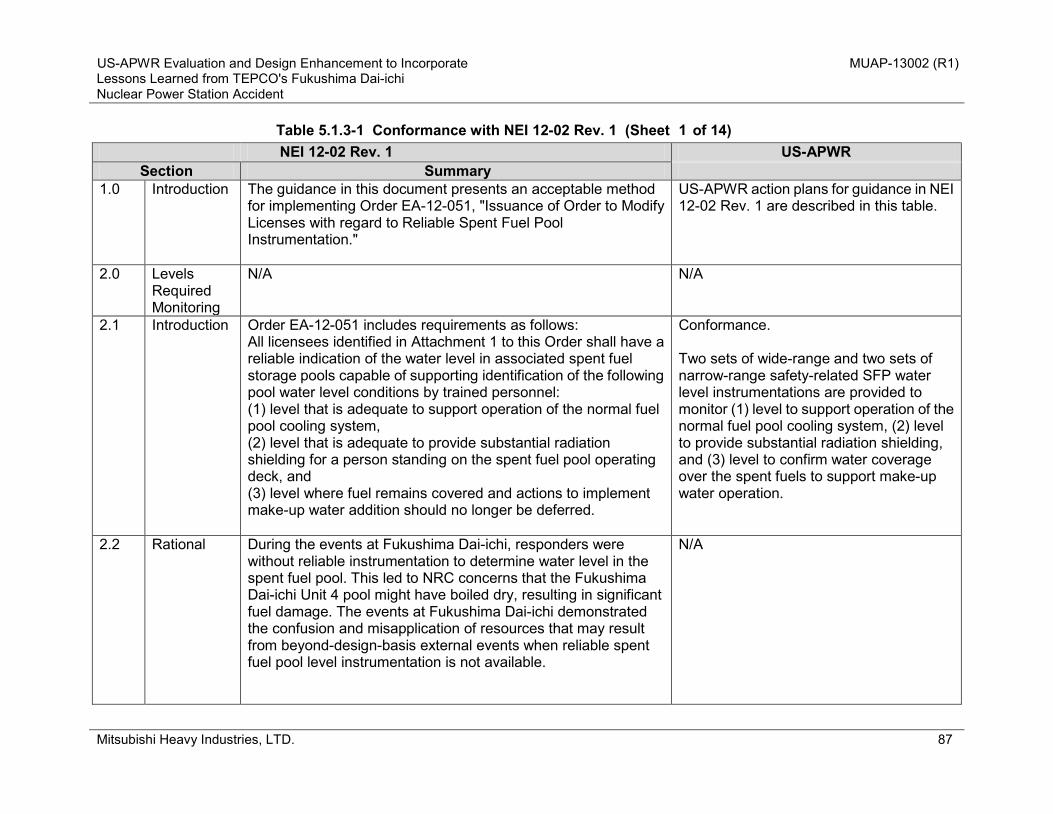
US-APWR Evaluation and Design Enhancement to Incorporate MUAP-13002 (R1) Lessons Learned from TEPCO's Fukushima Dai-ichi Nuclear Power Station Accident
Mitsubishi Heavy Industries, LTD. 87
Table 5.1.3-1 Conformance with NEI 12-02 Rev. 1 (Sheet of 14) NEI 12-02 Rev. 1 US-APWR
Section Summary 1.0 Introduction The guidance in this document presents an acceptable method
for implementing Order EA-12-051, "Issuance of Order to Modify Licenses with regard to Reliable Spent Fuel Pool Instrumentation."
US-APWR action plans for guidance in NEI 12-02 Rev. 1 are described in this table.
2.0 Levels Required Monitoring
N/A N/A
2.1 Introduction Order EA-12-051 includes requirements as follows: All licensees identified in Attachment 1 to this Order shall have a reliable indication of the water level in associated spent fuel storage pools capable of supporting identification of the following pool water level conditions by trained personnel: (1) level that is adequate to support operation of the normal fuel pool cooling system, (2) level that is adequate to provide substantial radiation shielding for a person standing on the spent fuel pool operating deck, and (3) level where fuel remains covered and actions to implement make-up water addition should no longer be deferred.
Conformance. Two sets of wide-range and two sets of narrow-range safety-related SFP water level instrumentations are provided to monitor (1) level to support operation of the normal fuel pool cooling system, (2) level to provide substantial radiation shielding, and (3) level to confirm water coverage over the spent fuels to support make-up water operation.
2.2 Rational During the events at Fukushima Dai-ichi, responders were without reliable instrumentation to determine water level in the spent fuel pool. This led to NRC concerns that the Fukushima Dai-ichi Unit 4 pool might have boiled dry, resulting in significant fuel damage. The events at Fukushima Dai-ichi demonstrated the confusion and misapplication of resources that may result from beyond-design-basis external events when reliable spent fuel pool level instrumentation is not available.
N/A
1

US-APWR Evaluation and Design Enhancement to Incorporate MUAP-13002 (R1) Lessons Learned from TEPCO's Fukushima Dai-ichi Nuclear Power Station Accident
Mitsubishi Heavy Industries, LTD. 88
Table 5.1.3-1 Conformance with NEI 12-02 Rev. 1 (Sheet of 14) NEI 12-02 Rev. 1 US-APWR
Section Summary 2.3 Wide Range
Pool level Instrumentation
The requirement from this order is for instrumentation that covers a wide level range within the spent fuel pool. The three critical levels that must be monitored in a spent fuel pool are discussed below. It should be noted that continuous indication from a single instrument over the entire span from level 1 to level 3 is not required but could be used. If more than one instrument is used to monitor the entire span, that set of instruments constitutes a single channel satisfying either the primary or backup instrument channel requirement (refer to Figure 1 below). A visual representation of monitoring levels 1, 2 and 3 and the associated requirements for monitoring between the points are presented in Figure 1. The minimum requirements apply to the separation distance between level indications and support development of appropriate response procedures. These requirements are separate from the instrument channel design accuracy discussed in section 3, which apply to either discrete or to continuous instruments.
Conformance. Two sets of wide-range and two sets of narrow-range safety-related SFP water level instrumentations are provided to monitor (1) level to support operation of the normal fuel pool cooling system, (2) level to provide substantial radiation shielding, and (3) level to confirm water coverage over the spent fuels to support make-up water operation.
2.3.1 Level-1 Level that is adequate to support operation of the normal fuel pool cooling
Level 1 represents the HIGHER of the following two points: • The level at which reliable suction loss occurs due to uncovering of the coolant inlet pipe, weir or vacuum breaker (depending on the design), or • The level at which the water height, assuming saturated conditions, above the centerline of the cooling pump suction provides the required net positive suction head specified by the pump manufacturer or engineering analysis.
Conformance. - The narrow-range SFP water level instruments cover Level 1. - For the SFP and its cooling system, the level at which the water height, assuming saturated conditions, above the centerline of the cooling pump suction provides the
2

US-APWR Evaluation and Design Enhancement to Incorporate MUAP-13002 (R1) Lessons Learned from TEPCO's Fukushima Dai-ichi Nuclear Power Station Accident
Mitsubishi Heavy Industries, LTD. 89
Table 5.1.3-1 Conformance with NEI 12-02 Rev. 1 (Sheet of 14) NEI 12-02 Rev. 1 US-APWR
Section Summary system required net positive suction head
specified by the pump manufacturer or engineering analysis is higher than the level at which reliable suction loss occurs due to uncovering of the coolant inlet pipe, weir or vacuum breaker.
2.3.2 Level-2 Level that is adequate to provide substantial radiation shielding for a person standing on the SFP operation deck
Level 2 is based on either of the following: • 10 feet (+/- 1 foot) above the highest point of any fuel rack seated in the spent fuel pools, or • a designated level that provides adequate radiation shielding to maintain personnel radiological dose levels within acceptable limits while performing local operations in the vicinity of the pool. This level shall be based on either plant-specific or appropriate generic shielding calculations, considering the emergency conditions that may apply at the time and the scope of necessary local operations, including installation of portable SFP instrument channel components. Designation of this level should not be interpreted to imply that actions to initiate water make-up must be delayed until SFP water levels have reached or are lower than this point
Conformance. The wide-range SFP water level instruments cover Level 2. The instruments cover 10 feet above the highest point of any fuel rack seated in the spent fuel pools, to provide adequate radiation shielding to maintain personnel radiological dose levels within acceptable limits while performing local operations in the vicinity of the pool.
2.3.3 Level-3 Level where fuel remains covered and actions to implement make-up water addition
Level 3 corresponds nominally (i.e., +/- 1 foot) to the highest point of any fuel rack seated in the spent fuel pool. Level 3 is defined in this manner to provide the maximum range of information to operators, decision makers and emergency response personnel. Designation of this level should not be interpreted to imply that actions to initiate water make-up must or should be delayed until this level is reached.
Conformance. The wide-range SFP water level instruments cover Level 3. The instruments cover water coverage over the spent fuel to support make-up water operation.
3

US-APWR Evaluation and Design Enhancement to Incorporate MUAP-13002 (R1) Lessons Learned from TEPCO's Fukushima Dai-ichi Nuclear Power Station Accident
Mitsubishi Heavy Industries, LTD. 90
Table 5.1.3-1 Conformance with NEI 12-02 Rev. 1 (Sheet of 14) NEI 12-02 Rev. 1 US-APWR
Section Summary should no longer be differed
3.0 Instrumentation design features
N/A
N/A
3.1
Instruments This instrumentation shall consist of at least one primary and one backup instrument channel. Reliable level indication shall be functional (for fixed channels) or functional when installed (for portable channels or combination of fixed and portable component channels) during all modes of operation consistent with paragraph 4.3, Testing and Calibration, below. If portable components are used as part of a backup instrument channel then, to limit personnel resources required for deployment, it shall be designed such that it can easily be deployed by a maximum of two trained personnel within 30 minutes at the spent fuel pool (i.e., no more than 1 person-hour). Portable instrument components must be placed in service in predetermined accessible locations. However, in anticipation that such predetermined locations may be inaccessible at the time of the event, guidance must be provided to the trained personnel as to how to determine and use alternate locations.
Conformance, with following exemption. The US-APWR plant does not rely on portable SFP water level instrumentation.
4

US-APWR Evaluation and Design Enhancement to Incorporate MUAP-13002 (R1) Lessons Learned from TEPCO's Fukushima Dai-ichi Nuclear Power Station Accident
Mitsubishi Heavy Industries, LTD. 91
Table 5.1.3-1 Conformance with NEI 12-02 Rev. 1 (Sheet of 14) NEI 12-02 Rev. 1 US-APWR
Section Summary Portable instrument components must be stored in predetermined accessible locations that will not hinder the ability of trained personnel to install the portable components when needed.
3.2
Arrangement Installation of the SFP instrument channels shall be consistent with the plant-specific SFP design requirements and should not impair normal SFP function. Channel separation should be maintained by locating the installed sensors in different places in the SFP area. Provisions for portable instruments should also consider the need for physical separation. Plans for portable instrument use should allow inserting and operating the sensors and associated equipment in a different part of the SFP from the permanent channel. Ideally the portable channel will be able to use multiple (or all) SFP locations. Similarly, cabling for power supplies and indications for each channel should be routed separately from cabling for the other channels. To the extent not otherwise covered in this guidance, the reasonable protection guidance outlined in NEI 12-06 to meet Order EA-12-049 should be used to provide protection for installed and portable channels from external hazards.
Conformance. The spent fuel pool level instrument channels are arranged in a manner that provides reasonable protection of the level indication function against missiles that may result from damage to the structure over the spent fuel pool.
5

US-APWR Evaluation and Design Enhancement to Incorporate MUAP-13002 (R1) Lessons Learned from TEPCO's Fukushima Dai-ichi Nuclear Power Station Accident
Mitsubishi Heavy Industries, LTD. 92
Table 5.1.3-1 Conformance with NEI 12-02 Rev. 1 (Sheet of 14) NEI 12-02 Rev. 1 US-APWR
Section Summary At a minimum, cables routed outside structures should be protected in buried conduit and designed to commercial standards for submergence.
3.3
Mounting Consideration shall be given to the maximum seismic ground motion to the design basis of the SFP structure. The mounting shall be designed consistent with the highest seismic or safety classification of the SFP. An evaluation of other hardware stored in the SFP shall be conducted to ensure it will not create adverse interaction with the fixed instrument location(s). The basis for the seismic design for mountings in the SFP shall be the plant seismic design basis at the time of submittal of the Integrated Plan for implementing NRC Order EA-12-051 (See Appendix A-2-2).
Conformance. The enhanced SFP water level instrumentation is designed as seismic category I.
3.4 Qualification (Guidance)
Guidance The instrument channel reliability shall be demonstrated via an appropriate combination of design, analyses, operating experience, and/or testing of channel components for the following sets of parameters, as described in the paragraphs below: • conditions in the area of instrument channel component use for all instrument components, • effects of shock and vibration on instrument channel components used during any applicable event for only installed components, and • seismic effects on instrument channel components used during
See US-APWR actions for Qualification (Conditions), Qualification (Shock and Vibration) and Qualification (Seismic) as discussed below.
6

US-APWR Evaluation and Design Enhancement to Incorporate MUAP-13002 (R1) Lessons Learned from TEPCO's Fukushima Dai-ichi Nuclear Power Station Accident
Mitsubishi Heavy Industries, LTD. 93
Table 5.1.3-1 Conformance with NEI 12-02 Rev. 1 (Sheet of 14) NEI 12-02 Rev. 1 US-APWR
Section Summary and following a potential seismic event for only installed components. Selection of instrument channel components should consider ease and simplicity of design and replacement after the event. Readily available commercial components shall be considered.
Qualification (Conditions)
Conditions The temperature, humidity and radiation levels consistent with conditions in the vicinity of the SFP and the area of use considering normal operational, event and post-event conditions for no fewer than seven days post-event or until off-site resources can be deployed by the mitigating strategies resulting from Order EA-12-049 should be considered.
Conformance. The temperature, humidity and radiation levels consistent with conditions in the vicinity of the SFP and the area of use considering normal operational, event and post-event conditions for no fewer than 7 days post-event is considered.
Qualification (Shock and Vibration)
Shock and Vibration For the effects of shock and vibration in the area of instrument channel component use after an event for applicable components (with the exception of battery chargers and replaceable batteries), the following measures are acceptable to verify that the design and installation is adequate. Applicable components of the instrument channels are rated by the manufacturer (or otherwise tested) for shock and vibration at levels commensurate with those of postulated design basis event conditions in the area of instrument channel component use using one or more of the following methods: • instrument channel components use known operating principles, are supplied by manufacturers with commercial quality programs (such as ISO9001) with shock and vibration
Conformance. Either of the methods described in the NEI guidance for the effects of shock and vibration in the area of instrument channel component use after an event for applicable components (with the exception of battery chargers and replaceable batteries) is used.
7

US-APWR Evaluation and Design Enhancement to Incorporate MUAP-13002 (R1) Lessons Learned from TEPCO's Fukushima Dai-ichi Nuclear Power Station Accident
Mitsubishi Heavy Industries, LTD. 94
Table 5.1.3-1 Conformance with NEI 12-02 Rev. 1 (Sheet of 14) NEI 12-02 Rev. 1 US-APWR
Section Summary requirements included in the purchase specification and/or instrument design, and commercial design and testing for operation in environments where significant shock and vibration loadings are common, such as for portable hand-held devices or transportation applications; • substantial history of operational reliability in environments with significant shock and vibration loading, such as transportation applications; or • use of components inherently resistant to shock and vibration loadings or are seismically reliable such as cables.
Qualification (Seismic)
Seismic For seismic effects on instrument channel components used after a potential seismic event for only installed components (with the exception of battery chargers and replaceable batteries), the following measures are acceptable to verify that the design and installation is adequate. Applicable components of the instrument channels are rated by the manufacturer (or otherwise tested) for seismic effects at levels commensurate with those of postulated design basis event conditions, in the area of instrument channel component use, using one or more of the following methods: • instrument channel components use known operating principles, are supplied by manufacturers with commercial quality programs (such as ISO9001) with seismic requirements included in the purchase specification and/or instrument design, and commercial design and testing for operation in environments where significant seismic effects are common; • substantial history of operational reliability in environments with significant vibration, such as for portable hand-held devices or
Conformance. The enhanced SFP water level instrumentation is designed as seismic Category I.
8

US-APWR Evaluation and Design Enhancement to Incorporate MUAP-13002 (R1) Lessons Learned from TEPCO's Fukushima Dai-ichi Nuclear Power Station Accident
Mitsubishi Heavy Industries, LTD. 95
Table 5.1.3-1 Conformance with NEI 12-02 Rev. 1 (Sheet of 14) NEI 12-02 Rev. 1 US-APWR
Section Summary transportation applications; • demonstration of seismic reliability using methods that predict the equipment’s performance by - analysis, - testing of the equipment under simulated seismic conditions, -using a combination of test and analysis, or -the use of experience data. • demonstration that proposed devices are substantially similar in design to models that have been previously tested for seismic effects in excess of the plant design basis at the location where the instrument is to be installed (g-levels and frequency ranges); or • seismic qualification using seismic motion consistent with that of existing design basis loading at the installation location.
Qualification (General)
General The basis for the seismic qualification for instrument channel components shall be the plant seismic design basis at the time of submittal of the Integrated Plan for implementing NRC Order EA-12-051 (See Appendix A-2-2).
Conformance.
3.5 Independence
If plant ac or dc power sources are used then the power sources shall be from different buses and preferably different divisions/channels depending on available sources of power. For two (2) permanently mounted (fixed) instruments in the pool, they should be separated to the extent practicable considering existing spent fuel pool construction (reference Section 3.2).
Conformance. Each channel of the wide-range and narrow- range SFP water level instruments is powered from a different division of the plant I&C power supply systems. Two channels of the permanent wide-range and narrow-range SFP water level instrumentation are physically separated to the extent practicable.
9

US-APWR Evaluation and Design Enhancement to Incorporate MUAP-13002 (R1) Lessons Learned from TEPCO's Fukushima Dai-ichi Nuclear Power Station Accident
Mitsubishi Heavy Industries, LTD. 96
Table 5.1.3-1 Conformance with NEI 12-02 Rev. 1 (Sheet of 14) NEI 12-02 Rev. 1 US-APWR
Section Summary 3.6 Power
Supplies The normal electrical power supply for each channel shall be provided by different sources such that the loss of one of the channels primary power supply will not result in a loss of power supply function to both channels of SFP level instrumentation. All channels of SFP level instrumentation shall provide the capability of connecting the channel to a source of power (e.g., portable generators or replaceable batteries) independent of the normal plant ac and dc power systems. For fixed channels this alternate capability shall include the ability to isolate the installed channel from its normal power supply or supplies. The portable power sources for the portable and installed channels shall be stored at separate locations, consistent with the reasonable protection requirements associated with NEI 12-06 (Order EA-12-049). The portable generator or replaceable batteries should be accessible and have sufficient capacity to support reliable instrument channel operation until off-site resources can be deployed by the mitigating strategies resulting from Order EA-12-049 If adequate power supply for either an installed or portable level instrument credits intermittent operation, then the provisions shall be made for quickly and reliably taking the channel out of service and restoring it to service.
Conformance, with a deviation. The normal electrical power supply for each channel of the wide-range and narrow-range SFP water level instrumentation is provided by a different power division. As described in Section 5.1.3, the Class 1E batteries or AAC GTGs can supply power to the SFP water level instrumentation even after the BDB external event. Therefore, a stand-alone alternate power supply for the SFP water level instrumentation is not incorporated.
10

US-APWR Evaluation and Design Enhancement to Incorporate MUAP-13002 (R1) Lessons Learned from TEPCO's Fukushima Dai-ichi Nuclear Power Station Accident
Mitsubishi Heavy Industries, LTD. 97
Table 5.1.3-1 Conformance with NEI 12-02 Rev. 1 (Sheet of 14) NEI 12-02 Rev. 1 US-APWR
Section Summary 3.7 Accuracy The instrument channels shall maintain their designed accuracy
following a power interruption or change in power source without recalibration. Accuracy should consider SFP conditions, e.g., saturated water, steam environment, or concentrated borated water. Additionally, instrument accuracy should be sufficient to allow trained personnel to determine when the actual level exceeds the specified lower level of each indicating range (levels 1, 2 and 3) without conflicting or ambiguous indication.
Conformance. The accuracy of the wide-range and narrow- range SFP water level instrumentation is decided considering SFP conditions, e.g., saturated water, steam environment, or concentrated borated water and is sufficient to allow trained personnel to determine when the actual level exceeds the specified lower level of each indicating range without conflicting or ambiguous indication as shown in Figure 6.7.1-1.
3.8 Testing Static or non-active installed (fixed) sensors can be used and should be designed such that testing and /or calibration can be performed in-situ. For microprocessor based channels, the instrument channel design shall be capable of testing while mounted in the pool. Back-up portable channels shall be designed such that calibration does not require the use of any additional test or reference equipment at the time of deployment, i.e., plug-and-play type technology.
Conformance. The wide-range and narrow-range SFP water level instrumentation is designed such that testing and/or calibration can be performed in-situ. Microprocessor based channels will not be used. Back-up portable channels will not be used.
3.9 Display SFP level indication from the installed channel shall be displayed in the control room, at the alternate shutdown panel, or another appropriate and accessible location (reference NEI 12-06).
Conformance. The wide-range and narrow-range SFP water level are displayed on the Safety VDUs located in the main control room
11

US-APWR Evaluation and Design Enhancement to Incorporate MUAP-13002 (R1) Lessons Learned from TEPCO's Fukushima Dai-ichi Nuclear Power Station Accident
Mitsubishi Heavy Industries, LTD. 98
Table 5.1.3-1 Conformance with NEI 12-02 Rev. 1 (Sheet of 14) NEI 12-02 Rev. 1 US-APWR
Section Summary An appropriate and accessible location shall include the following characteristics: • occupied or promptly accessible to the appropriate plant staff giving appropriate consideration to various drain down scenarios, • outside of the area surrounding the SFP floor, e.g., an appropriate distance from the radiological sources resulting from an event impacting the SFP, • inside a structure providing protection against adverse weather, and • outside of any very high radiation areas or LOCKED HIGH RAD AREA during normal operation. If multiple display locations beyond the required "appropriate and accessible location" are desired, then the instrument channel shall be designed with the capability to drive the multiple display locations without impacting the primary “appropriate and accessible” display. SFP level indication from a portable channel shall be displayed in an accessible location.
(MCR) and in the remote shutdown room (RSR).
4.0 Program Features
N/A N/A
4.1 Training The personnel performing functions associated with these SFP level instrumentation channels shall be trained to perform the job specific functions necessary for their assigned tasks (maintenance, calibration, surveillance, etc.). SFP instrumentation should be installed via the normal modification processes. In either case utilities should use the Systematic Approach to
This is outside the scope of the standard design. The COL applicants are responsible for performing training to ensure the personnel performing functions associated with these SFP water level instrumentation channels are able to perform the job
12
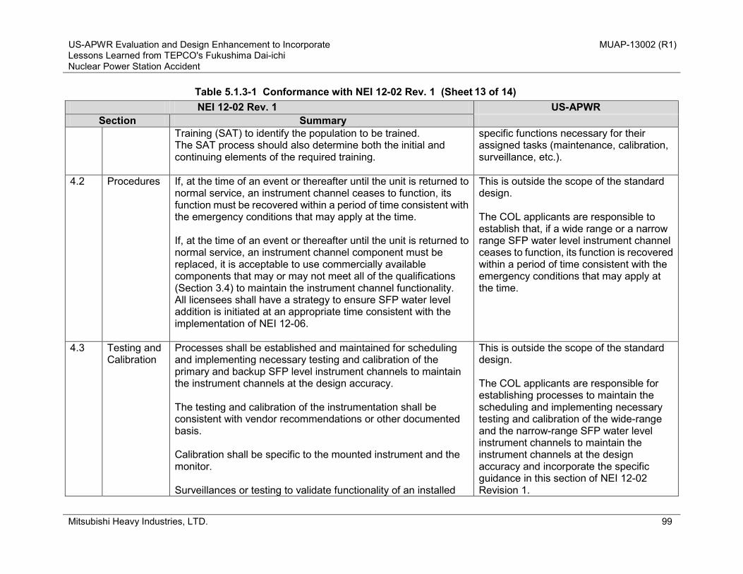
US-APWR Evaluation and Design Enhancement to Incorporate MUAP-13002 (R1) Lessons Learned from TEPCO's Fukushima Dai-ichi Nuclear Power Station Accident
Mitsubishi Heavy Industries, LTD. 99
Table 5.1.3-1 Conformance with NEI 12-02 Rev. 1 (Sheet of 14) NEI 12-02 Rev. 1 US-APWR
Section Summary Training (SAT) to identify the population to be trained. The SAT process should also determine both the initial and continuing elements of the required training.
specific functions necessary for their assigned tasks (maintenance, calibration, surveillance, etc.).
4.2 Procedures If, at the time of an event or thereafter until the unit is returned to normal service, an instrument channel ceases to function, its function must be recovered within a period of time consistent with the emergency conditions that may apply at the time. If, at the time of an event or thereafter until the unit is returned to normal service, an instrument channel component must be replaced, it is acceptable to use commercially available components that may or may not meet all of the qualifications (Section 3.4) to maintain the instrument channel functionality. All licensees shall have a strategy to ensure SFP water level addition is initiated at an appropriate time consistent with the implementation of NEI 12-06.
This is outside the scope of the standard design. The COL applicants are responsible to establish that, if a wide range or a narrow range SFP water level instrument channel ceases to function, its function is recovered within a period of time consistent with the emergency conditions that may apply at the time.
4.3 Testing and Calibration
Processes shall be established and maintained for scheduling and implementing necessary testing and calibration of the primary and backup SFP level instrument channels to maintain the instrument channels at the design accuracy. The testing and calibration of the instrumentation shall be consistent with vendor recommendations or other documented basis. Calibration shall be specific to the mounted instrument and the monitor. Surveillances or testing to validate functionality of an installed
This is outside the scope of the standard design. The COL applicants are responsible for establishing processes to maintain the scheduling and implementing necessary testing and calibration of the wide-range and the narrow-range SFP water level instrument channels to maintain the instrument channels at the design accuracy and incorporate the specific guidance in this section of NEI 12-02 Revision 1.
13

US-APWR Evaluation and Design Enhancement to Incorporate MUAP-13002 (R1) Lessons Learned from TEPCO's Fukushima Dai-ichi Nuclear Power Station Accident
Mitsubishi Heavy Industries, LTD. 100
Table 5.1.3-1 Conformance with NEI 12-02 Rev. 1 (Sheet of 14) NEI 12-02 Rev. 1 US-APWR
Section Summary instrument channel shall be performed within 60 days of a planned refueling outage considering normal testing scheduling allowances (e.g., 25%). Additionally, compensatory actions must be taken if the instrumentation channel is not expected to be restored or is not restored within 90 days. If a single SFP for the purposes of this order is divided by the closure of a normally open gate(s) such that a portion of the SFP containing fuel used for power production within the last five years is no longer able to be monitored by a required SFP instrumentation channel, then the actions described above must be taken for the impacted instrumentation channel.
.
5.0 References N/A
N/A
14

US
-AP
WR
Eva
luat
ion
and
Des
ign
Enh
ance
men
t to
Inco
rpor
ate
MU
AP-1
3002
(R1)
Le
sson
s Le
arne
d fro
m T
EPC
O's
Fuk
ushi
ma
Dai
-ichi
N
ucle
ar P
ower
Sta
tion
Acc
iden
t
Mits
ubis
hi H
eavy
Indu
strie
s, L
TD.
101
RC
SC
oolin
g by
SG
CH
P/R
CP
Seal
Coo
ling
>AC
feed
by
A
AC to
- C
HP
- H
VAC
>Coo
ling
wat
er fe
ed b
y n
on-E
CW
S C
/T
8hr
14hr
1 da
y7
day
Hot
-Shu
tdow
n
Star
t RC
Sco
oldo
wn
by
EFW
P-SG
-MSD
V
1hr
Mak
eup
EFW
pits
by
porta
ble
wat
er p
ump
(if D
WST
una
vaila
ble)
>Sta
rt no
n-EC
WS
C/T
for
CH
P co
olin
g>S
tart
CH
P
ACC
initi
atio
n
Con
nect
AAC
to
Cla
ss 1
E bu
sR
efill
AAC
fuel
Mak
eup
non-
ECW
SC
/T b
y po
rtabl
e w
ater
pum
pMak
eup
EFW
pits
or D
WST
be
fore
depl
etio
n
Phase 1‐b
Phase 2
Phase 3
Phase 1‐a
Time
RCP Temp
Fi
gure
5.1
.2-1
Cor
e C
oolin
g Ti
mel
ine

US-APWR Evaluation and Design Enhancement to Incorporate MUAP-13002 (R1) Lessons Learned from TEPCO's Fukushima Dai-ichi Nuclear Power Station Accident
Mitsubishi Heavy Industries, LTD. 102
Figure 5.1.2-2 Alternate UHS

US-APWR Evaluation and Design Enhancement to Incorporate MUAP-13002 (R1) Lessons Learned from TEPCO's Fukushima Dai-ichi Nuclear Power Station Accident
Mitsubishi Heavy Industries, LTD. 103
OFL Narrow Range Wide Range
100% 100%
HWL
NWL
LWL
LLWL Level 1
Siphon break pipe head 0%
SFP pump suction pipeinner top
Level 2Water Shield +10ft
Fuel Rack top EL 0% Level 3
Figure 5.1.3-1 SFP Water Level Setpoints

US-APWR Evaluation and Design Enhancement to Incorporate MUAP-13002 (R1) Lessons Learned from TEPCO's Fukushima Dai-ichi Nuclear Power Station Accident
Mitsubishi Heavy Industries, LTD. 104
5.2 Tier 2 Items 5.2.1 Recommendations 7.2, 7.3, 7.4, 7.5 5.2.1.1 Recommendation 7.2 AC power for two refueling water pumps that can supply RWSP water to the SFP is supplied from Class 1E buses and this configuration is in line with this NTTF recommendation. 5.2.1.2 Recommendation 7.3 As the order addressed in this recommendation has not been issued, the US-APWR does not take any action for this recommendation at this time. 5.2.1.3 Recommendation 7.4 Considering this NTTF recommendation, the SFP diverse makeup lines and spray lines of the US-APWR are designed to withstand a SSE. See also the MHI response to DCD RAI 1043-7175 (Reference 5.5-15). 5.2.1.4 Recommendation 7.5 As this is an action for the NRC, the US-APWR does not take any action for this recommendation at this time.
5.2.2 Recommendation 9.3 (Other than Staffing, Communications, ERDS Capability) COL applicants who construct a US-APWR are responsible for this recommendation.

US-APWR Evaluation and Design Enhancement to Incorporate MUAP-13002 (R1) Lessons Learned from TEPCO's Fukushima Dai-ichi Nuclear Power Station Accident
Mitsubishi Heavy Industries, LTD. 105
5.3 Others (Items which are not directly applied to US-APWR and Tier 3) 5.3.1 Recommendation 2.1 Flooding Reevaluation As it is clearly stated in SECY-12-0025 (Reference 5.5-2), this recommendation is addressed through the normal COL and ESP processes. Therefore, no specific action is required by the US-APWR.
5.3.2 Recommendation 2.1 Other External Events This was newly added as a Tier 2 issue in SECY-12-0025. As the intent of the recommendation is reevaluation of the existing operating reactors against a set of new plant evaluation criteria and the other external events have been fully evaluated in the US-APWR DCD, neither MHI nor COL applicants need to take action on this recommendation.
5.3.3 Recommendation 2.2 Ten-Year Confirmation of Seismic and Flooding Hazards This recommendation is only applicable to operating plants. Therefore, the US-APWR will not take any action on this recommendation. 5.3.4 Recommendation 2.3 Seismic and Flood Walkdowns As it is stated in SECY-12-0025 that this item is not applicable to COL holders, the US-APWR will not take any action on this recommendation.
5.3.5 Recommendation 3 Potential Enhancements to the Capability to Prevent or
Mitigate Seismically-Induced Fires and Floods (Long-Term Evaluation) Neither MHI nor COL applicants are required to take action because in SECY-12-0095 (Reference 5.5-3), the NRC staff proposed that it will defer the evaluation of NTTF Recommendation 3 (Reference 5.5-1) until 2016.

US-APWR Evaluation and Design Enhancement to Incorporate MUAP-13002 (R1) Lessons Learned from TEPCO's Fukushima Dai-ichi Nuclear Power Station Accident
Mitsubishi Heavy Industries, LTD. 106
5.3.6 Recommendation 5.1 Including AR1 Filtered Vent Neither MHI nor COL applicants are required to take action because this is only applicable to BWRs with Mark I or Mark II containments.
5.3.7 Recommendation 5.2 Reliable Hardened Vents for Other Containment Designs
(Long-Term Evaluation) The staff plans to defer consideration of venting for other containment designs (e.g., Mark III, ice condenser, and large dry containments) until the Commission reaches a decision on the need for severe accident venting and filtered venting for BWR Mark I and Mark II containments.
5.3.8 Recommendation 6 Hydrogen Control and Mitigation Inside Containment or in
Other Buildings The NRC plans to develop and issue a rule on hydrogen control and mitigation inside the containment or in other buildings as a long-term issue. Currently there is an insufficient amount of information to substantiate changes to the current US-APWR design. Therefore, MHI will not take action on this recommendation at this time. 5.3.9 Recommendation 9.1 Emergency Preparedness (EP) Enhancements for
Prolonged SBO and Multiunit Events The NRC plans to develop and issue a rule on emergency preparedness by 2016 (which is beyond the DCD approval schedule). No action is required at this time.
5.3.10 Recommendation 9.2 Emergency Preparedness (EP) Enhancements for
Prolonged SBO and Multiunit Events The NRC plans to develop and issue a rule on emergency preparedness by 2016 (which is beyond the DCD approval schedule). No action is required at this time.

US-APWR Evaluation and Design Enhancement to Incorporate MUAP-13002 (R1) Lessons Learned from TEPCO's Fukushima Dai-ichi Nuclear Power Station Accident
Mitsubishi Heavy Industries, LTD. 107
5.3.11 Recommendation 9.3 ERDS Capability The US-APWR has power supply capability to plant communication systems including the EDRS to cope with an extended loss of all ac power (ELAP) after a beyond-design-basis event, as described in DCD Tier 2 Subsections 9.5.2.1.1 and 9.5.2.6. 5.3.12 Recommendation 10 Additional EP Topics for Prolonged SBO and Multiunit
Events The NRC plans to develop and issue a rule on emergency preparedness by 2016 (which is beyond the DCD approval schedule). No action is required at this time.
5.3.13 Recommendation 11 EP Topics for Decision-Making, Radiation Monitoring,
and Public Education The NRC plans to develop and issue a rule on emergency preparedness by 2016 (which is beyond the DCD approval schedule). No action is required at this time.
5.3.14 Recommendation 12.1 Reactor Oversight Process Modifications to Reflect
the Recommended Defense-in-Depth Framework The NRC staff proposed in SECY-12-0095 that the staff will defer action on Recommendation 12.1 until the Commission has provided staff guidance regarding Recommendation 1. No action is required at this time.
5.3.15 Recommendation 12.2 Staff Training on Severe Accidents and Resident Inspector Training on SAMGs
This recommendation is for the NRC. No action is required at this time.
5.3.16 Additional Recommendation 3 (EPZ) As the recommendation is regarding the fundamental issue of existing regulatory framework that should be developed by the NRC, no action is required at this time.

US-APWR Evaluation and Design Enhancement to Incorporate MUAP-13002 (R1) Lessons Learned from TEPCO's Fukushima Dai-ichi Nuclear Power Station Accident
Mitsubishi Heavy Industries, LTD. 108
5.3.17 Additional Recommendation 4 (KI) This is an operational issue and the NRC staff proposed in SECY-12-0095 that the project to evaluate the issue takes 5-7 years. Therefore, no action is required at this time.
5.3.18 Additional Recommendation 5 (Dry Cask Storage) This is an operational issue and the NRC staff proposed in SECY-12-0095 that the project to evaluate the issue takes 5 years. Therefore, no action is required at this time.

US-APWR Evaluation and Design Enhancement to Incorporate MUAP-13002 (R1) Lessons Learned from TEPCO's Fukushima Dai-ichi Nuclear Power Station Accident
Mitsubishi Heavy Industries, LTD. 109
5.4 Deleted

US-APWR Evaluation and Design Enhancement to Incorporate MUAP-13002 (R1) Lessons Learned from TEPCO's Fukushima Dai-ichi Nuclear Power Station Accident
Mitsubishi Heavy Industries, LTD. 110
5.5 References 5.5-1 Recommendations for Enhancing Reactor Safety in the 21st Century, SECY-11-0093,
July 2011. 5.5-2 Proposed Orders and Requests for Information in Response to Lessons Learned from
Japan’s March 11, 2011, Great Tohoku Earthquake and Tsunami, SECY-12-0025, February 2012.
5.5-3 Tier 3 Program Plans and 6-Month Status Update in Response to Lessons Learned from Japan’s March 11, 2011, Great Tohoku Earthquake and Subsequent Tsunami, SECY-12-0095, October 2012.
5.5-4 Order to Modifying Licenses with Regard to Requirements for Mitigation Strategies for Beyond-Design-Basis External Events, NRC Order EA-12-049, March 2012.
5.5-5 Compliance with Order EA-12-049, Order Modifying Licenses with Regard to Requirements for Mitigation Strategies for Beyond-Design-Basis External Events, Interim Staff Guidance JLD-ISG-2012-01, Revision 0, August 2012.
5.5-6 Diverse and Flexible Coping Strategies (FLEX) Implementation Guide, NEI 12-06 Revision 0, August 2012.
5.5-7 Order to Modifying Licenses with Regard to Reliable Spent Fuel Pool Instrumentation (Effective Immediately), NRC Order EA-12-051, March 2012.
5.5-8 Compliance with Order EA-12-051, Reliable Spent Fuel Pool Instrumentation, JLD-ISG-2012-03 Revision 0, August 29, 2012.
5.5-9 Industry Guidance for Compliance with NRC Order EA-12-051, “To Modify Licenses with Regard to Reliable Spent Fuel Pool Instrumentation, NEI 12-02, Revision 1, August 2012.
5.5-10 Enclosure 5 to Requests for Information Pursuant to Title 10 of the Code of Federal Regulations 50.54(f) Regarding Recommendations 2.1, 2.3, and 9.3 of the Near-Term Task Force Review of Insights from the Fukushima Dai-ichi Accident, NRC, March, 2012.
5.5-11 Guideline for Assessing Beyond Design Basis Accident Response Staffing and Communications Capabilities, NEI 12-01, Revision 0, January 2012.
5.5-12 US-APWR RCP No. 2 Seal Test Report, MUAP-13003-P, Revision 0, March 2013. 5.5-13 Request for Additional Information No. 944-6516 Revision 3, SRP Section 1.05 – Other
Regulatory Considerations, June 19, 2012 (ML12171A228).
US-APWR Evaluation and Design Enhancement to Incorporate MUAP-13002 (R1) Lessons Learned from TEPCO's Fukushima Dai-ichi Nuclear Power Station Accident
Mitsubishi Heavy Industries, LTD. 111
6.0 DESIGN FEATURES TO INCORPORATE FUKUSHIMA LESSONS-LEARNED This chapter describes US-APWR design features to support the US-APWR operational strategies to cope with the Tier 1 and Tier 2 NTTF recommendations, including EA-12-049, EA-12-051, 50.54(f) letter on Recommendation 2.1 and 9.3. 6.1 BDB Flood Protection 6.1.1 Design Feature Description The reactor building (R/B) and the power source buildings (PS/Bs) are the buildings in the standard design that contains the essential systems to be protected from BDB external flooding. These buildings have robust external concrete walls and a common basemat which protect inside facilities from flooding. The access to those buildings and penetrations are sealed with enhanced capability to withstand a BDB external flooding event, the level of which is determined as 20 ft above the design basis external flood level as a standard design feature. This shall prevent internal flooding due to external flooding. The access doors and penetrations located at the elevations below the BDB external flood level are subject to the enhanced design. The boundary walls and floor (basemat), including access doors/penetrations below the BDB external flood level, which are essential to protect these buildings from BDB external flooding, are shown in Figure 6.1-1. 6.1.2 Design Basis The NRC SECY 11-0093, Enclosure “Task Force Report” Section 4.2.1 (Reference 6.1.6-1) recommends the BDB external flood level as follows:
“As a practical matter, and to prevent undue delays in implementing additional SBO protections, the Task Force concludes that locating SBO mitigation equipment in the plant one level above flood level (about 5 to 6 meters (15 to 20 feet)) or in watertight enclosures would provide sufficient enhanced protection for this level of defense-in-depth.”
In accordance with the recommendation, the US-APWR considers that 20 ft above the design basis external flood level is the BDB external flood level of the R/B and the PS/Bs as a standard design

US-APWR Evaluation and Design Enhancement to Incorporate MUAP-13002 (R1) Lessons Learned from TEPCO's Fukushima Dai-ichi Nuclear Power Station Accident
Mitsubishi Heavy Industries, LTD. 112
feature, while the BDB external flood level of site-specific SSCs that are required to implement the baseline coping strategies should be determined by site-specific external flood conditions. As discussed in the DCD Section 2.4, the design basis external flood level is EL.1’-7”, which is 1 ft below the plant grade (EL. 2’-7”). Therefore, the BDB external flood level of the R/B and the PS/Bs is EL. 21’-7” which is 19ft above the plant grade (EL. 2’-7”). Elevation 21’-7” is below the 2nd floor of the R/B (EL.25’-3”), and is also below the roof of the PS/Bs (EL. 39’-6”). 6.1.3 Compliance with NRC Recommendations The design features for flood protection described above provide reasonable protection from a BDB external flooding event to prevent the equipment that is relied upon in the strategies described in Chapter 5 from being submerged. In accordance with recommendation described in SECY 11-0093, the flood protection features are designed to prevent water ingress up to one level above the plant design-basis flooding level, which is 1 ft below plant grade as described in the DCD Chapter 2 (Reference 6.1.6-2). Therefore, the design features ensure that equipment required for core cooling, containment, and SFP cooling functions perform their respective functions without loss of capability, and conforms with JLD-ISG-2012-01, “Compliance with Order EA-12-049, Order Modifying Licenses with Regard to Requirements for Mitigation Strategies for Beyond-Design-Basis External Events” (Reference 6.1.6-3). 6.1.4 DCD Description (1) Tier 1 • The flood elevation that reflects the water-tight doors installed for the BDB external flood
protection is incorporated in Table 2.2-5. • The location of the water-tight doors installed for the BDB external flood protection are shown in
Figure 2.2-14 and Figure 2.2-16. (2) Tier 2 • This technical report, MUAP-13002 (R0), is incorporated by reference in Section 1.6. • The essential information of the BDB external flood protection design features is addressed in
Section 3.4.1.2. • The internal flood elevations that reflect the water-tight doors installed for the BDB external
flood protection are described and shown in Section 3.4.1.5.2.1 and Table 3K-2 in Appendix 3K.

US-APWR Evaluation and Design Enhancement to Incorporate MUAP-13002 (R1) Lessons Learned from TEPCO's Fukushima Dai-ichi Nuclear Power Station Accident
Mitsubishi Heavy Industries, LTD. 113
• The location of the water-tight doors installed for BDB external flood protection is indicated in Figures 3K-1 and 3K-3 in Appendix 3K.
6.1.5 Combined License Information COL item COL 1.9(3) is addressed in DCD Section 1.9. 6 and requests COL applicants to describe the protection from BDB external flood for site-specific SSCs that is required to implement the baseline coping strategies. 6.1.6 References 6.1.6-1 Recommendations for Enhancing Reactor Safety in the 21st Century, SECY-11-0093,
July 2011. 6.1.6-2 US-APWR DCD, Rev. 4, Chapter 2. 6.1.6-3 Compliance with Order EA-12-049, Order Modifying Licenses with Regard to
Requirements for Mitigation Strategies for Beyond-Design-Basis External Events, Interim Staff Guidance JLD-ISG-2012-01, Revision 0, August 2012.

US-APWR Evaluation and Design Enhancement to Incorporate MUAP-13002 (R1) Lessons Learned from TEPCO's Fukushima Dai-ichi Nuclear Power Station Accident
Mitsubishi Heavy Industries, LTD. 114
Figure 6.1-1 Design Enhancement for BDB External Flood Protection (Sheet 1 of 5)
Security-Related Information – Withheld Under 10 CFR 2.390

US-APWR Evaluation and Design Enhancement to Incorporate MUAP-13002 (R1) Lessons Learned from TEPCO's Fukushima Dai-ichi Nuclear Power Station Accident
Mitsubishi Heavy Industries, LTD. 115
Figure 6.1-1 Design Enhancement for BDB External Flood Protection (Sheet 2 of 5)
Security-Related Information – Withheld Under 10 CFR 2.390

US-APWR Evaluation and Design Enhancement to Incorporate MUAP-13002 (R1) Lessons Learned from TEPCO's Fukushima Dai-ichi Nuclear Power Station Accident
Mitsubishi Heavy Industries, LTD. 116
Figure 6.1-1 Design Enhancement for BDB External Flood Protection (Sheet 3 of 5)
Security-Related Information – Withheld Under 10 CFR 2.390
US-APWR Evaluation and Design Enhancement to Incorporate MUAP-13002 (R1) Lessons Learned from TEPCO's Fukushima Dai-ichi Nuclear Power Station Accident
Mitsubishi Heavy Industries, LTD. 117
Figure 6.1-1 Design Enhancement for BDB External Flood Protection (Sheet 4 of 5)
Security-Related Information – Withheld Under 10 CFR 2.390

US-APWR Evaluation and Design Enhancement to Incorporate MUAP-13002 (R1) Lessons Learned from TEPCO's Fukushima Dai-ichi Nuclear Power Station Accident
Mitsubishi Heavy Industries, LTD. 118
Figure 6.1-1 Design Enhancement for BDB External Flood Protection (Sheet 5 of 5)
Security-Related Information – Withheld Under 10 CFR 2.390
US-APWR Evaluation and Design Enhancement to Incorporate MUAP-13002 (R1) Lessons Learned from TEPCO's Fukushima Dai-ichi Nuclear Power Station Accident
Mitsubishi Heavy Industries, LTD. 119
6.2 Deleted

US-APWR Evaluation and Design Enhancement to Incorporate MUAP-13002 (R1) Lessons Learned from TEPCO's Fukushima Dai-ichi Nuclear Power Station Accident
Mitsubishi Heavy Industries, LTD. 120
6.3 RCP No. 2 Seal Performance
6.3.1 Design Feature Description of RCP Seal under SBO Condition The RCP seal system consists of three seals. The No. 1 seal is a hydrostatic seal; the No. 2 and No. 3 seals are mechanical seals. The No. 3 seal is installed as a backup for No. 2 seal during normal operation. During an SBO, the charging pumps and the CCW pumps stop resulting in a loss of seal water injection and CCW flow through the RCP thermal barrier, which allow high temperature reactor coolant from the RCS to enter the seal housing. The MHI RCP seal is designed to prevent a seal LOCA by limiting leakage from the No. 2 seal under an SBO condition. This is accomplished by designing the No. 2 seal to have adequate seating force and by using heat-resistant O-rings for the RCP seal. Endurance of the RCP No. 2 seal beyond 8 hrs after an SBO has been verified by the RCP No. 2 seal testing under an SBO event. 6.3.2 Seal Performance Based on Test Result During SBO conditions, the high temperature and pressure RCS water reaches the seal section. The No. 2 seal must seal against RCS pressure because flow in the No. 1 leak-off line is isolated by design. To qualify the capability of the RCP No. 2 seal, a full size endurance test of the No. 2 seal was performed to evaluate leakage prevention capability of MHI seals under SBO conditions (MUAP-13003 US-APWR RCP No. 2 Seal Test Report). The criteria of the full size endurance test are 1.0 m³/h (4.4 gpm) per RCP or less of RCP seal leakage for 8 hrs. For the O-ring, which is the most limiting subcomponent in terms of heat resistance used for the No. 2 seal, element endurance tests and characteristic tests were performed to confirm the endurance under SBO conditions. These O-ring element test results afforded the supporting evidence for the No. 2 seal endurance verified by the full size endurance test. The full size endurance test performed provided empirical evidence of leakage rate under SBO conditions. The No. 2 seal was subjected to pressure and temperature parameters in excess of the postulated SBO event condition. Testing was conducted for a period exceeding 8 hrs in duration. Leakage was verified not to exceed 0.03 gpm during the testing. Additionally, inspection of the seal following testing showed no damage that would prevent return to service. Given the above, MHI concludes that the RCP seal system is capable of performing without seal injection flow for at least 8 hrs post-SBO event.
US-APWR Evaluation and Design Enhancement to Incorporate MUAP-13002 (R1) Lessons Learned from TEPCO's Fukushima Dai-ichi Nuclear Power Station Accident
Mitsubishi Heavy Industries, LTD. 121
6.3.3 Compliance with NRC Recommendations The NRC Fukushima Near-Term Task Force (NTTF) issued the following recommendations to cope with beyond-design-basis external events in SECY-11-0093, ”Recommendations for Enhancing Reactor Safety in the 21st Century, The Near-Term Tack Force Review of Insights from the Fukushima Dai-ichi Accident” (Reference 6.3.6-1): 1. The 8-hour coping capability should only rely on permanently installed equipment. 2. Operator actions should be limited to routine types of operational activities. The MHI RCP design satisfies this NRC recommendation as demonstrated, in part, by the RCP No. 2 seal testing. The results of the testing are summarized in the MUAP-13003-P (R0), “US-APWR RCP No. 2 Seal Test Report.” 6.3.4 DCD Description (1) Tier 1 None (2) Tier 2 The type of MHI RCP seal that is incorporated into the US-APWR is addressed in Section 5.4.1.3.1.
6.3.5 Combined License Information None 6.3.6 References 6.3.6-1 Recommendations for Enhancing Reactor Safety in the 21st Century, SECY-11-0093,
July 2011. 6.3.6-2 US-APWR RCP No. 2 Seal Test Report, MUAP-13003-P, March 2013.

US-APWR Evaluation and Design Enhancement to Incorporate MUAP-13002 (R1) Lessons Learned from TEPCO's Fukushima Dai-ichi Nuclear Power Station Accident
Mitsubishi Heavy Industries, LTD. 122
6.4 Electric Power Supply System 6.4.1 AAC Power System 6.4.1.1 Design Features
a. AAC GTG Seismic Capability US-APWR AAC power sources (AAC GTG) are confirmed to withstand seismic events to the extent that they can function after the safe shutdown earthquake (SSE). Methods to confirm the seismic capability of AAC GTG are described in Appendix 3 to this report. b. AAC Power Supply Capacity During Phase 2 and Phase 3 of beyond-design-basis external event (BDB external event) mitigation with a simultaneous loss of all ac power and loss of normal access to the UHS, an AAC GTG is assumed to be available based on seismic capability described in item a. above and external flood protection described in Section 6.1. Therefore, the AAC GTGs should have enough capacity to supply power to the required loads during Phases 2 and 3. The loads of the AAC GTGs during a SBO event are shown in Table 6.4.1-1. Figures 6.4.1-1, 6.4.1-2 and 6.4.1-3 show the ac power supply from AAC GTG to each piece of equipment to be used for the BDB external event mitigation. Since the capacity of each AAC GTG is 4600 kW, cold shutdown condition can be achieved by one AAC as shown in Table 6.4.1-1. Thus, after Phase 3, a single 4600 kW AAC GTG can supply ac power to the loads required during the BDB external event, including SFP, UHS, RHR and CCW system. The capacity of Fuel Oil Storage Tank for AAC GTG is designed based on an assumption that the AAC GTG will operate at rated power for 7 days. c. Protective Measures for Permanent Bus Loads As described in Section 6.4.1 item d), when alternate UHS equipment are used for BDB external event mitigation, the alternate UHS is expected to connect to the AAC MCCs. While the AAC MMCs are normally connected to the permanent buses, the BDB mitigation strategy assumes that they are aligned to the AACs within 8 hrs following the BDB external event. Considering the strategy, a second level of undervoltage protection with a time delay parameter is provided for each permanent bus to protect the alternate UHS equipment from prolonged undervoltage periods during plant

US-APWR Evaluation and Design Enhancement to Incorporate MUAP-13002 (R1) Lessons Learned from TEPCO's Fukushima Dai-ichi Nuclear Power Station Accident
Mitsubishi Heavy Industries, LTD. 123
normal operation. This protective feature already exists for Class 1E buses as specified by the NRC BTP 8-6 (Reference 6.4.6-1). A degraded voltage condition is detected using a two out of three logic. Two separate time delays are provided for detecting the degraded voltage conditions. The first time delay is set with sufficient tolerance to prevent operation during under-voltage conditions due to motor starting transients. Following this time delay, an alarm is initiated in the MCR. The second time delay is set to prevent damage to permanently connected P1 and P2 non-Class 1E loads. Following this time delay, the following actions are automatically initiated:
- Tripping the incoming circuit breaker from the offsite power source to isolate the P1 and P2 non-Class 1E 6.9kV buses from the offsite power system
- Starting the AAC GTGs d. Alternate UHS Power Supply Configuration The ac power supply for the two non-essential chilled water system (non-ECWS) cooling tower fans and non-ECWS condenser water pumps of the alternate UHS is configured to receive ac power from A-AAC GTG and B-AAC GTG, respectively via their respective AAC motor control centers which are located in the associated PS/B so that the alternate UHS can be powered from each AAC GTG during and after Phase 2. The ac power supply configuration for the alternate UHS is shown in Figure 6.4.1-4. e. Switching Devices in AAC Selector Circuits In the AAC selector circuit panels, a circuit breaker is used to connect/disconnect each AAC GTG to/from each Class 1E 6.9kV switchgear and to/from each non-Class 1E 6.9 kV permanent bus to interrupt faulted current for protecting AAC and associated circuits. Reasons for these configuration are 1) during Phase 2, the AAC GTG will need to be connected to the Class 1E power system and as a result permanent buses cannot be powered from AAC GTG and 2) the non-Class 1E 6.9kV switchgear and the non-Class 1E 480V load centers are assumed to be unavailable due to the seismic event because these are located in the T/B.

US-APWR Evaluation and Design Enhancement to Incorporate MUAP-13002 (R1) Lessons Learned from TEPCO's Fukushima Dai-ichi Nuclear Power Station Accident
Mitsubishi Heavy Industries, LTD. 124
f. AAC selector circuit panel operation The following paragraph describes AAC selector circuit panel operation during an ELAP after a BDB external event: • Two AAC GTGs are started automatically by an undervoltage signal or by a degraded grid
voltage signal in the non-Class 1E 6.9kV switchgear P1 and P2. The incoming breakers from the offsite power supply sources to the non-Class 1E 6.9kV permanent bus P1 and P2 are tripped by the undervoltage signal or the degraded grid voltage signal in bus P1 and P2. The circuit breaker in the selector circuit for the AAC GTGs are closed automatically after the AAC GTGs reach the set voltage and frequency and the power supply from the AAC GTGs are restored to the non-Class 1E 6.9.kV permanent bus P1 and P2 automatically. The required loads on the non-Class 1E 6.9kV and the 480V permanent buses P1 and P2 are started automatically by the LOOP sequencer.
• During Phase 1, before restoring the power supply to the Class 1E buses from the AAC GTGs, the loads supplied from the non-Class 1E permanent bus P1 and P2, are tripped manually. Power is restored to one of the Class 1E 6.9kV buses A or D using an AAC GTG by manually closing the associated circuit breaker in selector circuits and the Class 1E incoming circuit breaker in the 6.9kV Class 1E bus A or D from AAC GTGs prior to Phase 2. This is due to ensure the RCP No. 2 seal integrity by restoring seal injection using the charging pump.
• During Phase 3, if a T/D EFW pump is no longer available, a M/D EFW pump is used for RCS cooling. The M/D EFW pump is supplied by power from bus B (or C). Therefore, the AAC GTGs are required to connect to both the Class 1E 6.9kV bus A (or D) and bus B (or C). At this time, the circuit breakers in the selector circuit to the Class 1E 6.9kV buses A and B (C and D) are both closed at the same time so that power is restored to both of the Class 1E 6.9kV buses A and B (and C and D).
During normal plant operation, a keyed interlocking mechanism will prevent the circuit breakers in the selector circuit panel from closing at the same time so that power will not be provided to both of the Class 1E 6.9kV buses A and B (C and D) at the same time.

US-APWR Evaluation and Design Enhancement to Incorporate MUAP-13002 (R1) Lessons Learned from TEPCO's Fukushima Dai-ichi Nuclear Power Station Accident
Mitsubishi Heavy Industries, LTD. 125
During Phase 3, the key-interlocked mechanism will be released by the operator so that circuit breakers in the selector circuit panel could be closed to provide power to both of the Class 1E 6.9kV buses A and B (C and D) at the same time. 6.4.1.2 Design Basis The AAC power system is designed to meet the overall US-APWR plant design criteria. Specific design bases for the AAC power system to cope with the ELAP and simultaneous loss of normal access to the UHS after a BDB external event are as follows: (1) Seismic Application to Distribution Equipment Electrical equipment such as AAC motor control centers (AAC MCCs), transformers, and selector circuit panels are located in the power source buildings (PS/Bs) which are seismic Category I structures. Electrical power distribution systems are described in Table A3-1. (2) Flood Protection As described in Section 6.1, the PS/Bs are designed to preclude water from entering inside the building during and after the beyond design basis flooding event. Therefore, the power supply systems and distribution equipment will not be affected by flooding. As the AAC GTGs are non-safety equipment, they are not in the list of internal flood protection design. However, they are protected from the internal flood in the as-designed arrangement of the AAC GTG rooms within the PS/B. (3) Electrical System Design Consideration If an electrical fault occurs in the turbine building (T/B) due to a seismic event, the incoming circuit breaker on the permanent bus may fail to isolate. In order to ensure AAC power capability during the condition stated, circuit breakers are to be used at branch circuits in AAC selector circuit panels to isolate against fault conditions in the T/B without relying on circuit breakers in the permanent buses.

US-APWR Evaluation and Design Enhancement to Incorporate MUAP-13002 (R1) Lessons Learned from TEPCO's Fukushima Dai-ichi Nuclear Power Station Accident
Mitsubishi Heavy Industries, LTD. 126
Table 6.4.1-1 Electrical Load Distribution – AAC GTG
Load Rated Load [kW]
SBO Hot Shutdown Cold Shutdown
Quantity [kW] [kVAR] [kVA] Quantity [kW] [kVAR] [kVA] 6.9kV SWGR (“A and B” or “C and D”) Component Cooling Water Pump 610 0 0 0 0 1 610 378 718 Essential Service Water Pump 720 0 0 0 0 1 720 446 847 Containment Spray/Residual Heat Removal Pump 400 0 0 0 0 1 400 248 471 MD-EFWP 590 1 453 281 533 0 0 0 0 Charging Pump 820 1 820 508 965 1 820 508 965 Essential Chiller Unit 260 2 520 322 612 1 260 161 306 480V Load Center (“A and B” or “C and D”) Class 1E Electrical Room Air Handling Unit Electric Heating Coil 160 1 160 0 160 1 160 0 160 Class 1E Electrical Room AHU Fan 110 1 116 87 145 1 116 87 145 UHS Cooling Tower Fan 150 0 0 0 0 1 158 119 198 UHS Cooling Tower Fan 150 0 0 0 0 1 158 119 198 480V Motor Control Center(“A and B” or “C and D”) 1 400 300 500 1 400 300 500 480V Load Center (A1 or D1) Spent Fuel Pit Pump 230 0 0 0 0 1 243 182 303 480V Motor Control Center (A1 or D1) 1 40 30 50 1 50 38 63 AAC Motor Control Center (A or B) Non-ECWS C/T Fan 70 1 74 55 92 0 0 0 0 Condenser Water Pump 80 1 84 63 106 0 0 0 0 Communication Systems 1 7.5 0 7.5 1 7.5 0 7.5 AAC Supporting Equipment 1 80 60 100 1 80 60 100
Total 2755 1706 3240 4183 2646 4950
Note: The equipment ratings are preliminary and typical, and are subject to change during detailed design.

US-APWR Evaluation and Design Enhancement to Incorporate MUAP-13002 (R1) Lessons Learned from TEPCO's Fukushima Dai-ichi Nuclear Power Station Accident
Mitsubishi Heavy Industries, LTD. 127
Figure 6.4.1-1 AC Power Supply from AAC GTG (Phase 1)
Cla
ss 1
E G
TG
Class 1E 480V Load Center
Class 1E 480V MCC
Class 1E 480V MCC
Class 1E 480V Load Center
Class 1E 480V MCC
Class 1E 480V Load Center
AAC
GTG
B (or C) Class 1E 6 9kV SWGR
A (or D) Class 1E 6 9kV SWGR
To Non-Class 1E Permanent Bus
AAC MCC
AAC Selector Circuit
Com
pone
nt C
oolin
g W
ater
Pum
p
Esse
ntia
l Ser
vice
Wat
er P
ump
Con
tain
men
t Spr
ay/R
esid
ual
Hea
t Rem
oval
Pum
p
MD
-EFW
P
Cha
rgin
g Pu
mp
Esse
ntia
l Chi
ller U
nit
Cla
ss 1
E El
ectri
cal R
oom
Air
H
andl
ing
Uni
t Ele
ctric
Hea
ting
Coi
l
Cla
ss 1
E El
ectri
cal R
oom
AH
U F
an
UH
S C
oolin
g To
wer
Fan
Spen
t Fue
l Pi
t Pum
p
Non
-EC
WS
C/T
Fan
Con
dens
er W
ater
Pum
p
AAC
Sup
porti
ng E
quip
men
t
Cla
ss 1
E G
TG
Esse
ntia
l Chi
ller U
nit
MO
V In
verte
r
UPS
UPS
Class 1E Battery
Class 1E Battery
MO
V In
verte
r
Com
mun
icat
ion
Syst
ems
UH
S C
oolin
g To
wer
Fan

US-APWR Evaluation and Design Enhancement to Incorporate MUAP-13002 (R1) Lessons Learned from TEPCO's Fukushima Dai-ichi Nuclear Power Station Accident
Mitsubishi Heavy Industries, LTD. 128
Figure 6.4.1-2 AC Power Supply from AAC GTG (Phase 2)
Cla
ss 1
E G
TG
Class 1E 480V Load Center
Class 1E 480V MCC
Class 1E 480V MCC
Class 1E 480V Load Center
Class 1E 480V MCC
Class 1E 480V Load Center
AAC
GTG
B (or C) Class 1E 6 9kV SWGR
A (or D) Class 1E 6 9kV SWGR
To Non-Class 1E Permanent Bus
AAC MCC
AAC Selector Circuit
Com
pone
nt C
oolin
g W
ater
Pum
p
Esse
ntia
l Ser
vice
Wat
er P
ump
Con
tain
men
t Spr
ay/R
esid
ual
Hea
t Rem
oval
Pum
p
MD
-EFW
P
Cha
rgin
g Pu
mp
Esse
ntia
l Chi
ller U
nit
Cla
ss 1
E El
ectri
cal R
oom
Air
H
andl
ing
Uni
t Ele
ctric
Hea
ting
Coi
l
Cla
ss 1
E El
ectri
cal R
oom
AH
U F
an
UH
S C
oolin
g To
wer
Fan
Spen
t Fue
l Pi
t Pum
p
Non
-EC
WS
C/T
Fan
Con
dens
er W
ater
Pum
p
AAC
Sup
porti
ng E
quip
men
t
Cla
ss 1
E G
TG
Esse
ntia
l Chi
ller U
nit
MO
V In
verte
r
UPS
UPS
Class 1E Battery
Class 1E Battery
MO
V In
verte
r
Com
mun
icat
ion
Syst
ems
UH
S C
oolin
g To
wer
Fan

US-APWR Evaluation and Design Enhancement to Incorporate MUAP-13002 (R1) Lessons Learned from TEPCO's Fukushima Dai-ichi Nuclear Power Station Accident
Mitsubishi Heavy Industries, LTD. 129
Figure 6.4.1-3 AC Power Supply from AAC GTG (Phase 3)
Cla
ss 1
E G
TG
Class 1E 480V Load Center
Class 1E 480V MCC
Class 1E 480V MCC
Class 1E 480V Load Center
Class 1E 480V MCC
Class 1E 480V Load Center
AAC
GTG
B (or C) Class 1E 6 9kV SWGR
A (or D) Class 1E 6 9kV SWGR
To Non-Class 1E Permanent Bus
AAC MCC
AAC Selector Circuit
Com
pone
nt C
oolin
g W
ater
Pum
p
Esse
ntia
l Ser
vice
Wat
er P
ump
Con
tain
men
t Spr
ay/R
esid
ual
Hea
t Rem
oval
Pum
p
MD
-EFW
P
Cha
rgin
g Pu
mp
Esse
ntia
l Chi
ller U
nit
Cla
ss 1
E El
ectri
cal R
oom
Air
H
andl
ing
Uni
t Ele
ctric
Hea
ting
Coi
l
Cla
ss 1
E El
ectri
cal R
oom
AH
U F
an
UH
S C
oolin
g To
wer
Fan
Spen
t Fue
l Pi
t Pum
p
Non
-EC
WS
C/T
Fan
Con
dens
er W
ater
Pum
p
AAC
Sup
porti
ng E
quip
men
t
Cla
ss 1
E G
TG
Esse
ntia
l Chi
ller U
nit
MO
V In
verte
r
UPS
UPS
Class 1E Battery
Class 1E Battery
MO
V In
verte
r
Com
mun
icat
ion
Syst
ems
UH
S C
oolin
g To
wer
Fan

US-APWR Evaluation and Design Enhancement to Incorporate MUAP-13002 (R1) Lessons Learned from TEPCO's Fukushima Dai-ichi Nuclear Power Station Accident
Mitsubishi Heavy Industries, LTD. 130
Figure 6.4.1-4 Alternate UHS Power Supply
Class 1E 6.9kV MV SWGR (R/B)
Non-Class 1E P1 MV SWGR (T/B)
G
A-AAC (PS/B)
P1 Load Center
(T/B)
AAC MCC (PS/B)
Transformer (PS/B)
Transformer (T/B)
M M
AAC Supporting System Loads
M M
Non-ECWS C/T Fan
Condenser Water Pump
M
M
Non-ECWS C/T Fan
G Class 1E
GTG (PS/B)
Condenser Water Pump

US-APWR Evaluation and Design Enhancement to Incorporate MUAP-13002 (R1) Lessons Learned from TEPCO's Fukushima Dai-ichi Nuclear Power Station Accident
Mitsubishi Heavy Industries, LTD. 131
6.4.2 I&C Power Supply System Design 6.4.2.1 Design Features I&C power supply system to PSMS equipment is designed such that each dc power train supplies dc power only to the PSMS equipment in the same train in the normal configuration. This feature, along with capacity of Class 1E batteries, allows the Class 1E batteries to supply dc power to the design loads for at least 8 hrs without load shedding. The I&C power supply configuration for PSMS equipment is shown in Figure 6.4.2-1. With this design feature, load shedding operations of the I&C power supply system is not necessary during Phase 1.

US-APWR Evaluation and Design Enhancement to Incorporate MUAP-13002 (R1) Lessons Learned from TEPCO's Fukushima Dai-ichi Nuclear Power Station Accident
Mitsubishi Heavy Industries, LTD. 132
.
Figure 6.4.2-1 PSMS Power Supply Configuration
UPS A
MCC A DC Bus A
SSW
NC
AC/DC AC/DC Train A PSMS
A GTG Control
etc.
NC NO
UPS B
MCC B DC Bus B
SSW
NC
AC/DC AC/DC Train B PSMS
NO NC
B GTG Control
etc.
NC NC
NO NC
NC NO NC NC NO NC
NC NO
NC NC

US-APWR Evaluation and Design Enhancement to Incorporate MUAP-13002 (R1) Lessons Learned from TEPCO's Fukushima Dai-ichi Nuclear Power Station Accident
Mitsubishi Heavy Industries, LTD. 133
6.4.2.2 Design Basis The I&C power supply system is designed to meet the overall US-APWR plant design criteria. Specific design bases for the I&C power supply system to cope with the ELAP and simultaneous loss of normal access to the UHS after a BDB external event are as follows: In order to maintain the integrity of the “I&C Power System” and the “ac Power Supply System” during a BDB external event, all relevant power sources (i.e. battery system and AAC) and related distribution systems are designed to be protected from postulated flooding and earthquakes.

US-APWR Evaluation and Design Enhancement to Incorporate MUAP-13002 (R1) Lessons Learned from TEPCO's Fukushima Dai-ichi Nuclear Power Station Accident
Mitsubishi Heavy Industries, LTD. 134
6.4.3 Compliance with NRC Recommendations The description in this section addresses the on-site power supply system enhancement specified in NTTF Recommendation 4.2 (Reference 6.4.7-2).
6.4.4 DCD Description (1) Tier 1 • AAC power system design features for ELAP / loss of normal access to the UHS mitigation are
incorporated into Figure 2.6.1-1, Section 2.6.5.1 and Table 2.6.5-1.
• I&C power supply system design features for ELAP / loss of normal access to the UHS mitigation are incorporated into Table 2.6.3-1, Table 2.6.3-2 and Figure 2.6.3-1.
(2) Tier 2 • AAC power system design features for ELAP / loss of normal access to the UHS mitigation are
described and illustrated in Figure 8.1-1, Section 8.3.1.1.1, Section 8.3.1.1.2.2, Section 8.3.1.1.2.4, Section 8.3.1.1.8, Section 8.3.2.1.1, Table 8.3.1-1, Table 8.3.1-5, Table 8.3.1-6, Figure 8.3.1-1, Figure 8.3.1-2, Section 8.4.1.1, Section 8.4.1.3, Section 8.4.1.4, Section 8.4.2.1.2 and Section 8.4.2.2.
• I&C power supply system design features for ELAP / loss of normal access to the UHS mitigation are described and illustrated in Section 7.1.1.10, Section 7.1.4.1.2.2, Section 7.1.4.2.2.2, Figure 7.1-4, Figure 7.1-5, Section7.2.3.2, Section7.3.3.2, Section7.4.3.1, Section 8.1.3.1, Figure.8.1-1, Section 8.3.1.1.2.1, Section 8.3.1.1.6, Section 8.3.1.2.2, Section 8.3.2.1.1, Section 8.3.2.2.2, Table 8.3.1-9, Table 8.3.2-1 and Figure 8.3.1-3.
6.4.5 Combined License Information None 6.4.6 References 6.4.6-1 Adequacy of Station Electric Distribution System Voltage, BTP 8-6, March 2007. 6.4.6-2 Compliance with Order EA-12-049, Order Modifying Licenses with Regard to
Requirements for Mitigation Strategies for Beyond-Design-Basis External Events, Interim Staff Guidance JLD-ISG-2012-01, Revision 0, August 2012.

US-APWR Evaluation and Design Enhancement to Incorporate MUAP-13002 (R1) Lessons Learned from TEPCO's Fukushima Dai-ichi Nuclear Power Station Accident
Mitsubishi Heavy Industries, LTD. 135
6.5 Alternate Suction to CHP 6.5.1 Design Features While the water source for suction to the charging pumps (CHPs) during normal operation is the volume control tank (VCT), the refueling water storage pit (RWSP) or the refueling water storage auxiliary tank (RWSAT) can supply water to the suction of the CHPs when the VCT is not available. The borated water in the RWSP is taken from upstream of the refueling water recirculation pump. Under this configuration, the CHPs can supply cooling water to the reactor coolant pumps (RCPs) even when a simultaneous loss of all ac power (ELAP) and loss of normal access to the UHS occurs after a beyond-design-basis (BDB) external event, as assumed in NRC Order EA-12-049. No complicated operator action is necessary to switch the water source from the VCT to the RWSP except for opening a valve in the direct suction line from the RWSP to the CHP. Although SFP might be the water source of borated water, this design configuration also limits loss of the spent fuel pit (SFP) water inventory during the mitigation of the ELAP, when compared to the design which the SFP, which is also one of the largest water source, serves as an alternate CHP suction. 6.5.2 Design Basis The alternate suction configuration to the CHP is designed to meet the overall US-APWR plant design criteria. Specific design bases for the configuration to cope with the ELAP and simultaneous loss of normal access to the UHS after a BDB external event are as follows: (1) Water Inventory
RWSP has large water inventory, thus can serve as a suction source of the CHP more than 7 days after the onset on the BDB external event.
(2) Net Positive Suction Head of the CHP The suction water configuration from the RWSP to the CHP provides sufficient available NPSH for the CHP.
(3) Alternate Water Source
Although the US-APWR has two large source of borated waters the SFP and RWSP, the RWSP is the preferred option over the SFP as the alternate suction of CHP for the following

US-APWR Evaluation and Design Enhancement to Incorporate MUAP-13002 (R1) Lessons Learned from TEPCO's Fukushima Dai-ichi Nuclear Power Station Accident
Mitsubishi Heavy Industries, LTD. 136
reasons: a. Operator Action Simplification
If the SFP is used as an alternate suction for the CHP, complicated operator actions would be required during the ELAP mitigation as described below, while the direct connection to the RWSP limits these actions.
The SFP water suction pipe is installed at the upper part of the SFP to prevent excessive drain-down of the SFP. Thus, when considering SFP water evaporation, makeup frequency to SFP increases to maintain sufficient SFP inventory to continue water supply to the CHP. Moreover, since most operator actions required to accomplish SFP makeup are manual operations, the frequency of operator action would also increase in order to cope with this event. In addition, installing the direct injection line to the CHP from the RWSP enables the RWSAT, an additional alternate CHP suction, to supply borated water through a common line between the RWSP and the RWSAT instead of through its direct injection line to the CHP. As a result, the direct injection line to the CHP from the RWSAT is eliminated to simplify the configuration around the RWSAT and the CHP.
b. Keeping Spent Fuel Water Inventory
The simultaneous loss of all ac power and loss of normal access to the UHS is considered during a beyond design basis event. In this situation, CCW cannot be supplied to the SFP Hx. Since cooling of the SFP water inventory is not available, the SFP water level will decrease due to evaporation and would also impose the following risks:
・ SFP water temperature threatens the available NPSH of the CHP. ・ SFP water supplied to the CHP increases the RCP seal water temperature to above the
allowable value for RCP.
Therefore, the SFP is not suitable for the alternate water source of the CHP. 6.5.3 Compliance with NRC Recommendations These design features ensures reactor coolant pump seal integrity as required in Section 3.2 of JLD-ISG-2012-01 (Reference 6.5.6-1).

US-APWR Evaluation and Design Enhancement to Incorporate MUAP-13002 (R1) Lessons Learned from TEPCO's Fukushima Dai-ichi Nuclear Power Station Accident
Mitsubishi Heavy Industries, LTD. 137
6.5.4 DCD Description (1) Tier 1 • The alternate suction paths for the CHP are illustrated in Figure 2.4.6-1.
(2) Tier 2 • The alternate suction paths for the CHP are described and illustrated in Section 9.3.4.2.1,
Section 9.3.4.2.6.1 and Figure 9.3.4-1.
6.5.5 Combined License Information None 6.5.6 References 6.5.6-1 Compliance with Order EA-12-049, Order Modifying Licenses with Regard to
Requirements for Mitigation Strategies for Beyond-Design-Basis External Events, Interim Staff Guidance, JLD-ISG-2012-01, Revision 0, August 2012.

US-APWR Evaluation and Design Enhancement to Incorporate MUAP-13002 (R1) Lessons Learned from TEPCO's Fukushima Dai-ichi Nuclear Power Station Accident
Mitsubishi Heavy Industries, LTD. 138
Figure 6.5-1 Alternate Suction of Charging Pump Conceptual Diagram
Charging Pump
RWSP
1F
B1F
RWSAT
Tank House
RW Recirculation Pump
R/B C/V
3F
B1MF
R/B Outside

US-APWR Evaluation and Design Enhancement to Incorporate MUAP-13002 (R1) Lessons Learned from TEPCO's Fukushima Dai-ichi Nuclear Power Station Accident
Mitsubishi Heavy Industries, LTD. 139
6.6 Alternate UHS 6.6.1 Design Features 6.6.1.1 System Configuration The non-ECWS provides chilled water to non-safety related HVAC system air handling units that are used to maintain the room temperature within design temperature range during normal plant conditions. The non-ECWS consists of two subsystems (1) the non-essential chilled water subsystem and (2) the chiller condenser cooling water subsystem (with cooling tower). The non-essential chilled water subsystem consists of four chillers, four chilled water pumps, a single compression tank, a chilled water distribution loop, and associated instrumentation and controls. The chiller condenser cooling water subsystem consists of four separate trains each containing a condenser water pump, a mechanical draft-cooling tower, piping, valves and associated instrumentation and controls. The condenser (heat rejection) section of each chiller is supplied with cooling water from one of the four condenser cooling water systems (cooling tower). As described in Section 5.1.2, the US-APWR addresses NTTF Recommendation 4.2, Mitigation Strategies for the Beyond-Design-Basis (BDB) External Events (Reference 6.6.5-1), in part through an operational strategy for core cooling that includes alternate UHS for the case of the loss of all ac and normal access to the UHS. The non-essential chilled water system (non-ECWS) including the non-ECWS cooling tower (C/T), connections between the non-ECWS and the ESWS and the CCWS are designed to provide the capability to function as the alternate UHS. The alternate UHS will function to remove heat from the CHPs, the seal water heat exchanger, and the essential chiller units. The condenser cooling water subsystem will provide cooling water to these components through piping connections to the CCW system (for the CHP and the seal water heat exchanger cooling) and the ESW system (for essential chiller cooling). Make-up to the non-essential chilled water system cooling tower is provided from the DWST, if available, using an on-site portable pump. The non-essential chilled water system cooling tower fans and the non-essential chilled water system condenser water pumps are connected to the AAC motor control center (See Subsection 6.4.1 Item f) so that they can be operable during extended loss of all ac power after a BDB external event.

US-APWR Evaluation and Design Enhancement to Incorporate MUAP-13002 (R1) Lessons Learned from TEPCO's Fukushima Dai-ichi Nuclear Power Station Accident
Mitsubishi Heavy Industries, LTD. 140
6.6.1.2 Connections between Non ECWS and CHP/Seal Water Heat Exchanger/ECU To accomplish the design features described above, connection lines are installed to provide supply and return piping between the non-essential chilled water system (non-ECWS) and 1) CCW piping for the CHPs, 2) CCW piping for the seal water heat exchanger, and 3) ESW piping to the essential chiller units (ECU). The additional connections are shown in Figure 6.6-1.
6.6.1.3 Connections for Non ECWS C/T Makeup Makeup water for the non-ECWS cooling towers (C/T) is normally provided from the demineralized water system (DWS). Demineralized water is supplied by the demineralized water pump when the water level of cooling tower basin is low during normal operation. Because power for the demineralized water pump is supplied from a non-Class 1E bus, it is not operable under a loss of all ac. Therefore, permanent connections on the outside of the auxiliary building (A/B) and piping to each non-ECWS C/T are installed for the connection to a self-powered portable water pump. The self-powered portable water pump will draw suction from the demineralized water storage tank (DWST), if available. If the DWST is unavailable, a self-powered portable pump will be used to make up the non-ECWS C/T from UHS water inventory. A permanent connection is installed in the truck access area. 6.6.1.4 Non ECWS Seismic Capability Confirmation The non-ECWS C/T and piping which are used after the beyond-design-basis external event as an alternate UHS are designed to withstand seismic events to the extent that they can function after the safe shutdown earthquake (SSE). 6.6.2 Design Basis The alternate UHS, which consists of part of the ESWS, the CCWS, the ECWS and the non-ECWS, is designed to meet the overall US-APWR plant design criteria. Specific design bases for the alternate UHS to cope with the ELAP and simultaneous loss of UHS after a BDB external event are as follows:

US-APWR Evaluation and Design Enhancement to Incorporate MUAP-13002 (R1) Lessons Learned from TEPCO's Fukushima Dai-ichi Nuclear Power Station Accident
Mitsubishi Heavy Industries, LTD. 141
(1) For the loss of all ac power and loss of normal access to the UHS caused by a BDB external event, restoration of RCP seal injection from the charging pump is necessary for the period 8 hrs after the event initiation to maintain RCP No. 2 seal integrity. To support seal injection operation, the charging pumps are to be cooled by water supplied by the alternate UHS or fire protection water.
(2) Boration and seal water injection, without the normal letdown path available, will result in RCS
water level increase. In order to control RCS water level, emergency letdown operation is necessary. The water temperature in the RWSP, which is a suction source for the charging pump, rises because of heat input from emergency letdown. To ensure adequate NPSH is available for the charging pump, the seal water heat exchanger, cooled by water from the alternate UHS, is used to cool the CHP minimum recirculation flow.
(3) To maintain room temperatures within the required range shown in DCD Table 9.4-1, the main
control room (MCR) HVAC system, the Class 1E electrical room HVAC system, and the safety related component area HVAC system for charging pump room and essential chiller unit area are required to be operating after 8 hour from the onset of the loss of all ac and loss of normal access to the UHS event. Around 7 days after event initiation, the M/D EFW pump area HVAC system is required to maintain room temperature within the M/D EFW pump area. Therefore, the essential chilled water system is required to provide chilled water to MCR air handling unit (AHU) cooling coils, Class 1E electrical room AHU cooling coils, charging pump room AHU cooling coils and essential chiller unit area AHU cooling coils and M/D EFW pump area AHU cooling coils. The alternate UHS will supply cooling water to the condenser (heat rejection) section of the essential chiller units through the ESWS.
6.6.3 DCD Description (1) Tier 1 • The configuration of ESWS and CCWS is illustrated and described in Figure 2.7.3.1-1 and
Figure 2.7.3.3-1. • The non-ECWS condenser line is described in Section 2.7.3.6.1. (2) Tier 2 • The function of the alternate UHS after a BDB external event is described in Section 9.2.2.2.2.5.

US-APWR Evaluation and Design Enhancement to Incorporate MUAP-13002 (R1) Lessons Learned from TEPCO's Fukushima Dai-ichi Nuclear Power Station Accident
Mitsubishi Heavy Industries, LTD. 142
• The water supply from the non-ECWS to the essential chiller units is described in Section 9.2.1.2.1.
• The cooling water supply from the non-ECWS after a BDB external event is described in Section 9.2.7.2.2 and Section 9.2.7.2.2.1.4.
• The cooling water supply to the seal water heat exchanger from the non-ECWS after a BDB external event is described in Section 9.3.4.2.6.7.
• The configuration of ESWS and CCWS is illustrated in Figure 9.2.1-1 and Figure 9.2.2-1. • The configuration of the non-ECWS condenser line and self-powered portable water pump line
are illustrated in Figure 9.2.7-2. 6.6.4 Combined License Information None 6.6.5 References 6.6.5-1 Recommendations for Enhancing Reactor Safety in the 21st Century, SECY-11-0093,
July 2011.

US-APWR Evaluation and Design Enhancement to Incorporate MUAP-13002 (R1) Lessons Learned from TEPCO's Fukushima Dai-ichi Nuclear Power Station Accident
Mitsubishi Heavy Industries, LTD. 143
Figure 6.6-1 Alternate UHS

US-APWR Evaluation and Design Enhancement to Incorporate MUAP-13002 (R1) Lessons Learned from TEPCO's Fukushima Dai-ichi Nuclear Power Station Accident
Mitsubishi Heavy Industries, LTD. 144
6.7 SFP 6.7.1 SFP Water Level Instrumentation 6.7.1.1 Design Features Two sets of safety-related level instruments, one set to monitor narrow-range level (two channels) and one set to monitor wide-range level (two channels), are installed as the spent fuel pit (SFP) water level instruments of the US-APWR. 6.7.1.2 Design Basis The SFP water level instrumentation system is designed to meet the overall US-APWR plant design criteria. Specific design bases for the SFP water level instrumentation system to cope with the ELAP and simultaneous loss of normal access to the UHS after a BDB external event are as follows: In the NRC Order EA-12-051 (Reference 6.7.1-1), it is specified that safety-related water level instruments and their backups, which must be physically and electrically separated are required for the following SFP levels. (1) The level that is adequate to support operation of the normal fuel pool cooling system (2) The level that is adequate to provide substantial radiation shielding for a person standing on the
spent fuel pool operating deck (3) The level where fuel remains covered and actions to implement make-up water addition should
no longer be deferred. In order to address the full range of water levels above with safety-related instruments, a wide-range of 352” is required (See Figure 6.7.1-1) which addresses the elevations from the top of the spent fuel rack (EL. 555”) to EL. 907”, which is 10” below the SFP operating level. Given the required range of monitoring, this cannot be performed using the narrow-range instrument with range of 14”. On the other hand, if there is only the wide-range instrument, uncertainty for alarm and interlock operations would increase substantially. This increases the potential for an erroneous annunciation and erroneous operation.

US-APWR Evaluation and Design Enhancement to Incorporate MUAP-13002 (R1) Lessons Learned from TEPCO's Fukushima Dai-ichi Nuclear Power Station Accident
Mitsubishi Heavy Industries, LTD. 145
For these reasons, the water levels are monitored separately by two kinds of safety-related water level instruments with their backups physically and electrically separated. The two channels of narrow-range safety-related instruments monitor the following required water levels: (1) The level that is adequate to support operation of the normal fuel pool cooling system
Also, the following water levels are monitored by two channels of safety-related wide-range instruments: (2) The level that is adequate to provide substantial radiation shielding for a person standing on the
spent fuel pool operating deck. (3) The level where fuel remains covered and actions to implement makeup water addition should
no longer be deferred.
6.7.1.3 Compliance with NRC Recommendations The SFP water level instrumentation is consistent with the guidelines addressed in NRC EA-12-051 (Reference 6.7.1.6-1), JLD-ISG-2012-03 Rev. 0 (Reference 6.7.1.6-2) and NEI 12-02 Rev. 1 (Reference 6.7.1.6-3), with the exceptions and clarifications noted below: 6.7.1.3.1 Instruments The configurations of the SFP water level instruments after the design change is shown in Figure 6.7.1-1, and make it possible to monitor the water levels by increasing the number of installed safety-related water level instruments in accordance with requirements of EA-12-051. Section 2.3 of NEI 12-02 (Reference 6.7.1.6-3), which JLD-ISG-2012-03 (Reference 6.7.1.6-2) endorses, provides detailed guidelines for the three water levels required to be monitored. This design change enables the SFP instrumentation of US-APWR to conform to the guidance in NEI 12-02 Section 2.3. 6.7.1.3.2 Arrangement Portable instruments are not applied for the SFP level instrumentation, because primary and backup instruments are permanently installed. Channel separation between the SFP water level instruments is maintained by locating the installed sensors in different places in the SFP area.

US-APWR Evaluation and Design Enhancement to Incorporate MUAP-13002 (R1) Lessons Learned from TEPCO's Fukushima Dai-ichi Nuclear Power Station Accident
Mitsubishi Heavy Industries, LTD. 146
6.7.1.3.3 Mounting The mounting of the SFP water level instrumentation is designed as safety-related. 6.7.1.3.4 Qualification Portable instruments are not applied for the SFP water level instrumentation because the permanently installed SFP water level instrumentation is qualified as safety-related instrumentation. 6.7.1.3.5 Independence Two redundant SFP water level channels are assigned to two independent safety-related trains. 6.7.1.3.6 Power Supplies The redundant instrument channels receive power from redundant Class 1E power sources that are independent from each other. As described in Section 5.1.3, the AAC GTGs can supply alternate power to the SFP level instrumentation. A specific alternate power supply for the SFP level instrumentation is not incorporated. 6.7.1.3.7 Accuracy The accuracy of the SFP level instrumentation is consistent with the guidelines of NRC JLD-ISG-2012-03 and NEI 12-02. 6.7.1.3.8 Testing Testing of the SFP level instrumentation will be consistent with the guidelines of NRC JLD-ISG-2012-03 and NEI 12-02.

US-APWR Evaluation and Design Enhancement to Incorporate MUAP-13002 (R1) Lessons Learned from TEPCO's Fukushima Dai-ichi Nuclear Power Station Accident
Mitsubishi Heavy Industries, LTD. 147
6.7.1.3.9 Display The SFP water levels are displayed in the main control room and remote shutdown room. The displays are consistent with the guidelines of NRC JLD-ISG-2012-03 and NEI 12-02. 6.7.1.4 DCD Description (1) Tier 1 The SFP water level instruments are identified in Table 2.7.6.3-1 and Table 2.7.6.3-3. (2) Tier 2 The SFP water level instruments are identified and described in Table 3D-2, Section 9.1.3.5.4 and Figure 9.1.3-1. 6.7.1.5 Combined License Information None 6.7.1.6 References 6.7.1.6-1 Order Modifying Licenses with Regard to Reliable Spent Fuel Pool Instrumentation
(Effective Immediately), NRC Order EA-12-051, March 2012. 6.7.1.6-2 Compliance with Order EA-12-051, Reliable Spent Fuel Pool Instrumentation,
JLD-ISG-2012-03 Revision 0, August 29, 2012. 6.7.1.6-3 Industry Guidance for Compliance with NRC Order EA-12-051, “To Modify Licenses
with Regard to Reliable Spent Fuel Pool Instrumentation, NEI 12-02, Revision 1, August 2012.
6.7.1.6-4 MHI’s Response to US-APWR DCD RAI No. 944-6516 Revision 3 (SRP 01.05), UAP-HF-12206, July 2012.

US-APWR Evaluation and Design Enhancement to Incorporate MUAP-13002 (R1) Lessons Learned from TEPCO's Fukushima Dai-ichi Nuclear Power Station Accident
Mitsubishi Heavy Industries, LTD. 148
Figure 6.7.1-1 SFP Water Level Setpoints and Compliance with EA-12-051 and NEI 12-02
EL.:903”
EL.:894”
EL.:846”
EL.:893”
EL.:896”
EL.:899”
3”
3”
EL.:675”
EL.:555”
EL.:905”
EL.:907” EL.:907”
6”
2”
EL.:917” OFL
NWL
SFP pump operation limit to prevent vortex formation
SFP pump suction pipe inner top
Water Shield +10ft
Fuel Rack top EL
HWL
100% 100%
LWL
LLWL
0%
Narrow Range Wide Range
Level 3 ・ Highest point of fuel rack
Monitored by Wide Range
Level 1
・ 3” higher than siphon break pipe head ・ 50” higher than pump suction pipe inner
top
Level 2 ・ Ensures 10ft higher than fuel rack top ・ +26” margin to required level
Siphon break pipe head EL.:893”
EL.:555”
Tolerances: +1.5”/-1.5” Tolerances: +26”/-26”
Monitored by Narrow Range
26”
EL.:701”
48”
2”

US-APWR Evaluation and Design Enhancement to Incorporate MUAP-13002 (R1) Lessons Learned from TEPCO's Fukushima Dai-ichi Nuclear Power Station Accident
Mitsubishi Heavy Industries, LTD. 149
6.7.2 Deleted

US-APWR Evaluation and Design Enhancement to Incorporate MUAP-13002 (R1) Lessons Learned from TEPCO's Fukushima Dai-ichi Nuclear Power Station Accident
Mitsubishi Heavy Industries, LTD. 150
6.7.3 SFP Makeup Line and Spray Line 6.7.3.1 Design Features Two diverse makeup lines and two spray lines are permanently installed as the primary means of SFP makeup as shown in red lines in Figure 6.7.3-1, while one of the refueling water recirculation pumps that supply the refueling water storage pit (RWSP) water to the SFP is a secondary means for SFP makeup. The SFP diverse makeup and spray lines consist of 4-inch piping to enable 500 gpm of makeup flow and 200 gpm of SFP spray flow. Since at least 200 gpm of makeup flow is required to restore SFP inventory during SFP boiling, pipe size of the SFP diverse makeup and spray lines are sufficient to provide makeup or spray flow during this event. As shown in Figure 6.7.3-1, each diverse makeup line and spray line has a coupling located outside the reactor building (R/B) to a temporary hose for a portable, power independent pump which can supply UHS water inventory or other resources to the SFP. In addition, one of the diverse makeup lines has another coupling inside the R/B for protection from external hazards. In line with the NTTF Recommendation 7.4 (Reference 6.7.3.6-1), the permanently installed SFP spray line and SFP diverse makeup lines are designed to withstand a SSE to enhance their capability.

US-APWR Evaluation and Design Enhancement to Incorporate MUAP-13002 (R1) Lessons Learned from TEPCO's Fukushima Dai-ichi Nuclear Power Station Accident
Mitsubishi Heavy Industries, LTD. 151
Figure 6.7.3-1 SFP Makeup Line and Spray Line
EL: 76’-5”
EL: Ground Level Inside R/B Outside R/B
SFP
US-APWR Evaluation and Design Enhancement to Incorporate MUAP-13002 (R1) Lessons Learned from TEPCO's Fukushima Dai-ichi Nuclear Power Station Accident
Mitsubishi Heavy Industries, LTD. 152
6.7.3.2 Design Basis The SFP diverse makeup lines and spray lines are designed to meet the overall US-APWR plant design criteria. Specific design bases for the SFP diverse makeup lines and spray lines to cope with ELAP and simultaneous loss of normal access to the UHS after a BDB external event are as follows: NTTF Recommendation 7.4 states that the SFP spray line has to be seismically qualified. While the normal makeup lines from the RWSP shown in blue in Figure 6.7.3-1 are classified as seismic Category I, all of the permanently installed diverse SFP makeup lines and SFP spray lines, including valves and sprays, are designed to withstand a SSE to enhance their capability. Diversity, accessibility and protection from external hazard, including external flood and tornado/hurricane missile are considered for location and design of the branch lines, in line with NEI 12-06 (Reference 6.7.3.6-2). 6.7.3.3 Compliance with NRC Recommendations While no specific NRC requirement has been issued, the design features are in line with NTTF Recommendation 7.4 shown below:
“7.4 Order licensees to have an installed seismically qualified means to spray water into the spent fuel pools, including an easily accessible connection to supply the water (e.g., using a portable pump or pumper truck) at grade outside the building.”
6.7.3.4 DCD Description (1) Tier 1 None (2) Tier 2 The SFP makeup line and spray line are described and identified in Table 3.2-2, Section 9.1.3.2, Section 9.1.3.3.2 and Figure 9.1.3-1.

US-APWR Evaluation and Design Enhancement to Incorporate MUAP-13002 (R1) Lessons Learned from TEPCO's Fukushima Dai-ichi Nuclear Power Station Accident
Mitsubishi Heavy Industries, LTD. 153
6.7.3.5 Combined License Information None 6.7.3.6 References 6.7.3.6-1 Recommendations for Enhancing Reactor Safety in the 21st Century, SECY-11-0093,
July 2011. 6.7.3.6-2 Diverse and Flexible Coping Strategies (FLEX) Implementation Guide, NEI 12-06
Revision 0, August 2012.

US-APWR Evaluation and Design Enhancement to Incorporate MUAP-13002 (R1) Lessons Learned from TEPCO's Fukushima Dai-ichi Nuclear Power Station Accident
Mitsubishi Heavy Industries, LTD. 154
6.8 EFWS 6.8.1 EFW Pit Makeup 6.8.1.1 Design Features For ELAP / loss of normal access to the UHS mitigation after a BDB external event, two 3-inch branch lines with a check valve, a stop valve and a coupling are installed on the emergency feedwater (EFW) pit makeup line to enable making up the EFW pits from ultimate heat sink (UHS) water inventory using temporary hoses and an on-site self-powered portable pump. The on-site self-powered portable pump supplies UHS water inventory through this connection at 200 gpm in order to remove decay heat and keep the RCS at hot shutdown condition. One of the two branches is located outside the reactor building (R/B) and another is located inside the R/B, considering diversity, accessibility and protection of the branch from external hazard, including tornado and hurricane missile. The makeup line inside the R/B is designed as seismic Category II for the flooding prevention perspective, and the makeup line from the coupling located outside the R/B to the boundary outside of the R/B is designed to withstand a safe shutdown earthquake (SSE) in order to improve reliability. The EFW pit makeup lines for ELAP / loss of normal access to the UHS mitigation after a BDB external event are shown in red in Figure 6.8.1-1.

US-APWR Evaluation and Design Enhancement to Incorporate MUAP-13002 (R1) Lessons Learned from TEPCO's Fukushima Dai-ichi Nuclear Power Station Accident
Mitsubishi Heavy Industries, LTD. 155
Figure 6.8.1-1 EFW Pit Makeup Line
DWST
Outside Building
Reactor Building
A-EFW Pit
B-EFW Pit
EFW Pit Makeup Line
EC3
EC10(Note 1)
EC3
EC3
EC5
EC3
EC5
EC5 EC10(Note 1)
Note 1: Designed to withstand the SSE
EFWP
EFWP

US-APWR Evaluation and Design Enhancement to Incorporate MUAP-13002 (R1) Lessons Learned from TEPCO's Fukushima Dai-ichi Nuclear Power Station Accident
Mitsubishi Heavy Industries, LTD. 156
6.8.1.2 Design Basis The two branch lines to the EFW pit makeup lines are designed to meet the overall US-APWR plant design criteria. Specific design bases for the connections to cope with the ELAP and simultaneous loss of normal access to the UHS after a BDB external event are as follows: The EFW pits are expected to be used as water source for the steam generators (SGs) via the turbine-driven emergency feedwater pumps (T/D EFWP) and designed to achieve a hot shutdown condition within 14 hours after reactor shutdown. By the time water in the EFW pits depletes, the suction of the T/D EFWP is switched to the demineralized water tank. However, when it is assumed that the demineralized water tank is not available, an alternate water source of makeup to the EFW pits becomes necessary to ensure a water source to keep hot shutdown condition. Therefore, two branches with a coupling to a temporary hose and isolation valves (a check valve and a stop valve) are featured to the makeup line from the demineralized water tank to the EFW pits as shown in Figure 6.8.1-1. Diversity, accessibility and protection from external hazard including seismic events, external flood and tornado/hurricane missile are considered for location and design of the branch lines in line with NEI 12-06 (Reference 6.8.1.6-2). 6.8.1.3 Compliance with NRC Recommendations Through this design features, an alternative water makeup source to the EFW pits are available to supplement the makeup water source (i.e., the demineralized water storage tank(s)), increasing the reliability of the EFWS to maintain the reactor core cool after the BDB external event. This design feature complies with the requirement specified in SECY-12-0025 Enclosure 4 (Reference 6.8.1.6-1). 6.8.1.4 DCD Description (1) Tier 1 None

US-APWR Evaluation and Design Enhancement to Incorporate MUAP-13002 (R1) Lessons Learned from TEPCO's Fukushima Dai-ichi Nuclear Power Station Accident
Mitsubishi Heavy Industries, LTD. 157
(2) Tier 2 Branches for EFW pit makeup line are described in Section 10.4.9.2.1 and Figure 10.4.9-1. 6.8.1.5 Combined License Information None 6.8.1.6 References 6.8.1.6-1 Proposed Orders and Requests for Information in Response to Lessons Learned from
Japan’s March 11, 2011, Great Tohoku Earthquake and Tsunami, SECY-12-0025, February 2012.
6.8.1.6-2 Diverse and Flexible Coping Strategies (FLEX) Implementation Guide, NEI 12-06 Revision 0, August 2012.

US-APWR Evaluation and Design Enhancement to Incorporate MUAP-13002 (R1) Lessons Learned from TEPCO's Fukushima Dai-ichi Nuclear Power Station Accident
Mitsubishi Heavy Industries, LTD. 158
6.8.2 Automatic Opening of EFWS Header Tie-Line Valves 6.8.2.1 Design Features The emergency feedwater system (EFWS) is designed such that all EFWS header cross-tie line valves are automatically opened upon an automatic opening signal which is initiated on the condition that outlet pressure of either two EFW pumps out of four are low although an EFW actuation signal is initiated. This automatic function protects the reactor coolant pressure boundary (RCPB) and eliminates the need for prompt operator actions by supplying emergency feedwater to all the SGs from one or two turbine driven emergency feedwater pumps after SBO and loss of normal access to the UHS caused by a BDB external event. Figure 6.8.2-1 shows the logic for this function. 6.8.2.2 Design Basis The automatic opening design feature of the EFWS header tie-line valves is designed to meet the overall US-APWR plant design criteria. Specific design bases for the design feature to cope with the ELAP and simultaneous loss of normal access to the UHS after a BDB external event are as follows: This automatic function eliminates the need for prompt operator actions by supplying emergency feedwater to all the SGs from one or two turbine driven emergency feedwater pumps after SBO and loss of normal access to the UHS caused by a BDB external event. 6.8.2.3 Compliance with NRC Recommendations This design feature is not specifically addressed by the post-Fukushima NRC regulations.

US-APWR Evaluation and Design Enhancement to Incorporate MUAP-13002 (R1) Lessons Learned from TEPCO's Fukushima Dai-ichi Nuclear Power Station Accident
Mitsubishi Heavy Industries, LTD. 159
Figure 6.8.2-1 Logic for Automatic Opening of EFWS Header Tie-Line Valves

US-APWR Evaluation and Design Enhancement to Incorporate MUAP-13002 (R1) Lessons Learned from TEPCO's Fukushima Dai-ichi Nuclear Power Station Accident
Mitsubishi Heavy Industries, LTD. 160
6.8.2.4 DCD Description (1) Tier 1 None
(2) Tier 2 Automatic Opening of the EFWS header tie-line valves is shown in Figure 10.4.9-1. 6.8.2.5 Combined License Information None 6.8.2.6 References None

US-APWR Evaluation and Design Enhancement to Incorporate MUAP-13002 (R1) Lessons Learned from TEPCO's Fukushima Dai-ichi Nuclear Power Station Accident
Mitsubishi Heavy Industries, LTD. 161
6.9 Deleted

US-APWR Evaluation and Design Enhancement to Incorporate MUAP-13002 (R1) Lessons Learned from TEPCO's Fukushima Dai-ichi Nuclear Power Station Accident
Mitsubishi Heavy Industries, LTD. 162
6.10 Emergency Preparedness 6.10.1 Plant Communication Systems 6.10.1.1 Communication Systems Power Source 6.10.1.1.1 Design Features A beyond-design-basis external event (BDBEE) UPS and transformer are installed to supply power to the station communication systems to cope with a BDB external event with simultaneous loss of all ac power and loss of normal access to the UHS. Power is supplied from the AAC MCCs to communication equipment via BDBEE UPS, BDBEE transformer and 120V ac panel boards. In addition, a dedicated BDBEE battery which supplies dc power to the BDBEE UPS is also equipped to cope with the BDB external event. The dedicated BDBEE battery has sufficient capacity to supply power to the communication systems for 8 hrs to cope with potential communication system disturbances during Phase 1 of the event. Beyond 8 hrs after onset of the BDB external event (Phase 2 and Phase 3), the AAC GTGs are assumed to be available as described in Section 5.1.2. In addition to the features in power supply capability, automatic transfer switches (ATSs) and “ride-through” UPSs are installed in the power supply system to the communication systems as shown in the Figure 6.10.1-1. An automatic transfer switch (ATS) is installed in each communication system’s power feed from the non-Class 1E UPS Unit (ac inverter). A “ride-through” UPS is also being installed after the ATS. The ride-through UPS performs two functions: (1) It filters and protects the communication equipment from line spikes and surges (somewhat unlikely in the plant but possible) and (2) it provides continuous ac power to the communication equipment. This allows equipment power sources to be switched without shutting the equipment down. In the event that the ac inverter is lost, the ride-through UPS keeps the communication equipment operating. On loss of ac power from the ac inverter, the ATS senses this and automatically switches the power sources to the BDBEE UPS. This is effectively a bump-less transfer. This arrangement is shown on Figure 6.10.1-2. All of the major equipment in on-site communication systems is installed on the 2nd floor of the auxiliary building (A/B), which is one floor above the design base external flood level and is thus

US-APWR Evaluation and Design Enhancement to Incorporate MUAP-13002 (R1) Lessons Learned from TEPCO's Fukushima Dai-ichi Nuclear Power Station Accident
Mitsubishi Heavy Industries, LTD. 163
adequately protected from BDB external flood. Because the A/B is designed as a seismic Category II building as described in the DCD Section 3.8.4.4.4 (Reference 6.10.1.5-4), it can withstand an impact from an SSE. These design features ensure that the plant on site communications systems remain 100% operational with no requirement for station personnel to hook up portable equipment at the onset or during the BDB external event. These enhanced power supply components can be also used for design bases event.

US-APWR Evaluation and Design Enhancement to Incorporate MUAP-13002 (R1) Lessons Learned from TEPCO's Fukushima Dai-ichi Nuclear Power Station Accident
Mitsubishi Heavy Industries, LTD. 164
Non-Class 1E 120V Panel Board
Non-Class 1E Battery Charger
Non-Class 1E UPS Unit
Non-Class 1E MCC
Non-Class 1E DC Switchboard
Non-Class 1EBattery
G
GAAC
Class 1E GTG
G
G
AAC MCC
Non-Class 1E MV SWGR
Selector Circuit
PLANTPAGE
SYSTEM
PLANTRADIO
SYSTEM
PLANTTELEPHONE
SYSTEM
BDBEE UPS
BDBEE Battery
120V AC Panel Board
ATS ATS ATS
Ride-Through UPS
SATELLITETELEPHONE
SYSTEM
Class 1E 6.9kV MV SWGR
Note : Red part shows the enhanced portion
Ride-Through UPS
Ride-Through UPS
BDBEE Transformer
Figure 6.10.1-1 Communication Systems Power Supply Configuration

US-APWR Evaluation and Design Enhancement to Incorporate MUAP-13002 (R1) Lessons Learned from TEPCO's Fukushima Dai-ichi Nuclear Power Station Accident
Mitsubishi Heavy Industries, LTD. 165
6.10.1.1.2 Design Basis The communication systems power source is designed to meet the overall US-APWR plant design criteria. Specific design bases for the communication systems power source to cope with the ELAP after a BDB external event are as follows. Although all the on-site communication systems are designed as non-safety-related, all of the major equipment should be installed on the 2nd floor of the auxiliary building (A/B), which is one floor above the design base external flood level to be protected from BDB external flood and to withstand an impact from an SSE. 6.10.1.1.3 Compliance with NRC Recommendations The description in this section addresses the on-site communication system enhancement specified in Enclosure 7 to SECY-12-0025 (Reference 6.10.1.5-2), while no specific rule or order has been issued to resolve the NTTF Recommendation 9.3 (Reference 6.10.1.5-1). The enhanced communication system design fully considers NEI 12-01, Revision 0, “Guideline for Assessing Beyond Design Basis Accident Response Staffing and Communications Capabilities” (Reference 6.10.1.5-3). Section 4.1 of NEI 12-01 requires that communications systems and equipment associated with the following emergency response functions should be available during an extended loss of ac power. This enhancement of communication systems power source ensures that power is supplied during an extended loss of ac power. 6.10.1.2 Plant Communication Systems Equipment 6.10.1.2.1 Design Features In the assumed BDB external event with simultaneous loss of all ac power, both off-site and on-site power and offsite communication systems infrastructure is lost. The BDBEE UPS (and associated ATS and ride-through UPS for each active communication system) assures that the plant on site communication systems remain 100% operational with no need for limited station personnel to try and temporarily hook up portable equipment at the onset of the BDB external event. However, the plant staff will need a way to reliably communicate with the offsite personnel and organizations.

US-APWR Evaluation and Design Enhancement to Incorporate MUAP-13002 (R1) Lessons Learned from TEPCO's Fukushima Dai-ichi Nuclear Power Station Accident
Mitsubishi Heavy Industries, LTD. 166
To fulfill the needs after a BDB external event, a satellite telephone link is provided to the plant telephone system. The satellite link is tied directly into the private automatic branch telephone exchange (PABX) as an alternate source of outside telephone lines for the plant. The satellite telephone equipment includes a roof mounted antenna which is installed on the reactor building (R/B) roof. Block diagram of plant telephone system with satellite telephone backup is shown in Figure 6.10.1-2. An automatic fail over switch (line auctioneer) will switch the PABX to the satellite lines in the event that the normal outside lines (links) are lost as a result of the BDB external event. From a telephone user standpoint, this is a transparent switch and any plant telephone can continue to be used as if it were still tied into the normal outside lines. From a human factors standpoint, this arrangement means that the plant staff can continue to use the installed plant telephones just as before. The sound powered telephone system (SPTS) provides a backup communications mechanism during all modes of plant operations. To maintain function of the SPTS during and after a BDB external event, independence of the SPTS in the seismic Category I buildings from other buildings is provided.

US-APWR Evaluation and Design Enhancement to Incorporate MUAP-13002 (R1) Lessons Learned from TEPCO's Fukushima Dai-ichi Nuclear Power Station Accident
Mitsubishi Heavy Industries, LTD. 167
UPSSATELLITE
TELEPHONE
PLANTTELEPHONES,TYPICAL
RB ROOFROOFMOUNTEDANTENNA
ETHERNETTO PLANTCOMPUTERSYSTEMNETWORK(COL ITEM)
120 V ac~120 V ac1KVA
120 V ac
(ETHERNET)
RIDE-THROUGH UPS
120 V acBDBEEUPS
ATS
120 V ac
NON CLASS 1EINVERTER
~20 OUTSIDE LINES FORCONTINUOUS OFFSITECOMMUNICATION(ETHERNET)
PLANTOUTSIDEOF PLANT
EXISTING LINESTO LOCALEXCHANGE LINE
AUCTIONER
PLANT PABX
Note : shows the
enhanced portion.
Figure 6.10.1-2 Plant Telephone System with Satellite Telephone Link

US-APWR Evaluation and Design Enhancement to Incorporate MUAP-13002 (R1) Lessons Learned from TEPCO's Fukushima Dai-ichi Nuclear Power Station Accident
Mitsubishi Heavy Industries, LTD. 168
6.10.1.2.2 Design Basis The plant communication systems equipment is designed to meet the overall US-APWR plant design criteria. Specific design bases for the plant communication systems equipment to cope with the ELAP after a BDB external event are as follows. Although Base equipment for these communication systems for BDB external event is designed as non-safety related, it should be installed in the 2nd floor of the Auxiliary Building (seismic Category II) to be protected from BDB external flood and to withstand an impact from an SSE. 6.10.1.2.3 Compliance with NRC Recommendations The design features of the plant communication systems are in line with the intent of NTTF Recommendation 9.3 with regard to communication system requirements after a BDB external event and fully comply with the guidance addressed in NEI 12-01, Revision 0, “Guideline for Assessing Beyond Design Basis Accident Response Staffing and Communications Capabilities.” Section 4.1.3 of NEI 12-01 describes that "the normally used telephone system cannot be restored to service; these links could rely upon some combination of radio, sound-powered and satellite-based communications systems." The addition of a satellite telephone link is in accordance with the NEI 12-01 requirement. 6.10.1.3 DCD Description (1) Tier 1 None (2) Tier 2 • Overall design features of the plant communication systems to cope with the BDB external
events are described in Section 9.5.2.6. • The design features of the power basis of the plant communication systems to cope with the
BDB external event are described in Section 9.5.2.1.1. • The satellite telephone system is described in Section 9.5.2.2.2.4. • Independence of the SPTS is addressed in Section 9.5.2.2.3.

US-APWR Evaluation and Design Enhancement to Incorporate MUAP-13002 (R1) Lessons Learned from TEPCO's Fukushima Dai-ichi Nuclear Power Station Accident
Mitsubishi Heavy Industries, LTD. 169
6.10.1.4 Combined License Information A COL items COL 1.9(6) specifies that COL applicants address the off-site communication system enhancement specified in Enclosure 7 to SECY-12-0025, as described in the MHI’s response to US-APWR DCD RAI No. 944-6516 Revision 3 (SRP 01.05), UAP-HF-12206 (Reference 6.10.1.5-5). 6.10.1.5 References 6.10.1.5-1 Recommendations for Enhancing Reactor Safety in the 21st Century,
SECY-11-0093, July 2011. 6.10.1.5-2 Proposed Orders and Requests for Information in Response to Lessons Learned
from Japan’s March 11, 2011, Great Tohoku Earthquake and Tsunami, SECY-12-0025, February 2012.
6.10.1.5-3 Guideline for Assessing Beyond Design Basis Accident Response Staffing and Communications Capabilities, NEI 12-01, Revision 0.
6.10.1.5-4 US-APWR DCD, Revision 3, Section 3.8.4.4.4. 6.10.1.5-5 MHI’s Response to US-APWR DCD RAI No. 944-6516 Revision 3 (SRP 01.05),
UAP-HF-12206, July 2012.

US-APWR Evaluation and Design Enhancement to Incorporate MUAP-13002 (R1) Lessons Learned from TEPCO's Fukushima Dai-ichi Nuclear Power Station Accident
Mitsubishi Heavy Industries, LTD. 170
6.10.2 Deleted
US-APWR Evaluation and Design Enhancement to Incorporate MUAP-13002 (R1) Lessons Learned from TEPCO's Fukushima Dai-ichi Nuclear Power Station Accident
Mitsubishi Heavy Industries, LTD. 171
6.11 Deleted

US-APWR Evaluation and Design Enhancement to Incorporate MUAP-13002 (R1) Lessons Learned from TEPCO's Fukushima Dai-ichi Nuclear Power Station Accident
Mitsubishi Heavy Industries, LTD. 172
7.0 CONCLUSION The US-APWR strategy, design features, and conformance to regulatory recommendations and requirements are addressed in this report to incorporate lessons learned from the accident at Fukushima Dai-ichi Nuclear Power Plant after the 2011 Great Tohoku Earthquake on March 11, 2011. COL items are also addressed in this report for clarification. Multiple design features that enhance mitigation of simultaneous loss of all ac power and loss of normal access to the UHS after a beyond-design-basis (BDB) external event are addressed in this report with identification of the US-APWR DCD description, along with the description of the supporting analyses. The design features discussed in this report increase in safety of US-APWR against BDB external events and intend to minimize increase in burden on plant operators during Phase 1. The operational and programmatic aspects of responding to the BDB external event will be addressed by COL applicants.

US-APWR Evaluation and Design Enhancement to Incorporate MUAP-13002 (R1) Lessons Learned from TEPCO's Fukushima Dai-ichi Nuclear Power Station Accident
Mitsubishi Heavy Industries, LTD. 173
Appendix 1 Deleted

US-APWR Evaluation and Design Enhancement to Incorporate MUAP-13002 (R1) Lessons Learned from TEPCO's Fukushima Dai-ichi Nuclear Power Station Accident
Mitsubishi Heavy Industries, LTD. 174
Appendix 2 Supporting Analyses Results for the Operational Strategy for Core Cooling

US-APWR Evaluation and Design Enhancement to Incorporate MUAP-13002 (R1) Lessons Learned from TEPCO's Fukushima Dai-ichi Nuclear Power Station Accident
Mitsubishi Heavy Industries, LTD. 175
Appendix 2 Supporting Analyses Results for the Operational Strategy for Core Cooling
Appendix 2 shows the supporting analyses results for the operational strategy for core cooling described in Section 5.1.2. Supporting Analyses for the operational strategy for core cooling during the first 72 hrs following an SBO associated with loss of normal access to the UHS has been performed using M-RELAP5 (the safety analysis code used in DCD Ch.15) assuming RCP seal leakage to confirm the plant response according to the operational strategy for core cooling described in Section 5.1.2. Computer Codes For the supporting analysis for the operational strategy for core cooling during the first 72 hrs following the SBO, small RCP seal leakage is assumed. However, the core is maintained covered by accumulator actuation. The transient behavior of small RCP seal leakage and two phase flow while the core is covered, is similar to but less severe than the transient behavior of a small break LOCA. The M-RELAP5 code has the capability to analyze the thermal hydraulic behaviors and safety performance of the MHI US-APWR during a small break LOCA in DCD Ch. 15. The M-RELAP5 code is based on a non-equilibrium separated two-phase flow thermal-hydraulic approach with additional models to describe the behavior of the components of reactor systems including heat conduction in the core and reactor coolant system, reactor kinetics, control systems and trips. The code also has generic and specialized component models such as pumps and valves. In addition, special process models are included to represent those effects important in a thermal hydraulic system including form loss, flow at an abrupt area change, branching, and choked flow. Acceptance Criteria The following acceptance criteria based on NEI 12-06 Section 3.2.1 are applied to the supporting analyses for the operational strategy for core cooling during the first 72 hours following the SBO.
・ Core cooling is maintained. ・ No fuel failures.

US-APWR Evaluation and Design Enhancement to Incorporate MUAP-13002 (R1) Lessons Learned from TEPCO's Fukushima Dai-ichi Nuclear Power Station Accident
Mitsubishi Heavy Industries, LTD. 176
In addition, the following specific acceptance criteria are used in order to ensure the general criteria in NEI 12-06 Section 3.2.1 are met for the analysis. ・ RCS pressure boundary and main steam system pressure boundary is maintained (within
120% of the design pressure corresponding to postulated accident pressure boundary criterion in safety analysis).
・ Long-term sub-criticality. Analysis Conditions The analysis conditions are selected according to NEI 12-06 Section 3.2.1 and are as follows. ・ Initial state of the plant: Rated power operation, no uncertainty for system parameters is
assumed.
・ The initiating event is assumed to be a LOOP followed by loss of all Class 1E emergency ac power and loss of all non-Class 1E alternate ac power. No additional events or failures are assumed to occur immediately prior to or during the event, including security events.
・ The reactor is assumed to be tripped automatically by the low reactor coolant pump speed signal.
・ The main steam system valves are assumed to actuate automatically to maintain the decay heat removal function operable as designed.
・ RCP seal leakage is conservatively assumed to be constant 1.0 m3/h per RCP (i.e. total of 17.6 gpm) independent of RCS pressure and temperature with respect to core cooling.
・ Decay heat: ANSI/ANS-5.1-1979 using the best estimate values with no uncertainty ・ Operator action to cooldown RCS by SG-MSDVs is assumed from 8 hrs after the SBO based on
the mitigation strategy timeline described in Section 5.1.2.3.1.
・ Manual RCS cooldown rate is assumed to be 50 oF/h. ・ Charging pump is assumed to supply the borated water for RCS makeup at 8.0 m3/h (35 gpm)
after 8 hrs. After accumulator actuation occurs, the flow rate is assumed to be reduced to 4.0 m3/h (18 gpm).
・ No emergency feedwater to any SG is conservatively assumed within 300 seconds. Emergency feedwater by T/D EFW pump is conservatively assumed to provide flow to all SGs after tie lines open automatically. The emergency feedwater control valve is automatically isolated when SG water level reaches the high SG water level setpoint, 55.0%. The emergency feedwater control valve is automatically opened when SG water level decreases to the low SG water level, 14.0%.

US-APWR Evaluation and Design Enhancement to Incorporate MUAP-13002 (R1) Lessons Learned from TEPCO's Fukushima Dai-ichi Nuclear Power Station Accident
Mitsubishi Heavy Industries, LTD. 177
The manual adjusting of SG water level with emergency feedwater control valve is assumed from 8 hrs after SBO based on the mitigation strategy timeline.
・ Accumulators are assumed to automatically inject 4000 ppm borated water into RCS. ・ Manual control of pressurizer water level with emergency letdown system is assumed from
8 hrs after SBO based on the mitigation strategy timeline to maintain appropriate pressurizer water level.
・ Imperfect mixing is expected small effect on the results because the supporting analysis assumes symmetric heat removal through four steam generators and symmetric operation of four accumulators during Operational Strategy for Core Cooling of the first 72 hours following the SBO. However, the mixing factor for the reactor vessel inlet plenum is assumed to reflect imperfect mixing with respect to temperature and boron.
Analysis Results Two different RCP seal leakages cases were analyzed using M-RELAP5 and the analysis conditions described in Section 5.1.2.1.2. Table A2-1 summarizes the time sequence of events. Figures A2.1-1 through A2.1-6 provides the transient plots of key parameters. The analysis results demonstrate that core cooling during the first 72 hrs is adequately maintained.
・ For DNB, the transient in the short-term period of the SBO event is very similar to the complete loss of forced reactor coolant flow (multiple reactor coolant pumps trip). Therefore, the DNBR analysis for complete loss of RCS flow can be used as an alternate analysis to show that the DNB criterion is well maintained during an SBO transient. As the US-APWR DCD Chapter 15 Section 15.3.1 describes, a complete loss of forced reactor coolant flow will cause a reduction in core cooling capability. However, the resulting transient, even under conservatively assumed conditions, does not cause the minimum DNBR to decrease below the 95/95 DNBR design limit and, therefore, no fuel failures are predicted.
・ The SBO event does not result in exceeding any RCS pressure boundary design limits. The maximum reactor coolant pressure remains well below 120% of the design pressure as shown in Figure A2-1. In addition, the steam generator pressure (Figure A2-3) does not exceed 120% of the main steam system design pressure. Therefore, the integrity of the reactor coolant pressure boundary and main steam system pressure boundary are maintained. The analysis results show that the T/D-EFWP and main steam safety valves remove the decay heat of the core through natural circulation of the reactor coolant. The analysis results also show that the RCS can be cooled down to the 350 oF (RHR cut-in condition) as shown in Figure A2-2.
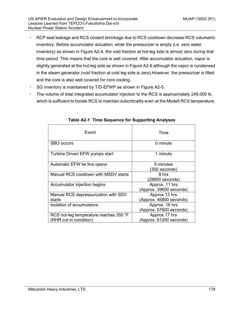
US-APWR Evaluation and Design Enhancement to Incorporate MUAP-13002 (R1) Lessons Learned from TEPCO's Fukushima Dai-ichi Nuclear Power Station Accident
Mitsubishi Heavy Industries, LTD. 178
・ RCP seal leakage and RCS coolant shrinkage due to RCS cooldown decrease RCS volumetric inventory. Before accumulator actuation, while the pressurizer is empty (i.e. zero water inventory) as shown in Figure A2-4, the void fraction at hot-leg side is almost zero during that time period. This means that the core is well covered. After accumulator actuation, vapor is slightly generated at the hot-leg side as shown in Figure A2-6 although the vapor is condensed in the steam generator (void fraction at cold leg side is zero).However, the pressurizer is filled and the core is also well covered for core cooling.
・ SG inventory is maintained by T/D-EFWP as shown in Figure A2-5. ・ The volume of total integrated accumulator injection to the RCS is approximately 249,000 lb,
which is sufficient to borate RCS to maintain subcriticality even at the Mode5 RCS temperature.
Table A2-1 Time Sequence for Supporting Analyses
Event
Time
SBO occurs
0 minute
Turbine Driven EFW pumps start
1 minute
Automatic EFW tie line opens 5 minutes (300 seconds)
Manual RCS cooldown with MSDV starts 8 hrs (28800 seconds)
Accumulator injection begins Approx. 11 hrs (Approx. 39600 seconds)
Manual RCS depressurization with SDV starts
Approx.13 hrs (Approx. 46800 seconds)
Isolation of accumulators Approx. 16 hrs (Approx. 57600 seconds)
RCS hot-leg temperature reaches 350 oF (RHR cut-in condition)
Approx.17 hrs (Approx. 61200 seconds)

US-APWR Evaluation and Design Enhancement to Incorporate MUAP-13002 (R1) Lessons Learned from TEPCO's Fukushima Dai-ichi Nuclear Power Station Accident
Mitsubishi Heavy Industries, LTD. 179
2500
2000
1500
1000
500
0
RC
S P
ress
ure
(psi
a)
80x1036040200Time (seconds)
Figure A2-1 RCS Pressure versus Time
650
600
550
500
450
400
350
300
250
RC
S T
empe
ratu
re (d
egF)
80x1036040200Time (seconds)
Thot Tcold
Figure A2-2 RCS Temperature versus Time

US-APWR Evaluation and Design Enhancement to Incorporate MUAP-13002 (R1) Lessons Learned from TEPCO's Fukushima Dai-ichi Nuclear Power Station Accident
Mitsubishi Heavy Industries, LTD. 180
2500
2000
1500
1000
500
0
Ste
am G
ener
ator
Pre
ssur
e (p
sia)
80x1036040200Time (seconds)
Figure A2-3 Steam Generator Pressure versus Time
100
80
60
40
20
0
Pre
ssur
izer
Wat
er L
evel
(%)
80x1036040200Time (seconds)
Figure A2-4 Pressurizer Water Level versus Time

US-APWR Evaluation and Design Enhancement to Incorporate MUAP-13002 (R1) Lessons Learned from TEPCO's Fukushima Dai-ichi Nuclear Power Station Accident
Mitsubishi Heavy Industries, LTD. 181
100
80
60
40
20
0
Ste
am G
ener
ator
Wat
er L
evel
(%)
80x1036040200Time (seconds)
Figure A2-5 Steam Generator Water Level versus Time
1.0
0.8
0.6
0.4
0.2
0.0
Voi
d fra
ctio
n (-)
80x1036040200Time (seconds)
Hot Leg Cold Leg
Figure A2-6 Void Fraction at Hot/Cold Leg versus Time

US-APWR Evaluation and Design Enhancement to Incorporate MUAP-13002 (R1) Lessons Learned from TEPCO's Fukushima Dai-ichi Nuclear Power Station Accident
Mitsubishi Heavy Industries, LTD. 182
Appendix 3 AAC GTG Seismic Capability Confirmation Plan

US-APWR Evaluation and Design Enhancement to Incorporate MUAP-13002 (R1) Lessons Learned from TEPCO's Fukushima Dai-ichi Nuclear Power Station Accident
Mitsubishi Heavy Industries, LTD. 183
Appendix 3 AAC GTG Seismic Capability Confirmation Plan 1. Purpose The purpose of this section is to show the scope, the methodology and the timeline, that is necessary to confirm the capability of the AAC GTG against the postulated earthquake. Results from the end of the seismic capability confirmation process will be used to ensure the AAC GTG will be able to show a reasonable safety margin. If necessary, re-design or modification will be considered in order to sustain the seismic events. 2. Scope and Methodology 2.1 Concept for Scope and Method for AAC Seismic Capability Confirmation The seismic capability confirmation of the AAC GTG will be achieved under the requirements for non-safety related components and for the beyond design base event. Based on this understanding, the seismic capability confirmation of the AAC GTG does not need to be performed in the same manner as safety-related GTG’s. However, since it must be confirmed that this AAC GTG system can function after a postulated earthquake, the scope and process of this confirmation for all of the equipment related to the AAC GTG system can be prioritized or limited and can be performed using a graded approach. A detailed discussion is shown in the following sections. 2.1.1 Scope of AAC Seismic Capability Confirmation AAC seismic capability confirmation is divided into two phases, the “US-APWR Standard Design Stage” and the “Plant Construction Stage” for each plant. In this report, the seismic capability confirmation primarily addresses the “US-APWR Standard Design Stage.” Additionally, the components that comprise the AAC GTG can be classified into “parts with unique design for the AAC” or “parts with industry-wide design”. In the case of “parts unique to the AAC design”, the seismic capability confirmation for those components will be done during “US-APWR Standard Design Stage” since there are no substitutes for the unique item and it is critical to the operability of the AAC system.
US-APWR Evaluation and Design Enhancement to Incorporate MUAP-13002 (R1) Lessons Learned from TEPCO's Fukushima Dai-ichi Nuclear Power Station Accident
Mitsubishi Heavy Industries, LTD. 184
In the case of “parts with industry-wide application”, the seismic capability confirmation will be performed during “US-APWR standard design stage” or “Plant Construction Stage”, based on the following criteria:
1. “Parts with industry-wide design” that are also available as safety related components.
The components need not be specified at this time, and also it is the typical process to procure those components which have seismic capability at each actual plant’s construction stage in the future. Based on this reason, the seismic capability confirmation for these components should be performed in the “Plant Construction Stage”.
2. “Parts with industry-wide design” that have not been used as (or qualified as) safety related
components.
Since there is no technical basis to show the seismic capability of these components, the seismic capability confirmation should be done during “US-APWR Standard Design Stage”.
2.1.2 Method to Perform the Seismic Capability Confirmation There are two methods for the seismic capability confirmation. One is “Testing”, and the other is “Analysis”. The concept for selecting either method, “Testing” or “Analysis” is as follows:
1. Static components (e.g. tank, piping) : Confirmed by analysis 2. Previously analyzed active components : Confirmed by analysis 3. Active components which have not been previously analyzed : Confirmed by testing
2.2 Categorizing of AAC Equipment Each component is categorized as shown in the following table:

US-APWR Evaluation and Design Enhancement to Incorporate MUAP-13002 (R1) Lessons Learned from TEPCO's Fukushima Dai-ichi Nuclear Power Station Accident
Mitsubishi Heavy Industries, LTD. 185
Table A3-1 Screening Table on AAC GTG’s Components Unique
or Industry-Wide
Product
Static or
Active Components
NPP Seismic Qualification’s
Experience
Testing or
Analysis
(1) GT Engine Industry-wide Active No Test (2) Gearbox Industry-wide Active No Test (3) Generator Industry-wide Active Yes (Analysis)* (4) GTG Enclosure Unique Static No Analysis (5) Skid Unique Static No Analysis (6) Starting System Industry-wide Active Yes (Analysis)* (7) Fuel Oil Pump Industry-wide Active Yes (Analysis)* (8) Fuel System Piping Industry-wide Static Yes (Analysis)* (9) Lube Oil Pump Industry-wide Active Yes (Analysis)* (10) Lube Oil Piping Industry-wide Static Yes (Analysis)* (11) Intake/Exhaust Silencer Industry-wide Static Yes (Analysis)* (12) Ventilation System Industry-wide Static / Active Yes (Analysis)* (13) Control Cabinet Industry-wide Static Yes (Analysis)* (14) Fuel Day Tank Industry-wide Static Yes (Analysis)* (15) Battery Industry-wide Static Yes (Analysis)* (16) Electrical Power Distribution Equipment (AAC MCCs,
transformer selector circuit panel)
Industry-wide Static Yes (Analysis)*
(Note): All seismic analysis followed by an asterisk will be performed in “Plant Construction Stage”.

US-APWR Evaluation and Design Enhancement to Incorporate MUAP-13002 (R1) Lessons Learned from TEPCO's Fukushima Dai-ichi Nuclear Power Station Accident
Mitsubishi Heavy Industries, LTD. 186
2.3 Scope for “US-APWR Standard Design” According to Section 2.1.1, the components which are listed below will be confirmed during “US-APWR Standard Design Stage”.
- The components which are confirmed by testing: GT engine Gear box
- The components which are confirmed by analysis: GTG Enclosure Skid
(1) The components which are confirmed by testing Regarding the GT engine and gear box, these two components will be tested using a shake table. However, because the design of these two components originally came from an industry standard design, it is more appropriate to use a graded approach rather than only applying the shake table test. The graded approach begins with an “analytical examination” and is followed by a detailed “experimental confirmation,” as necessary to complete the confirmation. The basic “analytical examination” consists of a conceptual finite element method (FEM) analysis performed by Mitsubishi in order to confirm that these components do not have any significant challenges when subjected to the US-APWR seismic ISRS. If challenges are observed, Mitsubishi will implement design changes in this stage to mitigate the observed deficiency. Due to the importance of this process, it will be performed during the DCD phase. Thus, allowing Mitsubishi to eliminate seismically incompatible components from the AAC design. Secondly, the detailed “experimental confirmation” consists of shake table tests after DCD certification performed by Mitsubishi. It is not expected that significant challenges will be found during this phase because the basic “analytical examination” will be conducted prior to this activity. (2) The components which are confirmed by analysis Regarding the GTG enclosure and skid which will be confirmed by analysis, these two parts are classified as “parts unique to the design of the AAC”. Because of the nature of the “unique design”,

US-APWR Evaluation and Design Enhancement to Incorporate MUAP-13002 (R1) Lessons Learned from TEPCO's Fukushima Dai-ichi Nuclear Power Station Accident
Mitsubishi Heavy Industries, LTD. 187
the seismic capability for these components is commonly established during the design stage in order to satisfy the design specification. This confirmation will be done after DCD certification as US-APWR standard design confirmation. 2.4 Scope for “Plant Construction Stage” As Table A3-1 shows, several components will be confirmed during the “Plant Construction Stage”.
- The components which will be confirmed by Analysis during “Plant Construction Stage”: Generator Starting System Fuel Oil Pump Fuel System Piping Lube Oil Pump Lube Oil Piping Intake/Exhaust Silencer Ventilation System Control Cabinet Fuel Day tank Battery
As explained in Section 2.1.1, the above components are categorized as “Parts with industry-wide application” that are readily available and currently used as safety-related components in several NPPs. This indicates there is capability to procure these items as seismically qualified in the future. Based on this understanding, seismic capability confirmation of these components will be performed during the “Plant Construction Stage” after DCD certification. 3. Method of Seismic Confirmation by Testing Seismic capability confirmation, both analysis and testing, of the AAC GTG will be performed under the assumption that the AAC GTG’s engine will not be running during the postulated earthquake. This assumption is based on the GTG operating conditions below:
a. During GTG operation a seismic event occurs and the GTG is tripped either by the main
control panel or by the GTG vibration monitoring system. If the GTG is not operating before the seismic event, only item “b" will apply.

US-APWR Evaluation and Design Enhancement to Incorporate MUAP-13002 (R1) Lessons Learned from TEPCO's Fukushima Dai-ichi Nuclear Power Station Accident
Mitsubishi Heavy Industries, LTD. 188
b. After the seismic event, the GTG starts and provides the required non-safety related emergency power source for the plant.
Seismic capability confirmation will employ either an analysis or a physical seismic test. The GTG engine and gear box will be verified by a conceptual analysis during the DCD phase before shake table testing. In both methods of verification, Mitsubishi will use US-APWR ISRS as an input. During the shake table tests, each component will be installed on frames, skids and supporting elements that represent the GTG design. The seismic load that the comonents receive will bound the seismic load that they would be expected to when installed in the nuclear power plant. Failures during the functional testing will result in investigations and modifications to ensure the final design is adequate for the intended service. The response spectra used for the confirmation is defined in MUAP-10006, Rev. 3, “Soil-Structure Interaction Analyses and Results for the US-APWR Standard Plant” (Reference 5-1). Seismic confirmation by testing will be performed as described below.
a. Manufacture/ procure components and inspect to applicable drawings and specifications. b. Functional testing of all components operating together at testing facilities. Test results to be
recorded and the components re-inspected and prepared for shipment to the testing facility. c. Testing facility performs shake table tests and ships the components back to Mitsubishi with
test reports. d. Mitsubishi performs a visual inspection and functional test as per item b above. Test results
to be recorded in the same manner as in item b above. e. Mitsubishi reviews and evaluates all inspection and testing results. f. If necessary, Mitsubishi will implement possible modifications of components.
4. Timeline The timeline for seismic capability confirmation of the AAC GTG is shown in Figure A3-1. As discussed above, regarding the GTG engine and gear box, these two components should be confirmed by testing after the design certification. Regarding the GTG enclosure and skid, these two components should be confirmed by analysis after the design certification. The other components will be confirmed by analysis during the "Plant Construction Stage."

US-APWR Evaluation and Design Enhancement to Incorporate MUAP-13002 (R1) Lessons Learned from TEPCO's Fukushima Dai-ichi Nuclear Power Station Accident
Mitsubishi Heavy Industries, LTD. 189
5 References 5-1 Soil-Structure Interaction Analyses and Results for the US-APWR Standard Plant,
MUAP-10006, Rev. 3, November 2012.

US
-AP
WR
Eva
luat
ion
and
Des
ign
Enh
ance
men
t to
Inco
rpor
ate
M
UA
P-13
002
(R1)
Le
sson
s Le
arne
d fro
m T
EPC
O's
Fuk
ushi
ma
Dai
-ichi
N
ucle
ar P
ower
Sta
tion
Acc
iden
t
Mits
ubis
hi H
eavy
Indu
strie
s, L
TD.
190
DC
D L
icen
sing
Pha
se
Sei
smic
con
firm
atio
n S
tage
Sei
smic
con
firm
atio
n Ite
mG
T E
ngin
e
G
earb
oxE
nclo
sure
Ski
d
Oth
er c
ompo
nent
s
2013
2008
2009
2010
2011
2012
2014
2015
P6
Ph
ase
1 :
Ph
ase
2 : S
ER
with
Op
en It
ems
Ph
ase
3 : A
CR
S M
eetin
gs
Ph
ase
4 : A
dva
nce
d S
ER
with
no
Ope
n P
5
Des
ign
Cer
tific
atio
n A
fter D
esig
n C
ertif
icat
ion
Pro
cess
US
-AP
WR
Sta
ndar
d D
esig
n S
tage
Pla
nt C
onst
ruct
ion
Sta
ge
An
alys
is (1
yea
r)S
hak
e ta
ble
test
(2 y
ears
)
An
alys
is (1
yea
r)
An
alys
is (2
yea
rs)
Rul
e M
akin
g
Fi
gure
A3-
1 T
imel
ine
for A
AC
GTG
Sei
smic
Cap
abili
ty C
onfir
mat
ion

US-APWR Evaluation and Design Enhancement to Incorporate MUAP-13002 (R1) Lessons Learned from TEPCO's Fukushima Dai-ichi Nuclear Power Station Accident
Mitsubishi Heavy Industries, LTD. 191
Appendix 4 Impact of Design and Program Changes on PRA

US-APWR Evaluation and Design Enhancement to Incorporate MUAP-13002 (R1) Lessons Learned from TEPCO's Fukushima Dai-ichi Nuclear Power Station Accident
Mitsubishi Heavy Industries, LTD. 192
Appendix 4 Impact of Design and Program Changes on PRA
1. Preface
This appendix describes the impact of design and program changes that were described in MUAP-13002-P Revision 0, dated March 2013, and have now been incorporated into the US-APWR DCD Revision 4, dated August 2013, on the probabilistic risk assessment (PRA). MHI is planning to update the PRA model to incorporate the Fukushima-related design changes. The updated PRA model will be documented in the US-APWR PRA Technical Report, MUAP-07030 Revision 4, which will be submitted to the NRC in May 2014 (Ref. UAP-HF-13101, dated April 2013). At that time, this appendix will no longer be applicable since all Fukushima-related design changes will have been incorporated into the PRA.
2. Impact of Design and Program Changes on PRA
Section 6.0 of this technical report provides the features and design and program changes US-APWR DCD Revision 3 to incorporate lessons learned from the accidents at Fukushima Dai-ichi Nuclear Power Station after the Great Tohoku Earthquake and Tsunami. Some of these design and program changes have potential impacts on PRA. This appendix provides the results of the qualitative assessment of the impact on PRA discussed in DCD Chapter 19. The areas of the PRA that are addressed include:
・ Internal event for at-power ・ Internal fire ・ Internal flooding ・ Internal event for low-power and shutdown (LPSD) ・ PRA-based seismic margin analysis (SMA)
The impact assessment results are summarized in Table A4-1. The PRA model will be updated to incorporate the Fukushima-related design changes in Section 6.0 (and summarized in Table A4-1) by May 2014. Note that the RCP No. 2 seal test was a test performed to verify the existing design and not a design change; therefore, no PRA model update will be performed for this item. Following the PRA model update, DCD Table 3.2-2 “Classification of

US-APWR Evaluation and Design Enhancement to Incorporate MUAP-13002 (R1) Lessons Learned from TEPCO's Fukushima Dai-ichi Nuclear Power Station Accident
Mitsubishi Heavy Industries, LTD. 193
Mechanical and Fluid Systems, Components, and Equipment”, DCD Table 14.3-1d “PRA and Severe Accident Analysis Key Design Features”, and DCD Table 17.4-1 “Risk-significant SSCs” will be revised to incorporate the results of the updated PRA.

US-APWR Evaluation and Design Enhancement to Incorporate MUAP-13002 (R1) Lessons Learned from TEPCO's Fukushima Dai-ichi Nuclear Power Station Accident
Mitsubishi Heavy Industries, LTD. 194
Table A4-1 Qualitative Impact on PRA (Sheet 1 of 3)
Item Impact on PRA Qualitative Assessment Results Internal Event Internal Fire Internal Flooding LPSD PRA-based SMA 1 BDB Flood Protection No impact No impact No impact No impact No impact This design change is effective to protect flooding from only outside of the
plant. Flooding from outside of the plant can be screened out using the design information described in the DCD and FSAR Chapter 2. The design change has no impact on external flooding events, whose scope is in the COLA.
2 AAC GTG Seismic Testing Plan
No impact No impact No impact No impact No impact The PRA-based SMA in DCD Subsection 19.1.5.1 assumes that the AACs are available under seismic induced loss of offsite power event. The assumption has been addressed in DCD Table 19.1-119, which has been provided in the response to RAI #750-5675 Q19-519 (Ref. UAP-HF-12269). The seismic test ensures that the assumption is valid. Therefore, the testing plan has no impact on the current PRA-based SMA results.
3 RCP No. 2 Seal Testing
Yes, Note 1 No impact No impact No impact No impact Probability of offsite power recovery is determined by the time to RCP seal LOCA after a loss of water cooling. The PRA assumes that RCP seal LOCA occurs 1 hrs after a loss of water cooling and the testing result can extend the timing of RCP seal LOCA occurrence.
Internal flooding does not cause a loss of offsite power event and internal fire PRA does not credit the offsite power recovery within 24 hrs after a fire-induced loss of offsite power event. Also, the RCP is not expected as a mitigation function in the LPSD PRA. The testing result impacts only internal events PRA for at-power operation. The testing results combined with Item 4 can effectively reduce the plant risk for at-power internal events PRA. The detail is addressed in Note 1.
4 Electric Power Supply System
Yes, Note 1 Negligible Negligible Negligible No impact AC power supply system ・ Failure probability of circuit breaker used in the PRA is applied to the
switch. Component change from “disconnect switch” to “circuit breaker” has no impact on the PRA.
・ Human error probability modeled in the PRA is not dependent on allowable time for operator action. Changing of the operation time to connect AACs to Class 1E buses (from 60 minutes to 8 hrs) has no impact on the PRA.
I&C power supply system ・ The design change decreases the reliability of the I&C power supply
system to the PSMS equipment. The unreliability of the I&C power supply system is much lower than that of other components such as Class 1E GTGs and engineered safety feature signals such as emergency core cooling actuation signals. Impact on the PRA due to this design change can be considered to be negligible.
・ The design change enables the Class 1E batteries to maintain power supply for 8 hrs without load shedding. This design change combined with Item 3 can reduce the plant risk for internal events PRA during at-power operation. The qualitative impact is discussed in Note 1.

US-APWR Evaluation and Design Enhancement to Incorporate MUAP-13002 (R1) Lessons Learned from TEPCO's Fukushima Dai-ichi Nuclear Power Station Accident
Mitsubishi Heavy Industries, LTD. 195
Table A4-1 Qualitative Impact on PRA (Sheet of 3)
Item Impact on PRA Qualitative Assessment Results Internal Event Internal Fire Internal Flooding LPSD PRA-based SMA 5 Alternate Suction to
CHP No impact No impact No impact Reduction of
core damage frequency
(CDF)
No impact Internal and external event PRAs for at-power operation assumes that, the
water source of the CHP is only the volume control tank. Change of the alternate water source for the CHP does not affect the at-power PRA.
LPSD PRA expects RCS injection using the CHP followed by a loss of RHR event. In such a situation, the refueling water storage auxiliary tank is considered to be the first water source. The LPSD PRA assumes that the refueling water storage auxiliary tank does not have sufficient inventory to supply the coolant into the RCS for more than 24 hrs. When the tank level is low, operators manually supply inventory in the RWSP to the tank. The operator action is identified as risk-significant. This design change enables the operator action to be eliminated so that the risk during LPSD operation would be reduced.
6 Alternate UHS No impact No impact No impact No impact No impact This item includes the three design changes, as provided in Section 6.6. Impact on the PRA is addressed for each of them:
・ Alternate charging pump cooling using non-ECWS has been modeled in the latest PRA model so that the design change has no impact on the PRA.
・ RCP seal injection function can maintain its function for 3 days, regardless of seal water heat exchanger cooling. Mission time used in the PRA is 24 hrs so that the operability does not have impact on the PRA.
・ HVAC system for two motor-driven EFW pump rooms is modeled in the PRA and the system for other rooms is not modeled because components other than motor-driven EFW pumps can operate within the PRA mission time, regardless of the operability of each area HVAC system. According to Subsection 6.6.1, the alternate UHS provides no cooling function to the motor-driven EFW pump room areas, therefore, the design change has no impact on the PRA.
7 SFP No impact No impact No impact No impact No impact Risk evaluation of the spent fuel damage is not evaluated in the DCD PRA because there is sufficient time for recovery action due to the large coolant inventory in the SFP. Therefore, the design change has no impact on the PRA.
2

US-APWR Evaluation and Design Enhancement to Incorporate MUAP-13002 (R1) Lessons Learned from TEPCO's Fukushima Dai-ichi Nuclear Power Station Accident
Mitsubishi Heavy Industries, LTD. 196
Table A4-1 Qualitative Impact on PRA (Sheet of 3)
Item Impact on PRA Qualitative Assessment Results Internal Event Internal Fire Internal Flooding LPSD PRA-based SMA 8 EFWS Decrease of
CDF Decrease of
CDF Decrease of CDF No impact No impact This item includes two design changes, as provided in Section 6.8. Impact
on the PRA is addressed for both changes: ・ The PRA considers manual makeup to the EFW pit from the
demineralized water tank when the EFW pit level is low. Human error has a large contribution to the plant risk and, especially, the internal flooding PRA. The design change ensures redundancy of the EFW pit makeup line and results in the higher reliability of the makeup to remain available. However, the design change has no impact on the PRA if a complete dependency between operator errors to makeup the EFW pit from the demineralized water tank and from outside is assumed.
・ Operator action to manually open the EFW header tie-line valves under a loss of offsite power event is identified as risk-significant. This design change effectively reduces the core damage frequency (CDF) due to an SBO event for at-power PRAs.
・ The LPSD PRA takes credit for the decay heat removal via SGs after a loss of RHR cooling. One SG with one EFW pump can remove the decay heat from the reactor, as provided in the response to RAI #39-548 Q19-45 (Ref. UAP-HF-08260). This means that opening of the EFW header tie-line valves is not required to maintain the decay heat from the SGs. Therefore, the design change has no impact on LPSD PRA.
Note 1. RCP No. 2 seal testing needs to be discussed with design change of the I&C power supply system in Item 4.
(1) The following is the RCP seal LOCA model in the PRA:
・ RCP seal keeps its integrity for 1 hour without water cooling ・ RCP seal LOCA with a leak rate of 109 m3/h (480 gpm) per RCP occurs 1 hour after both thermal barrier and RCP seal injection function are lost. ・ The reactor core is uncovered 2 hrs after RCP seal LOCA occurs.
Probability of offsite power recovery in the internal events PRA is determined using the above, that is, the PRA models the offsite power recovery within 3 hrs after a loss of RCP cooling. The RCP seal testing results can extend the duration that the seal integrity will be maintained under a no water cooling condition and can extend the duration before the core is uncovered. According to DCD Subsection 19.1.4.1.2, a core damage scenario involving RCP seal LOCA contributes to more than 60% of the CDF in the internal event. The testing results demonstrate that there would be no possibility of core uncovery within 8 hrs after a loss of seal cooling.
(2) In the DCD Rev. 3 design, Class 1E batteries have the capacity to supply dc power within 2 hrs under an SBO condition. While the battery supplies power to the PSMS, SG water level sensors are available and decay heat from the RCS can be removed by a secondary heat sink. Due to the design change of Item 4, the Class 1E batteries can supply power to the PSMS for 8 hrs with no ac power, so that the decay heat removal function via SGs can be maintained for 8 hrs after an SBO occurs.
Due to the design changes, the CDF of SBO event would be reduced because the probability of offsite power recovery before core damage becomes higher. On the other hand, the CDF associated with RCP seal LOCA caused by a loss of CCW would hardly be decreased because it is likely that the recovery of CCW system or ESW system cannot be accomplished within a short period.
3

US-APWR Evaluation and Design Enhancement to Incorporate MUAP-13002 (R1) Lessons Learned from TEPCO's Fukushima Dai-ichi Nuclear Power Station Accident
Mitsubishi Heavy Industries, LTD. 197
Appendix 5 Containment Thermal-Hydraulic Analysis

US-APWR Evaluation and Design Enhancement to Incorporate MUAP-13002 (R1) Lessons Learned from TEPCO's Fukushima Dai-ichi Nuclear Power Station Accident
Mitsubishi Heavy Industries, LTD. 198
1. Preface
The containment response is evaluated for two characteristic plant conditions, one is when the feed and bleed to steam generators (SGs) are available so that reactor coolant system (RCS) can be cooled via the secondary system (Modes 1-4) and the other is when SGs are isolated so that RCS is not coolable via the secondary system (Modes 5-6). 2. Containment Thermal-Hydraulic Analysis for Modes 1 to 4 In order to figure out the transient behavior of the containment response for Modes 1 to 4 under ELAP / loss of normal access to the UHS, examinations with numerical calculations were conducted with application of a design basis model. In the following subsections, scenario selection, evaluation methodology and results are described. 2.1. Evaluation scenarios The plant condition of Mode 1 is considered more appropriate for evaluation rather than Modes 2 through 4 conditions because of the initial power conditions and stored energy. Therefore, containment response analyses of the US-APWR at Mode1 have been conducted using the GOTHIC code for the period 1 week after initiation of ELAP / loss of normal access to the UHS. 2.2. Methodology The containment model applied to the containment maximum pressure /temperature evaluation described in DCD Section 6.2.1.1 is employed for this evaluation, except for the disabled containment spray and pumped SI system. Analysis conditions are shown in Table A5-1.

US-APWR Evaluation and Design Enhancement to Incorporate MUAP-13002 (R1) Lessons Learned from TEPCO's Fukushima Dai-ichi Nuclear Power Station Accident
Mitsubishi Heavy Industries, LTD. 199
Table A5-1 Analysis conditions A. Boundary Conditions Description Value Notes Mass and energy release from RCP sealing
4 m3/hr (1.826 lbm/sec) 553.4 btu/lbm
2280 psia / 555.1 °F (Tcold at 102 % -Power operation plus uncertainty and instrument errors) Assuming constant throughout 1 week
Heat-up from RCS 1.817 MW 102 % power operation plus uncertainty and instrument errors Assumed constant throughout the 1 week analysis period
B. Initial Conditions Description Value Notes Initial pressure 16.696 psia Maximum value Initial temperature for vapor phase and RWSP liquid
120 °F Maximum value
Initial humidity 0% Minimum value C. Containment Modeling Description Value Notes Free volume 2,743,000 ft3 Minimum value RWSP liquid volume 44,000 ft3 Minimum value
No heat and mass transfer with vapor phase Heat sink in containment Conservative volume and
surface area, same as Table 6.2.1-9 of DCD Revision 3
Minimum value
Heat transfer with heat sink in containment
DLM Conservative assumption
Heat transfer with environment
None Assumed adiabatic
Available ESFs No containment heat removal systems and pumped injection systems
Assumed ELAP with simultaneous loss of normal access to the UHS
2.3. Results
The results of the analyses are shown in Figure A5-1 and Figure A5-2 in this appendix. The calculated peak containment pressure and temperature 1 week after the initiation of the event remains below the design limits of the containment - containment pressure 68 psig (82.7 psia) and containment temperature 300 °F - even with containment heat removal systems and pumped safety injection systems disabled and no manual operation.
After 1 week, applicable mitigation measures will be taken such as containment spray initiation by alternative water storage, or secondary system feed and bleed. Therefore, containment pressure and temperature will decrease.

US-APWR Evaluation and Design Enhancement to Incorporate MUAP-13002 (R1) Lessons Learned from TEPCO's Fukushima Dai-ichi Nuclear Power Station Accident
Mitsubishi Heavy Industries, LTD. 200
Figure A5-1 Containment Pressure (Mode 1)
Figure A5-2 Containment Temperature (Mode 1)

US-APWR Evaluation and Design Enhancement to Incorporate MUAP-13002 (R1) Lessons Learned from TEPCO's Fukushima Dai-ichi Nuclear Power Station Accident
Mitsubishi Heavy Industries, LTD. 201
3. Containment Thermal-Hydraulic Analysis for Modes 5 and 6
3.1. Evaluation scenarios
The plant condition of Mode 5 (cold shutdown) is considered more appropriate for evaluation rather than Mode 6 (refueling) conditions in light of the containment pressurization behavior. In Mode 6, decay heat is lower than Mode 5 because it has passed longer after reactor shutdown, so that it is obvious that containment pressurization in Mode 5 becomes more severe than in Mode 6.
The low-power and shutdown (LPSD) operation conditions are classified into 13 plant operation states (POS) in the US-APWR LPSD PRA. These POSs are identified considering the plant configuration, potential of initiating events and plant responses. The definition of POSs is documented in DCD Ch. 19 Table 19.1-82. Table A5-2 below, which is extracted from DCD Table 19.1-82, summarizes the plant configurations from POS 1 through 5 with time elapsed after shutdown.
Table A5-2 POS Assumption Considered in the US-APWR LPSD PRA
POS ID
Plant Configuration Time [hour]
From To After shutdown Duration
1 Power operation Insertion of control rods 0 3
2 Insertion of control rods RHR connection 3 9
3 RHR connection Initiation of RCS draining 12 24
4-1 Initiation of RCS draining Opening the SG manways 36 24
4-2 Opening the SG manways Installation of SG nozzle dams 60 12
4-3 Installation of SG nozzle dams Refueling cavity full 72 36
5 Initiation of fuel offload Fuel movement ends 108 72
POS 1 and 2 are in a transition status from power operation to hot shutdown, so that these POSs are categorized as Modes 1-3.
POS 3 is in a transition status from hot shutdown to cold shutdown. RCS is fully filled with water and the safety systems are not isolated. RCS pressure boundary is still maintained. Therefore it is in an equivalent condition with the power operation in terms of the containment pressurization. This POS is categorized as Mode 4.

US-APWR Evaluation and Design Enhancement to Incorporate MUAP-13002 (R1) Lessons Learned from TEPCO's Fukushima Dai-ichi Nuclear Power Station Accident
Mitsubishi Heavy Industries, LTD. 202
POS 4 is mid-loop operation. This POS is further classified into three sub-states depending on the SG conditions. During POS 4-1, SGs are connected to the RCS and the pressure boundary is still maintained. SG manways are open at POS 4-2 and SG nozzle dams are placed at POS 4-3. In POS 4-2 and 4-3, the RCS pressure boundary is intentionally open to the containment atmosphere by removing pressurizer safety valves or pressurizer manway in order to prevent RCS over-pressurization. Therefore, especially in POS 4-2 and 4-3, the RCS inventory, including liquid and vapor, is easily released into the containment, which is the source of containment pressurization. These POSs are categorized as Mode 5. POS 5 is a refueling status. Containment may be open for refueling operation so that containment will not be pressurized. The refueling cavity is filled with water and other water sources are available in abundant. Therefore it is considered that core damage accident is very unlikely to occur during refueling operation, and thus less significant than other operating states in terms of the accident progression evaluation. This POS is categorized in Mode 6. RCS inventory during mid-loop operation and refueling is summarized in Figure A5-3. This figure is taken from DCD Ch. 19 Figure 19.1-23. The RCS and SG configurations assumed for POS 4-1, 4-2 and 4-3 are shown in Figure A5-4, Figure A5-5 and Figure A5-6, respectively. For POS 4-1, SGs are connected to the RCS and the pressure boundary is still maintained, so that mass and energy release from RCS to containment is limited. Containment pressurization is accordingly less significant; and therefore POS 4-1 is eliminated from the evaluation scope. POS 4-2 and 4-3 are evaluated in this study. The plant configurations assumed for POSs 4-2 and 4-3 are summarized in Table A5-3. Differences in the RCS configurations for these POSs may not significantly influence the containment pressurization behavior especially for the relatively long-term evaluation up to 72 hours because the RCS pressure boundary is open to the containment atmosphere. The initial decay heat condition should have certain impact; in addition this condition involves uncertainties related to the progression of outage activities. Therefore in this study, these two cases are evaluated as being representative of the LPSD conditions.

US-APWR Evaluation and Design Enhancement to Incorporate MUAP-13002 (R1) Lessons Learned from TEPCO's Fukushima Dai-ichi Nuclear Power Station Accident
Mitsubishi Heavy Industries, LTD. 203
Table A5-3 Plant Conditions Assumed in Evaluations for POS 4-2 and 4-3
POS 4-2 POS 4-3 Basis
RCS
Initial temperature 140 °F 140 °F Realistic: DCD 5.4.7.2.3.3
Initial pressure 0 psig 0 psig Realistic: Atmospheric
Initial water level Top of MCP Top of MCP Realistic: DCD Figure 19.1-23
Time after shutdown 60 hours 72 hours POS definition: DCD Table 19.1-82
Initial decay heat 19.3 MW 18.1 MW ANSI/ANS 5.1-1979
Pressurizer safety valve Installed Removed POS definition: DCD Table 19.1-82
SG manway Open Open POS definition: DCD Table 19.1-82
SG nozzle dam Not installed Installed POS definition: DCD Table 19.1-82
RV upper plenum Closed Closed POS definition: DCD Table 19.1-82
For this containment thermal-hydraulic analysis assuming ELAP + loss of normal access to the UHS, the evaluation basis is for Fukushima type of accident event with incorporating various design improvements to cope with such an event. Figure A5-7 shows the summary of available functions for core cooling and containment heat removal during ELAP + loss of normal access to the UHS event. The phase progression is defined in accordance with the conditions discussed in NEI-12-06, i.e. Phase 1, only relying on installed plant equipment, is within 1 hour after the onset of an accident, Phase 2, transition from installed plant equipment to on-site FLEX equipment, is after 1 hour until 72 hours, and Phase 3, additional offsite resources become available, is after 72 hours. Based on this definition, AAC is assumed initiated within 1 hour, and then core cooling becomes available by using a charging pump after 1 hour, and finally containment heat removal becomes available after 72 hours obtaining offsite resources. Therefore, it is assumed in this evaluation that the core cooling function will be recovered by employing a charging pump within 1 hour after accident initiation. As shown in DCD Ch.19 Table 19.1-141, the time to core uncovery during mid-loop operation with loss of RHR is evaluated as 13 hours for POS 4-1, 1.7 hours for POS 4-2 and 1.8 hours for POS 4-3. Core will be therefore maintained intact if core injection is recovered within 1 hour (note 1). However, any containment cooling function may not be available until offsite resource will be expected, which is assumed after 72 hours from accident initiation (note 2). The calculation is therefore performed up to 72 hours and the containment pressure is evaluated to confirm that containment pressurization is within the containment ultimate capability, 216 psia. In addition, the containment temperature is evaluated to demonstrate that the calculation basis for the containment ultimate pressure is satisfied. The containment ultimate pressure is calculated assuming 400°F as a severe accident environmental

US-APWR Evaluation and Design Enhancement to Incorporate MUAP-13002 (R1) Lessons Learned from TEPCO's Fukushima Dai-ichi Nuclear Power Station Accident
Mitsubishi Heavy Industries, LTD. 204
condition. The containment temperature is therefore needed to be maintained below 400°F to show that the containment ultimate pressure calculation is appropriate (note 3). After 72 hours, assuming containment spray utilizing the off-site resources including the fire service water, etc. will become available; it is assumed that the containment is appropriately depressurized. Before starting the containment depressurization operation, it is necessary to change the core injection from a charging pump to a temporary pump. When containment is depressurized, NPSH available of a charging pump may become insufficient. A temporary pump is therefore alternatively connected to RHR piping and core injection is continued. (Note 1) RWSP water is injected into reactor vessel using a charging pump. Alternate UHS is expected to supply cooling water to a charging pump in a same way as Mode 1 through 4. However, considering the difficulty to appropriately activate the alternate UHS within a very limited time in Phase 1 due to various operators’ activities required to do, cooling of a charging pump is implemented by employing the CCWS without cooling by UHS in the early stage of Phase 2. And then, before the CCW temperature exceeds the design temperature of cooling water of a charging pump, which will occur within 2 hours after the initiation of charging pump operation, cooling water supply is switched from CCWS to the alternate UHS. (Note 2) Since CS/RHR pumps are not available due to loss of normal access to the UHS, any available water source and a temporary pump is employed for alternate containment spray. Potential option for alternate containment spray is the fire protection water supply system, but not limited. However, alternate containment spray is not applicable for recirculation operation; instead it can merely deliver water into the containment. It does not provide a heat exchange function either. And thus, for a long term containment heat removal operation, it is necessary to discharge delivered water to outside containment in order to remove heat from containment. (Note 3) The containment ultimate temperature is not established for the US-APWR containment design. This 400°F criterion is specifically determined for this particular containment thermal-hydraulic analysis only, and this value is not used for any other purposes. As described in DCD Ch. 19 Section 19.2.4.1; the ultimate pressure is predicted by summation of each multiplication of the cross sectional area and yielding stress of rebar, tendon, and liner plate. In terms of the material property of carbon steel, there is no significant deterioration on strength for temperatures around 400°F~600°F. The temperature criterion of 400°F for this containment thermal-hydraulic analysis is therefore considered conservative.

US-APWR Evaluation and Design Enhancement to Incorporate MUAP-13002 (R1) Lessons Learned from TEPCO's Fukushima Dai-ichi Nuclear Power Station Accident
Mitsubishi Heavy Industries, LTD. 205
A B A B C D E A B C D E A B
Note 1: Automaitic isolation for low-pressure letdown line when Low signal actuates CVCS: Chemical and Volume Control System RV: Reactor VesselNote 2: Initiation of gravity injection when Low-Low signal actuates PSV: Pressurizer Safety Vavle H/L: Hot LegNote 3: Assumptiion that RCS level is at a center of MCP is used for estimation of allowable time for core uncovery ICIS: In-Core Instrumentation System C/L: Cold Leg
MCP: Main Coolant Piping
Mid-loop OperationRefueling
8-24-1 4-3 8-1 8-37654-2
Performed Key Activities
POS
RCSWaterLevel
Mid-loop Operation
De-tensioning RV Head Stud Bolts
1. Open SG Manway on H/L side2. Open SG Manway on C/L side
1. Install SG Nozzle Dam on C/L side.2. Install SG Nozzle Dam on H/L side
1. Remove SG Nozzle Dam on H/L side2. Remove SG Nozzle Dam on C/L side
1. Close SG Manway on C/L side2. Close SG Manway on H/L side
Remove ICIS
Remove RV Head Install RV Head Tensioning RV Head Stud Bolts
Remove either at least 3PSVs or pressurizer manway
Vacuum Venting
Install ICIS
Controlled by CVCS
Flange Level
Center of MCP
Low-Low Note2
Low Note1
Top of MCP
Cavity Full
Realistic Operation
PRA Assump ion Note3
Controlled by CVCS
SG Drain
Realistic Operation
PRA Assumption Note3
Close RCS vent path
Figure A5-3 RCS Inventory during Mid-loop Operation and Refueling with Key Activities

US-APWR Evaluation and Design Enhancement to Incorporate MUAP-13002 (R1) Lessons Learned from TEPCO's Fukushima Dai-ichi Nuclear Power Station Accident
Mitsubishi Heavy Industries, LTD. 206
Reactor Vessel
SG
RCP
RCP ReactorVessel
PressurizerRelief Tank
PressurizerSafety Valve
Pressurizer
Figure A5-4 RCS and SG Configuration Assumed during POS 4-1

US-APWR Evaluation and Design Enhancement to Incorporate MUAP-13002 (R1) Lessons Learned from TEPCO's Fukushima Dai-ichi Nuclear Power Station Accident
Mitsubishi Heavy Industries, LTD. 207
Reactor Vessel
SG
RCP
SG ManwayRCP ReactorVessel
PressurizerRelief Tank
PressurizerSafety Valve
PressurizerManway
Pressurizer
Figure A5-5 RCS and SG Configuration Assumed during POS 4-2

US-APWR Evaluation and Design Enhancement to Incorporate MUAP-13002 (R1) Lessons Learned from TEPCO's Fukushima Dai-ichi Nuclear Power Station Accident
Mitsubishi Heavy Industries, LTD. 208
Reactor Vessel
SG
RCP
SG ManwayRCP ReactorVesselSG Nozzle Dam
PressurizerRelief Tank
PressurizerSafety Valve
PressurizerManway
Pressurizer
Figure A5-6 RCS and SG Configuration Assumed during POS 4-3

US
-AP
WR
Eva
luat
ion
and
Des
ign
Enh
ance
men
t to
Inco
rpor
ate
MU
AP
-130
02 (R
1)
Less
ons
Lear
ned
from
TEP
CO
's F
ukus
him
a D
ai-ic
hi
Nuc
lear
Pow
er S
tatio
n A
ccid
ent
Mits
ubis
hi H
eavy
Indu
strie
s, L
TD.
209
0h1h
2h20
h72
h (3
days
)
Phas
e 1
Ons
ite p
erm
anen
tfa
cilit
ies
only
Cor
eIn
ject
ion
Pum
pC
oolin
g
Wa t
erSo
urce
Containmentdepressurization
Con
tain
men
tSp
ray
――
――
Tran
sit T
ime
Phas
ePh
ase
2O
nsite
tem
pora
ry fa
iclit
ies
avai
labl
eP
hase
3O
ffsite
reso
urce
s av
aila
ble
Core Cooling
Act
ivat
eA
AC
w
ithin
1h
Cha
rgin
gpu
mp
Alte
rnat
eUH
SUs
ing
Non-
ECW
S Co
olin
g to
wer
RWSP
Con
tain
men
t spr
ayUs
ing
alte
rnat
ive
wat
er s
ourc
e(w
hate
ver a
vaila
ble,
incl
udin
g fir
e se
rvic
e w
ater
, etc
.)
CC
WS
Coo
ling
with
circ
ulat
ion
by C
CW
P on
ly,w
ithou
t U
HS
coo
ling
‐RWSP
‐Alte
rnativewater so
urce
Tem
pora
rypu
mp
Inst
all c
onne
ctio
n ta
ps a
t RH
R pi
ping
Figu
re A
5-7
Sta
tus
of H
eat R
emov
al F
unct
ions
Ass
umed
in E
ach
Phas
e fo
r Mod
e 5
and
6

US-APWR Evaluation and Design Enhancement to Incorporate MUAP-13002 (R1) Lessons Learned from TEPCO's Fukushima Dai-ichi Nuclear Power Station Accident
Mitsubishi Heavy Industries, LTD. 210
3.2. Methodology
MAAP 4.0.6 is utilized for this evaluation, employing the model developed for the DCD Rev. 3. MAAP code is capable of performing integrated calculation of the RCS boiling behavior, which is the heat source of containment pressurization, and the resulting containment thermal-hydraulic behavior. GOTHIC code is capable of calculating the containment thermal-hydraulic behavior with assuming certain heat source for containment; however the integrated calculation for RCS and containment such as MAAP is not available. Therefore in order to employ GOTHIC code, it is necessary to provide the heat source data by using another thermal-hydraulic code to evaluate the RCS behavior or to provide data based on certain assumptions. For this containment thermal-hydraulic analysis, it is assumed that the water source for core injection using a charging pump is taken from the RWSP, and the steam generated in core is released to the containment atmosphere and if the injected water flows out from the RCS opening, the spilled water returns back to the RWSP. In order to model such plant behavior, it is considered that MAAP is more suitable than GOTHIC because of its capability of integrated calculation of RCS and containment. In addition, MAAP code was primarily employed for the beyond design-basis accident progression analysis for the US-APWR design, described in the DCD Ch. 19 PRA and severe accident evaluation, so that MAAP is considered appropriate for this calculation objective, ELAP + loss of normal access to the UHS event.
3.3. Acceptance Criteria
The acceptance criteria for this containment thermal-hydraulic analysis are following:
• Containment pressure: less than 216 psia (the ultimate pressure) • Containment temperature: less than 400°F (basis to calculate the ultimate pressure)
The containment design pressure (83 psia) and design temperature (300°F) are the criteria to evaluate the design-basis events. For this beyond design-basis ELAP + loss of normal access to the UHS event evaluation, it is not necessary to satisfy the design-basis criteria; instead the ultimate capability is appropriate. Containment integrity is maintained when these criteria are satisfied.
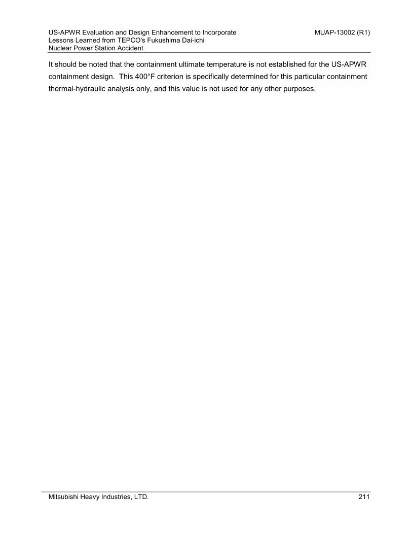
US-APWR Evaluation and Design Enhancement to Incorporate MUAP-13002 (R1) Lessons Learned from TEPCO's Fukushima Dai-ichi Nuclear Power Station Accident
Mitsubishi Heavy Industries, LTD. 211
It should be noted that the containment ultimate temperature is not established for the US-APWR containment design. This 400°F criterion is specifically determined for this particular containment thermal-hydraulic analysis only, and this value is not used for any other purposes.

US-APWR Evaluation and Design Enhancement to Incorporate MUAP-13002 (R1) Lessons Learned from TEPCO's Fukushima Dai-ichi Nuclear Power Station Accident
Mitsubishi Heavy Industries, LTD. 212
3.4. Results
3.4.1. POS 4-2
Accident progression is evaluated for the following sequence: • Accident sequence: Loss of RHR during mid-loop operation at 60 hours
+ 0/4 High head injection + 0/4 Containment spray + 0/4 Accumulators + SG manway is open + Core cooling via CHP becomes available at 1 hour
It is assumed that hot leg side manways of all 4 SGs are open. Therefore other RCS openings such as the pressurizer relief valves and pressurizer manway do not significantly influence the containment pressurization. Containment pressure evaluation result is shown in Figure A5-8. Containment pressure reaches approximately 150 psia at 72 hours, which is below the containment ultimate capacity of 216 psia, therefore the containment can maintain its integrity for this accident condition. Containment temperature evaluation result is shown in Figure A5-9, which shows that the temperature is maintained below 400°F. The containment ultimate pressure calculation is therefore appropriate for this environmental condition. In addition, RWSP water level and RWSP water temperature are shown in Figure A5-10 and Figure A5-11, respectively. RWSP water is sufficiently available within 72 hours to continuously provide coolant to core and the water temperature is maintained below its saturated temperature. It can be therefore concluded that the plant condition is well controlled under this accident condition within 72 hours after accident initiation.

US-APWR Evaluation and Design Enhancement to Incorporate MUAP-13002 (R1) Lessons Learned from TEPCO's Fukushima Dai-ichi Nuclear Power Station Accident
Mitsubishi Heavy Industries, LTD. 213
Figure A5-8 Containment Pressure for POS 4-2
Figure A5-9 Containment Temperature for POS 4-2
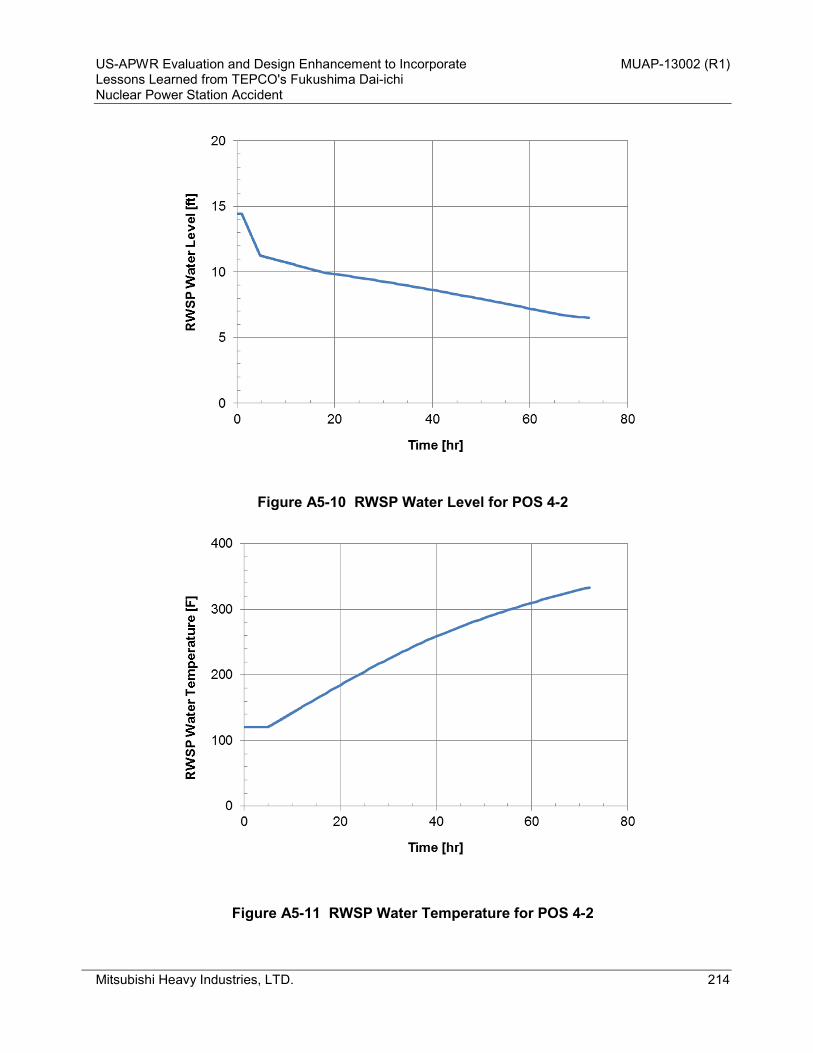
US-APWR Evaluation and Design Enhancement to Incorporate MUAP-13002 (R1) Lessons Learned from TEPCO's Fukushima Dai-ichi Nuclear Power Station Accident
Mitsubishi Heavy Industries, LTD. 214
Figure A5-10 RWSP Water Level for POS 4-2
Figure A5-11 RWSP Water Temperature for POS 4-2

US-APWR Evaluation and Design Enhancement to Incorporate MUAP-13002 (R1) Lessons Learned from TEPCO's Fukushima Dai-ichi Nuclear Power Station Accident
Mitsubishi Heavy Industries, LTD. 215
3.4.2. POS 4-3 Accident progression is evaluated for the following sequence: • Accident sequence: Loss of RHR during mid-loop operation at 72 hours
+ 0/4 High head injection + 0/4 Containment spray + 0/4 Accumulators + 4 pressurizer safety valves are removed + Core cooling via CHP becomes available at 1 hour
It is assumed that manways of all 4 SGs are closed by installing nozzle dams, on the other hand, pressurizer safety valves are removed due to maintenance. In this evaluation, it is assumed that all four pressurizer safety valves are removed as a conservative assumption in terms of containment pressurization. Containment pressure evaluation result is shown in Figure A5-12. Containment pressure reaches approximately 130 psia at 72 hours, which is below the containment ultimate capacity of 216 psia, therefore the containment can maintain its integrity for this accident condition. Containment temperature evaluation result is shown in Figure A5-13, which shows that the temperature is maintained below 400°F. The containment ultimate pressure calculation is therefore appropriate for this environmental condition. In addition, RWSP water level and RWSP water temperature are shown in Figure A5-14 and Figure A5-15, respectively. RWSP water is sufficiently available within 72 hours to continuously provide coolant to core and the water temperature is maintained below its saturated temperature. It can be therefore concluded that the plant condition is well controlled under this accident condition within 72 hours after accident initiation.

US-APWR Evaluation and Design Enhancement to Incorporate MUAP-13002 (R1) Lessons Learned from TEPCO's Fukushima Dai-ichi Nuclear Power Station Accident
Mitsubishi Heavy Industries, LTD. 216
Figure A5-12 Containment Pressure for POS 4-3
Figure A5-13 Containment Temperature for POS 4-3

US-APWR Evaluation and Design Enhancement to Incorporate MUAP-13002 (R1) Lessons Learned from TEPCO's Fukushima Dai-ichi Nuclear Power Station Accident
Mitsubishi Heavy Industries, LTD. 217
Figure A5-14 RWSP Water Level for POS 4-3
Figure A5-15 RWSP Water Temperature for POS 4-3

US-APWR Evaluation and Design Enhancement to Incorporate MUAP-13002 (R1) Lessons Learned from TEPCO's Fukushima Dai-ichi Nuclear Power Station Accident
Mitsubishi Heavy Industries, LTD. 218
3.5. Conclusion
Containment thermal-hydraulic analysis is performed for POS 4-2 and POS 4-3, assuming the initial time after shutdown of 60 hours and 72 hours, respectively. For both accident conditions, the containment pressure and temperature are maintained below the acceptance criteria, so that the containment integrity can be maintained within 72 hours after the onset of ELAP + loss of normal access to the UHS. After 72 hours, the containment will be depressurized, assuming containment spray utilizing the off-site resources including the fire service water, etc. are available.

US-APWR Evaluation and Design Enhancement to Incorporate MUAP-13002 (R1) Lessons Learned from TEPCO's Fukushima Dai-ichi Nuclear Power Station Accident
Mitsubishi Heavy Industries, LTD. 219
– END of REPORT –