
MRI-induced heating of deep brain stimulation leads
11
Progress In Electromagnetics Research, PIER 83, 81–91, 2008 MRI INDUCED HEATING OF DEEP BRAIN STIMULATION LEADS: EFFECT OF THE AIR-TISSUE INTERFACE S. A. Mohsin and N. M. Sheikh Department of Electrical Engineering University of Engineering and Technology Lahore, Pakistan U. Saeed School of Electrical and Computer Engineering Georgia Institute of Technology Atlanta, GA, USA Abstract—We have investigated the scattering of the Magnetic Resonance Imaging (MRI) radiofrequency (RF) field by implants for Deep Brain Stimulation (DBS) and the resultant heating of the tissue surrounding the DBS electrodes. The finite element method has been used to perform full 3-D realistic simulations. The near field has been computed for varying distances of the connecting portion of the lead from the air-tissue interface. Dissipated powers and induced temperature rise distributions have been obtained in the region surrounding the electrodes. It is shown that the near proximity of the air-tissue interface results in a reduction in the induced temperature rise. 1. INTRODUCTION Deep brain stimulation (DBS) systems are being increasingly used in the treatment of neurological disorders such as Parkinson’s disease. Figure 1 illustrates the use of such systems in which an implantable pulse generator (IPG) is connected to DBS electrodes for the chronic stimulation of the thalamus, global pallidus, or subthalamic nucleus [1]. The connecting part of the lead runs just below the skin and consists of thin individually insulated wires contained in an insulating sheath. The DBS electrodes are placed optimally inside the brain under MRI guidance, and often post-implantation MRI procedures need to be
Transcript of MRI-induced heating of deep brain stimulation leads

Progress In Electromagnetics Research, PIER 83, 81–91, 2008
MRI INDUCED HEATING OF DEEP BRAINSTIMULATION LEADS: EFFECT OF THE AIR-TISSUEINTERFACE
S. A. Mohsin and N. M. Sheikh
Department of Electrical EngineeringUniversity of Engineering and TechnologyLahore, Pakistan
U. Saeed
School of Electrical and Computer EngineeringGeorgia Institute of TechnologyAtlanta, GA, USA
Abstract—We have investigated the scattering of the MagneticResonance Imaging (MRI) radiofrequency (RF) field by implants forDeep Brain Stimulation (DBS) and the resultant heating of the tissuesurrounding the DBS electrodes. The finite element method hasbeen used to perform full 3-D realistic simulations. The near fieldhas been computed for varying distances of the connecting portionof the lead from the air-tissue interface. Dissipated powers andinduced temperature rise distributions have been obtained in the regionsurrounding the electrodes. It is shown that the near proximity of theair-tissue interface results in a reduction in the induced temperaturerise.
1. INTRODUCTION
Deep brain stimulation (DBS) systems are being increasingly used inthe treatment of neurological disorders such as Parkinson’s disease.Figure 1 illustrates the use of such systems in which an implantablepulse generator (IPG) is connected to DBS electrodes for the chronicstimulation of the thalamus, global pallidus, or subthalamic nucleus [1].The connecting part of the lead runs just below the skin and consistsof thin individually insulated wires contained in an insulating sheath.The DBS electrodes are placed optimally inside the brain under MRIguidance, and often post-implantation MRI procedures need to be

82 Mohsin, Sheikh, and Saeed
Figure 1. The use of a lead for neurostimulation. The shadingshows the electric intensity in V/m of the typical background RFfield (without an implant) that exists in tissue. The lead is shownto illustrate its placement. The scattered field of the lead is not shownin this figure.
performed [1, 2]. This necessitates an investigation into the interactionof the MRI fields with the DBS lead implant.
In a typical whole-body cylindrical bore MRI system, there arethree types of fields. These are a static magnetic field B0 which istypically 1.5 or 3.0 Tesla, pulsed gradient fields which are magnetic fieldpulses with spatial variations, and an RF electromagnetic field B1 [3, 4].The static magnetic field does not interact with the DBS lead. This isdue to the fact that no magnetic materials are present and there is nodirect current. The pulsed gradient fields induce currents in body tissueand a long wire implant has a concentrating effect on these currents.However this concentration tends to be small due to cancellation effectsof the surrounding tissue [3]. The strongest interaction with the leadis shown by the MRI RF field that exists inside body tissues; this isdue to the fact that this field is scattered by the lead structure.
The frequency of the B1 RF field is determined from thestrength of the B0 field. The Larmor frequency is 42.58 MHz/T,and for a 1.5 T system the frequency of the B1 field will be42.58 MHz×1.5 = 63.86 MHz. A typical DBS lead implant has anoverall length in the range 20 to 50 cm. At 63.86 MHz the wavelength ofthe B1 field in air, λair, is 4.7 m and that in typical body tissue, λtissue,with conductivity 0.27 S/m and relative permittivity 77, is 0.488 m. For

Progress In Electromagnetics Research, PIER 83, 2008 83
this wavelength of the MRI RF field in tissue, there will be a strongcoupling of this field with the implanted DBS lead device. In fact thelong conducting wires connecting the IPG to the DBS electrodes willshow waveguide properties which will produce very intense fields atthe tips of the lead [5]. The MRI RF field in a patient’s body withoutan implant has been the subject of a number of research studies [4, 6].The effect of a DBS lead implant is of course to further concentratethis RF field in the immediate region around the implant, especially atthe tips. In terms of electromagnetic behavior, a DBS lead embeddedwithin body tissue is like an antenna in a dissipative medium. Kinget al. [7–9] analyzed such antennas using transmission line theoryto find the current in the antenna and then the radiation integralswere used to obtain the surrounding fields. Atlamazoglou et al. [10]applied the method of moments (MoM) to an insulated antenna in ahomogeneous and infinite dissipative medium. Park et al. [11] appliedthe method in [10] to find the scattered field due to a DBS lead usingthe homogeneous and infinite medium idealization. In actual practice,the lead runs close to the skin for most of its length and only the lastfew centimeters are embedded deep inside brain tissue. Also the tissuecontaining the lead is not homogeneous; the constitutive parametersof brain tissue are different from those of the tissue adjacent to theskin which has a greater fat content. The present paper takes intoaccount the proximity of the lead to the air-tissue interface as well asthe inhomogeneous nature of the tissue in which the lead is embedded.It is shown in the present paper that the scattered field decays toalmost zero within a radial distance of about 2.5 cm from the leadaxis. The finite-element-method is used to find the scattered field as itis mathematically well-suited to handle the inhomogeneous nature ofthe computational domain as compared to the moment method [12].Finally the Pennes’ bioheat equation is solved to find the temperaturerise in the brain tissue surrounding the electrodes.
2. COMPUTATION OF THE SCATTERED FIELD
Figure 2 shows the model lead structure. Let (Ei,Hi) be the incidentelectromagnetic field satisfying the free-space Maxwell’s equations.This incident field excites a finite region of space occupied by amedium having conductivity σ and permittivity ε. No magnetic mediaare present and thus the permeability is always equal to µ0. FromMaxwell’s equations we find that the scattered field (Es, Hs) inside

84 Mohsin, Sheikh, and Saeed
the finite region then must satisfy
∇× Hs = (σ + jωε)Es + Ji (1)∇× Es = −jωµ0Hs (2)
where Ji = {σ + jω (ε− ε0)}Ei, and ω is the angular frequency. Theconductivity σ and permittivity ε = ε0εr of the media occupying thedifferent regions are specified in Figure 2. Inserting in (1) and (2) theproper values of σ and ε for each region gives the equations describingthe scattered field (Es,Hs) in that region. Taking the curl of (2) andusing (1) leads to the equation
(1/jωµ0)∇×∇× Es = −Ji − (σ + jωε)Es (3)
Weighting with a set of real vector functions v(r), where r is theposition vector, and integrating over the entire volume V of thecomputational domain we have∫V
[(1
jωµ0
)∇×∇×Es · v(r)+(σ+jωε)Es ·v(r)
]dV = −
∫V
Ji · v(r)dV
(4)
The components of v(r) must be square integrable. Using Green’s
Figure 2. A cross-section of the computational domain is shown.L = 25 or 48 cm and d = 3, 9, or 15 mm. The background SAR valuesare as follows: In fat tissue: 0.5 W/kg: in brain tissue: 2.35 W/kg.The cross-sectional plane shown passes through the central axis of theimplanted lead and is perpendicular to the air-tissue interface. Thefigure is not drawn to scale (since L � lead dia).

Progress In Electromagnetics Research, PIER 83, 2008 85
first vector identity we are led to the weak form∫V
[1
jωµ0(∇× Es) · (∇× v(r)) + (σ + jωε)Es · v(r)
]dV
−∫S
n̂× Hs · v(r)dS = −∫V
Ji·v(r)dV (5)
At the exterior bounding surface S, Hs can be related to Es by asecond-order absorbing boundary condition (ABC) [12],
n̂× Hs =−√
ε0
µ0Es
t +j
2(ωµ0)2
õ0
ε0[∇×(n̂(∇× Es)n) +∇t (∇ · Es
t )]
(6)
where n̂ is the outward unit normal to S and the subscripts t and nrefer to the tangential and normal components to S respectively.
The volume V is divided into a number of volume elements. Thewhole computational domain in each of the different models solved herecontains about 2×10⁵ elements. We have used tetrahedral elements ofunequal size. Regions where finer resolution is required contain moreelements per unit volume than other regions. Here the lead region andthe tissue near to and surrounding the lead are meshed much morefinely than outlying tissue and the air region. The lead region (leadconnecting portion, insulation, and electrodes) contains no less than8 × 104 volume elements. The scattered field Es is represented by anexpansion (quadratic) of vector basis functions w(r) in each volumeelement V e,
Es(r) =Ne∑p=1
Epwp(r) (7)
where N e = 6 is the number of edges in a tetrahedron. The wp(r)are known as edge-base functions and are of the form as given in [12]and [13]. Each wp(r) is nonzero if r ∈ V e and zero otherwise. The Ep
are unknown coefficients and are complex scalars. Substituting (6) in(5), and using (7) with Galerkin’s testing, v(r) = w(r), we obtain thediscretized form of (5) as
[A] {E} + [B] {E} ={Ci
}(8)

86 Mohsin, Sheikh, and Saeed
where
Amp=∫V
[1
jωµ0(∇×wp(r))·(∇×wm(r))+(σ+jωε)wp(r)·wm(r)
]dv (9)
Bmp=∫S
[√ε0
µ0wpt(r) −
j
2(ωµ0)2
õ0
ε0
{∇×
(n̂ (∇× wp(r))n
)
+∇t (∇ · wpt(r))}] · wm(r)dS (10)
Cim = −
∫V
Ji · wm(r)dV (11)
[A] is a sparse, banded, and symmetric N ×N matrix. N is the totalnumber of edges. [B] is a N×N sparse matrix with only those elementsbeing nonzero that correspond to edges lying on S. {E} is a N × 1matrix of the unknown coefficients that are to be determined.
{Ci
}is a
known N×1 matrix. p and m are indices stepping through the N edgesand the subscripts t and n mean tangential and normal, respectively(to S).
All DBS lead models, M1 thru M8, are as shown in Figure 2 andare described in Table 1.
Table 1. Description of DBS lead models. The lead geometry and thenature of the embedding tissue is as shown in Figure 2. All models areanalyzed for a 1.5 Tesla MR system. L is the total length of the leadincluding the length of the electrodes.
M1: L = 25 cm with noair-tissue interface (d → ∞)
M5: L = 48 cm with noair-tissue interface (d → ∞)
M2: L = 25 cm, d = 15 mm M6: L = 48 cm, d = 15 mmM3: L = 25 cm, d = 9 mm M7: L = 48 cm, d = 9 mmM4: L = 25 cm, d = 3 mm M8: L = 48 cm, d = 3 mm
3. SAR DISTRIBUTIONS AND DISSIPATED POWERS
The specific absorption rate (SAR in W/kg) is given by
SAR = σE · E∗/(2ρ) (12)
where E∗ is the conjugate of E, σ is the conductivity, and ρ is themass density of tissue. SAR is the absorbed power per unit mass at

Progress In Electromagnetics Research, PIER 83, 2008 87
a point and provides a good measure for the local resistive heating.The maximum SAR values at a lateral distance of 0.5 mm from theelectrodes surface are found to be 8.21×10³ W/kg and 3.46×10⁴ W/kgfor lead models M1 and M5 respectively. These are very high localizedSAR values and are much greater than the SAR values produced insidehead tissue due to mobile phones where the spatial peak values do notexceed 55 W/kg [15–18]. The quantity (1/2)σE ·E∗ is integrated overthe cylindrical volume 0 < r < 1 cm, −2 cm< τ < 1 cm for P1, andover 0 < r < 0.5 cm, −1 cm< τ < 0.5 cm for P2. The values of P1
and P2 are given in Table 2. Note that the electrode region is fromτ = −6 mm to τ = 0. It is apparent from the values of the ratio P2/P1
that almost 87% of the power is dissipated (as heat) within a radialdistance of 5 mm from the electrode surface.
Table 2. Dissipated powers.
DBS
Lead
P1
(mW)
P2
(mW)
P2/P1
(%)
DBS
Lead
P1
(mW)
P2
(mW)
P2/P1
(%)
M1 525 460 87.6 M5 2106 1839 87.3
M2 502 440 87.7 M6 1982 1731 87.3
M3 480 420 87.5 M7 1955 1707 87.3
M4 425 372 87.5 M8 1869 1633 87.4
4. INDUCED TEMPERATURE RISES
The temperature rise is found by solving the Pennes’ bioheat equation,
ρCp∂T
∂t= ∇ (k∇T ) − b (T − Tb) + Q (13)
where T is the temperature (◦C) at a point at time t, ρ is the density(kg·m−3) of the medium, Cp is the heat capacity (J·kg−1◦C−1), k is thethermal conductivity (W·m−1◦C−1), b is the blood perfusion constant,Tb is the blood temperature, and Q is the heat source (W·m−3) atthe point. We have Q = σE · E∗/2 at a point and Q = ρ · SAR intissue. The effect of blood perfusion is to spread the temperature riseover a larger region of tissue. To investigate the worst case scenariofor localized SAR heating over small tissue regions we take b = 0.An FEM tool was used to solve the bioheat equation. The thermalproperties given in Table 3 were used. The induced temperature risesversus time are shown in Figure 3. The spatial temperature rise and
88 Mohsin, Sheikh, and Saeed
Table 3. Thermal properties of tissue and DBS lead materials.
Material ρ (kg·m−3) Cp (J·kg−1◦C−1) k (W·m−1◦C−1)Tissue 1000 4186 0.6
Insulation 1000 1500 0.2Metal 8920 300 400
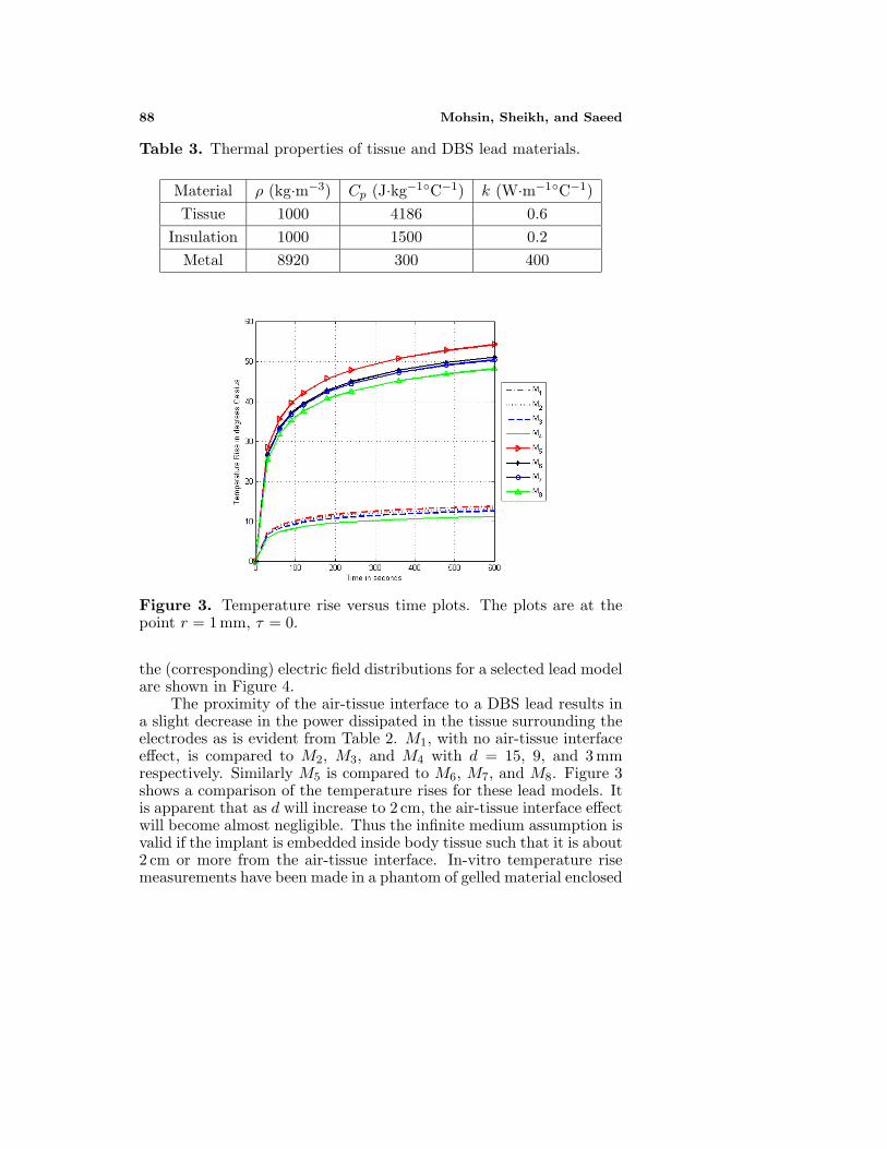
Figure 3. Temperature rise versus time plots. The plots are at thepoint r = 1 mm, τ = 0.
the (corresponding) electric field distributions for a selected lead modelare shown in Figure 4.
The proximity of the air-tissue interface to a DBS lead results ina slight decrease in the power dissipated in the tissue surrounding theelectrodes as is evident from Table 2. M1, with no air-tissue interfaceeffect, is compared to M2, M3, and M4 with d = 15, 9, and 3 mmrespectively. Similarly M5 is compared to M6, M7, and M8. Figure 3shows a comparison of the temperature rises for these lead models. Itis apparent that as d will increase to 2 cm, the air-tissue interface effectwill become almost negligible. Thus the infinite medium assumption isvalid if the implant is embedded inside body tissue such that it is about2 cm or more from the air-tissue interface. In-vitro temperature risemeasurements have been made in a phantom of gelled material enclosed

Progress In Electromagnetics Research, PIER 83, 2008 89
in a MRI RF birdcage coil as detailed in [14]; these measurements weremade with the lead well inside the phantom (far from the walls) andthus the infinite medium assumption is applicable. Our computedtemperature rises for the infinite medium cases (d → ∞) agree wellwith the in-vitro measurements.
Figure 4. Figure showing the typical spatial distribution of theelectric field (V/m) and the induced temperature rise (degrees Celsius)in brain tissue surrounding the electrodes. The plots are for lead modelM5. The temperature rise is shown after 6 minutes of application ofRF input power.
5. CONCLUSIONS
Of the three fields used in MRI, only the RF field strongly interactswith a DBS lead. The interaction produces a very intense scatteredfield in the tissue surrounding the DBS electrodes. Conductioncurrents in the tissue cause heating and temperature rises as high as53◦C can result in the immediate proximity of the electrodes. Theeffect of the air-tissue interface is to decrease the intensity of thescattered field and hence to reduce the induced temperature rise aswell. The effect of the air-tissue interface becomes negligible as thelateral distance of the interface from the lead increases to 2 cm ormore.
90 Mohsin, Sheikh, and Saeed
ACKNOWLEDGMENT
The first author wishes to acknowledge the cooperation of the staff andthe MRI research group in the Department of Electrical Engineering,Purdue University, West Lafayette, IN during his stay as a VisitingResearch Scientist there.
REFERENCES
1. Rezai, A. R., D. Finneli, J. A. Nyenhuis, G. Hrdlicka, J. Tkach,A. Sharan, P. Rugieri, et al., “Neurostimulation systems for deepbrain stimulation: In vitro evaluation of magnetic resonanceimaging-related heating at 1.5 Tesla,” J Magn. Reson. Imaging,Vol. 15, No. 3, 241–250, 2002.
2. Dormont, D., P. Cornu, B. Pidoux, et al., “Chronic thalamicstimulation with three-dimensional MR stereotactic guidance,”Am. J. Neuroradiology, Vol. 18, No. 6, 1093–1097, 1997.
3. Nyenhuis, J. A., S. M. Park, et al., “MRI and implanted medicaldevices: Basic interactions with an emphasis on heating,” IEEETrans. Device and Materials Reliability, Vol. 5, No. 3, 467–480,2005.
4. Jin, J. M., J. Chen, W. C. Chew, et al., “Computation ofelectromagnetic fields for high-frequency magnetic resonanceimaging applications,” Phys. Med. Biol., Vol. 41, 2719–2738, 1996.
5. Nitz, W. R., A. Oppelt, W. Renz, et al., “On the heatingof linear conductive structures as guide wires and catheters ininterventional MRI,” J. Magn. Reson. Imag., Vol. 13, No. 1, 105–114, 2001.
6. Nguyen, U. D., J. S. Brown, et al., “Numerical evaluation ofheating of the human head due to magnetic resonance imaging,”IEEE Trans. Biomed. Eng., Vol. 51, No. 8, 1301–1309, 2004.
7. King, R. W. P., B. S. Trembly, and J. W. Strohbehn, “Theelectromagnetic field of an insulated antenna in a conducting ordielectric medium,” IEEE Trans. MTT, Vol. 31, No. 7, 574–583,1983.
8. King, R. W. P., “Antennas in material media near boundarieswith application to communication and geophysical exploration,Part I: The bare metal dipole,” IEEE Trans. on Anten. and Prop.,Vol. 34, No. 4, 483–489, 1986.
9. King, R. W. P., “Antennas in material media near boundarieswith application to communication and geophysical exploration,

Progress In Electromagnetics Research, PIER 83, 2008 91
Part II: The terminated insulated antenna,” IEEE Trans. onAnten. and Prop., Vol. 34, No. 4, 490–496, 1986.
10. Atlamazoglou, P. E. and N. K. Uzunoglu, “Galerkin momentmethod for the analysis of an insulated antenna in a dissipativedielectric medium,” IEEE Trans. MTT, Vol. 44, No. 7, 988–996,1998.
11. Park, S. M., R. Kamondetdacha, A. Amjad, and J. A. Nyenhuis,“MRI safety: RF induced heating on straight wires,” IEEE Trans.Magn., Vol. 41, No. 10, 4197–4199, 2005.
12. Volakis, J. L., A. Chatterjee, and L. C. Kempel, “Review ofthe finite-element method for three-dimensional electromagneticscattering,” J. Opt. Soc. Am. A, Vol. 11, No. 4, 1422–1433, 1994.
13. Jin, J. M., The Finite Element Method in Electromagnetics, 2ndedition, John Wiley and Sons, 2002.
14. Park, S. M., Ph.D. thesis, Purdue University, West Lafayette, IN,2006.
15. Ibrahiem, A., C. Dale, W. Tabbara, and J. Wiart, “Analysis of thetemperature increase linked to the power induced by RF source,”Progress In Electromagnetics Research, PIER 52, 23–46, 2005.
16. Kuo, L.-C., Y.-C. Kan, and H.-R. Chuang, “Analusis of a900/1800-Mhz dual-band gap loop antenna on a handset withproximate head and hand model,” J. of Electromagn. Waves andAppl., Vol 21, No. 1, 107–122, 2007.
17. Khalatbari, S., D. Sardari, A. A. Mirzaee, and H. A. Sadafi,“Calculating SAR in two models of the human head exposedto mobile phones radiations at 900 and 1800 MHz,” ProgressIn Electromagnetics Research Symposium, 104–109, Cambridge,USA, March 26–29, 2006.
18. Kouveliotis, K. and C. N. Capsalis, “Prediction of the SAR levelinduced in a dielectric sphere by a thin wire dipole antenna,”Progress In Electromagnetics Research, PIER 80, 321–336, 2008.