Module I : Radio , Audio , Video system and Appliances
28
Upgradation of ITIs into Centres of Excellence- Broad guidelines for implementation of Advanced Module of Sector “Electronics ”. These Centres will be providing multiskill training to meet the skill requirement of particular sector of industry with their active involvement in all aspects of training. The training will be provided in three parts as given below: ♦ Training in Basic skill areas for a period of one year. ♦ Training in Advanced modules of six months duration after Broad based basic Training(BBBT) ♦ Testing & Certification both for the Broad Based Basic Training & Advanced Module Training during subsequent six months will be conducted under the aegis of NCVT . ♦ Training in specialized modules mainly by the industry (The course curricula, duration etc will be designed in consultations with the IMC/local industry). The trade testing & certification for specialized module will be done jointly by the State Government & Industry. Said certificate will have recognization from NCVT ♦ As per the recommendations of the EFC, Training in the shop floor should constitute alteast 25-40% of the curriculum. The training programme will have multi-entry and multi-exit provisions as given below: • trainee can opt to go to the labour market after completing broad based basic training of one year duration or after completing advanced module/s. • multi-entry and multi-exit provisions would enable a trainee to take admission for advanced/ additional advanced /specialized module as per his/her need . Guidelines for Training in Advanced modules Ð A minimum of three modules would be essentially needed , so as to ensure that all the 96 trainees are accommodated in the three modules may be selected in consultation with IMC for which in two shifts . Ð If it is felt that available modules for which the course curricula has been developed at National Level are not sufficient to cater to the needs of local industry in a particular state, States are free to select module as per need in consultation with industry . They may develop suitable module(s) accordingly in consultations with the industry clearly indicating tool & equipment list , instructor qualifications , space norms etc. & forward the same to DGE&T for seeking approval of NCVT. Ð A trainee at a time can opt only for one Advanced Module . Ð Admission Criteria, Space requirement, Qualification of instructor of the various modules of “Electronics ” sector are attached herewith. 1
-
Upload
khangminh22 -
Category
Documents
-
view
1 -
download
0
Transcript of Module I : Radio , Audio , Video system and Appliances

Upgradation of ITIs into Centres of Excellence-
Broad guidelines for implementation of Advanced Module of Sector “Electronics ”.
These Centres will be providing multiskill training to meet the skill requirement of particular sector of industry with their active involvement in all aspects of training. The training will be provided in three parts as given below:
♦ Training in Basic skill areas for a period of one year. ♦ Training in Advanced modules of six months duration after Broad based basic Training(BBBT) ♦ Testing & Certification both for the Broad Based Basic Training & Advanced Module Training during subsequent six months will be
conducted under the aegis of NCVT . ♦ Training in specialized modules mainly by the industry (The course curricula, duration etc will be designed in consultations with the
IMC/local industry). The trade testing & certification for specialized module will be done jointly by the State Government & Industry. Said certificate will have recognization from NCVT
♦ As per the recommendations of the EFC, Training in the shop floor should constitute alteast 25-40% of the curriculum. The training programme will have multi-entry and multi-exit provisions as given below:
• trainee can opt to go to the labour market after completing broad based basic training of one year duration or after completing advanced module/s.
• multi-entry and multi-exit provisions would enable a trainee to take admission for advanced/ additional advanced /specialized module as per his/her need .
Guidelines for Training in Advanced modules
A minimum of three modules would be essentially needed , so as to ensure that all the 96 trainees are accommodated in the three modules may be selected in consultation with IMC for which in two shifts .
If it is felt that available modules for which the course curricula has been developed at National Level are not sufficient to cater
to the needs of local industry in a particular state, States are free to select module as per need in consultation with industry . They may develop suitable module(s) accordingly in consultations with the industry clearly indicating tool & equipment list , instructor qualifications , space norms etc. & forward the same to DGE&T for seeking approval of NCVT.
A trainee at a time can opt only for one Advanced Module .
Admission Criteria, Space requirement, Qualification of instructor of the various modules of “Electronics ” sector are
attached herewith.
1

Admission to Advanced Module for the graduates of ITI in related trades: There is a provision for lateral entry for graduates of ITIs (NTC /NAC passed outs from conventional system ) of the related trades subject to availability of seats in Advanced Module. Trades of conventional system mentioned against each advanced module in the enclosed statement, could be offered admission in Advanced Module .
MODULE NO. NAME OF THE
MODULE
Admission criteria
Space requirement
Duration In Weeks
Qualification/ Status Of Instructor
EAT-01 Radio , Audio , Video System and Appliances
Completed BBBT in Sector Electronics OR NTC/NAC in Electronics Mechanic, Radio & TV, Consumer Electronics or any other related trade OR Diploma in Electronics
EAT-02 Inverters, UPS ,Voltage stabilizers and Industrial Drives
Completed BBBT in Sector Electronics OR NTC/NAC in Electronics Mechanic, Radio & TV or any other related trade OR Diploma in Electronics
EAT-03 Repair & Maintenance of Electronic Test Equipment
Completed BBBT in Sector Electronics OR NTC/NAC in Electronics Mechanic, Instrumentation or any other related trade OR Diploma in Electronics
EAT-04 Automobile Electronics
Completed BBBT in Sector Electronics OR NTC/NAC in Electronics Mechanic, Auto Electronic or any other related trade OR Diploma in Electronics
EAT-05 Communication System
Completed BBBT in Sector Electronics OR NTC/NAC in Electronics Mechanic, Radio & TV or any other related trade OR Diploma in Electronics
EAT-06 Embeded System and PLC
Completed BBBT in Sector Electronics OR NTC/NAC in Electronics Mechanic, or any other related trade OR Diploma in Electronics
70 sq m 24 weeks
Degree in Electronics with minimum two years teaching/industrial experience in the relevant field OR Diploma in Electronics with min four years teaching/industrial experience in the relevant field OR HNTC in Related area with min five years teaching/industrial experience in the relevant field .
2

Advanced Module of Electronic Sector: MODULE-1 Radio , Audio , Video system and Appliances
Theory Practical RADIO BASICS AUDIO FUNDAMENTALS: Sound wave characteristics, Room, Acoustics, Decibel, B.H. Curve, A.C./D.C. Bias, P.A. System , Amplifiers , Various microphones, speakers and their selection RADIO FUNDAMENTALS: Modulation , Demodulation techniques, Introduction to AM, FM & PM SSBSC & DSBSC FM Generation & Detection : different method FM
Plot the Frequency Vs Output characteristics of various types of Microphones and Speakers, Woofer/Tweeter, Baffles, Audio Recording, Find the modulation, Modulation Increase in various Modulation techniques.
Radio Receivers: Types, Super heterodyne receiver Blocks, Principle, characteristics, advantages and disadvantages, FM Receives, Pre-emphasis and De-emphasis, AFC in FM Receivers
Identify and test the various parts & control of Superhetrodyne receiver
RF, IF &AF Amplifier Sections: Gain, Frequency, Voltage , Power, AGC, AVC Circuits squelch circuit in receives, AM/FM RX Alignment, Radio Wave Propagation – Principle, Fading, Antenna and Testing,
Fault findings of RF, IF and AF Amplifier Sections, AGC, AVC Circuits squelch circuit AM/FM RX Alignment
Audio Cassette recorder: Audio recording & playback principle , Audio Deck mechanism-layout & identification , Electronic circuits-block diagram & description of each block, Dolby sound, Surround sound system, Home theatre ,Impedance matching , speakers, graphic equalizer, microphones.
Identify the functions of different parts of different deck mechanism Testing & fault finding in audio cassette recorder
ACD / VCD PLAYER Working principle of ACD/VCD/DVD players, CD mechanism & power supply , types of CD’s and writing procedure on CDs , five in one system, MP3 formats / flash memory recording
Identify and study the various parts and control of ACD/VCD players
3

Functional detail of circuits – Audio, RF, Encoder etc. , Digital recording techniques , Digital audio receivers Circuit , functional details and fault finding procedure of all circuits
Circuit study of Audio, RF, Encoder etc. Rectify the fault in the given circuit
Laser fundamentals, optical pickup units, laser beam , CD recording standards Difference between ACD and VCD players, & DVD , ,MP easy card, Single CD and 3 CD changer. Fault finding procedure in different stages including CD drive mechanism.
Fault findings of given VCD player Fault finding on given ACD / VCD drive mechanism Study and fault findings of optical pickup units, and drive mechanism ,to wire up ACD to VCD conversion card
TELEVISION Working principle, Basic Blocks – BW TV & CTV, Difference between Black and White TV & Color TV Receivers, TV Systems and Standards, Color TV Transmitter, Color fundamentals, Television Transmission, VSB , Low Power Transmitters and High Power Transmitters functions,
Identify, operate and adjust front panel controls of CTV Dismantle TV and Identify the internal sections/ICs and Test points. Review on power supplies.
Camera Tubes: Light characteristics Types of Tubes: Vidicon, Plumbicon , CCD and their working, Camera circuit functioning, Electronic TV Tuner – Types & Features, TV Antenna, TV Power Supply, Regulated Power Supplies, PS Circuits using Integrated circuits, Switched mode power supply, CTV Blocks, Video camera:Specifications and working
TV Power supplies, SMPS, Testing and repairing, Familiarize with various SMPS circuits.
Colour signal: Generation and Encoding Development of Sub-carrier, modulation of Sub-carrier, Composite Video Signal, UV Signals separation, UV Signals demodulation, Chroma Section and Delay line, PAL-D colour receiver, colour signal decoding and matrixing, Video IF and detector section. AGC and Sync Separator: AGC types, AGC circuits and their adjustments, Horizontal oscillator, Horizontal and vertical synchronization.
Identify and test the Chroma section – Measure the voltage and observe the wave form on chroma input and output sections. Fault finding in chroma section, AGC sync and horizontal sections.
Sync Separator: Principle and circuits, Effect of noise in synchronization, IC based circuits, faults in AGC and Sync Separator stages.Horizontal and Vertical Sections: HOT Section, Switching transistor functions, inputs in HOT, Outputs from EHT, Signal Flow through different stages in the block. Vertical Sweep section, Vertical section – blocks scanning, functions of related ICs, Input signals to
Identify and test the Horizontal , vertical sections Trace the Sync separator, AFC and Horizontal oscillator circuits / ICs and locate test points for measurement of voltages/wave forms Trace and rectify the faults in a Horz. And Vert. Driver and out put section
4

this stage, outputs from this stage,processing of Video signal – Functions of related IC Video Amplifier ICs – Configuration and functions. Colour Picture tube – Parts and functions,Construction, function of degaussing coil, functions of pure and convergent magnets, difference between monochrome and colour picture tubes. TV Remote Control –Types, parts and functions,IR Code transmitter and IR Code Receiver,Working principle, operation of remote control. Different adjustments,general faults in Remote Control. LCD & Plazma TV,Digital & Projection TV
Trace and rectify the faults of a various remote controls Identify the various controls and sections of Plasma , projection TV,Digital TV
Domestic Appliances : Microwave oven: Different types of oven,study the various functions of Oven, Microwave generation system-circuit , description & working ,study ,working of Power supply,various precautions to be observed, Different aspects of servicing of Microwave Oven. Washing M/c: different types of machines,Block diagram & basic working principle of manual, semi automatic and fully automatic machines,study the working of motors, different types of timers, power supply circuits, Different aspects of servicing of Washing M/C Vacuume cleaner-Block diagram,working principle, study of different features of the machine,study & working of motor used , Electronic circuit, power supply, Different aspects of servicing of Vacuume cleaner. Mixer/Grinder: Block diagram,working principle , study of different features of machine , Study & working of motor used ,different aspects of servicing of Vacuume cleaner. Fax M/C: Block diagram, working principle, study of different features of the machine, Various precautions to be observed, Different aspects of servicing.
Dismantle and identification of various parts, wiring, tracing of various controls, fault finding in Microwave oven. Dismantle and identification of various parts, wiring, tracing of various controls,Electronic circuits, fault finding in various types of washing M/C. Dismantle and identification of various parts, wiring, tracing of various controls, Electronic circuits, fault finding in various types of Vacuume cleaners. Dismantle and identification of various parts, wiring, tracing of various controls,Electronic circuits, fault finding in various types of Mixers/grinders.
Computer Monitors :Block diagram ,working and study of their different circuits,Different aspects of servicing of Monitors. Photocopier & Photocopier cum Duplicator M/C: Block diagram and working principle of Photo copier, study of front panel and its features, mechanical system and electronic circuits of photocopier and duplicatotrs, servicing aspects of m/c Scanners: Block diagram, working principle, study of different
Identification of different blocks on assembled PCB, tracing of different Monitor circuits. Dismantle and identification of various parts, wiring, tracing of various controls , Electronic circuits,mechanical system and its assembly,fault finding in various types of machines. Dismantle and identification of various parts,wiring , tracing of various controls,Electronic circuits, fault finding in various types
5
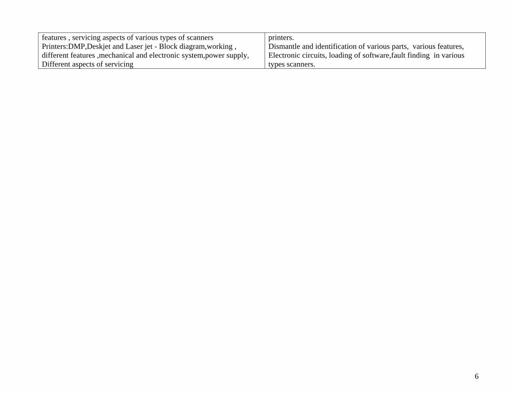
features , servicing aspects of various types of scanners Printers:DMP,Deskjet and Laser jet - Block diagram,working , different features ,mechanical and electronic system,power supply, Different aspects of servicing
printers. Dismantle and identification of various parts, various features, Electronic circuits, loading of software,fault finding in various types scanners.
6

Equipment List : Radio , Audio , Video system and Appliances
SL No Description of Items Qty
1 Trainee Tool Kit 16 2 Trimming kit 43 AM/FM Radio Receivers 4 4 MW/SW/FM Radio Receiver Trainer 4 5 Oscilloscope dual trace storage 4 6 AM/FM Signal Generator 2 7 Digital Multimeters 48 AF Power Meter 2 9 RF Power Meter 2 10 Temperature Controlled Soldering Station 6 11 Frequency Counters 212 DC Power Supply 0-30V, 1A 4 13 Washing Machine 14. Microwave Oven 15. Mixer / Grinder 16. Fax Machine 17. Colour T.V. 18. VCD Players 19. DVD Players 20. Computers 21. Scanners 22. Printers 23. Photo Copier
7

Space Norm 16 Mtrs Advanced Module of Electronic Sector – MODULE -2 8 Mtrs. Inverters, UPS ,Voltage stabilizers and Industrial drives : Theory Practicals Review on Wires and Cables, their types, Voltage and current rating, selection of cables for various applications , passive components- Resistor, Capacitors & Inductors,
Familiarise with various types of wires and cables Exercises on High Wattage resistors, Capacitors , various types of Inductors.
Review of Electrical circuits,Faraday’s law of electromagnetic nduction, Lenz’s law, Fleming’s right hand & left hand rule,Various controlling and protective devices - Switches, main switches, Fuse, MCB, ELCB, relays and S S Relays etc,
Identify the terminals and rating of various types of switches and protective devices.
Electrical wiring for Single phase and Three phase systems, Earthing and earth resistance measurement, calculation of load ,power and power factor Review on Batteries – various types, their selection, grouping of cells and batteries, charging of batteries,Various Battery charging circuits used in Inverters and UPS , Maintenance of Batteries
Understand the wiring circuits and protective devices used in domestic and industrial wiring . Earth resistance measurement. Familiarize with various types of batteries, grouping of batteries, connectors used with batteries. Assemble and test the various battery charging circuit
Transformers – their types, core materials, ferrite core transformers, Magnetic Hysterisis , various losses of transformers, Efficiency of Transformers,3 phase transformers, Star / Delta connections, OC & SC test of Transformers,Factors affecting the functions of transformers, Selection of Tx for Inverter,UPS,Automatic & servo Voltage stabilizers
Identify and test the types of transformers. OC and SC test of Transformers. Method to find the winding sequence of the transformer.
Diode, Power diodes –capacitance of diode, low frequency and high frequency applications, Rectifiers, 3 phase rectifiers, Switching action,period and power rating of transistors, low frequency and high frequency transistors, Heat sinks – their types, ratings and their cooling systems, Review of Power supply,filter circuits, ripple factor, High current rectifier circuits, precaution and handling of rectifier circuits,
Testing of Power Diodes and Power transistors. Familiarise with various packages of diodes and Transistors. Identification and selection of Heat sinks for various applications. Assemble and test the high current rectifier circuits, measure various parameters, find out the simulated fault and rectify
Power MOSFET, IGBT - their types, characteristics, switching speed, power ratings and protection. SCR–SCR as rectifier,Power ratings of SCR,Half and full wave ckts of SCR,3 phase rectifiers,SCR Protection circuits,Power control using SCR
Testing methods used for MOSFET, IGBT. Familiarise with various packs of MOSFET and IGBT, wire up a circuit and test MOSFET/IWE working as switch. Construct, half and full converters using SCR, measure various
8

parameters, construct a half converter circuit used s battery charger.
Oscillators and wave shaping circuits: classification , Different 50 Hz oscillator circuits, oscillator circuits used in Inverters, Sinewave generation using PWm techniques. Manual & automatic and servo voltage stabilizers-concept and block diagram, o/p voltage adjustment, voltage cutoff systems, study of different types of relays used in stabilizers, study of electronic circuit commonly used, buck and boost concept
Assemble ,test the oscillators & wave shaping .Assemble and test various oscillator circuits used in inverters. Construct a PWM circuit using MOSGFET for DC power control and measure various parameters. Construct the electronic control circuit used in servo controlled stabilizers using temp. ICs, TRIAC, adjust the circuit for low and high voltage, over current cut-off.
Inverter – their principle & operation, power rating, change over period. Installation of Inverters, Protection circuits used in inverters– battery level, over load, over charging etc.Various faults and its rectification
Construct and test Inverters of various power ratings Installation of inverters,Test the various protection circuits used in Inverters,fault finding in inverters.
Three phase inverter circuits – principle and working. Testing and Installation of Three phase Inverters Microcontroller PLC 8051:Architecture,programming,instruction set Execution of program instruction using Controller kit Concept of UPS, OFF LINE and ONLINE . Difference between Inverters and UPS. Low power Off line UPS circuits. Selection of UPS – calculation of load power,Line interactive UPS
Assemble and test low power Off-line UPS circuits. Selection of UPS
ON- Line UPS, their circuit description and working- controlling circuits, Micro controller circuits, power circuits, charging circuits, alarm circuits, Indicator circuits
Familiarise with the various types of ON-LINE UPS and their circuits. Fault finding in UPS.
Three phase UPS Circuits,Installation of single phase and 3 phase UPS. 3 phase UPS Circuits, Installation of single phase &3 phase UPS. DC Motors– types, working ,torque speed characteristics,staring of DC Motors & change the DOR, 3 point and 4 point Starters,speed control of DC motor, Field flux control & armature current control. Brushless DC Motors.
Understand all the information on a Motor template Connect and run the DC Shunt motors, Speed control of DC shunt motor.
Fundamentals of 3 phase & single phase Induction motors, synchronous speed, slip, rotor frequency , torque – speed characteristics, Starters used for Induction motors, speed control of Induction motors
Connect and run the 3 phase induction motor, Familiarise with the DOL, Star/delta and Transformer type starter
DC drives-their principle and working, open loop speed control system Construct and control PWM circuit for the speed control of DC motors
Closed loop speed control system,speed sensing devices& circuits,Hall sensor,Opto couplers,Magnetic sensors,tacho generators,Back emf system
Study & observe the O/P of various speed sensing Circuits
Closed loop control of DC shunt motor using various methods,rotating M/C load characteristics,Introduction to harmonics, Closed loop speed control method for 3 phase induction motor, VF
Study constructional details & test the closed loop control DC drive, identify and rectify them simulated parts in DC motor. Study the load characteristics of 3 phase induction motor.
9

method, rectifiers and filters used in VFD, Prog parameters sequence and programming of VFD
Connect and test the VF drives. Connect VFD with various control ,programming device
B,ock diagram of basic PLCSystem ,Different types of I/P & O/P,PLC Programming,Instruction set. Connection of drive with PLC and control
Connect the drives with PLC and test for variousb application.
Tool List Inverters, UPS ,Voltage stabilizers and Industrial drives:
Sl No Description of Items Qty 1 Crimping tool set 4 2 Spanner set DE, Ring 2 3 Screw drivers assorted size 2 each 4 Soldering Iron 65w 2 5 Neon Testers, 500V 2 6 Combination Plier 47 Loose Nose plier 4 8 Diagonal cutter 49 Neon Tester 1610 Screw driver set 16 11 Electrician Knife 1612 Allen key set 4 13 Steel rule 414 Hammer 415 Mallet 416 Hand Shear metal cutting 25 cm 4 17 Electric drilling machine portable 10mm 4 18 File flat 200mm 2nd cut 4 19 Tri square 420 Instrument file set 4 21 Bench vice 200mm 6
10

Equipment List
Sl No Description of Item Qty Inverters 500VAwith suitable batteries 4 ,Inverter 1KVA, 3KVA with suitable batteries 1 each OFF – LINE UPS 500VA, 1KVA, 3 KVA 1 each ON-LINE UPS 5 KVA 1 each Inverter 3 phase 3 KVA 1 ON-LINE UPS, 3 phase, 3 KVA 1 Clip on Meter – digital 2 Power supplies 0-30V, 5A 2 Multimeter 20Meg, 20 Amps AC/DC 4 Watt meter 10A 1 Earth Megger 2 Multimeter Digital Dual power supply 0-30V, 2A 1 CRO, 50 MHz, Dual Trace 2 Function Generator 2 Battery charger 2 Line Interactive UPS 1 Discharge Tester 2 1 KVA & 2 KVA automatic Voltage Stabilizers 1 each 1KVA,2 KVA & 5 KVA Servo Controlled Voltage stabilizers. 1 each Servo Stabilizer Trainer 1 Basic Electronics Trainer 2 Power Electronics Trainer 2 Microcontroller Kit along with add on cards DAC,ADC,Stepper Motor 4 DC shunt motor 5 HP,1500 rpm 1 DC Compound motor 5HP,1500 rpm 1 AC 3 phase Induction motor,7.5 HP Squiril cage 1 AC 3 phase slip ring Induction motor 1 3 Pt & 4 Pt starter 2 each Brushless DC Motor 1 Universal motor 2
11

Single phase Transformer, 3 Phase transformer 2 DC drive/ Trainer using phase control, PWM 1 Each Variable Frequency Drive/Trainer 1 No. Trainers of various sensors -Hall sensor ,Magnetic sensor,tacho
generator,Opto-couplerwith complete set up 1
PLC system 1 Open loop & Close loop speed Control Trainers for AC motor and test setup
compatible with PLC system 1
12

Advanced Module of Electronic Sector MODULE- 3 Repair & Maintenance of Electronic test equipment: Theory Practical Introduction to various Electronic Test Equipment Familiarization with:
Analog Multimeter ,Digital Multimeter, Function Generator Oscilloscopes ,DC Power Supply ,LCR Bridge ,Sine & Square Wave Oscillator ,RF Oscillators (Signal Generators) Digital IC Tester ,EPROM Programmers Universal programmers
Review of passive Electronic components ,their specifications and applications: Resistor ,Capacitor ,Inductor Transformers, choke coils, various switches
Identification of components: Resistor – Value & Wattage , Finding value from colour code Wattage . Capacitor-Type of capacitors, Polarized & Non-polarized capacitors, Reading value, working voltage & tolerance of a capacitor Transformers & coils-step down and step up transformer, Air-core coil ,Iron-core coil ,Ferrite core coil Variac
Review of active components: Diode , precision rectifiers ,Transistors , LED, FET, MOSFET, SCR ,TRIAC and DIAC,OP-AMP
Identification of Diodes: Types of Diodes, Identifying the anode & cathode , Identification of transistor : Types of transistors – NPN/PNP Lead identification (EBC),Signal transistors, Medium power transistors & Power transistors Identification and testing of : N channel & P channel FET, ,MOSFET-IGBT , UJT, SCR , TRIAC & DIAC Testing and use Linear Ics-Op Amps & Comparators
Review of Basic Logic gates ,TTL and CMOS Integrated circuits Logic Tester/Logic Clip: Use and working of Logic tester and Logic Clip
Testing of TTL and CMOS IC Identification and use of Logic Tester and Logic Clip
Microprocessor : basic architecture , programming, (8 bit) interfacing , DMA Microcontroller : basic architecture , programming, (8 bit) interfacing , DMA
Execution of program instruction on 8085 Execution and testing of program instruction on 8031/8051 Micocontroller. Testing Memory IC ,Testing Peripheral IC, Testing of Microprocessor -Testing IC in Step mode ,Testing IC in HUNT mode ,Interfacing IC Tester to a PC
13

Memory classification , Memory Ics-RAM, ROM, EPROM Study of EPROM Programmer : Specifications and block diagram , Introduction to EPROMS Operation of a EPROM programmer , Circuit description (in brief)
Familiarization with an EPROM programmer- Front panel controls, switches & displays Using program perform : Read , Blank check , Burn ,Verify
Study of Universal Programmer – PC Interface : Specifications and block diagrams , Interfacing programmer to a PC
Installing the universal programmer with a PC Selecting the device to be programmed Programming various devices using programmer
Study of Analog Multimeter : Block diagram & specifications, Construction of moving coil meter (PMMC),DC Voltage measurement circuit AC voltage measurement circuit ,Resistance measurement circuit ,DC Current measurement circuit
Construction of moving coil meter movement ,Circuit tracing & identifying components of (a) DC voltage measurement circuits (b) AC voltage measurement circuit (c) DC current & (d) Ohms/Resistance measurement circuit
Study of Digital Multimeter : Specifications , Block diagram ,Displays – LED, LCD Introduction & methods used for Analog to Digital Converters (Dual slope A/D converter) IC used in DMM for A/D conversion for 3 ½ digit & 4 ½ digit IC 7106 ,IC 7107, etc. Circuit description of (a) DC voltage measurement (b) AC voltage measurement, (c) DC current measurement ,(d) AC current measurement (e) Resistance measurement. DMM Trouble shooting and calibration procedure.
Doing measurement using DMM & checking its performance on DC Voltage ,AC Voltage, DC mA, AC mA, & Resistance measurement ranges. Opening a Digital multimeter and identifying the components used in it. Testing the display : LED , LCD type displays. Identifying and tracing circuit related to A/D converter & other section’s & its trouble shooting. Testing the performance of DMM using standard/calibrator.
Study of CRO : Specifications and block diagram , Familiarization with front panel and controls of a CRO. Study of CRO circuits (a) Vertical preamp (b) Vertical Intermediate amplifier (c) Vertical Final amplifier (d) Time base circuits, (e) Horizontal Final amplifier (f) Low voltage & EHT power supply circuits. Study of H V circuits Digital storage and IEEE interface of a oscilloscope. Trouble shooting procedure of a CRO.
Doing measurement using CRO – Measurement of DC Voltage, AC voltage, Period & Frequency & observing voltage and wave form measurement. Troubleshooting CRO Vertical Preamplifier & all other sections (a) to (f). Familiarize and doing measurement using Digital storage oscilloscope Interfacing DSO with a PC (IEEE)
Study of Function Generator : Specifications & Block diagram , Study of circuit used in
Familiarization with front panel controls of a Function Generator Opening a Function Generator and identifying the components used in it ,
14

Function Generator using: (a) Descrete components and (b) custom built ICs (Function Generator (ICs) Microprocessor / Microcontroller based Functiongenerator Trouble shooting on function generator
Circuit tracing and identifying circuit as per block diagram , Voltage & waveform measurement at different section of a Function Generator Testing the performance of it
Study of LCR Bridge : Specifications and Block diagram , Types of Bridge – DC & AC , Circuits used. LCR-Q Bridge with Auto-compute facilities.
Familiarization with front panel and controls of a LCR bridge and measurement of Resistance , Capacitance , Inductance 7 Q.
Study of a Sine , Square wave Generators & RF signal Generators : Specifications & Block diagram , Circuit operation
Familiarization with front panel & control of a Sine wave, Square wave and RF-Signal Generator generator Observe and study the output waveforms of a sine and square wave generator using CRO Observe and study the output waveforms of a RF-Signal Generator using CRO
Study of Power Supplies : specifications & block diagram , Linear power supplies Fixed output voltage , Variable output voltage (adjustable output) , Power supply using 3-pin IC regulator-Circuit description SMPS -Specifications and block diagram & Circuit description
Familiarization with different types of Power Supply Testing Power Supplies as per its specifications : a) Line Regulation ,(b) Load Regulation (c) Ripple Assemble , test and fault finding in IC regulators Identification of different section of SMPS Assemble, test and fault finding of SMPS
Study of a Digital IC Tester : Specifications & Block diagram , Operation and circuit description of of a Digital IC Tester Study of a Linear IC Tester ; Specifications and block diagram , Operation of a Analog IC Tester and its Circuit description (in brief)
Familiarization with front panel controls and display system Testing of : TTL , CMOS ,Memory ,Peripheral Ics Testing of Microprocessor Familiarization with front panel controls and display system Testing of OP-AMP,Comparators
Specification & block diagram of Special equipment : Pattern Generator, Logic Analyser, Microprocessor based Recorder, IEEE interface Multimeter, Spectrum Analyser, Frequency counter ,Barcode reader
Identify various parts/ section , controls and features of Pattern Generator , Logic Analyser, Microprocessor based Recorder, IEEE interface Multimeter, Spectrum Analyser , Frequency counter , Barcode reader.
15

Repair & Maintenance of Electronic test equipments Equipment List :
Sl No Description of iItem Qty 1 Tool Kit 16 Digital Multimeter 16 Analog Multimeter 8 Basic Electronics Trainer with bread board facility 4 Power Electronics Trainer with bread board facility 4 Digital IC Trainer(TTL & CMOS) with bread board facility 4 Linear IC Trainer with bread board facility 4 Logic Clip 4 Logic Tester 4 8085 basedMicroprocessor Trainer kit(8 bit) with peripheral study boards 4 8031 based Microcontroller Trainer Kit (8bit) 4 EPROM programmer 2 Universal/PAL programmer 2 Digital Multimeter Trainer. 2 20 MH Oscilloscope Trainer 4 Function generators with different O/P 8 LCR bridge 2 RF/AF signal generators Trainer 2 Power supplies 0-30V variable regulated DC 8 IC based Power supply 5V,12V-1 Amp 8 SMPS Trainer 5V/12 V 2 Color pattern generator 1 Logic analyzer 1 Microprocessor based recorder 1 IEEE interface Multimeter 2 Frequency Analyser 1 Barcode reader 1
16

Advanced Module of Electronic Sector MODULE- 4 Automobile Electronics Theory Practical Hand tools, various tools;and their specific uses. Familiarise with the hand tools. Automobile engine –IC engines, two stroke, 4 stroke diesel and petrol engines.
Identify and familiarise with different engines.
Functions of carburetor – atomization , speed control of petrol engine, idle speed and max. speed . Fuel pump used in diesel engines. Speed control of Diesel engines.
Familiarise with the internal parts and working of a carburetor and Fuel pump.
Multi cylinder petrol engines – firing order, power development, speed governing methods used in petrol engines.
Familiarise with the petrol engine parts and its working
Multi cylinder diesel engines – firing order, power development, speed governing methods used in diesel engines.
Familiarise with the diesel engine parts and its working
Auto alternator/Dynamo – its working principle, advantages of alternator, rectifier circuits.
Testing of alternator/dynamo, rectify the faults in rectifier circuits.
Description of the wiring circuit, head light circuit, parking light, penal instrument, fog light circuit
Trace wiring circuit, head light circuit, parking light, panel instrument, fog light circuit
Description of brake, tail and reverse light, flasher light, working, assembling/disassembling and testing of horn
Trace brake, tail and reverse light, flasher light, disassembling & assembling and testing of horn
Working of wiper motor, central lock and power window, flywheel magneto
Disassemble wiper motor, central lock and power window, flywheel magneto and test for proper function
Working of Solenoid switches, panel meters, fuel and temperature gauges
Trace the locations, circuits and disassemble/re-assemble the Solenoid switches, panel meters, fuel and temperature gauges
Electronic ignition system, capacitor discharge type, thyristor type, contact less ignition systems. Spark gap, adjustment of point gap, spark advance mechanism, centrifugal advance mechanism, vacuum advance mechanism.
Test and rectify the fault in electronic ignition systems.
Introduction to Microcontrollers,architecture,interfacing , functioning & its application in auto control, Familiarise with
Testing the microcontroller, circuit components and accessories. Tracing the location of sensors, actuators and transducers and test for proper
17
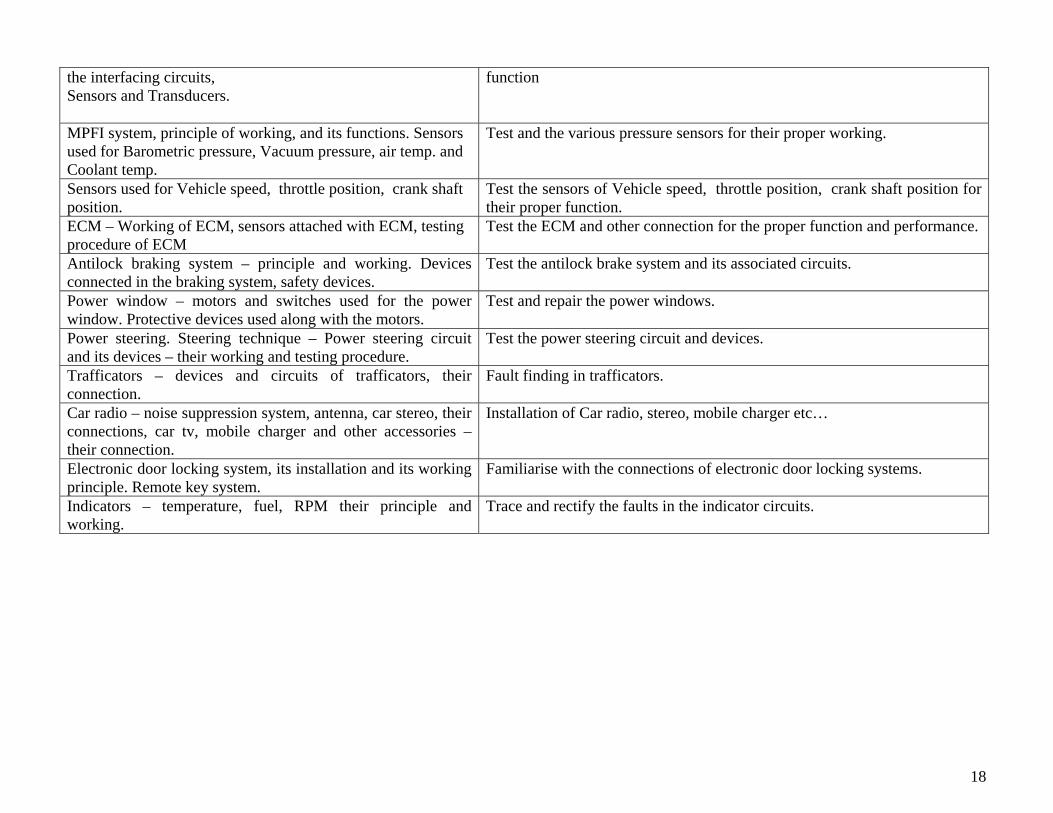
the interfacing circuits, Sensors and Transducers.
function
MPFI system, principle of working, and its functions. Sensors used for Barometric pressure, Vacuum pressure, air temp. and Coolant temp.
Test and the various pressure sensors for their proper working.
Sensors used for Vehicle speed, throttle position, crank shaft position.
Test the sensors of Vehicle speed, throttle position, crank shaft position for their proper function.
ECM – Working of ECM, sensors attached with ECM, testing procedure of ECM
Test the ECM and other connection for the proper function and performance.
Antilock braking system – principle and working. Devices connected in the braking system, safety devices.
Test the antilock brake system and its associated circuits.
Power window – motors and switches used for the power window. Protective devices used along with the motors.
Test and repair the power windows.
Power steering. Steering technique – Power steering circuit and its devices – their working and testing procedure.
Test the power steering circuit and devices.
Trafficators – devices and circuits of trafficators, their connection.
Fault finding in trafficators.
Car radio – noise suppression system, antenna, car stereo, their connections, car tv, mobile charger and other accessories – their connection.
Installation of Car radio, stereo, mobile charger etc…
Electronic door locking system, its installation and its working principle. Remote key system.
Familiarise with the connections of electronic door locking systems.
Indicators – temperature, fuel, RPM their principle and working.
Trace and rectify the faults in the indicator circuits.
18

Automobile Electronics Equipment List :
Sl No Description of Item Qty 1. Rule Steel 300mm 4 2. Chisel cross cut 200mm x 6mm 4 3. Hammer Ball Peen 0.5 Kg 4 4. Hammer copper 1 kg. with handle 4 5. Hack saw frame for 30 cm blade 4 6. Hand Vice 37mm 4 7. Screw Driver, Electrician type 15cm size 8 8. File flat 35cm bastard 4 9. File flat 25cm second cut 4 10. Soldering iron 120 watts 2 11. Clip on Meter Digital 2 12. Steel Almirah 180 x 90 x 50 cm 2 13. Tachometer 2 14. Tester sparking plug “NEON” Type 2 15. High rate discharge tester 2 16. Battery charger 2 17. Multimeter digital 4 18. AC alternator slip ring puller 2 19. AC alternator slip ring press tool 2 20. Executive Auto Electrical Tool kit 4 21. Distributor tester 4 22. Electrical test bench 4 23. Alternator regulator tester 4 24. Car stereo 2 25. Hydrometer 2 26. Vehicle Euro 2 & 3 1 each 27. Enginer scanner 1 28. 2 stroke & 4 Stroke petrol engine 1 each 29. 2 stroke & 4 stroke Diesel engine 1 each 30. Multi Cylinder Petrol engine 1 31. Multi Cylinder diesel engine 1 32. MPFI system 1 33. Car Radio and stereo system 1 34. Car locking remote system 1 35. P IV Computer system 4
19

Advanced Module of Electronic Sector MODULE- 5 Communication System :
Theory Practical Interoduction- Telephone network, Duplex, Susbscriber’s loop,Signaling Tones, DTMF dialing, Pulse Dialling, Dial tone, Ringing tone, Busy tone, Number Unobtainable tone Call in Progress tone
Identify ingTelephone line, Rosset Box connections Demonstration of different types of Electronic Push Button Instruments(EPBT) and Identifying external Controls and their applications. Determining difference between different tones.
Modulation theory & circuit- Amplitude Modulation,(AM) DSB/SC, AM-SSB and their comparison Modulation-PAN,PDN, PPM, PCM, Delta modulation and Circuits. Principles of Multiplexing of DM & TDM , frequency generation and Synchronization circuits
Assemble,test the PAN,PDN, PPM, PCM, Delta modulation Trace the various signal O/P using CRO
Block Wise Description- Polarity Guard, Ringer Section, Speech , Different tones – Dial, Ring, Busy, etc. Dialer Section- Stage Wise Circuit Description for different brands & models .
Identify and Trace the Circuit for different Stages. Ringer, Speech, Dialar, etc. Trace Signal Path, Different tones – Dial, Ring, Busy, etc. Measure Loop Current, Measure Line DC Voltage, On Hook/ Off Hook AC Line Voltage Measurement and Trace Signal Wave Shape in Ring Mode at test Ringer IC input and output
Fault Finding Methods-By Voltage measurements, by Wave Shape Tracing and by Signal Injecting Methods in different make/brand instruments
Measure DC Voltages of Speech IC & Ringer IC Trace Signal Wave Shape in Speech Mode at IC, Signal Wave Shapes in Pulse Mode and Tone Mode at Test Points, Receiver and Transmitter ( Mouth and Hearing Piece), Crystal Frequency Measurement with Frequency Counter/Oscilloscope
IP Phones, Caller ID, Coin operation, Play phones, working principle
Stage Wise Simulated fault finding with the help of different fault finding methods, signal injecting, signal tracing and voltage measurement
Introduction- Cordless Telephone Base Unit and Hand Set Technical Specification-Block Wise description, IC’s Pin description, function, types of data cables-mobile phone circuits
Identifying different input and output sockets, controls, Operating CLT for Different settings on base unit, Programming calling numbers, and getting familiar with other controls on base unit/hand set Dis-assembling CLTinstrument-Identifying SMD components, different stages circuit tracing
Functional description of Base Unit –Opto-cuplar working Principal for detecting ring signal , Functional description of CPU for signal detection, coupling,
Voltage measurements-Opto-cupler for ring detecting, Voltage Charger, CPU at ring or no ring, receiver & transmitter voltage controlled oscillators , Frequency measurements-receiver & transmitter sections of Base Unit & hand
20

Signal, Battery Charge detection and other application
set.
Base Unit, Hand Set receiver and transmitter RF signal and their frequenciesprocessing-Multiplexing, Modulation, Power amplification and transmission, Signal receiving and demodulation process
Tracing wave shapes with the help of Oscilloscope at different test points. Different stages in base unit and hand set Tx and Rx frequency settings ,
Types of faults and their remedies Simulated faults finding in Base unit and Hand set Introduction- Public Switching Telephone Network (PSTN),Central Office Line, DTMF, Subscriber, Signaling, Switching1 EPABX Standards- Stored Program Control(SPC), Space Switch, Time division multiplexing
Identifying different stage- Speech Circuit ,DTMF & Pulse Dialing Circuit. Dule tone ring generating, Subscriber line & switching digital circuits, Ring & Tone Generator & it’s interface
Types of EPABX- ANALOG & Digital Block diagram of digital exchange- MDF, SLIC, Trunk Line interface, CPU, TDM switching, Power Supply
Identify- Time Division Multiplexing & Demultiplexing , TDM pulse Modulation & demodulation
Configuration of an EPABX Architecture & Interface- SLIC, co LINE , TGU, CPU, Main Distribution Fram & Power supply
Data Coding Techniques &Phase Encoded format, Amplitude Shift Keying &Frequency Shift Keying, Phase Shifting Keying Techniques
EPABX System Features- direct outward dialing, Paging, Line Networking, Call privacy, line out of service, direct inward dialing, emergency Extention Features- Extension to CO line, Local call, STD ISD, Extension to Extension call, Extension to tie line, Automatic call back-busy, call forward & etc.
Delta Modulation & Demodulation, Adaptive Delta Modulation Demodulation, Compander , Expander, & Voice communication, Structure Configuration
DC voltage- Source, Distribution and cabling Hardware & software setup of the ISDN Mobile phone- introduction, user guide, Mobile Phone Circuits Diagrams, Mobile phone System -TDMA, GSM, CDMA
Different brand of cell phones-NOKIA, SAMSUNG, LG, MOTOROLLA, SONY, PANASONIC, NITSUBISHI, SIEMENS, etc. Identifying different components-Resistors, Diodes, Coils, Filters, Capacitors, Transistors, Crystals, Modules, Integrated Circuits
Mobile Phone Programming (Service Software Operation) Mobile phone data cable computer interface diagram
Mobile unit Power supply, Data processing, Display Section, Audio Section., dialing section
Mobile Phone data cables, dissembling procedure, SMD Resistors, Diodes, Coils, Filters, Capacitors, Transistor,Crystal, Modules, Integrated circuits.
Circuit Tracing, Basic training, circuit reading, MIC, LED, Key pad, Speaker, Buzzer, On & Off switch, Display, Antenna, Charging pin, PCB circuit
Mobile units- Power supply, data processing, Display SMD technique Mobile spare parts and installation technique, Online
21

section,Audio section, dialing component testing, Input and output supply, checking 15 testing points Work shop technique, Servicing technique, Testing points of mobile circuits mobile problems and solution, Study of Mobile Software and its installation Software problems and solution. Fault finding with Software.
Fault finding sequence , hardware problems and solution
Inteduction to GSM, SIM Cord Recorder, Advance Mobile Phones.
Mobile software installation, Software problems and solution flashing
Understanding and designing of Fibre OPTIC Analog Transmission system : fundamental of fibre optics, properties of Transmission & Receiver, charectarization of fibre optic cable, fibre optic intensity modulation system for Analog Transmission & frequency response Understanding and designing of Fibre OPTIC Digital Transmission system : fundamental of fibre optics,properties of Transmission & Receiver, charectarization of fibre optic cable, design and study of Fibre optic Digital link,rise and fall time distortions, propagation delay and data transmission, CRT terminal interface and communication parameters. Basics of Microwave communication system - Frequency spectrum , Microwave generation-Gunn diode, Klystron Wave guides,Transmission and reception of Microwave signal, repeater stations, propagation
Identify and study the Transmitter, Receiver, Sinewave generator, optical fibre cable-parameters in Fibre optic Analog Transmission system , Intensity modulation and demodulation system . Identify and study the Transmitter, Receiver, TTL square wave generator,optical fibre cable-parameters in Fibre optic Digital Transmission system , Design and study the - Fibre optic digital link, Rise time & Fall time distortion, propagation delay Assemble and test the Microwave signal using Gunn diode, Klystron, Transmission and reception of signals
22

Communication System Equipment List :
Sl No Description of Items Qty 1 Different type and brand telephone instruments 4 each 2 Different type and brand cordless telephone 2 each 3 Different type and brand cell phones 2 each 4 Mobile Trainers 2 5 EPBAX Trainer 2 6 EPABX exchanges 1 7 Telephone Analyzers 1 8 Personal Computers P IV system 4 9 Different brand cell phone data cable 2 10 Digital Multimeters 411 Oscilloscopes 100 Mhz.
Dual trace with LCD display 2
12 Frequency counters 113 UPS 500 VA 4 14 GSM SIM Cord Reader 1 15 Camera Phones 116 Coin Operated Phones 1 17 Cell Phone Test Jig 2 18 DC Regulated Power Supply 0-30V, 1 A 2 19 Temperature controlled soldering stations 5 20 SMD rework stations 1 21 Precision Screw driver sets 6 22 Multipurpose Screw driver sets 16 23 Magnifier Lens 10 X with lighting 2 24 Micro Soldering Irons with different tips 4 25 Tool kit suitable to syllabus equipment 16 26 Analog Fibre Optic Trainer 2 27 Digital Fibre Optic Trainer 2 28 Wave guides 229 Microwave generation Trainer 2
23

Advanced Module of Electronic Sector MODULE- 6 Embedded system and PLC : Theory Practical Introduction to basic Computer architecture ,CPU & its spcification. Accumulator & Register based processors Microprocessor an overview of 8 bit (8085 )Processor, architecture , Interrupt system, Mapping & DMA, Basic programing concept-Assembler, flowchart, debugging. Addressing modes , types of instructions, Instruction set Comparison with other 8 bit processors.
Familiarization of MP kit Program Execution using - Data Transfer Group,Logic Group, Arithmetic Group Branch Group Interface microprocessor kit with different application boards and run the applications
Microprocessor and Microcontroller- a comparison Mocrocontroller an over view of 8051 & its Architecture, Instruction set, Addressing modes, Programming-Data Transfer, Arithmetic, Logic, Boolean Variable manipulation & branching Instruction
Familiarization of MC kit Program Execution using -Data Transfer Group, Logic Group, Arithmetic Group, Branch Group Study of interfacing techniques
I/O ports pins and their functions, I/O Programming, Bit manipulation ,Timers, modes of Timers, application of Timer to generate Time Delays. Interrupts and polling, various interrupt SFR’s related to Interrupt Programming Edge Triggered and level triggered interrupts Priority of interrupts
Hard ware and software Exercises in ports & Read the status of a switch using MC port pin Drive a relay using MC port pin Develop & run programs using Timer, Counter & Interrupt applications
Difference between serial and parallel Communication ,serial communication protocal, synchronous and Asynchronous communication, Data Framing, RS232 Standard, max 232 chips Baud Rates, programming Techniques.
Transmit & Receive Data with PC using serial link, Connection of Microcontroller kit to PC
Various methods of A to D & D to A conversion-counter type ADC, Successive type, Integrating Type ADC’s Specification of DAC & ADC, 8255-programmable peripheral device, Concepts of Traffic light control, Fundamentals of Stepper motor-
Interfacing of MC using 8255 and study the working of: Traffic light controller ,DAC, ADC, Stepper motor ,Elevator, LCD KEYBOARD
24

types, driving methods, Elevator ,Key board and LCD Introduction to C Language, Constants, variables and Data Types, Operators, Expessions, Input & Output operators, Decision Making and Branching, Looping, Array, Chracter Strings, User Defined Functions, Structures & Unions, Pointers, Classes in C++ & Stack operationsrrtrt
Basic structure of c program Execution & compiling c program Program with -various data types ,using mathematical operators Program with input & output operations Program with simple loops & using 2D array, multidimensional arrays, character string& user defined functions
Introduction to PIC MC, Architecture, Instruction set, Additional Features
Exercise on PIC MC
Network features-Network topologies,protocols-TCP/IP,UDP/FTP,models, types, components,network medias,-specification and standards,types of cables Difference between PC & Server, Server-Usages of Server ,Types ,Server hardware, Operating system-OS ,NOS-features,types
Identify physical topology of a network and members of the network ,identify the protocols installed and check resource sharing Identify the cables and components in the network Identify controls and ports on servers Identify the hardware of servers and configuration Starting and shutting down servers Identifying and using basic features Using Win 2000 Prof/Linux/Unix/Novell features Making UTP cross cables and testing ,Making straight cables and testing ,Making cable layout drawing Installing information outlet points. Install different common protocols one bye one and test communication and features Install and check TCP/IP utilities and services
Architecture of 16 bit (8086 )processor, Basic programing concept-Assembler, flowchart, debugging .Addressing modes , types of instructions, Instruction set , Comparison with other 16 bit processors.
Program Execution using Kit and PC Study of interfacing techniques
Evolution of different control techniques like manual, hardwired, electronic gate control and programmable control. Advantages and disadvantages of different techniques mentioned above. Different type of analog and digital input and output field devices used in process industries. Types of voltage and current formats used in field devices. Types of connections of field devices to controllers.Type of cables used for connecting field devices to
Identification of different digital input and output field devices used in process/ mechanical industries categorized w.r.t voltage levels, single end and differential end etc. Operate and test the above mentioned field devices Identify different type of cables used to connect field devices to closed loop single/multi loop controllers and programmable controllers. Identify different cables and connectors used to connect programming terminals such as HHT, PC etc to the programmable controllers.
25

controllers. Block diagram of a basic PLC system and the Architecture, PLC components principles of working of PLCs, Specifications of PLCs. Different type of modules like Digital and Analog input and output modules and their working Hardware description of I/O, power supply Modules I/O addressing concepts. Types of memory used in PLCs. Memory and its impact on performance of PLC Memory map and Data files used in PLCs Different functional blocks/files and their uses
Identify the CPU type and the memory inside. Identify typical modules of the given PLC systems (such as power supply, Digital and Analog I/O(signal modules), basic module, high speed module, special function modules, RTD/Thermocouple etc) Identify the type of connectivity between the CPU and different. Modules of PLC. Identify the type of communication between different modules with PLC.
Different industry Bus communication standards like RS232, RS 422, DH, DH+, 485 etc and their charac-teristics. Different type protocols used in the field of PLCs. Programming of PLCs using different techni-ques such as Ladder, Instruction list, Control system flow chart etc. Instruction set covering basic I/O operations, timer, counter, data copy, arithmetic Logical, compare type, program control, shift instructions etc., PLC interrupts, PLC subroutines, PLC sequencers. Wiring, entering, documenting and testing program.
Install the PLC Software on the PC. Configure the software to communicate with a PLC. Familiarization with the software and use of different Data files/ function blocks etc. Develop simple programs and Download them for execution for simple digital I/O Develop programs using timers and counters and execute. Develop programs to cover different instructions and execute.
Types of special function modules such as memory module, high speed counter, Communication processor module and its importance. Introduction to SCADA and DCS system
Develop and run simple tasks such as control of a relay, contactor, lamp & motor etc for different input conditions. Monitor the status of the application ONLINE. Perform some Force operations. Develop programs to acquire analog data using Analog input card. Develop programs to display/control data using Analog output card. Make a closed loop control system using analog I/Os and control a process. PID Control using PLC. Interrupts using PLCs. Sub-routine development in PLCs. Repeat all the above for any two popular commercial PLCs.
Common faults in a typical PLC- based system with respect to hardware i.e power supply, digital/analog I/Os, special function modules, communication modules etc. Diagnostic capabilities of the PLC Software and the typical codes generated by the system for the effective troubleshooting of different modules of PLCs
Familiarization and interpretation of the screens and its contents provided for diagnostic purpose in the software. Interpretation of the error codes. Clearing the minor errors and major errors. Troubleshooting screens.
Wireless communication standards & various types of networks Exercise on wireless
26

Embeded system and PLC :Equipment List
Sl No Description of Item Qty 1 8085 based Microprocessor Kit 4 2 8051 Based Microcontroller kit 4 3 Interfacing Modules such as DAC,ADC,TRAFFIC LIGHT ,STEPPER MOTOR,LCD
Display & Key board 4 each
4 8086 based 16 bit Trainer Kit 4 5 Pic Microcontroller Kit 4 6 P IV Computer Server configuration 1 7 P IV Computers 4 8 Compiler on C language 1 9 Window 2000 software 1 10 8 Port Hub 1 11 NIC cards,cables and peripherals 4 12 Bread Boards 213 Microcontroller Programmer 114 Components (MC, Memories,Resistors, cap, wires ETC) As required 15 Soldering Iron (Temperature Controlled) 6 16 PIC programmer 1 17 In-circuit emulator 1 18 Oscilloscope (100MHZ) 119 Digital Mulitimeter 620 PLC Trainer Systems ( SIEMENS & ALLENBRADLEY ) 1 each 21 PLC development software for Siemens & Allenbradley PLC systems. 1 each 22 Working models for PLCs 23 a) Bottle fill trainer 1 24 b) Speed control module 1 25 c) Batch process reactor 1 26 d) Start delta starter 1 27 e) Discrete application trainer 1 28 SCADA software 129 Hand held programming terminal for PLC 1
27

30 Miniature type lab compressor with necessary accessories 1 31 Sensors: Thermal, Optical, Pressure, Flow, Position, Motion etc. 1 each 32 Different types of Electronic push buttons (NC & NO ), toggle switches, valves , relays,
solenoids valves 1 each
33 Variable DC Power supplies 0-30 V 2 34 Dual trace oscilloscope 20 MHz 2 35 Online UPS (5 KVA) 1 36 OHP 1 37 LCD Projector 138 Printers Laser jet 1 39 Scanner A4 1 40 Air-conditioner 1.5 Tonn 3 41 Laboratory tools As required
SPACE REQUIREMENTS
1) Classroom - 1 No. 100 Ft. 2) Laboratory - 30 Ft
28