
Modelization of hybrid systems with hydrogen and renewable energy oriented to electric propulsion in...
11
Modelization of hybrid systems with hydrogen and renewable energy oriented to electric propulsion in sailboats Víctor Alfonsín a,* , Andres Suarez a , Angeles Cancela b , Angel Sanchez b , Rocio Maceiras b a Defense University Center, Escuela Naval Militar, Plaza de Espa~ na 2, 36920 Marín, Spain b Chemical Engineering Department, EEI, University of Vigo, 36310 Vigo, Spain article info Article history: Received 23 March 2014 Received in revised form 9 May 2014 Accepted 16 May 2014 Available online xxx Keywords: Sailboat Electric Battery Fuel cell Hydrogen Electrolyzer abstract This paper presents a conceptual model of a hybrid electric sailboat in which energy from electric grid is stored in batteries and energy from renewable energies (eolic, solar and hydro) is stored as hydrogen. The main objective of this model is to study the viability of electrifying traditional sailboats with internal combustion engines into hybrid systems with batteries and fuel cell. The most important advantage of this design is the possibility to reduce up to zero emissions of traditional sailboat. Conversion of renewable energy to hydrogen is performed through an electrolyzer and post conversion to energy is carried out by a fuel cell. The fuel cell with the batteries forms the hybrid system (batteries-fuel cell) for propulsion electrical energy supply. In order to model the boat dynamic and energy systems, modular mathematical models were developed under Matlab ® -Simulink ® , using a fixed-step solver for the simulation of global model. A simulated logic controller manages the global model. In this paper, many models have been used: some of them are based in literature models and others were developed from experimental data. A control strategy has also been developed to manage energy flows and then it has been embedded to Mat- lab ® language. The global model permits test the performance of the sailboat. Copyright © 2014, Hydrogen Energy Publications, LLC. Published by Elsevier Ltd. All rights reserved. Introduction The increase of energetic and environmental problems has favored the development of alternative energy conversion systems [1]. Transport machines with only internal combus- tion engine (ICE) are being replaced by hybrid systems using two or more power sources [2,3]. Battery systems are the most widely used power sources due to their high efficiency and relatively low cost [4]. On the other hand, fuel cell systems are a new emerging technology that could solve environmental problems, contribute the accomplishment of Kyoto Protocol and besides it can help to solve the oil dependence [5e7]. Due to similarities between batteries and fuel cell systems, their combined effect promise great results [8]. Furthermore, in recent years the implementation of renewable sources as photovoltaic and eolic energy in Hybrid Renewable Energy Systems (HRES) is becoming popular for power generation [9]. The main disadvantage of these type of renewable energy sources is their seasonal nature, which * Corresponding author. Tel.: þ34 986 804942. E-mail addresses: [email protected], [email protected] (V. Alfonsín). Available online at www.sciencedirect.com ScienceDirect journal homepage: www.elsevier.com/locate/he international journal of hydrogen energy xxx (2014) 1 e11 Please cite this article in press as: Alfonsín V, et al., Modelization of hybrid systems with hydrogen and renewable energy oriented to electric propulsion in sailboats, International Journal of Hydrogen Energy (2014), http://dx.doi.org/10.1016/ j.ijhydene.2014.05.104 http://dx.doi.org/10.1016/j.ijhydene.2014.05.104 0360-3199/Copyright © 2014, Hydrogen Energy Publications, LLC. Published by Elsevier Ltd. All rights reserved.
-
Upload
independent -
Category
Documents
-
view
5 -
download
0
Transcript of Modelization of hybrid systems with hydrogen and renewable energy oriented to electric propulsion in...

ww.sciencedirect.com
i n t e r n a t i o n a l j o u r n a l o f h yd r o g e n e n e r g y x x x ( 2 0 1 4 ) 1e1 1
Available online at w
ScienceDirect
journal homepage: www.elsevier .com/locate/he
Modelization of hybrid systems with hydrogen andrenewable energy oriented to electric propulsion insailboats
Víctor Alfonsín a,*, Andres Suarez a, Angeles Cancela b, Angel Sanchez b,Rocio Maceiras b
a Defense University Center, Escuela Naval Militar, Plaza de Espa~na 2, 36920 Marín, Spainb Chemical Engineering Department, EEI, University of Vigo, 36310 Vigo, Spain
a r t i c l e i n f o
Article history:
Received 23 March 2014
Received in revised form
9 May 2014
Accepted 16 May 2014
Available online xxx
Keywords:
Sailboat
Electric
Battery
Fuel cell
Hydrogen
Electrolyzer
* Corresponding author. Tel.: þ34 986 804942E-mail addresses: [email protected]
Please cite this article in press as: Alfonoriented to electric propulsion in sailbj.ijhydene.2014.05.104
http://dx.doi.org/10.1016/j.ijhydene.2014.05.10360-3199/Copyright © 2014, Hydrogen Ener
a b s t r a c t
This paper presents a conceptual model of a hybrid electric sailboat in which energy from
electric grid is stored in batteries and energy from renewable energies (eolic, solar and
hydro) is stored as hydrogen. The main objective of this model is to study the viability of
electrifying traditional sailboats with internal combustion engines into hybrid systems
with batteries and fuel cell. The most important advantage of this design is the possibility
to reduce up to zero emissions of traditional sailboat. Conversion of renewable energy to
hydrogen is performed through an electrolyzer and post conversion to energy is carried out
by a fuel cell. The fuel cell with the batteries forms the hybrid system (batteries-fuel cell)
for propulsion electrical energy supply. In order to model the boat dynamic and energy
systems, modular mathematical models were developed under Matlab®-Simulink®, using a
fixed-step solver for the simulation of global model. A simulated logic controller manages
the global model. In this paper, many models have been used: some of them are based in
literature models and others were developed from experimental data. A control strategy
has also been developed to manage energy flows and then it has been embedded to Mat-
lab® language. The global model permits test the performance of the sailboat.
Copyright © 2014, Hydrogen Energy Publications, LLC. Published by Elsevier Ltd. All rights
reserved.
Introduction
The increase of energetic and environmental problems has
favored the development of alternative energy conversion
systems [1]. Transport machines with only internal combus-
tion engine (ICE) are being replaced by hybrid systems using
two or more power sources [2,3]. Battery systems are themost
widely used power sources due to their high efficiency and
relatively low cost [4]. On the other hand, fuel cell systems are
., [email protected] (V
sín V, et al., Modelizatioats, International Jou
04gy Publications, LLC. Publ
a new emerging technology that could solve environmental
problems, contribute the accomplishment of Kyoto Protocol
and besides it can help to solve the oil dependence [5e7]. Due
to similarities between batteries and fuel cell systems, their
combined effect promise great results [8].
Furthermore, in recent years the implementation of
renewable sources as photovoltaic and eolic energy in Hybrid
Renewable Energy Systems (HRES) is becoming popular for
power generation [9]. The main disadvantage of these type of
renewable energy sources is their seasonal nature, which
. Alfonsín).
on of hybrid systems with hydrogen and renewable energyrnal of Hydrogen Energy (2014), http://dx.doi.org/10.1016/
ished by Elsevier Ltd. All rights reserved.
i n t e r n a t i o n a l j o u r n a l o f h y d r o g e n en e r g y x x x ( 2 0 1 4 ) 1e1 12
means great variability over time [10,11]. Generation of
hydrogen based on renewable resources using electrolyzers
could become the nexus for the implementation of this tech-
nology in hybrid systems [12,13].
Plus land vehicles [14,15], it is possible to incorporate fuel
cell and battery hybrid systems in boats [16]. Hydrogen pro-
duction is performed with renewable energy provided by
several photovoltaic panels and small eolic generators located
in the own boat. Furthermore, if a sailboat is selected, this
energy production can be increased during the sail navigation
with one or more hydrogenerators.
For this type of systems, where many power sources are
mixed, mathematical simulation has become in object of
study for battery electric vehicles and all kind of hybrid con-
figurations and even specific software has been developed
[17e19]. However, there is a lack of information about battery
electric ship simulations and even less about energy renew-
able sources applied in these kinds of vehicles.
There is not any information about Energy Management
Unit (EMU) strategies in the case of HRES implemented in
sailboats. But, it is possible to find a vast amount of informa-
tion in many application areas as transportation, distributed
generation or portable applications. Some of most important
are: direct integration, single converter based or multiple
converter based [20].
In this paper, a conceptual zero emissions electric sailboat
is studied. Renewable energy sources (photovoltaic, eolic and
hydrogeneration), energy storage with batteries (in the case of
electrical energy provided by the grid) and an electrolyzer-fuel
cell system (for renewable energy) are implemented. Subse-
quently independent modular models with each energy sys-
temhas been developed inMatlab®/Simulink® and embedded.
All of these individual models are managed by a logic
controller implemented in Matlab®.
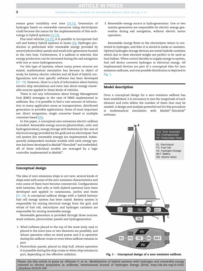
Fig. 1 e Conceptual design of a zero emission sailboat.
Conceptual design
The idea of zero emissions ships is not new, several kinds of
ships exist with some of the zero-emission characteristics and
even some of them have become commercial. Configurations
with batteries, fuel cells or both (hybrid systems) have been
developed and applied to catamarans, yachts and boats
[21e24]. A conceptual sailboat design with a hybrid battery/
fuel cell energy system has been raised. Battery system is
responsible for storing electrical energy from the grid, and
whole of fuel cell, electrolyzer and hydrogen canisters are
responsible for storing renewable energy.
Renewable generation is provided through three sources:
wind turbines, photovoltaic panels and hydrogeneration
1. Wind turbines placed to the top of the mast (only one) or
placed in the stern (one or two elements are possible), and
whose operation relies on wind power and it is operative
during the sailboat cruise or evenwhen sailboat remains in
port.
2. Photovoltaic panels, placed on ship hull, whose operation
it is possible during the ship cruise orwhen ship remains in
port, depending on the effective radiation.
Please cite this article in press as: Alfonsín V, et al., Modelizatioriented to electric propulsion in sailboats, International Jouj.ijhydene.2014.05.104
3. Renewable energy source is hydrogeneration. One or two
marine generators are responsible for electric energy gen-
eration during sail navigation, without electric motor
operation.
Renewable energy flows to the electrolyzer where is con-
verted to hydrogen, and then it is stored in tanks or canisters.
Optimal hydrogen storage devices aremetal hydride canisters
which due to their elevated weight are perfect to be used as
boat ballast.When control decides to supply energy to system,
fuel cell device converts hydrogen to electrical energy. All
implemented devices are part of a conceptual idea for zero
emission sailboats, and one possible distribution is depicted in
Fig. 1.
Model description
Once a conceptual design for a zero emission sailboat has
been established, it is necessary to size the magnitude of each
element and even define the number of them that may be
needed. A design and analysis powerful tool for this procedure
is mathematical simulation with Matlab®-Simulink®
software.
on of hybrid systems with hydrogen and renewable energyrnal of Hydrogen Energy (2014), http://dx.doi.org/10.1016/
i n t e r n a t i o n a l j o u r n a l o f h yd r o g e n e n e r g y x x x ( 2 0 1 4 ) 1e1 1 3
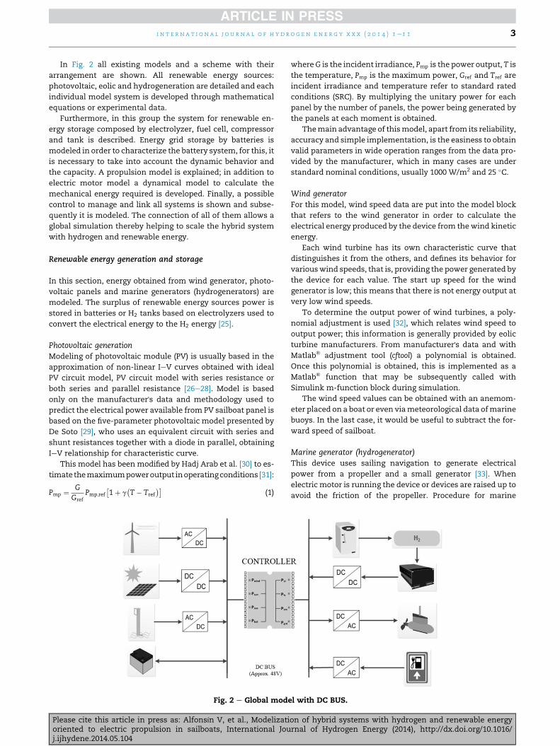
In Fig. 2 all existing models and a scheme with their
arrangement are shown. All renewable energy sources:
photovoltaic, eolic and hydrogeneration are detailed and each
individual model system is developed through mathematical
equations or experimental data.
Furthermore, in this group the system for renewable en-
ergy storage composed by electrolyzer, fuel cell, compressor
and tank is described. Energy grid storage by batteries is
modeled in order to characterize the battery system, for this, it
is necessary to take into account the dynamic behavior and
the capacity. A propulsion model is explained; in addition to
electric motor model a dynamical model to calculate the
mechanical energy required is developed. Finally, a possible
control to manage and link all systems is shown and subse-
quently it is modeled. The connection of all of them allows a
global simulation thereby helping to scale the hybrid system
with hydrogen and renewable energy.
Renewable energy generation and storage
In this section, energy obtained from wind generator, photo-
voltaic panels and marine generators (hydrogenerators) are
modeled. The surplus of renewable energy sources power is
stored in batteries or H2 tanks based on electrolyzers used to
convert the electrical energy to the H2 energy [25].
Photovoltaic generationModeling of photovoltaic module (PV) is usually based in the
approximation of non-linear IeV curves obtained with ideal
PV circuit model, PV circuit model with series resistance or
both series and parallel resistance [26e28]. Model is based
only on the manufacturer's data and methodology used to
predict the electrical power available from PV sailboat panel is
based on the five-parameter photovoltaic model presented by
De Soto [29], who uses an equivalent circuit with series and
shunt resistances together with a diode in parallel, obtaining
IeV relationship for characteristic curve.
This model has been modified by Hadj Arab et al. [30] to es-
timate themaximumpoweroutput inoperatingconditions [31]:
Pmp ¼ GGref
Pmp;ref
�1þ g
�T� Tref
��(1)
Fig. 2 e Global mode
Please cite this article in press as: Alfonsín V, et al., Modelizatioriented to electric propulsion in sailboats, International Jouj.ijhydene.2014.05.104
whereG is the incident irradiance, Pmp is the power output, T is
the temperature, Pmp is the maximum power, Gref and Tref are
incident irradiance and temperature refer to standard rated
conditions (SRC). By multiplying the unitary power for each
panel by the number of panels, the power being generated by
the panels at each moment is obtained.
Themain advantage of thismodel, apart from its reliability,
accuracy and simple implementation, is the easiness to obtain
valid parameters in wide operation ranges from the data pro-
vided by the manufacturer, which in many cases are under
standard nominal conditions, usually 1000 W/m2 and 25 �C.
Wind generatorFor this model, wind speed data are put into the model block
that refers to the wind generator in order to calculate the
electrical energy produced by the device from thewind kinetic
energy.
Each wind turbine has its own characteristic curve that
distinguishes it from the others, and defines its behavior for
variouswind speeds, that is, providing the power generated by
the device for each value. The start up speed for the wind
generator is low; this means that there is not energy output at
very low wind speeds.
To determine the output power of wind turbines, a poly-
nomial adjustment is used [32], which relates wind speed to
output power; this information is generally provided by eolic
turbine manufacturers. From manufacturer's data and with
Matlab® adjustment tool (cftool) a polynomial is obtained.
Once this polynomial is obtained, this is implemented as a
Matlab® function that may be subsequently called with
Simulink m-function block during simulation.
The wind speed values can be obtained with an anemom-
eter placed on a boat or even viameteorological data ofmarine
buoys. In the last case, it would be useful to subtract the for-
ward speed of sailboat.
Marine generator (hydrogenerator)This device uses sailing navigation to generate electrical
power from a propeller and a small generator [33]. When
electric motor is running the device or devices are raised up to
avoid the friction of the propeller. Procedure for marine
l with DC BUS.
on of hybrid systems with hydrogen and renewable energyrnal of Hydrogen Energy (2014), http://dx.doi.org/10.1016/
i n t e r n a t i o n a l j o u r n a l o f h y d r o g e n en e r g y x x x ( 2 0 1 4 ) 1e1 14
generator model is the same than eolic generator model. The
polynomial adjustment is performed from manufacturer data
which are then implemented to Matlab-Simulink®. Commer-
cial hydrogeneration devices typically incorporate inside AC/
DC converters and the data provided by the manufacturer
usually include converter efficiency [34]. In the case that it is
not possible, efficiency value must be included in model.
Electrolyzer modelIn electrolyzer, electric current passes through a series of
electrolytic cells, where there is a water input current. Due to
the electrolysis provoked by the electric current, water current
is split into two separate currents: hydrogen and oxygen.
The currentevoltage curve chosen for the electrolyzer is
shown in Eq. (4) [35]. The number of active electrolyzers used
depends on the input power, when this exceeds maximum
nominal power for one electrolyzer, both of them are
switched on.
Ve ¼ Ve;0 þ b ln
�IeIe;0
�þ ReIe (2)
where Ve (V) is the voltage of a cell, Ve;0 (V) is the reversible
voltage for a cell, b (V�1) is a characteristic coefficient of the
electrolyzer, Ie;0 (A) is the exchange current, Re (U) is the Ohmic
resistance in the cell and Ie (A) is the current.
Electrolyzer only works for values above 15% of its rated
power although this value can be changed. A parasitic loss of
1% is assumed for each electrolyzer switched on [36].
Compression and storage of hydrogenOnce hydrogen production occurs, high pressure storage will
be necessary. For this reason, a model for a compressor must
be developed and implemented after electrolysis stage. The
compressor buffer is an intermediate tank between the gas
outlet from the electrolyzer, which works continually, and the
compressor input.
The second function has a control system for the tank
level, which, once reached a set level, activates an emptying
signal to the compressor to evacuate the hydrogen towards
the higher capacity tank. The two input variables are the
electrolyzer output flow and the flow to the compressor
creating a hydrogen balance that, by being integrated, repre-
sents the amount of hydrogen:
dNH2 ;buf
dt¼ FH2 ;buf;in � FH2 ;buf;out (3)
where NH2 ;buf is the number of accumulated moles in the
buffer, FH2 ;buf;in (mol s�1) the hydrogen flow entering from the
electrolyzer and FH2 ;buf;out (mol s�1) the output towards the
compressor. Applying a logical comparison system with
memory, a trigger signal can be sent once a particular level is
reached and a deactivation signal can be sent if a lower level is
reached.
When buffer reaches the desired level, the compressor is
triggered and compresses the hydrogen at nominal power, to
achieve a lower volume of gas and thus a smaller final storage
tank. A discontinuous flow model has been chosen, to avoid
large hydrogen flows to the compressor that would need a
much more powerful compressor.
Please cite this article in press as: Alfonsín V, et al., Modelizatioriented to electric propulsion in sailboats, International Jouj.ijhydene.2014.05.104
Compression takes place in three stages to obtain the
maximum amount of hydrogen compressed, which is ach-
ieved when the ratio between the output and input pressures
for each compressor stage are equal and therefore the energy
consumed at each stage is the same. The molar flow of com-
pressed hydrogen is expressed as follows:
FH2 ;comp ¼ Pet;compnpoly � 1
npolyhcomp
hcomp
RT
264�
P2P1
� hpolyhpoly�1
� 1
375
(4)
where npoly is the polytropic coefficient, hcomp is the efficiency
of the compression, P1 (bar) and P2 (bar) the input and output
pressures, respectively, Pet;comp is the energy used in each
stage.
The tank is the final element in the model. The tank model
is simple, the inflow from the compressor and outflow to the
fuel cell of hydrogen are taken into account and this is inte-
grated in order to have a real value for the amount of hydrogen
stored per year. Thus, using the evolution of the amount of
hydrogen, the tank can be scaled accordingly. The balance for
the tank is the following:
dNH2 ;Tank
dt¼ FH2 ;in;Tank � FH2 ;out;Tank (5)
where: dNH2 ;Tank is the number of accumulatedmoles, FH2 ;in;Tank
(mol s�1) the hydrogen flow entering from the compressor and
FH2 ;out;Tank (mol s�1) the output towards the fuel cell.
Hydrogen consumption modelThe fuel cell works in the opposite way to the electrolyzer,
thus unregulated direct electrical current and water are ob-
tained from the combination of hydrogen and oxygen. The
input current at the anode will be the hydrogen obtained by of
electrolysis, supplied by the pressurized storage tank,
whereas the input current at the cathode will be air with
approximately 21% oxygen, reacting gas, and nitrogen, which
is inert.
In this case, a hydrogen consumption model has been
constructed rather than a fuel cell electric power model [37].
An equation to model the hydrogen intake as a function of
power demanded by the fuel cell (by the motor and the
auxiliary systems) can be used.
Thus, based on the simple reaction stoichiometry, Fara-
day's Constant, fuel cell efficiency and stack potential Vc, the
following equation is obtained [17]:
H2usage ¼Pelectric
2VcF(6)
This equation depends only on the power demanded by the
fuel cell ðPelectricÞ and stack potential Vc is referred to the lower
heating value of hydrogen, as [38]:
hfc ¼Vc
1:25(7)
It yields the hydrogen mass flux ðH2usage Þ, in moles per sec-
ond, whichmakes possible to know the hydrogen tank level at
every moment.
on of hybrid systems with hydrogen and renewable energyrnal of Hydrogen Energy (2014), http://dx.doi.org/10.1016/

i n t e r n a t i o n a l j o u r n a l o f h yd r o g e n e n e r g y x x x ( 2 0 1 4 ) 1e1 1 5
Grid energy storage. Battery model
Main energy source of zero sailboats is provided by grid and
electrical energy storage made with batteries while boat is in
port. The purpose of battery simulation is to predict the bat-
tery dynamic behavior versus energy demand (battery
discharge) or energy supply (battery charge). Furthermore,
battery capacity is influenced by current that flows through
battery. Magnitude of these effects is influenced by the type of
battery being used. All these factors are considered in this
section about battery model.
Battery dynamic behavior. Open circuit voltageIn this case, dynamic behavior model is performed through a
simple battery equivalent circuit (Fig. 3) where it is necessary
to know internal resistance and open circuit electric potential
(OCV) [17,39]. Assuming that current is flowing out the battery,
as is depicted in Fig. 3, basic voltage equation is [40]:
V ¼ E� IZ (8)
where V is terminal voltage, E is open circuit voltage (OCV), I is
current across circuit and Z internal resistance. OCV values
change in function of battery state of charge (SoC), and they
can be introduced in battery model from a Matlab® function.
Internal resistance values and OCV plots are obtained from
experimental data [41] or are provided from literature [42]. All
of them vary depending battery technology used (lead acid,
nickelecadmium, lithium, etc…).
Battery capacity model. Peukert coefficientBattery capacity is affected by the discharge power magni-
tude, generally when discharge is high, the capacity is lower
and vice-versa. The power magnitude is affected by battery
technology used. This effect is important for electric vehicles
due to high and discontinuous discharge currents. To
compensate this effect Peukert's equation is implemented
[43].
Some authors consider this model is non-optimal for
vehicle simulation since temperature effect is not being taken
into account and correction factor is obtained with constant
discharge current [43,44]. But this last factor in a sailboat
simulation is not a problem because current under discharge
conditions is quite constant and the temperature effect can be
considered if necessary [45], moreover the simulation
Fig. 3 e Simple equivalent circuit model composed of four
cells.
Please cite this article in press as: Alfonsín V, et al., Modelizatioriented to electric propulsion in sailboats, International Jouj.ijhydene.2014.05.104
objective is to obtain a first estimate in order to study viability
for a zero emission sailboat.
Peukert's equation was originally developed for lead acid
batteries, but has since been used for other types [46]. Equa-
tion estimates the available capacity using the following
equation:
Cp ¼ Tdis$Ikdis (9)
where Cp is theoretical Peukert capacity (A h), Idis is discharge
current, Tdis discharge time and k the Peukert's coefficient,
which value varies depending of the kind of battery. Peukert'scoefficient can be estimated with experimental data or data
provided by manufacturer.
Sailboat propulsion
Drive resistance of a vessel over the sea (hydrodynamic
resistance) is a complex task, but Delft Series [47] shows good
results in the case of sailboats. These series have been
developed in Delft Ship Hydrodynamics Laboratory for several
different sailboat hulls. This series let to estimate mechanical
power demand and with motor efficiency can be obtained
electric power to be supplied by batteries and fuel cell system.
Mechanical power. Delft seriesGeometrical coefficients used to define the shape of a boat are:
the prismatic coefficient ðCpÞ, longitudinal center of buoyancyðLCBÞ, ratio between beam of waterline and canoe body draft
ðBwl=TcÞ, ratio of length at the waterline and displaced volume
ðLwl=Vol1=3Þ and relation between beam of waterline and
length at the waterline ðLwl=BwlÞ [47]. If these data are not
available the software (Free!Ship Plus©) can provide this
information.
Frictional resistance (RF) is obtained from sumof resistance
of hull, keel and rudder from next equation [48]:
RF ¼ 12rv2ðScCFh þ SkCFk þ SrCFrÞ (10)
where r is density ofwater, v forward speed of sailboat, S is the
wetted area at zero speed and CF is the friction coefficient for
dipped parts.
Grigson [49] and Katsui et al. [50] proposed methods to
predict friction resistance for model-through ship-scale Rey-
nolds numbers, by solving the momentum integral equation.
The 25th ITTC RC [51] conducted an analytical study on fric-
tion lines, starting to analyze the possible recommendation
for a new formula. This correctional line is shown below:
CF ¼ 0:0066577
ðlog Re� 4:3762Þ0:042612$log Reþ0:56725(11)
And Reynolds number (Re) for dipped parts is determined
separately with:
Rnh ¼ V0:7Lwl
m; Rnk ¼ VCk
my Rnc ¼ VCr
m(12)
where m is the kinematic viscosity (saltwater or freshwater)
and Lwl the waterline length.
To approximate the residual resistance, drive resistance is
included and frictional resistance is excluded, therefore wave
on of hybrid systems with hydrogen and renewable energyrnal of Hydrogen Energy (2014), http://dx.doi.org/10.1016/
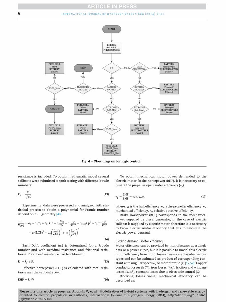
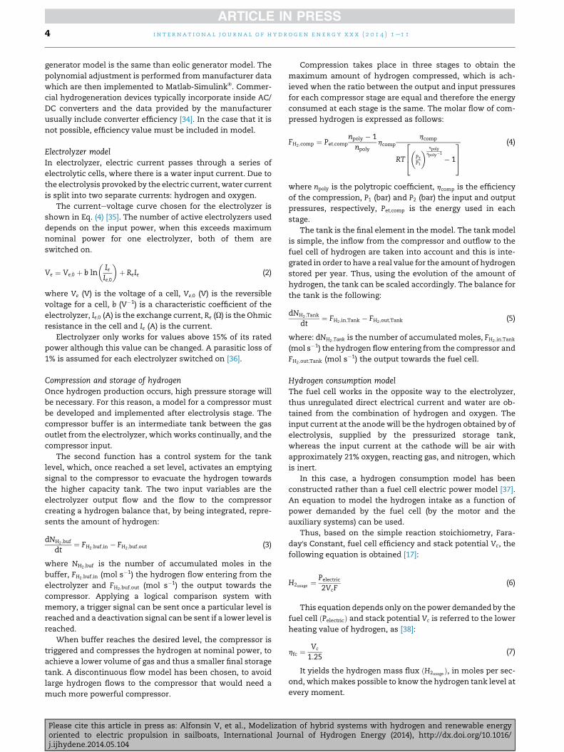
Fig. 4 e Flow diagram for logic control.
i n t e r n a t i o n a l j o u r n a l o f h y d r o g e n en e r g y x x x ( 2 0 1 4 ) 1e1 16
resistance is included. To obtain mathematic model several
sailboats were submitted to tank testing with different Froude
numbers:
Fn ¼ VffiffiffiffiffiffigL
p (13)
Experimental data were processed and analyzed with sta-
tistical process to obtain a polynomial for Froude number
depend on hull geometry [48]:
Rr
Vcrg¼ a0 þ a1Cp þ a2LCBþ a3
Bwl
Tcþ a4
Lwl
V1=3þ a51wlCp
2 þ a6CpLwl
V1=3
þ a7ðLCBÞ2 þ a8
�Lwl
V1=3
�2
þ a9
�Lwl
V1=3
�3
(14)
Each Delft coefficient (an) is determined for a Froude
number and with Residual resistance and frictional resis-
tance. Total boat resistance can be obtained:
Rt ¼ Rf þ Rr (15)
Effective horsepower (EHP) is calculated with total resis-
tance and the sailboat speed:
EHP ¼ Rt*V (16)
Please cite this article in press as: Alfonsín V, et al., Modelizatioriented to electric propulsion in sailboats, International Jouj.ijhydene.2014.05.104
To obtain mechanical motor power demanded to the
electric motor, brake horsepower (BHP), it is necessary to es-
timate the propeller open water efficiency (hp):
hp ¼EHPBHP
¼ hhhohmhrr (17)
where: hh is the hull efficiency, h0 is the propeller efficiency, hm
mechanical efficiency, hrr relative rotative efficiency.
Brake horsepower (BHP) corresponds to the mechanical
power supplied by diesel generator, in the case of electric
sailboat is supplied by electric motor, therefore it is necessary
to know electric motor efficiency that lets to calculate the
electric power demand.
Electric demand. Motor efficiencyMotor efficiency can be provided by manufacturer as a single
data or a power curve, but it is possible to model this electric
motor efficiency frommotor losses. Losses are classified in four
types and can be estimated as product of corresponding con-
stant with angular speed (u) or motor torque (T) [17,52]: Copper
conductor losses ðkcT2Þ, iron losses ðkiuÞ, friction and windage
losses ðkuu3Þ, constant losses due to electronic control (C).
Knowing losses value, mechanical efficiency can be
described as:
on of hybrid systems with hydrogen and renewable energyrnal of Hydrogen Energy (2014), http://dx.doi.org/10.1016/
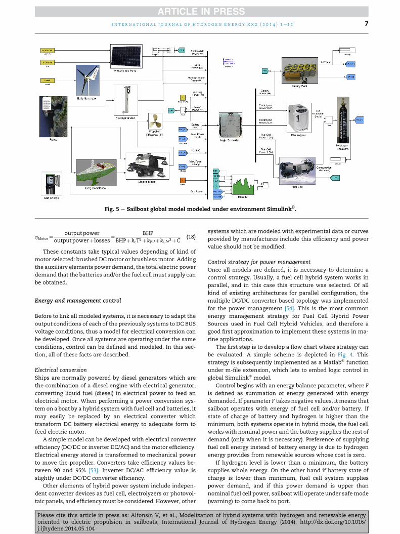
Fig. 5 e Sailboat global model modeled under environment Simulink©.
i n t e r n a t i o n a l j o u r n a l o f h yd r o g e n e n e r g y x x x ( 2 0 1 4 ) 1e1 1 7
hMotor¼outputpower
outputpowerþ losses¼ BHPBHPþkcT2þkiuþkuu3þC
(18)
These constants take typical values depending of kind of
motor selected: brushed DCmotor or brushlessmotor. Adding
the auxiliary elements power demand, the total electric power
demand that the batteries and/or the fuel cell must supply can
be obtained.
Energy and management control
Before to link all modeled systems, it is necessary to adapt the
output conditions of each of the previously systems to DC BUS
voltage conditions, thus a model for electrical conversion can
be developed. Once all systems are operating under the same
conditions, control can be defined and modeled. In this sec-
tion, all of these facts are described.
Electrical conversionShips are normally powered by diesel generators which are
the combination of a diesel engine with electrical generator,
converting liquid fuel (diesel) in electrical power to feed an
electrical motor. When performing a power conversion sys-
tem on a boat by a hybrid systemwith fuel cell and batteries, it
may easily be replaced by an electrical converter which
transform DC battery electrical energy to adequate form to
feed electric motor.
A simple model can be developed with electrical converter
efficiency (DC/DC or inverter DC/AC) and themotor efficiency.
Electrical energy stored is transformed to mechanical power
to move the propeller. Converters take efficiency values be-
tween 90 and 95% [53]. Inverter DC/AC efficiency value is
slightly under DC/DC converter efficiency.
Other elements of hybrid power system include indepen-
dent converter devices as fuel cell, electrolyzers or photovol-
taic panels, and efficiencymust be considered. However, other
Please cite this article in press as: Alfonsín V, et al., Modelizatioriented to electric propulsion in sailboats, International Jouj.ijhydene.2014.05.104
systems which are modeled with experimental data or curves
provided by manufactures include this efficiency and power
value should not be modified.
Control strategy for power managementOnce all models are defined, it is necessary to determine a
control strategy. Usually, a fuel cell hybrid system works in
parallel, and in this case this structure was selected. Of all
kind of existing architectures for parallel configuration, the
multiple DC/DC converter based topology was implemented
for the power management [54]. This is the most common
energy management strategy for Fuel Cell Hybrid Power
Sources used in Fuel Cell Hybrid Vehicles, and therefore a
good first approximation to implement these systems in ma-
rine applications.
The first step is to develop a flow chart where strategy can
be evaluated. A simple scheme is depicted in Fig. 4. This
strategy is subsequently implemented as a Matlab® function
under m-file extension, which lets to embed logic control in
global Simulink® model.
Control begins with an energy balance parameter, where F
is defined as summation of energy generated with energy
demanded. If parameter F takes negative values, it means that
sailboat operates with energy of fuel cell and/or battery. If
state of charge of battery and hydrogen is higher than the
minimum, both systems operate in hybrid mode, the fuel cell
works with nominal power and the battery supplies the rest of
demand (only when it is necessary). Preference of supplying
fuel cell energy instead of battery energy is due to hydrogen
energy provides from renewable sources whose cost is zero.
If hydrogen level is lower than a minimum, the battery
supplies whole energy. On the other hand if battery state of
charge is lower than minimum, fuel cell system supplies
power demand, and if this power demand is upper than
nominal fuel cell power, sailboat will operate under safemode
(warning) to come back to port.
on of hybrid systems with hydrogen and renewable energyrnal of Hydrogen Energy (2014), http://dx.doi.org/10.1016/
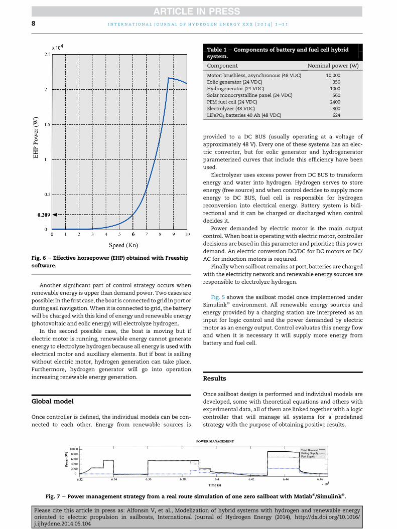
Fig. 6 e Effective horsepower (EHP) obtained with Freeship
software.
Table 1 e Components of battery and fuel cell hybridsystem.
Component Nominal power (W)
Motor: brushless, asynchronous (48 VDC) 10,000
Eolic generator (24 VDC) 350
Hydrogenerator (24 VDC) 1000
Solar monocrystalline panel (24 VDC) 560
PEM fuel cell (24 VDC) 2400
Electrolyzer (48 VDC) 800
LiFePO4 batteries 40 Ah (48 VDC) 624
i n t e r n a t i o n a l j o u r n a l o f h y d r o g e n en e r g y x x x ( 2 0 1 4 ) 1e1 18
Another significant part of control strategy occurs when
renewable energy is upper than demand power. Two cases are
possible: In thefirst case, theboat is connected to grid inport or
during sail navigation.When it is connected to grid, the battery
will be chargedwith this kind of energy and renewable energy
(photovoltaic and eolic energy) will electrolyze hydrogen.
In the second possible case, the boat is moving but if
electric motor is running, renewable energy cannot generate
energy to electrolyze hydrogen because all energy is usedwith
electrical motor and auxiliary elements. But if boat is sailing
without electric motor, hydrogen generation can take place.
Furthermore, hydrogen generator will go into operation
increasing renewable energy generation.
Global model
Once controller is defined, the individual models can be con-
nected to each other. Energy from renewable sources is
Fig. 7 e Power management strategy from a real route sim
Please cite this article in press as: Alfonsín V, et al., Modelizatioriented to electric propulsion in sailboats, International Jouj.ijhydene.2014.05.104
provided to a DC BUS (usually operating at a voltage of
approximately 48 V). Every one of these systems has an elec-
tric converter, but for eolic generator and hydrogenerator
parameterized curves that include this efficiency have been
used.
Electrolyzer uses excess power from DC BUS to transform
energy and water into hydrogen. Hydrogen serves to store
energy (free source) and when control decides to supply more
energy to DC BUS, fuel cell is responsible for hydrogen
reconversion into electrical energy. Battery system is bidi-
rectional and it can be charged or discharged when control
decides it.
Power demanded by electric motor is the main output
control. When boat is operating with electric motor, controller
decisions are based in this parameter and prioritize this power
demand. An electric conversion DC/DC for DC motors or DC/
AC for induction motors is required.
Finallywhen sailboat remains at port, batteries are charged
with the electricity network and renewable energy sources are
responsible to electrolyze hydrogen.
Fig. 5 shows the sailboat model once implemented under
Simulink© environment. All renewable energy sources and
energy provided by a charging station are interpreted as an
input for logic control and the power demanded by electric
motor as an energy output. Control evaluates this energy flow
and when it is necessary it will supply more energy from
battery and fuel cell.
Results
Once sailboat design is performed and individual models are
developed, some with theoretical equations and others with
experimental data, all of them are linked together with a logic
controller that will manage all systems for a predefined
strategy with the purpose of obtaining positive results.
ulation of one zero sailboat with Matlab®/Simulink®.
on of hybrid systems with hydrogen and renewable energyrnal of Hydrogen Energy (2014), http://dx.doi.org/10.1016/
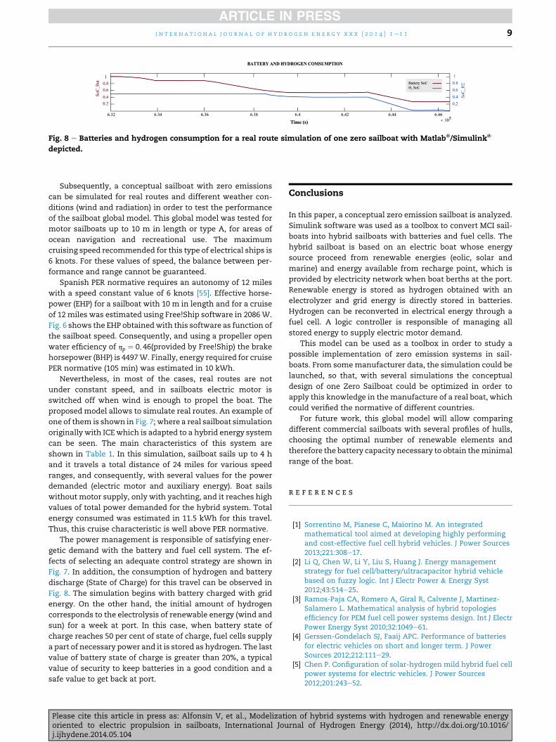
Fig. 8 e Batteries and hydrogen consumption for a real route simulation of one zero sailboat with Matlab®/Simulink®
depicted.
i n t e r n a t i o n a l j o u r n a l o f h yd r o g e n e n e r g y x x x ( 2 0 1 4 ) 1e1 1 9
Subsequently, a conceptual sailboat with zero emissions
can be simulated for real routes and different weather con-
ditions (wind and radiation) in order to test the performance
of the sailboat global model. This global model was tested for
motor sailboats up to 10 m in length or type A, for areas of
ocean navigation and recreational use. The maximum
cruising speed recommended for this type of electrical ships is
6 knots. For these values of speed, the balance between per-
formance and range cannot be guaranteed.
Spanish PER normative requires an autonomy of 12 miles
with a speed constant value of 6 knots [55]. Effective horse-
power (EHP) for a sailboat with 10 m in length and for a cruise
of 12 miles was estimated using Free!Ship software in 2086W.
Fig. 6 shows the EHP obtainedwith this software as function of
the sailboat speed. Consequently, and using a propeller open
water efficiency of hp ¼ 0;46(provided by Free!Ship) the brake
horsepower (BHP) is 4497W. Finally, energy required for cruise
PER normative (105 min) was estimated in 10 kWh.
Nevertheless, in most of the cases, real routes are not
under constant speed, and in sailboats electric motor is
switched off when wind is enough to propel the boat. The
proposedmodel allows to simulate real routes. An example of
one of them is shown in Fig. 7; where a real sailboat simulation
originally with ICE which is adapted to a hybrid energy system
can be seen. The main characteristics of this system are
shown in Table 1. In this simulation, sailboat sails up to 4 h
and it travels a total distance of 24 miles for various speed
ranges, and consequently, with several values for the power
demanded (electric motor and auxiliary energy). Boat sails
without motor supply, only with yachting, and it reaches high
values of total power demanded for the hybrid system. Total
energy consumed was estimated in 11.5 kWh for this travel.
Thus, this cruise characteristic is well above PER normative.
The power management is responsible of satisfying ener-
getic demand with the battery and fuel cell system. The ef-
fects of selecting an adequate control strategy are shown in
Fig. 7. In addition, the consumption of hydrogen and battery
discharge (State of Charge) for this travel can be observed in
Fig. 8. The simulation begins with battery charged with grid
energy. On the other hand, the initial amount of hydrogen
corresponds to the electrolysis of renewable energy (wind and
sun) for a week at port. In this case, when battery state of
charge reaches 50 per cent of state of charge, fuel cells supply
a part of necessary power and it is stored as hydrogen. The last
value of battery state of charge is greater than 20%, a typical
value of security to keep batteries in a good condition and a
safe value to get back at port.
Please cite this article in press as: Alfonsín V, et al., Modelizatioriented to electric propulsion in sailboats, International Jouj.ijhydene.2014.05.104
Conclusions
In this paper, a conceptual zero emission sailboat is analyzed.
Simulink software was used as a toolbox to convert MCI sail-
boats into hybrid sailboats with batteries and fuel cells. The
hybrid sailboat is based on an electric boat whose energy
source proceed from renewable energies (eolic, solar and
marine) and energy available from recharge point, which is
provided by electricity network when boat berths at the port.
Renewable energy is stored as hydrogen obtained with an
electrolyzer and grid energy is directly stored in batteries.
Hydrogen can be reconverted in electrical energy through a
fuel cell. A logic controller is responsible of managing all
stored energy to supply electric motor demand.
This model can be used as a toolbox in order to study a
possible implementation of zero emission systems in sail-
boats. From somemanufacturer data, the simulation could be
launched, so that, with several simulations the conceptual
design of one Zero Sailboat could be optimized in order to
apply this knowledge in themanufacture of a real boat, which
could verified the normative of different countries.
For future work, this global model will allow comparing
different commercial sailboats with several profiles of hulls,
choosing the optimal number of renewable elements and
therefore the battery capacity necessary to obtain theminimal
range of the boat.
r e f e r e n c e s
[1] Sorrentino M, Pianese C, Maiorino M. An integratedmathematical tool aimed at developing highly performingand cost-effective fuel cell hybrid vehicles. J Power Sources2013;221:308e17.
[2] Li Q, Chen W, Li Y, Liu S, Huang J. Energy managementstrategy for fuel cell/battery/ultracapacitor hybrid vehiclebased on fuzzy logic. Int J Electr Power & Energy Syst2012;43:514e25.
[3] Ramos-Paja CA, Romero A, Giral R, Calvente J, Martinez-Salamero L. Mathematical analysis of hybrid topologiesefficiency for PEM fuel cell power systems design. Int J ElectrPower Energy Syst 2010;32:1049e61.
[4] Gerssen-Gondelach SJ, Faaij APC. Performance of batteriesfor electric vehicles on short and longer term. J PowerSources 2012;212:111e29.
[5] Chen P. Configuration of solar-hydrogen mild hybrid fuel cellpower systems for electric vehicles. J Power Sources2012;201:243e52.
on of hybrid systems with hydrogen and renewable energyrnal of Hydrogen Energy (2014), http://dx.doi.org/10.1016/

i n t e r n a t i o n a l j o u r n a l o f h y d r o g e n en e r g y x x x ( 2 0 1 4 ) 1e1 110
[6] Anandarajah G, McDowall W, Ekins P. Decarbonising roadtransport with hydrogen and electricity: long term globaltechnology learning scenarios. Int J Hydrogen Energy2013;38:3419e32.
[7] Gonz�alez Y, Rodríguez S. A comparative study on theultrafine particle episodes induced by vehicle exhaust: acrude oil refinery and ship emissions. Atmos Res2013;120e121:43e54.
[8] Pollet BG, Staffell I, Shang JL. Current status of hybrid, batteryand fuel cell electric vehicles: from electrochemistry tomarket prospects. Electrochim Acta 2012;84:235e49.
[9] Bajpai P, Dash V. Hybrid renewable energy systems for powergeneration in stand-alone applications: a review. RenewSustain Energy Rev 2012;16:2926e39.
[10] Ringel M. Fostering the use of renewable energies in theEuropean Union: the race between feed-in tariffs and greencertificates. Renew Energy 2006;31:1e17.
[11] Lloyd B, Subbarao S. Development challenges under theclean development mechanism (CDM)dcan renewableenergy initiatives be put in place before peak oil? EnergyPolicy 2009;37:237e45.
[12] Gibson TL, Kelly NA. Optimization of solar poweredhydrogen production using photovoltaic electrolysis devices.Int J Hydrogen Energy 2008;33:5931e40.
[13] Rodríguez CR, Riso M, Jim�enez Yob G, Ottogalli R, SantaCruz R, Aisa S, et al. Analysis of the potential for hydrogenproduction in the province of C�ordoba, Argentina, from windresources. Int J Hydrogen Energy 2010;35:5952e6.
[14] Brown D, Alexander M, Brunner D, Advani SG, Prasad AK.Drive-train simulator for a fuel cell hybrid vehicle. J PowerSources 2008;183:275e81.
[15] Van Mierlo J, Van den Bossche P, Maggetto G. Models ofenergy sources for EV and HEV: fuel cells, batteries,ultracapacitors, flywheels and engine-generators. J PowerSources 2004;128:76e89.
[16] McConnell VP. Now, voyager? The increasing marine use offuel cells. Fuel Cells Bull 2010;2010:12e7.
[17] Larminie J, Lowry J. Electric vehicle technology explained.Oxford: John Wiley & Sons; 2003.
[18] Markel T, Brooker A, Hendricks T, Johnson V, Kelly K,Kramer B, et al. ADVISOR: a systems analysis tool foradvanced vehicle modeling. J Power Sources2002;110:255e66.
[19] Moore RM, Hauer KH, Friedman D, Cunningham J,Badrinarayanan P, Ramaswamy S, et al. A dynamicsimulation tool for hydrogen fuel cell vehicles. J PowerSources 2005;141:272e85.
[20] Erdinc O, Uzunoglu M. Recent trends in PEM fuel cell-powered hybrid systems: investigation of application areas,design architectures and energy management approaches.Renew Sustain Energy Rev 2010;14:2874e84.
[21] Fonseca N, Farias T, Duarte F, Gonçalves G, Pereira A. TheHIDROCAT project e an all electric ship with photovoltaicpanels and hydrogen fuel cells. World Electr Veh J 2009;3.
[22] Zero CO2 yacht sets off on first stage of mediterraneanmission. Fuel Cells Bull 2010;2010:5.
[23] Nemo H2: Amsterdam's latest canal cruise boat is poweredby hydrogen. Hol Shipbuild 2010;59:29e32.
[24] Siuru B. Sailing the deep blue gets greener. Diesel Prog NorthAm Ed 2010;76:44e5.
[25] Busby RL. Hydrogen and fuel cells: a comprehensive guide.Tulsa: PennWell Corporation; 2005.
[26] García-Valverde R, Espinosa N, Urbina A. Optimized methodfor photovoltaic-water electrolyser direct coupling. Int JHydrogen Energy 2011;36:10574e86.
[27] Ishaque K, Salam Z. An improved modeling method todetermine the model parameters of photovoltaic (PV)
Please cite this article in press as: Alfonsín V, et al., Modelizatioriented to electric propulsion in sailboats, International Jouj.ijhydene.2014.05.104
modules using differential evolution (DE). Sol Energy2011;85:2349e59.
[28] Vengatesh RP, Rajan SE. Investigation of cloudless solarradiation with PV module employing MatlabeSimulink. SolEnergy 2011;85:1727e34.
[29] De Soto W. Improvement and validation of a model forphotovoltaic array performance; 2004.
[30] Hadj Arab A, Chenlo F, Benghanem M. Loss-of-loadprobability of photovoltaic water pumping systems. SolEnergy 2004;76:713e23.
[31] Rosell JI, Ib�a~nez M. Modelling power output in photovoltaicmodules for outdoor operating conditions. Energy ConversManag 2006;47:2424e30.
[32] Bilodeau A, Agbossou K. Control analysis of renewableenergy system with hydrogen storage for residentialapplications. J Power Sources 2006;162:757e64.
[33] Queeney T. Electricity from heavy water. Ocean NavigJanuary/February 2012;12.
[34] Watt&Sea. Technical data sheet cruising hydro generator,vol. 2013; 2013.
[35] Santarelli M, Call M, Macagno S. Design and analysis ofstand-alone hydrogen energy systems with differentrenewable sources. Int J Hydrogen Energy 2004;29:1571e86.
[36] Kelly NA, Gibson TL, Ouwerkerk DB. A solar-powered, high-efficiency hydrogen fueling system using high-pressureelectrolysis of water: design and initial results. Int JHydrogen Energy 2008;33:2747e64.
[37] Sanchez A, Cancela A, Urr�ejola S, Maceiras R, Alfonsín V.Simulation framework to evaluate the range of hydrogenfuel cell vehicles. I RE CH E 2010;2:840.
[38] Larminie J, Dicks A. Fuel cell systems explained. Oxford: JohnWiley & Sons Ltd; 2003.
[39] Roscher MA, Sauer DU. Dynamic electric behavior and open-circuit-voltage modeling of LiFePO4-based lithium ionsecondary batteries. J Power Sources 2011;196:331e6.
[40] Bird J. Electrical circuit theory and technology. Oxford: Taylor& Francis; 2007.
[41] Abu-Sharkh S, Doerffel D. Rapid test and non-linear modelcharacterisation of solid-state lithium-ion batteries. J PowerSources 2004;130:266e74.
[42] Conway BE. In: Kiehne HA, editor. Battery technologyhandbook. New York: Marcel Dekker; 1989. p. 517 [JElectroanal Chem 328 (1992) 367e368].
[43] Peukert W. Uber die Abh€anigkeit der Kapazit€at von derEntladestromst€arke bei, vol. 27; 1897. pp. 287e8.
[44] Doerffel D, Sharkh SA. A critical review of using the Peukertequation for determining the remaining capacity of lead-acidand lithium-ion batteries. J Power Sources 2006;155:395e400.
[45] Wu G, Lu R, Zhu C, Chan CC. Apply a piece-wise Peukert'sequation with temperature correction factor to NiMH batterystate of charge estimation. J Asian Electr Veh 2010;8:1419e23.
[46] Omar N, Daowd M, van den Bossche P, Hegazy O, Smekens J,Coosemans T, et al. Rechargeable energy storage systems forplug-in hybrid electric vehicles-assessment of electricalcharacteristics. Energies 2012;5:2952e88.
[47] Larsson L, Eliasson RE. Principles of yatch design. 2nd ed.London: Adlard Coles Nautical; 2000.
[48] Keuning JA, Sonnenberg UB. Approximation of thehydrodynamic forces on a sailing yatch based on the 'DelftSystematic Yatch Hull Series'. In: The international HISWAsimposium on yatch design and yatch construction; 1998.p. 99.
[49] Grigson CWB. A planar friction algorithm and its use inanalysing hull resistance. RINA 1999;76.
[50] Katsui T, Asai H, Himeno Y, Tahara Y. The proposal of a newfriction line, fifth Osaka colloquium on advanced CFDapplications to ship flow and hull form design; 2005.
on of hybrid systems with hydrogen and renewable energyrnal of Hydrogen Energy (2014), http://dx.doi.org/10.1016/

i n t e r n a t i o n a l j o u r n a l o f h yd r o g e n e n e r g y x x x ( 2 0 1 4 ) 1e1 1 11
[51] Campana EF, Gorski J, Day AH, Huang D, MacFarlane G,Mikkola T, et al. Final report (The Resistance Committee).ITTC Fukuoka 2008;1:1.
[52] Auinger H. Determination and designation of the efficiencyof electrical machines. Power Eng J 1999;13:15e23.
[53] Choi W, Lee C. Photovoltaic panel integrated powerconditioning system using a high efficiency step-up DCeDCconverter. Renew Energy 2012;41:227e34.
Please cite this article in press as: Alfonsín V, et al., Modelizatioriented to electric propulsion in sailboats, International Jouj.ijhydene.2014.05.104
[54] Zhang X, Mi CC, Masrur A, Daniszewski D. Wavelet-transform-based power management of hybrid vehicles withmultiple on-board energy sources including fuel cell, batteryand ultracapacitor. J Power Sources 2008;185:1533e43.
[55] Government of Spain. Boatmaster's Certif (PER)<br/><br/>2014;2014:1.
on of hybrid systems with hydrogen and renewable energyrnal of Hydrogen Energy (2014), http://dx.doi.org/10.1016/