MODELING CONFIGURABLE PRODUCT FAMILIES
22
4 th WDK Workshop on Product Structuring October 22-23, 1998 Delft University of Technology Delft, The Netherlands MODELING CONFIGURABLE PRODUCT FAMILIES Juha Tiihonen, Timo Lehtonen, Timo Soininen, Antti Pulkkinen, Reijo Sulonen, and Asko Riitahuhta Product configuration, product variation, product modeling, conceptual analysis, case study Abstract This paper presents a method for managing and modeling a product fam- ily as a configurable product. The method enables efficient management of a large number of product variants. The modeling is based on a recently pro- posed conceptualization of configuration domain, which is a synthesis and extension of the main approaches to configuration. The concepts of the con- ceptualization are components, attributes, resources, ports, contexts, func- tions and constraints. In addition to discussing the concepts, we give guide- lines on using them. The conceptualization was evaluated through a case study of modeling rock drilling equipment. The conceptualization matched the modeling needs in the case product. Some improvements to the conceptualization are proposed on the basis of the case study. The guidelines should also be extended and refined. Informa- tion technology support for modeling was found to be necessary for full- scale use of the conceptualization. The conceptualization is primarily intended for representing configura- tion models. However, we present some possibilities for utilizing the con- ceptualization in the product development process. 1. Introduction In many industries competitiveness requires efficient design and delivery of large numbers of product variants. One-of-a-kind products or a large number of fixed products often lead to excessive amounts of design and customer specific engineering, or problems with the manage- ment of a large number of product variants. In this paper we present a method for managing large product families as a configurable product. The utilization of configurable products requires a systematic sales-delivery process and modeling the product family as a configurable product. Instead of explicitly defining a set of product variants in a product family, a configurable product has a configuration model that contains all the information on the possibilities of adapting the product to customer needs. The configuration model defines a set of pre-designed components, rules on how these can be combined into valid product variants and rules on how to achieve the desired functions for a
Transcript of MODELING CONFIGURABLE PRODUCT FAMILIES
4th WDK Workshop on Product StructuringOctober 22-23, 1998
Delft University of TechnologyDelft, The Netherlands
MODELING CONFIGURABLE PRODUCT FAMILIES
Juha Tiihonen, Timo Lehtonen, Timo Soininen, Antti Pulkkinen, Reijo Sulonen, and Asko Riitahuhta
Product configuration, product variation, product modeling, conceptual analysis, case study
AbstractThis paper presents a method for managing and modeling a product fam-
ily as a configurable product. The method enables efficient management of alarge number of product variants. The modeling is based on a recently pro-posed conceptualization of configuration domain, which is a synthesis andextension of the main approaches to configuration. The concepts of the con-ceptualization are components, attributes, resources, ports, contexts, func-tions and constraints. In addition to discussing the concepts, we give guide-lines on using them. The conceptualization was evaluated through a casestudy of modeling rock drilling equipment.
The conceptualization matched the modeling needs in the case product.Some improvements to the conceptualization are proposed on the basis ofthe case study. The guidelines should also be extended and refined. Informa-tion technology support for modeling was found to be necessary for full-scale use of the conceptualization.
The conceptualization is primarily intended for representing configura-tion models. However, we present some possibilities for utilizing the con-ceptualization in the product development process.
1. Introduction
In many industries competitiveness requires efficient design and delivery of large numbers ofproduct variants. One-of-a-kind products or a large number of fixed products often lead toexcessive amounts of design and customer specific engineering, or problems with the manage-ment of a large number of product variants.
In this paper we present a method for managing large product families as a configurableproduct. The utilization of configurable products requires a systematic sales-delivery processand modeling the product family as a configurable product. Instead of explicitly defining a setof product variants in a product family, a configurable product has a configuration model thatcontains all the information on the possibilities of adapting the product to customer needs. Theconfiguration model defines a set of pre-designed components, rules on how these can becombined into valid product variants and rules on how to achieve the desired functions for a
2
customer. However, the product needs to be designed and systemized with configurability inmind in order to make the configuration models manageable. Configurable products havebecome popular with companies as a means to satisfy a wide range of customer requirements,reduce costs and decrease the lead-times in the sales-delivery process [1].
In this paper we first briefly discuss the main characteristics of configurable products. We thendescribe a recently proposed conceptualization [2] of configuration models, configurations andrequirements on a configuration. Guidelines on how the concepts are used in modeling aregiven. Our conceptualization unifies many of the different conceptualizations that have beenproposed in AI-oriented research on configuration (see e.g.[3]). These approaches are furthergeneralized on the basis of our experiences with real world products.
We demonstrate the conceptualization and evaluate it using a case study of modeling a productin the field of mobile machinery. The conceptualization matched the modeling needs in the caseproduct. Some improvements and extensions to the conceptualization are proposed on the basisof the case study. The guidelines should be extended and refined. Information technologysupport for modeling was found to be necessary for full-scale use of the conceptualization.
The conceptualization is primarily intended for representing the product knowledge needed inthe sales-delivery process. However, we argue that the conceptualization can also be used in theproduct development process. The main benefits arise from improved communication betweenproduct development team and other functions of the company. It is also possible to use theconceptualization in a Design For Configuration (DFC) tool.
2. Configurable products and configuration process
According to our definition a configurable product has the following basic properties:
• Each delivered product individual is tailored to the individual needs of an individualcustomer.
• The product has been pre-designed to meet a given range of different customer requirements.
• Each product individual is specified as a combination of pre-designed components ormodules. Thus, there is no need to design new components as a part of the sales-deliveryprocess.
• The product has a pre-designed general structure.
• The sales-delivery process requires only systematic variant design, not adaptive or originaldesign in the sense of Pahl and Beitz [4].
The product development and sales-delivery processes of configurable products are separate.The product development process of a configurable product produces, among other deliverables,an explicit configuration model. However, in relatively common industrial practice theconfiguration models are only implicitly present as tacit knowledge in product experts’ minds orin varied documents.
3
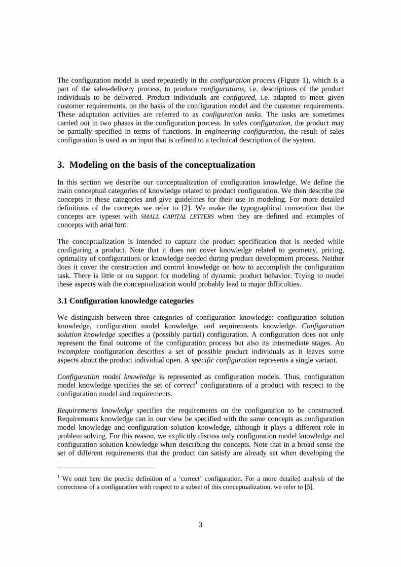
The configuration model is used repeatedly in the configuration process (Figure 1), which is apart of the sales-delivery process, to produce configurations, i.e. descriptions of the productindividuals to be delivered. Product individuals are configured, i.e. adapted to meet givencustomer requirements, on the basis of the configuration model and the customer requirements.These adaptation activities are referred to as configuration tasks. The tasks are sometimescarried out in two phases in the configuration process. In sales configuration, the product maybe partially specified in terms of functions. In engineering configuration, the result of salesconfiguration is used as an input that is refined to a technical description of the system.
3. Modeling on the basis of the conceptualization
In this section we describe our conceptualization of configuration knowledge. We define themain conceptual categories of knowledge related to product configuration. We then describe theconcepts in these categories and give guidelines for their use in modeling. For more detaileddefinitions of the concepts we refer to [2]. We make the typographical convention that theconcepts are typeset with SMALL CAPITAL LETTERS when they are defined and examples ofconcepts with arial font.
The conceptualization is intended to capture the product specification that is needed whileconfiguring a product. Note that it does not cover knowledge related to geometry, pricing,optimality of configurations or knowledge needed during product development process. Neitherdoes it cover the construction and control knowledge on how to accomplish the configurationtask. There is little or no support for modeling of dynamic product behavior. Trying to modelthese aspects with the conceptualization would probably lead to major difficulties.
3.1 Configuration knowledge categories
We distinguish between three categories of configuration knowledge: configuration solutionknowledge, configuration model knowledge, and requirements knowledge. Configurationsolution knowledge specifies a (possibly partial) configuration. A configuration does not onlyrepresent the final outcome of the configuration process but also its intermediate stages. Anincomplete configuration describes a set of possible product individuals as it leaves someaspects about the product individual open. A specific configuration represents a single variant.
Configuration model knowledge is represented as configuration models. Thus, configurationmodel knowledge specifies the set of correct1 configurations of a product with respect to theconfiguration model and requirements.
Requirements knowledge specifies the requirements on the configuration to be constructed.Requirements knowledge can in our view be specified with the same concepts as configurationmodel knowledge and configuration solution knowledge, although it plays a different role inproblem solving. For this reason, we explicitly discuss only configuration model knowledge andconfiguration solution knowledge when describing the concepts. Note that in a broad sense theset of different requirements that the product can satisfy are already set when developing the
1 We omit here the precise definition of a ‘correct’ configuration. For a more detailed analysis of thecorrectness of a configuration with respect to a subset of this conceptualization, we refer to [5].
4
product and its configuration model. The requirements knowledge referred to here is a system-ized representation of the requirements that can be set on an individual configuration. Aconfigurer must translate the actual requirements of a customer to the elements available in aconfiguration model.
3.2 Modeling guidelines
A configuration model is based on an analysis of the product to be modeled. Therefore themodeler should have a good understanding of the product. The product should be modeled byproduct experts in the product development process. The configuration model is an abstractionof the real world product family that is specifically meant for configuration purposes. Forexample, it may suffice to model the different types of motors of drill rigs as simple undivisiblecomponents although they are very complex assemblies. When a drill rig is configured, it isenough to decide the type of the motor.
We consider object-oriented analysis and modeling (e.g. [6]) a good method for configurationknowledge modeling with the conceptualization. In the first phase the primary concern is to
configuration process
configuration #456 at T0
configuration #456 at T1
single configuration for a single order at different times during the configuration process
specific configuration
manufacturing process
physical products
product development
process
configuration model
requirementscustomer
configuration #456 at T2
Figure 1. Configuration process
5
recognize the relevant entities. These are subtypes of the concepts in the conceptualization.After that, and to some extent in parallel with the previous stage, relationships between theentities and their properties are identified. Again, the conceptualization provides the relevantproperties and relations. In parallel with the previous steps, classification hierarchies ofcomponent, resource, port and function types are constructed to capture common characteristics.Constraints are identified and modeled.
For all the concepts, the rule is: use as few types and definitions in a model as possible whilemaking sure that the model 1) contains all the necessary knowledge, and 2) is understandableand manageable. The second requirement is subjective and requires both practice and goodunderstanding of the product to be modeled and of its usage. It is also evident that differentneeds lead to different models of the same product.
3.3 Classification hierarchy
3.3.1 Concepts
We introduce the concepts of a TYPE and an INDIVIDUAL to clearly distinguish between theentities that occur in configuration model knowledge and configuration solution knowledge.Configuration knowledge is commonly discussed using terms that do not distinguish betweenconfiguration model knowledge and configuration solution knowledge. For example, thesentence “Car has an engine as a part” can be interpreted in two ways. As configuration modelknowledge the sentence can be understood as saying that every car individual must have anengine individual as a part. As configuration solution knowledge it states that a particularconfiguration includes a particular car individual that has a particular engine individual as apart.
In the conceptualization a configuration can contain individuals of four different types in theconfiguration model knowledge: component, port, resource and function. These are organized ina classification hierarchy in the usual manner [6]. A type has a set of property definitions suchas attribute, part and port definitions. A type inherits the properties of its supertypes in theclassification hierarchy. In other words properties from each supertype of a type are “added” tothose of the type itself. For example, type Motor may define properties common to all motors ofFord Mondeos™. Types Zetec_2.0_16V™ and Endura_TD_1.8™ would have the commonproperties defined by Motor. We say that Zetec_2.0_16V and Endura_TD_1.8 are directsubtypes of Motor. Motor is a direct supertype of Zetec_2.0_16V and Endura_TD_1.8. All directsubtypes of a type and their subtypes, and so on are collectively called subtypes of a type.Supertypes are defined analogously. Multiple inheritance, i.e. having several direct supertypes,may cause complications, which are ignored here.
A subtype may refine the property definitions it has inherited. Refinement of property defini-tions is semantically based on the notion that the set of potential valid individuals directly of thesubtype is smaller than the set of valid individuals directly of the supertype. For example, typeMondeo might define that applicable motors are the whole line of motors available. TypeMondeo_CL might limit compatible motors to smaller ones and Mondeo_GLX to larger ones.
A type is either abstract or concrete. An individual directly of a concrete type is accurate enoughto be used in an unambiguous configuration. An individual directly of an abstract type providesonly partial information on the real world entity it represents. A specific configuration contains
6
only individuals directly of concrete types to unambiguously specify a product individual. Notethat a concrete type may allow variation in the properties of the individual, for example differentindividuals of a concrete type can have different attribute values.
3.3.2 Modeling guidelines
Classification hierarchies should be used when there is a set of types that have commonproperties or that need to be referred to collectively in some definitions. A model can be mademore compact and maintainable by collecting the common properties to supertypes.
There are always several criteria for classification and one has to choose the most useful ones.Classification in product configuration models should be constructed from the point of view ofconfiguration to facilitate easy construction and maintenance of configuration models. Forexample, classification hierarchies of part library standards such as ISO13584 and classificationconstructed for the purpose of a company’s general PDM may not be appropriate for configura-tion models.
One should consider carefully which properties belong to a given type and which ones to itssubtypes or supertypes. Common properties should be presented as high in the classificationhierarchy as possible. Classification requires a good understanding of the domain beingmodeled.
Abstract types naturally emerge when the knowledge common to a set of types is gathered in asupertype. Quite often intermediate (abstract) types can be used to represent properties commonto a set of types, but intermediate types should not be created without proper justification. Forexample, we do not recommend using intermediate types like “motors usable in Ranger_500”,because this is best accomplished using part definitions (see Section 3.5).
3.4 Attributes
3.4.1 Concepts
Component, port, resource and function types can define attributes. Attributes represent thecharacteristics of an individual of the type. Some attributes have fixed values and others can begiven a value. An ATTRIBUTE DEFINITION consists of an ATTRIBUTE NAME, an ATTRIBUTE VALUE
TYPE and a NECESSITY DEFINITION. In a correct configuration an individual of the type having anattribute definition has an ATTRIBUTE according to the attribute definition and either exactly one(necessary attribute) or at most one (optional attribute) ATTRIBUTE VALUE of the attribute valuetype. One particularly important attribute type is PHYSICAL QUANTITY such as length or mass.
3.4.2 Modeling guidelines
Typical attributes include physical dimensions of parametric components, surface material,color, resistance, and capacity. For example, an engine could have weight and volume asattributes.
Attributes can be used to parameterise components with respect to some properties. In somecases one can create either one or a few parametric types or a relatively large number of non-parametric types. In extreme cases one parametric component type can represent millions of
7
non-parametric types. A large set of similar component types in a model may indicate that theset could be represented as a parametric component type.
3.5 Components and structure
In this section we first motivate the need for advanced product structure modeling. Then wedefine the central concepts of component types, component individuals and their compositionalstructure.
One of the most fundamental aspects of any technical system is its hierarchical decomposition.Fixed part lists or bills of material (BOM) with no support for variation are commonly used todescribe the structure of both fixed and one-of-a-kind products. This approach becomesunmanageable when the number of different structures becomes very large.
Configurable products make the management of very large numbers, even millions or more, ofvariants efficient. This is due to a configuration model defining its product variants in acombinatorial manner. For example, a configuration model representing 4 options that one mayeither include in the product individual or not and 5 choices with 4 alternatives for each choicein effect represents 24×45 = 16384 variants. Changing one of the alternatives for one choicewould affect 4096 fixed structures if the product family were modeled as fixed products. In aconfiguration model only one change could be required.
3.5.1 Concepts
A COMPONENT TYPE represents a distinguishable entity in a product that is meaningful forproduct configuration. A configuration is composed of COMPONENT INDIVIDUALS of thecomponent types in a configuration model. Component types are either dependent or independ-ent. Only individuals of independent types can serve as roots of the product structure.
The conceptualization directly supports generalized product structures with varying number ofmandatory, alternative and optional parts. A component type can define roles for its parts. Theseroles are filled by component individuals in configurations. As an example, component typeLamp has part roles Lampshade and a Stand. Each part role defines which component types areviable alternatives for that part role. For example, the lampshade may be a blue lampshadeLsBlue or a black lampshade LsBlack. Component individuals are assigned to fill the part role ina configuration. For example LsBlack456 fills the role Lampshade of Lamp123. No othercomponent individuals than those of the types defined to be possible lampshades may fill thelampshade role. A component individual can only have the parts defined by roles in its type. Forexample, one cannot have a configuration where an umbrella reflector is a part of a lamp if acorresponding part role has not been specified.
A component type specifies its part roles as a set of PART DEFINITIONs. A part definitionspecifies a PART NAME, a SET OF POSSIBLE PART TYPES and a CARDINALITY. In addition, a partdefinition includes an EXCLUSIVITY DEFINITION and an optional HAS PART INHERITANCE DEFI-NITION. For brevity, the latter two are not discussed in this paper. The part name identifies therole. The possible part types indicate the component types whose component individuals areallowed to occur in the role. The cardinality specifies how many component individuals must
8
occur as parts in the role. Cardinality is expressed as a set of non-negative integer ranges. If oneof these ranges includes 0, the part is said to be optional. Otherwise it is mandatory.
Examples of part definitions in types include: A Car has an Engine and a Chassis as parts andthere are several alternatives for each. A Computer has a part display unit that can be one of thefollowing: Brand A 15” Flat, Brand A 17” Super or Brand B 19” HD.
3.5.2 Modeling guidelines
A coherent whole in a product should be modeled as a component type when it
(1) is distinct in the sense that it either may or may not appear in the configuration, or
(2) is an alternative for something else, or
(3) refers to a well-defined part of the product.
Usually one should avoid modeling things that are common to all variants or fixed substructuresof a component type. Common parts and fixed substructures are usually irrelevant for theconfiguration view of the product and can usually be managed in an MRP system.
A part definition should be included in a configuration model if it is natural to think that anindividual of component type A contains an individual of component type B, and both A and Bare integral wholes whose modeling is justified by the reasons given above. In general, the partsof a whole should be separable and have a distinct identity. Usually the parts of a whole aresomehow different from each other. The difference can, for example, be related to the role,function, or type of the part. Most part definitions are meaningful in the configuration senseonly if a choice of a component type or number of parts can be made. However, quite manyproducts include a mandatory “base unit” that can also be modeled. It is sometimes difficult todecide whether component type A is part of component type B or vice versa. In this case, thereoften is a component type C that both A and B are parts of.
Note that we model product families, assemblies, sub-assemblies and atomic parts uniformly ascomponents. Examples of mostly mechanical components include engines, gears, elevator cars,and chassis. Electrical components include computers, microprocessors, memories, ASICs, andPCBs. Non-physical component types include software systems, software modules, applets, anddifferent insurance policies.
3.6 Ports
3.6.1 Concepts
Ports are used to model connections and compatibilities between components. The idea is thatcomponent individuals can be connected only if they have compatible interfaces. We modelconnection interfaces as ports. A PORT TYPE is a definition of a connection interface. A PORT
INDIVIDUAL represents a “place” where in a component individual some other port individualmay be connected. A port type has a COMPATIBILITY DEFINITION that defines a set of port typeswhose port individuals can be connected to the port individuals of that port type. In addition, aport type defines a set of CONNECTION CONSTRAINTS. Only port individuals that satisfy the
9
connection constraints defined by their port types may be connected to each other. A connectionconstraint may also specify that port individuals with given attribute values and of particulartype can or must be connected. Connection constraints are a special case of constraints (seeSection 0.).
A component type specifies its connection possibilities by PORT DEFINITIONS. A port definitionspecifies a PORT NAME for the port, a SET OF POSSIBLE PORT TYPES, a CARDINALITY and additionalconnection constraints. Cardinality expresses the possible number of port individuals as a set ofranges. A port definition can refine the set of compatible port types from those specified by theport type using the .
3.6.2 Modeling guidelines
The connections modeled with ports can be physical or logical. Ports are especially suitable formodeling compatibility expressed as interfaces, which is often the case for modular products.
If component individuals do not have compatible ports, they cannot be connected, but they canstill exist in the same configuration. In effect, components are by default compatible but notconnectible. Compatibility can be restricted to component types with compatible ports byrequiring connections using constraints.
Note that a component type can offer alternative port types, which allows configuring theinterface by selecting a port type. Port definitions can also be used for limiting the number ofconnections, because the number of port individuals can be specified and at most one connec-tion can be made to a port individual. In some cases only the number of connection points oravailable space for connections is relevant without the need to model exactly the connectionsbetween the ports. This type of phenomenon may be better modeled as a resource interaction(see below).
Examples of connections that can be modeled using ports include a motor requiring a specifictype of a power source. This can be modeled with appropriate in and out port types for themotor and power source and defining that only certain kinds of in port types fit certain types ofout ports. Another example is a computer that can be plugged to a printer if both of them have aparallel port. The parallel port is an interface which is modeled as a port.
Quite often actual connections require connecting components like cables or pipes. It may bedifficult to decide whether a connecting component needs to be modeled or can be abstractedaway. This depends on whether the connecting component has alternative types, is parametric orhas some other reason for being specified separately.
It may sometimes be difficult to decide whether a component type is a part of another or isconnected to it via ports. One distinguishing criterion for this is that a connection between theport individuals of two component individuals is symmetric. In other words, it seems intuitivelyclear that if component individual A is connected to component individual B, then B is alsoconnected to A. On the other hand, the has-part relation between component individuals isusually interpreted as antisymmetric, i.e. if component individual A has-part componentindividual B, then B must not have A as a part.
10
There is also another dependency between connections and parthood: connections are oftenfound between components that are parts of the same whole. Therefore, if there is set ofcomponent types that are parts of the same whole in the model, one should check whether thereare some connections between these component types that are relevant for configuration andshould be modeled. In the other direction, if there is a set of component types in the model thatcan be connected to each other, it should be checked whether they should be a part of somecommon whole.
3.7 Resources and contexts
3.7.1 Concepts
In this section we define resource-oriented concepts, which are needed for modeling theproduction and use of some more or less abstract entity. The underlying idea is that somecomponent individual(s) produce some resource and other component individual(s) use it.
Resource production and use must be either satisfied, in which case the quantity of resourceproduced must be equal to or greater than the quantity of the resource used or balanced, inwhich case the quantity of resource produced must be equal to the quantity of the resource used.
Basic resource concepts offer a simple mechanism for modeling resource production and usewithout regard to product structure or connections, i.e. resources are considered to be globallyavailable. The conceptualization adds a context mechanism that makes it possible to limitresource availability to some specific set of component individuals. The motivation is thatunrestricted flow of resources from producers to users may in some cases be too simplistic tomodel a product adequately. A resource is only available to component individuals that are inthe same context as the producing component individual.
In the conceptualization, a RESOURCE TYPE defines the properties of the resource. A resourcetype has a COMPUTATION DEFINITION that specifies whether the resource should be satisfied orbalanced and a UNIT OF MEASURE. In addition, the computation definition specifies how theproduction and use of the resource type by several component individuals are combined,possibly taking into account production by sub- and supertypes. This is done through a TOTAL
PRODUCTION FUNCTION and a TOTAL USE FUNCTION. The prototypical case is that the quantitiesof the resource produced or used are added together to get the total quantity.
A component type specifies by PRODUCTION DEFINITIONs and USE DEFINITIONs the resourcetypes it produces and uses. Both production and use definitions specify a SET OF POSSIBLERESOURCE TYPES produced or used, a PROPERTY DEFINITION, a MAGNITUDE RANGE and aCONTEXT DEFINITION. The produced or used resource must be of one of the possible resourcetypes. The property definition is a special case of constraints (see Section 0.) that specifies arestriction on the attribute values of the resource produced or used. The magnitude rangespecifies how much of the resource component individuals produce or use.
3.7.2 Modeling guidelines
Quite often when a component of one type requires a component of another type for the wholeto operate correctly, the underlying reason is that there is a resource which is provided by thefirst and used by the second. Another indication of a phenomenon that can be modeled as a
11
resource is that there is a flow of some thing from a component type to another. However,resources are not intended for modeling the dynamic behavior of a system. Resource conceptsare useful for modeling the following phenomena:
• Individuals of a component type(s) consume some amounts of abstract or physicalresources that individuals of some other component type(s) produce. Examples includediscrete physical locations, space in rack, slots, electric power and current, disk space, torqueor power produced by motor.
• Individuals of a component type(s) require the existence of an abstract service withoutregard to who is producing it. Typically these are found in computer systems and similardevices. Abstract services are often shared in the sense that the existence of one producer isenough to satisfy all users. Examples include availability of a protocol or availability of anAPI (Application Program Interface).
• Individuals of a component type require the existence of an individual of other compo-nent type in the configuration. This can be modeled as abstract services by creating a re-source type that is produced by the required component type(s) and consumed by the re-quiring component type(s). Note that this is a practical way of associating two sets of com-ponent types to each other: If there is an individual of the first set in the configuration, theremust also be an individual of the other set. The number of individuals from these sets canalso be easily balanced, if required.
Resource concepts are not intended for situations where there is a need to model explicitly theconnections between component individuals producing and using resources. Another way oftelling connections and resource interactions apart is that connections are symmetric, whereasresource interactions are asymmetric (from the producer to the user, but not vice versa).
Property definition in resource production and use definitions can be used, for example, tomodel different qualities of electricity. Effectively this enables permitting or rejecting the use ofa resource on basis of its attributes.
Contexts are used in situations where there is an additional condition that specifies from where aresource is obtained or where it can be used. An example is a product with two subsystems thateach have their own power supplies. Power supplied within one subsystem cannot be usedoutside of it. Although one subsystem may have surplus power, it is not available to the othersubsystem. Unexpected results may occur if a configuration can have several top-levelcomponents that are intended to be roots for independent product individuals, because resourceinteractions between them are possible. A context should always be specified to keep resourceswithin a product individual in such a configuration.
3.8 Functions
3.8.1 Concepts
In this section we define the function and function structure concepts for representing thefunctionality that the product individual provides to the customer, the user of the product or theenvironment in which the product individual will be situated. The concepts introduced so far arecalled technical concepts since they have risen from the technical point of view on the product.
12
A complex product is often configured in two stages, as discussed in Section 2. A functionalspecification may, for example, specify that a telecommunications switch must provide access toat least 1000 subscribers. This function is implemented by a combination of componentindividuals in certain relations to each other. These relations may be expressed using thetechnical concepts defined above.
The basic concept in the functional view is FUNCTION TYPE. We call a function individual aFUNCTION. A PART DEFINITION of a function type corresponds to a part definition of a compo-nent type with the exception that the possible part types must be function types. It is used torepresent the hierachical breakdown of the function to subfunctions.
The relation between technical concepts and functions and their properties is expressed asIMPLEMENTATION CONSTRAINTS. They are a special form of general constraints (see Section 0.)Several different combinations of technical concepts may implement the same functions and onecombination of technical concepts may implement several functions.
There can be constraints on how different functions and their attribute values can be combined.These SPECIFICATION CONSTRAINTS are a special case of the generic constraints (see Section 0.)that only refer to functional concepts. They are used similarly as other constraints to restrict thecombinations of functions that a product can implement.
3.8.2 Modeling guidelines
A function type is typically an abstract characterization of the product that a customer or salesperson would use to describe what the product can be used for, or what need the productsatisfies. Another, a possibly more engineering-oriented source of function types is the set ofeffects that the product causes in its environment. Functions are usually not convenientlydefined by the technical concepts. Note that only functions of function types that are defined ina configuration model can be used for describing the functional requirements on the product. Allcustomer requirements are not necessarily described as functions: also constraints, componentindividuals with attribute value assignments, resources and port individuals can be used. Acombination of these forms the systematized requirements knowledge related to a configuration.
Functions are distinct from resources, since the latter are meant to be used for defining thetechnical rules that the product must conform to. In addition, a resource type is produced by oneor several component types in separation, whereas a function type may be produced by anarbitrary combination of component types and their relations.
Implementation constraints are used to define when the technical part of a configurationimplements some functions. An example of an implementation constraint in the context of thecase product (see Section 4) would be that the function type ‘rough-terrain-operability’ isimplemented by the configuration having two component individuals of type ‘three-edge-track’and one component individual of type ‘winch’. Another example of an implementationconstraint from the PC domain is that the ability to use a MS Word7® word processor requiresthe configuration to have enough memory, a correct operating system and a fast enoughprocessor.
Specification constraints are used to rule out undesirable combinations of functions. Typicallythey originate from marketing or product policy decisions. In our view, specification constraints
13
should not be used to rule out technically invalidcombinations. Rather, these should be ruled out withtechnical concepts.
3.9 Constraints
3.9.1 Concepts
Constraints are a general mechanism for specifying theinterdependencies of configuration related types in theconfiguration model. A constraint is a formal rule,logical or mathematical or a mixture of these, whichspecifies a condition that must hold in a correctconfiguration. We assume the existence of a constraintlanguage with enough expressive power to express thedesired concepts. The only (obvious) restriction we seton a constraint language is that it must be possible toevaluate whether a constraint is satisfied, violated orits truth-value is unknown with respect to a given configuration. Special cases of constraints,has part inheritance definitions, property definitions of resource types, connection constraints,specification constraints and implementation constraints, have already been mentioned. Aconstraint language should provide special support for specifying these types of constraints.
The conceptualization includes a mechanism for defining subsets of constraints, calledCONSTRAINT SETS, that limit the allowed configurations from specific points of view. A con-straint belongs to at least one constraint set. Correctness of a configuration can be checked froma given point of view by checking whether the corresponding constraint set is satisfied.
3.9.2 Modeling guidelines
Constraints are meant to be used when other constructs of the conceptualization do not capturethe intended meaning adequately or conveniently. It is possible that for some slowly evolvingproducts a simple interaction that could be captured by deeper resource or port modeling can bemodeled more easily as shallow knowledge using a simple constraint.
Technical and marketing constraints are examples of constraint sets. The technical constraintslimit the configurations on the basis of which combinations are technically feasible. Marketingconstraints limit the combinations on the basis of product policy, i.e., which of the technicallyfeasible combinations a company is willing to sell. Technical constraints may be further dividedinto, for example, technology and manufacturing constraints.
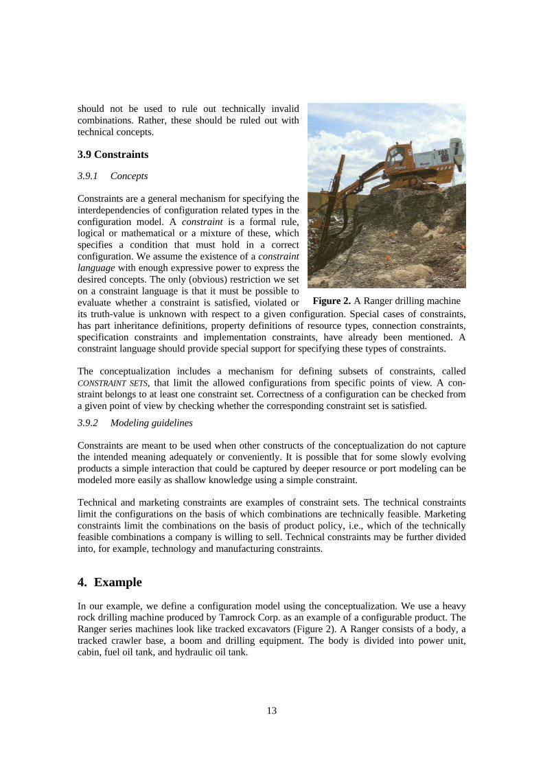
4. Example
In our example, we define a configuration model using the conceptualization. We use a heavyrock drilling machine produced by Tamrock Corp. as an example of a configurable product. TheRanger series machines look like tracked excavators (Figure 2). A Ranger consists of a body, atracked crawler base, a boom and drilling equipment. The body is divided into power unit,cabin, fuel oil tank, and hydraulic oil tank.
Figure 2. A Ranger drilling machine
14
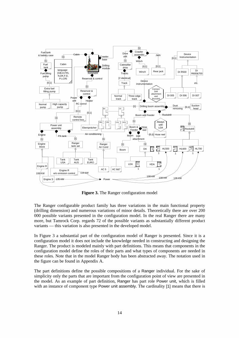
The Ranger configurable product family has three variations in the main functional property(drilling dimension) and numerous variations of minor details. Theoretically there are over 200000 possible variants presented in the configuration model. In the real Ranger there are manymore, but Tamrock Corp. regards 72 of the possible variants as substantially different productvariants — this variation is also presented in the developed model.
In Figure 3 a substantial part of the configuration model of Ranger is presented. Since it is aconfiguration model it does not include the knowledge needed in constructing and designing theRanger. The product is modeled mainly with part definitions. This means that components in theconfiguration model define the roles of their parts and what types of components are needed inthese roles. Note that in the model Ranger body has been abstracted away. The notation used inthe figure can be found in Appendix A.
The part definitions define the possible compositions of a Ranger individual. For the sake ofsimplicity only the parts that are important from the configuration point of view are presented inthe model. As an example of part definition, Ranger has part role Power unit, which is filledwith an instance of component type Power unit assembly. The cardinality [1] means that there is
Crawler assembly
Engine block
Ranger tank set
Power unit assembly
Ranger Air Cond
Engine R
Engine S
Engine R w/o emission control
Tank USA
Tank AUS
Tank EURO
AC 5 AC 6&7
Remote control box
Ebersprächer
[0,1]
HeaterRC conrol
[0,1]
Engine PA tank[1] [1]
[1]
Reservoir & control
Drilling boom assembly
Drilling module
Boom & Feeder Rockdrill
Boom and Feeder Rockdrill
LDA
[1][1]
[1]
HL500 HL600 HL700
Suction head
[0,1]Dust removing
Normal track
Three edge track
Track
[2 identical]
Drive unit
[1]
Winch Rear jack
[0,1] [0,1]
Winch
JackCrawler
base
[1]
Cabin
language: {GB,D,FIN,N,DK,F,E,
P,I,CR}
Cabin[1]
Fuel tank
[1]
Fuel tank & battery case
Extra fuel filling pump
Normal pump
High capacity pump
Fuel filling pump
[0,1]
Device Instrumentation
DI R500 DI R600&700
Device instrumentation
[0,1]
DI 005 DI 006 DI 007
Power
108 KW 119 kW
135 kW108 kW108 kW
Hose reel
Always with LDA
[0,1]
Hose reel
Boom
DA
[1]
Drill attachment
HDA
Boom
Reservoir & control
assembly
Caterpillar drive
RANGER
[1]
[1]
Air conditioning
DA
HDALDA
BA
HBA LBA
135 kW
DA
HDALDA
1 1
1 1 1
LBA HBA HBA
etc.
Power unit
Tracks
[1]
BA
Connect Drill
attachment and
Rockdrill
Figure 3. The Ranger configuration model
15
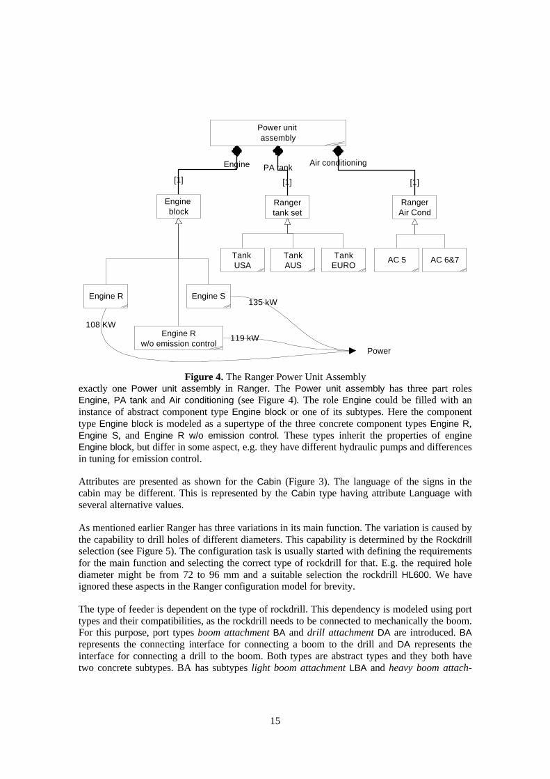
exactly one Power unit assembly in Ranger. The Power unit assembly has three part rolesEngine, PA tank and Air conditioning (see Figure 4). The role Engine could be filled with aninstance of abstract component type Engine block or one of its subtypes. Here the componenttype Engine block is modeled as a supertype of the three concrete component types Engine R,Engine S, and Engine R w/o emission control. These types inherit the properties of engineEngine block, but differ in some aspect, e.g. they have different hydraulic pumps and differencesin tuning for emission control.
Attributes are presented as shown for the Cabin (Figure 3). The language of the signs in thecabin may be different. This is represented by the Cabin type having attribute Language withseveral alternative values.
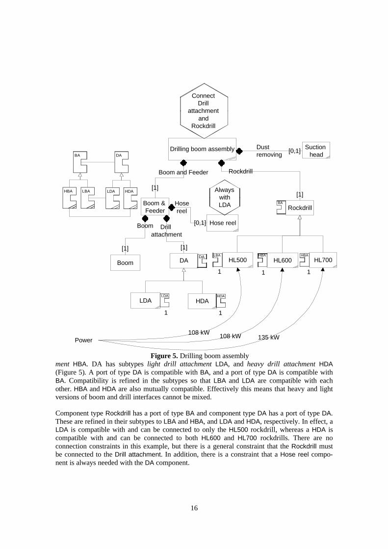
As mentioned earlier Ranger has three variations in its main function. The variation is caused bythe capability to drill holes of different diameters. This capability is determined by the Rockdrillselection (see Figure 5). The configuration task is usually started with defining the requirementsfor the main function and selecting the correct type of rockdrill for that. E.g. the required holediameter might be from 72 to 96 mm and a suitable selection the rockdrill HL600. We haveignored these aspects in the Ranger configuration model for brevity.
The type of feeder is dependent on the type of rockdrill. This dependency is modeled using porttypes and their compatibilities, as the rockdrill needs to be connected to mechanically the boom.For this purpose, port types boom attachment BA and drill attachment DA are introduced. BArepresents the connecting interface for connecting a boom to the drill and DA represents theinterface for connecting a drill to the boom. Both types are abstract types and they both havetwo concrete subtypes. BA has subtypes light boom attachment LBA and heavy boom attach-
Engine block
Ranger tank set
Power unit assembly
Ranger Air Cond
Engine R Engine S
Engine R w/o emission control
Tank USA
Tank AUS
Tank EURO
AC 5 AC 6&7
Engine PA tankAir conditioning
[1] [1] [1]
Power
108 KW
119 kW
135 kW
Figure 4. The Ranger Power Unit Assembly
16
ment HBA. DA has subtypes light drill attachment LDA, and heavy drill attachment HDA(Figure 5). A port of type DA is compatible with BA, and a port of type DA is compatible withBA. Compatibility is refined in the subtypes so that LBA and LDA are compatible with eachother. HBA and HDA are also mutually compatible. Effectively this means that heavy and lightversions of boom and drill interfaces cannot be mixed.
Component type Rockdrill has a port of type BA and component type DA has a port of type DA.These are refined in their subtypes to LBA and HBA, and LDA and HDA, respectively. In effect, aLDA is compatible with and can be connected to only the HL500 rockdrill, whereas a HDA iscompatible with and can be connected to both HL600 and HL700 rockdrills. There are noconnection constraints in this example, but there is a general constraint that the Rockdrill mustbe connected to the Drill attachment. In addition, there is a constraint that a Hose reel compo-nent is always needed with the DA component.
Drilling boom assembly
Boom & Feeder Rockdrill
Boom and Feeder Rockdrill
LDA
[1][1]
HL500 HL600 HL700
Suction head
[0,1]Dust removing
Power 135 kW108 kW108 kW
Hose reel
Always with LDA
[0,1]
Hose reel
Boom
DA
[1]
Drill attachment
HDA
Boom
DA
HDALDA
BA
HBA LBA
DA
HDALDA
1 1
1 1 1
LBA HBA HBA
[1]
BA
Connect Drill
attachment and
Rockdrill
Figure 5. Drilling boom assembly
17
The power requirement of rockdrills varies. This is modeled by using resources. The enginesproduce certain amounts of resource type Power which has unit kW (Figure 4). The rockdrillsuse this resource, represented in the bottom of Figure 5. The computation definition for Power issatisfied, which means that Power must be produced in at least the amount it is used. Thecontexts of Power production and use by the engines and rockdrills is in this model All, whichmeans that any rockdrill could use Power produced by any engine within the Ranger. This hasno significance in this particular model because (according the cardinalities) there is alwaysonly one engine and rockdrill in a configuration, assuming that there is only one Rangerindividual. In other product families produced by Tamrock the number of (external) powersources and rockdrills varies, in which case defining contexts for the resource production anduse would likely be necessary.
5. Discussion
5.1 General
Some concepts of the conceptualization overlap in the sense of formal expressiveness. Forexample, ports could be used to model part definitions, and a general constraint language alonecould have enough expressive power for modeling configuration knowledge. In our view, theclarity of configuration models should not be compromised by minimizing the number ofconcepts. Higher level concepts for representing typical forms of configuration knowledgeresult in a more compact and understandable representation of a configuration model. Webelieve to have struck a good balance between minimizing the number of concepts and makingconfiguration models understandable. This facilitates the maintenance of the knowledge byproduct developers or product managers. It is also possible to model a phenomenon in severalways with the conceptualization. The guidelines given in this paper are intended to help indeciding which modeling concepts to apply.
The conceptualization of product structure is quite close to generic bills-of-material (GBOM)(e.g. [7]). These approaches typically add to the traditional BOM concepts optional andalternative components and rules on how the alternatives and options can be combined. Themain differences to the GBOM approaches are that this conceptualization
• utilizes concepts such as types, individuals and inheritance from object-oriented modelingapproaches (e.g. [6]) that improve the understandability and maintainability of models,
• allows modeling connections and functions of a product,
• includes a more sophisticated means for expressing the rules on how the components can becombined, and
• represents part roles explicitly via part definitions.
Part definitions allow referring to a part of a whole without knowing the actual part to fill thatrole. In our view this is very important. For example, it is possible to specify that two parts mustbe connectable without knowing what the types of the parts will be.
We model product families, assemblies, and indivisible building blocks as components. Werecognize that there is a need to distinguish between at least these different types of entities, but
18
our component conceptualization can be used to represent their characteristics. These kinds ofconcepts can easily be defined on top of our component concept.
According to our experiences, a number of configurable products have been modeled success-fully with only two-level structures: wholes and their undivisible parts. We believe that mostpart structures in configuration models of configurable products are relatively shallow, due tothe fact that the variation is accomplished through choosing the top-level components whosedetailed structure is not variable. In the Ranger example, we have a three level structure: theRanger, its main assemblies and their parts. If a product is not easy to configure, deep structuresmay be needed to represent minor parts that are affected by configuration.
Configuration models have been modeled as bond graphs [8]. Our port conceptualization is lessexpressive as we do not try to capture conversion laws, dynamic physical behavior etc. physicalprocesses. The port mechanism for connection and compatibility modeling is relatively simplebut we believe that it suffices for configuration purposes. Ports can be used to establish binaryconnections between component individuals, and constraints can be used to propagate valuesfrom “in-ports” to “out-ports”, possibly with some transformations. However, the conceptuali-zation has no direct support for resource flow through component individuals via port individu-als, and transitive connections are not directly supported. For example, pipelines that spanacross several component individuals cannot be directly modeled. Possibilities offered by bondgraphs could be used to add expressiveness to the conceptualization.
Interfaces between components tend to live longer than individual component types. Whencompatibility is modeled through stable interfaces using ports, long term management ofconfiguration models becomes easier. Like port types, resource types may live longer thanindividual component types with analogous effects to maintainability. To facilitate moreadvanced long-term management, the conceptualization should be extended with concepts fromconfiguration management and product data management.
5.2 Case study experiences
Classification hierarchy was found to be useful and it was used extensively in the example,particularly for component types. Multiple inheritance was not required. We defined only fewattributes in the example because the company uses few parametric components and because wemodeled few technical details of the component types. We believe that a full-scale configurationmodel for Rangers would include many more attributes to cover the technical details. Note thatmany legacy systems where product data is managed do not support attributes, which isreflected in the material we received and subsequently in the configuration model.
Part definitions were found to be a convenient way of representing the product. The genericstructure describing Rangers was easy to construct. Similarity requirements for multiple partswould be an useful enhancement to the conceptualization. For example, Rangers have twotracks that must be identical.
Ports were used relatively little in the example. It was somewhat difficult to identify relevantports on the basis of the available material. Ports would probably be easier to use if theinterfaces of the component types in the product were originally set to high priority and thusbetter documented. As with ports, resource modeling was not used in Tamrock and similar
19
observations apply. Nevertheless, some natural resource interactions in the product wereidentified, of which the resource “power” is an example.
The example required relatively few general constraints. Thus, for this product our conceptuali-zation covered the typical configuration phenomena fairly well. It should be further studiedwhether this result generalizes to a larger set of different kinds of products.
A computer-based tool directly supporting the conceptualization is a prerequisite for using theconceptualization successfully in real-world scale examples. Manual modeling is too tediousand offers no support for testing a model and configurations. In addition, simplicity is achallenge for the presentation and understandability of configuration models. A computer-basedtool would allow a clearer graphic representation of configuration models. For example,hierarchical browsing of a configuration model, e.g. based on the product structure, separateviews for classification, part definitions, ports and resources would enhance the readability ofconfiguration models.
5.3 Ideas for improving the model and future work
There is a need to investigate several enhancements to the port mechanism. Examples includedecomposition of ports to sub-ports, assignment of ports or sub-ports to implementing compo-nents and refinement of connections between ports to components. For example, the DAcomponent type of the example in Section 4 could be modeled both as a port and a componenttype depending on the usage and point of view chosen. Flexible mechanisms to model compo-nents that are also ports or connectors seem to be needed.
Context concepts could be useful with other concepts than resources also, but currently they canonly be used in association with resources. For example, connections via ports or applicabilityof constraints could be restricted to a context.
Constraint schemes and a specific constraint language for expressing common types ofconstraints would be useful. Examples include connection, incompatible-with and requires typesof constraints. A table based constraint representation would be useful to represent tightlyconnected configuration decisions.
An important part in modeling some products is to ensure that connections between some partsare made. For example, it may be required to connect a fuel pump to a motor or a disk unit to adisk controller. Our conceptualization allows this to be expressed as constraints, but there is nodirect support.
5.4 Relationship to product design and development
Generally, design process can be seen as an interplay between functional and physical domains[9]. It can be understood as a composition of two different activities: synthesis and analysis,which are related to the domains. The physical system is synthesized on the basis of the requiredfunctionality. Functionality can be analyzed on the basis of a description of the physical system[10]. Design process usually proceeds from general to details, which can be modeled with theconceptualization.
20
The conceptualization does not directly provide means for modeling physical relationships suchas geometry usually used by common design tools like mechanical CAD. The conceptualizationcould, in principle, provide limited support for design decisions on the basis of already modeledknowledge. For example: given a partial configuration model and a component library modeledon the basis of the conceptualization, one could find suitable components by using inferencefrom interfaces, resource behavior and functions. However, because our conceptualization isbased on the assumption that all relevant knowledge is modeled, little support can be providedfor decisions required in original and adaptive design.
Andreasen and Hein [12] have modeled the Integrated Product Development (IPD) process as acomposition of six phases: (0) recognition of need, (1) investigation of need, (2) generation ofproduct principle, (3) product design, (4) production preparation, and (5) execution phase. Inour view, configuration models could be utilized in several phases of the IPD process. In phases(2) and (3), a preliminary configuration model consisting mostly of functions, components, partdefinitions and interfaces modeled as ports could be used to communicate the preliminaryproperties of the new product family to sales, marketing, design, and production. The creativedesign in the product design phase (3) is not supported by the conceptualization. In theproduction preparation and execution phases (4) and (5) a configuration model facilitatestransferring information on the new product especially to sales and persons responsible forengineering configuration. Because the configuration model is built during the three first phasesof the IPD process, some delays caused by late modeling may be eliminated.
The conceptualization could serve as a (partial) basis for a DFC (Design For Configuration)tool. The configurability and modularity of the product can be analyzed on basis of its configu-ration model. For example, module coupling and configuration related interfaces could beanalyzed through ports and connection constraints. The number of configuration decisions canbe determined and the complexity of function to technical configuration mapping can becharacterized. As the usual modeling and evaluation tools in the DFX field [11], the conceptu-alization supports relevant modeling and enables evaluating of the design.
6. Conclusions
Managing product families consisting of a large set of product variants as configurable productsrequires defining a configuration model. We presented a conceptualization for configurationmodels and gave guidelines on using the concepts. The conceptualization was evaluated bymodeling a case product and was found to cover the relevant modeling needs fairly well.However, several improvements to the conceptualization were identified. For example, moreelaborate mechanisms for connection modeling would be useful. The concepts and modelingguidelines for them should be extended, refined, and further validated.
Information system support is necessary for modeling real-world-sized products. Modeling withthe conceptualization sets new requirements for the designer. In addition to having a goodunderstanding of the product, a designer should be familiar with object oriented modeling.
In our view the conceptualization can also be used in the product development process. Themain benefit there would be improving communication within the product development teamand to other functions of the company. The benefits also include the use of the conceptualization
21
to document the knowledge on the product functions, structure and the related design constraintsduring the product development.
References
[1] Tiihonen, J., Soininen, T., Männistö, T. and Sulonen, R. Configurable products - Lessonslearned from the Finnish Industry. In Proceedings of 2nd International Conference onEngineering Design and Automation. Integrated Technology Systems,Inc., 1998.
[2] Soininen, T., Tiihonen, J., Männistö, T. and Sulonen, R. Towards a General Ontology ofConfiguration. In AI EDAM (Artificial Intelligence for Engineering Design, Analysis andManufacturing), Special Issue on Configuration Design, Vol. 12, No. 4, 1998.
[3] Faltings B. and Freuder E. Configuration—Papers from the 1996 AAAI Fall Symposium.AAAI Press Technical Report FS-96-03. AAAI Press, 1996.
[4] Pahl, G. and Beitz, W. Koneensuunnitteluoppi. Springer Verlag and MetalliteollisuudenKustannus Oy, 1990. Translation of Konstruktionslehre, Handbuch für Studium undPraxis, Springer Verlag, 1986.
[5] Peltonen, H., Männistö, T., Soininen, T., Tiihonen, J., Martio, A. and Sulonen, R.Concepts for Modelling Configurable Products. In Proceedings of European ConferenceProduct Data Technology Days 1998. Quality Marketing Services, Sandhurst, UK, 1998.
[6] Rumbaugh, J., Blaha, M., Premerlani, W., Eddy, F. and Lorensen, W. Object-OrientedModelling and Design. Prentice-Hall, Inc., Eaglewood Cliffs, 1991.
[7] van Veen, E. Modelling Product Structures by generic Bills-of-Material. PhD thesis,Technische Universiteit Eindhoven, 1991.
[8] Snavely, G. L. and Papalambros, P. Y. Abstraction as a configuration design methodology.Advances in Design Automation. Volume 1, 1993.
[9] Suh N. The Principles of Design. Oxford University Press, New York. 1990
[10] Erens F., Verhulst K. Architectures for product families. Proceedings of the 2nd WDKWorkshop on product structuring. June 3-4 1996. Delft University of Technology. pp. 45-60
[11] Tichem M. A Design Coordination Approach to Design for X. PhD dissertation. DelftUniversity of Technology. 1997
[12] Andreasen M.M., Hein L. Integrated Product Development. IFS Publications Ltd. /Springer-Verlag, London. 1987.
Acknowledgements
We gratefully acknowledge the financial support of Technology Development Centre Finlandand Helsinki Graduate School of Computer Science and Engineering (HeCSE). We thankHannu Peltonen for his comments on how to improve the presentation of the paper. We thankTamrock Corp. for providing us access to Ranger documentation that made the modeling effortpossible.
22
Juha Tiihonen, Timo Soininen,Reijo SulonenHelsinki University of TechnologyTAI Research CentreProduct Data Management GroupP.O. Box 9555FIN-02015 HUT, Finlandtel . +358-9-451 3242fax. +358-9-451 [email protected]@[email protected]
Timo Lehtonen, Antti Pulkkinen,Asko RiitahuhtaTampere University of TechnologyMachine Design LaboratoryP.O. BOX 589,FIN-33101 Tampere, Finlandtel. +358-3-365 2627fax. +358-3-365 [email protected]@[email protected]
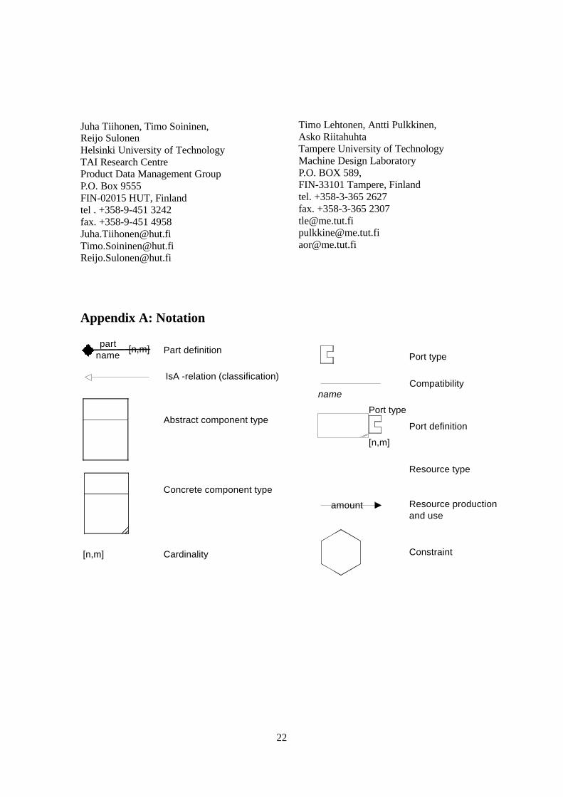
Appendix A: Notation
Part definition
IsA -relation (classification)
[n,m] Cardinality
Port type
Compatibility
Resource type
Resource production and use
Constraint
Abstract component type
Concrete component type
name
[n,m]
Port definition
part name
amount
[n,m]
Port type