Model Answer Important suggestions to examiners - Msbte ...
36
MAHARASHTRA STATE BOARD OF TECHNICAL EDUCATION (Autonomous) (ISO/IEC-27001-2005 Certified) SUMMER– 2019 Examinations Subject Code: 17417 Model Answer Page 1 of 36 Important suggestions to examiners: 1) The answers should be examined by key words and not as word-to-word as given in the model answer scheme. 2) The model answer and the answer written by candidate may vary but the examiner may try to assess the understanding level of the candidate. 3) The language errors such as grammatical, spelling errors should not be given more importance. (Not applicable for subject English and communication skills) 4) While assessing figures, examiner may give credit for principle components indicated in a figure. The figures drawn by candidate and model answer may vary. The examiner may give credit for any equivalent figure drawn. 5) Credits may be given step wise for numerical problems. In some cases, the assumed constant values may vary and there may be some difference in the candidate’s answers and model answer. 6) In case some questions credit may be given by judgment on part of examiner of relevant answer based on candidate understands. 7) For programming language papers, credit may be given to any other program based on equivalent concept. Q.1 Attempt any TEN of the following: 20 Marks a) Draw a single line diagram of A.C supply system. Ans: Single line diagram of an Electric supply system: ( 2 Marks) OR Equivalent Figure OR
-
Upload
khangminh22 -
Category
Documents
-
view
0 -
download
0
Transcript of Model Answer Important suggestions to examiners - Msbte ...

MAHARASHTRA STATE BOARD OF TECHNICAL EDUCATION (Autonomous)
(ISO/IEC-27001-2005 Certified)
SUMMER– 2019 Examinations
Subject Code: 17417 Model Answer Page 1 of 36
Important suggestions to examiners:
1) The answers should be examined by key words and not as word-to-word as given in the model answer scheme.
2) The model answer and the answer written by candidate may vary but the examiner may try to assess the understanding level of the candidate.
3) The language errors such as grammatical, spelling errors should not be given more importance. (Not applicable for subject English and communication skills)
4) While assessing figures, examiner may give credit for principle components indicated in a figure. The figures drawn by candidate and model answer may vary. The examiner may give credit for any equivalent figure drawn.
5) Credits may be given step wise for numerical problems. In some cases, the assumed constant values may vary and there may be some difference in the candidate’s answers and model answer.
6) In case some questions credit may be given by judgment on part of examiner of relevant answer based on candidate understands.
7) For programming language papers, credit may be given to any other program based on equivalent concept.
Q.1 Attempt any TEN of the following: 20 Marks a) Draw a single line diagram of A.C supply system.
Ans: Single line diagram of an Electric supply system: ( 2 Marks)
OR Equivalent Figure
OR

MAHARASHTRA STATE BOARD OF TECHNICAL EDUCATION (Autonomous)
(ISO/IEC-27001-2005 Certified)
SUMMER– 2019 Examinations
Subject Code: 17417 Model Answer Page 2 of 36
b) Classify transmission line according to length of the line. Ans: According to Length of Transmission line: ( 2 Mark)
a) Short Distance Transmission Line - (up to 50 KM)
b) Medium Distance Transmission Line - (up to 50 to 150 KM)
c) Long Distance Transmission Line - (above 150 KM)
OR
1) Short Transmission Line: - The length of Short transmission Line is up to 50KM and
its line voltage is less than 20 KV
2) Medium Transmission Line: - The length of Medium transmission Line is up to
50KM- 150KM and its line voltage is between 20KV to 100 KV
3) Long Transmission Line: - The length of Long transmission Line is above 150KM and
its line voltage is above 100KV
OR
1) Short Transmission Line: - The length of Short transmission Line is up to 80KM and its
line voltage is less than 20 KV
2) Medium Transmission Line: - The length of Medium transmission Line is up to 80KM-
200KM and its line voltage is between 20KV to 100 KV
3) Long Transmission Line: - The length of Long transmission Line is above 200KM and
its line voltage is above 100KV
c) State long form of: (i) AAC (ii) ACSR Ans: Long form of : ( Each long form 1 Mark : Total 2 Marks)
(i) AAC : All Aluminum Conductor
(ii) ACSR : Aluminum conductor steel Re-in force
MAHARASHTRA STATE BOARD OF TECHNICAL EDUCATION (Autonomous)
(ISO/IEC-27001-2005 Certified)
SUMMER– 2019 Examinations
Subject Code: 17417 Model Answer Page 3 of 36
d) State four properties of conducting materials. Ans: ( Any Four properties expected :1/2 Mark each, Total 2 Marks)
Following are requirements of conductor:-
1. High conductivity :-
Material should have high conductivity
2. High mechanical strength:- Material should have sufficiently high mechanical strength
3. Flexibility:- Material should be flexible
4. Weight:- Material should be light in weight.
5. High resistance to corrosion:- Material should have high resistance to corrosion
6. Brittleness:-
Material should not be brittle.
7. Temperature coefficient of resistance:-
Material should have low temperature coefficient of resistance.
8. Availability & cost:-
Material should be easily available & less costly.
9. Scrap Value:-
Material should have high scrap value.
e) Define regulation of transmission line and write formula. Ans: (Definition 1 Mark & formula 1 Mark ,Total 2 Marks)
Regulation:
Voltage regulation is nothing but voltage drop in transmission line expressed in % of receiving end voltage
% Regulation = 100Re
Re
VoltageEndceiving
VoltageEndceivingVoltageEndSending
f) State any two applications of HVDC transmission system.
Ans: Following are the different applications of HVDC transmission system:-
( Any two Application are expected: 1 Mark each, Total : 2 Mark)
1) HVDC is economical to transmit bulk amount of power (1000 MW) & above Over a

MAHARASHTRA STATE BOARD OF TECHNICAL EDUCATION (Autonomous)
(ISO/IEC-27001-2005 Certified)
SUMMER– 2019 Examinations
Subject Code: 17417 Model Answer Page 4 of 36
long distance 800 Km & above
2) HVDC is preferred for underground cable transmission as incoming line in megacities.
3) HVDC is preferred for underground cable transmission for crossing long lake, ocean
etc.
4) HVDC is preferred for underground cable transmission where atmospheric conditions
are too bad for overhead transmission line, e.g. High wind pressure, rainfall etc.
5) Interconnection of two transmission lines having different frequencies is possible
through HVDC link.
g) State the function of following layer in construction of a cable: (i) Armouring (ii) Metallic sheathing
Ans: (i) Armouring: ( 1 Mark)
Its purpose is to protect the cable from mechanical injury, while rough handling & at the
time of maintenance.
(ii) Metallic sheathing: ( 1 Mark)
It is provided over insulation to provide the protection of core from entry of moisture,
gases or other damaging liquids (acids & alkaline) in the soil & atmospheric,
h) Why radical system is used for short distances? Ans: Because of following disadvantages radial distribution system is not used for long
distance: (Only two points are expected) ( 2 Marks)
Since there is only one feeder to DTC feed at one point so, 1) There is no reliability to maintain supply at the time of fault on incoming feeder. 2) There is no reliability to maintain supply at the time of maintenance of incoming
feeder. 3) If the system is used for long distance then it takes more time for fault finding &
repairing Hence radial distribution system is used for short distance.
i) What is meant by Ferranti effect of transmission line conductor? Ans: Ferranti effect : ( 2 Marks)
When long distance transmission is lightly loaded or there is no load condition
than it is observe that receiving end voltage (VR) is found to be greater than
sending end voltage (VS). This phenomenon is known as Ferranti effect.

MAHARASHTRA STATE BOARD OF TECHNICAL EDUCATION (Autonomous)
(ISO/IEC-27001-2005 Certified)
SUMMER– 2019 Examinations
Subject Code: 17417 Model Answer Page 5 of 36
j) State the application of suspension types and pin type insulators. Ans: 1. Application of Suspension type : (1 Mark)
Here one disc is designed for 11 KV so by connecting number of discs in a string of
suspension insulators it can be used for 33/66/110/132/220/400/765 KV & even for
more voltages.
When Line is running straight.
2. Application of Pin type: (1 Mark)
Used for voltage level up to 33 KV maximum.
When Line is running straight.
k) State why three phase four wire system is preferred for secondary distribution system.
Ans: Reason of three phase four wire system is preferred for secondary distribution
system ( 2 Marks)
To obtain 230 volt for single phase supply consumers and to obtain 400/440 volt
for three phase consumers three phase four wire system is preferred for secondary
distribution system.
l) State any two application of HVDC transmission system. Ans: Following are the different applications of HVDC transmission system:-
( Any two Application are expected: 1 Mark each, Total : 2 Mark)
1) HVDC is economical to transmit bulk amount of power (1000 MW) & above. Over a
long distance (800 Km & above)
2) HVDC is preferred for underground cable transmission as incoming line in megacities.
3) HVDC is preferred for underground cable transmission for crossing long lake, ocean
etc.
4) HVDC is preferred for underground cable transmission where atmospheric conditions
are too bad for overhead transmission line, e.g. High wind pressure, rainfall etc.
5) Interconnection of two transmission lines having different frequencies is possible
through HVDC link.

MAHARASHTRA STATE BOARD OF TECHNICAL EDUCATION (Autonomous)
(ISO/IEC-27001-2005 Certified)
SUMMER– 2019 Examinations
Subject Code: 17417 Model Answer Page 6 of 36
Q.2 Attempt any FOUR of the following: 16 Marks a) Compare overhead line and underground cable (any four points).
Ans: (Any Four points expected: 1 Mark each, Total 4 Marks)
S.No Points Overhead line Underground cable
1 Capital cost Less More 2 Erecting cost Less More 3 Time require for
completion of work Less More
4 Flexibility More flexibility No flexibility 5 Future expansion in
voltage level System voltage can be increased easily
System voltage cannot be increased
6 Overload capacity More Less 7 Fault finding Easy Difficult 8 Charging Current Less More 9 Chances of fault More Less 10 Chances of accident More No chances of accident 11 Safety Less More 12 Radio interference Produces radio interferences Not produces radio
interferences 13 Short cute route Difficult Possible 14 Theft Of energy More possibility Less possibility 15 Voltage drop More Less 16 Power factor Less More 17 Reliability Less More 18 Life Less More
19 Space consumed Space consumed No space consumed 20 Appearance Not good Very good
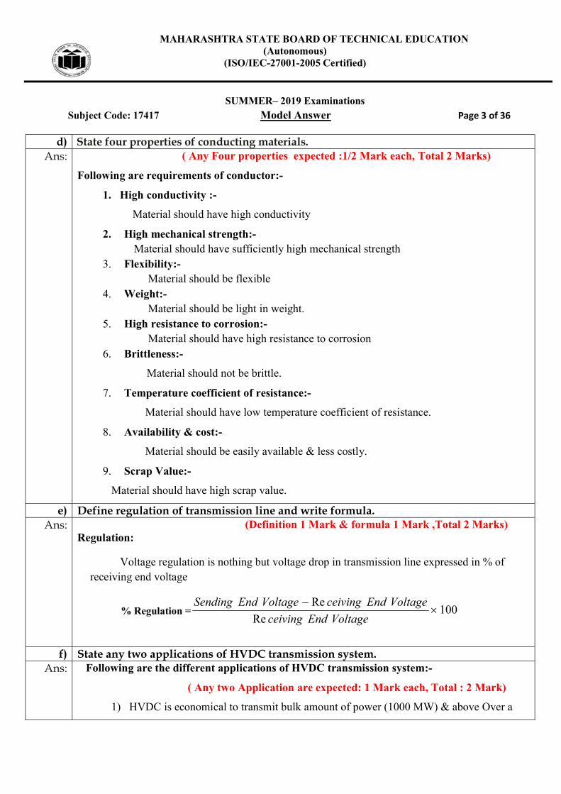
b) With the help of neat diagram, explain the concept of transposition of conductors. Ans: The concept of transposition of conductors:
( Concept of Transposition: 2 & Figure : 2 Mark , Total 4 Marks)
Transposition of conductor means exchanging the position of 3 phases (R-Y-B) at regular interval.
Each phase occupies 3 different positions consequently on line support (Tower) as shown in fig.
OR Transposition of line conductors means changing the positions of 3 phases on the line
MAHARASHTRA STATE BOARD OF TECHNICAL EDUCATION (Autonomous)
(ISO/IEC-27001-2005 Certified)
SUMMER– 2019 Examinations
Subject Code: 17417 Model Answer Page 7 of 36
supports twice over the total length of the line
Figure of transposition of conductor:
OR Equivalent Figure
c) State any four applications where HVDC transmission is used through cable only and not by overhead line.
Ans: Application of High Voltage DC (HVDC) transmission is used through cable:
( Any Four Application Expected: 1 each Point : Total 4 Marks)
1) HVDC is preferred for underground cable when power transmission through
underground cable is greater than 40-50 KM than only HVDC uniquely
suited.
2) HVDC is preferred for underground cable transmission as incoming line in
megacities. . / City centre in- feed.
3) HVDC is preferred for underground cable transmission for crossing long
lake, ocean etc.
4) HVDC is preferred for underground cable transmission where atmospheric
conditions are too bad for overhead transmission line, e.g. High wind
pressure, rainfall, icefall etc.
5) HVDC is preferred for underground cable for long distance underwater
power links.
6) HVDC is preferred for underground cable for powering island from onshore.
7) HVDC is preferred for underground cable for taking power from offshore
wind farm.

MAHARASHTRA STATE BOARD OF TECHNICAL EDUCATION (Autonomous)
(ISO/IEC-27001-2005 Certified)
SUMMER– 2019 Examinations
Subject Code: 17417 Model Answer Page 8 of 36
8) HVDC is preferred for underground cable for powering oil and gas offshore
floating platform.
d) State the requirements of a distribution system. Ans: Following requirements of a distribution system.
( Only Four requirement expected 1 Mark each : Total : 4 Marks)
1. Layout should be simple in design.
2. It should have less initial cost
3. The distribution system should have minimum distribution losses.
4. Voltage drop in distribution system should be less and within permissible limit ( 6%).
5. From safety point of view distribution system should maintain proper clearances.
6. The rating of distribution transformer & cross section of conductor should be
proportional to result of load densities present & future.
7. Power should be available to consumers whenever needed.
8. A steady, non-fluctuating, quality supply (Pure sine wave) should be available to
consumers.
9. Distribution system should not be over loaded.
10. Distribution system should have high reliability to maintain supply.
11. Distribution system lay out should not affect the appearance of locality.
12. Before installation of distribution system proposed widening of the road in the
near future are to be kept in mind
13. It should have low, easy, less costly & less time consuming maintenance.
14. Fault on nearest distribution system should not affect stability of existing
distribution system.
15. Time required for completion of work should be less.

MAHARASHTRA STATE BOARD OF TECHNICAL EDUCATION (Autonomous)
(ISO/IEC-27001-2005 Certified)
SUMMER– 2019 Examinations
Subject Code: 17417 Model Answer Page 9 of 36
e) A three phase overhead transmission line is being supported by 3 disc insulators. The potentials across top unit and middle units are 8 kV and 11 kV respectively. Calculate: (i) Line voltage (ii) String efficiency
Ans: Given Data: V1= 8KV, V2= 11KV i) Ratio of capacitance ‘k’ :- V2 = V1 (1+ m) 11 = 8 (1+ 8m) 11 = 8 + 8m 3 = 8m k = m = 0.375 ------------------------------------ (1/2 Mark)
V3 = V1 (m2 + 3m + 1)
= 8 ( 0.3752 + (3x 0.375) +1)
V3 = 18.125 KV ---------------------------------------- (1 Mark)
Voltage across string = Vph = V1 +V2+ V3 = 8+11+18.125 = 37.125 KV ------------------------------- (1/2 Mark)
ii) The line voltage VL = phV3
VL = 125.373
VL = 64.30KV ---------------------------------------- (1 Mark) iii) String efficiency:-
String 1003
00
V
Vph
String 100125.183
125.370
0
String 00 = 68.27 %. ---------------------------------------- (1 Mark)
f) Compare outdoor and indoor substation. Ans: ( Any four point expected: 1 Mark each point: Total: 4 Marks)
S.No Points Outdoor Substation Indoor Substation
1 Capital cost Less, as construction work cost is less.
High, as construction work cost is more.
2 Time required Less, as construction work is More, as construction work is

MAHARASHTRA STATE BOARD OF TECHNICAL EDUCATION (Autonomous)
(ISO/IEC-27001-2005 Certified)
SUMMER– 2019 Examinations
Subject Code: 17417 Model Answer Page 10 of 36
for completion less. more.
3 Distance between two equipment
More, this will reduce possibility of fault & safety increases
Less, this will increase possibility of fault & safety reduces.
4 Access for incoming & outgoing line
Easy access for incoming & outgoing lines because of outdoor installation.
Difficult access for incoming & outgoing lines because of indoor installation.
5 Cooling arrangement
Natural cooling is available due to outdoor installation. This reduces energy consumption charges due to outdoor installation.
Natural cooling is not available so artificial cooling arrangement is required This increases energy consumption charges due to indoor installation.
6 Availability of natural light
Natural light is available in day time, so there is no need of illumination during day time. So it saves electrical energy & its cost
Natural light is not available even in day time, so there is need of illumination even during a day time. This increases energy consumption charges due to indoor installation
7 Detection of fault
Easy, as all equipment’s are easily viewed.
Difficult, as all equipment’s are not easily viewed.
8 Replacement of equipment
Easy, due to outdoor installation. Difficult, due to indoor installation.
9 Future expansion
Expansion of substation is easily possible whenever needed & can be completed in less time & cost.
Expansion of substation is not easily possible whenever needed because of construction work. Also it require more time & cost.
10 In case of accident
In case of accident there is less risk & damage to other equipment’s than indoor substation.
In case of accident there is more risk & damage to other equipment’s than outdoor substation.
11 Space Require More Less

MAHARASHTRA STATE BOARD OF TECHNICAL EDUCATION (Autonomous)
(ISO/IEC-27001-2005 Certified)
SUMMER– 2019 Examinations
Subject Code: 17417 Model Answer Page 11 of 36
12 Effect of atmospheric condition
Switching operation is difficult in rainy season & it is less safe
Switching operation is not difficult in rainy season & it is more safe due to indoor installation
13 Chances of leakage current
More due to outdoor installation Less due to indoor installation
14 Maintenance cost
More due to outdoor installation. Less due to indoor installation
15 Applications Where atmospheric conditions are clean and dry also where space available is more than subs stations are installed outdoor.
In places where heavy rainfall, snow fall occurs or there is humidity in atmosphere also where availability of space is less then under such situations sub stations are installed indoor.
Q.3 Attempt any FOUR of the following: 16 Marks a) Under which conditions Ferranti effect occurs. State any four conditions? What is
Ferranti effect? Ans: Under Following conditions Ferranti effect occurs:
( Any Four condition expected: 1/2 Mark each : Total : 2 Marks)
1. When there is no load on transmission line (IL = 0) OR
2. When There is no load at receiving sub-station or Lightly loaded OR
3. When there is sudden load thrown OFF. OR
4. When there is sudden load shading. OR
5. When Transmission line is open circuited due to load failure.
Ferranti effect : ( 2 Marks)
Under any one above condition, it is oberve that receiving end voltage (VR) is
found to be greater than sending end voltage (VS). This phenomenon is known as
Ferranti effect.

MAHARASHTRA STATE BOARD OF TECHNICAL EDUCATION (Autonomous)
(ISO/IEC-27001-2005 Certified)
SUMMER– 2019 Examinations
Subject Code: 17417 Model Answer Page 12 of 36
b) State any four factors which affects corona. State two points how corona effect can be reduced.
Ans: The Following Factors affecting corona:- ( Any Four Factors expected: 1/2 Mark each : Total : 2 Marks)
1. Magnitude of Voltage :
If voltage across two conductors is greater than 30 KV/cm, i.e. breakdown
voltage of air than corona formation starts. Corona will not start if voltage is below
30 KV/cm
2. Distance between two conductor:
If spacing between two conductors is very large as compare to their diameter
than there is no possibility of corona formation. Because value of voltage at which
corona occurs increases.
3. Size of conductor:
If size (Cross section) of conductor is more, than magnitude of voltage
required to occur the corona increases.
4. Condition of conductor & Hardware:
Rough and irregular surface of conductor and hardware will give more
corona than solid, smooth body conductor & hardware.
5. Atmospheric Condition:
As corona takes place due to ionization of air so it depends on condition of
air so for dry air formation of corona occurs late than in wet air (damp atmosphere
condition/ rainy season/thunderstorms/fog air becomes more conductivity)
6. Effect of supply Frequency:
Corona loss varies directly as the supply frequency
7. Effect of density of air:
Corona loss increases with the decrease in the density of air (The
corona loss of transmission line passing through hilly area is higher than that of a
similar line in plain due to reduced value of air density at high level /altitude)

MAHARASHTRA STATE BOARD OF TECHNICAL EDUCATION (Autonomous)
(ISO/IEC-27001-2005 Certified)
SUMMER– 2019 Examinations
Subject Code: 17417 Model Answer Page 13 of 36
As Following points Corona effect can be reduced:
( Any Two Point expected: 1 Mark each : Total : 2 Marks)
1. By increasing distance between two conductor i.e. by using longer cross arm.
2. By using larger size(diameter) of conductor e.g./ using ACSR, bundled conductor
3. By using smooth body conductor and hardware.
c) State generalized constants A, B, C, D of formula for nominal `T' network. Ans: Generalized constants A, B, C, D of formula for nominal `T' network: ( 4 Marks)
phR
phS
V
VA ------------ Voltage Ratio
R
phS
I
VB ------------ Impedance in ohm
phR
S
V
IC ------------ Conductance in mho
R
S
I
ID ------------ Current Ratio
A, B, C, D constants are generally complex number
Values of ABCD constants T-equivalent circuits of are as bellows:
A = D =2
1YZ
B = Z 4
1YZ
ohm
C = Y mho
MAHARASHTRA STATE BOARD OF TECHNICAL EDUCATION (Autonomous)
(ISO/IEC-27001-2005 Certified)
SUMMER– 2019 Examinations
Subject Code: 17417 Model Answer Page 14 of 36
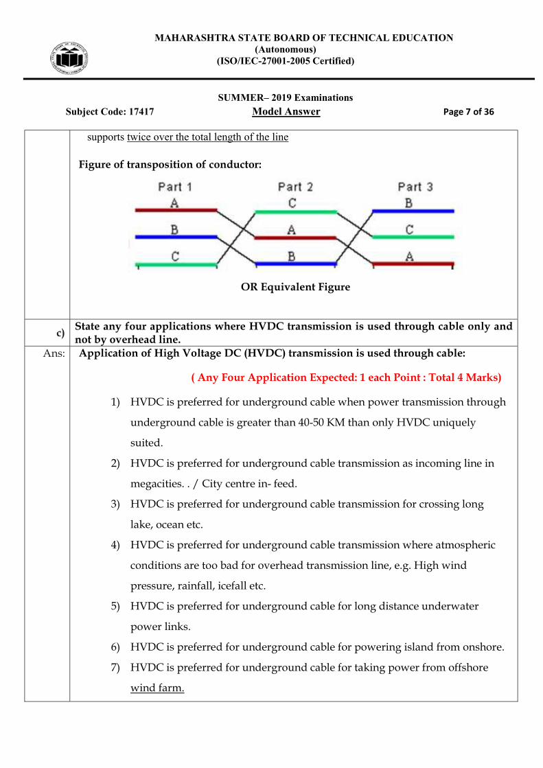
d) Draw a neat layout of Grid distribution scheme. State two advantages of it.
Ans:
Layout of Grid distribution scheme: ( 2 Marks)
OR
OR Equivalent Figure
Advantages of Grid distribution scheme:
( Any Two point expected: 1 Mark each : Total 2 Marks)
1. Supply to distribution transformer center is given through two different

MAHARASHTRA STATE BOARD OF TECHNICAL EDUCATION (Autonomous)
(ISO/IEC-27001-2005 Certified)
SUMMER– 2019 Examinations
Subject Code: 17417 Model Answer Page 15 of 36
generating stations or major generating stations
2. It has highest reliability to maintain supply even when there is a fault on any
one feeder
3. It has highest reliability to maintain supply even when there was maintenance
on any one feeder.
e) Draw a typical layout diagram of 11 kV distribution substation. Ans: Typical layout diagram of I1 kV distribution substation ( 4 Mark )
OR
OR

MAHARASHTRA STATE BOARD OF TECHNICAL EDUCATION (Autonomous)
(ISO/IEC-27001-2005 Certified)
SUMMER– 2019 Examinations
Subject Code: 17417 Model Answer Page 16 of 36
f) A single phase 11 kV with a length of 15 km is to transmit 500 kVA. The inductive reactance of the line is 0.5 ohm/km and resistance is 0.3 ohm/km. Calculate the efficiency and regulation of the line for 0.8 lagging p.f. Draw vector diagram.
Ans: Length of line =15km, PR = 500KVA, VR = 11KV, P.F. = 0.8 lag, R Per conductor =0.3ohm/km, X Per conductor = 0.5
ohm /km
Step 1: To calculate current
Power in KW= KVAP.F.
= 5000.8 = 400Kw
Power P = cosVI
cosV
PI
, 8.011
400
I
ampI 45.45 ------------------------------------- ( 1/2 Marks)
Step 2: To calculate value of sin :
6.0sin8.0 RRCos
R=0.3 ohm/km x 15= 4.5 ohm
X= 0.5ohm/km x 15= 7.5 ohm

MAHARASHTRA STATE BOARD OF TECHNICAL EDUCATION (Autonomous)
(ISO/IEC-27001-2005 Certified)
SUMMER– 2019 Examinations
Subject Code: 17417 Model Answer Page 17 of 36
To Calculate Total /loop values of R & X
Total resistance RT = 2R= 2 x 4.5 = 9 ohm
Total Reactance XT = 2 X =27.5 =15 ohm
Step 3: To calculate Sending end voltage:
Vs = RTRTR XRIV sincos
= 6.0158.0945.451011 3
= 11736.29 volt
Vs = 11.73629 KV ---------------------------------------- ( 1/2 Marks)
Step 4: To calculate Total Line Losses:
Total Line Losses = TRI 2
= 9)45.45( 2
= 18591.323 Watt
= 18.591323 KW ------------------------------------- ( 1/2 Marks)
Step 5:To calculate voltage regulation:
% Voltage Regulation = 100
R
RS
V
VV
= 10011
1173629.11
% voltage regulation: = 6.69 % ----------------------------------- ( 1 Marks)
Step 6: To calculate Total Transmission efficiency:
100200
TR
RT RIP
P
100323.1859110400
104003
3
00
T
00
00 56.95T ---------------------------- ( 1 Marks)

MAHARASHTRA STATE BOARD OF TECHNICAL EDUCATION (Autonomous)
(ISO/IEC-27001-2005 Certified)
SUMMER– 2019 Examinations
Subject Code: 17417 Model Answer Page 18 of 36
Step 7: Vector Diagram: ------------------------------------- ( 1/2 Marks)
Q.4 Attempt any FOUR of the following: 16 Marks a) Draw a neat labeled diagram of an underground cable to show different parts.
Ans: Neat diagram show the various parts of an underground core cable. ( 4 Marks)
OR
MAHARASHTRA STATE BOARD OF TECHNICAL EDUCATION (Autonomous)
(ISO/IEC-27001-2005 Certified)
SUMMER– 2019 Examinations
Subject Code: 17417 Model Answer Page 19 of 36
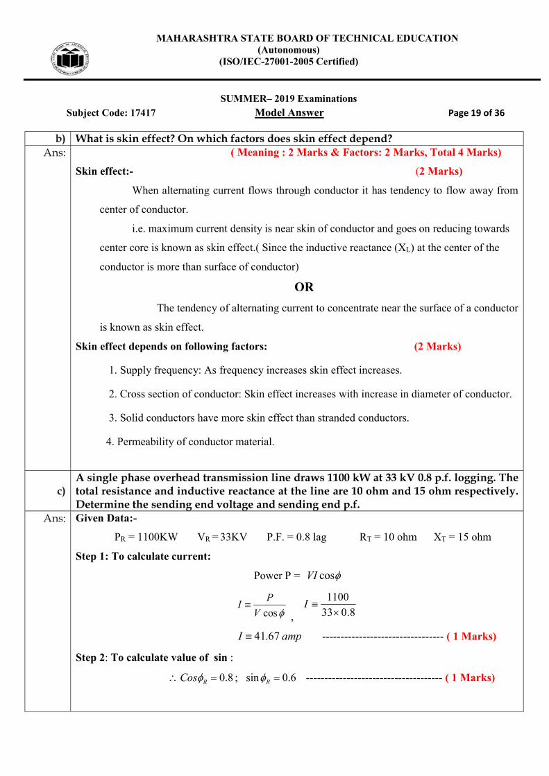
b) What is skin effect? On which factors does skin effect depend? Ans: ( Meaning : 2 Marks & Factors: 2 Marks, Total 4 Marks)
Skin effect:- (2 Marks)
When alternating current flows through conductor it has tendency to flow away from
center of conductor.
i.e. maximum current density is near skin of conductor and goes on reducing towards
center core is known as skin effect.( Since the inductive reactance (XL) at the center of the
conductor is more than surface of conductor)
OR
The tendency of alternating current to concentrate near the surface of a conductor
is known as skin effect.
Skin effect depends on following factors: (2 Marks)
1. Supply frequency: As frequency increases skin effect increases.
2. Cross section of conductor: Skin effect increases with increase in diameter of conductor.
3. Solid conductors have more skin effect than stranded conductors.
4. Permeability of conductor material.
c) A single phase overhead transmission line draws 1100 kW at 33 kV 0.8 p.f. logging. The total resistance and inductive reactance at the line are 10 ohm and 15 ohm respectively. Determine the sending end voltage and sending end p.f.
Ans: Given Data:-
PR = 1100KW VR = 33KV P.F. = 0.8 lag RT = 10 ohm XT = 15 ohm
Step 1: To calculate current:
Power P = cosVI
cosV
PI
, 8.033
1100
I
ampI 67.41 --------------------------------- ( 1 Marks)
Step 2: To calculate value of sin :
6.0sin;8.0 RRCos ------------------------------------- ( 1 Marks)

MAHARASHTRA STATE BOARD OF TECHNICAL EDUCATION (Autonomous)
(ISO/IEC-27001-2005 Certified)
SUMMER– 2019 Examinations
Subject Code: 17417 Model Answer Page 20 of 36
Step 3: To calculate Sending end voltage:
Vs = RTRTR XRIV sincos
= 6.0158.01067.411033 3
= 33708.39volt
Vs = 33.70839 KV ------------------------------------- ( 1 Marks)
Step 4: To calculate sending end Power factor:
S
TRR
V
IRVs
coscos
3
3
1070839.33
1067.418.01033cos
s
lags 7955.0cos ------------------------------------- ( 1 Marks)
d)
Study the Fig. No. 1 and answer following questions:
(i) Which part is shown by 'A'? (ii) State the meaning of symbol shown at 'B' point. (iii) State the voltage rating of equipment at point `D'. (iv) Which part is shown by 'E'?
Ans: ( Each answer : 1 Mark, Total 4 Marks)
(i) Part is shown by 'A' : Generation
(ii) The meaning of symbol shown at 'B' point : Step-up transformer Substation
(iii) The voltage rating of equipment at point `D'.: Distribution transformer Substation
(iv) Which part is shown by 'E' : Primary transmission line ( 3-ph, 3 wire)

MAHARASHTRA STATE BOARD OF TECHNICAL EDUCATION (Autonomous)
(ISO/IEC-27001-2005 Certified)
SUMMER– 2019 Examinations
Subject Code: 17417 Model Answer Page 21 of 36
e) State and explain any one method for improving string efficiency. Ans: The Methods of Improving String Efficiency:-
( Methods : 2 Mark & Any one explanation: 2 Marks : Total 4 Marks)
1) By reducing value of ‘m’ or (‘k’) by using longer cross arm.
2) By Making of ‘m’ or (‘k’) equal to zero
3) By grading of Insulator.
4) By Using guard ring.
Explanation:-
1) By reducing value of ‘m’ or (‘k’) by using longer cross arm:-
Fig:-
The value of ‘m’ can be decreased by reducing value of shunt capacitance (C1) since m = C1/C. In order to reduce value shunt capacitance (C1) distance of string of insulator from tower must be increased. i.e. by using longer cross arm. Due to this value of shunt capacitance (C1) reduces.
Therefore value of m reduces Since (C
Cm 1 ) As value of ‘m’ reduces
there will be more uniform voltage distribution along a string of suspension insulator. In this way string efficiency increases. Limitation:
In practice there is limitation to increase length of cross arm as cost of tower increases. In practice m= 0.1 is the limit which can be achieved by this method.
2) By Making of ‘m’ or (‘k’) equal to zero:-
or equivalent Figure

MAHARASHTRA STATE BOARD OF TECHNICAL EDUCATION (Autonomous)
(ISO/IEC-27001-2005 Certified)
SUMMER– 2019 Examinations
Subject Code: 17417 Model Answer Page 22 of 36
If an insulating material or any non conducting material of high strength is
used for connection between two disc insulators in a string instead of using steel
part.
Than value of Shunt Capacitance (C1) becomes Zero,(Capacitance will not
form) therefore value of ‘m’ becomes zero (since m = C1/C) So string efficiency
becomes 100%.
3) By grading Insulator :-
In this method, disc insulators of different dimensions are so selected that each
disc has different capacitance. The assembly in the string of suspension insulator is
made in such a way that the top unit insulator has fewer dimensions. (Less
capacitance) (C A) and dimensions of insulators progressively goes on increasing
i.e. bottom unit has maximum capacitance due to large dimensions of insulators.
(Since Q=C/V i.e. V is inversely proportional to capacitance So as A Increases C
increases therefore voltage decreases)
In this way it equalizer potential distribution across the string and therefore
increase string efficiency.
This method has disadvantages that it requires disc insulator of different
dimensions in one string of suspension insulator. Practically it is not possible to
obtain such ration. But very high voltage transmission line (1200KV). This method is
used.
4) By Using guard ring :-
or equivalent Figure

MAHARASHTRA STATE BOARD OF TECHNICAL EDUCATION (Autonomous)
(ISO/IEC-27001-2005 Certified)
SUMMER– 2019 Examinations
Subject Code: 17417 Model Answer Page 23 of 36
Guard ring is a metal ring electrically connected to conductor and surrounding
the bottom insulator.
Due to guard ring leakage current through all discs in a string is same.
So, we will get uniform voltage distribution along the string of suspension
insulator, In this way string efficiency increases.
f) Write down the functions of following elements of a substation: (i) CB (ii) Relays (iii) Lightning arrester (iv) Isolators
Ans: (i) CB ( Circuit Breaker) ( 1 Mark)
It is protective device. It open or break the circuit whenever there is fault &
protect the equipment. It can be operated manually or remote control whenever
required.
ii) Relay: ( 1 Mark)
It sense the faults & gives signal to trip circuit of C.B. to open. There are
different types of relay e.g. Earth fault relay, Phase to Phase/short circuit fault
relay, Thermal relay etc.
iii) Lightning Arrester: - ( 1 Mark)
It is provided for protection of substation, transformer against lightning
stroke .It is connected in between line and ground at the starting point of substation.
Under normal condition it acts as an insulator.
iv) Isolator : - ( 1 Mark)
Its function is to connect or disconnect the circuit only when there is no load.
Isolator is inter locked with C.B. Isolator can be operated by hand locally as well as
by motorized mechanism from remote position. Normally it is closed.
MAHARASHTRA STATE BOARD OF TECHNICAL EDUCATION (Autonomous)
(ISO/IEC-27001-2005 Certified)
SUMMER– 2019 Examinations
Subject Code: 17417 Model Answer Page 24 of 36
Q.5 Attempt any FOUR of the following: 16 Marks
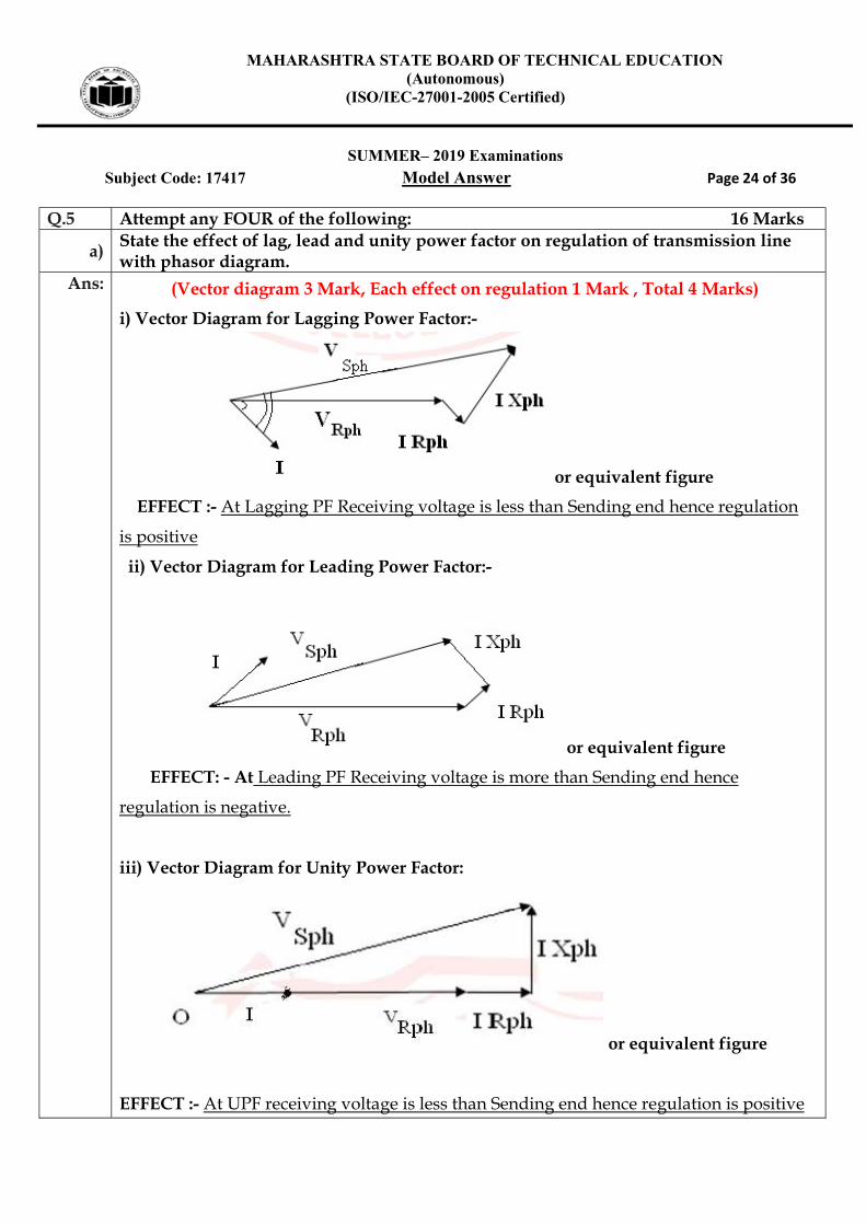
a) State the effect of lag, lead and unity power factor on regulation of transmission line with phasor diagram.
Ans: (Vector diagram 3 Mark, Each effect on regulation 1 Mark , Total 4 Marks)
i) Vector Diagram for Lagging Power Factor:-
or equivalent figure
EFFECT :- At Lagging PF Receiving voltage is less than Sending end hence regulation
is positive
ii) Vector Diagram for Leading Power Factor:-
or equivalent figure
EFFECT: - At Leading PF Receiving voltage is more than Sending end hence
regulation is negative.
iii) Vector Diagram for Unity Power Factor:
or equivalent figure
EFFECT :- At UPF receiving voltage is less than Sending end hence regulation is positive

MAHARASHTRA STATE BOARD OF TECHNICAL EDUCATION (Autonomous)
(ISO/IEC-27001-2005 Certified)
SUMMER– 2019 Examinations
Subject Code: 17417 Model Answer Page 25 of 36
b)
A single phase AC distributors of 900 m length has total impedance of (0.02 + 0.04j) ohm and is fed from one end at 250 V. If it is loaded as in Fig. No 2. Calculate the voltage drop and voltage at far end.
Ans:
04.002.0 jZ
givenimpedanceTotalZT 43.630447.0
Step 1: To find section impedance:
04.002.0900
300jZAB
)04.002.0(33.0 ABZ
)0132.00066.0 JZ AB
434.630147.00 ABZ
434.630147.00 CDBCAB ZZZ
Step 2 : To Calculate section current :
lagfpatID 7.0..,60
AI D 5729.4560
AjID 8485.4242

MAHARASHTRA STATE BOARD OF TECHNICAL EDUCATION (Autonomous)
(ISO/IEC-27001-2005 Certified)
SUMMER– 2019 Examinations
Subject Code: 17417 Model Answer Page 26 of 36
lagfpatAIC 8.0..,60
86.3660 CI
AjIC 3600.48
ALfpUnityatAIB0060)(..,60
AjI B 060 ----------------------------------------------------------------(1/2 Marks)
DCBC III
)8485.4242()3600.48( jjI BC
8485.7890 jIBC
AIBC 2214.416540.119
DCD II
AjICD 8485.4242
DCBAB IIII
)8485.4242()3600.48()060( jjjI AB
8485.78150 jI AB
AI AB 72.2746.169 -- ------------------------------------------(1/2 Marks)
Step-3: To Calculate Section voltage drop
04.002.0 jZ
givenimpedanceTotalZT 43.630447.0
CDBCAB ZZZ
434.630147.00 CDBCAB ZZZ --------------------------------- (1/2 Marks)
Voltage drop in section CD:-
= ICD X ZCD
= )434.630147.0()5729.4560( 00

MAHARASHTRA STATE BOARD OF TECHNICAL EDUCATION (Autonomous)
(ISO/IEC-27001-2005 Certified)
SUMMER– 2019 Examinations
Subject Code: 17417 Model Answer Page 27 of 36
= Volts0864.17882.0
VCD = Voltsj 27.0839.0 ------------------------------------ (1/2 Marks)
Voltage drop in section BC:-
= IBC X ZBC
= )434.630147.0()22.416540.119(
= Volts0214.2276.1
VBC = Voltsj 6654.0629.1 ----------------------------------- (1/2 Marks)
Voltage drop in section AB:-
= IAB X ZAB
= )434.630147.0()72.2746.1169(
= Volts714.3549.2
VAB = Voltsj 454.102.2 ------------------------------------(1/2 Marks)
Total Voltage drop from A to D:-
= VAB+ VBC +VCD
= )27.0839.0()6654.0629.1()454.1021.2( jjj
= Voltsj 3894.2489.4
= Volts00254.280853.5 ---------------------------------- (1/2 Marks)
Voltage at far end:- DtoAfromdropvolatgeTotalvolatgeendSending
= )0250( j )3894.2489.4( j
= Voltsj 3842.2511.245
= Volts05576.05226.245 --------------------------------- (1/2 Marks)
c) Write down any four properties of line support. Ans: Following are requirements or properties of the line supports
( Any Four Point expected: 1 Mark each point, Total 4 Marks)
1. High mechanical strength:-
It should have high mechanical strength to withstand against -
Wind pressure
MAHARASHTRA STATE BOARD OF TECHNICAL EDUCATION (Autonomous)
(ISO/IEC-27001-2005 Certified)
SUMMER– 2019 Examinations
Subject Code: 17417 Model Answer Page 28 of 36
Load of fabrication
Weight of Insulator
Weight of conductor etc.
2. Light in weight:-
It should be light in weight to reduce-
Transportation cost
Handling, loading, unloading cost and
Erection cost.
3. Effect of atmospheric conditions: It should be withstand even at bad
atmospheric condition.
4. High resistance to corrosion: It should have high resistance to corrosion to avoid
rusting.
5. Initial & Maintenance cost: It should be less.
6. Easy access: It should be easily accessible for wireman for line work and
maintenance work. or They must be easily accessible for point and erection of
line conductors
7. Life: It should have longer life.
8. Appearance: It should have good appearance or They must be of pleasing shape
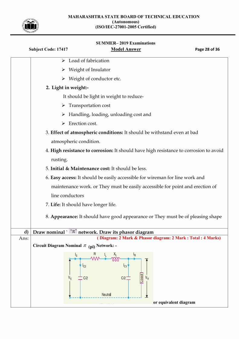
d) Draw nominal ` network. Draw its phasor diagram
Ans: ( Diagram: 2 Mark & Phasor diagram: 2 Mark : Total : 4 Marks)
Circuit Diagram Nominal (pi) Network: -
or equivalent diagram
MAHARASHTRA STATE BOARD OF TECHNICAL EDUCATION (Autonomous)
(ISO/IEC-27001-2005 Certified)
SUMMER– 2019 Examinations
Subject Code: 17417 Model Answer Page 29 of 36
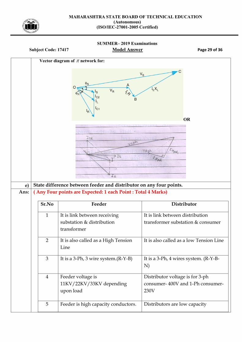
Vector diagram of network for:
OR
e) State difference between feeder and distributor on any four points.
Ans: ( Any Four points are Expected: 1 each Point : Total 4 Marks)
Sr.No Feeder Distributor
1 It is link between receiving substation & distribution transformer
It is link between distribution transformer substation & consumer
2 It is also called as a High Tension Line
It is also called as a low Tension Line
3 It is a 3-Ph, 3 wire system.(R-Y-B) It is a 3-Ph, 4 wires system. (R-Y-B-N)
4 Feeder voltage is 11KV/22KV/33KV depending upon load
Distributor voltage is for 3-ph consumer- 400V and 1-Ph consumer- 230V
5 Feeder is high capacity conductors. Distributors are low capacity

MAHARASHTRA STATE BOARD OF TECHNICAL EDUCATION (Autonomous)
(ISO/IEC-27001-2005 Certified)
SUMMER– 2019 Examinations
Subject Code: 17417 Model Answer Page 30 of 36
conductors
6 Feeder forms the primary distribution system
Distributors forms secondary distributor system.
7 While designing feeder its current carrying capacity is important
While designing distributor its voltage drop calculation is important.
8 Feeder is not tapped along its length
Distributors are tapped throughout its length.
9 Its loading point is at substation only
Distributors loading point is throughout its length.
f) State the factors to be considered while deciding location of site for substations. Ans: Following factors should be considered while deciding location of site for sub-station:-
( Any four point expected : 1 Mark each, Total 4 Mark )
1. Near load center:
Sub-station should be located near load centre to reduce cost of Transmission and
distribution lines and to reduce losses in it.
2. Easy access for transmission Line :
There should be easy access for incoming and outgoing line.
3. Easy access towards sub-station :-
There should be easy access towards sub-station for transportation of equipments and
manpower etc.
4. Space(Land ) available :
The land proposed for a substation should be normally level and open from all sides &
sufficient land should be available for installation of sub-station and future expansion. e.g.
5. Atmospheric conditions :
Atmospheric condition in the area of sub-station should be clean and dry also There should
be less atmospheric pollution.
5. Cost of land :
MAHARASHTRA STATE BOARD OF TECHNICAL EDUCATION (Autonomous)
(ISO/IEC-27001-2005 Certified)
SUMMER– 2019 Examinations
Subject Code: 17417 Model Answer Page 31 of 36
Cost of land should be less to reduce capital cost of sub-station.
6. Municipal restriction :
Where municipal restriction will not take any objection for required type building of sub-
station.
7. Staff amenities :
The site should be such that essential amenities must be available to staff like residential
quarters, drinking water, school, hospital, public transportation, communication.
8. Bearing capacity of land (Hard land ):
To reduce construction cost of building and for better foundation of equipments land
should have high bearing capacity.
9. Area free from earthquake :
To avoid damage to sub-station area should be free earth quake.
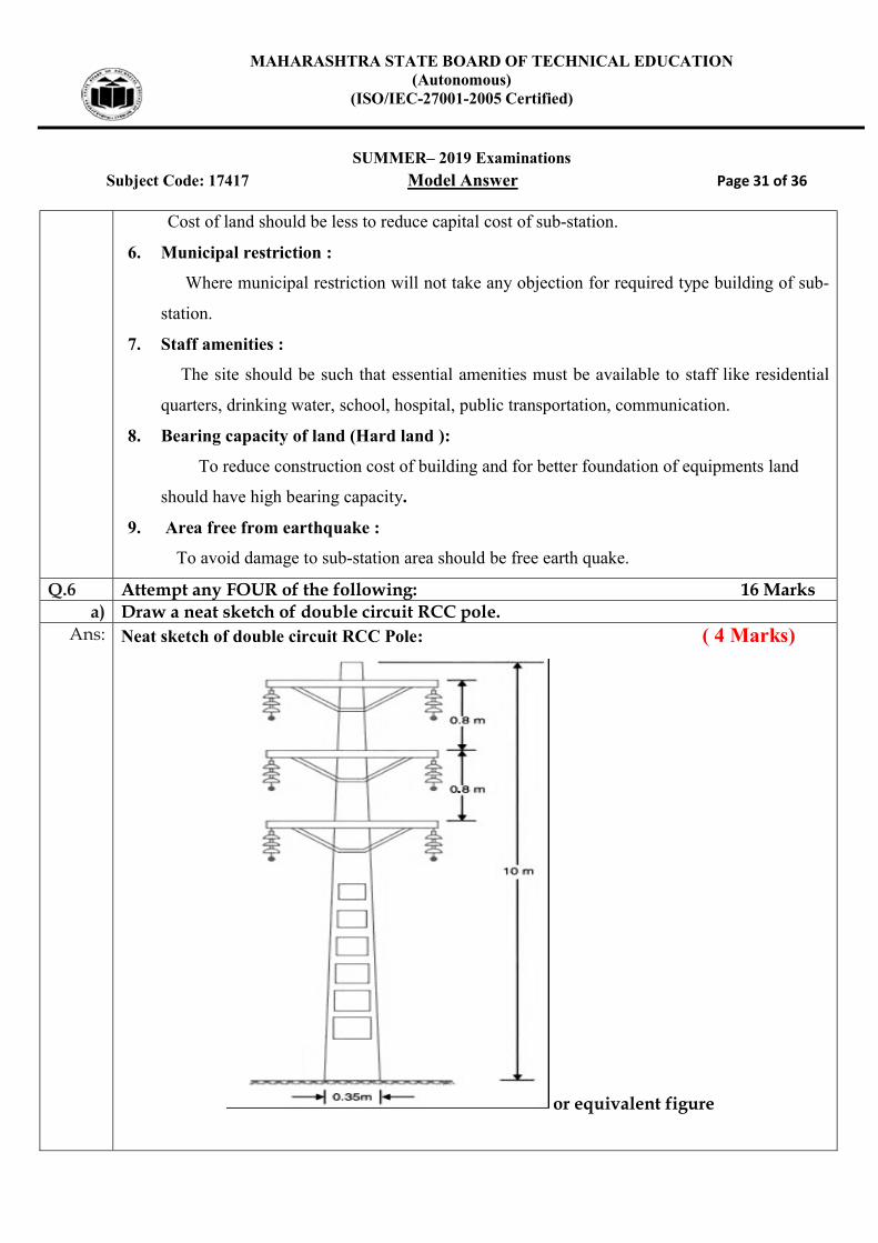
Q.6 Attempt any FOUR of the following: 16 Marks a) Draw a neat sketch of double circuit RCC pole.
Ans: Neat sketch of double circuit RCC Pole: ( 4 Marks)
or equivalent figure

MAHARASHTRA STATE BOARD OF TECHNICAL EDUCATION (Autonomous)
(ISO/IEC-27001-2005 Certified)
SUMMER– 2019 Examinations
Subject Code: 17417 Model Answer Page 32 of 36
b) Draw diagram of end condenser method. Also draw phasor diagram. Ans: Diagram of end condenser method:
(Diagram : 2 Mark & Phasor diagram: 2 Mark, Total : 4 Mark)
or equivalent diagram
Phasor diagram of end condenser method:
or equivalent diagram
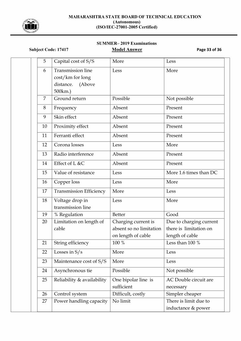
c) Compare HVDC transmission with EHVAC transmission. Ans: (Any four Point Expected : 1 Mark each, Total 4 Marks)
S.N
o
Points HVDC EHVAC
1 Number of conductor required for single circuit
One conductor.& Ground is used as a return path
Three conductors (R.Y.B)
2 For double circuit Two conductors.& Ground is used as a return path
Six conductors (R,Y,B & R,Y,B)
3 Design of Tower Light Heavy
4 Intermediate substation Not required Required at every 250
Km
MAHARASHTRA STATE BOARD OF TECHNICAL EDUCATION (Autonomous)
(ISO/IEC-27001-2005 Certified)
SUMMER– 2019 Examinations
Subject Code: 17417 Model Answer Page 33 of 36
5 Capital cost of S/S More Less
6 Transmission line cost/km for long distance. (Above 500km.)
Less More
7 Ground return Possible Not possible
8 Frequency Absent Present
9 Skin effect Absent Present
10 Proximity effect Absent Present
11 Ferranti effect Absent Present
12 Corona losses Less More
13 Radio interference Absent Present
14 Effect of L &C Absent Present
15 Value of resistance Less More 1.6 times than DC
16 Copper loss Less More
17 Transmission Efficiency More Less
18 Voltage drop in transmission line
Less More
19 % Regulation Better Good 20 Limitation on length of
cable Charging current is absent so no limitation on length of cable
Due to charging current there is limitation on length of cable
21 String efficiency 100 % Less than 100 %
22 Losses in S/s More Less
23 Maintenance cost of S/S More Less
24 Asynchronous tie Possible Not possible
25 Reliability & availability One bipolar line is sufficient
AC Double circuit are necessary
26 Control system Difficult, costly Simpler cheaper 27 Power handling capacity No limit There is limit due to
inductance & power

MAHARASHTRA STATE BOARD OF TECHNICAL EDUCATION (Autonomous)
(ISO/IEC-27001-2005 Certified)
SUMMER– 2019 Examinations
Subject Code: 17417 Model Answer Page 34 of 36
angle 28 Voltage control for long
distance lines Easier as L&C are not effective
Difficult for long distance lines due to presence of L &C
29 Stability limit No limit due to absent
of inductance &
power angle
EHVAC limits due to
inductance & power
angle
30 Power flow control Power can be quickly(fast) controlled,
Power flow cannot be easily controlled, (slow)
31 Power transfer ability High Lower
32 Transient performance Excellent Poor
33 Back to Back conversion stations
Possible Not Possible
34 Short-circuit current
level
Less More
35 Reliable circuit breaker Not available Available
36 Fault levels Remains unchanged Get added after
interconnection
37 Frequency conversion Possible Not possible
38 Cascade tripping of
circuit
Avoided Likely
39 Spinning reserve Reduced Not much reduced
40 Frequency of fault Less More
d) Draw ring main system and give its advantages. Ans: Ring main system of distribution with neat diagram:
( Figure ; 2 Mark & Advantages: 2 Marks)

MAHARASHTRA STATE BOARD OF TECHNICAL EDUCATION (Autonomous)
(ISO/IEC-27001-2005 Certified)
SUMMER– 2019 Examinations
Subject Code: 17417 Model Answer Page 35 of 36
or equivalent figure
Advantages:-(Any TWO point is expected)
1. Supply to distribution transformer center is given through two different Feeders
2. Reliability to maintain supply is more even when there is a fault on any one feeder.
3. Reliability to maintain supply is more even when there was maintenance on any
one feeder
e) Describe the effect of load p.f on performance of transmission line.
Ans: Effect of load p.f on performance of transmission line:
1. Effect of improved power factor on Efficiency:- ( 2 Mark) As power factor increases, current decreases, so Copper losses decreases, Hence
transmission efficiency increases & vice versa.
2. Effect of improved power factor on Regulation:- ( 2 Mark)
As power factor increases, current decreases, So Voltage drop in transmission line
decreases, As a result, regulation get improved (decrease) an vice versa.
OR
1. Effect of poor power factor on efficiency:- ( 2 Mark)
MAHARASHTRA STATE BOARD OF TECHNICAL EDUCATION (Autonomous)
(ISO/IEC-27001-2005 Certified)
SUMMER– 2019 Examinations
Subject Code: 17417 Model Answer Page 36 of 36
When power factor of load reduces current drawn by transmission line increases so copper losses in transmission line increases, hence transmission efficiency reduces.
2. Effect of poor power factor on voltage Regulation:- ( 2 Mark) When power factor of load reduces current through transmission line
increases, so voltage drop in transmission line (due to resistance & inductive reactance) increases so regulation increases. (Become Poor)
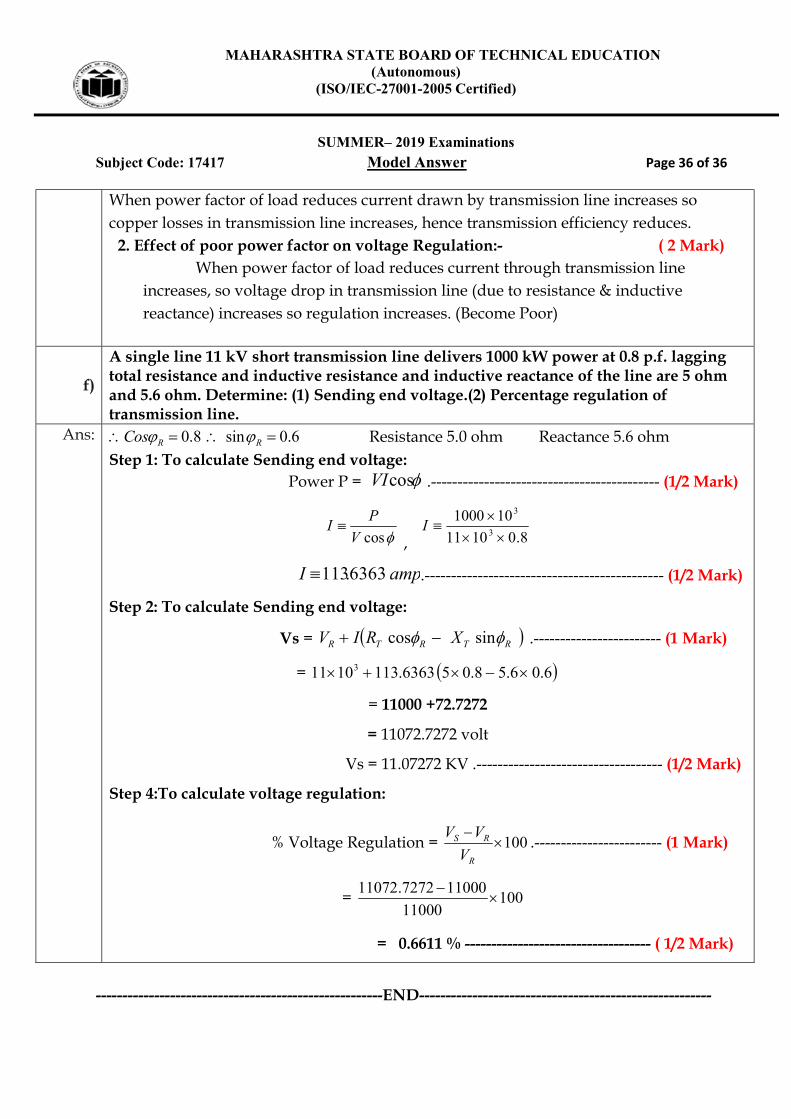
f)
A single line 11 kV short transmission line delivers 1000 kW power at 0.8 p.f. lagging total resistance and inductive resistance and inductive reactance of the line are 5 ohm and 5.6 ohm. Determine: (1) Sending end voltage.(2) Percentage regulation of transmission line.
Ans: 0.8 sin 0.6R RCos Resistance 5.0 ohm Reactance 5.6 ohm Step 1: To calculate Sending end voltage: Power P = cosVI .------------------------------------------- (1/2 Mark)
cosV
PI
, 8.01011
1010003
3
I
ampI 6363.113 .--------------------------------------------- (1/2 Mark)
Step 2: To calculate Sending end voltage:
Vs = RTRTR XRIV sincos .------------------------ (1 Mark)
= 6.06.58.056363.1131011 3
= 11000 +72.7272
= 11072.7272 volt
Vs = 11.07272 KV .----------------------------------- (1/2 Mark)
Step 4:To calculate voltage regulation:
% Voltage Regulation = 100
R
RS
V
VV.------------------------ (1 Mark)
= 10011000
110007272.11072
= 0.6611 % ----------------------------------- ( 1/2 Mark)
------------------------------------------------------END-------------------------------------------------------