mission specialist human-robot interaction - OAKTrust
214
MISSION SPECIALIST HUMAN-ROBOT INTERACTION IN MICRO UNMANNED AERIAL SYSTEMS A Dissertation by JOSHUA MICHAEL PESCHEL Submitted to the Office of Graduate Studies of Texas A&M University in partial fulfillment of the requirements for the degree of DOCTOR OF PHILOSOPHY August 2012 Major Subject: Computer Science
-
Upload
khangminh22 -
Category
Documents
-
view
2 -
download
0
Transcript of mission specialist human-robot interaction - OAKTrust

MISSION SPECIALIST HUMAN-ROBOT INTERACTION
IN MICRO UNMANNED AERIAL SYSTEMS
A Dissertation
by
JOSHUA MICHAEL PESCHEL
Submitted to the Office of Graduate Studies of Texas A&M University
in partial fulfillment of the requirements for the degree of
DOCTOR OF PHILOSOPHY
August 2012
Major Subject: Computer Science

Mission Specialist Human-Robot Interaction in Micro Unmanned Aerial Systems
Copyright 2012 Joshua Michael Peschel
MISSION SPECIALIST HUMAN-ROBOT INTERACTION
IN MICRO UNMANNED AERIAL SYSTEMS
A Dissertation
by
JOSHUA MICHAEL PESCHEL
Submitted to the Office of Graduate Studies of Texas A&M University
in partial fulfillment of the requirements for the degree of
DOCTOR OF PHILOSOPHY
Approved by:
Chair of Committee, Robin R. Murphy Committee Members, John B. Mander Dylan A. Shell Dezhen Song Head of Department, Duncan M. Walker
August 2012
Major Subject: Computer Science

iii
ABSTRACT
Mission Specialist Human-Robot Interaction
in Micro Unmanned Aerial Systems. (August 2012)
Joshua Michael Peschel, B.S.; M.S., Texas A&M University
Chair of Advisory Committee: Dr. Robin R. Murphy
This research investigated the Mission Specialist role in micro unmanned aerial sys-
tems (mUAS) and was informed by human-robot interaction (HRI) and technology find-
ings, resulting in the design of an interface that increased the individual performance of 26
untrained CBRN (chemical, biological, radiological, nuclear) responders during two field
studies, and yielded formative observations for HRI in mUAS.
Findings from the HRI literature suggested a Mission Specialist requires a role-specific
interface that shares visual common ground with the Pilot role and allows active control
of the unmanned aerial vehicle (UAV) payload camera. Current interaction technology
prohibits this as responders view the same interface as the Pilot and give verbal directions
for navigation and payload control. A review of interaction principles resulted in a syn-
thesis of five design guidelines and a system architecture that were used to implement a
Mission Specialist interface on an Apple R� iPad. The Shared Roles Model was used to
model the mUAS human-robot team using three formal role descriptions synthesized from
the literature (Flight Director, Pilot, and Mission Specialist).
The Mission Specialist interface was evaluated through two separate field studies in-
volving 26 CBRN experts who did not have mUAS experience. The studies consisted
of 52 mission trials to surveil, evaluate, and capture imagery of a chemical train derail-
ment incident staged at Disaster City R�. Results from the experimental study showed
that when a Mission Specialist was able to actively control the UAV payload camera and
verbally coordinate with the Pilot, greater role empowerment (confidence, comfort, and

iv
perceived best individual and team performance) was reported by a majority of partici-
pants for similar tasks; thus, a role-specific interface is preferred and should be used by
untrained responders instead of viewing the same interface as the Pilot in mUAS.
Formative observations made during this research suggested: i) establishing common
ground in mUAS is both verbal and visual, ii) type of coordination (active or passive) pre-
ferred by the Mission Specialist is affected by command-level experience and perceived
responsibility for the robot, and iii) a separate Pilot role is necessary regardless of preferred
coordination type in mUAS. This research is of importance to HRI and CBRN researchers
and practitioners, as well as those in the fields of robotics, human-computer interaction,
and artificial intelligence, because it found that a human Pilot role is necessary for assis-
tance and understanding, and that there are hidden dependencies in the human-robot team
that affect Mission Specialist performance.

v
ACKNOWLEDGMENTS
This research work was made possible by the help and support of my colleagues,
friends, and family.
Professor Robin Murphy served as my dissertation advisor. It was through her human-
robot interaction class that I initially came to appreciate the importance of the field and
this research topic. Professor Murphy advised me during my PhD studies with honor and
integrity and I appreciated most the opportunity to learn her disciplined approach to the
creative process. I thank her for all that she has taught me over the years. Professors John
Mander, Dezhen Song, and Dylan Shell served as the other members of my dissertation
committee. I thank each of them for their suggestions and encouragement during my work
on this research topic.
The field experiments for this research would not have been possible without the Dis-
aster City R� facility supported by the Texas Engineering Extension Service (TEEX) at
Texas A&M University. Chief David Martin and Mr. Clint Arnett were instrumental in the
planning and arranging of the facilities and responder participants. My sincere thanks go
to them and the Disaster City R� staff for their unique expertise and efforts. This research
was supported by National Science Foundation Grant IIS-1143713, EAGER: Shared Vi-
sual Common Ground in Human-Robot Interaction for Small Unmanned Aerial Systems,
the first joint grant between TEEX and the Center for Robot-Assisted Search and Rescue
(CRASAR) to study human-robot interaction for the response community.
I owe special thanks to Mr. Thomas Meyer from AirRobot US, Inc., Mr. Zenon Dragan
and Mr. Mark Bateson from Draganfly Innovations, Inc., and Professor Nasir Gharaibeh
from the Zachry Department of Civil Engineering, for providing unique access to the un-
manned aerial vehicles used in my experiments. I would like to thank Professor Clifford
Nass from Stanford University and Professor Cindy Bethel from Mississippi State Uni-
versity for their helpful suggestions on my survey questions and experimental designs.
Thanks also go to Professors Anthony Cahill and Kelly Brumbelow from the Zachry De-

vi
partment of Civil Engineering for providing me with assistantship funding in the early part
of my graduate studies.
I was very fortunate to be a member of Team UAV, unquestionably the best team from
a strong research group filled with excellent students and scholars. Ms. Brittany Duncan
was my office mate and pilot-in-command of Team UAV. She also holds the rather unex-
pected distinction of being my very last college roommate. To say this research would not
have been possible without her help is an understatement; I can offer her only my sincer-
est thanks. Team UAV was rounded out by Mr. Adrian Jimenez Gonzalez who I thank for
spending a significant amount of time keeping copious mission notes during my experi-
ments. I would additionally like to thank the other members of the field team, Mr. Jaewook
Yoo and Dr. Xiaoming Li, for their helpful feedback during the preparation of my thesis
defense. Members of the Survivor Buddy Team (Vasant Srinivasan, Zack Henkel, Jessica
Gonzales, Jesus Suarez, Bethany McNabb) and the Multi-Robot Systems Group (Lantao
Liu, Ben Fine, Taahir Ahmed, YoungHo Kim, Jung-Hwan Kim, Yong Song, Kate Wells,
Asish Ghoshal, Plamen Ivanov, Changjoo Nam, Sasin Janpuangtong) provided insightful
questions during all of my AI Robotics Lab seminar talks and I thank them as well.
Finally I would like to thank my family and friends who have supported me throughout
all of my studies, the most essential and influential being my wife and best friend, Cas-
sandra Rutherford (now Professor Cassandra Rutherford). The last twelve years simply
would not have been the same without her presence in my life. This work is dedicated to
her unwavering love and support.

vii
NOMENCLATURE
AM Arithmetic Mean
CBRN Chemical, Biological, Radiological, Nuclear
cvJB Jarque-Bera Critical Value
cvL Lilliefors Critical Value
df Degrees of Freedom
dfd Denominator Degrees of Freedom
dfn Numerator Degrees of Freedom
eCDF Empirical Cumulative Distribution Function
GM Geometric Mean
GSD Geometric Standard Deviation
HCI Human-Computer Interaction
HRI Human-Robot Interaction
JB Jarque-Bera Test Statistic
JCS Joint Cognitive System
k Kurtosis
KS Kolmogorov-Smirnov Test Statistic
M Median
mUAS Micro Unmanned Aerial Systems
n Number of Data Points
p Statistical Significance
rqp Normal Quantile Plot Correlation Coefficient
R2 Coefficient of Determination
s Skewness
SD Standard Deviation
UAS Unmanned Aerial System
UAV Unmanned Aerial Vehicle

viii
TABLE OF CONTENTS
Page
ABSTRACT . . . . . . . . . . . . . . . . . . . . . . . . . . . . . . . . . . . . . iii
ACKNOWLEDGMENTS . . . . . . . . . . . . . . . . . . . . . . . . . . . . . . v
NOMENCLATURE . . . . . . . . . . . . . . . . . . . . . . . . . . . . . . . . . vii
TABLE OF CONTENTS . . . . . . . . . . . . . . . . . . . . . . . . . . . . . . viii
LIST OF TABLES . . . . . . . . . . . . . . . . . . . . . . . . . . . . . . . . . . xiii
LIST OF FIGURES . . . . . . . . . . . . . . . . . . . . . . . . . . . . . . . . . xiv
1 INTRODUCTION . . . . . . . . . . . . . . . . . . . . . . . . . . . . . . . . 1
1.1 Research Question . . . . . . . . . . . . . . . . . . . . . . . . . . . . . 31.2 Why Focus on the Mission Specialist Role . . . . . . . . . . . . . . . . . 41.3 Understanding Unmanned Aerial Vehicles . . . . . . . . . . . . . . . . . 5
1.3.1 Micro Unmanned Aerial Vehicles . . . . . . . . . . . . . . . . . 51.3.2 Other Unmanned Aerial Vehicles . . . . . . . . . . . . . . . . . 6
1.4 Importance to CBRN . . . . . . . . . . . . . . . . . . . . . . . . . . . 71.5 Contributions . . . . . . . . . . . . . . . . . . . . . . . . . . . . . . . 8
1.5.1 First Focused Study of the Mission Specialist Role . . . . . . . . 91.5.2 New Guidelines for a Mission Specialist Interface . . . . . . . . . 91.5.3 Unique Empirical Evaluation of the Shared Roles Model . . . . . 10
1.6 Organization of the Dissertation . . . . . . . . . . . . . . . . . . . . . . 101.7 . . . . . . . . . . . . . . . . . . . . . . . . . . . . . . . . . . . . . . . 11
2 RELATED WORK . . . . . . . . . . . . . . . . . . . . . . . . . . . . . . . 12
2.1 Human-Robot Team Models Related to Micro Unmanned Aerial Systems 122.1.1 Joint Cognitive Systems . . . . . . . . . . . . . . . . . . . . . . 122.1.2 Shared Roles Model . . . . . . . . . . . . . . . . . . . . . . . . 13
2.2 Human-Robot Interaction Literature on Micro Unmanned Aerial Systems 152.2.1 The Murphy 2008 Study . . . . . . . . . . . . . . . . . . . . . . 152.2.2 The Adams 2009 Study . . . . . . . . . . . . . . . . . . . . . . 162.2.3 The Oron-Gilad 2010 Study . . . . . . . . . . . . . . . . . . . . 172.2.4 Other Commercial Micro Unmanned Aerial Systems . . . . . . . 18
2.3 Interaction Principles Applicable to Micro Unmanned Aerial Systems . . 192.3.1 Human-Computer Interaction Principles . . . . . . . . . . . . . . 19

ix
Page
2.3.2 Human-Robot Interaction Principles . . . . . . . . . . . . . . . . 272.4 Summary . . . . . . . . . . . . . . . . . . . . . . . . . . . . . . . . . . 322.5 . . . . . . . . . . . . . . . . . . . . . . . . . . . . . . . . . . . . . . . 32
3 THEORY AND APPROACH . . . . . . . . . . . . . . . . . . . . . . . . . . 33
3.1 Shared Roles Model for a Micro Unmanned Aerial System . . . . . . . . 333.1.1 Flight Director Role Description . . . . . . . . . . . . . . . . . 333.1.2 Pilot Role Description . . . . . . . . . . . . . . . . . . . . . . . 353.1.3 Mission Specialist Role Description . . . . . . . . . . . . . . . . 35
3.2 Human-Robot Interaction Findings in Micro Unmanned Aerial Systems . 353.2.1 Small, Mobile, and Visual Displays . . . . . . . . . . . . . . . . 353.2.2 Shared, Duplicate, or Passive Interaction . . . . . . . . . . . . . 363.2.3 Lack of Software-Based Interfaces . . . . . . . . . . . . . . . . 36
3.3 Recommended Design Guidelines for a Mission Specialist Interface . . . 373.3.1 Design for Unary Interaction . . . . . . . . . . . . . . . . . . . 373.3.2 Design for Adequate Data Context . . . . . . . . . . . . . . . . 373.3.3 Design for Natural Human Interaction . . . . . . . . . . . . . . . 383.3.4 Design for Cueing and Communication . . . . . . . . . . . . . . 383.3.5 Design for Flexibility and Expansion . . . . . . . . . . . . . . . 38
3.4 System Architecture for a Mission Specialist Interface . . . . . . . . . . . 383.5 Summary . . . . . . . . . . . . . . . . . . . . . . . . . . . . . . . . . . 403.6 . . . . . . . . . . . . . . . . . . . . . . . . . . . . . . . . . . . . . . . 40
4 IMPLEMENTATION . . . . . . . . . . . . . . . . . . . . . . . . . . . . . . 41
4.1 Hardware Platform Description . . . . . . . . . . . . . . . . . . . . . . 414.2 Software Platform Description . . . . . . . . . . . . . . . . . . . . . . . 434.3 Summary . . . . . . . . . . . . . . . . . . . . . . . . . . . . . . . . . . 434.4 . . . . . . . . . . . . . . . . . . . . . . . . . . . . . . . . . . . . . . . 43
5 EXPLORATORY STUDY . . . . . . . . . . . . . . . . . . . . . . . . . . . . 44
5.1 Overview . . . . . . . . . . . . . . . . . . . . . . . . . . . . . . . . . . 445.2 Participants . . . . . . . . . . . . . . . . . . . . . . . . . . . . . . . . 475.3 Measurements . . . . . . . . . . . . . . . . . . . . . . . . . . . . . . . 48
5.3.1 Task Completion . . . . . . . . . . . . . . . . . . . . . . . . . . 485.3.2 Post-Assessment Surveys . . . . . . . . . . . . . . . . . . . . . 485.3.3 Biophysical . . . . . . . . . . . . . . . . . . . . . . . . . . . . 495.3.4 Audio and Video . . . . . . . . . . . . . . . . . . . . . . . . . . 49
5.4 Results . . . . . . . . . . . . . . . . . . . . . . . . . . . . . . . . . . . 495.4.1 Number of Completed Tasks . . . . . . . . . . . . . . . . . . . . 505.4.2 Levels of Stress . . . . . . . . . . . . . . . . . . . . . . . . . . 515.4.3 Role Empowerment . . . . . . . . . . . . . . . . . . . . . . . . 51
x
Page
5.5 Observations . . . . . . . . . . . . . . . . . . . . . . . . . . . . . . . . 525.5.1 More Captured Images with Passive Display . . . . . . . . . . . 525.5.2 Similar Captured Images for Well-Defined Tasks . . . . . . . . . 535.5.3 Similar Levels of Stress . . . . . . . . . . . . . . . . . . . . . . 535.5.4 Lack of Adequate Visual Feedback . . . . . . . . . . . . . . . . 545.5.5 Greater Role Empowerment with Passive Display . . . . . . . . . 54
5.6 Recommendations . . . . . . . . . . . . . . . . . . . . . . . . . . . . . 545.6.1 Deeper Focus on Role Empowerment . . . . . . . . . . . . . . . 555.6.2 More Visual Feedback on Interface . . . . . . . . . . . . . . . . 555.6.3 Reduce UAV Platform Latency . . . . . . . . . . . . . . . . . . 56
5.7 Interface Terminology Precision . . . . . . . . . . . . . . . . . . . . . . 565.8 Summary . . . . . . . . . . . . . . . . . . . . . . . . . . . . . . . . . . 585.9 . . . . . . . . . . . . . . . . . . . . . . . . . . . . . . . . . . . . . . . 59
6 EXPERIMENTAL METHODS AND DESIGN . . . . . . . . . . . . . . . . . 60
6.1 Study Overview . . . . . . . . . . . . . . . . . . . . . . . . . . . . . . 606.2 Research Hypotheses and Expected Findings . . . . . . . . . . . . . . . 61
6.2.1 Same or Less Task Completion Time . . . . . . . . . . . . . . . 626.2.2 Same or Less Stress . . . . . . . . . . . . . . . . . . . . . . . . 626.2.3 Same or Greater Role Empowerment . . . . . . . . . . . . . . . 62
6.3 Participants . . . . . . . . . . . . . . . . . . . . . . . . . . . . . . . . 626.4 Facilities . . . . . . . . . . . . . . . . . . . . . . . . . . . . . . . . . . 636.5 Equipment . . . . . . . . . . . . . . . . . . . . . . . . . . . . . . . . . 646.6 Personnel . . . . . . . . . . . . . . . . . . . . . . . . . . . . . . . . . 646.7 Pre-Assessment Survey . . . . . . . . . . . . . . . . . . . . . . . . . . 656.8 Experimental Design . . . . . . . . . . . . . . . . . . . . . . . . . . . . 656.9 Measuring Mission Specialist Performance . . . . . . . . . . . . . . . . 656.10 Post-Assessment Survey . . . . . . . . . . . . . . . . . . . . . . . . . . 666.11 Study Protocol . . . . . . . . . . . . . . . . . . . . . . . . . . . . . . . 666.12 Contingency Plan . . . . . . . . . . . . . . . . . . . . . . . . . . . . . 676.13 Summary . . . . . . . . . . . . . . . . . . . . . . . . . . . . . . . . . . 686.14 . . . . . . . . . . . . . . . . . . . . . . . . . . . . . . . . . . . . . . . 68
7 DATA ANALYSIS AND RESULTS . . . . . . . . . . . . . . . . . . . . . . . 69
7.1 Task Completion Time Analyses and Results . . . . . . . . . . . . . . . 697.1.1 Object Identification Tasks . . . . . . . . . . . . . . . . . . . . . 707.1.2 Evaluation Tasks . . . . . . . . . . . . . . . . . . . . . . . . . . 767.1.3 Image Capture Tasks . . . . . . . . . . . . . . . . . . . . . . . . 81
7.2 Levels of Stress Analyses and Results . . . . . . . . . . . . . . . . . . . 877.2.1 Heart Rate Descriptive Statistical Analyses . . . . . . . . . . . . 877.2.2 Heart Rate Inferential Statistical Analyses . . . . . . . . . . . . . 88

xi
Page
7.3 Role Empowerment Analyses and Results . . . . . . . . . . . . . . . . . 887.3.1 Locating Objects . . . . . . . . . . . . . . . . . . . . . . . . . . 897.3.2 Capturing Images . . . . . . . . . . . . . . . . . . . . . . . . . 917.3.3 Payload Camera Tilt . . . . . . . . . . . . . . . . . . . . . . . . 917.3.4 Payload Camera Zoom . . . . . . . . . . . . . . . . . . . . . . . 927.3.5 Perceived Best Individual and Team Performance . . . . . . . . . 92
7.4 Summary . . . . . . . . . . . . . . . . . . . . . . . . . . . . . . . . . . 947.5 . . . . . . . . . . . . . . . . . . . . . . . . . . . . . . . . . . . . . . . 95
8 DISCUSSION . . . . . . . . . . . . . . . . . . . . . . . . . . . . . . . . . . 96
8.1 Task Completion Time Discussion . . . . . . . . . . . . . . . . . . . . . 968.1.1 Object Identification Tasks . . . . . . . . . . . . . . . . . . . . . 978.1.2 Evaluation Tasks . . . . . . . . . . . . . . . . . . . . . . . . . . 978.1.3 Image Capture Tasks . . . . . . . . . . . . . . . . . . . . . . . . 97
8.2 Levels of Stress Discussion . . . . . . . . . . . . . . . . . . . . . . . . 988.3 Role Empowerment Discussion . . . . . . . . . . . . . . . . . . . . . . 988.4 Formative Observations . . . . . . . . . . . . . . . . . . . . . . . . . . 99
8.4.1 The Commander Effect . . . . . . . . . . . . . . . . . . . . . . 998.4.2 The Responsibility Effect . . . . . . . . . . . . . . . . . . . . . 100
8.5 Dimensions of the Shared Roles Model . . . . . . . . . . . . . . . . . . 1018.5.1 Mission Specialist Control . . . . . . . . . . . . . . . . . . . . . 1038.5.2 Focused Visual Common Ground . . . . . . . . . . . . . . . . . 103
8.6 Factors that May Have Impacted the Results . . . . . . . . . . . . . . . . 1048.6.1 Hand Physiology . . . . . . . . . . . . . . . . . . . . . . . . . 1048.6.2 Novelty of the Robot . . . . . . . . . . . . . . . . . . . . . . . 105
8.7 Summary . . . . . . . . . . . . . . . . . . . . . . . . . . . . . . . . . . 1058.8 . . . . . . . . . . . . . . . . . . . . . . . . . . . . . . . . . . . . . . . 106
9 CONCLUSIONS AND FUTURE WORK . . . . . . . . . . . . . . . . . . . . 107
9.1 Significant Contributions and Conclusions . . . . . . . . . . . . . . . . . 1079.1.1 Theoretical Contributions . . . . . . . . . . . . . . . . . . . . . 1089.1.2 Practical Contributions . . . . . . . . . . . . . . . . . . . . . . 110
9.2 Future Work . . . . . . . . . . . . . . . . . . . . . . . . . . . . . . . . 1129.2.1 Immediate Future Research Goals . . . . . . . . . . . . . . . . . 1129.2.2 Long-Term Future Research Goals . . . . . . . . . . . . . . . . 112
9.3 . . . . . . . . . . . . . . . . . . . . . . . . . . . . . . . . . . . . . . . 113REFERENCES . . . . . . . . . . . . . . . . . . . . . . . . . . . . . . . . . . . 114
APPENDIX A VERBAL ANNOUNCEMENT SCRIPT . . . . . . . . . . . . . . 119
APPENDIX B EXPLORATORY STUDY INFORMATION SHEET . . . . . . . . 120

xii
Page
APPENDIX C EXPLORATORY STUDY CONSENT FORM . . . . . . . . . . . 122
APPENDIX D EXPLORATORY STUDY PRE-ASSESSMENT . . . . . . . . . . 124
APPENDIX E EXPLORATORY STUDY COMMAND PROTOCOLS . . . . . . 128
APPENDIX F EXPLORATORY STUDY MISSION SCRIPT . . . . . . . . . . . 130
APPENDIX G EXPLORATORY STUDY SCRIPT FOR FLIGHT 1 . . . . . . . . 132
APPENDIX H EXPLORATORY STUDY SCRIPT FOR FLIGHT 2 . . . . . . . . 135
APPENDIX I EXPLORATORY STUDY POST-ASSESSMENT 1 . . . . . . . . 138
APPENDIX J EXPLORATORY STUDY POST-ASSESSMENT 2 . . . . . . . . 141
APPENDIX K EXPERIMENTAL STUDY INFORMATION SHEET . . . . . . . 144
APPENDIX L EXPERIMENTAL STUDY CONSENT FORM . . . . . . . . . . 146
APPENDIX M EXPERIMENTAL STUDY PRE-ASSESSMENT . . . . . . . . . 148
APPENDIX N EXPERIMENTAL STUDY COMMAND PROTOCOLS . . . . . . 171
APPENDIX O EXPERIMENTAL STUDY MISSION SCRIPT . . . . . . . . . . 173
APPENDIX P EXPERIMENTAL STUDY SCRIPT FOR FLIGHT 1 . . . . . . . 175
APPENDIX Q EXPERIMENTAL STUDY SCRIPT FOR FLIGHT 2 . . . . . . . 179
APPENDIX R EXPERIMENTAL STUDY POST-ASSESSMENT 1 . . . . . . . . 183
APPENDIX S EXPERIMENTAL STUDY POST-ASSESSMENT 2 . . . . . . . . 186
APPENDIX T EXPERIMENTAL STUDY POST-ASSESSMENT 3 . . . . . . . . 189
VITA . . . . . . . . . . . . . . . . . . . . . . . . . . . . . . . . . . . . . . . . . 196

xiii
LIST OF TABLES
TABLE Page
1.1 Classifications of Selected Unmanned Aerial Vehicles Currently in Operation 6
7.1 Descriptive Statistical Results for Object Identification Task Completion TimeBetween Interface Conditions. . . . . . . . . . . . . . . . . . . . . . . . . . 71
7.2 Results of Statistical Difference of Means and Medians Tests Between Inter-face Conditions for Object Identification Task Completion Time. . . . . . . . 75
7.3 Descriptive Statistical Results for Evaluation Task Completion Time BetweenInterface Conditions. . . . . . . . . . . . . . . . . . . . . . . . . . . . . . . 77
7.4 Results of Statistical Difference of Means and Medians Tests Between Inter-face Conditions for Evaluation Task Completion Time. . . . . . . . . . . . . 80
7.5 Descriptive Statistical Results for Image Capture Task Completion Time Be-tween Interface Conditions. . . . . . . . . . . . . . . . . . . . . . . . . . . 82
7.6 Results of Statistical Difference of Means and Medians Tests Between Inter-face Conditions for Image Capture Task Completion Time. . . . . . . . . . . 86
7.7 Arithmetic Mean Results for Participant Heart Rate Between Interface Condi-tions. . . . . . . . . . . . . . . . . . . . . . . . . . . . . . . . . . . . . . . 88
7.8 Descriptive Statistical Results for Reported Role Empowerment ConfidenceBetween Interface Conditions. . . . . . . . . . . . . . . . . . . . . . . . . . 89
7.9 Descriptive Statistical Results for Reported Role Empowerment Comfort Be-tween Interface Conditions. . . . . . . . . . . . . . . . . . . . . . . . . . . 90
7.10 Descriptive Statistical Results for Reported Best Individual and Team Perfor-mance Between Interface Conditions. . . . . . . . . . . . . . . . . . . . . . 93
8.1 Correlation Findings Between Level of Command Experience and ReportedRole Empowerment. . . . . . . . . . . . . . . . . . . . . . . . . . . . . . . 100
8.2 Correlation Findings Between Reported Responsibility for the Robot and Re-ported Role Empowerment. . . . . . . . . . . . . . . . . . . . . . . . . . . 101

xiv
LIST OF FIGURES
FIGURE Page
1.1 A Micro UAS Mission Specialist (far right) Passively Shares an AirRobot R�AR-100B Payload Camera Display with the Pilot (center). The Display (upperleft) Contains Numerous Visual Indicators Such as Battery Voltage, FlightTime, Distance from Home, etc. that are Important to the Pilot but not theMission Specialist . . . . . . . . . . . . . . . . . . . . . . . . . . . . . . . 2
2.1 General Illustration of the Shared Roles Model for a Human-Robot Team . . . 14
3.1 Formulation of the the Shared Roles Model for mUAS that Focuses Only onthe Pilot and Mission Specialist Roles and Represents the State of the PracticeWhere the Mission Specialist is a Passive Viewer of the Pilot Interface. TheBlue Arrow Indicates Verbal Communication from the Mission Specialist tothe Pilot for Payload Camera Control and Image Capture. The KnowledgeWorker and Flight Director Roles are Excluded to Simplify Focus Toward theMission Specialist . . . . . . . . . . . . . . . . . . . . . . . . . . . . . . . 34
3.2 Interface Design Architecture for a Mission Specialist Interface for mUAS. . . 39
4.1 Touch-Based Gestures Afforded in the Role-Specific Mission Specialist Inter-face Design . . . . . . . . . . . . . . . . . . . . . . . . . . . . . . . . . . 42
5.1 Initial Implementation of the Mission Specialist Interface on an Apple R� iPad.A Captured Image of the Simulated Train Derailment is Shown. The MissionSpecialist Swipes (Up and Down) and Pinches (In and Out) Directly on theVideo Display to Control the Payload Camera for Tilt (Up and Down) andZoom (Out and In). Images are Captured by Pressing the Capture Image Button 45
5.2 Overhead Map of the Simulated Train Derailment at Disaster City R� with theThree Waypoints Shown for Each Mission Trial. Mission Trial 1 Waypointsare Shown as Circles and Mission Trial 2 Waypoints are Shown as Squares.The Numbers Indicate the Three Waypoints in the Ascending Order TheyWere Visited . . . . . . . . . . . . . . . . . . . . . . . . . . . . . . . . . . 46
5.3 Refinements of the Role-Specific Mission Specialist Interface Informed by theExploratory Study. A Captured Image of the Simulated Train Derailment isShown. The Mission Specialist Swipes (Up and Down) and Pinches (In andOut) Directly on the Video Display to Control the Payload Camera for Tilt(Up and Down) and Zoom (Out and In). Images are Captured by Pressing theCapture Image Button. Additionally Added are Zoom and Tilt Indicators, anOverview Map, Position of the Robot, and a Digital Compass . . . . . . . . . 57

xv
FIGURE Page
5.4 Shared Roles Model Representations of the Mission Specialist Interface Ver-sions. (a) The Passive-Coordinated, Filtered Interface Permits Only PassiveViewing of the Filtered Pilot Display and Verbal Direction of the Pilot. (b)The Active-Coordinated, Filtered Interface Permits Only Direct Control ofthe Payload Camera and Limited Verbal Communication with the Pilot. (c)The Dual-Coordinated, Role-Specific Interface Permits Direct Control of thePayload Camera and Full Verbal Communication with the Pilot. ObservedContention for Payload Camera Control is Shown in Red . . . . . . . . . . . 58
6.1 Frontal and Overhead Map Views of the Simulated Train Derailment at Disas-ter City R� with the Three Waypoints Shown for Each Mission Trial. MissionTrial 1 Waypoints are Shown as Circles and Mission Trial 2 Waypoints areShown as Squares. The Numbers Indicate the Three Waypoints in the As-cending Order They Were Visited . . . . . . . . . . . . . . . . . . . . . . . 61
7.1 Empirical Cumulative Distribution Functions for Object Identification TaskCompletion Time by Interface Condition. Blue Squares Represent Passive-Coordinated, Filtered Time Measurements (n = 57). The Solid Blue Line isthe Line of Best Fit for the Passive-Coordinated, Filtered Time Series. RedCircles Represent Dual-Coordinated, Role-Specific Time Measurements (n =51). The Dashed Red Line is the Line of Best Fit for the Dual-Coordinated,Role-Specific Time Series . . . . . . . . . . . . . . . . . . . . . . . . . . . 73
7.2 Empirical Cumulative Distribution Functions for Object Identification TaskCompletion Frequency by Interface Condition. Blue Squares Represent Passive-Coordinated, Filtered Frequency Measurements (n = 57). The Solid Blue Lineis the Line of Best Fit for the Passive-Coordinated, Filtered Frequency Series.Red Circles Represent Dual-Coordinated, Role-Specific Frequency Measure-ments (n = 51). The Dashed Red Line is the Line of Best Fit for the Dual-Coordinated, Role-Specific Frequency Series. The Frequency Measurementsare Displayed on a Logarithmic Scale . . . . . . . . . . . . . . . . . . . . . 74
7.3 Empirical Cumulative Distribution Functions for Evaluation Task CompletionTime by Interface Condition. Blue Squares Represent Passive-Coordinated,Filtered Time Measurements (n = 51). The Solid Blue Line is the Line of BestFit for the Passive-Coordinated, Filtered Time Series. Red Circles RepresentDual-Coordinated, Role-Specific Time Measurements (n = 47). The DashedRed Line is the Line of Best Fit for the Dual-Coordinated, Role-Specific TimeSeries . . . . . . . . . . . . . . . . . . . . . . . . . . . . . . . . . . . . . 78
7.4 Empirical Cumulative Distribution Functions for Evaluation Task CompletionFrequency by Interface Condition. Blue Squares Represent Passive-Coordinated,Filtered Frequency Measurements (n = 51). The Solid Blue Line is the Lineof Best Fit for the Passive-Coordinated, Filtered Frequency Series. Red Cir-cles Represent Dual-Coordinated, Role-Specific Frequency Measurements (n= 47). The Dashed Red Line is the Line of Best Fit for the Dual-Coordinated,Role-Specific Frequency Series. The Frequency Measurements are Displayedon a Logarithmic Scale . . . . . . . . . . . . . . . . . . . . . . . . . . . . 79

xvi
FIGURE Page
7.5 Empirical Cumulative Distribution Functions for Image Capture Task Com-pletion Time by Interface Condition. Blue Squares Represent Passive-Coordinated,Filtered Time Measurements (n = 49). The Solid Blue Line is the Line of BestFit for the Passive-Coordinated, Filtered Time Series. Red Circles RepresentDual-Coordinated, Role-Specific Time Measurements (n = 46). The DashedRed Line is the Line of Best Fit for the Dual-Coordinated, Role-Specific TimeSeries . . . . . . . . . . . . . . . . . . . . . . . . . . . . . . . . . . . . . 83
7.6 Empirical Cumulative Distribution Functions for Image Capture Task Com-pletion Frequency by Interface Condition. Blue Squares Represent Passive-Coordinated, Filtered Frequency Measurements (n = 49). The Solid Blue Lineis the Line of Best Fit for the Passive-Coordinated, Filtered Frequency Series.Red Circles Represent Dual-Coordinated, Role-Specific Frequency Measure-ments (n = 46). The Dashed Red Line is the Line of Best Fit for the Dual-Coordinated, Role-Specific Frequency Series. The Frequency Measurementsare Displayed on a Logarithmic Scale . . . . . . . . . . . . . . . . . . . . . 84
8.1 Nine States of the Shared Roles Model Across Two Dimensions - FocusedVisual Common Ground and Mission Specialist Control. The Rows Repre-sent Level of Control from Passive (None), to Dual (Shared), to Active (Full).The Columns Represent Common Ground Focus of the Interface from Un-filtered (None), to Filtered (Pilot-Only Artifacts Removed), to Role-Specific(Additional Mission Specialist-Only Information Added) . . . . . . . . . . . 102
E.1 Gestures Used During the Exploratory Study for Apple iPad R� Control of theDraganFlyerTMX6 Payload Camera . . . . . . . . . . . . . . . . . . . . . . 129
G.1 Image Captured by the DraganFlyerTM X6 Payload Camera Illustrating theView from Waypoint 1 on Flight 1 . . . . . . . . . . . . . . . . . . . . . . . 132
G.2 Image Captured by the DraganFlyerTMX6 Payload Camera Illustrating theView from Waypoint 2 on Flight 1 . . . . . . . . . . . . . . . . . . . . . . . 133
G.3 Image Captured by the DraganFlyerTM X6 Payload Camera Illustrating theView from Waypoint 3 on Flight 1 . . . . . . . . . . . . . . . . . . . . . . . 134
H.1 Image Captured by the DraganFlyerTM X6 Payload Camera Illustrating theView from Waypoint 1 on Flight 2 . . . . . . . . . . . . . . . . . . . . . . . 135
H.2 Image Captured by the DraganFlyerTM X6 Payload Camera Illustrating theView from Waypoint 2 on Flight 2 . . . . . . . . . . . . . . . . . . . . . . . 136
H.3 Image Captured by the DraganFlyerTM X6 Payload Camera Illustrating theView from Waypoint 3 on Flight 2 . . . . . . . . . . . . . . . . . . . . . . . 137
N.1 Gestures Used During the Experimental Study for Apple iPad R� Control ofthe AirRobot R� AR-100B Payload Camera . . . . . . . . . . . . . . . . . . 172

xvii
FIGURE Page
P.1 Image Captured by the AirRobot R� AR-100B Payload Camera Illustrating theView from Waypoint 1 on Flight 1 . . . . . . . . . . . . . . . . . . . . . . . 176
P.2 Image Captured by the AirRobot R� AR-100B Payload Camera Illustrating theView from Waypoint 2 on Flight 1 . . . . . . . . . . . . . . . . . . . . . . . 177
P.3 Image Captured by the AirRobot R� AR-100B Payload Camera Illustrating theView from Waypoint 3 on Flight 1 . . . . . . . . . . . . . . . . . . . . . . . 178
Q.1 Image Captured by the AirRobot R� AR-100B Payload Camera Illustrating theView from Waypoint 1 on Flight 2 . . . . . . . . . . . . . . . . . . . . . . . 179
Q.2 Image Captured by the AirRobot R� AR-100B Payload Camera Illustrating theView from Waypoint 2 on Flight 2 . . . . . . . . . . . . . . . . . . . . . . . 180
Q.3 Image Captured by the AirRobot R� AR-100B Payload Camera Illustrating theView from Waypoint 3 on Flight 2 . . . . . . . . . . . . . . . . . . . . . . . 181

1
1. INTRODUCTION
Unmanned aerial systems (UAS) have experienced significant technological advance-
ment and permeation into a myriad of modern domains [1, 2], especially military and
various search and rescue operations [3–6]. Several factors can be attributed to this trend
in overall UAS operational integration, including human safety [7,8], clandestine capabili-
ties [9,10], remote access [11,12], and high spatial resolution information retrieval [13,14].
All UAS operations involve a human-robot team [15–19] and thus require a knowledge
of human-robot interaction (HRI) for better interfaces and for fundamental concerns such
as reducing the human-robot ratio and team organizational complexity. For the purposes
of this research, the UAS human-robot team is defined as the human personnel primarily
responsible for UAS flight, navigation, and acquisition of mission-related information and
will exclude consumers of information without direct control over the payload or platform
(referred to as Knowledge Workers in [20]). As will be discussed in Section 1.3, human
team members may be co-located with the unmanned aerial vehicle (UAV) or at a remote
location, and, depending on the type of UAV and mission, can vary in number. Addition-
ally, human team member spatial and functional roles may both overlap (Figure 1.1).
Human roles occur in all UAS but are not well documented in the research or trade
literature, especially for micro UAS (mUAS). There has typically been strong research
focus on the technical capabilities of UAVs rather than on the people charged with their
operation. Consequently, the framework for understanding UAS has traditionally favored
improvements in UAV technology rather than exploring and improving human factors. Ad-
vancements in UAV technology have certainly extended the operational capabilities of the
human team, but there must be a concerted effort put forth to study the human element,
which may logically have an impact on UAS performance. This can be accomplished
through formal HRI studies that adopt proper experimental design and evaluation method-
This dissertation follows the style of IEEE Transactions on Systems, Man, and Cybernetics, Part C: Appli-
cations and Reviews.

2
Fig. 1.1. A Micro UAS Mission Specialist (far right) Passively Shares anAirRobot R� AR-100B Payload Camera Display with the Pilot (center).The Display (upper left) Contains Numerous Visual Indicators Such asBattery Voltage, Flight Time, Distance from Home, etc. that are Impor-tant to the Pilot but not the Mission Specialist (Courtesy of Center forRobot-Assisted Search and Rescue).
ologies. Studies such as these will provide insight into the complete state of HRI and offer
potential improvements for UAS.
This section begins with the primary and secondary research questions that are in-
vestigated through this dissertation work. Section 1.2 discusses the importance of the
Mission Specialist role in mUAS and the need for investigating a role-specific Mission
Specialist interface in the context of HRI. In Section 1.3 details are provided for a better
operational understanding of UAVs. Section 1.4 discusses the motivation for human-robot
team involvement in the CBRN (chemical, biological, radiological, nuclear) domain. The

3
contributions of this dissertation work are provided in Section 1.5. An outline for the
organization of this dissertation work is given in Section 1.6.
1.1 Research Question
The primary research question this dissertation work addresses is:
What is an appropriate human-robot interface for the Mission Specialist human team
member in a micro unmanned aerial system that increases individual role performance?
HRI research for micro (or any) UAS human team roles does not readily appear in
the literature, presenting a challenge for designers and developers working with current
and future unmanned systems. The HRI knowledge void becomes manifest as research
efforts attempt to improve UAS capabilities by instead focusing on, among other things,
reducing the human-robot crewing ratio through merging human team roles and increasing
UAV autonomy [21–23], increasing the number of UAVs in a single UAS [24–26], and
making UAS smaller, more mobile, and available to more diverse domains [27], without
first understanding how human team roles are actually interacting. As Hobbs [28] points
out, there have been no human factors analyses published on any mobile interfaces for any
UAS. The present lack of HRI understanding inhibits researchable improvements in UAS
capabilities - especially for mUAS - that may be possible by considering individual (and
team) interactions within a UAS human-robot team.
The primary research question can be decomposed into the following three secondary
research questions:
1. What is the current state of human-robot interaction for the Mission Specialist role
in existing micro unmanned aerial systems? This question is addressed in Section
2 through a comprehensive review of the current research literature on three mUAS
field studies, as well as an examination of the trade literature for commercially-
available mUAS.

4
2. Which aspects of human-robot interaction support the creation of a role-specific in-
terface for the Mission Specialist role in a micro unmanned aerial system? This
question is addressed in Section 3 through an examination of the Shared Roles
Model, and a synthesis of five recommended design guidelines for a Mission Spe-
cialist interface from the literature findings for mUAS.
3. How does a role-specific interface for the Mission Specialist affect individual Mis-
sion Specialist role performance? This question is addressed in Sections 5 and 6
through experimental field studies with 26 untrained CBRN experts; three hypothe-
ses are evaluated to assess the effects of a role-specific Mission Specialist interface
for a mUAS.
This dissertation work is a comprehensive investigation of the Mission Specialist role
in a mUAS, an examination of existing interaction principles to support the development of
a role-specific interface for the Mission Specialist, and an assessment of individual perfor-
mance for the Mission Specialist when utilizing a role-specific interface. The application
domain used for this investigation is CBRN. Results are expected to be applicable to sup-
porting domains and related domains outside of CBRN, and may include: the military, law
enforcement, and civil engineering. This work will benefit not only the HRI and CBRN
communities, but also the larger science, engineering, and education communities.
1.2 Why Focus on the Mission Specialist Role
The Mission Specialist role of operating the sensor payload occurs in all UAS teams
but is not well documented. The roles of the human team members have had to adapt
to UAS technological advances, such as increased range and autonomy; this adaptation
has generally been accomplished through improvements in both hardware and software
interfaces [28]. Understanding how a human fulfills the Mission Specialist role through
the lens of HRI is critical for investigating general HRI in UAS, reducing the human-robot
crewing ratio, and improving the individual role and team performance. However, research

5
and development to improve the HRI experience of UAS interfaces has largely focused on
UAS flight and navigation [29,30]. A HRI approach to support the acquisition of data and
mission-related information remains historically less well developed [31], especially for
mUAS [32], as does an understanding of the HRI aspects of the Mission Specialist as the
human team member responsible for such acquisition [28].
1.3 Understanding Unmanned Aerial Vehicles
The exact composition of a UAS human-robot team has been postulated to depend
largely on the complexity of the UAV [33]. In this work, though focus is limited to mUAS,
it is necessarily cogent to the discussion to provide basic terminology descriptions of UAV
categories that human team members may operate. A four group classification system is
employed here: micro, small, medium altitude long endurance (MALE), and high altitude
long endurance (HALE), which is consistent with the size categorization of the United
States Air Force [34, 35], Army [36], and Navy and Marine Corps [37] (Table 1.1). It is
noted that for the purposes of this discussion, focus is restricted to subsonic and suborbital
UAVs.
1.3.1 Micro Unmanned Aerial Vehicles
The first group, and primary focus of this work, consists of micro UAVs. This category
of vehicle represents the smallest physical size, operational range (distance of travel), alti-
tude (elevation above ground or sea level), and endurance (time of operation) of all UAVs,
and it is the vehicle type most commonly available for commercial and civilian opera-
tions, such as wilderness and urban search and rescue. Micro UAVs allow human team
members, which are usually co-located, to remotely navigate and visualize information in
environments where, for example, humans or other ground-based robots are not practical.
UAVs in the micro category are traditionally of a rotor- or fixed-wing design.

6
Table 1.1Classifications of Selected Unmanned Aerial Vehicles (UAVs) Currently in Operation1.
Group UAV PlatformName
Size2
[meters]Weight3
[kilograms]
Range[kilome-
ters]
Altitude[kilometers]
Endurance[hours]
AirRobotAR100B R� 1.0 ⇥ 1.0 0.2 0.5-1.4 0.9 0.2-0.5
Micro Aeryon Scout 0.8 ⇥ 0.8 0.3 3.1 0.5 0.2-0.3Draganflyer X6 0.9 ⇥ 0.9 0.5 0.5 2.4 0.2-0.3AeroVironmentRaven R� 1.1 ⇥ 1.3 0.2 10.0 4.6 1.3
Small AAI Shadow600 4.8 ⇥ 6.8 41.3 200 4.9 12-14
Northrop Grum-man Fire Scout 9.1 ⇥ 8.4 272 127 6.1 5-8
General Atom-ics Predator R� 8.2 ⇥ 16.8 136-204 460 7.6 24
MALE TAI Anka 10.1 ⇥ 17.3 441 200 9.1 24IAI Heron 1 8.5 ⇥ 16.6 550 300 9.1 20-45General Atom-ics Reaper R� 11.0 ⇥ 20.1 386-1,361 5,926 15.2 30
HALE IAI Heron TP 14.0 ⇥ 26.0 1,000 7,408 13.7 36NorthropGrummanGlobal Hawk
14.5 ⇥ 39.9 1,361 22,772 18.3 36
1 Maximum operational parameters are reported and referenced from manufacturer specification sheets -normal operational parameter values will usually be lower and domain dependent.
2 Dimensions given are (length ⇥ wingspan)3 The maximum payload weight the vehicle can carry
1.3.2 Other Unmanned Aerial Vehicles
Small UAVs expand upon the operational range, altitude, and endurance of the human-
robot team without a significant change in the physical size of the vehicle. This would
be important, for example, to on-site military combat units who will co-locate with the
vehicle, but need to maintain a large displacement distance for reconnaissance operations.
Increased levels of autonomy are also found in small UAVs. One of the main differences
between micro and small UAVs, besides an improvement in operational characteristics, is

7
the dominance of fixed-wing vehicles and the increased payload weight capacity for small
UAVs; very few rotor-based vehicles have been developed with small UAV (or higher)
operational parameters.
The two larger two groups consist of MALE and HALE UAVs. MALE UAVs possess
a several order of magnitude larger endurance than small UAVs. Consequently, the size
of the MALE vehicles also dramatically increases. A tenable advantage to the increase
in vehicle size is a significantly larger payload weight capacity, which may consist of
not only reconnaissance sensor technology, but also the ability to transport and remotely
deliver munitions to identified targets. MALE UAVs are typically not co-located with
their primary human team members, as they may require more specialized service and
maintenance, as well as more formal takeoff and landing areas. HALE UAVs represent
the largest and most complex UAVs that have been developed to date. Most of the HALE
UAVs mirror many of the operational characteristics of modern manned military aircraft
in terms of their range, altitude, and endurance. The main difference between MALE and
HALE UAVs, besides operational characteristics, is the size of the vehicle and, therefore,
the increased payload weight capacity that HALE UAVs are capable of carrying.
1.4 Importance to CBRN
Human teams in the CBRN domain, robot-assisted or otherwise, are established to
accomplish specified tasks and goals in response to natural or man-made disaster events.
Typically, CBRN teams are instantiated by a supervisory emergency management effort
or agency [38]. An example of a CBRN-related team deployment may include looking for
survivors after a massive structural collapse [39]. Recovery efforts may also be included,
for example, the inspection of potential property losses after massive destruction from a
hurricane [18]. Human team participants must usually undergo specialized emergency
responder training to be considered for inclusion on a CBRN team; participation there-
fore tends to be most common from fire and emergency rescue departments in local and

8
regional jurisdictions who would not usually have a great deal of experience interacting
with robots.
The addition of a UAV to a CBRN team (forming a UAS human-robot team) can extend
the visual capabilities of the team into disaster-affected locations that may be hazardous
or unreachable for humans alone. Including the robot may require additional specialized
training time for involved personnel, but it has the potential to expedite search, rescue,
and/or recovery efforts [40]. Typically there are two types of UAV involved with CBRN.
The first type of UAV used is a fixed-wing vehicle that allows for high search patterns,
producing a plan view perspective for visual investigations. An example of a fixed-wing
UAV would be the AeroVironment Raven R�. The second type of UAV used is a quad-rotor
vehicle that permits both high search patterns and forward-facing visual investigations due
to the vertical takeoff and hover capabilities. An example of a quad-rotor vehicle would
be the AirRobot R� AR-100B. The selection of which type of UAV tends to be mission-
specific; however, in this work, focus will be on a quad-rotor vehicle type due to the dual
nature of its operational capabilities.
1.5 Contributions
Three primary contributions are proposed by this dissertation work to the fields of HRI
and CBRN: i) the first focused HRI analysis and specification of the Mission Specialist
role, ii) a new set of recommended design guidelines for, and an implementation of, a Mis-
sion Specialist interface that increases individual role performance, and iii) an empirical
evaluation of the Shared Roles Model for identifying vulnerabilities in HRI with mUAS.
For each contribution, specific impacts to both fields are characterized as scientific, eco-
nomic, and social in nature. The three contributions and their respective impacts to the
fields of HRI and CBRN are as follows.
9
1.5.1 First Focused Study of the Mission Specialist Role
This work presents the first focused study of the Mission Specialist role for mUAS;
it is also the first of its kind for any UAS. The review of literature and synthesis of three
human team roles provides scientific understanding for the current state of mUAS HRI.
mUAS personnel requirements for CBRN may also be impacted in that the three human
team roles could become codified in state and federal UAS operation regulations. The
economic impacts for each of the two fields lay primarily with the human labor involved;
knowing a priori how many human team roles will be necessary for mUAS operations
will allow for proper economic planning and budgeting. Social impacts from the formal
study of the Mission Specialist role also dually affect HRI and CBRN. Understanding that
the current manner of Mission Specialist role interaction in mUAS may be suboptimal
provides supporting evidence for an investigation of alternative pathways to improved role
and team performance; optimality should necessarily influence response time for victim
assistance and may help save more human lives and/or property.
1.5.2 New Guidelines for a Mission Specialist Interface
There are currently no published design guidelines for a Mission Specialist interface
for mUAS (or any UAS). This work investigates HCI and HRI principles from the research
literature and synthesizes five recommended design guidelines, giving a scientific frame-
work for pursuing such an interface. The Mission Specialist interface is also an example
of rapid prototyping that can easily be deployed for HRI field exercises in the domain of
urban search and rescue. Economic impacts from this dissertation work include potential
new employment opportunities for software engineers and developers, who will have ac-
cess to the recommended design guidelines and interface software from which to propose
new applications for HRI, as well as CBRN. The social impacts of this work will manifest
through improvements in human-robot team interaction through the use of the Mission
Specialist interface. Likewise, the view of the public and government officials towards

10
CBRN-related operations should improve as movement toward optimal performance typ-
ically creates positive perspectives towards publicly-funded projects.
1.5.3 Unique Empirical Evaluation of the Shared Roles Model
This work provides the first empirical evaluation of the Shared Roles Model for mUAS.
Application of the Shared Roles Model will yield new scientific insight into identifying
vulnerabilities in HRI with a mUAS human-robot team in the CBRN domain, and could
lead to new ideas and approaches in Social Roles Theory. The economic impacts from the
application of the Shared Roles Model would likely be an increase in the supply of highly-
trained professionals who, through working on this project, can understand, research, and
improve upon the Shared Roles Model and Social Roles Theory in general. By its very
nature, the Shared Roles Model is social and will impact the efficiency of individual roles
on the human-robot team, as well as other individual roles on similar human-robot teams
that have not yet been investigated within the same modeling context. Other social impacts
may manifest in the form of the full Shared Roles Model where Knowledge Workers,
roles external to the actual human-robot team, gain benefit from the data collected during
mission operations to inform and improve decision-making in a much larger context.
1.6 Organization of the Dissertation
This dissertation is organized as follows. Section 2 serves as a review of the research
literature for factors associated with Mission Specialist HRI in mUAS. A brief overview of
Joint Cognitive Systems and the Shared Roles Model, as a basis for characterizing human-
robot teams, is provided. Presented next in Section 2 is a review of three HRI studies
from the research literature that focus on mUAS; six commercial systems that have not
been formally studied in the literature are reviewed as well. Finally in Section 2, interac-
tion principles from both HCI and HRI applicable to mUAS are discussed. In Section 3,
the theoretical foundations and approach for this dissertation work are given. The Shared

11
Roles Model is formulated for mUAS that includes two human team roles (Pilot and Mis-
sion Specialist) synthesized from the literature findings. Recommended design guidelines
for a Mission Specialist interface, synthesized from the literature findings in Section 2.3,
are given that provide for the construction of a system architecture. Section 4 describes the
implementation of a Mission Specialist interface for a mUAS, including the hardware and
software specifications. An exploratory field study for the Mission Specialist interface is
given in Section 5. Section 6 presents the experimental methods and design to assess the
effects of a Mission Specialist interface on individual role performance. An analysis of the
experimental data and results is given in Section 7. Section 8 presents a discussion of the
experimental results. The conclusions, including specific details for the main contributions
of this dissertation work, and proposed future work are given in Section 9.
1.7

12
2. RELATED WORK
In this section, a literature review of factors relevant to understanding the HRI of a
Mission Specialist role is given for mUAS. Human-robot team modeling is discussed,
with a specific review of Joint Cognitive Systems and the Shared Roles Model for generic
unmanned systems. Next, a review of three published mUAS field studies is given, as
well as an additional review of commercially-available mUAS technology from the trade
literature. Finally, eight sets of interaction principles are reviewed from both the HCI and
HRI literature.
2.1 Human-Robot Team Models Related to Micro Unmanned Aerial Systems
There are several frameworks from which to model collaboration in human-robot
teams [41]. For the case of mUAS, the Shared Roles Model (developed from Social Role
Theory and described within the context of a Joint Cognitive System) provides an accept-
able framework for human-robot team interaction as it was based on empirical unmanned
systems studies [20]. The Shared Roles Model is a compromise between two polar oppo-
site approaches - the Taskable Agent Model and the Remote Tool Model - emphasizing
its ability to capture an appropriate balance of robot semi-autonomy and the connectivity
needs of the human team [20].
2.1.1 Joint Cognitive Systems
The Shared Roles Model relies on the viewpoint of a human-robot team operating as
a Joint Cognitive System (JCS). As described by Hollnagel and Woods [42], the focus of
the JCS is on the co-agency of the participants rather than on the individual participants
as distinct components. The what and why are emphasized in a JCS rather than the how.
The JCS approach permits less restriction on formalized definition of the cognitive system
itself, including functions and processes. This permits an easier description of robots as

13
agents or as artifacts and, more importantly, leads to the idea of the Shared Roles Model
[20].
2.1.2 Shared Roles Model
The Shared Roles Model is a compromise between the Taskable Agent Model and
the Remote Tool Model for describing human-robot teaming. In the case of the Taskable
Agent Model, full autonomy of the robot is the goal of the system, with teleoperation being
temporary in nature, if necessary at all. On the opposite end of the human-robot model
spectrum is the Remote Tool Model. According to premises of the Remote Tool Model,
the robot is essentially devoid of autonomy and used entirely as a tool by the human team.
The Shared Roles Model is a hybrid approach that assumes robot semi-autonomy with
improved human connectivity for communication [20].
In Murphy and Burke [20], the Shared Roles Model has six different types of primary
agents, four shared roles (Pilot-Platform Telefactor, Mission Specialist-Payload Telefac-
tor), and two singletons (Safety Officer and Knowledge Worker) (Figure 2.1). The Mission
Specialist role primarily has an egocentric perspective through the UAV that is shared with
the Pilot role. The Pilot role primarily has an exocentric perspective of the UAV that is
shared with the Mission Specialist role. The Safety Officer and Knowledge Worker roles do
not share either perspective. Information transfer can occur between the Pilot and Mission
Specialist roles. Communication of mission directives can occur between the Pilot and
Knowledge Worker roles. Similarly, transfer of data can occur between the Mission Spe-
cialist and Knowledge Worker roles. An important factor to consider in the Shared Roles
Model is the potential latency of information transfer, whether it is data from the Mission
Specialist role or communication of directives to and from the Pilot role. Results from
the application of the Shared Roles Model must be hypothesis-driven due to the empirical
nature of the model.

14
Fig. 2.1. General Illustration of the Shared Roles Model for a Human-Robot Team (From Murphy and Burke [20]).

15
2.2 Human-Robot Interaction Literature on Micro Unmanned Aerial Systems
In comparison to larger UAS [2, 6, 15, 16, 19, 22, 23, 30, 31, 43, 44], studies of mUAS
HRI are the least well documented among all UAV categories, which may likely be due
to the often non-domain-specific nature of use in mostly commercial and civilian appli-
cations. In this section, three mUAS studies are summarized from the research literature
for insight into domain applications, human team roles, and the HRI technology involved.
Additionally, commercially-available mUAS not formally studied in the research literature
are summarized.
2.2.1 The Murphy 2008 Study
Murphy et al. [18] used a Like90 T-Rex rotary-wing micro UAV in order to survey
damage in post-Hurricane Katrina and post-Hurricane Wilma operations. Three human
team roles are described: Flight Director, Pilot, and Mission Specialist, as well as the in-
teraction technology (radio control hardware and a heads-up display) used by the Mission
Specialist role with the micro UAV.
2.2.1.1 Human-Robot Team Description
Murphy et al. [18] defined three human team roles: Flight Director (also denoted
as the Safety Officer), Pilot, and Mission Specialist in the post-Hurricanes Katrina and
Wilma missions. The Flight Director role was described as the individual responsible for
overall safety of the team members (human and UAV). The Flight Director is in charge of
mission situation awareness and has the authority to terminate the operation at any point.
The role of a micro UAV Pilot defined by the Murphy study is the human team member
responsible for teleoperating the vehicle within line-of-sight. They further indicate that the
Pilot is responsible for the general airworthiness of the UAV prior to and during flight, and
addresses maintenance issues of the vehicle. Finally, the Murphy study defines the role

16
of a micro UAV Mission Specialist as a single human team member solely in charge of
the collecting reconnaissance data. Specific responsibilities include viewing the real-time
video output from the UAV camera, directing the Pilot for reconnaissance, and adjusting
the UAV camera settings for optimal image capture.
2.2.1.2 Interaction Technology Description
The Mission Specialist role observed the real-time video feed from the T-Rex UAV
camera on a separate display screen and used independent radio control hardware for
camera positioning. A second study described by Murphy et al. [18] during a separate
post-Hurricane Katrina operation involved the use of an iSENSYS IP-3 rotary wing mi-
cro UAV. Here the Mission Specialist role wore a heads-up-display (HUD) for real-time
visualization and utilized radio control hardware for positioning of the payload camera.
2.2.2 The Adams 2009 Study
In a study on goal-directed task analysis for wilderness search and rescue exercises that
was based on prior field studies by Cooper and Goodrich [21], Adams et al. [5] defined
three human team roles: Incident Commander, Pilot, and Sensor Operator and employed
the use of experimental fixed-wing micro UAVs fitted with a gimbaled camera.
2.2.2.1 Human-Robot Team Description
The Adams study defined three human team roles: Incident Commander, Pilot, and
Sensor Operator in their description of wilderness search and rescue exercises. The In-
cident Commander was characterized as having the unique role of managing the search
and rescue effort. They describe the Pilot as the role responsible for both aviation and
navigation. Finally, the Adams study defines the Sensor Operator as the human team

17
member role assigned the responsibility of directing a gimbaled camera on the micro UAV
for scanning and imagery analysis.
2.2.2.2 Interaction Technology Description
The Sensor Operator role as described by Adams et al. [5] visualized the video feeds
from the vehicle on a display screen and controlled the camera settings using independent
radio control hardware.
2.2.3 The Oron-Gilad 2010 Study
Oron-Gilad and Minkov [45] provide two investigations of combat units utilizing a mi-
cro UAV during the Second Lebanon War of 2006. Four human team roles are described:
(Team Commander, Mission Commander, Field Operator, and Operator), as well as the
interaction technology (handheld touch screen with a keyboard, trackball, and joystick)
used by the Operator role with the micro UAV.
2.2.3.1 Human-Robot Team Description
Oron-Gilad and Minkov [45] ethnographically describe four human team roles: Team
Commander, Mission Commander, Field Operator, and Operator. A Team Commander
role serves as the head of the human-robot team, and may communicate with other UAS
human-robot teams in the field or control stations and, in addition, may monitor the tech-
nical condition of the vehicle. More complex situations described did arise requiring an
additional individual, a Mission Commander, to join the team in order to focus only on
strategy and coordination. Oron-Gilad and Minkov [45] provide detail on a Field Opera-
tor role that gives input as needed regarding where the vehicle should fly; however, this
role appears to, at best, have limited flight control and navigation input capabilities. Fi-
nally, Oron-Gilad and Minkov describe an Operator role that is responsible for looking at

18
specific areas and targets to evaluate the occupancy status of enemy troops. In their study,
the Operator focused on reconnaissance and the tactical aspects of the UAS mission.
2.2.3.2 Interaction Technology Description
Both studies presented by Oron-Gilad and Minkov indicated that the Operator role
interacted with a handheld touch screen device. Additionally, there was a dedicated tablet
laptop docked to the handheld device. The control panel had traditional hardware setup
for interfacing, including a keyboard, trackball, and combination mouse/joystick. It was
implied that both the Pilot and Mission Specialist roles had to share the same handheld
device to interact with the vehicle.
2.2.4 Other Commercial Micro Unmanned Aerial Systems
Though not formally studied in the research literature, there are several commercially-
available micro UAVs. User interaction with these vehicles ranges from simple hardware-
based radio control to more sophisticated software-based control interfaces. Skybotix
Technologies offers the CoaX R�, a coaxial helicopter capable of general surveillance
through a fixed-mounted onboard camera. An open-source application programming in-
terface (API) is available to allow for flight control customization by one or more team
members; however, the onboard camera is not controllable [46]. The Parrot AR.Drone is a
quad-rotor UAV that has both fixed forward- and vertical-facing cameras. An open-source
API is also available. The AR.Drone is unique in that it is controllable only with Apple
iOS devices [27].
Larger micro UAVs include the AirRobot R� AR-100B, which is a quad-rotor micro
UAV that includes an interchangeable payload. The Pilot for flight operations uses a hard-
ware control interface that also contains a small display screen that can project real-time
video when a camera is used as a payload. An API is available for the AirRobot R� AR-
100B for control (both flight and camera) customization; therefore a Mission Specialist
19
role could separately interact with the vehicle for data gathering purposes on a separate
laptop device [47]. The DraganFlyerTM X series of rotor-based micro UAVs, produced by
Draganfly Innovations, Inc., is controlled primarily by a hardware interface with limited
touch screen interaction for flight and navigation. An onboard camera is also controllable
using the same hardware interface, but video can be broadcast wirelessly to a HUD or
a separate display station, thereby allowing a Mission Specialist role the ability to com-
plete reconnaissance tasks [48]. Aeryon Labs has designed the Scout, a quad-rotor vehicle
with a hot-swappable payload that may include a gimbaled camera. The Aeryon Scout
is capable of beyond line-of-sight-operations and uses exclusively a touch-based software
interface for flight and navigation control. Real-time video and image data transmission
during the flight is available (to any wireless display device) and a Mission Specialist role
could independently interact with the system to control the camera and complete recon-
naissance tasks using a customized version of the touch screen interface [49].
2.3 Interaction Principles Applicable to Micro Unmanned Aerial Systems
Human-computer interaction (HCI) and HRI as design-focused areas in the field of
human factors consider issues such as accessibility, awareness, and experience [50]. It is
therefore necessary to consider a survey of interaction principles from both HCI and HRI,
in order to gain insight and an interaction frame of reference for the investigation of a
role-specific Mission Specialist interface.
2.3.1 Human-Computer Interaction Principles
At the most fundamental level, HCI is the study of people, computer technology, and
the ways in which these two groups influence one another [51]. It is not enough to simply
understand the technology, or the people; rather it is essential to understand both in the
context of the work that is to be performed. There have been numerous publications over
the years that attempt to present the guidelines that should be used throughout HCI. Not

20
surprisingly, there has not been one universal set of guidelines produced that has been
widely adopted. However, from the literature that has been published it is possible to
extract salient HCI principles that are applicable to the design of a Mission Specialist
interface. In the following paragraphs, a survey of four fundamentally different approach
areas to HCI design principles is presented including, where possible, a brief summary
from each author for each principle.
The first set of HCI principles surveyed are from Schneiderman and Plaisant [52] and
are based on over thirty years of HCI research, design, and testing across multiple domains.
These principles represent a more general, common user-approach to user interface design
in HCI. Schniederman and Paisant refer to their guidelines as the Eight Golden Rules for
user interface design are as follows.
1. Strive for consistency. Consistent sequences of actions should be required in sim-
ilar situations; identical terminology should be used in prompts, menus, and help
screens; and consistent color, layout, capitalization, fonts, and so on should be em-
ployed throughout. Exceptions such as required confirmation of the delete command
or no echoing of passwords, should be comprehensible and limited in number.
2. Cater to universal usability. Recognize the needs of diverse users and design for
plasticity, facilitating transformation of content. Novice to expert differences, age
ranges, disabilities, and technological diversity each enrich the spectrum of require-
ments that guides design. Adding features for novices, such as explanations, and
feature for experts, such as shortcuts and faster pacing, can enrich the interface de-
sign and improve perceived system quality.
3. Offer informative feedback. For every user action, there should be a system feed-
back. For frequent and minor actions, the response can be modest, whereas for
infrequent and major actions, the response should be more substantial. Visual pre-
sentation of the objects of interest provides a convenient environment for showing
changes explicitly.

21
4. Design dialogs to yield closure. Sequences of actions should be organized into
groups with a beginning, middle, and end. Informative feedback at the completion
of a group of actions gives operators the satisfaction of accomplishment, a sense
of relief, a signal to drop contingency plans from their minds, and an indicator to
prepare for the next group of actions.
5. Prevent errors. As much as possible, design the system such that users cannot make
serious errors. If a user makes an error, the interface should detect the error and
offer simple, constructive, and specific instructions for recovery. Erroneous actions
should leave the system state unchanged, or the interface should give instructions
restoring the state.
6. Permit easy reversal of actions. As much as possible, actions should be reversible.
This feature relieves anxiety, since the user knows that errors can be undone, and
encourages exploration of unfamiliar options. The units of reversibility may be a
single action, a data-entry task, or a complete group of actions.
7. Support internal locus of control. Experienced users strongly desire the sense that
they are in charge of the interface and that the interface responds to their actions.
They do not want surprises or changes in familiar behavior, and they are annoyed
by tedious data-entry sequences, difficulty in obtaining necessary information, and
inability to produce their desired result.
8. Reduce short-term memory load. Humans’ limited capacity for information pro-
cessing in short-term memory requires that designers avoid interfaces in which users
must remember information from one screen and then use that information on an-
other screen.
The next set of HCI principles surveyed are from Sharp et al. [53] and are largely
based on the work of Norman [54]. These HCI design principles also represent a general

22
approach to user interface design, but focus specifically on interaction design. The five
HCI design principles given by Sharp et al. are as follows.
1. Visibility. It is important that the methods of interaction for the user interface are
visible and not hidden from the user. Additionally, the methods of interaction should
not be arranged in an ambiguous or confusing manner. Highly visible controls that
are intuitive to the user are ideal in design.
2. Feedback. The concepts of visibility and feedback are highly interconnected. Feed-
back should be provided to the user regarding what action has been undertaken and
what goal has been accomplished. The decision as to what combinations of feed-
back are appropriate will depend on the activity, but will ultimately be essential in
providing the correct level of interaction visibility to the user.
3. Constraints. The design concept of constraining refers to determining ways of re-
stricting the kinds of user interaction that can take place at a given moment. This is
usually manifest as a deactivation of certain visible methods of interaction because
they are not relevant or available to the current activity.
4. Consistency. The term consistency refers to designing interfaces to have similar
operations and use similar elements for achieving similar tasks. A consistent inter-
face is one that follows a set of standardized rules. Consistent interfaces are easier
to learn and use, and create an environment where users are less prone to making
mistakes.
5. Affordance. The affordances of an interface refers to the attributes of objects that
allow people to know how to use them. When the affordances of a physically-based
object are perceptually obvious, it is easy to know its methods of interaction. Doing
so make interaction easier for a user and reduces learning time for completing an
action and goal.
23
Effective visualization of data in a concise format is important for many domain ap-
plication designs, and especially for the design of a Mission Specialist interface. Few [55]
suggests Thirteen Common Mistakes in Dashboard Design where, by definition, a dash-
board is a single-screen display of the most essential information needed to perform a
job. Dashboards are most common in business or financial domains, but the single-screen,
highly-graphical wont of mobile devices make the principles of dashboard design cogent
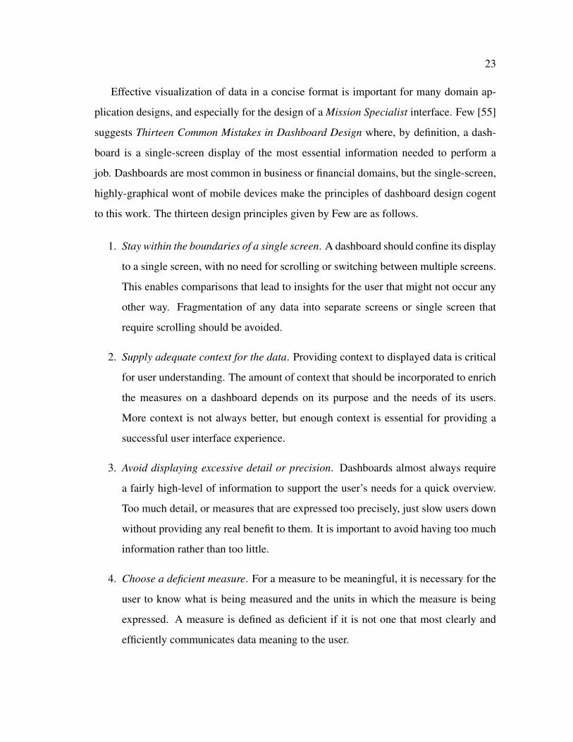
to this work. The thirteen design principles given by Few are as follows.
1. Stay within the boundaries of a single screen. A dashboard should confine its display
to a single screen, with no need for scrolling or switching between multiple screens.
This enables comparisons that lead to insights for the user that might not occur any
other way. Fragmentation of any data into separate screens or single screen that
require scrolling should be avoided.
2. Supply adequate context for the data. Providing context to displayed data is critical
for user understanding. The amount of context that should be incorporated to enrich
the measures on a dashboard depends on its purpose and the needs of its users.
More context is not always better, but enough context is essential for providing a
successful user interface experience.
3. Avoid displaying excessive detail or precision. Dashboards almost always require
a fairly high-level of information to support the user’s needs for a quick overview.
Too much detail, or measures that are expressed too precisely, just slow users down
without providing any real benefit to them. It is important to avoid having too much
information rather than too little.
4. Choose a deficient measure. For a measure to be meaningful, it is necessary for the
user to know what is being measured and the units in which the measure is being
expressed. A measure is defined as deficient if it is not one that most clearly and
efficiently communicates data meaning to the user.

24
5. Choose appropriate display media. Quantitative data should be represented in the
most appropriate format available. Graphical representations should be used for
easy visualization by the user, and should lead to straightforward comparison when
more than one data source is to be examined.
6. Introduce meaningful consistency. The means of visual display should always be
selected on the basis of what works best, even if the results in a dashboard are filled
with nothing but the same instance of data representation. Users are not likely to be
bored with consistency if they have the necessary information to do their jobs.
7. Use well designed display media. It is not enough to choose the right medium to
display the data and its message - it is also necessary to design the components
of the medium to communicate clearly and efficiently, without distraction. Use of
color, layout, and scale are always important factors.
8. Encode quantitative data accurately. Graphical representations of quantitative data
are sometimes mistakenly designed in ways that display inaccurate values. Scale
plays an especially important role here, particularly when two or more data sets are
compared within the same graphical representation.
9. Arrange the data properly. Dashboards often need to present a large amount of
information in a limited amount of space. Information should be well organized,
with appropriate placement based on importance and desired viewing sequence, and
with a visual design that does not segregates data into fragmented or meaningless
groups.
10. Highlight important data effectively or not at all. When a user looks at a dashboard,
their eyes should be immediately drawn to the information that is most important,
even when it does not reside in the most visually prominent areas of the screen. Since
all data represented on a dashboard is in essence, important, highlighted emphasis
should be activity specific.

25
11. Keep the display free of clutter and useless decoration. Even if users initially enjoy
fancy decorations upon first sight, they will eventually grow weary of it in a few
days. Static features that do not serve as a method of interaction should be kept
small and visually subtle for the user.
12. Appropriate use of color. Color should not be use haphazardly. Choices in color
should be made thoughtfully, with an understanding of how humans perceive color
and the significance of color differences. Avoid using the same color in different
sections of a dashboard because users are likely to assign meaning and comparison.
13. Design an attractive visual display. Most dashboards that have been designed are
just plain ugly. When a dashboard is unattractive, the user is put in a frame of mind
that is not conducive to its use. Care should be taken to display data in an attractive
manner, without adding anything that distracts from or obscures it.
The final set of HCI principles surveyed are from Endsley et al. [56] and represent
an approach to user-centered situation awareness design. Situation awareness, loosely de-
fined here from Endsley et al. is the act of being aware of what is happening around you
and understanding what that information means to you now and in the future. Situation
awareness is decomposed into three levels: i) perception of the elements in the environ-
ment, ii) comprehension of the current situation, and iii) projection of future status. The
eight HCI design principles given by Endsley et al. are as follows.
1. Organize information around goals. Information should be organized in terms of the
user’s major goals, rather than presenting it in a way that is technology-oriented. It
should be organized so that the information needed for a particular goal is co-located
and directly answers the major decisions associated with the goal.
2. Present level 2 situation awareness information directly - support comprehension.
As attention and working memory are limited, the degree to which displays provide
information that is processed and integrated in terms of Level 2 situation awareness
requirements will positively impact situation awareness.

26
3. Provide assistance for Level 3 situation awareness projections. One of the most dif-
ficult and taxing parts of situation awareness is projection of future states of the sys-
tem. System-generated support for projecting future events and states of the system
should directly benefit Level 3 situation awareness, particularly for less experience
users.
4. Support global situation awareness. A frequent problem for situation awareness
occurs when attention is directed to a subset of information, and other important
elements are not attended to. Designs that restrict access to information only con-
tribute to attentional narrowing for a user.
5. Support trade-offs between goal-driven and data-driven processing. Designs need
to take into consideration both top-down and bottom-up processing. The design of a
system around user goals will support goal-driven processing, while the big picture
display that supports global situation awareness will support data-driven processing
by directing the user as to where to focus attention to achieve high-priority goals.
6. Make critical cues for schema activation salient. In that mental models and schemata
are hypothesized to be key features used for achieving the higher levels of situation
awareness in complex systems, the critical cues use for activating these mechanisms
need to be determined and made salient in the interface design for a user.
7. Take advantage of parallel processing capabilities. The ability to share attention be-
tween multiple tasks and sources of information is important in any complex system.
System designs that support parallel processing of information by the user should
directly benefit situation awareness.
8. Use information filtering carefully. The problem of information overload in many
systems must still be considered. The filtering of extraneous information not related
to situation awareness needs, and reduction of data by processing and integrating

27
low-level data to arrive at situation awareness requirements, should be beneficial to
situation awareness.
2.3.2 Human-Robot Interaction Principles
As with HCI principles, there also does not exist one universally-accepted set of HRI
guidelines that have been widely adopted. Consequently, there are no formal HRI guide-
lines that address the design of a role-based interface for a mUAS human-robot team.
However, a survey of the HRI literature does reveal different investigations for narrow
aspects of HRI design such as goal-directed task analysis [57], task structure [58], and
metrics of analysis [59]. In the following paragraphs, a survey of four different - but
system-relevant - sets of design principles for HRI is presented including, where possible,
a brief summary from each author for each principle.
The first set of HRI principles surveyed are from Goodrich and Olsen [60] and are
based on previous studies of neglect tolerant autonomy and efficient interfaces. These prin-
ciples represent a cognitive information processing approach to design in HRI. Goodrich
and Olsen refer to their guidelines as the Seven Principles of Efficient Human Robot Inter-
action and are as follows.
1. Implicitly switch interfaces and autonomy modes. It is often desirable to change the
way in which a user controls a robot and receives information about the robot. Such
changes are sometimes mandated by the environment and sometimes made at the
discretion of the human; which autonomy mode and interface elements are selected
depends on the context established by the environment, communications channel,
user, etc.
2. Let the robot use natural human cues. People have extensive experience in accom-
plishing tasks and in interacting with other people. With this experience comes a
set of natural expressions. Natural language is an elusive goal but there are some

28
natural forms of expression that can be useful, such as pen-based computing and
multi-touch interaction.
3. Manipulate the world instead of the robot. The purpose of interacting with a remote
robot is to accomplish some task in the world. Insofar as is possible, robot artificial
intelligence and interfaces should be designed so as to allow the task to be done,
rather than drawing attention to the robot and the interface per se.
4. Manipulate the relationship between the robot and the world. It is sometimes diffi-
cult to develop interfaces and autonomy that directly supports world manipulation.
Human attention may need to be drawn to the robot. Information regarding the sta-
tus of the robot in relation to a goal state or information that relates robot pose to
world coordinates is useful.
5. Let people manipulate presented information. One primary purpose of an interface
is to present information, primarily about the world, the relationship between the
world and the robot, and about the robot. When information is displayed to the user,
the purpose of the information should be to support decision-making by the user.
6. Externalize memory. One primary difficulty with teleoperating a robot via camera
perspective is that the user cannot see the robot’s true point of view. To simplify
the cognitive load resulting from projecting one’s self into the perspective of the
robot, memory should be externalized to help create a proper sense of self during
operation.
7. Help people manage attention. Attention is a major bottleneck in cognitive informa-
tion processing. Even if sufficient information is presented to a user, if their attention
is not on this information than incorrect decisions can be made. Thus, it is important
for a user to properly manage attention.

29
The second set of HRI principles surveyed are from Riley et al. [61]. These HRI
principles represent situation awareness-oriented design guidelines for enhancing HRI.
The five HRI design principles given by Riley et al. are as follows.
1. Task/Mission factors. Interface design must support the perceptual, cognitive, and
physical demands imposed on the user by performance requirements as well as dif-
ferent mission parameters. Requirements for divided attention should be minimized
and the human-robot ratio should be increased to facilitate higher levels of situation
awareness.
2. System factors. Automation usage decisions must be guided by a user-centered de-
sign approach that emphasizes the goals of the human user, rather than the technol-
ogy to be built. Automation must be tempered by consideration of the effects of
different automation characteristics on user workload, situation awareness, and task
performance.
3. Environmental factors. Well-designed user interfaces will enable users to maintain
situation awareness for both their own local environment and the remote environ-
ment where the robot is located. When multiple robots or locations are involved,
interfaces will also need to support user prioritization of environments and tasks
through proper use of alerts and alarms.
4. Individual and team factors. Effective human-robot task performance is dependent
upon each user’s individual situation awareness, the team’s overall situation aware-
ness, and the team’s joint situation awareness. Interfaces should be designed to
flexibly adapt to individual differences in user innate ability, skill, and level of ex-
perience.
5. External world and user interface design factors. Other actors (humans, robots,
targets, etc.), display characteristics, and control limitations interact with other HRI
factors (task/mission, system, etc.) to influence user situation awareness. Negative

30
effects can be mitigated by designing interfaces that expressly address problems
associated with control latency and information integration, whether purely visual
or interactive in nature.
The third set of HRI principles surveyed are from Oron-Gilad and Minkov [45]. These
principles were developed based on an ethnographic survey of soldiers operating a remotely-
operated vehicle, and represent a bottom-up operational perspective. The six common
design guidelines given by Oron-Gilad and Minkov are as follows.
1. Modularity and flexibility. The interface should fit and/or adapt to different mission
properties. The user should be able to choose the most suitable configuration for a
specific mission.
2. Automation. The users should focus on the main task, which is usually video in-
terpretation and guiding troops. Automation tools and flexible level of automation
selection can free users from the technical operation of the system when necessary.
3. Training. For simple tasks, operating UAV systems is feasible even when based on a
short training period. Training efforts should focus more on mission implementation
and not merely on the operation of the system.
4. Customization. Customization can sometimes contradict the need for short, effec-
tive training. Despite this, the ability to customize the user interface is beneficial
specifically to active users.
5. Display size. The effect of display size depends on the task to be completed. A
standard laptop PC with a display screen size of 14-inches is considered satisfactory
for field-based applications, but weight and portability are primary concerns.
6. Hand-held control device. Hand-held control devices are a clearly needed for smaller
UAS. The importance of hand-held devices that can be mounted or carried on a
user’s body in some way are ideal for mobile applications.
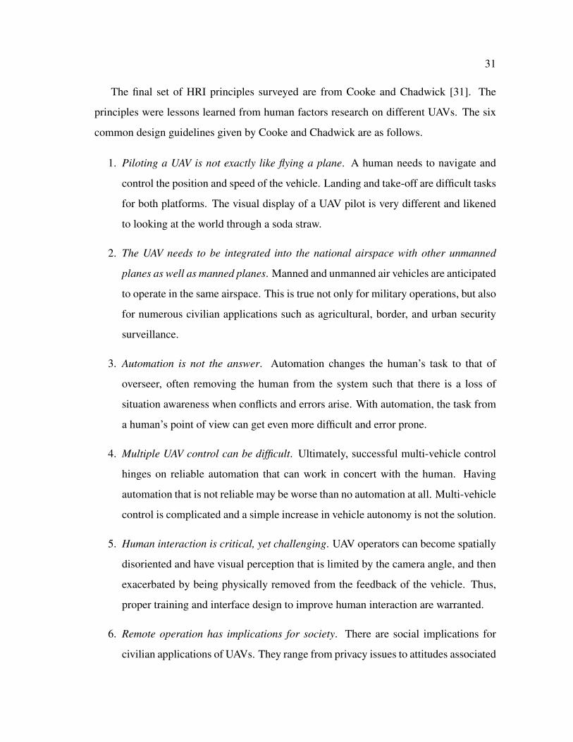
31
The final set of HRI principles surveyed are from Cooke and Chadwick [31]. The
principles were lessons learned from human factors research on different UAVs. The six
common design guidelines given by Cooke and Chadwick are as follows.
1. Piloting a UAV is not exactly like flying a plane. A human needs to navigate and
control the position and speed of the vehicle. Landing and take-off are difficult tasks
for both platforms. The visual display of a UAV pilot is very different and likened
to looking at the world through a soda straw.
2. The UAV needs to be integrated into the national airspace with other unmanned
planes as well as manned planes. Manned and unmanned air vehicles are anticipated
to operate in the same airspace. This is true not only for military operations, but also
for numerous civilian applications such as agricultural, border, and urban security
surveillance.
3. Automation is not the answer. Automation changes the human’s task to that of
overseer, often removing the human from the system such that there is a loss of
situation awareness when conflicts and errors arise. With automation, the task from
a human’s point of view can get even more difficult and error prone.
4. Multiple UAV control can be difficult. Ultimately, successful multi-vehicle control
hinges on reliable automation that can work in concert with the human. Having
automation that is not reliable may be worse than no automation at all. Multi-vehicle
control is complicated and a simple increase in vehicle autonomy is not the solution.
5. Human interaction is critical, yet challenging. UAV operators can become spatially
disoriented and have visual perception that is limited by the camera angle, and then
exacerbated by being physically removed from the feedback of the vehicle. Thus,
proper training and interface design to improve human interaction are warranted.
6. Remote operation has implications for society. There are social implications for
civilian applications of UAVs. They range from privacy issues to attitudes associated

32
with suggesting that future passenger flights may be completely pilotless. Issues
such as these should be considered for UAV integration into the national airspace.
2.4 Summary
This section provided a background overview for factors associated with Mission Spe-
cialist HRI in mUAS. Human-robot team theory and modeling were discussed in the
context of a Joint Cognitive System. The general form of the Shared Roles Model was
presented. Details of three HRI studies from the research literature, which included de-
scriptions of the human-robot team and the interaction technology used, were given. Also
provided were details on commercial mUAS that have not been formally studied in the
literature. Finally, eight sets of interaction principles (from both human-computer interac-
tion and human-robot interaction literature) applicable to mUAS were reviewed.
2.5

33
3. THEORY AND APPROACH
This section presents the theoretical foundations and approach for a Mission Specialist
interface for mUAS. A formulation of the Shared Roles Model for mUAS is presented,
including three formal human team roles synthesized from the literature (Flight Director,
Pilot, and Mission Specialist). Three findings are developed from mUAS field studies
literature that suggest a Mission Specialist role will require a small, mobile, and visual
interface that is role-specific and software-based. Five recommended design guidelines
are synthesized from a survey of current interaction principles, which result in a system
architecture for a Mission Specialist interface for mUAS.
3.1 Shared Roles Model for a Micro Unmanned Aerial System
To formulate the Shared Roles Model for mUAS, the Knowledge Worker and Flight
Director roles are excluded in order to simplify focus toward the Mission Specialist (Fig-
ure 3.1). Formal role labels in the model are defined in the following sections: Pilot and
Mission Specialist. Payload and platform telefactors, representing egocentric and exocen-
tric perspectives, respectively, remain consistent for this work. An interface is shown to
illustrate the manner in which each human interacts with the micro UAV. Figure 3.1 rep-
resents the the state of the practice where the Mission Specialist is a passive viewer of
the Pilot interface; verbal communication is from the Mission Specialist to the Pilot for
payload camera control and image capture.
3.1.1 Flight Director Role Description
Proper supervisory planning, coordination, and control of any operation are critical to
its success, especially for a mUAS human-robot team. Across the mUAS field studies
literature, one or more human team member responsible for directing the mission was

34
Fig. 3.1. Formulation of the the Shared Roles Model for mUAS that Fo-cuses Only on the Pilot and Mission Specialist Roles and Represents theState of the Practice Where the Mission Specialist is a Passive Viewerof the Pilot Interface. The Blue Arrow Indicates Verbal Communicationfrom the Mission Specialist to the Pilot for Payload Camera Control andImage Capture. The Knowledge Worker and Flight Director Roles areExcluded to Simplify Focus Toward the Mission Specialist (Formulatedfrom Murphy and Burke [20]).

35
found to be a recurring role. For the Shared Roles Model in this work, this role will be
referred to as the Flight Director.
3.1.2 Pilot Role Description
Piloting the UAV is an essential human role and common to all mUAS human-robot
teams. However, the degree to which one or more individuals is solely responsible for
flight control activity may vary; navigation responsibilities may also be included as a role
responsibility. For the formulation of the Shared Roles Model for mUAS, this human team
role will be referred to as the Pilot.
3.1.3 Mission Specialist Role Description
mUAS operational capabilities allow a human-robot team to insert themselves re-
motely for the main purposes of visual investigation and recording and, in more advanced
vehicle systems, delivery of an onboard payload. It is therefore incumbent that one mem-
ber of the human team be solely responsible for carrying out these kinds of activities. This
role is referred to as the Mission Specialist.
3.2 Human-Robot Interaction Findings in Micro Unmanned Aerial Systems
In this section, an analysis is provided for interaction technology found for the Mission
Specialist role across all mUAS and reviewed in Section 2.1.2. Three findings are given
that suggest current Mission Specialist performance in mUAS may be suboptimal due to
the sharing of a single Pilot-oriented interface or a reuse of the Pilot interface.
3.2.1 Small, Mobile, and Visual Displays
The interaction technology used by the Mission Specialist had the three primary char-
acteristics: mobile, small, and visual. Mobility was observed in all of the interfaces that the

36
Mission Specialist interacted with. Handheld controllers that could be carried and handled
by one individual were the most common form of interaction device. Inputs were accom-
plished by the Mission Specialist through interactions with small controls, most commonly
isotonic joysticks and pushbuttons on the handheld controllers. Interactive feedback to the
Mission Specialist was visual and took the form of small video displays, graphical menus,
and real-time video.
3.2.2 Shared, Duplicate, or Passive Interaction
In the literature the Mission Specialist either shared the same interface with the Pilot
role, was given a duplicate of the Pilot interface, or was a passive viewer. No UAV system
in the literature had a role-specific Mission Specialist interface; however, the availability
of API customization in commercial UAV systems does allow for that possibility. Given
that the Mission Specialist is a unique human team role, a distinct or different modality of
HCI technology from that of the Pilot would be expected. Therefore, existing interfaces,
in general, do not support the functionality of the Mission Specialist role.
3.2.3 Lack of Software-Based Interfaces
A mUAS Mission Specialist is more likely to use a hardware interface than a soft-
ware interface. The responsibility of the Mission Specialist is for data acquisition and,
often, interpretation. The possibility for direct manipulation of the imagery for verifica-
tion, including extracting single static images and a video series for real-time playback
while the flight continued to be recorded, appeared present in only one [45] of the ten
surveyed mUAS (the full extent of which, however, was not clear). It should also be noted
that this interaction was accomplished through the UAV interface with the broadest array
of available HCI technology (isotonic joystick, keyboard, mouse, trackball, pushbutton
panel, and touch screen). Interpretation support (such as synthetic overlays) and other
software initiated functions were present on five of the ten systems surveyed, but these
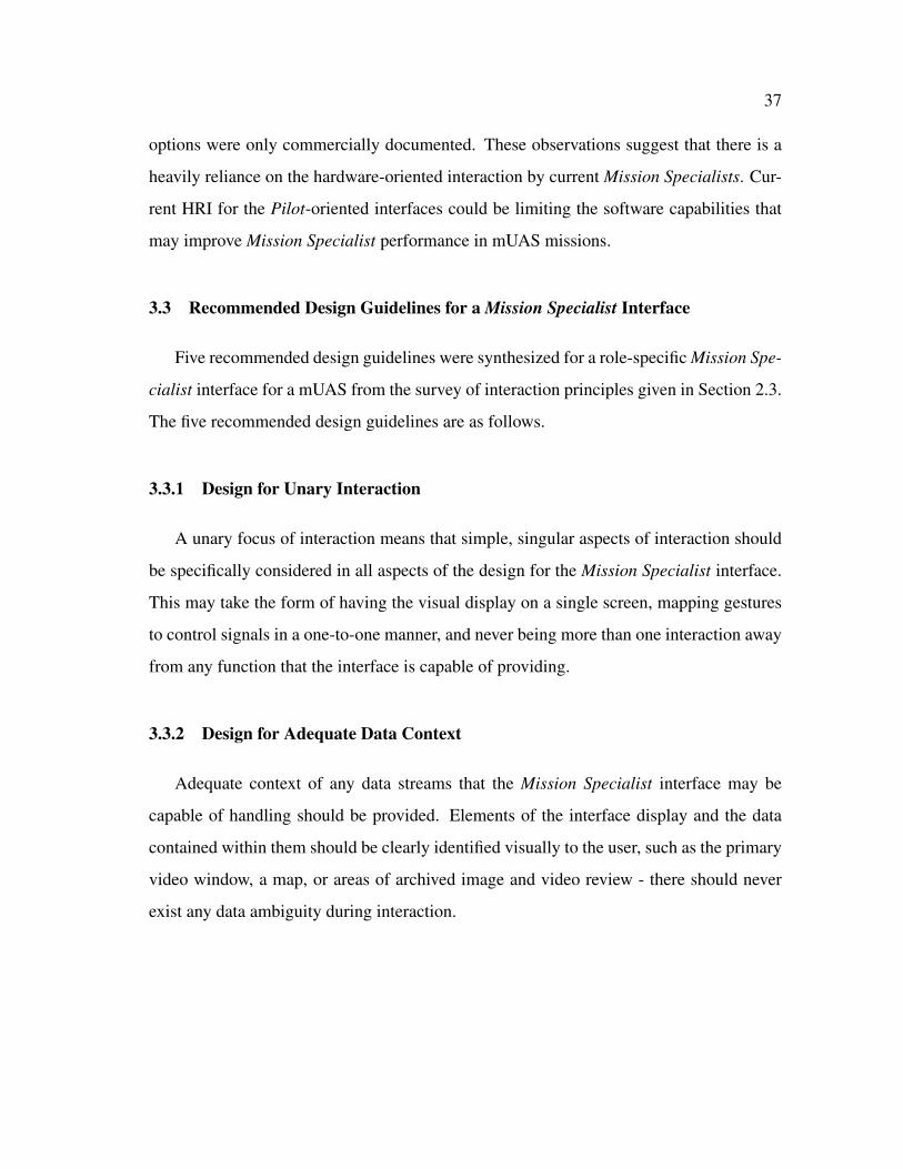
37
options were only commercially documented. These observations suggest that there is a
heavily reliance on the hardware-oriented interaction by current Mission Specialists. Cur-
rent HRI for the Pilot-oriented interfaces could be limiting the software capabilities that
may improve Mission Specialist performance in mUAS missions.
3.3 Recommended Design Guidelines for a Mission Specialist Interface
Five recommended design guidelines were synthesized for a role-specific Mission Spe-
cialist interface for a mUAS from the survey of interaction principles given in Section 2.3.
The five recommended design guidelines are as follows.
3.3.1 Design for Unary Interaction
A unary focus of interaction means that simple, singular aspects of interaction should
be specifically considered in all aspects of the design for the Mission Specialist interface.
This may take the form of having the visual display on a single screen, mapping gestures
to control signals in a one-to-one manner, and never being more than one interaction away
from any function that the interface is capable of providing.
3.3.2 Design for Adequate Data Context
Adequate context of any data streams that the Mission Specialist interface may be
capable of handling should be provided. Elements of the interface display and the data
contained within them should be clearly identified visually to the user, such as the primary
video window, a map, or areas of archived image and video review - there should never
exist any data ambiguity during interaction.
38
3.3.3 Design for Natural Human Interaction
There are many different modes of interaction for user interfaces - graphical, textural,
written, haptics, etc. For a Mission Specialist interface that will be used in field conditions,
the impetus of small and mobile form-factoring necessarily dictates users having haptics-
based interaction since keyboards and other ancillary devices become peripheral premiums
and could be difficult to use.
3.3.4 Design for Cueing and Communication
In the context of the Social Roles Model, a human-robot team must be able to ap-
propriately cue and communicate among one another. This should be taken into account
for the design of a Mission Specialist interface and may manifest as subtle alert messages
when an image has been captured, or as other visual cues indicating that data is available
or there is a message to be communicated within the team.
3.3.5 Design for Flexibility and Expansion
No good interface design is ever perfect or permanent. Great interface designs al-
low for flexibility towards the user as new information is discovered about humans and/or
domains. Likewise, advances in technology always provide new leverages that can po-
tentially improve existing user interaction. The ability to easily expand functionality will
provide longevity to any Mission Specialist interface design.
3.4 System Architecture for a Mission Specialist Interface
An interface design architecture based on the five recommended design guidelines syn-
thesized for a Mission Specialist interface (see Section 3.3) is given in Figure 3.2. The Mis-
sion Specialist has two modes of interaction with the interface: i) viewing of the real-time
data coming from the UAV, and ii) sending control signals to the payload camera. Control

39
Fig. 3.2. Interface Design Architecture for a Mission Specialist Interface for mUAS.
40
signals include camera tilt, zoom, and image capture. Likewise, the UAV transmits real-
time video and receives camera control signals. Communication is done wirelessly and
through a central network server. Data is stored on the local interface device. Additional
features of location-based services, static image review, and video review could also be
integrated but will not be individually evaluated in this work. Additional expansion of
the interface technology could include multiple co- or remotely-located Mission Specialist
interfaces networked together to form a common space of interaction, and could possibly
include other roles such as the Pilot.
3.5 Summary
This section discussed the theory and approach for the design of a Mission Spe-
cialist interface for mUAS. The Shared Roles Model was formulated for mUAS. Three
formal human-robot team roles were synthesized from the literature for use in the Shared
Roles Model: Flight Director, Pilot, and Mission Specialist. Five recommended design
guidelines, based on a synthesis of interaction principles from the human-computer and
human-robot interaction literature, were given. A system architecture was created, based
on the five recommended design guidelines, for a Mission Specialist interface.
3.6

41
4. IMPLEMENTATION
The Mission Specialist interface with system architecture as described in Section 3.4
was implemented on an Apple R� iPad device. Programming of the interface was accom-
plished using both the Objective-C and standard C programming languages. Additional
open-source static C libraries that provide networking and real-time video processing ca-
pabilities were used.
4.1 Hardware Platform Description
There are several mobile devices available on the current market. Two of the more
capable devices types for input and visualization are mobile tablets (e.g. Apple R� iPad,
Samsung Galaxy) and tablet PCs (e.g., Lenovo Thinkpad X200 Tablet, Dell Latitude XT2).
Mobile tablets are typically 10-inches or smaller in screen size and resemble slate-based
tablet PCs in terms of their form-factor; they are usually similar to smartphones (e.g.,
Apple R� iPhone or Motorola Droid X) with regard to their operating systems (iOS and
Android). Tablet PCs are larger and resemble the operational characteristics of normal
laptops, including size and operating system. Based on the hardware platforms available,
the Apple R� iPad was selected for this work.
The Apple R� iPad platform was selected for this work due to its mobility, unique multi-
touch interface, and ability to provide a usable display in outdoor conditions. The Apple R�
iPad hardware affords three important touch-based gestures that can be customized and
used for designing an interface: swipes, pinches, and taps (Figure 4.1). For control of
the payload camera by the Mission Specialist interface, swipe up and down gestures will
proportionally control the up and down tilt of the camera, in and out pinch gestures will
proportionally control the zoom in and zoom out of the camera, and finger tap gestures will
control button functionality (e.g., capture an image). Each of these gestures represents a
natural and intuitive manner of interaction with the payload camera.

42
Fig. 4.1. Touch-Based Gestures Afforded in the Role-Specific MissionSpecialist Interface Design (Adapted from GestureWorks.com).

43
4.2 Software Platform Description
The programming language that the Apple R� iPad uses is Objective-C; however, much
of the non-interface programming (e.g., network connectivity, etc.) was done using stan-
dard C with open-source static libraries. The Mission Specialist interface communicates
wirelessly through an ad hoc network to a dedicated C-based server socket on a lap-
top computer running Microsoft Windows XP that is connected to the UAV base sta-
tions. This manner of connectivity was a requirement of the AirRobot R� AR-100B and
DraganFlyerTM X6 platforms but, due to the server software being written in standard C,
could easily be adapted to other robot platforms that may support a different operating
system (e.g., Linux or OSX). Real-time imagery from the payload camera is streamed to
the Mission Specialist interface using a compiled static library version of Willow Garage’s
OpenCV software [62].
4.3 Summary
This section described the implementation of a Mission Specialist interface for a
mUAS. The implementation was based on set of five recommended design guidelines and
a system architecture established in Section 3. Detailed descriptions of the Apple R� iPad
platform and its software programming language and interaction capabilities were given.
4.4

44
5. EXPLORATORY STUDY
This section describes the overview, participants, measurements, results, and observa-
tions from an exploratory study of the Mission Specialist interface. The study consisted
of 16 untrained responders that were CBRN experts, but had no mUAS experience, each
participating in two different UAS mission trials to visually evaluate and capture images
of a train derailment incident involving hazardous materials. Four types of measurements
(performance, biophysical, survey, and audio/video) were recorded for each participant.
Observations from the study suggested that with refinements, a Mission Specialist inter-
face could be a useful tool for further studies to explore the HRI of individual Mission
Specialist role performance in a mUAS.
5.1 Overview
The purpose of the exploratory study was to i) field test the Mission Specialist inter-
face (Figure 5.1) within the context of actual mUAS missions and ii) explore the types of
measurable interactions exhibited by the Mission Specialist. All of the exploratory study
mission trials took place at the Disaster City R� facility located on the campus of Texas
A&M University. The context of the mission was a simulated train derailment involving
hazardous materials, which is representative of the CBRN domain.
A 16 participant mixed-model study design was developed from the HRI study guide-
lines in [63]. The number of participants was chosen based on a power analysis to attain
power equal to 0.80 in a single group measures design at an alpha equal to 0.05, given an
estimate of mean correlation for repeated measures of 0.80. Each participant made two
different UAV flights - one per mission trial - with each flight having three pre-defined
stationary waypoints and corresponding sets of questions regarding the identification of
certain objects (e.g., identify any punctures or ruptures in the tanker truck and capture an
image of each you may identify) (Figure 5.2). The maximum duration of the flights were
limited to 7-minutes for consistency. The order of the interfaces (conditions) was random-

45
Fig. 5.1. Initial Implementation of the Mission Specialist Interface on anApple R� iPad. A Captured Image of the Simulated Train Derailment isShown. The Mission Specialist Swipes (Up and Down) and Pinches (Inand Out) Directly on the Video Display to Control the Payload Camerafor Tilt (Up and Down) and Zoom (Out and In). Images are Capturedby Pressing the Capture Image Button (Courtesy of Center for Robot-Assisted Search and Rescue).
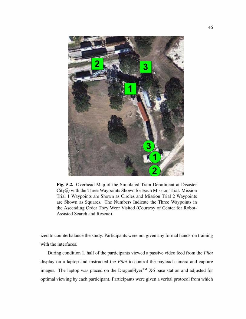
46
Fig. 5.2. Overhead Map of the Simulated Train Derailment at DisasterCity R� with the Three Waypoints Shown for Each Mission Trial. MissionTrial 1 Waypoints are Shown as Circles and Mission Trial 2 Waypointsare Shown as Squares. The Numbers Indicate the Three Waypoints inthe Ascending Order They Were Visited (Courtesy of Center for Robot-Assisted Search and Rescue).
ized to counterbalance the study. Participants were not given any formal hands-on training
with the interfaces.
During condition 1, half of the participants viewed a passive video feed from the Pilot
display on a laptop and instructed the Pilot to control the payload camera and capture
images. The laptop was placed on the DraganFlyerTM X6 base station and adjusted for
optimal viewing by each participant. Participants were given a verbal protocol from which

47
they could issue the following camera control instructions to the Pilot: tilt camera up, tilt
camera down, zoom camera in, zoom camera out, and take photo. The second half of
the participants used the Mission Specialist interface to actively control the camera and
capture images. The Apple R� iPad was placed on a camera stand that was adjusted for
optimal viewing and interaction by each participant. Each participant in condition 2 used
the interface they did not have in condition 1. For both flights, participants were given a
verbal protocol from which they could issue the following UAV control instructions to the
Pilot: turn left -degrees and turn right -degrees. The verbal protocol for UAV control
was made available to participants since the DraganFlyerTM X6 platform camera mount
cannot turn left or right.
The DraganFlyerTM X6 platform was used during the exploratory study. A professional
pilot with extensive experience operating the vehicle served in the Pilot role for all of the
mission trials. The Pilot was instructed to only follow the verbal commands issued by
participants regarding camera and UAV control and to not anticipate the intentions of the
participants.
5.2 Participants
Participants were selected primarily for their experience as specialized responders from
CBRN in coordination with the Texas Engineering Extension Service (TEEX). Detailed
demographic information about each participant was collected through a pre-assessment
survey consisting of 18 questions. Of the 16 participants, 14 were men and 2 were women.
Age ranges were: 25-years to 34-years (1 participant), 35-years to 44-years (2 partici-
pants), 45-years to 54-years (10 participants), and 55-years and older (3 participants). Each
of the participants had prior experience with a mobile touch-based device (e.g., Apple R�
iPhone or iPad), with frequency of use from several times per week to continuously, for
a period of at least one year. The types of interactions participants had with their mobile
touch-based devices were: use it as a phone (all participants), check email (15 partici-
pants), surf the Internet (14 participants), and play games (7 participants). A majority of

48
the participants had previously used a Tablet PC or other pen-based device (e.g., Palm
PDA) but indicated only short-term and/or infrequent usage. There were 9 participants
who had prior experience controlling a remote camera either on a robot or through the
Internet. Each of the participants, except one, had played a major role in actual CBRN-
related missions. Two participants had been involved with a robot-assisted search and
rescue mission (CBRN-related), which was reported as an exercise.
5.3 Measurements
There were four different types of measurements taken during the exploratory study: i)
the number of completed tasks, ii) written post-assessment surveys, iii) biophysical mea-
surements, and iv) audio/video recordings. Details for each type of measurement are as
follows.
5.3.1 Task Completion
Task completion was measured by the number of images a participant captured during
each mission trial. Images captured when using the Mission Specialist interface were saved
on both the Apple R� iPad and the payload camera. When participants passively viewed
the video feed and instructed the Pilot to capture an image, resulting images were stored
only on the payload camera. All images were time-stamped so they could be correctly
associated with the corresponding participant and mission trial.
5.3.2 Post-Assessment Surveys
Post-assessment surveys to evaluate role empowerment (confidence and comfort) as
reported by the participant in the Mission Specialist role were given. The post-assessment
survey consisted of two parts of 10 questions each, and was given after each mission
trial (i.e., a post-assessment survey after using the passive-coordinated interface, and a

49
post-assessment survey after using the active-coordinated interface - each with identical
questions but in the context of the interface used). Responses addressed confidence and
comfort in interface actions as measured on a standard 5-point Likert scale.
5.3.3 Biophysical
Participant heart rate was recorded during both mission trials. Biopack BioNomadix R�
sensors were used for wireless recording and were placed on the non-dominant hand of
each participant. Prior to the set of mission trials, each participant was asked which hand
they would swipe a mobile device with and the sensor was placed on the opposite hand
indicated. Active recording status was verified before and throughout each mission trial.
5.3.4 Audio and Video
Four high-definition GoPro R� cameras were used for recording audio and video. The
first camera was mounted on a hard hat that each participant wore to provide a first-person
perspective. The second camera was mounted on the stand that held the Apple R� iPad
to provide a view of each participant when they interacted with the Mission Specialist
interface. The third camera was mounted to the top of the laptop to provide a view of
each participant when they viewed the mirrored display from the Pilot. A final camera
was placed approximately 20-feet behind the participants to capture an overall view of the
study. Video from the UAV was also recorded. All cameras were calibrated before each
mission trial to ensure a correct field of view.
5.4 Results
The Mission Specialist interface was successfully used in 16 mUAS mission trials.
Measurement data were collected for task completion, levels of stress, and role empower-
ment. A between ⇥ within analysis of variance (ANOVA) was used to analyze the results

50
from the mixed-factor design study to determine if there was a significant effect between
participants and/or within participants, based on the order the participants used the two
interface types and the interface type used.
5.4.1 Number of Completed Tasks
The mixed-model design for number of completed tasks consisted of the between par-
ticipants factor being the number of captured and the within participants factor being the
number of captured images per interface type. These two completed task variables were
measured by reviewing the number of captured images on the payload camera for each
condition. The interaction of which interface was presented first was also examined for its
impact.
The between participants analysis results (F[1,14] = 0.32, p = 0.58) indicated there was
not an effect of order in which the interfaces were presented. This result would suggest
the participants are likely to perform a similar number of completed tasks regardless of the
order in which they used the interfaces. The within participants analysis results (F[1,14]
= 12.04, p = 0.004) suggest there is significant interaction within participants based on the
number of images captured on the mission trials and based on the type of interface used.
Image capture statistics were examined to determine the significance of the within par-
ticipants analysis results. Participants on average captured more images on both mission
trials when using the passive approach (M = 6.63, SD = 3.01) than they did using the
Mission Specialist interface (M = 3.88, SD = 2.33). On mission trial 1 when participants
used the passive approach, more images were captured (M = 6.75, SD = 2.66) than when
using the Mission Specialist interface (M = 4.63, SD = 2.26). On mission trial 2, partici-
pants using the passive approach captured more images (M = 6.50, SD = 3.51) than when
using the Mission Specialist interface (M = 3.13, SD = 2.30). These results suggest that
mission trial 1 (M = 4.94, SD = 2.56) and mission trial 2 (M = 5.56, SD = 1.33) had, on
average, a difference of less than one captured image. There is also an average of less than
a difference of one captured image based on which interface was first used.
51
5.4.2 Levels of Stress
The level of stress consisted of the within participant factor being the average heart
rate (in beats per minute) per interface type. This biophysical variable was measured by
averaging the heart rate data of each participant for each condition. The interaction of
which interface was presented first was also examined for its impact. All heart rate results
were determined to be non-significant.
5.4.3 Role Empowerment
The mixed-model design for role empowerment (confidence and comfort) consisted of
the between participants factor being the average 5-point Likert confidence score and the
within participants factor being the average 5-point Likert confidence score per interface
type. These two survey variables were measured by averaging the post-assessment sur-
vey data of each participant for each condition. The interaction of which interface was
presented first was also examined for its impact.
The between participants analysis results (F[1,14] = 1.48, p = 0.24) indicated there
was not an effect of order in which the interfaces were presented. This result suggests the
participants are likely to experience similar role empowerment regardless of the order in
which they used the interfaces. The within participants analysis results (F[1,14] = 14.35, p
= 0.002) suggest there is significant interaction within participants based on reported role
empowerment for the mission trials and the order in which the interfaces were presented.
Post-assessment survey statistics were examined to determine the significance of the
within participants analysis results. Participants on average reported more role empower-
ment regardless of mission trial when using the passive approach (M = 4.53, SD = 0.80)
than they did using the Mission Specialist interface (M = 3.56, SD = 1.07). On mission
trial 1 when participants used the passive approach, more role empowerment was reported
(M = 4.33, SD = 0.96) than when using the Mission Specialist interface (M = 3.84, SD
= 0.97). On mission trial 2, participants using the passive approach reported more role

52
empowerment (M = 4.73, SD = 0.59) than when using the Mission Specialist interface
(M = 3.28, SD = 1.16). These results suggest that mission trial 1 (M = 3.80, SD = 0.74)
and mission trial 2 (M = 4.28, SD = 0.63) had, on average, less than one half confidence
rating point difference. There is also an average of less than one confidence rating point
difference based on which interface was first used.
5.5 Observations
An analysis of the exploratory study results for the Mission Specialist interface resulted
in five observations: viewing only a shared display and instructing the Pilot tended to re-
sult in more captured images, well-defined identification and image capture tasks resulted
in similar results using both interfaces, similar levels of stress are experienced with both
interfaces, similar visual feedback confusion was experienced using both interfaces, and
more positive role empowerment was reported for the passive approach. These observa-
tions suggested that with refinements, a Mission Specialist interface could be a useful tool
for further exploring role performance in mUAS.
5.5.1 More Captured Images with Passive Display
Participants captured more images when viewing a passive display and instructing the
Pilot to control the payload camera and capture images. During the study, though time
was emphasized as a limiting factor (i.e., 7-minute maximum flight time) and participants
were asked only to capture a representative image, there was no penalty associated with
capturing additional images. This led to multiple instances where participants using the
passive approach directed the Pilot to perform exploratory 360-degree rotations of the
UAV in order to capture several different images surrounding the train derailment. A
similar observation did not occur with the Mission Specialist interface where participants
were more focused on controlling the payload camera. This difference could be due to the

53
fact that giving instructions requires less effort of the participant, though it results in more
action being taken by the Pilot.
5.5.2 Similar Captured Images for Well-Defined Tasks
For identification and image capture tasks that were well-defined, participants pro-
vided satisfactory responses and captured images in a similar manner when using both
interface approaches. Well-defined tasks included reading and capturing images of var-
ious numbers printed on train cars and identifying punctures, ruptures, and vents on an
overturned tanker truck. For tasks that were not well-defined, participants captured more
representative images when viewing the passive display and instructing the Pilot to con-
trol the payload camera. Identification and image capture tasks that were not well-defined
included identifying any hazardous product flows or possible exposure hazards associated
with the derailment.
5.5.3 Similar Levels of Stress
Participants experienced a similar level of stress as measured by average heart rate for
both interfaces. The Mission Specialist interface was not observed to induce any more
stress than the passive approach. Each of the participants had been trained as a specialized
emergency responder to work in high-stress situations; therefore, as realistic as the simu-
lated train derailment was, it may not have fully replicated the conditions for which they
are uniquely trained. Additionally, both types of interfaces used in the mission trial con-
ditions represented a new experience to each of the participants, thus the non-significant
level of stress recorded may have reflected the general lack of familiarity with both of the
interface technologies.

54
5.5.4 Lack of Adequate Visual Feedback
Participants experienced a lack of adequate visual feedback when using both interface
approaches. In both interface cases, each participant experienced at least one instance of
difficulty with establishing payload camera status (i.e., extent of zoom or degree of tilt).
For example, participants would attempt to zoom the payload camera in when the camera
was already at maximum zoom. This suggests that payload camera status feedback should
be provided visually to the Mission Specialist even though this feedback is not presently
available to the Pilot. This is especially important if the Mission Specialist is a member of
an ad hoc human-robot team and does not have training similar to that of the Pilot.
5.5.5 Greater Role Empowerment with Passive Display
Participants reported more positive role empowerment when viewing a passive display
and instructing the Pilot to control the payload camera and capture images. Since role em-
powerment was reported as confidence in the ability to execute tasks with each interface,
a possible cause of lower role empowerment may be latency. Each of the participants ex-
perienced some degree of latency in the payload camera controls when using the Mission
Specialist interface. This was due in part to the technical limitations of an older UAV plat-
form that was used for the study and may not be present in newer or different platforms.
Conversely, the proprietary Pilot controls allowed for faster and smoother operation of the
payload camera. If the control scheme for the Pilot could be better adapted to software-
based control for a active-coordinated Mission Specialist interface, the latency issue would
be likely be resolved.
5.6 Recommendations
Through an evaluation of the exploratory study observations, verbal participant feed-
back, and discussions with other specialized emergency responders at TEEX, regarding

55
the Mission Specialist interface, there were three recommendations for refinements and
future studies: deeper focus on occupational expertise and role empowerment, more vi-
sual feedback is necessary on the interface, and UAV platform latency must be reduced.
Refinements of the interface necessitate more precise interface terminology, which is de-
scribed as active, passive, or dual.
5.6.1 Deeper Focus on Role Empowerment
Participant occupational experience and personality were minimally examined dur-
ing the exploratory study. Additionally, there was no summative post-assessment survey
instrument given in the exploratory study that compared both interface methods (only for-
mative post-assessments after each interface condition). An examination of participant
pre-assessment reporting found that most of the participants currently hold, or have held,
more senior supervisory positions. This may suggest that in their current or prior roles
as supervisors, participants may be more comfortable issuing directives (i.e., capture an
image) than doing technical tasks themselves. A more appropriate approach to partici-
pant selection would be to ensure a broad range of command- and non-command-level
experience in the participant pool. Likewise, a summative assessment after both interface
conditions are complete to assess role empowerment at a task-level resolution may provide
insight into why participants perform in a particular manner with each interface condition.
5.6.2 More Visual Feedback on Interface
An inadequate level of visual feedback for the Mission Specialist interface was re-
ported by all of the participants in the exploratory study. This became especially apparent
when the robot encountered poor wind conditions (greater than 10-miles per hour) and be-
gan pitching backwards and forward, which would often interfere with payload camera tilt
inputs (i.e., it was unclear to the participants that they were over or under tilting). Zoom
was also found to be an issue in both interface conditions as all of the participants. In the

56
case of the Mission Specialist interface condition, participants would often try to zoom
in or out when the camera was at maximum zoom. This was also observed in the pas-
sive interface condition when they asked the Pilot for additional zoom when the payload
camera was already at a maximum. Final recommendations from the exploratory study
for refinements to the Mission Specialist interface are to include payload camera tilt and
zoom indicators, an overview map, compass, and real-time position of the robot (Figure
5.3). The addition of the role focused information to the interface effectively focused the
visual common ground for the Mission Specialist.
5.6.3 Reduce UAV Platform Latency
Each of the participants in the exploratory study experienced some degree of latency
in the payload camera controls when using the Mission Specialist interface. This was due
in part to the technical limitations of an older UAV platform that was used for the study
and may not be present in newer or different platforms. Similar to the trend observed
for the number of captured images, the command-level of experience present in each of
the participants may have resulted in latency driving them to be more confident to issue
instructions to the Pilot role. In future studies, it is recommended that any payload camera
latency be minimized in order to provide an adequate evaluation experience.
5.7 Interface Terminology Precision
With the refinements to the Mission Specialist interface resulting in a third version, it
is appropriate to consider more precise terminology to define the method of interaction
which can also be visualized with the Shared Roles Model (Figure 5.4). When a Mission
Specialist is only passively viewing a filtered video feed and instructing the Pilot for pay-
load camera control and image capture, this is referred to as a passive-coordinated, filtered
interface (Figure 5.4a). The Mission Specialist interface in the exploratory study is consid-
ered to be active-coordinated, filtered (Figure 5.4b) since it permits only direct control of

57
Fig. 5.3. Refinements of the Role-Specific Mission Specialist InterfaceInformed by the Exploratory Study. A Captured Image of the Simu-lated Train Derailment is Shown. The Mission Specialist Swipes (Up andDown) and Pinches (In and Out) Directly on the Video Display to Con-trol the Payload Camera for Tilt (Up and Down) and Zoom (Out and In).Images are Captured by Pressing the Capture Image Button. AdditionallyAdded are Zoom and Tilt Indicators, an Overview Map, Position of theRobot, and a Digital Compass (Courtesy of Center for Robot-AssistedSearch and Rescue).

58
Fig. 5.4. Shared Roles Model Representations of the Mission Special-ist Interface Versions. (a) The Passive-Coordinated, Filtered InterfacePermits Only Passive Viewing of the Filtered Pilot Display and VerbalDirection of the Pilot. (b) The Active-Coordinated, Filtered InterfacePermits Only Direct Control of the Payload Camera and Limited VerbalCommunication with the Pilot. (c) The Dual-Coordinated, Role-SpecificInterface Permits Direct Control of the Payload Camera and Full VerbalCommunication with the Pilot. Observed Contention for Payload CameraControl is Shown in Red (Courtesy of Center for Robot-Assisted Searchand Rescue).
the payload camera and little verbal communication with the Pilot. The refinements to the
Mission Specialist interface combined with the option to verbally coordinate payload cam-
era control and image capture with the Pilot identify it as a dual-coordinated, role-specific
interface (Figure 5.4c). These more precise interface descriptions will be used throughout
the remainder of this paper.
5.8 Summary
To summarize, this exploratory study for a mUAS Mission Specialist provided obser-
vations that when using a role focused interface fewer images were captured, well-defined
tasks resulted in a similar number of images captured, similar levels of stress were experi-
enced, adequate visual feedback was not experienced, and less positive role empowerment
was reported by the Mission Specialist than when viewing a mirrored display and in-
structing the Pilot. The fewer number of images captured when the Mission Specialist

59
used the role focused interface may depend on the cost associated with capturing images,
which the exploratory study did not adequately address. More specifically, the amount
of effort required to complete a task was not considered and may negatively impact the
Pilot role. Well-defined tasks resulted in a similar number of correct identifications and
images captured with both interfaces. Future studies should focus on well-defined tasks
for the evaluation of interfaces. The levels of stress experienced by a Mission Specialist
are expected to be similar, regardless of the type of interface used, and may depend on
the training of the participant. An actual train derailment scenario (i.e., an ethnographic
study) may result in different or higher levels of stress experienced by similar participants.
A lack of adequate visual feedback was experienced by all participants in this study. Fu-
ture interfaces should incorporate visual feedback indicators for the payload camera status
even though this information may not be accessible to the Pilot. Less positive role empow-
erment was reported when using the Mission Specialist interface, which was likely due to
latency in the controls that were used. Removing this confound may result in greater levels
of confidence for users of a Mission Specialist interface.
5.9

60
6. EXPERIMENTAL METHODS AND DESIGN
This section presents the experimental methodology and design for assessing the use of
a role-specific Mission Specialist interface for mUAS. Three hypotheses are outlined (with
expected findings) that were empirically used to answer the primary research question
given in Section 1.1. Details of the experiment are given, including those for participants,
facilities, equipment, and personnel. Assessment of the participants is discussed, including
pre- and post-assessment surveys, as well as the metrics for measuring individual Mission
Specialist performance. The study protocol and contingency plan for this investigation are
also provided in this section.
6.1 Study Overview
A 10 participant mixed-model experimental study was conducted at the Disaster City R�
facility at Texas A&M in the context of a simulated train derailment involving hazardous
materials. Each participant received interface instructions and participated in a 5-minute
training flight prior to each interface condition. Two different UAV flights were made, one
per mission trial, with each flight having three pre-defined stationary waypoints (Figure
6.1); participants completed activities and answered questions at each waypoint, consist-
ing of object identification, evaluation, and capturing images. The maximum duration of
the flights were limited to 10-minutes for consistency and participants were instructed that
their goal was to capture images for all of the questions at all of the waypoints within this
period of time. The order of the interfaces (conditions) was randomized to counterbalance
the study. An AirRobot R� AR100-B UAV was used in the experimental study.
During condition 1, half of the participants used the passive-coordinated, filtered inter-
face on an Apple R� iPad and instructed the Pilot to control the payload camera and capture
images. Participants were given a verbal protocol from which they could issue the follow-
ing camera control instructions to the Pilot: tilt camera up, tilt camera down, turn camera
left, turn camera right, zoom camera in, zoom camera out, and take photo. The second half

61
Fig. 6.1. Frontal and Overhead Map Views of the Simulated Train De-railment at Disaster City R� with the Three Waypoints Shown for EachMission Trial. Mission Trial 1 Waypoints are Shown as Circles and Mis-sion Trial 2 Waypoints are Shown as Squares. The Numbers Indicate theThree Waypoints in the Ascending Order They Were Visited (Courtesy ofCenter for Robot-Assisted Search and Rescue).
of the participants used the dual-coordinated, role-specific interface to control the camera
and capture images (Figure 5.3). Participants could additionally, at any time, provide the
same verbal commands to the Pilot that were available for the passive-coordinated, filtered
interface condition. Each participant in condition 2 used the interface they did not have in
condition 1.
6.2 Research Hypotheses and Expected Findings
There were three hypotheses and expected findings for the formal evaluation of a role-
specified interface for the Mission Specialist human team member role that assesses affects
on individual Mission Specialist role performance. The hypotheses address task role em-
powerment, task completion time, and levels of stress.
62
6.2.1 Same or Less Task Completion Time
Hypothesis 1 proposed that a Mission Specialist using a dual-coordinated, role-specific
interface will complete tasks at the same speed or faster, as measured by the time it takes
to complete assigned tasks. It was expected that the Mission Specialist would complete
tasks faster having shared control of the payload camera with the Pilot.
6.2.2 Same or Less Stress
Hypothesis 2 proposed that a Mission Specialist using a dual-coordinated, role-specific
interface will experience the same or less stress, as measured by the biophysical parameter
heart rate. It was expected that the Mission Specialist role would experience less stress
during the completion of a mission due to greater spatial and functional flexibility that the
dedicated interface should provide.
6.2.3 Same or Greater Role Empowerment
Hypothesis 3 proposed that a Mission Specialist using a dual-coordinated, role-specific
interface will report the same or greater role empowerment (confidence and comfort) as
indicated through a post-assessment survey. It was expected that a Mission Specialist role
would be more empowered in their role with direct control of the payload camera and the
ability to verbally coordinate with the Pilot.
6.3 Participants
Participants were selected primarily for their experience as specialized CBRN respon-
ders in coordination with the Texas Engineering Extension Service (TEEX). Detailed de-
mographic information about each participant was collected through a pre-assessment sur-
vey consisting of 36 questions (Appendix M).

63
Of the 10 participants, all were men. Age ranges were: 35-years to 44-years (3 partici-
pants), 45-years to 54-years (4 participants), and 55-years and older (3 participants). Eight
of the participants had prior experience with a mobile touch-based device (e.g., Apple
iPhone R� or iPad R�), with frequency of use from several times per week to continuously,
for a period of at least one year. Two of the participants had no prior experience with
mobile touch-based devices. The types of interactions participants had with their mobile
touch-based devices were: use it as a phone (8 participants), check email (7 participants),
surf the Internet (6 participants), and play games (5 participants). A majority of the par-
ticipants had previously used a Tablet PC or other pen-based device (e.g., Palm PDA) but
indicated only short-term and/or infrequent usage. There were 6 participants who had prior
experience controlling a remote camera either on a robot or through the Internet. Eight of
the participants had played a major role in actual search and rescue missions or exercises.
Only three participants had been involved with a robot-assisted search and rescue missions
or exercises. Six of the participants had command-level experience (e.g., Fire Captain,
EMS Team Leader) and four had non-command-level experience (e.g., HAZMAT techni-
cian, Equipment Specialist). Nine of the participants were scored as having non-dominant
personalities (one participant scored as having a dominant personality). Nine of the par-
ticipants were scored as introverts (one participants scored as being an extrovert). All of
the participants scored as having a high internal locus of control.
6.4 Facilities
All of the experimental trials took place at the Disaster City R� facility, located on
the Texas A&M campus, within the context of a chemical train derailment incident in-
volving hazardous materials. Disaster City R� has a collection of mockup buildings and
various transportation infrastructure, forming an urban-like community that is capable of
re-creating full-scale, collapsed structural disasters. The goal of these models is to simu-
late a wide array of disasters and wreckage that may be experienced by an urban search
and rescue team. Disaster City R� is one of the most comprehensive specialized emer-
64
gency response personnel training facilities available in the United States and provided
ideal conditions for this experiment.
6.5 Equipment
Nine different pieces of equipment were used for this experiment. An AirRobot R�
AR-100B UAV, discussed in Section 2.2.4, was be used for the robot role. As discussed
in Section 4.1, the Apple R� iPad was used as the role-specific Mission Specialist inter-
face. One additional Apple R� iPad was also be kept onsite as a backup device. A Lenovo
Thinkpad X200 Tablet PC was used as the network server acting between the AirRobot R�
AR-100B base station and the Apple R� iPad. To provide the necessary wireless network
connectivity between the Apple R� iPad and the network server, an Apple AirPort Extreme
device with 802.11n capabilities was used. For biometric sensing of the Mission Specialist
role, wearable Biopack R� BioNomadix sensors were used. Finally, three video and audio
feeds were recorded by two external stationary and one first-person helmet GoPro high-
definition cameras. Any additional equipment (e.g., power, cables, etc.) were included as
needed for the primary equipment.
6.6 Personnel
The investigator of this work was primarily responsible for setting up experimental
protocols and running all of the trials, and for analysis of the results. One trained Pilot role
flew the AirRobot R� AR-100B UAV. One trained Flight Director, although not included
in the formal modeling, served as Safety Officer to ensure the safety of the human team
during each mission trial.

65
6.7 Pre-Assessment Survey
An IRB-approved pre-assessment survey of individual background knowledge, expe-
rience, and personality was given to each participant (e.g., experiences with HRI, remote
search and rescue video equipment, etc.) to ensure that were not, for example, all ex-
perts or all novices with mobile interface technology of the proposed type. These results
were summarized for the participants in Section 6.3. Appendix M provides the 36 pre-
assessment survey questions for each participant in this study.
6.8 Experimental Design
Measuring individual Mission Specialist performance was the primary focus of the ex-
perimental design. Individual performance measures included task completion time, heart
rate (stress), and role empowerment (confidence and comfort). Based on the guidelines
given in [63], the experiment consisted of a within-subjects trial that included 10 expert
participants. Each participant made two UAV flights per trial (a total of 20 UAV flights).
The original number of participants was chosen as 16 and was based on a power analysis
to attain power equal to 0.80 in a single group measures design at an alpha equal to 0.05,
given an estimate of mean correlation for repeated measures of 0.80. However, due to par-
ticipant scheduling limitations, poor weather, robot availability, and facilities availability,
there were only 10 participants who successfully completed the experiments.
6.9 Measuring Mission Specialist Performance
The main aspect of the experimental design was the performance evaluation of the
Mission Specialist role individually using the role-specific interface, which was examined
during the train derailment incident involving hazardous materials. The dual-coordinated,
role-specific interface was compared with the passive-coordinated method where the Mis-

66
sion Specialist passively views a filtered display from the Pilot role and instructs the Pilot
how to control the payload camera.
Direct measurement of individual Mission Specialist performance consisted of i) time
to complete tasks, and ii) heart rate measurements (stress). Each high fidelity UAS mission
flight required the Mission Specialist participant to identify and capture imagery of a series
of features from the UAV video feed.
The time it took to complete assigned tasks was measured as the difference between the
time the experimenter asked a question (or gave a directive), and the time the participant
responds accordingly. There were three task categories (object identification, evaluation,
and image capture). The time (in milliseconds) was used to evaluate the participant in-
teracting with the both interface conditions for each task type category. Biophysical mea-
surements, which included heart rate, for each participant were monitored to assess stress
levels during the mission trials of the Mission Specialist role. Therefore, Hypotheses 1
and 2 were addressed using the direct measures (see Sections 6.2.1 and 6.2.2).
6.10 Post-Assessment Survey
An IRB-approved summative post-assessment survey to evaluate role empowerment
(confidence and comfort) as experienced by the participant in the Mission Specialist role
was given. The summative post-assessment survey consisted of 19 questions, and was
given after both interface conditions were completed. Standard statistical results were
developed based on the data from the post-assessment survey and were used to answer
Hypothesis 1 that deals with role empowerment (see Section 6.2.3). Appendix T provides
the 19 post-assessment survey questions for each participant in this study.
6.11 Study Protocol
For each potential participant in the experiment, an IRB-approved announcement for
the study was read aloud by the investigator (see Appendix A). The verbal announcement

67
began with an introduction of the investigator and presented an overview of the study for
individuals who may choose to participate. A contingency for individuals who did not
wish to participate (at any time) in the experiment was given. A copy of the IRB-approved
Information Form was then distributed for examination by the potential participants. Fi-
nally, potential participants completed the IRB-approved Consent Form. Upon consent,
the potential participants became participants.
After formal consent has been given by each participant, an IRB-approved mission
scenario script was then read to each participant (see Appendix F). Depending on which
type of display a participant was to use (mirrored or dedicated - and assigned accordingly
to prevent confounding), a summary of the specific mission was read. In either interface
condition case, participants were instructed on acquiring imagery of targets, and on their
roles and communication capabilities with the Pilot role, as well as with the investigator.
After the mission scenario script had been read to each participant, questions were solicited
by the investigator and then each experimental trial began. A 5-minute test flight was
given to each participant prior to the main flight to gain familiarity with the interface and
to reduce learning effects.
6.12 Contingency Plan
The principal contingency issue that did arise during the course of this work was the
availability of participants for the experiment. As indicated in 6.3, all of the Mission
Specialist participants were specialized response personnel. The contingency plan for
this study was to leave participation open to other qualified individuals that may include,
just as an example, student members of the Texas A&M Corps of Cadets. However, this
additional participant pool was not pursued since it was desired to maintain a homogenous
pool of specialized responders. The investigator coordinated any participant involvement
through the appropriate channels at TEEX and CRASAR.

68
6.13 Summary
This section described the details for assessing the effects of a dual-coordinated, role-
specific Mission Specialist interface on individual Mission Specialist role performance.
Three hypotheses with expected findings were outlined to answer the primary research
question. Participant, facility, equipment, and personnel details were given. Descriptions
of the participant surveys and the experimental design to assess individual Mission Spe-
cialist performance appear. Finally, a protocol and contingency plan for the study were
given that permit a reproducible plan for other investigators.
6.14

69
7. DATA ANALYSIS AND RESULTS
This section presents the analyses for data collected during the experimental field study
to evaluate the appropriate human-robot interface (passive-coordinated, filtered versus
dual-coordinated, role-specific) that increases individual role performance for a Mission
Specialist in a mUAS. Only a subset of the video and post-assessment survey data col-
lected were analyzed for this dissertation as focus was restricted to individual Mission
Specialist role performance; individual performance of the Pilot role and the actual per-
formance and process of the team were not considered. The analyses performed for the
experimental field study data included three categories: i) task completion time (object
identification, evaluation, and image capture), ii) levels of stress (heart rate), and iii) role
empowerment (confidence, comfort, and perceived best individual and team performance).
For each of the three analyses, descriptive and inferential statistics are presented.
7.1 Task Completion Time Analyses and Results
This section presents the data analyses performed for the three task completion time
categories (object identification, evaluation, image capture) for the two different interface
conditions (passive-coordinated, filtered versus dual-coordinated, role-specific). Descrip-
tive and inferential statistical results are provided for the task completion time categories.
Descriptive statistical analyses were performed using MATLAB R� for all task comple-
tion time data in each of the three task completion time categories. The descriptive statis-
tical analyses consisted of calculating the arithmetic mean (AM), standard deviation (SD),
geometric mean (GM), geometric standard deviation (GSD), median (M), skewness (s),
and kurtosis (k) for each task completion time category. Sauro and Lewis [64] have shown
that the geometric mean is the best population center estimator to report for usability time
studies involving less than 26 participants; this work followed that recommendation for
reporting.

70
Inferential statistical analyses were performed using MATLAB R� for all task comple-
tion time data in each of the three task completion time categories. The task completion
time distribution type for each interface condition was determined by analyzing each em-
pirical cumulative distribution function (eCDF) using the non-parametric Lilliefors and
Jarque-Bera tests for goodness-of-fit. Normality was additionally examined using normal
quantile plot correlation. The values reported for the Lilliefors test are the Kolmogorov-
Smirnov KS test statistic, critical value (cvL), and statistical significance (p-value). The
JB test statistic, critical value (cvJB), and statistical significance (p-value) were reported
for the Jarque-Bera test. Normal quantile plot correlation was reported as a correlation
coefficient (rqp). Equivalence of variances between interface condition eCDFs was de-
termined using the two-sample F test. Results of the equivalence of variances F-test are
reported as a an F-statistic, numerator degrees of freedom (dfn), denominator degrees of
freedom (dfd), and statistical significance (p-value). Equivalence of means between in-
terface conditions was determined using Welch’s t-test. Results for Welch’s t-test were
reported as a t-statistic (t) with associated degrees-of-freedom (df ), and statistical signif-
icance (p-value). Equivalence of medians between interface conditions was determined
using the Wilcoxon rank sum test. The Wilcoxon test results were reported as a p-value
indicating the statistical significance. All statistical tests were performed at a significance
level (↵) of 0.05.
7.1.1 Object Identification Tasks
The descriptive and inferential statistical results for object identification task com-
pletion time by interface condition are given in this section. Object identification task
completion time results were found not to be statistically significantly different between
the two interface conditions; therefore, a Mission Specialist using either the passive-
coordinated, filtered or the dual-coordinated, role-specific interface completed object iden-
tification tasks in a similar amount of time. Object identification task completion time data

71
Table 7.1Descriptive Statistical Results for Object Identification Task CompletionTime Between Interface Conditions.
Descriptive Statistic1 Passive-Coordinated,Filtered
Dual-Coordinated,Role-Specific
Arithmetic Mean (AM) 15.0 11.0Standard Deviation (SD) 19.3 16.6Geometric Mean (GM) 5.8 3.3Geometric Standard Deviation (GSD) 4.8 5.7Median (M) 7.2 3.8Skewness (s) 2.0 2.6Kurtosis (k) 7.3 10.71 Each descriptive statistic is reported in units of seconds except for skewness and kur-
tosis which are dimensionless quantities.
for both interface conditions were shown to follow a log-normal distribution with equal
variances.
7.1.1.1 Descriptive Statistical Analyses for Object Identification Task Completion
Time
Descriptive statistics for object identification task completion time are shown in Table
7.1. Object identification task completion when using the dual-coordinated, role-specific
interface condition was determined to occur arithmetically faster (AM = 11.0-seconds,
SD = 16.6-seconds) than object identification task completion when using the passive-
coordinated, filtered interface condition (AM = 15.0-seconds, SD = 19.3-seconds). The
dual-coordinated, role-specific interface condition was geometrically faster (GM = 3.3-
seconds, GSD = 5.7-seconds) than the passive-coordinated, filtered interface condition
(GM = 5.8-seconds, GSD = 4.8-seconds). The median object identification completion
time was faster for the dual-coordinated, role-specific condition (M = 3.8-seconds) ver-

72
sus the passive-coordinated, filtered condition (M = 7.2-seconds). The dual-coordinated,
role-specific interface condition had positive skewness (s = 2.6) and was leptokurtic (k
= 10.7); the passive-coordinated, filtered interface condition had similar results (s = 2.0,
k = 10.7). Considering geometric mean as the primary measure for object identification
task completion, identifying objects when using the dual-coordinated, role-specific inter-
face was accomplished, on average, 2.5-seconds (or 1.8 times) faster than when using the
passive-coordinated, filtered interface.
7.1.1.2 Inferential Statistical Analyses for Object Identification Task Completion
Time
Object identification task completion time-based eCDFs were developed for each in-
terface condition (Figure 7.1). A line of best fit was determined for each object identifi-
cation task completion eCDF time series. For the passive-coordinated, filtered and dual-
coordinated, role-specific time-based eCDFs, the determined lines of best fit are given by
Equation 7.1 (R2 = 0.985) and Equation 7.2 (R2 = 0.984), respectively:
P = 0.183 ln (t) + 0.180 (7.1)
P = 0.164 ln (t) + 0.302 (7.2)
where P is the eCDF probability and t is object identification task completion time in
seconds. A frequency-based representation for each object identification task completion
eCDF is shown in Figure 7.2 to provide an alternative view of object identification task
completion speed. As can be observed in Figure 7.2, the dual-coordinated, role-specific
interface appears to result in faster object identification task completion.
A visual inspection of Figures 7.1 and 7.2 and the determination of the lines of best fit
suggested the object identification task completion time eCDF data follow a log-normal
distribution; therefore, the time series data were log transformed and tested for normality.

73
0.0
0.2
0.4
0.6
0.8
1.0
0 10 20 30 40 50 60 70 80 90 100
Pro
babi
lity
Time [seconds]
Passive-Coordinated, Filtered
Dual-Coordinated, Role-Specific
Fig. 7.1. Empirical Cumulative Distribution Functions for Object Iden-tification Task Completion Time by Interface Condition. Blue SquaresRepresent Passive-Coordinated, Filtered Time Measurements (n = 57).The Solid Blue Line is the Line of Best Fit for the Passive-Coordinated,Filtered Time Series. Red Circles Represent Dual-Coordinated, Role-Specific Time Measurements (n = 51). The Dashed Red Line is the Lineof Best Fit for the Dual-Coordinated, Role-Specific Time Series.

74
0.0
0.2
0.4
0.6
0.8
1.0
0.01 0.10 1.00 10.00
Pro
babi
lity
Log(Frequency) [hertz]
Passive-Coordinated, Filtered
Dual-Coordinated, Role-Specific
Fig. 7.2. Empirical Cumulative Distribution Functions for Object Identifi-cation Task Completion Frequency by Interface Condition. Blue SquaresRepresent Passive-Coordinated, Filtered Frequency Measurements (n =57). The Solid Blue Line is the Line of Best Fit for the Passive-Coordinated, Filtered Frequency Series. Red Circles Represent Dual-Coordinated, Role-Specific Frequency Measurements (n = 51). TheDashed Red Line is the Line of Best Fit for the Dual-Coordinated, Role-Specific Frequency Series. The Frequency Measurements are Displayedon a Logarithmic Scale.
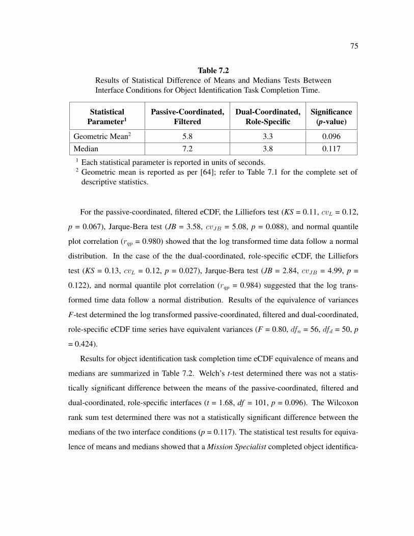
75
Table 7.2Results of Statistical Difference of Means and Medians Tests BetweenInterface Conditions for Object Identification Task Completion Time.
StatisticalParameter1
Passive-Coordinated,Filtered
Dual-Coordinated,Role-Specific
Significance(p-value)
Geometric Mean2 5.8 3.3 0.096Median 7.2 3.8 0.1171 Each statistical parameter is reported in units of seconds.2 Geometric mean is reported as per [64]; refer to Table 7.1 for the complete set of
descriptive statistics.
For the passive-coordinated, filtered eCDF, the Lilliefors test (KS = 0.11, cvL = 0.12,
p = 0.067), Jarque-Bera test (JB = 3.58, cvJB = 5.08, p = 0.088), and normal quantile
plot correlation (rqp = 0.980) showed that the log transformed time data follow a normal
distribution. In the case of the the dual-coordinated, role-specific eCDF, the Lilliefors
test (KS = 0.13, cvL = 0.12, p = 0.027), Jarque-Bera test (JB = 2.84, cvJB = 4.99, p =
0.122), and normal quantile plot correlation (rqp = 0.984) suggested that the log trans-
formed time data follow a normal distribution. Results of the equivalence of variances
F-test determined the log transformed passive-coordinated, filtered and dual-coordinated,
role-specific eCDF time series have equivalent variances (F = 0.80, dfn = 56, dfd = 50, p
= 0.424).
Results for object identification task completion time eCDF equivalence of means and
medians are summarized in Table 7.2. Welch’s t-test determined there was not a statis-
tically significant difference between the means of the passive-coordinated, filtered and
dual-coordinated, role-specific interfaces (t = 1.68, df = 101, p = 0.096). The Wilcoxon
rank sum test determined there was not a statistically significant difference between the
medians of the two interface conditions (p = 0.117). The statistical test results for equiva-
lence of means and medians showed that a Mission Specialist completed object identifica-

76
tion tasks in the same amount of time using both interfaces; therefore, research hypothesis
1 was supported (Section 6.2.1)
7.1.2 Evaluation Tasks
The descriptive and inferential statistical results for evaluation task completion time
by interface condition are given in this section. Results were found not to be statistically
significantly different between the two interface conditions; therefore, a Mission Specialist
using either the passive-coordinated, filtered or the dual-coordinated, role-specific inter-
face completed evaluation tasks in a similar amount of time. Evaluation task completion
time data for both interface conditions were shown to follow a log-normal distribution with
equal variances.
7.1.2.1 Descriptive Statistical Analyses for Evaluation Task Completion Time
Descriptive statistics for evaluation task completion time are shown in Table 7.3. Eval-
uation task completion when using the dual-coordinated, role-specific interface condition
was determined to be arithmetically faster (AM = 10.2-seconds, SD = 12.0-seconds) than
evaluation task completion when using the passive-coordinated, filtered interface condi-
tion (AM = 13.4-seconds, SD = 23.8-seconds). The dual-coordinated, role-specific inter-
face condition was geometrically faster (GM = 4.8-seconds, GSD = 4.3-seconds) than the
passive-coordinated, filtered interface condition (GM = 6.7-seconds, GSD = 3.1-seconds).
The median evaluation completion time was faster for the dual-coordinated, role-specific
condition (M = 6.5-seconds) versus the passive-coordinated, filtered condition (M = 6.7-
seconds). The dual-coordinated, role-specific interface condition had positive skewness (s
= 2.1) and was leptokurtic (k = 7.5); the passive-coordinated, filtered interface condition
had similar results (s = 4.7, k = 27.7). Considering geometric mean as the primary mea-
sure for evaluation task completion, evaluating objects and information when using the

77
Table 7.3Descriptive Statistical Results for Evaluation Task Completion Time Be-tween Interface Conditions.
Descriptive Statistic1 Passive-Coordinated,Filtered
Dual-Coordinated,Role-Specific
Arithmetic Mean (AM) 13.4 10.2Standard Deviation (SD) 23.8 12.0Geometric Mean (GM) 6.7 4.8Geometric Standard Deviation (GSD) 3.1 4.3Median (M) 6.7 6.5Skewness (s) 4.7 2.1Kurtosis (k) 27.7 7.51 Each descriptive statistic is reported in units of seconds except for skewness and kur-
tosis which are dimensionless quantities.
dual-coordinated, role-specific interface was accomplished, on average, 1.9-seconds (or
1.4 times) faster than when using the passive-coordinated, filtered interface.
7.1.2.2 Inferential Statistical Analyses for Evaluation Task Completion Time
Evaluation task completion time-based eCDFs were developed for each interface con-
dition (Figure 7.3). A line of best fit was determined for each evaluation task completion
eCDF time series. For the passive-coordinated, filtered and dual-coordinated, role-specific
time-based eCDFs, the determined lines of best fit are given by Equation 7.3 (R2 = 0.938)
and Equation 7.4 (R2 = 0.913), respectively:
P = 0.249 ln (t) + 0.025 (7.3)
P = 0.189 ln (t) + 0.206 (7.4)

78
0.0
0.2
0.4
0.6
0.8
1.0
0 10 20 30 40 50 60 70
Pro
babi
lity
Time [seconds]
Passive-Coordinated, Filtered
Dual-Coordinated, Role-Specific
Fig. 7.3. Empirical Cumulative Distribution Functions for EvaluationTask Completion Time by Interface Condition. Blue Squares RepresentPassive-Coordinated, Filtered Time Measurements (n = 51). The SolidBlue Line is the Line of Best Fit for the Passive-Coordinated, FilteredTime Series. Red Circles Represent Dual-Coordinated, Role-SpecificTime Measurements (n = 47). The Dashed Red Line is the Line of BestFit for the Dual-Coordinated, Role-Specific Time Series.
where P is the eCDF probability and t is evaluation task completion time in seconds.
A frequency-based representation for each evaluation task completion eCDF is shown in
Figure 7.4 to provide an alternative view of evaluation task completion speed. As can be
observed in Figure 7.4, the dual-coordinated, role-specific interface appears to result in
faster evaluation task completion.

79
0.0
0.2
0.4
0.6
0.8
1.0
0.0010 0.0100 0.1000 1.0000 10.0000
Pro
babi
lity
Log(Frequency) [hertz]
Passive-Coordinated, Filtered
Dual-Coordinated, Role-Specific
Fig. 7.4. Empirical Cumulative Distribution Functions for EvaluationTask Completion Frequency by Interface Condition. Blue Squares Rep-resent Passive-Coordinated, Filtered Frequency Measurements (n = 51).The Solid Blue Line is the Line of Best Fit for the Passive-Coordinated,Filtered Frequency Series. Red Circles Represent Dual-Coordinated,Role-Specific Frequency Measurements (n = 47). The Dashed Red Lineis the Line of Best Fit for the Dual-Coordinated, Role-Specific FrequencySeries. The Frequency Measurements are Displayed on a LogarithmicScale.

80
Table 7.4Results of Statistical Difference of Means and Medians Tests BetweenInterface Conditions for Evaluation Task Completion Time.
StatisticalParameter1
Passive-Coordinated,Filtered
Dual-Coordinated,Role-Specific
Significance(p-value)
Geometric Mean2 5.8 3.3 0.197Median 7.2 3.8 0.4931 Each statistical parameter is reported in units of seconds.2 Geometric mean is reported as per [64]; refer to Table 7.3 for the complete set of
descriptive statistics.
A visual inspection of Figures 7.3 and 7.4 and the determination of the lines of best fit
suggested the evaluation task completion time eCDF data follow a log-normal distribution;
therefore, the time series data were log transformed and tested for normality. For the
passive-coordinated, filtered eCDF, the Lilliefors test (KS = 0.07, cvL = 0.12, p = 0.500),
Jarque-Bera test (JB = 0.43, cvJB = 4.99, p = 0.500), and normal quantile plot correlation
(rqp = 0.993) showed that the log transformed time data follow a normal distribution. In
the case of the the dual-coordinated, role-specific eCDF, the Lilliefors test (KS = 0.13,
cvL = 0.13, p = 0.038), Jarque-Bera test (JB = 4.63, cvJB = 4.91, p = 0.055), and normal
quantile plot correlation (rqp = 0.984) suggested that the log transformed time data follow
a normal distribution. Results of the equivalence of variances F-test determined the log
transformed passive-coordinated, filtered and dual-coordinated, role-specific eCDF time
series have equivalent variances (F = 0.59, dfn = 50, dfd = 46, p = 0.068).
Results for evaluation task completion time eCDF equivalence of means and medi-
ans are summarized in Table 7.4. Welch’s t-test determined there was not a statistically
significant difference between the means of the passive-coordinated, filtered and dual-
coordinated, role-specific interfaces (t = 1.30, df = 86, p = 0.197). The Wilcoxon rank
sum test determined there was not a statistically significant difference between the medi-
ans of the two interface conditions (p = 0.493). The statistical test results for equivalence

81
of means and medians showed that a Mission Specialist completed evaluation tasks in the
same amount of time using both interfaces; therefore, research hypothesis 1 was supported
(Section 6.2.1)
7.1.3 Image Capture Tasks
The descriptive and inferential statistical results for image capture task completion
time by interface condition are given in this section. Results were found not to be statisti-
cally significantly different between the two interface conditions; therefore, a Mission Spe-
cialist using either the passive-coordinated, filtered or the dual-coordinated, role-specific
interface completed image capture tasks in a similar amount of time. Image capture task
completion time data for both interface conditions were shown to follow a log-normal
distribution with equal variances.
7.1.3.1 Descriptive Statistical Analyses for Image Capture Task Completion Time
Descriptive statistics for image capture task completion time are shown in Table 7.5.
Image capture task completion when using the passive-coordinated, filtered interface con-
dition was determined to be arithmetically faster (AM = 17.3-seconds, SD = 27.4-seconds)
than image capture task completion when using the dual-coordinated, role-specific inter-
face condition (AM = 21.9-seconds, SD = 34.5-seconds). The dual-coordinated, role-
specific interface condition was geometrically faster (GM = 5.6-seconds, GSD = 6.4-
seconds) than the passive-coordinated, filtered interface condition (GM = 6.7-seconds,
GSD = 4.1-seconds). The median image capture completion time was faster for the dual-
coordinated, role-specific condition (M = 6.9-seconds) versus the passive-coordinated, fil-
tered condition (M = 7.0-seconds). The dual-coordinated, role-specific interface condition
had positive skewness (s = 2.0) and was leptokurtic (k = 6.2); the passive-coordinated, fil-
tered interface condition had similar results (s = 2.6, k = 9.5). Considering geometric mean
as the primary measure for image capture task completion, capturing images of objects and

82
Table 7.5Descriptive Statistical Results for Image Capture Task Completion TimeBetween Interface Conditions.
Descriptive Statistic1 Passive-Coordinated,Filtered
Dual-Coordinated,Role-Specific
Arithmetic Mean (AM) 17.3 21.9Standard Deviation (SD) 27.4 34.5Geometric Mean (GM) 6.7 5.6Geometric Standard Deviation (GSD) 4.1 6.4Median (M) 7.0 6.9Skewness (s) 2.6 2.0Kurtosis (k) 9.5 6.21 Each descriptive statistic is reported in units of seconds except for skewness and kur-
tosis which are dimensionless quantities.
information when using the dual-coordinated, role-specific interface was accomplished, on
average, 1.1-seconds (or 1.2 times) faster than when using the passive-coordinated, filtered
interface.
7.1.3.2 Inferential Statistical Analyses for Image Capture Task Completion Time
Image capture task completion time-based eCDFs were developed for each interface
condition (Figure 7.5). A line of best fit was determined for each image capture task
completion eCDF time series. For the passive-coordinated, filtered and dual-coordinated,
role-specific time-based eCDFs, the determined lines of best fit are given by Equation 7.5
(R2 = 0.981) and Equation 7.6 (R2 = 0.978), respectively:
P = 0.204 ln (t) + 0.113 (7.5)
P = 0.154 ln (t) + 0.231 (7.6)

83
0.0
0.2
0.4
0.6
0.8
1.0
0 10 20 30 40 50 60 70
Pro
babi
lity
Time [seconds]
Passive-Coordinated, Filtered
Dual-Coordinated, Role-Specific
Fig. 7.5. Empirical Cumulative Distribution Functions for Image CaptureTask Completion Time by Interface Condition. Blue Squares RepresentPassive-Coordinated, Filtered Time Measurements (n = 49). The SolidBlue Line is the Line of Best Fit for the Passive-Coordinated, FilteredTime Series. Red Circles Represent Dual-Coordinated, Role-SpecificTime Measurements (n = 46). The Dashed Red Line is the Line of BestFit for the Dual-Coordinated, Role-Specific Time Series.

84
0.0
0.2
0.4
0.6
0.8
1.0
0.0010 0.0100 0.1000 1.0000 10.0000
Pro
babi
lity
Log(Frequency) [hertz]
Passive-Coordinated, Filtered
Dual-Coordinated, Role-Specific
Fig. 7.6. Empirical Cumulative Distribution Functions for Image CaptureTask Completion Frequency by Interface Condition. Blue Squares Rep-resent Passive-Coordinated, Filtered Frequency Measurements (n = 49).The Solid Blue Line is the Line of Best Fit for the Passive-Coordinated,Filtered Frequency Series. Red Circles Represent Dual-Coordinated,Role-Specific Frequency Measurements (n = 46). The Dashed Red Lineis the Line of Best Fit for the Dual-Coordinated, Role-Specific FrequencySeries. The Frequency Measurements are Displayed on a LogarithmicScale.

85
where P is the eCDF probability and t is image capture task completion time in seconds. A
frequency-based representation for each image capture task completion eCDF is shown in
Figure 7.6 to provide an alternative view of image capture task completion speed. As can
be observed in Figure 7.6, the dual-coordinated, role-specific interface appears to result in
faster image capture task completion.
A visual inspection of Figures 7.5 and 7.6 and the determination of the lines of best fit
suggested the image capture task completion time eCDF data follow a log-normal distribu-
tion; therefore, the time series data were log transformed and tested for normality. For the
passive-coordinated, filtered eCDF, the Lilliefors test (KS = 0.09, cvL = 0.13, p = 0.403),
Jarque-Bera test (JB = 2.15, cvJB = 4.95, p = 0.195), and normal quantile plot correlation
(rqp = 0.984) showed that the log transformed time data follow a normal distribution. In
the case of the the dual-coordinated, role-specific eCDF, the Lilliefors test (KS = 0.08,
cvL = 0.13, p = 0.500), Jarque-Bera test (JB = 1.29, cvJB = 4.89, p = 0.392), and normal
quantile plot correlation (rqp = 0.992) showed that the log transformed time data follow
a normal distribution. Results of the equivalence of variances F-test determined the log
transformed passive-coordinated, filtered and dual-coordinated, role-specific eCDF time
series do not have equivalent variances (F = 0.53, dfn = 48, dfd = 45, p = 0.033).
Results for image capture task completion time eCDF equivalence of means and me-
dians are summarized in Table 7.6. Welch’s t-test determined there was not a statistically
significant difference between the means of the passive-coordinated, filtered and dual-
coordinated, role-specific interfaces (t = 0.26, df = 82, p = 0.794). The Wilcoxon rank
sum test determined there was not a statistically significant difference between the medi-
ans of the two interface conditions (p = 0.882). The statistical test results for equivalence
of means and medians showed that a Mission Specialist completed image capture tasks
in the same amount of time using both interfaces; therefore, research hypothesis 1 was
supported (Section 6.2.1)

86
Table 7.6Results of Statistical Difference of Means and Medians Tests BetweenInterface Conditions for Image Capture Task Completion Time.
StatisticalParameter1
Passive-Coordinated,Filtered
Dual-Coordinated,Role-Specific
Significance(p-value)
Geometric Mean2 6.7 5.6 0.794Median 7.0 6.9 0.8821 Each statistical parameter is reported in units of seconds.2 Geometric mean is reported as per [64]; refer to Table 7.5 for the complete set of
descriptive statistics.

87
7.2 Levels of Stress Analyses and Results
This section presents the data analyses performed for heart rate data as a measure
of levels of stress for the two different interface conditions (passive-coordinated, filtered
versus dual-coordinated, role-specific). Descriptive and inferential statistical results are
provided for the heart rate data.
Descriptive statistical analyses for the heart rate data were completed using the accom-
panying Biopack R� BioNomadix software and MATLAB R�. The descriptive statistical
analyses consisted of calculating the arithmetic mean (AM) for each heart rate time series
recorded for each interface condition.
Inferential statistical analyses were performed using MATLAB R� for the heart rate data
interface condition. Repeated measures analyses were performed for the within-subjects
factor of interface condition (passive-coordinated, filtered versus dual-coordinated, role-
specific). The dependent variable in each analysis was arithmetic mean heart rate in beats
per minute, which was evaluated for statistical significance through a two-way analysis
of variance (ANOVA). Statistical results are reported by an F-statistic with accompanying
degrees of freedom (df ), and statistical significance (p-value).
7.2.1 Heart Rate Descriptive Statistical Analyses
Descriptive statistics for participant heart rate in each interface condition (passive-
coordinated, filtered and dual-coordinated, role-specific) are shown in Table 7.7. Three
participants experienced a slower average heart rate when using the dual-coordinated, role-
specific interface than when using the passive-coordinated, filtered interface; six partici-
pants experience a faster average heart rate. One participant experienced no difference in
heart rate between interface conditions.

88
Table 7.7Arithmetic Mean Results for Participant Heart Rate Between Interface Conditions.
Participant Passive-Coordinated,Filtered1
Dual-Coordinated,Role-Specific1
1 86 802 75 793 88 884 88 895 83 886 76 807 77 848 73 679 71 75
10 76 751 Arithmetic mean values are reported in beats per minute.
7.2.2 Heart Rate Inferential Statistical Analyses
Results for the two-way ANOVA test determined there was not a statistically signif-
icant difference between the mean heart rate measured for participants when using the
passive-coordinated, filtered and dual-coordinated, role-specific interfaces (F = 0.16, df =
1, p = 0.693). The statistical test results showed that a Mission Specialist experienced the
same level of stress as measured by heart rate using both interfaces; therefore, research
hypothesis 2 was supported (Section 6.2.2)
7.3 Role Empowerment Analyses and Results
This section presents the data analyses performed for the summative post-assessment
data reported for participant role empowerment (confidence, comfort, and perceived best
individual and team performance) when considering both interface conditions (passive-

89
Table 7.8Descriptive Statistical Results for Reported Role Empowerment Confi-dence Between Interface Conditions.
Participant Activity Passive-Coordinated,Filtered1
Dual-Coordinated,Role-Specific1
Locate Objects (Individual) 10 90Capture Images (Individual) 10 90Capture Images (Team) 40 60Camera Tilt (Individual) 50 50Camera Zoom (Individual) 50 501 Values reported are percentage of participants indicating the interface condition gave
them the most confidence for the specified activity.
coordinated, filtered and dual-coordinated, role-specific). Descriptive statistical analyses
were performed for the role empowerment data using MATLAB R�. Since the reported
role empowerment data were categorical, the descriptive statistical analyses consisted of
percentages of total participants for each post-assessment survey question type (e.g., which
method gave the most confidence for capturing images). The determined percentages for
confidence and comfort are provided in Tables 7.8 and 7.9, respectively.
7.3.1 Locating Objects
Ninety percent (90%) of all participants reported the most individual confidence in
the dual-coordinated, role-specific interface for locating objects. Ten percent (10%) in-
dicated the most individual confidence came from using the passive-coordinated, filtered
interface. Sixty percent (60%) of all participants reported the most individual comfort
using the dual-coordinated, role-specific interface to locate objects. Forty percent (40%)
of participants reported that using the passive-coordinated, filtered interface and asking
the Pilot was more comfortable for them individually. Therefore, the dual-coordinated,
role-specific interface provided greater role empowerment (confidence and comfort) for a

90
Table 7.9Descriptive Statistical Results for Reported Role Empowerment ComfortBetween Interface Conditions.
Participant Activity Passive-Coordinated,Filtered1
Dual-Coordinated,Role-Specific1
Locate Objects (Individual) 40 60Capture Images (Individual) 20 80Capture Images (Team) 30 60Camera Tilt (Individual) 50 50Camera Zoom (Individual) 50 501 Values reported are percentage of participants indicating the interface condition was
the most comfortable for them for the specified activity.

91
Mission Specialist to individually locate objects and research hypothesis 3 was supported
(Section 6.2.3)
7.3.2 Capturing Images
Ninety percent (90%) of all participants reported the most individual confidence in
the dual-coordinated, role-specific interface for capturing images. Ten percent (10%) in-
dicated the most individual confidence came from using the passive-coordinated, filtered
interface. Eighty percent (80%) of all participants reported the most individual comfort us-
ing the dual-coordinated, role-specific interface to capture images. Twenty percent (20%)
of participants reported that using the passive-coordinated, filtered interface and asking
the Pilot was more comfortable for them individually.
Sixty percent (60%) of participants reported the most confidence when using the dual-
coordinated, role-specific interface for their team’s ability capturing images. Forty per-
cent (40%) indicated the most confidence in their team came from using the passive-
coordinated, filtered interface. Sixty percent (60%) of all participants reported the most
comfort for their team using the dual-coordinated, role-specific interface to capture im-
ages. Forty percent (40%) of participants reported that using the passive-coordinated,
filtered interface and asking the Pilot was more comfortable for them in the context of the
team.
The dual-coordinated, role-specific interface provided greater role empowerment (con-
fidence and comfort) for a Mission Specialist to individually and, as a team, capture im-
ages; thus, research hypothesis 3 was supported (Section 6.2.3)
7.3.3 Payload Camera Tilt
Fifty percent (50%) of all participants reported the most individual confidence in the
dual-coordinated, role-specific interface for tilting the payload camera. Fifty percent
(50%) indicated the most individual confidence came from using the passive-coordinated,

92
filtered interface. Fifty percent (50%) of all participants reported the most individual com-
fort using the dual-coordinated, role-specific interface to tilt the payload camera. Fifty
percent (50%) of participants reported that using the passive-coordinated, filtered inter-
face and asking the Pilot was more comfortable for them individually. Therefore, the
dual-coordinated, role-specific interface provided the same role empowerment (confidence
and comfort) for a Mission Specialist to individually tilt the payload camera and research
hypothesis 3 was supported (Section 6.2.3)
7.3.4 Payload Camera Zoom
Fifty percent (50%) of all participants reported the most individual confidence in the
dual-coordinated, role-specific interface for zooming the payload camera. Fifty percent
(50%) indicated the most individual confidence came from using the passive-coordinated,
filtered interface. Fifty percent (50%) of all participants reported the most individual com-
fort using the dual-coordinated, role-specific interface to zoom the payload camera. Fifty
percent (50%) of participants reported that using the passive-coordinated, filtered interface
and asking the Pilot was more comfortable for them individually. Therefore, the dual-
coordinated, role-specific interface provided the same role empowerment (confidence and
comfort) for a Mission Specialist to individually zoom the payload camera and research
hypothesis 3 was supported (Section 6.2.3)
7.3.5 Perceived Best Individual and Team Performance
Participants responded to one question asking which interface method provided them
with the best individual performance for acquiring images of identified objects. Three
possible answer responses were given for both questions and included i) controlling the
payload camera themselves, ii) only asking the Pilot to control the payload camera, or iii)
both doing it themselves and asking the Pilot. The determined percentages for perceived
best individual and team performance are provided in Table 7.10.

93
Table 7.10Descriptive Statistical Results for Reported Best Individual and Team Per-formance Between Interface Conditions.
Participant Perception Passive-Coordinated,Filtered1
Dual-Coordinated,Role-Specific1
Best Individual Performance 40 60Best Team Performance 40 601 Values reported are percentage of participants indicating the interface condition gave
them or their team the best performance.

94
Sixty percent (60%) of all participants reported that their best individual performance
for acquiring images of objects resulted from the interface method where they had both
active control of the payload camera and were able to verbally coordinate with the Pilot
(dual-coordinated, role-specific). Forty percent (40%) of participants reported that their
best individual performance for acquiring images of objects resulted from the interface
where they passively viewed the mirrored display and only verbally coordinated with the
Pilot (passive-coordinated, filtered).
Sixty percent (60%) of all participants reported that the performance from their team
for acquiring images of objects resulted from the interface method where they had both
active control of the payload camera and were able to verbally coordinate with the Pilot
(dual-coordinated, role-specific). Forty percent (40%) of participants reported that the
performance from their team for acquiring images of objects resulted from the interface
where they passively viewed the mirrored display and only verbally coordinated with the
Pilot (passive-coordinated, filtered).
The dual-coordinated, role-specific interface provided greater role empowerment (per-
ceived best individual and team performance) for a Mission Specialist to locate objects
and capture images; thus, research hypothesis 3 was supported (Section 6.2.3).
7.4 Summary
This section presented the statistical analyses and results for data collected as part
of an experimental field study and determined the appropriate human-robot interface for
a Mission Specialist in a micro UAS is a role-specific visual common ground interface
permitting shared control of the payload camera and verbal coordination with the Pilot.
Analyses of task completion time in three separate task categories (object identifi-
cation, evaluation, and image capture) showed that a Mission Specialist using a dual-
coordinated, role-specific interface completed tasks in the same amount of time as when
using a passive-coordinated, filtered interface. These results supported research hypothesis
1 (Section 6.2.3).

95
An analyses of participant heart rate data determined that a Mission Specialist will
experience the same level of stress regardless of the interface condition they use (dual-
coordinated, role-specific or passive-coordinated, filtered). The results of the levels of
stress analyses supported research hypothesis 2 (Section 6.2.2).
Role empowerment (confidence, comfort, and perceived best individual and team per-
formance) analyses showed that a Mission Specialist preferred a dual-coordinated, role-
specific interface over a passive-coordinated, filtered interface. These results supported
research hypothesis 3 (Section 6.2.3).
7.5

96
8. DISCUSSION
This section discusses and interprets the results obtained from the experimental field
study, describes three trends observed from the collected data, and identifies two factors
that may have impacted the result outcomes. The results from this dissertation research
revealed three interesting trends associated with Mission Specialist interfaces in a micro
UAS: i) command-level experience affects control preference, ii) perceived responsibility
for the robot affects control preference, and iii) level of control and focused visual common
ground form a space of interaction for the Shared Roles Model. The micro category of
UAS is the most accessible technology for civilian-supported CBRN operations such as
fire and rescue, law enforcement, and civil engineering and legislative trends suggest that
micro UAS are in high demand for these domains and will become widely available to ad
hoc users much faster than any other category of UAS. Understanding how these different
types of users will perform in the Mission Specialist role is essential for mUAS mission
planning and success.
8.1 Task Completion Time Discussion
Each of the three task categories a Mission Specialist completed (object identification,
evaluation, image capture) were determined to take the same amount of time, if the Mission
Specialist had shared control of the payload camera versus was only able to instruct the
Pilot for payload camera control. The numeric results shown in Tables 7.1, 7.3, and 7.5
suggest that on average, a Mission Specialist can complete tasks faster with the dual-
coordinated, role-specific interface, though with large variation which would likely depend
on the type of task being attempted.

97
8.1.1 Object Identification Tasks
The most significantly different task completion time category was object identifica-
tion as it showed, on average, the greatest difference when the Mission Specialist used the
dual-coordinated, role-specific interface. Object identification tasks were the initial tasks
asked of each participant when they arrived at a waypoint. The improvement in task com-
pletion time was likely due to the Mission Specialist having direct control of the payload
camera and being able to more quickly search for an object with their own interface versus
issuing verbal instructions for individual payload camera movements. This would assist
specialized responders as faster object identification would aid decision making.
8.1.2 Evaluation Tasks
Evaluation tasks were completed approximately 1.4 times faster when a Mission Spe-
cialist used the dual-coordinated, role-specific interface. Evaluation tasks were the sec-
ondary tasks asked of each participant once they identified an object (e.g., getting a spe-
cific number from a derailed train car). Improvement in this task completion category
suggests that a Mission Specialist would be able to obtain critical information regarding
an identified object of interest faster than if they were only viewing a mirrored interface
and instructing the Pilot. Specialized responders often gain a deeper understanding for
operational planning with this type of information (e.g., determining the type of chemical
present in a derailment).
8.1.3 Image Capture Tasks
The most similar task completion time result between the two interface conditions
was for capturing images. All participants when using the dual-coordinated, role-specific
interface were observed trying to properly frame the object of interest in the center of the
screen prior to capturing an image, likely leading to a longer task completion times. When

98
participants directed the Pilot to capture an image, a focus on framing was not observed;
the task was essentially out of the participants’ control. A greater focus by participants
on capturing the image themselves could correlate with the high internal locus of control
observed in all of the participants. Further study would be warranted to determine the
exact cause of the observed extended time spent properly framing images.
8.2 Levels of Stress Discussion
A Mission Specialist when using the dual-coordinated, role-specific interface did not
experience any more stress than when using the passive-coordinate, filtered interface. Each
of the participants had been trained as a specialized emergency responder to work in high-
stress situations (e.g., HAZMAT, search and rescue, etc.); therefore, as realistic as the
simulated train derailment was, it may not have fully replicated the conditions for which
they are uniquely trained. Additionally, both types of interfaces used in the experimental
field study conditions represented a new experience to each of the participants; thus, a
non-statistically significant level of stress recorded may have reflected the general lack
of familiarity with both of the interface technologies. Alternatively, this may be a very
positive finding, in general, if neither interface condition causes stressful conditions; more
work to evaluate levels of stress in specialized responders when using different types of
robotics-based technologies should be undertaken.
8.3 Role Empowerment Discussion
The most significant experimental finding was that greater role empowerment was ex-
perienced by a Mission Specialist when using a dual-coordinated, role-specific interface.
As was shown in Table 7.8, the most significant result observed was a Mission Specialist
preferring the choice to either capture images themselves or instruct the Pilot to capture
images. Each subsequent role empowerment category related to payload camera control
and perceived best individual and team performance also showed a majority or balanced
99
preference. Results in the subsequent role empowerment categories are likely less strong
due to contention observed between the Mission Specialist and Pilot for control of the pay-
load camera. All participants, when given the choice, used both direct control and verbal
coordination with the Pilot for payload camera control and capturing images. However,
there was also at least once instance where each participant asked the Pilot to control the
payload camera (e.g., tilt down) while simultaneously attempting to issue the same com-
mand themselves through the interface. This contention caused movement of the payload
camera beyond what was initially desired by the Mission Specialist and had to be corrected
with additional inputs.
8.4 Formative Observations
Command experience and perceived responsibility for the robot were observed to af-
fect Mission Specialist interface preference. Mission Specialist participants with command-
level experience preferred shared control while non-commanders preferred only to ask the
Pilot for control of the payload camera. Participants who reported they would be re-
sponsible for the robot’s maintenance and upkeep did not want shared control and instead
preferred to only communicate with the Pilot. These formative observations suggest that
work experience and responsibility for the robot by the Mission Specialist influence the
preferred method of HRI for micro UAS operations.
8.4.1 The Commander Effect
A Mission Specialist having command-level experience (e.g., Fire and Rescue Captain,
EMS Team Leader) reported the greatest role empowerment using the dual-coordinated,
role-specific interface. Conversely, a Mission Specialist with non-command-level experi-
ence (e.g., HAZMAT technician, search and rescue team member) reported the greatest
role empowerment resulted from only instructing the Pilot for payload camera control and
image capture. This Commander Effect was determined through a correlation analysis

100
Table 8.1Correlation Findings Between Level of Command Experience and Re-ported Role Empowerment.
Role Empowerment Category CorrelationCoefficient
Best Performance (Team) 1.00
Capturing Images 1.00
Best Performance (Individual) 0.82
Locating Objects 0.80
Zooming the Payload Camera 0.80
between command-level experience reported through the pre-assessment survey and each
role empowerment category reported through the summative post-assessment survey. Each
role empowerment category, except confidence and comfort for payload camera tilt, was
determined to correlate at a statistically significant level (p < 0.05) with command-level
experience (Table 8.1).
8.4.2 The Responsibility Effect
Mission Specialist participants who reported they would be responsible for mainte-
nance of the robot reported their perceived best individual performance came from using
the passive-coordinated, filtered interface. Conversely, a Mission Specialist who reported
they would not be responsible for maintenance for the robot reported their perceived best
individual performance resulted from shared control of the payload camera with the Pilot.
This Responsibility Effect was determined through a correlation analysis between indi-
cated responsibility and each role empowerment category reported through the summative
post-assessment survey. Perceived best individual performance and, interestingly, confi-
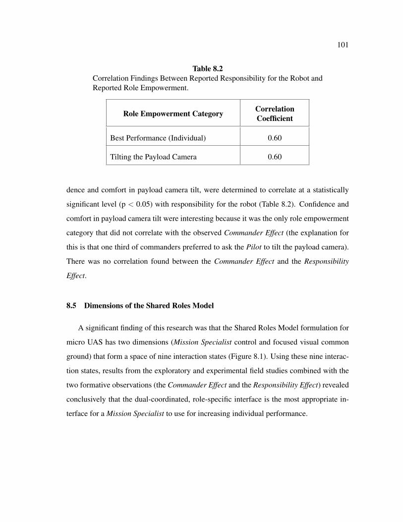
101
Table 8.2Correlation Findings Between Reported Responsibility for the Robot andReported Role Empowerment.
Role Empowerment Category CorrelationCoefficient
Best Performance (Individual) 0.60
Tilting the Payload Camera 0.60
dence and comfort in payload camera tilt, were determined to correlate at a statistically
significant level (p < 0.05) with responsibility for the robot (Table 8.2). Confidence and
comfort in payload camera tilt were interesting because it was the only role empowerment
category that did not correlate with the observed Commander Effect (the explanation for
this is that one third of commanders preferred to ask the Pilot to tilt the payload camera).
There was no correlation found between the Commander Effect and the Responsibility
Effect.
8.5 Dimensions of the Shared Roles Model
A significant finding of this research was that the Shared Roles Model formulation for
micro UAS has two dimensions (Mission Specialist control and focused visual common
ground) that form a space of nine interaction states (Figure 8.1). Using these nine interac-
tion states, results from the exploratory and experimental field studies combined with the
two formative observations (the Commander Effect and the Responsibility Effect) revealed
conclusively that the dual-coordinated, role-specific interface is the most appropriate in-
terface for a Mission Specialist to use for increasing individual performance.

102
Fig. 8.1. Nine States of the Shared Roles Model Across Two Dimensions- Focused Visual Common Ground and Mission Specialist Control. TheRows Represent Level of Control from Passive (None), to Dual (Shared),to Active (Full). The Columns Represent Common Ground Focus of theInterface from Unfiltered (None), to Filtered (Pilot-Only Artifacts Re-moved), to Role-Specific (Additional Mission Specialist-Only Informa-tion Added).

103
8.5.1 Mission Specialist Control
The exploratory field study evaluated the passive-coordinated, filtered and the active-
coordinated, filtered interfaces. In this set of interface conditions, either the Pilot con-
trolled the payload camera based on instructions from the Mission Specialist, or the Mis-
sion Specialist controlled the payload camera themselves, respectively; there was no shared
control. The results showed that a Mission Specialist preferred the passive-coordinated,
filtered interface condition and did not want active (sole) control of the payload camera.
This result indicated that an upper bound on Mission Specialist control can be placed for
active-coordination for any of the three states in which active control is present.
8.5.2 Focused Visual Common Ground
Another important finding of the exploratory field study was a lack of adequate visual
feedback and the need for more role focused information (i.e., focused visual common
ground). The experimental field study evaluated the passive-coordinated, filtered and the
dual-coordinated, role-specific interfaces. The results showed that a Mission Specialist
preferred the interface with shared control of the payload camera and verbal coordina-
tion with the Pilot (i.e., dual-coordinated, role-specific). This result indicated that a lower
bound on focused visual common ground can be placed at the filtered level as role-specific
information was clearly preferred. For the remaining two states of the Shared Roles Model,
dual-coordinated, role-specific and passive-coordinated, role-specific, the Commander Ef-
fect and the Responsibility Effect show that the dual-coordinated, role-specific interface
is most appropriate. This is conclusive because the dual-coordinated, role-specific inter-
face accommodates both effects; non-commanders and those who would be responsible
for the robot can use the dual-coordinated, role-specific interface as passive viewers, but
the reverse is not true.

104
8.6 Factors that May Have Impacted the Results
Two factors were observed that may have impacted the results of this research: i) hand
physiology of the participants and ii) perceived novelty of the robot. Three participants
with very calloused fingers experienced difficulty with the touch-based interaction and
had to use different, non-calloused fingers. Almost all participants had to be reminded to
stay on task as they perceived the views obtained with the robot as novel, leading them to
deviate at times into exploration when they were assigned specific tasks to complete.
8.6.1 Hand Physiology
The Mission Specialist interface was implemented on an Apple R� iPad and uses touch-
based interaction for input that requires the fingers of a user be able to provide a measur-
able difference in electrical capacitance at the surface of the screen. Conductive materials
such as skin and metals (e.g., aluminum and silicon) provide a satisfactory difference in
capacitance. Non-conductive materials, such as wood and plastic, do not provide a satis-
factory difference in capacitance. There are no published minimum levels of capacitance
by Apple R� for human skin; however, it was observed during both the exploratory (1 par-
ticipant) and experimental (2 participants) field studies that participants with very callused
index fingers and/or thumbs had difficulty interacting. This was observed for payload
camera tilt and zoom gestures (i.e., swipes and pinches) as well as simple touches (i.e.,
pressing the Capture Image button). The three participants with callused fingers deferred
to using other fingers or parts of their hand that they normally would not swipe or touch
with (e.g., a ring finger or a knuckle). When the participants were asked about this ob-
servation, all indicated that the lack of finger recognition was actually a common problem
with other non-Apple R� touch-based devices and that they had just adapted accordingly.
As such, the three participants with very callused fingers could have produced results with
the Mission Specialist interface that would not be as good as if they did not have the cal-

105
luses. This could be a limiting factor with touch-based devices in general; research on this
issue should be explored.
8.6.2 Novelty of the Robot
Another factor that may have influenced participant performance was the perceived
novelty of the robot. Very few organized groups of specialized responders (e.g., Texas
Task Force 1) have in their cache of equipment a micro UAV. None of the participants
in either the exploratory or experimental studies had significant exposure or immediate
access to this type of technology. There was an anecdotally observed wow factor exhib-
ited by almost all of the participants. During the two flights participants had to be kept
on task and not be allowed to deviate into self-exploration with the payload camera. A
common example of this was be when participants were asked to identify any product or
materials that had been spilled, some would deviate from looking for spills and instead
look for placards on the derailed cars containing information about what was in the car
because they thought that would be more important in a HAZMAT situation than finding
spilled product. For an exploratory study, this would be fine but for an evaluation task un-
der experimental conditions this type of deviation may have lead to, for example, the high
degree of variability recorded for task completion time. The most appropriate recommen-
dation for this impact factor (for both experimental studies and real world application of a
micro UAS) would be to have a clearly defined mission plan determined before the flight.
Since the flight time for a micro UAV is only between 10- to 20-minutes maximum, devi-
ation into an exploration process may utilize the robot resource in a sub-optimal manner,
regardless of interface condition.
8.7 Summary
This section discussed the experimental field study results, described three trends from
the collected data, and identified two factors that may have impacted the result outcomes.

106
The results from this dissertation research showed command-level experience and per-
ceived responsibility for the robot affect interface preference, there are two dimensions to
the Shared Roles Model for mUAS (Mission Specialist control and focused visual common
ground), and hand physiology and robot novelty may have impacted the results.
8.8

107
9. CONCLUSIONS AND FUTURE WORK
This research determined that a Mission Specialist in a mUAS requires a role-specific,
visual common ground interface permitting shared control of the payload camera and ver-
bal coordination with the Pilot. Results from field experiments with 26 responders from
the CBRN domain without mUAS experience showed that a Mission Specialist using the
role-specific interface reported greater role empowerment while completing similar tasks
in the same amount of time and experiencing the same level of stress as when passively
viewing and instructing the Pilot for payload camera control. The most significant findings
were that the work experience of a Mission Specialist and their perceived responsibility for
the robot will influence the preferred interface for HRI mUAS. The role-specific interface
is the most appropriate for an ad hoc Mission Specialist, regardless of work experience
and perceived responsibility, as it permits both direct control of the payload camera and
verbal coordination with the Pilot.
9.1 Significant Contributions and Conclusions
This section presents the significant theoretical and practical contributions from this
research. There are three theoretical contributions that include: i) a link established be-
tween the Shared Roles Model and the field of human-computer interaction, ii) a new
analysis method for human-robot interaction, and iii) an empirical determination that the
Mission Specialist wants a Pilot. There are also three practical contributions of this work.
They include: i) the importance of having untrained CBRN domain experts as participants
in this research, ii) an empirical demonstration that HRI design requires ethnographic in-
vestigation, and iii) the development of a Mission Specialist interface. The theoretical
contributions address concerns primarily of importance to the HRI research community.
The practical contributions address issues mostly of importance to HRI practitioners.

108
9.1.1 Theoretical Contributions
This research made three significant theoretical contributions: i) a linkage between the
Shared Roles Model and HCI now exists through the instantiation of the payload telefac-
tor, ii) a new method of analysis is now available for human-robot interaction studies, and
iii) an empirical determination that the Mission Specialist wants a Pilot. Each theoretical
contribution is discussed in context of the research results and discussion, indicating pri-
mary stakeholders and beneficiaries, and provides where appropriate the broader impacts
for the HRI and CBRN communities.
9.1.1.1 Linkage Between the Shared Roles Model and HCI
The Mission Specialist interface as an instantiation of the UAV payload telefactor con-
nects the Shared Roles Model to HCI. This linkage is important for two reasons: i) it
is the first time the payload telefactor abstraction in the Shared Roles Model has had a
physical and testable form, and ii) that HCI-based principles can be successfully trans-
lated to physically-based interaction between a human and a robot operating as part of a
human-robot team. The research result that the Mission Specialist perceived the robot and
interface as providing similar security, loyalty, and support (versus the Pilot) may suggest
that Mission Specialist views the interface as the robot itself. If this is true, it would em-
pirically support the Shared Roles Model assumption that the robot and humans are in fact
co-agents operating as a JCS and that this was accomplished through the integration of
HCI principles. It would be of value to the HRI community to investigate the extent of as-
sociation between a robot and its payload telefactor with regard to perceived co-agency by
the Mission Specialist. Of additional significant interest is the question, what impact does
co-location with the robot have on perceived co-agency? In the CBRN domain where in
the future an untrained expert occupying the Mission Specialist role may not necessarily be
co-located, understanding the extent of perceived co-agency may help inform individual
and team performance and process expectations.

109
9.1.1.2 New Method of Analysis for HRI
This research presented a new method of analysis for HRI by demonstrating use of the
Shared Roles Model to analyze the Mission Specialist role in mUAS. Use of the Shared
Roles Model allowed the first focused study of the Mission Specialist role for a mUAS;
it was also the first of its kind for any UAS. The ability to focus on an individual human
role (or the entire human-robot team) benefits HRI researchers investigating UAS and any
other unmanned systems. Demonstration of this new method of analysis for HRI provides
a framework for scientific insight for the study of other roles, such as the Pilot. Under-
standing hidden dependencies, contentions, etc. that the Shared Roles Model has been
shown through this work to reveal for mUAS, UAV designers and developers will have
an additional perspective to existing UAV technology (e.g., the use of only one payload
camera) and will be able to improve upon existing and future interfaces and platforms.
9.1.1.3 The Mission Specialist Wants a Separate Pilot Role
The Mission Specialist engaged in verbal coordination with the co-located Pilot role
even if they preferred to have active control of the robot’s payload camera. The greater
trust towards and perceived support by the Pilot versus the robot, as reported by the Mis-
sion Specialist, implies that the physical presence of a separate Pilot role is necessary for
the Mission Specialist to feel sufficiently confident and comfortable interacting with the
robot. This is important as a Mission Specialist on an ad hoc team may have had little
exposure or training with the robot, unlike the Pilot who is usually an expert trained on
a specific UAV platform. It is not known if the verbal coordination preferred by the Mis-
sion Specialist has any impacts (e.g., stress, workload, etc.) on the Pilot role. Because
mUAS human-robot teams in the CBRN domain will likely be ad hoc, it is expected that
verbal coordination will vary based on i) the mission planning specific to the incident, and
ii) the person filling the Mission Specialist role. Further research needs to be conducted
to assess any potential impacts on the Pilot role resulting from varying degrees of verbal

110
coordination with the Mission Specialist. The most important open questions arising from
this theoretical contribution are: would Mission Specialist empowerment (e.g., confidence,
comfort, etc.) be affected and, if so, how would this impact performance, if the Pilot role
were a software agent, the robot itself, or simply remotely-located?
9.1.2 Practical Contributions
There were three significant practical contributions resulting from this research: i)
participation and an archival data set from specialized personnel who work the CBRN
domain, ii) an exemplar for the importance for ethnographic investigation in HRI design,
and iii) design recommendations, a computational architecture, and an implementation of
the payload telefactor for the Shared Roles Model. Each practical contribution is discussed
in context of the research results, indicating primary stakeholders and beneficiaries, and
provides where appropriate the broader impacts for the HRI and CBRN communities.
9.1.2.1 Participation of Specialized Emergency Responders
Specialized personnel from the CBRN domain served as participants in this study and
provided an archival data set for analysis. This is important for two reasons: i) authenticity
of the research results, and ii) well informed design feedback. There have not been any
CBRN-related UAS studies that have used actual CBRN personnel in their studies for data
collection. As such, it is uncertain if the experimental results for role-specific interfaces
found by other researchers [65] using participants with no domain experience are valid.
The authenticity of the data collected through this research strengthen the case for adoption
of UAV technology by personnel in the CBRN domain, especially since the responders
were untrained with mUAS. Therefore, the design of the interface itself and data that were
collected are unique to CBRN in ways that no other previous UAS study has been before.
111
9.1.2.2 HRI Design Requires Ethnographic Investigation
This research empirically showed that theoretical considerations do not always trans-
late to effective practice and instead require ethnographic investigations with domain ex-
perts. Without the exploratory and experimental study results it would not have been
possible to determine the hidden dependencies and effects of interface specialization that
the Shared Roles Model revealed. The literature and technology findings were not suf-
ficient enough to make this determination, nor would an evaluation of the interface with
non-domain experts have provided information about the Commander Effect and the Re-
sponsibility Effect. Each of these empirical results were necessary to answer the main
research question in an appropriate manner that a theoretical approach or data from re-
lated studies or non-experts could not. Ethnographic investigations should be used by HRI
researchers and practitioners as domain-specific observations and data are necessary to
help shape the final design in HRI.
9.1.2.3 Creation of a Mission Specialist Interface
Five recommended design guidelines, a computational architecture, and an implemen-
tation for a role-specific Mission Specialist interface for a micro UAS (or any UAS) are the
available because of this research. The Mission Specialist interface is an example of rapid
prototyping that could be used by either responders or researchers now, with the long term
advantage of expanded use for different HRI studies and the creation of new knowledge.
The role-specific Mission Specialist interface is also an example of rapid prototyping. The
impacts on unmanned systems technology from this dissertation work include potential
new employment opportunities for software engineers and unmanned systems developers,
who will have access to the recommended design guidelines and interface software from
which to propose new applications for HRI, as well as CBRN. It is recommended that this
interface and it supporting principles be the standard method of human-robot interaction
for a Mission Specialist in mUAS.

112
9.2 Future Work
There are both immediate and long-term research goals for which this dissertation
work can be extended for mUAS. The immediate research goals proposed here address
additional analyses of the video and post-assessment survey data to better understand team
process and performance. Long-term research goals focus on questions that will require
further investigation, most likely on a five-year time horizon or longer.
9.2.1 Immediate Future Research Goals
A very important immediate research goal that can be addressed in less than five years
is analyzing the video data to evaluate overall team performance in the context of the
role-specific Mission Specialist interface. It may be possible to discern levels of stress
experience by the Pilot role through evaluating confusion in the verbal dialog. Likewise,
role collision can likely be evaluated. Shorter-term research studies could be developed
to measure stress on the Pilot. An important short-term open question that remains is:
what factors associated with the mission and/or what conditions in the environment caused
control to be ceded to the Pilot even when the Mission Specialist preferred to control the
payload camera?
9.2.2 Long-Term Future Research Goals
Summative experiments with longer, more complete scenarios and measuring Mission
Specialist and Pilot biometrics may provide insight for micro UAS team performance.
Individual and joint situation awareness studies should be developed to non-invasively
measure micro UAS team process. Given the length of the experiments required for this
dissertation work on individual Mission Specialist role performance, individual and joint
studies for situation awareness are more likely to be on a much longer time horizon. One

113
long-term open question is: what other forms of visual communication are important for a
role-specific Mission Specialist interface?
9.3

114
REFERENCES
[1] L. R. Newcome. Unmanned Aviation: A Brief History of Unmanned Aerial Vehicles,Reston, VA: American Institute of Aeronautics and Astronautics, 2004.
[2] N. J. Cooke and H. K. Pedersen. “Unmanned aerial vehicles,” In J.A. Wise, V.D.Hopkin, and D.J. Garland, editors, Handbook of Aviation Human Factors, 2nd Edi-tion, pp. 18.1-18.8, Boca Raton, FL: CRC Press, 2010.
[3] R. R. Murphy, E. Steimle, C. Griffin, M. Hall, and K. Pratt, “Cooperative use ofunmanned sea surface and micro aerial vehicle at Hurricane Wilma,” Journal ofField Robotics, vol. 25, no. 1-2, pp. 164-180, 2008.
[4] M. A. Goodrich, B. S. Morse, D. Gerhardt, J. L. Cooper, J. Adams, C. Humphrey,and M. Quigley, “Supporting wilderness search and rescue using a camera-equippedUAV,” Journal of Field Robotics, vol. 25, no. 1-2, pp. 89-110, 2009.
[5] J. A. Adams, C. M. Humphrey, M. A. Goodrich, J. L. Cooper, B. S. Morse, C.Engh, and N. Rasmussen, “Cognitive task analysis for developing unmanned aerialvehicle wilderness search support,” Journal of Cognitive Engineering and DecisionMaking, vol. 3, no. 1, pp. 1-26, 2009.
[6] B. T. Schreiber, D. R. Lyon, E. L. Martin, and H. A. Confer, “Impact of prior flightexperience on learning Predator UAV operator skills,” United States Air Force Re-search Laboratory Report AFRL-HE-AZ-TR-2002-0026, 2002.
[7] J. Blazakis, “Border security and unmanned aerial vehicles,” CRS Report for theUnited States Congress, Order Code RS21691, January 2004.
[8] R. M. Taylor, “Human automation integration for supervisory control of UAV’s,”in Proc. of the Virtual Media for Military Applications, Meeting Proceedings RTO-MP-HFM-136, pp. 12.1-12.10, 2006.
[9] D.A. Fulghum. (2005, August 15) “New technology promises leapsin UAV warfighting capability,” Aviation Week. [Online]. Available:http://www.aviationweek.com/aw/generic/story generic.jsp?channel=awst&id=news/08155p02.xml&headline=New%20Technology%20Promises%20Leaps%20in%20UAV%20Warfighting%20Capability.
[10] J. R. Wilson. (2002, July) “UAVs and the hu-man factor,” Aerospace America. [Online]. Available:http://www.aiaa.org/aerospace/Article.cfm?issuetocid=233&ArchiveIssueID=28.
[11] A. Rango, A. Laliberte, J. E. Herrick, C. Winters, and K. Havstad. “Development ofan operational UAV/remote sensing capability for rangeland management,” in Proc.of the Twenty-Third International UAV Conference, 2008.
[12] L. C. Trost. “Unmanned air vehicles (UAVs) for cooperative monitoring,” SandiaNational Laboratories Report SAND2000-0185, 2000.

115
[13] R. C. Hruska, G. D. Lancaster, J. L. Harbour, and S. J. Cherry. “Small UAV-acquired, high resolution, georeferenced still imagery,” Idaho National LaboratoryReport INL/CON-05-00235, 2005.
[14] L. F. Johnson, S. Herwitz, S. Dunagan, B. Lobitz, D. Sullivan, and R. Slye. “Collec-tion of ultra high spatial and spectral resolution image data over California vinyardswith a small UAV,” in Proc. of the International Symposium on Remote Sensing ofthe Environment, 2003.
[15] M. J. Barnes, B. G. Knapp, B. W. Tillman, B. A. Walters, and D. Velicki. “Crewsystems analysis of unmanned aerial vehicle (UAV) future job and tasking environ-ments,” United States Army Research Laboratory Report TR-2081, 2000.
[16] N. J. Cooke, H. K. Pederson, O. Connor, J. C. Gorman, and D. Andrews. “Acquir-ing team-level command and control skill for UAV operation,” in N. J. Cooke, H.L. Pringle, H. K. Pedersen, and O. Connor, editors, Human Factors of RemotelyOperated Vehicles, vol. 7, pp. 285-297, New York, NY: Elsevier, 2006.
[17] M.A. Goodrich, J. Cooper, J. A. Adams, C. Humphrey, R. Zeeman, and B. G. Buss.“Using a mini-UAV to support wilderness search and rescue: Practices for human-robot teaming,” in Proc. of the IEEE International Workshop on Safety, Security,and Rescue Robots, pp. 1-6, 2007.
[18] R. R. Murphy, K. S. Pratt, and J. L. Burke. “Crew roles and operational protocols forrotary-wing -UAVs in close urban environments,” in Proc. of the Third ACM/IEEEInternational Conference on Human-Robot Interaction, pp. 73-80, 2008.
[19] C. E. Rash, P. A. LeDuc, and S. D. Manning. “Human factors in U.S. militaryunmanned aerial vehicle accidents,” in N. J. Cooke, H. L. Pringle, H. K. Pedersen,and O. Connor, editors, Human Factors of Remotely Operated Vehicles, vol. 7, pp.117-131, New York, NY: Elsevier, 2006.
[20] R. R. Murphy and J. L. Burke. “From remote tool to shared roles,” in IEEE Roboticsand Automation Magazine, special issue on New Vistas and Challenges for Teleop-eration, vol. 15, no. 4, pp. 39-49, 2008.
[21] J. Cooper and M. A. Goodrich. “Towards combining uav and sensor operator rolesin UAV-enabled visual search,” in Proc. of the Third ACM/IEEE International Con-ference on Human-Robot Interaction, pp. 351-358, 2008.
[22] M. L. Cummings and P. J. Mitchell. “Managing multiple uavs through a timelinedisplay,” in Proc. of the American Institute of Aeronautics and Astronautics In-fotech@Aerospace, September 2005.
[23] M. L. Cummings, S. Bruni, S. Mercier and P. J. Mitchell. “Automation architec-ture for single operator-multiple uav command and control,” The International C2Journal, vol. 1, no. 2, pp. 1-24, 2007.
[24] A. Burkle, F. Segor and M. Kollmann. “Toward autonomous micro uav swarms,”Journal of Intelligent and Robotic Systems, vol. 61, no. 1-4, pp. 339-353, 2011.
[25] J. G. Manathara, P. B. Sujit and R. W. Beard. “Multiple uav coalitions for a searchand prosecute mission,” Journal of Intelligent and Robotic Systems, vol. 62, no. 1,pp. 125-358, 2011.

116
[26] A. Tsourdos, B. A. White and M. Shanmugavel. Cooperative Path Planning of Un-manned Aerial Vehicles, Hoboken, NJ: John Wiley and Sons, Inc., 2011.
[27] Parrot. (2011) Parrot AR.Drone User Guide. [Online]. Available:http://www.parrot.com/fr/support/guidesutilisateur/ar.drone user-guide uk.pdf.
[28] A. Hobbs. “Unmanned aircraft systems,” In E. Salas and D. Maurino, editors, Hu-man Factors in Aviation, 2nd Edition, pp. 505-531, New York, NY: Elsevier, 2010.
[29] A. P. Tvaryanas. “Human systems integration in remotely piloted aircraft opera-tions,” Aviation, Space, and Environmental Medicine, vol. 77, no. 12, pp. 1278-1282, 2006.
[30] B. Walters and M. J. Barnes. “Modeling the effects of crew size and crew fatigueon the control of tactical unmanned aerial vehicles (UAVs)”, in Proc. of the WinterSimulation Conference, pp. 920-924, 2000.
[31] N. J. Cooke and R. A. Chadwick. “Lessons learned from human-robotic interactionson the ground and in the air,” in M. Barnes and F. Jentsch, editors, Human-Robot In-teraction in Future Military Operations, pp. 355-372, London, UK: Ashgate, 2010.
[32] J. M. Peschel and R. R. Murphy. “Mission specialist interfaces in unmanned aerialsystems,” in Proc. of the Sixth ACM/IEEE International Conference on Human-Robot Interaction, pp. 225-226, 2011.
[33] R. Hopcroft, E. Burchat, and J. Vince. “Unmanned aerial vehicles for maritimepatrol: human factors issues,” Australian Defence Science and Technology Organi-sation Report DSTO-GD-0463, 2006.
[34] W. Bierbaum. (1995) “UAVs,” Air and Space Power Journal Archives. [Online].Available: http://www.airpower.maxwell.af.mil/airchronicles/cc/uav.html.
[35] United States Air Force. “United States Air Force unmannedaircraft systems flight plan 2009-2047,” [Online]. Available:http://www.defense.gov/dodcmsshare/briefingslide/339/090723-D-6570C-001.pdf.
[36] United States Army. “U.S. Army unmanned aircraft systems roadmap 2010-2035,”[Online]. Available: http://www.fas.org/irp/program/collect/uas-army.pdf.
[37] Office of the United States Secretary of Defense. “Un-manned aircraft system roadmap 2005-2030,” [Online]. Available:http://www.fas.org/irp/program/collect/uav roadmap2005.pdf.
[38] J. L. Burke, “RSVP: an investigation of the effects of remote shared visual presenceon team process and performance in US&R teams,” Ph.D. Dissertation, Universityof South Florida, April 2006.
[39] K. Pratt, R. R. Murphy, J. L. Burke, J. Craighead, C. Griffin and S. Stover. “Use oftethered small unmanned aerial system at Berkman Plaza II collapse,” in Proc. ofthe IEEE/RSJ International Conference on Intelligent Robots and Systems, 2008.
[40] R. R. Muprhy. “Human-robot interaction in rescue robotics,” IEEE Transactions onSystems, Man, and Cybernetics, Part C: Applications and Reviews, vol. 34, no. 2,pp. 138-153, 2004.

117
[41] G. Hoffman and C. Breazeal. “Collaboration in human-robot teams,” in Proc. of theFirst AIAA Intelligent Systems Technical Conference, pp. 18, 2004.
[42] D. D. Woods and E. Hollnagel, Joint Cognitive Systems: Patterns in Cognitive Sys-tems Engineering, Boca Raton, FL: CRC Press, 2006.
[43] M. Nas. “The changing face of the interface: an overview of UAS control issuesand controller certification,” Unmanned Aircraft Technology Applications Research(UATAR) Working Group 27, 2008.
[44] J. L. Weeks. “Unmanned aerial vehicle operator qualifications,” United States AirForce Research Laboratory Report AFRL-HE-AZ-TR-2000-2002, 2000.
[45] T. Oron-Gilad and Y. Minkov. “Remotely operated vehicles (ROVs) from thebottom-up operational perspective,” In M. Barnes and F. Jentsch, editors, Human-Robot Interaction in Future Military Operations, pp. 211-227, London, UK: Ash-gate, 2010.
[46] Skybotix Technologies. (2011) CoaX R�Coaxial Helicopter Product InformationSheet. [Online]. Available: http://www.skybotix.com.
[47] AirRobot. (2010) AirRobot AR100B R�Product Information Sheet. [Online]. Avail-able: http://www.airrobot-uk.com/air-robot-products.htm.
[48] Draganfly Innovations, Inc. (2011) Draganflyer X Series Product Information. [On-line]. Available: http://www.draganfly.com/industrial/products.php.
[49] Aeryon Labs, Inc. (2011) Scout Product Information Sheet. [Online]. Available:http://www.aeryon.com/products/avs.html.
[50] J. A. Jacko and A. Sears. The Human-Computer Interaction Handbook: Fundamen-tals, Evolving Technologies and Emerging Applications. Mahwah, NJ: LawrenceErlbaum Associates, 2003.
[51] A. Dix, J. Finlay, G. Abowd and R. Beale. Human-Computer Interaction, 2nd Edi-tion. London, UK: Prentice Hall Europe, 1998.
[52] B. Schneiderman and C. Plaisant. Designing the User Interface: Strategies for Ef-fective Human-Computer Interaction, 5th Edition. New York, NY: Addison-Wesley,2010.
[53] H. Sharp, Y. Rogers and J. Preece. Interaction Design: Beyond Human-ComputerInteraction, 2nd Edition. West Sussex, England: John Wiley & Sons, Ltd., 2007.
[54] D. A. Norman. The Design of Everyday Things. New York, NY: Basic Books, 2002.
[55] S. Few. Information Dashboard Design: The Effective Visual Communication ofData. Sebastopol, CA: O’Reilly Media, Inc., 2006.
[56] M. R. Endsley, B. Bolte and D. G. Jones. Designing for Situation Awareness: AnApproach to User-Centered Design. New York, NY: Taylor & Francis, Inc., 2003.

118
[57] B. Mutlu, S. Osman, J. Forlizzi, J. Hodgins and S. Kiesler. “Task structure and userattributes as elements of human-robot interaction design,” in Proc. of the FifteenthIEEE International Symposium on Robot and Human Interactive Communication,pp. 74-79, 2006.
[58] J. A. Adams. “Human-robot interaction design: Understanding user needs and re-quirements,” in Proc. of the Forty-Ninth Annual Meeting of the Human Factors andErgonomics Society, pp. 447-451, 2006.
[59] A. Steinfeld, T. Fong, D. Kaber, M. Lewis, J. Scholtz, A. Schultz and M. Goodrich.“Common metrics for human-robot interaction,” in Proc. of the First ACM/IEEEInternational Conference on Human-Robot Interaction, pp. 33-40, 2006.
[60] M. A. Goodrich and D. R. Olsen, Jr. “Seven principles of efficient human-robotinteraction,” in Proc. of the IEEE International Conference on Systems, Man andCybernetics, vol. 4, pp. 3942-3948, 2003.
[61] J. M. Riley, L. D. Strater, S. L. Chappell, E. S. Connors and M. R. Endsley. “Situ-ation awareness in human-robot interaction: Challenges and user interface require-ments,” In M. Barnes and F. Jentsch, editors, Human-Robot Interaction in FutureMilitary Operations, pp. 171-192, London, UK: Ashgate, 2010.
[62] Willow Garage. (2011) “OpenCV (Open Source Computer Vision) Wiki”. [Online].Available: http://opencv.willowgarage.com.
[63] C. L. Bethel and R. R. Murphy, “Review of human studies methods in HRI andrecommendations,” International Journal of Social Robotics, vol. 2, no. 4, pp. 347-359, 2010.
[64] J. Sauro and J. R. Lewis. “Average task times in usability tests: what to report?,” inProc. of the 28th International Conference on Human Factors in Computing Sys-tems (CHI ’10), 2010.
[65] C.M. Humphrey. “Information abstraction visualization for human-robot interac-tion,” Ph.D. Dissertation, Vanderbilt University, August 2009.

119
APPENDIX A
VERBAL ANNOUNCEMENT SCRIPT
Welcome the prospective participant(s) and introduce yourself. State that you are speak-ing to the individual (or group) to solicit volunteers to participate in a study on the useof mobile touch-based devices (Apple iPads R�) for unmanned aerial systems. Determinewhether or not the individual (or group) wishes to be considered as a prospective partic-ipant. If no, thank the individual (or group) and end the discussion. If yes, proceed withthe rest of this verbal announcement.
Issue a copy of the Information Form (Appendix B) to the individual (or group). Read theinformation contained on the Information Form aloud to the individual (or group). At theend of reading aloud, ask for any questions about the information that has been read. If theprospective participant(s) do not wish to participate, thank the individual (or group) andend the discussion. If yes, proceed with the rest of this verbal announcement.
Issue a copy of the Consent Form (Appendix C). Read the information contained on theConsent Form aloud to the individual (or group). At the end of reading aloud, ask for anyquestions about the information that has been read. If the prospective participant(s) do notwish to participate, thank the individual (or group) and end the discussion. If yes, obtainsignature(s) on the Consent Form(s) and proceed to the Mission Script (Appendix F).

120
APPENDIX B
EXPLORATORY STUDY INFORMATION SHEET
IRB Version 06/09/11
IntroductionThe purpose of this form is to provide you (as a prospective research study participant) in-formation that may affect your decision as to whether or not to participate in this research.
You have been asked to participate in a research study that examines the individual per-formance of a human interacting with an unmanned aerial vehicle (UAV). The purpose ofthis study is to evaluate an Apple iPad R� application we have developed that will allowyou to view real-time video from a UAV and capture images of pre-determined objects.You were selected to be a possible participant because you have experience as a special-ized emergency responder and/or are a roboticist who develops search and rescue roboticstechnology.
What will I be asked to do?If you agree to participate in this study, you will be asked to 1) complete a pre-study back-ground survey and short training meeting, 2) watch a video feed on an Apple iPad R� ora laptop computer and interact with the UAV camera to capture images from the video ofpre-determined objects when they become visible, and 3) complete a post-study survey.This study will take approximately 1-hour to complete.
Your participation will be video recorded with audio.
What are the risks involved in this study?The risks associated with this study are minimal, and are not greater than risks ordinarilyencountered in daily life.
What are the possible benefits of this study?The possible benefits of participation are that you will gain experience working with aUAV in a high-fidelity search and rescue exercise that uses cutting-edge robotics technol-ogy.
Do I have to participate?No. Your participation is voluntary. You may decide not to participate or to withdrawat any time without your current or future relations with Texas A&M University (or anyrelated System affiliates) being affected.

121
Who will know about my participation in this research study?This study is confidential and the records of this study will be kept private. No identifierslinking you to this study will be included in any sort of report that might be published.Research records will be stored securely and only Dr. Robin R. Murphy and Mr. JoshuaPeschel will have access to the records.
If you choose to participate in this study, you will be video recorded with audio. Anyaudio/video recordings will be stored securely and only Dr. Robin R. Murphy and Mr.Joshua Peschel will have access to the recordings. Any recordings will be kept for 3-yearsand then erased.
Is there anything else I should consider?The researchers can choose to end the experiment at any time.
Whom do I contact with questions about the research?If you have questions regarding this study, you may contact Dr. Robin R. Murphy, (979)845-2015, [email protected] or Mr. Joshua Peschel, (979) 324-0985, [email protected].
Whom do I contact about my rights as a research participant?This research study has been reviewed by the Human Subjects’ Protection Program and/orthe Institutional Review Board at Texas A&M University. For research-related problemsor questions regarding your rights as a research participant, you can contact these officesat (979) 458-4067 or [email protected].
ParticipationPlease be sure you have read the above information, asked questions and received answersto your satisfaction. If you would like to be in the study, please refer to and sign theconsent form.

122
APPENDIX C
EXPLORATORY STUDY CONSENT FORM
IRB Version 06/09/11
IntroductionThe purpose of this form is to provide you information that may affect your decision asto whether or not to participate in this research study. If you decide to participate in thisstudy, this form will also be used to record your consent.
You have been asked to participate in a research project study that examines the individualperformance of a human interacting with an unmanned aerial vehicle (UAV). The purposeof this study is to evaluate an Apple iPad R� application we have developed that will allowyou to view real-time video from a UAV and capture image of pre-determined objects.You were selected to be a possible participant because you have experience as a special-ized emergency responder and/or are a roboticist who develops search and rescue roboticstechnology.
What will I be asked to do?If you agree to participate in this study, you will be asked to 1) complete a pre-study back-ground survey and short training meeting, 2) watch a video feed on an Apple iPad R� ora laptop computer and interact with the UAV camera to capture images from the video ofpre-determined objects when they become visible, and 3) complete a post-study survey.This study will take approximately 1-hour to complete.
Your participation will be video recorded with audio.
What are the risks involved in this study?The risks associated with this study are minimal, and are not greater than the risks ordi-narily encountered in daily life.
What are the possible benefits of this study?The possible benefits of participation are that you will gain experience working with aUAV in a high-fidelity search and rescue exercise that uses cutting-edge robotics technol-ogy.
Do I have to participate?No. Your participation is voluntary. You may decide not to participate or to withdrawat any time without your current or future relations with Texas A&M University (or any

123
related System affiliates) being affected.
Who will know about my participation in this research study?This study is confidential and the records of this study will be kept private. No identifierslinking you to this study will be included in any sort of report that might be published.Research records will be stored securely and only Dr. Robin R. Murphy and Mr. JoshuaPeschel will have access to the records.
If you choose to participate in this study, you will be video recorded with audio. Anyaudio/video recordings will be stored securely and only Dr. Robin R. Murphy and Mr.Joshua Peschel will have access to the recordings. Any recordings will be kept for 3-yearsand then erased.
Is there anything else I should consider?The researchers can choose to end the experiment at any time.
Whom do I contact with questions about the research?If you have questions regarding this study, you may contact Dr. Robin R. Murphy, (979)845-2015, [email protected] or Mr. Joshua Peschel, (979) 324-0985, [email protected].
Whom do I contact about my rights as a research participant?This research study has been reviewed by the Human Subjects’ Protection Program and/orthe Institutional Review Board at Texas A&M University. For research-related problemsor questions regarding your rights as a research participant, you can contact these officesat (979) 458-4067 or [email protected].
SignaturePlease be sure you have read the above information, asked questions and received answersto your satisfaction. You will be given a copy of the consent form for your records. Bysigning this document, you consent to participate in this study.
Signature of Participant: Date:
Printed Name:
Signature of Person Obtaining Consent: Date:
Printed Name:

124
APPENDIX D
EXPLORATORY STUDY PRE-ASSESSMENT
Please answer the following survey questions. All information is confidential and will beused for research purposes only.
Question 1: What is your age?
(a) Under 25-years(b) 25-years to 34-years(c) 35-years to 44-years(d) 45-years to 54-years(e) 55-years and older
Question 2: What is your gender?
(a) Male(b) Female
Question 3: Have you ever used a mobile touch-based device (e.g., Apple iPhone R� oriPad R�) before?
(a) Yes(b) No
Question 4: If you answered ‘Yes’ to Question 3, how long have you used mobiletouch-based devices? If you answered ‘No’ to Question 3, please skip to Question 7.
(a) 0 to 6-months(b) 6- to 12-months(c) More than 1-year(d) More than 2-years(e) More than 3-years

125
Question 5: If you answered ‘Yes’ to Question 3, how often do you use mobile touch-based devices? If you answered ‘No’ to Question 3, please skip to Question 7.
(a) Continuously throughout every day(b) A few times per week(c) A few times per month(d) A few times per year
Question 6: If you answered ‘Yes’ to Question 3, in what context to you typically in-teract with mobile touch-based devices? If you answered ‘No’ to Question 3, pleaseskip to Question 7. This question can have more than one answer.
(a) I use it as my phone(b) I use it to play games(c) I use it to surf the Internet(d) I use it to check email(e) I do not own a device but I borrow from others
Question 7: Have you ever used a Tablet PC or other electronic pen-based devicebefore?
(a) Yes(b) No
Question 8: If you answered ‘Yes’ to Question 1, how long have you used a TabletPC or other electronic pen-based devices? If you answered ‘No’ to Question 7, pleaseskip to Question 11.
(a) 0 to 6-months(b) 6- to 12-months(c) More than 1-year(d) More than 2-years(e) More than 3-years

126
Question 9: If you answered ‘Yes’ to Question 7, how often do you use a Tablet PC orother electronic pen-based devices? If you answered ‘No’ to Question 7, please skipto Question 11.
(a) Continuously throughout every day(b) A few times per week(c) A few times per month(d) A few times per year
Question 10: If you answered ‘Yes’ to Question 7, in what context to you typicallyinteract with a Tablet PC or other electronic pen-based devices? If you answered‘No’ to Question 7, please skip to Question 11. This question can have more than oneanswer.
(a) I use it as my primary computer(b) I use it to play games(c) I use it to surf the Internet(d) I use it to check email(e) I do not own a device but I borrow from others
Question 11: How often do you play video games?
(a) Continuously throughout every day(b) A few times per week(c) A few times per month(d) A few times per year(e) I do not play video games
Question 12: If you do play video games, how often do you play first-person actiongames (e.g., Quake, HalfLife, etc.)?
(a) Continuously throughout every day(b) A few times per week(c) A few times per month(d) A few times per year(e) I do not play first-person simulation games

127
Question 13: Have you ever controlled a camera remotely before (e.g., on a robot orthrough the Internet)?
(a) Yes(b) No
Question 14: If you answered ‘Yes’ to Question 13, please briefly describe the situa-tion(s) in which you have controlled a camera remotely before.
Question 15: Have you ever participated in a search and rescue mission before?
(a) Yes(b) No
Question 16: If you answered ‘Yes’ to Question 15, please briefly list and/or describeyour role in the situation(s) in which you have participated in a search and rescuemission before.
Question 17: Have you ever participated in a robot-assisted search and rescue mis-sion or exercise before?
(a) Yes(b) No
Question 18: If you answered ‘Yes’ to Question 17, please briefly list and/or describeyour role and the type of robot (e.g., air, ground, sea) in the situation(s) in which youhave participated in a robot-assisted search and rescue mission before.
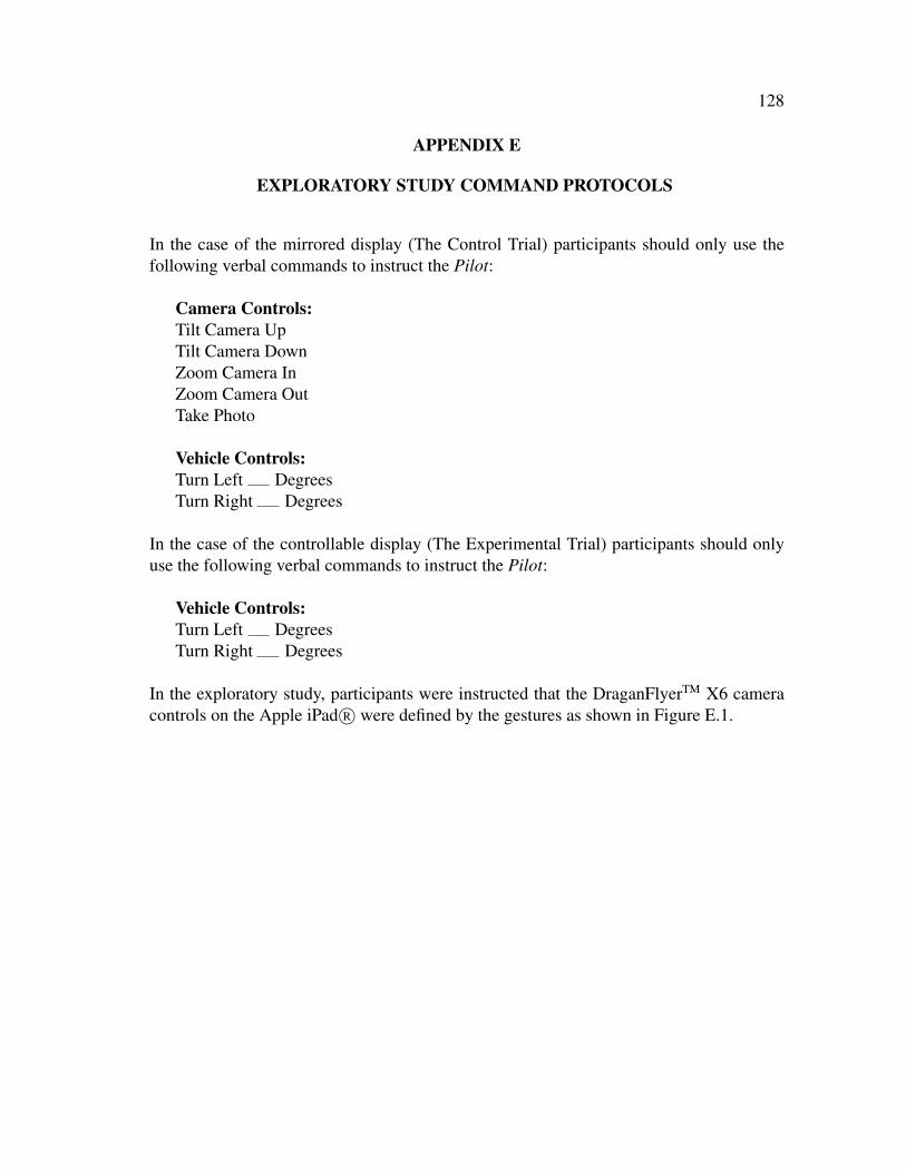
128
APPENDIX E
EXPLORATORY STUDY COMMAND PROTOCOLS
In the case of the mirrored display (The Control Trial) participants should only use thefollowing verbal commands to instruct the Pilot:
Camera Controls:Tilt Camera UpTilt Camera DownZoom Camera InZoom Camera OutTake Photo
Vehicle Controls:Turn Left DegreesTurn Right Degrees
In the case of the controllable display (The Experimental Trial) participants should onlyuse the following verbal commands to instruct the Pilot:
Vehicle Controls:Turn Left DegreesTurn Right Degrees
In the exploratory study, participants were instructed that the DraganFlyerTM X6 cameracontrols on the Apple iPad R� were defined by the gestures as shown in Figure E.1.

129
Fig. E.1. Gestures Used During the Exploratory Study for Apple iPad R�Control of the DraganFlyerTMX6 Payload Camera (Courtesy of Center forRobot-Assisted Search and Rescue).

130
APPENDIX F
EXPLORATORY STUDY MISSION SCRIPT
Welcome the participants to the study. Introduce yourself and the other members of theresearch team. Obtain verbal confirmation from each participant that both the InformationSheet (Appendix B) has been received and read, and that the Consent Form (Appendix C)has been received, read, and signed.
In the case of the mirrored display (The Control Trial) say this:
You will be participating as part of an unmanned aerial system, which includes a humanteam and a micro unmanned aerial vehicle, for the purposes of investigating a simulatedtrain derailment involving hazardous materials. Your team’s mission is to fly a predeter-mined pattern over the accident scene to capture and interpret video that may aid otherresponders to deal with the accident.
Your role will be as the Mission Specialist. Your responsibilities are to watch the live videofeed from the unmanned aerial vehicle camera on the Mission Specialist interface and ver-bally direct the Pilot to control the camera (tilt and zoom) and take photographs when anidentified target becomes visible. During the mission you may refer to a quick referencesheet indicating commands you may give the Pilot for camera control. At various pointsin the mission, I will ask you one or more questions about a specific target that is beingexamined.
We will be recording the mission activities on video, therefore please speak clearly andloud enough to be recorded. We will also be monitoring your heart rate, so please do notinterfere with or remove any of the monitoring equipment. If the equipment becomes un-comfortable at any time, please let me know and we will adjust it for you. If you haveany questions about how to operate the Mission Specialist interface, I can answer those foryou. However, I cannot answer any questions about the mission itself. Do you have anyquestions before we start?
In the case of the controllable display (The Experimental Trial) say this:
You will be participating as part of an unmanned aerial system, which includes a humanteam and a micro unmanned aerial vehicle, for the purposes of investigating a simulatedtrain derailment involving hazardous materials. Your team’s mission is to fly a predeter-mined pattern over the accident scene to capture and interpret video that may aid otherresponders to deal with the accident.

131
Your role will be as the Mission Specialist. Your responsibility is to watch the live videofeed from the unmanned aerial vehicle camera, control the camera (tilt and zoom), andtake pictures using the Mission Specialist interface when an identified target becomes vis-ible. At various points in the mission, I will ask you one or more questions about a specifictarget that is being examined.
We will be recording the mission activities on video, therefore please speak clearly andloud enough to be recorded. We will also be monitoring your heart rate, so please do notinterfere with or remove any of the monitoring equipment. If the equipment becomes un-comfortable at any time, please let me know and we will adjust it for you. If you haveany questions about how to operate the Mission Specialist interface, I can answer those foryou. However, I cannot answer any questions about the mission itself. Do you have anyquestions before we start?
When the participant finishes the mission, thank them for participating and direct themback to the main building.

132
APPENDIX G
EXPLORATORY STUDY SCRIPT FOR FLIGHT 1
Because every participant has to go through the same tasks and have the opportunity tosee the same things in the same amount of time, we have to constrain how you would mostlikely use a UAV in practice or what different models of UAVs can do. We would be happyto talk with you about UAVs after the experiments.
For this experiment, the Pilot will go to a series of pre-specified waypoints and then youwill answer a set of questions and get specific pictures. At each waypoint, the UAV willhave to stay at the same altitude and can’t move location. However, you can tell the Pilotto turn the UAV turn left or right (with the mirrored display, also add make the camerazoom in and out, and make the camera turn up and down).
The goal is to answer all the questions and get the pictures for all the waypoints within7-minutes.
Provide verbal commands for either mirrored or controllable condition (Appendix F).
We will now begin Flight 1. You do not have to pay attention before we get to waypoint 1or between waypoints.
Waypoint 1 [above tanker truck at 65-feet]:
Fig. G.1. Image Captured by the DraganFlyerTM X6 Payload CameraIllustrating the View from Waypoint 1 on Flight 1 (Courtesy of Center forRobot-Assisted Search and Rescue).

133
We are now at Waypoint 1 (Figure G.1). Please begin and remember to use the specificverbal commands to talk to the Pilot.
How many rail cars can you count? Remember you can turn, tilt, zoom.
Please obtain one photo that best captures the number of cars you see.
From this position, is there any product flowing or are there any exposure hazards youcan identify? If so, what are they? And if yes please obtain one photo of each hazards orproduct you may identify.
Now we are moving to Waypoint 2.
Waypoint 2 [move backwards from tanker truck at 65-feet]:
Fig. G.2. Image Captured by the DraganFlyerTM X6 Payload CameraIllustrating the View from Waypoint 2 on Flight 1 (Courtesy of Center forRobot-Assisted Search and Rescue).
We are now at Waypoint 2 (Figure G.2).
Find the tanker truck.
Can you count the number of vents on the top of the tanker truck? If so, how many ventsare there? Remember you can use zoom.
Please obtain one photo that best captures the number of vents you see.

134
Can you identify any punctures or ruptures to the tanker truck and if so, please obtain onephoto of any puncture or ruptures you may see.
Now we are moving to Waypoint 3.
Waypoint 3 [move leftwards from tanker truck at 65-feet]:
Fig. G.3. Image Captured by the DraganFlyerTM X6 Payload CameraIllustrating the View from Waypoint 3 on Flight 1 (Courtesy of Center forRobot-Assisted Search and Rescue).
We are now at Waypoint 3 (Figure G.3).
Find the train engine.
Please identify and read the number off of the black engine car, and obtain one photo ofthe number on the black engine car.
We are done.

135
APPENDIX H
EXPLORATORY STUDY SCRIPT FOR FLIGHT 2
We will now begin Flight 2.
This will be a different set of waypoints and but the goal is the same: to get the picturesfor all the waypoints in 7-minutes. The UAV will have the same constraints as before.
Provide verbal commands for either mirrored or controllable condition (Appendix F).
Remember, you do not have to pay attention before we get to waypoint or between way-points.
Waypoint 1 [above gray tanker at 70-feet]:
Fig. H.1. Image Captured by the DraganFlyerTM X6 Payload CameraIllustrating the View from Waypoint 1 on Flight 2 (Courtesy of Center forRobot-Assisted Search and Rescue).
We are now at Waypoint 1 (Figure H.1). Please begin and remember to use the specificverbal commands to talk to the Pilot.
From this position, are there any exposure hazards that you can identify? If so, what arethey and Please obtain one photo that best captures each hazard.
How many train cars can you count?

136
Please obtain one photo that best captures the number of cars you see.
Now we are moving to Waypoint 2.
Waypoint 2 [move backwards from gray tanker car at 70-feet]:
Fig. H.2. Image Captured by the DraganFlyerTM X6 Payload CameraIllustrating the View from Waypoint 2 on Flight 2 (Courtesy of Center forRobot-Assisted Search and Rescue).
We are now at Waypoint 2 (Figure H.2).
Find the overturned gray tanker car.
Please identify and read the chemical name printed on the overturned gray tanker car.
Please obtain one photo that best captures the chemical name you see.
Please identify and read the emergency telephone number printed on the overturned graytanker car and obtain one or more photos that best captures the emergency telephone num-ber you see.
Now we are moving to Waypoint 3.
Waypoint 3 [turn toward the black tanker cars at 70-feet]:
We are now at Waypoint 3 (Figure H.3).

137
Fig. H.3. Image Captured by the DraganFlyerTM X6 Payload CameraIllustrating the View from Waypoint 3 on Flight 2 (Courtesy of Center forRobot-Assisted Search and Rescue).
Find the black tanker cars.
Please identify and read the number off of the black tanker car sitting on top of the over-turned black tanker car.
Please obtain one or more photos of the number on the black tanker car.
We are done.

138
APPENDIX I
EXPLORATORY STUDY POST-ASSESSMENT 1
Please answer the following survey questions for the mirrored display trial. All informa-tion is confidential and will be used for research purposes only.
Question 1: How confidant did you feel in your ability to instruct the Pilot to accu-rately move the camera up and down?
(a) Not confidant at all(b) Somewhat not confidant(c) Neutral(d) Somewhat confidant(e) Very confidant
Question 2: How confidant did you feel in your ability to instruct the Pilot to accu-rately zoom the camera in and out?
(a) Not confidant at all(b) Somewhat not confidant(c) Neutral(d) Somewhat confidant(e) Very confidant
Question 3: How confidant did you feel in your ability to instruct the Pilot to accu-rately take pictures?
(a) Not confidant at all(b) Somewhat not confidant(c) Neutral(d) Somewhat confidant(e) Very confidant

139
Question 4: How comfortable did you feel asking the Pilot to move the camera upand down?
(a) Not comfortable at all(b) Somewhat not comfortable(c) Neutral(d) Somewhat comfortable(e) Very comfortable
Question 5: How comfortable did you feel asking the Pilot to zoom the camera in andout?
(a) Not comfortable at all(b) Somewhat not comfortable(c) Neutral(d) Somewhat comfortable(e) Very comfortable
Question 6: How comfortable did you feel asking the Pilot to to accurately take pic-tures?
(a) Not comfortable at all(b) Somewhat not comfortable(c) Neutral(d) Somewhat comfortable(e) Very comfortable
Question 7: How confidant did you feel in your individual ability to accurately in-struct the Pilot to acquire photos of the targets?
(a) Not confidant at all(b) Somewhat not confidant(c) Neutral(d) Somewhat confidant(e) Very confidant

140
Question 8: How comfortable did you individually feel instructing the Pilot to acquirephotos of the targets?
(a) Not comfortable at all(b) Somewhat not comfortable(c) Neutral(d) Somewhat comfortable(e) Very comfortable
Question 9: How confidant did you feel in your team’s ability to accurately acquirephotos of the targets when instructing the Pilot?
(a) Not confidant at all(b) Somewhat not confidant(c) Neutral(d) Somewhat confidant(e) Very confidant
Question 10: How comfortable did you feel in your team’s ability to acquire photosof the targets when instructing the Pilot?
(a) Not comfortable at all(b) Somewhat not comfortable(c) Neutral(d) Somewhat comfortable(e) Very comfortable

141
APPENDIX J
EXPLORATORY STUDY POST-ASSESSMENT 2
Please answer the following survey questions for the controllable display trial. All infor-mation is confidential and will be used for research purposes only.
Question 1: How confidant did you feel in your ability to accurately move the cameraup and down with the touch interface?
(a) Not confidant at all(b) Somewhat not confidant(c) Neutral(d) Somewhat confidant(e) Very confidant
Question 2: How confidant did you feel in your ability to accurately zoom the camerain and out with the touch interface?
(a) Not confidant at all(b) Somewhat not confidant(c) Neutral(d) Somewhat confidant(e) Very confidant
Question 3: How confidant did you feel in your ability to accurately take pictureswith the touch interface?
(a) Not confidant at all(b) Somewhat not confidant(c) Neutral(d) Somewhat confidant(e) Very confidant

142
Question 4: How comfortable did you feel with the gesture to move the camera upand down with the touch interface?
(a) Not comfortable at all(b) Somewhat not comfortable(c) Neutral(d) Somewhat comfortable(e) Very comfortable
Question 5: How comfortable did you feel with the gesture to zoom the camera inand out with the touch interface?
(a) Not comfortable at all(b) Somewhat not comfortable(c) Neutral(d) Somewhat comfortable(e) Very comfortable
Question 6: How comfortable did you feel with the gesture to take pictures with thetouch interface?
(a) Not comfortable at all(b) Somewhat not comfortable(c) Neutral(d) Somewhat comfortable(e) Very comfortable
Question 7: How confidant did you feel in your individual ability to accurately ac-quire photos of the targets using the touch interface?
(a) Not confidant at all(b) Somewhat not confidant(c) Neutral(d) Somewhat confidant(e) Very confidant

143
Question 8: How comfortable did you individually feel in using the touch interface toacquire photos of the targets?
(a) Not comfortable at all(b) Somewhat not comfortable(c) Neutral(d) Somewhat comfortable(e) Very comfortable
Question 9: How confidant did you feel in your team’s ability to accurately acquirephotos of the targets when using the touch interface?
(a) Not confidant at all(b) Somewhat not confidant(c) Neutral(d) Somewhat confidant(e) Very confidant
Question 10: How comfortable did you feel in your team’s ability to acquire photosof the targets when using the touch interface?
(a) Not comfortable at all(b) Somewhat not comfortable(c) Neutral(d) Somewhat comfortable(e) Very comfortable

144
APPENDIX K
EXPERIMENTAL STUDY INFORMATION SHEET
IRB Version 01/24/12
IntroductionThe purpose of this form is to provide you (as a prospective research study participant) in-formation that may affect your decision as to whether or not to participate in this research.
You have been asked to participate in a research study that examines the individual per-formance of a human interacting with an unmanned aerial vehicle (UAV). The purpose ofthis study is to evaluate an Apple iPad R� application we have developed that will allowyou to view real-time video from a UAV and capture images of pre-determined objects.You were selected to be a possible participant because you have experience as a special-ized emergency responder and/or are a roboticist who develops search and rescue roboticstechnology.
What will I be asked to do?If you agree to participate in this study, you will be asked to 1) complete a pre-study back-ground survey and short training meeting, 2) watch a video feed on an Apple iPad R� ora laptop computer and interact with the UAV camera to capture images from the video ofpre-determined objects when they become visible, and 3) complete a post-study survey.This study will take approximately 2-hours to complete.
Your participation will be video recorded with audio.
What are the risks involved in this study?The risks associated with this study are minimal, and are not greater than risks ordinarilyencountered in daily life.
What are the possible benefits of this study?The possible benefits of participation are that you will gain experience working with aUAV in a high-fidelity search and rescue exercise that uses cutting-edge robotics technol-ogy.
Do I have to participate?No. Your participation is voluntary. You may decide not to participate or to withdrawat any time without your current or future relations with Texas A&M University (or anyrelated System affiliates) being affected.

145
Who will know about my participation in this research study?This study is confidential and the records of this study will be kept private. No identifierslinking you to this study will be included in any sort of report that might be published.Research records will be stored securely and only Dr. Robin R. Murphy and Mr. JoshuaPeschel will have access to the records.
If you choose to participate in this study, you will be video recorded with audio. Anyaudio/video recordings will be stored securely and only Dr. Robin R. Murphy and Mr.Joshua Peschel will have access to the recordings. Any recordings will be kept for 3-yearsand then erased.
Is there anything else I should consider?The researchers can choose to end the experiment at any time.
Whom do I contact with questions about the research?If you have questions regarding this study, you may contact Dr. Robin R. Murphy, (979)845-2015, [email protected] or Mr. Joshua Peschel, (979) 324-0985, [email protected].
Whom do I contact about my rights as a research participant?This research study has been reviewed by the Human Subjects’ Protection Program and/orthe Institutional Review Board at Texas A&M University. For research-related problemsor questions regarding your rights as a research participant, you can contact these officesat (979) 458-4067 or [email protected].
ParticipationPlease be sure you have read the above information, asked questions and received answersto your satisfaction. If you would like to be in the study, please refer to and sign theconsent form.

146
APPENDIX L
EXPERIMENTAL STUDY CONSENT FORM
IRB Version 01/24/12
IntroductionThe purpose of this form is to provide you information that may affect your decision asto whether or not to participate in this research study. If you decide to participate in thisstudy, this form will also be used to record your consent.
You have been asked to participate in a research project study that examines the individualperformance of a human interacting with an unmanned aerial vehicle (UAV). The purposeof this study is to evaluate an Apple iPad R� application we have developed that will allowyou to view real-time video from a UAV and capture image of pre-determined objects.You were selected to be a possible participant because you have experience as a special-ized emergency responder and/or are a roboticist who develops search and rescue roboticstechnology.
What will I be asked to do?If you agree to participate in this study, you will be asked to 1) complete a pre-study back-ground survey and short training meeting, 2) watch a video feed on an Apple iPad R� ora laptop computer and interact with the UAV camera to capture images from the video ofpre-determined objects when they become visible, and 3) complete a post-study survey.This study will take approximately 2-hours to complete.
Your participation will be video recorded with audio.
What are the risks involved in this study?The risks associated with this study are minimal, and are not greater than the risks ordi-narily encountered in daily life.
What are the possible benefits of this study?The possible benefits of participation are that you will gain experience working with aUAV in a high-fidelity search and rescue exercise that uses cutting-edge robotics technol-ogy.
Do I have to participate?No. Your participation is voluntary. You may decide not to participate or to withdrawat any time without your current or future relations with Texas A&M University (or any

147
related System affiliates) being affected.
Who will know about my participation in this research study?This study is confidential and the records of this study will be kept private. No identifierslinking you to this study will be included in any sort of report that might be published.Research records will be stored securely and only Dr. Robin R. Murphy and Mr. JoshuaPeschel will have access to the records.
If you choose to participate in this study, you will be video recorded with audio. Anyaudio/video recordings will be stored securely and only Dr. Robin R. Murphy and Mr.Joshua Peschel will have access to the recordings. Any recordings will be kept for 3-yearsand then erased.
Is there anything else I should consider?The researchers can choose to end the experiment at any time.
Whom do I contact with questions about the research?If you have questions regarding this study, you may contact Dr. Robin R. Murphy, (979)845-2015, [email protected] or Mr. Joshua Peschel, (979) 324-0985, [email protected].
Whom do I contact about my rights as a research participant?This research study has been reviewed by the Human Subjects’ Protection Program and/orthe Institutional Review Board at Texas A&M University. For research-related problemsor questions regarding your rights as a research participant, you can contact these officesat (979) 458-4067 or [email protected].
SignaturePlease be sure you have read the above information, asked questions and received answersto your satisfaction. You will be given a copy of the consent form for your records. Bysigning this document, you consent to participate in this study.
Signature of Participant: Date:
Printed Name:
Signature of Person Obtaining Consent: Date:
Printed Name:

148
APPENDIX M
EXPERIMENTAL STUDY PRE-ASSESSMENT
Please answer the following survey questions. All information is confidential and will beused for research purposes only.
Question 1: What is your age?
(a) Under 25-years(b) 25-years to 34-years(c) 35-years to 44-years(d) 45-years to 54-years(e) 55-years and older
Question 2: What is your gender?
(a) Male(b) Female
Question 3: What is your current occupation?
Question 4: What is your ethnicity/race?
Question 5: Have you ever used a mobile touch-based device (e.g., Apple iPhone R�or iPad R�) before?
(a) Yes(b) No
Question 6: If you answered ‘Yes’ to Question 5, do you currently use any of the fol-lowing mobile touch-based devices? If you answered ‘No’ to Question 5, please skipto Question 10.
(a) Apple iPhone R�(b) Apple iPad R�(c) AndroidTM phone(d) AndroidTM tablet(e) Other touch-based phone or tablet, please specify:

149
Question 7: If you answered ‘Yes’ to Question 5, how long have you used mobiletouch-based devices? If you answered ‘No’ to Question 5, please skip to Question 10.
(a) 0 to 6-months(b) 6- to 12-months(c) More than 1-year(d) More than 2-years(e) More than 3-years
Question 8: If you answered ‘Yes’ to Question 5, how often do you use mobile touch-based devices? If you answered ‘No’ to Question 5, please skip to Question 10.
(a) Continuously throughout every day(b) A few times per week(c) A few times per month(d) A few times per year
Question 9: If you answered ‘Yes’ to Question 5, in what context to you typically in-teract with mobile touch-based devices? If you answered ‘No’ to Question 5, pleaseskip to Question 10. This question can have more than one answer.
(a) I use it as my phone(b) I use it to play games(c) I use it to surf the Internet(d) I use it to check email(e) I do not own a device but I borrow from others
Question 10: Have you ever used a Tablet PC or other electronic pen-based devicebefore?
(a) Yes(b) No

150
Question 11: If you answered ‘Yes’ to Question 10, how long have you used a TabletPC or other electronic pen-based devices? If you answered ‘No’ to Question 10,please skip to Question 14.
(a) 0 to 6-months(b) 6- to 12-months(c) More than 1-year(d) More than 2-years(e) More than 3-years
Question 12: If you answered ‘Yes’ to Question 10, how often do you use a Tablet PCor other electronic pen-based devices? If you answered ‘No’ to Question 10, pleaseskip to Question 14.
(a) Continuously throughout every day(b) A few times per week(c) A few times per month(d) A few times per year
Question 13: If you answered ‘Yes’ to Question 10, in what context to you typicallyinteract with a Tablet PC or other electronic pen-based devices? If you answered‘No’ to Question 10, please skip to Question 14.
(a) I use it as my primary computer(b) I use it to play games(c) I use it to surf the Internet(d) I use it to check email(e) I do not own a device but I borrow from others
Question 14: How often do you play video games?
(a) Continuously throughout every day(b) A few times per week(c) A few times per month(d) A few times per year(e) I do not play video games

151
Question 15: If you do play video games, how often do you play first-person actiongames (e.g., Quake, HalfLife, etc.)?
(a) Continuously throughout every day(b) A few times per week(c) A few times per month(d) A few times per year(e) I do not play first-person simulation games
Question 16: Have you ever interacted with a robot before?
(a) Yes(b) No
Question 17: If you answered ‘Yes’ to Question 16, how often have you interactedwith a robot before?
(a) Once(b) Yearly(c) Monthly(d) Weekly(e) Daily
Question 18: Have you ever owned a robot before?
(a) Yes(b) No
Question 19: If you answered ‘Yes’ to Question 18, please briefly describe the type(s)of robot(s) you have owned before.
Question 20: Have you ever flown RC helicopters or a plane?
(a) Yes(b) No
Question 21: If you answered ‘Yes’ to Question 20, please briefly describe the type(s)of RC helicopter(s) and/or plane(s) you have flown before. If you answered ‘No’ toQuestion 20, please skip to Question 23.

152
Question 22: If you answered ‘Yes’ to Question 20, how would you rate your flyingexpertise? If you answered ‘No’ to Question 20, please skip to Question 23.
(a) Novice(b) Below Average Expertise(c) Average Expertise(d) Above Average Expertise(e) Expert
Question 23: Do you currently have a pilot’s license?
(a) Yes(b) No
Question 24: Have you ever controlled a camera remotely before (e.g., on a robot orthrough the Internet)?
(a) Yes(b) No
Question 25: If you answered ‘Yes’ to Question 24, please briefly describe the situa-tion(s) in which you have controlled a camera remotely before.
Question 26: Have you ever participated in a search and rescue or accident/disasterresponse mission or exercise before?
(a) Yes(b) No
Question 27: If you answered ‘Yes’ to Question 26, please briefly list and/or describeyour role (function and command level; some examples may be: technical searchteam lead, transportation consulting reporting to DOT, etc.) in the situation(s) inwhich you have participated in a search and rescue or accident/disaster responsemission before.

153
Question 28: Have you ever participated in a robot-assisted search and rescue or ac-cident/disaster response mission or exercise before?
(a) Yes(b) No
Question 29: If you answered ‘Yes’ to Question 28, please briefly list and/or describeyour role (function and command level; some examples may be: technical searchteam lead, transportation consulting reporting to DOT, etc.) and the type of robot(e.g., air, ground, sea) in the situation(s) in which you have participated in a robot-assisted search and rescue or accident/disaster response mission before.
Question 30: Do you currently supervise one or more person(s) in a team or workenvironment?
(a) Yes(b) No
Question 31: If you answered ‘Yes’ to Question 30, please briefly list and/or describeyour role(s) (function and command level; some examples may be: technical searchteam lead, transportation consulting reporting to DOT, etc.) and the type of supervi-sion(s) you provide.
Question 32: List below are information and/or technology methods that can be usedfor decision-making. Circle the best choice that reflects your use of the informationand/or technology method for decision-making in your current job.
Verbal Reports (e.g., telling someone “the area is all clear”)
(a) Never Use(b) Below Average Use(c) Average Use(d) Above Average Use(e) Always Use

154
Geographic Information on Paper Maps (e.g., topo maps)
(a) Never Use(b) Below Average Use(c) Average Use(d) Above Average Use(e) Always Use
Geographic Information on an Electronic Device (e.g., Google maps)
(a) Never Use(b) Below Average Use(c) Average Use(d) Above Average Use(e) Always Use
Digital Photographs and/or Video (e.g., digital cameras)
(a) Never Use(b) Below Average Use(c) Average Use(d) Above Average Use(e) Always Use
Commercial or Custom Apps on a Mobile Electronic Device (e.g., Apple iPhone R�,AndroidTM, etc.)
(a) Never Use(b) Below Average Use; Please Specify Apps:(c) Average Use; Please Specify Apps:(d) Above Average Use; Please Specify Apps:(e) Always Use; Please Specify Apps:

155
Question 33: List below are information and/or technology methods that can be usedfor decision-making. Circle the best choice that reflects your creation of the informa-tion and/or technology method for decision-making in your current job.
Verbal Reports (e.g., telling someone “the area is all clear”)
(a) Never Create(b) Below Average Creation(c) Average Creation(d) Above Average Creation(e) Always Create
Geographic Information on Paper Maps (e.g., topo maps)
(a) Never Create(b) Below Average Creation(c) Average Creation(d) Above Average Creation(e) Always Create
Geographic Information on an Electronic Device (e.g., Google maps)
(a) Never Create(b) Below Average Creation(c) Average Creation(d) Above Average Creation(e) Always Create
Digital Photographs and/or Video (e.g., digital cameras)
(a) Never Create(b) Below Average Creation(c) Average Creation(d) Above Average Creation(e) Always Create

156
Commercial or Custom Apps on a Mobile Electronic Device (e.g., Apple iPhone R�,AndroidTM, etc.)
(a) Never Create(b) Below Average Creation; Please Specify Apps:(c) Average Creation; Please Specify Apps:(d) Above Average Creation; Please Specify Apps:(e) Always Creation; Please Specify Apps:
Question 34: List below are information and/or technology methods that can be usedfor decision-making. If your job does not currently utilize one or more of the listeditems, please circle which one(s) do you wish it did.
(a) Verbal Reports(b) Geographic Information on Paper Maps(c) Geographic Information on Electronic Devices(d) Digital Photographs and/or Video(e) Commercial or Custom Apps on a Mobile Electronic Device(f) Other (please specify):

157
Question 35: On the following pages, there are phrases describing people’s behaviors.Please use the rating scale below to describe how accurately each statement describesyou. Describe yourself as you generally are now, not as you wish to be in the future.Describe yourself as you honestly see yourself, in relation to other people you know ofthe same sex as you are, and roughly your same age. So that you can describe yourselfin an honest manner, your responses will be kept in absolute confidence. Please readeach statement carefully, and then circle the number that corresponds to the numberon the scale.
Response Options:1: Very Inaccurate2: Moderately Inaccurate3: Neither Inaccurate nor Accurate4: Moderately Accurate5: Very Accurate
Try to surpass others’ accomplishments.
1 2 3 4 5
Very Inaccurate Very Accurate
Break my promises.
1 2 3 4 5
Very Inaccurate Very Accurate
Try to outdo others.
1 2 3 4 5
Very Inaccurate Very Accurate
Am afraid I will do the wrong thing.
1 2 3 4 5
Very Inaccurate Very Accurate

158
Am quick to correct others.
1 2 3 4 5
Very Inaccurate Very Accurate
Feel that I’m unable to deal with things.
1 2 3 4 5
Very Inaccurate Very Accurate
Impose my will on others.
1 2 3 4 5
Very Inaccurate Very Accurate
Avoid responsibilities.
1 2 3 4 5
Very Inaccurate Very Accurate
Demand explanations from others.
1 2 3 4 5
Very Inaccurate Very Accurate
Suspect hidden motives in others.
1 2 3 4 5
Very Inaccurate Very Accurate

159
Want to control the conversation.
1 2 3 4 5
Very Inaccurate Very Accurate
Feel that my life lacks direction.
1 2 3 4 5
Very Inaccurate Very Accurate
Am not afraid of providing criticism.
1 2 3 4 5
Very Inaccurate Very Accurate
Do not like art.
1 2 3 4 5
Very Inaccurate Very Accurate
Challenge others’ points of view.
1 2 3 4 5
Very Inaccurate Very Accurate
Believe that too much tax money goes to support artists.
1 2 3 4 5
Very Inaccurate Very Accurate

160
Lay down the law to others.
1 2 3 4 5
Very Inaccurate Very Accurate
Look for hidden meanings in things.
1 2 3 4 5
Very Inaccurate Very Accurate
Put people under pressure.
1 2 3 4 5
Very Inaccurate Very Accurate
Become overwhelmed by events.
1 2 3 4 5
Very Inaccurate Very Accurate
Hate to seem pushy.
1 2 3 4 5
Very Inaccurate Very Accurate
Feel lucky most of the time.
1 2 3 4 5
Very Inaccurate Very Accurate

161
Question 36: On the following pages, there are phrases describing people’s behaviors.Please use the rating scale below to describe how accurately each statement describesyou. Describe yourself as you generally are now, not as you wish to be in the future.Describe yourself as you honestly see yourself, in relation to other people you know ofthe same sex as you are, and roughly your same age. So that you can describe yourselfin an honest manner, your responses will be kept in absolute confidence. Please readeach statement carefully, and then circle the number that corresponds to the numberon the scale.
Response Options:1: Very Inaccurate2: Moderately Inaccurate3: Neither Inaccurate nor Accurate4: Moderately Accurate5: Very Accurate
Don’t like to draw attention to myself.
1 2 3 4 5
Very Inaccurate Very Accurate
Am comfortable in unfamiliar situations.
1 2 3 4 5
Very Inaccurate Very Accurate
Keep in the background.
1 2 3 4 5
Very Inaccurate Very Accurate

162
Feel at ease with people.
1 2 3 4 5
Very Inaccurate Very Accurate
Dislike being the center of attention.
1 2 3 4 5
Very Inaccurate Very Accurate
Am relaxed most of the time.
1 2 3 4 5
Very Inaccurate Very Accurate
Don’t talk a lot.
1 2 3 4 5
Very Inaccurate Very Accurate
Love life.
1 2 3 4 5
Very Inaccurate Very Accurate
Don’t mind being the center of attention.
1 2 3 4 5
Very Inaccurate Very Accurate

163
Feel comfortable with myself.
1 2 3 4 5
Very Inaccurate Very Accurate
Take charge.
1 2 3 4 5
Very Inaccurate Very Accurate
Tend to vote for conservative political candidates.
1 2 3 4 5
Very Inaccurate Very Accurate
Want to be in charge.
1 2 3 4 5
Very Inaccurate Very Accurate
Believe laws should be strictly enforced.
1 2 3 4 5
Very Inaccurate Very Accurate
Am the life of the party.
1 2 3 4 5
Very Inaccurate Very Accurate

164
Seldom complain.
1 2 3 4 5
Very Inaccurate Very Accurate
Can talk others into doing things.
1 2 3 4 5
Very Inaccurate Very Accurate
Get to work at once.
1 2 3 4 5
Very Inaccurate Very Accurate
Seek to influence others.
1 2 3 4 5
Very Inaccurate Very Accurate

165
Question 37: Please read each statement. Where there is a blank, decide what yournormal or usual attitude, feeling, or behavior would be:
Response Options:A: Rarely (less than 10% of the time)B: Occasionally (about 30% of the time)C: Sometimes (about half the time)D: Frequently (about 70% of the time)E: Usually (more than 90% of the time)
Of course, there are always unusual situations in which this would not be the case,but think of what you would do or feel in most normal situations.
Circle the letter that describes your usual attitude or behavior.
When faced with a problem I try to forgot it.
A B C D E
Very Rarely Occasionally Sometimes Frequently Usually
I need frequent encouragement from others for me to keep working ata difficult task.
A B C D E
Very Rarely Occasionally Sometimes Frequently Usually
I like jobs where I can make decisions and be responsible for my ownwork.
A B C D E
Very Rarely Occasionally Sometimes Frequently Usually

166
I change my opinion when someone I admire disagrees with me.
A B C D E
Very Rarely Occasionally Sometimes Frequently Usually
If I want something I work hard to get it.
A B C D E
Very Rarely Occasionally Sometimes Frequently Usually
I prefer to learn the facts about something from someone else ratherthan have to dig them out myself.
A B C D E
Very Rarely Occasionally Sometimes Frequently Usually
I will accept jobs that require me to supervise others.
A B C D E
Very Rarely Occasionally Sometimes Frequently Usually
I have a hard time saying “no” when someone tries to sell me some-thing I don’t want.
A B C D E
Very Rarely Occasionally Sometimes Frequently Usually

167
I like to have a say in any decisions made by any group I’m in.
A B C D E
Very Rarely Occasionally Sometimes Frequently Usually
I consider the different sides of an issue before making any decisions.
A B C D E
Very Rarely Occasionally Sometimes Frequently Usually
What other people think has a great influence on my behavior.
A B C D E
Very Rarely Occasionally Sometimes Frequently Usually
Whenever something good happens to me I feel it is because I’ve earnedit.
A B C D E
Very Rarely Occasionally Sometimes Frequently Usually
I enjoy being in a position of leadership.
A B C D E
Very Rarely Occasionally Sometimes Frequently Usually

168
I need someone else to praise my work before I am satisfied with whatI’ve done.
A B C D E
Very Rarely Occasionally Sometimes Frequently Usually
I am sure enough of my opinions to try and influence others.
A B C D E
Very Rarely Occasionally Sometimes Frequently Usually
When something is going to affect me I learn as much about it as I can.
A B C D E
Very Rarely Occasionally Sometimes Frequently Usually
I decide to do things on the spur of the moment.
A B C D E
Very Rarely Occasionally Sometimes Frequently Usually
For me, knowing I’ve done something well is more important than be-ing praised by someone else.
A B C D E
Very Rarely Occasionally Sometimes Frequently Usually

169
I let other people’s demands keep me from doing things I want to do.
A B C D E
Very Rarely Occasionally Sometimes Frequently Usually
I let other people’s demands keep me from doing things I want to do.
A B C D E
Very Rarely Occasionally Sometimes Frequently Usually
I stick to my opinions when someone disagrees with me.
A B C D E
Very Rarely Occasionally Sometimes Frequently Usually
I do what I feel like doing not what other people think I ought to do.
A B C D E
Very Rarely Occasionally Sometimes Frequently Usually
I get discouraged when doing something that takes a long time toachieve results.
A B C D E
Very Rarely Occasionally Sometimes Frequently Usually
When part of a group I prefer to let other people make all the decisions.
A B C D E
Very Rarely Occasionally Sometimes Frequently Usually

170
When I have a problem I follow the advice of friends or relatives.
A B C D E
Very Rarely Occasionally Sometimes Frequently Usually
I enjoy trying to do difficult tasks more than I enjoy trying to do easytasks.
A B C D E
Very Rarely Occasionally Sometimes Frequently Usually
I prefer situations where I can depend on someone else’s ability ratherthan just my own.
A B C D E
Very Rarely Occasionally Sometimes Frequently Usually
Having someone important tell me I did a good job is more importantto me than feeling I’ve done a good job.
A B C D E
Very Rarely Occasionally Sometimes Frequently Usually
When I’m involved in something I try to find out all I can about whatis going on even when someone else is in charge.
A B C D E
Very Rarely Occasionally Sometimes Frequently Usually

171
APPENDIX N
EXPERIMENTAL STUDY COMMAND PROTOCOLS
In the case of the mirrored display (The Control Trial) participants should only use thefollowing verbal commands to instruct the Pilot:
Camera Controls:Tilt Camera UpTilt Camera DownZoom Camera InZoom Camera OutTake Photo
Vehicle Controls:Turn Left DegreesTurn Right Degrees
In the case of the controllable display (The Experimental Trial) participants may use thefollowing verbal commands to instruct the Pilot:
Camera Controls:Tilt Camera UpTilt Camera DownZoom Camera InZoom Camera OutTake Photo
Vehicle Controls:Turn Left DegreesTurn Right Degrees
In the experimental study, participants were instructed that the AirRobot R� AR-100B cam-era controls on the Apple R� iPad were defined by the gestures as shown in Figure N.1.Note that in the experimental study, participants could choose to have the zoom pinchcontrols reversed if it was more intuitive for them.

172
Fig. N.1. Gestures Used During the Experimental Study for Apple iPad R�Control of the AirRobot R� AR-100B Payload Camera (Courtesy of Cen-ter for Robot-Assisted Search and Rescue).

173
APPENDIX O
EXPERIMENTAL STUDY MISSION SCRIPT
Welcome the participants to the study. Introduce yourself and the other members of theresearch team. Obtain verbal confirmation from each participant that both the InformationSheet (Appendix K) has been received and read, and that the Consent Form (Appendix L)has been received, read, and signed.
In the case of the mirrored display (The Control Trial) say this:
You will be participating as part of an unmanned aerial system, which includes a humanteam and a micro unmanned aerial vehicle, for the purposes of investigating a simulatedtrain derailment involving hazardous materials. Your team’s mission is to fly a predeter-mined pattern over the accident scene to capture and interpret video that may aid otherresponders to deal with the accident.
Your role will be as the Mission Specialist. Your responsibilities are to watch the live videofeed from the unmanned aerial vehicle camera on the Mission Specialist interface and ver-bally direct the Pilot to control the camera (tilt and zoom) and take photographs when anidentified target becomes visible. During the mission you may refer to a quick referencesheet indicating commands you may give the Pilot for camera control. At various pointsin the mission, I will ask you one or more questions about a specific target that is beingexamined.
We will be recording the mission activities on video, therefore please speak clearly andloud enough to be recorded. We will also be monitoring your heart rate, so please do notinterfere with or remove any of the monitoring equipment. If the equipment becomes un-comfortable at any time, please let me know and we will adjust it for you. If you haveany questions about how to operate the Mission Specialist interface, I can answer those foryou. However, I cannot answer any questions about the mission itself. Do you have anyquestions before we start?
In the case of the controllable display (The Experimental Trial) say this:
You will be participating as part of an unmanned aerial system, which includes a humanteam and a micro unmanned aerial vehicle, for the purposes of investigating a simulatedtrain derailment involving hazardous materials. Your team’s mission is to fly a predeter-mined pattern over the accident scene to capture and interpret video that may aid otherresponders to deal with the accident.

174
Your role will be as the Mission Specialist. Your responsibility is to watch the live videofeed from the unmanned aerial vehicle camera, control the camera (tilt and zoom), andtake pictures using the Mission Specialist interface when an identified target becomes vis-ible. At various points in the mission, I will ask you one or more questions about a specifictarget that is being examined.
We will be recording the mission activities on video, therefore please speak clearly andloud enough to be recorded. We will also be monitoring your heart rate, so please do notinterfere with or remove any of the monitoring equipment. If the equipment becomes un-comfortable at any time, please let me know and we will adjust it for you. If you haveany questions about how to operate the Mission Specialist interface, I can answer those foryou. However, I cannot answer any questions about the mission itself. Do you have anyquestions before we start?
When the participant finishes the mission, thank them for participating and direct themback to the main building.

175
APPENDIX P
EXPERIMENTAL STUDY SCRIPT FOR FLIGHT 1
If using the traditional approach, read the mirrored display mission script (Appendix O).
If using the dedicated approach, read the controllable display mission script (Appendix O).
Because every participant has to go through the same tasks and have the opportunity tosee the same things in the same amount of time, we have to constrain how you would mostlikely use a UAV in practice or what different models of UAVs can do. We would be happyto talk with you about UAVs after the experiments.
For this flight, the pilot will go to three different waypoints. At each waypoint you willthen answer a set of questions and get specific pictures. At each waypoint, the UAV willhave to stay at the same altitude and cannot move its location (i.e., backwards or forwards,or side to side). However, you can tell the Pilot to turn the UAV turn left or right, makethe camera zoom in and out, and make the camera turn up and down.
Your goal is to answer all the questions and get the pictures for all the waypoints within10-minutes.
We will now begin Flight 1. You do not have to pay attention before we get to waypoint 1or between waypoints.
[Waypoint 1: Looking at Front of Train; Altitude: 50-feet]:
We are now at Waypoint 1 (Figure P.1). We will now begin and remember to use:
If Traditional: specific verbal commands to direct the PilotIf Dedicated: Apple R� iPad interface and/or specific verbal commands to direct the Pilot
Question 1a: Yes or No, can you identify any derailed train cars?
Question 1b: Verbally indicate which train cars have been derailed.
Question 1c: Capture a photo of each derailed train car you indicated.
Question 2a: Yes or No, can you identify any product or material that has spilledfrom any of the derailed train cars?

176
Fig. P.1. Image Captured by the AirRobot R� AR-100B Payload CameraIllustrating the View from Waypoint 1 on Flight 1 (Courtesy of Center forRobot-Assisted Search and Rescue).
Question 2b: Verbally indicate which train cars have product or material spilling.
Question 2c: Capture a photo of each derailed train car with product or materialspilling you indicated.
Now we are moving to Waypoint 2.
[Waypoint 2: Backed Up from Tanker Truck; Altitude: 50-feet]:
We are now at Waypoint 2 (Figure P.2). We will now begin and remember to use:
If Traditional: specific verbal commands to direct the PilotIf Dedicated: Apple R� iPad interface and/or specific verbal commands to direct the Pilot
Question 1a: Yes or No, can you identify the tanker truck?
Question 1b: Verbally indicate the current orientation of the tanker truck relative tothe train.
Question 1c: Capture a photo of the tanker truck with the orientation you indicated.
Question 2a: Yes or No, can you identify any punctures or ruptures to the tankertruck?

177
Fig. P.2. Image Captured by the AirRobot R� AR-100B Payload CameraIllustrating the View from Waypoint 2 on Flight 1 (Courtesy of Center forRobot-Assisted Search and Rescue).
Question 2b: Verbally indicate how many punctures or ruptures you can identify.
Question 2c: Capture photos of each puncture or rupture you identified.
Now we are moving to Waypoint 3.
[Waypoint 3: Near Side of Black Train Engine; Altitude: 50-feet]
We are now at Waypoint 3 (Figure P.3). We will now begin and remember to use:
If Traditional: specific verbal commands to direct the PilotIf Dedicated: Apple R� iPad interface and/or specific verbal commands to direct the Pilot
Question 1a: Yes or No, can you identify the black train engine?
Question 1b: Yes or No, is there any fire or smoke coming from the black train engine.
Question 1c: Capture a photo of the black train engine.
Question 2a: Yes or No, can you identify the identification number on black trainengine?
Question 2b: Verbally indicate the identification number on the black train engine.

178
Fig. P.3. Image Captured by the AirRobot R� AR-100B Payload CameraIllustrating the View from Waypoint 3 on Flight 1 (Courtesy of Center forRobot-Assisted Search and Rescue).
Question 2c: Capture a photo of the identification number on the black train engineyou indicated.
We are now done with Flight 1.

179
APPENDIX Q
EXPERIMENTAL STUDY SCRIPT FOR FLIGHT 2
If using the traditional approach, read the mirrored display mission script (Appendix O).
If using the dedicated approach, read the controllable display mission script (Appendix O).
This will be a different set of three waypoints but your goal is same: to answer all thequestions and get the pictures for all the waypoints within 10-minutes.
As before, you do not have to pay attention before we get to waypoint or between way-points.
[Waypoint 1: On Top of Black Tanker Cars; Altitude: 50-feet]:
Fig. Q.1. Image Captured by the AirRobot R� AR-100B Payload CameraIllustrating the View from Waypoint 1 on Flight 2 (Courtesy of Center forRobot-Assisted Search and Rescue).
We are now at Waypoint 1 (Figure Q.1). We will now begin and remember to use:
If Traditional: specific verbal commands to direct the PilotIf Dedicated: Apple R� iPad interface and/or specific verbal commands to direct the Pilot
Question 1a: Yes or No, can you identify the black tanker cars?

180
Question 1b: Verbally indicate the current orientation of the black tanker cars rela-tive to each other.
Question 1c: Capture a photo of the black tanker cars.
Question 2a: Yes or No, can you identify the identification number on topmost blacktanker car?
Question 2b: Verbally indicate the identification number on the topmost black tankercar.
Question 2c: Capture a photo of the identification number on the topmost blacktanker car you indicated.
Now we are moving to Waypoint 2.
[Waypoint 2: Overturned Gray Tanker Car; Altitude: 50-feet]:
Fig. Q.2. Image Captured by the AirRobot R� AR-100B Payload CameraIllustrating the View from Waypoint 2 on Flight 2 (Courtesy of Center forRobot-Assisted Search and Rescue).
We are now at Waypoint 2 (Figure Q.2). We will now begin and remember to use:
If Traditional: specific verbal commands to direct the PilotIf Dedicated: Apple R� iPad interface and/or specific verbal commands to direct the Pilot

181
Question 1a: Yes or No, can you identify the overturned gray tanker car?
Question 1b: Verbally indicate the current orientation of the overturned gray tankercar relative to the train track.
Question 1c: Capture a photo of the orientation of the overturned gray tanker carthat you indicated.
Question 2a: Yes or No, can you identify any disconnected wheel carriages from theoverturned gray tanker car?
Question 2b: Verbally indicate how the number of disconnected wheel carriages youcan count.
Question 2c: Capture a photo of each disconnected wheel carriage you identified.
Now we are moving to Waypoint 3.
[Waypoint 3: Near Side of Gray Tanker Car; Altitude: 50-feet]
Fig. Q.3. Image Captured by the AirRobot R� AR-100B Payload CameraIllustrating the View from Waypoint 3 on Flight 2 (Courtesy of Center forRobot-Assisted Search and Rescue).
We are now at Waypoint 3 (Figure Q.3). We will now begin and remember to use:

182
If Traditional: specific verbal commands to direct the PilotIf Dedicated: Apple R� iPad interface and/or specific verbal commands to direct the Pilot
Question 1a: Yes or No, can you identify any missing train track?
Question 1b: Indicate the location of the missing train track.
Question 1c: Capture a photo of the missing train track you indicated.
Question 2a: Yes or No, can you identify any train tracks nearby the track on whichthe derailment has occurred?
Question 2b: Indicate the location of the nearby train track relative to the train trackon which the derailment has occurred.
Question 2c: Capture a photo of the nearby train track you indicated.
We are now done with Flight 2.

183
APPENDIX R
EXPERIMENTAL STUDY POST-ASSESSMENT 1
Please answer the following survey questions for the mirrored display trial. All informa-tion is confidential and will be used for research purposes only.
Question 1: How confidant did you feel in your ability to instruct the Pilot to accu-rately move the camera up and down?
(a) Not confidant at all(b) Somewhat not confidant(c) Neutral(d) Somewhat confidant(e) Very confidant
Question 2: How confidant did you feel in your ability to instruct the Pilot to accu-rately zoom the camera in and out?
(a) Not confidant at all(b) Somewhat not confidant(c) Neutral(d) Somewhat confidant(e) Very confidant
Question 3: How confidant did you feel in your ability to instruct the Pilot to accu-rately take pictures?
(a) Not confidant at all(b) Somewhat not confidant(c) Neutral(d) Somewhat confidant(e) Very confidant

184
Question 4: How comfortable did you feel asking the Pilot to move the camera upand down?
(a) Not comfortable at all(b) Somewhat not comfortable(c) Neutral(d) Somewhat comfortable(e) Very comfortable
Question 5: How comfortable did you feel asking the Pilot to zoom the camera in andout?
(a) Not comfortable at all(b) Somewhat not comfortable(c) Neutral(d) Somewhat comfortable(e) Very comfortable
Question 6: How comfortable did you feel asking the Pilot to to accurately take pic-tures?
(a) Not comfortable at all(b) Somewhat not comfortable(c) Neutral(d) Somewhat comfortable(e) Very comfortable
Question 7: How confidant did you feel in your individual ability to accurately in-struct the Pilot to acquire photos of the targets?
(a) Not confidant at all(b) Somewhat not confidant(c) Neutral(d) Somewhat confidant(e) Very confidant

185
Question 8: How comfortable did you individually feel instructing the Pilot to acquirephotos of the targets?
(a) Not comfortable at all(b) Somewhat not comfortable(c) Neutral(d) Somewhat comfortable(e) Very comfortable
Question 9: How confidant did you feel in your team’s ability to accurately acquirephotos of the targets when instructing the Pilot?
(a) Not confidant at all(b) Somewhat not confidant(c) Neutral(d) Somewhat confidant(e) Very confidant
Question 10: How comfortable did you feel in your team’s ability to acquire photosof the targets when instructing the Pilot?
(a) Not comfortable at all(b) Somewhat not comfortable(c) Neutral(d) Somewhat comfortable(e) Very comfortable

186
APPENDIX S
EXPERIMENTAL STUDY POST-ASSESSMENT 2
Please answer the following survey questions for the controllable display trial. All infor-mation is confidential and will be used for research purposes only.
Question 1: How confidant did you feel in your ability to accurately move the cameraup and down with the touch interface?
(a) Not confidant at all(b) Somewhat not confidant(c) Neutral(d) Somewhat confidant(e) Very confidant
Question 2: How confidant did you feel in your ability to accurately zoom the camerain and out with the touch interface?
(a) Not confidant at all(b) Somewhat not confidant(c) Neutral(d) Somewhat confidant(e) Very confidant
Question 3: How confidant did you feel in your ability to accurately take pictureswith the touch interface?
(a) Not confidant at all(b) Somewhat not confidant(c) Neutral(d) Somewhat confidant(e) Very confidant
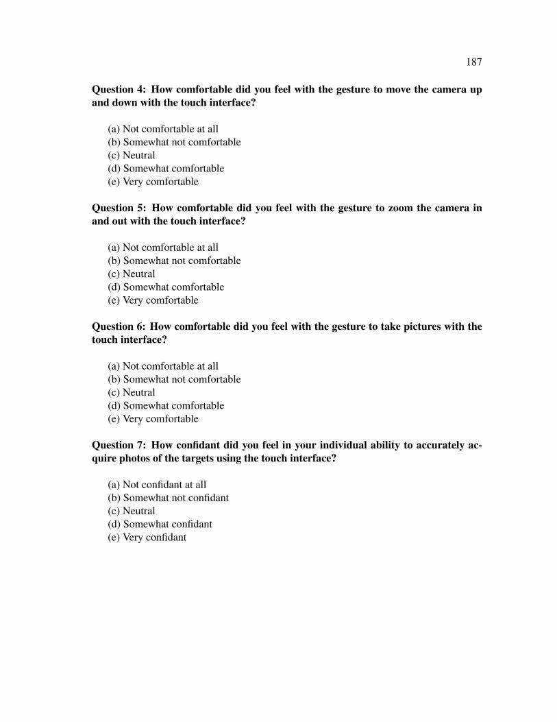
187
Question 4: How comfortable did you feel with the gesture to move the camera upand down with the touch interface?
(a) Not comfortable at all(b) Somewhat not comfortable(c) Neutral(d) Somewhat comfortable(e) Very comfortable
Question 5: How comfortable did you feel with the gesture to zoom the camera inand out with the touch interface?
(a) Not comfortable at all(b) Somewhat not comfortable(c) Neutral(d) Somewhat comfortable(e) Very comfortable
Question 6: How comfortable did you feel with the gesture to take pictures with thetouch interface?
(a) Not comfortable at all(b) Somewhat not comfortable(c) Neutral(d) Somewhat comfortable(e) Very comfortable
Question 7: How confidant did you feel in your individual ability to accurately ac-quire photos of the targets using the touch interface?
(a) Not confidant at all(b) Somewhat not confidant(c) Neutral(d) Somewhat confidant(e) Very confidant

188
Question 8: How comfortable did you individually feel in using the touch interface toacquire photos of the targets?
(a) Not comfortable at all(b) Somewhat not comfortable(c) Neutral(d) Somewhat comfortable(e) Very comfortable
Question 9: How confidant did you feel in your team’s ability to accurately acquirephotos of the targets when using the touch interface?
(a) Not confidant at all(b) Somewhat not confidant(c) Neutral(d) Somewhat confidant(e) Very confidant
Question 10: How comfortable did you feel in your team’s ability to acquire photosof the targets when using the touch interface?
(a) Not comfortable at all(b) Somewhat not comfortable(c) Neutral(d) Somewhat comfortable(e) Very comfortable

189
APPENDIX T
EXPERIMENTAL STUDY POST-ASSESSMENT 3
Please answer the following survey questions after both trials are complete. All informa-tion is confidential and will be used for research purposes only.
Question 1: Which method were you most confident in using to accurately move thecamera up and down?
(a) Move the camera up and down yourself(b) Asking the Pilot to move the camera up and down(c) Both (a) and (b)
Question 2: Which method were you most confident in using to accurately zoom thecamera in and out?
(a) Zoom the camera in and out yourself(b) Asking the Pilot to zoom the camera in and out(c) Both (a) and (b)
Question 3: Which method were you most confident in using to accurately take pho-tos?
(a) Take photos yourself(b) Asking the Pilot to take photos(c) Both (a) and (b)
Question 4: Which method were you most comfortable in using to accurately movethe camera up and down?
(a) Move the camera up and down yourself(b) Asking the Pilot to move the camera up and down(c) Both (a) and (b)

190
Question 5: Which method were you most comfortable in using to accurately zoomthe camera in and out?
(a) Zoom the camera in and out yourself(b) Asking the Pilot to zoom the camera in and out(c) Both (a) and (b)
Question 6: Which method were you most comfortable in using to accurately takephotos?
(a) Take photos yourself(b) Asking the Pilot to take photos(c) Both (a) and (b)
Question 7: Which method were you most confident in using to locate targets?
(a) Watch the video and asking the Pilot to control the camera(b) Controlling the camera yourself(c) Both (a) and (b)
Question 8: Which method were you most comfortable in using to locate targets?
(a) Watching the video and asking the Pilot to control the camera(b) Controlling the camera yourself(c) Both (a) and (b)
Question 9: Which method were you most confident in using for your team to accu-rately acquire photos of the targets?
(a) Watching the video and asking the Pilot to control the camera and take photos(b) Controlling the camera and taking photos yourself(c) Both (a) and (b)
Question 10: Which method were you most comfortable in using for your team toaccurately acquire photos of the targets?
(a) Watching the video and asking the Pilot to control the camera and take photos(b) Controlling the camera and taking photos yourself(c) Both (a) and (b)

191
Question 11: Which method allowed you to individually perform the best to accu-rately acquire photos of the targets?
(a) Watching the video and asking the Pilot to control the camera and take photos(b) Controlling the camera and taking photos yourself(c) Both (a) and (b)
Question 12: Which method allowed your team to perform the best to accurately ac-quire photos of the targets?
(a) Watching the video and asking the Pilot to control the camera and take photos(b) Controlling the camera and taking photos yourself(c) Both (a) and (b)
Question 13: If a UAV was given to your organization as a tool, would you be respon-sible for maintaining the robot?
(a) Yes(b) No
Question 14: If a UAV was given to your organization as a tool, would you be respon-sible for the robot in terms of planning?
(a) Yes(b) No
Question 15: If a UAV was given to your organization as a tool, would you likely bethe one to pilot the robot?
(a) Yes(b) No
Question 16: If a UAV was given to your organization as a tool, would you expect touse the data from the robot?
(a) Yes(b) No

192
Question 17: On the following pages, there are statements related to your feelingsduring the study. Please use the rating scale below to describe how accurately eachstatement describes you. Please read each statement carefully, and then circle thenumber that corresponds to the number on the scale.
Response Options:1: Strongly Disagree2: Moderately Disagree3: Neither Agree nor Disagree4: Moderately Agree5: Strongly Agree
The robot’s primary purpose was to help me.
1 2 3 4 5
Strongly Agree Strongly Disagree
The robot’s primary purpose was to help my team.
1 2 3 4 5
Strongly Agree Strongly Disagree
The robot would only do things that were in my best interest.
1 2 3 4 5
Strongly Agree Strongly Disagree
The robot was more loyal to me than the Pilot.
1 2 3 4 5
Strongly Agree Strongly Disagree

193
The robot was on my side.
1 2 3 4 5
Strongly Agree Strongly Disagree
I trusted the robot.
1 2 3 4 5
Strongly Agree Strongly Disagree
The Pilot’s primary purpose was to help me.
1 2 3 4 5
Strongly Agree Strongly Disagree
The Pilot’s primary purpose was to help my team.
1 2 3 4 5
Strongly Agree Strongly Disagree
The Pilot would only do things that were in my best interest.
1 2 3 4 5
Strongly Agree Strongly Disagree
The Pilot was more loyal to me than the robot.
1 2 3 4 5
Strongly Agree Strongly Disagree

194
The Pilot was on my side.
1 2 3 4 5
Strongly Agree Strongly Disagree
I trusted the Pilot.
1 2 3 4 5
Strongly Agree Strongly Disagree
The Apple iPad R� interface’s primary purpose was to help me.
1 2 3 4 5
Strongly Agree Strongly Disagree
The Apple iPad R� interface would only permit actions that were in my best interest.
1 2 3 4 5
Strongly Agree Strongly Disagree
The Apple iPad R� interface was more loyal to me than the Pilot.
1 2 3 4 5
Strongly Agree Strongly Disagree
The Apple iPad R� interface was on my side.
1 2 3 4 5
Strongly Agree Strongly Disagree

195
I trusted the Apple iPad R� interface.
1 2 3 4 5
Strongly Agree Strongly Disagree
Question 18: Are there any feature changes or feature additions to the controllableinterface that you would like to see?
Question 19: Do you have any other comments about this experiment?

196
VITA
Joshua Michael Peschel received a B.S. in biological systems engineering and a M.S.
in biological & agricultural engineering in 2001 and 2004, respectively, from Texas A&M
University. He began working with Professor Robin Murphy in the Department of Com-
puter Science and Engineering at Texas A&M University in May 2010. Upon completion
of his dissertation research in June 2012, Joshua joined the faculty in the Department of
Civil and Environmental Engineering at the University of Illinois at Urbana-Champaign
as a Research Assistant Professor.
Joshua may be reached at the Department of Civil and Environmental Engineering,
1114 Newmark Civil Engineering Laboratory, 205 North Matthews Avenue, Urbana, Illi-
nois 61801-2352. His email is [email protected].