Miracle: The Multi-Interface Cross-Layer Extension of ns2
16
Hindawi Publishing Corporation EURASIP Journal on Wireless Communications and Networking Volume 2010, Article ID 761792, 16 pages doi:10.1155/2010/761792 Research Article Miracle: The Multi-Interface Cross-Layer Extension of ns2 Nicola Baldo, 1 Marco Miozzo, 1 Federico Guerra, 2 Michele Rossi, 2 and Michele Zorzi 2 1 Centre Tecnol` ogic de Telecomunicacions de Catalunya, 08860 Castelldefels (Barcelona), Spain 2 Department of Information Engineering, University of Padova, 35131 Padova, Italy Correspondence should be addressed to Marco Miozzo, [email protected] Received 15 June 2009; Revised 6 November 2009; Accepted 21 January 2010 Academic Editor: Nikos Passas Copyright © 2010 Nicola Baldo et al. This is an open access article distributed under the Creative Commons Attribution License, which permits unrestricted use, distribution, and reproduction in any medium, provided the original work is properly cited. We present Miracle, a novel framework which extends ns2 to facilitate the simulation and the design of beyond 4G networks. Miracle enhances ns2 by providing an efficient and embedded engine for handling cross-layer messages and, at the same time, enabling the coexistence of multiple modules within each layer of the protocol stack. We also present a novel framework developed as an extension of Miracle called Miracle PHY and MAC. This framework facilitates the development of more realistic Channel, PHY and MAC modules, considering features currently lacking in most state-of-the-art simulators, while at the same time giving a strong emphasis on code modularity, interoperability and reusability. Finally, we provide an overview of the wireless technologies implemented in Miracle, discussing in particular the models for the IEEE 802.11, UMTS and WiMAX standards and for Underwater Acoustic Networks. We observe that, thanks to Miracle and its extensions, it is possible to carefully simulate complex network architectures at all the OSI layers, from the physical reception model to standard applications and system management schemes. This allows to have a comprehensive view of all the interactions among network components, which play an important role in many research areas, such as cognitive networking and cross-layer design. 1. Introduction In the last few years, advances in the hardware for wire- less networking and, especially, embedded microprocessor technologies have made it possible to manufacture very small radio equipments at low cost. This has enabled the integration of different technologies in a single mobile terminal. These multi-technology solutions are now available on the market and open up the possibility of exploiting new communication paradigms. Also, as multi-interface hardware becomes available at low cost, there is a parallel need for understanding its performance limits and devising new networking protocols that will make full use of the offered potential. Often, these systems are way too complex to be fully characterized analytically, and we have to resort to simulation tools for a more comprehensive understanding. As a consequence of these facts, there has been an increasing need for investigation tools, in particular network simulators, to be conveniently exploited for these research purposes. Many are the features that researchers seek in network simulators. In this paper, we focus on the issues which in our opinion are not addressed to a great extent by current network simulators. These issues are the following. (1) Accurate channel and PHY layer modeling: recently, there has been an increasing need for accurate modeling of channel and PHY layer aspects. While simplified models, such as the disk propagation model, are still useful in some contexts, a general purpose simulator is nowadays expected to provide more realistic representations of the signal propagation and reception processes. (2) Modeling of a complete system: the increasing com- plexity of communication systems has made performance evaluation a truly complex task, due to the fact that subtle interactions among the different components of the system can play an important role in determining its overall performance. These interactions are often not clear when only one or a few of the system components are modeled in isolation. This is a crucial issue in many novel research areas, such as cross-layer design [1, 2] and Cognitive Networking [3–5]. For this reason, a good general purpose network simulator is nowadays expected to provide means to model a complete communication system, from channel and PHY
Transcript of Miracle: The Multi-Interface Cross-Layer Extension of ns2

Hindawi Publishing CorporationEURASIP Journal on Wireless Communications and NetworkingVolume 2010, Article ID 761792, 16 pagesdoi:10.1155/2010/761792
Research Article
Miracle: The Multi-Interface Cross-Layer Extension of ns2
Nicola Baldo,1 Marco Miozzo,1 Federico Guerra,2 Michele Rossi,2 and Michele Zorzi2
1 Centre Tecnologic de Telecomunicacions de Catalunya, 08860 Castelldefels (Barcelona), Spain2 Department of Information Engineering, University of Padova, 35131 Padova, Italy
Correspondence should be addressed to Marco Miozzo, [email protected]
Received 15 June 2009; Revised 6 November 2009; Accepted 21 January 2010
Academic Editor: Nikos Passas
Copyright © 2010 Nicola Baldo et al. This is an open access article distributed under the Creative Commons Attribution License,which permits unrestricted use, distribution, and reproduction in any medium, provided the original work is properly cited.
We present Miracle, a novel framework which extends ns2 to facilitate the simulation and the design of beyond 4G networks.Miracle enhances ns2 by providing an efficient and embedded engine for handling cross-layer messages and, at the same time,enabling the coexistence of multiple modules within each layer of the protocol stack. We also present a novel framework developedas an extension of Miracle called Miracle PHY and MAC. This framework facilitates the development of more realistic Channel,PHY and MAC modules, considering features currently lacking in most state-of-the-art simulators, while at the same timegiving a strong emphasis on code modularity, interoperability and reusability. Finally, we provide an overview of the wirelesstechnologies implemented in Miracle, discussing in particular the models for the IEEE 802.11, UMTS and WiMAX standards andfor Underwater Acoustic Networks. We observe that, thanks to Miracle and its extensions, it is possible to carefully simulatecomplex network architectures at all the OSI layers, from the physical reception model to standard applications and systemmanagement schemes. This allows to have a comprehensive view of all the interactions among network components, which playan important role in many research areas, such as cognitive networking and cross-layer design.
1. Introduction
In the last few years, advances in the hardware for wire-less networking and, especially, embedded microprocessortechnologies have made it possible to manufacture verysmall radio equipments at low cost. This has enabled theintegration of different technologies in a single mobileterminal. These multi-technology solutions are now availableon the market and open up the possibility of exploitingnew communication paradigms. Also, as multi-interfacehardware becomes available at low cost, there is a parallelneed for understanding its performance limits and devisingnew networking protocols that will make full use of theoffered potential. Often, these systems are way too complexto be fully characterized analytically, and we have to resort tosimulation tools for a more comprehensive understanding.
As a consequence of these facts, there has been anincreasing need for investigation tools, in particular networksimulators, to be conveniently exploited for these researchpurposes. Many are the features that researchers seek innetwork simulators. In this paper, we focus on the issues
which in our opinion are not addressed to a great extent bycurrent network simulators. These issues are the following.
(1) Accurate channel and PHY layer modeling: recently,there has been an increasing need for accurate modeling ofchannel and PHY layer aspects. While simplified models,such as the disk propagation model, are still useful insome contexts, a general purpose simulator is nowadaysexpected to provide more realistic representations of thesignal propagation and reception processes.
(2) Modeling of a complete system: the increasing com-plexity of communication systems has made performanceevaluation a truly complex task, due to the fact that subtleinteractions among the different components of the systemcan play an important role in determining its overallperformance. These interactions are often not clear whenonly one or a few of the system components are modeled inisolation. This is a crucial issue in many novel research areas,such as cross-layer design [1, 2] and Cognitive Networking[3–5]. For this reason, a good general purpose networksimulator is nowadays expected to provide means to modela complete communication system, from channel and PHY
2 EURASIP Journal on Wireless Communications and Networking
layer all the way through the protocol stack up to theapplication layer.
(3) Rapid prototyping of new wireless technologies: newwireless technologies have been proposed and released atan amazing pace in recent years, and it is commonly thecase that researchers struggle to develop simulation toolsin a timely fashion to study these technologies as theyemerge. In the past, the majority of the code for wirelessnetworking simulation (especially at the PHY and MAClayers) has mainly been designed for specific technologies,without addressing code reusability during its design phase.The ns2 simulator, in particular, was not originally designedto simulate wireless networks, and support for this has beenadded only in a second phase, and in a rather improvisedand nonsystematic way. As a consequence, the task ofproperly designing and developing code for the simulationof new wireless technologies is time consuming. Thoughwireless systems can overall differ significantly from eachother, it is to be noted that there are many aspects andcomponents of the PHY and MAC layers which are verysimilar across different technologies. An ideal simulatorwould treat these components through the same set ofprocedures and would leverage on well-defined ApplicationProgramming Interfaces (APIs) for PHY and MAC modulesto allow easier and faster development of simulator code. Allof this should be done with a particular emphasis on codemodularity and reusability.
(4) Spectrum awareness: recently, research in fields such asCognitive Radio, Ultra Wide Band, MultiCarrier Modulationschemes, and Underwater communications systems hascreated a strong need for network simulators to providea better modeling of the Radio Frequency aspects ofcommunications systems, such as spectrum occupation,RF filtering and inter-channel interference. State-of-the-artnetwork simulators such as ns2 lack support for a correctmodeling of how communication systems make use of thefrequency spectrum.
(5) Intertechnology interference: unlicensed bands, inparticular the 2.4 GHz ISM band, are characterized by thesimultaneous presence of different wireless technologiesinterfering with each other; this is the case of popularwireless communication technologies such as IEEE 802.11,Bluetooth, and WiMAX, as well as noncommunicatingtechnologies such as microwave ovens. Therefore, theintroduction of spectrum awareness in wireless networksimulators should be made in such a way to allow properaccounting of how different technologies interact amongthemselves in the propagation medium. We note that thisgoes beyond the issues discussed above. In fact, supportfor spectrum awareness in a single-technology scenario canbe introduced by performing custom modifications to thecode implementing that particular technology, while thesimulation of Intertechnology interference requires that alltechnologies use the same representation of interference andspectrum usage.
(6) Multi-technology multi-interface communication ca-pabilities: as more and more devices nowadays are equippedwith multiple interfaces using different communicationtechnologies, network simulators should provide support
for proper modeling of these scenarios, by means of aflexible and modular protocol stack architecture togetherwith proper support for the development of the controlmodules which are needed to manage such a complexarchitecture.
(7) Support for cross-layer interactions and optimizations:while traditional networking strongly relied on protocol layerencapsulation to cope with system reliability and complexityissues, in recent years wireless networking research hasshown that superior performance can actually be achievedby exploiting cross-layer optimization, that is, by optimizingthe behavior of the whole communication system makingdifferent protocol layers interact with each other. Cross-layeroptimization has now become a widely accepted paradigmamong researchers, and for this reason it is very importantthat Network Simulators provide means to support theprototyping and testing of cross-layer solutions.
(8) Support for heterogeneous networks: while traditionalnetworking research mainly focused on homogeneous net-works, such as infrastructured, ad hoc, and mesh networks,in recent years there has been an increasing interest in sce-narios in which these types of networks coexist. Simulatingthis type of scenarios today is very challenging, in particulardue to the fact that the routing layer of state-of-the-artsimulators is mainly designed for homogeneous networks.As a consequence, there is a need for supporting this typeof heterogeneous network composition at all the layers of theprotocol stack.
In this paper we present Miracle, an extension for thens2 simulator that we developed with the aim of solvingthe above issues and therefore facilitating the simulation ofmodern communications systems. Our framework is calledMulti InteRfAce cross-layer extension (Miracle) for ns2 [6]. Itis conceived as a set of additional dynamic libraries whichprovide ns2 with support for multi-technology and cross-layering. Our architecture is highly modular as it allows theinterconnection of multiple down and upstream modules atevery layer of the protocol stack. In addition, a dedicatedcommunications facility provides the protocol stack ofeach node with cross-layer interaction capabilities. Afterdiscussing Miracle, we also present an additional frameworkfor the simulation of the physical and medium access layers,developed on top of Miracle.
This paper is structured as follows. The next Section 2presents the Miracle framework along with its main features.In Section 2.1, we start with a discussion of the relatedliterature, where we motivate our work and contrast it withexisting approaches. Subsequently, in Section 2.2 we delveinto the description of the Miracle’s node architecture andof its offered benefits in terms of modularity, cross-layersupport, and extensibility. In Section 2.3, we discuss howexisting ns2 modules can be reused within our framework.Furthermore, in Section 3 we describe the Miracle PHYand MAC extension, which we developed to allow accurate,flexible and reusable modeling of physical propagationchannels and channel access procedures. In Section 4, wereview existing implementations of wireless technologies inMiracle. Section 5 gives a quick overview of the projects thatused Miracle and Section 6 concludes the paper.
EURASIP Journal on Wireless Communications and Networking 3
2. Miracle
2.1. Related Work. The main motivation that led us to thedevelopment of this library was the need for a flexibleand easy to use tool for the simulation of multilayer andmultistack architectures in mixed wired/wireless settings.In this respect, there have recently been a few attempts toadd flexibility to ns2, and in particular to overcome thecurrent ns2 limit of no more than one wireless interface permobile node. For example, TENS [7], Hyacinth [8], and thesolution proposed by Aguero and Perez [9] are extensionsto ns2 which introduce the possibility of using multiplewireless interfaces within the same mobile node; however,they are currently limited to the use of the same radiotechnology (namely, IEEE 802.11) for all wireless interfaces.MW-Node [10], in addition to the support for multiplewireless interfaces, also allows coexistence of different radiotechnologies and routing protocols within the same node;still, its scope remains somewhat limited, since modularity isaddressed only at the network layer and below, and the fixedprotocol stack architecture of ns2 is maintained.
We note that the recently started ns3 project [11] shareswith Miracle some relevant goals, such as enhanced mod-ularity of components, while at the same time addressingsome particular ns2 issues, such as support for distributedsimulation and emulation, which are not considered inMiracle. Nevertheless, this choice for ns3 has required acomplete rewrite of the simulator, which prevents reusabilityof the many valuable components already implemented forns2. Miracle on the other hand, allows the reuse of ns2code and can consequently exploit many of the featuresalready included in ns2 with little or no development effort,as we will discuss in Section 2.3. Furthermore, ns3 triesto mimic as close as possible the protocol stack of realsystems (in particular Unix systems), whereas Miracle givestotal freedom to the researchers in specifying the way inwhich their protocol stack is built. Finally, while in ns3cross-layer functionalities have to be implemented usinggeneral purpose tools such as Packet Tags and Callbacks,Miracle provides a dedicated framework to handle cross-layer interactions, which makes it easier to implement notonly complex cross-layer optimization solutions, but alsoautomatic discovery and configuration of modules at run-time, which turns out to be very effective in reducing thetime taken to configure the simulator through dedicatedscripts.
2.2. Miracle Node Architecture. One of the primary goalsof Miracle is to facilitate the interconnection of differentprotocol modules while uniforming the procedure by whichmultiple protocol layers are plugged into the same node. Wemay define, for instance, a node with multiple PHY, MAC,or routing modules and we may use all of them in the samesimulation by making decisions on which ones to use atruntime. This is the typical case of, for example, advancedradio resource management (RRM) schemes, which has toefficiently make a decision on which interface(s) is to be usedin order to meet quality of service (QoS) requirements forthe users.
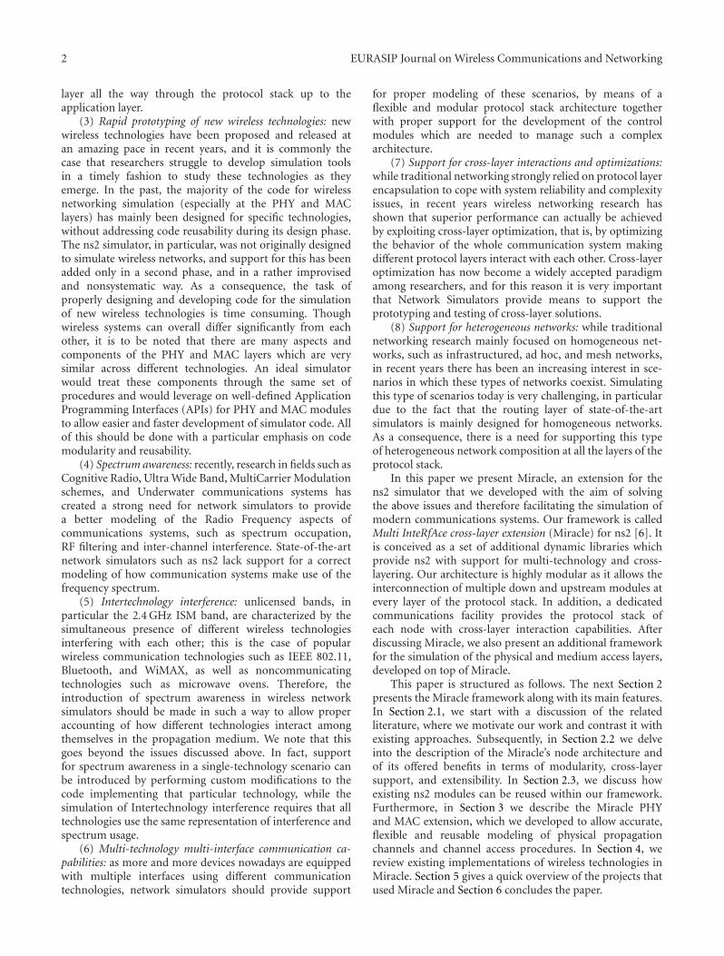
We started our work from a few existing ns2 classesthat were extended to obtain the basic building blocks ofour framework. The reason for this choice was to maintainbackward compatibility with previously developed ns2 code.In Figure 1, we show a diagram of the Miracle nodearchitecture. One of the most important blocks is probablythe Module class. As shown in the left side of this figure,multiple Modules can coexist within the same protocol layerand can be connected to up and downstream Modules.Each Module contains a specific protocol or entity whichmay be a PHY, MAC, routing layer, transport protocol,application, and so forth. The Module class provides thefollowing methods for the communication with adjacentModule instances:
(i) sendDown(Packet∗ p, double delay = 0) andsendUp(Packet∗ p, double delay = 0) areused to send a Packet, respectively, to the Module(s)below and above with, possibly, a delay. Using thesetwo methods, a copy of the Packet is delivered to eachof the up or downstream Modules.
(ii) sendDown(int moduleId, Packet∗ p, doubledelay = 0) and sendUp(int moduleId,Packet∗ p, double delay = 0) allow to sendPackets to a specific Module below and above,respectively. In this respect, we note that Moduleinstances are automatically assigned a uniqueidentifier; and a Module instance can know theidentifier of other instances either statically fromconfiguration or dynamically by using a discoveryprocess at run time.
Dedicated objects, referred to here as Connector-Traces, are automatically allocated by Miracle to allow com-munication across Modules through the above methods.Hence, the user is only responsible for specifying whereeach module appears in the protocol stack, and what othermodule it needs to connect to; the necessary connectors areput in place and configured automatically. In this case, sincewe are referring to standard OSI communication, we used aspecific extension of the ConnectorTrace called SAP.
All Modules within the same stack are connected to aunique structure called NodeCore. The role of the NodeCoreis twofold: (1) first, it enables communication amongModules and thus facilitates cross-layer design and (2) theNodeCore manages information coming from the Modulesand provides functionalities of common interest for all or agroup of them.
Regarding cross-layer interactions, we note that thecommon practice in standard ns2 consists of either includingcontrol messages within packet headers (e.g., as done in[12]) or manipulating the ns2 node structure in a ratherad hoc manner (as is the case for several ns2 extensionswhich are discussed in [10]). In the former case, however,control messages would be tightly bound to the packet flow,whereas in the latter, it would likely be difficult to adapt thecode to additional needs. Note that these are static solutionsas communication interfaces among modules and cross-layer algorithms must be defined in advance, that is, during
4 EURASIP Journal on Wireless Communications and Networking
Layer N − 2
Layer N − 1
Layer N
Layer N + 1
......
...
ConnectorTrace...
Module
Module Module
Module
Module Module Module
PlugInCLSAP
SAP
SAP
CLSAP
Nod
eCor
e
PlugIn
Figure 1: Example of a general multilayer architecture within the Miracle framework.
the development of each module. In ns3, this functionalitycan be achieved by means of Callbacks. However, the need forexplicitly connecting all callbacks puts a significant burdenon the user. Furthermore, this strategy only allows one-to-one interactions where the communicating entities areknown at configuration time. Actually, in ns3, also PacketTags can be used to exchange cross-layer messages; however,this practice consists of piggybacking cross-layer informationonto data packets, and for this reason its applicabilityis limited to those cross-layer interactions which happenconcurrently with data exchange.
In contrast, the solution provided by Miracle adheres tothe widely accepted concept of having a bus for interlayercommunication [1]. This makes it possible to exchangemessages among Modules at any time and without theneed for interleaving them with the data flow. The way inwhich cross-layer information is exchanged is defined by theClMessage abstract base class, which provides means foraddressing cross-layer information among modules withinthe same node. In particular, a ClMessage can be addressedto a particular module (unicast ClMessage), to all modulesin the node (broadcast ClMessage), or to all modules withinthe same layer (layercast ClMessage); in all these cases, therouting of ClMessagees is performed by the NodeCorethrough a specific extension of the ConnectorTraceclass called ClSAP (i.e., cross-layer SAP). Furthermore, aClMessage can be addressed from a module to the modulesin the layer immediately above or below it; in this case, themessage is routed directly by the SAP between modules. Theapplications of this last type of cross-layer messaging are veryuseful for automatic configuration purposes; for instance,the routing layer can discover, during the simulation, whichradio interfaces are available, by just sending a ClMessage toall the modules in the layer below. The interface provided bythe Module class for the ClMessage management includesthe following methods:
(i) sendAsyncClMsgDown(ClMessage∗ m, doubledelay = 0) and sendAsyncClMsgUp(ClMessage∗m, double delay = 0): these methods allow tosend ClMessages, respectively, to the Modulesbelow and above in an asynchronous fashion,
that is, each method returns immediately and theClMessage will be scheduled for later deliveryaccording to the specified delay.
(ii) sendSyncClMsgDown(ClMessage∗ m) and send-SyncClMsgUp(ClMessage∗ m): these allow to sendClMessages, respectively, to the Modules belowand above in an synchronous fashion, that is, eachmethod returns only after the ClMessage has beendelivered and processed by all receiver Module(s).
As to the maintenance of common information andfunctionalities, the NodeCore currently maintains the geo-graphical position for each node. To this end, we defined ageneric interface which can be used for the implementationof mobility models directly in C++. Currently, the frame-work features deterministic and Gauss-Markov [13] mobilitymodels.
Another important piece of the architecture is thePlugIn class. PlugIns are attached to the NodeCoreand are the perfect place for cross-layer algorithms, forexample, resource radio management modules, cognitiveengines, decision logic for the selection of optimal protocolparameters, and so forth. Thanks to ClMessages, controlmessages can be easily exchanged between PlugIns andprotocol Modules. In this case, the interface implements themethods sendSyncClMsg and sendAsyncClMsg to deliveryClMessages to the intended destination(s) in asynchronousand synchronous fashions.
Finally, Miracle implements a brand new tracing tech-nique: all packets and cross-layer messages are traced byeach specific extension of ConnectorTrace as they passthrough it. Hence, the development of tracing functionalitiesis not bound to the implementation of Modules. Thelevel of verbosity of message traces is fully tunable andprogrammable. With tunable, we mean that the tracingfunctionality can be independently turned on/off for eachConnectorTrace. Programmable means that the output ofthe tracers can be fully defined by the user. Accordingly,each implementation of a Module/PlugIn can define itsown tracing rules, which can be exploited for debugging orcollection of statistics.
EURASIP Journal on Wireless Communications and Networking 5
TclObject Handler
NsObject
Position+x : double+y : double+z : double
+<<virtual>>getX(): double+<<virtual>>getY(): double+<<virtual>>getX(x:double): void+<<virtual>>getY(y:double): void+<<virtual>>getZ():double+<<virtual>>setZ(z:double): void
+<<virtual>> getPosition(): Position∗#position: Position∗ -UId : int
+clsap: CLSAP∗+recv(Packet∗ , callback:Handler∗ = �): void+sendSynchCL(m: CLmessage∗ , delay : double= �): void+sendSynchCL(m: CLmessage∗ , delay : double= �)
+upLayerSAP : SAP∗∗+unLayetSAPNum : int+downLayerSAP : SAP∗∗+downLayerSAPNum : int
+<<virtual>> recv(p:packet∗): void#sendUp (p:Packet∗ , double= �): void#sendDown (p:Packet∗ , double= �): void#sendUp (moduleId : int,p:Packet∗ , double= �): void#sendDown (moduleId:int, p : Packet∗ , double= �): void
#upModule : Module∗#downModule : Module∗+<<virtual>> sendUp(∗p:Packet, delay : double): void+<<virtual>> sendDown(∗p:Packet, delay : double): void+getModuleUpId(): int+getModuleDownId(): int#trace(p:Packet∗): void
-pluginPtr : PlugIn∗-nodeCodePtr : NodeCore∗
NodeCore PlugIn
Module
ConnectorTrace
SAP CISAP
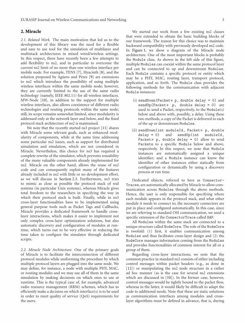
Figure 2: Class diagram for the Miracle framework.
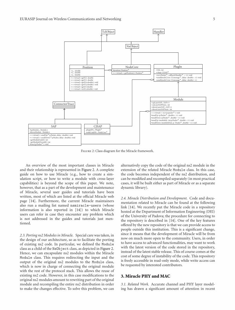
An overview of the most important classes in Miracleand their relationship is represented in Figure 2. A completeguide on how to use Miracle (e.g., how to create a sim-ulation script, or how to write a module with cross-layercapabilities) is beyond the scope of this paper. We note,however, that as a part of the development and maintenanceof Miracle, several user guides and tutorials have beenwritten, most of which are listed at the official Miracle webpage [14]. Furthermore, the current Miracle maintainersalso run a mailing list named nsmiracle-users (whoseinformation is also reported in [14]) to which Miracleusers can refer in case they encounter any problem whichis not addressed in the guides and tutorials just men-tioned.
2.3. Porting ns2 Modules in Miracle. Special care was taken, inthe design of our architecture, so as to facilitate the portingof existing ns2 code. In particular, we defined the Moduleclass as a child of the NsObject class, as depicted in Figure 2.Hence, we can encapsulate ns2 modules within the MiracleModule class. This requires redirecting the input and theoutput of the original ns2 modules to the Module class,which is now in charge of connecting the original modulewith the rest of the protocol stack. This allows the reuse ofexisting ns2 code. However, in this case modifications to theoriginal ns2 modules amount to rewriting part of the originalmodule and recompiling the entire ns2 distribution in orderto make the changes effective. To solve this problem, we can
alternatively copy the code of the original ns2 module in theextension of the related Miracle Module class. In this case,the code becomes independent of the ns2 distribution, andcan be modified and recompiled separately (in most practicalcases, it will be built either as part of Miracle or as a separatedynamic library).
2.4. Miracle Distribution and Development. Code and docu-mentation related to Miracle can be found at the followinglink [14]. We recently put the Miracle code in a repositoryhosted at the Department of Information Engineering (DEI)of the University of Padova; the procedure for connecting tothe repository is described in [14]. One of the key featuresoffered by the new repository is that we can provide access topeople outside this institution. This is a significant change,since it means that the development of Miracle will be fromnow on much more open to the community. Users, in orderto have access to advanced functionalities, may want to workwith the latest version of the code stored in the repository,instead of the latest stable release. This of course comes at thecost of some degree of instability of the code. This repositoryis freely accessible in read-only mode, while write access canbe requested by interested contributors.
3. Miracle PHY and MAC
3.1. Related Work. Accurate channel and PHY layer model-ing has drawn a significant amount of attention in recent
6 EURASIP Journal on Wireless Communications and Networking
years, and much work has been done in this respect. Thens2 simulator, in particular, was well known for its poorchannel and PHY layer modeling, and for this reason severalenhancements have been proposed [15–17]. However, theaddition of this functionality has always been done in atechnology-specific manner, and often in a “quick-and-dirty” fashion. The ns2 mobile node, in particular, does nothave a good separation of functionalities between the MACand the physical layer [16]. As an example, some key PHYfunctionalities, such as in particular the determination ofthe end of the reception of a packet, are performed at theMAC layer, making it difficult to introduce functionalitiessuch as interference calculation, as well as making thecode notoriously hard to read and to debug. In fact,the introduction of features such as enhanced error andinterference models has required significant modifications,such as those introduced in dei80211mr [15], and improvingthe architecture of the code for the sake of easier debuggingand readability has required its complete redesign, as is thecase of the new IEEE 802.11 model of [16]. Moreover, theintroduction of the support for new wireless technologieshas required extensive tweaking, if not even the use of thens2 code as a mere entry point for completely customizedcode, as is the case of [18]. To summarize, every time anew technology is to be implemented, significant developereffort is needed, which is exacerbated by the fact that thebasic ns2 mobile node does not provide good channelmodels, and that all extensions in this respect have beentoo much technology-specific and cannot be easily reusedfor different technologies. Regarding other simulators, it isto be noted that some of them, such as ns3, allow thespecification of customized callbacks between modules atdifferent layers of the protocol stack. However, the typeof interactions in use commonly varies depending on thetechnology being considered as well as on the particularimplementation, and a well-defined set of callbacks to beexploited for channel, PHY and MAC layer modeling is stilllacking. Finally, to the best of our knowledge, no well-knownsimulator provides a good and generic model addressing howdifferent wireless technologies make use of the frequencyspectrum and mutually interact.
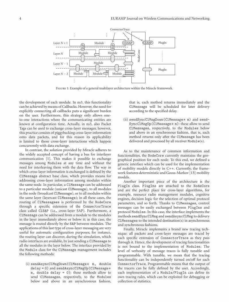
3.2. The Miracle PHY and MAC Framework. The MiraclePHY and MAC framework was explicitly designed to over-come these issues. In our effort to develop a modular andextensible framework for channel and PHY layer modeling,we chose an object-oriented design and we defined a set ofclasses, as shown in Figure 3.
The channel model we developed is based on the mod-eling of a fundamental entity, the PHY Layer Transmission(PLT) of a packet. We define a PLT by the attributescharacterizing it; choosing these attributes corresponds tochoosing our PHY and channel modeling assumptions. PLTsinstances have a 1 : 1 association with ns2 Packet instances,and therefore PLT attributes are conveniently gathered ina new ns2 packet header named hdr MPhy. The attributeswe define for PLTs, and the consequent channel modelingassumptions we make, are as follows:
(i) duration: a PLT is an event which extends over agiven time interval. The length of this interval is given by theduration attribute.
(ii) Pt: a PLT is characterized by its transmission power,as set by the PHY layer of the transmitter. This attribute refersto the PLT as a whole; in other words, power is consideredto be constant during the whole duration of a transmission.This choice is intended to achieve a reasonable tradeoffbetween modeling accuracy and complexity. We note that,while this is the approach in use by the vast majority ofsimulators, it is nevertheless a simplifying assumption ofwhich we should be aware.
(iii) Pr: the processes performed on the reception ofa PLT are modeled by mathematical operations performedon the Pt attribute, which result in the Pr attribute, thatrepresents the received power. Examples of these processesare propagation effects, antenna gains, RF filtering, andsignal processing at the PHY layer (e.g., interleaving, coding,etc.).
(iv) Position: a PLT is characterized by the geographicalposition of the transmitter (srcPosition) and that of thereceiver (dstPosition). These attributes are references toinstances of classes belonging to the Position class hierar-chy defined in Miracle, which we discussed in Section 2. Theycan provide additional information such as the direction andthe speed of motion in case the nodes are mobile. This canbe used for enhanced channel modeling features, such as thedetermination of the effects of fast fading as a function ofspeed.
(v) modulationType: this is a value univocally identi-fying the particular modulation and coding scheme in useby the physical layer. The main purpose of this attributeis to provide support for modeling the acquisition processin multi-technology scenarios (by acquisition process herewe mean the set of tasks such as preamble detection,which are commonly performed by the PHY layer at thebeginning of a reception). We note that this solution canaccommodate perfect acquisition models, where the receiveralways correctly acquires signals of the desired type anddiscards all others, as well as more complex solutions suchas stochastic models for preamble detection.
(vi) srcSpectralMask: a transmission consists ofpower radiated nonuniformly into the frequency spectrum.We assume that the specification of the power spectral den-sity function of the transmission (normalized with respectto the transmission power) can account in sufficient detailfor this fact. srcSpectralMask is a pointer to a class of theMSpectralMask hierarchy which is intended to implementthis function. We chose to use an abstract class for thispurpose, in order not to pose any particular limitation onhow this function is implemented. Nevertheless, piece-wiseconstant or linear functions should be enough for mostpurposes, and for this reason the only implementations weprovide for MSpectralMask use a rectangular function.
(vii) dstSpectralMask: each reception process is char-acterized by an RF filter, which is represented by means of itsfrequency response. The implementation issues for this arethe same as for the spectrum usage information discussedabove. For these reasons, as we did for the power spectral

EURASIP Journal on Wireless Communications and Networking 7
MSpectralMask
PositionMAntenna
MPhyhdr MPhy
MCorrelation
MPropagation
MInterference
802.11 WiFi UMTS
UMTS Mobile Equipment UMST Base Station Underwater BPSK
BPSK 802.16 WiMAXUnderwaterShannon
+getFreq(): double+getPropagationSpeed (): double+getLambda (): double+getBandwidth (): double
+getOverLap (rm:MSpectralMask∗ , p: Packet∗): double
+getGain (p:PAcket∗): double +getX (): double+getY (): double+getZ (): double
+getGain (p:PAcket∗): double
+getGain (p:PAcket∗): double #interference : MInterference∗#propagation : MPropagation∗
#Correlation : MCorrelation∗
+getTxDuration (p:Packet∗): double
+getTxPower (p:Packet∗): double
+getNoisePower() (p:Packet∗): double
+getTxAntenna (p:Packet∗): MAntenna∗
+getRxAntenna (p:Packet∗): MAntenna∗
+getTxSpectralMask (p:Packet∗): MSpectralMask∗
+getRXSpectraMask (p:Packet∗): MSpectralMask∗
#startTx (p:Packet∗)
#endTx (p:Packet∗)
#startRx (p:Packet∗)
#endRx (p:Packet∗)
#Phy2MacEndTx (p:const Packet∗)
#Phy2MacStartRx( p:const Packet∗)#Phy2MacCCA (cca:bool)
+modulationType: int
+srcSpectralMAsk: MSpectralMAsk∗
+dstSpectralMask: MSpectralMask∗
+srcPosition: Position∗+dstPosition: Position∗+srcAntenna: MAntenna∗+dstAntenna: MAntenna∗+Pt: double+Pr: double+Pi: double+txtime: double+rxtime: double+duration: double
+addToInterference (p:Packet∗)
+getInterferencePower (p:Packet∗)
+getCurrentTotalPower(): double
Figure 3: Class diagram for MPhy and related classes.
density of PLTs, RF filters are represented by instances of theMSpectralMask class. The RF filtering process is modeled asa gain applied to the received power of the PLT; this gain isdetermined as a function of the spectral mask applied to thetransmission and the carrier frequency.
(viii) Pn: the noise power at the receiver. The value ofthis attribute is calculated by the receiving MPhy instancein a technology-dependent fashion. For most wireless tech-nologies, we argue that it will suffice to determine thenoise power according to an AWGN model by integratinga predetermined noise spectral power density over thefrequency response of the RF filter (which is implementedby dstSpectralMask). We note that for some particularmodels, such as the underwater acoustic communicationsmodel that we will describe in Section 4.3, more complexcalculations need to be involved.
(ix) Pi: the multiuser interference is summarized bythe interference power attribute Pi, calculated aggregatingall simultaneous PLTs (whose transmissions overlap intime), and with respect to a particular PLT for whichreception is being attempted. We do not pose any particular
constraint on the exact model to be used for this purpose.Rather, interference models are to be implemented byinheriting from the MInterference, and implementing theaddToInterference() and getInterferencePower()methods according to the chosen model. We provideone particular implementation of these classes, calledInterferenceMIV, which aggregates all simultaneous PLTs(also referred to as interfering PLTs) into a single piece-wiseconstant function of time using the well-known Gaussianmodel (i.e., summing power values), and returns the totalinterference power on a given packet calculated as the meanintegral value of the aggregation of interfering PLTs.
The other important element of our channel and PHYmodeling framework is the MPhy class: it is an abstractclass providing channel modeling functionalities and theAPI for the development of PHY layer implementations.Channel modeling is implemented by associating eachMPhy instance with instances of other objects which imple-ment the different components of a channel model. Wedefine the following classes of objects for channel model-ing:
8 EURASIP Journal on Wireless Communications and Networking
(i) MPropagation: similarly to the Propagation class ofns2, implementations of this class account for theattenuation of the power of a PLT due to effects suchas path loss, fading, and shadowing;
(ii) MAntenna: similarly to the Antenna class in ns2, thisclass hierarchy provides means to implement the gainof directional antennas as a function of PLT attributes(the most useful for this purpose being the positionattributes);
(iii) MCorrelation: this class of objects is intended toimplement the gains due to the signal processingperformed by the receiver. A remarkable use case forthis class of objects is the processing gain of directsequence spread spectrum (DSSS) and code divisionmultiple access (CDMA) systems.
(iv) MInterference: this class of objects handles thecalculations of multi-user interference.
The first three of the above mentioned classes are onlyrequired to implement a getGain(Packet∗ p) methodwhich is expected to provide the gain value to be applied toa given PLT. On the other hand, the MInterference class isrequired to produce the interference perceived by a particularPLT. This task is more complex since in general interferencedepends on all PLTs whose transmission overlaps in time andfrequency with the particular PLT being considered (targetPLT). For this reason, classes implementing MInterferenceare expected to keep track of all currently active PLTs (i.e.,whose transmission is ongoing), by providing implementa-tion of two methods: addToInterference(Packet∗ p),which has to be called at the beginning of the transmissionof every PLT so it can be added to the set of active PLTs, andgetInterferencePower(Packet∗ p), which returns theinterference caused by all active PLTs on the target PLT.
The MPhy class is meant to only provide support forfunctionalities which are shared by different channel mod-els and wireless technology implementations. Technology-specific PHY layer functionalities are taken into accountby inheriting from the MPhy class and implementing thefollowing virtual methods:
(i) getTxDuration(Packet∗ p): must be providedby the transmitting PHY to determine the durationof a transmission.
(ii) getTxPower(Packet∗ p): must be provided bythe transmitting PHY to determine the transmissionpower to be used for a given PLT.
(iii) getNoisePower(Packet∗ p): must be providedby the receiving PHY to determine the noise powerat the receiver for a given PLT.
(iv) getTxAntenna(Packet∗ p) andgetRxAntenna(Packet∗ p): must be provided by,respectively, the transmitting and receiving PHYs todetermine the antenna being used for a given PLT.
(v) getTxSpectralMask(Packet∗ p): must be pro-vided by the transmitting PHY to determine thespectrum used by a PLT.
(vi) getRxSpectralMask(Packet∗ p): must be pro-vided by the receiving PHY to determine the RF filterused for receiving a PLT.
(vii) getModulationId(Packet∗ p): must be pro-vided by the transmitting PHY to determine themodulation and coding scheme to be used for a PLT.
(viii) startTx(Packet∗ p): the entry point for thecode that is to be executed at the beginning of atransmission. The implementation of this method isresponsible for actually sending the Packet instanceon the channel.
(ix) endTx(Packet∗ p): the entry point for the codethat is to be executed at the end of a transmission.
(x) startRx(Packet∗ p): the entry point for the codethat is to be executed at the beginning of a reception.This code should handle the PLT acquisition process,for example, implementing preamble detection, syn-chronization, and so forth.
(xi) endRx(Packet∗ p): the entry point for the codethat is to be executed at the end of a reception. Thiscode is responsible for determining the presence oferrors in the packet, using an error model suitablefor the PHY technology being implemented, and forthe eventual forwarding of the Packet instance to theupper layers.
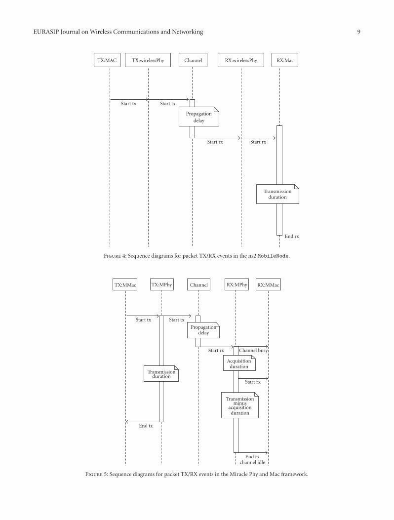
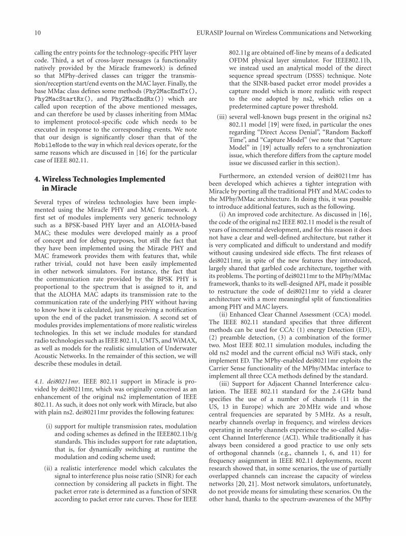
One of the reasons for which we developed APIs for PHYand MAC layer development is that the ns2 MobileNode didnot natively provide support to simulate the different phasesof transmission and reception of packets, neither at the MACnor at the PHY layer. A diagram of this is shown in Figure 4:at the transmitter, only the beginning of a transmission isconsidered, both at the MAC and PHY layers; at the receiver,the PHY layer is only aware of the beginning of the reception,while the MAC layer has notion of both the beginning andthe end of the reception. This in our opinion is not a gooddesign. First of all, whenever the MAC and the PHY layersneed to perform any operation upon packet termination(i.e., change the status of the PHY or the MAC statemachine), dedicated events need to be generated. Secondly,the duration of a transmission is determined at the PHYlayer, since it depends on the packet size, the modulation andcoding scheme, and possibly other PHY-specific aspects suchas the length of synchronization preambles; consequently,having to determine it at the MAC layer to schedule thenecessary events involves the duplication at the MAC layerof PHY layer attributes and functionalities, which can lead toinconsistencies and poor readability and maintainability ofthe code. Finally, this design has led to the misplacement ofthe implementation of several functionalities; for example,this is the case of PHY error models, which in severalimplementations had to be placed within the recv timer()method of the MAC code.
Our design, represented in Figure 5, attempts to solvethese issues. First of all, the duration of a PLT is alwaysdetermined by the PHY layer; furthermore, the scheduling ofthe start/end of transmission and reception events is a func-tionality provided by the MPhy base class, which takes care of
EURASIP Journal on Wireless Communications and Networking 9
TX:MAC TX:wirelessPhy Channel
Start tx Start tx
Propagationdelay
RX:wirelessPhy
Start rx Start rx
RX:Mac
Transmissionduration
End rx
Figure 4: Sequence diagrams for packet TX/RX events in the ns2 MobileNode.
TX:MMac TX:MPhy Channel RX:MPhy RX:MMac
Start tx Start tx
Propagationdelay
Transmissionduration
Acquisitionduration
Transmissionminus
acquisitionduration
Start rx Channel busy
Start rx
End tx
End rxchannel idle
Figure 5: Sequence diagrams for packet TX/RX events in the Miracle Phy and Mac framework.
10 EURASIP Journal on Wireless Communications and Networking
calling the entry points for the technology-specific PHY layercode. Third, a set of cross-layer messages (a functionalitynatively provided by the Miracle framework) is definedso that MPhy-derived classes can trigger the transmis-sion/reception start/end events on the MAC layer. Finally, thebase MMac class defines some methods (Phy2MacEndTx(),Phy2MacStartRx(), and Phy2MacEndRx()) which arecalled upon reception of the above mentioned messages,and can therefore be used by classes inheriting from MMacto implement protocol-specific code which needs to beexecuted in response to the corresponding events. We notethat our design is significantly closer than that of theMobileNode to the way in which real devices operate, for thesame reasons which are discussed in [16] for the particularcase of IEEE 802.11.
4. Wireless Technologies Implementedin Miracle
Several types of wireless technologies have been imple-mented using the Miracle PHY and MAC framework. Afirst set of modules implements very generic technologysuch as a BPSK-based PHY layer and an ALOHA-basedMAC; these modules were developed mainly as a proofof concept and for debug purposes, but still the fact thatthey have been implemented using the Miracle PHY andMAC framework provides them with features that, whilerather trivial, could not have been easily implementedin other network simulators. For instance, the fact thatthe communication rate provided by the BPSK PHY isproportional to the spectrum that is assigned to it, andthat the ALOHA MAC adapts its transmission rate to thecommunication rate of the underlying PHY without havingto know how it is calculated, just by receiving a notificationupon the end of the packet transmission. A second set ofmodules provides implementations of more realistic wirelesstechnologies. In this set we include modules for standardradio technologies such as IEEE 802.11, UMTS, and WiMAX,as well as models for the realistic simulation of UnderwaterAcoustic Networks. In the remainder of this section, we willdescribe these modules in detail.
4.1. dei80211mr. IEEE 802.11 support in Miracle is pro-vided by dei80211mr, which was originally conceived as anenhancement of the original ns2 implementation of IEEE802.11. As such, it does not only work with Miracle, but alsowith plain ns2. dei80211mr provides the following features:
(i) support for multiple transmission rates, modulationand coding schemes as defined in the IEEE802.11b/gstandards. This includes support for rate adaptation,that is, for dynamically switching at runtime themodulation and coding scheme used;
(ii) a realistic interference model which calculates thesignal to interference plus noise ratio (SINR) for eachconnection by considering all packets in flight. Thepacket error rate is determined as a function of SINRaccording to packet error rate curves. These for IEEE
802.11g are obtained off-line by means of a dedicatedOFDM physical layer simulator. For IEEE802.11b,we instead used an analytical model of the directsequence spread spectrum (DSSS) technique. Notethat the SINR-based packet error model provides acapture model which is more realistic with respectto the one adopted by ns2, which relies on apredetermined capture power threshold.
(iii) several well-known bugs present in the original ns2802.11 model [19] were fixed, in particular the onesregarding “Direct Access Denial”, “Random BackoffTime”, and “Capture Model” (we note that “CaptureModel” in [19] actually refers to a synchronizationissue, which therefore differs from the capture modelissue we discussed earlier in this section).
Furthermore, an extended version of dei80211mr hasbeen developed which achieves a tighter integration withMiracle by porting all the traditional PHY and MAC codes tothe MPhy/MMac architecture. In doing this, it was possibleto introduce additional features, such as the following.
(i) An improved code architecture. As discussed in [16],the code of the original ns2 IEEE 802.11 model is the result ofyears of incremental development, and for this reason it doesnot have a clear and well-defined architecture, but rather itis very complicated and difficult to understand and modifywithout causing undesired side effects. The first releases ofdei80211mr, in spite of the new features they introduced,largely shared that garbled code architecture, together withits problems. The porting of dei80211mr to the MPhy/MMacframework, thanks to its well-designed API, made it possibleto restructure the code of dei80211mr to yield a clearerarchitecture with a more meaningful split of functionalitiesamong PHY and MAC layers.
(ii) Enhanced Clear Channel Assessment (CCA) model.The IEEE 802.11 standard specifies that three differentmethods can be used for CCA: (1) energy Detection (ED),(2) preamble detection, (3) a combination of the formertwo. Most IEEE 802.11 simulation modules, including theold ns2 model and the current official ns3 WiFi stack, onlyimplement ED. The MPhy-enabled dei80211mr exploits theCarrier Sense functionality of the MPhy/MMac interface toimplement all three CCA methods defined by the standard.
(iii) Support for Adjacent Channel Interference calcu-lation. The IEEE 802.11 standard for the 2.4 GHz bandspecifies the use of a number of channels (11 in theUS, 13 in Europe) which are 20 MHz wide and whosecentral frequencies are separated by 5 MHz. As a result,nearby channels overlap in frequency, and wireless devicesoperating in nearby channels experience the so-called Adja-cent Channel Interference (ACI). While traditionally it hasalways been considered a good practice to use only setsof orthogonal channels (e.g., channels 1, 6, and 11) forfrequency assignment in IEEE 802.11 deployments, recentresearch showed that, in some scenarios, the use of partiallyoverlapped channels can increase the capacity of wirelessnetworks [20, 21]. Most network simulators, unfortunately,do not provide means for simulating these scenarios. On theother hand, thanks to the spectrum-awareness of the MPhy
EURASIP Journal on Wireless Communications and Networking 11
AP 5 AP 2
STAs
AP 1
AP 4 AP 3
Distan
ce
param
eter
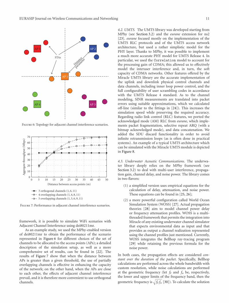
Figure 6: Topology for adjacent channel interference scenarios.
0
10
20
30
Agg
rega
teth
rou
ghpu
t(M
bps)
40
50
60
70
0 10
Distance between access points (m)
15 20 25 305
3 orthogonal channels (1, 6, 11)4 overlapping channels (1, 4, 8, 11)5 overlapping channels (1, 3, 6, 9, 11)
40 45 5035
Figure 7: Performance in adjacent channel interference scenarios.
framework, it is possible to simulate WiFi scenarios withAdjacent Channel Interference using dei80211mr.
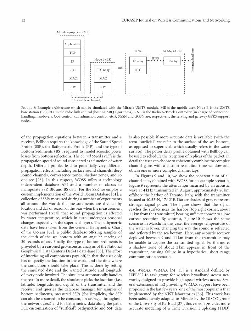
As an example study, we used the MPhy-enabled versionof dei80211mr to obtain the performance of the scenariorepresented in Figure 6 for different choices of the set ofchannels to be allocated to the access points (APs); a detaileddescription of the simulation setup, as well as a morecomprehensive set of results, can be found in [22]. Theresults of Figure 7 show that when the distance betweenAPs is greater than a given threshold, the use of partiallyoverlapping channels is effective in enhancing the capacityof the network; on the other hand, when the APs are closeto each other, the effects of adjacent channel interferenceprevail, and it is therefore more convenient to use orthogonalchannels.
4.2. UMTS. The UMTS library was developed starting fromMPhy (see Section 3.2) and the eurane extension for ns2[23]. eurane focused mostly on the implementation of theUMTS RLC protocols and of the UMTS access networkarchitecture, but used a rather simplistic model for thePHY layer. Thanks to MPhy, it was possible to implementa much more accurate PHY model for UMTS Release 4. Inparticular, we used the Correlation model to account forthe processing gain of CDMA; this allowed us to effectivelymodel the interuser interference and, in turn, the softcapacity of CDMA networks. Other features offered by theMiracle UMTS library are the accurate implementation ofthe uplink and downlink physical control channels anddata channels, including inner loop power control, and thefull configurability of user scrambling codes in accordancewith the UMTS Release 4 standard. As to the channelmodeling, SINR measurements are translated into packeterrors using suitable approximations, which we calculatedoff-line (similar to the fittings in [24]). This increases thesimulation speed while preserving the required accuracy.Regarding radio link control (RLC) features, we ported theacknowledged mode (AM) RLC from eurane, which imple-ments packet fragmentation, selective repeat ARQ (with abitmap acknowledged mode), and data concatenation. Weadded the SDU discard functionality in order to avoidinfinite retransmission loops (as is often done in practicalsystems). An example of a typical UMTS architecture whichcan be simulated with the Miracle UMTS module is depictedin Figure 8.
4.3. Underwater Acoustic Communications. The underwa-ter library deeply relies on the MPhy framework (seeSection 3.2) to deal with multi-user interference, propaga-tion gain, channel delay, and noise power. The library comesin two flavors:
(1) a simplified version uses empirical equations for thecalculation of delay, attenuation, and noise power.These equations can be found in [25, 26];
(2) a more powerful configuration called World OceanSimulation System (WOSS) [27]. Actual propagationtheories [28] aim to model channel power delayor frequency attenuation profiles. WOSS is a multi-threaded framework that permits the integration intoMiracle of any existing underwater channel simulatorthat expects environmental data as input and thatprovides as output a channel realization representedusing the channel profiles just mentioned. Currently,WOSS integrates the Bellhop ray-tracing program[29] while retaining the previous formula for thenoise power.
In both cases, the propagation effects are considered con-stant over the duration of the packet. Specifically, Bellhopcalculations are performed across the whole bandwidth withcustom resolution, while noise calculations are performedat the geometric frequency (let f� and fu be, respectively,the lower and upper limits of the frequency band, then the
geometric frequency is√f� fu [30]). To calculate the solution
12 EURASIP Journal on Wireless Communications and Networking
Mobile equipment (ME)
Application
TCP
IP
RLC RLC relay RLC
RNC SGSN, GGSN
IP relay
Inte
rnet
/fixe
dh
ost
IUPSIP relay
Iub
Node B (BS)
MAC MAC
PHY
Uu (wireless channel)
PHY
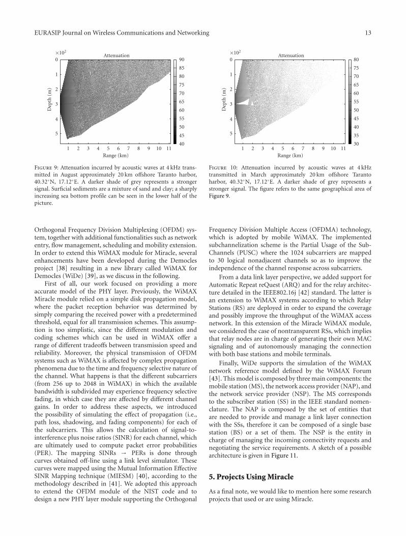
Figure 8: Example architecture which can be simulated with the Miracle UMTS module. ME is the mobile user, Node B is the UMTSbase station (BS), RLC is the radio link control (hosting ARQ algorithms), RNC is the Radio Network Controller (in charge of connectionhandling, handovers, QoS control, call admission control, etc.), SGSN and GGSN are, respectively, the serving and gateway GPRS supportnodes.
of the propagation equations between a transmitter and areceiver, Bellhop requires the knowledge of the Sound SpeedProfile (SSP), the Bathymetric Profile (BP), and the type ofBottom Sediments (BS), required to model acoustic powerlosses from bottom reflections. The Sound Speed Profile is thepropagation speed of sound considered as a function of waterdepth. Different profiles lead to potentially very differentpropagation effects, including surface sound channels, deepsound channels, convergence zones, shadow zones, and soon; see [28]. In this respect, WOSS offers a technologyindependent database API and a number of classes tomanipulate SSP, BP, and BS data. For the SSP, we employ acustom implementation of the World Ocean Database [31], acollection of SSPs measured during a number of experimentsall around the world; the measurements are divided bylocation and day or season of the year when the measurementwas performed (recall that sound propagation is affectedby water temperature, which in turn undergoes seasonalchanges, especially in the superficial layer). The bathymetricdata have been taken from the General Bathymetric Chartof the Oceans [32], a public database offering samples ofthe depth of the sea bottom with an angular spacing of30 seconds of arc. Finally, the type of bottom sediments isprovided by a reasoned geo-acoustic analysis of the NationalGeophysical Data Center’s Deck41 data-base [33]. The effortof interfacing all components pays off, in that the user onlyhas to specify the location in the world and the time wherethe simulation should take place. This is done by settingthe simulated date and the wanted latitude and longitudeof every node involved. The simulator automatically handlesthe rest. In more detail, the simulator picks the location (i.e.,latitude, longitude, and depth) of the transmitter and thereceiver and queries the database manager for samples ofbottom sediments, measured SSPs (for simplicity, the SSPcan also be assumed to be constant, on average, throughoutthe network area) and for bathymetric data along the path.Full customization of “surficial”, bathymetric and SSP data
is also possible if more accurate data is available (with theterm “surficial” we refer to the surface of the sea bottom,as opposed to superficial, which usually refers to the watersurface). The power delay profile obtained with Bellhop canbe used to schedule the reception of replicas of the packet: indetail the user can choose to coherently combine the complexchannel gains with a custom resolution time window andobtain one or more complex channel taps.
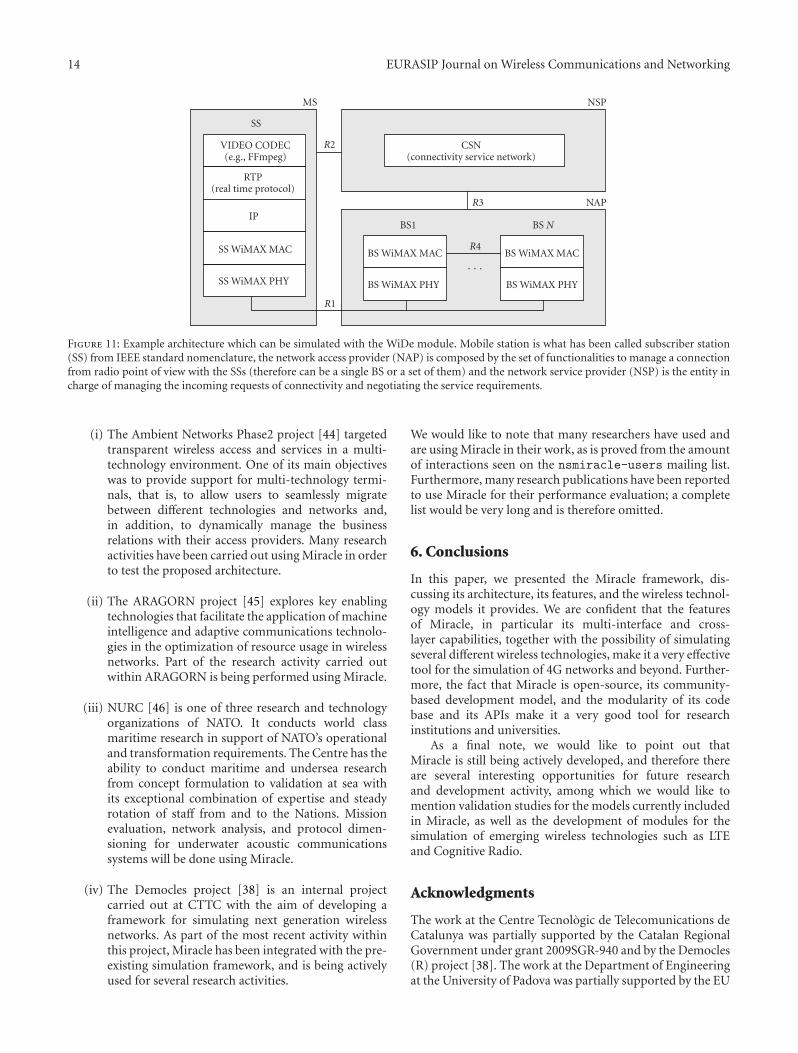
In Figures 9 and 10, we show the coherent sum of allchannel taps, obtained with WOSS for an example scenario.Figure 9 represents the attenuation incurred by an acousticwave at 4 kHz transmitted in August, approximately 20 kmoffshore the harbor of Taranto, Italy, with the transmitterlocated at 40.32◦N, 17.12◦E. Darker shades of gray representstronger signal power. The figure shows that the signalreaches the surface near the harbor (top right corner, about11 km from the transmitter) bearing sufficient power to allowcorrect reception. By contrast, Figure 10 shows the samescenario in March: in this case, the average temperature ofthe water is lower, changing the way the sound is refractedand reflected by the sea bottom. Here, any acoustic receiverdeployed between 9 and 11 km from the transmitter maybe unable to acquire the transmitted signal. Furthermore,a shadow zone of about 2 km appears in front of thetransmitter, causing failure in a hypothetical short rangecommunication scenario.
4.4. WiMAX. WiMAX [34, 35] is a standard defined byIEEE802.16 task group for wireless broadband access net-works, designed to provide high-speed wireless access. Sev-eral extensions of ns2 providing WiMAX support have beenproposed in the last few years; one of the most popular is thatimplemented by the NIST laboratories [36]. This work hasbeen subsequently adapted to Miracle by the DISCO groupof the University of Karlstad [37]; this version provides moreaccurate modeling of a Time Division Duplexing (TDD)
EURASIP Journal on Wireless Communications and Networking 13
5
4
Dep
th(m
)
3
2
1
0×102
1 2 3 4 5 6 7 8 9 10 11
45
50
55
60
65
70
75
80
85
90
40
Attenuation
Range (km)
Figure 9: Attenuation incurred by acoustic waves at 4 kHz trans-mitted in August approximately 20 km offshore Taranto harbor,40.32◦N, 17.12◦E. A darker shade of grey represents a strongersignal. Surficial sediments are a mixture of sand and clay; a sharplyincreasing sea bottom profile can be seen in the lower half of thepicture.
Orthogonal Frequency Division Multiplexing (OFDM) sys-tem, together with additional functionalities such as networkentry, flow management, scheduling and mobility extension.In order to extend this WiMAX module for Miracle, severalenhancements have been developed during the Democlesproject [38] resulting in a new library called WiMAX forDemocles (WiDe) [39], as we discuss in the following.
First of all, our work focused on providing a moreaccurate model of the PHY layer. Previously, the WiMAXMiracle module relied on a simple disk propagation model,where the packet reception behavior was determined bysimply comparing the received power with a predeterminedthreshold, equal for all transmission schemes. This assump-tion is too simplistic, since the different modulation andcoding schemes which can be used in WiMAX offer arange of different tradeoffs between transmission speed andreliability. Moreover, the physical transmission of OFDMsystems such as WiMAX is affected by complex propagationphenomena due to the time and frequency selective nature ofthe channel. What happens is that the different subcarriers(from 256 up to 2048 in WiMAX) in which the availablebandwidth is subdivided may experience frequency selectivefading, in which case they are affected by different channelgains. In order to address these aspects, we introducedthe possibility of simulating the effect of propagation (i.e.,path loss, shadowing, and fading components) for each ofthe subcarriers. This allows the calculation of signal-to-interference plus noise ratios (SINR) for each channel, whichare ultimately used to compute packet error probabilities(PER). The mapping SINRs → PERs is done throughcurves obtained off-line using a link level simulator. Thesecurves were mapped using the Mutual Information EffectiveSINR Mapping technique (MIESM) [40], according to themethodology described in [41]. We adopted this approachto extend the OFDM module of the NIST code and todesign a new PHY layer module supporting the Orthogonal
5
4
Dep
th(m
)
3
2
1
0×102
1 2 3 4 5 6 7 8 9 10 11
35
40
45
50
55
60
65
70
75
80
30
Attenuation
Range (km)
Figure 10: Attenuation incurred by acoustic waves at 4 kHztransmitted in March approximately 20 km offshore Tarantoharbor, 40.32◦N, 17.12◦E. A darker shade of grey represents astronger signal. The figure refers to the same geographical area ofFigure 9.
Frequency Division Multiple Access (OFDMA) technology,which is adopted by mobile WiMAX. The implementedsubchannelization scheme is the Partial Usage of the Sub-Channels (PUSC) where the 1024 subcarriers are mappedto 30 logical nonadjacent channels so as to improve theindependence of the channel response across subcarriers.
From a data link layer perspective, we added support forAutomatic Repeat reQuest (ARQ) and for the relay architec-ture detailed in the IEEE802.16j [42] standard. The latter isan extension to WiMAX systems according to which RelayStations (RS) are deployed in order to expand the coverageand possibly improve the throughput of the WiMAX accessnetwork. In this extension of the Miracle WiMAX module,we considered the case of nontransparent RSs, which impliesthat relay nodes are in charge of generating their own MACsignaling and of autonomously managing the connectionwith both base stations and mobile terminals.
Finally, WiDe supports the simulation of the WiMAXnetwork reference model defined by the WiMAX Forum[43]. This model is composed by three main components: themobile station (MS), the network access provider (NAP), andthe network service provider (NSP). The MS correspondsto the subscriber station (SS) in the IEEE standard nomen-clature. The NAP is composed by the set of entities thatare needed to provide and manage a link layer connectionwith the SSs, therefore it can be composed of a single basestation (BS) or a set of them. The NSP is the entity incharge of managing the incoming connectivity requests andnegotiating the service requirements. A sketch of a possiblearchitecture is given in Figure 11.
5. Projects Using Miracle
As a final note, we would like to mention here some researchprojects that used or are using Miracle.
14 EURASIP Journal on Wireless Communications and Networking
VIDEO CODEC(e.g., FFmpeg)
RTP(real time protocol)
IP
SS WiMAX MAC
SS WiMAX PHY
CSN(connectivity service network)
BS WiMAX MAC
BS WiMAX PHY
BS WiMAX MAC
BS WiMAX PHY
SS
R2
R3
R4
· · ·
NAP
R1
BS1 BS N
MS NSP
Figure 11: Example architecture which can be simulated with the WiDe module. Mobile station is what has been called subscriber station(SS) from IEEE standard nomenclature, the network access provider (NAP) is composed by the set of functionalities to manage a connectionfrom radio point of view with the SSs (therefore can be a single BS or a set of them) and the network service provider (NSP) is the entity incharge of managing the incoming requests of connectivity and negotiating the service requirements.
(i) The Ambient Networks Phase2 project [44] targetedtransparent wireless access and services in a multi-technology environment. One of its main objectiveswas to provide support for multi-technology termi-nals, that is, to allow users to seamlessly migratebetween different technologies and networks and,in addition, to dynamically manage the businessrelations with their access providers. Many researchactivities have been carried out using Miracle in orderto test the proposed architecture.
(ii) The ARAGORN project [45] explores key enablingtechnologies that facilitate the application of machineintelligence and adaptive communications technolo-gies in the optimization of resource usage in wirelessnetworks. Part of the research activity carried outwithin ARAGORN is being performed using Miracle.
(iii) NURC [46] is one of three research and technologyorganizations of NATO. It conducts world classmaritime research in support of NATO’s operationaland transformation requirements. The Centre has theability to conduct maritime and undersea researchfrom concept formulation to validation at sea withits exceptional combination of expertise and steadyrotation of staff from and to the Nations. Missionevaluation, network analysis, and protocol dimen-sioning for underwater acoustic communicationssystems will be done using Miracle.
(iv) The Democles project [38] is an internal projectcarried out at CTTC with the aim of developing aframework for simulating next generation wirelessnetworks. As part of the most recent activity withinthis project, Miracle has been integrated with the pre-existing simulation framework, and is being activelyused for several research activities.
We would like to note that many researchers have used andare using Miracle in their work, as is proved from the amountof interactions seen on the nsmiracle-users mailing list.Furthermore, many research publications have been reportedto use Miracle for their performance evaluation; a completelist would be very long and is therefore omitted.
6. Conclusions
In this paper, we presented the Miracle framework, dis-cussing its architecture, its features, and the wireless technol-ogy models it provides. We are confident that the featuresof Miracle, in particular its multi-interface and cross-layer capabilities, together with the possibility of simulatingseveral different wireless technologies, make it a very effectivetool for the simulation of 4G networks and beyond. Further-more, the fact that Miracle is open-source, its community-based development model, and the modularity of its codebase and its APIs make it a very good tool for researchinstitutions and universities.
As a final note, we would like to point out thatMiracle is still being actively developed, and therefore thereare several interesting opportunities for future researchand development activity, among which we would like tomention validation studies for the models currently includedin Miracle, as well as the development of modules for thesimulation of emerging wireless technologies such as LTEand Cognitive Radio.
Acknowledgments
The work at the Centre Tecnologic de Telecomunications deCatalunya was partially supported by the Catalan RegionalGovernment under grant 2009SGR-940 and by the Democles(R) project [38]. The work at the Department of Engineeringat the University of Padova was partially supported by the EU
EURASIP Journal on Wireless Communications and Networking 15
through the ARAGORN project [45] (FP7 ICT-216856) aspart of the Seventh Framework Programme ICT-2007.1.1“The Network of the Future.” This article is dedicated to thememory of Federico Maguolo, one of the original designersand developers of Miracle, who died in a tragic accident inJune 2008.
References
[1] S. Shakkottai, T. S. Rappaport, and P. C. Karlsson, “Cross-layer design for wireless networks,” IEEE CommunicationsMagazine, vol. 41, no. 10, pp. 74–80, 2003.
[2] I. F. Akyildiz and X. Wang, “Cross-layer design in wirelessmesh networks,” IEEE Transactions on Vehicular Technology,vol. 57, no. 2, pp. 1061–1076, 2008.
[3] R. W. Thomas, D. H. Friend, L. A. Dasilva, and A. B. Macken-zie, “Cognitive networks: adaptation and learning to achieveend-to-end performance objectives,” IEEE CommunicationsMagazine, vol. 44, no. 12, pp. 51–57, 2006.
[4] S. Haykin, “Cognitive radio: brain-empowered wireless com-munications,” IEEE Journal on Selected Areas in Communica-tions, vol. 23, no. 2, pp. 201–220, 2005.
[5] D. D. Clark, C. Partridge, J. Ramming, and J. T. Wroclawski,“A knowledge plane for the internet,” in Proceedings of theAnnual Conference on the ACM Special Interest Group onData Communication (SIGCOMM ’03), Karlsruhe, Germany,August 2003.
[6] N. Baldo, F. Maguolo, M. Miozzo, M. Rossi, and M. Zorzi,“ns2-MIRACLE: a modular framework for multi-technologyand cross-layer support in network simulator 2,” in Proceed-ings of the ACM International Workshop on Network SimulationTools (NSTools ’07), Nantes, France, October 2007.
[7] “The Enhanced Network Simulator,” http://www.cse.iitk.ac.in/users/braman/tens.
[8] “Hyacinth: An IEEE802.11-based Multi-channel WirelessMesh Network,” http://www.ecsl.cs.sunysb.edu/multichannel.
[9] R. Aguero and J. Perez, “Adding Multiple Interface Support inNS-2,” http://personales.unican.es/aguerocr.
[10] L. Paquereau and B. E. Helvik, “A module-based wireless nodefor ns-2,” in Proceedings of the ACM International Workshopon NS-2: The IP Network Simulator (WNS2 ’06), Pisa, Italy,October 2006.
[11] T. R. Henderson, S. Roy, S. Floyd, and G. F. Riley, “ns-3 projectgoals,” in Proceedings of the ACM International Workshop onNS-2: The IP Network Simulator (WNS2 ’06), Pisa, Italy,October 2006.
[12] S. Varatharajan, A. Jabbar, A. Mohammad, et al., “Cross-LayerFramework for the ns-2 Simulator,” The University of Kansas,June 2008.
[13] B. Liang and Z. J. Haas, “Predictive distance-based mobilitymanagement for PCS networks,” in Proceedings of the Confer-ence on Computer Communications (INFOCOM ’99), vol. 3,pp. 1377–1384, New York, NY, USA, March 1999.
[14] “ns-MIRACLE: Multi InteRfAce Cross Layer Extension for ns-2,” http://telecom.dei.unipd.it/download.
[15] “An improved 802.11 implementation for ns2 with enhancedinterference model,” http://www.dei.unipd.it/wdyn/?sez alias=ricerca/signet/tools/dei80211mr.
[16] Q. Chen, F. Schmidt-Eisenlohr, D. Jiang, M. Torrent-Moreno,L. Delgrossi, and H. Hartenstein, “Overhaul of IEEE 802.11modeling and simulation in ns-2,” in Proceedings of the 10th
ACM Symposium on Modeling, Analysis, and Simulation ofWireless and Mobile Systems (MSWiM ’07), pp. 159–168,Chania, Greece, October 2007.
[17] L. Betancur, R. C. Hincapie, and R. Bustamante, “WiMAXchannel: PHY model in network simulator 2,” in Proceedingsof the ACM International Workshop on NS-2: The IP NetworkSimulator (WNS2 ’06), Pisa, Italy, October 2006.
[18] A. F. Harris and M. Zorzi, “Modeling the underwater acousticchannel in ns2,” in Proceedings of the 2nd InternationalConference on Performance Evaluation Methodologies and Tools(NSTools ’07), Nantes, France, October 2007.
[19] I. Purushotaman and S. Roy, IEEE802.11 ImplementationIssues in Network Simulator 2, Department of ElectricalEngineering, University of Washington, Washington, DC,USA, http://ee.washington.edu/research/funlab.
[20] A. Mishra, V. Shrivastava, S. Banerjee, and W. Arbaugh,“Partially overlapped channels not considered harmful,” inProceedings of the ACM International Conference on Mea-surement and Modeling of Computer Systems (SIGMET-RICS/Performance ’06), Saint-Malo, France, June 2006.
[21] E. G. Villegas, E. Lopez-Aguilera, R. Vidal, and J. Paradells,“Effect of adjacent-channel interference in IEEE 802.11WLANs,” in Proceedings of the 2nd International Conference onCognitive Radio Oriented Wireless Networks and Communica-tions (CrownCom ’07), pp. 118–125, Orlando, Fla, USA, July-August 2007.
[22] G. Perale, A study of the effect of the non-orthogonality of thechannels in IEEE 802.11 systems, M.S. thesis, University ofPadova, Padova, Italy, April 2009.
[23] “Enhanced UMTS Radio Network Extensions for ns-2,”http://eurane.ti-wmc.nl/eurane.
[24] M. Rossi, P. Casari, M. Levorato, and M. Zorzi, “Multicaststreaming over 3G cellular networks through multi-channeltransmissions: proposals and performance evaluation,” in Pro-ceedings of the IEEE Wireless Communications and NetworkingConference (WCNC ’05), vol. 3, pp. 1761–1766, New Orleans,La, USA, March 2005.
[25] R. Urick, Principles of Underwater Sound, McGraw-Hill,Boston, Mass, USA, 1983.
[26] M. Stojanovic, “On the relationship between capacity anddistance in an underwater acoustic communication channel,”ACM Mobile Computing and Communications Review, vol. 11,no. 4, pp. 34–43, 2007.
[27] F. Guerra, P. Casari, and M. Zorzi, “World ocean simulationsystem (WOSS): a simulation tool for underwater networkswith realistic propagation modeling,” in Proceedings of the4th ACM International Workshop on UnderWater Networks(WUWNet ’09), Berkeley, Calif, USA, November 2009.
[28] F. Jensen, W. Kuperman, M. Porter, and H. Schmidt, Compu-tational Ocean Acoustics, Springer, New York, NY, USA, 2000.
[29] “Bellhop code,” http://oalib.hlsresearch.com/Rays/index.html.[30] P. C. Etter, Underwater Acoustic Modeling and Simulation,
Spon Press, Taylor & Francis, London, UK, 2003.[31] “World ocean atlas,” http://www.nodc.noaa.gov/OC5/WOA05
/pr woa05.html.[32] “General bathymetric chart of the oceans,” http://www.gebco
.net/.[33] “National geophysical data center, seafloor surficial sedi-
ment descriptions,” http://www.ngdc.noaa.gov/mgg/geology/deck41.html.
[34] IEEE Std. 802.16-2004, “IEEE Standard for Local andMetropolitan Area Networks—Part 16: Air Interface for FixedBroadband Wireless Access Systems,” October 2004.
16 EURASIP Journal on Wireless Communications and Networking
[35] IEEE Std. 802.16e-2005, “IEEE Standard for Local andMetropolitan Area Networks—Part 16: Air Interface for FixedBroadband Wireless Access Systems—Amendment 2: Physicaland Medium Access Control Layers for Combined Fixed andMobile Operation in License Bands,” February 2006.
[36] “The Network Simulator ns-2 NIST add-on—IEEE 802.16model (MAC+PHY),” Tech. Rep., National Institute of Stan-dards and Technology, June 2007.
[37] “NS2MiracleWimax,” http://ns2miraclewimax.sourceforge.net.
[38] “DEMOCLES�, Simulation-based testbed for dynamicRRM,” http://www.cttc.es/en/projects/testbeds/project/DEM-OCLES.jsp.
[39] “WiMAX for DEMOCLES�,” http://www.cttc.cat/wiki/access/index.php/Democles.
[40] K. Brueninghaus, D. Astelyt, T. Salzer, et al., “Link perfor-mance models for system level simulations of broadbandradio access systems,” in Proceedings of the IEEE InternationalSymposium on Personal, Indoor and Mobile Radio Communi-cations (PIMRC ’05), vol. 4, pp. 2306–2311, Berlin, Germany,September 2005.
[41] WiMAX Forum, “WiMAX System Evaluation MethodologyDoucument—Version 1.0,” January 2007.
[42] IEEE Std. 802.16j, “Air Interface for Fixed Broadband WirelessAccess Systems: Multihop relay specifications,” July 2008.
[43] WiMAX Forum White Paper, “Mobile WiMAX—part I: atechnical overview and performance evaluation,” March 2006.
[44] N. Niebert, A. Schieder, J. Zander, and R. Hancock, AmbientNetworks, John Wiley & Sons, 2007.
[45] “The ARAGORN project,” http://www.ict-aragorn.eu/.[46] “The Nato Undersea Research Centre,” http://www.nurc.nato
.int/.