MINIMUM DESIGN STANDARDS FOR WATER DISTRIBUTION
242
City of Lubbock Engineering Minimum Design Standards and Specifications Department of Engineering City of Lubbock, Texas May 1, 2020
-
Upload
khangminh22 -
Category
Documents
-
view
1 -
download
0
Transcript of MINIMUM DESIGN STANDARDS FOR WATER DISTRIBUTION

City of Lubbock Engineering
Minimum Design Standards and
Specifications
Department of Engineering
City of Lubbock, Texas
May 1, 2020

This document contains general standards and specifications for design work on public
infrastructure. At all times these regulations are subject to the direct supervision and
judgment of the City Engineer who may make modifications in their implementation as
may be necessary on a case-by-case basis, acting in the best interest of the public.
Approval of plans shall constitute general conformance with the City of Lubbock
Minimum Design Standards and Specifications. Approval of plans shall not relieve the
Engineer of Record or the Developer from the responsibility to comply with local, State,
or Federal requirements, and/or any errors or omissions in plans and specifications.

C:\USERS\158869\APPDATA\LOCAL\MICROSOFT\WINDOWS\INETCACHE\CONTENT.OUTLOOK\AVIQY0AF\STD SPECS ADOPTION LETTER.DOCX
May 4, 2020
Subject: City of Lubbock Public Works Engineering
Minimum Design Standards & Specifications
To whom it may concern:
This letter is to advise of the release of the 2020 annual update to the City of Lubbock Public
Works Engineering Minimum Design Standards and Specifications. Over the past two years
the City of Lubbock Engineering staff has been working with vendors, manufacturers,
engineering firms and the development community to update and improve the 2018 edition.
The Public Works Engineering Department will be reviewing plans and making comments
according to these standards for any proposed infrastructure beginning May 11, 2020.
Therefore, any plans received by this department dated on or after May 11, 2020 will be
reviewed under these newly adopted design and construction standards.
This manual is available in digital format on the City of Lubbock website.
Please feel free to contact me if you have any questions
Sincerely,
Michael G. Keenum, P.E.
Division Director of Engineering / City Engineer
City of Lubbock
1625 13th Street
Lubbock, Texas 79401
(806) 775-2393


2018 Design Standards and Specifications
Table of Contents
i
SECTION 1 ....................................................................................................................................... 1 MINIMUM DESIGN STANDARDS FOR WATER DISTRIBUTION ......................................................... 1
1.01 General ................................................................................................................................... 1 1.02 Design Flow ............................................................................................................................. 1 1.03 Design Pressure ....................................................................................................................... 2 1.04 Hydraulic Design ...................................................................................................................... 2 1.05 Typical Layout.......................................................................................................................... 2 1.06 Bedding and Cover ................................................................................................................... 3 1.07 Relation to Sanitary Sewer Mains and Appurtenances .................................................................. 3 1.08 Pipe Size and Spacing ............................................................................................................... 6 1.09 Pipe Materials .......................................................................................................................... 6 1.10 Methods of Connection ............................................................................................................. 6 1.11 Flanged Outlets ........................................................................................................................ 7 1.12 Valve Spacing .......................................................................................................................... 7 1.13 Fire Protection Requirements .................................................................................................... 7 1.14 Easements ............................................................................................................................... 8 1.15 Soil Analysis ............................................................................................................................. 9 1.16 Pipe Restraints and Reaction Blocking ........................................................................................ 9 1.17 Tunneling, Jacking and Boring ................................................................................................... 9 1.18 Dead-end Mains ..................................................................................................................... 10 1.19 Abandonment of Water Mains ................................................................................................. 10
SECTION 2 ..................................................................................................................................... 11 CHECK LIST FOR WATER DISTRIBUTION CONSTRUCTION PLANS ................................................ 11
2.01 Plan Submittal Requirements ................................................................................................... 11 2.02 Plan Details ........................................................................................................................... 13
SECTION 3 ..................................................................................................................................... 17 MINIMUM DESIGN STANDARDS FOR SANITARY SEWERS ............................................................. 17
3.01 General ................................................................................................................................. 17 3.02 Design Flow ........................................................................................................................... 17 3.03 Hydraulic Design .................................................................................................................... 18 3.04 Design Details ........................................................................................................................ 18 3.05 Typical Layout........................................................................................................................ 19 3.06 Bedding and Cover ................................................................................................................. 20 3.07 Relation to Water Mains .......................................................................................................... 20 3.08 Abandonment of Sewer Mains and Manholes ............................................................................ 22 3.09 Easements ............................................................................................................................. 22 3.10 Soil Analysis ........................................................................................................................... 22 3.11 Tunneling, Jacking and Boring ................................................................................................. 23 3.12 Lift Station ............................................................................................................................. 23
SECTION 4 ..................................................................................................................................... 25 CHECK LIST FOR SANITARY SEWER CONSTRUCTION PLANS ........................................................ 25
4.01 Plan Submittal Requirements ................................................................................................... 25 4.02 Plan Details ........................................................................................................................... 27
SECTION 5 ..................................................................................................................................... 29 STANDARD SPECIFICATIONS FOR WATER MAIN CONSTRUCTION ................................................ 29
5.01 General ................................................................................................................................. 29 5.02 Plan Requirements ................................................................................................................. 29 5.03 Plan Approval ......................................................................................................................... 29 5.04 Inspection ............................................................................................................................. 29 5.05 Specifications ......................................................................................................................... 29 5.06 Materials of Construction ........................................................................................................ 29 5.07 Methods of Construction ......................................................................................................... 38 5.08 Pneumatic Testing for Tapping Sleeves .................................................................................... 45 5.09 Hydrostatic Pressure Testing ................................................................................................... 45 5.10 Sterilization and Bacteriological Testing .................................................................................... 46

2018 Design Standards and Specifications
Table of Contents
ii
5.11 Restoration and Clean Up ........................................................................................................ 47 5.12 Warranty and Acceptance ....................................................................................................... 48
SECTION 6 ..................................................................................................................................... 49 STANDARD SPECIFICATIONS FOR SANITARY SEWER MAIN CONSTRUCTION .............................. 49
6.01 General ................................................................................................................................. 49 6.02 Plan Requirements ................................................................................................................. 49 6.03 Plan Approval ......................................................................................................................... 49 6.04 Inspection ............................................................................................................................. 49 6.05 Specifications ......................................................................................................................... 49 6.06 Materials of Construction ........................................................................................................ 50 6.07 Methods of Construction ......................................................................................................... 54 6.08 Inspection, Testing, Approval and Acceptance of Gravity Flow Sanitary Sewer Pipe and Manholes . 63 6.09 Lift Station ............................................................................................................................. 69 6.10 Restoration and Clean Up ........................................................................................................ 70 6.11 Warranty and Acceptance ....................................................................................................... 71
SECTION 7 ..................................................................................................................................... 73 APPROVED MATERIALS AND MANUFACTURERS LIST .................................................................... 73
7.01 Introduction ........................................................................................................................... 73 7.02 Product Submittal Procedures .................................................................................................. 73 7.03 Evaluation Process ................................................................................................................. 74 7.04 Approval Process .................................................................................................................... 74 7.05 Water System ........................................................................................................................ 76 7.06 Sanitary Sewer System ........................................................................................................... 83 7.07 Water and Sanitary Sewer Systems .......................................................................................... 88
SECTION 8 ..................................................................................................................................... 91 Standard Specifications for streets and drainage construction ..................................................... 91
8.01 General ................................................................................................................................. 91 8.02 Design Standards ................................................................................................................... 92 8.03 Testing and Inspection ........................................................................................................... 93 8.04 Notification of Property Owners ............................................................................................... 93 8.05 Protection of Utilities and Irrigation Systems ............................................................................. 93 8.06 Water for Construction............................................................................................................ 94 8.07 Concrete ............................................................................................................................... 95 8.08 Subgrade and Base .............................................................................................................. 103 8.09 Hot Mix Asphalt Concrete Surface (HMAC) .............................................................................. 109 8.10 Micro-Surfacing .................................................................................................................... 116 8.11 Storm Sewer ........................................................................................................................ 120 8.12 Fences ................................................................................................................................ 125 8.13 Salvage of Asphalt Paving ..................................................................................................... 126 8.14 Traffic Control ...................................................................................................................... 126 8.15 Prosecution of the Work and Working Days ............................................................................ 127 8.16 Measurement and Payment ................................................................................................... 128 8.17 Restoration and Clean Up ...................................................................................................... 131 8.18 Certificate of Completion and Warranty .................................................................................. 131
SECTION 9 ................................................................................................................................... 132 CHECK LIST FOR STREETs AND DRAINAGE CONSTRUCTION PLANS ........................................... 133
9.01 Plan Submittal Requirements ................................................................................................. 133 9.02 Plan Details ......................................................................................................................... 136
SECTION 10 ................................................................................................................................. 139 TYPICAL DETAILS OF CONSTRUCTION ........................................................................................ 139
10.01 General Details ........................................................................................................................ A 10.02 Water Details ........................................................................................................................... B 10.03 Sewer Details ........................................................................................................................... C 10.04 Street and Drainage Details ...................................................................................................... D

2018 Design Standards and Specifications
Water Standards
Section 1 1
SECTION 1
MINIMUM DESIGN STANDARDS FOR WATER DISTRIBUTION
1.01 General
1.01.01 All water distribution system design shall be in accordance with the requirements of TCEQ Chapter 290, AWWA Standards, City of Lubbock Water System Master Plan, current City ordinances and the City of Lubbock Minimum Design Standards for Water Distribution.
1.02 Design Flow
1.02.01 The design of the water distribution system shall be based on the following:
A. Design flow for residential use:
Design Criteria Design Value Units
Peak Hourly Demand 1,000 gpcd
Maximum Daily Demand 650 gpcd
Average Daily Demand 240 gpcd
Capita per Household (Single Family) 3.2 persons
Capita per Household (Multi-family) 2.5 persons
i. Domestic water service shall be provided from an alley or easement.
ii. Lines in alleys or easements shall be adequate to provide for a maximum size water meter of 1-½ inches per lot for each 75 feet of frontage.
iii. Property owner may acquire a maximum domestic water tap and meter of 1-½ inches or the equivalent in two meters per lot for each 75 feet of frontage.
iv. Minimum size water tap and meter shall be one inch.
B. Design flow for fire protection:
Proposed Use Minimum Fire Flow (gpm)
1- and 2-Family Residential 1,000
Other Than 1- and 2-Family Residential 1,500-8,000
i. Fire protection service shall be provided from a street right-of-way or comparable easement.
ii. Flow may be from more than one fire hydrant, provided the additional hydrants are accessible to any possible fire location.
iii. Fire protection must comply with Fire Marshall’s Office regulations, and in no case be less than currently adopted International Fire Code requirements.
iv. Additional infrastructure may be required to provide fire protection service when existing water distribution lines are inadequate.
2018 Design Standards and Specifications
Water Standards
2 Section 1
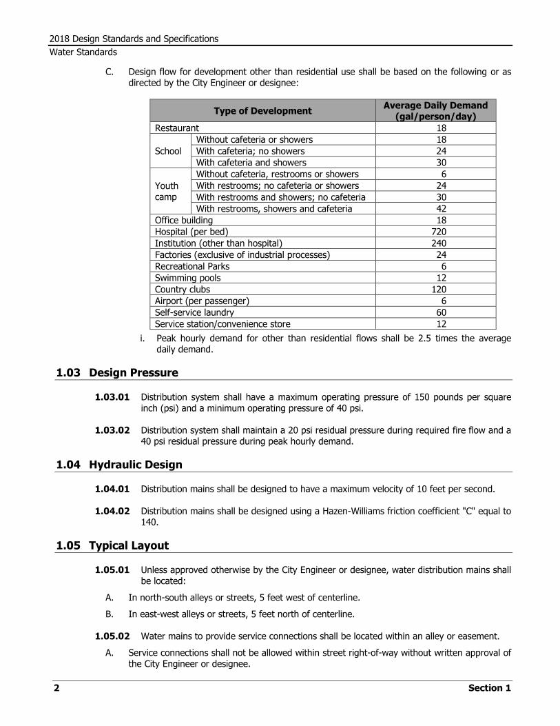
C. Design flow for development other than residential use shall be based on the following or as directed by the City Engineer or designee:
Type of Development Average Daily Demand
(gal/person/day)
Restaurant 18
School
Without cafeteria or showers 18
With cafeteria; no showers 24
With cafeteria and showers 30
Youth camp
Without cafeteria, restrooms or showers 6
With restrooms; no cafeteria or showers 24
With restrooms and showers; no cafeteria 30
With restrooms, showers and cafeteria 42
Office building 18
Hospital (per bed) 720
Institution (other than hospital) 240
Factories (exclusive of industrial processes) 24
Recreational Parks 6
Swimming pools 12
Country clubs 120
Airport (per passenger) 6
Self-service laundry 60
Service station/convenience store 12
i. Peak hourly demand for other than residential flows shall be 2.5 times the average daily demand.
1.03 Design Pressure
1.03.01 Distribution system shall have a maximum operating pressure of 150 pounds per square inch (psi) and a minimum operating pressure of 40 psi.
1.03.02 Distribution system shall maintain a 20 psi residual pressure during required fire flow and a 40 psi residual pressure during peak hourly demand.
1.04 Hydraulic Design
1.04.01 Distribution mains shall be designed to have a maximum velocity of 10 feet per second.
1.04.02 Distribution mains shall be designed using a Hazen-Williams friction coefficient "C" equal to 140.
1.05 Typical Layout
1.05.01 Unless approved otherwise by the City Engineer or designee, water distribution mains shall be located:
A. In north-south alleys or streets, 5 feet west of centerline.
B. In east-west alleys or streets, 5 feet north of centerline.
1.05.02 Water mains to provide service connections shall be located within an alley or easement.
A. Service connections shall not be allowed within street right-of-way without written approval of the City Engineer or designee.

2018 Design Standards and Specifications
Water Standards
Section 1 3
B. Service lines shall not cross property boundaries into adjacent private property without coverage by a dedicated easement.
1.05.03 Where a water distribution main crosses a street, the crossing shall be made at as near to perpendicular as possible.
1.05.04 Valves shall be installed at each junction such that no more than one connecting leg is unvalved.
A. At street intersections, valves shall be located at right-of-way lines unless flanged fittings are required.
B. At alley intersections with streets, valves shall be located 2 feet from the right of way line towards the centerline of the street where possible.
C. Where possible, valves in streets should be designed to fall outside of wheel paths.
1.05.05 Water mains shall be designed as looped systems.
1.05.06 Minimum radius of curvature and maximum deflection angle of pipe joints shall be restricted to 80% of manufacturer’s recommendation, after which the use of horizontal or vertical bends will be required.
1.05.07 In all instances water mains shall extend to the extremities of the platted property or the subdivision served, and further when required to tie into existing mains adjacent to the development.
1.06 Bedding and Cover
1.06.01 Water distribution mains shall ordinarily have a minimum of 4 feet of cover from top of pipe to finished ground surface.
1.06.02 All water lines shall be laid as horizontal as possible, avoiding excessive numbers of high or low points.
1.06.03 Pipe bedding and embedment shall be in accordance with the Standard Specifications for Water Main Construction but in all cases shall be not less than manufacturer recommendations.
1.07 Relation to Sanitary Sewer Mains and Appurtenances
1.07.01 No physical connection shall be made between a drinking water supply and a sewer line.
A. Appurtenances shall be designed and constructed so as to prevent any possibility of sewage entering the drinking water system.
1.07.02 Water lines shall be located a minimum of 9 feet horizontally outside to outside from existing or proposed sanitary sewer lines or appurtenances.
A. Where the 9 foot separation distance cannot be achieved, the following criteria shall apply:
i. New waterline installation—parallel lines:
a. Where a new potable waterline parallels an existing, non-pressure or pressure rated sanitary sewer main and the Design Engineer is able to determine that the existing sanitary sewer main is not leaking:

2018 Design Standards and Specifications
Water Standards
4 Section 1
(1) The new potable waterline shall be located a minimum of 2 feet above and a minimum of 4 feet horizontally between outside diameters from the existing sanitary sewer main.
(2) Every effort shall be exerted not to disturb the bedding and backfill of the existing sanitary sewer main.
b. Where a new potable waterline parallels an existing, non-pressure or pressure rated sanitary sewer main and it cannot be determined by the Design Engineer if the existing line is leaking:
(1) The existing sanitary sewer main shall be replaced with at least 150 psi pressure rated pipe.
(2) The new potable waterline shall be located a minimum of 2 feet above and a minimum of 4 feet horizontally between outside diameters from the existing sanitary sewer main.
c. Where a new potable waterline parallels a new sanitary sewer main:
(1) The sanitary sewer main shall be constructed of at least 150 psi pressure rated pipe.
(2) The new potable waterline shall be located a minimum of 2 feet above and a minimum of 4 feet horizontally between outside diameters from the existing sanitary sewer main.
ii. New waterline installation—crossing lines:
a. Where a new potable waterline crosses over an existing, non-pressure rated sanitary sewer main:
(1) A minimum 2 foot separation distance between outside diameters shall be maintained.
(2) One segment of the waterline pipe shall be centered over the sanitary sewer main such that the joints of the waterline pipe are equidistant and at least 9 feet horizontally from the centerline of the sanitary sewer main.
(3) Whenever possible, the crossing shall be centered between the joints of the sanitary sewer main.
(4) Every effort shall be exerted not to disturb the bedding and backfill of the existing sanitary sewer main.
(5) If the existing sanitary sewer main is disturbed or shows signs of leaking, it shall be replaced for at least 9 feet in both directions (18 feet total) with at least 150 psi pressure rated pipe.
b. Where a new potable waterline crosses over an existing, pressure rated sanitary sewer main:
(1) An absolute minimum separation distance of 6 inches between outside diameters shall be maintained.
(2) One segment of the waterline pipe shall be centered over the sanitary sewer main such that the joints of the waterline pipe are equidistant and at least 9 feet horizontally from the centerline of the sanitary sewer main.
(3) Whenever possible, the crossing shall be centered between the joints of the sanitary sewer main.
(4) Every effort shall be exerted not to disturb the bedding and backfill of the existing sanitary sewer main.
(5) If the existing sanitary sewer main is disturbed or shows signs of leaking, it shall be replaced for at least 9 feet in both directions (18 feet total) with at least 150 psi pressure rated pipe.
2018 Design Standards and Specifications
Water Standards
Section 1 5
c. Where a new potable waterline crosses over a new, non-pressure rated sanitary sewer main:
(1) A minimum 2 foot separation distance between outside diameters shall be maintained.
(2) One segment of the waterline pipe shall be centered over the sanitary sewer main such that the joints of the waterline pipe are equidistant and at least 9 feet horizontally from the centerline of the sanitary sewer main.
(3) Whenever possible, the crossing shall be centered between the joints of the sanitary sewer main.
(4) The sanitary sewer main shall be embedded in flowable fill from one quarter of the diameter of the sanitary sewer main below the centerline of the pipe up to 12 inches above top of pipe for the total length of one pipe segment, minimum 9 feet in each direction from water line, plus 12 inches beyond the joint on each end.
d. Where a new potable waterline crosses over a new, pressure rated sanitary sewer main:
(1) An absolute minimum separation distance of 6 inches between outside diameters shall be maintained.
(2) The sanitary sewer main shall be constructed of at least 150 psi pressure rated pipe.
(3) One segment of the waterline pipe shall be centered over the sanitary sewer line such that the joints of the waterline pipe are equidistant and at least 9 feet horizontally from the center line of the sanitary sewer main.
(4) Whenever possible, the crossing shall be centered between the joints of the sanitary sewer main.
(5) The sanitary sewer main shall be embedded in flowable fill from one quarter of the diameter of the sanitary sewer main below the centerline of the pipe up to 12 inches above top of pipe for the total length of one pipe segment, minimum 9 feet in each direction from water line, plus 12 inches beyond the joint on each end.
e. When a new potable waterline crosses under a sanitary sewer main:
(1) An absolute minimum separation distance of 1 foot between outside diameters shall be maintained.
(2) The waterline shall be encased in an 18-foot or longer section of pipe or be constructed of ductile iron or steel pipe with mechanical or welded joints as appropriate.
(3) The encasing pipe shall be centered on the sewer line and shall be at least 2 nominal pipe diameters larger than the water line.
(4) The carrier pipe shall be supported at 5-foot or less intervals with spacers.
(5) Each end of the casing shall be sealed with watertight non-shrink cement grout or a manufactured watertight seal.
(6) Both the waterline and sanitary sewer main must pass a pressure and leakage test as specified in AWWA C600.
iii. The use of brown coloring in flowable fill for pressure rated sanitary sewer main embedment is recommended for identification during future construction.
iv. In all cases, suitable backfill or other structural protection shall be provided to preclude settling and/or failure of the higher pipe.

2018 Design Standards and Specifications
Water Standards
6 Section 1
B. Location of fire hydrants
i. Fire hydrants shall not be installed within 9 feet vertically or horizontally of any sanitary sewer main, manhole or service line regardless of construction.
C. Location of potable or raw water supply or suction lines
i. Suction mains to pumping equipment shall not cross sanitary sewer mains or sanitary sewer service lines.
ii. Raw water supply lines shall not be installed within 5 feet of any tile or concrete sanitary sewer main or sanitary sewer service line.
D. Proximity of septic tank drain fields
i. Waterlines shall not be installed closer than 20 feet to septic tank drain fields.
1.07.03 Water and sewer lines shall be installed in separate trenches.
1.07.04 For other instances not covered in these design standards, consult current TCEQ regulations.
1.08 Pipe Size and Spacing
1.08.01 Distribution mains shall be located and sized in accordance with the current City of Lubbock Water System Master Plan and current TCEQ rules:
Water Line Size Spacing
16-inch or larger Section Line (mile)
10- or 12-inch Half-Section Line (1/2 mile)
6- or 8-inch Eighth-Section Line (660 feet)
1.08.02 The standard pipe sizes that shall be used are 4-, 6-, 8-, 10-, 12-, 16-, 20- and 24-inch. Pipe sizes not listed here are considered non-standard and shall not be used in the City of Lubbock water distribution system, unless approved by the City Engineer or designee.
1.09 Pipe Materials
1.09.01 All pipe used in the City of Lubbock water distribution system shall be Cement-lined Ductile Iron, C900 PVC, C905 PVC, C301 Prestressed-Concrete Steel Cylinder Pressure or Concrete Bar-wrapped Steel Cylinder Pressure Pipe.
1.09.02 See City of Lubbock Standard Specifications for Water Main Construction for details on materials and methods of construction.
1.10 Methods of Connection
1.10.01 Tapping Sleeves
A. Tapping sleeves with tapping valves shall be used whenever possible for connections to existing mains in order to avoid interruption of water service.
B. Maximum tap size shall be no larger than one standard size smaller than the main to be tapped.
C. Size-on-size taps shall not be allowed without prior approval by the City Engineer or designee.
D. Using a tapping sleeve of one standard size smaller than the main to be tapped and immediately increasing the pipe to a larger size shall not be allowed without prior approval by the City Engineer or designee.

2018 Design Standards and Specifications
Water Standards
Section 1 7
1.10.02 Cut-in Tees
A. When it is necessary for a size-on-size connection and interruption of water service is not an issue, a cut-in tee with valve shall be used.
B. Cut-in tees shall not be used without prior approval by the City Engineer or designee.
1.10.03 Service Connections
A. Taps shall be provided in water main lines for service connections at each lot or building site.
B. Service connections shall ordinarily be located 5.0 feet north or west of the centerline of the lot.
C. Service lines shall not cross property boundaries into adjacent private property without coverage by a dedicated easement.
D. Typical sizes of service connections are 1 inch, 1 ½ inch, or 2 inch diameter for residential, commercial, or industrial service. Service taps 3 inches or larger are available for commercial and industrial only.
E. Maximum size service connection shall be no larger than one standard size smaller than the main to be tapped.
F. Size-on-size service connections are not allowed.
1.11 Flanged Outlets
1.11.01 All side outlets for valve attachments on lines 16-inches and larger shall be flanged.
1.12 Valve Spacing
1.12.01 Valves shall be provided in the distribution system so that no single accident, break or repair will necessitate shutting down a length of pipe greater than 600 feet.
A. On distribution mains 12-inch diameter and smaller, valves shall be located at each tee, cross or other junction.
B. Valves shall be installed at each junction such that no more than one connecting leg is unvalved.
1.12.02 On 16-inch arterial mains, valves shall be spaced no greater than 800 feet as the arterial feeder main traverses undeveloped land or is not intersected by other distribution mains.
1.12.03 Transmission mains 20-inch diameter and larger shall be equipped with valves at one-half mile intervals unless intersected by arterial mains or other distribution mains, or it is determined that more valves are required.
1.13 Fire Protection Requirements
1.13.01 Fire protection must comply with Fire Marshall’s Office regulations, and in no case be less than currently adopted International Fire Code requirements.
A. Each building in the city limits shall be within 500 feet of a fire hydrant, as measured by lay-of-hose length.
1.13.02 In all cases, the following criteria shall be adhered to:
A. Fire hydrant leads shall be minimum 6-inch diameter, sole purpose and shall not exceed 150 feet in length. The entire length of the lead shall be mechanically restrained.

2018 Design Standards and Specifications
Water Standards
8 Section 1
B. Private fire protection lines and hydrant leads shall connect at the main with a gate valve or tapping valve of at least equal size to the fire protection line.
C. A fire hydrant is required within 200 feet of a Fire Department Connection.
D. Fire lines from public mains to buildings shall be installed by a state certified fire sprinkler firm and tested to Fire Marshall’s Office requirements.
E. Fire hydrants shall be located at intersections wherever possible.
i. Consult Section C-104 of the International Fire Code for requirements on hydrants that may obstruct access during fire fighting operations.
F. A hydrant shall be placed at the throat or beginning of each cul-de-sac at the intersecting street.
i. Additional fire hydrants may be required based on length of cul-de-sac.
ii. Fire hydrants placed at the bulb end of cul-de-sacs should be avoided.
G. On divided highways hydrants shall be placed on each side of the highway wherever possible.
H. Fire hydrants shall be installed with the 4-inch nozzle facing the required access way or street.
I. Fire hydrants shall be installed and maintained so that the center of the lowest water outlet is 18 inches above the ground.
J. Fire hydrants shall be placed so that they are readily visible from the street and shall be no closer than 2 feet nor further than 5 feet from back of curb.
K. A reflective, blue, raised pavement marker shall be placed at the center of the required access way or street for any new fire hydrant installation, in line with the 4-inch nozzle.
L. No bushes, ground cover over 6 inches in height, or other obstructions shall be placed within a 5 foot radius in all directions of a hydrant or fire department connection.
M. Where fire hydrants are vulnerable to vehicular damage, appropriate crash posts shall be provided.
i. No obstructions shall exist within a 3-foot working area of each fire hydrant.
ii. Crash posts shall be 4-inch, cement-filled pipe with a minimum of 3 feet above finished grade and 2 feet of pipe anchored in concrete below grade.
N. Fire hydrants shall be in operation before framing is started or combustibles are stored on any construction site.
O. Streets and fire access roadways shall be able to support fire apparatus in wet weather before framing is started or combustibles are stored on any construction site.
P. Fire hydrant shall be installed with flange 0.2 to 0.4 foot above finished grade so that the bury line will be between finished grade and 0.2 foot above finished grade.
Q. No size-on-size taps for fire suppression shall be allowed.
1.14 Easements
1.14.01 When it is determined not to be feasible to construct a public water distribution main in a street or alley, the installation may be made in a dedicated easement or right-of-way.
1.14.02 The minimum width of an easement or right-of-way for a public water distribution main is 10 feet exclusive, 20 feet if shared with a public sanitary sewer main or other utilities or if depth of water distribution main is greater than 10 feet.
1.14.03 Easements will not be allowed between residential lots unless they are in combination with a drainage easement or with prior approval from the City Engineer or designee.

2018 Design Standards and Specifications
Water Standards
Section 1 9
1.14.04 When a fire hydrant is to be installed on private property, an easement shall be dedicated which provides a minimum of 5 feet clearance in all directions from the center of the fire hydrant.
1.15 Soil Analysis
1.15.01 The Contractor or Design Engineer may be required to submit a report showing the types and characteristics of the soils to be encountered, water table elevations along the proposed water distribution main, recommended methods of dewatering for water distribution main construction, and the recommended methods of backfilling and compacting to be used.
1.16 Pipe Restraints and Reaction Blocking
1.16.01 The size of required pipe restraints and reaction blocks shall be determined by the Design Engineer for the project based on the allowable soil pressure and the anticipated working pressure plus water hammer of the line.
1.16.02 For restrained joint lengths required, refer to Appendix A as derived from EBAA Iron, Inc.
1.17 Tunneling, Jacking and Boring
1.17.01 Tunneling, jacking and boring are methods used for water line placement under restrictive conditions when open cut construction is not allowed.
A. Only straight pipe alignments for both horizontal and vertical alignment are allowed.
B. Casing shall extend full width of right-of-way or as directed by the City Engineer or designee.
C. Casing pipe shall be a minimum of two standard sizes larger than encased pipe.
D. Casing pipe thickness shall be:
Casing Diameter Minimum Casing Thickness
<24 inches 3/8 inch
≥24 inches 1/2 inch
E. Manufactured centralizers or spacers shall be required at minimum 5-foot intervals or as recommended by the manufacturer.
i. Only purpose-built centralizers may be used.
F. Coal tar coating for casing pipe shall conform to AWWA C203.
G. For bores in excess of 100 feet, purpose-built fused or restrained joint pipe shall be used.
H. All bores must comply with City Utility Excavation Manual.
1.17.02 Slick boring or directional drilling without encasement shall be considered on a case-by-case basis by the City Engineer or designee. All slick bores shall be restrained or encased.
1.17.03 No annular space shall remain between casing, or uncased pipe, and bored hole.
1.17.04 Unbraced, uncased bore holes shall be left open no more than 24 hours.

2018 Design Standards and Specifications
Water Standards
10 Section 1
1.18 Dead-end Mains
1.18.01 A dead-end main is defined as a length of water line greater than 150 feet with no looped connection.
1.18.02 Dead-end mains shall not be allowed unless approved by the City Engineer or designee.
1.18.03 Where dead-end mains are necessary as a stage in the growth of the system, they shall be designed so that:
A. The system may be periodically flushed by use of a blow-off valve or fire hydrant, or
B. A temporary looped connection is installed.
1.19 Abandonment of Water Mains
1.19.01 When a water line is to be abandoned, allowances shall be made so that existing and new water mains may be in service simultaneously, thereby providing a means for transferring customer’s service from the old main to the new main with minimal interruption.
1.19.02 If the construction of a proposed main necessitates the abandoning of the existing main prior to the new main’s placement into service, provisions for a temporary water main with services must be addressed.
1.19.03 On mains to be abandoned, the designer shall note locations of cut and plug as close as possible to the main that remains in service.
1.19.04 Fire hydrants, valves and other fittings located on mains to be abandoned shall be removed and delivered to the City of Lubbock Water Utilities Department.

2018 Design Standards and Specifications
Water Check List
Section 2 11
SECTION 2
CHECK LIST FOR WATER DISTRIBUTION CONSTRUCTION PLANS
2.01 Plan Submittal Requirements
2.01.01 All water main construction plans shall be checked for conformance with City of Lubbock Minimum Design Standards for Water Distribution prior to submittal to the Engineering Department. Approval of plans is for general conformance with the City of Lubbock Minimum Design Standards and Specifications. Approval of plans shall not relieve the Engineer or Developer from any City, State or other governing requirements nor for errors or omissions in plans and specifications.
2.01.02 Plan Review
A. The Design Engineer shall submit water main construction plans to the City Engineer or designee for review and comment. The Design Engineer shall use the City of Lubbock Customer Self Service (CSS) website to submit plans.
http://egovaccess.ci.lubbock.tx.us/EnerGov_Prod/SelfService/#/home
B. Please call 806-775-2347 if you have any questions regarding the CCS submission process.
C. Upon completion of review and receipt of payment for appropriate Plan Review fees, comments shall be returned to the Design Engineer on the CSS website.
i. Plans requiring resubmittal for substantial changes as determined by City Engineer or Designee may require payment of an additional Plan Review fee.
D. After comments have been addressed and changes have been made the Design Engineer will submit the revised plan using CSS website.
i. If comments have not been addressed on plans submitted for final approval for construction the plans will be rejected.
ii. Plans will not be approved unless testing and inspection fees have been paid.
iii. If the design engineer does not submit plans for approval within 6 months of comments being issued or if fees are not paid within 6 months then the review will be terminated and the design engineer will have to start the plan review process over.
E. Upon approval, the city will return an electronic copy of the plan stamped “Approved for Construction” through the CSS web site.
i. The design Engineer will be required to submit two half size copies of the approved for construction stamped plans.
F. Final construction plans should not be submitted for Engineering Department approval for work that will not be installed within 6 months of the approval date.
i. Delays between approval date and construction may require resubmittal of the plans for review under current standards.
2.01.03 Pro Rata Estimate and Fees
A. The Pro Rata Cost Estimates shall be submitted for review at the time of plan review submittal.
B. Plan Review Fees in the amount of 0.5% of the Pro Rata Cost Estimate (minimum $50) shall be submitted at the time of plan review submittal.

2018 Design Standards and Specifications
Water Check List
12 Section 2
C. Inspection and Testing Fees in the amount of 1.5% of the Pro Rata Cost Estimate (minimum $125) shall be submitted prior to construction.
D. In the event of significant changes in design, an updated Pro Rata Cost Estimate shall be submitted and resulting differences in fee amounts settled.
2.01.04 Checklist
A. A copy of the completed “City of Lubbock Municipal Water and Sewer Submittal Checklist” shall be submitted at the time of plan review submittal. The checklist can be found in the Appendix.
2.01.05 Construction Plans
A. All plans to be used or kept on the job site shall be original or reproduced plan sets clearly marked “Approved for Construction” with the signature of reviewer and date approved by the Engineering Department.
B. Should circumstances during construction warrant changes from the approved plans or specifications, a written approval must be obtained from the Engineering Department.
i. Copies of the written approval shall be attached to the construction plans and maintained on the job site.
2.01.06 Record Drawings
A. The Design Engineer shall be responsible for recording constructed dimensions and information on a set of Record Drawings during the progress of construction.
i. The City of Lubbock Engineering Department shall monitor this process to assure that changes in construction are kept up to date on the Record Drawings.
B. Digital PDF “Record Drawings” certified by the Design Engineer shall be submitted to the Engineering Department on the CSS website within 30 days of completion of the construction.
i. Record Drawings shall include locations of all valves, valve vaults, fire hydrants, bends and tees or other changes in main pipe direction, material or size.
a. GPS Coordinates or property ties are acceptable.
C. Where the construction is phased and a lapse of more than 60 days occurs between phases, then Record Drawings shall be submitted to the Engineering Department reflecting the completed construction prior to issuance of the Certificate of Acceptance of Utility Construction.
D. Items required to be submitted with Record Drawings:
i. Letter of Transmittal
ii. Record Drawing
iii. Updated Pro Rata Cost Estimate
iv. Certificate of Completion (Provided to Contractor from City Inspector)
v. Developer’s Warranty Statement (See Appendix)
vi. Adjacent Mains Refund Contract (see Apendix)
2.01.07 Acceptance
A. Upon completion of construction, satisfactory system tests and submittal of Record Drawings, the Design Engineer shall submit a request to the City Engineer or designee for a Certificate of Acceptance of Utility Construction.
i. Water distribution system improvements shall not be put online or brought into service without written approval by the Engineering Department.

2018 Design Standards and Specifications
Water Check List
Section 2 13
ii. A newly constructed system will not be accepted until the supplying, adjacent system has been accepted.
iii. A Certificate of Acceptance of Utility Construction shall not be issued until Record Drawings are provided to the Engineering Department.
iv. When all paperwork has been completed and provided to the City with a written notification, utilities will be accepted within 30 days if there is no exception by the City.
B. Building Permits for residential developments and Certificates of Occupancy for commercial facilities to be serviced by a newly constructed water system will not be released by the Engineering Department until said system has been brought into service.
2.02 Plan Details
2.02.01 Plan Format
A. Standard drawing size shall be 22-inch by 34-inch.
2.02.02 The following information shall be shown on the plans:
A. General
i. Title Block (lower right hand corner preferred)
ii. Scale
iii. Original Date and Revision Dates
iv. Name of Professional Engineer
v. Professional Engineer's Seal
vi. Firm Name and Contact Information
vii. City of Lubbock Engineering Department Contact Information:
a. Development Services Engineering: (806) 775-2347
b. Senior Inspector: (806) 548-4152
viii. Drawings Number(s)
ix. Legal Description of Property Being Improved
x. Location Map or Plat (if available)
xi. Statement: “All work shall be performed in accordance with the current version of the City of Lubbock Minimum Design Standards and Specifications.”
B. Plan
i. Bench Marks
ii. North Arrow
iii. Property Lines
iv. Street Names and Easements with Width Dimensions
v. Other Pertinent Details (Buildings, Curbs, Water Courses, Etc.)
vi. Proposed Water Mains (Bold)
a. Stationing
b. Size
c. Length
d. Material and Type of Joints
e. Location Dimensions
f. Fittings

2018 Design Standards and Specifications
Water Check List
14 Section 2
g. Tees
h. Crosses
i. Reducers
j. Bends
k. Plugs
l. Blow-offs
m. Thrust Blocks
n. Valves
o. Fire Hydrants
vii. Existing Utility Lines (Gray) with Location and Depth According to the Following Standard:

2018 Design Standards and Specifications
Water Check List
Section 2 15
C. Profile (required for water lines greater than 12-inch diameter)
i. Ground Surface - Existing (Dotted) and Proposed (Solid)
ii. Station Numbers
iii. Existing and Proposed Utilities Where Crossed
iv. Proposed Water Main Control Elevation and Grades
D. Plan, Profile and Complete Details for Off-Site Transmission Mains, Pump Stations, Special Valves and Vaults, Tanks, Etc.
E. Detail Sheet - As Required
i. Standard Bedding Detail
ii. Thrust Block and Joint Restraint Tables
iii. Fire Hydrant Detail
iv. Tapping Details
v. Air Valve Detail
vi. Blow-off Detail
vii. Crossing Detail
F. Overall Layout Sheet - If Required
i. Scale 1 "=100'
ii. Lot Lines
iii. Streets and Street Names
iv. Water Line Sizes and Material
v. Valves
vi. Fire Hydrants
vii. Connections to Existing System

2018 Design Standards and Specifications
Water Check List
16 Section 2

2018 Design Standards and Specifications
Sewer Standards
Section 3 17
SECTION 3
MINIMUM DESIGN STANDARDS FOR SANITARY SEWERS
3.01 General
3.01.01 All sanitary sewer system design shall be in accordance with the requirements of TCEQ Chapter 217, AWWA Standards, City of Lubbock Sewer System Master Plan, current City ordinances and the City of Lubbock Minimum Design Standards for Sanitary Sewers.
3.02 Design Flow
3.02.01 The design of the sanitary sewer system shall be based on the following:
A. For sewers in new developments sewer main lines and lift stations shall be designed for the estimated future population to be served plus adequate allowance for future institutional and commercial flows.
B. Minimum flow capacity for sizing of sewers for peak flow conditions shall not be less than the following:
Design Criteria Design Value Units
Average Daily Flow 100 gpcd
Peak Factor, 2-hour flow <0.5 MGD 5 -
Peak Factor, 2-hour flow >0.5 MGD 4 -
Capita per Household (Single Family) 3.2 persons
Capita per Household (Multi-family) 2.5 persons
C. Minimum residential population density shall be figured on a basis of 6 houses per acre, and 70 percent of total land area developed as residential, unless detailed analysis of the area to be served indicates differently.
D. Design flow for development other than residential use shall be based on the following or as directed by the City Engineer or designee:
Type of Development Design Criteria Daily Flow - gpcd
Trailer Park – transient 2.5 persons/trailer 50
Mobile Home Park 3 persons/trailer 75
School with cafeteria With showers 20
Without showers 15
Recreational Parks Day Use 5
Overnight Use 30
Commercial/Industrial Building 20
Motel 50
Restaurant Per meal served 5
Hospital Per bed 200
Nursing Home Per bed 100

2018 Design Standards and Specifications
Sewer Standards
18 Section 3
3.03 Hydraulic Design
3.03.01 The minimum velocity at the design flow rate shall be 2.0 feet per second.
3.03.02 Maximum allowable velocity shall be 10 feet per second.
3.03.03 Manning’s coefficient for design purposes shall be n=0.013 for PVC pipe.
3.03.04 Manhole inverts shall be designed in such a manner that the energy gradient is consistently falling in the direction of flow.
3.04 Design Details
3.04.01 Sewer Pipe
A. The standard pipe sizes that shall be used are 6-, 8-, 10-, 12-, 15-, 18- and 21-inch. Pipe sizes not listed here are considered non-standard and shall not be used in the City of Lubbock sanitary sewer system, unless approved by the City Engineer or designee.
B. The following City slope standards shall apply to sanitary sewer mains: (refer to TCEQ guidelines 30 TAC Section 217.53.1.2.A Table C.1.)
Pipe Diameter Minimum Slope (%) Maximum Slope (%)
6 inch 0.60 [0.50 TCEQ] 12.35
8 inch 0.40 [0.33 TCEQ] 8.40
10 inch 0.28 [0.25 TCEQ] 6.23
12 inch 0.22 [0.20 TCEQ] 4.88
15 inch 0.15 [0.15 TCEQ] 3.62
18 inch 0.12 [0.11 TCEQ] 2.83
C. Sewer main lines shall be straight between manholes both in line and grade.
D. All sewer main lines shall terminate in a manhole.
i. Cleanouts on sewer main lines shall not be permitted without written approval of the City Engineer or designee.
3.04.02 Manholes
A. Manholes shall be a minimum of 48-inch diameter and shall be provided at every change in direction, grade, or connection with other sewer main lines.
B. Manhole spacing and depth shall be as follows:
Pipe Diameter Manhole
Depth Manhole Diameter
Max. Spacing Between Manholes
15 inches or smaller 0-16 Ft. 48 in. 500 Ft.
15 inches or smaller Over 16 Ft. 60 in. 500 Ft.
Over 15 inches All depths 60 in. 800 Ft.
C. Manholes greater than 16 feet deep or serving pipes larger than 15 inches shall be 60-inch diameter and include a protective coating system per the Approved Materials List.
D. Connections at manholes shall be designed such that the crowns of connecting pipes are equal elevation if possible.
E. Force mains shall discharge directly into a manhole through a 90o downspout connection.

2018 Design Standards and Specifications
Sewer Standards
Section 3 19
F. Manholes receiving force main discharge shall include a protective coating system per the Approved Materials List.
G. Minimum elevation difference across manhole inverts shall be as follows:
Deflection Angle Between
Inlet/Outlet Min. Elevation Difference
Less than 30o 0.10 Ft.
Greater than 30o 0.20 Ft.
H. Drop manholes shall be provided for sewer main lines entering a manhole at an elevation 24 inches or more above the manhole invert.
i. Drop connections on new manholes shall be constructed with an exterior or “outside” drop system on all 48 inch manholes. All “outside” drops shall be flow filled against undisturbed soil up to the depth of the main.
ii. Drop connections on existing manholes shall be constructed with an interior or “inside” drop system. “Inside” drops shall be allowed for existing 60 inch manholes only.
I. Where the difference in elevation is less than 24 inches, the invert shall be filleted to prevent solids deposition.
J. Manholes shall be stubbed out with suitable size pipe wherever future extension of the sewer is anticipated.
i. Stub-outs shall extend beyond the edge of existing or proposed paving.
K. Inflow Prevention Devices (IPDs) shall be specified on all new manhole installations.
3.04.03 Service Connections
A. Tees or wyes shall be provided in sewer main lines for service connections at each lot or building site.
B. Service connections shall ordinarily be located 5.0 feet south or east of the centerline of the lot.
C. Service lines shall not cross property boundaries into adjacent private property without coverage by a dedicated easement.
D. Minimum size service connections shall be 4 inch diameter.
E. Maximum size service connection shall be no larger than one standard size smaller than the main to be tapped.
F. Size-on-size service connections are not allowed.
G. Gravity sewer taps shall connect to sewer main lines at or above the spring line.
H. No gravity service lines shall discharge directly into a manhole.
I. Service connections shall not be installed within 5 feet of the outside wall of a manhole.
3.05 Typical Layout
3.05.01 Unless approved otherwise by the City Engineer or designee, sanitary sewer mains shall be located:
A. In north-south alleys or streets, 5 feet east of the centerline.
B. In east-west alleys or streets, 5 feet south of the centerline.

2018 Design Standards and Specifications
Sewer Standards
20 Section 3
3.05.02 Sanitary sewer mains to provide service connections shall be located within an alley or easement.
A. Service connections shall not be allowed within street right-of-way without written approval of the City Engineer or designee.
B. Service connections shall not be deeper than 12 foot without prior written approval from the City Engineer or designee.
3.05.03 Where a sanitary sewer main crosses a street, the crossing shall be made at as near to perpendicular as possible.
3.05.04 Manholes shall be located as to provide access for maintenance crews and equipment.
A. Where possible, manholes in streets should be designed to fall outside of wheel paths.
B. Where possible, manholes in alleys should be designed to fall at the projected intersection of perpendicular lot lines.
3.05.05 In all instances sanitary sewer mains shall extend to the extremities of the platted property or the subdivision served.
3.06 Bedding and Cover
3.06.01 Sewer mains shall have a minimum of 4 feet of cover from top of pipe to proposed finished ground surface unless approved by City Engineer or designee.
A. Where less than 5 feet of elevation difference between the finished lot grade at building line and the top of the sewer main is provided, the plans shall indicate that the lot is served by a "shallow sewer" and appropriate elevation information shall be given.
B. Where a sewer main has less than 4 feet of cover, provisions shall be made to protect the pipe from impact loading when located in a street or alley.
C. Maximum sanitary sewer depth in alleys shall be 12 feet unless approved by the Engineering Department.
3.06.02 Pipe bedding and embedment shall be in accordance with the Standard Specifications for Sanitary Sewer Main Construction but in all cases shall be not less than manufacturer recommendations.
3.07 Relation to Water Mains
3.07.01 No physical connection shall be made between a drinking water supply and a sewer line.
A. Appurtenances shall be designed and constructed so as to prevent any possibility of sewage entering the drinking water system.
3.07.02 Sewers shall be located a minimum of 9 feet horizontally outside to outside from existing or proposed water mains.
A. Where the 9-foot separation distance cannot be achieved, the following guidelines shall apply:
i. New sanitary sewer installation – parallel lines:
a. Where a new sanitary sewer main parallels a water line:
(1) The sewer shall be constructed of ductile iron or PVC meeting ASTM specifications with a pressure rating for both the pipe and joints of 150 psi.
(2) The vertical separation shall be a minimum of 2 feet and the horizontal separation shall be a minimum of 4 feet between outside diameters.

2018 Design Standards and Specifications
Sewer Standards
Section 3 21
(3) The sewer shall be located below the water line.
ii. New sanitary sewer installation – crossing lines:
a. Where a sanitary sewer crosses under a water line and the sewer is constructed of ductile iron or PVC with a minimum pressure rating of 150 psi:
(1) An absolute minimum separation distance of 6 inches between outside diameters shall be maintained.
(2) One segment of the sewer pipe shall be centered on the water line such that the joints of the sewer pipe are equidistant and at least 9 feet horizontally from the centerline of the water line.
(3) Whenever possible, the crossing shall be centered between the joints of the waterline.
(4) The sanitary sewer main shall be embedded in flowable fill from one quarter of the diameter of the sanitary sewer main below the centerline of the pipe up to 12 inches above top of pipe for the total length of one pipe segment, minimum 9 feet in each direction from water line, plus 12 inches beyond the joint on each end.
b. Where a sanitary sewer crosses under a water line and the sewer is constructed of ABS truss pipe, similar semi-rigid plastic composite pipe, clay pipe or concrete pipe with gasketed joints (Non-pressure rated pipe):
(1) A minimum 2 foot separation distance between outside diameters shall be maintained.
(2) One segment of the sewer pipe shall be centered on the water line such that the joints of the sewer pipe are equidistant and at least 9 feet horizontally from the centerline of the water line.
(3) Whenever possible, the crossing shall be centered between the joints of the waterline.
(4) The sanitary sewer main shall be embedded in flowable fill from one quarter of the diameter of the sanitary sewer main below the centerline of the pipe up to 12 inches above top of pipe for the total length of one pipe segment, minimum 9 feet in each direction from water line, plus 12 inches beyond the joint on each end.
c. Where a sanitary sewer crosses over a water line:
(1) An absolute minimum separation distance of 1 foot between outside diameters shall be maintained.
(2) All portions of the sewer within 9 feet of the water line shall be encased in a joint of 150 psi pressure class pipe at least 18 feet long and 2 nominal sizes larger than the new conveyance.
(3) The carrier pipe shall be supported at 5-foot or less intervals with spacers.
(4) The encasement pipe should be centered on the crossing and each end sealed with watertight non-shrink cement grout or a manufactured watertight seal.
(5) Both the waterline and sanitary sewer main must pass a pressure and leakage test as specified in AWWA C600.
iii. The use of brown coloring in flowable fill for pressure rated sanitary sewer main embedment is recommended for identification during future construction.
iv. In all cases, suitable backfill or other structural protection shall be provided to preclude settling and/or failure of the higher pipe.
B. Sanitary sewer manhole and clean out separation from water
i. Manholes and clean outs must be installed so as to provide a minimum of 9 feet of outside to outside clearance from an existing or proposed water line.

2018 Design Standards and Specifications
Sewer Standards
22 Section 3
ii. Where the 9-foot separation distance cannot be achieved, an encasement pipe as described in subparagraph (c.) above may be used for the water line.
3.07.03 Water and sewer lines shall be installed in separate trenches.
3.07.04 For other instances not covered in these design standards, consult current TCEQ regulations.
3.08 Abandonment of Sewer Mains and Manholes
3.08.01 When a sewer system is to be abandoned the Design Engineer shall ensure that all existing mains and service connections are properly plugged or transferred to the new system prior to decommissioning of the existing system.
3.08.02 Sewer Mains
A. If a line to be abandoned terminates in a manhole that will remain in service, the existing main to be decommissioned shall be plugged from within the manhole and clearly marked on the plans.
i. Cutting and plugging of existing lines directly outside of manholes should be avoided.
B. If a portion of a line is to be abandoned a manhole must be installed on the new terminus of the portion of line to remain in service.
3.08.03 Sewer Manholes
A. Manholes may be decommissioned by either of the following methods or as approved by the City Engineer or designee:
i. Complete removal of the manhole structure including ring, lid, cone, riser sections, base and all appurtenances. The excavation shall be backfilled with compacted native material or flowable fill.
ii. Remove cone, ring and lid sections and backfill to top of remaining structure with flowable fill. Remaining excavation shall be backfilled with compacted native material or flowable fill.
3.09 Easements
3.09.01 When it is determined not to be feasible to construct a public sanitary sewer line in a street or alley, the installation may be made in a dedicated easement or right-of-way.
3.09.02 The minimum width of easement or right-of-way for a public sanitary sewer is 10 feet exclusive, 20 feet if shared with a public water main or other utilities or if depth of sewer main is greater than 10 feet.
3.10 Soil Analysis
3.10.01 The Contractor or Design Engineer may be required to submit a report showing the types and characteristics of the soils to be encountered, water table elevations along the proposed sewer, recommended methods of dewatering for sewer main construction, and the recommended methods of backfilling and compacting to be used.

2018 Design Standards and Specifications
Sewer Standards
Section 3 23
3.11 Tunneling, Jacking and Boring
3.11.01 Tunneling, jacking and boring are methods used for sewer line placement under restrictive conditions when open cut construction is not allowed.
A. Only straight pipe alignments for both horizontal and vertical alignment are allowed.
B. Casing shall extend full width of right-of-way or as directed by the City Engineer or designee.
C. Casing pipe shall be a minimum of two standard sizes larger than encased pipe and must allow for the required casing spacers.
D. Casing pipe thickness shall be:
Casing Diameter Minimum Casing Thickness
<24 inches 3/8 inch
≥24 inches 1/2 inch
E. Manufactured centralizers or spacers shall be required at minimum 5-foot intervals or as recommended by the manufacturer.
i. Only purpose-built centralizers may be used.
F. Coal tar coating for casing pipe shall conform to AWWA C203.
G. For bores in excess of 100 feet, purpose-built fused or restrained joint pipe shall be used.
3.11.02 Slick boring or directional drilling without encasement shall be considered on a case-by-case basis by the City Engineer or designee.
3.11.03 Annular space between casing or uncased pipe and bored hole shall be injection grouted.
3.11.04 All pipe longer than 50’ installed by bore, jacking or tunneling must be video inspected by the developer after running water through the pipe to identify low areas. Video inspection shall conform to Section 6.08.07.
3.12 Lift Station
3.12.01 A thorough engineering analysis must be performed on physical and economic factors to determine if a lift station is required.
A. A preliminary engineering report will be required to list all factors including TCEQ regulations as outlined in the Standard Specifications for Sanitary Sewer Construction.
B. The City Engineer or designee will review the preliminary report and reserves the right to determine if there is merit to require a lift station.
C. After approval of the preliminary report design shall follow the Standard Specifications for Sanitary Sewer Main Construction.
D. Design of a lift station facility shall take into consideration the entire drainage basin, as well as local runoff. The top slab of the lift station shall be higher than the adjacent ground and the 100 year flood event.
E. The review and approval process for lift station design could be subject to addition rules and requirements more comprehensive than those listed in these specifications.

2018 Design Standards and Specifications
Sewer Standards
24 Section 3

2018 Design Standards and Specifications
Sewer Check List
Section 4 25
SECTION 4
CHECK LIST FOR SANITARY SEWER CONSTRUCTION PLANS
4.01 Plan Submittal Requirements
4.01.01 All sanitary sewer main construction plans shall be checked for conformance with City of Lubbock Minimum Design Standards for Sanitary Sewer prior to submittal to the Engineering Department for approval. Approval of plans is for general conformance with the City of Lubbock Minimum Design Standards and Specifications. Approval of plans shall not relieve the Engineer or Developer from any City, State or other governing requirements nor for errors or omissions in plans and specifications.
4.01.02 Plan Review
A. The Design Engineer shall submit sanitary sewer main construction plans to the City Engineer or designee for review and comment. The Design Engineer shall use the City of Lubbock Customer Self Service (CSS) website to submit plans.
http://egovaccess.ci.lubbock.tx.us/EnerGov_Prod/SelfService/#/home
B. Please call 806-775-2347 if you have any questions regarding the CCS submission process.
C. Upon completion of review and receipt of payment for appropriate Plan Review fees, comments shall be returned to the Design Engineer on the CSS website.
i. Plans requiring resubmittal for substantial changes as determined by City Engineer or Designee may require payment of an additional Plan Review fee.
D. After comments have been addressed and changes have been made the Design Engineer will submit the revised plan using CSS website.
i. If comments have not been addressed on plans submitted for final approval for construction the plans will be rejected.
ii. If testing and inspection fees have not been paid, plans will be rejected.
E. Upon approval, the city will return an electronic copy of the plan stamped “Approved for Construction” through the CSS web site.
i. The design Engineer will be required to submit two half size copies of the approved for construction stamped plans.
F. Final construction plans should not be submitted for Engineering Department approval for work that will not be installed within 6 months of the approval date.
i. Delays between approval date and construction may require resubmittal of the plans for review under current standards.
4.01.03 Pro Rata Estimate and Fees
A. Two (2) sets of Pro Rata Cost Estimates shall be submitted for review at the time of plan review submittal.
B. Plan Review Fees in the amount of 0.5% of the Pro Rata Cost Estimate (minimum $50) shall be submitted at the time of plan review submittal.
C. Inspection and Testing Fees in the amount of 1.5% of the Pro Rata Cost Estimate (minimum $125) shall be submitted prior to construction.
D. In the event of significant changes in design, an updated Pro Rata Cost Estimate shall be submitted and resulting differences in fee amounts settled.

2018 Design Standards and Specifications
Sewer Check List
26 Section 4
4.01.04 Checklist
A. A copy of the completed “City of Lubbock Municipal Water and Sewer Submittal Checklist” shall be submitted at the time of plan review submittal. The checklist can be found in the Appendix.
4.01.05 Construction Plans
A. All plans to be used or kept on the job site shall be original or reproduced plan sets clearly marked “Approved for Construction” with the signature of reviewer and date approved by the Engineering Department.
B. Should circumstances during construction warrant changes from the approved plans or specifications, a written approval must be obtained from the Engineering Department.
i. Copies of the written approval shall be attached to the construction plans and maintained on the job site.
4.01.06 Record Drawings
A. The Design Engineer shall be responsible for recording constructed dimensions and information on a set of Record Drawings during the progress of construction.
i. The City of Lubbock Engineering Department shall monitor this process to assure that changes in construction are kept up to date on the Record Drawings.
B. Digital PDF “Record Drawings”, certified by the Design Engineer, shall be submitted to the Engineering Department within 30 days of completion of the construction.
i. Record Drawings shall include locations of all lift stations, manholes or other changes in main pipe direction, material or size.
a. GPS Coordinates or property ties are acceptable.
C. Where the construction is phased and a lapse of more than 60 days occurs between phases, then Record Drawings shall be submitted to the Engineering Department reflecting the completed construction prior to issuance of the Certificate of Acceptance of Utility Construction.
D. Items required to be submitted with Record Drawings:
i. Letter of Transmittal
ii. Record Drawing
iii. Updated Pro Rata Cost Estimate
iv. Certificate of Completion (Provided to Contractor from City Inspector)
v. Developer’s Warranty Statement (See Appendix)
vi. Adjacent Mains Refund Contract (see Apendix)
4.01.07 Acceptance
A. Upon completion of construction, satisfactory system tests and submittal of Record Drawings, the Design Engineer shall submit a request to the City Engineer or designee for a Certificate of Acceptance of Utility Construction.
i. Sanitary sewer system improvements shall not be put online or brought into service without written approval by the Engineering Department.
ii. A newly constructed system will not be accepted until the receiving, downstream system has been accepted.
iii. A Certificate of Acceptance of Utility Construction shall not be issued until Record Drawings are provided to the Water Utilities Department.

2018 Design Standards and Specifications
Sewer Check List
Section 4 27
iv. When all paperwork has been completed and provided to the City with a written notification, utilities will be accepted within 30 days if there is no exception by the City.
B. Building Permits for residential developments and Certificates of Occupancy for commercial facilities to be serviced by a newly constructed system will not be released by the Engineering Department until said system has been brought into service.
4.02 Plan Details
4.02.01 Plan Format
A. Standard drawing size shall be 22-inch by 34-inch.
4.02.02 The following details shall be shown on the plans:
A. General
i. Title Block (lower right hand corner preferred)
ii. Scale
iii. Original Date and Revision Dates
iv. Name of Professional Engineer
v. Professional Engineer's Seal
vi. Firm Name and Contact Information
vii. City of Lubbock Engineering Department Contact Information:
a. Development Engineering Services: (806) 775-2347
b. Senior Inspector: (806) 548-4152
viii. Drawings Number(s)
ix. Legal Description of Property Being Improved
x. Location Map or Plat (if available)
xi. Statement: “All work shall be performed in accordance with the current version of the City of Lubbock Minimum Design Standards and Specifications.”
B. Plan
i. Bench Marks
ii. North Arrow
iii. Property Lines
iv. Street Names and Easements with Width Dimensions
v. Other Pertinent Details (Buildings, Curbs, Water Courses, Etc.)
vi. Proposed Sanitary Sewer Mains (Bold)
a. Stationing
b. Size
c. Materials
d. Gradients
e. Length between Manholes
f. Proposed Manholes
g. Elevation of Inverts In And Out Of Manhole
h. Elevation of Manhole Rim
i. Location Control Dimensions

2018 Design Standards and Specifications
Sewer Check List
28 Section 4
j. Manhole Stub-Outs
k. Proposed Future Extensions
l. Proposed Service Connections or Stub-Ins
m. Standard Bedding Cross-Section
n. Proposed Concrete Encasement
o. Proposed Cut-Off Walls
vii. Existing Utility Lines (Gray) with Location and Depth According to the Following Standard:
C. Profile
i. Ground Surface - Existing (Dotted) and Proposed (Solid)
ii. Station Numbers
iii. Existing and Proposed Utilities Where Crossed
iv. Existing Manhole Invert and Rim Elevations
D. Plan, Profile and Complete Details for Off-Site Force or Gravity Mains, Lift Stations, Special Valves and Vaults, Tanks, Etc.
E. Detail Sheet - As Required
i. Standard Bedding Detail
ii. Standard Manhole Detail
iii. Drop Manhole Details
iv. Tapping Details
F. Overall Layout Sheet - If Required
i. Scale 1 "=100'
ii. Lot Lines
iii. Streets and Street Names
iv. Sewer Line Sizes and Material
v. Manholes
vi. Connections to Existing System

2018 Design Standards and Specifications
Water Specifications
Section 5 29
SECTION 5
STANDARD SPECIFICATIONS FOR WATER MAIN CONSTRUCTION
5.01 General
5.01.01 All water main construction within the City of Lubbock water system or for future connections to the City of Lubbock water system shall be accomplished in accordance with the requirements of these specifications.
5.02 Plan Requirements
5.02.01 Water main construction shall be done in accordance with engineered construction plans for the work, prepared under the direction of a Professional Engineer and approved by the City of Lubbock Engineering Department.
5.02.02 Plans shall conform to the City of Lubbock's Minimum Design Standards for Water Distribution and shall show all information called for on the City of Lubbock Check List for Water Distribution Construction Plans.
5.03 Plan Approval
5.03.01 The Engineering Department shall review, approve and issue plans stamped “Approved for Construction” to the Design Engineer.
5.04 Inspection
5.04.01 Engineer and/or Contractor shall notify the Engineering Department 48 hours prior to the planned construction is to commence and also before starting up when construction is interrupted for any reason.
5.04.02 All work shall be inspected by a representative of the Engineering Department who shall have the authority to halt construction when, in their opinion, construction is being performed contrary to these specifications or other approved plans.
5.04.03 Whenever any portion of these specifications is violated, the City Engineer or designee, by written notice, may order that portion of construction in violation of these specifications or other approved plans, specifications and material to cease until such violation is corrected.
5.05 Specifications
5.05.01 All standard specifications and quality standards; i.e., ASA, AWWA, ASTM, etc., which are made a portion of these specifications by reference shall be the latest edition and revision thereof.
5.06 Materials of Construction
5.06.01 Water Pipe
A. All pipe used in the City of Lubbock water distribution system shall be C900 PVC, C905 PVC, C906 High Density Polyethylene (HDPE), Cement-lined Ductile Iron, C301 Prestressed-

2018 Design Standards and Specifications
Water Specifications
30 Section 5
Concrete Steel Cylinder Pressure Pipe or C303 Concrete Bar-wrapped Steel Cylinder Pressure Pipe and shall conform to the Approved Materials List.
B. The following are approved materials for water main construction:
i. PVC Pipe
a. Polyvinyl chloride (PVC) pipe shall be manufactured in accordance with AWWA C900 or C905 specifications and shall be minimum DR-18, Pressure Class 235 PSI.
b. Pipe shall be furnished with bell and spigot joint with rubber gasket joint conforming to the above specification.
c. Spigot ends shall be beveled and reference marked to facilitate joining and insure proper seating depth.
d. Water pipe shall be blue.
ii. High Density Polyethylene (HDPE)
a. HDPE pipe shall be made of high density, high molecular weight polyethylene pipe material meeting the requirements of the latest revision of AWWA C906, PE 4710, Minimum DR11, Pressure Class 200 PSI.
b. Use of HDPE pipe must be preapproved by the City Engineer or designee in writing prior to use within the City of Lubbock service area.
iii. Cement-lined Ductile Iron Pipe
a. Ductile iron pipe shall conform to AWWA C150 – ANSI A21.50 and AWWA C151 – ANSI A21.51.
b. All ductile iron pipe shall be cement lined in accordance with AWWA C104 - ANSI A21.4 specifications. The external surface shall be coated with an asphalt base paint.
c. All joints for ductile iron pipe shall be of the rubber gasket bell and spigot type, except where connecting flanged fittings, and shall otherwise conform to the base specifications to which the pipe is manufactured.
d. The joint shall be the latest approved type of rubber gasket joint for ductile iron pipe.
e. All joints of ductile iron pipe and fittings shall be sealed with a continuous ring rubber gasket meeting standards specified by AWWA C111 - ANSI A21.11 or its latest revision.
f. Flanged joints shall conform to AWWA C115 – ANSI A21.15
iv. Concrete Cylinder Pipe
a. Pre-stressed Concrete Steel Cylinder Pressure Pipe shall be manufactured in accordance with the latest revision of AWWA C301.
b. Concrete Bar-wrapped Steel Cylinder Pressure Pipe shall be manufactured in accordance with the latest revision of AWWA C303.
c. Concrete Cylinder Pipe shall withstand a minimum pressure of 150 psi longitudinally and helically.
d. The joints of the pre-tensioned concrete cylinder pipe and fittings shall be sealed with a continuous ring rubber gasket meeting standards specified in AWWA C303.
e. A Portland cement mortar shall be used to fill the annular space both inside and outside of joints in the pre-tensioned concrete cylinder pipe.
(1) Portland cement used in the mortar shall conform to ASTM C150 and C77.
(2) Sand for the mortar shall conform to ASTM C33 for fine aggregate.
f. The exterior joints on pre-tensioned concrete cylinder pipe shall be poured with a heavy duty diaper. The width of the diaper shall be 9 inches. The band shall be provided with 3/8 inch x 0.20 steel straps on each side.

2018 Design Standards and Specifications
Water Specifications
Section 5 31
5.06.02 Service Saddles
A. 1-inch and 2-inch Service Connection
i. Service connections shall be made through an approved service saddle.
a. Service saddles shall be manufactured to conform to ASTM A240 Type 304 stainless steel.
b. Service saddles shall be 4-bolt, double band type.
c. Service saddle shall be fusion bonded epoxy or nylon coated.
d. 1-inch service saddles shall have AWWA Tapered (CS/CC) threaded connection.
e. 2-inch service saddles shall have iron pipe sized (IPS) threaded connection.
5.06.03 Tapping Procedures
A. Tapping Sleeves
i. General
a. Clean, disinfect, and prepare the main line, valve, and tapping machine with NSF approved disinfectant prior to operation.
b. Ensure shell cutter will clear valve walls.
ii. Tapping Machine
a. Use the appropriate pilot bit for the pipe material being tapped; follow pipe and bit manufacturer’s requirements.
b. Upon request, contractor shall provide specification for pilot bit and shell cutter.
c. If it is determined by the inspector that the bit or shell cutter is dull or damaged a new bit or shell cutter must be provided for all taps.
d. If tapping machine is a solid body machine and the bit/shell cutter travels, the full weight of the tapping machine must be supported with cribbing.
e. If the tapping machine is a two-piece body machine and moves with the bit/shell cutter, the valve must be supported with cribbing or concrete.
iii. 4-inch through 12-inch Main Line Connection
a. Tapping sleeves shall be ductile iron or stainless steel, mechanical joint and conform to the latest revision of ASTM Standard Designations. The tapping sleeve shall withstand a working pressure of 200 psi.
b. Gaskets shall be compounded from new materials, and the shape of cross-section of gasket shall provide adequate seal for the design pressure. Gaskets shall be shop glued to the groove provided in the body section.
c. Bolts and hex nuts shall be stainless steel.
iv. 16-inch through 24-inch Main Line Connection
a. Tapping sleeves shall be ductile iron or stainless steel, mechanical joint and conform to the latest revision of ASTM Standard Designations. Tapping sleeves shall be capable of withstanding a working pressure of 200 psi.
b. Flanges shall be fabricated from steel plate conforming to ASTM Standard Designation A36 or A285, Grade C.
c. Dimensions shall conform to AWWA Standard C207, "Steel Pipe Flanges," Class D.
(1) Flanges shall be machined to a flat face with finish of 250 micro-inches or machined to a flat surface with a serrated finished in accordance with AWWA Standard C-207, "Steel Pipe Flanges."
(2) Machined face shall be recessed for tapping valves in accordance with the MSS Standard SP-60.

2018 Design Standards and Specifications
Water Specifications
32 Section 5
d. Gaskets shall be compounded from new materials, and the shape of cross-section of gasket shall provide adequate seal for the design pressure. Gaskets shall be shop glued to the groove provided in the body section.
e. Bolts and hex nuts shall be stainless steel.
B. Testing Outlet
i. A ¾-inch NPT by welded coupling shall be attached to the outlet nozzle of each tapping sleeve assembly complete with a ¾-inch square head pipe plug.
C. Painting
i. All surfaces of the saddle shall be clean, dry, and free from grease and dirt before painting.
ii. All surfaces of tapping sleeve except face of flange, bolts and nuts, shall be given a shop coat of a two-part thermosetting epoxy. Face of flanges shall be shop coated with a rust preventive compound.
iii. Bolts and nuts shall be shipped bare (no paint or protective coating).
5.06.04 Ductile Iron Fittings
A. Fittings shall be mechanical joint or rubber gasket AWWA Class D bell with transition gasket for the type of pipe used.
B. All fittings shall be lined with cement or coal tar and coated with an asphaltic paint.
C. Fittings shall conform to AWWA C104, AWWA C110 and AWWA C111 latest revision.
5.06.05 Double Disc Gate Valves
A. Double disc gate valves 12-inch and smaller shall be parallel seat, ductile iron body and bronze mounted throughout. In line valves shall be flanged or mechanical joint. Side outlets shall be flanged.
i. Gate valves 12-inch and smaller shall be direct bury.
ii. Valves shall have non-rising stems, shall open by turning to the left (counter-clockwise), and shall be furnished with a 2-inch square operating nut.
iii. Valves shall comply with the latest revision of AWWA C500 standards.
5.06.06 Resilient Seat Gate Valves
A. Resilient seat gate valves 12-inch and smaller shall be ductile iron. In line valves shall be flanged or mechanical joint. Side outlets shall be flanged.
i. Gate valves 12-inch and smaller shall be direct bury.
ii. Valves shall have non-rising stems, shall open by turning to the left (counter-clockwise), and shall be furnished with a 2-inch square operating nut.
iii. Valves shall comply with the latest revision of AWWA C509 or C515 standards.
5.06.07 Butterfly Valves
A. Butterfly valves 16-inch and larger shall be ductile iron and may be either short body or long body lengths.
i. Butterfly valves shall be installed in a concrete valve vault and shall be equipped with a hand wheel, a 2-inch square operating nut, a locking device and a position indicator.
ii. Valve shall open by turning to the left (counter-clockwise).
iii. Valves shall be designed for positive stop in the closed position.

2018 Design Standards and Specifications
Water Specifications
Section 5 33
iv. Valve shall be manually operated with enclosed worm gear or traveling nut operation and shall be designed to operate at maximum torque with a maximum pull of 80 pounds.
v. The design water pressure differential shall be 150 psi upstream and 0 psi downstream.
vi. Valves shall comply with the latest revision of AWWA C504 for Class 150B.
B. Valves installed in vaults shall be painted with heavy-duty machinery paint with color and type to be approved by Engineering Department.
5.06.08 Pressure Regulating Valves
A. The function of a pressure regulating valve is to reduce an existing high pressure to a pre-adjusted lower downstream pressure for varying rates of flow without causing shock or water hammer on the system.
i. The pressure reducing valve shall be hydraulically operated with a free floating guided piston having a seat diameter equal to the size of the valve.
ii. A pilot valve for controlling operation of the main valve shall be a single seated, diaphragm operated and spring loaded type.
iii. Pilot valve shall be attached to the main valve with piping and isolation valves so arranged for easy access in making adjustments and also for its removal from the main valve while the main valve is under pressure.
iv. Needle valve shall be all bronze and included with the main valve to control the speed of piston travel.
v. An indicator rod shall be furnished as an integral part of the valve to show the position of the piston within the valve body.
vi. The valve shall be designed to provide an access opening in the valve body for removing the piston and other internal parts without removing the main valve body from the line.
B. The valve shall be fully bronze-mounted and all packing shall have either leather or rubber seals to provide tight closure and prevent metal to metal friction.
i. Valves shall be ductile iron body.
ii. Bronze casting or parts for internal trim shall conform to ASTM B62.
C. All valves shall be furnished with flanged ends sized and drilled in accordance with ANSI B16.1, Class 125.
i. Flanges and covers shall conform to ASTM A126, Class B.
ii. Flanges shall be machined to a flat face with a finish of 250 micro-inches or machined to a flat surface with a serrated finish in accordance with AWWA C207.
D. Pressure regulating valves shall be capable of withstanding an operating pressure of 150 psi.
E. Body of the pressure reducing valve shall be given a hydrostatic test of 50% more than the operating pressure specified herein. A second test of check seating of the cylinder shall be made at the operating pressure.
F. All surfaces of the valve shall be clean, dry, and free from grease and dirt before painting.
i. Ductile iron surfaces, except the machined face of the flange, shall be evenly coated with a suitable primer to inhibit rust, or a black asphalt varnish in accordance with Federal Specification TT-V-51e.
ii. The face of flanges shall be shop coated with a rust preventive compound.
G. Pressure regulating valves shall be installed in an approved concrete valve vault.

2018 Design Standards and Specifications
Water Specifications
34 Section 5
5.06.09 2-inch Combination Air and Vacuum Release Valves
A. The function of a combination air and vacuum release valve is to allow air to escape during pipeline filling and to enter during draining of the pipeline. Valve shall close water tight when liquid enters the valve. The valve shall also be capable of releasing small pockets of trapped air after the pipeline is filled and under pressure.
i. Combination air and vacuum release valves shall be shop assembled and shipped as a complete unit ready for field installation.
ii. The combination air valve shall be the single body type.
iii. The valve body and cover shall be designed to operate under a maximum working pressure of 250 psi.
iv. Material shall be one of the following:
a. Valve body
(1) Cast Iron - ASTM A48-CIass 35
(2) Cast Steel - ASTM A27 GR U60-30
(3) Ductile Iron - ASTM A536 GR 65-45-12
(4) Bosses for tapping pipe threads shall be cast integrally with each valve body and cover.
v. The diameter of the large orifice of the combination air valve shall be 2 inches and the small orifice diameter shall be 3/32 inch.
vi. Inlet shall be 2 inches in diameter with tapered iron pipe thread conforming to AWWA C800.
vii. For valves not found in the approved materials and vendors list, all other components shall conform to the following additional specifications:
a. Float shall be stainless steel.
b. All other internal parts shall be fabricated from bronze.
c. Valve seat shall be fabricated from oil resistant synthetic rubber.
B. Guard Valve and Connecting Pipe
i. Guard valve to be used with air valve shall be bronze ball valve with female iron pipe thread ends.
ii. Connections between the air valve and the guard valve shall be made using brass nipples with tapered iron pipe threads conforming to AWWA Standard C800.
C. All components shall be capable of withstanding an operating pressure of 250 psi.
D. Each shop assembled valve shall be given a hydrostatic test of 2 times the rated operating pressure. During the test, air shall be injected into the body chamber of the valve to check its ability to release entrained air to the atmosphere under operating pressure.
E. All surfaces of the valve shall be clean, dry and free from grease before painting. Exterior and interior surfaces except the stainless steel trim and the seating surface of the flange face shall be evenly coated with a suitable primer, or a black asphalt varnish in accordance with Federal Specification TT-V51 C or Military Specification C-450-C, Type II.
5.06.10 Swing Check Valves
A. Swing check valves shall be manufactured in accordance with AWWA Standard C508, "Swing-Check Valves for Ordinary Waterworks Service", with the following additional requirements or exceptions.
B. All valves shall be iron body, fully bronze-mounted, metal to metal seating with a swing-type disc.

2018 Design Standards and Specifications
Water Specifications
Section 5 35
i. Valves installed in vaults shall be in a horizontal position with exterior lever and adjustable spring or weight operation.
ii. Valves which are buried shall be installed in a horizontal position and shall be gravity operated with no external levers or weights.
C. Swing check valves shall be capable of withstanding an operating pressure of 150 psi.
D. Bolts and hex nuts used for attaching top cap to the body shall be the manufacturer's standard, either fabricated from a low-alloy steel for corrosion resistance or electroplated with zinc or cadmium.
i. The hot-dip process in accordance with ASTM A135 is not acceptable for the threaded portions of the bolts and nuts.
E. Flat gasket, either ring type or full faced type, required at the body and cap connection, shall be fabricated from compressed asbestos sheet with a rubber compound binder.
i. Use of a homogeneous rubber or vegetable fiber sheets is not acceptable.
F. All check valves shall be furnished with flanged ends. The size and drilling shall be in accordance with ANSI B16.1 Class 125; flanges shall be machined to a flat face with a finish of 250 micro-inches or machined to a flat surface with a serrated finish in accordance with AWWA Standard C207.
G. All surfaces of the valve shall be clean, dry and free from grease before painting.
i. All ferrous surfaces, exterior and interior, except the seating surfaces of flange faces, shall be evenly coated with a suitable primer to inhibit rust or black asphalt varnish in accordance with Federal Specification TT-V-51f.
ii. Flange faces shall be shop coated with a rust preventive compound.
5.06.11 Blowoffs
A. Temporary or permanent blowoffs may be fabricated from 2-inch pipe with a 2-inch gate valve.
B. Valve to be iron bodied bronze mounted with 2-inch square operating nut complete with valve box.
C. Valve and valve box shall be as specified in the Approved Materials List.
5.06.12 Fire Hydrants
A. Fire hydrants shall be standard AWWA C502 hydrants, iron body, bronze mounted throughout including drain seat ring, and shall be designed for a working pressure of 150 psi.
B. Fire hydrants shall be traffic model type and shall have a 5-1/4 inch valve opening, two 2-1/2 inch hose nozzles, one 4-inch steamer nozzle with 4 threads per inch and a crest to crest dimension of 4.995 inches, and shall open by turning counter-clockwise.
C. Hydrants shall be for 6-inch mechanical joint connection and shall be 4-1/2 foot bury unless otherwise shown on plans.
D. When required, a single fire hydrant extension section shall be used to bring the fire hydrant to the appropriate elevation. No more than one extension will be allowed per installation.
E. Operating nuts shall be 1-1/2 inch pentagons measured to a point.
F. Hydrants shall be painted orange.
G. Fire hydrants that are not yet in service or have been taken out of service shall be covered completely and securely with black plastic wrap or bags.
H. Hydrants shall meet the requirements as detailed in the Approved Materials List.

2018 Design Standards and Specifications
Water Specifications
36 Section 5
5.06.13 Valve Boxes, Vaults, Frames and Covers
A. Valve boxes for 12-inch or smaller valves shall be as specified in the Approved Materials List.
i. The boxes shall be designed to fit over a section of 6-inch C900 PVC pipe which will be used as an extension from the top of the valve. Align riser pipe to ensure continuity between box and pipe, using couplers if spliced.
ii. Top of valve box shall be set flush with surrounding finished grade.
iii. Valve boxes set in HMAC or brick pavement shall have a 2-foot square by 6-inch thick reinforced concrete collar.
iv. Valve box shall be heavy cast iron.
v. Valve box shall have a heavy cast iron cover marked "Water Valve".
vi. Valve box shall have a flange type base approximately 2 inches larger in diameter than the outside diameter of the barrel of the box.
B. Valve vaults for butterfly valves and gate valves 16-inches and larger shall be poured concrete or pre-cast construction.
i. Valve vaults shall be constructed with the dimensions as called for on the plans or as approved by the City Engineer or designee.
ii. Valve vault cover opening shall be centered over operating nut.
C. Manhole frames and covers shall be of good quality gray iron casting of a pattern similar to that shown on the plans and with a clear opening of not less than 30 inches.
i. Frame and cover shall be designed with a full bearing ring so as to provide a continuous seat between frame and cover.
ii. Cover shall be furnished with lifting ring cast into the cover in such manner as to prevent leaking through.
iii. The cover shall be marked "City of Lubbock Water".
iv. Frame and cover shall be as specified in the Approved Materials List.
5.06.14 Boring Encasement Pipe
A. Encasement pipe shall be smooth steel pipe conforming to the following:
Casing Diameter Minimum Casing Thickness
<24 inches 3/8 inch
≥24 inches 1/2 inch
B. Boring encasement steel pipe shall have welded joints.
5.06.15 Concrete
A. Proportioning of the constituents of the concrete shall produce a dense and workable mixture and the designed mix shall be approved by the Engineer before any concrete is placed.
i. The concrete shall be of such consistency that it will flow without separation of the aggregates.
B. Concrete mix shall be based on the water-cement ratio, and shall be as follows for the different applications:
i. Concrete for manhole bases, valve vaults and other reinforced concrete structures shall contain not more than 7.0 gallons of water per sack of cement and yield a 28-day compressive strength of not less than 3,000 psi.
ii. Concrete for pipe cradling, thrust blocking or fittings and other non-reinforced concrete shall contain not more than 9 gallons of water per sack of cement and yield a 28-day compressive strength of not less than 2,500 psi.
2018 Design Standards and Specifications
Water Specifications
Section 5 37
C. Concrete shall be made with Portland cement which conforms to "Standard Specifications for Portland Cement", ASTM C150.
D. Concrete aggregates shall consist of natural washed and screened sand, and washed and screened gravel or clean crushed limestone conforming to "Standard Specifications for Concrete Aggregate", ASTM C33.
i. Aggregates shall be well graded from coarse to fine and shall be free from injurious amounts of clay, soft or flaky materials, loam or organic impurities.
ii. Aggregates shall be approved by the City Engineer or designee before use.
E. Water used in mixing concrete shall be clear, clean, free from oil, acid or organic matter and free from injurious amounts of alkali, salts or other chemicals and shall conform to ASTM C1602/C1602M “Standard Specification for Mixing Water Used in the production of Hydraulic Cement Concrete.”
F. Surface moisture or moisture carried by the aggregates shall be included as part of the mixing water.
G. Reinforcing steel used in concrete shall be deformed bars conforming to ASTM A615 “Standard Specification for Deformed and Plain Carbon-Steel Bars for Concrete Reinforcement” or ASTM A996 “Standard Specification for Rail-Steel and Axel-Steel Deformed Bars for Concrete Reinforcement” grade 40 or grade 50.
i. All reinforcement shall be permanently marked with grade, identification marks or shall, on delivery, be accompanied by a manufacturer's guarantee.
H. Forms shall be of wood or metal and shall be of sufficient strength to support the concrete without bulging between supports and sufficiently water tight to hold the concrete mortar.
i. Forms shall be so constructed that the finished concrete shall be of the form and dimensions shown on the plans.
ii. Form work for exposed surfaces shall be of such material and so constructed as to produce a wall with a smooth, even surface when the concrete is poured.
iii. Wall forms shall be set plumb and true and rigidly braced to maintain them in correct position and alignment.
iv. Walls for all reinforced concrete work shall be formed inside and outside.
v. Form ties shall be adjustable in length and of such type as to leave no metal closer than 1-inch of the surface, and shall not be fitted with lugs, cones, washers, or other devices acting as a spreader which will leave a hole larger than 7/8-inch in diameter or depth back of the exposed surface of the concrete.
vi. Temporary openings for cleaning and inspection shall be provided at the base of vertical forms or other places where necessary. Such openings shall be neatly and securely closed before concrete is placed.
vii. Forms shall be oiled before use.
viii. No forms shall be removed without permission of the City Inspector. However, in general, wall forms may be removed after the concrete has been in place for 24 hours and on roof slabs after the concrete has been in place for 10 days.
ix. Immediately upon removal of the forms any honey-combed sections shall be repaired as directed by the City Inspector.
I. Compounds used to form an air tight membrane over a fresh concrete surface shall be in accordance with Texas Department of Transportation Item 360.2.C (DMS-4650).
i. Curing compound shall be applied with a pressurized sprayer in an even coating or as recommended by the manufacturer.

2018 Design Standards and Specifications
Water Specifications
38 Section 5
5.06.16 Bedding, Embedment and Backfill
A. Water Pipe 12-inch diameter and smaller
i. Bedding and embedment shall be native, sandy soil material free from rocks, clods, roots or other debris larger than 1-inch diameter.
ii. Backfill material shall be native, sandy soil material free from rocks, clods, roots or other debris larger than 2-inch diameter.
B. Water Pipe 16-inch diameter and larger
i. Bedding shall be select sand or aggregate free from rocks, clods, roots or other debris larger than 3/8-inch.
a. Bedding material shall be free from injurious amounts of clay, dust, blow sand, caliche or slag.
ii. Embedment material shall be crushed stone with irregular surfaces and comply with the following gradation requirements:
Standard Crushed Rock Aggregate Cumulative Percent Retained
(by weight)
Retained on 1” Sieve 0
Retained on 1/2” Sieve 0-20
Retained on 3/8” Sieve 15-40
Retained on No. 4 Sieve 60-90
Retained on No. 8 Sieve 95-100
a. Embedment shall extend to 12 inches above top of pipe.
iii. Backfill material shall be native, sandy soil material free from rocks, clods, roots or other debris larger than 2-inch diameter.
C. Compaction
i. Bedding, embedment and backfill shall be compacted to 95% Modified Proctor Density by approved mechanical means.
a. Compaction shall be in maximum 6-inch compacted lifts.
ii. Water jetting will not be allowed.
5.06.17 Flowable Fill
A. Flowable fill shall consist of a concrete mixture of pea gravel and sand with a cement content of 1-1/2 sacks per cubic yard.
i. Utility ditches in Right of Way shall be backfilled in accordance with Details UEM-01 through UEM-07 in the appendix.
ii. Use of concrete in place of flowable fill is not acceptable, and if used in place of flowable fill shall be removed by the Contractor at their expense.
5.07 Methods of Construction
5.07.01 Scope
A. The work covered by this section consists of constructing water distribution mains and other appurtenances normally installed as a part of this system. Construction may include surface preparation; trench excavation; shoring; dewatering; laying, aligning and joining pipe; installation of pipe, valves, valve boxes, and fittings; cradling, blocking and anchorage; bedding, embedment and backfilling; and other related work.

2018 Design Standards and Specifications
Water Specifications
Section 5 39
5.07.02 Quality Standards
Standard Topic
ASTM D698 Standard Test Methods for Laboratory Compaction Characteristics of Soil Using Standard Effort
AWWA C600 (ANSI) Installation of Ductile Iron Mains and Their Appurtenances
AWWA C900 Polyvinyl Chloride (PVC) Pressure Pipe and Fabricated Fittings, 4-inch through 12-inch for Water Transmission and Distribution
AWWA C905 Polyvinyl Chloride (PVC) Pressure Pipe and Fabricated Fittings, 14-inch through 48-inch for Water Transmission and Distribution
AWWA M23 Polyvinyl Chloride (PVC) Pipe Design and Installation
ACPA Concrete Pipe Installation Manual (Published by American Concrete Pipe Association)
ASTM C891 Installation of Underground Pre-cast Utility Structures
5.07.03 Materials
A. The Contractor shall install water distribution pipe of the type, diameter, wall-thickness and protective coating that is defined in the Approved Materials List or designated by the City Engineer or designee.
B. One or more acceptable types of pipe may be used. As such, the Contractor shall have the option of installing any of the acceptable types, provided only one type is used throughout any single size designation or run of pipe.
5.07.04 Storm Water Pollution Prevention Plan (SWPPP)
A. Prior to disturbance of construction area, Contractor shall coordinate with the City of Lubbock Engineering Department to develop a site-specific Storm Water Pollution Prevention Plan.
B. SWP3 measures shall conform to the integrated Stormwater Management (iSWM) criteria developed by the North Central Texas Council of Governments.
C. SWP3 measures shall be installed prior to construction and shall be maintained throughout the construction until final stabilization.
5.07.05 Surface Preparation
A. Within Easements, Cultivated or Agricultural Areas
i. All vegetation such as brush, sod, heavy growth, grass, weeds, decayed vegetable matter, rubbish and other unsuitable material within the area of excavation and spoils storage shall be stripped and properly disposed.
ii. Topsoil shall be removed to a depth of 8 inches or the full depth of topsoil, whichever is less.
iii. Removed topsoil shall be stockpiled during construction in an approved location.
B. Within Unpaved Roadway Areas
i. Contractor shall strip the cover material from graveled roadways or other developed but unpaved traffic surfaces to the full depth of the existing surfacing.
ii. Surfacing shall be stockpiled to the extent that it is acceptable for restoration purposes.
C. Within Paved Areas
i. All pavement cuts and repairs shall be in accordance with the current City of Lubbock Street Ordinance.
2018 Design Standards and Specifications
Water Specifications
40 Section 5
ii. Wherever it is necessary to make cuts in existing pavements, sidewalks, driveways, or curbs and gutters, the cuts shall be made in such a manner as to cause the least possible damage to adjoining surfaces.
iii. Asphalt Paving
a. Asphalt surfaces shall be saw cut along each side of the trench ahead of the trenching machine and the paving and base removed with the trenching machine as the trench is excavated.
b. The width of surface removed by the Contractor is not to exceed the outside limits of the trench plus 12 inches.
iv. Concrete Paving
a. Removal of any sidewalks, concrete pavement, concrete base, concrete curbs and gutters shall be made by saw cutting the concrete to a straight line on each side of the trench and removing the concrete ahead of the trenching.
b. Concrete shall be saw cut vertically in straight lines and avoiding acute angles.
c. Concrete pavement, sidewalks, driveways or curb and gutter shall be cut with a power saw to a depth of not less than 2 inches prior to breaking.
d. Overbreak, separation or other damage to the existing bitumen or concrete outside the designated cut lines shall be replaced at the Contractor's expense.
e. Tunneling may be required under curb and gutters.
f. The width of surface removed by the Contractor of concrete paving is not to exceed the outside limits of the trench plus 12 inches.
v. All spoil piles must be 3’ from travel lanes or have a traffic barrier that will prevent the soil from encroaching on travel lanes.
vi. If roll off dumpsters are placed on street paving, then the paving must be protected from damage.
5.07.06 Barricades and Safety Measures
A. Contractor shall, at their own expense, furnish and erect barricades and safety measures for the protection of persons, property and the works as may be necessary.
B. All barricades and safety measures shall meet the rules and regulations of Federal, state and local authorities, including but not limited to:
i. OSHA regulations for excavation, trenching and shoring
ii. Texas Manual on Uniform Traffic Control Devices
iii. City of Lubbock Barricade Ordinance
C. Contractor will be held responsible for all damage to the work due to failure of barricades and safety measures.
i. If damage is incurred, the damaged portion shall be immediately removed and replaced by Contractor at their own cost and expense.
D. Contractor's responsibility for maintenance of barricades and safety measures shall not cease until the project is accepted by the City.
5.07.07 Water for Construction
A. The City will furnish water from fire hydrants for construction purposes.
i. To use City water for construction the contractor shall acquire a water meter for use on a City fire hydrant, and will be charged the applicable rate for the quantity of water used.

2018 Design Standards and Specifications
Water Specifications
Section 5 41
ii. The contractor shall contact Lubbock Power and Light Customer Service Department and establish a utility account. The contractor must pay the current deposit for each fire hydrant meter and will be responsible for all charges associated with that account.
iii. Once an account is established and the deposit is paid, the contractor may pick up a meter from the City Water Department at 600 Municipal Drive.
iv. The contractor shall be responsible for reporting monthly water usage.
v. All water used shall be in accordance with City Ordinance, all water shall be used within City Limits.
B. Fire hydrants shall be operated only by use of an approved fire hydrant wrench. No pipe wrenches, or other unapproved devices, shall be used to open or close a fire hydrant.
C. For top loading trucks or containers the contractor shall provide a back flow prevention assembly on the discharge side of the meter.
i. The backflow prevention assembly shall be in the form of two spring loaded ball check valves.
ii. When filling the truck or container there shall be an air gap of at least two times the opening diameter of the truck or container.
D. For bottom loading trucks the contractor shall provide a Reduced Pressure Zone (RPZ) type backflow prevention assembly.
i. All RPZ type back flow prevention assemblies must be tested and the test results approved by the City prior to use.
ii. The test results shall be sent to the City of Lubbock Public Works Department, Meter and Customer Service Supervisor for approval.
E. In accordance with City of Lubbock Ordinance No. 10208 “Pertaining to Backflow Prevention”, City representatives are authorized to suspend water use from a fire hydrant by a contractor until the proper and correct backflow prevention device is installed.
5.07.08 Protection of Existing Utilities
A. It shall be the Contractor’s responsibility to properly mark (white line) the work area and notify the Texas Excavation Safety System, 1-800-DIG-TESS (1-800-344-8377) a minimum of 48 hours prior to construction or excavation.
B. Contractor shall locate all utility lines, including customer service lines, far enough in advance of the trenching to make proper provisions for protecting the lines and to allow for any deviations that may be required from the established lines and grades.
C. If required, the Contractor shall “pothole” or physically locate existing underground utilities ahead of trench excavation.
D. A contractor shall not be allowed to disrupt water service without permission from the Engineering Department.
i. When a service disruption is planned, the Contractor shall notify the Engineering Department a minimum of 48 hours in advance.
E. Contractor shall notify local utilities whenever working near gas mains or services or near electrical or telephone cables or when the presence of these utilities is suspected in the area of construction.
F. Contractor shall proceed with caution in the excavation and preparation of the trench so that the exact location of underground structures, both known and unknown, may be determined.
G. Hand excavation shall be used where necessary.
H. All utility lines shall be properly supported to prevent settlement or damage to the line both during and after construction.

2018 Design Standards and Specifications
Water Specifications
42 Section 5
I. Contractor shall be held responsible for the repair of any utilities when broken or otherwise damaged because of carelessness on their part.
J. The Contractor shall immediately notify the proper utility company of any damage to utility lines in order that service may be established with the least possible delay. Any damage to existing lines and the repair of customer lines which are authorized to be cut shall be at the Contractor’s expense, and as directed by an official representative of the utility company involved.
K. Any permanent relocation of existing utility lines shall be done by the proper utility company.
5.07.09 Excavation and Trenching
A. Minimum width of the trench shall be the outside diameter of the pipe plus 12 inches.
B. Maximum width of the trench shall be the outside diameter of the pipe plus 18 inches.
i. The City Engineer or designee shall review instances where trench widths are required to be greater than the maximum allowable due to installation techniques or shoring.
C. Contractor shall take all necessary precautions for protecting paved streets and drives from being damaged by the trenching and backfilling equipment.
D. Grade shall be such that the pipe will rest firmly on the bedding material throughout the entire length of the pipe cylinder.
i. Bell holes of ample dimensions shall be dug at each joint to permit the proper jointing of the pipe.
E. In order to obtain a true, even grade, the trench shall be fine-graded.
i. Material for fine grading shall be free of rocks, roots, grass or any other debris. The depth of the fine grading material shall not exceed 3 inches.
ii. Where the trench is excavated in excess of 3 inches below grade, the bedding material shall be compacted to 95% Modified Proctor Density.
iii. If the material being excavated is rock or other unyielding material, it shall be removed to a depth of 3 inches below grade and replaced with approved bedding material to grade.
F. All excavated material shall be placed in a manner that will not endanger the work or damage existing structures.
5.07.10 Methods of Connection
A. Service and main line taps and connections shall comply with current City of Lubbock Utilities Ordinance.
B. Service Taps
i. All service taps on existing mains shall be installed by City personnel or a City-designated contractor.
C. Main Line Taps
i. All taps on existing mains in service shall comply with current TCEQ requirements.
ii. Persons installing main line taps shall hold a Class “C” or higher TCEQ Water Operator’s License.
iii. A person holding a Class “D” TCEQ Water Operator’s License may install main line taps only if they are in direct communication with a person holding a Class “C” or higher TCEQ Water Operator’s License.
iv. City Inspector must be present for any tap being installed on an existing main.
D. Valve Operating Procedures

2018 Design Standards and Specifications
Water Specifications
Section 5 43
i. Contractors shall not operate valves within the existing City of Lubbock water distribution system.
ii. Operation of valves shall be done by authorized City of Lubbock personnel only.
iii. Contractors shall arrange opening or closing of valves by notifying the Engineering Department at least 24-hours prior to needing a valve operated.
5.07.11 Pipe Installation
A. Pipe, fittings, valves and other accessories shall be inspected, handled, laid and joined in the manner herein specified.
B. Pipe, fittings, valves, and accessories shall be inspected upon delivery and during the progress of the work and any material found to be defective may be rejected.
i. If rejected, the Contractor shall remove and replace such defective material at their own expense.
C. Pipe, fittings, valves, and other accessories shall be handled in accordance with manufacturer’s specifications.
i. Before lowering into the trench the pipe, fittings, valves and accessories shall be inspected for defects.
a. Any defective, damaged, or unsound pipe or other incidental materials shall not be incorporated into the work.
b. Contractor shall remove and replace such defective material at their own expense.
ii. All pipe, fittings, valves and accessories shall be carefully lowered into the trench piece by piece using suitable tools or equipment in such a manner as to prevent damage to the material.
iii. Under no circumstance shall pipe, valves, fittings, accessories or tools be dropped directly into the trench.
D. All foreign matter shall be removed from the inside of the pipe, bells, spigots or parts of the pipe used in forming the joint before the pipe is lowered into the trench;
i. Pipe shall be kept clean by approved means during and after laying.
ii. The open end of the pipe in the trench shall be plugged when pipe is not being laid.
E. Pipe shall be laid to the alignment as established on the approved plans.
i. Where grade is being maintained as shown on the plans, the use of batter boards or laser beam will be required to fine grade the trench.
ii. Whenever it is necessary to deflect pipe from a straight line either in a vertical or horizontal plane to avoid obstructions, to plumb valves, or where vertical or horizontal curves are required, the allowable angle of curvature shall be 80% of the manufacturer’s maximum recommended curvature.
iii. Deflection at each joint shall not exceed 80% of the manufacturer’s maximum recommended deflection.
F. Pipe shall be laid so that the pipe label is facing up.
G. Pipe shall be jointed per manufacturer’s requirements.
i. Pipe shall be laid with bells facing in the direction of laying.
a. For lines on appreciable slopes, the Engineer may specify the pipe to be installed with the bell ends facing up grade.
ii. Bell, spigot and gasket of pipe to be laid shall be wiped clean prior to jointing.
iii. Cutting of pipe for inserting valves, fittings or closure pieces shall be done in a neat workmanlike manner without damage to the pipe or lining.
iv. Jointing shall be completed for all pipe laid each day.

2018 Design Standards and Specifications
Water Specifications
44 Section 5
a. At the times when pipe laying is not in progress, the open ends of pipe shall be properly plugged and sealed to prevent contamination.
b. No trench water shall be permitted to enter the pipe.
v. No pipe shall be laid in conditions unsuitable for such work as determined by the City Inspector.
5.07.12 Trace wire for nonmetallic pipe installation
A. Conductive trace wire shall be installed in the same trench and inside bored holes and casing with all nonmetallic pipe during pipe installation.
i. Trace wire shall be 12 gauge minimum solid copper with 30 mil HDPE insulation recommended for direct bury.
ii. Trace wire shall be secured to the pipe as required to insure that the wire remains directly on top of the pipe.
iii. Trace wire shall be securely bonded together at all wire joints with wire connectors that are watertight and provide for electrical continuity.
iv. Trace wire shall be made accessible at water valve boxes and fire hydrants.
a. Trace wire shall not be placed inside valve box risers.
b. Trace wire shall be installed such that no less than 6 inches but no more than 12 inches of wire remain accessible.
5.07.13 Marking Tape
A. Marking tape shall be installed in the same trench with all pipe during pipe installation.
i. Marking tape for water mains shall be 3-inch, blue in color and clearly labeled “Caution: Buried Water Line.”
ii. Marking tape shall be installed directly above the centerline of the pipe a minimum of 24 inches above top of pipe.
iii. Depth of bury shall be 18 inches below top of trench.
5.07.14 Setting Valves, Valve Boxes and Fittings
A. Valves and fittings shall be set at the locations shown on the approved plans.
B. Valves and fittings shall be adequately blocked for thrust with concrete or mechanically restrained.
i. Refer to thrust blocking details or Appendix A – Restrained Joint Lengths.
5.07.15 Cradling, Blocking and Anchorage
A. Contractor will be required to install concrete pipe cradle at all valve vaults and properly block or mechanically restrain all fittings including tees, bends and valves.
B. Where concrete cradling or blocking is used, concrete shall conform to the concrete specifications.
C. Before placing the concrete, all loose earth shall be removed from the trench.
D. Concrete shall be placed in the trench by the use of chutes extending to within 3 feet of the bottom of the trench and shall be deposited uniformly on each side of the pipe in such a manner as to not disturb the grade and alignment of the pipe.
E. Blocking shall be placed between solid ground and the fitting to be anchored. The area of bearing on pipe and on the ground in each instance shall be that required by the Engineer.
F. Blocking shall be placed so that the joints of all pipe and fittings are accessible for repair.
2018 Design Standards and Specifications
Water Specifications
Section 5 45
G. Soil bearing value for thrust blocking shall be as recommended by the Engineer based on soil analysis of the site. In the absence of such recommendation, the allowable soil bearing value shall not exceed 2,500 pounds per square foot.
5.07.16 Backfilling
A. Backfilling of all trenches and excavations shall comply with the current City of Lubbock Street Ordinance as well as the City of Lubbock Utility Excavation Manual.
B. After the trench has been backfilled, the disturbed area shall be cleared of all rocks larger than 1-1/2 inches in diameter and leveled so that the surface will have the same slope and appearance as it possessed before construction.
C. All surplus material shall be loaded and legally disposed of at the Contractor's expense at an approved location.
D. Contractor shall compact backfill and clean up as close behind the pipe laying and backfilling as possible.
E. Following completion of backfill and cleanup, the Contractor shall maintain the street and trench surfaces in a satisfactory manner until final acceptance of the work.
i. Maintenance shall include blading, filling depressions caused by settlement, sprinkling to settle dust, brooming and other work required to keep the streets and disturbed areas in satisfactory condition as determined by the City Engineer or designee.
ii. The Contractor shall maintain and be responsible for all paving cuts until such time as repairs can be completed.
5.08 Pneumatic Testing for Tapping Sleeves
5.08.01 Upon completion of tapping sleeve installation, the tapping sleeve shall be subjected to a pneumatic pressure test according to the most recent City of Lubbock requirements.
5.08.02 Pneumatic Pressure Test
A. Contractor shall be responsible for performing a pneumatic pressure test witnessed by a City Inspector.
i. Tapping sleeve shall be pressurized through ¾-inch NPT port at a minimum test pressure of 50 psi.
ii. Duration of the pressure test shall be a minimum of 10 minutes or as directed by the City Inspector.
5.09 Hydrostatic Pressure Testing
5.09.01 Upon completion of pipe installation, the line shall be subjected to a hydrostatic pressure test and leakage test according to the most recent AWWA standards, TCEQ rules and City of Lubbock requirements.
5.09.02 Hydrostatic Pressure Test
A. Contractor shall be responsible for performing a hydrostatic pressure test witnessed by a City Inspector.
i. Minimum test pressure shall be 100 psi or 150% of static operating pressure, whichever is greater.
ii. Duration of each pressure test shall be a minimum of 2 hours or as directed by the City Engineer or designee.
B. Hydrostatic Test Procedure
2018 Design Standards and Specifications
Water Specifications
46 Section 5
i. Each valved section of pipe shall be slowly filled with water.
ii. As the line is being filled, all air shall be expelled from the pipe.
a. Taps shall be made, if necessary, at points of highest elevation.
b. Taps shall be tightly plugged upon satisfactory completion of the test.
iii. Pressure shall be applied and maintained by means of a pump connected to the pipe in a manner satisfactory to the City Inspector.
iv. The pump, pipe connection, and all necessary apparatus except meters shall be furnished by the Contractor.
v. Contractor shall furnish all necessary labor for connecting the pump, meter, and gages.
vi. Water for filling and making tests may be obtained at a location designated by the Engineering Department.
a. No charge will be made for the first 2 pipe volumes of water.
b. Contractor will be charged for water used in subsequent tests at the current rate of bulk usage.
vii. The line shall be carefully checked at regular intervals for breaks or leaks.
viii. Any joints showing appreciable leaks shall be repaired and any cracked or defective pipes or fittings shall be removed and replaced at the Contractor’s own expense.
ix. The test shall be repeated until satisfactory results are obtained.
C. Leakage Test
i. For pipe of 12-inch diameter or smaller, no leakage or pressure drop shall be allowed over a two hour period at the test pressure.
ii. For pipe 16-inch diameter or larger, the allowable leakage (gallons per hour) shall not be greater than:
7400
PNDL
L = Gallons per Hour
N = Number of Joints
D = Nominal Pipe Diameter (in.)
P = Test Pressure (PSI)
iii. The leakage shall be determined by measuring the quantity of water supplied to each valved section of the lines, during the test period, when the various sections of the lines are under pressure.
iv. If individual sections show leakage greater than the limits specified above, the Contractor shall locate and repair the defective portions at their own expense.
5.10 Sterilization and Bacteriological Testing
5.10.01 Upon completion of pipe installation, the line shall be sterilized and tested according to the most recent AWWA standards, TCEQ rules and City of Lubbock requirements including AWWA C651.
A. Contractor shall notify City of Lubbock inspector a minimum of 24 hours in advance of intended filling, chlorinating or flushing a new water main.
B. Contractor shall furnish all labor, equipment and material necessary for the chlorination and testing of the new pipe lines which shall be sterilized before being placed into service.
C. Sterilization Procedure
i. Contractor shall advise City Inspector of filling and chlorinating plan.

2018 Design Standards and Specifications
Water Specifications
Section 5 47
ii. Contractor shall verify that all valves adjacent to test section are closed.
a. Valves shall be operated in accordance with the current City of Lubbock valve operating procedures, and only when a City of Lubbock inspector is on site.
iii. Lines shall be sterilized by the application of an approved chlorinating agent.
iv. Chlorinating agent may be liquid chlorine, or a calcium hypochlorite solution, which shall be fed into the lines through a suitable solution-feed device or other methods approved by the City Engineer or designee.
v. All newly installed pipes and related products must conform to American National Standards Institute / National Sanitation Foundation (ANSI/NSF) Standard 61 and must be certified by an organization accredited by ANSI, including chlorine for disinfection.
vi. Chlorinating agent shall be applied at or near the point from which the line is being filled, and through a corporation stop or other approved connection inserted in the horizontal axis of the newly laid pipe.
vii. Water being used to fill the line shall be controlled to flow into the section to be sterilized very slowly.
viii. Rate of application of the chlorinating agent shall be at least 50 parts per million.
ix. Chlorinated water shall be retained in the pipe lines for a period of not less than 24 hours.
D. Testing/Sampling Procedure
i. Sample ports shall be protected from contamination.
ii. Every sample port shall have a “NON-POTABLE WATER” tag and cap that require tools to remove.
iii. The sampling riser shall be located at the farthest point possible from the chlorination point.
a. The riser shall be above ground and equipped with a faucet for control of flow during sampling.
iv. Samples shall be taken by City of Lubbock Inspectors from the line and will be tested for bacteriologic growth at a City of Lubbock certified laboratory.
a. Samples will be taken twice in a 48 hour period not less than 24 hours apart.
b. Initial samples may only be taken on Monday, Tuesday or Wednesday prior to 2:00 p.m.
E. Chlorinated water used for sterilization shall be legally disposed of per current TCEQ or other applicable regulations.
i. A temporary blow off may be required to achieve adequate flushing flow rates.
ii. Under no circumstances shall chlorinated water used for sterilization be released directly into the storm drain system or a body of water.
iii. Contractor must dechlorinate water before it reaches a curb and gutter, storm drain or body of water.
iv. All flushing must conform with the City of Lubbock Storm Water Permit and SWP3 Best Practices.
5.11 Restoration and Clean Up
5.11.01 The Contractor shall restore or replace all removed or damaged paving, curbing, sidewalks, gutters, sod, shrubbery, fences, irrigation systems, pipe, or other structures or surfaces to a condition equal to that before the work began and to the satisfaction of the City Engineer or designee.

2018 Design Standards and Specifications
Water Specifications
48 Section 5
5.11.02 All streets, alleys, driveways, sidewalks, curbs or other surfaces broken, cut or damaged by the Contractor shall be reconstructed as required by the current City of Lubbock Street Ordinance.
5.11.03 Topsoil material shall be replaced to pre-construction conditions or better.
5.11.04 All rubbish, unused materials and other non-native materials shall be removed from the jobsite.
5.11.05 The right-of-way shall be left in a state of order and cleanliness as determined by the City Engineer or designee.
5.12 Warranty and Acceptance
5.12.01 Within 30 calendar days after the Developer or Developers Engineer has given written notice that the improvements have been substantially completed, the City shall inspect the completed improvements and provide a punch list if necessary.
A. If it is mutually determined that the improvements have been constructed in accordance with the engineering plans and the City of Lubbock Engineering Minimum Design Standards and Specifications, the Developers Engineer shall submit Record Drawings, Certificate of Completion and Developers Warranty Statement (Copies of the Certificate of Completion and the Developers Warranty Statement are included in the City of Lubbock Engineering Minimum Design Standards and Specifications)
B. Upon receipt of the Developers Certificate of Completion, Record Drawings and the Developers Warranty Statement, the City will accept improvements within 30 calendar days; unless exception is given in writing.
C. Neither the Final Payment nor the Certificate of Completion shall relieve the Developer or Contractor of responsibility related to warranty of materials or workmanship.
D. The Developer shall remedy any defects due to faulty materials or workmanship that appear within 1 year from the date of acceptance by the City of Lubbock.

2018 Design Standards and Specifications
Sewer Specifications
Section 6 49
SECTION 6
STANDARD SPECIFICATIONS FOR SANITARY SEWER MAIN CONSTRUCTION
6.01 General
6.01.01 All sanitary sewer main construction within the City of Lubbock sanitary sewerage system or for future connections to the City of Lubbock sanitary sewerage system shall be accomplished in accordance with the requirements of these specifications.
6.02 Plan Requirements
6.02.01 Sanitary sewer main construction shall be done in accordance with engineered construction plans for the work, prepared under the direction of a Professional Engineer and approved by the City of Lubbock Engineering Department.
6.02.02 Plans shall conform to the City of Lubbock's Minimum Design Standards for Sanitary Sewer and shall show all information called for on the City of Lubbock Check List for Sanitary Sewer Construction Plans.
6.03 Plan Approval
6.03.01 The Engineering Department shall review, approve and issue plans stamped “Approved for Construction” to the Design Engineer.
6.04 Inspection
6.04.01 Engineer and/or Contractor shall notify the Engineering Department 48 hours before the planned construction is to commence and also before starting up when construction is interrupted for any reason.
6.04.02 All work shall be inspected by a representative of the Engineering Department who shall have the authority to halt construction when, in their opinion, construction is being performed contrary to these specifications or other approved plans.
6.04.03 Whenever any portion of these specifications is violated, the City Engineer or designee, by written notice, may order that portion of construction which is in violation of these specifications or other approved plans, specifications and material to cease until such violation is corrected.
6.05 Specifications
6.05.01 All standard specifications and quality standards; i.e., ASA, AWWA, ASTM, etc., which are made a portion of these specifications by reference shall be the latest edition and revision thereof.

2018 Design Standards and Specifications
Sewer Specifications
50 Section 6
6.06 Materials of Construction
6.06.01 Sewer Pipe
A. All pipe used in the City of Lubbock sanitary sewer collection system shall be SDR 35 PVC, SDR 26 PVC, PVC Corrugated Sewer Pipe with Smooth Interior, High Density Polyethylene (HDPE), Ductile Iron, Steel Reinforced Polymer Concrete or Polypropylene Corrugated Single Wall or Dual Wall Pipe and shall conform to the Approved Materials List.
B. PVC Pipe - Gravity Flow
i. Gravity flow PVC pipe and fittings shall conform to the requirements of ASTM F679 and D3034 for SDR 35 sewer pipe.
ii. The pipe shall be jointed with an integral bell and spigot type rubber gasketed joint.
a. Each integral bell joint shall consist of a formed bell complete with a single rubber gasket.
b. Gaskets shall conform to ASTM F477.
iii. Standard joint length shall be 14 or 20 feet ± one inch.
iv. Gravity flow PVC pipe shall be installed in accordance with the manufacturer's recommendations and shall not exceed 80% of the manufacturer’s recommended maximum deflection.
v. The minimum pipe stiffness factor shall be 46 psi.
vi. Gravity flow sewer pipe shall be green.
C. PVC Pipe - Pressure Rated
i. Pressure rated PVC sewer pipe and fittings shall conform to the requirements of ASTM D2241 for SDR 26 sewer pipe.
ii. The pipe shall be joined with an integral bell and spigot type rubber gasketed joint.
a. Each integral bell joint shall consist of a formed bell complete with a single rubber gasket.
b. Gaskets shall conform to ASTM F477.
iii. Pressure rated PVC pipe shall be installed in accordance with the manufacturer's recommendations and shall not exceed 80% of the manufacturer’s recommended maximum deflection.
iv. Standard joint length shall be 14 or 20 feet ± one inch.
v. Pressure rated sewer pipe shall be green.
D. PVC Pipe - Spiral Wound
i. Spiral wound PVC pipe and fittings shall conform to the requirements of the latest revision of ASTM F794 for large diameter ribbed gravity sewer pipe.
ii. Spiral wound PVC pipe shall be installed in accordance with the manufacture's recommendations and shall not exceed 80% of the manufacturer’s recommended maximum deflection.
iii. The minimum pipe stiffness factor shall be 46 psi.
E. High Density Polyethylene Pipe
i. The pipe shall be made of high density, high molecular weight polyethylene pipe material meeting the requirements of ASTM F894.
ii. Rubber gaskets shall comply in all respects with the physical requirements specified in the non-pressure requirements of ASTM Specifications C443.
iii. Polyethylene pipe shall be installed in accordance with the manufacturer's recommendations.

2018 Design Standards and Specifications
Sewer Specifications
Section 6 51
F. Ductile Iron Pipe
i. Ductile iron pipe shall conform to ANSI/ASTM specifications A746 for Ductile Iron Sewer Pipe.
a. Pipe and fittings shall have a 30-mil thickness epoxy lining on the interior.
b. Pipe and fittings shall have an exterior coating of coal tar pitch conforming to requirements of Federal Specifications WW-P-421.
ii. Joints for Ductile Iron shall be of the rubber gasket bell and spigot, except when otherwise shown on the plans and where connecting to flanged fittings, and shall conform to the base specifications to which the pipe is manufactured.
iii. Fittings shall be AWWA Standard Class "D" bell and spigot type or an approved gasket joint for the particular type of pipe used and designed for the pressures of the pipe except as shown on the plans.
G. Steel Reinforced Polymer Concrete Pipe
i. Steel Reinforced Polymer Concrete Pipe and fittings shall conform to ASTM C76, D6783 and A615 and all other applicable standards.
ii. Steel Reinforced Polymer Concrete Pipe shall be installed in accordance with the manufacturer's recommendations and shall not exceed 80% of the manufacturer’s recommended maximum deflection.
H. Polypropylene Corrugated Dual Wall and Triple Wall Pipe
i. Polypropylene Corrugated Dual Wall Pipe and fittings shall conform to ASTM F2736.
ii. Polypropylene Corrugated Triple Wall Pipe and fittings shall conform to ASTM F2764.
iii. Polypropylene Corrugated Dual Wall and Triple Wall Pipe shall be installed in accordance with the manufacturer's recommendations and shall not exceed 80% of the manufacturer’s recommended maximum deflection.
6.06.02 Pre-cast Reinforced Concrete Manholes
A. Manhole barrel, cone, and extension sections shall be constructed of pre-cast concrete.
i. Manhole products shall be smooth, uniform in size and dimensions, consistent in components throughout and free of voids or honeycombs.
ii. No grouting shall be applied to the edges or inside surfaces of manholes during the manufacturing process.
iii. A plant inspection may be required for production facility inspection and to review record-keeping for material certification.
iv. Steps are prohibited in a manhole.
B. Manufacturer must provide certification that all materials used for manufacturing meet with the following ASTM Specifications:
Specification Material
ASTM C-33 Aggregates
ASTM C-150 Cement
ASTM C-39 Sampling Specimens
ASTM A-615 or A-996
Reinforcing
ASTM C-144 Sand and Mortar
C. Pre-cast Concrete Manhole Sections
i. Pre-cast concrete manhole sections shall conform to ASTM C478 specifications.
ii. Compressive strength test results must verify concrete strengths meet or exceed 4,000 psi.

2018 Design Standards and Specifications
Sewer Specifications
52 Section 6
iii. Coarse aggregate shall consist of 95% crushed limestone.
iv. Manholes shall be designed to withstand H-20 AASHTO loading.
v. Manholes shall have lifting holes that do not protrude through manhole wall; one full inch of concrete thickness must remain between lift hole and outside or inside wall of manhole.
D. Joints Other Than Grade Rings
i. Joints other than grade rings shall be tongue and groove or an equivalent male and female type joint.
ii. Joints shall be effectively joined with water-tight sealant to prevent leakage and infiltration. Sealant shall comply with the Approved Materials List.
E. Cones and Grade Rings
i. Cones and grade rings shall maintain a clear 30-inch opening.
ii. Grade rings shall be reinforced with the same percentage of steel as risers and tops and shall also meet ASTM C478 specifications.
6.06.03 Inflow Prevention Device (IPD)
A. All new manholes shall be equipped with an approved IPD to prevent unwanted inflow into the sanitary sewer system.
B. IPDs shall be constructed of corrosion proof material and load tested to withstand 800 pounds.
C. IPDs shall be equipped with a handle or lifting strap capable of supporting a minimum uniform load of 500 pounds.
D. IPDs shall be equipped with ventilation valves or holes.
i. Release of water through vent valves or holes shall not exceed 5 gallons per 24 hour period.
ii. Vent valves or holes shall vent sewer gas at one p.s.i. or less.
E. IPDs shall comply with the Approved Materials List.
6.06.04 Manhole Frames and Cover
A. Manhole frames and covers shall be of good quality gray iron casting and conform to ASTM Designation A48, having a clear opening of not less than 30 inches.
B. Casting shall be designed with a full bearing ring so as to provide a continuous seat between frame and cover.
C. Cover shall be furnished with lifting ring or pick bar cast into the cover in such a manner as to prevent water leaking through.
D. Frame and cover shall have a weight of not less than 275 pounds, shall include lettering “City of Lubbock, Texas Sanitary Sewer” and shall comply with the Approved Materials List.
6.06.05 Concrete
A. Proportioning of the constituents of the concrete shall be such as to produce a dense and workable mixture, and the designed mix shall be approved by the Engineer before any concrete is placed.
i. The concrete shall be of such consistency that it will flow without separation of the aggregates.
B. Concrete mix shall be based on the water-cement ratio, and shall be as follows for the different applications:

2018 Design Standards and Specifications
Sewer Specifications
Section 6 53
i. Concrete for manholes, valve vaults and other reinforced concrete structures shall have a water-cement ratio of no more than ASTM C-478 max of 0.53 (by weight) and yield a 28-day compressive strength of not less than 3,000 psi.
ii. Concrete for pipe cradling, blocking of fittings, manhole inverts and other non-reinforced concrete shall contain not more than 9.0 gallons of water per sack of cement and yield a 28-day compressive strength of not less than 2,500 psi.
C. Concrete to be used in manhole bases, sections, cones, grade rings and inverts shall be made with Portland cement which conforms to "Standard Specifications for Portland Cement", ASTM C150.
D. Concrete coarse aggregates shall consist of natural washed and screened sand, and clean crushed limestone conforming to "Standard Specifications for Concrete Aggregate", ASTM C33.
i. Aggregates shall be well graded from coarse to fine and shall be free from injurious amounts of clay, soft or flaky materials, loam or organic impurities.
ii. Aggregates shall be approved by the City Engineer or designee before use.
E. Sand to be used in cement mortar shall conform to ASTM C144 specifications.
F. Water used in mixing concrete or mortar shall be clear, clean, free from oil, acid or organic matter and free from injurious amounts of alkali, salts or other chemicals.
G. Surface moisture or moisture carried by the aggregates shall be included as part of the mixing water.
H. Reinforcing steel used in concrete shall be deformed bars conforming to ASTM A615 “Standard Specification for Deformed and Plain Carbon-Steel Bars for Concrete Reinforcement” or ASTM A996 “Standard Specification for Rail-Steel and Axel-Steel Deformed Bars for Concrete Reinforcement” grades 40, 50, or 60.
i. All reinforcement shall be permanently marked with grade, identification marks or shall, on delivery, be accompanied by a manufacturer's guarantee.
I. Forms shall be of wood or metal and shall be of sufficient strength to support the concrete without bulging between supports and sufficiently water tight to hold the concrete mortar.
i. Forms shall be so constructed that the finished concrete shall be of the form and dimensions shown on the plans.
ii. Form work for exposed surfaces shall be of such material and so constructed as to produce a wall with a smooth, even surface when the concrete is poured.
iii. Wall forms shall be set plumb and true and rigidly braced to maintain them in correct position and alignment.
iv. Walls for all reinforced concrete work shall be formed inside and outside.
v. Form ties shall be adjustable in length and of such type as to leave no metal closer than 1-inch of the surface, and shall not be fitted with lugs, cones, washers, or other devices acting as a spreader which will leave a hole larger than 7/8-inch in diameter or depth back of the exposed surface of the concrete.
a. Wire ties will not be permitted.
vi. Temporary openings for cleaning and inspection shall be provided at the base of vertical forms or other places where necessary. Such openings shall be neatly and securely closed before concrete is placed.
vii. Forms shall be oiled before use.
viii. No forms shall be removed without permission of the City Inspector. However, in general, wall forms may be removed after the concrete has been in place for 24 hours and on roof slabs after the concrete has been in place for 10 days.

2018 Design Standards and Specifications
Sewer Specifications
54 Section 6
ix. Immediately upon removal of the forms any honey-combed sections shall be repaired as directed by the City Inspector.
J. Compounds used to form an air tight membrane over a fresh concrete surface shall be in accordance with Texas Department of Transportation Item 360.2.C (DMS-4650).
i. Curing compound shall be applied with a pressurized sprayer in an even coating or as recommended by the manufacturer.
6.06.06 Bedding, Embedment and Backfill
A. Sewer Pipe, All Diameters
i. Bedding shall be select sand or aggregate free from rocks, clods, roots or other debris larger than 1/2-inch.
a. Bedding material shall be free from injurious amounts of clay, dust, blow sand, caliche or slag.
b. Bedding shall be 6 inches below pipe.
ii. Embedment material shall be crushed stone with irregular surfaces and comply with the following gradation requirements:
Standard Crushed Rock Aggregate Cumulative Percent Retained
(by weight)
Retained on 1” Sieve 0
Retained on 1/2” Sieve 0-20
Retained on 3/8” Sieve 15-30
Retained on No. 4 Sieve 60-90
Retained on No. 8 Sieve 90-100
a. Embedment shall extend to 12 inches above top of pipe.
iii. Backfill material shall be native, sandy soil material free from rocks, clods, roots or other debris larger than 2-inch diameter.
6.06.07 Flowable Fill
A. Flowable fill shall consist of a mixture of Portland cement, pea gravel and sand with a cement content of 1-1/2 sacks per cubic yard.
i. Utility ditches in Right of Way shall be backfilled in accordance with Details UEM-01 through UEM-07 in the appendix.
ii. Use of concrete in place of flowable fill is not acceptable, and if used in place of flowable fill shall be removed by the Contractor at their own expense.
6.07 Methods of Construction
6.07.01 Scope
A. The work covered by this section consists of constructing gravity flow sanitary sewers, manholes and other appurtenances normally installed as a part of this system. Construction may include surface preparation; trench excavation; shoring; dewatering; laying, aligning and jointing pipe; installation of appurtenances; construction of pre-cast, pre-assembled or field assembled manholes; manhole bases; placement and assembly of manhole risers, cones, or tops; installation of manhole rings, covers and grade rings; bedding, embedment and backfilling; and other related work.

2018 Design Standards and Specifications
Sewer Specifications
Section 6 55
6.07.02 Quality Standards
Standard Topic
ASTM D698 Standard Test Methods for Laboratory Compaction Characteristics of Soil Using Standard Effort
ASTM A746 (ANSI) Ductile Iron Gravity Sewer Pipe
AWWA C600 (ANSI) Installation of Ductile Iron Mains and Their Appurtenances
AWWA M23 Polyvinyl Chloride (PVC) Pipe Design and Installation
UNI B 5 Recommended Practice for Polyvinyl Chloride (PVC) Sewer Pipe
ASTM C891 Installation of Underground Pre-cast Utility Structures
6.07.03 Materials
A. The Contractor shall install sanitary sewer pipe of the type, diameter, wall-thickness and protective coating that is defined in the Approved Materials List or designated by the City Engineer or designee.
B. One or more acceptable types of pipe may be used. As such, the Contractor shall have the option of installing any of the acceptable types, provided only one type is used throughout any single size designation or run of pipe.
6.07.04 Storm Water Pollution Prevention Plan (SWP3)
A. Prior to disturbance of construction area, Contractor shall coordinate with the City of Lubbock Engineering Department to develop a site-specific Storm Water Pollution Prevention Plan.
B. SWP3 measures shall conform to the integrated Stormwater Management (iSWM) criteria developed by the North Central Texas Council of Governments.
C. SWP3 measures shall be installed prior to construction and shall be maintained throughout the construction until final stabilization.
6.07.05 Surface Preparation
A. Within Easements, Cultivated or Agricultural Areas
i. All vegetation such as brush, sod, heavy growth, grass, weeds, decayed vegetable matter, rubbish and other unsuitable material within the area of excavation and spoils storage shall be stripped and properly disposed.
ii. Topsoil shall be removed to a depth of 8 inches or the full depth of topsoil, whichever is less.
iii. Removed topsoil shall be stockpiled during construction in an approved location.
B. Within Unpaved Roadway Areas
i. Contractor shall strip the cover material from graveled roadways or other developed but unpaved traffic surfaces to the full depth of the existing surfacing.
ii. Surfacing shall be stockpiled to the extent that it is acceptable for restoration purposes.
C. Within Paved Areas
i. All pavement cuts and repairs shall be in accordance with the current City of Lubbock Street Ordinance and the City of Lubbock Engineering Minimum Design Standards and Specifications.
ii. Wherever it is necessary to make cuts in existing pavements, sidewalks, driveways, or curbs and gutters, the cuts shall be made in such a manner as to cause the least possible damage to adjoining surfaces.
2018 Design Standards and Specifications
Sewer Specifications
56 Section 6
iii. Asphalt Paving
a. Asphalt surface shall be cut along each side of the trench ahead of the trenching machine and the surfacing and base removed with the trenching machine as the trench is excavated.
b. The width of surface removed by the Contractor is not to exceed the outside limits of the trench plus 12 inches.
iv. Concrete Paving
a. Removal of any sidewalks, concrete pavement, concrete base, concrete curbs and gutters shall be made by cutting the concrete to a straight line on each side of the trench and removing the concrete ahead of the trenching.
b. Concrete shall be cut vertically in straight lines and avoiding acute angles.
c. Concrete pavement, sidewalks, driveways or curb and gutter shall be cut with a power saw to a depth of 2 inches prior to breaking.
d. Overbreak, separation or other damage to the existing bitumen or concrete outside the designated cut lines shall be replaced at the Contractor's expense.
e. Tunneling may be required under curb and gutters.
f. The width of surface removed by the Contractor of concrete paving is not to exceed the outside limits of the trench plus 12 inches.
v. All spoil piles must be 3’ from travel lanes or have a traffic barrier that will prevent the soil from encroaching on travel lanes.
vi. If roll off dumpsters are placed on street paving, then the paving must be protected from damage.
6.07.06 Barricades and Safety Measures
A. Contractor shall, at their own expense, furnish and erect barricades and safety measures for the protection of persons, property and the works as may be necessary.
B. All barricades and safety measures shall meet the rules and regulations of Federal, state and local authorities, including but not limited to:
i. OSHA regulations for excavation, trenching and shoring
ii. Texas Manual on Uniform Traffic Control Devices
iii. City of Lubbock Barricade Ordinance
C. Contractor will be held responsible for all damage to the work due to failure of barricades and safety measures.
i. If damage is incurred, the damaged portion shall be immediately removed and replaced by Contractor at their own cost and expense.
D. Contractor's responsibility for maintenance of barricades and safety measures shall not cease until the project is accepted by the City.
6.07.07 Water for Construction
A. Water is available from fire hydrants for construction purposes.
i. To use City water for construction the contractor shall acquire a water meter for use on a City fire hydrant, and will be charged the applicable rate for the quantity of water used.
ii. The contractor shall contact Lubbock Power and Light Customer Service Department and establish a utility account. The contractor must pay the current deposit for each fire hydrant meter and will be responsible for all charges associated with that account.
iii. Once an account is established and the deposit is paid, the contractor may pick up a meter from the City Water Department at 600 Municipal Drive.

2018 Design Standards and Specifications
Sewer Specifications
Section 6 57
iv. The contractor shall be responsible for reporting monthly water usage.
B. Fire hydrants shall be operated only by use of an approved fire hydrant wrench. No pipe wrenches, or other unapproved devices, shall be used to open or close a fire hydrant.
C. For top loading trucks or containers the contractor shall provide a back flow prevention assembly on the discharge side of the meter.
i. The backflow prevention assembly shall be in the form of two spring loaded ball check valves.
ii. When filling the truck or container there shall be an air gap of at least two times the opening diameter of the truck or container.
D. For bottom loading trucks the contractor shall provide a Reduced Pressure Zone (RPZ) type backflow prevention assembly.
i. All RPZ type back flow prevention assemblies must be tested and the test results approved by the City prior to use.
ii. The test results shall be sent to the City of Lubbock Public Works Department, Meter and Customer Service Supervisor for approval.
E. In accordance with City of Lubbock Ordinance No. 10208 “Pertaining to Backflow Prevention”, City representatives are authorized to suspend water use from a fire hydrant by a contractor until the proper and correct backflow prevention devices are installed.
6.07.08 Protection of Existing Utilities
A. It shall be the Contractor’s responsibility to properly mark (white line) the work area and notify the Texas Excavation Safety System, 1-800-DIG-TESS (1-800-344-8377) a minimum of 48 hours prior to construction or excavation.
B. Contractor shall locate all utility lines, including customer service lines, far enough in advance of the trenching to make proper provisions for protecting the lines and to allow for any deviations that may be required from the established lines and grades.
C. If required, the Contractor shall “pothole” or physically locate existing underground utilities ahead of trench excavation.
D. Contractor will not be allowed to disrupt the service on any utility lines except customer service lines, which may be taken out of service for short periods of time, provided the Contractor obtains permission from the Engineering Department and from the owner of the premises being served by the utility.
i. When a customer outage is planned, Contractor shall notify effected customer a minimum of 24 hours in advance.
E. Contractor shall notify local utilities whenever working near gas mains or services or near electrical or telephone cables or when the presence of these utilities is suspected in the area of construction.
F. Contractor shall proceed with caution in the excavation and preparation of the trench so that the exact location of underground structures, both known and unknown, may be determined.
G. Hand excavation shall be used where necessary.
H. All utility lines shall be properly supported to prevent settlement or damage to the line both during and after construction.
I. Contractor shall be held responsible for the repair of such structures when broken or otherwise damaged because of carelessness on their part.
J. The Contractor shall immediately notify the proper utility company of any damage to utility lines in order that service may be established with the least possible delay. Any damage to

2018 Design Standards and Specifications
Sewer Specifications
58 Section 6
existing lines and the repair of customer lines which are authorized to be cut shall be at the Contractor’s expense, and as directed by an official representative of the utility company involved.
K. Any permanent relocation of existing utility lines shall be done by the proper utility company.
6.07.09 Excavation and Trenching
A. The width of the trench shall provide adequate working room for installation, joining and proper compaction along both sides of the pipe. Trenches shall conform to the following dimensions, unless otherwise shown on the Plans:
Pipe Size Min. Trench Width Max. Trench Width
4” thru 12” Pipe O.D. +12” Pipe O.D. +18”
15” thru 21” Pipe O.D. +18” Pipe O.D. +24”
B. Contractor shall take all necessary precautions for protecting paved streets and drives from being damaged by the trenching and backfilling equipment.
C. Grade shall be such that the pipe will rest firmly on the bedding material throughout the entire length of the pipe cylinder.
i. Bell holes of ample dimensions shall be dug at each joint to permit the proper jointing of the pipe.
D. In order to obtain a true, even grade, the trench shall be fine-graded.
i. Material for fine grading shall be free of rocks, roots, grass or any other debris. The depth of the fine grading material shall not exceed 3 inches.
ii. Where the trench is excavated in excess of 3 inches below grade, the material shall be compacted to 95% Modified Proctor Density or shall be replaced with approved bedding material.
iii. If the material being excavated is rock or other unyielding material, it shall be removed to a depth of 3 inches below grade and replaced with approved bedding material to grade.
E. Excavation for manholes, structures and other appurtenances shall be sufficient to provide clearances adequate for proper backfill and compacting on all sides.
F. All excavated material shall be placed in a manner that will not endanger the work or damage existing structures.
6.07.10 Dewatering
A. All pipe trenches and excavation for structures and appurtenances shall be kept free of water during pipe laying and other related work.
B. The method of dewatering shall provide for a dry foundation at the final grades of the excavation.
C. Water shall be disposed of in accordance with current City of Lubbock Engineering Department requirements and in a manner that does not inconvenience the public or result in a menace to public health.
D. Pipe trenches shall contain enough backfill to prevent pipe flotation before dewatering is discontinued.
E. Dewatering shall continue until such time as it is safe to allow the water to rise in the excavation.
6.07.11 Methods of Connection

2018 Design Standards and Specifications
Sewer Specifications
Section 6 59
A. Service and main line taps and connections shall comply with current City of Lubbock Utilities Ordinance.
B. Service Taps
i. Service taps on newly constructed mains shall be installed by the utility contractor at the time of pipe installation.
ii. Service taps on existing, in-service mains shall be installed by City personnel or a City-designated contractor.
C. Main Line Connections
i. Connections on existing mains shall comply with current TCEQ requirements.
ii. Connection to existing main shall be by a new manhole constructed on the existing main or connection to an existing manhole.
iii. City Inspector must be present for any connection being installed on an existing main.
6.07.12 Pipe Installation
A. The Contractor shall be responsible for all materials intended for the Work including the safe and proper storage of such materials until incorporated into the work.
B. Gravity sanitary sewer pipe and other accessories shall be inspected, handled, laid and joined in the manner herein specified.
i. Force mains shall be installed according to water pipe installation specifications and current TCEQ requirements.
C. Pipe and accessories shall be inspected upon delivery and periodically during the progress of the work. Any material found to be defective may be rejected.
i. If rejected, the Contractor shall remove and replace such defective material at their expense.
D. Pipe and accessories shall be handled in accordance with manufacturer’s specifications.
i. Before lowering into the trench, the pipe and accessories shall be inspected for defects.
a. Any defective, damaged, or unsound pipe or other incidental materials shall not be incorporated into the work.
ii. All pipe and accessories shall be carefully lowered into the trench piece by piece using suitable tools or equipment in such a manner as to prevent damage to the material.
iii. Under no circumstance shall pipe, accessories or tools be dropped directly into the trench.
E. Pipe shall be laid to the alignment as established on the approved plans.
i. Pipe shall be laid from lowest point to highest point.
ii. Pipe shall be laid with spigots facing in the direction of flow.
iii. Batter boards or laser beam will be required to fine grade the trench.
iv. Each time the instrument used to verify grades is moved, a shot off the hub is required to verify setup.
v. All foreign matter shall be removed from the inside of the pipe, bells, spigots, or parts of the pipe used in forming the joint before the pipe is lowered into the trench;
a. Pipe shall be kept clean by approved means during and after laying.
b. At the times when pipe laying is not in progress, the open ends of pipe shall be closed by approved means.
vi. Bell holes shall be dug at each joint of sufficient depth to allow the entire length of the barrel of the pipe to rest on the bottom of the trench and to allow ample space for properly jointing the pipe.

2018 Design Standards and Specifications
Sewer Specifications
60 Section 6
F. Pipe shall be laid so that the pipe label is facing up.
G. Pipe shall be jointed per manufacturer’s requirements.
i. Bell, spigot and gasket of pipe shall be wiped clean prior to joining.
ii. Cutting of pipe for inserting accessories or closure pieces shall be done in a neat workmanlike manner without damage to the pipe or lining.
iii. If the pipe is disturbed from line and grade after being laid and jointed, the pipe shall be removed from trench, the joints cleaned and the pipe re-laid.
iv. Jointing shall be completed for all pipe laid each day.
v. No pipe shall be laid in conditions unsuitable for such work as determined by the City Inspector.
vi. No trench water shall be permitted to enter the pipe.
H. The Engineering Department shall be notified at least 24 hours in advance of when pipe is to be laid in any trench.
i. No pipes shall be covered or authorized for cover until they have been inspected by the City's Inspector.
6.07.13 Marking Tape
A. Marking tape shall be installed in the same trench with all pipe during pipe installation.
i. Marking tape for sewer mains shall be 3-inch, green in color and clearly labeled “Caution: Buried Sewer Line” for gravity mains or “Caution: Buried Sewer Force Main” for force mains.
ii. Marking tape shall be installed directly above the centerline of the pipe a minimum of 24 inches above top of pipe.
iii. Depth of bury shall be 18 inches below top of trench.
6.07.14 Backfill around Pipe
A. Bedding
i. Bedding material shall be fine graded select sand or aggregate material conforming to the Materials of Construction section of these Specifications and shall be a minimum of 2 inches thick.
B. Embedment
i. Embedment, including haunching under pipe and to a point 12 inches above the top of the pipe shall be carefully placed and shall be graded embedment material conforming to the Materials of Construction section of these Specifications.
C. Compaction
i. Bedding and embedment shall be compacted to in accordance with pipe manufacturer’s specifications and approved mechanical means.
ii. Compaction shall be in maximum 6-inch compacted lifts.
D. Backfill
i. The remainder of the backfill shall conform to the current City of Lubbock Street Ordinance and the City of Lubbock Utility Excavation Manual.
ii. In street or alley Right of Way or paved easements backfill shall be compacted to a minimum of 95% modified Proctor Density.
iii. In unpaved easements the backfill shall be compacted to a minimum of 90% modified Proctor Density. Top 12” of backfill shall be uncompacted. Top 2” of backfill shall be top soil.

2018 Design Standards and Specifications
Sewer Specifications
Section 6 61
iv. A minimum of 12” flow fill cap under paving will be required with a minimum of 18” under Arterial paving.
v. Flowable fill may be substituted for compacted backfill.
vi. Special situations such as state highway or railroad crossings may be subject to more stringent requirements and shall be addressed on a case-by-case basis.
vii. Water jetting will not be allowed.
viii. See plates UEM-01 to UEM-05 for backfill details.
E. Following the completion of the backfilling, the Contractor shall maintain the trench surfaces in a satisfactory manner until final completion and acceptance of the work.
i. The maintenance may include blading from time to time as necessary, filling depressions caused by settlement, sprinkling to settle dust, brooming or flushing at the request of the City Engineer or designee and other work required to keep the streets and roads in satisfactory condition for traffic.
ii. The Contractor shall maintain and be responsible for all paving cuts until such time as permanent repairs are made.
6.07.15 Manhole Construction
A. The Contractor shall be responsible for all materials intended for the Work including the safe and proper storage of such materials until incorporated into the work.
B. Manholes and other accessories shall be inspected, handled, and installed in the manner herein specified.
C. Fiberglass manholes shall be installed per detail SS-5b.
D. Manhole components and accessories shall be inspected upon delivery and periodically during the progress of the work. Any material found to be defective may be rejected.
i. If rejected, the Contractor shall remove and replace such defective material at their expense.
E. Manhole Base
i. Field poured concrete bases shall be at least 12 inches thick and not less than 12 inches greater diameter than the outside diameter of the manhole riser section.
ii. Concrete shall be minimum 3,000 psi.
iii. Concrete placement shall conform to ACI and good construction practices.
iv. Concrete shall be consolidated and struck-off to a horizontal surface within the forms or pouring rings.
v. Field poured concrete bases shall be reinforced.
vi. Pre-cast reinforced concrete bases shall be of the size and shape detailed on the Plans.
F. Manhole Inverts
i. Invert channels shall be smooth and semi-circular in shape conforming to the inside of the adjacent sewer section.
ii. Changes in direction of flow shall be made with a smooth curve of as large radius as the size of the manhole will permit.
iii. Changes in size and grade of the channels shall be made gradually and evenly.
iv. The invert channels may be formed directly in the concrete of the manhole base or may be half-pipe laid in concrete.
v. The floor of the manhole outside the channel shall be smooth and shall slope toward the channel not less than one inch per foot or more than two inches per foot.
G. Manhole Barrels
2018 Design Standards and Specifications
Sewer Specifications
62 Section 6
i. Manhole barrels shall be assembled of pre-cast riser sections. Riser sections shall be placed vertically with tongues and grooves properly keyed.
ii. Free drop inside the manhole shall not exceed 24 inches measured from the invert of the inlet pipe to the invert of the outlet pipe.
a. Where the drop exceeds 24 inches, an approved drop manhole shall be required.
iii. All connections between the riser or base sections and the sewer pipe shall be joined in such a manner as to make the manholes watertight.
a. Preformed rubber waterstop gaskets shall be cast into the riser or base section.
b. Approved preformed flexible plastic sealing compounds are also acceptable, provided water tightness is achieved.
H. Top or Cone Sections
i. Cone shaped top sections shall be assembled on top of the manhole barrel with tongues and grooves properly keyed.
ii. On shallow lines where standard cone sections will not conform to specified elevations, flat top sections may be considered with prior approval of the City Engineer or designee.
I. Grade Rings
i. Grade rings shall be used for adjusting the top elevation.
a. Grade rings shall be set to the elevations shown on the Plans or established by the City's Inspector.
b. Each manhole shall have a minimum of 6 inches of grade adjustment.
c. Total height of the grade rings shall not exceed 18-inches at any manhole.
d. Non-shrink grout shall be placed around and under the rings to provide a seal and properly seat the rings at the required elevation.
J. Manhole Frame and Cover
i. Manhole frame and cover shall be set to the elevation shown on the plans.
ii. Non-shrink grout shall be placed around and under the frame to provide a seal and properly seat the frame at the required elevation.
K. Inflow Prevention Device (IPD)
i. All newly installed manholes shall be equipped with an approved IPD to prevent unwanted inflow into the sanitary sewer system.
ii. IPDs shall be installed such that lifting strap is to the North.
iii. IPDs shall comply with the Approved Materials List.
L. Water Tightness
i. Finished manholes are expected to be as watertight as the pipe system they are incorporated into. Infiltration or exfiltration shall not exceed the limits established in these specifications.
ii. All connections between riser sections, bases and tops shall be sealed with an approved preformed flexible plastic joint sealing compound.
iii. Application of primer and sealing compound shall be accomplished in conformance with the manufacturer's recommendations.
iv. Grade of materials, quantity of materials and application temperatures shall conform to the manufacturer’s recommendations.
M. Protective Lining System
i. When required for rehabilitation of an existing manhole, construction of a new 60-inch diameter manhole or construction of a manhole serving an 18-inch diameter or larger

2018 Design Standards and Specifications
Sewer Specifications
Section 6 63
pipe, an approved protective lining or coating system shall be installed per manufacturer’s instructions. Protective lining and coating systems shall conform to the Approved Materials List.
N. Backfilling Around Manholes
i. Backfilling around manholes shall conform to the requirements as specified for backfilling around pipe.
ii. Embedment material shall be placed up to a point equal to that required for the adjacent pipe.
O. Following the completion of the backfilling, the Contractor shall maintain the excavated surfaces in a satisfactory manner until final completion and acceptance of the work.
i. The maintenance may include blading from time to time as necessary, filling depressions caused by settlement, sprinkling to settle dust, brooming or flushing at the request of the City Engineer or designee and other work required to keep the streets and roads in satisfactory condition for traffic.
ii. The Contractor shall maintain and be responsible for all paving cuts until such time as permanent repairs are made.
6.07.16 Service Connections
A. Service connections on newly constructed mains shall be installed by the utility contractor at the time of pipe installation.
B. Service connections on existing sewer mains shall be made by City of Lubbock Water Utility forces.
C. Contractor shall place wyes and tees for service connections where required by the approved construction plans on new sewer mains.
i. Wyes and tees shall be of like material as the sewer pipe.
ii. Service lateral lines shall be installed to 2 feet inside adjacent property line at a typical depth of between 4 feet and 6 feet, or deeper when required.
iii. Watertight plugs shall be installed in each branch pipe or stub.
iv. Service locations shall be marked with a piece of two-inch by four-inch lumber extended from the end of the pipe to above ground level with the above-ground portion painted green.
6.08 Inspection, Testing, Approval and Acceptance of Gravity Flow Sanitary Sewer Pipe and Manholes
6.08.01 Scope
A. The work covered by this section consists of the inspection, testing, approval and acceptance of gravity flow sanitary sewers and manholes and other appurtenances normally installed as part of this system. The work may include inspection, cleaning, leakage testing, deflection testing and television inspection of the interior of the finished sewer system.

2018 Design Standards and Specifications
Sewer Specifications
64 Section 6
6.08.02 Quality Standards
A. The latest published revision of:
Standard Topic
ASTM C969 Infiltration and Exfiltration Acceptance Testing of Installed Sewer Lines
ASTM C828 Low Pressure Air Test of Sewer Lines
UNI B 6 Recommended Practice for Low Pressure Air Testing of Installed Sewer Pipe
ASTM C1214 Standard Test Method for Concrete Pipe Sewer Lines by Negative Air Pressure (Vacuum) Test Method
ASTM C1244 Standard Test Method for Concrete Sewer Manholes by the Negative Air Pressure (Vacuum) Test Prior to Backfill
6.08.03 Materials
A. Water used for exfiltration tests shall be potable or as otherwise approved by the City Inspector.
B. Equipment for tests shall be of the type, quality and capacity to perform the operations required and shall be furnished by the Contractor.
C. All labor and materials, including water, shall be furnished at the Contractor’s expense.
6.08.04 Inspection
A. City Inspector shall inspect and approve all work accomplished.
i. Testing shall be performed at the discretion of the City Inspector.
B. It shall be the responsibility of the Contractor to coordinate inspection and testing with the Engineering Department.
6.08.05 Cleaning
A. Contractor shall remove all foreign matter from the interior of the system prior to testing any section of sewer pipe.
i. Chunks of concrete, mortar or other debris including dirt, small gravel, and grit shall be removed from the interior of the newly installed system.
ii. Flushing debris into the downstream system shall not be allowed.
B. Watertight plugs or other methods approved by the City Inspector shall be used to prevent dirt or debris from entering the system.
C. After cleaning manholes, manhole cover shall be positioned to prevent dirt or debris from entering the system. Other means of preventing intrusion of dirt or debris may be employed if approved by the City Inspector.
6.08.06 Pipe Testing
A. Contractor shall have the option of conducting a hydrostatic exfiltration test or a low-pressure air test. An infiltration test may also be required if the pipeline is continuously subjected to an exterior hydrostatic head.
B. Contractor shall notify the City Inspector a minimum of 24 hours in advance of any testing.
C. Testing shall be conducted by the Contractor at their own expense.
2018 Design Standards and Specifications
Sewer Specifications
Section 6 65
D. Testing shall be accomplished in the presence of the City Inspector or his authorized representative.
E. Testing shall not commence on any portion of the pipeline until all field placed concrete in contact with the pipe, fittings or appurtenances is adequately cured.
F. Exfiltration Test
i. The sewer line being tested may be filled with water for a period long enough to allow water absorption in the pipe wall. The saturation period shall be a minimum of 4 hours and not more than 72 hours.
ii. Each section of the pipeline shall be tested between successive manholes or other structures. The lower end of the section shall be closed with a watertight device. The inlet end of the section to be tested shall be filled with water to a point 4 feet above the pipe invert at the centerline of the upper manhole or structure.
a. If the ground water level is above the pipe invert, the water level in the upper manhole shall be 4 feet above the adjacent ground water level. Ground water level shall be determined by the Contractor, subject to approval by the City Inspector.
iii. Allowable exfiltration shall not exceed 10 gallons/inch diameter/mile of pipe/24 hour period.
iv. For construction within the 25-year flood plain, the infiltration shall not exceed 5 gallons/ inch diameter/mile of pipe/24 hour period at the same minimum test head.
v. Leakage shall be measured by checking the drop in the water level in the upper manhole or structure over a period of 4 hours.
vi. Contractor shall repair obvious or concentrated leaks and other repairs as necessary to reduce exfiltration leakage to an acceptable rate.
vii. Contractor shall repeat the 4 hour exfiltration test after repairs are made until an acceptable leakage rate is attained.
viii. Repairs required shall be at the Contractor's own expense.
G. Low-Pressure Air Test
i. Low-pressure air test shall be conducted in accordance to the provisions of UNI-B-6, "Recommended Practice for Low-Pressure Air Testing of Installed Sewer Pipe," published by Uni-Bell Plastic Pipe Association.
ii. Low pressure air shall be slowly introduced into the sealed line until the internal air pressure reaches 4.0 psig greater than the average backpressure of the groundwater above the pipe.
iii. The air supply shall be throttled to maintain that internal pressure for at least 2 minutes to permit the temperature of the entering air to equalize with the temperature of the pipe wall.
iv. When temperatures have been equalized and the pressure stabilized at 4.0 psig, the air supply shall be shut off or disconnected.
v. Time shall be recorded for the pressure inside the pipe to drop 4.0 psig to 3.0 psig.
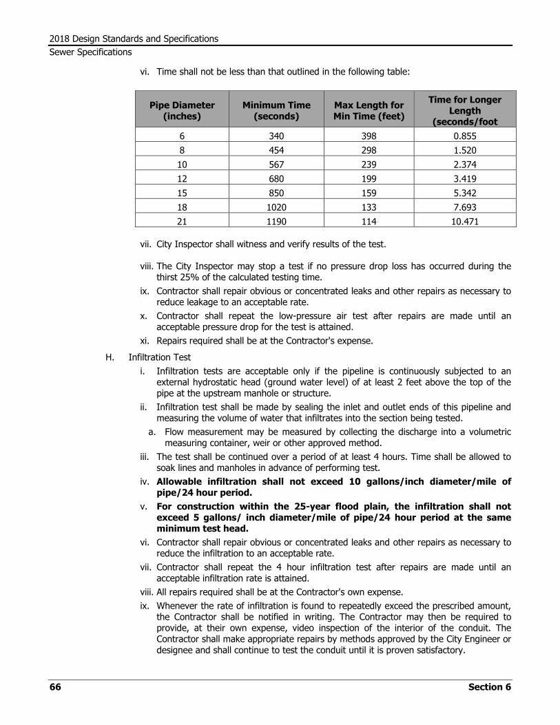
2018 Design Standards and Specifications
Sewer Specifications
66 Section 6
vi. Time shall not be less than that outlined in the following table:
Pipe Diameter (inches)
Minimum Time (seconds)
Max Length for Min Time (feet)
Time for Longer Length
(seconds/foot
6 340 398 0.855
8 454 298 1.520
10 567 239 2.374
12 680 199 3.419
15 850 159 5.342
18 1020 133 7.693
21 1190 114 10.471
vii. City Inspector shall witness and verify results of the test.
viii. The City Inspector may stop a test if no pressure drop loss has occurred during the thirst 25% of the calculated testing time.
ix. Contractor shall repair obvious or concentrated leaks and other repairs as necessary to reduce leakage to an acceptable rate.
x. Contractor shall repeat the low-pressure air test after repairs are made until an acceptable pressure drop for the test is attained.
xi. Repairs required shall be at the Contractor's expense.
H. Infiltration Test
i. Infiltration tests are acceptable only if the pipeline is continuously subjected to an external hydrostatic head (ground water level) of at least 2 feet above the top of the pipe at the upstream manhole or structure.
ii. Infiltration test shall be made by sealing the inlet and outlet ends of this pipeline and measuring the volume of water that infiltrates into the section being tested.
a. Flow measurement may be measured by collecting the discharge into a volumetric measuring container, weir or other approved method.
iii. The test shall be continued over a period of at least 4 hours. Time shall be allowed to soak lines and manholes in advance of performing test.
iv. Allowable infiltration shall not exceed 10 gallons/inch diameter/mile of pipe/24 hour period.
v. For construction within the 25-year flood plain, the infiltration shall not exceed 5 gallons/ inch diameter/mile of pipe/24 hour period at the same minimum test head.
vi. Contractor shall repair obvious or concentrated leaks and other repairs as necessary to reduce the infiltration to an acceptable rate.
vii. Contractor shall repeat the 4 hour infiltration test after repairs are made until an acceptable infiltration rate is attained.
viii. All repairs required shall be at the Contractor's own expense.
ix. Whenever the rate of infiltration is found to repeatedly exceed the prescribed amount, the Contractor shall be notified in writing. The Contractor may then be required to provide, at their own expense, video inspection of the interior of the conduit. The Contractor shall make appropriate repairs by methods approved by the City Engineer or designee and shall continue to test the conduit until it is proven satisfactory.

2018 Design Standards and Specifications
Sewer Specifications
Section 6 67
6.08.07 Video Inspection
A. Where determined to be necessary, the new sewer pipe shall be inspected by video camera prior to final acceptance.
i. Initial video inspection shall be at the Contractor’s own expense.
B. Video equipment expressly designed for pipeline inspection purposes and operated by experienced and qualified personnel shall be pulled through the entire pipeline.
i. Video equipment operator shall maintain a log of all inspections and note location, type and extent of any deficiencies.
ii. Video equipment operator shall also photograph all deficiencies and not less than one "typical" location per each 500 feet of pipeline inspected.
C. Contractor shall bear all costs incurred in correcting deficiencies found during the video inspection, including cost of additional video inspection required to verify correction of noted deficiencies.
D. Video inspection conducted solely for the Contractor's benefit shall be at the Contractor's own expense.
6.08.08 Deflection Test
A. Deflection tests shall be conducted in the presence of the City Inspector after the pipe has been installed and backfilled.
i. The deflection test shall be conducted by pulling a mandrel (go no-go device) through the pipe.
ii. The mandrel shall be designed and sized for each size and type of pipe and shall be at least 1.5 pipe diameters in length.
iii. The mandrel shall be constructed with an odd number of runners placed parallel to the pipe centerline and equally spaced around the perimeter of the mandrel.
iv. Test mandrel shall be furnished by the Contractor and approved by the City Inspector.
v. Test equipment, calibration data and procedures shall be subject to the approval of the City Inspector.
vi. Deflection test cannot be performed until 30 days after final backfill per Title 30 Texas Administrative Code Chapter 217.57(b)(4).
B. Ring or diametric deflection of the installed pipe shall not exceed 5% of the design internal diameter of the pipe. Pipe sections that restrict free passage of the mandrel shall be removed and replaced or excavated, re-bedded, backfilled and retested.
C. All repairs, replacement, remedial work and retesting shall be performed by the Contractor at their own expense.
D. Deflection test may be conducted concurrently with the video inspection of the pipe interior, subject to approval by the City Inspector.
6.08.09 Manhole Testing
A. Manholes shall be tested for leakage separately and independently of the sanitary sewer lines by vacuum testing, hydrostatic exfiltration testing or other methods approved by the City Inspector. An infiltration test may also be required if the manhole is continuously subjected to an exterior hydrostatic head.
B. Contractor shall notify the City Inspector a minimum of 24 hours in advance of any testing.
C. Testing shall be conducted by the Contractor at their own expense.
2018 Design Standards and Specifications
Sewer Specifications
68 Section 6
D. Testing shall be accomplished in the presence of the City Inspector or his authorized representative.
E. Testing shall not commence on any portion of the pipeline until all field placed concrete in contact with the pipe, fittings or appurtenances is adequately cured.
F. Vacuum Test
i. All inlet and outlet pipes in the manhole shall be plugged with an airtight device.
ii. All lift holes and exterior joints shall be plugged with a non-shrink grout.
a. No grout shall be placed in horizontal joints prior to testing.
iii. The manhole opening shall be sealed by a method approved by the City Inspector.
iv. Vacuum test shall be in accordance with ASTM 1244-11.
v. The Contractor shall have the option to repeat the vacuum test one time after repairs
vi. If a vacuum test is failed twice, the manhole shall be repaired and an exfiltration test shall be performed.
vii. All repairs required shall be at the Contractor's own expense.
G. Exfiltration Test
i. All inlet and outlet pipes in the manhole shall be plugged with a watertight device.
ii. The manhole being tested may be filled with water for a period long enough to allow water absorption into the manhole. The saturation period shall be a minimum of 4 hours and not more than 72 hours.
iii. Test shall be conducted with the manhole filled with water to the top of the cone section.
iv. Allowable leakage shall not exceed 0.025 gallon/foot diameter/foot of manhole depth/hour over a 4 hour period.
v. The Contractor shall repeat the exfiltration test after repairs until an acceptable leakage rate is attained.
vi. All repairs required shall be at the Contractor's own expense.
H. Infiltration Test
i. Infiltration tests are acceptable only if the connecting conduit is continuously subjected to an external hydrostatic head (ground water level) at least 2 feet above the top of the conduit. Ground water level shall be determined by the Contractor, subject to approval by the City Inspector.
ii. All inlet and outlet pipes in the manhole shall be plugged with a watertight device. The volume of water that infiltrates into the manhole during a 4 hour period shall be measured in a manner determined by the City Inspector.
iii. The test shall be conducted after the manhole has been subjected to the maximum ground water level for at least 4 hours to thoroughly saturate the manhole wall.
iv. The allowable infiltration shall not exceed 0.025 gallon/foot of diameter/foot of manhole depth/hour during a 4 hour test.
v. The Contractor shall repeat the 4 hour infiltration test after repairs until an acceptable leakage rate is attained.
vi. All repairs required shall be at the Contractor's own expense.
6.08.10 Approval
A. Final approval of sewer lines and manholes shall be based on an inspection covering all items in this specification and other approved plans and material. The inspection shall be done in an appropriate manner by representatives of the City Engineer or designee.

2018 Design Standards and Specifications
Sewer Specifications
Section 6 69
B. Contractor shall remedy any defects in workmanship or materials revealed by inspection at their own expense.
C. Final approval will be based on re-inspection of the sewer after the appropriate repairs and corrections are completed.
6.08.11 Acceptance
A. Flow of any kind into the existing sanitary sewer collection system shall not be allowed until the new sewer lines and manholes has been satisfactorily completed and accepted for use by the City Engineer or designee.
B. Portions of the work completed may be placed in operation after all cleaning, testing and inspection requirements have been fulfilled. Such partial use or partial acceptance shall be subject to approval of the City Engineer or designee.
6.09 Lift Station
6.09.01 Lift station design must conform to the most recent TCEQ design criteria.
6.09.02 Site Layout
A. Lift station site location shall be approved by the City Engineer or designee.
B. Site shall be chosen to provide the least negative impact to surrounding existing and future development.
C. The station site shall be located so it may serve as much of the entire sewer drainage basin as possible. This may require that the station be located off-site of the development.
D. The station site shall be protected from the 100-year flood plain and shall be accessible during the 25-year storm event.
E. Lift station site and associated access road shall be located in a dedicated right-of-way or permanent easement.
i. Access road shall be a minimum 12-foot wide all-weather surface.
ii. Additional staging and parking area shall be provided.
iii. Station grounds shall be minimum 5-inch thick, aggregate road base material.
F. Lift station site shall be fully enclosed by intruder-resistant fence and include a 14-foot vehicle gate and 3-foot man gate. Vehicle gate shall be situated such that pumps and equipment are accessible by service vehicles.
G. Lift station shall have bypass capability.
H. Lift station shall have lightning protection for all electronic components.
I. Lift station site shall be illuminated by a security light system.
J. Lift station shall be fitted with SCADA antennae.
6.09.03 Dry Well
A. Dry well shall have separate, dedicated entrance with ladder.
B. The dry well or valve vault shall have an approved, lockable, 26-inch x 36-inch pedestrian-rated aluminum hatch.
C. Provisions shall be made for water removal from the dry well.
D. Dry well shall be adequately vented with a minimum of two 4-inch vent pipes with one having an active ventilation blower.

2018 Design Standards and Specifications
Sewer Specifications
70 Section 6
6.09.04 Wet Well
A. Wet wells must be enclosed by water-tight and gas-tight walls.
B. Interior walls of wet wells shall be lined with a lining system per the Approved Materials List.
C. Wet well shall have a maintenance hatch for servicing pumps and a separate, dedicated entrance.
i. Dedicated entrance shall have an approved, lockable, 26-inch x 36-inch pedestrian-rated aluminum safety hatch.
ii. Maintenance hatch shall be an approved, double-door, lockable, 48-inch x 72-inch pedestrian-rated aluminum hatch or as required to adequately maintain the wet well pumps and components.
D. A gravity sewer pipe discharging to a wet well must be located so that the invert elevation is above the level of the system’s “on” setting.
E. All piping within wet well shall be PVC with flanged fittings.
F. All interior components shall be stainless steel including nuts, bolts, other fasteners and all base plates.
G. Each pump shall be fitted with minimum 25 feet of stainless steel lifting chain.
H. Each pump shall be fitted with dual-rail stainless steel guide bar and upper guide bar brackets.
I. Wet well shall have a sloped bottom toward the pump intake to avoid solids deposition.
J. Wet well shall be adequately vented with a minimum of two 4-inch vent pipes with one having an active ventilation blower.
K. Piping associated with lift stations shall be approved gravity or pressure rated sewer pipe.
6.10 Restoration and Clean Up
6.10.01 The Contractor shall restore or replace all removed or damaged paving, curbing, sidewalks, gutters, sod, shrubbery, fences, irrigation systems, pipe, or other structures or surfaces to a condition equal to that before the work began and to the satisfaction of the City Engineer or designee.
6.10.02 All streets, alleys, driveways, sidewalks, curbs or other surfaces broken, cut or damaged by the Contractor shall be reconstructed as required by the current City of Lubbock Street Ordinance.
6.10.03 Irrigation systems affected by construction shall be properly repaired by a licensed irrigator, with materials equal to the existing system and in compliance with current applicable codes.
6.10.04 All rubbish, excess excavated materials, unused materials and other non-native materials shall be removed from the jobsite and legally disposed.
6.10.05 The right-of-way shall be left in a state of order and cleanliness as determined by the City Engineer or designee.

2018 Design Standards and Specifications
Sewer Specifications
Section 6 71
6.11 Warranty and Acceptance
6.11.01 Within 30 calendar days after the Developer or Developers Engineer has given written notice that the improvements have been substantially completed, the City shall inspect the completed improvements and provide a punch list if necessary.
A. If it is mutually determined that the improvements have been constructed in accordance with the engineering plans and the City of Lubbock Engineering Minimum Design Standards and Specifications, the Developers Engineer shall submit Record Drawings, Certificate of Completion and Developers Warranty Statement (Copies of the Certificate of Completion and the Developers Warranty Statement are included in the City of Lubbock Engineering Minimum Design Standards and Specifications)
B. Upon receipt of the Developers Certificate of Completion, Record Drawings and the Developers Warranty Statement, the City will accept improvements within 30 calendar days; unless exception is given in writing.
C. Neither the Final Payment nor the Certificate of Completion shall relieve the Developer or Contractor of responsibility related to warranty of materials or workmanship.
D. The Developer shall remedy any defects due to faulty materials or workmanship that appear within 1 year from the date of acceptance by the City of Lubbock.

2018 Design Standards and Specifications
Sewer Specifications
72 Section 6

2018 Design Standards and Specifications
Approved Materials List
Section 7 73
SECTION 7
APPROVED MATERIALS AND MANUFACTURERS LIST
7.01 Introduction
7.01.01 This section lists specific products and manufacturers that have been approved for use within the City of Lubbock water and sanitary sewer system.
7.01.02 This listing is intended to be used as a reference source for Water Utilities employees, design engineers, developers, contractors and vendors.
7.01.03 Materials produced by manufacturers not listed herein are not acceptable for use within the City's system.
7.01.04 Manufacturers interested in submitting products for evaluation and possible approval should submit a written request in accordance with the procedures listed below.
7.02 Product Submittal Procedures
7.02.01 Written requests should be sent to the attention of “City Engineer, City of Lubbock, PO Box 2000, Lubbock, Texas 79401”.
7.02.02 Written requests shall include the following:
A. A complete Application for New Product(s) (See Appendix A-1)
B. Four (4) copies of the following documents:
i. A list of all applicable standards regarding the product and certification (AWWA, ANSI, ASTM, etc.)
ii. Adequate shop drawings and design information (brochures and other product information)
iii. Location of the manufacturer's plant
iv. Location of the nearest local distribution point and retail outlet
v. A list of any special tools, fittings or methods of construction required for installation and/or maintenance
vi. Spare parts and service availability information
vii. A 5-year history of the product documenting its performance
viii. Warranties
ix. Product sample (where appropriate)
x. User references, with contact person and telephone numbers (Specifically in the State of Texas)
xi. Life cycle costs (where appropriate)
xii. A statement of why the approval of the product would be beneficial to City of Lubbock
C. Applicant shall send a formal review meeting request to the City Engineer or designee.
D. All submissions shall be made at least 30 days prior to the meeting at which review is requested.
2018 Design Standards and Specifications
Approved Materials List
74 Section 7
7.03 Evaluation Process
7.03.01 Product evaluation will be conducted by the City Engineer or designee or their designee.
A. Review shall include:
i. Conformance with the City of Lubbock Minimum Design Standards and Specifications.
ii. Comments made by contractors, engineers, developers, suppliers, etc.
iii. Any other matters regarding the design, construction and implementation of the proposed product into the City of Lubbock water and sanitary sewer system.
B. Applicant may be requested to make a brief presentation regarding the product. Representatives shall be knowledgeable on product use, locations, design and reference checks. The representative shall also have the authority to approve a trial run in City of Lubbock.
7.04 Approval Process
7.04.01 The decision of the City Engineer or designee is final.
7.04.02 For each product that has been submitted, one of the following recommendations will be made:
A. Approval for Use
i. This approves a product for use throughout the City’s service area.
ii. The City Engineer or designee may withdraw the Approval for Use status for violation of the City of Lubbock Minimum Design Standards and Specifications.
iii. All use of the product will be in conformance with the manufacturer's specifications and good engineering practices.
B. Conditional Approval for Use
i. This approves a product for use throughout the City's service area; however, the product will be reviewed periodically to ensure that no unforeseen installation or maintenance problems have risen and that quality assurance/quality control meet City Standards.
ii. After a suitable period of field observation, this approval may be upgraded to Approval for Use status. The frequency of review and the length of field observation period will be determined by the City Engineer or designee.
iii. If, during the field observation period, problems with installation, operation or maintenance of the product are observed, the City Engineer or designee may downgrade the status of the product to Disapproved for Use.
iv. The City Engineer or designee may withdraw the Conditional Approval for Use status for violation of the City of Lubbock Minimum Design Standards and Specifications.
v. All use of the product will be in conformance with the manufacturer's specifications and good engineering practices.
C. Limited Approval for Use
i. This approves a product for use only in certain sites or projects within the City's service area. The City Engineer or designee will determine where the product can be used.
ii. The product will be reviewed periodically to ensure that no unforeseen installation, operation or maintenance problems have arisen.
iii. After a suitable period of field observation, this approval may be upgraded to Conditional Approval for Use or Approval for Use status. The frequency of review and

2018 Design Standards and Specifications
Approved Materials List
Section 7 75
the length of the field observation period will be determined by the City Engineer or designee.
iv. If, during the field observation period, problems with the installation, operation or maintenance of the product are observed, the City Engineer or designee may downgrade the status of the product to Disapproved for Use.
v. The City Engineer or designee may withdraw the Limited Approval for Use status for violation of the City of Lubbock Minimum Design Standards and Specifications.
vi. All use of the product will be in conformance with manufacturer's specifications and good engineering practices.
D. Disapproved for Use
i. The product may not be used anywhere within the City's service area.
ii. If a product has been given a Disapproved for Use status by the City Engineer or designee, the product may not be resubmitted for review unless significant changes have been made to the product.
iii. The City Engineer or designee will not reconsider a product Disapproved for Use until at least twelve (12) months have passed from the date of disapproval.
E. Insufficient Information
i. Not enough information was provided to evaluate the product.
ii. Upon receipt of requested additional information, the City Engineer or designee will reevaluate the product.
iii. If, upon reevaluation, it is determined that not enough information was provided a Disapproved for Use status will be given.
7.04.03 Design Changes of Approved Products
A. After the approval of a product, the manufacturer or their representative shall inform the City Engineer or designee, in writing, of any modifications in design or material. Such changes may require further evaluation and approval.
7.04.04 Withdrawal of Approval
A. The City Engineer or designee may withdraw any approval as a result of a design change, field observation, testing, product failure, or other factors that, in the opinion City Engineer or designee, warrant such withdrawal.

2018 Design Standards and Specifications
Approved Materials List
76 Section 7
7.05 Water System
7.05.01 Water Pipe
A. Polyvinyl Chloride (PVC) 4-inch to 24-inch
i. AWWA C900 or C905; Minimum DR-18
ii. Manufacturers:
a. CertainTeed
(1) Certa-Lok
b. Diamond Plastics
c. JM Eagle
(1) Blue Brute
(2) Big Blue
(3) Eagle Loc 900
d. North American Pipe
e. Northern Pipe Products
f. Pipelife Jetstream
g. VinylPlex, Inc.
h. Royal Building Products
B. High Density Polyethylene (HDPE)
i. AWWA C906, PE 4710, Minimum DR11, Pressure Class 200
ii. Manufacturers
a. Chevron
b. JM Eagle
c. Plexco
C. Cement-lined Ductile Iron (DIP) - Push-On or Mechanical Joint
i. AWWA C151 Minimum Thickness Class 50
ii. Manufacturers
a. American Cast Iron Pipe
b. Griffin Pipe Products
c. McWane Pipe
d. U.S. Pipe and Foundry
D. Concrete Cylinder Pipe
i. AWWA C301, Pre-stressed Concrete Steel Cylinder Pressure Pipe
ii. AWWA C303, Concrete Bar-wrapped Steel Cylinder Pressure Pipe
iii. Manufacturers:
a. Forterra
7.05.02 Fittings: (Bends, Crosses, Tees and Offset Glands)
A. Ductile Iron; Compact
B. AWWA C110 and C-153
C. Manufacturers:
i. American Cast Iron Pipe
ii. Griffin Pipe Products

2018 Design Standards and Specifications
Approved Materials List
Section 7 77
iii. McWane Pipe
iv. Sigma Corporation
v. Star Pipe Products, Inc.
vi. Tyler Pipe and Foundry Utilities
vii. U.S. Pipe and Foundry
7.05.03 Couplings (Transition or Straight), Non-Restrained
A. Low-alloy or stainless steel bolts and nuts; outside finish: heat fused nylon coating or fusion bonded epoxy coating; standard length body.
B. Manufacturers
i. Dresser
ii. Ford
iii. JCM Industries
iv. Romac
v. Smith-Blair
7.05.04 Resilient Wedge Gate Valves, 4-inch through 12-inch
A. Ductile Iron Body; Outside finish: heat fused nylon coating or fusion bonded epoxy coating.
B. AWWA C509 and C515
C. Manufacturers
i. American AVK
ii. Clow
iii. Darling
iv. EJIW
v. Mueller
vi. M & H Model 4067
7.05.05 Butterfly Valves – 16-inch and Greater, with gearing if required by manufacturer
A. Ductile Iron Body; Outside finish: heat fused nylon coating or fusion bonded epoxy coating.
B. AWWA C504
C. Manufacturers
i. DeZurik
ii. Mueller
iii. M & H
7.05.06 Fire Hydrants
A. AWWA C502
B. 5-1/4-inch valve opening; 2-1/2-inch hose nozzles; 4-inch steamer nozzle
C. Factory painted orange
D. Manufacturers
i. American Darling Model B-84-B
ii. East Jordan Iron Works
2018 Design Standards and Specifications
Approved Materials List
78 Section 7
iii. Clow Medallion
iv. Mueller Centurion
v. M & H Style 129-09
7.05.07 Fire Hydrant Raised Pavement Marker
A. Manufacturer
i. Stimsonite Model 80
7.05.08 Service Saddles
A. Epoxy coated ductile iron body; Double band with SS bands and bolts
B. AWWA C800
C. 1-inch
i. Female AWWA Taper threads (CC or CS)
ii. Manufacturers
a. Ford
b. JCM Industries
c. Mueller
d. Romac Industries, Inc.
e. Smith-Blair
f. PowerSeal Pipeline Products
D. 2-inch
i. Female iron pipe threads
ii. Manufacturers
a. Ford
b. JCM Industries
c. Mueller
d. Romac Industries, Inc.
e. Smith-Blair
f. PowerSeal Pipeline Products
7.05.09 Corporation Stops
A. Full Port Ball Valve
B. AWWA C800
C. 1-inch
i. Male AWWA Taper threads (CC or CS) by flared copper or compression
ii. Manufacturers
a. A. Y. McDonald
b. Ford
c. Mueller
D. 2-inch
i. Male iron pipe threads by flared copper or compression
ii. Manufacturers
a. A. Y. McDonald

2018 Design Standards and Specifications
Approved Materials List
Section 7 79
b. Ford
c. Mueller
7.05.10 Service Tubing
A. Copper Tubing
i. ASTM B88
ii. Flared copper fittings
iii. 1-inch
a. Type K - Soft
iv. 2-inch
a. Type K - Hard
B. Polyethylene Tubing (PET and PEXa);
i. ASTM D2737 - Copper Tube Size (CTS), 200 PSI Minimum, Black or Blue
ii. Slip Fittings
a. Ford - Ultratite
b. Mueller - Instatite
iii. Manufacturers
a. Endot – Endopure PE 4710 – 1-inch only
b. NuMex PE 4710 – 1-inch only
c. Rehau – Municipex PEXa – 1-inch, 1.5-inch or 2-inch
d. Silverline – Sil-O-Flex PE 3408 or 4710 – 1-inch only
e. Ultraline – Driscoplex 5100 Series PE 4710 – 1-inch only
7.05.11 Curb Stops
A. Full Port Ball Valve
B. 360 degree rotation
C. AWWA C800
D. Curb stops shall include meter swivel nut (meter spud) connection on outlet side such that meter nut can be replaced without removing valve from operation.
E. Reductions for smaller meter sizes shall be accomplished by use of appropriately sized iron pipe threaded brass bushing on outlet side of curb stop.
F. 1-inch and 2-inch
i. Flared copper or compression by female iron pipe threads with meter swivel nut.
ii. Manufacturers
a. A. Y. McDonald
b. Ford
c. Mueller
7.05.12 Compression Fittings
A. Compression fittings shall be quick joint type.
B. Manufacturers
i. Mueller Insta-Tite Connection
ii. Ford Ultra-Tite Connection

2018 Design Standards and Specifications
Approved Materials List
80 Section 7
7.05.13 Tapping Sleeves
A. Stainless Steel Sleeves with Stainless Steel or Carbon Steel Flange
B. Epoxy coated with stainless steel bolts and nuts
C. Manufacturers
i. Ford FAST
ii. JCM Industries #469
iii. Smith Blair #662
iv. ROMAC #SST
v. PowerSeal Pipeline Products
7.05.14 Resilient Seat Wedge Tapping Valves
A. AWWA C509
B. Manufacturers:
i. American
ii. Clow
iii. EJIW
iv. Mueller
v. M & H
vi. U. S. Pipe
7.05.15 Water Meter Boxes and Vaults
A. Manufacturers
i. Boxes for 1” meters
a. DFW Plastics model DFW38FWP-18-AF1QF1 SMALL LID
ii. Boxes for 1.5” or 2” meters
a. DFW Plastics model DFW1324C-AF1QF SMALL LID
7.05.16 Double Check, Double Detector Check and Reduced Pressure Principle Devices
A. American Society of Sanitary Engineering Seal Approval
B. Call City of Lubbock backflow coordinator at (806) 775-2589 for specific applications.
C. Manufacturers
i. Ames
ii. Febco
iii. Watts
iv. Wilkins
7.05.17 Backflow Preventer Box
A. Polyester or Aluminum Enclosure, Heated and Insulated ASSE 1060
B. Manufacturers
i. EZ Box Model HEZ
ii. Hot Box
iii. Safe-T-Cover

2018 Design Standards and Specifications
Approved Materials List
Section 7 81
7.05.18 Air Release Valves
A. Manufacturers
i. APCO
ii. ARI
iii. Crespin
7.05.19 Flushing Hydrants
A. Manufacturers
i. Kupferle
7.05.20 Sampling Stations
A. Manufacturers
i. Kupferle
7.05.21 Valve boxes
A. Cast-Iron slip type
B. Manufacturers
i. EJIW
ii. Sigma
iii. Star Pipe
7.05.22 Pipe Restraints
A. ASTM F1674
B. Manufacturers
i. EBAA Iron, Inc.
ii. Ford
iii. Romac
iv. Sigma
v. Smith-Blair
vi. Star Pipe Products, Inc.
vii. Tyler Union
viii. AccuCast
7.05.23 Casing Spacers
A. Manufacturers
i. Advance Products
ii. BMW
iii. Cascade
iv. CCI Pipeline
v. Culpico
vi. PSI
7.05.24 Precast Concrete Vaults, HS-20 Rated
A. Manufacturers
i. Hanson Pipe and Products

2018 Design Standards and Specifications
Approved Materials List
82 Section 7
ii. Vaughn Concrete Products
7.05.25 Waterline Marker
i. Manufacturers
a. Blackburn
b. Carsonite International

2018 Design Standards and Specifications
Approved Materials List
Section 7 83
7.06 Sanitary Sewer System
7.06.01 Gravity Sewer Pipe
A. Polyvinyl Chloride (PVC) Pipe
i. 6-inch thru 15-inch: ASTM D3034, Minimum Class SDR 35
ii. 18-inch thru 48-inch: ASTM F679, Minimum Class PS-46
iii. Fittings ASTM D1784
iv. Gaskets ASTM F477
v. Manufacturers
a. Certainteed Corporation
b. Diamond Plastics
c. GPK (Fittings Only)
d. Harco (Fittings Only)
e. JM Eagle
f. Multi Fittings (Fittings Only)
g. National Pipe and Plastics Ever-Green Sewer Pipe
h. North American Pipe ASTM D3034
i. Plastic Trend (Fittings Only)
j. VINYL Plex (Fittings Only)
k. Royal Building Products
B. PVC Corrugated Sewer Pipe with Smooth Interior
i. ASTM F949, ASTM F794
ii. Manufacturer
a. Diamond Plastics
C. High Density Polyethylene (HDPE)
i. ASTM F714
ii. Manufacturers
a. Chevron
b. JM Eagle
c. Plexco
D. Ductile Iron (DIP)
i. AWWA C151 Minimum Thickness Class 50 with Sewer Gas Resistant Interior Lining
ii. Manufacturers
a. American Ductile Iron Pipe
b. Griffin Pipe Corporation
c. McWane
d. U.S. Pipe and Foundry Company
E. Steel Reinforced Polymer Concrete
i. ASTM D6783
ii. Manufacturers
a. U. S. Composite Pipe
F. Polypropylene Corrugated Dual Wall and Triple Wall
i. 12-inch thru 30-inch: ASTM F2736

2018 Design Standards and Specifications
Approved Materials List
84 Section 7
ii. 30-inch thru 60-inch: ASTM F2764
iii. Manufacturer
a. ADS Sanitite HP
7.06.02 Pressure Sewer Pipe
A. Polyvinyl Chloride (PVC)
i. AWWA C900 Minimum Class DR25
a. Manufacturers
(1) Diamond Plastics
(2) JM Eagle
(3) North American Pipe
ii. SDR26 Class 160
a. Manufacturers
(1) Diamond Plastics
(2) JM Eagle
(3) North American Pipe
B. Ductile Iron (DIP)
i. Minimum Thickness Class 50 with Sewer Gas Resistant Interior Lining
ii. Manufacturers
a. American Ductile Iron Pipe
b. Griffin Pipe Corporation
c. U. S. Pipe and Foundry Company
C. High Density Polyethylene (HDPE)
i. AWWA: C906, Minimum Pressure Class 160
ii. Manufacturers
a. Chevron
b. JM Eagle
c. Plexco
7.06.03 Manholes
A. Precast Concrete Manholes
i. ASTM C478
ii. Manufacturers
a. Hanson Building Products
b. South Plains Concrete Products
c. The Turner Company
d. Vaughn Concrete Products
B. Glass-Fiber-Reinforced Polyester Manholes, Wetwells and Manhole Liners
i. ASTM D3753
ii. Manufacturer
a. LF Manufacturing
b. Containment Solutions
C. Composite Manholes
i. Amarok

2018 Design Standards and Specifications
Approved Materials List
Section 7 85
ii. US Composite Pipe
7.06.04 Manhole Frames and Covers
A. ASTM A48, Class 35B, AASHTO M-306
B. Standard Solid Cover
i. Manufacturers
a. East Jordan Iron Works
C. Watertight Frame and Cover
i. Manufacturers
a. East Jordan Iron Works
b. Rexus
7.06.05 Manhole Coatings/Protective Lining System
A. Manufacturers
i. A-Lok - Dura Plate 100 PVC Liner
ii. Raven 405
iii. Tnemec – Series 436 PermaShield
7.06.06 Gaskets and Flexible Manhole Connections
A. Flexible cast-in-place seal or flexible boots installed with hydraulic pressure after manhole manufacture. Manhole openings shall be made by hole-formers inserted during manufacture.
B. Manufacturers
i. Press-Seal Gasket Corp.
ii. A-Lok
iii. International Precast Supply
iv. NPC
7.06.07 Internal Chimney Seals
A. ASTM C923
B. Manufacturers
i. Cretex
ii. NPC
7.06.08 Manhole Joint Seals
A. Sealant per ASTM C990
B. O-ring gaskets meeting ASTM C443 and ASTM C1628.
7.06.09 Manhole Joint Wrap (in addition to O-ring specified above)
A. Manufacturers
i. Ram Nek
ii. ConSeal CS 102
7.06.10 Manhole Joint Sealers
A. Butyl Mastic

2018 Design Standards and Specifications
Approved Materials List
86 Section 7
B. Manufacturers
i. Ram Nek
7.06.11 ConSeal CS 102Inflow Prevention Device
A. Non-Corrodible with self cleaning gas relief and vacuum relief valves
B. Manufacturers
i. L.F. Manufacturing Inc. - Rain Guard
ii. No Flow-In Flow
iii. The Man Pan
iv. Southwestern Packing and Seals, Inc. - Rainstopper
7.06.12 Polyethylene Slope Adjusting Ring
A. ASTM D1248
B. Manufacturers
i. Ladtech
7.06.13 Saddles
A. Manufacturer
i. NDS
7.06.14 Cleanout Cover
A. Manufacturer
i. East Jordan Iron Works
7.06.15 Valves – Must Be Approved for Use in Wastewater Application
A. Plug, Full Port
i. Manufacturers
a. DeZurik
B. Resilient Seat Gate
i. AWWA C509
ii. Manufacturers
a. American Flow Control
b. Clow
c. M & H
d. Mueller
e. U.S. Pipe
C. Swing Check
i. Manufacturer
a. Golden Anderson
b. M & H
c. Val-Matic
7.06.16 Backwater Valve for Manhole Vent
A. Manufacturer

2018 Design Standards and Specifications
Approved Materials List
Section 7 87
i. Josam
7.06.17 Lateral Backwater Valve
A. Diaphram Operated Stainless Steel Knife Valve ASME Al 12.14.1
B. Manufacturer
i. John Stephens
ii. Plastic Trends
iii. Smith Floodgate
7.06.18 Sewage Combination Air/Vacuum Valve
A. Manufacturers
i. APCO/Willamette
ii. ARI
iii. Golden Anderson Industries
7.06.19 Sanitary Sewer Marker
A. Manufacturers
i. Blackburn
ii. Carsonite International
7.06.20 Wastewater Pumps
A. Manufacturer
i. Flygt N-Pump

2018 Design Standards and Specifications
Approved Materials List
88 Section 7
7.07 Water and Sanitary Sewer Systems
7.07.01 Modular Wall Seal
A. EPDM with stainless steel nuts and bolts
B. Manufacturer
i. Thunderline
ii. Pipe Seal
iii. Link Seal
7.07.02 Vault Doors
A. Type K heavy duty aluminum double leaf door, H-20 rated
B. Manufacturers
i. Bilco
ii. Halliday
iii. USF Fabrication, Inc.
7.07.03 Tracer Wire
A. 12-gauge
B. Manufacturers
i. Copperhead
ii. Southwire
7.07.04 Marking Tape
A. 3-inch width, Sewer – green, Water - blue
B. Manufacturers
i. Presco Prodcuts
ii. Terra Tape

2018 Design Standards and Specifications
Approved Materials List
Section 7 89
7.08 Street Construction
7.08.01 Detectable warning surface for handicap ramps
A. Manufacturers
i. StronGo Industries – Tek Way Dome Tiles
7.08.02 Fiber Reinforcement
A. Manufacturers
i. BASF macro fibers

2018 Design Standards and Specifications
Approved Materials List
90 Section 7

2018 Design Standards and Specifications
Streets and Drainage Specifications
Section 8 91
SECTION 8
STANDARD SPECIFICATIONS FOR STREETS AND DRAINAGE CONSTRUCTION
8.01 General
8.01.01 The construction and materials for any City of Lubbock Engineering paving or drainage improvements project shall conform to the following specifications and associated standard details.
A. Any construction or materials failing to meet the requirements of these specifications or the standard details shall be removed and replaced at the Contractor’s own expense.
B. No consideration will be given to requests for reduced payments for construction or materials not in conformance with these specifications and the plan sheets.
8.01.02 The term Engineer used in these specifications shall refer to the City of Lubbock City Engineer or an individual designated by the City Engineer to administer these specifications and associated plans.
8.01.03 The Engineer may require certificates from manufacturers certifying that materials or equipment to be incorporated into the work meet these specifications.
A. Material Safety Data Sheets (MSDS) shall be required on all materials.
B. All materials or equipment shall be subject to approval by the Engineer before being incorporated into any project.
C. After approval, the source and/or character of materials shall not be changed without written authorization by the Engineer.
8.01.04 Streets to be constructed in a location where the traffic is expected to consist of an unusual number of trucks or other heavy vehicles shall have an approved pavement structure design specific to that loading condition.
8.01.05 All construction covered by these specifications shall be in compliance with the City of Lubbock Code of Ordinances, Chapter 30 Lakes and Water Ways, Chapter 36 Streets, Sidewalks, and Other Public Ways, Chapter 38 Subdivisions, and other chapters as applicable.
8.01.06 Any references to these specifications, ASTM, AASHTO, TxDOT, or other designated tests, procedures, quality standards, or requirements which are included in these specifications or any associated plans shall be the latest edition and revision thereof.
A. When information indicated on the plan sheets is in conflict with these specifications, the more stringent requirement shall govern, unless the City Engineer or designee gives written approval for a specific variance.
8.01.07 Storm Water Pollution Prevention Plan (SWP3)
A. Prior to disturbance of construction area, Contractor shall coordinate with the City of Lubbock Engineering Department to develop a site-specific Storm Water Pollution Prevention Plan.
B. SWP3 measures shall conform to the integrated Stormwater Management (iSWM) criteria developed by the North Central Texas Council of Governments.
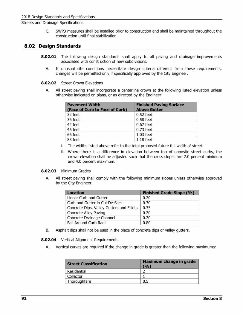
2018 Design Standards and Specifications
Streets and Drainage Specifications
92 Section 8
C. SWP3 measures shall be installed prior to construction and shall be maintained throughout the construction until final stabilization.
8.02 Design Standards
8.02.01 The following design standards shall apply to all paving and drainage improvements associated with construction of new subdivisions.
A. If unusual site conditions necessitate design criteria different from these requirements, changes will be permitted only if specifically approved by the City Engineer.
8.02.02 Street Crown Elevations
A. All street paving shall incorporate a centerline crown at the following listed elevation unless otherwise indicated on plans, or as directed by the Engineer:
Pavement Width (Face of Curb to Face of Curb)
Finished Paving Surface Above Gutter
32 feet 0.52 feet
36 feet 0.58 feet
42 feet 0.67 feet
46 feet 0.73 feet
66 feet 1.03 feet
88 feet 1.18 feet
i. The widths listed above refer to the total proposed future full width of street.
ii. Where there is a difference in elevation between top of opposite street curbs, the crown elevation shall be adjusted such that the cross slopes are 2.0 percent minimum and 4.0 percent maximum.
8.02.03 Minimum Grades
A. All street paving shall comply with the following minimum slopes unless otherwise approved by the City Engineer:
Location Finished Grade Slope (%)
Linear Curb and Gutter 0.20
Curb and Gutter in Cul-De-Sacs 0.30
Concrete Dips, Valley Gutters and Fillets 0.35
Concrete Alley Paving 0.20
Concrete Drainage Channel 0.20
Fall Around Curb Radii 0.80
B. Asphalt dips shall not be used in the place of concrete dips or valley gutters.
8.02.04 Vertical Alignment Requirements
A. Vertical curves are required if the change in grade is greater than the following maximums:
Street Classification Maximum change in grade (%)
Residential 2
Collector 1
Thoroughfare 0.5

2018 Design Standards and Specifications
Streets and Drainage Specifications
Section 8 93
B. Vertical curves are to be a minimum of 100’ long and shall be designed for a speed of 5 MPH greater than the posted speed limit.
C. The minimum gutter slope in a sag vertical curve shall be 0.2%, while a crest vertical curve has no minimum.
8.03 Testing and Inspection
8.03.01 All work shall be inspected and tested by a representative designated by the City Engineer, who shall have the authority to halt construction when, in their opinion, construction is being performed contrary to these specifications or associated plans.
A. Whenever any portion of these specifications or associated plans is violated, the Engineer may order the portion of construction that is in violation to cease until such violation is corrected.
8.03.02 Contractor shall cooperate with the Engineer in providing for sampling and testing procedures.
A. The contractor shall provide at least a 2 hour notification to the City Inspection Staff prior to requesting any inspection services.
B. In the event the City tests indicate out of specification materials, additional tests may be provided by the contractor at their own expense.
C. Conflicting tests provided by the contractor will not automatically be considered as compliance with City specifications, but will be considered only as additional information to be used by the Engineer to determine the compliance of the material or construction in question.
8.03.03 The testing and inspection provided by the City is intended only to verify that materials and construction comply with plans and specifications. The City's testing and inspection efforts are not intended to replace the contractor's responsibility to comply with the specifications.
A. With respect to new material sources, or where the City lab has determined materials or construction do not comply with these specifications, the City will not re-test until the contractor has provided their own testing to demonstrate the materials and construction are in compliance with the plans and specifications.
8.03.04 Upon completion of construction, the Contractor will apply sufficient water to all paving improvements within the project to ensure all surfaces meet drainage requirements and are in compliance with these specifications.
8.04 Notification of Property Owners
8.04.01 The contractor shall be responsible for maintaining positive communication with adjacent property owners.
8.04.02 The contractor shall provide two days notice to all affected property owners with respect to pending construction, and restriction of access or driveway locations.
8.05 Protection of Utilities and Irrigation Systems
8.05.01 The plans show only approximate locations of utilities as obtained from various utility companies.
A. It is not implied that all utilities or their accurate locations are shown on the plans.
8.05.02 It is the contractor’s responsibility to become familiar with all utilities and locations.

2018 Design Standards and Specifications
Streets and Drainage Specifications
94 Section 8
A. The contractor shall comply with all laws, ordinances, and regulations with respect to utility notification and protection, including Underground Facility Damage Prevention Notification Centers.
B. The contractor shall call DIG TESS (1-800-344-8377) and provide sufficient time for all utilities to be identified prior to construction.
8.05.03 On all projects the contractor shall exercise care not to damage any sanitary sewer pipe, manholes, storm sewers, water lines, valves and boxes, communication cables, power cables, gas lines, nor any other pipe or utility. The contractor will be responsible during the construction period for damages to any utilities.
8.05.04 Irrigation systems affected by construction shall be properly repaired by a licensed irrigator, with materials equal to the existing system, and in compliance with current applicable codes. The repairs shall be pressure tested to the satisfaction of the Engineer prior to being covered.
8.05.05 If construction activities block the flow of water, then standing water shall be pumped off existing paving daily.
8.06 Water for Construction
8.06.01 Water is available from fire hydrants for construction purposes.
A. To use City water for construction the contractor shall acquire a water meter for use on a City fire hydrant and will be charged the applicable rate for the quantity of water used.
B. The contractor shall contact Lubbock Power and Light Customer Service Department to establish a utility account. The contractor must pay a deposit for each fire hydrant meter and will be responsible for all charges associated with that account.
C. Once an account is established and the deposit is paid, the contractor may pick up a meter from the City Water Department at 600 Municipal Drive.
8.06.02 Fire hydrants shall be operated only by use of an approved fire hydrant wrench. No pipe wrenches, or other unapproved devices, shall be used to open and close a fire hydrant.
8.06.03 For top loading trucks or containers the contractor shall provide a back flow prevention assembly on the discharge side of the meter.
A. The backflow prevention assembly shall be in the form of two spring loaded ball check valves.
B. When filling the truck or container there shall be an air gap of at least two times the opening diameter of the truck or container.
8.06.04 For bottom loading trucks the contractor shall provide a Reduced Pressure Zone (RPZ) type backflow prevention assembly.
A. All RPZ type back flow prevention assemblies must be tested and the test results approved by the City prior to use.
B. The test results shall be sent to the City of Lubbock Public Works Department, Meter and Customer Service Supervisor for approval.
8.06.05 In accordance with City of Lubbock Ordinance No. 10208 “Pertaining to Backflow Prevention”, City representatives are authorized to suspend water use from a fire hydrant by a contractor until the proper and correct backflow prevention devices are installed.

2018 Design Standards and Specifications
Streets and Drainage Specifications
Section 8 95
8.07 Concrete
8.07.01 These specifications shall govern Portland cement concrete used for curb and gutter, valley gutters and fillets, alley paving, sidewalks, street paving, curb ramps, medians, and drainage improvements.
A. The concrete shall be produced at a Ready-Mix Concrete Batch Plant conforming to ASTM C94.
B. The concrete shall be transported to the project location in approved Revolving Drum Agitator Trucks, and shall be placed within one hour of mixing time. The concrete shall be continuously mixed during transit.
C. Concrete shall have a temperature of less than 90 degrees at time of placement. Concrete above this temperature will be rejected and shall be removed from the job site.
D. No more than eight cubic yards of concrete shall be loaded in a Revolving Drum Agitator Truck and transported to the job site. Loads in excess of eight cubic yards will be rejected and shall be removed from the job site.
E. Admixture for increasing and or decreasing air shall be a temporary solution while the batch plant makes adjustments. A maximum of three loads may be treated per plant per day.
F. No patching of any nature shall be allowed in repairing any damage to concrete improvements. Where damage occurs, the section shall be removed to the nearest joints and shall be replaced with new construction. Small cracks with no evidence of displacement may be repaired with epoxy, only where approved by the Engineer.
G. All concrete shall have 5 percent, minus 1.5 percent to plus 1.5 percent, air content in conformance with ASTM C231.
H. When delivered to the jobsite, each truck shall provide the load ticket indicating weights of all concrete ingredients, including cement, aggregates, water, and admixtures.
I. Load tickets must be computer generated.
8.07.02 Classification
A. The following City of Lubbock classes of concrete shall be used:
Class Typical Uses
A Curb and gutter, sidewalks, curb ramps, drainage channels, medians, inlet boxes, headwalls, junction boxes, driveways, and retaining walls.
B Valley gutters and fillets, alley returns, and alley paving.
C Concrete street pavement.
D Utility encasements
E Fast setting concrete pavement such as “Fast Track” Concrete Pavement or, other special design.
8.07.03 Thickness of Concrete Pavement
A. The following City of Lubbock minimum concrete pavement thickness shall be used:
Street Classification Minimum Concrete Pavement Thickness
Residential and Collector (R-1/R-1A/R-2/C-1/Industrial) 6”
Minor Arterial 7”
Principal Arterial 9”

2018 Design Standards and Specifications
Streets and Drainage Specifications
96 Section 8
B. Concrete alley paving shall have a minimum thickness of 7-1/2 inches at edge and 5 inches at flow line.
i. No tolerance on minimum thickness will be allowed.
ii. No additional compensation will be made to the contractor for thickness greater than specified.
C. All other proposed concrete pavement thickness and steel requirements not meeting the COL minimum design standards and specifications shall be approved in writing by the City Engineer.
8.07.04 Drainage Easements
A. All drainage easements shall have, at a minimum, a 10-foot wide concrete flow line to be constructed with the street and alley paving improvements.
B. Drainage easements shall not be used as alleys or garbage collection.
8.07.05 Mix Design
A. Thirty (30) days prior to beginning any concrete construction the contractor shall submit an engineer’s recommended concrete mix design. The following shall be included in the submittal:
i. Test certificates from an approved commercial testing laboratory on all proposed aggregate.
(1) Certificates shall indicate material source, gradation, and loss from 5 cycle Magnesium Sulfate test not to exceed 25 percent.
ii. Mix design based on water-cement ratio.
iii. Results of compressive strength tests in conformance with ASTM C 39 and/or flexural strength tests in conformance with ASTM C78, made by an approved commercial testing laboratory.
(1) Tests shall be made on 6 cylinders and/or 6 beams at curing times appropriate to the class of concrete.
B. The Engineer will approve or reject the mix design and materials based on these submittals.
C. Mix design approval shall be subject to additional testing during construction.
D. Mix designs for various classes of concrete shall conform to the following:
Class Min. Sacks Cement
per cubic yard Water/Cement Ratio
Max. Slump (Inches)
A 5.0 0.40 – 0.60 5
B 5.5 0.40 – 0.60 5
C 6.0 0.35 – 0.45 3
D 4.5 0.40 – 0.60 5
E As required for specific cure time and strength.
i. New mix designs shall be submitted annually, or when material properties or sources change.
ii. New mix design submittal will be required for any deviation from the mix design during construction.

2018 Design Standards and Specifications
Streets and Drainage Specifications
Section 8 97
8.07.06 Strength Requirements
A. The various classes of concrete shall conform to the following minimum strengths in pounds per square inch (psi) as determined by the average of two test cylinders or beams:
Class Min. Compressive Strength
3 Day 7 Day 28 Day
A - 2100 3000
B - 2500 3600
C - 2500 3600
D - - 2500
E 3000 psi at 24 hours
B. ACI Testing will be followed.
C. When cores are subsequently used to prove compressive strength where test cylinders indicate failures or the quality of installation is of concern, the cores shall be tested in accordance with ACI C42. The cores shall meet the minimum 28 day compressive strength in the table above and meet 85% of the mix design strength.
D. To place concrete in service the strength must meet 75% of the 28 day minimum compressive strength in the table above.
8.07.07 Cement
A. Cement shall be Type I, Type II, or Type I-II cements, conforming to ASTM C150 “Standard Specification for Portland Cement”.
B. The contractor shall notify the Engineer prior to any changes of the cement supplier or source during construction. The Engineer may require a new mix design if changes of supplier or source occur.
C. Supplementary Cementitious Materials may replace up to 50% of the Cement with the following limits.
i. Fly Ash conforming to ASTM C618, Class C or F no more than 30% by weight.
ii. Slag Cement conforming to ASTM C989, Class 100 or 120 no more than 50% by weight.
iii. Silica Fume conforming to ASTM C1240 no more than 10% by weight.
iv. Metakaolin conforming to ASTM C618 no more than 10% by weight.
8.07.08 Aggregate
A. Concrete aggregate shall consist of natural, washed and screened sand, and washed and screened gravel or clean crushed stone conforming to ASTM C33.
B. All aggregate shall be free of injurious amounts of clay, soft or flaky materials, loam, organic impurities, or other deleterious materials.
C. Fine aggregate shall be graded from fine to coarse and shall conform to ASTM C136.
i. The gradation for fine aggregate shall meet the following requirements:
Fine Aggregate Cumulative Percent Passing (by
weight)
3/8” Sieve 100
No. 4 Sieve 95-100
No. 8 Sieve 80-100
No. 16 Sieve 50-85
No. 30 Sieve 25-65

2018 Design Standards and Specifications
Streets and Drainage Specifications
98 Section 8
No. 50 Sieve 10-35
No. 100 Sieve 0-10
No. 200 Sieve 0-3
D. Coarse aggregates shall be well graded from coarse to fine with a maximum size of 1-1/2 inches, and shall conform to ASTM C136.
i. The gradation for coarse aggregate shall meet the following requirements:
Coarse Aggregate Cumulative Percent Passing (by
weight)
1-3/4” Sieve 100
1-1/2” Sieve 95-100
3/4” Sieve 60-90
1/2" Sieve 25-60
No. 4 Sieve 0-5
E. Coarse aggregate for Class C or E concrete shall be crushed limestone . Crushed gravel will be allowed if on the TxDOT Quarterly Monitoring Program, or if specifically approved by the engineer.
F. Aggregate shall comply with the following limits:
Material Property Max. Allowable Limit
Deleterious Material 2.0%
Decantation 1.5%
Flakiness Index 17
Magnesium Sulfate Soundness 25%
G. Stockpiles shall be protected from dusty conditions by drift fences or other methods approved by the Engineer.
i. Stockpiling methods used shall not allow aggregate to roll down the slope as it is added to existing stockpiles.
ii. Stockpiles shall be built in layers of uniform thickness.
iii. Equipment shall not be permitted to operate over the same lift repeatedly.
8.07.09 Flowable Fill
A. Flowable fill shall consist of a concrete mixture of pea gravel and sand with a cement content of 1-1/2 sacks (141 lbs) per cubic yard.
B. Utility ditches in Right of Way shall be backfilled in accordance with Details UEM-01 through UEM-07 in the appendix.
C. Use of concrete in place of flowable fill is not acceptable, and if used in place of flowable fill shall be removed by the contractor at their expense.
8.07.10 Water
A. Water shall be clean, clear, free from oil, acid or organic matter and free from injurious amounts of alkali, salts, or other chemicals and shall conform to AASHTO T26.
8.07.11 Admixtures
A. Admixtures may be included in the concrete mix when approved by the Engineer to achieve any desired special properties. Chemical admixtures shall conform to ASTM C494 or ASTM C260. Chemical admixtures shall not be used as a substitute for Cement.

2018 Design Standards and Specifications
Streets and Drainage Specifications
Section 8 99
B. Admixture for increasing and or decreasing air shall be a temporary solution while the batch plant makes adjustments. A maximum of three loads may be treated per plant per day.
8.07.12 Reinforcing Material
A. All concrete shall incorporate reinforcement as follows:
i. Curb and gutter - horizontal paving steel shall extend to within 2” of back of curb. When poured monolithically with adjacent concrete pavement.
ii. Residential (R-1/R-1A/R-2) and Collector (C-1/Industrial) Street Pavement – Refer to Plate No. 38-7 through Plate No. 38-11 for more information.
iii. Valley Gutters and Fillets – A minimum of #4 deformed bars 12 inches on center both ways.
iv. Drainage Channel – A minimum of #5 deformed steel bars 12 inches on center both ways or design approved in writing by the City Engineer.
v. Alley Paving - No. 6 deformed steel bars on both edges as indicated on detail sheets and fiber reinforcement as specified in section 8.07.12 (C).
vi. Alley Returns - #4 deformed steel bars 12 inch on centers both ways or 6-inch x 6-inch - 6 gauge welded wire fabric.
vii. Sidewalk, Driveways (other than commercial), and Wheelchair Ramps - Fiber reinforcement, or as required by the City of Lubbock Building Official, or design approved in writing by the City Engineer.
viii. Commercial driveways, including pedestrian crossing area – #3 deformed steel bars through the gutter section as indicated on the detail sheets and either #4 deformed bards 12 inches on center both ways or 6 -inch x 6-inch – 6 gauge welded wire fabric.
B. Steel
i. All steel reinforcing materials shall be securely held in proper position with devices appropriate to the type of reinforcement used, subject to approval by the Engineer.
ii. Welded wire reinforcement shall conform to ASTM A1064, and shall be 6-inch x 6-inch - 6 gauge welded wire fabric as specified.
iii. Reinforcing bars shall be grade 60 (60 KSI), open-hearth, basic oxygen or electric furnace new billet steel manufactured in accordance with ASTM A615.
a. Steel reinforcing materials shall be stored off the ground in a manner as to be protected from accumulations of grease, mud, other foreign matter and rust producing materials.
b. When incorporated into construction, steel reinforcement shall be free from rust, scale, oil, mud, and structural defects.
iv. Dowels for slip joints shall be smooth plain round bars free from burrs, rough surfaces, and deformations. Caps, sleeves, or wrapping shall be as indicated on plan sheets.
v. Chairs shall be used to support the reinforcing steel in the correct position while concrete is being placed. Chairs shall be made of plastic (preferred) or steel, and shall be of adequate size to positively hold the reinforcing materials in position.
C. Fiber
a. Fiber reinforcement shall be either 100 percent virgin polypropylene, collated, fibrillated fibers specifically manufactured for use as concrete reinforcement, containing no reprocessed olefin materials, or steel fibers.
b. The manufacturer shall provide calculations for equivalent amounts of fiber to replace steel reinforcement, with a minimum of 1.5 pounds per cubic yard. The amount of fiber used may be less than the equivalent steel for residential streets if approved by the City Engineer or designee. When submitting less fiber than the equivalent steel, the design must be stamped by a licensed engineer.

2018 Design Standards and Specifications
Streets and Drainage Specifications
100 Section 8
c. Fiber calculations must be done in accordance with ACI standards.
d. The physical characteristics on the fiber shall be as follows:
Physical Characteristic Value
Specific Gravity 0.91
Tensile Strength 70,000 psi to 110,000 psi
Minimum Length 3/4 inch
8.07.13 Joints
A. Curb and gutter (Class A concrete) shall be constructed with an expansion joint at the tangent point of each return at intersections and at intervals not more than 40 feet between the intersections.
i. Construction joints formed by removable metal templates accurately shaped to the cross-section of the curb and gutter shall be located at the midpoint of each section between expansion joints, or as directed by the Engineer.
ii. Tooled contraction joints cut at least one quarter the concrete depth shall be placed at 10 foot intervals.
iii. Expansion joint material shall be placed full depth of the concrete curb.
B. Alley paving (Class B concrete) shall be constructed with an expansion joint at each cold joint and at a maximum spacing of 130 feet.
i. Alley returns shall be poured monolithically with curb radii and fillets with joints as indicated in Standard Detail 36-7.
ii. Tooled contraction joints, cut 1/2 inch wide 2 inch deep, shall be placed as shown on Standard Detail 36-11.
iii. Alley paving contraction joints shall be sealed with an elastomeric sealer.
iv. Expansion joints shall include bituminous pre-molded expansion joint board.
C. Street Paving (Class C or E concrete) shall be constructed with contraction and expansion joints as indicated on plan and detail sheets.
i. Unless otherwise specified, the joints shall be sawed 1/2 inch wide and to depth equal to 1/4 of the pavement thickness plus one half inch.
ii. Joints shall be saw cut within 12 hours of placement of the concrete paving.
iii. Joints shall be sealed with an elastomeric sealer.
iv. Joints shall be cleaned thoroughly with high pressure air prior to installation of any sealing materials.
D. Valley gutters and fillets shall be constructed with tooled construction joints.
i. Joints shall be sealed with an elastomeric sealer.
ii. Joints shall be cleaned thoroughly with high pressure air prior to installation of any sealing materials.
E. Joint Sealing Materials
i. Zip Strip or Bituminous pre-molded expansion joint board material shall conform to ASTM D1751 and shall be placed as indicated on plan sheets or in these specifications.
a. Expansion joint material shall be placed full depth of the concrete slab.
ii. Elastomeric sealant for contraction joints shall be, or shall be equivalent to, W.R.Meadows “SOF-SEAL”, W.R. Meadows #158 cold applied, or “GARDOX” as required by plan sheets.
a. Hot poured sealant for joints between Portland cement concrete and Bituminous concrete shall conform to ASTM D3405.

2018 Design Standards and Specifications
Streets and Drainage Specifications
Section 8 101
b. Hot poured joint sealant for all other joints in Portland cement concrete pavement shall conform to ASTM D3406.
c. Cold poured joint sealant shall conform to ASTM C920.
iii. Elastomeric joint sealant shall be mixed and applied in accordance with the manufacturer’s recommendations.
a. Prior to application, joints shall be cleaned by sandblasting and otherwise prepared so that the sealant adheres to the surfaces to form an effective seal against moisture and solid particles.
b. The sealant shall be a soft, highly flexible, rubber like material after curing which shall not track, flow, crack, or break when exposed to hot and cold temperature extremes typical of local conditions.
iv. Backer rod used with elastomeric sealant shall be 25 percent greater in diameter than the joint width. It shall be made of polyethylene foam or other material as recommended by the sealant manufacturer.
a. Compression of the backer rod material shall be approximately 25 percent shrinkage at 8 psi applied stress.
b. The material shall not melt, shrink, evaporate, or absorb water, and shall be compatible with the application of the sealant to be used.
8.07.14 Curing Compounds
A. All fresh concrete surfaces shall be completely sprayed with a liquid membrane forming curing compound at a rate of one gallon per every 180 square feet. Its application shall conform to DMS - 4650 and TxDOT Item "Concrete Structures - Curing Materials”.
i. Fresh concrete is defined as less than 10 minutes after finishing
B. No other methods of moisture retention on fresh concrete shall be used unless specifically approved by the Engineer.
8.07.15 Forms
A. Forms for curb and gutter, paving, and flatwork may be of wood or metal, of a section satisfactory to the Engineer, straight, free of warp, and of a depth equal to the depth of the concrete section formed.
B. Forms shall be constructed accurately to the line and grade as established in the field, shall be adequately braced so that they will not move during the placing of the concrete, and shall remain in place at least 12 hours after placing of the concrete.
C. Forms shall be treated with a light oil or release agent before each use, and forms which are to be re-used shall be cleaned immediately after each use and maintained in good condition.
D. Curb forms shall be such that the face of the curb can be formed by use of a face form held in place by steel templates.
E. Forms used for curb radii shall meet all of the above specifications, except that face forms on curb radii may be omitted if a true section and an accurate flow line can be obtained by other methods approved by the Engineer.
F. In no case will concrete placement be started without the approval of the Engineer.
G. No forms shall be placed until the subgrade is within one inch of its finished grade.
H. Forms for paving slabs may be used as a guide for screeding.
I. Where longitudinal construction joints are required, the form shall be so constructed as to provide an approved load transfer mechanism in the face.

2018 Design Standards and Specifications
Streets and Drainage Specifications
102 Section 8
8.07.16 Placing and Finishing Concrete
A. Placing of concrete shall not start before sunrise, and shall stop one hour before sunset.
i. Concrete shall be placed as close to its proper location as practical.
ii. Sufficient concrete shall be placed to allow for shrinkage and extra material for finishing.
iii. The concrete shall be floated and troweled to the approximate section.
iv. When water is needed for finishing purposes it must be dispensed by a pressurized canister with a misting nozzle.
B. Removal of face forms and finishing of curb and gutter shall be started only after a partial set occurs.
i. Only construction approved forms, templates, and tools shall be used to form the cross-sections indicated on plan or detail sheets.
C. Concrete shall not be placed when the ambient temperature and the surface temperature is below 40 degrees F or if sustained winds are 25 mph or higher as determined by field measurements by city inspector, or if field measurement is not available then the Texas Tech University Mesonet sites in Lubbock. If the sustained winds exceed the 25 miles per hour all placement operations will cease immediately.
i. The contractor shall have available sufficient covering material, approved by the Engineer, to immediately protect concrete should the air temperature fall below 33 degrees F. This protection and forms shall remain in place as long as the temperature continues below 32 degrees, to a maximum of 5 days.
ii. No salt or other chemical admixtures shall be added to the concrete to prevent freezing.
D. All concrete placed for pavement shall be consolidated by use of mechanical vibrators approved by the Engineer and designed to vibrate the concrete internally.
i. Vibrators shall be operated in a manner not to interfere with joints, and shall not come in contact with forms.
ii. Vibrators shall not be used to move concrete within the forms.
E. The surface of concrete street paving shall incorporate a tined finish perpendicular to the travel direction.
F. All other concrete surfaces shall be completed with a light broom finish.
G. When forms are used for concrete paving the forms must stay in place for a minimum of 12 hours.
H. No equipment shall be placed on concrete until it has reached 75 percent of the specified 28 day compressive strength.
I. Finished concrete surfaces shall not have irregularities in excess of 1/8 inch when tested with a 10 foot straightedge using the TxDOT Item 585 Surface Test Type A.
J. Prior to acceptance, the Contractor shall apply sufficient water to all gutters and paving to determine locations of ponding.
i. Ponded areas deeper than 1/8 inch shall be removed and replaced, or rectified as directed by the Engineer.
K. Where the surface of Major or Minor Arterial paving is noticeably uneven, the City may require measurement of the ride quality using the TxDOT Surface Test Type B.
i. If the International Roughness Index (IRI) is determined to exceed 65 inches per mile corrective action shall be performed by diamond grinding, or other methods acceptable to the Engineer.

2018 Design Standards and Specifications
Streets and Drainage Specifications
Section 8 103
ii. If the IRI exceeds 95 inches per mile the pavement shall be removed and replaced.
L. Any concrete construction damaged by equipment, tools, vandals, or other influences shall be replaced at the contractor’s own expense.
8.07.17 Tolerance in Elevation and Grade
A. Curb and gutter or other concrete surfaces shall be constructed to the elevations and grades as indicated on plan sheets. Deviation from elevations indicated on plans resulting in a longitudinal slope of less than 0.15%, will be considered to be deficient, and shall be removed and replaced at the correct elevations as indicated on the plans, unless curb and gutter surfaces drain with flood testing and approved in writing by the City Engineer or designated staff.
8.07.18 Concrete Alley Paving Cuts
A. Refer to Standard Detail UEM-06.
B. Transverse Cuts
i. Minimum width between transverse joints shall be 4 feet.
ii. No more than 2 transverse joints shall be added between existing 13 foot tooled joints.
iii. Transverse joints shall be doweled 6 inches into existing pavement with #5 dowel bars at 3 foot spacing. When installed at expansion joints, slip dowels shall be used.
C. Longitudinal Cuts
i. Longitudinal cuts along the edge of existing alley pavement shall be a minimum width of 3 feet.
ii. Maximum width of longitudinal cuts shall be 4 feet.
iii. Longitudinal cuts wider than 4 feet, regardless of location, shall replace the full width of existing alley paving.
iv. Longitudinal joints shall be doweled 6 inches into existing pavement with #5 dowel bars at 3 foot spacing.
D. Potholing for Locating Existing Utilities
i. Pavement cuts for potholing purposes shall be circular cored holes or clean square cutouts.
a. Cored holes in asphalt pavement shall be filled with cold-mix asphalt to match the depth of existing pavement.
b. Cored holes in concrete pavement shall be filled with concrete to match the depth of existing pavement.
c. Cutouts shall be repaired as specified in Plate No. UEM-02
8.08 Subgrade and Base
8.08.01 Subgrade
A. Subgrade material for concrete or asphalt construction shall consist of suitable native soil or off-site soil, free from vegetation or other objectionable matter.
B. All unstable or objectionable material shall be removed from the subgrade and replaced with approved material.

2018 Design Standards and Specifications
Streets and Drainage Specifications
104 Section 8
C. Subgrade material shall be suitable for forming a stable embankment and shall meet the following requirements:
Material Property Wet
(ASTM 4318 – 05.10.1 Dry
(ASTM 4318 – 05.10.2
Liquid Limit Max 45 Max 45
Plasticity Index Min 5; Max 20 Min 10; Max 25
Linear Shrinkage Min 2; Max 10 Min 2; Max 10
D. Subgrade Construction
i. All testing of subgrade will be completed prior to any placement of curb and gutter. Subgrade will be processed the entire width of the roadway including under the curb and gutter section.
ii. Subgrade shall be prepared in conformance with the lines and grades shown on the plans, or as directed by the Engineer, by scarifying and compacting to a minimum of 95 percent of Modified Proctor Density at optimum moisture content, plus or minus 2 percent.
iii. Subgrade shall be constructed in maximum of 6 inch lifts, and each 6 inch lift tested for moisture and density.
iv. Subgrade thickness shall be a minimum of 12 inches for all streets, regardless of street width or classification.
v. The compaction method for subgrade shall provide for each lift to be compacted to the specified density using appropriate equipment.
a. After each section of subgrade is complete, moisture/density testing will be performed by the City of Lubbock inspection staff.
b. At any time the City Engineer may require proof rolling on streets or alleys with a 25 ton pneumatic roller, to test the uniformity of compaction.
c. Rollers will be completely loaded with water or wet sand to ensure they meet the manufacturer's weight requirements.
vi. All utility ditches shall be determined to be stable prior to construction of subgrade over such utility ditch.
vii. Any fill placed within existing or proposed street right-of-way in execution of an approved cut and fill plan shall be in compliance with these specifications for materials and construction.
a. Cut and fill operations shall comply with Chapter 38 of the City of Lubbock Code of Ordinances.
viii. Subgrade which has become wet, or otherwise altered, after completion may be subject to retesting and reprocessing as determined by the Engineer.
ix. Special care shall be exercised in grading street intersections where dips or valley gutters are located so that the cross profiles present a smooth riding surface, and so that the compacted subgrade thickness will not be less than specified above.
a. Crown section shall begin transition at a distance equal to one-half of the lip-to-lip roadway width from concrete intersection or valley gutter, as indicated on Standard Detail 36-11.
E. Rejected Subgrade Material
i. Rejected subgrade material, either from the construction area or delivered to the job site, shall be dumped on the job site outside the area of construction, and remain there until all construction is completed.

2018 Design Standards and Specifications
Streets and Drainage Specifications
Section 8 105
a. If it is determined that unapproved material has been incorporated into the construction, all in place material shall be considered unapproved and shall be removed.
b. No payment will be made for rejected material or construction.
8.08.02 Flexible Base (Caliche)
A. Material for flexible base shall consist of crushed caliche, limestone, and calcareous clay particles produced from oversize quarried aggregate, sized by crushing and produced from a naturally occurring single source.
i. All base material sources are subject to approval by the Engineer.
ii. If material characteristics within an approved source change, the material shall be subject to retesting and re-approval prior to continued use.
iii. The Contractor shall not change material sources without approval by the Engineer.
B. Crushed concrete may be blended with quarried material only to the extent necessary to produce material in compliance with these specifications, to a maximum of 20 percent crushed concrete by weight.
i. Crushed concrete shall be produced from parent material consisting of structural strength concrete, such as City of Lubbock Class A, B, and C.
ii. Lower strength materials, such as flowable fill, are not acceptable.
iii. Crushed concrete shall be free of reinforcing steel and any objectionable material, and have a maximum of 1.5 percent deleterious material when tested in accordance with Tex-413-A.
iv. When crushed concrete is used, the final product shall be entirely in compliance with the specifications for single source material.
C. Recycled Asphalt Pavement (RAP) will not be approved for use in flexible base.
D. Prior to construction the contractor shall build stockpiles of sufficient quantity of base material as required to complete the entire project or subdivision.
i. Each stockpile shall be dedicated, and identified as to the project or subdivision it is for.
ii. Stockpiles may be on site or at the plant.
iii. After a stockpile is completed the contractor shall not add material to that stockpile.
iv. The contractor's methods, plant, and equipment are subject to approval by the Engineer, and shall be appropriate and in suitable condition to produce stockpiles in compliance with these specifications.
E. Material Tests
i. Flexible base material shall be tested yearly to confirm that the material conforms to the following requirements:
a. Sieve Analysis
Standard Crushed Rock Aggregate Cumulative Percent Passing(by
weight)
1-3/4” Sieve 100
7/8” Sieve 65-90
3/8” Sieve 50-70
No. 4 Sieve 45-55
No. 40 Sieve 15-30

2018 Design Standards and Specifications
Streets and Drainage Specifications
106 Section 8
b. Atterberg Limits
(1) Material passing the No. 40 Sieve shall be known as “Soil Binder” and shall meet the following requirements:
Material Property Value
Liquid Limit Max 35
Plasticity Index Min 3; Max 15
c. Wet Ball Mill
(1) When tested in accordance with Tex-116-E (Wet Ball Mill) the base material shall have a value not to exceed 45.
(2) The percent of material passing the #40 sieve shall not increase by more than 20 during the test.
F. Flexible Base Construction
i. Areas behind curbs shall be backfilled and leveled with approved topsoil prior to placing base material.
ii. Approved flexible base material shall be hauled in vehicles of uniform capacity and dumped evenly along the project length for processing and compaction.
iii. Flexible base thickness shall be a minimum of 6 inches for R1a, R1 and R2 streets. Flexible base thickness shall be a minimum of 8” for collector streets. Flexible base thickness shall be 10” for industrial Streets. Flexible base thickness shall be 12” for arterial streets. Alternative designs may be approved by the City Engineer.
iv. Processing shall be accomplished in lifts of 6 inches compacted thickness.
v. Each course shall be wetted and rolled with a pneumatic roller as required to produce a uniform compaction to a minimum of 95 percent of Modified Proctor Density with a moisture content of 2 percent above to 2 percent below optimum
a. Densities will be taken by City of Lubbock inspection staff
b. At any time the Engineer may require proof rolling with a 25 ton pneumatic roller to ensure uniform compaction of base.
c. Processing for compaction of caliche base with a sheep's foot type roller will not be permitted.
vi. The base shall be allowed to cure a minimum of 3 days, or until determined by the Engineer to be adequately cured, before placing prime or surface course.
a. During the cure time the base shall be maintained by blading or other methods until the wearing surface is placed.
b. Windrow caliche shall not be removed until the base has passed finish inspection.
c. Base which becomes wet, or otherwise altered, may be subject to retesting and reprocessing as determined by the Engineer.
vii. The compacted flexible base shall be finished and shaped immediately preceding the application of the surface treatment
a. All loose or unconsolidated material shall be removed and the surface moistened and rolled with a steel wheel roller.
b. All irregularities, depressions, or weak spots which develop shall be corrected by scarifying, adding or removing material as required, reshaping, and recompacting, or other methods approved by the Engineer.
viii. Special care shall be exercised in grading street intersections where dips or valley gutters are located so that the cross profiles present a smooth riding surface and so that the compacted base thickness will not be less than 6 inches, or thickness otherwise specified by the engineer.
2018 Design Standards and Specifications
Streets and Drainage Specifications
Section 8 107
a. Crown section shall begin transition at a distance equal to one-half of the lip-to-lip roadway width from concrete intersection or valley gutter, as indicated on Standard Detail 36-11.
ix. Any deviation in the surface of the finished base in excess of 3/8 inch from the established grade or true cross-section, using a 10 foot long straight edge, shall be corrected as provided above.
x. The compaction method for flexible base shall provide for each lift to be compacted to the specified density using appropriate equipment.
xi. After each section of flexbase is complete, moisture/density testing will be performed by the City of Lubbock inspection staff.
a. All irregularities, depressions, weak or soft spots which develop shall be corrected immediately by the contractor.
G. Rejected Flexible Base Material
i. Rejected material, either from the construction area or delivered to the job site, shall be dumped on the job site outside the area of construction, and remain there until all construction is completed.
ii. If it is determined that unapproved material has been incorporated into the construction, all in place material shall be considered unapproved and shall be removed.
iii. No payment will be made for rejected material or construction.
8.08.03 Asphalt Stabilized Base (ASB)
A. Asphalt stabilized base shall consist of a uniform mixture of mineral aggregate and asphalt cement mixed hot in a mixing plant in accordance with these specifications.
i. Caliche is not an acceptable aggregate for ASB.
B. The contractor’s plant and equipment are subject to approval by the Engineer, and shall be appropriate and in suitable condition to produce the base material consistently in compliance with these specifications.
C. In place compaction control is required for all ASB.
i. Locations of Cores, when required, will be determined by City of Lubbock personnel and marked
ii. The ASB will be cored by the City inspection staff to determine composition, compaction, thickness, and density.
iii. The contractor shall replace the pavement removed from core holes at no cost to the City.
iv. ASB found to be deficient in composition, compaction, thickness, or density shall be corrected at the contractor’s expense as directed by the Engineer.
D. ASB Mix Design
i. The contractor shall submit an ASB mix design less than one year old, prepared by a qualified lab, in compliance with these specifications using approved materials indicating gradation and optimum asphalt content.

2018 Design Standards and Specifications
Streets and Drainage Specifications
108 Section 8
ii. The aggregate mixture shall conform to the following master gradation:
Standard Crushed Rock Aggregate Cumulative Percent Passing
(by weight)
Passing 1” Sieve 98-100
Passing 3/4” Sieve 84-98
Passing 3/8” Sieve 60-80
Passing No. 4 Sieve 40-60
Passing No. 8 Sieve 29-34
Passing No. 30 Sieve 13-28
Passing No. 50 Sieve 6-20
Passing No. 200 Sieve 2-7
a. Design produced Minimum VMA 13.0 percent
b. Plant produced Minimum VMA 12.0 percent
iii. Material passing the No. 40 sieve shall be known as “soil binder” and shall meet the following requirements:
Material Property Value
Liquid Limit Max 45
Plasticity Index Max 15
Linear Shrinkage Max 5
iv. The mineral aggregate shall not contain more than 0.5 percent moisture prior to entering the pug mill for mixing with asphalt.
v. The mix design shall have optimum asphalt content determined in accordance with Tex-204-F, with a target lab molded density of 96.5 percent.
vi. Asphalt content of the Job Mix Formula shall not vary during construction from the design by more than 0.3 percent.
vii. Asphalt for the mixture shall be a Performance Grade (PG) 64-28, or better.
viii. New mix designs must be submitted annually, or when material properties change.
ix. A maximum of 20 percent approved rap material can be added to ASB.
E. ASB Placement
i. The ASB material shall be placed on the approved prepared surface using an approved lay down machine.
ii. ASB thickness shall be a minimum of 9 inches, or as required by the Engineer.
iii. Asphalt Stabilized Base shall be placed and compacted in 4 inch lifts to form the specified thickness of compacted base, unless otherwise directed by the Engineer.
a. Prior to placing ASB, the subgrade shall be prepared as previously specified.
iv. The cross-section shall be constructed to form the specified crown on the ASB surface at the centerline of the street, or as indicated on the plans.
v. ASB shall not be placed when the air temperature, as measured by city inspector in field or if field measurement is not avalible as reported by the Texas Tech University Mesonet sites in Lubbock, less than 50 degrees F ambient or 60 degrees surface temperature.
vi. ASB maximum temperature is 350 degrees. ASB minimum temperature in truck is 325 degrees. ASB minimum lay down temperature is 265 degrees.
vii. Any ASB material that is outside the specified temperature ranges, shall be rejected by the Engineer.

2018 Design Standards and Specifications
Streets and Drainage Specifications
Section 8 109
viii. The material shall be placed in such a manner that when properly compacted the finished course is smooth, of uniform density, and in conformance with the cross-sections and grades shown on the associated plans.
ix. Special care shall be exercised in grading street intersections where dips or valley gutters are located so that the cross profiles present a smooth riding surface and so that the compacted base thickness is not less than 9 inches.
a. Crown section shall begin transition at a distance equal to one-half of the lip-to-lip roadway width from concrete intersection or valley gutter, as indicated on Standard Detail 36-11.
F. ASB Compaction
i. ASB shall be compacted thoroughly and uniformly with approved rollers to a density between 93 percent and 98 percent of the maximum theoretical gravity, with a lab molded target of 96.5 percent using the Texas Gyratory compaction method.
a. All results will be calculated using the maximum theoretical Rice gravity.
ii. Compaction less than 93 percent or greater than 98 percent will be considered deficient. All deficient pavement shall be removed and replaced as determined by the Engineer at the contractor's expense.
iii. ASB shall meet all compaction requirements at the time of inspection. Re-rolling is not an approved method for achieving compaction requirements.
iv. Contractor shall set rolling patterns using a thin lift nuclear gauge in order to ensure maximum compaction.
v. All roller marks shall be removed and compaction completed prior to the ASB mixture cooling below 185 degrees F.
G. Rejected ASB Material
i. Rejected ASB material, either from the construction area or delivered to the job site, shall be dumped on the job site outside the area of construction, and remain there until all construction is completed.
ii. If it is determined that unapproved material has been incorporated into the construction, all in place material shall be considered unapproved and shall be removed.
iii. No payment will be made for rejected material or construction.
8.09 Hot Mix Asphalt Concrete Surface (HMAC)
8.09.01 Hot mix asphalt concrete surface shall consist of a uniform mixture of mineral aggregate (coarse aggregate, fine aggregate, mineral filler) and asphalt cement mixed hot in a mixing plant in accordance with these specifications.
8.09.02 The contractor's methods, plant, and equipment are subject to approval by the Engineer, and shall be appropriate and in suitable condition to produce the HMAC surface material consistently in compliance with these specifications.
8.09.03 Strip paving is a substandard, temporary improvement and does not satisfy the paving requirements of the platting process. Strip paving may be used only in special circumstances and must be approved by the City Council. If strip paving is used, the developer is still responsible for providing for the required permanent curb and gutter and paving.
A. Unless otherwise specified, the materials and construction shall conform to TxDOT Item 340 - Dense-Graded-Hot-Mix Asphalt (Method).

2018 Design Standards and Specifications
Streets and Drainage Specifications
110 Section 8
B. Approval of the source and character of the materials shall be obtained from the Engineer prior to use.
i. The combined mineral aggregate, after final processing by the mixing plant and prior to addition of asphalt and mineral filler, shall have a sand equivalent value of not less than 45 when tested in accordance with Test Method Tex-203-F.
ii. The percent of flat and elongated slivers of stone for any aggregate shall not exceed 25 percent when tested in accordance with Test Method Tex-224-F.
iii. Asphaltic mixtures with aggregates which exhibit stripping characteristics shall be conditioned with either minimum 1 percent lime in accordance with DMS-6350, or liquid anti-stripping agent approved by the Engineer.
a. Anti-stripping agents shall meet requirements of TXDOT Item 301 - Asphalt Anti-stripping Agents, and shall be added at the manufacturer’s recommended dosage and temperature range.
8.09.04 A minimum of two sets of cores per day will be taken to determine thickness and density of HMAC surfaces.
A. Core locations will be marked and cored at random locations by City of Lubbock inspection staff.
B. Cores will be taken in pairs and averaged to determine the percent air voids based on the theoretical maximum gravity.
C. HMAC surface found to be deficient shall be corrected at the contractor’s own expense as directed by the Engineer.
D. The contractor shall replace the pavement removed from core holes immediately after testing at no cost to the City.
8.09.05 Thickness of HMAC Surfaces
A. HMAC thickness shall be a minimum of 2 inches for Residential and Collector, 2.5 inches for industrial, 3” for minor arterial and 5” for principal arterial, or as indicated on the plans.
i. No tolerance on minimum thickness will be allowed.
B. If a core shows less than the specified minimum thickness, prior to being trimmed, the HMAC surface shall be considered deficient with respect to thickness, and the deficiency shall be rectified by removal and replacement at the specified thickness.
i. Additional cores will be taken at 25 foot spacing to define the limits of deficiency.
C. No additional compensation will be made to the contractor for thickness of HMAC surface greater than specified.
8.09.06 HMAC Mix Design
A. The contractor shall provide a current HMAC mix design using the approved materials, indicating gradation and optimum asphalt content as determined by Test Method Tex-204-F.
i. The mix design shall have a lab molded density of 96.5 percent using the Texas Gyratory compaction method.
ii. New designs shall be submitted annually, or when material properties change.

2018 Design Standards and Specifications
Streets and Drainage Specifications
Section 8 111
iii. The aggregate mixture shall conform to the following master gradation:
a. Type “C” Coarse Graded Surface Course – Curb and gutter street widths greater than 36 feet:
Standard Crushed Rock Aggregate Cumulative Percent Passing
(by weight)
Passing 3/4” Sieve 95-100
Passing 3/8” Sieve 70-85
Passing No. 4 Sieve 43-63
Passing No. 8 Sieve 32-44
Passing No. 30 Sieve 14-28
Passing No. 50 Sieve 7-21
Passing No. 200 Sieve 2-7
(1) Design Produced Minimum VMA 14 percent
(2) Plant Produced Minimum VMA 13 percent
b. Type “D” Fine Graded Surface Course – Curb and gutter street widths of 36 feet or less and strip paved streets of any width:
Standard Crushed Rock Aggregate Cumulative Percent Passing
(by weight)
Passing 1/2” Sieve 98-100
Passing 3/8” Sieve 85-100
Passing No. 4 Sieve 50-70
Passing No. 8 Sieve 35-46
Passing No. 30 Sieve 15-29
Passing No. 50 Sieve 7-20
Passing No. 200 Sieve 2-7
(1) Design Produced Minimum VMA 15 percent
(2) Plant Produced Minimum VMA 14 percent
c. HMAC Type is in reference to the ultimate full width street, not half width.
iv. Material passing the No. 40 sieve shall be known as “soil binder” and shall maximum linear shrinkage value of 5.
v. Mineral aggregate shall not contain more than 0.5 percent moisture prior to entering the pugmill for mixing with asphalt.
vi. HMAC mixture shall consist of a uniform mixture of mineral aggregate and asphalt material.
vii. The contractor's materials and mix design shall meet all the performance criteria addressed in these specifications.
B. Coarse Aggregate
i. Coarse aggregate must be approved for use by the Engineer and must be on the TXDOT source rating catalog or approved in writing by the City Engineer.
ii. Coarse aggregate shall be the material retained on a No. 4 sieve, and shall consist of clean, washed, tough, durable fragments of crushed stone of uniform quality.
a. Mixing or combining of crushed gravel and crushed stone will not be permitted.
iii. Coarse aggregate shall be crushed to the extent that produces a minimum of 80 percent crushed faces for both Type “C” HMAC, and Type “D” HMAC, when tested in accordance with Test Method Tex-460-A Part I "Determination of Crushed Face Count".
iv. Decantation shall be a maximum of 1.5 percent when tested in accordance with Tex-217-F.

2018 Design Standards and Specifications
Streets and Drainage Specifications
112 Section 8
v. Deleterious materials shall be a maximum of 2.0 percent when tested in accordance with Tex-217-F.
vi. Coarse aggregate shall have a maximum loss of 25 percent when subjected to 5 cycles of the Magnesium Sulfate Soundness Test ASTM C-88.
vii. The amount of organic matter, clays, loams, or particles coated therewith, or other undesirable materials shall not exceed 1.5 percent.
C. Fine Aggregate
i. Fine aggregate shall be that part of the aggregate passing the No. 10 sieve and shall be of uniform quality throughout.
ii. A maximum of 15 percent of the total virgin aggregate may be field sand or other crushed fine aggregate.
iii. Sand which exhibits no variation in particle size shall be limited to a maximum of 7 percent of the total virgin aggregate.
iv. Screenings shall be of the same or similar material as specified for coarse aggregate.
v. Linear shrinkage shall be a maximum of 3 percent.
vi. Mineral filler shall consist of thoroughly dry stone dust, slate dust, Portland cement or other material dust approved by the Engineer.
a. The mineral filler shall be free of foreign and other injurious matter and shall meet the following gradation:
Standard Crushed Rock Aggregate Cumulative Percent Passing
(by weight)
Passing No. 8 Sieve 100
Passing No. 200 Sieve 55-100
D. Asphalt
i. Asphalt shall be a Performance Graded (PG) 64-28, or better, unless otherwise shown on plans.
ii. The contractor shall notify the Engineer of the source of asphaltic material for approval prior to production of the asphaltic mixture.
a. The contractor shall notify the Engineer prior to any changes of the asphalt supplier or source.
b. The Engineer may require a new mix design if changes of supplier or source occur.
iii. Asphalt content shall not vary more than plus or minus 0.3 percent of design during production
a. Asphalt content within that range is considered to be acceptable if no other defects are noted, with the requirement that adjustments shall be made during production to achieve the optimum asphalt content.
b. If the asphalt content falls outside these parameters immediate action is required.
c. If at any time the asphalt content varies to plus or minus 0.5 percent of optimum, production shall immediately cease and all affected material shall be removed.
d. Production shall not be resumed until the contractor has provided sufficient evidence of the problem being corrected.
e. A maximum of 10 percent approved RAP will be allowed within the surface course, as included in the submitted design.
2018 Design Standards and Specifications
Streets and Drainage Specifications
Section 8 113
8.09.07 HMAC Placement
A. Prior to production beginning, contractor must submit in writing a job mix formula (JMF) for the mix design proposed to be run on that project. The JMF will be held to tolerances as outlined.
B. Prime and Tack Coats
i. Prior to placing HMAC on flexible base, the surface shall be primed and cured 48 hours or until determined by the Engineer to be adequately cured, using an application of 0.20 gallons of asphalt per square yard of surface.
a. The contractor shall strap the asphalt distributor in the presence of the inspector to verify the application rate.
ii. Before any asphaltic mixture is laid, the surfaces against which the pavement is to be placed shall be cleaned, primed, and tacked to the satisfaction of the Engineer.
a. The surfaces shall be given a uniform application of tack coat using asphaltic materials of this specification.
(1) Prime coat will not be used as a tack coat.
b. The tack coat shall be evenly and thoroughly applied with an approved sprayer as directed by the Engineer.
(1) Mopping or brooming of tack coat is not allowed, unless prior approval by City Inspection Staff.
(2) Minimum thickness shall be no less than 2 mil. thickness.
c. All contact surfaces of curb and gutter, structures, and joints shall be sprayed with a thin uniform tack coat.
iii. The prime coat shall be MC 30, and shall be applied in accordance with TxDOT Item 310 Prime Coat.
iv. The tack coat shall be an asphalt material such as PG, AC-10.
a. Asphalt materials cut with kerosene, diesel, or other petroleum solvent may not be used.
C. HMAC Installation Requirements
i. Pavement shall only be constructed on previously approved base.
ii. HMAC surface shall not be placed until at least 48 hours after the application of the prime coat.
iii. Placing of HMAC shall not start until 30 minutes after sunrise, and must stop and all equipment off the right of way 30 minutes prior to sunset.
iv. Air temperature requirements for placing HMAC shall be as follows:
a. HMAC shall not be placed when the air temperature is below 45 degrees F and falling.
b. HMAC may be placed when the air temperature is above 45 degrees F and rising.
c. The forecasted high must be 50 degrees or above for the day by the National Weather Service.
v. Surface of roadway must be 60 degrees or higher prior to placing HMAC pavement, as determined in the field.
vi. Air temperature and wind speed shall be determined by City of Lubbock inspector field measurement. If field measurement by inspector is not available the Texas Tech University Mesonet sites in Lubbock shall be used.
vii. HMAC shall be placed at a temperature between 265 and 325 degrees F.
a. Any HMAC material that is above or below the specified temperature range, measured at any point, shall be rejected by the Engineer.

2018 Design Standards and Specifications
Streets and Drainage Specifications
114 Section 8
viii. When high winds occur, contractor must provide a water truck in order to minimize blowing dust.
a. If the sustained winds reach 25 mph, all concrete and HMAC operations will cease production immediately.
ix. The asphaltic mixture shall be dumped and spread on the approved prepared surface using an approved spreading and finishing machine.
a. The material shall be placed in such a manner that when properly compacted the finished course is smooth, of uniform density, and in conformance with the cross-sections and grades shown on the associated plans.
b. Wings of the laydown machine may not be dumped unless they are dumped after every load.
c. The loose aggregate along the edge may not be raked back onto the mat.
x. A level up course 1/2 inch to 2 inch in thickness shall require the use of Type D HMAC.
xi. A level up course greater than 2 inch shall require the use of ASB.
xii. When the asphaltic mixture is placed in a small area where use of a finishing machine is not practical, the contractor may use other methods approved by the Engineer provided a satisfactory surface can be obtained.
xiii. Adjacent to curbs gutters or other flush structures, the surface shall be finished uniformly high so that when compacted it will be 1/4 inch above the curb or other concrete surface.
xiv. All concrete structures shall be complete before asphalt is placed.
xv. All joints shall present the same texture, density, and smoothness as other sections of the course.
a. The joints between old and new pavements or between successive day’s work shall be made to insure a continuous bond between the old and new sections of the course.
xvi. The transverse edges of old pavement and, if required by the Engineer, the successive day’s pavement shall be cut with an approved concrete saw to expose an even vertical surface for the full thickness of the course.
xvii. All contact surfaces of previously constructed pavement shall be painted with a thin uniform coat of approved tack coat before the fresh mixture is placed.
xviii. Special care shall be exercised in grading street intersections where dips or valley gutters are located so that the cross profiles present a smooth riding surface and so that the compacted asphalt thickness is not less than 2 inches.
a. Crown section shall begin transition at a distance equal to one-half of the lip-to-lip roadway width from concrete intersection or valley gutter, as indicated on Standard Detail 36-11.
xix. If the laydown machine is idling, the temperature of the asphalt shall remain between 230 and 345 degrees. If the temperature is outside this range the contractor must create a clean joint in the asphalt.
xx. Any Utilities installed after placement of pavement but before certificate of completion will require pavement to be removed to the next joint. All edges shall be sawcut.
D. HMAC Compaction
i. HMAC surfaces shall be constructed to the following compacted thickness stated in 8.09.05(A) with a maximum of 0.5 inches more thickness for Type D and a maximum of 1.0 inches more thickness for Type C. No allowance will be made for less than minimum thicknesses.
ii. Using appropriate rollers approved by the Engineer, the HMAC surface shall be compacted thoroughly and uniformly to a density between 94 percent and 98 percent

2018 Design Standards and Specifications
Streets and Drainage Specifications
Section 8 115
of the theoretical maximum gravity, with a lab molded target of 96.5 percent using the Texas Gyratory compaction method.
a. All results will be calculated using the maximum theoretical Rice gravity.
iii. Compaction less than 94 percent or greater than 98 percent will be considered deficient.
iv. All deficient HMAC shall be removed and replaced as determined by the Engineer at the contractor's expense.
v. HMAC shall meet all compaction requirements at the time of inspection. Re-rolling is not an approved method for achieving compaction requirements.
vi. The contractor shall set rolling patterns using a thin lift nuclear gauge in order to ensure correct compaction.
vii. Gasoline, oil, grease, solvents, or other foreign matter shall not be permitted to fall on the pavement when rollers are in operation or standing.
viii. Places inaccessible to the rollers may be compacted using lightly oiled tamps.
ix. Trenches and other limited areas where required compaction cannot be obtained using a three wheel roller shall be compacted with a trench type roller.
x. The surface of the pavement after compaction shall be smooth and true to the established line, grade, and cross-section.
xi. Finished surfaces, including asphalt and concrete, shall not have irregularities in excess of 1/8 inch when tested with a 10 foot straightedge.
xii. Prior to acceptance, the contractor shall apply sufficient water to all paving surfaces, asphalt and concrete, to determine location of ponding.
a. Ponded areas deeper than 1/8 inch shall be removed and replaced, or rectified as directed by the Engineer.
xiii. Where the surface of Major or Minor Arterial paving is noticeably uneven the City may require measurement of the ride quality using the TxDOT Surface Test Type B.
a. If the International Roughness Index (IRI) is determined to exceed 65 inches per mile corrective action shall be performed by diamond grinding, or other methods approved by the Engineer.
b. If the IRI exceeds 95 inches per mile the pavement shall be removed and replaced.
E. Emulsified Asphalt Sealer
i. All HMAC surface courses shall be sprayed with an emulsified asphalt sealer consisting of a 15/85 mixture of CSS-1H, or 20/80 SS-1, liquid anionic asphalt and distilled water.
ii. The emulsified asphalt sealer shall be applied after the HMAC surface has cooled to below 70 degrees F, and shall be applied at a rate of 0.10 to 0.12 gallons per square yard of surface.
F. Release Agents
i. Diesel shall not be used as a release agent.
ii. Only approved agents (such as Black Magic or equivalent) will be used.
iii. Diesel will not be permitted to be used on any tools or machinery that comes into contact with the HMAC.
8.09.08 Sampling of HMAC
A. When sampling HMAC for testing purposes, the City of Lubbock representative will determine when the sample is taken and will split the sample with the contractor (at the contractor's request).
B. A "referee" sample will be taken at the same time and held at the city laboratory until all test results are completed.

2018 Design Standards and Specifications
Streets and Drainage Specifications
116 Section 8
C. If the contractor's results differ from the City's results the referee will be utilized and it will be run at an independent laboratory at the expense of the contractor, at which time all tests are final.
D. If the contractor does not run quality control samples then no referee will be utilized and the City of Lubbock test results will be final.
8.09.09 Rejected HMAC Material
A. Rejected HMAC material, either from the construction area or delivered to the job site shall be dumped on the job site outside the area of construction, and remain there until all construction is completed.
B. If it is determined that unapproved material has been incorporated into the construction, all in place material shall be considered unapproved and shall be removed.
C. No payment will be made for rejected material or construction.
8.09.10 Islands In Streets
A. Islands in streets require City Council approval.
i. As a condition of approval, persons requesting approval of islands within a street shall be required to submit to the City Engineer a street pavement structural design that exceeds the minimum standard specifications for street paving.
ii. In general that shall mean an approved reinforced concrete pavement design.
iii. The paving design shall apply to all street paving adjacent to, and 50 feet beyond any proposed island.
B. The submitted request shall include the proposed pavement design, surface treatment of the island, types of plant materials, and methods and details of irrigation systems.
8.10 Micro-Surfacing
8.10.01 Micro-surfacing materials and construction shall conform to TxDOT Specification Item # 350. There shall be no deviation from these specifications unless so directed by the Street Superintendent.
8.10.02 It shall be the responsibility of the Contractor to produce, transport, and place the micro-surfacing pavement and to ensure that the finished surface has a uniform texture and the micro-surfacing mat is fully adhered to the existing roadway surface.
8.10.03 Materials of Construction
A. All materials that are to be stockpiled shall be protected from dust and other contamination.
B. Mineral filler shall be stored in a manner that will keep it dry and free from contamination.
C. All asphalt materials shall be kept free from contamination.
D. Cationic Polymer-Modified Asphalt Emulsion
i. Provide CSS-1P in accordance with TxDOT Item # 300.2.D “Emulsified Asphalt”.
E. Aggregate
i. Aggregate shall consist of clean, washed, tough, durable fragments of crushed stone of uniform quality and from a single source.
ii. Aggregate shall meet TxDOT Class “A” surfacing classification.
iii. Contractor shall include the amount of mineral filler added to the mix determining the total minus No. 200 sieve aggregate fraction.

2018 Design Standards and Specifications
Streets and Drainage Specifications
Section 8 117
iv. Aggregate shall meet the following gradation requirements:
Standard Crushed Rock Aggregate Cumulative Percent Retained
(by weight)
Retained on 1/2” Sieve 0
Retained on 3/8” Sieve 0-1
Retained on No. 4 Sieve 6-14
Retained on No. 8 Sieve 35-55
Retained on No. 16 Sieve 54-75
Retained on No. 30 Sieve 65-85
Retained on No. 50 Sieve 75-90
Retained on No. 100 Sieve 82-93
Retained on No. 200 Sieve 85-95
v. Maximum Magnesium Sulfate Soundness shall be 30 percent (5 cycles) based upon TxDOT Test Method Tex-411-A
vi. Minimum Sand Equivalent shall be 70 percent based upon TxDOT Test Method Tex-203-F.
F. Mineral Filler shall be free of lumps and foreign matter consisting of Type S Lime.
G. Contractor shall adjust the mix design to attenuate the usage of Lime.
H. Water shall be potable and free of harmful soluble salts.
I. Use only approved additives as recommended by the emulsion manufacturer in the emulsion mix or in any of the component materials when necessary to adjust mix time in field.
8.10.04 Methods of Construction
A. Equipment
i. Equipment shall be kept in good working conditions with no leaks.
ii. Any equipment that shows signs of leaks shall be fixed immediately and shall not be used until such leaks are fixed.
iii. The mixing machine shall be a self-propelled micro-surfacing mixing machine with self-loading devices to promote continuous laying operations.
iv. Mixing machine shall have sufficient storage capacity for mixture materials with individual volume or weight controls that will proportion each material to be added to the mixture.
v. Mixing machine shall have a water pressure system and nozzle-type spray bar immediately ahead of spreader box capable of spraying the roadway for the width of the spreader box.
vi. Scales used for weighing materials and emulsion must be calibrated and meet the requirements of TxDOT Item # 520.
vii. Electronic Monitoring System
a. The micro-surfacing machine shall be equipped with an electronic monitoring system that consists of pulse sensors measuring material delivery rates, a radar gun to monitor distance traveled, and programmable micro-controller, and operators display/input board and an on-board printer.
b. System shall be capable of monitoring and displaying application rates and use of aggregate, emulsion, fines, water and additives.
c. System shall be capable of calculating and displaying ratios of emulsion to aggregate, fines to aggregate, additive to aggregate, water to aggregate, and application rate in pounds per square yard.

2018 Design Standards and Specifications
Streets and Drainage Specifications
118 Section 8
d. System shall be capable of printing a hard copy report on demand which displays the date, weight of aggregate, emulsion, fines, number of gallons of additive and gallons of water, and all of the above mentioned ratios since last reset.
e. A computer-generated report providing statistics for the full work day shall be provided with each hand calculated daily run sheet.
f. This system shall be accurate to within 1/2 of a percent of actual weights and measures for all parameters noted above. The system is not expected to calculate quantities and ratios for materials used in handwork and cul-de-sac areas.
B. Air temperature requirements for placing micro-surfacing pavement shall be as follows:
i. November 1 to April 1
a. Micro-surfacing shall not be placed when the air temperature is below 60 degrees F and falling.
b. Micro-surfacing may be placed when the air temperature is above 50 degrees F and rising.
ii. April 1 to November 1
a. Micro-surfacing shall not be placed when the air temperature is below 50 degrees F and falling.
b. Micro-surfacing may be placed when the air temperature is above 50 degrees and rising.
iii. Surface of roadway must be 60 degrees or higher prior to placing micro-surfacing pavement, as determined in the field.
iv. Air temperature shall be determined by the Texas Tech University Mesonet sites in Lubbock, Texas.
C. Placement of Micro-Surfacing
i. The existing roadway surface shall be thoroughly clean and free of all vegetation, loose aggregate, and soil.
ii. Existing raised pavement markers and thermoplastic markings shall be thoroughly removed.
iii. When existing roadway surface conditions require, provide a water spray immediately ahead of the spreader box.
a. Apply water at a rate that dampens the entire surface without any free-flowing water ahead of the spreader box.
iv. Micro-surfacing shall be spread uniformly at a rate of not less than 25 pounds per square yard and no more than 30 pounds per square yard, or as directed.
v. The spreader box shall be kept clean to minimize lumps.
vi. Set and maintain the skis on the spreader box as to prevent chatter in the finished mat.
vii. Adjust the rear seal to provide the desired spread
viii. Adjust the secondary strike-off to provide the desired surface texture.
ix. The finished mat shall be protected from traffic until it has cured and traffic will not harm it.
x. Adjustments shall be made to the mixture to allow rolling traffic back on the surface in one hour.
xi. Locations with turning or stop-and-go traffic shall be protected for longer periods of time.
xii. Special care shall be taken by the Contractor to ensure that all manholes, water valves, and other surface structures are sufficiently protected from the micro-surfacing process by the use of a plastic membrane covering or other approved method.

2018 Design Standards and Specifications
Streets and Drainage Specifications
Section 8 119
xiii. The Contractor shall be responsible for uncovering each manhole, water valve, and other structure after the micro-surfacing pavement has been applied to the roadway surface.
D. Rutting on Major Thoroughfares and Collector Streets
i. Shallow ruts that are less than ½ inch in depth may be covered by a full width scratch box utilizing a steel primary strike-off plate.
ii. Ruts that are between ½ inch and 1 inch in depth shall be filled independently with a fixed width spreader box no more than 6 feet wide. The rut filling box shall have a steel primary strike-off plate that is the same width as the spreader box.
iii. Ruts that are in excess of 1 inch in depth shall be filled with a 5-foot wide rut filling spreader box specifically designed to fill wheel path ruts. This operation will require multiple placement passes to restore the pavement to its original cross section. Special care shall be used by the Contractor to ensure that the material has proper time to dry between applications to promote bonding between the original pavement and the micro-surfacing pavement.
iv. Maximum micro-surfacing thickness applied as rut filling shall not exceed 1 inch for each pass required to restore pavement to the original profile.
E. Asphalt Milling at Concrete Intersections
i. All thoroughfares and collector streets which have concrete intersections or where concrete valley gutters intersect the street shall have the asphalt surface milled to such a depth as to allow a smooth transition between concrete and the completed micro-surfacing pavement.
F. Scratch Course
i. All “Scratch Course” applications shall be performed utilizing a steel primary strike-off plate.
ii. This will allow the bottom, or “scratch course”, to mitigate any irregularities and have a more uniform profile for the micro-surfacing pavement to be applied to.
G. Finished Surface
i. Micro-surfacing pavement finished grade shall be uniform in texture and free from excessive scratch marks, tears, and other surface irregularities.
a. All such irregularities shall be repaired by the Contractor at their own expense.
ii. Longitudinal joints shall be place on lane lines unless otherwise directed by the Engineer.
iii. Joints shall be uniform in appearance when placed adjacent to existing joints.
iv. Joints and edges shall be uniform and neat in appearance.
v. All ruts, utility cuts, and depressions in the surface shall be filled in a separate pass from the final pass.
8.10.05 Hours of Operation
A. Operating hours will be Monday through Saturday as outlined in Section 8.15 of these Specifications, unless otherwise directed by the Engineer.
B. Hours of operation shall be:
i. Major Thoroughfare: 7:00pm to 7:00am (Night)
ii. Residential Areas: 7:00am to 7:00pm (Day)
C. On major thoroughfares the micro-surfacing pavement shall be traffic ready by 7:00am, including all traffic control devices and barricades being removed from the roadway.

2018 Design Standards and Specifications
Streets and Drainage Specifications
120 Section 8
8.11 Storm Sewer
8.11.01 Storm sewer shall include installation of pipe, manholes, inlet structures, outlet structures, and all appurtenances associated with these items.
8.11.02 Contractor shall use only materials, tools, methods, and equipment considered standard by the pipeline construction industry, and approved by the Engineer.
8.11.03 Grade and horizontal alignment shall be maintained using a laser or batter boards.
8.11.04 Materials of Construction
A. Storm Sewer Pipe
i. As a standard, storm sewer shall be constructed using reinforced concrete pipe, either precast or cast in place.
ii. Pipe shall conform to the requirements of AASHTO M170 or ASTM C76. Pipe shall be Class III unless otherwise noted on plan sheets.
iii. Other pipe materials may be considered for approval by the Engineer based on engineering and design criteria.
B. Mortar
i. Mortar shall be used for grouting and filling between pipe and drainage structures.
ii. Mortar shall be composed of 1 part, by volume, of Portland cement and 2 parts of mortar sand.
a. Portland cement shall conform to the requirements of ASTM C150, Type I.
b. Sand shall conform to the requirements of ASTM C144.
iii. Hydrated lime may be added to the mixture of sand and cement in an amount equal to 15 percent of the weight of cement used.
a. Hydrated lime shall meet the requirements of ASTM C6.
iv. Mortar which has not been used after 45 minutes of having water added shall be discarded.
a. Mortar may not be retempered by having water added.
C. Preformed Bituminous Gasket Joints
i. Preformed bituminous gaskets for concrete non-pressure pipe shall conform to the requirements ASTM D994, and shall be Ram-Nek or approved equal.
ii. Gaskets shall be installed in accordance with manufacturer’s recommendations and shall form a water-tight joint.
D. Manholes, Frames, and Covers
i. Manhole barrel, cone and extension sections shall be constructed of precast concrete.
ii. A plant inspection may be required for production facility inspection and to review record-keeping for material certification.
iii. The manufacturer must provide certification that all materials used for manufacturing meet with the following ASTM Specifications:
ASTM Specification Material
ASTM C33 Aggregates
ASTM C150 Cement
ASTM C39 Sampling Specimens
ASTM A-615 or A-996 Reinforcing
ASTM C144 Sand and Mortar

2018 Design Standards and Specifications
Streets and Drainage Specifications
Section 8 121
iv. Precast concrete sections for manholes shall conform to ASTM C478 specifications.
a. Compressive strength test results must verify concrete strengths meet or exceed 4,000 psi.
v. Joints, excepting grade rings, shall be tongue and groove or an equivalent male and female type joint as approved by the Engineer.
a. Joints shall be effectively jointed to prevent leakage and infiltration.
b. Connections between wall sections shall be joined with Conseal Joint Sealant or approved equal to provide a watertight manhole.
(1) Sealant will be provided by supplier and will be considered an essential part of each shipment.
vi. Cones and adjusting rings shall maintain a clear 30-inch opening.
a. Adjusting rings shall be reinforced with the same percentage of steel as risers and tops and will also meet ASTM C478 specifications.
b. Adjusting rings, as well as all precast concrete manhole products, shall be smooth, uniform in size and dimensions, consistent in components throughout and free of voids or honeycombs.
vii. Manholes shall be designed to withstand H-20 AASHTO loading.
viii. Manholes shall also have lifting holes that do not protrude through manhole wall.
a. One full inch of concrete thickness must remain between lift hole and outside wall of manhole.
ix. Manhole barrels shall be assembled of precast riser section.
a. Riser sections and top cone sections shall be placed vertically with tongues and grooves properly keyed.
x. Invert channels shall be smooth and semi-circular in shape conforming to the inside of the adjacent pipe section.
a. Changes in direction of flow shall be made with a smooth curve of as large a radius as the size of the manhole will permit.
b. Changes in size and grade of the channels shall be made gradually and evenly.
c. Invert channels may be formed directly in the concrete of the manhole base or may be half-pipe laid in concrete.
d. The floor of the manhole outside the channel shall be smooth and shall slope toward the channel not less than one inch per foot, nor more than two inches per foot.
xi. Connections between the riser or base sections and the sewer pipe shall be joined in such a manner as to make the manholes watertight.
a. Preformed rubber waterstop gaskets cast into the riser or base section are acceptable.
b. Preformed flexible plastic sealing compounds equivalent to “Ram-nek” or “Kent Seal” may be used provided a watertight seal is achieved.
xii. Adjusting rings may be used for adjusting the top elevation of manholes.
a. Each manhole shall have a minimum of 6 inches of grade adjustment.
b. Total height of the adjusting rings shall not exceed 12 inches at any manhole.
c. Concrete shall be placed around and under the rings to provide a seal and seat the ring at the proper elevation.
xiii. Frames and Covers
a. Manhole frames and covers shall be of good quality gray iron casting and conform to ASTM A48, having a clear opening of not less than 22 inches.
b. The casting shall be designed with a full bearing ring so as to provide a continuous seat between frame and cover.

2018 Design Standards and Specifications
Streets and Drainage Specifications
122 Section 8
c. The cover shall be furnished with lifting ring cast into the cover in such manner as to prevent water leaking through.
d. Frame and cover shall have a weight of not less than 275 pounds.
e. The manhole ring and cover shall conform with Plate SS-2.
8.11.05 Methods of Construction
A. All equipment necessary and required for the proper construction of storm sewers, manholes and culverts shall be on the project, in first-class working condition, and approved by the Engineer before construction is permitted to start.
B. If precast concrete pipe or manhole sections are used, the Contractor shall provide appropriate hoisting equipment to handle the pipe or sections while unloading and placing it in its final position without damage to the pipe.
C. The Contractor shall provide hand tampers and pneumatic tampers to obtain the required compaction of the pipe bed, the manhole bed and the backfill, as specified.
D. Excavation and Trenching
i. The Contractor shall do all excavation to the depth shown on the plans.
ii. Where rock, or soil containing rocks or gravel, hard pan or other unyielding foundation material is encountered in trench excavation, the pipe shall be bedded in accordance with the requirements of one of the classes of bedding, and the hard unyielding material shall be excavated below the elevation of the bottom of the pipe or pipe bell to a depth of at least 8 inches or 1/2 inch for each foot of fill over the top of the pipe, whichever is greater, but not more than three-fourths the nominal diameter of the pipe.
a. The cushion shall consist of a fine compressive material, such as silty clay or loam, lightly compacted, and shaped as required for the specified class of bedding.
b. The cost of furnishing and placing the cushion material shall be included in the bid price per linear foot of pipe in place.
c. The bottom of the trench shall be excavated to a horizontal section as far as practicable.
iii. Excavated material not required or acceptable for backfill shall be disposed of by the Contractor as directed by the Engineer.
iv. Excavation shall not be carried below the required depth; but when it is, the trench shall be backfilled at the Contractor's expense with material approved by the Engineer and compacted to the density of the surrounding earth material as determined by AASHTO T180.
v. When directed, unstable soil shall be removed for the full width of the trench and replaced with sand or with approved granular material.
a. The Engineer shall determine the depth of removal of unstable soil and the amount of backfill necessary.
vi. Backfill shall be compacted and shaped to a firm but slightly yielding condition to form the bed for the pipe.
vii. Grades for pipe shall be as shown on the drawings. No changes in grade will be made unless so directed by the Engineer.
viii. The minimum width of the trench at the top of the pipe, when placed, shall be a width which will permit the proper construction of joints and compaction of backfill around the pipe.
ix. The sides of the trench shall be vertical, unless otherwise approved by the Engineer.
x. The width of the trench shall provide adequate working room for installation, joining and proper compaction along both sides of the pipe.

2018 Design Standards and Specifications
Streets and Drainage Specifications
Section 8 123
a. Trenches shall conform to the following dimensions, unless otherwise shown on the Plans:
Pipe Size Min. Trench Width Max. Trench Width
Less than 18” Pipe O.D. +12” Pipe O.D. +18”
18” thru 36” Pipe O.D. +18” Pipe O.D. +24”
37” thru 60” Pipe O.D. + 24” Pipe O.D. + 30”
b. The width of the trench above the top of the pipe may be as wide as necessary for shoring, bracing or proper installation of the pipe.
c. Excavation in paved areas shall be confined to a minimum practical width.
xi. The bed for pipe shall be so shaped that at least the lower quarter of the pipe circumference shall be in continuous contact with the bottom of the trench.
xii. Manholes
a. The excavation for manholes shall be essentially the same as that for the piping.
b. The sides of the excavation shall be vertical unless otherwise approved by the Engineer.
c. The Contractor shall do such trench bracing, sheathing or shoring necessary to perform and protect the excavation as required for safety and conformance to applicable laws and regulations.
d. Bracing, sheathing, or shoring shall not be removed in one operation but shall be done in successive stages to prevent overloading of the pipe during backfilling operations.
e. The cost of the bracing, sheathing, or shoring and the removal of same, shall be included in the unit price bid per foot for the pipe.
xiii. Surface water shall be prevented from entering the excavation.
xiv. Heavy equipment, except for excavating equipment, shall not be operated within 20 feet of the edge of the excavation.
xv. Excavated materials shall be stockpiled no closer than 3 feet from the edge of the excavation.
E. Pipe Installation
i. Contractor shall provide the appropriate tools and methods to insure installation of the pipe to line and grade, as shown on the drawings.
ii. Contractor's method for lowering pipe into the trench shall be such that neither the pipe nor the trench will be damaged or disturbed.
iii. The Engineer shall inspect all pipe before it is placed in the trench.
iv. Any section that is damaged by handling or is defective to a degree which, in the opinion of the Engineer, will materially affect the function and service of the pipe shall be rejected and removed from the job site.
v. Installing pipe in the finished trench shall be started at the lowest point and laid upgrade.
a. For tongue and groove pipe, the grooved end shall be laid upgrade.
vi. The pipe shall be firmly and accurately installed to line and grade so that the invert will be smooth and uniform.
vii. The pipe shall be protected from water during placing and until the concrete, for cast-in-place pipe, or the mortar, for joints of precast or cast in place pipe, has thoroughly set.
a. The contractor shall provide temporary diversions as necessary to prevent surface water flow into the excavation.
viii. Pipe shall not be laid or installed on frozen ground.

2018 Design Standards and Specifications
Streets and Drainage Specifications
124 Section 8
ix. Pipe which is not true in alignment, or which shows any change in grade after laying or installing, shall be taken up and re-laid or re-installed without additional compensation.
x. Mortar shall be used for caulking and filling between the pipe and the drainage structures.
xi. Mortar that is not used within 45 minutes after water has been added shall be discarded.
a. Retempering of mortar shall not be permitted.
xii. Pipe joints for precast concrete pipe shall be of the tongue and groove type.
xiii. Joints shall be made water tight by means of a preformed bituminous gasket.
a. Gaskets shall be installed as recommended by the pipe manufacturer.
xiv. Field poured concrete bases shall be at least 12 inches thick and not less than 12 inches greater diameter than the outside diameter of the manhole riser section.
xv. Concrete shall be Class A at a minimum 3000 psi 28 day compressive strength.
xvi. Concrete placement shall conform to ACI and good construction practices.
xvii. Concrete shall be consolidated and struck-off to a horizontal surface within the forms or pouring rings.
xviii. Field poured concrete bases shall be reinforced as detailed on the Plans or as shown in the Standard Details.
xix. Manholes shall be constructed to ASTM C-891 standards.
xx. Precast reinforced concrete bases shall be of the size and shape detailed on the Plans or as shown in the Standard Details.
F. Backfilling
i. All trenches and excavations shall be backfilled as the pipes and manholes are installed, unless otherwise directed by the Engineer.
ii. Outside of street right of way the backfill material shall be selected granular material from excavation or borrow; material which is placed at the sides of the pipe and manhole and 1 foot over the top shall be material which can be readily compacted.
a. It shall not contain stones retained on a 2-inch sieve, frozen lumps, chunks of highly plastic clay, or any other material which is objectionable to the Engineer.
b. The material shall be moistened or dried, if necessary, to be compacted by the method in use.
c. Backfill material shall be approved by the Engineer.
iii. The backfill shall be placed in loose layers not to exceed 6 inches in depth along each side of the pipe and manhole.
a. Special care shall be taken to secure thorough compaction under the haunches and at the sides of the pipe and manhole.
b. This backfill shall be brought up evenly on each side of the structure to an elevation of 1 foot over the top of the pipe, or such greater elevation as directed by the Engineer.
c. Backfilling shall be done in a manner as to avoid injurious top or side pressures on the pipe and manhole.
d. Backfill shall be compacted to minimum 95 percent Modified Proctor Density.
iv. Unless otherwise directed by the Engineer or plans, excavation within street right of way shall be backfilled with flowable fill material (2-sacks of cement per cubic yard concrete mix) to 2 inches below the asphalt surface.
a. The pipe shall be restrained so that during the pour the pipe shall not be displaced.
v. Movement of construction machinery over a culvert, pipeline, or manhole shall be at the Contractor's risk.

2018 Design Standards and Specifications
Streets and Drainage Specifications
Section 8 125
a. Any damaged construction shall be removed and replaced at the Contractor’s own expense.
8.11.06 Trench Protection
A. Trench excavations not exceeding five feet in depth shall be protected in accordance with applicable OSHA, state, and local requirements.
B. Trench excavations greater than five feet in depth shall be protected in accordance with the following specifications.
i. All work performed under this section shall also comply with OSHA Part 1926, Subpart P and all State and Local codes.
ii. The Contractor shall be responsible for complying with all trench safety requirements, the requirements of the specifications, drawings and all applicable codes.
iii. Trench protection shall be performed by forces having at least two years experience with similar types of trench safety systems.
iv. The manufacturer of prefabricated items used in trench safety systems shall have at least two years of experience in fabricating the items.
v. The contractor shall provide detailed drawings for proposed trench safety systems.
a. The drawings shall identify where each system is proposed for use and type of system to be used.
vi. Trench excavations shall not be started until trench safety systems have been submitted and approved by the Engineer.
vii. If trench boxes are to be used, the contractor shall submit manufacturer’s standard data sheet and certificate of compliance stating the maximum allowable depth for the given design pressure for each type of trench box proposed for use.
viii. If alternative systems composed of steel, aluminum, wood or a combination of materials are proposed, the contractor shall submit design data demonstrating the ability of the proposed materials to provide the necessary trench protection.
ix. Materials used for trench safety shall be capable of withstanding imposed loads without excessive deflections.
x. Materials shall be clean, free of rust, holes, knots and other defects, and shall conform to the following:
a. Steel – Steel shall be of type and thickness as required and shall have a minimum yield stress of 36 ksi.
b. Aluminum – Type 6061-T6, thickness as required.
c. Wood in Contact with Earth – Pressure treated woods.
d. Wood not in Contact with Earth – Soft or hardwood as required.
8.12 Fences
8.12.01 Unless otherwise indicated on plans, existing fences which must be adjusted or relocated shall be reconstructed using the same or equivalent materials, height, and construction in the proper location.
8.12.02 The contractor shall remove existing fences and either store for reuse or legally dispose of the fence materials, as directed by the Engineer.
8.12.03 New fence construction shall be in accordance with specifications and details included on plan sheets.

2018 Design Standards and Specifications
Streets and Drainage Specifications
126 Section 8
8.13 Salvage of Asphalt Paving
8.13.01 All salvaged asphalt material shall be broken into pieces not more than 2 inch in size and stockpiled at a location indicated in the plans.
8.13.02 Any non-asphaltic materials, such as flexible base and soil, shall be kept separated from the salvaged asphalt.
8.14 Traffic Control
8.14.01 Prior to starting work on any project covered by these specifications, the contractor shall submit a Traffic Control Plan for approval by the Engineer.
A. The contractor shall have the sole responsibility for providing, installing, moving, replacing, maintaining, cleaning, and removing upon completion of work, all traffic control devices.
B. The Traffic Control Plan and devices shall be in compliance with the Texas Manual of Uniform Traffic Control Devices (MUTCD).
8.14.02 The Traffic Control Plan approved by the Engineer shall be considered the minimum requirement for the project.
A. The contractor shall provide additional devices as determined to be necessary during the project.
B. If at any time during construction the approved plan does not accomplish the intended purpose, due to weather or other conditions affecting the safe handling of traffic, the contractor shall immediately make necessary changes to correct the unsatisfactory conditions.
8.14.03 The contractor shall provide and maintain at least one driveway to each property open directly to the project corridor, at all times during construction.
A. Driveway width to remain open shall be appropriate for the character and volume of traffic accessing the property, and shall require approval by the Engineer.
B. No driveways shall be closed along the project corridor without either a comprehensive access management plan approved by the Engineer, or approval for individual closures from the Engineer.
C. The contractor shall notify affected property owners a minimum of two (2) days in advance of any driveway restriction or closure.
8.14.04 All signing and barricading shall be in place before construction operations are started and during all times construction is in progress.
A. All hazards shall be clearly marked and adequately protected.
8.14.05 If pedestrian walkways are blocked, pedestrian control shall conform to “Typical Sidewalk and Curb-Lane Closure for Pedestrian Control” as indicated in Texas MUTCD.
8.14.06 If traffic control is not specifically stated in the bid proposal, no separate payment will be made for traffic control. The required plan and devices shall be considered to be subsidiary to pay items.
8.14.07 During the period the Contractor is directing traffic over the base, the surface shall be satisfactorily maintained by the use of sprinkling and blading as required, so that no hazard will result.
A. The base course shall be maintained until the wearing surface is placed thereon.
2018 Design Standards and Specifications
Streets and Drainage Specifications
Section 8 127
B. At no time during the period of construction shall driveways and/or alleys be left impassable between the night hours of 6:00 PM to 6:00 AM, except during the construction of curb and gutter for which the driveways and/or alley’s shall remain closed not more than 4 days.
C. Contractor shall give a minimum of one (1) day advance notice of the work schedule to affected property owners, and shall conduct construction efforts so as not to create a disturbance or nuisance.
8.14.08 All spoil piles must be 3’ from travel lanes or have a traffic barrier that will prevent the soil from encroaching on travel lanes.
8.14.09 If roll off dumpsters are placed on street paving, then the paving must be protected from damage.
8.15 Prosecution of the Work and Working Days
8.15.01 As a standard, no work will be performed on weekends, nights, or holidays.
A. Requests by the contractor to work evenings, weekends, or holidays must be made and processed in accordance with current City of Lubbock Administrative Policies and Procedures "Construction on Weekends, Nights, or Holidays".
B. If the request is approved, the contractor shall be responsible for all City personnel costs associated with the work.
C. If the Engineer determines that it is necessary and appropriate to work after dark or before daylight, the contractor shall provide adequate lighting as required to allow prosecution of the work equivalent to that in daylight hours.
8.15.02 Working Days Definition
A. City contracted paving projects will be based on working days allowed.
i. No requests for extensions of time will be considered.
B. A working day is defined as a calendar day, not including Saturdays, Sundays, or City of Lubbock designated holidays, in which weather or other conditions beyond control of the contractor will permit the performance of the principal unit of work for a continuous period of not less than 7 hours between 7:00 am and 6:00 pm.
i. Work on Saturdays, Sundays, or City of Lubbock designated holidays must be authorized by the Engineer.
ii. For each Saturday, Sunday, or City of Lubbock designated holiday on which the Contractor chooses to work and has authorization from the Engineer to work, 1 day will be charged against the contract working time.
iii. Work on Sunday will not be authorized except in cases of extreme emergency, as determined by the Engineer.
C. Working days will be considered to begin on the effective date stated in the Notice to Proceed, unless the contractor is unable to begin work on that date due to factors beyond their control as determined by the Engineer.
i. In that event, time charged against the project will begin on the date the contractor could first work a minimum of 7 hours as described above.
D. The Engineer will furnish the contractor a monthly statement showing the number of working days used and the working days remaining.
i. The contractor shall be allowed 10 calendar days in which to protest the correctness of each statement.

2018 Design Standards and Specifications
Streets and Drainage Specifications
128 Section 8
ii. The protest shall be in writing, addressed to the Engineer, and shall indicate basis of the protest.
iii. The Engineer shall respond to the protest within 10 calendar days of receiving the protest.
iv. Failure to file a protest within the allotted 10 days for any statement shall indicate the contractor’s approval of the time charges as shown on that period’s time statement, and future consideration of that time statement will not be permitted.
8.15.03 Work Between November 1 and January 2, and on Other City Holidays
A. If conditions are such that, in the opinion of the Engineer, construction will negatively affect local businesses during holiday periods, the Engineer may suspend construction operations from November 1 to January 2.
B. The City of Lubbock observes specific holidays, and City staff is not required to work those days.
i. As standard procedure, construction operations that require testing/inspection may not be performed on those holidays.
ii. If the contractor needs to perform construction operations that require City personnel on holidays, the contractor shall make a written request for authorization to work from the Engineer.
iii. The request shall state the reason the work is necessary, and shall state that the contractor agrees to pay the City for the related personnel expenses including salary, overtime, and benefits.
iv. If City personnel are available, the Engineer may approve the request.
8.16 Measurement and Payment
8.16.01 The unit price bid for all bid items shall include furnishing and installing all materials, excavation, filling, backfilling, reinforcement, forming, finishing, joint cutting, joint sealing, and all incidentals necessary to complete the work, except as otherwise specified, necessary or incidental to complete the various items of work in accordance with the plans and specifications.
A. Cost of work or materials shown on the plans or called for in the specifications and for which no bid item is indicated shall be considered subsidiary to the various bid items.
i. No separate payment shall be made for such subsidiary work or materials.
B. Payment will not be made for any item that is not complete, including all associated incidental work.
C. All of the items covered by these standard specifications may not be included in a particular project.
D. Only those items indicated on bid documents and plan sheets shall be included for construction and payment.
8.16.02 Separate Curb and Gutter
A. Measurement will be made of the linear feet of separate curb and gutter actually constructed.
B. Separate curb and gutter will be paid for at the unit price bid per linear foot.
C. The 24-inch curb and gutter shall be considered standard; The 30-inch curb and gutter shall be used only if specifically indicated on plans or bid documents.

2018 Design Standards and Specifications
Streets and Drainage Specifications
Section 8 129
D. Curb on a slab that is part of a sidewalk, driveway, alley return, alley paving, valley gutter and fillets, drainage channel, or wheelchair ramp will be considered to be subsidiary to those items, and no separate payment will be made for such curb.
8.16.03 Concrete Flat Slabs - Sidewalk, Driveway, Alley Return, Alley Paving, and Valley Gutters and Fillets
A. Measurement will be made of the area, in square feet, of flat slab actually constructed.
B. Flat slabs will be paid for at the unit price bid per square foot for each specific type of slab.
C. Curb on sidewalks, driveways, alley returns, alley paving and valley gutters and fillets shall be included in the area measured for the slab and will not be paid for as a separate item as curb and gutter.
8.16.04 Curb Ramps (Handicap Ramps)
A. Measurement will be made of the area, in square feet, of curb ramp actually constructed, including surface treatments and top surface area of any curb above the slab.
B. Landings, wings, and ramps will be paid for per square foot as 4 inch thick sidewalk.
C. Curb ramps will be paid for at the unit price bid per square foot. No separate payment will be made for curb as part of a ramp.
8.16.05 Concrete Drainage Channel
A. Measurement will be made of the area, in square feet, of drainage channel actually constructed, including top surface area of any curb above the slab.
B. Drainage channel will be paid for at the unit price bid per square foot.
8.16.06 Retaining Walls
A. Retaining wall will be considered as that portion of concrete construction which constitutes a separate reinforced structural member for soil retention, extending above and below a surface slab.
B. Measurement will be made of the linear feet of retaining wall actually constructed.
C. Retaining wall will be paid for at the unit price bid per linear foot.
8.16.07 Concrete Median
A. Measurement will be made of the area, in square feet, of median actually constructed.
B. Median will be paid for at the unit price bid per square foot.
8.16.08 Concrete Street Paving
A. Measurement will be made of the area, in square yards, of concrete street paving actually constructed.
B. Concrete street paving will be paid for at the unit price bid per square yard.
8.16.09 Sawing and Sealing of Joints in Concrete Street Paving
A. Measurement will be made of the linear feet of sawed and sealed joints actually constructed.
B. Sawing and sealing of joints will be paid for at the unit price bid per linear foot.
8.16.10 Curb and Gutter Removal
A. Measurement will be made of the linear feet of curb and gutter actually removed.

2018 Design Standards and Specifications
Streets and Drainage Specifications
130 Section 8
B. Payment will be made at the unit price bid per linear foot of curb and gutter removed.
C. The contractor shall ensure that the Engineer has the opportunity to measure the linear feet of curb and gutter prior to removal.
D. If curb and gutter is removed without measurement by the Engineer, no payment will be made for that removal.
8.16.11 Concrete Slab Removal and Disposal
A. Measurement will be made of the area in square feet of concrete slab actually removed and legally disposed of.
B. The contractor shall ensure that the Engineer has the opportunity to measure the area of concrete slab prior to removal.
C. If concrete slab is removed without measurement by the Engineer, no payment will be made for that removal and disposal.
D. Payment will be made at the unit price bid per square foot of concrete slab removed and disposed of.
8.16.12 1-1/2 Sack (141 lbs) Flowable Fill
A. Quantities of 1-1/2 sack (141 lbs) flowable fill will be determined from tickets provided by the drivers of the delivery trucks.
B. Payment will be made at the unit price bid per cubic yard of in place 1-1/2 sack (120 lbs) flowable fill.
8.16.13 Asphalt Paving
A. Measurement will be made of the area, in square yards, of asphalt paving actually constructed.
B. The unit price bid shall include furnishing and installing all materials, subgrade preparation, construction of caliche or asphalt stabilized base as specified, excavation, filling, tack and prime coats, HMAC surface, emulsion seal, and all incidentals necessary to complete the work
C. Payment will be made at the unit price bid per square yard of asphalt paving.
8.16.14 Asphalt Paving Repair
A. Measurement will be made of the area, in square yards, of in place asphalt paving repair.
B. The unit price bid shall include removal of existing surface materials, furnishing and placing all asphaltic materials, sawing of existing paving edges, smoothing and preparation of the existing base, tack and prime coats, compaction, and all incidentals necessary to complete the work.
C. Payment will be made at the unit price bid per square yard of paving repair.
8.16.15 Micro-Surfacing
A. Micro-surfacing will be measured by the ton of composite micro-surfacing mixture used, defined as the asphalt emulsion, aggregate, and mineral filler.
B. The unit price bid shall include surface preparation, furnishing, hauling, preparing, and placing materials, and all required equipment, labor, tools and incidentals necessary to complete the work.
C. Payment will be made at the unit price per ton of composite micro-surfacing mixture used.

2018 Design Standards and Specifications
Streets and Drainage Specifications
Section 8 131
8.16.16 Excavation and Grading Outside Limits of Construction
A. Volume of excavation or fill, in cubic yards, will be determined by average end area method.
B. The unit price bid shall include all labor, equipment, and incidentals necessary to excavate or fill the site to the grades established by the Engineer.
C. No separate payment will be made for disposing of excess material.
D. Payment will be made at the unit price bid per cubic yard of completed excavation or fill.
8.16.17 Ditch Grading and Unpaved Street Surface Grading
A. Measurement will be made of the linear feet of ditch or street grading.
B. No separate payment will be made for disposing of excess material.
C. Payment will be made at the unit price bid per linear foot of completed ditch or street grading.
8.16.18 Traffic Control
A. Set up and maintenance of traffic control plans indicated as a bid item in the contract will be paid for on a per day basis for each day the control plan devices are required to be in place.
B. If no bid item for traffic control is included in the contract it shall be considered to be subsidiary to bid items, and no separate payment shall be made for traffic control.
8.16.19 Mobilization
A. Contractor mobilization indicated as a bid item in the contract shall be paid for as a lump sum.
B. If no separate bid item for mobilization is included in the contract it shall be considered subsidiary to contract bid items, and no separate payment shall be made for mobilization.
8.17 Restoration and Clean Up
8.17.01 After any construction covered by these specifications is completed, the Contractor shall remove all equipment, surplus materials, and rubbish from the site.
8.17.02 The contractor shall restore all disturbed areas to their original condition satisfactory to the Engineer, including sidewalks, driveways, curb or curb and gutter, sprinkler systems, and turf or landscaping disturbed outside the defined construction area.
8.18 Certificate of Completion and Warranty
8.18.01 Within 30 calendar days after the Developer or Developers Engineer has given written notice that the improvements have been substantially completed, the City shall inspect the completed improvements and provide a punch list if necessary.
A. If it is mutually determined that the improvements have been constructed in accordance with the engineering plans and the City of Lubbock Engineering Minimum Design Standards and Specifications, the Developers Engineer shall submit Record Drawings, Certificate of Completion and Developers Warranty Statement (Copies of the Certificate of Completion and the Developers Warranty Statement are included in the City of Lubbock Engineering Minimum Design Standards and Specifications).
B. Upon receipt of the Developers Certificate of Completion, Record Drawings and the Developers Warranty Statement, the City will accept improvements within 30 calendar days; unless exception is given in writing.
2018 Design Standards and Specifications
Streets and Drainage Specifications
132 Section 8
C. Neither the Final Payment nor the Certificate of Completion shall relieve the Developer or Contractor of responsibility related to warranty of materials or workmanship.
D. The Developer shall remedy any defects due to faulty materials or workmanship that appear within 2 years from the date of acceptance by the City of Lubbock.

2018 Design Standards and Specifications
Streets and Drainage Check List
Section 9 133
SECTION 9
CHECK LIST FOR STREETS AND DRAINAGE CONSTRUCTION PLANS
9.01 Plan Submittal Requirements
9.01.01 All street and drainage improvements construction plans shall be checked for conformance with City of Lubbock Standard Specifications for Street and Drainage Construction prior to submittal to the Engineering Department. Approval of plans is for general conformance with the City of Lubbock Minimum Design Standards and Specifications. Approval of plans shall not relieve the Engineer or Developer from any City, State or other governing requirements nor for errors or omissions in the plans and specifications.
9.01.02 Plan Review
A. The Design Engineer shall submit Paving and drainage construction plans to the City Engineer or designee for review and comment. The Design Engineer shall use the City of Lubbock Customer Self Service (CSS) website to submit plans.
http://egovaccess.ci.lubbock.tx.us/EnerGov_Prod/SelfService/#/home
B. Please call 806-775-2347 if you have any questions regarding the CCS submission process.
C. Upon completion of review and receipt of payment for appropriate Plan Review fees, comments shall be returned to the Design Engineer on the CSS website.
i. Plans requiring resubmittal for substantial changes as determined by City Engineer or Designee may require payment of an additional Plan Review fee.
D. After comments have been addressed and changes have been made the Design Engineer will submit the revised plan using CSS website.
i. If comments have not been addressed on plans submitted for final approval for construction the plans will be rejected.
ii. If testing and inspection fees have not been paid, plans will be rejected.
E. Upon approval, the city will return an electronic copy of the plan stamped “Approved for Construction” through the CSS web site.
i. The design Engineer will be required to submit two half size copies of the approved for construction stamped plans.
F. Final construction plans should not be submitted for Engineering Department approval for work that will not be installed within 6 months of the approval date.
i. Delays between approval date and construction may require resubmittal of the plans for review under current standards.
9.01.03 Construction Cost Estimate and Fees
A. Two (2) sets of preliminary Cost Estimates shall be submitted for review at the time of plan review submittal.
i. The preliminary Estimate shall be based upon reasonable estimates for the work as established by the Design Engineer.
B. Two (2) sets of final Cost Estimates shall be submitted for review and reference at the time that a contract is awarded for the work.
i. The final Cost Estimate shall be based upon actual contract values.
C. Plan Review Fees in the amount of 0.5 percent of the final Estimate amount (minimum $50) shall be submitted prior to construction.
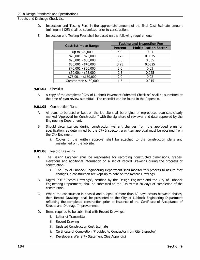
2018 Design Standards and Specifications
Streets and Drainage Check List
134 Section 9
D. Inspection and Testing Fees in the appropriate amount of the final Cost Estimate amount (minimum $125) shall be submitted prior to construction.
E. Inspection and Testing Fees shall be based on the following requirements:
Cost Estimate Range Testing and Inspection Fee
Percent Multiplication Factor
Up to $20,000 4.0 0.04
$20,001 - $25,000 3.75 0.0375
$25,001 - $30,000 3.5 0.035
$30,001 - $40,000 3.25 0.0325
$40,001 - $50,000 3.0 0.03
$50,001 - $75,000 2.5 0.025
$75,001 - $150,000 2.0 0.02
Greater than $150,000 1.5 0.015
9.01.04 Checklist
A. A copy of the completed “City of Lubbock Pavement Submittal Checklist” shall be submitted at the time of plan review submittal. The checklist can be found in the Appendix.
9.01.05 Construction Plans
A. All plans to be used or kept on the job site shall be original or reproduced plan sets clearly marked “Approved for Construction” with the signature of reviewer and date approved by the Engineering Department.
B. Should circumstances during construction warrant changes from the approved plans or specification, as determined by the City Inspector, a written approval must be obtained from the City Engineer.
i. Copies of the written approval shall be attached to the construction plans and maintained on the job site.
9.01.06 Record Drawings
A. The Design Engineer shall be responsible for recording constructed dimensions, grades, elevations and additional information on a set of Record Drawings during the progress of construction.
i. The City of Lubbock Engineering Department shall monitor this process to assure that changes in construction are kept up to date on the Record Drawings.
B. Digital PDF “Record Drawings”, certified by the Design Engineer and the City of Lubbock Engineering Department, shall be submitted to the City within 30 days of completion of the construction.
C. Where the construction is phased and a lapse of more than 60 days occurs between phases, then Record Drawings shall be presented to the City of Lubbock Engineering Department reflecting the completed construction prior to issuance of the Certificate of Acceptance of Streets and Drainage Improvements.
D. Items required to be submitted with Record Drawings:
i. Letter of Transmittal
ii. Record Drawing
iii. Updated Construction Cost Estimate
iv. Certificate of Completion (Provided to Contractor from City Inspector)
v. Developer’s Warranty Statement (See Appendix)

2018 Design Standards and Specifications
Streets and Drainage Check List
Section 9 135
9.01.07 Acceptance
A. Upon completion of construction, satisfactory tests, completion of punch list items, and submittal of Record Drawings, the Design Engineer shall submit a request to the City Engineer for a Certificate of Acceptance of Streets and Drainage Improvements.

2018 Design Standards and Specifications
Streets and Drainage Check List
136 Section 9
9.02 Plan Details
9.02.01 Plan Format
A. All drawings shall be no larger than 22-inch by 34-inch in size.
9.02.02 The following information shall be shown on the plans:
A. General
i. Title Block (lower right hand corner preferred)
ii. Scale
a. Horizontal 1”=20’ or 1”=50’
b. Vertical 1”=1’ (preferred) or 1”=2’ (maximum)
iii. Original Date and Revision Dates
iv. Name of Professional Engineer
v. Professional Engineer's Seal
vi. Firm Name and Contact Information
vii. Legal Description of Property Being Improved
viii. Drawings Number (s)
ix. City of Lubbock Engineering Department Contact Information:
a. Streets Inspector: 775-3750
x. Statement: “All work shall be performed in accordance with the current version of the City of Lubbock Minimum Design Standards and Specifications.”
B. Plan
i. Bench Marks and USGS Datum
ii. North Arrow
iii. ROW Lines, Property Lines and Lot Numbers
iv. Street Names and Easements with Width Dimensions
v. Existing Curbs and Paving (Gray)
vi. Proposed Curbs and Paving (Bold)
vii. Spot Elevations on Radii, Dips, Grade Breaks, and Ditches
viii. Location and Direction of Dips
ix. Other Pertinent Details (Buildings, Utilities, Water Courses, Etc.)
C. Profile
i. Existing Ground Surface at Curb Lines (Gray)
ii. Existing Gutters or Flow Lines (Gray)
iii. Proposed Gutters or Flow Lines (Bold)
iv. Stationing with Profiles Indexed to Plan View
v. Intermediate Station Numbers and Elevations at Points of Grade Change and Radii
vi. Ditch Grades
vii. Existing and Proposed Utilities Where Crossed
D. Detail Sheet
i. Details are not required when engineers plans refer to City standards
ii. Include all non-standard details

2018 Design Standards and Specifications
Streets and Drainage Check List
Section 9 137
E. Overall Layout Sheet – As Required
i. Scale 1 "=100'
ii. Lot Lines
iii. Streets and Street Names

2018 Design Standards and Specifications
Streets and Drainage Check List
138 Section 9

Design Standards and Specifications
Construction Details
Section 10 A
SECTION 10 TYPICAL DETAILS OF CONSTRUCTION

Design Standards and Specifications
Construction Details
A Section 10

Design Standards and Specifications
Construction Details
Section 10 A
10.01 General Details
10.01.01 Construction shall be in accordance with the following standard details unless otherwise indicated on plans or directed by the Engineer.

MAIN
SEWER
AT&T CABLE
BURIED
PR
OPE
RT
Y LIN
E
POLE
UTILITY
FINISHED GRADE
T.V. CABLE
BURIED
GAS MAIN
PR
OPE
RT
Y LIN
E
WA
TE
R LIN
E
GAS LIN
E
SE
WE
R LIN
E
TYPICAL LOT
TYPICAL LOT
WATER LINE
GAS LINE
SEWER LINE
N
CL
METER
WATER
2'
3' 9"
5'
7' 5"
10'
20'
10'
7' 6"
5'
2'
9' MINIMUM
MAIN
WATER
SERVICE
HOUSE
METER
WATER
CABLE
ELECTRICAL
BURIED
4'-
MIN.
4'MIN.NTS CABLE
BURIED
2'MIN.
3'MIN.
2'MIN.
2'MIN.
2'
ELECTRIC CONDUIT
OVER BURIED
CONCRETE PAD
CABLE
ELECTRICAL
BURIED
4' 6"M
IN.
2'
SERVICE
HOUSE
5'5'
SEWER SERVICE LINE
WATER SERVICE LINE
5'
5'
20'
5'
5'
5'
5'
DRAWING NUMBERDRAWING NUMBER
REVISED
G-1
TYPICAL LOCATIONS
FOR UTILITIES IN ALLEYS
POLE
UTILITY
4' 6"M
IN.
MAR. 2019


Design Standards and Specifications
Construction Details
Section 10 B
10.02 Water Details

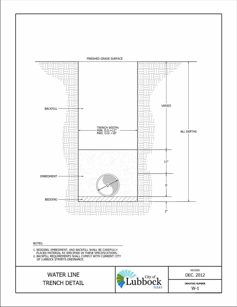


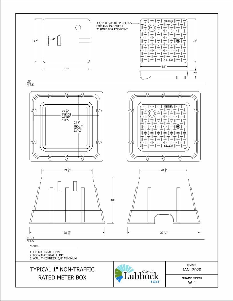


WATER MAIN
MA
XIM
UM 6'
VA
RIE
S
PLAN VIEW
NOTES:
1. TREAT EACH SIDE OF VALVE AS A DEAD END OF EQUAL SIZE.
INSTALL THE CORRESPONDING LENGTH (FOR A DEAD END) OF FULLY
RESTRAINED PIPE THE FULL DISTANCE ON EACH SIDE OF VALVE
2. CONCRETE SUPPORT CRADLE AND SUPPORT PAD SHALL BE 3,600 P.S.I.
CONCRETE.
3. POLYWRAP BURIED GATE VALVES AND FITTINGS
4. TORQUE BOLTS PRIOR TO BACKFILL PER MANUFACTURERS RECOMENDATIONS
5. TOP OF VALVE NUT SHALL BE LESS THAN 6 FEET FROM FINISHED GRADE.
IF MORE THAN 6 FEET, INSTALL EXTENSION SO THAT TOP OF NUT IS LESS
THAN 6 FEET FROM FINISHED GRADE.
6. SET COVER OF VALVE BOX AND COLLAR 1/4" BELOW GRADE IN PAVEMENT OR
SHOULDER, AND 2" ABOVE GRADE ELSEWHERE.
2' SQUARE
AND COVER
VALVE BOX
CONCRETE PAVEMENT)
(NOT REQUIRED IN
CONCRETE COLLAR
EACH WAY
NO. 4 BARS
"WATER VALVE"
BE STAMPED
VALVE COVER SHALL
BLOCK UNDER BODY OF BURIED VALVES
8" X 8" X 6" MIN. 2,500 PSI CONCRETE
TRACER WIRE
TYPICAL TYPICAL GATE VALVE
RISER PIPE
6" PVC C900
CONCRETE PAVEMENT)
(NOT REQUIRED IN
CONCRETE COLLAR
H.M.A.C. PAVEMENT
AND COVER
TYPICAL VALVE BOX
EACH WAY
NO. 4 BARS
EMBEDMENT
BEDDING &
TYPICAL PIPE
VALVE
WATER
REVISED
DRAWING NUMBERDRAWING NUMBER
APRIL 2019
W-8
BURIED VERTICAL GATE
VALVE DETAIL
6"
SREET OR CURB
OR PERPENDICULAR TO
ORIENT SQUARE PARALLEL
FINISHED GRADE SURFACE
MIN. 6"
MATCH PAVING THICKNESS
ASPHALT PAVING
IS CUT IN AFTER
CONCRETE COLLAR
FLOW FILL WHEN


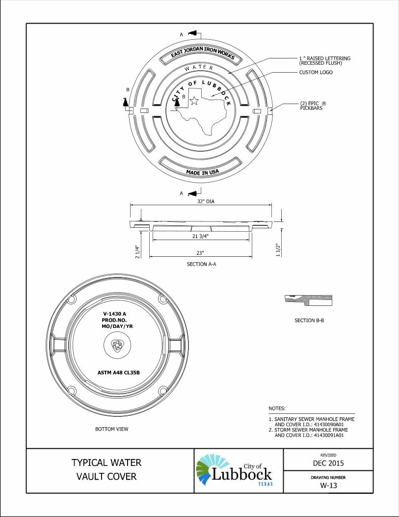


Design Standards and Specifications
Construction Details
Section 10 C
10.03 Sewer Details
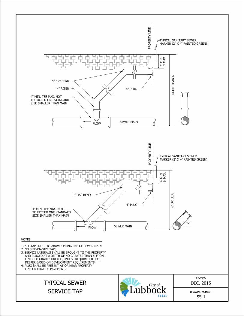


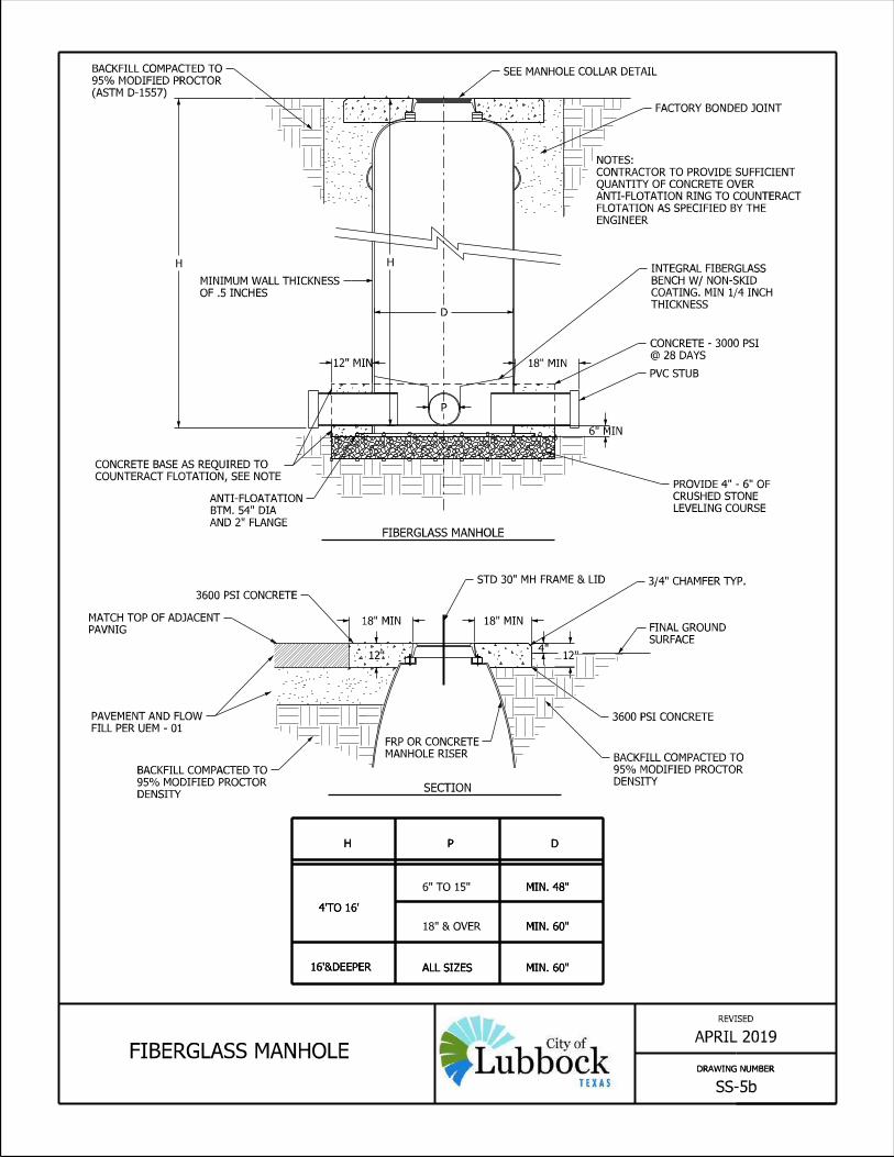


FINISHED GRADE SURFACE
ZONE
PIPE
PIPE WIDTH
HAUNCHING
BACKFILL
FINAL
PIP
E E
MBE
DM
EN
T
SPRINGLINE
OF LUBBOCK STREETS ORDINANCE.
3. BACKFILL REQUIREMENTS SHALL COMPLY WITH CURRENT CITY
PLACED MATERIAL AS SPECIFIED IN THESE SPECIFICATIONS.
1. BEDDING, EMBEDMENT, AND BACKFILL SHALL BE CAREFULLY
NOTES:
(MAY NOT BE REQUIRED)
FOUNDATION
DRAWING NUMBERDRAWING NUMBER
APRIL 2019TRENCH CROSS-SECTION
SHOWING TERMINOLOGY
REVISED
SS-10
12" COVER
6" BEDDING
MATERIAL
EMBEDMENT


Design Standards and Specifications
Construction Details
Section 10 D
10.04 Street and Drainage Details


SECTION A-A
PR
OPE
RT
Y LIN
EP
RO
PE
RT
Y LIN
E
OF SID
EW
ALK.
4"
MIN.
THIC
KN
ESS
JOINT
EXPANSION
(RESIDENTIAL)
SECTIONS B-B
DRIVEWAY.
TO CURB AND GUTTER OR
ASPHALT REPAIR ADJACENT
SEE PLATE NO. 36-4 FOR
NOTE:
REMOVED.
CURB
VARIABLE 4' SIDEWALK
VARIABLE 4' SIDEWALK
(COMMERCIAL)
SECTIONS B-B
AS REQUIRED.
INNER CURB
THIC
KN
ESS.
6"
MIN.
CURB RAMP DETAILS.
4. SEE PLATES 36-16 AND 36-16(A) FOR
RADII ON RESIDENTIAL DRIVEWAYS.
3. 30° TO 45° FLARE MAY BE USED IN LIEU OF
" THICK.432. ALL EXPANSION JOINTS TO BE
1. MAINTAIN GUTTER FLOWINE THROUGH DRIVEWAY.
NOTES:
3' MIN. @ 2% MAX. SLOPE
THIC
KN
ESS.
4"
MIN.
3' MIN. @ 2% MAX. SLOPE
THIC
KN
ESS.
6"
MIN.
LENGTH OF NEW GUTTER.
BARS RUNNING ENTIRE
RECONSTRUCTED WITH #3
COMPLETELY REMOVED AND
CURB AND GUTTER TO BE
FOR COMMERCIAL DRIVEWAY:
REVISED
PLATE NO.
SLAB AT 4' INTERVALS.
1/2 WAY THROUGH
CONTRACTION MARKINGS
6"X6" - 6 GAUGE WELDED WIRE FABRIC.
BOTH WAYS, CENTERED IN SLAB OR
#4 DEFORMED STEEL BARS 12" O.C.
HYDRANT/POLE
6" PAST EDGE OF
IN CONCRETE. EXTEND
OUT WHEN ENCLOSED
EXPANSION JOINT BLOCK-
POLE, ETC. MUST HAVE
FIRE HYDRANT, POWER
(10' T
YPIC
AL)
VA
RIE
S
4' SIDEWALK
PROPERTY LINEAA
JOINTS
EXPANSION
SLO
PE
2% M
AX.
FR
OM P.L.
3'
MIN.
B
B
PROPERTY LINE
SIDEWALK RUN.
SPACED 36' MAX. ALONG
EXPANSION JOINTS
MAR. 2019
SECTION C-C
PROPERTY LINE
3' MIN.SIDEWALK ELEVATION
4' SIDEWALK
CONSTRUCTION DETAILS36-2 (A)


REVISED
APRIL 2019
PLATE NO.
ASPHALT REPAIR ADJACENT TO
CURB AND GUTTER OR DRIVEWAY36-4(A)
18" TYPICAL 12"
H.M.A.C. SURFACE.2" MIN. TYPE "C" SAWCUT
SMOOTH
IN PLACE.TO REMAINH.M.A.C. SURFACE,
BASE
FLOWABLE FILL
SURFACE.
FLOWABLE FILL AND PAVING
PRIOR TO INSTALLATION OF
TOE FORM - TO BE REMOVED
DRIVEWAY
NEW CONCRETE
6"
6"
TOE FORM.
POUR NEW DRIVEWAY FLUSH AGAINST
2. REMOVE CURB TO LIP LINE AND
FLOW LINE.
ALIGNMENT OF CURB, LIP, AND GUTTER
1. MAINTAIN VERTICAL AND HORIZONTAL
NOTES:
TO RECEIVE TACK COAT
VERTICAL SURFACES
1/4"
1/2"


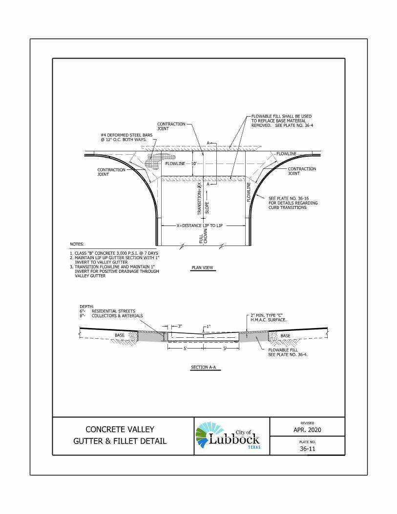

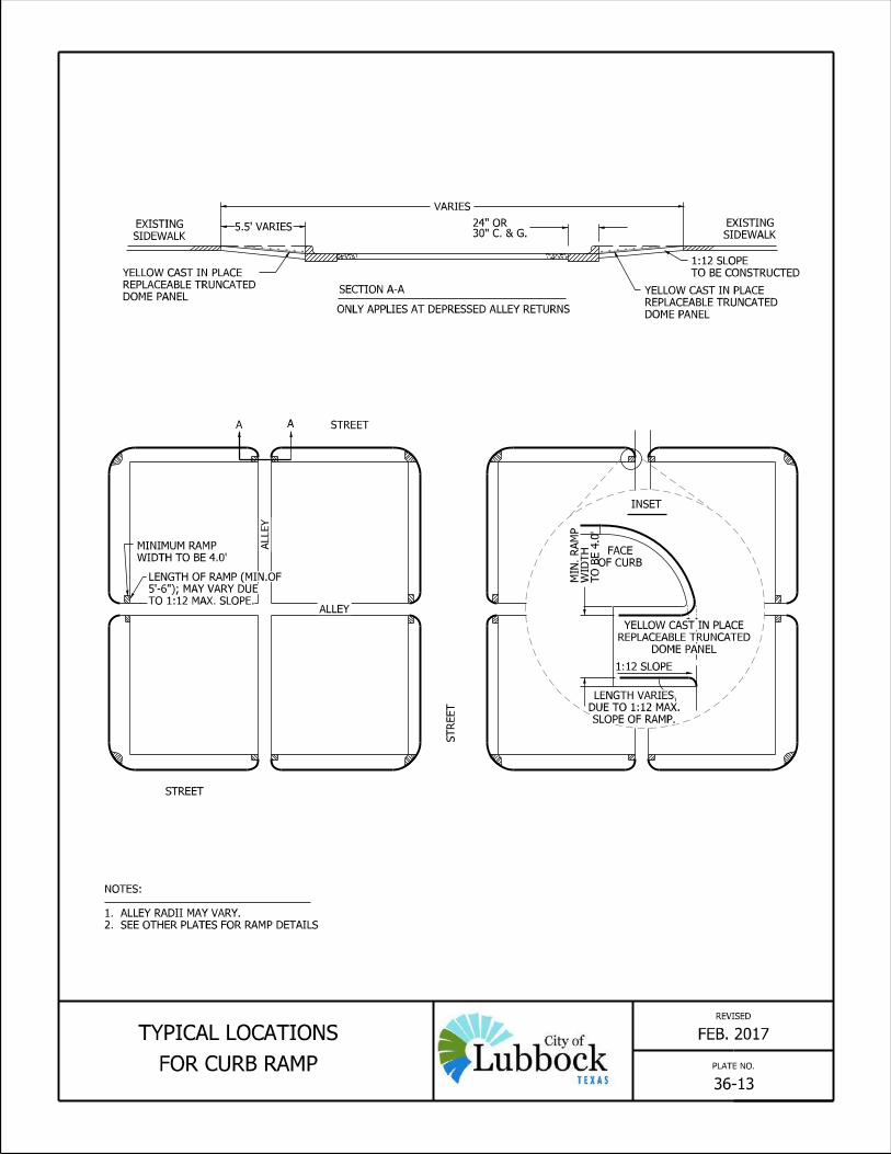


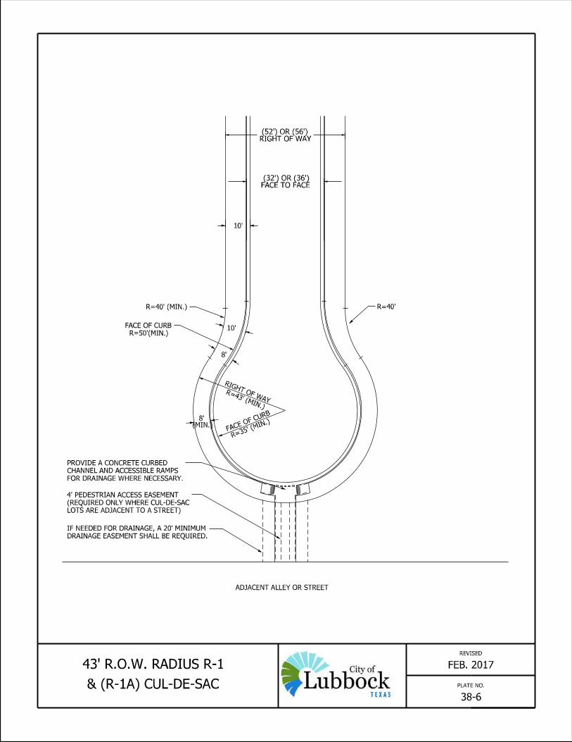
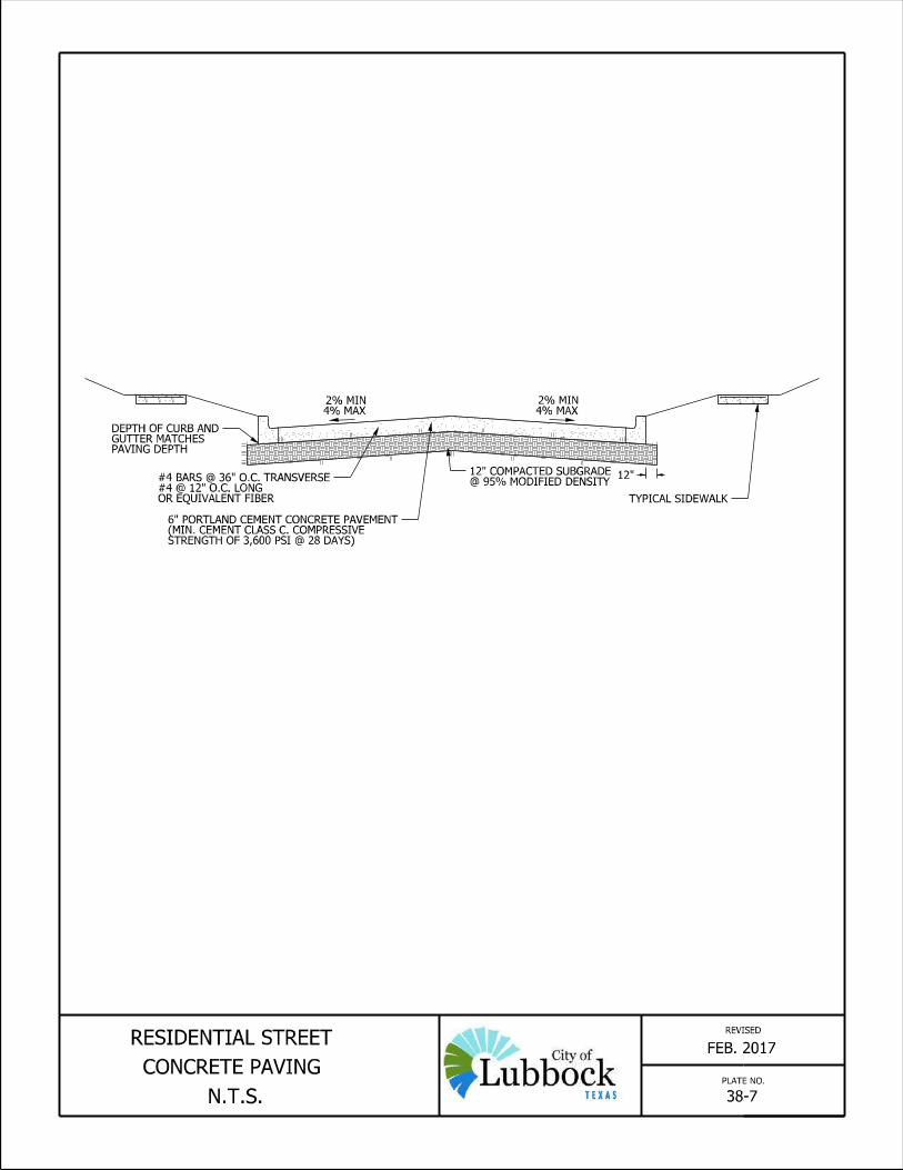


4,5 OR 7
COMPOUND CLASS
JOINT SEALING
4,5 OR 7
COMPOUND CLASS
JOINT SEALING
T
CONTRACTION JOINT
COMPOUND
SEALING
JOINT
/T
/T
-
3
INITIAL
SAW CUT
3 1
- -
TO
COMPOUND
SEALING
JOINT-
TO
JOINT SEALING
COMPOUND
CONSTRUCTION JOINT
TO
""
SAW CUT
INITIAL
ROD
BACKER
-
3"
1"
"
LONGITUDINAL JOINT
SAWED
EXPANSION JOINT
LONGITUDINAL OR TRANSVERSE
TRANSVERSE FORMEDTRANSVERSE SAWED
"81 "4
1
"211
"41
"81
"41
" MIN.
21
"83
"81
"41 "8
1"4
1
"4
1
"2
1
"41
"4
1
"2
1
41
21
43
"41"- 16
1
"41"- 16
1
"8
5
"8
5
REVISED
PLATE NO.
GENERAL NOTES
38-113 OF 3
CONCRETE PAVING DETAILS
RESIDENTIAL AND COLLECTOR STREET
ALLEYS.5. TRANSVERSE CONTRACTION JOINTS SHALL BE PLACED AT THE RADII OF INTERSECTING
STREETS.4. TRANSVERSE EXPANSION JOINT SHALL BE PLACED AT THE RADII OF INTERSECTING
THICKNESS.3. THE SAW CUT FOR THE LONGITUDINAL JOINT SHALL BE ONE FOURTH THE SLAB
THE RECOMMENDED EQUIPMENT AND INSTALLATION PROCEDURES TO BE USED. SHALL SUBMIT A STATEMENT FROM THE SEALANT MANUFACTURER SHOWING REQUIREMENT AND PRIOR TO BEGINNING OPERATIONS, THE CONTRACTOR 2. THE JOINTS SHALL BE CLEANED IN ACCORDANCE WITH THE MANUFACTURES
CONSTRUCTION AND THE TWO SAWED JOINTS. SHOWN ON THE PLANS FOR THE LONGITUDINAL AND TRANSVERSE 1. THE JOINT RESERVOIR FOR SEALANT SHALL BE SAWED UNLESS OTHER WISE
APRIL 2019
ZIP STRIP


6"
MIN
8" MIN
12"
REVISED
UEM-03
BRICK STREET
CUT REPAIRS
MAR. 2019
(MAX. 6" LIFTS.)
OPTIMUM MOISTURE CONTENT.
(ASTM D 698) 2% OF
MODIFIED PROCTOR
BACKFILL COMPACTED TO 95%± OR RAIN EVENT
FROM A WATER LEAK
DUE TO MOISTURE
COMPROMISED SOIL
MINIMUM.
1" SAND CUSHION
STREET SUPERINTENDENT.
BLEND, OR AS APPROVED BY THE
WITH SAND/CEMENT AT A 50-50
BRICK JOINTS TO BE FILLED
3000 PSI AT 7 DAYS.
CLASS 'B' CONCRETE
CONCRETE CAP
BOTH DIRECTIONS.
MAX. SPACING IN
# 4 BARS, 12" O.C.
PEA GRAVEL.
(FLOWABLE FILL) WITH
LOW STRENGTH MATERIAL
1 1/2 SACK CONTROLLED
ALTERNATIVE BACKFILL
PAVING
BRICK
RECOMMENDATIONS).
AND MANUFACTURERS
THE ENGINEERS
ACCORDANCE WITH
PIPE BEDDING (IN
PLATE NO.
EXISTING BAR SIZE AND SPACING.
INTO EXISTING PAVING MATCH
PAVING. EPOXY GROUT BAR
TIE BARS 10" INTO EXISTING
DRILL AND DRIVE DEFORMED
8
7
6
5
4
3
BAR SIZE
33"
29"
25"
21"
18"
18"
MIN. SPLICE LENGTH
NOT REPAIRED IMMEDIATELY.
4. FLOW FILL CAP OR STEEL PLATES REQUIRED IF PAVEMENT IS
SPECIFICATIONS.
CONFORMANCE WITH CITY OF LUBBOCK STANDARD PAVING
3. ALL MATERIALS AND CONSTRUCTION PRACTICES SHALL BE IN
2. #5 DOWELS NEEDED IF TIED INTO EXISTING CONCRETE BASE.
1. SEE CONCRETE CAP DETAIL. PLATE NO. 36.09.05
NOTE:

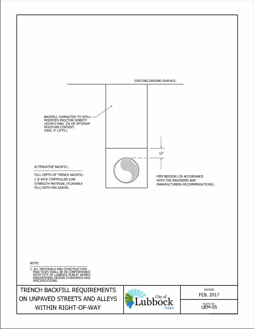


APPENDIX


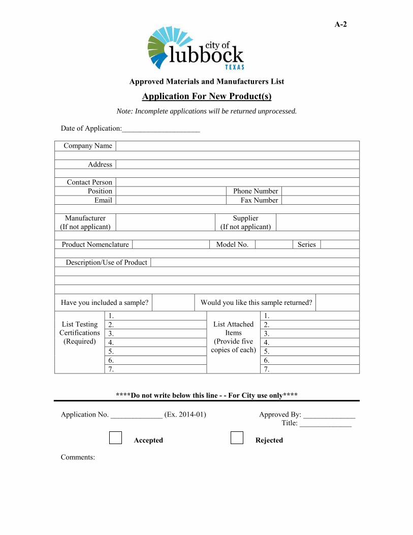
A-2
Approved Materials and Manufacturers List
Note: Incomplete applications will be returned unprocessed.
Application For New Product(s)
Date of Application:_____________________
Company Name
Address
Contact Person Position Phone Number
Email Fax Number
Manufacturer (If not applicant)
Supplier (If not applicant)
Product Nomenclature Model No. Series
Description/Use of Product
Have you included a sample? Would you like this sample returned?
List Testing
Certifications (Required)
1. List Attached
Items (Provide five
copies of each)
1. 2. 2. 3. 3. 4. 4. 5. 5. 6. 6. 7. 7.
****Do not write below this line - - For City use only**** Application No. ______________ (Ex. 2014-01) Approved By: ______________ Title: ______________
Accepted Rejected Comments:


Rev. 05-01-2014
CERTIFICATE OF COMPLETION
DATE: ___________________________
PROJECT DATA
SUBDIVISION NAME: _____________________________________
PLAT DESCRIPTION: _____________________________________
TYPE OF MUNICIPAL IMPROVEMENT
☐ WATER ☐ SEWER ☐ PAVING ☐ DRAINAGE
☐ OTHER ____________________________________________
CONTRACTOR'S AFFIDAVIT TO DEVELOPER
I certify that the work under the above named project, including all amendments thereto, has been satisfactorily completed in accordance with the engineering plans and specifications and in accordance with the City of Lubbock Public Works Engineering Minimum Design Standards and Specifications; that no liens have been or will be attached against the property and improvements of the owner; that no suits are pending by reason on the project under the contract; and no public liability claims are pending.
CONTRACTOR / DEVELOPER: _______________________________
ADDRESS: ____________________________________________
PHONE: ____________________________________________
SIGNED: ____________________________________________
PRINTED: ____________________________________________
TITLE: ____________________________________________
RECOGNITION BY CITY OF LUBBOCK
An inspection of the work on the above referenced Project was conducted on _____________________. Those participating in the inspection (final walk-through) were __________________, _________________, _____________________, _____________________, _________________, _______________________, ________________________, ________________________, and _________________________. The inspection revealed that the infrastructure inspected has been completed substantially in accordance with the plans and specifications and is recommended for acceptance on ___________________________.
City of Lubbock
__________________ By ______________________ Printed Name
______________________ Title

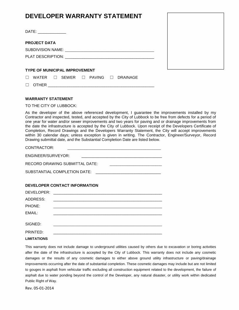
Rev. 05-01-2014
DEVELOPER WARRANTY STATEMENT DATE: _____________
PROJECT DATA
SUBDIVISION NAME: _________________________________________
PLAT DESCRIPTION: _________________________________________
TYPE OF MUNICIPAL IMPROVEMENT
☐ WATER ☐ SEWER ☐ PAVING ☐ DRAINAGE
☐ OTHER _________________________________________________
WARRANTY STATEMENT
TO THE CITY OF LUBBOCK:
As the developer of the above referenced development, I guarantee the improvements installed by my Contractor and inspected, tested, and accepted by the City of Lubbock to be free from defects for a period of one year for water and/or sewer improvements and two years for paving and or drainage improvements from the date the infrastructure is accepted by the City of Lubbock. Upon receipt of the Developers Certificate of Completion, Record Drawings and the Developers Warranty Statement, the City will accept improvements within 30 calendar days; unless exception is given in writing. The Contractor, Engineer/Surveyor, Record Drawing submittal date, and the Substantial Completion Date are listed below.
CONTRACTOR: ___________________________________________
ENGINEER/SURVEYOR: _____________________________________
RECORD DRAWING SUBMITTAL DATE: ________________________
SUBSTANTIAL COMPLETION DATE: ______________________________
DEVELOPER CONTACT INFORMATION
DEVELOPER: __________________________________________________
ADDRESS: __________________________________________________
PHONE: __________________________________________________
EMAIL: __________________________________________________
SIGNED: __________________________________________________
PRINTED: __________________________________________________ LIMITATIONS
This warranty does not include damage to underground utilities caused by others due to excavation or boring activities after the date of the infrastructure is accepted by the City of Lubbock. This warranty does not include any cosmetic damages or the results of any cosmetic damages to either above ground utility infrastructure or paving/drainage improvements occurring after the date of substantial completion. These cosmetic damages may include but are not limited to gouges in asphalt from vehicular traffic excluding all construction equipment related to the development, the failure of asphalt due to water ponding beyond the control of the Developer, any natural disaster, or utility work within dedicated Public Right of Way.


1
CRITERIA
MEE
TS
SPEC
IFIC
ATIO
NS
NO
T AP
PLIC
ABLE
NEE
D V
ARIA
NCE
NOTES
General RequirementsProvide 2 sets of plan for review Provide review fee calculationsProvide payment for review feeDrawings shall be no larger than 24”x36”.Include a Location mapInclude a Title Block (lower right corner preferred) Drawing Scale shall be Horizontal 1”=50’ or 1”=20’ Vertical 1”=1’ or 1”=2’Include original date and revision datesInclude Name of Professional EngineerInclude Firm Name and Contact InformationInclude Legal Description of Property Being Improved Include Drawings NumbersInclude City of Lubbock Inspector Contact Information 806-775-3751.Include Note on Plans “All work shall be in accordance with the City of Lubbock Minimum Design Standards and Specifications.”PlanInclude Benchmark and DatumInclude North Arrow
LEGAL DESCRIPTION:
ENGINEERING FIRM: ADDRESS:
E-MAIL: CONTACT:
PHONE NUMBER: DATE:
PAVEMENT MUNICIPAL IMPROVEMENTS
SUBMITTAL CHECKLIST
158869
Rectangle

2
CRITERIA
MEE
TS
SPEC
IFIC
ATIO
NS
NO
T AP
PLIC
ABLE
NEE
D V
ARIA
NCE
NOTES
Include ROW lines, property lines and lot numbersInclude Street Names and Easements with Width DimensionsInclude Existing Curbs and Paving (Gray)Include Proposed Curbs and Paving (Bold)Include Spot Elevations on Radii, Dips, Grade Breaks, and DitchesInclude Location and Direction of DipsInclude Other Pertinent Details (Buildings, Utilities, Water Courses, Etc.)ProfileInclude Existing Ground Surface at Curb Lines (Gray)Include Existing Gutters or Flow Lines (Gray)Include Proposed Gutters or Flow Lines (Bold)Include Stationing with Profiles Indexed to Plan ViewInclude Intermediate Station Numbers and Elevations at Points of Grade Change and RadiiInclude Ditch GradesInclude Existing and Proposed Utilities Where CrossedDetail SheetDetails are not required when engineers plans refer to City standardsInclude all non-standard detailsOverall Layout Sheet – As RequiredDrawing Scale shall be 1 "=100'Include Lot LinesInclude Streets and Street Names
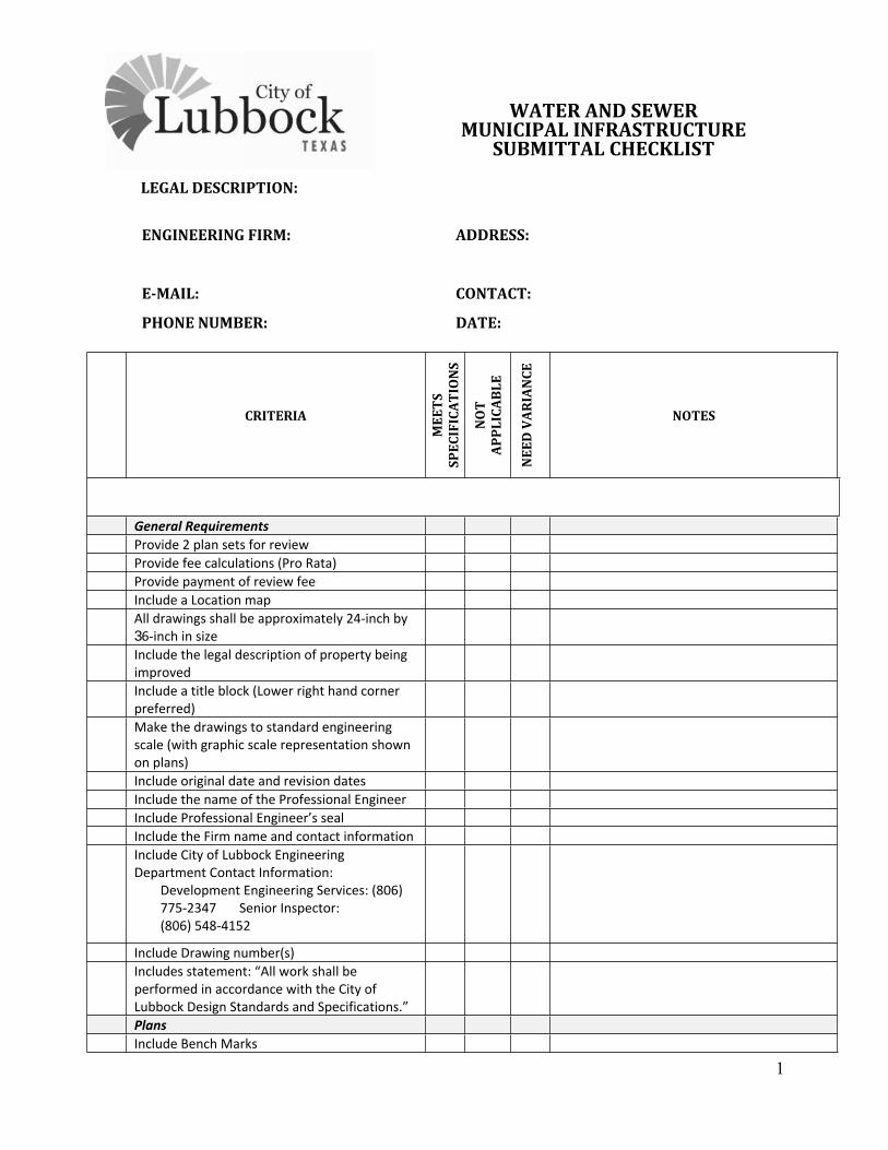
1
CRITERIAM
EETS
SP
ECIF
ICAT
ION
S
NO
T AP
PLIC
ABLE
NEE
D V
ARIA
NCE
NOTES
General RequirementsProvide 2 plan sets for reviewProvide fee calculations (Pro Rata)Provide payment of review feeInclude a Location mapAll drawings shall be approximately 24-inch by 36-inch in sizeInclude the legal description of property being improvedInclude a title block (Lower right hand corner preferred)Make the drawings to standard engineering scale (with graphic scale representation shown on plans)Include original date and revision datesInclude the name of the Professional EngineerInclude Professional Engineer’s sealInclude the Firm name and contact informationInclude City of Lubbock Engineering Department Contact Information:
Development Engineering Services: (806) 775-2347 Senior Inspector: (806) 548-4152
Include Drawing number(s)Includes statement: “All work shall be performed in accordance with the City of Lubbock Design Standards and Specifications.”PlansInclude Bench Marks
LEGAL DESCRIPTION:
ENGINEERING FIRM: ADDRESS:
E-MAIL: CONTACT:
PHONE NUMBER: DATE:
WATER AND SEWER MUNICIPAL INFRASTRUCTURE
SUBMITTAL CHECKLIST
158869
Rectangle

2
CRITERIA
MEE
TS
SPEC
IFIC
ATIO
NS
NO
T AP
PLIC
ABLE
NEE
D V
ARIA
NCE
NOTES
Include Location control dimensionsInclude North ArrowsInclude Property LinesInclude Street Names and Easements with Width DimensionsInclude Existing Buried Utility Lines Location and Depth (Gray-Dashed)
Water Gas Communications Storm drains Sanitary sewers Electric
Include Other Pertinent Details (Structures, Curbs, Water Courses, Etc.)Include Proposed water/sewer mains (Bold – Solid)
Label proposed diametersLabel proposed materials
Include proposed manholesLabel water line elements (fittings, tees, crosses, reducers, bends, plugs, blow-offs, thrust blocks, valves and fire hydrants)Include stationing and other number designationsInclude elevation of inverts in and out of manhole Include elevation of manhole rimLabel manhole stub-outs
Include proposed future extensions Include proposed service connections or stub-insInclude proposed concrete encasementInclude proposed cut-off walls
Include easement description for offsite easements.Make utility easements have correct orientation and offsets (water north & west, sewer 10ft from water lines)Profiles Include ground surface – existing (dotted) and proposed (Solid) Include station numbersInclude length between manholes and depth of cutInclude existing and proposed utilities where crossed

3
CRITERIA
MEE
TS
SPEC
IFIC
ATIO
NS
NO
T AP
PLIC
ABLE
NEE
D V
ARIA
NCE
NOTES
Include existing manhole invert and rim elevationsInclude Plan, Profile, and Complete Details for off-site transmission mains, lift stations, special valves and vaults, tanks, etc.Water DesignInclude water line summaryInclude overall layout (scale 1” = 100’)Include Profiles at large utility crossings including sewer mains >10”, fiber or electric duct banks, storm sewers, etc.Include profiles for 12” or larger water lines.Verify existing lines for tie-inAbandoned line procedure followedBoring and casing standards followedInclude shutoff valves (12” or < dist. mains <600ft, larger mains <800ft)Include a fire hydrant within 500ft of each structureMake a looped systemWater lines shall be 2 ft. above existing sewer lines (and force mains)Make joint spacing and clearances of 9ft at sewer crossingNo stub outs under pavingNo dead end mains > 150ftNo developed lines that cut off adjacent plots from future waterNo service taps off streetsNo size on size municipal taps without approvalSewer DesignInclude overall layout (scale 1” = 100’)Include profilesVerify existing line for tie-inAbandoned line procedure followedGradients follow:
6 in diam 0.60-12.35% 8 in diam 0.40-8.40% 10 in diam 0.28-6.23% 12 in diam 0.22-4.88% 15 in diam 0.15-3.62% 18 in diam 0.12-2.83%
All shallow manholes (<16ft) on small sewer lines (<15in diam) have 48in diam manholes spaced at <500ftAll deep manholes (>16ft) on small sewer lines (<15in diam) have 60in diam manholes spaced at <500ft

4
CRITERIA
MEE
TS
SPEC
IFIC
ATIO
NS
NO
T AP
PLIC
ABLE
NEE
D V
ARIA
NCE
NOTES
All manholes on large sewer lines (>15in diam) have 60in diam manholes spaced at <800ftProtective coatings specified on all large and drop manholes and manholes receiving force main dischargeMax sewer service tap depth of 12ft (or Engineering Department approval)Water lines shall be 2 ft. above existing sewer lines (and force mains)Joint spacing and clearance of 9ft at sewer crossingInlet drops in manholes follow:
Inlet angle <30 degree drop 0.10ft min Inlet angle >30 degree drop 0.20ft min
Inlet with <24 in drop must be filletedDrop manhole (>24in drop) follow:
Existing manholes drop inside New manholes drop outside
No stub outs under paving
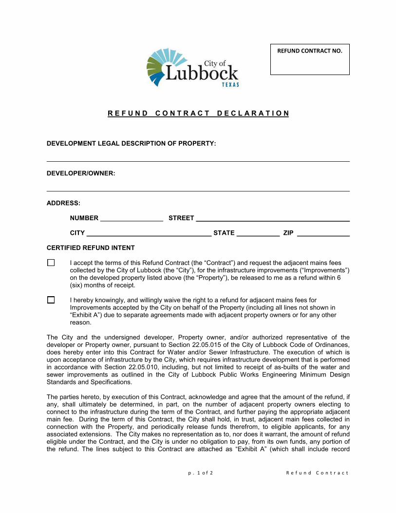
p . 1 o f 2 R e f u n d C o n t r a c t
R E F U N D C O N T R A C T D E C L A R A T I O N
DEVELOPMENT LEGAL DESCRIPTION OF PROPERTY: DEVELOPER/OWNER: ADDRESS: NUMBER STREET
CITY STATE ZIP
CERTIFIED REFUND INTENT
I accept the terms of this Refund Contract (the “Contract”) and request the adjacent mains fees collected by the City of Lubbock (the “City”), for the infrastructure improvements (“Improvements”) on the developed property listed above (the “Property”), be released to me as a refund within 6 (six) months of receipt. I hereby knowingly, and willingly waive the right to a refund for adjacent mains fees for Improvements accepted by the City on behalf of the Property (including all lines not shown in “Exhibit A”) due to separate agreements made with adjacent property owners or for any other reason.
The City and the undersigned developer, Property owner, and/or authorized representative of the developer or Property owner, pursuant to Section 22.05.015 of the City of Lubbock Code of Ordinances, does hereby enter into this Contract for Water and/or Sewer Infrastructure. The execution of which is upon acceptance of infrastructure by the City, which requires infrastructure development that is performed in accordance with Section 22.05.010, including, but not limited to receipt of as-builts of the water and sewer improvements as outlined in the City of Lubbock Public Works Engineering Minimum Design Standards and Specifications. The parties hereto, by execution of this Contract, acknowledge and agree that the amount of the refund, if any, shall ultimately be determined, in part, on the number of adjacent property owners electing to connect to the infrastructure during the term of the Contract, and further paying the appropriate adjacent main fee. During the term of this Contract, the City shall hold, in trust, adjacent main fees collected in connection with the Property, and periodically release funds therefrom, to eligible applicants, for any associated extensions. The City makes no representation as to, nor does it warrant, the amount of refund eligible under the Contract, and the City is under no obligation to pay, from its own funds, any portion of the refund. The lines subject to this Contract are attached as “Exhibit A” (which shall include record
REFUND CONTRACT NO.

p . 2 o f 2 R e f u n d C o n t r a c t
drawings including the water and sewer refund calculation spreadsheet for each line the developer is requesting the refund of fees collected), attached and incorporated herein. The term of this refund contract shall be fifteen (15) years from the date of execution, and in no case shall the City be liable to issue refunds after such term. No interest shall accrue or be paid on any funds held by the City.
___________________________________________
PRINTED NAME OF DEVELOPER/ PROPERTY OWNER OR AUTHORIZED
REPRESENTATIVE
SIGNATURE DATE BELOW TO BE COMPLETED BY THE CITY Lines Accepted On: ___________________ Authorized By the City: LUBBOCK ASSISTANT CITY MANAGER DATE
REFUND CONTRACT NO.