
MIKROKOPTER 飞控制作
29
2011/4/23 翻译 | Eric 四轴之 MIKROKOPTER 飞控制作
-
Upload
khangminh22 -
Category
Documents
-
view
0 -
download
0
Transcript of MIKROKOPTER 飞控制作
2011/4/23
翻译 | Eric
四轴之 MIKROKOPTER 飞控制作
By Eric QQ:1065842604 四轴飞行器制作之飞控板 MK-Flight-Ctrl 2011-4-23
2
[2011-4-23]
翻译 | Eric
四轴 MIKROKOPTER 飞控制作手册
By Eric QQ:1065842604 四轴飞行器制作之飞控板 MK-Flight-Ctrl 2011-4-23
3
源自网站:http://www.mikrokopter.de/ucwiki/FCAufbauUnbestueckt
FCAufbauUnbestueckt
De:Aufbau einer unbestückten Flight-Ctrl
En:Construction of a bare Flight-Ctrl
中文:一个基本飞控板的制作
De :Einleitung En: Introduction 中文:简介
De: Diese Seite gibt Hilfestellung, Hinweise und Tipps zum Aufbau einer unbestückten Flight-Ctrl-Platine.
Es wird sowohl das Löten der Hardware wie auch die Installation der Software erläutert.
Diese Anleitung bezieht sich auf die Versionen 1.0 bis 1.3 der Flight-Ctrl-Platine. Die im einzelnen
unterschiedliche Bestückung wird in der Stückliste (am Ende dieses Beitrags) erläutert.
En: This page provides help, advice and tips on building a bare Flight-Ctrl board. It explains both the
soldering of both hardware and software installation.
These instructions apply to versions 1.0 through 1.3 of the Flight-Ctrl board. The assembly is different in
detail in the bill (at the end of this post) explained.
中文:本文提供制作一个 Flight-Ctrl 板的帮助、建议和技巧。它阐释了无论是硬件的组装和焊接和软件的配置。这些适用
于版本 1.0 到 1.3 的 Flight-Ctrl 板。在本文的结尾会告知不同的原理图和原件清单。
De: Material und Werkzeug En: Materials and tools
中文:材料和工具
De: Zunächst sollte man sicherstellen, dass sämtliche Bauelemente vorhanden sind. Es ist ratsam, von den
kleinen Widerständen, Kondensatoren, etc. mehr als notwendig zu haben. Wenn diese Teile mal
runterfallen, findet man sie kaum wieder. Eine vernünftige, wackelfreie Arbeitsfläche und kleine Schachteln
für die Teile ist von Vorteil. Desweiteren ist ein kleiner Elektronikerschraubstock empfehlenswert (alternativ
muss man sich etwas anderes zum Festhalten besorgen).
En: First you should ensure that all components are present. It is recommended that small of the resistors,
capacitors, etc. to have more than necessary. If these parts fall down times, you can find them almost
unrecognizable. A reasonable, wobble-free work area and small boxes for the parts is an advantage.
Furthermore, a small electronics vice recommended (alternatively, you have to get something else to hold
on to) .

By Eric QQ:1065842604 四轴飞行器制作之飞控板 MK-Flight-Ctrl 2011-4-23
4
中文:首先你要确保所有的组件备齐物。建议小的电阻、电容等准备的比要求的多点好。如果这些零件掉地上的时候,你几
乎找不到他们。最好在一个合理的,不会乱抖动的地方工作、另外最好每部分元件在不同的小盒子里。此外,推荐用一个小
焊接辅助架台(或者,你找别的事要固定住方便焊接)
De: Folgende Dinge sind notwendig:
En: The following things are necessary:
中文:以下的事情是必要的:
DE:
• Lötstation mit feiner Spitze, einstellbarer Temperatur (empfehlenswert ist eine Station mit zusätzlichem Heißluftfön; Siehe auch -> LötStationen
• Lötzinn 0,5mm (Hinweis: kein bleifreies Lötzinn verwenden; es eignet sich kaum für derartige Lötungen von Hand)
• Flussmittel (Tip: Es eignet sich hervorragend ein flussmittelhaltiger Stift zum Auftragen. Dieser Stift ist im Fachhandel erhältlich)
• Entlötlitze 1,5-2mm
• Platinenreiniger (entfernt Flussmittelreste)
• spitze Pinzetten
• Seitenschneider für Elektronik
• Lupe und viel Licht (idealerweise eine Lampe mit Lupe)
• Geduld und Ausdauer (es dauert eben etwas)
En :
• Soldering station with a fine tip, adjustable temperature control (recommended is a station with additional heat gun; See also -> Soldering Stations
• Solder 0.5 mm (Note: Do not use lead-free solder, it is hardly suitable for this type of soldering by hand)
• Flux (Tip:. It is great a flux containing pen for application, this pin is in stores)
• Desoldering 1.5-2mm Platinum cleaner (removes flux residues)
• pointed tweezers
• Cutters for electronics
• Magnifying glass and natural light (ideally a lamp with a magnifying glass)
• Patience and perseverance (it takes just a little)
中文:
• 细尖焊台,可调节温度控制(推荐额外的热风枪,参见: 焊台 (点德文原文可以 跟踪 链接)
• 焊锡 0.5 毫米(注意:不要使用无铅焊锡,手工几乎不适合这种类型的焊接)
• 助焊剂 ? 最好的带有使用的笔,在商店销卖
• 吸焊枪 1.5-2mm
• 去松香的玩意 出去残留松香什么的(个人建议 无水酒精(乙醇)100%)
By Eric QQ:1065842604 四轴飞行器制作之飞控板 MK-Flight-Ctrl 2011-4-23
5
• 尖尖的镊子
• 尖口钳 斜口钳 剥线钳(个人建议 三者都有 专业嘛)
• 放大镜, (最好是是带灯的放大镜,有种小的淘宝有卖,个人感觉非常好)
• 耐心和毅力(只需要一点点 呵呵 )
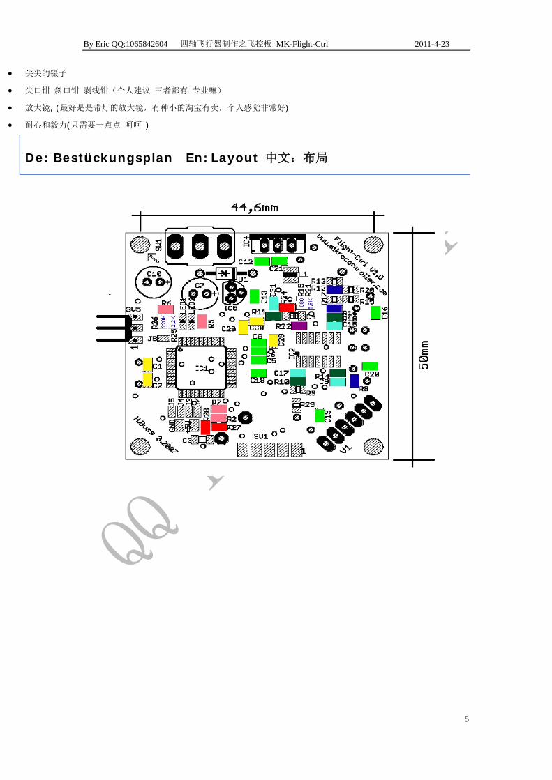
De: Bestückungsplan En: Layout 中文:布局

By Eric QQ:1065842604 四轴飞行器制作之飞控板 MK-Flight-Ctrl 2011-4-23
6
De: FC 1.3 Bestückungsplan im Detail:
En: FC 1.3 component placement in detail:
中文: FC1.3 器件组装布局细节

By Eric QQ:1065842604 四轴飞行器制作之飞控板 MK-Flight-Ctrl 2011-4-23
7
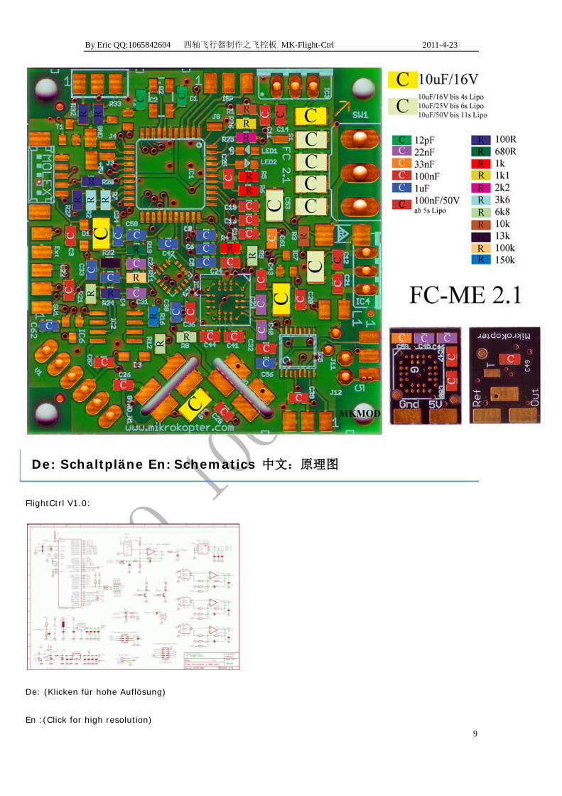
De: FC-ME Bestückungsplan im Detail:
En: FC-ME component placement in detail:
中文:FC-ME 元器件详细布局

By Eric QQ:1065842604 四轴飞行器制作之飞控板 MK-Flight-Ctrl 2011-4-23
8
De: FC-ME v2.1 Bestückungsplan:
En: FC-ME v2.1 component placement:
中文:FC-ME v2.1 器件布局:
By Eric QQ:1065842604 四轴飞行器制作之飞控板 MK-Flight-Ctrl 2011-4-23
9
De: Schaltpläne En: Schematics 中文:原理图
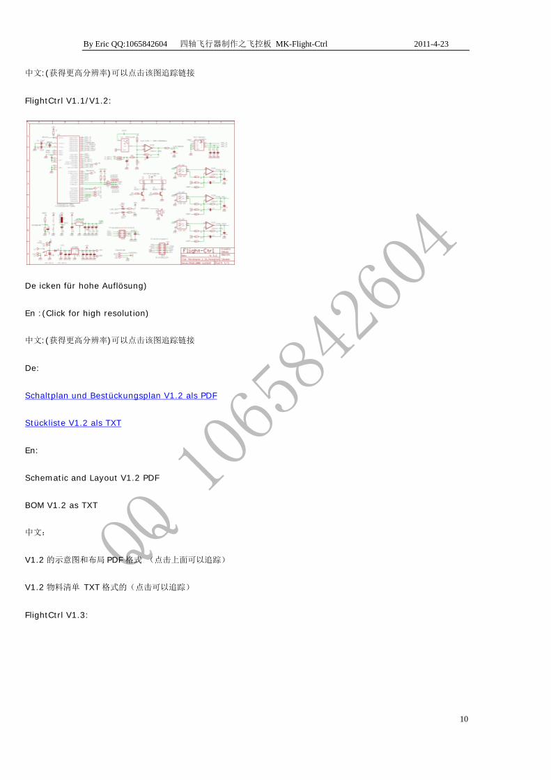
FlightCtrl V1.0:
De: (Klicken für hohe Auflösung)
En :(Click for high resolution)
By Eric QQ:1065842604 四轴飞行器制作之飞控板 MK-Flight-Ctrl 2011-4-23
10
中文:(获得更高分辨率)可以点击该图追踪链接
FlightCtrl V1.1/V1.2:
De icken für hohe Auflösung)
En :(Click for high resolution)
中文:(获得更高分辨率)可以点击该图追踪链接
De:
Schaltplan und Bestückungsplan V1.2 als PDF
Stückliste V1.2 als TXT
En:
Schematic and Layout V1.2 PDF
BOM V1.2 as TXT
中文:
V1.2 的示意图和布局 PDF 格式 (点击上面可以追踪)
V1.2 物料清单 TXT 格式的(点击可以追踪)
FlightCtrl V1.3:

By Eric QQ:1065842604 四轴飞行器制作之飞控板 MK-Flight-Ctrl 2011-4-23
11
De:(Klicken für hohe Auflösung)
En:(Click for high resolution)
中文:(获得更高分辨率)可以点击该图追踪链接
De: Schaltplan und Bestückungsplan V1.3 als PDF
Stückliste V1.3 als TXT
En: Schematic and Layout V1.3 PDF
BOM V1.3 as TXT
中文:
V1.3 的示意图和布局 PDF 格式 (点击上面可以追踪)
V1.3 物料清单 TXT 格式的(点击可以追踪)
De: Hinweise zur Bestückung En: Instructions for assembly
中文:组装说明
De: Es empfiehlt sich, sauber und in Ruhe zu arbeiten. Die Löttemperatur sollte beim Löten ca. 380°C und
beim Entlöten mit Entlötlitze ca. 400°C sein. Schief eingelötete Bauelemente sollte man aus- und wieder
neu einlöten. Es ist darauf zu achten, nicht zu wenig und nicht zu viel Lötzinn zu verwenden. Eine trübe oder
matte Lötstelle muss neu erhitzt werden, sie muss beim Erkalten glänzen.
En :It is advisable to clean and work in peace. The soldering tip for soldering about 380 ° C for de-soldering
and desoldering braid to be about 400 ° C. unbalanced components should be soldered off and solder again.

By Eric QQ:1065842604 四轴飞行器制作之飞控板 MK-Flight-Ctrl 2011-4-23
12
Make sure not to use too little and too much solder. A cloudy or dull solder joint must be heated again, it
must shine on cooling.
中文:明智的做法是在一个干净的地方静静地焊。在大约 380 度焊接和拆焊大约在 400 度。务必不要使用太少,太多的焊
锡。一个虚焊点或者暗焊点必须重新加热,再次冷却。
De:Reihenfolge En: Order 中文:焊接次序
De:
Die Reihenfolge der Bestückung ist nicht zwingend vorgeschrieben, aber folgende Beschreibung erleichtert
die Arbeit.
Zuerst sollte die Platine hinsichtlicht Kratzer auf der Oberfläche untersucht werden. Evtl. durchtrennte
Leiterbahnen können für unliebsame Überraschungen sorgen.
Das erste Bauelement ist der ATMega644(P). Hierbei ist mit großer Sorgfalt vorzugehen. Der Chip muss
sauber auf den Lötpads platziert und die Markierung (Punkt in der Ecke) ausgerichtet sein. Der Lötvorgang
sollte zügig erfolgen, da eine Überhitzung tötlich sein kann. Ist er aufgelötet, sollte man nochmals eine
Sichtkontrolle hinsichtlich durch Lötzinn kurzgeschlossener Pins durchführen. Dieses Zinn ist mit der
Entlötlitze zu entfernen. Jetzt kommen die anderen Chips (Beschleunigungssensor und
Operationsverstärker) dran.
Tip: Das Löten von SMD-Chips sollte man vorher mit anderen Bauteilen (Chipmuster, Resten) auf
Musterplatinen üben.
En :
The order of placement is not compulsory, but the following description makes work easier.
First, the board in terms of light scratches on the surface are investigated. Possibly. severed conductors can
make for unpleasant surprises.
The first component is the ATMega644 (P). It should proceed with great care. The chip must be neatly
placed on the pads and the mark (point in the corner) aligned. The soldering should be done quickly, since
overheating can be fatal. If it is soldered, you should again perform a visual inspection of solder regarding
shorted pins. This tin is to be removed with solder wick. Now the other chips (acceleration sensor and op
amp) to it.
Tip: Soldering of SMD chips should first practice with other components (chip samples, residues) for a type
boards.
中文:
在安置的顺序是不是强制性的,但按照下面的说明会使工作更容易。

By Eric QQ:1065842604 四轴飞行器制作之飞控板 MK-Flight-Ctrl 2011-4-23
13
首先,在检查光板表面有无划伤。有可能哦。会出现令人不快的意外:有的地方线断了。
第一部分是 ATmega644(P)的。要非常谨慎的去焊接。该芯片必须和焊点摆放整齐并且标记点(角点)对齐。焊接应
尽快进行,因为过热可能是致命的。如果焊好了,你应该再次进行引脚焊锡短路目视检查。将短路的焊锡吸掉。现在,焊
接其他芯片(加速度传感器和运算放大器)。
提示:焊接的 SMD 封装的芯片应该先练习与其他该封装类型的器件(芯片样品,废料)。
De:
Nach dem Chip sind zuerst sämtlich Widerstände, dann die SMD-Kondensatoren, danach die LEDs dran. Als
nächstes sind die Transistoren an der Reihe.
Tip: Für eine gerade Ausrichtung wird zuerst ein Pad verzinnt. Dann fasst man das Bauteil mit der Pinzette
und richtet es aus. Nun erhitzt man das verzinnte Pad und schiebt das Bauteil auf die richtige Stelle. Notfalls
kann man es nochmal erhitzen und besser ausrichten. Danach die andere Seite anlöten.
En:
After the first chip are all resistors, then the SMD capacitors, then the LEDs turn. Next, the transistors turn.
Tip: For a straight alignment is first plated pad. Then it summarizes the component with the tweezers and
directed it. Now heat the tinned pad and moves the component to the right place. If necessary, you can heat
it again and better align. Then solder the other side.
中文:在焊完第一个芯片后接着焊电阻,然后贴片电容,然后 LED,然后轮到晶体管。
提示:第一个焊盘要对准。然后,加热焊盘镀锡移动原件到正确位置。如果必要可以再次加热更好地协调。然后焊器件的
另一边。
De:
Nun kommen die nächstgrößeren Bauteile, wie die Spule, der etwas größere SMD-Kondensator und die
Diode dran. Gerade bei der Spule sollte man genau hinsehen.
Hinweis: Bei V1.0 ist die Diode bedrahtet, bei V1.1 und V1.2 ist sie in SMD-Ausführung. Es ist _unbedingt_
auf die Ausrichtung des Ringes achten.
Jetzt können der 3V-Spannungregler, die Stiftleisten, der Quarz sowie die GyroScope aufgelötet werden
(optional kommt jetzt der Höhensensor dran). Anschließend kommen der 5V-Spannungsregler und die
Elkos (auf Polung achten) dran. Wie man den Summer mit der Platine verbindet, hängt davon ab, ob ein
elektronischer Kompass eingesetzt werden soll. Da der Summer einen Magneten hat, beeinflusst er den
Kompass. In diesem Fall sollte man ihn mit einem Kabel verlegen. Nicht zu vergessen ist bei der Platine
V1.0 die Drahtbrücke von C3. Den Abschluss bildet der Schalter.
Nun ist die Bestückung der Platine fertig. Es kann zur Überprüfung der Elektronik gehen.

By Eric QQ:1065842604 四轴飞行器制作之飞控板 MK-Flight-Ctrl 2011-4-23
14
En :
Now come the next largest components, such as the coil, the slightly larger SMD capacitor and diode turn.
Especially with the coil you should look closely.
Note: For V1.0 leaded diode in V1.1 and V1.2 is in SMD version. It is absolutely pay attention to the
orientation of the ring.
Now, the 3 V voltage regulator, the headers, the quartz and the Gyroscope are soldered (optional now
moves on to the height sensor). Then come the 5V voltage regulator and electrolytic capacitor (observe
polarity) it. How to connect the buzzer to the circuit board depends on whether an electronic compass will
be used. As the Summer has a magnet, it will affect the compass. In this case you should install it with a
cable. Not to mention the V1.0 board, the jumper of C3. Finally there is the switch.
Now the assembly of the board is ready. It can go to check the electronics.
中文:现在就来下一个最大的部件,如线圈,贴片电容和稍大二极管。特别是随着线圈,你应该仔细观察。(线圈?)
注:在版本 V1.0 的二极管在 V1.1 和 V1.2 是贴片的。这是注意环要对齐。
现在轮到焊接 3 伏稳压芯片,头,晶振和陀螺仪(可去掉高度传感器)。接着是 5V 的电压调节器和电解电容(注意极性)。
如何连接蜂鸣器到板子依据是否用电子罗盘。因为蜂鸣器有个电磁铁,它会影响罗盘。在这种情况下,你应该用跳线装。
不涉及 V1.0 的板,C3 的跳线。最后还有一个开关。
现在的电路板组件已准备就绪。它可以去检查原件电器情况。
De: Ausrichtung spezieller Bauteile En:Targeting of specific components
中文:针对特定组件
Im Folgenden wird kurz die Ausrichtung der Chips und Dioden beschrieben.
• ATMega 644(P) (IC1): Die Markierung (kleiner Punkt in einer Ecke) muss in Flugrichtung (wie der kleine Pfeil in der Platinenecke) zeigen.
• Operationsverstärker (IC2): Entlang einer Seite ist das Gehäuse abgeschrägt. Diese Seite muss zum Höhensensor zeigen.
• Beschleunigungssensor(IC3): Die Markierung (kleiner Punkt in einer Ecke) muss in Richtung des Quarze zeigen.
• Diode (D1): Der Ring zeigt immer in Richtung des 5V-Spannungsregler.
• LEDs: Auf der Unterseite sieht man einen Pfeil. Dieser muss mit dem Aufdruck auf der Platine übereinstimmen.
• Luftdrucksensor: Die Metallseite muss nach innen zeigen.
• Gyros: Die bedrahteten Varianten haben kleine Nasen, so dass eine Verpolung ausgeschlossen ist. Allerdings ist beim Gier-Gyro drauf zu achten, das dessen Nase links ist (wenn man von oben schaut).

By Eric QQ:1065842604 四轴飞行器制作之飞控板 MK-Flight-Ctrl 2011-4-23
15
En:The following briefly describes the orientation of the chips and diodes.
• ATMega 644 (P) (IC1): The mark (small dot in one corner) must be in the direction of flight (like the little arrow in the corner of platinum) show.
• Operational amplifier (IC2): Along one side of the housing is chamfered. This page must point to the altitude sensor.
• Acceleration sensor (IC3) shows the mark (small dot in one corner) must be in the direction of the crystals.
• Diode (D1): The ring is pointed in the direction of the 5V voltage regulator.
• LEDs: On the bottom you see an arrow. This must match the print on the board match.
• Pressure Sensor: The show metal side inwards.
• Gyros: The wired versions have small noses, so that a reverse polarity excluded. However, the yaw-gyro to respect it, the nose is the left (when viewed from above).
中文: 下面简要介绍了芯片和二极管的方向。(要看 datasheet 建议去 www.alldatasheet.com 下载)
• ATMega644(P)的(IC1):标记(在一个角落里的小点)必须在指示的飞行方向(如在角落里的铂金小箭头)。
• 运算放大器(IC2 的):沿着一边是有倒角。这边必须指向高度传感器。
• 加速度传感器(IC3 的)显示标记(在一个角落里的小点)必须在该晶体的方向。
• 二极管(D1):这枚戒指是在 5V 的电压调节器的方向。
• 指示灯:在底部,你看到一个箭头。这必须与电路板匹配。
• 压力传感器:显示金属侧面向内。
• 陀螺仪:有线版本有小鼻子,使反极性排除在外。然而,偏航陀螺参考它,鼻子是左边(从上面看)。(这块翻译的比较搓 看
器件的 datasheet 就可以了)
De:
Hinweis:Auch die SMD-Version des Gier-Gyros wird hochkant befestigt, aber nicht direkt auf der Platine.
Der Punkt am Gehäuse der SMD-Gyros zeigt nicht immer Pin 1. Besser Pin 2 mit Durchgangsprüfer suchen:
Gehäuse ist auch Masse!
Pin 1 ist bei den SMD-Gyros auf der Unterseite markiert. Das entsprechende Lötpad ist an einer Ecke

By Eric QQ:1065842604 四轴飞行器制作之飞控板 MK-Flight-Ctrl 2011-4-23
16
abgeschrägt und mit der Lupe gut zu erkennen. Zur Sicherheit kann man natürlich, wie oben angemerkt,
noch einmal Pin 2 mit dem Durchgangsprüfer kontrollieren.
En:
Note: The SMD version of the yaw-gyro is mounted vertically, but not directly on the board. The
point on the housing of the SMD gyros do not always show pin 1. Pin 2 look better with
continuity tester: Housing is mass!
Pin 1 is marked with the SMD gyros on the bottom. The corresponding solder pad is angled at a
corner and be seen with a magnifying glass good. For safety, you can of course, as noted above,
check again pin 2 with the continuity tester.
中文:
注:陀螺仪贴片版本是垂直安装,而不是直接在板上。关于 SMD 外壳上的点并不总是意味着是引脚 1
引脚 2 和外壳用短路测试更好:外壳有点乱!
SMD 封装的陀螺仪底部标示出针脚 1。相应的焊盘是直角,在一个角落里,并用放大镜有好处的。为了安全,你当然可以
如上所述,再次短路测试管脚 2 与外壳。 (balabala 一堆不如直接看 pdf)
De:
• Die Pads der SMD-Gyros reißen EXTREM schnell ab! Nie nach dem Anlöten versuchen, die Ausrichtung zu korrigieren, es geht meist schief.
Notfalllösung: Sollte einmal ein Pad abreißen, kann man folgendes versuchen. Auf der Oberseite der
SMD-Gyros sieht man kleine goldene Ecken unter den abgeschrägten Kanten des Deckels hervorschauen.
Die vier Ecken sind zu den entsprechenden unteren Pads durchkontaktiert. Man kann jetzt versuchen, ein
sehr dünnes Kabel an diesen Eckpunkt zu löten und anschließend mit dem Pad der FC zu verbinden.
• Das Kabel darf dabei auf keinen Fall gegen den Gehäusedeckel kommen (außer bei Pin 2), da dieser Masse ist. Die Ecken eignen sich auch hervorragend, um mit einem Durchgangsprüfer seine Lötstellen zu
kontrollieren.
By Eric QQ:1065842604 四轴飞行器制作之飞控板 MK-Flight-Ctrl 2011-4-23
17
• Der Gyro sollte zusätzlich verklebt werden, am besten Heißleim verwenden. Dabei darf auf keinen Fall Klebstoff in den Gyro eindringen.
En
• The pads of the SMD Gyros tear EXTREMELY quickly! Never to the soldering try to correct the alignment, it usually goes wrong.
• Emergency Solution: If it should break off a pad, you can try the following. On the upper side of the SMD provides Gyros protrude one small gold corners under the beveled edges of the cover. The four corners are
contacted by the corresponding lower pads. You can now try to solder a very thin wire to that vertex and
then to connect with the pad of the FC.
• The cable must not come here by no means against the housing cover (except for pin 2), there is this mass. The corners are also ideal to check with a continuity tester its solder joints.
• The gyro should be glued in addition, the best use hot glue. It must in no way glue in the Gyro penetrate.
中文:
• SMD 封装的陀螺仪焊盘撕裂非常快!永远不要尝试纠正焊接位置,它通常会使其出问题.
• 应急方案:如果掉了一个焊盘,你可以尝试陀螺仪 SMD 下方提供的突出的一个小黄金斜角边缘的角落。您可以尝试用一
个非常薄的锡线焊接到该点与 FC 焊盘链接。
• 电线必须不能与外壳短路(除 2 脚) 外壳是理想的检查与短路焊点的地方。
• 陀螺用胶水粘下,最好用热胶。它不能以任何方式胶入陀螺
De:Elektrische Inbetriebnahme En: Electrical Commissioning 中
文:电气调试
De: Bevor die Software aufgespielt und die Platine verkabelt wird, sollte man die Spannungen und
Kondensatoren sowie Widerstände übersprüfen.
En: Before the software is playing up and the board is wired, you should check the voltages and capacitors
and resistors.
中文:在软件的运行和板子接线之前,你应该检查电压,电容和电阻。
De :Hinweise En: Notes 中文:注释
De:Als ein Minimum an Ausstattung benötigt man ein Multimeter, das sowohl Spannungen als auch
Widerstände messen kann. Desweiteren ist ein strombegrenzendes Netzteil dringend ratsam. Ferner ist
natürlich ein Oszilloskop wünschenswert (aber nicht unbedingt nötig).
En: As a minimum of equipment you will need a multimeter that can measure both tension and resistance.
Furthermore, a current-limiting power supply urgently recommended. Furthermore, of course, an
oscilloscope is desirable (but not necessary).
By Eric QQ:1065842604 四轴飞行器制作之飞控板 MK-Flight-Ctrl 2011-4-23
18
中文:你也至少需要一个万用表,可同时测量连接和电阻。此外建议用限流电源。当然,有示波器更好(但不是必须的)。
De:Passives Messen En: Passive Measurement 中文:被动测量
De: Um sicher zu gehen, dass man keine ungewollten Lötbrücken beim Bestücken in die Versorgung
eingebaut hat, prüft man mit einem Durchgangsprüfer die 5V gegen GND (es gibt zwei Lötpads, die mit
„5V“ und „GND“ beschriftet sind). Man sollte auch gleich die 3V-Versorgung auf Kurzschluss prüfen (z.B. auf
Durchgang über C16).
Bei diesen Durchgangsmessungen muss ein Widerstand deutlich über 0 Ohm gemessen werden, bzw. der
Durchgangsprüfer darf nicht 'piepen'. Sollte sich doch ein Kurzschluss eingeschlichen haben, sind
Lötbrücken an den 100nF-Kondensatoren häufig die Ursache. Bei Verwendung von Lötpaste gilt: weniger
ist mehr.
En: To make sure that you have installed any unwanted solder during assembly in the supply, we checked
with a continuity tester to 5V to GND (there are two solder pads that are labeled "5V" and "GND"). One
should also consider the same 3V supply for short circuit (eg to pass through C16).
In these measurements, through a resistance well above 0 ohms are measured, and the continuity tester
should not 'beep'. Case there happens to have slipped a short circuit, solder bridges are the 100nF
capacitors are often the cause. When using solder paste is concerned, less is better.
中文: 为了确定你已经安装不在组装手册中提供的任何不必要的焊接,我们检查了短路与否 5V 至 GND(有两种焊盘标
有“5V”和“地”片)。还应该考虑 3v 电源是否有短路(例如,通过 C16 的)。
在这些测量,通过远高于 0 欧姆电阻的测量,和短路测试应该不是'哔'。假如有刚好有下滑短路,焊桥是 100nF 的电容往
往是原因。使用焊锡少些好。
De: Messen der Spannungen und Ströme En: Measuring the voltages and
currents 中文:测量电压和电流
De: Vor dem Anschluss der Betriebsspannung sollte ein weiteres Mal der richtige Einbau des
Spannungsreglers IC4 (µA7805) und der Diode D1 überprüft werden. Die Betriebsspannung wird an den
Anschlüssen J1 (Markierung „+“ am Schalter) und am Anschluss J2 (Markierung „-“ neben dem Schalter)
angeschlossen. Es wird dringend empfohlen, ein strombegrenztes Netzteil zu verwenden, bis man weiß,
dass alles richtig funktioniert. Ein Steckernetzteil mit Gleichspannungsausgang von ca. 9–12V leistet hier
bereits gute Dienste. Die Gesamtstromaufnahme der nackten Platine sollte um die 65..70mA liegen. Das ist
ein wichtiges Indiz für intakte, richtig eingelötete Bauelemente.
En: Before connecting the power supply should once more the correct installation of the voltage regulator
IC4 (μA7805) and the diode D1 will be reviewed. The operating voltage at the terminals J1 (marked "+" at
the counter) and the connector J2 (marked - in addition to the switch) connected. It is strongly
recommended to use a current limited power supply until you know that it works correctly. An AC adapter
with DC output of about 9-12V makes this already good service. The total absorption of the bare board
should be about the 65th .70 mA. This is an important indicator of intact, correctly soldered components.

By Eric QQ:1065842604 四轴飞行器制作之飞控板 MK-Flight-Ctrl 2011-4-23
19
中文:在连接电源前应再次检查稳压芯片 IC4 的(μA7805)和二极管 D1 正确安装与否。在端子 J1 的工作电压(标有“+”
的一角)和跳线 J2(标记 – 加在开关上)相连。强烈建议使用限流电流电源供电,直到你知道它正常工作。与直流约 9 -
12V 输出的 AC 适配器使之良好的工作。裸板的电流 65 到 70 毫安。这是一个完整的,正确的焊接的组件的重要指标
De:
• Test der Digitalversorgung 5,0V: Dazu misst man am Testpunkt TP1 gegen Masse. Die Spannung sollte zwischen 4,9 und 5,1 V liegen.
• Test der Analogversorgung 3.0V: Dazu misst man am Testpunkt TP2 gegen Masse. Die Spannung sollte zwischen 2,9 und 3,1 V liegen.
En:
• Test of the digital supply 5.0 V: this is measured at test point TP1 to ground. The voltage should be between 4,9 and 5,1 V.
• 3.0V analog supply of the test: This is measured at test point TP2 to ground. The voltage should be between 2,9 and 3,1 V.
• 中文
• 测试的数字 5.0v 供电:在测试点 TP1 到地。电压应介于 4.9 和 5.1 之间
• 3.0V 的模拟电源的测试:测试点 TP2 到地。电压应介于 2.9 和 3.1 之间
De: Abgleich der Gyros En: Calibration of the gyros 中文:陀螺仪校准
De: An den Ausgängen der Gyro-Verstärker (Pins 8, 7 und 1 des IC2) sollte im unbewegten Zustand eine
Spannung von ca. 1,2-1,8V (idealerweise 1,5V) anliegen. Da das Ausgangssignal der Gyros werksseitig
bereits leicht variiert, muss das Signal ggf. leicht justiert werden.
Dazu müssen die Widerstände R9 (für Nick - TP4), R13 (für Roll - TP5) und R17 (für Gier - TP3) zum
Anheben des Signals nachbestückt werden (je niedriger der Widerstandswert, desto höher das
Ausgangssignal). Oder die Widerstände R29 (für Nick - TP4), R20 (für Roll - TP5) und R15 (für Gier - TP3)
zum Absenken des Signals (je niedriger der Widerstandswert, desto niedriger das Ausgangssignal).
En: At the outputs of the gyro-amplifier (pins 8, 7 and 1 of IC2) should be in the stationary state, a voltage
of about 1,2-1,8 V (ideally 1.5 V). Since the output signal of the gyro factory already slightly varied, the
signal may be easily adjusted.
according to his actual lifting of the signal (the lower the resistance value, the higher the output signal)
given by the resistors R9 (Nick - TP4), R13 (for rolling - - TP5) and R17 (TP3 for greed). Or the resistors R29
(for Nick - TP4), R20 (for rolling - TP5) and R15 (for greed - TP3) to lower the signal (the lower the
resistance value, the lower the output signal).
中文: 在陀螺仪-放大器输出端(引脚 8,第 7 和第 IC2 的 1)应在静止状态,大约 1.2-1.8v(最好是 1.5 V)的电压。
由于不同工厂的陀螺输出信号略有不同,该信号可以很容易地调整。

By Eric QQ:1065842604 四轴飞行器制作之飞控板 MK-Flight-Ctrl 2011-4-23
20
根据他的实际信号确定(电阻值越低,较高的输出信号)R9 的电阻(俯仰轴 - TP4),R13(横滚轴 - -TP5)和 R17
(偏航轴 TP3)。或电阻 R29(俯仰轴-TP4),R20 的(横滚轴 –TP5)和 R15(偏航 - TP3)降低信号(电阻值越低,
输出较低的信号)。
•
De:
Eine ausfürliche Anleitung findet man hier: GyroAbgleich
En:
An answer precisely manual are here: GyroAbgleich
中文:在这里有一个准确的操作手册:GyroAbgleich (链接)
De :Aufspielen der Software En: Download the software 中文:
下载软件
De :Hinweise En: Notes 中文:注释
De :Es empfielt sich, die Software noch vor der Verkabelung einzuspielen. Bei Verbindungsproblemen kann
man so schneller die Platine überprüfen.
Hier gibt es eine komprimierte Kurzübersicht zum Thema Flashen und Updaten

By Eric QQ:1065842604 四轴飞行器制作之飞控板 MK-Flight-Ctrl 2011-4-23
21
En :It is recommended to use the software more einzuspielen before wiring. Connection problems can be
faster to check the board.
Here is a condensed quick reference about flashing and updating
中文:建议接线前多使用熟练的软件。连接问题可以更快检查板子。
这是一个浓缩版快速烧录和更新参考Hier gibt es eine komprimierte Kurzübersicht zum Thema Flashen und
Updaten
De :Installieren des Bootloaders En:Installing the bootloader 中文:安装引导程
序
De :Zunächst muss der Bootloader installiert werden. Dafür muss ein Atmel-Programmer mit einem ISP6
Anschluss mit dem ISP Anschluss der Platine verbunden werden. Das geht am einfachsten mit unserem
seriellen Konverter (SerCon), in dem die ISP-Schaltung bereits eingebaut ist. Zum Programmieren muss
der PC über eine „echte“ serielle Schnittstelle verfügen. USB-auf-Seriell/Parallel-Wandler oder ähnliches
gehen definitiv nicht! Der Seriell-Konverter wird über ein Flachbandkabel an den 6-poligen Stiftleisten
verbunden. Die Betriebs-LED auf dem Konverter muss dabei nicht leuchten. Die Flight-Ctrl muss zum
Programmieren mit Spannung versorgt sein.
En: First, the bootloader will be installed. Connected for a Atmel programmer must be a ISP6 connection to
the ISP connector of the board. The easiest way with our serial converter (serial console), in which the ISP
connection is already installed. To program the PC must have a "real" serial port available.
USB-auf-Seriell/Parallel-Wandler go or the like definitely not! The serial converter is connected via a ribbon
cable to the 6-pin headers. The power LED on the converter does not have to light up. The Flight-Ctrl must
be supplied with voltage for programming.
中文: 首先,将安装引导程序。Atmel 编程必须通过 ISP6 芯线连接电路板的 ISP 口。最简单的方法是用我们的串行转换
器(Sercon),其中 ISP 的连接口已经做好。为了编程电脑必须有一个“真正的”串行端口可用。
USB-auf-Seriell/Parallel-Wandler 或类似的是绝对不可以!串行转换器是通过一个带状电缆连接到 6 针接头。电源指
示灯不一定必须亮。编程时必须为 FC 供电。
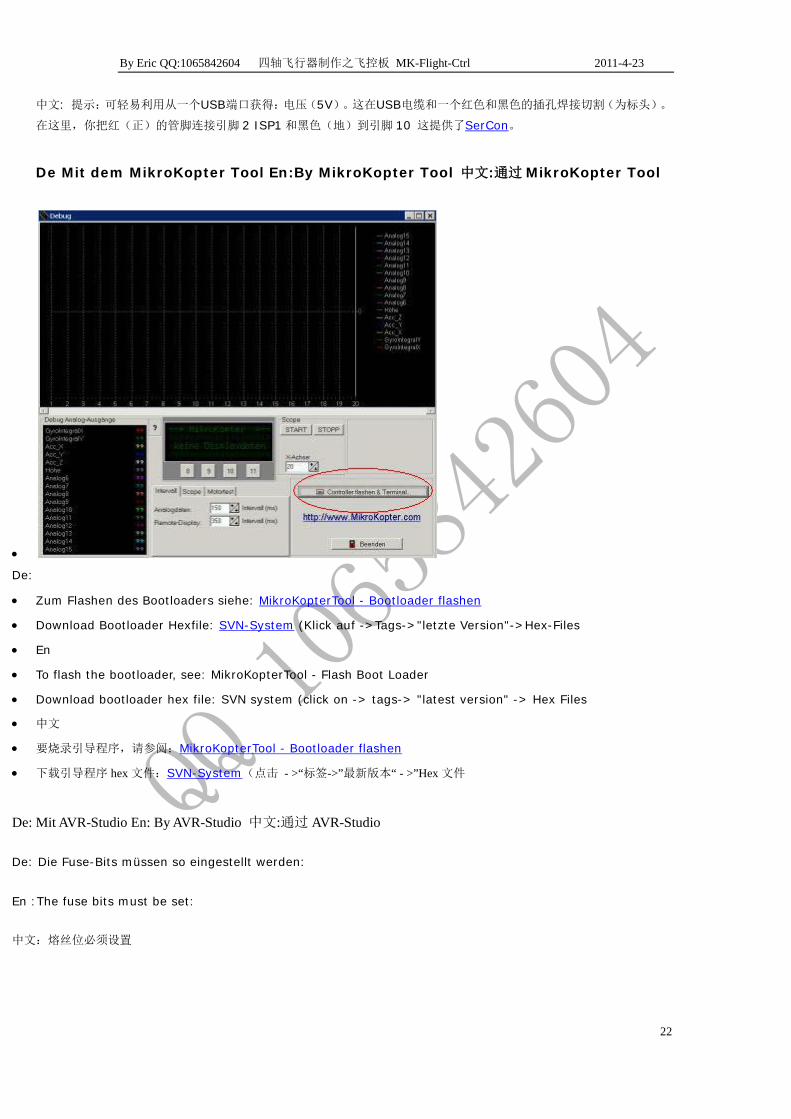
De : Tip: Die Spannung (5V) kann man leicht aus einem USB-Anschluss abgreifen. Dazu zerschneidet man
ein USB-Kabel und lötet an Rot und Schwarz eine Buchse (für die Stiftleisten). Dabei steckt man Rot (Plus)
an Pin 2 vom ISP1-Stecker und Schwarz (Masse) an Pin 10. Damit versorgt die SerCon den Controller auf
der Flight-Ctrl.
En: Tip: The voltage (5V) can be easily tapped from a USB port. This cuts to a USB cable and solder on a red
and black jack (for the headers). Here you put red (positive) to pin 2 of connector ISP1 and black (ground)
to pin 10th This provides the SerCon the controller on the Flight-Ctrl.
By Eric QQ:1065842604 四轴飞行器制作之飞控板 MK-Flight-Ctrl 2011-4-23
22
中文: 提示:可轻易利用从一个USB端口获得:电压(5V)。这在USB电缆和一个红色和黑色的插孔焊接切割(为标头)。
在这里,你把红(正)的管脚连接引脚 2 ISP1 和黑色(地)到引脚 10 这提供了SerCon。
De Mit dem MikroKopter Tool En:By MikroKopter Tool 中文:通过 MikroKopter Tool
•
De:
• Zum Flashen des Bootloaders siehe: MikroKopterTool - Bootloader flashen
• Download Bootloader Hexfile: SVN-System (Klick auf ->Tags->"letzte Version"->Hex-Files
• En
• To flash the bootloader, see: MikroKopterTool - Flash Boot Loader
• Download bootloader hex file: SVN system (click on -> tags-> "latest version" -> Hex Files
• 中文
• 要烧录引导程序,请参阅:MikroKopterTool - Bootloader flashen
• 下载引导程序 hex 文件:SVN-System(点击 - >“标签->”最新版本“ - >”Hex 文件
De: Mit AVR-Studio En: By AVR-Studio 中文:通过 AVR-Studio
De: Die Fuse-Bits müssen so eingestellt werden:
En :The fuse bits must be set:
中文:熔丝位必须设置

By Eric QQ:1065842604 四轴飞行器制作之飞控板 MK-Flight-Ctrl 2011-4-23
23
•
Mit avrdude unter Linux En: by avrdude under Linux 中文: 通过 Linux 下 avrdude
• avrdude -p m644 -P /dev/ttyS0 -c ponyser -b 57600 -U flash:w:BootLoader_MEGA644_20MHZ_VX_X.hex -u -U lfuse:w:0xff:m -U hfuse:w:0xdc:m -U efuse:w:0xfd:m
• X_X durch die Version des Bootloaders ersetzen ; ggf /dev/ttyS0 durch eine andere Schnittstelle ersetzen (不提供翻译)
De:Installieren der Firmware En: Installing the firmware 中文:安装固件
De :Die Firmware wird nun seriell über das SIO Interface mit dem MK-Tool eingespielt. Eine Anleitung findet
man hier: MikroKopterTool - Programm-Update
En :The firmware is now input serially via the SIO interface with the MK tool. For instructions, see here:
MikroKopterTool - Program Update

By Eric QQ:1065842604 四轴飞行器制作之飞控板 MK-Flight-Ctrl 2011-4-23
24
中文:现在输入固件通过串行接口与MK工具链接。有关说明,在这里看到:MikroKopterTool - Programm-Update
De :Alternative: Einspielen des Programms mit PonyProg v2.6g
En: Alternative: Programming with PonyProg v2.6g
中文:可以选择:通过 PonyProg v2.6g 编程
De :Alternativ lässt sich die Software auch mit PonyProg einspielen.
En :Alternatively, the software also import PonyProg.
中文: 另外,该软件还可以导入PonyProg
De :Problembehebung, wenn Zugriff auf den Prozessor fehlschlägt
Ist nach falschem Setzen der Fusebits oder nach einem fehlgeschlagenen Programmieren mit avrdude kein
weiterer Zugriff auf den Prozessor mehr möglich, so kann dieser evtl. mit einem Oszillator wiederbelebt
werden. Siehe dazu den Beitrag AVRWiederbelebung.
En :Fix when access fails on the processor
If, after setting the wrong fuse bits or after a failed avrdude programming with no further access to the
processor possible, this may possibly be revived with an oscillator. See the article AVRWiederbelebung.
中文: 在处理器访问失败时修复
如果在设置了错误的熔丝位或之后,没有进一步的访问处理器可能导致avrdude编程失败,这可能通过振荡器修复。请参
阅文章AVRWiederbelebung.。修复熔丝位故障
De :Test von Gyro- und Beschleunigungssensor En: Test of gyro
and acceleration sensor 中文: 陀螺仪和加速度传感器测试
De :Die Platine wird in die waagerechte Position gebracht und eingeschaltet bzw. resettet und die
Scope-Funktion im MikroKopter-Tool wird gestartet. Falls diese schon lief, sollte sie kurz gestoppt werden,
damit der Zoom-Bereich zurückgesetzt wird. Es werden hier zunächst nur die ersten fünf Analogwerte
beobachtet. Die restlichen Analogwerte können über den Reiter „Scope“ im MikroKopter-Tool abgeschaltet
werden, falls sie das Bild unübersichtlich machen.
Nun wird die Platine möglichst flüssig um ca. 45 Grad in der Nickachse gekippt. (Der Pfeil auf der Platine
zeigt nach vorne). Auf dem Scope beobachtet man die Signale der Messwerte. Dabei sollten das Signal des

By Eric QQ:1065842604 四轴飞行器制作之飞控板 MK-Flight-Ctrl 2011-4-23
25
Nick-Integrals und das des Nick-Beschleunigungssensors (hier rot und gelb) einen deutlichen Ausschlag
zeigen. Wichtig ist, dass die Linien weitestgehend deckungsgleich sind.
Das selbe prüft man auch auf der Rollachse (hier blau und grün):
En :The board is placed in a horizontal position and turned on or reset the scope function in the MikroKopter
tool starts. If this was already running, it should be stopped short to make the zoom range is reset. It will
first observed only the first five analog values. The other analog values can be disabled via the tab "Scope"
in the MikroKopter tool if they make the image confusing.
Now the board as smoothly as possible tilted about 45 degrees in the pitch axis. (The arrow on the board
facing forward). On the scope, the signals of the measured values. They should respect the integral signal
of the pitch and the pitch acceleration sensor (here red and yellow) show a significant scale. It is important
that the lines are largely congruent.
The same check on the roll axis (here, blue and green):
中文: 板子放置在一个水平位置,打开或重置在 MikroKopter 工具启动示波器功能。如果这时候已经运行,它应该停止,
使现实范围复位。首先观察到只有第 5 个模拟值。其他的模拟如果他们使图像混乱可以在 MikroKopter 工具标签“scope”
下被禁止
现在尽可能平滑的是fc板子在俯仰轴Nickachse方向进行 45 度倾斜。(上面临着板箭头)。示波器信号的值,他们应该
反应俯仰角积分和俯仰加速度传感器(这里红色和黄色)信号。重要的是,在很大程度上是线条一致。
再用同样的方法检查横滚轴Rollachse(在这里,蓝色和绿色):
By Eric QQ:1065842604 四轴飞行器制作之飞控板 MK-Flight-Ctrl 2011-4-23
26
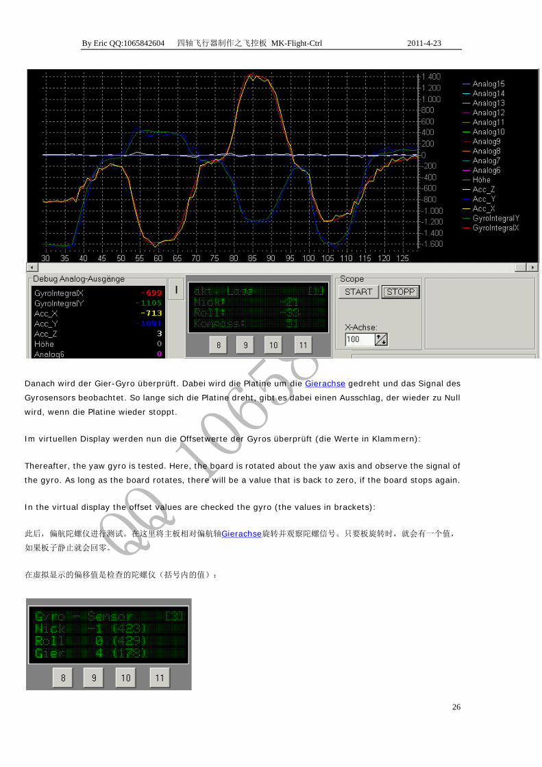
Danach wird der Gier-Gyro überprüft. Dabei wird die Platine um die Gierachse gedreht und das Signal des
Gyrosensors beobachtet. So lange sich die Platine dreht, gibt es dabei einen Ausschlag, der wieder zu Null
wird, wenn die Platine wieder stoppt.
Im virtuellen Display werden nun die Offsetwerte der Gyros überprüft (die Werte in Klammern):
Thereafter, the yaw gyro is tested. Here, the board is rotated about the yaw axis and observe the signal of
the gyro. As long as the board rotates, there will be a value that is back to zero, if the board stops again.
In the virtual display the offset values are checked the gyro (the values in brackets):
此后,偏航陀螺仪进行测试。在这里将主板相对偏航轴Gierachse旋转并观察陀螺信号。只要板旋转时,就会有一个值,
如果板子静止就会回零。
在虚拟显示的偏移值是检查的陀螺仪(括号内的值):

By Eric QQ:1065842604 四轴飞行器制作之飞控板 MK-Flight-Ctrl 2011-4-23
27
De :Dazu blättert man mit den Tasten in das entsprechende Menü. Die Offsets sollten bei den Gyros etwa
um 500 (±100) liegen. In diesem Beispiel hat der Gier-Gyro ein Problem (178). Es muss entweder
nachgetrimmt oder ausgetauscht werden.
En:For this purpose we click through the buttons in the menu. The offsets should be in the gyros around
500 (± 100). In this example, the yaw-gyro has a problem (178). It must be recalibrated or replaced.
中文:为此,我们通过点击菜单中的按钮。偏移量应在陀螺约 500(± 100)。在这个例子中,偏航陀螺有一个问题(178)。
它必须重新调整或更换。
De :Nun wird noch der Beschleunigungssensor überprüft:
En :Now is still under review, the acceleration sensor:
中文:现在仍在检测加速传感器:
De :Für Nick und Roll sollten sich Werte von 465...563 und für Hoch von 651...788 ergeben. Genaues
siehe BeschleunigungsSensor.
Wichtig: Die Platine bzw. der Kopter sollte dabei gerade stehen, die Erdanziehungskraft würde sonst auf die
anderen Achsen wirken und müsste mit berücksichtigt werden.
En :For pitch and roll should values of 465th .. 563 and for high yield of .. 651st 788th Accurate see
acceleration sensor.
Important: The board or the Copts should be put straight, the force of gravity would otherwise contribute
to the other axes, and would have to be considered.
中文:对于俯仰和横滚值应该在 465 到 563 之间最高在 651 到 788 之间 .具体见链接BeschleunigungsSensor.
重要事项:板子或飞行器应该水平放置,否则其他轴会将重力影响考虑在内。
De :Test des Empfangssignals En: Test of the received signal 中
文:接收信号的测试
De :Im virtuellen Display lassen sich die Fernbedienungswerte ablesen:

By Eric QQ:1065842604 四轴飞行器制作之飞控板 MK-Flight-Ctrl 2011-4-23
28
En :The virtual display can be read off the remote values:
中文:由虚拟显示器可以读出远程值:
De :Mit der Fernbedienung lassen sich die Werte im Bereich von ca. -120 bis +120 verändert.
En :With the remote control, the values can be changed in the range of about -120 to +120.
中文:用遥控器控制,可以改变该值 约在-120 至 120 的范围。
De :Test der Spannungsmessung En:Test the voltage
measurement 中文:测试电压测量
De :In einem Menü kann der Wert der Spannungsmessung kontrolliert werden:
En:In an instant, the value of the voltage measurement to be controlled
中文:实时控制 电压的测量:
De :In diesem Beispiel ist das 11,3V.
En:In this example, the 11.3 V
中文:在这个例子中,电压 11.3V
De :Der Empfangspegel ist 0, weil kein Empfänger angeschlossen ist.
En :The receive level is 0 because no receiver is connected

By Eric QQ:1065842604 四轴飞行器制作之飞控板 MK-Flight-Ctrl 2011-4-23
29
中文:接收级别为 0,因为没有接收器。
De :Hinweise zur Inbetriebnahme des Mikrokopters En:
Information on commissioning the Mikrokopter 中文:信息调试
Mikrokopter
De :Ausführliche Anleitungen zum Kalibrieren der Gyros findet man im MikroKopterEinstieg. Alles rund um
die Verkabelung hier: ElektronikVerkabelung
En :Detailed instructions for calibrating the gyros can be found in MikroKopterEinstieg. Everything about
the wiring here: electronics wiring
中文:用于校准陀螺的详细说明中可以在MikroKopterEinstieg找到。一切有关的布线可以再这里找
到: ElektronikVerkabelung
De:Bauteilelisten En:Parts lists 零件清单
De : Tipp: Es empfiehlt sich, beide Seiten der unbestückten Platine zunächst einzuscannen oder zu fotografieren. Das macht es später einfacher ungewollte Lötbrücken und ähnliche Fehler aufzuspüren.
En :Tip: You might want to scan both sides of the bare board first or photographed. This makes it easier
later unwanted solder bridges and similar error detection.
中文: 提示:您首先可能想要裸板两侧扫描或照片。这样更容易焊,并且焊接后不需要的类似的错误检测。