Etherification of benzyl alcohols with 1-hexanol over organosulfonic acid mesostructured materials
Upload
independentCategory
view
2download
0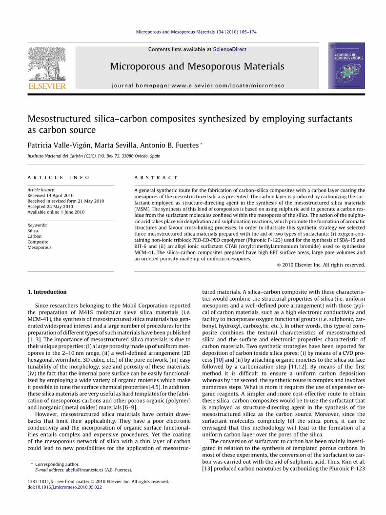
Microporous and Mesoporous Materials 134 (2010) 165–174
Contents lists available at ScienceDirect
Microporous and Mesoporous Materials
journal homepage: www.elsevier .com/locate /micromeso
Mesostructured silica–carbon composites synthesized by employing surfactantsas carbon source
Patricia Valle-Vigón, Marta Sevilla, Antonio B. Fuertes *
Instituto Nacional del Carbón (CSIC), P.O. Box 73, 33080 Oviedo, Spain
a r t i c l e i n f o a b s t r a c t
Article history:Received 14 April 2010Received in revised form 21 May 2010Accepted 24 May 2010Available online 1 June 2010
Keywords:SilicaCarbonCompositeMesoporous
1387-1811/$ - see front matter � 2010 Elsevier Inc. Adoi:10.1016/j.micromeso.2010.05.022
* Corresponding author.E-mail address: [email protected] (A.B. Fuertes).
A general synthetic route for the fabrication of carbon–silica composites with a carbon layer coating themesopores of the mesostructured silica is presented. The carbon layer is produced by carbonizing the sur-factant employed as structure-directing agent in the synthesis of the mesostructured silica materials(MSM). The synthesis of this kind of composites is based on using sulphuric acid to generate a carbon res-idue from the surfactant molecules confined within the mesopores of the silica. The action of the sulphu-ric acid takes place via dehydration and sulphonation reactions, which promote the formation of aromaticstructures and favour cross-linking processes. In order to illustrate this synthetic strategy we selectedthree mesostructured silica materials prepared with the aid of two types of surfactants: (i) oxygen-con-taining non-ionic triblock PEO-EO-PEO copolymer (Pluronic P-123) used for the synthesis of SBA-15 andKIT-6 and (ii) an alkyl ionic surfactant CTAB (cetyltrimethylammonium bromide) used to synthesizeMCM-41. The silica–carbon composites prepared have high BET surface areas, large pore volumes andan ordered porosity made up of uniform mesopores.
� 2010 Elsevier Inc. All rights reserved.
1. Introduction
Since researchers belonging to the Mobil Corporation reportedthe preparation of M41S molecular sieve silica materials (i.e.MCM-41), the synthesis of mesostructured silica materials has gen-erated widespread interest and a large number of procedures for thepreparation of different types of such materials have been published[1–3]. The importance of mesostructured silica materials is due totheir unique properties: (i) a large porosity made up of uniform mes-opores in the 2–10 nm range, (ii) a well-defined arrangement (2Dhexagonal, wormhole, 3D cubic, etc.) of the pore network, (iii) easytunability of the morphology, size and porosity of these materials,(iv) the fact that the internal pore surface can be easily functional-ized by employing a wide variety of organic moieties which makeit possible to tune the surface chemical properties [4,5]. In addition,these silica materials are very useful as hard templates for the fabri-cation of mesoporous carbons and other porous organic (polymer)and inorganic (metal oxides) materials [6–9].
However, mesostructured silica materials have certain draw-backs that limit their applicability. They have a poor electronicconductivity and the incorporation of organic surface functional-ities entails complex and expensive procedures. Yet the coatingof the mesoporous network of silica with a thin layer of carboncould lead to new possibilities for the application of mesostruc-
ll rights reserved.
tured materials. A silica–carbon composite with these characteris-tics would combine the structural properties of silica (i.e. uniformmesopores and a well-defined pore arrangement) with those typi-cal of carbon materials, such as a high electronic conductivity andfacility to incorporate oxygen functional groups (i.e. sulphonic, car-bonyl, hydroxyl, carboxylic, etc.). In other words, this type of com-posite combines the textural characteristics of mesostructuredsilica and the surface and electronic properties characteristic ofcarbon materials. Two synthetic strategies have been reported fordeposition of carbon inside silica pores: (i) by means of a CVD pro-cess [10] and (ii) by attaching organic moieties to the silica surfacefollowed by a carbonization step [11,12]. By means of the firstmethod it is difficult to ensure a uniform carbon depositionwhereas by the second, the synthetic route is complex and involvesnumerous steps. What is more it requires the use of expensive or-ganic reagents. A simpler and more cost-effective route to obtainthese silica–carbon composites would be to use the surfactant thatis employed as structure-directing agent in the synthesis of themesostructured silica as the carbon source. Moreover, since thesurfactant molecules completely fill the silica pores, it can beenvisaged that this methodology will lead to the formation of auniform carbon layer over the pores of the silica.
The conversion of surfactant to carbon has been mainly investi-gated in relation to the synthesis of templated porous carbons. Inmost of these experiments, the conversion of the surfactant to car-bon was carried out with the aid of sulphuric acid. Thus, Kim et al.[13] produced carbon nanotubes by carbonizing the Pluronic P-123

166 P. Valle-Vigón et al. / Microporous and Mesoporous Materials 134 (2010) 165–174
triblock copolymer (PEO-EO-PEO) trapped inside the mesopores ofsilica with a 2D hexagonal pore arrangement. Kim et al. [14], Liuet al. [15] and Yan et al. [16] propose the use of the surfactant (Plu-ronic P-123) confined within the silica pores as precursor for thesynthesis of templated mesoporous carbons. Liu et al. [17] haveinvestigated the possibility of modulating the mesopore size viathe formation of a carbon layer within the pores of the silica. Itshould be noted that in all previous works, only the non-ionic
Table 1Structural parameters of the silica samples (calcined at 550 �C) and silica–carbon compos
Sample Carbon (wt.%) SBET (m2 g�1) Vp (cm3 g�1)a
KIT-6 – 730 1.3KIT-6/C 10 520 1.0SBA-15 – 640 1.22SBA-15/C 13 460 0.78MCM-41 – 960 0.82MCM-41/C 10 710 0.58
a Pore volume determined at p/po = 0.99.b Maximum of the pore size distribution. The full width at half maximum (in nm) ofc Pore volume of structural mesopores.d External surface area.e Unit cell parameter, a (KIT-6 or KIT-6/C) = 61/2d211, a (SBA-15/MCM-41 or SBA-15-C
0
200
400
600
800
0.0 0.2 0.4 0.6 0.8 1.0
Relative pressure (p/po)
Ad
sorb
ed
vo
lum
e, c
m 3 S
TP
·g-1
KIT-6
KIT-6/C
0
25
50
75
100
8 9 10 11 12 13Pore size (D), nm
dV/d
log(
D),
cm
3 ·g-1
9.4 nm
10.4 nm
0.0 0.2 0.4
Relative press
0
100
200
300
400
500
Ads
orbe
d vo
lum
e, c
m
3 ST
P·g
-1
MCM-41
MCM-41/C
0
10
20
30
40
2
dV/d
log(
D),
cm
3·g
-1
a
c
Fig. 1. Nitrogen sorption isotherms and pore size distributions (insets) of the silica andMCM-41 and MCM-41/C.
PEO-EO-PEO triblock copolymer surfactants (mostly Pluronic P-123) were used as carbon source. The employ of sulphuric acidfor the generation of carbon from the organic substance is not lim-ited to the surfactants. Thus, the conversion of the sucrose into car-bon in presence of sulphuric acid is a procedure commonlyemployed to fabricate templated mesoporous carbons [18]. A re-cent example of this methodology has been reported by Deviet al. [19], which described the synthesis of a sulphonated carbona-
ites (carbonized at 800 �C).
Pore size (nm)b as-plot results a (nm)e
Vm (cm3 g�1)c Sext (m2 g�1)d
10.4 (0.4) 1.3 55 23.79.4 (0.6) 0.91 19 23.29.7 (0.9) 1.08 73 11.18.8 (1.8) 0.95 44 11.03.2 (0.1) 0.77 20 4.72.9 (0.2) 0.52 15 4.5
the pore size distribution is given in parentheses.
/MCM-41-C) = 2 � 3�1/2d100.
0
200
400
600
800
0.0 0.2 0.4 0.6 0.8 1.0
Relative pressure (p/po)
0.6 0.8 1.0
ure (p/po)
Ad
sorb
ed
volu
me,
cm
3 ST
P·g
-1
SBA-15
SBA-15/C
0
5
10
15
20
5 10 15 20Pore size (D), nm
dV/d
log(
D),
cm
3 ·g-1
9.7 nm
8.8nm
3 4 5Pore size (D), nm
3.2 nm
2.9 nm
b
silica–carbon composites. (a) KIT-6 and KIT-6/C, (b) SBA-15 and SBA-15/C and (c)
P. Valle-Vigón et al. / Microporous and Mesoporous Materials 134 (2010) 165–174 167
ceous material obtained through the carbonization of a mixture ofglycerol and sulphuric acid. However, although the sulphuric acidhas been widely employed to prepare carbon materials from a vari-ety of organic substances, its role in the conversion of organic mol-ecules to carbon has hardly been investigated.
In the present work, we carried out a systematic investigationinto the fabrication of carbon coated mesostructured silica materi-als by carbonizing hybrid silica/surfactant materials. This study isnot only limited to silica/triblock (PEO-EO-PEO) nanocompositesbut also introduces a methodology for fabricating silica–carboncomposites by using ionic surfactants as carbon source i.e. n-alkyl-trimethylammonium halides (CTAB). This synthetic method hasbeen used to fabricate a variety of silica–carbon composites basedon the PEO-EO-PEO triblock surfactant Pluronic P-123 (SBA-15/Cand KIT-6/C) and on cationic alkyl surfactant CTAB (MCM-41/C).The mechanism via which carbon is formed from these surfactantswas also investigated.
0.5 1.5 2.5 32 Theta
Inte
nsity
(a.
u.)
0.5 1.5 2.5 3.5 4.5
2 Theta (º)
Inte
nsity
(a.
u.)
KIT-6
KIT-6/C
MC
(211)
(220)
(420)
(100) c
a
Fig. 2. XRD patterns in the low-angle region of the mesostructured silica materials andSBA-15/C and (c) MCM-41 and MCM-41/C.
2. Experimental
2.1. Preparation of hybrid silica/surfactant materials
2.1.1. KIT-6/P-123This hybrid silica/surfactant material was prepared as described
by Kleitz et al. [20] by using a non-ionic oligomeric alkyl-ethyleneoxide surfactant as structure-directing agent, i.e. Pluronic P-123. A2.4 g of Pluronic P-123 (Aldrich) was dissolved in 66.4 g of waterand 22.9 g HCl 2 M. Once the surfactant had dissolved, 2.4 g n-butanol (Aldrich, >99.4%) was added, the mixture then being main-tained under stirring at 35 �C for 1 h. Then, 5.16 g of tetraethylorthosilicate (TEOS, Aldrich, 98%) was added and the resulting mix-ture was kept under stirring for 24 h at 35 �C and subsequentlyheated under static conditions for 24 h at 130 �C. The solid productobtained was separated by centrifugation, washed with distilledwater and ethanol and dried at 100 �C.
.5 4.5 5.5 (º)
0.5 1.5 2.5 3.5 4.52 Theta (º)
Inte
nsity
(a.
u.)
SBA-15/C
SBA-15
M-41/C
MCM-41
(100)
(110) (200)
(110) (200)
b
the corresponding silica–carbon composites. (a) KIT-6 and KIT-6/C, (b) SBA-15 and
168 P. Valle-Vigón et al. / Microporous and Mesoporous Materials 134 (2010) 165–174
2.1.2. SBA-15/P-123This hybrid composite was synthesised, under acid pH, as re-
ported by Zhao et al. [21]. In a typical synthesis, the silica source(TEOS) was added to an aqueous solution containing HCl and sur-factant (starting mol ratio: TEOS/surfactant/HCl/H2O = 1/0.017/5.7/193). The mixture was then magnetically stirred until the TEOSwas well-dispersed. Next, it was placed in a closed Teflon vesseland stirred for 20 h at 35 �C and allowed to age at a temperatureof 135 �C. The solid product was recovered as before.
2.1.3. MCM-41/CTABThe synthesis of this hybrid material was performed as
explained by Grün et al. [22]. About 2 g of CTAB (Aldrich, 95%)was dissolved in 100 g water and 7.6 g of aqueous ammonia(25 wt.%). While being stirred, 8 g of TEOS was added slowly tothe solution for a period of 15 min. The mixture was then stirredfor 1 h and transferred to a Teflon autoclave and maintained at105 �C for 7 days. The solid product was recovered by means ofthe procedure outlined above.
2.2. Synthesis of the silica–carbon composites
The silica–carbon composites were prepared from the hybridsilica/surfactant samples with the aid of sulphuric acid. One gramof hybrid silica/surfactant material was dispersed, under stirringfor 1 h, in a mixture of 10 g water and around 0.2 g of H2SO4 (Pro-
Fig. 3. TEM images of the silica–carbon composites
labo, 98 wt.%). This dispersion was heat-treated in air at 100 �C for6 h and then at 160 �C for around 12 h. Next, the resulting black so-lid was heated under a nitrogen flow up to 800 �C for 1 h (heatingrate: 3 �C/min). In the case of the hybrid samples which containedalkyl surfactants (i.e. CTAB), prior to treatment with sulphuric acid,the material was oxidized with a solution of H2O2 (Prolabo,30 wt.%) for 15 h. The oxidation step was introduced in order tocreate oxygen functional groups that favour the action of sulphuricacid via dehydration reactions. The silica–carbon samples were de-noted as X/C where X = KIT-6, SBA-15 or MCM-41 depending onthe type of mesostructured silica material. Porous carbon materialswere obtained by removing the silica from the silica–carbon com-posites with HF (Prolabo, 48 wt.%). Obviously, the dissolution ofthe silica framework indicates that the formed carbon layer has acertain porosity that permits the diffusion of the etching agentup to the silica walls. These carbon samples are denoted asC � (X) where X = KIT-6, SBA-15 or MCM-41.
2.3. Characterisation of the materials
Small and wide angle X-ray diffraction (XRD) patterns were ob-tained on a Siemens D5000 instrument operating at 40 kV and20 mA and using Cu Ka radiation (k = 0.15406 nm). Nitrogen sorp-tion isotherms were performed at �196 �C on a MicromeriticsASAP 2020 volumetric adsorption system. The BET surface areawas deduced from the analysis of isotherm in the relative pressure
. (a) KIT-6/C, (b) SBA-15/C and (c) MCM-41/C.
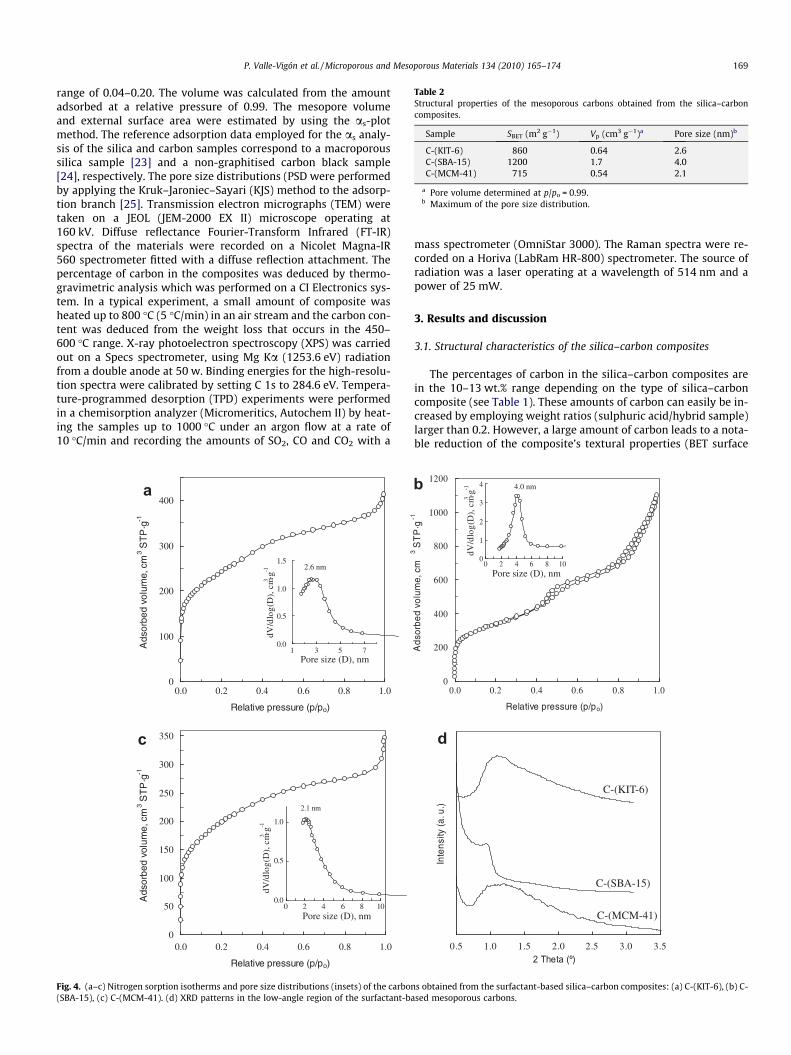
Table 2Structural properties of the mesoporous carbons obtained from the silica–carboncomposites.
Sample SBET (m2 g�1) Vp (cm3 g�1)a Pore size (nm)b
C-(KIT-6) 860 0.64 2.6C-(SBA-15) 1200 1.7 4.0C-(MCM-41) 715 0.54 2.1
a Pore volume determined at p/po = 0.99.b Maximum of the pore size distribution.
P. Valle-Vigón et al. / Microporous and Mesoporous Materials 134 (2010) 165–174 169
range of 0.04–0.20. The volume was calculated from the amountadsorbed at a relative pressure of 0.99. The mesopore volumeand external surface area were estimated by using the as-plotmethod. The reference adsorption data employed for the as analy-sis of the silica and carbon samples correspond to a macroporoussilica sample [23] and a non-graphitised carbon black sample[24], respectively. The pore size distributions (PSD were performedby applying the Kruk–Jaroniec–Sayari (KJS) method to the adsorp-tion branch [25]. Transmission electron micrographs (TEM) weretaken on a JEOL (JEM-2000 EX II) microscope operating at160 kV. Diffuse reflectance Fourier-Transform Infrared (FT-IR)spectra of the materials were recorded on a Nicolet Magna-IR560 spectrometer fitted with a diffuse reflection attachment. Thepercentage of carbon in the composites was deduced by thermo-gravimetric analysis which was performed on a CI Electronics sys-tem. In a typical experiment, a small amount of composite washeated up to 800 �C (5 �C/min) in an air stream and the carbon con-tent was deduced from the weight loss that occurs in the 450–600 �C range. X-ray photoelectron spectroscopy (XPS) was carriedout on a Specs spectrometer, using Mg Ka (1253.6 eV) radiationfrom a double anode at 50 w. Binding energies for the high-resolu-tion spectra were calibrated by setting C 1s to 284.6 eV. Tempera-ture-programmed desorption (TPD) experiments were performedin a chemisorption analyzer (Micromeritics, Autochem II) by heat-ing the samples up to 1000 �C under an argon flow at a rate of10 �C/min and recording the amounts of SO2, CO and CO2 with a
0
50
100
150
200
250
300
350
0.0 0.2 0.4 0.6 0.8 1.0
Relative pressure (p/po)
Ads
orbe
d vo
lum
e, c
m 3 S
TP
·g-1
0.0
0.5
1.0
0 2 4 6 8 10
2.1 nm
0
100
200
300
400
0.0 0.2 0.4 0.6 0.8 1.0
Relative pressure (p/po)
Ads
orbe
d vo
lum
e, c
m 3 S
TP
·g-1
0.0
0.5
1.0
1.5
1 3 5 7Pore size (D), nm
Pore size (D), nm
dV/d
log(
D),
cm3 ·g
-1dV
/dlo
g(D
), c
m3 ·g-1
2.6 nm
a
c
Fig. 4. (a–c) Nitrogen sorption isotherms and pore size distributions (insets) of the carbon(SBA-15), (c) C-(MCM-41). (d) XRD patterns in the low-angle region of the surfactant-ba
mass spectrometer (OmniStar 3000). The Raman spectra were re-corded on a Horiva (LabRam HR-800) spectrometer. The source ofradiation was a laser operating at a wavelength of 514 nm and apower of 25 mW.
3. Results and discussion
3.1. Structural characteristics of the silica–carbon composites
The percentages of carbon in the silica–carbon composites arein the 10–13 wt.% range depending on the type of silica–carboncomposite (see Table 1). These amounts of carbon can easily be in-creased by employing weight ratios (sulphuric acid/hybrid sample)larger than 0.2. However, a large amount of carbon leads to a nota-ble reduction of the composite’s textural properties (BET surface
0.5 1.0 1.5 2.0 2.5 3.0 3.52 Theta (º)
Inte
nsity
(a. u
.)
C-(MCM-41)
C-(SBA-15)
C-(KIT-6)
dV/d
log(
D),
cm3 ·g
-1
0
200
400
600
800
1000
1200
0.0 0.2 0.4 0.6 0.8 1.0
Relative pressure (p/po)
Ads
orbe
d vo
lum
e, c
m
3 ST
P·g
-1
0
1
2
3
4
0 2 4 6 8 10Pore size (D), nm
4.0 nmb
d
s obtained from the surfactant-based silica–carbon composites: (a) C-(KIT-6), (b) C-sed mesoporous carbons.
500150025003500
Wavenumber (cm-1)
Tran
smita
nce
(a. u
.)
KIT-6
KIT-6/C
KIT-6/P-123
a
500150025003500
Wavenumber (cm -1)
Tran
smita
nce
(a.u
.)
MCM-41/CTAB
MCM-41
MCM-41/C
b
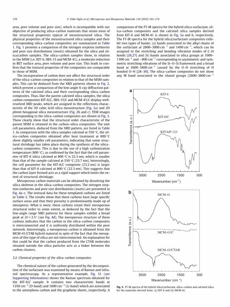
Fig. 5. FT-IR spectra of the hybrid silica/surfactant, silica–carbon and calcined silicafor the materials derived from: (a) KIT-6 and (b) MCM-41.
170 P. Valle-Vigón et al. / Microporous and Mesoporous Materials 134 (2010) 165–174
area, pore volume and pore size), which is incompatible with ourobjective of producing silica–carbon materials that retain most ofthe structural properties typical of mesostructured silica. Thephysical properties of the mesostructured silica samples and theircorresponding silica–carbon composites are summarized in Table1. Fig. 1 presents a comparison of the nitrogen sorption isothermsand pore size distributions (insets) obtained for the silica and sil-ica/carbon samples. The silica–carbon samples show, in relationto the MSM (i.e. KIT-6, SBA-15 and MCM-41), a moderate reductionin BET surface area, pore volume and pore size. This leads to con-firm that the textural properties of the composites are comparableto those of MSM.
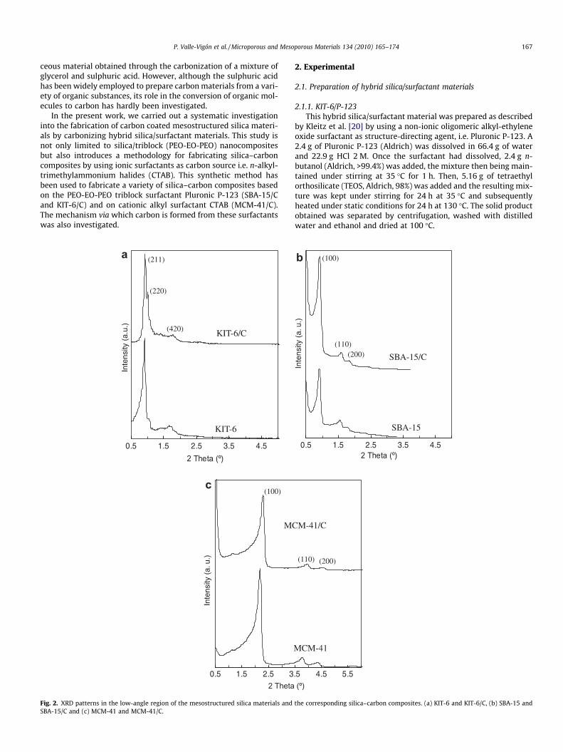
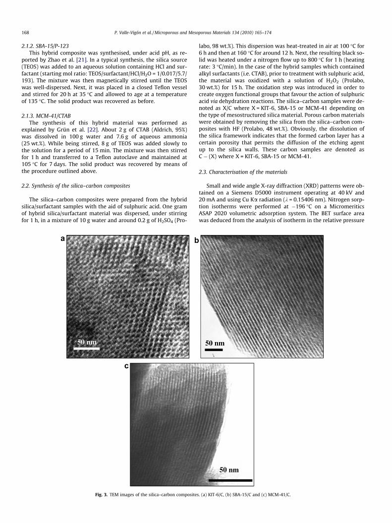
The incorporation of carbon does not affect the structural orderof the silica–carbon composites in relation to that of the MSM sam-ples. This can be deduced from the XRD patterns shown in Fig. 2,which present a comparison of the low-angle X-ray diffraction pat-terns of the calcined silica and their corresponding silica–carboncomposites. Thus, like the parent calcined silica samples, the silicacarbon composites KIT-6/C, SBA-15/C and MCM-41/C display well-resolved XRD peaks, which are assigned to the reflections charac-teristic of the 3D cubic Ia3d silica mesostructure (Fig. 2a) and 2Dp6mm hexagonal silica mesostructure (Fig. 2b and c). TEM imagescorresponding to the silica–carbon composites are shown in Fig. 3.These clearly show that the structural order characteristic of theparent MSM is retained in the carbon–silica composites. The unitcell parameters, deduced from the XRD pattern, are listed in Table1. In comparison with the silica samples calcined at 550 �C, the sil-ica–carbon composites obtained after heat treatment at 800 �Cshow slightly smaller cell parameters, indicating that some struc-tural shrinkage has taken place during the synthesis of the silica–carbon composites. This is due to the use of a high carbonizationtemperature (800 �C), as confirmed by the fact that the cell param-eter of KIT-6 silica calcined at 800 �C is 22.3 nm, which is smallerthan that of the sample calcined at 550 �C (23.7 nm). Interestingly,the cell parameter for the KIT-6/C composite (23.2 nm) is largerthan that of KIT-6 calcined at 800 �C (22.3 nm). This suggests thatthe carbon layer formed acts as a rigid support which limits the ex-tent of structural shrinkage.
Mesoporous carbon materials can be obtained by dissolving thesilica skeleton in the silica–carbon composites. The nitrogen sorp-tion isotherms and pore size distributions (insets) are presented inFig. 4a–c. The textural data for these templated carbons are listedin Table 2. The results show that these carbons have large specificsurface areas and that their porosity is predominantly made up ofmesopores. What is more, these carbons retain their mesoporousstructural order to some extent, as deduced by the fact that thelow-angle range XRD patterns for these samples exhibit a broadpeak at 2h < 2.5� (see Fig. 4d). The mesoporous structure of thesecarbons indicates that the carbon in the silica–carbon compositesis interconnected and it is uniformly distributed within the porenetwork. Interestingly, a mesoporous carbon is obtained from theMCM-41/CTAB hybrid material in spite of the fact that the mesop-ores of this type of silica are not interconnected. An explanation forthis could be that the carbon produced from the CTAB moleculessituated outside the silica particles acts as a linker between thecarbon clusters.
3.2. Chemical properties of the silica–carbon composites
The chemical nature of the carbon generated by the decomposi-tion of the surfactant was examined by means of Raman and infra-red spectroscopy. As a representative example, Fig. S1 (seeSupporting Information) shows the Raman spectrum obtained forthe KIT-6/C sample. It contains two characteristic bands at1350 cm�1 (D-band) and 1600 cm�1 (G-band) which are associatedto the amorphous carbon and the graphene sheets, respectively. A
comparison of the FT-IR spectra for the hybrid silica-surfactant, sil-ica–carbon composites and the calcined silica samples derivedfrom KIT-6 and MCM-41 is shown in Fig. 5a and b, respectively.The FT-IR spectra for the hybrid silica/surfactant composites exhi-bit two types of bands: (a) bands associated to the alkyl chains ofthe surfactant at 2800–3000 cm�1 and 1490 cm�1, which can beassigned to the stretching and bending vibration modes of C–Hbonds [26,27] and (b) bands associated to silica groups at 1000–1300 cm�1 and �800 cm�1 corresponding to asymmetric and sym-metric stretching vibrations of the Si–O–Si framework and a broadband at 2600–3800 cm�1 caused by the O–H stretching of Hbonded O–H [28–30]. The silica–carbon composites do not showany IR band associated to the silanol groups (2600–3800 cm�1

5001000150020002500300035004000Wavenumber, cm -1
Tran
smita
nce
(a. u
.)
S=O
S-O
C=C
O-HC=O
C-H
OH····H
a
b
c
d
Fig. 7. FT-IR spectra corresponding to the carbonaceous samples obtained from thehybrid materials (silica/surfactant) treated with H2SO4 up to 160 �C and 300 �C. (a)MCM-41/CTAB at 160 �C, (b) MCM-41/CTAB at 300 �C, (c) SBA-15/P-123 at 160 �Cand (d) SBA-15/P-123 at 300 �C.
P. Valle-Vigón et al. / Microporous and Mesoporous Materials 134 (2010) 165–174 171
range). Moreover, when the carbon layer in the silica–carbon com-posites is removed (by calcination in air), the broad IR band asso-ciated to the silanol groups re-emerges in the resulting silicasamples. These silica samples show a sharp peak at 3750 cm�1
due to the stretching modes of isolated OH groups. The above re-sults suggest that the silica surface is completely coated by the car-bon layer in the silica–carbon composites.
X-ray photoelectron spectroscopy (XPS) was used to character-ize the oxygen functionalities associated to carbon which are pres-ent on the carbon layer of the silica–carbon composites. As arepresentative example, Fig. 6 shows the C 1s and O 1s core-levelspectra of the SBA-15/C composite and the peak fittings of the C1s and O 1s envelopes. Four peaks can be identified in the C 1sspectrum represented in Fig. 6a. The two peaks at lower bindingenergies correspond to the carbon which is not attached to oxygen(dashed line), whereas the other two peaks at higher binding ener-gies are attributed to carbon bonded to oxygen (solid line). Thus,the peak at 284.4 eV corresponds to C@C, the peak at 285.3 eV toC–C/C–Hx, the peak at 286.1 eV to –C–OR in the hydroxyl groupsor ethers and the last one at 289.0 eV to –COO in the carboxylicgroups, esters or lactones [31,32]. The O 1s spectrum confirmsthe presence of these oxygenated groups. Thus, as shown inFig. 6b, the peak corresponding to oxygen atoms in the carboxylgroups, esters or lactones is identified at 532.3 eV (dashed line).In addition, the peak at 533.7 eV (solid line) can be attributed tooxygen atoms in hydroxyl groups or ethers [32–34].
3.3. Mechanism of formation of carbon from the surfactants
The surfactant molecules contained in the as-synthesized silicasamples had completely decomposed into gaseous species duringpyrolysis (no carbon residue was detected), as demonstrated bythe thermogravimetric analysis shown in Fig. S2a (see SupportingInformation) for the MCM-41 and SBA-15 samples. In contrast,for the hybrid silica-surfactant materials previously treated withH2SO4, an important fraction of surfactant was transformed intocarbon during pyrolysis (�20 wt.%). This is illustrated by the ther-mograms in Fig. S2b (see Supporting Information). These resultsclearly demonstrate that the sulphuric acid plays a crucial role ingenerating carbon from the surfactants.
In order to elucidate the role of the sulphuric acid in the forma-tion of the carbonaceous material, we examined the chemical char-
Inte
nsity
(a.
u.)
Binding Energy (eV)282 284 286 288 290 292 294
a
Fig. 6. (a) C 1s and (b) O 1s core-level s
acteristics of materials obtained at several stages of the synthesisprocess. Thus, the functionalities present in the organic materials(the silica was removed using HF) derived from MCM-41 andSBA-15 after treatment with sulphuric acid at 160 �C and carbon-ization at 300 �C were examined by infrared spectroscopy(Fig. 7). The FT-IR spectra reveal the presence of sulphonic groups(–SO3H) in these samples. Indeed, the bands at 780 cm�1 are as-signed to S–O stretching vibrations, whereas the sharp peaks at1040 cm�1 are associated to symmetric S@O stretching vibrations[35,36]. Also significant is the broad band at 2450–2700 cm�1,which is assigned to an overtone of the bending mode of OH� � �Olinked by a strong hydrogen bond, suggesting that some –SO3Hgroups are contiguous [37]. These spectra also show other bandsthat are assigned to C@O stretching (1730 cm�1), C@C stretching(1630 cm�1), O–H bending (1250 cm�1) and C–H stretching and
Binding Energy (eV)528 530 532 534 536
Inte
nsity
(a.
u.)
b
pectra of the composite SBA-15/C.

0 1 2 3Energy (KeV)
Cou
nts
C
SO
0.00
0.01
0.02
0.03
0.04
0.05
0 200 400 600 800Temperature, ºC
Gas
con
cent
ratio
n, (
vol %
) CO
CO2
SO2
500 counts
160ºC (S=1.32 wt %)
300ºC (S=0.90 wt %)
800ºC (S=0.21 wt %)
a b
Fig. 8. (a) Variation of the concentration of evolved gases (TPD experiment) during the thermal treatment under nitrogen (heating rate: 5 �C/min) of the SBA-15/P-123 sampletreated in air at 160 �C (15 h) in the presence of H2SO4. (b) Energy-dispersive X-ray (EDX) spectra corresponding to the carbonaceous samples obtained from the MCM-41/CTAB hybrid material treated with H2SO4 up to 160 �C, 300 �C and 800 �C.
172 P. Valle-Vigón et al. / Microporous and Mesoporous Materials 134 (2010) 165–174
bending vibrations (2800–3000 cm�1 and 1460 cm�1) associated toalkyl residues from the surfactants (CTAB and P-123) [38]. Thepresence of C@C linkages suggests that parallel to the sulphonationof the surfactant molecules, a dehydration process occurs.
The sulphonic groups that are fixed during the sulphuric acidtreatment at 160 �C decompose during carbonization. This was de-
900 1100 1300 1500 1700 1900
Raman Shift (cm-1)
Imte
sity
(a.
u)
90
a
800ºC
MCM-41/CTAB
100ºC
160ºC
300ºC
Fig. 9. Raman spectra of the samples collected at different stages of the carbonizationmaterials.
duced from the temperature-programmed desorption (TPD) exper-iments on the sulphonated silica/surfactant samples (in H2SO4 at160 �C). A pronounced release of SO2 can be seen in the 200–400 �C range (maximum at �280 �C), which can be ascribed tothe decomposition of the unreacted sulphuric acid (H2SO4 ? -H2O + SO3) and most of the –SO3H groups. As an example, the
0 1100 1300 1500 1700 1900
Raman Shift (cm-1)
b
800ºC
300ºC
160ºC
SBA-15/P-123
process corresponding to the samples based on the (a) MCM-41 and (b) SBA-15
P. Valle-Vigón et al. / Microporous and Mesoporous Materials 134 (2010) 165–174 173
TPD curves of SO2, CO and CO2 for the SBA-15/P-123 sample whichwas treated with sulphuric acid (160 �C) are shown in Fig. 8a. Thepeaks corresponding to CO and CO2 show that, as the sulphuricacid and sulphonic groups decompose, the carbonaceous materialis partially gasified due to its oxidation by the in situ producedSO3 (SO3 + C ? SO2 + CO/CO2) and also due to the decompositionof oxygen groups as the temperature increases. However, not allthe fixed sulphur is released during the carbonization step. Thisis evidenced by the energy-dispersive X-ray spectra obtained forthe H2SO4-treated MCM-41/CTAB-based materials (Fig. 8b). Thesereveal: (a) a reduction of the sulphur content in the carbonaceousmaterial as the temperature increases and (b) that a small amountof sulphur remains in the carbonaceous material after carboniza-tion at 800 �C (S = 0.2 wt.%). This type of sulphur is probably asso-ciated to highly stable sulphur functionalities in the form ofsulphide bridges (–S–), as was observed in the pyrolysed sulpho-nated styrene–divinylbenzene copolymer [39].
Raman spectroscopy was applied to the samples obtained atseveral stages of the carbonization in order to acquire informationabout the evolution of the chemical nature of the carbonaceousmaterial. The Raman spectra for the MCM-41 and SBA-15 basedmaterials are represented in Fig. 9. The spectra for the as-synthe-sized silica/surfactant samples (i.e. MCM-41/CTAB and SBA-15/P-123) exhibit several peaks associated to the alkyl chains and ethergroups (SBA-15/P-123) of the surfactant molecules confined with-in the pores of the silica [38]. The spectrum corresponding to theMCM-41/CTAB sample which was impregnated with H2SO4 andtreated at 100 �C exhibits three broad bands; a strong band cen-tered at �1150 cm�1 and two weak bands at �1300 cm�1 and
O
O
O S
O
S
O
Heat treat
800ºC
Silica / Surfactant
H2SO
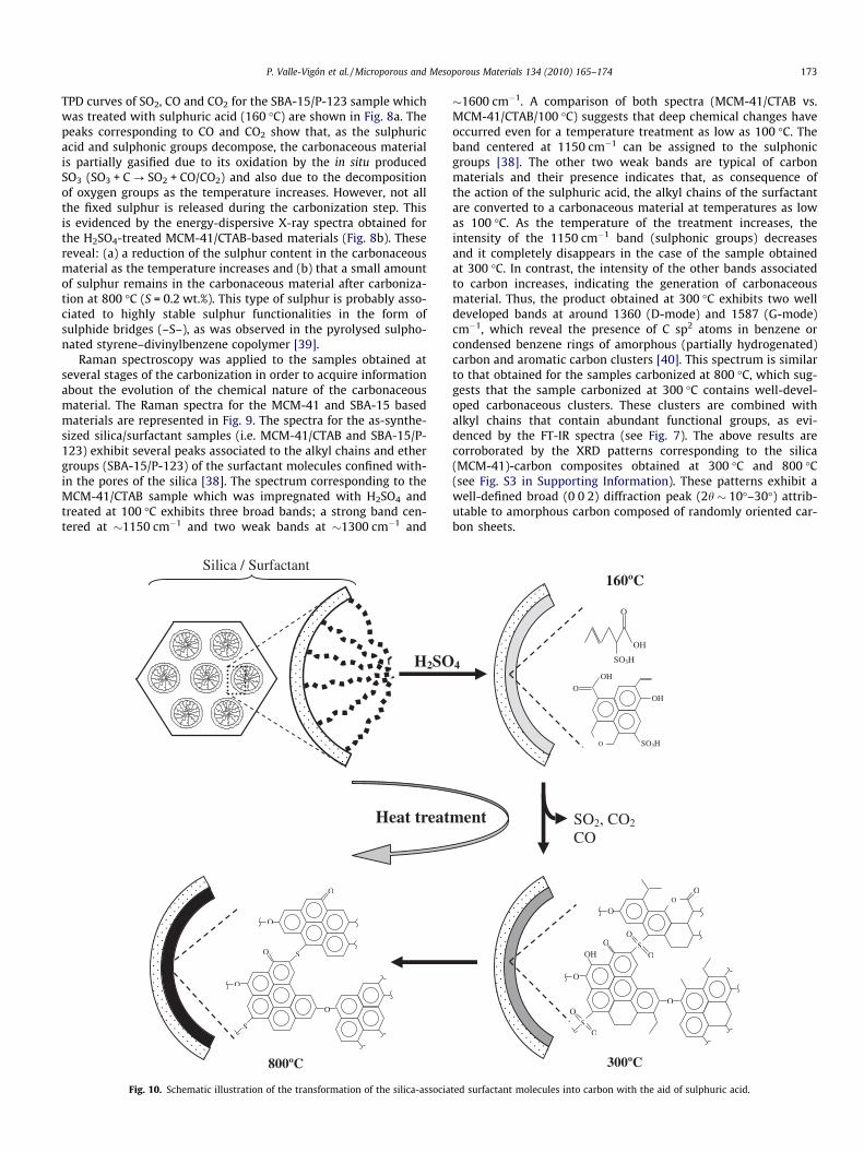
Fig. 10. Schematic illustration of the transformation of the silica-associa
�1600 cm�1. A comparison of both spectra (MCM-41/CTAB vs.MCM-41/CTAB/100 �C) suggests that deep chemical changes haveoccurred even for a temperature treatment as low as 100 �C. Theband centered at 1150 cm�1 can be assigned to the sulphonicgroups [38]. The other two weak bands are typical of carbonmaterials and their presence indicates that, as consequence ofthe action of the sulphuric acid, the alkyl chains of the surfactantare converted to a carbonaceous material at temperatures as lowas 100 �C. As the temperature of the treatment increases, theintensity of the 1150 cm�1 band (sulphonic groups) decreasesand it completely disappears in the case of the sample obtainedat 300 �C. In contrast, the intensity of the other bands associatedto carbon increases, indicating the generation of carbonaceousmaterial. Thus, the product obtained at 300 �C exhibits two welldeveloped bands at around 1360 (D-mode) and 1587 (G-mode)cm�1, which reveal the presence of C sp2 atoms in benzene orcondensed benzene rings of amorphous (partially hydrogenated)carbon and aromatic carbon clusters [40]. This spectrum is similarto that obtained for the samples carbonized at 800 �C, which sug-gests that the sample carbonized at 300 �C contains well-devel-oped carbonaceous clusters. These clusters are combined withalkyl chains that contain abundant functional groups, as evi-denced by the FT-IR spectra (see Fig. 7). The above results arecorroborated by the XRD patterns corresponding to the silica(MCM-41)-carbon composites obtained at 300 �C and 800 �C(see Fig. S3 in Supporting Information). These patterns exhibit awell-defined broad (0 0 2) diffraction peak (2h � 10�–30�) attrib-utable to amorphous carbon composed of randomly oriented car-bon sheets.
O
O
O
O
O
SO
O
SO
O
OH
O
SO2, CO2
CO ment
160ºC
300ºC
OH
O
SO3H
OH
O
O
OH
SO3H 4
ted surfactant molecules into carbon with the aid of sulphuric acid.
174 P. Valle-Vigón et al. / Microporous and Mesoporous Materials 134 (2010) 165–174
The experiments described clearly show that sulphuric acid isessential for the generating carbon residue from surfactant mole-cules. From a mechanistic point of view, the above results suggestthat sulphuric acid is involved in two types of process: dehydrationreactions and the formation of sulphonic groups, both of which oc-cur at low temperature (160 �C) and play an important role in theformation of carbonaceous residue. Thus, whereas dehydrationreactions favour aromatization, sulphonation increases the carbon-ization yield due to cross-linking processes resulting from the for-mation of sulphide bridges between adjacent phenyl rings. On thebasis of the previous results, Fig. 10 provides a schematic illustra-tion of the formation of carbonaceous material via the sulphona-tion of the alkyl chains of surfactant molecules confined withinthe mesopores of the silica. Finally, we want to point out that inour opinion, the role of sulphuric acid in the formation of carbonfrom a variety of organic substances such the mentioned sucroseor glycerol, will be similar to that described here in relation tothe surfactants.
4. Conclusions
In summary, we have reported a synthetic procedure for thefabrication of silica–carbon composites consisting of mesoporoussilica materials, whose porosity is coated with carbon. The syn-thetic strategy employs as carbon source the surfactant moleculesthat are used as structure-directing agents in the synthesis of themesostructured silica. This procedure has been applied to twotypes of surfactants: (a) an alkyl ionic surfactant (cetyltrimethyl-ammonium bromide: CTAB) and (b) an oxygen-containing non-io-nic triblock PEO-EO-PEO copolymer (Pluronic P-123). Thesesurfactants were used for the synthesis of three types of silicamaterials, i.e. MCM-41 (CTAB), KIT-6 (P-123) and SBA-15 (P-123).The silica–carbon composites retain the structural order character-istic of mesostructured silica materials, and they exhibit a largespecific surface area and a porosity made up of uniform and widemesopores. The onset of the conversion of the surfactant to carbonis achieved at low temperatures (i.e. 160 �C) by means of sulphuricacid, which is essential for generating a carbonaceous residue fromthe surfactant molecules. The action of the sulphuric acid takesplace via dehydration and sulphonation reactions, which promotethe formation of aromatic structures and favour cross-linking pro-cesses. The present approach provides an easy route for synthesis-ing mesoporous silica–carbon composites that combine thestructural properties of mesostructured silica materials (wide, uni-form and ordered mesoporosity) with the properties that are typ-ical of carbon materials.
Acknowledgments
The financial support for this research work provided by theSpanish MCyT (MAT2008-00407) is gratefully acknowledged.
P.V.-V. and M.S. thank the Spanish MCyT for the award of a grant(JAE-Predoc) and a Postdoctoral Mobility contract, respectively.
Appendix A. Supplementary data
Supplementary data associated with this article can be found, inthe online version, at doi:10.1016/j.micromeso.2010.05.022.
References
[1] A. Corma, Chem. Rev. 97 (1997) 2373.[2] G. Øye, W.R. Glomm, T. Vrålstad, S. Volden, H. Magnusson, M. Stöcker, J.
Sjöblom, Adv. Colloid Interface Sci. 123 (2006) 17.[3] Y. Wan, D.Y. Zhao, Chem. Rev. 107 (2007) 2822.[4] F. Hoffmann, M. Cornelius, J. Morell, M. Fröba, Angew. Chem. Int. Ed. 45 (2006)
3216.[5] Q. Yang, J. Liu, L. Zhang, C. Li, J. Mater. Chem. 19 (2009) 1945.[6] H. Yang, D.Y. Zhao, J. Mater. Chem. 15 (2005) 1217.[7] A.-H. Lu, F. Schüth, Adv. Mater. 18 (2006) 1793.[8] T. Valdes-Solıs, A.B. Fuertes, Mater. Res. Bull. 41 (2006) 2187.[9] C. Liang, Z. Li, S. Dai, Angew. Chem. Int. Ed. 47 (2008) 3696.
[10] Y. Zhang, F.L.-Y. Lam, X. Hu, Z. Yan, Chem. Commun. (2008) 5131.[11] J. Pang, V.T. John, D.A. Loy, Z. Yang, Y. Lu, Adv. Mater. 17 (2005) 704.[12] H. Nishihara, Y. Fukura, K. Inde, K. Tsuji, M. Takeuchi, T. Kyotani, Carbon 46
(2008) 48.[13] S.-S. Kim, D.-K. Lee, J. Shah, T.J. Pinnavaia, Chem. Commun. (2003) 1436.[14] J. Kim, J. Lee, T. Hyeon, Carbon 42 (2004) 2711.[15] X. Liu, F. Chang, L. Xu, Y. Yang, Y. He, Z. Liu, Carbon 44 (2006) 184.[16] X. Yan, H. Song, X. Chen, J. Mater. Chem. 19 (2009) 4491.[17] X. Liu, F. Chang, L. Xu, Y. Yang, P. Tian, L. Qu, Z. Liu, Microp. Mesop. Mater. 79
(2005) 269.[18] S. Jun, S.H. Joo, R. Ryoo, M. Kruk, M. Jaroniec, Z. Liu, T. Ohsuna, O. Terasaki, J.
Am. Chem. Soc. 122 (2000) 10712.[19] B.L.A. Devi, K.N. Gangadhar, P.S. Prasad, B. Jagannadh, R.B.N. Prasad, Chem. Sus.
Chem. 2 (2009) 617.[20] F. Kleitz, S.H. Choi, R. Ryoo, Chem. Commun. (2003) 2136.[21] D.Y. Zhao, Q. Huo, J. Feng, B.F. Chmelka, G.D. Stucky, J. Am. Chem. Soc. 120
(1998) 6024.[22] M. Grün, K.K. Unger, A. Matsumoto, K. Tsutsumi, Microp. Mesop. Mater. 27
(1999) 207.[23] M. Jaroniec, M. Kruk, J.P. Oliver, Langmuir 15 (1999) 5410.[24] M. Kruk, M. Jaroniec, K.P. Gadkaree, J. Colloid Interface Sci. 192 (1997) 250.[25] M. Kruk, M. Jaroniec, A. Sayari, Langmuir 13 (1997) 6267.[26] P. Innocenzi, P. Falcaro, D. Grosso, F. Babonneau, J. Phys. Chem. B 107 (2003)
4711.[27] K.-H.S. Kungt, K.F. Hayes, Langmuir 9 (1993) 263.[28] R.S. McDonald, J. Phys. Chem. 62 (1958) 1168.[29] B.A. Morrow, A.J. McFarlan, Langmuir 7 (1991) 1695.[30] A. Zecchina, S. Bordiga, G. Spoto, L. Marcbese, G. Petrid, G. Leofanti, M. Padovan,
J. Phys. Chem. 96 (1992) 4991.[31] E. Desimoni, A. Casella, A. Morone, M. Salvi, Surf. Interface Anal. 15 (1990) 627.[32] H. Darmstadt, C. Roy, S. Kaliaguine, Carbon 32 (1994) 1399.[33] S. Biniak, G. Szymanski, J. Siedlewski, A. Swiatkowski, Carbon 35 (1997) 1799.[34] Z.R. Yue, W. Jiang, L. Wang, S.D. Gardner, C.U. Pittman, Carbon 37 (1999) 1785.[35] Y. Sahin, A. Aydın, Y.A. Udum, K. Pekmez, A. Yıldız, J. Appl. Polym. Sci. 93 (2004)
526.[36] X. Tian, F. Su, X.S. Zhao, Green Chem. 10 (2008) 951.[37] S. Suganuma, K. Nakajima, M. Kitano, D. Yamaguchi, H. Kato, S. Hayashi, M.
Hara, J. Am. Chem. Soc. 130 (2008) 12787.[38] G. Socrates, Infrared and Raman Characteristic Group Frequencies, third ed.,
Wiley, New York, 2005.[39] M. Matsuda, K. Funabashi, J. Polym. Sci. A: Polym. Chem. 25 (1987) 669.[40] T. Jawhari, A. Roid, J. Casado, Carbon 33 (1995) 1561.
Copyright © 2022 FDOKUMEN