Society for Applied Microwave Electronics Engineering and ...
Upload
khangminh22Category
view
0download
0

BOUGHT WITH THE INCOMEFROM THE
SAGE ENDOWMENT FUNDTHE GIFT OF
fletirg W, Sage1S91
ll;.f^MaqH^ iLimif...3777

Cornell University LibraryTA 350.G65 1914
Mechanics applied to engineering.
3 1924 004 025 338

Cornell University
Library
The original of tliis book is in
tine Cornell University Library.
There are no known copyright restrictions in
the United States on the use of the text.
http://www.archive.org/details/cu31924004025338


MECHANICS APPLIED TOENGINEERING


MECHANICS APPLIED TOENGINEERING
JOHN GOODMANWh. Sch., M.I.C.E., M.I.M.E.
PROFESSOR OF ENGINEERING IN THE UNIVERSITY OF LEEDS
With 741 Illustrations and Numerous Examples
EIGHTH EDITION
LONGMANS, GREEN AND CO.
39 PATERNOSTER ROW, LONDONFOURTH AVENUE & 30th STREET, NEW YORK
BOMBAY, CALCUTTA, AND MADRAS
I9I4
All rights reserved


PREFACE
This book has been written especially for Engineers andStudents who already possess a fair knowledge of ElementaryMathematics and Theoretical Mechanics ; it is intended to
assist them to apply their knowledge to practical engineeringproblems.
Considerable pains have been taken to make each point
clear without being unduly diffuse. However, while alwaysaiming at conciseness, the short-cut methods in common usehave often—^and intentionally—been avoided, because theyappeal less forcibly to the student, and do not bring home to
him the principles involved so well as do the methods here
adopted.
Some of the critics of the first edition expressed the opinionthat Chapters I., II., III. might have been omitted or else con-
siderably curtailed ; others, however, commended the innovation
of introducing Mensuration and Moment work into a book onApplied Mechanics, and this opinion has been endorsed byreaders both in this country and in the United States. Inaddition to the value of the tables in these chapters for reference
purposes, the worked-out results afford the student an oppor»cunity of reviewing the methods adopted.
The Calculus has been introduced but sparingly, and then
only in its most elementary form. That its application doesnot demand high mathematical skill is evident from the
working out of the examples in the Mensuration and Momentchapters. For the benefit of the beginner, a very elementary
sketch of the subject has been given in the Appendix ; it is
hoped that he will follow up this introduction by studying suchworks as those by Barker, Perry, Smith, Wansbrough, or others.
For the assistance of the occasional reader, all the symbolsemployed in the book have been separately indexed, with the
exception of certain ones which only refer to the illustrations
in their respective accompanying paragraphs.

vi Preface.
In this (fourth) edition, some chapters have been con-
siderably enlarged, viz. Mechanics ; Dynamics of Machinery
;
Friction; Stress, Strain, and Elasticity; Hydraulic Motors and
Machines ; and Pumps. Several pages have also been added
to many of the other chapters.
A most gratifying feature in connection with the publication
of this book has been the number of complimentary letters
received from all parts of the world, expressive of the help it
has been to the writers ; this opportunity is taken of thanking
all correspondents both for their kind words and also for their
trouble in pointing out errors and misprints. It is believed that
the book is now fairly free from such imperfections, but the
author will always be glad to have any pointed out that have
escaped his notice, also to receive further suggestions. Whileremarking that the sale of the book has been very gratifying,
he would particularly express his pleasure at its reception in the
United States, where its success has been a matter of agreeable
surprise.
The author would again express his indebtedness to all
who kindly rendered him assistance with the earlier editions,
notably Professor Hele-Shaw, F.R.S., Mr. A. H. Barker, B.Sc,Mr. Aiidrew Forbes, Mr. E. R. Verity, and Mr. J. W. Jukes.
In preparing this edition, the author wishes to thank his old
friend Mr. H. Rolfe for many suggestions and much help ; also
his assistant, Mr. R. H. Duncan, for the great care and pains
he has taken in reading the proofs ; and, lastly, the numerouscorrespondents (most of them personally unknown to him) whohave sent in useful suggestions, but especially would he thankProfessor Oliver B. Zimmerman, M.E., of the University ofWisconsin, for the " gearing " conception employed in the
treatment of certain velocity problems in the chapter on" Mechanisms."
JOHN GOODMAN.
Thk University of Leeds,August, I904'

PREFACE TO EIGHTH EDITION
New Chapters on " Vibration " and " Gyroscopic Action
"
have been added to this Edition. Over a hundred newfigures and many new paragraphs have been inserted. Thesections dealing with the following subjects have been addedor much enlarged—Cams, Toothed Gearing, Flywheels,
Governors, Ball Bearings, Roller Bearings, Lubrication.
Strength of Flat Plates, Guest's Law, Effect of Longitudinal
Forces on Pipes under pressure. Reinforced Concrete Beams,Deflection of Beams due to Shear, Deflection of TaperedBeams, Whirling of Shafts, Hooks, Struts, Repeated Loading.
Flow of Water down Steep Slopes, Flooding of Culverts, Timeof Emptying Irregular Shaped Vessels, Continuous and Sinuous
flow in Pipes, Water Hammer in Pipes, Cavitation in Centri-
fugal Pumps.The mode of treatment continues on the same lines as
before ; simple, straightforward, easily remembered methodshave been used as far as possible. A more elegant treatment
might have been adopted in many instances, but unfortunately
such a treatment often requires more mathematical knowledgethan many readers possess, hence it is a "closed book" to the
majority of engineers and draughtsmen, and even to manywho have had a good mathematical training in their student
days.
There are comparatively few Engineering problems in
which the data are known to within, say, s per cent., hence it
is a sheer waste of time for the Engineer in practice to use
long, complex methods when simple, close approximations
can be used iii a fraction of the time. For higher branches
of research work exact, rigid niethods of treatment may be,
and usually are, essential, but the number of Engineers whorequire to make use of such methods is very small.
Much of the work involved in writing and revising this

viii Preface to the Eighth Edition.
Edition has been performed under very great difficulties, in
odd moments snatched from a very strenuous life, and but for
the kind and highly valued assistance of Mr. R. H. Duncanin correcting proofs and indexing, this Edition could nothave been completed in time for this Autumn's publication.
JOHN GOODMAN.
The University of Leeds,August, 1914.

CONTENTS
CHAP. JAGE
I. Introductory i
11. Mensuration .20III. Moments ... 50
IV. Resolution of Forces . . . , < 106
V. Mechanisms . .... ...... iig
VI. Dynamics of the Steam-engine .... -179VII. Vibration . . . 259
VIII. Gyroscopic Action . . 277
IK. Friction . . . ... 284
X. Stress, Strain, and Elasticity ... ... 360
XI. Beams ... 429
XII. Bending Moments and Shear Forces . . 474
XIII. Deflection of Beams 506
XIV. Combined Bending and Direct Stresses . . . 538
XV. Struts 550
XVI. Torsion. General Theory 571
XVII. Structures S93
XVIII. Hydraulics 637
XIX. Hydraulic Motors and Machines . . . .691
XX. Pumps 738
Appendix 781
Examples 794
Index ... 846


ERRATA.
Pages 34 and 35, bottom line, " + " should be ^' - ."
Page 79, top of page, " IX." should be " XI."
„ 102, the quantity in brackets should be multiplied by " — ."
„ 203, middle of page, "IX." should be "XI."
St 0-2'
bottom, " 45° " should be " 90°."
top, " sin Ra " should be " sin 20."
top, " A " should be " Ao."
top, " h* " should be " h."
top, " /i " should be " //„.'
top, " L " is the length of the suction pipe in feel.
247, line 12 from top, should be '
16
395. .


MECHANICS APPLIED TOENGINEERING
CHAPTER I.
INTRODUCTOR Y.
The province of science is to ascertain truth from sources far
and wide, to classify the observations made, and finally to
embody the whole in some brief statement or formula. If
some branches of truth have been left untouched or unclassi-
fied, the formula will only represent a part of the truth ; suchis the cause of discrepancies between theory and practice.
A scientific treatment of a subject is only possible whenour statements with regard to the facts and observations are
made in definite terms ; hence, in an attempt to treat such a
subject as Applied Mechanics from a scientific standpoint, wemust at the outset have some means of making definite state-
ments as to quantity. This we shall do by simply stating howmany arbitrarily chosen units are required to make up the
quantity in question.
Units.
Mass (M).—Unit, one pound.
I pound (lb.) = 0'454 kilogramme.I kilogramme = 2"2046 lbs.
I hundredweight (cwt.) = SO'8 kilos.
I ton = 1016 ,, (tonneau or Millier).
I tonneau or Millier = 0'984 ton.
Space {s).—Unit, one foot.
t foot = 0-305 metre. i mile = l6o9'3 metres.
I metre = 3'28 feet. i kilometre = I093'63 yards.
[ inch = 25'4 millimetres. = 0'62I mile.
I millimetre = o'0394 inch. i sq. foot = 0-0929 sq. metre.
I yard = 0'9I4 metre. I sq. metre = 10764 sq. feet.
I metre = l'094 yards. I sq. inch = 6'45I sq. cms.
B

Mechanics applied to Engineers
I sq.
I sq.
mm,cm.
r sq. metre
I atmosphere
I lb. per sq. inch
= O'00l55 sq. inch.
= O'ISS sq. inch.
= o'ooio76 sq. feet.
= 10764 sq. feet.
= I'igS sq. yards.
= 760 mm. of mercury.= 29-92 inches of mercury.
= 33'9o feet of water.
= I4'7 lbs. per. sq. inch.
= I '033 kg. per sq. cm.= 0-0703 kg. per sq. cm.= 2-307 feet of water.
= 2-036 inches of mercury.= 68970 dynes per sq. cm.
I lb. per sq. foot = 479 dynes per sq. cm.
I kilo, per sq. cm. = 14-223 lbs. per sq. inch.
I cubic inch = 16-387 c. cms.
I cubic foot = 0-0283 cubic metre.
I cubic yard = 0-7646 c. metre.
I c. cm. = 0-06103 c. inch.
I c. metre = 35-31 c. feet.
(See also pp. 4, 9, 10, 11, 19.)
Dimensions.—The relation which exists between anygiven complex unit
and the fundamentalunits is termed the
dimensions of the
unit. As an example,
see p. 20, ChapterII.
Speed.—^When abody changes its
position relatively to
surrounding objects,
it is said to be in
motion. The rate at
which a body changesits position whenmoving in a straight
line is termed the
speed of the body.Uniform Speed.—A body is said to have uniform speed
when it traverses equal spaces in equal intervals of time. Thebody is said to have unit speed when it traverses unit space in
unit time.
„,,.,, ,, space traversed (feet) sSpeed (m feet per second) = ——
:
; f-r
—
~ = -time (seconds) t
X 3 *Tim& "in secondsUmforiwsp.
Fig.

Introductory. 3
Varying Speed.—When a body does not traverse equalspaces in equal intervals of time, it is said to have a varying
speed. The speed at any instant is the space traversed in anexceedingly short interval of time divided by that interval;
the shorter the interval taken, the more nearly will the true
speed be arrived at.
In Fig. I we have a diagram representing the distance
travelled by a body moving with uniform speed, and in
Fig. 2, varying speed. The speed at any instant, a, can befound by drawing a tangent to the curve as shown. Fromthe slope of this tangent we see that, if the speed had been
1 i. 3 4- 5Tune in secondsVarying sjieett
Fig. a.
uniform, a space of 4*9 — 1 "4 = 3*5 ft. would have been
traversed in 2 sees., hence the speed at a is — = 175 ft. per2
second. Similarly, at h we find that 9 ft. would have been
traversed in 5-2 — 2*3 = 2-9 sees., or the speed at 3 is -^ =
3"i ft. per second. The same result will be obtained by taking
any point on the tangent. For a fuller discussion of variable
quantities, the reader is referred to either Perry's or Barker's
Calculus.
Velocity (z/).—The velocity of a body is the magnitude of
its speed in any given direction ; thus the velocity of a bodymay be changed by altering the speed with which it is moving,or by altering the direction in which it is moving. It does not

4 Mechanics applied to Engineering.
follow that if the speed of a body be uniform the velocity will
be also. The idea of velocity embodies direction of motion,
that of speed does not.
The speed of a point on a uniformly revolving wheel is
constant, but the velocity is changing at every instant. Velocity
and speed, however, have the same dimensions. The unit of
velocity is usually taken as i foot per second.
Velocity in feet 1 _ space (feet) traversed in a given direction
per second )
"~time (seconds)
s .
V = -J OT s — vt
I ft. per second = o"3o5 metre per second
„ „ = o"682 mile per hour
„ „ = IT kilometre per hou:
I metre per second = 3'28 ft. per second
J ( = o'o^28 ft. per secondI cm. per second < i u^
( = 0*0224 miles per hour., u f = I '467 ft. per second
I mile per hour < ^ ' f ,'^( = 0-447 metre per second
I kilometre " \=
°'^'l^^-
,( = 0-278 metre „
Angular Velocity (u), or Velodty of Spin.—Suppose abody to be spinning about an axis. The rate at which anangle is described by any line perpendicular to the axis is
termed the angular velocity of the line or body, or the velocity
of spinJthe direction of spin must also be specified. When
a body spins round in the direction of the hands of a watch,it is termed a + or positive spin ; and in the reverse direction,
a — or negative spin.
As in the case of linear velocity, angular velocity may beuniform or varying.
The unit of angular measure is a " radian ;
" that is, an anglesubtending an arc equal in length to the radius, The length of
6°a circular arc subtending an angle 6° is 2irr X -^-5, where ir
360is the ratio of the circumference to the diameter {2r) of a circle
and 6 is the angle subtended (see p. 22).
Then, when the arc is equal to the radius, we have—
•
2irrO n ^60 ,—T- = >' e=i_ = 57-296°360 2ir >" '

Introductory.5
Thus, if a body be spinning in such a manner that a radiusdescribes 100 degrees per second, its angular velocity is
—
0) = = i*7S radians per second57-3
It is frequently convenient to convert angular into linearvelocities, and the converse. When one radian is describedper second, the extremity of the radius vector describes everysecond a space equal to the radius, hence the space described
in one second is wr = v, ox <a = —.r
Angular velocity in radians per sec. = "near velocity (ft. per sec.)
radius (ft.)
The radius is a space quantity, hence
—
_ J _ I
"^ ~ Js~ 1
Thus an angular velocity is not affected by the unit of spaceadopted, and only depends on the time unit, but the time unitis one second in all systems of measurement, hence all angularmeasurements are the same for all systems ofunits—an importantpoint in favour of using angular measure.
Acceleration (/,) is the rate at which the velocity of abody increases in unit time—that is, if we take feet andseconds units, the acceleration is the number of feet per secondthat the velocity increases in one second ; thus, unit accelerationis an increase of velocity of one foot per second per second. It
should be noted that acceleration is the rate of change ofvelocity, and not merely change of speed. The speed of a bodyin certain cases does not change, yet there is an accelerationdue to the change of direction (see p. 18).
As in the case of speed and velocity, acceleration may beeither uniform or varying.
Uniform ac-^
celeration I _ increase of velocity in ft. per sec, in a given timein feet perj
~time in seconds
sec. per sec.J
f _ ^2 - ^1 _ V^'~
t ~1hence v =fj, 0XVi-v^=fJ . . , . (j.)

Mechanics applied to Engineering.
where »a is the velocity at the end of the interval of time,
and »! at the beginning, and v is the increase of velocity. In
Fig. 3, the vertical distance of
any point on any line ab from
the base line shows the velo-
city of a body at the corre-
sponding instant : it is straight
because the acceleration is as-
sumed constant, and therefore
the velocity increases directly
as the time. If the body start
from rest, when v-i is zero, the
mean velocity over any inter-
val of time will be — , and the2
spate traversed in the interval will be the mean velocity
X time, or
—
s = —t = •'-5— (see equation i.)
and/. = -
Acceleration in feet per sec. per sec. = constant X space (in>/)
(time)^ (in seconds)
When the body has an initial velocity v^, the mean velocity
during the time t is represented by the mean height of the figure
oabc.
t a- 3Time irv s0conds
Fig. j.
Mean velocity = ' = —^—1 = z-^ 4--ii2 2 2
(see equation i.)
The space traversed in the time t—. = (.+4^.
(ii.)
aii.)
which is represented in the diagram by the area of the diagramoabc. From equations i. and ii., we get
—
v^
Substituting from iii., we get
—
^" (;-)/•'=/••'-* = 2/,J
or v^ = z/,2 -f 2/.J

Introductory. 7
When a body falls freely due to gravity,/. = g = 32-2 ft.
per second per second, it is then usual to use the lei'ter A, the
height through which the body has fallen, instead of s.
When the body starts from rest, we have Vi = o, and z'j = »
;
then by substitution from above, we have
—
V = ij 2gh = 8'o2 ij h .... (iv.)
Momentum (Mo).—If a body of mass M * move with a
velocity v, the moving mass is said to possess momentum, or
quantity of motion, = Mv.Unit momentum is that of unit mass moving with unit
velocity
—
Mo = Mv = —
-
Impulse.—Consider a ball of mass M travelling throughspace with a velocity z/j, and let it receive a fair blow in the line
of motion (without causing it to spin) as it travels along, in sucha manner that its velocity is suddenly increased from v^ to V2-
The momentum before the blow = M»i„ after „ = Mw^
The change of momentum due to the blow = M{vz — »i)
The effect of the blow is termed an impulse, and is measured
by the change of momentum.
Impulse = change of momentum = M(Vi — v^)
Force (F).—If the ball in the paragraph above had received
a very large number of very small impulses instead of a single
blow, its velocity would have been gradually changed, and wqshould have had
—
The whole impulse per second = the change of momentumper second
When the impulses become infinitely rapid, the whole impulse
per second is termed \!ae. force acting on the body. Hence the
momentum may be changed gradually from M.-ffl\ to MaZ/j by a
force acting for t seconds. Then
—
' For a rational definition of mass, the reader is referred to Prof. KarPearson's " Grammar of Science," p. 357.

8 Mechanics applied to Engineering.
Yt = M(z/si - »,)
, „ _ total change of momentumtime
But ^' ~ ^'=/, (acceleration) (see p. 5)
hence F = M/, = -r-
Hence the dimensions of this unit are
—
Force = mass X acceleration
Unit force = unit mass X unit acceleration
Thus unit force is that force which, when acting on a mass
of one jP"'™ \ for one second, will change its velocity by
°"^ (Simetre) P" '^^°"'^' ^"'^ ^' *^™^*^ °°^ {d?ne!^^''
We are now in a position to appreciate the words of
Newton
—
Change of momentum is proportional to the impressed force,
and takes place in t/ie direction of theforce ; . . . zho, a body will
remain at rest, or, if in motion, will move with a uniform velocity
in a straight line unless acted tipon by some extei-nalforce.
Force simply describes how motion takes place, not why it
takes place.
It does not follow, because the velocity of a body is not
changing, or because it is at rest, that no forces are acting
upon it ; for suppose the ball mentioned above had been acted
upon by two equal and opposite forces at the same instant,
the one would have tended to accelerate the body backwards(termed a negative acceleration, or retardation) just as much as
the other tended to accelerate it forwards, with the result that
the one would have just neutralized the other, and the velocity,
and consequently the momentum, would have remained un-
changed. We say then, in this case, that the positive acceleration
is equal and opposite to the negative acceleration.
If a railway train be running at a constant velocity, it mustnot be imagined that no force is required to draw it ; the force
exerted by the engine produces a positive acceleration, while
' The poundal unit is nevei used by engineers.

Introductory. 5
the friction on the axles, tyres, etc., produces an equal andopposite negative acceleration. If the velocity of the train beconstant, the whole effort exerted by the engine is expended in
overcoming the frictional resistance, or the negative accelera-
tion. If the positive acceleration at any time exceeds the
negative acceleration due to the friction, the positive or forwardforce exerted by the engine will still be equal to the negative
or backward force or the total resistance overcome ; but the
resistance now consists partly of the frictional resistance, andpartly the resistance of the train to having its velocity increased.
The work done by the engine over and above that expended in
overcoming friction is stored up in the moving mass of the
train as energy of motion, or kinetic energy (see p. 14).
Units of Force.
Force. Mass. Acceleration.
Poundal. • One pound. One foot per second per second.
Dyne. One gram. One centimetre per second per second.
I poundal = 13,825 dynes.
I pound = 445,000 dynes.
Weight (W).—The weight pf a body is the force that
gravity exerts on that body. It depends (i) on the mass of the
body ; (2) on the acceleration of gravity (£), which varies
inversely as the square of the distance from the centre of the
earth, hence the weight of a body depends upon its position as
regards the centre of the earth. The distance, however, of all
inhabited places on the earth from the centre is so nearly
constant, that for all practical purposes we assume that the
acceleration of gravity is constant (the extreme variation is
about one-third of one per cent.). Consequently for practical
purposes we compare masses by their weights.
Weight = mass X acceleration of gravity
W = M^
We have shown above that
—
Force = mass X acceleration
'
' Expressing this in absolute units, we have
—
Weight or force (poundals) = mass (pounds) x acceleration (feet pei
second per second)
Then-Force of gravity on a mass of one pound = i x 32*2 = 32 '2 poundals
But, as poundals are exceedingly inconvenient units to use for practical

lo Mechanics applied to Engineering.
hence we speak of forces as being equal to the weight of so
many pounds; but for convenience of expression we shall
speak of forces of so many pounds, or of so many tons, as the
case may be.
Values of g-.'
In centimetre-
In foot-pounds, sees. grammes, sees.
The equator 32'09i ... gyS'ioLondon 32'i9l ••. 9^i'i7The pole 3Z'2SS — Q^S""
Work.—When a body is moved so as to overcome a resist-
ance, we know that it must have been acted upon by a force
acting in the direction of the displacement. The force is then
said to perform work, and the measure of the work done is the
product of the force and the displacement. The absolute unif
of work is unit force (one poundal) acting through unit dis-
placement (foot), or onefoot-poundal. Such a unit of work is,
however, never used by engineers ; the unit nearly always usedin England is the "foot-pound," i.e. one pound weight lifted
one foot high.
Work = force X displacement= FS
The dimensions of the unit of work are therefore —5-
.
purposes, we shall adopt the engineer's unit of one pound weight, i.e. aunit 32-2 times as great ; then, in order that the fundamental equation mayhold for this unit, viz.
—
Weight or force (pounds) = mass X acceleration
we must divide our weight or force expressed in poundals by 32'2, andwe get
—
Weight or force (pounds)=weight or force (poundals)
_massX acceleration
or
—
, , , , mass in pounds , ...weight or force (pounds) = -— x acceleration in ft. -sec. per sec.
32 2
Thus we must take our new unit of mass as 32*2 times as great as theabsolute unit of mass.
Readers who do not see the point in the above had better leave il
alone—at any rate, for the present, as it will not affect any question weshall have to deal with. As a matter of fact, engineers always do(probably unconsciously) make the assumption, but do not explicitly
state it.
' Hicks's " Elementary Dynamics," p. 45.

Introductory. 1 1
Frequently we shall have to deal with a variable force
acting through a given displacement; the work done is then
the average ' force multiplied by the displacement. Methodsof finding such averages will be discussed later on. In certain
cases it will be convenient to remember that the work done in
lifting a body is the weight of the body multiplied by the
height through which the centre of gravity of the body is lifted.
Units of Work.
Force. Displacement. Unit of work.
Pound. Foot. Foot-pound.Kilogiam, Metre. Kilogrammetre.Dyne. Centimetre. Erg.
I foot-pound = 32*2 foot-poundals.
„ = 13,560,000 ergs.
Power.—Power is the rate of doing work. Unit poweris unit work done in unit time, or one foot-pound per second.
„ total work done FfPower = -.
i—5—r- = —
time taken to do it /
The dimensions of the unit of power are therefore -—.
The unit of power commonly used by engineers i^ an
arbitrary unit established by James Watt, viz. a horse-power,
which is 33,000 foot-pounds of work done per minute.
Horse-power
_ foot-pounds of work done in a given time~ time (in minutes) occupied in doing the work X 33,000
I horse-power = 33jOoo foot-pounds per minute= 7*46 X 10° ergs per second.
I French horse-power = 32,500 foot-pounds per minute= 736 X 10^ ergs per second.
I horse-power = 746 watts
I watt =10' ergs per second.
Couples.—When forces act upon a body in such a manneras to tend to give it a spin or a rotation about an axis without
any tendency to shift its c. of g., the body is said to be acted
' Space-average.

12 Mechanics applied to Engineering.
upon by a couple. Thus, in the figure the force F tends
to turn the body round about the point O. If, however,
this were the only force acting on the body, it would have a
motion of translation in the direction of the force as well as
a spin round the axis j in order
to prevent this motion of trans-
lation, another force, Fu equal
and parallel but opposite in direc-
tion to F, must be applied to the
body in the same plane. Thus, a
couple is said to consist of two
parallel forces of equal magnitude
acting in opposite directions, but
not in the same straight line.
P,Q ^The perpendicular distance x
between the forces is termed the
arm of the couple. The tendency of a couple is to turn
the body to which it is applied in the plane of the couple.
When it tends to turn it in the direction of the hands of a
watch, it is termed a clockwise, or positive (-)-) couple, and in
the contrary direction, a contra-clockwise, or negative (—
)
couple.
It is readily proved ^ that not only may a couple be shifted
anywhere in its own plane, but its arm may be altered (as long
as its moment is kept the same) without affecting the equili-
brium of the body.Moments.—The moment of a couple is the product of
one of the forces and the length of the arm. It is usual to
speak of the moment of a force about a given point—that is,
the product of the force and the perpendicular distance fromits line of action to the point in question.
As in the case of couples, moments are spoken of as clock-
wise and contra-clockwise.
If a rigid body be in equilibrium under any given system
of moments, the algebraic sum of all the moments in any given
plane must be zero, or the clockwise moments must be equal
to the contra-clockwise moments in any given plane.
Moment = force X arm= F«
The dimensions of a moment are therefore —^.C'
' See Hicks's " Elementary Mechanics."

Introductory, 13
Centre of Gravity (c. of g.).—The gravitation forces
acting on the several particles of a body may be considered to
act parallel to one another.
If a point be so chosen in a body that the sum of the
moments of all the gravitation forces acting on the several
particles about the one side of any straight line passing through
that point be equal to the sum of the moments on the other
side of the line, that point is termed the centre of gravity of the
body.
Thus, the resultant of all the gravitation forces acting on a
body passes through its centre of gravity, however the bodymay be tilted about.
Centroid.—The corresponding point in a geometrical
surface which has no weight is frequently termed the centroid
;
such cases are fully dealt with in Chapter III.
Suergy.—Capacity for doing work is termed energy.
Conservation of Energy.—Experience shows us that
energy cannot be created or destroyed ; it may be dissipated,
or it may be transformed from any one form to any other, hencethe whole of the work supplied to any machine must be equal
to the work got out of the machine, together with the workconverted into heat,i either by the friction or the impact of the
parts one on the other.
Mechanical Equivalent of Heat.—It was experiment-
ally shown by Joule that in the conversion of mechanical into
heat energy,* 772 foot-lbs. of work have to be expended in
order to generate one thermal unit.
Efficiency of a Machine.—The efificiency of a machineis the ratio of the useful work got out of the machine to the
gross work supplied to the machine.
_„. . work got out of the machineEfificiency = —=—2— —
work supplied to the machine
This ratio is necessarily less than unity.
The counter-efficiency is the reciprocal of the efficiency,
and is always greater than unity.
_ ^ „ . work supplied to the machineCounter-efficiency = -,—&£ ^-^ -^.—
work got out of the machine
' To be strictly accurate, we should also say light, sound, electricity,
etc.' By far the most accurate determination is that recently made by Pro-
fessor Osborne Reynolds and Mr. W. H. Moorby, who obtained the value
776-94 (see Phil. Trans., vol. igo, pp. 301-422) from 32° F. to 212° F.,
which is equivalent to about 773 at 39° F. and 778 at 60° F.

14 Mechanics applied to Engineering.
Kinetic Energy.—From the principle of the conservation
of energy, we know that when a body falls freely by gravity, the
work done on the falling body must be equal to the energy of
motion stored in the body (neglecting friction).
The work done by gravity on a weight of W pounds mfalling through a height h ft. = WA foot-lbs. But we have
shown above that h = —, where v is the velocity after falling
through a height h ; whence
—
W/4 = — , or2g 2
This quantity, , is known as the kinetic energy of the
body, or the energy due to its motion.
Inertia.—Since energy has to be expended when the
velocity of a body is increased, a body may be said to offer a
resistance to having its velocity increased, this resistance is
known as the inertia of the body. Inertia is sometimes defined
as the " deadness of matter."
Moment of Inertia (I).—We may define inertia as the
capacity of a body to possess momentum, and momentum as
the product of mass and velocity {Mv). If we have a very
small body of mass Mrotating about an axis
at a radius r, with anangular velocity ui, the
linear velocity of the
body will be z/ = ar,
and the momentum will
beMz/. But if the bodybe shifted further fromthe axis of rotation,
and r be thereby in-
creased, the momen-tum will also be in-
creased in the sameratio. Hence, when we are dealing with a rotating body, wehave not only to deal with its mass, but with the arrangementof the body about the axis of rotation, i.e. with its momentabout the axis.
Let the body be acted upon by a twisting moment, Yr = T,
M
GrooveAjUiUeyconsidered^ 0£
-*/»
Fig. 5.

Introductory. 1
5
then, as the force P acts at the same radius as that of the body,
it may be regarded as acting on the body itself. The force
P acting at a radius r will produce the same effect as a
rforce n? acting at a radius . The force P actmg on the
mass M gives it a linear acceleration /„ where P = M^, or
P • I
/, = -—. The angular velocity (o is - times the hnear velocity,M T
hence the angular acceleration is - times the linear accelera-
tion. Let A = the angular acceleration ; then
—
r Mr M/-2 M^, , .
.
twisting moment ^
or angular acceleration = 5__—_—
_
mass X (radius)"
In the case we have just dealt with, the mass M is supposed to
be exceedingly small, and every part of it at a distance r fromthe axis. When the body is great, it may be considered to bemade up of a large number of small masses. Mi, M^, etc., at radii
»-i, ^2, etc., respectively ; then the above expression becomes
—
A =(Min' + M^Ta" + Mar,^ +, etc.)
The quantity in the denominator is termed the "moment of
inertia " of the body.
We stated above that the capacity of a body to possess
momentum is termed the " inertia of the body." Now, in a
case in which the capacity of the body to possess angular
momentum depends upon the moment of the several portions
of the body about a given axis, we see why the capacity of a
rotating body to possess momentum should be termed the
" moment of inertia."
Let M = mass of the whole body, then M = M1+M2+M3,etc. ; then the moment of inertia of the body, I, = Mk^= (Miz-i" + M^r^^ etc.).
Radius of Gyration (k).—The k in the paragraph above
is known as the radius of gyration of the body. Thus, if wecould condense the whole body into a single particle at a
distance k from the axis of rotation, the body would still have
' The reader is advised to turn back to the paragraph on " couples,"
so that he may not lose sight of the fact that a couple involves tuio forces.

i6 Mechanics applied to Engineering.
the same capacity for possessing energy, due to rotation about
that axis.
Representation of Displacements, Velocities/Accelerations, Forces by Straight Lines.— Any
I
displacement]
,'I
is fully represented when we state its magni-
force J
tude and its direction, and, in the case of force, its point of
application.
Hence a straight line may be used to represent any
Idisplacemenfjvelocity r ^^ length of which represents its magni-
force j
tude, and the direction of the line the direction in which the
force, etc., acts.
I
displacements!
Velocities 1 • •
accelerations '"^^^^^ ^' ^ P°''''' ""^^
forces /
be replaced by one force, etc., passing through the same point,
which is termed the resultant force, etc.
(displacements!
If twoP^l°"'ies.
not in the same straight line,1 accelerations ,
6 >
I forces
Fig. 6.
meeting at a point a, be represented
, by two straight lines, ab, ac, and if
two other straight lines, dc, hd, bedrawn parallel to them from their
extremities to form a parallelogram,
abdc,thediagonalof theparallelogram
ad which passes through that point
I
displacement \
acceleration I^ magnitude
force)
and direction.
Hence, if a force equal and opposite to ad act on the pointin the same plane, the point will be in equilibrium.
It is evident from the figure that bd is equal in every
Including angular velocities or spins.

Introductory. 17
respect to ac; then the three forces are represented by the threesides of the triangle ai, bd, ad. Hence we may say that if three
forces act upon a point in such a manner that they are equaland parallel to the sides of a triangle, the point is in equi-
librium under the action of those forces. This is known asthe theorem of the " triangle of forces."
Many special applications of this method will be dealt within future chapters.
The proof of the above statements will be found in all
elementary books on Mechanics.Hodograph.—The motion of a body moving in a curved
path may be very conveniently analyzed by means of a curvecalled a "hodograph." In Fig. 7, suppose a point movingalong the path P, Pj, Pa, with varying velocity. If a line, op,
known as a "radius vector," be drawn so that its lengthrepresents on any given scale the speed of the point at P,and the direction of the radius vector the direction in
which P is moving, the line op completely represents thevelocity of the point P. If other radii are drawn in the samemanner, the curve traced out
by their extremities is knownas the "hodograph" of the
point P. The change of ve-
locity of the point P in pass-
ing from P to Pi is represented
on the hodograph by the
distance ppi, consisting of achange in the length of the
line, viz. q-^p-^ representing the
change in speed of the point
P, and/^i the change of velo-
city due to change of direction, Fig. 7.
if a radius vector be drawneach second ; then //i will represent the average change of
velocity per second, or in the limit the rate of change of
velocity of the point P, or, in other words, the acceleration
(see p. s) of the point P ; thus the velocity of / represents the
acceleration of the point P. •
If the speed of the point P remained constant, then the
length of the line op would also be constant, and the hodo-graph would become the arc of a circle, and the only changein the velocity would be the change in direction pq-^.
Centrifugal Force.—If a heavy body be attached to the
end of a piece of string, and the body be caused to move round

1
8
Mechanics applied to Engineering.
in a circular path, the string will be put into tension,the amount
of which will depend upon (i) the mass of the body, (2) the
length of the string, and (3) the velocity with which the body
moves. The tension in the string is equal to the centrifugal
force. We will now show how the exact value of this force maybe calculated in any given instance.'
Let the speed with which the body describes the circle be
constant; then the radius vector of the hodograph will be
of constant length, and the hodograph it-
self will be a circle. Let the body describe
the outer of the two circles shown in the
figure, with a velocity v, and let its velocity
at A be represented by the radius OP, the
inner circle being the hodograph of A.
Now let A move through an extremely
small space to Ai, and the corresponding
radius vector to OPj; then the line PPj
p,e J represents the change in velocity of Awhile it was moving to Ai. (The reader
should never lose sight of the fact that change of velocity
involves change of direction as well as change of speed, andas the speed is constant in this case, the change of velocity is
wholly a change of direction.)
As the distance AA, becomes smaller, PPj becomes morenearly perpendicular to OP, and in the limit it does becomeperpendicular, and parallel to OA ; thus the change of velocity
is radial and towards the centre.
We have shown on p. 17 that the velocity of P represents
the acceleration of the point A ; then, as both circles are de-scribed in the same time
—
velocity of P _ OPvelocity of A ~ OA
lad
of
OA = R; then—
But OP was made equal to the velocity of A, viz. v, andOA is the radius of the circle described by the body. Let
velocity of P v
V = R
or velocity of P = R' For another method of treatment, see Barker's " Graphic Methods o(
Engine Pesi{rn."

Introductory. 19
and acceleration of A = ^and since force = mass x acceleration
we have centrifugal force C = ^-. . , . ^ W»2
or in gravitational units, C = —„-
This force acts radially outwards from the centre.
Sometimes it is convenient to have the centrifugal force
expressed in terms of the angular velocity of the body. Wehave
—
V = <dR
hence C = Mw^RW<o=R
or C =g
Change of Units.—It frequently happens that we wish
to change the units in a given expression to some other units
more convenient for our immediate purpose ; such an alteration
in units is very simple, provided we set about it in systematic
fashion. The expression must first be reduced to its funda-
mental units; then each unit must be multiplied by the
required constant to convert it into the new unit. Forexample, suppose we wish to convert foot-pounds of work to
ergs, then
—
The dimensions of. work are —5-
r, . „ J ,
pounds X (feet)"work in ft.-poundals = -—; ,^,„ ''
(seconds)^
work in ergs = g^ams X (centimetres)^
(seconds)^
I pound = 453"6 gramsI foot = 3o"48 centimetres
Hence
—
I foot-poundal = 4S3'6 X 3o"48' = 421,390 ergs
and I foot-pound = 32-2 foot-poundals
= 32-2 X 421,390 = 13,560,000 ergs

CHAPTER II.
MENSURATION.
Mensuration consists of the measurement of lengths, areas,
and volumes, and the expression of such measurements in
terms of a simple unit of length.
Length.—If a point be shifted through any given distance,
it traces out a line in space, and the length of the line is the
distance the point has been shifted. A simple statement in
units of length of this one shift completely expresses its only
dimension, length ; hence a line is said to have but one dimension,
and when we speak of a line of length /, we mean a line con-
taining / length units.
Area.—If a straight line be given a side shift in any given
plane, the line sweeps out a sraface in space. The area of the
surface swept out is dependent upon two distinct shifts of the
generating point : (i) on the length of the original shift of
the point, i.e. on the length of the gene-
^TI
rating line (J); (2) on the length of theU
iside shift of the generating line (d).
_X_ 1Thus a statement of the area of a given— I > surface must involve two length quantities,
Fio. 9. / and d, both expressed in the same units
of length. Hence a surface is said to havetwo dimensions, and the area of a surface Id must always beexpressed as the product of two lengths, each containing somany length units, viz.
—
Area = length units x length units
= (length units)'
Volume.—If a plane surface be given a side shift to bringit into another plane, the surface sweeps out a volume in space.

Mensuration. 21
The volume of the space swept out is dependent upon three
distinct shifts of the generating point : (i) on the length of theoriginal shift of the generating point, i.e. on the length of thegenerating line /; (2) on the length
of the side shift of the generating
line d; (3) on the side shift of the
generating surface /. Thus the state-
ment of the volume of a given bodyor space must involve three length
quantities, /, d, t, all expressed in
the same units of length.
Hence a volume is said to have three dimensions, and the
volume of a body must always be expressed as the product of
three lengths, each containing so many length units, viz.
—
Volume = length units X length units >< length units
= (length units)'
/i

22 Mechanics applied to Engineering.
Lengths.
Straight line.
Circumference of circle.
Length of circumference = ird
/^ ^\ = 3 •14161/
/ \ 6*2832r
Y / The last two decimals above may usually
V^_...^ be neglected ; the error will be less than \ in.
* dj * on a lo-ft. circle.
Fis. II.
Length of arc = —7-
2irr0 rOor =• ^
360 57-3
For an arc less than a semicircle
—
8C — CFioril
Length =—^ ° approximately
Arc of ellipse.
d \^ Length of circumference approx.
/^ A 4D - d)= ir^+ 2(D -d)- ^^ '-
r,a. x3.^ V(D+rf)(D + 2rf)

Mensuration. 23
The length of lines can be measured to within -^ in. witha scale divided into either tenths or twentieths of an inch.
With special appliances lengths can be measured to within' in. if necessary.1000000
The mathematical process by which the value of ir is deter-mined is too long for insertion here. One method consists ofcalculating the perimeter of a many-sided polygon describedabout a circle, also of one bscribed in a circle. The perimeterof the outer polygon is greater, and that of the inner less, thanthe perimetpr of the circle. The greater the number of sides
the smaller is the difference. The value of ir has been foundto 750 places of decimals, but it is rarely required for practical
purposes beyond three or four places. For a simple methodof finding the value of tt, see " Longmans' School Mensura-tion," p. 48.
The length of the arc is less than the length of theQ
circumference in the ratio —^.360
Length of arc = -ira X -—- = -pr-360 360
The approximate formula given is extremely near when A is
not great compared with C„-; even for a semicircle the error is
only about i in 80. The proof is given in Lodge's " Mensura-tion for Senior Students " (Longmans).
No simple expression for the exact value of the length of
an elliptic arc can be given, the value opposite is due to Mr.
M. Arnold Pears, of New South Wales, see Trautwine's" Pocket-book," 18th edition, p. 189.

24 Mechanics applied to Engineering
Arc ofparabola.
Length of arc = 2
(approximately)
Fig. 14.
Irregular curved line abc.
Set ofT tangent cd. With pair
of dividers start from a, making
small steps till the point c is
reached, or nearly so. Count
number of steps, and step off
-—.d same number along tangent.
FrG. 15.
Areas.
Area of figure = Ih
Triangles.
Area of figure = bh
Equilateral triangle.
Area of figure tbv^ = 0-4.,433^
Fio. 18.

Mensuration
No simple expression can be given for the
parabolic arc—a common approximation is that e
opposite page. The error is negligible when h is
pared with b, but when h is equal to b the error
about 8J per cent.

26 Mechanics applied to Engineering.
Triangle.
Let s =a \-h -\- c
A^i Area of figure = ,Js(s— d){s-b)(s—c)
FrG, ig.
Quadrilateral,
Area of figure = bh
Fic. 9a
Trapezium,
-A.
Area of figure = ( j li
Fig. «.
Irrtgular straight-linedfigure. ,
6
Area of figure = area ahdef— area 3frf
or area of triangles (acb-^acf-\-cfe->rced)
Fig. »9*

Mensuration. 27
The proof is somewhat lengthy, but perfectly simple (see" Longmans' Mensuration," p. 18).
Area of upper triangle = —-'
2
„ lower triangle = —-
2
both triangles = b( ^l±Jh \ = bh
2
Aiea. of parallelogram = 61/1
Area of triangle = \ ~ "2
Area of whole figure = (^ - '^1 + ^'^)^ = iA±m2 2
Simple case of addition and subtraction of areas.

28 Mechanics applied to Engineering.
Area of figure = izr^ = 3-1416^'
or— = o-i^SAiP
Sector of circle.
Area of figure = —
^
360
Fig. 34.
Segment of circle.
Area of figure = fC^^ when h is small
= A(6C. + 8C,) nearly
Fig. 25.
Hollow circle.
Area of figure = area of outer circle —area of inner circle
= TrTj" — wTi*
= T(r,» - r^)= irr^
or = cySSifj'
or = '' ^V, i.e. mean cir-2
cumf. X thickness
Fig. 36.

Mensuration. 29
The circle may be conceived to be made up of a great
number of tiny triangles, such as the one shown, the base of
each little triangle being b units, then the area of each triangle
. brIS —
Jbut the sum of all the bases equals the circumference, or
%b = 2irr, hence the area of all the triangles put together,
. , 2irr . r ,
ue. the area of the circle, = = '^r'-
The area of the sector is less than the area of the circle in
6 Trr^dthe ratio —r-, hence the area of the sector = —j-
; if fl be the300 360 '^
angle expressed in circular measure, then the above ratio
becomes —
•
The area = —
^
2
When k is less than —^, the arc of the circle very nearly
coincides with a parabolic arc (see p. 31). For proof of secondformula, see Lodge's " Mensuration for Senior Students
"
(Longmans).
Simple Case ofSubtraction ofAreas.—The substitution of r^for r^ — r^ follows from the properties of the right-angled
triangle (Euc. I. 47).
The mean circumference X thickness is a very convenient
form of expression ; it is arrived at thus
—
Ttid^ + (fi)
Mean circumference = —'
2
thickness = — ^
2
product = ^-^^^ X^ = ^(4= - d^)

30 Mechanics applied to Engineering.
Ellipse.
Area of figure = Trr^r^
or = —d-id^4
Fig. 37.
Parabolic segments.
'^ Area of figure = |BHI
i.e. f(area of circumscribing rectangle)
Fig. 29.
Area of figure = f area ofA aie
Make de = ^earea of figure = area ofA aid

Mensuration. 31
An ellipse may be regarded as a flattened or an elon-
gated circle j hence the area of an ellipse is |^®* \ thanigreaterJ
the area of a circle whose diameter is the /™?J°'^1a^is of anImmorf
ellipse{J},
in the ratio}J
;°J-
Area = ^\ 4' = -'^i<^2, or !^' X ^ = ""-M^4 "2 4 4 t^i 4
From the properties of the parabola, we have
—
H= B
V B B*
area of strip = h . db = ( —-)
V B* ^
r-

32 Mechanics applied to Engineering.
d
Area of shaded figure = \ area ofA o.bd
Surfaces bounded by an irregular curve.
Area of figure = areas of para-
bolic segments (a — b-\rC-\-d-\-e)
+ areas of triangles {g + K).
Fig. 32.
Mean ordinate method.
Area of figure = (/« + Aj + ^ +hi +, etc.)a:
Fio. 33.

Mensuration. 33
The area abc = f area of triangle abd, hence the remainder\ of triangle abd.
Simply a case of addition and subtraction of areas. It is
a somewhat clumsy and tedious method, and is not recom-mended for general work. One of the following methods is
considered to be better.
This is a fairly accurate method if a large number of ordi-
nates are taken. The value of ^ + ^1 -)- ^2 + h^, etc., is most
^ ' ^1 I K^ /ij I and so on.
Fig. 33fl.
easily found by marking them off continuously on a strip of
paper.
The value of x must be accurately found ; thus, If n be
the number of ordinates, then x= -.n
The method assumes that the areas a, a cut off are equal to
the areas a^, a^ put on.
D

34 Mechanics applied to Engineering.
Simpson's Method.
Area of figure = -{k-\- 4^1 \-2hs,
+ 4/^3 + 2hi + 4/^6 + 2-4g
+ 4/4, + 2,48 + A^h +^a)
The end ordinates should beobtained by drawing the meanlines (shown broken). If they
Fig. 34. are taken as zero the expres-
sion gives too low a result.
Any odd number of ordinates may be taken ; the greater
the number the greater will be the accuracy.
Curved surface of a spherical indentation.
I Curved surface
Fig. 34*.

Mensuration. 35
This is by far the most accurate and useful of all methodsof measuring such areas. The proof is as follows :
—
The curve gfedc is assumed to be a parabolic arc.
Area aieg = j/ '' "*" '-' j . . . . (i,)
„ .3« =4^) .... (ii.)
„ abceg= ^(Ai + 2^^ + ^^) . (i.+ii.) ^/f-'
„ abcjg= 2:c(^L±i5)=;c(/5,+ >^3)(iii.)I*'
Area ofA g'^ = (i-) + ("•) — (iii.)
X2
2
= -{K-V'iK-'rh^ — x{h^-\-h^ Fio. 34a.
(2/^ - h^- h^ (iv.)
Area of parabolic ) _ 4/- v 2X,segment gcdef \
" 3^'^-/ " y (2'^2 - fh- 4) (v.)
Whole figure = (iii.) + (v.) = x{hy, + h^) ->r^{2fh - fh- h^
= ^(/i, + 4/i, + /g
If two more slices were added to the figure, the added areaX
would be as above = -{h^ + 4/^4 + h^, and when the two are
Xadded they become= -(/^i + \li^ + 2^3 + 4/^4 + h^.
The curved surface of the slice = ^irr^s
By similar triangles we have
S _ Rly- r^
Substituting the value of S we have
Curved surface of slice = ziiRZy
„ ,, indentation = zttRY
Expressing Y in terms of R and d we have
H-Y ^
Fig. 34^.
tRY = 2!rR(^R +/^R^ - -)

36 Mechanics applied to Engineering.
Surfaces of revolution.
Pappus^ or Guldiwis' Method.—Area of surface swept out by
^the revolution of the line > = L X zirp
defaboMt the axis ab )Length of line =• L
Radius of c. of g. of line defi _considered as a fine wire y
~ ^
This method also holds for any part of
a revolution as well as for a completerevolution. The area of such figures as
circles, hollow circles, sectors, parallelo-
grams (p = cc ), can also be found by this
method.
Surface of sphere.
Area of surface of sphere = 47rr^
The surface of a sphere is the same asthe curved surface of a cylinder of samediameter and length = d.
Fig. 36.
Surface of cone.
I
.1
Area of curved surface of cone = wrh
Fig. 37-

Mensuration. 37
The area of the surface traced out by a narrow strip of
i<.„„i.i, /4 and radius po = 2t/|,po\ ,
length \,f^" T"], and so on.
Area of whole surface 1
= 2t(/oPo + kp\ +, etc.) -^ 1 ^= 2ff(each elemental length of u/^ I ^x
wire X its distance from axis 'F^' y-~-'-'y-~---~-'-\
of revolution) |°
_a ^= 2'7r(total length of revolving wireI
'"*
X distance of c. of g. fromj
axis of revolution) (see p.|
58) Fig. 35a.
= (total length of revolving wire
X length of path described by its centre of gravity)
= Lzirp
N.B.—The revolving wire must lie wholly on one side of
the axis of revolution and in the same plane.
The distance of the c. of g. of any circular arc, or wire bentre
to a circular arc, from the centre of the circle is y = — = Pia
where r = radius of circle, t: chord of arc, a length of arc (see
p. 64).
In the spherical surface a = L = irr, c = 2r, p = — = —
2rSurface of sphere = irr . 2t .— = 47ir*
Length of revolving wire = \, = h
radius of c. of g. „ „ = p = -
hlirrsurface of cone = = m-h

38 Mechanics applied to Engineering.
Hyperbola.
Area of figure = XY log.r
log, = 2-31 X ordinary log
Fig. 3»
Area of figure = XY - X.Yi

Mensuration.
In the hyperbola we have
—
XY = X,Yi = xy
u XYhence v = —
Xdx
area of strip = y . dx = XY
—
Areawholefigure
°n rlie > = XYre j j
« = Xidx
Xx= X
= XY (log. X, - log. X) I
= XY log.Xi
Using the figure above, in this case we have
—
YX» = YiXi" = yxTYX»
hence y =—rr-
YX-area of strip = y .dx = —^dx = YX"x-"dx
J*
= Xi ,-v 1 - n _ Vl - «\
x-"dx = YXH \_„ )jc = X •
_ YX"Xi'-"- YXI — n
But Y,Xi" = YX»
Multiply both sides by Xj'""
then Y,X, = YX"X,'--
Substituting, we have
—
Area of whole figure = iii^=i liiI — «
YX - YiX,or = 1—1.

40 Mechanics applied to Engineering.
Irregular areas.
Irregular areas of every description are most easily andaccurately measured by a planimeter, such as Amsler's or
Goodman's.A very convenient method is to cut out a piece of thin
cardboard or sheet metal to the exact dimensions of the area
;
weigh it, and compare with a known area (such as a circle or
square) cut from the same cardboard or metal. A convenientmethod of weighing is shown on the opposite page, and gives
very accurate results if reasonable care be taken.
Prisms.
^ I
Fin. II.
Ur
Volumes.
Let A = area of the end of prism
;
/ = length of prism.
Volume = /A
Parallelopiped.
Volume = Idt
Hexagonalprism.
Volume = 2'598.fV
Cylinder.
Volume = "^— = o-yS^aTV4
^

Mensuration. 41
Suspend a knitting-needle or a straight piece of wire or
wood by a piece of cotton,
and accurately balance byshifting the cotton. Thensuspend the two pieces of
cardboard by pieces of
cotton or silk ; shift themtilltheybalance ; then mea-sure the distances x and^.
Then A^ = '&y
or B=: —y
The area of A should not differ very greatly from the area
of B, or one arm becomes very short, and error is more likely
to occur.
Area of end = td
volume = ltd
Fig. 40.
Area of hexagon = area of six equilateral triangles
= 6 X o*433S'' (see Fig. 18)
volume = 2'598SVor say 2"6SV
Area of circular end = -d^4KdH
volume =4

42 Mechanics applied to Engineering.
Prismoid.
Simpsoris Method.—
Volume = '(A1+4A2+2A8+4A44-AJ)3
and so on for any odd number of sections.
Contoured volume.
N.B.—Each area is to be taken as in-
cluding those within it, not the area between
the two contours. A3 is shaded over to
make this clear.
&ddntorCber of£yuidCstant slices
FjR. 45-
Solids 0/ revolution.
Method of Pappus or Guldinus.—
Let A = area of full-lined surface
;
p = radius of c. of g. of surface.
Volume of solid of revolution = 2irpA
N.B.—The surface must lie wholly onone side of the axis of revolution, and in thesame plane.
This method is applicable to a greatnumber of problems, spheres, cones, rings,
etc.
Fig. 47.

Mensuration. 43
Area of end (or side) = -(h^ 4. 4^^ + 2,^3 +, etc.) (see p. 34),
where h^^ k^, etc., are the heights of the sections.
XVolume = -{hJ-\- iji4 -V 2/^3/+, etc.)
= -(Ai + 4A2 + 2A3 +, etc.)
3
The above proof assumes that the sections are parallelo-
grams, i.e. the solid is flat-topped along its length. We shall
later on show that the formula is accurate for many solids
having surfaces curved in all directions, such as a sphere,
ellipsoid, paraboloid, hyperboloid.
If the number of sections be even, calculate the volume of
the greater portion by this method, and treat the volume of the
remainder as a paraboloid of revolution or as a prism.
Let the area be revolved around the axis ; then
—
The volume swept out by an"! ^^-"
elemental area «„, when re- 1 _ „ ^^o (volving round the axis at aj "
/ f*distance p, ' \
^'
Ditto ditto a^ and pi = fli X 'iirp^ \ <
and so on. VWhole volume swept out by all^
the elemental areas, a^, a^, etc.,
when revolving round the axis
at their respective distances, poj
Pi, etc.
= 2ir(each elemental area, a^, a^, etc. x their respective
distances, po, Pi, from the axis of revolution)
= 2ir(sum of elemental areas, or whole area X distance of
c. of g. of whole area from the axis of revolution)
(see p. 58)= A X 2irp = 27rpA
But 27rp is the distance the c. of g. has moved through, or the
length of the path of the c, of g. ; hence
—
Whole volume = area of generating surface X the length of the
path of the c. of g. of the area
This proof holds for any part of a revolution, and for any
value of p; when p becomes infinite, the path becomes a
straight line, in such a case as a prism.
Fn. 46a.
= 27r(a„po + aipi +, etc.)

44 Mechanics applied to Engineering.
Sphere.
Volume of sphere = — , or ^irr^
Volume of sphere = | volume of circum-
scribing cylinder
Hollow sphere.
Volume of > _ fvolume of outer sphere—
External diameter
=
a.hoUow Sphere/" \ volume of inner sphere
Internal diameter ::
Fig. 48._ -n-d.^ _ ltd?
6 6
= JW d?)
Slice of sphere.
/T

Mensuration. 45
Sphere.—The revolving area is a semicircle of area
The distance of the c. of e. 1 Ar
,
, ,,
from the diameter f= '' = ^ ('^^ P- ^^)
Ar K(Pvolume swept out = 27r X ^L, x —- = \iti^ = _3T 2 ^ 6
or by Simpson's rule
—
'
Volume of sphere = - (o + 47r;i + o) == iwr"
Volume of elemental slice = icc^dy
= 7r{R2 - (R2 +/ - '2.^y))dy
— ir(zRy — y'^)dy
Volume ofwhole 1- =slice
ry=~-i(2RjKy-f')dy
-t2R/ _/
y=Y,
y=Y,
_s_ ±rJi_
= J zRC^iri^) _ Y,3-Y.n
Fic. 4g<z.
The same result can be obtained by Simpson's method
—
Volume = -(irCj2 + /[ttC' + rCi')
\4i
For X substitute
(^ „ (2 R;/ —y) with the proper suflSxes.
The algebraic work is long, but the results by the twomethods will be found to be identical.

46 Mechanics applied to Engineering.
*- /?
Special case in which Yj = o.
Volume of slice = -(sRY^^ - Y/)
When Ya = R, and Yj = o, the slice
becomes a hemisphere, and the^
Volume of hemisphere = -(2R')Fig. 51.
which is one-half the volume of the sphere found by the other
method.
Paraboloid.
Volume of\_^„2„ ^aparaboloid /- 2^ ""'^ 8° "
= iSyR'H, or o-39D''H's \ volume circumscrib-
ing cylinder
Fig. 51.
Cone.
Volume of cone = -R'H3
=J!:d»h12
= ^ volume circumscrib-
ing cylinder
Fig. sj.

Mensuration.
{Continuedfrom page 45.)
For the hemisphere it comes out veryeasily, thus—
R
R
«»= R»- R'
Volume = ^^{o+,r(4R2 - R^) + ,rR^}6
= |7rR^Fio. 51,
47
From the properties of the parabola, we have
—
R" H
HVolume of slice =
volume of solid =
-J, irRV/
r
R
Volume of slice = irT^dh =
volume of cone =
#

48 Mechanics applied to Engineering.
Pyramid.
., B,BHVolume of pyramid = —
—
=— , whenB,=B=H3
= i volume circumscrib-«^--—
^f-->'' ing solid
F:g. 54-
Slightly tapered body.
'a'
'I™ Mean Areas Method.—
^ ''?..V.V.:^/;:.':1| volume of body=(^^t^^^t^)/(approx.)
' ill = (mean area)/
SI'Fig. ss-
Ring.
wd'Volume of ring = — X tD = 2'^i(PY)
4
Fig. s6.

Mensuration. 49
This may be proved in precisely the
same manner as the cone, or thus bySimpson's method
—
Volume=^jO+4(?X?^)+BxB.
This method is only approximately true when the taper is
very slight. For such a body as a pyramid it would beseriously in error ; the volume obtained by this method wouldbe T^HMnstead of ,^H3.
The diameter D is measured from centre to centre of the
sections of the ring, i.e. their centres of gravity
—
Volume = area of surface of revolution x length of path of
c. of g. of section
Weight of Materials.
ConcretePine and larch
Pitch pine and oakTeakGreenheart ...
130 to 150 lbs. per cubic foot.
301040 „40 to 60 ,, ,,
4StoS565 to 75

CHAPTER III.
MOMENTS.
That branch of applied mechanics which deals with momentsis of the utmost importance to the engineer, and yet perhaps
it gives the beginner more trouble than any other part of the
subject. The following simple illustrations may possibly help
to make the matter clear. We have already (see p. 12)
explained the meaning of the terms " clockwise " and " contra-
clockwise " moments.In the figures that follow, the two pulleys of radii R and Rj
are attached to the same shaft, so that they rotate together.
We shall assume that there is no friction on the axle.
Fio. 57.
n^
-R.—
'
JFig. 59.
Let a cord be wound round each pulley in such a mannerthat when a force P is applied to one cord, the weight W will
be lifted by the other.
Now let the cord be pulled through a sufficient distance to
cause the pulleys to make one complete revolution j we shall
then have—

Moments. 5
1
The work done by pulling the cord = P x 2irR
„ „ in lifting the weight = W X zttRj
These must be equal, as it is assumed that no work is wastedm friction; hence
—
PairR = W2irR,or PR = WRi
or the contra-clockwise moment = the clockwise moment
It is clear that this relation will hold for any portion of a
revolution, however small ; also for any size of pulleys.
The levers shown in the same figures may be regarded as
small portions of the pulleys ; hence the same relations hold in
their case.
It may be stated as a general principle that if a rigid bodyDe in equilibrium under any given system of moments, the
algebraic sum of all the moments in any given plane must bezero, or the clockwise moments must be equal to the contra-
clockwise moments.
r force (/) \
rirst Moments.—The product oi & < mass («;) f
\ volume {v))
the length of its arm /, viz. <^ ^/ ^> is termed ihe first moment
force "^
of the < „ >>, or sometimes simply the moment.
volume \
i force
A statement of the first moment of a -s „__„ \- mustI area
\ volume
f force units X length units.
consist of the product of \ "^^^^ "'?[*« ></^'^g* "'?''^-'^
Iarea units X length units.
\ volume units X length units.
In speaking of moments, we shall always put the units offorce, etc., first, and the length units afterwards. For example,we shall speak of a moment as so many pounds-feet or tons-
inches, to avoid confusion with work units.

52 Mechanics applied to Engineering.
/force (/) \
Second Moments.—The product of a -; ^g^ (j^ \ ^^
(^volume (v))
the squarq or second power of the length {I) of its arm, viz.
(fl\~\ (forceI
^^f ( , is termed the second moment of the } ^^^* \ . The
^vP J (volume)second moment of a volume or an area is sometimes termed
the "moment of inertia" (see p. 78) of the volume or area.
Strictly, this term should only be used when dealing with
questions involving the inertia of bodies ; but in other cases,
where the second moment has nothing whatever to do with
inertia, the term " second moment " is preferable.
C force \
A statement of the second moment of a < ™*®^ > must1 area (
I volume I
( force units X (length units)'!
,1 mass units X (length units)*,consist of the product of < ^rea units X (length units)".
\ volume imits x (length units)'.
First Moments.
Levers.
<r-ljr->^—^-
*S «5 -"i
Fig. 60.
T'
Fig. St.
Cloclcwise moments
about the point a.
Contra-clockwise moments
about the point a.
lUjt + wj.
= a'iA
= a/,4

Moments. 53
Reactidh R at fulcrum tf,
z.f. the resultant of all
the forces actingon lever.

54 Mechanics applied to Engineering.
1(3 ITS
rrAi^
Fig. 62.
<—-ij"»* -- ? -»
-«?
i^-f-.:
li'lG. 63.
rSnnnnnoo
Clockwise moments
about the point a.
W-or2 2
If w = dis-
tributed load
per unit length,
w/= W
W-or —2 2
W/W = weight of
long arm of
lever
W, = weight of
Contra-clockwise moments
rabout the point a.
=wJi+w.J.i+wJi
= w^l^
= Wi^ + wA
or —i—I- Wi/i2
= W,/,+w/„-|-a:'3/,
/= distance of c. of
g. of long armfrom a
/i = distance of c.
of g. of short
arm from a
= P/
/i= distance of c.
of g. of lever
from a
orl
P^J_is

Reaction R at fulcrum a,i.e. the resultant of all
the forces actingon lever.

S6 Medianics applied to Engineering.
Fic. 68.
Clockwise moments
about the point a.
ii'Ji
Contra- clockwisemoni«?nL5
rabout the point a.
= Wji + Wji
w4i + w/s = Wj/i + w/.
W/ + w4^
W = weight
of horizon-
tal arm
/ = distance of c.
of g. from a
Fig. 70.
tia
a
W2= weight of
long curved
arm of lever
Wi = ditto
short arm
= W.A + uuU
12= distance of c. of
g. of long armfrom a
li= ditto short arm/<= perpendicular
distance of the
line of w^ from a
W= weight of
bodyI = perpendicular
distance of force
W from a

Moments.
Reaction R. Remarks.
57
In all
these cases
it must befound bythe paral-
lelogramof forces.
It should be noticed that the direction of the
resultant R varies with the position of the weights ;
hence, if a bell-crank lever be fitted with a knife-
edge, and the weights travel along, as in sometypes of testing-machines, the resultant passes
through the knife-edge, but not always normal to the
seating, thus causing it to chimble away, or to
damage its fine edge.
Fig. 68a.
The shape of the lever makes no difference whatever to the
! leverage.
Consider each force as acting through a cord wrapped round
the pulleys as shown, then it will be seen that the moment of
each force is the product of the force and the radius of the
pulley from which the cord proceeds, i.e. the perpendicular
distance of the line of action of the force from the fulcrum.

58 Mechanics applied to Engineering.
Centres of Gravity, and Centroids.—We have already
given the following definition of the centre of gravity (see p. 13).
If a point be so chosen in a body that the sum of the momentsof all the gravitational forces acting on the several particles
about the one side of any straight line passing through that
point, be equal to the sum of the moments on the other side of
the line, that point is termed the centre of gravity ; or if the
moments on the one side of the line be termed positive ( + ),
and the moments on the other side of the line be termednegative ( — ), the sum of the moments will be zero.
From this definition it will be seen that, as the particles of
any body are acted upon by a system of parallel forces, viz.
.1.
"^S-
Jiof.w.
<>gravity acting upon each, the
algebraic sum of the momentsof these forces about a line
must be zero when that line
passes through the c. of g. of
the body.
Let the weights Wi, Wj,^'G' 72- be attached, as shown, to a
balanced rod—we need not consider the rod itself, as it is
balanced—then, by our definition of the c. of g., we haveW,L, = W,Lj.
In finding the position of the c. of g., it will be moreconvenient to take moments about another point, say x,
distant /j and ^ from Wj and Wj respectively, and distant /,
(at present unknown) from the c. of g.
Wi4 + WaLa= R/,
= (W, + W,)/,
. _ W/i + Wa4' W, + W,
If we are dealing with a thin sheet of uniform thicknessand weighing K pounds per unit of area, the weight of anygiven portion will be K« pounds. Then we may put Wi = Kai,and W, = Kfflj
;
J / _ K(gi/i + aa4) _ g/i + aj^'"'^ - K(«. + a,) A—
or, expressed in words
—
distance of c. of g. from the point xthe sum of the moments of all elemental surfaces about x
area of surface

or =
Moments. 59
the moment of surface about xarea of surface
where A = «i + a^ = whole area.
In an actual case there will, of course, be a great numberof elemental areas, a, a^, a^, a^, etc., with their corresponding
arms, /, /j, 4> 4> etc. Only two have been taken above, they
being sufficient to show the principle involved.
When dealing with a body at rest, we may consider its
whole mass as being concentrated at its centre of gravity.
When speaking of the c. of g. of a thin weightless lamina
or a geometrical surface, it is better to use the term " centroid"
instead of centre of gravity.
Position of Centre of Gravity, or Centroid.
Parallelograms.
Intersection of diagonals.
Height above base ab = —2
In a symmetrical figure it is evident that the c. of g. lies onthe axis of symmetry. A parallelogram has two axes of
symmetry, viz. the diagonals ; hence the c. of g. lies on each,
and therefore at their intersection, and as they bisect one
another, the intersection is at a height — from the base.

6o Mechanics applied to Engineering.
Triangle.
H I
Fig. 74.
Intersection of ae and bd, where dand e are the middle points of ac and
be respectively.
Height above base be = —
,. • . V.2H
height above apex a = ^—
Triangle.
a
Distance of c. of g. from b
« + S= ^/=:
Ditto from e = ef=
3
z + S
Fig, 74a.
Trapezium.
<?<-;:v5r;;.::^ *
Intersection of a3 and ed,
where a and b are the middlepoints of S and Si, and ed = Si,
/^ = S.
JHeight above) _ H(2S + SQ
base Hi 5 3(5 + sjdepth below) _ H(S + 2S1)
top H, ] 3(s + Si)

'I
Moments. 6i
Conceive the triangle divided up into a great number ofvery narrow strips parallel to one of the sides, viz. be. It is
evident that the c. of g. of each strip will be at the middlepoints of each, and therefore will lie on a line drawn from the
opposite angle point a to the middle point of the side e, i.e. onae; likewise it will lie on bd; therefore the c. of g. is at the
intersection of ae and bd, viz. g.
Join de. Then by construction ad= dc = — , and be — ec2
= - ; hence the triangles acb and dee are similar, and therefore2
de = —. The triangles agb and dge are also similar, hence
ag aeeg= ^=—.
^. 3
Since g is situated at 5 height from the base, we have
2/Sjr = - t.e. = -( x]
3 3\2 /
t/+x = b/=
Draw the dotted line parallel to the sloping side of the
trapezium in Fig. 75*.
Height of c. of g. of figure from base
_TT _ area of parallg. x ht. of its c. ofg.+ area ofA x ht. of its c. of g.'
area of whole figure
SHxH , ,„ „>H H
/S + S,w 3(S + S,)
SH X H . /„ (j,H 2H-^— + (b. - S)- X—^ ^^g ^ ^g^^
(S±S)„ 3(S + S,)
^1 = gS + Si ^ IH, 2S, + S
s, +§
<—s

62 Mechanics applied to Engineering.
Position of Centre of Gravity, or Ckntroid.
Ti \i
,..->Ij:;^-:;;--
Area dbe = Aiice = Ajc^e = A,
c. of g. of area a&e QJ) JJ i^CC U2
„ „ whole fig-
ure C1.J.S.
Trapezium and triangles.
Intersection of line joining c. of g.
„.(; of triangle and c of g. of trapeziunij
viz. ab and cd, where ac = area of
trapezium, and db area of triangle, ac
\ is parallel to bd.
Fig. 77.
r Lamina with hole.
Let A = area abcde;
H = height of its c. of g. fromed;
Hi = height of its c. of g. from<Ci''drawn at right anglesto ed;
a = area of hole g/i;
h = height of its c. of g. fromed;
hi = height of its c. of g. fromd/.
Then—Hf = height of c. of g. of whole figure from edK'c = height of c. of g. of whole figure from dfTjr AH — ahKc=—r-
A — a
HV = •'^^1 ~ ^^
Fig. 78.

Moments. 63
The principle of these graphic methods is as follows :
—
Let the centres of gravity of two areas, Aj and Aj, besituated at points Q and Ca ^respectively, and let the commoncentre of gravity be situated at
c, distant «, from Ci, and X2 from
•^
'A/
Caj then we shall have Ai*,
=Aa«a- From Ca set off a line
cj)^, whose length represents onsome given scale the area Aj,
and from Ci a line c^b^^ parallel
to it, whose length represents
on the same scale the area Aj.
Join bi, b^ Then the intersec-
tion of bj>i and QCa is the
common centre of gravity c.
The two triangles are simikr, therefore
—
~r = ~Z^) '^^ "-i^i ~ 'Vs^a < X,Ai *i ^ X, >c, '
N.B.—The lines C,*, arid C^b, \^/J'
are set off on opposite sides of ^ / ^
C„ Cj, and at opposite ends to their
respective areas, at any convenient
angle ; but it is undesirable to have
a very acute angle at c, otherwise
the point will not be well defined.
When one of the areas, say Aj, is
negative, i.e. is the area of a hole
or a part cut out of a lamina, then
the lines f,i, and c^b, must be set off
on the same side of the line, thus
—
Then—
'Az
Fig. 76a.

64 Mechanics applied to Engineering.
Position of Centre of Gravity, or Centroid.
Graphical method.Lamina with hole.
j^ ^^ ^^ ^^^ ^_ ^f g_ „f ^3^^, .
^2 >. ). SJ^- .
Join ^1, ^2, and produce;
set off C2K2 and fjKi parallel
to one another and equal to
A and a respectively; through
the end points K5, Kj draw a
line to meet the line through
^1, (Tj in "^1.21 which is the c. of
Fig. 70.^'-s
g. of the whole figure.
Note.—The lines c^Ks, f,K, need not be at right angles to the line
^,fj, but the line KjK, should not cut it at a very acute angle.
Portion of a regular polygon or an arc of a circle, considered as
a thin wire.
Let A = length of the sides of the poly-
gon, or the length of the arc
in the case of a circle
;
R = radius of a circle inscribed in
the polygon, or the radius of
the circle itself;
C„ = chord of the arc of the polygonor circle
;
Y = distance of the c. of g. fromthe centre of the circle.
Then A : R
R Y
or Y = RC.
N.B.—The same expression holds for an arc greater than a semicircle.

Moments. 65
See p. 63.
Fig. 8a>>.
Regard each side of the polygon as a piece of wire of
length I; the c. of g. of each side will be at the middle point,
and distant _j'i,j'2,_)'3, etc., from
the diameter of the inscribed
circle; and let the projected f>y
length of each side on the ^j/''
diameter be c-i, c,, c,, etc. //The triangles def and Oba Ui;^
.
are similar
;
.' /{
,^ , fd Oa / R M--therefore-V = -^, or - = — ^
Je ab C-, y^
and J'l = —likewise y^ = -j, and so on
Let Y = distance of c. of g. of portion of polygon from the
centre O
;
w = weight of each side of the polygon.
Then
—
y ^ wyi + wy.i+, etc.
wn
where n = number of sides. The w Cancels top and bottom.
Substituting the values oiyi,yi, etc., found above, we have—
Y = -k, + c,+, etc.)nl
(Proof concluded on p. i>i^

66 Mechanics applied to Engineering.
Position of Centre of Gravity or Centroid.
Semicircular arc or wire.
9\ \ ^i I
-VLL
cs^i^ '
Fig. 8z.
Circular sector considered as a thin sheet.
..A
!
^^^
^\c.(fq.of/^ V — 'RC„
Fig. 82.
Semicircular lamina or sheet
"-ofQ- ofs^etr « 4R 2D
_^ \ 3ir 3T
^--CgZR >
Fig. 83.
Parabolic segment.
ri \i V = fHwhere Y = distance of c. of g. from apex.
'\c.fy. }A The figure being symmetrical, the c. of•,1
i \ S- li^s °^ ^^^ 3.xis.
Fig. 84.

Moments. 67
but Ci + ^2 +1 etc. = the whole chord subtended by the sides ofthe polygon
= C,and nl = A.
RC,A
When n becomes infinitely great, the polygon becomes acircle.
The axis of symmetry on which the c. of g. lies is a line
drawn from the centre of the circle at right angles to the chord.
Y =
In the case of the sector of a polygon or a circle, we haveto find the c. of g. of a series of triangles, instead of their
bases, which, as we have shown before, is situated at a distance
equal to two-thirds of their height from the apex ; hence the
c. of g. of a sector is situated at a distance = |Y from the
centre of the inscribed circle.
From the properties of the parabola, we hav
h_
H
' = ¥*
B>%Area of strip = b .dk = —
-j dhrl
{Continued on p. 69.)

68 Mechanics applied to Engineering.
Position of Centre of Gravity or Centroid,
Parabolic segment.
Y = fH (see above)
where Y, = distance of c. of g. from axis.
Fig. 8j.

Moments.
moment of strip about apex =
69
h.b .dh =—idh
moment of whole figure about apex = — f^^fi — —r X -«-
H* J o H' 7
= fBH2
the area of the figure = |BH (see p. 30)
the dist. of the c. of g. from the apex :
|BIPfBH
= |H
From the properties of the parabola, we have-

^o Mechanics applied to Engineering.
^Apeoc
Position of Centre of Gravity or Centroid.
Ex-parabolic segment.
< B
Y = AHwhere Y, = distance of c. of g. from
axis;
Y = distance of c. of g. fromapex.
Fig. 86.
Irregular figure.
Y = Mhy+3^+5>^8+7^4+, etc.)
2('4i+'^2+'4,+.«i+, etc.)
where Y = distance of c. of g. fromline AB
;
111 = width of strips
;
A = mean height of thestrips.
Y. = '^{ ^'i+3^„+5^'b+7A\+, etc. x
2 V li\+k\+A',+/i',+, etc. Jwhere Y„ = distance of c. of g. from
Une CD
;
lel = width of strips
;
A' = mean height of the strips.

Moments. 71
By the principle of moments, we have
—
Distance of c. of g. of figure from axis
farea of rect. X(^ist of its c. of g.| _|area ofpara.|
><fdist. of its c. ofg. \
_\ I. from axis J I segment ) \ from axis /
Yi =
Likewise
—
area of figure
BH X ? - |BH X fB
H
fB
BH X - - |BH X fHY = ^ = -5-H
iBH
This is a simple case of moments, in which we have
—
Distance of c. of g.^ _ moment of each strip about ABarea of whole figurefrom line AB
Moment of first strip= w^, x —2
„ second „ ^wh^y.^2
,, third „ =a/^x^-2
: wh-i, + whi + w^s +, etc.
The area ofthe first strip
=
wht,
„ „ second „ =whi
„ „ third „ =wht
and so on.
Area of whole figure
Distance of c.j
w/^i X - + wA, X ^ + wA, X 5^ +,etc.
of g. frninl_Y_ ^ ',
2
line ABJ
whx + wh^ + wh^ +, etc.
one w cancels out top and bottom, and we have
—
Y ^-w / K + 3^2 + 5^'3 + ih +, etc.
2 V h-i-{-K-\- hi-\- hi-V, etc.
and similarly with Yj.
The division of
the figure may be
done thus : Draw a
Une, xy, at any angle,
and set oif equal parts
as shown; project the
first, third, fifth, etc.,
on to xz drawn normal
to AB.Fig. 87a.

Mechanics applied to Engineering.
Position of Centre of GravityOR Centroid.
Wedge.
On a plane midway between the ends,
and at a height — from base.3
For frustum of wedge, see Trapezium.
Pyramid or cone.
On a line drawn from the middle.point of
the base to the apex, and at a distance fHfrom the apex.
Fig. Bg.
Frusitim ofpyramid or cone.
t .f,4P««
On a line drawn from the middle pointof the base to the apex, and at a height
/I — f&\ H|H( ; 1 from the apex, where « = _-
1
* V I - ;;V Hor ^

Moments. 73
A wedge may be considered as a large number of triangular
laminae placed side by side, the c. of g. of each being situated
at a height — from .the base.
Volume of layer = b'^ . dh
moment of layer about apex = b'^ . k . dh
But ^-=1h B.
b = h. BH
B^/JVmoment of layer about apex = -^^dh
Yia. igtt.
moment of the whole pyramid! _ B^ I ,3 ., B'H^ B^H^
about apex J" iP J o4H» " 4
volume of pyramidB'H
3B^H^
distance of c. of g. from apex = „^„ - 3
'
In the case above, instead of integrating between the limits
of H and o for the moment about the apex, we must integrate
between the limits H and Hi ; thus
—
Moment of frustum of pyramid) _B^ f ^ .3
about the (imaginary) apex S H'' „J Hi
_ F /- ff HiM- ffV 4
~4 )
•
volume of frustum =
Bi
4 4B^H Bi'Hi
3 3
Hi
(i.)
(ii.)
substituting the value -^=^ = n
then the distance of the c. of g-\ ilj ^ ag /''"^'^ ~\
from the apex / (ii.) * Vi-«^>

Fio. 91,
74 Mechanics applied to Engineering.
Position of Centre of Gravity or Centroid.
Locomotive or other symmetrical body.
The height of the c. of g.
above the rails can be found
graphically, after calculating
a;,byerecting a perpendicular
to cut' the centre line.
W, the weight of the
engine, is found by weighing
it in the ordinary way. Wais found by tilting the engine
as shown, with one set of
wheels resting on blocks onthe platform of a weighing
machine, and the other set
resting on the ground.
Let hi be the height of
the c. of g. above the rails.
Fig. 92.
Irregular surfaces.
Also see Barker's " Graphical Calculus," p. 179, for agraphical integration of irregular surfaces.

Moments.
By taking moments about the lower rail, we have-
But - = I-x^ G
whence ~%^ = Wjj-
75
«i =W,GWy = — - ^1
2
G2
By similar triangles
—
y AK
W,GW
^^
/4, =h
(These symbols refer to Fig. 92 only.)
The c. of g. is easily found by balancing methods ; thus,
if the c. of g. of an irregular surface be required, cut out the
required figure in thin sheet metal
or cardboard, and balance on the
edge of a steel straight-edge, thus :
The points a, a and b, b are
marked and afterwards joined:
the point where they cut is the
c. of g. As a check on the
result, it is well to balance about
a third line cc; the three lines
should intersect at one point, and not form a small triangle.
The c. of g. of many solids can also be found in a similar
manner, or by suspending them by means of a wire, anddropping a perpendicular through the points of suspension.
Second Moments—Moments of Inertia.
A definition of a second moment has been given on p. 52.
In every case we shall find the second moment by summing up
Fig. 93.

76 Mechanics applied to Engineering.
or integrating the product of every element of the body or
surface by the square of its distance from the axis in question.
In some cases we shall find it convenient to make use of the
following theorems :
—
Let lo = the second moment, or moment of inertia, of any
surface (treated as a thin lamina) or body about
a given axis
;
I = the second moment, or moment of inertia, of anysurface (treated as a thin lamina) or body about
a parallel axis passing through the c. of g.
;
M = mass of the body
;
A = area of the surface;
Ro = the perpendicular distance between the two axes.
Then I„ = I + MR„2, or 1 + ARo"
Let xy be the axis passing through the c. of g.
Let «;yi be the axis of
revolution, parallel to xy andin the plane of the surface or
lamina.
Let the elemental areas,
<hi (h., thi etc., be situated at
distances r„ r,, r„ etc., fromxy. Then we have
—
I„ = ai(R„ + ri)2 + «,(R,
+ ;j)-''+,etc.
= c^(R,' + r,' + 2R,rO
+, etc.
= ajTi" + a.f.^ +, etc.
+ R„'(a,+a,+,etc.)
+ 2R|,(airi + tVa+ , etc.)
But as xy passes through the c. of^. of the section, wehave (hr^ + cv^ +i etc. = o (see p. 58), for some r's
are positive and some negative ; hence the latter termvanishes.
The second term, ffj + <?, +, etc. = the whole area (A)
;
whence it becomes Ro'^A.
In the first term, we have simply the second moment, ot
moment of inertia, about the axis passing through the c. of g.= I ; hence we get
—
I„ = 1 + R.2A

Moments. 77
We may, of course, substitute Wj, m^, etc., for the elemental
masses, and M for the mass of the body instead of A.When a body or surface (treated as a thin lamina) revolves
about an axis or pole perpendicular to its plane of re/olution,
the second moment,or moment of in-
ertia, is termed the
second polar mo-ment, or polar mo-ment of inertia.
The second polar
moment of any sur-
face is the sum of
the second momentsabout any two rect-
angular axes in its
own plane passing
through the axis of
revolution, or \^
Ip = I. + Iv
Consider any ele-
mental area a, distant
r from the pole.
I, about ox = ay''
I, » oy = ax^
Tp „ pole = ar-
But r'=«2+yand ar'^=ax'^+ay
hence I,= I,-f I,
In a similar way, it
may be proved for every element of the surface.
When finding the position of the c. of g., we had the following
relation :
—
Distance of c. of g. from
the axis xy (k)
first moment of surface about xj) area of surface
_ first moment of body about xy
volume of body
lar

78 Mechanics applied to Engineering.
Now, when dealing with the second moment, we have a
corresponding centre, termed the centre of gyration, at whichthe whole of a moving body or surface may be considered to
be concentrated ; the distance of the centre of gyration fromthe axis of revolution is termed the " radius of gyration."
When finding its value, we have the following relation :
—
Radius of gyrationV second moment of surface about xyabout the axis xy (k?)
J
=area of surface
second moment of body about xy
volume of body
2^ I
A
or =
^ ='
-= "X. or I = Ak'
Second Moment, or Moment of Inertia (I).
Parcdklogram treated as a thin lamina about
its extreme end.
O
I.=BIP
K M
oo
If the figure be a
square
—
B = H = S
we have I,, = —
Fio. g6.
Radius of gyration
H

Moments, 79
For other cases of moments of inertia or second moments,see Chapter IX., Beams.
Area of elemental strip = "&. dh
second moment of strip = 'R.h'' .dh
second momentof whole surface!-//Ifl.dh = BH^
-/I.
5!3
area of whole | _ -dtt
surface )
~
square of radius 1 _ BH^of gyration )
~ 3BH'
radius of gyration = —p^
It will be seen that the above reasoning holds, however
the parallelogram may be distorted sideways, as shown.
<^
-M
Fig. 96a,

8o Mechanics applied to Engineering.
Second Moment, or Moment ofInertia (I).

Moments. &i
This is simply a case of two parallelograms such as theXT
above put together axis to axis, each of length —
;
\2 ) BH^Then the second moment of each = —
3 8X3then the second moment "i _ /BH°\ BH''
of the two together / \ 24 / 12
area of whole surface = BH
radius of gyration = k/ -BH' H2BH- V77
From the theorem given above (p. 76), we have-
I, = [ + Ro'A I =^^^+R/BH A = BH12 "
= BH(!i + R/j
when Ro = o, lo = I
L L-

82 Mechanics applied to Engineering.
Secoxd Moment, or Moment of Inertia (I).
Fig. gg.
Hollow parallelogi-am.
Let le = second moment of
external figure;
\i = second moment of
internal figure
;
lo = second moment of
hollow figure
;
lo = I. - I..
Radius of gyration
Triangle about an axis parallel to the base
passing through the apex.
O
Io = BH3 H
Triangle about an axis parallel to the base
passing through the c. ofg.
I = BH336
HVil
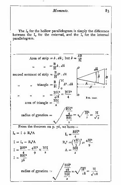
Moments. 83
The lo for the hollow parallelogram is simply the difference
between the I, for the external, and the Ij for the internal
parallelogram.
Area of strip = b.dh; but * = ^

84 Mechanics applied to Engineering.
Second Moment, or Moment of Inertia (I).
O Triangle about an axis
at the base.
_BH'12
FtG. T02.
Radius of gyration
H^6
Trapezium about an axis coinciding with its
short base.
O
4<--- H
Io=(3B + BQH'
Let Bi= «B. V 6(« +3_
6(« + i)
^Fig. 103.
Trapezium about an axis coinciding with its
long base,
-H
I.,=(3B, + B)H'
12
or-77(3«+ i)
Fig. ro4.
H / 3"+
I
V 6(« 4- i)

Moments. 85
From the theorem quoted above, we have-
I„ = 1 + Ro'A
BIT W36 + 9
I
-BH'
R„^ =H"
I« = BH
Radius of gyration obtained as in the last case.
This figure may be treated as a parallelogram and a triangle
about an axis passing through the apex.
BiH' •
. For parallelogram, lo = —
—
for triangle, I,, =(B - BQH'
B.ff (B-B.)H '
for trapezmm, lo—
•
—-—+ 7
I„(3E + BQff
Fig. 103a.
When the axis coincides with the long base, the I for the/D "D \TT3
triangle = ^^ —; then, adding the I for the parallelogram
as above, we get the result as given.
When « = r, the figures become parallelograms, and
I = , as found above,^
, r BH'When « = o, the figures become triangles, and the I = —
—
for the first case, as found for the triangle about its apex ; and
I = for the second case, as found for the triangle about12
its base.

86 Mechanics applied to Engineering.
Second Moment, or Moment of Inertia (I).
Radius ol gyration
ma parallel wtm cne oase.
O
, _ (B.' + 4B.B + B°)H3
36(B. + B)
^^BIP/«Mm«jLi\36 \ « + I )
Bi
For a close approximation,
see next figure.
Approximate method for trapezium about axis
passing through c. ofg.
The I for dotted rectangle
about an axis passing through
its c. of g., is approximately
C^ the same as the I for trapezium.
For dotted rectangle
—
J _ (B + B.)H3
orif B, = «B
Fig. 106.
I = (« + i)
24

Moments. 87
From the theorem on p. 76, we have-
I = I„ - R,2A l^ ^ (3B1 + B)ff^^^^^^ i^^g
^'^base)
Substituting the values in the above equation and simplify-
ing, we get the result as given. The working out is simple
algebra, but too lengthy to give here.
D'XJ3
The I for a rectangle is (see p. 80). Putting in the
value 5-+^ = B', we get-
I =_ B + B. ^ H3 _ (B + B,)H3
24
The following table shows the error involved in the above
assumption ; it will be seen that the error becomes serious
when « < o"S :
—
Valueof «.

88 Mechanics applied to Engineering.
Second Moment, or Moment of Inertia (I).
Square about its diagonal.
t2
Radius of gyration
s
^12
Circle about a diameter.
I =:64
Hollow circle about a dia-
meter.
D4
VD.^+D.^

Moments. 89
This may' be taken as two triangles about their bases fsee
p. 84).
In this case, B = v' 2S

90 Mechanics applied to Engineering.
Second Moment, or Moment of Inertia (I).
Hollow eccentric circle about a line normal to
the line joining the two centres, and passing
through the c. of g. of thefigure.
where x is the eccentricity.
Note.—When the eccentricity
is zero, i.e. when the outer andinner circles are concentric, the
latter term in the above expression
vanishes, and the value of I is the
y same as in the case given abovefor the hollow circle.
Radius of gyration
Ellipse about minor axis.
o
64

Moments. 91
The axis 00 passes through the c. of g. of the figure, andis at a distance b from the centre of the outer circle, and a fromthe centre of the inner circle.
From the principle of moments, we have
—
--QHb + «) = -V).^b
4 4
whence b —D,^ - W
also--D,2(a-^) = -D,2a4 4
whence a = BJ'x
From the theorem on p. 76, wehave-
I', = I, + A/^ for the outer circle
about the c. of g. of figure
64 4also F, = I, + A,fl^ for the inner circle about the c. of g. of
figure
64 4and I = r. — I', for the whole figure.
Substituting the values given above, and reducing, we get
the expression given on the opposite page.
The second moment, or moment of inertia, of a figure
varies directly as its breadth taken parallel to the axis of
revolution ; hence the I for an ellipse about its minor axis is
simply the I for a circle of diameter Da reduced in the ratio =:-i
D2
or-D^xg'64 D, 64

92 Meclianics applied to Engineering.

Moments. 93
And for an ellipse about its major axis, the I is that for
a circle of diameter Di increased in the ratio —
-
or^*X°? = 3!^^64 D, 64
h = ^{\ - -^ (see p. 69).
area of strip =: h .db
second moment of strip = b"^ .h. db
second moment of whole
figure
.3 SB^j o
"F _ B'l
.3 sj= H
2HB15
second moment for double"!
figure shown on opposite > = AHB'page

94 Mechanics applied to Engineering.
Second Moment, or Moment of Inertia (I).
Radius of gyration
Parabola about its base.
jApejc I = Ji^BH^
Fig. Z14.
V^H
Irregularfigures.
4
49*1 +. etc.)
Fig. T15.
(See opposite
page.)

b =
Moments.
B .h*
95
H*area of strip = b . dh
second momentJ^^jj_ ^^,3 _^^
of strip
{Yi.-hfBh\dh
YC
second moment of whole !
figure /
Fig. ii4ff.
B fH=^ {Wh* + h^ - 2h^B)dh
B_ \2Wk^
H*}_
3
2K
= B(|ff + fH» - 4H')18 T)XJ3
for the double figure shown^ _ _32_t)tt8
on opposite page ) ' "*
Divide the figure up as shown in Fig. 87a.
Let the areas of the strips be a^, a^, a^, a^, etc., respectively
;
and their mean distances from the axis be r^, r^, r,, r^, etc.,
respectively.
Then Iq = a-^r^ + a^i + a^^ +, etc.
But fli = wb^, and a^ = wb^, and so on
and n =— , ^2 = -^, ^3 = ^— , and so on2 2 2
hencel. = «.{^0 +<fj + .3(?j+,et.c.}
4{bi + 9*a + 25*3 + 49^4 +, etc.)
Also k'
— (^ + 9*2 + 25^3 + 49^4 +, etc.)
ii>{bi + b^ + bs + bi+, etc.
^ ^ / ^1 + 9/^2 + 25<^3 +, etcT
2 V ^j 4. ^^ + ^3 +^ etc.
This expression should be compared with that obtained for
finding the position of the c. of g. on p. 71. Tke comparisonhelps one to realize the relation between the first and secondmoments.
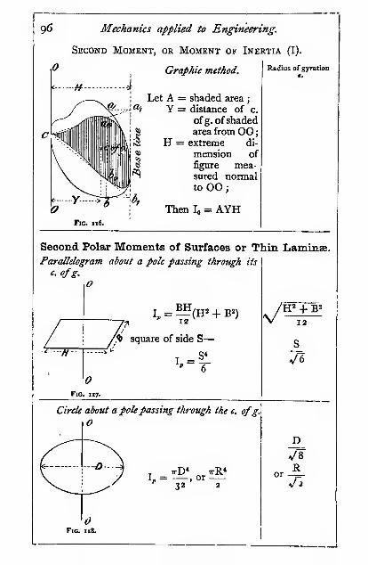
96 Mechanics applied to Engineering.

Moments, 97
Divi.le the figure up into a number of strips, as shown in
Fig. ii6j project each on to the base-line, e.g. ab projected to
fli^ij join «i and b^ to c, some convenient point on 00, cutting
ab in a^^, and so on with the other lines, which when joined
up give the boundary of the shaded figure. Find the c. of g. of
shaded figure (by cutting out in cardboard and balancing). Theprinciple of this construction is fully explained in Chap. IX.,
p. 360.
See also Barker's "Graphical Calculus," p. 184, and Line-
ham's " Text-book of Mechanical Engineering," Appendix.
From the theorem on p. 77, we have
—
I, = I, + I» =^+4fBH" , HB'12 12
\y
12
Fig. Tiya.
I
4
Thickness of ring = dr
area of ring = zirr . dr
second moment of ring = 2irr .r^ . dr
fRcircle = 2ir \ r^ . dr= 2ir I f^ .
(«R-e)
2«-R^_
4
2 X 16
2

98 Mechanics applied to Engineering.
Second Polar Moment, or Polar Moment of Inertia.
ffHollow circle about a pole
passing through the c.
of g. a7td normal to the
plane.
I, = ^(D.* - D<^)
Radius of gyration
V 8~"or
/R.' + R.'
Second (Polar) Moments of Solids.
Gravitational Units.
Bar of rectangular section about a pole passingthrough its c. ofg.
,
^1~~
O)fIG. I20.
B"! For a circular bar of
radius R
—
12 ^
L'' + B^
V'^
si-L' + 3R'
12
Cylinder about its axis,
o
Di-
<- -R--*
: T ttD^HW irR^HWH I»= —> or
32 ^ 2 g
Fig. 191.

Moments, 99
The Ij, for the hollow circle is simply the difference betweenthe L for the outer and the L for the inner circles.
The bar may be regarded as being made up of a great
number of thin laminae of rectangular form, of length L andbreadth B, revolving about their polar axis, the radius of
/\? + B^gyration of each being K= a/——— (see Fig. 1 1 7), which
is the radius of gyration of the bar. The second moment of the
LBH Wbar will then be K^ (weight of bar), or -^fl{U + ^l-Where W is the weight of 1 cubic inch or foot of the
material, according to the units chosen.
The cylinder may be regarded as being made up of a greatnumber of thin circular lamins revolving about a pole passingthrough their centre, the radius of gyration of each being
The second moment of cylinder = K^ (weight of cylinder)
D^ irD^HW ttD^HW= - X =8 4 ^ 32 ^

lOO Mechanics applied to Engineering.
< R.
Second Polar Moment, or PolarMoment of Inertia.
g— V-/Pf--> ^ Hollow cylinder about Radius of gyration
M
I.
I a polepassingihi-ottghI its axis.H
or —(R/ - R/)-or
Discflywheel.
iTreat each part sepa-
rately as hollow cylinders,
and add the results.

Moments. lOl
The Ij, for the hollow cylinder is simply the difference
between the I, for the outer and the inner cylinders.
It must be particularly noticed that the radius of gyrationof a solid body, such as a cylinder, flywheel, etc., is not the
radius of gyration of a .
plane section ; the radius ,
of gyration of a plane P Vsection is that of a thin
lamina of uniform thick-
ness, while the radius of
gyration of a solid is that
of a thin wedge. Theradius of gyration of a
solid may be found bycorrecting the section in
this manner, and finding [^ Jffe>-
the I for the shaded figure Fig. 123a.
treated as a plane surface.
The construction simply reduces the width of the solid
section at each point proportional to its distance from OO ; it
is, in fact, the " modulus figure " (see Chap. IX.) of the section.
Let y^ = the distance of the c. of g. of the second modulusfigure from the axis 00 shown black
;
A = the area of the black figure.
Ai = the area of the modulus figure
then Ii = AiK^ = hyj (see page 96)
AxK^ = :
The moment of inertia
of the wheel V-Weight of the wheel X k-ycy

102 Mechanics applied to Engineering.
Second Polar Moment, or Moment of
Flywheel with arms.
Treat the rim and boss
separately as hollow cylin-
ders, and each arm thus
(assumed parallel)
—
For each arm (see Fig.
120)
—
L (sectional area),, a p ga
12F'°-"4. + I2R„")
where R, = the radius of the c. of g. of the arm.
For most practical purposes the rim only is
considered, and the arms and boss neglected.
Inertia.
Radius of gyration
Sphere about its diameter.
W
or i,rD»w
RVfDor-^=V 10

Moments. 103
The arms are assumed to be of rectangular section; if they
are not, the error involved will be exceedingly small.
The sphere may be regarded as being made up of a great
number of thin circular layers of radius rj, and radius of
gyration -T=(see p. 96).
+2RJ'= 2Rj-/
volume of thin layer = irr^dy
second moment of \ „ r^
layer about 00 / = '^''1 '0' X T
= -Ai^y-ffdy
= j(4Ry+y-4R/Kj»'
second moment of hemi-
1
sphere, i.e. of all layers|
on one side of the I
diameter dd J
(4Ry+/-4R/K^
_^r4Ry /_4R/1-y = ^
. 2L 3 ^5 4 \y=oIT r4R° R^ 4Rn
second moment of sphere = iV^R"
L-3 4 J

I04 Mechanics applied to Engineering.
Second Polar Moment, or Polar Moment of Inertia.
Radius of gyrationSphere about an external axis.
w
When the axis becomes atangent, Ro = R
;
I = rR=—
Fig. 126.
Cone about its axis.
O
I,=^R^H^.10 ^
or ^D^H^160 g
I
i.e. I of the I for the cir-
cumscribing cylinder.
^ 10
Dv'X^ 40

Moments. 105
From the theorem on p. 7 6, we have-
K == (^R» + I^R'Ro") V = |,rR»
The cone may also be regarded as being
a great number of thin layers.
Volume of thin layer = irr^dk
second moment of \ «,, ^ r' '^t*Ji.
layer about axis OOj7rR*/J<
second momentof cone
2H'dh
v%\y'''irR*H

CHAPTER IV.
RESOLUTION OF FORCES.
We have already explained how two forces acting on a point
may be replaced by one which will have precisely the sameefifect on the point as the two. We must now see how to applythe principle involved to more complex systems of forces.
Polygon of Forces.—If we require to find the resultant
of more than two forces which act on a point, we can do so byfinding the resultant of any two by means of the parallelogram
of forces, and then take the resultant of this resultant and the
,next force, and so on, as shownin the diagram. The resultant
of I and 2 is marked Ri.2.,
!;.,R,i and so on. Then we finally
get the resultant Ri.2.3.4. for
the whole system.
Such a method is, however,
Jclumsy. The following will befound much more direct andconvenient : Start from anypoint O, and draw the line i
parallel and equal on a givenscale to the force 1 ; from theextremity of 1 draw the line
2 equal and parallel to theforce 2 ; then, by the triangleof forces, it will be seen thatthe line R1.2. is the resultantof the forces 1 and 2. From
the extremity of 2 draw 3 in a similar manner, and so on withall the forces; then it will be seen that the line Ri,2.3.4.represents the resultant of the forces. In using this con-struction, there is no need to put in the lines R1.2., etc.in the figure they have been inserted in order to make it
Fig. 128.
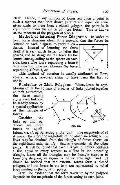
Resolution of Forces. 107
clear. Hence, if any number of forces act upon a point in
such a manner that Unas drawn parallel and equal on somegiven scale to them form a closed polygon, the point is in
equilibrium under the action of those forces. This is knownas the theorem of the polygon of forces.
Method of lettering Force Diagrams.—In order to
keep force diagrams clear, it is essential that the forces belettered in each diagram to prevent con-fusion. Instead of lettering the force
itself, it is very much better to letter the
spaces, and to designate the force by the
letters corresponding to the spaces on eachside, thus : The force separating a from b
is termed the force ab ; likewise the force
separating d from b, db. fig- "9.
This method of notation is usually attributed to Bow;several writers, however, claim to have been the first to
use it.
Funicular or Link Polygons.—When. forces in equi-
librium act at the corners of a series of links jointed together
at their extremities,
the force acting
along each link can
be readily found bya special application
of the triangle of
forces.
Consider the
links ag and bg.
There are three
forces in equili-
brium, viz. ab^ ag, bg, acting at the joint. The magnitude of ab
is known, therefore the magnitude of the other two acting on the
links may be obtained from the triangle of forces shown onthe right-hand side, viz. abg. Similarly consider all the other
joints. It will be found that each triangle of forces contains
a line equal in every respect to a line in the preceding
triangle, hence all the triangles may be brought together to
form one diagram, as shown to the extreme right hand. It
should . be noticed that the external forces form a closed
polygon, and the forces in the bars are represented by radial
lines meeting in the point or pole g.
It will be evident that the form taken up by the polygon
depends on the magnitude of the forces acting at each joint.
Fig. 130.

io8 Mechanics applied to Engineering.
Saspecsiou Bridge.—^Another special application of the
triangle of forces in a funicular polygon is that of finding the
forces in the chain of a suspension bridge. The platform on
which the roadway is carried is supported from the chain by
means of vertical ties. We will assume that the weight sup-
ported by each tie is known. The force acting on each
portion of the chain can be found by constructing a triangle of
forces at each joint of a vertical tie to the chain, as shown in
the figure above the chain. But bo occurs in both triangles;
hence the two triangles may be fitted together, bo being com-
mon to each. Likewise all the triangles of forces for all the
joints may be fitted together. Such a figure is shown at
the side, and is known as a ray or vector polygon. Instead,
Fig. 131.
however, of constructing each triangle separately and fitting
them together, we simply set oiF all the vertical loads ab, be,
etc., on a straight line, and from them draw lines parallel to
each link of the suspension chain ; if correctly drawn, all the
rays will meet in a point. The force then acting on eachsegment of the chain is measured off the vector polygon, to
the same scale as the vertical loads. In the figure the vertical
loads are drawn to a scale of 1" = 10 tons ; hence, for example,
the tension in the segment ao is 9*8 tons.
The downward pressure on the piers and the tension in the
outer portion of the chain is given by the triangle aol.
If a chain (or rope) hangs freely without any platform
suspended below, the vertical load will be simply that due to
the weight of the chain itself. If the weight per foot of hori-
zontal span were constant, it is easy to show that the curvetaken up by the chain is a parabola (see p. 493). In the samechapter, the link and vector polygon construction is employed

Resolution of Forces, 109
to deteimine the bending moment due to an evenly distributed
load. The bending moment M^ at x is there shown to be the
depth D, multiplied by the polar distance OH (Fig. 132) ; ix.
Fig. X33.
the dip of the chain at x multiplied by the horizontal com-ponent of the forces acting on the links, viz. the force acting
on the link at x, or M^ = D,, X OH. In the same chapter, it
is also shown that with an evenly distributed load M^^ = -5-,o
where w is the load per foot run, and / is the span in feet
Hence8
= D, . OH = D,,
or .^ =8D«
where h is the tension at the bottom of the chain, viz. at x.
It will, however, be seen that the load on a freely hangingchain is not evenly distributed per foot of horizontal run,
because the inclination of the chain varies from point to point.
Therefore the curve is not parabolic; it is, in reality, a
catenary curve. For nearly all practical purposes, however,
when the dip is not great compared with the span, it is suffi-
ciently accurate to take the curve as being parabolic.
Then, assuming the curve to be parabolic, the tension at
any other point, y, is given by the length of the corresponding
line on the vector polygon, which is readily seen to be
—
T, = ^h^ + w'l^
The true value of the tension obtained from the catenary
is
—
T, = >4 + wD,
(see Unwin's " Machine Design," p. 421), which will be found
to agree closely with the approximate value given above.

no Mechanics applied to Engineering.
Data for Force Polygons.—Sometimes it is impossible
to construct a polygon of forces on accoimt of the incomplete
ness of the data.
In the case of the triangle and polygon of forces, the follow-
ing data must be given in order that the triangle or polygon can
be constructed. If there are « conditions in the completed
polygon, « — 2 conditions must be given ; thus, in the triangle
of forces there are six conditions, three magnitudes and three
directions: then at least four must be supplied before the
triangle can be constructed, such as
—
3 magnitude(s) and i direction(s)
Likewise in a five-sided polygon, there are ten conditions, eight
of which must be known before the polygon can be constructed.
When the two imknown conditions refer to the same or
adjacent sides, the construction is perfectly simple, but whenthe unknown conditions refer to non-adjacent sides, a special
construction is necessary. Thus, for example, suppose whendealing with five forces, the forces i, 2, and 4 are completelyknown, but only the directions, not the magnitudes, of 3 and 5are known. We proceed thus :
Draw lines r and 2 in the polygon of forces. Fig. 133, in the
usual way. From the extremity of 2 draw a line of indefinite
Fig. 133. Fig. 134.
length parallel to the force 3 ; its length cannot yet be fixed,
because we do not know its value. From the origin of i drawa line of indefinite length parallel to 5 ; its leng& is also notyet known. From the extremity of 4 in the diagram of forces,
Fig. 134, drop a perpendicular ah on to 3, and in the polygonof forces, Fig. 133, draw a line parallel to 3, at a distance ab

Resolution of Forces. Ill
from it. The point where this line cuts the line S is the
extremity of 5. From this point draw a line parallel to 4 ; then
by construction it will be seen that its extremity falls on the
line 3, giving us the length of 3.
The order in which the forces are taken is of no import-
ance.
Forces in the Members of a Jib Crane. Case I.
The weight W simply suspendedfrom the end of the jib.—Thereis no need to construct a separate dia-
gram of forces. Set off be = W, or BCon some convenient scale,^ and draw ca
parallel to the tie CA ; then the triangle
bac is the triangle of forces acting on the
point b. On measuring the force dia-
gram, we find there is a compressive
force of 15 "2 tons along AB, and a
tension force of 9-8 tons along AC.The pressure on the bottom pivot is
W (neglecting the weight of the crane
itself). The horizontal pull at the top
of the crane-post is ad, or 7-9 tons ; and
the force (tension) acting on the post
between the junction of the jib and the
tie is cd, or 6 tons.
The bending moment at y will be
ad X h, or W X /. For determining the bending stress at y,
see Chap. IX.
Taking moments about the pivot bearing, we have
—

112 Mechanics applied to Engineering.
W + ^(weight of jib and tie). The downward pressure on the
pivot will be W + weight of structure.
The dimensions of the structure must then be increased
accordingly. In a large structure the forces should be again
determined, to allow for the increased dimensions.
The bending moment on the crane-post at y may be very
much reduced by placing a balance weight Wj on the crane, as
shown. The forces acting on the balance-weight members are
found in a similar manner to that described above, and, neglect-
ing the weight of the structure, are found to be 8" i tons on the
tie, and 4*4 tons on the horizontal strut.
The balance weight produces a compression in the upperpart of the post of 6*8 tons ; but, due to the tie ac, we had a
tension of 6"o tons, therefore there is a compression of o'8 ton
Fig. 136. Fig. 137.
in the upper part of the crane-post The pressure on the lowerpart of the crane-post and pivot is W -1- Wj -f weight of
structure.
Then, neglecting the weight of the structure, the bendingmoment on the post at y will be
—
W/ - Wi/,
W/The moment Wi*^ should be made equal to —, then the
2
post will never be subjected to a bending moment of morethan one-half that due to the lifted load, and the pressure/.and /a will be correspondingly reduced.
Case II. The weight W suspendedfrom a chain passing to abarrel on the crane-post.—As both poitions of the chain are

Resolution of Forces "3
subjected to a pull W, the resultant R is readily determined.From c a line ac is drawn parallel to the tie ; then the force
acting down the jib is ab = i6'4 tons j down the tie ac = 4*4
tons. The bending moments on the post, etc., are determinedin precisely the same manner as in Case I.
When pulley blocks are used for lifting the load, the pull
in the chain between the jib pulley and the barrel will be less
than W in the proportion of the velocity ratio.
The general effect of the pull on the chain is to increase
the thrust on the jib, and to reduce the tension in the tie. Indesigning a crane, the members should be made strong enoughto resist the greater of the two, as it is quite possible that alink of the chain may catch in the jib pulley, and the conditionsof Case I. be realized.
Forces in the Members of Sheer Legs.—In the typeof crane known as sheer legs the crane-post is dispensed with,
and lateral stability is given by using two jibs or sheer legs
spread out at the foot ; the tie is usually brought down to thelevel of the ground, and is attached to a nut working in guides.
By means of a horizontal screw, the sheer legs can be tilted or" derricked " at will
:
the end thrust on the
screw is taken by a
thrust block ; the up-
ward pull on the nut
and guides is taken bybolts passing down to
massive foundations
below. The forces are
readily determined bythe triangle of forces.
The line ^^ris drawnparallel to the tie, andrepresents the force
acting on it; then ac
represents the force
acting down the middleline of the two sheer
legs. This is shownmore clearly on the
projected view of the
sheer legs, cd is then ^'°- '38-
drawn parallel to the sheer leg ae; then dc represents the force
acting down the sheer leg ae ; likewise ad down the leg of, andI

114 Mechanics applied to Engineering.
dg the force acting at the bottom of the sheer legs tending to
make them spread; ch represents the thrust of the screw onthe thrust block and the force on the screw, and bh the upwardpull which has to be resisted by the nut guides and the founda-
tion bolts.
The members of this type of structure are necessarily very
Fig. i33«.
heavy and long, consequently the bending stress due to theirown weight is very considerable, and has to be carefully con-sidered in the design. The problem of combined bending andcompression is dealt with in Chapter XII.
Forces in a Tripod or Three Legs.—Let the lengths

Resolution of Forces. "5
of the legs be measured from a horizontal plane. The vertical
height of the apex O from the plane, also the horizontal
distances, AB, EC, CA, must be known.In the plan set out the triangle ABC from the known
lengths of the sides; from A as centre describe an arc of
radius equal to the length of the pole A, likewise from Bdescribe an arc of radius equal to the length of the pole B.
They cut in the point o-^. From o^ drop a perpendicular onAB and produce ; similarly, by describing arcs from B and Cof their respective radii, find the point o-a, and from it drop a
perpendicular on BC, and produce to meet the perpendicular
from Ox in O, which is the apex of the tripod. The plan of
the three legs can now be filled in, viz. AO, BO, CO. Produce
AO to meet CB in D. From O set off the height of the apexabove the plane, viz. O^uj, at right angles to AO ;
join Af^m.
This should be measured to see that it checks with the length
of the pole A. Join DiPm. From o-a\ set off a length to a con-
venient scale to represent W, complete the parallelogram of
forces, then Oxa^ gives the force acting down the leg A, and
o-a.\d the force acting down the imaginary leg D, shown in
broken line, which lies in the plane of the triangle OBC ; resolve
this force down OC and OB by setting off o-ad along OuD equal
to o-a.\d, found by the preceding parallelogram, then the force
acting down the leg B is Oyj), and that down C is o-aC
The horizontal force tending to spread the legs AOm and
DOui is given by fd. This is set off at A/,'and is resolved along
AC and AB. The force acting on an imaginary tie AC is Ke,
and on AB is A^, similarly with the remaining tie.
When the three legs are of equal length and are symmetric-
ally placed, the forces can be obtained thus
—
l^J-V - ^
Three equal fe^s
Fig. 138*.
where / is the force acting down each leg.

ii6 Mechanics applied to Engineering.
Forces in the Members of a Roof Truss.—Let the
roof truss be loaded with equal weights at the joints, as shown
;
the reactions at each support will be each equal to half the
total load on the structure. We shall for the present neglect
the weight of the structure itself.
.t
The forces acting on each member can be readily found bya special application of the polygon of forces.
Consider the joint at the left-hand support BJA or Rj. Wehave three forces meeting at a point ; the magnitude of one,
viz. Rj or ba, and the direction of all are known ; hence we candetermine the other two magnitudes by the triangle of forces.
This we have done in the triangle ajh.

Resolution of Forces 11
7
Consider the joint BJIC Here we have four forces
meeting at a point ; the magnitude of one is given, viz. be, andthe direction of all the others ; but this is not sufficient—wemust have at least six conditions known (see p. no). Onreferring back to the triangle of forces just constructed, we iind
that the force bj is known ; hence we can proceed to draw our
. polygon of forces cbji by taking the length of bj from the tri-
angle previously constructed. By proceeding in a similar
manner with every joint, we can determine all the forces
acting on the structure.
On examination, we find that each polygon contains one
side which has occurred in the previous polygon ; hence, if these
similar and equal sides be brought together, each polygon can
be tacked on to the last, and so made to form one figure con-
taining all the sides. Such a figure is shown below the
structure, and is known as a " reciprocal diagram."
When determining the forces acting on the various membersof a structure, we invariably use the reciprocal diagram without
going through the construction of the separate polygons. Wehave only done so in this case in order to show that the reciprocal
diagram is nothing more nor less than the polygon of forces.
We must now determine the nature of the forces, whether
tensile or compressive, acting on the various members. In
order to do this, we shall put
arrows on the bars to indicate the
direction in which the bars resist
the externalforces.
The illustration represents a
man's arm stretched out, resisting
certain forces. The arrows indi-
cate the direction in which he is
exerting himself, from which it^^^
will be seen that when the arrows '
^^'
on his arms point outwards his arms are in compression, and
when in the reverse direction, as in the chains, they are in
tension ; hence, when we ascertain the directions in which a
bar is resisting the external forces acting on it, we can at once
say whether the bar is in tension or compression, or, in other
words, whether it is a tie or a strut.
We know, from the triangle and polygon of forces, that the
arrows indicating the directions in which the forces act follow
round in the same rotary direction ; hence, knowing the direc-
tion of one of the forces in the polygon, we can immediately
find the direction of the others. Thus at the joint BJA we

ii8 Mechanics applied to Engineering.
know that the arrow points upwards from b Xa a; then, con-
tinuing round the triangle, we get the arrow-heads as sliown.
Transfer these arrows to the bars themselves at the joint in
question ; then, if an arrow points outwards at one end of a bar,
the arrow at the other end must also point outwards ; hence
we can at once put in the arrow at the other end of the bar,
and determine whether it is a strut or tie. When the arrows
point outwards the bar is a strut, and when inwards a tie.
Each separate polygon has been thus treated, and the arrow-
heads transferred to the structure. But arrow-heads must not
be put on the reciprocal diagram ; if they are they will cause
hopeless confusion. With a very little practice, however, one
can run round the various sections of the reciprocal diagram
by eye, and put the arrow-heads on the structure without
making a single mark on the diagram. If a mistake has beenmade anywhere, it is certain to be detected before all the bars
have been marked. If the beginner experiences any difficulty,
he should make separate rough sketches for each polygon of
forces, and mark the arrow-heads ori each side. At somejoints, where there are no external forces, the direction of the
arrows will not be evident at first; they must not be taken
from other polygons, but from the arrow-heads on the structure
itself at the joint in question. For example, the arrows at the
joints ABJ and BJIC are perfectly readily obtained, the direc-
tion being started by the forces AB and BC, but at the joint
JIA the direction of the arrow on the bars JI and JA are
known at the joint ; either of these gives the direction for
starting round the polygon ahij.
The following bars are struts : BJ, IC, GD, FE, JI, GF.The following bars are ties : JA, IH, HA, HG, FA.Some more examples of reciprocal diagrams will be given
in the chapter on " Framework St.Tictures."

CHAPTER V.
MECHANISMS.
Professor Kennedy '^ defines a machine as " a combinationof resistant bodies, whose relative motions are completelyconstrained, and by means of which the natural energies at ourdisposal may be transformed into any special form of work."Whereas a mechanism consists of a combination of simple
links, arranged so as to give the same relative motions as the
machine, but not necessarily possessing the resistant qualities
of the machine parts ; thus a mechanism may be regarded as a
skeleton form of a machine.
Constrained and Free Motion.—Motion may beeither constrained or free. A body which is free to move in
any direction relatively to another body is said to have freemotion, but a body which is constrained to move in a definite
path is said to have constrained motion. Of course, in bothcases the body moves in the direction of the resultant of all
the forces acting upon it ; but in the latter case, if any of the
forces do not act in the
direction of the desired
path, they automatically
bring into play constraining
forces in the shape of
stresses in the machineparts. Thus, in the figure,
let a^ be a crank whichrevolves about a, and let
the force be in the direc-
tion of the connecting-rod act on the pin at b. Then, if b
were free, it would move off in the direction of the dotted line,
but as b must move in a circular path, a force must act alongthe crank in order to prevent it following the dotted line. Thisforce acting along the crank is readily found by resolving be in
' " Mechanics of Machinery,'' p. 2.

120 Mec/ianics applied to Engineering.
a direction normal to the crank, viz. bd, i.e. in the direction in
which b is moving, and along the crank, viz. dc, which in this
instance is a compression. Hence the path of 6 is determined
by the force acting along the connecting-rod and the force
acting along the crank.
The constraining forces always have to be supplied by the
pdrts of the machine itself. Machine design consists in
arranging suitable materials in suitable form to supply these
constraining forces.
The various forms of constrained motion we shall nowconsider.
Plane Motion.—When a body moves in such a mannerthat any point of it continues to move in one plane, such as
in revolving shafts, wheels, connecting-rods, cross-heads, links,
etc., such motion is known as plane motion. In plane motiona body may have either a motion of translation in anydirection in a given plane or a motion of rotation about anaxis.
Screw Motion.—^When a body has both a motion of
rotation and a translation perpendicular to the plane of rota-
tion, a point on its surface is said to have a screw motion, andwhen the velocity of the rotation and translation are keptconstant, the point is said to describe a helix, and the amountof translation corresponding to one complete rotation is termedt\i& pitch of the helix or screw.
Spheric Motion.—When a body moves in such a mannerthat every point in it remains at a constant distance from afixed point, such as when a body slides about on the surface of
a sphere, the motion is said to be spheric. When the spherebecomes infinitely great, spheric motion becomes planemotion.
Relative Motion.—When we speak of a body being in
motion, we mean that it is shifting its position relatively to
some other body. This, indeed, is the only conception we canhave of motion. Generally we speak of bodies as being in
motion relatively to the earth, and, although the earth is goingthrough a very complex series of movements, it in nowiseaffects our using it as a standard to which to refer the motionsof bodies ; it is evident that the relative motion of two bodiesis not affected by any motions which they may have in common.Thus, when two bodies have a common motion, and at
the same time are moving relatively to one another, we maytreat the one as being stationary, and the other as movingrelatively to it : that is to say, we may subtract their common

Mecltanisms. 121
motion from each, and then regard the one as being at rest.
Similarly, we may add a common motion to two moving bodies
without affecting their relative motion. We shall find that such
a treatment will be a great convenience in solving manyproblems in which we have two bodies, both of which are
moving relatively to one another and to a third. As an
example of this, suppose we are studying the action of a valve
gear on a marine engine; it is a perfectly simple matter to
construct a diagram showing the relative positions of the valve
and piston. Precisely the same relations will hold, as regards
the valve and piston, whether the ship be moving forwards or
backwards, or rolling. In this case we, in effect, add or
subtract the motion of the ship to the motion of both the valve
and the piston.
Velocity.—Our remarks in the above paragraph, as regards
relative motion, hold equally well for relative
velocity.
Many problems in mechanisms resolve
themselves into finding the velocity of one
part of a mechanism relatively to that of
another. The method to be adopted will
depend upon the very simple principle that
the linear velocity of any point in a rotating */^body varies directly as the distance of that 'a^^"<^'^
point from the axis or centre of rotation. ^°- '*^"
Thus, when the link OA rotates about O, we have
—
velocity of A V„ r^
velocity of B ~ Vj ~ rj
If the link be rotating with an angular velocity w radians
per second (see p. 4), then the linear velocity of a, viz.
V. = uir„ and of b, Vj = eo^j, but the angular velocity of every
point in the link is the same.
As the link rotates, every point in it moves at any given
instant in a direction normal to the line drawn to the centre of
rotation, hence at each instant the point is moving in the
direction of the tangent to the path of the point, and the centre
about which the point is rotating lies on a line drawn normalto the tangent of the curve at that point. This property will
enable us to find the centre about which a body having plane
motion is rotating. The plane motion of a body is completelyknown when we know the motion of any two points in the
body. , If the paths of the points be circular and concentric,
then the centre of rotation will be the same for all positions of

122 Mechanics applied to Engineering.
the body. Such a centre is termed a " permanent " or " fixed"
centre ; but when the centre shifts as the body shifts, its centre
at any given instant is termed its " instantaneous " or " virtual
"
centre.
Instantaneous or Virtual Centre.—Complex plane
motions of a body can always be reduced to one very simply
expressed by utilizing the principle of the virtual centre. Forexample, let the link ab be part of a mechanism having a
complex motion. The paths of the two end points, a and b,
are known, and are shown dotted. In order to find the relative
velocities of the two points, we draw tangents to the paths at
a and b, which give us the directions in which each is movingat the instant. From the points a, b draw normals aa' and bl/
to the tangents ; then the centre about which a is moving at the
instant lies somewhere on the Une ad, likewise with bb' ; hence
the centre about which both points are revolving at the instant,
must be at the intersection of the two lines, viz. at O. This
Fig. 143.
point is termed the virtual or instantaneous centre, and the
whole motion of the link at the instant is the same as if it were
attached by rods to the centre O. As the link has thickness
normal to the plane of the paper, it would be more correct to
speak of O as the plan of the virtual axis. If the bar had anarm projecting as shown in Fig. 144, the path of the point
C could easily be determined, for every point in the body, at
the instant, is describing an arc of a circle round the centre O
;
thus, in order to determine the path of the point C, all we have
to do is to describe a small arc of a circle passing through C,
struck from the centre O with the radius OC.The radii OA, OB, OC are known as the virtual radii of
the several points.
If the tangents to the point-paths at A and B had beenparallel, the radii would not meet, except at infinity. In that

Mechanisms. \ 23
case, the points may be considered to be describing arcs ofcircles of infinite radius, i.e. their point-paths are straight
parallel lines.
If the link AB had yet another arm projecting as shown in
the figure, the end point of
which coincided with the virtual
centre O, it would, at the in-
stant, have no motion at all
relatively to the plane, i.e. it is
a fixed point. Hence there is
no reason why we should not
regard the virtual centre as apoint in the moving body itself.
It is evident that there can-
not be more than one of suchfixed points, or the bar as a whole would be fixed, and then it
could not rotate about the centre O.It is clear, from what we have said on relative motion, that if
we fixed the bar, which we will term m (Fig. 146), and movethe plane, which we will term n, the relative motion of the twowould be precisely the same. We shall term the virtual centre
of the bar m relatively to the plane n, Omn.Oentrode and Axode.—As the link m moves in such a
manner that its end joints a and i follow the point-paths, the
virtual centre Omn also shifts relatively to the plane, and traces
out the curve as shown in Fig. 146. This curve is simply the
point-path of the virtual centre, or the virtual axis. This curve
is known as the centrode, or axode.
Now, if we fix the link m, and move the plane n relatively to
it, we shall, at any instant, obtain the same relative motion,
therefore the position of the virtual centre will be the same in
both cases. The centrodes, however, will not be the same,
but as they have one point in common, viz. the virtual centre,
they will always touch at this point, and as the motions of
the two bodies continue, the two centrodes will roll on oneanother.
This rolling action can be very clearly seen in the simple
four-bar mechanism shown in Fig. 147. The point A movesin the arc of a circle struck from the centre D, hence AD is
normal to the tangent to the point-path of A ; hence the virtual
centre lies somewhere on the line AD. For a similar reason, it
lies somewhere on the line BC ; the only point common to tiie
two is their intersection O, which is therefore their virtual
centre. If the virtual centre, i.e. the intersection of the two

124 Mechanics applied to Engineering.
bars, be found for several positions of the mechanism, the
centrodes will be found to be ellipses.
As the mechanism revolves, the two ellipses will be found to
r<?»n.
«?-•
Fio. 146.
roll on one another, because A, B and C, D are the foci of the
two ellipses. That such is the case can easily be provedexperimentally, by a model consisting of two ellipses cut out of
suitable material and joined by cross-bars AD and BC ; it will
be found that they will roll on one another perfectly.
Hence we see that, if we have given a pair of centrodes for
two bodies, we can, by making the one centrode roll on the other,
completely determine the relative motion of the two bodies.
Position of Virtual Centre.—^We have shown abovethat when two point-paths of any body are known, we can

Mechanisms. 125
readily find the position of the virtual centre. In the case of
most mechanisms, however, we can determine the virtual
centres without first constructing
the point-paths. We will showthis by taking one or two simple
cases. In the four-bar mechanismshown in Fig. 148, it is evident
that if we consider d as stationary, /
the virtual centre Odd will be at
the joint of a and d, and the\
velocity of any point in a relatively
to any point in d will be propor-
tional to the distance from this
joint ; likewise with Ode. Then,if we consider b as fixed, the
virtual centre of a and b will also
be at their joint. By similar
,
reasoning, we have the virtual!
centre Obc. Again, let d be I
fixed, and consider the motionof b relatively to d. The point-
path of one end of b, viz. Oab,
describes the arc of a circle
about Oad, therefore the virtual
centre lies on a produced j for asimilar reason, the virtual centre lies on c produced hence it
must be at Obd, the meet of the two lines.
0^0
OaxsFig. 14S.
Odo
In a similar manner, consider the link e as fixed ; then, for

126 Mechanics applied to Engineering.
the same reason as was given above for b and d, the virtual centre
of a and c lies at the meet of the two lines b and d, viz. Oac.
If the mechanism be slightly altered, as shown in Fig. 149,
we shall get one of the virtual centres at infinity, viz. Ocd.
oOcd
Oad, ObcFig. 150.
The mechanism shown in Fig. 149 is kinematically similar
to the mechanism in Fig. 150. Instead of c sliding to and fro
in guides, a link of any length may be substituted, and the
fixed link d may be carried round in order to provide a centre
from which c shall swing. Then it is evident that the joint
Obc moves in the arc of a circle, and if c be infinitely long it
moves in a straight line in precisely the same manner as the
sliding link c in Fig. 149.
The only virtual centre that may present any difficulty in
finding is Oac. Consider the link c as fixed, then the bar dswings about the centre Ocd; hence every point in it movesin a path at right angles to a line drawn from that point to
Ocd. Hence the virtual centre lies on the line Ocd, Oad; also,
for reasons given below, it lies on the prolongation of the bar
b, viz. Oac.
Three Virtual Centres on a Line.—By referring to thefigures above, it will be seen that there are always three virtual
centres on each line. In Figs. 149, 150, it must be rememberedthat the three virtual centres Ocui, Oac, Ocd are on one line
;
also Obc, Obd, Ocd.
The proof that the three virtual centres corresponding to the
three contiguous links must lie on one line is quite simple, and as
this property is of very great value in determining the positions
of the virtual centres for complex mechanisms, we will give it
here. Let b (Fig. 151) be a body moving relatively to a, anJlet the virtual centre of its motion relative to a be O^^ ; likewise
let Oac be the virtual centre of c's motion relative to a. If we

Mechanisms. X'Z'J
want to find the velocity dof a point in b relatively to a point ii
€, we must find the virtual centre, Obc. Let it be at O : then,considering it as a point of
b, it will move in the arc
i.i struck from the centre
Oab; but considering it as
a point in c, it will move in
the arc 2.2 struck from the
centre Oac. But the tangents
of these arcs intersect at 0,therefore the point O has a
motion in two directions at
the same time, which is im- fig. 151.
possible. In the same manner,
it may be shown that the virtual centre Obc cannot lie any-
where but on the line joining Oab, Oac, for at that point only
will the tangents to the point-paths at O coincide ; therefore
the three virtual centres must lie on one straight line.
Relative Linear Velocities of Points in Mechan-isms.—Once having found the virtual centre of any two bars
of a mechanism, the finding of the
velocity of any point in one bar
relatively to that of any other point
is a very simple matter, for their
velocities vary directly as their ^
virtual radii.
In the mechanism shown, let
the bar d be fixed; to find the
relative velocities of the points i
and 2, we have
—
velocity i _ Obd i _ ^1
velocity 2 Obd 2 r^
Similarly
—
velocity i _ r-^
velocity 3 r,
^^^ vdocity 3 ^ /3
velocity 4 rt,
The relative velocities are not affected in the slightest
degree by the skape of the bars.
When finding the velocity of a point on one bar relatively to
the velocity of a point on another bar, it must be remembered

128 Mechanics applied to Engineering,
that at any instant the two bars move' as though they had one
point in common, viz. their virtual centre.
As an instance of points on non-adjacent bars, we will pro-
ceed to find the velocity of the point 8 (Fig. 153) relatively to
that of point 9. By the method already explained, the virtual
centre Oac is found, which may be regarded as a point in the
bar c pivoted at Ocd; likewise as a point in the bar a pivoted
Fig. 153-
at Oad. As an aid in getting a clear conception of the action,
imagine the line Ocd . Oac, also the bar c, to be arms of a toothed
wheel of radius /04, and the line Oad . Oac, also the bar a, to bearms of an annular toothed wheel of radius pa, the two wheelsare supposed to be in gear, and to have the common point Oac,
therefore their peripheral velocities are the same. Denotingthe angular velocity of a as o)„ and the linear velocity of the
point 8 as Vg, etc., we have
—
<^ap3 = <^cpiy and <o„ = -^ also Vg = oi^ps Vg = 01^
Substituting the value of (i)„, we have
—
Vg _ MqPjPs _ piPs ^ i'29 X 076 _ ^ .^^
Vg _ OM.SY,~ Odd.g~ 2-i6
or
paPs
2'20
2'29 X 0'42
= I'02

Mechanisms. 1 29
Similarly, if we require the velocity of the point 6 relatively
to that of point 5
—
Vg _ Pb V - ^8P6iT » 6 —Vs Pa Pi
^j — P} V = X5P?V9 P9 P9
whence — = —' .^5^= P^'P'^" = M.'Vs Vj pePn PsPsPePi PsPe
Voac Ps Vfl^ p4
Vg p4pe 1-29 X 0-3= 0-36
V5 psPs 2-29 X 0-47
Likewise
—
velocity 7 _ R? _ 2'3i _velocity 8 Rs 2-20
~
velocity 6 p^ x velocity 8 X Rhence
velocity 7 Ps X K.7 X velocity 8
= 0-38Ps X R7 076 X 2-31
Fig. 154.
This can be arrived at much more readily by a graphical
process; thus (Fig. 154): With Oad as centre, and p, as
K

130 Mechanics applied to Engineering.
radius, set off Oad.h = p, along the line joining Oad to 8 ; set
off a line Ai to a convenient scale in any direction to represent
the velocity of 6. From Oad draw a line through i, and from8 draw a line Be parallel to /it ; this line will then represent the
velocity of the point 8 to the same scale as 6, for the twotriangles Oad.8.e and Oad.h.i are similar ; therefore
—
8(? Oad • 8 _ Pa _ velocity 8 _ o'8o _hi Oad.h p^ velocity 6 0-32
From the centre Odd and radius Rj, set off Odd./ = Rj
;
6ia.vf/.g parallel to <?. 8, and from Odd draw a line through e to
meet this line in g", then,/^ = V,, for the two triangles Obd.f.gand Obd.i.e are similar; therefore
—
fg _ Obd.f _ R7 _ velocity 7 _ 2-3
8^ ~ Obd.B ~ Rs~
velocity 8 ~ 2^ ^ ^'°^
, velocity 6 ih o'^zand —.—H^ = T = —5- = o'38
velocity 7 ^ o'84 "^
The same graphical process can be readily applied to all casesof velocities in mechanisms.
Relative Angular Velocities of Bars in Mechan-isms.—Every point in a rotating bar has the same angularvelocity. Let a bar be turning about a point O in the barwith an angular velocity m; then the linear velocity V„ of apoint A situated at a radius r„ is
—
VV„ = u)r„ and m = -^
In order to find the relative angular velocities of any twolinks, let the point A (Fig. 155) be first regarded as a pointin the bar a, and let its radius about Oad be r^. When thepoint A is regarded as a point in the bar b, we shall term it
B, and its radius about Obd, r^. Let the linear velocity of Abe Vju and that of B be Vb, and the angular velocity of A be0)4, and of B be Mg. Then V^ = Wjj-^, and Vi = m^rj^.
But Va = Vb as A and B are the same point ; hence
—
<"ii ''a {Oad)A

Mechanisms. 131
This may be very easily obtained graphically thus : Set off
a line he in any direction from A, whose length on some givenscale is equal to (Oij join e.Obd; from Oad draw 0«(^/ parallel
b
Obd
Fig. iss. Fig. 156.
X.0 e.Obd. Then A/= 0)3, because the two triangles k.f.Oadand A.e.Obd are similar. Hence
—
he ^ (Obd)B _ (0^
A/ (Oad)A (ub
In Fig. 156, the distance A^ has been made equal to h.Oad,and gf is drawn parallel to e.Obd. The proof is the same as in
the last case. When a is parallel to e, the virtual centre is at
infinity, and the angular velocity of b becomes zero.
When finding the relative angular velocity of two non-adjacent links, such as a and e, we proceed thus : For con-venience we have numbered the various points instead of using
the more cumbersome virtual centre nomenclature (Figs. 157and 158). The radius 1.6 we shall term r^^, and so on.
Then, considering points i and 2 as points of the bar b, wehave
—
V ''2.6

132 Mechanics applied to Engineering.
Then, regarding point i as a point in bar c, and regarding
point 2 as a point in bar a—V, = w„ X n.. Vo = (o.ra.;
J:: _
s
?-•""
Fig. 158.
Then, substituting the values of Vj and Vj in the equationabove, we have
—

Mechanisms. 133
Draw 4.7 parallel to 2.3 ; then, by the similar triangles
1.2. 6 and 1.7.4
—
4-7 ri.4
and ^a., X i-i., = ?-i,, X 4.7
Substituting this value above, we have
—
^c 1.6 X ^as
'1.8
= -M, or = iiP by similar trianglesX 4-7 4-7 5-4
Thus, if the length ^2.3 represents the angular velocity of c,
and a line be drawn from 4 to meet the opposite side in 7,
4.7 represents on the same scale the angular velocity of a. Orit may conveniently be done graphically thus : Set off from 3 aline in any direction whose length 3.8 represents the angular
velocity off; from 4 draw a line parallel to 3.8; from 5 drawa line through 8 to meet the line from 4 in 9. Then 4.9 repre-
sents the angular velocity of a, the proof of which will beperfectly obvious from what has been shown above.
When b is parallel to d, the virtual centre Oac is at infinity,
and the angular velocity of a is then equal to the angular
velocity of c.
Steam-engine Mechanism.—On p. 126 we showedhow a four-bar mechanism may be developed into the ordinary
steam-engine mechanism, which is then often called the" slider-crank chain."
This mechanism appears in many forms in practice, but
some of them are so
disguised that they are
not readily recognized.
We will proceed to
examine it first in its //
most familiar form, viz.
the ordinary steam-
engine mechanism. ^^^^ yHaving given the
'
fig. 139.
speed of the engine in
revolutions per minute, and the radius of the crank, the velocity
of the crank-pin is known, and the velocity of the cross-head
at any instant is readily found by means of the principles laid
down above. We have shown that
—
velocity P Obd.V
velocity X ~ OW.X
XM

1 34 Mechanics applied to Engineering.
From O draw a line parallel to the connecting-rod, and
from P drop a perpendicular to meet it in e. Then the triangle
QI2e is similar to the triangle P.OW.X ; hence
—
OP Obd.V velocity of pin
"p7 ~ Obd.^ ~ velocity of cross-head
But the velocity of the crank-pin may be taken to be constant.
Let it be represented by the radius of the crank-circle OP;then to the same scale Te represents the velocity of the cross-
head. Set up fg = P<? at several positions of the crank-pin,
and draw a curve
through them; then
the ordinates of this
curve represent the
velocity of the cross-
head at every point
in the stroke, wherethe radius of the
crank - circle repre-
sents the velocity of
the crank-pin.
When the connecting-rod is of infinite length, or in the case
of such a mechanism as that shown in Fig, i6o, the line gc
(Fig. 159) is always parallel to the axis, and consequently the
crosshead-velocity diagram becomes a semicircle.
An analytical treatment of these problems will be found in
the early part of the next chapter.
Another problem of considerable interest in connection
with the steam-engine is that of finding the journal velocity, or
the velocity with which the various journals or pins riib ontheir brasses. The object of making such an investigation will
be more apparent after reading the chapter on friction.
Let it be required to find the velocity of rubbing of (i) the
crank-shaft in its main bearings; (2) the crank-pin in the big
end brasses of the connecting-rod; (3) the gudgeon-pin in the
small end brasses.
Let the radius of the crank-shaft journal be r„ that of the
crank-pin be r^, and the gudgeon-pin r,.
Let the number of revolutions per minute (N) be 160.
Let the radius of the crank be i'25 feet.
Let the radii of all the journals be 0*25 foot. We havetaken them all to be of the same size for the sake of comparing

Mechanisms. 135
the velocities, although the gudgeon-pin would usually beconsiderably smaller.
(i) V, = 2irr„N
or u)^r„ =250 feet per minute in round numbers
(2) We must solve this part of the problem by finding the
relative angular velocity of the connecting-rod and the crank.
Knowing the angular velocity of a relatively to d, we obtain the
angular velocity of b relatively to d thus : The virtual centre
Oab may be regarded as a part of the bar a pivoted at Oad^also as a part of the bar b rotating for the instant about the
virtual centre Obd; then, by the gearing conception already
explained, we have
—
il' = ]^», or <o. = '^ = Yi.«. Ri' R. R»
When the crank-arm and the connecting-rod are rotating in
the opposite sense, the rubbing velocity
—
This has its maximum value when^ is greatest, i.e. whenR»

136 Mechanics applied to Engineering.
Rj is least and is equal to the length of the connecting-rod, i.e.
at the extreme " in " end of the stroke. Let the connecting-rod
be n cranks long ; then this expression becomes
—
v, = .,4+i)
which gives for the example taken
—
= 314 feet per minute
taking « = 4.
But when the crank-arm and the connecting-rod are rotating
in the same sense, the rubbing velocity becomes
—
V =.,«.„(.- 1)
The polar diagram shows how the rubbing velocity varies at
the several parts of the stroke.
Conn£ctui'9 rod b?
O \ •'tnol/iolder
Gegrwilh
'"^'•e Off-
^e'd
Fig. i6xa.
(3) Since the gudgeon-pin itself does not rotate, the rubbingvelocity is simply due to the angular velocity of the connecting-rod.

Mechanisms. 117
which has its maximum value when R, is least, viz. at theextreme end of the " in " stroke, and is then 63 feet per minutein the example we have taken.
By taking the same mechanism, and by fixing the link binstead of d, we get another familiar form, viz. the oscillating
cylinder engine mechanism. On rotating the crank the link dbecomes the connecting-rod, in reality the piston rod in this
case, and the link c oscillates about its centre, which was the
gudgeon-pin in the ordinary steam-engine, but in this case it is
the cylinder trunnion, and the link c now becomes the cylinder
of the engine. Another slight modification of the sameinversion of the mechanism is one form of a quick-return
motion used on shaping machines. In Fig. i6ia we show the
two side by side, and in the case of the engine we give a polardiagram to show the angular velocity of the link c at all parts
of the stroke when a rotates uniformly.
We shall again make use of the gearing conception in the
solution of this problem, whence we have
—
o)„R„ = oj^Ra, and <*<« = t>
R.
Taking the circle mn to represent the constant angularvelocity of the crank, the polar curves op, qrrepresent to the same scale the angular
velocity of the oscillating link c for corre-
sponding positions of the crank. Fromthese diagrams it will be seen that the
swing to and fro of the cylinder is not
accomplished in equal times. The in-
equality so apparent to an observer of the
oscillating engine is usefully applied as a
quick-return motion on shaping machines.
The cutting stroke takes place during the
slow swing of c, i.e. when the crank-pin is
traversing the upper portion of its arc, andthe return stroke is quickly effected while
the pin is in its lower position. The ratio
of the mean time occupied in the cutting
stroke to that of the return stroke is termedthe " ratio of the gear," which is readily
determined. The link c is in its extreme
position when the link « is at right angles to it ; the cutting
angle is 360 — B, and the return angle B (Fig. 161J).
Fig. i6ij.

•38 Mechanics applied to Engineering.
The ratio of the gear R =360 -g
or 0(R + i) = 360°
and a = b cos —2
Let R = 2 ; B = 1 20°J
b = 2a.
^ = 3 J ^ — 9°° > ^ — 'i'42a.
Another form of quick-return motion is obtained by fixing
the link a. When the link d is driven at a constant velocity,
the link b rotates rapidly during one part of its revolution andslowly during the other part. The exactspeed at any instant can be found bythe method already given for the oscil-
lating cylinder engine.
The ratio R has the same value as
before, but in this case we haveQ
Fig. i6k. a — d COS — : therefore d must be made2
equal to 2a for a ratio of 2, and i'42a for a ratio of 3. Thismechanism has also been used for a steam-engine, but it is best
known as Rigg's hydraulic engine (Fig. i6i«:). This special
form was adopted on account of its lending itself readily to avariation of the stroke of the piston as may be required for
various powers. This varia-
tion is accomplished by shift-
ing the point Oad to or fromthe centre of the fl5rwheel Oab.
A very curious develop-ment of the steam-enginemechanism is found in Stan-nah's pendulum pump (Fig.
161/^. The link C is fixed,
and the link d simply rocksto and fro ; the link a is theflywheel, and the pin Oab is
attached to the rim and worksin brasses fitted in an eye in
the piston-rod.
The velocity of the pointFig. i6irf.
Oab is the same as that of any other point in the link b.
When C is fixed, the velocity of b relatively to C is the sameas the velocity of C relatively to b when b is fixed, whence fromp. 133 we have
—

Mechanisms. 139
^ Oad
'Oab
R.«tfjRj
R.
",R,
= 0)^
The Principle of Virtual Velocities applied toMechanisms.—If a force acts on any point of a mechanismand overcomes a resistance at any other point, the work doneat the two points must be equal if friction be neglected.
In Fig. 162, let the force P act on the link a at the
point 2. Find the magnitude of the force R at the point 4required to keep the mechanism in equilibrium.
If the bar a be given a small shift, the path of the point 2
will be normal to the link a, and the path of the point 4 will
be normal to the radius 5.4.
Resolve P along Fr parallel to a, which component, of
course, has no turning effort on the bar ; also along the normalP« in the direction of motion of the point 2.
Likewise resolve R along the radius Rr, and normal to the
radius R«.Now we must find the relative velocity of the points 2 and
4 by methods previously explained, and shown by the construc-
tion on the diagram. Then, as no work is wasted in friction,
we have— ^
' The small simultaneous displacements are proportional to the velocities.

140 Mechanics applied to Engineering.

Mechanisms^ 141
P„V3 = R„V4 and Rn =' 4
Velocity and Acceleration Curves.—Let the link a
revolve with a constant angular velocity. Curves are con-
structed to show the velocity of the point / relatively to the
constant velocity of the point e.
Divide the circle that e describes into any convenient
number of equal parts (in this case 16). The point / will
move in the arc of a circle struck from the centre g; then, bymeans of a pair of compasses opened an amount equal to ef,
from each position of e set off the corresponding position of/on the arc struck from the centre g. By joining up he, ef,fg,
we can thus get every position of the mechanism ; but only one
position is shown in the figure for clearness. Then, in order to
find the relative velocity of e and /, we produce the links a
and c to obtain the virtual centre Obd. This will often comeoff the paper. We can, however, very easily get the relative
velocities by drawing a line ^'parallel to c. Then the triangles
hej and Obd.e.f are similar, therefore
—
he _ Obd.e _ velocity of e
hj ~ Obd.f velocity of/
The velocity of e is constant ; let the constant length of the
link a, viz. he, represent it; then, from the relation above, hj
will represent on the same scale the velocity of/.
Set off on a straight line the distances on the e curve o. i,
1.2, 2.3, etc., as the base of the speed curve. At each point
set up ordinates equal to 4/' for each position of the mechanism.
On drawing a curve through the tops of these ordinates, we get
a complete speed curve for the point / when the crank a
revolves uniformly. The speed curve for the point if is a
straight line parallel to the base.
In constructing the change of speed curve, each of
the divisions o.i, 1.2, 2.3, etc., represents an interval of one
second, and if horizontals be drawn from the speed curve as
shown, the height X represents the increase in the speed during
the interval o.i, i.e. in this case one second; then on the
change of speed diagram the height X is set up in the middle
of each space to show the mean change in speed that the
point / has undergone during the interval 0.1, and so on
for each space. A curve drawn through the points so
obtained is the rate of change of speed curve for the point /.

142 Mechanics applied to Engineering.
The velocity curve is obtained in the same way as the speed
curve, but it indicates the direction of the motion as well
as its speed, and similarly in the case of the acceleration
curve.
Let the curve (Fig. 164) represent the velocity of anypoint as it moves through space. Let the time-interval
between the two dotted lines be dt, and the change of velocity
of the point while passing through that space be dv. Then, . ,, • , . . dv . change of velocity
the acceleration during the interval is — , t.e.—.—-—;——-:
—
-,dt interval of time
or the change of velocity in the given interval.
By similar triangles, we have —• = —
.
' ° ' 'f* xydt
When dt= 1 second, dv = mean acceleration.
Hence, make xy^ = i on the time scale, then z^y^, the
subnormal, gives us the acceleration measured on the samescale as the velocity.
The sub-normals to the
curve above have been plotted
in thisway to give the accelera-
tion curve from 7 to 16. Thescale of the acceleration curvewill be the same as that of thevelocity curve.
The reader isrecommendedto refer to Barker's " Graphical
-r. ' Calculus " and Duncan's
/ / "Practical Curve Tracing"Fig. 164, /T \
°(Longmans).
Velocity Diagrams for Mechanisms.—Force andreciprocal diagrams are in common use by engineers for find-
ing the forces acting on the various members of a structure,
but it is rare to find such diagrams used for finding the velocities
of points and bars in mechanisms. We are indebted to Pro-fessor R. H, Smith for the method. (For fuller details, readersshould refer to his own treatise on the subject.')
Let ABC represent a rigid body having motion parallel tothe plane of the paper ; the point A of which is moving with aknown velocity V^ as shown by the arrow ; the angular velocity(It of the body must also be known. If oi be zero, then every
• " Graphics," by R. H. Smith, Bk. I. chap. ix. ; or " Kinematics ofMachines," by R. J. Durley (J. Wiley & Sons),

Mechanisms. H3
point in the body will move with the same velocity as V^.
From A draw a line at right angles to the direction of motionas indicated by Va, then the body is moving about a centre
situated somewhere on this line, but since we know V^ and
0), we can find the virtual centre P, since coRi = Va. Join
PB and PC, which are virtual
radii, and from which we know the
direction and velocities of B and C,
'
because each point moves in a path
at right angles to its radius, and its
velocity is proportional to the length
of the radius ; thus
—
Vb = «).PB, and Vo = u-PC
The same result can be arrived at
by a purely graphical process; thus
—
From any pole p draw (i) the
ray pa to represent Va ; (2) a ray
at right angles to PB; (3) a ray at
right angles to PC. These rays
give the directions in which the
points are moving.
We must now proceed to find
the magnitude of the velocities.
From a draw ab at right angles to AB ; then pb gives the
velocity of the point B. Likewise from b draw be at right angles
to BC, or from a draw ac at right angles to AC ; then/^ gives
the velocity of the point C.
The reason for this construction is that* the rays pa, pb, pcare drawn respectively at right angles to PA, PB, and PC, i.e.
at right angles to the virtual radii ; therefore, the rays indicate
the directions in which the several points move. The ray-
lengths, too, are proportional to their several velocities, since
the motion of B may be regarded as being compounded of a
translation in the direction of Va and a spin, in virtue of which
the point moves in a direction at right angles to AB ; the com-
ponent pa represents its motion in the direction Va, and ab its
motion at right angles to AB, whence /5 represents the velocity
of B in magnitude and direction. Similarly, the point C par-
takes of the general motion /a in the direction Va, and, due to
the spin of ttie body, it moves in a direction at right angles to
AC, viz. ac, whence pc represents the velocity of C. The point
c can be equally well obtained by drawing be at right angles
toBC.

144 Mechanics applied to Engineering.
The triangular connecting-rod of the Musgrave engine canbe readily treated by this construction. A is the crank-pin,
whose velocity and direction of motion are known. Thepistons are attached to the corners of the triangle by means of
short connecting-rods, a suspension link DE serves to keep the
connecting-rod in position, the direction in which D moves is
at right angles to DE. Produce DE and AF to meet in P,
which is the virtual centre of AD and FE. Join PB and PC.From the pole/ draw the ray/a to represent the velocity ofthe point A, also draw rays at right angles to PB, PC, PD.From a draw a line at right angles to AD, to meet the ray at
Prr^,,
R-9
Fig. i66.
right angles to PD in d, also a line from a at right angles to AB,to meet the corresponding ray in b. Similarly, a line from a atright angles to AC, to meet the ray in c. Then pb, pc, pd givethe velocities of the points B, C, D respectively. The velocityof the pistons themselves is obtained in the same manner.
As a check, we will proceed to find the velocities by anothermethod. The mechanism ADEF is simply the four-barmechanism previously treated ; find the virtual centre of DEand AF, viz. Q; then (see Fig. 153)
—
V^ _ AF . EQVb ED . QF

Mechanisms. 145
Tlie points C and B may be regarded as points on the
bar AD, whence
—
PC PB RGVc = Vi>p^, and Vb = V^p^, and V = V^^
Let the radius of the crank be 16', and the revolutions
per minute be 80 ; then
—
V,=_ 3'i4 X 2 X 16 X 80 = 670 feet per minute
Then we' get
—
Vg = 250 feet per minute
Vc = 790Vd = 515Vg = 246 „ „
Vh = 792 .. ..
Cnmkpbi•,
Valverod
• Fig. 167.
By taking one more example, we shall probably cover most
of the points that are likely to arise in practice. We have selected
that of a link-motion. Having given the speed of the engine
and the dimensions of the valve-gear, we proceed to find the
velocity of the slide-valve.
In the diagram A and B represent the centres of the
eccentrics ; the link is suspended from S. The velocity of the
points A and B is known from the speed- of the engine, and
the direction of motion is also known of A, B, and S. Choose
a pole /, and draw a ray pa parallel to the direction of the
motion of A, and make its length equal on some given scale to
L

146 Mechanics applied to Engineering.
the velocity of A : likewise draw pb for the motion of B. Drawa ray from p parallel to the direction of motion of S, i.e. at
right angles to US ; through a draw a line at right angles to
AS, to cut this ray in the point j. From s draw a line at right
angles to ST ; from b draw a line at right angles to BT ; where
this line cuts the last gives us the point /. join//,/ s, which
give respectively the velocities of T and S. From/ draw a line
at right angles to TV, and from S a line at right angles to SV
;
they meet in z', : then pvx is the velocity of a point on the link
in the position of V. But since V is guided to move in a
straight line, from v^ draw a line parallel to a tangent at V, andfrom/ a line parallel to the valve-rod, meeting in v ; then pv is
the required velocity of the valve, and vv-^ is the velocity of" slip " of the die in the link.
Cams.—When designing automatic and other machinery
it often happens that the desired motion of a certain portion
of the machine cannot readily be secured by the use of ordinary
mechanisms such as cranks, links, wheels, etc.; cams mustthen be resorted to, but unless they are carefully constructed
they often give trouble.
A rotating cam usually consists of a non-circular disc
formed in such a manner that it imparts the desired recipro-
cating motion, in its own plane of rotation, to a body or
follower which is kept in contact with the periphery of the
disc.
Another form of cam consists of a cylindrical surface which
rotates about its own axis, and has one or both edges of its
curved surface specially formed to give a predetermined
motion to a body which is kept in contact with them thus,
causing it to slide to and fro in a direction parallel, or nearly
so, to the axis of the shaft.
Generally speaking, it is a simple matter to design a camto give the desired motion, but it is a mistake to assume that
any conceivable motion whatever can be obtained by meansof a cam. Many cams which work quite satisfactorily at lowspeeds entirely fail at high speeds on account of the inertia of
the follower and its attachments. The hammering action
often experienced on the valve stems of internal combustionengines is a familiar example of the trouble which sometimesarises from this cause.
Design of Cams.— (i) Constant Velocity Cams.—In dealing
with the design of cams it will be convenient to take definite
numerical examples. In all cases we shall assume that theyrotate at a constant angular velocity. Let it be required to

Mechanisms. 147
design a cam to impart a reciprocating motion of 2 inchesstroke to a follower moving at uniform speed {a) in a radial
path, (5) in a segment of a circle.
In Fig. 168 three cams of different dimensions are shown,each of which fulfils condition {a), but it will shortly be shownthat the largest, will give more satisfactory results than thesmaller cams. The method of construction is as follows :
—
Take the base circle abed, say 3 inches diameter. Make ce = 2
inches, that is, the stroke of the follower. Draw the semicircle
efgsxA divide it into a convenient number of equal parts—say
Scale : fths full size.
Fig. 168.
6—and draw the radii. Divide ag, the path of the follower,
into the same number of equal parts, and from each division
draw circles to meet the respective radii as shown, then drawthe profile of the cam through these points. It will be obviousfrom the construction that the follower rises and falls equal
amounts for equal angles passed through by the cam, and since
the latter rotates at a constant angular speed, the follower
therefore rises and falls at a uniform speed, the total lift being
ce or ag. The two inner cams are constructed in a similar
manner, but with base circles of t inch and 5 inch respectively.
The form of the cam is the well-known Archimedian spiral.

148 Mechanics applied to Engineering.
The dotted profile shows the shape of the cam when the
follower is fitted with a roller. The diameter of the roller
must never be altered for any given cam or the timing will be
upset.
In Fig. 169 a constant velocity cam is shown which raises
its follower through 2 inches in g of a revolution a to e, keeps
Jrd full size.
Fig. 169.
it there for 5 of a revolution e Xaf, and then lowers it at a con-
stant velocity in g of a revolution/to g where it rests for the
remaining \, g to a. The construction will be readily followed
from the figure.
When the follower is attached to the end of a radius bar
the point in contact with the cam moves in a circular arc ag.
Fig. 170. In constructing the cam the curved path is
reproduced at each interval and the points of intersection of
these paths and the circles give points on the cam. Theprofile shown in broken lines is the form of the cam when the
radius bar is provided with a roller.
The cams already dealt with raise and lower the follower
at a constant velocity. At two points, a and if, Figs. 168 and170, and at four points a, e,f, g, Fig. 169, the velocity of the
follower, if it could be kept in contact with the cam, would beinstantaneously changed and would thereby require an infinitely
great force, which is obviously impossible ; hence such cams

Mechanisms. 149
cannot be used in practice unless modified by "easing off"at the above-mentioned points, but even then the accelerationof the follower may be so great at high speeds that the camface soon wears irregularly and causes the follower to run in
an unsatisfactory manner. By still further easing the cam maybe made to work well, but by the time all this easing has been
Fig. 170.
accomplished the cam practically becomes a simple harmoniccam.
(ii) Constant acceleration or gravity cam.—This cam, as its
name suggests, accelerates the follower in exactly the samemanner as a body falling freely under gravity, hence there is
a constant pressure on the face of the cam when lifting thefollower, but none when falling. The space through which afalling body moves is given by the well-known relation
—
S = \gfi
The total spaces fallen through in the given times are propor-tional to the values of S given in the table, that is, proportionalto the squares of the angular displacements of the radius vectors.
Time, / . . . .

ISO Mechanics applied to Engineering.
Acceleration diagram
for the follower.
Fig. 17X.
'' ' 'y/
Fig. 172.

Mechanisms. 151
In Fig. 171 the length of the radius vectors which fall
outside the circle abed are set off proportional to the values of
S given in the table. For the sake of comparison a " constant
velocity " cam profile is shown in broken line. A cam of this
design must also be " eased " off at e or the follower will leave
the cam face at this point. As a matter of fact a true gravity
cam is useless in practice; for this reason designers will dowell to leave it severely alone.
In Fig. 172 the cam possesses the same properties, but
the follower is idle during one half the time
—
dab— and is then
accelerated at a constant rate during be for a quarter of a
revolution and finally is allowed to fall with a constant
retardation during ed, the last quarter of a revolution.
(iii) Simple harmonic cam.—In a simple harmonic camthe motion of the follower is precisely the same as that of a
crosshead which is moved by a crank and infinitely long con-
necting rod, or its equivalent—the slotted crosshead, see
Fig. 160. There would be no reason for using such a camrather than a crank or eccentric if the motion were required
to take place in one complete revolution of the cam, but in
A
Fig. 173.
the majority of cases the s. h. m. is required to take place
during a portion only of the revolution and the follower is
stationary during the remainder of the time.

152 Mechanics applied to Engineering.
In the cam abed shown in Fig. 173 the follower is at
rest for one half the time, during dab, and has s. h. m. for the re-
mainder of the time, bed. The circle at the top of the figure
represents the path of an imaginary crank pin, the diameter
of the circle being equal to the stroke of the follower. To con-
struct such a cam the semi-circumference of the equivalent crank
circle is divided up into a number of equal parts, in this case six,
to represent the positions of the imaginary crank pin at equal
intervals of time. These points are projected on to the line ag,
the path of the follower, and give its corresponding positions.
From the latter points circles are drawn to cut the corre-
sponding radii of the cam circle. If a cam be required to give
s. h. m. to the follower without any
period of rest the same construction
may be used, the cam itself (only onehalf of which, afe, is shown) then be-
coming approximately a circle with its
centre at h. The distance ho being
equal to the radius of the imaginary
as!'
crank viz. — . If the cam were made2
truly circular, as in Fig. 174, it is
evident that oh, the radius of thecrank, and ih, the equivalent connect-ing rod, would be of constant Jength,
hence the rotation of the cam impartsthe same motion to the roller as a
Fig 174.crank and connecting rod of the sameproportions.
Size of Cams.—The radius of a cam does not in anyway affect the form of motion it imparts to the follower, but inmany instances it greatly affects the sweetness of running. Acam of large diameter will, as a rule, run much more smoothlythan one of smaller diameter which is designed to give pre-cisely the same motion to the follower. The first case to beconsidered is that of a follower moving in a radial path inwhich guide-bar friction is neglected.
In Fig. 168 suppose the cam to be turned round until thefollower is in contact at the point i (for convenience thefollower has been tilted while the cam remains stationary).Draw a tangent to the cam profile at i and let the anglebetween the tangent and the radius be 6. The follower is, forthe instant, acted upon by the equivalent of an inclined planeon the cam face whose angle of inclination is a = 90 - 6.

Mechanisms. 153
The force acting normally to the radius, / = W tan (a + ^)(seep. 291), where ^ is the friction angle for the cam face
and follower, and W is the radial pressure exerted by the
follower. When a + <^ = 90° the follower will jamb in theguides and consequently the cam will no longer be able to lift
it, and as a matter of fact in practice unless a + S^"is much less
than 90° the cam will not work smoothly. Let the cam rotate
through a small angle 8^. Then a point on the cam at aradius p will move through a small arc of llength 8S = p80.
During this interval the follower will move through a radial
distance hh.
Hence, tan a = —
^
Thus for any given movement of the follower, the angle a, whichvaries nearly as the tangent for small angles, varies inversely
as the radius of the cam p at the point of contact. By referring
to Fig. 168 it will be seen that the angle a is much greater
for the two smaller cams than for the largest. It has already
been shown that the tendency to jamb increases as a increases,
whence it follows that a cam of small radius has a greater
tendency to jamb its follower than has a cam of larger radius.
The friction angle ^ is usually reduced by fitting a roller
to the follower.
When the friction between the guides and follower is
considered, we have, approximately,
/ = (W +/ tan <^i) (tan {a. + <^\)
where ^1 is the friction angle between the guide and follower.
The best practical way of reducing the guide friction of
the follower is to attach it to a radius arm.
When the follower moves in a radial path the cam, if
symmetrical in profile, will run equally well, or badly, in both
directions of rotation, but it will work better in one direction
and worse in the other when the follower is attached to a
radius arm.In Fig. 170 let the cam rotate until the follower is in
contact at the point j, draw a tangent to the profile at this
point, also a line making an angle <^, the friction angle, with it.
The resultant force acting on the follower is ib where id is the
pressure acting normally to the radius of the follower arm iy
and ic is drawn normal to the tangent at the point i. The line
di is drawn normal to id. The force ib has a clockwise
moment ib X r about the pin y tending to lift the follower, if
the slope of the cam is such that bi passes through y the cam

1 54 Mechanics applied to Engineering.
will jamb, likewise if in this particular case the moment of the
force about y is contra-clockwise, no amount of turning effort
on the cam will lift the follower.
Velocity ratio of Cams and Followers.—The camA shown 'in Fig. 175 rotates about the centre Oab. Sincethe follower c moves in a straight guide, the virtual centre Obcis on a line drawn at right angles to the direction of ihotion of
c and at infinity. Draw a tangent to the cam profile at the
point of contact y which gives the direction in which sliding
is taking place at the instant. The virtual centre of A and Ctherefore lies on a line passing through the point of contact yand normal .to the tangent, it also lies on the line Oab Obc,
Fig. 175. Fig. 176.
therefore it is on the intersection, viz. Oac. The virtual radius
of the cam is Oab . x, i.e. the perpendicular distance of Oab fromthe liormal at the point of contact. Let the angular velocity
of the cam be ua, then 0)^ x Oab . x = V where V is the com-ponent of C's velocity in the direction yx. In the triangle ofvelocities, V„ represents the velocity of c in the guides, andV, the velocity of sliding. This triangle is similar to thetriangle Oab Oac , x . hence
VOab . Oac
Oab .X

Mechanisms. 1 5 S
Substituting the value of V we have
V„ _ Oah . Oac
(i)j^ . Oab . X Oab . x
Vand — = Oab . Oac
("a
In the case in which the follower is attached to an arm as
shown in the accompanying figure, Fig. 176, the virtual centres
are obtained in a similar manner, and
toSibc . Oac = wjdab . Oac
u„ _ Oab . Oac
0)^ Obc . Oac
we also have the velocity V^ of the point of the follower in
contact with the cam,
Y, = ,^j:)bc.y
ft), Oab . Oac V,
0), Obc. Oac Obey X &)«
V„ Oab. Oac. Obey ^ , ^— = -
—
„, „ = Oab . Oaco)« Obc . Oac
fObey \
\0bc.0ac)
When the follower moves in a radial path the virtual
centre is at infinity and the quantity in the bracket becomesunity; the expression then becomes that already found for
this particular case.
In Figs. 171, 172, 173, polar velocity diagrams are given
for the follower ; the velocity has been found by the methodgiven above, a tangent has been drawn to the cam profile
at y, the normal to which cuts a radial line at right angles
to the radius Oy in the point z, the length Oz is then trans-
ferred to the polar velocity diagram, viz. OV, in some cases
enlarged for the sake of clearness.
In Figs. 168, 170, the velocity of the follower is zero
at a and e, and immediately after passing these points the
velocity is finite ; hence if the follower actually moved as
required by such cams, the change of velocity and the accele-
ration would be infinite at a and e, which is impossible ; hence
if such cams be used they must be eased off at the above-mentioned points.
In Fig. 169 there are four such points; the polar diagram

156 Mechanics applied to Engineering.
indicates the manner in which the velocity changes ; the
dotted lines show the effect of easing oif the cam at the said
points.
The cams shown in Figs. 171, 172, are constructed to
give a constant acceleration to the. follower, or to increase the
velocity of the follower by an equal amount in each succeed-
ing interval of time ; hence the polar velocity diagram for
such cams is of the same form as a constant velocity cam, viz.
an Archimedian spiral.
Having constructed the polar velocity diagram, it is a
simple matter to obtain the acceleration diagram from it,
since the acceleration is the change of velocity per second.
Assume, in the first place, that the time interval between anytwo adjacent radius vectors on the polar velocity diagram is
one second, then the acceleration of the follower—to a scale
shortly to be determined—is given by the difference in length
between adjacent radius vectors as shown by thickened lines
in Figs. 171, r72, 173.
The construction of the acceleration diagram for the
simple harmonic cam is given in Fig. 173. The radius
vector differences on the polar diagram give the mean accele-
rations during each interval ; they are therefore set off at the
middle of each space on the base line ij, and at right angles
to it. It should be noted that these spaces are of equal length
and, moreover, that the same interval of time is taken for the
radius vector differences in both cams. In the case of the
cam which keeps the follower at rest for one half the time,
the lifting also has to be accomplished in one half the time, or
the velocity is doubled ; hence since the radial acceleration
varies as the square of the velocity of the imaginary crankpin, the acceleration for the half-time cam is four times as
great as that for the full time cam. Similar acceleration
diagrams are obtained by a different process of reasoning in
Chapter VI., p. 180. Analytical methods are also given for
arriving at the acceleration in such a case as that now underconsideration.
The particular case shown in Fig. 173 is chosen becausethe results obtained by the graphic process can be readily
checked by a simple algebraic expression shortly to be given.
In the above-mentioned chapter it is shown that when a crankmakes N revolutions per minute, and the stroke of the cross-
head, which is equivalent to the travel of the follower in thecase of a simple harmonic cam, is 2R (measured in feet), themaximum force in pounds weight, acting along the centre line

Mechanisms. 157
of the mechanism, required to accelerate a follower of Wpounds is o'ooo34WRN'^ for the case in which the follower is
lifted to its full extent in half a revolution of the cam, such as
afe (only one half of the cam is shown). But when there is anidle period, such as occurs with the cam abe. Fig. 173, the
velocity with which the follower is lifted is greater than before
in the ratio where a. is the angle passed through by thea
cam while lifting the follower. Since the radial acceleration
varies as the square of the velocity, we have for such a case—
The maximum force'j
in pounds weight I _ o'ooo34WRN2 x i8o2 _ ii'osWRN^required to accele-
j
~^2
~^,2
rate the follower )
The pressure existing between the follower and the face of
a simple harmonic cam, when the follower falls by its ownweight is
—
,-.,
II-03WRN2maximum pressure, W -\ ^^
a."
. . „, iro3WRN2mmimum pressure, W =^=-r
a''
When the follower is just about to leave the cam face
—
iro3WRN2w ^
a"
and the speed at which this occurs is
—
VrHence a simple harmonic cam must never run at a higher
speed than is given by this expression, unless some special
provision is made to prevent separation. A spring attached
either directly to the follower or by means of a lever is often
used for this purpose. When directly attached to the follower,
the spring should be so arranged that it exerts its maximumeffort when the follower is just about to leave the cam face,
II-03WRN2which should therefore be not less than 5 W,
when the follower simply rests on the cam, andn-o-!WRN2
^^—5 + W, when the follower is below the cam.

158 Mechanics applied to Engineering.
The methods for finding the dimensions of such springs
are given in Chapter XIV.Instead of a spring, a grooved cam (see Fig. 177), which
is capable of general application, or a cam with double rollers
Fig. 177. Fig. 178.
on the follower (see Fig. 178), can be used to prevent sepa-
ration, but when wear takes place the mechanism is apt to benoisy, and the latter is only applicable to cases where the
requisite movement can be obtained in 180° movement of the
cam. When the follower is attached to an arm, the weight
of the arm and its attachments Wa must be reduced to the
equivalent weight acting on the follower.
Let K = the radius of gyration of the arm about the pivot.
r„ = the radius of the c. of g. of the arm about thepivot.
r = the radius of the arm itself from the follower to
the pivot.
We = the equivalent weight acting on the follower whenconsidering inertia effects.
W„ = Ditto, when considering the dead weight of the arm.
W K W rThen W, = -^-^ and W„ = ^^^^
ThenII-03WRN2 iro3W,KRN2
and W becomes
a."
W„/-.in the expressions above for the case
when the follower is attached to a radius arm.

Mechanisms, 159
General Case of Cam Acceleration.—In Fig. 179,
velocity and acceleration diagrams have been worked out for
such a cam as that shown in Fig. 175. The polar velocity
diagram has been plotted abonj a zero velocity circle, in
which the radius vectors outside the circle represent velocities
of the follower when it is rising, and those inside the circle
when it is falling ; they have afterwards been transferred to a
straight base, and by means of the method given on p. 141,
the acceleration diagram has also been constructed. It will
be seen that even with such a simple-looking cam the accele-
i 6 z
ration of the follower varies considerably in amount and
rapidly, and the sign not unfrequently changes.
Scale of Acceleration Diagrams.—Let the drawing of
the cam be -th full size,- and let the length of the radiusn
vectors on the polar velocity diagram be m times the corre-
sponding length obtained from the cam drawing. In Fig.
171, /« = 3. In Fig. 172, m = X. In Fig. 173, m = 2.
27rNLet the cam make N revolutions per mmute, or -g—
= radians per second.9"55
The velocity of the follower at any point where the length
of the radius vector is OV (see Fig. 173) measured in feet, is
V, = feet per second.

i6o Mechanics applied to Engineering.
One foot length on the polar diagram represents
inch
9"5S»2|
feet
per
second
Let the angle between the successive radius vectors be 6
degrees, and let the change of velocity during one of the
intervals be SV. Then each portion of the circle subtending
9 represents an interval of time 8i = ^ ^^ = ,-tt- seconds.^ 360N 6NThe acceleration of the follower is
—
8V _ 8/ X N2 X « X 6
8/^ 'X N2x« feet per second
per second.9"55 Xfnxd 1-59 XmX6)Where 8/ is the difference in length of two adjacent radius
vectors, measured in feet. The numeral in the denominatorbecomes ig-i if 8/ is measured in inches.
The force due to the acceleration of the follower is in all
Wcases found by multiplying the above expressions by— or
•§"
the equivalent when a rocking arm is used.
Useful information on the designing and cutting of camswill be found in pamphlet No. 9 of " Machinery's " ReferenceSeries, published by " Machinery," 27, Chancery Lane ; "AMethod of Designing Cams," by Frederick Grover, A.M.LC.E.
;
Proceedings I.C.E., Vol. cxcii. p. 258.
The author wishes to acknowledge his indebtedness toMr. Frederick Grover, of Leeds, for many valuable sugges-tions on cams.
the figure let A and B be theA rotates at a given speed ; it is
required to drive B at somepredetermined speed of rota-
tion. If the shafts be pro-vided with circular discs aand b of suitable diameters,and whose peripheries arekept in contact, the shaft Awill drive B as desired solong as there is sufficient
friction at the line of contact,but the latter condition is
the twisting moment is small, and noIn order to prevent slipping each wheel
Toothed Gearing.—In
end elevations of two shafts.
Fig. 180.
only realized whenslipping takes place.

Mechanisms. 1 6
1
must be provided with teeth which gear with one another, andthe form of which is such that the relative speeds of the twoshafts are maintained at every instant.
The circles representing the two discs in Fig. i8o areknown as the pitch circles in toothed gearing. The namesgiven to the various portions of the teeth are given in Fig. i8i.
Clearance —' /f\ —-.^^^^
fioot circle \^Fig. i8i.
The pitch P is measured on the pitch circle. The usual
proportions are A = o'sP, B = 0*47 to o'48P, C = 0-53 to
0-52P. The clearance at the bottom of the teeth is o'lP, thus
the total depth of the tooth is 07 P. The width is chosen to
suit the load which comes on each tooth—for light wheels it is
often as small as o'sP and for heavy gearing it gets up to 5 P.
Most books on machine design assume that the whole load is
concentrated on the corner of the tooth, and the breadth Bcalculated accordingly, but gearing calculated on this basis is
far heavier than necessary.
Velocity Ratio.—Referring to Fig. 180, let there besufificient friction at the line of contact to make the one wheelrevolve without slipping when the other is rotated, if this b.e so
the linear velocity of each rim will be the same.
Let the radius of a be r„, of bhe. r^;
the angular velocity of a be a)„, of ^ be wj
;
N^ = the number of revolutions of « in a unit of
time;
N} = the number of revolutions of ^ in a unit of time.
Then m^ = —^—? = 27rN„, and wj = 27rNj'a
„, '»_"«_ ^irN^ _ N„^^— — —sr ^irr
7\ u)j 2TrNi, NjM

162 Mechanics applied to Engineering.
or the revolutions of the wheels are inversely proportional to
their respective radii.
The virtual centres of a and c, and of b and c, are evidently
at their permanent centres, and as the three virtual centres
must lie in one line (see p. 126), the virtual centre Oab mustlie on the line joining the centres of a and b, and must be apoint (or axis) common to each. The only point which fulfils
these conditions is Oab, the point of contact of the two discs.
To insure that the velocity ratio at every instant shall beconstant, the virtual centre Oab must always retain its present
position. We have shown that the direction of motion of anypoint in a body moving relatively to another body is normalto the virtual radius; hence, if we make a projection or a
tooth, say on A (Fig. 182), the direction of motion of anypoint d relatively to B, will be a normal to the line drawn fromd through the virtual centre Oab.
Likewise with any point in B relatively to A. Hence, if aprojection on the one wheel is required to fit into a recess in
the other, a normal to their
^ (aW\ surfaces at the point of con-
^5~\^I^Wj \. tact must pass through the
/^\~7/w.^/\v virtual centre Oah. If such
/A \/ '^^^^^^\p\ ^ normal do not pass through
_ ^v.^_^ccE^ _\.J^- Oa*, the velocity ratio will^
—
r ^^ be altered, and if Oab shifts
J\ about as the one wheel^ moves relatively to the
Fig. 182. Other, the motion will bejerky.
Hence, in designing the teeth of wheels, we must so formthem that they fulfil the condition that the normal to theirprofiles at the point of contact must pass through the virtual
centre of the one wheel relatively to the other, i.e. the pointwhere the two pitch circles touch one another, or the pointwhere the pitch circles cut the line joining their centres. Aninfinite number of forms might be designed to fulfil this con-dition; but some forms are more easily constructed thanothers, and for this reason they are chosen.
The forms usually adopted for the teeth of wheels are thecycloid and the involute, both of which are easily constructedand fulfil the necessary conditions.
If the circle e rolls on either the straight line or the arc ofa circle/, it is evident that the virtual centre is at their pointof contact, viz. Oef\ and the path of any point d in the circle

Mechanisms. 163
moves in a direction normal to the line joining d to Oef, ornormal to the virtual radius. When the circle rolls on astraight line, the curve traced out is termed a cycloid (Fig.
183) ; when on the outside of a circle, the curve traced out is
Fig. 184.
termed an epicycloid (Fig. 184) ; when on the inside of a circle,
the curve traced out is termed a hypocycloid (Fig. 185).If a straight line / (Fig.
186) be rolled without slipping
on the arc of a circle, it is
evident that the virtual centre• is at their point of contact,
viz. Oef, and the path of anypoint d in the line moves in
a direction normal to the line
/, or normal to the virtual
radius. The curve traced out
by d is an involute. It maybe described by wrapping a
piece of string round a circular disc and attaching a pencil
at ^ ; as the string is unwound d moves in an involute.
When setting out cycloidal teeth, only small portions of the
cycloids are actually used.
The cycloidal portions can d .7^
be obtained by construc-
tion or by rolling a cir-
cular disc on the pitch
circle. By reference to
Fig. 187, which represents
a model used to demonstrate the theory of cycloidal teeth, the
reason why such teeth gear together smoothly will be evident.
Fig. 186.

164 Mechanics applied to Engineering.
A and B are parts of two circular discs of the same diameteras the pitch circles ; they are arranged on spindles, so that
when the one revolves the other turns by the friction at the line
of contact. Two small discs or rolling circles are provided with
Fig. 187.
double-pointed pencils attached to their rims ; they are pressedagainst the large discs, and turn as they turn. Each of thelarge discs, A and B, is provided with a flange as shown.Then, when these discs and the rolling circles all turn together,

Mechavisms. i65
the pencil-point i traces an epicycloid on the inside of the
flange of A, due to the rolling of the rolling circle on A, in
exactly the same manner as in Fig. 184 ; at the same time the
pencil-point 2 traces a hypocycloid on the side of the disc B,
as in Fig. 185. Then, if these two curves be used for the pro-
files of teeth on the two wheels, the teeth will work smoothly
together, for both curves have been drawn by the same pencil
when the wheels have been revolving smoothly. The curve
traced on the flange of A by the point i is shown on the lower
figure, viz. i.i.i ; likewise that traced on the disc B by the
point 2 is shown, viz. 2.2.2. In a similar manner, the curves
3.3.3, 4.4.4, have been obtained. The full-lined curves are those
actually drawn by the pencils, the remainder of the teeth are
dotted in by copying the full-lined curves.
In the model, when the curves have been drawn, the discs
are taken apart and the flanges pushed down flush with the
inner faces of the discs, then the upper and lower parts of the
curves fit together, viz. the curve drawn by 3 joins the part
drawn by 2 ; likewise with i and 4.
From this figure it will also be clear that the point of
contact of the teeth always lies on the rolling circles, and that
contact begins at C and ends at D. The double arc from Cto D is termed the " arc of contact " of the teeth. In order
that two pairs of teeth may always be in contact at any one
time, the arc CD must not be less than the pitch. Thedirection of pressure between the teeth when friction is
neglected is evidently in the direction of a tangent to this arc
at the point of contact. Hence, the greater the angle the
tangent makes to a line EF (drawn normal to the line joining
the centres of the wheels), the greater will be the pressure
pushing the two wheels apart, and the greater the friction on
the bearings ; for this reason the angle is rarely allowed to be
more than 30°. The effect of friction is to increase this angle
during the arc of approach by an amount equal to the friction
angle between the surfaces of the teeth in contact, and to
diminish it by the same amount during the arc of recess. Theeffect of friction in reducing the efficiency is consequently
more marked during approach than during recess, for this
reason the teeth of the wheels used in watches and clocks are
usually made of such a shape that they do not rub during the
arc of approach. In order to keep this angle small, a large
rolling circle must be used.
In many instances the size of the rolling circle has to be
carefully considered. A large rolling circle increases the path

166 Mechanics applied to Engineering.
of contact and tends to make the gear run smoothly with a
small amount of outward thrust, but as the diameter of the
rolling circle is increased the thickness of the tooth at the
flank is decreased and consequently weakened. If the
diameter of the rolling circle be one half that of the pitch
circle the flanks become radial, and if larger than that the
flanks are undercut. Hence, in cases where the strength of
the teeth is the ruling factor, the diameter of the rolling circle
is never made less than one half the diameter of the smallest
wheel in the train.
Generally speaking the same rolling circle is used for all
the wheels required to gear together, but in special cases,
where such a practice might lead to undercut flanks in the
Fig. i88.
small wheels of a train, one rolling circle may be used for
generating the faces of the teeth on a wheel A, and the flanks
of the teeth they gear with on a wheel B, and another size ofrolling circle may be used for the flanks of A and the faces of
B. In some instances the teeth are made shorter than the
standard proportions in order to increase their strength.
In setting out the teeth of wheels in practice, it is usual
to make use of wooden templates. The template A (Fig. i88)is made with its inner and outer edges of the same radius as
the. pitch circle, and the edge of the template B is of the sameradius as the rolling circle. A piece of lead pencil is attached
by means of a clip to the edge of the template, and having its
point exactly on the circumference of the circle. The template

Mechanisms. 167
A is kept in place on the drawing paper
weight or screws, a
pencil run round the
convex edge gives the
pitch circle. The tem-plate B is placed with
the pencil point just
touching the pitch circle;
it is then rolled, without
slipping, on the edge of
the template A and the
pencil traces out the
epicycloid required for
the face of a tooth. Thetemplate A is then
shifted until its concave
edge coincides with the
pitch circle. The tem-plate B is then placed
with the pencil point onthe pitch line, and co-
inciding with the first
point of the epicycloid,
then when rolled uponthe inside edge of the
template A, the pencil
traces out the hypocy-
cloid which gives the
profile of the flank of
the tooth. A metal tem-
plate is then carefully
made to exactly fit
the profile of one side
of the tooth thus ob-
tained, and the rest of
the teeth are set out bymeans of it. It is well
known that cycloidal
teeth do not work well
in practice in cases
where it is difficult to
ensure ideal conditions
as regards constancy of
shaft centres, perfection
by means of a heavy

168 Mechanics applied to Engineering.
of workmanship, freedom from grit, etc. For this reason
involute teeth are almost universally used for engineering
purposes.
The model for illustrating the principle of involute teeth is
shown in Fig. 189. Here again A and B are parts of twocircular discs connected together with a thin cross-band whichrolls off one disc on to the other, and as the one disc turns it
makes the other revolve in the opposite direction. The bandis provided with a double-pointed pencil, which is pressed
against two flanges on the discs ; then, when the discs turn, the
pencil-points describe involutes on the two flanges, in exactly
the same manner as that described on p. 164.
Then, from what has been said on cycloidal teeth, it is
evident that if such curves be used as profiles for teeth, the
two wheels will gear smoothly together, for they have beendrawn by the same pencil as the wheels revolved smoothlytogether.
The point of contact of the teeth in this case always lies
on the band ; contact begins at C, and ends at D. The arcof contact here becomes the straight line CD. In order to
prevent too great pressure on the axles of the wheels, the
angle DEF seldom exceeds is|° ; this gives a base circle |f ofthe pitch circle. In special cases where pinions are requiredwith a small number of teeth, this angle is sometimes increasedto 20°.
Involute teeth can be set off by templates similar to thoseshown in Fig. 188, but instead of the template A being madeto fit the pitch circle, it is curved to fit the base circle, andthe template B is simply a straight-edge with a pencil attachedand having its point on the edge itself.
If for any reason the distance between the centres of twoinvolute gear wheels be altered by a small amount, the teeth
will still work perfectly, provided the path of contact is notless than the pitch. By reference to Fig. 189 it will be evidentthat altering the wheel centres only alters the diameters of thepitch circles, but does not affect the diameters of the basecircles upon which the velocity ratio entirely depends. Thisis a very valuable property of involute teeth, and enables themto be used in many places where the wheel centres cannot for
many reasons be kept constant. If the same angle DEF,Fig. 189, be used in setting out the teeth, all involute wheelsof the same pitch will gear with one another.
The portions of the flanks inside the base circles are maderadial.

Mechanisms. 169
Readers interested in mechanical devices for drawing the
teeth of wheels and the pistons for rotary pumps and blowersshould refer to a paper by Dr. Hele-Shaw, F.R.S., in the
British Association Report for 1898, an extract of which will
be found in Dunkerley's " Mechanism " (Longmans). Thegeneral question of the design of toothed gearing will also
be found in standard books on machine design. Readersshould also refer to Anthony's " Essentials of Gearing " (D. C.Heath & Co., Boston, U.S.A.), and the series of pamphletspublished by " Machinery," 27, Chancery Lane. No. i,iWorraGearing; No. 15, Spur Gearing; No. 20, Spiral Gearing.
Velocity Ratio of Wheel Trains.— In most cases
the problem of finding the velocity ratio of wheel trains is
Fig. 190. Fig. 191.
easily solved, but there are special cases in which difficulties
may arise. The velocity ratio may have a positive or a
negative value, according to Hob.form of the wheels used; thus
if a in Fig. 190 have a clockwise or + rotation, h will have ananti-clockwise or — rotation; but in Fig. 191 both wheels
rotate in the same sense, since an annular wheel, i.e. one with
internal teeth, rotates in the reverse direction to that of a
wheel with external teeth. In both cases the velocity ratio is
—
V = ?:» = I-' = ^ai-^bc ^ N,' R, T„ Qab.Oac N^
where T,, is the number of teeth in a, and T5 in b, and N„ is the
number of revolutions per minute of a and N5 of b.
In the case of the three simple wheels in Fig. 192, we have
the same peripheral velocity for all of them ; hence
—
o)„R„ = — wjRj = co„R„
<«5 ^ R„ ^ Tj ^ N^°'
a,, R,. T„ N„
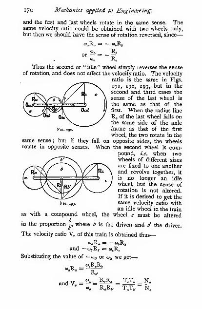
17o Mechanics applied to Engineering.
and the first and last wheels rotate in the same sense. Thesame velocity ratio could be obtained with two wheels only,
but then we should have the sense of rotation reversed, since
—
or - = -—<«s R.
Fig. 192.
Thus the second or " idle " wheel simply reverses the senseof rotation, and does not affect the velocity ratio. The velocity
ratio is the same in Figs.
191, 192, 193, but in the
second and third cases the
sense of the last wheel is
the same as that of the
first. When the radius line
R„ of the last wheel falls onthe same side of the axleframe as that of the first
wheel, the two rotate in thesame sense; but if they fall on opposite sides, the wheelsrotate in opposite senses. When the second wheel is com-
pound, i.e. when twowheels of different sizes
are fixed to one anotherand revolve together, it
is no longer an idle
wheel, but the sense ofrotation is not altered.
If it is desired to get thesame velocity ratio withan idle wheel in the train
the wheel c must be alteredas with
Fig. 193.
a compound wheel,
bin the proportion r„ where b is the driven and V the driver.
The velocity ratio V, of this train is obtained thus
—
and - (OiRy = <o„R„
Substituting the value of — wj, or eoj, we get
—
<«.R„R»<iR» =
R»'
andV, = '!^« = |4^:0)„ RaRj-
T,T, N2

Mechanisms. 171
Thus, taking a as the driving wheel, we have for the velocity
ratio
—
Revolutions of driving wheel
Revolutions of the last wheel in train
_ product of the radii or number of teeth in driven wheels
product of the radii or number of teeth in driving wheels
The same relation may be proved for any number of wheelsin a train.
If C were an annular wheel, the virtual centres would beas shown. R„ is on the opposite side of d to R„ ; therefore
the wheel c rotates in the opposite sense to a (Fig. 194).
In some instances the wheel C rotates on the same axle
as a ; such a case as this is often met with in the feed arrange-
ments of a drilling-machine (Fig.
195). The wheel A fits loosely onthe outside of the threads of the
screwed spindle S, and is driven bymeans of a feather which slides in
a sunk keyway, the wheels B andB' are both keyed to the sameshaft ; C, however, is a nut which
works freely on the screw S.
Now, if A and C make the samenumber of revolutions per minute,
the screw will not advance, but if
C runs faster than A, the screw will advance ; the number of
teeth in the several wheels are so arranged that C shall do so.
For example—Let A have 30teeth, B, 20, B', 21, C, 29,
and the screw have four threads
per inch : find the linear ad-
vance of the screw per revo-
lution of S. For one revolu-
tion of A the wheel C makes30 X 21 „„o= 5f2 = i'o86 revo-20 X 29 ^*°
lution. Thus, C makes o-o86
revolution relatively to A per
revolution of the spindle, or it
advances the screw H:^
Fig. 194.
Jig. ips.
o"o2i inch per revolution of S.1-
Change Speed Gears.—The old-fashioned back gear

1/2 Mechanics applied to Engineering.
so common on machine tools is often replaced by more con-
venient methods of changing the speed. The advent of
motor-cars has also been responsible for many very ingenious
devices for rapidly changing speed gears. The sliding keyarrangement of Lang is largely used in many change-speed
gears ; in this arrangement all the wheels are kept continuously
in mesh, and the two which are required to transmit the powerare thrown into gear by means of a sliding cotter or key. In
Fig. 196 the wheels on the shaft A are keyed, whereas the
wheels on the hollow shaft B are loose, the latter wheels are
each provided with six keyways, a sliding key or cotter which
passes through slots in the shaft engages with two of these key-
ways in one of the desired wheels. The wheel to be driven is
Fig. 196.
determined by the position of the key, which is shifted to andfro by means of a rod which slides freely in the hollow shaft.
The bosses of the wheels are counterbored to such an extent thatwhen the key is shifted from the one wheel to the next bothkeyways are clear of the key, and consequently both wheels arefree. The sliding rod is held in position by a suitable leverand locking gear, which holds it in any desired position.
Epicyclic Trains.—In all the cases that we have con-sidered up to the present, the axle frame on which the wheelsare mounted is stationary, but when the frame itself moves, its
own rotation has to be added to that of the wheels. In themechanism of Fig. 197, if the bar the fixed, and the wheel abe rotated in clockwise fashion, the point x would approachc, and the wheel b would rotate in contra-clockwise fashion.

Mechanisms. 173
If a be fixed, the bar c must be moved in contra-clockwise
fashion to cause c and x to approach, but b will still continueto move in contra-clockwise fashion. Let c be rotated throughone complete revolution in contra-clockwise fashion; then h
will make — N revolutions due to
the teeth, where N = 7^, and at thelb
same time it will make — 1 revolu-
tion due to its bodily rotation rounda, or the total revolutions of h will
be — N — I or — (N -f i) revolu-
tions relative to a, the fixed wheel. '^'°' '*'"
The — sign is used because both the arm and the wheel rotate
in a contra-clockwise sense. But if b had been an annular
wheel, as shown by a broken line, its rotation would have beenof the opposite sense to that of c; consequently, in that case,
b would make N — i
revolutions to one of c.
If either idle' or com-pound wheels be intro-
duced, as in Fig. 198,
we get the revolutions of
each wheel as shown for
each revolution of the
Tarm e, where v^j, = ~,
and v.^ =
:
when there
is an idle wheel between,
or z/,e = V '^° when
there is a compoundwheel.
In the last figure the
wheel c is mounted loosely on the same axle as a and d. In this
arrangement neither the velocity ratio nor the sense is altered.
The general action of all epicyclic trains may be summed
up thus : The number of revolutions of any wheel of the train
for one revolution of the arm is the number of revolutions
that the wheel would make if the arm were fixed, and the first
wheel were turned through one revolution, -|- i for wheels that
rotate in the same sense as the arm, and - i for wheels that
rotate in the opposite sense to the arm.

174 Mechanics applied to Engineering.
In the case of simple, i.e. not bevil trains, it should beremembered that wheels on the «th axle rotate in the samesense as the arm when n is an even number, and in the opposite
sense to that of the arm when n is an odd number, countingthe axle of the fixed wheel as " one." Hence we have
—
«

Mechanisms. I7S
JEEM11!.""^. Jl
Qlueruer
Um/cUui tllli
wcu/
Fig.
The bevil train shown in Fig. 200 is readily dealt with,thus let T„, T„, etc., represent the number of teeth in a and crespectively
—
b is an idle
wheel, and consequentlyTj does not affect the
velocity ratio. Fix D, androtate a contra-clockwise
through one revolution,
Tthen c makes ~ revolu-
tions in a clockwisedirection. Fix a androtate the arm D throughone clockwise revolution.
Then since the tooth of
b, which meshes with the stationary tooth of a, may be regardedas the fulcrum of a lever ; hence the tooth of b, which mesheswith c, moves in the same direction as D, and at twice the speed.
THence the number of revolutions of cis 7=r + i for one revolution
of D. The problem may also be dealt with in the same manneras the simple epicyclic train. The number of revolutions of anywheel of the train for one revolution of the arm is the numberof revolutions that the wheel would make if the arm werefixed and the first wheel were turned through one revolution,
+ I for wheels that rotate in the same sense as the arm, and— I for wheels that rotate in the opposite sense to the arm.
For elementary bevil trains, such as that shown in Fig.
200, wheels on the «th axle rotate in the opposite sense to the
arm when n is an even number, and in the same sense whenn is an odd number. Hence we have for elementary bevil
trains
—
n

1/6 Mechanics applied to Engineering.
In all cases the actual number of revolutions per minute of
the several wheels calculated for one revolution of the armmust be multiplied by the number of revolutions per minute
of the arm N^, also, if the wheel a rotates, its revolutions per
minute must be added, with due regard to the sign, to the
revolutions per minute of each wheel calculated for a stationary
wheel.
The following table may be of assistance in this connection.

Mechanisms. 177
Revs. E = revs, of B x t^-' + i = - i-i'S X M + i
= -0-541 + I = 0-459
Whence for one revolution of E, C makes4-83
°'459= io"53
revolutions.
The -f- sign in the expressions for the speed of C and E is
Fig. 20I.
on account of these wheels of the epicyclic train rotating in thesame sense as that of the arm d.
As stated above the «th wheel in a bevil train of this typerotates in the same sense as the arm when n is odd, and in theopposite sense when n is even ; hence the sign is + for oddaxes, and — for even axes, always counting the first as " one."
It may help some readers to grasp the solution of this
problem more clearly if we work it out by another method.Let A be free, and let d be prevented from rotating ; turn Athrough one —revolution] then
—
Revs.l product of teeth in drivers
ofEj product of teeth in drivenwheels
Revs.l Ta
T,XT,^
't:xt:-0-541
ofc}=T:=3-«3
Hence, when A is fixed by clamping the split bearing G, andd is rotated, the train becomes epicyclic, and since C and E are
on odd axes of bevil trains, they rotate in the same sense as the
arm ; consequently, for reasons already given, we have
—
Revs. E _ Ne _ — 0-541 + I _ 1
Revs. C Ne 3-83 + I 10-53

178 Mechanics applied to Engineeritig,
Particular attention must be paid to the sense of rotation.
Bevil gears are more troublesome to follow than plain gears
;
hence it is well to put an arrow on the drawing, showing the
direction in which the observer is supposed to be looking.
This mechanism can also be used as a simple reduction
gear—in which case the shaft Fj is not continuous with Fj.
The wheel C is then keyed to Fj, or drives it through the set
„ „. „ . , J , T. , Revs. E Revs. Fjscrew S. Since E is keyed to F, we have =; ;; = =; -.
Revs. C Revs. F2Thus, if F2 is coupled to a motor running at 1053 revs, permin., the low speed shaft Fi will run at 100 revs, per min. for
the set of wheels mentioned above.

CHAPTER VI.
lOYNAMICS OF THE STEAM-ENGINE.
Reciprocating Farts.—Oh p. 133 we gave the construction
for a diagram to show the velocity of the piston at each
part of the stroke when the velocity of the crank-pin wasassumed to be constant. We there showed that, for an infinitely
long connecting-rod or a slotted cross-head (see Fig. 160), such
a diagram is a semicircle when the ordinates represent the
velocity of the piston, and the abscissae the distance it has
moved through. The radius of the semicircle represents the
constant velocity of the crank-pin. We see from such a dia-
gram that the velocity of the reciprocating parts is zero at each
end of the stroke, and is a maximum at the middle ; hence
during the first half of the stroke the velocity is increased, or
the reciprocating parts are accelerated, for which purpose
energy has to be expended ; and during the second half of the
stroke the velocity is decreased, or the reciprocating parts are
retarded, and the energy expended during the first half of the
stroke is given back. This alternate expenditure and paying
back of energy very materially affects the smoothness of run-
ning of high-speed engines, unless some means are adopted for
counteracting these disturbing effects.
We will first consider the case of an infinitely long con-
necting-rod, and see how to calculate
the pressure at any part of the stroke
required to accelerate and retard the
reciprocating parts.
The velocity diagram for this case
is given in Fig. 202. Let R represent
V, the linear velocity of the crank-pin,
assumed constant ; then the ordinates
Yi, Ya represent to the same scale the velocity of the piston
V Ywhen it is at the positions Ai, Aj respectively, and -^ = ~

i8o Mechanics applied to Engineering.
Let the total weight of the reciprocating parts = W.Then—
The kinetic energy of the V _ WVi''
reciprocating parts at Aj \~ 2g
Likewise at A. =2^-R^
The increase of kinetic energy^ _ WV^ , ^
during the interval A1A2 • j~ 2°^^' ~^^)
This energy must have come from the steam or other motivefluid in the cylinder.
Let P = the pressure on the piston required to accelerate
the moving parts.
Work done on the piston in accelerating the) _ -pi _ \
moving parts during the interval 3~ '^^ *!'
But V + Y,^ = xi + Ya^ = Rhence Y^ — Yi = x^ — x^
and
—
Increase of kinetic energy of the] -nnnreciprocating parts during the > = (x^ — x^)interval J
^S^
then P(*, - X,) = ^,(«/ - *.»)
WV
where * is the mean distance ' '*^ of the piston from the

Dynamics of the Steam-Engine. iSi
middle of the stroke ; and when ;«: = R at the beginning andend of the stroke, we have
—
P =
^-^
We shall term P the " total acceleration pressure." Thuswith an infinitely long connecting-rod the pressure at the endof the stroke required to accelerate or retard the reciprocating
parts is equal to the centrifugal force (see p. 19), assuming the
parts to be concentrated at the crank-pin, and at any other
part of the stroke distant x from the middle the pressure is less
00
in the ratio —
.
K.
Another simple way of arriving at the result given above is
as follows : If the connecting-rod be infinitely long, then it
always remains parallel
to the centre line of
the engine ; hence the
action is the same as
if the connecting-rod
were rigidly attached •
,/
to the cross-head and '- -
'
"~- •''
piston, and the whole Fig. 203.
rotated together as one solid body, then each point in the bodywould describe the arc of a circle, and would be subjected to
the centrifugal force C = —5-, but we are only concerned with
the component along the centre line of the piston, marked Pin the diagram. It will be seen that P vanishes in the middle
of the stroke, and increases directly as the distance from the
middle, becoming equal to C at the ends of the stroke.
When the piston is travelling towards the middle of the
stroke the pressure P is positive,
and when travelling away from
the middle it is negative. Thus,
in constructing a diagram to
show the pressure exerted at all
parts of the stroke, we put the
first half above, and the second
half below the base-line. Weshow such a diagram in Fig. 2 04.
The height of any point in the
sloping line ab above the base-line
Fig. 204.
represents the pressure

182 Mechanics applied to Engineering.
at that part of the stroke required to accelerate or retard the
moving parts. It is generally more convenient to express the
pressure in pounds per square inch, /, rather than the total
ppressure P ; then -7- =/> where A = the area of the piston. We
Wwill also put w = — , where w is the weight of the reciprocatmg
parts per square inch of piston. It is more usual to speak of
the speed of an engine in revolutions per minute N, than of
the velocity of the crank-pin V in feet per second.
27rRN
and/ '
60
6o=^R= o'ooo34ze'RN''
N.B.—-The radius of the crank R is measured in feet.
In arriving at the value ofw it is usual to take as reciprocating
parts—the piston-head, piston-rod, tail-rod (if any), cross-head,
small end of connecting-rod and half the plain part of the rod.
A more accurate method of finding the portion of the connect-
ing-rod to be included in the reciprocating parts is to place the
rod in a horizontal position with the small end resting on the plat-
form of a weighing machine or suspended from a spring balance,
the reading gives the amount to be included in the reciprocating
parts. When air-pumps or other connections are attached to
the cross-head, they may approximately be taken into account
in calculating the weight of the reciprocating parts j thus
—
Fig. 205.
weight of \ piston -)- piston and ail-rods -f- both cross-heads -f small
area of
end of con. rod -(- ' ' 1- air-2
piston
ir-pumpplungerf^j
\^.i^^l\ \

Dynamics of the Steam-Engine. 183
The kinetic energy of the parts varies as the square of the
velocity; hence the \j\
Values of w in pounds per square inch of piston :
—
Steam engines with no air pump or other attachments 2 to 4„ '
„ attachments 3 to 6
In compound and triple expansion engines the reciproca-
ting parts are frequently made of approximately the same total
weight in each cylinder for balancing purposes, in such cases
w is often as high as 6 lbs. for the H.P. cylinder and as low as
I lb. for the L.P.
Influence of Short Connecting-rods.—In Fig. 159a velocity diagram is given for a short connecting-rod ; repro-
ducing a part of the figure in Fig. 206, we have
—
Short rod—cross-head velocity _ OXcrank-pin velocity OCj
Infinite rod-— ,
cross-head velocity _ OXjcrank-pin velocity OCi
velocity of cross-head with short rod _ OXvelocity of cross-head with long rod OXj
But at the " in " end of the stroke .-2J=^ = li+^
and at the " out " end of the stroke = i — —
Thus if the connecting-rod is n cranks long, the pressure at
the "in" end is - greater, and at the "out" end - less, thann n '
if the rod were infinitely long.
The value of/ at each end of the stroke then becomes
—
p = o'ooo34wRNV I -|- - 1 for the " in " end
p = o'ooo34wRN-( 1 — - ) for the " out " end

184 Mechanics applied to Engineering.

Dynamics of the Steam-Engine. 185
The line ab is found by the method described on p. 133.
Set off aa„ = —, also bl>„ = — , and cc. = —, ^ is the positionn n n
of the cross-head when the crank is at right angles to the centreline, i.e. vertical in this case. The acceleration is zero wherethe slope of the velocity curve is zero, i.e. where a tangent to it
is horizontal. Draw a horizontal line to touch the curve, viz.
at/. As a check on the accuracy of the work, it should benoticed that this point very nearly indeed corresponds to theposition in which the connecting-rod is at right angles to the
crank; 'the crosshead is then at a distance R(V'«^-f- i — n),"P
or very nearly —, from the middle of the stroke. The point/
having been found, the corresponding position of the cross-
head g is then put in. At the instant when the slope of theshort-rod velocity curve is the same as that of the long-rodvelocity curve, viz. the semicircle (see page 134), the accelera-
tions will be the same in both cases. In order to find
where the accelerations are the same, draw arcs of circles
from C as centre to touch the short-rod curve, and from thepoints where they touch draw perpendiculars to cut the circle
at the points M and i. The corresponding positions of the
cross-head are shown at h and i respectively. In these
positions the acceleration curves cross one another, viz. at h„
and 4. It will shortly be shown that when the crank haspassed through 45° and 135° the acceleration pressure with
the short rod is equal to that with the infinitely long rod.
From ]i drop a perpendicular to k„ set off kji„ = L, also
k'k = L, and from the point where the perpendicular fromk'„ cuts ab draw a horizontal to meet the perpendicular fromk, where they cut is another point on the acceleration curvefor the short rod
;proceed similarly with /.
~ We now haveeight points on the short-rod acceleration curve through whicha smooth curve may be drawn, but for ordinary purposes three
are sufBcient, say a„, c„ b„.
The acceleration pressure at each instant may also bearrived at thus
—
Let 6 = the angle turned through by the crank starting
from the " in " end
;
V = the linear velocity of the crank-pin, assumedconstant and represented by R
;
V = the linear velocity of the cross-head.
' Engineering, }\x\y 15, 1892, p. S3 ; also June 2, 1899.

1 86 Mechanics applied to Engineering.
Then—v_ sin (g + g
)
V sin (90- a)^^^^^'^•^°''''
^,/sin 6 cos a + cos B sin a\» = V(
)\ cos a /
In all cases in practice the angle a is small, consequentlycos a is very nearly equal to unity; even with a very short
rod the average error in the final result is well within one percent. Hence—
z* = V (sin Q + cos sin a) nearly
We also have
—

Dynamics of the Steam- Engine. 187
and the acceleration pressure, when the crank has passedthrough the angle Q from the " in " end of the stroke, is—
wVY cos 2ff\
or/ = o-ooo34ze/RN=('cos B + E2if_^^
When 6 = 45° and 135°, cos 26 = and the expressionbecomes the same as that for a rod of infinite length. When
6 = and 180° the quantity in brackets becomes 1 + i and
I1 .
Correction of Indicator Diagram for AccelerationPressure.—An indicator diagram only shows the pressure ofthe working fluid in the cylin-
der; it does not show the
real pressure transmitted to
the crank-pin because someof the energy is absorbed in
accelerating the reciprocating
parts during the first part of_
the stroke, and is therefore"
~—™™™'-' rr^:. —>
not available for driving the
crank, whereas, during the latter part of the stroke, energy is
given back from the reciprocating parts, and there is excessenergy over that supplied from the working fluid. But, apartfrom these effects, a single indicator diagram does not showthe impelling pressure on a piston at every portion of the
stroke. The impelling pressure is really the difference be-tween the two pressures on both sides of the piston at anyone instant, hence the impelling pressure must be measuredbetween the top line of one diagram and the bottom line ofthe other, as shown in full lines in Fig. 207.
The diagram for the return stroke is obtained in the samemanner. The two diagrams are set out to a straight base in
Fig. 208, the one above the line and the other below. Onthe same base line the acceleration diagram is also given to
the same scale. The real pressure transmitted along the
centre line of the engine is given by the vertical height of the
shaded figures. In the case of a vertical engine the accelera-
tion line is shifted to increase the pressure on the downwardstroke and decrease it on the upward stroke by an amount zc,

i88 Mechanics applied to Engineering.
see Fig. 209. The area of these figures is not altered in anyway by the transformations they have passed through, but it
should be checked with the area of the indicator diagrams in
order to see that no error has crept in.
When dealing with engines having more than one cylinder,
the question of scales must be carefully attended to ; that is,
the heights of the diagrams must be corrected in such amanner that the mean height of each shall be proportional to
the total effort exerted on the piston.
^'- III!Il|ll
I, ,
Fig. Z08. Fig. 2og,
Let the original indicator diagrams be taken with springs of
the following scales, H.P. -, I.P. -, L.P.-. Let the areas ofoc z
the pistons (allowing for rods) be H.P. X, LP. Y, L.P. Z. Letall the pistons have the same stroke. Suppose we find that
the H.P. diagram is of a convenient size, we then reduce all the
others to correspond with it. If, say, the intermediate piston
were of the same size as the high-pressure piston, we should
simply have to alter the height of the intermediate diagram in
the ratio of the springs ; thus
—
Corrected height of LP. diagram) ^ fiiSltll x fif pistons were of same size 1 | diagram i i
= actual height X —X

Dynamics of the Steam-Engine. 189
But as the cylinders are not of the same size, the height ofthe diagram must be multiplied by the ratio of the two areas
;
thus
—
Height of intermediate diagramj
j-actual height of^ ^
corrected for scales of springs \ — \ intermediate V X ^ X -
and for areas of pistons J ( diagram j « X-J'v^
diagram j
= actual height X ^—
Similarly for the L.P. diagram
—
Height ofL.P. diagram corrected . ^^^^^j ^^^.^^ ^^. ^^
It is probably best to make this correction for scale andarea after having reduced the diagrams to the form given inFig. 208.
Pressure on the Crank-pin.—The diagram given in

190 Mechanics applied to Engineering.
the beginning of the stroke, and an excess at the end. Thedefects could be remedied by increasing the initial pressure
and the compression, or by running the engine at a lower
speed.
For many interesting examples of these diagrams, as applied
to steam engines, the reader is referred to Rigg's " Practical
Treatise on the Steam Engine ;" also a paper by the same
author, read before the Society of Engineers ; and to Haederand Huskisson's " Handbook on the Gas Engine," CrosbyLockwood, for the application of them to gas and oil engines.
Cushioning for Acceleration Pressures.—In order
to counteract the effects due to the acceleration pressure, it is
usual in steam-engines to close the exhaust port before the
end of the stroke, and thus cause the piston to compress the
exhaust steam that remains in the cylinder. By choosingthe point at which the exhaust port closes, the desired amountof compression can be obtained which will just counteract the
acceleration pressure. In certain types of vertical single-
acting high-speed engines, the steam is only admitted on the
downstroke ; hence on the upstroke some other method ofcushioning the reciprocating parts has to be adopted. In thewell-known Willans engine an air-cushion cylinder is used
;
the required amount of cushion at the top of the cylinder is
obtained by carefully regulating the volume of the clearance
space. The pistons of such cylinders are usually, of the trunkform ; the outside pressure of the atmosphere, therefore, acts
on the full area of the underside, and the compressed air
cushion on the annular top side.
Let A = area of the underside of the piston in square inches j
A„ = area of the annular top side in square inches;W = total weight of the reciprocating parts in lbs.;
c = clearance in feet at top of stroke.
At the top, i.e. at the " in end," of the stroke we have
—
Pi = o-ooo34WRN2(^i -fi^ - W -f i4-7A
Assuming isothermal compression of the air, and takingthe pressure to be atmospheric at the bottom of the stroke, wehave
—
I47A„(2R -t- f) = P,f
whence c = ^Pi - i4-7Aa

Dynamics of the Steam-Engine. 191
Or for adiabatic compression
—
I4-7A„(2R + <r)'"" = Pi<;^'"
2R
Vi47Aa/
in the expression for c given above.
The problem of balancing the reciprocating parts of gas andoil engines is one that presents much greater difiSculties than in
the steam-engine, partly because the ordinary cushioningmethod cannot be adopted, and further because the eifective
pressure on the piston is different for each stroke in the cycle.
Such engines can, however, be partially balanced by means of
helical springs attached either to the cross-head or to a tail-rod,
arranged in such a manner that they are under no stress whenthe piston is at the middle of the stroke, and are under their
maximum compression at the ends of the stroke. The weightof such springs is, however, a great drawback ; in one instance
known to the author the reciprocating parts weighed about1000 lbs. and the springs 800 lbs.
Polar Twisting-Moment Diagrams.^ From the
diagrams of real pressures transmitted to the crank-pin that
Fig. 211.
we have just constructed, we can readily determine the twisting
moment on the crank-shaft at each part of the revolution.
In Fig. 2ir,let/ be the horizontal pressure taken from sucha diagram as. Fig. 209. Then /i is the pressure transmitted
along the rod to the crank-pin. This may be resolved in adirection parallel to the crank and normal to it (/„) ; we neednot here concern ourselves with the pressure acting along thecrank, as that will have no turning effect. The twisting momenton the shaft is then/„R ; R, however, is constant, therefore thetwisting moment is proportional to/„. By setting off values of
p„ radially from the crank-circle we get a diagram showing the

192 Mechanics applied to Engineering.
twisting moment at each part of the revolution. /„ is measured
on the same scale, say -, as the indicator diagram ; then, if A
be the area of the piston in square inches, the twisting momentin pounds feet =/„a:AR, where /„ is measured in inches, andthe radius of the crank R is expressed in feet.
When the curve falls inside the circle it simply indi-
FiG. 2ia.
Gates that there is a deficiency of driving effort at that
place, or, in other words, that the crank-shaft is driving the
piston.
In Fig. 212 indicator diagrams are given, which have beenset down in the manner shown in Fig. 208, and after correct-
ing for inertia pressure they have been utilized for construct-
ing the twisting moment diagram shown in Fig. 213. Thediagrams were taken from a vertical triple-expansion engine
made by Messrs. McLaren of Leeds, and by whose courtesy
the author now gives them.
The dimensions of the engine were as follows :
—

Dynamics of the Steam-Engine. 193
Diameter of cylinders
—
High pressure
Intermediate
Low pressure
Stroke
9*01 inches,
I4"2S .1
22-47 >.
2 feet

Fig. 182*.
194 Mechanics applied to Engineering.
The details of reducing the indicator diagrams have been
omitted for the sake of clearness ; the method of reducing them
has been fully described.
Twisting Moment on a Crankshaft.—In some
instances it is more convenient to calculate the twisting
moment on the crank-
shaft when the crank
has passed through the
angle 6 from the inner
dead centre than to
construct a diagram.
Let P, = the effort on the piston-rod due to the working
fluid and to the inertia of the moving parts
;
Pi = the component of the eflfort acting along the
connecting-rod
;
, . sin 9P, = Pi cos o, and sm a = ^-
from which a can be obtained, since 6 and n are given.
The tangential component
—
T = Pi cos </)
and </) = 90 — (^ ^- a)
whence T= ^^cos {9o-(e + a)] = ^' ^'" ^^ + "^
cos a <'^ cos a
Flywheels.—The twisting-moment diagram we have just
constructed shows very clearly that the turning effort on the
crank-shaft is far from being constant ; hence, if the moment of
resistance be constant, the angplar velocity cannot be constant.
In fact, the irregularity is so great in a single-cylinder engine,
that if it were not for the flywheel the engine would come to a
standstill at the dead centre.
A flywheel is put on a crank-shaft with the object of storing
energy while the turning effort is greater than the mean, andgiving it back when the effort sinks below the mean, thus
making the combined effort, due to both the steam and the
flywheel, much more constant than it would otherwise be, andthereby making the velocity of rotation more nearly constant.
But, however large a flywheel may be, there must always besome variation in the velocity ; but it may be reduced to as
small an amount as we please by using a suitable flywheel.
In order to find the dimensions of a flywheel necessary for
keeping the cyclical velocity within certain limits, we shall makeuse of the twisting-moment diagram, plotted for convenience

Dynamics of the Steam-Engine. 195
to a straight instead of a circular base-line, the length of thebase being equal to the semicircumference of the crank-pincircle. Such a diagram we give in Fig. 215. The resistanceline, which for the present we shall assume to be straight, is
shown dotted; the diagonally shaded portions below the meanline are together equal to the horizontally shaded area above.
During the period AC the effort acting on the crank-pin is
less than the mean, and the velocity of rotation of the crank-pin is consequently reduced, becoming a minimum at C.During the period CE the effort is greater than the mean, andthe velocity of rotation is consequently increased, becoming amaximum at E.
Fig. 215.
Let V = mean velocity of a point on the rim at a radius equalto the radius of gyration of the wheel, in feet persecond—usually taken for practical purposes as the
velocity of the outside edge of the rim :
V„ = minimum velocity at C (Fig. 215);V^ = maximum „ E
;
W = weight of the flywheel in pounds, usually taken for
practical purposes as the weight of the rim;
R„ = radius of gyration in feet of the flywheel rim, usually
taken as the external radius for practical purposes.
For most practical purposes it is sheer waste of time cal-
culating the moments of inertia and radii of gyration for all
the rotating -parts, since the problem is not one that permits
of great accuracy of treatment, the form of the indicator
diagrams does not remain constant if any of the conditions
are altered even to a small extent, then again the coefficient
-of fluctuation k is not a definitely known quantity, since
different authorities give values varying to the extent of twoor three hundred per cent. The error involved in using the
above approximations is not often greater than five per cent,
which is negligible as compared with the other variations, andby adopting them a large amount of time is thereby saved.
' Figures 207, 208, 210, 215 are all constructed from the same indicator
diagram.

196 Mechanics applied to Engineering.
Then the energy stored in the flywheel at C = -
E =^g
WThe increase of energy during CE = —(V/— V„^) (i.)
This increase of energy is derived from the steam or other
source of energy ; therefore it must be equal to the workrepresented by the horizontally shaded area CDE = E„ (Fig.
215)-
Let E„ = OT X average work done per stroke.
Then the area CDE is m times the work done per stroke,
or m times the whole area BCDEF. Or
—
p, _ m X indicated horse-power of engine x 33000 ...
.
where N is the number of revolutions of the engine per minutein a double-acting engine.
Whence, from (i.) and (ii.), we have
—
W/^a 3. _ OT X I.H.P. X 33000 ,
Tg-'~ °' 2N • ^ '
But '"' ° = V (approximately)2
or V. + V. = 2VV — V
also —i^r=—5 = K, " the coefficient of speedfluctuation "
and V. - V. = KVv." - V/ = 2KV
Substituting this value in (iii.)
—
-(2KV=) = *^ ^ ^•^^- ^ 33000 ^ E2/ 2N "
„„A w - 48,5o°.o°o/« X I.H.P.
KWRJ ' • ' ^^^-^
The proportional fluctuation of velocity K is the fluctuation
of velocity on either side of the mean ; thus, when K = 0*02
it is a fluctuation of i per cent, on either side of the mean.The following are suitable values for K :
—

Dynamics of the Steani-Engine. 197
K = o'oi to o'oa for ordinary electric-lighting engines, but for
public lighting and traction stations it often gets as lowas o"ooi6 to 0-0025 to allow for very sudden and largechanges in the load ; the weight of all the rotatingparts, each multiplied by its own radius of gyration, is
to be included in the flywheel
;
= o'o2 to o'o4 for factory engines;= o'o6 to o'i6 for rough engines.
When designing flywheels for public lighting and tractionstations where great variations in the load may occur, it is
common to allow from 2-4 to 4-5 foot-tons (including rotor)of energy stored per I.H.P.
The calculations necessary for arriving at the value of E„for any proposed flywheel are somewhat long, and the resultwhen obtained has an element of uncertainty about it, becausethe indicator diagram must be assumed, since the engine sofar only exists on paper. The errors involved in the diagrammay not be serious, but the desired result may be arrived atwithin the same limits of error by the following simpler process.The table of constants given below has been arrived at byconstructing such diagrams as that given in Fig. 215 for alarge number of cases. They must be taken as fair averagevalues. The length of the connecting-rod, and the amount ofpressure required to accelerate and retard the moving parts,affect the result.
The following table gives approximate values of m. Inarriving at these figures it was found that if « = number of
cranks, then m varies as -^ approximately.
Approximate Values of m for Double-acting Steam-Engines.'
Cut-off.

198 Mechanics applied to Engineering.
m FOK Gas

Dynamics of the Steam-Engine. 199
In the following table we give the number of strokes that
must be stored in the flywheel in order to allow a total fluctua-
tion of speed of i per cent., i.e. \ per cent, on either side of
the mean. If a greater variation be permissible in any given
case, the number of strokes must be divided by the per-
missible percentage of fluctuation. Thus, if 4 per cent., i.e.
K = o'o4, be permitted, the numbers given below must bedivided by 4.
Number of Strokes stored in a Flywheel for Double-acting
Steam-Engines.'
Cut-off.

200 Mechanics applied to Engineering.
Gas-Engine Flywheels.—The value of m for a gas-
engine can be roughly arrived at by the following method.
Fig. 2i6.
The work done in one explosion is spread over four strokes
when the mixture explodes at every cycle. Hence the meaneffort is only one-fourth of the explosion-stroke effort, andthe excess energy is therefore approximately three-fourths
of the whole explosion-stroke effort, or three times the mean :
hence m = 2,.
Similarly, when every alternate explosion is missed, m = j.
By referring to the table, it will be seen that both of these
values are too low.
The diagram for a 4-stroke case is given in Fig. 216. It has
been constructed in precisely the same manner as Figs. 207,
208, and 215. When oil- or gas-engines are used for driving
dynamos, a small flywheel is often attached to the dynamodirect, and runs at a very much higher peripheral speed thanthe engine flywheel. Hence, for a given weight of metal, the
small high-speed flywheel stores a much larger amount of
energy than the same weight of metal in the engine flywheel.
The peripheral speed of large cast-iron flywheels has to bekept below a mile a minute (see p. 201) on account of their

Dynamics of the Steam-Engine. 201
danger of bursting. The small disc flywheels, such as are usedon dynamos, are hooped with a steel ring, shrunk on the rim,
which allows them to be safely run at much higher speeds than
the flywheel on the engine. The flywheel power of such anarrangement is then the sum of the energy stored in the twowheels.
There is no perceptible flicker in the lights when about forty
impulse strokes, or i6o average strokes (when exploding at
every cycle, and twice this number when missing alternate
cycles), are stored in the flywheels.
Case in which the Resistance varies.—In all the
above cases we have assumed that the resistance overcome bythe engine is constant. This, however, is not always the case
;
when the resistance varies, the value of E„ is found thus :
Fig. 217.
The line aaa is the engine curve as described above, the line
bbb the resistance to be overcome, the horizontal shadingindicates excess energy, and the vertical deficiency of energy.
The excess areas are, of course, equal to the deficiency areas
over any complete cycle. The resistance cycle may extend over
several engine cycles; an inspection or a measurement will
reveal the points of maximum and minimum velocity. Thevalue of m is the ratio of the horizontal shaded areas to the
whole area under the line aaa described during the complete
cycle of operations. See The Engineer, January 9, 1885.
Stress in Flywheel Rims.—If we neglect the effects of
the arms, the stress in the rim of
a flywheel may be treated in the
same manner as the stresses in
a boiler-shell or, more strictly,
a thick cylinder (see p. 421), in
which we have the relation
—
or P,R„ =/, when t = -i inch
The P, in this instance is the
pressure on each unit length of
rim due to centifugal force. We Fig. 2i3.

202 Mechanics applied to Engineering.
shall find it convenient to take the unit of length as i foot,
because we take the velocity of the rim in feet per second.
Then—WV ^ WV
"
where W, = the weight of i foot length of rim, i square inch
in section
= 3 "I lbs. for cast iron
We take i sq. inch in section, because the stress is expressed in
pounds per square inch. Then substituting the value of W,in the above equations, we have
—
32"2
/= 0-096V„'
V "/or/= -^ (very nearly)
10
In English practice V„ is rarely allowed to exceed 100 feet
per second, but in American practice much higher speeds are
often used, probably due to the fact that American cast iron is
much tougher and stronger than the average metal used in
England. An old millwright's rule was to limit the speed to a
mile a minute, i.e. 88 feet per second, corresponding to a stress
of about 800 lbs. per square inch.
The above expression gives the tensile stress set up in athin plain rotating ring, due to centrifugal force ; but it is not
the only or even the most important stress which occurs in
many flywheel and pulley rims. The direct stress in the
material causes the rim to stretch and to increase in diameter,
but owing to its attachment to the arms, it is unable to do so
beyond the amount permitted by the stretch of the arms,
with the result that the rim sections bend outwards betweenthe arms, and behave as beams which are constrained in
direction at the ends. If the arms stretched sufficiently to
allow the rim to remain circular when under centrifugal stress
there would be no bending action, and, on the other hand,if the arms were quite rigid the bending stress in the rimsections between the arms could be calculated by treating
them as beams built in at each end and supporting an evenlydistributed load equal in intensity to the centrifugal force
acting on the several portions of the rim ; neither of these
conditions actually hold and the real state of the beam

Dynamics of the Steam-Engine. 203
is intermediate between that due to the above-mentionedassumptions, the exact amount of bending depending largely
upon the stretch of the arms.
A rigid solution of the problem is almost impossible, the
results obtained by different authorities are not in agree-
ment, owing to arbitrary assumptions being made. In all
cases it is assumed that there are no cooling stresses exist-
ing in the arms of the wheel, which every practical manknows is not always correct. However, the results obtained
by the more complete reasoning are unquestionably nearer
the truth than those obtained by the elementary treatment
given above.
For a more complete treatment the reader is referred to
Unwin's "Elements of Machine Design," Part II. (Longmans).The following approximate treatment may be of service to
those who have not the opportunity of following the morecomplete theory.
The maximum bending moment in pound-inches on an
initially straight beam built in at both ends is— (see p. 529),
where w is the evenly distributed load per inch run, and / is
the length between supports in inches. In the case of the
flywheel, w is the centrifugal force acting on the various
portions of the rim, and is° ^ "— , where 0-26 is the weight
of a cubic inch of cast iron, V„ is the rim velocity in feet per
second, A the area of the section of the rim in square inches,
g the acceleration of gravity, R„ the radius of the rim in feet,
Z the tension modulus of the section (see Chapter IX.).
Then the bending stress in the rim due to centrifugal force
o-26V„^A/''^ '" 12 X 32-2 X R„ X Z
The rim section, however, is not initially straight, hence
the ordinary beam formula does not rigidly hold. / is taken
as the chord of the arc between the arms. As already ex-
plained, the stress due to bending is really less than the above
expression gives, but by introducing a constant obtained bycomparing this treatment with one more complete, we can
bring the results into approximate agreement : this constant is
about 2'2. Henceo-26V„^A/' ^ V^'A/'
^^ ~ 2-2 X 12 X 32'2R„Z ~ 327oR„Z

204 Mechanics applied to Engineering.
and the resulting tensile stress in the rim is
—
All who have had any experience in the foundry will be
familiar with the serious nature of the internal cooling stresses
in flywheel and pulley arms. The foundry novice not unfre-
quently finds that one or more of the arms of his pulleys are
broken when taken out of the sand, due to unequal cooling ;
by the exercise of due care the moulder can prevent such
catastrophes, but it is a matter of common knowledge that, in
spite of the most skilful treatment it is almost impossible to
ensure that a wheel is free from cooling stresses. Hence only
low-working stresses should be permitted.
When a wheel gets overheated through the use of a friction
brake, the risk of bursting is still greater; there are manycases on record in which wheels have burst, in some instances
with fatal results, through such overheating. In a case knownto the Author of a steam-engine fitted with two flywheels, 5 feet
in diameter, and running at 160 revolutions per minute, oneof the wheels broke during an engine test. The other wheel
was removed with the object of cutting through the boss in
order to relieve the cooling stresses; but as soon as the cut
was started the wheel broke into several pieces, with a loud
report like a cannon, thus proving that it was previously sub-
jected to very serious cooling stresses. In order to reduce
the risk of the bursting of large flywheels, when made with
solid rims, they should always be provided with split bosses.
In some cases the boss is made in several sections, each beingattached to a single arm, which effectually prevents the armsfrom being subjected to initial tension due to cooling. Built-up
rims are in general much weaker than solid rims ; but whenthey cannot be avoided, their design should be most carefully
considered. The question is discussed in Lanza's " Dynamicsof Machinery " (Chapman & Hall).
Large wheels are not infrequently built up entirely ofwrought iron or steel sections and plates ; in some instances
a channel rim has been used into which hard-drawn steel wire
is wound under tension. Such wheels are of necessity morecostly than cast-iron wheels of the same weight, but since thematerial is safe under much higher stresses than cast iron, thepermissible peripheral speed may be much higher, and conse-quently the same amount of energy may be stored in a muchlighter wheel, with the result that for a given speed fluctuation

Dynamics of the Steam-Engine. 205
the cost of the built-up wheel may be even less than that of a
cast-iron wheel.
In the place of arms thin plate webs are often used with
great success ; such webs support the rim far better than arms,
and moreover they have the additional advantage that they
materially reduce the air resistance, which is much more im-
portant than many are inclined to believe.
Experimental Determination of the Bursting Speedof Flywheels.—Professor C. H. Benjamin, of the Case School,
Cleveland, Ohio, has done some excellent research work on
the actual bursting speed of flywheels, which well corroborates
the general accuracy of the theory. The results he obtained are
given below, but the original paper read by him before the
American Society of Mechanical Engineers in 1899 should beconsulted by those interested in the matter.
Bursting speedin feet per sec.

2o6 Mechanics applied to Engineering.
Arms of Flywheels.— In addition to the unknowntensile stresses in wheels with solid bosses and rims, the arms
are under tension due to the centrifugal force acting (i) on the
arm itself, (ii) on a portion of the rim, amounting to approxi-
mately one-fourth of the length of rim between the arms. In
addition to these stresses the arms are subjected to bending
due (iii) to a change in the speed of the wheel, (iv) to the
power transmitted through the wheel when it is used for
driving purposes.
The tension due to (i) is arrived at thus
—
Let Aa = Sectional area of the arm in square inches as-
sumed to be the same throughout its length.
r = Radius from centre of wheel to any element of
the arm in feet.
(1) = Angular velocity of the arm.
/"i= Radius of inside of the rim of the wheel in feet,
fa = Radius of boss of the wheel in feet.
w = Weight of a cubic inch of the material.
The centrifugal force acting on the element of the arm is
gand on the whole arm
g Jvi g \ 2 /
6'
The tension in the arm due to the centrifugal force acting
on one-fourth of the rim between the arms is
_ w\NJ'
Hence the tensile stress in the arm at the boss due to both is
7r Ir --T— + T>PP'°'-
Let the 'acceleration of the rim, arising from a change ofspeed of the shaft, be 8V feet per sec. per sec. Let W be theweight of the rim in pounds, then, since the arms are built in
at both ends, the bending moment on them (see p. 504) is
6WR„.8V . ^ J 1 ,. ^ ..mch-pounds, approximately ; the bendmg stress is

Dynamics of the Steam-Engine. 207
6WR .8V'^— , where n is the number of arms and Z the modulus
gnT.
of the section of the arms in bending.
If the flywheel be also used for transmitting power, and Pbe the effective force acting on the rim of the wheel, the
bending stress in the arms is —?, on the assumption that
the stress in the most strained arm is twice the mean, whichexperiments show is a reasonable assumption.
Hence the bending stress in the arms due to both causes
The strength of flywheel and pulley arms should always bechecked as regards bending.
Bending Stresses in Locomotive Coupling-rods.—Each point in the rod describes a circle (relatively to the
Fig. 219.
engine) as the wheels revolve ; hence each particle of the rod
is subjected to centrifugal force, which bends the rod upwards
when it is at the top of its path and downwards when at the
bottom. Since the stress in the rod is given in pounds per
square inch, the bending moment on the rod must be ex-
pressed in pound-inches ; and the length of the rod / in
inches. In the expression for centrifugal force we have
foot units, hence the radius of the coupling crank must be in
feet.
The centrifugal force acting ) ^ ^ o-ooo34«/R„N^on the rod per men run ^
jt
where w is the weight of the rod in pounds per inch run,
ox w = o'28A pounds, where A is the sectional area of
the rod.
The centrifugal force is an evenly distributed load all along
the rod if it be parallel.
2o8 Mechanics applied to Engineering.
The maximum bending moment ) _ C/^ _ /At'
in the middle of the rod \~i>~ y
(see Chapters IX. and X.)
where k^ = the square of the radius of gyration (inch units)
about a horizontal axis through the c. of g.
;
y = the half-depth of the section (inches).
Then, substituting the value of C, we have
—
000034 X o'zS X A X R, X N° X /° X J'~8 X A X K^
'
o-oooor2R„Ny;/ _ R^N^^~
k" '""^ ~
84,0001^
The value of k' can be obtained from Chapter III. For a
rectangular section, k' = — ; and for an I section, k' =
BH° - bh?
I2(BH - bh)
It should be noticed that the stress is independent of the
sectional area of the rod, but that it varies inversely as the
square of the radius of gyration of the section ; hence the im-
portance of making rods of I section, in which the metal is
placed as far from the neutral axis as possible. If the stress
be calculated for a rectangular rod, and then for the same rodwhich has been fluted by milling out the sides, it will be found
that the fluting very materially reduces the bending stress.
The bending stress can be still further reduced byremoving superfluous metal from the ends of the rod, i.e. byproportioning each section to the corresponding bendingmoment, which is a maximum in the middle and diminishes
towards the ends. The " bellying '' of rods in this manner is acommon practice on' many railways.
In addition to the bending stress in a vertical plane, there
is also a direct stress of nearly uniform intensity acting overthe section of the rod, sometimes in tension and sometimes in
compression. This stress is due to the driving effort trans-
mitted through the rod from the driving to the coupled wheel,
but it is impossible to say what this eiFort may amount to.
It is usual to assume that it amounts to one-half of the total
pressure on the piston, but a safer method is to calculate it
from the maximum adhesion of the coupled wheels. Thecoefficient of friction between the wheels and rails may betaken at o'3.

Dynamics of the Steam-Engine. 209
On account of the bending moment on these rods a certain
amount of deflection occurs, which reaches its maximum valuewhen the rod is at the top and bottom of its traverse. Whenthe rod is transmitting a compressive stress it becomes a strut
loaded out of the centre, and the direct stress is no longer
distributed uniformly. The deflection due to the bendingmoment already considered is
8 =384EI 8o7,oooEI
if T be the thrust on the rod in pounds.
The bending stress due to the eccentric loading is
TS_ TR.NV*Z ~ Soy.oooEK'^Z
and the maximum stress due to all causes is
RoN'/'j)' ( .T/^
84,oook^1 +
9-6iEI - AThe + sign refers to the maximum compressive stress andthe — sign to the tensile stress. The second term in the
brackets is usually very small and negligible.
A more exact treatment will be found in Morley's " Strength
of Materials," page 263.
In all cases coupling rods should be checked to see that
they are safe against buckling sideways as struts ; many break-
downs occur through weakness in this direction.
Bending Stress in Connecting-rods.—In the case of
a coupling-rod of uniform section, in which each particle
describes a circle of the same radius as the coupling-crank pin,
the centrifugal force produces an evenly distributed load ; but
in the case of a connecting-rod the swing, and therefore the
centrifugal force at any sec-
tion, varies from a maximumat the crank-pin to zero
at the gudgeon-pin. Thecentrifugal force acting onany element distant x from
the gudgeon-pin is —,
where C is the centrifugal^"^ "°-
force acting on it if rotating in a circular path of radius R, i.e.
the radius of the crank, and /is the length of the connecting-rod.
Let the rod be in its extreme upper or lower position, andp

2IO Mechanics applied to Engineering.
let the reaction at the gudgeon-pin, due to the centrifugal
force acting on the rod, be R,. Then, since the centrifugal
force varies directly as the distance x from the gudgeon-pin,
the load distribution diagram is a triangle, and
—
•n , C/ / , „ C/RJ = — X - whence R„ = -r"^2
3"6
The shear at a section distant x')_^_ fCx x\
from the gudgeon-pin ) 6 V / 2/
C/ C:x^ IThe shear changes sign when -^ = —^ or when x = —;=:
o 2/ V3
But the bending moment is a maximum at the section
where the shear changes sign (see p. 482). The bendingmoment at a section y distant x from R^
—
M^ = R^ 5- X - X - = R^a; - -^"^ / 2 3
"6/
The position of the maximum bending moment may alsobe obtained thus
—
for a maximum value

Dynamics of the Steam- Engine. 211
The rod is also subjected to a direct stress and to a very
small bending stress due to the deflection of the rod, which
can be treated by the method given for coupling rods.
Readers who wish to go very thoroughly into this question
should refer to a series of articles in the Engineer, March,
1903.
Balancing Revolving Axles.
Case I. " Standing Balancer— If an unbalanced pulley or
wheel be mounted on a shaft and the shaft be laid across twolevelled straight-edges, the shaft will roll until the heavy side of
the wheel comes to the bottom.If the same shaft and wheel are mounted in bearings and
rotated rapidly, the centrifugal force acting on the unbalanced
portion would cause a pressure on the bearings acting always
in the direction of the unbalanced portion ; if the bearings were
very slack and the shaft light, it would lift bodily at every
revolution. In order to prevent this action, a balance weight
or weights must be attached to the wheel in its own plane of
rotation, with the centre of gravity diametrically opposite to the
unbalanced portion.
Let W = the weight of the unbalanced portion;
Wj = „ „ balance weight
;
R = the radius of the c. of g. of the unbalancedportion
;
Ri = the radius of the c. of g. of the balance weight.
Then, in order that the centrifugal force acting on the balanceweight may exactly counteract the centrifugal force acting onthe unbalanced portion, we must have
—
0-00034WRN2 = o-ooo34WiRiN*or WR = WiRi
or WR - WiR, = o
that is to say, the algebraic sum of the moments of the rotatingweights about the axis of rotation must be zero, which is
equivalent to saying that the centre of gravity of all the rotating
weights must coincide with the axis of rotation. When this is
the case, the shaft will not tend to roll on levelled straight-
edges, and therefore the shaft is said to have "standingbalance."

212 Mechanics applied to Engineering.
When a shaft has standing balance, it will also be perfectly
balanced at all speeds, //-mafei/ that all the weights rotate in the
same plane.We must now consider the case in which all the weights do
not rotate in the same plane.
Case II. Running Balance.—If we have two or moreweights attached to a shaft which fulfil the conditions for
standing balance, but yet do not/(iC rotate in the same plane, the
shaft will no longer tend to lift
bodily at each revolution ; but it
will tend to wobble, that is, it
I will tend to turn about an axis
I perpendicular to its own when it
^ rotates rapidly. If the bearings
were very slack, it would trace outthe surface of a double cone in
space as indicated by the dotted
Fig. 221. lines, and the axis would be con-stantly shifting its position, i.e. it
would not be permanent. The reason for this is, that thetwo centrifugal forces c and c-^ form a couple, tending to turnthe shaft about some point A between them. In order to
Fig, !
counteract this turning action, an equal and opposite couplemust be introduced by placing balance weights diametricallyopposite, which fulfil the conditions for " standing balance." and

Dynamics of the Steam-Engine. 213
moreover their centrifugal moments about any point in the
axis of rotation must be equal and opposite in effect to those
of the original weights. Then, of course, the algebraic sum of
all the centrifugal moments is zero, and the shaft will have notendency to wobble, and the axis of rotation will be permanent.
In the figure, let the weights W and W, be the original
weights, balanced as regards " standing balance," but whenrotating they exert a centrifugal couple tending to alter the
direction of the axis of rotation. Let the balance weights
Wa and W3 be attached to the shaft in the same plane as
Wi and W, i.e. diametrically opposite to them, also having
"standing laalance." Then, in order that the axis may bepermanent, the following condition must be fulfilled :
—
<y + c^y-i = c^y^i + hyo-ooo34N^(WRy+W,R,ji'i) = o'ooo34N'(W,R2j/,+W3R3jFs)
or WRj/ + WjRi^i - W,R,j/s, - WsR^^a = o
The point A, about which the moments are taken, may be
chosen anywhere along the axis of the shaft without affecting
the results in the slightest degree. Great care must be taken
with the signs, viz. a + sign for a clockwise moment, and a —sign for a contra-clockwise moment.
The condition for standing balance in this case is
—
WR - WiR, - W^Ra + WaRa = o
So far we have only dealt with the case in which the
balance weights are placed diametrically opposite to the
weight to be balanced. In some cases this may lead to morethan one balance weight in a plane of rotation ; the reduction
to one equivalent weight is a simple matter, and will be dealt
with shortly. Then, remembering this condition, the only other
conditions for securing a permanent axis of rotation, oy a" running balance," are
—
SWR = o
and SWR,)- = o
where 2WR is the algebraic sum of the moments of all
the rotating weights about the axis of rotation, and y is the
distance, measured parallel to the shaft, of the plane of rotation
of each weight from some given point in the axis of rotation.
Thus the c. of g. of all the weights must lie in the axis of
rotation.

214 Mechanics applied to Engineering.
Graphic Treatment of Balance Weights.—Such a
problem as the one just dealt vpith can be very readily treated
graphically. For the sake, however, of giving a more general
application of the method, we will take a case in which the
'J3
Fig. 223.
weights are not placed diametrically opposite, but are as shown
in the figure.
Let all the quantities be given except the position and
weight of W4, and the arm yi, which we shall proceed to find
by construction.
Standing balance.
There must be no tendency for
the axis to lift bodily ; hence the
vector sum of the forces C,, Cj, C„Ci, must be zero, i.e. they must forma closed polygon. Since C is pro-
portional to WR, set- oflf W,R„
WR,
WjRj, W,R„ to some suitable scale
and in their respective directions
;
then the closing line of the force
polygon gives us W^R, in direction,
magnitude, and sense. The radius
R, IS given, whence W, is found bydividing by R,.
Runfiing balance.
There must be no tendency for
the axis to wobble ; hence the vector
sum of the moments C,_j'„ etc.,
about a. given plane must be zero,
i.e. they, like the forces, must forma closed polygon. We adopt Pro-fessor D^by's method of takingthe plane of one of the rotating
masses, viz. W, for our planeof reference ; thenthe force C, has nomoment about the
plane. Constructing
the triangle of mo-ments, we get the
value of W,R,^4 from the closing
line of the triangle. Then dividing
by WjR,, we get the value of V4.
W,R,»,

Dynamics of the Steam-Engine. 215
/to
A B
TcrrFig. 224.
Provided the above-mentioned conditions are fulfilled, the
axle will be perfectly balanced at all speeds. It should benoted' that the second condition cannot' be fulfilled if the
number of rotating masses be less than four.
Balancing of Stationary Steam-Engines.—Let the
sketch represent the scheme of a two- cylinder vertical steam-engine with cranks at right angles. Consider the moments ofthe unbalanced forces/, and/j about the point O. When the
piston A is at the bottom of' its stroke,
there is a contra-clockwise mome.n\.,p^y„
due to the acceleration pressure p^ tend-
ing to turn the whole engine round in a-
contra-clockwise direction about the point
O. The force /j is zero in this position
(neglecting the effect of the obliquity of
the rod). When, however, A gets to
the top of its stroke, there is a moment,
^oJ«i tending to turn the whole enginein a contrary direction about the point
O. Likewise with B ; hence there is aconstant tendency for the engine to lift
first at O, then at P, which has to be counteracted by theholding-down bolts, and may give rise to very serious vibra-tions unless the foundations be very massive. It must beclearly understood that the cushioning of the steam men-tioned on p. 190 in no way tends to reduce this effect; balanceweights on the cranks will partially remedy the evil, but it is
quite possible to entirely eliminate it in such an engine asthis.
A two-cylinder engine can, however, be arranged so that
the balance is perfect in every
respect. Such a one is found in
the Barker engine. In this engine
the two cylinders are in line, andthe cranks are immediately op-posite and of equal throw. Theconnecting-rod of the A piston is
forked, while that of the B piston is coupled to a central crank
;
thus any forces that may act on either of the two rods are
equally distributed between the two main bearings of the
bed-plate, and consequently no disturbing moments are set
up. Then if the mass of A and its attachments is equal to
that of B, also if the moments of inertia of the two con-
necting-rods about the gudgeon-pins are the same, the

2i6 Mechanics applied td Engineering.
disturbing effect of the obliquity of the rods will be entirely
eliminated.
A single cylinder engine can be balanced by a similar
device. Let B represent the piston, cross-head, and connecting
rod of a single-cylinder engine, and let a " bob-weight " be
substituted for the piston and cross-head of the cylinder A.
Then, provided the " bob-weight " slides to and fro in a
similar manner and fulfils the conditions mentioned above, a
perfect balance will be established. In certain cases it maybe more convenient to use two " bob-weights," Aj and A^, each
attached to a separate connecting rod. Let the distances of
the planes of the connecting rods from a plane taken through
B be Oil and x^, and the "bob-weights" be Wj and Wa, andthe radii of the cranks r^ and r.^, respectively. Let the weight
of the reciprocating parts of B be'W and the radius of the
crank r. Then using connecting rods of equal moment of
inertia about the gudgeon pin for Aj and Aj, and whose com-bined moments of inertia are equal to that of B, we must have
—
Wi/-i(a:i -f x^ = WrjCj, also '^ir4^Xi + x^= Vfrx^.
The same arrangement can be used for three-cylinder
engines,^the "bob-weights" then become the weights of the
reciprocating parts of the two cylinders Aj and Aj.
Any three-cylinder engine can be balanced in a similar man-ner by the addition of two extra cranks or eccentrics to drive
suitable "bob-weights," the calculations for arriving at the neces-
sary weights, radii of cranks and their positions along the shaft
can be readily made by the methods shortly to be discussed.
If slotted cross-heads are used in order to secure simple
harmonic motion for the reciprocating parts the matter is
simplified in that no connecting rods are used and consequently
there are no moments of inertia to be considered.
A three-cylinder vertical engine having cranks at r2o°, andhaving equal reciprocating and rotating masses for each cylinder,
can be entirely balanced along the centre line of the engine.
The truth of this statement can be readily demonstrated byinserting the angles 6, 6 + 120°, and B + 240° in the equation
on p, 186 ; the sum of the inertia forces will be found to bezero. The proof was first given by M. Normand of Havre,
and will be found in " Ripper's Steam Engine Theory andPractice."
There will, however, be small unbalanced forces acting at
right angles to the centre line, tending to make the engine
rock about an axis parallel to the centre line of the crank-shaft.

Dynamics of the Steam-Engine. 217
A four-cylinder engine, apart from a small error due to the
obliquity of the rods, can be perfectly balanced j thus
—
Fig. 226. JtBi, "msf
Let the reciprocating masses be
Wi, Wa, etc.
;
the radii of the cranks be Rj, Rj, etc.;
the distance from the plane of refer-
ence taken through the first crank
bejj'a.ji'a, etc.
Then the acceleration pressure, neglecting the obliquity
of the rods at each end of the stroke, will be o"ooo34WRN^,with the corresponding suffixes for each cylinder. Since the
speed of all of them is the same, the acceleration pressure will
be proportional to WR. It will be convenient to tabulate the
various quantities, thus
—
t5'

2i8 Mechanics applied to Engineering.
The vector sum of both the forces and the moments of the
forces must be zero to secure perfect balance, i.e. they must
form closed polygons ; such polygons are drawn to show howthe cranks must be arranged and the weights distributed.
The method is due to Professor Dalby, who treats the
whole question of balancing very thoroughly in his " Balancing
of Engines." The reader is recommended to consult this bookfor further details.
Balancing Locomotives.—In order that a locomotive
may run steadily at high speeds, the rotating and reciprocating
parts must be very carefully balanced. If the rotating parts
be left unbalanced, there will be a serious blow on the rails
every time the unbalanced portion gets to the bottom; this
is known as the " hammer blow." If the reciprocating parts
be left unbalanced, the engine will oscillate to and fro at every
revolution about a vertical axis situated near the middle of
the crank-shaft ; this is known as the " elbowing action."
By balancing the rotating parts, the hammer blow maybe overcome, but then the engine will elbow j if, in addition,
the reciprocating parts be entirely balanced, the engine will beoverbalanced vertically ; hence we have to compromise matters
by only partially balancing the reciprocating parts. Then,again, the obliquity of the connecting-rod causes the pressure
due to the inertia of the reciprocating parts to be greater at
one end of the stroke than at the other, a variation whichcannot be compensated for by balance weights rotating at a
constant radius.
Thus we see that it is absolutely impossible to perfectly
balance a locomotive of ordinary design, and the compromisewe adopt must be based on experience.
The following symbols will be used in the paragraphs onlocomotive balancing :
—
W„ for rotating weights (pounds) to be balanced.
Wp, for reciprocating weights (pounds) to be balanced.
Wb, for balance weights ; if with a suffix p, as Wsp, it will
indicate the balance weight for the reciprocating parts,
and so on with other suffixes.
R, for radius of crank (feet).
R„ „ „ coupling-crank.
Rb, „ „ balance weights.
Rotating Parts of Locomotive.—^The balancing ofthe rotating parts is effected in the manner described in the
paragraph on standing balance, p. 2 1 1, which gives us
—
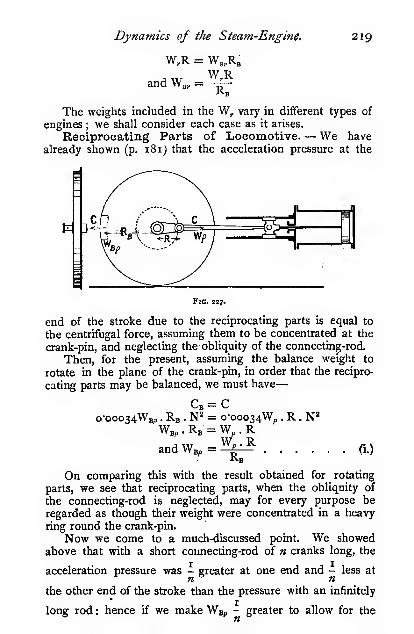
Dynamics of the Steam-Engine, 219
W,R = W,,R3
and W,, =Kb
The weights included in the W, vary in different types of
engines ; we shall consider each case as it arises.
Reciprocating Parts of Locomotive.— We have
already shown (p. 181) that the acceleration pressure at the
Fig. 227.
end of the stroke due to the reciprocating parts is equal to
the centrifugal force, assuming them to be concentrated at the
crank-pin, and neglecting the obliquity of the connecting-rod.
Then, for the present, assuming the balance weight to
rotate in the plane of the crank-pin, in order that the recipro-
cating parts may be balanced, we must have
—
C = Co-ooo34Wbp . Rb . N^ = o-ooo34Wp .R.N'
Wbp . Rb = Wp . RandWBp=^%^ (i.)
•Kb
On comparing this with the result obtained for rotating
parts, we see that reciprocating parts, when the obliquity of
the connecting-rod is neglected, may for every purpose be
regarded as though their weight were concentrated in a heavy
ring round the crank-pin.
Now we come to a much-discussed point. We showedabove that with a short connecting-rod of n cranks long, the
acceleration pressure was - greater at one end and - less at
the other end of the stroke than the pressure with an infinitely
long rod : hence if we make Wsp - greater to allow for the

220 Mechanics applied to Engineering.
2 ,
obliquity of the rod at one end, it will be - too. great at the
other end of the stroke. Thus we really do mischief by
attempting to compensate for the obliquity of the rod at either
end; we shall therefore proceed as though the rod were of
infinite length.
If the reader wishes to follow the effect of the obliquity
of the rod at all parts of the stroke, he should consult a paper
by Mr. Hill, in the Proceedings of the Itistitute ofCivilEngineers
,
vol. civ. ; or Barker's " Graphic Methods of Engine Design ;
"
also Dalby's " Balancing of Engines."
The portion of the connecting-rod which may be regarded
as rotating with the crank-pin and the portion as reciprocating
with the cross-head may be most readily obtained by find-
ing the centre of gravity of the whole rod—let its distance
from the crank-pin centre be x, the length of the rod centres /,
then the portion to be included in the reciprocating parts is
—j-, where W is the weight of the whole rod. The remainder
(i— j-Jistobe included in the rotating parts. If the rod
be placed horizontally with the small end on a weighing
machine or be suspended from a spring balance the reading
will give the weight to be included in the reciprocating parts.
For most purposes it is sufficiently near to take the weight
of the small end together with one-half the plain part as
reciprocating, and the big end with one-half the plain part as
rotating.
Inside-cylinder Engine (uncoupled).- -In this case
we have
—
Wp = weight of (piston -|- piston-rod -f cross-head -|- small
end of connecting-rod -|- \ plain part of rod);
W, = weight of (crank-pin -1- crank-webs ' -f- big end of
connecting-rod -P \ plain part of rod).
If we arrange balance weights so that their c. of g. rotates
in the same plane as the crank-pins, their combined weightwould be Wg, -|- Wup, placed at the radius Rb, and if we only
counterbalance two-thirds of the reciprocating parts, we get
—
W
R(|Wp + W,)
See p. 229,
_ J-V^3»vp T T',y ... ,
»'B0 — t5 V"'J

Dynamics of the Steam-Engine. 221
Balance weights are not usually placed opposite the crank-
webs as shown, but are distributed over the wheels in such a
manner that their centrifugal moments about the plane of
rotation of the crank-pin is zero. IfW be the balance weight
on one w^heel, and Wj the other, distant y' and yl from the
plane of the crank, then
—
or Wy = W,;/i'
which is equivalent to saying that the centre of gravity of the
two weights lies in the plane of rotation of the crank. Theobject of this particular arrangement is to keep the axis of
WboXy
i°off'K/heel
opposite 'off"crank
Cofe.ifCr^/rmi^/llS.
WboZy
On "near"wheel
opposite "near^Qrank
Flc. 328.
rotation permanent. Then, considering the vertical crank
shown in Fig. 228, by taking moments, we get the equivalent
weights at the wheel centres as given in the figure.
We have, from the figure
—
X =
z=y-^i
J2
_y \-c

222 Mechanics applied to Engineering.
Substituting these values, we get
—
^»/ y — c) = Wbi, as the proportion of the balance weight
on the " off" wheel opposite the far crank
and —"(v + ^) = Wb2, as the proportion of the balance weight
on the " near " wheel opposite near crank
Exactly similar balance weights are required for the other
crank. Thus on each wheel we get
one large balance weight W^a at N(Fig. 229), opposite the near crank,
and one small one Wei at F, opposite
the far crank. Such an arrangement
\f would, however, be very clumsy, so weshall combine the two balance weights
by the parallelogram of forces as
shown, and for them substitute the
large weight Wb at M. .
ThenWB= VWbi' + Wb
On substituting the values given above for Wei and Wj,we have, when simplified
—
W„ V2Wb2y
V/ + ^
In English practice^ = 2'^c (approximately)
On substitution, we get
—
Wb = o-76Wb,
Substituting from ii., we have
—
o-76R(|W, + W,)
Rb
Let the angle between the final balance weight and the
near crank be a, and the far crank Q + 90.
Then a = 180 - 6
andtane = S^=^^Wbs ;» + <

Dynamics of the Steam-Engine. 223
Substituting the value oiy for English practice, we get
—
tan B = ——= o"42Q3-5 ^ ^
Now, 6 = ^ very nearly ; hence, for English practice, if
the quadrant opposite the crank quadrant be divided into
W„ = Wb nearly
Fig. 230.
four equal parts, the balance weight must be placed on the first
of these, counting from the line opposite the near crank.
Outside-eylinder Engine (uncoupled).—Wp and W,are the same as in the last paragraph. If the plane of rotation
of the crank-pin nearly coincides, as it frequently does, with the
plane of rotation of the balance weight, we have
—
Rb
and the balance weight is placed diametrically opposite the
crank.
When the planes do not approximately coincide
—
Let J/= the distance between the wheel centres
;
cylinder centres
;
cylinder centre line andthe " near " wheel
;
cylinder centre line andthe " off" wheel.
2
c =X =
* =c-y
The balance weight required!
on the "off" wheel opposite?
the " far " crank '
The balance weight required.
Wbo^:
2y
on the "near" wheel oppo-|= —'^- = ^^(c+y) = W^site the "near" crdnk ) ^ '-^

224 Mechanics applied to Engineering.
Then W, = ^2W„2y
'Jf + c"
which is precisely the same expression as we obtained for
inside-cylinder engines, but in this casejc = o'8f to o'<)c. Onsubstitution, we get Wb = i'I3Wb„ to i-osW^o, and fl= 6° to 3°.
The same reasoning applies to the coupling-rod balanceweights Wbo in the next paragraphs.
Inside-cylinder Engine (coupled).—In this case wehave Wp the same as in the previous cases.
Wo = the weight of coupling crank-web and pin ^ -f couplingrod from a to b, or c to d, otbto c (Fig. 195), as thecase may be
;
Wbo = the weight of the balance weight required to counter-balance the coupling attachments
;
Ro = the radius of the coupling crank.
Fio. 231.
In the case of the driving-wheel of the four-wheel coupled
engine, we have Wb arrived at in precisely the same manneras in the case of the inside-cylinder uncoupled engine, and
^^ Rb•
The portion of the coupling rod included in the Wo is, in
this case, one-half the whole rod. The balance weight Wbo is
placed diametrically opposite the coupling crank-pin. After
finding Wb and Wbo. tliey are combined in one weight Wbf bythe parallelogram of forces, as already described.
With this type of engine the balance weight is usually
small. Sometimes the weights of the rods are so adjusted
that a balance weight may be dispensed with on the driving-
wheel.
' See p. 229.

Dynamics of the Sieam-Engine. 225
It frequently happens, however, that W^ is larger than Wpo
;
in that case Wgp is placed much nearer Wj than is shown in
the figure.
On the coupled wheel the balance weight Wjo is of the
same value as that given above, and is placed diametrically
opposite the coupling crank-pin.
Fig. 232.
In the six-wheel coupled engine the method of treatment is
precisely the same, but one or two points require notice.
RcWcW'b„ = .
Rn
The portion of the coupling rod included in the Wo is from
b\.o e; whereas in the Wbo the portion is from a to ^ or ^ to d.
Coupling cranks * have been placed with the crank-pins
;
the balance weights then become very much greater. They are
treated in precisely the same way.
Some locomotive-builders evenly distribute the balance
weights on coupled engines over all the wheels : most authorities
strongly condemn this practice. Space will not allow of this
point being discussed here.
Outside-cylinder Engine (coupled).
W is the same as before
;
W, is the weight of crank-web ' and pin -|- coupling rod
from a\.ob \- big end of connecting-rod + half plain
part of rod
;
Wc is the same as in the last paragraph;
Ro = R
VV3 = \Vn„ =
' See Proc. Inst. C.£., vol. Uxxi. p.
m

226 Mechanics applied to Engineering.
The six-wheel coupled engine is treated in a similar way
;
the remarks in the last paragraph also apply here.
The above treatment only holds when the planes of the
crank-pins and wheels nearly coincide, as already explained
when dealing with the uncoupled outside-cylinder engine.
On some narrow-gauge railways, in which the wheels are
placed inside the frames, the crank and coupling pins are often
at a considerable distance fromthe plane of the wheels. Letthe coupling rods be on the
outer pins. It will be convenient,
|.,. . when dealing with this case, to
l^'i jt~^jp^^^^la^i^^;^^ ' iJij', find the distance between the
1^ planes containing the centres ofI
'«--t}-i
—
^— y ' ' gravity of the coupling andr* g connecting rods, viz. C,.
„ _ W.Q + (W, -I- fW,)C
c
IFig. 234. W, -f W, + fWp
The W, must include the weight of the crank-webs andpins all reduced to the radius of the pin and to the distance C.
For all practical purposes, C, may be taken as the distance
between the insides of the collars on the crank-pin. Then, byprecisely similar reasoning to that given above
—
where W.^'^^tyVp + W.-fW.)
In some cases _)> is only osC, ; then
—
Wb = i-s8Wbo, and 0= 18°

Dynamics of the Steam- Engine. 227
Hammer Blow.— If the rotating parts only of a loco-
motive are fully balanced there is no variation of load onthe rail due to their centrifugal force, but when, in addition,
the reciprocating parts are partially or fully Ijalanced the
vertical component of the centrifugal force of the excessbalance weight over and above that required to balance the
rotating parts causes a considerable variation of the load onthe rail, tending to lift the wheel off the rail when the balanceweight is on top and causing a very rapid increase of rail load
—almost amounting to a blow—when the balance weight is
at the bottom. The hammer blow is rather severe on the
cross girders of bridges and on the permanent way generally.
At very high speeds the upward force will actually lift the
wheel off the rail if it exceeds the dead weight on the wheel.
On some American railroads the proportion of the recipro-
cating parts to be balanced is settled by the maximum speedthe engine is likely to reach.
In arriving at this speed, the balance weight required to
completely balance the rotating parts is first determined, then
the balance weight for both rotating and reciprocating parts is
found, the difference between the two is the unbalanced portion
which is responsible for the hammer blow and the tendency to
lift the wheel off the rail.
Let the difference be W^' then the centrifugal force tending
to lift the wheel is
o"ooo34VV^RbN*
and when this exceeds the dead weight W„ on the rail the
wheel will lift, hence the speed of lifting is
-sjW
No-ooo34W^Rb
When calculating the speed of the train from N it must not
be forgotten that the radius of the wheel is greater than Rb.Centre of Gravity of Balance Weights and Crank-
webs.—The usual methods adopted for finding the position
and weight of balance weights are long and tedious ; the follow-
ing method will be found more convenient. The effective
balance weight is the whole weight minus the weight of the
spokes embedded.Let Figs. 235, 236, 237 represent sections through a part of
the balance weight and a spoke ; then, instead of dealing first
with the balance weight as a whole, and afterwards deducting

228 Mechanics applied to Engineering.
the spokes, we shall deduct the spokes first. Draw the centre
lines of the spokes x, x, and from them set off a width w on
Fig. ass-
each side as shown in Fig. 236, where wi = half the area of
the spoke section ; in the case
of the elliptical spoke, wf =o'785Di^
o'392Di/
of the rectangular spoke, wi = —2
o'sD^
By doing this we have not altered either the weight or theposition of the centre of gravity of the section of the balanceweight, but we have reduced it to a much simpler form todeal with. If a centre line yy (Fig. 235) be drawn throughthe balance weight, it is only necessary to dealt with thesegments on one side of it.
Measure the area of the segments when thus treated.

Dynamics of the Steam-Engine. 229
Let them be Aj, A^, A3 ; then the weight of the whole balance
weight is the sum of these segments
—
Wb = 2twJ,k^ + A, + A3)
where zc„ = the weight per cubic inch of the metal.
For a cast-iron weight
—
Wb = o-52/(Ai + Aj, + A3)
For a wrought-iron or cast-steel weight
—
Wb = o-56/(Ai + A, + A3)
all dimensions being in inches.
The centre of gravity of each section can be calculated, but
it is far less trouble to cut out pieces of cardboard to the shape
of each segment, and then find the position of the centre of
gravity by balancing, as described on p. 75. Measure the
distance of each centre of gravity from the line AB drawn
through the centre of the wheel.
Let them be ri, r^, r^ respectively ; then the radius of the
centre of gravity of the whole weight (see Fig. 235)
—
Rb-A, + A,-t-A.
(^^«P-S8)
md WgRj =\ or
(0-56;
i?(Airi + AaZ-a + Aa^s)

?30 Mechanics applied to Engineering.
If there were more segments than those shown, we should
get further similar terms in the brackets.
Tig. 237- Fig. 238.
AVhen dealing with cranks, precisely the same method maybe adopted for finding their weight and the position of the
centre of gravity.
In the figures, the weight of the crank = zto™ X shadedareas. The position of the centre of gravity is found as before,
but no material error will be introduced by assuming it to beat the crank-pin.
Governors.—The function of a flywheel is to keep the
speed of an engine approximately constant during one revolu-
tion or one cycle of its operations, but the function of a
governor is to regulate the number of revolutions or cycles
that the engine makes per minute. In order to regulate the
speed, the supply of energy must be varied proportionately to
the resistance overcome ; this is usually achieved automatically
by a governor consisting essentially of a rotating weight
suspended in such a manner that its position relatively to the
axis of rotation varies as the centrifugal force acting upon it,
and therefore as the speed. As the position of the weight varies,
it either directly or indirectly opens and closes the valve
through which the energy is supplied, closing it when the speedrises, opening it when it falls.
The governor weight shifts its position on account of a
change in speed ; hence some variation of speed must always
take place when the resistance is varied, but the change in

Dynamics of the Steam-Engine. 231
speed can be reduced to a very small amount by suitably
arranging the governor. qSimple Watt Governor. — Let the
ball shown in the figure be suspended by
an arm pivoted at O, and let it rotate roundthe axis OOi at a constant rate. The ball
is kept in equilibrium by the three forces
W, the weight of the ball acting vertically
downwards (we shall for the present neglect
the weight of the arm and its attachments,
also friction on the joints) ; C, the centri-
fugal force acting horizontally; T, the tension
in the supporting arm.fIG. 239.
Let H = height of the governor in feet
;
h = „ „ „ inches;
R = radius of the ball path in feet
;
N, = number of revolutions made by the governor per
second
;
N = number of revolutions made by the governor per
minute
;
V = velocity (linear) in feet per second of the balls.
By taking moments about the pin 0, we have—
WV^HCH = WR,
hence H =
i;R-=WR
g^^ o'8i6
47r^R^N/ N 1
Expressing the height in inches, and the speed in revolu-
tions per minute, we get
—
3513?h =
Thus we see that the height at which a simple Watt governorwill run is entirely dependent upon the number of revolutions
per minute at which it runs. The size of the balls and length
of arms make no difference whatever as regards the height
when the balls are " floating."
The following table gives the height of a simple Watt<• governor for various speeds :
—

232 Mechanics applied to Engineering.

Dynamics of the Steam- Engine. 233
height of the simple Watt governor " is increased from H to
H^. Then, constructing the triangle of forces, or, by taking
Wmoments about the pin, and remembering that —- acts ver-
2
tically downwards through the centre of the ball, we have
—
Fig. 240.
\V
R. r—
Then, by precisely the same reasoning as in the case given
above, we have
—
H.=
W ^W 4-—!°o-8i6/ ^ 2
N/ W
or h,
W +—3523°! LN" \ W
If W„ be m times the weight of one ball, we have
—
the value of m usually varies from 10 to 50.
This expression must, however, be used with caution.
Consider the case of a simple Watt governor . both whenunloaded and when loaded as shown in Figs. 239 and 240.
If the same governor be taken in both instances, it is evident
that its maximum height, i^. when it just begins to lift, also its

234 Mechanics applied to Engineering.
minimuni apex angle, will be the same whether loaded or
unloaded, and cannot in any case be greater than the length
of the suspension arm measured to the centre of the ball.
The speed of the loaded governor corresponding to any given
height will, however, be greater than that of the unloaded
governor in the ratio » /i + — to i, and if the engine runs at
the same speed in both cases, the governor must be geared upin this ratio, but the alteration in height for any given alteration
in the speed of the engine will be the same in both cases, or, in
other words, the proportional sensitiveness will be the samewhether loaded or unloaded. We shall later on show, however,that the loaded governor is better on account of its greater power.
In the author's opinion most writers on this subject are in
error ; they compare the sensitiveness of a loaded governor at
heights which are physically impossible (because greater eventhan the length of the suspension arms), with the much smaller,
but possible, heights of an unloaded governor. If the readerwishes to appeal to experiment he can easily do so, and will
find that the sensitiveness actually is the same in both cases.
The following table may help to make this point clear.
m has been chosen as i6 : then/ m
On comparing the last column of this table with that for
the unloaded governor, it will be seen that they are identical,
or the sensitiveness is the same in the two cases.

Dynamics of the Steam- Engine. 235
If, by any system of leverage, the weight W„ moves up anddown .t: times as fast as the balls, theabove expression becomes
—
Porter and other Loaded Governors.—The methodof loading shown in Fig. 240 is not convenient, and is rarely
adopted in practice. The usual method is that shown in
Fig. 241, viz. the Porter governor, in which the links are
usually of equal length, thus making x = 2; but this proportion
is not always adhered to. Then—
-
u _ 35230/W + W„N
^' = ^(^ + *")
Occasionally, governors of this type are loaded by means of
a spring, as shown in Fig. 243, instead of a central weight. Thearrangement is, however, bad, since the central load increases
as the governor rises, and consequently makes it far too sluggish
in its action.
Let the length of the spring be such that it is free from
load when the balls are right in, «'.*. when their centres coincide
with the axis of rotation, or when the apex angle is zero. Thereason for making this stipulation will be apparent when wehave dealt with other forms of spring governors.
Let the pressure on the spring = Pa:, lbs. when the spring
is compressed x„ feet;
/ = the length of each link in feet
;
H, = the equivalent height of the governor in feet
;
^V = the weight of each ball in lbs.
;
X. = 2(1 - H.);
N = revolutions of governor per minute
;
Then, as in the Porter- governor, or, by taking momentsabout the apex pin, and remembering that the force Px^ acts
parallel to the spindle, we have
—
H. _ W + Pa:. _ W + gP/ - zPH.R, ~ C ~ o-ooo34WR,N!',HXo-ooo34WN2 + 2P) = W + 2P/
„ W + 2PI .
,
"• = 0-00034WN' + 2P ^°' ** ^"''*=^^ SovernoT
zP/H, = 'iTrNT2~i—T> >i horizontal „

236 Mechanics applied to Engineering.
In the type of governor shown in Fig. 244, which is
frequently met with, springs are often used instead of a deadweight. The value of * is usually a small fraction, consequentlya huge weight would be required to give the same results as
a Porter or similar type of governor. But it has other inherent
defects which will shortly be apparent.Isochronous Governors.—A perfectly isochronous
governor will go through its whole range with the slightest
Fig. 241. Fig. 242.
variation in speed ; but such a governor is practically uselessfor governing an engine, for reasons shortly to be ^cussed.
Fig. 243.
'
But when designing a governor which is required to be verysensitive, we sail as near the wind as we dare, and make it
very nearly isochronous. In the governors we have considered.

Dynamics of the Steam-Engine. 237
the height of the governor has to be altered in order to alter
the throttle or other valve opening. If this could be accom-plished without altering the height of the governor, it could
also be accomplished without altering the speed, and we should
have an isochronous governor. Such a governor can be con-
structed by causing the balls to move in the arc of a parabola,
the axis being the axis of rotation. Then, from the pro-
perties of the parabola, we know that the height of the'
governor, i.e. the subnormal to the path of the balls, is constant
for all positions of the balls ; therefore the sleeve which
actuates the governing valve moves through its entire range
for the smallest increase in speed. We shall only consider
an approximate form which is very commonly used, viz. the
crossed-arm governor.
The curve abc is a parabolic arc ; the axis of the parabola
is O^; then, if normals be drawn to the curve at the highest
and lowest positions of the
ball, they intersect at somepoint d on the other side of
the axis. Then, if the balls
be suspended from this point,
they will move in an approxi-
mately parabolic arc, and the
governor will therefore beapproximately isochronous—and probably useless because
too sensitive. If it be de- <
sired to make the governor
more stable, the points d, dare brought in nearer the
axis. The virtual centre of
the arms is at their inter-
section ; hence the height of
the governor is H, which is approximately constant. Theequivalent height can be raised by adding a central weight as
in a Porter governor. It, of course, does not affect the
sensitiveness, but it increases the power of the governor to
overcome resistances. The speed at which a crossed-armgovernor lifts depends upon the height in precisely the samemanner as in the simple Watt governor.
It can also be arrived at thus. By taking moments aboutthe pin d, W is the weight of the ball, / the length of the armad.
Fig. 24s.

238 Mechanics applied to Engineering.
VV(R \-x) = CH„ = 0-00034WRNV/'' - (R + xf
^=s/- ^^+^0-00034 kV/'' - (R + xf
X H„ - H , „ RH„ o-8i6 x 60^
or thus: - = -^^ and H =^^-^ = - ^,—
--^-2937(jc + R)
KH„
when the dimensions of the governor are taken in feet and
the speed in revolutions per minute.
In some instances Watt governors are made with the arms
suspended at some distance, say x, from the axis of rotation,
as shown in Fig. 249, but without the central weight. Thenthe above expression becomes
—
N- /R-*
o-ooo34RV/'-(R-a:)^
and when the expression for H is used (p. 231), the height H is
measured from the level of the ball centres to the point where
the two arms cross (see Fig. 249).
Astronomical Clock Governor.—A beautiful applica-
tion of the crossed-arm principle as applied to isochronous
governors is found in the governors used on the astronomical
clocks made by Messrs. Warner and Swazey of Cleveland,
Ohio. Such a clock is used for turning an equatorial telescope
on its axis at such a speed that the telescope shall keep exactly
focussed on a star for many hours together, usually for the
purpose of taking a photograph of that portion of the heavens
immediately surrounding the star. If the telescope failed to
move in the desired direction, and at the exact apparent
speed of the star, the relative motion of the telescope and star
would not be zero, and a blurred image would be produced;
hence an extreme degree of accuracy in driving is required.
The results obtained with this governor are so perfect that noordinary means of measuring time are sufficiently accurate to
detect any error.
The spindle A and cradle are driven by the clock, whose

Dynamics of the Steam-Engine. 239
speed has to be controlled, A short link, c, is pivoted to armson the driving spindle at b ; the
governor weights are suspendedby links from the point d; a brakeshoe, e, covered with some soft
material, is attached to a lug onthe link c, and, as the governorrotates, presses on the fixed drumf. The point of suspension, d, is
so chosen that the governor is,
practically isochronous. The
;
weights rest in their cradle until '^V
the speed of the governor is
sufficiently high to cause them to
lift ; when in their lowest position, ^'°' ''*^-
the centre line of the weight arm passes through b, and con-
sequently the pull along the arm has no moment about this
point, but, as soon as the speed rises sufficiently to lift the
weights, the centre line of the weight arm no longer coincides
with b, and the pull acting along the weight arm now has amoment about b, and thus sets up a pressure between the
rotating brake shoe e and the fixed drum /. The friction
between the two acts as a brake, and thus checks the speedof the clock.
It will be seen that this is an extremely sensitive arrange-
ment, since the moment of the force acting along the ball link,
and with it the pressure on the brake shoe, varies rapidly as the
ball rises ; but since the governor is practically isochronous,
only an extremely small variation in speed is possible. It
should be noted that the driving effort should be slightly in
excess of that required to drive the clock and telescope, apart
from the friction on the governor drum, in order to ensure that
there is always some pressure between the brake shoe andthe drum.
Wilson Hartnell Governor.—Another well-known andhighly successful isochronous governor is the " Wilson Hartnell
"
governor.
In the diagram, c is the centrifugal force acting on the ball,
and / the pressure due to the spring, i.e. one-half the total
pressure. As the balls fly out the spring is compressed, and since
the pressure increases directly as the compression, the pressure
p increases directly (or very nearly so) as the radius r of the
balls ; hence we nn.ay write / = Kr, where K is a constant
depending on the stiffness of the spring.

240 Mechanics applied to Engineering.
Let r^ = nr, frequently n =. \.
Then Wj — prand o'ooo34W>-''«N^ = YJ-'
and N'' = Ko"ooo34Wn
For any given governor the weight W of the ball is con-
stant; hence the denominator of the fraction is constant,
whence N^, and therefore N,is constant ; i.e. there is only
one speed at which the
governor will float, and anyincrease or decrease in the
speed will cause the balls to
fly right out or in, or, in
other words, will close or
fully open the governing
valve ; therefore the governor
is isochronous.
There are one or twosmall points that slightly
affect the isochronous cha-FlG. 247.
racter of the governor. For example, the weight of the ball,
except when its arm is vertical, has a moment about the
pivot. Then, except when the spring arm is horizontal, the
centrifugal force acting on the spring arm tends to makethe ball fly in or out according as the arm is above or belowthe horizontal.
We shall shortly show how the sensitiveness can be varied
by altering the compression on the spring.
Weight of Governor Arms.—Up to the present we haveneglected the weight of the governor arms and links, and havesimply dealt with the weight of the balls themselves ; but with
some forms of governors such an approximate treatment wouldgive results very far from the truth.
Dealing first with the case of the arm, and afterwards with
the ball-Let the vertical section of the arm be a square inches, and
all other dimensions be in inches. The centrifugal momentacting on the element is
—
wadr.rurh _ wau^r^dr
1 2p 1 2"- tan Q

Dynamics of the Steam-Engine.
and on the whole arm
241
Jr^dr
1 2g tan 0.
12X3^ tan 9
which may be written
„ R' «-'
waR X — X :
—
a3 J2g tan
The quantity wa^ is the
weight of the whole arm VV„,
R2and — IS the square of the
.3radius of gyration of the armabout the axis of rotation, andthe product is the moment of
Fio. 248.
inertia of the arm in pounds weight and inch ^ units.
lo)' W„RVThe centrifugal moment)acting on the arm ) i2g tan 36^ tan 6
In the case of the ball we have the centrifugal moment for
the elemental slice.
waidf\r'i(i?ki
12g
and for the whole ball^
woyrVia?/
(77i)«"^=MVn
The quantity outside the brackets is the sum of the
moments of the weight of each vertical slice of the ball aboutthe axis of rotation, which is the product of the weight of
the ball and the distance of its centre of gravity from the axis.
The centrifugal moment of the ball is—
•
We X Rb X <o' X K
This is the value usually taken for the centrifugal momentR

242 Mechanics applied to Engineering.
of the governor, but it of course neglects the arms. A commonway of taking the arms into account is to assume that thecentrifugal force acts at the centre of gravity of the arm; butit is incorrect. By this assumption we get for the centrifugalmoment
—
wd^ R H „ M.aRa)^R=X X — X «)' = — ^
g 2X12 2 48^ tan B
W„RV48^ tan Q
Hence the ratio of the true centrifugal moment of the
arm to the approximation commonly used isf, thus the error
involved in the assumption is 33 per cent, of the centrifugal
moment of the arm. In cases in which the weight of the armis small compared with the weight of the ball the error is notserious, but in the case of some governors in which thick
'stumpy arms are used, commonly found where the balls andarms are of cast or malleable iron, the error may amount to
as much as 20 per cent., which represents about 1 1 per cent,
error in the speed. The centre of gravity assumption is aconvenient one, and may be adhered to without error byassuming that the weight of the arm is f of its real weight.
When the arm is pivoted at a point which is not on the axis
of rotation, the corresponding moment of inertia of the armshould be taken. The error involved in assuming it to be onthe axis is quite small in nearly all cases.
In all cases the centripetal moment in a gravity governoris found by taking the moment of the arm and ball about the
point of suspension. The weight of the
arm and ball is considered as concen-trated at the centre of gravity ; but in
the case of the lower links, the bottomjoint rises approximately twice as fast
as the upper joint, hence its centre ofgravity rises 1-5 times as fast as thetop joint, and its weight must be takenas I 'S times its real weight; this re-
mark also applies to the centrifugalmoment, in that case the lower link
is taken as twice its real weight.The height of this governor is H„
not h^ ; i.e. the height is measured from the virtual centre at
the apex.

Dynamics of the Steam-Engine. 243
H =n - '-a
A governor having arms suspended in this manner is very
much more stable and sluggish than when the arms are sus-
pended from a central pin, and still more so than when the
arms are crossed.
In Fig. 250 we show the governor used on the De Laval
steam turbine. The ball weights in this case consist of two halves
of a hollow cylinder mounted on knife-edges to reduce the
friction. The speed of these governors is usually calculated
by assuming that the mass of each arm is concentrated at its
centre of gravity, or that it is a governor having weightless
arms carrying equivalent balls, as shown in broken lines in
the figure. It can be readily shown by such reasoning as that
given above that such an assumption is correct provided the
arms are parallel with the spindle, and that the error is small
provided that the arms only move through a small angle.
These governors work exceedingly well, and keep the speed
within very narrow Hmits. The figure is not drawn to scale.
Fig. 250.
Crank-shaft Governors.—The governing of steam-
engines is often effected by varying the point at which the
steam is cut off in the cylinder. Any of the forms of governor
that we have considered can be adapted to this method, but
the one which lends itself most readily to it is the crank-shaft
governor, which alters the cut-off by altering the throw of the
eccentric. We will consider one typical instance only, the
Hartnell-McLaren governor, chosen because it contains manygood points, and, moreover, has a great reputation for govern-
ing within extremely fine limits (Figs. 251 and 252).
The eccentric E is attached to a plate pivoted at A, andsuspended by spherical-ended rods at B and C. A curved cam.

244 Mechanics applied to Engineering.
DD, attached to this plate, fits in a groove in the governor
weight W in such a manner that, as the weight flies outwards
due to centrifugal force, it causes the eccentric plate to tilt,
and so bring the centre of the eccentric nearer to the centre of
the shaft, or, in other words, to reduce its eccentricity, andconsequently the travel of the valve, thus causing the steam
to be cut off earlier in the stroke. The cam DD is so arrangedthat when the weight W is right in, the cut-off is as late as the
slide-valve will allow it to be. Then, when the weight is right
out, the travel of the valve is so reduced that no steam is
admitted to the cylinder. A spring, SS, is attached to the
weight arm to supply the necessary centripetal force. Thespeed of the engine is regulated by the tension on this spring.
In order to alter the speed while the engine is running, the
lower end of the spring is attached to a screwed hook, F. Thenut G is in the form of a worm wheel ; the worm spindle is
provided with a small milled wheel, H. If it be desired to
alter the speed when running, a leather-covered lever is pu.shed
into gear, so that the rim of the wheel H comes in contact with
it at each revolution, and is thereby turned through a small
amount, thus tightening or loosening the spring as the case maybe. If the lever bears on the one edge of the wheel H, the
spring is tightened and the qpeed of the engine increased, andif on the other edge the reverse. The spring S is attached
to the weight arm as near its centre of gravity as possible, in
order to eliminate friction on the pin J when the engine is
running.
The governor is designed to be extremely sensitive, and,
in order to prevent hunting, a dashpot K is attached to the
weight arm.
In the actual governor two weights are used, coupledtogether by rods running across the wheel. The figure mustbe regarded as purely diagrammatic.
It will be seen that this governor is practically isochronous,for the load on the spring increases as the radius of the weight,and therefore, as explained in the Hartnell governor, as thecentrifugal force.
The sensitiveness can be varied by altering the position ofsuspension, J. In order to be isochronous, the path of theweight must as nearly as possible coincide with a radial line
drawn from O, and the direction of S must be parallel to this
radial line.
A later form of the same governor is shown in Fig. 252,an inertia weight I is attached to the eccentric. The speeding

Dynamics of the Steam-Engine. 24S
up is accomplishedby the differential
bevil gear shown.The outer pulley A is
attached to the inner
bevil wheelA, and the
inner pulley B to the
adjoining wheel; byapplying a brake to
one pulley the bevil
wheels turn in onedirection, and whenthe brake is applied
to the other pulley
the wheels turn in the
opposite direction,
and so tighten or
slacken the springs
SS.Inertia Effects
on Governors. —Many governors rely

246 Mechanics applied to Engineering.
entirely on the inertia of their weights or balls for regulating
the supply of steam to the engine when a change of speed
occurs, while in other cases the inertia effect on the weights is
so small that it is often neglected ; it is, however, well whendesigning a governor to arrange the mechanism in such a
manner that the inertia effects shall act with rather than against
the centrifugal effects.
In all cases of governors the weights or balls tend to fly out
radially under the action of the centrifugal force, but in the
case of crank-shaft governors, in which the balls rotate in oneplane, they are subjected to another foi^ce, acting at right angles
to the centrifugal, whenever a change of speed takes place; the
latter force, therefore, acts tangentially, and is due to the
tangential acceleration of the weights. For convenience of
expression we shall term the latter the " inertia force."
The precise effect of this inertia force on the governorentirely depends upon the sign of its moment about the pointof suspension of the ball arm : if the moment of the inertia force
be of the same sign as that of the centrifugal force about thepivot, the inertia effects will assist the governor in causing it
to act more promptly ; but if the two be of opposite sign, tiiey
will tend to neutralize one another, and will make the governorsluggish in its action.
Since the inertia of a body is the resistance it offers tohaving its velocity increased, it will be evident that the inertia
force acts in an opposite sense to that of the rotation. In thefigures and table given below we have only stated the case in
which the speed of rotation is increased ; when it is decreasedthe effect on the governor is the same as before, since themoments act together or against one another.
In the case of a governor in which the inertia momentassists the centrifugal, if the speed be suddenly increased, boththe centrifugal and the inertia moments tend to make the ballsfly out, and thereby to partially or wholly shut off the supplyof steam,—the resulting moment is therefore the j«/« of the two,and a prompt action is secured ; but if, on the other hand, theinertia moment aqts against the centrifugal, the resulting momentis the difference of the two, and a sluggish action results. If,
as is quite possible, the inertia moment were greater than thecentrifugal, and of opposite sign, a sudden increase of speedwould cause the governor balls to close in and to admit moresteam, thus producing serious disturbances. The table givenbelow will serve to show the effect of the two moments on thegovernor shown in Fig. 253.

Dynamics of the Steam-Engine. 247
In every
inertia force.
case c is the centrifrugal force, and T the
dv W dvT = M—7, or = — — , where W is the weightdv _dt ^ g^'"df
of the ball, and ^ the acceleration in feet per second per
second. For example, let the centre of gravity of a crank-
shaft governor arm and weight be at a radius of 4 inches whenthe governor is running at 300 revolutions per minute, and let
it be at a radius of 7 inches when the governor is running at
312 revolutions per minute, and let the change take place in
o'2 second. The weight of the arm and weight is 25 pounds.
The change of velocity is
—
2 X ^'14—(7 X 312 — 4 X 300) = 8-59 feet per sec^ond.X 60
SV8-SQand the acceleration -kt —7-^ = 42*95 feet per sec. per sec,
and the force T = n_='-'^—? = 23-4 pounds.
22'2
Sense ofrotation.

248 Mechanics applied to Engineering.
Scale0-2? feet
the centrifugal and centripetal moments as the governor balls
fly outwards. These diagrams are the invention of Mr. Wilson
Hartnell, who first described them in a paper read before the
Institute of Mechanical Engineers in 1882.
In Fig. 254 we give such a diagram for a simple Watt
governor, neglecting the weight of the arms. The axis
OOi is the axis of rotation. The ball is shown in its two
extreme positions. The ball is under the action of two
moments—the centrifugal moment CH and the centripetal
moment W„R, which are equal for all positions of the
ball, unless the ball is
being accelerated or
retarded. The centri-
fugal moment tends
to carry the ball out-
wards, the centripetal to
bring it back. The four
numbered curves showthe relation between the
moment tendingto makethe balls fly out (ordi-
nates) and the position
of the balls. The centri-
petal moment line showsthe relation between the
moment tending to
bring the balls back andthe position of the balls,
which is independent of
the speed.
We have
—
CH = o-ooo34WRN2H= o-ooo34WN''(RH)=KRHThe quantity O'ooo34
WN^ is constant for anygiven ball running at anygiven speed. Values ofKRH have been calcu-
lated for various posi-
tions and speeds, andthe curves plotted,
directly as the radius
;
The
Fig. 254.
value of W.R

Dynamics of the Steam-Engine. 249
hence the centripetal line is straight, and passes through the
origin O. From this we see that the governor begins to lift
at a speed of about 82 revolutions per minute, but gets to aspeed of about 94 before the governor lifts to its extremeposition. Hence, if it were intended to run at a mean speedof 88 revolutions per minute, it would, if free from friction,
vary about 9 per cent, on either side of the mean, and whenretarded by friction it will vary to a greater extent.
For the centrifugal moment, W = weight of (ball
+ 1 arm + | link). The resultant acts at the centre ofgravity of W. For the centripetal moment, W„ = weight of
(ball + sleeve + arm + i link). The resultant acts at the
centre of gravity of W„ , the weight of the sleeve being re-
garded as concentrated at the top joint of the link. It is
here assumed that the sleeve rises twice as fast as the top pin
of the link.
If the centrifugal and centripetal curves coincided, the
governor would be isochronous. If the slope of the centrifugal
curve be less than that of the centripetal, the governor is
too stable ; but if, on the other hand, the slope of the
centrifugal curve be greater than that of the centripetal,
the governor is too sensitive, for as soon as the governorbegins to lift, the centrifugal moment, tending to make the
balls fly out, increases more rapidly than the centripetal
moment, tending to keep the balls in—consequently the balls
are accelerated, and fly out to their extreme position, com-pletely closing the governing valve, which immediately causes
the engine to slow down. But as soon as this occurs, the
balls close right in and fully open the governing valve, thus
causing the engine to race and the balls to fly out again, andso on. This alternate racing and slowing down is known as
hunting, and is the most common defect of governors intended
to be sensitive.
It will be seen that this action cannot possibly occur
with a simple Watt governor unless there is some disturbing
action.
When designing a governor which is intended to regulate
the speed within narrow limits, it is important to so arrange
it that any given change in the speed of the engine shall beconstant for any given change in the height throughout its
range. Thus if a rise of 1 inch in the sleeve corresponds to a
difference of 5 revolutions per minute in the speed, then each
|th of an inch rise should produce a difference of i revolution
per minute of the engine in whatever position the governor

250 Mechanics applied to Engineering.
may be. This condition can be much more readily
realized in automatic expansion governors than in throttling
governors.
Friction of Governors.
—So far, we have neglected
the effect of friction . on the
sensitiveness, but it is in reality
one of the most important
factors to be considered in
connection with sensitive
governors. Many a governor
is practically perfect on paper
—friction neglected—but is to
all intents and purposes -useless
in the material form on an
engine, on account of retarda-
tion due to friction. Thefriction is not merely due to
the pins, etc., of the governor
itself, but to the moving of
the governing valve or its
equivalent and its connections.
In Fig. 255 we show howfriction affects the sensitiveness
of a governor. The vertical
height of the shaded portion represents the friction momentthat the governor has to overcome. Instead of the governor
lifting at 8q revolutions per minute, the speed at which it
should lift if there were no friction, it does not lift till the
speed gets to about 92 revolutions per minute ; likewise on fall-
ing, the speed falls to 64 revolutions per minute. Thus with
friction the speed varies about 22 per cent, above and belowthe mean. Unfortunately, very little experimental data exists
on the friction of governors and their attachments ;' but a
designer cannot err by doing his utmost to reduce it even to
the extent of fitting all joints, etc., with ball-bearings or with
knife-edges (see Fig. 250).
The effect of friction is to increase the height of the
governor when it is rising, and to reduce it when falling. Theexact difference in height can be calculated if the frictional
' See Paper by Ransome, Proc. Inst. C.£., vol. cxiii. j the question
was investigated some years ago by one of the author's students, Mr.Eurich, wJio found that when oiled the Watt governor tested lagged
behind to the extent of 7'S per cent., and when unoiled I7"5 per cent.
Fig. 255.

Dynamics of the Steam-Engine. 251
resistance referred to the sleeve is known ; it is equivalent
to increasing the weight on the sleeve when rising and re-
ducing it when falling.
In the well-known Pickering governor, the friction of the
governoritself is reducedto a minimum by mount-ing the ballson a numberof thin band springs in-
stead of arms moving onpins. The attachmentof the spring at the c.
of g. of the weight andarm, as in the McLarengovernor, is a point also ^
worthy of attention. Wewill now examine in de-
tail several types of go-
vernor by the methodjust described.
Porter GovernorDiagram.—In this case
the centripetal force is
greatly increased while
the centrifugal is un-
affected by the central
weight W^, which rises
twice as fast as the balls
(Fig. 256) when the
links are of equal
length. Resolve W„ in
the directions of the
two arms as shown : it
is evident that the com-ponent ab, acting along
the upper arm, has nomoment about O, but
l)d = Wo has a centri-
petal moment, WoR,, ; then we have
—
CH = WR -f W„R„
Values of each have been calculated and plotted as in
Fig. 254. In the central spring governor W„ varies as the balls
liltj in other respects the construction is the same.It should be noticed that the centripetal and centrifugal
Fig. 256.

252 Mechanics applied to Engineering.
moment curves coincide much more closely as the height of
the governor increases j thus the sensitiveness increases with
the height—a conclusion we have already come to by another
process of reasoning.
Crossed-arm Governor Diagram.—In this governor His constant, and as C varies directly as,the radius for any given
speed, it is evident that the centripetal and centrifugal lines
are both straight and comcident, hence the governor is
isochronous.
Wilson Hartnell Governor Diagram (Fig. 257).
—
When constructing the curves a, b, c, d, e, the moment of the
weight of the ball on either side of the suspension pin, also
the other disturbing causes, have been neglected.
We have shown that cr„ = pr, also that c and p vary as R,hence the centrifugal moment lines (shown in full) and the
centripetal moment line Oa both pass through the origin,
under these conditions the governor is isochronous. A com-mon method of varying the speed of such governors is to alter
the load on the spring by the lock nuts at the top ; this hasthe effect of bodily shifting the centripetal moment line up or
down, but it does not alter the slope, such as db, ec, both of
which are parallel to Oa. But such an alteration also affects
the sensitiveness ; if the centripetal line was db, the governorwould hunt, and if ec, it would be too stable. These defects
can, however, be remedied by altering the stiffness of the
spring, by throwing more or less coils out of action by thecorkscrew nut shown in section, by means of which db can bealtered to dc and ec to eb. For fine governing both of these
adjustments are necessary.
When the moment of the weight of the ball and otherdisturbing causes are taken into account, the curves / and gare obtained.
Instead of altering the spring for adjusting the speed, somemakers leave a hollow space in the balls for the insertion oflead until the exact weight and speed are obtained. It is
usually accomplished by making the hollow spaces on theinside edge of the ball, then the centrifugal force tends to
keep the lead in position.
The sensitiveness of the Wilson Hartnell governor mayalso be varied at will by a simple method devised by the authorsome years ago, which has been successfully applied to several
forms of governor. In general, if a governor tends to hunt,
it can be corrected by making the centripetal moment increase
more rapidly, or, if it be too sluggish, by making it increase less

Dynamics of the Steam- Engine.
Oi
253
Fro. 257.

254 Mechanics applied to Engineering.
rapidly as the centrifugal moment of the balls increases. Thegovernor, which is shown in Fig. 258, is of the four-ball
horizontal type ; it originally hunted very badly, and in order
to correct it the conical washer A was fitted to the ball path,
which was previously flat. It will be seen that as the balls fly
out the inclined ball path causes the spring to be compressedmore rapidly than if the path were flat, and consequently the
rate of increase of the centripetal moment is increased, andwith it the stability of the governor.
Id constructing the diagram it was found convenient to
make use of the virtual centre of the ball arm in each position;
after finding it, the method of procedure is similar to that
already given for other cases. In order to show the efiect of
the conical washer, a second centripetal curve is shown by_ a
broken line for a flat plate. With the conical washer, neglect-
ing friction, the diagram shows that the governor lifts at 430revolutions, and reaches 490 revolutions at its extreme range
;
by experiment it was found that it began to lift at 440, androse to 500, when the balls were lifting, and it began to fall at
480, getting down to 415 before the balls finally closed in.
The conical washer A in t"his case is rather too steep for
accurate governing.
The centrifugal moment at any instant is
—
4 X o-ooo34WRN=H
where W is the weight of one ball.
And the centripetal moment is
—
Load on spring x R.
See Fig. 258 for the meaning of R„ viz. the distance of
the virtual centre from the point of suspension of the arm.Taking position 4, we have for the centrifugal moment at
450 revolutions per minute
—
4 X 0-00034 X 2'S X n^ X 450^* X I'sS = 260 pound-inches
and for the centripetal moment
—
The load on the spring =111 lbs. ; and R, = 278centripetal moment = in x 278 = 310 pound-inches
McLaren's Crank-shaft Governor.—In this governorwe have CR, = SR. ; but C varies as R, hence if there be notension on the spring when R is zero, it will be evident that Swill vary directly as R ; but C also varies in the same manner,hence the centrifugal and centripetal moment lines are nearly

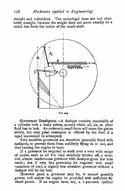
256 Mechanics applied to Engineering.
straight and coincident, The centrifugal lines are not abso-
lutely straight, because the weight does not move exactly on a
radial line from the centre of the crank-shaft.
Fig. 359.
Governor Dashpots.—^A dashpot consists essentially of
a cylinder with a leaky piston, around which oil, air, or other
fluid has to leak. An extremely small force will move the piston
slowly, but very great resistance is offered by the fluid if arapid movement be attempted.
Very sensitive governors are therefore generally fitted with
dashpots, to prevent them from suddenly flying in or out, andthus causing the engine to hunt.
If a governor be required to work over a very wide rangeof power, such as all the load suddenly thrown off, a sensi-
tive, almost isochronous governor with dashpot gives the best
result ; but if very fine governing be required over small
variations of load, a slightly less sensitive governor without a
dashpot will be the best.
However good a governor may be, it cannot possibly
govern well unless the engine be provided with sufficient fly-
wheel power. If an engine have, say, a 2-per-cent cyclical

Dynamics of the Steam-Engine. 257
variation and a very sensitive governor, the balls will be
constantly fluctuating in and out during every stroke.
Power of Governors.—The "power" of a governor is its
capacity for overcoming external resistances. The greater the
poweiTj the greater the external resistance it will overcome with
a given alteration in speed.
Nearly all governor failures are due to their lack of power.
The useful energy stored in a governor is readily found
thus, approximately :
—
Simple Watt governor, crossed-arm and others of a
similar type
—
Energy = weight of both balls X vertical rise of balls
Porter and other loaded governors—Energy = weight of both balls X vertical rise of balls + weight
of central weight X its vertical rise
Spring governors—Energy = weight of both balls X vertical rise (if any) of balls
. ^max. load on spring + min. load on spring
\
X the stretch or compression of spring
where n = the number of springs employed j express weights
in poimdSj and distances in feet.
The following may be taken as a rough guide as to the
energy that should be stored in a governor to get good results :
it is always better to store too much rather than too little
energy jn a governor :
—
Foot-pounds of energyType of governor. stored per inch diametei
of cylinder.
For trip gears and where small resistances have to
be overcome ... ... ... .-• ... o'5-o*7S
For fairly well balanced throttle-valves 075-1
In the earlier editions of this book values were given for
automatic expansion gears, which were bfsed on the only data
available to the author at the time; but since collecting a
considerable amount of information, he fears that no definite
values can be given in this form. For example, in the case of
governors acting through reversible mechanisms on well-
balanced slide-valves, about 100 foot-pounds of energy per inch
diameter of the high-pressure cylinder is found to give goodresults ; but in other cases, with unbalanced slide-valves, five
s

258 Mechanics applied to Engineering.
times that amount of energy stored is found to be insufficient.
If tiie driving mechanism of the governor be non-reversible,
only about one-half of this amount of energy will be required.
A better method of dealing with this question is to calculate,
by such diagrams as those given in the " Mechanisms " chapter,
the actual effort that the governor is capable of exerting on the
valve rod, and ensuring that this effort shall be greatly in excess
of that required to drive the slide-valve. Experiments showthat the latter amounts to about one-fifth to one-sixth of the
total pressure on the back of a slide-valve (j.e. the whole area
of tha back x the steam pressure) in the case of unbalancedvalves. The effort a governor is capable of exerting can also
be arrived at approximately by finding the energy stored in the
springs, and dividing it by the distance the slide-valve moveswhile the springs move through their extreme range.
Generally speaking, it is better to so design the governor
that the valve-gear cannot react upon it, then no amount of
pressure on the valve-gear will after the height of the governor;
that is to say, the reversed efficiency of the mechanism whichalters the cut-off must be negative, or the efficiency of the
mechanism must be less than 50 per cent. On referring to the
McLaren governor, it will be seen that no amount of pressure onthe eccentric will cause the main weight W to move in or out.
Readers who wish to go more fully into the question of
governors will find detailed information in " Governors andGoverning Mechanism," by H. R. Hall, The TechnicalPublishing Co., Manchester ; " Dynamics of Machinery," byLauza, Chapman and Hall ;
" Shaft Governors," Trinks andHousum, Van Nostrand & Co., New York.

CHAPTER VII.
VIBRA TION.
Simple Harmonic Motion (S.H.M.).—When a crank
rotates at a uniform velocity, a slotted cross-head,, such as is
shown in Fig. i6o, moves to and fro with simple harmonicmotion. In Chapter, VI. it is shown that the force required
to accelerate the cross-head is
T,WV^ * /^
^^ = 7r^r •. • •«•
where W = weight of the cross-head in pounds.
V = velocity of the crank-pin in feet per sec.
R = radius of the crank in feet.
X = displacement of cross-head in feet from the
central position.
g = acceleration of gravity.
K = radius of gyration in feet.
Then the acceleration of the crosshead in this position
'\'^x _ Y! V i''* displacement from the middle
"rs" ~ r2 ^ 1 of the stroke,
V _ /acceleration _ /^jS_ ,..>
°' R - V displacement "V W^ • • • .(n^
These expressions show that the acceleration of the cross-head
is proportional to the displacement x, and since the force
tending to make it slide is zero at the middle of the stroke,
and varies directly as x, it is clear that the direction of the
acceleration is always towards the centre O.
The time t taken by the cross-head in making one complete
journey to and fro is the same as that taken by the crank in
making one complete revolution.
W "

26o Mechanics applied to Engineering
Hence t27rR = 2TrsJ'
displacement
acceleration
(iii)
On referring to the argument leading up to expression (i)
in Chapter VI. it will be seen that Pj is the force acting along
the centre line of the cross-head when it is displaced anamount x from its middle or zero-force position. Whendealing with the vibration of elastic bodies W is the weight of
the vibrating body in pounds, and Pj is the force in poundsweight required to strain the body through a distance x feet.
When dealing with angular oscillations we substitute thus
—
Angular.

Vibration. 261
Simple Pendulum.—In the case of a simple pendulumthe weight of the suspension wire is regarded as negligible
when compared with the weight of the bob, andthe displacement x is small compared to /. Thetension in the wire is normal to the path, hencethe only accelerating force is the component of
W, the weight of the bob, tangential to the path,
hence Pj = W sin 6 = —r-
/Wxl /
g(v)
where / is the length of the pendulum in feet rm. ^go.
measured from the point of suspension to the
c. of g. of the bob; t is the time in seconds taken by the
pendulum in making one complete oscillation through a smallarc.
The above expression may be obtained direct from (iv) by
substituting — for I, and "Wx or W/5 for C.g
Then
VfBg
Compound Pendulum.—When the weight of the arm is
not a negligible quantity, the pendulum is termed compound.Let W be the weight of the bob and
arm, and /, b^ the distance of their
c. of g. from the point of suspension.
Then if ;«; be a small horizontal dis-
placement of the c. of g.
C = W^c = W49 (nearly), and
W/'(vi)
CofG
4? Fig. 261.
where Ko is the radius of gyration of the body about the point
of suspension. If K be the radius of gyration of the body
about an axis through the centre of gravity, then (see p. 76)

262
and
Mechanics applied to Engineering.
J^ VVK vv^ ^ w ,
S g g
If / be the length of a simple pendulum which has the sameperiod of oscillation, then
g
1 =K= + //
and/„(/-4) = K^
or OG.GOi = K°, and since the position, of G will be the samewhether the point of suspension be O or Oj the time of oscil-
lation will be the same for each.
Oscillation of Springs.—Let a weight W be suspended
from a helical spring as shown, and let it stretch an amount8 (inches) when supporting the load W, where
8 = -^^ (see page 587).
D is the mean diameter of the coils in inches
d „ diameter of the wire in inches
n ,, number of free coils
G „ modulus of rigidity in pounds persquare inch
W „ weight in pounds,
Then, neglecting the weight of the spring itself, we have, for
the time of one complete oscillation of the spring (from iii)
/W^ / W8 / D'Wwt = 2-rsJ s— = 2'r\/ rr— = 2-K\J -—
^ ^ig ^ i2W^ V v^gGd"
t = o-904>/ -^^ (vm)
t = 2TT\/ - , where A is the deflection in feet. For a
simple pendulum t = 2ir\J - , hence the time of one complete
oscillation of a spring is the same as that of a simple pendulum

' Vibration. 263
whose length is equal to the static deflection of the spring due
to the weight W.The weight of the spring itself does not usually affect the
problem to any material extent, but it can be taken into
account thus : the coil at the free end of the spring oscillates
at the same velocity as the weight, but the remainder of the
coils move at a velocity proportional to their distance from the
free end.
Let the weight per cubic inch of the spring = w, the area
of the section = a. Consider a short length of spring dl, distant
/from the fixed end of the spring, L being the total length of
the wire in the spring.
Weight of short length = wa . dl
V/LV/
Velocity of element = -j-
w , ci , V^Kinetic energy of element =
' Ml2g\I
waVV'=^„ „ waV\}Kmetic energy of sprmg =
^I I dl =
3 X 2g\j
3 X 2^~
3\ 2g )
where W, is the weight of the spring. Thus the kinetic energy
stored in the spring at any instant is equal to that stored in an
oscillating body of one-third the weight of the spring. Thusthe W in the expression for the time of vibration should
include one-third the weight of the spring in addition to that
of the weight itself.
Expression (viii.) now becomes
—
Example.—D = 2 inches d = 0-2 inch
W = 80 pounds « = 8
G = 12,000,000 pounds per sq. inch.
Find the lime of one complete oscillation, (a) neglecting
the weight of the spring, (d) taking it into consideration.

264 Mechanics applied to Engineering.
/ 2= X 80 X 8 /—7-/=o'Q04x/ - = o'Q04v 0-267V 12,000,000 X o'ooib
= 0-4668 sec, say 0*47 second.
In some instances the deflection x is given in terms of the
force Pi ; if the deflection S be woiked out by the expression
given on page 587, it will be found to be 1-33" or o'li foot for
every 50 lbs. Then-
/.' = 2W/y/
80 X o-ii = 0-47 sec.50 X 32-2
The weight of the spring = o-69«^D= 0-69 X 8 X 0-04 X 2
Wj = 0-44 lb.
Then allowing for the weight of the spring
—
/ 8 X 80-15 X 8 ^ ,
t = o-oo4x/ 2 = o"4074 second'V 12,000,000x0-0010
say 0-47 sefcond.
Thus it is only when extreme accuracy is required that the
weight of the spring need be taken into account.
In the case of a weight W pounds on the end of a cantilever
L inches long, the time of one complete oscillation is found
by inserting the value for 8 (see p. 587) in equation (iii), which
gives
—
The value of 8 can be inserted in the general equation for anycases that may arise.
Oscillation ofSpring-controlledGovernor Arms.—In
the design of governors it
is often of importance to
know the period of oscil-
lation of the governorarms. This is a case of
angular oscillation, the
time of which has already been given in equation (iv), viz.
= 27r^10
C

Vibration. 265
The I is the moment of inertia of the weight and arm about
the pivot in foot and pound units, and is obtained thus (see
page 76)
g S^ 12 4)
where K is the radius of gyration of the weight about an axis
parallel to the pivot and passing through the centre of gravity.
For a cylindrical weight K'' = — , and for a spherical weighto
K^ = — . The weight of the arm, which is assumed to be of10
uniform section is w. More complex forms of arms and weights
must be dealt with by the graphic methods given on page loi.
Example.—The cylindrical weight W is 48 pounds, and is
5 inches diameter. The weight of the arm =12 pounds,
Zj = 18 inches, 4=12 inches, /j = 8 inches, h = 2 inches.
The spring stretches o'3 inch per 100 pounds. If the
dimensions be kept in inch units, the value for the moment of
inertia must be divided by 144 to bring it to foot units.
T = 48 /25 \ 12 y/3 24 + \\ 3^132-2x144X8 ^V"^32-2 X i44^V 12 / 43
= 1-8 pounds-feet units.
0-3 100 X 8e = —^ when C =
hence t= 2 X 2,'^^\/ a J ,Z. ^ a ~ °'^ ^^"^•X o"3 X 12
8 X 100 X 8
Vertical Tension Rod.—For a rod of length / supported
at top with a weight W at the lovyer end^ Inserting the values
// - / w/X =-<g and Pi = A/ we get t = ztt^ g^
Torsional Oscillations of Shafts.—If an elastic shaft
be held at one end, and a body be attached at the other as
shown, it will oscillate with simple harmonic motion if it be
turned through a small arc, and then released. The time of
one complete oscillation has already been shown (iv) to be
/Te= ^W c

266 Mechanics applied to Engineering.
on page 579 it is shown that
= —
^
GI„
6^
Fig 264.
radians, where M, is the twisting momentin pounds inches, and I^ is the polar
moment of inertia of the shaft section
in inch' units. G is the modulus of
rigidity in pounds per square inch, / is
the length in inches.
Substituting this value, we get
—
I2lM^M.GI„
/12I/2,r^ GT
Note.—C is in pounds-feet, and M, in pounds-inchesunits. Writing L for the length in feet, we get
—
/i44lL / J,L
where Ij is the moment of inertia of the oscillating body in
pound and • inch units. If all the quantities be expressed in
inch units, and the constants be reduced, we get
-Wc^.If greater accuracy is required, one-third of the polar
moment of inertia of the rod should be added to I^, but in
general it is quite a negligible quantity.
If there are two rotating bodies or wheels on a shaft, there
will be a node somewhere between them, and the time of acomplete oscillation will be
and
It not infrequently happens in practice that engine crank


268 Mechanics applied to Engineering.
treatment for certain simple cases gives results sufficiently
accurate for practical purposes.
The energy stored at any instant in a vibrating bodyconsists partly of kinetic energy and partly of potential or strain
energy, the total energy at any instant being constant, but the
relation between the two kinds of energy changes at every
instant. In the case of a simple pendulum the whole energy
stored in the bob is potential when it is at its extreme position,
but it is wholly kinetic in its central position, and in inter-
mediate positions it is partly potential and partly kinetic.
If a periodic force of the same frequency act on the
pendulum bob it will increase the energy at each application,
and unless there are other disturbing causes the energy will
continue to increase until some disaster occurs. In an elastic
vibrating structure the energy increases imtil the elastic limit
is passed, or possibly even until rupture takes place. When a
horizontal shaft rests on its hearings the weight of the shaft
sets up bending stresses, consequently some of the fibres are
subjected to tension and some to compression, depending uponwhether they are above or below the neutral axis, hence whenthe shaft rotates each fibre is alternately brought into tension
and compression at every revolution. The same distribution
and intensity of stress can be produced in a stationary shaft
by causing it to vibrate laterally. Hence if a shaft revolve at
such a speed that the period of rotation of the shaft agrees
with the natural period of vibration, the energy will be increased
at each revolution, and if this particular speed be persistent
the bending of the shaft will continue to increase until the
elastic limit is reached, or the shaft collapses. The speed at
which this occurs is known as the whirling speed of the shaft.
The problem of calculating this speed thus resolves itself into
finding the natural period of lateral vibration of the shaft, if
this be expressed in vibrations per minute, the same numbergives the revolutions per minute at which whirling occurs.
The fundamental equation is the one already arrived
For the present purpose it is more convenient to use revolutions
per minute N rather than the time in seconds of one vibration,
also to express the deflection of the shaft 8 in inches.
t 27rV vva
at. viz.- /^

Vibration. 269
In this case the displacing force Pi is the load W whichtends to bend the shaft, and x is the deflection. Reducing the
constants we get
—
In the expression for the deflection of a beam it is usual to
take the length (/) in inches, but in Professor Dunkerley's
classical papers on the whirling of shafts he takes the length Lin feet, and for the sake of comparing our approximations with
his exact values, the length in the following expressions is
taken in feet. The diameter of the shaft {d) is in inches. Theweight per cubic inch = o'zS lb. E is taken at 30,000,000 lbs.
. ird*per square inch. The value of I is -7— . For the values of S
see Chapter XIII.
Parallel Shaft Supported freely at each end.—- _ ^wl^ _ 270WL* _
384EI EI 25000^'
O-ziiird^ ,
where w = pounds4
i8y 29S90i/ yFirst critical speed^ "~
'
—
^- iJ \ —^single bow
25000;^''
munkerley gets^^ / )
At the second critical speed the virtual length is — , hence
N,= ^^=il^ double bow
. (9
,„d N3=^ = ?%^^reblebow.
The following experimental results by the author will showto what extent the calculations may be trusted. Steel shaft
—
short bearings, d = 0-372 inch, L = 5-44 feet.

270 Mechanics applied to Engineering.
Condition.

Vibration. 27
1
assumed conditions does not appreciably aifect the deflection,py
then since p = —- = constant, the beam bends to an arc of a
circle, and
—
s _^ = 54WL°
32EI~ EI
^^ 31050^
Note.—The d is the diameter at the largest section
If tlie taper varies £
stant, and we have
—
If tlie taper varies so that the stress is constant, then — is con-
W/s _6sWL'
N =
26-5EI EI
281001^
Vwi?Shafts usually conform roughly to one of the above con-
ditions but it is improbable that the taper will be such as to
give a lower whirling speed than the latter value. For calcu-
lating a shaft of any profile the following method is convenient.
In Chapter XIII., we show that
II
S = :^ (2 m .X .dxioi z. parallel shaft.
In the case of a tapered shaft this becomes
S JmxBx
_ Moment of the area of half the bending moment diagram~ Moment of the area of half the b.ni. diagram after altering
its depth at each section in the ratio of the moment of
inertia in the middle to the moment of inertia at that
section.
W/= area e/gA x h ,„. .. \^' = i8EI^
•
1 <^'S.^66.)^
area ehg X -3

2/2 Mechanics applied to Engineering.
where—, = =^ = ^r a similar correction being made at everyctb 1-^ a"
section.
The I in the above expressions is for the largest section,
. ttDVIZ. —.—
.
64
Fig. 266.
For some purposes the following method is more convenient.
Let the bending moment diagram egh be divided into a num-ber of vertical strips of equal width, it will be convenient to
take 10 strips, each — wide. Start numbering from the
support (see page 508).
Mean bending moment at themiddle of the

Vibration. 273
The respective moments of inertia are Ij, I2, I3, etc., that at
the middle of the shaft being I.
Then
EIVSoIi 20 40 80I2 20 40
+ V-r X — X 3- + etc. I
80I3 20 40 /
S= W/^ ^i^9_)_^5^49 ,81 ^121 ^169
^
225
64oooE\Ii I2 I3 I4 Ib le ~ J7 Is
289,
36i \
8==J^a + J-^ + ii + l? + etc. + f,^)3i42E\a'f 4* (/s* fl'i (/lo/
„ WL' / I, ,
36i\
+ I + I
Experimental Results.—d = 0-995 inch, parallel in
middle, tapering to 0*5 inch diameter at ends. L = 3"i7
feet.

274 Mechanics applied to Engineering.
not stifF, the natural period of vibration of the frame must
be considered. An insufficiently rigid frame may cause the
shaft to whirl at speeds far below those calculated.
Vertical shafts, if perfectly balanced, do not whirl, but if
thrown even a small amount out of balance they will whirl at
the same speeds as horizontal shafts of similar dimensions.
The following table gives a brief summary of the results
obtained by Dunkerley. See "The Whirling and Vibration
of Shafts" read before the Liverpool Engineering Society,
Session 1894-5, also by the same author in " The Trans-
actions of the Royal Society," Vol. 185A, p. 299.
N = the number of revolutions per minute of the shaft
when whirling takes place
d = the diameter of the shaft in inches
L = the length of the shaft in feet
Description of shaft.

Vibration. 275
Description of shaft.

276 Mechanics applied to Engineering
TABLE I.
Value of »= ?_.

CHAPTER VIII.
GYROSCOPIC ACTIOX.
When a wheel or other body is rotating at a high speed aconsiderable resistance is experienced if an attempt be madeto rapidly change the direction of its
plane of rotation. This statement canbe verified by a simple experiment onthe front wheel of a bicycle. Takethe front wheel and axle out of the
fork, suspend the axle from one endonly by means of a piece of string.
Hold the axle horizontal and spin the
wheel rapidly in a vertical plane, onreleasing the free end of the axle it
will be found that the wheel retains
its vertical position so long as it con-
tinues to spin at a high speed. Theexternal couple required to keep the
wheel and axle in this position is
known as the gyroscopic couple.
The gyroscopic top is also a
famiUar and striking instance of gyro-
scopic action, and moreover affords an
excellent illustration for demonstrating
the principle involved, which is simply
the rotational analogue of Newton's
second law of motion, and may be stated thus
—
When a < til ^^^^ ^"^ ^ body, or self-contained system
the change ofJ^^g^^j^^ momentum^
is proportional to the ii^pressed j , |.
Hence, if an external couple act for a given time on the
wheel of a gyroscope the angular momentum about the axis of
the couple will be increased in proportion to the couple.
Fig. 267.
From Worthington's "Dyna-mics of Rotation."
momentum ) generated in a given time

278 Mechanics applied to Engineering.
If a second external couple be impressed on the system
for the same length of time about the same or another axis
the angular momentum will be proportionately increased about
that axis. Since angular momenta are vector quantities they
can be combined by the method used in the parallelogram of
forces.
Precession of Gyroscope.—A general view of a gyro-
scopic top is shown in Fig. 267, a plan and part sectional
elevation in Figs. 268 and 269.
Fig. 269.
If the wheel were not rotating and a weight W weresuspended from the pivot x as shown, the wheel and gimbalring would naturally rotate about the axis yy., but when thewheel is rotating at a high speed the action of the weight at
first sight appears to be entirely different.
Let the axis 00 be vertical, and let the gimbal ring be placedhorizontal to start with. Looking at the top of the wheel (Fig.
268), let the angular momentum of a particle on the rim berepresented by Qm in a horizontal plane, and let 0« I'epresent
the angular momentum in a direction at right angles to Omgenerated in the same time by the moment of W about yy.The resultant angular momentum will be represented by Or,that is to say, the plane of rotation of the wheel will alter
or precess into the direction shown by Or; thus, to theobserver, it.precesses in a contra-clockwise sense at a rate
shortly to be determined. The precession will be reversedin sense if the wheel rotates in the opposite direction or if theexternal couple tends to lift the right-hand pivot x.
If any other particle on the rim be considered, similar

Gyroscopic Action. 279
results, as regards the precession of the system will be
obtained.
Consider next the case of a horizontal force P applied to
the right-hand pivot.
Let ym (Fig. 270) represent the angular momentum of a
particle on the rim of the wheel, which at the instant is movingin a vertical plane. Let ynrepresent the angular mo-mentum generated by the
external couple of P about
the axis 00. The resultant
angular momentum is repre-
sented by yr, thus indicating
that the plane of rotation
which was vertical before the
application of the external
moment has now tilted over
or precessed to the inclined
position indicated by yr.
Thus an observer at y-^ look-
ing horizontally at the edgeof the wheel sees it precess-
ing about y-^^y in a contra-
clockwise sense. If the sense
of rotation of the wheel bereversed, or if P act in the
opposite direction, the sense of the precession will also bereversed.
We thus get the very curious result with a spinning gyro-
scope that when it is acted on by an external couple or twist-
ing moment the resulting rotation does not occur about the
axis of the couple but about an axis at right angles to it.
An easily remembered method of determining the sense in
which the gyroscope tends to precess is to consider the motionof a point on the rim of the wheel just as it is penetrating the
plane containing the axis of the wheel and the external couple.
In Fig. 268 this point is on the axis 00 on either the top or
bottom of the rim. In Fig. 270 it is on the axis yy. Thediagram of velocity' is constructed on a plane tangential
IVAngular momentum = In? ; K
Since I and K are constant, the angular momentum generated is pro-portional to V, hence velocity diagrams may be used instead of angularmomentum diagrams.

28o Mechanics applied to Engineering.
to the rim of the wheel at the point in question and parallel
to the axis of rotation, by drawing lines to represent
(i) the velocity of the point owing to the rotation of the
wheel
;
(ii) the velocity of the point due to the extemal coupje
;
(iii) the resultant velocity, the direction of which indicates
the plane towards which the wheel tends to precess.
In the case of rotating bodies in which the precession is
forced the sense and direction of lines (i) and (iii) are known
;
hence the sense and direction of (ii) are readily obtained, thus
supplying all the data for finding the sense of the external
couple.
When only the sense of the precession is required, it is
not necessary to regard the magnitude of the velocities or the
corresponding lengths of the lines.
Rate of Precession.—When the wheel of a gyroscope is
rotating at a given speed, the rate at which precession occurs
Ae
p*
Fig. 271.
is entirely dependent upon the applied twisting moment, the
magnitude of which can be readily found by a process of
reasoning similar to that used for finding centrifugal force.
See the paragraph on the Hodograph on p. 17.
The close connection between the two phenomena is
shown by the following statements :
—
(Gyroscopic couple) : —3 ((wheel)] "((spinning))
at a constant </,\ > speed and be constrained in such a
.1. ^-A moves ) , . Ca centre O in the plane ofmanner that it
J(precesses)r^°"* l(an axis 00 at right angles
motionI
to the axis of rotation) j*
Let OP, represent the[(^'^^^,^^^^]
velocity of the\i^^^l^^

Gyroscopic Action. 281
when in position r and let a[(/^J^f^^| act on the^"J,
J
in such a manner as to bring it into position 2.
Then OP2 represents its corresponding \ ,
'"^ j"^^ > velocity,
and PiP„ represents, to the same scale, the change ofr velocity j
I (angular velocity)/-
'^he{(eouple)|^^1"'-d '° ^^^^ ^^^ change ofjjj^^tr
velocity)]'^g'^^^^y
W _ WVS2 \
i/'^^^ WVKS2 WK^^ ^^ \|(^CK = = ii(o = IQo)
j
or Centrifugal force
= mass of body x velocity x angular velocity.
Gyroscopic couple
{moment of inertia of
wheel about the axis
of rotation
angular)
velocity X S^T'^''^^^°"'y
of wheel) I of precession.
In the above expressions
—
W = Weight of body or the wheel in pounds.
V = Velocity in feet per second of the c. of g. of the
body or of a point on the wheel at a radius equal
to the radius of gyration K (in feet).
i2 = The angular velocity of the body or the wheel in
radians per second.
to = The rate of precession in radians per second.
N = Revolutions per minute of the wheel.
n = Revolutions per minute of the precession.
For engineering purposes it is generally more convenient
to express the speeds in revolutions per minute. Inserting
the value of^ and reducing we get
—
WK^N«Gyroscopic couple = = o'ooo34WK^N« in pounds-
feet.

282 Mechanics applied to Engineering.
The following examples of gyroscopic effects may serve to
show the magnitude of the forces to be dealt with.
The wheels of a locomotive weigh 2000 pounds each, the
diameter on the tread is 6 feet 6 inches, and the radius of
gyration is z'8 feet. Find the gyroscopic couple acting on
the wheels when running round a curve at 50 miles per hour.
Radius of curve 400 feet. Find the vertical load on the
outer and inner rails when there is no super-elevation, andwhen the dead load on each wheel is 10,000 pounds. Rail
centres 5 feet.
N = 215-5 n = r75
Gyroscopic couple =2000 X 2'8^ X 2is'5 X f75
2937= 2015 pounds-feet.
Arm of couple, 5 feet. Force, 403 pounds.
The figure will assist in determining the sense in which
the external couple acts. Since the wheels precess about a
vertical axis passing through the centre of the curve, we knowthat the external forces act in a vertical direction. As thewheels traverse the curve their direction is changed from oni
to or, hence the external couple tends to move the top of thewheel in the direction on. The force, which is the reaction ofthe outer rail, therefore acts upwards, which is equivalent tosaying that the vertical pressure on the rail is greater by the

Gyroscopic Action. 283
amount of the gyroscopic force than the dead weight on the
wheel. Since the total pressure due to both wheels is equal
to the dead weight upon them, it follows that the vertical
pressure on the inner rail is less by the amount of the gyro-
scopic force than the dead weight on the wheel. The vertical
pressure on the outer rail is 10,009 + 403 = iOi403 pounds,
a«id on the inner rail 10,000 — 403 = 9597 pounds. (Nosuper-elevation.)
Thus it will be seen that the gyroscopic effect intensifies
the centrifugal effect as far as the overturning moment is con-
cerned.
If the figure represented a pair of spinning gyroscopic
wheels which are not resting upon rails, but with the frame
supported at the pivot O, the gyroscope would precess in the
direction of the arrow if an upward force were applied to
the left-hand pivot x, or if a weight were suspended from the
right-hand pivot x.
In the case of a motor-car, in which the plane of the fly-
wheel is parallel to that of the driving wheels, the angular
momentum of the flywheel must be added to that of the road
wheels, when the sense of rotation of the flywheel is the same
as that of the road wheels, and subtracted when rotating in
the opposite sense.
When the flywheel rotates in a plane at right angles to
that of the road wheels, and its sense of rotation is clockwise
when viewed from the front of the car, the weight on the
steering wheels will be increased and that on the driving
wheels will be diminished when the car steers to the chauffeur's
left hand, and vice versa when steering to the right ; the
actual amount, however, is very small. When a car turns
very suddenly, as when it skids in turning a corner on a
greasy road, the gyroscopic effect may be so serious as to
bend the crank shaft. Lanchester strengthens the crank weband the neck of the crank-shaft next the flywheel, in order
to provide against such an accident.

CHAPTER IX.
FRICTION.
W=iV
When one body, whether solid, liquid, or gaseous, is caused to
slide over the surface of another, a resistance to sliding is
experienced, which is termed the " friction " between the twobodies.
Many theories have been advanced to account for the
friction between sliding bodies, but none are quite satisfactory.
To attribute it merely to the roughness between the surfaces is
but a very crude and incomplete statement j the theory that the
surfaces somewhat resemble a short-bristled brush or velvet
pile much more nearly accounts for known phenomena, but
still is far from being satisfactory.
However, our province is not to account for what happens,
but simply to observe andclassify, and, if possible, to sumup our whole experience in abrief statement or formula.
Frictional Resistance.(F).—If a block of weight W beplaced on a horizontal plane, as
shown, and the force F applied
parallel to the surface be required
to make it slide, the force Fis termed the frictional resistance of the block. The normalpressure between the surfaces is N.
Coefficient of Friction (/i).—Referring to the figure
F F .
above, the ratio^ or ^ = /*, and is termed the coefficient of
friction. It is, in more popular terms, the ratio the friction
bears to the normal pressure between the surfaces. It may be
found by dragging a block along a plane surface and measuring
F and N, or it may be found by tilting the surface as in Fig. 274.
The plane is tilted till the block just begins to slide. The vertical
Fig. 273.

Friction, 285
weight W may be resolved normal N and parallel to the plane
F. The friction is due to the normal pressure N, and the
Fig. 274. Fig. 27s.
force required to make the body slide is F ; then the coefficient
F Fof friction ^ — ^3& before. But ^ = tan <^, where ^ is the
angle the plane makes to the horizontal when sliding just
commences.The angle ^ is termed the " friction angle," or " angle of
repose." The body will not slide if the plane be tilted at an
angle less than the friction angle, a force Fo (Fig. 275) will
-r-^/r..
Fig. 276. Fig. 277.
then have to be applied parallel to the plane in order to make
it slide. Whereas, if the angle be greater than ^, the body will
be accelerated due to the force Fj (Fig. 276).
There is yet another way of looking at this problem. Let
the body rest on a horizontal plane, and let a force P beapplied at an angle to the normal ; the body will not begin to
slide until the angle becomes equal to the angle ^, the angle of
friction. If the line representing P be revolved round the
normal, it will describe the surface of a cone in space, the apex
angle being 2^; this cone is known as the "friction cone."

286 Mechanics applied to Erigineering.
If the angle with the normal be less than <^, the block will not
slide, and if greater the block will be accelerated, due to the
force Fj, In this case the weight of the block is neglected.
If P be very great compared with the area of the surfaces
in contact, the surfaces will seize or cling to one another, andif continued the surfaces will be torn or abradec!.
Friction of Dry Surfaces.—The experiments usually
quoted on the friction of dry surfaces are those made by Morinand Coulomb ; they were made under very small pressures andspeeds, hence the laws deduced from them only hold very
imperfectly for the pressures and speeds usually met with in
practice. They are as follows :
—
1. The friction is directly proportional to the normalpressure between the two surfaces.
2. The friction is independent of the area of the surfaces
in contact for any given normal pressure, i.e. it is independentof the intensity of the normal pressure.
3. The friction is independent of the velocity of
rubbing.
4. The friction between two surfaces at rest is greater than
when they are in motion, or the friction of rest ' is greater
than the friction of motion.
5. The friction depends upon the nature of the surfaces in
contact.
We will now see how the above laws agree with experimentsmade on a larger scale.
The first two laws are based on the assumption that the
coefficient of friction is constant for all pressures; this,
however, is not the case.
The cmves in Fig. 278 show approximately the diflFerence
between Coulomb's law and actual experiments carried to highpressures. At the low pressure at which the early workersworked, the two curves practically agree, but at higherpressures the friction falls off, and then rises until seizing
takes place.
Instead of the frictional resistance being
F =/x,N
it is more nearly given by F = f<,N"''', or F = /h^'I'v'N
The variation is really in /a and not in N, but the ex-pression, which is empirical, assumes its simplest form as givenabove.
For dry surfaces ft has the following values :
—
' The friction of rest has been very aptly termed the " sticktion."

Friction. 287
Wood on woodMetal „Melal on metal
o'2S to 0-50
020 to o'6o
0'I5 to o'30
Leather on wood,, metal
Stone on stone
0-25 to o'5o
o'3o to o'6o
040 to o"6s
These coefficients must always be taken with caution ; they
vary very greatly
indeed with the
state of the sur-
faces in contact.
The third law
given above is far
from representing
facts ,: in the limit
the fourth law
becomes a special
case of the third. '^
If the surfaces
were perfectly '^
clean, and there ij;
were no film of
air between, this
law would pro-
bably be strictly
accurate, but all
experiments show that the friction decreases with velocity of
rubbing.
IntensUy of jn-essuro
Fig. 278.
+ Morin-.
O Ri'iLtiCe.
• Westinghouse & Ga/ton
30 40 SO 60
Speed in feet per second.
Fig. 279.

288 Mechanics applied to Engineering.
The following empirical formula fairly well agrees with
experiments :
—
Let ft = coefficient of friction;
K = a constant to be determined by experiment
;
V = the velocity of sliding.
Ihen u = 7=2-4VV
The results obtained with dry surfaces by various experi-
menters are shown in Fig. 279.
The fourth law has been observed by nearly every experi-
menter on friction. The following figures by Morin and others
will suffice to make this clear :
—

Friction. 289
the point b ; then be, measured to the same scale as W, is the
magnitude of the force P required to make the body slide..
The frictional resistance is F, and the total normal pressure
« 4- W; hence F = /^(« + W). When 6 = o, P„ = fa? = /tW.
When 6 is negative, it simply indicates that Pj is pulling
away from the plane : the magnitude is given by ce. From the
figure it is clear that the least value of P is when its direction
is normal to ab, i.e. when 6 = 4>; then
—
P,„in. = Po cos <j> = fxW cos(t>
= tan "^ W cos<l>
= W sin 4>
It will be seen from the figure that P is infinitely great
when ab is parallel to be—that is, when P is just on the edge
of the friction cone, or when go — 6 = <j>. When 6 = — 90°, Pacts vertically upwards and is equal to W.
A general expression for P is found thus
—
;? = P sin e
F = P cos e = /x(W + n)
F = //.(W + P sin ff)
and P(cos 6 + i>.s\n 6) = fiW
/X.W tan </. Whence P =
P =
cos ^ + /x sin 6 cos 6 + /u, sin
sin<f> W
cos <^ cos + sin <^ sin 6
_ W sin <^
~ cos (^ + 6)
When P acts upwards away from the plane, the — sign is
to be used in the denominator ; and for the minimum value of P,
<f>= —6; then the denominator is unity, and P = W sin <j>, the
result given above, but arrived at by a different process.
Thus, in order to drag a load, whether sliding or on wheels,
along a plane, the line of pull should be upwards, making an
angle with the plane equal to the friction angle.
Force required to make a Body slide on an InclinedPlane.—A special case of the above is that in which the plane
is inclined to the horizontal at an angle a. Let the block of
weight W rest on the inclined plane as shown. In order to
make it slide up the plane, work must be done in lifting the
block as well as overcoming the friction. The pull required
to raise the block is readily obtained thus : Set down a line be
tc represent the weight W, and from e draw a line ed, makingV

290 Mechanics applied to Engineering.
Fig. aSi.
an angle a with it ; then, if from b a. line be drawn parallel to
the direction of pull Pi, the line M^ represents to the samescale as W the required
pull if there were nofriction. An examination
of the diagram will at
once show that id^c is
simply the triangle of
forces acting on the
block ; the line cdi is, of
course, normal to the
plane.
When friction is
taken into account, drawthe line ce, making anangle
<f>(the friction
angle) with cd; then ie^
gives the pull Pj required
to drag the block up the
plane including friction.
For it will be seen that the normal pressure on the plane is
cdo, and that the friction parallel to the direction of sliding,
viz. normal to cd, is
—
fx, . cdQ ^= tan (^ . cd^
= d^^
Then resolving d^^ in the direction of the pull, we get the pull
lequired to overcome the
friction dye-^ ; hence the total
pull required to both raise
the block and overcome the
friction is be^.
Least Pull.—The least
pull required to pull the block
up the plane is when be has
its least value, i.e. when be is
normal to ce ; the direction of
pull then makes an angle <^
with the plane, ox B = ^, for
cd is normal to the plane, and
F,o. 28s.<* makes an angle <^ with cd.
Then ?„,„ = W sin (<A + a) (i-)

Friction. 291
Horizontal Pull.—When the body is raised by a hori-zontal pull, we have (Fig. 283)
—
Pj = W tan (^ + a) (ii.)
Fig. 283. Fig. 284.
Thus, in all cases, the effect of friction is equivalent tomaking the slope steeper by , -»
an amount equal to the friction I
-
angle.
Parallel Pull.—When the '^body is raised by a pull parallel ^ /?---to the plane, we have (Fig. 284)
—
fig^s.
V^^^ + db
But ed = dc tan ^ = /idc
and dc = W , cos a
therefore^= /t . W . cos a
and d3 = W sin o
hence P, = W(fj. . cos a -f sin a) , .
This may be expressed thus (see Fig. 285)
—
(Hi)
p, = w(.g-fg)
or P,L = W//,B + WHor, Work done in
dragging a bodyof weightW up a .
plane, by a force /
acting parallel to
the plane/
'work done in dragging^
the body through the
same distance on ahorizontal planeagainst friction.
/work donein lifting
I the body

292 Mechanics applied to Engineering.
General Case.—When the body is raised by a pull making
an angle Q with the plane
—
P =
P =
of
(iv.)
COS (e - ^)
Substituting the value
P„,„. from equation (i.)
—
W sin («^ + a)
COS (6 - <^)
When the line of action of
P is towards the plane, as in
Po, the B becomes minus, and
we get
—
W sin (<^ + a)
cos ( — ^ — <^)
F,o. 286. All the above expressions
may be obtained from this.
When the direction of pull, Po, is parallel to ec, it will
only meet .ec at infinity—that is, an infinitely great force wouldbe required to make it slide ; but this is impossible, hence the
direction of pull must make an angle to the plane 6 < (90 — <j>)
in order that sliding may take place.
We must now consider the case in which a body is dragged
down a plane, or simply' allowed to slide down. If the angle a
be less than<f>,
the body must be dragged down, and if a be
Po =
Note.—The friction now assists the lowering, hence « is set off to the
right olcti.

Friction. 293
greater, a force must be applied to prevent it from being
accelerated.
Least pull when body is lowered, <^ < a (Fig. 287).
Pmin. =. be = W sin'(a - <^) and 6 = <^ . . . (v.)
When <^>a, be^ is the least force required to make the bodyslide down the plane.
P,».„. = ^i = W sin (<^ - a) . . . . (vi.)
when <^ = a, P„|„, is of course zero.
The remaining cases are arrived at in a similar manner ; wewill therefore simply state them.

294 Mechanics applied to Engineering.
The work done without friction = -^— from (iv.)
cos 6
„ „ with „ = LW sin (<^ + a) from (i.)
where L = the distance through'which the bpdy is dragged
;
a = the inclination of the plane to the horizon
;
B = the inclination of the force to the plane
;
^ = the friction angle.
LW sin a
(vii.)Then maximuml _ cos 6 _ sin a
efficiency ) LW sin (<^ + a) cos B sin (^ + a)
When the pull is horizontal, ^ = a, and
—
„^ . sin o tan a. / \Efficiency = —rr-r—^ = -—jj—.—• (viii.)
cos a . tan (<;* + a) tan (^ + a)
when the pull is parallel, 6 = o, and cos 6 = i
;
,71V- • sin a . cos <i /• \Efficiency = ^
—
-.—-—f .... (ix.)sin (a + (ji)
General case, when the line of pull makes an angle 6 with
the direction of sliding^
sin a . cos (0 — ^) / >
o— „ / 1 I
—\ • • • (^•)Efficiency = -^—-—7-7—i—
(
' cos 6 . sin (0 + a)
Friction of Wedge.—This is simply a special case of the
inclined plane in which the pull
is horizontal, or when it acts
normal to W. We then havefrom equation (ii.) P = W tan
(<^ + a) for a single inclined
plane; but here we have twoinclined planes, each at an angle
F,Q 'j5g,a, hence W moves twice as far
for any given movement of Pas in the single inclined plane ; hence
—
P = zW tan (<j> + a) for a wedge
The wedge will not hold itself in position, but will spring
back, if the angle a be greater than the friction angle </!>.
From the table on p. 293 we have the pull required to
withdraw the wedge
—
- P = 2W tan (a - ,^)

Friction. 295
The efficiency of the wedge is the same as that of the
inclined plane, viz.
—
Efficiency = :
—
,°
, ^ when overcoming a resistance (xi.)
reversed| ^ tan (a - ^) ^^^^ withdrawing from a resistance
efficiency J tan a(^^^ p 335)
Efficiency of Screws and Worms—Square Thread.
—A screw thread is in effect a narrow inclined plane wound
round a cylinder; hence the efficiency is the same as that of
an inclined plane. We shall, however, work it out by another
method.
Fig. 290.
Let/ = the pitch of the screw
;
^0 = the mean diameter of the threads
;
W = the weight lifted.
The useful work done per revolution! _ -^p _ -^^^ ^^^on the nut without friction I
"
The force applied at the mean radius ofl ^ fP = Wtan(a+^)the thread required to raise nut I I (see equation ii.)
The work done in turning the nut) _ p^^^through one complete revolution f
= 'Wirda tan (a + 4>)
Wx otan g
Efficiency, when raising the weight, =YV^^^laiToSTT^)
tan a sin a cos (a + 0)
tan (a + </)) cos a sin (a + 4>)
_ sinJ2a_+ «^) - sin ^ ^ ^2 sin (^
'"sin"(2a"+ <^) + sin <^ sin(2a + ^) + sin <^
This has its maximum value when the fractional part is
least, or when sin (2a + ^) = i.

296 Mechanics applied to Engineering.
Since the sine of an angle cannot be greater than i, then
2a + c^ = 90 and u = 45 . Inserting this value,
maximum efficiency =|
^I = i — 2/i (nearly).
In addition to the friction on the threads, the friction onthe thrust collar of the screw must be taken into account. Thethrust collar may be assumed to be of the same diameter asthe thread ; then the
efficiency of screw thread 1 _ tan a .
and thrust collar ]"
tan (a + 2^)WP"""^-)
In the case of a nut the radius at which the friction actswill be about i^ times that of the threads ; we may then say
—
efficiency of screw thread and nut ) _ tan obedding on a flat surface
j
~tan (a + 2*5A)
If the angle of the thread be very steep, the screw will bereversible, that is, the nut will drive the screw. By similar
reasoning to that given above, we have
—
reversed efficiency = ^ — (see p. 335)
Such an instance is found in the Archimedian drill brace,
and another in the twisted hydraulic crane-post used largely onboard ship. By raising and lowering the twisted crane-post,
the crane, which is in reality a part of a huge nut, is slewedround as desired.
Triangular Thread.—In the triangular thread the normalpressure on the nut is greater than in the square-threaded
Wn I Wscrew, in the ratio oi~ = -, and Wq =— , where 6 isW p (7
cos - cos —2 2
the angle of the thread. In the Whitworth thread the angle 6is 55°, hence Wo = 1-13 W, In the Sellers thread 6 = 60° andW„ = i'i5 W
Jthen, taking a mean value of Wo = i'i4 W, we
have
—
efficiency = *^" "
tan (a -|- I "141^)

Friction. 297
In tlie case of an ordinary bolt and nut, the radius at whichthe friction acts between the nut and the
washer is about i^ times that of the thread,
and, taking the same coefficient of friction
for both, we have
—
efficiency \
of a bolt = tan a
and nut Itan (a + 2-6+.^)
(approx.)
The following table may be useful in
showing roughly the efficiency of screws.
In several cases they have been checked
Fig. 291. by experiments, and found to be fair
average values ; the efficiency varies greatlywith the amount of lubrication :
—
Table of Approximate Efficiencies of Screw Threads.

298 Mechanics applied to Engineering.
P . BA = W . ACW.AC
orP =
LetAC = K;
Then P =
BA
W.K
J

Friction. 299
.place, and again slips on the wheel in the reverse direction to
its motion. Thus the resistance to rolling is in reality dueto the sliding of the two surfaces. On account of the stretch-
ing of the path over whichthe wheel rolls, the actual
length of path rolled over
is greater than the hori-
zontal distance travelled
by the wheel, hence it
does not travel its geo-
metrical distance ; the
amount it falls short of it
or the " slip " dependsupon the hardness of the
surfaces in contact. Even Fig. 294.
with the balls in ball bear-
ings the " slip " is quite appreciable.
Antifriction Wheels.—In order to reduce the friction
on an axle it is sometimes mounted on antifriction wheels, as
shown. A is the axle in question, B and C are the anti-
friction wheels. If W be the load on the axle, the load on
each antifriction wheel bearing will be
—
W„=-W W
-1, and the load on both ^^' cos d2 cos
Let Ra = the radius of the main axle
;
R= „ „ antifriction wheel
;
r — „ ,, axle of the antifriction wheel.
The rolling resistance on the surfacej _ WK
of the wheels J"~R^ cos d
The frictional resistance referred toj ^the surface of the antifriction wheels, V = ~-or the surface of the main axle
)^ • ^°^ "
W /K ,u,A
The total resistance = ^^1 ^ + -5-^
cos ^ \R„ R /
If the main axle were running in plain bearings, the
resistance would be /aW ; hence
—
/<.R cos Bfriction with plain bearings
friction with antifriction wheels k| + ^.

300 Mechanics applied to Engitieering.
In some instances a single antifriction wheel i? used, the
axle A being kept vertically over the axle of the wheel bymeans of guides. The main trouble with all such devices is
that the axle travels in an endwise direction unless prevented
by some form of thrust bearing. One British Railway Com-pany has had large numbers of waggons fitted with a single
antifriction disc on each axle bearing ; the roUing resistance is
materially less than when fitted with ordinary bearings, but the
discs are liable to get " cross cornered," and to give trouble
in other ways.
Roller Bearings.—There are many forms of roller bear-
ings in common use, but unfortunately few of them give really
satisfactory results. The friction of even the worst of them is
considerably lower than that of bearings provided with ordinary
lubrication. If the rollers are not perfectly parallel in them-
selves (in a cylindrical bearing), and are not kept absolutely
parallel with the shaft, they tend to roll in a helical path, but
since the cage and casing prevent them from doing so, they
press the cage against the flange of the casing and set up what
Lcfmibuduwl Sectiorv.IfaWCross Section,
onljine A-BFig. 295.
I/aJfCross Section-
an C0rUreLvi£
is known as " end-thrust," which thereby gives rise to a large
amount of friction between the end of the cage and the flange
of the bearing, and in other ways disturbs the smoothness of
running. Few, if any, roller bearings are entirely free fromthis defect ; it is moreover liable to vary greatly from time to
time both as regards its amount and direction. In general, it
is less at high speeds than at low, and it increases with the load
on the bearing ; it does not appear to be greatly affected bylubrication. Bearings in which the end-thrust is high nearly
always show a high coefficient of friction, and vice versa. Highfriction is always accompanied with a large amount of wearand vibration. In order tO- reduce wear and to ensure smooth

Friction. 301
running, the rollers, sleeve, and liner should be of the hardest
steel, very accurately ground and finished. In many of the
cheaper forms of roller bearing no sleeve is used, hence the
rollers are in direct contact with the shaft. The outer casing is
usually split to allow of a bearing on a long line of shafting
being replaced when necessary without removing the pulleys
and couplings, or without taking the shafting down. This is anundoubted advantage which is not possessed by ball bearings.
The reason why ball bearings will not run with split or jointed
races will be obvious after reading the paragraphs devoted to
ball bearings.
The commonest form of roller bearing is that shownin Fig. 295. There is no sleeve on the shaft and no liner in
the casing ; the steel rollers are
kept in position by means of a
gun-metal cage, which is split
to allow of the rollers beingreadily removed.
Another cheap form of roller
bearing which is extensively
used is the Hyatt, in which the
rollers take the form of helical
springs ; they are more flexible
than solid rollers, and conse-
quently accommodate them-selves to imperfections of align-
ment arid workmanship. —In the Hoffmann short roller
bearing. Fig. 296, the length
of the rollers is equal to their diameter; the roller paths androllers are of the hardest steel ground to a great degree of
accuracy. The end-thrust is almost negligible and the co-
efficient of friction is low ; the bearings will run under a con-
siderably higher load than a ball bearing of similar dimensions.
The following table gives fair average results for a friction test
of an ordinary roller bearing :
—
Centre ofShaft1
Fig. 296.
Total load

303 Mechanics applied to Engineering.
A test of a Hoffmann short roller bearing gave the following
results :
—
Total load in lbs.

Friction. 303
not a success. The three-point bearing H was designed onsimilar lines, but a considerable amount of grinding of the
balls took place.
To return to the radial bearings. A two-point bearing is
shown at D; the balls rolled between tfro plain cylindrical
surfaces. A cage was usually provided for holding the balls
in their relative position. In E the balls ran in grooved races.
In these bearings a true rolling motion is secured, the balls do
not grind or scratch, and the friction is considerably less than in
A, B, C. Thrust bearings designed on similar lines are shownat I and J. A more detailed view of such bearings is shownin Fig. 298. The lower race is made with a spherical seatto allow it to swivel in case the shaft gets out of line with its
housing, a very wise precaution which greatly increases thelife of the bearing.
When designing bearings for very heavy loads, the difficulty
is often experienced of placing in one row a sufficient number

304 Mechanics applied to Engineering.
of balls of the required diameter. In that case two or morerows or rings may be arranged concentrically, but it is almost
impossible to get the
workmanship sufificiently
accurate, and to reduce
the elastic strain on the
housings to such an ex-
tent as to evenly dis-
tribute the load on both
rings. The one set
should therefore bebacked with a sheet of
linoleum or other soft
material which will yield
to a sufficient extent to
equalize approximately the load on each ring. Such a bearing
is shown in Fig. 299. The sheet-iron casing dips into an oil
channel for the purpose of excluding dust. The lower half
of the housing is made with a spherical seat.
Fig. 258.
Fig. 299.
Modern cylindrical or radial bearings are almost always
made of the two-point type; for special purposes plain
cylindrical races may be used, but balls running in groovedraces will safely carry much higher loads than when they runon plain cylinders. With plain raceS there is no difficulty in
inserting the full number of balls in the bearing, but whengrooved races are used, only about one-half the number canbe inserted unless some special device be resorted to. But

Friction. 305
since the load-carrying capacity of a bearing depends upon
the number of balls it contains, it is evidently important to
get the bearing as nearly filled as possible. After packing in
and spacing as many balls as possible, the remaining balls are
inserted through a transverse slot in one side of the race ; the
depth of this slot is slightly less than that of the groove in
which the balls run, hence it does not in any way affect the
smoothness of running. See Fig. 300.
When two or more rows of balls are used in a cylindrical
bearing, each row must be provided with a separate ring.
The inner ring or sleeve must be rigidly attached to the shaft,
and the outer ring should be backed with linoleum in order
Fio. 300.
to evenly distribute the load on each row of balls. Thehousing itself should be provided'with a spherical seating to
allow for any want of alignment. A design for such a bearing
is shown in the Author's paper referred to above. A special
form of bearing has been designed by the Hoffmann Co. with
the same object.
It is of great importance to attach the sleeve, or inner ring,
of the bearing rigidly to the shaft. It is sometimes accom-plished by shrinking ; in that case the shrinkage must not be more
,diameter of shaft ^r .1 ^- j j
than . If this proportion is exceeded the2000
ring is liable to crack on cooling, or to expand to such anextent as to jamb the balls. Where shrinking is not resorted

3o6 Mechanics applied to Engineering.
to the ring is sometimes made taper in the bore, and is
tightened on to the shaft by means of a nut, or by a clamping
sleeve, as shown in Fig. 300.
In the Skefco ball bearing shown in Fig. 301 the outer
ball race is ground to a spherical surface, and the sleeve is
provided with grooved races to receive two rows of balls. By
this arrangement the full number of balls can be packed in
by tilting the inner race, but the great feature of the bearing
is the spherical ball race which enables the bearing to be
used on a shaft which does not run true, or on a machine in
which the frame springs considerably relative to the shaft.
Centre ofShaft
Fig. 301. Fig. 302.
Approach of the Balls Race when under Load.—When an elastic ball is placed between two elastic surfaces
which are pressed together, the ball yields under the pressure
and the surfaces become hollow ; the theory of the subject wasfirst enunciated by Hertz, and afterwards by Heerwagen. Theresults obtained by the two theories are not identical, but there
is no material diiference between them. Experimental re-
searches on the strain which steel balls undergo when loadedshow that the theories are trustworthy within narrow limits.
The following expression is due to Hertz.
Let 8 = the amount, in inches, the plates approach oneanother when loaded.
P = the load on the ball in pounds.
d = the diameter of the ball in inches.

Friction. 307
Then
;V/pa
32,000 * d
Distribution of the Load on the Balls of a RadialBearing.—The load on the respective balls in a radial
bearing may be arrived at by Stribeck's method. Thus
—
When the bearing is loaded the inner race approachesthe outer race by an amount S„. The load on the ball aimmediately in the line of loading is p^. The load on the
adjacent balls b is less, because they are compressed a smaller
amount than a, namely, 8j = 8„ cos aj. Similarly, 8„ = S^ cos a^.
Let m be the number of balls in the bearing, then
—
360° , 2 X ?6o°a„ = •s and a„ = -^
m m3 /pa
Then 8„ = -32,000
p 2 p 2 p s
hence ^ = jT = Tl ~ ^^'^•' when d does not vary.
P* = PA^P„8jcosi(^°)
8«^
' = P„ cos'^\ m /
and P„ = P, cos!' 2
The total load on the bearing W is
—
W = P„ + 2P, + 2P, + etc.
= P.[. + 4c«.i(f) + c.,i<3^) + e,c.}]
Exapiples—m

3oS Mechanics applied to Engineering.
This expression is only true when there is no initial " shake"
or " bind " in the bearing and no distortion of the ball races.
To allow for such deficiencies Stribeck proposes
—
P„ = 5^and W =^m 5
Necessity for Accuracy of Workmanship.—Theexpression for the approach of the plates shows how very
small is the amount for ordinary working conditions. In a
one-inch ball the approach is about j^ of an inch ; hence anycombined errors, such as hills on the races or balls to the
extent of j^ of an inch, will increase the load on the ball
by 50 per cent. Extreme accuracy in finishing the races andballs is therefore absolutely essential for success.
Friction of Ball Bearings.—The results of experiments
tend to show that the friction of a ball bearing
—
(i) Varies directly as the load;
(2) Is independent of the speed
;
(3) Is independent of the temperature
;
(4) The friction of rest is but very slightly greater than thefriction of motion
;
(5) Is not reduced by lubrication in a clean well-designedbearing.
The following results, which may be regarded as typical,
lend support to the statements (i), (2), (3):
—
Load, in lbs.
Friction moment,inch-lbs.
1000
S-o
2000
6-0
3000
8-4
4000
12-8
Sooo
lyo
5ooo
20'4
7000
25-2
8030
30-4
9000
36-0
10,000
40'o
Speed, in revs, per
min. (approx.)...
Friction moment,inch-lbs.
S
20'0
5°
19-8
100
19-7
500
19-8
800
20'I
1000
20'0
Temperature, Fahrenheit ..
.
Friction moment, inch-lbs.
58°
37-665°38-1
77°39-0 39"o
98°
38-7
The curves given in Fig. 303 were obtained by an auto-
graphic recorder in the author's laboratory. They show clearly

Friction. 309
lo'Ol

3IO Mechanics applied to Engineering.
ND + C^
where K and C have the following values :—
Type of bearing

Friction. 311
3. The frictional resistance is not
greatly affected by the temperature.
4. The frictional resistance de-
pends largely upon the nature of
the material of which the rubbing
surfaces are composed.
5. The friction of rest is slightly
greater than the friction of motion.
6. When the pressures betweenthe surfacesbecome excessive, seizing
occurs.
7. The frictional resistance is
greatest at first, and rapidly de-
creases with the time after the twosurfaces are brought together, pro-
bably due to the polishing of the
surfaces.
8. The frictional resistance is
always greater immediately after
reversal of direction of sliding.
3. The frictional resistance de-
pends largely upon the temperature
of the bearing, partly due to the
variation in the viscosity of the oil,
and partly to the fact that the
diameter of the bearing increases
with a rise of temperature morerapidly than the diameter of the
shaft, and thereby relieves the bear-
ing of side pressure.
4. The frictional resistance witha flooded bearing depends butslightly upon the nature of the
material of which the surfaces are
composed, but as the lubrication
becomes meagre, the friction follows
much the same laws as in the case
of dry surfaces.
5. The friction of rest is enor-
mously greater than the friction of
motion, especially if thin lubricants
be used, probably due to their beingsqueezed out when standing.
6. When the pressures betweenthe surfaces become excessive,
which is at a much higher pressure
than with dry surfaces, the lubri-
cant is squeezed out and seizing
occurs. The pressure at which this
occurs depends upon the viscosity
of the lubricant.
7. The frictional resistance is
least at first, and rapidly increases
with the time after the two surfaces
are brought together, probably dueto the partial squeezing out of the
lubricant.
8. Same as in the case of dry
surfaces.
The following instances will serve to show the nature of
the experimental evidence upon which the above laws are
based.
I. The frictional resistance is independent of the pressure
with bath lubrication.

312 Mechanics applied to Engineering.
Tower's Experiment
[jubricant.
Pressure in pounds per square inch.
153 205 310 415 S20 625
Frictional resistance in pounds.
Olive oil ...
Lard oil
Sperm oil ...
Mineral grease
0-890-900*64
0-87

Friction. 313
2. The manner in which the friction of a flooded bearingvaries with the velocity of rubbing is shown in Fig. 305.Curves A and B were obtained from a solid bush bearingsuch as a' lathe neck by Heiman {Zeitschrift des Vereines Deut-scher Ingenieure, Bd. 49, p. n6i). Curves C and D were
1

314 Mechanics applied to Engineering.
In the theory of the shear of an elastic body we have the
relation (see page 376)
—
/ G AG
where/, is the intensity of shear stress.
F, is the total resistance to shear.
A is the cross-sectional area of the element sub-
jected to shear.
G is the modulus of rigidity.
But in the case of viscous fluids in which the resistance to flow
varies directly as the speed S, we have
—
S_/. _ F. AKS7=K-AK ^"'^ ^'^—r
where K is the coefficient of viscosity.
When a journal runs in a solid cylindrical bush of diameter
d and length L with a film of oil of uniform thickness inter-
posed, the friction of the journal is
—
If W be the load on the journal, and /x be the coefficient of
friction, then
_F, _x^LKS'* ~ W ~ W/
lip be the nominal intensity of pressure—
W
henceM=— = -
From this relation we should expect that the coefficient of
friction in an oil-borne brass would vary directly as the speed,
as the coefficient of viscosity, also inversely as the intensity of
pressure and as the thickness of the film. But owing to dis-
turbing factors this relation is not found to hold in actual
bearings. Osborne Reynolds and Sommerfeld have pointed
out that the thickness of the oil film on the " on " side of a
brass is greater than on the "off" side. The author has

Friction. 3 1 g
experimentally proved that this is the case by direct measure-ment, and indirectly by showing that the wear on the " off"
side is greater than on the " on " side. The above-mentionedwriters have also shown that the difference in the thickness onthe two sides depends on the speed of rotation, the eccentricity
being greatest at low speeds. Reynolds has shown that the
friction increases with the eccentricity ; hence at low velocities
the effect of the eccentricity is predominant, but as the speedincreases it diminishes with a corresponding reduction in the
friction until the minimum value is reached (see Fig. 305).After the minimum is passed the effect of the eccentricity
becomes less important, and if the temperature of the oil film
remained constant the friction would vary very nearly as the
speed, but owing to the fact that more heat is generated in
shearing the oil film at high speeds than at low the tempera-
ture of the film increases, and thereby reduces the viscosity of
the oil, also the friction with the result that it increases less
rapidly than a direct ratio of the speed. Experiments showthat when the temperature is not controlled the friction varies
more nearly as the square root of the speed. This square
root relation appears to hold between the minimum point andabout 500 feet per minute ; above that speed it increases less
rapidly than the square root, and when it exceeds about 3000feet per minute the friction appears to remain constant at all
speeds. For a flooded bearing in which the temperature is
not controlled the friction appears to follow the law
—
between the above-mentioned limits.
The fact must not be overlooked that the deviation from
the straight line law of friction and speed after the minimumis passed is largely due to the fact that the temperature of the
film does not remain constant. In some tests made by the
author in 1885 {Proceedings Inst. C. Engineers, vol. Ixxxix.,
page 449) the friction was found to vary directly as the speed
when the temperature was controlled by circulating cooling
water through the shaft. The speeds varied from 4 to 200
feet per minute with both bath and pad lubrication, and with
brasses embracing arcs from 180° to 30°. Tests of a similar
character made on white metals on a large testing machinealso showed the straight line law to hold between about 15and 1000 feet per minute with both bath and pad lubrication.

3i6 Mechanics applied to Engineering.
Where the temperature of the bearing is controlled, the
friction-speed relation appears to closely agree with that de-
duced above from viscosity considerations, viz.
—
<rS
3. The curves given in Fig. 307 show the relation between
8»
5 50
(3
ui" 30
• Specimen A. Temp&rautLu-a conjtroU£d.a£ 120°F.C Specimen A. Tempsralure ctSaiuettto vafi/.
+ Specimen fl. Temperatur-e controUeoLat t20'*F.
4 Speoimen B. TemperaUi-re aJiojuedt to vary
.
SCfFt
-L.2.000 4.000 6,000 a,ooo fO,00O /z,ooo /C,OOCf
Lo(z<3^ 07V Meexj^iTxg : PoundsFig. 307.
the friction and the temperature. When other conditions arekept constant the relation between the coefficient of friction

Friction. 317
ju. and the temperature t may be represented approximatelyby the empirical expression
—
constant
where /a, is the coefficient of friction at the temperature t F.
Thus, if the coefficient at 60° F. is o'oi76 the constant is 0-332,
and the coefficient at 120° F. would be 0-005 r.
Tower showed that the relation
constant
^' =—T~closely held for many of his tests.
When making comparative friction tests of bearing metals
it is of great importance to control the temperature of the
bearing at a predetermined point for all the metals under test.
In all friction testing machines provision should be madefor circulating water through the shaft or the bearing for coii •
trolling the temperature.
The curves in Fig. 307- shows the effect of controlling the
TemperaUtre in. Degrees Fakrenheit ft)
Fig. 3070:.
temperature when testing white antifriction metals, also of
allowing it to vary as the test proceeds.
4. Mr. Tower and others have shown that in the case of a

3i8 Mechanics applied to Engineering.
flooded bearing there is no metallic contact between the shaft
and bearing ; it is therefore quite evident that under such
circumstances the material of which the bearing is composedmakes no difference to the friction. When the author first
began to experiment on the relative friction of antifriction
metals, he used profuse lubrication, and was quite unable to
detect the slightest difference in the friction ; but on using the
smallest amount of oil consistent with security against seizing,
he was able to detect a very great deal of difference in the
friction. In the table below, the two metals A and B only
differed in composition by changing one ingredient, amountingto 0-23 per cent, of the whole.
Load in lbs. sq. inch
Coefficient of (Afriction tB
1500-01430-0083

Friction. 319
6. Experiments by Tower and others show that a steel
shaft in a gun-metal bearing seizes at about 600 lbs. squareinch under steady running, whereas when dry the same materials
ft
9

320 Mechanics applied to Engineering.
is very meagre or with a dry bearing it is a maximum at the
crown, and is least at the two sides. When the bearing is
flooded with oil the distribution of
pressure can be calculated from hydro-
dynamical principles, an account of
which will be found in Dr. Nicolson's
paper, " Friction and Lubrication,"
read before the Manchester Associa-
tion of Engineers, November, 1907.
Fig. 310. For the purpose of comparing
roughly the intensity of pressure ontwo bearings, the pressure is assumed to be evenly distri-
buted over the projected area of the bearing. Thus, if w bethe width of the bearing across the chord, and / the length
of the bearing, the nominal area is wl, and the nominal pressure
Wper square inch is —„ whereW is the total load on the bearing.
Beauchamp Tower's Experiments.—These experi-
ments were carried out for a research committee of the
Centre
Fig. 311.
Institution of Mechanical Engineers, and deservedly hold the
highest place amongst friction experiments as regards accuracy.
The reader is referred to the Reports for full details in the
Institution Proceedings, 1885.
Most of the experiments were carried out with oil-bath
lubrication, on account of the difficulty of getting regular
lubrication by any other system. It was found that the
bearing was completely oil-borne, and that the oil pressure

Friction. 321
varied as shown in Fig. 3CI, the pressure being greatest onthe "off" side. In this connection Mr. Tower shows thatit is useless—worse than useless—to drill an oil-hole on theresultant line of pressure of a bearing, for not only is it
irnpossible for oil to be fed to the bearing by such means, butoil is also collected from other sources and forced out of thehole (Fig. 312), thus robbing the bearings of oil at exactly thespot where it is most required. If oil-holes are used, they mustcommunicate with a part of the bearing where there is little
or rio pressure (Fig. 313). The position of the point ofminimum pressure depends somewhat on the speed ofrotation.
Fig. 312. Fig. 313.
A general summary of the results obtained by Mr. Towerare given in the following table. The oil used was rape ; the
speed of rubbing 150 feet per minute; and the temperature
about 90° F. :
—
Form of bear-
ing. oLoad at whichseizing occur-
red, in lbs.
sq. inch.
Coefficient of
friction
150 370
0'Oo6
55°
0'Oo6
600 90
0-035
Other of Mr. Tower's experiments are referred to in
preceding and succeeding paragraphs.
Professor Osborne Reynolds' Investigations,—
A
theoretical treatment of the friction of a flooded bearing has
been investigated by Professor Osborne Reynolds, a full
Y

322 Mechanics applied to Engineering.
account of which will be found in the Philosophical Transac-
tions, Part I, 1886; see also his published papers, Vol. II.
p. 228. In this investigation, he has shown a complete agree-
ment between theory and experiment as regards the total
frictional resistance of a flooded bearing, the distribution of
oil pressure, and the thickness of the oil film, besides manyother points of the greatest interest. Professor Petroff, of
St. Petersburg and Sommerfeld have also done very similar
work. A convenient summary of the work done by the
above-mentioned writers- will be found in Archbutt and Deeley's" Lubrication and Lubricants."
The theory of the distribution of oil pressure in a
flooded collar bearing has been recently investigated byMichell, who has successfully applied it to the more difficult
problem of producing an oil-borne thrust bearing. See a
paper by Newbigin in the Proceedings of the Institution ofCivil Engineers, Session 1913-1914; also Zeitschrift fiir
Mathematik und Physik, Vol. 52, 1905.
Goodman's Experiments.—The author, shortly after
the results of Mr. Tower's experiments were published, repeated
his experiments on a much larger machine belonging to the
L. B. & S, C. Railway Company ; he further found that the
oil pressure could only be registered when the bearing wasflooded ; if a sponge saturated with oil were applied to the
bearing, the pressure was immediately shown on the gauge, butas the oil ran away and the supply fell oflf, so the pressure fell.
In another case a bearing was provided with an oil-hole
on the resultant line of pressure, to which a screw-down valve
was attached. When the oil-hole was open the friction on thebearing was very nearly 25 per cent,
greater than when it was closedand the oil thereby prevented fromescaping.
Another bearing was fitted witha micrometer screw for the purposeof measuring the thickness of the oil
film ; in one instance, in which theconditions were similar to thoseassumed by Professor Reynolds, thethickness by measurement was foundto be 0-0004 inch, and by his calcu-
lation o'ooo6 inch. By the same appliance the author foundthat the thickness was greater on the " on " side than on the" off" side of the bearing. The wear always takes place wherethe film is thinnest, i.e. on the " off" side of the bearing
Fig. 314.

Friction. 323
exactly the reverse of what would be expected if the shaft were
regarded as a roller, and the bearing as being rolled forwards.
When white metal bearings are tested to destruction, the metal
always begins to fuse on the " off " side first.
The side on which the wear takes place depends, however,
upon the arc of the bearing in contact with the shaft. Whenthe arc subtends an angle greater than about 90° (with white
metal bearings this angle is nearer 60°) the wear is on the off
side ; if less than 90°, on the "on" side. This wear was measured
thus : The four screws, a, a, a, a, were fitted to an overhanging lip
- J?iarrL o^
Fig. 315.
O-ZS O'J 0-7J t-O
Cfwrcts irv cemtact
Fig. 316.
on the bearing as shown. They were composed of soft brass.
Before commencing a run, they were all tightened up to just
touch the shaft; on removing the bearing after some weeks'
running, it was seen at once which screws had been bearing and
which were free.
Another set of experiments were made in 1885, to ascertam
the effect of cutting away the sides of a bearing. The bearings
experimented upon were semicircular to begin with, and the
sides were afterwards cut away step by step till the width of
the bearing was-only i d. The effect of removing the sides is
shown in Fig. 316.

324 Mechanics applied to Engineering.
The relation may be expressed by the following empirical
formula :
—
Let R = frictional resistance
;
_ width of chord in contact
diameter of journal
K and N are constants for any given bearing. Then
—
R = K + NCMethods of Lubricating.—In some instances a small
force-pump is used to force the oil into the bearing ; it then
becomes equivalent to bath lubrication. Many high-speed
Fig. 318.—Collar bearing. Fig. 319.—Pivot or footstep.
engines and turbines are now lubricated in this way. The oilis forced into every bearing, and the surplus runs back into

Friction. 325
a receiver, where it is filtered and cooled. When forced
lubrication is adopted with solid bushes, or in bearings in
which the load constantly changes in direction, as in connect-
ing rods, the clearance must be considerably greater than whenmeagre lubrication is supplied. The clearances usually adoptedare about one thousandth of the diameter of the shaft for
ordinary lubrication, and rather more for flooded bearings.
Relaiive Friction of Different Systems of Luhrication.
Mode of lubrication.

326 Mechanics applied to Engineering.
spring will cause a shaft to bear on practically the edge of the
bearing (Fig. 320), and thereby to set up a very intense pressure.
This can be readily avoided byusing spherical-seated bearings.
For several examples of suchbearings the reader is referred to
books on " Machine Design."
Seizing is very rare indeed with
soft white metal bearings ; this is
probably due to the metal flowing
and adjusting itself when any un-even pressure conies upon it.
This flowing action is seen clearly
in Fig. 321, which is from photo-graphs. The lower portion showsthe bearing before it was tested in
a friction-testing machine, and the
upper portion after it was tested.
The metal began to flow at atemperature of370° Fahr., under apressure of 2000 lbs. per squareinch : surface speed, 2094 feet perminute. The conditions underwhich the oil film ruptures in aflooded bearing will be discussedshortly.
Bearing Metals.— If abearing can be kept completelyoil-borne, as in Tower's oil-bath
experiments, the quality of the
bearing metal is of very little
importance, because the shaft is not in contact with the bear-
ing; but unfortunately, such ideal conditions can rarely beensured, hence the nature of the bearing metal is one of great
importance, and the designer must very carefully consider the
conditions under which the bearing will work before deciding
upon what metal he will use in any given case. Before goingfurther, it will be well to point out that in the case of bearings
running at a moderate speed under moderate loads, practically
any material will answer perfectly ; but these are not the cases
that cause anxiety and give trouble to all concerned : the really
troublesome bearings are those that have to run under extremely
heavy loads or at very high speeds, and perhaps both.
The first question to be considered is whether the bearing
Fig. 32X.

Friction. 327
will be subjected to blows or not; if so, a hard tough metal mustbe used, but if not, a soft white metal will give far better
frictional and wearing results than a harder metal. It would beextremely foolish to put such a metal into the connecting-rodends of a gas or oil engine, unless it was thoroughly encased to
prevent spreading, but for a steadily running journal nothingcould be better.
The following is believed to be a fair statement of the
relative advantages and disadvantages of soft white metal for
bearings :—
•
Soft White Metals for Bearings.
Advantages. Disadvantages.
The friction is much lower than Will not stand the hammeringwith hard bronzes, cast-iron, etc., action that some shafts are sub-
hence it is less liable to heat. jected to.
The wear is very small indeed The wear is very rapid at first
after the bearing has once got well if the shaft is at all rough ; the
bedded (see disadvantages). action resembles that of a new file
on lead. At first the file cuts
rapidly, but it soon clogs, and thenceases to act as a file.
It rarely scores the shaft, even if It is liable to melt out if the
the bearing heats. bearing runs hot.
It absorbs any grit that may get If made of unsuitable material
into the bearing, instead of allowing it is liable to corrode,
it to churn round and round, and so
cause damage.
As far as the author's tests go, amounting to over onehundred different metals on a 6-inch axle up to loads of
10 tons, and speeds up to 1500 revolutions per minute, he finds
that ordinary commercial lead gives excellent results undermoderate pressure : the friction is lower than that of any other
metal he has tested, and, provided the pressure does not greatly
exceed 300 lbs. per square inch, the wear is not excessive.
A series of tests made by the author for the purpose of
ascertaining the effect of adding to antifriction alloys small'
quantities of metals whose atomic volume differed from that
of the bulk, yielded very interesting results. The bulk metal
under test consisted of lead, 80; antimony, 15 ; tin, 5 ; andthe added metal, 0*25. With the exception of one or twometals, which for other reasons gave anomalous results, it wasfound that the addition of a metal whose atomic volume wasgreater than that of the bulk caused a diminution in the friction,
whereas the addition of a metal whose atomic volume was less
than that of the bulk caused an increase in the friction, and

328 Mechanics applied to Engineering.
metals of the same atomic volume had apparently no effect onthe friction.
All white metals are improved if thoroughly cleaned bystirrjng in sal ammoniac and plumbago when in a molten state.
Area of Bearing Surfaces.—From our remarks onseizing it will be evident that the safe working pressure for
revolving bearings largely depends upon their temperature andthe lubricant that is used. If the temperature rise abnormally,
the viscosity of the oil is so reduced that it gets squeezed out.
The temperature that a bearing attains to depends (i) on the
heat generated; (2) on the means for conducting away the
heat.
Let S = surface speed in feet per minute
;
W = load on the bearing in pounds
;
/„ = number of thermal units conducted away per
square inch of bearing per minute in order to
keep the temperature down to the desired limit.
u,WSThe thermal units generated per minute = -—
773The nominal area of bearing surfacel _ A^WS
in square inches, viz. dhJ
"~7734
As a first approximation the following values of /a, and 4may be assumed :
—
VaLDES of /i AND tu.
Method of lubrication. Value of i^
Bath o'004Pad 0'0i2Syphon 0020

Friction. 329
After arriving at the area by the method given above, it
should be checked to see that the pressure is not excessive.
Bearing.
Crank-pins.—Locomotive ...
Marine and stationary
Shearing machinesGudgeon pins.—Locomotive
Marine and stationary
Railway car axles
Ordinary pedestals,—Gun-metalGood white metal
Collar and thrust bearings,—Gun-metalGood white metalLignum vilse ...
Slide blocks.—Cast-iron or gun-metalGood white metal
Chain and ropepulleysfor cranes,—Gun-metal bush
aximum permis-sible pressure in
'bs. per sq. inch.
15006003000ZOOO800
20050080
200
SO802501000
Work absorbed in Revolving Bearings.
Let W = total load on bearing in pounds;
D = diameter of bearing in inches;
N = number of revolutions per minute
;
L = length of journal in inches.
For Cylindrical Bearings.—Work done per minute"! _ /uWttDN
in foot-pounds j
~
horse-power absorbed =
12
WttDN/* _ /itWDN
12 X 33)000 126,000
A convenient rough-and-ready estimate of the work absorbed
by a bearing can be made by assuming that the frictional
resistance F on the surface of a bearing is 3 lbs. per square
inch for ordinary lubrication, 2 lbs. for pad, r lb. for bath, the
surface being reckoned on the nominal area.
Work done in overcoming the friction \ _ ttD^LFNper minute in foot-pounds /
"~i^
Flat Pivot.—If the thrust be evenly distributed over the
whole surface, the intensity of pressure is
—
'7rR»

330 Mechanics applied to Engineering.
pressure on an elementary ring = 2irrp . drmoment of friction on an elementary ring = iirr^iip . dr
moment of friction on whole surface = 2irfjipfr' . dr
3
Substituting the value of/ from above
—
M, =|/x,WR
work done per minute in foot-pounds =5 73
ftWDN189,000
horse-power absorbed:
This result might have been arrived at
thus : Assuming the load evenly distributed,
the triangle (Fig. 323) shows the distribution of
pressure, and consequently the distribution of
the friction. The centre of gravity of the
triangle is then the position of the resultant
friction, which therefore acts at a radius equal
to f radius of the pivot.
If it be assumed that the unequal wear of
the pivot causes the pressure to be unevenlydistributed in such a manner that the productof the normal pressure / and the velocity of
rubbing V be a constant, we get a differentFig. 322.
value for M,; the f becomes \. It is veryuncertain, however, which is the true value. The same remark
also applies to the two following paragraphs.
Collar Bearing (Fig. 325).—By similar
reasoning to that given above, we get
—
Fig. 323.
Moment of friction 1 _on collar
J~ "^^^
M _ 2/^W(R,^ - R33)
3(Ri" - R2=)
jr=R,dr
Conical Pivot.—^The intensity of pressure p all over the
surface is the same, whatever may be the angle a.
Let Po be the pressure acting on one half of the cone
—
VV
a sm a

Friction. 331
The area of half the surface of the cone is
—
rRL_ ttR'
2 2 sin aA = :
. _ Po _ W . 2 sin a _ W _ weight
A 2sina.irR^ jtR^ projected area
Fig. 324. Fig. :
Total normal pressure on any elementary ring = zirrp . dl
moment of friction on elementary ring = zttz-V/ dl
/, ,, dr \ iirr^apdr
\ sin a) sm a
Sirixp i
moment of friction on whole surface = • fr^ . drsm a
M,=27r/t/R°
3 sin a
Substituting the value of/, we have
—
2/iWRM,=
J sin o
The angle a becomes 90°, and sin » = i when the pivot
becomes flat.
By similar reasoning, we get for a truncated conical pivot
(Fig. 326)—2/.W(R,^ - R,°)
*^^'-3 sin a(R,2 - R,')

332 Mechanics applied to Engineering.
Schiele's Pivot and Onion Bearing (Figs. 327, 328).
—
Conical and flat pivots often give trouble through heating, pro-
baBly due to the fact that the wear is uneven, and therefore the
contact between the pivot and step is imperfect, thereby giving
rise to intense local pressure. Theobject sought in the Schiele pivot is
to secure even wear allover the pivot.
As the footstep wears, every point
in the pivot will sink a vertical dis-
tance h, and the point a sinks to «i,
where aa^ = h. Draw ab normal to
the curve at a, and ac normal to the
axis. Also draw ba^ tangential to
the dotted curve at b, and ad to the
full-lined curve at a ; then, if h betaken as very small, ba-^ will bepractically parallel to ad, and the
two triangles aba-^ and acd will bepractically similar, and
—
Fig. 326. ad aa-, , ac Y. aa,— =—2, 01 ad = -'
ac ba ba
or ad =ba
But ba is the wear of the footstep nornial to the pivot, which is
usually assumed to be proportional to the friction F betweenthe surfaces, and to the velocity V of rubbing ; hence
—
ba 00 FV 00f>.p . 27rrN
or ba = Vi-iJ-pr
where K is a constant for any given speed and rate of wear
;
hence
—
ad :
K/u//- K/t/
But h is constant by hypothesis, and /* is assumed to be constantall over the pivot; / we_have already proved to be constant
(last paragraph) ; hence ad, the length of the tangent to thecurve, is constant; thus, if the profile of a pivot be so con-structed that the length of the tangent ad = the constant, thewear will be (nearly) even all over the pivot. Although our

Friction. 333
assumptions are not entirely justified, experience shows that
such pivots do work very smoothly and well. The calculation
of the friction moment is very similar to that of the conical
pivot.
Fig. 327. Fig. 328.
The normal pressure at every point is
—
weight _ Wprojected area 7r(Ri'' — R^)
By similar reasoning to that given for the conical pivot, wehave
—
Moment of friction on an elementary^ _ 2-irr'ii.pdr
ring of radius r ) iuTo"
(but -J^ = /) = 2TTtu.prdr\ sm a /
'^
and moment of friction for whole pivot = 2Ttt)x.p r .dr
Mf = 2-jrffip^1' - R2'
Substituting the value of/, M, = Wju/"

334 Mecltanics applied to Engineering,
The onion bearing shown in the figure is simply a Schiele
pivot with the load suspended from below.
Friction of Cup Leathers.—The resistance of a
hydraulic plunger sliding through a cup leather has beeninvestigated by Hick, Tuit, and others. The formula proposedby Hick for liie friction of cup leathers does not agree well
with experiments ; the author has therefore recently tabulated
the results of published experiments and others made in his
laboratory, and finds that tiie following formulae much morenearly agree with experiment :
—
Let F = frictional resistance of a leather in pounds per
square inch of water-pressure
;
d = diameter of plunger in inches;
p = water-pressure in pounds per square inch.
Then F = o"o8/ -I
—
-j- when in good condition
F = 0-08/ +^ „ bad
Efficiency of Machines.—In all cases of machines, the
work supplied is expended in overcoming the useful resistances
for which the machine is intended, in addition to the useless or
frictional resistances. Hence the work supplied must always
be greater than the useful work done by the machine.
Let the work supplied to the machine be equivalent to
lowering a weight W through a height h
;
the useful work done by the machine be equivalent to
raising a weight W„ through a height /«„
;
the work done in overcoming friction be equivalent to
raising a weight W, through a height A^.
Then, if there were no friction
—
Supply of energy = useful work doneW/4 = W„/5„
or mechanical advantage = velocity ratio
When there is friction, we have
—
Supply of energy = usefiil work done -f- work wasted in friction
W/t = WA + W/,

Friction. 335
and
—
, L 1 a: useful work donethe mechanical efticiency = ——, 7—=
total work done
the work sot outor = —i ;-e —
the work put in
Let t] = the mechanical eflficiency ; then
—
„ _ WA ^^ WA' -wh ' WA + w/,
Tj is, of course, always less than unity. The " counter-
efficiency " is -, and is always greater than unity.
Reversed Efficiency.—When a machine is reversed, for
example, when a load is being lowered by lifting-tackle, the
original resistance becomes the driver, and the original driver
becomes the resistance ; then
—
_ A cc • useful work done in liftingW through hReversed efficiency = —=
=-^i r-- . °„, ,°, ,
total work done in lowering W„ through h„
W/^ _ WA-W/^'''
W„/5„ WAWhen W acts in the same direction as W„, i.e. when the
machine has to be assisted to lower its load, i;, takes the
negative sign. In an experiment with a two-sheaved pulley
block, the pull on the rope was 170 lbs. when lifting a weightJ.
of 500 lbs.; the velocity ratio in this case R = -^ = ^.
TV,»„ - ^"'''« - 5°° X I _„.-,.1 hen 17 = ,^r- = =07^5
' W/4 T70 X 4•^
The friction work in this case y^/h, was 170 x 4 — 500 X 1
= 180 foot-lbs. Hence the reversed efficiency w, =500
= o'64, and in order to lower the 500 lbs. weight gently, the
backward pull on the rope must be
—
-—- X 0*64 = 80 lbs.
4
If the 80 lbs. had been found by experiments, the reversed
efficiency would have been found thus
—
80 X 4 ./-
m, = 3l = 0-64500 X I

336 Mechanics applied to Engineering.
The reversed efficiency must always be less than unity, andmay even become negative when the frictional resistance of
the machine is greater than the useful resistance. In order to
lower the load with such a machine, an additional force acting
in the same sense as the load has to be applied ; hence such a
machine is self-sustaining, i.e. it will not run back when left to
itself. The least frictional resistance necessary to ensure that it
shall be self-sustaining is when W/i, = W„^„ ; then, substituting
this value in the efficiency expression for forward motion, wehave
—
Thus, in order that a machine which is not fitted with anon-return mechanism may be self-supporting its etficiency
cannot be over 50 per cent. This statement is not strictly
accurate, because the frictional resistance varies somewhatwith the forces transmitted, and consequently is smaller whenlowering than when raising the load ; the error is, however,rarely taken into account in practical considerations of
efficiency.
This self-supporting property of a machine is, for manypurposes, highly convenient, especially in hand-lifting tackle,
such as screw-jacks, Weston pulley blocks, etc.
Combined Efficiency of a Series of Mechanisms.—If in any machine the power is transmitted through a series
of simple mechanisms, the efficiency of each being jj„ j/j, %,etc., the efficiency of the whole machine will be
—
>SJ^ 17 = iji X r;a X %, etc.
If the power be transmitted through n mechan-isms of the same kind, each having an efficiency iji,
the efficiency of the whole series will be approxi-
mately—
p Hence, knowing the efficiency of various simple' mechanisms, it becomes a simple matter to calculate
with a fair degree of accuracy the efficiency of anycomplex machine.
Efficiency of Various Machine Elements.Fra. 329. Pulleys.—In the case of a rope or chain pass-
ing over a simple pulley, the frictional resistancesare due to (i) the resistance of the rope or chain to bending
;
(2) the friction on the axle. The first varies with the make.
W

Friction. 337
size, and newness of rope ; the second with the lubrication.
The following table gives a fairly good idea of the total
eflficiency at or near full load of single pulleys j it includes
both resistances i and 2 :
—
Diameter of rope
,, . fClean and well oiledMaximum U;efficiency! Clean and well oiled, 1
per cent,y ^j^j^ gjiij- ne,,. jopg ]
i in.
9694
Jin.
939>
91
91
89
i\ in.r
8886
chain.
95-9793-96
These figures are fair averages of a large number of
experiments. The diameter of the pulley varied from 8 to 1
2
times the diameter of the rope, and the diameter of the pins
from \ inch to i^ inch.
It is useless to attempt to calculate the efficiency with any
great degree of accuracy.
Pulley Blocks.'—When a number of pulleys are combinedfor hoisting tackle, the
,^\\\\^^\^^^^^^^^\\^^Kx\\^^^^^^^
efficiency of the whole
maybe calculatedapproxi-
mately from the knownefficiency of the single
pulley. The efficiency of
a single pulley does not
vary greatly with the load
uqless it is absurdly low
;
hence we may assume that
the efficiency of each is
the same. Then, if the
rope passes over n pulleys,
each having an efficiency
1J1,we have the efficiency
of the whole
—
The following table
will serve to show howthe efficiency varies in different pulley blocks.

338 Mechanics applied to Engineering.

Friction. 339
on the lower pulley; but due to the friction on the upper
pulley only 97 per cent, of the effort on the right-hand chain
can be transmitted to the left-hand chain, whence for equi-
librium, when P = o, we have
—
W W„~r = o'97 X o'97 x —
R
ox r = o'94R2R
and the velocity ratio =R - 0-94R
= 33
which is about the value commonly adopted. The abovetreatment is only approximate, but it will serve to show the
relation between the efficiency and the ratio between the
pulleys.
Morris High-efficiency Self-sustaining PulleyBlock.—In pulley blocks of the Weston type the efficiency
rarely exceeds 45 per cent., but in geared self-sustaining blocks
it may reach nearly 90 per cent.
The self-sustaining mechanism is shown in Fig. 332.
When hoisting the load the sprocket wheel A together with
Ratchet
\
Back *f4s^e/-l__J Brake|
Driver in hoisting
Drivers irfien hoisting.
Fig. 33J.
By kind permission of Messrs. Herbert Morris, Ltd.; Lougliborough.
the nut N are rotated by means of an endless hand chain
running in a clockwise sense of rotation. The nut traverses
the quick running thread until the leather brake ring presses
on the face of the ratchet wheel, the friction between these
surfaces^ also between the back of the ratchet wheel and the
back washer, becomes sufficiently great to lock them altogether.
The back washer is keyed to the pinion shaft, the pinion gears

340 Mechanics applied to Engineering.
into a toothed wheel provided with a pocketed groove for the
lifting chain.
Let P,, = the pull on the hand-chain.
D = the diameter of the hand-chain sprocket wheel A.
d„ = the mean diameter of the screw thread (see
page 295). _
P = the circumferential force acting at the meandiameter of the screw thread when lifting.
W = the axial pressure exerted by the screw whenlifting.
e = the mechanical efficiency of the gear from the
lifting hook to the brake,
a = the angle of the screw thread.
<^ = the friction angle for the threads and hut whichis always less than a.
/ij = the coefficient of friction between the brake ring
and the ratchet wheel.
/i,» = ditto, back washer and ratchet wheel.
Di = mean diameter of brake ring.
D,„ = mean diameter of back washer bearing surface.
Then P = ?i^ = W tan (a + <^) . . . . (i.)
(see page 295)
^^= W^. tan (a -J- <^) (ii.)
The axial pressure must be at least sufficient to produceenough friction on the brake ring and on the back washer to
prevent the load on the hook from running down when thehand chain is released.
HenceP D
W^iisDj -f j«.,„D,„) must be greater than -^^— (iii.)
In order to provide a margin of safety against the load
running back, the friction on the back washer may be neg-lected ; then from (ii.) and (iii.)
W^i.D, = Wrf„ tan (a -f <^)
Dj tan (a -f- <^) ,. ^
and —r — *(iv.)

Friction. 341
When these conditions are fulfilled the brake automatically
locks on releasing the hand chain. The overall mechanicalefficiency of the pulley block can be calculated from the
mechanical efficiency of the toothed gearing and the friction
of the chain in the pocketed grooves.
When lowering the load the hand-chain wheel revolves in
the opposite direction, thus tending to relieve the pressure of
the brake. At the same time the sleeve on which the handwheel is mounted bears against the washer and nut at the endof the pinion shaft, so that a drive in the lowering direction
can be obtained through the gears.
General Efficiency Law.—A simple law can be found
to represent tolerably accurately the friction of any machinewhen working under any load it may be capable of dealing
with. It can be stated thus :" The total effort F that must
be exerted on a machine is a constant quantity K, plus a
simple function of the resistance W to be overcome by the
machine."
The quantity K is the effort required to overcome the
friction of the machine itself apart from any useful work.
The law may be expressed thus
—
F = K + Wa;
The value of K depends upon the type of machine under
consideration, and the value of si upon the velocity ratio v^ of
the machine. From Fig. 333 it will be seen how largely the
efficiency is dependent upon the value of K. The broken and

342 Mechanics applied to Engineering.
the full-line efficiency curves are for the same machine, with a
large and a small initial resistance.
The mechanical efficiency i; =VV
Yvr (K + Wx)v,
Thus we see that the efficiency increases as the load WK.
increases. Under very heavy loads ^^ may become negligible
;
hence the efficiency may approach, but can never exceed
—
Vmar
The following
experiments :
—

Friction, 343
pretence to accuracy. The following empirical formula fairly
well represents average values of experiments :
—
For one pair of machine-cut toothed wheels, including the
friction on the axles
—
t\ = o'g6 —
for rough unfinished teeth
—
1/ = o'go —
2-5N
2-5N
Where N is the number of teeth in the smallest wheel.
When there are several wheels in one train, let n = the
number of pairs of wheels in gear
;
Efficiency of train 17, = 17"
The efficiency increases slightly with the velocity of the
pitch lines (see Engineering, vol. xli. pp. 285, 363, 581; also
Kennedy's " Mechanics of Machinery," p. 579).
Velocity of pitch line in \
feet per minute ...J
Efficiency
10
0*940
5°
o"972
100
o'gSo
150
o'9S4
200
0-986
Screw and Worm Gearing.—We have already shown
Fig. 334-
how to arrive at the efficiency of screws and worms when the
coefficient of friction is known. The following table is taken
from the source mentioned above :
—

344 Mechanics applied to Engineering.
Velocity of pitch line in feet per)minute .... )

Friction. 345
)f line shafting on which the«
_ horse-power transmitted - friction horse-power
Hence the efficiency of line shafting on which there arenumerous pulleys is
—
horse-power transmitted
1\=

346 Mechanics applied to Engineering.
Consider first the case of a shaft of the same diameterthroughout its entire length.
Let L = the length of the shaft in feet;R = the radius of the shaft in inches
;
W = the weight of the shaft i square inch in sectionand I foot long
;
/A = the coefficient of friction
;
q = the efficiency of transmission
;
/ = the torsional, skin stress on the shaft per squareinch;
Weight of the) „. r,2T ik*
shaft f=W,rR=Llbs.
moment of the 1 ., t,3t • u iufriction
|=/^W,rR3Lmch-lbs.
the maximum]twisting mo- , ^3ment at the )=-'-i inch-lbs. (see p. 576)motoi end I
^
of the shaft I
^^^f??"^"*^^
) the effective twisting moment at the far endof the trans- \= —-r
—
r-r—. 2 —mission n I
*^ twisting moment at the motor end
_ maximum twisting moment — friction momentmaximum twisting moment
_ _ friction momentmaximum twisting moment/aWttR^L _ 2j^WL
" ' ~ /3rR3 * -/.
2
For a hollow shaft in which the inner radius is - of the
outer, this becomes
—
2«WL/ «" \
Now consider •^he case in which the shaft is reduced in
diameter in order to keep the skin stress constant throughoutits length.
Let the maximum twisting moment at the motor end of the
shaft = T,
;

Friction. 347
Let the useful twisting moment at the far end of theshaft = Tj.
Then the increase of twisting moment dt due to the frictionon an elemental length dl = fjiW-n-R^d/ = dt.
For the twisting moment / we may substitute
—
'=-^(seep. 576)
or 7rR3 = ?;?
J*
by substitution, we get
—
dt= ^Jt^^^
and^^=?^^i /.
Integrating
—
where e = 372, the base of the system of natural logarithms.
The efficiency ,' =J"=.^
_ 2>iWL
and for a hollow shaft, such as a series of drawn tubes, whichare reduced in size at convenient intervals
—
_ 2)jWLg'
The following table shows the distance L to which powermay be transmitted with an efficiency of 80 per cent. Foror(Unary bearings we have assumed a high coefficient of
friction, viz. 0*04, to allow for poor lubrication and want ofaccurate alignment of the bearings. For ball bearings we also

348 Mechanics applied to Engineering.
take a high value, viz. o'ooz. Let the skin stress y^ on the
shaft be 8000 lbs. sq. inch, and let « = i"25.
Form of shafting

Friction. 349
Osborne Reynolds, F.R.S., in a series of Cantor Lectures onthe transmission of power.
Belt and Rope Transmission.—The efficiency of belt
and rope transmission for each pair of pulleys is from 95 to
96 per cent., including the friction on the bearings ; hence, if
there are n sets of ropes or belts each having an efficiency rj,
the efficiency of the whole will be, approximately
—
% = ij"
Experiments by the author on a large number of belts
show that the work wasted by belts due to resistance to bendingover pulleys, creeping, etc., varies from 16 to zi foot-lbs. per
square foot of belt passed over the pulleys.
Mechanical EfSciency of Steam-engines.— Thework absorbed in overcoming the friction of a steam-engine is
roughly constant at all powers ; it increases slightly as the powerincreases. A full investigation of the question has been madeby Professor Thurston, who finds that the friction is distributed
as follows :
—
Main bearings 3S~47 P^f cent.
Piston and rod 21-33Ciank-pin 5-7
Cross-head and gudgeon-pin 4-5
Valve and rod ... 2°5 balanced, 22 unbalanced
Eccentric strap 4-SLink and eccentric 9
The following instances may be of interest in illustrating
the approximate constancy of the friction at all powers :
—
Experimental Engine, Univeestty College, Lot
Syphon Lubrication.
London.
LH.PB.H.PFriction H.P. ...

3S0 Mechanics applied to Engineering.
Belliss Engine, Bath (Forced) Lubrication.
(See Proc. J.M.E., 1897.)
I.H.P.B.H.P.Friction H.P.
49-8

Friction. 35
1
T .. draw bar H.P. ,^ „^Locomotives o5~751. ri.r.
Two-ton testing-machine, worm and wheel, screw and
nut, slide, two collars ... ... ... 2-3
Screw displacer—hydraulic pump and testing-machine,
two cup leathers, toothed-gearing four contacts, three
shafts (bearing area, 48 sq. inches), area of flat slides,
18 sq. inches, two screws and nuts 2-3(About 1000 H.P. engines,
spur-gearing, and engine
friction 74Rope drives 70Belt , 71Direct (400-H.P. engines) ... 76
Belts.
Coil Friction.—Let the pulley in Fig. 336 be fixed, anda belt or rope pass round a portion of it as shown. Theweight W produces a tension Tj ; in order to raise the weight
W, the tension Tg must be greater than T, by the amount of
friction between the belt and the pulley.
Let F = frictional resistance of the belt
;
/ = normal pressure between belt and pulley at any
point.
Then, if /* = coefficient of friction
—
F = T, - T, = 2/./
Let the angle a embraced by the belt be divided into a
agreat number, say «, parts, so that - is very small ; then the
tension on both sides of this very small angle is nearly the
same. Let the mean tension be T ; then, expressing a in
circulav measure, we have
—
/ = T?• n
The friction at any point is (neglecting the stiffness of the
belt)—
ft* = mT - = Tj' - T,'
But we may write - as 8a : also Tj - T,' as ST. Then—
fiT . 8a = 8T

352 Mechanics applied to Engineering.
which in the limit becomes
—
/iT . da = </r
— = li.da
We now require the sum of all these small tensions ex-
pressed in terms of the angle
embraced by the belt :
—
log, Tj - log. Ti = ixa
n log.
'1\
ixa
= /^°
or-©= ±o'4343/^"
V l— /J^
where e = 272, the base of the
system of natural logarithms,
and log e = 0-4343.When W is being raised, the
+ sign is used in the index, andwhen lowered, the — sign. Thevalue of /A for leather, cotton, or
hemp rope on cast iron is fromo'2 to o'4, and for wire rope 0*5.
If a wide belt or plaited
rope be used as an absorption
dynamometer,andbe thoroughlysmeared with tallow or other
thick grease, the resistance will
be greatly increased, due to the shearing of the film of grease
between the wheel and the rope. By this means the author
has frequently obtained an apparent value of /n of over i—
a
result, of course, quite impossible with perfectly clean surfaces.
Power transmitted by Belts.—Generally speaking, the
power that can be transmitted by a belt is limited by the
friction between the belt and the pulley. When excessively
loaded, a belt usually slips rather than breaks, hence the
Fig. 336.

Friction. 353
friction is a very important factor in deciding upon the powerthat can be transmitted. When the belt is just on the point ofslipping, we have
—
Horse-power transmittec = = ^—
^
i^—33.000 33,000
33.000
t/i - ^
where the friction F is expressed in pounds, and V = velocity
in feet per minute. Substituting the value of <f, and putting
/A = o'4 and o = 3"i4 (180°), we have the tension on the tight
side 3 '5 times that on the slack side.
H.P. = ""y^"^'^
33,000
For single-ply belting Tj may be taken as about 80 lbs. per
inch of width, allowing for the laced joints, etc.
Let w = width of belt.
Then T2=8ow

354 Mechanics applied to Engineering.
This will be found to be an extremely convenient expression
for committal to memory.Centrifugal Action on Belts.—In Chapter VI. we
showed that the two halves of a flywheel rim tended to fly
apart due to the centrifugal force acting on them ; in precisely
the same manner a tension is set up in that portion of a belt
wrapped round a pulley. On p. 202 we showed that the
stress due to centrifugal force was
—
g
where W, is the weight of i foot of belting i square inch in
section. W, = 0*43 lb., and V„ = the velocity in feet per
second : V = velocity in feet per minute ; hence
—
o-43V„'' ^ v." ^ V^
32"2 75 270,000
and the effective tension for the transmission of power is
—
V=T —270,000
The usual thickness of single-ply belting is about 0-22 inch,
and taking the maximum tension as 80 lbs. per inch of width,
this gives -;— = 364 lbs. per square inch of belt, and the
power transmitted per square inch of belt section is
—

Friction. 355
The tension in the belt when transmitting the maximumpower is therefore
—
Ts —r— = 364 — 121 = 243 lbs. per square inch.270,000
and the maximum horse-power transmitted per square inch ofbelt section
—
072 X 243 X 5700H.Pma«. = —— = 3° nearly.
33,000
For ropes we have taken the weight per foot run as o'35 lb.
2000 3000 1000 5000 6000 7000
Velocity in Feeifer Minult,
Fig. 337.
per square inch of section, and the maximum permissible
stress as 200 lbs. per square inch. On this basis we get the
maximum horse-power transmitted when V = 4700 feet per
minute, and the maximum horse-power per square inch of
rope = i7*i.
The curves in Fig. 337 show how the horse-power trans-
mitted varies with the speed.
The accompanying figure (Fig. 338), showing the stretch of
a belt due to centrifugal tension, is from a photograph of anindiarubber belt running at a very high speed ; for comparison

356 Mechanics applied to Engineering.
the belt is also shown stationary. The author is indebted to
his colleague Dr. Stroud for the photograph, taken in the
Physics laboratory at the Leeds University.
Creeping of Belts.—^The material on the tight side of 9
belt is necessarily stretched more than that on the slack side,
hence a driving pulley always receives a greater length of belt
than it gives out ; in order to compensate for this, the belt creeps
as it passes over the pulley.
Let / = unstretched length of belt passing over the pulleys
in feet per minute;
Li = stretched length on the Tj side
;
A ^^ )) )» » '1 »i
N, = revolutions per minute of driven pulley
;
N2= , driving „di = diameter of driven pulley) measured to the middle
(/a= „ driving „ J of the belt
;
X = stretch of belt in feet
;
E = Yoimg's modulus
;
/, Atid/j = stresses corresponding to T, and Tg in lbs. square
inch.
Then x -.

Friction. 357
Ta = 80 lbs. per inch of width, and the thickness as o'2 2 inch,
we have when a — 3-14
—
f-i= = 364 lbs. per square inch
0*22Q _ Q _
and Ti = Trr^-~T. =— = 23 lbs. per inch width2"12 3'5
/i = —2_ = 104 lbs. per square inch0'22
Hence %±fy = ^°'°°° + ^°4 = ^.975E +/a 10,000 + 364
^'^
Fig. 338.
or the belt under these conditions creeps or slips 2's per
cent.
When a belt transmits power, however small, there must besome slip or creep.

358 Mechanics applied to Engineering.
When calculating the speed of pulleys the diameter of the
pulley should always be measured to the centre of the belt ; thus
the effective diameter of each pulley is D + /, where / is the
thickness of the belt. In many instances this refinement is of
little importance, but when small pulleys are used and great
accuracy is required, it is of importance. For example, the
driving pulley on an engine is 6 feet diameter, the driven
pulley on the countershaft is 13 inches, the driving pulley onwhich is 3 feet 7 inches diameter, and the driven pulley on adynamo is 8 inches diameter; the thickness of the belt is
o"22 inches; the creep of each belt is 2-5 per cent.; the
engine runs at 140 revolutions per minute : find the speed of the
dynamo. By the common method of finding the speed of
the dynamo, we should get
—
— —rr-^ = 4168 revolutions per minute13 X 8
But the true speed would be much more nearly
—
140 X 72-22 X 43'22 X o'Q75 X o"o7s „—
i
5j? —^15 11^ = 3822 revs, per mmute13'22 X 8'22 '^
Thus the common method is in error in this case to the extent
of 9 per cent.
Chain Driving.—In cases in which it is important to
prevent slip, chain drives should be used.
They moreover possess many advantagesover ordinary belt driving if they are
properly designed. For the scientific
designing of chains and sprocket wheels,the reader is referred to a pamphlet onthe subject by Mr. Hans Renold, ofManchester.
Fig. 339.Rope Driving.—When a rope does
not bottom in a grooved pulley, it wedgesitself in, and the normal pressure is thereby increased to
—
p -JLsm -
2
The angle 6 is usually about 45°; hence P, = 2 -6?.
The most convenient way of dealing with this increasedpressure is to use a false coefficient 2"6 times its true value.Taking /i = 0*3 for a rope on cast iron, the false /i for agrooved pulley becomes 2-6 x 0-3 = o'78.

Friction. 359
The value of ei^' now becomes lo'i when the rope embraces
half the pulley. The factor of safety on driving-ropes is very
large, often amounting to about 80, to allow for defective
splicing, and to prevent undue stretching. The workingstrength in pounds may be taken from loc^ to i6c'^, where c\s
the circumference in inches.
Then, by similar reasoning to that given for belts, we get
for the horse-power that may be transmitted per rope for the
former value
—
„ „ c^V </-VH.P. = , or
3740 374
where d = diameter of rope in inches.
The reader should refer to a paper on rope driving byMr. Coombe, Insf. Mech. Engrs. Proceedings, 1889.
Coefficients of Friction.
The following coefficients obtained on large bearings will
give a fair idea of their friction :
—
Ball bearings with plain| ^ .
cyhndrical ball races, i ^ ^'
_, r Flat ball races „ „ o-ooo8 to 0-0012Ihrust jOneflat,one vrace, 3 ,. „ mean 00018"^^""Sslxwoyraces, 4 » .. .. o'o°S5
Gun-metal bearings r Plain cylindrical journals^
tested by Mr. with bath lubrication /
Beauchamp Tower Plain cyhndrical journals
V
for the Institution' withordinary lubrication/
of Mechanical Thrust or collar bearingj^.^
Engineers ^ well lubricated / ^
Good white metal (author) with very meagrej^.^^
lubrication >
Poor white metal under same conditions o*oo3
o'ooi
o'oi
Reference-books on Friction.
" Lubrication and Lubricants," Archbutt and Deeley.
"Friction and Lubrication," Dr. J. T. Nicolson, Man-
chester Association of Engineers, 1907— 1908.
" Cantor Lectures on Friction," by Dr. Hele-Shaw, F.R.S.
Published by the Society of Arts.

CHAPTER X.
STSESS, STRAIN, AND ELASTICITY.
Stress.—If, on any number of sections being made in a body, it
is found that there is no tendency for any one part of it to moverelatively to any other part, that body is said to be in a state ofease; but when one part tends to move relatively to the other
parts, we know that the body is acted upon by a system of
equal and opposite forces, and the body is said to be in a state
of stress. Thus, if, on making a series of saw-cuts in a plate
of metal, the cuts were found to open or close before the sawhad got right through, we should know that the plate was in astate of stress, because the one part tends to move relatively. to
the other. The stress might be due either to external forces
acting on the plate, or to internal initial stresses in the material,
such as is often found in badly designed castings.
Intensity of Stress.—The intensity of direct stress onany given section of a body is the total force acting normal to
the section divided by the area of the section over which it is
distributed ; or, in other words, it is the amount of force per
unit area.
Intensity of stress in) _ the given force in poundspounds per sq. inch J
~area of the section over which the
force acts in sq. inches
For brevity the word " stress " is generally used for the
term " intensity of stress."
The conditions which have to be fulfilled in order that the
intensity of stress may be the same at all parts of the section
are dealt with in Chapter XV.Strain.—The strain of a body is the change of form or
dimensions that it undergoes when placed in a state of stress.
No bodies are absolutely rigid ; they all yield, or are strained
more or less, when subjected to stress, however small in amount.The various kinds of stresses and strains that we shall
consider are given below in tabular form.

Stress, Strain, and Elasticity. 361
s.s.
O >ig
H <3 V41 3 4->
5 «.3
-H

362 Mechanics applied to Engineering.
Elasticity,—A body is said to be elastic when the strain
entirely disappears on the removal of the stress that produced
it. Very few materials can be said to be perfectly elastic except
for very low stresses, but a great many are approximately so
over a wide range of stress.
Fenuanent Set.—That part of the strain that does not
entirely disappear on the removal of the stress is termed" permanent set."
Elastic Limit.—The stress at wjiich a marked permanent
set occurs is termed the elastic limit of the material. We use
the word marked because, if very delicate measuring instruments
be used, very slight sets can be detected with, much lower stresses
than those usually associated with the elastic limit. In elastic
materials the strain is usually proportional to the stress ; but
this is not the case in all materials that fulfil the conditions of
elasticity laid down above. Hence there is an objection to the
definition that the elastic limit is that point at which the strain
ceases to be proportional to the stress.
Plasticity,—If none of the strain disappears on the
removal of the stress, the body is said to be plastic. Suchbodies as soft clay and wax are almost perfectly plastic.
Ductility.—If only a small part of the strain be elastic,
but the greater part be permanent after the removal of the
stress, the material is said to be ductile. Soft wrought iron,
mild steel, copper, and other materials, pass through such a
stage before becoming plastic.
Brittleness.—When a material breaks with a very lowstress and deforms but a very small amount before fracture, it
is termed a brittle material.
Behaviour of Materials subjected to Tension.Ductile Materials.—If a bar of ductile metal, such as wrought
iron or mild steel, be subjected to a low tensile stress, it will
stretch a certain amount, depending on the material ; and if the
stress be doubled, the stretch will also be doubled, or the stretch
will be proportional to the stress (within very narrow limits).
Up to this point, if the bar be relieved of stress, it will return
to its original length, i.e. the bar is elastic ; but if the stress begradually increased, a point will be reached when the stretch
will increase much more rapidly than the stress ; and if the bar
be relieved of stress, it will not return to its original length—in
other words, it has taken a " permanent set." The stress at
which this occurs is, as will be seen from our definition above,the elastic limit of the material.
Let the stress be still further increased. Very shortly a

Stress, Strain, and Elasticity. 363
point will be reached when the strain will (in good wroughtiron and mild steel) suddenly increase to 10 or 20 times its
previous amount. This point is termed \ih& yieldpoint of the
material, and is always quite near the elastic limit. For all
commercial purposes, the elastic limit is taken as being the
same as the yield point. Just before the elastic limit wasreached, while the bar was still elastic, the stretch would onlybe about xrjo of the length of the bar ; but when the yield
point is reached, the stretch would amount to y^, or ^ of the
length of the bar.
The elastic extensions of specimens cannot be taken bydirect measurements unless the specimens are very longindeed; they are usually measured by some form of exten-
someter. That shown in Fig. 340 was designed by the author
Fig. 340.
some years ago, and gives entirely satisfactory results ; it reads
to ^q^(,J of an inch ; it is simple in construction, and does
not get out of order with ordinary use. It consists of suitable
clips for attachment to the specimen, from which a graduated
scale is supported ; the relative movement of the clips is read
on the scale by means of a pointer on the end of a 100 to i
lever.
In Fig. 341 several elastic curves are given. In the case
of wrought iron and steel, the elastic lines are practically
straight, but they rapidly bend off at the elastic limit. In the
case of cast iron the elastic line is never straight ; the strains
always increase more rapidly than the stresses, hence Young'smodulus is not constant Such a material as copper takes a" permanent set " at very low loads ; it is almost impossible to
say exactly where the elastic limit occurs.

364 Mechanics applied to Engineering.
As the stress is increased beyond the yield point, the strain
continues to increase much more rapidly than before, and the
material becomes more and more ductile ; and if the stress benow removed, almost the whole of the strain will be found to
be permanent. But still a careful measurement will show that
a very small amount of the strain is still elastic.
OOlB
fs
^4 6 8 10Stress in. Ions per Sf Inxfi,
Fig. 341.
14
Just before the maximum stress is reached, the materialappears to be nearly perfectly plastic. It keeps on stretchingwithout any increase in the load. Up to this point the strainon the bar has been evenly distributed (approximately) alongits whole length; but very shortly after the plastic state hasbeen reached the bar extends locally, and "stricture" com-mences, «.<f. a local reduction in the diameter occurs, which is
followed almost immediately by the fracture of the bar. Theextension before stricture occurs is termed the " proportional
"
extension, and that after fracture the " final " extension, which

Stress, Strain, and Elasticity. 365
is known simply as the "extension" in commercial testing.
We shall return to this point later on.
The stress-strain diagram given in Fig. 342 will illustrate
clearly the points mentioned above.Brittle Materials.—Brittle materials at first behave in a
similar manner to ductile materials, but have no marked elastic
limit or yield point. They break oflf short, and have noductile or plastic stage.
Extension of Ductile Materials.—We pointed outabove that the final extension of a ductile bar consisted of twoparts—(i) An extension evenly distributed along the wholelength of the bar, the total amount of which is consequently
Stress
orMiltl Steel-
Stricture
tJu-esT
Fis.
proportional to the length of the bar; (2) A local extension at
fracture, which is very much greater per unit length than the
distributed or proportional extension, and is independent(nearly so) of the length of the bar. Hence, on a short bar the
local extension is a very much greater proportion of the wholethan on a long bar. Consequently, if two bars of the samematerial but of different lengths be taken, the percentage of
extension on the short bar will be much greater than on the
long bar.
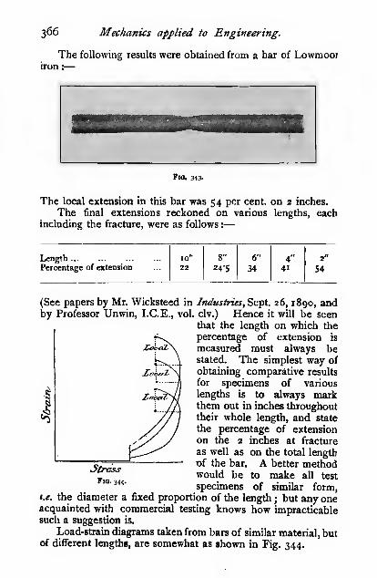
366 Mechanics applied to Evgineering.
The following results were obtained from a bar of Lowmoor
Flo. 343-
The local extension in this bar was 54 per cent, on 2 inches.
The final extensions reckoned on various lengths, eachincluding the fracture, were as follows :
—
LengthPercentage of extension
10
22 24-5
6"
344
41
2
54
(See papers by Mr. Wicksteed \-a Industries, Sept. 26, 1890, andby Professor Unwin, I.C.E., vol. civ.) Hence it will be seen
that the length on which the
percentage of extension is
measured must always bestated. The simplest way of
obtaining comparative results
for specimens of various
lengths is to always markthem out in inches throughouttheir whole length, and state
the percentage of extensionon the 2 inches at fracture
as well as on the total length
T)f the bar. A better methodwould be to make all test
specimens of similar form.
StressVia. 344.
t.e. the diameter a fixed proportion of the length ; but any oneacquainted with commercial testing knows how impracticablesuch a suggestion is.
Load-strain diagrams taken from bars of similar material, butof different lengths, are somewhat as shown in Fig. 344.
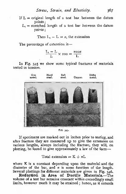
Stress, Strain, and Elasticity. 367
If L = original length of a test bar between the datumpoints
;
Li = stretched length of a test bar between the datumpoints
;
Then Lj — L = x, the extension
The percentage of extension is
—
L, — L loox-^—— X roo = —
—
In Fig. 345 we show some typical fractures of materials
tested in tension.
Gunmetal.
Hardsteel.
Soft Deltasteel. Copper. metal.
Fig. 345.
If specimens are marked out in inches prior to testing, andafter fracture they are measured up to give the extension onvarious lengths, always including the fracture, they will, onplotting, be found to give approximately a law of the form
—
Total extension = K + «L
where K is a constant depending upon the material and the
diameter of the bar, and n is some function of the length.
Several plottings for different materials are given in Fig. 346.Beduction in Area of Ductile Materials.—The
volume of a test bar remains constant within exceedingly smalllimits, however much it may be strained ; hence, as it exterids

368 Mechanics applied to Engineering.
the sectional area of the bar is necessarily reduced. Thereduction in area is considered by some authorities to be thebest measure of the ductility of the material.
Annealed Coppe*
Mild Steel
Wroughi Iron
4- e aLength.
Fig. 346.
to. tnches
Let A = the original sectional area of the bar;
Ai = the final area at the fracture.
Then the percentage of reduction in area is——^ x 100A
If a bar remained parallel right up to the breaking point,as some materials approximately do, the reduction in area caiibe calculated from the extension, thus
:

Stress, Strain, and Elasticity. 369
The volume of the bar remains constant ; hence
—

370 Mechanics applied to Engineering.
Then, as the volume of the bar remains constant
—
L ALA = LiA„ and ^ = .
-
W
S W Ai L~KSLn
OT the real stress Sj = -^r-
The diagram of real stress may be conveniently constructed
as in Fig. 347 from the ordinary stress-strain diagram.
The construction for one point only is given. The length
Tl^-'"
AFig. 347.
i^ e strain %
L of the specimen is set oflf along the strain axis, and thestress ordinate de is projected on to the stress axis, viz. ao.The line ba is then drawn to meet ed produced in c, whichgives us one point on the curve of real stress. For by similartriangles we have
—
S, L. SLi
which we have shown above to be the real stress.
The last part of the diagram, however, cannot be obtained

Stress, Strain, and Elasticity. 371
thus, as the above relation only holds as long as the barremains parallel; but points on the real stress diagram between

372 Mechanics applied to Engineering.
349, were drawn by the author's autographic recorder
(see Engineering, December 19, 1902), from bars of the samelength and diameter.
Some of the curves in Fig. 350 are curiously serrated, i.e.
the metal does not stretch regu-
larly (these serrations are notdue to errors in the recording
apparatus, such as are obtained
by recorders which record the
faults of the operator as well as
the characteristics of the ma-terial). The author finds that
all alloys containing iron give aserrated diagram when cold anda smooth diagram when hot,
whereas steel does the reverse.
This peculiar effect, which is
disputed by some, has beenindependently noticed by Mons.
(«) Le Chatelier.
Artificial Raising of theFig. 350.—(a) Rolled aluminium .
roHed copper i^c) rolled "bull "metal,temp. 400° Fahr. ; (a!) ditto 60° Kahr.N.B.—Bull metal and delta metal ElastiC Limit. The form ofbehave in practically the same way in „t „ 4. _ j 1
the testing-machine. a strcss-strain curve dependsmuch upon the physical state
of the metal, and whether the elastic limit has been artificially
raised or not. It has been known for many years that if apiece of metal be loaded beyond the elastic limit, and the load
be then released, the nexttime the material is loaded,the elastic limit will approxi-mately coincide with the pre-
vious load. In the diagram in
Fig- 35 1, the metal was loadedup to the point c, and then re-
leased ; on reloading, theelastic limit occurred at the
stress cd, whereas the original
elastic limit was at the stress
ab. Now, if in manufacture,by cold rolling, drawing, orotherwise, the limit had beenthus artificially raised, the
stress-strain diagram would have been dee.
Young's Modulus of Elasticity (E).—We have already

Stress, Strain, and Elasticity. 373
stated that experiments show that the strain of an elastic bodyis proportional to the stress. In some elastic materials the
strain is much greater than in others for the same intensity of
stress, hence we need some means of concisely expressing the
amount of strain that a body undergoes when subjected to agiven stress. The usual method of doing this is to state the-
intensity of stress required to strain the bar by an amountequal to its own length, asstiming the material to remainperfectly elastic. This stress is known as Young's modulusof (or measure of) elasticity. We shall give another definition
of it shortly.
4
.[]J _^....'Vj; ~~yiPess~
Fig. 352.
In the diagram in Fig. 352 we have shown a test-bar of
length / between the datum points. The lower end is supposed
to be rigidly fixed, and the upper end to be pulled ; let a stress-
strain diagram be plotted, showing the strain along the vertical
and the stress along the horizontal. As the test proceeds weshall get a diagram abed as shown, similar to the diagrams
shown on p. 365. Produce the elastic line onward as shown(we have had to break it in order to get it on the page) until
the elastic strain is equal to /; then, if x be the elastic strain
at any point along the elastic line of the diagram corresponding
to a stress/, we have by similar triangles
—
I E

374 Mechanics applied to Engineering.
The stress E is termed " Young's modulus of elasticity,"
and sometimes briefly " The modulus of elasticity." Thus in
tension we might have defined the modulus of elasticity as
The stress required to stretch a bar to twice its ori^nal length,
assuming the material to remain perfectly elastic. It need hardly
be pointed out that no constructive materials used by engineers
do remain perfectly elastic when pulled out to twice their
original length ; in fact, very few materials will stretch muchmore than the one-thousandth of their length and remain elastic.
It is of the highest importance that the elastic stretch should
not be confused with the stretch beyond the elastic limit. It
will be seen in the diagram above that the part bed has nothing
whatever to do with the modulus of elasticity.
We may write the above expression thus :
E=ZX/
Then, if we reckon the strain per unit length as on p. 361,
ha'
thus :-
we have - = unit strain, and we may write the above relation
Young's modulus of elasticity = —^
unit stramThus Young's modulus is often defined as the ratio of the unit
stress to the unit strain while the material is perfectly elastic,
or we may say that it is that stress at which the strain becomesunity, assuming the material to remain perfectly elastic.
"The first definition we gave above is, however, by far theclearest and most easily followed.
'For compression the diagram must be slightly altered, as in
Fig- 353-In this case the lower part of the specimen is fixed and the
upper end pushed down ; in other respects the description ofthe tension figure applies to this diagram, and here, as before,
we have
—
/ E
For most materials the value of E is the same for bothtension and compression ; the actual values are given in tabularform on p. 427.

Stress, Strain, and Elasticity. 375
Occasionally in structures we find the combination of twoor more materials having very different coefficients of elasticity
;
the problem then arises, what proportion of the total load is
b|:":;a":: ••^ stress
Fig. 353.
borne by each? Take the case of a compound tension
member.
Let E, = Young's modulus for material i
;
^2 ^^)» J» )) 2 j
Ai = the sectional area of i;
"2 = )i_
II 2
;
/i = the tensile stress in i
;
/i — >i I. 2
;
W = the total load on the bar.
Then
/2 Eja'/i Eg
since the components of the member are attached together at
both ends, and therefore the proportional strain is the same in
both;

376 Mechanics applied to Engineering.
andA2/2 A.E^ Wj
which gives us the proportion of the load borne by each of the
component members
;
Wand Wi =
1 +A,E,
W,=
A1A2
w1 +
AjEj
A2E2
By similar reasoning the load in each component of a barcontaining three different materials can be found.
The Modulus of Transverse Elasticity, or theCoefficient of Rigidity (G).—The strain or distortion of an
Fig. 354.
element subjected to shear is measured by the slide, x (see
p. 361). The shear stress required to make the slide x equalto the length / is termed the modulus of transverse elasticity, orthe coefficient of rigidity, G. Assuming, as before, that thematerial remains perfectly elastic, we can also represent thisgraphically by a diagram similar to those given for directelasticity.
In this case the base of the square element in shear is
rigidly fixed, and the outer end sheared, as shown.

Stress, Strain, and Elasticity. 177
From similar triangles, we have
I G_ / stressG = - = -
X strain
Relation between the Moduli of Direct and Trans-verse Elasticity.—Let abed be a square element in a perfectly
elastic material which is to be subjected to
—
(i) Tensile stress equal to the modulus stress; then the
length / of the line ab will be stretched to 2/, viz. abi, and the
2/— /strain reckoned on unit length will be
—
-— = i.
(2) Shearing stress also equal to the modulus stress ; then
the length / of the line ab will be stretched to is/P + P= ^2l= I "41/, and the strain reckoned on unit length
1-41/-/will be = 0-41.
Thus, when the modulus stress is reached in shear the
strain is 0-41 of the strain when the modulus stress is reached
Fig. 3SS.
in tension ; but the stress is proportional to the strain, therefore
the modulus qf transverse elasticity is o'4i, or | nearly, of the
modulus of direct elasticity.
The above proof must be regarded rather as a popular
demonstration of this relation than a scientific treatment. Theorthodox treatment will be given shortly.
Strength of Wire.—Surprise is often expressed that the

378 Mechanics applied to Engineering.
strength of wire is so much greater than that of the material
from which it was made; the great difference between the two
is, however, largely due to the fact that the nominal tensile
strength of a piece of material is very much less than the real
strength reckoned on the final area. The process of drawing
wire is equivalent to producing an elongated stricture in the
material ; hence we should expect the strength of the wire to
approximate to that of the real strength of the material fromwhich it was made (Fig. 356). That it does so
will be clear from the following diagrams. In
addition to this the skin of the wire is under very
severe tensile stress, due to the punishing action
of the draw-plate, which causes a compression
_ g of the core, with the result that the density of
the wire is slightly increased with a correspond-
ing increase in strength. Evidence will shortly be given to
show that the skin is in tension and the core in compression.
The process of wire-drawing very materially raises the
elastic limit, and if several passes be made without annealing
the wire, the elastic limit may be raised right up to the break-
ing point ; the permanent stretch of the wire is then extremely
small. If a given material will stretch, say, 50 per cent, in
the stricture before fracture, and a portion of the material bestretched, say, 48 per cent., by continual passes through the
draw-plate without being annealed, that wire will only stretch
roughly the remainder, viz. 2 per cent., before fracture. Wequalify this remark by saying roughly, because there are other
disturbing factors ; the statement is, however, tolerably accu-
rate. If a piece of wire be annealed, the strength will bereduced to practically that of the original material, and the
proportional extension before fracture will also approximate
to that of the undrawn material.
If a number of wires of various sizes, all made from the
same material, be taken, it will be found that the real stress onthe final area is very nearly the same throughout, although the
nominal strength of a small, hard, i.e. unannealed, wire is
considerably greater than that of a large wire.
The above remarks with regard to the properties of wire
also apply to the case of cold drawn tubes and extruded
metal bars.
The curves given in Fig. 357 clearly show the general
effects of wire-drawing on steel ; it is possible under certain
conditions to get several " passes " without annealing.
The range of elastic extension of wires is far greater than

Stress, Strain, and Elasticity. 379
that of the material in its untreated state; in the latter casehe elastic extension is rarely more than ^Ao of the length ofthe bar, but in wires it mayreach i^Vo " "The elastic extension curve for a sampleof hard steel wire is givenin Fig. 358. In some in-
vestigations by the authorit was found that Young'sModulus for wires was con-siderably lower than that for
the undrawn material. Onconsidering the matter, heconcluded that the highlystressed skin of the wireacted as an elastic tube tightly
stretched over a core ofmaterial, which thereby com-pressed it transversely, andcaused it to elongate longi-
tudinally. If this theory becorrect, annealing ought to
increase Young's Modulus for the wire. On appealing to ex-periment it was found that such was the case. A further series
I 2NumAer orPasses
Fig 357.
30 40 50 60 70stress in. tons j)er Sq. IntJi.
Tig. 3s8.
90
of experiments was made on wires of different sizes, all made

38o Mechanics applied to Engineering,
from the same billet of steel; the results corroborated the
former experiments. In every case the hard-drawn steel wires
had a lower modulus than the same wires after annealing.
The results were
—
o*i6o0*160
0*210
o'aio
0-1740*174
0*1460*146
0*115
0*115
Elastic
limit.
Maxi-mumstress.
Pounds per sq. inch.
181,700
59,600
78,00063,800
125,00071,600
z6o,ooo7i»3«>
316,000102,400
126,700
164,800124,800
189,700xxi,ooo
Extensionper centon 10ins,
9-6
3'S
on 3
ins.
19*0
19*5
5 n
34'S54'o
46-8
5a'3
31*551 'o
30*4
S7'i
E.Poundssq. inch.
25,430,00028,500,000
37,520,00037,800,000
25,4x0,000a7,5oo»ooo
35,300,00027,200,000
Remarks-
Hard drawnAnnealed
Rolled rodDitto annealed
Rod after one " pass"
Ditto annealed
Rod after two "
Ditto annealed
188,000
72,000
318,900
1x3,800
30*3 35.330,00037,000,00031,400,000
Rod after three " paaDitto annealedDitto after breaking
Wire Bopes.—The form in which wire is generally usedfor structural purposes is that of wire ropes. The wires are
suitably twisted into strands, and the strands into ropes, either
in the same or in the opposite sense as the wires according to
the purpose for which the rope is required j for details, special
treatises on wire ropes must be consulted.
The hauling capacity of a wire rope entirely depends uponthe strength at its weakest spot, which is usually at the attach-
ment of the hook or shackle. The terminal attachment, or the" capping," as it is generally tended, can be accomplished in
many ways, but, unfortunately, very few of the methods are
at all satisfactory. In the table below the average results of
a large number of tests by the author are given.
The method adopted for testing purposes in the LeedsUniversity Machine is shown in Fig. 359. After binding the
rope with wire, and tightly " serving " with thick tar band in
order to keep the strands in position, the ends are frayed out,

Stress, Strain, and Elasticity. 381
cleaned thoroughly with emery cloth, and finally a hard
white metal 1 end is cast on. With ordinary ropes high
efficiencies are obtained, but with very hard steel wires, which
only stretch a very small amount before breaking, the wires
have not the same chance of adjusting themselves to the
variable tension in each (due
to imperfect manufacture andcapping), and consequently tend
to break piecemeal at a muchlower load than they would if
each bore its full share of the
load.
On first loading a new wire
rope the strain is usually large,
due to the tightening up of the
strands and wires on one another
(see Fig. 359)., but the rope
shortly settles down to an elastic
condition, then passes an ill-
defined elastic limit, and ulti-
mately fractures. From its be-
haviour during the elastic stage,
a value for Young's modulus
can be obtained which is always
very much lower than that of
the wires of which it is com-
posed. This low value is largely
due to the tightening of the
strands, which continues more
or less even up to the breaking
load. In old ropes which have
taken a permanent " set " the
tightening effect is reduced to a
minimum, and consequently Young's modulus is greater than
for the same rope when new.
The value of E for old ropes varies from 8000 to 10,000
tons per square inch. The strength is often seriously reduced
by wear, corrosion, and occasionally by kinks.
Fig. 35g.—Method of capping wire ropes
' A mixture of lead 90 per cent., antimony 10 per cent.

382 Mechanics applied to Engineering.

Stress, Strain, and Elasticity. 383
Sir Alexander Kennedy has pointed out that the curve
during the ductile and plastic stages is a very close approxima-
tion to a parabola. Assuming it to be so, the work done can
be calculated without the aid of a diagram, thus
:
Let L = the elastic limit in tons per square inch
;
M = the maximum stress in tons per square inch
;
X = the extension in inches.
Then the work done in inch-tons per) _ ^ . 2 ,^ _ , .
square inch of section of bar )~ "t" 3^ /
= |(L + 2M)
work done in inch-tons per cubic inch = —7(L + 2M)
^ X, . .
But Y X 100 = tf, the percentage of extension
hence the work done in inch-tons per) £_,y , ^>cubic inch )
~ 3oo'' '
The work done in inch-tons per cubic inch is certainly byfar the best method of measuring the capacity of a given
material for standing shocks and blows. Strictly speaking, in
order to get comparative results from bars of various lengths,
that part of the diagram where stricture occurs should beomitted, but with our present system of recording tests such a
procedure would be inconvenient.
The value of the expression for the '' work done " in fractur-
ing a bar is evident when one considers the question of bolts
which are subjected to jars and vibration. It was pointed out
many years ago that ordinary bolts are liable to break off short
in the thread when subjected to a severe blow or to long-
continued vibration, and further, that their life may be greatly
increased by reducing the sectional area of the shank down to
that of the area at the bottom of the thread. The reason for this
is apparent when one calculates the work done in fracturing
the bolt in the two cases ; it is necessarily very small if the
section of the shank be much greater than that at the bottomof the thread, because the bolt breaks before the shank has
even passed the elastic limit, consequently all the extension is
localized in the short length at the bottom of the thread, but
when the area of the shank is reduced the extension is evenly
distributed along the bolt. The following tests will serve to
emphasize this point :
—

384 Mechanics applied to Engineering.
Diameterof bolt.

Stress, Strain, and Elasticity. 38s
Fig. 362.
prevent buckling. Such short specimens, however, are incon-
venient, for measuring accurately the relations between the
stress and the strain.
(Jp to the elastic limit,
ductile materials be-
have in much the
same way as they doin tension, viz. the
strain is proportional
to the stress. At the
yield point the strain
does not increase so
suddenly as in tension,
and when the plastic
stage is reached, the
sectional area gradu-
ally increases and the
metal spreads. Withvery soft homo-geneous materials, this
spreading goes onuntil the metal is squeezed to a flat disc without fracture.
Such materials are soft
copper, or aluminium,
or lead.
In fibrous mate-
rials, such as wrought
iron and wood, in
which the strength
across the grain is
much lower than with
the grain, the material
fails by splittbg side-
ways, due to the lateral
tension.
The . usual form
of the stress - strain
curve for a ductile
material is somewhat
as shown in Fig. 362.
If the material
reached a perfectly
^, , , . load at any instant (W),
plastic stage, the real stress, t.e. —-.' ' / , '
'^ °sectional area at that mstant (Aj)
2 c
Fig? 363.

386 Mechanics applied to Engineeiing.
would be constant, however much the material was compressed
;
then, using the same notation as before
—
A, - _W
and from above, — = constantAi
Substituting the value of Ai from above, we have
—
-—' = constant
;
/A.
But /A, the volume of the bar, is constant
;
hence W/j = constant
or the stress-strain curve during the plastic period Is a
hyperbola. The material
never is perfectly plastic,
and therefore never perfectly
complies with this, but in
some materials it very nearly
approaches it. For example,
copper and aluminium(author's recorder) (Fig.
363). The constancy of the
real stress will be apparentwhen we draw the real stress
curves.
BrittleMaterials.—Brittle
materials in compression, as
in tension, have no markedelastic limit or plastic stage.
When crushed they either
split up into prisms or, if ofcubical form, into pyramids,and sometimes by the one-half of the specimen shearingover the other at an angle of
about 45°. Such a fracture is shown in Fig. 361 (cast iron).
The shearing fracture is quite what one might expect frompurely theoretical reasoning. In Fig. 365 let the sectionalarea = A ;
Fig. 364.— Asphalte,
then the stress on the cross-section S =W

Stress, Strain, and Elasticity. 3^7
and the stress on an oblique section aa, making an angle a
'»5J5m5^&?;$^J%%M^
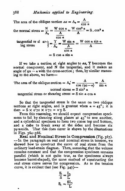
388 Mechanics applied to Engineering.
The area of the oblique section aa = Ao=^ cos a
.1. 1 ^ N W cos a W cos* a _ „ ,the normal stress = — =—-— = ^ a . cos" a
cos a
tangential or si ar-) _ T _ W sin a _ W cos a sin a
f Aoing stress f , Aj A Acos a
= S COS a sin a
If we take a section at right angles to aa, T becomes the
normal component, and N tiie tangential, and it makes an
angle of 90 — o with the cross-section ; then, by similar reason-
ing to the above, we have
—
A AThe area of the oblique section = A^,' = -. .^ = -:
—
cos (90 — a) sm o
normal stress = S sin* a
tangential stress or shearing stress = S sin a cos a
So that the tangential stress is the same on two oblique
sections at right angles, and is greatest when a = 45°; it is
then = S X 071 X 0-71 = 0-5 S.
From this reasoning, we should expect compression speci-
mens to fail by shearing along planes at 45° to one another,
and a cylindrical specimen to form two cones top and bottom,and a cube to break away at the sides and become six
pyramids. That this does occur is shown by the illustrations
in Figs. 364-366.Real and Nominal Stress in Compression (Fig. 367).—In the paragraph on real and nominal stress in tension, we
showed how to construct the curve of real stress from the
ordinary load-strain diagram. Then, assuming, that the volumeremains constant and that the compression specimen remainsparallel (which is not quite true, as the specimens alwaysbecome barrel-shaped), the same method of constructing the
real stress curve serves for compression. As in the tension
curve, it is evident that (see Fig. 347)
—
S Lc SL]

Stress, Strain, and Elasticity. 389
Behavia ar of Materials subjected to Shear. Natureof Shear Stress.—If an originally square plate or block be
SffessFig. 367.
acted upon by forces P parallel to two of its opposite sides, the
square will be distorted into a rhombus, as shown in Fig. 368,
. *^ v

390 Mechanics applied to Engineering,
perfectly general, we will take a rectangular plate as shown in
Fig- 369-The plate is acted upon by a clockwise couple, P . ad, or
f,.ab . ad, and a contra-clockwise couple, P, . a^ ox f, .ad . ab,
but these must be equal if the plate be in equilibrium;
theny^ .ab.ad =fi .ad.abor/. =/;
t.A the intensity of stress on the two sides of the plate is the
same.
Now, for convenience we will return to our square plate.
The forces acting on the two sides P and Pi may be resolvedinto forces R and E.i acting along the diagonals as shown in
Fig. 370. The effect of these forces will be to distort the
square into a rhombus exactly as before. (N.B.—The rhombus
Fig. 370. Fig. 371.
in Fig. 368 is drawn in a wrong position for simplicity.) Thesetwo forces act at right angles to one another ; hence we see
that a shear stress consists of two equal and opposite stresses,
a tension and a compression, acting at right angles to oneanother.
In Fig. 371 it will be seen that there is a tensile stress
acting normal to one diagonal, and a compressive stress normalto the other. The one set of resultants, R, tend to pull the twotriangles abc, acd apart, and the other resultants to push the twotriangles abd, bdc together.
Let/o = the stress normal to the diagonal.
Then/oa<r =/,,»/ lab, Oif^Jibc = RBut V 2P, or ij 2f,. ab, or ij 2/,. be ='&.
hence/, =/, =/,'

Stress, Strain, and Elasticity. 391
Thus the intensity of shear stress is equal on all the four
edges and the tension and compression on the two diagonals
of a rectangular plate subjected to shear.
Materials in Shear.—^When ductile materials are sheared,
they pass through an elastic stage similar to that in tension andcompression. If an element be slightly distorted, it will return
to its original form on the removal of the stress, and during
this period the strain is proportional to the stress; but after
the elastic limit has been reached, the plate becomes perma-nently deformed, but has not any point of sudden alteration as
in tension. On continuing to increase the stress, a ductile andplastic stage is reached, but as there is no alteration of area
under shear, there is no stage corresponding with the stricture
stage in tension.
The shearing strength of ductile materials, both at the
elastic limit and at the maximum stress, is about f of their
tensile strength (see p. 400).
Ductile Materials in Shear.—The following results, ob-tained in a double-shear shearing tackle, will give some idea of
the relative strengths of the same bars when tested in tension
and in shear ; they are averages of a large number of tests :
—
' Material.Nominaltensile
strength.
Shearingstrength.
Shearing strength.
Tensile strength.
Work doneper sq. in.
of metalshearedthrough.
Cast iron—hard, close grained
,, ordinary . . .
„ soft, open grainedBest wrought iron ....Mild steel
Hard steel
Gun-metalCopperAluminium
I4'6
io'9
7-922'026-6
48-013-5
1508-8
13-5
I2"9
107i8-i
20'9
34'o15-2
II-O
S7
0-92
i-i8
1-36•0-82
079071I-I3
0730-65
From autographic shearing and punching diagrams, it is
found that the maximum force required occurs when the
shearing tackle is about \ of the way through the bar, andwhen the punch is about \ of the way through the plate.
From a series of punching tests it was found that where
—
'• n\rt
load on punch
circumference of hole X thickness of plate

392 Meclianics applied to Engineering.

Stress, Strain, and Elasticity. 393
Now consider the two horizontal forces acting on the
«,« C't— ^
Fig. 372.
element, viz. T and P, and resolve them normally to the face
gh as shown, we get T. and P,.

394 Mechanics applied to Engineering.
cos d COS Q
alsoP„ + T„ = P„=/«i;4
hence, substituting the above values, we have
—
ff'B +/.. hi =fggh cos e =f„.'gl
and/.+-^=/«
Next consider the vertical force acting on the element,
viz. Pj.
Pi = P„ sin =fagh_s\n 6 =fjd
or^.^7=/>'~and ^-^^ = M
-. = ^ = tan e
Substituting this value of hi in the
equation above, we have
—
or/«/. ^ff=f^Jtt ~ Juft —J,
Fig. 373.
Solving, we get /. = J±V^7?+^
The maximum tensile stress on the) ^i _ft , /ft , ^{a.cegh 5
-''-2"^V ^+-/'
and the compressive stress on the face)
at right angles to gh, viz.j'h i /»=f-vf+^"Some materials are more liable to fail by shear than by
tension, hence it is necessary to find the maximum shear stress.
Drawy^ at right angles to gh, and// making an angle a with it,
the value of which will be determined. The compressivestress onj'h is/^, and the total stress represented by mn isj'h ./„.
The maximum shear stress^ occurs on the i&CQJl, and the
total shear stress on// is/^ . jl. The tensile stress on tiie face kl
ISfa and the total stress is -4/ .^ which is represented by fq. If
the tensile stress be + the compressive stress will be — . Since

Stress, Strain, and Elasticity. 395
we want to find the shear stress we must resolve these stresses
in the direction of the shear. Resolve pg, also mn^ parallel
and normal to jl.
pr = pq sin a = kl.fa sin a
on = tun cos d = —jk.f^ cos a
f.Ji = pr — on = kl.fa sin a - jk ./„ cos o
fm. = Jjf^sm a -J^f^ cos a
=-f^ cos a sin u, — _/^ cos a sin a = (/„ —f^ cos a sin a
= sm 2a,2
This is a minimum when 2a = 90° and sin Ra = i.
Then /^ = yirt JK
/» , = \/// +f^
This is the maximum inten-
sity of shear stress which occurs
when a piece of elastic material
is subjected to a direct stress
ft and a shear stress /,. Thedirection of the most stressed
section is inclined at 45° to
that on which the maximumIntensity of tensile stress occurs. Bi^^*—
Compound Stresses.—Let the block ABCD, of uni-
form thickness be subjected to
tensile stresses f^ and/, acting
normal to the mutually perpen-
dicular faces AD and DC or
BC and AB. The force
P^=/^. AD or/«.BCP,=/,.ABor/,.DCP„=/„.ACV,=ft- AC. (/j is the tangential or shear stress).
Fig. 374.
It is required to find (i) the intensity and direction of the

396 Mechanics applied to Engineering'
normal stress/„ acting on the face AC, the normal to whichmakes an angle Q with the direction of P,. (ii) the in-
tensity of the shear or tangential stress y^ acting on the face
AC.Resolving perpendicular to AC we have
—
P„ = P„, + P.« = Py cos + P. sin
/;AC =/,AB cos d +/«BC sin Q
, ,AB ., ,BC . a/» =/»Xc *^°^ ^ "^-^'AC
^'°
/„ =/, cos" e +/, sin» ealso P, = P„ - P,.
P, = P, sin 6 -V, cos 6
/,A.C =/»AB sin -/,BC cos 6
. .AB . . ,BC .
•^' "•^'AC^'"
~-^'AC*^°^
^ =^ cos sin B — /, sin 9 cos
ft = (/» -/.) cos d sin e =^^^^ sin 2^
This is a maximum when B = 45°. The tangential or
shear stress is then = ———. Thus the maximum intensity of
shear stress is equal to one half the difference between the twodirect stresses.
The same result was obtained on page 395 by a different
process.
FoiBSOn's Ratio.—When a bar is stretched longitudinally,
it contracts laterally; likewise when it is compressed longi-
tudinally, it bulges or spreads out laterally. Then, termingstretches or spreads as positive (+) strains, and compressionsor contractions as negative (— ) strains, we may say that whenthe longitudinal strain is positive (+), the lateral strain is
negative (— ).
Let the lateral strain be - of the longitudinal strain. The
fraction - is generally known as Foisson's ratio, although in
reality Foisson's ratio is but a special value of the fraction, viz. \.
Strains resulting from Three Direct Stressesacting at Bight Angles.—In the following paragraph it will

Stress, Strain, and Elasticity. 397
be convenient to use suffixes to denote the directions in whichthe forces act and in which the strains take place. Thus anyforce P which acts, say,
normal to the face x will
be termed P,, and the^
strain per unit length -~
will be termed S„ and the
stress on the face f^ ; then
/xS,='g(seep. 374).
Every applied force
which produces a stretch
or a + strain in its owndirection will betermed +,and vice versd.
The strains produced
Thuiknj&ss
Fig. 375.
by forces acting in the various
directions are shown in tabulated form below.
Fio. 376.
Force actingoa face of
cube.

398 Mechanics applied to Engineering.
These equations give us the strains in any direction due to
the stresses/,,^,/, acting alone; if two or more act together,
the resulting strain can be found by adding the separate strains,
due attention being paid to the signs.
Shear.—We showed above (p. 390) that a shear consists oftwo equal stresses of opposite sign acting at right angles to one.
another. The resulting strain can be obtained by adding the
strains given in the table above due to the stresses^ andyi,which are of opposite sign and act at right angles to oneanother.
The strains are
—
4 + 4; = T^f1 + -^ in the direction (i)
» .. (3)
E «E
-4+4=0«E «E
Thus the strain in two directions has been increased by
- due to the superposition of the two stresses, and has been
reduced to zero in the third direction.
LetS=4(r+i).
If a square abed had been drawn on the side of the element,
it would have become the rhombus db'dd' after the strain, the
AT— l*ac-..a. .;:,
A":>\d'
Fig. 378.
long diagonal of the rhombus being to the diagonal of thesquare as i + S to i. The two superposed are shown in Fig. 378.Then we have
—
^ + (/+*)»=(i+S)»or 2/» + 2/a: + «» = I + 2S + S»

Stress, Strain, and Elasticity. 399
But as the diagonal of the square = i, we have—
2/»= I
XAnd let 7 = So ; x = IS^; then by substitution we have
—
a/» + 2/% + /%" =1 + 23 + 3"
and I + So + — = 1 + 2S + S'2
Both S and S, are exceedingly small fractions, never more thanabout YoVo" ^i^'i their squares will be still smaller, and therefore
negligible. Hence we may write the above
—
r I + S„ = I + 2S
orSo=2S = ^(x+i)
/ /E E/ I \ E«^"'""^ ^=:777rr^( TTi )^ ^(«+^)
hence n = 5 y^, and E = —^
When « = s, G = -j^E = o-42E.
« = 4, G = |E = o-4oE.
« = 3. G = fE = 0-38E.
« = 2, G = |E = 0-33E.
Some values of n will be given shortly.
We have shown above that the maximum strain in anelement subject to shear is
—
=K.-0but the maximum strain in an element subject to a direct stress
in tension is
—
»<- E
hence — =3 iG+33,- /
E= (.^0^
orS = s,(. + I)

400 Mechanics applied to Engineering.

Stress, Strain, and Elasticity. 401
Then -=^ 4-—E «E^«E
and /^ = «/, -f^ =fy{n - 1) since/„ =/,The strain in direction x is
—
E «E(« - 1) E\ «(« - 1)/ "^ E
Or the longitudinal strain of a bar
held in this manner is only f as great as
when the bar is free. \^J [/|
Anticlastio Curvature.—When a yecllljt'
beam is bent into a circular arc some of
the fibres are stretched and some com-pressed (see the chapter on beams), the
amount depending upon their distance
from the N.A.; due to the extension
of the fibres, the tension side of the
beam section contracts laterally andthe compression side extends. Then, Fig. 380.
corresponding to the strain at EE on the beam profile, we
have - as much at E'E' on the section ; also, the proportional
strain
—
EE - LL _yLL p
E'E' - L'L' _ yL'L' p.
ButZ = i.2Pi » P
hence pi = np = 4p
and
This relation only holds when all the fibres are free laterally,
which is very nearly the case in deep narrow sections ; but if the
section be shallow and wide, as in a flat plate, the layers which
would contract sideways are so near to those which would
extend sideways, that they are to a large extent prevented from
moving laterally ; hence the material in a flat wide beam is
nearly in the state of a bar prevented from contracting laterally
in one direction. Hence the beam is stifTer in the ratio of«3
«!"-= yI than if the section were narrow.
2 D

402 Mechanics applied to Engineering.
Boiler Shell.—On p. 421 we show that P. = aP,;
/. = 2/. ; /. = /.
ii
I
Fig. 381. Fig. 382.
Strains.
Let « = 4.
' E E« EV2 J ^E
' E« E« B.\2n J "E
" ~ E« ^ E ~ E*. i^/ ~ » E
Thus the maximum strain is in the direction S^By the thin-cylinder theory we have the maximum strain
- ^ > thus the real strain is only -j as great, or a cylindrical
boiler shell will stand f= iT4or 14 per cent, more pressure
before the elastic limit is reached than is given by the ordinary
ring theory.
Thin Sphere subjected to Internal Fluid Pressure.—In the case of the sphere, we have P. = P.; /i = ^.
Strains.—c _ /. _ 21 =-6/'i - i^ = s/'^' E E« EV «/ *Ec A - A = _/'/'i 4- ^^ - _ i/'°'~ E« E« E\n^ nj »E
*•" E^^E EV n)~*E

Stress, Strain, and Elasticity. 403
But^ in this dase ='^in the case given above;
.-. S. in this case = | X ^ =|^
Maximum strain in sphere _ -f _ 3.
maximum strain in boiler shell \ ''
Hence, in order that the hemispherical ends of boilers should
enlarge to the same extent as the cylindrical shells when under
pressure, the plates in the ends should be f thickness of the
plates in cylindrical portion. If the proportion be not adhered
to, bending will be set up at the junction of the ends and the
cylindrical part.
Cylinder exposed to Longitudinal Stress whenunder Internal Pressure.—When testing pipes underpressure it is a common practice to close the ends by flat
plates held in position by one long bolt passing through the
pipe and covers, or several long bolts outside the pipe. Themethod may be convenient, but it causes the pipes to burst
at lower pressures than if flanged covers were used. In the
case of pipes with no flanges a long rod fitted with two pistons
and cup leathers can be inserted in the pipe, and the water
pressure admitted between them through one of the pistons,
which produces a pure ring stress, with the result that the
pipes burst at a much higher pressure than when tested as
described above.
(i) Strain with simple ring stress = ^zff
Pressure required to burst a thin cylinder/ = —a
(ii) Strain with flanged covers = 8„
2ftPressure required to burst a thin cylinder = p = ^-~
(iii) When the covers are held in position by a longitudinal
bolt, the load on whith is Pj, the longitudinal compression in
Pthe walls of the pipe is-j =7^.
The circumferential ring strain due to internal pressure andlongitudinal compression
—

404 Mechanics applied to Engineering.
where m =-^Jx
n 2ftand/ = —j— X -^
n + m a
Example.—Let d= 8 ins. / = 05 in. f^ = ro.ooo lbs.
sq. in.
Simple ring stress / = 1250 lbs. sq. in.
With flanged covers/ = 1428 lbs. sq. in.
With longitudmal bolt and let «? = 2. "j
This is a high value but is sometimes\ p = 830 lbs. sq. in.
experienced'
Thus if a pipe be tested with longitudinal bolts under the
extreme condition assumed, the bursting pressure will be only
58 per cent, of that obtained with flanged covers.
Alteration of Volume due to Stress.—If a bodywere placed in water or other fluid, and were subjected to
pressure, its volume would be diminished in proportion to the
pressure.
Let V = original volume of body;
Sv = change of volume due to change of pressure
;
Bp „ pressure.
Sp change of pressure
~ Sv"" change ofvolume per cubic unit of the body
~V
V
K is termed the coefficient of elasticity of volume.
The change of volume is the algebraic sum of all the strains
produced. Then, putting p =f^ =fy =/; for a fluid pressure,
we have, from the table on p.. 397, the resulting strains
—
E £«"*"£ E«'^E E« E E« E E«_/ _ pEn _ E« - _ EG
3/« — bp 3« — 6 9G — 3E
ButE = ^-^(^(p.399)
hence K ='^^^ = i(-^)e and n = 'g + ^^3« - 6 ^\« - 2/ 3K - 2G

Stress, Strain, and Elasticity. 405
The following table gives values of K in tons per sc^uare
inch also of n
:
—
Material.

4o6 Mechanics- applied to Engineering.
The moment of the reactions of the edges oi\ ^^^ ^the plate when freely supported, the resultant is =— X -
assumed to act at the middle of each side j 2 2
The resulting moment is equal to the moment of resistance
of the plate to bending across the diagonal, hence
—
ab c ab c , dfi ,^ _,, ^_.p—X~-p—X- = f-r (See Chapter XI)22-^23'^6 "^ '
pabc _ ,^"^, ab
But d = y/a^ + 1^ and c = -7=?==^
2{cP + ^)/"•^^'^^^ „/„8 I »\/a ~ f when freely supported.
and / 2 1psM ~'f w^^'' ^^ edges are rigidly held.
For a square plate of side a this becomes
^ =/ when freely supported.V
and -Ya = /when the edges are securely bolted.
From experiments on such plates, Mr. T. H. Bryson, of
Troy, U.S.A., arrived at the expression
pj^_
When the length of a is very great as compared with b, the
support from the ends is negligible. When the edges are
rigidly held, the plate simply becomes a built-in beam of
breadth a, depth t, span b—p.ab.~=f-r
12
Pl-r
For a circular plate of diameter d and radius r
The moment of the water pressure about a^ trr^p 4^diameter j
~ ~2~ ^rir
The moment of the reactions of the edge of) tn^p 2rthe plate when freely supported \ ^ ~^ ^ '^

Siress, Strain, and Elasticity.
The. !^(-)=/£j! ^=/When the edges are rigidly held^ = /
407
w
WFig. 384.
Riveted Joints.
Strength of a Perforated Strip.—If a perforated strip
of width w be pulled apart in the testing-machine, it will break
through the hole, and if the material be only very slightly
ductile, the breaking load will be (approximateLy)«*
W =ft{'W — d)t, where _;^ is the tensile strength of
the metal, and t the thickness of the plate. If the
metal be very ductile the breaking load will behigher than this, due to the fact that the tensile
strength is always reckoned on the original area of
the test bar, and not on the final area at the point of
fracture. The difference between the real and the
nominal tensile strength, therefore, depends upon the
reduction in area. If we could prevent the area
from contracting, we should raise the nominal tensile
strength. In a perforated bar the minimum area
of the section—through the hole—is surrounded bymetal not so highly stressed, hence the reduction in
area is less and the nominal tensile strength is greater
than that of a plain bar. This apparent increase in strength
does not occur until the stress is well past the
elastic limit, hence we have no need to take it
into account in the design of riveted joints.
Strength of an Elementary Fin Joint.
—If a bar, perforated at both ends as shown,
were pulled apart through the medium of pins,
failure might occur through the tearing of the
plates, as shown at aa or bb, or by the shearing
of the pins themselves.
Let d = the diameter of the pins
;
c = the clearance in the holes.
Then the diameter of the holes =d + c no. 38s.
LetyS = the shearing strength of the material in the pins.
For simplicity at the present stage, we will assume the pins
to be in single shear. Then, for equal strength of plate and
pins, we have— -^2
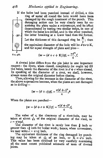
4o8 Mechanics applied to Engineering.
If the holes had been punched instead of drilled, a thin
ring of metal all round the hole would have beendamaged by the rough treatment of the punch. Thisdamaging action can be very clearly seen by ex-
amining the plate under a microscope, and its effect
demonstrated by testing two similar strips, in one ofwhich the holes are drilled, and in the other punched,the latter breaking at a lower load than the former.
Let the thickness of this damaged ring be — ; then2
the equivalent diameter of the hole will be <^-f-f+K,and for equal strength of plate and pins
—
4
A riveted joint differs from the pin joint in one importantrespect : the rivets, when closed, completely (or ought to) fill
the holes, hence the diameter of the rivet \^d-\-c when closed.In speaking of the diameter of a rivet, we shall, however,always mean the original diameter before closing.
Then, allowing for the increase in the diameter of the rivet,
the above expressions become, when the plates are not damagedas in drilling
—
Fig. 386.
{w-{d^c)W, T{d + cy/
When the plates are punched
—
[w-{d + c+TL)]ff,=r(d+cY
-/.
The value of c, the clearance of a rivet-hole, may betaken at about ^V of the original diameter of the rivet, orc = o'o^d.
The diameter of the rivet is rarely less than | inch orgreater than i^ inch for boiler work ; hence, when convenient,we may write c = o'os inch.
The equivalent thickness of the ring damaged by punch-ing may be taken at ^ of an inch, or K = 0-2 inch.This value has been obtained by very carefully examiningall the most recent published accounts of tests of rivetedjoints.

Stress, Strain, and Elasticity. 409
The relation between the diameter of the rivet and the
thickness of the plate is largely a matter of practical conve-
nience. In the best modern practice somewhat smaller rivets
are used than was the custom a few years ago; taking
d = i"i // and {d + cf = r^T,t appears to agree with present
practice.
Instead of using 7^, we may write f^ (see 400), where
/, is the tensile strength of the rivet material.
The values oifi,f„ B.nAf, may be taken as follows, but if in
any special case they differ materially, the actual values should
be inserted.
Material.
Iron ...
Steel ...
A' fr... Jo 24 21
K
. ,
W 28 28 \^"^ P" square inch.
Ways in which a Riveted Joint may fail.—Riveted
joints are designed to be equally strong in tearing the plate
o o
Tearing platethrough rivet-
holes.
Shearing of rivet.
-S-
J^
Burstingthrough edge
of plate;
Fig. 387.
-Q-
Shearingthroughedge ofplate.
Crushing ofrivet.
and in shearing the rivet ; the design is then checked, to see
that the plates and rivets are safe against crushing.
Failure through bursting or shearing of the edge of the
plate is easily avoided by allowing sufficient margin between
the edge of the rivet-hole and the edge of the plate ; usually
this is not less than the diameter of the rivet
See paragraph on Bearing Pressure.

4IO Mechanics applied to Engineering.
Lap and Single Cover-plate Riveted Joints.—Whensuch joints are pulled, the plates bend, as shown, till the two
Fig. 388. Fig. 389.
lines of pull coincide. This bending action very considerably
increases the stress in the material, and consequently weakensthe joint. It is not usual to take this bending action into
account, although it is as great or greater than the direct stress,
and is the cause of the dangerous grooving so often found in
lap-riveted boilers.'
' The bending stress can be approximately arrived at thus : The. P/
maximum bendmg moment on the plates is — (see p. 505), where P is
the total load on a strip of width w. This bending moment decreases as
the plates bend. Then, /( being the stress in the metal between the
rivet-holes, the stress in the metal where there are no holes 'i& M —^— |>
\ w )
hence—
and the bending moment = -^^ -
The plate bends along lines where there are no holes ; hence
Z =^ (see Chap. XI.)6
and the skin stress due to bending
—

Stress, Strain, and Elasticity. 411
Single Row of Rivets.
Punched iron—{w ~ d — c
4 5
Fig. 390. Fig. 391.
Then, substituting 0-05 inch for e on the left-hand side of
the equation, and putting in the numerical value of K as given
above, also putting {d + cf = i"33/', we have on reduction
—
/w — d = o-83'^ + o'25 inchJt
w — d= 1*20 inches
Thus the space between the rivet-holes (w — d) of all punchediron plates with single lap or cover joints is i"20 inch, or say
I5 inch for all thicknesses of plate.
By a similar process, we get for
—
Punched steel—w — d = I '09 inches
In the case of drilled plates the constant K disappears,
hence w — diso'2 inch less than in the case of punched plates
;
then we have for
—
Drilled iron—
Drilled steel—w — d = I'o inch
m— d = o"89 inch
Double Row of Rivets.—In this case two rivets have to
Fig. 393. Fig. 393.

412 Mechanics applied to Engineering.
be sheared through per unit width of plate w; hence wehave
—
Punched iron—
{iv — d — -Yi)ff.=VL^d^c)^^4 5
/IV — d = i-gi"^ + 0-2S inch
Jt
Punched steel—
Drilled iron—
Drilled steel—
w — d = zt6 inches
w — d = i-g2 inches
w — d = vg6 inches
w — d = V]2 inches
Double Cover-plate Joints.—In this type of joint there
is no bending action on the plates. Eachrivet is in double shear; therefore, with asingle row of rivets the space between the
rivet-holes is the same as in the lap joint
with two rows of rivets. The joint shownin Fig. 394 has a single row of rivets («.*. in
each plate).
Double Row of Rivets.—In this case
there are two rivets in double shear, whichis equivalent to four rivets in single shearfor each unit width of plate w.
Punched iron—
(w-d-c-Y:)tf, = ^(d + cj^4 5
Fig. 394. w-d= 3-347 + 0-25It
r\ i

Stress, Strain, and Elasticity. 413
Diamond Riveting.—In this case there are five rivets in
double shear, which is equivalent to ten rivets in single shear,
Fig. 396.
in each unit width of plate w ; whence we have for drilled steel
'
plates
—
{JV - d - c)if, = ^^{d ^,cf^4 5
w — d= 8*4 inches
Combined Lap and Cover-plate Joint.—This joint
may fail by
—
(i) Tearing through the outer row of rivet-holes.'
(2) Tearing through the | \ ^m^inner row of rivet-holes andshearing the outer rivet (single
shear).
(3) Shearing three rivets in
single shear (one on outer row,
and two on inner).
Making (i) = (3), we have
for drilled steel
—
o ' o 1 o o---I— j
oo6o<i>ooool
l^
Fio. 397.
(^-u>-d-c)tf, = ^{d + cf^^'4 5
w — d = 2'7i inches
If we make (3) = (2), we get
{w-2d- 2c)tf, + -(^ + cf"^ = ^-{d -f cf-^4 5 4 5
On reduction, this becomes
—
w — 2d= 2*07 inches
* This joint is rarely used for other than drilled steel plates.

414 Mechanics applied to Engineering.
If the value of d be supplied^ it will be seen that the joint
will not fail by (2), hence such joints may be designed bymaking (i) = (3).
Fitch of Rivets.—The pitch of the rivets, i.e. the distance
from centre to centre, is simply w ; in certain cases, which are
IS)
very readily seen, the pitch is —. The pitch for a number of
joints is given in the table below. The diameters of the
rivets to the nearest ^V of an inch are given in brackets.

Stress, Strain, and Elasticity. 415

4i6 Mechanics applied to Engineering.
given in the table above, and in those instances in which it is
excessive they have been crossed out with a diagonal line, andthe greatest permissible pitch has been inserted.
Efficiency of Joints.
—
^''offSU-^-^tl?"joint J
strength of plate
effective width of metal between rivet-holes
w — d — cor
pitch of rivets
w — d — c —K.
The table on the following page gives the efficiency of
joints corresponding to the table of pitches given above. All
the values are per cent.
Zigzag Riveting.—In zigzag riveting, if the two rows are
placed too near together, the plates tear across in zigzag fashion.
If the material of the plate were equally
Q Q strong with and across the grain, then a:,,
\ ,''' ", the zigzag distance between the two holes,"0' Q X
-X-^j ^ should be -. The plate is, however.
Fig. 398. weaker along than across the grain, con-sequently when it tears from one row to
the other it partially follows the grain, and therefore tears morereadily. The joint is found to be equally strong in both
directions when Xi =—
.
3Riveted Tie-bar Joints.—When riveting a tie bar, a
very high efficiency
can be obtained byproperly arranging the
-._^rivets.
The arrangementshown in Fig. 399 is
radically wrong for
tension joints. Thestrength of such ajoint is, neglecting the
—» clearance in the holes,
and damage done bypunching
—
(w — 4d)/^ at aa
Fig. 399.
-ted
abedFic. 400.

Stress, Strain, and Elasticity.
Efficiency of Riveted Joints.
417
Type of joint.
It::
Thick-ness of
plate.
i^
Iron plates andrivets.
Punched. Drilled
51
4846
44
[a) 6567
65
63

41
8
Mechanics applied to Engineering.
whereas with the arrangement shown in Fig. 400 the strength
is
—
(w — i)fit at aa (tearing only)
(k' - iisff + -d^f, at bb (tearing and shearing one rivet)
4
{w - 2,<^f + —-^X at cc ( „ „ three rivets)
4
(w - i4)f,t 4- -^d^f. at dd ( „ „ six „ )
4
By assuming some dimensions and working out the strength
at each place, the weakest section may be found, which will be
far greater than that of the joint shown in Fig. 399. The joint
in Fig. 400 will be found to be of approximately equal strength
at all the sections, hence for simplicity of calculation it may be
taken as being
—
(w - d)ff
In the above expressions the constants c and K have beenomitted j they are not usually taken into account in such
joints.
The working bearing pressure on the rivets should not
exceed 8 tons per square inch, and where there is much vibra-
tion the bearing pressure should not exceed 6 tons per square
inch.
Tie bar joints are frequently made with double cover
plates ; the , bearing stress on the rivets in such joints often
requires more careful consideration than the shearing stress.
When ties are built up of several thicknesses of plate they
should be riveted at intervals in order to keep the plates
close together, and so prevent rain and moisture from entering.
For this reason the pitch of the rivets in outside work should
never exceed 12/, where t is the thickness of the outside plates
of the joint. Attention to this point is also important in the
case of all compression members, whether for outside or inside
work, because the plates tend to open between the rivets.
GrcSups of Rivets.—In the Chapter on combined bend-ing and direct stress, it is shown that the stress may be very
seriously increased by loading a bar in such a manner that
the line of pull or thrust does not coincide with the centre of
gravity of the section of the bar. Hence, in order to get the
stress evenly distributed over a bar, the centre of gravity of the

Stress, Strain, and Elasticity. 419
group of rivets must lie on the line drawn through the centre
of gravity of the cross-section of the bar. And when two bars
Fig. 401.
not in line are riveted, as in the case of the bracing and the
boom of a bridge, the centre of gravity of the group must lie
Fig. 402.
on the intersection of the lines drawn through the centres of
gravity of the cross-sections of the two bars.

420 Mechanics applied to Engineering.
In other words, the rivets must be arranged symmetrically
about the two centre lines (Fig. 4°i)-
Punching E£fects.—Although the strength of a punchedplate may not be very much less than that of a similar drilled
plate, yet it must not be imagined that the effect of the punch-
ing is not evident beyond the imaginary ring of ^ inch in
thickness. When doing some research work upon this question
the author found in some instances that a i-inch hole punchedin a mild steel bar 6 inches wide caused the whole of the
fracture on both sides of the hole to be crystalline, whereas
the same material gave a clean silky fracture in the unpunchedbars. Fig. 402 shows some of the fractures obtained. The
' punching also very seriously reduces the ductility of the bar
;
in many instances the reduction of area at fracture in the
punched bars was not more than one-tenth as great as in the un-
punched bars. These are not isolated cases, but may be taken
as the general result of a series of tests on about 150 bars of
mild steel of various thicknesses, widths, and diameters of hole.
Strength of Cylinders subjected to Internal
Pressure.
Thin Cylinders.—Consider a short cylindrical ring i inch
in length, subjected to an internal
pressure of p lbs. square inch.
Then the total pressure tending
to burst the cylinder and tear the
plates at aa and bb is /D, whereD is the internal diameter in
inches. This bursting pressure
has to be resisted by the stress
in the ring of metal, which is
>2//, where /, is the tensile stress
in the material.
^'"- '°^' Then/D = if,t
or/R =f,t
When the cylinder is riveted with a joint having an efficiency
H, we have
—
/R =/A
In addition to the cylinder tending to burst by tearing
the plates longitudinally, there is also a tendency to burst

Stress, Strain, and Elasticity. 421
circumferentially. The total bursting pressure in this direction
Is/ttR'', and the resistance of the metal Is zttR^,, where /j is
the tensile stress in the material.
Then/7rR2 = 27rR^or/R = 2tff
and when riveted
—
/R = 2tfy
Thus the stress on a circumferential section is one-half as
great as on a longitudinal section. On p. 402 a method is
given for combining these two stresses.
The above relations only hold when the plates are very
thin; with thick-sided vessels the stress is greater than the
value obtained by the thin cylinder formula.
Thick Cylinders.
Barlow's Theory.—When the cylinder is exposed to aninternal pressure (/), the radii will be increased, due to the
stretching of the metal.
When under pressure
—
Let /; be strained to r, + «jr, = ^^(1 + «<)
r, „ „ r, + V. = ''.(i + «.)
where « is a small fraction indicating
the elastic strain of the metal, whichnever exceeds yoVo fo'' ^^^^ workingstresses (see p. 364).
The sectional area of the cylinder
will be the same (to all intents
and purpose:^) before and after
the a^iication of the pressure;
hence
—
Fig. 404.
T(r.=' - r?) = ^{r.^{i + „,y - r,\i + «,)'}
which on reduction becomes
—
ri%n? + 2n^) = r,\n,^ + 2«,)
« being a very small fraction, its square is still smaller andmay be neglected, and the expression may be written
—

422 Mechanics applied to Engineering.
The material being elastic, the stress/ will be proportional
to the strain n ; hence we may write
—
^'' =4 or/,n^ =/,;-."re Ji
that is, the stress on any thin ring varies inversely as the square
of the radius of the ring.
Consider the stress/ in any ring of radius r and thickness
dr and of unit width.
The total stress on any section of the) _ f jelementary ring
)
=LflLdrr\
= fir?.r-Hr
The total stress on the whole section) _ , i\'-2jof one side of the cylinder )
~ •''''''I
^
_ /^«v. '-/<n— I
(Substituting the value of/(;»,' from above)
— I
= /'«-//'.
This total stress on the section of the cylinder is due to thetotal pressure//-,; hence
—
pn=/,r,-/^.
Substituting the value of/„ we have
—

Stress, Strain, and Elasticity. 423
For a thin cylinder, we have
—
pr, =ft
Thus a thick cylinder may be dealt with by the sameform ofexpression as a thin cylinder, taking the presstire to act on the
external instead of on the internal radius.
The diagram (Fig. 404, abed) shows the distribution of
stress on the section of the cylinder, ad representing the stress
at the interior, and be at the exterior. The curve dc isfr^ =constant.
Lames Theory.^All theories of thick cylinders indicate
that the stress on the inner skin is
greater than that on the outer when the
cylinder is exposed to an internal pres-
sure, but they do not all agree as to the
exact distribution of the stress.
Consider a thin ring i inch long andof internal radius ;-, of thickness hr.
Let the radial pressure on the inner
surface of the ring be /, and on the
outer surface {p — Sp), when the fluid
pressure is internal. In addition to
these pressures the ring itself is sub-
jected to a hoop stress_/, as in the thin
cylinder. Each element of the ring is
subjected to the stresses as shown in !"'= 4°5-
the figure.
The force tending to burst this thin ring = / x 2;-. . (i.)
„ prevent bursting ={ ^V/t^S^SThese two must be equal
—
2pr = 2pr + 2/8r — 2r%p -|- 2/Sr
(iii.)
We can find another relation between/ and p, which will
enable us to solve this equation. The radial stress/ tends to
squeeze the element into a thinner slice, and thereby to cause
it to spread transversely; the stress / tends to stretch the
element in its own direction, and causes it to contract in

424 Mechanics applied to Engineering.
thickness and normal to the plane of the paper. Consider the
Pstrain of the element normal to the paper ; due to / it is —
-
/(see p. 397), and due to/ it is — ~, and the total longitudinal
P fstrain normal to the paper is^ p. Both/and/, however,
diminish towards the outer skin, and the one stress dependsupon the other.
Now, as regards the strain in the direction/ both pressures
/and/ act together, and on the assumption just made
—
/ —/ = a constant = 2a
The 2 is inserted for convenience of integration.
From (iii.) we have
—
Ip 2p 2a dp . . .
-^ = — — ^ = -f^ m the hmitor r r dr
Integrating we get—
.
b,
/ = 7.+ «
, b
where a and b are constants.
Let the internal pressure above the atmosphere be /<, andthe external pressure/, = o, we have the stress on the inner
skin
—
Reducing Barlow's formula to the same form of expression, weget—
fi=Pi^^_,.^
Kxperlmental Determination of the Distributionof Stress in Thick Cylinders.—In order to ascertain
whether there was any great difference between the distribution
of stress as indicated by Barlow's and by Lamp's theories, the

Stress, Strain, and Elasticity. 425
author, assisted by Messrs. Wales, Day, and Duncan, students,
made a series of experiments on two cast-iron cylinders with
open ends. Well-fitting plugs were inserted in each end, andthe cylinder was filled with paraffin wax ; the plugs were then
forced in by the 100-ton testing machine, a delicate extenso-
meter, capable of reading to^ ,'0 „ of an inch, was fitted on
/rttenor ofCylinder
per ^iMerilpressure
'US
2-607!m%Sqmckimefnal.^jfressare-^
033T0ISqrinA.oderiml
p» pressure
By experimenJti.
Lame's theory .
Barlow^ theory _
W
\^
x\
-Cyhnder WaU-
FlG. 406.
the outside j a series of readings were then taken at various
pressures. Two small holes were then drilled diametrically
into the cylinder to a depth of 0*5 inch; pointed pins were
loosely inserted, and the extensometer was applied to their
outer ends, and a second set of observations were taken. Theholes were then drilled deeper, and similar observations taken

426 Mechanics applied to Engineering.
at various depths. From these observations it is a simple
matter to deduce the proportional strain and the stress. Theresults obtained are shown in Fig. 333^, and for purposes of
comparison, Lamp's and Barlow's curves are inserted.
Built-up Cylinders.—In order to equalize the stress over
the section of a cylinder or a gun, various devices are adopted.
In the early days of high pressures,
cast-iron guns were cast round chills,
so that the metal at the interior wasimmediately cooled; then when the
outside hot metal contracted, it
brought the interior metal into com-pression. Thus the initial stress in
a section of the gun was somewhatas shown by the line ah, ag beingcompression, and bh tension. Then,when subjected to pressure, the curve
of stress would have been dc as
before, but when combined with
ab the resulting stress on the section is represented by ef, thus
showing a much more even distribution of stress than before.
This equalizing process is effected in modem guns byeither shrinking rings on one another in such a manner that
the internal rings are initially in compression and the externa]
rings in tension, or by winding wire round an internal tube to
produce the same effect. The exact tension on the wire re-
quired to produce the desired eflfect is regulated by drawing the
wire through friction dies mounted on a pivoted arm—in
effect, a friction brake.
Fig. 407.

Stress, Strain, and Elasticity. 427
Strength and Coefficients of Elasticity of Materials in
Tons square inch.

428 Mechanics applied to Engineering.

CHAPTER XI.
BEAMS.
The beam illustrated in Fig. 408 is an indiarubber modelused for lecture purposes. Before photographing it for this
illustration, it was painted black, and some thin paper was stuckon evenly with seccotine. When it was thoroughly set thepaper was slightly damped with a sponge, and a weight wasplaced on the free end, thus causing it to bend ; the paperon the upper edge cracked, indicating tension, and that on thelower edge buckled, indicating compressioii, whereas betweenthe two a strip remained unbroken, thus indicating no longi-
FlG. 40S.
tudinal strain or stress. We shall see shortly that such a result
is exactly what we should expect from the theory of bending.
General Theory.—The T lever shown in Fig. 409 is
hinged at tjie centre on a pivot or knife-edge, around which the
lever can turn. The bracket supporting the pivot simply takes
the shear. For the lever to be in equilibrium, the two couples
acting on it must be equal and opposite, viz. W/ = px.
Replace the T lever by the model shown in Fig. 410. It

430 Mechanics applied to Engineering.
is attached to the abutment by two pieces of any convenient
material, say indiarubber. The upper one is dovetailed, be-
cause it is in tension, and the lower is plain, because it is in
--^-
FlG. 4og, Fig. 410.
compression. Let the sectional area of each block be a ; then,
as before, we have "^l = px. But/ =fa, where/= the stress
in either block in either tension or compression
;
Or-
hence W/ = faxor = 2fay
The moment of] fthe moment of the internal forces, or the
the external I = ! internal moment of resistance of theforces I I beam
= stress on the area a X (moment of the twoareas {a) about the pivot)
Hence the resistance of any section to bending—apart alto-
gether from the strength of the material of the beam—^varies
. directly as the area a and as the distance x, or as the momentax. Hence the quantity in brackets is termed the " measureof the strength of the section," or the " modulus of the section,"
and is usually denoted by the letter Z. Hence we have
—
W/ = M =/Z, or
The bending moment^ _ Jstress on the) (modulus of the
at any section) \ material f ( section
The connection between the T lever, the beam model 01
Fig. 410, and an actual beam may not be apparent to somereaders, so in Fig. 411 we show arolled joist or I section, having top andbottom flanges, which may be regardedas the two indiarubber blocks of themodel, the thin vertical web serves thepurpose of a pivot and bracket fortaking the shear; then the formula thatwe have just deduced for the model
applies equally well to the joist. We shall have to slightly
Fio.,

Beams. 431
modify this statement later on, but the form in which we havestated the case is so near the truth that it is always taken in
this way for practical purposes.
Now take a fresh model with four blocks instead of
two. When loaded, the
outer end will sag as ^ (yy)
shown by the dotted ^ |/o"
lines, pivoting about the
point resting on the
bracket. Then the outer
blocks will be stretched
and compressed, or
strained, more than the
inner blocks in the ratio
— or ^ : i.e. the strain is directly proportional to the distance«" ^1
from the point of the pivot.
The enlarged figure shows this more distinctly, where e, e^
show the extensions, and c, Cj show the compressions at the
distances y, y^ from the pivot. From the similar
Fl'G, 41a.
triangles, we have also - = ^. But we= y.; also i = y.
ex y-L h yi
have previously seen (p. 375) that when a piece
of material is strained {i.e. stretched or compressed),
the stress varies directly as the ^'asxa, provided the
elastic limit has not been passed. Hence, since the
strain varies directly as the distance from the pivot,
the stress must also vary in the same manner.
Let/= stress in outer blocks, and/j = stress
in inner blocks ; then
—
Z = Zor/,=^/i yx y
Then, taking moments about the pivot as before, we have™
W/ = ifay + z/ioyi
Substituting the value of/i, we have
—
W/ = 2fay + z/ayi'
If V, = ^. W/ = 2fay + ^*2 AyW/ = 2fay(x + \)

432 Mechanics applied to Engineering.
Thus the addition of two inner blocks at one-half the
distance of the outer blocks from the pivot has only increased
the strength of the beam by \, or, in other words, the four-block
model will only support x\ times the load (W) that the two-
block model will support.
If we had a model with a very large number of blocks, or a
beam section supposed to be made up of a large number of
layers of area a, a^, a^, a,, etc., and situated at distances y, y-^,
yi, yz, etc., respectively from the pivot, which we shall nowterm the neutral axis, we should have, as above
—
W/ = 2fay + 2A.yi' 4. zAj-a" + zAjI'a' ^_ gtj._
Fig. 414.
= ^2((zy= -j- a^yy^ + a-ij/i + a^y^^ -\-, etc.)
The quantity in brackets, viz. each
little area (a) multiplied by the square of
its distance {y'') from a given line (N.A.),
is termed the second moment or momentof inertia of the upper portion of the
beam section ; and as the two half-sec-
tions are similar, twice the quantity in
brackets is the moment of inertia (I) of
the whole section of the beam. Thus wehave
—
W/ = /Ior
The bending moment at any section
the stress on thei (second moment, or moment of
_ outermost layer( ( inertia of the section
distance of the outermost layer from the neutral axis
But we have shown above that the stress varies directly as the
distance from the neutral axis j hence the stress on the outer-
most layer is the maximum stress on any part of the beamsection, and we may say
—
The bending moment at any section
the maximum stress) I second moment, or moment ofon the section ) 1 inertia of the section
distance of the outermost layer from the neutral axis

Beams, 433
But we have also seen that W/ = /Z, and here we have
therefore Z = -
The quantity - is termed the " measure of the strength of the
section," or, more briefly, the " modulus of the section ; " it is
usually designated by the letter Z. Thus we get W/ = /Z, orM=/Z, or—
moment' aU = i*^maximum or skin) (the modulus of
any section) 'stress on the section) •^
\ the section
Assumptions of Beam Theory.—To go into the
question of all the assumptions made in the beam theorywould occupy far too much space. We will briefly considerthe most important of them.
First Assumption.—That originally plane sections of abeam remain plane after bending; that is to say, we assumethat a solid beam acts in a similar way to our beam modelin Fig. 412, in that the strain does increase directly as the
distance from the neutral axis. Very delicate experiments
clearly show that this assumption is true to within exceedingly
narrow limits, provided the elastic limit of the . material is not
passed.
Second Assumption.—That the stress in any layer of a beamvaries directly as the distance of that layer from the neutral
axis. That the strain does vary in this way we have just
seen. Hence the assumption really amounts to assuming that
the stress is proportional to the strain. Reference to the
elastic curves on p. 364 will show that the elastic line is
straight, i.e. that the stress does vary as the strain. In mostcast materials the line is unquestionably slightly curved, but for
low (working) stresses the line is sensibly straight. Hence for
working conditions of beams we are justified in our assumption.
After the elastic limit has been passed, this relation entirely
ceases. Hence the beam theory ceases to hold good as soon as the
elastic limit has been passed.
Third Assumption.—That the modulus of elasticity in
tension is equal to the modulus of elasticity in compression.
Suppose, in the beam model, we had used soft rubber in the
2 F

434 Mechanics applied to Engineering.
tension blocks and hard rubber in the compression blocks, i.e.
that the modulus of elasticity of the tension blocks was less
than the modulus of elasticity of the compression blocks ; then
the stretch on the upper blocks would be greater thjui the
compression on the lower blocks, with the result that the beamwould tend to turn about some point other than the pivot, Fig.
415; and the relations given above entirely cease to hold, for
the strain and the stress will not vary directly as
the distance from the pivot or neutral axis, butdirectly as the distance from a, which later on weshall see how to calculate.
For most materials there is no serious error in
making this assumption ; but in some materials the
error is appreciable, but still not sufficient to be of
any practical importance.
Neither of the above assumptions «t& perfectly
Fig. 415. true ; but they are so near the truth that for all
practical purposes they may be considered to beperfectly true, but only so long as the elastic limit of the material
is not passed. In other parts of this book definite experi-
mental proof will be given of the accuracy of the beamtheory.
Graphical Method of finding the Modulns of the
Section (Z = -).—The modulus of the section of a beamy
might be found by splitting the section up into a great many
layers and multiplying the area of each by ^, as shown above.
The process, however, would be very tedious.
But in the graphic method, instead of dealing with eachstrip separately, we graphically find the magnitude of theresultant of all the forces, viz.-^
fa +fiai -^fa^ +, etc.
acting on each side of the neutral axis, also the position ordistance apart of these resultants. The product of the twogives us the moment of the forces on each side of the neutralaxis, and the sum of the two moments gives us the total amountof resistance for the beam section, viz./Z.
Imagine a beam section divided up into a great number ofthin layers parallel to the neutral axis, and the stress in eachlayer varying directly as its distance from it. Then if we con-struct a figure in which the width, and consequently the area,

Beams. 43 S
of each layer is reduced in the ratio of the stress in that layer
to the stress in the outermost layer, we shall have the intensity
of stress the same in each. Thus, if the original area of the
layer be «i, the reduced area of the layer will be
—
<«yy- say «!
whence we havey^Oj =fa^
Then the sum of the forces acting over the half-section, viz.
—
fa +/,<?! 4-/2«a +, etc.
becomes/a +fal \-fai +, etc.
or/(a + «i' + flJa' +, etc
or/(area of the figure on one side of the neutral axis)
or (the whole force acting on one side of the neutral axis)
Then, since the intensity of stress all over i!a& figure is the
same, the position of the resultant will be at the centroid or
centre of gravity of the figure.
Let Ai = the area of the figure below the neutral axis
;
Aa = „ „ above „ „d-^ = the distance of the centre of gravity of the lower
figure from the neutral axis;
di = the distance of the centre of gravity of the upper
figure from the neutral axis.
Then the moment of all the forces acting! _ ,
.
on one side of the neutral axis |
" -^ ' ^ '
Then the moment of all the forces acting j _ fi\ j \ \ j\on both sides of the neutral axis f
~ ^^^•'^' + ^^'^''>
= /Z(seep. 354)or Z = A,rfi + Aj^/a
We shall shortly show that Ai = Aj = A (see next para-
graph).
Then Z = A(^i + 4)Z = AD
where D is the distance between the two centres of gravity.
In a section which is symmetrical about the neutral axis
d = di — d, and (^ + (^a = 2;/-

436 Mechanics applied to Engineering.
Then Z = 2Mor Z = AD
The units in which Z is expressed are as follows
—
Z =U (length units)* ^ ^ j^ ^^i^^j3
y length
or Z = AD = area X distance
= (length units)'' X length units
= (length units)'
Hence, if a modulus figure be drawn, say, - full size, the
result obtained must be multiplied by «* to get the true value.
For example, if a beam section were
drawn to a scale of 3 inches = i foot,
i.e. \ full size, the Z obtained on that
scale must be multiplied by 4' = 64.
We showed above that in order to
construct this figure, which we will term
a "modulus figure," the width of each
strip of the section had to be reduced in
the ratio^, which we have previously seen
is equal to — . This reduction is easily
done thus: Let Fig. 416 represent a section through the
indiarubber blocks of the beam model. Join ao, bo, cutting
^ ,. ,# the inner block in c and d. Then bysimilar triangles
—
t: zszzi
Fig. 416.
rabor w{' = <y)
the strip in c and d.
In the case of a section in whichthe strips are not all of the same width,the same construction holds. Projectthe strip ab on to the base-line asshown, viz. db'. Join «'<?, l/o, cuttingBy similar triangles we have
—
^^^ ^1=7=7. °^-'^ = «^(7)

Beams. 437
Several fully worked-out sections will be given later on.
By way of illustration, we will work out the strength of the
four-block beam model by this method, and see how it agrees
with the expression found above on p. 432.
The area A of the modulus figure onl _ ^ 1 ^
'
one side of the neutral axis / '
The distance d of the c. of g. of the modulusl _^_+J^of the c. of g. of the modulus! _ ay + Oiy-.
; neutral axis (see p. 58) / a + Oi'figure from the
ButW/=/Z =/X 2Ad
or W/ = 2/(a + a/) X ~^rff = ^/^^ + 2>i>"
But a,' = a^, .-. W/ = 2fay +^^^
which is the same expression as we had on p. 431.
The graphic method of finding Z should only be used
when a convenient mathematical expression cannot beobtained.
Position of Neutral Axis.—We have stated abovethat the neutral axis in a beam section corresponds with the
pivot in the beam model; on the one side of the neutral axis
the material is in tension, and on the other side in compression,
and at the neutral axis, where the stress changes from tension to
compression, there is, of course, no stress (except shear, which
we will treat later on). In all calculations, whether graphic or
otherwise, the first thing to be determined is the position of the
neutral axis with regard to the section.
We have already stated on p. 58 that, if a point be so
chosen in a body that the sum of the moments of all the
gravitational forces acting on the several particles about the
one side of any straight line passing through that point, beequal to the sum of the moments on the other side of the
line, that point is termed the centre of gravity of the body ; or,
if the moments on the one side of the line be termed positive
( + )( and the moments on the other side of the line be termednegative (— ), the sum of the moments will be zero. We are
about to show that precisely the same definition may be used
for stating the position of the neutral axis ; or, in other words,
we are about to prove that, accepting the assumptions given
above, the neutral axis invariably passes through the centre of
gravity of the section of a beam.

438 Mechanics applied to Engineering.
liBt the given section be divided up into a large number of
strips as shown
—
Let the areas of the strips above
the neutral axis be fli, (h, ^a> etc.
;
and below the neutral axis be a/, ^a',
a,', etc. ; and their respective distances
above the neutral axis yi, y^, y^, etc.
;
ditto below j/, y^, yl, etc : and the
stresses in the several layers above
the neutral axis be /i, ft, /s, etc. ; ditto
below the neutral axis be //, fi, fi-
Then, as the stress in each layer
varies directly as its distance from
y',^i
Fig. 4i3.
the neutral axis, we have
—
^=^. and/.=^^U y2 yi
also ^' = ^7i yi
The total stress in all the layers] =/i«i + fnHi +,etc.
on one side of the neutral I /,, ,, .. \
I
= -(aiyi + «a;'2 +, etc.)axis 1 j/j
The total stress in all the layers)
on the Other side of the neutral! =^(fli,'j'i' + a^y^' +, etc.)
j y.axis
But as the tensions and compressions form a couple, the
total amount of tension on the one side of the neutral axis
must be equal to the total amount of compression on the other
side ; hence
—
ay + a^yi + (jys +. etc. = dy' + a/j/ + aiyl +, etc.
or, expressed in words, the sum of the moments of all the ele-
mental areas on the one side of the neutral axis is equal to the
sum of the moments on the other side of the neutral axis ; but
this is precisely the definition of a line which passes through
the centre of gravity of the section. Hence, the neutral axis
passes through the centre ofgravity of the section.
It should be noticed that not one word has been said in the
above proof about the material of which the beam is made ; all
that is taken for granted in the above proof is that the modulusof elasticity in tension is equal to the modulus of elasticity in

Beams. 439
compression. The position of the neutral axis has nothing
whatever to do with the relative strengths of the material in
tension and compression. In a reinforced concrete beam the
modulus of elasticity of the tension rods differs from that of
the concrete, which is in compression. Such beams are dealt
with later on.
Unsymmetrical Sections,—In a symmetrical section,
the centre of gravity is equidistant from the skin in tension andcompression; hence the maximum stress on the material in
tension is equal to the maximum stress in compression. Now,some materials, notably cast iron, are from five to six times as
strong in compression as in tension ; hence, if we use asymmetrical section in cast iron, the material fails on the
tension side at from ^ to -^ the load that would be required to
make it fail in compression. In order to make the beamequally strong in tension and compression, we make the section
of cast-iron beams of such s.form that the neutral axis is aboutfive or six times ^ as far from the compression flange as fromthe tension flange, so that the stress in compression shall be five
or six times as great as the stress in tension. It should be•particularly noted that the reason why the neutral axis is nearer
the one flange than the other is entirely due to theform of the
section, and not to the material ; the neutral axis would be in
precisely the same place if the material were of wrought iron,
or lead, or stone, or timber (provided assumption 3, p. 433, is
true). We have shown above on p. 432 that M =/-, and that
I .
•''
Z = -, where VIS the distance of the skin from the neutral axis.
y. .
In a symmetrical section y is simply the half depth of the section ;
but in the unsymmetrical section y may have two values : the
distance of the tension skin from the neutral axis, or the
distance of the compression skin from the neutral axis. If
the maximum tensile stress ft is required, the 7, must be takenas the distance of the tension skin from the neutral axis ; andlikewise when the maximum compressive stress /<, is required,
the y^ must be measured from the compression skin. Thus wehave either
—
' We shall show later on that such a great difference as 5 ot 6 is
undesirable for practical reasons.

440 Mechanics applied to Engineering.
and as - = — , we get precisely the same value for the bendingyt y<i
moment whichever we take. We also have two values of
^ I ^ ,1 r.Z, VIZ. - = Z, and - = Z.
;
andM =y^Z, or/^.
We shall invariably take /jZ, when dealing with cast-iron
sections, mainly because such sections are always designed in
such a manner that they fail in tension.
The construction of the modulus figures for such sections is
a simple matter.
G^mpressioTV 6as& Zma,
yA /
Comjiressiorhh<xse'tmj&
Xensio7v 'base Zirve
Fig. 419. Fig. 420.
Construction for Z^ (Fig. 419).—Find the centre of gravity
of the section, and through it draw the neutral axis parallel
with the flanges. Draw a compression base-line touching the
outside of the compression flange ; set off the tension base-line
parallel to the neutral axis, at the same distance from it as the
compression base-line, viz. _j'^; project the parts of the section
down to each base-line, and join up to the central point which
gives the shaded figure as shown. Find the centre of gravity
of each figure (cut out in cardboard and balance). Let
D = distance between them ; then Zo = shaded area above or
below the neutral axis X D.Construction for Z, (Fig. 420).—Proceed as above, only
the tension base-line is made to touch the outside of the tension
flange, and the compression base-line cuts the figure ; the parts
of the section above the compression base-line have been pro-
jected down on to it, and the modulus figure beyond it passes

Beams. 441
outside the section ; at the base-lines the figure is of the samewidth as the section. The centre of gravity of the two figures
is found as before, also the Z.
The reason for setting the base-lines in this manner will beevident when it is remembered that the stress varies directly as
the distance from the neutral axis; hence, the stress on the
tension flange,/^ is to the stress on the compression flange/„ as
yt is to y^
N.B.—The tension base-line touches the tension flange when the figure
is being drawn for the tension modulus figure Z,, and similarly for the
compression.
As the tensions and compressions form a couple, the total
amount of tension is equal to the total amount of compression,
therefore the area of the figure above the neutral axis must beequal to the area of the figure below the neutral axis, whetherthe section be symmetrical or otherwise; but the moment of
the tension is not equal to the moment of the compression
about the neutral axis in unsymmetrical sections. Theaccuracy of the drawing of moJulus figures should be tested bymeasuring both areas ; if they only differ slightly (say not morethan 5 per cent.), the mean of the two may be taken ; but if the
error be greater than this, the figure should be drawn again.
If, in any given instance, the Z^ has been found, and the Z,
is required or vice versA, there is no need to construct the twofigures, for
—
Z, = Z. X ^-°, or Z„ = Z, X -^
.;'. yc
hence the one can always be obtained from the other.
Most Economical Sections for Cast-iron Beams.—Experiments by Hodgkinson and others show that it is un-
desirable to adopt so great a difference as 5 or 6 to i betweenthe compressive and tensile stresses. This is mainly due to
the fact that, if sections be made with such a great difference,
the tension flange would be very thick or very wide com-pared with the compression flange ; if a very thick flange were
used, as the casting cooled the thin compression flange andweb would cool first, and the thick flange afterwards, and set
up serious initial cooling stresses in the metal.
The author, when testing large cast-iron girders with very
unequal flanges, has seen them break with their own weight
before any external load was applied, due to this cause. Verywide flanges are undesirable, because they bend transversely
when loaded, as in Fig. 421.
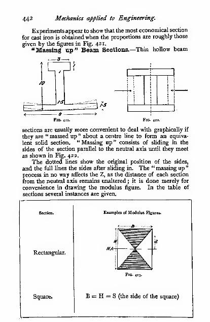
442 Mechanics applied to Engineering.
Experiments appear to show that the most economical section
for cast iron is obtained when the proportions are roughly those
given by the figures in Fig. 421.
"Massing up" Beam Sections.—Thin hollow beam
CT^f/o
[- i-
/s
aFig. 421. Fig. 422.
sections are usually more convenient to deal with graphically if
they are " massed up " about a centre line to form an equiva-
lent solid section. " Massing up " consists of sliding in the
sides of the section parallel to the neutral axis until they meet
as shown in Fig. 422.
The dotted lines show the original position of the sides,
and the full lines the sides after sliding in. The " massing up "
process in no way affects the Z, as the distance of each section
from the neutral axis remains unaltered j it is done merely for
convenience in drawing the modulus figure. In the table of
sections several instances are given.
Section.
Rectangular.
Square.
Examples of Modulus Figures.
< S »
Fig. 423.
B = H = S (the side of the square)

Beams. 443
Those who have frequently to solve problems involving
the strength and other properties of rolled sections will dowell to get the book of sections issued by The British Standards
Committee.
Modulus of thesection Z.

444 Meclianics applied to Engineering.
Section.
Hollow rect-
angles and girder
sections.
One corruga-
tion of a trough
flooring.
Examples of Modulus Figures.
" Corrtjor^c.sston'
NA-
^Te.n^torv
k

Beams, 445
Modulus of thesection Z.
BH' - bh'
6H
Approximate-ly, when the
web is thin,
as in a rolled
joist
—
Bmwhere t is the
mean thickness
of the flange.
BH*Moment of inertia for outer rectangle =
;' =
inner „

446 Mechanics applied to Engineering.
Section. Examples of Modulus Figures.
Square onedge.
Fig. 426.
Tees, angles,
and LIsections.
Fig. 427.
t
I
This figure
, , H becomes a T orffAj^. \ .\ u when massed
i up about a ver-
tical line.
Fig. 428.

Beams. 447
Modulus of thesection Z.
0-II8S'
The moment of inertia (see p. 88) =—S
§112 VzS' = oii8S»
BiH,'+B.,IV-3A'3H,
H, = 07H approx.
H, = 0-3H „
The moment of inertia for \ _ BiH|*the part above the N.A./ ~ 3
Ditto below = -^—
^
3
Ditto for whole section = ^'^' + ^'^' ~ ^'^'
3~, , ,, B,H,' + BjHj' - M'Z for stress at top = ——*
—
—^-23H,
If the position of the centre of gravity be calculatedfor the form of section usually used, it will be foundto be approximately 0"3H from the bottom.
Rolled sections, of course, have not square comersas shown in the above sketches, but the error involvedis not material if a mean thickness be taken.

448 Mechanics applied to Engineering.
Section.
T section
on edge andcruciform sec-
tions.
Examples of Modulus Figures.
2 ff B >
Fig. 439.
Unequalflanged sec-
tions.

Modulus of the section Z,
iW + B/4»
6H
AppTOT. Z
6

4SO
Section,
Mechanics applied to Engineering.
Examples of Modulus Figures.
...JBt.-,
M/1.
h
FlO. 432.
This
_ figure be-
!
Icomes the'
i
J,
same as
'^{T the last
i Iwhen
-f— massedHi about a
icentre
line.
Triangle.///«
Trapezium.AfA

Modulus of thesection Z.

45.2 Mechanics applied to Engineering.
SectloD.
Circle.
Hollowcircle andcorrugated
section.
Examples of Modulus Figuzvt.
Fig. 435.

Beams. 4S3
Modulus of thesection Z.
10*2
The moment of inertia of a circle \ _ "'D*
about a diameter (see p. 88) /~ 64D '
D - 32
2
ir(D' - D.«)
32D
The moment of inertia of a hollow circle \ _ t(D* — Dj*)
about a diameter (see p. 88) /~
64D
^=2
Z =
t(D' - D(')
64
D2
., _ ir(D' - D««)
32D
This may be obtained direct from the Z thus
—
Z for outer circle = irD'
32
'^^''xg' (see p. 445)
hollow
32
^ t(D' - D/)32D
For corrugated sections in which tbe corrugations are notperfectly circular, the error involved is very slight if the
diameters D and Di are mea-sured vertically. The expres-
sion given is for one corruga-
tion. It need hardly be pointed
out that the corrugations mustnot be placed as in Fig. 438. F'°' 438.
The strength, then, is simply that of a rectangular section of
height H = thickness of plate.

454 Mechanics applied to Engineering.
Irregular sections.
Bull-headed
rail.
Examples of Modulus Figures.
Fig. 439.
Flat-bottomed
rail.
Fig. 440.
Tram rail
(distorted).
Fig. 441,

Beams. 455
Irregular sections.
Bulb section.
Hobson's
patent floor-
ing.
Fireproof
flooring.
Examples of Modulus Figures.
Fic. 442'
One section.
Four sections massed up.
Fig. 443.
Fig. 444-

456 Mechanics applied to Engineering.
Irregular sections.
Fireproof
flooring.
Examples oC Modulus Figure
4-
FlG. 445.
Table of
hydraulic
press.
FlQ. 446.

Beams. 457
Fig. 447.
Shear on Beam Sections.—In the Fig. 447 the rect-
angular element abed on the unstrained beam becomes aW(^when the beam is bent, and the
element has undergone a shear.
The total shear force on anyvertical section = W, and, assum-ing for the present that the shear
stress is evenly distributed over
the whole section, the mean shear
Wstress = x, where A = the area
of the section ; or we may write it
WT. TT . But we have shown (p.
390) that the shear stress along
any two parallel sides of a rectangular element is equal to
the shear stress along the other twoparallel sides, hence the shear stress
Walong cd is also equal to x •
The shear on vertical planes tends
to make the various parts of the
beam slide downwards as shown in
Fig. 448, a, but the shear on the
horizontal planes tends to make the
parts of the beam slide as in Fig.
448, b. This action may be illustrated
by bending some thin strips of wood,when it will be foimd that they slide
over one another in the manner shown,
often fail in this manner when tested.
In the paragraph abovewe assumed that the shear
stress was evenly distributed
over the section; this, how-ever, is far from being the
case, for the shearing force
at any part of a beam section
is the algebraic sum of the
shearing forces acting oneither side of that part of
the section (see p. 479). We "*'
will now work out one orra-449-
two cases to show the distribution of the shear on a beam
FlQ. 448.
Solid timber beams

4S8 Mechanics applied to Engineering.
section by a graphical method, and afterwards find an analytical
expression for the same.
In Fig. 449 the distribution of stress is shown by the width
of the modulus figure. Divide the figure up as shown into strips,
and construct a figure at the side on the base-line aa, the
ordinates of which represent the shear at that part of the section,
i.e. the sum of the forces acting to either side of it, thus
—
The shear at i is zero
2 is proportional to the area of the strip between
I and 2 = ft^ on a given scale.
3 is proportional to the area of the strip between
I and 3 = 4^ on a given scale.
4 is proportional to the area of the strip between
I and 4 = ^A on a given scale.
5 is proportional to the area of the strip between
1 and 5 = y on a given scale.
6 is proportional to the area of the istrip between
I and 6 = ^/ on a given scale.
Let the width of the modulus figure at any point distant yfrom the neutral axis = b; then
—
the shear at v =2 2
But^ = ?,and* = l?
the shear atjF = ?X_^ = ^/_ \{f)2 2Y 2Y
in the figure U=^ ff, = \(j^)2 2 1
Thus the shear curve is a parabola, as the ordinates //,,etc., vary as y^ ; hence the maximum ordinate kl = \ (meanordinate) (see p. 30), or the maximum shear on the section
is f of the mean shear.
In Figs. 450, 45 1 similar curves are constructed for a circular
and for an I section.
It will .be observed that in the I section nearly all the shear
is taken by the web ; hence it is usual, in designing plate girders
of this section, to assume that the whole of the shear is taken bythe web. The outer line in Fig. 45 1 shows the total shear andthe inner figure the intensity of shear at the different layers. The
Wshear at any section (Fig. 452) ab = — , and the intensity of

Beams. 459
Wshear on the above assumption = —^, where A„ = the sectional
2A«,
But thearea of the web, or the intensity of shear =
intensity of shear stress on aa^ = the intensity of shear stress
2ht
heights
Fig. 4SO. Fig. 451.
on ab, hence the intensity of the shear stress between the webW
and flange is also = —;-. We shall make use of this when2ht
working out the requisite spacing for the rivets in the angles
between the flanges and the web of a plate girder.
In all the above cases it should be noticed that the shear
stress is a maximum at the neutral plane, and the total shear
JVmJtraZ-pl^zna
2.
. r
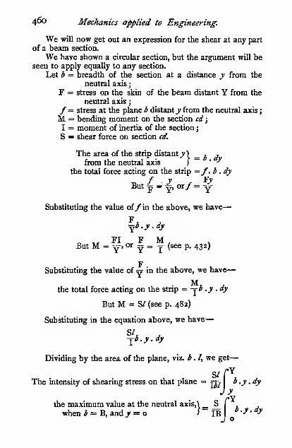
460 Mechanics applied to Engineering.
We will now get out an expression for the shear at any part
of a beam section.
We have shown a circular section, but the argument will beseen to apply equally to any section.
Let b = breadth of the section at a distance y from the
neutral axis
;
F = stress on the skin of the beam distant Y from the
neutral axis
;
/ = stress at the plane b distant y from the neutral axis
;
M = bending moment on the section cd
;
I = moment of inertia of the sectionj
S = shear force on section cd.
The area of the strip distant j*) _ i jfrom the neutral axis )
~" "
the total force acting on the strip =f.b.dyf V Fy
But|=^, or/= y-
Substituting the value of/ in the above, we have
—
^b.y.dy
„ „ FI F M,
But M = Y>""^ y = Y (see p. 432)
FSubstituting the value of y ii the above, we have
—
the total force actmg on the stnp = -jO .y .ay
But M = S/ (see p. 482)
Substituting in the equation above, we have
—
-^b.y.dy
Dividing by the area of the plane, viz. b.I,v{e get
—
S/fYThe intensity of shearing stress. on that plane = fl> I
b.y.dy
J y
JYD.y.dy

Beams. 461
gthe mean intensity of shear stress = -r
nrhcre A = the area of the section.
S fYIB
^-y-^yThe ratio of the maximum"! _ J o
intensity to the meanJ
~s
A
IBJoK = — b.y.dy
The value of K is easily obtained by this expression for
geometrical figures, but for such sections as tram-rails a graphic
solution must be resorted to.
riThe value of I b.y.dyi^ the sum of the
moments of all the small areas b . dy about the
N.A., between the limits of _y = o, i.e. starting fromthe N.A., and J = Y, which is the moment of the ^'°' ^^'"
shaded area Aj about the N.A., viz. AiY„ where Y, is the
distance of the centre of gravity of the shaded area fromthe N.A.
Since the neutral axis passes through the centre of gravity
of the section, the above quantity will be the same whether the
moments be taken above or below the N.A.
Deflection due to Shear.—The shear in ieam sections
increases the deflection over and above that due to the
bending moment. The shear effect is negligible in solid
beanie of ordinary proportions, but in the case of beams havingnatrow webs, especially when the length of span is small com-pared to the depth of the section, the shear deflection may be3o or 30 per cent, of the total.
Consider a short cantilever of length /, loaded at the free
end. The deflection due to shear is x. For the present the
deflection due to the bending moment is neglected.
Work done by W in deflecting the beam by shear = —2
Let the force required to deflect the strip of area hdh
through the distance x be d^, let the shear stress in the strip
be/„ then
—

462 Mechanics applied to Engineering.
X f, dWG Gbdh
V
(see page 376)
(fW =ffidh

Beams. 463
Work done in deflecting the strip by) _ xd'W _fflbdhshear 5
- ~^ - 2GTotal work done in deflecting the) / V^i
-fih^j, _ ^^beam section by shear j ~ ^j _^ -'• '"^"' ~~
Let a be the area of the modulus figure between h and Hi.
Let /i be the skin stress due to bending. The total longi-
tudinal force acting on the portion of the beam section betweenh and Hi is a/i, and the shear area over which this force is
distributed is bl, hence /, = -^, since the shear is constant
throughout the length.
WG/i_H, 6 ~WG//Hi ay/i
where Ao = / —7—; which is the area of the figure mno^
between the limits Hj and — H2, Substituting the value of
/i in terms of the bending moment M and the modulus of the
section Zj
AqM^ _ sAqM^
*~WGZl^~2WEZlVSAoW/
X = " -3 for a cantilever, and the total
deflection at the free end of a cantilever with an end load,
due to bending and shear, is
—
^=.S + x =^ + ^E2? ^^^^ P^^® 5^°^
and for a beam of length L = 2/ supporting a central load
Wi= 2W
^ W,U 5A„WiL
48EI''" SEZi^
WiL/U; sAA\6I
"^Z,= /
and E =8A \6I '
Zi=
In the case of beams of such sections as rectangles andcircles the deflection due to shear is very small and is usually

464 Mechanics applied to Engineering.
negligible, especially when the ratio of length to depth is
great.
In the case of plate web sections, rolled joists, braced
girders, etc., the deflection due to the shear is by no meansnegligible. In textbooks on bridge work it is often stated
that the central deflection of a girder is always greater than
that calculated by the usual bending formula, on account of
the "give" in the riveted joints between the web and the
flanges. It is probable that a structure may take a "permanentset " due to this cause after its first loading, but after this has
once occurred, it is unreasonable to suppose that the riveted
joints materially affect the deflection ; indeed, if one calculates
the deflection due to both bending and shear, it will be found
to agree well with the observed deflection. Bridge engineers
often use the ordinary deflection formula for bending, and take
a lower modulus of elasticity (about 9000 to 10,000 tons square
inch) to allow for the shear.
Experiments on the Deflection of I Sections.

Beams. 46s
area of mnop was afterwards multiplied by 4. The original
drawing has been reduced to 0-405 of full size to suit the size
of page.
a in square inches.

466 Mechanics applied to Engineering.
Deflection due to shear 32!Deflection due to bending
1^, the shear deflection is about 2 per cent, ofTaking — as
the bending deflection.
Discrepancies between Experiment and Theory.
—
Far too much is usually made of the slight discrepancies
between experiments and the theory of beams ; it has mainly
arisen through an improper application of the beam formula,
and to the use of very imperfect appliances for measuring the
elastic deflection of beams.
The discrepancies may be dealt with under three heads
—
(r) Discrepancies below the elastic limit
(2) » at
(3) ..after
(1) The discrepancies below the elastic limit are partly dueto the fact that the modulus of elasticity (E^) in compression is
not always the same as inCompression- tension (E,).
For example, suppose a
piece of material to be tested
by pure tension for E„ andthe same piece of material
to be afterwards tested as a
beam for Ej (modulus of
elasticity from a bendingtest) ; then, by the usual beamtheory, the two results should
be identical, but in the case^"'- ts'- of cast materials it will pro-
bably be found that the bending test will give the higher
result ; for if, as is often the case, the E„ is greater than the E„the compression area A„ of the modulus figure will be smaller
than the tension area A,, for the tensions and compressions
form a couple, and AcE„ = A,E,. The modulus of the section
will now be A. X D, or IM x y^r^'/TT4 V -Ci, + V Jit
fifA TjuhejtE^'Be
X D ; thus the Z is
1 /Fincreased in the ratio . °.„ . If the E, be 10 per cent.
^E. + ^E,'

Beams. 46;
greater than E„ the Ej found from the beam will be about
2 "5 per cent, greater than the E, found by pure traction.
This difference in the elasticity will certainly account for
considerable discrepancies, and will nearly always tend to
make the Ej greater than E,. There is also another dis-
crepancy which has a similar tendency, viz. that some materials
do r^ot. perfectly obey Hooke's law; the strain increases slightly
more rapidly than the stress (see p. 364). This tends to
increase the size of the modulus figures, as shown exaggeratedin dotted lines, and thereby to increase the value of Z, whichagain tends to increase its strength and stiffness, and con-
sequently make the E5 greater than E,.,
On the other hand, the deflection due to the shear (see
p. 463) is usually neglected in calculating the value Ej, whichconsequently tends to make the deflection
greater than calculated, and reduces the value
of Ej. And, again, experimenters often mea-sure the deflection between the bottom of
the beam and the supports as shown (Fig.
458). The supports slightly indent the beamwhen loaded, and they moreover spring
slightly, both of which tend to make the
deflection greater than it should be, and con-
sequently reduce the value of Ej.
The discrepancies, however, betweentheory and experiment in the case of beams which are not
loaded beyond the elastic limit are very, very small, far smaller
than the errors usually made in estimating the loads onbeams.
(2) The discrepancies at the elastic limit are more imaginary
than real. A beam is usually assumed to pass the elastic limit
when the rate of increase of the
deflection per unit increase of
load increases rapidly, i.e. whenthe slope of the tangent to the
load-deflection diagram increases
rapidly, or when a marked per-
manent set is produced, but the
load at which- this occurs is far beyond the true elastic
limit of the material. In the case of a tension bar the
stress is evenly distributed over any cross-section, hence the
whole section of the bar passes the elastic limit at the same
instant; but in the case of a beam the stress is not evenly
distributed, consequently only a very thin skin of the metal
Fic.,
Fig. 458.

468 Mechanics applied to Engineering.
passes the elastic limit at first, while the rest of the section
remains elastic, hence there cannot possibly be a sudden
increase in the strain (deflection) such as is experienced in
tension. When the load is removed, the elastic portion of the
section restores the beam to very nearly its original form, andthus prevents any marked permanent set. Further, in the case
of a tension specimen, the sudden stretch at the elastic limit
occurs over the whole length of the bar, but in a beam only
over a very small part of the length, viz. just where the
bending moment is a maximum, hence the load at which the
sudden stretch occurs is much less definitely marked in a beamthan in a tension bar. .
In the case of a beam of, say, mild steel, the distribution
of stress in a section just after passing the elastic limit is
approximately that shown in the shadedmodulus figure of Fig. 459, whereas if the
material had remained perfectly elastic, it
would have been that indicated by the
triangles aob. By the methods describedin the next chapter, the deflection after the
elastic limit can be calculated, and therebyit can be readily shown that the rate of
increase in the deflection for stresses far
above the elastic limit is very gradual, hence it is practically
impossible to detect the true elastic limit of a piece of material
from an ordinary bendingtest. Results of tests will
be found in the Appendix.
(3) The discrepanciesafter the elastic limit haveoccurred. The word "dis-crepancy" shouldnotbe usedin this connection at all, for
if there is oneprinciple aboveall others that is laid downin the beam theory, it is that
the material is taken to be perfectly elastic, i.e. that it has notpassed the elastic limit, and yet one is constantly hearing of the" error in the beam theory," because it does not hold underconditions in which the theory expressly states that it will nothold. But, for the sake of those who wish to account for theapparent error, they can do it approximately in the followingway. The beam theory assumes the stress to be proportionalto the distance from the neutral axis, or to vary as shown by the
Fig. 459.
Fig. 460.

Beams. 469
line ab ; under such conditions we get the usual modulus figure.
When, however, the beam is loaded beyond the elastic limit,
the distribution of stress in the section is shown by the line
adb, hence the width of the modulus figure must be increased
in the ratio of the widths of the two curves as shown, and the
Z thus corrected is the shaded area X D as before.^ This in
many instances will entirely account for the so-called error.
Similar figures corrected in this manner are shown below,
from which it will be seen that the difference is much greater
in the circle than in the rolled joist, and, for obvious reasons,
it will be seen that the difference is greatest in those sections
in which much material is concentrated about the neutral axis.
Fig. 461. Fig. 462.
But before leaving this subject the author would warnreaders against such reasoning as this. The actual breaking
strength of a beam is very much higher than the breaking
strength calculated by the beam formula, hence much greater
stresses may be allowed on beams than in the same material in
tension and compression. Such reasoning is utterly misleading,
for the apparent error only occurs afkr the elastic limit has
been passed.
Reinforced Concrete Beams.—The tensile strength of
concrete is from 80 to 250 pounds per square inch, but the
compressive strength is from 1500 to 5000 pounds per square
inch. Hence a concrete beam of symmetrical section will always
fail in tension long before the compressive stress reaches its
' Readers should refer to Proceedings I.C.E., vol. cxlix. p. 313. It
should also be remembered that when one speaks of the tensile strength of
a piece of material, one always refers to the nominal tensile strength, not
to the real; the difference, of course, is due to the reduction of the section
as the test proceeds. Now, no such reduction in the Z occurs in the beam,hence we must multiply this corrected Z by the ratio of the real to the
nominal tensile stress at the maximum load.

470 Mechanics applied to Engineering.
ultimate value. In order to strengthen the tension side of the
beam, iron or steel rods are embedded in the concrete, it is
then known as a reinforced beam. The position of the neutral
axis of the section can be obtained thus
—
Let E = the modulus of elasticity of the rods.
E„ = the „ „ „ concrete.
E ,r = :^ = from lo to 12.
/ = the tensile stress in the rods.
/, = the maximum compressive stress in the concrete.
a = the combined sectional area of the rods in square
inches.
The tension in the concrete
may be neglected owing to the
fact that it generally cracks at
quite a low stress. It is as-
sunied that originally plane
sections of the beam remain
plane after loading, hence the
strain varies directly as the
distance from the neutral axis,
or
i^ = - and '- =
The total compressive force acting on the concrete is equal
to the total tensile force acting on the rods, then for a section
of breadth b.
he"
E.
bi?
c Eor bcx - = a=r X e
2 E,
which may be written — =(</
obtained.
c)ra, from which c can be
The quantity bcX - is the moment of the concrete area
about the neutral axis, and a— x « is the moment of the rodE.

Beams. 47
1
area, increased in the ratio r of the two moduli of elasticity,
also about the neutral axis. Hence if the sectional area of
the rods be increased in the ratio of the modulus of elasticity
of the rods to that of the concrete the neutral axis passes
through the centre of gravity, or the centroid, of the section
when thus corrected as shown in Fig. 464.The moment of resistance of the section (/Z) is, when
considering the stress in the concrete,
/o(7)(^+^) or /„©(§. -f.)
and when considering the stress in the rods—
fa{g-\-e) or fa{^c-\-e)
The working stress in the concrete /, is usually taken
from 400 lbs. to 600 lbs. per square inch, and / from 10,000
lbs. to 16,000 lbs. per square inch.
For the greatest economy in the reinforcements, the momentof resistance of the concrete should be equal to that of the
rods, but if they are not equal in any given case, the lower
value should be taken.
The modulus of the section for the concrete side is—
and the corresponding moment of inertia
—
Similarly, in the case of the reinforced side of the section
—
I = aer^^c + e\
Example.—Total depth of section 18 inches; breadth
6 inches, four rods | inch diameter, distance of centres frombottom edge i| inch, the compressive stress in the concrete
400 lbs. per square inch, r ~ 12. Find the moment of
resistance of the section, the stress in the rods, and the
moment of inertia of the section.
In this case d= 16 '5 inches, a = 0-785 square inch.
—^=(i6-5 -^)i2 X 0-785
c = 5-8 inches. e = 10-7 inches.

472 Mechanics applied to Engineering.
Moment of resistance for the concrete
—
For the stress in the rods
—
^2 X 5-8/Xo-78s(' + 107j= loi,400 inch-lbs.
/= 8860 lbs. per square inch
The moment of inertia
—
/6 X 5'8'V2 X 5-8,
\ . , 4 .,
(-^— 11
2 Y 107 I= 1470 mch -units
or
(0785 X 107 1470 inch*-units
Fig. 465.
In reinforced concrete floors, the upper portion is a part
of the floor; at intervals reinforced beams are arranged as
shown.Example.—^Total depth = 24 inches, thickness of floor it)
= 4 inches, breadth {b) = 22 inches, breadth of web (J>')= 7
inches. Six |" rods, the centres of which are I's" from the
tension skin. Compressive stress in concrete (/„) 400 lbs.
per sq. inch. /= 12. Find the moment of resistance, the
stress in the rods, and the moment of inertia.
Here d = 22*5 inches a = 2'6s square inches.
Position of neutral axis
—
22 X 4{c - 2) -f 7^^ ^ = 2-65 X 12(22-5 - c)
c=r^s' ^ = 3-15" <?= i5'35

Beams 473
Moment of resistance of concrete—
\^(! X 7'i5 + 15-34) - (^^-^J3-i5
X ^(1 X 3'iS + iS'35)|4oo(i4oo)4oo = 560,000 in.-lbs.
Stress on rods
—
560,000 =/ X 2-65 X 20'I
/= 10,500 lbs. square inch.
Moment of inertia
—
1400 X 7"1 5 = 10,000 inch*-units
or 2-65 X 15-35 X 12 X 20-I = 9810 „ „
In order to get the two values to agree exactly it would benecessary to express c to three places of decimals.
For further details of the design of reinforced concrete
beams, books specially devoted to the subject should beconsulted.

CHAPTER XII.
BENDING MOMENTS AND SHEAR FORCES.
Bending Moments.— When two ^ equal and opposite couples
are applied at opposite ends'y'/'/y':/i of a bar in suck a manner
as to tend to rotate it in
opposite directions, the bar
is said to be subjected to a
bending moment.
Thus, in Fig. 466, the
bar ab is subjected to the
two equal and opposite
couples R . ac and W . be,
which tend to make the
two parts of the bar rotate
in opposite directions round the points; or, in other words,
they tend to bend the bar.
iR*W
Fig. 466.
W-R,+lf2
Fig. 467.
Loa/i.
Svpj ^ort
\lioaei
hence the term "bendingmoment." Likewise in Fig.
467 the couples are RiOfand Ra^iT, which have the
same effect as the couples
in Fig. 466. The bar in
Fig. 466 is termed a " canti-
lever." The couple
R . af is due to the
resistance of the wall
into which it is built.
The bar in Fig. 467is termed a " beam."
When a cantilever
or beam is subjected
to a bending momentwhich tends to bend it
If there be more than two couples, they can always be reduced to two
Stj^ tport

Bending Moments and Shear Forces. 475
Fig. 469.
concave upwards, as in Fig. 468 (a), the bending moment will betermed positive (+), and when it tends to bend it the reverse
way, as in Fig. 468 {b), it will be termed negative (— ).
Bending-moment Diagrams.—In order to show the
variation of the bending moments at various parts of a beam,we frequently make use of bending-moment diagrams. Thebending moment at the point cin Fig. 469 is W . ^tf ; set downfrom c the ordinate ct^ = 'W .be
on some given scale. The bend-ing moment at d=Vf .bd; set
down from d, the ordinate
dd' = W .bd on the same scale
;
and so on for any number of
points : then, as the bendingmoment at any point increases directly as the distance of that
point from W, the points b, d', c, etc., will lie on a straight line.
Join up these points as shown, then the depth of the diagram
below any point in the beam represents on the given scale the
bending moment at that point. This diagram is termed a" bending-moment diagram."
In precisely the same manner the diagram in Fig. 470 is
obtained. The ordinate
ddi represents on a given
scale the bending mo-ment Ri«(f, likewise cci
the bending momentRioc or Ra^c, also ee^ the
bending moment Rj>e.
The reactions Ri andRj are easily found bythe principlesofmomentsthus. Taking moments about the point b, we have
—
Fig. 470.
R^ab = Wbc Ri = W.bcab
R, = W-R,
In the cantilever in Fig. 469, let W = 800 lbs., be = 675feet, bd = 4-5 feet.
The bending moment ai c = W .be
= 800 (lbs.) X 6-75 (feet)
= 5400 (Ibs.-feet)
Let I inch on the bending-moment diagram = 12,000 (lbs.-
, /ii. r ,.\ u 12000 Ibs.-feet
feet), or a scale of 1 2,000 (Ibs.-feet) per inch, or j-.—j-v—
.

476 Mechanics applied to Engineering.
^, , !• S400 (Ibs.-feet) ,. ,
.
Then the ordinate ec, = ,,, , \ = 0*45 (inch)' 12000 (Ibs.-feet) ^^ ^ '
I (inch)
Measuring the ordinate dd^, we find it to be 0*3 inch.
Then 0-3 (inch) X"°°° O^s-feet) ^ ^3600 (Ibs.-feet) bending
•^ ^ ' I (inch) ( moment at a
In this instance the bending moment could hav£ beenobtained as readily by direct calculation; but in the great
majority of cases, the calculation of the bending moment is
long and tedious, and can be very readily found from a
diagram.
In the beam (Fig. 470), let W = 1200 lbs., ac= $ feet,
dc= 5 feet, ad= 2 feet.
yv .be 1200 (lbs.) X 3 (feet)
R>=^r= 8 (feet)=450 lbs.
the bending moment at ^ = 450 (lbs.) X 5 (feet)
= 2250 (lbs.-feet)
Let 1 inch on the bending-moment diagram = 4000 Ibs.-
4000 (lbs.-feet)feet), or a scale of 4000 (lbs.-feet) per mch, or ) . >
— •
™, , ,- 2250 (lbs.-feet) , ,. ,
.
Then the ordinate cc, = ,,, ^ J. = o'go (mch)' 4000 (lbs.-feet) •' ^ '
I (inch)
Measuring the ordinate ddi, we find it to be 0*225 (inch).
„, 0-225 (inch) X 4000 (lbs.-feet) ^ 1 900 (lbs.-feet) bendingI (inch) ( moment at (/
General Case of Bending IVEoments.
—
Tke bending
moment at any section of a beam is t}u algebraic sum of all the
moments of the externalforces about the section acting either to the
left or to the right of the section.
Thus the bending moment at the section/ in Fig. 471 is,
taking moments to the left of/—
or, taking moments to the right of/—

Bendinsr Moments and Shear Forces. All
That the same result is obtained in both cases is easily
verified by taking a numerical example.
Let Wj = 30 lbs., W2 = 50 lbs., W3 = 40 lbs.; ac = 2 feet,
cd = 2*5 feet, df = i'8 feet,/^ = 2-2 feet, eb = ^ feet.
W,W2
w.
or f
R.
Fio. 471.
We must first calculate the values of Ri and Ra. Takingmoments about b, we have
—
.
R,«^ = V^^cb + y^^db + ^^b„ W,<r^ + ^^b + Ws^-J^' ^_ 3o(lbs.) X 9-5(feet)+5o(lbs.) X 7(feet)+4o(lbs.) X 3(feet
)
11-5 (feet)
\=755 0bs-feet)^
11-5 (feet) ^ ^
.R,=Wi + Wa + W3-R,R, =3o(lbs.)+So(lbs.)+4o(lbs.)-6s-6s (lbs.)= 54-3S (lbs.)
The bending moment at/, taking moments to the left of/,
= Ri«/-Wie^-W3^= 65-65 (lbs.) X 6-3 (feet) - 30 (lbs.) X 4"3 (feet) - 50 (lbs.)
X I -8 (feet) = 194-6 (lbs.-feet)
The bending moment at/, taking moments to the right oif,
= R,bf- Wsef= 54'3S (lbs.) X 5-2 (feet) — 40 (lbs.) X 22 (feet)
= 194-6 (lbs.-feet)
Thus the bending moment at / is the same whether we take
moments to the right or to the left of the point/ Thecalculation of it by both ways gives an excellent check on the
accuracy of the working, but generally we shall choose that
side of the section that involves the least amount of calculation.
Thus, in the case above, we should have taken moments to the
right of the section, for that only involves the calculation of two
moments, whereas if we had taken it to the left it would have
involved three moments.

478 Mechanics applied to Engineering.
The above method becomes very tedious when dealing
with many loads. For such cases we shall adopt graphical
methods.
Shearing Forces.—When couples are applied to a beamin the way described above, the beam is not only subjected to
a bending moment, but also to a shearing action. In a long
beam or cantilever, the bending is by far the most important,
but a short stumpy beam or cantilever will nearly always fail
by shear.
Let the cantilever in Fig. 472 be loaded until it fails. It

Bending Moments and Shear Forces. 479
When the sheared part slides in a Iclockwise \
'^t contra-clockwise J
direction relatively to the fixed part, we term it a
(positive {A-) shear)
(negative (— ) shear)
Shear Diagrams.—In order to show clearly the amountof shear at various sections of a beam, we frequently makeuse of shear diagrams. In cases in which the shear is partly
positive and partly negative, we shall invariably place the
positive part of the shear diagram above the base-line, and the
negative part below the base-line. Attention to this point will
save endless trouble.
In Fig. 472, the shear is positive and constant at all vertical
sections, and equal to W. This is very simply represented
graphically by constructing a diagram immediately under the
beam or cantilever of the same length, and whose depth is
equal to W on some given scale, then the depth of this diagramat every point represents on the same scale the shear at that
point. Usually the shear diagram will not be of uniform depth.
The construction for various cases will be shortly considered.
It will be found that its use greatly facilitates all calculations of
the shear in girders, beams, etc.
In Fig. 47 3, the shear at all sections between a and c is
constant and equal to Rj. It is also positive (-[-), because the
slide takes place in a clockwise direction ; and, again, the shear
at all sections between b and c is constant and equal to Rj, but
it is of negative (— ) sign, because the slide takes place in a
contra-clockwise direction ; hence the shear diagram betweena and c will be above the base-line, and that between b and c
below the line, as shown in the diagram. The shear changes
sign immediately under the load, and the resultant shear at that
section is Rj— R^.
General Case of Shear,—The shear at any section of a
beam or cantilever is the algebraic sum of all the forces acting to
the right or to the left of that section.
One example will serve to make this clear.
In Fig. 475 three forces are shown acting on the canti-
lever fixed at d, two acting downwards, and one acting
upwards.
The shear at any section between a and d = -fW due to W„ b „ rf=-W, „ W,
.. ,. .. c „ d= -t-Wj „ W,

48o Mechanics applied to Engineering.
Construct the diagrams separately for each shear as shown,
then combine by superposing the — diagram on the + diagram.
The unshaded portion shows where the — shear neutralizes the
«S
W,
W
m>
m
iili

Bending Moments and Shear Forces. 481
Resultant shear at any section
—

482 Mechanics applied to Engineering.
- W/i + Wj/j, i.e. to the bending moment at a. Hence weget this relation
—
The bending moment at any section of a freely supported
beam is equal to the area of the shear diagram up to that point.
The bending moment is therefore a maximum where the shear
changes sign.
w.

Bending Moments and Shear Forces. 483
The area of the negative part of the shear diagram belowthe base-line is — o'4oi sq. inch, and the positive part above the
base-line is 0*056 sq. inch; thus the area of the shear diagramup to the section a is — o'4oi + o"o56 = 0*345 sq. inch. ButI sq. inch on the shear diagram = 640 (Ibs.-feet) bendingmoment, thus the bending moment at the section a =o*345 X 640 = 221 (Ibs.-feet). The area of the shear diagramto the left of a = o'345 sq. inch, i.e. the same as the area to the
right of the section. As a check on the above, we will calculate
the bending moment at a by the direct method, thus
—
The bending moment at a = W^^ + W/j — W/4= 80 (lbs.) X 2 (feet) + 70 (lbs.) X
4 (feet) - 132-2 (lbs.) X 5 (feet)
= 221 (Ibs.-feet)
which is the same result as we obtained above from the shear
diagram.
This interesting connection between the two diagrams canbe shown to hold in all cases from load to slope diagrams. If
a beam supports a distributed load, it can be represented at
every part of the beam by means of a diagram whose height is
proportional to the load at each point ; then the amount of load
between the abutment and any given point is proportional to
the area of the load diagram over that portion of the beam.But we have shown that the shear at any section is the algebraic
sum of all the forces acting either to the right or to the left of
that section, whence the shear at that section is equal to the
reaction minus the area of the load diagram between the section
in question and the said reaction. We have already shown the
connection between the shear and bending moment diagrams,
and we shall shortly show that the slope between a tangent to
the bent beam at any point and any other point is proportional
to the area of the bending-moment diagram enclosed by normals
to the bent beam drawn through those points.

484 Mechanics applied to Engineering.
Cantilever with
single load at
free end.
Fig. 477.
Cantilever with
two loads.
W*w,
Fig. 478.

Bending Moments and SJiear Forces. 485
Bending moment M in
ll».-incheft
= W(lbs.)X/(in.)M, = W/,M = (/. mn
at any section whered= depth ofberiding-moment diagram in
inches
Depth of bend-in^-momentdlagnun In
mches.
Scale of W,m lbs. = 1 indi.
Scale of/,
-full size.
W/mn
mn
Remarks.
The only moment acting to the right
of X is W/, which is therefore the
bending moment at x. Likewise at^.
The complete statement of the units
for the depth of the bending-momentdiagram is as follows :
—
xn(lbs.)= i inch on diagram, or -^.—
^
^ ' ^ ' l{mch)«(in.)=l „ „W (lbs.) /,(inches) W/m (lbs.)
I inch
n (inches) mti(inches)
M = 1/ . mn mn
This is a simple case of combiningtwo such bending-moment diagramsas we had above. The lower one is
tilted up from the diagram shown in
dotted lines.

486 Mechanics applied to Engineering.
Cantilever with
an evenly distri-
buted load of wlbs. per inch run.
Cfg.ofloads
Hendiuruf TTvoTnentff
apfix-

Bending Moments and S/iear Forces. 487
Bending moment M in
lbs.-inche8.
Mx = iv?
w(\hi, ) ^(inches)'
inches 2 (constant)
- ^.p (Ibs.-inches)
constant
Let W = o)/
Depth 3f bend-inc-momentdiagram in
inches.
Scale of r/,m lbs.=si inch.
Scale of/,
- full size.
2
M = 1/ , mn
W/2mn
Remarks.
Tn statics any system of forces mayalways be replaced by their resultant,
which in this case issiluatedat the centreof gravity of the loads ; and as the dis-
tribution of the loading is uniform, the
resultant acts'^t a distance - from x.2
The total load on the beam is wl, orW ; hence the bending moment at *
/ wl'= wl X —=. At any other sec-22
tion, V = wl. X - = —=-,^ '2 2Thus the
bending moment at any section varies
as the square of the distance of thesection from the free end of the beam,therefore the bending moment dia-p;ram is a parabola. As the beamis fully covered irith Ioad.s, the sumof the forces to the right of anysection varies directly as the lengthof the beam to the right of thesection ; therefore the shearing forceat any section varies directly as thedistance of that section from the free
end of the beam, and the depth of theshearing-force diagram varies in like
manner, and is therefore triangular,
with the apex at the free end asshown, and the depth at any pointdistant /, from the free end is wl,, i.e.
the sum of the loads to the right of /,,
aird the area of the shear diagram up
to that point is ^?i2iZ« = !<, ,-.,.•^
2 2the bending moment at that point.

488 Mechanics applied to Engineering.
Cantilever irregu-
larly loaded.
Fig. 480.
Beam supportedat both ends, with
a central load.
Fig. 481.

Bending Moments and Shear Forces. 489
Bending momentMm
lbs.-inches.
M«=W/+W,/,
"*"2
M = </ . mn
Depth of bending'moment diagram
in inches.
Scale of W,m lbs. ^ X inch.
Scale of/,
- full siM.
to/."
Remarks.
This is simply a case of the combina-tion of the diagrams in Figs. 478 and 479.However complex the loading maybe, this method can always be adopted,
although the graphic method to bedescribed later on is generally moreconvenient for many loads.
w/

490 Mechanics applied to Engineering.
Beam supported
at both ends, with
one load not in the
middle of the span.
Fig. 482.
Beam supportedat both ends, with
two symmetrically
placed loads.
R'W
Fio. 483,

Bending Moments and Shear Forces. 491
Bending momentMin
Ibs.-inchcBi
WM.= y(AA)
M = </ . mn
Depth of bending-moment diagram
in inches.
Scale of W,It lbs. = I inch.
Scale of /p
- full size.
Imn
Remarks.
Taking moments about one support,
we have R,/ = W/,, or R, = H4. The
bending moment at x—W.M. = R,/, = -^(/,4)
M, = W4M„ = W/.M = </, mn
W4mn
The beam being symmetricallyloaded, each abutment takes one weight= W = R.
The only moment to the right ortheright-hand section ;ir is W . 4 ; likewisewith the left-hand section.
At any other section y between theloads, and distant /v from one of them,we have, taking moments to the left of
y, R{4 + /,) - W . /, = R . 4 + R . /,- R . 4 = R . 4 01 W . 4, ».«. thebending moment is constant betweenthe two loads.
The sum of the forces to the right orleft aiy_ = W — R = o, and to the right
of the right-hand section the sum of theforces = R,= W at every section.

492 Mechanics applied to Engineering.
Beam supportedat both ends, load
evenly distributed,
w lbs. per inch run.
Fig. 484.

Bending Moments and Shear Forces. 493
Bendingmoment M inlbs.-incbes.
Let W = a//
Mx =8
N.B.—Bevery caieful
to reduce the
distributedload topounds perinth tun if
the dimen-sions of the
beam are in
inelus.
Depth of
bending-momentdiagramin inches.
ScaleofW,Mlbs.s 1 inch.
Scale of/,
— full WBt.
Remarks.
As in the case of the uniformly loaded cantilever,
we must replace the system of forces by their
resultant.
The load being symmetrically placed, the abut-
ments each take one-half the load =— •
2Then, taking moments to the left of *, we have
—
wl wl I
2 ^a 2^4-wP8
wlThe — shown midway between x and the abut-
ment is the resultant of the loads on half the beam,
acting at the centre of gravity of the load, viz. -4
from X, or the abutment. ,
The bending moment at any other section y,distant I, from the abutment, is : taking momentsto the right oty—wl , ,
ly '"'ly,.
=f<4««.?(^)where I,' = I — /,.
Thus the bending moment at any section is
proportional to the product of the segments intowhich the section divides the beam. Hence thebending-moment diagram is a parabola, with its
axis vertical and under the middle of the beam as
shown.The forces acting to the right of the section x =
=^0 ; i.e. the shear at the middle section2 2is zero.
Atthe section>=i»/,-^ = w (/,--). Hence
the shear varies inversely as the distance from theabutment, and at the abutment, where 4 = o, it is
wl

494 Mechanics applied to Engineering,
Beam supported
at two points equi-
distant from the
ends, and a load
of w lbs. per inch
run evenly distri-
buted.
PCTTTTYTXTY^I ^ y f ]
* ij >i ^/ -11-. -^-->
J\re^ative B. M. thteto dvorhanffTr^ loads
Positive B. If^eh^e^^centred- ^euv
ComhmeA B. M.
SJvear
Fio. 485.

Bending Mommts mid Shear Forces. 495

496 Mechanics applied to Engineering.
Beam supported
at each end andirregularly loaded.
FlQ. 486.

Bending Moments and Shear Forces. 497
Bending
MinIbs.-inches.
Depth of bend'ing-momentdiagramin inches.
Scale ofW.M lbs.=i inch.
Scale of/,
— full size.
Msid , mnmnor
mnetc
Remarks,
The method shown in the upper figure is
simply that of drawing in the triangular bending-moment diagram for each load treated separately,
as in Fig. 481, then adding the ordinates of eachto form the final diagram by stepping off with apair of dividers.
In the lower diagram, the heights ag,gh, etc.,
are set off on the vertical drawn through the abut-ment = W,/„ Wj/j, etc., as shown. The sumof these, of course, = R,/. From the starting-
point a draw a sloping line ai, cutting thevertical through W, m the point b. Join gb andproduce to e, join he and produce to d, and soon, till the point/ is readied ; join fa, whichcompletes the bending-moment dis^am abcdcf,
the depth of which in inches multiplied by mngives the bending moment. The proof of theconstruction is as follows : The bending momentat any point * is R,4 — W^^,.
On the bending-moment diagram-^= j-; or
R./X4K/ =^ = = =R,/.
0/if X /. W,/, X r. = W/.
and the depth ofl
the bending-mo- >=KO=K/-0/=R/,- W^r,ment diagram )
It will be observed that this construction
does not involve the calculation of R, and R,.For the shear diagram R, can be obtained thus
:
Measure off of in inches ; then -^—z = R^,
where / is the actual length of the beam ininches.

49^ Mechanics applied to Engineering.
Beam supportedat the ends andirregularly loaded.

Bending Moments and Shear Forces. 499
Bendtne momentMin
IbS'-incbes.
M = )n.n(DxOk)
Remakks.
Make the height of the load lines on the beam propor-
tional to the loads, Tu. —i.W,
etc., inches. Drop
perpendiculars through each as shown. On a vertical fb\V W
set ofify!r = — , ed = —?, etc. Choose any convenient
point O distant Oh from the vertical. Ok is termed the"polar distance." JoinyO, <0, etc. From any pointyon the line passing through R, draw a line/m parallel to
_/0 ; from m draw mK parallel to eO, and so on, till theline through R, is reached in g. Join gf, and draw Oa onthe vector polygon parallel to this last line ; then thereaction R, =_/a, and Rj = ia. Then the vertical depthof the bending-moment diagram at any given section is
proportional to the bending moment at that section.
Proof.—The two trianglesjr^wj and Oafaxe similar, for
Jm is parallel to/D, axA jp to aO, and/w iofa ; also/?is drawn at right angles to the base mp. Hence
—
height ofA ipm _ base ofA iiim
height of^ Oaf base of^ Oaf
or^ = OAmp af
. h -Ok••D.-R-,
For7^ = /i and af^ R, ; and let mp = D^, i.e. the depthof the bending-moment diagram at the section x, or R,/,= D,OA = M, = the bending moment at x.
By similar reasoning, we have
—
R,4 = rf)t.Ohalso \V,(4 - /,) = rlC X Oh
the bending moment at^ = M,, = Rj/j — W,(/j — /,)
= Oh{,rt - rK)= 0/5(K/)= OA.D,
where D, = the depth of the bending-moment diagram at
the section J/.
Thus the bending moment at any section is equal to thedepth of the diagram at that section multiplied by the
polar distance, both taken to the proper scales, which wewill now determine. The diagram is drawn so that
—
I inch on the load scale = m lbs,
I „ „ length „ = » inches.
Hence the measurements taken from the diagram in inchesmust be multiplied by mn.
The bending moment expressed \ „ ,t^ ..,,,
in lbs. .incites at any section ) = M = r«. « . (D . 0-5)

Soo Mechanics applied to Engineering.
Beam sup-
ported at twopoints with
overhanging
ends and irre-
gularly loaded.

Bending Moments and Shear- Forces. 501
Bending momentMin
lbs.-inches.
where D is the depth of the diagram in inches at that
section, and Oh is the polar distance in inches.
In Chap. IV. we showed that the resultant of such asystem of parallel forces as we have on the beam passes
through the meet of the first and last links of the link
polygon, viz. through u, where/»« cuts gh. Then, as the
whole system of loads may be replaced by the resultant,
we have Rj/j = Rj/,. But we have shown above that
the triangles juw and Oaf are similar ; hence ^ = —^.\jh of
But jv — /j, therefore af x l, = Oh x uw =: Rj/j, or
af— R,. Similarly it may be shown that ab = R^.
M= »j. «(Dx0/0
The loads are set down to the proper scale on the
vector polygon as in the last case, A pole O is chosenas before. The vertical load lines are dotted in order to
keep them distinct from the reaction lines which are
shown in full. Starting from the point/ on the reaction
line Ri, a linejm is drawn parallel to oO on the vectorpolygon, from m a line mk (in the space i) is drawnparallel to bO, and so on till the point u is reached, from« a line is drawn parallel to fO to meet the reaction line
R2 in the point g. Join Jg. From the pole O draw aline Oj parallel lojg.
Then ai gives the reaction R„ and if the reaction Rj.
The bending moment diagram is shown shaded. Thepoints where the bending moment is zero are known as
the points of contrary flexure.
The construction of the shear diagram will be evident
when it is remembered that the shear at any section is
the algebraic sum of the forces to the right or to the left
of the section.
The bending moment at any section of a beam loaded
in this manner can be readily calculated. The reactions
must first be found by taking moments about one of the
points of support. The bending moment at any section
X distant 4 from the load ^is
Mx = Tdli + 7el, - R,/, + rf/x
and the distance ig of the point of contrary flexure fromthe load ef is obtained thus
/« = d^h - R.A" "" —^ . -r-
ef+de- Rj

502 MecJianics applied to Engineering.
Beam supported
at each end andloaded with anevenly distributed
load of TV lbs. per
inch run over a
part of its length.
Beam supported
at each end with
a distributed load
which varies
directly as the dis-
tance from one
end.

Bending Moments and Shear Forces. 503
BendinK momentM in
Ibs.-incbes.
MnM.= —P
Remarks.
Remembering that the bending moment at any section
is equal to the area of the shear diagram up to that section,
the maximum bending moment will occur at the sectionwhere the sliear chapges sign.
R.= 2a/4'
/
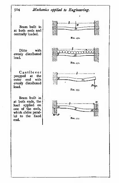
504 MecJianics applied to Engineering.
Beam built in
at both ends andcentrally loaded.
Ditto with
evenly distributed
load
Cantileverpropped at the
outer end with
evenly distributed
load.
Beam built in
at both ends, the
load applied onone of the ends,
which slides paral-
lel to the fixed
end.
(jgS
-I \
Fig. 491.
i*^ o^ ^p
Fig. 492.
l^fp.
Fig. 493.
rv
: |i
W'/fFig. 494.

Bending Moments and Shear Forces. 505
Bending momentMm
Ibs.-!nches.
M,= W/
M.=24
Mx ~128tap
M„ =
M,= —M, =
The determination of these bending moments depends
on the elastic properties of the beams, which are fully
discussed in Chap. XIII.
In all these cases the beam is shown built in at both
ends. The beams are assumed to be free endwise, and
guided so that the ends shall remain horizontal as the
beam is bent. If they were rigidly held at both ends, the
pioblem would be much more complex.
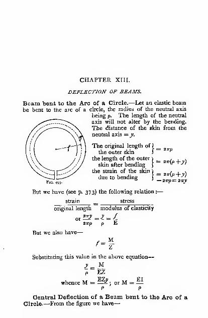
CHAPTER XIII.
DEFLECTION OF BEAMS.
Beam bent to the Arc of a Circle.—Let an elastic beambe bent to the arc of a circle, the radius of the neutral axis
being p. The length of the neutral
axis will not alter by the bending.
The distance of the skin from the
neutral axis = y.
The original length of ) _the outer skin != 27rp
Fig. 495.
the length of the outer i ^ ^, .
skin after bending)
^ "the strain of the skin ) _ , / i \
due to bending C^^^ ^'
° ' — 2irp= 27ry
But we have (see p. 373) the following relation :
—
strain _ stress
original length modulus of elasticity
2'^' _ > _ /or27rp
But we also have
—
/ =M
Substituting this value in the above equation
—
p EZ
whence M = —^ ; or M = —P P
Central Deflection of a Beam bent to the Arc of a
Circle.—From the figure we have
—

Deflection of Beams.
,-^ = (p-8)^+(L^y
S07
whence 2p8 — 8' = —4
The elastic deflection (S) of a
beam is rarely more than -p^ of
the simn (L) ; hence the 8* will
not exceed —^ , which is quite360,000 ^
negligible;
T a
hence 2pS = —4
But p=^l
8 =8p
/if V
hence 8 = ML*8EI
\Vc shall shortly give another method for arriving at this result.
General Statement regarding Deflection.— In
speaking of the deflection of a cantilever or beam, we always
mean the deflection measuredfroma line drawn tangential to that
part of the bent cantilever or
beam which remains parallel to its
unstrained position. The deflec-
tion 8 will be seen by referring to
the figures shown.The point / at which the tan-
gent touches the beam we shall
term the " tangent point." Whendealing with beams, we shall find it
convenient to speak of the deflec-
tion at the support, «.& the height
of the support above the tangent.
Deflection of a Cantilever.—Let the upper diagram(Fig. 498) represent the distribution of bending moment acting
on the cantilever, the dark line the bent cantilever, and the
straight dotted line the unstrained position of the cantilever.
Consider any very small portion ^j/, distant /, from the free end of
the cantilever. We will suppose the length jy so small that the
radius of curvature p, is the same at both points, y,y. Let the
angle subtending yy be 6, (circular measure) ; then the angle

So8 Miclianics applied to Engineering.
between the two tangents ya, yb will also be 6,. Then the
deflection at the extremity of these tangents due to the bending
between ^/.j* is—o» = ^- ^
-yyBute, =-^-^
Pi
and from p. 424, we have
—
'? EI
where M, is the mean bending
moment between the points
y^y- , . .
Then by substitution, we
have
—
^'~ EI
where Q, is the "slope" be-
tween the two tangents to the
bent beam at^_j';
But Mjj'j' = area (shown shaded) of the bending-momentdiagram between y, y
hence ^, = .gr?
Fig. 498.
and 8,
:
A/,
EI
That is, the deflection at the free end of the cantilever due
to the bending between the points y, y is numerically equal to
the moment of the portion of the bending-moment diagram
over yy about the free end of the cantilever divided by EI.
The total deflection at the free end is
—
8 = S(8, + 8. -1-, etc.)
8 = ^5A^, + A.4 -f , etc.
where the suffix x refers to any other very small portion of the
cantilever xx.
Thus the total deflection at the free end of the cantilever is

Deflection of Beams. 509
numerically equal to the sum of the moments of each little
element of area of the bending-moment diagram about the free
end of the cantilever divided by EI. But, instead of dealing
with the moment of each little element of area, we may take
the moment of the whole bending-moment diagram about the
free end, i.e. the area of the diagram X the distance of its centre
of gravity from the free end
;
or 8 =EI
where A = the area of the bending-moment diagram
;
Lc = the distance of the centre of gravity of the bending-moment diagram from the free end.
To readers familiar with the integral calculus, it will be seen
that the length that we have termed yy above, is in calculus
nomenclature dl in the limit, and the deflection at the free enddue to the bending over the elementary length dl is
—
M„. /„.<//_8,=
£1
and the total deflection between points distant L and o fromthe free end is—
« = ^IMl.dl (ii.)
where M = the bending moment at the point distant / from
the free end.
Another calculus methodcommonly used is as follows.
The slope of the beam between
P and Q (the distance PQ is
supposed to be infinitely small)
dyis denoted by — . This ratio
dxis constant if the beam is
straight, but in bent beamsthe slope varies from point to
point, and the change of slope
in a given length dx is
—
Fig. 499-
\dx'
dx dx^'

Sio Mechanics applied to Engineering.
When Q is very small dx becomes equal to the arc subtending
the angle Q, and p? = Pq = p, then -j- = —-^, in the limit
PQ = dx, and the change in slope in the length dx is
<?) .
dx
M''
ds^(iii.)
This expression will be utilized shortly for finding the deflection
in certain cases of loaded beams.
Case I.
—
Cantilever with load W on free end. Length L.
Method (i).
Fig. 50a
A = WL X - =2 2
S =
2
WL'3EI
EI
Method (ii.).—By integration
M = W/W
hence 8 = —-,
EI
'^ = ^' WL'
/=o 3EI
Method (iii.).—Consider a section of the beam distant xfrom the abutment.
d}vThe bending moment M = W(L - a;) = El-^
L — a; =
Integrating
EI^"iN d£-
L.-^Vc = |f2 Yl dx
where C is the integration constant. When x = o the slope
dy-r is also zero, hence C = o.ax

Deflection of Beams. S"
Integrating again
—
L^= x"^, ^^ EI
2 6 WWhen * = o, the deflection y is zero, hence K = o and
_ WL^ _ ^\•''"
E[\ 2 6/
which gives the deflection of the beam at any point distant xfrom the abutment. An exactly similar expression can beobtained by method (i.).
The deflection S at the free end of the beam where:r = L is
—
'=iEI
In this particular case the result could be obtained muchmore readily by methods (i.) and (ii.).
Case II.
—
Cantilever with load W evenly distributed or wper -unit length. Length L.
Method (i.)—
XfLx^
8 =wL*
8EI8EI
or by integration
—
Method (lu) M =
hence S =
/=Ll\, wJJ

512 Mechanics applied to Engineering.
Method (iii.)— Consider a section distant x from the
abutment.
rr^, , ,• ,, K'fL — xf „,d^yThe bending moment M = = El-j-5
w doc
r, .x' zL^c"
,^ 2EI dy
Integratms Ux -i f- C = r32 w dx
For the reason given in Case I, C = o
. LV,
«* L^,^ 2EI
Integrating again f- K = y° 2123 w
as explained above K = o,
^ = 2lEi^^^'^ +*'-4^^^
•which gives the deflection of the beam at any point distant xfrom the abutment. This is an instance in which the valueof J* is found more readily by method (iii.) than by (i.) or (ii.).
The deflection 8 at the end of the beam where x='L is
—
_ w\} _ WL°8E1 ~ 8EI
Case III.
—
Cantilever with loadW not at thefree end.
A = WL. X ^ = ^-3 3
L, = L - ^3
2EI\^ 3Fig. 502.
•'
N.B.—The portion db is straight.
8 = S(l-L')

Deflection of Beams. 513
Case IV.
—
Cantilever with two loads Wi, Wa, neither oj
them at thefree end.
(-^)2EI \- 3
, WaL,'
Wj
Fig. S03.
Case V.— Cantilever with load unevenly distributed.
Length L.
Let the bending-moment diagram shown above the canti-
lever be obtained by the method shown on p. 487.
Then if i inch = m lbs. on the load scale
;
I inch = n inches on the length scale
;
D = depth of the bending-moment diagrammeasured in inches
;
OH = the polar distance in inches ;
M =fthe bending-moment in inch-lbs.;
M = w.w.D.OH;
hence i inch depth on the bending-moment diagram represents
M .
=r = m .n . OH mch-lbs. j and i square inch of the bending-
moment diagram represents tn .rfi . OH inch-inch-lbs. \ hence
—
f area of bending-moment N j ^;^ ^- V diagram in square inches y ^ • " '
"^ ^ ^«8=
El2 L

514 Mechanics applied to Engineering.
The deflection 8 found thus will be somewhere betweenthe deflection for a single end load and for an evenly
distributed load;
generally by inspection it can be seen
whether it will approach the one or the other condition.
Such a calculation is useful in preventing great errors fromcreeping in.
In irregularly loaded beams and cantilevers, the deflection
cannot conveniently be arrived at by an integration.
Deflection of a Beam freely supported.—Let the
lower diagram represent the distribution of bending momenton the beam. Thedark line represents the
bent beam, and the
straight dotted line the
unstrained position of
the beam. By the sameprocess of reasoning as
in the case of the
cantilever, it is readily
shown that the deflec-
tion of the free end or
the support is the sumof the moments of eachlittle area of the bend-ing-moment diagrambetween the tangentpoint and the free endabout the free end ; or,
as before, instead of
dealing with the mo-ment of each little area,
we may take the moment of the whole area of the bending-moment diagram between the free end and the tangentpoint, about the free end, i.e. the area of the bending-momentdiagram between the tangent point and the free end X distanceof the centre of gravity of this area from the free end. Then,as before
—
J^eeJBrul
Fig. 505.
AL.EI
where A and L, have the slightly modified meanings mentionedabove.

Deflection of Beams. 515
Case VI.
—
Beam loaded with central load W. Length L.
A=^xtL,=-
- ...1-
\ .? EI
8 =4WL3
Fig. 506.48EI
Or by integration, at any point distant / from the support
—
M = —i2
J
~ EI I 2 EI V6 z'
<^ n
When / = — , we have
—
2
WLs8 = .
WL»2" X 6EI 48EI
Case VII.
—
Beam loaded with an evenly distributed load wper unit length. Length L.
8 = ^'xSjxf^16 EI
S= 5^L^ _ SWL'384EI 384EI Fig. 507.
Or by integration, at any point distant / from the support (see
p. 512) the bending moment is
—
M=^(/L-/^)=^-^2^ 82
where x is the distance measured from the middle of the beamand y the vertical height of the point above the tangent at the
middle of the beam. Then by method (iii.)
—
d'y wU wx2

5i6 Mechanics applied to Engineering.
^^^ = "8 6" + ^
16
•w
(C = o)
(K = o)
. so/L* sWL' ^ Lo = - „, = o „T when * = -
384EI 384EI 2
Case VIII.
—
Beam loaded with two equal weights symmetri-
cally placed.—By taking the*f W moments ofthe triangular area
._^_ i^ _:^ abc and the rectangle bced, the
--Z/— — i.^—^y—-i---, deflection becomes
—
and when L, = L2 = — , this
3
c eFig. 508.
expression becomes
—
„ 23WL» WL» - , V
^ =Wl = iSEI<"^"'y>
or if Wo be the total load
—
Case IX.
—
Beam loaded with one eccentric concentrated load.
. LW
L,
Fig. 509.
It should be noted that the point of maximum deflection
does not coincide with that of the maximum bending moment.We have shown that the point of maximum bending moment
in a beam is the point where the shear changes sign, and we

Deflection of Beams. 517
shall also show that the bent form of a beam is obtained byconstructing a second bending-moment diagram obtained bytaking the original bending-moment diagram as a load diagram.
Hence, if we construct a second shear diagram, still treating
the original bending-moment diagram as a load diagram, weshall find the point at which the second shear changes sign, or
where the second bending moment, i.e. the deflection, is a
maximum. This is how we propose to find the point of
maximum deflection in the present instance.
Referring to p. 483, we have
—
The shear at a section| _ t> _ ^^
distant / from Ri j^ 2L1
=^.=^(^+^7) +ML =
The shear changes sign and the deflection is a maximumwhen
—
ML/ LiN ML/ M/2
orwhen/=^^\L.+\)+% =L^3^ 3L ^3
where Lj = «L and La = L — Lj, i.e. the shorter of the twosegments ; and the deflection at this point is
—
3EI 3EIL
The deflection 8 under the load itself can be found thus
—
Let the tangent to the beam at this point o be »«; thenwe have
—
But these are the deflections measured from the tangent vx.Let S = slope of the tangent vx; then uv = SLj, and
xy = SL2, and the actual deflection under the load, or thevertical distance of o from the original position of thebeam, is
—
8 = 81 — «?/, or 8 = 8a -f xy
whence W_sL^ = 5^V SI.

5i8 Mechanics applied to Engineering.
3EI V Lj + La /
and 8 = 5^' +J-ig / ixiJji — K-2i-A2
3EI ' 3EU L, + L, )
which reduces
g _ WLi'La' _WW3EI(La + L,) 3EIL
Case X.
—
Beam hinged at one end, free at the other, proppedin the middle. Load at thefree end.
The load on the
hinge is also equal to W,since the prop is central,
and the load on the propis 2W; hence we maytreat it as a beam sup-ported at each end and
^^ centrally loaded with aload zW. Hence the
2WL'central deflection would be if the two ends were kept
level ; but the deflection at the free end is twice this amount
;
or
—
8 = 4WL' ^ WL'48EI 12EI
Case XI.
—
General case of a learn whose section variesfrompoint to point. (See also p. 270.)
(i.) Let the depth of the section be constant, and let thebreadth of the section vary directly as the bending moment
;
then the stress will be constant. We have
—
,, /I EI / 1M = '^ = — , or ^ = -y 9 ^y p
But, since/, y, and E are constant in any given case, p is also
constant, whence the beam bends to the arc of a circle.
(ii.) Let both the depth of the section and the stress vary
;
then <- = - if V varies directly as /, -t will be constant, andy 9 y
the beam will again bend to the arc of a circle.

Deflection of Beams. 519
From p. 507, we have-
8EI
g - 3WL^8EB^
32EI
Let the plate be cut up into strips, and bring the two longedges of each together, making a plate with pointed ends ofthe same form as plate i on the plan
; pack all the strips asshown into a symmetrical heap. Looked at sideways, we see aplate railway spring.
t: 1
>Fig. 511
Let there be n plates, in this case 5, each of breadth b\then B = nb. Substitute in the expression above
—
s _ 3WL»8E«,5/»
If a railway-plate spring be tested for deflection, it may not,
probably will not, quite agree with the calculated value onaccount of the friction between the plates or leaves. The result
of a test is shown in Fig. 512. When a spring is very rusty it
deflects less, and when unloading more than the formula gives,
but when clean and well oiled it much more closely agrees with

520 Medianics applied to Engineering.
the formula, as shown by the dotted lines. If friction could beentirely eliminated, probably experiment and theory wouldagree.
In calculating the deflection of such springs, E should betaken at about 26,000,000, which is rather below the value for
the steel plates liiemselves. Probably the deflection due to
shear is partly responsible for the low modulus of elasticity, and
'V 6 8 10
Locul on Spring12
from the fact that the small central plate (No. 5) is always
omitted in springs.
Case XII. Beam unevenly loaded.—Let the beam be loaded
as shown. Construct the bending-moment diagram shown belowthe beam by the method given on p. 498. Then the bending
moment at any section is M = »«.«. D . OH inch-lbs., using
the same notation as on p. 499. Then i inch on the vertical
Mscale of the bending-mpment diagram = — = »«.«. OHinch-lbs., and i inch on the horizontal scale = n inches.
Hence one square inch on the diagram = m . «'0H inch-lbs.
Then A = a.m. «^0H, where a = the shaded area measuredin square inches.
The centre of gravity must be found by one of the methods

Deflection of Beams. 521
described in Chap. III. Then L„ = « . 4 where /„ is measuredin inches, and the deflection
—
AL,EI
a.m. «^0H . /,
EI
It is evident that the height of the supports above the
tangent is the same at bothends. Hence the moment of
the areas about the supports
on either side of the tangentpoint must be the same. Thepoint of maximum deflection
must be found in this way bya series of trials and errors,
which is very clumsy.
The deflection may bemore conveniently found by asomewhat diflferent process, as
in Fig. 514.We showed above that the deflection is numerically equal
to the moment of each little element of area of the bending-
moment diagram about the free end -i- EL The moment of
Fig. 513-
Jtefledian, Curve
Fig. 514.
each portion of the bending-moment diagram may be foundreadily by a link-and-vector polygon, similar to that employedfor the bending-moment diagram itself.
Treat the bending-moment diagram as a load diagram ; split
it up into narrow strips of width x, as shown by the dottedlines ; draw the middle ordinate of each, as shown in full lines
:
then any given ordinate x by « is the area of the strip. Set
down these ordinates on a vertical line as shown; choose a

5^2 Mechanics applied to Engineering.
pole O', and complete both polygons as in previous examples.The link polygon thus constructed gives the form of the bentbeam ; this is then reproduced to a horizontal base-line, andgives the bent beam shown in dark lines above. The only
point remaining to be determined is the scale of the deflection
curve.
We have i inch on the load scale of the]
first bending-moment diagramalso I inch on the length of the bending-1 _moment diagram j
~ "^ mches
and the bending moment at any point M = m .n.Ti . OH
' I = OT lbs.
where D is the depth of the bending-moment diagram at the
point in inches, and OH is the polar distance, also expressed
in inches. Hence i inch depth of the bending-moment diagram
represents Y=r-= wz« . OH inch-lbs., and i square inch of the
bending-moment diagram represents ot«*OH inch-inch-lbs.
Hence the area xQ represents arDww^OH inch-inch-lbs. ; but
as this area is represented on the second vector polygon by D,
its scale is xmn'OH. ; hence
—
s «w«='OHmDiOiHi8=
Ei
EI
If it be found convenient to reduce the vertical ordinates of
the bending-moment diagram when constructing the deflection
vector polygon by say -, then the above expression must be
multiplied by r.
The following table of deflection constants k will befound very useful for calculating the deflection at any section,
if the load W is expressed in tons, E must be expressed in
tons per square inch. The length L and the moment ofinertia I are both to be expressed in inch units.
Example.—A beam 20 feet long supports a load of 3 tons
at a point 4 feet from one support : find the deflection at
12 feet from the same support. I = 138 inch^-units. E =12,000 tons per square inch.
The position of the load is ^ = o'2.

Deflection of Beams. 523
H
<
aoU
oz
Qa
QHPSO
pEOj JO nopisoj b b b bON
b
i. ^O r^
u
»> ="
S 01
< ow 9N
O
o
QHWHOs
<;o
g
M

524 Mechanics applied to Engineering.
The position at which the deflection is measured = ^ = 0-6.
Referring to the table, ^ = 0-0107.
Then 8 =0-0107 X 3 X 240 = 0-24 inch.
12,000 X 138
When a beam supports a number of loads, the deflection
due to each must be calculated and the results added. Whenthe loads are not on the even spaces given in the table, the
constant can be obtained approximately by interpolation or
by plotting.
A very convenient diagram for calculating the deflection of
beams has been constructed by Mr. Livingstone; it is pub-lished by, "The Electrician" Printing and Publishing Co.,
Fleet Street, London.Another type of diagram for the same purpose was published
in Engineering, January 13, 1913, p. 143.Example.—A beam 20 feet long, freely supported at each
end, was loaded as follows :
—
Load in
tons (W).

Deflection of Beams. 525
and when a beam is built in at both ends (Fig. 517), we get acombined curvature, thus
—
Fig. 519.
Then considering the one kind of curvature as positive andthe other kind as negative, the curvature will be zero at the
points XX (Fig. 518), at which it changes sign; such are termed"points of contrary flexure." As the beam undergoes nobending at these points, the bending moment is zero. Thusthe beam may be regarded as a short central beam with free
ends resting on short cantilevers, as shown in Fig. 519.Hence, in order to determine the strength and deflection of
built-in beams, we must calculate first the positions of the
points *, X. It is evident that they occur at the points at whichthe upward slope of the beam is equal to the downward slope
of the cantilever.
We showed above that the slope of a beam or cantilever at
any point is given by the expression
—
ASlope =
EI
Case XIII. Beam built in at both ends, with central load.
0-2S—*Fig.
A for cantilever42
WTA for beam = Iltl^ X i^ =
2 2

526 Mechanics applied to Engineering.
Hence, as the slope is the same at the point where the beamjoins the cantilever, we have
—
WL,= _ WL,'-, or L, = L2 = —
4 4 4
Maximum bending moment in middle of central span^
WLs ^ WL2 8
Maximum bending moment on cantilever spans
—
WLi_ WL8
Deflection of central span-
W(2L,
48Er
Deflection of cantilever
—
^L»2 '
\ = -—3EI
..w@". WL«48EI 384EI
3E1 384E1
WL*
Total deflection in middle of central span
—
WL»8 = 8^ + 8 =
[92EI
This problem may be treated by another method, which,
in some instances, is simpler to apply than the one just given.
Wlien a beam is built in at both ends, the ends are necessarily
level, or their slope is zero ; hence the summation of the slope
taken over the whole beam is zero, if downward slopes be

Deflection of Beams. 527
given the opposite sign to that of upward slopes. Since the
slope between any two sections of a beam is proportional to
the area of the bending-moment diagram between those
sections, the net area of the bending-moment diagram for a
built-in beam must also be zero.
A built-in beam may be regarded as a free-ended beamhaving overhanging ends, da, Vb, which are loaded in such a
manner that the negative or pier moments are just sufficient to
bring those portions of the beam which are over the supports
to a level position. Then, since the net area must be zero, wehave the areas
—
feg-adf-gcb^ o
But in order that this condition may be satisfied, the area
of the pier-moment diagram adcb must be equal to the area of
the bending-moment diagram aeb for a freely supported beam,or
—
, head = —
Whence the bending moment at the middle and ends is -5-,
and the distance between the points of contrary flexure
fg = - ; all the other quantities are the same as those found2
by the previous method.
It will be seen that dc is simply the mean height-line of the
bending-moment diagram for the free-ended beam.Thus when the ends are built in, the maximum bending
moment is reduced to one-half, and the deflection to one-
quarter, of what it would have been with free ends.
Case XIV.
—
Beam built in at both ends, with a uniformly
distributed load.
A. for cantilever-
A for beam
—
f'wLjL, , a/L,+ >2
^3
These must be equal, as explained above—
.^26

528 Mechanics applied to Engineering.
Let Iq = wLa.
Then ^ = ^^^ + ^5^3262 = 3«^ + «'
which on solving gives us « = 0732,
We also have
—
L, + L, = -2
or 1732L2 = -2
La = o'289L
and Li = 0732 X o'289L = o'2iiL
^L.
Fig. 5sa.
Maximum bending moment in middle of central span
—
a/La" ^ a; X o-289'L '' ^ wL»2 2 24
Maximum bending moment on cantilever spans
—
w\^ + ^' = «' X 0-289L X o-2iiL+"'^°'"''^'2 2
_ «/L'
13
Deflection of central span
—
g ^ 5K/(o-578L)* ^ w\}'
384EI 689EI
Deflection of cantilevers due to distributed load
—
« _ w(o'2iiLy _ wh*^
8El 4038EI

Deflection of Beams.
Deflection due to half-load on central part
—
5 _ zfLa X Li' _ w X o'289L x o-2ii'L'
3EI~~
^Ei
1105EI
Total deflection in middle of central span
—
K/L*
529
= ^ + 8, + 8„ =384EI
This problem may also be treated in a similar manner to
the last case. The area
of the parabolic bending- ;v<vj
moment diagram axbxc
\bf . ac, and the mean ^height ae = ^bf; whenceae, the bending moment at
the ends, is
—
^~8 TT
and bg, the bending moment in the middle, is—
and for the distance xx, we have
—
-(L,L,) =^2 12
L,(L - L,) = 1?
L] = o'2iiL
These calculations will be sufficient to show that identical
results are obtained by both methods. Thus, when the endsare built in and free to slide sideways, the maximum bendingmoment on a uniformly loaded beam is reduced to -j-"^ =
-f,and
the deflection to \ of what it would have been with free ends.
Case XV.
—
Beam built in at both ends, with an irregularly
distribtited load.
Since the ends of the beam are guided horizontally the
slope of the ends is zero, hence the net area of the bending

S30 Mechanics applied to Engineering.
moment diagram is also zero. The area of the bending
moment diagram A for a freely supported beam is therefore
equal to that of the pier moment diagram.
and Mo = ^- - M. Mp = Mo
x = -\ -Z-.—TTF^ I (See p. 60.)3VM<j + Mp/ '^ ^ '
Substituting the value of Mq'and reducing
—
Mp = ^(2/- 3a:)
2Aalso Mq = -^(3^ - I)
where x = The distance of the centre of gravity of thebending moment diagram for a freely supportedbeam from the nearest abutment (the centre ofgravity of the pier moment diagram is at thesame distance from the abutment).
c = The distance of the centre of gravity of thebending moment diagram from the middle of
the beam.
A = The area of the bending moment diagram for
a freely supported beam.If the beam be regarded as a cantilever fixed at one end,
say Q, and free at the other. The moment of the external
system of loading between P and Q causes it to bend down-wards, but the pier moment causes it to bend upwards, and

Deflection of Beams. 531
since the deflection at P is zero under Ihe two systems of
loading it is evident that the moment of the banding-momentdiagram due to the external loads between P and Q is equal
to the moment of the pier bending-moment diagram, and since
the areas of the two diagrams are equal the distance of the
centre of gravity of each is at the same distaijce from Q.When the load is symmetrically disposed f = o, and the
bending moment at the ends of the built-in beam is simply the
mean bending moment for a freely supported beam, underthe same system of loading. And the maximum bendingmoment in the middle of the built-in beam is the maximumbending moment for the freely supported beam minus the
mean bending moment. The reader should test the accuracy
of this statement for the cases already given.
Beams supported at more than Two Points.—Wliena beam rests on three or more supports, it is termed a
continuous beam. We shall only treat a few of the simplest
cases in order to show the principle involved.
Case XVI. Beam resting on three supports, load evenly
distributed.—The proportion of the load carried by eachsupport entirely depends upon their relative heights. If the
central support or prop be so low that it only just touches the
beam, the end supports will take the whole of the load.
Likewise, if it be so high that the ends of the beam only just
touch the end supports, the central support will take the wholeof the load.
The deflection of an elastic beam is strictly proportional to
the load. Hence from the deflection we can readily find the
load.
The deflection in the middle) _ 3 _ S^L^when not propped j 384EI
Let Wi be the load on the central prop.
W,L'Then the upward deflection due to W, = Si =
4SEI
If the top of the three supports be in one straight line, the
upward deflection due to Wj must be equal to the downwarddeflection due to W, the distributed load ; then we have
—
5WL3 _ WiL''
384EI ~ 48EIwhence Wi = |W

532 Mechanics applied to Engineering.
Thus the central support or prop takes | of the wholeload ; and as the load is evenly distributed, each of the endsupports takes one-half of the remainder, viz. ^ of the load.
Fig. 525.
The bending moment at any point x distant /j from theend support is
—
M, = igwL/i — wliX -
= z./(^L-9 = ^\3L-84)
The points of contrary flexure occur at the points wherethe bending moment is zero, i.e. when
—
^'(3L - 8/,) = or when 3L = B/j or /, = fL
Thus the length of the middle span is — . It is readily shown,4
by the methods used in previous paragraphs, that the maximumwP
bending moment occurs over the middle prop, and is there—
,
32or 5 as great as when not propped.
When the three supports are not level. Let the load onthe prop be
—
mvL = nW
Then the upward deflection due to the prop is
—
48EI
and the difference of level between the central support and the
end supports is
—
384 EI ~ 48EI ~ 384EI^^ "^

Deflection of Beams. 533
When the result is negative it indicates that the central
support is higher than the end supports ; if « = i the wholeWL'
load is taken by the prop, and its height is —-^=-z above the
end supports.
When the load is evenly distributed over the three
supports « = I the prop is then below the end supports by7WL= WL«
-^^ = —r-v^ nearly.11S2EI i6sEI
'
Where there are two props symmetrically placed at adistance x from the middle of the beam, the downward de-
flection at these points when freely supported at each endis (see page 516)
—
^ ^~384EI 384EI^'4L^ ibx
)
If the spans are equal x = -^ and
_ 4-s46wU _ WL'^~ 384EI ~ 88-4EI
The upward deflection due to the two props is
—
o'o309PL'
El
where P is the load on each prop ; the constant is taken from
the table on page 523.
When all the supports are level
—
WL" _ o-o309PL»
88-4EI ~ EIW
P = —- = 0-37W273
And the load on each end support is 0T3W.Case XVII. Beam with the load unevenly distributed, with
an uncentral prop.—Construct the bending moment and deflec-
tion curves for the beam when supported at the ends only
(Fig. 526).
Then, retammg the same scales, construct similar curves for
the beam when supported by the prop only (Fig. 527). If, due
to the uneven distribution of the load, the beam does not
balance on its prop, we must find what force must be applied

534 Mechanics applied to Engineering.
at one end of the beam in order to balance it. The unbalanced
moment is shown by xy (Fig. 527). In order to find the force
required at z to balance this, join xz and yz, and from the pole
of the vector polygon draw lines parallel to them ; then the
intercept x-^y-^, = Wj on the vertical load line gives the required
force acting upwards (in this case).
A f, yFig. 529.
In Fig. 528 set off 8 and 80 on a vertical. If too small to beconveniently dealt with, increase by the method shown ioj/,ej,
and construct the rectangle efgh. If the prop be lowered sothat the beam only just touches it,- the whole load will comeon the end supports ; the proportion on each is obtained from
Ri and R3 in Fig. 526. Divide ^/4 in i in this proportion.
As the prop is pushed up, the two ends keep on the end

Deflection of Beams. 535
supports until the deflection becomes 8 + So ; at that instant the
reaction Rj becomes zero just as the beam end is about to lift
ofl" the support, but the other reaction Rj supports the un-
balanced force W]. This is shown in the diagram by ee-^ = W,to same scale as Ri and Rj.
Join ie and ge-^ ; then, if the three supports be level, the propwill be at the height/. Draw a horizontal from/ to meet ge-^ in
gf,; erect a perpendicular. Then the proportion of the load
taken by the prop is ^^, by the support Rj is |^, by the/««« /o«o
support Rais^.
Likewise, if the prop be raised to a height corresponding to
/i, the proportions will be as above, with the altered suffixes
to the letters.
In Fig. 528, we have the final bending-moment diagram for
the propped beam when all the supports are level ; comparingit with Fig. 526, it will be seen how greatly a prop assists in
reducing the bending moment.It should be noted that in the above constructions there is
no need to trouble about the scale of the deflections when thesupports are level, but it is necessary when the prop is raised
or lowered above or below the end supports.
This method, which the author believes to be new, is
equally applicable to continuous beams of any number ofspans, but space will not allow of any further cases beinggiven.
Stiffness of Beams.—The ratio'^^^^^^^°"
is termed thespan
' stiffness " of a beam. This ratio varies from aboutthe best English practice for bridge work ; it is often as greatas 3^ for small girders and rolled joists.
By comparing the formulas given above for the deflection,
it will be seen that it may be expressed thus
—
«EI
where M is the bending moment- and « is a constant depend-ing on the method of loading.
In the above equation we may substitute /Z for M and Zyfor I ; then— -
g^/ZL^^/L^nYlLy nEy

536 Mechanics applied to Engineering.
Hence for a stiffness of 2^5, we have
—
i = _i_ = fhL 2000 wEy
or 2000/L = wEy
Let/= 15,000 lbs. square inch;
E = 30,000,000 „ „
Then «y = L
But V = -2
where d = depth of section (for symmetrical sections) ; then—
nd = 2L, d 2
and =r- = -L »
Values of «.
Beam. Cantilever.
(a) Central load ... 12 —End load ... ... — 3
{i) Evenly distributed load g-6 4{e) Two equal symmetrically placed loads dividing }
beam into three equal parts ... ... ...\ ^ ^
{d) Irregular loading (approx.) 11 3*5
Values of ~

Deflection of Beams. 537
hence/= -^^
The system of loading being known, the value of n can be
found from the table above. The value of E must be assumedfor the material in the beam. The depth of the section d can
readily be measured, also 8 and L.
The above method is extremely convenient for finding
approximately the stress in any given beam. The error cannot
well exceed lo per cent., and usually will not amount to morethan 5 per cent.

CHAPTER XIV.
COMBINED BENDING AND DIRECT STRESSES.
In the figure, let a weightW be supported by two bars, i and 2,
whose sectional areas are respectively Aj and Aj, and the
corresponding loads on the bars Rjand R2; then, in order that the stress
may be the same in each, W must beso placed that Rj and R2 are pro-
portional to the sectional areas of the
Ri_Ai
m

Combined Bending and Direct Stresses. S39
uniformly all over the section and a bending moment War. Th(^
intensity of stress on any part of the section will be the sumof the direct stress and the stress due to bending, tension andcompression being regarded as stresses of opposite sign.
In the figure let the bar be subjected to both a direct stress
(+), say tension, andbending stresses. The i
—'
^^^^ ^
—
,leMfied
direct stress acting uni- ' ^^^m \juia-
formly all over the section
may be represented bythe diagram aicd, wherea6 or cd is the intensity
of the tensile stress (+)
;
then if the intensity of tensile stress due to bending be
represented by 6e (+), and the compressive stress (— ) hy fc,
we shall have
—
The total tensile stress on the outer skin = ab \- be = ae
„ „ „ inner „ = dc -fc=df
If the bending moment had been stili greater, as shown in
side-
side
Xtnlocuz0<t-sid&
Fig. 533, the stress (^ would be — , i.e. one side of the bar
would have been in compression.
Stresses on Bars loaded out of the Centre.—Let W = the load on the bar producing either direct tensile
or compressive stresses
;
A = the sectional area of the bar
;
Z = the modulus of the section in bending
;
*• = the eccentricity of the load, i.e. the distance of the
point of application of the load from the centre
of gravity- of the section
;
/', = the direct tensile stress acting evenly over the
section
;
J\ — the direct compressive stress acting evenly over
the section
;

540 Mechanics applied to Engineering,
f, = the tensile stress due to bending
;
fc = the compressive stress due to bending
;
M = the bending moment on the section.
WThen j-=/c orf, or/' (direct stress)
M W*"2 = "2" ^-^ ^"^-/^ or/ (bending stress)
Then the maximum stress on the skinj _ ^ i ^ _ W , Wa:of the section on the loaded side /""•' '""a "Z^
Then the maximum stress on the skin^ _ f _ f _ xv/^i x\
of the section on the unloaded side/ "•'-'~ \A
~z)
In order that the stress on the unloaded side may not be of
opposite sign to the direct stress, the quantity - must be greater
'
than -. When they are equal, the stress will be zero on the
unloaded side, and of twice the intensity of the direct stress onJ X Z
the loaded side ; then we have t = v>or — = «. Hence, in
Jx cj A.
order that the stress may no": change sign or that there may beno reversal of stress in a section, the line of action of the
7external force must not be situated at a greater distance than —
Afrom the neutral axis.
ZFor convenience of reference, we give various values of -
Ain the following table :
—

Combined Bending and Direct Stresses. 541
i

542 Mechanics applied to Engineering.
Af\A.
i
General Case of Eccentric Loading.—In the aboveinstances we have only dealt
with sections symmetrical about
the neutral axis, and we showedthat the skin stress was muchgreater on the one side than the
other. In order to equalize the
skin stress, we frequently use
unsymmetrical sections.
Let the skin stress at a dueto bending and direct stress
,...^..„_^.
Fig. 538.
= /'„ ; likewise that at i = f\.
WThe direct stress all over the section =f = —-
AFor bending we have
—
according to the side we are considering;
or Wa; = — or -r
hence/a =W;cy.
andA=/+/=T +—^-also/»=/'-/=
WAW
" A'
V^x y<.
I
When y^ = y^ the expression becomes the same as wehad above.
Cranked Tie-bar.—Occasionally tie bars and rods have
Fig. 539.
to be cranked in order to give clearance or for other reasons,but they are very rarely properly designed, and therefore are asource of constant trouble.

Combined Bending and Direct Stresses. 543
The normal width of the tie-bar is b ; the width in the cranked
part must be greater as it is subjected to bending as well as to
tension. We will calculate the width B to satisfy the condition
that the maximum intensity of stress in the wide part shall not
be greater than that due to direct tension in the narrow part.
Let the thickness of the bar be t.
Then, using the same notation as before
—
B bX = - + u — -
2 2
the direct stress on the\ W ^wide part of the bar I Bt ~ '
the bending stress on the"! _ Wx \ 2^
2 /
wide part of the bar / z"^
BV
the maximum skm stress) _ W \ 2 2 /
due to both > Bt'^ Wt
But as the stress on the wide part of the bar has to be
made equal to the stress on the narrow part, we have
—
W _ W 6W(B + 2u- b)
it ~Bt'^ 2BV
WThen dividing both sides of the equation by y, and solvmg,
we get
—
B = a/66u + 3^ + 26
Both 6 and u are known for any given case, hence the width
B is readily arrived at. If a rectangular section be retained,
the stress on the inner side will be much greater than on the
outer. The actual values are easily calculated by the methodsgiven above, hence there will be a considerable waste of
material. For economy of material, the section should be
tapered oif at the back to form a trapezium section. Such a
section may be assumed, and the stresses calculated by the
method given in the last paragraph ; if still imequal, the correct
section can be arrived at by one or two trials. An expression
can be got out to give the form of the section at once, but it is
very cumbersome and more trouble in the end to use than the
trial and error method.

544 Mechanics applied to Engineering.
Bending of Curved Bars.—Let the curved bar in its
original condition be represented by the full lines, and after
bending by the broken lines.
C.A.
Fig. S40.
Let the distance of any layer from the central axis whichpasses through the centroid of the section be 4-^ whenmeasured towards the extrados, and —y when measuredtowards the intrados.
Let the area of the cross section be A = S^Sy = 28aThe original circumferential length of a) _ ^tj , ^r, _ ,
layer distant j/ from the central axis 3~
'+^/''i ~ ^i
The final length =(R2+j')62 = 4The strain on the layer = (R2 + y)^^ — (Rj + y)Q-^^ = x
a:=RA-RA+J^(^2-<9i) . . . • (i.)
a: = o when y = —6a — Oi
= h (ii.)
The only layer on which the strain is zero is that at the
neutral axis, hence h is the distance of the neutral axis fromthe central axis of the section. Rj and ^2 are unknown at this
stage in the reasoning, hence the expression must be put in
another form before h can be calculated.
Substituting the value of h in (i.),
x= -h{6^-6,)+y{e^-6,)x = (y-A){e!,-eO = {y-A)^6 . . (iii.)

Combined Bending and Direct Stresses. 545
For elastic materials we have
—
1 = 1=^ and /=^ = E.. . (iv.)
'-—~h—
^^-x
Substituting the value of x from (iii.)
J -j^
= Etf . . . . (vi.)
Since the total tension on the one side of the neutral axisis equal to the total compression on the other, the net forceon the whole section 2(/Sa) = o
or/ifli +/2aa + etc. =//«i' +/2V + etc.
o, e4('J^*>. + elc.} - EA^K-'-i+i),. + ett.}
^) <^^)'
4-a->i
^ ^ R^+y Ri(A - A') .
A = -^ = -^, '- (see p. 546) . . . (vii.)
Ri+JfWe also have M =/Z =/i^i«i +^^2*2 + etc.
or M = 27(/. J . S«) = E A6li;|-^^-^~
'^^
8g|
Ae= , ^
Substituting this value in (vi.)
2 N
271

546 Mechanics applied to Engineering.
Substituting the value of /i
f=Z-^ M
But
Hence
Ula = o, and Rj -^—;— = o
/ =_ MRi+y'y — h
~ hK Ri +yThe stress at the intrados
—
,_ M{y,-h)^' hA{R,-y,)
The stress at the extrados
—
y:= My. + h)
hh(K,+y,)
where yi and ^, are the dis-
tances of the intrados andthe extrados respectively fromthe central axis.
The value of
^a-.)A' or R:
can be found graphically
thus : The section of the
curved bar is shown in full
lines ; the centre of curvature
is at O. The points a and b
are joined to O ; they cut the
central axis in d and b'. Atthese points erect perpen-
diculars to cut the line ab, as
shown in «„ and b^ which
are points on the new area A', because
ab ~Ri+;'

Combined Bending and Direct Stresses. 547
Similarlycd
"~Ri — _y
The two areas, A and A', must be accurately measuredby a planimeter. The author wishes to acknowledge his
indebtedness to Morley's " Strength of Materials," from whichthe above paragraph is largely drawn.
Hooks.—In the commonly accepted, but erroneous, theory
of hooks, a hook is regarded as a special case of a crankedtie bar, and the stresses are calcu-
lated by the expressions given in
the paragraph on the " general case
of eccentric loading,'' but such atreatment gives too low a value for
the tensile stress on the intrados, andtoo high a value for the compressive
stress on the extrados. In spite,
however, of its inaccuracy, it will
probably continue in use on account
of its simplicity; and provided the
permissible tensile stress be taken
somewhat lower to allow for the
error, the method gives quite goodresults in practice.
The most elaborate and com-plete treatment of hooks is that
by Pearson & Andrews, "On a'°' "^'
Theory of the Stresses in Crane and Coupling Hooks,"
published by Dulau & Co., 37, Soho Square, W.The application of their theory is, however, by no means
simple when applied to such hook sections as are commonlyused for cranes. In the graphical treatment the sections must
be drawn to a very large scale, since very small errors in
drawing produce large errors in the final result. For a com-
parison of their theory with tests on large crane hooks, see
a paper by the author. Proceedings I.C.E., clxvii.
For a comparison of the ordinary theory with tests on-
drop forged steel hooks, see a paper by the author. Engineering,
October 18, 1901.
The hook section shown in Fig. 541 gave the following
results
—
A = 14-53 sq. ins. Aj = 15-74 sq. ins. Ri = 5 ins.
h = 0-384 in. M = 85 in.-tons. yi = 2'46 ins,
y, = 2-81 ins. Then/, = 12-5 tons sq. in.

548 Mechanics applied to Engineering.
The Andrews-Pearson theory gave i3"9 tons sq. in., the
common theory 8-8 tons sq. in., and by experiment i3'2 tons
sq. in.
By this theory/, = 6*2 tons sq. in., the Andrews-Pearsontheory gave 4"6, and the common theory 7-6 tons sq. in.
Inclined Beam.—Many cases of inclined beams occur in
practice, such as in roofs, etc. ; they
are in reality members subject to
combined bending and direct stresses.
In Fig. 543, resolve W into two com-ponents, W, acting normal to the
beam, and P acting parallel with the
beam ; then the bending moment at
the section x = Wj/i.
But Wi = W sin a
F.G. 543.^"'^ ^ = ilHT
hence M. = W sin ui X -* sm a
M, = W/=/ZW/
^~ Z
fr.1 ^ . -11 i.u ..• P W cos OThe tension actmg all over the section = x = a
—hencey max. =
and/min. =
W cos a
~AW cos a W/ „, / cos a /\
N.B.—The Z is for the section x taken normal to the beam, ftof a
vertical section.
Machine Frames sub-jected to Bending and DirectStresses.—Many machine frameswhich have a gap, such as punch-ing andshearingmachines, riveters,
etc., are subject to both bendingand direct stresses. Take, for
example, a punching-machine witha box-shaped section through AB.
Let the load on the punch= W, and the distance of the
punch from the centre of gravity of the section = X. X is at
Fig. 544.

Combined Bending and Direct Stresses. 549
present unknown, unless a section has been assumed, but if
not a fairly close approximation can be obtained thus : We mustfirst of all fix roughly upon the ratio of the compressive to the
tensile stress due to bending ; the actual ratio
will be somewhat less, on account of the uni-
form tension all over the section, which will
diminish the compression and_ increase the m ptension. Let the ratio be, say, 3 to i; then, W^^-i\neglecting the strength of the web, our section
will be somewhat as follows :
—
Make A. = ^A,
then X = G, + - approx.'^'*
4 *''G- S45-
Z = - = ^4 ^ ^ l±i. (approx.)
4Z :» sAjH (for tension)
But WX =/Z (/being the tensile stress)
W ('
'(g. + 5) = 3A3/
wCg.4-5) WrG,4--Ac = Tj or -—
p
3H/ «H/
where n is the ratio of the compressive to thetensile stress,
and A, = «A,
Having thus approximately obtained the sectional areas ofthe flanges, complete the section as shown in Fig. 546 ; andas a check on the work, calculate the stresses by finding thecentre of gravity, also the Z or the I of the complete sectionby the method given on page 544, or better by the " curvedbar" method.

CHAPtER XV.
STRUTS.
General Statement.—The manner in which short com-pression pieces fail is shown in Chapter X. ; but when their
length is great in proportion to their diameter, they bendlaterally, tmless they are initially absolutely straight, exactly
centrally loaded, and of perfectly uniform material—three
conditions which are never fulfilled in practice. The nature of
the stresses occurring in a strut is, therefore, that of a bar
subjected to both bending and compressive stresses. In
Chapter XIV. it was shown that if the load deviated but very
slightly from the centre of gravity of the section, it very greatly
increased the stress in the material ; thus, in the case of a
circular section, if the load only deviated by an amount equal
to one-eighth diameter from the centre, the stress was doubled
;
hence a very slight initial bend in a compression member very
seriously affects its strength.
Effects of Imperfect Loading.—Even it a strut beinitially straight before loading, it does not follow that it will
BFig. 547.
remain so when loaded j either or both of the following causes
may set up bending :
—
(i) The one side of the strut may be harder and stiffer
than the other ; and consequently the soft side will yield most,
and the strut will bend as shown in A, Fig. 547.
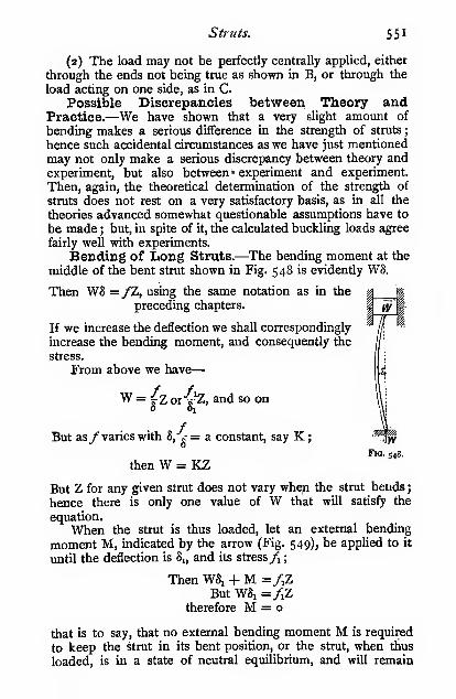
Struts. 55
1
(2) The load may not be perfectly centrally applied, either
through the ends not being true as shown in B, or through the
load acting on one side, as in C.
Possible Discrepancies between Theory andPractice.—We have shown that a very slight amount of
bending makes a serious difference in the strength of struts
;
hence such accidental circumstances as we have just mentioned
may not only make a serious discrepancy between theory andexperiment, but also between » experiment and experiment.
Then, again, the theoretical determination of the strength of
struts does not rest on a very satisfactory basis, as in all the
theories advanced somewhat questionable assumptions have to
be made ; but, in spite of it, the calculated buckling loads agree
fairly well with experiments.
Bending of Long Struts.—The bending moment at the
middle of the bent strut shown in Fig. 548 is evidently W8.
Then WS =/Z, using the same notation as in the
preceding chapters.
If we increase the deflection we shall correspondingly
increase the bending moment, and consequently the
stress.
From above we have
—
^ =iz or's'Z, and so onO Oj
But as /varies with 8,"s-= a constant, say K;Fig. 548.
then W = KZ
But Z for any given strut does not vary whqn the strut bends
;
hence there is only one value of W that will satisfy the
equation.
When the strut is thus loaded, let an external bending
moment M, indicated by the arrow (Fig. 549), be applied to it
until the deflection is Sj, and its stress /i
;
Then W81 + M =/,ZBut W81 =/iZ
therefore M = o
that is to say, that no external bending moment M is required
to keep the strut in its bent position, or the strut, when thus
loaded, is in a state of neutral equilibrium, and will remain

SS2 Mechanics applied to Engineering.
when left alone in any position in which it may be placed;
this condition, of course, only holds so long as the strut is
elastic, i.e. before the elastic limit is reached. This state of
neutral equilibrium may be proved experimentally, if a long
thin piece of elastic material be loaded as shown.
Now, place a load Wj less than W on the strut,
say W = Wj + w, and let it again be bent by anexternal bending moment M till its deflection is Sj
and the stress /i ; then we have, as before
—
WiSi + M =/iZ = W8i = WA + wl^
hence M = w\Thus, in order to keep the strut in its bent position
with a deflection Sj, we must subject it to a + bend-
ing moment M, i.e. one which tends to bend the
strut in the same direction as WiSi ; hence, if weremove the bending moment M, the deflection will
become zero, i.e. the strut will straighten itself.
Now, let a load Wa greater than W be placed onthe strut, say W s= Wj — a/, and let it again be bent until its
deflection = Sj, and the stress f^ by an external bendingmoment M ; then we have as before
—
WA + M =/,Z = WA - wS,hence M = —w\
Thus, in order to keep the strut in its bent position with adeflection \, we must subject it to a — bending moment M, i.e.
one which tends to bend the strut in the opposite direction to
W281 ; hence, if we remove the bending moment M, the de-
flection will go on increasing, and ere long the elastic limit will
be reached when the strain will increase suddenly and muchmore rapidly than the stress, consequently the deflection will
suddenly increase and the strut will buckle.
Thus, the strut may be in one of three conditions
—
Fig. 549-
Condition.
When slightly bent by an ex-
ternal bending moment M,on being released, the strut
will-
When supportinga load
—
Remain bent
Straighten itself
Bend still further and ultimatelybuckle
W.less than W.greater than W.

Struts. SS3
_Condition ii. is, of course, the only one in which a strut can
exist for practical purposes ; how much the working load mustbe less than W is determined by a suitable factor of safety.
Buckling Load of Long Thin Struts, Euler'sFormula.—The results arrived at in the paragraph aboverefer only to very long thin struts.
As a first approximation, mainly for the sake of gettingthe form of expression for the buckling load of a slender strut,
assume that the strut bends to an arc of a circle.
Let / = the eifective length of the strut (see Fig.
S5o);E = Young's modulus of elasticity
;
I = the least moment of inertia of a section
of the strut (assumed to be of constant
cross-section).
Then for a strut loaded thus
—
* = 8Rt(^^«P- 425) =•SEP8EI
8EI
or W = —7^ (first approximation)
As the strut is very long and the deflection
small, the length / remains practically constant, -and
the other quantities 8, E, I are also constant for j-,<;. j^^^
any given strut ; thus, W is equal to a constant,
which we have previously shown must be the case.
Once the strut has begun to bend it cannot remain acircular arc, because the bending moment no longer remainsconstant at every section, but it will vary directly as the
distance of any given section from the line of application of
the load. Under these conditions assume as a second approxi-
mation that it bends to a parabolic arc, then the deflection
—
<» ^ ^ ., S I ^r M/^ W8/28=-X-Mx§X--^EI = -7^7 = -7^3 2
a„dW = 9^' 9-6EI 9-6EI
The value obtained by Euler was
—
_ g^EI _ 9-87EI _ loEI(nearly)

554 Mechanics applied to Engineering.
This expression is obtained thus
—
The bending moment M at any point distant x from the middleof the strut is
M = -WS = El^ (see page 510)
Multiply each side by —
^.^^ _WS ^dx ds^ EI dx
Integrating (|J=-S(8^ + c)
When^ = o, 8 = A, hence C = - A^dx
Integrating again
—
^ = A/^sin-'- + KV W A
When a: = o, 8 = 0, therefore K = o
Hence 8 = A sin \x^—
j
When a; = - 8 = Az
'CVI,)=and sin ( "EI>
The only angles whose sines are = 1 are -, — , etc. We2 2
require the least value of W, hence
—
aV EI~
2
and W =
EI
;ei

Struts. 555
It must not be forgotten that this expression is only an
approximation, since the direct stress on the strut is neglected.
When the strut is very long and slender the direct compressive
stress is very small and therefore negligible, but in short struts
the direct stress is not negligible consequently for such cases
the above expression gives results very far from the truth.
Effect of End holding on the Buckling Load.—In the case we have j-ust considered the strut was supposed to
be free or pivoted at the ends, but if the ends are not free the
stmt behaves in a different manner, as shown in the accompany-ing diagram.
Diagram showing Struts of Equal Strength.
One end free, theother hxed.
/=3L
p =
Both ends pivoted orrounded.
/=L
Fig.
W =
P =
loEI
loEp'
One end rounded or
pivoted, the other
end built in or
fixed.
P =20Ep'
Both ends fixed orbuilt in.
1=^2
Each strut is supposed to be of the same section, and loaded
with the same weight W.

556 Mechanics applied to Engineering.
WAW
Let P = the buckling stress of the strut, i.e. —, where
W = the buckling load of the strut
;
A = the sectional area of the strut.
We also have r- = p'' (see p. 78), where p is the radius of
gyration of the section.
Substituting these values in the above equation, we have
—
' /=>
The " eflfective " or " virtual "length /, shown in the diagram,
is found by the methods given in Chapter XIII. for finding the
virtual length of built-in beams.
The square-ended struts in the diagrams are shown bolted
down to emphasize the importance of rigidly fixing the ends ; if
the ends merely rested on flat flanges without any means of
fixing, they much more nearly approximate round-ended struts.
It will be observed that Euler's formula takes no account
of the compressive stress on the material ; it simply aims at
giving the load which will produce neutral equilibrium as
regards bending in a long bar, and even this it only doesimperfectly, for when a bar is subjected to both direct andbending stresses, the neutral axis no longer passes through the
centre of gravity of the section. We have shown above that
when the line of application of the load is shifted but one-eighth of the diameter from the centre of a round bar, the
neutral axis shifts to the outermost edge of the bar. Inthe case of a strut subject to bending, the neutral axis shifts
away from the line of application of the load ; thus the bend-ing moment increases more rapidly than Euler's hypothesisassumes it to do, consequently his formula gives too highresults; but in very long columns in which the compressivestress is small compared with the stress due to bending, the
error may not be serious. But if the formula be applied to
short struts, the result will be absurd. Take, for example, aniron strut of circular section, say 4 inches diameter and 40
mches long; we get P = — z9000000 1 _ jgj ^^^ jj^^^1000
per square inch, which is far higher than the crushing strength
of a short specimen of the material, and obviously absurd.
If Euler's formula be employed, it must be used exclusively

Struts. 557
for long struts, whose length / is not less than 30 dia-
meters for wrought iron and steel, or 12 for cast iron andwood.
Notwithstanding the unsatisfactory basis on which it rests,
many high authorities prefer it to Gordon's, which we will
shortly consider. For a full discussion of the whole question
of struts, the reader is referred to Todhunter and Pearson's" History of the Theory of Elasticity."
Gordon's Strut Formula rationalized.— Gordon'sstrut formula, as usually given, contains empirical constants
obtained from experiments by Hodgkinson and others; but
by making certain assumptions constants can be obtained
rationally which agree remarkably well with those found
by experiment.
Gordon's formula certainly has this advantage, that it agrees
far better with experiments on the ultimate resistance of
columns than does the formula propounded by Euler; and,
moreover, it is applicable to columns of any length, short or
long, which, we have seen above, is not the case with Euler's
formula. The elastic conditions assumed by Euler cease to
hold when the elastic limit is passed, hence a long strut always
fails at or possibly before that point is reached ; but in the
case of a short strut, in which the bending stress is small
compared with the compressive stress, it does not at all follow
that the strut will fail when the elastic limit in compression is
reached—indeed, experiments show conclusively that such is
not the case. A formula for struts of any length must there-
fore cover both cases, and be equally applicable to short struts
that fail by crushing and to long struts that fail by bending.
In constructing this formula we assume that the strut fails
either by buckling or by crushing,' when the sum of the direct
compressive stress and the skin stress, due to bending, are
equal to the crushing strength of the material ; in using the
term " crushing strength " for ductile materials, we mean the
stress at which the material becomes plastic. This assumption,
we know, is not strictly true, but it cannot be far from the
truth, or the calculated values of the constant (a), shortly to
be considered, would not agree so well with the experimental
values.
' Mons. Considire and others have found that for long columns the
resistance does not vary directly as the crushing resistance of the material,
but for short columns, which fail by crushing and not by bending, the re-
sistance does of course entirely depend upon it, and therefore must appear
in any formula professing to cover struts of all lengths.
558 Mechanics applied to Engineering.
Let S = the crushing (or plastic) strength of a short specimenof the material
;
C = the direct compressive stress on the section of the
strut;
then, adopting our former notation, we have
—
C = -and/= —then S = C +/
S = -- + -=- (the least Z of the section)
We have shown above that, on Euler's hypothesis, the
maximum deflection of a strut is
—
g^ M/' _ fZflloEI loEZy
where y is the distance of the most strained skin from the
centre of gravity of the section, or from the assumed position
of the neutral axis. We shall assume that the same expression
holds in the present case. In symmetrical sections y = -,3
where d is the least diameter of the strut section.
By substitution, we have
—
8 = 4^.
, ^ W , W/72 ,. V
^ SEdZjw/
_ W/ A/d P\~ A^' + pZ "^W
IfW be the buckling load, we may replace — by P,
Then S = p(i + a^^)
T, S S

Struts. 559
where r = ->, which is a modification of " Gordon's Struta
Formula.''
P may be termed the buckling stress of the strut.
The d in the above formula is the least dimension of the
section, thus
—
L
JJ !Fig. 532.
It now remains to be seen how the values of the constant a
agree with those found by experiment ; it, of course, depends
upon the values we choose for / and E. The latter presents
no difficulty, as it is well known for all materials; but the
former is not so obvious at first. In equation (i.), the first
term provides for the crushing resistance of the material
irrespective of any stress set up by bending ; and the second
term provides for the bending resistance of the strut. Wehave already shown that the strut buckles when the elastic
limit is reached, hence we may reasonably take/ as the elastic
limit of the material.
It will be seen that the formula is only true for the two
extreme cases, viz. for a very short strut, when W = AS, and
for a very long strut, in which S =/; then
—
,„ 5E</Z loEIW = -j^ or -p-
which is Euler's formula. It is impossible to get a rational
formula for intermediate cases, because any expression for 8
only holds up to the elastic limit, and even then only when the
neutral axis passes through the centre of gravity of the section,
i.e. when there is pure bending and no longitudinal stress.
However, the fact that the rational value for a agrees so well
with the experimental value is strong evidence that the formula
is trustworthy.
Values of S,/, and E are given in the table below j they

S6o Mechanics applied to Engineering.
must be taken as fair average values, to be used in the absence
of more precise data.

Struts. 561
Material.

562 Mechanics applied to Engineering.
where h = fand„ uvw^^ -^ ~ A'
'' *^^ equivalent length
divided by the /^aj/ radius of gyration of the. section about aline passing through the centroid- of the section. Values of kwill be found in Chapters III. and XI.
The values of b are as follows :
—

Struts. 563
stress on the tension skin, the value given by this formula agrees
fairly well with the values calculated from the original formula;
hence we see that such struts are about as likely to fail by
tension on the convex side as bycompression on the concave side.
The following tables have been worked out by the formula
given above to the nearest 100 lbs. per square inch. For those
who are constantly designing struts, it will be found convenient
to plot them to a large scale, in the same manner as shown in
Fig. 553. In order better to compare the results obtained byEuler's and by Gordon's formula, curves representing both are

564 Mechanics applied to Engineering.
Buckling Load of Struts in Pounds per Square Inch of Section.

Struts. 56S
Factor of Safety for Struts.
Wrought iron and steel
Cast iron
Timber
350
Dead loads.

S66 Mechanics applied to Engineering.
one gets in the testing of full-sized struts and columns, the
more one realizes how futile it is to attempt to calculate the
buckling load with any great degree of accuracy. If the struts
are of homogeneous material and have been turned or
machined all over, and are, moreover, very caitfully tested
with special holders, which ensure dead accuracy in loading,
and every possible care be taken, the results may agree within
5 per cent, of the calculated value; but in the case of com-mercial struts, which are not aX^jiSiys perfectly straight, and are
350r
300
250
1 200
1l50
^100
50

Struts. 567
Material.

S68 Mechanics applied to Engineering.
XW
Columns loaded on Side Brackets.—The barbarous
practice of loading columns on side brackets is
\Wi unfortunately far too common. As usually carried
"n..!... out, the I practice reduces the strength of the
cohimn to one-tenth ' of its strength when cen-
trally loaded.
In Fig. 557 the height of the shaded figure
on the bracket of the column shows the relative
loads that may be safely placed at the various
distances from the axis of the column. It will beperceived how very rapidly the value of the safe
load falls as the eccentricity is increased. If adesigner will take the trouble to go carefully into
the matter, he will find that it is positively cheaper
to use two separate centrally loaded columnsFig. 556. instead of putting a side bracket on the much
larger column that is required for equal strength.
Lety^ = the maximum compressive stress on the material
due to both direct and bending stresses
;
ff = the maximum tensile stress on the
material due to both direct andbending stresses
;
/ = the skin stress due to bending
;
C = the compressive stress acting all over
the section due to the weight W;
A = the sectional area of the column.WX W
Then/.=/-FC = ^4-^wx_ wZ A
If the column also carries a central
and /, =
load Wi, the above become
—
/, = WX W-fWiZ *" A
/,=WX W + WiZ A
Columns loaded thus almost invariably
fail in tension, therefore the strength mustbe calculated on the /, basis. We haveneglected the deflection due to loading
• The ten is not used with any special significance here ; may beone-tenth or »ven oue-twenlieth.
Fig. 557-

Struts. 569
(Fig. 558), which makes matters still worse; the tensile stress
then becomes
—
/.=W(X + 8) W_+ W,
The deflection of a column loaded in this way may be
obtained in the following manner :
—
The bending moment = WXarea of bending-moment diagram = WXL
„ WXL'(approximately)
After the column has bent, the bending moment of course
is greater than WX, and approximates to W(X + 8), but S is
"1^
if= 0-2 ^
S^ff,!^
Fig. 558. Fig. 559.
usually small compared with X, therefore no serious error arises
from taking this approximation.
A column in a public building was loaded as shown in
Fig. 559; the deflections given were taken when the gallery
was empty. The deflections were so serious that when the
gallery was full, an experienced eye immediately detected
them on entering the building.
The building in question has been condemned, the galleries
have been removed, and larger columns without brackets have

570 Mechanics applied to Engineering.
been substituted. Thecolumn, as shown, was tested to destruc-
tion by the author, with the following results
—
External diameter 4 '95 inches
Internal diameter ... ... ... 3'7o ,,
Sectional area ... fi'49sq. inches
Modulus of the section 8" 18
Distance of load from centre of column ... 6 inches
Height of bracket above base ... 8' 6"
Deflection measured, above base 4' 3"
Win tons... I 2 I 4 I 6 1 8 I 10 I 12 I 14 I 16 I 18
5 in inches...|o'035 1 o'o69 1 o'loo
10'148 1 o'igs 1
0'245 1 0^300 1 0-355 ' 0'42o
The column broke at iS'iy tons; the modulus of rupture
was i3'3 tons per sq. inch.
Judging from the deflection when the weight of the gallery
rested on the bracket, it will be seen that the column was in aperilously dangerous state.
Another test of a column by the author will serve to
emphasize the folly of loading columns on side brackets.
Estimated Buckling Load if centrally loaded, about1000 tons.
Length 10 feet, end flat, not fixed.
Sectional area of metal at fracture ... 34*3 sq. inches
Modulus of section at fracture 75 'O
Distance of point of application of load
from centre of column, neglecting slight
amount of deflection when loaded ... 17 inches
Breaking load applied at edge of bracket 65'5 tOnSBending moment on section when fracture
occurred 1114 tons-inches
Compressive stress all over section whenfracture occurred I '91 tons per sq. inch
Skin stress on the material due to bending,
assuming the bending formula to holdup to the breaking point ... ... I4"85 ,, ,,
Total tensile stress on material due to
combined bending and compression * ... 12*94 tons per sq. inch
Total compressive stress on material dueto combined bending and compression l6'76 ,, ,,
Tensile strength of material as ascertained
from subsequent tests 8'45 ,, ,,
Compressive strength of material as ascer-
tained from subsequent tests ... ... 30'4 i> i>
Thus we see that the column failed by tension in the
material on the off side, i.e. the side remote from the load.
' The discrepancy between this and the tensile strength is due to the
bending formula not holding good at the breaking point, as previously
explained.

CHAPTER XVI.
TORSION. GENERAL THEORY.
Let Fig. 560 represent two pieces of shafting provided with
y
Fig. s6o.
disc couplings as shown, the one being driven from the other
through the pin P, which is evidently in shear.
Let S = the shearing resistance of
the pin.
Then we have W/ = Sy
Let the area of the pin = a, andthe shear stress 'on the pin he/,.
Thenwemay write the above equation
—
W/ = f^y
Now consider the case in which
there are two pins, then
—
Fig. 561.
w/ = Sy + Si^/i =fAy +Aaxyi
The dotted holes in the figure are supposed to represent the
pin-holes in the other disc coupUng. Before W was applied
the pin-holes were exactly opposite one another, but after the
application ofW the yielding or the shear of the pins caused a

572 Mechanics applied to Engineering.
slight movement of the one disc relatively to the other, but
shown very much exaggerated in the figure. It will be seen
that the yielding or the strain varies directly as the distance
from the axis of revolution (the centre of the shaft). Whenthe material is elastic, the stress varies directly as the strain
;
hence
—
Substituting this value in the equation above, we have
—
y
y=-^'(a/ + «^>'.')
Then, if a = Oj, and say y^_y
4
Thus the inner pin, as in the beam (see p. 432), has onlyincreased the strength by j. Now consider a similar arrange-ment with a great number of pins, such a number as to forma hollow or a solid section, the areas of each little pin orelement being a, a^, a^, etc., distant y, y^, y^, etc., respectively
from the axis of revolution. Then, as before, we have
—
W/=-^(ay^ + a^j^ + 0^,=' +, etc.)
But the quantity in brackets, viz. each little area multiplied
by the square of its distance from the axis of revolution, is the
polar moment of inertia of the section (see p. 77), which wewill term I,. Then
—
The W/ is termed the twisting moment, M,. /, is the skin
shear stress on the material furthest from the centre, and is
therefore the maximum stress on the material, often termed theskin stress.
y is the distance of the skin from the axis of revolution.

Torsion. General Theory. 573
-^ = the modulus of the section = Z^. To prevent confusion,
we shall use the suffix/ to indicate that it is the polar modulusof the section, and not the modulus for bending.
Thus we have M, =/,Zpor the twisting moment = the skin stress X the polar modulus
of the section
Shafts subject to Torsion.—To return to the shaft
couplings. When power is transmitted from one disc to the
other, the pin evidently will be in shear, and will be distorted
P
Fig. 562.
as shown (exaggerated). Likewise, if a small square be markedon the surface of a shaft, when the shaft is twisted it will also
become a rhombus, as shown dotted on the shaft below.
In Chapter X. we showed that when an element was
distorted by shear, as shown in Fig. 563 (a), it was
Fig. 363.
equivalent to the element being pulled out at two opposite
corners and pushed in at the others, as shown in Fig. 563,
(b) and {c), hence all along the diagonal section AB there

574 Mechanics applied to Engineering.
is a tension tending to pull the two triangles ADB, ACBapart ; similarly there is a compression along the diagonal CD.These diagonals make an angle of 45° with their sides. Thus,
if two lines be marked on a shaft at an angle of 45° with the
axis, there will be a tension normal to the one diagonal, and a
compression normal to the
J other. That this is the case
can be shown very clearly
by getting a piece of thin
tube and sawing a diagonal
slot along it at an angle of
45°. When the outer end is
p,Q jg^.twisted in the direction of
the arrow A, there will be
compression normal to the slot, shown by a full Une, and the
slot will close ; but if it be twisted in the direction of the arrow
B, there will be tension normal to the slot, and will cause it
to open.
Graphical Method of finding the Polar Modulusfor a Circular Section.—The method of graphically finding
the polar modulus of the section is precisely similar in principle
to that given for bending (see Chap. XL), hence we shall not
do more than briefly indicate the construction of the modulus
figure. It is of very limited application, as it is only true for
circular sections.
As in the beam modulus figure, we want to construct a
figure to show the distribution of stress in the section.
Consider a small piece of a circular
section as shown, with two blocks equiva-
lent to the pins we used in th« disc
couplings above. The stress on the inner
block = fa, and on the outer block = /,
;
then -^ = ^. Then by projecting the
width of the inner block on to the outer
circle, and joining down to the centre of
the circle, it is evident, from similar
triangles, that we reduce the width and
area of the inner block in the ratio — , or in the ratio of •^.
The reduced area of the inner block, shown shaded, we will
now term ai, where — =-^ =-^, or <j!,|/; = aja-<h J, y
Fig. 565.

Torsion. General Theory. S7S
Then the magnitude of the resultant force acting on the twoblocks = af, + «,/,!
= of, + <f. =/.(« + «i')
=f, (sHaded area or area of modulus figure)
And the position of the resultant is distant y,, from the centre,
where
—
ay + gi>i
i.e. at the centre of gravity of the blocks.
Then/.Z, =f,{a + «,') X ^^^^=f.{ay + ch'y,) =^{ay^ + a^y^)
which is the same result as we had before for W/, thus proving
the correctness of the graphical method.In the figure above we have only taken a small portion of
a circle ; we will now use the same method to find the Z_ for a
-no
Fig. s66.
circle. For convenience in working, we will set it offon a straight
base thus : Draw a tangent ab to the circle, making the length
= irD;join the ends to the centre O ; draw a series of lines
parallel to the tangent ; then their lengths intercepted betweenao and bo are equal to the ciicumference of circles of radii Oi,
Oa, etc. Thus the triangle Oab represents the circle rolled out
to a straight base. Project each of these lines on to the tangent,
and join up to the centre ; then the width of the line I'l', etc.,
represents the stress in the metal at that layer in precisely the
same manner as in the beam modulus figures. Then
—
The polar modulus of ) S^'^%°^ T^'f^ ^^T^ f''f
"''^
the section Z,=
i "^ ^; °^ S- of modulus figtfrefrom' '
{_ centre of circle
or Z, = Ay.

5/6 Mechanics applied to Engineering.
The construction for a hollow circle is precisely the same
as for the solid circle. It is given for the sake of graphically
illustrating the very small amount that a shaft is weakened by
making it hollow.
This construction can be applied to any form of section,
Fig. 567.
but the strengths of shafts other than circular do not vary as
their polar moments of inertia or moduli of their sections;
serious errors will be involved if they are assumed to be so.
The calculation of the stresses in irregular figures in torsion
involves fairly high mathematical work. The results of such
calculations by St. Venant and Lord Kelvin will be given in
tabulated form later on in this chapter.
Strength of Circular Shafts in Torsion.—We haveshown above that the strength of a cylindrical shaft varies as
?2 = Z,. In Chapter III., we showed that I. =—, where Dy 32
is the diameter, and y in this case = — ; hence
—
2
which, it will be noticed, is just twice the value of the Z for
bending. In order to recollect which is which, it should beremembered that the material in a circular shaft is in the very
best form to resist torsion, but in a very bad form to resist
bending ; hence the torsion modulus will be greater than the
bending modulus.
For a hollow shaft
—

Torsion. General Theory. 577
I„ = —^^ '-, -where D< = the internal diameter32 '
hence Z, =.ep
= oT96(^^^-j
If - of the metal be removed from the centre of the shaft,n '
we have
—
the external areaThe internal area = •
n
—^ = or Dj^ = -a4 4» W'
Z, = o-i96D{i-i)
The strength of a shaft with a sunk keyway has neverbeen arrived at by a mathematical process. Experimentsshow that if the key be made to the usual proportions, viz.
the width of the key = \ diameter of shaft, and the depthof the keyway = \ width of the key, the shaft is therebyweakened about 19 per cent. See Engineering, March 3rd191 1, page 287.
Another empirical rule which closely agrees with experi-ments is : The strength of a shaft having a sunk keyway is
equal to that of a shaft whose diameter is less than that ofthe actual shaft by one-half the depth of the keyway j thus,the strength of a 2-inch shaft having a sunk keyway 0-25 inch
deep is equal to a shaft {2 ~j = r87S inches diameter.
This rule gives practically the same result as that quotedabove.
2 p

578 Mechanics applied to Engineering.
Strength of Shafts of Various Sections.
„ . ,/D* - DA
Fig. 569.
Fin. 570.
5 --
Fig. 571.
Z, = -^,or
Z, = 0-I96D3
z =

Torsion. General Theory. 579
Twist of Shafts.—In Chapter X., we showed that
when an element was sheared, the
amount of slide x bore the follow-
ing relation :
—
I G (i.)
where f, is the shear stress on the
material
;
G is the coefficient of rigidity.
In the case of a shaft, the xis measured on the curved surface.
It will be more convenient if weexpress it in terms of the angle of
twist.
If Qr be expressed in radians, then
—
Fig. 573-
e,Dand Qr
— 2flGD
If 6 be expressed in degrees
—
irD9X = —7-
360
Substituting the value of x in equation (i.), we have—
360/ G irGD
But M, =/.Z, =f:^, and/. =^hence 6 - 3^0 X 16 X M/ _ 584M./
for solid circular shafts. Substituting the value of Z, for a
hollow shaft in the above, we get
—
e-.
584M/G(D^ - D,*)
for hollow circular shafts.
N.B.—The stiffness of a hollow shaft is the difference of the stifihess
of two solid shafts whose diameters are respectively the outer and inner
diameters of the hollow shaft.
When it is desired to keep the twist or spring of shafts
within narrow limits, the stress has to be correspondingly

580 Mechanics applied to Engineering.
reduced. Long shafts are frequently made very much stronger
than they need be in order to reduce the spring. A commonlimit to the amount of spring is 1° in 20 diameters; the stress
corresponding to this is arrived at thus
—
We have above 6 = ^-dfr
But when = 1°, / = 20Da-GD G_
then/. -^g^ ^ ^^p _ ^^^^
For steel, G = 13,000,000; /, = 5670 lbs. per sq, inch
Wrought iron, G = 11,000,000;^ = 4800 „ „
Cast iron, G = 6,000,000;/, = 2620 „ „
In the case of short shafts, in which the spring is of no
importance, the following stresses may be allowed :
—
Steel,^ = 10,000 lbs. per sq. inch
Wrought iron,/, = 8000 „ „Cast iron, yi = 3000 „ „
Horse-power transmitted by Shafts.—Let a meanforce of P lbs. act at a distance r inches from the centre of
a shaft ; then
—
The twisting mo-1
ment on the shaft } = P (lbs.) X r (inches)
in Ibs.-inches J
The work done per ) t, /ii, \ ,, / u \ .
revolution in foot- = P Obs.) X r (mches) X 2^
lbs. )"
The work done perl _ P (lbs.) x r (inches) x 27rN (revs.)
minute in foot-lbs.| ^
where N = number of revolutions per minute.
27rPrNThe horse-power transmitted = = H P'^ 12 X 33000
•"'
then
—
_ 12 X 33000 X H.P. /D»^'~2irN ~ 5-1
_3 _ 12 X 33000 X H.P. X 5-1 _ 321400 H.P.
2tN/. - N^:
64-3 H.P .
Ntaking/, at Sooo lbs. per square inch.

D =
Torsion. General Theory. ^^i
4-^/ —:^ (nearly) for 5000 lbs, per sq. inch
VHPT~ 3"S\/ ~N~^'^^ 7500 lbs. per sq. inch
= 3\/ "1^' ^°^ i2)Ooo lbs. per sq. inch
In the case of crank shafts the maximum effort is often
much greater than the mean, hence in arriving at the diameterctf the shaft the maximum twisting moment should be takenrather than the mean, and where there is bending as well as
twisting, it must be allowed for as shown in the next paragraph.
Combined Torsion and Bending.—In Fig. 574 a shaft
is shown subjected to torsion only. We have previously seen
Fig 574.
(Chapter X.) that in such a case there is a tension acting
^y^ Tension ont^
Fig. S7S-
normal to a diagonal drawn at an angle of 45° with the axis of
the shaft, as shown by the arrows in the figure. In Fig. 575a shaft is shown subjected to tension only. In this case the
tension acts normally to a face at 90° with the axis. In
Fig. 576 a shaft is shown subjected to both torsion and

582 Mechanics applied to Engineering.
tension ; the face on which the normal tensile stress is a
maximum will therefore lie between the two faces mentioned
above, and the intensity of the stress on this face will be
Fig. 576.
greater than that on either of the other faces, when subjected
to torsion or tension only.
We have shown in Chapter X. that the stress /„ normal to
the face gh due to combined tension and shear is
—
/.
If the tension be produced by bending, we have
—
7,-2
If the shear be produced by twisting—
^' Z, 2Z
Substituting these values in the above equation
—
/«Z = M, =M+ <JW+Mi
alsoA X 2Z = /.,Z, = M„ = M + Vm» + M,"

Torsion,. General Theory. 583
The M„ is termed the equivalent bending moment, the
Mjj the equivalent twisting
moment, that would producethe same intensity of stress
in the material as the com-bined bending and twisting.
The construction shownin Fig. 578 is a convenient
graphical method of finding
In Chapter X. we also
showed that
—
Fig. 578.
f,gi--f^hw[\Q and
L^ = ^ cos = sin;e
/»=^Hll=tan0,or/« cos d
—^ = tanM«
From this expression we can find the angle of greatest
normal tensile stress 6, and therefore the angle at which
fracture will probably occur, in the case of materials which
are weaker in tension than in shear, such as cast iron andother brittle materials.
In Fig. 579 we show the fractures of two cast-iron torsion
test-pieces, the one broken by pure torsion, the other bycombined torsion and bending. Around each a spiral piece of
paper, cut to the theoretical angle, has been wrapped in order
to show how the angle of fracture agreed with the theoretical
angle 6 ; the agreement is remarkably close.
The following results of tests made in the author's laboratory
show the results that are obtained when cast-iron bars are
tested in combined torsion and bending as compared with pure
torsion and pure bending tests. The reason why the shear
stress calculated from the combined tests is greater than whenobtained from pure torsion or shear, is due to the fact that
neither of the formulae ought to be used for stresses up to
rupture ; however, the results are interesting as a comparison.
The angles of fracture agree well with the calculated values.

584 Mechanics applied to Engineering.
Twisting
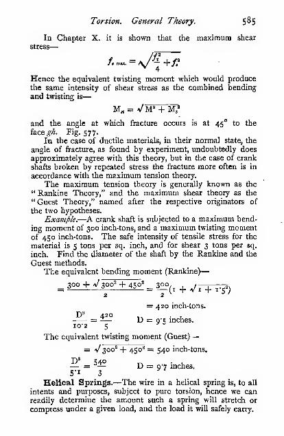
Torsion. General Theory. 5^5
In Chapter X. it is shown that the maximum shear
stress
—
/. max. — \/ — + f^4
Hence the equivalent twisting moment which would producethe same intensity of shear stress as the combined bendingand twisting is
—
and the angle at which fracture occurs is at 45° to the
face^^ Fig. 577.' In the case of ductile materials, in their normal state, the
angle of fracture, as found by experiment, undoubtedly doesapproximately agree with this theory, but in the case of crank
shafts broken by repeated stress the fracture more often is in
accordance with the maximum tension theory.
The maximum tension theory is generally known as the" Rankine Theory," and the maximum shear theory as the
"Guest Theory," named after the respective originators of
the two hypotheses.
Example.—A crank shaft is subjected to a maximum bend-
ing moment of 300 inch-tons, and a maximum twisting momentof 450 inch-tons. The safe intensity of tensile stress for the
material is 5 tons per sq. inch, and for shear 3 tons per sq.
inch. Find the diameter of the shaft by the Rankine and the
Guest methods.
The equivalent bending moment (Rankine)
—
2 2 '
= 420 inch-tons.
D' 420 _ . ,= ~— D = Q'l; mches.10-2 5
^ =
The equivalent twisting moment (Guest)
—
= Vsoo^ -f 450^ = 540 inch-tons.
— = ^^-^ D = 07 mches.5-13Helical Springs.—The wire in a helical spring is, to all
intents and purposes, subject to pure torsion, hence we canreadily determine the amount such a spring will stretch or
compress under a given load, and the load it will safely carry.

586 Mechanics applied to Engineering.
We may regard a helical spring as a long thin shaft coiled
into a helix, hence we may represent our helical spring thus
—
'xS:
Fig. s8o.
In the figure to the left we have the wire of the helical spring
straightened out into a shaft, and provided with a groovedpulley of diameter D, i.e. the mean diameter of the coils in the
. . WDspring; hence the twistmg moment upon it is . That the
twisting moment on the wire when coiled into a helix is also
WDwill be clear from the bottom right-hand figure. The
length of wire in the spring (not including the ends and hook)is equal to /. Let n = the number of coils ; then / = irDn
nearly, or more accurately / = t/{TrT>nY + L*, Fig. 581, arefinement which is quite unnecessary for springs as ordinarily
made.When the load W is applied, the end of the shaft twists,
so that a point on the surface
moves througha distance*,anda point on the rim of the pulley
moves through a distance 8,
where -,and8 = ^.X f
But we have -=^
hence S = -pJ^
"I(i)

Torsion. General Theory. 587
AlsoM=/.z,=/i!l^2 16
_ 16WD _ 2-55WD ,. .
then 8 = ^SP'^ (from i. and ii.)
Substituting the value of / = mrD—g^ 2-55D'W^,rD _ SD'Wn
Gd* Gd*D'W«G for steel = 12,000,000 8 =
1,500,000^*
DHV«G for hard brass = 5,000,000 8 =
Safe Load.—From equation (ii.), W625,0001^
2-S5D
Experiments by Mr. Wilson Hartnell show that for steel
wire the following stresses are permissible :
—
Diameter of wire. Safe stress {/si-
\ inch . . , 70,000 lbs. per square inch
I „ ... 60,000 lbs. „ „J „ ... 50,000 lbs. „ „
When a spring is required to stretch M times its initial
length L, let the initial pitch of the coils be/, then L =«/
From (i.) 8 =^8 = L(M - i) = «/(M - 1) =^~Gd
pd{M. — 1) _ t/, _ 3-14 X 70,000 _ 1^
D^ G 11,000,000 50
and so(M - 1) = —
For a close coiled spring,p= d, then
—
Vso(M-i)=?

588 Mechanics applied to Engineering.
Work stored in Springs.
The work done in stretching 1 _ W8or compressing a spring \
~ 2
f^ X V)lf. ,, . .....= 2 X 2-55D X Qd ^^'""^ "• ^*i ">•)
Jl^nQ
(substituting the value of /) = , ^ (inch-lbs.)
19,500,000putting G = 12,000,000
Weight of Spring.—Taking the weight of i cub. inch of
steel = o"28 lb., then
—
The weight of the spring w = o"j8^d^I X o'28 = o'22d^/
Substituting the value of /, we have
—
w = Q'Sgnd'D
Height a Steel Spring will lift itself (A).
work stored in spring~ weight of spring
, /.'^«D /^. ,
'* ~ r62G X o-6gnd^D ' ri2G'"*^^^
= -^— = — feeti3'4G 161,000,000
The value of // is given in the following table corresponding
to various values of/":
—
f, (lbs. per square inch) ... 30,000 60,000 90,000 120,000 150,000
A (feet) 5-56 22-4 50-3 89-5 139-8
h also gives the number of foot-pounds of energy stored
per pound of spring.
All the quantities given above are for springs made of wire
of circular section ; for wire of square section of side S, andtaking the same value for G as before, we get
—

Torsion. General Theory. 589
,i35,°°°y ^''""^ 'P""S')o =2
890.0008^(brass springs)
n4s ) square section'
W = ^9°^°°^-Sbrass
Safe Load for Springs -of Square Section.
W = ^' — stress 70,000 lbs. per square inch
24,9608'= —^-^— » 60,000 lbs. „ „
20,8ooS' ,,= —i^ „ 50,000 lbs. „ „
Taking a mean value, we have
—
W =J.— (square section)
work stored = ' „ (inch-lbs.) steel24,680,000 ^ '
weight = o-88«S''D (steel)
Height a square-section spring), fl_ ,, .
will lift itself (steel) ]" - 260,600,000 ^ >
/^ (lbs. per square inch) ... 30,000 60,000 90,000 120,000 150,000
-iCfeet) 3-45 138 31-1 55-3 86'3
It will be observed that in no respect is a square-section
spring so economical in material as a spring of circular
section.
Helical Spring in Torsion.—When a helical spring is
twisted the wire is subjected to a bending moment due to the
change of curvature of the spring, which is proportional to the
twisting moment.

5go Mechanics applied to Engineering,
Let /3j and p^ = the mean radii of the spring in inches before
and after twisting respectively
;
«, and «2 = the number of free coils before and after
twisting respectively
;
^1 and Qi = the angles subtended by the wire in inches
before and after twisting respectively
;
= 36o«i and 360/2, respectively
;
6 = ^1 — ^3, or the angle twisted through by the
free end of the spring in degrees
;
M, = the twisting moment in pounds-inches
;
I = the moment of inertia of the wire section
about the neutral axis in inch units;
d = the diameter or side of the wire in inches
;
L = the length of frefe wire in the spring in
inches
;
E = M,L _ 36oM,L2irl(«i — «j) 2irl8
E = 734opi«iM,j.^j. ^jj.^ ^f circular section
trO
E = 4320Pi«iM,f ^^jj.g pf 5 g section
d*e
If 6^ be the angle of twist expressed in radians, we have
—
Open-coiled Helical Spring.—In the treatment given
above for helical springs, we took the case in which the coils
were close, and assumed that the wire was subjected to torsion
only ; but if the coils be open, and the angle of the helix beconsiderable, this is no longer an admissible assumption.
Instead of there being a simple twisting moment WR acting
on the wire, we have a twisting moment M, = WR cos a, which
twists the wire about an axis ad. Think of ai as a little shaft
attached to the spring wire at a, and ei as the side view of acircular disc attached to it, then, by twisting this disc, the wire
will be subjected to a torsional stress. In addition to this, let al>
represent the side view of half an annular disc, suitably attached
to the wire at a, and which rotates about an axis ai. Then, by
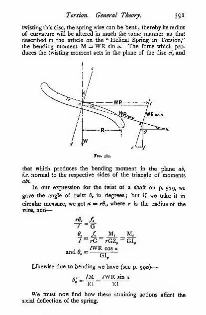
Torsion. General Theory. 591
twisting this disc, the spring wire can be bent ; thereby its radius
of curvature will be altered in much the same manner as that
described in the article on the " Helical Spring in Torsion,"
the bending moment M = WR sin a. The force which pro-
duces the twisting moment acts in the plane of the disc «, and
Fig. 582.
that which produces the bending moment in the plane ab,
i.e. normal to the respective sides of the triangle of momentsobi.
In our expression for the twist of a shaft on p. 579, we
gave the angle of twist 6c in degrees; but if we take it in
circular measure, we get * = rd„ where r is the radius of the
vyire, and
—
I -G^_2l_ M, M,I- rG- rGZ„ " GI„
and 6. =AVR cos g
GL
Likewise due to bending we have (see p. 590)
—
a, /M /WR sin g° ~ EI ~ EI
We must now find how these straining actions affect the
axial deflection of the spring.

592 Mechanics applied to Engineering.
The twisting moment about ab produces a strain be = RS^,
which may be resolved into two components, viz. one, ef= R^,sin a, which alters the radius of curvature of the coils, andwhich we are not at present concerned with ; and the other,
bf = R5„ cos a, which alters the axial extension of the spring
/WR^cos^aby an amount pj
The bending moment about cd in the plane of the imaginary
disc ab produces a strain bh = RdJ, of which Ag alters the
radius of curvature in a horizontal plane, normal to the axis
of the spring ; and bg- = R6,' sin a alters the axial extension of
the spring in the same direction as that due to twisting, by an
/WR'' sin2 oamount -
EI
whence the total axial ") = /WR2extension 8 j < w jx.
^ qj^
On substitution and reduction, we get
—
cos^ a smEI
'-)
8 =8«D'W
Gd* cos acos' o +
I"2S
and for the case of springs in which the bending action is
neglected, we get
—
swpnv~ Gd^ cos a
Angle.

CHAPTER XVII.
STRUCTURES.
Wind Pressures.—Nearly all structures at times are exposed
to wind pressure. In many instances, the pressure of the wind
is the greatest force a structure ever has to withstand.
Let V = velocity of the wind in feet per second
;
V = velocity of the wind in miles per hour
;
M = mass of air delivered per square foot per second
;
W = weight of air delivered per square foot per second
(pounds)
;
w = weight of 1 cubic foot of air (say o'o8o7 lb.)
;
P = pressure of wind per square foot of surface
exposed (poimds).
Then, when a stream of air of finite cross-section impinges
normally on a flat surface, whose area is much greater than
that of the stream, the change of momentum per second per
square foot of air stream is
—
Mz'= P
or = Pg
But W = wo
hence— = Pg
or expressed in miles per hour by substituting v - i'466V,
and putting in the value of w, we have
—
p _ o-o8o7 X 1-466'' X V . ^,,r = ! = o'ooi;4V*32-2 ^^
If, however, the section of the air stream is much greatei
than the area of the flat surface on which it impinges, the
change of direction of the air stream is not complete, andconsequently the change of momentum is considerably less
than (approximately one-half) the value just obtained. Smeaton,
from experiments by Rouse, obtained the coefficient 0*005, tut2 Q

594 Mechanics applied to Engineering.
later experimenters have shown that such a value is probably
too high. Martin gives 0*004, Kernot o'oo33, Dines 0*0029,
and the most recent experiments by Stanton (see Proceedings
I.C.E., vol. clvi.) give 0*0027 for t^^ maximum pressure in the
middle of the surface on the windward side. In all cases of
wind pressure the resultant pressure on the surface is composedof the positive pressure on the windward side, and a suction
or negative pressure on the leeward side. Stanton found in the
case of circular plates that the ratio of the maximum pressure
on the windward side to the negative' pressure on the leeward
side was 2*1 to 1 in the case of circular plates, and a mean of
I "5 to I for various rectangular plates. Hence, for the re-
sultant pressure on plates, Stanton's experiments give as an
average P = o*oo36V".
Recent experiments by Eiffel, Hagen, and others show that
the total pressure on a surface depends partly on the area of
the surface exposed to the wind, and partly on the periphery
of the surface. The total pressure P is fairly well represented
by an expression of the form
—
P = (a + ^^)SV*
where S = normal surface exposed to the wind in square feet
;
/ = periphery of the surface in feet.
a and b are constants.
When a wind blowing horizontally impinges on a flat,
inclined surface, the pressure in horizontal, vertical, and normal
directions may be arrived at thus
—
the normal pressure P„ = P . sin fl
the horizontal pressure P, = P„ sin
= P sin^ 6
the vertical pressure P, = P„ cos 6= P . cos d . sin
In the above we have neg-
lected the friction of the air
moving over the inclined sur-
face, which will largely ac-
count for the discrepancy
between the calculated pres-
sure and that found by expe-riment. The following table
Fig. 583.will enable a comparison to
be made. The experimental
values have been reduced to a horizontal pressure of 40 lbs. per

Structures. 595
square foot of vertical section of air stream acting on a flat
vertical surface.

S96 Mechanics applied to Engineering,
These figures appear to show that the pressure varies
roughly as the square root of the height above the ground.The wind pressure as measured by small gauges is always
higher than that found from gauges offering a large surface
to the wind, probably because the highest pressures are onlyconfined to very small areas, and are much greater than the
mean taken on a larger surface.
Forth Bridge Experiments.
Date.

Structures. 597
Let W = weight of ironwork per square foot of covered area{i.e. floor area) in pounds
;
D = distance apart of principals in feet
;
S = span of roof in feet.
Then for trusses
—
w=e^38
and for arched roofs
—
W =^- + 3
Distribution of Load on a Roof.—It will often savetrouble and errors if a sketch be made of the load distribution
on a roof in this manner.
wrniD
Fig. 584.
The height of the diagram shaded normal to the roof is
the weight of the covering and ironwork (assumed uniformly
distributed). The height of the diagonally shaded diagramrepresents the wind pressure on the one side. The lowest
section of the diagram on each side is left unshaded, to indicate
that if both ends of the structure are rigidly fixed to the
supporting walls, that portion of the load may be neglected
as far as the structure is concerned. But if A be on rollers,
and B be fixed, then the wind-load only on the A side must betaken into account.
When the slope of the roof varies, as in curved roofs, the
height of the wind diagram must be altered accordingly. Aninstance of this will be given shortly.
The whole of the covering and wind-load must be con-
centrated at the joints, otherwise bending stresses will be set upin the bars.
Method of Sections.—Sometimes it is convenient to
check the force acting on a bar by a method known as the

598 Mechanics applied to Engineering.
method of sections—usually attributed to Ritter, but really
due to Rankine—termed the method of sections, because the
structure is supposed to be cut in two, and the forces required
to keep it in equilibrium are calculated by taking moments.Suppose it be re-
*"quired to find the force
/ I. jc^. i acting along the bar/^.
^^--;;/V<J^ . ... .^ i Take a section through
X^^)/ / X'^J^ \'"^i-':the Structure a^ ; then
^-(^\ / p \/\N? three forces,/a, qe, pq,
[
^"'^^\/—aZ— L v X/^^j y. must be applied to the
I/ \ -y^i *^"'- ^^"^ ^° ^^^P '^'^
J, \' Structure in equili-
FiG. 585. brium. Takemomentsabout the point O.
The forces pa and qe pass through O, and therefore have nomoment about it ; but pq has a moment pq X y about O.
pqXy = Wi*i + Waaij + Wa«3- W,x, + W^, + W^,pq =
By this method forces may often be arrived at which are
difficult by other methods.
Forces in Roof Structures.—We have already shownin Chapter IV. how to construct force or reciprocal diagrams
for simple roof structures. Space will only allow of our nowdealing with one or two cases in which difficulties may arise.
In the truss shown (Fig. 586), a difficulty arises after the
force in the bar tu has been found. Some writers, in order to
get over the difficulty, assume that the force in the bar rs is
the same as in ut. This may be the case when the structure is
evenly loaded, but it certainly is not so when wind is acting onone side of the structure. We have taken the simplest case of
loading possible, in order to show clearly the special methodof dealing with such a case.
The method of drawing the reciprocal diagram has already
been described. We go ahead in the ordinary way till wereach the bar st (Fig. 586). In the place of sr and rq substitute
a temporary bar xy, shown dotted in the side figure. With this
alteration we can now get the force ey or eq; then qr, rs, etc.,
follow quite readily ; also the other half of the structure.
There are other methods of solving this problem, but the
one given is believed to be the best and simplest. The author

Structures. 599
is indebted to Professor Barr, of Glasgow University, for this
method.
When the wind acts on a structure, having one side fixed andthe other on rollers, the only difficulty is in finding the reactions.
The method of doing this by means of a funicular polygon is
shown in Fig. 587. .The funicular polygon has been fully
described in Chapters IV. and XII, hence no further description
is necessary. The direction of the reaction at the fixed support
Fig. 586.
is unknown, but as it must pass through the point where the roof
is fixed, the funicular polygon should be started from this point.
The direction of the reaction at the roller end is vertical,
hence from/ in the vector polygon a perpendicular is dropped
to meet the ray drawn parallel to the closing line of the
funicular polygon. This gives us the point a ; then, joining ba,
we get the direction of the fixed reaction. The reciprocal

6oo Mechanics applied to Engineering.
diagram is also constructed ; it presents no difficulties beyondthat mentioned in thfe last paragraph.
In the figure, the vertical forces represent the dead weight
on the structure, and the inclined forces the wind. The twoare combined by the parallelogram of forces.
In designing a structure, a reciprocal diagram must bedrawn for the structure, both when the wind is on the roller
Vector polygonfor finding
the reactions.
Fig. 587.
and on the fixed side of the structure, and each member of
the structure must be designed for the greatest load.
The nature of the forces, whether compressive or tensional,
must be obtained by the method described in Chapter IV.
Island Station Boof.—This roof presents one or two
interesting problems, especially the stresses in the main post,
The determination of the resultant of the wind and dead load
at each joint is a simple matter. The resultant of all the forces
is given \yjpa on the vector polygon in magnitude and direction
(Fig. 588). Its position on the structure must then be deter-
mined. This has been done by constructing a funicular polygon

Structures. 60
1
in the usual way, and producing the first and last links to meetin the point Q. Through Q a line is drawn parallel to pa in
Vectorpolygon for
finding thereaction.
Fig. 588.
the vector polygon. This resultant cuts the post in r, and maybe resolved into its horizontal and vertical components, the
horizontal component producing bendingmoments of different sign, thus giving the
post a double curvature (Fig. 589).
The bending moment on the post is
obtained by the product j>a X Z, where Zis the perpendicular distance of Q from
the apex of the post.
When using reciprocal diagrams for
determining the stresses in structures, wecan only deal with direct tensions andcompressions. But in the present instance,
where there is bending in one of the members, we mustintiroduce an imaginary external force to prevent this bending
action. It will be convenient to assume that the structure is
pivoted at the virtual joint r, and that an external horizontal
force F is introduced at the apex Y to keep the structure in
equilibrium. The value of F is readily found thus. Takingmoments about r, we have
—
Fig. 589.

6o2 Mechanics applied to Engineering.
F X >-Y =^ X 3
z is the perpendicular distance from the pointY to the resultant.
On drawing the reciprocal diagram, neglecting F, it will be
found that it will not close. This force is shown dotted on the
reciprocal diagram / /, and on measurement will be found to be
equal to F.
Dead and Live Loads on Bridges.—The dead loads
consist of the weight of the main and cross girders, floor, ballast,
etc., and, if a railway bridge, the permanent way ; and the live
loads consist of the train or other traffic passing over the
bridge, and the wind pressure.
The determination of the amount of the dead loads and
the resulting bending moment is generally quite a simple
Fig. sgo.
matter. In order to simplify matters, it is usual to assume(in small bridges) that the dead load is evenly distributed, andconsequently that the bending-moment diagram is parabolic.
In arriving at the bending moment on railway bridges, anequivalent evenly distributed load is often taken to represent
the actual but somewhat unevenly distributed load due to a
passing train. The maximum bending moment produced by a
train which covers a bridge (treated as a standing load) can bearrived at thus (Fig. 590). Take a span greater than twice
the actual span, so as to get every possible combination of loads
that may come on the structure. Construct a bending-momentdiagram in the ordinary way, then find by trial where the greatest
bending moment occurs, by fitting in a line whose length is
equal to the span. A parabola may then be drawn to enclose

Structures. 603
this diagram as shown in the lower figure ; then, \i d = depthwP
of this parabola to proper scale, we have -— = d, where a
is the equivalent evenly distributed load due to the train.
(The small diagram is not to scale in this case.)
Let W, = total rolling load in tons distributed on each pair
of rails;
S = span in feet.
Then for English railways W, = i-6S + 20
Maximum Shear due to a Rolling Load, Concentrated
Rolling Load.—The shear
at any section is equal to
the algebraic sum of the
forces acting to the right or
left of any section, hencethe shear between the load
and either abutment is ^"'- s?'-
equal to the reaction at the abutment. We have above
—
Ri/= Wa;,
R, = W^
likewise Rj W^
When the load reaches the abutment, the shear becomes W,W
and when in the middle of the span the shear is — . The
shear diagram is shown shaded vertically.
Uniform Rolling Load, whose Length exceeds the Span.—Let
(VrrrrrCrC^
w = the uniform live load per foot run, and zv^ = the uniform
dead load per foot run.
Let M = ^

6o4 Mechanics applied to Engineering.
The total load on the structure = wn = Vf
then Ri/=— = —2 2
Ri = —«2 = Kw"2/
where K is a constant for any given case. But as the train
passes from the right to the left abutment, the shear betweenthe head of the train and the left abutment is equal to the left
reaction Rj, but this varies as the square of the coveredlength of the bridge, hence the curve of shear is a parabola.
When the train reaches the abutment, I = n;
then Ri = — = —2 2
The curves of shear for both dead and live loads are shownin Fig. 593. When a train passes from right to left over the
point /, the shear is re-
versed in sign, because
the one shear is positive,
and the other negative.
The distance x betweenthe two points /, / is
known as the " focal
distance " of the bridge.
The focal distance xcan be calculated thiis : The point / occurs where the shear
due to the live load is equal to that due to the dead load.
Fig. 593-
wnThe shear due to the live load = —j
dead ,, = -^ = w^2
m^ (I \
Solving, we get
—
n = l^U + M^ - /Mand X = I — 2n
= /(i - 2VmTIP + 2M)

Structures. 605
Determination of the Forces acting on the
Members of a Girder.—In the case of the girder given
\W'P^''''''"4'^ Changes
Fig. 594.
as an example, the dead load w^ = 075 ton per foot, or
?-^^ ^^ = 5 tons per joint.
The live load w = 175 ton per foot run, or 175 X 13*5
= 23-6 tons on each bottom joint, thus giving 5 tons on
each top joint, and 28'6 tons on each bottom joint.
The forces acting on the booms can be obtained either by

6o6 Mechanics applied to Engineering.
constructing a reciprocal diagram for the structure when fully
loaded as shown, or by constructing the bending-momentdiagram for the same conditions. The depth of this diagramat any section measured on the moment scale, divided by the
depth of the structure, gives the force acting on the boom at
that section. The results should agree if the diagrams are
carefully constructed.
The forces in the bracing bars, however, cannot be obtained
by these methods, unless separate reciprocal diagrams are con-
structed for several (in this instance six) positions of the train,
since the force in each bar varies with each position of the
train. The nature of the stress on the bracing bars within
the focal length changes as the train passes ; hence, instead of
designing the focal members to withstand the reversal of stress,
it is usual, for economic reasons, to counterbrace these panels
with two tie-bars, and to assume that at any given instant only
one of the bars is subjected to stress, viz. that bar which at the
instant is in tension, since the other tie-bar is not of a suitable
section to resist compression.
All questions relating to moving loads on structures are
much more readily solved by " Influence Lines " than by the
tedious method of constructing reciprocal diagrams for each
position of the moving load. By this means the greatest
stresses which occur in the various members of the structure
can be determined in a fraction of the time required by the
older methods.Deflection of Braced Structures.— The deflection
produced by any system of loading can be calculated either
algebraically by equating the work done by the external forces
to the internal elastic work done on the various members of
the structure, or graphically by means of the Williott diagram.Readers should refer to Warren's " Engineering Construc-
tion in Iron, Steel, and Timber," Fidler's " Practical Treatise
on Bridge Construction," Husband and Harby's " Structural
Engineering," Burr and Falk's " Influence Lines for Bridges
and Roofs."
Girder with a Double System of Triangulation.—Most girders with double triangulation are statically indeter-
minate, and have to be treated by special methods. They can,
however, generally be treated by reciprocal diagrams without
any material error (Fig. 595). We will take one simple case
to illustrate two methods of treatment. In the first each system
is treated separately, and where the members overlap, the
forces must be added : in the second the whole diagram will

Structures. 607
be constructed in one operation. The same result will, of
course, be obtained by both methods.
Fig. 595.
/ V^

6o8 Mechanics applied to Engineering.
In dealing with the second method, the forces mn, hg acting
on the two end verticals are simply the reactions of Fig. A.
There is less liability to error if they are treated as two upwardforces, as shown in Fig. C, than if they are left in as two vertical
bars. It will be seen, from the reciprocal diagram, that the
force in qs is the same as that in rt, which, of course, must bethe case, as they are one and the same bar.
Incomplete and Redundant Framed Structures.—If a jointed structure have not sufficient bars to make it retain
its original shape under all conditions of loading, it is termedan "incomplete" structure. Such a structure may, however,
be used in practice for one special distribution of loading
which never varies, but if the distribution should ever bealtered, the structure will change its shape. The determination
of the forces acting on the various members can be found bythe reciprocal diagram.
But if a structure have more than sufficient bars to make it
retain its original shape, it is termed a " redundant " structure.
Then the stress on the bars depends entirely upon their relative
yielding when loaded, and cannot be obtained from a reciprocal
diagram. Such structures are termed " statically indeterminate
structures." Even the most superficial treatment would occupyfar too much space. If the reader wishes to follow up the
subject, he cannot do better than consult an excellent little
book on the subject, " Statically Indeterminate Structures," byMartin, published at Engineering Office.
Pin Joints.—In all the above cases we have assumedthat all the bars are jointed with frictionless pin joints, acondition which, of course, is never obtained in an actual
structure. In American bridge practice pin joints are nearly
always used, but in Europe the more rigid riveted joint finds
favour. When a structure deflects under its load, its shape is
slightly altered, and consequently bending stresses are set upin the bars when rigidly jointed. Generally speaking, suchstresses are neglected by designers.
Plate Girders.—It is always assumed that the flanges of
a rectangular plate girder resist the whole of the bendingstresses, and that the web resists the whole of the shear stresses.
That such an assumption is not far from the truth is evident
from the shear diagram given on p. 596.
In the case of a parabolic plate girder, the flanges take someof the shear, the amount of which is easily determined.
The determination of the bending moment by means of
a diagram has already been fully explained. The bending

Structures. 609
moment at any point divided by the corresponding depth of
the girder gives the total stress in the flanges, and this, divided
by the intensity of the stress, gives the net area of one flange.
In the rectangular girder the total flange stress will be greatest
in the middle, and will diminish towards the abutments,consequently the section of the flanges should correspondingly
diminish. This is usually accomplished by keeping the widthof the flanges the samethroughout, and reducing r
—
>
3_
T^
the thickness by reducing ,
the number of plates. The \i
i
bending-moment diagram N^lends itself very readily to
the stepping of the plates.
Thussuppose itwere found Fig. 597.
that four thicknesses of
plate were required to resist the bending stresses in the flanges
in the middle of the girder ; then, if the bending-momentdiagram be divided into four strips of equal thickness, eachstrip will represent one plate. If these strips be projected up>
on to the flange as shown, it gives the position where the plates
may be stepped.^
The shear in the web may be conveniently obtained fromthe shear diagram (see Chapter XII.).
Then if S = shear at any point in tons,
f, = permissible shear stress, usually not exceeding
3 tons per square inch of gross section of web,d^ = depth of web in inches,
/ = thickness of plate in inches (rarely less than finch),
we have
—
The depth is usually decided upon when scheming the
girder ; it is frequently made from -g- to -^ span. The thickness
of web is then readily obtained. If on calculation the thickness
comes out less than | inch, and it has been decided not to use
a thinner web, the depth in some cases is decreased accordingly
within reasonable limits.
' It is usual to allow from 6 inches to 12 inches overlap of the plates
beyond the points thus, obtained,
2 R

6io Mechanics applied to Engineering.
The web is attached to the flanges or booms by means of
angle irons arranged thus :
Fig. 599.
Fig. 598.
The pitch / of the rivets must be such that the bearing
and shearing stresses are
within the prescribed
Hmits.
On p. 389 we showedthat, in the case of anyrectangular element subject
to shear, the shear stress
is equal in two directions
at right angles, i.e. the
shear stress along ef =shear stress along ed,
which has to be taken bythe rivets a, a. Fig. 598.
The shep-r per (gross) inch run of web plate along ef
The shearing resistance of each rivet is (in double shear)
4Whence, to satisfy shearing conditions
—
This pitch is, however, often teo small to be convenient
;
then two (zigzag) rows of rivets are used, and/ = twice the
above value.
The bearing resistance of each rivet is
—
dtf,=Up

Structures. 6ll
The bearing pressure /, is usually taken at about 8 tons per
square inch. We get, to satisfy bearing-pressure conditions
—
p = ^d (for a single row of rivets) (approximately)
p = 6d (for a double row of rivets) „
The joint-bearing area of the two rivets b, b attaching the
angles to the booms is about twice that of a single rivet (a)
through the web ; hence, as far as bearing pressure is concerned,
single rows are sufficient at b, b. A very common practice is
to adopt a pitch of 4 inches, putting two rows in the web at a, a,
and single rows at b, b.
The pitch of the rivets in the vertical joints of the web(with double cover plates) is the same as in the angles.
The shear diminishes from the abutments to the middle
of the span, hence the thickness cff the web plates may bediminished accordingly. It often happens, however, that it is
more convenient on the whole to keep the web plate of the
same thickness throughout. The pitch / of the rivets may then

6i2 Meclianics applied to Engineering.
such stiffeners are absolutely necessary in many cases nonewill deny, but up to the present no one appears to have arrived
at a satisfactory theory as to the dimensions or pitch required.
Rankine, considering that the web was liable to buckle
diagonally, due to the compression component of the shear,
treated a narrow diagonal strip of the web as a strut, and-
proceeded to calculate the longest length permissible against
buckling. Having arrived at this length, it becomes a simple
matter to find the pitch of the stiffeners, but, unfortunately for
this theory, there are a large number of plate girders that havebeen in constant use for many years which show no signs of
weakness, although they ought to have buckled up under their
ordinary working load if the Rankine theory were correct.
The Rankine method of treatment is, however, so commonthat we must give our reasons for considering it to be wrong in
principle. From the theory of shear, we know that a pure
shear consists of two forces of equal magnitude and opposite
in kind, acting at right angles to one another, each making anangle of 45° with the roadway ; hence, whenever one diagonal
strip of a web is subjected to a compressive stress, the other
diagonal is necessarily subjected to a tensile stress of equal
intensity. Further, we know that if a long strut of length / besupported laterally (even very flimsily) in the middle, the
effective length of that strut is thereby reduced to -, and in
general the effective length of any strut is the length of its
longest unstayed segment. But even designers who adhere to
the Rankinian theory of plate webs act in accordance with this
principle when designing latticed girders, in which they use
thin flat bars for compression members, which are quite
incapable of acting as long struts. But, as is well known, they
do not buckle simply because the diagonal ties to which they
are attached prevent lateral deflection, and the closer the
lattice bracing the smaller is the liability to buckling; hencethere is no tendency to buckle in the case in which the lattice
bars become so numerous that they touch one another, or
become one continuous plate, since the diagonal tension in
the plate web effectually prevents buckling along the other
diagonal, provided that the web is subjected to shear only. What,then, is the object of using stiffeners ? Much light has recently
been thrown on this question by Mr. A. E. Guy (see "TheFlexure of Beams :
" Crosby Lockwood and Son), who has verythoroughly, both experimentally and analytically, treated the
question of the twisting of deep narrow sections. It is well

Structures. 613
known that for a given amount of material the deeper andnarrower we make a beam of rectangular section the stronger
will it be if we can only prevent it from twisting sideways.
Mr. Guy has investigated this point, and has made the mostimportant discovery that the load at which such a beam will
buckle sideways is that load which would buckle the same beamif it were placed vertically, and thereby converted into a strut.
If readers will refer to the published accounts (" Menai andConway Tubular Bridges," by Sir William Fairbairn) of the
original experiments made on the large models of the Menaitubular bridge by Sir William Fairbairn, they will see that
failure repeatedly occurred through the twisting of the girders
;
and in the later experiments two diagonals were put in in order
to prevent this side twisting, and finally in the bridge itself the
ends of the girders were supported in such a way as to prevent
this action, and in addition substantial gusset stays were riveted
into the corners for the same purpose. Some tests by the
author on a series of small plate girders of 15 feet span, showedin every case that failure occurred through their twisting.
The primary function, then, of web stiffeners is believed to
be that of giving torsional rigidity to the girder to prevent side
twisting, but the author regrets that he does not see any way of
calculating the pitch of plate or tee-stiffeners to secure the
necessary -stiffness ; he trusts, however, that, having pointed out
what he believes to be the true function of stiffeners, others maybe persuaded to pursue the question further.
This twisting' action appears to show itself most clearly
when the girder is loaded along its tension flange, i.e. when the
compression flange is free to buckle. Probably if the load were
evenly distributed on flooring attached to the compression
flange, there would be no need for any stiffeners, because the
flooring itself would prevent side twisting ; in fact, in the United
States one sees a great many plate girders used without any
web stiffeners at all when they are loaded in this manner.
But if the flooring is attached to the bottom of the girder,
leaving the top compression flange without much lateral support,
stiffeners will certainly be required to keep the top flange
straight and parallel with the bottom flange. The top flange in
such a case tends to pivot about a vertical axis passing through
its centre. For this reason the ends should be more rigidly
stiffened than the middle of the girder, which is, of course, the
common practice, but it is usually assigned to another cause.
There are, however, other reasons for using web stiffeners.
Whenever a concentrated load is applied to either flange it

6 14 Mechanics applied to Engineering.
produces severe local stresses ; for example, when testing rolled
sections and riveted girders which, owing to their shortness, donot fail by twisting, the web always locally buckles just under
the point of application of the load. This local buckling is
totally different from the supposed buckling propounded byRankine. By riveting tee-stiffeners on both sides of the web,
the local loading is more evenly distributed over it, and the
buckling is thereby prevented. Again, when a concentrated
load is locally applied to the lower flange, it tends to tear the
flange and angles away from the web. Here again a tee or
plate stiffener well riveted to the flange and web very effectually
prevents this by distributing the load over the web.
In deciding upon the necessary pitch of stiffeners /,, there
should certainly be one at every cross girder, or other con-
centrated load, and for the prevention of twisting, well-fitted
plate stiffeners near the ends, pitched empirically about 2 feet
6 inches to 3 feet apart ; then alternate plate and tee stiffeners,
increasing in pitch to not more than 4 feet, appear to accord
with the best modern practice.
Weight of Plate Girders.—For preliminary estimates,
the weight of a plate girder may be arrived at thus
—
Let w = weight of girder in tons per foot run
;
W = total load on the girder, not including its ownweight, in tons.
WThen w = - rouehly
500 ^ '
Arched Structures.—We have already shown how to
determine the forces acting on the various segments of asuspension-bridge chain. If such a chain were made of
suitable form and material to resist compression, it would,when inverted, simply become an arch. The exact profile
taken up by a suspension-bridge chain depends entirely uponthe distribution of the load, but as the chain is in tension, and,moreover, in stable equilibrium, it immediately and automatically
adjusts itself to any altered condition of loading ; but if such achain Avere inverted and brought into compression, it would bein a state of unstable equilibrium, and the smallest disturbance
of the load distribution would cause it to collapse immediately.Hence arched structures must be made of such a section that
they will resist change of shape in profile ; in other words, theymust be capable of resisting bending as well as direct stresses.
Masonry Arches.—^In a masonry arch the permissible

Structures. 615
bending stress is small in order to ensure that there may be
no, or only a small amount of, tensile stress on the joints of the
voussoirs, or arch stones. Assuming for the present that there
may be no tension, then the resultant line of thrust must lie
within the middle third of the voussoir (see p. 541). In
order to secure this condition, the form of the arch must
be such that under its normal system of loading the line
of thrust must pass through or near the middle line of the
voussoirs. Then, when under the most trying conditions of
live loading, the line of thrust must not pass outside the middlethird. This condition can be secured either by increasing the
depth of the voussoirs, or by increasing the dead load onthe arch in order to reduce liie ratio of the live to the deadload. Many writers still insist on the condition that there shall
be no tension in the joints of a masonry structure, but every
one who has had any experience of such structures is perfectly
well aware that there are very few masonry structureis in whichthe joints do not tend to open, and yet show no signs of
instability or unsafeness. There is a limit, of course, to the
amount of permissible tension. If the line of thrust pass
throtigh the middle third, the maximum intensity of compres-
sive stress on the edge of the voussoir is twice the mean, andif there be no adhesion between the mortar and the stones, the
intensity of compressive stress is found thus
—
Let T = the thrust on the voussoirs at any given joint per
unit width
;
d = the depth or thickness of the voussoirs
;
X = the distance of the line of thrust from the middle
of the joint;
P = the maximum intensity of the compressive stress
on the loaded edge of the joint.
The distance of the line of thrust from the loaded edge is
- — X, and since the stress varies directly as the distance from2
this edge, the diagram of stress distribution will be a triangle
with its centre of gravity in the line of thrust, and the area of
the triangle represents the total stress ; hence
—
pxag-.)
and P =
= T
2T
<;-)

6i6 Mechanics applied to Engineering.
TThe mean stress on the section = —
d
hence, when
—
d ^ . . r* = T, P = 2 X mean intensity of stress
d „ . .
X = -, P = 2^ X mean intensity4
A masonry arch may fail in several ways; the mostimportant are
—
1. By the crushing of the voussoirs.
2. By the sliding of one voussoir over the other.
3. By the tilting or rotation of the voussoirs.
The first is avoided by making the voussoirs sufficiently
deep, or of sufficient sectional area to keep the compressive
stress within that considered safe for the material. This
condition is fulfilled if
—
2'67T—-J-
= or < the permissible compressive stress
The depth of the arch stones or voussoirs d in feet at the
keystone can be approximately found by the following
expressions :
—
Let S = the clear span of the arch in feetj
R, = the radius of the arch in feet.
— a/S a/SThen d = ^— for brick to ^^ for masonry
2-23
or, according to Trautwine
—
d =
where K = i for the best work
;
I •12 for second-class work;
I '33 for brickwork.
The second-mentioned method of failure is avoided by so
arranging the joints that the line of thrust never cuts the normal
to th3 joint at an angle greater than the friction angle. Let //
be tie line of thrust, then sliding will occur in 9ie manner

Structures. 617
shown by the dotted lines, if the joints be arranged as shownat M—that is, if the angle a exceeds the friction angle <^. Butif the joint be as shown at aa, sliding cannot occur.
The third-mentioned method of failure only occurs whenthe line of thrust passes right outside the section ; the voussoirs
then tilt till the line of thrust passes through the pivoting points.
An arch can never fail in this way if the line of thrust be keptinside the middle halt.
Fig. 601. Fig. 602.
The rise of the arch R (Fig. 505) will depend upon local
conditions, and the lines of thrust for the various conditions of
loading are constructed in precisely the same manner as the
link-and-vector polygon. A line of thrust is first constructed for
the distributed load to give the form of the arch, and if the line
of thrust comes too high or too low to suit the desired rise, it is
corrected by altering the polar distance. Thus, suppose the rise
of the line of thrust were Rj, and it was required to bring it to Rj.
If the original polar distance were OoH, the new polar distance
required to bring the rise to Rj would be dH = OqH X ^•
After the median line of the arch has been constructed,
other link polygons, such as the bottom right-hand figure, are
drawn in for the arch loaded on one side only, for one-third
of the length, on the middle only, and any other ways which
are likely to throw the line of thrust away from the medianline. After these lines have been put in, envelope curves
parallel to the median line are drawn in to enclose these lines
of thrust at every point ; this gives us the middle half of the
voussoirs. The outer lines are then drawn in equidistant from
the middle half lines, making the total depth of the voussoirs
equal to twice the depth of the envelope curves.
An infinite number of lines of thrust may be drawn in for
any given distribution of load. Which of these is the right
one ? is a question by no means easily answered, and whatever

6i8 Mechanics applied to Engineering.
answer may be given, it is to a large extent a matter of opinion.
For a full discussion of the question, the reader should refei
to I. O. Baker's " Treatise on Masonry " (Wiley and Co., NewYork); and a paper by H. M. Martin, I.C.E. Proceedings,
vol. xciii. p. 462.
7v y / B' d OU
Fig. 603.
From an examination of several successful arches, the
author considers that if, by altering the polar distance OH, a
line of thrust can be flattened or bent so as to fall within the
middle half, it may be concluded that such a line of thrust is
admissible. One portion or point of it itiay touch the inner
and one the outer middle half lines. As a matter of fact, an

Structures. 6ig
exact solution of the masonry arch problem in which the
voussoirs rest on plane surfaces is indeterminate, and we canonly say that a certain assumption is admissible if we find that
arches designed on this assumption are successful.
Arched Ribs.—In the case of iron and steel arches, the
line of thrust may pass right outside the section, for in a
continuous rib capable of resisting tension as well as compres-sion the rib retains its shape by its resistance to bending.
The bending moment varies as the distance of the line of
thrust from the centre of gravity of the section of the rib.
The determination of the position of the line of thrust is
therefore important.
Arched ribs are often hinged at three points—at the
Fig. 604.
springings and at the crown. It is evident in such a case that
the line of thrust must pass through the hinges, hence there
is no difficulty in finding its exact position. But when the archis rigidly held at one or both springings, and not hinged at the
CMOwn, Ihe position of the line of thrust may be found thus :
'
Fio. 606.
' See also a paper by Bell, I.C.E., vol. xxxiii. p. 68.

620 Mechanics applied to Engineering.
Consider a short element of the rib mn of length /. Whenthe rib is unequally loaded, it is strained so that mn takes upthe position nin'. Both the slope and the vertical position
of the element are altered by the straining of the rib. First
consider the efifect of the alteration in slope ; for this purpose
that portion of the rib from B to A may be considered as being
pivoted at B. Join BA ; then, when the rib is strained, BAbecomes BAj. Thus the point A, has received a horizontal
displacement AD, and a vertical displacement AjD. The twotriangles BAE, AAjD are similar; hence
—
AD V . „ AAi . ,. ,
6 being expressed in circular measure. Likewise
—
AjD X, ^ AAi ...
AA;= AB A,D=^.^ = e.* . . (11.)
A similar relation holds for every other small portion of the
rib, but as A does not actually move, it follows that some of the
horizontal displacements of A are outwards, and some inwards.
Hence the algebraic sum of all the horizontal displacements
must be zero, or 'XQy — o (iii.)
Now consider the vertical movement of the element. If
the rib be pivoted at C, and free at A, when mn is moved to
niti, the rib moves through an angle B„ and the point Areceives a vertical displacement S . B^ We have previously seen
that A has also a vertical displacement due to the bending of
the rib ; but as the point A does not actually move vertically,
some of the vertical displacements must be upwards, and somedownwards. Hence the algebraic sum of all the vertical
displacements is also zero, or
—
%6x^'&B, = o (iv.)
By similar reasoning
—
Mx-, + Si9a = o
or S(S - a;)0 + S^A = o (v.)
If the arch be rigidly fixed at C
—
and "SSx = o (vL)

Structures. 621
If it be fixed at A
—
Sa^oand S(S — x)6 = o from v.
If it be fixed at both ends, we have by addition
—
S(S9 -xe + xff) = o
2Se = o
Then, since S is constant
—
26 = o (vii.)
Whence for the three conditions of arches we have
—
Arch hinged at both ends, %y6 = o from iii.
„ fixed „ „ "Zyd, and 39 = o from iii. andvii.
„ „ „ one end only, ^yO, and 1,x6 = o fromi. and vi.
We must now find an expression for 6. Let the full line
represent the portion of the unstrained
rib, and the dotted line the same whenstrained.
Let the radius of curvature before strain-
ing be po) and after straining p^.
Then, using the symbols of Chapter
XIII., we have
—
M„ = 5^, and M^ = ^Po Pi
Then the bending moment on the rib due
to the change of curvature when strained
IS
—
^ Fig. 607.
-l-i
M = Mi- M„= Ya(---\\pi Pa'
(viii.)
But as / remains practically constant before and after the
strain, we have
—
61 = -, and 5o =Pi Po
and 0. - 5o = (9 = /- - -)\Pi. po'
or /= .
I
Pi
I
P»
(ix.)

622 Mechanics applied to Engineering.
EI
Then we have from viii. and ix.
—
M/ = Eie
ande=-
If the arched rib be of constant cross-section,
constant ; but if it be not so, then the length / must be taken
,I
so that y IS constant.
The bending moment M on the rib is M = F . ab, wherethe lowest curved line through cb is
the line of thrust, and the upper
dark line the median line of the rib.
Draw ac vertical at c;
dc tangential at c;
ab normal to dc;
ad horizontal.
Let H be the horizontal thrust
on the vector polygon. Then the
triangles adc, dd d, also adb, cda.
are similar ; hence
—
Fig. 608.
F cd \ ab

Structures. 623
median line is divided up into a number of parts of length /,
and perpendiculars dropped from each. The horizontal dis-
tances between them will, of course, not be equal; then all
the values z Y. y must be found, some z's being negative, and
Fig. 609.
some positive, and the sum found. If the sum of the negative
values are greater than the positive, the line of thrust must beraised by reducing the polar distance of the vector polygon,
and vice versa if the positive are greater than the negative.
The line of thrust always passes through the hinged ends. Inthe case of the arch with fixed ends, the sum of the a's must also
Fig. 610.
be zero ; this can be obtained by raising or lowering the line ofthrust bodily. When one end only is fixed, the sum of all thequantities x . z must be zero as well as zy; this is obtained byshifting the line of thrust bodily sideways.
Having fixed on the line of thrust, the stresses in the rib
are obtained thus :
—
The compressive stress all over the rib at any section is
—
Jc ^where T is the thrust obtained from the vector polygon, and Ais the sectional area of the rib.
The skin stress due to bending is
—
Or/= —
;
M T . nb(see Fig. 608)

624 Mechanics applied to Engineering.
and the maximum stress in the material due to both
—
T,H.2
°^ = A +^Except in the case of very large arches, it is never worth
while to spend much time in getting the exact position of the
worst line of thrust ; in many instances its correct position maybe detected by eye within very small limits of error.
Effect of Change of Length and Temperature onArched Ribs.—Long girders are always arranged with ex-
pansion rollers at one end to allow for changes in length as the
temperature varies. Arched ribs, of course, cannot be so treated
—hence, if their length varies due to any cause, the radius of
curvature is changed, and bending stresses are thereby set up.
The change of curvature and the stress due to it may bearrived at by the following
approximation, assumingthe rib to be an arc of acircle :
—
Let N, = n(^i - t\
N^ = R2 + ?14
4N" - Ni^' = R= - R,»Fio. 611.
Substituting the value of Ni and reducing, we get
—
_£L+?£1=(R + R,)(R_R,)n^ n
But R - Rj = 8
and R + Ri = 2R (nearly)
The fraction - is very small, viz. <^^ and is rarely more thann tj
jJ^j ; hence the quantity involving its square, viz.
is negligible.
l"hen we get
—
N»9000000'

Structures.

626 Meclianics applied to Engineering.
The stress at the crown due to the change of curvature onaccount of the compression of the rib then becomes
—
-• _ 2E^p
and 1=/' (see p. 374)
where _/j is the compressive stress all over the section of the rib
at the crown ; hence
—
J ^12 vj-S
taking /„ as a preliminary estimate at about 4 tons per square
inch ; then - ='—— (about). In the case of the change of
curvature due to change of temperature, it is usual to take the
expansion and contraction on either side of the mean tempera-ture of 60° Fahr. as \ inch per 100 feet for temperate climates
such as England, and twice this amount for tropical climates.
Hence for England
—
n 1200 4800
putting E = 12,000 tons per square inch;
•' va
Thus in England the stress due to temperature change of
curvature is about five-eighths as great as that due to the com-pression change of curvature.
The value of p varies from I'zsN to 2'sN, and d fromN N— to —
.
30 20
Hence, due to the compression change of curvature
—
/= o'6 to o"8 ton per square inch
and due to temperature in England^
/ = 0-4 to o"5 ton per square inch
In the case of ribs fixed rigidly at each end, it can be

Structures. 627
shown by a process similar to that given in Chapter XIII., of
the beam built in at both ends, that the change of curvature
stresses at the abutments of a rigidly held arch is nearly twice
as greatj and the stress at the crown about 50 per cent, greater
than the stress in the hinged arch.
An arched rib must, then, be designed to withstand the
direct compression, the bending stresses due to the line of
thrust passing outside the section, the bending stresses due to
the change of curvature, and finally it must be checked to see
that it is safe when regarded as a long strut ; to prevent side
buckling, all the arched ribs in a structure are braced together.
Effect of Sudden Loads on Structures.—If a bar besubjected to a gradually increasing stress, the strain increases in
proportion, provided the elastic limit is not passed. Thework done in producing the strain is given by the shaded area
abc in Fig. 612.
Let, X = the elastic strain produced
;
/ = the unstrained length of the bar
;
/= the stress over any cross-section
;
E = Young's Modulus of Elasticity
;
A = sectional area of bar.
Then .* = irill
The work dorie in straining! /Aa: _/°A/
a bar of section A /~ 2 ~ 2E
,
A/ P= T^E= \ vol. of bar X modulus of
elastic resilience
The work done in stretching a bar beyond the elastic Umit
has been treated in Chapter X.
If the stress be produced by a hanging weight (Fig. 613),
and the whole load be suddenly applied instead of being
gradually increased, then, taking A as i square inch to save the
constant repetition of the symbol, we have
—
Fig. 6i2.
The work stored in the weight w^due to falling through a height jcf
= fx
But when the weight reaches c (Fig. 613), only a portion of
the energy developed during the fall has been expended in
stretching the bar, and the remainder is still stored in the

628 Mechanics applied to Engineering.
falling weight ; the bar, therefore, continues to stretch until the
kinetic energy of the weight is absorbed by the bar.*
• fxThe work done in stretching the bar by an amount « is —
;
hence the kinetic energy of
the weight, when it reaches c,
is the difference between the
total work done by the weight
and the work done in stretch-
fx fxing the bar, ox fx =—
.
The bar will therefore con-
tinue to stretch until the worktaken up by it is equal to the
total work done by gravity
on the falling weight, or until
the area ahd'xz equal to the
area ageh. Then, of course,
the area bed is equal to the
area ach.
When the weight reaches
h, the strain, and therefore the
stress, is doubled ; thus, whena load is suddenly applied to
a bar or a structure, the stress
produced is twice as great as if the load were gradually applied.
When the weight reaches ^, the tension on the bar is greater
than the weight; hence the bar contracts, and in doing so
raises the weight back to nearly its original position at a ; it
then drops again, oscillating up and down until it finally"comes
to rest at c. See page 265.
If the bar in question supported a dead weight W, and afurther weight w^ were suddenly applied, the momentary loadon the bar would, by the same process of reasoning, beW + 2ze/„.
If the suddenly applied load acted upwards, tending to
compress the bar, the momentary load would be W — 2Wo.Whether or not the bar ever came into compression wouldentirely depend upon the relative values ofW and Wo.
The special case when Wo = 2W is of interest ; the momen-tary load is then
—
W- 2(2W) = -3Wthe negative sign simply indicating that the stress has been

StrucHires. 629
(ii)
(ill)
Fig. 614.
reversed. This is the case of a revolving loaded axle. Con-
sider it as stationary for the moment, and overhanging as
shown
—
The upper skin of the axle in
case (i) is in tension, due to W.In order to relieve it of this stress,
i.e. to straighten the axle, a force
—W must be applied, as in (ii)
;
and,- further, to bring the upperskin into compression of the sameintensity, as in (i), a force — 2Wmust be applied, as shown in (iii).
Now, when an axle revolves, every
portion of the skin is alternately
brought into tension and compres-
sion ; 'hence we may regard a
revolving axle as being under the
same system of loading as in (iii),
or that the momentary load is
three times the steady load.
The following is a convenient method of arriving at the
momentary force produced by a suddenly applied load.
The dead load W is shown by heavy lines with arrows
pointing up for tension and down for compression, the suddenly
-n
ZIV
^
<
^
l?^~
iCM
^1
» I
\'V I
Fig. 615.

630 Mechanics applied to Engineering.
applied load Wi is shown by full light lines, the dynamicincrement by broken lines. The equivalent momentary load is
denoted W„. In some instances in which the suddenly applied
load is of opposite sign to that of the dead load, the deadload may be greater than the equivalent momentary load ; for
example, cases 5, 6, 7, 8. In case 7 the momentary load is
compressive ; when designing a member which is subjected
to such a system of loading it should be carefully considered
from the standpoint of a strut to withstand a load W^, and a
tie to withstand a load W. In case 8 the member must bedesigned as a strut to support a load — W, and be checked as
a tie for a load W„.
In case 3, W may represent the dead load due to the weight
of a bridge, and Wj the weight of a train when standing on the
bridge. W^ is the momentary load when a train crosses the
bridge.
There are many other methods in use by designers for
allowing for the effect of live loads, some of which give higher
and some lower results than the above method.Falling Weight.—When the weight W„ falls through a
height h before striking the collar on the bottom of the bar,
Fig. 613, the momentary effect produced is considerably
greater than 2W„.
Let/, = the static stress due to the load z£/„
_ w„~ A
/ = the equivalent momentary stress produced
I2 2E
^=EWork done in stretching the bar— '
or the resilience of the bar per
square inch of section
Work done by the falling weight, \ ^ W , s _ .,, , s
per sq. inch of section j ^ ^^ + •»; -W + x)
/../(. V. + f)If a helical buffer spring be placed on the collar, the
momentary stress in the bar will be greatly reduced. Let

Structures. 63
1
the spring compress i inch for a load of P lbs., and let the
maximum compression under the falling weight be S inches,
and h the height the weight falls before it strikes the spring.
The momentary load on the spring = P8The momentary load on the bar —f,h.
PS =/.AThe total work done in stretching the ) _ kf^l P82
bar and compressing the spring j 2E 2
The work done by the falling weight = (W„(/^ + S + a:)
from which the value of/^ can be obtained.
Experiments on the Repetition of Stress.—In 1870Wohler published the results of some extremely interesting
experiments on the effect of repeated stresses on materials,
often termed the fatigue of materials ; since then many others
have done similar work, with the result that a large amount of
experimental data is now available, which enables us to con-
struct empirical formulas to approximately represent the general
results obtained. In these experiments many materials have
been subjected to tensile, compressive, torsional, and bending
stresses which were wholly or partially removed, and in somecases reversed as regards the nature of the stress imposed.
In all cases the experiments conclusively showed that whenthe intensity of the stresses imposed approached that of the
static breaking strength of the material, the number of repe-
titions before fracture occurred was small, but as the intensity
was reduced the number of repetitions required to producefracture increased, and finally it was found that if the stress
imposed was kept below a certain limit, the bar might beloaded an infinite number of times without producing fracture.
This limiting stress appears to depend (i) upon the ultimate
strength of the material {not upon the elastic limit), and (ii)
upon the amount of fluctuation of the stress, often termedthe " range of stress " to which the material is subjected.
In a general way the results obtained by the different
experimenters are fairly concordant, but small irregularities
in the material and in the apparatus used appear to producemarked effects, consequently it is necessary to take the average
of large numbers of tests in order to arrive at reliable data.
The following figures, selected mainly from Wohler's tests,
will serve to show the sort of results that may be expected
from repetition of stress experiments :
—

632 Mechanics applied to Engineering.
Material.
Krupp's Axle Steel.
Tensile strength, varying from 42 to 49 tons per sq. inch.
Tensile

Strttcturis,
Material.
Phceiiix Iron for Axles.
Tensile strength, 21 '3 tons per sq. inch.
633
Nominalin a re>

634 Mechanics applied to Engineering.
Various theories have been advanced to account for the
results obtained by repeated loading tests, but all are moreor less unsatisfactory ; hence in designing structures we are
obliged to make use of empirical formulas, which only ap-
proximately fit experimental data.
Many of the empirical formulas in use are needlessly com-
plicated, and are not always easy of application ; by far the
simplest is the " dynamic theory " equation, in which it is
assumed that the varying loads applied to test bars by Wohler
and others produce the same effects as suddenly applied loads.
In this theory it is assumed that a bar will not break under
repeated loadings if the "momentary stress" (see Fig. 614)
does not exceed the stress which would produce failure if
statically applied. Whether the assumptions are justified or
not is quite an open question, and the only excuse for adopt-
ing such a theory is that it gives results fairly in accord with
experimental values, and moreover it is easily rememberedand applied.
The diagram, Fig. 616, is a convenient method of showing
Static braaking stress i
Fig. 616.
to what extent repetition of stress experiments give results in
accordance with the " dynamic theory." In this diagram all

Structures. 63 5
stresses are expressed as fractions of the ultimate static stress,
which will cause fracture of the material. The minimum stress
due to the dead load on the material is plotted on the line aoh,
and the corresponding maximum stress, which may be applied
over four million (and therefore presumably an infinite numberof) times is shown by the spots along the maximum stress line.
If the " dynamic theory " held perfectly for repeated loading,
or fatigue tests, the spots would all lie on the line AB^, since
the stress due to the dead load, i.e. the vertical height betweenthe zero stress line and the minimum stress line plus twice the
live load stress, represented by the vertical distance betweenthe minimum and maximum stress lines, together are equal to
the static breaking stress.
The results of tests of revolving axles are shown in group
A; the dynamic theory demands that they should be repre-
sented by a point situated o'33 from the zero stress axis.
Likewise, when the stress varies from o to a maximum, the
results are shown at B ; by the dynamic theory, they should berepresented by a point situated o'S from the zero axis. Forall other cases the upper points should lie on the maximumstress line. Whether they do lie reasonably near this line
must be judged from the diagram. When one considers the
many accidental occurrences that may upset such experiments
as these, one can hardly wonder at the points not lying
regularly on the mean line.
For an application of this diagram to the most recent workon the effect of repeated loading, readers should refer to the
Proceedings ofthe Institution ofMechanical Engineers., November,
1911, p. gro.
Assuming that the dynamic theory is applicable to mem-bers of structures when subjected to repeated loads, we proceed
thus—let the dead or steady load be termed W,„i„ , and the live
or fluctuating load (W,„„ — W„[„), then the equivalent static
load is
—
W = W Z 2('W - W • )* * c ^ rain, -r ^ V max. * ^ inin./
or using the nomenclature of Fig. 614
W„ = W + 2(W + K'l - W)W^ = W + 2Wi
The plus sign is used when both the dead and the live
loads act together, i.e. when both are tension or both com-pression, and the minus when the one is tension and the other
compression.

636 Mechanics applied to Engineering.
For a fuller discussion of this question, readers are referred
to the following sources :—Wohler's original tests, see En-gineering, vol. xi., 1871; British Association Report, 1887,
p. 424; Unwin's " Testing of Materials "; Fidler's "Practical
Treatise on Bridge Construction " ; Morley's " Theory of
Structures
"
; Stanton and Bairstow, " On the Resistance of
Iron and Steel to Reversals of Direct Stress," Froc. Inst. Civil
Engineers, 1906, vol. clxvi. ; Eden, Rose, and Cunningham,"The Endurance of Metals," Froc. Inst. Mech. Efigineers,
November, 1911.

CHAPTER XVIII.
HYDRAULICS.
In Chapter X. we stated that a body which resists a
change of form when under the action of a distorting stress
is termed a solid body, and if the bddy returns to its original
form after the removal of the stress, the body is said to be anelastic solid {t:.g. wrought iron, steel, etc., under small stresses)
;
but if it retains the distorted form it assumed when understress, it is said to be a plastic solid {e.g. putty, clay, etc.). If,
on the other hand, the body does not resist a change of formwhen mider the action of a distorting stress, it is said to be a
fluid body ; if the change of form takes place immediately it
comes under the action of the distorting stress, the body is said
to be a. perfect fluid {e.g. alcohol, ether, water, etc., are very
nearly so) ; if, however, the change of form takes place gradually
after it has come imder the action of the distorting stress, the
body is said to be a viscous fluid (e.g. tar, treacle, etc.). Theviscosity is measured by the rate of change of form under a
given distorting stress.
In nearly all that follows in this chapter, we shall assumethat water is a perfect fluid ; in some instances, however, weshall have to carefully consider some points depending uponits viscosity.
Weight of Water.—The weight of water for all practical
purposes is taken at 62'5 lbs. per cubic foot, or o'o36 lb. per
cubic inch. It varies slightly with the temperature, as shownin the table on the following page, which is for pure distilled
water.
The volume corresponding to any temperature can be found
very closely by the following empirical formula :
—
Volume at absolute temperature T, taking (T^" + 2 so 000
the volume at 39' 2° Fahr. or 500°! = ^i,
absolute as i \
PresBure due to a Given Head.—If a cube of water of

638 Mechanics applied to Engineering,
I foot side be imagined to be composed of a series of vertical
columns, each of i square inch section, and i foot high, each62'^
will weigh —5= 0-434 lb. Hence a column of water i foot144
high produces a pressure of o'434 lb. per square inch.
Temp. Fahr.

Hydraulics. 639
The pressure over any unit area of surface at « = /„ = o-i,j,i,h„
b = P, = o-434'4.
and so on.
The horizontal width of the triangular diagram at the side
shows the pressure per square inch at anydepth below the surface.
Thus, if the height of the triangle be
made to a scale of i inch to the foot,
and the width of the base 0*434^, the
width of the triangle measured in
inches will give the pressure in pounds
per square inch at any point, at the
same depth below the surface.
Compressibility of Water.—The popular notion that water is
incompressible is erroneous; the
alteration of volume under such
pressures as are usually used is,
however, very small. Experiments show that the alteration
in volume is proportional to the pressure, hence the relation
between the change of volume when under pressure may be
expressed in the same form as we used for Young's modulus
on p. 374-Let V = the dimmution of volume under any given pressure
p in pounds per square inch (corresponding to xon p. 374);
V = the original volume (corresponding to / on p. 37 4) j
K = the modulus of elasticity of volume of water
;
p = the pressure in pounds per square inch.
Fig. 617.
Then \ = ^_/VorK=
V
K = from 320,000 to 300,000 lbs. per square inch.
Thus water is reduced in bulk or increased in density by
I per cent, when under a pressure of 3000 lbs. per square inch.
This is quite apart from the stretch of the containing vessel.
Total Pressure on an Immersed Surface.—If, for
any purpose, we require the total normal pressure acting' on an
immersed surface, we must find the mean pressure acting on
the surface, and multiply it by the area of the surface. Weshall show that the mean pressure acting on a surface is the
pressure due to the head of water above the centre of gravity
of the surface.

640 Mechanics applied to Engineering.
Let Fig. 618 represent an immersed surface. Let it be
divided up into a large number of horizontal strips of length
^//j, etc., and of width* each at=-=^-= ^f=:^^";3p^-=--- a depth h-^, th, etc., respectively
. t^.
—
.^^^^^ from the surface. Then the
/''
] total pressure on each strip is
I^^3^^' PA^t PA^, etc., where pi, p^etc., are the pressures corre-
FiG. 618. spending to A,, ^, etc.
But/ = wh, and UJ> = Oi, Ij) = ^a, etc.
The total pressure on each strip = wcL^h^, wciji^, etc.
Total pressure on whole surface = P„ = w(^Ai + aji^ + etc.)
But the sum of all the areas a^, a^, etc., make up the whole area
of the surface A, and by the principle of the centre of gravity
(p. 58) we have
—
ajii + aji^ +, etc., = AHo
where Ho is the depth of the centre of gravity of the immersed
surface from the surface of the water, or
—
P„ = wAH,— '"n.'-H
Thus the total pressure in pounds on the immersed surface
is the area of the surface in square units X the pressure in
pounds per square unit due to the head of water above the
centre of gravity of the surface.
Centre of Pressure.—The centre of pressure of a plane
immersed surface is the point in the surface through which
the resultant of all the pressure on the surface acts.
It can be found thus
—
Let H„ = the head of water above the centre of pressure
;
Ho = the head of water above the centre of gravity of
the surface
;
Q = the angle the immersed surface makes with the
surface of the water
;
lo = the second moment, or moment of inertia of the
surface about a line lying on the surface of
the water and passing through o
;
I = the second moment of the surface about a line
parallel to the above-mentioned line, andpassing through the centre of gravity of the
surface
;

Hydraulics. 641
Ro = the perpendicular distance between the twoaxes;
K* = the square of the radius of gyration of the
surface about a horizontal axis passing through
the c. of g. of the surface
;
«„ Oj, etc. = small areas at depths h-^, h^, etc., respectively
below the surface and at distances x^^x^, etc.,
from O.A = the area of the surface.
Taking moments about O, we have
—
p^OiXx ^pia^i +, etc. = P*,XT
wh^a^Xi + wh^a^^ +, etc. = wAHo^ °
"sin B
a/ sin Q{a^oc^ + a^ +, etc.) = z«/AH„-t°
'sin 61
sin^ Q{a^x^ + a^^ +, etc.) = AH„H,
Fig. 619.
On p. 76 we have shown that the quantity in brackets onthe left-hand side of the equation is the second moment, or
moment of inertia, of the surface about an axis on the surface
of the water passing through O. Then we have
—
sin^ e lo = sin^ e(I + ARo") = AH„H„or sin^ B{k.K^ + AR,") = AH„H,
Substituting the value of R,, we get
—
„ sin^ e K* + Ho"^' =
H^
The centre of pressure also lies in a vertical plane whichpasses through the c. of g. of the surface, and which is normalto the surface.
The depth of the centre of pressure from the surface of the
water is given for a few cases in the following table :
—
z T

642 Mechanics applied to Engineering.
Vertical surface.

Hydraulics. 643
Fig. 621.
The total normal pressure on the surface is the shaded area
A, multiplied by the pressure due to the head at the base-line,
or
—
Total normal pressure = wA^j
Practical Application of the Centre of Pressure.—A good illustration of a practical applica-
tion of the use of the centre of pressure is
shown in Fig. 6a i, which represents a self-
acting movable flood dam. The dam AB,-usually of timber, is pivoted to a backstay, CD, the point C being placed at adistance = fAB from the top j hence, whenthe level of the water is below A the centre
of pressure falls below C, and the dam is
stable; if, however, the water flows over
A, the centre of pressure rises above C, andthe dam tips over. Thus as soon as a flood occurs the damautomatically tips over and prevents the water rising muchabove its normal. Each section, of course, has to be replaced
by those in attendance when the flood has abated.
Velocity of Flow due to
a Given Head.—Let the tank
shown in the figure be provided
with an orifice in the bottom as
shown, through which water flows
with a velocity V feet per second.
Let the water in the tank be kept
level by a supply-pipe as shown,
and suppose the tank to be very
large compared with the quantity
passing the orifice per second, andthat the water is sensibly at rest yw. 6sa.
and free from eddies.
Let A = area of orifice in square feet
;
Aj = the contracted area of the jet
;
Q = quantity of water passing through the orifice in
cubic feet per second
;
V = velocity of flow in feet per second
;
W = weight of water passing in pounds per second
;
h = head in feet above the orifice.
Then Q = A„VWork done per second by W lbs. of \ _ ^tt , r m,
water falling through h feet / ~ loot-iDs.

644 Mechanics applied to Engineering.
)=
But these two quantities must be equal, or
—
Kinetic energy of the water on \ _ WV*leaving the orifice )
~ 2g
WA =, and h =—
and V = V '2'gh
that is, the velocity of flow is equal to the velocity acquired bya body in falling through a height of h feet.
Contraction and Friction of a Stream passingthrough an Orifice.—The actual velocity with which water
flows through an orifice is less than that due to the head,
mainly on account of the friction of the stream on the sides of
the orifice ; and, moreover, the stream contracts after it leaves
the orifice, the reason for whichwill be seen from the figure.
If each side of the orifice beregarded as a ledge over whicha stream of water is flowing, it
is evident that the path taken
by the water will be the result-
FiG. 623. ant of its horizontal and vertical
movements, and therefore it
does not fall vertically as indicated by the dotted lines, which it
would have to do if the area of the stream were equal to thearea of the orifice. Both the friction and the contraction canbe measured experimentally, but they are usually combined in
one coefficient of discharge K^, which is found experimentally.Hydraulic Coefficients.—The coefficient of discharge Y^
may be split up into the coefficient of velocity K„ viz.
—
actual velocity of flow
and the coefficient of contraction K„ viz.
—
actual area of the stream
area of the orifice
Then the coefficient of discharge
—
K^ = K„K.

Hydraulics. 645
The coefficient of resistance
—
jr _ actual kinetic energy of the jet of water leaving the orifice
kinetic energy of the jet if there were no losses
The coefficient of velocity for any orifice can be foundexperimentally by fitting the orifice into the vertical side of atank and allowing a jet of water to issue from it horizontally.
If the jet be allowed to pass through a ring distant h^ feet
below the centre of the orifice and h^ feet horizontally from it,
then any given particle of water falls A, feet vertically whiletravelling h.^ feet horizontally,
where ^1 = \gfi
and/ = A /?^^ g
also h^ = v^
where v^ = the horizontal velocity of the water on leaving theorifice. If there were no resistance in the orifice, it would havea greater velocity of efflux, viz.
—
V = ij 2gh
where h is the head of water in the tank over the centre of theorifice.
Then », = '^^
andK. = -»=- ^
This coefficient can also be found by means of a Pitot tube.
i.e. a small sharp-edged tube which is inserted in the jet in
such a manner that the water plays axially into its sharp-edgedmouth ; the other end of the tube, which is usually bent for
convenience in handling, is attached to a glass water-gauge.
The water rises in this gauge to a height proportional to the
velocity with which the water enters the sharp-edged mouth-
piece. Let this height be h^^ then Vi = ij 2gh^, from which the
coefficient of velocity can be obtained. This method is not
so good as the last mentioned, because a Pitot tube, howeverwell constructed, has a coefficient of resistance of its own, andtherefore this method tends to give too low a value for K,.

646 Mechanics applied to Engineering.
The area of the stream issuing from the orifice can bemeasured approximately by means of sharp-pointed micro-
meter screws attached to brackets on the under side of the
orifice plate. The screws are adjusted to just touch the issuing
stream of water usually taken at a distance of about three
diameters from the orifice. On stopping the flow the distance
between the screw-points is measured, which is the diameter of
the jet ; but it is very diflScult to thus get satisfactory results.
A better way is to get it by working backwards from the
coefficient of discharge.
Plain Orifice.—^The edges should be chamfered off as
shown (Fig. 624); if not, the water dribbles down the sides
and makes the coefficient variable. In this case K, = about
0*97, and K, = about 0-64, giving K^ = o'62. Experiments
show that Ki decreases with an increase in the head and the
diameter of the orifice, also the sharper the edges the smaller
is the coefficient, but it rarely gets below o'sga, and sometimes
reaches o'64. As a mean value K^ = o'62.
Q = o'62A.\ 2gh
Fig. 624. Fig. 625.
Rounded Orifice.—If the orifice be rounded to the sameform as a contracted jet, the contraction can be entirely avoided,
hence K, = i ; but the friction is rather greater than in the
plain orifice, K, = o"96 to cgS, according to the curvature
and the roughness of the surface. The head h and the diameter
of the orifice must be measured at the bottom, i.e. at the place
where the water leaves the orifice ; as a mean value we maytake
—
Q= o-qTK'J 2gh

Hydraulics. 647
Pipe Orifice.—The length of the pipe should be not
less than three times the diameter.
The jet contracts after leaving the
square corner, as in the sharp-edged
orifice ; it expands again lower
down, and fills the tube. It is
possible to get a clear jet right
through, but a very slight disturb-
ance will make it run as shown.In the case of the clear stream, the
value of K is approximately the /k \'same as in the plain orifice. When \^)nhithe pipe runs full, there is a suddenchange of velocity from the con-
tracted to the full part of the jet,
with a consequent loss of energy
and velocity of discharge.
Let the velocity at ^ = Vj ; and the head = h^
the velocity at o = V,; „ „ = h^
Then the loss of head = ^—= -'- (see p. 673)
V 2 ^V. — V )^
and A,=— + '^ -^
The velocities at the sections a and 6 will be inversely asthe respective areas. If K„ be the coefficient of contraction at
6, we have Vj = j^; inserting this value in the expression
given above, we get
—
Fig. 626.
v„ =
V'Hi-')/^gK
The fractional part of this expression is the coefficient of
velocity K, for this particular form of orifice. The coefficient
of discharge Kj, is from 0*94 to 0-95 of this, on account offriction in the pipe. Then, taking a mean value
—
Q = 0-945K.AV2PI
The pressure at a is atmospheric, but at b it is less (see

648 Mechanics applied to Engineering.
p. 666). If the stream ran clear of the sides of the pipe into
the atmosphere, the discharge would be
—
but in this case it is
—
Qi = K„Av'2^^.
Let h^ — nhf
Then Qi = YLjykiJ 2gnhi
or the discharge is —^— times as great as before ; hence we
may write
—
Q, = =^X lL^y.K^2gnh^
-^)h when running a full stream
and only h^ when running clear. The difference is due to a
partial vacuum at b amounting to hAn{=~-\ — i \.
If the head h^ be kept constant and the length of the pipe
be increased it will be found that the quantity passing diminishes.
The maximum quantity passes when D = 4//4j where D is the
diameter of the pipe in feet, and / is the friction coefficient,
see p. 679.Readers familiar with the Calculus will have no difficulty
in obtaining this result, the relation can also be proved bycalculating the quantity of water passing for various values of
the length ab.
When the pipe is horizontal n = 1, and the vacuum head is

Hydraulics. 649
The following results were obtained by experiment :
—
The diameter of the pipe = 0*945 inches
Length h^ = 2 "96 ,,
Ka = o"6i2
Head ^j (inches) ...

650 Mechanics applied to Engineering.
Then the total pressure due to the column \ _ .
.
of water over the orifice '
the mass of water flowing per second =
the momentum of the water flowing per second =
The water before entering the mouthpiece was sensibly at
rest, hence this expression gives us the change of momentumper second.
Change of momentum) . , ,
per second 1
"^ »™P"lse per second, or pressure
waSf^ _ K/AV
hence a = o'sAor K„ = o'5
If the pipe be short compared to its diameter, the value of
P, will not be zero, hence the value of K can only have this
low value when the pipe is long. The following experiments
by the author show the effect of the length of pipe on the
coefficient :
—
Length of projecting pipe
expressed in diameters

Hydraulics. 6si
Plain Orifice in a small Approach Channel.—Whenthe area a of the stream passing through the orifice is appre-
ciable as compared with the area of the approach channel A„,
the value of K„ varies with the proportions between the two.
With a small approach channel there is an imperfect con-
traction of the jet, and according to Rankine's empirical
formula
—
Tr\/'2-6i8 - r6i8
A^
where A is the area of the orifice, and A„ is the area of the
approach channel.
The author has, however, obtained a rational value for
this coefficient (see Engineering, March ii, 1904), but the
article is too long for reproduction here. The value obtained
IS
—
K _ o'5 ( ,«* - 2«2-I- I \
where « = the ratio of the radius of the approach channel tc
the radius of the orifice.
The results obtained by the two formulas are
—
ff.

652 Mechanics applied to Engineering.
increased by adding a nozzle of this form to the outlet end,
because the velocity of flow in the throat a is greater than the
velocity due to the head of
water h above it. The pressure
at b is atmospheric ; ^ hence the
pressure at a is less than atmo-
spheric (see p. 666); thus the
water is discharging into a
partial vacuum. If a water-
gauge be attached at a, and the
vacuum measured, the velocity
of flow at a will be found to
be due to the head of water
above it pltis the vacuum head.
We shall shortly show that the energy of any steadily
flowing stream of water in a pipe in which the diameter varies
gradually is constant at all sections, neglecting friction.
By Bernouilli's theorem we have (see p. 666)
—
Fig. 623.
W 2g W 2g W 2g
where — is the atmospheric pressure acting on the freew
surface of the water. The pressure at the mouth, viz. /„ is also
atmospheric ; hence £-=^.w w
VVThe velocity V is zero, hence — is zero.
^g
Then, assuming no loss by friction, we have
—
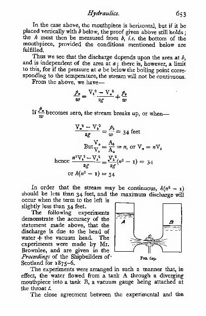
Hydraulics. 6S3
In the case above, the mouthpifece is horizontal, but if it beplaced vertically with b below, the proof given above still holds
j
the h must then be measured from b, i.e. the bottom of themouthpiece, provided the conditions mentioned below arefulfilled.
Thus we see that the discharge depends upon the area at b,
and is independent of the area at a ; there is, however, a limitto this, for if the pressure at a be below the boiUng point corre-sponding to the temperature, the stream will not be continuous.
From the above, we have
—
w
'
2g"^ W
If —^ becomes zero, the stream breaks up, or when
—
2g= ^=34 feet
Buty^ =^ = «, or V„ = «Vj
hence ^-X» li_^.l^(«2 - i) = 342^ 2.?-
or A(n^ — i) = 34
In order that the stream may be continuous, ^n' — 1)should be less than 34 feet, and the maximum discharge will
occur when the term to the left is
slightly less than 34 feet.
The following experimentsdemonstrate the accuracy of the
statement made above, that the
discharge is due to the head of
water + the vacuum head. Theexperiments were made by Mr,Brownlee, and are given in the
Proceedings of the Shipbuilders of* fig. 629.
Scotland for 1875-6.
The experiments were arranged in such a manner that, in
effect, the water flowed from a tank A through a diverging
mouthpiece into a tank B, a vacuum gauge being attached at
the throat t.
The close agreement between the experimental and the
' A'

6S4 Mechanics applied to Engineering.
calculated values as given in the last two columns, is a clear
proof of the accuracy of the theory given above.
Head of waterin tank A.
Feet.

Hydraulics. 655
back-pressure valve, and the spaces should gradually increase
in area as the high-pressure water proceeds—that is to say, the
first suction space should be very small, and the next rather
larger, and so on.
Rectangular Notch.—An orifice in a vertical plane with
an open top is termed a notch, or sometimes a weir. Theonly two forms of notches commonly used are the rectangular
and the triangular.
dh»
B- f—'i
Fig. 631.
From the figure, it will be observed that the head of waterimmediately over the crest is less than the head measuredfurther back, which is, however, the true head H.
In calculating the quantity of water Q that flows over sucha notch, we proceed thus
—
The area of any elementary strip as shown = '&.dhquantity of water passing strip perl v t? /^asecond, neglecting contraction
J
~ » • ^ • »"
where V = velocity of flow in feet per second,
\
\hhdh
= ijzgh, or
Hence the quantity ofwaterpassing stripl _ .
—
-ojiji.
per second, neglecting contraction f
~ ^ *^
the whole quantity of water Q passing"^
over the notch in cubic feet per>=V*^Bsecond, neglecting contraction J
- h'
Q = -/^BfWnQ = PH^2^H
introducing a coefficient to)^ T?-2T>tT /—
s
allow for contraction fQ=^^^^
^ *^"
where B and H are both measured in feet; where K has
values varying from 0*59 to o'64 depending largely on the

656 Mechanics applied to Engineering.
proportions of the section of the stream, i.e. the ratio of the
depth to the width, and on the relative size of the notch andthe section of the stream above it. In the absence of precise
data it is usual to take K = o'62. The following empirical
formula by Braschmann gives values of |K for various heads Hallowing for the velocity of approach. Let B^ = the breadth
of the approach channel in feet.
|K = (0-3838 + o-o386l+°-:?gli)
Triangular Notch.—In order to avoid the uncertainty
of the value of K, Professor James Thompson proposed the
use of V notches ; the form of the section of the stream then
always remains constant however the head may vary. Experi-
Fin. 633.
ments show that K for such a notch is very nearly constant.
Hence, in the absence of precise data, it may be used with
much greater confidence than the rectangular notch. Thequantity of water that passes is arrived at thus
:
Area of elementary strip = b . dh
^ b B.-h, ^ B(H - >4)
area of elementary strip = ' ~—'- dhrl
velocity of water passing strip = V = ij 2gh = \'^h^
quantity of water passing] -g/jj _ >,
strip per second, neglect- [ = -i—=
—
-^2gh^ . dhing contraction I
"whole quantity of water Q j f^ = H
\dh
lole quantity of water Q]
T^ = Hpassing over the notch in I B
(jj - h)h'cubic feet per second, ~"H'^"^Ja = oneglecting contraction

Hydraulics. 657
B _P = ^
J h = a
^ = \j^g 33
h = \\
Q = |V^(fH? - |Hi) = |ViiAH^
Introducing a coefficient for the contraction of the steam
and putting B = 2H for a right-angled notch.
where C has the following values. See Engineering, April
8th and 15th, igio.
H (feet) ...

658 Mechanics applied to Engineering.
both sides of an orifice, the discharge is not free ; the calculation
of the flow is, however, a very simple matter. The headproducing flow at any section xy (Fig. 634) is Hj — Hj = H
j
likewise, if any other section be taken, the head producing flow
is also H. Hence the velocity of flow V = V 2^H, and the
quantity discharged
—
Q= KAVz^HK varies somewhat, but is usually taken o"62 as a mean value.
Flov7 under a Constant Head.—It is often found
necessary to keep a perfectly constant head in a tank whenmaking careful measurements of the flow of
liquids, but it is often very difficult to accom-plish by keeping the supply exactly equal to
the delivery. It can, however, be easily
managed with the device shown in the figure.
It consists of a closed tank fitted with anorifice, also a gland and sliding pipe opento the atmosphere. The vessel is filled, or
nearly so, with the fluid, and the sliding pipe
adjusted to give the required flow. Theflow is due to the head H, and the negative
pressure/ above the surface of the water, for
a.F^E5
H-h
Fig. 635. as the water sinks a partial vacuum is formedin the upper part of the vessel, and air
bubbles through. Hence the pressure p is always due to the
head h, and the effective head producing flow through the
orifice is H — ^, which is independent of the height of water
in the vessel, and is constant provided the water does not sink
below the bottom of the pipe. The quantity of water
delivered is
—
Q = KAv'2^^H - h)
where K has the values given above for different orifices.
Velocity of Approach.—If the water approaching anotch or weir have a velocity V„, the quantity of water passingwill be correspondingly greater, but the exact amount will
depend upon whether the velocity of the stream is uniform at
every part of the cross-section, or whether it varies from pointto point as in the section over the crest of a weir or notch.
Let the velocity be uniform, as when approaching an orifice
of area a, the area of the approach channel being A.Let V = velocity due to the head /4, i.e. the head over the
orifice
;
V = velocity of water issuing from the orifice.

Hydraulics. 659
Then V„ = ^V, and V = V, + p
V = —V + VA
V = .
Ka
Broad-Crested Weir.—The water flows in a parallel
stream over the crest of the weir if the sill is of sufficient
Fig. 636.
breadth to allow the stream lines to take a horizontal direction.
Neglecting the velocity of approach, the velocity of the stream
passing over the crest is, V = V zgh where h is the depth of
the surface below that of the water in the approach channel.
Let B = the breadth (in feet) of the weir at right angles
to the direction of flow.
Then the quantity passing over the weir in cubic feet per
second is
—
Q = B(H->%)V2p
The value of h, however, is unknown. If h be large in
proportion to H, the section of the stream will be small, and
the velocity large; on the other hand, if h be small in pro-
portion to H, the section of the stream will be large and the
velocity small, hence there must be some value of h which
gives a maximum flow.
Let /4 = «H; _Q = BV'2^(H - nYi)>JnK
Q = BVii X hV - n")
dQ ,— 3,, _i „ I,

66o Mechanics applied to Engineering;
This is a maximum when
—
5«~- = ^ffi or when n = \
Inserting the value of n in the equation for Q, we have
—
Q = o-sSsBHV'i^
The actual flow in small smooth-topped weirs agrees well
with this expression, but in rough masonry weirs the flow is
less according to the degree of roughness.
Time required to Lower the Water in a Tankthrough an Orifice.—The problem of finding the time Trequired to lower the water in a dock or tank through a sluice-
gate, or through an orifice in the bottom, is one that often
arises.
(i.) 2'ank of uniform cross-section.
Let the area of the surface of the water be A.;
„ „ „ stream through the orifice be K^A
;
„ greater head of water above the orifice be Hi
;
„ lesser,, „
^ ^„ „ xlg •
„ head of water at any given instant be h.
The quantity of water passing through) _-k- a /
—
r j,
the orifice in the time dt ^- ii-.*A.v 2^A
.dt
Let the level of the water in the tank be lowered by anamount dh in the interval of time dt.
Then the quantity in the tank is reduced by an amountKJth, which is equal to' that which has passed through the
orifice in the interval, or
—
Y^i^,jlgh.dt= kjh
dt = ^ f° /i -^dh
p = H,
'^=K:f7p' ^~*^*
2A,(VHi-_VH,)
K.A^2^
The time required to empty the tank is
—

Hydraulics. 661
It is impossible to get an exact expression for this, because the
assumed conditions fail when the head becomes very small
;
the expression may, however, be used for most practical
purposes.
(ii.) Tapered tank of uniform breadth B.
In this case the quan-
tity in the tank is reduced
by the amount 'Q.l.dh
in the given interval of 1 ^time dt. H?
|
But/=y ^
ill
hence '&.l.dh = -^r^h dh«i
Fig. 637.
dt =BL
HiK^AVz^Ji'dh
Integrating, we get-
2BL(Hii - H,J)
3HiK,AV2i-
(iii.) Hemispherical tank.
In this case
—
1^= 2-SJi-h''
The quantity in the tank is
reduced by ir(2Ry4 — h'^)dh in the ^
interval dt.
dt =K,AV2ir
T =
(2R/4 - hyrUhFig. 638.
K,AV2^ (2R/*^ - h^) dh
J H,
i
rate.
T = _^ 5 _3 5 /
KiAV2^
Hv.) C«J<? ;« which the surface of the water falls at a uniform

662 Mechanics applied to Engineering.
In this case — is constant
;
at
hence Kik^~2gh = A„ X a constant
But K^Av 2^ is constant in any given case, hence the area of
the tank A„ at any height h above the orifice varies as ^/h. or the vertical section of the tank
must be paraboUc as shown.(v.) Time required to change the
level when water is flowing into atank at constant rate and leaving
by an orifice.
Let Aa = area of the surface of
the water in square
feet, when the depthof water above the
outlet is h feet.Fic. 638 A.
In a tank of geometrical form we may write
A„ = C/?" where C and n are constants.
Q, = the quantity of water in cubic feet per second runninginto the tank.
A = the area of the orifice in square feet.
T, = the time required to raise the level of the water fromHi to H„ feet.
T( = the time required to lower the level of the water fromH„ to Hi feet.
The quantity of water flowing into the tank) _/-,,.in the time dt V
The portion of the water which is retained in j _ *
the tank in the time dt \~ "dh
The quantity of water flowing out of the tank) _ t^ a /—i jj
through the outlet in the time dt \~ ^"^'^ "^^"^ "
When the water is entering the tank at a constant rate andleaving more slowly at a rate dependent upon the head, wehave
—
Y^iK'Jlgh dt=. Qi dt - A„ dh
dt{Q_t - K^aV^) = A,dh = Ch" dh/•Hm in J
I
^Jh, Q,-K,A^/2^-4
This expression can be integrated, but the final expression is

Hydraulics. 663
very long, and moreover in practice the form of the tank or
reservoir does not always conform to a geometrical law, hence
we use an approximate solution which can be made as accurate
as we please by taking a large number of layers between
measured contour areas. The above expression then becomes
'H
A1 Qi-K^aV 2^0-^1
A, M A2 Ih A,U+ 'Z ,, ,==- + — ZTT^"^ • ' •
2(q,-nVho q,-nVh2 q,-nVHs
2(Q,-NVHji
The first and last terms are divided by 2 because we start andend at the middle sections of the upper and lower layers,
hence the thickness of these layers is only one half as great
as that of the intermediate layers.
If we require to find the time necessary to lower the
surface, i.e. when the water leaves more rapidly than it enters,
we have
—
,4 Ai SA,
A2 8/% , As U+ ^^ ,— — + ^^ , r— — +
2{NVHi-Qe) NVH^-Q, NVHs-Q,
2(NVH„-Q,)3
Where Aj is the area of the surface at a height Hj abovethe middle of the culvert j and A2 is the area at a height
Ha = Hi + 8;^, and A3 at a height H3 = Hg + 8/4, and so on,
and N = K^a^/ 2g.
Example.—Let Q, = 48 cubic feet per second
Hi = 12 ft., hh = 0-5 ft, K^AVzg = 7
Ai = 140 sq. ft., Ag = 151, A3 s= 162, A4=i7o, Ag = 190
Then the time required to raise the level from 12 to 14 feet
would be
—
T ^ 140 X o-5_ 151 X 0-5 r62 X o-5_
2(48—7^/12) 48 — 7Vi2-5 48 — 7V13170 X 0-5
,190 X o'5
H—-^—
-\ -p= = 14-3 seconds.
48-7Vi3-s 2(48- 7V 14)
(vi.) Time of discharge through a submerged orifice.—In Fig.
639 we have
—

664 Mechanics applied to Engineering,
and 8Ha + mj^ 8A
8Hi =Ih A^U!+
Aa X Ab Uht =
Fig. 639.
T =
T =
Aa X Ab
(Aa+Ab)k^aV2^/*
(Aa + Ab)K^aV2^-zAa X Ab
i _ .
(Aa + Ab)k,aV2/ ''
p
h
-L-
Fig. 640.
where H and Hi are the initial
arid final differences of heads.
lime of discharge whenthe two tanks are connected
by a pipe of length L.—The loss of head h, due to
LVfriction in the pipe is =:=-
(see page 681), and the headh, dissipated in eddies at the
Voutlet is —
2P-
hence V =y h + h, _ / h /h_
KD^2^LKD "*"
ig
Hence from similar reasoning to that given in the last
paragraph we have
—
T = AaAbVcV H,
\dh(Aa + Ab^AJ Hi
2AaAbVc ,
(Aa + Ab)a(H -Hx')
Where A is the area of the pipe which is taken to be bell-
mouthed at entry, if it be otherwise the loss at entry (see
p. 673) must be added to the friction loss.

Hydraulics. 665
Time required to lower the Water in a Tank whenit flpws over a Weir or Notch.^
—
Rectangular Notch.—Bythe methods already given for orifices we have
—
jdi= ^^%-i \-^dh
zK^Bv 2^J Ha
Right-angled Vee Notch.—In this case we get by similar
reasoning
—
T = ^SA^r .-= dh =_25A„^( H,-^-- - H.-^-^
j8K^//2^-iHa 8K,V2^A -1-5 /
-T ^ 5A. / I i_\
Flow-through Pipes of Variable Section.—For the
present we shall only deal with pipes running full, in which the
section varies very gradually from point to point. If the varia-
tion be abrupt, an entirely different action takes place. Thisparticular case we shall deal with later on. The main point
that we have to concern ourselves with at present is to showthat the energy of the water at any section of the pipe is
constant—neglecting friction.
If W lbs. of water be raised from a given datum to a
receiver at a certain height h feet above, the work done in
raising the water is W^ foot-lbs., or h foot-lbs. per pound ofwater. By lowering the water to the datum, WA foot-lbs. of
work will be done. Hence, when the water is in the raised
position its energy is termed its energy of position, or
—
The energy of position = WA foot-lbs.
If the water were allowed to fall freely, i.e. doing nowork in its descent, it would attain a velocity V feet per
V^second, where V = »/ 2gh, or h =— . Then, smce no energy
2g WVis destroyed in the fall, we have VJh = foot-lbs. of
energy stored in the falling water when it reaches the datum,
or — foot-lbs. per pound of water. This energy, which is
due to its velocity, is termed its kinetic energy, or energy of
motion ; or— WVThe energy of motion =

666 Mechanics applied to Engineering.
If the water in the receiver descends by a pipe to the
datum level—for conveniencewe will take the pipe as one square
inch area—the pressure / at the foot of the pipe will be wh lbs.
per square inch. This pressure is capable of overcoming a
resistance through a distance / feet, and thereby doing pi foot-
lbs, of work ; then, as no energy is destroyed in passing along
the pipe, we have// = W^ = -^ foot-lbs. of work done by the
water under pressure, or ^ foot-lbs. per pound of water. Thisw
is known as its pressure-energy, or
—
The pressure-energy = —£-
Thus the energy of a given quantity of water may exist
exclusively in either of the above forms, or partially in oneform and partially in another, or in any combination of the
three.
Total energy perl _ (energy of)' (energy ofl , (pressure-)
pound of water) ~ \ position\ \ motion ft energy )
ig w
This may, perhaps, be more clearly seen by referring to the
figure.
Fig. 64Z
Then, as no energy of the water is destroyed on passing
through the pipe, the total energy at each section must be the
same, or
—
;i, + Yk +A =^ 4. Yl +A ^ constantig W 2g W

Hydraultcs. 667
The quantity of water passing any given section of the pipe
in a given time is the same, or—
or AjVi = AjV,
Yi = ^V, A,
or the velocity of the water varies inversely as the sectional
area
—
Fig. 642.
Some interesting points in this connection were given bythe late Mr. Froude at the British Association in 1875.
Let vertical pipes be inserted in the main pipe as shown
;
then the height H, to which the water will rise in each, will beproportional to the pressure, or
—
H, = ^, and Hj = -^Wl w
and the total heights of the water-columns above datum
—
w w
and the differences of the heights
—
^-^ + Aw
•-h =•W 2g 2g
V ' — VH, - H, = -1? 11
2.?
from the equation given above.
Thus we see that, when water is steadily running through

668 Mechanics applied to Engineering.
a full pipe of variable section, the pressure is greatest at the
greatest section, and least at the least section.
In addition to many other experiments that can be madeto prove that such is the case, one has been devised by Pro-
fessor Osborne Reynolds that beautifully illustrates this point.
Take a piece of glass tube, say \ inch bore drawn down to a
fine waist in the middle of, say, -^ inch diameter ; then, whenwater is forced through it at a high velocity, the pressure is so
reduced at the waist that the water boils and hisses loudly.
The pressure is atmospheric at the outlet, but very much less at
the waist. The hissing in water-injectors and partially openedvalves is also due to this cause.
Ventnri Water-meter.—An interesting application of
this principle is the Venturi water-meter. The water is forced
through a very easy waist in a pipe, and the pressure measuredat the smallest and largest section ; then, if the difierence of
the heads corresponding to the two pressures be Ho in feet of
water (Fig. 643)—V^ — V
' „ ^ = H„, or Vi - V,^ = 2^Ho
Let Aj = nKi, ; then Vj = —n
hence V/ - (^J = 2^Ho and V^ = /J^Si.
• '/Ho'=cVh;Q = A,V, = Aj
V

Hydraulics. 669
of velocity K, which is very nearly constant over a very widerange, its value is from 0-97 to o'gS, or say, o'gys, then
—
Q = K^cVroS V'H^ = CVh^ very nearly.
At very low velocities of flow, where errors are usually of
no importance, the value of K„ varies in a very erratic fashion,
the reason for which is unknown at present; but for such
velocities of flow as are likely to be used in practice the meter
gives extremely accurate results. When used for waterworks
purposes the meter is always fitted with a recorder andintegrator, particulars of which can be obtained of Mr. Kent,
of High Holborn, London.
Fig. 643.
The loss of head on the whole meter often amounts to
about — - For experimental data on the losses in divergent
pipes, readers should refer to a paper by Gibson, "TheResistance to Flow of Water through Pipes or Passages havingDivergent Boundaries," Transactions of the Royal Society ofEdinburgh, vol. xlviii.
Radiating Currents and Free Vortex Motion.—Letthe figure represent the section of two circular plates at a small
distance apart, and let water flow up the vertical pipe andescape round the circumference of the plates. Take any small
portion of the plates as shown ; the strips represent portions of
rings of water moving towards the outside. Let their areas beOi, «2j then, since the flow is constant, we have
—

670 Mechanics applied to Engineering.
V2 <h n
,
''1
Wiffi = Villi, or — = — = — hence w^ = v-r-»i a.i r^ r^
or the velocity varies inversely as the radius. The plates being
horizontal, the energy of position remains constant ; therefore
—
2g W 2g W
Substituting the value of v^ found above, we have—
!!l J.-6 _'"'''"''M
2g W 2g. Ti
Then, substituting — + - = H2g w
.P2
w
from above, and putting
r; ^1"^ = ^, we have
—
'2
H-/4,=A
Then, starting
with a value for hy,
the h^ for other posi-
tions is readily calcu-
lated and set downfrom the line above.
If a large numberof radial segmentswere taken, theywould form a com-plete cylinder ofwater, in which the
water enters at the^""" ^^ centre and escapes
radially outwards. The distribution of pressure will be the
same as in the radial segments, and the form of the waterwill be a solid of revolution formed by spinning the dottedline of pressures, known as Barlow's curve, round the axis.
The case in which this kind of vortex is most commonlymet with is when water flows in radially to a central hole, andthen escapes.
Forced Vortex.—If water be forced to revolve in andwith a revolving vessel, the form taken up by the surface is
readily found thus
:

Hydraulics. 671
Let the vessel be rotating n times per second.
Any particle of water is acted uponby the following forces :
—
(i.) The weight W acting vertically
downwards.
(ii.) The centrifugal force act-
ing horizontally, where V is its velocity
in feet per second, and r its radius in
feet.
(iii.) The fluid pressure, which is
equal to the resultant of i. and ii.
From the figure, we have
—
wae
be
Fig. 645.
which may be written
—
'Wgr be
2 TTBut— IS constant, say C
;
g
Then Cfyt^ = "1
be
But ac = r
therefore C«^ = —be
And for any given number of revolutions per second «* doesnot vary ; therefore be, the
subnormal, is constant, andthe curve is therefore a para-
bola. If an orifice were madein the bottom of the vessel
at 0, the discharge would bedue to the head h.
Loss of Energy due toAbrupt Change of Direc-tion.—If a stream of water flow down an inclined surface ABwith a velocity Vj feet per second, when it reaches B the
direction of flow is suddenly changed from AB to BC, and the

672 Mechanics applied to Engineering.
layers of water overtop one another, thus causing a breaking-up
of the stream, and an eddying action which rapidly dissipates
the energy of the stream by the frictional resistance of the
particles of the water; this is sometimes termed the loss byshock. The velocity V3 with which the water flows after
passing the corner is given by the diagram of velocities ABD,from which we see that the component Vj, normal to BC, is
wasted in eddying, and the energy wasted per pound of water
IS _1- =—i
As the angle ABD increases the loss of energy increases,
and when it becomes a right angle the whole of the energy is
wasted by shock (Fig. 646).
If the surface be a smooth curve (Fig. 647) in which there
is no abrupt change of direction, there will be no loss due to
^ \
Fig. 646. Fig. 647.
shock ; hence the smooth easy curves that are adopted for the
vanes of motors, etc.
If the surface against which the water strikes (normally) is
moving in the same direction as the jet with a velocity
y— , then the striking velocity will be
—
V. - X.' = V,n
and the loss of energy per pound of water will be—
2£ 2g- 2g\ n'

Hydraulics. 673
When « = I, no striking lakes place, and consequently noloss of energy
Jwhen «= 00 , i.e. when the surface is stationary,
the loss is -i, i.e. the whole energy of the jet is dissipated.
Loss of Energy due to Abrupt Change of Section.—When water flows along a pipe in which there is an abruptchange of section, as shown, we may regard it as a jet of watermoving with a velocity Vj striking against a surface (in this casea body of water) moving in the same
Ydirection, but with a velocity —
j henceI ci9^
—~~
the loss of energy per pound of water * ^nzj^Cr-^Ais precisely the same as in the last para- ^^s>;r:rr
(y -ViV ^-^^^
—
I ' > ~) Fig. 648 (see also No. 3graph, viz.
^ ^ . The energy lost ^c'lg p- 67+).
in this case is in eddying in the corners of the large section,
as shown. As the water in the large section is moving -n
as fast as in the small section, the area of the large sectionis n times the area of the small section. Then the loss ofenergy per pound of water, or the loss of head when a pipesuddenly enlarges « times, is
—
v.'(--;)'
Or if we refer to the velocity in the large section as Vj, wehave the velocity in the small section «Vi, and the loss ofhead
—
When the water flows in the opposite direction, i.e. fromthe large to the small section, the loss
of head is due to the abrupt change of
velocity from the contracted to the
full section of the small stream. Thecontracted section in pipes under pres-
sure is, according to some experiments
made in the author's laboratory, from fig.' 649 Cs« also No. 4 facing
0*62 to o"66; hence, «* = from i'6i p-674).
to i'5 ; then, the loss of head =
2 X

6/4 Mechanics applied to Engineering.
Total Loss of Energy due to a Sudden Enlargementand Contraction.—Let the section before the enlargement
be termed i, the enlarged section 2, and the section after the
enlargement 3, with corresponding suffixes for velocities and
pressures. Then for a horizontal pipe we have
—
W- 2g W 2g 2g\ nJ
W Ig;
Gibson finds that the loss of energy is slightly greater than
this expression gives. The author finds that the actual loss in
some cases is nearly twice as great as the calculated.
Experiments on the Character of Fluid Motion.—Some very beautiful experiments, by Professor Hele-Shaw,
F.R.S., on the flow of-fluids, enable us to study exactly the
fn^nner ,ip which th,e ^ow takes place in channels of various
fofms. He' takes two sheets of glass and' fits them into a
suitable frame, whichholds them in position at about yj^ inch
apart. , Through this narrow space liquid is caused to flow underpressare, and in order to demonstrate the exact manner in
which the flow takes place, bands of. coloured liquid are
injected at the inlet end. In the narrow sections of the
channel, where the velocity of flow is greatest, the bandsthemselves are narrowest, and they widen out in that portion
of the channel where the velocity is least. The perfect
manner in which the bands converge and diverge as the
liquid passes through a neck or a pierced diaphragm, is in
itself an elegant demonstration of the behaviour of a perfect
fluid (see Diagrams i and 5). The form and behaviour of the
bands, moreover, exactly correspond with mathematical demon-strations of the mode of flow of perfect fluids. The author
is indebted to Professor Hele-Shaw, for the illustrations given,
which are reproduced from his own photographs.
In the majority of cases, however, that occur in practice,
we are unfortunately unable to secure such perfect stream-line
motions as we have just described. We usually have to deal
with water flowing in sitiuous fashion with very complex eddy-ings, which is much more difficult to ocularly demonstrate thantrue stream-line motion. Professor Hele-Shaw's method of
showing the tumultuous conditions under which the water is
moving, is to inject fine bubbles of air into the water, whichmake the disturbances within quite evident. The diagrams 2,

ITofacep. 674.
FLOW OF WATER DIAGRAMS.
Kindly supplied by Processor Helt-Shaw, F.R.S.


Hydraulics. 675
3, 4, and 6, also reproduced from his photographs, clearly
demonstrate the breaking up of the water when it encounters
sudden enlargements and contractions, as predicted by theory.
A careful study of these figures, in conjunction with the
theoretical treatment of the subject, is of the greatest value in
getting a clear idea of the turbulent action of flowing water..
Readers should refer to the original communications byProfessor Hele-Shaw in the Transactions of theNaval Architects,
1897-98, also the engineering journals at that time.
Surface Friction.—When a body immersed in water is
caused to move, or when water flows over a body, a certain
resistance to motion is experienced ; this resistance is termedthe surface or fluid friction between the body and the water.
At very low velocities, only a thin film of the water actually
in contact with the body appears to be affected, a mere skim-ming action ; but as the velocity is increased, the moving bodyappears to carry more or less of the water with it, and to causelocal eddying for some distance from the body. Experimentsmade by Professor Osborne Reynolds clearly demonstrate the
difference between the twokinds of resistances—the sur-
face resistance and the eddy-
ing resistance. Water is caused
to flow through the glass pipe
AB at a given velocity ; a bent
glass tube and funnel C is
fixed in such a manner that a
fine stream of deeply coloured
dye is ejected. When the water fig. 650.
flows through at a low velocity,
the stream of dye runs right through like an unbroken thread
;
but as soon as the velocity is increased beyond a certain
point, the thread breaks up and passes through in sinuous
fashion, thus demonstrating that the water is not flowing
through as a steady stream, as it did at the lower velocities.
Friction in Pipes.—Contimeotis Flow.—When the flow
in a pipe is continuous, i.e. not of an eddying nature, the
resistance to flow is entirely due to the viscosity of the fluid.
On p. 314 we showed that the resistance to shearing a viscous
fluid is
—
where A is the wetted surface in square feet, K is the

6/6 Mechanics applied to Engineering.
coefficient of viscosity, S the speed of shearing (usually denotedby V in hydraulics) in feet per second, / is the thickness of
the sheared element in feet, in the case of a pipe of radius
R, / = R. Then, without going fully into the question, for
which treatises on Hydraulics should be consulted
—
Let Pi = the initial pressure in pounds per sq. foot.
Pa = the final pressure in pounds per sq. foot.
L = the length of the pipe in feet.
Aj, = the area of the pipe in sq. feet.
F, = (Pi - Pe)A, = W„(Hi - H,)A^F. = W„/iA^
where h„ is the loss of head in feet due to the resistance on alength of pipe L.
Then W„/4.A, =^^^R
(27rRL)KV _ 2LKV ^ 8LKVW„.(xR^)R ~ W„R' ~ W^D''
LVCD"
This expression only holds for stream line, or con-
tinuous flow, the critical velocity V„ at which the flow changes
from continuous to sinuous is always much higher than the
velocity V„i at which the flow changes from sinuous to con-
tinuous. The critical velocity also largely depends upon the
temperature of the water owing to a change in the viscosity.
Let Vc = the critical velocity, i.e. the velocity in feet per
second at which the flow changes from con-tinuous to sinuous.
V„i = ditto at which the flow changes from sinuous to
continuous.
n and «i = coefficients which depend upon the temperature
of the water.
D = the diameter of the pipe in feet,
then V. = -
and V,i = g

Hydraulics. 677
TemperatureFahrenheit.

678 Mechanics applied to Engineering.
which the water breaks up is very much greater than this
expression gives. See a paper on " Hydraulics of the Re-
sistance of Ships," read at the Engineering Congress in
Glasgow, 1901 ; also Engineering, December 20, 1901, from
which the curves in Fig. 651 have been taken. The Osborne
Reynolds' law is represented by AC and BD, whereas Thrupp
shows that experimental values lie somewhere between AAand BB.
The change points from continuous to sinuous flow are
shown in Fig. 652. At low velocities of flow the loss of

Hydraulics. 679
its Applications," and Turner and Brightmore's " WaterworksEngineering."
Sinuous Flow.—Experiments by Mr. Froude at Torquay(see Brit. Ass. Proceedings, 1874), on the frictional resistance
of long planks, towed end-on through the water at various
velocities, showed that the following laws appear to hold
within narrow limits :
—
(i.) The friction varies directly as the extent of the wetted
surface.
(ii.^ The friction varies directly as the roughness of the
surface.
(iii.) The friction varies directly as the square of the
velocity.
(iv.) The friction is independent of the pressure.
For fluids other than water, we should have to add
—
(v.) The friction varies directly as the density and viscosity
of the fluid.
Hence, if S = the wetted surface in square feet
;
/= a coefficient depending on the roughness of
the surface ; i.e. the resistance per square
foot at I foot per second in pounds
;
V = velocity of flow relatively tp the surface in
feet per second
;
R = frictional resistance in pounds
;
Then, R = S/V^
Some have endeavoured to prove from Mr. Froude's ownfigures that the first of the laws given above does not evenapproximately hold. The basis of their argument is that the
frictional resistance of a plank, say 50 feet in length, is not
ten times as great as the resistance of a plank 5 feet in length.
This effect is, however, entirely due to the fact that the first
portion of the plank meets with water at rest, and, therefore, if
a plank be said to be moving at a speed of 10 feet a second, it
simply means that this is the relative velocity of the plank andthe still water. But the moving plank imparts a considerable
velocity to the surrounding water by dragging it along with it,
hence the relative velocity of the rear end of the plank and the
water is less than 10 feet a second, and the friction is corre-
spondingly reduced. In order to make this point clear the
author has plotted the curves in Figs. 653 and 654, which are
deduced from Mr. Froude's own figures. It is worthy of note
that planks with rough surfaces drag the water along with themto a much greater extent than is the case with planks having

68o Mechanics applied to Engineering.
1-3
B\
0-3^
0-2 -
^!??5
r-Af
-i.
'^^
Qa<£^
COAff.JE SAfID
VW£^ ^4A^
*0 2S 30
DISTANCE nan CVTIMrenFig. 653.

Hydraulics. 68
1
smooth surfaces, a result quite in accordance with what onemight expect.
The value of/deduced from these experiments is
—
Surface covered with coarse sand ...

682 Mechanics applied to Engineering.
D'Arcy's experiments were made on pipes varying in
diameter from \ inch up to 20 inches ; for small pipes his
coefficient appears to hold tolerably well, but it is certainly
incorrect for large pipes.
The author has recently looked into this question, andfinds that the following expression better fits the most recent
published experiments for pipes of over 8 inch diameter
(see a paper by Lawford, Proceedings I.C.E., vol. cliii. p.
297) :—
— = ( I + -r~ ) for clean cast-iron pipesK 5ooo\ 2D/
— = ( I H—;:r I for incrusted pipesK 25oo\ 2D/
But the above expression at the best is only a rough
approximation, since the value of / varies very largely for
different surfaces, and the resistance does not always vary as
the square of the velocity, nor simply inversely as D.
The energy of motion of i lb. of water moving with a
velocity V feet per second is — ; hence the whole energy of
motion of the water is dissipated in friction when
—
V^ LV2g~ KD
Taking K = 2400 and putting in the numerical value for g,
we get L = 37D. This value 37, of course, depends on the
roughness of the pipe. We shall find this method of regarding
frictional resistances exceedingly convenient when dealing with
the resistances of T's, elbows, etc., in pipes.
Still adhering to the rough formula given above, we can
calculate the discharge of any pipe thus
:
The quantity discharged in) ^ _ a v _ '^^"^
cubic feet per second j^- ti — AV — —
—
From the same formula, we have
—
''2400DAvV^

Hydraulics. 683
Substituting this value, we have
—
Q=38-SD^\/J=38-SD^>/ L
Thrupp's Formula for the Plow of Water.—All
formulas for the flow of water are, or should be, constructed
to fit experiments, and that which fits the widest range of ex-
periments is of course the most reliable. Several investigators
in recent years have collected together the results of published
experiments, and have adjusted the older formulas or haveconstructed new ones to better accord with experiments.
There is very little to choose between the best of recent
formulas, but on the whole the author believes that this
formula best fits the widest range of experiments ; others are
equally as good for smaller ranges. It is a modification of
Hagen's formula, and was published in a paper read before the
Society of Engineers in 1887.
Let V = velocity of flow in feet per second
;
R = hydraulic mean radius in feet, i.e. the area of the
stream divided by the wetted perimeter, and
is? for circular and square pipes:
L = length of pipe in feet
;
h = loss of head due to friction in feet
;
S = cosecant of angle of slope = —
;
Q = quantity of water flowing in cubic feet per second.
Then V =C^S
where x, C, n are coeflScients depending on the nature of the
surface of the pipe or channel.
For small values of R, more accurate results will be ob-
tained by substituting for the index x the value x + y^
In this formula the effect of a change of temperature is not
taken into account. The friction varies, roughly, inversely as
the absolute temperature of the water.

684 Mechanics applied to Engineering.
Siufacc.

Hydraulics. 685
slope " of the main. If the lower end of the main be partially
closed, it will reduce the virtual slope ; and if it be closed
altogether, the virtual slope will be nil, or the line will be
horizontal, and, of course, no water will flow. The velocity
of flow is proportional to the virtual slope, the tangent of the
angle of slope is the -^ in the expressions we use for thei-t
friction in pipes.
The above statement is only strictly true when there is no
loss of head at entry into the main, and when the main is of
uniform diameter and roughness throughout, and when there
are no artificial resistances. When any such irregularities doexist, the construction of the virtual slope line offers, as a rule,
no difficulties, but it is no longer straight.
Fig. 655.
In the case of the pipe shown in full lines the resistance is
uniform throughout, but in the case of the pipe shown in
broken line, there is a loss at entry a, due to the pipe project-
ing into the top reservoir ; the virtual slope line is then
parallel to the upper line until it reaches b, when it drops, dueto a sudden contraction in the main ; from ^ to ^ its slope is
steeper than from a to b, on account of the pipe being smaller
in diameter ; at c there is a drop due to a sudden enlargement
and contraction, the slope from ^ to 1/ is the same as from b to
c, and at d there is a drop due to a sudden enlargement, then
from dXo e the line is parallel to the upper line. The amountof the drop at each resistance can be calculated by the methodsalready explained.
The pressure at every point in the main is proportional to
the height of the virtual slope line above the main ; hence, if
the main at any point rises above the virtual slope line, the
pressure will be negative, i.e. less than atmospheric, or there
will be a partial vacuum at such a point. If the main rises
more than 34 feet above the virtual slope line, the water will

686 Mechanics applied to Engineering.
break up, and may cause very serious trouble. In waterworks
mains great pains are taken to keep them below the virtual
slope line, but if it is impracticable to do so, air-cocks are
placed at such summits to prevent the pressure falling belowthat of the atmosphere ; the flow is then due to the virtual slope
between the upper reservoir and this point. In certain cases
it is better to put an artificial resistance in the shape of a
pierced diaphragm or a valve on the outlet end of the pipe, in
order to raise the virtual slope line sufficient to bring it aboveevery point of the main, or the same result may be accom-plished by using smaller pipes for the lower reaches.
Flow of Water down an Open Channel on a SteepSlope.—
Let u = the initial velocity of the water in feet per second.
V = the velocity of the water after running along aportion of the channel of length /(feet) measuredon the slope.
6 = the angle of the slope to the horizontal.
H = the vertical fall of the channel in the length / then
H = / sin e.
h = the loss of head in feet due to friction while the
water is flowing along the length /.
R = the hydraulic mean depth of the channel.
K = four times the constant in D'Arcy's formula for
pipes (multiplied by 4 to make it applicable to
channels, and using the hydraulic mean depthinstead of the diameter).
The velocity of a particle of water running down a slopeis the same as that of a particle falling freely through thesame vertical height, if there is no friction. When there is
friction we have—V^ = u^ + 2^(H - A)
The loss of head due to friction is
—
/(?/' + 2^'-H)KR ^ / {t{' + 2glsine)KRV KR-l-2^/ V KR + 2^/

Hydraulics. 687
This expression is used by calculating in the first place
the value for V, taking for H some small amount, say 10 feet.
Then all the quantities under the root are constant, except u,
hence we may write
—
v. = -v/!^+ n sin 0)in
m + n
for the first 10 feet, then the u for the second 10 feet becomes
-^and for the third 10 feet-
V.
(Vi^ + n sin
_ /(V/ + n sin e)m
and so on for each succeeding 10 feet.
The following table shows a comparison between the
results obtained by Mr. Hill's formula ' and that given above
—
« = 15 feet per second,
R=i-S3-K = 15130 (deduced from Mr. Hill's constant).
e= 12° 40'.
H = 10 feet. / = 45 "7 feet.

688 Mechanics applied to Engineering.
If the slope varies from point to point the angle 5 must betaken to suit : similarly, if the hydraulic mean depth varies
the proper values of R must be inserted in the expression.
An interesting application of the above theory to the
formation of ponds at the approach end of culverts will befound in a paper by the author, " The Flooding of the ApproachEnd of a Culvert," Proc. Inst. Civil Engineers, vol. clxxxvi.
Flow through a Pipe with a Restricted Outlet.
—
When a pipe is fitted with a valve or nozzle at the outlet end,
the kinetic energy of the escaping water is usually quite a
large fraction of the potential energy of the water in the upper
reservoir ; but in the absence of such a restriction, the kinetic
energy of the escaping water is quite a negligible quantity in
the case of long pipes.
The velocity of the water can be found thus
:
Let H = head of water above the valve in feet
;
L = length of main in feet
;
V = velocity of flow in the main in feet per second
;
K = a constant depending on the roughness of the
pipe (see p. 68 1)
;
D = diameter of the pipe in feetj
Vi = velocity of flow tlu'ough the valve opening
;
n = the ratio of the valve opening to the area of the
Vpipe, or « = =^
.
»i
The total energy per pound of water is H foot-lbs. Thisis expended (i.) in overcoming friction, (ii.) in imparting kinetic
energy to the water issuing from the valve ; or
—
LV» V,^
VSubstitutmg the value of Vj = — , we have
—
H
KD "*zgn^
On p. 717 we give some diagrams to show how the
velocity of the water in the main varies as the valve is closed
;
in all cases we have neglected the frictional resistance of the
valve itself, which will vary with the type employed. - In the
case of a long pipe it will be noticed that the velocity of flow
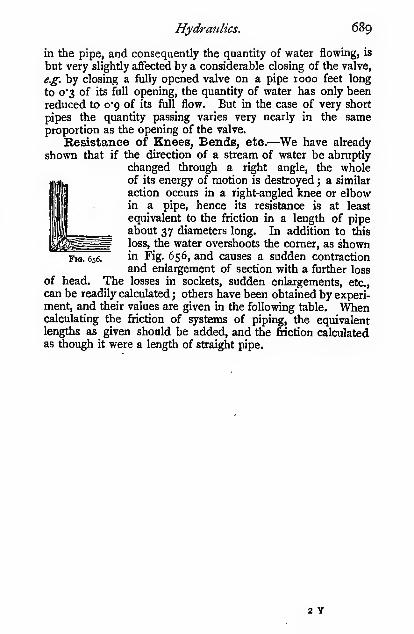
Hydraulics. 689
in the pipe, and consequently the quantity of water flowing, is
but very slightly affected by a considerable closing of the valve,
e.g. by closing a fully opened valve on a pipe 1000 feet long
to o"3 of its full opening, the quantity of water has only been
reduced to 0*9 of its full flow. But in the case of very short
pipes the quantity passing varies very nearly in the sameproportion as the opening of the valve.
Resistance of Knees, Bends, etc.—^We have already
shown that if the direction of a stream of water be abruptly
changed through a right angle, the wholeof its energy of motion is destroyed ; a similar
action occurs in a right-angled knee or elbowin a pipe, hence its resistance is at least
equivalent to the friction in a length of pipeabout 37 diameters long. In addition to this
^^^^^ loss, the water overshoots the corner, as shownFig. 656. in Fig- 656, and causes a sudden contraction
and enlargement of section with a further loss
of head. The losses in sockets, sudden enlargements, etc.,
can be readily calculated ; others have been obtained by experi-ment, and their values are given in the following table. Whencalculating the friction of systems of piping, the equivalentlengths as given should be added, and the friction calculatedas though it were a length of straight pipe.
2 Y

690 Mechanics applied to Engineering.
Nature of resistance.
Equivalent length of straight
pipe expressed in diameters,
on the basis of L =: 36D,
15"
30°
45°
ij inch check valve
ij inch ball check valve
Sluice and slide valves «=
Unwin
Right-angled knee or elbow (experiments)
Right-angled bends, exclusive of resist-
ance of socketsi at ends, radius of bend,= 4 diameters
Ditto including sockets (experiments)
Sockets (screvred) calculated from the!
sudden enlargement and contraction (
(average sizes)
Ditto by experimentSudden enlargement to a square-ended)
, large areapipe, where n =—=7^' "^ small area
Sudden contraction
Mushroom valves
{handleturned
throue;h
port area
area of opening
„. J J. V area of pipePierced diaphragm » = .f \
area of hole
Water entering a re-entrant pipe, such as\
a Borda's mouthpiece ... ... ...J
Water entering a square-ended pipe flush)
with the side of the tank /
/30-40 in plain pipe
\50-90 with screwed elbow
3-1
S
22-30
24
16-20
H-ff12 approx.120-400
27200HOC700-15002000-3000
ioo(« — l)'
36(1 -Sb - i)»
18
9-12
Velocity of Water in Pipes.—Water is allowed to flow
at about the velocities given below for the various purposesnamed :
—
Pressure pipes for hydraulic purposes for long mains 3 to 4 feet per sec.
Ditto for short lengths ' Up to 25 „Ditto through valve passages ' Up to 50 „Pumping mains
_3 to S «t
Waterworks mains 2 to 3 „
' Such velocities are unfortunately common, but they should be avoided
if possible.

CHAPTER XIX.
HYDRAULIC MOTORS AND MACHINES.
The work done by raising water from a given datum to a
receiver at a higher level is recoverable by utilizing it in oneof three distinct types of motor.
r. Gravity machines, in which the weight of the water is
utilized.
2. Pressure machines, in which the pressure of the water is
utilized.
3. Velocity machines, in which the velocity of the water is
utilized.
Gravity Machines.—In this type of machine the weight-
energy of the water is utihzed by causing the water to flow
into the receivers of the machine at the higher level, then to
descend with the receivers in either a straight or curved path
to the lower level at which it is discharged. IfW lbs. of water
have descended through a height H feet, the work done =WH foot-lbs. Only a part, however, of this will be utiUzed bythe motor, for reasons which we will now consider.
Fig. 637. Fig. 658.
The illustrations. Figs. 657, 658, show various methods of

692 Mechanics applied to Engineering.
utilizing the weight-energy of water. Those shown in Fig. 657are very rarely used, but they serve well to illustrate the
principle involved. The ordinary overshot wheel shown in
Fig. 658 will perhaps be the most instructive example to
investigate as regards efficiency.
Although we have termed all of these machines gravity
machines, they are not purely such, for they all derive a small
portion of their power from the water striking the buckets onentry. Later on we shall show that, for motors which utilize
the velocity of the water, the maximum efficiency occurs whenthe velocity of the jet is twice the velocity of the buckets or
vanes.
In the case of an overshot water-wheel, it is necessary to
keep down the linear velocity of the buckets, otherwise the
centrifugal force acting on the water will cause much of it to
be wasted by spilling over the buckets. If we decide that the
inclination of the surface of the water in the buckets to the
horizontal shall not exceed 1 in 8, we get the peripheral
velocity of the wheel V„ = zVRj where R is the radius of the
wheel in feet.
Take, for example, a wheel required for a fall of 15 feet.
The diameter of the wheel may be taken as a first approxima-tion as 12 feet. Then the velocity of the rim should not
exceed 2 v' 6 = say 5 feet per second. Then the velocity of
the water issuing from the sluice should be 10 feet persecond ; the head h required to produce this velocity will be
h = — , or, introducing a coefficient to
allow for the friction in the sluice, we may
write It ^= = 1-6 foot. One-half
of this head, we shall show later, is lost
by shock. The depth of the shroud is
usually from 075 to i foot ; the distancefrom the middle of the stream to the c.
of g. of the water in the bucket may betaken at about i foot, which is also asource of loss.
The next source of waste is due tothe water leaving the wheel before it reaches the bottom.The exact position at which it leaves varies with the formof buckets adopted, but for our present purpose it may betaken that the mean discharge occurs at an angle of 45° as
FiQ. 659.

Hydraulic Motors and Machines. 693'
shown. Then by measurement from the diagram, or by a
simple calculation, we see that this loss is o'isD, A clearance
of about o's foot is usually allowed between the wheel andthe tail water. We can now find the diameter of the wheel,
remembering that H = 15 feet, and taking the height from the
surface of the water to the wheel as 2 feet. This together
with the 0*5 foot clearance at the bottom gives us D = i2'5
feet.
Thus the losses with this wheel are
—
Half the sluice head = o'8 foot
Drop from centre of stream to buckets = I'o „Water leaving wheel too early,) _ ..„
o-is X 12-5 feet ]-^9 »
Clearance at bottom = o's „
4' 2 feet
15— 4"2
Hydraulic efficiency of wheel =—--— = 72 per cent.
The mechanical efficiency of the axle and one toothed
wheel will be about 90 per cent., thus giving a total efficiency
of the wheel of 65 per cent.
With greater falls this efficiency can be raised to 80 per cent.
The above calculations do not profess to be a completetreatment of the overshot wheel, but they fairly indicate the
sort of losses such wheels are liable to.
The loss due to the water leaving too early can be largely
avoided by arranging the wheel as shown in Fig. 660.
Fig. 660. Fig. 661.
Pressure Machines.—In these machines the water at the
higher level descends by a pipe to the lower level, from whenceit passes to a closed vessel or a cylinder, and acts on a movable

694 Mechanics applied to Engineering.
piston in precisely the same manner as in a steam-engine.
The work done is the same as before, viz. WH foot-lbs. for
f

Hydraulic Motors and Machines. 69s
to special books on hydraulic machines, such as Blaine ' or
Robinson.''
The chief sources of loss in efficiency in these motors are
—
1. Friction of the water in the mains and passages.
2. Losses by shock through abrupt changes in velocity of
water.
3. Friction of mechanism.
4. Waste of water due to the same quantity being used whenrunning under light loads as when running with the full load.
The friction and shock losses may be reduced to a minimumby careful attention to the design of the ports and passages
;
re-entrant angles, abrupt changes of section of ports andpassages, high velocities of flow, and other sources of loss
given in the chapter on hydraulics should be carefully avoided.
By far the most serious loss in most motors of this type is
that mentioned in No. 4 above. Many very ingenious devices
have been tried with the object of overcoming this loss.
Amongst the most promising of those tried are devices
for automatically regulating the length of the stroke in pro-
portion to the resistance overcome by the motor. Perhaps
the best known of these devices is that of the Hastie engine,
a full description of which will be found in Professor Unwin's
article on Hydromechanics in the " Encyclopaedia Britannica."
In an experiment on this engine, the following results wereobtained :—
-
Weight in pounds lifted \
22 feet /

696 Mechanics applied to Engineeritig.
only for full loads. The valves for changing over the con-
ditions are usually worked by hand, but it is very often found
that the man in charge does not take advantage of the smallei
cylinder. In order to place it beyond his control, the ex-
tremely ingenious device shown in Fig. 664 is sometimes used.
FULL P/fESSUKE c
The author is indebted to Mr. R. H. Thorp, of New York,
the inventor, for the drawings and particulars from which the
following account is taken. The working cylinder is shown at
AB. 'Wlien working at full power, the valve D is in the
position shown in full lines, which allows the water from B to
escape freely by means of the exhaust pipes E and K ; then
the quantity of water used is given by the volume A. But whenworking at half-power, the valve D is in the position shown in
dotted lines ; the water in B then returns vid the pipe E, the
valve D, and the pipe F to the A side of the piston. Undersuch conditions it will be seen that the quantity of high-pressure
water used is the volume A minus the volume B, which is
usually one-half of the former quantity. The position of the
valve D, which determines the conditions of full or half power,
is generally controlled by hand. The action of the automatic
device shown depends upon the fact that the pressure of the
water in the cylinder is proportional to the load lifted, for if the
pressure were in excess of that required to steadily raise a light

Hydraulic Motors and Machines. 697
load, the piston would be accelerated, and the pressure would
be reduced, due to the high velocity in the ports. In general,
the man in charge of the crane throttles the water at the inlet
valve in order to prevent any such acceleration. In Mr.
Thorp's arrangement, the valve D is worked automatically.
In the position shown, the crane is working at full power
;
but if the crane be only lightly loaded, the piston will beaccelerated and the pressure of the water will be reduced byfriction in passing through the pipe C, until the total pressure
on the plunger H will be less than the total full water-pressure
on the plunger G, with the result that the valve D will be forced
over to the right, thus establishing communication between
B and A, through the pipes E and F, and thereby putting the
crane at half-power. As soon as the pressure is raised in A,
the valve D returns to its full-power position, due to the area
of H being greater than that of G, and to the pendulumweight W.
It very rarely happens that a natural supply of high-pressure
water can be obtained, conse-
quently a power-driven pump hasto be resorted to as a means of
raising the water to a sufSciently
high pressure. In certain simple
operations the water may beused direct from the pump, butnearly always some method of
storing the power is necessary.
If a tank could be convenientlyplaced at a sufficient height, the
pump might be arranged to
deliver into it, from whence the
hydraulic installation would drawits supply of high-pressure water.
In the absence of such a con-
venience, which, however, is
seldom met with, a hydraulic
accumulator (Fig. 665) is used.
It consists essentially of a vertical
cylinder, provided with a long-
stroke plunger, which is weighted
to give the required pressure,
Fig. 66s.* usually from 700 to 1000 lbs. per
square inch. With such a meansof storing energy, a very large amount of power—^far in excess

698 Mechanics applied to Engineering.
of that of the pump—may be obtained for short periods. In
fact, this is one of the greatest points in favour of hydraulic
methods of transmitting power. The levers shown at the side
are for the purpose of automatically stopping and starting the
pumps when the accumulator weights get to the top or bottomof the stroke.
Energy stored in an Accumulator.—\l s = the stroke of the accumulator in feet
j
d = the diameter of the ram in inches
;
fi= the pressure in pounds per square inch.
Then the work stored in foot-lbs. = o-']2>^cPps
Work stored per cubic foot of water in 1, , .
foot-lbs. [= '44/
Work stored per gallon of water = -^r;— = 23'o4^
Number of gallons required per minute \ _ 33»°°p _ 143'
at the pressure / per horse-power |
~ 23'o4/ "" pNumber of cubic feet required per minute 1 _ 33>°°° _ 229-2
at the pressure/ l~ 144/ ~ /
Effects of Inertia of Water in Pressure Systems.—In nearly all pressure motors and machines, the inertia of the
water seriously modifies the pressures actually obtained in the
cylinders and mains. For this reason such machines have to
be run at comparatively low piston speeds, seldom exceeding100 feet per minute. In the case of free piston machines, such
as hydraulic riveters, the pressure on the rivet due to this cause
is frequently twice as great as would be given by the steady
accumulator pressure.
In the case of a water-pressure motor, the water in the
mains moves along with the piston, and may be regarded as a
part of the reciprocating parts. The pressure set up in the
pipes, due to bringing it to rest, may be arrived at in the samemanner as the " Inertia pressure," discussed in Chapter VI.
Let w = weight of a column of water 1 square inch in
section, whose length L in feet is that of the
main along which the water is flowing to the
motor = o"434L
;
area of plunger or pistonm = the ratio p -; ?—:
-.—
area of section of water main

Hydraulic Motors and Machines. 699
/ = the pressure in pounds per square inch set up in
the pipe, due to bringing the water to rest at the
end of the stroke (with no air-vessel)
;
N = the number of revolutions per minute of the
motor
;
R = the radius of the crank in feet.
Then, remembering that the pressure varies directly as the
velocity of the moving masses, we have, from pp. 182, 187
—
p = o"ooo34»2(o'434L)RN^ ( i ± -]
p = o"ooor5«LRN^( i ± -)
Relief valves are frequently placed on long lines of piping,
in order to relieve any dangerous pressure that may be set
up by this cause.
Pressure due to Shock.—If water flows along a long
pipe with a velocity V feet per second, and a valve at the
outlet end is suddenly closed, the kinetic energy of the water
will be expended in compressing the water and in stretching the
walls of the pipe. If the water and the pipe were both
materials of an unyielding character, the whole of the water
would be instantly brought to rest, and the pressure set upwould be infinitely great. Both the water and the pipe, how-ever, do yield considerably under pressure. Hence, even after
the valve is closed, water continues to enter at the inlet endwith undiminished velocity for a period of i seconds, until the
whole of the water in the pipe is compressed, thus producing amomentary pressure greater than the static pressure of the
water. The compressed water then expands, and the distended
pipe contracts, thus setting up a return-wave, and thereby
causing the water-pressure to fall below the static pressure.
Let K = the modulus of elasticity of bulk of water= 300,000 lbs. per square inch (see p. 405)
;
X = the amount the column of water is shortened,
due to the compression of the water and to
the distention of the pipe, in feet
;
/ = the compressive stress or pressure in pounds persquare inch due to shock
;
w = the weight of a unit column of water, i.e. i sq.
inch section, i foot long, = 0-434 lb.
;
L = the length of the column of flowing water in
feet:

700 Mechanics applied to Engineering.
d = the diameter of the pipe in inchesj
T = the thickness of the pipe in inches
;
/, = the tensile stress in the pipe (considered thin)
due to the increased internal pressure/;
E = Young's modulus of elasticity for the pipe
material.
Then/, =2 1
The increase in diameter dae to thel _ fd^increased pressure I 2TE
tip ltdThe increase in cross-section = =^=rp X —2TE 2
The increase in volume of the pipe perl _ \jfd
square inch of cross-section ) TELet a portion of the pipe in question be represented by
Fig. 666. Consider a plane section of the pipe, ab, distant Lfrom the valve at the instant the valve is suddenly closed. On
account of the yielding ofthe pipe and the compres-sion of the water, the
plane ab still continues
to move forward until the
spring of the water andthe pipe is a maximum, i.e. when the position dV is reached,
let the distance between them bearj then, due to the elastic
compression of the water, the plane ab moves forward by an
amount x^= ~ (see p. 374), and a further amount due to the
distention of the pipe of a;, = -,==-, hence—X ill
a, a'

Hydraulic Motors and Machines. 701
wave in traversing a distance - is -^r; and the distance x^n «V„
which the plane ab traverses in this time is - , butn
*=Xe+^]4X=^^-Xn X niL _ \,
Hence — = - = —- = mS[,
Thus the velocity with which the plane ab travels is constant.
Let the velocity of the water at the instant of closing the valvebe V, and since the velocity of ab is constant the water con-tinues to enter the pipe at the velocity V for a period of t
seconds after closing the valve, i.e. until the pressure wave
reaches the open end of the pipe, hence V = -
The change of mo-) _ mass of the change of velocity in
mentum in the time t )~ water ^ the time t
ft_ °'434L X
Substituting the value of x, we have
—
L_ /
\/«'(^+T^)and when the elasticity of the pipe is neglected—
^V^The quantity — is the velocity with which the compression
wave traverses the pipe, pr the velocity of pulsation. Inserting
numerical values for the symbols under the root, we get the
velocity of pulsation 4720 feet per second, i.e. the velocity of
sound in water when the elasticity of the pipe is neglected.
The kinetic energy of the column of| _ o-434LV^water per sq. inch of section 5
'^
The work done in compressing the water) _f{x„ + x^and in the distention of the pipe j
~ "
2
2 Vk ^ TE/

702 Mechanics applied to Engineering.
2g 2 VK TE/
and/=
^^'V K d
When the elasticity of the pipe is neglected
—
/i = 63-5V
A comparison between calculated and experimental results
are given below. The experimental values are taken from
Gibson's "Hydraulics and its Applications," p. 217.
Sudden Closing of Valve.
Velocity in feet per second

Hydraulic Motors and Machines. 703
closing the valve is not greater than this, the pressure set upat the instant of closing will be approximately that given bythe above expression for f, but the length of time during
which the pressure is maintained at its full amount will becorrespondingly reduced. If the period of closing be greater
than — seconds, the pressure set up at the instant of closing
will be less than/, but a rigid solution of the problem then
becomes somewhat complex.
Maximum Power transmitted by a Water-Main.—We showed on p. 580 that the quantity of water that can bepassed through a pipe with a given loss of head is
—
Q = 38-50^\/^Each cubic foot of water falling per second through a height of
one foot gives
—
•
62-5 X 60= 0*1135 horse-power
33,ooo_ •'^ ^
henceH.P. = o-ii3sQH
where H is the fall in feet, and Q the quantity of water in cubic
feet per second.
Then, if h be the loss of head due to friction, the horse-
power delivered at the far end of the main L feet away is
—
H.P. = o-ii35Q(H--4)
Substituting the value of Q from above, we have
—
ap; = 0II3S X 38-50^ (H - h)\/ JLet h = «H. Then, by substitution and reduction, we get
the power delivered at the far end
—
, ,/«H»I
H.P. = 4-37 (i - «)V -17
ig-inWB^i - «)'
H.P.''
These equations give us the horse-power that can be

704 Mechanics applied to Engineering.
transmitted with any given fraction of the head lost in frictionj
also the permissible length of main for any given loss whentransmitting a certain amount of power.
The power that can be transmitted through a pipe depends
on (i.) the quantity of water that can be passed ;(ii.) the effective
head, i.e. the total head minus the friction head.
Power transmitted P = Q(H — ^) X a constant
or P = AV( H - j^ I X a constant
(ALV \AHV ^ 1 X a constant2400D/2401
Then—
^=(^H-f^X a constant
When the power is a maximum this becomes zero ; then
—
LV H240oD ~ 3
or « = —3
hence the maximum power is transmitted when \ of the headis wasted in friction.
Those not familiar with the differential method can arrive
at the same result by calculating out several values of V — V^,until a maximum is found.
Whence the maximum horse-power that can be transmitted
through any given pipe is
—
H.P. {max) = 1-67 isj 5!£'
obtained by inserting n =\va. the equation above.
N.B.—H, D, and L are all expressed in feet
Velocity MacMnes.—In these machines, the water,
having descended from the higher to the lower level by a pipe,
is allowed to flow freely and to acquire velocity due to
its head. The whole of its energy then exists as energy of
motion. The energy is utilized by causing the water to
impinge on moving vanes, which change its direction of flow,
and more or less reduce its velocity. If it left the vanes with

Hydraulic Motors and Machines. 705
110 velocity relative to the earth, the whole of the energy would
be utilized, a condition of affairs which is never attained in
practice.
The velocity with which the water issues, apart fromfriction, is given by
—
V= ./JgR
where H is the head of water above the outlet. When friction
is taken into account
—
V = V2^(H - h)
where h is the head lost in friction.
Relative and Absolute Velocities of Streams.—Weshall always use the term " absolute velocity," as the velocity
relative to the earth.
Let the tank shown in Fig. 667 be mounted on wheels, or
otherwise arranged so that it can be moved along horizontally
Ftr. 667.
at a velocity V in the direction indicated by the arrow, and let
water issue from the various nozzles as shown. In every case
let the water issue from the tank with a velocity v at an angle 6
with the direction of motion of the tank ; then we have
—
Nozzle.

7o6 Mechanics applied to Engineering.
The velocity Vo will be clear from the diagram. The expression
for D is arrived at thus
:
y = ab cos 6 = v . cos 6
and X = V .sm 6
Vo = ^(V+^f + *=
Substituting the values of x and y, and remembering that
cos' + sin° 6 = 1, we get the expression given above. If the
value of cos 6 for A, B, and C be inserted in the general
expression D, the same results will be obtained as those given.
Now, suppose a jet of water to be moving, as shown by the
arrow, with a velocity V„ relative to the ground ; also the tankto be moving with a velocity V relative to the ground ; then it
is obvious that the velocity of the water relatively to the tankis given by ab or v. We shall be constantly making use of this
construction when considering turbines.
Pressure on a Surface due to an Impinging Jet.—When a body of mass M, moving with a velocity V, receives
an impulse due t-o a force P for a space of time /, the velocity
will be increased to Vj, and the energy of motion of the bodywill also be increased ; but, as no other force has acted on thebody during the interval, this increase of energy must be equalto the work expended on the body, or^
The work done on") . [distance through whichthe body I
= "»P"'«^ X\ it is exerted
= increase in kinetic energyThe kinetic energy ~l MVbefore the impulse j
~ ^The kinetic energy 1 MVi"
after the impulseJ~ ~2
Increase in kinetic 1 Menergy
J~ T '^ ~ * )
The distance through which the impulse is exerted is
—
V, + V ,
2
M V, 4- Vhence ^(V,» - V) = P/ '
^or P^ = M(V, - V)
or impulse in time / = change of momentum in time /

Hydraulic Motors and Machines. 707
Let a jet of water moving with a velocity V feet per second
impinge on a plate, as shown. After
impinging, its velocity in its original direc-
tion is zero, hence its change of velocity
on striking is V, and therefore
—
Yt = MVorP=-V
MBut -T is the mass of water delivered per fig. 668.
second.
Let W = weight of water deliveredper second.
r^, W MThen— = -r
S i
, -^ WVand P =
g
For another method of arriving at the same result, see
P- 593-It should be noticed that the pressure due to an impingmg
jet is just twice as great as the pressure due to the head of
water corresponding to the same velocity. This can be shownthus
:
. =^^
p = wh =
where w = the weight of a unit column of water.
We have W = o/V. Substituting this value of wV—
/ =WV2^
The impinging jet corresponds to a dynamic load, and a
column of water to a steady load (see p. 627).
In this connection it is interesting to note that, in the case
of a sea-wave, the pressure due to a wave of oscillation is
approximately equal to that of a head of water of the sameheight as the wave, and, in the case of a wave of translation, to
twice that amount.

7o8 Mechanics applied to Engineering.
Pressure on a Moving Surface due to an Imping-ing Jet.—Let the plate shown in the Fig. 669 be one of a
series on which the jet impinges at very
short intervals. The reason for makingthis stipulation will be seen shortly.
Let the weight of water delivered per
second be W lbs. as before ; then, if the
plates succeed one another very rapidly as
in many types of water-wheels, the quantitj-
impinging on the plates will also be sensi-
bly equal to W. The impinging velocityFig. 669.
is V —, or V f I — -J
; hence the pressure in pounds'
weight on the plates is
—
WVP =
And the work done per second on the plates in foot-lbs.
—
wv<i-J)n
(i.)
and the energy of the jet is
—
WV'(ii.)
i. 2( \\hence the efficiency of the jet= Tr = ^l^i ~«>
The value of « for maximum efficiency can be obtained byplotting or by differentiation.* It will be found that n = 2.
The efficiency is then 50 per cent., which is the highest that
can be obtained with a jet impinging on flat vanes. A commonexample of a motor working in this manner is the ordinary
' Efficiency = t) = — ( ij22 _, _
1) = — = 2n ' — 2»^
d-n = — 2tt~' + 4« ' = o, when t) is a maximumdn
or 2H~' = 4«~'
-i= 4, whence « = 2

Hydraulic Motors and Machines. 709
undershot water-wheel ; but, due to leakage past the floats, axle
friction, etc., the efficiency is rarely over 30 per cent.
If the jet had been impinging on only one plate instead of
a large number, the quantity of water that reached the plate
per second would only have been W f i — -) > then, sub-
stituting this value for W in the equation above, it will be seen
2 ( I \ 2
that the efficiency of the jet = -I i I , and the maximum
efficiency occurs when « = 3, and is equal to about 30 per cent.
Pressure on an ObliqueSurface due to an ImpingingJet.—The jet impinges obliquely
at an angle Q to the plate, and splits
up into two streams. The velocity Vmay be resolved into Vj normal andV„ parallel to the plate. After im-
• ..u » T. 1 V Fig. 670.pingmg, the water has no velocity
normal to the plate, therefore the normal pressure
—
WVi WV sin Q
~ g ~ gPressure on a Smooth Curved Surface due to an
Fig. 671.
Impinging Jet.—We will first consider the case in which tjie
surface is stationary and the water slides on it without shock
;

•JIO Mechanics applied to Engineering.
how to secure this latter condition we will consider shortly.
We show three forms of surface (Fig. 671), to all of which the
following reasoning applies.
Draw ab to represent the initial velocity V of the jet in
magnitude and direction ; then, neglecting friction, the final
velocity of the water on leaving the surface will be V, and its
direction will be tangential to the last tip of the surface. Drawac parallel to the final direction and equal to ab, then be repre-
sents the change of velocity Vj ; hence the resultant pressure
on the surface in the direction of cb is
—
P =WVig
Then, reproducing the diagram of velocities above, we
have
—
_j; = V sin e
a; = V cos B
y,^=(V -xf+f
Then, substituting the values of x and _v
and reducing, we have
—
Fig. 672.
V, = Vv'2(i -cose
The component parallel to the jet is V - .»: = V(i - cos 0).
Thus in all the three cases given above we have the pressure
parallel to the jet
—
_ WV(i - cos e)^0 —
' The effect of friction is to reduce the length ac (Fig. 671), hence
when 8 is less than 90°, the pressure is greater, and when fl is greater than
90°, it is less than Po. The following results were obtained in the
author's laboratory. The calculated value being taken as unity.
Po by experiment
Cone (45°).

Hydraulic Motors and Machines. 711
1
a
£i
•Ss
^'-' ^


Hydratilic Motors and Machines. 713
Pelton or Tangent Wheel Vanes.—The double vaneshown in section is usually known as the Pelton WheelVane; but whether Pelton should have the credit of the in-
vention or not is a disputed point. In this type of vane the
angle B approaches 180°, then i — cos 6 = 2, and the resultant
pressure on such a vane is twice as great as that on a flat vane,
and the theoretical efficiency is 100 per cent, when n= 2
;
but for various reasons such an efficiency is never reached,
although it sometimes exceeds 80 per cent., . including the
friction of the axle.
A general view of such a wheel is shown in Fig. 673.
Fig. 673.
It is very instructive to examine the action of the jet of
water on the vanes in wheels of this type, and thereby to
see why the theoretical efficiency is never reached;
(1) There is always some loss of head in the nozzle itself;
but this may be reduced to an exceedingly small amount bycarefully proportioning the internal curves of the nozzle.
(2) The vanes are usually designed to give the best effect
when the jet plays fairly in the centre of the vanes; but in
other positions the effect is often very poor, and, consequently,
as each vane enters and leaves the jet, serious losses by shock
very frequently occur. In order to avoid the loss at entry,
Mr. Doble, of San Francisco, after a very careful study of the
matter, has' shown that the shape of vane as usually used is
' Reproduced by the kind permission of Messrs. Gilbert Gilkes andCo., Kendal.

714 Mechanics applied to Engineering.
very faulty, since the water after striking the outer lip is
abruptly changed in direction at the corners a and b, wheremuch of its energy is dissipated in eddying ; then, further, on
Fig 674.
leaving the vane it strikes the back of the approaching vane,and thereby produces a back pressure on the wheel with a
Fig. 675.—Doblo " Tangent Wheel " buckets.
consequent loss in efficiency. This action is shown irf Fig.
674. The outer lip is not only unnecessary, but is distinctly
wrong in theory and practice. In the Doble vane (Fig, 675)

Hydraulic Motors and Machines. 715
the outer lip is dispensed with, and only the central rib retained
for parting the water sideways, with the result that the efficiency
of the Doble wheel is materially higher than that obtained
from wheels made in the usual form.
(3) The angle B cannot practically be made so great as
180°, because the water on leaving the sides of the vanes
would strike the back edges of the vanes which immediately
follow ; hence for clearance purposes this angle must be made
somewhat less than 180°, with a corresponding loss in efficiency.
(4) Some of the energy of the jet is wasted in overcoming
the friction of the axle.
In an actual wheel the maximum efficiency dQes not occur
1-0 2-0 3-0
Matio ofJet to ivheel velocity
Fig. 676.
when the velocity of the jet is twice that of the vanes, but
when the ratio is about 2 2.
The curve shown in Fig. 676 shows how the efficiency
varies with a variation in speed ratio. The results wereobtained from a small Pelton or tangent wheel in the author's
laboratory; the available water pressure is about 30 lbs. per
square inch. Probably much better results would be obtained
with a higher water pressure.
This form of wheel possesses so many great advantages
over the ordinary type of impulse turbine that it is rapidly
coming into very general use for driving electrical and other
installations ; hence the question of accurately governing it is
one of great importance. In cases in which a waste ofwater
is immaterial, excellent results with small wheels can be

7i6 Mechanics applied to Engineering.
obtained by the Cassel governor, in which the two halves of
the vanes are mounted on separate wheels. When the wheel
is working at its full power the two halves are kept together,
and thus form an ordinary Pelton wheel ; when, however, the
speed increases, the governor causes the two wheels to partially
separate, and thus allows some of the water to escape betweenthe central rib of the vanes. For much larger wheels Dobleobtains the same result by affixing the jet nozzle to the end of
a pivoted pipe in such a manner that the jet plays centrally on
the vanes for full power, and when the speed increases, the
governor deflects the nozzle to such an extent that the jet
partially or fully misses the tips of the vanes, and so allows
some of the water to escape without performing any work on
the wheel.
But by far the most elegant and satisfactory device for
regulating motors of this type is the conical expanding nozzle,
which effects the desired regulation without allowing any waste
of water. The nozzle is fitted with an internal cone of special
construction, which can be advanced or withdrawn, and thereby
it reduces or enlarges the area of the annular stream of water.
Many have attempted to use a similar device, but have failed
to get the jet to perfectly coalesce after it leaves the point of
the cone. The cone in the Doble ' arrangement is balanced
as regards shifting along the axis of the nozzle ; therefore the
governor only has to overcome a very small resistance in
altering the area of the jet. Many other devices have beentried for varying the area of the jet in order to produce the
desired regulation of speed, but not always with markedsuccess. Another method in common use for governing andfor regulating the power supplied to large wheels of this type
is to employ several jets, any number of which can be brought
to play on the vanes at will, but the arrangement is not
altogether satisfactory, as the efficiency of the wheel decreases
materially as the number of jets increases. In some tests
made in California the following results were obtained :
—
Number of jets.

Hydraulic Motms and Machines 717
The problem of governing water-wheels of this type, even
when a perfect expanding nozzle can be produced, is one of
considerable difficulty, and those who have experimented uponsuch motors have often obtained curious results which have
greatly puzzled them. The theoretical treatment which follows
is believed to throw much light on many hitherto unexplained
phenojnena, such as (i.) It has frequently been noticed that
the speed of a water motor decreases when the area of the jet
is increased, the head of water, and the load on the motor,
01 0-2 0-3 O* 0-5 0-6 0-7 0-8 0-9 10
c/osed. Satio of Valv» opening to Aretv ofPipe=N. Fu/t op en.
Fig. 677.
remaining the same, and via versd, when the area of the jet is
decreased the speed increases. If the area of the jet is regu-
lated by means of a governor, the motor under such circum-
stances will hunt in a most extraordinary manner, and the
governor itself is blamed ; but, generally speaking, the fault is
not in the governor at all, but in the proportions of the pipe
and jet. (ii.) A governor which controls the speed admirably
in the case of a given water motor when working under certain
conditions, may entirely fail in the case of a similar water
motor when tht; conditions are only slightly altered, such as ar?
alteration in the length or diameter of the supply pipe.

7i8 Mechanics applied to Engineering.
On p. 688 we showed that the velocity (V) of flow at anyinstant in a pipe is given by the expression
—
V/ITL . I
KD + ign''
In Fig. 677 we give a series of curves to show the mannerin which V varies with the ratio of the area of the jet to the
area of the cross-section of the pipe, viz. n. From these curves
it will be seen that the velocity of flow falls off very slowly at
first, as the area of the jet is diminished, and afterwards, as the" shut " position of the nozzle is approached, the velocity falls
Vvery rapidly. The velocity of efflux V, = — of the jet itself is
also shown by full lined curves.
The quantity of water passing any cross-section of the mainper second, or through the nozzle, is AV cubic feet per second,
or 62-4AV lbs. per second.
The kinetic energy of the stream issuing from the nozzle
is
—
62-4AV2gn^
Inserting the value of V, and reducing, we get
—
^, , • • r ,O76DV H \3
The kinetic energy of the stream = 2— / j I2
VkD "*" 2P«
V
Which may be written
—
K. = ^i —:— r where B =g^ n
C 1
~ («5)i/ ^ A3 - (B«J -j- n-\)\
= C(B«J 4- n-l) -\
5" = C { - f(B«^ + n-\)-\^nl - %n-\)\

Hydraulic Motors and Machines.
which may be written
—
C{-f«S(B«^ + i)-^ X |«-S(2B«^ - i)}
and C{-(B«''+i)-^X(2B«^-i)} =owhen it has its maximum value, but (B«^ + i) is greater
unity, hence 2B«^ — i = o
, 1 KD2B 4^L
719
than
and n = sj"^ = 4-4\/t
taking an average value for K.
4^L
01 02 03 O-l- 0-5 0-6 0-7 0-8 09 {o"'^'^'
e/tse<f. Matio of Valve opening to Area, ofPipe^N, , Fulfopen,
Fig. 678.

720 Mechanics applied to Engineering.
Curves showing how the kinetic energy of the stream varies
with n are given in Fig. 678. Starting from a fully openednozzle, the kinetic energy increases as the area of the jet is
decreased up to a certain point, where it reaches its maximumvalue, and then it decreases as the area of the jet is further
decreased. The increase in the kinetic energy, as the area of
the jet decreases, will account for the curious action mentionedabove, in which the speed of the motor was found to increase
when the area of the jet was decreased, and vice versL Thespeed necessarily increases when the kinetic energy increases,
if the load on the motor remains constant. If, however, the
area of the jet be small compared with the area of the pipe,
the kinetic energy varies directly as the area of the jet, or
nearly so. Such a state is, of course, the only one consistent
with good governing.
We have shown above that
—
the kinetic energy is a maximum when n = 4"4'v/ —
hence for good governing the area of the jet must be less
than
—
4*4 (area of the cross-section of the pipe)/v/ —
45Vt;
L
/D"»or, 3-.
L
Poncelot Water-wheel Vanes.—In this wheel a thin
stream of water having a velocity V feet per second glides upV
curved vanes having a velocity - in the same direction as the
stream. The water moves up the vane with the velocity V — —n
relatively to it, and attains a height corresponding to this ve-locity, when at its uppermost point it is at rest relatively to the
vane ; it then falls, attaining the velocity — (V j, neglecting
friction ; the negative sign is used because it is in the reversedirection to which it entered. Hence, as the water is moving

Hydraulic Motors and Machines. 721
forward with the wheel with a velocity -, and backwardn
relatively to the wheel with a velocity - (VJ,
the absolute
velocity of the water on leaving the vanes is
—
Fig. 679.
-Y_(v-^) = v(?-r)
hence, when « = 2 the absolute velocity of discharge is zero, or
all the energy of the stream is utilized. The efficiency mayalso be arrived at thus
—
Let a = the angle between the direction of the entering
stream and a tangent to the wheel at the point of entry. Thenthe component of V along the tangent is V cos a.
The pressure exerted in the ) _ 2W (^ y _ _ ^ ^direction of the tangent '
^f \ 'n )
'
The work done per second "1 aWV / _ i \on the plate ]~ gn ^ n f
And the hydraulic efficiency| _i{ ^q^ a — -^of the wheel
J~ « \ " «
/
3^

722 Mechanics applied to Engineering.
The efficiency of these wheels varies from 65 to 75 per
cent., including the friction of the axle.
Form of Vane to prevent Shock.—In order that the
water may glide gently on to the vanes of any motor, the tangent
to the entering tip of the vanes
must be in the same direction
as the path of the water relative
to the tip of the wheel ; thus,
in the figure, if ab represents
the velocity of the entering
stream, ad the velocity of theFig. 680. vane, then db represents the
relative path of the water, andthe entering tip must be parallel to it. The stream then gently
glides on the vane without shock.
Turbines.—Turbines may be conveniently divided into
two classes : (1) Those in which the whole energy of the water
is converted into energy of motion in the form of free jets or
streams which are delivered on to suitably shaped vanes in
order to reduce the absolute velocity of the water on leaving
to zero or nearly so. Such a turbine wheel receives its
impulse from the direct action of impinging jets or streams
;
and is known as an " impulse " turbine. When the admission
only takes place over a small portion of the circumference, it is
known as a "partial admission" turbine. The jets of water
proceeding from the guide-blades are perfectly free, and after
impinging on the wheel-vanes the water at once escapes into
the air above the tail-race.
(2) Those in which some of the energy is converted into
pressure energy, and some into energy of motion. The water
is therefore under pressure in both the guide-blades and in the
wheel passages, consequently they must always be full, andthere must always be a pressure in the clearance space betweenthe wheel and the guides, which is not the case in impulse
turbines. Such are known as "reaction" turbines, becausethe wheel derives its impulse from the reaction of the water as
it leaves the wheel passages. There is often some little
difficulty in realizing the pressure effects in reaction turbines.
Probably the best way of making it clear is to refer for onemoment to the simple reaction wheel shown in Fig. 681, in
which water runs into the central chamber and is discharged at
opposite sides by two curved horizontal pipes as shown ; the
reaction of the jets on the horizontal pipes causes the whole to
revolve. Now, instead of allowing the central chamber to

Hydraulic Motors and Machines. 723
revolve with the horizontal pipes, we may fix the central chamber,
as in Fig. 682, and allow the arms only to revolve ; we shall get a
crude form of a reaction turbine. It will be clear that a water-
tight joint must be made between the arms and the chamber,
because there is pressure in the clearance space between. It will
also be seen that the admission of water must take place over
FjG. 68i. Frc. 6S2.
the whole circumference, and, further, that the passages mustalways be full of water. A typical case of such a turbine is
shown in Fig. 689. These turbines may either discharge into
the air above the tail-water, or the revolving wheel may dis-
charge into a casing which is fitted with a long suction pipe,
and a partial vacuum is thereby formed into which the waterdischarges.
In addition to the above distinctions, turbines are termedparallel flow, inward flow, outward flow, and mixed-flowturbines, according as the water passes through the wheelparallel to the axis, from the circumference inwards towardsthe axis, from the axis outwards towards the circumference, or
both parallel to the axis and either inwards or outwards.
We may tabulate the special features of the two forms of
turbine thus
:

724 Mechanics applied to Engineering.
Impulse. Reaction.
All the energy of the water is Some of the energy of the water
converted into kinetic energy before is converted into kinetic energy, and
being utilized. some into pressure energy.
The water impinges on curved The water is under pressure in
wheel-vanes in free jets or streams, both the guide and wheel passages,
consequently the wheel passages also in the clearance space ; hence
must not be filled. the wheel passages are always full.
The water is discharged freely As the wheel passages are always
into the atmosphere above the tail- full, it will work equally well whenwater ; hence the turbine must be discharging into the atmosphere or
at the foot of the fall. into water, i.e. above or below the
tail-water, or into suction pipes.
The turbine may be placed 30 feet
above the foot of fhe fall.
Water may be admitted on a Water must be admitted on the
portion or on the whole circum- whole circumference of the wheel,
ference of the wheel.
Power easily regulated without Power difficult to regulate with-
much loss. out loss.
In any form of turbine, it is quite impossible to so arrange
it that the water leaves with no velocity, otherwise the wheel
would not clear itself. From 5 to 8 per cent, of the head
is often required for this purpose, and is rejected in the tail-
race.
Form of Blades for Impulse Turbine.—The form
of blades required for the guide passages and wheel of a
turbine are most easily arrived at by a graphical method. Themain points to be borne in mind are—the water must enter the
guide and wheel passages without shock. To avoid losses
through sudden changes of direction, the vanes must be smootheasy curves, and the changes of section of the passages gradual
(for reaction turbines specially). The absolute velocity of the
water on leaving must be as small as is consistent with makingthe wheel to clear itself.
For simplicity we shall treat the wheel as being of infinite
radius, and after designing the blades on that basis we shall,
by a special construction, bend them round to the required
radius. In all the diagrams given the water is represented
as entering the guides in a direction normal to that in whichthe wheel is moving. Let the velocity of the water bereduced 6 per cent, by friction in passing over the guide-
blades, and let 7 per cent, of the head be rejected in the
tail-race.
The water enters the guides vertically, hence the first tip
of the guide-blade must be vertical as shown. In order to

Hydraulic Motors and Machines. 725
find the direction of the final tip, we proceed thus : We have
decided that the water shall enter the wheel with a velocity of
.S1&.
WH£SL
Fig. 683.
Fig. 684.
94 per cent, of that due to the head, since 6 per cent, is lost
in friction, whence
—
Vo = o-94V'2^H:
also the velocity of rejection
—
V TOO
We now set down ab to represent the vertical velocity with
which the water passes through the turbine wheel, and fromb we set off be to represent Vq ; then ac gives us the horizontal
component of the velocity of the water, and = v 0^94^ — 0-27^
= o"9^ = Vi : cb gives us the direction in which the water leaves
the guide-vanes ; hence a tangent drawn to the last tip of the
' We omit n/2^H to save constant repetition.

726 Mechanics applied to Engineering.
guide-vanes must be parallel to cb. We are now able to con-
struct the guide-vanes, having given the first and last tangents
by joining them up with a smooth curve as shown.
Let the velocity of the wheel be one-half the horizontal
velocity of the entering stream, or V„ = — = 0*45 ; hence the
horizontal velocity of the water relative to the wheel is also 0*45
.
Set off dV as before = o'27, and dd horizontal and = 0-45 : we
get dV representing the velocity of the water relative to the
vane ; hence, in order that there may be no shock, a tangent
drawn to the first tip of the wheel-vane must be parallel to
dV \ but, as we want the water to leave the vanes with no
absolute horizontal velocity, we must deflect it during its
passage through the wheel, so that it has a backward velocity
relative to the wheel of —0-45, and as it moves forward with
it, the absolute horizontal velocity will be — o'45 -1- 0*45 = o.
To accomplish this, set off de = 0-45. Then ffe gives us the
final velocity of the water relative to the wheel; hence the
tangent to the last tip of the wheel-vane must be parallel to lie.
Then, joining up the two tangents with a smooth curve. We get
the required form of vane.
It will be seen that an infinite number of guides and vanes
could be put in to satisfy the conditions of the initial and final
tangents, such as the dotted ones shown. The guides are, foi
frictionah reasons, usually made as short as is consistent with
a smooth easy-connecting curve, in order to reduce the surface
to a minimum. The wheel-vanes should be so arranged that
the absolute path of the water through the wheel is a smooth
curve without a sharp bend.

Hydraulic Motors and Machines. Jzj
to deflect it, where hi is the distance moved by the vane while
the water is traveUing from kto i; but the wheel-vanes deflect
it through a horizontal distance hg, hence a particle of water
at g has been deflected through the distance gj by the vanes,
where gh = ij. The absolute paths of the water corresponding
to the three vanes, i, 2, 3, are shown in the broken lines bear-
ing the same numbers. In order to let the water get awayvery freely, and to prevent any possibility of them choking, the
sides of the wheel-passages are usually provided with venti-
lation holes, and the wheel is flared out. The efficiency of the
turbine is readily found thus :
The whole of the horizontal component of the velocity of
the water has been imparted to the turbine wheel, hence
—
the work done per pound of) Vi" (o'gV)*
water \~ 2g ~ 2g
the energy per pound of the \ _ V^water on entering '~
2g
the hydraulic efficiency =^ = o'g" = 81 per cent.
The losses assumed in this example are larger than is usual
m well-designed turbines in which the velocity of rejection V,
= o'i2e,)J 2gS.; hence a higher hydraulic efficiency than that
found above may readily be obtained. The total or overall
efficiency is necessarily lower than the hydraulic efficiency on
account of the axle friction and other losses. Under the most
favourable conditions an overall efficiency of 80 per cent, maybe obtained; but statements as to much higher values than
this must be regarded with suspicion.
In some instances an analytical method for obtaining the
blade angles is more convenient than the graphical. Take the
case of an outward-flow turbine, and let, say, 5 per cent, of
the head be wasted in friction when passing over the guide-
blades, and the velocity of flow through the guides be
o'i2^n/ 2gYi. Then the last tip of the guide-blades will makean angle 61 with a tangent to the outer guide-blade circle,
where sin ft= = ©•i28, and ft = 7" 22'. The horizontal
°"97Scomponent of the velocity Vi = 0*125 cot 6 = o'gey.
The circumferential velocity of the inner periphery of the
wheel "V„ = o"483. The inlet tip of the wheel-vanes makes an
angle ft with a tangent to the inner periphery of the wheel
;

72t Mechanics applied to Engineering,
or, to what is the same thing, the outer guide-blade circle,
where tan e^ = -—J'^ = o'zS9. and 6^ = 14° 31'.0403
Let the velocity of flow through the wheel be reduced to
o'o8V^^H at the outer periphery of the wheel, due to widening
or flaring out the wheel-vanes, and let the outer diameter of
-Os--Fig. 686.
the wheel be i'3 times the inner diameter; then the circum-
ferential velocity of the outer periphery of the wheel will be
0*483 X i'3 = 0-628, and the outlet tip of the wheel-vanes
will make an angle B^ with a tangent to the outer periphery of
o-o8the wheel, where tan B^ = = 0-127, 3-nd 6t — 7° 16'.
0-628
Pressure Turbine.—Before pro-
ceeding to consider the vanes for a
pressure turbine, we will briefly look at
its forerunner, the simple reaction
wheel. Let the speed of the orifices
be V ; then, if the water were simply
left behind as the wheel revolved, the
velocity of the water relative to the
orifices would be V, and the headrequired to produce this velocity
—
A =V2
Let ^,
\v-y
Fig. 687.
the height of the surface
of the water or the headabove the orifices.
Then the total head! _ , , , _V2 , ,
producing flow, Hf -'*+^'-^"'"^'

Hydraulic Motors and Machines. 7^9
Let V = the relative velocity with which the water leaves
the orifices.
Then z'^ = 2^H = V^ + 2g/i^
The velocity of the water relative to the ground = » — V.
If the jet impinged on a plate, the pressure would be
per pound of water; but the reaction on the orifices is equal
to this pressure, therefore the reaction
—
R = ^
and the work done per second ) iiv — ^(^ ~ ^)by the jets in foot-lbs.
I~ ^ (i.)
energy wasted in discharge! (z/ — V)^ .water per pound in foot-lbs.
)
^ ' • '"•)
total enerev per 1 ,•• » — V*energy per
1'1. + u. =
pound of water f 2g
i. 2Vhydraulic efficiency —
i. 4- ii.~ w + V
As the value of V approaches v, the efficiency approaches
100 per cent., but for various reasons such a high efficiency
Fig. 689.
can never be reached. The hydraulic eflSciency may reach 65
per cent., and the total 60 per cent. The loss is due to the
water leaving with a velocity of whirl v — Y. In order to
reduce this loss, Fourneyron, by means of guide-blades, gave
the water an initial whirl in the opposite direction before it
entered the wheel, and thus caused the water to leave with

730 Mechanics applied to Engineering.
little or no velocity of whirl, and a corresponding increase in
efBciency.
The method of arranging such guides is shown in Fig. 688 ;
they are simply placed in the central chamber of such a wheelas that shown in Fig. 682. Sometimes, however, the guides
are outside the wheel, and sometimes above, according to the
type of turbine.
Form of Blades for Pressure Turbine.—As in the
impulse turbine, let, say, 7 per cent, of the head be rejected in
the tail-race, and say 13 per cent, is wasted in friction. Thenwe get 20 per cent, wasted, and 80 per cent, utilized.
Some of the head may be converted into pressure energy,
and some into kinetic energy; the relation between them is
optional as far as the efficiency is concerned, but it is con-
venient to remember that the speed of the turbine increases as
the ratio ==^ increases ; hence within the limit of the head of
water at disposal any desired speed of the turbine wheel can
be obtained, but for practical reasons it is not usual to makethe above-mentioned ratio greater than i*6. Care must always
be taken to ensure that the pressure in the clearance space
between the guides and the wheel is not below that of the
atmosphere, or air may leak in and interfere with the smoothworking of the turbine. In this case say one-half is converted
into pressure energy, and one-half into kinetic energy. If 80per cent, of the head be utilized, the corresponding velocity
will be
—
V=\/ H X 80 „ ,__-'^ Tnn =o-89^/2^H
Thus 89 per cent, of the velocity will be utilized. To find
the corresponding vertical or pressure component V, and the
horizontal or velocity component Vj, we draw the triangle of
velocities as shown (Fig. 690), and find that each is 0-63 v'z^j'H.
We will determine the velocity of the wheel by the principle
of momentum. Water enters the wheel with a horizontal
velocity V» = o'63, and leaves with no horizontal momentum.
VHorizontal pressure per pound of water = — lbs.
useful work done in foot-lbs. per second perl _ V^V, _\-pound of water I g
since we are going to utilize 80 per cent, of the head.
= 0-8H

Hydraulic Motors and Machines. 731
Hence V„ =o%H
0-63 / 2^H
V„= o•64^/2^H
o-63>/2
We now have all the necessary data to enable us to
determine the form of the vanes. Set down ab to represent
the velocity of flow through the wheel, and ac the horizontal
velocity. Completing the triangle, we find cb = 0-69, which
gives us the direction in which the water enters the wheel or
leaves the guides. The guide-blade is then put m by the
method explained for the impulse wheel.
^ WHEEL
Fig. 69s.
To obtain the form of a wheel-vane. Set off ed to
represent the horizontal velocity of the wheel, and ef parallel to
cb to represent the velocity of the water on leaving the guides
;
then df represents the velocity of the water relative to the
wheel, which gives us the direction of the tangent to the first
tip of the wheel-vanes. Then, in order that the water shall
leave with no horizontal velocity, we must deflect it during its
passage through the wheel so that it has a backward velocity
relative to the wheel of — 0-64. Then^ setting down gh = o"2 7,
and^'= — 0-64, we get hi as the final velocity of the water, whichgives us the direction of the tangent to the last tip of the vane.
In Figs. 693, 694, 695 we show the form taken by the

732 Mechanics applied to Engineering.
wheel-vanes for various proportions between the pressure andvelocity energy.
Fig. 693.
Ficj. 694.
099,
Fig. 595.
In the case in which V„ = o, the whole of the energy is
converted into kinetic energy ; then V^ = 0*89, and
—
0-8P-HV =
V„ = 0-45 Va^H
Or the velocity of the wheel is one-half the- horizontalvelocity of the water, as in the impulse wheel. The form of
blades in this case is precisely the same as in Fig. 683, butthey are arrived at in a slightly different manner.
For the sake of clearness all these diagrams are drawn with

Hydraulic Motors and Machines. 733
assumed losses much higher than those usually found in
practice.
Centrifugal Head in Turbines.—It was pointed out
some years ago by Professor James Thompson that the centri-
fugal force acting on the water which is passing through an
inward-flow turbine may be utilized in securing steady running,
and in making it partially self-governing, whereas in an outward-
flow turbine it has just the opposite effect.
Let R„ = external radius of the turbine wheel
;
Rj = internal „ „ „V, = velocity of the outer periphery of the wheel
;
Vj = „ „ inner „ „CO .= angular velocity of the wheel
;
w = weight of a unit column of water.
Consider a ring of rotating water of radius /• and thickness
dr, moving with a velocity v.
The mass of a portion of the ring of area| _ ^^^a measured normal to a radius > g
The centrifugal force acting on the mass = dr
wan?= r . dr
'he centrifugal force acting on all the') wao? {^'masses lying between the radius R(>-= I r,i
and R. j "^ J R,
or-
The centrifugal head = f —^——^jg
wa
The centrifugal head per square inch) V,^ — Vj^
per pound of water J~
2g
This expression gives us the head which tends to produceoutward radial flow of the water through the wheel due tocentrifugal force—it increases as the velocity of rotation
increases ; hence in the case of an inward-flow turbine, whenan increase of speed occurs through a reduction in the external
load, the centrifugal head also increases, which thereby reducesthe effective head producing flow, and thus tends to reduce

734 Mechanics applied to Engineering
the quantity of water flowing through the turbine, and thereby
to keep the speed of the wheel within reasonable limits. Onthe other hand, the centrifugal head tends to increase the flow
through the wheel in the case of an outward-flow turbine when
the speed increases, and thus to still further augment the speed
instead of checking it.
The following results of experiments made in the author's
laboratory will serve to show how the speed affects the quantity
of water passing through the wheel of an inward- flow turbine :
—
GiLKEs' Vortex Turbine.
External diameter of wheel 075 foot
Internal „ „ 0-375 >.
Static head (H,) of water above turbine 24 feet
Guide blades Half open

Hydraulic Motors and Machines. 73
S
Let B = breadth of the water-inlet passages in the turbine
wheel
;
R = mean radius of the inlet passage where the water
enters the wheel
;
Vj, = velocity of flow through the turbine wheel
;
H = available head of water above the turbine
;
Q = quantity of water passing through the turbine in
cubic feet per second;
P = horse-power of the turbine
;
17 = the efiBciency of the turbine
;
N = revolutions of wheel per minute.Then, if B be made proportional to the mean radius of the
water opening, say
—
B = aR ^
and V, = b\/2g&. \ where a, b, and c are constants
V = cs/^imthen Q = 2TrRBV, = 2abTr^^\/2gS., neglecting the thickness
of the blades
p = 62HQH, ^ „. ^^^R2 Hv/^55° ' -^ ^
rV ^_=
V„ = m\/2g'H.{c' — P), where ro = -^ = 1 for impulse
turbines
The velocity of the wheel V„ is to be measured at the meanradius of the water inlet. Then
—
27rRN = 6oV„ = 6oms/2gH.(c-' - P)
^ _ 6oms/2gB.(c' - &')
2TrR
By substituting the value of R and reducing, we get-
jj ^ l82wHVg3i;(<^ ^^)

736 Mechanics applied to Engineering.
These equations enable us to find the necessary inlet area
for the water, and the speed at which the turbine must run in
order to develop the required power, having given the available
head and quantity of water. The constants can all be
determined by the methods already described.
Projection of Turbine Blades.—In all the above cases
we have constructed the vanes for a turbine of infinite radius,
sometimes known as a" turbine rod." We shall
now proceed to give a
construction for bendingthe rod round to a tur-
bine of small radius.
The blades for the
straight turbine being
given, draw a series of
lines across as shown;in this case only one is
shown for sake of clear-
ness, viz. ab, which cuts
the blade in the point c.
Project this point onto the base-line, viz. d.
From the centre o de-
scribe a circle dV touch-
ing the line ab. Join od, cutting the circle dV in the point /.This point / on the circular turbine blade corresponds to the
point c on the straight blade. Other points are found in the
same manner, and a smooth curve is drawn through them.The blades for the straight turbine are shown dotted, and
those for the circular turbine in full lines.
EflSciency of Turbines.—The following figures are takenfrom some curves given by Professor Unwin in a lecture
delivered at the Institution of Civil Engineers in the Hydro-mechanics course in 1884-5
—
1'"|G. 696.
Type of turbine.

Hydraulic Motors and Machines. 737
Losses in Turbines.—The various losses in turbines of
course depend largely on the care with which^they are designedand manufactured, but the following values taken from the
source mentioned above will give a good idea of the magnitudeof the losses.
Loss due to surface friction, eddying, etc,,! » ,
in the turbine . ... .'j^ to 14 per cent.
Loss due to energy rejected in tail-race . 3 to 7 „„ shaft friction . . , 2 to 3 „
3 B

CHAPTER XX.
PUMPS.
Nearly all water-motors, when suitably arranged, can bemade reversible—that is to say, that if sufficient power besupplied to drive a water-motor backwards, it will raise water
from the tail-race and deliver it into the
^^—^ head-race, or, in other words, it will act as a
/L-sN pump-The only type of motor that cannot, for
practical purposes, be reversed is an impulse
motor, which derives its energy from a free
jet or stream of water, such as a Pelton
wheel.
We shall consider one or two typical
cases of reversed motors.
Reversed Gravity Motors : BucketPumps, Chain Pump, Dredgers, ScoopWheels, etc.—The two gravity motorsshown in Figs. 657, 658, will act perfectly as
pumps if reversed; an example of a chain
pump is shown in Fig. 697. The floats are
usually spaced about 10 feet apart, and the
slip or the leakage past the floats is about 20per cent. They are suitable for lifts up to
60 feet. The chain speed varies from 200to 300 feet per minute, and the efficiency is
about 63 per cent.
The ordinary dredger is also anotherpump of the same type.
Reversed overshot water-wheels havebeen used as pumps, but they do not readily
lend themselves to such work.
A pump very similar to the reversed undershot or breastwheel is largely used for low lifts, and gives remarkably good
Fig. 697.

Pumps. 739
results ; such a pump is known as a " scoop wheel " (see Fig.
698).The circumferential speed is from 6 to 10 feet per second.
The slip varies from 5 per
cent, in well-fitted wheels
to 20 per cent, in badly
fitted wheels.
The diameter varies
from 20 to 50 feet, andthe width from i to 5
feet; the paddles are
pitched at about 18 inches.
The total efficiency, in-
cluding the engine, varies
from 50 to 70 per cent.
Reversed Pressure Motors, or Reciprocating Pumps.—If a pressure motor be driven from some external source the
feed pipe becomes a suction pipe, and the exhaust a delivery
pipe ; such a reversed motor is termed a plunger, bucket, or
Fia
I
a<i
£^I' llllllllll
^ I
Fig. 699. Fig. 700.
piston pump. They are termed single or double acting accord-
ing as they deliver water at every or at alternate strokes of the
piston or plunger. In Figs. 669, 700, 701, and 702 we show
typical examples of various forms of reciprocating pumps.

740 Mechanics applied to Engineering.
Fig. 669 is a bucket pump, single acting, and gives anintermittent discharge. It is only suitable for low lifts. Some-times this form of pump is modified as shown in dotted lines,
when it is required to force water to a height.
Fig. 700 is a double-acting force or piston pump. Whensuch pumps are made single acting, the upper set of valves
are dispensed with. They can be used for high lifts. Themanner in which the flow fluctuates will be dealt with in a
future paragraph.
Fig. 701 is a plunger pump. It is single acting, and is the
Fig. 701. Fig. 702.
form usually adopted for very high pressures. The flow is
intermittent.
Fig. 702 is a combined bucket-and-plunger pump. It is
double acting, but has only one inlet and one delivery valve.
The flow is similar to that of Fig. 700.
There is no need to enter into a detailed description of the
manner in which these pumps work ; it will be obvious fromthe diagrams. It may, however, be well to point out that if the
velocity past the valves be excessive, the frictional resistance
becomes very great, and the work done by the pump greatly
exceeds the work done in simply lifting the water. Provideda pump is dealing with water only, and not air and water, the
amount of clearance at each end of the stroke is a matter ol
no importance.
Fluctuation of Delivery.—In all forms of reciprocating

Pumps. 741
pumps there is more or less fluctuation in the delivery, both
during the stroke and, in the case of single-acting pumps,between the delivery strokes. The fluctuation during the
stroke is largely due to the variation in the speed of the piston,
bucket, or plunger. As this fluctuation is in some instances a
serious matter, e.g. on long lengths of mains, we shall carefully
consider the matter.
When dealing with the steam-engine mechanism in ChapterVI. we gave a construction for finding the velocity of the
piston at every part of the stroke. We repeat it in Fig. 703,showing the construction lines for only one or two points.
The flow varies directly as the velocity, hence the velocity
diagram is also a flow diagram.
T^fcjtctA/ gfgwnA.j't^
Fig. 703.
We give some typical flow diagrams below for the case
of pumps having no stand-pipe or air-vessel. The vertical
height of the diagram represents the quantity of water beingdelivered at that particular part of the stroke. In all cases wehave assumed that jthe crank revolves at a constant speed, andhave adhered to the proportion of the connecting-rod = 3cranks. The letters A and B refer to the particular end of the
stroke, corresponding to d and e. Fig. 206.
Single-acting Pump.—One barrel.
Fig.
Single-acting Pump.—Two barrels, cranks Nos. i and 2
opposite one another or at 180°.

742 Mechanics applied to Engineering.
Each stroke is precisely the same as in the case above.
g J .,^«. g^ fiA V
Fig. 705.
Single-acting Pump.—Two barrels, cranks Nos. i and 2
at 90°.
^ ff\*
—
JJelutcrufronvTUil-^—^juclujii. 'Ftoi t^—P^a'r^^)ri>m,7J^i—''*JwJunT-7M»
Fio. 706.
Where the two curves overlap, the ordinates are added. It
will be observed that the fluctuation is very much greater than
before. It should be noted that the second barrel begins to
deliver just after the middle of the stroke.
Single-acting Pump.—Three barrels, Nos. i, 2, 3cranks at 120°.
Fig. 707.
It will be observed that the flow is much more constant
than in any of the previous cases.
Similar diagrams are easily constructed for double-acting
pumps with one or more barrels ; it should, however, benoticed that the diagram for the return stroke should bereversed end for end, thus
—
Fig. 708.
We shall shortly see the highly injurious effects that suddenchanges of flow have on a long pipe. In order to partially
mitigate them and to equalize the flow, air-vessels are usually
placed on the delivery pipe close to the pump. Their function

Pumps. 743
on a pump is very similar to that of a flywheel on an engine.
When the pump delivers more than its mean quantity of water
the surplus finds its way into the air-vessel, and compresses the
air in the upper portion j then when the delivery falls below
the mean, the compressed air forces the stored water into the
main, and thereby tends to equalize the pressure and the flow.
The method of arriving at the size of air-vessel required to
keep the flow within given limits is of a similar character to
that adopted for determining the size of flywheel required for
an engine.
For three-throw pumps the ratio of the volume of the air-
vessel to the volume displaced by the pump plunger per stroke
is from i to 2, in duplex pumps from i'5 to 5, and in cer-
tain instances of fast-running, single-acting pumps it gets upto 30. Great care must be taken to ensure that air-vessels docontain the intended quantity of air. They are very liable
to get water-logged through the absorption of the air by the
water.
Speed of Pumps.—The term " speed of pump " is always
used for the mean speed of the piston or plunger; The speedhas to be kept down to moderate limits, or the resistance of
the water in passing the valves becomes serious, and the shockdue to the inertia of the water causes mischief by bursting
the pipes or parts of the pump. The following are commonmaximum speeds for pumps :
—
Large pumping engines and mining pumps 100 to 300 ft. minExceptional cases with controlled valves ... up to 600 .,
Fire-engines 15010250 ,,
Slow-running pumps 30 to 50 ,,
Force pumps on locomotives up 10 900 „
The high speed mentioned above for the loco, force-pumpwould not be possible unless the pipes were very short and the
valves very carefully designed; the valves in such cases are
often 4-inch diameter with only |-inch lift. If a greater lift
be given, the valves batter themselves to pieces in a very short
time ; but in spite of all precautions of this kind, the pressures
due to the inertia of the water are very excessive. One or
two instances will be given shortly.
Suction.—We have shown that the pressure of the atmo-sphere is equivalent to a head of water of about 34 feet. Nopump will, however, lift water to so great a height by suction,
partly due to the leakage of air into the suction pipes, to the
resistance of the suction valves, and to the fact that the water

744 Mechanics applied to Engineering.
gives oflf vapour at very low pressures and destroys the vacuumthat would otherwise be obtained. Under exceptionally
favourable circumstances, a pump will lift by suction through
a height of 30 feet, but it is rarely safe to reckon on more than
25 feet for pumps of average quaUty.
Inertia Effects in Pumps.—The hydraulic rammingaction in reciprocating pumps due to the inertia of the water
has to be treated in the same way as the inertia effects in water-
pressure motors (see p. 699). In a pump the length of either
the suction or the delivery pipe corresponds to the length of
main, L.
As an illustration of the very serious effects of the inertia
of the water in pumps, the following extreme case, which cameunder the author's notice, may be of interest. The force-pumps
on the locomotives of one of the main English lines of railway
were constantly giving trouble through bursting ; an indicator
was therefore attached in order to ascertain the pressures set
up. After smashing more than one instrument through the
extreme pressure, one was ultimately got to work successfully.
The steam-pressure in the boiler was 140 lbs., but that in the
pump sometimes amounted to 3500 lbs. per square inch ; the
velocity of the water was about 28 feet per second through
the pipes, and still higher through the valves ; the air-vessel wasof the same capacity as the pump. After greatly increasing
the areas through the valves, enlarging the pipes and air-vessels
to five times the capacity of the pump, the pressure was reduced
to 900 lbs. per sq. inch, but further enlargements failed to
materially reduce it below this amount. The friction through
the valve pipes and passages will account for about 80 lbs. per
sq. inch, and the boiler pressure 140, or 220 lbs. per sq. inch
due to both ; the remaining 680 lbs. per sq. inch are due to
inertia of the water in the pipes, etc.
Volume of Water delivered.—In the case of slow-speed
pumps, if there were no leakage past the valves and piston, andif the valves opened and closed instantly, the volume of waterdelivered would be the volume displaced by the piston. This,
however, is never the case; generally speaking, the quantity
delivered is less than that- displaced by the piston, sometimes it
only reaches 90 per cent. No figures that will apply to all
cases can possibly be given, as it varies with every pump andits speed of working. As might be expected, the leakage is
generally greater at very slow than at moderate speeds, and is
greater with high than with low pressures. This deficiency in
the quantity delivered is termed the " slip " of the pump.

Pumps. 745
With a long suction pipe and a low delivery pressure, it is
often found that both small and large pumps deliver more
water than the displacement of the piston will account for
;
such an effect is due to the momentum of the water. During
the suction stroke the delivery valves are supposed to be
closed, but just before the end of the stroke, when the piston
is coming to rest, there may be a considerable pressure in the
barrel due to the inertia of the water (see p. 746), which, if
sufficiently great, will force open the delivery valves and allow
the water to pass into the delivery pipes until the pressure in
the barrel becomes equal to that in the uptake.
When a pump is running so slowly that the inertia effects
on the water are practically nil, the indicator diagram from the
pump barrel is rectangular in form ; the suction line will be
slightly below but practically parallel to the atmospheric line.
When, however, the speed increases, the inertia effect on the
water in the suction pipe begins to be felt, and the suction line
of the diagram is of the same form as the inertia pressure line
a^Jtfio in Fig. 206. Theoretical and actual pump diagrams
are shown in Fig. 709. In this case the inertia pressure at the
end of the stroke was less than the delivery pressure in the
uptake of the pump. If the speed be still further increased
until the inertia pressure exceeds that in the delivery pipe, the
pressure in the suction pipe will force open the delivery valves
before the end of the suction stroke, and such diagrams as those
shown in Fig. 710 will be obtained. A comparison of these
diagrams with the delivery-valve lift diagram taken at the sametime is of interest in showing that the delivery valve actually
does open at the instant that theory indicates.
Apart from friction, the whole of the work done in
accelerating the water in the suction pipe during the early
portion of the stroke is given back by the retarded water
during the latter portion of the stroke.
In Fig. 710 the line dV represents the distribution of
pressure due to the inertia at all parts of the stroke. From a'
to c the pressure is negative, because the pump is accelerating
the water in the suction pipe. At <! the iiiertia pressure becomeszero, and in consequence of the water being retarded after that
point is reached, it actually exerts a driving effort on the plunger.
When the plunger reaches d, the inertia pressure becomes equal
to the delivery pressure, and it immediately forces open the
delivery valve, causing the water to pass up the delivery pipe
before the completion of the suction stroke. Since the ordinates
of the curve dH represent the water-pressure on the plunger,

746 Mechanics applied to Engineering.
and abscissas the horizontal distances the plunger has moved,
ihe area ^dM represents the work done by the retarded water
in forcing the plunger forward, and the area dVf represents the
work done in delivering the extra water during the suction
stroke; and the work done under normal conditions is pro-
„ -, Theoretical diagtam,^-\ ^
f r 'k-. ::::::=' 'f
Fig. 709.
Vatve on seat
Fig. 710.—Pressure due to inertia of watci
portional to the area efnm ; hence the discharge of the pumpn 'rprx ft n f
under these conditions is greater in the ratio i + ^area efnm
to I. This ratio is known as the " discharge coefficient " of the
pump. This quantity can be readily calculated for the case of
a long connecting-rod thus
—
Iiet R = the radius of the crank in feet
;
L = the length of connecting-rod in feet
;
L
N = revolutions of the pump per minutej
w = the weight of a unit column of water i foot highand I sq. inch section = o"434 lb.
;
W = weight of the reciprocating parts per square inchof plunger in pounds ; in this case the weight of
a column of water of i sq. inch sectional
area and whose length is equal to that of the
suction pipe, i.e. o'434L = wL;
P = the " inertia pressure " at the end of the stroke, i.e.
the pressure required to accelerate and retard
the column of water at the beginning and endof the stroke.

Pumps. 747
Tnen, if the suction pipe be of the same diameter as the
pump plunger, we have P = o'ooo34WRN*, but if the area
of the suction pipe be A„ and that of the plunger A^, we have,
substituting the value of W given above
—
P = 0-00034 X o-434LRN^ -^
The area dbf {Y\%. 711) = (P - P,;f = ^^^^p^^^
the area efnin = zP^R(F - P.)'
the discharge coefScient = i + 4PP.
This value will not differ greatly from that found for a pumphaving a short connecting-rod when running at the same speed.
The discharge coefficients found by experiment agree quite
closely with the calculated values, provided the pump is
running under normal conditions, i.e. with the plunger always
in contact with the water in the barrel.
Cavitation in Reciprocating Pumps.—During the
suction stroke of a pump the water follows the plunger only
so long as the absolute external pressure acting on the water
is greater than that in the pump barrel ; the velocity with which
the water enters the barrel is due to the excess of external
pressure over the internal, hence the velocity of flow into the
barrel can never exceed that due to a perfect vacuum in the
pump barrel plus the head of water in the suction sump above
the barrel, or minus if it be below the barrel. In the event
of the velocity of the plunger being greater than the velocity of

748 Mechanics applied to Engineering.
the surface speed of the water, the plunger leaves the water,
and thereby forms a cavity between itself and the water. Later
in the stroke the water catches up the plunger, and when the
two meet a violent bang is produced, and the water-ram
pressure then set up in the suction pipe and barrel of the
pump is far higher than theory can at present account for.
The " discharge coefficient," when cavitation is taking place, is
also very much greater than the foregoing theory indicates.
The speed of the pump at which cavitation takes place is
readily arrived at, thus
—
Adhering to the notation given above, and further
—
Let h, = the suction head below the pump, ?>. the height
of the surface of the water in the sump below
the bottom of the pump barrel ; if it be above,
this quantity must be given the negative sign
;
Af = the loss of head due to friction in the passages
and pipes. Then the pressure required to
accelerate the moving water at the beginning of
the suction stroke, in this case when the plunger
is at the bottom of the stroke, is as before
—
P = 0-00034 X 0-434LRN2 ( i -^ } _^
The heiriit of the water-barometer may be taken as 34 feet,
then the efective pressure driving the water into the pumpbarrel is (34 — h, — h^w. Separation occurs when this quantity
is less than P ; equating these two quantities, we get the maxi-
mum speed N, at which the pump can run without separation
taking place, and reducing we get
—
NVLR(r-2)A,
That the theory and experiment agree fairly well will be
seen from the following results :
—

Pumps. 749
The manner in which the " discharge coefficient " varies
with the speed is clearly shown by Fig. 712, which is one of
the series of curves obtained by the author, and published in
the Proceedings of the Institution of Mechanical Engineers,
1903.The dimensions of the pump were
—
Diameter of plunger 4 inches.
Stroke 6 „length of connecting-rod 12 „Length of suction and delivery pipes 63 feet each.
Diameter of suction pipe 3 inches.
The manner in which the water ram in the suction pipe is
dependent upon the delivery pressure is shown in Fig. 713.Direct-acting Steam-pumps.— The term "direct-
acting " is applied to those steam-pumps which have no crank
or flywheel, and in which the water-piston or plunger is on the
same rod as the steam-piston ; or, in other words, the steam
and water ends are in one straight line. They are usually madedouble acting, with two steam and two water cylinders. Therelative advantages and disadvantages are perhaps best shownthus
:
Advantages. Disadvantages.
Compact. Steam cannot be used expan-Small number of working parts. sively, except with special arrange-
No flywheel or crank-shaft. ments, hence
—
Small fluctuation in the dis- Wasteful in steam.
charge. Liable to run short strokes.
Almost entire avoidance of shock
in the pipes.
Less liability to cavitation Liable to stick when the steani
troubles than flywheel pumps. pressure is low.
We have seen thai, when a pump is driven by a uniformly
revolving crank, the velocity of the piston, and consequently
the flow, varies between very wide limits, and, provided there
is a heavy flywheel on the crank-shaft, the velocity of the piston
(within fairly narrow limits) is not affected by the resistance it
has to overcome ; hence the serious ramming effects in the
pipes and pump chambers. In a direct-acting pump, however,
the pistons are free, hence their velocity depends entirely on
the water-resistance to be overcome, provided the "steam-
pressure is constant throughout the stroke ; therefore the water
is very gradually put into motion, and kept flowing much moresteadily than is possible with a piston which moves practically
irrespectively of the resistance it has to overcome. A diagram

7SO
s
5^
I
Mechanics applied to Engineering.
OS

Pumps. 751
of flow from a pump of this character is shown in Fig. 7 14 ; it is
intended to show the regularity of flow from a Worthington
pump, which owes much of its smoothness of running to the
fact that the piston pauses at the end of each stroke.'
We will now look at some of the disadvantages of direct-
acting pumps, and see how they can be avoided. The reason
why steam cannot be used expansively in pumps of this type
is because the water-pressure in the barrel is practically
constant, hence the steam-pressure must at all parts of the
stroke be sufficiently high to overcome the water-pressure;
thus, if the steam were used expansively, it would be too high
at the beginning of the stroke and too low at the end of the
stroke. The economy, however, resulting from the expansive
use of steam is so great, that this feature of a direct-acting
pump is considered to be a very great drawback, especially
for large sizes. Many ingenious devices have been tried wit'n
~^^^%r '^fy^/nTz ^^Tx^fcr ^Jj/^
Fig. 714-
the object of overcoming this difficulty, and some with markedsuccess ; we shall consider one or two of them. Many of the
devices consist of some arrangement for storing the excess
energy during the first part of the stroke, and restoring it
during the second part, when there is a deficiency of energy.
It need hardly be pointed out that the work done in the steam-
cylinder is equal to that done in the water-cylinder together
with the friction work of the pump (Fig. 715). It is easy enoughto see how this is accomplished in the case of a pump fitted
with a crank and heavy flywheel (see Chapter VI.), since energy
is stored in the wheel during the first part of the stroke,
and returned during the latter part. Now, instead of using a
rotating body such as a flywheel to store the energy, a recipro-
cating body such as a very heavy piston may be used ; then
the excess work during the early part of the stroke is absorbed
in accelerating this heavy mass, and the stored energy is given
back during the latter part of the stroke while the mass is being
retarded, and a very nearly even driving pressure throughout
the stroke can be obtained
The heavy piston is, however, not a practical success for
' Taken from a paper on the Worthington Pump, Proc, Inst, of Civil
Engineers, vol. Ixxxvi. p. 293.

752 Mechanics applied to Engineering.
many reasons. A far better arrangement is D'Auria's pendulum
pump, which is quite successful (Fig. 716). It is in principle
^ y^^tecorvpressiu^
J^i>cU<7rv
Fig. 715.—The line ©""real pressure has heen put in as in Fig. 200.
oWater
1Steam/
r^\ii
«-Fig. 716.
Stecun Water ^ Hate,Compensator
ir"^Fig. 717.
the same as the heavy piston, only a much smaller reciprocating
(or swinging) mass moving at a higher velocity is used; By far

Pumps. 753
the most elegant arrangement of this kind ' is D'Auria's water-
compensator, shown in Fig. 717. It consists of ordinary steam
and water ends, with an intermediate water-compensator
cylinder, which, together with the curved pipe below, is keptfull of water. The piston in this cylinder simply causes the
• The author is indebted to Messrs. Thorp and Piatt, of New York,for the particulars of this pump.
3 G

754 Mechanics applied to Engineering.
water to pass to and fro through the pipe, and thus transfers
the water from one end of the cylinder to the other. Its action
is precisely similar to that of a heavy piston, or rather the
pendulum arrangement shown in Fig. 716, for the area of the
pipe is smaller than that of the cylinder, hence the water
moves with a higher velocity than the piston, and consequently
a smaller quantity is required.
The indicator diagrams in Fig. 718 were taken from a
pump of this type. The mean steam-pressure line has been
Fig. 719.
added to represent the work lost, in friction, and the velocitycurve has been arrived at thus :
Let M = the moving mass of the pistons and water in thecompensator, etc., per square inch of piston,each reduced to its equivalent velocity
;V = velocity of piston in feet per second.
Then the energy stored in the mass at any instant is; but
this work is equal to that done by the steam over and abovethat required to overcome friction and to pump the water
MV ^ MV 2
'
hence the shaded area px^ =—-^, and likewise px^ = '-,

Pumps. 755
where p is the mean pressure acting during the interval x ; but
— is a constant for any given case, hence V = s/px X con-2
stant. When the steam-pressure falls below the mean steam-
pressure line the areas are reckoned as negative. Sufficient
data for the pump in question are not known, hence no scale
can be assigned.
Another very ingenious device for the same purpose is the
compensator cylinders of the Worthington high duty pump(see Fig. 719)- The high and low pressure steam-cylinders are
shown to the left, and the water-
plunger to the right. Midwaybetween, the compensator cylin-
ders A, A are shown ; they are
kept full of water, but they com- I
municate with a small high-pres-
sure air-vessel not shown in the
figure.
When the steam-pistons are
at the beginning of the "out"stroke, and the steam-pressure
is higher than that necessary to
overcome the water-pressure, the
compensator cylinder is in the
position I, and as the pistons
move forward the water is forced
from the compensator cylinder
into the air-vessel, and thus by
compressing the air stores upenergy ; at half-stroke the com-pensator is in position 2, but
immediately the half-stroke is
passed, the compensator plunger
is forced out by the compressed
air in the vessel, thus- giving
back the stored energy when the
steam-pressure is lower than
that necessary to overcome the v/ater-pressure ; at the end of the
stroke the compensator is in position 3. A diagram of the effective
compensator pressure on the piston-rods is shown to a small
scale above the compensators, and complete indicator diagrams
are shown in Fig. 720. No. i shows the two steam diagrams
reduced to a common scale. No. 3 is the water diagram. In
No. 2 the dotted curved Une shows the compensator pressures

756 Mechanics applied to Engineering.
at all parts of the stroke ; the light full line gives the combineddiagram due to the high and low pressure cylinders, and the
dark line the combined steam and compensator pressure
diagram, from which it will be seen that the pressure due to the
combination is practically constant and similar to the water-
pressure diagram in spite of the variation of the steam-pressure.
We must not leave this question without reference to another
most ingenious arrangement for using steam expansively in a
pump—the Davy differential pump. It is not, strictly speaking,
a direct-acting pump„but on the other hand it is not a flywheel
pump. We show the arrangement in Fig. 721.1 The discs
Fig. 721.
move to and fro through an angle rather less than a right
angle.
In Fig. 722 we show a diagram which roughly indicates the
manner in which the varying pressure in the steam-cylinder
produces a tolerably uniform pressure in the water-cylinder.
When the full pressure of steam is on the piston it movesslowly, and at the same time the water-piston moves rapidly
;
then when the steam expands, the steam-piston moves rapidly
and the water-piston slowly : thus in any given period of timethe work done in each cylinder is approximately the same. We
' Reproduced by the kind permission of the Editor of the Engineer andthe makers, Messrs. Hathorn, Davy & Co., Leeds.

Pumps. 7S7
have moved the crank-pin through equal spaces, and shaded
alternate strips of the water and steam diagrams. The corre-
sponding positions of the steam-piston have been found by
simple construction, and the corresponding strips of the steam
diagram have also been shaded ; they will be found to be
equal to the corresponding water-diagram strips (neglecting
friction). It will be observed that by this very simple arrange-
ment the variable steam-pressure on the piston is very nearly
balanced at each portion of the stroke by the constant water-
pressure in the pump barrel. The pressure in the pumpbarrel is indicated by the horizontal width of the strips. We
Ajte^xm-Un^der^
jtSarr'eo
Fig.
have neglected friction and the inertia of the moving masses,
but our diagram will suffice to show the principle involved.
Reversed Keactiou Wheel.—If a reaction wheel, such
as that shown in Fig. 68i, be placed with the nozzles in water,
and the wheel be revolved in the opposite direction from someexternal source of power, the water will enter the nozzles andbe forced up the vertical pipe ; the arrangement would, how-ever, be very faulty, and a very poor efficiency obtained. Afar better result would be, and indeed has been, obtained byturning it upside down with the nozzles revolving in the samesense as in a motor, and with the bottom of the central
chamber dipping in water. The pipes have to be primed, i.e.
filled with water before starting j then the water is delivered
from the nozzles in the same manner as it would be from a
motor. The arrangement is inconvenient in many respects.

758 Mechanics applied to Engineering.
A far more convenient and equally efficient form of pump will
be dealt with in the next paragraph.
Reversed Turbine or Centrifugal Pump.—If anordinary turbine were driven backwards from an external
source of power, it would act as a pump, but the efficiency
would probably be very low; if, however, the guides andblades were suitably curved, and the casing was adapted to
the new conditions of flow, a highly efficient pump might beproduced. Such pumps, known as turbine-pumps, are already
on the market, and give considerably better results than haveever been obtained from the old type of centrifugal pump, and,
moreover, they will raise water to heights hitherto considered
impossible for pumps other than reciprocating. In most cases
turbine-pumps are made in sections, each of which used singly
is only suitable for a moderate lift ; but when it is required to
deal with high lifts, several of such sections are bolted together
in series.
In the Parsons centrifugal augmentor pump the flow is
axial, and both the wheel and guide blades are similar in
appearance to the well-known Parsons steam-turbine blades;
but, of course, their exact angles and form are arranged to suit
the pressure and flow conditions of the water. In a test of apump of this type made by the author, the following results
were obtained :
—
Total lift in
feet.

Pumps. 759
reversed outward-flow turbine, or, more accurately, a reversed
mixed-outward-flow turbine, since the water usually flows
parallel to the axle before entering the " eye '' of the pump,and when in the " eye " it partakes of the rotary motion of the
vanes which give it a small velocity of whirl, the magnitude of
which is a somewhat uncertain quantity. In order to deter-
mine the most efficient form of blades a knowledge of this
velocity is necessary, but unfortunately it is a very difficult
quantity to measure, and practically no data exist on the
questionJtherefore in most cases an estimate is made, and
the blades are designed accordingly j but in some special cases
guide-blades are inserted to direct the water in the desired
path. Such a refinement is, however, never adopted in anybut very large pumps, since the loss at entry into the wheel is
not, as a rule, very serious. The manner in which the shapeof the blades is determined will be dealt with shortly. Thewater on leaving the wheel possesses a considerable amountof kinetic energy in virtue of its velocity of whirl and radial
velocity. In some types of pump no attempt is made to utilize
this energy, and consequently their efficiency is low; but in
other types great care is taken to convert it irito useful orpressure energy, and thus to materially raise the hydraulicefficiency of 3ie pump. Almost all improvements in centri-
fugal pumps consist of some method of converting the useless
kinetic -energy of the water on leaving the runner into useful
pressure, or head energy.
Form of Vanes for Centrifugal Pump.—Let thefigure represent a small portion of the disc and vanes, some-times termed the "runner," of a centrifugal pump. Symbolswith the suffix i refer to the inner edge of the vanes.
Let the water have a radial velocity of flow V,
;
„ „ velocity of whirl V„i, in the " eye " ofthe pump just as it enters the vanes
;
Let the water have a velocity of whirl V„ as it leaves thevanes and enters the casing.
N.B.—It should be noted that this is not the velocity with which thewater circulates in the casing around the wheel.
Let the velocity of the tips of the vanes be V and Vj.
Then, setting off ah = V^ radially and ad = V„i tangentially,
on completing the parallelogram we get ac representing thevelocity of entry of the water; then, setting off a? = Vj alsotangentially, and completing the figure, we get ec representingthe velocity of the water relative to the disc. Hence, in orderthat there shall be no shock on entry, the tangent to the first

76o Mechanics applied to Engineering.
tip of the vane must be parallel to ec. In a similar manner, if
we decide upon the velocity of whirl V„ on leaving the vanes,
we can find the direction of the tangent to the outer tip of the
vanes ; the angle that this makes to the tangent we term 6. In
some cases wo shall decide upon the angle B beforehand, and
Fig. 723.
obtain the velocity of whirl by working backwards. Havingfound the first and last tangents, we connect them by a smoothcurve. The radial velocity V, is usually made \,J 2£SL, aboutthe same as in a turbine.
In order to keep this velocity constant as the water passes
B\
\i/Fig. 724. KiG. 725.
through the fan, the side discs are generally made hyperboloidal(Fig, 724). This is secured by making the product of thewidth of the waterway between the discs at any mdius andthat radius a constant.
If the width at the outer radius is one-half the irmer, and the

Pumps. 761
radius of the " eye " is one-half the radius of the outer rim, the
area of the waterway will be .constant. The area must beregulated to give the velocity of flow mentioned above.
The net area of the waterway on the circumference of the
runner in square feet, multiplied by the velocity of flow V, in
feet per second, gives the quantity of water that is passing
through the pump in cubic feet per second.
If the pump does not run at the velocity for which it wasdesigned, there will be a loss due to shock on entry ;''
if the first
tip of the vanes were made tangential tofa (Fig. 725), and for
the altered conditions of running it should have been tangential
to ga, the loss of head due to shock will be N=i°i-, where/« and
ga are proportional to the respective velocities.
Hydraulic Efficiency of Centrifugal Pumps. General
Case in which the Speed and Lift of the Pump are known.—In
all cases we shall neglect friction losses.
liCt H = the total head against which the pump is lifting
the water, including the suction, delivery, andhead due to friction in the pipes.
N.B.—When fixing a centrifugal pump it should be placed close to the
water, with as little suction head as possible, e.g. a pump required to lift
water through a total height of, say, 20 feet will work more efficiently withl-foot suction and 19-feet delivery head than with 5-feet suction and is-feet
delivery head ; it is liable to give trouble if the length of the delivery pipe
is less than the suction. All high-speed centrifugal pumps should have avery ample suction pipe and passages, and the entry resistances reduced to
a minimum. If these precautions are not attended to, serious troubles dueto cavitation in the runner will be liable to arise.
Let W lbs. of water pass through the pump per second, andlet the runner or vanes be acted upon by a twisting moment Tderived from the driving belt or other source of power. Andfurther, let the angular velocity of the water be m. Then,adhering to the symbols used in the last paragraph
—
The change ofmomentum ofthe water perl _ ^/y _ y \
second in passing through the runner '"~
^"
The change in the moment of thei
momentum of the water per second, I _ W ,„ -d _ y t> \
or, the change of angular momentum\~ ~g "inper second J
This change in the angular momentum of the water is due
to the twisting moment which is acting on the runner or
vanes.

762 Mechanics applied to Engineering.
Hence
—
WT = -(V„R - V„,R,)
The work done per second on thel _ r^ _ W it x> \
water by the twisting moment T/ - ^"' ~ y(V„Ko)- V^K,eo;
The useful work done by thel _ -^^tt
pump per second /~
Hence
—
The hydraulic efficiency\
of the pump 17 I WWH
^(V„Ra, - V„,R,a,)g
In some instances guide-blades are inserted in the eye of
the pump to give the water an initial velocity whirl of V„i, but
usually the water enters the eye radially ; in that case V„i is
zero, and putting Ro> = V, we get
—
In designing the vanes we assumed an initial velocity of
whirl for the water on entering the vanes proper. This velocity
is imparted to the water by the revolving arms of the runner
after it has entered the eye, but before it has entered the vanes
;
hence the energy expended in imparting this velocity to the
water is derived from the
same source as that fromwhich the runner is driven,
and therefore, as far as the
efficiency of the pump is
concerned, the initial velo-
city of whirl is zero.
Investigation oftheEfiacienoy of VariousTypes of CentrifugalFumps. Case I. Pumpwith no Volute.—In this
case the water is dis-
charged from the runnerat a high velocity into achamber in which there is
no provision made for utilizing its energy of motion, con-
sequently nearly the whole of it is dissipated in eddies before
Fig. 726.
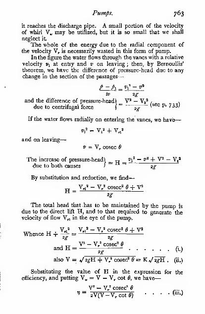
Pumps. 763
it reaches the discharge pipe. A small portion of the velocity
of whirl V„ may be utilized, but it is so small that we shall
neglect it.
The whole of the energy due to the radial component of
the velocity V, is necessarily wasted in this form of pump.In the figure the water flows through the vanes with a relative
velocity Wj at entry and v on leaving ; then, by BernouUis'
theorem, we have the difference of pressure-head due to anychange in the section of the passages
—
/ — pi _ Vi — v^
W 2gand the difference of pressure-head) _ V^ — V,'' / >
due to centrifugal force)
'^ '^^^ P* '^^^'
If the water flows radially on entering the vanes, we havb
—
and on leaving
—
= V, cosec 6
The increase of pressure-headl _ tt _ ^1' — g" + V — V-^
due to both causes I~ ~ 2g
By substitution and reduction, we find
—
V,!^ - V,2 cosec'' e + V^H2g
The total head that has to be maintained by the pump is
due to the direct lift H, and to that required to generate thevelocity of flow V,i in the eye of the pump.
Whence H +— =
^ ,, V= - V/ cosec" eand H =
({)
also Y =^2gH. + V/ cosec" 6 = Kv'2^H . (ii.)
Substituting the value of H in the expression for the
efficiency, and putting V„ = V — V, cot 6, we have
—
_ V - V/ cosec' e''"" 2V(V-V,cote) • •
("!•)

764 Mechanics -applied to Engineering.
which reduces to-
•7=.k(k-^
when V, = \j2g&,.
When Q = 90°, i.e. with radial blades
—
V^ — V *
V= 2V^ '• •
and when 6 is very small
—
¥„ = ¥ — » (nearly)
V2 - I/" V + v
(iv.)
Then 77 =2VV„ 2VV + V, cosec 6 , , .
V ^-fv(nearly) (v.)
The following table shows how the efficiency and the
peripheral velocity of the runner depend upon the vane angle
for the case of a pump having no volute, and no means of
utilizing the kinetic energy of the water on leaving the runner.
In arriving at the efficiency 17, the skin friction on the disc has
been neglected, and, since it varies as the cube of the speed, it
will be readily seen that the actual efficiency does not continue
to increase as the angle is reduced, because the speed also
increases. According to Professor Unwin, Proc. J.C.E., vol.
lii., the best results are obtained when 6 lies between 30° and
40°, or when V = about \'i,J 2gii.
»

Pumps. 765
It appears from the table given above that the efficiency of
a pump having radial blades is very low, but it must not beforgotten that this low efficiency is due to the fact that about
one half the energy of the water leaving a radial-bladed runner
is dissipated in eddies in the pump casing and at discharge
;
but if suitable means, such as gradually enlarging guide pas-
sages, a whirlpool chamber, or a bell mouth, be adopted, a
radial-bladed pump runner may be made to give excellent
results (see a paper by Mons. Gerard Lavergne, Le Genie Civil,
April 21, 1894).
Many large pumps, are fitted with guide blades as shownin Fig. 727, the guides are arranged parallel to V^„, Fig.
r^nFootValve BO 00
Fig. 727.
729. Readers should refer to a paper by Gibson on "TheDesign of Volute Chambers and of Guide Passages for Centri-fugal Pumps." Proceedings Institution Mechanical Engineers,March, r9i3.
In very high-speed centrifugal pumps, driven electrically
or by steam turbines, runners of very small diameter are used,and the angle B is often as small as 15°. The friction is
reduced as much as possible by careful polishing of the discs,
and the efficiency is said to be very high, even when a singlepump is employed for lifting water to a height of 300 feet. For

^^ Mechanics applied to Engineering.
greater lifts two or more pumps are placed in series, each ofwhich raises the pressure through a like amount.
Case II. Pump with a Volute (Fig. 728).—The meanvelocity of the water over any section of the volute is constant,hence the area of the volute at any section must be propor-tional to the quantity of water passing that section in anygiven time. To secure a uniform velocity of flow, the form ofthe volute is arranged as shown in Fig. 728.
Fig. 728.
The volute is shown in radial sections. The first section
has to carry off the water from section i of the runner, the
second section from sections i and 2 of the runner ; therefore
at the radius 2 it is made twice as wide as at 1 ; likewise at 3it is three times as wide as at i, and so on. As these radii
enclose equal angles, it will be seen that the form of the
casing is an Archimedian spiral if the breadth be madeconstant.
Let V„ be the velocity of whirl in the volute, or the velocity
with which the water circulates round the spiral casing ; it is
generally less than V„.
The water leaves the vanes with an absolute velocity of
flow Nf, which is changed to V.. If the change be abrupt, the
loss of head due to shock is
—
But if the change be gradual, the gain of head due to the
decreased velocity is
—
V/ - V,°

Pumps.
And the net gain of head due to the change is
—
H, = v; - v/ - v/ ^ 2(v.v^ - v„°)
4-
767
Fig. 729.
Differentiating, we get
—
im,_ Y„- 2V.
Hence the maximum possible gain of head due to this
cause is when
—
whence
—
The maximum gain of head = 2VJ(vi.)
Adding this to the value found for H (equation i.), wehave
—
jj ^ V^ _ V," cosec° 6 2VI^g 2g 2g
and V = '^2gn + \;' cosec^ ^ - 2V/
and the efficiency (with a volute casing)
—
.V^-V^cosec^ 6 + 2V„2
n =
the value of V„ =
2V(V - V, cot 6)
V - V, cot
(vii.)
(viii.)
(ix.)
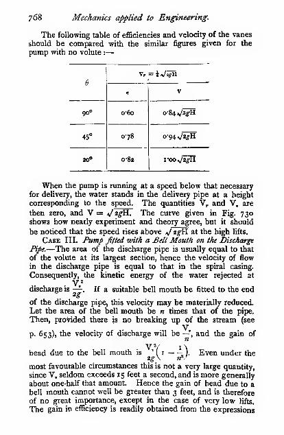
768 Mechanics applied to Engineering.
The following table of efficiencies and velocity of the vanes
should be compared with the similar figures given for the
pump with no volute :
—
6

Pumps. 769
given above, by adding to the expression for H (Equations
i. and vii.) the gain due to the bell-mouth.
Fig. 730.
Case IV. Ptimp fitted with a Whirlpool Chamber.—If awhirlpool chamber, such as that shown in Fig. 731, be fitted
to a pump, a free vortex will be formed in the chamber, and acorresponding gain in head will be effected, amounting to
—
2^V r.^J
for a pump with no volute.
2g\ /-.V
for a pump with a volute (see p. 767).This gain of head for well-designed pumps is usually small,
and rarely amounts to more than 5 per cent, of the total head,and is often as low as ij per cent. The cost of making apump with a whirlpool chamber is considerably greater thanthat of providing a bell mouth for the discharge pipe, hencemany makers have discarded the whirlpool chamber in favourof the bell-mouth. There is, of course, no need to use botha bell-mouth and a whirlpool chamber. Some very interesting
matter bearing on this question will be found in a paper by3D

770 Mechanics applied to Engineering.
Dr. Stanton in the Proceedings of the Institution of MechanicalEngineers, October, 1903.
Skin Friction of the Rotating Discs in a Centri-fugal Pump.—The skin friction of the rotating discs is a very
important factor in the actual efficiency of centrifugal pumps.
Fig. 731.
Let/= the coefficient of friction (see p. 681).
Consider a ring of radius r feet and thickness dr rotating
with a linear velocity u feet per second, relatively to the water
in the casing ; then
—
y^K = —
.
RThe skin resistance of the ring ^fu^'iirrdr
>. > » =f^2ir*^dr
The moment of the frictional resistance\ /^of the ring /~ R=
The moment of the frictional resistance) _/V'2ir ['' =
of the whole disc Iua I ' ^"^
\= -TiK-2in*dr
and for the two discs
—
The moment of the frictional resistance =^/ R" - RAi, R' 7

Pumps. 771
The horse-power wasted in overcoming'. _ /VVR^^^^^u^N
the skin friction ;- 216V R»R
Taking the usual proportions for the runner, viz. R, = —
,
on substitution we get
—
The horse-power wasted in skin friction =/V«R'223
The practical outcome of an investigation of the disc
friction is important j it shows that the work wasted in friction
varies in the first place as the cube of the peripheral velocity
of the runner. The head, however, against which the pumpwill raise water varies as the square of the velocity, hence the
wasted power varies as (head)3. Thus, as the head increases,
the work done in overcoming the skin friction also increases
at a more rapid rate, and thereby imposes a limit on the headagainst which a centrifugal pump can be economically em-ployed. Modern turbine-driven pumps are, however, made to
work quite efficiently up to heads of looo feet. Further, the
work wasted in disc skin friction varies as the square of the
radius—other things being equal ; hence a runner of small
diameter running at a very great number of revolutions per
minute, wastes far less in skin friction than does a large disc
running at a smaller number of revolutions with the sameperipheral velocity. An excellent example of this is found in
the centrifugal pumps driven by the De Laval steam turbines.
The author is indebted to Messrs. Greenwood and Batley,
Leeds, for the following results :
—

7/2 Mechanics applied to Engineering.
In addition to the disc friction there is also a small amount
of friction between the water and the interior of the runners,
due to the outward flow of the water through the wheel passages.
This, however, is negligible compared to the disc friction.
Capacity of Centrifugal Pumps.—When the velocity
of flow V, through the runner of a centrifugal pump is known,
the quantity of water passing per second can be readily obtained
by taking the product of this velocity and the circumferential
area of the passages through the runner ; or, if the velocity of
whirl in the volute V, be known, the quantity passing can be
found from the product of this velocity and the sectional area
of the volute close to the discharge pipe, which is usually madeequal to the area of the discharge pipe itself. Whence from a
knowledge of the dimensions of a pump both V, and V, can
be readily obtained for any given discharge. The most im-
portant quantity to obtain is, however, the speed of the pumpV for any given discharge. Expressions have already been given
for V in terms of the head H, the angle Q, the velocities V, andv.; but on comparing the value of V calculated from these
expressions with actual values, a discrepancy will be discovered
which is largely due to the friction of the water in the suction
and discharge pipes, and in the pump itself. The latter quantity
can be most readily expressed in terms of the length of pipe,
which produces an equal amount of friction. A few cases that
the author has examined appear to show that the internal
resistance of the pump and foot valve together is equivalent to
the friction on a length of about 80 diameters of the discharge
pipe. This head must be added to the actual lift of the pumpin order to find the real head H, against which the pump is
Ufting.
When designing centrifugal pumps it is usual to make the
velocity of flow V, about \>J 2g^, and the diameter of the
runner about twice the diameter of the " eye," the latter beingusually equal to the diameter of the discharge pipe.
A concrete example of a pump in which the actual per-
formances are known, will serve to show the extent to whichour theoretical deductions may be trusted.
Diameter of runner ... ... ... 12 ins.
,, delivery pipe ... 6 „Circumferential area of wheel passages ... ... o'36 sq, ft.
Blade angle (fl) 45°Lift 29 ft.
Length of delivery pipes, including four bends ... 42 „„ suction pipe (straight) 8,,

Pumps. 773
The pump is fitted with a volute, but no whirlpool chamberor bell-mouth.
Quantityof waterin cubicfeet persecond.

774 Mechanics applied to Engineering.
Where A is the area in square feet of the section pipe, Hj the
height of the water barometer in feet, i.e. 34 feet for cold
water (and tight joints). H, the suction head in feet below
the centre of the pump, h the head in feet corresponding to
the friction of the suction pipe and foot valve. V, the velocity
in feet per second of the water in the suction pipe. Thefriction head can be expressed in terms of the quantity thus
—
hence Q = Kj2g{&, - H, - ^£) = ^ - b
which reduces to
N ^ „. A-Am - H.)KDV KD + 2gL ^
N is the speed at which cavitation occurs. In order to
be on the safe side, Hj should not be taken over 30 feet for
cold water, and even then all joints must be in good con-
dition. In calculating the friction of the foot valve, one with
ample passages may be taken as equivalent to 15 diameters
of pipe, but in badly designed valves the loss may be puchgreater.
Multiple-lift Centrifugal Pumps.—In the case of a
centrifugal pump which delivers against a very high lift, the
peripheral speed of the runner becomes very great, and the
skin friction of the discs assumes somewhat serious proportions.
The very high speed of the runner is not a serious drawbackfor pumps driven direct from steam turbines or electric motors,
and, in fact, such speeds are often found to be very convenient
;
the angle Q, however, becomes inconveniently small, and the
skin friction is often so great as to materially reduce the
efficiency. In order to avoid these drawbacks and yet obtain
high lifts, two or more pumps may be arranged in series. Thefirst pump delivers its water into the suction pipe of the secondpump, which again delivers it to the third pump, and so on,
according to the lift required; by this means the peripheral
speed and the disc friction can be kept within moderate limits.
One of the earliest and most successful pumps of this type is
the Mather-Reynolds pump, made by Messrs. Mather andPiatt, of Manchester, and by whose courtesy the section
shown in P"ig. 613a is reproduced.

Pumps. 775
The direction in which the water flows through the pumpis indicated by arrows. It enters the runner axially from both
sides, in order to eliminate axial thrust, and after traversing
the runner the water is discharged into a chamber fitted with
04- 0-8 12 1-6 20Quaniib/ iw cubio feetper second/.
Fig. 732.
expanding guide-passages for the purpose of converting the
kinetic energy of the water leaving the runner into pressure
energy. This chamber is the special feature of the pump, andjudging from the excellent results obtained, it much more

7/6 Mechanics applied to Engineering.

Pumps. 777
effectually produces the desired result than the ordinary whirl-
pool chamber mentioned in a previous paragraph. The reader
should also notice the great care that has been bestowed on
the design of the pump, in order to avoid sudden changes in
the direction of flow, and in the cross-section of the passages.
In Fig. 734 is shown a multiple chamber pump of the samedesign. The water in this instance enters on one side only
of the runner ; then, after passing through expanding guide-
passages, it is brought round to the other side of the runner,
and after passing more guide-passages, it goes on to the next
runner, and so on.
The following results of a test of one of these pumps will
serve to show what excellent results are obtained ; the figures
are taken from curves published in the maker's catalogue :
—
Diameter of suction pipe =12 ins.
,, delivery pipe = lo ,,
Lift looft.
Quantity of water in
gallons per minute.
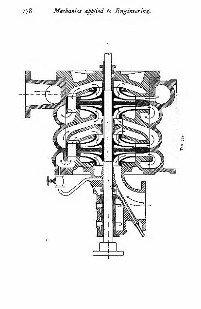
7/8 Mechanics applied to Engineering.

Pumps. 779
Destination of pump . .
.
Suction-head in all tests
Sydney WaterworksII ft.
Lift in feet.


APPENDIX
The reader should get into the habit of checking the units in anyexpression he may arrive at, for the sake of preventing errors andfor getting a better idea of the quantity he is dealing with.
A mere number or a constant may be struck out of an ex-
pression at once, as it in no way affects the units : thus, the lengthof the circumference of a circle is 27rr (p. 22) ; or
—
The length = zir (a constant) x r {expressed in length units)= a certain number of length units
Similarly, the area of a circle = irr^ (p. 28) ; or
—
The area = i (a constant) x r {in length units) x r {in length units)= a certain number of (length units)^
Similarly, the voiunie of a sphere = |irH ; or
—
The volume = — {a constant) x r{in length units) x r{in length
units) X r {in length units)
= a certain number of (length units)'
The same relation holds in a more complex case, e.g. the slice
of a sphere (p. 44).
The volume = -{l^^^ - Y,2) -\^ + Y,']
= -{a constant) {3 (a constant) x R (?« length units)
[Yj^ (in length units)" - Y," {in length units)'] - Y/{length unitsY + Y,' {in length units)^}
= a constant [a constant [{length unitsf — {lengthunitsY — {length unitsY + {length unitif\
= a constant x {length unitsY= a certain number of (length units)'}
One more example may serve to make this question of unitsquite clear.
The weight of a flywheel rim is given by the following ex-pression (p. 196) :
—

782 Appendix.
Weight of rim =-y=^'g {an aceeleration) X En (force X space) X R* (>'« length units)'
The weight = ^ (« constant) X V« (velocity unitsf X R^" (/« /«;^/4 »k«j)'
^ (acceleration) X E„[ marj X . X j/a«j
j^N.B.—The (length units)' cancel out, and the constant is
omitted, as it does not affect the units.]
TV • 1.,.acceleration x mass x space' x time'
The weight = ~.—
=
*—;;^ time' X space'= mass X acceleration of gravity (see p. 9)
Thus showing that the form or the dimensions of our flywheelequation is correct.
Operations of Dififerentialiing and Integrating.—Not oneengineer in a thousand ever requires to make use of any mathe-matics beyond an elementary knowledge of the calculus, but anyone who wishes to get beyond the Kindergarten stage of the prin-ciples that underlie engineering work must have such an elementaryknowledge. The labour spent in acquiring sufficient knowledge ofthe calculus to enable him to solve practically all the problems heis likely to come across, can be acquired in a fraction of the timethat he would have to spend in dodging it by some roundaboutprocess. There is no excuse for ignorance of the subject now thatwe have such excellent and simple books on the calculus for
engineers as Perry's, Barker's, Smith's, Miller's, and others. Forthe benefit of those who know nothing whatever of the subject, thefollowing treatment may be of some assistance ; but it must bedistinctly understood that it is only given here for the sake of help-ing beginners to get some idea of what such processes as differentia-
tion and integration mean, not that they may stop when they canmechanically perform them, but rather to encourage them to readup the subject.
Suppose we have a square the length of whose sides is x units,then the area of the square is fl = **. Nowlet the side be increased by a small amountAjr, and in consequence let the area be in-creased by a corresponding amount aa ; thenwe have
—
« -1- Aa = (jT -H Ajr)2 = ** -H zrAr + (A:ir)'
'(")' Subtracting our original value of a, we have
—
Ad = 2XiUt + {AxY
Thus by increasing the side of the square by an amount Ax, we

Appendix 783
ries, i.e. \
reases or >
creases j
have increased the area -by the two narrow strips of length x andof width Ajr, and by the small black square at the comer (A;r)'.
f varies,
For many problems we want to know how the area< increases i
( decreasesf variation, i.e.\
with any given < increase or \ in the length of the side ; or, ex-
( decrease j
pressed in symbols, we want to know the value of — , which we can
obtain from the expression above thus
—
AaAT
= 2Jr + A;r
^aNow, if we make ts.x smaller and smaller, the fraction ^^ will
A*-become more and more nearly equal to 2x, and ultimately (whichwe shall term the limit) it will be 7,x exactly. We then substituteda and dx for Aa and A;r, and write it thus
—
da
Tx=^'
or, expressed in words, the area of the square varies ix times as fast
as the length of the side. This is actually and absolutely true,
not a mere approximation, as we shall show later on by someexamples.
The fraction -j- is termed the differential coefficient of a with
regard to x. Then, having given a = jr^, we are said to differentiate
a with regard to x when we write ,- =
We will now go one step further,
and consider a cube of side x ; its
volume V = **.
As before, let its side be in-
creased by a very small amountA;ir, and in consequence let thevolume be increased by a corre-
sponding amount aV. Then weget—
V -1- aV = (ar + A;r)» = *« -H yfi^x+ 3MA*')2 -t- (A^)3
p,^^^^_
Subtracting our original value of V, we have
—
aV = 3r«A;ir -1- 3Jr(A*-)» -1- (Ajr)»
The increase is shown in the figure, viz. three flat portions of

784 Appendix.
area x^ and thickness Ajr, three long prisms of length x and section
(Aj-)-, and one small cube of volume (ajt)'. From the above, wehave
—
aV = 'ix^ + 3;irAjr + Ajr^
which in the limit (i.e. when ^x becomes infinitely small) be-comes
—
dx ^
By a.similar process, we can show that if j = /*
—
Ji = ^''
Likewise, if we expand by the binomial theorem, or if we workout a lot of results and tabulate them, we shall find that the follow-
ing relation holds :
—
when X =

Appendix. 785
constants. Then by a similar process to the one just given, weget—
dx _
-J-= mky-' ± nBy"-' ± C
It sometimes happens that x increases to a certain value, its
maximum, and then decreases to a certain value, its minimum, andpossibly increases again, and so on. If at any one instant it is
found to be increasing, and the next to be decreasing, it is certainthat there must be a point between the two when it neither increasesnor decreases ; this may occur at either the maximum or the
dxminimum. At that instant we know that -j- = o. Then, in order
to find when a given quantity has a maximum or a minimum value,dx
we have to find the value of j- and equate it to zero.
Thus, suppose we want to divide a given number N into twoparts such that the product is a maximum. Let x be one part, anda — X the other, and^ be the product. Then
—
jf = {N - x)x = T<lx - x'
and -j? = N — 2:r = o when v is a maximumax •"
or 2:r = Nand x= —
2
As an example, letN = 10
:
N -:i:
98
76
5
4and so on.
NThus we see that _f has its maximum value when ar = — = s.
2In some cases we may be in doubt as to whether the value we
arrive at is a maximum or a minimum ; in such cases the beginnerhad better assume one or two numerical values near the maximumor minimum, and see whether they increase or decrease, or whatis very often a convenient method—to plot a diagram. Thisquestion is very clearly treated in either of the books mentionedabove.
The process of integration follows quite readily from that ofdiflferentiation.
Let the Kne ae be formed by placing end to end a number of
3E
x

786 Appendix.
short lines ab all of the same length. When the line gets to c, let
its length be termed Lc, and when it gets to e, L,. The length ce wehave already said is equal to a^. Now, what is «? It is simply thedifference between the length of the line ae and the line ac, or
L, — L„ ; then, instead of writing in full that ce
t L, . is the difference in length of the two lines, we^'—i.—'-.-.-—!' ,. will write it A/, i.e. the difference in the length^^'. ' "* after adding or subtracting one of the short
Fin. 737.lengths. Now, however long or however short
the line may be, the difference in the length after
adding or subtracting one of the lengths will be A/. The wholelength of the line L, is the sum of all the short lengths of whichit is composed ; this we usually write briefly thus
:
L. _ _L.S„A/ = [/]^=L.
or, the sum of (2) all the short lengths A/ between the limits whenthe line is of length L,and of zero length is equal to L^ Sometimesthe sign of summation is written
—
/=L.S A/ = L./=o
Similarly, the length Li is the sum of all the short lengths betweenb and c, and may be written
—
L. Lc
S A/ = \l\ = L, - U = LiL. L Jl.
the upper limit L, being termed the superior, and the lowerlimit Lj the inferior limit : the superior limit is always the largerquantity.. The lower limit of / is subtracted from the upper limit.
In the case of a line, the above statements are prafectly true,
however large or however small the short lengths A/ are taken, butin some cases which we shall shortly consider it will be seen thatif a/ be taken large, an error will be introduced, and that the errorbecomes smaller as a/ becomes smaller, and it disappears when a/becomes infinitely small ; then we substitute dl for A/, but it still
means the difference in length between the two lines L, and Lc,
although ce has become infinitely small. We shall now use aslightly different sign of summation, or, as we shall term it, integra-tion. For the Greek letter 2 (sigma) we shall use the old English j,
viz./, and—L, /-L,
2 ^l becomes | (^/ = L,
o ' o
Lo /-L,
and S a/ becomes I rf/ = L, — L» = L,L* •'l.

Appendix. 787
The expression still means that the sum of all the infinitely short
lengths dl between the limits of length Lj and Lj is Lj, which is, of
course, perfectly evident from the diagram.Now that we have explained the meaning of the symbols, we
will show a general connection between the processes of dif-
ferentiation and integration. We have shojifn that when
—
dx(i.)
dy - "-^
and dx = ny-''df (ii.)
But the sum of all such quantities dx, viz. /dx, = x =y (iii.)
;
hence, substituting the value of dx from (ii.), we have
—
/dx =/ny-^dy
But from (iii.) we have
—
/dx=yhence/ny-'^dy =y
This operation of integrating a function of a variable j/ may beexpressed in words thus
:
Add I to the index 0/thepower 0/y, and divide by the index so
increased, and by the differential 0/ the variable.
Thus—
/ny-'^dy_ ny-'^*'^dy _
(» - I + \)dy=y
Similarly
—
/mydy —» + I
Let »« = 4, « = 2. Then
—
/4yV^ = 4^
or when m = 3"2, n = \—
/^•2yidy1 + 1
.i+i
In order to illustrate this method of finding
the sum of a large number of small quantities
we will consider one or two simple cases.
Let the triangle be formed of a number of
strips all of equal length, ab or A/. The width fig. 738.
IV of each strip varies ; not only is each oneof different width from the next, but its own width is not

788 Appendix.
constant. If we take the greater width of, say, the strip cefi,
viz. w,, the area w«A/ is too great, and if we take the smaller
width Wc, the area w^t^l will be too small. The narrower we take
the strips the nearer will w, = w„ and whenthe strips are infinitely narrow, a/, = w^ = ivd,
Iand the area will be w^l exactly, and
I
the stepped figfure gradually becomes aI triangle.
IV The area of the triangle is the sum of the
,areas of all the small strips w . dl (Fig. 739).
^ w _l W/ „ ^,I But is- = i^, or <w = T^. Hence the areaJ
W L. uof the triangle is the sum of all the small strips
FJG. 739- w/of area -j—dl, which we write
—
^^/,or
^ 1 =tfl.dl =
L 2
.WL2
W.The -p is placed outside the sign of integration, because neither
W nor L varies. Now,from other sources we know that the area
WLof the triangle is . Thus we have an independent proof of the
accuracy of our reasoning.
Suppose we wanted the area of the trapezium bounded byW and Wi, distant L and L, from the apex. We have
—
it'-'-W^^But here again we know,y>-«« other sources, that the area of thetrapezium is
—
WL _ WiL, ^ W/L» - L,
2 2 lV• iir WLi
since Wj = -^pJ
"-)
which again corroborates our rule for integration.
By way of further illustrating the method, we will find thevolume of a triangular plate of uniform thickness /. The volumeof the plate is the sum of the volumes of the thin slices of thick-
ness dl.

Appendix. 789
Volume of a thin slice1
(termed an elementary \ = w.t.dlslice) J
= -^t.dl
Vol.ofwhole plate j-\l.dl= y-( — 1= "~^
a result which we could have obtained byWL
taking the product of the area —^ and the,
thickness i.
Similarly, the volume of the trapezoidal plate is
—
x/^:--=rt^^)One more case yet remains—that in which
i varies, as in a pyramid.
Volume of an elementary slice = w .t.dl
W/ T/' = 17
WT,hence the volume of slice = -^rj"/^ . dl Fig. 741.
WT r WT L'Volume of pyramid = -yx I l^ .dl=. -ya- x
—WTL
We know, however, from other sources, that the volume of apyramid is one-third the volume of the circumscribing solid. Thisis easily shown by making a solid and the corresponding pyramidof the same material, and comparing the weights or the volumesof the two ; or a cube can be so cut as to form three similar
pyramids. In this case the volume of the circumscribing solid is
WTL, and the volume ofthe pyramid . Thus we have another
proof of the accuracy of our method of integration. Similarly withthe volume of the frustum of a pyramid.
WT/"^...= -(-^)
Until the reader has had an opportunity of following up thesubject a little further, we must ask him to accept on faith thefollowing results :
—

T^ Appendix.
I -dx = log.
;
v X
-dx= log, xi - log, *-j = log. ^'X x^
Xand if^ = log, x
dy _\_dx X
Where log, = 2'3 x theordinarylog.ofthe number, log, is knownas the hyperbolic logarithm. The reader should also read up theelements of conic sections, especially the parabola and hyperbola.
Checking Besults.—The more experience one gets the moreone realizes how very liable one is to make slips in calculations,
and how essential it is to check results. " Cultivate the habit ofchecking every calculation," is, perhaps, the best advice one cangive a young engineer.
First and foremost in importance is the habit of mentallyreasoning out roughly the sort of result one would expect to get
;
this will prevent huge errors such as this. In an examinationpaper a question was asked as to the deflection of a beam of lofeet span under a certain load. One student gave it as 34-2 inches,
whereas it should have been o"342 inch—an easy slip to makewhen working with a slide rule ; but if he had thought for onemoment, he would have seen that it is impossible to get nearly
3 feet elastic deflection on a lo-feet beam.If an approximate method of arriving at a result is known, it
should be used as a check on the more accurate method ; or if thereare two different ways of arriving at a result, it should be workedout by both to see if they agree. A graphical method is often anexcellent check on an analytical method, or vice vend. For example,suppose the deflection of an irregularly loaded beam has beenarrived at by a graphical process ; it can be roughly checked bycalculating the deflection on the assumption that the load is evenlydistributed. If the load be mostly placed in the middle, the graphicalprocess should show a rather greater deflection ; but if most of theload be near the two abutments, the graphical process should showa rather smaller deflection. In this way a very good check maybe obtained. A little ingenuity will suggest ways of checking everyresult one obtains.
In solving an equation or in simplifying a vulgar firaction withseveral terms, rough cancelling can often be done which will enableone by inspection to see the sort of result that should be obtained,and calculations made on the slide rule can be checked by takingthe terms in a diffierent order.
Then, lastly, all very important work should be independentlychecked by another worker, or in some cases by two others.
Real and Imaginary Acctiraoy.—Some vainly imagine thatthe more significant figures they use in expressing the numerical

Appendix. 791
value of a quantity, the greater is the accuracy of their work. Thisis an exceedingly foolish procedure, for if the data upon which the
calculations are based are not known to within 5 per cent., then all
figures professing to g^ive results nearer than 5 per cent, are false
and misleading. For example, very few steam-engine indicators,
with their attendant reducing gears, etc., are accurate to within
3 per cent., and yet one often sees the I.H.P. of an engine given
as, say, 2345"67 ; the possible error here is 2345"67 x ig^ = 7o"37
I.H.P. Thus we are not even certain of the 45 in the 2345 ; hencethe figures that follow are not only meaningless, but liable to misleadby causing others to think that we can measure the I.H.P. of anengine much more accurately than we really can. In the abovecase, it is only justifiable to state the I.H.P. as 2340, or rather nearer
2350 ; that is, to give one significant figure more than we are really
certain of, and adding o's after the uncertain significant figure. Insome cases a large number of significant figures is justifiable ; for
example, the number of revolutions made by an engine in a giventime, say a day. The counter is, generally speaking, absolutely
reliable, and therefore the digits are as certam as tifie millions.
Generally speaking, engineering calculations are not reliable to
anything nearer than one per cent., and not unfrequently to within
10 or even 20 per cent. The number of significant figures usedshould therefore vary with the probable accuracy of the available
data.
Sxperimenta,! Proof of the Accuracy of the BeamTheory.—Each year the students in the author's laboratorymake a tolerably complete series of experiments on the strength
and elasticity of beams, in order to show the discrepancies (if any)between theory and experiment. The following results are thosemade during the past session, and are not selected for any special
reason, but they serve well to show that there is no material error
involved iA the usual assumptions made in the beam theory. Thedeflection due to the shear has been neglected. The gear for
measuring the deflection was attached at the neutral plane of the
beam just over the end supports, in order to prevent any error dueto external causes. If there had been any material error in thetheory, the value of Young's Modulus E, found by bending, wouldnot have agreed so closely with the values found by the tensionand compression experiments. The material was mild steel ; all
the specimens were cut from one bar, and all annealed together.
The section wab approximately 2 inches square, but the exactdimensions are given in each case.

792 Appendix.
Bending.

Appendix. 793
Load in

EXAMPLES
Chapter I.
INTRODUCTORY.
1. Express 25 tons per square inch in kilos, per square millimetre.
Am. 394.2. A train is running at 30 miles per hour. What is its speed in feet
per second ? Ans. 44.
3. What is the angular speed of the wheels in the last question?
Diameter = 6 feet. Ans. 14I radians per second.
4. A train running at 30 miles per hour is pulled up gradually and
evenly in 100 yards by brakes. What is the negative acceleration 7
Ans. 3*23 feet per second per second.
5. What is the negative acceleration, if the train in Question 4 be
pulled up from 40 miles to 5 miles per hour in 80 yards ?
Ans. 7 '06 feet per second per second.
6. If the train in Question 5 vireighed 300 tons, what was the total
retarding force on the brakes? Atis. 65 '8 tons.
(Check your result by seeing if the work done in pulling up the train
is equal to the change of kinetic energy in the train.)
7. Water at 60° Fahr. falls over a clifif 1000 feet high. What wouldbe the temperature in the stream below if there were no disturbing
causes? ^«j. 61 •29° Fahr.
8. A body weighing 10 lbs. is attached to the rim of s^ rotating pulley
of 8 feet diameter. If a force of 50 lbs. were required to detach the body,
calculate the speed at which the wheel must rotate in order to make it
fly off. Ans. 6l revolutions per minute.
9. (I.C.E., October, 1897.) Taking the diameter of the earth as 8000miles, calculate the work in foot-pounds required to remove to an infinite
distance from the earth's surface a stone weighing i lb.
Ans. 21,120,000 foot-lbs.
10. (I.C.E., October, 1897.) If a man coasting on a bicycle down a
uniform slope of I in 50 attains a limiting speed of 8 miles per hour,
what horse-power must he exert to drive his machine up the hill at the
same speed, there being no wind in either case ? The weight of man andbicycle together is 200 lbs. Ans. o"i7.
11. Find the maximum and minimum speeds with which the bodyrepresented in Fig. 2 is moving. Express the result in feet per second
and metres per minute.
Ans. Maximum, 13 feet per second, or 238 metres per minute at
about the fifth second ; minimum, o'5 foot per second, or g'lsmetres per minute at about the third second.

Examples. 795
12. A flywheel is running at 500 revolutions per minute and is brought
to rest by the friction of the bearings, which may be assumed to be con-
stant, in 4 minutes. How many revolutions will it make before stopping ?
What was the angular acceleration in radians per second per second ?
Ans. 1000 revolutions ; 0'2i8 radians per second per second.
13. (I.C.E., February, 1910.) At a height of 4 feet above the level
floor of a gate-chamber, a jet of water issues horizontally through a small
orifice in the gate, and strikes the ^oor at a distance of 12 feet from the
gate. What is the velocity of the issuing jet? Ans. z^'l feet per second.
14. A pit cage weighing 10 tons is being hauled up the shaft by a rope.
What is the tension in the rope— (i) when the cage is being lifted with an
acceleration of 2 feet per second per second ; (ii.) when the cage is being
lifted at uniform speed ;(iii.) when the cage is being retarded 2 feet per
second per second ? Ans. io'62 j 10; 9-38 tons.
15. (I.C.E., February, 1903.) With what speed must a locomotive berunning on level railway lines, forming a curve of 968 feet radius, if it
produces a horizontal thrust on the outer rail equal to ^ of its weight ?
Ans. I5'05 miles per hour.
16. (I.C.E., February, 1912.) A 2-ton motor-car is working at con-
stant horse-power and travels a distance of 20 miles in 30 minutes, rising
500 feet in tne time. The frictional resistance to motion is equivalent to
an average force of 50 lbs., and its initial and final speeds are the same.
Find the horse-power of the car. Ans. 76.17. (I.C.E., October, 19H.) Find in direction and magnitude the
force required to compel a body weighing 10 lbs. to move in a curved path,
the radius of curvature at the point considered being 20 feet, the velocity
of the body 40 feet per second, and the acceleration in its path 48 feet per
second per. second. Ans. 29 lbs. ; 59° with path.
Chapter II.
MENSURATION.
1. A locomotive wheel 8 feet 6 inches diameter slips 17 revolutions
per mile. How many revolutions does it actually make per mile ?
Ans. 2147.
2. In Fig. 13, C = 200 feet, C, = l2o feet. Find the length of the
arc by both methods. Ans. 256 feet, 2S3'3 feet.
3. Find the length of a semicircular arc of 2 inches radius by meansof the method shown in Fig. 15, and see whether it agrees with the
actual length, viz. 6*28 inches.
4. Find the weight of a piece of j-inch boiler plate 12' 3" x 4' 6",
having an elliptical manhole 15" X 10" in it. (One-inch plate weighs
40 lbs. per square foot.) Am. 1629 lbs., or 073 ton.
5. Find the area of a regular hexagon inscribed in a circle of 50 feet
radius. Ans. 6495 square feet.
6. Find the area in square yards of a quadrilateral ABCD. Lengthof AB = 200 yards, BC = 650 yards, CD = 905 yards, DA = 570 yards,
AC = 800 yards.
(N.B.—The length BD can be calculated by working backwardswhen the area is known, but the work is very long. The tie-lines ACand DB in a survey are often checked by this method.)
Am. 272,560 square yards.

79^ Examples.
7. A piece of sheet iron 5 feet wide is about to be corrugated.Assuming the corrugations to be semicircular of 3-inch pitch, what will
be the width when corrugated? Ans. 3"i8 feet.
8. Find the error per cent, involved in using the first formula of
Fig. 25, when H = ^ for a circle 5 feet diameter, assuming the second
formula to be exact. Ans. ^•%.
9. Find the area of the shaded portion of Fig. 426. 8 = 4 inches
;
the outlines are parabolic. Ans. 2 '67 square inches.
10. Cut an irregular-shaped figure out of a piece of thin cardboard ormetal with smooth edges. Find its area by—(l) the method shovm in
Fig. 32 ; (2) the mean ordinate method ; (3) Simpson's method ; (4) the
planimeter ; (5) by weighing.
11. Find the area of Figs. 29, 31, 32, 33, 34 expressed in squareinches. Ans. (29) 0-29, (31) o-i6, (32) 1-14, (33) 0-83, (34) o-86.
12. Find the sectional area of a hollow circular column, I2 inches
diameter outside, 9 inches diameter inside. Ans. 49*48 square inches.
13. Bend a piece of thin wire to form the quarter of an arc of a circle,
balance it to find the c. of g., and then find the surface of a hemisphere bythe method shown in Fig. 35. Check the result by calculation by themethod given in Fig. 36,
14. Find the heating surface of a taper boiler-tube—length, 3 feet
;
diameter at one end, 5 inches ; at the other, 8 inches.
Ans. 5'I square feet.
15. Find the mean height of an indicator diagram in which the initial
height Y is 2 inches, and cut-off occurs at \ stroke, log 4 = 0*602
—
(i.) with hyperbolic expansion ; (ii). with adiabatic expansion. (» = 1*4.)
Ans. (i.) 1*19 inch ; (iL) i*02 inch.
16. Find the weight of a cylindrical tank 4 feet diameter inside, and7 feet deep, when full of water. Thickness of sides \ inch ; the bottom,which b J inch thick, is attached by an internal angle 3" X 3" X J".There are two vertical seams in the sides, having an overlap of 3 inches
;
pitch of all rivets, 2\ inches ; diameter, | inch. Water weighs 62*5 lbs.
pet cubic foot, and the metal weighs 480 lbs. per cubic foot.
Ans. 7270 lbs.
17. (Victoria, 1893.) A series of contours of a reservoir bed have thefollowing areas :
—
At water-level 4,800,000 sq. yards.
2 feet down 3,700,000 „4 >j 2,000,000 „6 >i 700,000 „8*4 ,, ... ... ... Zero
Find the volume of the reservoir in cubic yards.
Ans. 5,900,000 (approx.).
18. The area of it half-section of a concrete building consisting ofcylindrical walls and a dome is 12,000 square feet. The c. of g. of thesection is situated 70 feet from the axis of the building. Find the numberof cubic yards of concrete in the structure. Ans. 195,400.
19. Find the weight of water in a spherical vessel 6 feet diameter, thedepth of water being 5 feet. Ans. 6545 lbs.

Examples. 797
20. In the last question, how much water must be taken out in order
to lower the level by 6 inches. Ans. 581 lbs.
(Roughly check the result by making a drawing of the slice, measurethe mean diameter of it, then calculate the volume by multiplying the
mean area by the thickness of the slice.
)
21. Calculate the number of cubic feet of water in an egg-endedboiler, diameter, 6 feet ; total length, 30 feet ; depth of water, 5*3 feet.
Ans. 746.
22. Find the number of cubic feet of solid stone in a heap having arectangular base 60' X 18', standing on level ground ; slope of sides, ij to
I foot ; flat-topped, height 4 feet ; the voids being 35 per cent.
Ans. i88i.
23. Find the weight of a steel projectile with solid body and taperedpoint, assumed to be a paraboloid. Material weighs 0"28 lb. per cubicinch ; diameter, 6 inches ; length over all, 24 inches ; length of taperedpart, 8 inches. Ans. 158 lbs.
24. Find the weight of a wrought-iron anchor ring, 6 inches internal,
and 10 inches external diameter, section circular. Ans. 22 lbs.
Chapter III.
MOMENTS.
1. A uniform bar of iron, f inch square section and 6 feet long, rests
on a support 18 inches from one end. Find the weight required on the
short arm at a distance of 15 inches from the support in order to balancethe long arm. Ans. lyt, lbs.
2. In the case of a lever such as that shown in Fig. 65, W, = i J ton,
I, = 28 inches, / = 42*5 inches, /, = 50 inches, 4 = 4 inches, w^ = i ton.
Find W when w, = O, and 6nd w, when Wj/j is clockwise and l, = I2'5
feet. Ans. W = 2 tons ; w, = 50 tons.
(N.B.—In the Buckton testing-machine, Wj is the load on the bar under
test.)
3. A lever safety-valve is required to blow ofiF at 70 lbs. per square
inch. Diameter of valve, 3 inches ; weight of valve, 3 lbs. ; short armof lever, 2} inches ; weight of lever, 1 1 lbs. ; dbtance of c. of g. of lever
from fulcrum, 15 inches. Find the distance at which a cast-iron ball 6inches diameter mn-st be placed from the fulcrum. The weight of the
ball-hook = o-6 lb. Ans. 35-5 inches.
4. In a system of compound levers the arms of the first lever are 3 inches
and 25 inches, of the second 2*5 inches and 25*5 inches, of the third 2Tinches and 25*9 inches, a force of 84 lbs. is exerted on the end of the long
arm of the third lever. Find the force that must be exerted on the short
arm of the first lever when the sjrstem is arranged to give the greatest
possible leverage. Ans. 88,060 lbs.
5. Find the position of the c. of g. of a beam section such as that
shown in Fig. 430.
Top flange 3 inches wide, i} inch thick.
Bottom flange 15 „ wide, if „ thick.
Web ij „ thick.
Total height 18 „
Ans. 572 inches from the bottom edge.

798 Examples.
6. Find the height of the c. of g. of a T-shaped section from the foot,
the top cross-piece being 12 inches wide, 4 inches deep, the stem 3 feet
deep, 3 inches wide. Ans. 24* 16 inches.
(Check by seeing if the moments are equal about a line passing throughthe section at the height found.)
7. Cut out of a piece of thin card or metal such a figure as is shown in
Figs. 78 and 87. Find the c. of g. by calculation or by the graphical
process, and check the result by balancing as shown on p. 75.
8. In such a figure as 77, the width of the base is 4 inches, and at the
base of the top triangle i '5 inch. The height of the trapezium = 2
inches, and the total height = 5 inches. Find the height of the c. of g.
from the apex. Ans. 3*54 inches.
9. A trapezoidal ' wall has a vertical back and a sloping front face
:
width of base, 10 feet ; width of top, 7 feet ; height, 30 feet. Whathorizontal force must be applied at a point 20 feet from the top in order to
overturn it, i.e. to make it pivot about the toe ? Width of wall, i foot
;
weight of masonry in wall, 130 lbs. per cubic foot. Ans. 18,900 lbs.
10. Find the height of the c. of g. of a column 4 feet square and 40feet high, resting on a tapered base forming a frustum of a square-based
pyramid 10 feet high and 8 feet square at the base.
Aru, 20*4 feet &om base.
1 1
.
Find the position of the c. of g. of a piece of wire bent to formthree-fourths of an arc of a circle of radius R.
Ans. On a line drawn from the centre of the circle to a point
bisecting the arc, and at a distance 0'3R from the centre.
12. Find the position of the c. of g. of a balance weight having the
form of a circular sector of radius R, subtending an angle of go°.
Ans. o'6R fiom centre of circle.
13. Find the second moment (I,,) of a thin door about its hinges
:
width, 7 feet ; height, 4 feet. Ans. 457 in feet* units.
14. Find the second moment (I) of a rectangular section 9 inchesdeep, 3 inches wide, about an axis passing through the c. of g., andparallel to the short side. Ans. 183 inch' units.
15. Find the second moment (I,) of a square section of 4-inch sideabout an axis parallel to one side and 5 inches from the nearest edge.
Ans. 8os"3 inch* units.
16. Find the second moment (I,) of a triangle o'g inch high, base06 inch wide as in Fig. 100. Ans. o'log inch* units.
17. Find the second moment (I) of a triangle 4 inches high and 3 inchesbase, about an axis passing through the c. of g. of the section and parallelwith the base. Ans. 5J inch* units.
Ditto (I,) about the base of the triangle. Ans. 16 inch* units.Ditto (I,) of a trapezium (Fig. 103) ; B = 3 inches, B, = 2 inches,
4 = 2 inches. Ans. 7-3 inch* units.Ditto (I,) ditto, as shown in Fig. 104. Ans. 6 inch* units.Ditto (I) ditto, as shown in Fig. 105. Ans. i'64 inch' units.Ditto ditto, by the approximate method in Fig. 106.
Ans. I -67 inch* units.
18. Find the second moment (I) of a square of 6 inches edge about itsdiagonal. Ans. 108 inch* units.
19. Find the second moment (I) of a circle 6 inches diameter about adiameter. Ans. 6y6 inch* units.

Examples. 799
20. Find the second moment (I) of a hollow circle 6 inches external
and 4 inches internal diameter about a diameter. Arts. 51 inch* units.
21. Find the second moment (I) of a hollow eccentric circle, as shownin Fig. 1 10. D« = 6 inches, Di = 4 inches. The metal is \ inch thick on
the one side, and ij inch on the other side. Ans. 45'4 inch* units.
22. Find the second moment (I) of an ellipse about its minor axis.
D, = 6 inches, D] = 4 inches. Ans. 42'4 inch* units.
Ditto, ditto about the major axis, Ans. i8'84inch* units,
23. Find the second moment (I) of a parabola about its axis, H = 6
inches, B = 4 inches. Ans. I02'4 inch* units.
Ditto, ditto (Ig) about its base, as in Fig, 1 14.
Ans. 263'3 inch* units,
24. Take an irregular figure, such as that shown in Fig. 115, and find
its second moment (Ig) by calculation. Check the result by the graphical
method given on p. 96,
25. Find the second polar moment (Ij,) of a rectangular surface as
shown in Fig, 117. B = 4 inches, H = 6 inches, Ans, 104 inch* units.
Ditto, ditto, ditto for Fig, 118. D = 6 inches.
Ans, 127 '2 inch* units.
Ditto, ditto, ditto for Fig. 119. D, = 6 inches, D< = 4 inches.
Ans. 102 inch* units.
26. Find the second polar moment (I^,) of such a bar as that shown ir.
Fig. 120. B = ? inches, H = 2 inches, L = 16 inches.
Ans. 2120 inch* units.
27. Find the second polar moment (Ip) for a. cylinder as shown in
Fig. 121. D = 16 inches, H = 2 inches. Ans 12,870 inch* units.
28. Find the second polar moment (Ip) for a hollow cylinder as shownin Fig. 122. R, = 8 inches, Rj = S inches, H = 2 inches.
Ans. 10,903 inch* units.
29. Find the second polar moment (I,,) of a disc flywheel about its axis.
External radius of rim = 8 inches
Internal radius of rim = 6,
Internal radius of web = i'5,
Thickness of web = 07 ,
Internal radius of boss = 075
,
Thickness of boss = 3 ,
Width of rim = 3 ,
Ans. 14,640 inch* units.
30. Find the second polar moment (Ij,) of a sphere 6 inches diameterabout its diameter. Ans. 407 inch' units.
Find the second polar moment (I„p) about a line situated 12 inches
from the centre of the sphere. Ans. 16,690 inch* units.
Find the second polar moment (Ip) of a cone about its axis. H = 12
inches, R = 2 inches. Ans. 60-3 inch' units.
WIn examples 26, 27, 28, 29, 30, — is taken as unity,
o

8cx) Examples.
Chapter IV.
RESOLUTION OF FORCES.
1. Set off on a piece of drawing-paper six lines representing forces
acting on a point in various directions. Find the resultant in direction
and magnitude by the two methods shown in Fig. 128.
2. Set off on a piece of drawing-paper six lines as shown in Fig. 130.
Find the magnitude of the forces required to keep it in equilibrium in the
position shown.
3. In the case of a suspension bridge loaded with eight equal loads of
1000 lbs. each placed at equal distances apart. Find the forces acting oneach link by means of the method shown in Fig. 131.
4. (I.C.E., October, 1897.) A pair of shear legs make an angle of 20°
with one another, and their plane is inclined at 60° to the horizontal.
The back stay is inclined at 30° to the plane of the legs. Find the force
on each leg, and on the stay per ton of load carried.
Ans. Each leg, 0'88 ; stay, vo ton.
5. A telegraph wire ^ inch diameter is supported on poles 170 feet
apart and dips 2 feet in the middle. Find the pnll on the wire.
Ans. 47-4 lbs.
6. A crane has a vertical post DC as in Fig. 135, 8 feet high. The tie
AC is 10 feet loi^, and the jib AB 14 feet long. Find the forces acting
along the jib and tie when loaded wiUi 5 tons simply snspended from the
extremity of the jib. Ans. Tie, 6*3 tons ; jib, 8"8 tons.
7. In the case of the crane in Question 6, find the radins, viz. /, bymeans of a diagram. If the distance :r be 4 feet, find the pressures /,and/,. /4>M. /,=/, = 12'2 tons.
8. Again referring to Question 6. Taking the weight of the tie at
50 lbs., and that of the jib as 350 lbs., and the pulley, etc., at the end of
the jib as 50 lbs. find the forces acting on the jib and tie.
Ans. Jib, 8;99 ; tie, 6'39 tons.
9. In the case of the crane in Question 6, find the forces when the
crane chain passes down to a barrel as shown in Fig. 137. Let the sloping
chain bisect the angle between the tie and the jib. Find W, if /, = 5 feet
;
also find the force acting along the back stay.
Ans. Jib, ii"4 ; tie = 3'6 ; W, = 4-9 ; back stay, 5'8 tons.
10. Each leg of a pair of shear legs is 50 feet long. They are spread
out 20 feet at the foot. The back stay is 75 feet long. Find the forces
acting on each member when lifting a load of 20 tons at a distance of
20 feet from the foot of the shear legs, neglecting the weight of the
structure. Ans. Legs, l6"7 ; back stay, l6'S tons.
11. In the last question, find the horizontal pull on the screw and thetotal upward pull on the guides, also the force tending to thrust the feet
of the shear legs apart.
Ans. Horizontal pull, 167 ; npward pull, 875; thrust, 4*1 tons.
12. The three legs of a tripod AO.BO.CO, are respectively 28, 29, and27 feet long. The horizontal distances apart of the feet are AB, 15 feet ;
BC, 17 feet ; CA, 13 feet. A load of 12 tons is supported from the apex,find the thrust on each leg.
Ans. A = 2'94 tons ; B = 2*22 tons ; C = 7'3S tons.

Examples. . 80
1
13. A simple triangular truss of 30 feet span and 5 feet deep supports
a load of 4 tons at the apex. Find the force acting on each member,Ans. 6 tons on the tie ; 6*32 tons on the rafters.
14. (I.C.E., October, 1897.) Give a reciprocal diagram of the stress
in the bars of such a roof as that shown in Fig. 139, loaded with 2 tons
at each joint of the rafters ; span, 40 feet ; total height, 10 feet ; depth of
truss in the middle, 8 feet 7) inches.
ij. The platform of a suspension foot bridge 100 feet span is 10 feet
wide, and supports a load of 150 lbs. per square foot, including its ownweight. The two suspension chains have a dip of 20 feet. Find the force
acting on each chain close to the tower and in the middle, assuming the
chain to hang in a parabolic curve.
An'!. 60,000 lbs. close to tower; 47,000 lbs. in middle,
r6. (London U., 1914.) A footbridge 8 feet wide has to be supportedacross a river 75 feet wide by means of two cables of uniform cross section.
The dip of the cables at the centre is 9 feet, and the maximum load on the
platform is to be taken as 140 lbs. per square foot of platform area. Theworking stress in the cables is not to exceed 5 tons per square inch, andthe steel from which the cables are made weighs o'28 lb. per cubic inch.
Determine a suitable cross sectional area for these cables.
Ans. 4'4 square inches.
17. (Leeds U., 1914.) Three spheres which are kept in contact with oneanother rest on a plane horizontal surfade. Another similar sphere is placedon the top. Find the pressure the top one exerts on the three lower spheres.
Weight of each sphere, 100 lbs. Ans. 40'8 lbs. on each lower sphere.
18. A ladle is lifted by means of three sling chains each 3 feet in length,
the upper ends are attached to a ring and the lower ends to three hooksplaced 4 feet apart, i.e. at the angular points of an equilateral triangle.
Find the load on each chain. Ans. 2*6 tons.
19. (London U., 1913.) In a tripod the lengths of the legs are AO,iS feet, BO 16 feet, CO 17 feet, and the distances apart of the feet are AB15 feet, BC 14 feet, CA 14 feet 6 inches.
A load of 40 tons is suspended from the apex O. Find the force acting
down each leg. Assuming that the feet rest on a perfectly smooth, level
plane, and that they are prevented from spreading by means of ties attachedto the feet. Find the tension in each tie.
Ans. OA, 10 tons; OB, 21-6 tons ; OC, 14 tons; AB, 4-2 tons ;
BC, 57 tons ; CA, 2-5 tons.
20. (I.C.E., February, 1903), A Warren girder, length 100 feet, is
divided into five bays on the lower flange, the length of the inclined braces
being 20 feet ; if loads of 30 tons are carried by the girder at the joints,
20 feet and 40 from one end. Find the stresses in members,Ans. Middle' bottom bay, 52 tons ; middle top bay remote from
loads, 41 '6 tons ; middle diagonal remote from loads, 20'8 tons.
3 F

8o2 Examples.
Chapter V.
MECHANISMS.
1. Construct the centrodes of 0».d and Oa.c for the mechanism shown in
Fig. 148, when the link d is fixed.
2. In Fig. 149, if the link b be fixed, the mechanism is that of anoscillating cylinder engine, the link c representing the cylinder, a the
crank, and d the piston-rod. Construct a digram to show the relative
angular velocity of the piston and the rod for one stroke when the crankrotates uniformly.
3. Construct a curve to show the velocity of the cross-head at all partsof the stroke for a uniformly revolving crank of I foot radius—length of con-necting rod = 3 feet—and from this curve construct an acceleration curve,
scale 2 inches = I foot. State the scale of the acceleration curve whenthe crank makes 120 revolutions per minute.
4. The bars in a four-bar mechanism are of the following lengths : a1'2, i 2, c I'g, d i'4. Find the angular velocity of e when norm^ to d,
having j;iven the angular velocity of a as 2*3 radians per second.
5. In Fig, 153, find the weight that must be suspended from the point6 in order to keep the mechanism in equilibrium, when a weight of 30 lbs.
is suspended from the point 5, neglecting the friction and the weight ol
the mechanism itself.
6. In Fig. 158, take the length of o = 2, i = 10, c = 4, rf = io"75.
The interior angle at 3 = 156°. Find the angular velocity of c when that
of a is 5. jias. 2"I9.
7. Find the angular velocity of the connecting rod in the case of anengine. Radius of crank = O'S foot ; length of connecting rod = 6 cranks.
Revolutions per min. 200 ; crank angle, 45°.
Ans. 2'5 radians per second.
8. In Fig. l6la, the length of a = i'5, i = 5, find the angular velocity
of c when the crank is in its lowest position, and when making 100 revolu-tions per minute. Ans. o"4S radians per second.
9. Construct velocity and acceleration curves, such as those shown in
Fig. 163, for the mechanism given in Question 4.
10. In a Stephenson's link motion, the throw of the eccentrics is 3Jinches. The angle of advance 16°, i.e. 106° from the crank. The lengthof the eccentric rods is S7j inches. The rods are attached to the link in
the manner shown in Fig. 164^. The distance ST = 17J inches. Thesuspension link is attached at T, and is 25J inches long. The point U is
lOj inches above the centre line of the engine, and is 5 feet from the centreof the crank shaft. Find the velocity of the top and bottom pins of tielink when the engine makes 100 revolutions per minute, and the link is inits lowest position, and when the crank has turned through 30° from its
inner dead centre.
Ans. Top pin, 2'8 feet per second ; bottom pin, 4*4 feet per second,
11. In a Humpage gear, the numbers of teeth in the wheels are :—A = 42, B = 28, B, = 15, C = 24, E = 31. Find the number of revo-lutions made by C for one revolution of the shaft. A>is. I0'03.
12. Construct (i.) an epicycloidal, (ii.) a hypocycloidal, tooth for a spur

Examples. 803
wheel ; width of tooth on pitch line, I inch ; depth below pitch line, \ inch
;
do. above, f inch ; diameter of pitch circle, 18 inches ; do. of rolling
circle, 6 inches. Also construct an involute and a cycloidal tooth for a
straight rack.
13. The cam, shown in Fig. 175, rotates at 84 revolutions per
minute ; find the speed and acceleration of the follower when the camis in the position shown.Ans. Speed i'3 feet per second ; acceleration 45 feet per second per second.
14. In Fig. 200 the wheel a rotates at 1000 revolutions per minute,
the arm D rotates in the same sense at 975 revolutions per minute ; find
the speed of c and the sense of rotation.
Alts. 950 revolutions per minute in the same sense as a.
15. Referring to the data given in Question 14, find the speed of Dwhen c rotates at 950 revohitions per minute in the opposite sense to a.
Ans. 25 revolutions per minute.
16. Find the angular velocity of a connecting-rod when the crankmakes 140 revolutions per minute and has moved through 30°, from its
inner dead centre. The connecting-rod is 4 cranks long.
Afis. 186 radians per minute.
17. Three wheels are arranged as shown in Fig. 192. The numbersof teeth are (a) 60, (i) 120, (c) 150. Find the revolutions of the unfixed
wheels when(i) The frame d is fixed and a is given + i revolution,
(ii) a is fixed and d is given — i revolution,
(iii) d is fixed and li is given -f 0"S revolution,
(iv) c is fixed and d is given — 0*4 revolution.
Am.

8o4 Examples.
4. In a horizontal engine, such as that shown in Fig. 205, the weights
of the parts were as follows :
—
Piston 54 lbs.
Piston and tail rods ... ... 40 „Both cross-heads too ,,
Small end of connecting-rod ... ... •... 18 ,,
Plain part of ,, ... 24 ,,
Air-pump plunger ... ... ... ... 18 ,,
h 3 feet
/, I foot
w, 20 lbs.
i»i • 7 ..
Diameter of cylinder ... 8 inches
Revolutions per minute r40Length of connecting-rod ... ... ... 40 inches
Length of stroke ' 18 ,,
Find the acceleration pressure at each end of the stroke.
Ans. 27 '8, 17'6 lbs. sq. inch.
J. (Victoria, 1902.) In an inverted vertical engine the radius of the crank
is I foot ; the length of the connecting-rod, 4 feet ; diameter of the piston,
16 inches ; revolutions per minute, 200 ; weight of the reciprocating parts,
500 lbs. Find the twisting moment on the crank shaft when the piston is
descending and the crank has turned through 30° from the top centre. Theeffective pressure on the piston is 50 lbs. sq. inch. Ans. 2400 lbs. -feet.
6. (Victoria, 1903.) A weight of 50 lbs. is attached to a long projecting
pin on the ram of a slotting machine. Find the downward force acting onthe pin when the ram is at the top and the bottom of its downward stroke.
The speed of the machine is 60 revolutions per minute, the stroke is
12 inches, and the connecting-rod which is below the crank-pin is 24 inches
long. Ans. bottom, 87 "5 lbs. ; top, 27'5 lbs.
7. In an engine of the Willans type the annular air cushion cylinder is
12 inches and 9 inches diameter, the weight of the reciprocating parts is
1000 lbs. The radius of the crank is 3 inches, the length of the cotmecting-
rod is 12 inches. Revolutions per minute 450, the air pressure at the
bottom of the stroke is atmospheric. Find the required clearance at the topof the stroke, assuming (i.) hyperbolic, (ii.) adiabatic compression of the
air. A?is. (i.) o'20 inch, (ii.) o"58 inch.
8. Take the indicator diagrams from a compound steam-engine (if
the reader does not happen to possess any, he can frequently find some in
the Engineering papers), and construct diagrams similar to those shown in
Figs. 20S to 213. Also find the value of m, p. 196, and the weight of
flywheel required, taking the diameter of the wheel as five times the stroke.
9. Taking the average piston speed of an engine as 400 feet per minute,
and the value ol m zs\\ the fluctuation of velocity as i °/;, on either side
of the mean, namely K = 002 ; the radius of the flywheel as twice the
stroke ; show that the weight of the rim may be taken as 50 lbs. per
I.H.P. for a single-cylinder engine, running at 100 revolutions per
minute.
10. A two-cylinder engine with cranks at right angles indicates 120 H.P,at 40 revolutions per minute. The fluctuation of energy per stroke is
12 °/o {i.e. m = 0'I2) ; the percentage fluctuation of velocity is 2 °/q oneither side of the mean {i.e. K = 0"04) ; the diameter of the fljrwheel is
10 feet. Find the weight of the rim. Ans. 4-87 tons.

Examples. 805
11. Taking the average value of the piston speed of a gas-engine as
600 feet per minute, and the value of >n as 8'5, the fluctuation of velocity
as 2 °/o (i.e. K = 0'04) ; on either side of the mean, the radius of the fly-
wheel as twice the stroke, show that the weight of the rim may be takenat about 150 lbs. per I.H.P. for & single cylinder engine running at
200 revolutions per minute.
12. Find the weight of rim required for the flywheel of a punchingmachine, intended to punch holes 1 j-inch diameter through I J-inch plate,
speed of rim 30 feet per second. Ans. 1 180 lbs.
13. (I.e.E., October, 1897.) A flywheel supported on a horizontal axle
2 inches in diameter is pulled round by a cord wound round the axle
carrying a weight. It is found that a weight of 4 lbs. is just sufficient to
overcome the friction. . A further weight of 16 lbs., making 20 in all, is
applied, and after two seconds starting from rest it is found that the weighthas gone down 12 feet. Find the moment of inerbia of the wheel.
Ans. o"oi4 mass feet' units.
(N.B.—For the purposes of this question, you may assume that the speedof the wheel when the weight is released is twice the mean.)
14. (I.C.E., October, 1897.) In a gas-engine, using the Otto cycle, theI.H.P. is 8, and the speed is 264 revolutions per minute. Treating eachfourth single stroke as effective and the resistance as uniform, find howmany foot-lbs. of energy must be stored in the flywheel in order that thespeed shall not vary by more than one-fortieth above or below its meanvalue. Ans. 15,000 foot-lbs.
15. Find the stress due to centrifugal force in the rim of a cast-iron
wheel 8 feet diameter, running at 160 revolutions per minute.Ans. 431 lbs. sq, inch.
16. (S. & A., 1896.) A flywheel weighing 5 tons has a mean radius
of gyration of 10 feet. The wheel is carried on a shaft of 12 inches
diameter, and is running at 65 revolutions per minute. How many revolu-
tions .will the wheel make before stopping, if the coefficient of friction of
the shaft in its bearing is o'o65 ? -(Other resistances may be neglected.)
Ans. 352.
17. Find the bending stress in the middle section of a coupling-rod of
rectangular section when running thus : Radius of coupling-crank, 1
1
inches ; length of coupling-rod, 8 feet ; depth of coupling-rod, 4*5 inches;
width, 2 inches ; revolutions per minute, 200. Ans. 2"4 tons per sq. inch.
18. Find the bending stress in the rod given in the last question if the
sides were fluted to make an I section ; the depth of fluting, 3 inches
;
thickness of web, i inch. Ans. 1 "87 ton sq. inch.
19. Assuming that one-half of the force exerted by the steam on onepiston of a locomotive is transmitted through a coupling-rod, find themaximum stress in the rod mentioned in the two foregoing questions.
Diameter of cylinder, 16 inches ; steam-pressure, 140 lbs. per sq. inch.
Ans. 3'09 tons sq. inch for rectangular rod; 2*92 tons sq. inch for
fluted rod.
20. If the rod in Question 17 had been tapered off to each end insteadof being parallel in side elevation, find the bending stress at the middlesection of the rod. The rod has a straight taper of ^ inch per foot.
Ans. 2'22 tons sq. inch.
21. Find the skin stress due to bending in a connecting-rod when runningthus : Radius of crank, 10 inches ; length of rod, 4 feet ; diameter of rod,
3 inches; numbfer of revolutions per minute, 120. Ans. 4J0 lbs. sq. inch.

8o6 Examples.
22. A railway carriage wheel is found to be out of balance to the
extent of 3 lbs. at a radius of 18 inches. What will be the amount of
"hammer blow" on the rails when running at 60 miles per hour?Diameter of wheels, 3 feet 6 inches. A71S. 354 lbs.
23. In Mr. Hill's paper (I.C.E., vol. civ. p. ;5s) on locomotive
balancing, the following problem is set :
—
The radius of the crank =12 inches ; radius of balance-weight, 33inches ; weight of the reciprocating parts, 500 lbs. ; weight of the
rotating parts, 680 lbs. ; distance from centre to centre of cylinders
= 24 inches ; ditto of balance-weights, 60 inches. Find the weight of the
balance-weight if both the reciprocating and rotating weights are fully
balanced. Ans. 325 lbs.
24. Find the weight and position of the balance-weights of an inside
cylinder locomotive working under the following conditions :
—
Weight of connecting rod, big end ... ... 150 lbs.
,, ,, ,, small end,. ,, ,, plain part
,. cross-head and slide blocks
,p piston and rod
,, crank-web and pin...
Radius of c. of g. of crank-web and pin
,, ,, crank (R)
,, ,, balance-weight (Rj)
Cylinder centres (C) ...
Wheel centres (j/)
Find the requisite balance-weight and its position for balancing the
rotating and two-thirds of the reciprocating parts.
Am. 259 lbs. ; 9 = 26J°.
25. An English railway company, instead of taking two-thirds of the
reciprocating, and the whole of the rotating parts, take as a convenientcompromise the whole of the reciprocating parts. Find the amount of eachbalance-weight for such a condition, taking the values given in Question 23.
Am. 138 Mas,.
26. Find the amount of balance-weight required for the conditions
given in Question 24 for an uncoupled outside-cylinder engine. Weightof coupling crank and pin, 80 lbs. ; radius of c. of g. of ditto, 11 i' cbes j
Rg = 12 inches. Ans. 266 lbs.
27. Find the amount and position of the balance-weight required for a
six-wheel coupled inside-cylinder engine, where w from a Xa b and c to d= 140 lbs., and w from 6 to c = 300 lbs. ; weight of coupling-crank andpin, 80 lbs. ; radius of c. of g. of ditto, 11 inches ; R, = 12 inches. Theother weights may be taken from Question 24.
Ans, S5 lbs. on trailing and leading wheels ; 140 lbs. on drivingwheel ; fl = SS°.
28. Find the balance-weights for such an engine as that shown in
Fig. 234. C„ = 100 inches, C, = 108 indies. For other details see
Question 24.
Aus. 200 lbs. on trailing wheel ; 480 lbs. on driving wheel.
29. Find the speed at which a simple Watt governor runs when the armmakes an angle of 30° with the vertical. Length of arm from centre of
pin to centre of ball =18 inches. Ans. 47-5 revs, per minute
r180

Examples. 807
30. (Victoria, 1896.) A loaded Porter's governor geared to an engine
with a velocity ratio 5 has rods and links i foot long, balls weighing 2 lbs,
each, and a load of 100 lbs. ; the valve is full open when the arms are at
30° to the vertical, and shut when at 45°. Find the extreme workingspeeds of the engine. Ans. 92 and 83'2 revs, per minute.
31. (Victoria, 1898.) The balls of a Porter governor weigh 4 lbs. each,
and the load on it is 44 lbs. The arms of the links are so arranged that
the load is raised twice the distance that the balls rise for any givenincrease of speed. Calculate the height of this governor for a speed of 180revolutions per minute. Calculate also the force required to hold the
sleeve for an increase of speed of 3%.Ans, Height, I3'05 inches ; force, 2*92 lbs.
32. Find the amount the sleeve rises in the case of a simple Wattgovernor when the speed is increased from 40 to 41 revolutions per minute.
The sleeve rises twice as fast as the balls. Find the weight of each ball
required to overcome a resistance on the sleeve of i lb. so that the increase
in speed shall not exceed the above-mentioned amount.Ans. 2' 14 inches ; 20 lbs.
33. Find the speed at which a crossed-arm governor runs when the
arms make an angle of 30° with the vertical. The length of the armsfrom centre of pin to centre of ball = 29 inches ; the points of suspension
are 7 inches apart. Ans. 43 revs, per minute.
34. In a Wilson-Hartnell governor (Fig, 247) r, and r = 6 inches whenthe lower arm is horizontal K = 12, W = 2 lbs.. « = i. Find the speedat which the governor will float, Ans. 133 revs, per minute.
35. In a McLaren governor (Fig, 251), the weight W weighs 60 lbs,,
the radius ofW about the centre of the shaft is 8 inches, the load on the
spring J = looo lbs., the radius of the c, of g, of W about the point J is
9 inches, and the radius at which the spring is attached is 8 inches. Findthe speed at which the governor will begin to act.
Ans. 256 revs, per minute.
36. A simple Watt governor 1 1 inches high lags behind to the extent
of 10% of its speed when just about to lift. The weight of each ball is
15 lbs. The sleeve moves up twice as fast as the balls. Calculate the
equivalent frictional resistance on the sleeve, Ans. 3*2 lbs,
37. In the governor mentioned in Question 30, find the total amountof energy stored. For what size of engine would such a governor besuitable if controlled by a throttle valve ?
Ans. 32*44 foot-lbs. About 35 I,H,P,
38. Find the energy stored in the McLaren governor mentioned in
Question 35. There are two sets of weights and springs ; the weight
moves out 3 inches, and the final tension on the spring is 1380 lbs,
Ans. 529 foot-lbs.
39. (London U., 1914,) A loaded governor has arms and links 13
inches long, the two rotating balls each weigh 3 lbs,, and the central
weight" is 108 lbs. When the arms are inclined at an angle of 45° the
steam valve is full open, and when the arms are inclined at 30° to the
vertical the steam valve is shut.
Assuming that the frictional resistances to the motion of the sleeve are
equivalent to a load of 2§ lbs,, determine the extreme range of speed.
Ans. 381 and 336 revs, per minute ; range 45 revs, per minute.
40. (London U., 1914.) In a spring controlled governor the radial
force acting on the balls was 900 lbs. when the centre of the balls was

8o8 Examples.
8 inches from the axis, and 1500 lbs. when at 12 inches, assuming that the
force varies directly as the radius, find the radius of the ball-path when
the governor runs at 270 revolutions per minute ; also find what alteration
in the spring load is required in order to make the governor isochronous,
and at what speed would it then run ?
Weight of each ball = 60 lbs.
Ans. II'S inches. Initial load on spring, 300 lbs. Speed 297 revs,
per minute when the governor is isochronous.
Chapter VII.
VIBRATION.
I. A particle moving with simple harmonic motion makes one com-
plete oscillation in 4 seconds and has an amplitude of 2 feet. Find its
velocity and acceleration after 0'2, o'5, and i'4 seconds respectively from
one end of the swing.
Ans. o'97, 2*22, 2*54 it/sec. 4'69, 3'48, 2-90 fl./sec./sec.
z. (I.C.E., October, 1913.) An engine piston weighing 400 lbs. has
a stroke of 2 feet, and makes 160 strokes per minute. If its motion is
regarded as simple harmonic, find its velocity, kinetic energy, andacceleration when it has travelled a quarter stroke from one end position.
Ans. 7'2S ft./sec. ; 327 ft. lbs. ; 3S'I ft./sec./sec.
3. (I.C.E., October, 1911.) The table of a machine weighs 160 lbs.
and moves horiEontally with simple harmonic motion. The travel is I
foot and the mean speed 80 feet per minute. Find the force required to
overcome the inertia at the ends of the stroke and the kinetic energy at
quarter stroke. Ans. ^y^ lbs., 8*2 feet lbs.
4. {I.C.E., February, 1912.) A vertical helical spring, whose weight
is negligible, extended I inch by an axial pull of 100 lbs. A weight of
250 lbs. is attached to it and set vibrating axially. Find the time of a
complete vibration. If the amplitude of the oscillation is 2 inches, find
the kinetic energy when the weight is | inch below the central position.
Afis. O'SOS second; 14-82 feet lbs.
5. (I.C.E., February, 1911.) When a carriage underframe and bodyis mounted on. its springs these are observed to deflect ij inch. Calculate
the time of a vertical oscillation. Ans. 0*392 second.
6. A simple pendulum is 5 feet long. How many complete swingswill it make per minute ? . Ans. 24*4.
7. (I.C.E., February, 1914.) A connecting-rod weighing 200 lbs.,
when set vibrating round an axis through the centre of the small end,makes one "to and fro" vibration in 208 sees. Its centre of gravity is
distant 33 inches from the centre of the small end. Find its moment ofinertia about an axis parallel to the axis of vibration, and passing throughthe centre of gravity. Ans. 13-3 lbs. feet units.
8. A fan shaft 3-5 inches diameter, length between centres of swivelledbearings 7 feet, weight of fan disc 11 70 lbs. Find the speed at whichwhirling will commence.
Ans. 725 revolutions per minute (an actual test gave 770).9. (Victoria, 1900.) A cylindrical disc 4 inches diameter, o"2 inches
thick (weight 0-3 lb. per cubic inch) vibrates about its centre and is

Examples. 809
controlled by the elastic twist of a vertical wire held rigidly at its upper
end. The wire twists 20 degrees for a twisting moment of O'oi pounds feet.
Find the time of a complete oscillation of the disc, neglecting the mass of
the wire. Ans. 0'67 seconds.
10. (Victoria, 1900.) Find the period of vibration of a uniform heavybar, hinged at one end, so that it is free to turn in a vertical plane, andsupported horizontally in equilibrium by a light vertical spring of such
stiffness that 200 lbs. deflects it one foot. The spring is 4 feet from the
hinge and 8 feet from the other end. The bar may be considered as rigid,
its weight being 100 lbs. Ans. i'33 seconds.
11. Calculate the approximate speed at which a plain cylindrical
unloaded shaft will whirl when supported freely at each end
.
Ans. 300 revolutions per minute.
12, Find the approximate whirling speed for a shaft which is parallel
for a length of 14 inches in the middle and has a straight taper to eachend. Diameter in middle, 10 inches ; diameter at ends, 7 inches. Length,
9 feet. Central load, 8 tons. E = 12,000 tons per square inch.
Ans. 840 revolutions per minute.
13. A wheel weighing 3500 lbs. is mounted in the middle of a tapered
shaft which is supported in swivelled bearings at each end. The taper is
such that the moment of inertia of the shaft at every section varies directly
as the bending moment at that section.
The diameter in the middle is 4 inches.
Length between bearings, 53 inches.
The weight of the shaft itself may be neglected.
Find the speed at which whirling will occur.
Ans. 903 revolutions per minute.
14. Find the frequency of natural torsional vibration in the case of anengine crank shaft which has (a) one fly-wheel weighing 4000 lbs. situated
15 inches from the middle of the crank-pin ; [b) two fly-wheels weighing2000 lbs. each, 30 inches apart symmetrically placed as regards the crank-pin. The radius of gyration in all cases is 28 inches, the diameter of theshaft is 4 inches. Ans. (a) 476 ; (b) 673 rev. per minute.
In case (a) if the engine ran at 238, 159, 119 revolutions per minutedangerous oscillations might be set up which might lead to disaster. Incase (b) the corresponding speeds are 336, 224, 168 revolutions per minute.
15. A circular bar IT25 inch diameter and 2 feet in length andweighing 0-28 lb. per cubic inch, is suspended horizontally by a vertical
wire 10 feet long and o'04 inch diameter. G = 10,000,000 lbs. squareinch. Find the time of one vibration. Ans. 28*3 seconds.
16. Find the time of one complete oscillation of a helical spring, meandiameter of coils 5 '37 inches, diameter of wire o'627 inch, number offree coils 7-5, oscillating weight 311 7 lbs., weight of spring 13-8 lbs.
G = 4400 tons per square inch. Ans. 0'44 second.
17. A thin ring 6 feet in diameter hangs on a horizontal peg. Findthe time of a complete oscillation.
Ans. The equivalent length of a simple pendulum is 6 feet, hencethe time is 271 seconds.
18. (London U.) A steel shaft 4J inches in diameter has two wheelsweighing 3000 and 4000 lbs. respectively, fixed upon it at a distance of42 inches apart. The radii of gyration of the wheels are 30 inches and33 inches respectively.
Calculate the frequency of the natural torsional vibrations, and prove

8io Examples.
the formula employed. The effect of the inertia of the shaft may be
neglected.
Modulus of transverse elasticity or rigidity = 12,000,000 lbs. per square inch.
Ans. 494 per minute.
Chapter VIII.
GYROSCOPIC ACTION.
1
.
A rotor of a marine steam turbine revolves at 950 revolutions per
minute and propels the vessel at a speed of 32 knots (I knot = 6080 feet
per hour). Find the gyroscopic moment exerted on the stator of the
turbine when the vessel is moving in a circle of 1 140 feet radius.
Weight of rotor 10,000 lbs.
Radms of gyration of rotor I'45 ft.
Ans. 3077 pounds-feet.
2. (Lanchester in paper before the Incorporated Institute of Auto-
mobile Engineers.) A car of 10 feet wheel base travelling at 50 feet per
second along a curve of 250 feet radius. Radius of gyration, 075 feet
;
speed of motor, 20 revolutions per second. Find the gyroscopic twisting
moment.Ans, 47 pounds-feetj or 47 pounds increase on one axle and decrease
on the other.
3. If the same car experiences a side slip on a greasy road and turns
through 180° in one second, find the gyroscopic twisting moment.Ans. 690 pounds-feet.
4. The wheels of a bicycle weigh 7 lbs., the radius of gyration is I2"9
inches, and the diameter of the wheels 28 inches. Find the gyroscopic
moment when turning a corner of 44 feet radius at a speed of 20 miles per
hour. Ans. 4*2 pounds-feet.
5. (London U.) The revolving parts of a motor-car engine rotate
clockwise when looked at from the front of the car, and have a momentof inertia of 400 in pound and foot units. The car is being steered in acircular path of 400 feet radius at 12 miles per hour, and the engine runs
at 800 revolutions per minute, (a) What are the effects on the steering
and driving axles due to gyroscopic action ? The distance between these
axles is S feet, (i) Suppose the car to be turned and driven in the reverse
direction over the same curve at the same speed, what will be the effects
on the axles ?
Ans. The load on the steering axle will be reduced (increased), andthat on the back axle increased (reduced), when the car turns to the right
(left) to the extent of 57 lbs.
6. The wheels of a motor bicycle weigh 16 lbs., the radius of gyration
is 12'9 inches, and the diameter of the wheels 28 inches. There is a plain
disc flywheel 12 inches diameter on the engine, weighing 30 lbs., whichmakes 2000 revolutions per minute, in a plane parallel to the road wheels.
Find the gyroscopic moment when rounding a corner of 70 feet radius at
a speed of 40 miles per hour, when the flywheel rotates in (a) the samedirection ; {b) the opposite direction to the road-wheels.
Ans. (a) 40'8; (b) 3'4 pounds-feet. Thus, if the machine and rider
together weighed 350 pounds, the centre of gravity will have to be
= I "4 inch further from the vertical than if centrifugal force35°
only were acting.

Examples. 8ii
Chapter IX.
FRICTION.
1. (S. and A., 1896.) A weight of 5 cwt., resting on a horizontal
plane, requires a horizontal force of lOO lbs. to move it against friction.
What is the coefficient of friction ? Ans. o'l1<).
2. (S. and A., 1891.) The saddle of a lathe weighs 5 cwt.; it is
moved along the bed of the lathe by a rack-and-pinion arrangement.What force, applied at the end of a handle 10 inches in length, will bejust capable ot moving the saddle, supposing the pinion to have twelveteeth of li inch pitch, and the coefficient of friction between the saddleand lathe bed to be o'l, other friction being neglected?
Ans. I3"37 lbs.
3. A block rests on a plane which is tilted till the block commences to
slide. The inclination is found to be 8,'4 inches at starting, and after-
wards 6 '3 inches on a horizontal length of 2 feet. Find the coefficient of
friction when the block starts to slide, and after it has started.
Ans. o'3S ; 0'26.
4. In the case of the block in the last question, what would be theacceleration if the plane were kept in the first-mentioned position ?
Ans. 27 feet per second per second.
5. A block of wood weighing 300 lbs. is dragged over a horizontal
metal plate. The frictional resistance is 126 lbs. What would be theprobable frictional resistance if it be dragged along when a weight of
600 lbs. is placed on the wooden block, (i.) on the assumption that the
value of p. remains constant ; (ii.) that it decreases with the intensity of
pressure as given on p. 230. Ans. (i.) 378 lbs. ; (ii.) 30S lbs.
6. In an experiment, the coefficient of friction of metal on metal wasfound to be o'2 at 3 feet per second. What will it probably be at 10 feet
per second ? Find the value of K as given on p. 288.
Ans. o" 1 1 ; K = 0'83.
7. (S. and A., 1897.) A locomotive with three pairs of wheels coupledweighs 35 tons ; the coefficient of friction between wheels and rails is o'i8.
Find the greatest pull which the engine can e.\ert in pulling itself and atrain. What is the total weight of itself and train which it can draw upan incline of i in 100, if the resistance to motion is 12 lbs. per ton on,thelevel ? Ans, 6'3 tons ; 410 tons.
8. (Victoria, 1896.) Taking the coefficient of friction to be /i, find the
angle 9 at which the normal to a plane must be inclined to the vertical so
that the work done by a horizontal force in sliding a weight w up the
plane to a height h may be zwh, Ans. 10° 35'.
9. A body weighing icoo lbs. is pulled along a horizontal plane, thecoefficient of friction being 0*3 ; the line of action being (i.) horizontal
;
(ii.) at 45° ; (iii.) such as to give the least pull. Find the magnitude of thepull, and the normal pressure between the surfaces.
Afis. Pull, (i.) 300 lbs., (ii.) 326 lbs., (iii.) 287 lbs. Normal pressure,
(i.) 1000 lbs., (ii.) 770 lbs., (iii.) 917 lbs.
10. A horse drags a load weighing 35 cwt. up an incline of i in 20.
The resistance on the level is 100 lbs. per ton. Find the pull on thetraces when they are (i.) horizontal, (ii.) parallel with the incline, (iii.) in
the position of least pull.
Ans. (i.) 3717 lbs., (ii.) 370-67 lbs., (iii.) 370-04.
11. A cotter, or wedge, having a taper of I in 8, is driven into a

8 12 Examples.
cottered joint with an estimated pressure of 600 lbs. Taking the co-
efficient of friction between the surfaces as o"2, find the force with which
the two parts of the joint are drawn together, and the force required to
withdraw the wedge. Ans. 1 128 lbs. ; 307 lbs.
12. Find the mechanical efficiency of a screw-jack in which the load
rotates with the head of the jack in order to eliminate collar friction.
Threads per inch, 3 ; mean diameter of threads, if inch ; coefficient of
friction, o'i4. Also find the efficiency when the load does not rotate.
Ans. 30 per cent. ; Vj'l per cent.
13. (Victoria, 1897.) Find the turning moment necessary to rabe a
weight of W lbs. by a vertical square-threaded screw having a pitch of
6 inches, the mean diameter of the thread being 4 inches, and the coefficient
of friction \. Ans. i'93 W Ibs.-inches.
14. (Victoria, 189S.) Find the tension in the shank of a bolt in terms
of the twisting moment T on the shank when screwing up, (i.) when the
thread is square, (ii.) when the angle of the thread is SS° > neglecting
the friction between the head of the bolt and the washer ; taking r = the
outside radius of the thread, a = the depth of thread, « = the number of
threads to an inch,/ = the coefficient of friction.
,. , 2irT« 2irT»Ans. (1.) r —
(ii.)
I + 2ir«/( r—-] I + 2-26irn/l r — -)
In the answers given it was assumed as a close approximation thattan (a -1- ^) = tan a + tan <p. An ex^ct solution for (i.) gives—
2nnT{r- -) -/T
The approximate method in a given instance gave 1675 lbs., and the exactmethod 1670 lbs. The simpler approximate solution is therefore quiteaccurate enough in practice.
15. The mean diameter of the threads of a J-inch bolt is o'45 inch, theslope of the thread 0-07, and the coefficient of friction o-i6. Find thetension on the bolt when pulled up by a force of 20 lbs. on the end of aspanner 12 inches long. Ans. 1920 lbs.
16. The rolling resistance of a waggon is found to be 73 lbs. per ton onthe level ; the wheels are 4 feel 6 inches diameter. Find the value of K.
Ans. o'88.17. A 4-inch axle makes 400 revolutions per minute on anti-friction
wheels 30 inches diameter, which are mounted on 3-inch axles. The loadon the axle is 5 tons ; /i = 01 ; fl = 30° ; K = o-oi. Find the horse-power absorbed. Ans. fj.
18. A horizontal axle 10 inches diameter has a vertical load upon it of20 tons, and a horizontal pull of 4 tons. The coefficient of friction is 0'02.Find the heat generated per minute, and the horse-power wasted infriction, when making 50 revolutions per minute.
Ans. 155 thermal units; 3-63 II. P.

Examples. 81
3
19. Calculate the length required for the two necks in the case of the
axle given in the last question, if placed in a tolerably cool place (/ = 0'3).
Ans. 26 inches,
20. Calculate the horse-power of the bearing mentioned in Question 18
by the rongh method given on p. 329, taking the resistance as 2 lbs. per
square inch. Ans. 4'i3 H.P.
21. Calculate the horse-power absorbed by a footstep bearing 8 inches
diameter when supporting a load of 4000 lbs,, and making 100 revolutions
per minute, n = o'03, with (i.) a flat end ; (ii,) a conical pivot ; a = 30°
;
n(iii.) a Schiele pivot, i = R„ Rj = -—
.
Ans. (i.) O'SI ;.{ii,) i'02 ; (iii,) 076,22. The efSciency of a single-rope pulley is found to be 94%. Over
how many of such pulleys must the rope pass in order to make it self-
sustaining, i.e. to have an efficiency of under 50%. Ans. 12 pulleys.
23. In a three-sheaved pulley-block, the pull W on the rope wasno lbs,, and the weight lifted, W„, was 369 lbs. What was the
mechanical efficiency? and if the friction were 80 % of its former value
when reversed, what would be the reversed efficiency, and what resistance
would have to be applied to the rope in order to allow the weight to gently
lower? Ans. ^$'9 per cent. ; 36-9 per cent,, 227 lbs.
(N.B.—The probable friction when reversed may be roughly arrived at
thus : The total load on the blocks was 3C9 -1- 1 10 = 479 lbs., when raising
the load. Then, calculating the resistance when lowering, assuming the
friction to be the same, we get 369 + 227 = 391 "7 lbs. Assuming the
friction to vary as the load, we get the friction when lowering to be f§g
= 0'S2. This is only a rough approximation, but experiments on pulleys
show that it holds fairly well. In the question above, the experimentgave 23'4 lbs. resistance against 227 lbs., and the efficiency as 38 %against 36-9 %. Many other experiments agree equally well.)
24. (S. and A., 1896.) A lifting tackle is formed of two blocks, each
weighing 15 lbs. ; the lower block is a single movable pulley, and the
upper or fixed block has two sheaves. The cords are vertical, and the fast
end is attached to the movable block. Sketch the arrangement, anddetermine what pull on the cord will support 200 lbs. hung from the
movable block, and also what will then be the pressure on the point of
support of the upper block. Ans, Jil lbs, pull ; 30I§ lbs. on support.
25. (S. and A., 1896.) If in a Weston pulley block only 40 % of the
energy expended is utilized in lifting the load, what would require to be
the diameter of the smaller part of the compound pulley when the largest
diameter is 8 inches in order that a pull of 50 lbs. on the chain may raise-a
load of 550 lbs. ? Ans. 7-42 inches,
26. Find the horse-power that may be transmitted through a conical
friction clutch, the slope of the cone being I in 6, and the mean diameter
of the bearing surfaces 18 inches. The two portions are pressed together
with a force of 170 lbs. The coefficient of friction between the surfaces is
O'lS- Revolutions per minute, 200. Ans. 4-4.
27. An engine is required to drive an overhead travelling crane for
lifting a load of 30 tons at 4 feet per minute. The power is transmitted
by means of 2j-inch shafting, making 160 revolutions per minute. (For
the purposes of this question use the expression at foot of p. 344,) Thelength of the shafting is 250 feet ; the power is transmitted from the shaft

8 14 Examples.
through two pairs ofbevel wheels (efficiency 90% each including bearings)
and one worm and wheel having an efficiency of 85 % including its bearings.
Taking the mechanical efficiency of the steam-engine at 80 %, calculate the
required I.H.P. of the engine. Ans. 22.
28. (I.C.E., October, 1897.) WTien a band is slipping over a pulley,
show how the ratio of the tensions on the tight and slack sides depends onthe friction and on the angle in contact. Apply your result to explain whya rope exerting a great pull may be readily held by giving it two or three
turns round a post.
39. (S. and A., 1896. ) What is the greatest load that can be supported
by a rope which passes round a drum 12 inches in diameter of a crab or
winch which is fitted with a strap friction brake worked by a lever, to the
long arm of which a jirdssure of 60 lbs. is applied ? The diameter of the
brake pulley is 30 inches, and the brake-handle is 3 feet in length from its
fulcrum ; one end of the brake strap is immovable, being attached to the
pin forming the fulcrum of the brake-handle, while the other end of the
strap is attached to the shorter arm, 3 inches in length, of the brake-lever.
The angle a = — . The gearing of the crab is as follows : On the shaft
which carries the brake-wheel is a pinion of 15 teeth, and this gears into a
wheel of 50 teeth on the second shaft ; a pinion of 20 teeth on this latter
shaft gears into a wheel with 60 teeth carried upon the drum or barrel
shaft. ^ = o'l. Ans. 4'83 tons.
30. (S. and A., 1896.) The table of a small planing-machine, whichweighs I cwt., makes six double strokes of 4^ feet each per minute. Thecoefficient of friction between the sliding surfaces is o'oy. What is the
work performed in foot-pounds per minute in moving the table ?
Ans. 423-3.
31. (S. and A., 1897.) A belt laps 150° round a pulley of 3 feet
diameter, making 130 revolutions per minute ; the coefficient of friction
is 0"35. What is the maximum pull on the belt when 20 H.P. is beingtransmitted and the belt is just on the point of slipping ? Ans. 898 lbs.
32. (Victoria, 1897.) Find the width of belt necessary to transmit
«o H.P. to a pulley 12 inches in diameter, so that the greatest tension maynot exceed 40 lbs. per inch of the width when the pulley makes 1500revolutions per minute, the weight of the belt per square foot being i'5 lbs.,
taking the coefficient of friction as o'25, Ans. 8 inches.
33. A strap is hung over a fixed pulley, and is in contact over an arc of
length equal to two-thirds of the total circumference. Under these circum-
stances a pull of 475 lbs. is found to be necessary in order to raise a load of
P50 lbs. Determine the coefficient of friction between the strap and thepulley-rim. Ans. 0*275.
34. Power is transmitted from a pulley 5 feet in diameter, running at
no revolutions per minute, to a pulley 8 inches in diameter. Thickness ol
belt = o"24 inch ; modulus of elasticity of belt, 9000 lbs. per square inch
;
tension on tight side per inch of width = 60 lbs. ; ratio of tensions, 2*3 to I
.
Find the revolutions per minute of the small pulley. Ans. 792.
35. How many ropes, 4 inches in circumference, are required to transmit200 H.P. from a pulley 16 feet in diameter making 90 revolutions perminute? Ans. 10.
36. Find the horse-power that can be transmitted through a friction
clutch having conical surfaces under the following conditions :
—

Examples. 8 1
5
Mean diameter of coned surfaces .

8i6 Examples.
Calculate the stress at the elastic limit, the maximum stress ; the per-
centage of extension on lo inches ; the reduction in area ; the work donein fracturing the bar. Compare the calculated work with that obtained
from the diagram ; the modulus of elasticity (mean up to 28,000 lbs.).
Original dimensions: Length, 10 inches; width, 1753 inch; thickness,
o'6ii inch. Final dimensions; I^ength, I2'9 inches; width, i'472 inch;thickness, 0-482 inch.
Loads in pounds ...
Extension in inches

Examples, 817
tensile stress of <,ooa lbs. per square inch, and to a shearing stress of
3500 lbs. per square inch. What would be the resultant equivalent tensile
stress in the material ? Ans. 6800 lbs. per square inch.
8. (I.e. E., October, 1897.) Explain what is meant by Poisson's Ratio.
A cube of unit length of side has two simple normal stresses jJ, and/j onpairs of opposite faces. Find the length of the sides of the cube when de-formed by the stresses (tensile).
9. Find the pitch of the rivets for a double row lap joint. Plates
\ inch thick ; rivets, i inch diameter ; clearance,x'g
inch ; thickness of ring
damaged by punching, ^ inch ; /« = 23 tons per square inch ; _/^ = 25tons per square inch. Ans. 4*27 inches.
10. Calculate the bearing pressure on the rivets when the above-mentioned joint is just about to fracture. Ans, 33"3 tons per square inch.
H. Calculate the pitch of rivets for a double cover plate riveted joint
with diamond riveting as in Fig. 396, the one cover plate being wideenough to take three rows of rivets, but the other only two rows ; thickness
of plates, 2 inch ; drilled holes ; material steel ; the pitch of the outer rowof the narrow cover plate must not exceed six times the diameter of the
rivet. What is the efficiency of the joint and the bearing pressure ?
Ans. io'84 inches outer row, 5'42 inches inner row ; 887 per cent.,
50'5 tons per square inch.
12. Two lengths of a flat tie-bar are connected by a lap riveted joint.
The load to be transmitted is 50 tons. Taking the tensile stress in theplates at 5 tons per square inch, the shear stress in the rivets at 4 tons persquare inch, and the thickness of the plates as f inch ; find the diameterand the number of rivets required, also the necessary width of bar for
both the types of joint as shown in Figs. 399 and 400. What is theefficiency of each, and the working bearing pressure ?
Ans. o'94 inch. 18 are sufficient, but 20 must be used for con-venience ; 17 inches and 14J inches ; 78 and 93 '4 per cent. ;
3'6 tons per square inch.
13. Find the thickness of plates required for a boiler shell to work at apressure of 160 lbs. per square inch : diaineter of shell, 8 feet ; efficiency of
riveted joint, 89% ; stress in plates, 5 tons per square inch.
Ans. 077 inch, or say §| inch.
14. Find the maximum and minimum stress in the walls of a thick
cylinder ; internal diameter, 8 inches ; external diameter, 14 inches
;
internal fluid pressure, 2000 lbs. per square inch. (Barlow's Theory.)Ans. 4670 lbs. per square inch ; 1520 lbs. per square inch.
15. A thick cylinder is built up in such a manner that the initial tensile
stress on the outer skin and the compressive stress on the inner skin are
both 3 tons per square inch. Calculate the resultant stress on both the
outer and the inner skin when under pressure. Internal fluid pressure,
4*5 tons per square inch. (Barlow's Theory. ) Internal diameter, 6 inches j
external diameter, 15 inches. Ans. 4-2 and 4*5 tons per square inch.
16. Find the strain energy stored per square foot of plate in the
cylindrical shell of a boiler 6 feet 6 inches diameter, | inch thick, steam-
pressure 150 lbs. per square inch.
Young's modulus, 13,000 tons per square inch.
Poisson's ratio = }. Ans. 135 inch lbs.
3 G

8i8 Examples.
17. Find the normal and tangential components of stress on a section
inclined at 45° to the axis of a boiler shell. Diameter, 8 feet ; thickness,
f inch ; steam pressure, 160 lbs. per square inch.
Ans. 7680 lbs. square inch, normal ; 2560, tangential.
18. (London U., 1913.) A symmetrically shaped body weighing 20tons rests on three vertical cylinders placed in line at equal intervals andof approximately i'5 inch in height. The block and the base on whichthe cylinders rest may be regarded as rigid. The centre of gravity of the
block is immediately over the central cylinder. The diameter of eachcylinder is I inch.
Find the load supported by each cylinder when the central cylinder is
O'ooi inch (a) shorter, (b) longer than the others.
Young's Modulus of Elasticity : 12,000 tons per square inch.
Ans, Two outer cylinders (a) 875 tons each, (b) 4'6 tons.
Central cylinder (a) 2'5 tons. \b) I0'8 tons.
19. The covers are held in position on the ends of a piece of pipe bymeans of a central bolt. Find by how much the nut must be screwed upin order to subject the pipe to a compressive stress of 3 tons per square inch.
Length of pipe to outside of covers .... 32 in.
Internal diameter of pipe 2'4 in.
External ,, ,, 3'2 in.
Diameter of bolt I'75 in.
Modulus of elasticity of bolt . 13,000 tons square inch
Modulus of elasticity of pipe . 6,000 ,, „
The strain on the covers may be neglected, also any effect of the re-
duced sectional area at the bottom of the thread. Ans. o'0268 inch.
20. Find the pressure required to produce permanent deformation in asteel cylinder cover, thickness \ inch ; diameter 14 inches ; elastic limit of
steel, 16 tons per square inch. Ans. 560 lbs. per square inch.
21. Find the thickness of a flat cast-iron rectangular cover 18" x 12"
to withstand a water pressure of 80 lbs. per square inch. Stress 1*5 ton
per square inch. Ans. i"i inch.
22. What intensity of wind pressure would be required to blow in awindow pane 50" x 20", thickness o-i inch. Tensile strength of glass
2000 lbs per square inch. Ans. l6'7 pounds per square foot.
23. An empirical formula used by boiler designers for finding the
largest flat area that may remain unstayed is
7S,ooo<'
where S is fhe area in square inches of the largest circle that can be drawnbetween the stays on a flat surface, t is the thickness of the plates in
inches, p is the working pressure in pounds per square inch.
What intensity of stress in the plates does this represent ?
Ans. 23,900 lbs. square inch.

Examples. 819
Chapter XI.
Beams.
1. (Victoria, 1897.) Find the greatest stress which occurs in the section
of a beam resting on two supports, the beam being of rectangular section,
12 inches deep, 6 inches wide, carrying a uniform load of S cwt. per foot
run, span 35 feet. Ans. 3-12 tons square inch.
2. Rolled joists are used to support a floor which is loaded with 1 50 lbs.
per square foot including its own weight. The pitch of the joists 'n 3 feet
;
span, 20 feet ; skin stress, 5 tons per squ.ire inch. Find the required Zand a suitable section for the joists, taking the depth at not less than j'j cf
the span. Ans. Z = 24-1 ; say lo" X 5" X \"
.
3. A rectangular beam, 9 inches deep, 3 inches wide, supports a load of
J ton, concentrated at the middle of an 8-foot span. Find the maximumskin stress. Ans. 0'3 ton square inch.
4. A beam of circular section is loaded with an evenly distributed load
of 200 lbs. per foot run ; span, 14 feet ; skin stress, 5 tons per square inch.
Find the diameter. Ans. 377 inches.
5. Calculate approximately the safe central load for a simple webriveted girder, 6 feet deep; flanges, 18 inches wide, 2J inches thick.
The flange is attached to the web by two 4" X J" angles. Neglecting
the strength of the web, and assuming that the section of each flange is
reduced by two rivet-holes \ inch diameter passing through the flange andangles. Span of girder, 50 feet ; stress in flanges, 5 tons per square inch.
Ans. no tons.
6. Find the relative weights of beams of equal strength having the
following sections : Rectangular, h= ^b; Square ; circular ; rolled joist,
hi = 2bi = I2t.
Ans. Rectangular, I'oo; square, I "44; circular, i'6l ; joist, 0"S4.
7. Find the safe distributed load for n cast-iron beam of the following
dimensions: Top flange, 3" X l" ; bottom flange, 8" X I"S" ; web, 1-25
inch thick ; total depth, 10 inches ; with (i. ) the bottom flange in tension,
(ii.) when inverted; span, 12 feet ; skin stress, 3000 lbs. per square inch.
Am. (i.) 57 ; (ii.) 3-2 tons.
8. In the last question, find the safe central load for a stress of 3000 lbs.
per square inch, including the stress due to the weight of the beam. Thebeam is of constant cross-section. Ans. (i.) 2"6s ;
(ii.) i'4 ton.
9. (S. and A., 1896.) If a bar of cast iron, I inch square and I inch
long, when secured at one end, breaks transversely with a load of 6000 lbs.
suspended at the free end, what would be the safe working pressure, em-ploying a factor of safety of 10, between the two teelh which are in contact
in a pair of spur-wheels whose width of tooth is 6 ijiches, the depth of the
tooth, measured from the point to the root, being 2 inches, and the thick-
ness at the root of the tooth 14 inch? (Assume that one tooth takes the
whole load.) Ans. 4050 lbs.
10. (8. and A., 1897.) Compare the resistance to bending of a wrought-
iron I section when the beam is placed like this, I, and like this, >-• . Theflanges of the beam are each 6 inches wide and i inch thick, and the webis \ inch thick and measures 8 inches between the flanges.
Ans. 4-56 to I.

820 Examples.
1 1
.
A trough section, such as that shown in Fig. 425, is used for the
flooring of a bridge ; each section has to support a uniformly distributed
load of 150 lbs. per square foot, and a concentrated central load of 4tons. Find the span for which such a section may be safely used. Skinstress = 5 tons per square inch ; pitch of corrugation, 2 feet ; depth, I
foot ; width of flange (B, Fig. 425) = 8 inches ; thickness = \ inch.
Ans. 19 feet.
12. A 4" X 4" X J" J. section is used for a roof purlin, the load being
applied on the flanges : the span is 12 feet ; the evenly distributed load is
100 lbs. per foot run. Find the skin stress at the top and the bottom of
the section.
Ans. Top, 4"9 tons square inch compression ; bottom, 2"i tons
square inch tension.
13. A triangular knife-edge of a weighing-machine overhangs 1} inch,
and supports a load of 2 tons (assume evenly distributed). . Taking the
triangle to be equilateral, find the requisite size for a tensile stress at the
apex of 10 tons per square inch. Ans. S = 1 '84 inch.
14. A cast-iron water main, 30 inches inside diameter and 32 inches
outside, is unsupported for a length of 12 feet. Find the stress in the
metal due to bending, Ans. 180 lbs. square inch.
15. In the case of a tram-rail, the area A of one part of the modulusfigure is 4'I2 square inches, and the distance D between the two centres
of gravity is S'S5 inches ; the neutral axis is situated at a distance of
3' I inches from the skin of the bottom flange. Find the I and Z.
Ans. 709 ; 22'86.
16. Find the Z for the sections given on pp. 454, 455, and 456, whichare drawn to the following scales : Figs. 439, 440, and 441, 4 inches= I foot
;
Fig. 442, 3 inches = I foot ; Fig. 443, i inch = i foot ; Fig. 444, J full
size ; Fig. 445, -;- full size ; Fig. 446, | inch = I foot. (You may assume
that the crosses correctly indicate the c. of g. of each figure.) The areas
must be measured by a planimeter or by one of the methods given in
Chapter II. Ans. 4'86; 6-03; I7-3; 87S; 36-3 ; IS'S; li'4; 460.
17. When testing a 9" X 9" tim'.ier beam, the beam split along thegrain by shearing along the neutral axis under a central load of 15 tons.
Calculate the shear stress. Ans. 310 lbs. square inch.
18. Calculate the ratio of the maximum shear stress to the mean in the
case of a square beam loaded with one diagonal vertical.
Ans. I ; i.e. they are equal.
19. Calculate the central deflection of a tram rail due to (i.) bending,(ii.) shear, when centrally loaded on a span of 3 feet 6 inches with a loadof 10 tons. E = 12,300 tons square inch. I = 8o"S inch units ; A = io"5square inches. G = 4900 tons square inch ; K = 4^03.
Ans. (i.) O'oi6 inch ; (ii. ) O'OoS inch.
20. Find the position of the neutral axis, also the moments of resistance
of a reinforced concrete beam of rectangular section 14 inches deep, 6 incheswide ; area of rods, 2'8 square inches ; centre of rods, 1 inch from thetension edge of the concrete. Ratio of moduli of elasticity, 12. Workingstress in rods, 6 tons per square inch, and o'25 tons per square inch inconcrete. Ans. The N.A. is 77 inches from the compression skin.
Concrete moment = 6o'2 inch tons. Rod moment = I7S'2.

Examples. 821
21. An open-lopped rectangular reinforced concrete conduit is usedfor conveying water over a roadway ; it has a clear span of 48 feet. Findthe stress in the concrete and in the reinforcements when the depth of
water in the conduit is 4 feet 6 inches.
External depth 8 feet
Internal depth 5 „External width 6 „Internal width 4 ,
,
The reinforcements consist of 20 rods } inch diameter, the centres of
which are 2 inches from the bottom of the section. The rods take the
whole of the tension.
Weight of concrete , . . . 140 lbs. per cubic foot
Ratio of moduli of elasticity . 12
Ans. o'3i tons per square inch in concrete ; I0'3 in rods.
22. The evenly distributed load on an overhung crank-pin is 75,000 lbs.
The intensity of pressure on the projected area is 700 lbs. per square inch.
The bending stress in the pin is 8000 lbs. per square inch, the shearing
stress may be neglected. Find the diameter and length of the pin.
Ans. Diameter 8'46", length 127".
23. Find the tension and compression Z's for an unequal I section.
Flanges, 3" X I'S" and 12" X 2". Web, I'7S" thick; overall depth, 10".
Ans. 120; 55.
24. Find the " modulus of the section " of a solid circular beam section
12 inches diameter, having a 4-inch hole through the middle, i.e. across
the beam and coinciding with the neutral axis. Ans. 1587.
25. Find the Zo and Zj for a rectangular section 10 inches deep, 3 inches
wide, having a horizontal hole i J inch diameter through the section parallel
to the neutral axis and having its centre 3 inches from the top edge.
Ans, 42'6 and 49 respectively.
26. Find the Z for a corrugated floor, having semicircular corruga-
tions of 6 in. pitch. Thickness o'5 inch. ^?w. 3'I per corrugation.
Chapter XII.
BENDING MOMENTS AND SHEAR FORCES.
1. (Victoria, 1897.) The total load on the axle of a truck is 6 tons.
The wheels are 6 feet apart, and the two axle-boxes 5 feet apart. Drawthe curve of bending moment on the axle, and state what it is in the
centre. Ans. 18 tons-inches.
2. (Victoria, 1896.) A beam 20 feet long is loaded at four points
equi-distant from each other and the ends, with equal weights of 3 tons.
Find the bending moment at each of these points, aid draw the curve of
shearing force. Ans. 24, 36, 36, 24 tons-feet.
3. (I.C.E., October, 189S.) In a beam ABODE, the length (AE) of
24 feet is divided into four equal panels of 6 feet each by the points
B, C, D. Draw the diagram of moments for the following conditions of

822 Examples.
loading, writing their values at each panel-point : (i.) Beam sac^portcd a?
A and E, loaded at D with a weight of lo tons j (ii.) beam supported at Band D, loaded with lO tons at C, and with a weight of 2 tons at each end
A and E ; (iii.) beam encastrl from A to B, loaded with a weight of 2 tons
at each of the points C, D, and E.
Alls, (i.) Mb = 15, Mc = 30, Md = 45 tons-feet,
(ii.) Mb and JVId = 12, Mo = 18 „(iii.) Mb = ^^, Mc = 36, Md = 12 „
4. Find the bending moment and shear at the abutment, also at a
section situated 4 feet from the free end in the case of a cantilever loaded
thus : length, 12 feet ; loads, 3 tons at extreme end, iJ ton 2 feet from end,
4 tons 3 feet 6 inches from end, 8 tons 7 feet from end.
Ans. M at abutment, 125 tons-feet ; ditto 4 feet from end, 17 tons-feet.
Shear ,, i6'Stons> „ „ 8'5 .„
5. Construct bending moment and shear diagrams for a beam 20 feet
long resting on supports 12 feet apart. The left-hand support is 3 feet
from the end. The beam is loaded thus : 2 tons at the extreme left-hand
end, I ton 2'5 feet from it, 3 tons 5 feet from it, 8 tons 12 feet from it,
and 6 tons on the extreme right-hand end. Write the values of the
bending moment under each load.
Ans. 30 tons-feet at the right abutment ; 4'62 tons-feet under the 8-ton
load ; I '42 under the 3-ton load ; 6'5 over the left abutment.
6. A beam arranged with symmetrical overhanging ends, as in Fig. 485,is loaded with three equal loads—one at each end and one in the middle.
What is the distance apart of the supports, in terms of the total length /,
when the bending moment is equal over the supports and in the middle,
and at what sections is the bending moment zero ? /
Ans. |/. At sections situated between the supports distant 7 "°™
them.
7. A square timber beam of 12 inches side and 20 feet long supports a
load of 2 tons at the middle of its span. Calculate the skin stress at the
middle section, allowing for its own weight. The timber weighs 50 lbs.
per cubic foot. Ans. 1037 lbs. per square inch.
8. The two halves of a flanged coupling on a line of shafting are
accidentally separated so that there is a space of 2 inches between the faces.
Assuming the bolts to be a driving fit in each flange, calculate the bendingstress in the bolts when transmitting a. twisting moment of 10,000 Ibs.-
incbes. Diameter of bolt circle, 6 inches ; diameter of bolts, | inch
;
number of bolts, four. Ans. 9 tons square inch.
9. A uniformly tapered cantilever is loaded at its extreme outer end,
where the diameter is 12 inches, and it increases \ inch per inch distance
from the end. Find the position of the most highly stressed section.
Ans. 40 inches from the end.
10. A beam 28 feet long rests on supports 20 feet apart ; the left-hand
end overhangs 8 feet. A load of (i.) 4 tons is placed at the overhangingend; (ii.) 2'5 tons, 10 feet from it; (iii.) 11 tons, 17 feet from it. In
addition the beam supports & uniformly distributed load of O'S tons perfoot run throughout its length. Construct bending moment and shear
diagrams, and state their values at all the principal points.
Ans. Bending moments ; 8 feet from end, 57'6 tons feet ; 10 feet,
20'84 tons feet ; 17 feet, — 65'I2 tons feet. Shear at corre-
sponding points, I0'4 tons, — I7"S8 tons, f52 tons.

Examples. 823
11. A beam 30 feet long rests on two supports 18 feet apart, the left-
hand end overhangs 8 feet. Find the bending moment on the beam dueto its own weight, which is o"'4 tons per foot run, at the following places ;
(i.) over each support ; (ii.) at the section where it has its maximum valuebetween the supports. Also find the position of the points of contrary
flexure.
Ans. At the left-hand support — iz'S tons feet, at the right-handsupport — 3 '2 tons feet. The maximum occurs at a section
117 feet from the right-hand end, and there amounts to 5-6 tons
feet. The points of contrary flexure are 5-13 feet and i8'27 feet
from the right-hand end.
12. (London U.) A thin plate bulkhead in a ship is 14 feet in height,
and is strengthened by vertical rolled joists riveted to the plating at 2 feet
centres. If the compartment on the one side of the bulkhead is filled withwater, draw the diagram of shearing force on one of the beams and cal-
culate the maximum bending moment if the ends are simply supported andnot rigidly held as regards direction.
Ans. The maximum bending momeiit occurs where the shear
changes sign, i.e. 8'o8 feet from the top. Its value is 9*8
tons-feet.
13. Find the bending moment at the foot of a circular chimney on theassumption that the intensity of the wind pressure varies as the square rootof the height above the ground. At too feet it is 24 lbs. per square foot ona flat surface. The coefficient of wind resistance for a cylinder is 0'6.
The diameter of the chimney is 18 feet at the base and tapers at the rate
of ^th of a foot per foot in height. Height of chimney 230 feet.
Ans. 3045 tons feet.
Chapter XIII.
DEFLECTION OF BEAMS.
I. (Victoria, 1897.) A round steel rod J inch in diameter, resting
upon supports A and B, 4 feet apart, projects i foot beyond A, and 9 inchesbeyond B. The extremity beyond A is loaded with a weight of 12 lbs.,
and that beyond B with a weight of 16 lbs. Neglecting the weight of therod, investigate the curvature of the rod between the supports, and calculate
the greatest deflection between A and B. Find also the greatest intensity
of stress in the rod due to the two applied forces. (E = 30,000,000.
)
Ans. The rod bends to the arc of a circle between A and E.S = o'45 inch ;/= 1 1, 750 lbs. square inch.
3. A cantilever of length /is built into a wall and loaded evenly. Findthe position at which it must be propped in order that the bending momentmay be the least possible, and find the position of the virtual joints orpoints of inflection.
(N.B.—The solution of this is very long.)
Ans. Prop must be placed o'265/ from free end. Virtual joints
0-55/, 0-58/ from wall.
3. Find an expression for the maximum deflection of a beam supportedat the ends, and loaded in such a manner that the bending-moment diagramis (i.) a semicircle, the diameter coinciding with the beam ; (ij.) a rect-
angle ; height = J the span (L).
^«^.(i.)7y^i;(ii.)^I.

824 Examples.
4. What is the height of the prop relative to the supports in a centrally
propped beam with an evenly distributed load, when the load on the prop
IS equal to that on the supports ?
Ans. — ==- below the end supports.1152 EI
5. (S. and A., 1897.) A uniform beam is fixed at its ends, which are
20 feet apart. A load of 5 tons in the middle ; loads of 2 tons each at
5 feet from the ends. Construct the diagram of bending moment. State
what the maximum bending moment is, and where are the points of
inflection.
Ans. Mmax = 20 tons-feet close to built-in ends. Points of in-
flection 4'4 feet from ends.
6. Find an expression in the usual terms for the end deflection of a
cantilever of uniform depth, but of variable width, the plan of the beambeing a triangle with the apex loaded and the base built in.
Ans. 5 = ^-—2EI-
(Note.—In this case and in that given in Question 12, the I varies
directly as the bending moment, hence the curvature is constant along the
whole length, and the beam bends to the arc of a circle.)
7. Find an expression for the deflection at the free end of a cintilever
of length L under a uniformly distributed load W and an upward force
Wo acting at the free end. What proportion must Wo bear to the wholeof the evenly distributed load in order that the end deflection may bezero ? What is the bending moment close to the built-in end ?
Ans. i^Y^ -^Y Wo must be fW ; M at wall,^8. Find graphically the maximum deflection of a beam loaded thus :
Span, 15 fefet; load of 2 tons, 2 feet from the left-hand end, 4 tons
3 feet from the latter, I ton 2 feet ditto, 3 tons 4 feet ditto, i.e. at 4 feet
from the right-hand end. Take I = 242 ; E = 12,000 tons square inch.
Ans. o'32 inch,
9. (I.C.E., October, i8g8.) In a rolled steel beam (symmetrical about
the neutral axis), the moment of inertia of the section is 72 inch units.
The beam is 8 inches deep, and is laid across an opening of 10 feet, andcarries a distributed load of 9 tons. Find the maximum fibre stress, also
the central deflection, taking E at 13,000 tons square inch.
Ans. 7'5 tons square inch ; 0*215 '^^^•
10. (I.C.E., February, 1898.) A rolled steel joist, 40 feet in length,
depth 10 inches, breadth 5 inches, thickness throughout ^ inch, is continuoa!>
over three supports, forming two spans of 20 feet each. What uniforml)!
distributed load would produce a maximum stress of Si tons per squareinch ? Sketch the diagrams of bending moments and shear force.
Afis. 0*23 ton foot run.
11. (I.C.E., October, 1898.) A horizontal beam of uniform section,
whose moment of inertia is I, and whose total length is 2L, is supportedat the centre, one end being anchored down to a fixed abutment. Neglect-ing the weight of the beam, suppose it to be loaded at the other end witha single weight W. Find an expression for the vertical deflection at that
end below its unstrained position. ^ . _ 2WL*~W
12. A laminated spring of 3 feet span has 20 plates, each 0*375 i°ch

Examples. 825
thick and 2"g5 inches wide. Calculate the deflection when centrally loadedwith S tuns. E = 11,600 tons square inch. ^bj. 2 '45 inches.
Actual deflection, 2 '2 inches when loading.
» » 2-9 „ „ unloading.
13. A laminated spring of 40 inches span has 12 plates each 0*375inch thick, and 3"40 inches wide. Calculate the deflection when centrallyloaded with 4 tons. E = 11,600 tons square inch. Ans. 3-9 inches.
Actual deflection 3 '35 inches when loading.
„ „ 4-37 „ ,, unloading.
14. A laminated spring of 75 inches span has 13 plates, each 0'39inch thick, and 3 "5 inches wide. Calculate the deflection when centrallyloaded with i ton. E = 11,600 tons square inch. Ans. 5"o inches.
Actual deflection 4'2i inches when loading.
.1 > 4'97 i> .1 unloading.
The deflection due to shear in this long spring is evidently less than inthe short stumpy springs in Examples 12 and 13. The E by experimentcomes out 12,600. See page 461 for the efiects of shear on short beams.
15. One of the set of beams quoted in the Appendix was tested witha load applied at a distance of 12 inches from' one end, total length 36inches, h= 1-984 inch; b= 1-973 inch; taking E = 13,000 tons squareinch. Find the maximum deflection. Ans. 0-51 inch.
Actual deflection = 0-53 inch.
16. A cantilever is to be made of several round rofls of steel placedside by side. It is to .project 2 feet and is to support a load of 1000 lbs.
at the epd. The deflection is to be ^ inch and the maximum stress in thesteel 4 tons per square inch. Find the diameter of the rods and the'numberneeded. E = 30,000,000 lbs. per square inch. Ans. I'I4"; 18 rods.
17. Calculate the deflection at the free end of a cantilever of uniformsection when loaded with 4 tons at the extreme end and six tons in themiddle. Length = 14 feet. Depth = 18 inches. Stress = 5 , tons persquare inch. E = 13,000 tons per square inch. Ans. 0-34.
18. A horizontal cantilever is uniformly loaded throughout its length.
Find the position at which a prop must be placed in order that it maysupport one half of the load.
Ans. At a distance = 0-838 X length from the wall.
19. A cantilever loaded with an evenly distributed load is propped at
the outer end in such a manner that the bending moment at the wall is
one half of that due to an evenly distributed load on the cantilever whennot propped. Find (i.) the load on the prop, (ii.) the amount the top ofthe prop is above or below the unloaded position of the beam. Length= 80 inches. Load per foot run = 0-2 tons. Stress in beam = 5 tonsper square inch. Depth of beam section = 8 inches. E = 12,000 tonsper square inch. Ans. (i.) 0-33 ton, (ii.) O'll inch down.
20. A beam 20 feet long is loaded at a point 4 feet from the left-
hand end. Find the deflection at the middle of the beam and at a point
14 feet from the left-hand abutment. Load 8 tons. I = 300. E = 12,000tons per square inch. Ans. 0-36 inch in middle, 0-27 inch at 14 feet.
21. Find graphically the deflection of a beam at points a, a?, /"whenloaded thus : Load at o = 3 tons (end of beam), distance ab = 2, feet, loadat i = 3 tons, be -=2, feet, ^ is a support ; load at rf = 12 tons, cd = e, feet,
^ is a support ; </« = 7 feet, load at_/"= 5 tons, ef=$ feet,/" is the- end ofbeam.
Ans. Deflection at a = 0-05 inch, at </= 0-015 inch, at/= o'i6 inch.

826 Examples.
22. A beam of length L is freely supported at each end and supports
two loads W at distances — from each end. Find an expression for the
central deflection. , 11 WL'Ans, -s—==-.
384 EI
23. A beam 30 feet long, freeljr supported at each end, is loaded thus :
Distances from left-hand end, 3 feet, 9, 15, 18; respective loads 2'o tons,
3-2, l"5, 27. Find the deflection at a point 12 feet from the same end in
terms of E and I. . 6,700,000^'"- EI •
24. A beam 36 feet long is built at one end into a wall and is held bya sloping tie at the free end ; it is attached to the wall at a point 18 feet
above the beam. Find the tension in the tie when the beam is loadedwith 10 tons evenly distributed, also the bending moment close to the wall.
Ans. 8'4 tons, 45 tons-feet.
25. The vertical sides of an earthwork trench are timbered withhorizontal planks which are freely supported at the ends by vertical posts
placed 8 feet apart ; the thickness of the planks is 3 inches, and the depth(vertical) is 9 inches. The central deflection of the planks due to theearth pressure is 5 inches. Find (i.) the pressure per square foot exertedby the earthwork, (ii.) the stress in tlie planks. E = 900,000 lbs. persquare inch. Ans. (i.) 1320 lbs. ; (ii.) 7030 lbs. square inch.
26. Three beams of 100 inches span support a central weight of 600 lbs.
in such a way that the weight just touches the tops of the beams when the
weight is lowered and the beams support no load. The two outside beamsare 3 inches deep and 6 inches wide, the middle beam is 6 inches square.
Find the load supported by each beam and the stress in each.
Ans. Outside beams 60 lbs. each, middle beam 480 lbs. Stress in
outer beams 166 lbs. per square inch, and in the middle beam333 lbs. per square inch.
27. A steel shaft l6 feet in length is supported by three bearings.
Diameter 8 inches. E = 12,000 toiis per square inch. Find the amountthe central bearing must be set low in order that the pressure on eachbearing may be the same. Ans. o'022 inch.
28. A shaft 8 inches diameter, and 20 feet in length, is supported onthree bearings. It has two flywheels, each weighing 2 tons, placed oneon each side of the central bearing, and 3 feet from its middle. Find byhow much the central bearing must be set low in order to secure that eachbearing shall support one-third of the total load. Ans. 0'32 inch.
Chapter XIV.
COMBINED BENDING AND DIRECT STRESSES.
1. A brickwork pier, 18 inches square, supports a load of 4 tons ; theresultant pressure acts at a distance of 4 inches from the centre of the pier.
Calculate the maximum and minimum stresses in the brickwork.Ans. 4*15 tons square foot compression.
o"S9 >i >i tension.
2. (I.C.E., 1897.) The total vertical pressure on a horizontal section
of a wall of masonry is 100 tons per foot length of wall. The thickness of

Examples. 827
the wall is 4 feet, and the centre of stress is 6 inches from the centre of
thickness of the wall. Determine the intensity of stress at the opposite
edges of the horizontal joint. Ans. Outer edge, 43'7S tons square foot,
Inner „ 6-25 „ ,,
3. (I.C.E., October, 1898.) A hollow cylindrical tower of steel plate,
having an external diameter of 3 feet, a thickness of J inch, and a height of
60 feet, carries a central load of 50 tons, and is subjected to a horizontal wind-pressure of 55 lbs. per foot of its height. Calculate the vertical stresses at
the fixed base of the tower on the windward and on the leeward side.
(Allow for the weight of the tower itself.)
Ans. Windward side, o' 1 1 tons square inch.
Leeward „ a'og ,, ,,
4. (Victoria, 1897.) A tension bar, 8 inches wide, \\ inch thick, is
slightly curved in the plane of its width, so that the mean line of the stress
passes 2 inches from the axis at the middle of the bar. Calculate the
maximum and minimum stress in the material. Total load on bar, 25 tons.
Ans. Maximum, 6'25 tons square inch tension.
Minimum, l"25 ,, ,, compression.
5. (Victoria, 1896.) If the pin-holes for a bridge eye-bar were drilled
out of truth sideways, and the main body of the bar were 5 inches wideand 2 inches thick, what proportion would the maximum stress bear to the
mean over any cross-section of the bar at which the mean-line of force was\ inch from the middle of the section. Ans. I'I5.
6. The cast-iron column of a roo-ton testing-machine has a sectional
area of 133 square inches. Zi = 712 ; Zj, = 750. The distance from the
line of loading to the c. of g. of the section is 17
' 5 inches. Find the maximumtensile and compressivfe skin stresses.
Ans. 3'o8 tons square inch compression.
i'7i I, I, tension,
7. A tube in a bicycle frame is cranked \ inch, the external diameter
being 0*70 inch, and the internal 0'65 inch. Find how much the stress is
increased in the cranked tube over that in a similar straight tube under
the same load. Ans. Four times (nearly).
8. The section through the back of a hook is a trapezium with the wideside inwards. The narrow side is I inch, and the wide side 2 inches ; the
depth of the section is 2j inches ; the line of pull is iJ inch from the wideside of the section. Calculate the load on the hook that will produce a
tensile skin stress of 7 tons per square inch. Ans. y%i tons.
9. In the case of a punching-machine, the load on the punch is estimated
to be 160 tons. It has a gap of 3 feet from the centre of the punch. Thetension flange is 40" X 3", and the compression flange 20" X 2". Thereare two 2-inch webs ; the distance from centre to centre of flanges is 4 feet.
Calculate the stress in the tension flange. Ans. 2*05 tons square inch,
10. A cylindrical steel plate chimney 160 feet in height and 12 feet
external diameter is exposed to wind pressure, the intensity of whichvaries as the square root of the height above the ground, and is 30 lb. per
square foot at 100 feet high taken on the projected area. The coefificient
of wind resistance is 0'6. Find the stress in the plates, which are O'S inch
in thickness at the foot of the chimney. Ans. 3980 lbs. square inch.
11. A tower 150 feet high is 3 feet out of perpendicular towards the
east. A wind of 10 lbs. per square foot blows from the south. Theexternal diameter is 20 feet, the internal 10 feet. The masonry weighs
130 lbs. per cubic foot. Find (a) the bending moment due to the overhang.

828 Examplis.
(i) the bending moment due to tlie wind, {c) the maximum compressive
stress on the masonry due to wind and overhang.
Ans. (a) 3082 tons-feet, {b) 1003 tons-feet, (c) \y\ tons per square foot.
12. (See Morley's Strength of Materials, p. 330). The central horizontal
section of a hook is a symmetrical trapezium i\ inches deep, the inner
width being 2 inches and the outer width I inch. Estimate the extreme
intensities of stress when the hook carries a load of i'25 ton, the load
line passing 2 inches from the inside edge of the section, and the centre of
curvature being in the load line.
Ans. Maximum tension 3'83 tons per square inch.
,, compression 2'2S „ „
Chapter XV.
STRUTS.
1. Find the buckling load of a steel strut of 3 inches solid square section
with rounded ends, by both Euler's and Gordon's formula, for lengths of
2 feet 6 inches, 9 feet, 15 feet. E = 30,000,000,/= 49,000, S = 60,000.
Ans. Euler, 2,250,000, 173,600, 62,500 lbs.
Gordon, 4.65,500, 176,000, 79,900 lbs.
2. Calculate the buckling load of a 2" X i'03" rectangular section stmtof hard cast iron, 16 inches long, rounded ends. Take the tabular values
for a and I. /4kj. 40*3 tons. (Experiment gave 41 '6 tons.)
3._ Calculate the buckling load of a piece of cast-iron pipe, length,
24 inches ; external diameter, 4*4 inches ; internal diameter, 3'9 inches ;
rounded ends. Take the tabular values for a. and S.
Atis. 159 tons (hard), 98 tons (soft), 128 tons (mean). (Experiment,
1132 tons.)
4. Calculate the buckling load of a cast-iron column, 9 feet long,external diameier, 3'56 inches; internal diameter, 2-9i inches ; ends flat,
but not fi.ted ; flanges 8 inches diameter.Ans. 787 tons (hard), 48-4 (soft), 63-6 (mean). (Experiment, 61 tons.)
5. Ditto, ditto, but with pivoted ends.
Ans. 28'4 tons (hard). The iron was very hard, with fine close-grained fracture. (24-9 tons by experiment.
)
6. Calculate the safe load for a cast-iron column, external diameter,
3'S4 inches ; internal, 286 inches ; pivoted ends ; loaded 2 inches out ofthe centre ; safe tensile stress, i ton square inch. Ans. 2 tons (nearly).
(N.B.—Cast-iron columns loaded thus nearly always fail by tension.)
7. Calculate the buckling load of T iron struts as follows :
—
(!)>= 8-2
(2) r= i6-o
(3) '•=18-0
(4)' = i4'3
(5) '=19-8(6) r = 26-8

Examples. 829
/4?M. Calculated, (l)26'i tons; (2)19-2; (3)2i'5; (4) I4'8; (5); 20 3; (6)8-4.
By experiment, 29-0 ,, 18-5 19-7 15-9 19-3 12-7.
8. A hollow circular mild-steel golumn is required to support a load of
So tons, length, 28 feet ; ends rigidly held ; external diameter, 6 inches ;
factor of safety, 4. Find the thickness of the metal. Ans. 0-9 inch.
9. A solid circular-section cast-iron strut is required for a load of 20tons, length, 15 feet ; rounded ends ; factor of safety, 6. Find the
diameter. Ans. 6*25 inches.
(This is most easily arrived at by trial and error, by assuming a section,
calculating the buckling load, and altering the diameter until a suitable size
is arrived at.)
10. Find the buckling load of a rolled joist when used as a strut. Thelower end is rigidly built in, and the upper is simply guided.
Total length 25 feet.
Depth of section 7 inches.
Breadth of flanges 12 ,,
Thickness of flanges I'l ,,
Thickness of web 0-6 ,,
Crushing strength of a short strut 30 tons square inch.
Elastic limit of material ... 14 ,, ,,
E 13,000 ,, „Check your result by Euler's expression.
Ans. 696 tons (Gordon), 913 tons (Euler).
11. Find the safe load (factor of safety 5) for a strut of channel section12" X 7" X t". Total length 16 feet, both ends rigidly held. Check byEuler. Ans. Gordon no tons, Euler 300 tons.
Chapter XVI.
1. (S. and A., 1897.) Find the diameter of a wrought-iron shaft to
transmit 90 H.P. at 130 revolutions per minute. If there is a bending
moment equal to the twisting moment, what ought to be the diameter?
.Stress = 5000 lbs., per square inch. Am. 3-54 inches ; 4-75 incjies.
2. A winding drum 20 feet diameter is used to raise a load of 5 tons.
If the driving shaft were in pure torsion, find the diameter for a stress of
3.tons per square inch. Ans. lo'l inches.
3. Find the diameter for the above case if the load is accelerated at
the rate of 40 feet per second per second when the winding engine is first
started. Ans. lyz inches.
4. Find the diameter of shaft for a steam-engine having an overhung
crank. Diameter of cylinder, 18 inches j steam pressure, 130 lbs. per
square inch ; stroke, 2 feet 6 inches ; overhang of crank, i.f. centre of
crank-pin to centre of bearing, 18 inches ; stress, 70CO lbs. per square inch.
Ans. 10 inches.
5. Find the diameter of a hollow shaft required to transmit 5000 H.P.at 70 revolutions per minute ; stress, 75°° '^s- P^"^ square inch ; the external
diameter being twice the inner ; maximum twisting moment = ij times the
mean. Ans. 16-9 inches.
6. A 4-inch diameter shaft, 30 feet long, is found to spring 6-2° whentransmitting power ; revolutions per minute, 130. Find the horse-power
transmitted. G = 12,000,000. Ans. 187.

830 Examples.
7. (Victoria, 1898.) If a round bar, I inch in diameter and 40 inches
between supports, deflects o'0936 inch under a load of loo lbs. in the
middle, and twists through an angle of 0'037 radian when subjected to a
twisting moment of 1000 Ibs.-inches throughout its length of 40 inches,
find E, G, and.K; Young's modulus, the moduli of distortion, andvolume.
Ans. E = 29,020,000, G = 11,020,000, K = 26,250,000, all in
pounds per square inch.
8. A square steel shaft is required for transmitting power to a 30-ton
overhead travelling crane. The load is Ijfted at the rate of 4 feet perminute. Taking the mechanical efficiency of the crane gearing as 35 %,calculate the necessary size of shaft to run at 160 revolutions per minute.
The twist must not exceed l° in a length equal to 30 times the side of the
square. G = 13,000,000. Ans. 2 inches square.
9. A horse tram-car, weighing S tons, when travelling at 8 miles anhour, is pulled up by brakes. Find what weight of helical springs of
solid circular section would be required to store this energy. Stress in
springs, 60,000 lbs. per square inch. Ans. o"48 ton.
10. Calculate the amount a helical spring having the following
dimensions will compress under a load of one ton. Number of coils, 20'S ;
mean diameter of spring, 2'5 inches ; coils of square section steel, o"5i
inch side. Ans. 4'6i inches. (Experiment gave 4"57 inches.)
11. Calculate the stretch of a helical spring under a load of 112 lbs.
Number of coils, 22 j mean diameter, 0-75 inch. Diameter of wire, 0^14
inch. Ans, l'8o inch, (Experiment gave i'82 inch.)
12. A square shaft (Z" = O'2o8 S') is required to transmit 60 H.P. at
130 revolutions per minute. Find the size of shaft required, also theamount it will twist on a length of 80 feet.
Stress 6000 lbs. per square inch.
Modulus of rigidity .... 12,000,000 „ ,,
Ans. 2'86 inches ; I4'3°.
13. A close coiled helical spring is required to stretch to four times its
original length. Find the mean diameter of the coils and the load.
Diameter of wire ..... 0"3 inches.
Stress 60,000 lbs. per square inch.
Modulus of rigidity .... 12,000,000 „ ,,
Ans. 4' 1 6 inches diameter. Load 152 lbs.
14. (London U., 1913). A vessel having a single propeller shaft
12 inches in diameter, and running at 160 revolutions per minute, is re-
engined with turbines driving two equal propeller shafts at 750 revolutions
per minute and developing 60 per cent, more horse-power. If the workingstresses of the new shafts are 10 per cent, greater than that of the old shaft,
find their diameters. Ans. 6'S inches.
15. Find the diameter of shaft required to transmit 400 horse-power at
i6o revolutions per minute. The twist must not exceed one degree in alength of fourteen diameters.
G = 5000 tons square inch. Ans. 4'86 inches.
16. Find the relative strength of two shafts of the same material, oneof which contains no keyway, and the other a sunk keyway whose depthis Jth the diameter of the shaft. Ans. i to 0'824.
17. A crank shaft having the crank midway between the bearings, is
required for an engine. Find the diameter to satisfy the maximum shear

Examples. 831
and maximum tension conditions. Diameter of cylinder, 18 inches. Stroke,
2 feet. Bearing centres, 4*4 feet. Pressure, 90 lbs. square inch. Maximumtensile stress, 3'5 tons square inch. Maximum shear stress, 2 tons square
inch.
Ans. The diameter comes to practically the same in both cases,
viz. 7'74 inches.
18. A shaft overhangs 4 feet from the nearest bearing, and has a belt
pulley 5 feet in diameter at the free end. The pulley weighs i8o lbs.
The tension on the tight side of a vertical belt is 580 lbs., and on the
slack side no lbs. Find the size of the shaft to satisfy the conditions that
the maximum tensile stress shall not exceed 3 tons per square inch, andthe maximum shear stress shall not exceed 2 tons per square inch.
Ans. For tension conditions, 4'03 inches.
For shear conditions, 3'69 ,,
19. A helical spring is made of steel of circular section i'4 inch
diameter, the mean diameter of the coils is 1 1 inches. Number of coils
28. Find the load required to elongate it 4 inches. What is the load
that may be applied to the spring if the stress is not to exceed 8o,coo lbs.
per square inch ? G = 12,000,000. yi«j. 618 lbs. and 7826 lbs.
20. A weight W falls on to a helical buffer-spring consisting of 18
coils of I inch circular section ; the mean diameter of the coils is 9 inches.
Find the height the weight must fall before it strikes the spring in order to
compress it 6 inches.
G = 11,000,000 lbs. per square inch. W = 50 lbs. Ans. 317 inches.
Chapter XVII.
STRUCTURES.
1. Find the forces, by means of a reciprocal diagram, acting on the
members of such a roof as that shown in Fig. 585, with an evenly
distributed load of l5 lbs. per square foot of covered area. Span, 50 feet
;
distance apart of principals, 12 feet, which are fixed at both ends.
Calculate the f rce pa by taking moments about the apex of the roof.
Find the force tu by the method of sections. See how they check with
the values found from the reciprocal diagram.
2. In the case given above, find the forces when one of the ends is
mounted on rollers, both when the wind is acting on the roller side and onthe fixed side of the structure, taking a horizontal wixid-pressure of 30 lbs.
per square foot on a vertical surface.
3. Construct similar diagrams for Fig. 586.
4. Construct a polygon and a reciprocal diagram for the Island Station
roof shown in Fig. 587. Check the accuracy of the work by seeing
whether the force F is equal to li.
5. (Victoria, 1896.) A train of length T, weighing W tons per foot run,
passes over a bridge of length / greater than T, wmch weighs w tons per
foot tun. Find an expression for the maximum shear at any part of the
structure, and sketch the shear diagram.
Let y = the distance of the part from the middle of the structure.
WTShear = ^ (/ - T + 2^) + Toy

832 Examples.
N.B,—As far as the structure is concerned, the length of the train Tis only that portion of it actually upon the structure at the time. This
expression becomes that on p. 604, when the length of the train is not
less than the length of the structure.
6. Find an expression for the focal length X of a bridge which may beentirely covered with a rolling load of W tons per foot run. The dead
load on the bridge = w tons per foot run.
10Let M = iT=.W
« = /(!- 2v'M + M" + 2M)
7. A plate girder of 50 feet span, 4 feet deep in the web, supports a
uniformly distributed load of 4 tons per foot run. Find the thickness of
web required at the ends. Shear stress in web and rivets, 4 tons square
inch. Also find the pitch of rivets, J inch diameter, for shearing andbearing stress. Bearing pressure, 9 tons square inch.
Arts. Thickness, } inch. Pitch for single row in shear, 2'4 inches ;
better put two rows of say 4*8-inch pitch. Ditto for bearing,
I '97 inch and say 4 inches.
8. Find the skin stress due to change of curvature in a two-hinged
arch rib, on account of its own dead weight, which produces a mean com-
Eressive stress^ of 6 tons per square inch. E = 12,000 tons square inch,
pan, 550 feet; rise, 114 feet; depth of rib, 15 feet. Also find the
deflection due to a stationary test load which produces a further meancompressive stress^, of i ton per square inch.
Ans. Stress, 0'8 ton square inch ; S = 079 inch.
(Note.—The above arch is that over the Niagara River. Some of the
details have been assumed, but are believed to be nearly accurate. Whentested, the arch deflected 0'8l inch.)
9. Bridge members are subjected to the following loads. State for
what static loads you would design the members : (i.) Due to a dead load
on the structure of 10 tons in tension, and a live load of 30 tons in tension,
(ii.) Dead, 100 tons tension ; live, 30 tons compression, (iii.) Dead, 80tons tension ; live, 60 tons compressisn. (iv.) Dead, 50 tons tension ;
live, 70 tons compression.
Ans. (i.) 70 tons tension, (ii.) 100 tons tension ; when under the
action of the live load, the stress is diminished, (iii.) Either for
80 tons tension or 40 tons compression, whichever gave the
greatest section, (iv.) 90 tons compression.
10. Find the number of 4}-inch rings of brickwork required for an arch
of 40 feet clear span ; radius of arch, 30 feet.
Ans. By approximate formula, 34-4 inches = 8 rings ; by Trautwine,
31 "9 inches = 7 rings.
11. (Victoria, 1902). A load w, if applied slowly, induces an intensity
of stress _/i in a bar of length /. Show that (provided the limit of elasticity
be not exceeded) if the same load fall a height h before extending the bar
the stress induced is given by
—
/.{V-+f^}in which E represents Young's modulus of elasticity for the material of the
bar.
12. A sliding weight ot 4000 lbs. drops down a vertical rod I2 feet

Examples, 833
long and 2 inches diameter on to a collar at the bottom on which a buffer-
spring is placed. The spring deflects i inch for each looo lb. load. Findthe heijjht, reckoned from the free position of the spring, irom which the
weight must be dropped in order to produce a momentary stress of
10,000 lbs. per square inch in the bar. E = 30,000,090 lbs per square inch.
Ans. 92 inches with spring, o'i4 inch without.
13. A weight of \ ton is dropped on to the middle of a rolled joist
12" X 6" X 5" and 15 feet span. Find the height the weight must bedropped in order to produce a momentary stress of 7 tons per square inch.
E = 12,000 tons per square inch. Ans. 2-32 inches.
14. Calculate the equivalent momentary loads on members of structures
when subjected to the following loads :
—
Dead load due to the Load when a train standsweight ot the structure. on the structure.
(a) 18 tons tension 32 tons tension
W 18 .. >. 13 ..
(c) i8 ,, ,, ' 4 tons compression(rf) 18 „ „ 18 „
Ans. (a) 46 tons ; {b) 8 tons ; (.r) — 26 tons ; {d) 54 Ions.
Chapter XVIII.
HYDRAULICS.
1. Taking the weight of I cubic foot of water at 62'5 lbs. at atmo-spheric pressure and al 60° Fahr., calculate the weight of one cubic foot
when under a pressure of 3 tons per square inch and at a temperature of
100° Fahr. K = 140 tons square inch. Ans. 63'48 lbs.
2. Find the depth of the centre of pressure of an inclined rectangular
surface making an angle of 30° with the surface, length, 10 feet ; bottoic
edge 15 feet below surface and horizontal. Ans. I2'6 feet.
3. (Victoria, 1897.) Find the horizontal pull on a chain fixed to the top
of a dock gate to keep it from overturning, there being no resistance at
the sides of the gate, which is hinged horizontally at the bottom. Height
of gate, 40 feet ; depth of water on one side, 35 feet." Depth of water onthe other side, 23 feet ; width of gate, 70 feet ; weight of salt water,
64 lbs. per cubic foot. Ans. 256 tons.
4. The height of a dam such as that shown in Fig. 621 is 8 feet, andthe width 3 feet 6 inches ; the back stay is inclined at an angle of 45°.
Calculate the pressure on the stay. Ans. 9950 lbs.
5. A channel of triangular (eqiSilateral) cross-section of 8 feet sides is
closed by a gate supported at each comer. Find the pressure on each
support when the channel is full of water.
Ans. 1000 lbs. at each top corner ; 2000 lbs. at bottom corner.
6. Calculate the number of cubic feet per hour that will pass through
a plain orifice in the bottom of a tank ; diameter, i inch ; head,
8'2 inches ; K = o'62. Ans. 8o-6.
7. Find the size of a circular orifice required in the bottom of a tank
to pass 10,000 gallons per hour. ^ = 3 feet ; K = 0-62.
Ans. 3'o7 inches diameter.
8. Calculate the coefficient of discbarge for u pipe orifice having a
slightly roimded mouth, the coefficient of contraction for which is 0753H

834 Examples
when running a clear stream without touching the sides of the pipe. Thedischarge is reduced 5 per cent, by friction. Ans. 0*90.
9. Water issues from an orifice in a vertical plate, and passes through a
ring whose centre is 4 feet away from the plate and 3 feet below the
orifice. The head of water over the orifice is 2 feet. The area of the
orifice is o°oi square foot. The discharge is 25 gallons per minute- FindKt, Ko, Kd, and the coefficient of resistance.
Ans. K, = o'8l8, Ko=072, Ka = 0"S9, coefficient of resistance = O'Sgi.
10. How many gallons per minute will be discharged through a short
pipe 2 inches diameter leading from and flush with the bottom of a tank ?
Depth of water, 25 feet, Ans, 268.
11. In the last question, what would be the discharge if the pipe weremade to project 6 inches into the tank, the depth of water being the sameas before ? Ans. 172.
12. In an experiment with a diverging mouthpiece, the vacuum at thethroat was l8"3 inches of mercury, and the head of water over the mouth-piece was 30 feet, the diameter of the throat 0'6 inch. Calculate thedischarge through the mouthpiece in cubic feet per second. Ans. o'ii2.
13. (I.C.E., October, 1897.) A weir is 30 feet long, and has 18 inchesof head above the crest. Taking the coefficient at o'6, find the dischargein cubic feet per second, Ans. 176.
14. A rectangular weir, for discharging daily 10 million gallons ofcompensation water, is arranged for a normal head over the crest of
1 5 inches. Find the length of the weir. Take a coefficient of 0*7.
Ans. 3-56 feet.
15. Find the number of cubic feet of water that will flow over a right-
angled V notch per second. Head of water over bottom of notch, 4 inches;
K = 0-6. Am. o"i6s.16. (I.C.E., February, 1898.) The miner's inch is defined as the flow
through an orifice in a vertical plane of I square inch in area under anaverage head of t\ inches. Find the water-supply per hour which this
represents. Ans. 90 cubic feet per hour when K = o'6l.
17. (Victoria, 1898.) Find the discharge in gallons per hour from acircular orifice I inch in diameter under a head of 2 feet, the pipe leadingto the orifice being 6 inches in diameter. Ans, 885.
18. A swimming bath 60 feet long, 30 feet wide, 6 feet 6 inches deep at
one end, and 3 feet 6 inches at the other, has two 6-inch outlets, for whichKa = 0'9. Find the time required to empty the bath, assuming that all
the conditions hold to the last. Ans, 29*7 minutes.
19. Find the time required to lower the water in a hemispherical bowlof 5 feet radius from a depth of $ feet down to 2's feet, through a hole2 inches diameter in the bottom of the bowl. Ans. 14*3 minuies.
20. A horizontal pipe 4 inches diameter is reduced very gradually to
half an inch. The pressure in the 4-inch pipe is 50 lbs. square inch abovethe atmosphere. Calculate the maximum velocity of flow in the smallportion without any breaking up occurring in the stream.
Ans. 87 feet per second.21. A slanting pipe 2 inches diameter gradually enlarges to 4 inches
;
the pressure at a given section in the 2-inch pipe is 25 lbs. square inchabsolute, and the velocity 8 feet per second. Calculate the pressure in the4-inch portion at a section 14 feet below. Ans, 31*2 lbs. square inch.
22. In the last question, calculate the pressure for a sudden enlarge-ment. Ans. 30'96 lbs. square inch.

Examples. 835
23. (I.C.E., October, 1898.) A pipe tapers to one-tenth its original
area, and then widens out again to its former size. Calculate the reduc-tion of pressure at the neck, of the water flowing through it, in terms ofthe area of the pipe and the velocity of the water.
Ans. pi— f, = !-(loo - I)
N.B.—The 100 is the ratio(j
)'
2f
24. Find the loss of head due to water passing through a sjicket in a
pipe, the sectional area of the waterway through the socket being twice
that of the pipe. Velocity in pipe, 10 feet per second. Ans, 0'8s foot.
25. A Venturi water-meter is I3'90 inches diameter in the main, and5'68 inches diameter in the waist, the difference of head in inches of
mercury is 20*75 (both limbs of the mercury gauge being full of waterabove the mercury). Taking the coefficient of velocity K„ as 0"98, find
the quantity of water passing per minute. Ans. 2451 gallons.
26. Find the loss of head due to water passing through a diaphragmin a pipe, the area being one-third of that of the pipe. Velocity, 10 feet
per second. Ans. 21 '3 feet.
27. A locomotive scoops up water from a trough I mile in length.
Calculate the number of gallons of water that will be delivered into the
tender when the train travels at 40 miles per hour. The water is lifted
8 feet, and is delivered through a 4-inch pipe. The loss of head by friction
and other resistances is 30 %. Ans. 2130.
28. The head of water in a tank above an orifice is 4 feet. Calculate
the time required to lower the head to i foot. The area of the surface of
the water is 1000 times as great as the sectional area of the jet.
Ans. 250 seconds.
29. (I.C.E., February, 1898.) A canal lock with vertical sides is
emptied through a sluice in the tail gates. Putting A for area of lock
basin, a for area of sluice, H for the lift, find an expression for the time of
emptying the lock. (Ko = coefficient of contraction.) zK/JTi
30. (I.C.E., October, 1898.) A pipe 2 feet diameter draws water from
a reservoir at a level of 550 feet above the datum ; it falls for a certain
distance, and again rises to a level of 500 feet 5 miles from its starting-
point ; it then falls to a reservoir at a level of 400 feet i mile away.Calculate the rate of delivery into the lower reservoir.
Ans. I2"2 cubic feet per second.
31. (I.C.E., October, 1898.) Taking skin friction to be 0"4 lb. per
square foot at 10 feet per sccf)nd, find the skin resistance in pounds of a
ship of 12,000 square feet immersed surface at 15 knots (a knot = 6086feet per hour). Also the horse-power to overcome skin friction.
Ans. 30,860 lbs. resistance ; 1423 H.P.
32. (I.C.E., October, 1897.) A pipe 12 inches diameter connects tworeservoirs 5 miles apart, and having a difference of level of 20 feet. Findthe velocity of flow and discharge of the pipe, taking the coefficient of
friction at O'OI.
Ans. IT feet per second ; 0"8s cubic feet per second.
33. (Victoria, 1897.) The jet condenser of a marine engine is it, feet
below the surface of the water. Suppose a barometer connected with the

836 Examples.
condenser to stand at 5 inches (say 30 inches of vacuum) ; find the quantity
of water discharged per second into the condenser through a pipe I inch
diameter and 20 feet long. The contraction on entering the pipe may be
taken at O'S. Ans. O'l cubic foot,
34. (Victoria, 1896.) Water is admitted by a contracting mouthpiecefrom the bottom of a tank into a 4-inch pipe 600 feet long, and then
allowed to escape vertically as a fountain through a 2-inch nozzle into the
air, the nozzle being 100 feet below the level of the surface in the tank.
Find tLe height above the nozzle to which the water will rise if the
coefficient of resistance of the pipe is o'005. Ans. 30 feet.
35. (Victoria, 1898.) Find the amount of water in gallons per daywhich will be delivered by a 24-inch cast-iron pipe, 3 miles in total length,
when the surface of the water under which it discharges is 175 feet belowthe surface of the reservoir from which it is drawn, (i.) when the mouth is
full open ;(ii.) when restricted by a conical nozzle to one-fourth the area.
(Note.—When a pipe is provided with a nozzle, the total energy of the
water is equal to the frictional resistance due to V, and the kinetic energyof the escaping water at the velocity V„ together with the resistance at
entry into pipe, and resistances due to sudden enlargements, etc., if any.)
Ans. (i.) 12,580,000; (ii.) 12,120,000.
36. Calculate the velocity of discharge by Thrupp's formula in the case
of a new cast-iron pipe, o'2687 foot diameter, having a fall of 28 feet permile. « = I '85, C = O"0O5347, x = 0'67. Ans. i-8i foot per second.
37. Water is conveyed from a reservoir by a pipe I foot diameter and2 miles long, which contains, (i.)a short sudden enlargement to three timesits normal diameter ; (ii.) a half-closed sluice-valve; (iii.) a conical nozzleon the bottom end of one-fifth the area of the pipe. The nozzle is 80 feet
below the surface of the water in the reservoir. Find the discharge in cubicfeet per second. Ans. 3-3.
38. A tank in the form of a frustum of a cone is 8 feet diameter at thetop, 2 inches at the bottom, and 12 feet high. Find the time required toempty the tank through the bottom hole. K = O'g. Ans. 430 seconds.
39. A sluice ABC, in which AB is at right angles to BC, is pivotedabout a horizontal axis passing through B. The sluice is subjected towater pressure on the inside. Find the force acting at C and making anangle of 45° with BC, required to keep it in equilibrium. AB = i' 2",
BC = 3' 4" ; AB makes an angle of 60° to the horizontal, and BC 30°,both sides being below the pivot. The width of the sluice is 6 feet, andthe head of water above the hinge 42 feet. Ans. 14-8 tons.
40. A tank in the form of an inverted pyramid is provided with asquare door in one of the sides, the sides of the tank make an angle of60° to the horizontal. Find the force required to open the door by meansof a vertical chain which is attached to the middle of the bottom edge.The door is hinged along the top horizontal edge.
Dimensions of door 4 feet square.Depth of submersion of hinge . . 15 feet.
Ans. 77 tons.
41. A reservoir having vertical sides is provided with an overflowrectangular notch or weir 3 feet wide; the area of the water surface is
284,000 square feet. After heavy rain the water rises to a height of15 inches over the sill of the weir. Find the time required to lower thewater to 2 inches. Coefficient of discharge = 0'62. Ans. 247 hours.

Examples. 837
42. Water flows over a Vee notch in one of the vertical sides of a tank
.
The head over the apex of the notch is i"28 feet when the supply to the
tank is cut off. Find the time required to lower the head to 0"i2 feet.
Area of water surface 418 square feet.
Coefficient of discharge . . " . . . o'6
Ans. i,TZ minutes.
43. Find the loss of head and the horse-power required to force waterthrough the tubes of a surface condenser. The water passes through half
the number of tubes into a chamber, and from thence returns through the
rest of the tubes. The ends of the tubes in all cases are flush with thetube-plates.
Number of tubes 600.
Length of tubes . 8 feet.
Internal diameter of tubes o'^5 inches.
Quantity of water passing per minute . . 500 gallons.
Choose your own values for the friction and the contraction
coefficients. Ans. Cfof.
44. Two reservoirs with vertical walls are connected by means of ahorizontal pipe having bell-mouthed ends. Find the time required to
bring the water to a common level in each.
Area of reservoir A 4000 square feet.
B 2500 „ „Level of water in A above datum . . 67 feet.
»» ») B^ ,, „ . . 42 ,,
Diameter of connecting main .... 2 feet 3 inches.
Length ,, „ „ . . . . 600 feet.
Afis. 1000 seconds.
45. Water flows down a steep slope. Find the velocity of flow whenit reaches a point 60 feet below.
Width of channel 15 feet.
Depth of water at start ..... 2 „Initial velocity of water 3 „ per second.
Slope of bed, i vertical in 4 horizontal.
Coefficient of friction, O'OI.
You may neglect any variation in the hydraulic mean depth. It will
be sufficient to calculate the velocity of flow at each 10 feet vertical
fall. Ans. I9'8 feet square.
46. Water at a temperature of 80° F. flows through a pipe 0*5 inch
diameter. Find the critical velocity when the velocity is gradually
increasing. Find the quantity of water delivered per second when the
head of water at the inlet is (i.) 2 inches, (ii.) 2 feet, (iii.) 20 feet abovethe outlet end. Neglecting the kinetic energy at discharge. Length of
pipe 100 feet.
Ans. (i.) 0*00042 cubic feet per second, (ii.) o'ooi3, (iii.) o'0O43.
47. Find the quantity of water flowing over a flat-topped weir, withno end contractions ; the height of the approach stream is I4"2 inches
over the sill. Length of weir 7 feet. Ans. 27-9 cubic feet per second.
48. Compare the time of lowering the lev«l of the water in Question 19with the time found by the approximate expression given on page 663,taking layers 6 inches in thickness and no water flowing into the lank.
49. A main 3 feet 6 inches in diameter and 8 miles in length conveyswater to a city ; the height of the water in the reservoir is 187 feet above

S38 Examples.
the outlet end of the pipe. The quantity of water delivered is insufficient
for the requirements of the city ; a second main of the same size is there-
fore laid alongside, starting from the city—it is coupled to the original
main at a point 2 miles along by means of a suitable branch which offers
no appreciable resistance. Find to what extent the branch main increases
the flow. Ans. 1 1 per cent, increase.
Chapter XIX.
HYDRAULIC MOTORS AND MACHINES.
1. Calculate the approximate hydraulic and total efficiencies of anovershot water-wheel required for a fall of 40 feet. If 30 cubic feet of
water be delivered per second, find the useful horse-power of the wheel.Ans. 78 per cent, hydraulic efficiency.
70 „ total
95 H.P.
2. (Victoria, 1S95.) Find the diameter of a ram necessary for anaccumulator, loaded with 100 tons, in order that 50 H.P. may betransmitted from the accumulator through a pipe 2000 yards long and4 inches in diameter with a loss of 2 H.P. Ans. 19-8 inches.
3. (Victoria, 1896.) The velocity of flow of water in a service pipe48 feet long is 66 feet per second. If the stop-valve be closed so as tobring the water to rest uniformly in one-ninth of a second, find the(mean) increase of pressure near the valve, neglecting the resistance of thepipe. Ans. 384 lbs. square inch.
4. If the water in the last question had been brought suddenly to rest,
i.e. in an infinitely small space of time, what would have been the resultingpressure. Ans. 4190 lbs. square inch.
5. A rotary motor is driven by water from a supply-pipe 200 feet in
length. The diameter of the pipe is 3 inches, and the piston of the motor4 inches ; the stroke is 6 inches ; length of connecting-rod, I foot
;
revolutions, 120 per minute. Calculate the inertia pressure at the endof the " out " stroke. Ans. 247 lbs. square inch.
6. Calculate the horse-power that can be obtained for one minute firom
an accumulator having a ram of 20 inches diameter, 23-feet stroke, loadedto a pressure of 750 lbs. per square inch. Ans. 164.
7. A hydraulic crane, having a velocity ratio of 8 to i, is required tolift a load of 5 tons. Taking the efficiency of the chain gear at 80 percent., and the loss of pressure by friction as 90 lbs. per square inch, findthe size of ram required for a pressure in the mains of 700 lbs. per square"*<=h. Ans. IS'3 inches.
8. Calculate the side pressure per square foot of projected area on thepiers of a bridge standing in the middle of a river, velocity of stream8 miles per hour, (i.) when the piers present a flat surface to the stream
;
(ii.) when they are chamfered off at an angle of 45°.
Ans. (i.) 134 lbs. ; (ii.) 39 lbs,
9. A jet of water i^ inch diameter, moving at 50 feet per second,impinges normally on a series of flat vanes moving at a velocity of 20 (eetper second. Find the pressure exerted on the vanes. Ans. 357 lbs.
10. A jet of water, 2 inches in diameter, moving at a velocity of 60 feetper second, glides without shock on to a series of smooth curved vanesmoving in a direction parallel to the jet with a velocity of 35 feet per

Examples. 839
second. The last tip of the vane makes an angle of 60° with the first tip.
Find the pressure exerted on the vanes. Ans. 317 lbs.
11. Find the total efficiency of a Pelton wheel working under the
following conditions : Diameter of nozzle, 0^494 inch ; diameter of bralce
wheel, 12 inches ; net load on brake, 8'8 lbs. ; revolutions per minute,
S38 ; weight of water used per minute, 330 lbs. Ans. 66"4 per cent.
12. (I.C.E., February, 1898.) In an inward-flow turbine, the water
enters the inlet circumference, 2 feet diameter, at 60 feet per second and
at 10° to the tangent to the circumference. The velocity of flow through
the wheel is 5 feet per second. The water leaves the inner circumference,
I foot diameter, with a radial velocity of 5 feet per second. The peri-
pheral velocity of the inlet surface of the wheel is 50 feet per second.
Find the angles of the vanes (to the tangent) at the inlet and outlet surfaces.
Inlet, 49° ; outlet, 1 1°.
13. A locomotive picks up water from a trough when running. Cal-
culate the number of gallons of water delivered into the tender per second
when running at 50 miles per hour, assuming that 40 per cent, of the headwhich would be available for delivery purposes is wasted in friction. Theoutlet of the delivery pipe is II feet above the surface of the water in
the trough. Diameter of pipe 6 inches. At what speed will delivery
commence ?
Ans. 64'9 gallons per second. Delivery commences when the
speed reaches 26'6 feet per second.
14. In a reaction turbine 10 per cent, of the head is wasted in friction
in the guide blades, and $ per cent, of the head is rejected in the discharge.
The degree of reaction is 1*5. Design the blades for a turbine rod. Thehead of water at entry is 80 feet, and 4 cubic feet of water are supplied per
second. Find (i.) the area of passages required ; (ii. ) the horse-power ofthe wheel, taking the mechanical efficiency apart from the hydraulic losses
as 93 per cent. ; (iii.) the speed of the wheel, the diameter of which is
4 feet.
Ans. Guide angle = 23*5°, angle of inlet tip of wheel blades = 35°,
ditto outlet = 15°. (i.) o'2S square feet, (ii.) 287, (iii.) 285revolutions per minute.
15. The mean radius of the inlet passage of a parallel-flow impulseturbine wheel is 3 feet, the breadth of the passages is 8 inches, the pitch
of the wheel blades is 6 inches and the thickness J inch. The velocity of
flow is \ V2/fH. The available head at the sluice is 200 feet. The loss
of velocity due to friction in the guides and sluice is 5 per cent. Find(i.) the quantity of water passing through the turbine, (ii.) the hydraulicefficiency, (iii.) the gross hor-ise-power, and (iv.) the speed.
Ans. (i.) 164 cubic feet per second, (ii.) efficiency 88 per cent.,
(iii.) horse-power 3300, (iv.) 173 revolutions per minute.
16. Find the maximum, horse-power that can be transmitted througha water main 4 inches diameter, 2000 feet long ; head 800 lbs. per squareinch. Ans. 190.
1 7. Two cubic feet of water per second strike a fixed hollow cup ; thejet is parallel to the inlet edge, which is at an angle of 45° to the hori-
zontal, and the back of the outlet edge is at an angle of 30° to the horizontal.
The speed of the jet is 50 feet per second. Find the pressure exerted(i.) in the initial direction of the jet, (ii.) horizontally, (iii.) vertically.
Ans. (i.) 24s lbs., (ii.) 305 lbs., (iii.) 40 lbs.

840 Examples.
18. Water Is supplied to a Pelton wheel from o reservoir situated 8dofeet above the nozzle. The diameter of the pipe is 6 inches, the length
2810 feet, the diameter of the nozzle ij inches. Find the peripheral speed
of the vifheel to give the best results (ratio 2-2). If the efficiency of the
wheel is 82 per cent., find the useful horse-power developed.
Alts. 84 feet-seconds ; horse-power 112,
ig. A jet of water plays on the apex of a stationary cone which causes
the water to spread symmetrically. Find the axial pressure on the cone.
Diameter of jet . 075 inch.
Quantity of water passing per second . . 18 lbs,
Apex angle 45°.
Ans. 4 lbs.
Chatter XX.
PUMPS.
1. Find the quantity of water delivered and the horse-power required
to drive a single-acting pump working under the following conditions :
diameter of pump-barrel, 2 feet ; length of stroke, 6 feet ; slip, 4 per cent.
;
head of water on pump, $0 feet, exclusive of friction ; speed of flow in
main, 3 feet per second ; length of main, I mile ; strokes of pump, 20 perminute ; mechanical efficiency, 80 per cent.
Ans. 135,500 gallons per hour; S2'4 U.P.
2. Find the horse-power required to drive a feed-pump for supplying a100 H.P. boiler working at 130 lbs. per square inch, reckoning 30 lbs. ofwater per horse-power hour. Mechanical efficiency of pump, 60 per cent.
Ans. 0*76.
3. (I.C.E., February, 1898.) A steam pump is to deliver looo gallons
of water per minute against a pressure of 100 lbs. per square inch. Takingthe efficiency of the pump to be 07, what indicated horse-power must beprovided? Ans. too.
4. Find the speed of a centrifugal pump having radial vanes in orderto lift the water to a height of 20 feet ; the outside diameter of the vanes is
18 inches. Neglecting all sources of loss.
Ans. 470 revolutions per minute.
5. Find tlie speed of a centrifugal pump having curved vanes as in Fig.
726, with no volute, required to lilt water to a height of 20 feet, the outside
diameter of the vanes being 18 inches. V, = ^—^—, t = 30°, neglecting
losses by friction. Ans. 511 revolutions per minute.6. What is the hydraulic efficiency, neglecting friction^ of the pump in
the last question? .^'w. 65 per cent.
7. In the case of the pump given in Question 5, calculate the horse-power absorbed by friction on the outside of the two discs. Taking theinner diameter as one-half the outer, and the resistance per square foot at10 feet per second at 0"S lb. Arts. I'j.
8. Find an expression for the gain in pressure which occurs in thewhirlpool chamber of a centrifugal pump.
In a given instance the radial velocity of flow was 10 feet per second,and the velocity of whirl on leaving the impeller 65 feet per second.

Examples. 84
1
Find the increase in pressure at the outer radius of the whirlpool chamber,
which is 2'4 times the radius of the impeller. In the pressure conversion
one-third of the energy is dissipated in eddies. Ans. 37 feet.
9. It is required to pump the water out of a circular brick-lined reservoir
by means of a fixed pump on the bank ; the pump delivers 10,000 gallons
of water per minute. Find (a) the time taken to empty the pond, {b) the
number of useful foot-tons of work done. The diameter of the reservoir
at the bottom is 34 feet and 87 feet at the top ; the depth of the water is
28 feet.
The delivery pipe of the pump is 37 feet above the bottom of the
reservoir. Ans. (o) 53-4 minutes ;{b) 48,700.
10. In a centrifugal pump the quantity Q delivered in cubic feet per
Nsecond is given by the expression Q = — — 9, where N is the number of
revolutions per minute. The pump has a suction bead of 4 feet, the
suction pipe is 6 inches diameter and 8 feet long, the frictional resistance
of the foot valve is equal to the friction of 7 feet of pipe. Find the speed
at which cavitation commences in the " eye " of the pump.Ans. 1400 revolutions per minute.
11. A centrifugal pump is required to raise water through a total
height of 300 feet. Find the relative power wasted in disc friction for
(i.) a single stage, (ii.) a three-stage pump, the revolutions per minute
being the same in both cases. A71S. Taking (i.) as unity, (ii.) 5'z.
12. Find the horse-power wasted in skin friction on the sides of a
centrifugal pump runner 15 inches in diameter when lifting against a,
headof 170 feet. V = V2\^2,gM. Ans. 24-9.
. 13, A pump runs steadily at 60 revolutions per minute. Diameter of
plunger 8 inches, diameter of suction pipe 6 inches. Stroke i foot.
Length of suction pipe 90 feet. Delivery pressure 20 lbs. per square inch.
Find the coefficient of discharge when no cavitation takes place, (i.) Fora long rod ; (2) when the rod is 4 cranks long.
Ans. (i.) 1-15 ; (ii.) I'lS by graphical solution.
14. Find the force in the piston rod of a double-acting pump when the
piston is 6 inches from the middle of the stroke. Length of crank 9inches. Speed 70 revolutions per minute. Long connecting rod. Waterenters the pump under a head of 18 feet, and is discharged at a head of
60 feet above the pump. The suction pipe is short. Delivery pipe 113feet long. Area of piston and main 18 square inches.
Ans. 1065 lbs., and — 408 lbs.


INDEX OF SYMBOLS
The following symbols have been adopted throughout, except wherespecially noted :
—
A, a (mth or without suffixes), area ;
exceptions, p. 15, A is used for
angular acceleration ; A', see p.
546
B, used as a suffix in locomotivebalancing problems, and alwaysin connection with balanceweights ; in hydraulics, breadth
of weir
b. See p. 501
C, centrifugal force ; exceptions, p.
683, constant in Thrupp's for-
mula ; compressive , stress in" Strut " chapter ; see also pp.
657, 668, 676C„, chord of an arc
Cg. See p. 226c, centres of locomotive cylinders,
pp. 221-226 ; clearance in rivet-
holes, pp. 407-420 ; clearance in
cylinder, pp. 190, 191
c. ofg., centre of gravity
' "ft-i centre of pressure
D, diameter of ; coils (inches) of
springs, pp. 586-592 ; pipes (feet)
for all questions of flow of water ;
shafts (inches) in torsion
d, diameter of pulleys in belting
questions ; rivets, pipes (inches)
;
least diameter of struts (same
units as length) ; diameter of wire
in helical springs (inches) ; bolt
at bottom of thread, p. 384dt, dv, etc. See Appendix
E, Young's Modulus of Elasticity
En. See p. 196e, extension, percentage of, p. 383
F, force ; exception. Chap. IX.,
"Friction," it is used for fjric-
tional resistance
f, stress, intensity of; exception, in
friction of water problems. Seep. 648 and 679
f^, acceleration
fe andyj. See p. 422.
fi, bearing pressure on rivets
f„ tensile strength of rivets
f„ shear stress, intensity of
ft, tensile strength of plates in
riveted joints, of walls in pipes
;
exception, p. 400
fa, resultant tensile stress due to
shear and direct stress. See pp.
392, 584f,„ ditto, compressive
/„,. See p. 395
G, coefficient of rigidity
C„. See p. 549g, acceleration of gravity
H, h, height in feet, head in hy-draulics ; exceptions, in beamsections the height is in inches
h, loss of head in feet due to fric-
tion in pipes in all flow' of waterproblems
He, depth of immersion of centre ofpressure of an immersed area
Ho, depth of immersion of centre ofgravity of an immersed area
H.P., horse-power ; exception, p.
192, high pressure

844 Index of Symbols.
/, moment of inertia, or secondmoment, about an axis passingthrough the c. of g. of a surface
/„, moment of inertia about an axis
parallel to the - above-menlionedaxis
/,„ the polar moment of inertia, or
the second polar momentI.P., intermediate pressure (cylinder)
y, Joule's mechanical equivalent of
heat, p. 13
j, a constant
K, coefficientof elasticity ofvolume
;
sometimes used instead of k
(kappa) for radius of gyration ;
exceptions, pp. 196, 240, 259, 298,
324, 408, 461, 664, 675, 681
Ka, coefficient of approach
/Cc, „ contraction, p. 644A',, ,, discharge, p. 644A'„ ,, velocity, p. 644Kr, „ resistance, p. 645
L, or /, length ; exception, p. 383Z„. See p. 509
M, bending moment in beam ques-
tions ; exceptions, p. 383, mass in
dynamic questions ; see p. 603for rolling loads
Mo, momentumMt, twisting momentMm See p. 583Mu- See p. 585m. See pp. 196, 233, 307
N, revolutions per minute, often
with suffixes, which are explainedwhere used ; exceptions, pp. 324,
387, 663N,, revolutions per secondN.A^, neutral axis
n, ratio of length of connecting-rodto radius of crank in engine andpump problems (see p. 586 for
helical springs, p. 603 for rolling
loads, p. 659 for weir problems,
p. 668 for Venturi water-meter,
also see pp. 648, 676, 687, 688,
703) ; ratio of velocity of the jet
to that of the surface, in the
pressure of jets impinging onmoving surfaces
O.H., polar distance of a vector
polygon
P, pressure ; buckling stress in lbs.
per square inch in struts, see p.
S56 ; exception, see special mean-ing in " Friction " chapter
/, acceleration pressure (see p. 182)
in lbs. per square inch for engine
balancing problemsPe, mean effective pressure on a
piston in lbs. per square inch
Q, quantity of water flowing in
cubic feet per second
R, radius (feet) ; hydraulic meanradius (feet) in flow of water ;
exception, see p. 561r. See p. 559R^, R^, reactions of beam supports ;
exception, rise of arch, p. 624Rb, radius of t. of g. of balance
weightR„ radius of coupling crank of
locomotive
Ro, perpendicular distance betweenthe two parallel axes in momentof inertia, or second momentproblems
r„ radius of crank shaft journalrg, radius of gudgeon pin
>p, radius of crank pin
^, stress ; exceptions, side of squareshaft (inches), p. 578 ; span of
arch (feet), pp. 619-627 ; speedof shearing, pp. 314, 675 j wettedsurface in square feet, p. 679
s, space
T, t, time in seconds ; exceptions,
thickness of pipe (inches), p. 700
;
tension modulus of rupture, p.
562 ; tension in belts, pp. 351-358 ; thickness of plate in riveted
joints, girder webs, etc.
Ta, T},, etc., number of teeth in
wheels a, b, etc., respectively
«. See p. 538I
i/-', V, velocity (feet per second)
;

Index of Symbols. 845
exceptions (feet per minute), p. 353i(miles per hour), pp. 593, 594
Vk and Vn used for pressure tur-
bines. See p. 730, Fig. 690Vm velocity of rim of wheel or belt
in feet per second
Vr, velocity ratio
Vn velocity of rejection in turbines.
See p. 725
W, weight in pounds
Wb, Wf,W-r. Seep. 218
Wa Wbs. See p. 224Wr, weight of I foot of material
I sq. inch in section, pp. 202, 354]V„, weight of I cubic foot of water
in lbs.
w, weight per square inch ; excep-
tions, width of belt (inches), p.
353 ; unit strip in riveted joints,
pp. 410-418 ; weight of unit
column of water, i.e. I foot high,
I sq. inch section in hydraulics
X, extension or compression of a
body under strain ; exceptions,
eccentricity of loading in com-bined bending and direct stresses,
p. 538 ; in dynamics of steam
engine and vibration, see pp. 179,
259
y. See p. 461
y, distance of most strained skin
from the neutral axis in a beamsection. See also p. 544
Z, modulus of the section of a beam,. moment of inertiat.e.
yZp, polar modulus of the section of
a shaft
Greek Alphabet used.
a (alpha), angle embraced by belt,
352 ; a constant in the strut for-
mula, 5585 (delta), deflection ; exception, p.
306 ; in mathematical work, asmall increment in the variable
A (delta). See p. 4637) (eta), efficiency in every case
9 (tketa), angle, subtending arc, 22.
29 ; of balance weight, 222 ; be-
tween two successive tangents ona bent beam, 508 ; between the
line of force and the direction of
sliding in Chap. IX., exception,
p. 299 ; subtended by bent bar,
P- 544. .
Sc, angle expressed in circular mea-sure
K (kappa), radius of gyration
fi (mu), coefficient of friction
ir (fii), ratio of circumference to
diameter of circle
f (rho), radius
2 (sigma), symbol of summation<j) (phi), friction angle
oj (omega), angular velocity
n (omega), angular velocity

GENERAL INDEX.
Acceleration, def., S ; cam for con-
stant, 149 ; curves, 140-142 ; of
cam, 159 ; reciprocating parts,
181-188 ; vibrating bodies, 259 ;
on inclined plane, 286 ;pressure
due to, 180-191Accumulator, 697Accuracy, 790 ; ofbeam theory, 791Addendum Circle (Wheel Teeth),
i6l
Air, in motion, 501 ; vessels, 743 ;
weight, 593Aluminium, strength, 371, 372,
382, 38s, 391, 428Approach, of balls in bearing, 306 ;
velocity of, 658Andrew's, reference to hook theory,
547Angle of friction, 285 ; repose, 285,
sections, 446 ; of twist in shafts,
579^«jiK/a>' velocity (w), def., 4 ; bars
in mechanism, 130, 135Anticlastic curvature, 401Antifriction metals, 326 ; wheels,
299Arc of circle, 22; c. of g., 64, 66 ;
ellipse, 22 ; parabola, 24Arch, line of thrust, 618 ; masonry,
614 ; ribs, 619 ; temperature
effects, 624Area, bearings, 328 ; circle, 28
;
cone, 36 ; ellipse, 30 ; hyperbola,
38 ; irregular figures, 26-32
;
parallelogram, 24 ; parabolic seg-
ment, 32 ; spherical dent, 34 ;
sphere, 36 ; trapezium, 26 ; tri-
angle, 24-26Arms, flywheels, 205 ; governor,
240 ; oscillation of, 264Aspkalte, 386
Assumptions of beam theory, 433Astronomical clock governor, 238Axis, neutral (N.A.), 437 ; rein-
forced concrete beams, 469 ; of
rotation, 211
Axle, balancing, 21 1 ; friction,
Chap. IX.Axode, 122, 123
Bairstow, reference to, 636Baker, Prof. I. O., reference to, 618Balancing, axles, 211-218 ; loco-
motives, 218-230 ; weights, 227^a// bearings, 302-310, 348, 359;approach of balls in, 306 ; cost
ol, 309 ; distribution of load on,
307 ; friction of, 308 ; safe loadand speed, 309
Bar, curved, 544 ; moment of in-
ertia, 98Barker, A. H., reference to, 3, 18,
74, 142, 220Bartow, theory of thick cylinders,
421, 424, 42sBarr, Prof. A,, reference to, 599Beams, Chap. XII. ; angles, 446
;
bending moments, 474-S<>5 ; box,
444 ; breaking load, 469 ; built
in, 504, 524-531 ; cast iron, 441
;
channel, 446 ; circular, 452 : con-
crete, 469 ; continuous, 531-53S
;
curved, 544; deflection, 506-531
;
elastic limit, 467 ; experimental
proof of theory, Appendix, 791 ;
I, 444 ; ini-lined, 548 ; irregular
loads, 496-501, 529 ; irregular
sections, 454 ; model, 430 ; plate,
608; propped, 518, 531-535;rails, 454 ; shear, 457, 474-503 ;
stiffness, 535 ; unsymmelricalsections, 439.

General Index. 847
Bearings, area, 328 ; ball, 302-310,
348, 359 : collar, 303, 324, 330
;
conical, 330 ; lubrication, 320-
325 ; onion, 332 ; pivot, 329 ;
roller, 300 ; seizing, 325 ; Schiele,
332 ; wear, 323-329 ; work ab-
sorbed, 329-333.Bell, reference to, 619Bell crank lever, 56Belts, centrifugal action on, 354 ;
creeping, 35b ; friction, 351-353 5
strength, 353 ; tension on, 354
;
transmission of power by, 352-355-
Bending moment. Chap. XII. ; onarched ribs, 622 ; combined withtwisting moment, 582 ; on coup-ling and connecting-rods, 207-
209 ; of curved bar, 544Bends in pipes, 689Benjamin, Frof., reference to, 205Bevil train, epicyclic, 174Boiler, riveted joints for, 407-420;
shell, 402, 420Braced siructures, deflection of,
606Bracing, Chap. XVII.Brass, strength, 428Bridges, Chap. XVII. ; arch, 614-
627 ; floors, 444, 452, 455 ; loads,
602 ; plate girder, 608 ; rolling
load, 603 ; suspension, 108Brittleness, 362, 386, 392Broad-crested wtir, 659Bronze, strength, 428Brownlee, reference to, 653Buckling of struts. Chap. XV.Bulb section, 455Bull metal, 372, 428Burr and Faik, reference to, 606Bursting pressure, 402, 420-426 ;
of flywheels, 201-209
Cams, 146-160 ; acceleration of,
159 Jconstant acceleration, 149 ;
constant velocity, 146; grooved,
158 ; simple harmonic, 151 ; size
of, 152 Jvelocity ratio, 154
Cantilever, bendmg moment on,
475, 454-487, 504; deflection,
507-514, 5i8;stiffness, 535Cast-iron beams
^^see iieams)
;
columns, 562^5,70 ; in^compres-
sion, 3»4. 38s. 427 ; strength,
405, 427 ; strain, 364
Catenary, 109Cavitation, 747, 761, 773Cement, Portland, 387Centre of gravity (c. of g.), arc of
circle, 64, 66 ; balance weights,
227 ; cone, 72 ; definition, 17,
58 ; irregular figures, 62-70;locomotive, 74 ; parabolic seg-
ments, 66, 68, 70 ; parallelogram,
60 ; pyramid, 72 ; trapezium, 60 ;
triangle, 60 ; wedge, 72Centre of pressure, 640-643Centre, virtual, 122, 126
Centrifugal force, action on belts,
354 ; definition, 17 ; on flywheel
rims, 201 ; on governor balls,
231; on governor arms, 241
;
reciprocating parts, iSl
Centrifugal head, 733, 763Centrifugal pump, 758-779Centrode, 123, 124Chain, pump, 738 ; stress in sus-
pension, 109Change speed gears, 171Channel, Iriction of water in, 684 i
strength as beam, 446Charnock, Prof,, reference to, 596Chatley, Prof,, reference to, 596Checking results, Appendix, 790Circle, arc, 22 ; area, 28 ; circum-
ference, 22 ; moment of inertia,
88, 90, 96, 98 ; strength as beamsection, 452 ; strength as shaft
section, 576Clearance (wheel teeth), 161
Coefficient of friction, 284, 286, 288,
301, 302, 313-318, 321, 328, 353,
359. 079C«7 friction, 351Collar bearing, 303, 324, 330Columns, Chap. XV. ; eccentrically
loaded, 568-570Combined, bending and direct
stresses, Chap. XIV. ; shear ortorsion and direct stresses, 392,581
Compound, pendulum, 261 ; stresses,
395Compression, cement, 387 ; strength
of materials in, 384-388, 4^7-428 (see also struts. Chap, XV.);of water, 639
Concrete, reinforced, 469Cone, moment of inertia of 104 ;
surface of, 36 ; volume, 4b

848 General Index.
Connecting-rods, bending stresses
in, 209 ; influence of short, 183-
187 ; virtual centre, 126, 133-138
Conservation of energy, 13Constrained motion, 1 19Continuous beams, 53l~535 5 ^'^^
of water, 675Contraction of streams, 644-651 ;
655-660Coffer, extension, 368; fracture,
367 ; strength, 427 ; stress-strain
diagram. 364, 371, 372, 385Corrugated floors, 444, 452Cost of ball bearings, 369 ; struts,
566Couples, II
Coupling-rods, stress in, 207Crane, forces i]i> iii, 112; hook,
547Crank, and connecting-rod, 126,
133-136 ; pin, 189 ; shafts, 580 ;
shait governor, 243, 254 ; webs,
230Cranked \it-\ax, 542Creeping of belts, 356Critical velocity of water, 676Crossed-arm governor, 237, 252Crushing. See CompressionCunningham, reference to, 636Cup leathers, friction of, 334Curved bar, 544Cycloid, 163Cylinder, moment of inertia, 98,
100 ; strength under pressure,
402, 420-426 ; volume of, 40
Dalhy, Prof., reference to, 218, 220D'Arcy's formula for flow of water,
681D'Auria pump, 752-753Davfy pump, 756, 757Dejlution ol beams. Chap. XIII. ;
braced structures, 606 ; due to
shear, 461 j helical springs, 585-592 ; table of (beams), 523
De Laval steam turbine governor,
243 ; centrifugal pump, 771Delta metal, 372, 428Diagrams, bending moment and
shear. Chap. XII. ; indicator,
187, 746 ; stress-strains, 364-389 ;
twiiting moment, 191-194Differential calculus. See Appen-
dix, 782
Dimensions, 2, 20 ; importance ofchecking,Appendix, 781
Dines, reference to, 594Discharge of pipes, etc., 675-690 ;
weirs, Chap. XVIII.Discrepancies, beam theory, 466-469 ; strut theory, 551
Distribution of load on roofs, 597Doble, water-wheel, 714Dtutile materials, compression,
384 ; shear, 391 ; tension, 365-372
Dunkerley, Prof., reference to, 267,
269, 270, 274Durley, R. J., reference to, 142
Mccentric loading, 542, 568-570Mden, reference to, 636Efficiency, Bolt and nut, 297
;
centrifugal pump, 761—779
;
definition, 13 ; hydraulic motors.
Chap. XIX. ; inclined plane,
293 ; machines, 334-35' J pol-
leys, 336-340; riveted joints,
416 ; reversed, 335 ; screws andworms, 295, 343 ; steam engine,
349 ; table of, 350Elasticity, belts, 356 ; definition,
362 ; modulus of, 372-376 ; tableof, 427-428 ; transverse, 376-377> 399 5 o' volume, 404
Elastic Jimit, artificial raising, 372
;
definition, 362Ellipse, area, 30 ; moment of in-
ertia, 90, 92Energy, definition, 13 ; kinetic, 14 ;
loss due to shock, 671Engine, dynamics of, Chap, VI." Engineer" ]o\a^a\, reference to,
201"Engineering" Journal, reference
to, 185, 310, 343, 608, 657, 678,
758. 779Epicyclic trains, 172-178; bevil
trains, 174Epicycloid, 163Equivalent, mechanical, of heat, 13Euler strut formula, 553Extension o( test pieces, 366Extensometer, 363
.RK/«r of safety, struts, 565Eairburn, Sir W., reference to,
613Falling weight, stress due to, 63,0

General Index. 849
Flange of girder, 610Flat plate, 405Flexuri, points of contrary, 525Flooring, strength of, 444, 452,
455. 456Floor, reinforced concrete, 472Flow of water, 675-690 ; broad-
crested weir, 659 ; continuous,
675 ; critical velocity, 676
;
D'Arcy's formula, 68 1 ; downopen, channel on steep slope,
686 ; through pipe with restricted
outlet, 688 ; Thrupp's formula,
683 ; weirs and orifices, 644-65 5Fluctuation of energy, 195Flywheel, 194 ; arms, 205 ; burst-
ing speed, 205 ; gas engine, 199 ;
governor, 243 ; moment of in-
ertia, 100, 102 ; shearing andpunching machines, 199 ; stress
in rims and arms, 201-207j
weight, 196 ; work stored in,
198i^<7ca/ distance, 512Foot-pound, II; poundal, 10;
step, 303Force, centrifugal, 17 ;- definition,
7 ; gravity, 9 ;polygon, 106
;
pump, 740 ; in structures, Chaps.IV., XVII. ; triangle, 16
Fractures of metals, 367^;-a«i»(^ structures, Chap. XVII.Friction, Chap. IX. ; angle, 285 ;
on axle, 329 ; ball bearings, 302-
310, 348, 359; belts, 351-353;bends, 689 ; bolt and nut, 297 ;
body on horizontal plane, 28 1
;
ditto inclined, 285-294 ; coeffi-
cient, 284, 286, 288, 301, 302 ;
3i3-3'8. 321. 328. 353. 359.
679 ; coil, 351 ; cone, 285 ; cup
leather, 334 ; dry surfaces, 286 ;
gearing, 343; governors, 250
;
levers, 342 ; lubricated surfaces,
310-321 ;pivots, 329-333 ; pul-
leys, 336-340 ; rolling, 297-302 ;
roller bearings, 300; slides andshafting, 344-349 ; temperature
effects, 316 J lime effects, 319 ;
toothed gearing, 342 ; velocity,
effect of, 316; water, 679 ; wedge,
294 ; worms and screws, 295,
343Froude, reference to, 667, 679Funicular po\ygon, 107, 108
Gallon, experiments on friction,
287Gas-engine flywheels, 179Gearing, friction, 342 ; toothed,
160-178Gears, change speed, 151Gibson, Prof., reference to, 669,702
Girders, coniixmoni, 531 ; modulusof section, 444 ; plate, 608 ; .tri-
angulated, 645 ; Warren, 607Gordon, strut formula, 557-563Governing of water motors, 716-720
Governors, 230 ; astronomical, 238 ;
crankshaft, 243 ; dashpot for,
244, 256 ; friction, 250 ; Hart-nell, 239, 252-254 ; inertia
effects, 245 ; isochronous, 236 ;
loaded, 232 ; McLaren, 243, 254 ;
oscillations of arms, 264 ; para-bolic, 237 ; Porter, 235, 251 ;
power of, 257 ; sensitiveness, 247 ;
Watt, 231Gravity, cam, 149 ; centre of (c. of
g. ) (see Centre) ; acceleration of,
9Graver, F., reference to, i6oGuest, shaft theory, 585Guldinus, theorems of, 36, 42Gun-metal, 364, 368, 371, 385, 427Gyration, radius of, bar, 98 ; circle,
88, 90, 96, 98 ; cone, 104
;
cylinder, 98, 100; definition, 15 ;
ellipse, 90, 92 ; flywheel, 100,102 ; graphic method, 96 ; irre-
gular surface, 94; parabola, 92,
94 ; parallelogram, 78-82, 96 ;
sphere, 102, 104; square, 88;trapezium, 84, 86
Gyroscope, 277 ; precession of, 278-280
Gyroscopic action. Chap. VII., p.
277 ; on locomotive, 282 ; onmotor car, 283
Hartnell, governor, 239,1252-254;springs, 587
Hartnell-McLaren governor, 243Harmonic, cam, 151 ; motion,
simple, 259Hastie engine, 695Head of water, eddies, 671; energy,
666 ; friction, 675-688 ; effect
of sudden change, 671, 672;
."1 I

850 General Index.
pressure, 638; velocity due to,
643. 654Ueerwagen, reference to, 306Height ot governor, 231Heiman, relerence to, 313HeU-Shaw, reference to, 169, 674Helical springs, 5^5-592 ; open
coiled, 590 ; in torsion, 589Hemp ropes, strength, 359Hertz, reference to, 306Hicks, Prof., refeience to, 10, 12
Htll, reference to paper on loco-
motives, 220Hobson's patent flooring, 455HoJgkinson, beam section, 441Hodograph, 17
Hoffmann, ballbearing, 305 ; roller
beating, 301Holes, rivet, 408Hooks, 547Horse-power (H.P.), 1 1 ; of belts,
353 ; ol shafts, ffia
Humpage, gear, 176Husband and Harby, reference to,
596, 606Hyatt roller bearing, 301
Hydraulics. See Chaps. XVIII.,
XIX., XX.Hyperbola, area, 38Hypocycloid, 163
Imprulse, definition, 7 ; strokes
stored in flywheel, 199Inclined beam, 548; planes, 285-
294Incomplete structures, 608
Indiarubber, 405 ; tyres, 298
;
beam, 429Indicator diagram, correction for
inettia of reciprocating parti,
179-189Inertia, definition, 14; effects on
governor, 245 ; water pressure,
due to, 698 ; of reciprocating
parts, 179-189Inertia, moment of, 14, 75-loS '>
angles, 447 ; bar, 98 ; beamsections, 432 ; channel, 447
;
circle, 88, 96, 98, 453 ; cone,
104 ; cylinder, 98-100 ; ellipse,
90-92 ; flooring, 445, 453, 4SS,
456 ; flywheel, 100, 102 ;gir-
ders, 445 ; H section, 445 ; hy-
draulic-press table, 456 ; irregular
surface, 94 ; joists, 445 ;para-
bola, 92-94; parallelogram, 78-
82, 96 ; rails, 454 ; rectangle,
443; s^jhere, 102-104; square,
88, 447 ; tees, 447 ; trapezium,
8((, 86, 451 J triangle, 82, 84,
451Influence lines, 606Injector, hydraulic, 654Inside cylinder locomotive, 220Involute, 168Iron, angle, 446; cast, 364, 384,
385, 4jSi 427 ; ditto beams, 441
;
columns and struts, 562-570;modulus of elasticity, 427
;
riveted joints, 407-420 ; strength,
427 ^ stress-strain diagrams, 364,
371, 385; weight, 48; wrought,
3yi. 405Isochronous governor, 236
yet, pressure due to, 706Joints (see Riveted joints), 407-420 ; in masonry arches, 617
Joist, rolled, 444Journal, friction of, 329
Kennedy, Sir Alex., reference to,
119. 343. 383Kernot, Prof., reference to, 594Kinetic energy, 14Knees, resistance of, in water pipes,
689
Lami's theory of thick cylinders,
423Lap joint. See Riveted joints.
Lattice girders. See Structures,
Chap. XVII.Leather, belts, 351-358; cup,
friction of, 334 ; Iriction on iron,
287Levers, 52-56 ; friction, 342Lift, hydraulic, 694Limit of elasticity, 362 ; table of,
427, 428Link-motion,^ 145Link polygon, 107Load, beams, see: Chap. XII. ;
bridges^ 602 ; distribution onballs in bearing, 307 ; live, 627 ;
rolling, 603 ; rools, 596 ; safe
ior ball bearing, 309Locomotives, coupling-rods, 207
;
balancing, 218-230 ; centre of

General Index. 851
gravity, 74 ; gyroscopic aclion
on, 282
Lodge, Mensuration, reference to,
23. 29Longmans, Mensuration, reference
to, 27Lubrication, 310-325
Machine, definition, 119 ; efficiency
of, 334 ; frames, 548 ; hydraulic,
Chap. XIX.Martin, H. M., reference to, 594,
608, 618Masonry arches, 614-619Mass, 9 ,
Materials, strength of, 427, 428Matherand Piatt, centrifugal pump,
774-778McLaren, engine, 192 ;
governor,
243. 254Mechanisms, Chap. V.Mensuration, Chap. II.
Metals, strength, 427-428 ; weight,
48Meter, Venturi water, 668Metric equivalents. Chap. I.
Modulus, of beam sections, 433
;
circle, 453; flooring, 445, 453,
45S; girder. 445! graphic solu-
tion, 434 ; press table, 456 ; rails,
454 ; rectangular, 443 ; square onedge, 447; tees, angles, 447;trapezium, 451 ; triangle, 451
;
unsymmetrical, 439 ; of shaft
sections, 578 ; of elasticity, 372-
377, 404, 427 ; of belts, 356Moment of inertia, or second mo-
ment. See Inertia
Moments, 12, Chap. III. ; bending,
Chap. X. ; twisting, 191, 194Momentum, 7 ; moment of, 761Morin, Ian s of friction, 286
Morley, A., reference to, 547, 636Morris pulley block, 339Motion, constrained and free, 119;
plane, 120 ; screw, spheric andrelative, 120
Motor cars, gyroscopic action on, 283Mouthpieces, hydraulic, 649Moving loads, 603, 627
Musgrave engine, 144
Notch, rectangular, 655 ; V, -656
Nut, friction of, 297
Oak, strength, 428 ; strut, 561, 567Obliquity of connecting-rod, 1830(7 as lubricant, 310328Onion bearing, 332Orifices, flow of water through, 644-654
Oscil/atitig cylmder, 136, 693Oscillation, Chap. VII., of governor
arms, 264 ; ot springs, 262 ; tor-
sional, of shafts, 265Outside cylinder locomotive, 223^225
Overlap riveted joints, 410
Pappus, surfaces, 36 ; volumes, 42Parabola, area, 30 ; c. of g., 66-70 ;
chain, 109 ; governor, 237 ; mo-ment of inertia, 92-94
Paraboloid, volume, 46Parallelogram, area, 24 ; c. of g.,
60 ; forces, 16 ; moment of iner-
tia, 78-82, 96Parsons, pump, 758Pearson, Prof. K., reference to, 7,
547. 557Pelton wheel, 713Petidulum, compound, 261 ; simple,
261
Permanent tfiV, 362Perry, reference to book on Cal-
culus, 3, and Appendix, 782Petroff, Prof., reference to, 313Phosphor bronze, 428Pillars, See Struts
Pipes, bursting, 420 ; flow of waterin, 675-690 ; pressure due to
water-ram, 699, 750Pitch, circles, 161-169; rivets, 407-418
Pivots, conical, 330 ; flat, 329
;
Schiele, 332Plane, inclined, 285-294 ; motion,
120Plasticity, 362Plate girders, 608-614/'(Ufe springs, 5 19Plates, strength of, and strain
energy in, 405Poisson's ratio, 396Polygon forces, 106, 107 ; c. of g. of
arc, 64 ,
Poneclot water wheel, 720/«//?? governor, 235, 251Power, II ; transiuission, by shaft-
ing, 5?o ; water-main, 703

852 General Index.
Precession of gyroscope, 278 ; rale
of, .280
Pressure, acceleration, 179 ; bear-
ing", 329 ; bursting, 402, 420-426 ; centre of, 640 ; energy, 656
;
friction, effect of, Chap. IX.
;
inertia, 180; jets, 706-712;water, 639 : wind, 593
Prism, volume, 40Pulleys, friction, 336-341 ; Morris
block, 339Pumps, Chap. XX.Punched holes, 420Punching-machine, flywheel, 199 ;
frame, 548Pyramid, c. of g., 72 ; volume, 48
Quick-return mechanism, 136
Radius of gyration (/c), 15. SeeGyration
Rail sections, 454Rankine, reference to, 25, 585;
strut formula, 561Reciprocating pans of engines, 179-
191, 219Rectangle, area, 24 ; beam, 443 ; c.
of g., 60 ; moment of inertia andradius of gyration, 78, 82, 96
;
shaft section, 578Reduction in area, 367Redundant structures, 608Reinforced concrete beams, 469Relative motion, 120
Rennie experiments on friction, 287Renold, Hans, reference to, 358Repetition of stress, 627-636Repose, angle of, 285Resistance, bends, knees, etc., 690 ;
friction, Chap. IX. ; rolling, 297Resolution, 16, 106
Reynolds, Prof. Osborne, reference
to, 13, 298, 313, 314, 321, 668,
675Ribs. See ArchRigg, hydraulic engine, 138Ring, volume of anchor, 48Riveted yA\A%, 407-420, 610, 611
Roller bearings, 300 ; Hoffmann,
301 ; Hyatt, 301Rolling load on bridges, 603Roofs, 116; 596-601Root circle (wheel teeth), i6i
Ropes, transmission of power by,
355. 358
Rose, reference to, 636Rotating parts of locomotives, 218Running balance, 212
Schiele p\\ot, 332Scoop wheel, 739Screw, friction, 295, 343 ; motion,
120feoz/rf moments, 52. See Moments
of inertia
Seizing of bearings, 325Sensitiveness of governors, 247Shaft, friction, 344 ; efficiency of,
344-348 ; horse-power, 580 ; os-
cillation of (torsonialj, 265
;
spring of, 579 ; torsion, 573-585 ;
whirling of, 267Sharpe, Prof., reference to, 205Shear, Chap. XII. ; beams, 457-
466, 474 ; diagrams, 478-503 ;
deflection of beams due to, 461-466 ; and direct stress, 392, 581
:
modulus of elasticity in, 376, 398,427-428 ; nature of, 389 ; plate
girders, 609 ; rivets, 409 ; shafts,
573 ; strengih, 391Shearing machine, flywheel, 199 ;
frame, 548^tor legs, 113Shock, loss of energy due to, 671 :
pressure due to, 699Simple harmonic motion, 259
;
ditto cam, 151Simpsotis rule for areas, 34
;
volumes, 42Skefco ball bearing, 306Slides, friction, 344Slip of pumps, 744-749Slope of beams, 508Smith, Prof. R. H., reference to,
142, and Appendix, 782Sommerfeld, reference to, 313, 314Speed, 2 ; change gears, 1 7 1 ; fly-
wheel rims, 202 ; pumps, 743 ;
safe for ball bearing, 309Sphere, moment of inertia, 102-104
;
surface, 36 ; thin, subject to in-
ternal pressure, 402 ; volume, 44Spheric motion, 120Spiing, controlled governor arms,
264 ; helical, 585-592 ; oscilla-
tion of, 262; plate, 519; safe
load, 587, 589 ; square section,
589 ; in torsion, 589 ; work storedin, 588 J weight, 588

General Index. 853
Sijnare, beam section, 442, 446
;
moment of inertia, 88 ; shaft, 578 ;
spring section, 589Standmg haXsmzt, 211
Stannah pendulum pump, 138
Stanton, Dr. , reference to, 594, 636Steam-engine, balancing, 215-230;
connecting-rod, 181-187, 209
;
crank shafts, 581 ; crank pin, 134,
189 ; friction, 349 ; governors,
23CH-258 ; mechanism, 133; reci-
procating parts, 179-194; twist-
ing moment diagrams, 191
Steel, efiect of carbon, 371 ; strength,
etc., 427 ; wire, 377-382Stiffeners, plate girders, 611-614.Srt^Ksrj of girders, 535Strain, 340, 396-405Stream line theory, 666Strength of materials, 427-428Stress, compound, 395 ; coupling
rods, 207 ; definition, 360 ; dia-
grams, 364-389 ; due to falling
weight, 630 ; flywheel arms, 205 ;
flywheel rims, 201 ; oblique, 387;real and nominal, 369, 388
Stribeck, reference to, 307, 313Stroud, Prof. W., reference to, 336Structures, arched, 614-627 ; drad
loads on, 604 ; forces in, 597-608 ; girders (plate), 608 : in-
complete, 608 ; redundant, 608 ;
rolling loads, 603 ; weight, 614 ;
wind pressure, 593-596Struts, bending of, 551 ; eccentric
loading, 568-570 ; end holding,
555 ; Euler's formula, 553 ; Gor-don's formula, 5S7-563 ; Ran-kine's formula, 561 ; straight line
formula, 565-567 ; table, 564Sudden loads, 627, 630Suspension bridge, 108
Table, strength of, 456Tee section, 446, 559Teeth of wheels, 160 ; friction of,
342Temperature, effect on arched ribs,
624; effect on friction, 316;water, 637
Tensile strength, see table, 427, 428Tension, 361 ; and bending, 538 ;
vibration of rod, 265
1 homson. Prof. J., reference to, 656
Thorfc, R. H., reference to, 654,
696, 753Three-legs, 114Thrupp, formula for flow of water,
683 ; reference to, 677Thrust bearing, 303, 304, 321, 324,
330-3331 kurston, reference to, 318Tie-bar, cranked, 542Time, to empty tanks, 660-665
;
of vibration, 260Todhunter and Pearson, reference
to, 5S7Toothed ^tmng, 1 60-178; friction,
342Torsion, Chap. XVII. ; and bend-
ing, 581-585 ; helical spring, 589Torsional oscillation of shafts, 265Tower, B., experiments on friction,
317, 320, 321Trapezium, area, 26 ; c. of g., 60-
62; modulus of section, 86, 451Trantwine, reference to, 616Triangle, area, 24-26 ; c. of g., 60
;
moment of inertia, 82-84, 45
1
Tripod, 114Trough flooring, 444Turbines, 722-737Turner and Brightmore, reference
to, 679Twisting - moment diagram, 191;
shafts, 481
Units, I, 19, and Appendix, 781Unwin, Prof., reference to, 109,
203, 595, 636
Valve in pipe, pressure due to
closing, 702Vector polygon, 108Velocity, approach, 658 ; critical, ofwater, 676 ; points in machines,
127 ; ratio of cam, 159 ; ratio of
wheel trains, 161, 169 ; virtual,
121 ; water machines, 704 ; waterin pipes, 675-690
Venturi water meter, 668Vibration, Chap. VII. ; governorarm, 264 ; shafts (torsional), 265 ;
springs, 262 ; tension rod, 265 ;
time of, 260Virtual centre, 122 ; length ofbeams, 525 ; of struts, 555 ; slope,
684 ; velocity, 127Volume, cone, 46 ; cylinder, 40
;

854 General Index.
definition, 20 ; paraboloid, 46 ;
prism, 40 ; pyramid, 48 ; ring,
48 ; Simpson's method, 42 ; slice
of sphere, 44 ; solid of revolu-
tion, 42 ; sphere, 44 ; tapered
body, 48Vortex, forced, 670 ; free, 669
;
turbine, 734
Walmisley, reference to, 596Warner and Swazey governor, 238Warren girder, 607Warren, reference to, 606Water, Brownlee's experiments,
653 ; centre of pressure, 640
;
compressibility, 039 ; flow dueto head, 643 ; flow over notches,
655 ; flow under constant head,
658 ; friction, 675-690 ; hammer,750 ; inertia, 698 ; injector, 654
;
jets, 706-712; motors, Chap.XIX.; orifices, 644-651; pipes
of variable section, 665 ; powerthrough main, 703 ; pressure,
637 ; ditto machines, 693 ; ve-
locity machines, 704-735 ; weight,
637 ; wheels, 691-693, 720
W^flW governor, 231Wear of bearings, 323, 326Webs of plate girder, 608-614Wedge friction, 294Weight, 9 ; materials, 48Weir, broad crested, 659Westinghouse, experiments on fric-
tion, 287Wheels, anti-friction, 299 ; rolling
resistance, 297Whirling of shafts, 267White metal for bearings, 326Wicksteed, J. H., reference to, 366Williott diagram, 606Wilson-Hartnell governor, 239,
252Wind, 593 ; on roofs, 597Wire, 377-382fFS/i/f;- experiments, 631-636Work, 10, II; in fracturing a bar,
382 ; stored in flywheel, 198 ;
governors, 257 ; springs, 588Worms, friction, 343Worthington pump, 755
Young's Modulus of Elasticity, 372
THE END.
PRINTED BY WILLIAM CLOWES AND SONS, LIMITED. LONDON AND BECCLES.

Mechanics, Dynamics, Statics, Hydrostatics,
Hydraulics, etc.
ANALYTICAL MECHANICS : comprising the Kinetics and Statics of
Solids and Fluids. By Edwin H. Darton, D.Sc. (Lond.), F.R.S.E.,
A.M. I.E. E., F.Ph.S.L. With 241 Diagrams. 8vo,. loj. 6d. net.
INTRODUCTORY MECHANICS. By Edward J. Bedford. With133 Diagrams. Crown, 8vo, is. (xi.
AN ELEMENTARY TREATMENT OF THE THEORY OFSPINNING TOPS AND .GYROSCOPIC MOTION.. ByHarold Crabtree, M.A. With 3 Plates and over 100 Diagrams.
8vo, 7j. ta. net.
HYDRAULICS. By S.Dunkerley,D.Sc. 2Vo1s. 8vo. (Sold separately.)
Vol. I. HYDRAULIC MACHINERY. With 269 Diagrams.loj. 6a'. net.
Vol. IL RESISTANCE AND PROPULSION OF SHIPS.With numerous Diagrams. 10^. (>d. net.
MECHANISM. For use in University and Technical Colleges. ByS. DUNKERLEY, D.Sc, M.Inst.C.E., M.Inst.M.E'. With 451Diagrams and a Collection of Examples. 8vo, gj. net.
THE ELEMENTS OF MECHANISM. By T. M. Coodeve, M.A.With 357 Illustrations. Crovifn 8vo, ds.
APPLIED MECHANICS: Embracing Strength and Elasticity of
Materials, Theory and Design of Structures, Theory of Machinesand Hydraulics. By David Ali-an Low (Whitvi/orth Scholar),
M.I.Mech.E. With 850 Illustrations and 780 Exercises. 8vo,
7J. 6d. net.
LESSONS IN ELEMENTARY MECHANICS. By Sir PhilipMagnus, M.P., B.A., B.Sc. With numerous Exercises, Examples,Examination Questions and Solutions, etc. With Answers and 131Woodcuts. Fcp. 8vo, 3J. 6a?.
Key, for the use of Masters only, 5^. 3J1/. net,
MECHANICS FOR ENGINEERS : a Text-Book of Intermediate
Standard. By Arthur Morley, M.Sc, University Scholar (Vict.)
With 200 Diagrams and numerous Examples. Crown 8vo, ^s. net.
ELEMENTARY APPLIED MECHANICS. By Arthur Morley,M.Sc, M.I.Mech.E., and Wjlliam Inchley, B.Sc, A. M.I.Mech.E.With 285 Diagrams, numerous Examples and Answers. Cr. &vo, y. net.
LABORATORY INSTRUCTION SHEETS IN ELEMENTARYAPPLIED MECHANICS, By Arthur Morley, M.Sc,M.I.Mech.E., and William Inchley, B.Sc, A.M.I.Mech.E, 8vo,
IJ-. 3^. net.
ELEMENTARY APPLIED MECHANICS (STATICS), INTRO-DUCING THE UNITARY SYSTEM. By Alexander Nor-well, B.Sc, C.E. With 218 Diagrams. Crown 8vo, y.
LONG^rANS, GREEN & CO., 39 Paternoster Row, London,

Mechanics, Dynamics, Statics, Hydrostatics,
Hydraulics, etc.—cottttnued.
ELEMENTS OF HYDROSTATICS. By G. W. Parker, M.A.
With numerous Examples. Crown 8vo, 2s. td.
ELEMENTS OF MECHANICS. By G. W. Parker, M.A. With
numerous Examples. With n6 Diagrams and Answers. Jivo, 4J. dd.
MECHANICS OF PARTICLES AND RIGID BODIES. By J.
Prescott, M.A., Lecturer in Mathematics in the Manchester School
of Technology. With Diagrams. Crown 8vo, I2J, 6rf. net.
MECHANICS : Theoretical, Applied, and Experimental. By W. W. F.
PULLEN, Wh.Sc, M.I.M.E., A.M.I.C.E. With 318 Illustrations
and numerous Examples. Crown 8vo, 4J. dd.
WORKS BY y. E. TA YLOR, M.A., B.Sc. Lotid.
THEORETICAL MECHANICS, including Hydrostatics and Pneu-matics. With 17s Diagrams and Illustrations, and 522 ExaminationQuestions and Answers. Crown Svo, 2s. td.
THEORETICAL MECHANICS—SOLIDS. With 163 Illustrations,
120 Worked Examples and over 500 Examples from ExaminationPapers, etc. Crown Svo, 2s. td.
THEORETICAL MECHANICS—FLUIDS. With 122 lUustrations,
numerous Worked Examples and about 500 Examples from Examina-tion Papers, etc. Crown Svo, 2s. td.
THEORETICAL MECHANICS—SOLIDS. Including Kinematics,Statics and Kinetics. By Arthur Thornton, M.A., F.R.A.S.With 220 Illustrations, 130 Worked Examples, and over 900 Examplesfrom Examination Papers, etc. Crown Svo, 41. td.
ELEMENTS OF DYNAMICS (Kinetics and Statics). With numerousExercises. A Text-book for Junior Students. By the Rev. J. L.Robinson, M.A., Chaplain and Naval Instructor at the Royal NavalCollege, Greenwich. Crown Svo, ts.
AN ELEMENTARY TREATISE ON DYNAMICS. ContainingApplications to Thermodynamics, with numerous Examples. ByBenjamin Williamson, U.Sc, F.R.S., and Francis A. Tarlkton,LL.D. Crown Svo, loj. td.
DYNAMICS OF ROTATION : an Elementary Introduction to RigidDynamics. By C. B. WoRTHlNGrON, M.A., F.R.S. Crown 8vo,4J. td.
A STUDY OF SPLASHES. By C. B. Worthington, M.A., F.R.S.With 197 Illustrations from instantaneous Photographs. MediumSvo, 2x. td. net.
LONGMANS, GREEN & CO., 39 Paternostei^ Row, London.


Copyright © 2022 FDOKUMEN