MATH: Fundamentals of Structural Steel Design
17
Chapter 06 Combined Axial and Bending Stresses 6.1 INTRODUCTION Members subject to combined axial force and bending moment are called beam-column. The bending moment can be due to lateral loads or an eccentric load. 6.2 AXIAL COMPRESSION AND BENDING When a member is acted upon by these loads, the stresses produced (axial stress and bending stress) is not added to obtain the combined stresses. Additional stresses resulting from a secondary moment (caused by P-∆ effect) must be taken into account, especially when the member is subject to large axial compressive force. The secondary moment are known as secondary-order effects. To account for this second-order effects, moment amplification factors are used. 6.2.1 SMALL AXIAL COMPRESSION (f a /F a ≤ 0.15) An axial compressive load on a beam-column is considered “small” when f a /F a does not exceed 0.15. Such a member is essentially a beam and a simplified interaction equation is used without the amplification factors.
Transcript of MATH: Fundamentals of Structural Steel Design

Chapter 06
Combined Axial and Bending Stresses
6.1 INTRODUCTION
Members subject to combined axial force and bending moment are called beam-column. The bending moment can be due to lateral loads or an eccentric load.
6.2 AXIAL COMPRESSION AND BENDING
When a member is acted upon by these loads, the stresses produced (axial stress and bending stress) is not added to obtain the combined stresses. Additional stresses resulting from a secondary moment (caused by P-∆ effect) must be taken into account, especially when themember is subject to large axial compressive force.
The secondary moment are known as secondary-order effects. To account for this second-order effects, moment amplification factors are used.
6.2.1 SMALL AXIAL COMPRESSION (fa/Fa ≤ 0.15)
An axial compressive load on a beam-column is considered “small” when fa/Fa does not exceed 0.15. Such a member is essentially a beam and a simplified interaction equation is used without the amplification factors.

faFa
+fbx
Fbx+fby
Fby≤1.0
6.2.2 LARGE AXIAL COMPRESSION (fa/Fa > 0.15)
When fa/Fa exceeds 0.15, the beam-column is said to be under “large” compression. According to Section 508.2 of NSCP, the member must satisfy the following requirements:
Stability interaction criterion:
faFa
+Cmxfbx
(1−fa
F'ex )Fbx+
Cmyfby
(1−fa
F'ey)Fby
≤1.0
Strength interaction criterion:
fa
0.60Fy+fbx
Fbx+fbyFby
≤1.0
The terms 1/ [1- (fa/F’e)] are the moment amplification factors. F’e is the Euler stress divided by a factor of safety.
F'e=12r²E
23 (KLb/rb)²
Eq.6.1
Eq.6.4
Eq.6.3
Eq.6.2
The amplification factor is also modified by a reduction coefficient Cm. its value is taken as follows:
a. For compression members in frames subject to joint translation (sidesway), Cm= 0.85
b. For rotationally restrained compression members in frames braced against joint translation and not subject to transverse loading between their supports in the plane of bending,
Cm=0.6−0.4(M1
M2)≥0.40
Where M1/M2 is the ratio of the smaller to larger moments at the ends of the portion of the member unbraced in the plane of bending under consideration. M1/M2 is positive when the member is bent in reverse curvature, negative when bent in single curvature.
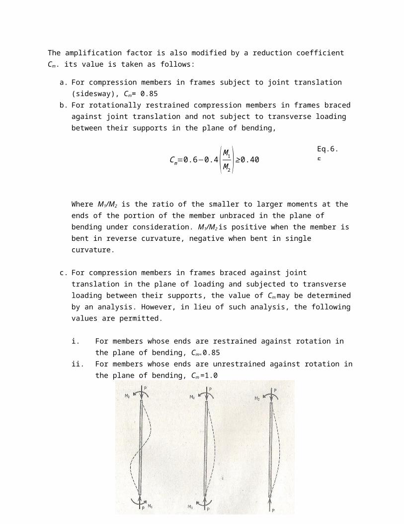
c. For compression members in frames braced against joint translation in the plane of loading and subjected to transverse loading between their supports, the value of Cm may be determined by an analysis. However, in lieu of such analysis, the following values are permitted.
i. For members whose ends are restrained against rotation in the plane of bending, Cm= 0.85
ii. For members whose ends are unrestrained against rotation in the plane of bending, Cm =1.0
Eq.6.5

Figure 6-1 – Values of Cm
Where
fa computed axial stress
fb computed bending stress
Fa allowable axial stress if axial force existed
Fb allowable compressive bending stress if bending moment alone existed
K effective length factor
Lb actual unbraced length in the plane of bending
rb corresponding radius of gyration
6.3 AXIAL TENSION AND BENDING
Members subject to both axial tension and bending stresses must satisfy the following equation:
faFt
+fbx
Fbx+fby
Fby≤1.0
Eq.6.6
M1 = ½ M2
Cm = 0.4M1/M2 is positive
M1 = M2
Cm = 1.0M1/M2 is negative
M1 = 0Cm = 0.6
M1/M2 is negative
Where fb is the computed bending stress, fa is the computed axial tensile stress, Fb is the allowable bending stress and Ft is the governing allowable tensile stress.
ILLUSTRATIVE PROBLEMS
Problem 6-1
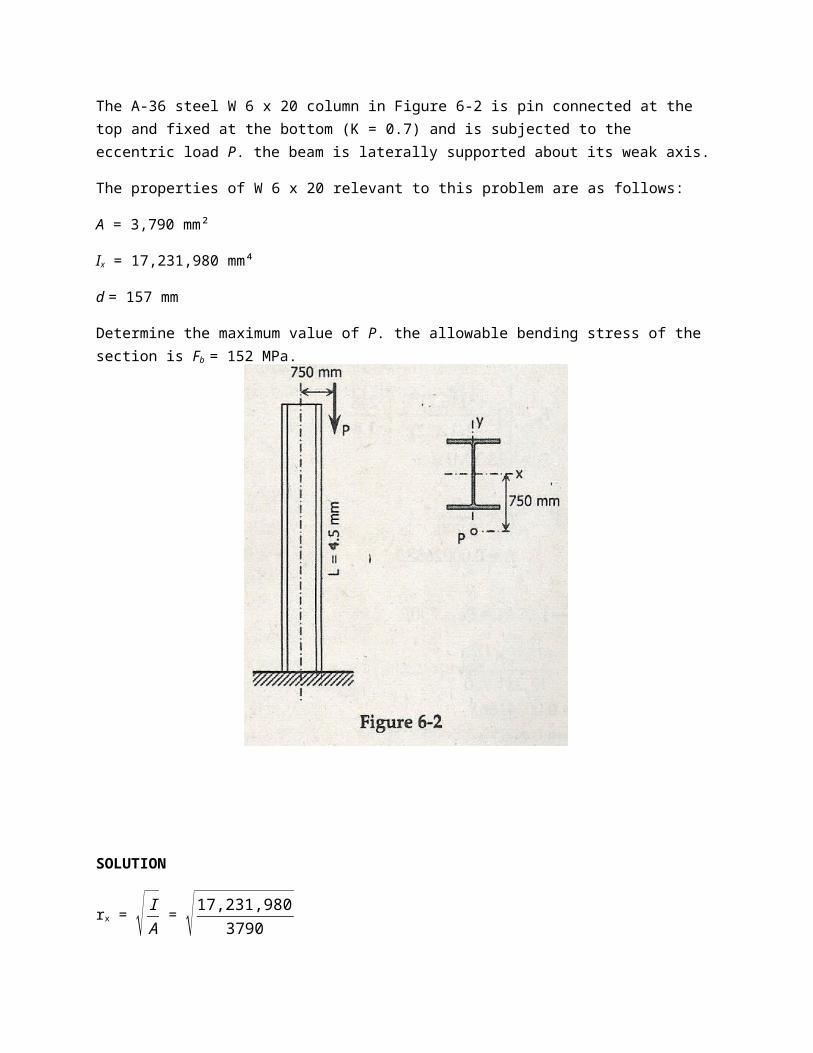
The A-36 steel W 6 x 20 column in Figure 6-2 is pin connected at the top and fixed at the bottom (K = 0.7) and is subjected to the eccentric load P. the beam is laterally supported about its weak axis.
The properties of W 6 x 20 relevant to this problem are as follows:
A = 3,790 mm²
Ix = 17,231,980 mm⁴
d = 157 mm
Determine the maximum value of P. the allowable bending stress of the section is Fb = 152 MPa.
SOLUTION
rx = √ IA = √17,231,9803790

rx = 67.43 mm
Slenderness ratio, SR = KLrx=0.7(4500)67.43
SR = 46.7
Solve for Fa:
[Cc =√2π²EFy] Fy = 248 MPa, E = 200,000 MPa
Cc = √2π²(200,000)248
= 126.2 > KL/r
Fa = ¿
FS=53
+3¿¿
FS=53
+3 (46.7)8 (126.2 )
−(46.7)3
8 (126.2)3=1.8
Fa = [1−(46.7)2
2 (126.2 )2 ] 2481.8
Fa = 128.3 MPa
[fa = PA ] fa =
P3,790
fa = 0.0002638P
[fb = McI ] M = Pe = 750P
fb = (750P )(157
2)
17,231,980
fb = 0.0034166P

Assuming fa / Fa ≤ 0.15,
[fa
Fa+fb
Fb≤1.0]
0.0002638P128.3+0.0034166P
152=1
P = 40,760 N
fa = 0.0002638(40,760) = 10.75 MPa
fa / Fa = 10.75/128.3 = 0.084 < 0.15 (OK)
Therefore, P = 40,760 N
Problem 6-2
Steel column 3.6 m long and hinged at both ends is used to carry an axial load of 1000 kN. The column is subject to end moments (reverse curvature) with M1 = 90% M2. Fy = 248 MPa, E = 200 GPa. The allowable axial stress Fa = 115 MPa and the allowable bending stress Fb = 149 MPa.
The properties of the section are as follows:
A = 0.013 m²
Sx = 0.00012 m³
rb = 94 mm.
a.) Determine the computed (actual) axial stress of the column.
b.) Determine the computed (actual) bending stress of thecolumn.
c.) Determine the moment capacity of the column.
SOLUTION
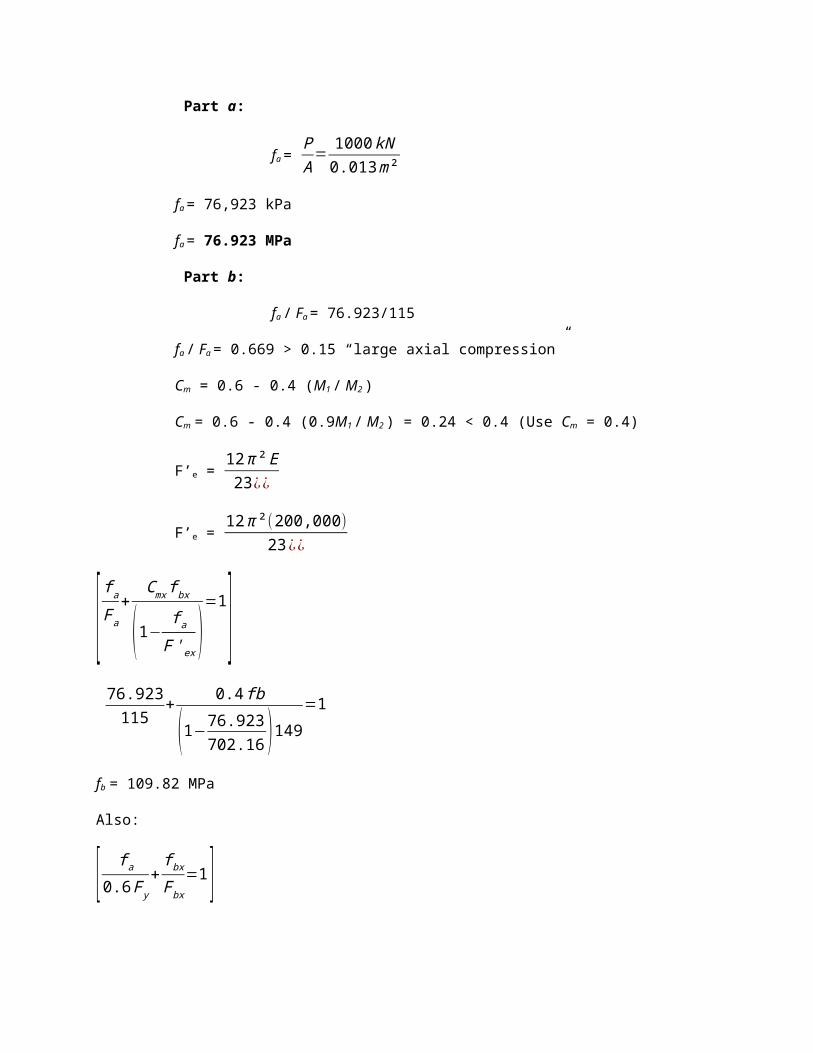
Part a:
fa = PA
=1000kN0.013m²
fa = 76,923 kPa
fa = 76.923 MPa
Part b:
fa / Fa = 76.923/115
fa / Fa = 0.669 > 0.15 “large axial compression”
Cm = 0.6 - 0.4 (M1 / M2 )
Cm = 0.6 - 0.4 (0.9M1 / M2 ) = 0.24 < 0.4 (Use Cm = 0.4)
F’e = 12π²E23¿¿
F’e = 12π²(200,000)
23¿¿
[fa
Fa+
Cmxfbx
(1−fa
F'ex )=1]
76.923115
+0.4fb
(1−76.923702.16 )149
=1
fb = 109.82 MPa
Also:
[ fa
0.6Fy+fbx
Fbx=1 ]

76.9230.6 (248 )
+ fb149
=1
fb = 71.97 MPa
Thus, fb = 71.97 MPa
Part c:
[fb=MSx ]fb=
M0.00012 (1000)3
=71.97
M = 8,636,400 N-mm
M = 8.6364 kN-m
Problem 6-3
Figure 6-3 shows a column subjected to axial load P = 40 kN and a bending moment of 60 kN-m on strong axis. The column is 9 m long and laterally supported about its weak axis at mid-height. The steel is A36 steel with Fy = 248 MPa. Effective length factor K = 1.0. the section used is a compact section. The allowable bending stress on strong axis is 114 MPa and the allowable bending stress on weak axis is 82 MPa.
The properties of the section are as follows:
A= 5,580 mm²
d/tw = 58.33
by/2ty = 9
rx = 147.9 mm
d = 350 mm
ry = 41.7 mm
Sx = 697 x 10³ mm³
rt = 47.8 mm
Bf = 180 mm
tf = 10 mm
a.) Determine the computed axial stress.b.) Determine the computed bending stress.

c.) Determine the value of the interaction equation.
SOLUTION
Part a:
Computed axial stress, fa = PA
=40,0005,580
Computed axial stress, fa = 7.17 MPa
Part b:
Computed bending stress, fb = MSx
=60x106697x103
Computed bending stress, fb = 86.08 MPa
Part c:
Allowable axial stress, Fax:

Cc = √2π2EFy= √2π²(200,000)
248= 126.17
Klx/rx = 1(9000)/147.9 = 60.85
Since kL/r < Cc:
FS = 53+3¿¿
Fa=¿
fa/Fa=7.17 /119.76
fa/Fa=0.06<0.15 “small axial compression”
[fa
Fa+fbx
Fbx+fbyFby
≤1.0]Note: The term
fbyFby
is zero since bending is on x axis only.
Fbx= 114 MPa
Value of interaction equation:
faFa
+fbx
Fbx=
7.17119.76
+86.08114
faFa
+fbx
Fbx = 0.815
Problem 6-4
Determine the adequacy of the W 14 x 120 A36 shape to carry an axial compressive load of 880 kN and a moment of 330 kN-m about its strong axis. The unsupported length is 6 m and the member is subjected to joint translation (sidesway). Use K = 1.0.
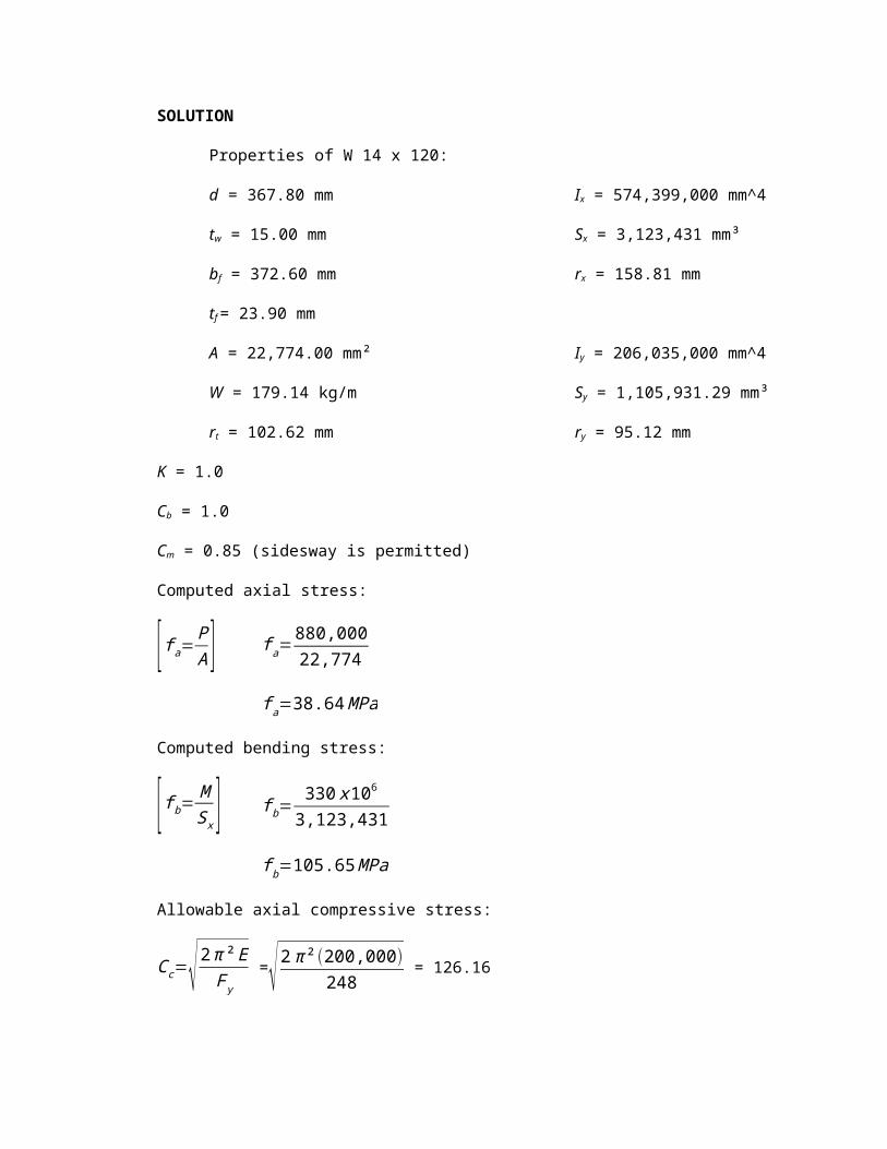
SOLUTION
Properties of W 14 x 120:
d = 367.80 mm
tw = 15.00 mm
bf = 372.60 mm
tf = 23.90 mm
A = 22,774.00 mm²
W = 179.14 kg/m
rt = 102.62 mm
Ix = 574,399,000 mm^4
Sx = 3,123,431 mm³
rx = 158.81 mm
Iy = 206,035,000 mm^4
Sy = 1,105,931.29 mm³
ry = 95.12 mm
K = 1.0
Cb = 1.0
Cm = 0.85 (sidesway is permitted)
Computed axial stress:
[fa=PA ] fa=
880,00022,774
fa=38.64MPa
Computed bending stress:
[fb=MSx ] fb=
330x1063,123,431
fb=105.65MPa
Allowable axial compressive stress:
Cc=√2π²EFy =√2π²(200,000)
248 = 126.16
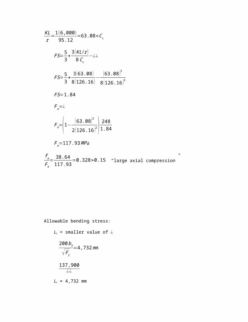
KLr
=1(6,000)95.12
=63.08<Cc
FS=53
+3 (KL /r )8Cc
−¿¿
FS=53
+3 (63.08 )8 (126.16 )
−(63.08 )3
8 (126.16 )3
FS=1.84
Fa=¿
Fa=(1−(63.08)2
2 (126.16 )2 ) 2481.84
Fa=117.93MPa
faFa
=38.64117.93
=0.328>0.15 “large axial compression”
Allowable bending stress:
Lc = smaller value of ¿
200bf√Fy
=4,732mm
137,900¿¿
Lc = 4,732 mm

Since Lb > Lc
LrT
= 6,000102.62
=58.47
√703,270CbFy = 53.25
√3,516,330Cb
Fy
= 119.07
703,270Cb
Fy<LrT
<√3,516,330Cb
Fy
Fb = larger value of (Fb1 & Fb3) ≤ 0.6 Fy
Fb1=¿
Fb1=165MPa
Fb3=82,740 (1 )
6,000 367.8372.6 (23.9)
=333.88MPa
0.6Fy=148.8MPa
Fb=148.8MPa
F'ex=
12π2E
23(KLx
rx )2=
12π2 (200,000)
23(1 (6,000 )158.81 )
2 =721.5MPa

Stability criterion:
faFa
+Cmxfbx
(1−fa
F'ex )Fbx+
Cmyfby
(1−fa
F'ey)Fby
≤1.0
0.328+ 0.85(105.65)
(1−38.64721.5 )148.8
+0−0.97<1.0
Strength criterion:
fa
0.60Fy+fbx
Fbx+fbyFby
≤1.0
38.640.60(248)
+105.65148.8
+0−0.97<1.0
Therefore, the section is ADEQUATE.
(OK)
(OK)