Manual No.'18 • KX-SM-292 - Stulz-benelux.com
181
SERVICE MANUAL Manual No.'18 • KX-SM-292 (1) Regarding the indoor unit series, refer to the No.'17 • KX-T-266 and '18 • KX-T-281. • Note: VRF INVERTER MULTI-SYSTEM AIR-CONDITIONERS (OUTDOOR UNIT) FDC224KXZME1, 280KXZME1, 335KXZME1 KXZ series (Heat pump type)
-
Upload
khangminh22 -
Category
Documents
-
view
3 -
download
0
Transcript of Manual No.'18 • KX-SM-292 - Stulz-benelux.com

SERVICE MANUAL
Manual No.'18 • KX-SM-292
DATA BOOK
(1) Regarding the indoor unit series, refer to the No.'17 • KX-T-266 and '18 • KX-T-281.• Note:
VRF INVERTER MULTI-SYSTEM AIR-CONDITIONERS
(OUTDOOR UNIT)
FDC224KXZME1, 280KXZME1, 335KXZME1
KXZ series (Heat pump type)
Manual No. '18 • KX-DB-291

– 1 –
'18 • KX-SM-292
CONTENTS
1. OUTLINE OF OPERATION CONTROL BY MICROCOMPUTER .....................21.1 Remote control (Option parts) ...................................................................21.2 Operation control function by the wired remote control .............................51.3 Operation control function by the indoor control .....................................101.4 Operation control function by the outdoor control ...................................25
2. SYSTEM TROUBLESHOOTING PROCEDURE .............................................622.1 Basics of troubleshooting ........................................................................622.2 Explanation of troubleshooting ................................................................632.3 Contents of troubleshooting ....................................................................642.4 Outdoor unit control PCB replacement procedure ................................1172.5 Inverter PCB replacement procedure ....................................................119
3. ELECTRICAL WIRING ..................................................................................1234. PIPING SYSTEM ............................................................................................1255. APPLICATION DATA ....................................................................................1276. OUTDOOR UNIT DISASSEMBLY PROCEDURE ......................................... 1507. INDOOR UNIT DISASSEMBLY PROCEDURE .............................................152

– 2 –
'18 • KX-SM-292
1. OUTLINE OF OPERATION CONTROL BY MICROCOMPUTER 1.1 Remote control (Option parts)
(1) Wired remote control
(a) Model RC-EX3A
'16 • PAC-T-251
① Run/Stop switch
② F1 switch ③ F2 switch
Touch panel system, which is operated by tapping the LCD screen with a finger, is employedfor any operations other than the ①Run/Stop, ②F1 and ③F2 switches.
One push on the button starts operation andanother push stops operation.
This switch starts operation that is set in F1/F2 function setting.
④ Operation lampThis lamp lights in green (yellow-green) duringoperation. It changes to red (orange) if any erroroccurs.Operation lamp luminance can be changed.
⑤ LCD (with backlight)A tap on the LCD lights the backlight.The backlight turns off automatically if there isno operation for certain period of time. Lightingperiod of the backlight lighting can be changed.
If the backlight is ON setting, when the screen is tapped while the backlight is turned off, the backlight only is turned on. (Operations with switches ①,②and ③ are excluded.)
⑥ USB portUSB connector (mini-B) allows connecting to apersonal computer.For operating methods, refer to the instructionmanual attached to the software for personalcomputer (remote control utility software).
Note(1) When connecting to a personal computer, do not connect simultaneously with other USB devices. Please be sure to connect to the computer directly, without
going through a hub, etc.
Model RC-EX3A
1.10 OUTLINE OF OPERATION CONTROL BY MICROCOMPUTER1.10.1 Remote control(1) Wired remote control
P044-055.pdf 2017/03/17 13:53:02
⑤ LCD (with backlight)
③ F2 switch
④ Operation lamp⑥ USB port (mini-B)
① Run/Stop switch② F1 switch

– 3 –
'18 • KX-SM-292
(b) Model RC-E5
- 112 -
'16 • PAC-T-251
The figure below shows the remote control with the cover opened. Note that all the items that may be displayed in the liquid crystal display area are shown in the figure for the sake of explanation.Characters displayed with dots in the liquid crystal display area are abbreviated.
* All displays are described in the liquid crystal display for explanation.
The figure below shows the remote control with the cover opened.
Ventilaion displayDisplayed during ventilation operation
Central control displayDisplayed when the air-conditioning system is controlled by central control.
Timer operation displayDisplays the timer operation setting.
Temperature setting buttonsThese buttons are used to set the temperature of the room.
Timer buttonThis button is used to setthe timer mode.
Timer setting buttonsThese buttons are used to setthe timer mode and the time.
ESP buttonThis button is used to select the auto static pressure adjustment mode.
Cover
AIR CON No. buttonDisplay the indoor unit number connected to thisremote control.
CHECK buttonThis button is used at servicing.
TEST buttonThis button is used during test operation.
Weekly timer displayDisplays the settings of theweekly timer.
Operation setting display area Displays setting temperature, air flow volume, operation mode and oparation message.
Operation/check indicator light During operation: Lit in greenIn case of error: Flashing in red
Operation/stop buttonThis button is used to operate and stop the air-conditioning system.Press the button once to operate the system and press it once again to stop the system.
MODE buttonThis button is used to change the operation mode.
FAN SPEED buttonThis button is used to set the air flow volume.
VENT buttonThis button is used to operate external ventilator.
LOUVER buttonThis button is used to operate/stop the swing louver.
SET buttonThis button is used to fix the setting.This button is used to set the silent mode.
RESET buttonIf you press this button while making settings, you can go back to the previous operation.This button is also used to reset the "FILTER CLEANING" display. (Press it after cleaning the air filter)
C
M
Y
CM
MY
CY
CMY
K
P044-055.pdf 2017/03/17 13:54:51

– 4 –
'18 • KX-SM-292
- 113 -
'16 • PAC-T-251
(2) Wireless remote control
Indication section
Operation section
(2) Wireless remote control
Model RCN-E2
D
C
4
5
6
1 8 9
@
B
A
3 7 2
① OPERATION MODE display Indicates selected operation mode.
②
SET TEMP display Indicates set temperature.SLEEP TIMER time display Indicates the amount of time remaining on the sleep timer.Indoor function setting number display Indicates the setting number of the indoor function setting.
③ FAN SPEED display Indicates the selected air flow volume.
④ UP/DOWN AIR FLOW display Indicates the up/down louver position.
⑤ LEFT/RIGHT AIR FLOW display Indicates the left/right louver position.
⑥ Clock display Indicates the current time. If the timer is set, the ON TIMER and OFF TIMER setting times are indicated.
⑦ ON/OFF TIMER display Displayed when the timer is set.⑧ ECO mode display Displayed when the energy-saving operation is active.⑨ HI POWER display Displayed when the high power operation is active.⑩ NIGHT SETBACK display Displayed when the home leave mode is active.⑪ SILENT display Displayed when the silent mode control is active.
⑫ Motion sensor display Displayed when the infrared sensor control(motion sensor control) is enabled.
⑬ Anti draft setting display Displayed when anti draft setting is enabled.⑭ Child lock display Displayed when child lock is enabled.
Transmitter:Sends signal to the air- conditioner.
1
K
75
2
D 4
3
6
I
G
A
B
HC@
8
F
9
E
J
① ON/OFF buttonWhen this is pressed once, the air-conditioner starts to operate and when this is pressed once again, it stops operating.
② MODE buttonEvery time this button is pressed, displays switch as below (AUTO) (COOL) (HEAT) (FAN) (DRY)
③ TEMP button Change the set temperature by pressing or button.
④ FAN SPEED button The fan speed is switched in the following order: 1-speed 2-speed 3-speed 4-speed AUTO 1-speed.
⑤ U/D button Used to determine the up/down louver position.⑥ L/R button Used to determine the left/right louver position.
⑦ 3D AUTO button Used to switch whether or not to enable or disable 3D AUTO mode.
⑧ ON TIMER button Used to set the ON TIMER.⑨ OFF TIMER button Used to set the OFF TIMER.
⑩ SELECT button Used to switch the time when setting the timer or adjusting the time.Used to switch the settings of the indoor function.
⑪ SET button
Used to determine the setting when setting the timer or adjusting the time.Used to determine the settings of the indoor function.When press and hold SET button ,Child Lock is enabled.
⑫ CANCEL button Used to cancel the timer setting.⑬ SLEEP button Used to set the sleep timer.
⑭ ECO button Pressing this button starts the energy-saving operation. Pressing this button again cancels it.
⑮ HI POWER button Pressing this button starts the high power operation. Pressing this button again cancels it.
⑯ SILENT button Pressing this button starts the silent mode control. Pressing this button again cancels it.
⑰ NIGHT SETBACK button Pressing this button starts the home leave mode. Pressing this button again cancels it.
⑱ FILTER button Pressing this button resets FILTER SIGN.⑲ FUNCTION SETTING switch Used to set the indoor function.⑳ TIME SETUP switch Used to set the current time. ACL switch Used to reset the microcomputer.
– 5 –
'18 • KX-SM-292
1.2 Operation control function by the wired remote control
Service & Maintenance
Special settings
Indoor unit capacity display
Back
Select the item.
前ページPrevious Back
Erase IU address
CPU reset
Restore of default setting
Touch panel calibration
Special settings
Select the item.
R/C function settings
Ventilation setting
Auto-restart
Auto temp setting
Back
Select the item.
Previous
Auto fan speed
② Auto-restart
Auto-restart
BackSelect the item.
Enable
Disable
1.10.2 Operation control function by the wired remote control(1) Model RC-EX3A
(a) Switching sequence of the operation mode switches of remote control (i) Tap the change operation mode button on the TOP screen. (ii) When the change operation mode screen is displayed, tap the button of desired mode. (iii) When the operation mode is selected, the display returns to the TOP screen. Icons displayed have the following meanings.
Cooling Fan
Dry Heating
Auto
Notes(1) Operation modes which cannot be selected depending on combinations of indoor unit and outdoor unit are not displayed. (2) When the Auto is selected,the cooling and heating switching operation is performed automatically according to indoor and outdoor temperatures.
(b) CPU resetReset CPU from the remote control as follows.
TOP screen Menu Service setting Service & Maintenance Service password
The selected screen isdisplayed.
The selected screen isdisplayed.
① Service & Maintenance #2 ② Special settings
⇒ ⇒ ⇒
CPU resetMicrocomputers of indoor unit and outdoor unit connected are reset(State of restoration after power failure).
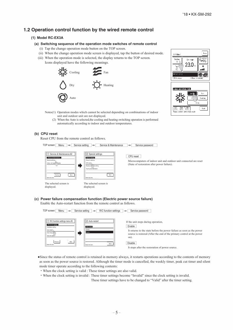
(c) Power failure compensation function (Electric power source failure)Enable the Auto-restart function from the remote control as follows.
TOP screen Menu ⇒ Service setting ⇒ R/C function settings Service password ⇒
① R/C function settings menu #3 If the unit stops during operation,
It returns to the state before the power failure as soon as the powersource is restored (After the end of the primary control at the poweron).
It stops after the restoration of power source.
Enable
Disable
Since the status of remote control is retained in memory always, it restarts operations according to the contents of memory as soon as the power source is restored. Although the timer mode is cancelled, the weekly timer, peak cut timer and silent mode timer operate according to the following contents: ・When the clock setting is valid : These timer settings are also valid. ・When the clock setting is invalid : These timer settings become “Invalid” since the clock setting is invalid. These timer settings have to be changed to “Valid” after the timer setting.

– 6 –
'18 • KX-SM-292
Clock setting check screen
Misconnection screen
Content memorized with the power failure compensation are as follows.Note(1) Items f) and g) are memorized regardless whether the power failure compensation is effective or not while the setting of silent mode is cancelled regardless whether the power failure compensation is effective or not.
a) At power failure – Operating/stopped If it had been operating under the off timer mode, sleep timer mode, the state of stop is memorized. b) Operation mode c) Air flow volume mode d) Room temperature setting e) Louver auto swing/stop However, the stop position (4-position) is cancelled so that it returns to Position (1). f) “Remote control function items” which have been set with the administrator or installation function settings (“Indoor function items” are saved in the memory of indoor unit.) g) Weekly timer, peak-cut timer or silent mode timer settings h) Remote control function setting
Please check the I/U
Set clock first on the initializingscreen & set the timer.
Other than A/C is connected
If the following a) to c) appear, check and repair as follows.
Communication check screen This appears if communications cannot be established between the remote control and the indoor unit. Check whether the system is correctly connected (indoor unit, outdoor unit, remote control) and whether the power source for the outdoor unit is connected.
This appears when the timer settings are done without clock setting. Set the clock setting before the timer settings.
This appears when something other than the air-conditioner has been connected to the remote control. Check the location to which the remote control is connected.
a) Communication check between indoor unit and remote control
b) Clock setting check
c) Misconnection
(d) Alert displays

– 7 –
'18 • KX-SM-292
(a) Switching sequence of the operation mode switches of remote control
DRY COOL FAN HEAT AUTO
(b) CPU reset This functions when “CHECK” and “ESP” buttons on the remote control are pressed simultaneously. Operation is same
as that of the power source reset.
(c) Power failure compensation function (Electric power source failure)• This becomes effective if “Power failure compensation effective” is selected with the setting of remote control function.• Since it memorizes always the condition of remote control, it starts operation according to the contents of memory
no sooner than normal state is recovered after the power failure. Although the auto swing stop position and the timer mode are cancelled, the weekly timer setting is restored with the holiday setting for all weekdays.After recovering from the power failure, it readjusts the clock and resets the holiday setting for each weekday so that the setting of weekly timer becomes effective.
• Content memorized with the power failure compensation are as follows.Note (1) Items f), g) and h) are memorized regardless whether the power failure compensation is effective or not while the setting of silent mode is
regardless whether the power failure compensation is effective or not.
At power failure – Operating/stoppedIf it had been operating under the off timer mode, sleep timer mode, the state of stop is memorized.
mode is cancelled at the recovery from power failure, the setting of weekly timer is
Operation mode
a)
b)
Room temperature setting e) Louver auto swing/stop
However, the stop position (4-position) is cancelled so that it returns to Position (1). f) “Remote control function items” which have been set with the remote control function setting (“Indoor
function items” are saved in the memory of indoor unit.)Upper limit value and lower limit value which have been set with the temperature setting controlSleep timer and weekly timer settings (Other timer settings are not memorized.)
[Parts layout on remote control PCB]
X Y
SW2
SW1
A
B
M
S
親
子SW1
SW2
Master/ slave setting when more than one remote controls are used
A maximum of two remote controls can be connected to one indoor unit (or one group of indoor units.)
Remote control cord (no polarity)
Remote controlSW1 "Master"
Switch Setting ContentM Master remote control
SW1S Slave remote control
Remote controlSW1 "Slave"
Indoor units
Note (1) Don’t change SW2 because it is not used normally.
CautionWhen using multiple remote controls, the following dispiays or settingscannot be done with the slave remote control. It is available only withthe master remote control. Louver position setting (set upper or lower limit of swinging range) Setting indoor unit functions Setting temperature range Operation data display Error data display Silent mode setting Test operation of drain pump Remote control sensor setting
Air flow volume mode
(2) Model RC-E5
c)
d)
g)
h)
cancelled
(Although the timer all weekdays.)changed to the holiday setting for

– 8 –
'18 • KX-SM-292
A : Refer to the instruction manual for RC-EX seriesB : Refer to the installation manual for RC-EX seriesC : Loading a utility software via Internet
:Nearly same function setting and operations are possible.:Similar function setting and operations are possible.
Setting & display item Description RC-EX3A RC-E5
1.Remote control network1 Control plural indoor units by a single remote control A remote control can control plural indoor units up to 16 (in one group of remote control network).
An address is set to each indoor unit.
2 Main/sub setting of remote controls A pair of remote controls (including optional wireless remote control) can be connected within the remote control network. Set one to “Main” and the other to “Sub”. B
2.TOP scrren, Switch manipulation1 Menu "Control","State", or "Details" can be selected. (3-8) A2 Operation mode "Cooling","Heating","Fan","Dry" or "Auto" can be set. A 3 Set temp. "Set temperature" can be set by 0.5˚C interval. A 4 Air flow direction "Air flow direction" [Individual flap control] can be set.
Select Enable or Disable for the “3D AUTO” (in case of FDK). *1 A
5 Fan speed "Fan speed" can be set. A 6 Timer setting "Timer operation" can be set. A 7 ON/OFF "On/Off operation of the system" can be done. A 8 F1 SW The system operates and is controlled according to the function specified to the F1 switch. A9 F2 SW The system operates and is controlled according to the function specified to the F2 switch. A
3.Useful functions1 Individual flap control The moving range (the positions of upper limit and lower limit) of the flap for individual flap can be set.
Set also the left and right limit positions for FDK. A
2 Anti draft setting When the panel with the anti-draft function is assembled.
When the panel with the anti draft function is assembled, select to Enable or Disable the anti draft setting for each operation mode and for each blow outlet. A
3 Timer settings Set On timer by hour The period of time to start operation after stopping can be set.・The period of set time can be set within range of 1hour-12houres (1hr interval).・The operation mode, set temp. and fan speed at starting operation can be set.
A
Set Off timer by hour The period of time to stop operation after starting can be set.・The period of set time can be set within range of 1hour-12houres (1hr interval). A
Set On timer by clock The clock time to start operation can be set.・The set clock time can be set by 5 minutes interval.・[Once (one time only)] or [Everyday] operation can be switched.・The operation mode, set temp. and fan speed at starting operation can be set.
A
Set Off timer by clock The clock time to stop operation can be set.・The set clock time can be set by 5 minutes interval.・[Once (one time only)] or [Everyday] operation can be switched.
A
Confirmation of timer settings Status of timer settings can be seen. A4 Favorite setting
[Administrator password]Set the operation mode, setting temperature, air flow capacity and air flow direction for the choice setting operations. Set them for the Favorite set 1 and the Favorite set 2 respectively. A
5 Weekly timer On timer and Off timer on weekly basis can be set.・8-operation patterns per day can be set at a maximum.・The setting clock time can be set by 5 minutes interval.・Holiday setting is available.・The operation mode, set temp. and fan speed at starting operation can be set.
A
6 Home leave mode
[Administrator password]
When leaving home for a long period like a vaction leave, the unit can be operated to maintain the room temperature not to be hotter in summer or not to be colder in winter.・ The judgment to switch the operation mode (Cooling ⇔ Heating) is done by the both factors of the set temp. and outdoor air temp.・The set temp. and fan speed can be set.
A
7 External VentilationWhen the ventilator is combined.
On/Off operation of the external ventilator can be done. It is necessary to set from [Menu] ⇒ [Service setting] ⇒ [R/C function settings] ⇒ [Ventilation setting]. ・ If the “Independent” is selected for the ventilation setting, the ventilator can be operated or stopped.
A
8 Select the language Select the language to display on the remote control. ・Select from English, German, French, Spanish, Italian, Dutch, Turkish, Portuguese, Russian,
Polish, Japanese and Chinese. A
4.Energy-saving setting Administrator password1 Sleep timer To prevent the timer from keeping ON, set hours to stop operation automatically with this timer.
・The selectable range of setting time is from 30 to 240 minutes. (10 miuutes interval)・When setting is "Enable", this timer will activate whenever the ON timer is set.
A
2 Peak-cut timer Power consumption can be reduced by restructing the maximum capacity.Set the [Start time], the [End time] and the capacity limit % (Peak-cut %).・4-operation patterns per day can be set at maximum.・The setting time can be changed by 5-minutes interval.・The selectable range of capacity limit % (Peak-cut % ) is from 0% to 40-80% (20% interval)・Holiday setting is available.
A
3 Automatic temp. set back After the elapse of the set time period, the current set temp. will be set back to the [Set back time.]・The setting can be done in cooling and heating mode respectively.・Selectable range of the set time is from 20 min. to 120 min. (10 min. interval).・Set the [Set back temp.] by 1˚C interval.
A
4 Infrared sensor control (Motion sensor control) When the panel with the infrared sensor (motion sensor) is assembled.
When the infrared sensor (motion sensor) is used, it is necessary to set Enable or Disable for the “Power control” and the “Auto-off”. A
5.Filter1 Filter sign reset Filter sign reset The filter sign can be reset. A
Setting next cleaning date The next cleaning date can be set. A6.User setting
1 Internal settings Clock setting The current date and time can be set or revised. ・If a power failure continues no longer than 80 hours, the clock continues to tick by the built-in power source. A
Date and time display [Display] or [Hide] the date and/or time can be set, and [12H] or [24H] display can be set. ASummer time When select [Enable], the +1hour adjustment of current time can be set. When select [Disable], the [Summer time] adjustment
can be reset. A
Contrast The contrast of LCD can be adjusted higher or lower. ABacklight Switching on/off a light can be set and period of the lighting time can be set within the range of 5sec-90 sec (5sec interval). AControl sound It can set with or without [Control sound (beep sound)] at touch panel. AOperation lamp luminance This is used to adjust the luminance of operation lamp. A
2 Administrator settings
[Administrator password]
Permission/Prohibition setting ・Permission/Prohibition setting of operation can be set. [On/Off][Change set temp] [Change operation mode] [Change flap direction] [Change fan speed] [High power operation][Energy-saving operation] [Timer]Request for administrator can be set.[Individual flap control] [Weekly timer] [Select the language] [Anti draft setting]
A
Outdoor unit silent mode timer The period of time to operate the outdoor unit by prioritizing the quiteness can be set.・The [Start time] and the [End time] for operating outdoor unit in silent mode can be set.・The period of the operation time can be set once aday by 5 minutes interal.
A
Setting temp. range The upper/lower limit of temp. setting range can be set.・The limitation of indoor temp. setting range can be set for each operation mode in cooling and heating. A
Temp. increment setting The temp. increment setting can be changed by 0.5˚C or 1.0˚C. ASet temp. display Ways of displaying setting temperatures can be selected. A
(3) Operation and setting from wired remote control

– 9 –
'18 • KX-SM-292
Setting & display item Description RC-EX3A RC-E5
2 Administrator settings
[Administrator password]
R/C display setting Register [Room name] [Name of I/U]Display [Indoor temp. display] or not.Display [Error code display] or not.Display [Heating stand-by display] [Defrost operation display] [Auto cooling/heating display] [Display temp. of R/C, Room, Outdoor] or not
A
Change administrator password The administrator password can be changed. (Default setting is "0000") AThe administrator password can be reset. B
F1/F2 function setting Functions can be set for F1 and F2. Selectable functions: [High power operation], [Energy-saving operation], [Silent mode cont.], [Home leave mode], [Favorite set 1],[Favorite set 2] and [Filter sign reset].
A
7.Service setting1 Installer settings
[Service password]
Installation date The [Installation date] can be registed.・ When registering the [Instaration date], the [Next service date] is displayed automatically.
(For changing the [Next service date], please refer the item of [Service & Maintenance])B
Company information The [Company information] can be registed and can be displayed on the R/C.・The [Company] can be registered within 26 characters.・The [Phone No.] can be registed within 13 digits.
B
Test run On/Off operation of the test run can be done.B Cooling test run The [Cooling test run] can be done at 5˚C of set temp. for 30 minutes.
Drain pump test run Only drain pump can be operated.Static pressure adjustment In case of combination with only the ducted indoor unit which has a function of static pressure adjustment, the static pressure is adjustable.
・It can be set for each indoor unit individually. B
Change auto-address The set address of each indoor unit decided by auto-address setting method can be changed to any other address.(For multiple KX units only) B
Address setting ofmain IU
Main indoor unit address can be set.・Only the Main indoor unit can change operation mode and the Sub indoor units dominated by the Main indoor shall follow.・The Main indoor unit can domain 10 indoor units at a maximum.
B
IU back-up function When a pair of indoor units (2 groups) is connected to one unit of remote control, it can be set Enable or Disable for the[IU rotation], [IU capacity back-up] and [IU fault back-up] B
Infrared sensor setting (Motion sensor setting) When the panel with the infrared sensor (motion sensor) is assembled.
Set Enable or Disable for the infrared sensor detectors of indoor units connected to the remote control. If Disable is selected, it cannot be control the infrared sensor control for the energy-saving setting. B
2 R/C function setting
[Service password]
Main/Sub R/C The R/C setting of [Main/Sub] can be changed. B Return air temp. When two or more indoor units are connected to one unit of remote control, suction sensors, which are used for the judgement
by thermostat, can be selected. ・It can be selected from [Individual], [Master IU] and [Average temp.].
B
R/C sensor It can be set the mode to switch to the remote control sensor. It can be selected from cooling and heating. B R/C sensor adjustment The offset value of [R/C sensor] sensing temp. can be set respectively in heating and cooling. B Operation mode Enable or Disable can be set for each operation mode. B ºC / ºF Set the unit for setting temperatures.
・°C or °F can be selected. B
Fan speed Fan speeds can be selected. B External input When two or more indoor units are connected to one unit of remote control, the range to apply CnT inputs can be set. B Upper/lower flap control [Stop at fixed position] or [Stop at any position] can be selected for the upper and lower louvers. B Left/right flap control [Fixed position stop] or [Stop at any position] can be selected for the right and left louvers. BVentilation setting Combination control for ventilator can be set. B Auto-restart The operation control method after recovery of power failure happened during operation can be set. B Auto temp. setting [Enable] or [Disable] of [Auto temp. setting] can be selected. BAuto fan speed [Enable] or [Disable] of [Auto fan speed] can be selected. B
3 IU settings Fan speed setting The fan speed for indoor units can be set. B Filter sign The setting of filter sign display timer can be done from following patterns. B
[Service password] External input 1 The connect of control by external input 1 can be changed. B External input 1 signal The type of external input 1 signal can be changed. B External input 2 The connect of control by external input 2 can be changed. BExternal input 2 signal The type of external input 2 signal can be changed. BHeating thermo-OFF temp. adjustment The judgement temp. of heating themo-off can be adjusted within the range from 0 to +3˚C (1˚C interval) B Return temperature adjustment The sensing temp. of return air temp. sensor built in the indoor unit can be adjusted within the range of ±2˚C. B Fan control in cooling thermo-OFF Fan control, when the cooling thermostat is turned OFF, can be changed. B Fan control in heating thermo-OFF Fan control, when the heating thermostat is turned OFF, can be changed. B Anti-frost temp. Judgment temperature for the anti-frost control during cooling can be changed. B Anti-frost control When the anti-frost control of indoor unit in cooling is activated, the fan speed can be changed. B Drain pump operation In any operation mode in addition to cooling and dry mode, the setting of drain pump operation can be done. B Keep fan operating after cooling is stopped
The time period residual fan operation after stopping or thermo-off in cooling mode can be set. B
Keep fan operating after heating is stopped
The time period residual fan operation after stopping or thermo-off in heating mode can be set. B
Intermittent fan operation in heating The fan operation rule following the residual fan operation after stopping or themo-off in heating mode can be set. B Fan circulator operation In case that the fan is operated as the circulator, the fan control rule can be set. BControl pressure adjust When only the OA processing units are operated, control pressure value can be changed. BAuto operation mode The [Auto rule selection] for switching the operation mode automatically can be selected from 3 patterns. BThermo. rule setting When selecting [Outdoor air temp. control], the judgment temp. can be offset by outdoor temp.. BAuto fan speed control Auto switching range for the auto fan speed control can be set. BIU overload alarm If the difference between the setting temperature and the suction temperature becomes larger than the temperature difference set for
the overload alarm, at 30 minutes after the start of operation, the overload alarm signal is transmitted from the external output (CnT-5). B
External output setting Functions assigned to the external outputs 1 to 4 can be changed. B
4 Service & Maintenance
[Service password]
IU address Max 16 indoor units can be connected to one remote control, and all address No. of the connected indoor units can be displayed.・ The indoor unit conforming to the address No. can be identified by selecting the address No. and tapping [Check] to operate the
indoor fan.B
Next service date The [Next service date] can be registered. ・The [Next service date] and [Company information] is displayed on the message screen. A B
Operation data The [Operation data] for indoor unit and outdoor unit can be displayed. B Error display
B Error history The error history can be displayed.Display anomaly data The operation data just before the latest error stop can be displayed.Erase anomaly data Anomaly operation data can be erased.Reset periodical check The timer for the periodical check can be reset.
Saving IU settings The I/U settings memorized in the indoor PCB connected to the remote control can be saved in the memory of the remote control. BSpecial settings [Erase IU address] [CPU reset] [Restore of default setting] [Touch panel calibration] B Indoor unit capacity display Address No. and capacities of indoor units connected to the remote control are displayed. B
8.Contact company Shows registered [Contact company] and [Contact phone].9.Inspection
Confirmation of Inspection This is displayed when any error occurs. A 10.PC connection
USB connection Weekly timer setting and etc., can be set from PC. C
Listed items may not function depending on the specifications of indoor and outdoor units which are combined.

– 10 –
'18 • KX-SM-292
(1) Operations of functional items during cooling/heating
Cooling Heating
Dehumidifying
Thermostat ON:Thermostat OFF:(2)
FanOperation
Functional itemThermostat
ONThermostat
ONThermostat
OFFThermostat
OFFHot start (Defrost)
Compressor
4-way valve
Outdoor unit fan
Indoor unit fan
Drain pump(3)
(2)
(2)
/
/
()
()
/
/
/
/
Notes (1) : Operation : Stop /: Turned ON/OFF by the control other than the room temperature control. (2) ON during the drain motor delay control. (3) Drain pump ON setting may be selected with the indoor unit function setting of the wired remote control.
/(2)
(3) Timer operation(a) RC-EX3A (i) Sleep timer
Set the time from the start to stop of operation. The time can be selected in the range from 30 to 240 minutes (in the unit of 10-minute).Note (1) Enable the “Sleep timer” setting from the remote control. If the setting is enabled, the timer operates at every time.
(ii) Set OFF timer by hourSet the time to stop the unit after operation, in the range from 1 to 12 hours (in the unit of hour).
(iii) Set ON timer by hourSet the time to start the unit after the stop of operation, in the range from 1 to 12 hours (in the unit of hour). It is allowed also to set simultaneously the indoor temperature, operation mode, air flow rate and warm-up enabled/disabled.
(iv) Set ON timer by clockSet the time to start operation. The time can be set in the unit of 5-minute. This setting can be activated only once or at every time. It is allowed also to set simultaneously the indoor temperature, operation mode, air flow rate and warm-up enabled/disabled.Note (1) It is necessary to set the clock to use this timer.
(v) Set OFF timer by clockSet the time to stop operation. The time can be set in the unit of 5-minute. This setting can be activated only once or at every time.Note (1) It is necessary to set the clock to use this timer.
(vi) Weekly timerSet the ON or OFF timer for a week. Up to 8 patterns can be set for a day. The day-off setting is provided for holidays and non-business days.Note (1) It is necessary to set the clock to use the weekly timer.
1.3 Operation control function by the indoor control
(2) Dehumidifying (DRY) operationIndoor ambient temperatures and humidity are controlled simultaneously with the relative humidity sensor (HS) and the suction temperature sensor [Thi-A (or the remote control sensor when it is activated)], which are installed at the suction inlet.
(a) When the operation has been started with cooling, if there is a difference of 2°C or less between the suction and setting temperatures, the tap of indoor fan is lowered by one tap. This tap is retained for 3 minutes after changing the tap.
(b)
After the above condition, when a difference between suction and setting temperature is lower than 3°C, and the relative humidity is high, the tap of indoor unit fan is lowered by one tap.When the difference between suction and setting temperature is larger than 3°C, the fan of indoor unit fan is raised by one tap. This tap is retained for 3 minutes after changing the tap.
(c) When relative humidity becomes lower, the indoor unit fan tap is retained.(d) In case of the thermostat OFF, the indoor unit fan tap at the thermostat ON is retained.

– 11 –
'18 • KX-SM-292
(b) RC-E5 (i) Sleep timer
Set the duration of time from the present to the time to turn off the air-conditioner.It can be selected from 10 steps in the range from “OFF 1 hour later” to “OFF 10 hours later”. After the sleep timer setting, the remaining time is displayed with progress of time in the unit of hour.
(ii) OFF timerTime to turn OFF the air-conditioner can be set in the unit of 10 minutes.
(iii) ON timerTime to turn ON the air-conditioner can be set. Indoor temperature can be set simultaneously.
(iv) Weekly timerTimer operation (ON timer, OFF timer) can be set up to 4 times a day for each weekday.
(v) Timer operations which can be set in combination
Timer
OFF timer
ON timer
Weekly timer
Timer
OFF timer
ON timer
Weekly timer
Notes (1) : Allowed : Not
ItemItem
(2) Since the ON timer, sleep timer and OFF timer are set in parallel, when the times to turn ON and OFF the air-conditioner are duplicated, the setting of the OFF timer has priority.
(vii) Combination of patterns which can be set for the timer operations
Note (1) : Allowed : Not
Sleep time
Sleep time
Set OFF timer by hour Weekly timerSet ON timer by hour Set OFF timer by clock Set ON timer by clock
Set OFF timer by hour
Set ON timer by hour
Set OFF timer by clock
Set ON timer by clock
Weekly timer
(4) Hot start (Cold draft prevention at heating)
(a) Operating conditions
When either one of following conditions is satisfied, the hot start control is performed. (i) From stop to heating operation (ii) From cooling to heating operation(iii) From heating thermostat OFF to ON(iv) After completing the defrost operation (only on units with thermostat ON)
(b) Contents of operation
(i) Indoor fan motor control at hot start
1) Within 7 minutes after starting heating operation, the fan mode is determined depending on the condition of
thermostat (fan control with heating thermostat OFF).
a) Thermostat OFF i) Operates according to the fan control setting at heating thermostat OFF. ii) Even if it changes from thermostat OFF to ON, the fan continues to operate with the fan control at thermostat
OFF till the heat exchanger temperature sensor (Thi-R1 or R2, whichever higher) detects 35°C or higher.iii) When the heat exchanger temperature sensor (Thi-R1 or R2, whichever higher) detects 35°C or higher, the fan
operates with the set air flow volume.

– 12 –
'18 • KX-SM-292
b) Thermostat ON i) When the heat exchanger temperature sensor (Thi-R1 or R2, whichever higher) detects 25°C or lower, the fan is
turned OFF and does not operate. ii) When the heat exchanger temperature sensor (Thi-R1 or R2, whichever higher) detects 25°C or higher, the fan
operates with the fan control at heating thermostat OFF.iii) When the heat exchanger temperature sensor (Thi-R1 or R2, whichever higher) detects 35°C or higher, the fan
operates with the set air flow volume.c) If the fan control at heating thermostat OFF is set at the “Set air flow volume” (from the remote control), the fan
operates with the set air flow volume regardless of the thermostat ON/OFF.2) Once the fan motor is changed from OFF to ON during the thermostat ON, the indoor fan motor is not turned OFF
even if the heat exchanger temperature sensor detects lower than 25°C.Note (1) When the defrost operation signal is received, it complies with the fan control during defrost operation.
3) Once the hot start is completed, it will not restart even if the temperature on the heat exchanger temperature sensor
drops.
(ii) During the hot start, the louver is kept at the horizontal position.
(iii) When the fan motor is turned OFF for 7 minutes continuously after defrost operation, the fan motor is turned ON re-gardless of the temperatures detected with the indoor heat exchanger temperature sensor (Thi-R1, R2).
(c) Ending condition
(i) If one of following conditions is satisfied during the hot start control, this control is terminated, and the fan is operated with the set air flow volume.
1) Heat exchanger temperature sensor (Thi-R1 or R2, whichever higher) detects 35°C or higher.
2) It has elapsed 7 minutes after starting the hot start control.
(5) Hot keep
Hot keep control is performed at the start of the defrost operation.(a) Control
(i) When the indoor heat exchanger temperature (detected with Thi-R1 or R2) drops to 35°C or lower, set the indoor fan to the low speed tap of each setting.
(ii) During the hot keep, the louver is kept at the horizontal position.(b) Ending condition
When the indoor fan is at the lower tap at each setting, it returns to the set air flow volume as the indoor heat exchanger temperature rises to 45°C or higher.
(6) Auto swing control
Note Even if [Auto Swing] is selected, the louver position with anti draft function is fixed to position 1.(a) RC-EX3A
(i) Louver control1) To operate the swing louver when the air-conditioner is operating, press the “Direction” button on the TOP screen of
remote control. The wind direction select screen will be displayed.2) To swing the louver, touch the “Auto swing” button. The lover will move up and down. To fix the swing louver at a
position, touch one of [1] - [4] buttons. The swing lover will stop at the selected position.3) Louver operation at the power on with a unit having the louver 4-position control function
The louver swings one time automatically (without operating the remote control) at the power on.This allows the microcomputer recognizing and inputting the louver motor (LM) position.
(ii) Automatic louver level setting during heatingAt the hot start and the heating thermostat OFF, regardless whether the auto swing switch is operated or not (auto swing or louver stop), the louver takes the level position (in order to prevent blowing of cool wind). The louver position display LCD continues to show the display which has been shown before entering this control.
(iii) Louver free stop controlIf you touch the “Menu” → “Service setting” → “R/C function settings” buttons one after another on the TOP screen of remote control, the “Upper / lower flap control” screen is displayed. If the free stop is selected on this screen, the louver motor stops upon receipt of the stop signal from the remote control. If the auto swing signal is received from the remote control, the auto swing will start from the position before the stop.

– 13 –
'18 • KX-SM-292
(b) RC-E5
(i) Louver control1) Press the “LOUVER” button to operate the swing louver when the air-conditioner is operating. “SWING ” is displayed for 3 seconds and then the swing louver moves up and down continuously.2) To fix the swing louver at a position, press one time the “LOUVER” button while the swing louver is moving so
that four stop positions are displayed one after another per second. When a desired stop position is displayed, press the “LOUVER” button again. The display stops, changes to show
the “STOP 1 ” for 5 seconds and then the swing louver stops.3) Louver operation at the power on with a unit having the louver 4-position control function The louver swings one time automatically (without operating the remote control) at the power on. This allows inputting the louver motor (LM) position, which is necessary for the microcomputer to recognize the
louver position.Note (1) If you press the “LOUVER” button, the swing motion is displayed on the louver position LCD for 10 second. The display changes to the
“SWING ” display 3 seconds later.
(ii) Automatic louver level setting during heating At the hot start with the heating thermostat OFF, regardless whether the auto swing switch is operated or not (auto
swing or louver stop), the louver takes the level position (In order to prevent the cold start). The louver position display LCD continues to show the display which has been shown before entering this control.
(iii) Louver-free stop control When the louver-free stop has been selected with the indoor function of wired remote control “ POSITION”, the
louver motor stops when it receives the stop signal from the remote control. If the auto swing signal is received from the remote control, the auto swing will start from the position where it was before the stop.Note (1) When the indoor function of wired remote control “ POSITION” has been switched, switch also the remote control function
“ POSITION” in the same way.
(7) Thermostat operation
(a) Cooling
(i) Thermostat is operated with the room temperature control. (ii) Thermostat is turned ON or OFF relative to the set room temperature as shown below.
Thermostat OFF
Set room temperature
Temperature dropTemperature rise
-1 +1
Thermostat ON
(iii) Thermostat is turned ON when the room temperature is in the range of -1 < Set temperature < +1 at the start of cool-ing operation (including from heating to cooling).
(b) Heating
(i) Thermostat is operated with the room temperature control. (ii) Thermostat is turned ON or OFF relative to the set room temperature as shown below.
Thermostat OFF
Heater OFFTemperature riseTemperature drop
Thermostat ON
Set room temperature
-1 +1
-1 +1
Heater ON
3 C
(iii) Thermostat is turned ON when the room temperature is in the range of -1 < Set point < +1 at the start of heating op-eration (including from cooling to heating).

– 14 –
'18 • KX-SM-292
(c) Fan control during heating thermostat OFF
(i) Following fan controls during the heating thermostat OFF can be selected with the indoor function setting of the wired remote control.
① Low fan speed (Factory default), ② Set fan speed, ③ Intermittence, ④ Fan OFF (ii) When the “Low fan speed (Factory default)” is selected, the following taps are used for the indoor fans. ・ For DC motor : ULo tap(iii) When the “Set fan speed” is selected, it is operated with the set fan speed also in the thermostat OFF condition.(iv) If the “Intermittence” is selected, following controls are performed:
1) If the thermostat is turned OFF during the heating operation, the indoor fan stops.2) Indoor fan OFF is fixed for 5 minutes. After the 5 minutes, the indoor fan is operated at ULo for 2 minutes. In the
meantime the louver is controlled at level.3) After operating at ULo for 2 minutes, the indoor fan moves to the state of 1) above.4) If the thermostat is turned ON, it moves to the hot start control.5) When the heating thermostat is turned OFF, the remote control displays the temperature detected at the fan stop
and revises the temperature later when the indoor fan changes from ULo to stop.The remote control uses the operation data display function to display temperatures and updates values of temperature even when the indoor fan is turned OFF.
6) When the defrost operation starts while the heating thermostat is turned OFF or the thermostat is turned OFF during defrost operation, the indoor fan is turned OFF. (Hot keep or hot start control takes priority.) However, the suction temperature is updated at every 7-minute.
7) When the heating thermostat is turned ON or the operation is changed to another mode (including stop), this control is stopped immediately, and the operating condition is restored.
(v) When the “Fan OFF” is selected, the fan on the indoor unit of which the thermostat has been turned OFF, is turned OFF.The same occurs also when the remote control sensor is effective.
(d) Fan control during cooling thermostat OFF (Except FDTC, FDTQ, FDUT15-56, FDUH, FDK, FDFW,
FDFL, FDFU)
(i) Following fan controls during the cooling thermostat OFF can be selected with the indoor function setting of the wired remote control.
① Low fan speed, ② Set fan speed (Factory default), ③ Intermittence, ④ Fan OFF (ii) When the “Low fan speed” is selected, the following taps are used for the indoor fans. ・ For DC motor : ULo tap(iii) When the “Set fan speed” is selected, it is operated with the set fan speed also in the thermostat OFF condition.(iv) If the “Intermittence” is selected, following controls are performed:
1) If the thermostat is turned OFF during the cooling operation, the indoor fan stops.
2) Indoor fan OFF is fixed for 5 minutes. After the 5 minutes, the indoor fan is operated at ULo for 2 minutes.
3) After operating at ULo for 2 minutes, the indoor fan moves to the state of 1) above.
4) If the thermostat is turned ON, the fan starts operation at set fan speed.
5) When the cooling thermostat is turned OFF, the remote control displays the temperature detected at the fan stop
and revises the temperature later when the indoor fan changes from ULo to stop.
By using operation data display function at wireless remote control, the temperature as displayad and the value is
updated including the fan stops.
6) When the cooling thermostat is turned ON or the operation is changed to another mode (including stop), this
control is stopped immediately, and the operating condition is restored.
(v) When the “Fan OFF” is selected, the fan on the indoor unit of which the thermostat has been turned OFF, is turned OFF.The same occurs also when the remote control sensor is effective.

– 15 –
'18 • KX-SM-292
(8) Filter sign
As the operation time (Total ON time of ON/OFF switch) accumulates to 180 hours (1), “FILTER CLEANING” is displayed on the remote control. (This is displayed when the unit is in trouble and under the central control, regardless of ON/OFF)
Notes (1) Time setting for the filter sign can be made as shown below using the indoor function of wired remote control “Filter sign”. (It is set at Setting 1 at the shipping from factory.)
Filter sign setting
Setting 1
Setting 2
Setting 3
Setting 4
Function
Setting time: 180 h (Factory default)
Setting time: 600 h
Setting time: 1,000 h
Setting time: 1,000 h (Unit stop) (2)
(2) After the setting time has elapsed, the “FILTER CLEANING” is displayed and, after operating for 24 hours further (counted also during the stop), the unit stops.
(9) Compressor inching prevention control
(a) Once the indoor unit thermostat has been turned ON, the thermostat is not turned OFF for 2 minutes (*1) after the compressor ON even if the thermostat is turned OFF at the state of item (7).
Thermostat ON/OFF with this control
2 minutes2 minutes
OFF
ON
ON
ON
Stopped by remote control, etc.
*1
*1 Even when the thermostat of another indoor unit is turned ON after the compressor ON, the thermostat is not turned OFF for 2 minutes after the compressor ON.
*1
OFF
OFF
3 minutes delay
Thermostat OFF in the condition of item (7)
Compressor
Indoor unit AThermostat
Indoor unit BThermostat
(b) When the oil return control has started while the thermostat is turned ON, the thermostat is not turned OFF even if the thermostat OFF condition is satisfied during the oil return control.
(10) Drain pump control (Except FDK)
(a) This control is operated when the inverter frequency is other than 0 Hz during the cooling operation and automatic cooling and dehumidifying operations.
(b) Drain pump ON condition continues for 5 minutes even when it enters the OFF range according to (i) above after turning the drain pump ON, and then stops. The 5 minutes delay continues also in the event of anomalous stop.
(c) The drain pump is operated with the 5 minutes delay operation when the compressor is changed from ON to OFF.(d) Even in conditions other than the above (such as heating, fan, stop, cooling thermostat OFF), the drain pump control is
performed by the drain detection.(e) Following settings can be made using the indoor function setting of the wired remote control.
(i) Standard in cooling & dry : Drain pump is run during cooling and dry.Operate in standard & heating : Drain pump is run during cooling, dry and heating.
Operate in heating & fan : Drain pump is run during cooling, dry, heating and fan.Operate in standard & fan : Drain pump is run during cooling, dry and fan.
(ii) (iii) (iv)
Note (1) Values in 〔 〕 are for the RC-EX3A model.

– 16 –
'18 • KX-SM-292
(11) Drain pump abnormalities detection (Except FDK)
(a) Drain detection switch is turned ON or OFF with the float switch (FS) and the timer.
[*1] Drain detection switch is turned “ON” when the float switch “Open” is detected for 3 seconds continuously in the drain detectable space.
[*2] Drain detection switch is turned “OFF” when the float switch “Close” is detected for 10 seconds continuously.(i) It detects always from 30 seconds after turning the power ON.
1) There is no detection of anomalous draining for 10 seconds after turning the drain pump OFF.
2) Turning the drain detection switch “ON” causes to turn ON the drain pump forcibly.
3) Turning the drain detection switch “OFF” releases the forced drain pump ON condition.
(b) Indoor unit performs the control A or B depending on each operating condition.
Normal state
[*1] [*2]
Normal state
Drain detection switch ON
Stop (1)
Indoor unit operation mode
Control A
Control B
Compressor ON
Compressor OFF
Cooling Dry HeatingFan (2) Notes (1) Including the stop from the cooling, dehumidifying, fan and heating, and the anomalous stop (2) Including the “Fan” operation according to the mismatch of operation modes
(i) Control A1) If the float switch detects any anomalous draining condition, the unit stops with the anomalous stop (displays E9)
and the drain pump starts. After detecting the anomalous condition, the drain motor continues to be ON.2) It keeps operating while the float switch is detecting the anomalous condition.
(ii) Control BIf the float switch detects any anomalous drain condition, the drain motor is turned ON for 5 minutes, and at 10 seconds after the drain motor OFF it checks the float switch. If it is normal, the unit is stopped under the normal mode or, if there is any anomalous condition, E9 is displayed and the drain motor is turned ON. (The ON condition is maintained during the drain detection.)
(12) Operation check/drain pump test run operation mode
(a) If the power is turned on by the dip switch (SW7-1) on the indoor unit control PCB when electric power source is supplied, it enters the mode of operation check/drain pump test run. It is ineffective (prohibited) to change the switch after turning power on.
(b) When the communication with the remote control has been established within 60 seconds after turning power on by the dip switch (SW7-1) ON, it enters the operation check mode. Unless the remote control communication is established, it enters the drain pump test run mode.Note (1) To select the drain pump test run mode, disconnect the remote control connector (CnB) on the indoor PCB to shut down the remote control
communication.
(c) Operation check mode There is no communication with the outdoor unit but it allows performing operation in respective modes by operating
the remote control.(d) Drain pump test run mode (Except FDK) As the drain pump test run is established, the drain pump only operates and during the operation protective functions by
the microcomputer of indoor unit become ineffective.
(13) Cooling, dehumidifying frost protection
(a) To prevent frosting during cooling mode or dehumidifying mode operation, the of thermostat-OFF if the indoor heat exchanger temperature (detected with Thi-R) drops to 1.0 °C or lower at 4 minutes after the thermostat-ON. If the indoor unit heat exchanger temperature is 1.0 °C or lower after 5 minutes, the indoor unit is controlled thermostat-OFF. If it becomes 10°C or higher, the control terminates. When the indoor heat exchanger temperature has become as show, the indoor unit send heat source unit the “Anti-frost” signal.
101.0Indoor heat exchanger temperature (°C)
Thermostat-OFF5 minutesThermostat-ON capable
SRC40~60
FDC100~140
Model Symbol A
4
4
1
1
1.0
1.0
2.5
2.5
B C D• Frost prevention temperature setting can be selected with the indoor unit function setting of the wired remote control.
SymbolItem A
Temperature - Low (Factory default) 1.0Temperature - High 2.5

– 17 –
'18 • KX-SM-292
(b) Selection of indoor fan speed If it enters the frost prevention control during cooling operation (excluding dehumidifying), the indoor fan speed is switched.
(i) When the indoor return air detection temperature (detected with Thi-A) is 23°C or higher and the indoor heat exchanger temperature (detected with Thi-R) detects the compressor frequency drop start temperature A°C+1°C, of indoor fan speed is increased by 20min-1.
(ii) If the phenomenon of (i) above is detected again after the acceleration of indoor fan, indoor fan speed is increased further by 20min-1.Note (1) Indoor fan speed can be increased by up to 2 taps.
• Compressor frequency drop start temperatureHs > 50% Hs ≦ 50%
ItemSymbol Low High Item
Symbol Low High
A 1.0 2.5 A -0.5 1.0B 2.5 4.0 B 1.0 2.5
Note (1) Frost prevention temperature setting can be selected with the indoor unit function setting of the wired remote control.
- 125 -
'16 • PAC-T-251
(c) Operation check mode There is no communication with the outdoor unit but it allows performing operation in respective modes by operating the
remote control.(d) Drain pump test run mode As the drain pump test run is established, the drain pump only operates and during the operation protective functions by
the microcomputer of indoor unit become ineffective.
(14) Cooling, dehumidifying frost protection(a) To prevent frosting during cooling mode or dehumidifying mode operation, the of compressor speed is reduced if
the indoor heat exchanger temperature (detected with Thi-R) drops to 1.0 °C or lower at 4 minutes after the start of compressor operation. If the indoor unit heat exchanger temperature is 1.0 °C or lower after 1 minutes, the compressor speed is reduced further. If it becomes 2.5 °C or higher, the control terminates. When the indoor heat exchanger temperature has become as show below after reducing the compressor speed, it is switched to the fan operation. For the selection of indoor fan speed, refer to item 2).
101.0Indoor heat exchanger temperature (°C)
Fan operation
Cooling operation
SRC40~60
FDC100~140
Model Symbol A
4
4
1
1
1.0
1.0
2.5
2.5
B C D
(b) Selection of indoor fan speed If it enters the frost prevention control during cooling operation (excluding dehumidifying), the indoor fan speed is
switched. (i) When the indoor return air detection temperature (detected with Thi-A) is 23°C or higher and the indoor heat
exchanger temperature (detected with Thi-R) detects the compressor frequency drop start temperature A°C+1°C, of indoor fan speed is increased by 20min-1.
(ii) If the phenomenon of (i) above is detected again after the acceleration of indoor fan, indoor fan speed is increased further by 20min-1.Note (1) Indoor fan speed can be increased by up to 2 taps.
• Compressor frequency drop start temperatureSymbol
Item A
Temperature - Low (Factory default) 1.0Temperature - High 2.5
Note (1) Frost prevention temperature setting can be selected with the indoor unit function setting of the wired remote control.
(15) Heating overload protection (a) If the indoor heat exchanger temperature (detected with Thi-R) at 63°C or higher is detected for 2 seconds continuously,
the compressor stops. When the compressor is restarted after a 3-minute delay, if a temperature at 63°C or higher is detected for 2 seconds continuously within 60 minutes after initial detection and if this is detected 5 times consecutively, the compressor stops with the anomalous stop (E8). Anomalous stop occurs also when the indoor heat exchanger temperature at 63°C or higher is detected for 6 minutes continuously.
56 63
Indoor heat exchanger temperature (°C)
Compressor ON
Compressor OFF
(b) Indoor fan speed selection If, after second detection of heating overload protection up to fourth, the indoor fan is set at Me and Lo taps when the
compressor is turned ON, the indoor fan speed is increased by 1 tap.(14) Anomalous fan motor
(a) After starting the fan motor, if the fan motor speed is 200min-1 or less is detected for 30 seconds continuously and 4 times within 60 minutes, then fan motor stops with the anomalous stop (E16).
(b) If the fan motor fails to reach at -50 min-1 less than the required speed, it stops with the anomalous stop (E20).
(15) Plural unit control – Control of 16 units group by one remote control(a) Function One remote control can control a group of multiple number of unit (Max. 16 indoor units). “Operation mode” which is set
by the remote control can operate or stop all units in the group one after another in the order of unit. No.(1). Thermostat and protective function of each unit function independently.Note (1) Unit No. is set by SW1, SW2, and SW5-2 on the indoor control PCB.
(b) Display to the remote control (i) Central or each remote control basis, heating preparation: the smallest unit No. among the operating units in the remote
mode (or the center mode unless the remote mode is available) is displayed. (ii) Inspection display, filter sign: Any of unit that starts initially is displayed.
(c) Confirmation of connected units (i) In case of RC-EX3A remote control
If you touch the buttons in the order of “Menu” →“Service setting”→“Service & Maintenance”→“Service password”→“IU address” on the TOP screen of remote control, the indoor units which are connected are displayed.
(ii) In case of RC-E5 remote controlPressing “AIR CON No.” button on the remote control displays the indoor unit address. If “” “” button is pressed at the next, it is displayed orderly starting from the unit of smallest No.
(d) In case of anomaly If any anomaly occurs on a unit in a group (a protective function operates), that unit stops with the anomalous stop but any
other normal units continue to run as they are.(e) Signal wiring procedure Signal wiring between indoor and outdoor units should be made on each unit same as the normal wiring. For the group
control, connect the remote control wiring to each indoor unit via terminal block for the remote control. Connect the remote control wiring separately from the power source cable or wires of other electric devices (AC220V or
higher).
(16) High ceiling controlWhen sufficient air flow rate cannot be obtained from the indoor unit which is installed at a room with high ceiling, the air flow rate can be increased by changing the fan tap. To change the fan tap, use the indoor unit function “FAN SPEED SET” on the wired remote control.
--- -- --STANDARDHIGH SPEED1FAN SPEED SET P-Hi1 - HiP-Hi1 - MeP-Hi1 - Hi - MeP-Hi2 - P-Hi1 - Hi - Me
Hi - ULo Hi - MeHi - Me - ULoP-Hi2 - Hi - Me - ULo
Indoor unit air flow settingFan tap
HIGH SPEED2 P-Hi2 - Hi - Me - Lo Hi - Me - Lo Hi - Lo Hi - Me
Notes (1) Factory default is STANDARD. (2) At the hot-start and heating thermostat OFF, or other, the indoor fan is operated at the low speed tap of each setting. (3) This function is not able to be set with wireless remote control or simple remote control (RCH-E3).

– 18 –
'18 • KX-SM-292
Priority order for combinations of CnT and CnTA input.
Note (1) Following operation commands are accepted when the operation prohibition is set with CnTA as indicated with *. Individual operation command from remote control, test run command from outdoor unit and operation command from option device, CnT input.
CnTA
① Operation stop level
② Operation stop pulse
③ Operation permission/prohibition
④ Operation permission/prohibition pulse
⑤ Cooling/heatingselection level
⑥ Cooling/heating selection pulse
⑦ Emergency stop
CnT
① Operation stop level CnT ① CnT ① CnT ① +CnTA ② CnT ① CnT ① /CnTA ⑤ CnT ① /CnTA ⑥ CnT ① <CnTA ⑦
② Operation stop pulse CnT ② CnT ② CnT ② +CnTA ③ CnT ② CnT ② /CnTA ⑤ CnT ② /CnTA ⑥ CnT ② <CnTA ⑦
③ Operation permission/prohibition level CnT ③ >CnTA ① CnT ③ >CnTA ② CnT ③ +CnTA ③ CnT ③ CnT ③ /CnTA ⑤ CnT ③ /CnTA ⑥ CnT ③ <CnTA ⑦
④ Operation permission/prohibition pulse CnT ④ CnT ④ CnT ④ +CnTA ③※ CnT ④ CnT ④ /CnTA ⑤ CnT ④ /CnTA ⑥ CnT ④ <CnTA ⑦
⑤ Cooling/heating selection level CnT ⑤ /CnTA ① CnT ⑤ /CnTA ② CnT ⑤ /CnTA ③ CnT ⑤ /CnTA ④ CnT ⑤ CnT ⑤ CnT ⑤ /CnTA ⑦
⑥ Cooling/heating selection pulse CnT ⑥ /CnTA ① CnT ⑥ /CnTA ② CnT ⑥ /CnTA ③ CnT ⑥ /CnTA ④ CnT ⑥ CnT ⑥ CnT ⑥ /CnTA ⑦
⑦ Emergency stop CnT ⑦ >CnTA ① CnT ⑦ >CnTA ② CnT ⑦ >CnTA ③ CnT ⑦ >CnTA ④ CnT ⑦ /CnTA ⑤ CnT ⑦ /CnTA ⑥ CnT ⑦ +CnTA ⑦
Indoor unit outputs the following signal for operation status monitoring.Output name Condition
1 Operation output During operation2 Heating output During heating operation3 Thermostat ON output During compressor operation4 Inspection (Error) output When anomalous condition occurs.5 Cooling output During cooling operation6 Fan operation output 1 When indoor unit's fan is operating7 Fan operation output 2 When indoor unit's fan is operating, and fan speed is higher than Hi speed.8 Fan operation output 3 When indoor unit's fan is operating, and fan speed is Lower than Me speed.9 Defrost/oil return output When indoor unit receive defrost/oil return signal from the outdoor unit.
10 Ventilation output When "Venti.ON" is selected from remote control11 Free cooling output When the ambient temp. is between 10-18 in cooling and fan operation12 Indoor unit overload alrm output Refer to "IU overload alarm"
- 127 -
'16 • PAC-T-251
(17) Abnormal temperature sensor (return air/indoor heat exchanger) broken wire/short-circuit detection (a) Broken wire detection
(b) Short-circuit detection If the heat exchanger temperature sensor detects short-circuit for 5 seconds continuously at 2 minutes and 20 seconds
after the compressor ON during cooling operation, the compressor stops (E6).
(18) External input/output control (CnT or CnTA)External input/output connectors are provided on the indoor unit control PCB, and each input/output is possible to be changed by RC-EX3A. Be sure to connect the wired remote control to the indoor unit. Remote operation with CnT/CnTA only is not possible.
・ CnT ・CnTA
XR1
1
2
3
4
5
6
XR3
XR4
CnTBlue12V
XR2
XR5
Priority order for combinations of CnT and CnTA input.
Note (1) Following operation commands are accepted when the operation prohibition is set with CnTA as indicated with *. Individual operation command from remote control, test run command from outdoor unit and operation command from option device, CnT input.
Reference: Explanation on the codes and the combinations of codes in the table above1. In case of CnT “Number”, the CnT “Number” is adopted and CnTA is invalidated.2. In case of CnTA “Number”, the CnTA “Number” is adopted and CnT is invalidated.3. In case of CnT “Number”/CnTA “Number”, the CnT “Number” and the CnTA “Number” become independent functions each other.4. In case of CnT “Number” + CnTA “Number”, the CnT “Number” and the CnTA “Number” become competing functions each other.5. In case of CnT “Number” > CnTA “Number”, the function of CnT “Number” supersedes that of CnTA “Number”.6. In case of CnT “Number” < CnTA “Number”, the function of CnTA “Number” supersedes that of CnT “Number”.(The “Number” above means ① - ⑥ in the table.)
CnTABlue12V
XR6
1
2
CnTA
① Operationstop level
② Operation stop pulse
③ Operation permission/prohibition
④ Operation permission/prohibition pulse
⑤ Cooling/heatingselection level
⑥ Cooling/heating selection pulse
⑦ Emergency stop
CnT
① Operation stop level CnT ①
② Operation stop pulse CnT ②
③ Operation permission/prohibition level CnT ③ >CnTA ①
④ Operation permission/prohibition pulse CnT ④
⑤ Cooling/heating selection level CnT ⑤ /CnTA ①
⑥ Cooling/heating selection pulse CnT ⑥ /CnTA ①
CnT ①
CnT ②
CnT ③ >CnTA ②
CnT ④
CnT ⑤ /CnTA ②
CnT ⑥ /CnTA ②
CnT ① +CnTA ②
CnT ② +CnTA ③
CnT ③ +CnTA ③
CnT ④ +CnTA ③※
CnT ⑤ /CnTA ③※
CnT ⑥ /CnTA ③
(a) Output for external control (remote display) Following output connectors (CnT) are provided on the indoor control PCB for monitoring operation status.
① Operation output: Outputs DC12V signal for driving relay during operation② Heating output: Outputs DC12V signal for driving relay during heating operation③ Compressor ON output: Outputs DC12V signal for driving relay when compressor is operating.④ Error output: Outputs DC12V signal for driving relay when anomalous condition occurs.
(b) Remote operation input Remote operation input connector (CnT-6 or CnTA) is provided on the indoor control PCB. However remote operation by CnT-6 or CnTA is not effective, when “Center mode” is selected by central control. Only the “LEVEL INPUT” is acceptable for external input, however when the indoor function setting of “Level
input (Factory default)” or “Pulse input” is selected by the function for “External input” of the wired remote control, operation status will be changed as follows.
CnT ①
CnT ②
CnT ③
CnT ④
CnT ⑤ /CnTA ④
CnT ⑥ /CnTA ④
CnT ① /CnTA ⑤
CnT ② /CnTA ⑤
CnT ③ /CnTA ⑤
CnT ④ /CnTA ⑤
CnT ⑤
CnT ⑥
CnT ① /CnTA ⑥
CnT ② /CnTA ⑥
CnT ③ /CnTA ⑥
CnT ④ /CnTA ⑥
CnT ⑤
CnT ⑥
CnT ① <CnTA ⑦
CnT ② <CnTA ⑦
CnT ③ <CnTA ⑦
CnT ④ <CnTA ⑦
CnT ⑤ /CnTA ⑦
CnT ⑥ /CnTA ⑦
⑦ Emergency stop CnT ⑦ >CnTA ① CnT ⑦ >CnTA ② CnT ⑦ >CnTA ③ CnT ⑦ >CnTA ④ CnT ⑦ /CnTA ⑤ CnT ⑦ /CnTA ⑥ CnT ⑦ +CnTA ⑦
If the return air temperature sensor detects broken wire for 5 seconds continuously, the compressor stops (E7). If the heat exchanger temperature sensor detects broken wire for 5 seconds continuously at 2 minutes and 20 seconds after the compressor ON, the compressor stops (E6).
Input/Output Connector Factory default setting RC-EX3A function name
Output
CnT-2 (XR1) Operation output External output 1CnT-3 (XR2) Heating output External output 2CnT-4 (XR3) Thermostat ON output External output 3CnT-5 (XR4) Inspection (Error) output External output 4
Input(Volt-free contact)
CnT-6 (XR5) Remote operation input External input 1CnTA (XR6) Remote operation input External input 2

– 19 –
'18 • KX-SM-292
(b) Input for external control The external input for the indoor unit can be selected from the following input by the wired remote control. The input connectors (CnT-6 and CnTA) are equipped on the indoor unit control PCB. “LEVEL INPUT(Factory default)” or ”PULSE INPUT” is selectable from the wired remote control.
Input name Content1 Run/Stop (Factory default) Refer to [(19) (c) Remote operation input]2 Permission/Prohibition Refer to [(20) Operation permission/prohibition]3 Cooling/Heating Refer to [(22) Selection of cooling/heating external input function]4 Emergency stop Refer to [(23) Emergency stop input]5 Setting temperature shift Set temperature is shifted by +2/-2 in cooling/heating.6 Forced thermo-OFF Unit goes thermo off.7 Temporary stop Refer to [(21) Temporary stop input]8 Silent mode Outdoor unit silent mode is activated.
(c) Remote operation input The indoor unit operation can be controlled by external input. However it is not effective when “Center mode” is selected by central control. Only the “LEVEL INPUT” is recommended for this input, and operation status is changed as follows.
(i) In case of “Level input” setting (Factory default) Input signal to CnT-6 or CnTA is OFF→ON …… unit ON Input signal to CnT-6 or CnTA is ON→OFF …… unit OFF Operation is not inverted.
ONON
OFF
OFF
OFF
ONON
ONON
Remotecontrol OFF
Remotecontrol ON
Remotecontrol OFF
Remotecontrol ON
OFF
OFF
ONON
OFF
OFF
ON
OFF
OFF
OFF
OFF
ONON
OFF OFF
CnT-6 or CnTA input
Unit A
Unit B
CnT-6 or CnTA input
Unit A
Unit B
Note: The latest operation has priority. It is available to operate/stop by remote control or central control.
(ii) In case of “Pulse input” setting (Local setting) It is effective only when the input signal to CnT-6 or CnTA is changed OFF→ON, and at that time unit operation [ON/OFF] is
inverted.
ONON
OFF
OFF
OFF
ONON
ONON
Remotecontrol OFF
Remotecontrol ON
Remotecontrol OFF
Remotecontrol ON
OFF
OFF
ONON
OFF
OFF
ON
OFF
OFF
OFF
OFF
ONON
OFF OFF
CnT-6 or CnTA input
Unit A
Unit B
CnT-6 or CnTA input
Unit A
Unit B
(iii) In case of multiple units (Max. 16 indoor units group) are connected to one wired remote controlWhen the R/C function setting of wired remote control for “External control set” is changed from “Individual (Factory default)” to “ For all units”, all units connected in one wired remote control system can be controlled by external operation input.
When the external input is selected to “Permission/Prohibition”, this control becomes effective.However it is not effective when “Center mode” is selected by central control.
ConnectorIndoor function
RC-EX3A RC-E5CnT External input 1 : Permission/Prohibition Operation permission/Prohibition : Valid
CnTA External input 2 : Permission/Prohibition No function
Only the “LEVEL INPUT” is recommended for this input, and operation status is changed as follows.
- 129 -
'16 • PAC-T-251
(19) Operation permission/prohibition(In case of adopting card key switches or commercially available timers)When the indoor function setting of wired remote control for “Operation permission/prohibition” is changed from “Invalid (Factory default)” to “ Valid”, following control becomes effective.
・CnT ・CnTA
XR5
Card keyswitch
XR1
1
2
3
4
5
6
XR3
XR4
CnTBlue
DC12V
XR2
Option
XR5
CnTABlue
DC12VXR6
1
2
Normal operation(Factory default)
Operation permission/prohibition mode“Valid” (Local setting)
CnT-6 orCnTA
ON OFF ON OFF
Operation Stop Operation permission*1
Operation prohibition (Unit stops)
*1 Only the “LEVEL INPUT” is acceptable for external input, however when the indoor function setting of “Level input (Factory default)” or “Pulse input” is selected by the function for “External input” of the wired remote control, operation status will be changed as follows.
In case of “Level input” setting In case of “Pulse input” settingUnit operation from the wired
remote control becomes available*(1)
Unit starts operation*(2)
*(1) In case that “Operation permission/prohibition mode” setting is “Valid” and “External input” setting is “Level input (Factory default)”;① When card key switch is ON (CnT-6 or CnTA ON: Operation permission), start/stop operation of the unit
from the wired remote control becomes available.② When card key switch is OFF (CnT-6 or CnTA OFF: Operation prohibition), the unit stops operation in
conjunction with OFF signal, and start/stop operation of the unit from the wired remote control becomes not unavailable.
*(2) In case that “Operation permission/prohibition mode” setting is “Valid” and “External input” setting is “Pulse input (Local setting)”;① When card key switch is ON (Operation permission), the unit starts operation in conjunction with ON signal.
and also start/stop operation of the unit from the wired remote control becomes available.② When card key switch is OFF (Operation prohibition), the unit stops operation in conjunction with OFF signal, and
start/stop operation of the unit from the wired remote control becomes unavailable. (3) This function is invalid only at “Center mode” setting done by central control.
(c) In case of CnT① operation stop level > CnTA③ operation permission/prohibition level
(※) CnT level input supersedes CnTA operation prohibition.
Operation permission Operation permission
CnTLevel input
CnTAOperation permission/prohibition setting
Operation permission/prohibition zone
Actual operation
Operation permission
Operation prohibition
Operation
Operation Operation
Operation
Operation( )
Operation
Prohibition
StopStopStop
Stop Stop Stop
Prohibition
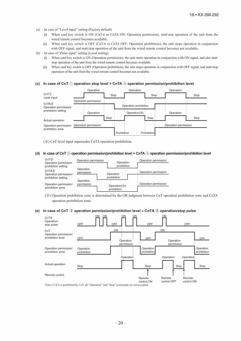
– 20 –
'18 • KX-SM-292
- 129 -
'16 • PAC-T-251
(19) Operation permission/prohibition(In case of adopting card key switches or commercially available timers)When the indoor function setting of wired remote control for “Operation permission/prohibition” is changed from “Invalid (Factory default)” to “ Valid”, following control becomes effective.
・CnT ・CnTA
XR5
Card keyswitch
XR1
1
2
3
4
5
6
XR3
XR4
CnTBlue
DC12V
XR2
Option
XR5
CnTABlue
DC12VXR6
1
2
Normal operation(Factory default)
Operation permission/prohibition mode“Valid” (Local setting)
CnT-6 orCnTA
ON OFF ON OFF
Operation Stop Operation permission*1
Operation prohibition (Unit stops)
*1 Only the “LEVEL INPUT” is acceptable for external input, however when the indoor function setting of “Level input (Factory default)” or “Pulse input” is selected by the function for “External input” of the wired remote control, operation status will be changed as follows.
In case of “Level input” setting In case of “Pulse input” settingUnit operation from the wired
remote control becomes available*(1)
Unit starts operation*(2)
*(1) In case that “Operation permission/prohibition mode” setting is “Valid” and “External input” setting is “Level input (Factory default)”;① When card key switch is ON (CnT-6 or CnTA ON: Operation permission), start/stop operation of the unit
from the wired remote control becomes available.② When card key switch is OFF (CnT-6 or CnTA OFF: Operation prohibition), the unit stops operation in
conjunction with OFF signal, and start/stop operation of the unit from the wired remote control becomes not unavailable.
*(2) In case that “Operation permission/prohibition mode” setting is “Valid” and “External input” setting is “Pulse input (Local setting)”;① When card key switch is ON (Operation permission), the unit starts operation in conjunction with ON signal.
and also start/stop operation of the unit from the wired remote control becomes available.② When card key switch is OFF (Operation prohibition), the unit stops operation in conjunction with OFF signal, and
start/stop operation of the unit from the wired remote control becomes unavailable. (3) This function is invalid only at “Center mode” setting done by central control.
(c) In case of CnT① operation stop level > CnTA③ operation permission/prohibition level
(※) CnT level input supersedes CnTA operation prohibition.
Operation permission Operation permission
CnTLevel input
CnTAOperation permission/prohibition setting
Operation permission/prohibition zone
Actual operation
Operation permission
Operation prohibition
Operation
Operation Operation
Operation
Operation( )
Operation
Prohibition
StopStopStop
Stop Stop Stop
Prohibition
- 130 -
'16 • PAC-T-251
(d) In case of CnT③ operation permission/prohibition level + CnTA③ operation permission/prohibition level
(※) Operation prohibition zone is determined by the OR judgment between CnT operation prohibition zone and CnTA operation prohibition zone.
CnTOperation permissionprohibition setting
CnTAOperation permission/prohibition setting
Operation permission/prohibition zone
Operation permission Operation permission
Operation permission
Operation permission
Operationpermission
Operationprohibition
Operationprohibition
Operationpermission
Operation( )prohibition
(21) Selection of cooling/heating external input function When “External input 1or 2 setting: Cooling/heating” is set by the indoor unit function from remote control, the cooling or
heating is selected with CnT-6 or CnTA.(a) In case of “Level input” setting (Factory default)・ CnT-6 or CnTA: OPEN → Cooling operation mode・ CnT-6 or CnTA: CLOSE → Heating operation mode
(b) In case of “Pulse input” setting (Local setting)If the external input is changed OPEN → CLOSE, operation modes are inverted (Cooling → Heating or Heating → Cooling).
Operation Operation Operation
Stop Stop Stop Stop
Operationprohibition
Operationprohibition
Operationprohibition
Operationprohibition
Operationprohibition
Operationprohibition
Operationpermission
Operation permission Operation permission
Operationpermission
CnTAOperation/stop pulse
CnTOperation permission/prohibition level
Operation permission/prohibition zone
Actual operation
Remote control
CnTOperation/stop pulse
CnTAOperation permission/prohibition level
Operation permission/prohibition zone
Actual operation
Remote control
Remotecontrol ON
Remotecontrol OFF
Remotecontrol ON
Remotecontrol ON
Remotecontrol OFF
Remotecontrol ON
ON ON
ON ON
ON ON ON
OFF OFF OFF OFF
OFFOFFOFF
ON ON
OFF
ON ON ON ON ON
OFF OFF OFF OFF
OFF OFF
OperationOperation Operation Operation
Stop Stop Stop Stop Stop
In case of CnT ③ operation permission/prohibition level > CnTA ② operation/stop pulse
(f) In case of CnT ② operation/stop pulse + CnTA ③ operation permission/prohibition levelNote (1) If it is prohibited by CnT, all “Operation” and “Stop” commands are not accepted.
(e)
(c) If the cooling/heating selection signal is given by the external input, the operation mode is transmitted to the remote control.
(a) In case of “Level input” setting (Factory default)(i) When card key switch is ON (CnT-6 or CnTA ON: Operation permission), start/stop operation of the unit from the
wired remote control becomes available.(ii) When card key switch is OFF (CnT-6 or CnTA OFF: Operation prohibition), the unit stops operation in conjunction
with OFF signal, and start/stop operation of the unit from the wired remote control becomes not available. (b) In case of “Pulse input” setting (Local setting)
(i) When card key switch is ON (Operation permission), the unit starts operation in conjunction with ON signal, and also start/stop operation of the unit from the wired remote control becomes available.
(ii) When card key switch is OFF (Operation prohibition), the unit stops operation in conjunction with OFF signal, and start/stop operation of the unit from the wired remote control becomes not available.

– 21 –
'18 • KX-SM-292
- 130 -
'16 • PAC-T-251
(d) In case of CnT③ operation permission/prohibition level + CnTA③ operation permission/prohibition level
(※) Operation prohibition zone is determined by the OR judgment between CnT operation prohibition zone and CnTA operation prohibition zone.
CnTOperation permissionprohibition setting
CnTAOperation permission/prohibition setting
Operation permission/prohibition zone
Operation permission Operation permission
Operation permission
Operation permission
Operationpermission
Operationprohibition
Operationprohibition
Operationpermission
Operation( )prohibition
(21) Selection of cooling/heating external input function When “External input 1or 2 setting: Cooling/heating” is set by the indoor unit function from remote control, the cooling or
heating is selected with CnT-6 or CnTA.(a) In case of “Level input” setting (Factory default)・ CnT-6 or CnTA: OPEN → Cooling operation mode・ CnT-6 or CnTA: CLOSE → Heating operation mode
(b) In case of “Pulse input” setting (Local setting)If the external input is changed OPEN → CLOSE, operation modes are inverted (Cooling → Heating or Heating → Cooling).
Operation Operation Operation
Stop Stop Stop Stop
Operationprohibition
Operationprohibition
Operationprohibition
Operationprohibition
Operationprohibition
Operationprohibition
Operationpermission
Operation permission Operation permission
Operationpermission
CnTAOperation/stop pulse
CnTOperation permission/prohibition level
Operation permission/prohibition zone
Actual operation
Remote control
CnTOperation/stop pulse
CnTAOperation permission/prohibition level
Operation permission/prohibition zone
Actual operation
Remote control
Remotecontrol ON
Remotecontrol OFF
Remotecontrol ON
Remotecontrol ON
Remotecontrol OFF
Remotecontrol ON
ON ON
ON ON
ON ON ON
OFF OFF OFF OFF
OFFOFFOFF
ON ON
OFF
ON ON ON ON ON
OFF OFF OFF OFF
OFF OFF
OperationOperation Operation Operation
Stop Stop Stop Stop Stop
In case of CnT ③ operation permission/prohibition level > CnTA ② operation/stop pulse
(f) In case of CnT ② operation/stop pulse + CnTA ③ operation permission/prohibition levelNote (1) If it is prohibited by CnT, all “Operation” and “Stop” commands are not accepted.
(e)
(c) If the cooling/heating selection signal is given by the external input, the operation mode is transmitted to the remote control.
- 131 -
'16 • PAC-T-251
(20) Temporary stop inputIn case of temporary stop, operation lamp of remote control lights, but indoor unit stop the operation.
(a) In case of “Level input” setting (Factory default)Input signal to CnT-6 or CnTA is OFF → ON : Temporary stopInput signal to CnT-6 or CnTA is OFF → ON : Normal operation
(b) In case of “Pulse input” setting (Local setting)It is effective only when the input signal is changed OFF→ON, and “temporary stop/normal operation” is inverted.
CnT-6 or CnTA input OFF
ON
OFF
ONON
Actual operation ON ON
Temporary stop Temporary stop
OFF
Remote control ON
OFF
Normal operation/ Temporary stop zone Normal
Temporary stop
Normal
Temporary stop
OFF
(23) Selection of cooling/heating external input function(a) When “External input 1 setting: Cooling/heating” is set by the indoor unit function from remote control, the cooling or
heating is selected with CnT-6 or CnTA.(b) When the external input 1 method selection: Level input is set by the indoor unit function:
・ CnT-6 or CnTA: OPEN → Cooling operation mode・ CnT-6 or CnTA: CLOSE → Heating operation mode
(c) When the external input 1 method selection: Pulse input is set by the indoor unit function:If the external input is changed OPEN → CLOSE, operation modes are inverted (Cooling → Heating or Heating →Cooling).
(d) If the cooling/heating selection signal is given by the external input, the operation mode is transmitted to the remotecontrol. Selection of cooling/heating external input function
External input selection
External input selectionCooling/heating selection
External input method
⑤ Level
External terminal input (CnT or CnTA)
Cooling/heating
Cooling/heating (Competitive)
External terminal input (CnT or CnTA)
Cooling/heating
Cooling/heating (Competitive)
⑥ Pulse
Operation
OFFCooling zone
Heating zone Cooling zone
Cooling zoneHeating zone Heating zone
OFFON
OFFOFFON ON
ON
CoolingHeating Heating
Cooling
Cooling
Cooling
Auto
Auto
Cooling
Auto, cooling, dry mode command↑ from remote control
↑Heating, auto, heating mode command from remote control
↑Set “Cooling/Heating” “Pulse”
↑Auto, cooling, dry mode command by remote control
↑Auto, heating mode command by remote control
↑After setting “Cooling/heating selection”, the cooling/heating is selected by the current operation mode.During heating:: Set at the heating zone (cooling prohibition zone).During cooling, dry, auto and fan mode: Set at cooling zone (heating prohibition zone).
Heating
Heating
HeatingCooling
HeatingCooling
Cooling
Notes (1) Regarding the priority order for combinations of CnT and CnTA, refer to Page 127.
CnT-6 or CnTA input OFF
ON
OFF
ON
Actual operation ON ON
ON
ON
Temporary stop Temporary stop
OFF
Remote control ON
OFF
P2.indb 131 2/20/2017 1:08:39 PM
C
M
Y
CM
MY
CY
CMY
K
P63.pdf 1 2018/11/02 10:27:47
- 130 -
'16 • PAC-T-251
(d) In case of CnT③ operation permission/prohibition level + CnTA③ operation permission/prohibition level
(※) Operation prohibition zone is determined by the OR judgment between CnT operation prohibition zone and CnTA operation prohibition zone.
CnTOperation permissionprohibition setting
CnTAOperation permission/prohibition setting
Operation permission/prohibition zone
Operation permission Operation permission
Operation permission
Operation permission
Operationpermission
Operationprohibition
Operationprohibition
Operationpermission
Operation( )prohibition
(21) Selection of cooling/heating external input function When “External input 1or 2 setting: Cooling/heating” is set by the indoor unit function from remote control, the cooling or
heating is selected with CnT-6 or CnTA.(a) In case of “Level input” setting (Factory default)・ CnT-6 or CnTA: OPEN → Cooling operation mode・ CnT-6 or CnTA: CLOSE → Heating operation mode
(b) In case of “Pulse input” setting (Local setting)If the external input is changed OPEN → CLOSE, operation modes are inverted (Cooling → Heating or Heating → Cooling).
Operation Operation Operation
Stop Stop Stop Stop
Operationprohibition
Operationprohibition
Operationprohibition
Operationprohibition
Operationprohibition
Operationprohibition
Operationpermission
Operation permission Operation permission
Operationpermission
CnTAOperation/stop pulse
CnTOperation permission/prohibition level
Operation permission/prohibition zone
Actual operation
Remote control
CnTOperation/stop pulse
CnTAOperation permission/prohibition level
Operation permission/prohibition zone
Actual operation
Remote control
Remotecontrol ON
Remotecontrol OFF
Remotecontrol ON
Remotecontrol ON
Remotecontrol OFF
Remotecontrol ON
ON ON
ON ON
ON ON ON
OFF OFF OFF OFF
OFFOFFOFF
ON ON
OFF
ON ON ON ON ON
OFF OFF OFF OFF
OFF OFF
OperationOperation Operation Operation
Stop Stop Stop Stop Stop
In case of CnT ③ operation permission/prohibition level > CnTA ② operation/stop pulse
(f) In case of CnT ② operation/stop pulse + CnTA ③ operation permission/prohibition levelNote (1) If it is prohibited by CnT, all “Operation” and “Stop” commands are not accepted.
(e)
(c) If the cooling/heating selection signal is given by the external input, the operation mode is transmitted to the remote control.

– 22 –
'18 • KX-SM-292
(c) If the cooling/heating selection signal is given by the external input, the operation mode is transmitted to the remote control. Selection of cooling/heating external input function
Notes (1) Regarding the priority order for combinations of CnT and CnTA, refer to Page 62.
External input selection
Cooling/heating selection
External input method
Level
External input (CnT or CnTA)
Cooling/heating
Cooling/heating (Competitive)
External input (CnT or CnTA)
Cooling/heating
Cooling/heating (Competitive)
Pulse
Operation
OFFCooling zone Cooling zoneHeating zone Heating zone
OFFON ON
CoolingHeating Heating
Cooling
Auto, cooling, dry mode command↑ from remote control
↑Heating, auto, heating mode command from remote control
HeatingCooling
HeatingCooling
Heating zone Cooling zoneOFFOFF
ON ON
Cooling
Cooling
Auto
Auto
Cooling
↑Set “Cooling/Heating” “Pulse”
↑Auto, cooling, dry mode command by remote control
↑Auto, heating mode command by remote control
↑After setting “Cooling/heating selection”, the cooling/heating is selected by the current operation mode.During heating : Set at the heating zone (cooling prohibition zone).During cooling, dry, auto and fan mode: Set at cooling zone (heating prohibition zone).
Heating
HeatingCooling
(23) Room temperature detection temperature compensation during heating
With the standard the compressor is turned ON/OFF with the thermostat setting temperature. When the thermostatis likely to turn OFF earlier because the unit is installed at the ceiling where warm air tends to accumulate, the setting can be changed with the wired remote control indoor unit function “ ”. The compressor and the heater are turned ON/OFF at one of the setting temperature +3, +2 or +1°C in order to improve the feeling of heating. The setting temperature, however, has the upper limit of 30°C.
Compressor Compressor Standard Operation
Stop
Setting temperature-1 +1
Room temperature (deg)
Operation
Stop
Setting temperature+2 +4
Room temperature (deg)
When it is set at +3°C
(24) Return air temperature compensationThis is the function to compensate the deviation between the detection temperature by the return air temperature sensor and the measured temperature after installing the unit.
(a) It is adjustable in the unit of 0.5°C with the wired remote control indoor unit function “RETURN AIR TEMP”. • +1.0°C, +1.5°C, +2.0°C • -1.0°C, -1.5°C, -2.0°C(b) Compensated temperature is transmitted to the remote control and the outdoor unit.
Note (1) The detection temperature compensation is effective on the indoor unit thermistor only.
(22) Emergency stop input When the external input is selected to “Emergency strop”, it is possible to stop the outdoor unit operation by the external
input to the indoor unit.
(a) Function setting Emergency stop input can be selected by the indoor function of wired remote control.
ConnectorIndoor function
RC-EX3A RC-E5CnT External input 1 : Emergency stop Emergency stop : Valid
CnTA External input 2 : Emergency stop No function
(b) Emergency stop control When the external input is OFF, the indoor and outdoor units stop.
The indoor unit receive the external input stops the operation, and the outdoor unit which the stopped indoor unit are connected stops with [E-63].

– 23 –
'18 • KX-SM-292
(25) High power operation (RC-EX3A only)
It operates at with the setting temperature fixed at 16°C for cooling, 30°C for heating and maximum indoor fan speed for 15 minutes maximum.
(26) Energy-saving operation (RC-EX3A only)It operates with the setting temperature fixed at 28°C for cooling, 22°C for heating or 25°C for auto. When fan control in cooling/heating thermo-OFF setting is “Set fan speed”, fan speed during thermo-OFF is changed to “Low”. (Maximum capacity is restricted at 80%.)
(27) Warm-up control (RC-EX3A only)Operation will be started 5 to 60 minutes before use according to the forecast made by the microcomputer which calculates when the operation should be started in order to warm up the indoor temperature near the setting temperature at the setting time of operation start.
(28) Home leave mode (RC-EX3A only)When the unit is not used for a long period of time, the room temperature is maintained at a moderate leval, avoiding extremely hot or cool temperature.
(a) Cooling or heating is operated according to the outdoor temperature (factory setting 35°C for cooling, 0°C for heating) and the setting temperature. (factory setting 33°C for cooling, 10°C for heating)
(b) Setting temperature and indoor fan speed can be set by RC-EX3A.
(29) Auto temperature setting (RC-EX3A only)Setting temperature is adjusted automatically at the adequate temperature the center setting temperature is 24°C by correcting the outdoor air temperature.
(30) Fan circulator operation (RC-EX3A only)When the fan is used for circulation, the unit is operated as follows depending on the setting with the remote control.
(a) If the invalid is selected with the remote control, the fan is operated continuously during the fan operation. (mormal fan mode)
(b) If the valid is selected with the remote control, the fan is operated or stopped when on the difference of the remote control temperature sensor and the return air temperature sensor becomes bigger than 3°C.
(31) The operation judgment is executed every 5 minutes (RC-EX3A only)Setting temperature Ts is changed according to outdoor temperature.This control is valid with cooling and heating mode. (Not auto mode)
(a) Operate 5 minutes forcedly. (b) Setting temperature is adjusted every 10 minutes.
(i) Cooling modeTs = outdoor temperature - offset value
(ii) Heating modeTs = outdoor temperature - offset value
(c) If the return air temperature lower than 18°C in cooling or return air temperature becomes higher than 25°C in heating, unit goes thermostat OFF.
(32) Auto fan speed control (RC-EX3A only)In order to reach the room temperature to the set temperature as quickly as possible, the air flow rate is increased when the set temperature of thermostat differs largely from the return air temperature. According to temperature difference between set temperature and return air temperature, indoor fan tap are controlled automalically.・ Auto 1: Changes the indoor fan tap within the range of Hi ↔ Me ↔ Lo.・ Auto 2: Changes the indoor fan tap within the range of P-Hi ↔ Hi ↔ Me ↔ Lo.
(33) Indoor unit overload alarm (RC-EX3A only)If the following condition is at 30 minutes after starting operation, RC-EX3A shows maintenance code "M07" and the signal is transmitted to the external output (CnT-2-5). It is necessary to select “Indoor unit overload alarm output” by the external output setting.
・ Cooling, Dry, Auto(Cooling) : Indoor air temperature = Set room temperature by remote control + Alarm temperature difference ・ Heating, Auto(Heating) : Indoor air temperature = Set room temperature by remote control - Alarm temperature difference
Alarm temperature difference is selectable between 5 to 10°C.If the following condition is satisfied or unit is stopped, the signal is disappeared. ・ Cooling, Dry, Auto(Cooling) : Indoor air temperature = Set room temperature + Alarm temperature difference -2°C・ Heating, Auto(Heating) : Indoor air temperature = Set room temperature - Alarm temperature difference +2°C

– 24 –
'18 • KX-SM-292
(26) Energy-saving operation (RC-EX3A only)It operates with the setting temperature fixed at 28°C for cooling, 22°C for heating or 25°C for auto. When fan control in cooling/heating thermo-OFF setting is “Set fan speed”, fan speed during thermo-OFF is changed to “Low”. (Maximum capacity is restricted at 80%.)
(27) Warm-up control (RC-EX3A only)Operation will be started 5 to 60 minutes before use according to the forecast made by the microcomputer which calculates when the operation should be started in order to warm up the indoor temperature near the setting temperature at the setting time of operation start.
(28) Home leave mode (RC-EX3A only)When the unit is not used for a long period of time, the room temperature is maintained at a moderate leval, avoiding extremely hot or cool temperature.
(a) Cooling or heating is operated according to the outdoor temperature (factory setting 35°C for cooling, 0°C for heating) and the setting temperature. (factory setting 33°C for cooling, 10°C for heating)
(b) Setting temperature and indoor fan speed can be set by RC-EX3A.
(29) Auto temperature setting (RC-EX3A only)Setting temperature is adjusted automatically at the adequate temperature the center setting temperature is 24°C by correcting the outdoor air temperature.
(30) Fan circulator operation (RC-EX3A only)When the fan is used for circulation, the unit is operated as follows depending on the setting with the remote control.
(a) If the invalid is selected with the remote control, the fan is operated continuously during the fan operation. (mormal fan mode)
(b) If the valid is selected with the remote control, the fan is operated or stopped when on the difference of the remote control temperature sensor and the return air temperature sensor becomes bigger than 3°C.
(31) The operation judgment is executed every 5 minutes (RC-EX3A only)Setting temperature Ts is changed according to outdoor temperature.This control is valid with cooling and heating mode. (Not auto mode)
(a) Operate 5 minutes forcedly. (b) Setting temperature is adjusted every 10 minutes.
(i) Cooling modeTs = outdoor temperature - offset value
(ii) Heating modeTs = outdoor temperature - offset value
(c) If the return air temperature lower than 18°C in cooling or return air temperature becomes higher than 25°C in heating, unit goes thermostat OFF.
(32) Auto fan speed control (RC-EX3A only)In order to reach the room temperature to the set temperature as quickly as possible, the air flow rate is increased when the set temperature of thermostat differs largely from the return air temperature. According to temperature difference between set temperature and return air temperature, indoor fan tap are controlled automalically.・ Auto 1: Changes the indoor fan tap within the range of Hi ↔ Me ↔ Lo.・ Auto 2: Changes the indoor fan tap within the range of P-Hi ↔ Hi ↔ Me ↔ Lo.
(33) Indoor unit overload alarm (RC-EX3A only)If the following condition is at 30 minutes after starting operation, RC-EX3A shows maintenance code "M07" and the signal is transmitted to the external output (CnT-2-5). It is necessary to select “Indoor unit overload alarm output” by the external output setting.
・ Cooling, Dry, Auto(Cooling) : Indoor air temperature = Set room temperature by remote control + Alarm temperature difference ・ Heating, Auto(Heating) : Indoor air temperature = Set room temperature by remote control - Alarm temperature difference
Alarm temperature difference is selectable between 5 to 10°C.If the following condition is satisfied or unit is stopped, the signal is disappeared. ・ Cooling, Dry, Auto(Cooling) : Indoor air temperature = Set room temperature + Alarm temperature difference -2°C・ Heating, Auto(Heating) : Indoor air temperature = Set room temperature - Alarm temperature difference +2°C
- 133 -
'16 • PAC-T-251
(34) Peak-cut timer (RC-EX3A only)Power consumption can be reduced by restricting the maximum capacity.Set the [Start time], the [End time] and the capacity limit % (Peak-cut %).・ 4-operation patterns per day can be set at maximum.・ The setting time can be changed by 5-minutes interval.・ The selectable range of capacity limit % (Peak-cut %) is from 0% to 40-80% (20% interval).・ Holiday setting is available.
(33) Motion sensor control (RC-EX3A only)The sensor determines the presence of people and the amount of activity, and the following controls are done by the motion sensor. Following settings are necessary to activate motion sensor control.(a) Infrared (motion) sensor setting : Installation setting of remote control. The indoor unit which is set to "Enable" become valid.(b) Infrared (motion) sensor control : Energy-saving setting of remote control. The function which is set to "Enable" become valid.
(i) Power saving controlThe set temperature is adjusted according to the presence of people and their amount of activity detected by the infrared sensor.
(ii) Auto-off controlWhen no activity is deteced for 1 hour, unit will go stand-by mode. Unit will re-start operation automatically by activity detection during the stand-by mode.
(35) Motion sensor control (RC-EX3A only)The sensor determines the presence of people and the amount of activity, and the following controls are done by the motion sensor. Following settings are necessary to activate motion sensor control.
(a) Infrared (motion) sensor setting: Installation setting of remote control The indoor unit which is set to “Enable” become valid.
(b) Infrared (motion) sensor control: Energy-saving setting of remote control The function which is set to “Enable” become valid.
(i) Power saving controlThe set temperature is adjusted according to the presence of people and their amount of activity detected by the infrared sensor.
(ii) Auto-off controlWhen no activity is detected for 1 hour, unit will go stand-by mode. Unit will re-start operation automatically by activity detection during the stand-by mode.

– 25 –
'18 • KX-SM-292
(A) Normal control(1) Operation of major functional components under each operation mode
Operation mode
Functional item
Cooling/DehumidifyingFan
Heating
ThermostatON
ThermostatOFF DefrostThermostat
ONThermostat
OFFCompressor (CM) 〇 × × 〇 × 〇Magnetic contactor CM1 (52X1, 52X2) 〇 〇 ×/〇 〇 〇 〇Outdoor fan mortor (FMo-1) 〇 ×/〇 ×/〇 〇/× ×/〇 〇→×Outdoor fan mortor (FMo-2) 〇/× ×/〇 ×/〇 〇/× ×/〇 〇→×4-way valve (20S) × × × 〇 〇 〇→×Heating electronic expansion valve (EEVH) Fully open Fully open ※1 Opening Angle
Control ※2 Fully closed /Fully open
Super cooling coil electronic expansion valve (EEVSC)
Opening AngleControl Fully closed Fully closed Fully closed Fully closed Fully closed
Solenoid valve (SV1) (oil return) 〇/× × × 〇/× × 〇/×Solenoid valve (SV6) (fluid return) 〇/× 〇/× × 〇/× 〇/× 〇/×Solenoid valve (SV11) (gas bypass) × × × 〇/× × ×Crankcase heater (CH) 〇/× 〇/× 〇 〇/× 〇/× 〇/×
Notes (1) It means 〇 : ON, × : OFF, 〇/× : -, ×/〇 : ON or OFF.(2) This shows the state of output when all indoor units are under the same mode.(3) ※1 : When stopped from cooling, it is fully open
When stopped from heating, it is fully closed unless another degree of opening is specified by the electronic expansion valve (EEV) control at the stop.
※2 : When stopped from heating, it is fully closed unless another degree of opening is specified by the electronic expansion valve (EEV) control at the stop.
1.4 Operation control function by the outdoor control

– 26 –
'18 • KX-SM-292
(2) Compressor pre-start control
(a) Remote control full stop → Operation
(i) Starting conditions
• When it has changed to the compressor operation frequency command > 0 Hz from the state of compressor stopping.(ii) Control contents
• It sets the compressor operation frequency command = 0 Hz, and then after this control ends, It starts thecompressor.
(iii) Ending conditionsWhen all of following conditions are satisfied① It has elapsed 15 seconds after the start of this control.
• Meaning of marks
52X1, 52X2 Solenoid for compressor CM CompressorEEVH Heating electronic expansion valve EEVSC Subcooling coil electronic expansion valveSV6 Solenoid valve [Oil return] ― ―――
ON
15 seconds
6 seconds
Normal control
Normal control
Initial opening
Initial opening
3 minutes
Time
2 minutes
Stop
OFF
0 rps
Opening at stop
0 pulse
OFF
Starting condition established
Operation
52X1, 52X2
CM
EEVH
EEVSC
SV6
ON
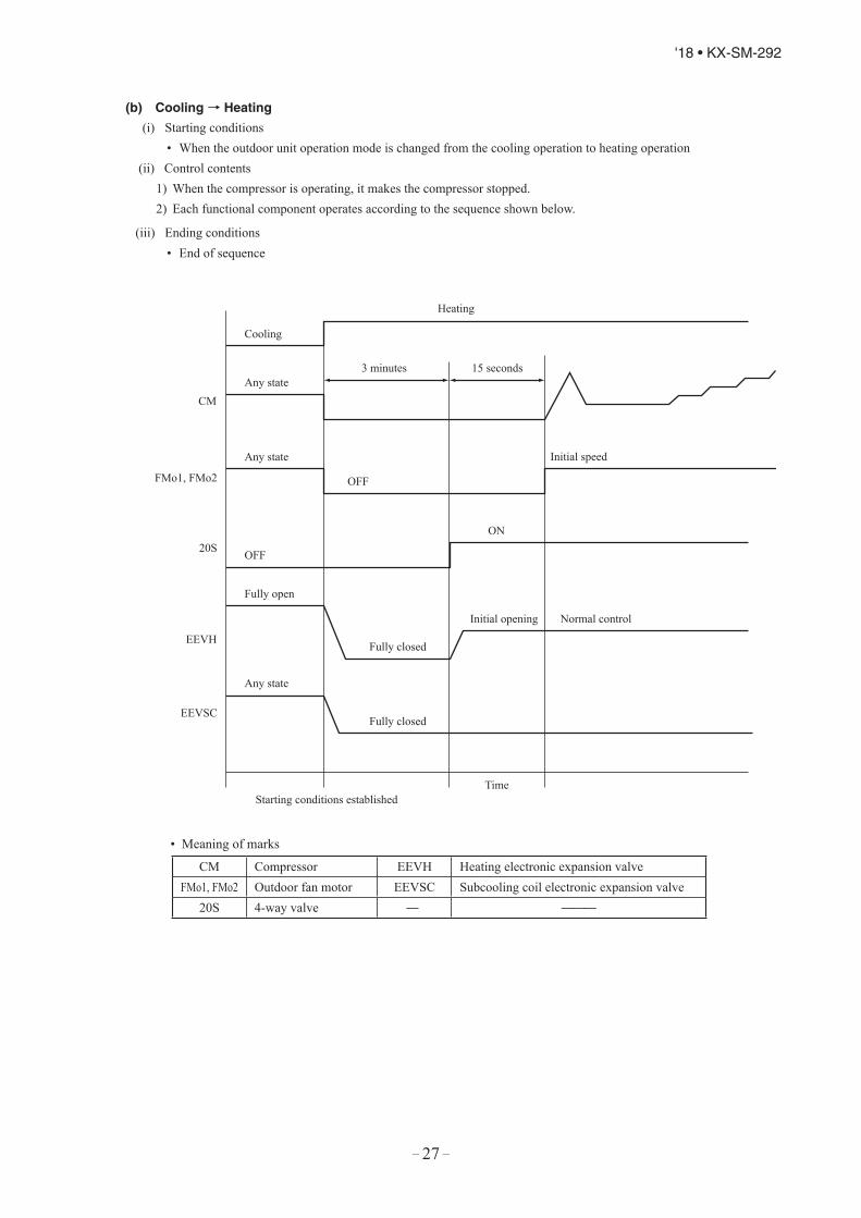
– 27 –
'18 • KX-SM-292
(b) Cooling → Heating
(i) Starting conditions• When the outdoor unit operation mode is changed from the cooling operation to heating operation
(ii) Control contents1) When the compressor is operating, it makes the compressor stopped.2) Each functional component operates according to the sequence shown below.
(iii) Ending conditions• End of sequence
• Meaning of marks
CM
Heating
15 seconds3 minutes
Initial speed
Normal controlInitial opening
Cooling
Any state
FMo1, FMo2
20S
EEVH
EEVSC
OFF
Fully open
Fully closed
Fully closed
TimeStarting conditions established
OFF
ON
Any state
Any state
CM Compressor EEVH Heating electronic expansion valveFMo1, FMo2 Outdoor fan motor EEVSC Subcooling coil electronic expansion valve
20S 4-way valve ― ―――
(2) Compressor pre-start control
(a) Remote control full stop → Operation
(i) Starting conditions
• When it has changed to the compressor operation frequency command > 0 Hz from the state of compressor stopping.(ii) Control contents
• It sets the compressor operation frequency command = 0 Hz, and then after this control ends, It starts thecompressor.
(iii) Ending conditionsWhen all of following conditions are satisfied① It has elapsed 15 seconds after the start of this control.
• Meaning of marks
52X1, 52X2 Solenoid for compressor CM CompressorEEVH Heating electronic expansion valve EEVSC Subcooling coil electronic expansion valveSV6 Solenoid valve [Oil return] ― ―――
ON
15 seconds
6 seconds
Normal control
Normal control
Initial opening
Initial opening
3 minutes
Time
2 minutes
Stop
OFF
0 rps
Opening at stop
0 pulse
OFF
Starting condition established
Operation
52X1, 52X2
CM
EEVH
EEVSC
SV6
ON

– 28 –
'18 • KX-SM-292
(c) Heating → Cooling
(i) Starting conditions• When the outdoor unit operation mode is changed from the heating operation to cooling operation
(ii) Control contents1) When the compressor is operating, it makes the compressor stopped.2) Each functional component operates according to the sequence shown below.
(iii) Ending conditions• End of sequence
Note (1) ※ : It is fully closed till the end of 3-minute delay after the automatic reset.
• Meaning of marks
CM
FMo1, FMo2
20S
EEVH
EEVSC
ON
Heating
Cooling
15 seconds3 minutes
Initial opening
Fully closed(※)
Time
Starting conditions established
Normal control
Initial speed
Fully closed
OFF
OFF
Fully open
Any state
Any state
Any state
CM Compressor EEVH Heating electronic expansion valveFMo1, FMo2 Outdoor fan motor EEVSC Subcooling coil electronic expansion valve
20S 4-way valve ― ―――

– 29 –
'18 • KX-SM-292
(c) Heating → Cooling
(i) Starting conditions• When the outdoor unit operation mode is changed from the heating operation to cooling operation
(ii) Control contents1) When the compressor is operating, it makes the compressor stopped.2) Each functional component operates according to the sequence shown below.
(iii) Ending conditions• End of sequence
Note (1) ※ : It is fully closed till the end of 3-minute delay after the automatic reset.
• Meaning of marks
CM
FMo1, FMo2
20S
EEVH
EEVSC
ON
Heating
Cooling
15 seconds3 minutes
Initial opening
Fully closed(※)
Time
Starting conditions established
Normal control
Initial speed
Fully closed
OFF
OFF
Fully open
Any state
Any state
Any state
CM Compressor EEVH Heating electronic expansion valveFMo1, FMo2 Outdoor fan motor EEVSC Subcooling coil electronic expansion valve
20S 4-way valve ― ―――
(3) Compressor control(a) 4-way valve switching safeguard
In order to switch 4-way valve completely, it makes the compressor speed increasing as follows.(i) This control starts to increase the compressor speed from 10 rps after the compressor pre-start control ends.(ii) The target compressor speed is shown in following table.
(b) Compressor protection startAfter the 4-way valve switching safeguard, the compressor is controlled with the following compressor protection start. Compressor protection start, normal Compressor protection start A Compressor protection start B
(i) Compressor protection start, normal< Control contents >
Compressor maintains operation at lower limit frequency, after 4-way valve switching safeguard ends.(During this control, compressor speed is prohibited to increase.)After this control ends, comperssor speed is governed by the compressor speed control.
< Ending conditions >When either one of the following conditions is establisheda) When it has elapsed 1 minute and 45 seconds after the start
(ii) Compressor protection start A< Control contents >
Compressor maintains operation at lower limit frequency, after 4-way valve switching safeguard ends.If the time from starting till reaching the lower limit frequency after 4-way valve switching safeguard operationhas elapsed 1minute, the target frequency is changed to that of 1minute later from the lower limit frequency.
During this control, the target frequency is increased at a rate of 5 rps/minute from the lower limit frequency.Note (1) The starting point of this control is the completion point of inverter start (10 rps).
ItemModel
4-way valve switching safeguard/Target compressor speedFrequency (Fk) Speed (rps)
FDC224KXZME170 50
FDC280KXZME1FDC335KXZME1 71 42
Initial start remote control ONerror reset
Thermostat ON startOperation mode
is changed during thermostat OFF
Operation mode is not changed during
thermostat OFF
Compressor ONInitial
Less than 45 min after power ON
Compressor protection start B
Compressor protection start B
Compressor protection start B
45min. or more after power ON
Compressor protection start A
Compressor protection start A
Compressor protection start A
Compressor ONSecond & later
Less than 45 min after stop
Compressor normal protection start
Compressor normal protection start
Compressor normal protection start
45min. or more after stop
Compressor protection start A
Compressor protection start A
Compressor protection start A
0706050452 030201
Lower limit frequency
Speed control
Start
Time (second)
80 90 105 120
60
40
20
10
Com
pres
sor
inve
rter f
requ
ency
(rps
)

– 30 –
'18 • KX-SM-292
< Ending conditions >When either one of following conditions is establisheda) When the frequency upper limit increase by this control continued for 15 minutes in total
When the inverter has stopped within 15 minutes after the start and is started again, it starts with the normalprotection start and increases the frequency upper limit at a rate of 5 rps/minute till the frequency increasecontinues for 15 minutes in total.
(iii) Compressor protection start B< Control contents >
Compressor maintains operation at lower limit frequency, after 4-way valve switching safeguard ends.If the time from starting till reaching the lower limit frequency after 4-way valve switching safeguard operationhas elapsed 2 minutes, the target frequency is changed to that of 2 minutes later from the lower limit frequency.
For 18 minutes after starting, the target frequency is increased at a rate of 5 rps/2 minutes from the lower limitfrequency.
For 18 minutes after starting, the starting point of this control is the completion point of inverter start (10 rps). From 18 minutes to 24 minutes, it is increased at a rate of 5 rps/minute.
< Ending conditions >When either one of the following conditions is established a) This frequency-up control will end when the cumulative operation time after starting becomes 24 minutes.
If the inverter stopped within 24 minutes after starting and starts again, it starts with Compressor protectionstart, normal and increases the frequency at a rate of 5 rps/minute till the cumulative operation time afterstarting becomes 24 minutes.However, if 45 minutes have been elapsed since inverter stopped and starts again, it starts with Compressorprotection start A
0 1 2 3 4 5 6 7 8 9 10 11 12 13 14 15
120
100
80
60
40
20Com
pres
sor i
nver
ter f
requ
ency
(rps
)
Upper limit frequency
Speed control
Lower limit frequency
Time (minute)Start
0 2 4 6 8 10 12 14 16 18 20 22 24
120
100
80
60
40
20
Com
pres
sor i
nver
ter f
requ
ency
(rps
)
Time (minute)Start
Speed control
Upper limit frequency
Lower limit frequency

– 31 –
'18 • KX-SM-292
< Ending conditions >When either one of following conditions is establisheda) When the frequency upper limit increase by this control continued for 15 minutes in total
When the inverter has stopped within 15 minutes after the start and is started again, it starts with the normalprotection start and increases the frequency upper limit at a rate of 5 rps/minute till the frequency increasecontinues for 15 minutes in total.
(iii) Compressor protection start B< Control contents >
Compressor maintains operation at lower limit frequency, after 4-way valve switching safeguard ends.If the time from starting till reaching the lower limit frequency after 4-way valve switching safeguard operationhas elapsed 2 minutes, the target frequency is changed to that of 2 minutes later from the lower limit frequency.
For 18 minutes after starting, the target frequency is increased at a rate of 5 rps/2 minutes from the lower limitfrequency.
For 18 minutes after starting, the starting point of this control is the completion point of inverter start (10 rps). From 18 minutes to 24 minutes, it is increased at a rate of 5 rps/minute.
< Ending conditions >When either one of the following conditions is established a) This frequency-up control will end when the cumulative operation time after starting becomes 24 minutes.
If the inverter stopped within 24 minutes after starting and starts again, it starts with Compressor protectionstart, normal and increases the frequency at a rate of 5 rps/minute till the cumulative operation time afterstarting becomes 24 minutes.However, if 45 minutes have been elapsed since inverter stopped and starts again, it starts with Compressorprotection start A
0 1 2 3 4 5 6 7 8 9 10 11 12 13 14 15
120
100
80
60
40
20Com
pres
sor i
nver
ter f
requ
ency
(rps
)
Upper limit frequency
Speed control
Lower limit frequency
Time (minute)Start
0 2 4 6 8 10 12 14 16 18 20 22 24
120
100
80
60
40
20
Com
pres
sor i
nver
ter f
requ
ency
(rps
)
Time (minute)Start
Speed control
Upper limit frequency
Lower limit frequency
(4) Outdoor fan control
(a) Outdoor fan speed and fan motor rotation speed.
The 7th outdoor fan speed in the following table is specified as the rated speed. Under the normal control, the speeds upto 8th level (800 min-1) are used.
Note (1) Figures in the parentheses in the above table are applicable to FDC224KXZME1.
(b) Fan control during cooling
During cooling and dehumidifying, fan speed is controlled in accordance with the high pressure (sensed by PSH) and theoutdoor air temperature (sensed by Tho-A).
(i) Initial fan speeds are as follows.Initial ourdoor fan speed at cooling
(ii) During normal operation, the speed is changed in accordance with the high pressure value. When it has detected HP ≧ 2.2 MPa for 1 minute continuously, the fan speed is raised by one tap. When it is 1.5 MPa < HP < 2.2 MPa, the present fan speed is maintained. When it has detected HP ≦ 1.5 MPa for 1 minute continuously, the fan speed is dropped by one tap. Control range of fan speed is 1th – 8th speeds.
(iii) When states under this control change from HP < 3.3 MPa to HP ≧ 3.3 MPa, the fan speed is changed preferentiallyto the followings. (After the change it returns to the normal control.) When the outdoor air temperature ≧ 30ºC, it changes to 7th or higher speed. When the outdoor air temperature < 30ºC, it changes to 3th or higher speed. When the fan speed was higher than the above before the change of states, the fan speed is not changed.
Outdoor fan tapCooling Heating
FMo1 [min-1] FMo2 [min-1] FMo1 [min-1] FMo2 [min-1]
0th speed 0 0 0 01st speed 200 0 200 02nd speed 200 200 200 2003rd speed 300 300 300 3004th speed 400 400 400 4005th speed 500 500 500 5006th speed 575 575 575 5757th speed 740 740 740 7408th speed 800 800 800 (780) 800 (780)
Model Outdoor air temp. ≤ 10ºC 10ºC < Outdoor air temp. < 15ºC 15ºC ≤ Outdoor air temp.
All models 2nd speed 4th speed 6th speed
1.5 2.2
One tap up
Maintained
One tap down
High pressure (MPa)

– 32 –
'18 • KX-SM-292
(c) Outdoor fan cooling control at low outdoor air temperature(i) Starting conditions
This control is performed when all of following conditions is established. When the ordinary outdoor fan control is performed Outdoor air temperature ≦ 10ºC (It is reset with the hysteresis of the outdoor air temperature > 15ºC.)
Outdoor fan speed = 1st speed (200 min-1)(ii) Control contents
Initial fan speed is 200 min-1
If the following high pressure is detected for 20 seconds continuously, fan speed will be changed
Outdoor fan speed is in a range of 130 min-1 – 300 min-1.(iii) Ending conditions
When either one of following conditions is established When the ordinary outdoor unit fan cooling control ends Outdoor air temperature > 15ºC Outdoor fan speed ≧ 2th speed(Note) This control range is not more than 300 min-1 × 1fan.
(d) Outdoor fan heating controlThe fan speed control is performed based on the low pressure (detected with PSL) during heating operation.
(i) Initial fan speed is 6th speed.(ii) Speed is changed depending on the low pressure value.
When it is detected LP ≦ 0.75 MPa for 30 seconds continuously, the fan speed is raised by 1 tap. When it is 0.75 MPa < LP < 0.85 MPa, the present fan speed is maintained. When it is detected LP ≧ 0.85 MPa for 30 seconds continuously, the fan speed is dropped by 1 tap. Control range of fan speed is 1st – 8th speeds.
(iii) When states change from LP < 1.0 MPa to HP ≧ 1.0 MPa during this control, the fan speed is changed preferentially to the following. (It returns to the normal control after the change.) It changes to 4th or lower speed. If the fan speed was lower than the above speed before the change of states, the fan speed does not change.
Valid
Invalid
10 15Outdoor air temperature
1.4 1.7
+10 min-1
−10 min-1
Maintained
High pressure (MPa)
0.75Low pressure (MPa)
0.85
One tap up
One tap down
Maintained

– 33 –
'18 • KX-SM-292
(c) Outdoor fan cooling control at low outdoor air temperature(i) Starting conditions
This control is performed when all of following conditions is established. When the ordinary outdoor fan control is performed Outdoor air temperature ≦ 10ºC (It is reset with the hysteresis of the outdoor air temperature > 15ºC.)
Outdoor fan speed = 1st speed (200 min-1)(ii) Control contents
Initial fan speed is 200 min-1
If the following high pressure is detected for 20 seconds continuously, fan speed will be changed
Outdoor fan speed is in a range of 130 min-1 – 300 min-1.(iii) Ending conditions
When either one of following conditions is established When the ordinary outdoor unit fan cooling control ends Outdoor air temperature > 15ºC Outdoor fan speed ≧ 2th speed(Note) This control range is not more than 300 min-1 × 1fan.
(d) Outdoor fan heating controlThe fan speed control is performed based on the low pressure (detected with PSL) during heating operation.
(i) Initial fan speed is 6th speed.(ii) Speed is changed depending on the low pressure value.
When it is detected LP ≦ 0.75 MPa for 30 seconds continuously, the fan speed is raised by 1 tap. When it is 0.75 MPa < LP < 0.85 MPa, the present fan speed is maintained. When it is detected LP ≧ 0.85 MPa for 30 seconds continuously, the fan speed is dropped by 1 tap. Control range of fan speed is 1st – 8th speeds.
(iii) When states change from LP < 1.0 MPa to HP ≧ 1.0 MPa during this control, the fan speed is changed preferentially to the following. (It returns to the normal control after the change.) It changes to 4th or lower speed. If the fan speed was lower than the above speed before the change of states, the fan speed does not change.
Valid
Invalid
10 15Outdoor air temperature
1.4 1.7
+10 min-1
−10 min-1
Maintained
High pressure (MPa)
0.75Low pressure (MPa)
0.85
One tap up
One tap down
Maintained
(5) Defrost control(a) Temperature condition of defrost operation
(i) Starting conditions jumper wire J15.)Defrost operation will start, when outdoor unit whose compressor is operating under heating mode has satisfied allthe following conditions.
1) When 33 minutes of cumulative compressor operation time has passed since heating operation started.2) When 33 minutes of cumulative compressor operation time has passed since the previous defrost operation ended.3) When 8 minutes has passed since the compressor turned ON from OFF status.4) When 8minutes has passed since one outdoor fan turned ON from OFF status.5) After all above conditions have been met, when any of the following conditions is satisfied
When the outdoor heat exchanger temperature (sensed by Tho-R) and the outdoor air temperature (sensedby Tho-A) dropped below the defrost operation start temperature in Fig. 1 for 30 seconds continuously.
When the suction pressure saturated temperature calculated by the low pressure (sensed by PSL) and theoutdoor air temperature (sensed by Tho-A) dropped below the defrost operation start temperature in Fig. 2 for 3minutes continuously
TR
: Hea
t exc
hang
er te
mpe
ratu
re (
°C)
TA: Outdoor air temperature (°C)
TA: Outdoor air temperature (°C)
Fig. 1
Cold region
Standard (Factory setting)
Defrost start zone
-2
-6
-15
-19
-21
-25
-20 -15 6
Without J15Cold region specification
With J15
SS
T: S
uctio
n pr
essu
re s
atur
ated
tem
pera
ture
(°C
)
Fig. 2
Cold region
Standard (Factory setting)
Defrost start zone
-6
-10
-19
-23
-25
-29
-20 -15 6
Without J15Cold region specification
With J15
(ii) Ending conditionsDefrost operation stops when any of the following conditions is satisfied
1) When 12 minutes has passed since defrost operation started2) When the outdoor heat exchanger temperature (sensed by Tho-R) is detected 10°C or higher continuously for
10 seconds3) When it has detected the high pressure (HP) ≥ 3.0MPa
(b) Time condition of defrost operation(i) Starting conditions
Defrost operation start when all of the following conditions are satisfied1) When 33 minutes of cumulative compressor operation time has passed since heating operation started.2) When 33 minutes of cumulative compressor operation time has passed since the previous defrost operation ended.3) When 105 seconds has passed since the compressor turned ON from OFF status in heating mode.4) When the oil return condition has been established5) Following cases are excluded.
When the upper limit frequency of the compressor protection start A or B is lower than the defrostfrequency
During the normal compressor protection start(ii) Ending conditions
Defrost operation stops when any of the following conditions is satisfied1) When 12 minutes has passed since defrost started2) When the outdoor heat exchanger temperature (sensed by Tho-R) is detected 10°C or higher continuously for
10 seconds3) When it has detected the high pressure (HP) ≥3.0MPa
(Standard specification or cold region specification can be selected by switching the

– 34 –
'18 • KX-SM-292
(6) Protective control(a) Discharge pipe temperature (Td) control
Discharge pipe temperature sensor (Tho-D1) monitors the discharge pipe temperature (Td) to avoid the rise of dischargepipe temperature.
(i) Compressor capacity control1) Starting conditions
When all of following conditions are satisfied When the compressor is ON state. When it detects the discharge pipe temperature (sensed by Tho-D1) is higher than 120ºC
2) Control contentsWhenever it detects the discharge pipe temperature is higher than 120ºC for 5 seconds, the capacity is decreased.
3) Ending conditionsWhen any of the following conditions is satisfied When the discharge pipe temperature (sensed by Tho-D1) drops below 110ºC When the compressor is OFF state. During the defrost operation
(ii) Indoor EEV slightly open control at heating stopRise of discharge pipe temperature (Td) is restarined by opening the indoor EEV during heating stop.
(b) Over-current protection control (Current safe)(i) If the input current value at the inverter inlet (converter inlet L3-phase) exceeds the setting value, the compressor
speed is reduced. If the higher value persists even after the speed reduction, the speed is reduced further.(ii) This control terminates when it is lower than the reset value for 3 minutes continuously or lower than the setting
value for 6 minutes continuously.
(c) Power transistor temperature (PT) protective controlIf the power transistor temperature exceeds 75°C, the compressor speed is controlled.
(7) Test run(a) Starting conditions
(i)(ii) Pump down switch (SW5-3) must be turned OFF.
(b) Contents of control
operation.1) Cooling operation
Compressor operation frequency control is conducted by the cooling low pressure control.2) Heating operation
Compressor operation frequency control is conducted by the heating high pressure control.
(c) Ending conditions(i) When the test run switch (SW5-1) is turned OFF, it stops.
(ii) When it has stopped anomalously by the error control during test run, the error is displayed in the same way as the case of normal operation and the state of anomalous stop is kept ON even if the test run switch (SW5-1) is turned OFF.
Speed is reduced once each minute
Retention
Release
72 75
Power transistor temperature (°C)
Turn ON the test run switch (SW5-1). The switch is invalid if it is turned ON before the power ON.
(i) Turning ON the dip switch (SW5-2) conducts cooling operation and turning OFF (SW5-2) conducts heating
(ii) Test run start signal under corresponding operation mode is transmitted to all indoor units connected.

– 35 –
'18 • KX-SM-292
(6) Protective control(a) Discharge pipe temperature (Td) control
Discharge pipe temperature sensor (Tho-D1) monitors the discharge pipe temperature (Td) to avoid the rise of dischargepipe temperature.
(i) Compressor capacity control1) Starting conditions
When all of following conditions are satisfied When the compressor is ON state. When it detects the discharge pipe temperature (sensed by Tho-D1) is higher than 120ºC
2) Control contentsWhenever it detects the discharge pipe temperature is higher than 120ºC for 5 seconds, the capacity is decreased.
3) Ending conditionsWhen any of the following conditions is satisfied When the discharge pipe temperature (sensed by Tho-D1) drops below 110ºC When the compressor is OFF state. During the defrost operation
(ii) Indoor EEV slightly open control at heating stopRise of discharge pipe temperature (Td) is restarined by opening the indoor EEV during heating stop.
(b) Over-current protection control (Current safe)(i) If the input current value at the inverter inlet (converter inlet L3-phase) exceeds the setting value, the compressor
speed is reduced. If the higher value persists even after the speed reduction, the speed is reduced further.(ii) This control terminates when it is lower than the reset value for 3 minutes continuously or lower than the setting
value for 6 minutes continuously.
(c) Power transistor temperature (PT) protective controlIf the power transistor temperature exceeds 75°C, the compressor speed is controlled.
(7) Test run(a) Starting conditions
(i)(ii) Pump down switch (SW5-3) must be turned OFF.
(b) Contents of control
operation.1) Cooling operation
Compressor operation frequency control is conducted by the cooling low pressure control.2) Heating operation
Compressor operation frequency control is conducted by the heating high pressure control.
(c) Ending conditions(i) When the test run switch (SW5-1) is turned OFF, it stops.
(ii) When it has stopped anomalously by the error control during test run, the error is displayed in the same way as the case of normal operation and the state of anomalous stop is kept ON even if the test run switch (SW5-1) is turned OFF.
Speed is reduced once each minute
Retention
Release
72 75
Power transistor temperature (°C)
Turn ON the test run switch (SW5-1). The switch is invalid if it is turned ON before the power ON.
(i) Turning ON the dip switch (SW5-2) conducts cooling operation and turning OFF (SW5-2) conducts heating
(ii) Test run start signal under corresponding operation mode is transmitted to all indoor units connected.
(B) Option controls• Functions of outdoor PCB connector CnS1, CnS2, CnG1, CnG2 and CnZ1
① CnS1 connector : By changing the allocation of external input functions [P07-“X”] on the 7-segment, followingfunctions can be selected.
② CnZ1 connector : By changing the allocation of external output functions [P06-“X”] on the 7-segment, followingfunctions can be selected.
Function No.“X” CnS1 short circuited CnS1 open“0” : External operation input Operation permission Operation prohibition“1” : Demand input Invalid Valid“2” : Forced cooling / heating input Heating Cooling“3” : Silent mode input 1 Valid Invalid“4” : Oil return control inpu t ON OFF“5” : Outdoor fan snow guard control input Valid Invalid“6” : Test run external input 1 Test run start Normal operation“7” : Test run external input 2 Cooling test run Heating test run“8” : Silent mode input 2 Valid Invalid“9” : 2-step demand input Invalid Valid
* [P07] for CnS1, [P08] for CnS2, [P09] for CnG1 and [P10] for CnG2
“0” : Operation output“1” : Error output“2” : Compressor ON cutput“3” : Fan ON output“4” : Oil return operation output“5” : High pressure control output for activating splaying system“6 – 9” : Spare
*

– 36 –
'18 • KX-SM-292
(1) External input and demand input
Note (1) With 7-segment display [P07]-[0] (CnS2:[P08]-[0], CnG1:[P09]-[0] and CnG2[P10]-[0] can be used as well.)
(i) Operation permission or operation prohibition mode is switched with the connector (CnS1) and the jumper wire (J13)on the outdoor PCB.J13: Switching of CnS1 input method
J13 short-circuited: CnS1 is for the level input.J13 open: CnS1 is for the pulse input.
(ii) Operation permission/prohibition control by the external input CnS1 of outdoor unit
Input: CnS1 Switching with J13 CnS1: Switching of operation permission/prohibition modes
Short-circuit
Open
Short-circuit (Level input) Operation prohibition mode Operation permission mode
Open (Pulse input) Switching of operation permission/operation prohibition modes (Reversal)
Open
Short-circuitShort-circuit (Level input) Operation permission mode
Operation prohibition mode
Open (Pulse input) (NOP)Note (1) Factory setting – J13: Short-circuit, CnS1: Short-circuit (Short-circuit pin connected)
(iii) The operation condition is desplayed on the LCD of remote control and is transferred to option central control.(iv) When the control comand from remote control is not accepted (Under the condition of the system all stop status by
external input), “Center” is dispalyed. See Item 5) mentioned below.(v) CnS1 performs the following operations depending on the short-circuit or open of the jumper wire (J13). In case of
pulse input, the pulse width is 500ms or larger.J13 – Short-circuit
CnS1 input OFF (Open)
Remote control operation
Remote control display
Air-conditioner operation/stop
PUSH PUSH PUSH PUSH
OFF
ON (Short-circuit) OFF (Open)
OFFOFF ONON
Air-conditioner ON OK
Center CenterRemote
J13 - Open
CnS1 input
Remote control operation
Remote control display
Air-conditioner operation/stop
OFF
OFF
ON
ON OFF OFFON
OFFON
Air-conditioner ON OK
Center Remote Center CenterRemote
PUSH PUSH PUSH PUSH PUSH
(b) Demand control
(i) Demand control and normal operation are switched with the connector (CnS2) and the jumper wire (J13) on theoutdoor PCB.J13: Switching of CnS2 input method
J13 short-circuit: CnS2 is for the level inputJ13 open: CnS2 is for the pulse input
(a) Operation permission or prohibition modes
Note(1) With 7-segment [P07] = [1] (CnS2:[P08]-[1], CnG1:[P09]-[1] and CnG2[P10]-[1] can be used as well.)

– 37 –
'18 • KX-SM-292
(ii) Operation/ stop control by the demand input CnS2 of outdoor unit
Input: CnS2 Switching with J13 CnS2: Switching of demand control/normal operation
Short-circuit
Open
Short-circuit (Level input) Demand control Normal operation
Open (Pulse input) Switching of normal operation/demand control (Reversal)
Open
Short-circuitShort-circuit (Level input) Normal operation
Demand control
Open (Pulse input) NOP
Note (1) Factory setting – J13: Short-circuit, CnS2: Short-circuit (Short-circuit pin connected)
(iii) The operation condition is desplayed on the LCD of remote control and is transferred to option central control.(iv) Demand control
Demand ratio can be switched with the dip switches (SW4-5, 4-6) on the outdoor PCB.SW4-5, SW4-6 demand switching: 0 – Open, 1 – Short-circuit (Factory default is open)
SW4-5 SW4-6CompressorOut put(%)
0 0 801 0 600 1 401 1 0
(v) CnS2 performs the following operations depending on the short circuited or open of the jumper wire (J13).In the case of pulse input, the pulse width is 500ms or larger .
J13 – Short-circuitON (Short-circuit) ON (Short-circuit)OFF (Open)
Normal NormalCnS2 input
Remote control operation
Remote control display
Air-conditioner operation/stop OFF OFF OFF
Demand control
Remote
Compressor OFFCompressor OFF
ONON
PUSH PUSH PUSH PUSH
J13 - OpenOFFOFF ONON
Demand control Demand controlCnS2 input
Remote control operation
Remote control display
Air-conditioner operation/stop
Remote
Compressor OFF Compressor OFF
PUSH PUSH PUSH PUSH
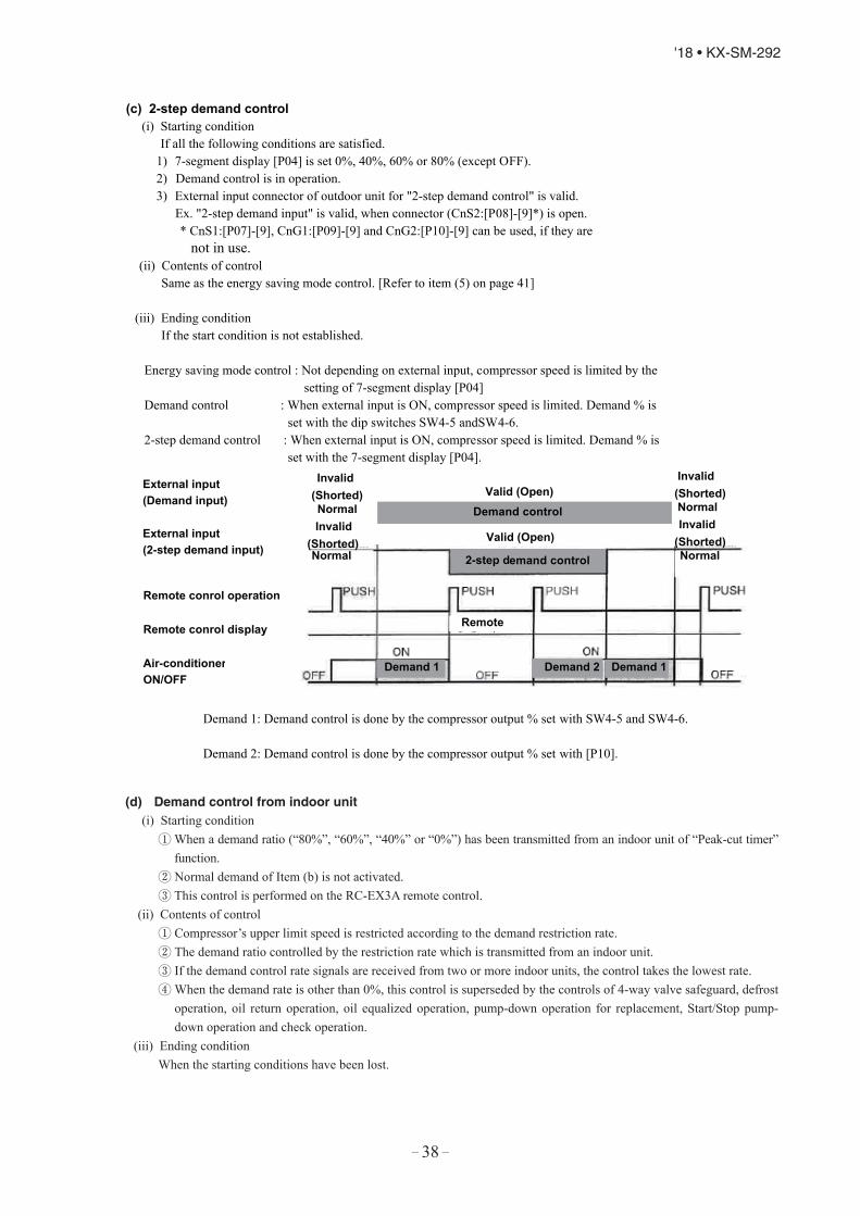
– 38 –
'18 • KX-SM-292
(c) 2-step demand control(i) Starting condition
If all the following conditions are satisfied.1) 7-segment display [P04] is set 0%, 40%, 60% or 80% (except OFF).2) Demand control is in operation.3) External input connector of outdoor unit for "2-step demand control" is valid.
Ex. "2-step demand input" is valid, when connector (CnS2:[P08]-[9]*) is open.* CnS1:[P07]-[9], CnG1:[P09]-[9] and CnG2:[P10]-[9] can be used, if they are
not in use.(ii) Contents of control
Same as the energy saving mode control. [Refer to item (5) on page 41]
(iii) Ending conditionIf the start condition is not established.
Energy saving mode control : Not depending on external input, compressor speed is limited by thesetting of 7-segment display [P04]
Demand control : When external input is ON, compressor speed is limited. Demand % isset with the dip switches SW4-5 andSW4-6.
2-step demand control : When external input is ON, compressor speed is limited. Demand % isset with the 7-segment display [P04].
Demand 1: Demand control is done by the compressor output % set with SW4-5 and SW4-6.
Demand 2: Demand control is done by the compressor output % set with [P10].
External input (Demand input)
Demand control
2-step demand control
Invalid(Shorted)
Valid (Open)
Demand 1 Demand 2
Remote
Demand 1
External input (2-step demand input)
Invalid (Shorted)
Remote conrol operation
Remote conrol display
Air-conditionerON/OFF
Normal Invalid
(Shorted)Invalid
(Shorted)
Normal
NormalNormal
Valid (Open)
(d) Demand control from indoor unit(i) Starting condition
① When a demand ratio (“80%”, “60%”, “40%” or “0%”) has been transmitted from an indoor unit of “Peak-cut timer” function.
② Normal demand of Item (b) is not activated.③ This control is performed on the RC-EX3A remote control.
(ii) Contents of control① Compressor’s upper limit speed is restricted according to the demand restriction rate.② The demand ratio controlled by the restriction rate which is transmitted from an indoor unit.③ If the demand control rate signals are received from two or more indoor units, the control takes the lowest rate.④ When the demand rate is other than 0%, this control is superseded by the controls of 4-way valve safeguard, defrost
operation, oil return operation, oil equalized operation, pump-down operation for replacement, Start/Stop pump-down operation and check operation.
(iii) Ending conditionWhen the starting conditions have been lost.
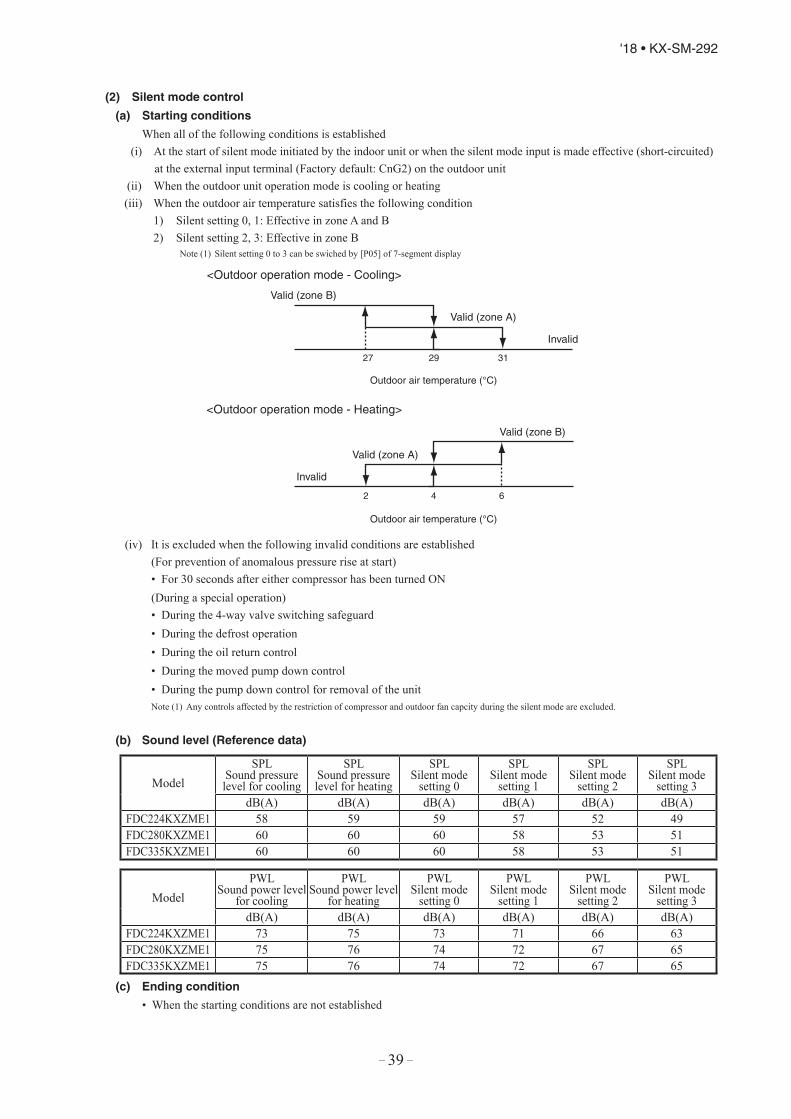
– 39 –
'18 • KX-SM-292
(2) Silent mode control
(a) Starting conditions
When all of the following conditions is established(i) At the start of silent mode initiated by the indoor unit or when the silent mode input is made effective (short-circuited)
at the external input terminal (Factory default: CnG2) on the outdoor unit(ii) When the outdoor unit operation mode is cooling or heating(iii) When the outdoor air temperature satisfies the following condition
1) Silent setting 0, 1: Effective in zone A and B2) Silent setting 2, 3: Effective in zone B
Note (1) Silent setting 0 to 3 can be swiched by [P05] of 7-segment display.
Valid (zone B)
Valid (zone A)
Invalid
27 29 31
<Outdoor operation mode - Heating>
<Outdoor operation mode - Cooling>
Outdoor air temperature (°C)
Valid (zone A)
Valid (zone B)
Invalid
2 4 6
Outdoor air temperature (°C)
(iv) It is excluded when the following invalid conditions are established(For prevention of anomalous pressure rise at start)• For 30 seconds after either compressor has been turned ON(During a special operation)• During the 4-way valve switching safeguard• During the defrost operation• During the oil return control• During the moved pump down control• During the pump down control for removal of the unitNote (1) Any controls affected by the restriction of compressor and outdoor fan capcity during the silent mode are excluded.
(b) Sound level (Reference data)
(c) Ending condition
• When the starting conditions are not established
(c) 2-step demand control(i) Starting condition
If all the following conditions are satisfied.1) 7-segment display [P04] is set 0%, 40%, 60% or 80% (except OFF).2) Demand control is in operation.3) External input connector of outdoor unit for "2-step demand control" is valid.
Ex. "2-step demand input" is valid, when connector (CnS2:[P08]-[9]*) is open.* CnS1:[P07]-[9], CnG1:[P09]-[9] and CnG2:[P10]-[9] can be used, if they are
not in use.(ii) Contents of control
Same as the energy saving mode control. [Refer to item (5) on page 41]
(iii) Ending conditionIf the start condition is not established.
Energy saving mode control : Not depending on external input, compressor speed is limited by thesetting of 7-segment display [P04]
Demand control : When external input is ON, compressor speed is limited. Demand % isset with the dip switches SW4-5 andSW4-6.
2-step demand control : When external input is ON, compressor speed is limited. Demand % isset with the 7-segment display [P04].
Demand 1: Demand control is done by the compressor output % set with SW4-5 and SW4-6.
Demand 2: Demand control is done by the compressor output % set with [P10].
External input (Demand input)
Demand control
2-step demand control
Invalid(Shorted)
Valid (Open)
Demand 1 Demand 2
Remote
Demand 1
External input (2-step demand input)
Invalid (Shorted)
Remote conrol operation
Remote conrol display
Air-conditionerON/OFF
Normal Invalid
(Shorted)Invalid
(Shorted)
Normal
NormalNormal
Valid (Open)
ModelSPL
Sound pressure level for cooling
SPLSound pressure level for heating
SPLSilent mode
setting 0
SPLSilent mode
setting 1
SPLSilent mode
setting 2
SPLSilent mode
setting 3dB(A) dB(A) dB(A) dB(A) dB(A) dB(A)
FDC224KXZME1 58 59 59 57 52 49FDC280KXZME1 60 60 60 58 53 51FDC335KXZME1 60 60 60 58 53 51
ModelPWL
Sound power level for cooling
PWLSound power level
for heating
PWLSilent mode
setting 0
PWLSilent mode
setting 1
PWLSilent mode
setting 2
PWLSilent mode
setting 3dB(A) dB(A) dB(A) dB(A) dB(A) dB(A)
FDC224KXZME1 73 75 73 71 66 63FDC280KXZME1 75 76 74 72 67 65FDC335KXZME1 75 76 74 72 67 65

– 40 –
'18 • KX-SM-292
(3) Outdoor fan snow protection control
(a) This control is enabled/disabled by entering data into 7-segment display.
(b) Setting method of outdoor fan control
[Starting conditions]
When following conditions are established for 10 minutes continuously.(i) Snow protection control setting is valid ([P02]-1) and outdoor air temperature < 3°C or external input of outdoor fan
snow protection control ON. ([P07]-5 and CnS1 is shorted) Set the Code No. to “P02”. “0” or “1” is displayed at the data display area.
“0”: Outdoor fan control disabled (Factory setting)“1”: Outdoor fan control enabled
Press SW7 (Data write/delete) for 3 seconds continuously. “0” or “1” blinks every 0.5 second at the data display area. Press SW8 (one digit) to toggle the display back and forth between “0” and “1” (blinking). If SW7 is pressed for 3 seconds or longer continuously while “0 “ and “1” is blinking, the blinking stops.
With this operation, the enabled/disabled setting of outdoor fan control is stored in memory of EEPROM, andhenceforth the outdoor fan is controlled according to the contents of memory.
Contents of the outdoor fan control are retained even if the power is turned off and backed on again.(c) Contents of outdoor fan snow protection control
If the outdoor air temperature drops 3°C or lower when the unit is all stop or error stop, the outdoor fan runs at therating speed (7th speed) once every 10 minutes.
The outdoor fan runs for 30 seconds.**Operation time outdoor fan is changeable from 10 to 600 seconds by [P03]
During this snow protection control, the compressor’s magnetic contactor (52X1 52X2) is ON.
When folowing conditions are established.(i) Snow protection control setting is invalid ([P02]-0) or outdoor air temperature > 5°C and external input of outdoor
fan snow protection control OFF ([P07]-[5]and CnS1is opend).(ii) Compressor ON
(iii) During all stop by anomaly
(4) External output
This function is used in order to operate the external option devices in conjunction with relay outputs of the respectiveoperation information from outdoor unit.[External output function]
External output function of CnZ1 can be switched by changing of [P06] on 7-segment display as mentioned below.0: Operation output
• When the outdoor unit operation mode is “Operation”, the external output relay is turned ON.Note (1) The “Operation” includes not only compressor ON mode but also Fan mode and thermostat OFF mode under the condition of remote control
ON. But the anomalous stop is excluded.
1: Error output•
pressed simutaneously after recovering from the anomaly. Even if “CHECK” and “RESET” buttons are pressed beforerecovering from the anomaly, it is not turned OFF, but when recovering from the anomaly later, it is automaticallyturned OFF.
2: Compressor ON output• It is turned ON when the compressor is ON.
3: Fan ON output• It is turned ON when the outdoor fan speed command > 0.
Valid
Invalid
Outdoor air temperature (°C )3 5
<Outdoor air temperature condition at snow protection control>
It is turned ON at anomalous stop, and turned OFF when “CHECK” and “RESET” buttons on remote control are
(d) Ending conditions of outdoor fan snow protection control
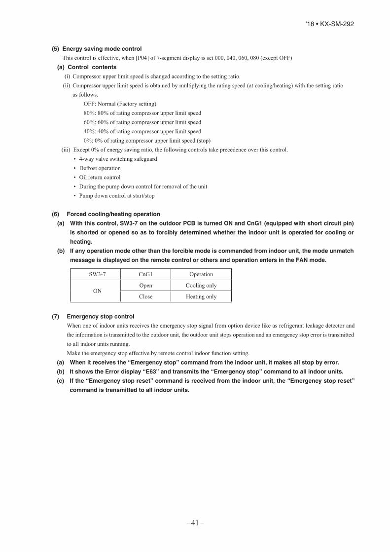
– 41 –
'18 • KX-SM-292
(3) Outdoor fan snow protection control
(a) This control is enabled/disabled by entering data into 7-segment display.
(b) Setting method of outdoor fan control
[Starting conditions]
When following conditions are established for 10 minutes continuously.(i) Snow protection control setting is valid ([P02]-1) and outdoor air temperature < 3°C or external input of outdoor fan
snow protection control ON. ([P07]-5 and CnS1 is shorted) Set the Code No. to “P02”. “0” or “1” is displayed at the data display area.
“0”: Outdoor fan control disabled (Factory setting)“1”: Outdoor fan control enabled
Press SW7 (Data write/delete) for 3 seconds continuously. “0” or “1” blinks every 0.5 second at the data display area. Press SW8 (one digit) to toggle the display back and forth between “0” and “1” (blinking). If SW7 is pressed for 3 seconds or longer continuously while “0 “ and “1” is blinking, the blinking stops.
With this operation, the enabled/disabled setting of outdoor fan control is stored in memory of EEPROM, andhenceforth the outdoor fan is controlled according to the contents of memory.
Contents of the outdoor fan control are retained even if the power is turned off and backed on again.(c) Contents of outdoor fan snow protection control
If the outdoor air temperature drops 3°C or lower when the unit is all stop or error stop, the outdoor fan runs at therating speed (7th speed) once every 10 minutes.
The outdoor fan runs for 30 seconds.**Operation time outdoor fan is changeable from 10 to 600 seconds by [P03]
During this snow protection control, the compressor’s magnetic contactor (52X1 52X2) is ON.
When folowing conditions are established.(i) Snow protection control setting is invalid ([P02]-0) or outdoor air temperature > 5°C and external input of outdoor
fan snow protection control OFF ([P07]-[5]and CnS1is opend).(ii) Compressor ON
(iii) During all stop by anomaly
(4) External output
This function is used in order to operate the external option devices in conjunction with relay outputs of the respectiveoperation information from outdoor unit.[External output function]
External output function of CnZ1 can be switched by changing of [P06] on 7-segment display as mentioned below.0: Operation output
• When the outdoor unit operation mode is “Operation”, the external output relay is turned ON.Note (1) The “Operation” includes not only compressor ON mode but also Fan mode and thermostat OFF mode under the condition of remote control
ON. But the anomalous stop is excluded.
1: Error output•
pressed simutaneously after recovering from the anomaly. Even if “CHECK” and “RESET” buttons are pressed beforerecovering from the anomaly, it is not turned OFF, but when recovering from the anomaly later, it is automaticallyturned OFF.
2: Compressor ON output• It is turned ON when the compressor is ON.
3: Fan ON output• It is turned ON when the outdoor fan speed command > 0.
Valid
Invalid
Outdoor air temperature (°C )3 5
<Outdoor air temperature condition at snow protection control>
It is turned ON at anomalous stop, and turned OFF when “CHECK” and “RESET” buttons on remote control are
(d) Ending conditions of outdoor fan snow protection control
This control is effective, when [P04] of 7-segment display is set 000, 040, 060, 080 (except OFF)(a) Control contents
(i)(ii)
as follows.OFF: Normal (Factory setting)80%: 80% of rating compressor upper limit speed60%: 60% of rating compressor upper limit speed40%: 40% of rating compressor upper limit speed0%: 0% of rating compressor upper limit speed (stop)
• 4-way valve switching safeguard• Defrost operation• Oil return control• During the pump down control for removal of the unit• Pump down control at start/stop
(6) Forced cooling/heating operation
(a) With this control, SW3-7 on the outdoor PCB is turned ON and CnG1 (equipped with short circuit pin)
is shorted or opened so as to forcibly determined whether the indoor unit is operated for cooling or
heating.
(b) If any operation mode other than the forcible mode is commanded from indoor unit, the mode unmatch
message is displayed on the remote control or others and operation enters in the FAN mode.
SW3-7 CnG1 Operation
ONOpen Cooling only
Close Heating only
(7) Emergency stop control
When one of indoor units receives the emergency stop signal from option device like as refrigerant leakage detector and the information is transmitted to the outdoor unit, the outdoor unit stops operation and an emergency stop error is transmitted to all indoor units running.Make the emergency stop effective by remote control indoor function setting.
(a) When it receives the “Emergency stop” command from the indoor unit, it makes all stop by error.
(b) It shows the Error display “E63” and transmits the “Emergency stop” command to all indoor units.
(c) If the “Emergency stop reset” command is received from the indoor unit, the “Emergency stop reset”
command is transmitted to all indoor units.
Compressor upper limit speed is changed according to the setting ratio.Compressor upper limit speed is obtained by multiplying the rating speed (at cooling/heating) with the setting ratio
(5) Energy saving mode control
(iii) Except 0% of energy saving ratio, the following controls take precedence over this control.

– 42 –
'18 • KX-SM-292
(8) Pump down operation control for removal of the unit
When an outdoor unit is discarded or removed, the pump down control is performed at the outdoor unit side in order to recover the refrigerant quickly to the outdoor unit.
(a) Starting conditions
This is implemented with the liquid service valve closed.(i) Outdoor unit operation mode – Stop
(ii) Turn ON the test run cooling switch SW5-2 (cooling).(iii) Turn ON the pump down switch SW5-3 (pump down).(iv) Turn ON the test run switch SW5-1 when the above (i)-(iii) statuses are satisfied.
Note (1) Input before the power ON is invalid.
(b) Control contents
(i) Compressor starts under compressor start protection control and runs at target speed of pump down operation.However, when the operation starting conditions have been established during the 3-minute delay control ofcompressor, the compressor starts after completing the 3-minute delay control.
ItemModel HP Target compressor speed at pump down operation
FDC224KXZME1 50rpsFDC280KXZME1 62rpsFDC335KXZME1 52rps
(ii) As the starting conditions are established, both red LED and green LED on the outdoor PCB flash continuously.7-segment display shows “PdS” (Channel 0) at the code display area.
(iii) During the pump down operation control, the protective controls (excluing low pressure protective control,anomalous low pressure control and pressure ratio protection control) and the error detection control are effective.
(iv) The sub-cooling coil expansion valve (EEVSC) closes fully during the pump down control.(c) Ending conditions
If any of the following conditions is satisfied, this control ends(i) If a low pressure (LP) ≤ 0.01MPa is detected for 5 seconds continuously, it ends normally and initiates the
followings. Red LED: keeps lighting Green LED: keeps flashin 7-segment display: PdE Remote control: Stop
(ii)(iii)
Anomalous all stop by the error detection controlIf the cumulative compressor operation time under the pump down control totals 15 minutes (ending by time countup), it stops and initiates the following. Red LED: stays OFF Green LED: keeps flashin 7-segment display: No display Remote control: Stop
(iv) When any of setting switches (SW5-1, SW5-2 and SW5-3) has been turned OFF during pump down.Note (1) Even if only the pump down switch SW5-3 is turned OFF, it does not recognized as the cooling test run mode , but stops.
81012

– 43 –
'18 • KX-SM-292
(9) Outdoor operation mode
On the standard models of 2 pipe system, the outdoor operation mode of Stop/Cooling/Heating is selected based on the information of indoor units, and then respective controls are performed.<Contents of control>
(a) Determination of outdoor operation modeOperation mode of outdoor unit is determined based on respective signals of Operation/Stop and Cooling/Heating.
(b) Type of outdoor operation mode (i) Outdoor operation mode - Stop (ii) Outdoor operation mode - Cooling(iii) Outdoor operation mode - Heating
(c) Priority in operation mode selection. (i) First priority is given to the forced cooling/heating operation.(ii) Second priority is given as follows Priority in the operation mode selection can be changed using the 7-segment setting [P01].
P01 setting Mode
0 (Factory default) First unit’s operation mode
1 Last unit’s operation mode
2 Priority of master unit’s setting operation mode
3 Priority of required major operation mode
・First unit’s operation mode: Operation mode of the indoor unit which is operated first time after stop of the outdoor unit operation mode
・Last unit’s operation mode: Operation mode of the indoor unit which is operated at the last time・Priority of master unit’s setting operation mode: Operation mode of indoor unit of which the address No. is smallest
(Master indoor unit). When the master indoor unit is turned off, it become valid the first push priority on other indoor units’ remote controls.
・Priority of required major operation mode: Operation mode of which the total capacity of operating indoor units is larger. There is no renewed judgment for 10 minutes after a change on the operation mode.The judgment, however, is renewed in following cases.- At the stop- When the P01 setting is changed.
(iii) In the event that agreement of operation mode is lost between indoor units and outdoor units by selecting the first or second priority after determining the operation mode, it is changed forcibly to the “Fan” mode. The operation mode LCD flickers to warn the “Mode unmatch”.
(iv) Example of operation mode selection<First unit’s operation mode>① If both of indoor units 0 and 1 have the same operation mode, it operates with the mode.
② Cooling does not match on indoor units 0 and 1 (Priority is given to previous operation.)
Indoor unit 0 Stop CoolingON
Cooling
Indoor unit 1 Stop CoolingON
Indoor unit 0 Stop Cooling CoolingON
Indoor unit 1 Stop Heating “Invalid operation” lamp flickers. FanON
(8) Pump down operation control for removal of the unit
When an outdoor unit is discarded or removed, the pump down control is performed at the outdoor unit side in order to recover the refrigerant quickly to the outdoor unit.
(a) Starting conditions
This is implemented with the liquid service valve closed.(i) Outdoor unit operation mode – Stop
(ii) Turn ON the test run cooling switch SW5-2 (cooling).(iii) Turn ON the pump down switch SW5-3 (pump down).(iv) Turn ON the test run switch SW5-1 when the above (i)-(iii) statuses are satisfied.
Note (1) Input before the power ON is invalid.
(b) Control contents
(i) Compressor starts under compressor start protection control and runs at target speed of pump down operation.However, when the operation starting conditions have been established during the 3-minute delay control ofcompressor, the compressor starts after completing the 3-minute delay control.
ItemModel HP Target compressor speed at pump down operation
FDC224KXZME1 50rpsFDC280KXZME1 62rpsFDC335KXZME1 52rps
(ii) As the starting conditions are established, both red LED and green LED on the outdoor PCB flash continuously.7-segment display shows “PdS” (Channel 0) at the code display area.
(iii) During the pump down operation control, the protective controls (excluing low pressure protective control,anomalous low pressure control and pressure ratio protection control) and the error detection control are effective.
(iv) The sub-cooling coil expansion valve (EEVSC) closes fully during the pump down control.(c) Ending conditions
If any of the following conditions is satisfied, this control ends(i) If a low pressure (LP) ≤ 0.01MPa is detected for 5 seconds continuously, it ends normally and initiates the
followings. Red LED: keeps lighting Green LED: keeps flashin 7-segment display: PdE Remote control: Stop
(ii)(iii)
Anomalous all stop by the error detection controlIf the cumulative compressor operation time under the pump down control totals 15 minutes (ending by time countup), it stops and initiates the following. Red LED: stays OFF Green LED: keeps flashin 7-segment display: No display Remote control: Stop
(iv) When any of setting switches (SW5-1, SW5-2 and SW5-3) has been turned OFF during pump down.Note (1) Even if only the pump down switch SW5-3 is turned OFF, it does not recognized as the cooling test run mode , but stops.
81012

– 44 –
'18 • KX-SM-292
Indoor unit 0 Stop Cooling Heating “Invalid operation” lamp flickers. FanON ON
Indoor unit 1 Stop Cooling CoolingON
③ When it is changed from same mode to unmatch.
④ Operation mode is prepared for change in the fan mode.
<Last unit’s operation mode>① If the indoor unit 1 of which operation mode is different has joined in when the indoor units 0 is operating.
<Priority of required major operation mode>
(v) Reset of unmatched condition (Cooling/heating unmatched)When unmatch occurs among indoor units, it can be reset by either one of followings.① If the operation mode of outdoor unit is matched with that of indoor unit.② If the operation mode is changed to “Fan” or “Stop” on the indoor units on which Cooling/heating is unmatched.
Indoor unit 0 Stop Fan FanON
Indoor unit 1 Stop Heating HeatingON
Indoor unit 0 Stop Cooling “Invalid operation” lamp flickers. FanON
Indoor unit 1 Stop Heating HeatingON
Outdoor operation mode
Indoor unit P90(Cooling)
Indoor unit P80(Heating)
Indoor unit P80(Heating)
ON
CoolingHeating
OFF
ONUnmatched ⇒ Fan mode
Unmatched ⇒ Fan mode
Thermostat ON
ON
OFF
(d) Forced cooling /heating operation (Master unit)Note (1) Following explanation is based on using CnG1 terminal and setting function [P09]-[2] with 7-segment display.
However other terminals can be used with following function setting of 7-segment display.
CnS1: [P07]-[2] CnS2: [P08]-[2] CnG2: [P10]-[2]
(i) When SW3-7 on the outdoor control PCB is turned ON after setting function [P09]-[2] with 7-segment display, if
CnG1 is shorted, forced heating operation is performed, but if CnG1 is open, forced cooling operation is performed.
(ii) If the different mode from the forced operation mode is commanded from indoor unit, the "mode unmatch" message is
displayed on the LCD of remote control and the operation is entered in FAN mode.
SW3-7ON CnG1
Open Operation in cooling onlyShorted Operation in heating only
OFF Normal operation

– 45 –
'18 • KX-SM-292
(iii) With the forced mode from indoor unit, if a different operation mode is commanded, following operations take place
based on the forced cooling/heating operation set with the 7-segment [P38].
P38 = 0: The operation mode unmatch is displayed on the remote control, etc., and it is changed to the fan
operation.
P38 = 1: It is operated with the forced cooling/heating operation mode.
Setting temperature for cooling … 28Setting temperature for heating … 20
(10) Pump-down operation by external inputIf an error stop is raised by an external input by refrigerant leaking alarm unit, the pump-down operation is performed at the outdoor unit side in order to prevent the refrigerant from leaking.
They are local arrangements.① Refrigerant leaking alarm unit② Valve to shut liquid pipe③ Valve to shut gas pipe
Valves of ② and ③ should be selected what the pressure loss of refrigerant piping doesn’t increase.(a) Status 1: Pump-down operation
(i) Starting condition① When the external input function is assigned to “0: External operation input” and the external input terminal is
open (by refrigerant leaking alarm unit).② If the pump-down control is valid when the error stop is raised by the setting on 7-segment. ([P77] = “1”)
(ii) Contents of control① ON is output on CnY, and the liquid service valve is shut down if it is connected on CnY.② The pump-down operation for replacement is performed.
(iii) Ending condition① When starting conditions are lost.② When the pump-down operation has ended.
(b) Status 2: Emergency stop operation(i) Starting condition
① When the pump-down operation has ended in the status 1.(ii) Contents of control
① ON is output to CnZ1, and the gas service valve is shut down if it is connected on CnZ1.② Operation stops with the error full stop. ([E63] is displayed.)
(iii) Ending condition① When starting conditions for the status 1 are lost.② State of error continues for 3 minutes after the error full stop. It cannot be reset in this condition from the remote
control. If the starting conditions for Status 1 are not yet established later, this can be reset by the remote control inspection reset.

– 46 –
'18 • KX-SM-292
(11) VTCC : Variable Temperature and capacity control (VRF inverter Multi-system energy save control)
On the multi-system, target pressures are set uniformly so that indoor units operate with a constant capacity and repeat the
ON/OFF control with which thermostats are turned OFF when temperatures become near the setting temperature.
Owing to the tuning of target high/low pressure near the setting temperature, it becomes possible to perform the high effi-
ciency operation near the setting temperature.
For this reason, duration of time for highly efficient operation is increased by providing the compressor upper limit speed
according to the thermostat ON capacity.
・Thermostat ON capacity … Total capacity of indoor units which are operating with the thermostat ON
(a) Correction of target high/low pressure
(i) Starting condition (either of ① or ② )
① When the external input function assignment [P07] - [P10]: Multi-system energy save control = Valid
② When 7-segment [P39] (Multi-system energy save control I) = ON, if the external input function assignment [P07]
- [P10] is not assigned this control.
(ii) Contents of control
① During the outdoor unit operation mode at cooling
・Indoor load more than 50% → Corrected to the target cooling low pressure lower.
・Indoor load less than 50% → Corrected to the target cooling low pressure higher.
② During the outdoor unit operation mode at heating
・Indoor load more than 50% → Corrected to the target heating high pressure higher.
・Indoor load less than 50% → Corrected to the target heating high pressure lower. (Total capacity of indoor units of which load is high)
(Note) Indoor load condition (%) = ――――――――――――――――――――――Total capacity of indoor units with the thermostat ON
(iii) Ending condition
① When the starting conditions are lost.
Pump down by external input
Emergency call => External operation input : Shorted
Alarm unit Gas leakage
Pump down operation
Activate by 7-segment:[P77]=“1”
E63 <==

– 47 –
'18 • KX-SM-292
(b) Compressor upper limit speed restriction for each operation capacity
(i) Starting condition (either of ① or ② )
① When the external input assignment [P07] – [P10]: Multi-system energy save operation = Valid and 7-segment [P67]
(Multi-system energy save control II) = 1 or 2 or 3
Factory default: 0 (OFF)/1 (Setting 1), 2 (Setting 2), 3 (Setting 3)
② 7-segment [P67] = 1 or 2 or 3, if the external input function assignment [P07] – [P10] is not assigned this control.
(ii) Contents of control
① Compressor upper limit speed is the value obtained by multiplying with the upper limit speed restriction rate ac-
cording to the thermostat ON capacity.
② The upper limit restriction rate is divided to the following 3 steps according to each setting of [P67] as follows.
Upp
er li
mit
spee
d re
stric
tion
rate
Upper limit Fk (Normal)
Setting 1: 60%
Thermostat ON capacity
Setting 2:40%
Setting 3:20%
0 100%
③ Following controls supersede this control.
・4-way valve safeguard ・Defrost operation
・Oil return operation ・Oil equalized operation
・Pump-down operation for replacement ・Start/Stop pump-down operation
(iii) Ending condition
① When the starting conditions are lost.
– 48 –
'18 • KX-SM-292
(C) Data output
(1) 7-segment and operation data retention
(a) 7-segment display
Operation information is displayed for checking various operation data during test run and for helping malfunctiondiagnosis at servicing. Input data to microcomputer, contents of outdoor unit control, indoor unit registration information,or other, are mainly displayed on the 7-segment LED.
(i) Operation information display Displays each item at 7-segment of 3-digit × 2 on the outdoor unit PCB. Display is controlled with the following buttons.
SW9: Setting button for order of 10 of display codeSW8: Setting button for order of 1 of display codeSW7: Data erase/write button
Select the order of 10 for the code No. of each item with SW9 or SW8 for the order of 1.Following identification alphabets are used at the code displa .
“C”: “C00” – “C99”“P”: “P00” – “PXX” (up to a place where content is specified
Code [C96]is operable item. It is possible to delete the retained operation data (data of 30 minutes preceding ananomalous stop) by following resetting procedure.<Resetting operation>• Select code [C96]. If any anomalous data is retained, the data display [dEL] is shown.• Pressing SW7 for 3 seconds erases the memory data on RAM.
(EEPROM data are not erased.)• As the data are erased, the data display shows [- - -].
When no anomalous data are retained, it displays [---] as well.• Unless the reset operation is performed, data are retained. Therefore, if normal operation is resumed without
the reset operation and an anomalous stop occurs again, no new anomalous data cannot be retained, butformer anomalous data are still retained unchanged.
If you press SW8 (order of 1), the number changes 0 1 2 ... 9 0. If you press SW9 (order of 10), the number jumps to the leading code of each order of 10.
Data display [CXX] and setting value display [PXX] are considered to be continuous.Example: Pressing SW9 at [C07] it changes to [C10]
: Pressing SW9 at [C90], it changes to [P00] Codes [C44] are operable items. With the following reset operation, the cumulative compressor operation time
corresponding to the code No. can be erased (reset). (Reset of operation time after replacing the compressor)<Resetting operation>• Select codes [C44]. Cumulative compressor operation time up to present is displayed.• Pressing SW7 for 3 seconds erases the memory data.
However, the cumulative compressor operation time data in the 30 minutes log data preceding an anomalousstop (if this retained log data are not deleted) are not erased by this procedure.
Data display for spare items is left in blank.(ii) When the temperature is below -10.0°C for the display of discharge pressure saturated temperature and suction
pressure saturated temperature, the fraction after decimal point is rounded up. (Because the range of 7-segmentdisplay is 3-digit.)
(iii) Return the error No. display after an error to the normal display by turning ON the DIP switch SW3-1.
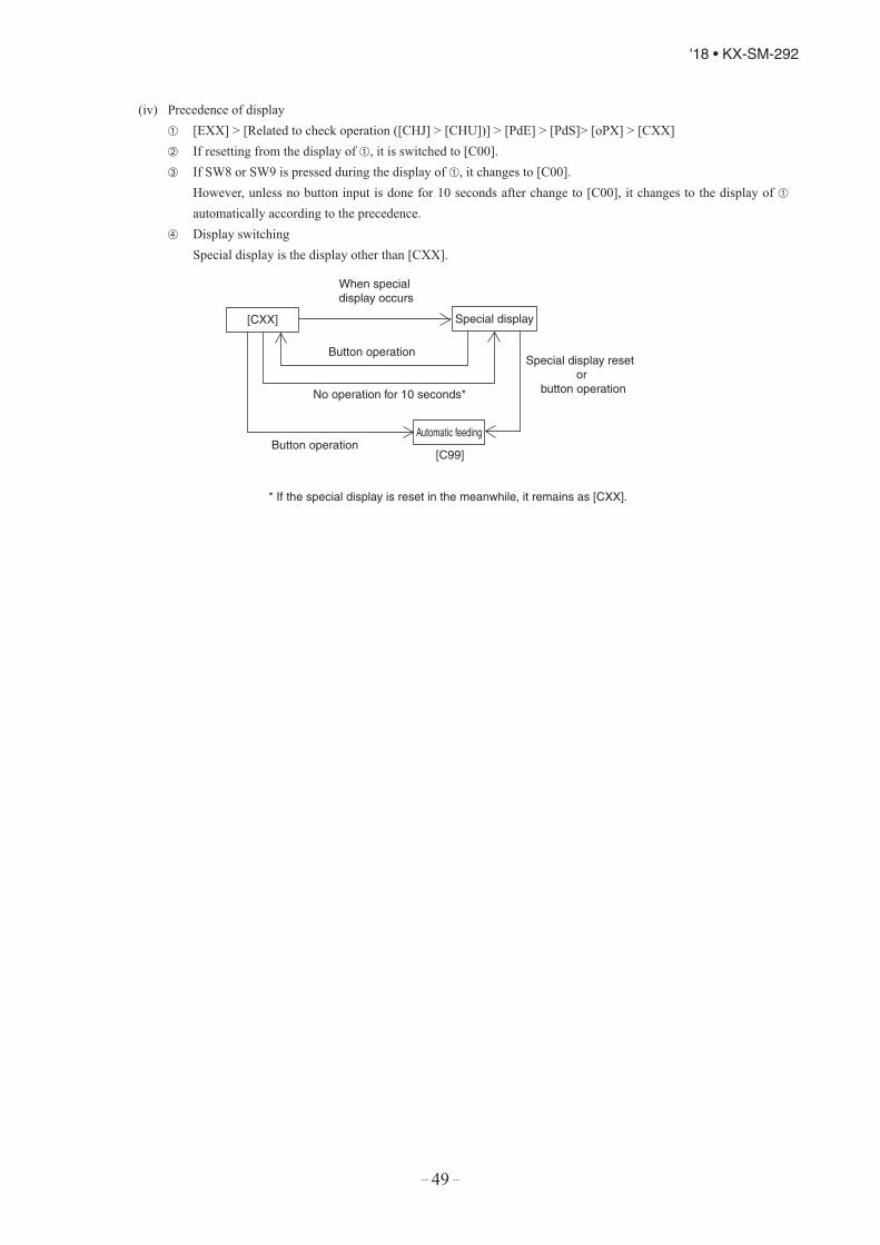
– 49 –
'18 • KX-SM-292
(C) Data output
(1) 7-segment and operation data retention
(a) 7-segment display
Operation information is displayed for checking various operation data during test run and for helping malfunctiondiagnosis at servicing. Input data to microcomputer, contents of outdoor unit control, indoor unit registration information,or other, are mainly displayed on the 7-segment LED.
(i) Operation information display Displays each item at 7-segment of 3-digit × 2 on the outdoor unit PCB. Display is controlled with the following buttons.
SW9: Setting button for order of 10 of display codeSW8: Setting button for order of 1 of display codeSW7: Data erase/write button
Select the order of 10 for the code No. of each item with SW9 or SW8 for the order of 1.Following identification alphabets are used at the code displa .
“C”: “C00” – “C99”“P”: “P00” – “PXX” (up to a place where content is specified
Code [C96]is operable item. It is possible to delete the retained operation data (data of 30 minutes preceding ananomalous stop) by following resetting procedure.<Resetting operation>• Select code [C96]. If any anomalous data is retained, the data display [dEL] is shown.• Pressing SW7 for 3 seconds erases the memory data on RAM.
(EEPROM data are not erased.)• As the data are erased, the data display shows [- - -].
When no anomalous data are retained, it displays [---] as well.• Unless the reset operation is performed, data are retained. Therefore, if normal operation is resumed without
the reset operation and an anomalous stop occurs again, no new anomalous data cannot be retained, butformer anomalous data are still retained unchanged.
If you press SW8 (order of 1), the number changes 0 1 2 ... 9 0. If you press SW9 (order of 10), the number jumps to the leading code of each order of 10.
Data display [CXX] and setting value display [PXX] are considered to be continuous.Example: Pressing SW9 at [C07] it changes to [C10]
: Pressing SW9 at [C90], it changes to [P00] Codes [C44] are operable items. With the following reset operation, the cumulative compressor operation time
corresponding to the code No. can be erased (reset). (Reset of operation time after replacing the compressor)<Resetting operation>• Select codes [C44]. Cumulative compressor operation time up to present is displayed.• Pressing SW7 for 3 seconds erases the memory data.
However, the cumulative compressor operation time data in the 30 minutes log data preceding an anomalousstop (if this retained log data are not deleted) are not erased by this procedure.
Data display for spare items is left in blank.(ii) When the temperature is below -10.0°C for the display of discharge pressure saturated temperature and suction
pressure saturated temperature, the fraction after decimal point is rounded up. (Because the range of 7-segmentdisplay is 3-digit.)
(iii) Return the error No. display after an error to the normal display by turning ON the DIP switch SW3-1.
(iv) Precedence of display [EXX] > [Related to check operation ([CHJ] > [CHU])] > [PdE] > [PdS]> [oPX] > [CXX] If resetting from the display of , it is switched to [C00]. If SW8 or SW9 is pressed during the display of , it changes to [C00]. However, unless no button input is done for 10 seconds after change to [C00], it changes to the display of
automatically according to the precedence. Display switching Special display is the display other than [CXX].
When special display occurs
Special display reset or
button operation
Button operation
Button operation
No operation for 10 seconds*
* If the special display is reset in the meanwhile, it remains as [CXX].
[CXX]
[C99]
Automatic feeding
Special display

– 50 –
'18 • KX-SM-292
(b) List of 7-segment displays
Code No. Contents of display Data display range Minimum unit Remarks
Error display [EXX]
Caution display [oPX]
Special display [PdS][PdE]
Code No. Contents of data display Data display range Minimum unit Remarks
<Sensor value, actuator information>C00 CM1 operation frequency 0 - 130 1HzC01 (Spare)C02 Tho-A Outdoor air temperature L,-20 - 43 1°CC03 Tho-R1 Heat exchanger temperature 1 L,-25 - 73 1°CC04 Tho-R2 Heat exchanger temperature 2 L,-25 - 73 1°CC05 (Spare) C06 (Spare) C07 Tho-D1 Discharge pipe temperature (CM1) L,31 - 136 1°CC08 (Spare) C09 (Spare)C10 Tho-C1 Under-dome temperature (CM1) L,5 - 90 1°CC11 (Spare)C12 Tho-P1 Power transistor temperature (CM1) L,5 - 136 1°CC13 (Spare)C14 Tho-SC Sub-cooling coil temperature 1 L,18 - 73 1°CC15 Tho-H Sub-cooling coil temperature 2 L,-25 - 73 1°CC16 Tho-S Suction pipe temperature L,-25 - 73 1°CC17 Inverter secondary current 0 - 50 1AC18 CT1 (CM1) current 0 - 50 1AC19 (Spare)C20 EEVH1 Heating expansion valve opening angle 0 - 500 1 pulseC21 (Spare)
C22 EEVSC Sub-cooling coil expansion valve opening angle 0 - 500 1 pulse
C23 FMo1 Actual fan speed 0 - 999 10min-1C24 FMo2 Actual fan speed 0 - 999 10min-1C25 PSH High pressure sensor 0 - 4.15 0.01MPaC26 PSL Low pressure sensor 0 - 1.70 0.01MPaC27 (Spare)C28 (Spare)C29 (Spare)
C30 Pressure switch 0,1(0: Close, 1: Open) –
Order of 100: 63H1-1Order of 10: (Spare)
Order of 1: (Spare)
C31 External input 0,1(0: Close, 1: Open) –
Order of 100: CnS1Order of 10: CnS2
Order of 1: CnG1

– 51 –
'18 • KX-SM-292
(b) List of 7-segment displays
Code No. Contents of display Data display range Minimum unit Remarks
Error display [EXX]
Caution display [oPX]
Special display [PdS][PdE]
Code No. Contents of data display Data display range Minimum unit Remarks
<Sensor value, actuator information>C00 CM1 operation frequency 0 - 130 1HzC01 (Spare)C02 Tho-A Outdoor air temperature L,-20 - 43 1°CC03 Tho-R1 Heat exchanger temperature 1 L,-25 - 73 1°CC04 Tho-R2 Heat exchanger temperature 2 L,-25 - 73 1°CC05 (Spare) C06 (Spare) C07 Tho-D1 Discharge pipe temperature (CM1) L,31 - 136 1°CC08 (Spare) C09 (Spare)C10 Tho-C1 Under-dome temperature (CM1) L,5 - 90 1°CC11 (Spare)C12 Tho-P1 Power transistor temperature (CM1) L,5 - 136 1°CC13 (Spare)C14 Tho-SC Sub-cooling coil temperature 1 L,18 - 73 1°CC15 Tho-H Sub-cooling coil temperature 2 L,-25 - 73 1°CC16 Tho-S Suction pipe temperature L,-25 - 73 1°CC17 Inverter secondary current 0 - 50 1AC18 CT1 (CM1) current 0 - 50 1AC19 (Spare)C20 EEVH1 Heating expansion valve opening angle 0 - 500 1 pulseC21 (Spare)
C22 EEVSC Sub-cooling coil expansion valve opening angle 0 - 500 1 pulse
C23 FMo1 Actual fan speed 0 - 999 10min-1C24 FMo2 Actual fan speed 0 - 999 10min-1C25 PSH High pressure sensor 0 - 4.15 0.01MPaC26 PSL Low pressure sensor 0 - 1.70 0.01MPaC27 (Spare)C28 (Spare)C29 (Spare)
C30 Pressure switch 0,1(0: Close, 1: Open) –
Order of 100: 63H1-1Order of 10: (Spare)
Order of 1: (Spare)
C31 External input 0,1(0: Close, 1: Open) –
Order of 100: CnS1Order of 10: CnS2
Order of 1: CnG1
Code No. Contents of data display Data display range Minimum
unit Remarks
C32 External input 0,1(0: Close, 1: Open) –
Order of 100: CnG2Order of 10: (Spare)
Order of 1: (Spare)
C33 Relay output 0,1(0: Close, 1: Open) –
Order of 100: 52C-1Order of 10: 20S
Order of 1: Crankcase heater 1
C34 Relay output 0,1(0: Close, 1: Open) –
Order of 100: SV6Order of 10: (Spare)
Order of 1: (Spare)
C35 Relay output 0,1(0: Close, 1: Open) –
Order of 100: SV1Order of 10: SV11
Order of 1: SV12
C36 Relay output 0,1(0: Close, 1: Open) –
Order of 100: (Spare)Order of 10: (Spare)
Order of 1: (Spare)
C37 External output 0,1(0: Close, 1: Open) –
Order of 100: External output (CnZ1)Order of 10: CnH Operation output
Order of 1: CnY Anomalous output
C38 (Spare) – –
C39 (Spare) – –
<Outdoor unit information>C40 Number of connected indoor units 0 - 50 1C41 Capacity of connected indoor units 0 - 200 1C42 Number of indoor units with thermostat ON 0 - 50 1C43 Required Hz total 0 - 999 1Hz
C44 Cumulative compressor operation time (CM1) 0 - 655 100h
C45 (Spare) C46 Discharge pressure saturated temperature -50 - 70 0.1°C Range unable to display (-10°C or under) is in the unit of 1°C.C47 Suction pressure saturated temperature -50 - 30 0.1°C Range unable to display (-10°C or under) is in the unit of 1°C.
C48 Sub-cooling coil temperature sensor 1 saturated pressure -0.68 - 4.15 0.01
MPa0 is omitted in negative range.-0.68 [-.68]
C49 Cooling sub-cooling 0 - 50 0.1degC50 Heating overheat 0 - 50 0.1degC51 Sub-cooling coil overheat 0 - 50 0.1degC52 Discharge pipe overheat 1 0 - 50 0.1degC53 Under-dome overheat 1 0 - 50 0.1degC54 Target cooling low pressure 0.00 - 2.00 0.01MPaC55 Target heating high pressure 1.60 - 4.15 0.01MPaC56 Target Fk 0 - 999 1HzC57 Inverter 1 operation frequency command 0 - 130 1HzC58 Demand ratio 0 - 100 1%C59 FMo1 Fan Speed command 0 - 999 10min-1C60 FMo2 Fan Speed command 0 - 999 10min-1

– 52 –
'18 • KX-SM-292
Code No. Contents of data display Data display range Minimum
unit Remarks
<Anomalous counter information>C70 Counter · Sensor wire disconnected 0 - 3 1C71 Counter · High pressure protection 0 - 5 1
C72 Counter · Anomalous low pressure (During operation) 0 - 5 1
C73 Counter · Anomalous low pressure (During stop) 0 - 5 1C74 Counter · Discharge pipe 1 anomalous temperature 0 - 5 1C75 Counter · Anomalous FMo1 stop 0 - 5 1C76 Counter · Anomalous FMo2 stop 0 - 5 1C77 Counter · Current cut (CM1) 0 - 4 1C78 Counter · Compressor 1 starting failure 0 - 20 1C79 Counter · Inverter 1 comunication error 0 - 4 1C80 Counter · Power transistor 1 overheat 0 - 4 1C81 (Spare)C82 Counter · Inverter 1 desynchronism error 0 - 127 1C83 Counter · Inverter 1 comunication error cumulative 0 - 127 1C84 Counter · Indoor/outdoor comunication error 0 - 255 1C85 Counter · CPU reset 0 - 255 1C86 (Spare)C87 (Spare)C88 (Spare )C89 (Spare)C90 (Spare)C91 (Spare)C92 (Spare)C93 Counter – Liquid-back error 0 - 3 1C94 (Spare)
<Others>C95 (Spare)C96 Data resetC97 Program · Sub version 0 - 991 –C98 Program · POL version 0.00 - 9.99 0.01C99 Auto feed display –

– 53 –
'18 • KX-SM-292
Code No. Contents of data display Data display range Minimum
unit Remarks
<User setting>P00 (Spare) – – – – –
P01 Operation preference switching0 : (Factory default)0,1,2,3
–
0: First push preference (Factory default)1: Last push preference2: Priority of master unit’s setting operation mode3: Priority of required major operation mode
P02 Outdoor fan snow protection control0 : (Factory default)0,1-4
–0: Outdoor fan snow protection control invalid
(Factory default)1-4: Outdoor fan snow protection control valid
P03Outdoor fan snow protection control ON time setting
30 : (Factory default)10, 30 - 600 [Sec]
30 Changes like 10, 30, 60 90 … 600
P04 Demand ratio change valueOFF : (Factory default)OFF,000,040,060,080
0: OFF, 1: 0%, 2: 40%. 3: 60%, 4: 80%Factory default is 0: OFF.
P05 Silent setting0 : (Factory default)0 - 9
1
P06 External output function allocation0 : (Factory default)0 - 9
1
P07External input (CnS1) function allocation
0 : (Factory default)0 - 20
1
P08(Spare)External input (CnS2) function allocation
1 : (Factory default)0 - 20
1
P09(Spare)External input (CnG1) function allocation
2 : (Factory default)0 - 20
1
P10(Spare)External input (CnG2) function allocation
3 : (Factory default)0 - 20
1
Code No. Contents of data display Data display range Minimum
unit Remarks
<Anomalous counter information>C70 Counter · Sensor wire disconnected 0 - 3 1C71 Counter · High pressure protection 0 - 5 1
C72 Counter · Anomalous low pressure (During operation) 0 - 5 1
C73 Counter · Anomalous low pressure (During stop) 0 - 5 1C74 Counter · Discharge pipe 1 anomalous temperature 0 - 5 1C75 Counter · Anomalous FMo1 stop 0 - 5 1C76 Counter · Anomalous FMo2 stop 0 - 5 1C77 Counter · Current cut (CM1) 0 - 4 1C78 Counter · Compressor 1 starting failure 0 - 20 1C79 Counter · Inverter 1 comunication error 0 - 4 1C80 Counter · Power transistor 1 overheat 0 - 4 1C81 (Spare)C82 Counter · Inverter 1 desynchronism error 0 - 127 1C83 Counter · Inverter 1 comunication error cumulative 0 - 127 1C84 Counter · Indoor/outdoor comunication error 0 - 255 1C85 Counter · CPU reset 0 - 255 1C86 (Spare)C87 (Spare)C88 (Spare )C89 (Spare)C90 (Spare)C91 (Spare)C92 (Spare)C93 Counter – Liquid-back error 0 - 3 1C94 (Spare)
<Others>C95 (Spare)C96 Data resetC97 Program · Sub version 0 - 991 –C98 Program · POL version 0.00 - 9.99 0.01C99 Auto feed display –

– 54 –
'18 • KX-SM-292
Code No.
Data display contents Data display rangeMin.unit
Remarks
<Service engineer setting>P16 (Spare) – – – – – – –
P17 (Spare) – – – – – – –
P18 (Spare) – – – – – – –
P19Preferencial switch to ensure certain indoor outlet air temperature at heating
0 : (Factory default)0.1
–
0: Control for ensuring certain indoor outlet air temperature at heating is valid
1: Control for ensuring certain indoor outlet air temperature at heating is invalid
P20
Allowable total capacity of thermostat ON indoor units to ensure certain indoor outlet temperature at heating
110 : (Factory default)100, 090, 080
Changes to 110, 100, 090, 080, 110 …
P21
Allowable number of thermostat ON indoor units to ensure certain indoor outlet temperature at heating
0 : (Factory default)0 - 9
1
10
P22 (Spare) – – – – – – –
P23 (Spare) – – – – – – –
P24 (Spare) – – – – – – –
P25 (Spare) – – – – – – –
<New Superlink setting>
P30Superlink communication status
0,1 –0: Previous Superlink1: New Superlink
P31Automatic address setting start input
0 : (Factory default)0,1
–0: Automatic address setting standby1: Automatic address setting start
P32Input the starting indoor address for automatic address setting
1 : (Factory default)1 - 127
1Specify the starting indoor address connected in one refrigerant system for automatic address setting.
P33Input the number of connected indoor units
1 : (Factory default)1 - 24 (*)
1
Specify the number of indoor units connected in one refrigerant system for automatic address setting.(*) Maximum connectable number of indoor units for each outdoor unit
P34 Polarity difinition0 : (Factory default)0,1
–0: Network polarity not defined1: Network polarity defined
P36 (Spare) –P37 (Spare) –P38 (Spare)P39 Multi・system energy save controlⅠ

– 55 –
'18 • KX-SM-292
Code No.
Data display contents Data display rangeMin.unit
Remarks
<Service engineer setting>P16 (Spare) – – – – – – –
P17 (Spare) – – – – – – –
P18 (Spare) – – – – – – –
P19Preferencial switch to ensure certain indoor outlet air temperature at heating
0 : (Factory default)0.1
–
0: Control for ensuring certain indoor outlet air temperature at heating is valid
1: Control for ensuring certain indoor outlet air temperature at heating is invalid
P20
Allowable total capacity of thermostat ON indoor units to ensure certain indoor outlet temperature at heating
110 : (Factory default)100, 090, 080
Changes to 110, 100, 090, 080, 110 …
P21
Allowable number of thermostat ON indoor units to ensure certain indoor outlet temperature at heating
0 : (Factory default)0 - 9
1
10
P22 (Spare) – – – – – – –
P23 (Spare) – – – – – – –
P24 (Spare) – – – – – – –
P25 (Spare) – – – – – – –
<New Superlink setting>
P30Superlink communication status
0,1 –0: Previous Superlink1: New Superlink
P31Automatic address setting start input
0 : (Factory default)0,1
–0: Automatic address setting standby1: Automatic address setting start
P32Input the starting indoor address for automatic address setting
1 : (Factory default)1 - 127
1Specify the starting indoor address connected in one refrigerant system for automatic address setting.
P33Input the number of connected indoor units
1 : (Factory default)1 - 24 (*)
1
Specify the number of indoor units connected in one refrigerant system for automatic address setting.(*) Maximum connectable number of indoor units for each outdoor unit
P34 Polarity difinition0 : (Factory default)0,1
–0: Network polarity not defined1: Network polarity defined
P36 (Spare) –P37 (Spare) –P38 (Spare)P39 Multi・system energy save controlⅠ
(c) Saving of operation data
Mainly for investigating the causes of market claims, operation data are always saved in memory. If any trouble occurs,the data writing is stopped and only the operation data prior to the time when the trouble occurs are recorded. These datacan be loaded to a PC via RS-232C connector of PCB and utilized for identifying causes.
(i) Operation data for a period of 30minutes prior to the present operation are saved and updated continuously.(ii) If an anomalous stop occurs, the data are not updated any more.
(iii) Data are written in based on 1 minute sampling interval and following data are transmitted to PC upon demand.
Data Data range ExampleSoftware version Ascii 15 bytes KD3C218######## (# : NULL)PID (Program ID) Ascii 2 bytes 5DOutdoor unit capacity Ascii 3 bytes As listed blowPower source frequency Ascii 2 bytes 60Outdoor address Ascii 2 bytes 00 - 3FIndoor address × 16 units Ascii 2 bytes × 16 units 40 - 7FIndoor capacity × 16 units Ascii 3 bytes × 16 units 015 - 280
Outdoor unit composition Outdoor unit capacity data RemarksSingle type Example: 10HP - [S10] S: Display with Horse Power of single type
(iv) Error retention and monitoring dataCode No. Write contents
Record dataData write range Unit of write Number of bytes Contents
00 Indoor 1 Thi-A –14 - 50 A/D value 1 Return air01 Indoor 1 Thi-R1 0 - 72 A/D value 1 Heat exchanger 102 Indoor 1 Thi-R2 0 - 72 A/D value 1 Heat exchanger 203 Indoor 1 Thi-R3 0 - 72 A/D value 1 Heat exchanger 304 Indoor 1 EEV 0 - 470 1 pulse 205 Indoor 1 operation/stop 0,1 – 1 0 Stop
1 Operation06 Indoor 1 operation mode 0 - 4 – 1 0 Auto
1 Dry2 Cooling3 Fan4 Heating
07 Indoor 1 request Hz 0 - 255 1Hz 108 Indoor 1 answer Hz 0 - 255 1Hz 109 Indoor 1 indoor local – – 1 Bit0 Anti-frost
Bit1 EEV opening angle implementation
10 Indoor 1 Thi spare –14 - 50 A/D value 1 Discharge11 Indoor 1 type 0 - 67 – 1 0 FDT
1 FDK2 Others3 FDE4 FDTC56760 -
12 Indoor 1PID – – 1

– 56 –
'18 • KX-SM-292
Code No. Write contents Record data
Data write range Unit of write Number of bytes Contents
0 Error code 00 - 99 – 1 00: No error on outdoor unit01-99: All errors
1 Error existing unit address 00 - FF – 1 00 – 3F: Outdoor40 – 6F: Indoor
<Sensor value>2 Tho-A Outdoor air temperature -20 - 70 A/D value 13 Tho-R1 Heat exchanger temperature 1 -40 - 75 A/D value 24 Tho-R2 Heat exchanger temperature 2 -40 - 75 A/D value 25 Tho-D1 Discharge pipe temperature (CM1) -20 - 140 A/D value 16 Tho-S Suction pipe temperature -40 - 75 A/D value 27 Tho-SC Sub-cooling coil temperature 1 -40 - 75 A/D value 28 Tho-H Sub-cooling coil temperature 2 -40 - 75 A/D value 29 Tho-P1 Power transistor temperature (Radiator fin) -20 - 140 A/D value 110 Inverter secondary current 0 - 50 A/D value 111 Tho-C1 Under-dome temperature (CM1) -40 - 90 A/D value 112 CT1 Current 0 - 50 A/D value 113 High pressure sensor 0 - 4.15 A/D value 114 Low pressure sensor 0 - 1.70 A/D value 1
<Outdoor unit information>15 Number of connected indoor units 0 - 127 1 unit 116 Capacity of connected indoor units 0 - 65535 – 217 Number of indoor units with thermostat ON 0 - 255 1 unit 1
18 Total capacity of indoor units with cooling thermostat ON 0 - 65535 2
19 Total capacity of indoor units with heating thermostat ON 0 - 65535 2
20 Operation mode 0 - 2 – 10 Stop1 Cooling2 Heating
21 Inverter CM1 actual operation frequency 0 - 255 1Hz 122 FMo1 Actual fan speed 0 - 65535 10min-1
23 FMo2 Actual fan speed 0 - 65535 10min-1
24 Required Hz total 0 - 65535 1Hz 225 Discharge pressure saturated temperature -50 - 70 0.01°C 226 Suction pressure saturated temperature -50 - 30 0.01°C 2
27 Sub-cooling coil temperature sensor 1saturated pressure -0.68 - 4.15 0.01MPa 2
28 Pressure ratio 1.0 - 10.0 0.1 129 Cooling sub-cooling 0 - 50 0.1deg 230 Suction overheat 0 - 50 0.1deg 231 Sub-cooling coil overheat 0 - 50 0.1deg 232 Discharge pipe overheat 0 - 50 0.1deg 233 Compressor 1 under-dome overheat 0 - 50 0.1deg 234 Target Fk 0 - 65535 1Hz 235 Answer Hz total 0 - 65535 1Hz 236 Inverter 1 operation frequency command 0 - 120 1Hz 1
22

– 57 –
'18 • KX-SM-292
Code No. Write contents Record data
Data write range Unit of write Number of bytes Contents
0 Error code 00 - 99 – 1 00: No error on outdoor unit01-99: All errors
1 Error existing unit address 00 - FF – 1 00 – 3F: Outdoor40 – 6F: Indoor
<Sensor value>2 Tho-A Outdoor air temperature -20 - 70 A/D value 13 Tho-R1 Heat exchanger temperature 1 -40 - 75 A/D value 24 Tho-R2 Heat exchanger temperature 2 -40 - 75 A/D value 25 Tho-D1 Discharge pipe temperature (CM1) -20 - 140 A/D value 16 Tho-S Suction pipe temperature -40 - 75 A/D value 27 Tho-SC Sub-cooling coil temperature 1 -40 - 75 A/D value 28 Tho-H Sub-cooling coil temperature 2 -40 - 75 A/D value 29 Tho-P1 Power transistor temperature (Radiator fin) -20 - 140 A/D value 110 Inverter secondary current 0 - 50 A/D value 111 Tho-C1 Under-dome temperature (CM1) -40 - 90 A/D value 112 CT1 Current 0 - 50 A/D value 113 High pressure sensor 0 - 4.15 A/D value 114 Low pressure sensor 0 - 1.70 A/D value 1
<Outdoor unit information>15 Number of connected indoor units 0 - 127 1 unit 116 Capacity of connected indoor units 0 - 65535 – 217 Number of indoor units with thermostat ON 0 - 255 1 unit 1
18 Total capacity of indoor units with cooling thermostat ON 0 - 65535 2
19 Total capacity of indoor units with heating thermostat ON 0 - 65535 2
20 Operation mode 0 - 2 – 10 Stop1 Cooling2 Heating
21 Inverter CM1 actual operation frequency 0 - 255 1Hz 122 FMo1 Actual fan speed 0 - 65535 10min-1
23 FMo2 Actual fan speed 0 - 65535 10min-1
24 Required Hz total 0 - 65535 1Hz 225 Discharge pressure saturated temperature -50 - 70 0.01°C 226 Suction pressure saturated temperature -50 - 30 0.01°C 2
27 Sub-cooling coil temperature sensor 1saturated pressure -0.68 - 4.15 0.01MPa 2
28 Pressure ratio 1.0 - 10.0 0.1 129 Cooling sub-cooling 0 - 50 0.1deg 230 Suction overheat 0 - 50 0.1deg 231 Sub-cooling coil overheat 0 - 50 0.1deg 232 Discharge pipe overheat 0 - 50 0.1deg 233 Compressor 1 under-dome overheat 0 - 50 0.1deg 234 Target Fk 0 - 65535 1Hz 235 Answer Hz total 0 - 65535 1Hz 236 Inverter 1 operation frequency command 0 - 120 1Hz 1
22
Code No. Write contents Record data
Data write rangeUnit of write
Number of bytes Contents
37 FMo1 Fan speed command 0 - 65535 10min-1
38 FMo2 Fan speed command 0 - 65535 10min-1
39 EEVH1 opening degree 0 - 65535 1 pulse 240 EEVSC opening degree 0 - 65535 1 pulse 241 Compressor target cooling low
pressure0.00 - 2.00 0.01MPa 1
42 Compressor target heating high pressure
0.00 - 4.15 0.01MPa 2
43 Outdoor EEVH target superheat 0 - 25.5 0.1°C 1 Actual range: 5°C – 11°C44 Outdoor EEVH initial learning
opeing position0 - 255 1 pulse 1
45 Outdoor EEVSC target superheat 0 - 25.5 0.1°C 146 Cumulative amount of hold-up oil 0 - 2550 10cc 1 Actual range: 0cc – 1100cc47 Oil return count down 0 - 255 3 min. 1 Actual range: 0 – 600min (10 hour)
<PCB hardware input>48 External input – – 1 Bit0 63H1 0: Open, 1: Short-circuit
Bit1 (Spare) 0: Open, 1: Short-circuitBit2 CnS1 0: Open, 1: Short-circuitBit3 CnS2 0: Open, 1: Short-circuitBit4 CnG1 0: Open, 1: Short-circuitBit5 CnG2 0: Open, 1: Short-circuitBit6 (Spare) 0: Open, 1: Short-circuitBit7 (Spare) 0: Open, 1: Short-circuit
49 DIP switch [SW3] – – 1 Bit0 SW3-1 0 : OFF, 1 : ONBit1 SW3-2 0 : OFF, 1 : ONBit2 SW3-3 0 : OFF, 1 : ONBit3 SW3-4 0 : OFF, 1 : ONBit4 SW3-5 0 : OFF, 1 : ONBit5 SW3-6 0 : OFF, 1 : ONBit6 SW3-7 0 : OFF, 1 : ONBit7 SW3-8 0 : OFF, 1 : ON
50 DIP switch [SW4] – – 1 Bit0 SW4-1 0 : OFF, 1 : ONBit1 SW4-2 0 : OFF, 1 : ONBit2 SW4-3 0 : OFF, 1 : ONBit3 SW4-4 0 : OFF, 1 : ONBit4 SW4-5 0 : OFF, 1 : ONBit5 SW4-6 0 : OFF, 1 : ONBit6 SW4-7 0 : OFF, 1 : ONBit7 SW4-8 0 : OFF, 1 : ON
51 DIP switch [SW5] – – 1 Bit0 SW5-1 0 : OFF, 1 : ONBit1 SW5-2 0 : OFF, 1 : ONBit2 SW5-3 0 : OFF, 1 : ONBit3 SW5-4 0 : OFF, 1 : ONBit4 SW5-5 0 : OFF, 1 : ONBit5 SW5-6 0 : OFF, 1 : ONBit6 SW5-7 0 : OFF, 1 : ONBit7 SW5-8 0 : OFF, 1 : ON
22

– 58 –
'18 • KX-SM-292
Code No. Write contents Record data
Data write rangeUnit of write
Number of bytes Contents
<Error counter information>72 Control status HP (63H1) anomaly counter 0 - 5 1 1
73 Control status LP anomaly counter while running 0 - 5 1 1
74 Control status LP anomaly counter while stopping 0 - 5 1 1
75 Control status Td1 error counter 0 - 5 1 176 Control status DC fan motor 1 error counter 0 - 5 1 177 Control status DC fan motor 2 error counter 0 - 5 1 1
78 Control status sensor wire disconnected counter 0 - 3 1 1
79 Control status INV1 current cut error counter 0 - 4 1 180 Control status INV1 starting failure counter 0 - 20 1 1
81 Control status INV1 communication error counter 0 - 4 1 1
82 Control status INV1 desynchronism error counter 0 - 4 1 1
83 Control status INV1 communication error counter cumulative 0 - 255 1 1
84 (Spare) Control status INV1 power transistor overheat error counter 0 - 4 1 1
85 Control status INV1 rotor lock error counter 0 - 127 1 1<Setting value display>
86 Operation priority switching 0 - 3 – 1
0 First push priority1 Last push priority2 Director mode
3 Operation modecapacity priority
87 Outdoor fan snow protection control 0,1 10 Valid1 Invalid
88 Outdoor fan snow protection control ON time setting
30: (Factory default)10, 30 – 600 [sec] 10 sec 1
89Demand ratio change value OFF, 000, 040, 060,
080Factory default 0: OFF
– 1
90 Silent mode setting 0 - 9 – 191 CnS1 function allocation value 0 - 20 – 192 CnS2 function allocation value 0 - 20 – 193 CnG1 function allocation value 0 - 20 – 194 CnG2 function allocation value 0 - 20 – 195 External output function allocation 0 - 9 – 196 Target cooling low pressure compensation -0.20 - +0.20 0.01MPa 197 Target cooling high pressure compensation 0.00 - 0.40 0.01MPa 198 Heating setting 1 (Target outlet temperature) 40 - 50 1 [°C] 1
Code No. Write contents Record data
Data write rangeUnit of write
Number of bytes Contents
52 DIP switch [SW6] – – 1 Bit0 SW6-1 0 : OFF, 1 : ONBit1 SW6-2 0 : OFF, 1 : ONBit2 SW6-3 0 : OFF, 1 : ONBit3 SW6-4 0 : OFF, 1 : ONBit4 SW6-5 0 : OFF, 1 : ONBit5 SW6-6 0 : OFF, 1 : ONBit6 SW6-7 0 : OFF, 1 : ONBit7 SW6-8 0 : OFF, 1 : ON
53 Jumper wire – – 1 Bit0 J11 0: Open, 1: Short-circuitBit1 J12 0: Open, 1: Short-circuitBit2 J13 0: Open, 1: Short-circuitBit3 J14 0: Open, 1: Short-circuitBit4 J15 0: Open, 1: Short-circuitBit5 J16 0: Open, 1: Short-circuitBit6 (Spare) Bit7 (Spare)
<PCB hardware output>54 Relay output – – 1 Bit0 52X1, 52X2 0 : OFF, 1 : ON
Bit1 20S 0 : OFF, 1 : ONBit2 CH1 0 : OFF, 1 : ONBit3 SV1 0 : OFF, 1 : ONBit4 SV6 0 : OFF, 1 : ONBit5 SV11 0 : OFF, 1 : ONBit6 (Spare) 0 : OFF, 1 : ONBit7 (Spare) FMC1,2 0 : OFF, 1 : ON
55 Relay output – – 1 Bit0 Operation output (CnH) 0 : OFF, 1 : ON
Bit1 Error output (CnY) 0 : OFF, 1 : ON
Bit2 External output (CnZ) 0 : OFF, 1 : ON
Bit3 (Spare) 0 : OFF, 1 : ONBit4 (Spare) 0 : OFF, 1 : ONBit5 (Spare) 0 : OFF, 1 : ONBit6 (Spare) 0 : OFF, 1 : ONBit7 (Spare) 0 : OFF, 1 : ON
<Related to compressor>
56 CM1 Cumulative operation hours (Approx.) 0 - 65535 1h 2
57 CM1 Starting times 0 - 65535 × 20 times 2
58 CM1 3-minute delay timer 0 - 180 1 sec 159 Energizing time count down 0 - 255 1 min 1
60 Control status CHCompressor protection timer 0 - 360 3 min 1
61 Control status CHCompressor protection start 0 - 15 – 1
15 Protection start complete
0 - 14 Protection start ON

– 59 –
'18 • KX-SM-292
Code No. Write contents Record data
Data write rangeUnit of write
Number of bytes Contents
<Error counter information>72 Control status HP (63H1) anomaly counter 0 - 5 1 1
73 Control status LP anomaly counter while running 0 - 5 1 1
74 Control status LP anomaly counter while stopping 0 - 5 1 1
75 Control status Td1 error counter 0 - 5 1 176 Control status DC fan motor 1 error counter 0 - 5 1 177 Control status DC fan motor 2 error counter 0 - 5 1 1
78 Control status sensor wire disconnected counter 0 - 3 1 1
79 Control status INV1 current cut error counter 0 - 4 1 180 Control status INV1 starting failure counter 0 - 20 1 1
81 Control status INV1 communication error counter 0 - 4 1 1
82 Control status INV1 desynchronism error counter 0 - 4 1 1
83 Control status INV1 communication error counter cumulative 0 - 255 1 1
84 (Spare) Control status INV1 power transistor overheat error counter 0 - 4 1 1
85 Control status INV1 rotor lock error counter 0 - 127 1 1<Setting value display>
86 Operation priority switching 0 - 3 – 1
0 First push priority1 Last push priority2 Director mode
3 Operation modecapacity priority
87 Outdoor fan snow protection control 0,1 10 Valid1 Invalid
88 Outdoor fan snow protection control ON time setting
30: (Factory default)10, 30 – 600 [sec] 10 sec 1
89Demand ratio change value OFF, 000, 040, 060,
080Factory default 0: OFF
– 1
90 Silent mode setting 0 - 9 – 191 CnS1 function allocation value 0 - 20 – 192 CnS2 function allocation value 0 - 20 – 193 CnG1 function allocation value 0 - 20 – 194 CnG2 function allocation value 0 - 20 – 195 External output function allocation 0 - 9 – 196 Target cooling low pressure compensation -0.20 - +0.20 0.01MPa 197 Target cooling high pressure compensation 0.00 - 0.40 0.01MPa 198 Heating setting 1 (Target outlet temperature) 40 - 50 1 [°C] 1
Code No. Write contents Record data
Data write rangeUnit of write
Number of bytes Contents
52 DIP switch [SW6] – – 1 Bit0 SW6-1 0 : OFF, 1 : ONBit1 SW6-2 0 : OFF, 1 : ONBit2 SW6-3 0 : OFF, 1 : ONBit3 SW6-4 0 : OFF, 1 : ONBit4 SW6-5 0 : OFF, 1 : ONBit5 SW6-6 0 : OFF, 1 : ONBit6 SW6-7 0 : OFF, 1 : ONBit7 SW6-8 0 : OFF, 1 : ON
53 Jumper wire – – 1 Bit0 J11 0: Open, 1: Short-circuitBit1 J12 0: Open, 1: Short-circuitBit2 J13 0: Open, 1: Short-circuitBit3 J14 0: Open, 1: Short-circuitBit4 J15 0: Open, 1: Short-circuitBit5 J16 0: Open, 1: Short-circuitBit6 (Spare) Bit7 (Spare)
<PCB hardware output>54 Relay output – – 1 Bit0 52X1, 52X2 0 : OFF, 1 : ON
Bit1 20S 0 : OFF, 1 : ONBit2 CH1 0 : OFF, 1 : ONBit3 SV1 0 : OFF, 1 : ONBit4 SV6 0 : OFF, 1 : ONBit5 SV11 0 : OFF, 1 : ONBit6 (Spare) 0 : OFF, 1 : ONBit7 (Spare) FMC1,2 0 : OFF, 1 : ON
55 Relay output – – 1 Bit0 Operation output (CnH) 0 : OFF, 1 : ON
Bit1 Error output (CnY) 0 : OFF, 1 : ON
Bit2 External output (CnZ) 0 : OFF, 1 : ON
Bit3 (Spare) 0 : OFF, 1 : ONBit4 (Spare) 0 : OFF, 1 : ONBit5 (Spare) 0 : OFF, 1 : ONBit6 (Spare) 0 : OFF, 1 : ONBit7 (Spare) 0 : OFF, 1 : ON
<Related to compressor>
56 CM1 Cumulative operation hours (Approx.) 0 - 65535 1h 2
57 CM1 Starting times 0 - 65535 × 20 times 2
58 CM1 3-minute delay timer 0 - 180 1 sec 159 Energizing time count down 0 - 255 1 min 1
60 Control status CHCompressor protection timer 0 - 360 3 min 1
61 Control status CHCompressor protection start 0 - 15 – 1
15 Protection start complete
0 - 14 Protection start ON

– 60 –
'18 • KX-SM-292
Code No. Write contents Record data
Data write rangeUnit of write
Number of bytes Contents
99Heating setting 2 (Target high pressure)
3.15 - 2.75 0.05
[MPa]1
100Heating setting 3 (Judgment temperature)
30 - 38 1 [°C] 1
<Other>104 Override number 0 - – 1
<Indoor unit information>106 Registered indoor 1 – 8 operation
mode0 - 4 – 8 0 Auto
1 Humidifying2 Cooling3 Fan4 Heating
107 Registered indoor 1 – 8 request Hz 0 - 255 1Hz 8108 Registered indoor 1 – 8 answer Hz 0 - 255 1Hz 8
Compressor stop cause (Cord No. C68)It shows the latest comprressor anomalous stop cause
Compressor stop cause NoAt power on 0
Sensor disconnection and/or short-circuit
Outdoor air temperature sensor 1Outdoor heat exchanger temperture sensor 1 2Outdoor heat exchanger temperture sensor 2 3Discharge pipe temperature sensor 1(CM1) 4Suction pipe temperature sensor 5Sub-cooling temperature sensor 1(liquid side) 6Sub-cooling temperature sensor 2(gas side) 7Under-dome temperature sensor 1 8Power transistor temperature sensor 1 9Active filter temperature sensor 10High pressure sensor 11Low pressure sensor 12
Anomaly detection
HP anomaly 20LP anomaly 21Td1 anomaly 22FMo1 anomaly 23FMo2 anomaly 24Inverter 1 current cut 25Inverter 1 startup failure 26Inverter 1 communication error 27Inverter 1 anomalous compressor induced voltage and torque 28Inverter 1 power tansistor overheat 29Inverter 1 rotor lock 30Liquid flooding anomaly 31
Stop by restriction Outdoor operation mode heating/cooling switching 40Heating overload protection 41

– 61 –
'18 • KX-SM-292
Code No. Write contents Record data
Data write rangeUnit of write
Number of bytes Contents
99Heating setting 2 (Target high pressure)
3.15 - 2.75 0.05
[MPa]1
100Heating setting 3 (Judgment temperature)
30 - 38 1 [°C] 1
<Other>104 Override number 0 - – 1
<Indoor unit information>106 Registered indoor 1 – 8 operation
mode0 - 4 – 8 0 Auto
1 Humidifying2 Cooling3 Fan4 Heating
107 Registered indoor 1 – 8 request Hz 0 - 255 1Hz 8108 Registered indoor 1 – 8 answer Hz 0 - 255 1Hz 8
Compressor stop cause (Cord No. C68)It shows the latest comprressor anomalous stop cause
Compressor stop cause NoAt power on 0
Sensor disconnection and/or short-circuit
Outdoor air temperature sensor 1Outdoor heat exchanger temperture sensor 1 2Outdoor heat exchanger temperture sensor 2 3Discharge pipe temperature sensor 1(CM1) 4Suction pipe temperature sensor 5Sub-cooling temperature sensor 1(liquid side) 6Sub-cooling temperature sensor 2(gas side) 7Under-dome temperature sensor 1 8Power transistor temperature sensor 1 9Active filter temperature sensor 10High pressure sensor 11Low pressure sensor 12
Anomaly detection
HP anomaly 20LP anomaly 21Td1 anomaly 22FMo1 anomaly 23FMo2 anomaly 24Inverter 1 current cut 25Inverter 1 startup failure 26Inverter 1 communication error 27Inverter 1 anomalous compressor induced voltage and torque 28Inverter 1 power tansistor overheat 29Inverter 1 rotor lock 30Liquid flooding anomaly 31
Stop by restriction Outdoor operation mode heating/cooling switching 40Heating overload protection 41
(2) Outdoor PCB setting
Code Input RemarksSW1 Outdoor address No. (Order of 10)SW2 Outdoor address No. (Order of 1)
SW3-1 Inspection LED reset Normal/ReseetSW3-2 Automatic backup operation None/WithSW3-7 Forced heating/cooling Normal/Forced heating-coolingSW3-8 Test mode Normal/TestSW5-1 Test run switch Normal/Test runSW5-2 Test run Heating/CoolingSW5-3 Pump down switch Normal/Pump downSW7 Data erase/WriteSW8 7-segment display code No. increasing (order of 1)SW9 7-segment display code No. increasing (order of 10)
SW4-1
Model selection See following table.SW4-2SW4-3SW4-4SW4-5 Demand ratio selection See following table.SW4-6 Demand ratio selection See following table.SW5-5 Superlink selection New Superlink/Previous Superlink
J11 Power source voltage selection OpenJ12 Power source voltage selection OpenJ13 External input Level/Pulse Level/PulseJ14 Defrost reset temperature Normal/IntensiveJ15 Defrost start temperature Normal/Cold region Normal/Cold weather region
Notes (1) Jumper wires J13, J15 indicate short-circuit/open.(2) Dip switch SW’s indicate OFF/ON.(3) indicates the factory default setting (OFF).
Model selection with SW4-1 – SW4-4
ModelSwitch FDC224 FDC280 FDC335
SW4-1 0 1 0SW4-2 0 0 1SW4-3 0 0 0SW4-4 0 0 1
Note (1) 0: OFF, 1: ON
Demand ratio selection with SW4-5, SW4-6
SW4-5 SW4-6 Compressor capacity (%)0 0 801 0 600 1 401 1 0
Note (1) 0: OFF, 1: ON

– 62 –
'18 • KX-SM-292
2 SYSTEM TROUBLESHOOTING PROCEDURE2.1 Basics of troubleshooting
Basic troubleshooting is to check/analyze/save data by connecting the Mente PC.
Whenever arriving at the site, always connect the Mente PC before starting work.
Method of error data analysis (Basic procedure)
• Identify whether particular error occurred during operation or stopping.
• Is it caused by the installation conditions of outdoor/indoor unit? (Refrigerant quantity, pipe length, short-circuit,
clogged filte , etc.)
• Isn’t there any beginner’s mistake at the installation? (Wrong address, mistake in piping or wiring, etc.)
• Is the failure related to any hardware (parts)? (SV main body, coil, capillary, check valve, sensor, etc.)
•
•
Is it a major component?
Compressor, inverter PCB and outdoor DC fan motor.
• Is it a failure of electrical component?
Error on indoor unit or outdoor unit?
Indoor unit Outdoor unit
Is the remote control
connected?
Was the power source reset after the
error occurred?
Check and write down themomentary data (retained in
before the error occurredthe remote control) just
Save the data for 30 minutesbefore the error occurred
in Mente PC
Connect the Mente PCand restart operation
Save the momentary datajust before the error
occurredin Mente PC
Connect the Mente PCand restart operation
Connect the Mente PCand restart operation
Connect the Mente PCand restart operation
2. SYSTEM TROUBLESHOOTING PROCEDURE 2.1 Basics of troubleshooting

– 63 –
'18 • KX-SM-292
2.2 Explanation of troubleshooting(a) Checking 15V on the control PCB (Step to check if the inverter PCB fails or not)
Use this to diagnose E41, E42, E45 and E48.
(b) Inspection of short-circuit on the power transistor module terminalsDisconnect the wiring of compressor and check for short-circuit with a tester.
Inspect between terminals of: P-U, P-V, P-W, N-U, N-V, N-W and P-NIt will be easier to contact the tester at the following place at each terminal.P: P terminal of power transistorN: N terminal of power transistorU: End of red harness to compressorV: End of white harness to compressorW: End of blue harness to compressor
Power OFF (Power source circuit breaker OFF) Fan motor check
Even if DC15V is detected, affection by fan motor anomaly is suspected. Implement following check.
*Be sure to check both fan motor 1 and 2
*After completion of checking both fan motor 1 and 2,replace the anomalous fan motor.
Turn the power ON (Power circuit breaker ON) and start operation with the test run switch.
Check between #1 and #2 of CnA2 on the controlPCB to see if DC 15V is detected.
Be sure to wait for 3 minutes after turning the power circuit breaker off.
Disconnect the fan motor wires. (Both the power cable and control wires)
Turn the power circuit breaker OFFWait 3 minutes
Check E41, 42, 45, 48
Connect the wires of fan motor 1 or 2
Power ONTest run switch ON
Since, unless DC15V is detected, faulty inverter PCB is suspected,check CnI at the control PCB side, the connector connection ofCnA at the inverter side and breakage of communication wires.
If everything is all right, replace the inverter PCB.
③
Terminal (+)PNPPPNNNUVWUVW
Terminal (-) NPUVWUVWPPPNNN
Several 10 M
Several 10 M
Several 10 M
Several 100K
Several 100K
Several M
CnA2
CnI3).
2 SYSTEM TROUBLESHOOTING PROCEDURE2.1 Basics of troubleshooting
Basic troubleshooting is to check/analyze/save data by connecting the Mente PC.
Whenever arriving at the site, always connect the Mente PC before starting work.
Method of error data analysis (Basic procedure)
• Identify whether particular error occurred during operation or stopping.
• Is it caused by the installation conditions of outdoor/indoor unit? (Refrigerant quantity, pipe length, short-circuit,
clogged filte , etc.)
• Isn’t there any beginner’s mistake at the installation? (Wrong address, mistake in piping or wiring, etc.)
• Is the failure related to any hardware (parts)? (SV main body, coil, capillary, check valve, sensor, etc.)
•
•
Is it a major component?
Compressor, inverter PCB and outdoor DC fan motor.
• Is it a failure of electrical component?
Error on indoor unit or outdoor unit?
Indoor unit Outdoor unit
Is the remote control
connected?
Was the power source reset after the
error occurred?
Check and write down themomentary data (retained in
before the error occurredthe remote control) just
Save the data for 30 minutesbefore the error occurred
in Mente PC
Connect the Mente PCand restart operation
Save the momentary datajust before the error
occurredin Mente PC
Connect the Mente PCand restart operation
Connect the Mente PCand restart operation
Connect the Mente PCand restart operation
2.2 Explanation of troubleshooting

– 64 –
'18 • KX-SM-292
2.3 Contents of troubleshooting(a) List of inspection displays
1) Indoor and outdoor unitsRemote control
error code7-segment
display Name of inspection Classification Page
E1 – Remote control communication error Communication error 81E2 – Duplicated indoor unit address Address setting error 82E3 – Outdoor unit signal line error Address pairing setting error 83E5 – Communication error during operation Communication error 84E6 – Indoor unit heat exchanger temperature sensor anomaly (Thi-R) Sensor wire breakage 85E7 – Indoor return air temperature sensor anomaly (Thi-A) Sensor wire breakage 86E9 – Drain trouble System error 87
E10 – Excessive number of indoor units (more than 17 units) by controlling one remote control Communication error 88
E12 – Address setting error by mixed setting method Address setting error 89
E16– Indoor fan motor anomaly (FDT series) DC fan motor error 90– Indoor fan motor anomaly (FDK series) DC fan motor error 91
E19 – Indoor unit operation check drain pump motor check mode anomaly Setting error 92E28 – Remote control temperature sensor anomaly (Thc) Sensor wire breakage 93E30 E30 Unmatch connection of indoor and outdoor unit System error 94E31 E31 Duplicated outdoor unit address No. Address setting error 95E32 E32 Open L3 Phase on power source at primary side Site setting error 96
E36E36-1 Discharge pipe temperature error (Tho-D1) System error 97E36-3 Liquid flooding anomaly System error 98
E37 E37-1, 2E37-5, 6
Outdoor unit heat exchanger temperature sensor (Tho-R) and subcooling coil temperature sensor (Tho-SC, -H) anomaly
Sensor wire breakage 99
E38 E38 Outdoor air temperature sensor anomaly (Tho-A) Sensor wire breakage 100E39 E39-1 Discharge pipe temperature sensor anomaly (Tho-D1) Sensor wire breakage 101E40 E40 High pressure anomaly (63H1-1 activated) System error 102
E41 (E51) E41 (E51)-1 Power transister overheat System error 103E42 E42-1 Current cut (CM1) System error 104
E43 E43-1E43-2
Excessive number of indoor units connected, excessive total capacity of connection Site setting erro
E45 E45-1 Communication error between inverter PCB and outdoor unit control (PCB) Communication error
E46 E46 Mixed address setting methods coexistent in same network Address setting error
E48 E48-1E48-2 Outdoor unit DC fan motor anomaly DC fan motor error
E49 E49 Low pressure anomaly System error 109
E53/E55 E53/E55-1 Suction pipe temperature sensor anomaly (Tho-S), Under-dome temperature sensor anomaly (Tho-C1)
Sensor wire breakage 110
E54 E54-1E54-2
High pressure sensor anomaly (PSH)/Low pressure sensor anomaly (PSL)
Sensor wire breakage 111
E56 E56-1 Power transitor temperature sensor anomaly (Tho-P1) Sensor wire breakage 112E58 E58-1 Anomalous compressor by loss of synchronism System error 113E59 E59-1 Compressor startup failure (CM1) System error 114E60 E60-1 Rotor position detection failure (CM1) System error 115E63 E63 Emergency stop Site setting error
2) Option control in-use
SL1N-ESL2NA-ESL4-AE/BE
Indoor unit control PCB
Outdoor unit control PCB Location of
trouble Description of trouble Repair methodError
codeRedLED
RedLED
GreenLED
RedLED
GreenLED
E75 Keeps flashing
Stays OFF
Keeps flashing
Stays OFF
Keep flashing
・Communication enor (Deflective comm-unication circuit on the main unit ofSL1N-E, SL2NA-E or SL4-AE/BE)
ReplacementSL1N-ESL2NA-ESL4-AE/BE
106
107
105
108
116
2.3 Contents of troubleshooting
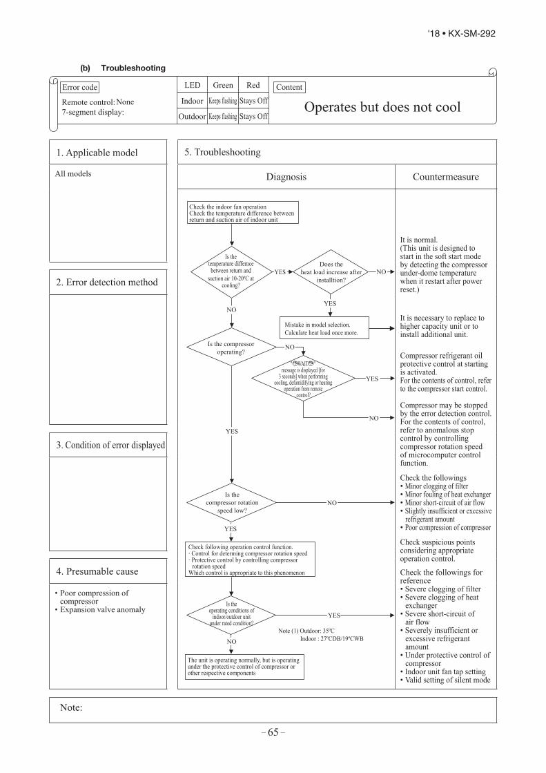
– 65 –
'18 • KX-SM-292
2.3 Contents of troubleshooting(a) List of inspection displays
1) Indoor and outdoor unitsRemote control
error code7-segment
display Name of inspection Classification Page
E1 – Remote control communication error Communication error 81E2 – Duplicated indoor unit address Address setting error 82E3 – Outdoor unit signal line error Address pairing setting error 83E5 – Communication error during operation Communication error 84E6 – Indoor unit heat exchanger temperature sensor anomaly (Thi-R) Sensor wire breakage 85E7 – Indoor return air temperature sensor anomaly (Thi-A) Sensor wire breakage 86E9 – Drain trouble System error 87
E10 – Excessive number of indoor units (more than 17 units) by controlling one remote control Communication error 88
E12 – Address setting error by mixed setting method Address setting error 89
E16– Indoor fan motor anomaly (FDT series) DC fan motor error 90– Indoor fan motor anomaly (FDK series) DC fan motor error 91
E19 – Indoor unit operation check drain pump motor check mode anomaly Setting error 92E28 – Remote control temperature sensor anomaly (Thc) Sensor wire breakage 93E30 E30 Unmatch connection of indoor and outdoor unit System error 94E31 E31 Duplicated outdoor unit address No. Address setting error 95E32 E32 Open L3 Phase on power source at primary side Site setting error 96
E36E36-1 Discharge pipe temperature error (Tho-D1) System error 97E36-3 Liquid flooding anomaly System error 98
E37 E37-1, 2E37-5, 6
Outdoor unit heat exchanger temperature sensor (Tho-R) and subcooling coil temperature sensor (Tho-SC, -H) anomaly
Sensor wire breakage 99
E38 E38 Outdoor air temperature sensor anomaly (Tho-A) Sensor wire breakage 100E39 E39-1 Discharge pipe temperature sensor anomaly (Tho-D1) Sensor wire breakage 101E40 E40 High pressure anomaly (63H1-1 activated) System error 102
E41 (E51) E41 (E51)-1 Power transister overheat System error 103E42 E42-1 Current cut (CM1) System error 104
E43 E43-1E43-2
Excessive number of indoor units connected, excessive total capacity of connection Site setting erro
E45 E45-1 Communication error between inverter PCB and outdoor unit control (PCB) Communication error
E46 E46 Mixed address setting methods coexistent in same network Address setting error
E48 E48-1E48-2 Outdoor unit DC fan motor anomaly DC fan motor error
E49 E49 Low pressure anomaly System error 109
E53/E55 E53/E55-1 Suction pipe temperature sensor anomaly (Tho-S), Under-dome temperature sensor anomaly (Tho-C1)
Sensor wire breakage 110
E54 E54-1E54-2
High pressure sensor anomaly (PSH)/Low pressure sensor anomaly (PSL)
Sensor wire breakage 111
E56 E56-1 Power transitor temperature sensor anomaly (Tho-P1) Sensor wire breakage 112E58 E58-1 Anomalous compressor by loss of synchronism System error 113E59 E59-1 Compressor startup failure (CM1) System error 114E60 E60-1 Rotor position detection failure (CM1) System error 115E63 E63 Emergency stop Site setting error
2) Option control in-use
SL1N-ESL2NA-ESL4-AE/BE
Indoor unit control PCB
Outdoor unit control PCB Location of
trouble Description of trouble Repair methodError
codeRedLED
RedLED
GreenLED
RedLED
GreenLED
E75 Keeps flashing
Stays OFF
Keeps flashing
Stays OFF
Keep flashing
・Communication enor (Deflective comm-unication circuit on the main unit ofSL1N-E, SL2NA-E or SL4-AE/BE)
ReplacementSL1N-ESL2NA-ESL4-AE/BE
106
107
105
108
116
(b) Troubleshooting
Error code
Remote control:7-segment display:
LED Green Red
Indoor
Outdoor
Content
None Operates but does not coolKeeps flashing Stays Off
Keeps flashing Stays Off
1. Applicable model 5. Troubleshooting
All models Diagnosis Countermeasure
NO
YES
YES
NO
YES
YES
YES
NO
NO
NO
YES
NO
Check the indoor fan operation Check the temperature difference between return and suction air of indoor unit
Mistake in model selection. Calculate heat load once more.
Check following operation control function. . Control for determing compressor rotation speed . Protective control by controlling compressor
rotation speed Which control is appropriate to this phenomenon
The unit is operating normally, but is operating under the protective control of compressor or other respective components
Is the temperature differncebetween return and
suction air 10-20ºC at cooling?
Does the heat load increase after
installtion?
Is the compressor operating?
Is the compressor rotation
speed low?
Is the operating conditions of
indoor/outdoor unit under rated condition?
" WAIT " message is displayed [for
3 seconds] when performing cooling, defumidifying or heating
operation from remote control?
Note (1) Outdoor: 35ºCIndoor : 27ºCDB/19ºCWB
It is normal.(This unit is designed to start in the soft start mode by detecting the compressor under-dome temperature when it restart after power reset.)
It is necessary to replace to higher capacity unit or to install additional unit.
Compressor refrigerant oil protective control at starting is activated.For the contents of control, refer to the compressor start control.
Compressor may be stopped by the error detection control.For the contents of control, refer to anomalous stop control by controlling compressor rotation speed of microcomputer control function.
Check the followings• Minor clogging of filter • Minor fouling of heat exchanger• Minor short-circuit of air flow• Slightly insufficient or excessive
refrigerant amount• Poor compression of compressor
Check suspicious points considering appropriate operation control.
Check the followings for reference• Severe clogging of filter• Severe clogging of heat
exchanger• Severe short-circuit of
air flow• Severely insufficient or
excessive refrigerant amount
• Under protective control ofcompressor
• Indoor unit fan tap setting• Valid setting of silent mode
2. Error detection method
3. Condition of error displayed
4. Presumable cause
• Poor compression ofcompressor
• Expansion valve anomaly
Note:
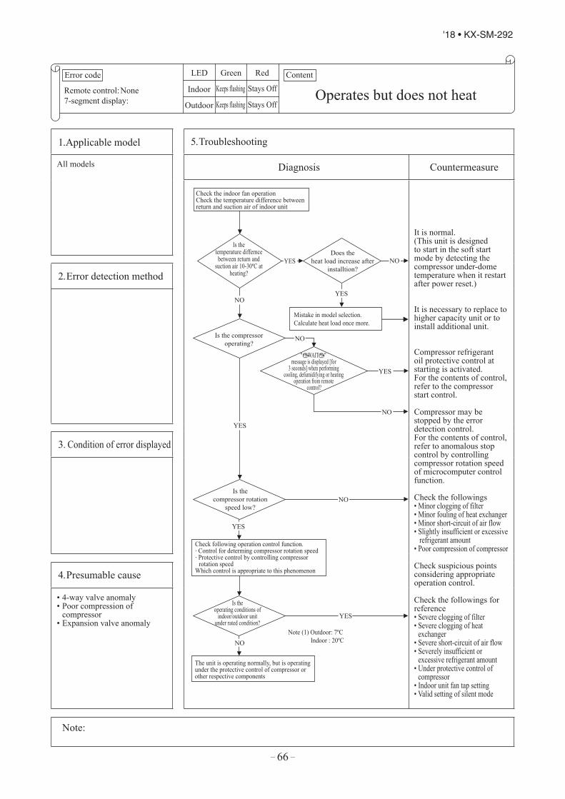
– 66 –
'18 • KX-SM-292
Error code
Remote control:7-segment display:
LED Green Red
Indoor
Outdoor
Content
None Operates but does not heatKeeps flashing Stays Off
Keeps flashing Stays Off
1. Applicable model 5. Troubleshooting
All models Diagnosis Countermeasure
NO
YES
YES
NO
YES
YES
YES
NO
NO
NO
YES
NO
Check the indoor fan operation Check the temperature difference between return and suction air of indoor unit
Mistake in model selection. Calculate heat load once more.
Check following operation control function. . Control for determing compressor rotation speed . Protective control by controlling compressor
rotation speed Which control is appropriate to this phenomenon
The unit is operating normally, but is operating under the protective control of compressor or other respective components
Is the temperature differncebetween return and
suction air 10-30ºC at heating?
Does the heat load increase after
installtion?
Is the compressor operating?
Is the compressor rotation
speed low?
Is the operating conditions of
indoor/outdoor unit under rated condition?
" WAIT " message is displayed [for
3 seconds] when performing cooling, defumidifying or heating
operation from remote control?
Note (1) Outdoor: 7ºCIndoor : 20ºC
It is normal.(This unit is designed to start in the soft start mode by detecting the compressor under-dome temperature when it restart after power reset.)
It is necessary to replace to higher capacity unit or to install additional unit.
Compressor refrigerant oil protective control at starting is activated.For the contents of control, refer to the compressor start control.
Compressor may be stopped by the error detection control.For the contents of control, refer to anomalous stop control by controlling compressor rotation speed of microcomputer control function.
Check the followings• Minor clogging of filter • Minor fouling of heat exchanger• Minor short-circuit of air flow• Slightly insufficient or excessive
refrigerant amount• Poor compression of compressor
Check suspicious points considering appropriate operation control.
Check the followings for reference• Severe clogging of filter• Severe clogging of heat
exchanger • Severe short-circuit of air flow• Severely insufficient or
excessive refrigerant amount• Under protective control of
compressor• Indoor unit fan tap setting• Valid setting of silent mode
2. Error detection method
3. Condition of error displayed
4. Presumable cause
• 4-way valve anomaly• Poor compression of
compressor• Expansion valve anomaly
Note:

– 67 –
'18 • KX-SM-292
Error code
Remote control:7-segment display:
LED Green Red
Indoor
Outdoor
Content
None Operates but does not heatKeeps flashing Stays Off
Keeps flashing Stays Off
1. Applicable model 5. Troubleshooting
All models Diagnosis Countermeasure
NO
YES
YES
NO
YES
YES
YES
NO
NO
NO
YES
NO
Check the indoor fan operation Check the temperature difference between return and suction air of indoor unit
Mistake in model selection. Calculate heat load once more.
Check following operation control function. . Control for determing compressor rotation speed . Protective control by controlling compressor
rotation speed Which control is appropriate to this phenomenon
The unit is operating normally, but is operating under the protective control of compressor or other respective components
Is the temperature differncebetween return and
suction air 10-30ºC at heating?
Does the heat load increase after
installtion?
Is the compressor operating?
Is the compressor rotation
speed low?
Is the operating conditions of
indoor/outdoor unit under rated condition?
" WAIT " message is displayed [for
3 seconds] when performing cooling, defumidifying or heating
operation from remote control?
Note (1) Outdoor: 7ºCIndoor : 20ºC
It is normal.(This unit is designed to start in the soft start mode by detecting the compressor under-dome temperature when it restart after power reset.)
It is necessary to replace to higher capacity unit or to install additional unit.
Compressor refrigerant oil protective control at starting is activated.For the contents of control, refer to the compressor start control.
Compressor may be stopped by the error detection control.For the contents of control, refer to anomalous stop control by controlling compressor rotation speed of microcomputer control function.
Check the followings• Minor clogging of filter • Minor fouling of heat exchanger• Minor short-circuit of air flow• Slightly insufficient or excessive
refrigerant amount• Poor compression of compressor
Check suspicious points considering appropriate operation control.
Check the followings for reference• Severe clogging of filter• Severe clogging of heat
exchanger • Severe short-circuit of air flow• Severely insufficient or
excessive refrigerant amount• Under protective control of
compressor• Indoor unit fan tap setting• Valid setting of silent mode
2. Error detection method
3. Condition of error displayed
4. Presumable cause
• 4-way valve anomaly• Poor compression of
compressor• Expansion valve anomaly
Note:
Error code
Remote control:7-segment display:
LED Green Red
Indoor
Outdoor
Content
None Earth leakage breaker activatedStays Off Stays Off
Stays Off Stays Off
1. Applicable model 5. Troubleshooting
All models Diagnosis Countermeasure
NO
NOIs insulation
of respective harnesses OK?
YES
Check of the outdoor unit grounding wire and earth leakage breaker
① Run an independent grounding wire from the grounding screwof outdoor unit to the grounding terminal on the distribution
panel. (Do not connect to another grounding wire.)② In order to prevent malfunction of the earth leakage breaker
itself, confirm the conformity of high harmonic regulation.
* Insulation resistance of compressor• Immediately after installation or when the unit has been left
for long period without power source, the insulationresistance may drop to a few MkΩ because of refrigerantmigrated in the compressor.When the earth leakage breaker is activated at lower insulationresistance, check the following points.
① 6 hours after power ON, check if the insulation resistance recovers to normal. When power ON, crankcase heater heat up compressor and evaporates the refrigerant migrated in the compressor.
② Check if the earth leakage breaker is conformed to higher harmonic regulation or not.Since the unit has inverter, it is necessary to use components
conformed to high harmonic regulation in order to prevent malfunction of earth leakage breaker.
YES
Check the outdoor unit groundingwire and earth leakage breaker
Is any hamess bittenbetween pannel and casing
or etc.?
NO
YES
Are the insulation resistance
and and coil resistance of compressor OK?
Replace compressor. *
Secure insulation resistance.
Secure insulationresistance.
2. Error detection method
3. Condition of error displayed
4. Presumable cause
• Compressor anomaly• Noise
Note:

– 68 –
'18 • KX-SM-292
Error code
Remote control:7-segment display:
LED Green Red
Indoor
Outdoor
Content
None Excessive noise/vibration (1/3)– –
– –
1. Applicable model 5. Troubleshooting
All models Diagnosis Countermeasure
Does the installation
of indoor/outdoor unit have looseness?
[Installation work]Does the noise/vibrationoccur not only from the
air-conditionerbut also from
entire building?
[Units]Does noise/vibration
occur when only the fan is operating?
Are pipes touching the wall
and etc?
Is fan or louver touching other components?
To 2/3
NO
NO
NO
NO
NO
NO
YES
YES
YES
YES
YES YES
Does noise/vibration occur during or soon after stopping
operation of air-conditioner?
If excessive noise/vibration persists when sufficienttime has elapsed after stopping the unit, it is considered that the air-conditioner is not the source.
Check the installed condition carefully, and correct the installed position or insert rubber cushions into the gap or take other measure in order to eliminate looseness.
Prevent the vibration from transmitting to wall and etc by fixing pipes on the walltightly or wrapping rubber cushion around the pipe which goes through the hole in the wall or applying other appropriate means.
Strength of ceiling wall, floo , etc. may be insufficient. Review theinstallation place or apply reinforcement to increase the strength.
Check for leaning of installed unit or incorrect mounting of fan, louver or motor, and then specify the contacting point and correct it.
When th eheat exchanger or filter is clogged, cleanthem.In case that the unit is installed at the site where background noise is very low, even the low level noise from indoor unit like as refrigerant flow noisecan be heard, but it is normal.Before installation, check for background noise. If background noise is very low, convince client prior to installation.
2. Error detection method
3. Condition of error displayed
4. Presumable cause
① Improper installation work・ Improper vibration-proof
work at instllation・ Insufficient strength of
mounting surface② Anomaly of product
・ Before/after shipment fromfactory
③ Improper adjustment duringcommissioning・ Excessive/insufficient
refrigerant.
Note:

– 69 –
'18 • KX-SM-292
Error code
Remote control:7-segment display:
LED Green Red
Indoor
Outdoor
Content
None Excessive noise/vibration (1/3)– –
– –
1. Applicable model 5. Troubleshooting
All models Diagnosis Countermeasure
Does the installation
of indoor/outdoor unit have looseness?
[Installation work]Does the noise/vibrationoccur not only from the
air-conditionerbut also from
entire building?
[Units]Does noise/vibration
occur when only the fan is operating?
Are pipes touching the wall
and etc?
Is fan or louver touching other components?
To 2/3
NO
NO
NO
NO
NO
NO
YES
YES
YES
YES
YES YES
Does noise/vibration occur during or soon after stopping
operation of air-conditioner?
If excessive noise/vibration persists when sufficienttime has elapsed after stopping the unit, it is considered that the air-conditioner is not the source.
Check the installed condition carefully, and correct the installed position or insert rubber cushions into the gap or take other measure in order to eliminate looseness.
Prevent the vibration from transmitting to wall and etc by fixing pipes on the walltightly or wrapping rubber cushion around the pipe which goes through the hole in the wall or applying other appropriate means.
Strength of ceiling wall, floo , etc. may be insufficient. Review theinstallation place or apply reinforcement to increase the strength.
Check for leaning of installed unit or incorrect mounting of fan, louver or motor, and then specify the contacting point and correct it.
When th eheat exchanger or filter is clogged, cleanthem.In case that the unit is installed at the site where background noise is very low, even the low level noise from indoor unit like as refrigerant flow noisecan be heard, but it is normal.Before installation, check for background noise. If background noise is very low, convince client prior to installation.
2. Error detection method
3. Condition of error displayed
4. Presumable cause
① Improper installation work・ Improper vibration-proof
work at instllation・ Insufficient strength of
mounting surface② Anomaly of product
・ Before/after shipment fromfactory
③ Improper adjustment duringcommissioning・ Excessive/insufficient
refrigerant.
Note:
Error code
Remote control:7-segment display:
LED Green Red
Indoor
Outdoor
Content
None Excessive noise/vibration (2/3)– –
– –
1. Applicable model 5. Troubleshooting
All models Diagnosis Countermeasure
[Unit]Does noise/vibration
occur when the cooling/heating operation is
performingnormally?
Are the pipes contacting with the
casing?
Is continuous hissing or roaring sound
occurred?
From 1/3
To 3/3 Is hissing sounds
occurred at the startup or stopping?
Is blowing sound occurred at
the start/stop of defrost operation during
heating mode?
Is cracking noise occurred during heating
operation?
Is hissing noise occurred
during cooling operation or after operation
stopped?
YES
Rearrange the piping to avoid contact with the casing.
Noise/vibration is generated when the refrigerant gas or liquid flows through inside ofpiping of air-conditioner. It is likely to occur particularly during cooling or defrost operation in the heating mode. It is normal.
The noise/vibration occurs when the refrigerant starts or stops flowing. It isnormal.
When the defrost operationstarts or stops during heating mode, the refrigerant flow is reversed due toswitching 4-way valve. This causes a large change in pressure wich produces a blowing sound. It may also accompany the hissing sound as mentioned above.This is normal.
After the start or stop of heating operation or during defrost operation, abrupt changes in temperature causeresin parts to shrink or expand. This is normal.
It is the sound produced by the drain pump that discharges drain from indoor unit.The pump continues to run for 5 minutes after stopping the cooling operation.This is normal.
Apply the damper sealant at the place considered to be the sources such as the pressure reducing mechanism. (Expansion valve, capillary tube, etc.)
2. Error detection method
3. Condition of error displayed
4. Presumable cause
Note:
NO
NO
NO
NO
NO
NO
YES
YES
YES
YES
YES
YES
NO

– 70 –
'18 • KX-SM-292
Error code
Remote control:7-segment display:
LED Green Red
Indoor
Outdoor
Content
None Excessive noise/vibration (3/3)– –
– –
1. Applicable model 5. Troubleshooting
All models Diagnosis Countermeasure
[Adjustment during commissioning]
Does noise/vibration occur when thecooling/heating operation isperformed under anomalous
condition?
From 2/3
YES
If insufficient coolingheating problem happens due to anomalous operating conditions at cooling /heating, followings are suspicious.
• Excessive chargedamount of refrigerant
• Insufficient chargeamount of refrigerant
• Intrusion of air, nitrogen,etc.
In such case, it is necessary to recover refrigerant, vacuum-dry and recharge refrigerant.
* Since there could bemany causes of noise/vibration, the above maynot cover all.In such case, check theconditions when, where,how the noise/vibrationoccurs according tofollowing check points andask our consultation.
• Indoor/outdoor unit• Cooling/heating/fan
mode• Startup/stop/during
operation• Operating condition
(Indoor/outdoortemperatures andpressures)
• Time it occurred• Operation data retained
by remote controlor Mente PC such ascompressor rotationspeed, heat exchangertemperature, EEVopening degree and etc.
• Tone (If available, recordthe noise)
• Any other anomalies
2. Error detection method
3. Condition of error displayed
4. Presumable cause
Note:

– 71 –
'18 • KX-SM-292
Error code
Remote control:7-segment display:
LED Green Red
Indoor
Outdoor
Content
None Excessive noise/vibration (3/3)– –
– –
1. Applicable model 5. Troubleshooting
All models Diagnosis Countermeasure
[Adjustment during commissioning]
Does noise/vibration occur when thecooling/heating operation isperformed under anomalous
condition?
From 2/3
YES
If insufficient coolingheating problem happens due to anomalous operating conditions at cooling /heating, followings are suspicious.
• Excessive chargedamount of refrigerant
• Insufficient chargeamount of refrigerant
• Intrusion of air, nitrogen,etc.
In such case, it is necessary to recover refrigerant, vacuum-dry and recharge refrigerant.
* Since there could bemany causes of noise/vibration, the above maynot cover all.In such case, check theconditions when, where,how the noise/vibrationoccurs according tofollowing check points andask our consultation.
• Indoor/outdoor unit• Cooling/heating/fan
mode• Startup/stop/during
operation• Operating condition
(Indoor/outdoortemperatures andpressures)
• Time it occurred• Operation data retained
by remote controlor Mente PC such ascompressor rotationspeed, heat exchangertemperature, EEVopening degree and etc.
• Tone (If available, recordthe noise)
• Any other anomalies
2. Error detection method
3. Condition of error displayed
4. Presumable cause
Note:
Error code
Remote control:7-segment display:
LED Green Red
Indoor
Outdoor
Content
None Louver motor anomalyKeeps flashing Stays Off
Keeps flashing Stays Off
1. Applicable model 5. Troubleshooting
All models Diagnosis Countermeasure
NO
YES Is LM harness
broken?
Is there any disconnection
or breakage of LM connector?
Is LM locked?
Does LM turn smoothly?
Is there any problem on the connection
link?
˜Check at the indoor unit side.
Is the setting of air flow direction change
prohibited?
Check how LS reacts when the power is turned
OFF and ON again
Check the remote control whether it is fixed free flow setting.
YES
Does the louver link press LS till crick sound
can be heard?
NO
NO
YES
In cases of FDTW, FDTS and FDTQ
Does the louver operate when
power on?
Notes (1) LM: Louver motor (2) LS: Limit switch
YES
NO
NO
NO
NO
YES
Operate after waiting for more than 1 minute.
It is normal if LM can be stopped by pressing LS two times.
In cases of FDT, FDTC, FDE and FDK
Check the remote control whether it is fixed free flow setting or not.
Correct it.
Repair harness.Check connector (CnJ).Replace Louver Motor.
Correct it.
Correct it.
Replace indoor unit control PCB.
Correct it.
Adjust LM lever and then check again.
• LS anomalyReplace.• Indoor unit control PCB
anomalyReplace.
2. Error detection method
3. Condition of error displayed
4. Presumable cause
• Louver motor anomaly• Disconnection/breakage of
LM harness• Limit switch anomaly
Note:
NO
NO
NO
YES
YES

– 72 –
'18 • KX-SM-292
Error code
Remote control:7-segment display:
LED Green Red
Indoor
Outdoor
Content
None Power source system anomaly (Power source to indoor unit PCB)
Stays Off Stays Off
Stays Off 2 times flash
1. Applicable model 5. Troubleshooting
All models Diagnosis Countermeasure
YES
YES
YES
YES
YES
NO
NO
NO
NO
NO
NO
NO
YES
YES
Is AC 220-240V/220V
detected between L-N on the indoor unit terminal
block?
Note (2) Remove transformer for other than FDT and FDTC series (CnW1)
Note (3) LM: Louver motor FM: Fan motor
Note (4) ⑤ for GND
IsAC 380/415V
for 3-phase unit detectedbetween L1, L2 and L3 on the
outdoor unit terminal blockrespectively?
Are fuses OK? (2 pcs)
Is power supply between① -② of
CnW0 OK?
IsDC5V detected
between ③- ④ ofCnW2?
Is power source to FM, LM and etc.
OK?
Note (1) FDT and FDTC series: F200, F201 Other than FDT and FDTC: Fuse between wires
(1)
(2)
(3)
(4)
Other than FDT and FDTC series
FDT and FDTC series
Is DC18V or higherdetected between Red-
Red (CnW2) at thetransformer secondary
side?
Outdoor noise filter PCBanomaly Replace it.
Wrong wiring or broken wires between outdoor and indoor units
Indoor unit power PCBanomaly Replace it.
Replace FM, LM and etc.
Replace fuse.
Indoor unit power PCB anomaly Replace it.
Indoor unit control PCB anomaly Replace it.
Replace transformer.
Indoor unit control PCB anomaly Replace it.
2. Error detection method
3. Condition of error displayed
4. Presumable cause
• Wrong connection or breakageof connecting wires
• Blown fuse• Transformer anomaly• Indoor unit power PCB anomaly• Broken harness• Indoor unit control PCB anomaly
Note:

– 73 –
'18 • KX-SM-292
Error code
Remote control:7-segment display:
LED Green Red
Indoor
Outdoor
Content
None Power source system anomaly (Power source to indoor unit PCB)
Stays Off Stays Off
Stays Off 2 times flash
1. Applicable model 5. Troubleshooting
All models Diagnosis Countermeasure
YES
YES
YES
YES
YES
NO
NO
NO
NO
NO
NO
NO
YES
YES
Is AC 220-240V/220V
detected between L-N on the indoor unit terminal
block?
Note (2) Remove transformer for other than FDT and FDTC series (CnW1)
Note (3) LM: Louver motor FM: Fan motor
Note (4) ⑤ for GND
IsAC 380/415V
for 3-phase unit detectedbetween L1, L2 and L3 on the
outdoor unit terminal blockrespectively?
Are fuses OK? (2 pcs)
Is power supply between① -② of
CnW0 OK?
IsDC5V detected
between ③- ④ ofCnW2?
Is power source to FM, LM and etc.
OK?
Note (1) FDT and FDTC series: F200, F201 Other than FDT and FDTC: Fuse between wires
(1)
(2)
(3)
(4)
Other than FDT and FDTC series
FDT and FDTC series
Is DC18V or higherdetected between Red-
Red (CnW2) at thetransformer secondary
side?
Outdoor noise filter PCBanomaly Replace it.
Wrong wiring or broken wires between outdoor and indoor units
Indoor unit power PCBanomaly Replace it.
Replace FM, LM and etc.
Replace fuse.
Indoor unit power PCB anomaly Replace it.
Indoor unit control PCB anomaly Replace it.
Replace transformer.
Indoor unit control PCB anomaly Replace it.
2. Error detection method
3. Condition of error displayed
4. Presumable cause
• Wrong connection or breakageof connecting wires
• Blown fuse• Transformer anomaly• Indoor unit power PCB anomaly• Broken harness• Indoor unit control PCB anomaly
Note:
Error code
Remote control:7-segment display:
LED Green Red
Indoor
Outdoor
Content
None Power source system error
(Power source to remote control)Stays Off Keeps lighting
Stays Off Keeps lighting
1. Applicable model 5. Troubleshooting
All models Diagnosis Countermeasure
Isn't there any loose connection of remote
control wires?
Isn't remote control wire broken or
short-circuited?
Is 23V or higher detected
between Brown-Brown at the transformer secondary
side?
Is DC18V
detected between ①-② of CNW2?
Disconnect the remote control
wires.
NO
Is DC15V or higher detected between X-Y of indoor unit terminal
block?
Other than FDT and FDTC Series
FDT and FDTC Series
YES
YES
YES
YES
NO
NO
YES
NO
NO
Correct it.
Replace wires.
Replace remote control.
Indoor unit power PCBanomaly Replace it.
Indoor unit control PCB anomaly Replace it.
Replace transformer.
Indoor unit control PCB anomaly Replace it.
2. Error detection method
3. Condition of error displayed
4. Presumable cause
• Remote control wire breakage/short-circuit
• Remote control anomaly• Malfunction by noise• Indoor unit power PCB anomaly• Broken harness
Note:

– 74 –
'18 • KX-SM-292
Error code
Remote control:7-segment display:
LED Green Red
Indoor
Outdoor
Content
WAITWAIT (1)
Keeps flashing Stays Off
Keeps flashing Keeps flashing
1. Applicable model 5. Troubleshooting
All models
(In case that is kept on displaying on the remote controller for more than 2 minutes after power ON)
Diagnosis Countermeasure
NO
NO
NO
NO
NO
NO
NO
YES
NO
NO
YES
YES
YES
YES
YES
YES
YES
is kept on displaying on the remote control for more than 2 minutes after power ON
Once turn OFF the breakerand turn ON it again at 3minute after power OFF
Isn't the power fuse (5A) on theoutdoor unit control PCB
blown?
Isthe connection of wire
between noise filter andinverter PCBs OK?
Arethe wires between indoor
and outdoor unitsconnected properly ?
IsAC220-240V detected
between L-N at indoor unitteminal block?
IsAC380-415V detected
between L1-L2, L2-L3, L3-L1 respectively at outdoor unit
terminal block?
Doesindoor green LED keep
flashing?
Doesindoor green LED flash
2 times?
IsAC380-415V detected at
the secondary side ofnoise filter PCB terminal?
Does it become normal?
Replace fuse
WAIT
Refer next page
Replace noise filter PCB.
Connect wires correctly.
Indoor unit control PCB anomaly Replace it.
Indoor/outdoor unit control PCB anomaly Replace it.Remote control anomaly Replace it.Breakage of connecting wiresof remote control Replace it.Correct the connecting wires between indoor and outdoor units.
Outdoor unit control PCB anomaly Replace it.
Breakage of connecting wire.Noise
Indoor unit control PCB anomaly Replace it.
2. Error detection method
3. Condition of error displayed
4. Presumable cause
• Fuse blown• Noise filter anomaly• Anomalous connection of
wire between PCBs• Indoor unit control PCB anomaly• Remote control anomaly• Breakage of connecting wires
of remote control• Outdoor unit control PCB anomaly
Note: (1) When anomaly occurs during establishing communication betweeen indoor and outdoor unit, error code E5 is displayed (outdoor red LED flash 2-time)In case of E5, the way of troubleshooting is same as above mentioned (except for checking of connecting wire)When reset the power after E5 occurs, if this anomaly recurs, WAIT is displayed on remote control. If power ON/OFF is repeated in a short period (within 1 minute), WAIT may be displayed. In such case, please wait for 3 minute after the power breaker OFF.
(2) If any error is detected 30 minutes after displaying WAIT on the remote control, the display changes to INSPECT I/U .
WAIT

– 75 –
'18 • KX-SM-292
Error code
Remote control:7-segment display:
LED Green Red
Indoor
Outdoor
Content
WAITWAIT (1)
Keeps flashing Stays Off
Keeps flashing Keeps flashing
1. Applicable model 5. Troubleshooting
All models
(In case that is kept on displaying on the remote controller for more than 2 minutes after power ON)
Diagnosis Countermeasure
NO
NO
NO
NO
NO
NO
NO
YES
NO
NO
YES
YES
YES
YES
YES
YES
YES
is kept on displaying on the remote control for more than 2 minutes after power ON
Once turn OFF the breakerand turn ON it again at 3minute after power OFF
Isn't the power fuse (5A) on theoutdoor unit control PCB
blown?
Isthe connection of wire
between noise filter andinverter PCBs OK?
Arethe wires between indoor
and outdoor unitsconnected properly ?
IsAC220-240V detected
between L-N at indoor unitteminal block?
IsAC380-415V detected
between L1-L2, L2-L3, L3-L1 respectively at outdoor unit
terminal block?
Doesindoor green LED keep
flashing?
Doesindoor green LED flash
2 times?
IsAC380-415V detected at
the secondary side ofnoise filter PCB terminal?
Does it become normal?
Replace fuse
WAIT
Refer next page
Replace noise filter PCB.
Connect wires correctly.
Indoor unit control PCB anomaly Replace it.
Indoor/outdoor unit control PCB anomaly Replace it.Remote control anomaly Replace it.Breakage of connecting wiresof remote control Replace it.Correct the connecting wires between indoor and outdoor units.
Outdoor unit control PCB anomaly Replace it.
Breakage of connecting wire.Noise
Indoor unit control PCB anomaly Replace it.
2. Error detection method
3. Condition of error displayed
4. Presumable cause
• Fuse blown• Noise filter anomaly• Anomalous connection of
wire between PCBs• Indoor unit control PCB anomaly• Remote control anomaly• Breakage of connecting wires
of remote control• Outdoor unit control PCB anomaly
Note: (1) When anomaly occurs during establishing communication betweeen indoor and outdoor unit, error code E5 is displayed (outdoor red LED flash 2-time)In case of E5, the way of troubleshooting is same as above mentioned (except for checking of connecting wire)When reset the power after E5 occurs, if this anomaly recurs, WAIT is displayed on remote control. If power ON/OFF is repeated in a short period (within 1 minute), WAIT may be displayed. In such case, please wait for 3 minute after the power breaker OFF.
(2) If any error is detected 30 minutes after displaying WAIT on the remote control, the display changes to INSPECT I/U .
WAIT
Error code
Remote control:7-segment display:
LED Green Red
Indoor
Outdoor
Content
WAITWAIT (2)
Keeps flashing Stays Off
Keeps flashing Keeps flashing
1. Applicable model 5. Troubleshooting
All models
(In case of fuse blown, how to check the unit before replacement of fuse)
Diagnosis Countermeasure
YES
YES
NO
NO
YES
NO
Isn't there any short circuit
between phases of noise filter?
Isn't there any crack or damage
on power transistor module or diode stack?
Isn't there any anomaly on
reactor?
Replace noise filter
Replace reactor
Replace inverter PCB
Replace fuse.
2. Error detection method
3. Condition of error displayed
4. Presumable cause
• Fuse blown• Noise filter anomaly• Anomalous connection of
wire between PCBs• Indoor unit control PCB anomaly• Remote control anomaly• Breakage of connecting wires
of remote control• Outdoor unit control PCB anomaly
Note:

– 76 –
'18 • KX-SM-292
Error code
Remote control:7-segment display:
LED Green Red
Indoor
Outdoor
Content
WAITWAIT (3)
Keeps flashing Stays Off
Keeps flashing Keeps flashing
1. Applicable model 5. Troubleshooting
All models
(No display on the remote control after power ON)
Diagnosis Countermeasure
NO
NO
NO
NO
NO
NO
NO
NO
YES
YES
YES
YES
YES
No display on the remote control after power ON
Does indoor green LED keep
flashing?
Does outdoor red LED flash
2-times?
Is the connecting wires
between indoor and outdoor units comnnected
properly?
Is AC380-415V detected
between L1-L2, L2-L3, L3-L1respectively at outdoor unit
terminal block?
Is AC220-240V detected
between L-N at indoor unitteminal block?
Is The fuse on indoor unit control
PCB OK?
Is AC18V or higher is
detected between Red-Redat secondary side of indoor unit
transformer? (1)
Is DC10-11V between
X-Y at indoor unit control PCB side when removing
remote control ?
Note (1) except FDT and FDTC
Fuse blown Replace fuse.
Transformer anomaly.
Remote control wire short-circuited.
Remote control anomaly.
Indoor unit control PCB anomaly.Remote control anomaly.Breakage of connecting wires of remote control
Correct the connecting wires properly.
Outdoor unit control PCB anomaly Replace it.
Breakage of connecting wire.Noise
Indoor unit control PCB anomaly Replace it.
2. Error detection method
3. Condition of error displayed
4. Presumable cause
• Fuse blown• Noise filter anomaly• Anomalous connection of
wire between PCBs• Indoor unit control PCB anomaly• Remote control anomaly• Breakage of connecting wires
of remote control• Outdoor unit control PCB anomaly
Note:
YES
YES
YES

– 77 –
'18 • KX-SM-292
Error code
Remote control:7-segment display:
LED Green Red
Indoor
Outdoor
Content
WAITWAIT (3)
Keeps flashing Stays Off
Keeps flashing Keeps flashing
1. Applicable model 5. Troubleshooting
All models
(No display on the remote control after power ON)
Diagnosis Countermeasure
NO
NO
NO
NO
NO
NO
NO
NO
YES
YES
YES
YES
YES
No display on the remote control after power ON
Does indoor green LED keep
flashing?
Does outdoor red LED flash
2-times?
Is the connecting wires
between indoor and outdoor units comnnected
properly?
Is AC380-415V detected
between L1-L2, L2-L3, L3-L1respectively at outdoor unit
terminal block?
Is AC220-240V detected
between L-N at indoor unitteminal block?
Is The fuse on indoor unit control
PCB OK?
Is AC18V or higher is
detected between Red-Redat secondary side of indoor unit
transformer? (1)
Is DC10-11V between
X-Y at indoor unit control PCB side when removing
remote control ?
Note (1) except FDT and FDTC
Fuse blown Replace fuse.
Transformer anomaly.
Remote control wire short-circuited.
Remote control anomaly.
Indoor unit control PCB anomaly.Remote control anomaly.Breakage of connecting wires of remote control
Correct the connecting wires properly.
Outdoor unit control PCB anomaly Replace it.
Breakage of connecting wire.Noise
Indoor unit control PCB anomaly Replace it.
2. Error detection method
3. Condition of error displayed
4. Presumable cause
• Fuse blown• Noise filter anomaly• Anomalous connection of
wire between PCBs• Indoor unit control PCB anomaly• Remote control anomaly• Breakage of connecting wires
of remote control• Outdoor unit control PCB anomaly
Note:
YES
YES
YES
Error code
Remote control:7-segment display:
LED Green Red
Indoor
Outdoor
Content
WAIT WAIT (4)
Keeps flashing Stays Off
Keeps flashing Keeps flashing
1. Applicable model 5. Troubleshooting
All models
(In case that is kept on displaying on the remote control for more than 2 minutes after power ON)
Diagnosis Countermeasure
NO
Does outdoor green LED keep
flashing?
is kept on displaying on the remote control for more than 2 minutes after power ON
Does indoor green LED keep
flashing?
Doesoutdoor red LED flash
2 times?
Are the wires between indoor
and outdoor units connected properly ?
Is AC380-415V detected
between L1-L2, L2-L3, L3-L1 respectively at outdoor unit
terminal block?
Is AC220-240V detected
between L-N at indoor unit teminal block?
NO
NO
NO
NO
NO
YES
YES
YES
YES
YES
YES
A
WAIT
Refer next page
Indoor unit control PCB anomaly Replace it.
Indoor unit control PCB anomaly Replace it.Remote control anomaly Replace it.Breakage of connecting wires of remote control Replace it.
Correct the connecting wires between indoor and outdoor units.
Outdoor unit control PCB anomaly Replace it.
Breakage of connecting wireNoiseIndoor unit control PCB anomaly Replace it.
2. Error detection method
3. Condition of error displayed
4. Presumable cause
• Fuse blown• Noise filter anomaly• Anomalous connection of
wire between PCBs• Indoor unit control PCB anomaly• Remote control anomaly• Breakage of connecting wires
of remote control• Outdoor unit control PCB anomaly
Note:
WAIT

– 78 –
'18 • KX-SM-292
Error code
Remote control:7-segment display:
LED Green Red
Indoor
Outdoor
Content
WAITWAIT (5)
Stays OFF Stays Off
Stays OFF Stays Off
1. Applicable model 5. Troubleshooting
All models
(In case that LED on outdoor unit control PCB stays OFF)
Diagnosis Countermeasure
In case that LED on outdoor unit control PCB stays
OFF
Ispower fuse (5A) on the
outdoor unit conrol PCBblown?
Is AC380-415V detected at secondary side of noise
filter?
Are connecting wires between
noise filter and inverter PCB connected properly?
Is the connection of
connecting wire of reactor OK?
Is there any anomaly on outdoor fan motor?
Once turn OFF the breaker and turn ON it again at 3 minute after power OFF
Does it become normal?
Check inverter before replacement of 52C
NO
NO
NO
NO
NO
NO
YES
YES
YES
YES
YES
YES
A
B
Normal(Malfunction by temporary noise)
Refer next page
Replace noise filter.
Connect the connecting wire properly.
Correct connection.(In case of breakage of wire replace it)
Outdoor unit control PCB anomaly Replace it.
Outdoor unit fan motoranomaly Replace it.
2. Error detection method
3. Condition of error displayed
4. Presumable cause
• Fuse blown• Noise filter anomaly• Anomalous connection of
wire between PCBs• Indoor unit control PCB anomaly• Remote control anomaly• Breakage of connecting wires
of remote control• Outdoor unit control PCB anomaly
Note:

– 79 –
'18 • KX-SM-292
Error code
Remote control:7-segment display:
LED Green Red
Indoor
Outdoor
Content
WAITWAIT (5)
Stays OFF Stays Off
Stays OFF Stays Off
1. Applicable model 5. Troubleshooting
All models
(In case that LED on outdoor unit control PCB stays OFF)
Diagnosis Countermeasure
In case that LED on outdoor unit control PCB stays
OFF
Ispower fuse (5A) on the
outdoor unit conrol PCBblown?
Is AC380-415V detected at secondary side of noise
filter?
Are connecting wires between
noise filter and inverter PCB connected properly?
Is the connection of
connecting wire of reactor OK?
Is there any anomaly on outdoor fan motor?
Once turn OFF the breaker and turn ON it again at 3 minute after power OFF
Does it become normal?
Check inverter before replacement of 52C
NO
NO
NO
NO
NO
NO
YES
YES
YES
YES
YES
YES
A
B
Normal(Malfunction by temporary noise)
Refer next page
Replace noise filter.
Connect the connecting wire properly.
Correct connection.(In case of breakage of wire replace it)
Outdoor unit control PCB anomaly Replace it.
Outdoor unit fan motoranomaly Replace it.
2. Error detection method
3. Condition of error displayed
4. Presumable cause
• Fuse blown• Noise filter anomaly• Anomalous connection of
wire between PCBs• Indoor unit control PCB anomaly• Remote control anomaly• Breakage of connecting wires
of remote control• Outdoor unit control PCB anomaly
Note:
Error code
Remote control:7-segment display:
LED Green Red
Indoor
Outdoor
Content
WAITWAIT (6)
Stays Off Stays Off
Stays Off Stays Off
1. Applicable model 5. Troubleshooting
All models
(In case of fuse blown, how to check the unit before replacement of fuse)
Diagnosis Countermeasure
Isn't there any short circuit
between phases of noise filter?
Replace Noise filter
Replace inverter PCB
Replace power fuse
Replace electrolytic capacitor
Replace reactor
Isn't there any short circuit
between phases at input terminal of inverter
PCB?
Isn't there any crack or damage on power transistor module
or diode stack?
Isn't there any anomaly on
reactor?
Isn't there any anomaly on electrolytic capacitor?
YES
YES
YES
YES
YES
NO
NO
NO
NO
NO
B
2. Error detection method
3. Condition of error displayed
4. Presumable cause
• Fuse blown• Noise filter anomaly• Anomalous connection of
wire between PCBs• Indoor unit control PCB anomaly• Remote control anomaly• Breakage of connecting wires
of remote control• Outdoor unit control PCB anomaly
Note:

– 80 –
'18 • KX-SM-292
Error code
Remote control:7-segment display:
LED Green Red
Indoor
Outdoor
Content
〔No display〕 [No display] Stays OFF Stays Off
Stays OFF Stays Off
1. Applicable model 5. Troubleshooting
All models
(No display on the remote control after power ON)
Diagnosis Countermeasure
NO
NO
NO
YES
YES
YES
No display on the remote control after power ON
Is DC10V or higher between X-Y
detected at remote control terminal?
Is DC10V or higher between X-Y
wires detected when removing remote
control?
Are connecting wires between indoor and outdoor units
connected properly?
Remote control anomaly.
Remote control anomaly.
Correct connecting wire.
Indoor unit control PCB anomaly
2. Error detection method
3. Condition of error displayed
4. Presumable cause
• Fuse blown• Noise filter anomaly• Anomalous connection of
wire between PCBs• Indoor unit control PCB anomaly• Remote control anomaly• Breakage of connecting wires
of remote control• Outdoor unit control PCB anomaly
Note:

– 81 –
'18 • KX-SM-292
Error code
Remote control:7-segment display:
LED Green Red
Indoor
Outdoor
Content
〔No display〕 [No display] Stays OFF Stays Off
Stays OFF Stays Off
1. Applicable model 5. Troubleshooting
All models
(No display on the remote control after power ON)
Diagnosis Countermeasure
NO
NO
NO
YES
YES
YES
No display on the remote control after power ON
Is DC10V or higher between X-Y
detected at remote control terminal?
Is DC10V or higher between X-Y
wires detected when removing remote
control?
Are connecting wires between indoor and outdoor units
connected properly?
Remote control anomaly.
Remote control anomaly.
Correct connecting wire.
Indoor unit control PCB anomaly
2. Error detection method
3. Condition of error displayed
4. Presumable cause
• Fuse blown• Noise filter anomaly• Anomalous connection of
wire between PCBs• Indoor unit control PCB anomaly• Remote control anomaly• Breakage of connecting wires
of remote control• Outdoor unit control PCB anomaly
Note:
Error code
Remote control:7-segment display:
LED Green Red
Indoor
Outdoor
Content
E1-
Remote control communication error
Keeps flashing Stays Off
Keeps flashing Stays Off
1. Applicable model 5. Troubleshooting
All models Diagnosis Countermeasure
Is it possible to reset normally by the power
source reset?
Does the drain pump start automatically at one minutes after power
ON?
Turn SW7-1 OFF. ONDisconnect the wire ③
between indoor and outdoor units
YES
YES
NO Note (1) SW7-1: OFF ON
Note (2) Does the remote control displays “Internal check ON” even after 3 minutes?
Reset power source
(2)
(1)
NO
Malfunction by temporary noise.Check peripheral environment.
Indoor unit control PCB anomaly Replace it.
Remote control anomaly Replace it.
2. Error detection method
When normal communication between remote control and indoor unit is interrupted for more than 2 minutes (Detectable only with the remote control)
3. Condition of error displayed
Same as above
4. Presumable cause
• Anomalous communication circuit between remote control and indoor unit
• Noise
Note: If the indoor unit cannot communicate normally with the remote control for 180 seconds, the indoor unit PCB starts to reset automatically.
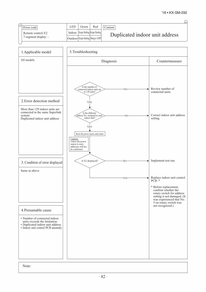
– 82 –
'18 • KX-SM-292
Error code
Remote control:7-segment display:
LED Green Red
Indoor
Outdoor
Content
E2- Duplicated indoor unit addressKeeps flashing Keeps flashing
Keeps flashing Stays Off
1. Applicable model 5. Troubleshooting
All models Diagnosis Countermeasure
Is the number of connected indoor units up
to 128 units?
Is the different address No. assigned to each
indoor unit?
Is E2 displayed?
Reset the power source and restart.
Caution:Unless the power source is reset, addresses will not be confirmed.
YES
NO
YES
NO
YES
NO
Review number of connected units.
Correct indoor unit address setting.
Implement test run.
Replace indoor unit control PCB. *
* Before replacement, confirm whether therotary switch for address setting is not damaged. (It was experienced that No. 5 on rotary switch was not recognized.)
2. Error detection method
More than 129 indoor units are connected in the same Superlink system.Duplicated indoor unit address
3. Condition of error displayed
Same as above
4. Presumable cause
• Number of connected indoorunits exceeds the limitation.
• Duplicated indoor unit address• Indoor unit control PCB anomaly
Note:

– 83 –
'18 • KX-SM-292
Error code
Remote control:7-segment display:
LED Green Red
Indoor
Outdoor
Content
E2- Duplicated indoor unit addressKeeps flashing Keeps flashing
Keeps flashing Stays Off
1. Applicable model 5. Troubleshooting
All models Diagnosis Countermeasure
Is the number of connected indoor units up
to 128 units?
Is the different address No. assigned to each
indoor unit?
Is E2 displayed?
Reset the power source and restart.
Caution:Unless the power source is reset, addresses will not be confirmed.
YES
NO
YES
NO
YES
NO
Review number of connected units.
Correct indoor unit address setting.
Implement test run.
Replace indoor unit control PCB. *
* Before replacement, confirm whether therotary switch for address setting is not damaged. (It was experienced that No. 5 on rotary switch was not recognized.)
2. Error detection method
More than 129 indoor units are connected in the same Superlink system.Duplicated indoor unit address
3. Condition of error displayed
Same as above
4. Presumable cause
• Number of connected indoorunits exceeds the limitation.
• Duplicated indoor unit address• Indoor unit control PCB anomaly
Note:
Error code
Remote control:7-segment display:
LED Green Red
Indoor
Outdoor
Content
E3/5- Outdoor unit signal line errorKeeps flashing 2 times flash
Keeps flashing Stays Off
1. Applicable model 5. Troubleshooting
All models Diagnosis Countermeasure
Is the power source to outdoor
unit OK?
Is the signal wires (betweenindoor - outdoor units)
connection OK?
Reset the power source and restart.
E3 is a communication error that occurs when communication betweenindoor and outdoor units is not established at all. Once the communicationbetween indoor and outdoor units is established, it changes to E5.In both cases, check signal wires (between indoor-outdoor units) locally.
YES
Is the outdoor unit address set on the indoor unit
OK?
YES
Is the LED on indoor unit control
PCB OK?
YES
Is protective fuse for the Superlink
circuit blown?
NO
Does E3/E5 occurs?
YES
NO
NO
NO
YES
YES
NO
NO
Temporary malfunction by noise.Identify the source of noise and correct it.
Change to spare circuit.
Indoor unit control PCB anomaly Replace it.
Correct it.
Correct it.
Correct it.
Outdoor unit control PCB anomaly Replace it.
2. Error detection method
No outdoor unit exists in the same Superlink system.
3. Condition of error displayed
Same as above
4. Presumable cause
• Power is not supplied to theoutdoor unit
• Unmatch of pairing betweenindoor and outdoor units
• Indoor unit control PCB anomaly• Outdoor unit control PCB anomaly• Missing local wiring
Note:

– 84 –
'18 • KX-SM-292
Error code
Remote control:7-segment display:
LED Green Red
Indoor
Outdoor
Content
E5- Communication error during operationKeeps flashing *See below
Keeps flashing 2 time flash
1. Applicable model 5. Troubleshooting
All models Diagnosis Countermeasure
Doesthe remote control LCD
becomes normal?
Reset the power source and restart.
YES
NO
* In case that indoor unit red LED stays OFF
Is the connection of signal wires
at the outdoor unit side OK?
Is the connection of signal wires
(between indoor and outdoor units) OK?
Does the remote control LCD
becomes normal?
Note (1) Check the connection (disconnection, looseness)of signal wires at outdoor unit terminal block
Reset the power source and restart.
Note (2) Check the connection (disconnection, looseness,brakage) of signal wires (between indoor andoutdoor units)
YES
NO
YES
NO
YES
NO
* In case that indoor unit red LED flashes 2 times
Repair signal wires.
Repair signal wires.
Go to the diagnosis of WAIT (1).
Unit is normal. (Malfunction by temporary noise, etc.)
Outdoor unit control PCB anomaly(Network communicaion circuit anomaly) → Replace it.Unit is normal. (Malfunction by temporary noise, etc.)
2. Error detection method
When the communication between indoor and outdoor units is interupted for more than 2 minutes
3. Condition of error displayed
When this anomaly is detected during operation.
4. Presumable cause
• Unit address No. setting error• Remote control wires broken• Poor connection/disconnection
of remote control wires• Indoor unit control PCB anomaly
Note: When the pump down switch is turned on, communication between indoor and outdoor units is cancelled so that "Communication error E5" will be displayed on the remote control and indoor unit control PCB, but this is normal.

– 85 –
'18 • KX-SM-292
Error code
Remote control:7-segment display:
LED Green Red
Indoor
Outdoor
Content
E5- Communication error during operationKeeps flashing *See below
Keeps flashing 2 time flash
1. Applicable model 5. Troubleshooting
All models Diagnosis Countermeasure
Doesthe remote control LCD
becomes normal?
Reset the power source and restart.
YES
NO
* In case that indoor unit red LED stays OFF
Is the connection of signal wires
at the outdoor unit side OK?
Is the connection of signal wires
(between indoor and outdoor units) OK?
Does the remote control LCD
becomes normal?
Note (1) Check the connection (disconnection, looseness)of signal wires at outdoor unit terminal block
Reset the power source and restart.
Note (2) Check the connection (disconnection, looseness,brakage) of signal wires (between indoor andoutdoor units)
YES
NO
YES
NO
YES
NO
* In case that indoor unit red LED flashes 2 times
Repair signal wires.
Repair signal wires.
Go to the diagnosis of WAIT (1).
Unit is normal. (Malfunction by temporary noise, etc.)
Outdoor unit control PCB anomaly(Network communicaion circuit anomaly) → Replace it.Unit is normal. (Malfunction by temporary noise, etc.)
2. Error detection method
When the communication between indoor and outdoor units is interupted for more than 2 minutes
3. Condition of error displayed
When this anomaly is detected during operation.
4. Presumable cause
• Unit address No. setting error• Remote control wires broken• Poor connection/disconnection
of remote control wires• Indoor unit control PCB anomaly
Note: When the pump down switch is turned on, communication between indoor and outdoor units is cancelled so that "Communication error E5" will be displayed on the remote control and indoor unit control PCB, but this is normal.
Error code
Remote control:7-segment display:
LED Green Red
Indoor
Outdoor
Content
E6-
Indoor unit heat exchangertemperature sensor anomaly (Thi-R)
Keeps flashing 1 time flash
Keeps flashing Stays Off
1. Applicable model 5. Troubleshooting
All models Diagnosis Countermeasure
Is the connector of sensor connected
properly ?
Regarding the characteristics of the sensor, see the following chart
Are the characteristics
of sensor OK?*1
NO
NO
YES
*1 Check several times to prove any poor connection
YES
Tem
pear
ture
sens
or re
sist
ance
(kΩ
)
Temperature-resistance characreristics of indoor unit heat exchanger temperature sensor (Thi-R1, R2, R3)
5kΩ at 25ºC
Temperature (ºC)
Insert the connector securely.
Replace sensor (Thi-R).
Replace indoor unit control PCB.
2. Error detection method
Detection of anomalously low temperature (resistance)of Thi-R1, R2, R3
3. Condition of error displayed
• If -50ºC or lower isdetected for 5 secondscontinuously, compressorstops. After 3 minutes delay,the compressor is restartedautomatically, but if thisanomaly occurs again within60 minutes after the initialdetection.
• Or if 70ºC or higher isdetected for 5 secondscontinuously.
4. Presumable cause
• Anomalous connecionof indoor unit heat exchangertemperature sensor
• Indoor unit heat exchangertemperature sensoranomaly
• Indoor unit control PCB anomaly
Note:

– 86 –
'18 • KX-SM-292
Error code
Remote control:7-segment display:
LED Green Red
Indoor
Outdoor
Content
E7-
Indoor return air temperature sensor anomaly (Thi-A)
Keeps flashing 1 time flash
Keeps flashing Stays Off
1. Applicable model 5. Troubleshooting
All models Diagnosis Countermeasure
Is the connector of sensor connected
properly ?
Regarding the characteristics of the sensor, see the following chart
Temperature-resistance characreristics of indoor return air temperature sensor (Thi-A)
Are the characteristics
of sensor OK?*1
NO
NO
YES
YES
*1 Check several times to prove any poor connection
15
10
5
0 10 30 40 20 50
Tem
pera
ture
sens
or re
sist
ance
(kΩ
)
Temperature (°C)
5kΩ at 25°C
Insert the connector securely.
Replace sensor (Thi-A).
Replace indoor unit controlPCB.
2. Error detection method
Detection of anomalously low temperature (resistance) of Thi-A
3. Condition of error displayed
• If -50°C or lower isdetected for 5 secondscontinuously, compressorstops. After 3 minutes delaythe compressor is restartedautomatically, but if thisanomaly occurs again within60 minutes after the initialdetection.
• Or if 48°C or higher isdetected for 5 secondscontinuously.
4. Presumable cause
• Anomalous connection ofindoor return air temperaturesensor
• Indoor return air temperaturesensor anomaly
• Indoor unit control PCB anomaly
Note:

– 87 –
'18 • KX-SM-292
Error code
Remote control:7-segment display:
LED Green Red
Indoor
Outdoor
Content
E7-
Indoor return air temperature sensor anomaly (Thi-A)
Keeps flashing 1 time flash
Keeps flashing Stays Off
1. Applicable model 5. Troubleshooting
All models Diagnosis Countermeasure
Is the connector of sensor connected
properly ?
Regarding the characteristics of the sensor, see the following chart
Temperature-resistance characreristics of indoor return air temperature sensor (Thi-A)
Are the characteristics
of sensor OK?*1
NO
NO
YES
YES
*1 Check several times to prove any poor connection
15
10
5
0 10 30 40 20 50
Tem
pera
ture
sens
or re
sist
ance
(kΩ
)
Temperature (°C)
5kΩ at 25°C
Insert the connector securely.
Replace sensor (Thi-A).
Replace indoor unit controlPCB.
2. Error detection method
Detection of anomalously low temperature (resistance) of Thi-A
3. Condition of error displayed
• If -50°C or lower isdetected for 5 secondscontinuously, compressorstops. After 3 minutes delaythe compressor is restartedautomatically, but if thisanomaly occurs again within60 minutes after the initialdetection.
• Or if 48°C or higher isdetected for 5 secondscontinuously.
4. Presumable cause
• Anomalous connection ofindoor return air temperaturesensor
• Indoor return air temperaturesensor anomaly
• Indoor unit control PCB anomaly
Note:
Error code
Remote control:7-segment display:
LED Green Red
Indoor
Outdoor
Content
E9- Drain troubleKeeps flashing 1 time flash
Keeps flashing Stays Off
1. Applicable model 5. Troubleshooting
FDT, FDTC, FDTW, FDTQ, FDTS, FDR, FDU, FDUM, and FDQS series
Diagnosis Countermeasure
Is the humidifier connected?
Drain pump motor ON from the remote control.
YES
Does the drain pump motor
operate?
YES
NO
Check the error data in the remote control.
Is there any overflow?
Is DC 12V detected at CnI
connector?
Is the CnI connected
firmly NO
YES
Is there any anomaly on the option
equipment? NO
YES
YES
Is the humidifier drain pump
motor interlocked by the indoor unit function setting of remote
control?
NO
YES
Is AC220/240V
detected at CnR?
NO
YES
Is the drain piping unclogged?
Is the drain pipe slop OK?
NO
YES
NO
YES NO
NO
Check float switch.
Check the connection of CnI.If it is loose, connect it securely.
Replace indoor unit control PCB.
Check option equipment.
Correct setting to "Humidifier drain pumpmotor interlock".
Indoor unit control PCB anomaly Replace it.
Check the wiring of drain pump motor.
Correct it.
Check drain pump motor.
2. Error detection method
Float switch is activated
3. Condition of error displayed
If the float switch OPENis detected for 3 seconds continuously or if float switchconnector is disconnected or wire broken.
4. Presumable cause
• Indoor unit control PCB anomaly• Mistake in setting of float
switch• Mistake in setting of
humidifier drain pump motorinterlock
• Mistake in setting of optionequipment
• Mistake in drain piping• Drain pump motor anomaly• Disconnection/breakage of
drain pump motor wires
Note: When this anomaly occurs at power ON, disconnection of connector or breakage of wire of float switch is suspected. Check and correct it (or replace it, if necessary).

– 88 –
'18 • KX-SM-292
Error code
Remote control:7-segment display:
LED Green Red
Indoor
Outdoor
Content
E10-
Excessive number of indoor units (moe than 17 units) by controlling one remoto control
Keeps flashing Stays Off
Keeps flashing Stays Off
1. Applicable model 5. Troubleshooting
All models Diagnosis Countermeasure
Aren't more than 17 indoor units
connected to one remote control?
NO
YES
Remote control anomaly Replace it.
Reduce to 16 or less units.2. Error detection method
When it detects more than 17 of indoor units connected to one remote contorl
3. Condition of error displayed
Same as above
4. Presumable cause
• Excessive number of indoorunits connected.
• Remote control anomaly.
Note:

– 89 –
'18 • KX-SM-292
Error code
Remote control:7-segment display:
LED Green Red
Indoor
Outdoor
Content
E10-
Excessive number of indoor units (moe than 17 units) by controlling one remoto control
Keeps flashing Stays Off
Keeps flashing Stays Off
1. Applicable model 5. Troubleshooting
All models Diagnosis Countermeasure
Aren't more than 17 indoor units
connected to one remote control?
NO
YES
Remote control anomaly Replace it.
Reduce to 16 or less units.2. Error detection method
When it detects more than 17 of indoor units connected to one remote contorl
3. Condition of error displayed
Same as above
4. Presumable cause
• Excessive number of indoorunits connected.
• Remote control anomaly.
Note:
Error code
Remote control:7-segment display:
LED Green Red
Indoor
Outdoor
Content
E12-
Address setting error by mixed setting method
Keeps flashing Keeps flashing
Keeps flashing Stays Off
1. Applicable model 5. Troubleshooting
All models Diagnosis Countermeasure
Isn't the automatic setting and
manual setting mixed in the address setting method for indoor
units?
YES
NO
Review address setting.
Replace indoor unit control PCB.
2. Error detection method
Automatic address setting and manual adress setting are mixed when setting adress of indoor units
3. Condition of error displayed
Same as above
4. Presumable cause
Mistake in address setting for indoor unit
Note:
Address setting method list (Figures in [ ] are for Previous Superlink models)
Models for new Superlink protocol Models for Previous Superlink protocol
Indoor unit address setting Outdoor unit address setting Indoor unit address setting Outdoor unit
address settingIndoor unit No. switch Outdoor unit No. switch Outdoor unit No. switch Indoor unit No. switch Outdoor unit No. switch Outdoor unit No. switch
Manual address setting(New SL) 000-127 00-31 00-31
00-47 00-47 00-47(Previous SL) [00-47] [00-47] [00-47]
Automatic address setting for single refrgerant system
(New SL)000 49 49 49 49 49
(Previous SL)Automatic address settingfor multiple refrgerant systems
(New SL) 000 49 00-31Not available
(Previous SL) Not available

– 90 –
'18 • KX-SM-292
Error code
Remote control:7-segment display:
LED Green Red
Indoor
Outdoor
Content
E16-
Indoor fan motor anomaly(FDT series)
Keeps flashing 1 time flash
Keeps flashing Stays Off
1. Applicable model 5. Troubleshooting
FDT series only Diagnosis Countermeasure
NO
YES
YES
Does any foreign matter intervene in rotational area of fan?
Is DC280V detected between ①-④ of
fan motor connector CnM?
Does it become normal?
Is the fuse F202 blown?
Does the fan rotate smoothly when turned
by hand?
YES
NO
NO
NO
YES
NO
YES Reset the power source and restart.
(1)
Note (1) ④ is GND
Remove foreign matter.
Replace the fan motor.
Check power source voltage.
Replace fan motor and power PCB.
Replace fan motor. (If the anomaly persists after replacing the fan motor, replace the indoor unit control PCB.)
Malfunction by temporary noise
2. Error detection method
Detected by revolution speed of indoor fan motor
3. Condition of error displayed
When actual revolution speed of indoor fan motor drops to lower than 200min-1 for 30 seconds continuously, the compressor and the indoor fan motor stop. After 2 seconds delay, fan motor starts again automatically, but if this anomaly occurs 4 times within 60 minutes after the initial detection.
4. Presumable cause
• Indoor fan motor anomaly• Foreign matter at rotational
area of fan propeller• Fan motor anomaly• Dust on control PCB• Blown fuse• External noise, surge
Note:
Error code
Remote control:7-segment display:
LED Green Red
Indoor
Outdoor
Content
E16-
Indoor fan motor anomaly(FDK series)
Keeps flashing 1 time flash
Keeps flashing Stays Off
1. Applicable model 5. Troubleshooting
FDK series only Diagnosis Countermeasure
NO
YES
YES
Does any foreign matter intervene in rotational area of fan
impeller?
Is DC280V detected between ①-③ of fan motor
connector CnM?
Does is become normal?
Does the fan rotate smoothly when
turned by hand?
YES
NO
NO
NO
YES
(1)
Note (1) ③ for GND
Reset the power source and restart.
Remove foreign matter.
Replace fan motor.
Replace fan motor and power PCB.
Replace fan motor. (If this anomaly persists after replacing the fan motor, replace indoor unit control PCB.)
Malfunction by temporary noise
2. Error detection method
Detected by revolution speed of indoor fan motor
3. Condition of error displayed
When actual revolution speed of indoor fan motor drops to lower than 200min-1 for 30 seconds continuously, the compressor and the indoor fan motor stop. After 3 seconds delay, fan motor starts again automatically, but if this anomaly occurs 4 times within 60 minutes after the initial detection.
4. Presumable cause
• Indoor fan motor anomaly• Foreign matter at rotational
area of fan impeller• Fan motor anomaly• Dust on control PCB• Blown fuse• External noise, surge
Note:

– 91 –
'18 • KX-SM-292
Error code
Remote control:7-segment display:
LED Green Red
Indoor
Outdoor
Content
E16-
Indoor fan motor anomaly(FDT series)
Keeps flashing 1 time flash
Keeps flashing Stays Off
1. Applicable model 5. Troubleshooting
FDT series only Diagnosis Countermeasure
NO
YES
YES
Does any foreign matter intervene in rotational area of fan?
Is DC280V detected between ①-④ of
fan motor connector CnM?
Does it become normal?
Is the fuse F202 blown?
Does the fan rotate smoothly when turned
by hand?
YES
NO
NO
NO
YES
NO
YES Reset the power source and restart.
(1)
Note (1) ④ is GND
Remove foreign matter.
Replace the fan motor.
Check power source voltage.
Replace fan motor and power PCB.
Replace fan motor. (If the anomaly persists after replacing the fan motor, replace the indoor unit control PCB.)
Malfunction by temporary noise
2. Error detection method
Detected by revolution speed of indoor fan motor
3. Condition of error displayed
When actual revolution speed of indoor fan motor drops to lower than 200min-1 for 30 seconds continuously, the compressor and the indoor fan motor stop. After 2 seconds delay, fan motor starts again automatically, but if this anomaly occurs 4 times within 60 minutes after the initial detection.
4. Presumable cause
• Indoor fan motor anomaly• Foreign matter at rotational
area of fan propeller• Fan motor anomaly• Dust on control PCB• Blown fuse• External noise, surge
Note:
Error code
Remote control:7-segment display:
LED Green Red
Indoor
Outdoor
Content
E16-
Indoor fan motor anomaly(FDK series)
Keeps flashing 1 time flash
Keeps flashing Stays Off
1. Applicable model 5. Troubleshooting
FDK series only Diagnosis Countermeasure
NO
YES
YES
Does any foreign matter intervene in rotational area of fan
impeller?
Is DC280V detected between ①-③ of fan motor
connector CnM?
Does is become normal?
Does the fan rotate smoothly when
turned by hand?
YES
NO
NO
NO
YES
(1)
Note (1) ③ for GND
Reset the power source and restart.
Remove foreign matter.
Replace fan motor.
Replace fan motor and power PCB.
Replace fan motor. (If this anomaly persists after replacing the fan motor, replace indoor unit control PCB.)
Malfunction by temporary noise
2. Error detection method
Detected by revolution speed of indoor fan motor
3. Condition of error displayed
When actual revolution speed of indoor fan motor drops to lower than 200min-1 for 30 seconds continuously, the compressor and the indoor fan motor stop. After 3 seconds delay, fan motor starts again automatically, but if this anomaly occurs 4 times within 60 minutes after the initial detection.
4. Presumable cause
• Indoor fan motor anomaly• Foreign matter at rotational
area of fan impeller• Fan motor anomaly• Dust on control PCB• Blown fuse• External noise, surge
Note:

– 92 –
'18 • KX-SM-292
Error code
Remote control:7-segment display:
LED Green Red
Indoor
Outdoor
Content
E19-
Indoor unit operation check,drain pump motor check mode anomaly
Keeps flashing 1 time flash
Keeps flashing Stays Off
1. Applicable model 5. Troubleshooting
All models Diagnosis Countermeasure
Indoor unit control PCB anomaly(Anomalous SW7) Replace.
Turn SW7-1 on the indoor unit control PCB OFF and reset the power.
2. Error detection method
E19 occurs
3. Condition of error displayed
Same as above
4. Presumable cause
Mistake in SW7-1 setting Due to forgetting to turn OFF SW7-1 after indoor unit operation check)
Note: Indoor unit operation check/drain pump check modeIf the power is ON after SW7-1ON. indoor unit operation check/drain pump check mode can be established.
1) When the communication between remote control and indoor unit PCB is established 15 seconds after power ON,it goes to indoor unit operation check.
2) When the communication between remote control and indoor unit PCB is not established, it goes to drain pump check(CnB connector should be open before power ON)
Is SW7-1 on the indoor unit control
PCB ON?
E19 occurs when the power ON
NO
YES
Error code
Remote control:7-segment display:
LED Green Red
Indoor
Outdoor
Content
E28-
Remote control temperature sensor anomaly (Thc)
Keeps flashing Stays Off
Keeps flashing Stays Off
1. Applicable model 5. Troubleshooting
All models Diagnosis Countermeasure
YES
Is the connector of
sensor connected properly ?
Are the characteristics
of sensor OK?Is the sensor wire
OK *1
NO
NO
YES
*1 Check several times to prove any poor connection
Temperature-resistance characreristics of remote control temperature sensor (Thc)
Regarding the characteristics of the sensor,see the following table
Insert the connector securely.
Replace sensor (Thc).
Replace indoor unit control PCB.
2. Error detection method
Detection of anomalously low temperature (resistance)of Thc
3. Condition of error displayed
• If -50ºC or lower is detected for 5 seconds continuously, compressor stops. After 3 minutes delay, the compressor is restarted automatically, biut if this anomaly occurs again within 60 minutes after the initial detection.
4. Presumable cause
• Anomalous connection of remote control temperature sensor
• Remote control temperature sensor anomaly
• Remote control PCB anomaly
Note: After 10 seconds has elapsed since remote control temperature sensor was switched from invalid to valid, E28 will not be displayed even if the sensor harness is disconnected or broken. However, in such case, the indoor return air temperature sensor (Thi-A) will be validinstantly instead of the remote control temperature sensor (Thc).Please note that even though the remote control temperature sensor (Thc) is valid, the displayed return air temperature on the remote control LCD shows the value detected by the indoor return air temperature sensor (Thi-A), not by the remote control temperaturesensor (Thc).
Temperature (°C) Resistance (kΩ) Temperature (°C) Resistance (kΩ) Temperature (°C) Resistance (kΩ) Temperature (°C) Resistance (kΩ)0 65 14 33 30 16 46 8.51 62 16 30 32 15 48 7.82 59 18 27 34 14 50 7.34 53 20 25 36 13 52 6.76 48 22 23 38 12 54 6.38 44 24 21 40 11 56 5.810 40 26 19 42 9.9 58 5.412 36 28 18 44 9.2 60 5.0

– 93 –
'18 • KX-SM-292
Error code
Remote control:7-segment display:
LED Green Red
Indoor
Outdoor
Content
E19-
Indoor unit operation check,drain pump motor check mode anomaly
Keeps flashing 1 time flash
Keeps flashing Stays Off
1. Applicable model 5. Troubleshooting
All models Diagnosis Countermeasure
Indoor unit control PCB anomaly(Anomalous SW7) Replace.
Turn SW7-1 on the indoor unit control PCB OFF and reset the power.
2. Error detection method
E19 occurs
3. Condition of error displayed
Same as above
4. Presumable cause
Mistake in SW7-1 setting Due to forgetting to turn OFF SW7-1 after indoor unit operation check)
Note: Indoor unit operation check/drain pump check modeIf the power is ON after SW7-1ON. indoor unit operation check/drain pump check mode can be established.
1) When the communication between remote control and indoor unit PCB is established 15 seconds after power ON,it goes to indoor unit operation check.
2) When the communication between remote control and indoor unit PCB is not established, it goes to drain pump check(CnB connector should be open before power ON)
Is SW7-1 on the indoor unit control
PCB ON?
E19 occurs when the power ON
NO
YES
Error code
Remote control:7-segment display:
LED Green Red
Indoor
Outdoor
Content
E28-
Remote control temperature sensor anomaly (Thc)
Keeps flashing Stays Off
Keeps flashing Stays Off
1. Applicable model 5. Troubleshooting
All models Diagnosis Countermeasure
YES
Is the connector of
sensor connected properly ?
Are the characteristics
of sensor OK?Is the sensor wire
OK *1
NO
NO
YES
*1 Check several times to prove any poor connection
Temperature-resistance characreristics of remote control temperature sensor (Thc)
Regarding the characteristics of the sensor,see the following table
Insert the connector securely.
Replace sensor (Thc).
Replace indoor unit control PCB.
2. Error detection method
Detection of anomalously low temperature (resistance)of Thc
3. Condition of error displayed
• If -50ºC or lower is detected for 5 seconds continuously, compressor stops. After 3 minutes delay, the compressor is restarted automatically, biut if this anomaly occurs again within 60 minutes after the initial detection.
4. Presumable cause
• Anomalous connection of remote control temperature sensor
• Remote control temperature sensor anomaly
• Remote control PCB anomaly
Note: After 10 seconds has elapsed since remote control temperature sensor was switched from invalid to valid, E28 will not be displayed even if the sensor harness is disconnected or broken. However, in such case, the indoor return air temperature sensor (Thi-A) will be validinstantly instead of the remote control temperature sensor (Thc).Please note that even though the remote control temperature sensor (Thc) is valid, the displayed return air temperature on the remote control LCD shows the value detected by the indoor return air temperature sensor (Thi-A), not by the remote control temperaturesensor (Thc).
Temperature (°C) Resistance (kΩ) Temperature (°C) Resistance (kΩ) Temperature (°C) Resistance (kΩ) Temperature (°C) Resistance (kΩ)0 65 14 33 30 16 46 8.51 62 16 30 32 15 48 7.82 59 18 27 34 14 50 7.34 53 20 25 36 13 52 6.76 48 22 23 38 12 54 6.38 44 24 21 40 11 56 5.8
10 40 26 19 42 9.9 58 5.412 36 28 18 44 9.2 60 5.0

– 94 –
'18 • KX-SM-292
Error code
Remote control:7-segment display:
LED Green Red
Indoor
Outdoor
Content
E30E30
Unmatch connection of indoor and outdoor unit
Keeps flashing Stays Off
Keeps flashing 1 time flash
1. Applicable model 5. Troubleshooting
Outdoor unit Diagnosis Countermeasure
Is thewiring connection betweenindoor and outdoor units
correctly?
YES
NO
Is the voltage
between L1-N at the terminal block on indoor unit
AC220/240V?
NO
Is the voltage between L1-L2, L2-L3
and L3-L1 at the terminal brock onoutdoor unit AC380/415V
respectively?
YES
YES
NO
Correct the wiring.
Replace outdoor unit control PCB.
Disconnection or breakage of wire between indoor and outdoor unit
Replace indoor unit PCB.
2. Error detection method
3. Condition of error displayed
4. Presumable cause
• Indoor unit control PCB anomaly• Outdoor unit control PCB anomaly
Note:

– 95 –
'18 • KX-SM-292
Error code
Remote control:7-segment display:
LED Green Red
Indoor
Outdoor
Content
E30E30
Unmatch connection of indoor and outdoor unit
Keeps flashing Stays Off
Keeps flashing 1 time flash
1. Applicable model 5. Troubleshooting
Outdoor unit Diagnosis Countermeasure
Is thewiring connection betweenindoor and outdoor units
correctly?
YES
NO
Is the voltage
between L1-N at the terminal block on indoor unit
AC220/240V?
NO
Is the voltage between L1-L2, L2-L3
and L3-L1 at the terminal brock onoutdoor unit AC380/415V
respectively?
YES
YES
NO
Correct the wiring.
Replace outdoor unit control PCB.
Disconnection or breakage of wire between indoor and outdoor unit
Replace indoor unit PCB.
2. Error detection method
3. Condition of error displayed
4. Presumable cause
• Indoor unit control PCB anomaly• Outdoor unit control PCB anomaly
Note:
Error code
Remote control:7-segment display:
LED Green Red
Indoor
Outdoor
Content
E31E31 Duplicated outdoor unit address No.Keeps flashing Stays Off
Keeps flashing 1 time flash
1. Applicable model 5. Troubleshooting
Outdoor unit Diagnosis Countermeasure
Does E31 recur?
Check outdoor unit address No. in the same Superlink system
Reset the power source and restart operation.
Save data for 30 minutes before stopping in Mente PC
Does the same address No. exist? YES
YES
NO
NO
Check and save the data of operating condition.Check the conditions whether it occurs immediately after the power on or during operation.Check the current address Nos. of outdoor units.
Test run*No action is taken becauseit is judged that the powerreset is not done afterchanging address.
Correct address.
Replace outdoor unit control PCB. *
* Before replacement, please confirm whetherthe rotary switch for address setting is not damaged.(It was experienced that No. 5 on rotary switch was not recognized.)
2. Error detection method
When the microcomputer of outdoor unit control PCBrecognizes the dupplicated addressNo. by scanning all adresses of outdoor units in the same Superlink system.
3. Condition of error displayed
When duplicated outdoor unit address No. exists in the same Superlink system.
4. Presumable cause
• Mistake in the address settingof outdoor units
• More than 129 indoor unitsconnected
[ Maximum number can be set by address switch is 128 units ]
• No setting of Master/Slavesetting switch for combinationuse
Note: After taken above measure, reset the power and confirm no error is displayed occursUnless the power is reset after changing address, the set address will not be confirmedIn case of combination use, set the same address to both master and slave units. Distinction of master or slave unit is done by setting SW4-7. (Refer to the instruction manual and technical manual for details)
Caution:Unless the power is reset after changing address, the set address will not be confirmed

– 96 –
'18 • KX-SM-292
Error code
Remote control:7-segment display:
LED Green Red
Indoor
Outdoor
Content
E32E32
Open L3 Phase on power source at primary side
Keeps flashing Stays Off
Keeps flashing 1 time flash
1. Applicable model 5. Troubleshooting
Outdoor unit Diagnosis Countermeasure
Is the power source voltage (between phases) at
the primary side OK?
Save data for 30 minutes before stopping in Mente PC
Does E32 recur?
YES
Reset the power source and restart operation.
NO
YES
NO
Check and save the data of operating condition.Check the conditions whether it occurs immediately after the power on or during operation or stopping.(It will be useful to persuade the customer why an improvement of power source is required by showing these data.)
Propose an improvement to the customer.
Check it, as much as possible, under the operating conditions for 30 minutes before error occurred.
Replace outdoor unit control PCB.
Wait and see without taking any action.
2. Error detection method
By Checking the power source voltage at primary side of the outdoor unit control PCB(Check only L3 phase)
3. Condition of error displayed
When the power source voltage between L1-L3 or L2-L3 becomes 0V and/or the current of L3 decrease to 0A
4. Presumable cause
• Anomalous power source atprimary side
• Outdoor unit control PCBanomaly.
Note:

– 97 –
'18 • KX-SM-292
Error code
Remote control:7-segment display:
LED Green Red
Indoor
Outdoor
Content
E32E32
Open L3 Phase on power source at primary side
Keeps flashing Stays Off
Keeps flashing 1 time flash
1. Applicable model 5. Troubleshooting
Outdoor unit Diagnosis Countermeasure
Is the power source voltage (between phases) at
the primary side OK?
Save data for 30 minutes before stopping in Mente PC
Does E32 recur?
YES
Reset the power source and restart operation.
NO
YES
NO
Check and save the data of operating condition.Check the conditions whether it occurs immediately after the power on or during operation or stopping.(It will be useful to persuade the customer why an improvement of power source is required by showing these data.)
Propose an improvement to the customer.
Check it, as much as possible, under the operating conditions for 30 minutes before error occurred.
Replace outdoor unit control PCB.
Wait and see without taking any action.
2. Error detection method
By Checking the power source voltage at primary side of the outdoor unit control PCB(Check only L3 phase)
3. Condition of error displayed
When the power source voltage between L1-L3 or L2-L3 becomes 0V and/or the current of L3 decrease to 0A
4. Presumable cause
• Anomalous power source atprimary side
• Outdoor unit control PCBanomaly.
Note:
Error code
Remote control:7-segment display:
LED Green Red
Indoor
Outdoor
Content
E36E36-1
Discharge pipe temperature error (Tho-D1)
Keeps flashing Stays Off
Keeps flashing 1 time flash
1. Applicable model 5. Troubleshooting
Outdoor unit Diagnosis Countermeasure
Is the unit installation environment
within the range of limitation?
Are the refrigerant amount and
piping length OK?
Is the discharge pipe
temperature sensor OK?
Save data for 30 minutes before stopping in Mente PC
Is the error recurwhen restarting?
Is thereAC200V of output
signal for SV1 fromoutdoor unit control
PCB?
Is the coil of SV1 energized?
Does the refrigerant flow through
SV1 main body ?
Is the insertion of the
sensor connector into the connector on outdoor unit
control PCB OK?
Reset the power source and restart operation.
NO
NO
NO
NO
NO
NO
NO
NO
Check and save the data of operating condition.Check the ROM version.Confiration of SV1 operation
Propose an improvement to the customer.
Adjust the refrigerant amount poperly.(Check whether the refrigerant amount is insufficient or not.)(Check the gas leakage.)
Insert connector securely.
Check if the characteristics are correct by referring the characteristics chart of E39. And if necessary, replace the discharge pipe temperature sensor.
Check it, as much as possible, under the operating conditions for 30 minutes before error occurred.
Wait and see.Continue to obtain data, if possible.(Keep connecting the Mente PC)
Replace outdoor unit control PCB.
Replace the coil SV1.
Replace the SV1 main body. (If there is no refrigerant in liquid line, charge refrigerant additional.)
Check refrigerant amount again.
2. Error detection method
When anomalously high temperature is detected by the discharge pipe temperature sensor (Tho-D1)
3. Condition of error displayed
When 130°C or higher is detected by the discharge temperature sensor, the compressor stops. After 3 minutes delay, the compressor starts again automatically, but if this anomaly occurs 2 times within 60 minutes after the initial detection, or 130°C or higher is detected continuously for 60 minutes.
4. Presumable cause
• Discharge pipe temperatureanomaly
• SV1 (liquid refrigerantby-pass valve ) anomaly• Beakage of coil• Faulty main body.
• Outdoor unit control PCB anomaly• Insufficient amount of
refrigerant• Insufficient air flow volume• Short-circuit of air flow
Note:
YES
YES
YES
YES
YES
YES
YES
YES
YES
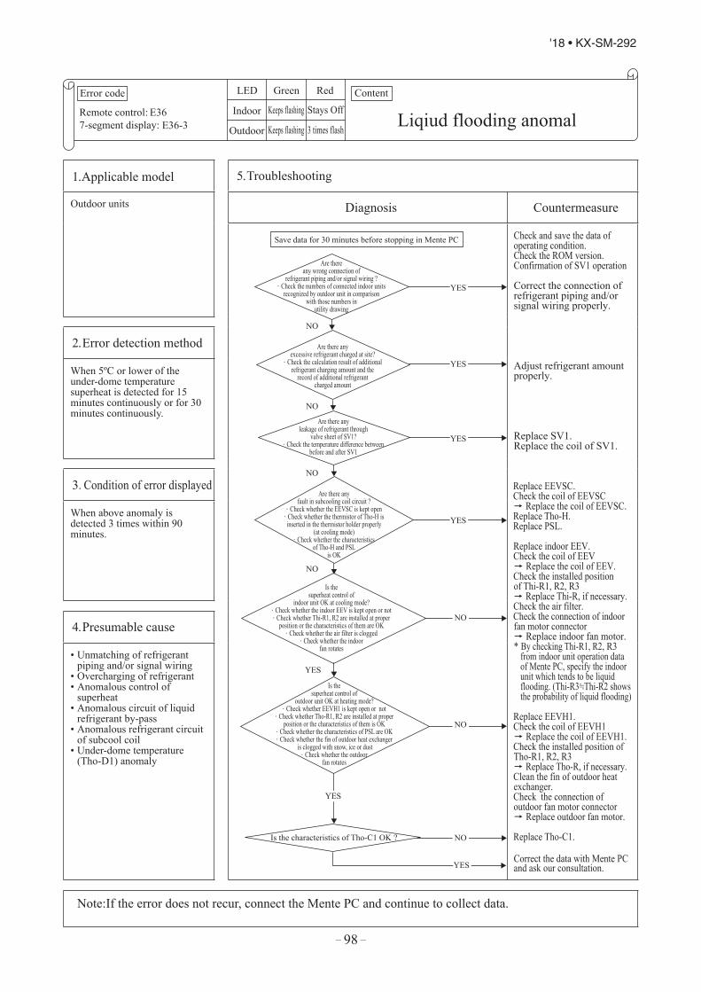
– 98 –
'18 • KX-SM-292
Error code
Remote control:7-segment display:
LED Green Red
Indoor
Outdoor
Content
E36E36-3 Liqiud flooding anomal
Keeps flashing Stays Off
Keeps flashing 3 times flash
1. Applicable model 5. Troubleshooting
Outdoor units Diagnosis Countermeasure
Are there any wrong connection of
refrigerant piping and/or signal wiring ? . Check the numbers of connected indoor units
recognized by outdoor unit in comparison with those numbers in
utility drawing
Are there any excessive refrigerant charged at site?
. Check the calculation result of additional refrigerant charging amount and the
record of additional refrigerant charged amount
Are there any leakage of refrigerant through
valve sheet of SV1? . Check the temperature difference between
before and after SV1
Are there anyfault in subcooling coil circuit ?
. Check whether the EEVSC is kept open. Check whether the thermistor of Tho-H is inserted in the thermistor holder properly
(at cooling mode). Check whether the characteristics
of Tho-H and PSLis OK
Is thesuperheat control of
indoor unit OK at cooling mode?. Check whether the indoor EEV is kept open or not. Check whether Thi-R1, R2 are installed at proper
position or the characteristics of them are OK. Check whether the air filter is clogged
. Check whether the indoorfan rotates
Is thesuperheat control of
outdoor unit OK at heating mode?. Check whether EEVH1 is kept open or not
. Check whether Tho-R1, R2 are installed at proper position or the characteristics of them is OK
. Check whether the characteristics of PSL are OK
. Check whether the fin of outdoor heat exchanger is clogged with snow, ice or dust
. Check whether the outdoorfan rotates
Save data for 30 minutes before stopping in Mente PC
Is the characteristics of Tho-C1 OK ?
NO
NO
NO
NO
NO
NO
NO
YES
YES
YES
YES
YES
YES
YES
Check and save the data of operating condition.Check the ROM version.Confirmation of SV1 operation
Correct the connection of refrigerant piping and/or signal wiring properly.
Adjust refrigerant amount properly.
Replace SV1.Replace the coil of SV1.
Replace EEVSC.Check the coil of EEVSC Replace the coil of EEVSC.Replace Tho-H.Replace PSL.
Replace indoor EEV.Check the coil of EEV Replace the coil of EEV.Check the installed position
of Thi-R1, R2, R3 Replace Thi-R, if necessary.Check the air filter.Check the connection of indoorfan motor connector Replace indoor fan motor.* By checking Thi-R1, R2, R3
from indoor unit operation data of Mente PC, specify the indoor unit which tends to be liquid flooding. (Thi-R3.=.Thi-R2 shows the probability of liquid flooding)
Replace EEVH1.Check the coil of EEVH1 Replace the coil of EEVH1.Check the installed position of Tho-R1, R2, R3 Replace Tho-R, if necessary.Clean the fin of outdoor heat exchanger.Check the connection of outdoor fan motor connector Replace outdoor fan motor.
Replace Tho-C1.
Correct the data with Mente PC and ask our consultation.
2. Error detection method
When 5ºC or lower of the under-dome temperature superheat is detected for 15 minutes continuously or for 30 minutes continuously.
3. Condition of error displayed
When above anomaly is detected 3 times within 90 minutes.
4. Presumable cause
• Unmatching of refrigerantpiping and/or signal wiring
• Overcharging of refrigerant• Anomalous control of
superheat• Anomalous circuit of liquid
refrigerant by-pass• Anomalous refrigerant circuit
of subcool coil• Under-dome temperature
(Tho-D1) anomaly
Note:If the error does not recur, connect the Mente PC and continue to collect data.

– 99 –
'18 • KX-SM-292
Error code
Remote control:7-segment display:
LED Green Red
Indoor
Outdoor
Content
E36E36-3 Liqiud flooding anomal
Keeps flashing Stays Off
Keeps flashing 3 times flash
1. Applicable model 5. Troubleshooting
Outdoor units Diagnosis Countermeasure
Are there any wrong connection of
refrigerant piping and/or signal wiring ? . Check the numbers of connected indoor units
recognized by outdoor unit in comparison with those numbers in
utility drawing
Are there any excessive refrigerant charged at site?
. Check the calculation result of additional refrigerant charging amount and the
record of additional refrigerant charged amount
Are there any leakage of refrigerant through
valve sheet of SV1? . Check the temperature difference between
before and after SV1
Are there anyfault in subcooling coil circuit ?
. Check whether the EEVSC is kept open. Check whether the thermistor of Tho-H is inserted in the thermistor holder properly
(at cooling mode). Check whether the characteristics
of Tho-H and PSLis OK
Is thesuperheat control of
indoor unit OK at cooling mode?. Check whether the indoor EEV is kept open or not. Check whether Thi-R1, R2 are installed at proper
position or the characteristics of them are OK. Check whether the air filter is clogged
. Check whether the indoorfan rotates
Is thesuperheat control of
outdoor unit OK at heating mode?. Check whether EEVH1 is kept open or not
. Check whether Tho-R1, R2 are installed at proper position or the characteristics of them is OK
. Check whether the characteristics of PSL are OK
. Check whether the fin of outdoor heat exchanger is clogged with snow, ice or dust
. Check whether the outdoorfan rotates
Save data for 30 minutes before stopping in Mente PC
Is the characteristics of Tho-C1 OK ?
NO
NO
NO
NO
NO
NO
NO
YES
YES
YES
YES
YES
YES
YES
Check and save the data of operating condition.Check the ROM version.Confirmation of SV1 operation
Correct the connection of refrigerant piping and/or signal wiring properly.
Adjust refrigerant amount properly.
Replace SV1.Replace the coil of SV1.
Replace EEVSC.Check the coil of EEVSC Replace the coil of EEVSC.Replace Tho-H.Replace PSL.
Replace indoor EEV.Check the coil of EEV Replace the coil of EEV.Check the installed position
of Thi-R1, R2, R3 Replace Thi-R, if necessary.Check the air filter.Check the connection of indoorfan motor connector Replace indoor fan motor.* By checking Thi-R1, R2, R3
from indoor unit operation data of Mente PC, specify the indoor unit which tends to be liquid flooding. (Thi-R3.=.Thi-R2 shows the probability of liquid flooding)
Replace EEVH1.Check the coil of EEVH1 Replace the coil of EEVH1.Check the installed position of Tho-R1, R2, R3 Replace Tho-R, if necessary.Clean the fin of outdoor heat exchanger.Check the connection of outdoor fan motor connector Replace outdoor fan motor.
Replace Tho-C1.
Correct the data with Mente PC and ask our consultation.
2. Error detection method
When 5ºC or lower of the under-dome temperature superheat is detected for 15 minutes continuously or for 30 minutes continuously.
3. Condition of error displayed
When above anomaly is detected 3 times within 90 minutes.
4. Presumable cause
• Unmatching of refrigerantpiping and/or signal wiring
• Overcharging of refrigerant• Anomalous control of
superheat• Anomalous circuit of liquid
refrigerant by-pass• Anomalous refrigerant circuit
of subcool coil• Under-dome temperature
(Tho-D1) anomaly
Note:If the error does not recur, connect the Mente PC and continue to collect data.
Error code
Remote control:7-segment display:
LED Green Red
Indoor
Outdoor
Content
*1 E37-1: one time flash (Tho-R1), E37-2: 2 time flash (Tho-R2), E37-5: 5 time flash (Tho-SC), E37-6: 6 time flash (Tho-H)
E37E37-1, 2, 5, 6*1
Outdoor unit heat exchangertemperature sensor (Tho-R) and subcooling coil
temperature sensor (Tho-SC,-H) anomalyKeeps flashing Stays Off
Keeps flashing *1
1. Applicable model 5. Troubleshooting
Outdoor unit Diagnosis Countermeasure
Is the connector of
sensor connected properly?
Are the characteristics of
sensor OK?*2
*2Check several times to prove any poor connection
Outdoor heat exchanger temperature sensor (Tho-R1, R2, R5, R6)Sub-cooling coil sensor (Tho-SC, Tho-H)Temperature-resistance characteristics
Save data for 30 minutes before stopping in Mente PC
NO
NO
YES
Temperature (°C)
5kΩ at 25°C
Tem
pera
ture
sens
or re
sist
ance
(kΩ
)
Check and save the data of operating conditions.Check the conditions whetherit occurs immediately after thepower on or during operationor stopping.Check the sensed value.Compare the temperatureon Mente PC with actual measured value.
Insert the connector securely.
Replace sensor .(Tho-SC, Tho-H, Tho-R)
Replace outdoor unit control PCB.
2. Error detection method
Detection of anomalously low temperature (resistance)of Tho-R or Tho-SC or Tho-H
3. Condition of error displayed
• If -50°C or lower is detected for 5 seconds continuously within 2 minutes to 2 minutes 20 seconds after the compressor ON, the compressor stops. And after 3 minutes delay, the compressor starts again automatically, but if this anomalous temperature is detected 3 times within 40 minutes after the initial detection.
• If -50°C or lower is detected for 5 seconds continuously within 20 seconds after power ON
4. Presumable cause
• Broken sensor harness orthe internal wire of sensingsection (Check the moldedsection as well)
• Disconnection of sensorharness connection(connector)
• Outdoor unit control PCBanomaly
Note:
YES

– 100 –
'18 • KX-SM-292
Error code
Remote control:7-segment display:
LED Green Red
Indoor
Outdoor
Content
E38E38
Outdoor air temperature sensor anomaly (Tho-A)
Keeps flashing Stays Off
Keeps flashing 1 time flash
1. Applicable model 5. Troubleshooting
Outdoor unit Diagnosis Countermeasure
Is the connector of
sensor connected properly?
Are the characteristics of
sensor OK?*1
*1Check several times to prove any poor connection
Temperature-resistance characteristics of Outdoor air temperature sensor (Tho-A)
Save data for 30 minutes before stopping in Mente PC
NO
NO
YES
Temperature (°C)
0
10
20
30
40
50
60
70
80
90
100
-20 -10 0 10 20 30 40 50
Tem
pera
ture
sens
or re
sist
ance
(kΩ
)
Check and save the data of operating condition. Check the conditions whether it occurs immediately after the power on or during operation or stopping. Check the sensed value.Compare the temperature on Mente PC with actual measured value.
Insert the connector securely.
Replace sensor (Tho-A).
Replace outdoor unit control PCB.
2. Error detection method
Detection of anomalously low temperature (resistance) of Tho-A
3. Condition of error displayed
• If -30°C or lower is detected for 5 seconds continuously within 2 minutes to 2 minutes 20 seconds after the compressor ON, the compressor stops. And after 3 minutes delay, the compressor starts again automatically, but if this anomalous temperature is detected 3 times within 40 minutes after the initial detection.
• If -30°C or lower is detected for 5 seconds continuously within 20 seconds after power ON.
4. Presumable cause
• Broken sensor harness orthe internal wire of sensingsection (Check the moldedsection as well)
• Disconnection of sensorharness connection(connector)
• Outdoor unit control PCBanomaly
Note:
YES

– 101 –
'18 • KX-SM-292
Error code
Remote control:7-segment display:
LED Green Red
Indoor
Outdoor
Content
E39E39-1
Discharge pipe temperature sensor anomaly (Tho-D1)
Keeps flashing Stays Off
Keeps flashing 1 time flash
1. Applicable model 5. Troubleshooting
Outdoor unit Diagnosis Countermeasure
Is the connector of
sensor connected properly?
Are the characteristics of
sensor OK? *3
*3Check several times to prove any poor connection
Temperature-resistance characteristics of dischargepipe temperature sensor (Tho-D1)
Save data for 30 minutes before stopping in Mente PC
NO
NO
YES
Temperature (°C)
Tem
pera
ture
sens
or
resi
stan
ce (k
Ω)
0 20 40 60 80
100 120 140 160 180 200
0 20 40 60 80 100 120 140 160
Check and save the data of operating condition.Check the conditions whether it occurs immediately after the power on or during operation or stopping.Check the sensed value.Compare the temperature on Mente PC with actual measured value.
Insert the connector securely.
Replace sensor (Tho-D1).
Replace outdoor unit control PCB.
2. Error detection method
Detection of anomalously low temperature (resistance) of Tho-D1
3. Condition of error displayed
• If 3°C or lower is detected for 5 seconds continuously within 10 minutes to 10 minutes 20 seconds after the compressor ON, the compressor stops. And after 3 minutes delay, the compressor starts again automatically, but if this anomalous temperature is detected 3 times within 40 minutes after the initial detection.
4. Presumable cause
• Broken sensor harness orthe internal wire of sensingsection (Check the moldedsection as well)
• Disconnection of sensorharness connection(connector)
• Outdoor unit control PCBanomaly
Note:
YES
Error code
Remote control:7-segment display:
LED Green Red
Indoor
Outdoor
Content
E38E38
Outdoor air temperature sensor anomaly (Tho-A)
Keeps flashing Stays Off
Keeps flashing 1 time flash
1. Applicable model 5. Troubleshooting
Outdoor unit Diagnosis Countermeasure
Is the connector of
sensor connected properly?
Are the characteristics of
sensor OK?*1
*1Check several times to prove any poor connection
Temperature-resistance characteristics of Outdoor air temperature sensor (Tho-A)
Save data for 30 minutes before stopping in Mente PC
NO
NO
YES
Temperature (°C)
0
10
20
30
40
50
60
70
80
90
100
-20 -10 0 10 20 30 40 50
Tem
pera
ture
sens
or re
sist
ance
(kΩ
)
Check and save the data of operating condition. Check the conditions whether it occurs immediately after the power on or during operation or stopping. Check the sensed value.Compare the temperature on Mente PC with actual measured value.
Insert the connector securely.
Replace sensor (Tho-A).
Replace outdoor unit control PCB.
2. Error detection method
Detection of anomalously low temperature (resistance) of Tho-A
3. Condition of error displayed
• If -30°C or lower is detected for 5 seconds continuously within 2 minutes to 2 minutes 20 seconds after the compressor ON, the compressor stops. And after 3 minutes delay, the compressor starts again automatically, but if this anomalous temperature is detected 3 times within 40 minutes after the initial detection.
• If -30°C or lower is detected for 5 seconds continuously within 20 seconds after power ON.
4. Presumable cause
• Broken sensor harness orthe internal wire of sensingsection (Check the moldedsection as well)
• Disconnection of sensorharness connection(connector)
• Outdoor unit control PCBanomaly
Note:
YES

– 102 –
'18 • KX-SM-292
Error code
Remote control:7-segment display:
LED Green Red
Indoor
Outdoor
Content
E40E40
High pressure anomaly(63H1-1activated)
Keeps flashing Stays Off
Keeps flashing 1 time flash
1. Applicable model 5. Troubleshooting
Outdoor unit Diagnosis Countermeasure
YES
NO
Save data for 30 minutes before stopping in Mente PC
Connect a pressure gauge and restart operation.
Was 63H1activated at 4.15MPa
or higher?
Does the sensed value of the high pressure
sensor show 4.15MPa? (Normal?)
Are the 63H1-1 OK?
Are the connector and/or harnesse
OK?
Are the service valves fully
open?
Is it stop at 4.15MPa of gauge
pressre ?
Is there any clogging in the refrigerant
circuit ?
NO
NO
YES
Check and save the data of operating condition.Check the sensed value of high pressure sensor when the 63H1-1 is activated.Check whether the high pressure switch is activated at the sensed value of high pressure sensor.
High pressure sensor anomaly is suspicious.Check high pressure sensor itself according to the troubleshooting procedure of E54, after retarting operation.(If the high pressure sensor [PSH] fails, replace it)
If the connector is disconnected or the harness is broken, correct it.Also check whether the high pressure switch is properly mounted or not.
Open operation valve.
Check it, as much as possible, under the operating conditions for 30 minutes before error occurred.
Replace outdoor control PCB.
Remove clogs.
Check items (condenser side):• Filter clogging• Air flow volume (Fan
motor)• Short-circuit of air flow
2. Error detection method
When high pressure switch 63H1-1 is activated
3. Condition of error displayed
• If high pressure exceeds4.15MPa
• If 63H1-1 is activated 5 timeswithin 60 minutes
• If 63H1-1 is activated for 60minutes continuously
4. Presumable cause
• Short-circuit of airflowat condenser side of heatexchanger/Disturbance ofairflow/Clogging filter/Fanmotor anomaly
• Disconnection of highpressure switch connector
• Breakage of high pressureswitch harness
• Closed service valves• High pressure sensor anomaly• High pressure switch anomaly
Note: If the error does not recur, connect the Mente PC and continue to collect data.
YES
YES
YES
YES
NO
NO
NO

– 103 –
'18 • KX-SM-292
Error code
Remote control:7-segment display:
LED Green Red
Indoor
Outdoor
Content
E40E40
High pressure anomaly(63H1-1activated)
Keeps flashing Stays Off
Keeps flashing 1 time flash
1. Applicable model 5. Troubleshooting
Outdoor unit Diagnosis Countermeasure
YES
NO
Save data for 30 minutes before stopping in Mente PC
Connect a pressure gauge and restart operation.
Was 63H1activated at 4.15MPa
or higher?
Does the sensed value of the high pressure
sensor show 4.15MPa? (Normal?)
Are the 63H1-1 OK?
Are the connector and/or harnesse
OK?
Are the service valves fully
open?
Is it stop at 4.15MPa of gauge
pressre ?
Is there any clogging in the refrigerant
circuit ?
NO
NO
YES
Check and save the data of operating condition.Check the sensed value of high pressure sensor when the 63H1-1 is activated.Check whether the high pressure switch is activated at the sensed value of high pressure sensor.
High pressure sensor anomaly is suspicious.Check high pressure sensor itself according to the troubleshooting procedure of E54, after retarting operation.(If the high pressure sensor [PSH] fails, replace it)
If the connector is disconnected or the harness is broken, correct it.Also check whether the high pressure switch is properly mounted or not.
Open operation valve.
Check it, as much as possible, under the operating conditions for 30 minutes before error occurred.
Replace outdoor control PCB.
Remove clogs.
Check items (condenser side):• Filter clogging• Air flow volume (Fan
motor)• Short-circuit of air flow
2. Error detection method
When high pressure switch 63H1-1 is activated
3. Condition of error displayed
• If high pressure exceeds4.15MPa
• If 63H1-1 is activated 5 timeswithin 60 minutes
• If 63H1-1 is activated for 60minutes continuously
4. Presumable cause
• Short-circuit of airflowat condenser side of heatexchanger/Disturbance ofairflow/Clogging filter/Fanmotor anomaly
• Disconnection of highpressure switch connector
• Breakage of high pressureswitch harness
• Closed service valves• High pressure sensor anomaly• High pressure switch anomaly
Note: If the error does not recur, connect the Mente PC and continue to collect data.
YES
YES
YES
YES
NO
NO
NO
Error code
Remote control:7-segment display:
LED Green Red
Indoor
Outdoor
Content
E41(E51)E41(E51)-1 Power transistor overheat
Keeps flashing Stays Off
Keeps flashing 1 time flash
1. Applicable model 5. Troubleshooting
Outdoor unit Diagnosis Countermeasure
Is the connection of power
transistor temperature sensor OK?
(Check short-circuit or breakage of harness)
Is the characteristics of power transitor
temperature sensor OK? *
* Refer the characterristics of power transistor temperature sensor to E56
Is the fixing of power transistor OK?
(Check tightening of screws or application of radiation
silicon)
Save data for 30 minutes before stopping in Mente PC
Does the outdoor fan run ?
Does the error recur when restarting?
Is the cooling fan for inverter running?
Is 15V of power for control PCB
detected?
Reset power source and restart
After power OFF
NO
NO
NO
NO
NO
NO
NO
YES
YES
YES
YES
YES
YES
YES
Check and save the data of operating conditions.Check the temperature of power transistor.Check the operation of outdoor fan and cooling fan.
Repair it according to the troubleshooting procedure of E48.Check it as much as possible under the operating conditions for 30 minutes before error occurred.
Wait and see.Continue to obain data, if possible (Keep connecting the Mente PC).
If the cooling fan does not run in spite of the operation ON range, check the voltage at the connector of cooling fan.If the 220/240V is detected, repalce cooling fan motor.If 0V is detected, replace outdoor unit control PCB.
After checking the loose connection of connetor or breakage of harness, replace inverter PCB.
Connect the connector of thermistor securely.Or replace power transistor temperature sensor.
Replace power transistor temperature sensor.
Fix power transistor on to the radiation fin with proper application of radiation silicon.
Replace power transistor.
2. Error detection method
When anomalously high temperature is detected by power transistor temperature sensor (Tho-P1)
3. Condition of error displayed
Anomalously high temperature of power transistor is detected 5 times within 60 minutes (E41).Or it is detected for 15 minutes continuously(E51)
4. Presumable cause
• Power transistor anomaly• Power transistor temperature
sensor anomaly• Improperly fixing of power
transistor to radiator fin• Inverter PCB anomaly• Outdoor fan motor anomaly• Anomalous cooling fan motor
for inverter• Inadequate installation space
of outdoor unit
Note: The operating conditions of cooling fan for inverter is shown in the right figureIf the error does not recur, connect the Mente PC and continue to collect data. 81°C
Power transistor sensor temperature
OFFON
85°C

– 104 –
'18 • KX-SM-292
Error code
Remote control:7-segment display:
LED Green Red
Indoor
Outdoor
Content
E42E42-1 Current cut (CM1)
Keeps flashing Stays Off
Keeps flashing 1 time flash
1. Applicable model 5. Troubleshooting
Outdoor unit Diagnosis Countermeasure
Is the coil resistance and insulation (megger check) of compressor
motor OK?
Is 15Vof power for control PCB
detected? Is the outdoor fan motor OK? (Refer the checking method of
15Vin page63)
Do you have inverter checker for
judging whether inverter PCB is OK or not?
After power OFF, Remove the 1-3 layers
of control box
Is the checked result by measuring
the resistance beween each terminal of power transistor module OK?
(Are there any short- circuit?)
Is the checked result by inverter checker
OK?
NO
NO
NO
NO
NO
NO
NO
YES
YES
YES
YES
YES
YES
Save data for 30 minutes before stopping in Mente PC
Does the outdoor fan run ?
Reset power source and restart
Does E42 recur?
Check and save the data of operating conditions.Check pressure anomaly.Check the operation of outdoor fan.
Replace compressor.Check the capillary tube and stariner of oil separator.If necessary, replace the capillary tube and strainer as well.
Repair it according to the troubleshooting of E48.
Replace inverter PCB or outdoor fan motor.
Check it as much as possible under the operating conditions for 30 minutes before error occurred.
Wait and see.Continue to obain data, if possible (Keep connecting the Mente PC).
Replace power transistor module.Replace inverter PCB.
Replace power transistor module.Refer Page 63.(Remove the power cable from compressor and check the resistance between P-U, P-V, P-W, N-U, N-V, N-Wrespectively.
Replace inverter PCB.
2. Error detection method
When anomalously high output current of inverter is detected by the current sensormounted in the power transistor
3. Condition of error displayed
When 88A or higher output current of inverter is detected 4 times within 15 minutes.
4. Presumable cause
• Compressor anomaly• Leakage of refrigerant• Power transistor module
anomaly • Anomalous power source for
inverter PCB• Outdoor fan motor anomaly
Note: In case that there is no the insulation resistance anomaly, the compressor anomaly could be considered.If this anomaly occurs after replacement of power transistor module and/or inverter PCB, try to replace compressor as well.If the error does not recur, connect the Mente PC and continue to collect data
YES

– 105 –
'18 • KX-SM-292
Error code
Remote control:7-segment display:
LED Green Red
Indoor
Outdoor
Content
E42E42-1 Current cut (CM1)
Keeps flashing Stays Off
Keeps flashing 1 time flash
1. Applicable model 5. Troubleshooting
Outdoor unit Diagnosis Countermeasure
Is the coil resistance and insulation (megger check) of compressor
motor OK?
Is 15Vof power for control PCB
detected? Is the outdoor fan motor OK? (Refer the checking method of
15Vin page63)
Do you have inverter checker for
judging whether inverter PCB is OK or not?
After power OFF, Remove the 1-3 layers
of control box
Is the checked result by measuring
the resistance beween each terminal of power transistor module OK?
(Are there any short- circuit?)
Is the checked result by inverter checker
OK?
NO
NO
NO
NO
NO
NO
NO
YES
YES
YES
YES
YES
YES
Save data for 30 minutes before stopping in Mente PC
Does the outdoor fan run ?
Reset power source and restart
Does E42 recur?
Check and save the data of operating conditions.Check pressure anomaly.Check the operation of outdoor fan.
Replace compressor.Check the capillary tube and stariner of oil separator.If necessary, replace the capillary tube and strainer as well.
Repair it according to the troubleshooting of E48.
Replace inverter PCB or outdoor fan motor.
Check it as much as possible under the operating conditions for 30 minutes before error occurred.
Wait and see.Continue to obain data, if possible (Keep connecting the Mente PC).
Replace power transistor module.Replace inverter PCB.
Replace power transistor module.Refer Page 63.(Remove the power cable from compressor and check the resistance between P-U, P-V, P-W, N-U, N-V, N-Wrespectively.
Replace inverter PCB.
2. Error detection method
When anomalously high output current of inverter is detected by the current sensormounted in the power transistor
3. Condition of error displayed
When 88A or higher output current of inverter is detected 4 times within 15 minutes.
4. Presumable cause
• Compressor anomaly• Leakage of refrigerant• Power transistor module
anomaly • Anomalous power source for
inverter PCB• Outdoor fan motor anomaly
Note: In case that there is no the insulation resistance anomaly, the compressor anomaly could be considered.If this anomaly occurs after replacement of power transistor module and/or inverter PCB, try to replace compressor as well.If the error does not recur, connect the Mente PC and continue to collect data
YES
Error code
Remote control:7-segment display:
LED Green Red
Indoor
Outdoor
Content
E43E43-1, 2 *1
Excessive number of indoor units connected, excessive total capacity of connection
Keeps flashing Stays Off
Keeps flashing *1
1. Applicable model 5. Troubleshooting
Outdoor unit Diagnosis Countermeasure
Does E43 recur?
Is there any indoor units which
is not expected to exsist in that signal
line?
Save data for 30 minutes before stopping in Mente PC
NO
Does the number of
indoor units connected and/or total capacity of connected indoor units
exceed the limitation?
Check the resistance between A and B of signal line as well.
Check the number of connected indoor units by the code No.C50of 7-segment display or MentePC with reference to the utilitydrawing (check not only onesystem, but also other systems)
YES
YES
YES
Throughly checking of the addresses of indoor/outdoor units by means of
• Outdoor unit: Mente PC, 7-segment display and rotary switch (SW1, SW2)• Indoor unit: Remote control and rotary switch (SW1, 2, 3, 4)
* Recommend to use means other than the rotary switch which could be faulty
Reset the power.
Check and save the data of operating condition.
Test run.No action is taken because it is judged that the power reset was not done after changing address.
Check indoor unit addresses and correct it.In case that total capacity of connected indoor units exceeds the limitation if tentative operation is required, turn ON the DIP switch SW5-4 on the outdoor unit control PCB. (However since this tentative solution could cause trouble, be sure to correct it as soon as possible.)
Signal wire may be connected to other outdoor unit system.→Correct the signal wire.
Correct addresses.(Either one of addresses is wrong.)If the address corrected by rotary switch is still wrong, replace control PCB (rotary switch anomaly).
* Before replacement, please confirm whetherthe rotary switch for address setting is not damaged. (It was experienced that No. 5 on rotary switch was not recognized.)
2. Error detection method
When the number of connected indoor units exceeds the limitation.When the total capacity of connected indoor units exceeds the limitation.
3. Condition of error displayed
• Excessive number of connected indoor units
• Excessive total capacity of connected indoor units
• The total capacity of connected indoor units exceeds the limitation
4. Presumable cause
• Mistake in setting of indoor/outdoor unit addresses
• Mistake in signal wire connection
Note: After completing the above procedure, reset the power and confirm that the error display does not recur. Unless the power is reset for both indoor unit and outdoor unit, the set addresses will not be confirmed.
*1 E43-1:1 time flash (Excessive number of indoor units connected), E43-2 :2 time flash (Excessive capacity of indoor units connection)
CautionUnless the power is reset after changing address, the set address will not be confirmed
NO
NO

– 106 –
'18 • KX-SM-292
Error code
Remote control:7-segment display:
LED Green Red
Indoor
Outdoor
Content
E45E45-1
Communication error between inverter PCB and outdoor unit control PCB
Keeps flashing Stays Off
Keeps flashing 1 time flash
1. Applicable model 5. Troubleshooting
Outdoor unit Diagnosis Countermeasure
Is 15Vof power for control PCB
detected? Is the outdoor fan motor OK? (Refer the checking method of 15V
in page 63)
Turn off the power.IS the harness and/or
connector between inverter PCB and outdoor unit control
PCB OK ?
Is the rush current prevention resistor
broken?
Is the harness and/or connector
between inverter PCB and diode module
OK?
Is the setting of switches on the inverter
PCB OK? *
Reset power source and restart
Does E45 recur?
NO
NO
NO
NO
NO
NO
YES
YES
YES
YES
YES
YES
Save data for 30 minutes before stopping in Mente PC
* Switch setting of inverter PCBSW1-1 SW1-2 SW1-3 SW1-4 JSW1-1 JSW1-2 JSW1-3 JSW1-4
OFFOFFOFFOFFONOFFOFFOFF
Check and save the data of operating conditions.
Replace inverter PCB or outdoor fan motor.
Check it as much as possible under the operating conditions for 30 minutes before error occurred.
Wait and see.Continue to obain data, if possible (Keep connecting the Mente PC).
Check whether the harness is broken?Check whether the connector is loose? If there is problem,correct it.
Disconnect the harness from the resistor and measure the resistance.If broken, replace the resistor.In such case check the harness between diode module and inverter PCB as well.
Check whether the harness is broken?Check whether the connector is loose? If there is problem,correct it.
Correct the setting of switches on the inverter PCB.
Replace outdoor unit control PCB.
2. Error detection method
When the communication between inverter PCB and outdoor unit control PCB is not established.
3. Condition of error displayed
Same as above
4. Presumable cause
• Signal wire anomaly• Outdoor unit control PCB
anomaly• Inverter PCB (INV1)
anomaly• Rush current prevention
resistor anomaly
Note: If the error does not recur, connect the Mente PC and continue to collect data.

– 107 –
'18 • KX-SM-292
Error code
Remote control:7-segment display:
LED Green Red
Indoor
Outdoor
Content
E45E45-1
Communication error between inverter PCB and outdoor unit control PCB
Keeps flashing Stays Off
Keeps flashing 1 time flash
1. Applicable model 5. Troubleshooting
Outdoor unit Diagnosis Countermeasure
Is 15Vof power for control PCB
detected? Is the outdoor fan motor OK? (Refer the checking method of 15V
in page 63)
Turn off the power.IS the harness and/or
connector between inverter PCB and outdoor unit control
PCB OK ?
Is the rush current prevention resistor
broken?
Is the harness and/or connector
between inverter PCB and diode module
OK?
Is the setting of switches on the inverter
PCB OK? *
Reset power source and restart
Does E45 recur?
NO
NO
NO
NO
NO
NO
YES
YES
YES
YES
YES
YES
Save data for 30 minutes before stopping in Mente PC
* Switch setting of inverter PCBSW1-1 SW1-2 SW1-3 SW1-4 JSW1-1 JSW1-2 JSW1-3 JSW1-4
OFFOFFOFFOFFONOFFOFFOFF
Check and save the data of operating conditions.
Replace inverter PCB or outdoor fan motor.
Check it as much as possible under the operating conditions for 30 minutes before error occurred.
Wait and see.Continue to obain data, if possible (Keep connecting the Mente PC).
Check whether the harness is broken?Check whether the connector is loose? If there is problem,correct it.
Disconnect the harness from the resistor and measure the resistance.If broken, replace the resistor.In such case check the harness between diode module and inverter PCB as well.
Check whether the harness is broken?Check whether the connector is loose? If there is problem,correct it.
Correct the setting of switches on the inverter PCB.
Replace outdoor unit control PCB.
2. Error detection method
When the communication between inverter PCB and outdoor unit control PCB is not established.
3. Condition of error displayed
Same as above
4. Presumable cause
• Signal wire anomaly• Outdoor unit control PCB
anomaly• Inverter PCB (INV1)
anomaly• Rush current prevention
resistor anomaly
Note: If the error does not recur, connect the Mente PC and continue to collect data.
Error code
Remote control:7-segment display:
LED Green Red
Indoor
Outdoor
Content
E46E46
Mixed address setting methods coexistent in same network.
Keeps flashing Stays Off
Keeps flashing Stays Off
1. Applicable model 5. Troubleshooting
Outdoor unit Diagnosis Countermeasure
NO
Reset power source and restart
If signal line is connected to more than 2 outdoor unit systems, address setting should be done by manually.
YES
Is't the signal line of a outdoor
unit system applying automatic address setting connected to
other outdoor unit system?
YES
NO Does E46 recur?
YES
Turn ON the power of each outdoor unit one by one and search the outdoor unit that can start up with automatic address setting
NO Is E46 still displayed?
Save data for 30 minutes before stopping in Mente PC Check and save the data of operating conditions.Check the address setting method of faulty network whether it is automatic setting or manual setting.
Test run.* No action is taken
because it is judged thatthe power rest is not doneafter changing address.
Correct signal line.*In case of automaticaddress setting, signal linecannot be connected toother outdoor unit system.
Test run
Replace outdoor unit control PCB*. (Rotary switch anomaly)
* Before replacement,please confirm whethethe rotary switch foraddress setting is notdamaged.(It was experienced thatNo.5 on rotary switchwas not recognized.)
2. Error detection method
If the signal line of a outdoor unit system applied automatic address setting is connected to other outdoor unit system(Detected at indoor unit side)
3. Condition of error displayed
Same as above
4. Presumable cause
• Mistake in the address setting• Mistake in the connection of
signal wire
Note: After completing the above procedure, reset the power and confirm that the error display does not recur. Unless the power is reset for both indoor unit and outdoor unit, the set addresses will not be confirmed
Caution:Unless the power is reset after changing address, the set address will not be confirmed.
<Reference>Error display at mixed address setting
Auto Manual
Auto address setting E31 E46
Manual address setting E46 Normal

– 108 –
'18 • KX-SM-292
Error code
Remote control:7-segment display:
LED Green Red
Indoor
Outdoor
Content
E48E48-1, 2 *1 Outdoor unit DC fan motor anomaly
Keeps flashing Stays Off
Keeps flashing *1
1. Applicable model 5. Troubleshooting
Outdoor unit Diagnosis Countermeasure
Is 15Vof power for control PCB
detected? Is the outdoor fan motor OK? (Refer the checking method of
15Vin page 63)
Does the fan rotate smoothly when turned
by hand? NO
NO
NO
NO
YES
Is E48restored at 10 seconds after
compressor starting?
Interchange the connectors of fan motor harnesses at the connectors on outdoor
unit control PCB side
Is the fan motor failed to start up
switched?
Start operation again
Turn the power source OFF
Reset power source and restart
Save data for 30 minutes before stopping in Mente PC
Check and save the data of operating conditions.
Replace fan motor.
Replace inverter PCB or fan motor.
Check it as much as possible under the operating conditions for 30 minutes before error occurred.
Wait and see.Continue to obain data, if possible.(Keep connecting the Mente PC)
Replace fan motor.
Replace outdoor unit control PCB.
2. Error detection method
• If 400min-1 or lower of the fan rotation command and the state of overcurent are detected for 10 times continueously
• If 100min-1 of the actual fan rotation speed is detected for 30 seconds(Fan motor is locked)
3. Condition of error displayed
Same as above
4. Presumable cause
• Breakage of harness or loose conection of
connector• Outdoor fan motor anomaly• Inverter PCB anomaly• Outdoor unit control PCB anomaly
Note: If the error does not recur, connect the Mente PC and continue to collect data.
*1 E48-1: 1 time flash (FMO1), E48-2 : 2 time flash (FMO2)
Inspect also the fan motor 2 even if it is E48-1. Inspect also the fan motor 1 even if it is E48-2.( )
YES
YES
YES

– 109 –
'18 • KX-SM-292
Error code
Remote control:7-segment display:
LED Green Red
Indoor
Outdoor
Content
E48E48-1, 2 *1 Outdoor unit DC fan motor anomaly
Keeps flashing Stays Off
Keeps flashing *1
1. Applicable model 5. Troubleshooting
Outdoor unit Diagnosis Countermeasure
Is 15Vof power for control PCB
detected? Is the outdoor fan motor OK? (Refer the checking method of
15Vin page 63)
Does the fan rotate smoothly when turned
by hand? NO
NO
NO
NO
YES
Is E48restored at 10 seconds after
compressor starting?
Interchange the connectors of fan motor harnesses at the connectors on outdoor
unit control PCB side
Is the fan motor failed to start up
switched?
Start operation again
Turn the power source OFF
Reset power source and restart
Save data for 30 minutes before stopping in Mente PC
Check and save the data of operating conditions.
Replace fan motor.
Replace inverter PCB or fan motor.
Check it as much as possible under the operating conditions for 30 minutes before error occurred.
Wait and see.Continue to obain data, if possible.(Keep connecting the Mente PC)
Replace fan motor.
Replace outdoor unit control PCB.
2. Error detection method
• If 400min-1 or lower of the fan rotation command and the state of overcurent are detected for 10 times continueously
• If 100min-1 of the actual fan rotation speed is detected for 30 seconds(Fan motor is locked)
3. Condition of error displayed
Same as above
4. Presumable cause
• Breakage of harness or loose conection of
connector• Outdoor fan motor anomaly• Inverter PCB anomaly• Outdoor unit control PCB anomaly
Note: If the error does not recur, connect the Mente PC and continue to collect data.
*1 E48-1: 1 time flash (FMO1), E48-2 : 2 time flash (FMO2)
Inspect also the fan motor 2 even if it is E48-1. Inspect also the fan motor 1 even if it is E48-2.( )
YES
YES
YES
Error code
Remote control:7-segment display:
LED Green Red
Indoor
Outdoor
Content
E49E49 Low pressure anomaly
Keeps flashing Stays Off
Keeps flashing 1 time flash
1. Applicable model 5. Troubleshooting
Outdoor unit Diagnosis Countermeasure
Does the low pressure fluctuate after the
startup?
Is the connection of sensor connector
OK?
Does the error occur immediately after
the startup?
Are the sensor characteristics
OK?* * The sensorcharacteristics is shown in
Page 111
Save data for 30 minutes before stopping in Mente PC
Reset power source and restart.
Is the opening degree of EEV
for evaporator side flucturing?
Is the connection of
sensor connector for heat exchanger
OK?
Is the checked result of harness and insulation
of EEV coil OK? Are the sensor
characteristics OK?
Does the EEV operate
normally by judging from Mente PC
data, etc?
Isn’t EEV or strainer clogged?
Check and save the data of operating conditions.Check error status.Is the refrigerant amount OK?Check additional refrigerant amount charged at site according to the piping length instructed on the label pasted on the panel of the unit.
Check whether the service valves are open.
Correct the connection of low pressure sensor connector.
Replace low pressure sensor.
Replace outdoor umit control PCB.
Correct the connection of temperature sensor connector of heat exchanger.
Replace temperature sensor of heat exchanger at evaporator side.
Replace control PCB at evaporator side.Replace EEV coil.
Replace EEV main body or strainer.
Check for short circuit of airflow of heat exchangerat evaporator side and for fan motor anomaly.
2. Error detection method
Detection of anomalously low pressure
3. Condition of error displayed
• At start up after power on:When the low pressure sensordetects lower than 0.003MPafor 60 seconds continuously.And if this anomaly occurs 2times.
• During operation:When the low pressure sensordetects 0.134MPa or lowerfor 30 seconds coninuously.And if this anomaly occurs 5times within 60 minutes
4. Presumable cause
• Low pressure sensor (PSL)anomaly
• Service valves closed• EEV anomaly (EEV closed)• Insufficient refrigerant
amount• Clogging at EEV or strainer
Note: Check whether the indoor unit is connected to other outdoor superlink network.If the error does not recur, connect the Mente PC and continue to collect data.
NO
NO
NO
NO
NO
NO
NO
NO
NO
NO
YES
YES
YES
YES
YES
YES
YES
YES
YES
YES

– 110 –
'18 • KX-SM-292
Error code
Remote control:7-segment display:
LED Green Red
Indoor
Outdoor
Content
E53/E55E53/E55-1
Suction pipe temperature sensor anomaly (Tho-S), Under-dome temperature sensor anomaly (Tho-C1)
Keeps flashing Stays Off
Keeps flashing 1 time flash
1. Applicable model 5. Troubleshooting
Outdoor unit Diagnosis Countermeasure
Check and save the data of operating conditions.Check the conditions whether it occurs immediately after the power on or during operation or stopping.Check the sensed value.Compare the temperature on Mente PC with actual measured value.
Insert the connector securely
Replace sensor(Tho-S or Tho-C1)
Replace outdoor unit control PCB.
2. Error detection method
Detection of anomalously low temperature (resistance) of Tho-S or Tho-C
3. Condition of error displayed
• if -50°C or lower is detected for 5 seconds continuously within 2 minutes to 2 minutes 20 seconds after compressor ON, compressor stops. When the compressor is restarted automatically after 3-minutes delay, if this anomaly occurs 3 times within 40 minutes
4. Presumable cause
• Broken thermistor harness or the internal wire of sensing section (Check the molded section as well)
• Disconnection of thermistor harness connection (connector)
• Outdoor unit control PCB anomaly
Note:
E53: Tho-S, E55-1: Tho-C1
5kΩ at 25Cº
Temperature (Cº)
Tem
pear
ture
sen
sor r
esis
tanc
e (k
Ω)
NO
NO
YES
YES
Save data for 30 minutes before stopping in Mente PC
Is the connector of sensor connected
properly ?
Are the characteristics
of sensor OK?*1
Regarding the characteristics of the sensor, see the following chart
Temperature-resistance characreristics of suction pipe temperature sensor (Tho-S)
Temperature-resistance characreristics ofunder-dome temperature sensor (Tho-C1)
*1 Check several times to prove any poor connection
Temperature (Cº)
Tem
pear
ture
sen
sor r
esis
tanc
e (k
Ω)
0 20 40 60 80
100 120 140 160 180 200
0 20 40 60 80 100 120 140 160

– 111 –
'18 • KX-SM-292
Error code
Remote control:7-segment display:
LED Green Red
Indoor
Outdoor
Content
E53/E55E53/E55-1
Suction pipe temperature sensor anomaly (Tho-S), Under-dome temperature sensor anomaly (Tho-C1)
Keeps flashing Stays Off
Keeps flashing 1 time flash
1. Applicable model 5. Troubleshooting
Outdoor unit Diagnosis Countermeasure
Check and save the data of operating conditions.Check the conditions whether it occurs immediately after the power on or during operation or stopping.Check the sensed value.Compare the temperature on Mente PC with actual measured value.
Insert the connector securely
Replace sensor(Tho-S or Tho-C1)
Replace outdoor unit control PCB.
2. Error detection method
Detection of anomalously low temperature (resistance) of Tho-S or Tho-C
3. Condition of error displayed
• if -50°C or lower is detected for 5 seconds continuously within 2 minutes to 2 minutes 20 seconds after compressor ON, compressor stops. When the compressor is restarted automatically after 3-minutes delay, if this anomaly occurs 3 times within 40 minutes
4. Presumable cause
• Broken thermistor harness or the internal wire of sensing section (Check the molded section as well)
• Disconnection of thermistor harness connection (connector)
• Outdoor unit control PCB anomaly
Note:
E53: Tho-S, E55-1: Tho-C1
5kΩ at 25Cº
Temperature (Cº)
Tem
pear
ture
sen
sor r
esis
tanc
e (k
Ω)
NO
NO
YES
YES
Save data for 30 minutes before stopping in Mente PC
Is the connector of sensor connected
properly ?
Are the characteristics
of sensor OK?*1
Regarding the characteristics of the sensor, see the following chart
Temperature-resistance characreristics of suction pipe temperature sensor (Tho-S)
Temperature-resistance characreristics ofunder-dome temperature sensor (Tho-C1)
*1 Check several times to prove any poor connection
Temperature (Cº)
Tem
pear
ture
sen
sor r
esis
tanc
e (k
Ω)
0 20 40 60 80
100 120 140 160 180 200
0 20 40 60 80 100 120 140 160
Error code
Remote control:7-segment display:
LED Green Red
Indoor
Outdoor
Content
E54E54-1, 2 *1
High pressure sensor anomaly (PSH)Low pressure sensor anomaly (PSL)
Keeps flashing Stays Off
Keeps flashing *1
1. Applicable model 5. Troubleshooting
Outdoor unit Diagnosis Countermeasure
Is anomalous pressure detected?
Is the connector of the sensor inserted
properly to the connector on the outdoor control
PCB?
Save data for 30 minutes before stopping in Mente PC
Reset the power and restart operation.
Check the data for 30 minutes before stopping
High pressure sensor output characteristics
Sensor output Black (GND) – White; Output voltage (Black – Red; DC5V)
Pressure (MPa) Pressure (MPa)
Low pressure sensor output characteristics
E54Does it recur?
Does the pressure
converted from the sensor output voltage match the
actual pressure measure by pressure
gauge?
Out
put v
olta
ge (V
)
Out
put v
olta
ge (V
)
Check and save the data of operating conditions.Check the conditions whether it occurs immediately after the power on or during operation or stopping.Check the sensed value.
Insert the connector securely and restart operation.
Temporary malfunction by noise.Correct if the source of noise is specified.
Replace sensor (PSH, PSL).
Replace outdoor unit control PCB.
2. Error detection method
Detection of anomalous pressure (valtage) of PSH or PSL
Operation rangeHigh pressure : 0-4.15MPaLow pressure : 0-1.7MPa
3. Condition of error displayed
If anomalous sensor output voltage (0V or lower or 3.49V or higher) is detected for 5 seconds within 2 minutes to 2 minutes 20 seconds after the compressor ON
4. Presumable cause
• Broken sensor harness• Disconnection of sensor
harness connection(connector)
• Sensor (PSH, PSL) anomaly• Outdoor unit control PCB
anomaly• Anomalous installation
conditions• Insufficient air flow volume• Excessive or insufficient
refrigerant amount
Note:
*1 E54-1: 1 time flash (PSL), E54-2 : 2 time flash (PSH)
[ ]
YES
YES
YES
YES
NO
NO
NO
NO
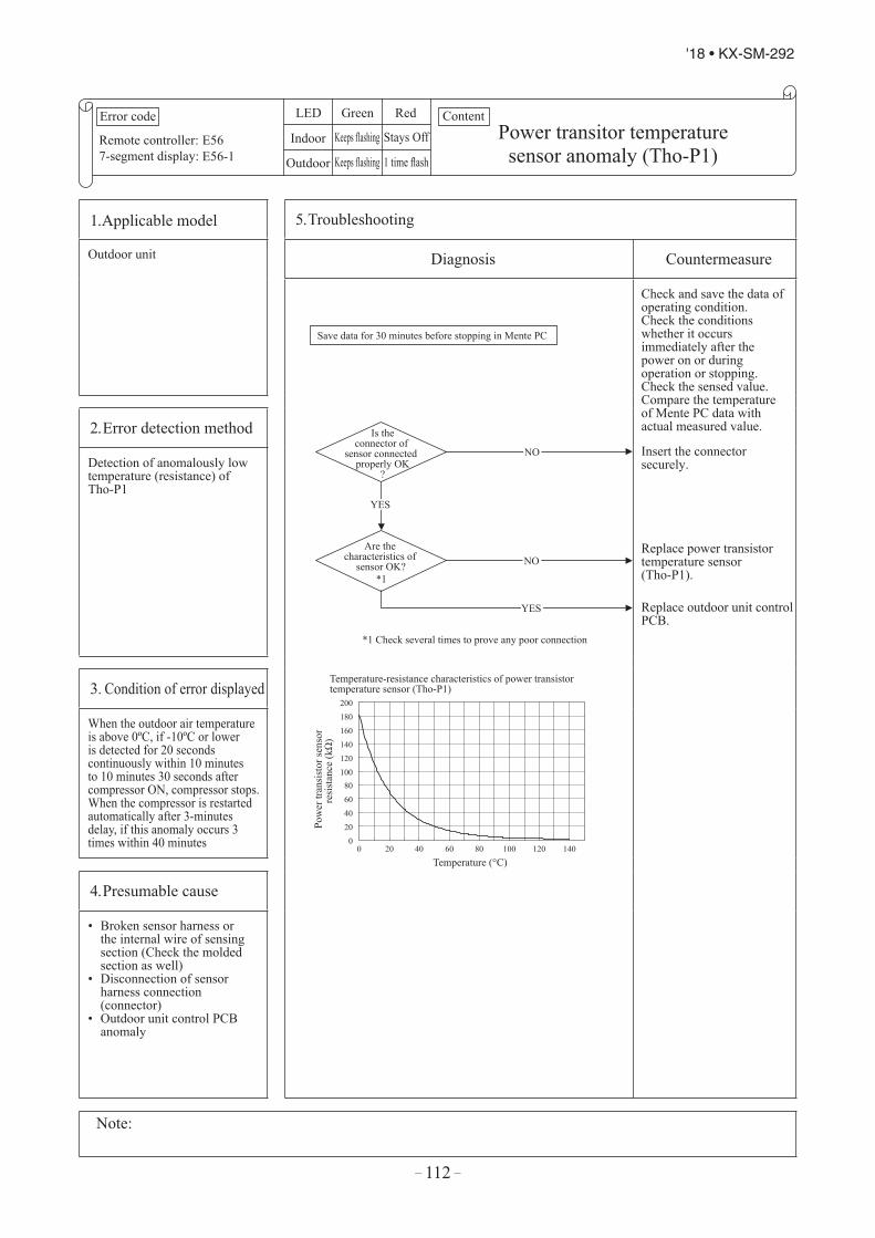
– 112 –
'18 • KX-SM-292
Error code
Remote controller:7-segment display:
LED Green Red
Indoor
Outdoor
Content
E56E56-1
Power transitor temperature sensor anomaly (Tho-P1)
Keeps flashing Stays Off
Keeps flashing 1 time flash
1. Applicable model 5. Troubleshooting
Outdoor unit Diagnosis Countermeasure
Is the connector of
sensor connected properly OK
?
Are the characteristics of
sensor OK?
Temperature-resistance characteristics of power transistor temperature sensor (Tho-P1)
Save data for 30 minutes before stopping in Mente PC
NO
NO
YES
Temperature (°C)
Pow
er tr
ansi
stor
sens
or
resi
stan
ce (k
Ω)
0 20 40 60 80
100 120 140 160 180 200
0 20 40 60 80 100 120 140
*1 Check several times to prove any poor connection
*1
Check and save the data of operating condition.Check the conditions whether it occurs immediately after the power on or during operation or stopping.Check the sensed value.Compare the temperature of Mente PC data with actual measured value.
Insert the connector securely.
Replace power transistor temperature sensor (Tho-P1).
Replace outdoor unit control PCB.
2. Error detection method
Detection of anomalously low temperature (resistance) of Tho-P1
3. Condition of error displayed
When the outdoor air temperature is above 0ºC, if -10ºC or lower is detected for 20 seconds continuously within 10 minutes to 10 minutes 30 seconds after compressor ON, compressor stops. When the compressor is restarted automatically after 3-minutes delay, if this anomaly occurs 3 times within 40 minutes
4. Presumable cause
• Broken sensor harness orthe internal wire of sensingsection (Check the moldedsection as well)
• Disconnection of sensorharness connection(connector)
• Outdoor unit control PCBanomaly
Note:
YES

– 113 –
'18 • KX-SM-292
Error code
Remote controller:7-segment display:
LED Green Red
Indoor
Outdoor
Content
E56E56-1
Power transitor temperature sensor anomaly (Tho-P1)
Keeps flashing Stays Off
Keeps flashing 1 time flash
1. Applicable model 5. Troubleshooting
Outdoor unit Diagnosis Countermeasure
Is the connector of
sensor connected properly OK
?
Are the characteristics of
sensor OK?
Temperature-resistance characteristics of power transistor temperature sensor (Tho-P1)
Save data for 30 minutes before stopping in Mente PC
NO
NO
YES
Temperature (°C)
Pow
er tr
ansi
stor
sens
or
resi
stan
ce (k
Ω)
0 20 40 60 80
100 120 140 160 180 200
0 20 40 60 80 100 120 140
*1 Check several times to prove any poor connection
*1
Check and save the data of operating condition.Check the conditions whether it occurs immediately after the power on or during operation or stopping.Check the sensed value.Compare the temperature of Mente PC data with actual measured value.
Insert the connector securely.
Replace power transistor temperature sensor (Tho-P1).
Replace outdoor unit control PCB.
2. Error detection method
Detection of anomalously low temperature (resistance) of Tho-P1
3. Condition of error displayed
When the outdoor air temperature is above 0ºC, if -10ºC or lower is detected for 20 seconds continuously within 10 minutes to 10 minutes 30 seconds after compressor ON, compressor stops. When the compressor is restarted automatically after 3-minutes delay, if this anomaly occurs 3 times within 40 minutes
4. Presumable cause
• Broken sensor harness orthe internal wire of sensingsection (Check the moldedsection as well)
• Disconnection of sensorharness connection(connector)
• Outdoor unit control PCBanomaly
Note:
YES
Error code
Remote control:7-segment display:
LED Green Red
Indoor
Outdoor
Content
E58E58-1
Anomalous compressor by loss of synchronism
Keeps flashing Stays Off
Keeps flashing 1 time flash
1. Applicable model 5. Troubleshooting
Outdoor unit Diagnosis Countermeasure
Is there any replacement record of
inverter PCB ?
Is this the first startup
within one hour after power is supplied?
Save data for 30 minutes before stopping in Mente PC
Check the data for 30 minutes before stopping
Compressor could be lockedReplace the compressor
Check and save the data of operating condition.
Refrigerant might be migrated in the refrigerant oil in the compressor.Wait for about one hour under the condition of power ON and start again.( Turn the on crankcase heater ON and evaporate the liquid refrigerant migrated in the compressor.
The model setting could be wrong.Check the DIP switch for model setting on the outdoor control PCB.
2. Error detection method
E58 is displayed on 7-segment LED
3. Condition of error displayed
This anomaly is established 4 times within 15 minutes.
4. Presumable cause
• Insufficient time elapsed after the power supplied, before compressor startup.
(Startup the compressor wihtout crankcase heater ON)
• Compressor anomaly
Note: If the error does not recur, connect the Mente PC and continue to collect data.
NO
NO
YES
YES

– 114 –
'18 • KX-SM-292
Error code
Remote control:7-segment display:
LED Green Red
Indoor
Outdoor
Content
E59E59-1 Compressor startup failure (CM1)
Keeps flashing Stays Off
Keeps flashing 1 time flash
1. Applicable model 5. Troubleshooting
Outdoor unit Diagnosis Countermeasure
NO
NO
NO
NO
NO
YES
YES
Is power source voltage
OK?specification of power source voltage380/415V
Is the pressure equalized
during 3-minute delaybefore startup?
Is there any loose connectionor breakage of cable
connected to the terminalof the compressor?
Under the condition of no pressure difference, startup by test operation mode
Is itthe unit with one
compressor?
Is thereany output of
inverter?
Check the data for 30 minutes before stopping
Can startup?
Save data for 30 minutes before stopping in Mente PCCheck and save the data of operating conditions.
Check the power source voltage and correct it.
Check the version No. of software (Is it latest?).Check whether the solenoid valve SV6 at the exit of oil separator is open during compressor stopping.(Is the pressure equalized?)
Replace the cable.(If there is a problem on the terminal of compressor, replace the compressor.)
Check the Model.
Wait and see.
Replace compressor.
Replace inverter PCB or power transistor module.(Check 15V on the outdoor unit control PCB and check power transistor by inverter checker. If the power transistor is OK, replace inverter PCB.)
2. Error detection method
When it fails to change over to the operation for rotor position detection of compressor motor
3. Condition of error displayed
If the compressor fails to startup for 20 times (10 patterns x 2 times) continuously.
4. Presumable cause
• Anomalous voltage of powersource
• Anomalous components forrefrigerant circuit
• Inverter PCB anomaly• Loose connection of
connector or cable• Compressor anomaly (Motor
or bearing)
Note: If the error does not recur, connect the Mente PC and continue to collect data.
NO
YES
YES
YES
YES
Error code
Remote control:7-segment display:
LED Green Red
Indoor
Outdoor
Content
E60E60-1
Rotor position detection failure(CM1)
Keeps flashing Stays Off
Keeps flashing 1 time flash
1. Applicable model 5. Troubleshooting
Outdoor unit Diagnosis Countermeasure
Can the compressor
startup?
Is power source voltage
OK?
Is the sound and vibration of
the compressor normal?
Is it operated normally without occurrence
of E60?
Does E42 occur?
Does E59 occur?
Reset the power source and restart operation
NO
NO
YES
Save data for 30 minutes before stopping in Mente PC
( anomalous sound and vibration )
Check and save the data of operating conditions.
Correct it.
Check it as much as possible under the operating conditions for 30 minutes before error occurred.
Correct it according to the troubleshooting procedure of E59.
Correct it according to the troubleshooting procedure of E42.
Replace compressor.
Check the insulation resistance and coil resistance of compressor.If necessary, replace compressor.
Replace compressor.
Temporary malfunction by noise.
2. Error detection method
Detection of the compressor rotor position.
3. Condition of error displayed
If it fails to detect the rotor position of compressor, after changinging over to the operation of compressor rotor position detection, the compressor stops.When it is restart automatically after 3 minutes delay, this anomaly occurs 4 times within 15 minute after the initial detection
4. Presumable cause
• Compressor anomaly• Inverter PCB anomaly• Anomaly of power source
Note: If the error does not recur, connect the Mente PC and continue to collect data.
NO
NO
NO
YES
YES
YES
YES
YES
YES

– 115 –
'18 • KX-SM-292
Error code
Remote control:7-segment display:
LED Green Red
Indoor
Outdoor
Content
E59E59-1 Compressor startup failure (CM1)
Keeps flashing Stays Off
Keeps flashing 1 time flash
1. Applicable model 5. Troubleshooting
Outdoor unit Diagnosis Countermeasure
NO
NO
NO
NO
NO
YES
YES
Is power source voltage
OK?specification of power source voltage380/415V
Is the pressure equalized
during 3-minute delaybefore startup?
Is there any loose connectionor breakage of cable
connected to the terminalof the compressor?
Under the condition of no pressure difference, startup by test operation mode
Is itthe unit with one
compressor?
Is thereany output of
inverter?
Check the data for 30 minutes before stopping
Can startup?
Save data for 30 minutes before stopping in Mente PCCheck and save the data of operating conditions.
Check the power source voltage and correct it.
Check the version No. of software (Is it latest?).Check whether the solenoid valve SV6 at the exit of oil separator is open during compressor stopping.(Is the pressure equalized?)
Replace the cable.(If there is a problem on the terminal of compressor, replace the compressor.)
Check the Model.
Wait and see.
Replace compressor.
Replace inverter PCB or power transistor module.(Check 15V on the outdoor unit control PCB and check power transistor by inverter checker. If the power transistor is OK, replace inverter PCB.)
2. Error detection method
When it fails to change over to the operation for rotor position detection of compressor motor
3. Condition of error displayed
If the compressor fails to startup for 20 times (10 patterns x 2 times) continuously.
4. Presumable cause
• Anomalous voltage of powersource
• Anomalous components forrefrigerant circuit
• Inverter PCB anomaly• Loose connection of
connector or cable• Compressor anomaly (Motor
or bearing)
Note: If the error does not recur, connect the Mente PC and continue to collect data.
NO
YES
YES
YES
YES
Error code
Remote control:7-segment display:
LED Green Red
Indoor
Outdoor
Content
E60E60-1
Rotor position detection failure(CM1)
Keeps flashing Stays Off
Keeps flashing 1 time flash
1. Applicable model 5. Troubleshooting
Outdoor unit Diagnosis Countermeasure
Can the compressor
startup?
Is power source voltage
OK?
Is the sound and vibration of
the compressor normal?
Is it operated normally without occurrence
of E60?
Does E42 occur?
Does E59 occur?
Reset the power source and restart operation
NO
NO
YES
Save data for 30 minutes before stopping in Mente PC
( anomalous sound and vibration )
Check and save the data of operating conditions.
Correct it.
Check it as much as possible under the operating conditions for 30 minutes before error occurred.
Correct it according to the troubleshooting procedure of E59.
Correct it according to the troubleshooting procedure of E42.
Replace compressor.
Check the insulation resistance and coil resistance of compressor.If necessary, replace compressor.
Replace compressor.
Temporary malfunction by noise.
2. Error detection method
Detection of the compressor rotor position.
3. Condition of error displayed
If it fails to detect the rotor position of compressor, after changinging over to the operation of compressor rotor position detection, the compressor stops.When it is restart automatically after 3 minutes delay, this anomaly occurs 4 times within 15 minute after the initial detection
4. Presumable cause
• Compressor anomaly• Inverter PCB anomaly• Anomaly of power source
Note: If the error does not recur, connect the Mente PC and continue to collect data.
NO
NO
NO
YES
YES
YES
YES
YES
YES
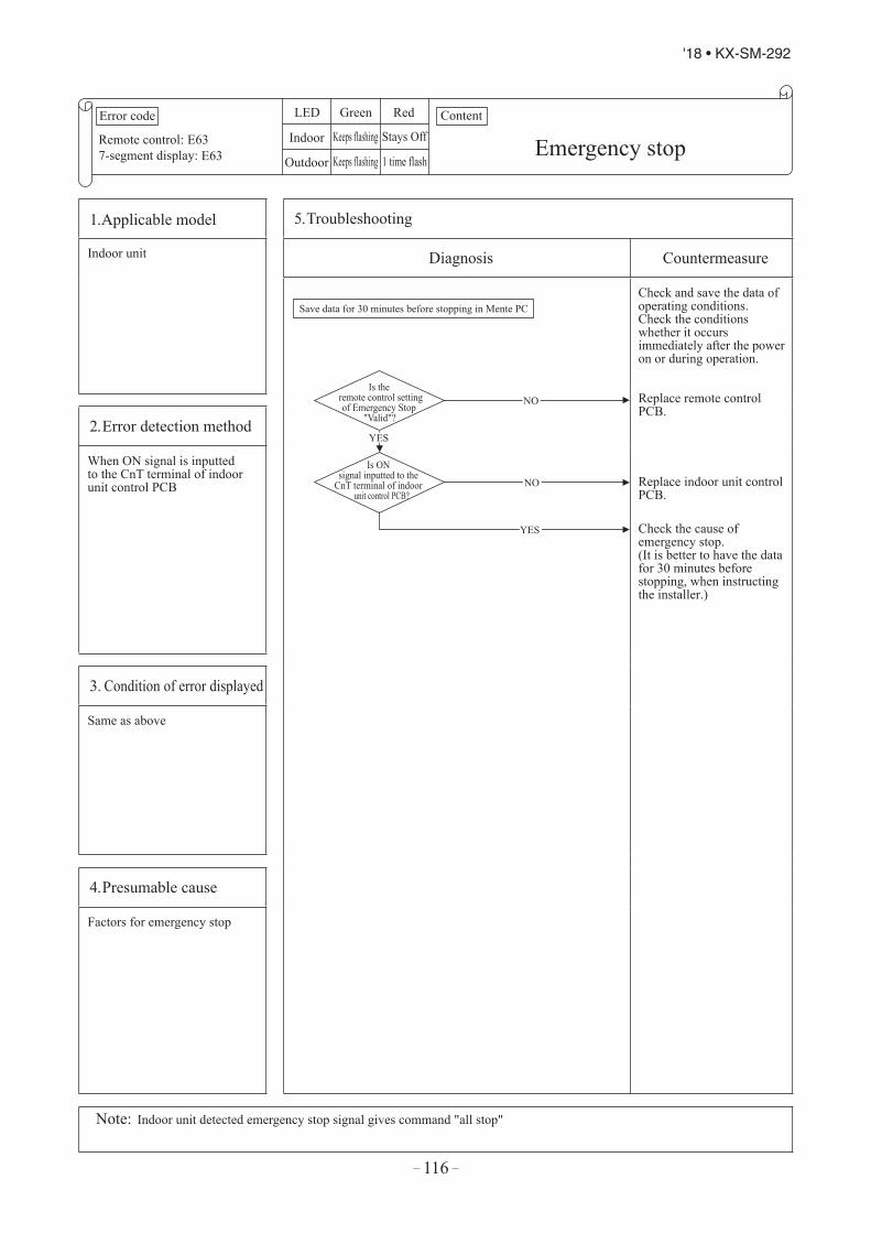
– 116 –
'18 • KX-SM-292
Error code
Remote control:7-segment display:
LED Green Red
Indoor
Outdoor
Content
E63E63 Emergency stopKeeps flashing Stays Off
Keeps flashing 1 time flash
1. Applicable model 5. Troubleshooting
Indoor unit Diagnosis Countermeasure
Is the remote control setting of Emergency Stop
"Valid"?
Is ON signal inputted to the
CnT terminal of indoor unit control PCB?
Save data for 30 minutes before stopping in Mente PC
NO
NO
YES
Check and save the data of operating conditions.Check the conditions whether it occurs immediately after the power on or during operation.
Replace remote control PCB.
Replace indoor unit control PCB.
Check the cause of emergency stop.(It is better to have the data for 30 minutes before stopping, when instructing the installer.)
2. Error detection method
When ON signal is inputted to the CnT terminal of indoor unit control PCB
3. Condition of error displayed
Same as above
4. Presumable cause
Factors for emergency stop
Note: Indoor unit detected emergency stop signal gives command "all stop"
YES
2.4 Outdoor unit control PCB replacement procedure
(Note) If cut the tie, the wiring cables should be bound with new tie again. Exchange the control PCB according to the following procedure.① Replace the control PCB after elapsing 3 minutes from power OFF.
(Be sure to measure voltage (DC) at both capacitor terminals (1. Power source for PCB 2. Power source for fan motor) and check that the voltage is discharged completely. (Refer to Fig.1))
② Disconnect the connectors from the PCB.③ Disconnect the blue wiring passing through CT1 on the PCB before replace the coutrol PCB.④ Set the setting switches (SW1-6) and jumper wires (J11-16) of new PCB same as previous PCB.⑤ Tighten up a screw after passing blue wiring through CT1 of the changed.⑥ Connect the connectors to the PCB. (Contirm the connectors are not half inserted.)
After elapsing 3 minutes from power OFF
CNQ3 2
CT1
LED2(Green)
CNN2
CNTH
CNEEV1
CNN9
CNI
only FDC335KXZME1
CNL1
CNFAN_2
CNR1
CNB2
CNEEV2 CNQ1
CNFAN_1
CNN6
CNW SW3-6
CNM1CNN1
SW1,2J11-16
Parts arrangement view
1 Reuse the parts used before the PCB exchange. 2 Please do not carry out wrong insertion.
The PCB will be destroyed if a mistake is made in putting CNA2 (brown) and CNQ3 (yellow).
CNA2 CNQ3
LED3(Green)
LED1(Red)
CNA2 2
CN 2
CNS1 CNS2 CNG1 CNG2
CNX1
CNU1CNF2 CNF1 CNP1
Precautions for Safety Since the following precaution is the important contents for safety, be sure to observe them.
WARNING and CAUTION are described as follows:Indicates an imminently hazardous situation which will result in death or serious injury if proper safety procedures and instructions are not adhered to.Indicates a potentially hazardous situation which may result in minor or moderate injury if proper safety procedures and instructions are not adhered to.
WARNING Securely replace PCB according to this following instruction.
If PCB is incorrectly replace, it will cause an electric shock or re. Be sure to check that the power source for the outdoor unit is turned OFF before replace PCB,
The PCB replacement under current-carrying will cause an electric shock. After nishing PCB replacement, check that wiring is correctly connected with the PCB before power
distribution, If PCB is incorrectly replace, it will cause an electric shock or re.
CAUTION Bundle the wiring so as not to tense because it will cause an electric shock.
WARNING
CAUTION
LPCB012D017G
134

– 117 –
'18 • KX-SM-292
Error code
Remote control:7-segment display:
LED Green Red
Indoor
Outdoor
Content
E63E63 Emergency stopKeeps flashing Stays Off
Keeps flashing 1 time flash
1. Applicable model 5. Troubleshooting
Indoor unit Diagnosis Countermeasure
Is the remote control setting of Emergency Stop
"Valid"?
Is ON signal inputted to the
CnT terminal of indoor unit control PCB?
Save data for 30 minutes before stopping in Mente PC
NO
NO
YES
Check and save the data of operating conditions.Check the conditions whether it occurs immediately after the power on or during operation.
Replace remote control PCB.
Replace indoor unit control PCB.
Check the cause of emergency stop.(It is better to have the data for 30 minutes before stopping, when instructing the installer.)
2. Error detection method
When ON signal is inputted to the CnT terminal of indoor unit control PCB
3. Condition of error displayed
Same as above
4. Presumable cause
Factors for emergency stop
Note: Indoor unit detected emergency stop signal gives command "all stop"
YES
2.4 Outdoor unit control PCB replacement procedure
(Note) If cut the tie, the wiring cables should be bound with new tie again. Exchange the control PCB according to the following procedure.① Replace the control PCB after elapsing 3 minutes from power OFF.
(Be sure to measure voltage (DC) at both capacitor terminals (1. Power source for PCB 2. Power source for fan motor) and check that the voltage is discharged completely. (Refer to Fig.1))
② Disconnect the connectors from the PCB.③ Disconnect the blue wiring passing through CT1 on the PCB before replace the coutrol PCB.④ Set the setting switches (SW1-6) and jumper wires (J11-16) of new PCB same as previous PCB.⑤ Tighten up a screw after passing blue wiring through CT1 of the changed.⑥ Connect the connectors to the PCB. (Contirm the connectors are not half inserted.)
After elapsing 3 minutes from power OFF
CNQ3 2
CT1
LED2(Green)
CNN2
CNTH
CNEEV1
CNN9
CNI
only FDC335KXZME1
CNL1
CNFAN_2
CNR1
CNB2
CNEEV2 CNQ1
CNFAN_1
CNN6
CNW SW3-6
CNM1CNN1
SW1,2J11-16
Parts arrangement view
1 Reuse the parts used before the PCB exchange. 2 Please do not carry out wrong insertion.
The PCB will be destroyed if a mistake is made in putting CNA2 (brown) and CNQ3 (yellow).
CNA2 CNQ3
LED3(Green)
LED1(Red)
CNA2 2
CN 2
CNS1 CNS2 CNG1 CNG2
CNX1
CNU1CNF2 CNF1 CNP1
Precautions for Safety Since the following precaution is the important contents for safety, be sure to observe them.
WARNING and CAUTION are described as follows:Indicates an imminently hazardous situation which will result in death or serious injury if proper safety procedures and instructions are not adhered to.Indicates a potentially hazardous situation which may result in minor or moderate injury if proper safety procedures and instructions are not adhered to.
WARNING Securely replace PCB according to this following instruction.
If PCB is incorrectly replace, it will cause an electric shock or re. Be sure to check that the power source for the outdoor unit is turned OFF before replace PCB,
The PCB replacement under current-carrying will cause an electric shock. After nishing PCB replacement, check that wiring is correctly connected with the PCB before power
distribution, If PCB is incorrectly replace, it will cause an electric shock or re.
CAUTION Bundle the wiring so as not to tense because it will cause an electric shock.
WARNING
CAUTION
LPCB012D017G
134
2.4 Outdoor unit control PCB replacement procedure
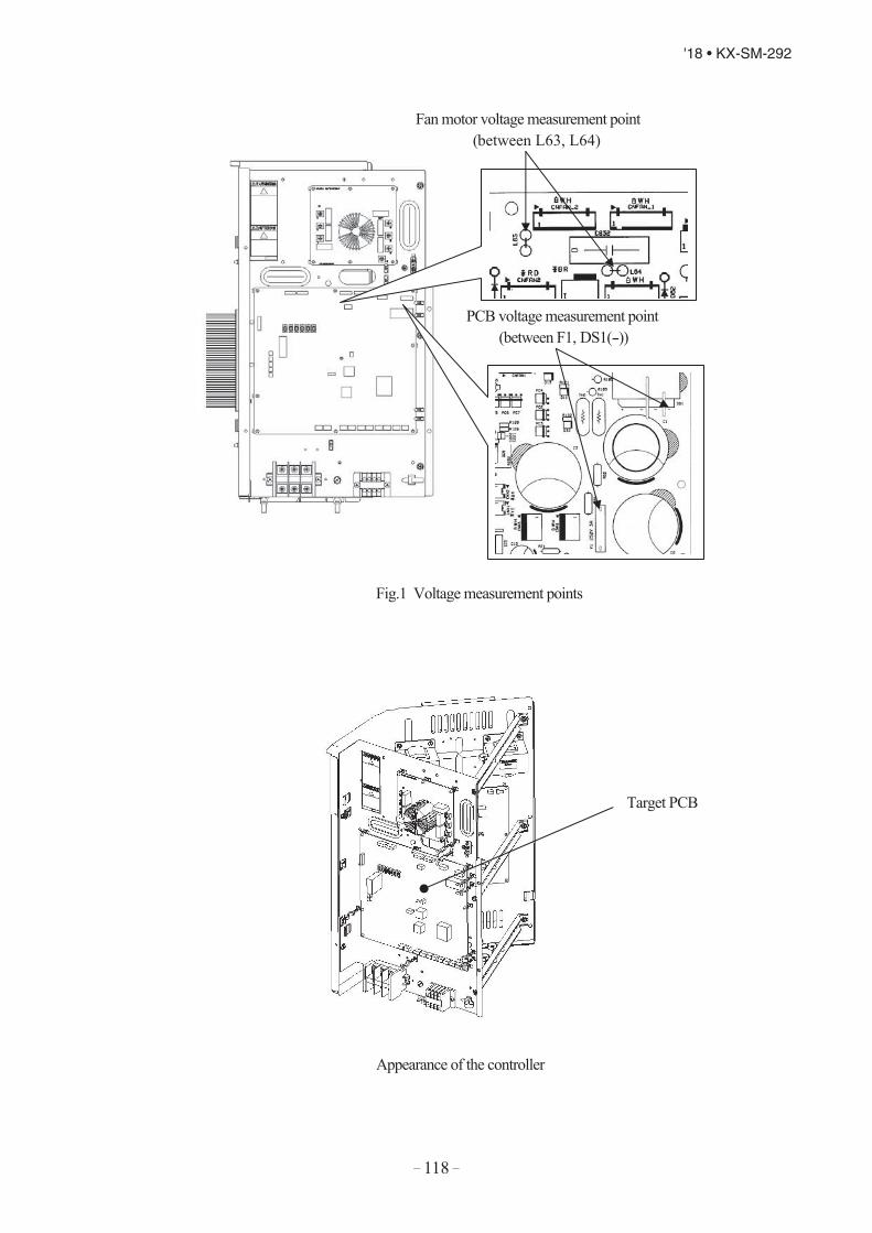
– 118 –
'18 • KX-SM-292
Appearance of the controller
PCB voltage measurement point (between F1, DS1(-))
Target PCB
Fan motor voltage measurement point (between L63, L64)
Fig.1 Voltage measurement points

– 119 –
'18 • KX-SM-292
Appearance of the controller
PCB voltage measurement point (between F1, DS1(-))
Target PCB
Fan motor voltage measurement point (between L63, L64)
Fig.1 Voltage measurement points
2.5 Inverter PCB replacement procedure
(Note) If cut the tie, the wiring cables should be bound with new tie again.Exchange the inverter PCB according to the following procedure.① Replace the inverter PCB after elapsing 3 minutes from power OFF.
(Be sure to measure voltage (DC) of two places (1. Power source for PCB 2. Power source for fan motor) and checkthat the voltage is discharged completely. (Refer to Fig.1))
②Disconnect all of terminals and connectors from the inverter PCB before replace the invertor PCB.③Replace to the new PCB.④Set the setting switches (JSW 10, 11) of new PCB as shown in table 1.⑤ Connect all of terminals and connectors to the new PCB securely.
(Check the secure connection of terminals and connectors again)
WARNING
CAUTION
Connectors are not half inserted
After elapsing 3 minutes from power OFF
Table.1 Switch Setting
Parts Arrangement View
CNA CNI2
LED1(Yellow)
CNR
JSW10,11
JSW101 2 3 4
JSW11Model
All models all OFF OFF OFFON OFF
Precautions for Safety Since the following precaution is the important contents for safety, be sure to observe them.WARNING and CAUTION are described as follows:
Indicates an imminently hazardous situation which will result in death or serious injury if proper safety procedures and instructions are not adhered to.Indicates a potentially hazardous situation which may result in minor or moderate injury if proper safety procedures and instructions are not adhered to.
WARNING
Securely replace PCB according to this following instruction.If PCB is incorrectly replace, it will cause an electric shock or re. Be sure to check that the power source for the outdoor unit is turned OFF before replace PCB,The PCB replacement under current-carrying will cause an electric shock. After nishing PCB replacement, check that wiring is correctly connected with the PCB before power distribution, If PCB is incorrectly replace, it will cause an electric shock or re.
CAUTION Bundle the wiring so as not to tense because it will cause an electric shock.
KPCB012D018AB 2.5 Inverter PCB replacement procedure

– 120 –
'18 • KX-SM-292
Target pwb
Pwb voltage measurement point(F1-DS(-))
Fan motor voltage measurement point(L63 - L64)
• Procedure on tightening harness (snubber capacitor) and power transistor with screw.A metallic connection binder is set in each hole of the inverter PCB of "P", "N", "U", "V", and "W" beforehand. Then tighten the harness (snubber capacitor) and the power transistor with the screw together.(Connect snubber capacitor with "P" and "N".)
Installation method to power transistor
Fig.1 Voltage Measurement Points
Terminal
Inverter PCBConnection binder
Snubber capacitorHarness
Power transistor (Metallic pillar)
PCB
PCB voltage measurement point
PCB voltage measurement point
Fig.1 Voltage measurement points

– 121 –
'18 • KX-SM-292
Target pwb
Pwb voltage measurement point(F1-DS(-))
Fan motor voltage measurement point(L63 - L64)
• Procedure on tightening harness (snubber capacitor) and power transistor with screw.A metallic connection binder is set in each hole of the inverter PCB of "P", "N", "U", "V", and "W" beforehand. Then tighten the harness (snubber capacitor) and the power transistor with the screw together.(Connect snubber capacitor with "P" and "N".)
Installation method to power transistor
Fig.1 Voltage Measurement Points
Terminal
Inverter PCBConnection binder
Snubber capacitorHarness
Power transistor (Metallic pillar)
PCB
PCB voltage measurement point
PCB voltage measurement point
Fig.1 Voltage measurement points
Function of DIP switch for control•SW3 (Function setting)
Switch Function
SW3-1ON Inspection LED resetOFF Normal
SW3-7ON Forced cooling/heatingOFF Normal
Function of Jumper wire (J13, 15)(With: Shorted / None: Opened)
Jumper Function
J13With External input Level inputNone External input Pulse input
J15With Defrost time NormalNone Defrost time Cold weather region
•SW5 (Function setting)
ON/OFF Function
SW5-1ON Test run switch Test runOFF Test run switch Normal
SW5-2ON Test run operation mode CoolingOFF Test run operation mode Heating
SW5-3ON Pump down switch Pump downOFF Pump down switch Normal
SW5-5ON Superlink protocol: Previos SLOFF Superlink protocol: New SL
•SW7, 8, 9 (Function setting)
Switch Function
SW7 Data erase/data writeSW8 7-segment dispalay No.UP order of 1SW9 7-segment dispalay No.UP order of 10
Function of Connector
Connector Function Color Connector Function ColorCNEEV1 Heating EEV (EEVH) Red CNF2 Sub-cooling coil temperature sensor (Tho-H) Green
Green
CNEEV2 Sub-cooling coil EEV (EEVSC) Blue CNP1 Power transistor temperature sensor (Tho-P1) YellowCNA2 Power fan motor Brown CNL1 High pressure sensor (PSH) BlueCNFAN1 Fan motor 1 (FMo1) White
WhiteCNL2 Low pressure sensor (PSL) White
CNFAN2 Fan motor 2 (FMo2) CNS1 External inputCNQ1 High pressure switch (CM1) White CNS2 Demand input
CNTH
Heat exchanger temperature sensor (Tho-R1)
White
CNN1 4-way switching solenoid valve (20S) RedRed
Discharge pipe temperature sensor (Tho-D1) CNN2 Solenoid valve (oil return) (SV6) GreenSuction pipe temperature sensor (Tho-S) CNN6 Solenoid valve (liquid bypass) (SV1) PinkExternal air temperature sensor (Tho-A) CNN9 Solenoid valve (gas bypass) (SV11) Black
CNB2 Heat exchanger temperature sensor (Tho-R2) Red CNM1 Solenoid for CM (52X1,2) GrayCNU1 Under-dome temperature sensor (Tho-C1) Blue CNR1 Crankcase heater (CH1) WhiteCNF1 Sub-cooling coil temperature sensor (Tho-SC) White
*
*CNN9 : only FDC335KXZME1

– 122 –
'18 • KX-SM-292
SW1 4SW2 9SW3-1 OFF
OFFSW3-3 OFFSW3-4 OFFSW3-5 OFFSW3-6 OFFSW3-7 OFFSW3-8 OFFSW4-1SW4-2SW4-3SW4-4SW4-5 OFFSW4-6 OFFSW4-7 OFFSW4-8 OFFSW5-1 OFFSW5-2 OFFSW5-3 OFFSW5-4 OFFSW5-5 OFFSW5-6 OFFSW5-7 OFFSW5-8 OFFSW6-1 OFFSW6-2 ONSW6-3 OFFSW6-4 OFFSW6-5 OFFSW6-6 ONSW6-7 OFFSW6-8 OFFSW7 Data Erase/Write OFFSW8 0SW9 0J10 WithJ11J12J13 With
WithJ15 WithJ16 With
* Default setting
Table 1: Model selection with SW4-1-SW4-4 and J160: OFF 1:ON
224 280 3350 1 00 0 10 0 00 0 1
None None None
Table 2: Demand ratio selection with SW4-5, SW4-60: OFF 1:ON
Table 3: Power voltage selection with J11, J120: None 1: With
Switch RemarksSW1 0SW2 0SW3 4SW4 9SW5-1 OFFSW5-2 OFF OFF: 0, ON: 1SW6-1SW6-2SW6-3SW6-4SW7-1 OFFSW7-2 OFFSW7-3 OFFSW7-4 OFFJSL1 With
* Default setting
Table 1: Indoor unit model selection with SW6-1-SW6-40: OFF 1:ON
P22 P28 P36 P45 P56 P71 P80 P90 P112 P140 P160 P224 P280SW6-1 0 1 0 0 0 0 1 0 1 0 1 0 1SW6-2 0 0 1 0 1 0 0 1 1 0 0 1 1SW6-3 0 0 0 1 1 0 0 0 0 1 1 1 1SW6-4 0 0 0 0 0 1 1 1 1 1 1 1 1
keep OFF
J14 Spare Keep With
ReservedForced heating/cooling Reserved
Normal*/Forced
Normal*/Cold region
7-segment display code No. increase (Order of 1)7-segment display code No. increase (Order of 10)Superlink terminal spare Normal*/switch to spare
Power voltage selection
KXR/KXDefrost start temperatureOutdoor unit type selection
External input Level*/Pulse
See table 1
Level
NormalKXR
See table 3
Normal
As per voltage
EraseErase*/Write
SpareSpareSpareModel selectionSpareSpare
Reserved
ReservedReservedReservedReserved
Keep OFFKeep OFF
HeatingNormal
New SL(Auto)
Keep OFFKeep OFFKeep OFF
Keep OFFKeep OFFKeep OFFKeep OFFKeep OFF
Reserved
Keep OFFKeep OFF
Keep OFF
Spare
New SL*/Previous SL
NormalNormal*/Test run
Reserved
Check operation startReservedSpare
Normal*/Start
Spare
Outdoor address No. (Order of 1) Normal*/ResetInspection LED reset
Outdoor address No. (Order of 10)
keep OFF
Normal
Normal
Normal
keep OFF
keep OFF
0-9
keep OFF
Description Default setting Remarks
0-9
380/415V 50Hz 0 0
Heating*/CoolingNormal*/Pump down
Test run modePump down operation
Outdoor unit J11 J12
Test run SW
Compressor capacity (%)
380V 60Hz 0 1
01 1
Superlink selection
0
As per model See table 1
Demand ratio selection See table 2
Model selection
1 401 0 60
SW4-60 0 80
SW4-3SW4-4J16
SW4-5
Switch
SW4-1SW4-2
SW3-2
Description Default settingIndoor unit address No. (Order of 10) 0-9Indoor unit address No. (Order of 1) 0-9Outdoor unit address No. (Order of 10) 0-9Outdoor unit address No. (Order of 1) 0-9Superlink selection Automatic*/Previous SL AutomaticIndoor unit address No. (Order of 100) 0
Model selection As per model See table 1
Test run, Drain motor Normal*/Test run NormalReserved keep OFFSpare keep OFFReserved keep OFFSuperlink terminal spare Normal*/switch to spare Normal
1 OFFOFFOFFOFFOFFONOFFOFF
2341234
JSW11
JSW10SW4-2
DIP Switch setting list(1) Outdoor unit
(a) Control PCB
(2) Indoor unit
(b) Inverter PCB

– 123 –
'18 • KX-SM-292
SW1 4SW2 9SW3-1 OFF
OFFSW3-3 OFFSW3-4 OFFSW3-5 OFFSW3-6 OFFSW3-7 OFFSW3-8 OFFSW4-1SW4-2SW4-3SW4-4SW4-5 OFFSW4-6 OFFSW4-7 OFFSW4-8 OFFSW5-1 OFFSW5-2 OFFSW5-3 OFFSW5-4 OFFSW5-5 OFFSW5-6 OFFSW5-7 OFFSW5-8 OFFSW6-1 OFFSW6-2 ONSW6-3 OFFSW6-4 OFFSW6-5 OFFSW6-6 ONSW6-7 OFFSW6-8 OFFSW7 Data Erase/Write OFFSW8 0SW9 0J10 WithJ11J12J13 With
WithJ15 WithJ16 With
* Default setting
Table 1: Model selection with SW4-1-SW4-4 and J160: OFF 1:ON
224 280 3350 1 00 0 10 0 00 0 1
None None None
Table 2: Demand ratio selection with SW4-5, SW4-60: OFF 1:ON
Table 3: Power voltage selection with J11, J120: None 1: With
Switch RemarksSW1 0SW2 0SW3 4SW4 9SW5-1 OFFSW5-2 OFF OFF: 0, ON: 1SW6-1SW6-2SW6-3SW6-4SW7-1 OFFSW7-2 OFFSW7-3 OFFSW7-4 OFFJSL1 With
* Default setting
Table 1: Indoor unit model selection with SW6-1-SW6-40: OFF 1:ON
P22 P28 P36 P45 P56 P71 P80 P90 P112 P140 P160 P224 P280SW6-1 0 1 0 0 0 0 1 0 1 0 1 0 1SW6-2 0 0 1 0 1 0 0 1 1 0 0 1 1SW6-3 0 0 0 1 1 0 0 0 0 1 1 1 1SW6-4 0 0 0 0 0 1 1 1 1 1 1 1 1
keep OFF
J14 Spare Keep With
ReservedForced heating/cooling Reserved
Normal*/Forced
Normal*/Cold region
7-segment display code No. increase (Order of 1)7-segment display code No. increase (Order of 10)Superlink terminal spare Normal*/switch to spare
Power voltage selection
KXR/KXDefrost start temperatureOutdoor unit type selection
External input Level*/Pulse
See table 1
Level
NormalKXR
See table 3
Normal
As per voltage
EraseErase*/Write
SpareSpareSpareModel selectionSpareSpare
Reserved
ReservedReservedReservedReserved
Keep OFFKeep OFF
HeatingNormal
New SL(Auto)
Keep OFFKeep OFFKeep OFF
Keep OFFKeep OFFKeep OFFKeep OFFKeep OFF
Reserved
Keep OFFKeep OFF
Keep OFF
Spare
New SL*/Previous SL
NormalNormal*/Test run
Reserved
Check operation startReservedSpare
Normal*/Start
Spare
Outdoor address No. (Order of 1) Normal*/ResetInspection LED reset
Outdoor address No. (Order of 10)
keep OFF
Normal
Normal
Normal
keep OFF
keep OFF
0-9
keep OFF
Description Default setting Remarks
0-9
380/415V 50Hz 0 0
Heating*/CoolingNormal*/Pump down
Test run modePump down operation
Outdoor unit J11 J12
Test run SW
Compressor capacity (%)
380V 60Hz 0 1
01 1
Superlink selection
0
As per model See table 1
Demand ratio selection See table 2
Model selection
1 401 0 60
SW4-60 0 80
SW4-3SW4-4J16
SW4-5
Switch
SW4-1SW4-2
SW3-2
Description Default settingIndoor unit address No. (Order of 10) 0-9Indoor unit address No. (Order of 1) 0-9Outdoor unit address No. (Order of 10) 0-9Outdoor unit address No. (Order of 1) 0-9Superlink selection Automatic*/Previous SL AutomaticIndoor unit address No. (Order of 100) 0
Model selection As per model See table 1
Test run, Drain motor Normal*/Test run NormalReserved keep OFFSpare keep OFFReserved keep OFFSuperlink terminal spare Normal*/switch to spare Normal
1 OFFOFFOFFOFFOFFONOFFOFF
2341234
JSW11
JSW10SW4-2
DIP Switch setting list(1) Outdoor unit
(a) Control PCB
(2) Indoor unit
(b) Inverter PCB
LED3
AC1 VU
WCM
RDWHBL
L1
KG
SIGN
ALLIN
E
TB2 A1 B1
L3TB1
L1 L2
SW2
M
R2
MM
EEVH
EEVS
CFM
o1M
FMo2
PWB1
SW1 CO
NTRO
L
t°t°
t°t°
t°
J13
SW7
SW8
SW9
YE
J11
J12
7SEG
17S
EG2
ON OFF
12
33
65
47
82
15
47
68
J15
J14
LED1
LED2
SW3
SW4
RD
CH1 BR
BL20S
BLSV6
Exter
nal
input
Dema
ndinp
ut
12
73
45
68
PC(
RS23
2C)
CNV
SW5
BLSV1
Oper
ation
outpu
t
Cooli
ng/
Heati
ngfor
ced i
nput
Trou
bleou
tput
Silen
t mod
einp
ut
63H1
-1
MS 3~
Earth
leak
age
brea
ker
POW
ER S
OURC
E
t°t°
t°t°
A2 B2
BLRD WHL1
i
L2i
L3i
L1o
L2o
L3o
E
-6+4
R5DM
L2
+
R4 IPM
PN
VU
WPW
B2
F1(
6A)
AC2AC3
CNSL
1,2
L3
BK
PSH WH
RD
PSL
BKBK
BLWH BLRD
BKBKBKBK
BLRD
WHWH
BKBL WH BK
BKGN
BL BL
RD
BETW
EEN
THE
INDO
OR U
NIT
AND
THE
OUTD
OOR
UNIT
BETW
EEN
THE
OUTD
OOR
UNIT
SA2
B2
A1B1
LED1
(INV
)
Rese
ave
outpu
t
C2
BKBla
ckBL BR GN GR OR RD WH Y/G
N
Blue
Brown
Gree
nGr
ayOr
ange
Red
White
Yellow
Pink
Yellow
/Gree
n
4
NNi
No
R1
RD
+
R3C1
BKBK
Va1Va2Va3
SA
Y/GN
GN
WH
WHRD
BL
RDWH
RD
RD
NETW
ORK
CONN
ECTO
R
BKWHRD
BR
RD
BL
WHOR
ORWH
BL
RD
BR
WHYEOR
RDBRBL
BLBRRD
ORYEWH
BK
BK
BK
BK
BK
BK
BK
BK
WH
WH
NOIS
EFI
LTER
PWB3
CNR
(W
H)
INVE
RTER
CNA
(W
H)
CNI2
(W
H)
CNX1
CNA1
(W
H)
CNA2
(BR
)
CNI1
(W
H)
CNW
(RD
)CN
R1(
WH)
CNN1
(RD
)CN
N6CN
N2(
GN)
CNQ1
(W
H)CN
L1(
BL)
CNL2
(W
H)CN
Z1(
RD)
CNH
(BL
)
CNY
(W
H)
CNG1
(BL
)
CNG2
(W
H)
CNS2
(RD
)
CNS1
(GN
)
CNP1
CNU1
(BL
)CN
F2(
GN)
CNF1
(W
H)CN
B2(
RD)
CNTH
(W
H)CN
EEV2
(BL
)CN
EEV1
(RD
)CN
FAN_
2(
WH)
CNFA
N_1
(W
H)
Tho-R1
Tho-D1
Tho-S
Tho-A
Tho-R2
Tho-SC
Tho-H
Tho-C1
Tho-P1
WH
WH
BK52X2
CNM1
RDBKWH
380/
415V
3N~
50Hz
380V
3
N~ 60
Hz
YEYERD
WH
WH
12
73
45
68
SW6
CH1
Cran
kcase
heate
rCM
Comp
resso
r moto
rCN
A-Z1
Conn
ector
CT1
Curre
nt se
nsor
C1, 2
Electr
olytic
capa
citor
DMDio
de m
odule
EEVH
Heati
ng ex
pans
ion va
lveEE
VSC
Supe
r-coo
ling co
il exp
ansio
n valv
eFM
o1,2
Blowe
r moto
rF1
Fuse
IPMInt
ellige
nt po
wer m
odule
J11,1
2Po
wer s
ource
, volt
age s
witch
ingJ1
3Ex
terna
l inpu
t swit
ching
leve
l/pu
lseJ1
4Sp
areJ1
5De
frost
opera
tion s
tart te
mpera
ture s
electio
n,no
rmal/
cold
region
LED1
Inspe
ction (
Red)
LED1
(INV
)No
rmal
(Yello
w) F
lashin
gLE
D2No
rmal
(Gree
n)LE
D3Se
rvice
(Gr
een)
L1-L3
DC re
actor
PSH
High p
ressu
re se
nsor
PSL
Low p
ressu
re se
nsor
PWB1
-3PC
BR1
-4Ru
sh cu
rrent
supp
ressio
n res
istor
SV1
Solen
oid va
lve (
fluid
return
)SV
6So
lenoid
valve
(oil
return
)
SW1
SW2
SW3-1
Inspe
ction L
ED re
set
SW3-2
-5Sp
are
SW3-7
ONFo
rced h
eatin
g/co
oling m
ode
OFF
Norm
al op
eratio
nSW
3-8ON
Test
mode
OFF
Norm
al op
eratio
nSW
4-1-4
Mode
l settin
gSW
4-5,6
Dema
nd sw
itching
SW4-7
,8Sp
areSW
5-1ON
Test
runOF
FNo
rmal
opera
tion
SW5-2
ONCo
oling a
t test
runOF
FHe
ating
at te
st run
SW5-3
ONPu
mp-do
wn op
eratio
nOF
FNo
rmal
opera
tion
SW5-4
Spare
SW5-5
ONSu
perlin
k com
munic
ation
OFF
Supe
rlink
com
munic
ation
SW7
Data
delet
e/wr
iteSW
87-s
egme
nt ind
icatio
n up (
1 digit
)SW
97-s
egme
nt ind
icatio
n up (
2 digit
s)
TB1,2
Term
inal b
lock
Tho-A
Exter
nal a
ir tem
perat
ure se
nsor
Tho-C
1Un
der-d
ome t
empe
rature
sens
orTh
o-D1
Disch
arge p
ipe te
mpera
ture s
enso
rTh
o-HSu
per-c
ooling
coil te
mpera
ture s
enso
r 2Th
o-P1
Powe
r tran
sistor
temp
eratur
e sen
sor
Tho-R
1He
at ex
chan
ger te
mpera
ture s
enso
r 1 (
Exit/
front)
Tho-R
2He
at ex
chan
ger te
mpera
ture s
enso
r 2 (
Exit/
rear)
Tho-S
Suctio
n pipe
temp
eratur
e sen
sor
Tho-S
CSu
per-c
ooling
coil te
mpera
ture s
enso
r 1X0
1-03,0
6-09
Aux.
relay
7SEG
17-s
egme
nt LE
D (Da
ta dis
play)
7SEG
27-s
egme
nt LE
D (Fu
nctio
n disp
lay)
20S
4-way
switch
ing so
lenoid
52X1
,2So
lenoid
for C
M63
H1-1
High p
ressu
re sw
itch
Addre
ss se
tting s
witch
outdo
or un
it No.
(2 di
gits)
Addre
ss se
tting s
witch
outdo
or un
it No.
(1 di
git)
52X1
52X2
52X1
(YE
)
(GY
)(
PK)
(YE
)
5 or 6
Wire
s5 o
r 6 W
ires
local
wiring
.sh
ows
SW6-6
Mode
l settin
g
SW3-6
ONPip
e was
hing m
ode
OFF
Norm
al op
eratio
n
Comp
ress
orter
mina
l bloc
k
U(Re
d)V(
Whit
e)
W(
Blue
)
Circu
it bre
aker
Color
mar
kMa
rkCo
lor
Name
Mark
Name
Mark
Name
Mark
YE PK
3. ELECTRICAL WIRINGModels FDC224KXZME1, 280KXZME1
PCB004Z334

– 124 –
'18 • KX-SM-292
LED3
AC1 VU
WCM
RDWHBL
L1
KG
SIGN
ALLIN
E
TB2 A1 B1
L3TB1
L1 L2
SW2
M
R2
MM
EEVH
EEVS
CFM
o1M
FMo2
PWB1
SW1 CO
NTRO
LSW
7
SW8
SW9
YE
7SEG
17S
EG2
ON OFF
12
33
65
47
82
15
47
68
LED1
LED2
SW3
SW4
RD
CH1 BR
BL20S
BLSV6
input
Dema
ndinp
ut
12
73
45
68
PCCNV
SW5
BLSV1
Oper
ation
outpu
t
force
d inp
ut
Trou
bleou
tput
Silen
t mod
einp
ut
63H1
-1
MS
POW
ER S
OURC
E A2 B2
BLRD WHL1
i
L2i
L3i
L1o
L2o
L3o
E
-6R5
DM
L2
R4 IPM
PN
VU
WPW
B2
AC2AC3
CNSL
1,2
L3
BK
PSH WH
RD
PSL
BKBK
BLWH BLRD
BKBKBKBK
BLRD
WHWH
BKBL WH BK
BKGN
BL BL
RD
BETW
EEN
THE
INDO
OR U
NIT
AND
THE
OUTD
OOR
UNIT
BETW
EEN
THE
OUTD
OOR
UNIT
SA2
B2
A1B1
outpu
t
C2
BK BL BR GN GR OR RD WH YE PK
Blue
Brown
Gree
nGr
ay
Red
White
Yellow
4
NNi
No
R1
RD
R3C1
BKBK
Va1Va2Va3
SA
GN
WH
WHRD
BL
RDWH
RD
RD
NETW
ORK
CONN
ECTO
R
BKWHRD
BR
RD
BL
WHOR
ORWH
BL
RD
BR
WHYEOR
RDBRBL
BLBRRD
ORYEWH
BK
BK
BK
BK
BK
BK
BK
BK
WH
WH
NOIS
EFI
LTER
PWB3
CNR
INVE
RTER
CNA
CNI2
CNX1
CNA1
CNA2
CNI1
CNW
CNR1
CNN1
CNN6
CNN2
BLSV11
CNN9 BK
CNL1
CNL2
CNZ1
CNH
CNY
CNG1
CNG2
CNS2
CNS1
CNP1
CNU1
CNF2
CNF1
CNB2
CNTH
CNEE
V2CN
EEV1
Tho-R1
Tho-D1
Tho-S
Tho-A
Tho-R2
Tho-SC
Tho-H
Tho-C1
Tho-P1
WH
WH
BK52X2
CNM1
RDBKWH
YEYERD
WH
WH
12
73
45
68
SW6
CH1
CMCo
mpres
sor m
otor
CNA-Z
1Co
nnec
torCT
1Cu
rrent
sens
orC1
, 2Ele
ctroly
tic ca
pacito
rDM
Diode
mod
uleEE
VHEE
VSC
FMo1
,2Blo
wer m
otor
F1Fu
seIPM
Spare
LED1
LED2
LED3
DC re
actor
PSH
PSL
Low p
ressu
re se
nsor
PCB
R1-4
Rush
curre
nt su
ppres
sion r
esisto
rSV
1SV
6
SW1
SW2
SW3-1
SW3-2
-5
SW4-1
-4X0
1-03,0
6-09
Inspe
ction L
ED re
set
Spare
SW3-7
ON OFF
Norm
al op
eratio
nSW
3-8ON
Test
mode
OFF
Norm
al op
eratio
n
SW4-5
,6SW
4-7,8
Spare
SW5-1
ONTe
st run
OFF
Norm
al op
eratio
nSW
5-2ON OF
FSW
5-3ON
Pump
-down
opera
tion
OFF
Norm
al op
eratio
nSW
5-4Sp
areSW
5-5ON OF
F
SW7
SW8
SW9
TB1,2
Tho-A
Tho-C
1Un
der-d
ome t
empe
rature
sens
orTh
o-D1
Tho-H
Tho-P
1Po
wer tr
ansis
tor te
mpera
ture s
enso
rTh
o-R1
Tho-R
2Th
o-SSu
ction p
ipe te
mpera
ture s
enso
rTh
o-SC
7SEG
17S
EG2
20S
52X1
,2So
lenoid
for C
M63
H1-1
52X1
52X2
52X1
5 or 6
Wire
s5 o
r 6 W
ires
show
s
SW6-6
SW3-6
ON OFF
Norm
al op
eratio
n
SV11
Comp
ress
or
Color
Name
Name
Name
tempe
rature
sens
or
tempe
rature
sens
ortem
perat
ure se
nsor
2
tempe
rature
sens
or 1
tempe
rature
sens
or 1
tempe
rature
sens
or 2
sourc
e
Supe
rlink c
ommu
nicati
onSu
perlin
k c
ommu
nicati
onL1
-L3
PWB1
-3
Defro
st op
eratio
n
Model FDC335KXZME1
PCB004Z335
Pres
sure
sw
itch
setti
ng v
alue
Sole
noid
val
ve o
pera
tion
Nam
eSe
tting
val
ue
High
pre
ssur
e sw
itch
(63H
1-1)
[For
pro
tect
ion]
4.15
ope
n/3.
15 c
lose
(MPa
)
Nam
e Co
ntro
l con
tent
SV6
SV1
At in
vert
er c
ompr
esso
rsta
rt :
Open
Durin
g un
der-
dom
e te
mpe
ratu
re c
ontr
ol :
Open
Durin
g di
scha
rge
tem
pera
ture
con
trol
:
Ope
n
Sens
or (T
ho-D
1)
Sens
or (T
ho-A
)
Sens
or (T
ho-R
1, R
2)
Sens
or (T
ho-S
)
Sens
or (T
ho-S
C)
Sens
or (T
ho-H
)
Sens
or (T
ho-C
1)
: For
con
trol
of d
isch
arge
pip
e te
mpe
ratu
re
: For
hea
ting
and
cool
ing
to lo
w o
utdo
or te
mpe
ratu
re, f
or c
ontro
l of d
efro
st o
pera
tion
: For
con
trol
of d
efro
st o
pera
tion
: For
con
trol
of s
uctio
n pi
pe te
mpe
ratu
re
: Sub
-coo
ling
coil
cont
rol d
urin
g co
olin
g
: Sub
-coo
ling
coil
cont
rol d
urin
g co
olin
g
: Und
er-d
ome
tem
pera
ture
con
trol
Func
tion
of s
enso
rLo
w p
ress
ure
sens
or (P
SL)
High
pre
ssur
e se
nsor
(PSH
)
Tem
pera
ture
sen
sor
(Thi
-R1,
R2)
(Thi
-R3)
: Com
pres
sor c
ontr
olPr
otec
tion
0.18
ON/
0.23
6 O
FF (M
Pa)
Erro
r 0.13
4 O
N/0.
18 O
FF (M
Pa)
: Com
pres
sor c
ontr
olPr
otec
tion
Cool
ing
: 3.7
0 O
N (M
Pa)
Heat
ing
: 3.0
0 O
N (M
Pa)
: Hea
ting
oper
atio
n : I
ndoo
r fan
con
trol
Cool
ing
oper
atio
n :
Fros
t pre
vent
ion
S
uper
heat
con
trol
: Coo
ling
supe
rhea
t con
trol
Gas
pipi
ng
Chec
k va
lve
4-w
ay s
witc
hing
sol
enoi
d
Serv
ice
valv
e
Serv
ice
valv
eLiq
uid pi
ping
ø9.52
St
eppi
ng m
otor
(for e
lect
roni
c ex
pans
ion
valv
e)
Step
ping
mot
or(fo
r ele
ctro
nic
expa
nsio
n va
lve)
To n
ext u
nit b
y tu
rn
Stra
iner
Stra
iner
Stra
iner
Stra
iner
Stra
iner
Sub-
cool
ing
coil
Sub-
cool
ing
coil
Tem
pera
ture
sen
sor
(Out
let) (Thi
-R3)
Tem
pera
ture
sen
sor
(Ret
urn
air)
(Thi
-A)
(Tho
-SC)
(EEV
SC)
(Tho-
C1)
(Tho
-D1)(6
3H1-
1)
(PSH
)
SV1
Tem
pera
ture
sen
sor
(Inl
et) ( T
hi-R
2)
Tem
pera
ture
sen
sor
(Out
let) (Thi
-R3)
Tem
pera
ture
sen
sor
(Ret
urn
air)
(Thi
-A)
Tem
pera
ture
sen
sor
(Inl
et) (Thi
-R2)
Tem
pera
ture
sen
sor
(Hea
t exc
hang
er)
(Thi
-R1)
( Thi
-R1)
Oil
sepa
rato
r
Tem
pera
ture
sen
sor
(Hea
t exc
hang
er)
Outd
oor u
nit
Stra
iner
Stra
iner
Rece
iver
Supe
r-coo
ling c
oiltem
perat
ure se
nsor
1Su
b-co
olin
g co
il
Supe
r-co
olin
g co
il ex
pans
ion
valv
e
Fusib
le
plug
Unde
r-dom
ete
mpe
ratu
re se
nsor
SV6
Capil
lary
tube
Disc
harg
e pi
pe te
mpe
ratu
re s
enso
r
(PSL
)Lo
w p
ress
ure
sens
or
(THo
-S)
Suct
ion
pipe
tem
pera
ture
sen
sor
High
pre
ssur
e sw
itch
Chec
k jo
int
High
pre
ssur
e se
nsor
Capi
llary
tube
(Tho
-H)
Supe
r-coo
ling c
oilte
mpe
ratu
re se
nsor
2
Sole
noid
val
ve (f
luid
retu
rn)
Heat
exc
hang
erHe
at e
xcha
nger
Chec
k jo
int
(Tho
-A)
(Tho
-R1)
Heat
excha
nger
temp
eratur
e sen
sor 1
(Tho
-R2)
Heat
exch
ange
rtem
pera
ture
sens
or 2
Exte
rnal
air
tem
pera
ture
sen
sor
Accumulator
Stra
iner
224:
ø19
.05
280:
ø22
.22
Heat exchanger Heat exchanger
Heat
ing
expa
nsio
n va
lve
(EEV
H)
Stra
iner
Stra
inerCo
olin
gHe
atin
g
Indo
or u
nit A
Indo
or u
nit B
Compressor accumulator
( oil r
etur
n)So
lenoid
valve
(
)

– 125 –
'18 • KX-SM-292
Pres
sure
sw
itch
setti
ng v
alue
Sole
noid
val
ve o
pera
tion
Nam
eSe
tting
val
ue
High
pre
ssur
e sw
itch
(63H
1-1)
[For
pro
tect
ion]
4.15
ope
n/3.
15 c
lose
(MPa
)
Nam
e Co
ntro
l con
tent
SV6
SV1
At in
vert
er c
ompr
esso
rsta
rt :
Open
Durin
g un
der-
dom
e te
mpe
ratu
re c
ontr
ol :
Open
Durin
g di
scha
rge
tem
pera
ture
con
trol
:
Ope
n
Sens
or (T
ho-D
1)
Sens
or (T
ho-A
)
Sens
or (T
ho-R
1, R
2)
Sens
or (T
ho-S
)
Sens
or (T
ho-S
C)
Sens
or (T
ho-H
)
Sens
or (T
ho-C
1)
: For
con
trol
of d
isch
arge
pip
e te
mpe
ratu
re
: For
hea
ting
and
cool
ing
to lo
w o
utdo
or te
mpe
ratu
re, f
or c
ontro
l of d
efro
st o
pera
tion
: For
con
trol
of d
efro
st o
pera
tion
: For
con
trol
of s
uctio
n pi
pe te
mpe
ratu
re
: Sub
-coo
ling
coil
cont
rol d
urin
g co
olin
g
: Sub
-coo
ling
coil
cont
rol d
urin
g co
olin
g
: Und
er-d
ome
tem
pera
ture
con
trol
Func
tion
of s
enso
rLo
w p
ress
ure
sens
or (P
SL)
High
pre
ssur
e se
nsor
(PSH
)
Tem
pera
ture
sen
sor
(Thi
-R1,
R2)
(Thi
-R3)
: Com
pres
sor c
ontr
olPr
otec
tion
0.18
ON/
0.23
6 O
FF (M
Pa)
Erro
r 0.13
4 O
N/0.
18 O
FF (M
Pa)
: Com
pres
sor c
ontr
olPr
otec
tion
Cool
ing
: 3.7
0 O
N (M
Pa)
Heat
ing
: 3.0
0 O
N (M
Pa)
: Hea
ting
oper
atio
n : I
ndoo
r fan
con
trol
Cool
ing
oper
atio
n :
Fros
t pre
vent
ion
S
uper
heat
con
trol
: Coo
ling
supe
rhea
t con
trol
Gas
pipi
ng
Chec
k va
lve
4-w
ay s
witc
hing
sol
enoi
d
Serv
ice
valv
e
Serv
ice
valv
eLiq
uid pi
ping
ø9.52
St
eppi
ng m
otor
(for e
lect
roni
c ex
pans
ion
valv
e)
Step
ping
mot
or(fo
r ele
ctro
nic
expa
nsio
n va
lve)
To n
ext u
nit b
y tu
rn
Stra
iner
Stra
iner
Stra
iner
Stra
iner
Stra
iner
Sub-
cool
ing
coil
Sub-
cool
ing
coil
Tem
pera
ture
sen
sor
(Out
let) (Thi
-R3)
Tem
pera
ture
sen
sor
(Ret
urn
air)
(Thi
-A)
(Tho
-SC)
(EEV
SC)
(Tho-
C1)
(Tho
-D1)(6
3H1-
1)
(PSH
)
SV1
Tem
pera
ture
sen
sor
(Inl
et) ( T
hi-R
2)
Tem
pera
ture
sen
sor
(Out
let) (Thi
-R3)
Tem
pera
ture
sen
sor
(Ret
urn
air)
(Thi
-A)
Tem
pera
ture
sen
sor
(Inl
et) (Thi
-R2)
Tem
pera
ture
sen
sor
(Hea
t exc
hang
er)
(Thi
-R1)
( Thi
-R1)
Oil
sepa
rato
r
Tem
pera
ture
sen
sor
(Hea
t exc
hang
er)
Outd
oor u
nit
Stra
iner
Stra
iner
Rece
iver
Supe
r-coo
ling c
oiltem
perat
ure se
nsor
1Su
b-co
olin
g co
il
Supe
r-co
olin
g co
il ex
pans
ion
valv
e
Fusib
le
plug
Unde
r-dom
ete
mpe
ratu
re se
nsor
SV6
Capil
lary
tube
Disc
harg
e pi
pe te
mpe
ratu
re s
enso
r
(PSL
)Lo
w p
ress
ure
sens
or
(THo
-S)
Suct
ion
pipe
tem
pera
ture
sen
sor
High
pre
ssur
e sw
itch
Chec
k jo
int
High
pre
ssur
e se
nsor
Capi
llary
tube
(Tho
-H)
Supe
r-coo
ling c
oilte
mpe
ratu
re se
nsor
2
Sole
noid
val
ve (f
luid
retu
rn)
Heat
exc
hang
erHe
at e
xcha
nger
Chec
k jo
int
(Tho
-A)
(Tho
-R1)
Heat
excha
nger
temp
eratur
e sen
sor 1
(Tho
-R2)
Heat
exch
ange
rtem
pera
ture
sens
or 2
Exte
rnal
air
tem
pera
ture
sen
sor
Accumulator
Stra
iner
224:
ø19
.05
280:
ø22
.22
Heat exchanger Heat exchanger
Heat
ing
expa
nsio
n va
lve
(EEV
H)
Stra
iner
Stra
inerCo
olin
gHe
atin
g
Indo
or u
nit A
Indo
or u
nit B
Compressor accumulator
( oil r
etur
n)So
lenoid
valve
(
)
4. PIPING SYSTEMModel FDC224KXZME1, 280KXZME1

– 126 –
'18 • KX-SM-292
Sens
or (T
ho-D
1)
Sens
or (T
ho-A
)
Sens
or (T
ho-R
1,R2
)
Sens
or (T
ho-S
)
Sens
or (T
ho-S
C)
Sens
or (T
ho-H
)
Sens
or (T
ho-C
1)
: For
con
trol
of d
isch
arge
pip
e te
mpe
ratu
re
: For
hea
ting
and
cool
ing
to lo
w o
utdo
or te
mpe
ratu
re, f
or c
ontro
l of d
efro
st o
pera
tion
: For
con
trol
of d
efro
st o
pera
tion
: For
con
trol
of s
uctio
n pi
pe te
mpe
ratu
re
: Sub
-coo
ling
coil
cont
rol d
urin
g co
olin
g
: Sub
-coo
ling
coil
cont
rol d
urin
g co
olin
g
: Und
er-d
ome
tem
pera
ture
con
trol
Func
tion
of s
enso
rLo
w p
ress
ure
sens
or (P
SL)
High
pre
ssur
e se
nsor
(PSH
)
Tem
pera
ture
sen
sor
(Thi
-R1,
R2)
(Th
i-R3)
: Com
pres
sor c
ontr
olPr
otec
tion
0.18
ON/
0.23
6 O
FF (M
Pa)
Erro
r 0.13
4 O
N/0.
18 O
FF (M
Pa)
: Com
pres
sor c
ontr
olPr
otec
tion
Cool
ing
: 3.7
0 O
N (M
Pa)
Heat
ing
: 3.0
0 O
N (M
Pa)
: Hea
ting
oper
atio
n :
Indo
or fa
n co
ntro
lCo
olin
g op
erat
ion
: Fr
ost p
reve
ntio
nSu
perh
eat c
ontr
ol: C
oolin
g su
perh
eat c
ontr
ol
Gas
pipi
ngø2
5.4
Chec
k va
lve
Serv
ice
valv
e
Serv
ice
valv
eLi
quid
pip
ing
ø12.
7
Step
ping
mot
or(f
or e
lect
roni
c ex
pans
ion
valv
e)
Step
ping
mot
or(f
or e
lect
roni
c ex
pans
ion
valv
e)
To n
ext u
nit b
y tu
rn
Stra
iner
Stra
iner
Stra
iner
Stra
iner
Stra
iner
Sub-
cool
ing
coil
Sub-
cool
ing
coil
Tem
pera
ture
sen
sor
(Out
let)
(Thi
-R3)
Tem
pera
ture
sen
sor
(Ret
urn
air)
(Thi
-A)
(Tho
-SC)
(EEV
SC)
(Tho
-C1)
(Tho
-D1)(6
3H1-
1)
(PSH
)
Tem
pera
ture
sen
sor
(Inl
et) (Thi
-R2)
Tem
pera
ture
sen
sor
(Out
let) (Thi
-R3)
Tem
pera
ture
sen
sor
(Ret
urn
air)
(Thi
-A)
Tem
pera
ture
sen
sor
(Inl
et)
(Thi
-R2)
Tem
pera
ture
sen
sor
(Hea
t exc
hang
er)
(Thi
-R1)
Tem
pera
ture
sen
sor
(Hea
t exc
hang
er)
(Thi
-R1)
Oil
sepa
rato
r
Outd
oor u
nit
Stra
iner
Stra
iner
Rece
iver
Sub-
cool
ing
coil
Fusi
ble
plug
Capil
lary
tube
Disc
harg
e pi
pe te
mpe
ratu
re s
enso
r
(PSL
)Lo
w p
ress
ure
sens
or
(THo
-S)
High
pre
ssur
e sw
itch
Chec
k jo
int
High
pre
ssur
e se
nsor
Capi
llary
tube
(Tho
-H)He
at e
xcha
nger
Heat
exc
hang
er
Chec
k jo
int
(Tho
-R1)
(Tho
-R2)
Accumulator
Stra
iner
Heat exchanger Heat exchanger
Compressor accumulator
Heat
exc
hang
erte
mpe
ratu
re s
enso
r 1
Heat
exc
hang
erte
mpe
ratu
re se
nsor
2
Heat
ing
expa
nsio
n va
lve
(EEV
H)
Stra
iner
Stra
iner
Stra
iner
Cool
ing
Heat
ing
Indo
or u
nit A
Indo
or u
nit B
SV6
( oil r
etur
n)So
lieno
id va
lve
Unde
r-do
me
tem
pera
ture
sen
sor
4-w
ay s
witc
hing
sol
enoi
d
SV1
Solen
oid va
lve (o
il retu
rn)
Suct
ion
pipe
tem
pera
ture
sen
sor
Supe
r-coo
ling
coil
tem
pera
ture
sens
or 2
Supe
r-co
olin
g co
ilte
mpe
ratu
re s
enso
r 1
Supe
r-co
olin
g co
il ex
pans
ion
valv
e
(Tho
-A)
Exte
rnal
air
tem
pera
ture
sens
or
Sole
noid
val
ve o
pera
tion
Nam
eCo
ntro
l con
tent
SV6
SV1
SV11
At in
verte
r com
pres
sor s
tart
: Ope
n
Durin
g un
der-d
ome
tem
pera
ture
con
trol
:
Ope
n
Durin
g di
scha
rge
tem
pera
ture
con
trol
Durin
g hi
gh p
ress
ure
cont
rol
at h
eatin
g m
ode
: Ope
n
: Ope
n
Pres
sure
swi
tch
setti
ng v
alue
Nam
eSe
tting
val
ue
High
pre
ssur
e sw
itch
(63H
1-1 )
[For
pro
tect
ion]
4.15
open
/3.15
clos
e(M
Pa)
Sole
noid
val
ve(fl
uid
retu
rn)
SV11
Model FDC335KXZME1

– 127 –
'18 • KX-SM-292
Sens
or (T
ho-D
1)
Sens
or (T
ho-A
)
Sens
or (T
ho-R
1,R2
)
Sens
or (T
ho-S
)
Sens
or (T
ho-S
C)
Sens
or (T
ho-H
)
Sens
or (T
ho-C
1)
: For
con
trol
of d
isch
arge
pip
e te
mpe
ratu
re
: For
hea
ting
and
cool
ing
to lo
w o
utdo
or te
mpe
ratu
re, f
or c
ontro
l of d
efro
st o
pera
tion
: For
con
trol
of d
efro
st o
pera
tion
: For
con
trol
of s
uctio
n pi
pe te
mpe
ratu
re
: Sub
-coo
ling
coil
cont
rol d
urin
g co
olin
g
: Sub
-coo
ling
coil
cont
rol d
urin
g co
olin
g
: Und
er-d
ome
tem
pera
ture
con
trol
Func
tion
of s
enso
rLo
w p
ress
ure
sens
or (P
SL)
High
pre
ssur
e se
nsor
(PSH
)
Tem
pera
ture
sen
sor
(Thi
-R1,
R2)
(Th
i-R3)
: Com
pres
sor c
ontr
olPr
otec
tion
0.18
ON/
0.23
6 O
FF (M
Pa)
Erro
r 0.13
4 O
N/0.
18 O
FF (M
Pa)
: Com
pres
sor c
ontr
olPr
otec
tion
Cool
ing
: 3.7
0 O
N (M
Pa)
Heat
ing
: 3.0
0 O
N (M
Pa)
: Hea
ting
oper
atio
n :
Indo
or fa
n co
ntro
lCo
olin
g op
erat
ion
: Fr
ost p
reve
ntio
nSu
perh
eat c
ontr
ol: C
oolin
g su
perh
eat c
ontr
ol
Gas
pipi
ngø2
5.4
Chec
k va
lve
Serv
ice
valv
e
Serv
ice
valv
eLi
quid
pip
ing
ø12.
7
Step
ping
mot
or(f
or e
lect
roni
c ex
pans
ion
valv
e)
Step
ping
mot
or(f
or e
lect
roni
c ex
pans
ion
valv
e)
To n
ext u
nit b
y tu
rn
Stra
iner
Stra
iner
Stra
iner
Stra
iner
Stra
iner
Sub-
cool
ing
coil
Sub-
cool
ing
coil
Tem
pera
ture
sen
sor
(Out
let)
(Thi
-R3)
Tem
pera
ture
sen
sor
(Ret
urn
air)
(Thi
-A)
(Tho
-SC)
(EEV
SC)
(Tho
-C1)
(Tho
-D1)(6
3H1-
1)
(PSH
)
Tem
pera
ture
sen
sor
(Inl
et) (Thi
-R2)
Tem
pera
ture
sen
sor
(Out
let) (Thi
-R3)
Tem
pera
ture
sen
sor
(Ret
urn
air)
(Thi
-A)
Tem
pera
ture
sen
sor
(Inl
et)
(Thi
-R2)
Tem
pera
ture
sen
sor
(Hea
t exc
hang
er)
(Thi
-R1)
Tem
pera
ture
sen
sor
(Hea
t exc
hang
er)
(Thi
-R1)
Oil
sepa
rato
r
Outd
oor u
nit
Stra
iner
Stra
iner
Rece
iver
Sub-
cool
ing
coil
Fusi
ble
plug
Capil
lary
tube
Disc
harg
e pi
pe te
mpe
ratu
re s
enso
r
(PSL
)Lo
w p
ress
ure
sens
or
(THo
-S)
High
pre
ssur
e sw
itch
Chec
k jo
int
High
pre
ssur
e se
nsor
Capi
llary
tube
(Tho
-H)He
at e
xcha
nger
Heat
exc
hang
er
Chec
k jo
int
(Tho
-R1)
(Tho
-R2)
Accumulator
Stra
iner
Heat exchanger Heat exchanger
Compressor accumulator
Heat
exc
hang
erte
mpe
ratu
re s
enso
r 1
Heat
exc
hang
erte
mpe
ratu
re se
nsor
2
Heat
ing
expa
nsio
n va
lve
(EEV
H)
Stra
iner
Stra
iner
Stra
iner
Cool
ing
Heat
ing
Indo
or u
nit A
Indo
or u
nit B
SV6
( oil r
etur
n)So
lieno
id va
lve
Unde
r-do
me
tem
pera
ture
sen
sor
4-w
ay s
witc
hing
sol
enoi
d
SV1
Solen
oid va
lve (o
il retu
rn)
Suct
ion
pipe
tem
pera
ture
sen
sor
Supe
r-coo
ling
coil
tem
pera
ture
sens
or 2
Supe
r-co
olin
g co
ilte
mpe
ratu
re s
enso
r 1
Supe
r-co
olin
g co
il ex
pans
ion
valv
e
(Tho
-A)
Exte
rnal
air
tem
pera
ture
sens
or
Sole
noid
val
ve o
pera
tion
Nam
eCo
ntro
l con
tent
SV6
SV1
SV11
At in
verte
r com
pres
sor s
tart
: Ope
n
Durin
g un
der-d
ome
tem
pera
ture
con
trol
:
Ope
n
Durin
g di
scha
rge
tem
pera
ture
con
trol
Durin
g hi
gh p
ress
ure
cont
rol
at h
eatin
g m
ode
: Ope
n
: Ope
n
Pres
sure
swi
tch
setti
ng v
alue
Nam
eSe
tting
val
ue
High
pre
ssur
e sw
itch
(63H
1-1 )
[For
pro
tect
ion]
4.15
open
/3.15
clos
e(M
Pa)
Sole
noid
val
ve(fl
uid
retu
rn)
SV11
20
Out door unit
Height difference between indoor units: 18 m thicker
Height difference 50 mActual length 160 mEquivalent length 185 mTotal piping length 510 m
Indoor unit
Suction
Blowout
195 195690
Foundation bolt position (4 places)
20520
20
The protrusion of an anchor bolt on the front side must be kept within 15 mm.
Securely install the unit so that it does not fall over during earthquakes or strong winds, etc.
Refer to the above illustrations for information regarding concrete foundations.
Install the unit in a level area. (With a gradient of 5 mm or less.)
Improper installation can result in a compressor failure, broken piping within the unit and abnormal noise generation.
Wooden base
Wear plate
fig1 Indoor unit
Indoor unit
Outdoor unit
Branch pipe set for indoor unit sideModel: DIS
Branch pipe set for indoor unit sideModel: DIS
Header set for indoor unit sideModel: HEAD
AB
B
C C
B B
C C C C
C C
Accessory
CautionBe sure to read this manual before installation to follow the proper installation methods.When installing the indoor unit, read the installation manual of indoor unit.Option distribution parts are required for the piping (Branch pipe set, header set). For details, refer to the catalog, etc.Make sure to install the earth leakage breaker. (Select a product compatible with high frequency.)There is risk of damaging the compressor if the unit is operated while the discharge pipe temperature sensor, suction pipe temperature sensor, pressure sensor, etc. are removed.
Never attempt to operation in such condition.With this air-conditioning system, room temperature may rise, depending on installation conditions, while indoor units are stopped, because small quantity of refrigerant flows into
the stopped indoor units if heating operation is conducted on the system.
Combination patternCombination pattern of outdoor units, number of indoor units connected and capacity of connection are as show in the table at right.It can be used in combination with the following indoor unit.
Name
Wire
Quantity
2
1
1
1
Location of use
Insert this in CnG on the outdoor unit PCB when using the silencing mode or forced cooling mode Secured in the control box with adhesive tape.
It is attached to the bracket with an adhesive tape in the proximity of the service valve.
Attached on the base below the service valve.
Attached on the base below the service valve.
1. BEFORE BEGINNING INSTALLATION (Check that the models, power source specifications, piping, wiring are correct.)
3-1. Delivery
2. INSTALLATION LOCATION (Obtain approval from the customer when selecting the installation area.)
2-1. Selecting the installation location
Deliver the unit in the packing to the specified installation place.To hoist the unit, attach a pair of textile ropes with cushion materials attached to protect it.
RequestPut cushion materials between the unit and the ropes to avoid damages.
Attach the ropes on the unit and carry it in avoiding displacement of gravity center.Improper slinging may cause the unit to lose balance and fall.
4. REFRIGERANT PIPING
3. Unit delivery and installation
(1) Limitation on use of pipes
(3) Pipe size selection
Caution
When arranging pipes, observe the restrictions on use concerning the longest distance of (1), total piping length,
allowable pipe length from initial branching and allowable difference of height (difference between heads).
Maximum length (To the furthest indoor unit) … Actual length Less than 160 m (Actual length less
than 185 m)It is required to change the pipe diameter when the actual length exceeds 90 m.Determine the size of main pipe, referring to the table of main pipe selection table of (3) (a).
Total piping length ………………………………………………………… 510 m or lessLength of main pipe ……………………………………………………… 130 m or lessAllowable pipe length from initial branching …………………………… 90 m or less
Difference in pipe lengths between indoor units, however, is 40 m or less.Allowable difference in height (Difference of heads)
(a) When an indoor unit is positioned at a higher place ……………… 50 m or less(b) When an outdoor unit is positioned at a lower place ……………… 40 m or less(c) Difference of heights between indoor units in a system …………… 18 m or less(d) Difference of heights between initial branching and indoor unit … 18 m or less
(2) Selection of pipe materialUse pipes with the inside clean and free from any harmful sulfur, oxides, dirt, chips & oil, or moisture
(contamination).Use following refrigerant pipes.
Material … Phosphate deoxidation treated seamless pipe (C1220T-O, 1/2H, JIS H 3300)C1220T-1/2H for O.D. ø19.05 or more, or C1220T-O for ø15.8 or less
Wall thickness and size - Select according to the guide for pipe size selection(This product uses R410A. Since, in case of pipes in the size of ø19.05 or more, materials of -O
thickness larger than the minimum thickness.)When a pipe is branched, make sure to use our branching set or header set.When setting branching pipes, take care of the mounting direction and consult carefully with the
instruction manual.Regarding the handling of service valve, refer to 4-3 (1) Operating method of service valve.
Make sure to lock the fixing legs of outdoor unit with 4 pieces of anchor bolt (M10). Best margin of protrusion for bolt above the floor is 20 mm.
When installing the unit, make sure to lock its legs with the following bolts.
3-2. Cautions for installation
CAUTIONMake sure to install within the range of limitation. Otherwise, resulting malfunction of compressor may not be warranted. Observe always the limitation of use during installation.
Over 500 mm Fasten with anchor bolts
Edging
Attached wire
Instruction manual
Use it for protection of a knock-out hole.
Use this when connecting gas pipe.
When the installation work is completed,give instructions to the customer and ask him/her to keep it.
4-1. Determination of piping specifications (Please select from the following matrix according to indoor unit specifications and installation site conditions.)
Lock with bolt (M10-12)
Suction Blowout
Use a long block to extend the width.Use a thicker block to anchor deeper.
PSC012D119
This installation manual deals with outdoor units and general installation specifications only. For indoor units, please refer to the respective installation manuals supplied with your units.Please read this manual carefully before you set to installation work and carry it out according to the instructions contained in this manual.
Outdoor unit capacityFDC224- 335
Notabilia as a unit designed for R410Aa)b)c)d)e)f)g)h)
Gauge manifoldCharge hoseElectronic scale for refrigerant chargingTorque wrenchFlare toolProtrusion control copper pipe gaugeVacuum pump adapterGas leak detector
Dedicated R410A tools
Do not use any refrigerant other than R410A. R410A will rise to pressure about 1.6 times higher than that of a conventional refrigerant. A unit designed for R410A has adopted a different size outdoor unit service valve charge port and a different size check joint provided in the unit to
prevent the charging of a wrong refrigerant by mistake. The processed dimension of the flared part of a refrigerant pipe and a flare nut's parallel side measurement have also been altered to raise strength against pressure. Accordingly, you are required to arrange dedicated R410A tools listed in the table on the right before installing or servicing this unit.
Do not use a charge cylinder. The use of a charge cylinder will cause the refrigerant composition to change, which results in performance degradation. In charging refrigerant, always take it out from a cylinder in the liquid phase. All indoor units must be models designed exclusively for R410A. Please check connectable indoor unit models in a catalog, etc.
(A wrong indoor unit, if connected into the system, will impair proper system operation)
SampleSize
L1
L2
L3
L4
Ⅰ
Open
300
300
250 (5)
Ⅱ
Open
5
300
250 (5)
Ⅲ
1500 (500)
Open
300
250 (5)
Air inlet
Air inlet
Air outlet
Service space
L3L2
L4
L1
(Unit : mm)a) Minimum installation space (Please select an installation point with due attention to the direction of installation of the refrigerant pipe)(If the installation conditions shown in this drawing are not satisfied, please consult with your dealer or the manufacturer.)
b) When two or more units are installed in a line, secure a service space of minimum 250 mm between each pair of neighboring units. The units can be operated, however, if they are separated by more than 10 mm each other. Where this minimum space is not available, it may be adapted by moving one of the units, for example, during the service work.
c) Don’t install at a place where it will be surrounded with walls in four directions.Even when it is not surrounded with walls in four directions and it is met the installation conditions as shown by this figure, if there is risk of short-circuit, install the flex flow adaptor to prevent the short-circuit.
d) There must be a 1-meter or larger space in the above.e) A barrier wall placed in front of the exhaust diffuser must not be higher than the unit.
2-2. Installation space (Ex. servicing space)
Floor surfaceFloor surfaceFloor surface
Liquid side
Horizontal
Floor surface Floor surface
Gas side
Floor surface
Branching at downstream
side
Important In case that the unit operates in cooling mode, when the outdoor temperature is –5°C or lower, please equip a flex flow adapter and a snow guard hood (option) on the unit.
[Items sold separately]Refrigerant pipe distribution parts, which are not contained in the package, will be required for installation.As for refrigerant pipe distribution parts, we offer branching pipe sets (Model type: DIS) and header sets (Model type: HEAD) as parts used on the indoor side of piping.Please select one suiting your application. In selecting distribution parts, please also refer to “4. REFRIGERANT PIPING.”If you are not sure which parts to select, please consult with your dealer or the manufacture.Use refrigerant branching pipe sets and header sets designed exclusively for R410A without fail.
①Place the unit outlet pipe perpendicular to the wind direction.
②Please install so the direction of the air from the blowing outlet will be perpendicular to the direction of the wind.
③When the foundation is not level, use wires to tie down the unit.
〇 Where air is not trapped.〇 Where the installation fittings can be firmly installed.〇 Where any object does not prevent inlet or outlet air.〇 Out of the heat range of other heat sources.〇 Where strong winds will not blow against the outlet air.〇 A place where stringent regulation of electric noises is applicable.〇 Where it is safe for the drain water to be discharged.
〇 Where noise and hot air will not bother neighboring residents.〇 Where snow will not accumulate.〇 A place where no TV set or radio receiver is placed within 5m. (If electrical interference is caused, seek a place less likely to cause the problem)〇 Do not install the unit in places which exposed to sea breeze (e.g. coastal area) or calcium
chloride (e.g. snow melting agent), exposed to ammonia substance (e.g. organic fertilizer).
Please notea) If there is a possibility of a short-circuit, then install a flex flow adapter.b) When installing multiple units, provide sufficient intake space so that a short-circuit does not occur.c) In areas where there is snowfall, install the unit in a frame or under a snow hood to prevent snow from accumulating on it.
(Inhibition of collective drain discharge in a snowy country)d) Do not install the equipment in areas where there is a danger for potential explosive atmosphere.e) Install the equipment in a location that can sufficiently support the weight of the equipment. f) If a unit is installed into a special environment as shown below, there will be a danger that the corrosion of the outdoor unit or its
malfunctioning is caused. If this is the case, please consult with the distributor from whom you have purchased the unit. ・Where corrosive gas is generated (such as a hot-spring resort area). ・Where the unit is subject to sea breezes (coastal area). ・Where the unit is subject to oil mists. ・Where equipment generating electromagnetic waves exists in the vicinity.g) When strong winds occur Where it is likely that the unit is subjected to strong winds, provide wind guards according to the following guidelines. Strong winds can cause performance degradation, an accidental stop due to a rise of high pressure and a broken fan.
CAUTIONPlease leave sufficient clearance around the unit without fail.Otherwise, a risk of compressor and/or electric component failure may arise.
When installing units side
required if a distance of 1,500 mm may be secured between the blowing outlet and the wall.)
Wind direction
Wind direction
Outdoor unit
224280335
Gas pipe
ø19.5×t1.0 ø22.22×t1.0
ø25.4(ø22.22)×t1.0
Liquid pipe
ø9.52×t0.8
ø12.7×t0.8
Gas pipe
ø22.22×t1.0
ø25.4(ø22.22)×t1.0
Liquid pipe
ø12.7×t0.80
Main pipe size (Ordinary) Pipe size for actual length longer than 90 m
For ø19.05 or larger, use C1220T-1/2H material.
Make sure to use the attached pipes in the length as shown at left.
For ø19.05 or larger, use C1220T-1/2H material.*1: When connecting indoor units of 280 at the downstream and the main gas pipe is of ø22.22 or larger, use the pipe of ø22.22x t1
(a) Main pipe (Between branch at outdoor unit side - initial branch at indoor unit side): Section A in Fig. 1When the maximum length (to the furthest indoor unit from outdoor unit) is 90 m or more (actual length), change the size of main pipe as shown by the following table.
(b) Between initial branch at indoor unit side- indoor unit side: Section B in Fig. 1Select from following table based on the total capacity of indoor units connected at the downstream side. However, it should never exceed the size of main pipe (Section A in Fig. 1).
Total capacity of indoor units
Less than 7070 - 180180 - 371371 - 540
Gas pipe
ø12.7 ×t1.0 ø15.88×t1.0 ø19.05×t1.0 *1
ø25.4(ø22.22)×t1.0
Liquid pipe
ø 9.52×t0.8
ø12.7×t0.8ø15.88×t1.0
For ø19.05 or larger, use C1220T-1/2H material.
Total capacity at downstream
Less than 180
180 - 371
371 - 540
Branch pipe set
DIS-22-1G
DIS-180-1G
DIS-371-1G
(c) Between branching at indoor unit side - indoor unit side: Section C in Fig. 1According to the table of pipe size for indoor unit. However, it should never exceed the size of main pipe (Section A in Fig. 1).
(4) Selection of the branch set for indoor unit side(a) Selection of the branch pipe set Size of branch pipe varies depending on the capacity of connected indoor units (total capacity at
downstream). Select it from the table at right.Request Adjust the indoor unit and the size of branch pipe at the indoor unit side according to the size of
pipe connected to indoor unit.
“Vertical branching”.
(b) Selection of the header set
depending on he number of units connected. For the size of plugged pipe, refer to the header set (option item).Request Adjust the header and indoor unit pipes to the size of pipes for connected indoor units.
branch is provided at the downstream side. Header is not allowed to receive indoor units of 224 or 280.
Capacity22, 28
36, 45, 5671, 80, 90, 112, 140, 160
224280
Gas pipe
ø 9.52×t0.8ø 12.7×t0.8ø15.88×t1.0ø19.05×t1.0ø22.22×t1.0
Liquid pipe
ø6.35×t0.8
ø9.52×t0.8Indoor unit
Vertical
Floor surface Floor surface Floor surface Floor surface
Horizontal
Total capacity at downstream
Less than 180
180 - 371
371 - 540
Header set model
HEAD4-22-1G
HEAD6-180-1G
HEAD8-371-2
Number of branches
Max. 4 branches
Max. 6 branches
Max. 6 branches
adaptor is installed.
SAFETY PRECAUTIONSWe recommend you to read this "SAFETY PRECAUTIONS" carefully before the installation work in order to gain full advantage of the functions of the unit and to avoid malfunction due to mishandling.The precautions described below are divided into and . The matters with possibilities leading to serious consequences such as death or serious personal
injury due to erroneous handling are listed in the and the matters with possibilities leading to personal injury or damage of the unit due to erroneous handling including probability leading to serious consequences in some cases are listed in . These are very important precautions for safety. Be sure to observe all of them without fail.
The meaning of"Marks"used here are as shown on the right.
Be sure to confirm no anomaly on the equipment by commissioning after completed installation and explain the operating methods as well as the maintenance methods of this equipment to the user according to the owner's manual.
Keep the installation manual together with owner's manual at a place where any user can read at any time. Moreover if necessary, ask to hand them to a new userThis unit complies with EN61000-3-3.
For outdoor unit, EN61000-3-2 is not applicable as consent by the utility company or notification to the utility company is given before usage. (Only 224, 280)For outdoor unit, EN61000-3-12 is not applicable as consent by the utility company or notification to the utility company is given before usage. (Only 335)
Never do it under any circumstance. Always do it according to the instruction.
WARNINGSWARNINGS
CAUTIONS
CAUTIONS
WARNING CAUTIONInstallation must be carried out by the qualified installer.
If you install the system by yourself, it may cause serious trouble such as water leaks, electric shocks, fire and personal injury , as a result of a system malfunction.
Install the system in full accordance with the instruction manual. Incorrect installation may cause bursts, personal injury, water leaks, electric shocks and fire.
Use the original accessories and the specified components for installation. If parts other than those prescribed by us are used, It may cause fall of the unit, water leaks, electric shocks, fire, refrigerant leak, substandard performance, contrl failure and personal injury.
When installing in small rooms, take prevention measures not to exceed the density limit of refrigerant in the event of leakage accordance with ISO5149.Consult the expert about prevention measures. If the density of refrigerant exceeds the limit in the event of leakage, lack of oxygen can occur, which can cause serious accidents.
Ventilate the working area well in the event of refrigerant leakage during installation. If the refrigerant comes into contact with naked flames, poisonous gas is produced.
After completed installation, check that no refrigerant leaks from the system. If refrigerant leaks into the room and comes into contact with an oven or other hot surface, poisonous gas is produced.
Hang up the unit at the specified points with ropes which can support the weight in lifting for portage. And to avoid jolting out of alignment, be sure to hang up the unit at 4-point support. An improper manner of portage such as 3-point support can cause death or serious personal injury due to falling of the unit.
Install the unit in a location with good support. Unsuitable installation locations can cause the unit to fall and cause material damage and personal injury.
Ensure the unit is stable when installed, so that it can withstand earthquakes and strong winds. Unsuitable installation locations can cause the unit to fall and cause material damage and personal injury.
The electrical installation must be carried out by the qualified electrician in accordance with "the norm for electrical work" and "national wiring regulation", and the system must be connected to the dedicated circuit. Power source with insufficient capacity and incorrect function done by improper work can cause electric shocks and fire.
Be sure to shut off the power before starting electrical work. Failure to shut off the power can cause electric shocks, unit failure or incorrect function of equipment.
Be sure to use the cables conformed to safety standard and cable ampacity for power distribution work. Unconformable cables can cause electric leak, anomalous heat production or fire.
Use the prescribed cables for electrical connection, tighten the cables securely in terminal block and relieve the cables correctly to prevent overloading the terminal blocks. Loose connections or cable mountings can cause anomalous heat production or fire.
Arrange the wiring in the control box so that it cannot be pushed up further into the box. Install the service panel correctly. Incorrect installation may result in overheating and fire.
In connecting the power cable, make sure that no anomakies such as dust deposits, socket clogging or wobble are found and insert the plug securely.Accumulation of dust, clogging on the socket, or looseness of plugging can cause electric shocks and fire.
Be sure not to reuse existing refrigerant pipes Conventional refrigerant oil or chlorine contained in the conventional refrigerant which is remaining in the existing refrigerant pipes can cause deterioration of refrigerant oil of new unit. And 1.6 times higher pressure of R410A refrigerant than conventional one can cause burst of existing pipe, personal injury or serious accident.
Do not perform brazing work in the airtight room It can cause lack of oxygen.
Use the prescribed pipes, flare nuts and tools for R410A. Using existing parts (for R22 or R407C) can cause the unit failure and serious accidents due to burst of the refrigerant circuit.
Tighten the flare nut by using double spanners and torque wrench according to prescribed method. Be sure not to tighten the flare nut too much. Loose flare connection or damage on the flare part by tightening with excess torque can cause burst or refrigerant leaks which may result in lack of oxygen.
Do not open the service valves for liquid line and gas line until completed refrigerant piping work, air tightness test and evacuation. If the compressor is operated in state of opening service valves before completed connection of refrigerant piping work, you may incur frost bite or injury from an abrupt refrigerant outflow and air can be sucked into refrigerant circuit, which can cause burst or personal injury due to anomalously high pressure in the refrigerant.
Do not put the drainage pipe directly into drainage channels where poisonous gases such as sulphide gas can occur.Poisonous gases will flow into the room through drainage pipe and seriously affect the user's health and safety. It can also cause the corrosion of the indoor unit and resultant unit failure or refrigerant leak.
Only use prescribed option parts. The installation must be carried out by the qualified installer. If you install the system by yourself, it can cause serious trouble such as water leaks, electric shocks, fire.
Do not perform any change of protective device itself or its setup condition The forced operation by short-circuiting protective device of pressure switch and temperature control or the use of non specified component can cause fire or burst.
Be sure to switch off the power source in the event of installation, inspection or servicing. If the power source is not shut off, there is a risk of electric shocks, unit failure or personal injury due to the unexpected start of fan.
Consult the dealer or an expert regarding removal of the unit. Incorrect installation can cause water leaks, electric shocks or fire.
Stop the compressor before closing valve and disconnecting refrigerant pipes in case of pump down operation. If disconnecting refrigerant pipes in state of opening service valves before compressor stopping, you may incur frost bite or injury from an abrupt refrigerant outflow and air can be sucked, which can cause burst or personal injury due to anomalously high pressure in the refrigerant circuit.
Ensure that no air enters in the refrigerant circuit when the unit is installed and removed. If air enters in the refrigerant circuit, the pressure in the refrigerant circuit becomes too high, which can cause burst and personal injury.
Do not run the unit with removed panels or protections Touching rotating equipments, hot surfaces or high voltage parts can cause personal injury due to entrapment, burn or electric shocks.
Be sure to fix up the service panels. Incorrect fixing can cause electric shocks or fire due to intrusion of dust or water.
Do not perform any repairs or modifications by yourself. Consult the dealer if the unit requires repair. If you repair or modify the unit, it can cause water leaks, electric shocks or fire.
Use the circuit breaker for all pole with correct capacity. Using the incorrect circuit breaker, it can cause the unit malfunction and fire.
Take care when carrying the unit by hand. If the unit weights more than 20kg, it must be carried by two or more persons. Do not carry by the plastic straps, always use the carry handle when carrying the unit by hand. Use gloves to minimize the risk of cuts by the aluminum fins.
Dispose of any packing materials correctly. Any remaining packing materials can cause personal injury as it contains nails and wood. And to avoid danger of suffocation, be sure to keep the plastic wrapper away from children and to dispose after tear it up.
Pay attention not to damage the drain pan by weld spatter when welding work is done near the indoor unit. If weld spatter entered into the indoor unit during welding work, it can cause pin-hole in drain pan and result in water leakage. To prevent such damage, keep the indoor unit in its packing or cover it.
Be sure to insulate the refrigerant pipes so as not to condense the ambient air moisture on them.Insufficient insulation can cause condensation, which can lead to moisture damage on the ceiling, floor, furniture and any other valuables.
Be sure to perform air tightness test by pressurizing with nitrogen gas after completed refrigerant piping work. If the density of refrigerant exceeds the limit in the event of refrigerant leakage in the small room, lack of oxygen can occur, which can cause serious accidents.
Perform installation work properly according to this installation manual.Improper installation can cause abnormal vibrations or increased noise generation.
Carry out the electrical work for ground lead with care.Do not connect the ground lead to the gas line, water line, lightning conductor or telephone line's ground lead. Incorrect grounding can cause unit faults such as electric shocks due to short-circuiting. Never connect the grounding wire to a gas pipe because if gas leaks, it could cause explosion or ignition.
Earth leakage breaker must be installed If the earth leakage breaker is not installed, it can cause fire or electric shocks.
Do not use any materials other than a fuse with the correct rating in the location where fuses are to be used. Connecting the circuit with copper wire or other metal thread can cause unit failure and fire.
Do not install the unit near the location where leakage of combustible gases can occur.If leaked gases accumulate around the unit, it can cause fire.
Do not install the unit where corrosive gas (such as sulfurous acid gas etc.) or combustible gas (such as thinner and petroleum gases) can accumulate or collect, or where volatile combustible substances are handled.Corrosive gas can cause corrosion of heat exchanger, breakage of plastic parts and etc. And combustible gas can cause fire.
Secure a space for installation, inspection and maintenance specified in the manual. Insufficient space can result in accident such as personal injury due to falling from the installation place.
When the outdoor unit is installed on a roof or a high place, provide permanent ladders and handrails along the access route and fences and handrails around the outdoor unit. If safety facilities are not provided, it can cause personal injury due to falling from the installation place.
Do not install nor use the system close to the equipment that generates electromagnetic fields or high frequency harmonicsEquipment such as inverters, standby generators, medical high frequency equipments and telecommunication equipments can affect the system, and cause malfunctions and breakdowns. The system can also affect medical equipment and telecommunication equipment, and obstruct its function or cause jamming.
Do not install the outdoor unit in a location where insects and small animals can inhabit. Insects and small animals can enter the electric parts and cause damage or fire. Instruct the user to keep the surroundings clean.
Do not use the base flame for outdoor unit which is corroded or damaged due to long periods of operation.Using an old and damage base flame can cause the unit falling down and cause personal injury.
Do not install the unit in the locations listed below • Locations where carbon fiber, metal powder or any powder is floating. • Locations where any substances that can affect the unit such as sulphide gas, chloride gas, acid and alkaline can occur. • Vehicles and ships • Locations where cosmetic or special sprays are often used. • Locations with direct exposure of oil mist and steam such as kitchen and machine plant. • Locations where any machines which generate high frequency harmonics are used. • Locations with salty atmospheres such as coastlines • Locations with heavy snow (If installed, be sure to provide base flame and snow hood mentioned in the manual) • Locations where the unit is exposed to chimney smoke • Locations at high altitude (more than 1000m high) • Locations with ammonic atmospheres (e.g. organic fertilizer). • Locations with calcium chloride (e.g. snow melting agent). • Locations where heat radiation from other heat source can affect the unit • Locations without good air circulation. • Locations with any obstacles which can prevent inlet and outlet air of the unit • Locations where short circuit of air can occur (in case of multiple units installation) • Locations where strong air blows against the air outlet of outdoor unit It can cause remarkable decrease in performance, corrosion and damage of components, malfunction and fire.
Do not install the outdoor unit in the locations listed below. • Locations where discharged hot air or operating sound of the outdoor unit can bother neighborhood. • Locations where outlet air of the outdoor unit blows directly to an animal or plants. The outlet air can affect adversely to
the plant etc. • Locations where vibration can be amplified and transmitted due to insufficient strength of structure. • Locations where vibration and operation sound generated by the outdoor unit can affect seriously. (on the wall or at the place near bed room) • Locations where an equipment affected by high harmonics is placed. (TV set or radio receiver is placed within 5m) • Locations where drainage cannot run off safely. It can affect surrounding environment and cause a claim
Do not use the unit for special purposes such as storing foods, cooling precision instruments and preservation of animals, plants or art. It can cause the damage of the items.
Do not touch any buttons with wet hands It can cause electric shocks
Do not shut off the power source immediately after stopping the operation. Wait at least 5 minutes, otherwise there is a risk of water leakage or breakdown.
Do not control the system with main power switch.It can cause fire or water leakage. In addition, the fan can start unexpectedly, which can cause personal injury.
Do not touch any refrigerant pipes with your hands when the system is in operation. During operation the refrigerant pipes become extremely hot or extremely cold depending the operating condition, and it can cause burn injury or frost injury.
Do not operate the outdoor unit with any article placed on it.You may incur property damage or personal injure from a fall of the article.
Do not step onto the outdoor unit.You may incur injury from a drop or fall.
When install the unit, be sure to check whether the selection of installation place, power source specifications, usage limitation (piping length, height differences between indoor and outdoor units, power source voltage and etc.) and installation spaces.
Application data
*1
*1
secured 250 mm for the dimension L4 when replacing the compressor.Establish this for example by moving the unit during the work.
*2
*2 *2 *2
Capacity
224
280
335
Combination pattern
Single
Single
Single
Number of units connected (unit)
1-15
1-19
1-22
Range of total capacity of connected indoor units
112-336
140-420
167-502
Outdoor unit Indoor unitIndoor unit Remote control Connection OK/NO
FDKXE6, KXZ
FDAKXE4R, KXE4BR, KXE5R
FDAKXE4, KXE4(A), KXE4A
RC-E3 (2 cores), RC-E4 (2 cores),
RC-E5 (2 cores), RC-EX1A (2 cores)
RC-E1R (3 cores)
RC-E1 (3 cores)
OK
NO
NO
5. APPLICATION DATA 5.1 Installation of outdoor unit

– 128 –
'18 • KX-SM-292
20
Out door unit
Height difference between indoor units: 18 m thicker
Height difference 50 mActual length 160 mEquivalent length 185 mTotal piping length 510 m
Indoor unit
Suction
Blowout
195 195690
Foundation bolt position (4 places)
20520
20
The protrusion of an anchor bolt on the front side must be kept within 15 mm.
Securely install the unit so that it does not fall over during earthquakes or strong winds, etc.
Refer to the above illustrations for information regarding concrete foundations.
Install the unit in a level area. (With a gradient of 5 mm or less.)
Improper installation can result in a compressor failure, broken piping within the unit and abnormal noise generation.
Wooden base
Wear plate
fig1 Indoor unit
Indoor unit
Outdoor unit
Branch pipe set for indoor unit sideModel: DIS
Branch pipe set for indoor unit sideModel: DIS
Header set for indoor unit sideModel: HEAD
AB
B
C C
B B
C C C C
C C
Accessory
CautionBe sure to read this manual before installation to follow the proper installation methods.When installing the indoor unit, read the installation manual of indoor unit.Option distribution parts are required for the piping (Branch pipe set, header set). For details, refer to the catalog, etc.Make sure to install the earth leakage breaker. (Select a product compatible with high frequency.)There is risk of damaging the compressor if the unit is operated while the discharge pipe temperature sensor, suction pipe temperature sensor, pressure sensor, etc. are removed.
Never attempt to operation in such condition.With this air-conditioning system, room temperature may rise, depending on installation conditions, while indoor units are stopped, because small quantity of refrigerant flows into
the stopped indoor units if heating operation is conducted on the system.
Combination patternCombination pattern of outdoor units, number of indoor units connected and capacity of connection are as show in the table at right.It can be used in combination with the following indoor unit.
Name
Wire
Quantity
2
1
1
1
Location of use
Insert this in CnG on the outdoor unit PCB when using the silencing mode or forced cooling mode Secured in the control box with adhesive tape.
It is attached to the bracket with an adhesive tape in the proximity of the service valve.
Attached on the base below the service valve.
Attached on the base below the service valve.
1. BEFORE BEGINNING INSTALLATION (Check that the models, power source specifications, piping, wiring are correct.)
3-1. Delivery
2. INSTALLATION LOCATION (Obtain approval from the customer when selecting the installation area.)
2-1. Selecting the installation location
Deliver the unit in the packing to the specified installation place.To hoist the unit, attach a pair of textile ropes with cushion materials attached to protect it.
RequestPut cushion materials between the unit and the ropes to avoid damages.
Attach the ropes on the unit and carry it in avoiding displacement of gravity center.Improper slinging may cause the unit to lose balance and fall.
4. REFRIGERANT PIPING
3. Unit delivery and installation
(1) Limitation on use of pipes
(3) Pipe size selection
Caution
When arranging pipes, observe the restrictions on use concerning the longest distance of (1), total piping length,
allowable pipe length from initial branching and allowable difference of height (difference between heads).
Maximum length (To the furthest indoor unit) … Actual length Less than 160 m (Actual length less
than 185 m)It is required to change the pipe diameter when the actual length exceeds 90 m.Determine the size of main pipe, referring to the table of main pipe selection table of (3) (a).
Total piping length ………………………………………………………… 510 m or lessLength of main pipe ……………………………………………………… 130 m or lessAllowable pipe length from initial branching …………………………… 90 m or less
Difference in pipe lengths between indoor units, however, is 40 m or less.Allowable difference in height (Difference of heads)
(a) When an indoor unit is positioned at a higher place ……………… 50 m or less(b) When an outdoor unit is positioned at a lower place ……………… 40 m or less(c) Difference of heights between indoor units in a system …………… 18 m or less(d) Difference of heights between initial branching and indoor unit … 18 m or less
(2) Selection of pipe materialUse pipes with the inside clean and free from any harmful sulfur, oxides, dirt, chips & oil, or moisture
(contamination).Use following refrigerant pipes.
Material … Phosphate deoxidation treated seamless pipe (C1220T-O, 1/2H, JIS H 3300)C1220T-1/2H for O.D. ø19.05 or more, or C1220T-O for ø15.8 or less
Wall thickness and size - Select according to the guide for pipe size selection(This product uses R410A. Since, in case of pipes in the size of ø19.05 or more, materials of -O
thickness larger than the minimum thickness.)When a pipe is branched, make sure to use our branching set or header set.When setting branching pipes, take care of the mounting direction and consult carefully with the
instruction manual.Regarding the handling of service valve, refer to 4-3 (1) Operating method of service valve.
Make sure to lock the fixing legs of outdoor unit with 4 pieces of anchor bolt (M10). Best margin of protrusion for bolt above the floor is 20 mm.
When installing the unit, make sure to lock its legs with the following bolts.
3-2. Cautions for installation
CAUTIONMake sure to install within the range of limitation. Otherwise, resulting malfunction of compressor may not be warranted. Observe always the limitation of use during installation.
Over 500 mm Fasten with anchor bolts
Edging
Attached wire
Instruction manual
Use it for protection of a knock-out hole.
Use this when connecting gas pipe.
When the installation work is completed,give instructions to the customer and ask him/her to keep it.
4-1. Determination of piping specifications (Please select from the following matrix according to indoor unit specifications and installation site conditions.)
Lock with bolt (M10-12)
Suction Blowout
Use a long block to extend the width.Use a thicker block to anchor deeper.
PSC012D119
This installation manual deals with outdoor units and general installation specifications only. For indoor units, please refer to the respective installation manuals supplied with your units.Please read this manual carefully before you set to installation work and carry it out according to the instructions contained in this manual.
Outdoor unit capacityFDC224- 335
Notabilia as a unit designed for R410Aa)b)c)d)e)f)g)h)
Gauge manifoldCharge hoseElectronic scale for refrigerant chargingTorque wrenchFlare toolProtrusion control copper pipe gaugeVacuum pump adapterGas leak detector
Dedicated R410A tools
Do not use any refrigerant other than R410A. R410A will rise to pressure about 1.6 times higher than that of a conventional refrigerant. A unit designed for R410A has adopted a different size outdoor unit service valve charge port and a different size check joint provided in the unit to
prevent the charging of a wrong refrigerant by mistake. The processed dimension of the flared part of a refrigerant pipe and a flare nut's parallel side measurement have also been altered to raise strength against pressure. Accordingly, you are required to arrange dedicated R410A tools listed in the table on the right before installing or servicing this unit.
Do not use a charge cylinder. The use of a charge cylinder will cause the refrigerant composition to change, which results in performance degradation. In charging refrigerant, always take it out from a cylinder in the liquid phase. All indoor units must be models designed exclusively for R410A. Please check connectable indoor unit models in a catalog, etc.
(A wrong indoor unit, if connected into the system, will impair proper system operation)
SampleSize
L1
L2
L3
L4
Ⅰ
Open
300
300
250 (5)
Ⅱ
Open
5
300
250 (5)
Ⅲ
1500 (500)
Open
300
250 (5)
Air inlet
Air inlet
Air outlet
Service space
L3L2
L4
L1
(Unit : mm)a) Minimum installation space (Please select an installation point with due attention to the direction of installation of the refrigerant pipe)(If the installation conditions shown in this drawing are not satisfied, please consult with your dealer or the manufacturer.)
b) When two or more units are installed in a line, secure a service space of minimum 250 mm between each pair of neighboring units. The units can be operated, however, if they are separated by more than 10 mm each other. Where this minimum space is not available, it may be adapted by moving one of the units, for example, during the service work.
c) Don’t install at a place where it will be surrounded with walls in four directions.Even when it is not surrounded with walls in four directions and it is met the installation conditions as shown by this figure, if there is risk of short-circuit, install the flex flow adaptor to prevent the short-circuit.
d) There must be a 1-meter or larger space in the above.e) A barrier wall placed in front of the exhaust diffuser must not be higher than the unit.
2-2. Installation space (Ex. servicing space)
Floor surfaceFloor surfaceFloor surface
Liquid side
Horizontal
Floor surface Floor surface
Gas side
Floor surface
Branching at downstream
side
Important In case that the unit operates in cooling mode, when the outdoor temperature is –5°C or lower, please equip a flex flow adapter and a snow guard hood (option) on the unit.
[Items sold separately]Refrigerant pipe distribution parts, which are not contained in the package, will be required for installation.As for refrigerant pipe distribution parts, we offer branching pipe sets (Model type: DIS) and header sets (Model type: HEAD) as parts used on the indoor side of piping.Please select one suiting your application. In selecting distribution parts, please also refer to “4. REFRIGERANT PIPING.”If you are not sure which parts to select, please consult with your dealer or the manufacture.Use refrigerant branching pipe sets and header sets designed exclusively for R410A without fail.
①Place the unit outlet pipe perpendicular to the wind direction.
②Please install so the direction of the air from the blowing outlet will be perpendicular to the direction of the wind.
③When the foundation is not level, use wires to tie down the unit.
〇 Where air is not trapped.〇 Where the installation fittings can be firmly installed.〇 Where any object does not prevent inlet or outlet air.〇 Out of the heat range of other heat sources.〇 Where strong winds will not blow against the outlet air.〇 A place where stringent regulation of electric noises is applicable.〇 Where it is safe for the drain water to be discharged.
〇 Where noise and hot air will not bother neighboring residents.〇 Where snow will not accumulate.〇 A place where no TV set or radio receiver is placed within 5m. (If electrical interference is caused, seek a place less likely to cause the problem)〇 Do not install the unit in places which exposed to sea breeze (e.g. coastal area) or calcium
chloride (e.g. snow melting agent), exposed to ammonia substance (e.g. organic fertilizer).
Please notea) If there is a possibility of a short-circuit, then install a flex flow adapter.b) When installing multiple units, provide sufficient intake space so that a short-circuit does not occur.c) In areas where there is snowfall, install the unit in a frame or under a snow hood to prevent snow from accumulating on it.
(Inhibition of collective drain discharge in a snowy country)d) Do not install the equipment in areas where there is a danger for potential explosive atmosphere.e) Install the equipment in a location that can sufficiently support the weight of the equipment. f) If a unit is installed into a special environment as shown below, there will be a danger that the corrosion of the outdoor unit or its
malfunctioning is caused. If this is the case, please consult with the distributor from whom you have purchased the unit. ・Where corrosive gas is generated (such as a hot-spring resort area). ・Where the unit is subject to sea breezes (coastal area). ・Where the unit is subject to oil mists. ・Where equipment generating electromagnetic waves exists in the vicinity.g) When strong winds occur Where it is likely that the unit is subjected to strong winds, provide wind guards according to the following guidelines. Strong winds can cause performance degradation, an accidental stop due to a rise of high pressure and a broken fan.
CAUTIONPlease leave sufficient clearance around the unit without fail.Otherwise, a risk of compressor and/or electric component failure may arise.
When installing units side
required if a distance of 1,500 mm may be secured between the blowing outlet and the wall.)
Wind direction
Wind direction
Outdoor unit
224280335
Gas pipe
ø19.5×t1.0 ø22.22×t1.0
ø25.4(ø22.22)×t1.0
Liquid pipe
ø9.52×t0.8
ø12.7×t0.8
Gas pipe
ø22.22×t1.0
ø25.4(ø22.22)×t1.0
Liquid pipe
ø12.7×t0.80
Main pipe size (Ordinary) Pipe size for actual length longer than 90 m
For ø19.05 or larger, use C1220T-1/2H material.
Make sure to use the attached pipes in the length as shown at left.
For ø19.05 or larger, use C1220T-1/2H material.*1: When connecting indoor units of 280 at the downstream and the main gas pipe is of ø22.22 or larger, use the pipe of ø22.22x t1
(a) Main pipe (Between branch at outdoor unit side - initial branch at indoor unit side): Section A in Fig. 1When the maximum length (to the furthest indoor unit from outdoor unit) is 90 m or more (actual length), change the size of main pipe as shown by the following table.
(b) Between initial branch at indoor unit side- indoor unit side: Section B in Fig. 1Select from following table based on the total capacity of indoor units connected at the downstream side. However, it should never exceed the size of main pipe (Section A in Fig. 1).
Total capacity of indoor units
Less than 7070 - 180180 - 371371 - 540
Gas pipe
ø12.7 ×t1.0 ø15.88×t1.0 ø19.05×t1.0 *1
ø25.4(ø22.22)×t1.0
Liquid pipe
ø 9.52×t0.8
ø12.7×t0.8ø15.88×t1.0
For ø19.05 or larger, use C1220T-1/2H material.
Total capacity at downstream
Less than 180
180 - 371
371 - 540
Branch pipe set
DIS-22-1G
DIS-180-1G
DIS-371-1G
(c) Between branching at indoor unit side - indoor unit side: Section C in Fig. 1According to the table of pipe size for indoor unit. However, it should never exceed the size of main pipe (Section A in Fig. 1).
(4) Selection of the branch set for indoor unit side(a) Selection of the branch pipe set Size of branch pipe varies depending on the capacity of connected indoor units (total capacity at
downstream). Select it from the table at right.Request Adjust the indoor unit and the size of branch pipe at the indoor unit side according to the size of
pipe connected to indoor unit.
“Vertical branching”.
(b) Selection of the header set
depending on he number of units connected. For the size of plugged pipe, refer to the header set (option item).Request Adjust the header and indoor unit pipes to the size of pipes for connected indoor units.
branch is provided at the downstream side. Header is not allowed to receive indoor units of 224 or 280.
Capacity22, 28
36, 45, 5671, 80, 90, 112, 140, 160
224280
Gas pipe
ø 9.52×t0.8ø 12.7×t0.8ø15.88×t1.0ø19.05×t1.0ø22.22×t1.0
Liquid pipe
ø6.35×t0.8
ø9.52×t0.8Indoor unit
Vertical
Floor surface Floor surface Floor surface Floor surface
Horizontal
Total capacity at downstream
Less than 180
180 - 371
371 - 540
Header set model
HEAD4-22-1G
HEAD6-180-1G
HEAD8-371-2
Number of branches
Max. 4 branches
Max. 6 branches
Max. 6 branches
adaptor is installed.
SAFETY PRECAUTIONSWe recommend you to read this "SAFETY PRECAUTIONS" carefully before the installation work in order to gain full advantage of the functions of the unit and to avoid malfunction due to mishandling.The precautions described below are divided into and . The matters with possibilities leading to serious consequences such as death or serious personal
injury due to erroneous handling are listed in the and the matters with possibilities leading to personal injury or damage of the unit due to erroneous handling including probability leading to serious consequences in some cases are listed in . These are very important precautions for safety. Be sure to observe all of them without fail.
The meaning of"Marks"used here are as shown on the right.
Be sure to confirm no anomaly on the equipment by commissioning after completed installation and explain the operating methods as well as the maintenance methods of this equipment to the user according to the owner's manual.
Keep the installation manual together with owner's manual at a place where any user can read at any time. Moreover if necessary, ask to hand them to a new userThis unit complies with EN61000-3-3.
For outdoor unit, EN61000-3-2 is not applicable as consent by the utility company or notification to the utility company is given before usage. (Only 224, 280)For outdoor unit, EN61000-3-12 is not applicable as consent by the utility company or notification to the utility company is given before usage. (Only 335)
Never do it under any circumstance. Always do it according to the instruction.
WARNINGSWARNINGS
CAUTIONS
CAUTIONS
WARNING CAUTIONInstallation must be carried out by the qualified installer.
If you install the system by yourself, it may cause serious trouble such as water leaks, electric shocks, fire and personal injury , as a result of a system malfunction.
Install the system in full accordance with the instruction manual. Incorrect installation may cause bursts, personal injury, water leaks, electric shocks and fire.
Use the original accessories and the specified components for installation. If parts other than those prescribed by us are used, It may cause fall of the unit, water leaks, electric shocks, fire, refrigerant leak, substandard performance, contrl failure and personal injury.
When installing in small rooms, take prevention measures not to exceed the density limit of refrigerant in the event of leakage accordance with ISO5149.Consult the expert about prevention measures. If the density of refrigerant exceeds the limit in the event of leakage, lack of oxygen can occur, which can cause serious accidents.
Ventilate the working area well in the event of refrigerant leakage during installation. If the refrigerant comes into contact with naked flames, poisonous gas is produced.
After completed installation, check that no refrigerant leaks from the system. If refrigerant leaks into the room and comes into contact with an oven or other hot surface, poisonous gas is produced.
Hang up the unit at the specified points with ropes which can support the weight in lifting for portage. And to avoid jolting out of alignment, be sure to hang up the unit at 4-point support. An improper manner of portage such as 3-point support can cause death or serious personal injury due to falling of the unit.
Install the unit in a location with good support. Unsuitable installation locations can cause the unit to fall and cause material damage and personal injury.
Ensure the unit is stable when installed, so that it can withstand earthquakes and strong winds. Unsuitable installation locations can cause the unit to fall and cause material damage and personal injury.
The electrical installation must be carried out by the qualified electrician in accordance with "the norm for electrical work" and "national wiring regulation", and the system must be connected to the dedicated circuit. Power source with insufficient capacity and incorrect function done by improper work can cause electric shocks and fire.
Be sure to shut off the power before starting electrical work. Failure to shut off the power can cause electric shocks, unit failure or incorrect function of equipment.
Be sure to use the cables conformed to safety standard and cable ampacity for power distribution work. Unconformable cables can cause electric leak, anomalous heat production or fire.
Use the prescribed cables for electrical connection, tighten the cables securely in terminal block and relieve the cables correctly to prevent overloading the terminal blocks. Loose connections or cable mountings can cause anomalous heat production or fire.
Arrange the wiring in the control box so that it cannot be pushed up further into the box. Install the service panel correctly. Incorrect installation may result in overheating and fire.
In connecting the power cable, make sure that no anomakies such as dust deposits, socket clogging or wobble are found and insert the plug securely.Accumulation of dust, clogging on the socket, or looseness of plugging can cause electric shocks and fire.
Be sure not to reuse existing refrigerant pipes Conventional refrigerant oil or chlorine contained in the conventional refrigerant which is remaining in the existing refrigerant pipes can cause deterioration of refrigerant oil of new unit. And 1.6 times higher pressure of R410A refrigerant than conventional one can cause burst of existing pipe, personal injury or serious accident.
Do not perform brazing work in the airtight room It can cause lack of oxygen.
Use the prescribed pipes, flare nuts and tools for R410A. Using existing parts (for R22 or R407C) can cause the unit failure and serious accidents due to burst of the refrigerant circuit.
Tighten the flare nut by using double spanners and torque wrench according to prescribed method. Be sure not to tighten the flare nut too much. Loose flare connection or damage on the flare part by tightening with excess torque can cause burst or refrigerant leaks which may result in lack of oxygen.
Do not open the service valves for liquid line and gas line until completed refrigerant piping work, air tightness test and evacuation. If the compressor is operated in state of opening service valves before completed connection of refrigerant piping work, you may incur frost bite or injury from an abrupt refrigerant outflow and air can be sucked into refrigerant circuit, which can cause burst or personal injury due to anomalously high pressure in the refrigerant.
Do not put the drainage pipe directly into drainage channels where poisonous gases such as sulphide gas can occur.Poisonous gases will flow into the room through drainage pipe and seriously affect the user's health and safety. It can also cause the corrosion of the indoor unit and resultant unit failure or refrigerant leak.
Only use prescribed option parts. The installation must be carried out by the qualified installer. If you install the system by yourself, it can cause serious trouble such as water leaks, electric shocks, fire.
Do not perform any change of protective device itself or its setup condition The forced operation by short-circuiting protective device of pressure switch and temperature control or the use of non specified component can cause fire or burst.
Be sure to switch off the power source in the event of installation, inspection or servicing. If the power source is not shut off, there is a risk of electric shocks, unit failure or personal injury due to the unexpected start of fan.
Consult the dealer or an expert regarding removal of the unit. Incorrect installation can cause water leaks, electric shocks or fire.
Stop the compressor before closing valve and disconnecting refrigerant pipes in case of pump down operation. If disconnecting refrigerant pipes in state of opening service valves before compressor stopping, you may incur frost bite or injury from an abrupt refrigerant outflow and air can be sucked, which can cause burst or personal injury due to anomalously high pressure in the refrigerant circuit.
Ensure that no air enters in the refrigerant circuit when the unit is installed and removed. If air enters in the refrigerant circuit, the pressure in the refrigerant circuit becomes too high, which can cause burst and personal injury.
Do not run the unit with removed panels or protections Touching rotating equipments, hot surfaces or high voltage parts can cause personal injury due to entrapment, burn or electric shocks.
Be sure to fix up the service panels. Incorrect fixing can cause electric shocks or fire due to intrusion of dust or water.
Do not perform any repairs or modifications by yourself. Consult the dealer if the unit requires repair. If you repair or modify the unit, it can cause water leaks, electric shocks or fire.
Use the circuit breaker for all pole with correct capacity. Using the incorrect circuit breaker, it can cause the unit malfunction and fire.
Take care when carrying the unit by hand. If the unit weights more than 20kg, it must be carried by two or more persons. Do not carry by the plastic straps, always use the carry handle when carrying the unit by hand. Use gloves to minimize the risk of cuts by the aluminum fins.
Dispose of any packing materials correctly. Any remaining packing materials can cause personal injury as it contains nails and wood. And to avoid danger of suffocation, be sure to keep the plastic wrapper away from children and to dispose after tear it up.
Pay attention not to damage the drain pan by weld spatter when welding work is done near the indoor unit. If weld spatter entered into the indoor unit during welding work, it can cause pin-hole in drain pan and result in water leakage. To prevent such damage, keep the indoor unit in its packing or cover it.
Be sure to insulate the refrigerant pipes so as not to condense the ambient air moisture on them.Insufficient insulation can cause condensation, which can lead to moisture damage on the ceiling, floor, furniture and any other valuables.
Be sure to perform air tightness test by pressurizing with nitrogen gas after completed refrigerant piping work. If the density of refrigerant exceeds the limit in the event of refrigerant leakage in the small room, lack of oxygen can occur, which can cause serious accidents.
Perform installation work properly according to this installation manual.Improper installation can cause abnormal vibrations or increased noise generation.
Carry out the electrical work for ground lead with care.Do not connect the ground lead to the gas line, water line, lightning conductor or telephone line's ground lead. Incorrect grounding can cause unit faults such as electric shocks due to short-circuiting. Never connect the grounding wire to a gas pipe because if gas leaks, it could cause explosion or ignition.
Earth leakage breaker must be installed If the earth leakage breaker is not installed, it can cause fire or electric shocks.
Do not use any materials other than a fuse with the correct rating in the location where fuses are to be used. Connecting the circuit with copper wire or other metal thread can cause unit failure and fire.
Do not install the unit near the location where leakage of combustible gases can occur.If leaked gases accumulate around the unit, it can cause fire.
Do not install the unit where corrosive gas (such as sulfurous acid gas etc.) or combustible gas (such as thinner and petroleum gases) can accumulate or collect, or where volatile combustible substances are handled.Corrosive gas can cause corrosion of heat exchanger, breakage of plastic parts and etc. And combustible gas can cause fire.
Secure a space for installation, inspection and maintenance specified in the manual. Insufficient space can result in accident such as personal injury due to falling from the installation place.
When the outdoor unit is installed on a roof or a high place, provide permanent ladders and handrails along the access route and fences and handrails around the outdoor unit. If safety facilities are not provided, it can cause personal injury due to falling from the installation place.
Do not install nor use the system close to the equipment that generates electromagnetic fields or high frequency harmonicsEquipment such as inverters, standby generators, medical high frequency equipments and telecommunication equipments can affect the system, and cause malfunctions and breakdowns. The system can also affect medical equipment and telecommunication equipment, and obstruct its function or cause jamming.
Do not install the outdoor unit in a location where insects and small animals can inhabit. Insects and small animals can enter the electric parts and cause damage or fire. Instruct the user to keep the surroundings clean.
Do not use the base flame for outdoor unit which is corroded or damaged due to long periods of operation.Using an old and damage base flame can cause the unit falling down and cause personal injury.
Do not install the unit in the locations listed below • Locations where carbon fiber, metal powder or any powder is floating. • Locations where any substances that can affect the unit such as sulphide gas, chloride gas, acid and alkaline can occur. • Vehicles and ships • Locations where cosmetic or special sprays are often used. • Locations with direct exposure of oil mist and steam such as kitchen and machine plant. • Locations where any machines which generate high frequency harmonics are used. • Locations with salty atmospheres such as coastlines • Locations with heavy snow (If installed, be sure to provide base flame and snow hood mentioned in the manual) • Locations where the unit is exposed to chimney smoke • Locations at high altitude (more than 1000m high) • Locations with ammonic atmospheres (e.g. organic fertilizer). • Locations with calcium chloride (e.g. snow melting agent). • Locations where heat radiation from other heat source can affect the unit • Locations without good air circulation. • Locations with any obstacles which can prevent inlet and outlet air of the unit • Locations where short circuit of air can occur (in case of multiple units installation) • Locations where strong air blows against the air outlet of outdoor unit It can cause remarkable decrease in performance, corrosion and damage of components, malfunction and fire.
Do not install the outdoor unit in the locations listed below. • Locations where discharged hot air or operating sound of the outdoor unit can bother neighborhood. • Locations where outlet air of the outdoor unit blows directly to an animal or plants. The outlet air can affect adversely to
the plant etc. • Locations where vibration can be amplified and transmitted due to insufficient strength of structure. • Locations where vibration and operation sound generated by the outdoor unit can affect seriously. (on the wall or at the place near bed room) • Locations where an equipment affected by high harmonics is placed. (TV set or radio receiver is placed within 5m) • Locations where drainage cannot run off safely. It can affect surrounding environment and cause a claim
Do not use the unit for special purposes such as storing foods, cooling precision instruments and preservation of animals, plants or art. It can cause the damage of the items.
Do not touch any buttons with wet hands It can cause electric shocks
Do not shut off the power source immediately after stopping the operation. Wait at least 5 minutes, otherwise there is a risk of water leakage or breakdown.
Do not control the system with main power switch.It can cause fire or water leakage. In addition, the fan can start unexpectedly, which can cause personal injury.
Do not touch any refrigerant pipes with your hands when the system is in operation. During operation the refrigerant pipes become extremely hot or extremely cold depending the operating condition, and it can cause burn injury or frost injury.
Do not operate the outdoor unit with any article placed on it.You may incur property damage or personal injure from a fall of the article.
Do not step onto the outdoor unit.You may incur injury from a drop or fall.
When install the unit, be sure to check whether the selection of installation place, power source specifications, usage limitation (piping length, height differences between indoor and outdoor units, power source voltage and etc.) and installation spaces.
Application data
*1
*1
secured 250 mm for the dimension L4 when replacing the compressor.Establish this for example by moving the unit during the work.
*2
*2 *2 *2
Capacity
224
280
335
Combination pattern
Single
Single
Single
Number of units connected (unit)
1-22
1-24
1-24
Range of total capacity of connected indoor units
112-336
140-420
167-502
Outdoor unit Indoor unitIndoor unit Remote control Connection OK/NO
FDKXE6, KXZ
FDAKXE4R, KXE4BR, KXE5R
FDAKXE4, KXE4(A), KXE4A
RC-E3 (2 cores), RC-E4 (2 cores),
RC-E5 (2 cores), RC-EX1A (2 cores)
RC-E1R (3 cores)
RC-E1 (3 cores)
OK
NO
NO

– 129 –
'18 • KX-SM-292
20
Out door unit
Height difference between indoor units: 18 m thicker
Height difference 50 mActual length 160 mEquivalent length 185 mTotal piping length 510 m
Indoor unit
Suction
Blowout
195 195690
Foundation bolt position (4 places)
20520
20
The protrusion of an anchor bolt on the front side must be kept within 15 mm.
Securely install the unit so that it does not fall over during earthquakes or strong winds, etc.
Refer to the above illustrations for information regarding concrete foundations.
Install the unit in a level area. (With a gradient of 5 mm or less.)
Improper installation can result in a compressor failure, broken piping within the unit and abnormal noise generation.
Wooden base
Wear plate
fig1 Indoor unit
Indoor unit
Outdoor unit
Branch pipe set for indoor unit sideModel: DIS
Branch pipe set for indoor unit sideModel: DIS
Header set for indoor unit sideModel: HEAD
AB
B
C C
B B
C C C C
C C
Accessory
CautionBe sure to read this manual before installation to follow the proper installation methods.When installing the indoor unit, read the installation manual of indoor unit.Option distribution parts are required for the piping (Branch pipe set, header set). For details, refer to the catalog, etc.Make sure to install the earth leakage breaker. (Select a product compatible with high frequency.)There is risk of damaging the compressor if the unit is operated while the discharge pipe temperature sensor, suction pipe temperature sensor, pressure sensor, etc. are removed.
Never attempt to operation in such condition.With this air-conditioning system, room temperature may rise, depending on installation conditions, while indoor units are stopped, because small quantity of refrigerant flows into
the stopped indoor units if heating operation is conducted on the system.
Combination patternCombination pattern of outdoor units, number of indoor units connected and capacity of connection are as show in the table at right.It can be used in combination with the following indoor unit.
Name
Wire
Quantity
2
1
1
1
Location of use
Insert this in CnG on the outdoor unit PCB when using the silencing mode or forced cooling mode Secured in the control box with adhesive tape.
It is attached to the bracket with an adhesive tape in the proximity of the service valve.
Attached on the base below the service valve.
Attached on the base below the service valve.
1. BEFORE BEGINNING INSTALLATION (Check that the models, power source specifications, piping, wiring are correct.)
3-1. Delivery
2. INSTALLATION LOCATION (Obtain approval from the customer when selecting the installation area.)
2-1. Selecting the installation location
Deliver the unit in the packing to the specified installation place.To hoist the unit, attach a pair of textile ropes with cushion materials attached to protect it.
RequestPut cushion materials between the unit and the ropes to avoid damages.
Attach the ropes on the unit and carry it in avoiding displacement of gravity center.Improper slinging may cause the unit to lose balance and fall.
4. REFRIGERANT PIPING
3. Unit delivery and installation
(1) Limitation on use of pipes
(3) Pipe size selection
Caution
When arranging pipes, observe the restrictions on use concerning the longest distance of (1), total piping length,
allowable pipe length from initial branching and allowable difference of height (difference between heads).
Maximum length (To the furthest indoor unit) … Actual length Less than 160 m (Actual length less
than 185 m)It is required to change the pipe diameter when the actual length exceeds 90 m.Determine the size of main pipe, referring to the table of main pipe selection table of (3) (a).
Total piping length ………………………………………………………… 510 m or lessLength of main pipe ……………………………………………………… 130 m or lessAllowable pipe length from initial branching …………………………… 90 m or less
Difference in pipe lengths between indoor units, however, is 40 m or less.Allowable difference in height (Difference of heads)
(a) When an indoor unit is positioned at a higher place ……………… 50 m or less(b) When an outdoor unit is positioned at a lower place ……………… 40 m or less(c) Difference of heights between indoor units in a system …………… 18 m or less(d) Difference of heights between initial branching and indoor unit … 18 m or less
(2) Selection of pipe materialUse pipes with the inside clean and free from any harmful sulfur, oxides, dirt, chips & oil, or moisture
(contamination).Use following refrigerant pipes.
Material … Phosphate deoxidation treated seamless pipe (C1220T-O, 1/2H, JIS H 3300)C1220T-1/2H for O.D. ø19.05 or more, or C1220T-O for ø15.8 or less
Wall thickness and size - Select according to the guide for pipe size selection(This product uses R410A. Since, in case of pipes in the size of ø19.05 or more, materials of -O
thickness larger than the minimum thickness.)When a pipe is branched, make sure to use our branching set or header set.When setting branching pipes, take care of the mounting direction and consult carefully with the
instruction manual.Regarding the handling of service valve, refer to 4-3 (1) Operating method of service valve.
Make sure to lock the fixing legs of outdoor unit with 4 pieces of anchor bolt (M10). Best margin of protrusion for bolt above the floor is 20 mm.
When installing the unit, make sure to lock its legs with the following bolts.
3-2. Cautions for installation
CAUTIONMake sure to install within the range of limitation. Otherwise, resulting malfunction of compressor may not be warranted. Observe always the limitation of use during installation.
Over 500 mm Fasten with anchor bolts
Edging
Attached wire
Instruction manual
Use it for protection of a knock-out hole.
Use this when connecting gas pipe.
When the installation work is completed,give instructions to the customer and ask him/her to keep it.
4-1. Determination of piping specifications (Please select from the following matrix according to indoor unit specifications and installation site conditions.)
Lock with bolt (M10-12)
Suction Blowout
Use a long block to extend the width.Use a thicker block to anchor deeper.
PSC012D119
This installation manual deals with outdoor units and general installation specifications only. For indoor units, please refer to the respective installation manuals supplied with your units.Please read this manual carefully before you set to installation work and carry it out according to the instructions contained in this manual.
Outdoor unit capacityFDC224- 335
Notabilia as a unit designed for R410Aa)b)c)d)e)f)g)h)
Gauge manifoldCharge hoseElectronic scale for refrigerant chargingTorque wrenchFlare toolProtrusion control copper pipe gaugeVacuum pump adapterGas leak detector
Dedicated R410A tools
Do not use any refrigerant other than R410A. R410A will rise to pressure about 1.6 times higher than that of a conventional refrigerant. A unit designed for R410A has adopted a different size outdoor unit service valve charge port and a different size check joint provided in the unit to
prevent the charging of a wrong refrigerant by mistake. The processed dimension of the flared part of a refrigerant pipe and a flare nut's parallel side measurement have also been altered to raise strength against pressure. Accordingly, you are required to arrange dedicated R410A tools listed in the table on the right before installing or servicing this unit.
Do not use a charge cylinder. The use of a charge cylinder will cause the refrigerant composition to change, which results in performance degradation. In charging refrigerant, always take it out from a cylinder in the liquid phase. All indoor units must be models designed exclusively for R410A. Please check connectable indoor unit models in a catalog, etc.
(A wrong indoor unit, if connected into the system, will impair proper system operation)
SampleSize
L1
L2
L3
L4
Ⅰ
Open
300
300
250 (5)
Ⅱ
Open
5
300
250 (5)
Ⅲ
1500 (500)
Open
300
250 (5)
Air inlet
Air inlet
Air outlet
Service space
L3L2
L4
L1
(Unit : mm)a) Minimum installation space (Please select an installation point with due attention to the direction of installation of the refrigerant pipe)(If the installation conditions shown in this drawing are not satisfied, please consult with your dealer or the manufacturer.)
b) When two or more units are installed in a line, secure a service space of minimum 250 mm between each pair of neighboring units. The units can be operated, however, if they are separated by more than 10 mm each other. Where this minimum space is not available, it may be adapted by moving one of the units, for example, during the service work.
c) Don’t install at a place where it will be surrounded with walls in four directions.Even when it is not surrounded with walls in four directions and it is met the installation conditions as shown by this figure, if there is risk of short-circuit, install the flex flow adaptor to prevent the short-circuit.
d) There must be a 1-meter or larger space in the above.e) A barrier wall placed in front of the exhaust diffuser must not be higher than the unit.
2-2. Installation space (Ex. servicing space)
Floor surfaceFloor surfaceFloor surface
Liquid side
Horizontal
Floor surface Floor surface
Gas side
Floor surface
Branching at downstream
side
Important In case that the unit operates in cooling mode, when the outdoor temperature is –5°C or lower, please equip a flex flow adapter and a snow guard hood (option) on the unit.
[Items sold separately]Refrigerant pipe distribution parts, which are not contained in the package, will be required for installation.As for refrigerant pipe distribution parts, we offer branching pipe sets (Model type: DIS) and header sets (Model type: HEAD) as parts used on the indoor side of piping.Please select one suiting your application. In selecting distribution parts, please also refer to “4. REFRIGERANT PIPING.”If you are not sure which parts to select, please consult with your dealer or the manufacture.Use refrigerant branching pipe sets and header sets designed exclusively for R410A without fail.
①Place the unit outlet pipe perpendicular to the wind direction.
②Please install so the direction of the air from the blowing outlet will be perpendicular to the direction of the wind.
③When the foundation is not level, use wires to tie down the unit.
〇 Where air is not trapped.〇 Where the installation fittings can be firmly installed.〇 Where any object does not prevent inlet or outlet air.〇 Out of the heat range of other heat sources.〇 Where strong winds will not blow against the outlet air.〇 A place where stringent regulation of electric noises is applicable.〇 Where it is safe for the drain water to be discharged.
〇 Where noise and hot air will not bother neighboring residents.〇 Where snow will not accumulate.〇 A place where no TV set or radio receiver is placed within 5m. (If electrical interference is caused, seek a place less likely to cause the problem)〇 Do not install the unit in places which exposed to sea breeze (e.g. coastal area) or calcium
chloride (e.g. snow melting agent), exposed to ammonia substance (e.g. organic fertilizer).
Please notea) If there is a possibility of a short-circuit, then install a flex flow adapter.b) When installing multiple units, provide sufficient intake space so that a short-circuit does not occur.c) In areas where there is snowfall, install the unit in a frame or under a snow hood to prevent snow from accumulating on it.
(Inhibition of collective drain discharge in a snowy country)d) Do not install the equipment in areas where there is a danger for potential explosive atmosphere.e) Install the equipment in a location that can sufficiently support the weight of the equipment. f) If a unit is installed into a special environment as shown below, there will be a danger that the corrosion of the outdoor unit or its
malfunctioning is caused. If this is the case, please consult with the distributor from whom you have purchased the unit. ・Where corrosive gas is generated (such as a hot-spring resort area). ・Where the unit is subject to sea breezes (coastal area). ・Where the unit is subject to oil mists. ・Where equipment generating electromagnetic waves exists in the vicinity.g) When strong winds occur Where it is likely that the unit is subjected to strong winds, provide wind guards according to the following guidelines. Strong winds can cause performance degradation, an accidental stop due to a rise of high pressure and a broken fan.
CAUTIONPlease leave sufficient clearance around the unit without fail.Otherwise, a risk of compressor and/or electric component failure may arise.
When installing units side
required if a distance of 1,500 mm may be secured between the blowing outlet and the wall.)
Wind direction
Wind direction
Outdoor unit
224280335
Gas pipe
ø19.5×t1.0 ø22.22×t1.0
ø25.4(ø22.22)×t1.0
Liquid pipe
ø9.52×t0.8
ø12.7×t0.8
Gas pipe
ø22.22×t1.0
ø25.4(ø22.22)×t1.0
Liquid pipe
ø12.7×t0.80
Main pipe size (Ordinary) Pipe size for actual length longer than 90 m
For ø19.05 or larger, use C1220T-1/2H material.
Make sure to use the attached pipes in the length as shown at left.
For ø19.05 or larger, use C1220T-1/2H material.*1: When connecting indoor units of 280 at the downstream and the main gas pipe is of ø22.22 or larger, use the pipe of ø22.22x t1
(a) Main pipe (Between branch at outdoor unit side - initial branch at indoor unit side): Section A in Fig. 1When the maximum length (to the furthest indoor unit from outdoor unit) is 90 m or more (actual length), change the size of main pipe as shown by the following table.
(b) Between initial branch at indoor unit side- indoor unit side: Section B in Fig. 1Select from following table based on the total capacity of indoor units connected at the downstream side. However, it should never exceed the size of main pipe (Section A in Fig. 1).
Total capacity of indoor units
Less than 7070 - 180180 - 371371 - 540
Gas pipe
ø12.7 ×t1.0 ø15.88×t1.0 ø19.05×t1.0 *1
ø25.4(ø22.22)×t1.0
Liquid pipe
ø 9.52×t0.8
ø12.7×t0.8ø15.88×t1.0
For ø19.05 or larger, use C1220T-1/2H material.
Total capacity at downstream
Less than 180
180 - 371
371 - 540
Branch pipe set
DIS-22-1G
DIS-180-1G
DIS-371-1G
(c) Between branching at indoor unit side - indoor unit side: Section C in Fig. 1According to the table of pipe size for indoor unit. However, it should never exceed the size of main pipe (Section A in Fig. 1).
(4) Selection of the branch set for indoor unit side(a) Selection of the branch pipe set Size of branch pipe varies depending on the capacity of connected indoor units (total capacity at
downstream). Select it from the table at right.Request Adjust the indoor unit and the size of branch pipe at the indoor unit side according to the size of
pipe connected to indoor unit.
“Vertical branching”.
(b) Selection of the header set
depending on he number of units connected. For the size of plugged pipe, refer to the header set (option item).Request Adjust the header and indoor unit pipes to the size of pipes for connected indoor units.
branch is provided at the downstream side. Header is not allowed to receive indoor units of 224 or 280.
Capacity22, 28
36, 45, 5671, 80, 90, 112, 140, 160
224280
Gas pipe
ø 9.52×t0.8ø 12.7×t0.8ø15.88×t1.0ø19.05×t1.0ø22.22×t1.0
Liquid pipe
ø6.35×t0.8
ø9.52×t0.8Indoor unit
Vertical
Floor surface Floor surface Floor surface Floor surface
Horizontal
Total capacity at downstream
Less than 180
180 - 371
371 - 540
Header set model
HEAD4-22-1G
HEAD6-180-1G
HEAD8-371-2
Number of branches
Max. 4 branches
Max. 6 branches
Max. 6 branches
adaptor is installed.
SAFETY PRECAUTIONSWe recommend you to read this "SAFETY PRECAUTIONS" carefully before the installation work in order to gain full advantage of the functions of the unit and to avoid malfunction due to mishandling.The precautions described below are divided into and . The matters with possibilities leading to serious consequences such as death or serious personal
injury due to erroneous handling are listed in the and the matters with possibilities leading to personal injury or damage of the unit due to erroneous handling including probability leading to serious consequences in some cases are listed in . These are very important precautions for safety. Be sure to observe all of them without fail.
The meaning of"Marks"used here are as shown on the right.
Be sure to confirm no anomaly on the equipment by commissioning after completed installation and explain the operating methods as well as the maintenance methods of this equipment to the user according to the owner's manual.
Keep the installation manual together with owner's manual at a place where any user can read at any time. Moreover if necessary, ask to hand them to a new userThis unit complies with EN61000-3-3.
For outdoor unit, EN61000-3-2 is not applicable as consent by the utility company or notification to the utility company is given before usage. (Only 224, 280)For outdoor unit, EN61000-3-12 is not applicable as consent by the utility company or notification to the utility company is given before usage. (Only 335)
Never do it under any circumstance. Always do it according to the instruction.
WARNINGSWARNINGS
CAUTIONS
CAUTIONS
WARNING CAUTIONInstallation must be carried out by the qualified installer.
If you install the system by yourself, it may cause serious trouble such as water leaks, electric shocks, fire and personal injury , as a result of a system malfunction.
Install the system in full accordance with the instruction manual. Incorrect installation may cause bursts, personal injury, water leaks, electric shocks and fire.
Use the original accessories and the specified components for installation. If parts other than those prescribed by us are used, It may cause fall of the unit, water leaks, electric shocks, fire, refrigerant leak, substandard performance, contrl failure and personal injury.
When installing in small rooms, take prevention measures not to exceed the density limit of refrigerant in the event of leakage accordance with ISO5149.Consult the expert about prevention measures. If the density of refrigerant exceeds the limit in the event of leakage, lack of oxygen can occur, which can cause serious accidents.
Ventilate the working area well in the event of refrigerant leakage during installation. If the refrigerant comes into contact with naked flames, poisonous gas is produced.
After completed installation, check that no refrigerant leaks from the system. If refrigerant leaks into the room and comes into contact with an oven or other hot surface, poisonous gas is produced.
Hang up the unit at the specified points with ropes which can support the weight in lifting for portage. And to avoid jolting out of alignment, be sure to hang up the unit at 4-point support. An improper manner of portage such as 3-point support can cause death or serious personal injury due to falling of the unit.
Install the unit in a location with good support. Unsuitable installation locations can cause the unit to fall and cause material damage and personal injury.
Ensure the unit is stable when installed, so that it can withstand earthquakes and strong winds. Unsuitable installation locations can cause the unit to fall and cause material damage and personal injury.
The electrical installation must be carried out by the qualified electrician in accordance with "the norm for electrical work" and "national wiring regulation", and the system must be connected to the dedicated circuit. Power source with insufficient capacity and incorrect function done by improper work can cause electric shocks and fire.
Be sure to shut off the power before starting electrical work. Failure to shut off the power can cause electric shocks, unit failure or incorrect function of equipment.
Be sure to use the cables conformed to safety standard and cable ampacity for power distribution work. Unconformable cables can cause electric leak, anomalous heat production or fire.
Use the prescribed cables for electrical connection, tighten the cables securely in terminal block and relieve the cables correctly to prevent overloading the terminal blocks. Loose connections or cable mountings can cause anomalous heat production or fire.
Arrange the wiring in the control box so that it cannot be pushed up further into the box. Install the service panel correctly. Incorrect installation may result in overheating and fire.
In connecting the power cable, make sure that no anomakies such as dust deposits, socket clogging or wobble are found and insert the plug securely.Accumulation of dust, clogging on the socket, or looseness of plugging can cause electric shocks and fire.
Be sure not to reuse existing refrigerant pipes Conventional refrigerant oil or chlorine contained in the conventional refrigerant which is remaining in the existing refrigerant pipes can cause deterioration of refrigerant oil of new unit. And 1.6 times higher pressure of R410A refrigerant than conventional one can cause burst of existing pipe, personal injury or serious accident.
Do not perform brazing work in the airtight room It can cause lack of oxygen.
Use the prescribed pipes, flare nuts and tools for R410A. Using existing parts (for R22 or R407C) can cause the unit failure and serious accidents due to burst of the refrigerant circuit.
Tighten the flare nut by using double spanners and torque wrench according to prescribed method. Be sure not to tighten the flare nut too much. Loose flare connection or damage on the flare part by tightening with excess torque can cause burst or refrigerant leaks which may result in lack of oxygen.
Do not open the service valves for liquid line and gas line until completed refrigerant piping work, air tightness test and evacuation. If the compressor is operated in state of opening service valves before completed connection of refrigerant piping work, you may incur frost bite or injury from an abrupt refrigerant outflow and air can be sucked into refrigerant circuit, which can cause burst or personal injury due to anomalously high pressure in the refrigerant.
Do not put the drainage pipe directly into drainage channels where poisonous gases such as sulphide gas can occur.Poisonous gases will flow into the room through drainage pipe and seriously affect the user's health and safety. It can also cause the corrosion of the indoor unit and resultant unit failure or refrigerant leak.
Only use prescribed option parts. The installation must be carried out by the qualified installer. If you install the system by yourself, it can cause serious trouble such as water leaks, electric shocks, fire.
Do not perform any change of protective device itself or its setup condition The forced operation by short-circuiting protective device of pressure switch and temperature control or the use of non specified component can cause fire or burst.
Be sure to switch off the power source in the event of installation, inspection or servicing. If the power source is not shut off, there is a risk of electric shocks, unit failure or personal injury due to the unexpected start of fan.
Consult the dealer or an expert regarding removal of the unit. Incorrect installation can cause water leaks, electric shocks or fire.
Stop the compressor before closing valve and disconnecting refrigerant pipes in case of pump down operation. If disconnecting refrigerant pipes in state of opening service valves before compressor stopping, you may incur frost bite or injury from an abrupt refrigerant outflow and air can be sucked, which can cause burst or personal injury due to anomalously high pressure in the refrigerant circuit.
Ensure that no air enters in the refrigerant circuit when the unit is installed and removed. If air enters in the refrigerant circuit, the pressure in the refrigerant circuit becomes too high, which can cause burst and personal injury.
Do not run the unit with removed panels or protections Touching rotating equipments, hot surfaces or high voltage parts can cause personal injury due to entrapment, burn or electric shocks.
Be sure to fix up the service panels. Incorrect fixing can cause electric shocks or fire due to intrusion of dust or water.
Do not perform any repairs or modifications by yourself. Consult the dealer if the unit requires repair. If you repair or modify the unit, it can cause water leaks, electric shocks or fire.
Use the circuit breaker for all pole with correct capacity. Using the incorrect circuit breaker, it can cause the unit malfunction and fire.
Take care when carrying the unit by hand. If the unit weights more than 20kg, it must be carried by two or more persons. Do not carry by the plastic straps, always use the carry handle when carrying the unit by hand. Use gloves to minimize the risk of cuts by the aluminum fins.
Dispose of any packing materials correctly. Any remaining packing materials can cause personal injury as it contains nails and wood. And to avoid danger of suffocation, be sure to keep the plastic wrapper away from children and to dispose after tear it up.
Pay attention not to damage the drain pan by weld spatter when welding work is done near the indoor unit. If weld spatter entered into the indoor unit during welding work, it can cause pin-hole in drain pan and result in water leakage. To prevent such damage, keep the indoor unit in its packing or cover it.
Be sure to insulate the refrigerant pipes so as not to condense the ambient air moisture on them.Insufficient insulation can cause condensation, which can lead to moisture damage on the ceiling, floor, furniture and any other valuables.
Be sure to perform air tightness test by pressurizing with nitrogen gas after completed refrigerant piping work. If the density of refrigerant exceeds the limit in the event of refrigerant leakage in the small room, lack of oxygen can occur, which can cause serious accidents.
Perform installation work properly according to this installation manual.Improper installation can cause abnormal vibrations or increased noise generation.
Carry out the electrical work for ground lead with care.Do not connect the ground lead to the gas line, water line, lightning conductor or telephone line's ground lead. Incorrect grounding can cause unit faults such as electric shocks due to short-circuiting. Never connect the grounding wire to a gas pipe because if gas leaks, it could cause explosion or ignition.
Earth leakage breaker must be installed If the earth leakage breaker is not installed, it can cause fire or electric shocks.
Do not use any materials other than a fuse with the correct rating in the location where fuses are to be used. Connecting the circuit with copper wire or other metal thread can cause unit failure and fire.
Do not install the unit near the location where leakage of combustible gases can occur.If leaked gases accumulate around the unit, it can cause fire.
Do not install the unit where corrosive gas (such as sulfurous acid gas etc.) or combustible gas (such as thinner and petroleum gases) can accumulate or collect, or where volatile combustible substances are handled.Corrosive gas can cause corrosion of heat exchanger, breakage of plastic parts and etc. And combustible gas can cause fire.
Secure a space for installation, inspection and maintenance specified in the manual. Insufficient space can result in accident such as personal injury due to falling from the installation place.
When the outdoor unit is installed on a roof or a high place, provide permanent ladders and handrails along the access route and fences and handrails around the outdoor unit. If safety facilities are not provided, it can cause personal injury due to falling from the installation place.
Do not install nor use the system close to the equipment that generates electromagnetic fields or high frequency harmonicsEquipment such as inverters, standby generators, medical high frequency equipments and telecommunication equipments can affect the system, and cause malfunctions and breakdowns. The system can also affect medical equipment and telecommunication equipment, and obstruct its function or cause jamming.
Do not install the outdoor unit in a location where insects and small animals can inhabit. Insects and small animals can enter the electric parts and cause damage or fire. Instruct the user to keep the surroundings clean.
Do not use the base flame for outdoor unit which is corroded or damaged due to long periods of operation.Using an old and damage base flame can cause the unit falling down and cause personal injury.
Do not install the unit in the locations listed below • Locations where carbon fiber, metal powder or any powder is floating. • Locations where any substances that can affect the unit such as sulphide gas, chloride gas, acid and alkaline can occur. • Vehicles and ships • Locations where cosmetic or special sprays are often used. • Locations with direct exposure of oil mist and steam such as kitchen and machine plant. • Locations where any machines which generate high frequency harmonics are used. • Locations with salty atmospheres such as coastlines • Locations with heavy snow (If installed, be sure to provide base flame and snow hood mentioned in the manual) • Locations where the unit is exposed to chimney smoke • Locations at high altitude (more than 1000m high) • Locations with ammonic atmospheres (e.g. organic fertilizer). • Locations with calcium chloride (e.g. snow melting agent). • Locations where heat radiation from other heat source can affect the unit • Locations without good air circulation. • Locations with any obstacles which can prevent inlet and outlet air of the unit • Locations where short circuit of air can occur (in case of multiple units installation) • Locations where strong air blows against the air outlet of outdoor unit It can cause remarkable decrease in performance, corrosion and damage of components, malfunction and fire.
Do not install the outdoor unit in the locations listed below. • Locations where discharged hot air or operating sound of the outdoor unit can bother neighborhood. • Locations where outlet air of the outdoor unit blows directly to an animal or plants. The outlet air can affect adversely to
the plant etc. • Locations where vibration can be amplified and transmitted due to insufficient strength of structure. • Locations where vibration and operation sound generated by the outdoor unit can affect seriously. (on the wall or at the place near bed room) • Locations where an equipment affected by high harmonics is placed. (TV set or radio receiver is placed within 5m) • Locations where drainage cannot run off safely. It can affect surrounding environment and cause a claim
Do not use the unit for special purposes such as storing foods, cooling precision instruments and preservation of animals, plants or art. It can cause the damage of the items.
Do not touch any buttons with wet hands It can cause electric shocks
Do not shut off the power source immediately after stopping the operation. Wait at least 5 minutes, otherwise there is a risk of water leakage or breakdown.
Do not control the system with main power switch.It can cause fire or water leakage. In addition, the fan can start unexpectedly, which can cause personal injury.
Do not touch any refrigerant pipes with your hands when the system is in operation. During operation the refrigerant pipes become extremely hot or extremely cold depending the operating condition, and it can cause burn injury or frost injury.
Do not operate the outdoor unit with any article placed on it.You may incur property damage or personal injure from a fall of the article.
Do not step onto the outdoor unit.You may incur injury from a drop or fall.
When install the unit, be sure to check whether the selection of installation place, power source specifications, usage limitation (piping length, height differences between indoor and outdoor units, power source voltage and etc.) and installation spaces.
Application data
*1
*1
secured 250 mm for the dimension L4 when replacing the compressor.Establish this for example by moving the unit during the work.
*2
*2 *2 *2
Capacity
224
280
335
Combination pattern
Single
Single
Single
Number of units connected (unit)
1-15
1-19
1-22
Range of total capacity of connected indoor units
112-336
140-420
167-502
Outdoor unit Indoor unitIndoor unit Remote control Connection OK/NO
FDKXE6, KXZ
FDAKXE4R, KXE4BR, KXE5R
FDAKXE4, KXE4(A), KXE4A
RC-E3 (2 cores), RC-E4 (2 cores),
RC-E5 (2 cores), RC-EX1A (2 cores)
RC-E1R (3 cores)
RC-E1 (3 cores)
OK
NO
NO

– 130 –
'18 • KX-SM-292
20
Out door unit
Height difference between indoor units: 18 m thicker
Height difference 50 mActual length 160 mEquivalent length 185 mTotal piping length 510 m
Indoor unit
Suction
Blowout
195 195690
Foundation bolt position (4 places)
20520
20
The protrusion of an anchor bolt on the front side must be kept within 15 mm.
Securely install the unit so that it does not fall over during earthquakes or strong winds, etc.
Refer to the above illustrations for information regarding concrete foundations.
Install the unit in a level area. (With a gradient of 5 mm or less.)
Improper installation can result in a compressor failure, broken piping within the unit and abnormal noise generation.
Wooden base
Wear plate
fig1 Indoor unit
Indoor unit
Outdoor unit
Branch pipe set for indoor unit sideModel: DIS
Branch pipe set for indoor unit sideModel: DIS
Header set for indoor unit sideModel: HEAD
AB
B
C C
B B
C C C C
C C
Accessory
CautionBe sure to read this manual before installation to follow the proper installation methods.When installing the indoor unit, read the installation manual of indoor unit.Option distribution parts are required for the piping (Branch pipe set, header set). For details, refer to the catalog, etc.Make sure to install the earth leakage breaker. (Select a product compatible with high frequency.)There is risk of damaging the compressor if the unit is operated while the discharge pipe temperature sensor, suction pipe temperature sensor, pressure sensor, etc. are removed.
Never attempt to operation in such condition.With this air-conditioning system, room temperature may rise, depending on installation conditions, while indoor units are stopped, because small quantity of refrigerant flows into
the stopped indoor units if heating operation is conducted on the system.
Combination patternCombination pattern of outdoor units, number of indoor units connected and capacity of connection are as show in the table at right.It can be used in combination with the following indoor unit.
Name
Wire
Quantity
2
1
1
1
Location of use
Insert this in CnG on the outdoor unit PCB when using the silencing mode or forced cooling mode Secured in the control box with adhesive tape.
It is attached to the bracket with an adhesive tape in the proximity of the service valve.
Attached on the base below the service valve.
Attached on the base below the service valve.
1. BEFORE BEGINNING INSTALLATION (Check that the models, power source specifications, piping, wiring are correct.)
3-1. Delivery
2. INSTALLATION LOCATION (Obtain approval from the customer when selecting the installation area.)
2-1. Selecting the installation location
Deliver the unit in the packing to the specified installation place.To hoist the unit, attach a pair of textile ropes with cushion materials attached to protect it.
RequestPut cushion materials between the unit and the ropes to avoid damages.
Attach the ropes on the unit and carry it in avoiding displacement of gravity center.Improper slinging may cause the unit to lose balance and fall.
4. REFRIGERANT PIPING
3. Unit delivery and installation
(1) Limitation on use of pipes
(3) Pipe size selection
Caution
When arranging pipes, observe the restrictions on use concerning the longest distance of (1), total piping length,
allowable pipe length from initial branching and allowable difference of height (difference between heads).
Maximum length (To the furthest indoor unit) … Actual length Less than 160 m (Actual length less
than 185 m)It is required to change the pipe diameter when the actual length exceeds 90 m.Determine the size of main pipe, referring to the table of main pipe selection table of (3) (a).
Total piping length ………………………………………………………… 510 m or lessLength of main pipe ……………………………………………………… 130 m or lessAllowable pipe length from initial branching …………………………… 90 m or less
Difference in pipe lengths between indoor units, however, is 40 m or less.Allowable difference in height (Difference of heads)
(a) When an indoor unit is positioned at a higher place ……………… 50 m or less(b) When an outdoor unit is positioned at a lower place ……………… 40 m or less(c) Difference of heights between indoor units in a system …………… 18 m or less(d) Difference of heights between initial branching and indoor unit … 18 m or less
(2) Selection of pipe materialUse pipes with the inside clean and free from any harmful sulfur, oxides, dirt, chips & oil, or moisture
(contamination).Use following refrigerant pipes.
Material … Phosphate deoxidation treated seamless pipe (C1220T-O, 1/2H, JIS H 3300)C1220T-1/2H for O.D. ø19.05 or more, or C1220T-O for ø15.8 or less
Wall thickness and size - Select according to the guide for pipe size selection(This product uses R410A. Since, in case of pipes in the size of ø19.05 or more, materials of -O
thickness larger than the minimum thickness.)When a pipe is branched, make sure to use our branching set or header set.When setting branching pipes, take care of the mounting direction and consult carefully with the
instruction manual.Regarding the handling of service valve, refer to 4-3 (1) Operating method of service valve.
Make sure to lock the fixing legs of outdoor unit with 4 pieces of anchor bolt (M10). Best margin of protrusion for bolt above the floor is 20 mm.
When installing the unit, make sure to lock its legs with the following bolts.
3-2. Cautions for installation
CAUTIONMake sure to install within the range of limitation. Otherwise, resulting malfunction of compressor may not be warranted. Observe always the limitation of use during installation.
Over 500 mm Fasten with anchor bolts
Edging
Attached wire
Instruction manual
Use it for protection of a knock-out hole.
Use this when connecting gas pipe.
When the installation work is completed,give instructions to the customer and ask him/her to keep it.
4-1. Determination of piping specifications (Please select from the following matrix according to indoor unit specifications and installation site conditions.)
Lock with bolt (M10-12)
Suction Blowout
Use a long block to extend the width.Use a thicker block to anchor deeper.
PSC012D119
This installation manual deals with outdoor units and general installation specifications only. For indoor units, please refer to the respective installation manuals supplied with your units.Please read this manual carefully before you set to installation work and carry it out according to the instructions contained in this manual.
Outdoor unit capacityFDC224- 335
Notabilia as a unit designed for R410Aa)b)c)d)e)f)g)h)
Gauge manifoldCharge hoseElectronic scale for refrigerant chargingTorque wrenchFlare toolProtrusion control copper pipe gaugeVacuum pump adapterGas leak detector
Dedicated R410A tools
Do not use any refrigerant other than R410A. R410A will rise to pressure about 1.6 times higher than that of a conventional refrigerant. A unit designed for R410A has adopted a different size outdoor unit service valve charge port and a different size check joint provided in the unit to
prevent the charging of a wrong refrigerant by mistake. The processed dimension of the flared part of a refrigerant pipe and a flare nut's parallel side measurement have also been altered to raise strength against pressure. Accordingly, you are required to arrange dedicated R410A tools listed in the table on the right before installing or servicing this unit.
Do not use a charge cylinder. The use of a charge cylinder will cause the refrigerant composition to change, which results in performance degradation. In charging refrigerant, always take it out from a cylinder in the liquid phase. All indoor units must be models designed exclusively for R410A. Please check connectable indoor unit models in a catalog, etc.
(A wrong indoor unit, if connected into the system, will impair proper system operation)
SampleSize
L1
L2
L3
L4
Ⅰ
Open
300
300
250 (5)
Ⅱ
Open
5
300
250 (5)
Ⅲ
1500 (500)
Open
300
250 (5)
Air inlet
Air inlet
Air outlet
Service space
L3L2
L4
L1
(Unit : mm)a) Minimum installation space (Please select an installation point with due attention to the direction of installation of the refrigerant pipe)(If the installation conditions shown in this drawing are not satisfied, please consult with your dealer or the manufacturer.)
b) When two or more units are installed in a line, secure a service space of minimum 250 mm between each pair of neighboring units. The units can be operated, however, if they are separated by more than 10 mm each other. Where this minimum space is not available, it may be adapted by moving one of the units, for example, during the service work.
c) Don’t install at a place where it will be surrounded with walls in four directions.Even when it is not surrounded with walls in four directions and it is met the installation conditions as shown by this figure, if there is risk of short-circuit, install the flex flow adaptor to prevent the short-circuit.
d) There must be a 1-meter or larger space in the above.e) A barrier wall placed in front of the exhaust diffuser must not be higher than the unit.
2-2. Installation space (Ex. servicing space)
Floor surfaceFloor surfaceFloor surface
Liquid side
Horizontal
Floor surface Floor surface
Gas side
Floor surface
Branching at downstream
side
Important In case that the unit operates in cooling mode, when the outdoor temperature is –5°C or lower, please equip a flex flow adapter and a snow guard hood (option) on the unit.
[Items sold separately]Refrigerant pipe distribution parts, which are not contained in the package, will be required for installation.As for refrigerant pipe distribution parts, we offer branching pipe sets (Model type: DIS) and header sets (Model type: HEAD) as parts used on the indoor side of piping.Please select one suiting your application. In selecting distribution parts, please also refer to “4. REFRIGERANT PIPING.”If you are not sure which parts to select, please consult with your dealer or the manufacture.Use refrigerant branching pipe sets and header sets designed exclusively for R410A without fail.
①Place the unit outlet pipe perpendicular to the wind direction.
②Please install so the direction of the air from the blowing outlet will be perpendicular to the direction of the wind.
③When the foundation is not level, use wires to tie down the unit.
〇 Where air is not trapped.〇 Where the installation fittings can be firmly installed.〇 Where any object does not prevent inlet or outlet air.〇 Out of the heat range of other heat sources.〇 Where strong winds will not blow against the outlet air.〇 A place where stringent regulation of electric noises is applicable.〇 Where it is safe for the drain water to be discharged.
〇 Where noise and hot air will not bother neighboring residents.〇 Where snow will not accumulate.〇 A place where no TV set or radio receiver is placed within 5m. (If electrical interference is caused, seek a place less likely to cause the problem)〇 Do not install the unit in places which exposed to sea breeze (e.g. coastal area) or calcium
chloride (e.g. snow melting agent), exposed to ammonia substance (e.g. organic fertilizer).
Please notea) If there is a possibility of a short-circuit, then install a flex flow adapter.b) When installing multiple units, provide sufficient intake space so that a short-circuit does not occur.c) In areas where there is snowfall, install the unit in a frame or under a snow hood to prevent snow from accumulating on it.
(Inhibition of collective drain discharge in a snowy country)d) Do not install the equipment in areas where there is a danger for potential explosive atmosphere.e) Install the equipment in a location that can sufficiently support the weight of the equipment. f) If a unit is installed into a special environment as shown below, there will be a danger that the corrosion of the outdoor unit or its
malfunctioning is caused. If this is the case, please consult with the distributor from whom you have purchased the unit. ・Where corrosive gas is generated (such as a hot-spring resort area). ・Where the unit is subject to sea breezes (coastal area). ・Where the unit is subject to oil mists. ・Where equipment generating electromagnetic waves exists in the vicinity.g) When strong winds occur Where it is likely that the unit is subjected to strong winds, provide wind guards according to the following guidelines. Strong winds can cause performance degradation, an accidental stop due to a rise of high pressure and a broken fan.
CAUTIONPlease leave sufficient clearance around the unit without fail.Otherwise, a risk of compressor and/or electric component failure may arise.
When installing units side
required if a distance of 1,500 mm may be secured between the blowing outlet and the wall.)
Wind direction
Wind direction
Outdoor unit
224280335
Gas pipe
ø19.5×t1.0 ø22.22×t1.0
ø25.4(ø22.22)×t1.0
Liquid pipe
ø9.52×t0.8
ø12.7×t0.8
Gas pipe
ø22.22×t1.0
ø25.4(ø22.22)×t1.0
Liquid pipe
ø12.7×t0.80
Main pipe size (Ordinary) Pipe size for actual length longer than 90 m
For ø19.05 or larger, use C1220T-1/2H material.
Make sure to use the attached pipes in the length as shown at left.
For ø19.05 or larger, use C1220T-1/2H material.*1: When connecting indoor units of 280 at the downstream and the main gas pipe is of ø22.22 or larger, use the pipe of ø22.22x t1
(a) Main pipe (Between branch at outdoor unit side - initial branch at indoor unit side): Section A in Fig. 1When the maximum length (to the furthest indoor unit from outdoor unit) is 90 m or more (actual length), change the size of main pipe as shown by the following table.
(b) Between initial branch at indoor unit side- indoor unit side: Section B in Fig. 1Select from following table based on the total capacity of indoor units connected at the downstream side. However, it should never exceed the size of main pipe (Section A in Fig. 1).
Total capacity of indoor units
Less than 7070 - 180180 - 371371 - 540
Gas pipe
ø12.7 ×t1.0 ø15.88×t1.0 ø19.05×t1.0 *1
ø25.4(ø22.22)×t1.0
Liquid pipe
ø 9.52×t0.8
ø12.7×t0.8ø15.88×t1.0
For ø19.05 or larger, use C1220T-1/2H material.
Total capacity at downstream
Less than 180
180 - 371
371 - 540
Branch pipe set
DIS-22-1G
DIS-180-1G
DIS-371-1G
(c) Between branching at indoor unit side - indoor unit side: Section C in Fig. 1According to the table of pipe size for indoor unit. However, it should never exceed the size of main pipe (Section A in Fig. 1).
(4) Selection of the branch set for indoor unit side(a) Selection of the branch pipe set Size of branch pipe varies depending on the capacity of connected indoor units (total capacity at
downstream). Select it from the table at right.Request Adjust the indoor unit and the size of branch pipe at the indoor unit side according to the size of
pipe connected to indoor unit.
“Vertical branching”.
(b) Selection of the header set
depending on he number of units connected. For the size of plugged pipe, refer to the header set (option item).Request Adjust the header and indoor unit pipes to the size of pipes for connected indoor units.
branch is provided at the downstream side. Header is not allowed to receive indoor units of 224 or 280.
Capacity22, 28
36, 45, 5671, 80, 90, 112, 140, 160
224280
Gas pipe
ø 9.52×t0.8ø 12.7×t0.8ø15.88×t1.0ø19.05×t1.0ø22.22×t1.0
Liquid pipe
ø6.35×t0.8
ø9.52×t0.8Indoor unit
Vertical
Floor surface Floor surface Floor surface Floor surface
Horizontal
Total capacity at downstream
Less than 180
180 - 371
371 - 540
Header set model
HEAD4-22-1G
HEAD6-180-1G
HEAD8-371-2
Number of branches
Max. 4 branches
Max. 6 branches
Max. 6 branches
adaptor is installed.
SAFETY PRECAUTIONSWe recommend you to read this "SAFETY PRECAUTIONS" carefully before the installation work in order to gain full advantage of the functions of the unit and to avoid malfunction due to mishandling.The precautions described below are divided into and . The matters with possibilities leading to serious consequences such as death or serious personal
injury due to erroneous handling are listed in the and the matters with possibilities leading to personal injury or damage of the unit due to erroneous handling including probability leading to serious consequences in some cases are listed in . These are very important precautions for safety. Be sure to observe all of them without fail.
The meaning of"Marks"used here are as shown on the right.
Be sure to confirm no anomaly on the equipment by commissioning after completed installation and explain the operating methods as well as the maintenance methods of this equipment to the user according to the owner's manual.
Keep the installation manual together with owner's manual at a place where any user can read at any time. Moreover if necessary, ask to hand them to a new userThis unit complies with EN61000-3-3.
For outdoor unit, EN61000-3-2 is not applicable as consent by the utility company or notification to the utility company is given before usage. (Only 224, 280)For outdoor unit, EN61000-3-12 is not applicable as consent by the utility company or notification to the utility company is given before usage. (Only 335)
Never do it under any circumstance. Always do it according to the instruction.
WARNINGSWARNINGS
CAUTIONS
CAUTIONS
WARNING CAUTIONInstallation must be carried out by the qualified installer.
If you install the system by yourself, it may cause serious trouble such as water leaks, electric shocks, fire and personal injury , as a result of a system malfunction.
Install the system in full accordance with the instruction manual. Incorrect installation may cause bursts, personal injury, water leaks, electric shocks and fire.
Use the original accessories and the specified components for installation. If parts other than those prescribed by us are used, It may cause fall of the unit, water leaks, electric shocks, fire, refrigerant leak, substandard performance, contrl failure and personal injury.
When installing in small rooms, take prevention measures not to exceed the density limit of refrigerant in the event of leakage accordance with ISO5149.Consult the expert about prevention measures. If the density of refrigerant exceeds the limit in the event of leakage, lack of oxygen can occur, which can cause serious accidents.
Ventilate the working area well in the event of refrigerant leakage during installation. If the refrigerant comes into contact with naked flames, poisonous gas is produced.
After completed installation, check that no refrigerant leaks from the system. If refrigerant leaks into the room and comes into contact with an oven or other hot surface, poisonous gas is produced.
Hang up the unit at the specified points with ropes which can support the weight in lifting for portage. And to avoid jolting out of alignment, be sure to hang up the unit at 4-point support. An improper manner of portage such as 3-point support can cause death or serious personal injury due to falling of the unit.
Install the unit in a location with good support. Unsuitable installation locations can cause the unit to fall and cause material damage and personal injury.
Ensure the unit is stable when installed, so that it can withstand earthquakes and strong winds. Unsuitable installation locations can cause the unit to fall and cause material damage and personal injury.
The electrical installation must be carried out by the qualified electrician in accordance with "the norm for electrical work" and "national wiring regulation", and the system must be connected to the dedicated circuit. Power source with insufficient capacity and incorrect function done by improper work can cause electric shocks and fire.
Be sure to shut off the power before starting electrical work. Failure to shut off the power can cause electric shocks, unit failure or incorrect function of equipment.
Be sure to use the cables conformed to safety standard and cable ampacity for power distribution work. Unconformable cables can cause electric leak, anomalous heat production or fire.
Use the prescribed cables for electrical connection, tighten the cables securely in terminal block and relieve the cables correctly to prevent overloading the terminal blocks. Loose connections or cable mountings can cause anomalous heat production or fire.
Arrange the wiring in the control box so that it cannot be pushed up further into the box. Install the service panel correctly. Incorrect installation may result in overheating and fire.
In connecting the power cable, make sure that no anomakies such as dust deposits, socket clogging or wobble are found and insert the plug securely.Accumulation of dust, clogging on the socket, or looseness of plugging can cause electric shocks and fire.
Be sure not to reuse existing refrigerant pipes Conventional refrigerant oil or chlorine contained in the conventional refrigerant which is remaining in the existing refrigerant pipes can cause deterioration of refrigerant oil of new unit. And 1.6 times higher pressure of R410A refrigerant than conventional one can cause burst of existing pipe, personal injury or serious accident.
Do not perform brazing work in the airtight room It can cause lack of oxygen.
Use the prescribed pipes, flare nuts and tools for R410A. Using existing parts (for R22 or R407C) can cause the unit failure and serious accidents due to burst of the refrigerant circuit.
Tighten the flare nut by using double spanners and torque wrench according to prescribed method. Be sure not to tighten the flare nut too much. Loose flare connection or damage on the flare part by tightening with excess torque can cause burst or refrigerant leaks which may result in lack of oxygen.
Do not open the service valves for liquid line and gas line until completed refrigerant piping work, air tightness test and evacuation. If the compressor is operated in state of opening service valves before completed connection of refrigerant piping work, you may incur frost bite or injury from an abrupt refrigerant outflow and air can be sucked into refrigerant circuit, which can cause burst or personal injury due to anomalously high pressure in the refrigerant.
Do not put the drainage pipe directly into drainage channels where poisonous gases such as sulphide gas can occur.Poisonous gases will flow into the room through drainage pipe and seriously affect the user's health and safety. It can also cause the corrosion of the indoor unit and resultant unit failure or refrigerant leak.
Only use prescribed option parts. The installation must be carried out by the qualified installer. If you install the system by yourself, it can cause serious trouble such as water leaks, electric shocks, fire.
Do not perform any change of protective device itself or its setup condition The forced operation by short-circuiting protective device of pressure switch and temperature control or the use of non specified component can cause fire or burst.
Be sure to switch off the power source in the event of installation, inspection or servicing. If the power source is not shut off, there is a risk of electric shocks, unit failure or personal injury due to the unexpected start of fan.
Consult the dealer or an expert regarding removal of the unit. Incorrect installation can cause water leaks, electric shocks or fire.
Stop the compressor before closing valve and disconnecting refrigerant pipes in case of pump down operation. If disconnecting refrigerant pipes in state of opening service valves before compressor stopping, you may incur frost bite or injury from an abrupt refrigerant outflow and air can be sucked, which can cause burst or personal injury due to anomalously high pressure in the refrigerant circuit.
Ensure that no air enters in the refrigerant circuit when the unit is installed and removed. If air enters in the refrigerant circuit, the pressure in the refrigerant circuit becomes too high, which can cause burst and personal injury.
Do not run the unit with removed panels or protections Touching rotating equipments, hot surfaces or high voltage parts can cause personal injury due to entrapment, burn or electric shocks.
Be sure to fix up the service panels. Incorrect fixing can cause electric shocks or fire due to intrusion of dust or water.
Do not perform any repairs or modifications by yourself. Consult the dealer if the unit requires repair. If you repair or modify the unit, it can cause water leaks, electric shocks or fire.
Use the circuit breaker for all pole with correct capacity. Using the incorrect circuit breaker, it can cause the unit malfunction and fire.
Take care when carrying the unit by hand. If the unit weights more than 20kg, it must be carried by two or more persons. Do not carry by the plastic straps, always use the carry handle when carrying the unit by hand. Use gloves to minimize the risk of cuts by the aluminum fins.
Dispose of any packing materials correctly. Any remaining packing materials can cause personal injury as it contains nails and wood. And to avoid danger of suffocation, be sure to keep the plastic wrapper away from children and to dispose after tear it up.
Pay attention not to damage the drain pan by weld spatter when welding work is done near the indoor unit. If weld spatter entered into the indoor unit during welding work, it can cause pin-hole in drain pan and result in water leakage. To prevent such damage, keep the indoor unit in its packing or cover it.
Be sure to insulate the refrigerant pipes so as not to condense the ambient air moisture on them.Insufficient insulation can cause condensation, which can lead to moisture damage on the ceiling, floor, furniture and any other valuables.
Be sure to perform air tightness test by pressurizing with nitrogen gas after completed refrigerant piping work. If the density of refrigerant exceeds the limit in the event of refrigerant leakage in the small room, lack of oxygen can occur, which can cause serious accidents.
Perform installation work properly according to this installation manual.Improper installation can cause abnormal vibrations or increased noise generation.
Carry out the electrical work for ground lead with care.Do not connect the ground lead to the gas line, water line, lightning conductor or telephone line's ground lead. Incorrect grounding can cause unit faults such as electric shocks due to short-circuiting. Never connect the grounding wire to a gas pipe because if gas leaks, it could cause explosion or ignition.
Earth leakage breaker must be installed If the earth leakage breaker is not installed, it can cause fire or electric shocks.
Do not use any materials other than a fuse with the correct rating in the location where fuses are to be used. Connecting the circuit with copper wire or other metal thread can cause unit failure and fire.
Do not install the unit near the location where leakage of combustible gases can occur.If leaked gases accumulate around the unit, it can cause fire.
Do not install the unit where corrosive gas (such as sulfurous acid gas etc.) or combustible gas (such as thinner and petroleum gases) can accumulate or collect, or where volatile combustible substances are handled.Corrosive gas can cause corrosion of heat exchanger, breakage of plastic parts and etc. And combustible gas can cause fire.
Secure a space for installation, inspection and maintenance specified in the manual. Insufficient space can result in accident such as personal injury due to falling from the installation place.
When the outdoor unit is installed on a roof or a high place, provide permanent ladders and handrails along the access route and fences and handrails around the outdoor unit. If safety facilities are not provided, it can cause personal injury due to falling from the installation place.
Do not install nor use the system close to the equipment that generates electromagnetic fields or high frequency harmonicsEquipment such as inverters, standby generators, medical high frequency equipments and telecommunication equipments can affect the system, and cause malfunctions and breakdowns. The system can also affect medical equipment and telecommunication equipment, and obstruct its function or cause jamming.
Do not install the outdoor unit in a location where insects and small animals can inhabit. Insects and small animals can enter the electric parts and cause damage or fire. Instruct the user to keep the surroundings clean.
Do not use the base flame for outdoor unit which is corroded or damaged due to long periods of operation.Using an old and damage base flame can cause the unit falling down and cause personal injury.
Do not install the unit in the locations listed below • Locations where carbon fiber, metal powder or any powder is floating. • Locations where any substances that can affect the unit such as sulphide gas, chloride gas, acid and alkaline can occur. • Vehicles and ships • Locations where cosmetic or special sprays are often used. • Locations with direct exposure of oil mist and steam such as kitchen and machine plant. • Locations where any machines which generate high frequency harmonics are used. • Locations with salty atmospheres such as coastlines • Locations with heavy snow (If installed, be sure to provide base flame and snow hood mentioned in the manual) • Locations where the unit is exposed to chimney smoke • Locations at high altitude (more than 1000m high) • Locations with ammonic atmospheres (e.g. organic fertilizer). • Locations with calcium chloride (e.g. snow melting agent). • Locations where heat radiation from other heat source can affect the unit • Locations without good air circulation. • Locations with any obstacles which can prevent inlet and outlet air of the unit • Locations where short circuit of air can occur (in case of multiple units installation) • Locations where strong air blows against the air outlet of outdoor unit It can cause remarkable decrease in performance, corrosion and damage of components, malfunction and fire.
Do not install the outdoor unit in the locations listed below. • Locations where discharged hot air or operating sound of the outdoor unit can bother neighborhood. • Locations where outlet air of the outdoor unit blows directly to an animal or plants. The outlet air can affect adversely to
the plant etc. • Locations where vibration can be amplified and transmitted due to insufficient strength of structure. • Locations where vibration and operation sound generated by the outdoor unit can affect seriously. (on the wall or at the place near bed room) • Locations where an equipment affected by high harmonics is placed. (TV set or radio receiver is placed within 5m) • Locations where drainage cannot run off safely. It can affect surrounding environment and cause a claim
Do not use the unit for special purposes such as storing foods, cooling precision instruments and preservation of animals, plants or art. It can cause the damage of the items.
Do not touch any buttons with wet hands It can cause electric shocks
Do not shut off the power source immediately after stopping the operation. Wait at least 5 minutes, otherwise there is a risk of water leakage or breakdown.
Do not control the system with main power switch.It can cause fire or water leakage. In addition, the fan can start unexpectedly, which can cause personal injury.
Do not touch any refrigerant pipes with your hands when the system is in operation. During operation the refrigerant pipes become extremely hot or extremely cold depending the operating condition, and it can cause burn injury or frost injury.
Do not operate the outdoor unit with any article placed on it.You may incur property damage or personal injure from a fall of the article.
Do not step onto the outdoor unit.You may incur injury from a drop or fall.
When install the unit, be sure to check whether the selection of installation place, power source specifications, usage limitation (piping length, height differences between indoor and outdoor units, power source voltage and etc.) and installation spaces.
Application data
*1
*1
secured 250 mm for the dimension L4 when replacing the compressor.Establish this for example by moving the unit during the work.
*2
*2 *2 *2
Capacity
224
280
335
Combination pattern
Single
Single
Single
Number of units connected (unit)
1-15
1-19
1-22
Range of total capacity of connected indoor units
112-336
140-420
167-502
Outdoor unit Indoor unitIndoor unit Remote control Connection OK/NO
FDKXE6, KXZ
FDAKXE4R, KXE4BR, KXE5R
FDAKXE4, KXE4(A), KXE4A
RC-E3 (2 cores), RC-E4 (2 cores),
RC-E5 (2 cores), RC-EX1A (2 cores)
RC-E1R (3 cores)
RC-E1 (3 cores)
OK
NO
NO

– 131 –
'18 • KX-SM-292
4-4. Additional charge of refrigerantRefrigerant must be in the state of fluid when charging.Make sure to use a measuring device when charging the refrigerant. When it cannot charge whole required quantity because the outdoor unit is stopped, operate the unit in the test run mode and charge. (See Section 8 for the method of test run.) Operating the unit for a long period of time with insufficient quantity of refrigerant could cause malfunction on the compressor. (When charging while operating the unit,
especially, complete the charge within 30 minutes.) This unit contains 11.5 kg of refrigerant. Calculate necessary quantity of additional charge with the following formula, and record the quantity of additionally charged refrigerant on the refrigerant quantity list provided
on the back of service panel.Charge the additional refrigerant depending on the size and length of fluid pipe. Determine the quantity of additional charge by rounding the second place after decimal point,
which means in the unit of 0.1 kg.
(2) Field piping workImportant
Securely tighten the cap and the blind nut after the adjustment.Avoid applying any excessive force when operating the shaft or when tightening the cap or blind nut. Otherwise, it could cause malfunction or leakage from the shaft, cap or blind nut.
(2) Air purge Perform the air purge from both the check joints at fluid side and gas side.
This product uses R410A. Take care of the following points. To avoid contamination with different type of oil, use separate tools depending on the type of refrigerant. It is prohibited especially to use the gauge manifold and the charge hose for different types of refrigerant (R22, R407C).
<Work flow>
When the needle pointer of vacuum gauge has crept up, it means that there is moisture in or leakage from the system. Identify and repair the leaking position and then perform the air purge again.
Operate the vacuum pump for more than 1 hour
after achieving -10 kPa or under (-765 mmHg or
under.
After letting it alone for more than 1 hour, the pointer needle of vacuum gauge should not creep up.
CAUTION
Insufficient degree of vacuum causes a capacity shortage, clogging by remaining moisture or malfunction of compressor
A Attached pipe connecting outlet at refrigerant gas sideB Pipe connection outlet at liquid refrigerant side (Slot 50x94)C Refrigerant pipe outletD Power cable outlet (ø30)E Power cable outlet (ø45)F Refrigerant pipe connection outlet (Slot 50x94)G Pipe connection outlet at gas refrigerant side
Legend
L3: Tot al length of ø15.88 pipes (m), L4: Total length of ø12.7 pipes (m) L5: Total length of ø0.952 pipes (m), L6: Total length of ø6.35 pipes (m)
This product uses R410A. Take care of the following points. ∙ To avoid contamination with different type of oil, use separate tools depending on the type of refrigerant. It is prohibited especially to use the gauge manifold and the charge
hose for different types of refrigerant (R22, R407C). ∙ Type of refrigerant is indicated with the color painted on the container (Yellow for R140A). Sufficient care must be taken to use correct refrigerant only. ∙ Never use a charge cylinder. Otherwise, the composition of refrigerant may change when introducing R410A into the cylinder. ∙ Make sure to charge the refrigerant in the state of fluid.
RequestRecord the refrigerant quantity calculated based on the piping length in the refrigerant quantity list provided on the back of service panel.
4-5. Heat insulation and moisture condensation proof
Refrigerant pipe size
Additional charge quantity(kg/m)
ø15.88
0.17
ø12.7
0.11
ø9.52
0.054
ø6.35
0.022
Remark
6-2. Power source connection
6-1. Wiring system drawing
6. Electric wiring
5. Drainage
(3) Outdoor unit power source specification: 380/415V 3N~ 50Hz 380V 3N~ 60Hz 220V 3~ 60Hz
Model
224KXZME1280KXZME1
335KXZME1
Power source
Three-phase380/415V 50Hz
380V 60Hz
Cable size forpower source (mm2)
5.5
8
Rated current
30
30
30
30
2
2
M5
M5
54
68
Switch capacityEarth leakage breaker
Size (mm2) Screw type
Hook
Service valve size (mm)
Tightening angle (° )
Tightening torque (N・m)
Recommended length of tool handle(mm)
ø6.35 (1/4") 14- 18 45-60
ø9.52 (3/8") 34- 42 30-45
ø12.7 (1/2") 49- 61 30-45
ø15.8 8(5/8") 68- 82 15-20
ø19.05 (3/4") 100- 120 15-20
150
200
250
300
450
Service valve size(mm)
Cap tightening torque (N・m)
Shaft tightening torque (N・m)
Check joint blind nut tightening torque
(N・m)
ø9.52 (3/8") 6- 20- 10 -12
ø12.7 (1/2") 14- 25
8
16 - 10 -12
ø19.05 (3/4") 3 30- 12
30
35
35 -14
4-2. Piping work
Standard torque at sections on service valve
Allen wrench (M4)
Fluid/gas service valve
Open
・Open the valve stem till it hits the stopper. No need to apply force more than that.・ After the adjustment, replace the blind nut as it was.
・After the adjustment, replace the cap as it was.
Remove the cap and adjust as shown below
State at shipping (closed) State of open
Pin type
Allen wrench type
Stopper
Pin
Drain elbow (1 pc) Drain grommet (3 pcs.)
Commercial general purpose hard polycarbonate pipe, VP16
Where water drained from the outdoor unit may freeze, connect the drain pipe using optional drain elbow and drain grommet.
Outdoor unit has 4 drain outlets on the bottom. When guiding drain water to a scupper, etc, install the parts on a flat stand (option item), blocks, or other. Connect the drain elbow as shown by the figure. Seal remaining holes with grommets. When draining water collectively, use holes for wires and pipes opened other than on the bottom. When this is
impracticable, sufficiently seal the drain pipe to prevent water leakage.
(1) Pipe connecting position and pipe outgoing direction
〈Ⅰ〉
Power source (outdoor unit side) Outdoor unit
Power source (indoor unit side)
Grounding work
Grounding work
Earth leakage breaker
Circuit breakerfor cabling
Earth leakage breaker
Circuit breakerfor cabling
Indoor unit
Remote control wire
〈Ⅱ〉
X・Y
X・Y
X・Y
X・Y
X・Y
X・Y
A・B A・B
L1・L2・L3orL1・L2・L3・N
1・21・2
Signal wire (between indoor units)
Remote control
〈Ⅷ〉
A・B1・2
・・・・・・
・・・
・・・
A1・B1
Signal wire (between outdoor - indoor units〈Ⅰ〉)
(Example of combination)
Front connection
Bottom connection
Right-hand side connection
Rear connection
Outdoor unit
4-3. Air tightness test and air purge(1) Air tightness test
Com
plet
ion
of
air t
ight
ness
test
Star
t of a
ir pu
rge
Com
plet
ion
of
air p
urge
Degr
ee o
f va
cuum
che
ck
Refri
gera
nt
char
ge
Additional charge quantity(kg)=2.5+(L3×0.17)+(L4×0.11)+(L5×0.054)+(L6×0.022)Standard additional refrigerant quantityMake sure to charge this quantity in addition to the charge quantity for the refrigerant piping.
Charge quantity for the refrigerant piping
Moulded-case circuit breaker (A) Earth wireWire length (m)
30A, 30mAless than 0.1 sec
30A, 30mAless than 0.1 sec
031584 30
GA
F
B
54 96
Drain outlet (ø20)
Figure in is for 335
Over 1.5m
Pipe fastening position
B
G 046
3555354
951682
54
60
120
14 43
ED
D
D
C C
C
A
43
54
471
95153
54 14
5468
Attached on the back of service panel.
Refrigerant quantity label
CAUTION
Make sure to enter the data. The data is required at maintenance or service.
First remove the five screws ( mark) of the service panel and push it down into the direction of the arrow mark and then remove it by pulling it toward you. The pipe can be laid in any of the following directions: side right, front, rear and downward. Remove a knock-out plate provided on the pipe penetration to open a minimum necessary area and attach an edging material supplied as an accessory by cutting it to an appropriate
length before laying a pipe. In laying pipes on the installation site, cut off the casing’s half blank that covers a hole for pipe penetration with nippers. If there is a risk of small animals entering from the pipe penetration part, close the part with some sealing material or the like (to be arranged on the installer’s part).
In the case of an installation using a collective drain system, use a port other than the bottom one to take out cables and pipes. If the bottom port is used, seal it thoroughly so that drain water may not spill out.
Use an elbow (to be arranged on the user’s part) to connect control valves to the piping. In anchoring piping on the installation site, give 1.5m or a longer distance between an outdoor unit and an anchoring point where the piping is secured as illustrated below. (A
failure to observe this instruction may result in a pipe fracture depending on a method of isolating vibrations employed.) The pipe should be anchored every 1.5m or less to isolate the vibration.
H
Flare nut parallel side measurement: H (mm)
φ6.35
φ9.52
φ12.7
φ15.88
Copper pipe outer diameter
H
17
22
26
29
A BFlared pipe end: A (mm) Copper pipe protrusion for flaring: B (mm)
φ6.35
φ9.52
φ12.7
φ15.88
Copper pipe outer diameter
0-0.4A
9.1
13.2
16.6
19.7
φ6.35
φ9.52
φ12.7
φ15.88
Copper pipe outer diameter
In the case of a rigid (clutch) type
With an R410A tool With a conventional tool
0- 0.5 0.7- 1.3
CAUTIONIf you tighten it without using double spanners, you may deform the service valve, which can cause an inflow of nitrogen gas into the outdoor unit. Please take care so that installed pipes may not touch components within a unit.
During the pipe installation at site, keep the service valves shut all the time. Give sufficient protections (compressed and brazed or by an adhesive tape) to pipe ends so that any water or foreign matters may not enter the pipes. In bending a pipe, bend it to the largest possible radius (at least four times the pipe diameter). Do not bend a pipe repeatedly to correct its form. An outdoor unit’s pipe and refrigerant piping are to be flare connected. Flare a pipe after engaging a flare nut onto it. A flare size for R410A is different from that for
conventional R407C. Although we recommend the use of flaring tools developed specifically for R410A, conventional flaring tools can also be used by adjusting the measurement of protrusion B with a protrusion control gauge.
Be sure to use the accessory pipe for connection to the gas service valve. For details, refer to the installation manual of the accessory pipe. Tighten a flare joint securely with two spanners. Observe flare nut tightening torque specified in the table below.
Use a torque wrench. If a torque wrench is not available, fasten the flare nut manually first and then tighten it further, using the left table as a guide.
Do not hold the valve cap area with a spanner.
Do not apply any oil on a flare joint. Blazing must be performed under a nitrogen gas flow. Without nitrogen gas, a large quantity of foreign matters (oxidized film) are created, causing a critical failure
from capillary tube or expansion valve clogging. Brazing of the service valve and the pipes should be performed while cooling the valve body with a wet towel. Perform flushing. To flush the piping, charge nitrogen gas at about 0.02 MPa with a pipe end closed with a hand. When pressure inside builds up to a sufficient level,
remove the hand to flush. (in flushing a pipe, close the other end of the pipe with a plug).
Plug the end of the pipe with tape, or other material, and fill the pipe with nitrogen gas.
Only use nitrogen gas (N2)
Taping <N2>
NitrogenBrazing
Brazing
Flatten
Adhesive tape
Station valve
Primary side Secondary side
0.02MPa
Hand
Relief valveNitrogen gas
Operation procedure① During the pipe installation at site, keep the service valves shut all the time.② Blazing must be performed under a nitrogen gas flow. Without nitrogen gas, a large
quantity of foreign matters (oxidized film) are created, causing a critical failure from capillary tube or expansion valve clogging.
③ Give sufficient protections (compressed and brazed or with an adhesive tape) so that water or foreign matters may not enter the piping.
④ Perform flushing. To flush the piping, charge nitrogen gas at about 0.02 MPa with a pipe end closed with a hand. When pressure inside builds up to a sufficient level, remove the hand to flush. (in flushing a pipe, close the other end of the pipe with a plug).
Nitrogengas
① Although an outdoor unit itself has been tested for air tightness at the factory, please check the connected pipes and indoor units for air tightness from the check joint of the service valve on the outdoor unit side. While conducting a test, keep the service valve shut all the time.
② Since refrigerant piping is pressurized to the design pressure of a unit with nitrogen gas for testing air tightness, please connect instruments according the drawing below.Under no circumstances should chlorine-based refrigerant, oxygen or any other combustible gas be used to pressurize a system.Keep the service valve shut all the time. Do not open it under any circumstances.Be sure to pressurize all of the liquid, gas pipes.
③ In pressurizing the piping, do not apply the specified level of pressure all at once, but gradually raise pressure.a) Raise the pressure to 0.5 MPa, and then stop. Leave it for five minutes or more to see if the pressure drops.b) Then raise the pressure to 1.5 MPa, and stop. Leave it for five more minutes to see if the pressure drops.c) Then raise the pressure to the specified level (4.15 MPa), and record the ambient temperature and the pressure.d) If no pressure drop is observed with an installation pressurized to the specified level and left for about one day, it is acceptable. When the ambient temperature
changes 1 C , the pressure also changes approximately 0.01 MPa. The pressure, if changed, should be compensated for.e) If a pressure drop is observed in checking e) and a) – d), a leak exists somewhere. Find a leak by applying bubble test liquid to welded parts and flare joints and repair
it. After repair, conduct an air-tightness test again.④Always pull air from the pipes after the airtightness test.
To indoor unit
Gauge manifoldLo
Lo knobHi
Hi knobService point (check joint)
Service valve
Liquid pipe
Gas pipe
Outdoor unit
CAUTION
Applying excessive pressure can cause an inflow of nitrogen gas into an outdoor unit.
(1) Dress refrigerant pipes (both gas and liquid pipes) for heat insulation and prevention of dew condensation. Improper heat insulation/anti-dew dressing can result in a water leak or dripping causing damage to household effects, etc. (2) Use a heat insulating material that can withstand 120 or a higher temperature. Poor heat insulating capacity can cause
heat insulation problems or cable deterioration. All gas pipes must be securely heat insulated in order to prevent damage from dripping water that comes from the
condensation formed on them during a cooling operation or personal injury from burns because their surface can reach quite a high temperature due to discharged gas flowing inside during a heating operation.
Wrap indoor units’ flare joints with heat insulating parts (pipe cover) for heat insulation (both gas and liquid pipes). Give heat insulation to both gas and liquid side pipes. Bundle a heat insulating material and a pipe tightly together so that no
gaps may be left between them and wrap them together with a connecting cable by a dressing tape. Although it is verified in a test that this air- conditioning unit shows satisfactory performance under JIS condensation test
conditions, both gas and liquid pipes need to be dressed with 20mm, or over, heat insulation materials additionally above the ceiling where relative humidity exceeds 70%.
Wires for connecting indoorand outdoor units Exterior tape
Gas piping
Insulation
Liquid piping
Band (accessory) Pipe cover (accessory)
Electrical installation work must be performed by an electrical installation service provider qualified by a power provider of the country.Electrical installation work must be executed according to the technical standards and other regulations applicable to electrical installations in the country. Please install an earth leakage breaker without fail. The installation of an earth leakage breaker is compulsory in order to prevent electric shocks or fire accidents.
(Since this unit employs inverter control, please use an impulse withstanding type to prevent an earth leakage breaker’s false actuation.)
Please notea) Use only copper wires. Do not use any supply cord lighter than one specified in parentheses for each type below.
- braided cord (code designation 60245 IEC 51), if allowed in the relevant part 2;- ordinary tough rubber sheathed cord (code designation 60245 IEC 53);- flat twin tinsel cord (code designation 60227 IEC 41)- ordinary polyvinyl chloride sheathed cord (code designation 60227 IEC 53).Please do not use anything lighter than polychloroprene sheathed flexible cord (cord designation 60245 IEC57) for supply cords of parts of appliances for outdoor use.
b) Use separate power source for the indoor and outdoor units.c ) The power source for indoor units in the same system should turn on and off simultaneously.d) Ground the unit. Do not connect the grounding wire to a gas pipe, water pipe, lightning rod or telephone grounding wire. A grounding wire must be connected before connecting the power cable. Provide a grounding wire longer than the power cable. If improperly grounded, an electric shock or malfunction may result.e) The installation of an impulse with standing type earth leakage breaker is necessary. A failure to install an earth leakage breaker can result in an accident such as an electric shock or a fire.
Do not turn on the power until the electrical work is completed. Be sure to turn off the power when servicing.f ) Please do not use a condensive capacitor for power factor improvement under any circumstances. (It does not improve power factor, while it can cause an abnormal overheat accident.)g) For power source cables, use conduits.h) Please do not lay electronic control cables (remote control and signaling lines) and other high current cables together outside the unit. Laying them together can result in malfunctioning or a
failure of the unit due to electric noises.i ) Power cables and signaling lines must always be connected to the terminal block and secured by cable fastening clamps provided in the unit.j ) Fasten cables so that they may not touch the piping, etc.k) When cables are connected, please make sure that all electrical components within the electrical component box are not free or not loose on the terminal connection and then attach the
cover securely. (Improper cover attachment can result in malfunctioning or a failure of the unit, if water penetrates into the box.)l ) Make sure to use circuit breakers (earth leakage breaker and circuit breaker) of proper capacity.
Use of breakers of larger capacity could result in trouble on components or fire accident. The circuit breaker should isolate all poles under over current.
m) Install isolator or disconnect switch on the power source wiring in accordance with the local codes and regulations. The isolator should be locked in OFF state in accordance with EN60204-1.n) After maintenance, all wiring, wiring ties and the like, should be returned to their original state and wiring route, and the necessary clearance from all metal parts should be secured.
220/240V ~ 50Hz220V ~ 60Hz CAUTION
If the earth leakage breaker is exclusively for ground fault protection, then you will need to install a circuit breaker for wiring work.
*Do not connect N-phase wire to the unit when the power source is 3-phase and 4-wire.
Round crimp contact terminal
Crimp contact terminal
Diameter of a cable:thin
Diameter of a cable:thick
Wire
(1) Method of leading out cables As shown on the drawing in Section 4-2, cables can be laid through the front, right, left or bottom casing. In wiring on the installation site, cut off a half-blank covering a penetration of the casing with nippers.
In the case of an installation using a collective drain system, use a port other than the bottom one to take out cables and pipes. If the bottom port is used, seal it thoroughly so that drain water may not spill out.
(2) Notabilia in connecting power cables Connect the ground wire before you connect the power cable. When you connect a grounding wire to a terminal block, use a
grounding wire longer than the power cable so that it may not be subject to tension. Do not turn on power until installation work is completed. Turn off power to the unit before you service the unit. Ensure that the unit is properly grounded. Always connect power cables to the power terminal block. To connect a cable to the power terminal block, use a round crimp contact terminal.
If two cables are to be connected to one terminal, arrange cables in such a manner that you put their crimp contact terminals together back to back. Further, put the thinner cable above the thicker one in arranging cables for such connection.
Use specified wires in wiring, and fasten them securely in such a manner that the terminal blocks are not subject to external force. In fastening a screw of a terminal block, use a correct-size driver.
Fastening a screw of a terminal block with excessive force can break the screw. When electrical installation work is completed, make sure that all electrical components within the electrical component box are free
of loose connector coupling or terminal connection.
a) The method of laying cables has been determined pursuant to the Japanese indoor wiring regulations (JEAC8001). (Please adapt it to the regulations in effect in each country.)b) For details, please refer to the installation manual supplied with the indoor unit.
Please note
Terminal block
380/415V 3N ~ 50Hz380V 3N ~ 60Hz
220V 3 ~ 50Hz/60Hz220V 3N ~ 60Hz*
service

– 132 –
'18 • KX-SM-292
4-4. Additional charge of refrigerantRefrigerant must be in the state of fluid when charging.Make sure to use a measuring device when charging the refrigerant. When it cannot charge whole required quantity because the outdoor unit is stopped, operate the unit in the test run mode and charge. (See Section 8 for the method of test run.) Operating the unit for a long period of time with insufficient quantity of refrigerant could cause malfunction on the compressor. (When charging while operating the unit,
especially, complete the charge within 30 minutes.) This unit contains 11.5 kg of refrigerant. Calculate necessary quantity of additional charge with the following formula, and record the quantity of additionally charged refrigerant on the refrigerant quantity list provided
on the back of service panel.Charge the additional refrigerant depending on the size and length of fluid pipe. Determine the quantity of additional charge by rounding the second place after decimal point,
which means in the unit of 0.1 kg.
(2) Field piping workImportant
Securely tighten the cap and the blind nut after the adjustment.Avoid applying any excessive force when operating the shaft or when tightening the cap or blind nut. Otherwise, it could cause malfunction or leakage from the shaft, cap or blind nut.
(2) Air purge Perform the air purge from both the check joints at fluid side and gas side.
This product uses R410A. Take care of the following points. To avoid contamination with different type of oil, use separate tools depending on the type of refrigerant. It is prohibited especially to use the gauge manifold and the charge hose for different types of refrigerant (R22, R407C).
<Work flow>
When the needle pointer of vacuum gauge has crept up, it means that there is moisture in or leakage from the system. Identify and repair the leaking position and then perform the air purge again.
Operate the vacuum pump for more than 1 hour
after achieving -10 kPa or under (-765 mmHg or
under.
After letting it alone for more than 1 hour, the pointer needle of vacuum gauge should not creep up.
CAUTION
Insufficient degree of vacuum causes a capacity shortage, clogging by remaining moisture or malfunction of compressor
A Attached pipe connecting outlet at refrigerant gas sideB Pipe connection outlet at liquid refrigerant side (Slot 50x94)C Refrigerant pipe outletD Power cable outlet (ø30)E Power cable outlet (ø45)F Refrigerant pipe connection outlet (Slot 50x94)G Pipe connection outlet at gas refrigerant side
Legend
L3: Tot al length of ø15.88 pipes (m), L4: Total length of ø12.7 pipes (m) L5: Total length of ø0.952 pipes (m), L6: Total length of ø6.35 pipes (m)
This product uses R410A. Take care of the following points. ∙ To avoid contamination with different type of oil, use separate tools depending on the type of refrigerant. It is prohibited especially to use the gauge manifold and the charge
hose for different types of refrigerant (R22, R407C). ∙ Type of refrigerant is indicated with the color painted on the container (Yellow for R140A). Sufficient care must be taken to use correct refrigerant only. ∙ Never use a charge cylinder. Otherwise, the composition of refrigerant may change when introducing R410A into the cylinder. ∙ Make sure to charge the refrigerant in the state of fluid.
RequestRecord the refrigerant quantity calculated based on the piping length in the refrigerant quantity list provided on the back of service panel.
4-5. Heat insulation and moisture condensation proof
Refrigerant pipe size
Additional charge quantity(kg/m)
ø15.88
0.17
ø12.7
0.11
ø9.52
0.054
ø6.35
0.022
Remark
6-2. Power source connection
6-1. Wiring system drawing
6. Electric wiring
5. Drainage
(3) Outdoor unit power source specification: 380/415V 3N~ 50Hz 380V 3N~ 60Hz 220V 3~ 60Hz
Model
224KXZME1280KXZME1
335KXZME1
Power source
Three-phase380/415V 50Hz
380V 60Hz
Cable size forpower source (mm2)
5.5
8
Rated current
30
30
30
30
2
2
M5
M5
54
68
Switch capacityEarth leakage breaker
Size (mm2) Screw type
Hook
Service valve size (mm)
Tightening angle (° )
Tightening torque (N・m)
Recommended length of tool handle(mm)
ø6.35 (1/4") 14- 18 45-60
ø9.52 (3/8") 34- 42 30-45
ø12.7 (1/2") 49- 61 30-45
ø15.8 8(5/8") 68- 82 15-20
ø19.05 (3/4") 100- 120 15-20
150
200
250
300
450
Service valve size(mm)
Cap tightening torque (N・m)
Shaft tightening torque (N・m)
Check joint blind nut tightening torque
(N・m)
ø9.52 (3/8") 6- 20- 10 -12
ø12.7 (1/2") 14- 25
8
16 - 10 -12
ø19.05 (3/4") 3 30- 12
30
35
35 -14
4-2. Piping work
Standard torque at sections on service valve
Allen wrench (M4)
Fluid/gas service valve
Open
・Open the valve stem till it hits the stopper. No need to apply force more than that.・ After the adjustment, replace the blind nut as it was.
・After the adjustment, replace the cap as it was.
Remove the cap and adjust as shown below
State at shipping (closed) State of open
Pin type
Allen wrench type
Stopper
Pin
Drain elbow (1 pc) Drain grommet (3 pcs.)
Commercial general purpose hard polycarbonate pipe, VP16
Where water drained from the outdoor unit may freeze, connect the drain pipe using optional drain elbow and drain grommet.
Outdoor unit has 4 drain outlets on the bottom. When guiding drain water to a scupper, etc, install the parts on a flat stand (option item), blocks, or other. Connect the drain elbow as shown by the figure. Seal remaining holes with grommets. When draining water collectively, use holes for wires and pipes opened other than on the bottom. When this is
impracticable, sufficiently seal the drain pipe to prevent water leakage.
(1) Pipe connecting position and pipe outgoing direction
〈Ⅰ〉
Power source (outdoor unit side) Outdoor unit
Power source (indoor unit side)
Grounding work
Grounding work
Earth leakage breaker
Circuit breakerfor cabling
Earth leakage breaker
Circuit breakerfor cabling
Indoor unit
Remote control wire
〈Ⅱ〉
X・Y
X・Y
X・Y
X・Y
X・Y
X・Y
A・B A・B
L1・L2・L3orL1・L2・L3・N
1・21・2
Signal wire (between indoor units)
Remote control
〈Ⅷ〉
A・B1・2
・・・・・・
・・・
・・・
A1・B1
Signal wire (between outdoor - indoor units〈Ⅰ〉)
(Example of combination)
Front connection
Bottom connection
Right-hand side connection
Rear connection
Outdoor unit
4-3. Air tightness test and air purge(1) Air tightness test
Com
plet
ion
of
air t
ight
ness
test
Star
t of a
ir pu
rge
Com
plet
ion
of
air p
urge
Degr
ee o
f va
cuum
che
ck
Refri
gera
nt
char
ge
Additional charge quantity(kg)=2.5+(L3×0.17)+(L4×0.11)+(L5×0.054)+(L6×0.022)Standard additional refrigerant quantityMake sure to charge this quantity in addition to the charge quantity for the refrigerant piping.
Charge quantity for the refrigerant piping
Moulded-case circuit breaker (A) Earth wireWire length (m)
30A, 30mAless than 0.1 sec
30A, 30mAless than 0.1 sec
031584 30
GA
F
B
54 96
Drain outlet (ø20)
Figure in is for 335
Over 1.5m
Pipe fastening position
B
G 046
3555354
951682
54
60
120
14 43
ED
D
D
C C
C
A
43
54
471
95153
54 14
5468
Attached on the back of service panel.
Refrigerant quantity label
CAUTION
Make sure to enter the data. The data is required at maintenance or service.
First remove the five screws ( mark) of the service panel and push it down into the direction of the arrow mark and then remove it by pulling it toward you. The pipe can be laid in any of the following directions: side right, front, rear and downward. Remove a knock-out plate provided on the pipe penetration to open a minimum necessary area and attach an edging material supplied as an accessory by cutting it to an appropriate
length before laying a pipe. In laying pipes on the installation site, cut off the casing’s half blank that covers a hole for pipe penetration with nippers. If there is a risk of small animals entering from the pipe penetration part, close the part with some sealing material or the like (to be arranged on the installer’s part).
In the case of an installation using a collective drain system, use a port other than the bottom one to take out cables and pipes. If the bottom port is used, seal it thoroughly so that drain water may not spill out.
Use an elbow (to be arranged on the user’s part) to connect control valves to the piping. In anchoring piping on the installation site, give 1.5m or a longer distance between an outdoor unit and an anchoring point where the piping is secured as illustrated below. (A
failure to observe this instruction may result in a pipe fracture depending on a method of isolating vibrations employed.) The pipe should be anchored every 1.5m or less to isolate the vibration.
H
Flare nut parallel side measurement: H (mm)
φ6.35
φ9.52
φ12.7
φ15.88
Copper pipe outer diameter
H
17
22
26
29
A BFlared pipe end: A (mm) Copper pipe protrusion for flaring: B (mm)
φ6.35
φ9.52
φ12.7
φ15.88
Copper pipe outer diameter
0-0.4A
9.1
13.2
16.6
19.7
φ6.35
φ9.52
φ12.7
φ15.88
Copper pipe outer diameter
In the case of a rigid (clutch) type
With an R410A tool With a conventional tool
0- 0.5 0.7- 1.3
CAUTIONIf you tighten it without using double spanners, you may deform the service valve, which can cause an inflow of nitrogen gas into the outdoor unit. Please take care so that installed pipes may not touch components within a unit.
During the pipe installation at site, keep the service valves shut all the time. Give sufficient protections (compressed and brazed or by an adhesive tape) to pipe ends so that any water or foreign matters may not enter the pipes. In bending a pipe, bend it to the largest possible radius (at least four times the pipe diameter). Do not bend a pipe repeatedly to correct its form. An outdoor unit’s pipe and refrigerant piping are to be flare connected. Flare a pipe after engaging a flare nut onto it. A flare size for R410A is different from that for
conventional R407C. Although we recommend the use of flaring tools developed specifically for R410A, conventional flaring tools can also be used by adjusting the measurement of protrusion B with a protrusion control gauge.
Be sure to use the accessory pipe for connection to the gas service valve. For details, refer to the installation manual of the accessory pipe. Tighten a flare joint securely with two spanners. Observe flare nut tightening torque specified in the table below.
Use a torque wrench. If a torque wrench is not available, fasten the flare nut manually first and then tighten it further, using the left table as a guide.
Do not hold the valve cap area with a spanner.
Do not apply any oil on a flare joint. Blazing must be performed under a nitrogen gas flow. Without nitrogen gas, a large quantity of foreign matters (oxidized film) are created, causing a critical failure
from capillary tube or expansion valve clogging. Brazing of the service valve and the pipes should be performed while cooling the valve body with a wet towel. Perform flushing. To flush the piping, charge nitrogen gas at about 0.02 MPa with a pipe end closed with a hand. When pressure inside builds up to a sufficient level,
remove the hand to flush. (in flushing a pipe, close the other end of the pipe with a plug).
Plug the end of the pipe with tape, or other material, and fill the pipe with nitrogen gas.
Only use nitrogen gas (N2)
Taping <N2>
NitrogenBrazing
Brazing
Flatten
Adhesive tape
Station valve
Primary side Secondary side
0.02MPa
Hand
Relief valveNitrogen gas
Operation procedure① During the pipe installation at site, keep the service valves shut all the time.② Blazing must be performed under a nitrogen gas flow. Without nitrogen gas, a large
quantity of foreign matters (oxidized film) are created, causing a critical failure from capillary tube or expansion valve clogging.
③ Give sufficient protections (compressed and brazed or with an adhesive tape) so that water or foreign matters may not enter the piping.
④ Perform flushing. To flush the piping, charge nitrogen gas at about 0.02 MPa with a pipe end closed with a hand. When pressure inside builds up to a sufficient level, remove the hand to flush. (in flushing a pipe, close the other end of the pipe with a plug).
Nitrogengas
① Although an outdoor unit itself has been tested for air tightness at the factory, please check the connected pipes and indoor units for air tightness from the check joint of the service valve on the outdoor unit side. While conducting a test, keep the service valve shut all the time.
② Since refrigerant piping is pressurized to the design pressure of a unit with nitrogen gas for testing air tightness, please connect instruments according the drawing below.Under no circumstances should chlorine-based refrigerant, oxygen or any other combustible gas be used to pressurize a system.Keep the service valve shut all the time. Do not open it under any circumstances.Be sure to pressurize all of the liquid, gas pipes.
③ In pressurizing the piping, do not apply the specified level of pressure all at once, but gradually raise pressure.a) Raise the pressure to 0.5 MPa, and then stop. Leave it for five minutes or more to see if the pressure drops.b) Then raise the pressure to 1.5 MPa, and stop. Leave it for five more minutes to see if the pressure drops.c) Then raise the pressure to the specified level (4.15 MPa), and record the ambient temperature and the pressure.d) If no pressure drop is observed with an installation pressurized to the specified level and left for about one day, it is acceptable. When the ambient temperature
changes 1 C , the pressure also changes approximately 0.01 MPa. The pressure, if changed, should be compensated for.e) If a pressure drop is observed in checking e) and a) – d), a leak exists somewhere. Find a leak by applying bubble test liquid to welded parts and flare joints and repair
it. After repair, conduct an air-tightness test again.④Always pull air from the pipes after the airtightness test.
To indoor unit
Gauge manifoldLo
Lo knobHi
Hi knobService point (check joint)
Service valve
Liquid pipe
Gas pipe
Outdoor unit
CAUTION
Applying excessive pressure can cause an inflow of nitrogen gas into an outdoor unit.
(1) Dress refrigerant pipes (both gas and liquid pipes) for heat insulation and prevention of dew condensation. Improper heat insulation/anti-dew dressing can result in a water leak or dripping causing damage to household effects, etc. (2) Use a heat insulating material that can withstand 120 or a higher temperature. Poor heat insulating capacity can cause
heat insulation problems or cable deterioration. All gas pipes must be securely heat insulated in order to prevent damage from dripping water that comes from the
condensation formed on them during a cooling operation or personal injury from burns because their surface can reach quite a high temperature due to discharged gas flowing inside during a heating operation.
Wrap indoor units’ flare joints with heat insulating parts (pipe cover) for heat insulation (both gas and liquid pipes). Give heat insulation to both gas and liquid side pipes. Bundle a heat insulating material and a pipe tightly together so that no
gaps may be left between them and wrap them together with a connecting cable by a dressing tape. Although it is verified in a test that this air- conditioning unit shows satisfactory performance under JIS condensation test
conditions, both gas and liquid pipes need to be dressed with 20mm, or over, heat insulation materials additionally above the ceiling where relative humidity exceeds 70%.
Wires for connecting indoorand outdoor units Exterior tape
Gas piping
Insulation
Liquid piping
Band (accessory) Pipe cover (accessory)
Electrical installation work must be performed by an electrical installation service provider qualified by a power provider of the country.Electrical installation work must be executed according to the technical standards and other regulations applicable to electrical installations in the country. Please install an earth leakage breaker without fail. The installation of an earth leakage breaker is compulsory in order to prevent electric shocks or fire accidents.
(Since this unit employs inverter control, please use an impulse withstanding type to prevent an earth leakage breaker’s false actuation.)
Please notea) Use only copper wires. Do not use any supply cord lighter than one specified in parentheses for each type below.
- braided cord (code designation 60245 IEC 51), if allowed in the relevant part 2;- ordinary tough rubber sheathed cord (code designation 60245 IEC 53);- flat twin tinsel cord (code designation 60227 IEC 41)- ordinary polyvinyl chloride sheathed cord (code designation 60227 IEC 53).Please do not use anything lighter than polychloroprene sheathed flexible cord (cord designation 60245 IEC57) for supply cords of parts of appliances for outdoor use.
b) Use separate power source for the indoor and outdoor units.c ) The power source for indoor units in the same system should turn on and off simultaneously.d) Ground the unit. Do not connect the grounding wire to a gas pipe, water pipe, lightning rod or telephone grounding wire. A grounding wire must be connected before connecting the power cable. Provide a grounding wire longer than the power cable. If improperly grounded, an electric shock or malfunction may result.e) The installation of an impulse with standing type earth leakage breaker is necessary. A failure to install an earth leakage breaker can result in an accident such as an electric shock or a fire.
Do not turn on the power until the electrical work is completed. Be sure to turn off the power when servicing.f ) Please do not use a condensive capacitor for power factor improvement under any circumstances. (It does not improve power factor, while it can cause an abnormal overheat accident.)g) For power source cables, use conduits.h) Please do not lay electronic control cables (remote control and signaling lines) and other high current cables together outside the unit. Laying them together can result in malfunctioning or a
failure of the unit due to electric noises.i ) Power cables and signaling lines must always be connected to the terminal block and secured by cable fastening clamps provided in the unit.j ) Fasten cables so that they may not touch the piping, etc.k) When cables are connected, please make sure that all electrical components within the electrical component box are not free or not loose on the terminal connection and then attach the
cover securely. (Improper cover attachment can result in malfunctioning or a failure of the unit, if water penetrates into the box.)l ) Make sure to use circuit breakers (earth leakage breaker and circuit breaker) of proper capacity.
Use of breakers of larger capacity could result in trouble on components or fire accident. The circuit breaker should isolate all poles under over current.
m) Install isolator or disconnect switch on the power source wiring in accordance with the local codes and regulations. The isolator should be locked in OFF state in accordance with EN60204-1.n) After maintenance, all wiring, wiring ties and the like, should be returned to their original state and wiring route, and the necessary clearance from all metal parts should be secured.
220/240V ~ 50Hz220V ~ 60Hz CAUTION
If the earth leakage breaker is exclusively for ground fault protection, then you will need to install a circuit breaker for wiring work.
*Do not connect N-phase wire to the unit when the power source is 3-phase and 4-wire.
Round crimp contact terminal
Crimp contact terminal
Diameter of a cable:thin
Diameter of a cable:thick
Wire
(1) Method of leading out cables As shown on the drawing in Section 4-2, cables can be laid through the front, right, left or bottom casing. In wiring on the installation site, cut off a half-blank covering a penetration of the casing with nippers.
In the case of an installation using a collective drain system, use a port other than the bottom one to take out cables and pipes. If the bottom port is used, seal it thoroughly so that drain water may not spill out.
(2) Notabilia in connecting power cables Connect the ground wire before you connect the power cable. When you connect a grounding wire to a terminal block, use a
grounding wire longer than the power cable so that it may not be subject to tension. Do not turn on power until installation work is completed. Turn off power to the unit before you service the unit. Ensure that the unit is properly grounded. Always connect power cables to the power terminal block. To connect a cable to the power terminal block, use a round crimp contact terminal.
If two cables are to be connected to one terminal, arrange cables in such a manner that you put their crimp contact terminals together back to back. Further, put the thinner cable above the thicker one in arranging cables for such connection.
Use specified wires in wiring, and fasten them securely in such a manner that the terminal blocks are not subject to external force. In fastening a screw of a terminal block, use a correct-size driver.
Fastening a screw of a terminal block with excessive force can break the screw. When electrical installation work is completed, make sure that all electrical components within the electrical component box are free
of loose connector coupling or terminal connection.
a) The method of laying cables has been determined pursuant to the Japanese indoor wiring regulations (JEAC8001). (Please adapt it to the regulations in effect in each country.)b) For details, please refer to the installation manual supplied with the indoor unit.
Please note
Terminal block
380/415V 3N ~ 50Hz380V 3N ~ 60Hz
220V 3 ~ 50Hz/60Hz220V 3N ~ 60Hz*
service

– 133 –
'18 • KX-SM-292
4-4. Additional charge of refrigerantRefrigerant must be in the state of fluid when charging.Make sure to use a measuring device when charging the refrigerant. When it cannot charge whole required quantity because the outdoor unit is stopped, operate the unit in the test run mode and charge. (See Section 8 for the method of test run.) Operating the unit for a long period of time with insufficient quantity of refrigerant could cause malfunction on the compressor. (When charging while operating the unit,
especially, complete the charge within 30 minutes.) This unit contains 11.5 kg of refrigerant. Calculate necessary quantity of additional charge with the following formula, and record the quantity of additionally charged refrigerant on the refrigerant quantity list provided
on the back of service panel.Charge the additional refrigerant depending on the size and length of fluid pipe. Determine the quantity of additional charge by rounding the second place after decimal point,
which means in the unit of 0.1 kg.
(2) Field piping workImportant
Securely tighten the cap and the blind nut after the adjustment.Avoid applying any excessive force when operating the shaft or when tightening the cap or blind nut. Otherwise, it could cause malfunction or leakage from the shaft, cap or blind nut.
(2) Air purge Perform the air purge from both the check joints at fluid side and gas side.
This product uses R410A. Take care of the following points. To avoid contamination with different type of oil, use separate tools depending on the type of refrigerant. It is prohibited especially to use the gauge manifold and the charge hose for different types of refrigerant (R22, R407C).
<Work flow>
When the needle pointer of vacuum gauge has crept up, it means that there is moisture in or leakage from the system. Identify and repair the leaking position and then perform the air purge again.
Operate the vacuum pump for more than 1 hour
after achieving -10 kPa or under (-765 mmHg or
under.
After letting it alone for more than 1 hour, the pointer needle of vacuum gauge should not creep up.
CAUTION
Insufficient degree of vacuum causes a capacity shortage, clogging by remaining moisture or malfunction of compressor
A Attached pipe connecting outlet at refrigerant gas sideB Pipe connection outlet at liquid refrigerant side (Slot 50x94)C Refrigerant pipe outletD Power cable outlet (ø30)E Power cable outlet (ø45)F Refrigerant pipe connection outlet (Slot 50x94)G Pipe connection outlet at gas refrigerant side
Legend
L3: Tot al length of ø15.88 pipes (m), L4: Total length of ø12.7 pipes (m) L5: Total length of ø0.952 pipes (m), L6: Total length of ø6.35 pipes (m)
This product uses R410A. Take care of the following points. ∙ To avoid contamination with different type of oil, use separate tools depending on the type of refrigerant. It is prohibited especially to use the gauge manifold and the charge
hose for different types of refrigerant (R22, R407C). ∙ Type of refrigerant is indicated with the color painted on the container (Yellow for R140A). Sufficient care must be taken to use correct refrigerant only. ∙ Never use a charge cylinder. Otherwise, the composition of refrigerant may change when introducing R410A into the cylinder. ∙ Make sure to charge the refrigerant in the state of fluid.
RequestRecord the refrigerant quantity calculated based on the piping length in the refrigerant quantity list provided on the back of service panel.
4-5. Heat insulation and moisture condensation proof
Refrigerant pipe size
Additional charge quantity(kg/m)
ø15.88
0.17
ø12.7
0.11
ø9.52
0.054
ø6.35
0.022
Remark
6-2. Power source connection
6-1. Wiring system drawing
6. Electric wiring
5. Drainage
(3) Outdoor unit power source specification: 380/415V 3N~ 50Hz 380V 3N~ 60Hz 220V 3~ 60Hz
Model
224KXZME1280KXZME1
335KXZME1
Power source
Three-phase380/415V 50Hz
380V 60Hz
Cable size forpower source (mm2)
5.5
8
Rated current
30
30
30
30
2
2
M5
M5
54
68
Switch capacityEarth leakage breaker
Size (mm2) Screw type
Hook
Service valve size (mm)
Tightening angle (° )
Tightening torque (N・m)
Recommended length of tool handle(mm)
ø6.35 (1/4") 14- 18 45-60
ø9.52 (3/8") 34- 42 30-45
ø12.7 (1/2") 49- 61 30-45
ø15.8 8(5/8") 68- 82 15-20
ø19.05 (3/4") 100- 120 15-20
150
200
250
300
450
Service valve size(mm)
Cap tightening torque (N・m)
Shaft tightening torque (N・m)
Check joint blind nut tightening torque
(N・m)
ø9.52 (3/8") 6- 20- 10 -12
ø12.7 (1/2") 14- 25
8
16 - 10 -12
ø19.05 (3/4") 3 30- 12
30
35
35 -14
4-2. Piping work
Standard torque at sections on service valve
Allen wrench (M4)
Fluid/gas service valve
Open
・Open the valve stem till it hits the stopper. No need to apply force more than that.・ After the adjustment, replace the blind nut as it was.
・After the adjustment, replace the cap as it was.
Remove the cap and adjust as shown below
State at shipping (closed) State of open
Pin type
Allen wrench type
Stopper
Pin
Drain elbow (1 pc) Drain grommet (3 pcs.)
Commercial general purpose hard polycarbonate pipe, VP16
Where water drained from the outdoor unit may freeze, connect the drain pipe using optional drain elbow and drain grommet.
Outdoor unit has 4 drain outlets on the bottom. When guiding drain water to a scupper, etc, install the parts on a flat stand (option item), blocks, or other. Connect the drain elbow as shown by the figure. Seal remaining holes with grommets. When draining water collectively, use holes for wires and pipes opened other than on the bottom. When this is
impracticable, sufficiently seal the drain pipe to prevent water leakage.
(1) Pipe connecting position and pipe outgoing direction
〈Ⅰ〉
Power source (outdoor unit side) Outdoor unit
Power source (indoor unit side)
Grounding work
Grounding work
Earth leakage breaker
Circuit breakerfor cabling
Earth leakage breaker
Circuit breakerfor cabling
Indoor unit
Remote control wire
〈Ⅱ〉
X・Y
X・Y
X・Y
X・Y
X・Y
X・Y
A・B A・B
L1・L2・L3orL1・L2・L3・N
1・21・2
Signal wire (between indoor units)
Remote control
〈Ⅷ〉
A・B1・2
・・・・・・
・・・
・・・
A1・B1
Signal wire (between outdoor - indoor units〈Ⅰ〉)
(Example of combination)
Front connection
Bottom connection
Right-hand side connection
Rear connection
Outdoor unit
4-3. Air tightness test and air purge(1) Air tightness test
Com
plet
ion
of
air t
ight
ness
test
Star
t of a
ir pu
rge
Com
plet
ion
of
air p
urge
Degr
ee o
f va
cuum
che
ck
Refri
gera
nt
char
ge
Additional charge quantity(kg)=2.5+(L3×0.17)+(L4×0.11)+(L5×0.054)+(L6×0.022)Standard additional refrigerant quantityMake sure to charge this quantity in addition to the charge quantity for the refrigerant piping.
Charge quantity for the refrigerant piping
Moulded-case circuit breaker (A) Earth wireWire length (m)
30A, 30mAless than 0.1 sec
30A, 30mAless than 0.1 sec
031584 30
GA
F
B
54 96
Drain outlet (ø20)
Figure in is for 335
Over 1.5m
Pipe fastening position
B
G 046
3555354
951682
54
60
120
14 43
ED
D
D
C C
C
A
43
54
471
95153
54 14
5468
Attached on the back of service panel.
Refrigerant quantity label
CAUTION
Make sure to enter the data. The data is required at maintenance or service.
First remove the five screws ( mark) of the service panel and push it down into the direction of the arrow mark and then remove it by pulling it toward you. The pipe can be laid in any of the following directions: side right, front, rear and downward. Remove a knock-out plate provided on the pipe penetration to open a minimum necessary area and attach an edging material supplied as an accessory by cutting it to an appropriate
length before laying a pipe. In laying pipes on the installation site, cut off the casing’s half blank that covers a hole for pipe penetration with nippers. If there is a risk of small animals entering from the pipe penetration part, close the part with some sealing material or the like (to be arranged on the installer’s part).
In the case of an installation using a collective drain system, use a port other than the bottom one to take out cables and pipes. If the bottom port is used, seal it thoroughly so that drain water may not spill out.
Use an elbow (to be arranged on the user’s part) to connect control valves to the piping. In anchoring piping on the installation site, give 1.5m or a longer distance between an outdoor unit and an anchoring point where the piping is secured as illustrated below. (A
failure to observe this instruction may result in a pipe fracture depending on a method of isolating vibrations employed.) The pipe should be anchored every 1.5m or less to isolate the vibration.
H
Flare nut parallel side measurement: H (mm)
φ6.35
φ9.52
φ12.7
φ15.88
Copper pipe outer diameter
H
17
22
26
29
A BFlared pipe end: A (mm) Copper pipe protrusion for flaring: B (mm)
φ6.35
φ9.52
φ12.7
φ15.88
Copper pipe outer diameter
0-0.4A
9.1
13.2
16.6
19.7
φ6.35
φ9.52
φ12.7
φ15.88
Copper pipe outer diameter
In the case of a rigid (clutch) type
With an R410A tool With a conventional tool
0- 0.5 0.7- 1.3
CAUTIONIf you tighten it without using double spanners, you may deform the service valve, which can cause an inflow of nitrogen gas into the outdoor unit. Please take care so that installed pipes may not touch components within a unit.
During the pipe installation at site, keep the service valves shut all the time. Give sufficient protections (compressed and brazed or by an adhesive tape) to pipe ends so that any water or foreign matters may not enter the pipes. In bending a pipe, bend it to the largest possible radius (at least four times the pipe diameter). Do not bend a pipe repeatedly to correct its form. An outdoor unit’s pipe and refrigerant piping are to be flare connected. Flare a pipe after engaging a flare nut onto it. A flare size for R410A is different from that for
conventional R407C. Although we recommend the use of flaring tools developed specifically for R410A, conventional flaring tools can also be used by adjusting the measurement of protrusion B with a protrusion control gauge.
Be sure to use the accessory pipe for connection to the gas service valve. For details, refer to the installation manual of the accessory pipe. Tighten a flare joint securely with two spanners. Observe flare nut tightening torque specified in the table below.
Use a torque wrench. If a torque wrench is not available, fasten the flare nut manually first and then tighten it further, using the left table as a guide.
Do not hold the valve cap area with a spanner.
Do not apply any oil on a flare joint. Blazing must be performed under a nitrogen gas flow. Without nitrogen gas, a large quantity of foreign matters (oxidized film) are created, causing a critical failure
from capillary tube or expansion valve clogging. Brazing of the service valve and the pipes should be performed while cooling the valve body with a wet towel. Perform flushing. To flush the piping, charge nitrogen gas at about 0.02 MPa with a pipe end closed with a hand. When pressure inside builds up to a sufficient level,
remove the hand to flush. (in flushing a pipe, close the other end of the pipe with a plug).
Plug the end of the pipe with tape, or other material, and fill the pipe with nitrogen gas.
Only use nitrogen gas (N2)
Taping <N2>
NitrogenBrazing
Brazing
Flatten
Adhesive tape
Station valve
Primary side Secondary side
0.02MPa
Hand
Relief valveNitrogen gas
Operation procedure① During the pipe installation at site, keep the service valves shut all the time.② Blazing must be performed under a nitrogen gas flow. Without nitrogen gas, a large
quantity of foreign matters (oxidized film) are created, causing a critical failure from capillary tube or expansion valve clogging.
③ Give sufficient protections (compressed and brazed or with an adhesive tape) so that water or foreign matters may not enter the piping.
④ Perform flushing. To flush the piping, charge nitrogen gas at about 0.02 MPa with a pipe end closed with a hand. When pressure inside builds up to a sufficient level, remove the hand to flush. (in flushing a pipe, close the other end of the pipe with a plug).
Nitrogengas
① Although an outdoor unit itself has been tested for air tightness at the factory, please check the connected pipes and indoor units for air tightness from the check joint of the service valve on the outdoor unit side. While conducting a test, keep the service valve shut all the time.
② Since refrigerant piping is pressurized to the design pressure of a unit with nitrogen gas for testing air tightness, please connect instruments according the drawing below.Under no circumstances should chlorine-based refrigerant, oxygen or any other combustible gas be used to pressurize a system.Keep the service valve shut all the time. Do not open it under any circumstances.Be sure to pressurize all of the liquid, gas pipes.
③ In pressurizing the piping, do not apply the specified level of pressure all at once, but gradually raise pressure.a) Raise the pressure to 0.5 MPa, and then stop. Leave it for five minutes or more to see if the pressure drops.b) Then raise the pressure to 1.5 MPa, and stop. Leave it for five more minutes to see if the pressure drops.c) Then raise the pressure to the specified level (4.15 MPa), and record the ambient temperature and the pressure.d) If no pressure drop is observed with an installation pressurized to the specified level and left for about one day, it is acceptable. When the ambient temperature
changes 1 C , the pressure also changes approximately 0.01 MPa. The pressure, if changed, should be compensated for.e) If a pressure drop is observed in checking e) and a) – d), a leak exists somewhere. Find a leak by applying bubble test liquid to welded parts and flare joints and repair
it. After repair, conduct an air-tightness test again.④Always pull air from the pipes after the airtightness test.
To indoor unit
Gauge manifoldLo
Lo knobHi
Hi knobService point (check joint)
Service valve
Liquid pipe
Gas pipe
Outdoor unit
CAUTION
Applying excessive pressure can cause an inflow of nitrogen gas into an outdoor unit.
(1) Dress refrigerant pipes (both gas and liquid pipes) for heat insulation and prevention of dew condensation. Improper heat insulation/anti-dew dressing can result in a water leak or dripping causing damage to household effects, etc. (2) Use a heat insulating material that can withstand 120 or a higher temperature. Poor heat insulating capacity can cause
heat insulation problems or cable deterioration. All gas pipes must be securely heat insulated in order to prevent damage from dripping water that comes from the
condensation formed on them during a cooling operation or personal injury from burns because their surface can reach quite a high temperature due to discharged gas flowing inside during a heating operation.
Wrap indoor units’ flare joints with heat insulating parts (pipe cover) for heat insulation (both gas and liquid pipes). Give heat insulation to both gas and liquid side pipes. Bundle a heat insulating material and a pipe tightly together so that no
gaps may be left between them and wrap them together with a connecting cable by a dressing tape. Although it is verified in a test that this air- conditioning unit shows satisfactory performance under JIS condensation test
conditions, both gas and liquid pipes need to be dressed with 20mm, or over, heat insulation materials additionally above the ceiling where relative humidity exceeds 70%.
Wires for connecting indoorand outdoor units Exterior tape
Gas piping
Insulation
Liquid piping
Band (accessory) Pipe cover (accessory)
Electrical installation work must be performed by an electrical installation service provider qualified by a power provider of the country.Electrical installation work must be executed according to the technical standards and other regulations applicable to electrical installations in the country. Please install an earth leakage breaker without fail. The installation of an earth leakage breaker is compulsory in order to prevent electric shocks or fire accidents.
(Since this unit employs inverter control, please use an impulse withstanding type to prevent an earth leakage breaker’s false actuation.)
Please notea) Use only copper wires. Do not use any supply cord lighter than one specified in parentheses for each type below.
- braided cord (code designation 60245 IEC 51), if allowed in the relevant part 2;- ordinary tough rubber sheathed cord (code designation 60245 IEC 53);- flat twin tinsel cord (code designation 60227 IEC 41)- ordinary polyvinyl chloride sheathed cord (code designation 60227 IEC 53).Please do not use anything lighter than polychloroprene sheathed flexible cord (cord designation 60245 IEC57) for supply cords of parts of appliances for outdoor use.
b) Use separate power source for the indoor and outdoor units.c ) The power source for indoor units in the same system should turn on and off simultaneously.d) Ground the unit. Do not connect the grounding wire to a gas pipe, water pipe, lightning rod or telephone grounding wire. A grounding wire must be connected before connecting the power cable. Provide a grounding wire longer than the power cable. If improperly grounded, an electric shock or malfunction may result.e) The installation of an impulse with standing type earth leakage breaker is necessary. A failure to install an earth leakage breaker can result in an accident such as an electric shock or a fire.
Do not turn on the power until the electrical work is completed. Be sure to turn off the power when servicing.f ) Please do not use a condensive capacitor for power factor improvement under any circumstances. (It does not improve power factor, while it can cause an abnormal overheat accident.)g) For power source cables, use conduits.h) Please do not lay electronic control cables (remote control and signaling lines) and other high current cables together outside the unit. Laying them together can result in malfunctioning or a
failure of the unit due to electric noises.i ) Power cables and signaling lines must always be connected to the terminal block and secured by cable fastening clamps provided in the unit.j ) Fasten cables so that they may not touch the piping, etc.k) When cables are connected, please make sure that all electrical components within the electrical component box are not free or not loose on the terminal connection and then attach the
cover securely. (Improper cover attachment can result in malfunctioning or a failure of the unit, if water penetrates into the box.)l ) Make sure to use circuit breakers (earth leakage breaker and circuit breaker) of proper capacity.
Use of breakers of larger capacity could result in trouble on components or fire accident. The circuit breaker should isolate all poles under over current.
m) Install isolator or disconnect switch on the power source wiring in accordance with the local codes and regulations. The isolator should be locked in OFF state in accordance with EN60204-1.n) After maintenance, all wiring, wiring ties and the like, should be returned to their original state and wiring route, and the necessary clearance from all metal parts should be secured.
220/240V ~ 50Hz220V ~ 60Hz CAUTION
If the earth leakage breaker is exclusively for ground fault protection, then you will need to install a circuit breaker for wiring work.
*Do not connect N-phase wire to the unit when the power source is 3-phase and 4-wire.
Round crimp contact terminal
Crimp contact terminal
Diameter of a cable:thin
Diameter of a cable:thick
Wire
(1) Method of leading out cables As shown on the drawing in Section 4-2, cables can be laid through the front, right, left or bottom casing. In wiring on the installation site, cut off a half-blank covering a penetration of the casing with nippers.
In the case of an installation using a collective drain system, use a port other than the bottom one to take out cables and pipes. If the bottom port is used, seal it thoroughly so that drain water may not spill out.
(2) Notabilia in connecting power cables Connect the ground wire before you connect the power cable. When you connect a grounding wire to a terminal block, use a
grounding wire longer than the power cable so that it may not be subject to tension. Do not turn on power until installation work is completed. Turn off power to the unit before you service the unit. Ensure that the unit is properly grounded. Always connect power cables to the power terminal block. To connect a cable to the power terminal block, use a round crimp contact terminal.
If two cables are to be connected to one terminal, arrange cables in such a manner that you put their crimp contact terminals together back to back. Further, put the thinner cable above the thicker one in arranging cables for such connection.
Use specified wires in wiring, and fasten them securely in such a manner that the terminal blocks are not subject to external force. In fastening a screw of a terminal block, use a correct-size driver.
Fastening a screw of a terminal block with excessive force can break the screw. When electrical installation work is completed, make sure that all electrical components within the electrical component box are free
of loose connector coupling or terminal connection.
a) The method of laying cables has been determined pursuant to the Japanese indoor wiring regulations (JEAC8001). (Please adapt it to the regulations in effect in each country.)b) For details, please refer to the installation manual supplied with the indoor unit.
Please note
Terminal block
380/415V 3N ~ 50Hz380V 3N ~ 60Hz
220V 3 ~ 50Hz/60Hz220V 3N ~ 60Hz*
service

– 134 –
'18 • KX-SM-292
4-4. Additional charge of refrigerantRefrigerant must be in the state of fluid when charging.Make sure to use a measuring device when charging the refrigerant. When it cannot charge whole required quantity because the outdoor unit is stopped, operate the unit in the test run mode and charge. (See Section 8 for the method of test run.) Operating the unit for a long period of time with insufficient quantity of refrigerant could cause malfunction on the compressor. (When charging while operating the unit,
especially, complete the charge within 30 minutes.) This unit contains 11.5 kg of refrigerant. Calculate necessary quantity of additional charge with the following formula, and record the quantity of additionally charged refrigerant on the refrigerant quantity list provided
on the back of service panel.Charge the additional refrigerant depending on the size and length of fluid pipe. Determine the quantity of additional charge by rounding the second place after decimal point,
which means in the unit of 0.1 kg.
(2) Field piping workImportant
Securely tighten the cap and the blind nut after the adjustment.Avoid applying any excessive force when operating the shaft or when tightening the cap or blind nut. Otherwise, it could cause malfunction or leakage from the shaft, cap or blind nut.
(2) Air purge Perform the air purge from both the check joints at fluid side and gas side.
This product uses R410A. Take care of the following points. To avoid contamination with different type of oil, use separate tools depending on the type of refrigerant. It is prohibited especially to use the gauge manifold and the charge hose for different types of refrigerant (R22, R407C).
<Work flow>
When the needle pointer of vacuum gauge has crept up, it means that there is moisture in or leakage from the system. Identify and repair the leaking position and then perform the air purge again.
Operate the vacuum pump for more than 1 hour
after achieving -10 kPa or under (-765 mmHg or
under.
After letting it alone for more than 1 hour, the pointer needle of vacuum gauge should not creep up.
CAUTION
Insufficient degree of vacuum causes a capacity shortage, clogging by remaining moisture or malfunction of compressor
A Attached pipe connecting outlet at refrigerant gas sideB Pipe connection outlet at liquid refrigerant side (Slot 50x94)C Refrigerant pipe outletD Power cable outlet (ø30)E Power cable outlet (ø45)F Refrigerant pipe connection outlet (Slot 50x94)G Pipe connection outlet at gas refrigerant side
Legend
L3: Tot al length of ø15.88 pipes (m), L4: Total length of ø12.7 pipes (m) L5: Total length of ø0.952 pipes (m), L6: Total length of ø6.35 pipes (m)
This product uses R410A. Take care of the following points. ∙ To avoid contamination with different type of oil, use separate tools depending on the type of refrigerant. It is prohibited especially to use the gauge manifold and the charge
hose for different types of refrigerant (R22, R407C). ∙ Type of refrigerant is indicated with the color painted on the container (Yellow for R140A). Sufficient care must be taken to use correct refrigerant only. ∙ Never use a charge cylinder. Otherwise, the composition of refrigerant may change when introducing R410A into the cylinder. ∙ Make sure to charge the refrigerant in the state of fluid.
RequestRecord the refrigerant quantity calculated based on the piping length in the refrigerant quantity list provided on the back of service panel.
4-5. Heat insulation and moisture condensation proof
Refrigerant pipe size
Additional charge quantity(kg/m)
ø15.88
0.17
ø12.7
0.11
ø9.52
0.054
ø6.35
0.022
Remark
6-2. Power source connection
6-1. Wiring system drawing
6. Electric wiring
5. Drainage
(3) Outdoor unit power source specification: 380/415V 3N~ 50Hz 380V 3N~ 60Hz 220V 3~ 60Hz
Model
224KXZME1280KXZME1
335KXZME1
Power source
Three-phase380/415V 50Hz
380V 60Hz
Cable size forpower source (mm2)
5.5
8
Rated current
30
30
30
30
2
2
M5
M5
54
68
Switch capacityEarth leakage breaker
Size (mm2) Screw type
Hook
Service valve size (mm)
Tightening angle (° )
Tightening torque (N・m)
Recommended length of tool handle(mm)
ø6.35 (1/4") 14- 18 45-60
ø9.52 (3/8") 34- 42 30-45
ø12.7 (1/2") 49- 61 30-45
ø15.8 8(5/8") 68- 82 15-20
ø19.05 (3/4") 100- 120 15-20
150
200
250
300
450
Service valve size(mm)
Cap tightening torque (N・m)
Shaft tightening torque (N・m)
Check joint blind nut tightening torque
(N・m)
ø9.52 (3/8") 6- 20- 10 -12
ø12.7 (1/2") 14- 25
8
16 - 10 -12
ø19.05 (3/4") 3 30- 12
30
35
35 -14
4-2. Piping work
Standard torque at sections on service valve
Allen wrench (M4)
Fluid/gas service valve
Open
・Open the valve stem till it hits the stopper. No need to apply force more than that.・ After the adjustment, replace the blind nut as it was.
・After the adjustment, replace the cap as it was.
Remove the cap and adjust as shown below
State at shipping (closed) State of open
Pin type
Allen wrench type
Stopper
Pin
Drain elbow (1 pc) Drain grommet (3 pcs.)
Commercial general purpose hard polycarbonate pipe, VP16
Where water drained from the outdoor unit may freeze, connect the drain pipe using optional drain elbow and drain grommet.
Outdoor unit has 4 drain outlets on the bottom. When guiding drain water to a scupper, etc, install the parts on a flat stand (option item), blocks, or other. Connect the drain elbow as shown by the figure. Seal remaining holes with grommets. When draining water collectively, use holes for wires and pipes opened other than on the bottom. When this is
impracticable, sufficiently seal the drain pipe to prevent water leakage.
(1) Pipe connecting position and pipe outgoing direction
〈Ⅰ〉
Power source (outdoor unit side) Outdoor unit
Power source (indoor unit side)
Grounding work
Grounding work
Earth leakage breaker
Circuit breakerfor cabling
Earth leakage breaker
Circuit breakerfor cabling
Indoor unit
Remote control wire
〈Ⅱ〉
X・Y
X・Y
X・Y
X・Y
X・Y
X・Y
A・B A・B
L1・L2・L3orL1・L2・L3・N
1・21・2
Signal wire (between indoor units)
Remote control
〈Ⅷ〉
A・B1・2
・・・・・・
・・・
・・・
A1・B1
Signal wire (between outdoor - indoor units〈Ⅰ〉)
(Example of combination)
Front connection
Bottom connection
Right-hand side connection
Rear connection
Outdoor unit
4-3. Air tightness test and air purge(1) Air tightness test
Com
plet
ion
of
air t
ight
ness
test
Star
t of a
ir pu
rge
Com
plet
ion
of
air p
urge
Degr
ee o
f va
cuum
che
ck
Refri
gera
nt
char
ge
Additional charge quantity(kg)=2.5+(L3×0.17)+(L4×0.11)+(L5×0.054)+(L6×0.022)Standard additional refrigerant quantityMake sure to charge this quantity in addition to the charge quantity for the refrigerant piping.
Charge quantity for the refrigerant piping
Moulded-case circuit breaker (A) Earth wireWire length (m)
30A, 30mAless than 0.1 sec
30A, 30mAless than 0.1 sec
031584 30
GA
F
B
54 96
Drain outlet (ø20)
Figure in is for 335
Over 1.5m
Pipe fastening position
B
G 046
3555354
951682
54
60
120
14 43
ED
D
D
C C
C
A
43
54
471
95153
54 14
5468
Attached on the back of service panel.
Refrigerant quantity label
CAUTION
Make sure to enter the data. The data is required at maintenance or service.
First remove the five screws ( mark) of the service panel and push it down into the direction of the arrow mark and then remove it by pulling it toward you. The pipe can be laid in any of the following directions: side right, front, rear and downward. Remove a knock-out plate provided on the pipe penetration to open a minimum necessary area and attach an edging material supplied as an accessory by cutting it to an appropriate
length before laying a pipe. In laying pipes on the installation site, cut off the casing’s half blank that covers a hole for pipe penetration with nippers. If there is a risk of small animals entering from the pipe penetration part, close the part with some sealing material or the like (to be arranged on the installer’s part).
In the case of an installation using a collective drain system, use a port other than the bottom one to take out cables and pipes. If the bottom port is used, seal it thoroughly so that drain water may not spill out.
Use an elbow (to be arranged on the user’s part) to connect control valves to the piping. In anchoring piping on the installation site, give 1.5m or a longer distance between an outdoor unit and an anchoring point where the piping is secured as illustrated below. (A
failure to observe this instruction may result in a pipe fracture depending on a method of isolating vibrations employed.) The pipe should be anchored every 1.5m or less to isolate the vibration.
H
Flare nut parallel side measurement: H (mm)
φ6.35
φ9.52
φ12.7
φ15.88
Copper pipe outer diameter
H
17
22
26
29
A BFlared pipe end: A (mm) Copper pipe protrusion for flaring: B (mm)
φ6.35
φ9.52
φ12.7
φ15.88
Copper pipe outer diameter
0-0.4A
9.1
13.2
16.6
19.7
φ6.35
φ9.52
φ12.7
φ15.88
Copper pipe outer diameter
In the case of a rigid (clutch) type
With an R410A tool With a conventional tool
0- 0.5 0.7- 1.3
CAUTIONIf you tighten it without using double spanners, you may deform the service valve, which can cause an inflow of nitrogen gas into the outdoor unit. Please take care so that installed pipes may not touch components within a unit.
During the pipe installation at site, keep the service valves shut all the time. Give sufficient protections (compressed and brazed or by an adhesive tape) to pipe ends so that any water or foreign matters may not enter the pipes. In bending a pipe, bend it to the largest possible radius (at least four times the pipe diameter). Do not bend a pipe repeatedly to correct its form. An outdoor unit’s pipe and refrigerant piping are to be flare connected. Flare a pipe after engaging a flare nut onto it. A flare size for R410A is different from that for
conventional R407C. Although we recommend the use of flaring tools developed specifically for R410A, conventional flaring tools can also be used by adjusting the measurement of protrusion B with a protrusion control gauge.
Be sure to use the accessory pipe for connection to the gas service valve. For details, refer to the installation manual of the accessory pipe. Tighten a flare joint securely with two spanners. Observe flare nut tightening torque specified in the table below.
Use a torque wrench. If a torque wrench is not available, fasten the flare nut manually first and then tighten it further, using the left table as a guide.
Do not hold the valve cap area with a spanner.
Do not apply any oil on a flare joint. Blazing must be performed under a nitrogen gas flow. Without nitrogen gas, a large quantity of foreign matters (oxidized film) are created, causing a critical failure
from capillary tube or expansion valve clogging. Brazing of the service valve and the pipes should be performed while cooling the valve body with a wet towel. Perform flushing. To flush the piping, charge nitrogen gas at about 0.02 MPa with a pipe end closed with a hand. When pressure inside builds up to a sufficient level,
remove the hand to flush. (in flushing a pipe, close the other end of the pipe with a plug).
Plug the end of the pipe with tape, or other material, and fill the pipe with nitrogen gas.
Only use nitrogen gas (N2)
Taping <N2>
NitrogenBrazing
Brazing
Flatten
Adhesive tape
Station valve
Primary side Secondary side
0.02MPa
Hand
Relief valveNitrogen gas
Operation procedure① During the pipe installation at site, keep the service valves shut all the time.② Blazing must be performed under a nitrogen gas flow. Without nitrogen gas, a large
quantity of foreign matters (oxidized film) are created, causing a critical failure from capillary tube or expansion valve clogging.
③ Give sufficient protections (compressed and brazed or with an adhesive tape) so that water or foreign matters may not enter the piping.
④ Perform flushing. To flush the piping, charge nitrogen gas at about 0.02 MPa with a pipe end closed with a hand. When pressure inside builds up to a sufficient level, remove the hand to flush. (in flushing a pipe, close the other end of the pipe with a plug).
Nitrogengas
① Although an outdoor unit itself has been tested for air tightness at the factory, please check the connected pipes and indoor units for air tightness from the check joint of the service valve on the outdoor unit side. While conducting a test, keep the service valve shut all the time.
② Since refrigerant piping is pressurized to the design pressure of a unit with nitrogen gas for testing air tightness, please connect instruments according the drawing below.Under no circumstances should chlorine-based refrigerant, oxygen or any other combustible gas be used to pressurize a system.Keep the service valve shut all the time. Do not open it under any circumstances.Be sure to pressurize all of the liquid, gas pipes.
③ In pressurizing the piping, do not apply the specified level of pressure all at once, but gradually raise pressure.a) Raise the pressure to 0.5 MPa, and then stop. Leave it for five minutes or more to see if the pressure drops.b) Then raise the pressure to 1.5 MPa, and stop. Leave it for five more minutes to see if the pressure drops.c) Then raise the pressure to the specified level (4.15 MPa), and record the ambient temperature and the pressure.d) If no pressure drop is observed with an installation pressurized to the specified level and left for about one day, it is acceptable. When the ambient temperature
changes 1 C , the pressure also changes approximately 0.01 MPa. The pressure, if changed, should be compensated for.e) If a pressure drop is observed in checking e) and a) – d), a leak exists somewhere. Find a leak by applying bubble test liquid to welded parts and flare joints and repair
it. After repair, conduct an air-tightness test again.④Always pull air from the pipes after the airtightness test.
To indoor unit
Gauge manifoldLo
Lo knobHi
Hi knobService point (check joint)
Service valve
Liquid pipe
Gas pipe
Outdoor unit
CAUTION
Applying excessive pressure can cause an inflow of nitrogen gas into an outdoor unit.
(1) Dress refrigerant pipes (both gas and liquid pipes) for heat insulation and prevention of dew condensation. Improper heat insulation/anti-dew dressing can result in a water leak or dripping causing damage to household effects, etc. (2) Use a heat insulating material that can withstand 120 or a higher temperature. Poor heat insulating capacity can cause
heat insulation problems or cable deterioration. All gas pipes must be securely heat insulated in order to prevent damage from dripping water that comes from the
condensation formed on them during a cooling operation or personal injury from burns because their surface can reach quite a high temperature due to discharged gas flowing inside during a heating operation.
Wrap indoor units’ flare joints with heat insulating parts (pipe cover) for heat insulation (both gas and liquid pipes). Give heat insulation to both gas and liquid side pipes. Bundle a heat insulating material and a pipe tightly together so that no
gaps may be left between them and wrap them together with a connecting cable by a dressing tape. Although it is verified in a test that this air- conditioning unit shows satisfactory performance under JIS condensation test
conditions, both gas and liquid pipes need to be dressed with 20mm, or over, heat insulation materials additionally above the ceiling where relative humidity exceeds 70%.
Wires for connecting indoorand outdoor units Exterior tape
Gas piping
Insulation
Liquid piping
Band (accessory) Pipe cover (accessory)
Electrical installation work must be performed by an electrical installation service provider qualified by a power provider of the country.Electrical installation work must be executed according to the technical standards and other regulations applicable to electrical installations in the country. Please install an earth leakage breaker without fail. The installation of an earth leakage breaker is compulsory in order to prevent electric shocks or fire accidents.
(Since this unit employs inverter control, please use an impulse withstanding type to prevent an earth leakage breaker’s false actuation.)
Please notea) Use only copper wires. Do not use any supply cord lighter than one specified in parentheses for each type below.
- braided cord (code designation 60245 IEC 51), if allowed in the relevant part 2;- ordinary tough rubber sheathed cord (code designation 60245 IEC 53);- flat twin tinsel cord (code designation 60227 IEC 41)- ordinary polyvinyl chloride sheathed cord (code designation 60227 IEC 53).Please do not use anything lighter than polychloroprene sheathed flexible cord (cord designation 60245 IEC57) for supply cords of parts of appliances for outdoor use.
b) Use separate power source for the indoor and outdoor units.c ) The power source for indoor units in the same system should turn on and off simultaneously.d) Ground the unit. Do not connect the grounding wire to a gas pipe, water pipe, lightning rod or telephone grounding wire. A grounding wire must be connected before connecting the power cable. Provide a grounding wire longer than the power cable. If improperly grounded, an electric shock or malfunction may result.e) The installation of an impulse with standing type earth leakage breaker is necessary. A failure to install an earth leakage breaker can result in an accident such as an electric shock or a fire.
Do not turn on the power until the electrical work is completed. Be sure to turn off the power when servicing.f ) Please do not use a condensive capacitor for power factor improvement under any circumstances. (It does not improve power factor, while it can cause an abnormal overheat accident.)g) For power source cables, use conduits.h) Please do not lay electronic control cables (remote control and signaling lines) and other high current cables together outside the unit. Laying them together can result in malfunctioning or a
failure of the unit due to electric noises.i ) Power cables and signaling lines must always be connected to the terminal block and secured by cable fastening clamps provided in the unit.j ) Fasten cables so that they may not touch the piping, etc.k) When cables are connected, please make sure that all electrical components within the electrical component box are not free or not loose on the terminal connection and then attach the
cover securely. (Improper cover attachment can result in malfunctioning or a failure of the unit, if water penetrates into the box.)l ) Make sure to use circuit breakers (earth leakage breaker and circuit breaker) of proper capacity.
Use of breakers of larger capacity could result in trouble on components or fire accident. The circuit breaker should isolate all poles under over current.
m) Install isolator or disconnect switch on the power source wiring in accordance with the local codes and regulations. The isolator should be locked in OFF state in accordance with EN60204-1.n) After maintenance, all wiring, wiring ties and the like, should be returned to their original state and wiring route, and the necessary clearance from all metal parts should be secured.
220/240V ~ 50Hz220V ~ 60Hz CAUTION
If the earth leakage breaker is exclusively for ground fault protection, then you will need to install a circuit breaker for wiring work.
*Do not connect N-phase wire to the unit when the power source is 3-phase and 4-wire.
Round crimp contact terminal
Crimp contact terminal
Diameter of a cable:thin
Diameter of a cable:thick
Wire
(1) Method of leading out cables As shown on the drawing in Section 4-2, cables can be laid through the front, right, left or bottom casing. In wiring on the installation site, cut off a half-blank covering a penetration of the casing with nippers.
In the case of an installation using a collective drain system, use a port other than the bottom one to take out cables and pipes. If the bottom port is used, seal it thoroughly so that drain water may not spill out.
(2) Notabilia in connecting power cables Connect the ground wire before you connect the power cable. When you connect a grounding wire to a terminal block, use a
grounding wire longer than the power cable so that it may not be subject to tension. Do not turn on power until installation work is completed. Turn off power to the unit before you service the unit. Ensure that the unit is properly grounded. Always connect power cables to the power terminal block. To connect a cable to the power terminal block, use a round crimp contact terminal.
If two cables are to be connected to one terminal, arrange cables in such a manner that you put their crimp contact terminals together back to back. Further, put the thinner cable above the thicker one in arranging cables for such connection.
Use specified wires in wiring, and fasten them securely in such a manner that the terminal blocks are not subject to external force. In fastening a screw of a terminal block, use a correct-size driver.
Fastening a screw of a terminal block with excessive force can break the screw. When electrical installation work is completed, make sure that all electrical components within the electrical component box are free
of loose connector coupling or terminal connection.
a) The method of laying cables has been determined pursuant to the Japanese indoor wiring regulations (JEAC8001). (Please adapt it to the regulations in effect in each country.)b) For details, please refer to the installation manual supplied with the indoor unit.
Please note
Terminal block
380/415V 3N ~ 50Hz380V 3N ~ 60Hz
220V 3 ~ 50Hz/60Hz220V 3N ~ 60Hz*
service

– 135 –
'18 • KX-SM-292
The communication protocol can be choosen from following two types. One of them is the conventional Superlink (hereinafter previous SL) and the other is the new SuperlinkⅡ (hereinafter new SL) . These two communication protocols have the following advantages and restrictions, so please choose a desirable one meeting your installation conditions such as connected indoor units and central control. When signal cables are connected into a network involving outdoor units, indoor units or central control equipment that do not support new SL, please select communications in the previous SL mode, even if the refrigerant system is separated from theirs.
(1) When one outdoor unit is used.
(1) The signal lines can also be connected using the method shown below.
Indoor and outdoor signal lines do not have a polarity. Any of the connections in the following illustration can be made.
(2) When plural outdoor units are used
Outdoor unit Outdoor unit
Signal line
Refrigerant pipe
Network connector
Outdoor unit
Indoor unit
Indoor unit
Indoor unit
Indoor unit
Indoor unit
Indoor unit
Outdoor unit
Outdoor unit
Indoor unit
Indoor unit
Indoor unit
Outdoor unit
Indoor unit
Indoor unit
Outdoor unit
Indoor unit
Indoor unit
Outdoor unit
Indoor unit
Outdoor unit
Indoor unit
Outdoor unit
Indoor unit
Outdoor signal lineterminal block
Indoor signal lineterminal block
Loop wiring prohibited.
The signal lines cannot form a loop, so the wirings shown as ....... in the diagram are prohibited.
Important
Connect the signal line between indoor unit and outdoor unit to A1 and B1. Connect the signal line between outdoor units to A2 and B2. Please use a shielded cable for a signal line and connect a shielding earth at all the indoor units and outdoor units.
A1 B1
A1・B1 A2・B2
A1
B1
A1
B1
A B A B A B
B
A
B
A
BA
BA
BA
BA
BA
BA
A1・B1 A2・B2 A1・B1 A2・B2
Address setting methodsThe following address setting methods can be used. The procedure for automatic address setting is different from the conventional one. Please use the automatic address setting function after reading this manual carefully.
This control system controls the controls of more than one air-conditioner's outdoor unit, indoor unit and remote control unit through communication control, using the microcomputers built in the respective controls. Address setting needs to be done for both outdoor and indoor units. Turn on power in the order of the outdoor units and then the indoor units. Use 1 minute as the rule of thumb for an interval between them.The communication protocol can be chosen from following two types. One of them is the conventional communication protocol (previous SL) and the other is the new communication protocol (new SL). These two communication protocols have their own features and restrictions as shown by Table 6-3. Select them according the indoor units and the central control to be connected. When signal cables are connected into a network involving outdoor units, indoor units or central control equipment that do not support new SL, please select communications in the previous SL mode, even if the refrigerant system is separated from theirs.When communication is established after setting addresses, check the communication protocol with the 7-segment display panel of the outdoor unit.
Signal line
CASE 1 CASE 2
CASE 3 CASE 4
Refrigerant pipe
Network connector Network connector
Network connector Network connector
Outdoor unit Outdoor unit Outdoor unit
Indoor unit
Indoor unit
Indoor unit
Indoor unit
Indoor unit
Indoor unit
Outdoor unit Outdoor unit Outdoor unit
Indoor unit
Indoor unit
Indoor unit
Indoor unit
Indoor unit
Indoor unit
Outdoor unit Outdoor unit Outdoor unit
Indoor unit
Indoor unit
Indoor unit
Indoor unit
Indoor unit
Indoor unit
Outdoor unit Outdoor unit Outdoor unit
Indoor unit
Indoor unit
Indoor unit
Indoor unit
Indoor unit
Indoor unit
Indoor unit address setting
000-127[47]
000
000
00-31[47]
49
49
Indoor unit address setting
00-47
49
×
00-47
49
×
00-31[47]
49
00-31
Outdoor unit address setting
00-47
49
×
Outdoor unit address setting
0 1
23
456
78
90 1
23
456
78
9
Address No. settingSet SW1 through 4 and SW5-2 provided on the PCB and SW1 & 2 provided on the outdoor unit PCB as shown in the drawings below.
※1 Do not connect the signal line between outdoor units to A1 and B1. This may interrupt proper address setting. (Case 3)Do not connect the signal line between indoor unit and outdoor unit to A2 and B2. This may interrupt proper address setting. (Case 4)
※2 In Case 2, automatic address setting is not available. Set addresses manually.
A1・B1 A2・B2
BA
BA
BA
BA
BA
BA
A1・B1 A2・B2 A1・B1 A2・B2 A1・B1 A2・B2
BA
BA
BA
BA
BA
BA
A1・B1 A2・B2 A1・B1 A2・B2
A1・B1 A2・B2
BA
BA
BA
BA
BA
BA
A1・B1 A2・B2 A1・B1 A2・B2 A1・B1 A2・B2
BA
BA
BA
BA
BA
BA
A1・B1 A2・B2 A1・B1 A2・B2
××
Summary of address setting methods (figures in [ ] should be used with previous SL)
Do not set numbers other than those shown in the table, or an error may be generated. Note: When units supporting new SL are added to a network using previous SL such as one involving FDAKXE4 series units, choose previous SL for the communication protocol and set addresses manually. Since the models FDT224 and 280 have 2 PCBs per unit, set different indoor unit No. and SW on each PCB. An outdoor unit No., which is used to identify which outdoor unit and indoor units are connected in a refrigerant system, is set on outdoor unit PCB and indoor unit PCB. Give the same outdoor unit
No. to all outdoor unit and indoor units connected in same refrigerant system. An indoor unit No. is used to identify individual indoor units. Assign a unique number that is not assigned to any other indoor units on the network.
Incorrect cable connection(The signal line between outdoor units is connected to A1 and B1)
Incorrect cable connection(The signal line between indoor unit and outdoor units is connected to A2 and B2)
Manual address setting(previous SL/new SL)
Units supporting new SL Units NOT supporting new SL
SW1 (SW3) SW2 (SW4)
For ten’s place For one’s place
By inserting a flat driver (precision screwdriver) into this groove and turn the arrow to point a desired number.
Indoor PCB
Outdoor PCB
SW1, 2 (blue)
SW3, 4 (green)
SW5-2
SW1, 2 (green)
For setting indoor No. (The ten’s and one’s)
For setting outdoor No. (The ten’s and one’s)
Indoor No. switch (The hundred’s Place) [OFF : 0, ON : 1]
For setting outdoor No. (The ten’s and one’s)
Automatic address setting formultiple refrigerant systems installation(with new SL only)
Automatic address setting forsingle refrigerant system installation (previous SL/new SL)
Indoor No. switch Outdoor No. switch Outdoor No. switch Indoor No. switch Outdoor No. switch Outdoor No. switch
(1) In the case of a single refrigerant system installation (Generally applicable to new SL/previous SL, use figures in [ ] with previous SL.)
① Outdoor unit address settingSet as follows before you turn on power.Make sure that the Outdoor Unit No. switch is set to 49 (factory setting)
② Indoor unit address settingSet as follows before you turn on power. Make sure that the Indoor Unit No. switch is set to 000 [in the case of previous SL: 49] (factory setting)Make sure that the Outdoor Unit No. switch is set to 49 (factory setting)
③ Turn on power in order from the outdoor unit to indoor units. Give a one-minute or longer interval for them. Unlike the procedure set out in (2) below, you need not change settings from the 7- segment display panel.
④ Make sure that the number of indoor units indicated on the 7-segment display panel agrees with the number of the indoor units that are actually connected to the refrigerant system.
(2) In the case of a multiple refrigerant systems installation (Applicable to new SL only. In the case of previous SL, set addresses with some other method.)
(This option is available when the interconnection wiring among refrigerant systems is on the outdoor side and new SL is chosen as the communication protocol.)
Address setting procedure (perform these steps for each outdoor unit)
[STEP1] (Items set before turning on power)
① Outdoor unit address settingSet as follows before you turn on power.Set the Outdoor Unit No. switch to a number 00 - 31. Set a unique number by avoiding the numbers assigned to other outdoor units on the network.
② Indoor unit address settingSet as follows before you turn on power. Make sure that the Indoor Unit No. switch is set to 000 (factory setting)Make sure that the Outdoor Unit No. switch is set to 49 (factory setting)
③ Isolate the present refrigerant system from the network.Disengage the network connectors (white 2P) of the outdoor units. (Turning on power without isolating each refrigerant system will result in erroneous address setting.)
[STEP2] (Power on and automatic address setting)
④ Turn on power to the outdoor unitTurn on power in order from the outdoor unit to indoor units. Give a one-minute or longer interval for them.
⑤ Select and enter “1” in P31 on the 7-segment display panel of each outdoor unit to input “Automatic address start.”
⑥ Input a starting address and the number of connected indoor units. Input a starting address in P32 on the 7-segment display panel of each outdoor unit.
⑦ When a starting address is entered, the display indication will switch back to the “Number of Connected Indoor Units Input” screen.Input the number of connected indoor units from the 7-segment display panel of each outdoor unit. Please input the number of connected indoor units for each outdoor unit. (You can input it from P33 on the 7-segment display panel.) When the number of connected indoor units is entered, the 7-segment display panel indication will switch to “AUX” and start flickering.
[STEP3] (Automatic address setting completion check)
⑧ Indoor unit address determination
When the indoor unit addresses are all set, the 7-segment display panel indication will switch to “AUE” and start flickering.If an error is detected in this process, the display will show “A.”Check the 7-segment display panel of each outdoor unit.Depending on the number of connected indoor units, it may take about 10 minutes before the indoor unit addresses are all set.
[STEP4] (Network definition setting)
⑨ Network connectionWhen you have confirmed an “AUE” indication on the display of each outdoor unit, engage the network connectors again.
⑩ Network polarity setting
After you have made sure that the network connectors are engaged in ⑧, select and enter “1” in P34 on the 7-segment display panel of any outdoor unit (on only 1 unit) to specify network polarity.
⑪ Network setting completion checkWhen the network is defined, “End” will appear on the 7-segment display panel. An “End” indication will go off, when some operation is made from the 7-segment display panel or 3 minutes after.
① Outdoor unit address settingSet as follows before you turn on power. Upon turning on power, the outdoor unit address is registered. Set the Outdoor Unit No. switch to a number 00 - 31 [in the case of previous SL: 00 - 47].Set a unique number by avoiding the numbers assigned to other outdoor units on the network.
② Indoor unit address settingSet as follows before you turn on power. Upon turning on power, the indoor unit address is registered.Set the Indoor Unit No. switch to a number 000 - 127 [in the case of previous SL: 00 - 47].Set the Outdoor Unit No. switch to the outdoor unit No. of the associated outdoor unit within the range of 00 - 31 [in the case of previous SL: 00 - 47].Set a unique number by avoiding the numbers assigned to other indoor units on the network.
③ Turn on power in order from the outdoor unit to indoor units. Give a one-minute or longer interval for them.* When there are some units not supporting new SL connected in the network, set SW5-5 to ON to choose the previous SL communication mode. In the case of previous SL, the maximum number of indoor units connectable in a network is 48.
Automatic address setting Generally applicable to new SL/previous SL, use figures in [ ] with previous SL.
Unless stated otherwise, the following procedures apply, when new SL is chosen for the communication protocol. When previous SL is chosen, use figures shown in [ ] in carrying out these procedures.
Manual address setting Generally applicable to new SL/previous SL, use figures in [ ] with previous SL.
With new SL, you can set indoor unit addresses automatically even for an installation involving multiple refrigerant systems connected with same network, in addition to the conventional automatic address setting of a single refrigerant system installation.However, an installation must satisfy some additional requirements such as for wiring methods, so please read this manual carefully before you carry out automatic address setting.
Signal line
Refrigerant pipe
Outdoor unit [01] Outdoor unit [02]
Indoor unit Indoor unit
Indoor unit Indoor unit
Indoor unit Indoor unit
Address change (available only with new SL)
・Within a refrigerant system, indoor units are assigned addresses in the order they are recognized by the outdoor unit. Therefore, they are not necessarily assigned addresses in order from the nearest to the outdoor unit first as depicted in drawings above.
・Make sure that power has been turned on to all indoor units.・When addresses are set, you can have the registered indoor unit address No.’s and the outdoor unit address No. displayed on the remote control unit by pressing its Inspection
switch.・Automatic address setting can be used for an installation in which prulal indoor units are controlled from one remote control unit.・Once they are registered, addresses are stored in microcomputers, even if power is turned off.・If you want to change an address after automatic address setting, you can change it from the remote control unit with its “Address Change” function or by means of manual
setting. Set a unique address by avoiding the address assigned to other indoor unit on the network when the address is changed.・Do not turn on power to central control equipment until automatic address setting is completed.・When addresses are set, be sure to perform a test run and ensure that you can operate all indoor and outdoor units normally. Also check the addresses assigned to the indoor
units.
②OFF
①OFF
②indoor000/outdoor 49(factory setting)
①01,02(Ex)③Disconnect(each outdoor unit)
STEP1 STEP2 STEP3 STEP4
Indoor unit(00)+01
Indoor unit(01)+01
Indoor unit(02)+01
Indoor unit(00)+04
Indoor unit(01)+04
Indoor unit(02)+04
Indoor unit01
Indoor unit02
Indoor unit03
Indoor unit02
Indoor unit03
Indoor unit04
Indoor unit05
Indoor unit06
Indoor unit04
Indoor unit05
Indoor unit06
[STEP1] [STEP2]
[STEP3] [STEP4]
Outdoor unit [01]
Start [01]Number [03]
Start [04]Number [03]
Outdoor unit [02]
Outdoor unit [01] Outdoor unit [02] Outdoor unit [01] Outdoor unit [02]
ー ー
ー
ー⑨Connect(each outdoor unit)
ー
ー
⑩ Set in P34 on the 7-segment display panel of any outdoor unit.
⑪「End」
ーー
ー
ーー
ー
ー
ー
⑧ “AUE”(blink), or “A” in error events.
Indoor unit power source
Outdoor unit power source
Indoor unit(indoor/outdoor No.switch)
Outdoor unit (outdoor No.switch)
Network connectors
Start automatic address setting
Set starting address
Set the number of indoor unit
Polarity setting
7-segment display
Indoor unit01
Indoor No.switch
000
000
Outdoor No.switch
49
49
Indoor unit address setting Outdoor unit address setting
Outdoor No.switch
49
00-31
“Address Change” is used, when you want to change an indoor unit address assigned with the “Automatic Address Setting” function from a remote control unit.Accordingly, the conditions that permit an address change from a remote control unit are as follows.
If “CHANGE ADD. ” is selected with some addresses falling outside these conditions, the following indication will appear for 3 seconds on the remote control ”INVALID OPER” .
Automatic address setting for multiple refrigerant systems installation
Automatic address setting forsingle refrigerant system installation
④ON
④ON
Polarity setting
⑦outdoor 01:「03」(Ex) outdoor 02:「03」(Ex)
⑥outdoor 01:「01」(Ex) outdoor 02:「04」(Ex)
⑤ Select “Automatic Address Start” on each outdoor unit.
⑦[AUX](Blink)
ー
ーー
ー
Signal cables are for DC 5 V. Never connect wires for 220/240 V or 380/415 V. Protective fuse on the PCB will trip.
① Confirm that signal cables are prevented from applying 220/240 V or 380/415 V ② Before turning the power on, check the resistance on the signal cable terminal block. If it is less than 100Ω, power source cables may be connected to the signal cable
terminal block.When units of FDKXE6 Series, FDKXZE1 series are connected: Standard resistance value=5,100/Number of connected units.When units of FDAKXE4 and 5 Series only are connected: Standard resistance value=9,200/Number of connected units.When units of FDKXE6 Series, FDKXZE1 series and units of FDAKXE4 and 5 Series are connected in a mixture: Standard resistance value=46,000/[(Number of connected FDAKXE4 and 5 Series units x 5) + (Number of connected FDKXE6 and KXZ Series units x 9)]The number of connected units includes those of indoor units, outdoor units and SL devices..If the resistance value is less than 100Ω, disconnect the signal cables temporarily to divide to more than one network, to reduce the number of indoor units on the same network, and check each network.
Outdoor unit setting (SW5-5)
No. of connectable indoor units
No. of connectable outdoor units in a network
No. of connectable outdoor units
Signal cable (furthest length)
Connectable units to a network
ON
Max. 48
Max. 48
Up to 1000m
Up to 1000m
Units not supporting new SL (FDAKXE4.5 series)Units supporting new SL (FDKXE6 series,FDKXZ series) Can be used together.
OFF (Factory default)
Max. 128
Max. 32
Up to 2,000 m for wires other than shielding wireUp to 1,500 m for 0.75 mm2 shielding wire (MVVS)Up to 1,000 m for 1.25 mm2 shielding wire (MVVS)
Up to 1000m
Units supporting new SL (FDKXE6 series, FDKXZ series)
Conventional communication protocol (previous SL)Communication protocol New communication protocol (new SL)
Note: For FDT224 and 280 models, calculate the number of units taking 1 indoor unit as 2 units for the sake of communication.
Network connector
Earth wire is giving slack.
Wiring label The wiring label is attached on the back of the service panel.
Outgoing cable direction
Fix the cables not to exert external force to the terminal connection.
As like the refrigerant pipe, it can be let out in any of 4 directions of right-hand side, front, rear and bottom.
Give adequate slack to cables in fastening them. Fix power cables separately from signal cables.
Wiring clamp
12.5 mm or less
7 mm or less
Length (m)
Within 100 - 200
Within - 300
Within - 400
Within - 600
Wire size
0.5mm2
0.75mm2
1.25mm2
2.0mm2
7-1. Unit address setting
Communication protocolAddress setting method
OK※1
×※2
OK
OK
OK
OK
OK
OK
OK
×
×
OK
new SL previous SL
Automatic Manual Automatic Manual
7. CONTROL SETTINGS
Case 1
Case 2
When signal lines linking plural refrigerant systems are provided between outdoor units.(When the network connector is disconnected, refrigerant systems are separated each other)
When signal lines linking plural refrigerant systems are provided between indoor units.
When only one refrigerant system is involved (signal lines do not link plural refrigerant systems)
Indoor and outdoor units signal cables
Power cable and signal cable connection
Request When connecting to the power source terminal block,
use the crimp terminals for M5 as shown at right. When connecting to the signal terminal block, use
the crimp terminals for M3.5 as shown at right.
Remote control wiring specifications For the remote control the standard wire is 0.3 mm 2. The max. length
is up to 600 m. When the wire is more than 100 m long, use the wire shown in the table.
Use 3-core wires for FDAKXE4 or 2-core wires for FDKXE6.
When plural refrigerant systems are linked with signal lines(e.g., to implement central control)
6-3. How to connect signal cables

– 136 –
'18 • KX-SM-292
The communication protocol can be choosen from following two types. One of them is the conventional Superlink (hereinafter previous SL) and the other is the new SuperlinkⅡ (hereinafter new SL) . These two communication protocols have the following advantages and restrictions, so please choose a desirable one meeting your installation conditions such as connected indoor units and central control. When signal cables are connected into a network involving outdoor units, indoor units or central control equipment that do not support new SL, please select communications in the previous SL mode, even if the refrigerant system is separated from theirs.
(1) When one outdoor unit is used.
(1) The signal lines can also be connected using the method shown below.
Indoor and outdoor signal lines do not have a polarity. Any of the connections in the following illustration can be made.
(2) When plural outdoor units are used
Outdoor unit Outdoor unit
Signal line
Refrigerant pipe
Network connector
Outdoor unit
Indoor unit
Indoor unit
Indoor unit
Indoor unit
Indoor unit
Indoor unit
Outdoor unit
Outdoor unit
Indoor unit
Indoor unit
Indoor unit
Outdoor unit
Indoor unit
Indoor unit
Outdoor unit
Indoor unit
Indoor unit
Outdoor unit
Indoor unit
Outdoor unit
Indoor unit
Outdoor unit
Indoor unit
Outdoor signal lineterminal block
Indoor signal lineterminal block
Loop wiring prohibited.
The signal lines cannot form a loop, so the wirings shown as ....... in the diagram are prohibited.
Important
Connect the signal line between indoor unit and outdoor unit to A1 and B1. Connect the signal line between outdoor units to A2 and B2. Please use a shielded cable for a signal line and connect a shielding earth at all the indoor units and outdoor units.
A1 B1
A1・B1 A2・B2
A1
B1
A1
B1
A B A B A B
B
A
B
A
BA
BA
BA
BA
BA
BA
A1・B1 A2・B2 A1・B1 A2・B2
Address setting methodsThe following address setting methods can be used. The procedure for automatic address setting is different from the conventional one. Please use the automatic address setting function after reading this manual carefully.
This control system controls the controls of more than one air-conditioner's outdoor unit, indoor unit and remote control unit through communication control, using the microcomputers built in the respective controls. Address setting needs to be done for both outdoor and indoor units. Turn on power in the order of the outdoor units and then the indoor units. Use 1 minute as the rule of thumb for an interval between them.The communication protocol can be chosen from following two types. One of them is the conventional communication protocol (previous SL) and the other is the new communication protocol (new SL). These two communication protocols have their own features and restrictions as shown by Table 6-3. Select them according the indoor units and the central control to be connected. When signal cables are connected into a network involving outdoor units, indoor units or central control equipment that do not support new SL, please select communications in the previous SL mode, even if the refrigerant system is separated from theirs.When communication is established after setting addresses, check the communication protocol with the 7-segment display panel of the outdoor unit.
Signal line
CASE 1 CASE 2
CASE 3 CASE 4
Refrigerant pipe
Network connector Network connector
Network connector Network connector
Outdoor unit Outdoor unit Outdoor unit
Indoor unit
Indoor unit
Indoor unit
Indoor unit
Indoor unit
Indoor unit
Outdoor unit Outdoor unit Outdoor unit
Indoor unit
Indoor unit
Indoor unit
Indoor unit
Indoor unit
Indoor unit
Outdoor unit Outdoor unit Outdoor unit
Indoor unit
Indoor unit
Indoor unit
Indoor unit
Indoor unit
Indoor unit
Outdoor unit Outdoor unit Outdoor unit
Indoor unit
Indoor unit
Indoor unit
Indoor unit
Indoor unit
Indoor unit
Indoor unit address setting
000-127[47]
000
000
00-31[47]
49
49
Indoor unit address setting
00-47
49
×
00-47
49
×
00-31[47]
49
00-31
Outdoor unit address setting
00-47
49
×
Outdoor unit address setting
0 1
23
456
78
90 1
23
456
78
9
Address No. settingSet SW1 through 4 and SW5-2 provided on the PCB and SW1 & 2 provided on the outdoor unit PCB as shown in the drawings below.
※1 Do not connect the signal line between outdoor units to A1 and B1. This may interrupt proper address setting. (Case 3)Do not connect the signal line between indoor unit and outdoor unit to A2 and B2. This may interrupt proper address setting. (Case 4)
※2 In Case 2, automatic address setting is not available. Set addresses manually.
A1・B1 A2・B2
BA
BA
BA
BA
BA
BA
A1・B1 A2・B2 A1・B1 A2・B2 A1・B1 A2・B2
BA
BA
BA
BA
BA
BA
A1・B1 A2・B2 A1・B1 A2・B2
A1・B1 A2・B2
BA
BA
BA
BA
BA
BA
A1・B1 A2・B2 A1・B1 A2・B2 A1・B1 A2・B2
BA
BA
BA
BA
BA
BA
A1・B1 A2・B2 A1・B1 A2・B2
××
Summary of address setting methods (figures in [ ] should be used with previous SL)
Do not set numbers other than those shown in the table, or an error may be generated. Note: When units supporting new SL are added to a network using previous SL such as one involving FDAKXE4 series units, choose previous SL for the communication protocol and set addresses manually. Since the models FDT224 and 280 have 2 PCBs per unit, set different indoor unit No. and SW on each PCB. An outdoor unit No., which is used to identify which outdoor unit and indoor units are connected in a refrigerant system, is set on outdoor unit PCB and indoor unit PCB. Give the same outdoor unit
No. to all outdoor unit and indoor units connected in same refrigerant system. An indoor unit No. is used to identify individual indoor units. Assign a unique number that is not assigned to any other indoor units on the network.
Incorrect cable connection(The signal line between outdoor units is connected to A1 and B1)
Incorrect cable connection(The signal line between indoor unit and outdoor units is connected to A2 and B2)
Manual address setting(previous SL/new SL)
Units supporting new SL Units NOT supporting new SL
SW1 (SW3) SW2 (SW4)
For ten’s place For one’s place
By inserting a flat driver (precision screwdriver) into this groove and turn the arrow to point a desired number.
Indoor PCB
Outdoor PCB
SW1, 2 (blue)
SW3, 4 (green)
SW5-2
SW1, 2 (green)
For setting indoor No. (The ten’s and one’s)
For setting outdoor No. (The ten’s and one’s)
Indoor No. switch (The hundred’s Place) [OFF : 0, ON : 1]
For setting outdoor No. (The ten’s and one’s)
Automatic address setting formultiple refrigerant systems installation(with new SL only)
Automatic address setting forsingle refrigerant system installation (previous SL/new SL)
Indoor No. switch Outdoor No. switch Outdoor No. switch Indoor No. switch Outdoor No. switch Outdoor No. switch
(1) In the case of a single refrigerant system installation (Generally applicable to new SL/previous SL, use figures in [ ] with previous SL.)
① Outdoor unit address settingSet as follows before you turn on power.Make sure that the Outdoor Unit No. switch is set to 49 (factory setting)
② Indoor unit address settingSet as follows before you turn on power. Make sure that the Indoor Unit No. switch is set to 000 [in the case of previous SL: 49] (factory setting)Make sure that the Outdoor Unit No. switch is set to 49 (factory setting)
③ Turn on power in order from the outdoor unit to indoor units. Give a one-minute or longer interval for them. Unlike the procedure set out in (2) below, you need not change settings from the 7- segment display panel.
④ Make sure that the number of indoor units indicated on the 7-segment display panel agrees with the number of the indoor units that are actually connected to the refrigerant system.
(2) In the case of a multiple refrigerant systems installation (Applicable to new SL only. In the case of previous SL, set addresses with some other method.)
(This option is available when the interconnection wiring among refrigerant systems is on the outdoor side and new SL is chosen as the communication protocol.)
Address setting procedure (perform these steps for each outdoor unit)
[STEP1] (Items set before turning on power)
① Outdoor unit address settingSet as follows before you turn on power.Set the Outdoor Unit No. switch to a number 00 - 31. Set a unique number by avoiding the numbers assigned to other outdoor units on the network.
② Indoor unit address settingSet as follows before you turn on power. Make sure that the Indoor Unit No. switch is set to 000 (factory setting)Make sure that the Outdoor Unit No. switch is set to 49 (factory setting)
③ Isolate the present refrigerant system from the network.Disengage the network connectors (white 2P) of the outdoor units. (Turning on power without isolating each refrigerant system will result in erroneous address setting.)
[STEP2] (Power on and automatic address setting)
④ Turn on power to the outdoor unitTurn on power in order from the outdoor unit to indoor units. Give a one-minute or longer interval for them.
⑤ Select and enter “1” in P31 on the 7-segment display panel of each outdoor unit to input “Automatic address start.”
⑥ Input a starting address and the number of connected indoor units. Input a starting address in P32 on the 7-segment display panel of each outdoor unit.
⑦ When a starting address is entered, the display indication will switch back to the “Number of Connected Indoor Units Input” screen.Input the number of connected indoor units from the 7-segment display panel of each outdoor unit. Please input the number of connected indoor units for each outdoor unit. (You can input it from P33 on the 7-segment display panel.) When the number of connected indoor units is entered, the 7-segment display panel indication will switch to “AUX” and start flickering.
[STEP3] (Automatic address setting completion check)
⑧ Indoor unit address determination
When the indoor unit addresses are all set, the 7-segment display panel indication will switch to “AUE” and start flickering.If an error is detected in this process, the display will show “A.”Check the 7-segment display panel of each outdoor unit.Depending on the number of connected indoor units, it may take about 10 minutes before the indoor unit addresses are all set.
[STEP4] (Network definition setting)
⑨ Network connectionWhen you have confirmed an “AUE” indication on the display of each outdoor unit, engage the network connectors again.
⑩ Network polarity setting
After you have made sure that the network connectors are engaged in ⑧, select and enter “1” in P34 on the 7-segment display panel of any outdoor unit (on only 1 unit) to specify network polarity.
⑪ Network setting completion checkWhen the network is defined, “End” will appear on the 7-segment display panel. An “End” indication will go off, when some operation is made from the 7-segment display panel or 3 minutes after.
① Outdoor unit address settingSet as follows before you turn on power. Upon turning on power, the outdoor unit address is registered. Set the Outdoor Unit No. switch to a number 00 - 31 [in the case of previous SL: 00 - 47].Set a unique number by avoiding the numbers assigned to other outdoor units on the network.
② Indoor unit address settingSet as follows before you turn on power. Upon turning on power, the indoor unit address is registered.Set the Indoor Unit No. switch to a number 000 - 127 [in the case of previous SL: 00 - 47].Set the Outdoor Unit No. switch to the outdoor unit No. of the associated outdoor unit within the range of 00 - 31 [in the case of previous SL: 00 - 47].Set a unique number by avoiding the numbers assigned to other indoor units on the network.
③ Turn on power in order from the outdoor unit to indoor units. Give a one-minute or longer interval for them.* When there are some units not supporting new SL connected in the network, set SW5-5 to ON to choose the previous SL communication mode. In the case of previous SL, the maximum number of indoor units connectable in a network is 48.
Automatic address setting Generally applicable to new SL/previous SL, use figures in [ ] with previous SL.
Unless stated otherwise, the following procedures apply, when new SL is chosen for the communication protocol. When previous SL is chosen, use figures shown in [ ] in carrying out these procedures.
Manual address setting Generally applicable to new SL/previous SL, use figures in [ ] with previous SL.
With new SL, you can set indoor unit addresses automatically even for an installation involving multiple refrigerant systems connected with same network, in addition to the conventional automatic address setting of a single refrigerant system installation.However, an installation must satisfy some additional requirements such as for wiring methods, so please read this manual carefully before you carry out automatic address setting.
Signal line
Refrigerant pipe
Outdoor unit [01] Outdoor unit [02]
Indoor unit Indoor unit
Indoor unit Indoor unit
Indoor unit Indoor unit
Address change (available only with new SL)
・Within a refrigerant system, indoor units are assigned addresses in the order they are recognized by the outdoor unit. Therefore, they are not necessarily assigned addresses in order from the nearest to the outdoor unit first as depicted in drawings above.
・Make sure that power has been turned on to all indoor units.・When addresses are set, you can have the registered indoor unit address No.’s and the outdoor unit address No. displayed on the remote control unit by pressing its Inspection
switch.・Automatic address setting can be used for an installation in which prulal indoor units are controlled from one remote control unit.・Once they are registered, addresses are stored in microcomputers, even if power is turned off.・If you want to change an address after automatic address setting, you can change it from the remote control unit with its “Address Change” function or by means of manual
setting. Set a unique address by avoiding the address assigned to other indoor unit on the network when the address is changed.・Do not turn on power to central control equipment until automatic address setting is completed.・When addresses are set, be sure to perform a test run and ensure that you can operate all indoor and outdoor units normally. Also check the addresses assigned to the indoor
units.
②OFF
①OFF
②indoor000/outdoor 49(factory setting)
①01,02(Ex)③Disconnect(each outdoor unit)
STEP1 STEP2 STEP3 STEP4
Indoor unit(00)+01
Indoor unit(01)+01
Indoor unit(02)+01
Indoor unit(00)+04
Indoor unit(01)+04
Indoor unit(02)+04
Indoor unit01
Indoor unit02
Indoor unit03
Indoor unit02
Indoor unit03
Indoor unit04
Indoor unit05
Indoor unit06
Indoor unit04
Indoor unit05
Indoor unit06
[STEP1] [STEP2]
[STEP3] [STEP4]
Outdoor unit [01]
Start [01]Number [03]
Start [04]Number [03]
Outdoor unit [02]
Outdoor unit [01] Outdoor unit [02] Outdoor unit [01] Outdoor unit [02]
ー ー
ー
ー⑨Connect(each outdoor unit)
ー
ー
⑩ Set in P34 on the 7-segment display panel of any outdoor unit.
⑪「End」
ーー
ー
ーー
ー
ー
ー
⑧ “AUE”(blink), or “A” in error events.
Indoor unit power source
Outdoor unit power source
Indoor unit(indoor/outdoor No.switch)
Outdoor unit (outdoor No.switch)
Network connectors
Start automatic address setting
Set starting address
Set the number of indoor unit
Polarity setting
7-segment display
Indoor unit01
Indoor No.switch
000
000
Outdoor No.switch
49
49
Indoor unit address setting Outdoor unit address setting
Outdoor No.switch
49
00-31
“Address Change” is used, when you want to change an indoor unit address assigned with the “Automatic Address Setting” function from a remote control unit.Accordingly, the conditions that permit an address change from a remote control unit are as follows.
If “CHANGE ADD. ” is selected with some addresses falling outside these conditions, the following indication will appear for 3 seconds on the remote control ”INVALID OPER” .
Automatic address setting for multiple refrigerant systems installation
Automatic address setting forsingle refrigerant system installation
④ON
④ON
Polarity setting
⑦outdoor 01:「03」(Ex) outdoor 02:「03」(Ex)
⑥outdoor 01:「01」(Ex) outdoor 02:「04」(Ex)
⑤ Select “Automatic Address Start” on each outdoor unit.
⑦[AUX](Blink)
ー
ーー
ー
Signal cables are for DC 5 V. Never connect wires for 220/240 V or 380/415 V. Protective fuse on the PCB will trip.
① Confirm that signal cables are prevented from applying 220/240 V or 380/415 V ② Before turning the power on, check the resistance on the signal cable terminal block. If it is less than 100Ω, power source cables may be connected to the signal cable
terminal block.When units of FDKXE6 Series, FDKXZE1 series are connected: Standard resistance value=5,100/Number of connected units.When units of FDAKXE4 and 5 Series only are connected: Standard resistance value=9,200/Number of connected units.When units of FDKXE6 Series, FDKXZE1 series and units of FDAKXE4 and 5 Series are connected in a mixture: Standard resistance value=46,000/[(Number of connected FDAKXE4 and 5 Series units x 5) + (Number of connected FDKXE6 and KXZ Series units x 9)]The number of connected units includes those of indoor units, outdoor units and SL devices..If the resistance value is less than 100Ω, disconnect the signal cables temporarily to divide to more than one network, to reduce the number of indoor units on the same network, and check each network.
Outdoor unit setting (SW5-5)
No. of connectable indoor units
No. of connectable outdoor units in a network
No. of connectable outdoor units
Signal cable (furthest length)
Connectable units to a network
ON
Max. 48
Max. 48
Up to 1000m
Up to 1000m
Units not supporting new SL (FDAKXE4.5 series)Units supporting new SL (FDKXE6 series,FDKXZ series) Can be used together.
OFF (Factory default)
Max. 128
Max. 32
Up to 2,000 m for wires other than shielding wireUp to 1,500 m for 0.75 mm2 shielding wire (MVVS)Up to 1,000 m for 1.25 mm2 shielding wire (MVVS)
Up to 1000m
Units supporting new SL (FDKXE6 series, FDKXZ series)
Conventional communication protocol (previous SL)Communication protocol New communication protocol (new SL)
Note: For FDT224 and 280 models, calculate the number of units taking 1 indoor unit as 2 units for the sake of communication.
Network connector
Earth wire is giving slack.
Wiring label The wiring label is attached on the back of the service panel.
Outgoing cable direction
Fix the cables not to exert external force to the terminal connection.
As like the refrigerant pipe, it can be let out in any of 4 directions of right-hand side, front, rear and bottom.
Give adequate slack to cables in fastening them. Fix power cables separately from signal cables.
Wiring clamp
12.5 mm or less
7 mm or less
Length (m)
Within 100 - 200
Within - 300
Within - 400
Within - 600
Wire size
0.5mm2
0.75mm2
1.25mm2
2.0mm2
7-1. Unit address setting
Communication protocolAddress setting method
OK※1
×※2
OK
OK
OK
OK
OK
OK
OK
×
×
OK
new SL previous SL
Automatic Manual Automatic Manual
7. CONTROL SETTINGS
Case 1
Case 2
When signal lines linking plural refrigerant systems are provided between outdoor units.(When the network connector is disconnected, refrigerant systems are separated each other)
When signal lines linking plural refrigerant systems are provided between indoor units.
When only one refrigerant system is involved (signal lines do not link plural refrigerant systems)
Indoor and outdoor units signal cables
Power cable and signal cable connection
Request When connecting to the power source terminal block,
use the crimp terminals for M5 as shown at right. When connecting to the signal terminal block, use
the crimp terminals for M3.5 as shown at right.
Remote control wiring specifications For the remote control the standard wire is 0.3 mm 2. The max. length
is up to 600 m. When the wire is more than 100 m long, use the wire shown in the table.
Use 3-core wires for FDAKXE4 or 2-core wires for FDKXE6.
When plural refrigerant systems are linked with signal lines(e.g., to implement central control)
6-3. How to connect signal cables

– 137 –
'18 • KX-SM-292
The communication protocol can be choosen from following two types. One of them is the conventional Superlink (hereinafter previous SL) and the other is the new SuperlinkⅡ (hereinafter new SL) . These two communication protocols have the following advantages and restrictions, so please choose a desirable one meeting your installation conditions such as connected indoor units and central control. When signal cables are connected into a network involving outdoor units, indoor units or central control equipment that do not support new SL, please select communications in the previous SL mode, even if the refrigerant system is separated from theirs.
(1) When one outdoor unit is used.
(1) The signal lines can also be connected using the method shown below.
Indoor and outdoor signal lines do not have a polarity. Any of the connections in the following illustration can be made.
(2) When plural outdoor units are used
Outdoor unit Outdoor unit
Signal line
Refrigerant pipe
Network connector
Outdoor unit
Indoor unit
Indoor unit
Indoor unit
Indoor unit
Indoor unit
Indoor unit
Outdoor unit
Outdoor unit
Indoor unit
Indoor unit
Indoor unit
Outdoor unit
Indoor unit
Indoor unit
Outdoor unit
Indoor unit
Indoor unit
Outdoor unit
Indoor unit
Outdoor unit
Indoor unit
Outdoor unit
Indoor unit
Outdoor signal lineterminal block
Indoor signal lineterminal block
Loop wiring prohibited.
The signal lines cannot form a loop, so the wirings shown as ....... in the diagram are prohibited.
Important
Connect the signal line between indoor unit and outdoor unit to A1 and B1. Connect the signal line between outdoor units to A2 and B2. Please use a shielded cable for a signal line and connect a shielding earth at all the indoor units and outdoor units.
A1 B1
A1・B1 A2・B2
A1
B1
A1
B1
A B A B A B
B
A
B
A
BA
BA
BA
BA
BA
BA
A1・B1 A2・B2 A1・B1 A2・B2
Address setting methodsThe following address setting methods can be used. The procedure for automatic address setting is different from the conventional one. Please use the automatic address setting function after reading this manual carefully.
This control system controls the controls of more than one air-conditioner's outdoor unit, indoor unit and remote control unit through communication control, using the microcomputers built in the respective controls. Address setting needs to be done for both outdoor and indoor units. Turn on power in the order of the outdoor units and then the indoor units. Use 1 minute as the rule of thumb for an interval between them.The communication protocol can be chosen from following two types. One of them is the conventional communication protocol (previous SL) and the other is the new communication protocol (new SL). These two communication protocols have their own features and restrictions as shown by Table 6-3. Select them according the indoor units and the central control to be connected. When signal cables are connected into a network involving outdoor units, indoor units or central control equipment that do not support new SL, please select communications in the previous SL mode, even if the refrigerant system is separated from theirs.When communication is established after setting addresses, check the communication protocol with the 7-segment display panel of the outdoor unit.
Signal line
CASE 1 CASE 2
CASE 3 CASE 4
Refrigerant pipe
Network connector Network connector
Network connector Network connector
Outdoor unit Outdoor unit Outdoor unit
Indoor unit
Indoor unit
Indoor unit
Indoor unit
Indoor unit
Indoor unit
Outdoor unit Outdoor unit Outdoor unit
Indoor unit
Indoor unit
Indoor unit
Indoor unit
Indoor unit
Indoor unit
Outdoor unit Outdoor unit Outdoor unit
Indoor unit
Indoor unit
Indoor unit
Indoor unit
Indoor unit
Indoor unit
Outdoor unit Outdoor unit Outdoor unit
Indoor unit
Indoor unit
Indoor unit
Indoor unit
Indoor unit
Indoor unit
Indoor unit address setting
000-127[47]
000
000
00-31[47]
49
49
Indoor unit address setting
00-47
49
×
00-47
49
×
00-31[47]
49
00-31
Outdoor unit address setting
00-47
49
×
Outdoor unit address setting
0 1
23
456
78
90 1
23
456
78
9
Address No. settingSet SW1 through 4 and SW5-2 provided on the PCB and SW1 & 2 provided on the outdoor unit PCB as shown in the drawings below.
※1 Do not connect the signal line between outdoor units to A1 and B1. This may interrupt proper address setting. (Case 3)Do not connect the signal line between indoor unit and outdoor unit to A2 and B2. This may interrupt proper address setting. (Case 4)
※2 In Case 2, automatic address setting is not available. Set addresses manually.
A1・B1 A2・B2
BA
BA
BA
BA
BA
BA
A1・B1 A2・B2 A1・B1 A2・B2 A1・B1 A2・B2
BA
BA
BA
BA
BA
BA
A1・B1 A2・B2 A1・B1 A2・B2
A1・B1 A2・B2
BA
BA
BA
BA
BA
BA
A1・B1 A2・B2 A1・B1 A2・B2 A1・B1 A2・B2
BA
BA
BA
BA
BA
BA
A1・B1 A2・B2 A1・B1 A2・B2
××
Summary of address setting methods (figures in [ ] should be used with previous SL)
Do not set numbers other than those shown in the table, or an error may be generated. Note: When units supporting new SL are added to a network using previous SL such as one involving FDAKXE4 series units, choose previous SL for the communication protocol and set addresses manually. Since the models FDT224 and 280 have 2 PCBs per unit, set different indoor unit No. and SW on each PCB. An outdoor unit No., which is used to identify which outdoor unit and indoor units are connected in a refrigerant system, is set on outdoor unit PCB and indoor unit PCB. Give the same outdoor unit
No. to all outdoor unit and indoor units connected in same refrigerant system. An indoor unit No. is used to identify individual indoor units. Assign a unique number that is not assigned to any other indoor units on the network.
Incorrect cable connection(The signal line between outdoor units is connected to A1 and B1)
Incorrect cable connection(The signal line between indoor unit and outdoor units is connected to A2 and B2)
Manual address setting(previous SL/new SL)
Units supporting new SL Units NOT supporting new SL
SW1 (SW3) SW2 (SW4)
For ten’s place For one’s place
By inserting a flat driver (precision screwdriver) into this groove and turn the arrow to point a desired number.
Indoor PCB
Outdoor PCB
SW1, 2 (blue)
SW3, 4 (green)
SW5-2
SW1, 2 (green)
For setting indoor No. (The ten’s and one’s)
For setting outdoor No. (The ten’s and one’s)
Indoor No. switch (The hundred’s Place) [OFF : 0, ON : 1]
For setting outdoor No. (The ten’s and one’s)
Automatic address setting formultiple refrigerant systems installation(with new SL only)
Automatic address setting forsingle refrigerant system installation (previous SL/new SL)
Indoor No. switch Outdoor No. switch Outdoor No. switch Indoor No. switch Outdoor No. switch Outdoor No. switch
(1) In the case of a single refrigerant system installation (Generally applicable to new SL/previous SL, use figures in [ ] with previous SL.)
① Outdoor unit address settingSet as follows before you turn on power.Make sure that the Outdoor Unit No. switch is set to 49 (factory setting)
② Indoor unit address settingSet as follows before you turn on power. Make sure that the Indoor Unit No. switch is set to 000 [in the case of previous SL: 49] (factory setting)Make sure that the Outdoor Unit No. switch is set to 49 (factory setting)
③ Turn on power in order from the outdoor unit to indoor units. Give a one-minute or longer interval for them. Unlike the procedure set out in (2) below, you need not change settings from the 7- segment display panel.
④ Make sure that the number of indoor units indicated on the 7-segment display panel agrees with the number of the indoor units that are actually connected to the refrigerant system.
(2) In the case of a multiple refrigerant systems installation (Applicable to new SL only. In the case of previous SL, set addresses with some other method.)
(This option is available when the interconnection wiring among refrigerant systems is on the outdoor side and new SL is chosen as the communication protocol.)
Address setting procedure (perform these steps for each outdoor unit)
[STEP1] (Items set before turning on power)
① Outdoor unit address settingSet as follows before you turn on power.Set the Outdoor Unit No. switch to a number 00 - 31. Set a unique number by avoiding the numbers assigned to other outdoor units on the network.
② Indoor unit address settingSet as follows before you turn on power. Make sure that the Indoor Unit No. switch is set to 000 (factory setting)Make sure that the Outdoor Unit No. switch is set to 49 (factory setting)
③ Isolate the present refrigerant system from the network.Disengage the network connectors (white 2P) of the outdoor units. (Turning on power without isolating each refrigerant system will result in erroneous address setting.)
[STEP2] (Power on and automatic address setting)
④ Turn on power to the outdoor unitTurn on power in order from the outdoor unit to indoor units. Give a one-minute or longer interval for them.
⑤ Select and enter “1” in P31 on the 7-segment display panel of each outdoor unit to input “Automatic address start.”
⑥ Input a starting address and the number of connected indoor units. Input a starting address in P32 on the 7-segment display panel of each outdoor unit.
⑦ When a starting address is entered, the display indication will switch back to the “Number of Connected Indoor Units Input” screen.Input the number of connected indoor units from the 7-segment display panel of each outdoor unit. Please input the number of connected indoor units for each outdoor unit. (You can input it from P33 on the 7-segment display panel.) When the number of connected indoor units is entered, the 7-segment display panel indication will switch to “AUX” and start flickering.
[STEP3] (Automatic address setting completion check)
⑧ Indoor unit address determination
When the indoor unit addresses are all set, the 7-segment display panel indication will switch to “AUE” and start flickering.If an error is detected in this process, the display will show “A.”Check the 7-segment display panel of each outdoor unit.Depending on the number of connected indoor units, it may take about 10 minutes before the indoor unit addresses are all set.
[STEP4] (Network definition setting)
⑨ Network connectionWhen you have confirmed an “AUE” indication on the display of each outdoor unit, engage the network connectors again.
⑩ Network polarity setting
After you have made sure that the network connectors are engaged in ⑧, select and enter “1” in P34 on the 7-segment display panel of any outdoor unit (on only 1 unit) to specify network polarity.
⑪ Network setting completion checkWhen the network is defined, “End” will appear on the 7-segment display panel. An “End” indication will go off, when some operation is made from the 7-segment display panel or 3 minutes after.
① Outdoor unit address settingSet as follows before you turn on power. Upon turning on power, the outdoor unit address is registered. Set the Outdoor Unit No. switch to a number 00 - 31 [in the case of previous SL: 00 - 47].Set a unique number by avoiding the numbers assigned to other outdoor units on the network.
② Indoor unit address settingSet as follows before you turn on power. Upon turning on power, the indoor unit address is registered.Set the Indoor Unit No. switch to a number 000 - 127 [in the case of previous SL: 00 - 47].Set the Outdoor Unit No. switch to the outdoor unit No. of the associated outdoor unit within the range of 00 - 31 [in the case of previous SL: 00 - 47].Set a unique number by avoiding the numbers assigned to other indoor units on the network.
③ Turn on power in order from the outdoor unit to indoor units. Give a one-minute or longer interval for them.* When there are some units not supporting new SL connected in the network, set SW5-5 to ON to choose the previous SL communication mode. In the case of previous SL, the maximum number of indoor units connectable in a network is 48.
Automatic address setting Generally applicable to new SL/previous SL, use figures in [ ] with previous SL.
Unless stated otherwise, the following procedures apply, when new SL is chosen for the communication protocol. When previous SL is chosen, use figures shown in [ ] in carrying out these procedures.
Manual address setting Generally applicable to new SL/previous SL, use figures in [ ] with previous SL.
With new SL, you can set indoor unit addresses automatically even for an installation involving multiple refrigerant systems connected with same network, in addition to the conventional automatic address setting of a single refrigerant system installation.However, an installation must satisfy some additional requirements such as for wiring methods, so please read this manual carefully before you carry out automatic address setting.
Signal line
Refrigerant pipe
Outdoor unit [01] Outdoor unit [02]
Indoor unit Indoor unit
Indoor unit Indoor unit
Indoor unit Indoor unit
Address change (available only with new SL)
・Within a refrigerant system, indoor units are assigned addresses in the order they are recognized by the outdoor unit. Therefore, they are not necessarily assigned addresses in order from the nearest to the outdoor unit first as depicted in drawings above.
・Make sure that power has been turned on to all indoor units.・When addresses are set, you can have the registered indoor unit address No.’s and the outdoor unit address No. displayed on the remote control unit by pressing its Inspection
switch.・Automatic address setting can be used for an installation in which prulal indoor units are controlled from one remote control unit.・Once they are registered, addresses are stored in microcomputers, even if power is turned off.・If you want to change an address after automatic address setting, you can change it from the remote control unit with its “Address Change” function or by means of manual
setting. Set a unique address by avoiding the address assigned to other indoor unit on the network when the address is changed.・Do not turn on power to central control equipment until automatic address setting is completed.・When addresses are set, be sure to perform a test run and ensure that you can operate all indoor and outdoor units normally. Also check the addresses assigned to the indoor
units.
②OFF
①OFF
②indoor000/outdoor 49(factory setting)
①01,02(Ex)③Disconnect(each outdoor unit)
STEP1 STEP2 STEP3 STEP4
Indoor unit(00)+01
Indoor unit(01)+01
Indoor unit(02)+01
Indoor unit(00)+04
Indoor unit(01)+04
Indoor unit(02)+04
Indoor unit01
Indoor unit02
Indoor unit03
Indoor unit02
Indoor unit03
Indoor unit04
Indoor unit05
Indoor unit06
Indoor unit04
Indoor unit05
Indoor unit06
[STEP1] [STEP2]
[STEP3] [STEP4]
Outdoor unit [01]
Start [01]Number [03]
Start [04]Number [03]
Outdoor unit [02]
Outdoor unit [01] Outdoor unit [02] Outdoor unit [01] Outdoor unit [02]
ー ー
ー
ー⑨Connect(each outdoor unit)
ー
ー
⑩ Set in P34 on the 7-segment display panel of any outdoor unit.
⑪「End」
ーー
ー
ーー
ー
ー
ー
⑧ “AUE”(blink), or “A” in error events.
Indoor unit power source
Outdoor unit power source
Indoor unit(indoor/outdoor No.switch)
Outdoor unit (outdoor No.switch)
Network connectors
Start automatic address setting
Set starting address
Set the number of indoor unit
Polarity setting
7-segment display
Indoor unit01
Indoor No.switch
000
000
Outdoor No.switch
49
49
Indoor unit address setting Outdoor unit address setting
Outdoor No.switch
49
00-31
“Address Change” is used, when you want to change an indoor unit address assigned with the “Automatic Address Setting” function from a remote control unit.Accordingly, the conditions that permit an address change from a remote control unit are as follows.
If “CHANGE ADD. ” is selected with some addresses falling outside these conditions, the following indication will appear for 3 seconds on the remote control ”INVALID OPER” .
Automatic address setting for multiple refrigerant systems installation
Automatic address setting forsingle refrigerant system installation
④ON
④ON
Polarity setting
⑦outdoor 01:「03」(Ex) outdoor 02:「03」(Ex)
⑥outdoor 01:「01」(Ex) outdoor 02:「04」(Ex)
⑤ Select “Automatic Address Start” on each outdoor unit.
⑦[AUX](Blink)
ー
ーー
ー
Signal cables are for DC 5 V. Never connect wires for 220/240 V or 380/415 V. Protective fuse on the PCB will trip.
① Confirm that signal cables are prevented from applying 220/240 V or 380/415 V ② Before turning the power on, check the resistance on the signal cable terminal block. If it is less than 100Ω, power source cables may be connected to the signal cable
terminal block.When units of FDKXE6 Series, FDKXZE1 series are connected: Standard resistance value=5,100/Number of connected units.When units of FDAKXE4 and 5 Series only are connected: Standard resistance value=9,200/Number of connected units.When units of FDKXE6 Series, FDKXZE1 series and units of FDAKXE4 and 5 Series are connected in a mixture: Standard resistance value=46,000/[(Number of connected FDAKXE4 and 5 Series units x 5) + (Number of connected FDKXE6 and KXZ Series units x 9)]The number of connected units includes those of indoor units, outdoor units and SL devices..If the resistance value is less than 100Ω, disconnect the signal cables temporarily to divide to more than one network, to reduce the number of indoor units on the same network, and check each network.
Outdoor unit setting (SW5-5)
No. of connectable indoor units
No. of connectable outdoor units in a network
No. of connectable outdoor units
Signal cable (furthest length)
Connectable units to a network
ON
Max. 48
Max. 48
Up to 1000m
Up to 1000m
Units not supporting new SL (FDAKXE4.5 series)Units supporting new SL (FDKXE6 series,FDKXZ series) Can be used together.
OFF (Factory default)
Max. 128
Max. 32
Up to 2,000 m for wires other than shielding wireUp to 1,500 m for 0.75 mm2 shielding wire (MVVS)Up to 1,000 m for 1.25 mm2 shielding wire (MVVS)
Up to 1000m
Units supporting new SL (FDKXE6 series, FDKXZ series)
Conventional communication protocol (previous SL)Communication protocol New communication protocol (new SL)
Note: For FDT224 and 280 models, calculate the number of units taking 1 indoor unit as 2 units for the sake of communication.
Network connector
Earth wire is giving slack.
Wiring label The wiring label is attached on the back of the service panel.
Outgoing cable direction
Fix the cables not to exert external force to the terminal connection.
As like the refrigerant pipe, it can be let out in any of 4 directions of right-hand side, front, rear and bottom.
Give adequate slack to cables in fastening them. Fix power cables separately from signal cables.
Wiring clamp
12.5 mm or less
7 mm or less
Length (m)
Within 100 - 200
Within - 300
Within - 400
Within - 600
Wire size
0.5mm2
0.75mm2
1.25mm2
2.0mm2
7-1. Unit address setting
Communication protocolAddress setting method
OK※1
×※2
OK
OK
OK
OK
OK
OK
OK
×
×
OK
new SL previous SL
Automatic Manual Automatic Manual
7. CONTROL SETTINGS
Case 1
Case 2
When signal lines linking plural refrigerant systems are provided between outdoor units.(When the network connector is disconnected, refrigerant systems are separated each other)
When signal lines linking plural refrigerant systems are provided between indoor units.
When only one refrigerant system is involved (signal lines do not link plural refrigerant systems)
Indoor and outdoor units signal cables
Power cable and signal cable connection
Request When connecting to the power source terminal block,
use the crimp terminals for M5 as shown at right. When connecting to the signal terminal block, use
the crimp terminals for M3.5 as shown at right.
Remote control wiring specifications For the remote control the standard wire is 0.3 mm 2. The max. length
is up to 600 m. When the wire is more than 100 m long, use the wire shown in the table.
Use 3-core wires for FDAKXE4 or 2-core wires for FDKXE6.
When plural refrigerant systems are linked with signal lines(e.g., to implement central control)
6-3. How to connect signal cables

– 138 –
'18 • KX-SM-292
The communication protocol can be choosen from following two types. One of them is the conventional Superlink (hereinafter previous SL) and the other is the new SuperlinkⅡ (hereinafter new SL) . These two communication protocols have the following advantages and restrictions, so please choose a desirable one meeting your installation conditions such as connected indoor units and central control. When signal cables are connected into a network involving outdoor units, indoor units or central control equipment that do not support new SL, please select communications in the previous SL mode, even if the refrigerant system is separated from theirs.
(1) When one outdoor unit is used.
(1) The signal lines can also be connected using the method shown below.
Indoor and outdoor signal lines do not have a polarity. Any of the connections in the following illustration can be made.
(2) When plural outdoor units are used
Outdoor unit Outdoor unit
Signal line
Refrigerant pipe
Network connector
Outdoor unit
Indoor unit
Indoor unit
Indoor unit
Indoor unit
Indoor unit
Indoor unit
Outdoor unit
Outdoor unit
Indoor unit
Indoor unit
Indoor unit
Outdoor unit
Indoor unit
Indoor unit
Outdoor unit
Indoor unit
Indoor unit
Outdoor unit
Indoor unit
Outdoor unit
Indoor unit
Outdoor unit
Indoor unit
Outdoor signal lineterminal block
Indoor signal lineterminal block
Loop wiring prohibited.
The signal lines cannot form a loop, so the wirings shown as ....... in the diagram are prohibited.
Important
Connect the signal line between indoor unit and outdoor unit to A1 and B1. Connect the signal line between outdoor units to A2 and B2. Please use a shielded cable for a signal line and connect a shielding earth at all the indoor units and outdoor units.
A1 B1
A1・B1 A2・B2
A1
B1
A1
B1
A B A B A B
B
A
B
A
BA
BA
BA
BA
BA
BA
A1・B1 A2・B2 A1・B1 A2・B2
Address setting methodsThe following address setting methods can be used. The procedure for automatic address setting is different from the conventional one. Please use the automatic address setting function after reading this manual carefully.
This control system controls the controls of more than one air-conditioner's outdoor unit, indoor unit and remote control unit through communication control, using the microcomputers built in the respective controls. Address setting needs to be done for both outdoor and indoor units. Turn on power in the order of the outdoor units and then the indoor units. Use 1 minute as the rule of thumb for an interval between them.The communication protocol can be chosen from following two types. One of them is the conventional communication protocol (previous SL) and the other is the new communication protocol (new SL). These two communication protocols have their own features and restrictions as shown by Table 6-3. Select them according the indoor units and the central control to be connected. When signal cables are connected into a network involving outdoor units, indoor units or central control equipment that do not support new SL, please select communications in the previous SL mode, even if the refrigerant system is separated from theirs.When communication is established after setting addresses, check the communication protocol with the 7-segment display panel of the outdoor unit.
Signal line
CASE 1 CASE 2
CASE 3 CASE 4
Refrigerant pipe
Network connector Network connector
Network connector Network connector
Outdoor unit Outdoor unit Outdoor unit
Indoor unit
Indoor unit
Indoor unit
Indoor unit
Indoor unit
Indoor unit
Outdoor unit Outdoor unit Outdoor unit
Indoor unit
Indoor unit
Indoor unit
Indoor unit
Indoor unit
Indoor unit
Outdoor unit Outdoor unit Outdoor unit
Indoor unit
Indoor unit
Indoor unit
Indoor unit
Indoor unit
Indoor unit
Outdoor unit Outdoor unit Outdoor unit
Indoor unit
Indoor unit
Indoor unit
Indoor unit
Indoor unit
Indoor unit
Indoor unit address setting
000-127[47]
000
000
00-31[47]
49
49
Indoor unit address setting
00-47
49
×
00-47
49
×
00-31[47]
49
00-31
Outdoor unit address setting
00-47
49
×
Outdoor unit address setting
0 1
23
456
78
90 1
23
456
78
9
Address No. settingSet SW1 through 4 and SW5-2 provided on the PCB and SW1 & 2 provided on the outdoor unit PCB as shown in the drawings below.
※1 Do not connect the signal line between outdoor units to A1 and B1. This may interrupt proper address setting. (Case 3)Do not connect the signal line between indoor unit and outdoor unit to A2 and B2. This may interrupt proper address setting. (Case 4)
※2 In Case 2, automatic address setting is not available. Set addresses manually.
A1・B1 A2・B2
BA
BA
BA
BA
BA
BA
A1・B1 A2・B2 A1・B1 A2・B2 A1・B1 A2・B2
BA
BA
BA
BA
BA
BA
A1・B1 A2・B2 A1・B1 A2・B2
A1・B1 A2・B2
BA
BA
BA
BA
BA
BA
A1・B1 A2・B2 A1・B1 A2・B2 A1・B1 A2・B2
BA
BA
BA
BA
BA
BA
A1・B1 A2・B2 A1・B1 A2・B2
××
Summary of address setting methods (figures in [ ] should be used with previous SL)
Do not set numbers other than those shown in the table, or an error may be generated. Note: When units supporting new SL are added to a network using previous SL such as one involving FDAKXE4 series units, choose previous SL for the communication protocol and set addresses manually. Since the models FDT224 and 280 have 2 PCBs per unit, set different indoor unit No. and SW on each PCB. An outdoor unit No., which is used to identify which outdoor unit and indoor units are connected in a refrigerant system, is set on outdoor unit PCB and indoor unit PCB. Give the same outdoor unit
No. to all outdoor unit and indoor units connected in same refrigerant system. An indoor unit No. is used to identify individual indoor units. Assign a unique number that is not assigned to any other indoor units on the network.
Incorrect cable connection(The signal line between outdoor units is connected to A1 and B1)
Incorrect cable connection(The signal line between indoor unit and outdoor units is connected to A2 and B2)
Manual address setting(previous SL/new SL)
Units supporting new SL Units NOT supporting new SL
SW1 (SW3) SW2 (SW4)
For ten’s place For one’s place
By inserting a flat driver (precision screwdriver) into this groove and turn the arrow to point a desired number.
Indoor PCB
Outdoor PCB
SW1, 2 (blue)
SW3, 4 (green)
SW5-2
SW1, 2 (green)
For setting indoor No. (The ten’s and one’s)
For setting outdoor No. (The ten’s and one’s)
Indoor No. switch (The hundred’s Place) [OFF : 0, ON : 1]
For setting outdoor No. (The ten’s and one’s)
Automatic address setting formultiple refrigerant systems installation(with new SL only)
Automatic address setting forsingle refrigerant system installation (previous SL/new SL)
Indoor No. switch Outdoor No. switch Outdoor No. switch Indoor No. switch Outdoor No. switch Outdoor No. switch
(1) In the case of a single refrigerant system installation (Generally applicable to new SL/previous SL, use figures in [ ] with previous SL.)
① Outdoor unit address settingSet as follows before you turn on power.Make sure that the Outdoor Unit No. switch is set to 49 (factory setting)
② Indoor unit address settingSet as follows before you turn on power. Make sure that the Indoor Unit No. switch is set to 000 [in the case of previous SL: 49] (factory setting)Make sure that the Outdoor Unit No. switch is set to 49 (factory setting)
③ Turn on power in order from the outdoor unit to indoor units. Give a one-minute or longer interval for them. Unlike the procedure set out in (2) below, you need not change settings from the 7- segment display panel.
④ Make sure that the number of indoor units indicated on the 7-segment display panel agrees with the number of the indoor units that are actually connected to the refrigerant system.
(2) In the case of a multiple refrigerant systems installation (Applicable to new SL only. In the case of previous SL, set addresses with some other method.)
(This option is available when the interconnection wiring among refrigerant systems is on the outdoor side and new SL is chosen as the communication protocol.)
Address setting procedure (perform these steps for each outdoor unit)
[STEP1] (Items set before turning on power)
① Outdoor unit address settingSet as follows before you turn on power.Set the Outdoor Unit No. switch to a number 00 - 31. Set a unique number by avoiding the numbers assigned to other outdoor units on the network.
② Indoor unit address settingSet as follows before you turn on power. Make sure that the Indoor Unit No. switch is set to 000 (factory setting)Make sure that the Outdoor Unit No. switch is set to 49 (factory setting)
③ Isolate the present refrigerant system from the network.Disengage the network connectors (white 2P) of the outdoor units. (Turning on power without isolating each refrigerant system will result in erroneous address setting.)
[STEP2] (Power on and automatic address setting)
④ Turn on power to the outdoor unitTurn on power in order from the outdoor unit to indoor units. Give a one-minute or longer interval for them.
⑤ Select and enter “1” in P31 on the 7-segment display panel of each outdoor unit to input “Automatic address start.”
⑥ Input a starting address and the number of connected indoor units. Input a starting address in P32 on the 7-segment display panel of each outdoor unit.
⑦ When a starting address is entered, the display indication will switch back to the “Number of Connected Indoor Units Input” screen.Input the number of connected indoor units from the 7-segment display panel of each outdoor unit. Please input the number of connected indoor units for each outdoor unit. (You can input it from P33 on the 7-segment display panel.) When the number of connected indoor units is entered, the 7-segment display panel indication will switch to “AUX” and start flickering.
[STEP3] (Automatic address setting completion check)
⑧ Indoor unit address determination
When the indoor unit addresses are all set, the 7-segment display panel indication will switch to “AUE” and start flickering.If an error is detected in this process, the display will show “A.”Check the 7-segment display panel of each outdoor unit.Depending on the number of connected indoor units, it may take about 10 minutes before the indoor unit addresses are all set.
[STEP4] (Network definition setting)
⑨ Network connectionWhen you have confirmed an “AUE” indication on the display of each outdoor unit, engage the network connectors again.
⑩ Network polarity setting
After you have made sure that the network connectors are engaged in ⑧, select and enter “1” in P34 on the 7-segment display panel of any outdoor unit (on only 1 unit) to specify network polarity.
⑪ Network setting completion checkWhen the network is defined, “End” will appear on the 7-segment display panel. An “End” indication will go off, when some operation is made from the 7-segment display panel or 3 minutes after.
① Outdoor unit address settingSet as follows before you turn on power. Upon turning on power, the outdoor unit address is registered. Set the Outdoor Unit No. switch to a number 00 - 31 [in the case of previous SL: 00 - 47].Set a unique number by avoiding the numbers assigned to other outdoor units on the network.
② Indoor unit address settingSet as follows before you turn on power. Upon turning on power, the indoor unit address is registered.Set the Indoor Unit No. switch to a number 000 - 127 [in the case of previous SL: 00 - 47].Set the Outdoor Unit No. switch to the outdoor unit No. of the associated outdoor unit within the range of 00 - 31 [in the case of previous SL: 00 - 47].Set a unique number by avoiding the numbers assigned to other indoor units on the network.
③ Turn on power in order from the outdoor unit to indoor units. Give a one-minute or longer interval for them.* When there are some units not supporting new SL connected in the network, set SW5-5 to ON to choose the previous SL communication mode. In the case of previous SL, the maximum number of indoor units connectable in a network is 48.
Automatic address setting Generally applicable to new SL/previous SL, use figures in [ ] with previous SL.
Unless stated otherwise, the following procedures apply, when new SL is chosen for the communication protocol. When previous SL is chosen, use figures shown in [ ] in carrying out these procedures.
Manual address setting Generally applicable to new SL/previous SL, use figures in [ ] with previous SL.
With new SL, you can set indoor unit addresses automatically even for an installation involving multiple refrigerant systems connected with same network, in addition to the conventional automatic address setting of a single refrigerant system installation.However, an installation must satisfy some additional requirements such as for wiring methods, so please read this manual carefully before you carry out automatic address setting.
Signal line
Refrigerant pipe
Outdoor unit [01] Outdoor unit [02]
Indoor unit Indoor unit
Indoor unit Indoor unit
Indoor unit Indoor unit
Address change (available only with new SL)
・Within a refrigerant system, indoor units are assigned addresses in the order they are recognized by the outdoor unit. Therefore, they are not necessarily assigned addresses in order from the nearest to the outdoor unit first as depicted in drawings above.
・Make sure that power has been turned on to all indoor units.・When addresses are set, you can have the registered indoor unit address No.’s and the outdoor unit address No. displayed on the remote control unit by pressing its Inspection
switch.・Automatic address setting can be used for an installation in which prulal indoor units are controlled from one remote control unit.・Once they are registered, addresses are stored in microcomputers, even if power is turned off.・If you want to change an address after automatic address setting, you can change it from the remote control unit with its “Address Change” function or by means of manual
setting. Set a unique address by avoiding the address assigned to other indoor unit on the network when the address is changed.・Do not turn on power to central control equipment until automatic address setting is completed.・When addresses are set, be sure to perform a test run and ensure that you can operate all indoor and outdoor units normally. Also check the addresses assigned to the indoor
units.
②OFF
①OFF
②indoor000/outdoor 49(factory setting)
①01,02(Ex)③Disconnect(each outdoor unit)
STEP1 STEP2 STEP3 STEP4
Indoor unit(00)+01
Indoor unit(01)+01
Indoor unit(02)+01
Indoor unit(00)+04
Indoor unit(01)+04
Indoor unit(02)+04
Indoor unit01
Indoor unit02
Indoor unit03
Indoor unit02
Indoor unit03
Indoor unit04
Indoor unit05
Indoor unit06
Indoor unit04
Indoor unit05
Indoor unit06
[STEP1] [STEP2]
[STEP3] [STEP4]
Outdoor unit [01]
Start [01]Number [03]
Start [04]Number [03]
Outdoor unit [02]
Outdoor unit [01] Outdoor unit [02] Outdoor unit [01] Outdoor unit [02]
ー ー
ー
ー⑨Connect(each outdoor unit)
ー
ー
⑩ Set in P34 on the 7-segment display panel of any outdoor unit.
⑪「End」
ーー
ー
ーー
ー
ー
ー
⑧ “AUE”(blink), or “A” in error events.
Indoor unit power source
Outdoor unit power source
Indoor unit(indoor/outdoor No.switch)
Outdoor unit (outdoor No.switch)
Network connectors
Start automatic address setting
Set starting address
Set the number of indoor unit
Polarity setting
7-segment display
Indoor unit01
Indoor No.switch
000
000
Outdoor No.switch
49
49
Indoor unit address setting Outdoor unit address setting
Outdoor No.switch
49
00-31
“Address Change” is used, when you want to change an indoor unit address assigned with the “Automatic Address Setting” function from a remote control unit.Accordingly, the conditions that permit an address change from a remote control unit are as follows.
If “CHANGE ADD. ” is selected with some addresses falling outside these conditions, the following indication will appear for 3 seconds on the remote control ”INVALID OPER” .
Automatic address setting for multiple refrigerant systems installation
Automatic address setting forsingle refrigerant system installation
④ON
④ON
Polarity setting
⑦outdoor 01:「03」(Ex) outdoor 02:「03」(Ex)
⑥outdoor 01:「01」(Ex) outdoor 02:「04」(Ex)
⑤ Select “Automatic Address Start” on each outdoor unit.
⑦[AUX](Blink)
ー
ーー
ー
Signal cables are for DC 5 V. Never connect wires for 220/240 V or 380/415 V. Protective fuse on the PCB will trip.
① Confirm that signal cables are prevented from applying 220/240 V or 380/415 V ② Before turning the power on, check the resistance on the signal cable terminal block. If it is less than 100Ω, power source cables may be connected to the signal cable
terminal block.When units of FDKXE6 Series, FDKXZE1 series are connected: Standard resistance value=5,100/Number of connected units.When units of FDAKXE4 and 5 Series only are connected: Standard resistance value=9,200/Number of connected units.When units of FDKXE6 Series, FDKXZE1 series and units of FDAKXE4 and 5 Series are connected in a mixture: Standard resistance value=46,000/[(Number of connected FDAKXE4 and 5 Series units x 5) + (Number of connected FDKXE6 and KXZ Series units x 9)]The number of connected units includes those of indoor units, outdoor units and SL devices..If the resistance value is less than 100Ω, disconnect the signal cables temporarily to divide to more than one network, to reduce the number of indoor units on the same network, and check each network.
Outdoor unit setting (SW5-5)
No. of connectable indoor units
No. of connectable outdoor units in a network
No. of connectable outdoor units
Signal cable (furthest length)
Connectable units to a network
ON
Max. 48
Max. 48
Up to 1000m
Up to 1000m
Units not supporting new SL (FDAKXE4.5 series)Units supporting new SL (FDKXE6 series,FDKXZ series) Can be used together.
OFF (Factory default)
Max. 128
Max. 32
Up to 2,000 m for wires other than shielding wireUp to 1,500 m for 0.75 mm2 shielding wire (MVVS)Up to 1,000 m for 1.25 mm2 shielding wire (MVVS)
Up to 1000m
Units supporting new SL (FDKXE6 series, FDKXZ series)
Conventional communication protocol (previous SL)Communication protocol New communication protocol (new SL)
Note: For FDT224 and 280 models, calculate the number of units taking 1 indoor unit as 2 units for the sake of communication.
Network connector
Earth wire is giving slack.
Wiring label The wiring label is attached on the back of the service panel.
Outgoing cable direction
Fix the cables not to exert external force to the terminal connection.
As like the refrigerant pipe, it can be let out in any of 4 directions of right-hand side, front, rear and bottom.
Give adequate slack to cables in fastening them. Fix power cables separately from signal cables.
Wiring clamp
12.5 mm or less
7 mm or less
Length (m)
Within 100 - 200
Within - 300
Within - 400
Within - 600
Wire size
0.5mm2
0.75mm2
1.25mm2
2.0mm2
7-1. Unit address setting
Communication protocolAddress setting method
OK※1
×※2
OK
OK
OK
OK
OK
OK
OK
×
×
OK
new SL previous SL
Automatic Manual Automatic Manual
7. CONTROL SETTINGS
Case 1
Case 2
When signal lines linking plural refrigerant systems are provided between outdoor units.(When the network connector is disconnected, refrigerant systems are separated each other)
When signal lines linking plural refrigerant systems are provided between indoor units.
When only one refrigerant system is involved (signal lines do not link plural refrigerant systems)
Indoor and outdoor units signal cables
Power cable and signal cable connection
Request When connecting to the power source terminal block,
use the crimp terminals for M5 as shown at right. When connecting to the signal terminal block, use
the crimp terminals for M3.5 as shown at right.
Remote control wiring specifications For the remote control the standard wire is 0.3 mm 2. The max. length
is up to 600 m. When the wire is more than 100 m long, use the wire shown in the table.
Use 3-core wires for FDAKXE4 or 2-core wires for FDKXE6.
When plural refrigerant systems are linked with signal lines(e.g., to implement central control)
6-3. How to connect signal cables

– 139 –
'18 • KX-SM-292
(1) Make sure that a measurement between the power source terminal block and ground, when measured with a 500V megger tester, is greater than 1 MΩ.(2) When the resistance of the signaling line terminal block is 100Ω or less before turning the power on, the power cables may be connected to the signaling line terminal block.
Check the wiring referring to the standard resistance value of 6-3.(3) Be sure turn ON the power source to supply power to the crank case heater 6 hours before operation. After supplying the power to the crank case heater, the compressor may not start unless the time mentioned above elapses. (For protection of compressor) In such occasion, the 7-segment LED shows “dL”. Wait till the temperature in the compressor rises sufficiently after turning power on to the crank case heater,
before starting the test run.(4) Make sure that the bottom of the compressor casing is warm. (5) Be sure to fully open the service valves (liquid, gas) for the outdoor unit. Operating the outdoor unit with the valves closed may damage the compressor.(6) Confirm that the power is supplied to all indoor units. It could cause trouble if there is any indoor unit which is not powered.
The switch will continuously change the display indication to the next one in every 0.25 seconds when it is pressed for 0.75 seconds or longer. If the Reset switch is pressed during an operation, the display indication returns to the one that was shown before the last Set switch operation. Even if an indoor unit No. is changed in this mode, the registered indoor unit No. before address change mode is displayed when [I/U SELECTION] is shown.When “SET COMPLETE” is shown, indoor unit No.’s are registered.
(2) When plural indoor units are connected to the remote control. When plural indoor units are connected, you can change their addresses without altering their cable connection.
Address change mode
Selecting an indoor unitto be changed address
Setting a new indoor unit No.
1
2
3
Setting a new outdoor unit No.
Ending the session
4
5
① Press the AIR CON Unit No. switch for 3 seconds or longer.
② Each time when you press the switch, the display indication will be switched.
③ Press the Set switch when the display shows “CHANGE ADD. ”The lowest indoor unit No. among the indoor units connected to the remote control unit will be shown.
④ Pressing the switch will change the display indication cyclically to show the unit No.’s of the indoor units connected to the remote control and the unit No.’s of the outdoor units connected with them.
⑤ Then the address No. of the indoor unit to be changed is determined and the screen switches to the display “ SET I/U ADD.”
⑥ Set a new indoor unit No. with the switch.A number indicated on the display will increase or decrease by 1 upon pressing the or switch respectively.
⑦ After selecting an address, press the Set switch. Then the address No.of the indoor unit is determined.
⑧ The display will indicate the determined indoor address No. for 2 seconds and then switch to the “ SET O/U ADD.” screen.A default value shown on the display is the current address.
⑨ Set a new outdoor unit No. with the switch.A number indicated on the display will increase or decrease by 1 upon pressing the or switch respectively.
⑩ After selecting an address, press the Set switch. Then the address of the indoor unit and outdoor unit are determined.
⑪ If you want to continue to change addresses, return to step ④.
⑫ If you want to end the session (and reflect new address settings)In Step ⑩, press the switch to select “END .”If you have finished changing addresses, press the Set switch while “END ” is shown. While new settings are being transmitted, “SET COMPLETE” will be indicated. Then the remote control display will change to the normal state.
⑬ If you want to end the session (without reflecting new address settings)Before you complete the present address setting session, press the “ON/OFF” switch. Then the display is change to exit from this mode and switch the display to the normal state.All address settings changed in the session will be aborted and not reflected.
[I/U 002] (2sec)
[I/U 002] (2sec lighting)⇔[ SET O/U ADD.](1sec)⇔[O/U 01 ] (Blink)
[O/U 00]⇔[O/U 01 ]⇔[O/U 02 ]⇔ ・・・⇔[O/U 31]
[I/U 002 O/U 02](2sec lighting)→[ SELECT](1sec lighting)→[I/U SELECTION](lighting)
[Press the switch](1sec)→[SET COMPLETE] (2-10sec lighting)
[END]→[SET COMPLETE] (2-10sec lighting)→Normal state
[ON/OFF]→Forced termination
[ SELECT I/U] (1sec)→[I/U 001 O/U 01] (Blink)
[CHANGE ADD]⇔[MASTER I/U]
[CHANGE ADD]
[I/U 001 O/U 01」⇔[I/U 002 O/U 01 ]⇔[I/U 003 O/U 01 ]⇔ ・・・⇔[I/U 016 O/U 01」
[ SET I/U ADD.] (1sec)→[I/U 001 ](Blink)
[I/U 000]⇔[I/U 001 ]⇔[I/U 002 ]⇔ ・・・⇔[I/U 127]
Turn on power to central control equipment after the addresses are determined.Turning on power in wrong order may result in a failure to recognize addresses.
Item Operation Display
NOTICE
⑦Set a new outdoor unit No. with the switch.A number indicated on the display will increase or decrease by 1 upon pressing the or switch respectively.
[I/U 000」⇔[I/U 001 ]⇔[I/U 002 ]⇔ ・・・⇔[I/U 127]
[I/U 002] (2sec Lighting)→[ SET O/U ADD.] (1sec)→[O/U 01 ] (Blink)
[I/U 001 O/U 01] (1sec)→[ SET I/U ADD.] (1sec)→[I/U 001 ] (Blink)
④ Set a new indoor unit No. with the switch.A number indicated on the display will increase or decrease by 1 upon pressing the or switch respectively.
Item
Operating procedure(1) When single indoor unit is connected to the remote control.
Address change mode
To set a new indoor unit No.
To set a new outdoor unit No.
1
2
3
① Press the AIR CON No. switch for 3 seconds or longer.
② Each time when you press the switch, the display indication will be switched.
[O/U 00]⇔[O/U 01 ]⇔[O/U 02 ]⇔ ・・・⇔[O/U 31]
Operation Display
③ Press the Set switch when the display shows “CHANGE ADD. ”and then start the address change mode, changing the display indication to the “Indoor Unit No. Setting” screen from the currently assigned address.
⑤ After selecting an address, press the Set switch, and then the indoor unit address No. is defined.
⑥ After showing the defined indoor address No. for 2 seconds, the display will change to the “Outdoor Address No. Setting” screen.The currently assigned address is shown as a default value.
⑧ After selecting an address, press the Set switch, and then the outdoor unit No. and the indoor unit No. are defined.
[CHANGE ADD.]
[CHANGE ADD.]⇔[MASTER I/U]
[I/U 002 O/U 02] (2sec Lighting)→[SET COMPLETE] (2sec Lighting)→Returns to normal condition.
[I/U 002] (2sec)
7-segment display indication in automatic address setting
Code Contents of a display
P30
P31
P32
P34
Code Contents of a display
Unable to find any indoor unit that can be actually communicated with.
The number of the indoor units that can be actually communicated with is less than the number specified in P33 on the 7-segment display panel.
The number of the indoor units that can be actually communicated with is more than the number specified in P33 on the 7-segment display panel.
Starting address (P32) + Number of connected indoor units (P33) > 128
While some units are operating in the previous SL mode on the network, the automatic address setting on multiple refrigerant systems is attempted.
Are signal lines connected properly without any loose connections?Is power for indoor units all turned on?
Are signal lines connected properly without any loose connections?Input the number of connected indoor units again.
Are signal lines connected properly without any loose connections?Are the network connectors coupled properly?Input the number of connected indoor units again.
Input the starting address again.Input the number of connected indoor units again.
Perform manual address setting.Separate old SL setting unit from the networkArrange all units to operate in the new SL.
Code
A00
A01
A02
A03
A04
Contents of a display Please check
Contents of a display CauseCode
E2
E3
E11
E12
E31
E46
Duplicating indoor unit address.
Incorrect pairing of indoor-outdoor units.
Incorrect adderess setting of indoor units.
Address setting for plural remote controllers.
Incorrect setting.
Duplicating outdoor unit address.
・Incorrect manual address setting
・Indoor unit address is set from plural remote controls.
・Plural outdoor units are exist as same address in same network.
・Automatic address setting and manual address setting are mixed.
・Automatic address setting and manual address setting are mixed.
・An outdoor unit number that does not exist in the network is specified・No master unit exists in combination outdoor unit.
Items that are to be set by the customer
Communication protocol 0: Previos SL mode 1: New SL mode
Polarity difinition 0: Network polarity not defined. 1: Network polarity defined.
AUXDuring automatic address setting. X: The number of indoor units recognized by the outdoor unit.
AUE Indoor unit address setting is completed normally.
EndPolarity is defined. (Automatic address)Completed normally.
Automatic address start
Input starting address Specify a starting indoor unit address in automatic address setting.
(The communication plotocol is displayed ; display only)
P33 Input number of connected indoor units Specify the number of indoor units connected in the refrigerant system in automatic address setting.
7-segment display indication in automatic address setting
Address setting failure indication
Error indication
Setting value for allocation of external input function
Name Purpose (Factory default) Specification Operating side connector
With external input terminals closed With external input terminals open
Invalid
Invalid
Valid
Valid
Valid
Test run start
Cooling
Valid
Invalid
External input CnS1
External input CnS2
External input CnG1
External input CnG2
External output CnZ1
External output CnH
External output CnY
External operation input (Closed at shipping)
Demand input (Closed at shipping)
Cooling/Heating forced input (Open at shipping)
Silencing mode input (Open at shipping)
Spare output (External output)
Operation output
Error output
Non-voltage contactor (DC12V)
Non-voltage contactor (DC12V)
Non-voltage contactor (DC12V)
Non-voltage contactor (DC12V)
DC12V output
DC12V output
DC12V output
J.S.T (NICHIATSU) B02B-XAMK-1 (LF) (SN)
J.S.T (NICHIATSU) B02B-XARK-1 (LF) (SN)
J.S.T (NICHIATSU) B02B-XAEK-1 (LF) (SN)
J.S.T (NICHIATSU) B02B-XASK-1 (LF) (SN)
MOLEX 5566-02A-RE
MOLEX 5566-02A-BU
MOLEX 5266-02A
Valid
Valid
Invalid
Invalid
Invalid
Normal
Heating
Invalid
Valid
"0" : External operation input
"1" : Demand input
"2" : Cooling/heating forced input
"3" : Silent mode 1 *1
"4" : Spare
"5" : Outdoor fan snow guard control input
"6" : Test run external input 1 (equivalent to SW5-1)
"7" : Test run external input 2 (equivalent to SW5-2)
"8" : Silent mode 2 *2
"9" : 2 stage demand input
By changing the allocation of external input functions (P07-19) on the 7-segment, functions of external input terminals may be selected. Inputting signals to external input terminals enable the following functions.
"0" : Operation output
"1" : Error output
"2" : Compressor ON output
"3" : Fan ON output
"4 – 9" : Spare
The external output function of CnZ1 can be changed by changing the setting in P06 on the 7-segment display panel.
Control selecting method Content of control
8. TEST OPERATION AND TRANSFER
9. CAUTIONS FOR SERVICING (for R410A and compatible machines)
(1) To avoid mixing of different types of oil, use separate tools for each type of refrigerant. (2) To avoid moisture from being absorbed by the ice machine oil, the time for when the refrigerant circuit is open should be kept as short as possible.
(Within 10 min. is ideal.)(3) For other piping work, airtighteness testing , vacuuming, and refrigerant charging, refer to section 4, REFRIGERANT PIPING.(4) Diagnostic Inspection Procedures
For the meanings of failure diagnosis messages, please refer to the technical manual.(5) 7-segment LED indication
Data are indicated when so chosen with the indication selector switch. For the details of indication, please refer to the technical manual.(6) Internal wiring
After maintenance, all wiring, wiring ties and the like, should be returned to their original state and wiring route, and the necessary clearance from all metal parts should be secured.
(2) Method of starting a test run for a cooling operation from an outdoor unit: please operate a remote control unit according to the following steps.(a) Start of a cooling test runOperate the unit by pressing the START/STOP button.Select the “COOLING” mode with the MODE button.Press the TEST RUN button for 3 seconds or longer.
The screen display will be switched from “Select with ITEM ”→“Determine with SET ”→“Cooling test run.”When the SET button is pressed while “Cooling test run ” is displayed, a cooling test run will start. The screen display will be switched to “COOLING TEST RUN.”
(b) Termination of a cooling test runWhen the START/STOP button or the “TEMP SET ” button is pressed, a cooling test run will be terminated.
(1) Test run from an outdoor unit.Whether CnS1 is set to ON or OFF, you can start a test run by using the SW5-1 and SW5-2 switches provided on the outdoor unit PCB.Select the test run mode first.Please set SW5-2 to ON for a cooling test run or OFF for a heating test run. (It is set to OFF at the factory for shipment.)Turning SW5-1 from OFF to ON next will cause all connected indoor units to start.When a test run is completed, please set SW5-1 to OFF.Note: During a test run, an indoor unit cannot be operated from the remote control unit (to change settings). (“Under central control” is indicated.)
CAUTION
Please make sure that the service valves (gas, liquid) are full open before a test run. Conducing a test run with any of them in a closed position can result in a compressor failure.
After completing the installation and test run, explain methods of use and maintenance to the customer, referring to the Instruction Manual. Ask the customer to keep the installation manual safely together with the Instruction Manual.
Instruct the customer that the power should not be turned off even if the unit is not to be used for a long time. This will enable operation of the air-conditioner any time. (Since the compressor bottom is warmed by the crank case heater, seasonal compressor trouble can be prevented.)
8-1. Before starting operation
7-2. Selection switching
7-3. External input and output terminals specifications
8-2. Test run
8-3. Transfer
*1 Control is switched when both the allocation of external input function (P07-10) and SW are changed. (Example: To use CnS1 for the input of forced cooling mode, set P07 at 2 and SW3-7 at ON. To use CnS2 for the input of forced cooling mode, set P08 at 2 and SW3-7 at ON.)*2 In the energy saving mode, the capacity restriction becomes effective even if no signals are input at external input terminals.
*1 Valid/invalid is changed depending on outdoor temperature.*2 It is always Valid, regardless of outdoor temperature.
SW setting on PCB
SW5-5
J13: Closed (Factory default), J13: Open
J14: Closed (Factory default), J14: Open
J15: Closed (Factory default), J15: Open
P on 7-segment
SW3-7 to ON=1 *1
SW5-1 to ON + SW5-2 to ON
SW5-1 to ON + SW5-2 to OFF
Cooling test run
Heating test run
Communication method selection ON: Previous SL communication, OFF: New SL communication
External input switing (CnS1, CnS2 only) Closed: Level input, Open: Pulse input
Defrost recover temperature Closed: normal, Open: cold weather district
Defrost start temperature Closed: normal, Open: cold weather district
Outdoor unit fan snow protection control ON time setting - 30 sec (at shipping) 10, 30-600 sec
Silencing mode setting 0 (at shipping) - 3: Larger values for larger effect
Allocation of external output (CnZ1)
Allocation of external input (CnS1)
Allocation of external input (CnS2)
Allocation of external input (CnG1)
Allocation of external input (CnG2)
Spare
Energy saving mode *22 stage demand mode
OFF: Disabled (at shipping)000, 040, 060, 080 [%]
Pump down operation
Operation priority selection
SW4-5:OFF, SW4-6:OFF*1 80% (Factory default)SW4-5:ON , SW4-6:OFF*1 60%SW4-5:OFF, SW4-6:ON*1 40%SW4-5:ON , SW4-6:ON*1 00%
ーー
ー
ーー
ー
ー
ー
ー
ー
ーーーーーーー
Close the fluid operation valve on outdoor unit and set as follows: (1) SW5-2 on PCB to ON (2) SW5-3 on PCB to ON (3) SW5-1 on PCB to ON
Forced cooling mode(It can be fixed at cooling with external input terminals open, or at heating with them short-circuited.)
Set external input function allocation to “2” *1
Set allocation of external input function to “1” *1
Inputting signals to external input terminals selects the demand mode.(J13 short-circuited: Level input, J13 open: Pulse input)
0: First push priority (at shipping)1: Last push priority2: Priority of master unit’s setting operation mode3: Priority of required major operation mode
Outdoor unit fan snow protection control 0: Control disabled (at shipping)1: Control enabled
P01
P02
P03
P04
P05
P06
P07
P08
P09
P10
P11~
Controls of outdoor unit may be selected as follows using the dip switches on the PCB and P on the 7-segment.To change P on the 7-segment, hold down SW8 (increasing a number shown on the 7-segment display panel: one’s place), SW9 (increasing a number shown on the 7-segment display panel: tens place) and SW7 (Data write/Enter).

– 140 –
'18 • KX-SM-292
(1) Make sure that a measurement between the power source terminal block and ground, when measured with a 500V megger tester, is greater than 1 MΩ.(2) When the resistance of the signaling line terminal block is 100Ω or less before turning the power on, the power cables may be connected to the signaling line terminal block.
Check the wiring referring to the standard resistance value of 6-3.(3) Be sure turn ON the power source to supply power to the crank case heater 6 hours before operation. After supplying the power to the crank case heater, the compressor may not start unless the time mentioned above elapses. (For protection of compressor) In such occasion, the 7-segment LED shows “dL”. Wait till the temperature in the compressor rises sufficiently after turning power on to the crank case heater,
before starting the test run.(4) Make sure that the bottom of the compressor casing is warm. (5) Be sure to fully open the service valves (liquid, gas) for the outdoor unit. Operating the outdoor unit with the valves closed may damage the compressor.(6) Confirm that the power is supplied to all indoor units. It could cause trouble if there is any indoor unit which is not powered.
The switch will continuously change the display indication to the next one in every 0.25 seconds when it is pressed for 0.75 seconds or longer. If the Reset switch is pressed during an operation, the display indication returns to the one that was shown before the last Set switch operation. Even if an indoor unit No. is changed in this mode, the registered indoor unit No. before address change mode is displayed when [I/U SELECTION] is shown.When “SET COMPLETE” is shown, indoor unit No.’s are registered.
(2) When plural indoor units are connected to the remote control. When plural indoor units are connected, you can change their addresses without altering their cable connection.
Address change mode
Selecting an indoor unitto be changed address
Setting a new indoor unit No.
1
2
3
Setting a new outdoor unit No.
Ending the session
4
5
① Press the AIR CON Unit No. switch for 3 seconds or longer.
② Each time when you press the switch, the display indication will be switched.
③ Press the Set switch when the display shows “CHANGE ADD. ”The lowest indoor unit No. among the indoor units connected to the remote control unit will be shown.
④ Pressing the switch will change the display indication cyclically to show the unit No.’s of the indoor units connected to the remote control and the unit No.’s of the outdoor units connected with them.
⑤ Then the address No. of the indoor unit to be changed is determined and the screen switches to the display “ SET I/U ADD.”
⑥ Set a new indoor unit No. with the switch.A number indicated on the display will increase or decrease by 1 upon pressing the or switch respectively.
⑦ After selecting an address, press the Set switch. Then the address No.of the indoor unit is determined.
⑧ The display will indicate the determined indoor address No. for 2 seconds and then switch to the “ SET O/U ADD.” screen.A default value shown on the display is the current address.
⑨ Set a new outdoor unit No. with the switch.A number indicated on the display will increase or decrease by 1 upon pressing the or switch respectively.
⑩ After selecting an address, press the Set switch. Then the address of the indoor unit and outdoor unit are determined.
⑪ If you want to continue to change addresses, return to step ④.
⑫ If you want to end the session (and reflect new address settings)In Step ⑩, press the switch to select “END .”If you have finished changing addresses, press the Set switch while “END ” is shown. While new settings are being transmitted, “SET COMPLETE” will be indicated. Then the remote control display will change to the normal state.
⑬ If you want to end the session (without reflecting new address settings)Before you complete the present address setting session, press the “ON/OFF” switch. Then the display is change to exit from this mode and switch the display to the normal state.All address settings changed in the session will be aborted and not reflected.
[I/U 002] (2sec)
[I/U 002] (2sec lighting)⇔[ SET O/U ADD.](1sec)⇔[O/U 01 ] (Blink)
[O/U 00]⇔[O/U 01 ]⇔[O/U 02 ]⇔ ・・・⇔[O/U 31]
[I/U 002 O/U 02](2sec lighting)→[ SELECT](1sec lighting)→[I/U SELECTION](lighting)
[Press the switch](1sec)→[SET COMPLETE] (2-10sec lighting)
[END]→[SET COMPLETE] (2-10sec lighting)→Normal state
[ON/OFF]→Forced termination
[ SELECT I/U] (1sec)→[I/U 001 O/U 01] (Blink)
[CHANGE ADD]⇔[MASTER I/U]
[CHANGE ADD]
[I/U 001 O/U 01」⇔[I/U 002 O/U 01 ]⇔[I/U 003 O/U 01 ]⇔ ・・・⇔[I/U 016 O/U 01」
[ SET I/U ADD.] (1sec)→[I/U 001 ](Blink)
[I/U 000]⇔[I/U 001 ]⇔[I/U 002 ]⇔ ・・・⇔[I/U 127]
Turn on power to central control equipment after the addresses are determined.Turning on power in wrong order may result in a failure to recognize addresses.
Item Operation Display
NOTICE
⑦Set a new outdoor unit No. with the switch.A number indicated on the display will increase or decrease by 1 upon pressing the or switch respectively.
[I/U 000」⇔[I/U 001 ]⇔[I/U 002 ]⇔ ・・・⇔[I/U 127]
[I/U 002] (2sec Lighting)→[ SET O/U ADD.] (1sec)→[O/U 01 ] (Blink)
[I/U 001 O/U 01] (1sec)→[ SET I/U ADD.] (1sec)→[I/U 001 ] (Blink)
④ Set a new indoor unit No. with the switch.A number indicated on the display will increase or decrease by 1 upon pressing the or switch respectively.
Item
Operating procedure(1) When single indoor unit is connected to the remote control.
Address change mode
To set a new indoor unit No.
To set a new outdoor unit No.
1
2
3
① Press the AIR CON No. switch for 3 seconds or longer.
② Each time when you press the switch, the display indication will be switched.
[O/U 00]⇔[O/U 01 ]⇔[O/U 02 ]⇔ ・・・⇔[O/U 31]
Operation Display
③ Press the Set switch when the display shows “CHANGE ADD. ”and then start the address change mode, changing the display indication to the “Indoor Unit No. Setting” screen from the currently assigned address.
⑤ After selecting an address, press the Set switch, and then the indoor unit address No. is defined.
⑥ After showing the defined indoor address No. for 2 seconds, the display will change to the “Outdoor Address No. Setting” screen.The currently assigned address is shown as a default value.
⑧ After selecting an address, press the Set switch, and then the outdoor unit No. and the indoor unit No. are defined.
[CHANGE ADD.]
[CHANGE ADD.]⇔[MASTER I/U]
[I/U 002 O/U 02] (2sec Lighting)→[SET COMPLETE] (2sec Lighting)→Returns to normal condition.
[I/U 002] (2sec)
7-segment display indication in automatic address setting
Code Contents of a display
P30
P31
P32
P34
Code Contents of a display
Unable to find any indoor unit that can be actually communicated with.
The number of the indoor units that can be actually communicated with is less than the number specified in P33 on the 7-segment display panel.
The number of the indoor units that can be actually communicated with is more than the number specified in P33 on the 7-segment display panel.
Starting address (P32) + Number of connected indoor units (P33) > 128
While some units are operating in the previous SL mode on the network, the automatic address setting on multiple refrigerant systems is attempted.
Are signal lines connected properly without any loose connections?Is power for indoor units all turned on?
Are signal lines connected properly without any loose connections?Input the number of connected indoor units again.
Are signal lines connected properly without any loose connections?Are the network connectors coupled properly?Input the number of connected indoor units again.
Input the starting address again.Input the number of connected indoor units again.
Perform manual address setting.Separate old SL setting unit from the networkArrange all units to operate in the new SL.
Code
A00
A01
A02
A03
A04
Contents of a display Please check
Contents of a display CauseCode
E2
E3
E11
E12
E31
E46
Duplicating indoor unit address.
Incorrect pairing of indoor-outdoor units.
Incorrect adderess setting of indoor units.
Address setting for plural remote controllers.
Incorrect setting.
Duplicating outdoor unit address.
・Incorrect manual address setting
・Indoor unit address is set from plural remote controls.
・Plural outdoor units are exist as same address in same network.
・Automatic address setting and manual address setting are mixed.
・Automatic address setting and manual address setting are mixed.
・An outdoor unit number that does not exist in the network is specified・No master unit exists in combination outdoor unit.
Items that are to be set by the customer
Communication protocol 0: Previos SL mode 1: New SL mode
Polarity difinition 0: Network polarity not defined. 1: Network polarity defined.
AUXDuring automatic address setting. X: The number of indoor units recognized by the outdoor unit.
AUE Indoor unit address setting is completed normally.
EndPolarity is defined. (Automatic address)Completed normally.
Automatic address start
Input starting address Specify a starting indoor unit address in automatic address setting.
(The communication plotocol is displayed ; display only)
P33 Input number of connected indoor units Specify the number of indoor units connected in the refrigerant system in automatic address setting.
7-segment display indication in automatic address setting
Address setting failure indication
Error indication
Setting value for allocation of external input function
Name Purpose (Factory default) Specification Operating side connector
With external input terminals closed With external input terminals open
Invalid
Invalid
Valid
Valid
Valid
Test run start
Cooling
Valid
Invalid
External input CnS1
External input CnS2
External input CnG1
External input CnG2
External output CnZ1
External output CnH
External output CnY
External operation input (Closed at shipping)
Demand input (Closed at shipping)
Cooling/Heating forced input (Open at shipping)
Silencing mode input (Open at shipping)
Spare output (External output)
Operation output
Error output
Non-voltage contactor (DC12V)
Non-voltage contactor (DC12V)
Non-voltage contactor (DC12V)
Non-voltage contactor (DC12V)
DC12V output
DC12V output
DC12V output
J.S.T (NICHIATSU) B02B-XAMK-1 (LF) (SN)
J.S.T (NICHIATSU) B02B-XARK-1 (LF) (SN)
J.S.T (NICHIATSU) B02B-XAEK-1 (LF) (SN)
J.S.T (NICHIATSU) B02B-XASK-1 (LF) (SN)
MOLEX 5566-02A-RE
MOLEX 5566-02A-BU
MOLEX 5266-02A
Valid
Valid
Invalid
Invalid
Invalid
Normal
Heating
Invalid
Valid
"0" : External operation input
"1" : Demand input
"2" : Cooling/heating forced input
"3" : Silent mode 1 *1
"4" : Spare
"5" : Outdoor fan snow guard control input
"6" : Test run external input 1 (equivalent to SW5-1)
"7" : Test run external input 2 (equivalent to SW5-2)
"8" : Silent mode 2 *2
"9" : 2 stage demand input
By changing the allocation of external input functions (P07-19) on the 7-segment, functions of external input terminals may be selected. Inputting signals to external input terminals enable the following functions.
"0" : Operation output
"1" : Error output
"2" : Compressor ON output
"3" : Fan ON output
"4 – 9" : Spare
The external output function of CnZ1 can be changed by changing the setting in P06 on the 7-segment display panel.
Control selecting method Content of control
8. TEST OPERATION AND TRANSFER
9. CAUTIONS FOR SERVICING (for R410A and compatible machines)
(1) To avoid mixing of different types of oil, use separate tools for each type of refrigerant. (2) To avoid moisture from being absorbed by the ice machine oil, the time for when the refrigerant circuit is open should be kept as short as possible.
(Within 10 min. is ideal.)(3) For other piping work, airtighteness testing , vacuuming, and refrigerant charging, refer to section 4, REFRIGERANT PIPING.(4) Diagnostic Inspection Procedures
For the meanings of failure diagnosis messages, please refer to the technical manual.(5) 7-segment LED indication
Data are indicated when so chosen with the indication selector switch. For the details of indication, please refer to the technical manual.(6) Internal wiring
After maintenance, all wiring, wiring ties and the like, should be returned to their original state and wiring route, and the necessary clearance from all metal parts should be secured.
(2) Method of starting a test run for a cooling operation from an outdoor unit: please operate a remote control unit according to the following steps.(a) Start of a cooling test runOperate the unit by pressing the START/STOP button.Select the “COOLING” mode with the MODE button.Press the TEST RUN button for 3 seconds or longer.
The screen display will be switched from “Select with ITEM ”→“Determine with SET ”→“Cooling test run.”When the SET button is pressed while “Cooling test run ” is displayed, a cooling test run will start. The screen display will be switched to “COOLING TEST RUN.”
(b) Termination of a cooling test runWhen the START/STOP button or the “TEMP SET ” button is pressed, a cooling test run will be terminated.
(1) Test run from an outdoor unit.Whether CnS1 is set to ON or OFF, you can start a test run by using the SW5-1 and SW5-2 switches provided on the outdoor unit PCB.Select the test run mode first.Please set SW5-2 to ON for a cooling test run or OFF for a heating test run. (It is set to OFF at the factory for shipment.)Turning SW5-1 from OFF to ON next will cause all connected indoor units to start.When a test run is completed, please set SW5-1 to OFF.Note: During a test run, an indoor unit cannot be operated from the remote control unit (to change settings). (“Under central control” is indicated.)
CAUTION
Please make sure that the service valves (gas, liquid) are full open before a test run. Conducing a test run with any of them in a closed position can result in a compressor failure.
After completing the installation and test run, explain methods of use and maintenance to the customer, referring to the Instruction Manual. Ask the customer to keep the installation manual safely together with the Instruction Manual.
Instruct the customer that the power should not be turned off even if the unit is not to be used for a long time. This will enable operation of the air-conditioner any time. (Since the compressor bottom is warmed by the crank case heater, seasonal compressor trouble can be prevented.)
8-1. Before starting operation
7-2. Selection switching
7-3. External input and output terminals specifications
8-2. Test run
8-3. Transfer
*1 Control is switched when both the allocation of external input function (P07-10) and SW are changed. (Example: To use CnS1 for the input of forced cooling mode, set P07 at 2 and SW3-7 at ON. To use CnS2 for the input of forced cooling mode, set P08 at 2 and SW3-7 at ON.)*2 In the energy saving mode, the capacity restriction becomes effective even if no signals are input at external input terminals.
*1 Valid/invalid is changed depending on outdoor temperature.*2 It is always Valid, regardless of outdoor temperature.
SW setting on PCB
SW5-5
J13: Closed (Factory default), J13: Open
J14: Closed (Factory default), J14: Open
J15: Closed (Factory default), J15: Open
P on 7-segment
SW3-7 to ON=1 *1
SW5-1 to ON + SW5-2 to ON
SW5-1 to ON + SW5-2 to OFF
Cooling test run
Heating test run
Communication method selection ON: Previous SL communication, OFF: New SL communication
External input switing (CnS1, CnS2 only) Closed: Level input, Open: Pulse input
Defrost recover temperature Closed: normal, Open: cold weather district
Defrost start temperature Closed: normal, Open: cold weather district
Outdoor unit fan snow protection control ON time setting - 30 sec (at shipping) 10, 30-600 sec
Silencing mode setting 0 (at shipping) - 3: Larger values for larger effect
Allocation of external output (CnZ1)
Allocation of external input (CnS1)
Allocation of external input (CnS2)
Allocation of external input (CnG1)
Allocation of external input (CnG2)
Spare
Energy saving mode *22 stage demand mode
OFF: Disabled (at shipping)000, 040, 060, 080 [%]
Pump down operation
Operation priority selection
SW4-5:OFF, SW4-6:OFF*1 80% (Factory default)SW4-5:ON , SW4-6:OFF*1 60%SW4-5:OFF, SW4-6:ON*1 40%SW4-5:ON , SW4-6:ON*1 00%
ーー
ー
ーー
ー
ー
ー
ー
ー
ーーーーーーー
Close the fluid operation valve on outdoor unit and set as follows: (1) SW5-2 on PCB to ON (2) SW5-3 on PCB to ON (3) SW5-1 on PCB to ON
Forced cooling mode(It can be fixed at cooling with external input terminals open, or at heating with them short-circuited.)
Set external input function allocation to “2” *1
Set allocation of external input function to “1” *1
Inputting signals to external input terminals selects the demand mode.(J13 short-circuited: Level input, J13 open: Pulse input)
0: First push priority (at shipping)1: Last push priority2: Priority of master unit’s setting operation mode3: Priority of required major operation mode
Outdoor unit fan snow protection control 0: Control disabled (at shipping)1: Control enabled
P01
P02
P03
P04
P05
P06
P07
P08
P09
P10
P11~
Controls of outdoor unit may be selected as follows using the dip switches on the PCB and P on the 7-segment.To change P on the 7-segment, hold down SW8 (increasing a number shown on the 7-segment display panel: one’s place), SW9 (increasing a number shown on the 7-segment display panel: tens place) and SW7 (Data write/Enter).

– 141 –
'18 • KX-SM-292
(1) Make sure that a measurement between the power source terminal block and ground, when measured with a 500V megger tester, is greater than 1 MΩ.(2) When the resistance of the signaling line terminal block is 100Ω or less before turning the power on, the power cables may be connected to the signaling line terminal block.
Check the wiring referring to the standard resistance value of 6-3.(3) Be sure turn ON the power source to supply power to the crank case heater 6 hours before operation. After supplying the power to the crank case heater, the compressor may not start unless the time mentioned above elapses. (For protection of compressor) In such occasion, the 7-segment LED shows “dL”. Wait till the temperature in the compressor rises sufficiently after turning power on to the crank case heater,
before starting the test run.(4) Make sure that the bottom of the compressor casing is warm. (5) Be sure to fully open the service valves (liquid, gas) for the outdoor unit. Operating the outdoor unit with the valves closed may damage the compressor.(6) Confirm that the power is supplied to all indoor units. It could cause trouble if there is any indoor unit which is not powered.
The switch will continuously change the display indication to the next one in every 0.25 seconds when it is pressed for 0.75 seconds or longer. If the Reset switch is pressed during an operation, the display indication returns to the one that was shown before the last Set switch operation. Even if an indoor unit No. is changed in this mode, the registered indoor unit No. before address change mode is displayed when [I/U SELECTION] is shown.When “SET COMPLETE” is shown, indoor unit No.’s are registered.
(2) When plural indoor units are connected to the remote control. When plural indoor units are connected, you can change their addresses without altering their cable connection.
Address change mode
Selecting an indoor unitto be changed address
Setting a new indoor unit No.
1
2
3
Setting a new outdoor unit No.
Ending the session
4
5
① Press the AIR CON Unit No. switch for 3 seconds or longer.
② Each time when you press the switch, the display indication will be switched.
③ Press the Set switch when the display shows “CHANGE ADD. ”The lowest indoor unit No. among the indoor units connected to the remote control unit will be shown.
④ Pressing the switch will change the display indication cyclically to show the unit No.’s of the indoor units connected to the remote control and the unit No.’s of the outdoor units connected with them.
⑤ Then the address No. of the indoor unit to be changed is determined and the screen switches to the display “ SET I/U ADD.”
⑥ Set a new indoor unit No. with the switch.A number indicated on the display will increase or decrease by 1 upon pressing the or switch respectively.
⑦ After selecting an address, press the Set switch. Then the address No.of the indoor unit is determined.
⑧ The display will indicate the determined indoor address No. for 2 seconds and then switch to the “ SET O/U ADD.” screen.A default value shown on the display is the current address.
⑨ Set a new outdoor unit No. with the switch.A number indicated on the display will increase or decrease by 1 upon pressing the or switch respectively.
⑩ After selecting an address, press the Set switch. Then the address of the indoor unit and outdoor unit are determined.
⑪ If you want to continue to change addresses, return to step ④.
⑫ If you want to end the session (and reflect new address settings)In Step ⑩, press the switch to select “END .”If you have finished changing addresses, press the Set switch while “END ” is shown. While new settings are being transmitted, “SET COMPLETE” will be indicated. Then the remote control display will change to the normal state.
⑬ If you want to end the session (without reflecting new address settings)Before you complete the present address setting session, press the “ON/OFF” switch. Then the display is change to exit from this mode and switch the display to the normal state.All address settings changed in the session will be aborted and not reflected.
[I/U 002] (2sec)
[I/U 002] (2sec lighting)⇔[ SET O/U ADD.](1sec)⇔[O/U 01 ] (Blink)
[O/U 00]⇔[O/U 01 ]⇔[O/U 02 ]⇔ ・・・⇔[O/U 31]
[I/U 002 O/U 02](2sec lighting)→[ SELECT](1sec lighting)→[I/U SELECTION](lighting)
[Press the switch](1sec)→[SET COMPLETE] (2-10sec lighting)
[END]→[SET COMPLETE] (2-10sec lighting)→Normal state
[ON/OFF]→Forced termination
[ SELECT I/U] (1sec)→[I/U 001 O/U 01] (Blink)
[CHANGE ADD]⇔[MASTER I/U]
[CHANGE ADD]
[I/U 001 O/U 01」⇔[I/U 002 O/U 01 ]⇔[I/U 003 O/U 01 ]⇔ ・・・⇔[I/U 016 O/U 01」
[ SET I/U ADD.] (1sec)→[I/U 001 ](Blink)
[I/U 000]⇔[I/U 001 ]⇔[I/U 002 ]⇔ ・・・⇔[I/U 127]
Turn on power to central control equipment after the addresses are determined.Turning on power in wrong order may result in a failure to recognize addresses.
Item Operation Display
NOTICE
⑦Set a new outdoor unit No. with the switch.A number indicated on the display will increase or decrease by 1 upon pressing the or switch respectively.
[I/U 000」⇔[I/U 001 ]⇔[I/U 002 ]⇔ ・・・⇔[I/U 127]
[I/U 002] (2sec Lighting)→[ SET O/U ADD.] (1sec)→[O/U 01 ] (Blink)
[I/U 001 O/U 01] (1sec)→[ SET I/U ADD.] (1sec)→[I/U 001 ] (Blink)
④ Set a new indoor unit No. with the switch.A number indicated on the display will increase or decrease by 1 upon pressing the or switch respectively.
Item
Operating procedure(1) When single indoor unit is connected to the remote control.
Address change mode
To set a new indoor unit No.
To set a new outdoor unit No.
1
2
3
① Press the AIR CON No. switch for 3 seconds or longer.
② Each time when you press the switch, the display indication will be switched.
[O/U 00]⇔[O/U 01 ]⇔[O/U 02 ]⇔ ・・・⇔[O/U 31]
Operation Display
③ Press the Set switch when the display shows “CHANGE ADD. ”and then start the address change mode, changing the display indication to the “Indoor Unit No. Setting” screen from the currently assigned address.
⑤ After selecting an address, press the Set switch, and then the indoor unit address No. is defined.
⑥ After showing the defined indoor address No. for 2 seconds, the display will change to the “Outdoor Address No. Setting” screen.The currently assigned address is shown as a default value.
⑧ After selecting an address, press the Set switch, and then the outdoor unit No. and the indoor unit No. are defined.
[CHANGE ADD.]
[CHANGE ADD.]⇔[MASTER I/U]
[I/U 002 O/U 02] (2sec Lighting)→[SET COMPLETE] (2sec Lighting)→Returns to normal condition.
[I/U 002] (2sec)
7-segment display indication in automatic address setting
Code Contents of a display
P30
P31
P32
P34
Code Contents of a display
Unable to find any indoor unit that can be actually communicated with.
The number of the indoor units that can be actually communicated with is less than the number specified in P33 on the 7-segment display panel.
The number of the indoor units that can be actually communicated with is more than the number specified in P33 on the 7-segment display panel.
Starting address (P32) + Number of connected indoor units (P33) > 128
While some units are operating in the previous SL mode on the network, the automatic address setting on multiple refrigerant systems is attempted.
Are signal lines connected properly without any loose connections?Is power for indoor units all turned on?
Are signal lines connected properly without any loose connections?Input the number of connected indoor units again.
Are signal lines connected properly without any loose connections?Are the network connectors coupled properly?Input the number of connected indoor units again.
Input the starting address again.Input the number of connected indoor units again.
Perform manual address setting.Separate old SL setting unit from the networkArrange all units to operate in the new SL.
Code
A00
A01
A02
A03
A04
Contents of a display Please check
Contents of a display CauseCode
E2
E3
E11
E12
E31
E46
Duplicating indoor unit address.
Incorrect pairing of indoor-outdoor units.
Incorrect adderess setting of indoor units.
Address setting for plural remote controllers.
Incorrect setting.
Duplicating outdoor unit address.
・Incorrect manual address setting
・Indoor unit address is set from plural remote controls.
・Plural outdoor units are exist as same address in same network.
・Automatic address setting and manual address setting are mixed.
・Automatic address setting and manual address setting are mixed.
・An outdoor unit number that does not exist in the network is specified・No master unit exists in combination outdoor unit.
Items that are to be set by the customer
Communication protocol 0: Previos SL mode 1: New SL mode
Polarity difinition 0: Network polarity not defined. 1: Network polarity defined.
AUXDuring automatic address setting. X: The number of indoor units recognized by the outdoor unit.
AUE Indoor unit address setting is completed normally.
EndPolarity is defined. (Automatic address)Completed normally.
Automatic address start
Input starting address Specify a starting indoor unit address in automatic address setting.
(The communication plotocol is displayed ; display only)
P33 Input number of connected indoor units Specify the number of indoor units connected in the refrigerant system in automatic address setting.
7-segment display indication in automatic address setting
Address setting failure indication
Error indication
Setting value for allocation of external input function
Name Purpose (Factory default) Specification Operating side connector
With external input terminals closed With external input terminals open
Invalid
Invalid
Valid
Valid
Valid
Test run start
Cooling
Valid
Invalid
External input CnS1
External input CnS2
External input CnG1
External input CnG2
External output CnZ1
External output CnH
External output CnY
External operation input (Closed at shipping)
Demand input (Closed at shipping)
Cooling/Heating forced input (Open at shipping)
Silencing mode input (Open at shipping)
Spare output (External output)
Operation output
Error output
Non-voltage contactor (DC12V)
Non-voltage contactor (DC12V)
Non-voltage contactor (DC12V)
Non-voltage contactor (DC12V)
DC12V output
DC12V output
DC12V output
J.S.T (NICHIATSU) B02B-XAMK-1 (LF) (SN)
J.S.T (NICHIATSU) B02B-XARK-1 (LF) (SN)
J.S.T (NICHIATSU) B02B-XAEK-1 (LF) (SN)
J.S.T (NICHIATSU) B02B-XASK-1 (LF) (SN)
MOLEX 5566-02A-RE
MOLEX 5566-02A-BU
MOLEX 5266-02A
Valid
Valid
Invalid
Invalid
Invalid
Normal
Heating
Invalid
Valid
"0" : External operation input
"1" : Demand input
"2" : Cooling/heating forced input
"3" : Silent mode 1 *1
"4" : Spare
"5" : Outdoor fan snow guard control input
"6" : Test run external input 1 (equivalent to SW5-1)
"7" : Test run external input 2 (equivalent to SW5-2)
"8" : Silent mode 2 *2
"9" : 2 stage demand input
By changing the allocation of external input functions (P07-19) on the 7-segment, functions of external input terminals may be selected. Inputting signals to external input terminals enable the following functions.
"0" : Operation output
"1" : Error output
"2" : Compressor ON output
"3" : Fan ON output
"4 – 9" : Spare
The external output function of CnZ1 can be changed by changing the setting in P06 on the 7-segment display panel.
Control selecting method Content of control
8. TEST OPERATION AND TRANSFER
9. CAUTIONS FOR SERVICING (for R410A and compatible machines)
(1) To avoid mixing of different types of oil, use separate tools for each type of refrigerant. (2) To avoid moisture from being absorbed by the ice machine oil, the time for when the refrigerant circuit is open should be kept as short as possible.
(Within 10 min. is ideal.)(3) For other piping work, airtighteness testing , vacuuming, and refrigerant charging, refer to section 4, REFRIGERANT PIPING.(4) Diagnostic Inspection Procedures
For the meanings of failure diagnosis messages, please refer to the technical manual.(5) 7-segment LED indication
Data are indicated when so chosen with the indication selector switch. For the details of indication, please refer to the technical manual.(6) Internal wiring
After maintenance, all wiring, wiring ties and the like, should be returned to their original state and wiring route, and the necessary clearance from all metal parts should be secured.
(2) Method of starting a test run for a cooling operation from an outdoor unit: please operate a remote control unit according to the following steps.(a) Start of a cooling test runOperate the unit by pressing the START/STOP button.Select the “COOLING” mode with the MODE button.Press the TEST RUN button for 3 seconds or longer.
The screen display will be switched from “Select with ITEM ”→“Determine with SET ”→“Cooling test run.”When the SET button is pressed while “Cooling test run ” is displayed, a cooling test run will start. The screen display will be switched to “COOLING TEST RUN.”
(b) Termination of a cooling test runWhen the START/STOP button or the “TEMP SET ” button is pressed, a cooling test run will be terminated.
(1) Test run from an outdoor unit.Whether CnS1 is set to ON or OFF, you can start a test run by using the SW5-1 and SW5-2 switches provided on the outdoor unit PCB.Select the test run mode first.Please set SW5-2 to ON for a cooling test run or OFF for a heating test run. (It is set to OFF at the factory for shipment.)Turning SW5-1 from OFF to ON next will cause all connected indoor units to start.When a test run is completed, please set SW5-1 to OFF.Note: During a test run, an indoor unit cannot be operated from the remote control unit (to change settings). (“Under central control” is indicated.)
CAUTION
Please make sure that the service valves (gas, liquid) are full open before a test run. Conducing a test run with any of them in a closed position can result in a compressor failure.
After completing the installation and test run, explain methods of use and maintenance to the customer, referring to the Instruction Manual. Ask the customer to keep the installation manual safely together with the Instruction Manual.
Instruct the customer that the power should not be turned off even if the unit is not to be used for a long time. This will enable operation of the air-conditioner any time. (Since the compressor bottom is warmed by the crank case heater, seasonal compressor trouble can be prevented.)
8-1. Before starting operation
7-2. Selection switching
7-3. External input and output terminals specifications
8-2. Test run
8-3. Transfer
*1 Control is switched when both the allocation of external input function (P07-10) and SW are changed. (Example: To use CnS1 for the input of forced cooling mode, set P07 at 2 and SW3-7 at ON. To use CnS2 for the input of forced cooling mode, set P08 at 2 and SW3-7 at ON.)*2 In the energy saving mode, the capacity restriction becomes effective even if no signals are input at external input terminals.
*1 Valid/invalid is changed depending on outdoor temperature.*2 It is always Valid, regardless of outdoor temperature.
SW setting on PCB
SW5-5
J13: Closed (Factory default), J13: Open
J14: Closed (Factory default), J14: Open
J15: Closed (Factory default), J15: Open
P on 7-segment
SW3-7 to ON=1 *1
SW5-1 to ON + SW5-2 to ON
SW5-1 to ON + SW5-2 to OFF
Cooling test run
Heating test run
Communication method selection ON: Previous SL communication, OFF: New SL communication
External input switing (CnS1, CnS2 only) Closed: Level input, Open: Pulse input
Defrost recover temperature Closed: normal, Open: cold weather district
Defrost start temperature Closed: normal, Open: cold weather district
Outdoor unit fan snow protection control ON time setting - 30 sec (at shipping) 10, 30-600 sec
Silencing mode setting 0 (at shipping) - 3: Larger values for larger effect
Allocation of external output (CnZ1)
Allocation of external input (CnS1)
Allocation of external input (CnS2)
Allocation of external input (CnG1)
Allocation of external input (CnG2)
Spare
Energy saving mode *22 stage demand mode
OFF: Disabled (at shipping)000, 040, 060, 080 [%]
Pump down operation
Operation priority selection
SW4-5:OFF, SW4-6:OFF*1 80% (Factory default)SW4-5:ON , SW4-6:OFF*1 60%SW4-5:OFF, SW4-6:ON*1 40%SW4-5:ON , SW4-6:ON*1 00%
ーー
ー
ーー
ー
ー
ー
ー
ー
ーーーーーーー
Close the fluid operation valve on outdoor unit and set as follows: (1) SW5-2 on PCB to ON (2) SW5-3 on PCB to ON (3) SW5-1 on PCB to ON
Forced cooling mode(It can be fixed at cooling with external input terminals open, or at heating with them short-circuited.)
Set external input function allocation to “2” *1
Set allocation of external input function to “1” *1
Inputting signals to external input terminals selects the demand mode.(J13 short-circuited: Level input, J13 open: Pulse input)
0: First push priority (at shipping)1: Last push priority2: Priority of master unit’s setting operation mode3: Priority of required major operation mode
Outdoor unit fan snow protection control 0: Control disabled (at shipping)1: Control enabled
P01
P02
P03
P04
P05
P06
P07
P08
P09
P10
P11~
Controls of outdoor unit may be selected as follows using the dip switches on the PCB and P on the 7-segment.To change P on the 7-segment, hold down SW8 (increasing a number shown on the 7-segment display panel: one’s place), SW9 (increasing a number shown on the 7-segment display panel: tens place) and SW7 (Data write/Enter).

– 142 –
'18 • KX-SM-292
(1) Make sure that a measurement between the power source terminal block and ground, when measured with a 500V megger tester, is greater than 1 MΩ.(2) When the resistance of the signaling line terminal block is 100Ω or less before turning the power on, the power cables may be connected to the signaling line terminal block.
Check the wiring referring to the standard resistance value of 6-3.(3) Be sure turn ON the power source to supply power to the crank case heater 6 hours before operation. After supplying the power to the crank case heater, the compressor may not start unless the time mentioned above elapses. (For protection of compressor) In such occasion, the 7-segment LED shows “dL”. Wait till the temperature in the compressor rises sufficiently after turning power on to the crank case heater,
before starting the test run.(4) Make sure that the bottom of the compressor casing is warm. (5) Be sure to fully open the service valves (liquid, gas) for the outdoor unit. Operating the outdoor unit with the valves closed may damage the compressor.(6) Confirm that the power is supplied to all indoor units. It could cause trouble if there is any indoor unit which is not powered.
The switch will continuously change the display indication to the next one in every 0.25 seconds when it is pressed for 0.75 seconds or longer. If the Reset switch is pressed during an operation, the display indication returns to the one that was shown before the last Set switch operation. Even if an indoor unit No. is changed in this mode, the registered indoor unit No. before address change mode is displayed when [I/U SELECTION] is shown.When “SET COMPLETE” is shown, indoor unit No.’s are registered.
(2) When plural indoor units are connected to the remote control. When plural indoor units are connected, you can change their addresses without altering their cable connection.
Address change mode
Selecting an indoor unitto be changed address
Setting a new indoor unit No.
1
2
3
Setting a new outdoor unit No.
Ending the session
4
5
① Press the AIR CON Unit No. switch for 3 seconds or longer.
② Each time when you press the switch, the display indication will be switched.
③ Press the Set switch when the display shows “CHANGE ADD. ”The lowest indoor unit No. among the indoor units connected to the remote control unit will be shown.
④ Pressing the switch will change the display indication cyclically to show the unit No.’s of the indoor units connected to the remote control and the unit No.’s of the outdoor units connected with them.
⑤ Then the address No. of the indoor unit to be changed is determined and the screen switches to the display “ SET I/U ADD.”
⑥ Set a new indoor unit No. with the switch.A number indicated on the display will increase or decrease by 1 upon pressing the or switch respectively.
⑦ After selecting an address, press the Set switch. Then the address No.of the indoor unit is determined.
⑧ The display will indicate the determined indoor address No. for 2 seconds and then switch to the “ SET O/U ADD.” screen.A default value shown on the display is the current address.
⑨ Set a new outdoor unit No. with the switch.A number indicated on the display will increase or decrease by 1 upon pressing the or switch respectively.
⑩ After selecting an address, press the Set switch. Then the address of the indoor unit and outdoor unit are determined.
⑪ If you want to continue to change addresses, return to step ④.
⑫ If you want to end the session (and reflect new address settings)In Step ⑩, press the switch to select “END .”If you have finished changing addresses, press the Set switch while “END ” is shown. While new settings are being transmitted, “SET COMPLETE” will be indicated. Then the remote control display will change to the normal state.
⑬ If you want to end the session (without reflecting new address settings)Before you complete the present address setting session, press the “ON/OFF” switch. Then the display is change to exit from this mode and switch the display to the normal state.All address settings changed in the session will be aborted and not reflected.
[I/U 002] (2sec)
[I/U 002] (2sec lighting)⇔[ SET O/U ADD.](1sec)⇔[O/U 01 ] (Blink)
[O/U 00]⇔[O/U 01 ]⇔[O/U 02 ]⇔ ・・・⇔[O/U 31]
[I/U 002 O/U 02](2sec lighting)→[ SELECT](1sec lighting)→[I/U SELECTION](lighting)
[Press the switch](1sec)→[SET COMPLETE] (2-10sec lighting)
[END]→[SET COMPLETE] (2-10sec lighting)→Normal state
[ON/OFF]→Forced termination
[ SELECT I/U] (1sec)→[I/U 001 O/U 01] (Blink)
[CHANGE ADD]⇔[MASTER I/U]
[CHANGE ADD]
[I/U 001 O/U 01」⇔[I/U 002 O/U 01 ]⇔[I/U 003 O/U 01 ]⇔ ・・・⇔[I/U 016 O/U 01」
[ SET I/U ADD.] (1sec)→[I/U 001 ](Blink)
[I/U 000]⇔[I/U 001 ]⇔[I/U 002 ]⇔ ・・・⇔[I/U 127]
Turn on power to central control equipment after the addresses are determined.Turning on power in wrong order may result in a failure to recognize addresses.
Item Operation Display
NOTICE
⑦Set a new outdoor unit No. with the switch.A number indicated on the display will increase or decrease by 1 upon pressing the or switch respectively.
[I/U 000」⇔[I/U 001 ]⇔[I/U 002 ]⇔ ・・・⇔[I/U 127]
[I/U 002] (2sec Lighting)→[ SET O/U ADD.] (1sec)→[O/U 01 ] (Blink)
[I/U 001 O/U 01] (1sec)→[ SET I/U ADD.] (1sec)→[I/U 001 ] (Blink)
④ Set a new indoor unit No. with the switch.A number indicated on the display will increase or decrease by 1 upon pressing the or switch respectively.
Item
Operating procedure(1) When single indoor unit is connected to the remote control.
Address change mode
To set a new indoor unit No.
To set a new outdoor unit No.
1
2
3
① Press the AIR CON No. switch for 3 seconds or longer.
② Each time when you press the switch, the display indication will be switched.
[O/U 00]⇔[O/U 01 ]⇔[O/U 02 ]⇔ ・・・⇔[O/U 31]
Operation Display
③ Press the Set switch when the display shows “CHANGE ADD. ”and then start the address change mode, changing the display indication to the “Indoor Unit No. Setting” screen from the currently assigned address.
⑤ After selecting an address, press the Set switch, and then the indoor unit address No. is defined.
⑥ After showing the defined indoor address No. for 2 seconds, the display will change to the “Outdoor Address No. Setting” screen.The currently assigned address is shown as a default value.
⑧ After selecting an address, press the Set switch, and then the outdoor unit No. and the indoor unit No. are defined.
[CHANGE ADD.]
[CHANGE ADD.]⇔[MASTER I/U]
[I/U 002 O/U 02] (2sec Lighting)→[SET COMPLETE] (2sec Lighting)→Returns to normal condition.
[I/U 002] (2sec)
7-segment display indication in automatic address setting
Code Contents of a display
P30
P31
P32
P34
Code Contents of a display
Unable to find any indoor unit that can be actually communicated with.
The number of the indoor units that can be actually communicated with is less than the number specified in P33 on the 7-segment display panel.
The number of the indoor units that can be actually communicated with is more than the number specified in P33 on the 7-segment display panel.
Starting address (P32) + Number of connected indoor units (P33) > 128
While some units are operating in the previous SL mode on the network, the automatic address setting on multiple refrigerant systems is attempted.
Are signal lines connected properly without any loose connections?Is power for indoor units all turned on?
Are signal lines connected properly without any loose connections?Input the number of connected indoor units again.
Are signal lines connected properly without any loose connections?Are the network connectors coupled properly?Input the number of connected indoor units again.
Input the starting address again.Input the number of connected indoor units again.
Perform manual address setting.Separate old SL setting unit from the networkArrange all units to operate in the new SL.
Code
A00
A01
A02
A03
A04
Contents of a display Please check
Contents of a display CauseCode
E2
E3
E11
E12
E31
E46
Duplicating indoor unit address.
Incorrect pairing of indoor-outdoor units.
Incorrect adderess setting of indoor units.
Address setting for plural remote controllers.
Incorrect setting.
Duplicating outdoor unit address.
・Incorrect manual address setting
・Indoor unit address is set from plural remote controls.
・Plural outdoor units are exist as same address in same network.
・Automatic address setting and manual address setting are mixed.
・Automatic address setting and manual address setting are mixed.
・An outdoor unit number that does not exist in the network is specified・No master unit exists in combination outdoor unit.
Items that are to be set by the customer
Communication protocol 0: Previos SL mode 1: New SL mode
Polarity difinition 0: Network polarity not defined. 1: Network polarity defined.
AUXDuring automatic address setting. X: The number of indoor units recognized by the outdoor unit.
AUE Indoor unit address setting is completed normally.
EndPolarity is defined. (Automatic address)Completed normally.
Automatic address start
Input starting address Specify a starting indoor unit address in automatic address setting.
(The communication plotocol is displayed ; display only)
P33 Input number of connected indoor units Specify the number of indoor units connected in the refrigerant system in automatic address setting.
7-segment display indication in automatic address setting
Address setting failure indication
Error indication
Setting value for allocation of external input function
Name Purpose (Factory default) Specification Operating side connector
With external input terminals closed With external input terminals open
Invalid
Invalid
Valid
Valid
Valid
Test run start
Cooling
Valid
Invalid
External input CnS1
External input CnS2
External input CnG1
External input CnG2
External output CnZ1
External output CnH
External output CnY
External operation input (Closed at shipping)
Demand input (Closed at shipping)
Cooling/Heating forced input (Open at shipping)
Silencing mode input (Open at shipping)
Spare output (External output)
Operation output
Error output
Non-voltage contactor (DC12V)
Non-voltage contactor (DC12V)
Non-voltage contactor (DC12V)
Non-voltage contactor (DC12V)
DC12V output
DC12V output
DC12V output
J.S.T (NICHIATSU) B02B-XAMK-1 (LF) (SN)
J.S.T (NICHIATSU) B02B-XARK-1 (LF) (SN)
J.S.T (NICHIATSU) B02B-XAEK-1 (LF) (SN)
J.S.T (NICHIATSU) B02B-XASK-1 (LF) (SN)
MOLEX 5566-02A-RE
MOLEX 5566-02A-BU
MOLEX 5266-02A
Valid
Valid
Invalid
Invalid
Invalid
Normal
Heating
Invalid
Valid
"0" : External operation input
"1" : Demand input
"2" : Cooling/heating forced input
"3" : Silent mode 1 *1
"4" : Spare
"5" : Outdoor fan snow guard control input
"6" : Test run external input 1 (equivalent to SW5-1)
"7" : Test run external input 2 (equivalent to SW5-2)
"8" : Silent mode 2 *2
"9" : 2 stage demand input
By changing the allocation of external input functions (P07-19) on the 7-segment, functions of external input terminals may be selected. Inputting signals to external input terminals enable the following functions.
"0" : Operation output
"1" : Error output
"2" : Compressor ON output
"3" : Fan ON output
"4 – 9" : Spare
The external output function of CnZ1 can be changed by changing the setting in P06 on the 7-segment display panel.
Control selecting method Content of control
8. TEST OPERATION AND TRANSFER
9. CAUTIONS FOR SERVICING (for R410A and compatible machines)
(1) To avoid mixing of different types of oil, use separate tools for each type of refrigerant. (2) To avoid moisture from being absorbed by the ice machine oil, the time for when the refrigerant circuit is open should be kept as short as possible.
(Within 10 min. is ideal.)(3) For other piping work, airtighteness testing , vacuuming, and refrigerant charging, refer to section 4, REFRIGERANT PIPING.(4) Diagnostic Inspection Procedures
For the meanings of failure diagnosis messages, please refer to the technical manual.(5) 7-segment LED indication
Data are indicated when so chosen with the indication selector switch. For the details of indication, please refer to the technical manual.(6) Internal wiring
After maintenance, all wiring, wiring ties and the like, should be returned to their original state and wiring route, and the necessary clearance from all metal parts should be secured.
(2) Method of starting a test run for a cooling operation from an outdoor unit: please operate a remote control unit according to the following steps.(a) Start of a cooling test runOperate the unit by pressing the START/STOP button.Select the “COOLING” mode with the MODE button.Press the TEST RUN button for 3 seconds or longer.
The screen display will be switched from “Select with ITEM ”→“Determine with SET ”→“Cooling test run.”When the SET button is pressed while “Cooling test run ” is displayed, a cooling test run will start. The screen display will be switched to “COOLING TEST RUN.”
(b) Termination of a cooling test runWhen the START/STOP button or the “TEMP SET ” button is pressed, a cooling test run will be terminated.
(1) Test run from an outdoor unit.Whether CnS1 is set to ON or OFF, you can start a test run by using the SW5-1 and SW5-2 switches provided on the outdoor unit PCB.Select the test run mode first.Please set SW5-2 to ON for a cooling test run or OFF for a heating test run. (It is set to OFF at the factory for shipment.)Turning SW5-1 from OFF to ON next will cause all connected indoor units to start.When a test run is completed, please set SW5-1 to OFF.Note: During a test run, an indoor unit cannot be operated from the remote control unit (to change settings). (“Under central control” is indicated.)
CAUTION
Please make sure that the service valves (gas, liquid) are full open before a test run. Conducing a test run with any of them in a closed position can result in a compressor failure.
After completing the installation and test run, explain methods of use and maintenance to the customer, referring to the Instruction Manual. Ask the customer to keep the installation manual safely together with the Instruction Manual.
Instruct the customer that the power should not be turned off even if the unit is not to be used for a long time. This will enable operation of the air-conditioner any time. (Since the compressor bottom is warmed by the crank case heater, seasonal compressor trouble can be prevented.)
8-1. Before starting operation
7-2. Selection switching
7-3. External input and output terminals specifications
8-2. Test run
8-3. Transfer
*1 Control is switched when both the allocation of external input function (P07-10) and SW are changed. (Example: To use CnS1 for the input of forced cooling mode, set P07 at 2 and SW3-7 at ON. To use CnS2 for the input of forced cooling mode, set P08 at 2 and SW3-7 at ON.)*2 In the energy saving mode, the capacity restriction becomes effective even if no signals are input at external input terminals.
*1 Valid/invalid is changed depending on outdoor temperature.*2 It is always Valid, regardless of outdoor temperature.
SW setting on PCB
SW5-5
J13: Closed (Factory default), J13: Open
J14: Closed (Factory default), J14: Open
J15: Closed (Factory default), J15: Open
P on 7-segment
SW3-7 to ON=1 *1
SW5-1 to ON + SW5-2 to ON
SW5-1 to ON + SW5-2 to OFF
Cooling test run
Heating test run
Communication method selection ON: Previous SL communication, OFF: New SL communication
External input switing (CnS1, CnS2 only) Closed: Level input, Open: Pulse input
Defrost recover temperature Closed: normal, Open: cold weather district
Defrost start temperature Closed: normal, Open: cold weather district
Outdoor unit fan snow protection control ON time setting - 30 sec (at shipping) 10, 30-600 sec
Silencing mode setting 0 (at shipping) - 3: Larger values for larger effect
Allocation of external output (CnZ1)
Allocation of external input (CnS1)
Allocation of external input (CnS2)
Allocation of external input (CnG1)
Allocation of external input (CnG2)
Spare
Energy saving mode *22 stage demand mode
OFF: Disabled (at shipping)000, 040, 060, 080 [%]
Pump down operation
Operation priority selection
SW4-5:OFF, SW4-6:OFF*1 80% (Factory default)SW4-5:ON , SW4-6:OFF*1 60%SW4-5:OFF, SW4-6:ON*1 40%SW4-5:ON , SW4-6:ON*1 00%
ーー
ー
ーー
ー
ー
ー
ー
ー
ーーーーーーー
Close the fluid operation valve on outdoor unit and set as follows: (1) SW5-2 on PCB to ON (2) SW5-3 on PCB to ON (3) SW5-1 on PCB to ON
Forced cooling mode(It can be fixed at cooling with external input terminals open, or at heating with them short-circuited.)
Set external input function allocation to “2” *1
Set allocation of external input function to “1” *1
Inputting signals to external input terminals selects the demand mode.(J13 short-circuited: Level input, J13 open: Pulse input)
0: First push priority (at shipping)1: Last push priority2: Priority of master unit’s setting operation mode3: Priority of required major operation mode
Outdoor unit fan snow protection control 0: Control disabled (at shipping)1: Control enabled
P01
P02
P03
P04
P05
P06
P07
P08
P09
P10
P11~
Controls of outdoor unit may be selected as follows using the dip switches on the PCB and P on the 7-segment.To change P on the 7-segment, hold down SW8 (increasing a number shown on the 7-segment display panel: one’s place), SW9 (increasing a number shown on the 7-segment display panel: tens place) and SW7 (Data write/Enter).

– 143 –
'18 • KX-SM-292
*Errors other than the above may be indicated by the detection of error. In such occasion, correct the matter by referring to the technical manual. *Code and Data are indicated alternately by 4-second intervals.
It is recommended to practice the check operation before the test run.(You may test run or perform normal operation even if the check operation is not performed.)For details of check operation, refer to the technical manual.
Important:・Before starting the check operation, complete the address setting of indoor and outdoor units and the refrigerant charge.・You cannot check precisely unless proper quantity of refrigerant is charged.・You cannot perform the check operation when the system is stopped under abnormal condition.・You cannot perform the check operation when total capacity of connected indoor units is less than 80% of outdoor units.・You cannot perform the check operation if the communication protocol is the conventional Superlink (previous SL).・Don’t perform the check operation at the same time on a plural number of refrigerant systems. You cannot check precisely.・Perform the check operation within the applicable temperature range (Outdoor air temperature: 0 - 43, indoor air temperature: 10 - 32). You cannot start the
check operation if it is out of the applicable temperature range.・You cannot check the fresh air ventilation indoor unit and the outdoor air processing unit. (You can check indoor units other than the fresh air ventilation indoor unit
and the outdoor air processing unit on the same refrigerant system.)・You cannot performe the check operation if the connected indoor unit is only one in one refrigerant system.・You cannot performe the check operation if it is set at 0% in the demand mode or capacity save mode.・Turn on the crankcase heater 6 hours before the check operation.
(If the degree of overheat at the under-dome is lower than 15, the check operation may not start because of the protective control.)
(1) Check itemCheck operation allows confirming the following points.・Whether the service valve is closed or not (Open/close check) ・Whether refrigerant pipes and signal line are connected properly on indoor/outdoor units or not (Mismatch check)・Whether the indoor unit expansion valve operates properly or not (Expansion valve failure check)
(2) Procedure of check operation(a) Start of check operation・Confirm that all of SW3-7 (Forced cooling/heating mode), SW-5-1 (Test run), SW5-2 (Test run cooling setting) and SW5-3 (Pump-down operation) are turned OFF.・Change then SW3-5 (Check operation) OFF→ON to start the check operation.・It takes normally about 15 - 30 minutes from the start to the end of check operation. (Max. 80 minutes)(b) Termination of check operation and result display・As the check operation terminates, the system stops automatically and displays the result on the 7-segment indicator.
<Normal termination> ・“CHO End” is shown on the 7-segment indicator. ・Return SW3-5 to OFF setting. 7-segment indicator returns to normal display.<Termination by error> ・Error is displayed on the 7-segment indicator. ・Correct the abnormal condition referring to the “Check Point” column, and return SW3-5 to OFF. ・Restart then the check operation from (2) (a).
Check operation
Data ContentCode
H1
H2
CHO
Max. remaining time
Max. remaining time
End
・Preparing for check operation. Indicates the maximum remaining time (minute).
・Normal termination of check operation.
・During the check operation. Indicates the maximum remaining time (minute).
7-segment display during check operation
Data Content Check PointCode
CHL
CHU
CHJ
CHE
CHE
– – –
– – –
Abnormal indoor unit No.
Abnormal indoor unit No.
Abnormal indoor unit No.
Display on 7-segment indicator after check operation
Service valve is closed. (Refrigerant circuit is choked somewhere.)
Mismatch of refrigrant pipes/signal line. Refrigerant is not circulated in the abnormal indoor unit.
Expansion valve does not operate properly on the abnormal indoor unit.
Termination of check operation by error
Termination of check operation by error. Indicated indoor unit is under abnormal condition.
・Is the service valve of outdoor unit closed?・Is the low pressure sensor normal? (Detection pressure can be confirmed on 7-segment indicator.)・Is the coil connector of indoor unit expansion valve connected?・Is the expansion valve coil of indoor unit detached from the valve body?・Is the heat exchanger sensor of indoor unit normal? (Check for sensor disconnection.)
・Are refrigerant pipes/signal line connected properly between indoor and outdoor units?・Is the coil connector of indoor unit expansion valve connected?・Is the expansion valve coil of indoor unit detached from the valve body?・Is the heat exchanger sensor of indoor unit normal? (Check for sensor disconnection.)
・Is the coil connector of indoor unit expansion valve connected?・Is the expansion valve coil of indoor unit detached from the valve body?・Is the heat exchanger sensor of indoor unit normal? (Check for sensor disconnection.)
・Is any error (E??) indicated on indoor or outdoor units? ・Is signal line connected without loose?・Was any SW setting changed during check operation?
・Is any error (E??) indicated on indoor or outdoor units? ・Is signal line connected without loose?・Is the power supply turned ON at the indoor unit side?
PCB012D027A 5.2 Check operation procedure

– 144 –
'18 • KX-SM-292
Be sure to use the accessory pipe to connect the operation valve on the gas side with the field pipe.
* Connect the attached pipe according to the following steps ① - ⑤ . When tightening the flare, connect the pipe securely by pressing the flared face of pipe against the operation valve. When brazing between the pipe in place and the attached pipe, confirm that no excessive force is applied to the flare joint. Otherwise gas could leak from the flare joint.
①Referring to Table ① and Table ② , prepare the straight pipe and the elbow in the field, which are used in the construction examples A-D applicable to the connecting direction.
②Firstly, use the accessory pipe to assemble the connecting pipe assembly outside the outdoor unit.As shown in the figures of construction examples A ~ applicable to the connecting direction (chain double dashed line), braze the accessory pipe and the parts prepared in the above . Orient the accessory pipe according to the dimensions as shown in of Fig. 1.
③After assembly of the connecting pipe, connect it to the service valve on the gas side inside the outdoor unit.Tighten the flare nut with appropriate torque.
④After connection of the connecting pipe assembly to the service valve on the gas side, braze the connecting pipe assembly and the field pipe.
⑤After the brazing, insulate using the attached heat insulating material and band as shown by Fig. 2.
Table ① Parts used for the connecting pipe assembly
Table ② Length and specification of straight pipe (Procured in the field)
Be sure to use pipes of 1/2H material, and wall thickness above 1mm. (Pressure resistance of O-type pipe is not enough)
NameAccessory pipe
Heat insulating material Band
Straight pipe ① Straight pipe ②
Elbow
No.123456
Quantity1121
1 or 01 or 0
RemarkAccessoryAccessoryAccessoryProcured at the fieldProcured at the field (Not required for downward direction)Procured at the field (Not required for downward direction)
Straight pipe ①
Straight pipe ②
Downward270 mm or over
—
Forward70-120mm
125mm or over
Rightward70-120mm
125mm or over
Backward70-120mm
515mm or over
Accessory pipe x 1 pcHeat insulating material x 1 pc Band x 2 pcs
Heat insulating material is attached to the accessory pipe with band. When installing the heat insulating material, cut the band and retrieve it.Two pieces of fig. 2 band for installation are found in a bag.
If no nitrogen gas is supplled, a large amount of impurity (oxidized film) will be generated,
which may clog the capillary tube and the expansion valve, resulting in fatal malfunction.
Be sure to braze while supplying nitrogen gas.
About brazing
ø19.05 100-120N·mProper torque
Select and use the pipes, which are procured in the field, according to the specification that corresponds to the outdoor unit capacity as described in the installation manual.
224280335
ø19.05 T1.0ø22.22 T1.0ø25.4 T1.0
Pipe specification
PSB012D917G L
①
A B C D
D
5.3 Method for connecting the accessory pipe

– 145 –
'18 • KX-SM-292
Be sure to use the accessory pipe to connect the operation valve on the gas side with the field pipe.
* Connect the attached pipe according to the following steps ① - ⑤ . When tightening the flare, connect the pipe securely by pressing the flared face of pipe against the operation valve. When brazing between the pipe in place and the attached pipe, confirm that no excessive force is applied to the flare joint. Otherwise gas could leak from the flare joint.
①Referring to Table ① and Table ② , prepare the straight pipe and the elbow in the field, which are used in the construction examples A-D applicable to the connecting direction.
②Firstly, use the accessory pipe to assemble the connecting pipe assembly outside the outdoor unit.As shown in the figures of construction examples A ~ applicable to the connecting direction (chain double dashed line), braze the accessory pipe and the parts prepared in the above . Orient the accessory pipe according to the dimensions as shown in of Fig. 1.
③After assembly of the connecting pipe, connect it to the service valve on the gas side inside the outdoor unit.Tighten the flare nut with appropriate torque.
④After connection of the connecting pipe assembly to the service valve on the gas side, braze the connecting pipe assembly and the field pipe.
⑤After the brazing, insulate using the attached heat insulating material and band as shown by Fig. 2.
Table ① Parts used for the connecting pipe assembly
Table ② Length and specification of straight pipe (Procured in the field)
Be sure to use pipes of 1/2H material, and wall thickness above 1mm. (Pressure resistance of O-type pipe is not enough)
NameAccessory pipe
Heat insulating material Band
Straight pipe ① Straight pipe ②
Elbow
No.123456
Quantity1121
1 or 01 or 0
RemarkAccessoryAccessoryAccessoryProcured at the fieldProcured at the field (Not required for downward direction)Procured at the field (Not required for downward direction)
Straight pipe ①
Straight pipe ②
Downward270 mm or over
—
Forward70-120mm
125mm or over
Rightward70-120mm
125mm or over
Backward70-120mm
515mm or over
Accessory pipe x 1 pcHeat insulating material x 1 pc Band x 2 pcs
Heat insulating material is attached to the accessory pipe with band. When installing the heat insulating material, cut the band and retrieve it.Two pieces of fig. 2 band for installation are found in a bag.
If no nitrogen gas is supplled, a large amount of impurity (oxidized film) will be generated,
which may clog the capillary tube and the expansion valve, resulting in fatal malfunction.
Be sure to braze while supplying nitrogen gas.
About brazing
ø19.05 100-120N·mProper torque
Select and use the pipes, which are procured in the field, according to the specification that corresponds to the outdoor unit capacity as described in the installation manual.
224280335
ø19.05 T1.0ø22.22 T1.0ø25.4 T1.0
Pipe specification
PSB012D917G L
①
A B C D
D
Accessory pipeInternal face of base
Service valve connecting position at gas side
Band
(Accessory)
(Accessory)
Heat insulating material
Intern
al face
of ba
se
Braze the refrigerant pipe here.
Heat insulating method
(Fig. 2)40
67
Straight pipe ①
①
②
①
②
①
②
(Procured in the field, 270 mm or more)
Accessory pipe position
(Fig. 1)
Connection example of refrigerant pipe - A(Downward connection)
Straight pipe
Straight pipe
Accessory pipe
(Procured in the field, 125 mm or more)
Elbow, procured in the field
Braze the refrigerant pipe here.
Connection example of refrigerant pipe - B(Forward connection)
(Procured in the field, 70 - 120 mm)
Accessory pipe
Straight pipe (Procured in the field, 125 mm or more)
Elbow, procured in the field
Braze the refrigerant pipe here.
Connection example of refrigerant pipe - (Rightward connection)
Straight pipe (Procured in the field, 70 - 120 mm)
Accessory pipe
Straight pipe (Procured in the field, 515 mm or more)Elbow,
procured in the field
Braze the refrigerant pipe here.
Connection example of refrigerant pipe - (Backward connection)
Straight pipe (Procured in the field, 70 - 120 mm)
C
D
【Connection example ~applicable to the connecting direction.】

– 146 –
'18 • KX-SM-292
PSB012D855D
PARTS LIST Branching pipe set type Gas side Liquid side Different diameter pipe joint
Bra
nchi
ng p
ipe
set
DIS-22-1G
442
94
IDφ15.88
IDφ12.7
IDφ12.7
IDφ15.88
IDφ19.05
IDφ9.52
370
87
IDφ
9.5
2ID
φ6
.35
IDφ
9.5
2
None
DIS-180-1G
544
117
IDφ
22.
22
IDφ
19.0
5ID
φ15
.88
IDφ
19.0
5ID
φ15
.88
IDφ
12.7
IDφ
9.52
91
448
IDφ
12.7
IDφ
9.52
IDφ
9.52
IDφ
6.3
5
IDφ
12.7
IDφ
15.8
8
ID:φ
25.4
OD:
φ22
.22100
ID:φ
28.5
8
OD:
φ22
.22100
1 pc. 1 pc. 1 pc.
OD:
φ19
.05
ID:φ
22.2
2100
DIS-371-1G
131
576
IDφ
19.0
5DI
φ22. 22
IDφ
25.4
IDφ
31.7
5ID
φ28
.58
IDφ
25.4
91
448
IDφ
15.8
8ID
φ12
.7
IDφ
15.8
8ID
φ12
.7ID
φ9.
52ID
φ6.
35
OD:
φ19
.05
ID:φ
15.8
8
100
ID:φ
22.2
2
OD:
φ25
.4100
ID:φ
34.9
2
OD:
φ31
.75100
OD:
φ25
.4
ID:φ
28.5
8100
OD:
φ19
.05
ID:φ
12.7100
OD:
φ19
.05
ID:φ
9.52100
1 pc. 1 pc. 1 pc.
1 pc. 1 pc. 1 pc.
DIS-540-3
753
196
IDφ
31.7
5ID
φ28
.58
IDφ
38.1
IDφ
31.7
5
IDφ
25.4
IDφ
19.0
5
IDφ
28.5
8
584
117
IDφ
15.8
8ID
φ12
.7ID
φ9.
52
IDφ
19.0
5
IDφ
19.0
5ID
φ15
.88
IDφ
12.7
IDφ
22.2
2
OD:
φ19
.05
ID:φ
15.8
8
100
OD:
φ9.
52
ID:φ
6.35100
OD:
φ19
.05
ID:φ
12.7100
OD:
φ19
.05
ID:φ
9.52100
OD:
φ25
.4
ID:φ
22.2
2100
ID:φ
25.4
OD:
φ28
.58100
ID:φ
34.9
2
OD:
φ38
.1100100
OD
:φ
31.7
5
ID:
φ38
.1
1 pc. 1 pc. 1 pc.
1 pc. 1 pc. 2 pc.
2 pc. 1 pc.
ID:φ
34.9
2
OD:
φ31
.75100
2 pc.
Out
door
b
ranc
hing
pip
e se
t
DOS-2A-3
458563
220
IDφ
31.7
5ID
φ28
.58
IDφ
38.
1
IDφ
28.5
8ID
φ25
.4
IDφ28.58IDφ25.4
344479
125
IDφ
12.7
IDφ
22.
22
IDφ12.7
IDφ
19.0
5ID
φ15
.88
IDφ
12.7
DOS-3A-3
Branch pipe 1
Branch pipe 2
Branch pipe 1
Branch pipe 2
618673
218
IDφ25.4IDφ28.58
IDφ
31.7
5ID
φ28
.58
IDφ
38.
1
IDφ
38.
1
344479
125
IDφ
12.7
IDφ
22.
22
IDφ12.7
IDφ
19.0
5ID
φ15
.88
IDφ
12.7
534774
164
IDφ
22.
22
IDφ
19.0
5ID
φ15
.58
IDφ
12.7
IDφ12.7IDφ9.52
IDφ
19.0
5
458563
220
IDφ
31.7
5ID
φ28
.58
IDφ
38.
1
IDφ
28.5
8ID
φ25
.4
IDφ28.58IDφ25.4
This manual describes the specifications of branching pipe set and header set installation. For outdoor unit installation and indoor unit installation, please refer to the respective installation manuals supplied with your outdoor unit and indoor unit.
Before you set about installation work, please read this manual carefully so that you can carry out installation work according to the instructions contained herein. Please read the safety instructions contained in the installation manual supplied with your outdoor unit carefully and carry out installation work unerringly. When installation work is completed, conduct a test run to check the installation for any anomaly. Please also give the customer necessary instructions as to the operation and
maintenance of the unit pursuant to the instruction manual (supplied with the indoor unit). Please ask the customer to keep the installation manual on the customer's part together with the instruction manual.
ID:φ
22.2
2
OD:
φ25
.4100
2 pc.
OD:
φ12
.7
ID:φ
9.52
100
1 pc.
ID:φ
34.9
2
OD:
φ38
.1100
1 pc.
ID:φ
34.9
2
OD:
φ38
.1100
3 pc.
36
18
ID:φ
9.52
1 pc.
ID:φ9.52
5.4 Instructions for installing the branch pipe set

– 147 –
'18 • KX-SM-292
Branching pipe set type Gas side Liquid side Different diameter pipe joint
HEAD4-22-1G None
HEAD6-180-1G
190
545
IDφ
22.2
2
IDφ15.88 IDφ12.7 IDφ9.52
IDφ
19.0
5
IDφ
15.8
8
135
107
540
IDφ
12.7
ID
φ9.
52
I Dφ
9.52
ID
φ6.
35
IDφ
15.8
8
I Dφ
12.7
OD:
φ22
.22
ID:φ
25.4
100
OD:
φ22
.22
ID:φ
28.5
8100
1 pc. 1 pc.
HEAD8-371-2
186
710
IDφ
28.5
8
IDφ
25.4
IDφ15.88 IDφ12.7 IDφ9.52
IDφ
31.7
5
110
90
665
IDφ
15.8
8 ID
φ12
.7
I Dφ
9.52
ID
φ6.
35
HEAD8-540-3
186
710
IDφ
28.5
8
IDφ
25.4
IDφ15.88 IDφ12.7 IDφ9.52
IDφ
31.7
5
105
90
745
IDφ
22.
22
ID
φ19
.05
IDφ
9.52
ID
φ6.
35
IDφ
15.8
8
IDφ
12.7
100
OD
:φ
31.7
5
ID:
φ38
.1
1 pc.
ID:φ
34.9
2
OD:
φ31
.75100
1 pc.
INSTALLATION PROCEDUCE (1) Please select an appropriate branching pipe set model and a pipe size by consulting with the installation manual of the indoor unit
or other relevant technical documents.
Attention ① Use a pipe conforming to a pipe size specified for indoor unit connection for the section between an indoor unit and a branching pipe.
② Use a pipe conforming to a pipe size specified for outdoor unit connection for the section between an outdoor branching pipe and an outdoor unit.
(2) Cut a branching pipe set or a different diameter joint with a pipe cutter to make it fit for a selected pipe size before application.
Attention ① In cutting pipes, always use a pipe cutter. Remove burrs from a cut end when you cut a pipe. In doing so, keep a cut end downward so
that no chips or burrs may enter the pipe.
② Take utmost care so that no foreign matter such as dust or water may enter piping during installation work.
・ Please cover all the open ends of piping until installation work is completed. Particularly, any openings in the section of piping laid outdoors should be sealed stringently.
・ As long as possible, avoid open ends left facing upward. Make them face either horizontally or downward.
③ A branching joint (for both gas and liquid) must always be positioned in such a way that it branches either horizontally or vertically.
・In the case of a branching pipe set (model type DIS)
・In the case of a outdoor unit’s branching pipe set (model type DOS)
HorizontalFloor surface Floor surface Floor surface Floor surface
Vertical
±15°Horizontal
Floor surfaceFloor surfaceFloor surfaceFloor surface
Tilt the branch pipe within ±15° to the floor surface.
Vertical
Use pipe cutter to cut pipes.
Cut in the middle
ID:φ
34.9
2
OD:
φ31
.75100
1 pc.
100
OD
:φ
31.7
5
ID:
φ38
.1
1 pc.
145
415
IDφ
12.7
ID
φ15
.88
IDφ
19.0
5
IDφ9.52 IDφ12.7
104
35
375
IDφ
12.7
ID
φ9.
52
IDφ
6.3
5

– 148 –
'18 • KX-SM-292
(3) Please dress it with an attached insulation sheet for heat insulation. (Please dress both liquid and gas sides.)
Attention ① Apply an attached insulation sheet along a pipe, tape the joining line with a joint tape (to be procured on the installer's part) for complete sealing, and wrap the pipe and insulation sheet
entirely with a tape.② Dress both liquid and gas pipes with attached insulation sheets for heat insulation.③ Ensure that the liquid pipe is given the heat insulation as good as that of the gas pipe. The absence of heat insulation can cause dripping water from dew condensing on the pipe or performance
degradation.
・In the case of a header set (model type HEAD)
④
⑤ Always apply nitrogen gas when soldering joints. If nitrogen gas is not applied, a large amount of film oxide will be formed which could lead to a critical failure in the unit. Use caution to prevent moisture or any foreign matters from entering the pipe when connecting pipe ends.For the method of air tightness testing and pulling air, please refer to the installation manual of the outdoor unit.
⑥ Do not leave piping with any open ends uncovered to prevent water or foreign matters from entering inside.
(4) How to select a branching pipe 1)Method to select a branch pipe set (Type DIS)
An appropriate branching pipe size varies depending on the capacity of connected indoor units (combined total capacity connected downstream), so please choose from the table below.
In the case of a 140/160 (5/6HP) outdoor unit, however, select DIS-22-1G. (Even if the capacity of connected indoor units reaches 180 or higher, select DIS-22-1G.)
Total capacity downstream Branching pipe set model type less than 180 DIS-22-1G
180 or higher – less than 371 DIS-180-1G371 or higher – less than 540 DIS-371-1G
540 or more DIS-540-3
Attention ① Use a pipe conforming to a pipe size specified for indoor unit connection for the section between an indoor unit and an indoor u nit side branching pipe.② A branching joint (for both gas and liquid) must always be positioned in such a way that it branches either horizontally or vertically.
2) How to select a header set Depending on the number of units connected, connect plugged pipes (to be procured on the installer's part) at a branching point (on the indoor unit connection side).
For the size of a plugged pipe, please refer to the documentation for a header set (option part).
In the case of a 140/160 (5/6HP) outdoor unit, however, select HEAD4-22-1G. (Even if the capacity of connected indoor units reaches 180 or higher, select HEAD4-22-1G.)
Horizontal
Horizontal
Horizontal
Floor surface
Gas side
Iiquid side
Floor surface
Floor surface
Floor surface
Floor surface
Floor surface
Adhesivesurface
Preparethese parts
on slte. Seal the seam and the entireinsulation with tape.
Insulation
InsulationTape
Gas side header
Pipes laid on sile Insulation
335335400
Outdoor unit 1 Outdoor unit 2 Outdoor unit 3
Outdoor unit’s branch pipe 1
Straight pipe section 500 mm or mor eStraight pipe section 500 mm or mor e
Outdoor unit’s branch pipe 2
When using the outdoor unit’s branch pipe set, make sure to secure a straight section of 500 mm or more for both the gas and liquid pipes before branching them.

– 149 –
'18 • KX-SM-292
(5) Example of piping Example 1: Branching type configuration Connected capacity: 294
Example 2: Header type configuration Connected capacity:272
Example 3: Branching + Header mixed type configuration Connected capacity: 1394
Total capacity downstream Header set model type Number of branches less than 180 HEAD4-22-1G Up to 4 branches
180 or higher – less than 371 HEAD6-180-1G Up to 6 branches371 or higher – less than 540 HEAD8-371-2 Up to 8 branches
540 or more HEAD8-540-3 Up to 8 branches
Attention ① Use a pipe conforming to a pipe size specified for indoor unit connection for the section between a header and an indoor unit.
② Always position a header (both gas and liquid headers) in such a way that it branches horizontally.③ No 224 or 280 indoor unit is connectable to a header.
Outdoor unit 1 Outdoor unit 2
560 615
A B C D
H
E F G
a
22
[DOS-2A-3]b
140
c
160
d
90
e
45
f
112
g
224
h
36
i
80
j
56
k
160
l
45
m
28
n
56
o
140
Branch pipe 1
Branch pipe 2 Branch pipe 3 Branch pipe 4Header 1
Indoor unit
Outdoor unit’s branching pipe
Header 2
Selection of a branching pipe set
Mark Selection procedure Branching pipe set
Branch pipe 1Combined total capacity of indoor units connected downstream
(22+140+160+90+45+112+224+36+80+56+160+45+28+56+140)=1394DIS-540-3
Branch pipe 2Combined total capacity of indoor units connected downstream
(140+160+90+45+112+224+36+80+56+160+45+28+56+140)=1372
DIS-540-3
Branch pipe 3Combined total capacity of indoor units connected downstream (112+224+36+80+56+160+45+28+56+140)=937
DIS-540-3
Branch pipe 4Combined total capacity of indoor units connected downstream (224+36+80+56+160+45+28+56+140)=825
DIS-540-3
Selection of a header set
Mark Selection procedure Header set
Header 1Combined total capacity of indoor units connected downstream (140+160+90+45)=435
HEAD8-371-2
Header 2Combined total capacity of indoor units connected downstream (36+80+56+160+45+28+56+140)=601
HEAD8-540-3
A B C
D
ab
c d e
280
80 90 56 40 28
Outdoor unit Branch pipe 1Branch pipe 2
Branch pipe 3
Indoor unit
Selection of a branching pipe set
Mark Selection procedure Branching pipe set
Branch pipe 1Combined total capacity of indoor units connected downstream (80+90+56+40+28)=294
DIS-180-1G
Branch pipe 2Combined total capacity of indoor units connected downstream(56+40+28)=124
DIS-22-1G
Branch pipe 3Combined total capacity of indoor units connected downstreamm(40+28)=68
DIS-22-1G
Outdoor unit
Header 1
Indoor unit 71 90 45 22 22 22
224
A
a b c d e f
Selection of a header set
Mark Selection procedure Header set
Header 1Combined total capacity of indoor units connected downstream (71+90+45+22+22+22)=272
HEAD6-180-1G

– 150 –
'18 • KX-SM-292
Precautions for safetyRead these "Precautions for safety" carefully before starting disassembly work and do it in the proper way.When disassembling, be sure to turn off the power. When disassembling the electrical components, check the electrical wiring diagram.The electrical components are under high voltage by the operation of the booster capacitor. Fully discharge the capacitor before commencing a repair work. Failure to observe this warning could result in electric shock.When parts of refrigerant cycle is disassembled by welding, be sure to work after collecting a refrigerant, if the refrigerant isn'tcollected, the unit might explode.Be sure to collect refrigerant without spreading it in the air.These contents are an example. Please refer to a similar part of actual unit.
1. To remove the service panel(1) Remove 5 service panel fixing screws and remove it.
2. To remove the fan motor (FM)(1) Remove the service panel.(See No.1)(2) Disconnect the motor connector(FMxx) on PCB in control box.(3) Remove 4 fan guard fixing screws and remove it.( mark)(4) Remove the propeller fan fixing nut and remove it.( mark)(5) Remove 4 fan motor fixing nuts and remove it.( mark)
3. To remove the 4-way valve (20S)(1) Remove the service panel.(See No.1)(2) Disconnect the coil of 4-way valve connector
(CNS,CNNx) on PCB in control box.(3) Remove the coil of 4-way valve fixing screws
( mark) and remove it.(4) Remove welded part of 4-way valve by
welding. ( mark)4. To remove the high pressure sensor (PSH)
(1) Remove the service panel.(See No.1)(2) Disconnect the PSH connector(CNLx) on PCB in control box.(3) Turn PSH to the left and remove it.
(Double spanners are needed.)
5. To remove the electronic expansion valve (EEV)(1) Remove the service panel.(See No.1)(2) Disconnect the EEV connector(CNEEVx) on PCB in control box.(3) Remove the coil of EEV by pull out on the top.(4) Remove welded part of EEV by welding. ( mark)
6. To remove the high pressure switch (63H)(1) Remove the service panel.(See No.1)(2) Disconnect the 63H connector(CNH or CNQx) on PCB
in control box.(3) Remove the metal fitting fixing screws and remove it.
( mark)(4) Remove welded part of high pressure switch by
welding. ( mark)7. To remove bypass valve (SV)(1) Remove the service panel.(See No.1)(2) Disconnect the SV connector(CNNxx) 8. To remove the sensors (example"Tho-D1")
)1.oN eeS(.lenap ecivres eht evomeR)1(.xob lortnoc ni BCP noBCP no )HTNC(rotcennoc 1D-ohT eht tcennocsiD)2(.swercs gnixif VS fo lioc eht evomeR)3(
( mark) in control box. "xxHT , 1D-ohT"temperature sensor eht tuo lluP)3(swercs gnixif VS fo lioc 2 evomeR)4(
and remove it.( mark) the sensor holder.(5) Remove welded part of SV by welding.
( mark)
DISASSEMBLY PROCEDURE
PROCEDURE & PICTURES (FDC series)
PCA012D087
Coil of 4-way valve
4-way valve
Coil of EEV
EEV
OUTDOOR UNIT DISASSEMBLY PROCEDURE
morf
6. OUTDOOR UNIT DISASSEMBLY PROCEDURE
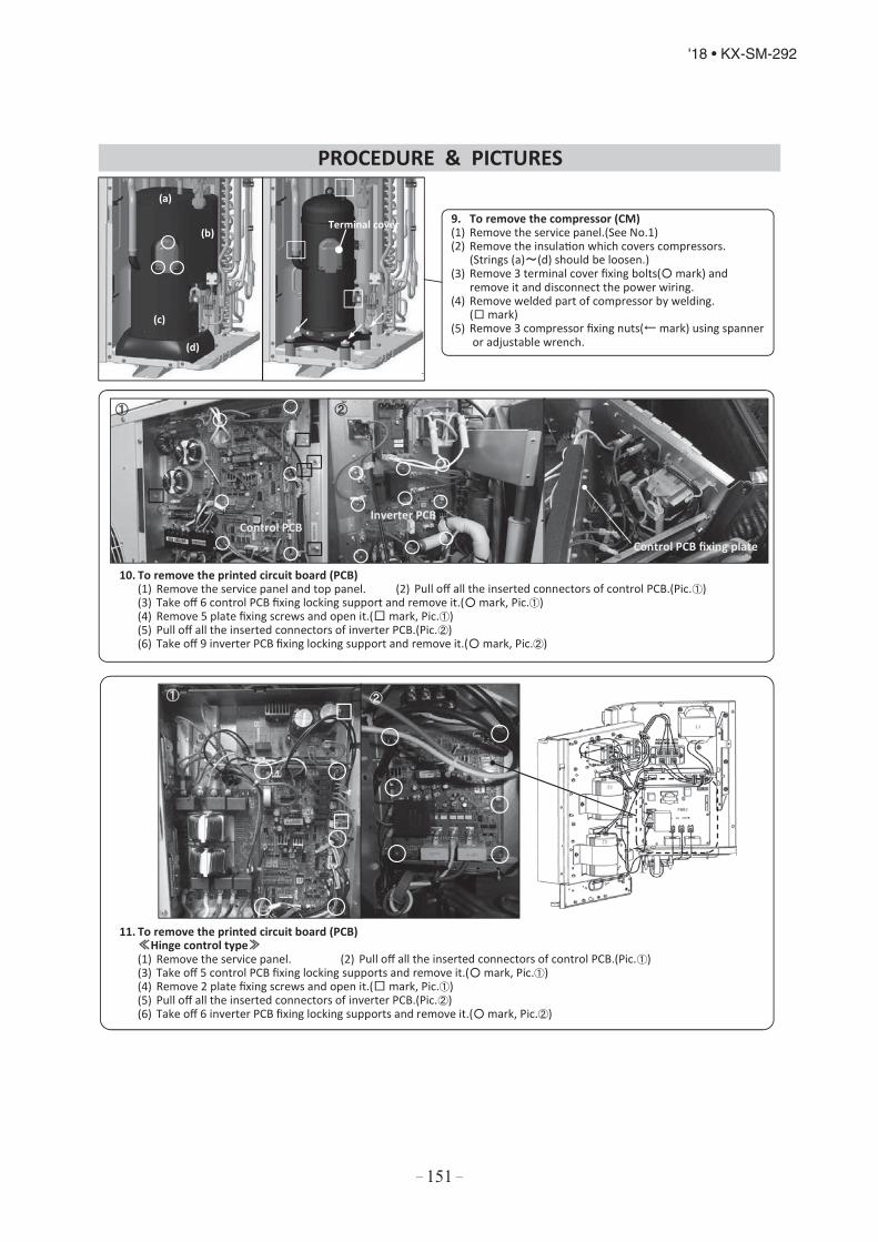
– 151 –
'18 • KX-SM-292
9. To remove the compressor (CM)(1) Remove the service panel.(See No.1)(2) Remove the insulation which covers compressors.
(Strings (a) (d) should be loosen.)(3) Remove 3 terminal cover fixing bolts( mark) and
remove it and disconnect the power wiring.(4) Remove welded part of compressor by welding.
( mark)(5) Remove 3 compressor fixing nuts( mark) using spanner
or adjustable wrench.
10. To remove the printed circuit board (PCB)(1) Remove the service panel and top panel. (2) Pull off all the inserted connectors of control PCB.(Pic. )(3) Take off 6 control PCB fixing locking support and remove it.( mark, Pic. )(4) Remove 5 plate fixing screws and open it.( mark, Pic. )(5) Pull off all the inserted connectors of inverter PCB.(Pic. )(6) Take off 9 inverter PCB fixing locking support and remove it.( mark, Pic. )
11. To remove the printed circuit board (PCB)Hinge control type
(1) Remove the service panel. (2) Pull off all the inserted connectors of control PCB.(Pic. )(3) Take off 5 control PCB fixing locking supports and remove it.( mark, Pic. )(4) Remove 2 plate fixing screws and open it.( mark, Pic. )(5) Pull off all the inserted connectors of inverter PCB.(Pic. )(6) Take off 6 inverter PCB fixing locking supports and remove it.( mark, Pic. )
PROCEDURE & PICTURES
(a)
(b)
(c)
(d)
Terminal cover
Control PCBInverter PCB
Control PCB fixing plate

– 152 –
'18 • KX-SM-292
Precautions for safetyRead these "Precautions for safety" carefully before starting disassembly work and do it in the proper way.When disassembling, be sure to turn off the power. When disassembling the electrical components, check the electrical wiring diagram.The electrical components are under high voltage by the operation of the booster capacitor. Fully discharge the capacitor before commencing a repair work. Failure to observe this warning could result in electric shock.When parts of refrigerant cycle is disassembled by welding, be sure to work after collecting a refrigerant, if the refrigerant isn'tcollected, the unit might explode.Be sure to collect refrigerant without spreading it in the air.These contents are an example. Please refer to a similar part of actual unit.
1. To remove the lid of control box(1) Remove 2 lid fixing screws and remove it.
2. To remove the printed circuit board (PCB)(1) Remove the lid of control box.(See No.1)(2) Pull off all the inserted connectors.(3) Take off 6 fixing hooks and remove it.
3. To remove the impeller and motor (FM)(1) Remove the lid of control box.(See No.1) 4. To remove the drain pan(2) Disconnect the motor connector(CNMx) on PCB in control box. (1) Remove the lid of control box.(See No.1)(3) Remove 5 bellmouth fixing screws and remove it.( mark) (2) Pull off all the inserted connectors.(4) Remove the impeller fixing nut and remove it.( mark) (3) Remove 2 plate fixing screws and remove it.(5) Remove 2 plate fixing screws and remove it.( mark) ( mark)(6) Remove 3 motor fixing nuts and remove it.( mark) (4) Remove 2 lid fixing screws and remove it.
( mark)(5) Remove 4 drain pan fixing screws and remove it.
( mark)
5. To remove drain pump (DM) and float switch (FS)(1) Remove the drain pan.(See No.4)(2) Pull the hose to the arrow direction and remove it.(3) Remove 3 drain pump fixing screws and remove it.( mark)(4) Remove the float switch fixing screw and remove it.( mark)
6. To remove the sensors (example"Thi-R1")(1) Remove the drain pan.(See No.4)(2) Pull out the temperature sensor "Thi-R1" from the sensor holder.
DISASSEMBLY PROCEDURE
PROCEDURE & PICTURES (FDT series)
7. INDOOR UNIT DISASSEMBLY PROCEDURE7. INDOOR UNIT DISASSEMBLY PROCEDURE

– 153 –
'18 • KX-SM-292
To remove the heat exchanger assembly(1) Remove the drain pan.(See No.4)(2) Remove 2 pipe lid fixing screws and remove it.( mark)(3) Remove 3 heat exchanger assembly fixing screws and remove it.( mark)
8. To remove the Electronic Expansion Valve (EEV)(1) Remove the heat exchanger assembly.(See No.7)(2) Remove the coil of EEV by pull out on the top.(3) Remove welded part of EEV by welding.( mark)
PROCEDURE & PICTURES
EEV
Coil of EEV
General view
Pipe lid

– 154 –
'18 • KX-SM-292
Precautions for safetyRead these "Precautions for safety" carefully before starting disassembly work and do it in the proper way.When disassembling, be sure to turn off the power. When disassembling the electrical components, check the electrical wiring diagram.The electrical components are under high voltage by the operation of the booster capacitor. Fully discharge the capacitor before commencing a repair work. Failure to observe this warning could result in electric shock.When parts of refrigerant cycle is disassembled by welding, be sure to work after collecting a refrigerant, if the refrigerant isn'tcollected, the unit might explode.Be sure to collect refrigerant without spreading it in the air.These contents are an example. Please refer to a similar part of actual unit.
1. To remove the lid of control box(1) Remove the lid fixing screw and remove it.
2. To remove the printed circuit board (PCB)(1) Remove the lid of control box.(See No.1)(2) Pull off all the inserted connectors.Power PCB(3) Take off 5 power PCB fixing locking supports
and remove it.( mark)Control PCB(4) Take off 4 control PCB fixing locking supports
and remove it.( mark)
3. To remove the impeller and motor (FM)(1) Remove the lid of control box.(See No.1) 4. To remove the drain pan(2) Disconnect the motor connector(CNMx) in the middle of wiring. (1) Remove 2 plate fixing screws and remove it.(3) Remove 4 bellmouth fixing screws and remove it.( mark) ( mark)(4) Remove the impeller fixing nut and remove it.( mark) (2) Remove 4 drain pan fixing screws and remove it.(5) Remove 2 plate fixing screws and remove it.( mark) ( mark, Four corners)(6) Remove 3 motor fixing nuts and remove it.( mark)
5. To remove drain pump (DM) and float switch (FS)(1) Remove the lid of control box.(See No.1)(2) Disconnect the drain pump connector(CNRx) and
float switch connector(CNIx) in the middle of wiring.(4) Remove the drain pan.(See No.4)(5) Pull the hose to the arrow direction and remove it.(6) Remove 3 drain pump fixing screws and remove it.( mark)(7) Remove the float switch fixing screw and remove it.( mark)
6. To remove the sensors (example"Thi-R1")(1) Remove the lid of control box.(See No.1)(2) Disconnect the Tho-R1 connector(CNNx) in the middle of wiring.(3) Remove the drain pan.(See No.3)(4) Pull out the temperature sensor "Thi-R1" from the sensor holder.
DISASSEMBLY PROCEDURE
PROCEDURE & PICTURES (FDTC series)
Power PCB
Control PCB

– 155 –
'18 • KX-SM-292
To remove the heat exchanger assembly(1) Remove the drain pan.(See No.4)(2) Remove 2 plate fixing screws and remove it.( mark)(3) Remove 3 heat exchanger assembly fixing screws and remove it.( mark)
8. To remove the Electronic Expansion Valve (EEV)(1) Remove the heat exchanger assembly.(See No.7)(2) Remove the coil of EEV by pull out on the top.(3) Remove welded part of EEV by welding.( mark)
PROCEDURE & PICTURES
EEV
Coil of EEV
General view
Pipe lid

– 156 –
'18 • KX-SM-292
Precautions for safetyRead these "Precautions for safety" carefully before starting disassembly work and do it in the proper way.When disassembling, be sure to turn off the power. When disassembling the electrical components, check the electrical wiring diagram.The electrical components are under high voltage by the operation of the booster capacitor. Fully discharge the capacitor before commencing a repair work. Failure to observe this warning could result in electric shock.When parts of refrigerant cycle is disassembled by welding, be sure to work after collecting a refrigerant, if the refrigerant isn't collected,the unit might explode.Be sure to collect refrigerant without spreading it in the air.These contents are an example. Please refer to a similar part of actual unit.
1. To remove the lid of control box(1) Remove 2 lid fixing screws and remove it.
2. To remove the printed circuit board (PCB)(1) Remove the lid of control box.(See No.1)(2) Pull off all the inserted connectors.Control PCB(3) Take off 4 control PCB fixing locking supports and remove it.( mark)Power PCB(4) Take off 4 power PCB fixing locking supports and remove it.( mark)
3. To remove the control box(1) Remove the lid of control box.(See No.1)(2) Pull off all the inserted connectors.(3) Remove 2 control box fixing screws( mark) and remove it.
4. To remove the impeller and motor (FM)(1) Remove the lid of control box.(See No.1) (4) Remove the impeller fixing nut and remove it.(Pic. )(2) Disconnect the motor connector(CNMx) on PCB in control box. (5) Remove 2 plate fixing screws and remove it.(Pic. , mark)(3) Remove 2 fan guard fixing screws and remove it.(Pic. ) (6) Remove 3 motor fixing nuts and remove it.(Pic. , mark)
5. To remove the drain pan(1) Remove the control box.(See No.3)(2) Remove the plate fixing screw and remove it.
(Pic. , mark)(3) Remove the bracket fixing screw.(Pic. , mark)(4) Pull drain pan off.
DISASSEMBLY PROCEDURE
PROCEDURE & PICTURES (FDTW series)
Control PCB
Power PCB
Drain pan

– 157 –
'18 • KX-SM-292
6. To remove the drain pump(DM) and float switch(FS)(1) Remove the drain pan.(See No.5)(2) Pull a hose to the arrow direction and remove it.(3) Remove 3 drain pump fixing screws and remove it.( mark)(4) Remove the float switch fixing screw and remove it.( mark)
7. To remove the sensors (example"Thi-R1")(1) Remove the drain pan.(See No.5)(2) Pull out the temperature sensor "Thi-R1" from
the sensor holder.
8. To remove the heat exchanger assembly(1) Remove the drain pan.(See No.5)(2) Remove 2 pipe lid fixing screws and remove it.( mark)(3) Remove 3 heat exchanger assembly fixing screws and remove it.( mark)
9. To remove the Electronic Expansion Valve (EEV)(1) Remove the heat exchanger assembly.(See No.8)(2) Remove the coil of EEV by pull out on the top.(3) Remove welded part of EEV by welding.( mark)
PROCEDURE & PICTURES
General view
Pipe lid
EEV
Coil of EEV

– 158 –
'18 • KX-SM-292
Precautions for safetyRead these "Precautions for safety" carefully before starting disassembly work and do it in the proper way.When disassembling, be sure to turn off the power. When disassembling the electrical components, check the electrical wiring diagram.The electrical components are under high voltage by the operation of the booster capacitor. Fully discharge the capacitor before commencing a repair work. Failure to observe this warning could result in electric shock.When parts of refrigerant cycle is disassembled by welding, be sure to work after collecting a refrigerant, if the refrigerant isn'tcollected, the unit might explode.Be sure to collect refrigerant without spreading it in the air.These contents are an example. Please refer to a similar part of actual unit.
1. To remove the lid of control box(1) Remove 2 lid fixing screws and remove it.
2. To remove the control box(1) Remove the lid of control box.(See No.1)(2) Pull off all the inserted connectors.(3) Remove 3 control box fixing screws and
remve it.(4) Pull out the contorl box.
3. To remove the printed circuit board (PCB)(1) Remove the lid of control box.(See No.1)(2) Remove control box.(See No.2)(3) Take off 6 PCB fixing locking supports and remove it.
4. To remove the drain pan.(1) Remove 2 plate fixing screws and
remove it.(right anf left)(2) Pull out the control box.
5. To remove the impeller and motor (FM)(1) Remove the lid of control box.(See No.1)(2) Disconnect the float switch connector(CNFx)
in the middle of wiring.(3) Take off 2 impeller casing hooks and
remove it.( mark)(4) Remove the impeller fixing bolt and
remove it.( mark)(5) Remove 2 motor fixing screws and
remove it.( mark)
7. To remove the float switch (FS)6. To remove the running capacitor of fan motor (1) Remove the lid of control box.(See No.1)
(1) Remove the running capacitor fixing screw (2) Disconnect the float switch connector(CNIx) in the .gniriw fo elddim.ti evomer dna
(3) Remove the drain pan.(See No.4)(4) Remove the float switch fixing screw and remove it.
DISASSEMBLY PROCEDURE
PROCEDURE & PICTURES (FDTQ series)
RunningCapacitor

– 159 –
'18 • KX-SM-292
8. To remove drain pump (DM)(1) Remove the lid of control box.(See No.1)(2) Remove the drain pan.(See No.4)(3) Disconnect the drain pump connector(CNRx)
in the middle of wiring.(4) Pull a hose to the arrow direction and remove it.(5) Remove 2 drain pump assembly fixing screws
and remove it.
9. To remove the sensors(example"Thi-R1")(1) Remove the lid of control box.(See No.1)(2) Disconnect the Tho-R1 connector(CNNx) on PCB in control box.(3) Remove the drain pan.(See No.4)(4) Pull out the temperature sensor "Thi-R1" from the sensor holder.
10. To remove the heat exchanger assembly(1) Remove the drain pan.(See No.3)(2) Remove 3 pipe lid fixing screws and remove it.( mark)(3) Remove 4 heat exchanger assy fixing screws and remove it.( mark)
11. To remove the Electronic Expansion Valve (EEV)(1) Remove the heat exchanger assembly.(See No.10)(2) Remove the coil of EEV by pull out on the top.(3) Remove welded part of EEV by welding.( mark)
PROCEDURE & PICTURES
Pipe lid
EEV
Coil of EEV
General view

– 160 –
'18 • KX-SM-292
Precautions for safetyRead these "Precautions for safety" carefully before starting disassembly work and do it in the proper way.When disassembling, be sure to turn off the power. When disassembling the electrical components, check the electrical wiring diagram.The electrical components are under high voltage by the operation of the booster capacitor. Fully discharge the capacitor before commencing a repair work. Failure to observe this warning could result in electric shock.When parts of refrigerant cycle is disassembled by welding, be sure to work after collecting a refrigerant, if the refrigerant isn'tcollected, the unit might explode.Be sure to collect refrigerant without spreading it in the air.These contents are an example. Please refer to a similar part of actual unit.
1. To remove the lid of control box(1) Remove 2 lid fixing screws and remove it.( mark)
2. To remove the control box(1) Remove the lid of control box.(See No.1)(2) Pull off all the inserted connectors.(3) Remove 2 control box fixing screws and remove it.( mark)
3. To remove the drain pan(1) Remove 10 drain pan fixing screws and remove it.
( mark)
4. To remove the printed circuit board (PCB)(1) Remove the lid of control box.(See No.1)(2) Pull off all the inserted connectors.Control PCB(3) Take off 4 control PCB fixing locking supports and remove it.( mark)Power PCB(4) Take off 4 power PCB fixing locking supports and remove it.( mark)
5. To remove the impeller and motor (FM)(1) Remove the lid of control box.(See No.1)(2) Disconnect the motor connector(CNMx) on PCB in control box.(3) Remove 2 motor fixings screw and remove it.( mark)(4) Remove the fan casing fixing screw and remove it.( mark)(5) Remove the impeller fixing bolt and remove it.( mark)
6. To remove the float switch (FS)(1) Remove the lid of control box.(See No.1)(2) Disconnect the float switch connector(CNI)
on PCB in control box.(3) Remove 4 drain pump assembly fixing
screws and remove it.( mark)(4) Remove the float switch fixing screw and
remove it.( mark)
DISASSEMBLY PROCEDURE
PROCEDURE & PICTURES (FDTS series)
Drain pan
c
Conrtol PCB
Power PCB

– 161 –
'18 • KX-SM-292
7. To remove drain pump (DM)(1) Remove the lid of control box.(See No.1)(2) Disconnect the drain pump connector(CNR)
on PCB in control box.(3) Remove 4 drain pump assembly fixing
screws and remove it.( mark)(4) Pull a hose to the arrow direction and
remove it.(5) Remove 3 drain pump fixing screws and
remove it.( mark)
8. To remove the sensors (example"Thi-R1")(1) Remove the lid of control box.(See No.1)(2) Disconnect the Tho-R1 connector(CNNx) on PCB in control box.(3) Remove the drain pan.(See No.3)(4) Pull out the temperature sensor "Thi-R1" from the sensor holder.
9. To remove the heat exchanger assembly(1) Remove the drain pan.(See No.3)(2) Remove 4 pipe lid fixing screws
and remove it.( mark)(3) Remove 4 heat exchanger assy fixing
screws and remove it.( mark)
10. To remove the electronic expansion Valve (EEV)(1) Remove the heat exchanger assembly.
(See No.7)(2) Remove the coil of EEV by pull out
on the top.(3) Remove welded part of EEV by welding.
( mark)
PROCEDURE & PICTURES
Pipe lid
c
EEVCoil of EEV
General view

– 162 –
'18 • KX-SM-292
Precautions for safetyRead these "Precautions for safety" carefully before starting disassembly work and do it in the proper way.When disassembling, be sure to turn off the power. When disassembling the electrical components, check the electrical wiring diagram.The electrical components are under high voltage by the operation of the booster capacitor. Fully discharge the capacitor before commencing a repair work. Failure to observe this warning could result in electric shock.When parts of refrigerant cycle is disassembled by welding, be sure to work after collecting a refrigerant, if the refrigerant isn'tcollected, the unit might explode.Be sure to collect refrigerant without spreading it in the air.These contents are an example. Please refer to a similar part of actual unit.
1. To remove the lid of control box(1) Remove 2 lid fixing screws and remove it.
2. To remove the printed circuit board (PCB)(1) Remove the lid of control box.(See No.1)(2) Pull off all the inserted connectors.Control PCB(3) Take off 4 control PCB fixing locking supports( mark)
and remove it. Power PCB(4) Take off 6 power PCB fixing locking supports( mark)
and remove it.
3. To remove the bottom panel(B)(1) Remove 18 panel fixing screws and remove it.
5. To remove the motor PCB4. To remove the impellers and motors(FM) (1) Remove the lid of control box.
)1.oN eeS()1.oN eeS(.xob lortnoc fo dil eht evomeR)1(.)B(lenap mottob eht evomeR)2()3.oN eeS(.)B(lenap mottob eht evomeR)2(
(3) Disconnect the motor connector(CNFMx or CNMx) on PCB in control box. (See No.3)rotcennoc BCP rotom eht tcennocsiD)3(.ti evomer dna wercs gnixif rotom eht evomeR)4(
( mark/right and left side) (CNFMx or CNMx)on PCB in control box.(5) Remove the fan casing fixing screw and remove it.( mark) (4) Remove 2 motor PCB fixing screws(6) Remove the sirocco fan fixing bolt and remove it.( mark) and remove it.
6. To remove the sensors (example"Thi-A")(1) Remove the lid of control box.(See No.1)(2) Remove the bottom panel(B).(See No.3)(3) Disconnect the Thi-A connector(CNH) on PCB in control box.(4) Pull the temperature sensor fixing clip and remove it.( mark)
DISASSEMBLY PROCEDURE
PROCEDURE & PICTURES (FDU FDUM series)
Control PCB
Power PCB
Motor
Motor PCB
Motor
(Bottom)
(Top)
Bottom panel(B)

– 163 –
'18 • KX-SM-292
7. To remove the drain pump(DM) and float switch(FS)(1) Remove the lid of control box.(See No.1)(2) Remove 5 drain pump assembly fixing screws and remove it.
( mark)(3) Disconnect the drain pump connector(CNR) on PCB in control box.(4) Pull a hose to the arrow direction and remove it.(5) Remove 3 drain pump fixing screws and remove it.( mark)(6) Disconnect the float switch connector(CNI) on PCB in control box.(7) Remove the float switch fixing screw and remove it.( mark)
8. To remove the heat exchanger assembly(1) Remove the bottom panel(B).(See No.3)(2) Remove 22 bottom panel(F) fixing screws and remove it.( mark)(3) Remove 2 drain pan fixing screws and remove it.( mark)(4) Remove 4 heat exchanger assy fixing screws and remove it.( mark)
9. To remove the Electronic Expansion Valve (EEV)(1) Remove the heat exchanger assembly.(See No.8)(2) Remove the coil of EEV by pull out on the top.(3) Remove welded part of EEV by welding.( mark)
10. To remove the sensors (example"Thi-R3")(1) Remove the lid of control box.(See No.1)(2) Disconnect the Thi-R3 connector(CNN) on PWB in control box.(3) Remove the drain pan.(See No.8)(4) Pull out the temperature sensor "Thi-R3" from the sensor holder.
PROCEDURE & PICTURES
Drain panBottom panel(F)
EEV
Coil of EEV
General view

– 164 –
'18 • KX-SM-292
Precautions for safetyRead these "Precautions for safety" carefully before starting disassembly work and do it in the proper way.When disassembling, be sure to turn off the power. When disassembling the electrical components, check the electrical wiring diagram.The electrical components are under high voltage by the operation of the booster capacitor. Fully discharge the capacitor before commencing a repair work. Failure to observe this warning could result in electric shock.When parts of refrigerant cycle is disassembled by welding, be sure to work after collecting a refrigerant, if the refrigerant isn'tcollected, the unit might explode.Be sure to collect refrigerant without spreading it in the air.These contents are an example. Please refer to a similar part of actual unit.
1. To remove the lid of control box 2. To remove the printed circuit board (PCB)(1) Remove 2 lid fixing screws and (1) Remove the lid of control box.(See No.1)
.srotcennoc detresni eht lla ffo lluP)2(.ti evomer Control PCB
3. To remove the bottom panel(B) (3) Take off 4 control PCB fixing locking supports and remove it. ( mark)(1) Remove 12 panel fixing screws Power PCB
)4(.ti evomer dna Take off 4 power PCB fixing locking supports and remove it. ( mark)
4. To remove the impellers and motors(FM)(1) Remove the lid of control box.(See No.1)
5. To remove the drain pan (2) Remove the bottom panel(B).(See No.3)(1) Remove the bottom panel(B).(See No.3) (3) Disconnect the motor connector(CNM1) on PCB in control box.(2) Remove 18 bottm panel(F) fixing screws (4) Remove 2 motor fixing screws and remove it.( mark)
and remove it.( mark) (5) Remove the fan casing fixing screw and remove it.( mark)(3) Remove 2 drain pan fixing screws (6) Remove the sirocco fan fixing bolt and remove it.( mark)
and remove it.( mark)
DISASSEMBLY PROCEDURE
PROCEDURE & PICTURES (FDUT series)
(Bottom)
(Top)
Control PCBPower PCB
Bottom panel(B)
Bottom panel(F)

– 165 –
'18 • KX-SM-292
6. To remove the control box(1) Remove the lid of control box.(See No.1)(2) Pull off all the inserted connectors.(3) Remove 2 cotrol box fixing screws and remove it.
7. To remove the heat exchanger assembly(1) Remove the bottom panel(B).(See No.3)(2) Remove the drain pan.(See No.5)(3) Remove the control box.(See No.6)(4) Remove 4 pipe lid fixing screws and remove it.( mark)(5) Remove 4 heat exchanger assy fixing screws and
remove it.( mark)8. To remove the drain pump(DM) and float switch(FS)
(1) Remove the control box.(See No.6)(2) Disconnect the drain pump connector(CNR)
on PCB in control box.(3) Disconnect the float switch connector(CNI)
on PCB in control box.(4) Remove 4 drain pump assembly fixing screws
and remove it.( mark)(5) Pull a hose to the arrow direction and remove it.(6) Remove 3 drain pump fixing screws and
remove it.( mark)(7) Remove the float switch fixing screw and
remove it.( mark)
9. To remove the electronic expansion Valve (EEV)(1) Remove the heat exchanger assembly.
(See No.7)(2) Remove the coil of EEV by pull out
on the top.(3) Remove welded part of EEV by welding.
( mark)
10. To remove the sensors (example"Thi-R1")(1) Remove the lid of control box.(See No.1)(2) Disconnect the Thi-R1 connector(CNN) on PWB in control box.(3) Remove the drain pan.(See No.5)(4) Pull out the temperature sensor "Thi-R3" from the sensor holder.
PROCEDURE & PICTURES
Pipe lid
EEVCoil of EEV
General view

– 166 –
'18 • KX-SM-292
Precautions for safetyRead these "Precautions for safety" carefully before starting disassembly work and do it in the proper way.When disassembling, be sure to turn off the power. When disassembling the electrical components, check the electrical wiring diagram.The electrical components are under high voltage by the operation of the booster capacitor. Fully discharge the capacitor before commencing a repair work. Failure to observe this warning could result in electric shock.When parts of refrigerant cycle is disassembled by welding, be sure to work after collecting a refrigerant, if the refrigerant isn'tcollected, the unit might explode.Be sure to collect refrigerant without spreading it in the air.These contents are an example. Please refer to a similar part of actual unit.
1. To remove the lid of control box(1) Remove 2 lid fixing screws and
remove it.
2. To remove the printed circuit board(1) Remove the lid of control box.
(See No.1)(2) Pull off all the inserted connectors.(3) Take off 6 control PCB fixing
locking supports and remove it.
3. To remove the bottom panel(B) and bottom panel(F)(1) Remove 12 bottom panel panel(B) fixing screws and remove it.( mark)(2) Remove 10 bottom panel panel(F) fixing screws and remove it.( mark)
4. To remove the drain pan.(1) Remove the bottom panel(B) and
bottom panel(F).(See.No.3)(2) Pull out the contorl box.
5. To remove the impeller and motor (FM)(1) Remove the lid of control box.(See No.1)(2) Remove the bottom panel(B).(See No.2)<Pic. >(3) Disconnect the motor connector(CNFx) in the
middle of wiring.(4) Take off the right and left hooks of the fan casing and
remove it.( mark)(5) Remove the impeller fixing bolt and remove it.( mark)(6) Remove 2 motor fixing screws and remove it.( mark)
6. To remove the sensors (example"Thi-R1")(1) Remove the lid of control box.(See No.1)(2) Disconnect the Tho-R1 connector(CNNx) on PCB in control box.(3) Remove the drain pan.(See No.4)(4) Pull out the temperature sensor "Thi-R1" from the sensor holder.
DISASSEMBLY PROCEDURE
PROCEDURE & PICTURES (FDUH series)
(Top)
(Bottom)
Bottom panel(B)
Bottom panel(F)
Control box
(Bottom)
(Top)

– 167 –
'18 • KX-SM-292
7. To remove the heat exchanger assembly(1) Remove the drain pan.(See No.3)(2) Remove 3 pipe lid fixing screws and remove it.( mark)(3) Remove 4 heat exchanger assy fixing screws and remove it.( mark)
8. To remove the Electronic Expansion Valve (EEV)(1) Remove the heat exchanger assembly.(See No.9)(2) Remove the coil of EEV by pull out on the top.(3) Remove welded part of EEV by welding.( mark)
8. To remove the running capacitor of fan motor(1) Remove the running capacitor fixing screw
and remove it.
PROCEDURE & PICTURES
Pipe lid
RunningCapacitor
EEV
Coil of EEV
Genaral view

– 168 –
'18 • KX-SM-292
PHA012D402
.

– 169 –
'18 • KX-SM-292
Screw

– 170 –
'18 • KX-SM-292

– 171 –
'18 • KX-SM-292

– 172 –
'18 • KX-SM-292
Precautions for safetyRead these "Precautions for safety" carefully before starting disassembly work and do it in the proper way.When disassembling, be sure to turn off the power. When disassembling the electrical components, check the electrical wiring diagram.The electrical components are under high voltage by the operation of the booster capacitor. Fully discharge the capacitor before commencing a repair work. Failure to observe this warning could result in electric shock.When parts of refrigerant cycle is disassembled by welding, be sure to work after collecting a refrigerant, if the refrigerant isn'tcollected, the unit might explode.Be sure to collect refrigerant without spreading it in the air.These contents are an example. Please refer to a similar part of actual unit.
1. To remove air inlet grille.(1) Slide the hook in the direction of
the arrow.( mark)(2) Remove 4 wire fixing screws.( mark)(3) Remove 4 air inlet grille fixing screws.
( mark)
2. To remove the lid of control box(1) To remove air inlet grille.(See.No.1)(2) Remove 2 wire fixing screws and remove it.
( mark)(3) Remove 2 lid fixing screws and remove it.
( mark)
3. To remove the control box(1) Remove the lid of control box.(See No.2)(2) Pull off all the inserted connectors.(3) Remove 2 control box fixing screws and
remve it.( mark)(4) Pull out the control box.
4. To remove the printed circuit board (PCB)(1) Remove the lid of control box.(See No.2)(2) Pull off all the inserted connectors.Control PCB(3) Take off 4 control PCB fixing locking supports and remove it.( mark)Power PCB(4) Take off 4 power PCB fixing locking supports and remove it.( mark)
5. To remove the impeller and motor (FM)(1) Remove the lid of control box.(See No.1)(2) Disconnect the motor connector(CNFx) in the middle way of wiring.(3) Remove the fan casing fixing screw.( mark) Take off the fan casing fixing hook and remove it.( mark)(4) Remove the impeller fixing screw and remove it.( mark) (5) Remove 2 motor fixing screws and remove it.( mark)
DISASSEMBLY PROCEDURE
PROCEDURE & PICTURES (FDE series)

– 173 –
'18 • KX-SM-292
6. To remove side panel and bottom panel(1) Remove air inlet grille.(See No.1)(2) Remove the right and left side panel fixing
screws and remove it.( mark)(3) Remove 5 bottom panel fixing screws.( mark)
Remove 6 bottom panel fixing screws and remove it. ( mark, left and right side)
7. To remove drain pan(1) Remove side panel and bottom panel.(See No.5)(2) Remove 2 plate fixing screws and remove it.( mark, Pic. )(3) Remove 2 support fixing screws and remove it.( mark, Pic. )(4) Pull out the drain pan.
8. To remove the heat exchanger assembly(1) Remove the drain pan.(See No.6)(2) Remove 6 heat exchanger assy fixing
screws and remove it.( mark)
9. To remove the louver motor (LM)(1) Remove the lid of control box.(See No.1)(2) Disconnect the louver motor connector
(CNJ) on PCB in control box. 10. To remove the sensors (example"Thi-R3")(3) Remove side panel.(See No.5) (1) Remove the lid of control box.(See No.1)(4) Remove 2 louver motor fixing screws (2) Disconnect the Tho-R3 connector(CNNx)
.xob lortnoc ni BCP no.ti evomer dna (3) Remove the drain pan.(See No.3)(4) Pull out the temperature sensor "Thi-R1"
from the sensor holder.
11. To remove the Electronic Expansion Valve (EEV)(1) Remove the heat exchanger assembly.(See No.9)(2) Remove the coil of EEV by pull out on the top.(3) Remove welded part of EEV by welding.( mark)
PROCEDURE & PICTURES
Bottom panel
Plate Support
EEV
Coil of EEV
General view

– 174 –
'18 • KX-SM-292
Precautions for safetyRead these "Precautions for safety" carefully before starting disassembly work and do it in the proper way.When disassembling, be sure to turn off the power. When disassembling the electrical components, check the electrical wiring diagram.The electrical components are under high voltage by the operation of the booster capacitor. Fully discharge the capacitor before commencing a repair work. Failure to observe this warning could result in electric shock.When parts of refrigerant cycle is disassembled by welding, be sure to work after collecting a refrigerant, if the refrigerant isn'tcollected, the unit might explode.Be sure to collect refrigerant without spreading it in the air.These contents are an example. Please refer to a similar part of actual unit.
1. To remove the control box(1) Remove hooks of the front panel and remove it.(2) Remove 5 filter assembly fixing screws and
remove it.( mark)(3) Remove 3 control box and lid fixing screws,
and remove it.( mark)(4) Pull the control box forward.
2. To remove the lower flap motor (LFM)(1) Remove the control box.(See No.1)(2) Disconnect the lower flap motor connector(CNJ3)
in the way of wiring.(3) Remove the cover fixing screw and remove it.( mark)(4) Remove 2 lower flap motor screws and remove it.
( mark)
3. To remove the upper flap motor (UFM)(1) Remove the control box.(See No.1)(2) Disconnect the upper flap motor connector(CNJ4) 4. To remove drain pan
)3.oN eeS(.rotom palf rewol eht evomeR)1(.gniriw fo yaw eht ni(3) Remove 2 upper flap motor fixing screws and (2) Remove 3 drain pan fixing screws and remove it.( mark)
remove it.( mark)
5. To remove the damper arm motor (DAM)(1) Remove the control box.(See No.1)(2) Disconnect the damper arm motor connector(CNJ2)
in the way of wiring.(3) Remove the cover fixing screw and remove it.
( mark) 6. To remove the damper motor (DM)(4) Remove 2 damper arm motor fixing screws and (1) Remove the control box.(See No.1)
remove it.( mark) (2) Disconnect the damper motor connector(CNJ1) in the way of wiring.
(3) Remove 2 damper arm motor fixing screws andremove it.( mark)
DISASSEMBLY PROCEDURE
PROCEDURE & PICTURES (FDFW series)

– 175 –
'18 • KX-SM-292
7. To remove the heat exchanger assembly(1) Remove the drain pan.(See No.4)(2) Remove 4 heat exchanger assy fixing screws and remove it.( mark)
8. To remove the impeller and motor (FM)(1) Remove control box.(See No.1)(2) Disconnect the motor connector(CNM) on PCB in control box.(3) Remove the heat exchanger assembly.(See No.7)(4) Remove the impeller fixing nut and remove it.( mark)(5) Remove 4 motor fixing bolts and remove it.( mark)(6) Take off the hooks of cover and remove it.
9. To remove the sensors (example"Thi-R1")(1) Remove control box.(See No.1)(2) Disconnect the Tho-R1 connector(CNN) on PCB in control box.(3) Pull out the temperature sensor "Thi-R1" from the sensor holder.
10. To remove the Electronic Expansion Valve (EEV)(1) Remove the heat exchanger assembly.(See No.7)(2) Remove the coil of EEV by pull out on the top.(3) Remove welded part of EEV by welding.( mark)
PROCEDURE & PICTURES
UFM
DAM
Cover
EEV
Coil of EEV
General view

– 176 –
'18 • KX-SM-292
Precautions for safetyRead these "Precautions for safety" carefully before starting disassembly work and do it in the proper way.When disassembling, be sure to turn off the power. When disassembling the electrical components, check the electrical wiring diagram.The electrical components are under high voltage by the operation of the booster capacitor. Fully discharge the capacitor before commencing a repair work. Failure to observe this warning could result in electric shock.When parts of refrigerant cycle is disassembled by welding, be sure to work after collecting a refrigerant, if the refrigerant isn'tcollected, the unit might explode.Be sure to collect refrigerant without spreading it in the air.These contents are an example. Please refer to a similar part of actual unit.
1. To remove the lid of control box(1) Remove 2 lid fixing screws and remove it.
2. To remove the printed circuit board (PCB)(1) Remove the lid of control box.(See No.1)(2) Pull off all the inserted connectors.(3) Take off 6 power PCB fixing locking supports
and remove it.
3. To remove the front panel (FDFU)(1) Remove 8 front panel fixing
screws and remove it.
4. To remove the impeller and motor (FM)(1) Remove the lid of control box.(See No.1), remove the front panel.(See No.3)(2) Disconnect the motor connector(CNF1) in the way of wiring.(3) Pull drain pan in the direction of the arrow and remove.(Pic. )(4) Remove 4 fan base fixing screws and remove fan motor assembly.( mark)(5) Remove the impeller fixing bolt and remove it.( mark)(6) Remove 2 motor fixing screws and remove it.( mark)
5. To remove the sensors (example"Thi-R1")(1) Remove the lid of control box.(See No.1)(2) Disconnect the Tho-R1 connector(CNNx) in the way of wiring.(3) Remove the front panel.(See No.3)(4) Pull out the temperature sensor "Thi-R1" from the sensor holder.
DISASSEMBLY PROCEDURE
PROCEDURE & PICTURES (FDFU FDFL series)
Left side Right side
Drain pan
Fan motor assembly
Pic.
Pic.
Front viewDrain pan
Fan motor assembly

– 177 –
'18 • KX-SM-292
6. To remove the heat exchanger assembly(1) Remove 9 top panel fixing screws and remove it .(Pic. )(2) Remove 2 support fixing screws and remove it .(Pic. )(3) Remove the lid of EEV box fixing screw and remove it.( mark, Pic. )
Remove 3 EEV box fixing screws and remove it.( mark, Pic. )(4) Remove 2 screws on the left side panel.(Pic. )(5) Remove 3 screws on the back side panel.(Pic. )(6) Remove 4 screws on the right side panel and pull the heat exchanger assembly to the right. (Pic. )
7. To remove the running capacitor of fan motor(1) Remove the fan motor assembly.
(See No.4)(2) Remove faston terminal.(3) Remove the running capacitor
fixing screw and remove it.
8. To remove the Electronic Expansion Valve (EEV)(1) Remove the heat exchanger assembly.(See No.9)(2) Remove the coil of EEV by pull out on the top.(3) Remove welded part of EEV by welding.( mark)
PROCEDURE & PICTURES
Top view
Front view
Motor
EEV
Coil of EEV
General view(FDFU)
General view(FDFL)
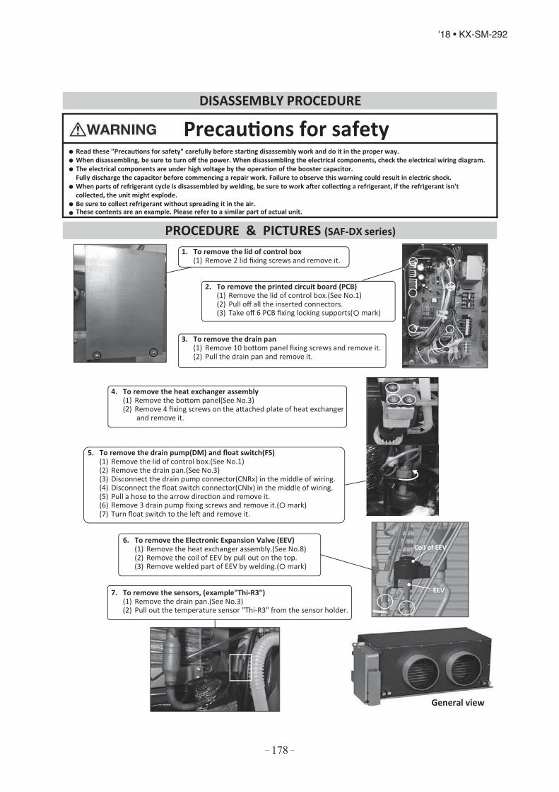
– 178 –
'18 • KX-SM-292
Precautions for safetyRead these "Precautions for safety" carefully before starting disassembly work and do it in the proper way.When disassembling, be sure to turn off the power. When disassembling the electrical components, check the electrical wiring diagram.The electrical components are under high voltage by the operation of the booster capacitor. Fully discharge the capacitor before commencing a repair work. Failure to observe this warning could result in electric shock.When parts of refrigerant cycle is disassembled by welding, be sure to work after collecting a refrigerant, if the refrigerant isn'tcollected, the unit might explode.Be sure to collect refrigerant without spreading it in the air.These contents are an example. Please refer to a similar part of actual unit.
1. To remove the lid of control box(1) Remove 2 lid fixing screws and remove it.
2. To remove the printed circuit board (PCB)(1) Remove the lid of control box.(See No.1)(2) Pull off all the inserted connectors.(3) Take off 6 PCB fixing locking supports( mark)
3. To remove the drain pan(1) Remove 10 bottom panel fixing screws and remove it.(2) Pull the drain pan and remove it.
4. To remove the heat exchanger assembly(1) Remove the bottom panel(See No.3)(2) Remove 4 fixing screws on the attached plate of heat exchanger
and remove it.
5. To remove the drain pump(DM) and float switch(FS)(1) Remove the lid of control box.(See No.1)(2) Remove the drain pan.(See No.3)(3) Disconnect the drain pump connector(CNRx) in the middle of wiring.(4) Disconnect the float switch connector(CNIx) in the middle of wiring.(5) Pull a hose to the arrow direction and remove it.(6) Remove 3 drain pump fixing screws and remove it.( mark)(7) Turn float switch to the left and remove it.
6. To remove the Electronic Expansion Valve (EEV)(1) Remove the heat exchanger assembly.(See No.8)(2) Remove the coil of EEV by pull out on the top.(3) Remove welded part of EEV by welding.( mark)
7. To remove the sensors, (example"Thi-R3")(1) Remove the drain pan.(See No.3)(2) Pull out the temperature sensor "Thi-R3" from the sensor holder.
DISASSEMBLY PROCEDURE
PROCEDURE & PICTURES (SAF-DX series)
EEV
Coil of EEV
General view
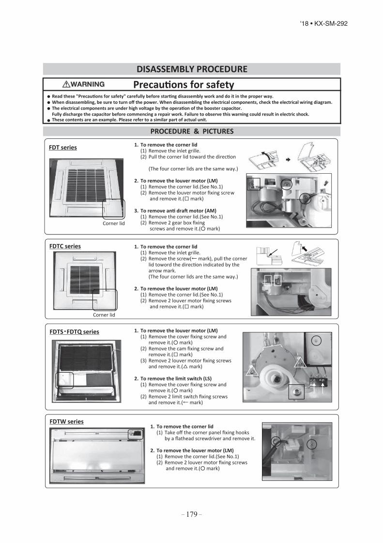
– 179 –
'18 • KX-SM-292
Precautions for safetyRead these "Precautions for safety" carefully before starting disassembly work and do it in the proper way.When disassembling, be sure to turn off the power. When disassembling the electrical components, check the electrical wiring diagram.The electrical components are under high voltage by the operation of the booster capacitor. Fully discharge the capacitor before commencing a repair work. Failure to observe this warning could result in electric shock.These contents are an example. Please refer to a similar part of actual unit.
1. To remove the corner lid(1) Remove the inlet grille.(2) Remove the screw( mark), pull the corner
lid toword the direction indicated by thearrow mark.(The four corner lids are the same way.)
2. To remove the louver motor (LM)(1) Remove the corner lid.(See No.1)(2) Remove 2 louver motor fixing screws
and remove it.( mark)
1. To remove the louver motor (LM)(1) Remove the cover fixing screw and
remove it.( mark)(2) Remove the cam fixing screw and
remove it.( mark)(3) Remove 2 louver motor fixing screws
and remove it.( mark)
2. To remove the limit switch (LS)(1) Remove the cover fixing screw and
remove it.( mark)(2) Remove 2 limit switch fixing screws
and remove it.( mark)
1. To remove the corner lid(1) Take off the corner panel fixing hooks
by a flathead screwdriver and remove it.
2. To remove the louver motor (LM)(1) Remove the corner lid.(See No.1)(2) Remove 2 louver motor fixing screws
and remove it.( mark)
DISASSEMBLY PROCEDURE
PROCEDURE & PICTURES
FDT series
FDTC series
FDTS FDTQ series
Corner lid
Corner lid
FDTW series
1.(1)(2)
2.(1)(2)
3.(1)(2)
To remove the corner lidRemove the inlet grille.Pull the corner lid toward the dire ction
(The four corner lids are the same way.)
To remove the louver motor (LM)Remove the corner lid.(See No.1)Remove the louver motor fixing scre w and remove it.( mark)
To remove anti draft motor (AM)Remove the corner lid.(See No.1)Remove 2 gear box fixing screws and remove it.( mark)

VRF INVERTER MULTI-SYSTEM AIR-CONDITIONERS
Because of our policy of continuous improvement, we reserve the right to make changes in all specifications without notice.
Copyright MITSUBISHI HEAVY INDUSTRIES THERMAL SYSTEMS, LTD.
MITSUBISHI HEAVY INDUSTRIES THERMAL SYSTEMS, LTD.16-5 Konan 2-chome, Minato-ku, Tokyo, 108-8215, Japanhttp://www.mhi-mth.co.jp/en/