MANUAL - Fremont, NE
233
... PHASE I WATER SYSTEM IMPROVEMENTS FREMONT, NEBRASKA 0 &. M MANUAL KAYTON ELECTRIC. INC. NORFOLK, NEBRASKA .")
-
Upload
khangminh22 -
Category
Documents
-
view
0 -
download
0
Transcript of MANUAL - Fremont, NE

...
PHASE I WATER SYSTEM IMPROVEMENTS
FREMONT, NEBRASKA
0 &. M MANUAL
KAYTON ELECTRIC. INC.
NORFOLK, NEBRASKA
.")

OPERATIONS AND MAINTENANCE MANUAL SECTION 01340
INDEX
INSTALLING CONTRACTOR ................................... PAGE 1 GUARAt·ff'EE •••.•.•••..••••.•.•••••.•• .' ,, •••.••••• , •••••.•..• PAGE 2
SECTION 1 ... , ............ CONDUIT ••••••••••• SPEC. HANDHOLE .......... SPEC.
SECTION 2 ..••....••...... SWITCHBOARDS, •.••• SPEC.
SECTION 3 ................ PANELBOARDS ....... SP~C. TRANSFORMERS •••••• ~PEC. SAFETY SWITCHES ••• SPEC.
SECTION 4 ................ LUNIKUL LWU!~MENT.~PEC.
SECTION 5 ................ DEVICES ........... SPEC.
SECTION 6 ................ HEAT TRACING •••••. SPEC.
SECTION 7 ................ INTERIOR LIGHTING.SPEC. LAMPS ............. SPEC.
SECTION 8 ................ EXTERIOR LIGHTING.SPEC. Lit1Mf:)5 ............. SPEC.
SECTION 9 ................ SITE LIGHTING ...... SPEC. LAMPS.,, ........•. SPEC.
SECTION 10 ............... LIGHTNING PROTECT.SPEC.
SECTION 16111 SECTION 16115
~ECTION 16470
SECTION 16150 SECTION 16190 SECTION 16475
St.CTI UN 16474
SECTION 16140
SECTION 16858
SECTION 16510 SECTION 16501
SECTION 16525 SECTION 16501
SECTION 16530 SE.CT:tON 16501
SECTION 16670
SEC1". I ON 11 ••• , ••.••• , , .•..••••••••••••••••••••••••••••.• TEST I NG
' SECTION 12 ............... ELECT. CONDUCTORS.SPEC. SECTION 16110
KAYTON ELECTRIC, INC. NORFORK, NE

KAYTON ELECTRIC, INC. 30fJ() OLD HADAR ROAD
P.O. BOX 674 NORFOLK, NE 68701
1-4()2-371-.5181 FAX: 1-402-:371-8389
PROJECT FORE~·l~l\N: Mil<E SINDELAR
HOME ()FFICE P.O. BOX 27
12() SOUTH LINCOLN HOLDREGE, NE 68949

GlJARANTEE KAYTON ELECTRIC·, INC. ClPlE) WILL
GlJARANTEE ALL MATERIALS,
INSTALLATION, AND t.10RK
PERFORMED BY KAY TON ELECTRIC .. S
EMPLOYEES FOR A PERIOD OF
ONE Ct) YEAR FROM DATE OF
StJBSTANTIAL COMPLETION.
t.1E ~TILL NOT GUARANTEE ANY 'WORl{
OR MATERIALS ADDED TO OR
INSTALLED BY OTHERS TO THE
EQUIPMENT INSTALLED BY
KAYTON ELECTRIC. INC. ~lE ALSO SHALL
HAVE THE SOLE AND FINAL
DECISION IF THE EQUIPMENT
INSTALLED BY OTHERS 'WAS THE
CAUSE OF BREAK DOt.lN OF THE
~IATERIAL OR EQUIPMENT INSTALLED
BY KAYTON ELECTRIC·, INC.
THANK YOlY

FREMONT WASTE SYSTEM IMPROVEMENTS
SECTION 16111 CONDUIT, FITTINGS, & SUPPORTS
16111-2.02 . I I ••• I I I I •••••••• I I .GALVANIZED RIGID STEEL CONDUIT COVER - MANUFACTURER SUPPLIER ....... I. I I I I ••••• I. I .PAGE 1 CONDUIT I • I •••••••• I •••••••••• ' •••••• ' • I • I •••• I ' • PAGE 2 & 3 F1 I rr T I NG S . . . . . . . . . . . . . , . . . . . . . . . . . . .. . . . . , . . . . . , . . PAGE 4 & 5 SPARE PARTS ..................................... NONE NEEDED
16111 2.03 ... I •••••••• I I I. I ••• I .PVC-COATED RIGID STEEL CONDUIT COVER - MANUFACTURER - SUPPLIER ..... , ... ,.,., .. ,, .... PAGE 1 CONDUIT .......... I •••••••••••• I •• I ••• ' ••••• I •••••• I I PAGE 2 FI'TTINGS .. , .... , .......... , ... , " .............. PAGES 2 TO 5 SPARE PARTS ............. I •••••••• I • I •• I ••••••••••••• PAGE 6
16111-2.04 ..... ' ...... ' ..... I ••••••• RIGID NON-METALLIC CONDUIT COVER - MANUFACTURER SUPPLIER ............... ,.,., .. PAGE 1 CONDlJIT ...................•...•......•..•..... l')AGES 2 TO 4 FITTINGS ..................................... PAGES 5 TO 11 SPARE PARTS, .................................. , . NONE NEEDED
FREMONT WASTE SYSTEM IMPROVEMENTS
SECTION 16115 UNDERGROUND CONDUIT, DUCTS, & HANDHOLES
OTHER SECTION 02224 PIPELINE UNDERCROSSINGS
02224-2.01 ....................................... CASTING PIPE SUPPLIER & CERTIFICATIONS ... , ......... , , ... , . PAGES 1 TO 4
OTHER SECTION 03308 CONCRETE, MATERIALS AND PROPORTIONING
03308-2.02.,., .. ,, . , .. ,, ............. , ..... CONCRETE MIX DESIGN COVER -· SUPPLIEH ............. I •••••• I ••••••••••••••• PAGE l DESIGN .... , .....•............... , .............. PAGES 2 & 3
16115-2.02 ...................... I ••••••••• HANDHOLES & MANHOLES COVER MANUFACTURER - SUPPLIER .......... ,, .......... PAGE 1 REBAR DESIGN ............... I ••• I ••••• I •••••• PAGES 2 THRU 4 HANDHOLES - BILL OF MATERIAL ................... I ••••• PAGE 5 HANDHOLES SPECIFICATIONS ................. I I .PAGES 6 THRU 12 SPARE PARTS .................. I •••••••••••• I ••••• NONE NEEDED

GALVANIZED RIGID STEEL
CONDUIT AND CONDUIT BODIES
BRAND-ALLIED TUBE. & CONDUIT
PURCHASED FROM:
ELECTRIC FIXTURE AND SUPPLY
1203 SO. 11TH
NORFOLK. NE 68701
(40:2) 371-3920 .
C402) 371-39:21 FAX
1-800-67:2-3491


ALLIE PROVIDES FULL ELECTRICAL SYSTEM
'PROTECTION Allied RIGID conduit is precision manufactured for dependable, longlasting value and protection for the electrical raceway system.
Manufactured from high-strength strip steel, Allied RIGID combines damage resistant strength with ductility to assure easy bending, cutting and joining. It also provides smooth, continuous raceways for fast wire-pulling. No need to worry about damage to the conduit system even when pulling through multiple 90° bends.
Allied RIGID is hot-dipped zinc galvanized. Then, it is chromated to form an additional protection layer against corrosion and abrasion.
Allied RIGID provides radiation protection and magnetic shielding and resists impact.
The%" NPT threads (ANSI 81 .20.1) are full cut and hot galvanized after cutting. Color-coded end-cap thread protectors keep the threads clean and sharp and also provide instant trade size recognition. Even-inch sizes are
color-coded blue, %-inch sizes are black, and W' sizes are red.
·FULL CODES AND STANDARDS COMPLIANCE Allied's RIGID is U.L. listed and is recognized by the National Electrical Code. It meets Underwriters laboratories' Standards for RIGID, U.L. 6. Allied's RIGID is also manufactured to meet the requirements of ANSI C80.1 and Federal Specifications. Federal Specifications now use U.L. 6 in lieu of WWC 581, Recognized as an equipment grounding conductor (NEC Article 250-91b).
Installation of Rigid Metal Conduit shall be in accordance with the
· National Electrical Code and U.l. General Information Card #DYIX.
Master bundles conform to NEMA standard RN2-1987.
SPECIFICATION DATA Rigid Metal Conduit shall be hot-dip galvanized steel equal to that manufactured by Allied Tube & Conduit Corporation. Threads shalt be hot galvanized after cutting. GRC shall be produced in accordance with
U.L. Safety Standard #6 and ANSI C80.1 and shall be listed by a nationally recognized testing laboratory with follow-up service. Where Kwik-Couple GRC is used it shall also meet U.L. Safety Standard #514-B. It is noted that these U.L. standards have been adopted by the federal government and separate military specifications no longer exist.
KWIK-COUPLE RIGID-A NEW INNOVATION FROM THE CONDUIT LEADER Allied's patented* Kwik-Couple RIGID has a factory-installed KwikCouple coupling threaded onto one end of each conduit length or elbow. The Kwik-Couple performs like a 3-piece coupling, threading securely onto both lengths of conduit at each connection by wrench-tightening the coupling instead of turning the conduit.
Specify U.L. listed Kwik-Cpuple RIGID ensures RIGID conduit reliability and performance, as well as economy. Contact Allied for detailed specifications on Kwik-Couple Rigid. Available in 21h''-4" sizes.
• U.S. Patent Numbers 4258936, 4547004.
WEIGHTS AND DIMENSIONS FOR GALVANIZED RIGID CONDUIT Trade Approx. Wt. Nominal Nominal Lenglh of Size, per 100 It. Outside Wall Finished
Inches (30.Sm\ Dla.1 Thlckness2 Conduit3 lb. kg in. mm in. mm It. m
1h 80 36.29 0.840 21.3 0.104 2.6 9'1H4" 3.03
% 109 49.44 1.050 26.7 0.107 2.7 9'11114'' 3.03
1 165 74.84 1.315 33.4 0.126 3.2 9'11" 3.02
1% 215 97.52 1.660 42.2 0.133 3.4 9'11" 3.02
1V2 258 117.03 1.900 48.3 0.138 3.5 9'11" 3.02
2 352 159.67 2.375 60.3 0.146 3.7 9'11" 3.02
21h 567 257.19 2.875 73.0 0.193 4.9 9'101h'' 3.01
3 714 323.87 3.500 88.9 0.205 5.2 9'101h'' 3.01
3V2 860 390.10 4.000 101.6 0.215 5.5 9'10114'' 3.00
4 1000 453.60 4.500 114.3 0.225 5.7 9'10114'' 3.00
5 1320 598.75 5.563 141.3 0.245 6.2 9'f0" 3.00
6 1785 809.68 6.625 168.3 0.266 6.8 9'10" 3.00
1Qutside diameter tolerances:+/- .015 In. (.38mm) for trade sizes 1h in. through 2 in.+/- .025 In. (.64mm) for trade sizes 21h in. through 4 In.+/- 1% for trade sizes 5 in. and 6 in. 2For more Information only; not a spec requirement. :iw1thout Coupling Length Tolerances:+/- .25 in (6.35mm).
@Allied Tube & Conduit 1/92 Printed in the U.S.A. ATC-L-1127-3
Quantity Quantity In Primary In Master
Bundle Bundle fl. m ft. m
100 30.48 2500 762
50 15.24 2000 610
50 15.24 1250 381
30 9.14 900 274
- - 800 244
- - 600 183
- - 370 113
- - 300 91
- - 250 76
- - 200 61
- - 150 46
- - 100 30
Approx. Wt. Volume of Master of Master Bundle Bundle
lb. kg cu ft. cum
2000 907 20.8 0.59
2180 989 24.3 0.69
2063 936 21.7 0.61
1935 878 23.3 0.66
2064 936 27.8 0.79
2112 958 33.8 0.96
2098 952 29.2 0.83
2142 972 31.3 0.89
2150 975 34.7 0.98
2000 907 33.7 0.95
1980 898 41.3 1.17
1785 810 38.9 1.10
~allied TUBE & CONDUIT
ELECTRICAL 16100 South Lathrnp Avenue Harvey. Illinois 60426 1708; 339·1610
@ A Grinnell4t:oMPAl4v
(
(
(

.. •!@LISTED) . @
.) Threaded Rigid C()~d~it. a.{d~iM~ Coupling1
~,~~d CC?n~ectors .. .: I ... !ii"· . ' -,· l• .. ;/ ; ''. I • • , ,: 1_ • • ;> ' •
i--A--1 11z•.3/,(-Steel
Catalog No. Size A Dime~sions C ~~~ ~~~ \ g~: · Three Pi~ce Unions-Concrete Tight EC-50 1/2 F/16 17/16 16.5 EC·75 3/4 19/18 19/1s 24.0 EC· 100 1 111/16 2 58.0 EC·125 11/4 · 21/8 27/18 98.0 EC·150 11;2 23/16 211/16 . 134.0 EC·200 2 27/1e 31/4 198.0 EC-250 21;2 25/a 313/1a 255.0
Std. Pkg.
100 100 25 25 25 25 10 10
. EC-350 31/2 25/a 53/16 380.0 ([j EC-300 3 25/a 45/a 394.0
10 10 5 5 5 5 2 1 1 1 1
5 5 2 1
EC-400 4 37/16 511/16 700.0 EC-500 5 31/2 615/16 788.0
_J 1'-6"-Mafleable Iron . EC-600 6 31/2 81/6 825.0
)
i )
90° Female Gasketed Pulling Elbows-Watertight-Malleable Iron FFL-50 1/2 13/1e 31.0 10 100 FFL-75 3/4 111/32 46.0 10 50 T
A FFL-100 1 11s;a2 76.0 5 25 FFL·125 11/4 37/a 120.0 5 25 FFL·150 11/2 41/2 160.0 5 10 FFL-200 2 55/e 293.0 5 10
.· 90° Male to Female Gasketed Pulling Elbows-Watertight-Malleable MFL-50 1/2 , . 13/18 17/16 15/32 36.0 10 . 100 MFL-75 3/4 111/32 111/u 1/2 55.0 10 50 MFL·100 1 119/a2 P/4 &/16 90.0 5 25
, MFL·125* 11/4 37/8 25/a IS/16 141.0 5 25 MFL·150* 11/2 41/2 3 1 192.0 5 10
, ,.,,.MFL-200* 2 55/e . 311/10 11/4 335.0 5 10
90° Female Pulling Elbows-Malleable lrontt PFfL.:50 1;2 21/18 11;0 · · 49.0 PFFL·75 3/4 223/a2 13/6 76.0
. PFFL·100 1 31/4 123/32 .·" 121.0
·T .·; .. ,,90° FemaleElbowstt A . LF90·50 1/2 . 11/2 ! 39.0 .
10 ·5
5
100 50 20
IE!iiDil-~+--''- I LF90·75 :·. ' 3/4 . 111/16 53.0 10 10
100 100
... /J~ 90° Male to Female Long Bushed Elbows-Malleable lrontt T·). LMFL90·50 . . . 1/2 ' P/4 125/32 19/32 / ·: 32.5 ' 25 ·* .. LMFL90-75 . 3/4 21/4 29/32 ·· 11;16 .. >.·5o.o · 5
C A.:. LMFL90·100 '· · 1 221/u 211/16 3/4 ii·:· 87.0 . 5 A . · · · .'' LMFL90·125 · · · .. · 11/4· 35/16 · 311/32 "' · 1 , , 126.0 . 5
. LMFL90·150 1'/2 315/16 . J31/s2 . · ;11/16 . 170.0 5 B - LMFL90·200 2 4 4 . 11/1& 410.0 . 1
100 25 25 20 10 10
. Q· · .. LM:~0~5~ale to F~~ale Sh~~~Bush~~3~.1~~~~;MaH~~~Je lro~tt .. 25 '{ , 100 · · · LMF90·75 3/4 . F/1& 111/16 · ,.: 13/16 · : .. 36.0
1
• 25 100 · LMF90·100 1 121/32 115/1& 1 ': 58.0 .· 10 100
. 90° Male to Female Short Box Connectors-Malleable lrontt , ; ·: ,, LMF90·50L 1/2 . 11/4 · 13/32 . 7 /16 26.0 . 25 so'
50 LMF90·75L · 3/4 F/16 11/4 7/10 34.0 25 ftNot CSA Certified •Furnished with Removable Nipple
Discount Schedule CF~2 · Refer to Pricing Index for Prices. ,
Copyright 1988 Printed in U.S.A.
1701 W. Wellington Ave. Chicago, Illinois 60657
Effective November, 1993 Page 5
I
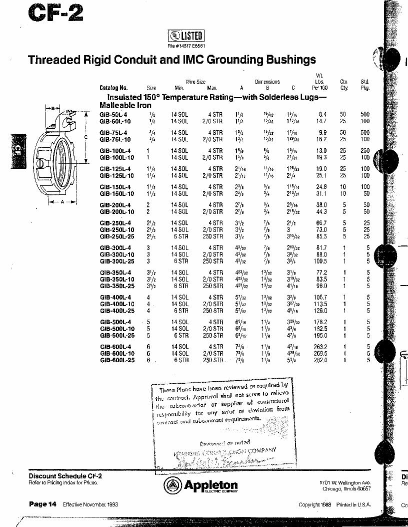
CF-2 l®USTEDI Fife #14817 E6581
Threaded Rigid Conduit and IMC Grounding Bushings Wt.
Wire Size Dimensions Lbs. Ctn. Std. Catalog No. Size Min. Max. A B C Per 100 Qty. Pkg.
Insulated 150° Temperature Rating-with Solderless LugsMalleable Iron GIB-50L-4 1/2 GIB·50L-10 1/2
GIB-75L-4 3/4
GIB-75L-10 3/4
GIB-100L-4 GIB-100L·10
GIB-125L-4 11/4 GIB-125L-10 11/4
GIB-150L-4 11/2 GIB-150L-10 11/2
GIB-200L-4 2 GIB-200L-10 2
GIB-250L-4 21/2 GIB-250L-10 21/2 GIB-250L-25 21/2
GIB-300L-4 3 GIB-300L-10 3 GJB-300L-25 3
GIB-350L-4 31/2 GIB-350L-10 31/2 GIB-350L-25 31;2
GIB-400L-4 4 GIB-400L-10 4 . GIB-400L-25 4
GIB-500L-4 5 GIB-500L·10 5 GIB-SOOL-25 5
GIB-600L-4 6 GIB-600L-10 6 GIB-600L-25 6
14SOL 14 SOL
14 SOL 14 SOL
14 SOL 14SOL
14 SOL 14 SOL
14 SOL 14SOL
14 SOL 14 SOL
14SOL 14SOL 6STR
14 SOL 14SOL 6STR
14SOL 14SOL 6STR
14 SOL 14SOL 6STR
14 SOL 14 SOL 6STR
14 SOL 14 SOL 6STR
4 STR 11;s 2/0 STR 11/s
4 STR 13/e 2/0 STR 13/a
4 STR 15/e 2/0 STR 15/a
4 STR 21/1s 2/0 STR 21/15
4 STR 23/e 2/0 STR 2a;a
4 STR 27/e 2/0 STR 27/e
4 STR 31/2 2/0 STR 31;2 250 STR 31;2
4 STR 43/32 2/0 STR 43/32 250 STR 43/32
4 STR 423/32 2/0 STR 423/32 250 STR 42a;a2
4 STR 51;a2 2/0 STR 57/32
250 STA 51 /a2
4 STA 65/16 2/0 STA 65/16 250 STR 65/n
4 STR 73/e 2/0 STR 73/a 250 STR 7a;a
15/32 15/16 15/32 113/16
15/32 F/1a 15/32 129/32 5/s 19/16 5/a 21/32
11/1a 125/32 11/16 21/4
3/4
3/4
3/4 3/4
1/a 1/a 7/a
1/a 7/a 7/e
13/32 13/32 13/32
13/32 13/32 13/32
11/s 11/a 11/a 11/a 11/e 11/a
115/16 213/32
23/16
219/32
21/2
3 315/32
213/32 39/32 33/4
31/a 319/32 41/16
33/e 327 /32 45/16
329/32 43/a 47/a 47/16 429/32
53/o
. These Plans have been reviewed as require~ by ' h ll ot serve to relieve fh"' contract. /1•)provc11 s a n I
Discount Schedule CF-2 Refer to Pricing Index for Prices.
v . I r I," of <;Onfrc;cftJrQ . the subcontractor or supp ie : • from
I ., ·t"y· fo1· any error 01' dev1at1on
1 l
rc>Spons1,1i.11
c~f\irad and subcontract requirements.
8.4 14.7
9.9 16.2
13.0 19.3
19.0 25.1
24.8 31.1
38.0 44.3
66.7 73.0 85.5
81.7 88.0
100.5
77.2 83.5 96.0
106.7 113.5 126.0
176.2 182.5 195.0
263.2 269.5 282.0
50 25
50 25
25 25
25 25
10 10
5 5
5 5 5
500 100
500 100
100 50
50 50
5 5 5
1701 W. Wellington Ave. Chicago, Illinois 60657
Page 14 Effective November, 1993 Copyright 1988 Printed in U.S.A.
-Di Re'

A. FURNISH AS SUBMITTED ~ 0. FURNISH AS NOTED 0 C. REVISE AND R!::SU3MIT 0 D. RE,JECTED 0 E. ENGINEER'S REVIEW NOT REQUIRED 0

PVC COATED IGID CONDUIT
AND CONDUIT BODIES
BRAND-PERMA COTE ?
PURCHASED FROM:
JESCO. INC.
700 OMAHA AVENUE
NORFOLK. NE 68701
(402) 371-:29:28
C40:2) 371-23:23 FAX
1-800-448-6:201

I.
\
I
\
RIGID STEEL CONDUIT --Size Catalog
No.
1/211 050CON PC 3/.ti 075 CON PC 1• 100 CON PC
1 '/," 125 CON PC 11/i' 150CON PC 2" 200CON PC
2'/." 250CON PC 3" 300CON PC
3'/." 350CON PC 4" 400 CON PC 5" 500CON PC 6" 600CON PC
• AWMl-COTE & IMCOTE available upon request -consult factory
EXTRA COUPLINGS Size Catalog
No.
'/2u 050CPL PC 3/t 075CPL PC 1'' 100 CPL PC
11;.11 125 CPL PC 1 '/i' 150 CPL PC 2" 200 CPL PC
21/t 250CPL PC 3" 300CPL PC
3'/," 350 CPL PC 4" 400 CPL PC 5" 500CPL PC 6" 600 CPL PC
<4, I
~·
LARGE RADIUS ELBOWS Size 12" Radius 15" Radius 18" ~1adius
1" 100x90x12 EL PC 100x90x15 EL PC 100x90x18 EL PC
1 '/," 125x90x12 EL PC 125x90xl5 EL PC 125x90x18 EL PC
1'//' 150x90x12 EL PC 150x90x15 EL PC 150x90X 18 El PC
2" 200x90x12 El PC 200x90x15 EL PC 200x90x18 EL PC
21/2
11 250x90x12 EL PC 250x90x15 EL PC 250x90x1 S EL PC
3• 300x90xl 5 EL PC 300x90x18 EL PC
3'/2' 350x90x18 El PC
4• 400x90x18 EL PC
5" 6"
• 30, 45 & 6ff' large radius elbows also available
... .. ,,_~ '
24" Radius
100x90x24 EL PC
125x90x24 EL PC
150x90x24 EL PC
200x90x24 EL PC
250x90x24 EL PC
300x90x24 EL PC
350x90x24 EL PC
400x90x24 El PC
·•·' ;,, -
To order Perma .. core Supreme rep face "PC" Suffix In part No. with "PS"
I ! l~
I I
"""""~·1 i
1 J 1 l I
1
I j ;~
-1
30" Radius
I 1 I f
100x90x30 El PC
125x90x30 EL PC
150x90x30 EL PC
200x90x30 EL PC
250x90x30 EL PC
300x90x30 EL PC
350x90x30 EL PC
400x90x30 El PC
500x90x30 El PC
l i
1
I l i
STANDARD RADIUS 90°ELBOWS
Size Catalog No. ,,,. 050x90 EL PC
'/." 075x90 EL PC 1" 100x90 EL PC
1 '/," 125x90 EL PC 11/2" 150x90 EL PC 2" 200x90 EL PC
2'//' 250x90 EL PC 3" 300x90 EL PC
3'/." 350x90 EL PC 4" 400x90 EL PC 5" 500x90 Et PC 6" 600x90 EL PC
• 45 & 311' elbows also available
ERICKSON COUPLING (3-PCS) Size Type Catalog No.
'f," 4-50 4-50 PC 3/,.,1' 4-75 4-75 PC 1" 4-100 4-100 PC
1 '/," 4-125 4-125 PC 1 '/," 4-150 4-150 PC 2" 4-200 4-200 PC
2'//' 4-250 4-250 PC 3" 4-300 4·300 PC
3'/i' 4-350 4-350 PC 4" 4-400 4-400 PC
.,,.511 4-500 4-500 PC 6" 4-600 4-600 PC --
36" Radius 42" Radius 46" Radius
100x90x36 EL PC 100x90x42 EL PC 100•00x48 EL PC
125x90x36 EL PC 125x90x42 EL PC 125x90x4B El PC
150x90x36 El. PC 150x90x42 EL PC 150x30x48 EL PC
200x90x36 EL PC 200x90x42 El PC 200x90x48 EL PC
250x90x36 EL f'C 250x90x42 El PC 250x".Ox48 EL PC
300x90x36 EL PC 300•90x42 EL PC 30Cx90x4B EL PC
350x90x36 EL PC 350x90x42 EL PC 350X00x48 EL PC
400x90x36 EL PC 400x90x42 El PC 400x.ax4B EL PC
500x90x36 EL PC 500x90x42 EL PC 500x00x48 EL PC
600x90x36 El PC 600x90x42 EL PC 600x90x48 El PC
(

~··
Form 8 with encapsulated screws
•· Form 7 supplied with stainless steel screws
Size Type Forms Form7 .,,. c 50PC 17 PC 3/,/' c 7.S f\~ 27 PC 1" c 100PC 37PC
11/411 c 125 PC 47PC 1 '/,• c 150PC 57PC 2· c 200PC 67 PC
2'/l c 250 PC 77PC 3" c 300PC 87 PC
3'/." c 350PC 97 PC 4" c 400PC 107 PC
Form 8 with encapsulated screws Form 7 supplied with stainless steel screws
Size Type Form 8 Form7 1/t LL 50PC 17 PC '/: LL 75 PC 27 PC 1" LL 100PC 37PC
11/4
11 LL 125 PC 47 PC 11/2n LL 150 PC 57 PC 2" LL 200PC 67 PC
21/2" LL 250PC 77PC 3" LL 300PC 87PC
3'/," LL 350PC 97PC 4" LL 400PC 107 PC
Form 8 with encapsulated screws Form 7 supplied with stainless steel screws
Size Type Form 8 Form7 ., .. TB 50PC 17 PC ~y." TB 75PC 27PC 1" TB 100 PC 37PC
1 '/," TB 125 PC 47 PC 1'/." TB 150 PC 57PC 2" TB 200 PC 67PC
Form 8 with encapsulated screws
Form 7 supplied with stainless steel screws Size Type Form 8 Form7
'/." T 50PC 17 PC 3/." T 75PC 27PC 1" T 100 PC 37PC
1 '/.'' T 125 PC 47PC 1 '/," T 150 PC 57PC 2" T 200PC 67PC
21/2" T 250PC 77PC 3" T 300PC 87PC
3'/,• T 350PC 97 PC 4" T· 400PC 107 PC
To order Perma-Cote Supreme replace "PC" Suffix in part No. with "PS"
I ' : ... I
1
Form 8 with encapsulated screws Form 7 supplied with stainless st~el screws Size Type Forms Form 7
1/2" LB 50PC 17PC '// LB 75PC 27 PC 1 '' LB 100PC 37 PC
11/4
11 LB 125 PC 47PC 11/2• LB 150PC 57 PC 2" LB 200PC 67 PC
2'/t LB 250PC 77PC 3" LB 300PC 87 PC
3'/,• LB 350 PC 97PC 4" LB 400 PC 107 PC
Form 8 with encapsulated screws Form ·7 supplied with stainless steel screws Size Type Form 8 Form 7
'/! LR 50PC 17 PC 3/.t LR 75 PC 27 PC 1" LR 100 PC 37 PC
1 '/." LR 125 PC 47 PC 11ll1 LR 150 PC 57PC 2" LR 200PC 67 PC
2'/i' LR 250 PC 77PC 3" LR 300 PC 87 PC
3'/," LR 350PC 97 PC 4" LR 400PC 107 PC --
( Form 8 with encapsulated screws
Form 7 supplied with stainless steel screws Size Type Form a Form 7
t/21t x 50PC 17 PC 3/
411 x 75 PC 27 PC
1" x 100PC 37 PC 11/411 x 125 PC 47 PC 1'/i' x 150 PC 57 PC 2" x 200 PC 67 PC
EXTRA COVERS Size Forms Form7
'Ii' BC50G PC 170 FPC 3/411 BC75G PC 270 FPC 1" BC100G PC 370 FPC
1'/." BC125G PC 470 FPC 1 '/." BC125G PC 570 FPC 2· BC200G PC 670 FPC
2'/,'' BC250G PC 870 FPC 3" BC250G PC 8"10 FPC
3'/," BC350G PC 970 FPC 4• BC550G PC 970 FPC

FD SERIES JUNCTION BOXES Without Covers
Size Type Catalog No. 1~./ FD1 FD1 PC 3,4 .. FD2 FD2PG ·j" FDJ FD3PC
1/'lll FDC1 FDC1PC 'Jll FDC2 FDC2 PC 1" FDC3 FDC3 PC
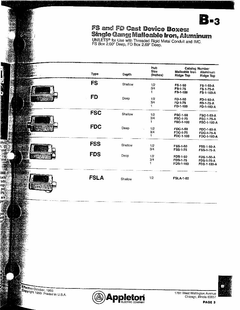
FD/FS COVERS ONLY Catalog No. Material Configuration
FS-1-BCS PC Steel Single Blank FS-1-BC PC Cast Single Blank
FS-2-BCS PC Steel Duplex Blank FS-2-BC PC Cast Duplex Blank
FS-1-SCS PC Steel Single Toggle FS-1-SCS PC Cast Duplex Toggle FS-1·DCS PC Steel Duplex Receptacle FS-2-DCS PC Steel DBL Duplex Receptacle
l{NOCl\OUT HUBS Size Type Catalog Type Catalog
No. No. Basic Scru-Tite Grounding Hub
1/2" ST-1 ST-1 PC STG-1 STG-1 PC 3// ST-2 ST-2 PC STG-2 STG-2 PC 1" ST-3 ST-3 PC STG-3 STG-3 PC
1 '/."' ST-4 ST-4 PC STG-4 STG-4 PC 1 '/i' ST-5 ST-5 PC STG-5 STG-5 PC 2" ST-6 ST-6 PC STG-6 STG-6 PC
21/2
11 ST-7 ST-7 PC STG-7 STG-7 PC 3" ST-8 ST-8 PC STG-8 STG-8 PC
3'/." ST-9 ST-9 PC STG-9 STG-9 PC 4" ST-10 ST-10 PC STG-10 STG-10 PC 5" ST-11 ST-11 PC STG-11 STG-11 PC 6" ST-12 ST-12 PC STG-12 STG-12 PC
EXPANSION FITTINGS. Size Type Catalog No.
1/: II • 2 AX-50 3/411 AX-75 1· AX-100
1 '/." AX-125 1 '/," AX-150 2" AX-200
2'/," AX-250 3" AX-300
3'/i' AX-350 4" AX-400
To order Perma·Cote Supreme replace "PC" Suffix in parl No. with "PS"
AX-50 PC
AX-75 PC
AX-100 PC
AX-125 PC
AX-150 PC AX-200 PC
AX-250 PC
AX-300 PC
AX-350 PC
AX-400 PC
I t t
r
i I
'
'·.·.·' ; .... .. ::.~ ... -.,:·· .
I . I I . - i I '
. .
P. .... _;,,,., .. ··,
.. ,,.. . .
. --.-~: PERMA-COTE llllln.1n1 IC.'TDll'.:C\
I
FS SERIES JUNCTION BOXES Without Covers
Size Type Catalog No. t/211 FS1-50 FS1-50 PC
3'"" FS1-75 FS1·75PC 1" FS1-100 FS1-100 PC 1/2" FS2-50 FS2-50 PC 3/,." FS2-75 FS2-75 PC 1" FS2-100 FS2-100 PC 1/2" FSC1-50 FSC1-50 PC 3/ .. " FSC1-75 FSC1-75 PC 1" FSC1-100 FSC1-100 PC 1/2" FSC2-50 FSC2-50 PC 3/ .. " FSC2-75 FSC2-75 PC 1" FSC2-100 FSC2-100 PC --
Type Size Catalog Type Catalog •·· No. No.
Through Bulkhead Without Nipples ,,2 .. STTB-1 STIB-1 PC STITB-1 STTTB-1 PC
3/,iH STTB-2 STTB-2 PC STTTB-2 STTTB-2 PC 1" STTB-3 STTB-3 PC STTTB-3 STTTB-3 PC
1 '/." STTB-4 STTB-4 PC STTTB-4 STTTB-4 PC 1 '/," STTB-5 STTB-5 PC STTTB-5 STTTB-5 PC 2" STTB-6 STTB-6 PC STTTB-6 STTTB-6 PC
2'/," STTB-7 STTB-7PC 3" STTB-8 STTB-8 PC
3'/," STTB-9 STTB-9 PC 4" STTB-10 STTB-10 PC 5" STTB·11 STTB-11 PC 6" STTB-12 STTB-12 PC
Size Type Catalog No.
I/./ AX-850 AX-850 PC 3/4" AX-875 AX-875 PC 1" AX-8100 AX-8100 PC
1 '/."' AX-8125 AX-8125 PC 1 '/," AX-8150 AX-8150 PC, 2" AX-8200 AX-8200 PC
21/i' AX-8250 AX-8250 PC 3" AX-8300 AX-8300 PC
31/i' AX-8350 AX-8350 PC 4" AX-8400 AX-8400 PC
I
I I I
t}),J i

:~<--_-__ ~:>--/_:_ .. : -- --.-r-~:\~~?-i';~ . . . -_-:;:~. . ".-,:; ;-_-,-· . ---~<:~'- - __ --{_- ,_._- ·'-_<:\-- . -1~~_:t'.~~_.-
R~:rma :J:ote;ln(j u~trf.es T7~t .Compli.ancet~ competitivf{~q'omparis«:>n· · · ·.·· \' 1
:'" ,_ <--?-~; ;• -- -- ; '
Description NEMA RNI ASTM# of Test Standard Perma-Cote OCAL
D-2240 Hardness-Shore A 75 85 85-90 Hardness-Shore D 25 40 N.A.
·-D-638 Elongation Test 200% 200% 200%
D-149 Dielectric Strength 325 v/miL 400 v/mil 400 v/mil @ 60 cycles @ 60 cycles @ 60 cycles
D-746 Brittleness Test 0°F
D-1790 Brittleness Test* 5°F ocF
G-23 Artificial Weathering 1000 hrs. 3000 hrs. 1000 hrs.
8-117 Salt Spray Test N.A. 3000 hrs. •·N.A.
G-6 Abrasion Test 200 hrs. 200 hrs. 200 hrs. no failure no failure no failure
----·----G-10 Bendability Test 9-no holiday 9-no holiday 9-no holiday
0··638 Tensile Strength 2000 psi 2000 psi 2000 psi
G-11 Outdoor 9 months Weathering no effect
D-635 Flammability Test burn@ 400°F burn@ 400°F self exting. self exting.
Toxicity 200°F 200°F and above and above
Rob Roy
85+-N.A.
200%
400 v/miL @ 60 cycles
o:F
1000 hrs.
N.A.
200 hrs. no failure
9-no holiday
2000 psi
burn @ 40ff'F self exting.
200°F and above
*NEMA Standards RNl-1989 specifies ASTM #1790 for Brittleness Testing, not D-746.
U~rlllimmm PERMA·COTE INDUSTRIES, INC. P.O. Box 1103 •Uniontown, PA 15401 •Phone: 412-628-9700 • FAx: 412-628-9653

FREMONT WASTE SYSTEM IMPROVEMENTS
SECTION 16111 CONDUIT, FITTINGS, & SUPPORTS
16111-2.03 ........... '. I •• I ••• I .PVC-COATED RIGID STEEL CONDUIT
SPARE PARTS ••••••••••••••••••••••••••••••••• , • , •• NOT REQUIHED
TOUCH-UP COMPOUND ........................ CATALOG #TC 1600 PC

RIGID NON-METALLIC CONDUIT AND
CONDUIT BODIES
BRAND-CANTEX PURCHASED FROM:
ELEC.TRIC FIXTURE & SUPPLY, INC. 1203 0. ltTH
NORFOLK, NE 68701 (402) 371-3920 C402l 371-3921 FAX 1-800-672-3491

\"1 , r r:om ( • KAYTON ELECTRIC I NC NORFOLK PHONE No. 402 371 8389 Aug.09 1996 2:19PM P02
·• CANTE><.
PVC PRODUCTS CAN 11. X l"VC P1oclt1cls hi:1d iU; bagin11i11u over' .40 yourn ugc.>, t'rn a division CJI <J ll<ill<mal qorporntic.m in tho LJlility and
buBcilnB GOflt:ilfUt;litm industry. 1 lu:: 1-'lrwtk::~ Oivisi<in gr~w i~1oacjily In 0120 am1 impurt$;ll1CG. Its produc.:I lirn~s t~xp1<:1nded
Into $everAI mf1jor cote'40rles:
• I.Jeclri(;al uistributor3 ond ountmolorn woro provided with a broli:ld linGt of PVC cr.1ndi.1it ~nd fillino~
• Power arid 1.11lli1y cC',mpanies were s~ippllod with Lmdergr(lund PVC duct and fittings.
• for tlU.i comrrn111i<:<Jiions lndu:slry, PVC conduit and fiHlng~ were mado nvniloblo lo tc:lophone and c:~bl<~
companicu for undo(9m1md cablg ini.:l«llatlons .
• M1111tcirm1 PUl)lit; worf<.S nr:cclo WOr!;l me\ wilh rvc pipe !or cfo>lribulion and colloc:lion.
• Th~ commerclt~I marf<.ct need wno fulfilled wilh PVC plurnhino pipo.
B(-:leaus(~ al ils t\Ucc1:1~;:-; i11 tho I 'VO Proc:h.mts blJSh103G, O/\NTrx (~;wghl !he oya of an inlarnatkmul or~31mizati<JO which
was planning for oxpan::;iun Into I 'VC 1 •rocJucw In t11e Western I lcrnitiphere. 111 Ftil>nJflry 1992, CANH:X wus acqtiirod
by t1'1c rnspcclod Sun1l'(omo Corportc1li<m. i':I rnullifacelod glob<il b1miness Ieacler. Out of this ncq1.1hiiti«>r1 tl'IA NEW
C/\NI LX E)mergccJ, ~qllipped will! w 1 inlon::;ci philosophy of service to ils Clmlornors and a renewed emph~1tiis <in proclucl qU:ilily ll'lat targots the chall~mges ol cl new century.
CANTi:.:x I~; a loading pror.Juc'-11 of PVC Prm:llJcts, willl five 111anufac.turii1g pf;rnl~ lo<:Htat'J stw109ically lrorn east to west
a(;reiss the counlry. Th(:~l:l pb:1nis fe<1li.iro so1Tir: of the ri-1ost modern production equiprn(lnt nnd advi.mcnd pm<:H!m
lo<.;lmOlogy found anywhcro in tlw illdllSl(y. Pwdu1.:llu11 fucililios inc;lude ~"':xlnmio11, injeclicin molding, e:ind lcibric<ilion
j)f0(;8HSOS to [HOCllJCt~ Lile bruetd li110~-1 of PVC r•roducls which ~crvo tl1(: powm, 111ilily, building cmnotruclion, and cornrnllnioaliorlB rni:irl,o!G.
ELECTRICAL PRODUCT LINE
Cl\N"I FX offers ~J c~omplme line <.)f extrw..1ec.1 cuut l11joc:1ion rnolderl etec1rlcal conduit, cJuc.;l, fillings c.md accessorit1s.
Pwduulu include o. full range of t:0iz.es in;
• Schedule 1'10 & 80 Cnndl~it
• I:ludrit:i-Jt r.:illill~JS & /\1:-:ce~.~·.nrie~• ·-Molded & rabricated
• Ulilily Du0t ·- Nt:MA TC·O & 0 LlJ/IJl) .. AGTM 0!3-100
• Duct Fillings & Acco$1-'l<>rl<'u
• Fii >1.1w::;, Bend~ & Swc:iups ·· Gtondurd & Opc:dal lladll1s
• [2'-rl..C::X tlactriccd Noru'l"letalllo 'lubing &rillh19~1
• C2NVll·t0-H r. x l lquidt!ghl Cc.me.lull & I' lllil l{.ltl
• Telept1<)11(': Gonduil -· 'l'yp<;;:i B·C·D • Oondln9 Lql1iprnonl
• Cc-irm-ml$l
Sl!AVICI! CAN'WX ~ltmlb frJt c.1 ~-u1nn1il1rt<:11I lo ~;rnvi(a; ti<;rviuc tiled µ~11~ \h~1 011\ilomrn fool. W(J ouoy uxtunuivo invcnto1foo
in ovrn :10 warnl'louses nntlonwitlo ftlr li::mt Ill! ll('ltrnJ11d anc.I complete;: ~•hipmeol:-;. Our efficient tmnsport.:dlon system, wllk:h
col'Jll)lncs our own tn ic:I~ fluot will 1 I 1ar 1~Jph.:l~Hd (;rn 1lrflot carriers. mecll ll':> rn Hime deliveries .,,nywhere In the U.O. The CAN1I:X
customer $!:lrvino lmu 11 i~ ~llC!Heu by pro10~1ski111:1lt-J wl !CJ provide you wi\ll ilnm~dilitli reHp<>nse £.inc.I c:.:ffc<.:livo cornmu11lc<1tio11u about your Or(lCirS ~md ::;tiiµ111c11li;, /\I 1111:1 NLW CANTfX. WF:. WORI< I OB 'II IL CUGTOMrn.

.'f.rpm :· KAYTON ELECTRIC INC NORFOLK '
PHONE No. 402 371 8389 Aug.09 1996 2:20PM P03
.·INDUSTRY ORGANIZATIONS
1
( N"I EX actively supports ttH)Se uryuni<.11llons whic;h ';ot slafld~rds und promote prolc:i~P-ionnl pmctk:c~~ in Ilia ok'Jclric~11 industry. Tl10S(-) il'lCIUCIO NF MFlA, N/\ED. Nr~M/\. IA[I. lrl"I~. /\OTM. lll<)ll~) with otl 1(}!' ar.oooiutionn ln lho <.!rn'H:lruc.lir..n
induslry.
QUALITY ASSURANCE CAN1 f-X has a compreh(~11slve quality Gontml progrwn lo onr.;urn c~(>r'nplianc<:> wilh imku:ilry slnndnrcfo 0Gk1blitd 1c.1d hy
UndarwrHor~ Lt-tborair.1rier.;, Nnllonal Dectric.:r.il Godc1. National l:lcl~lrlc1~! Manu(actl.irar~ Ai;S:it:>c:IAflon. and t!to /\moiic:.m
Socioty for Testing and Mnlcrinlr.,
From vh9h1 ruw inatoriF.'ll;;i blAncfod inlo comp<..)1..JIH% thni ~l<lnmlon or injac\i<.m moldino to !111::.il irn:pc~ctio1.1 :md to~~u111,1 nf
the finished product, the rnanufac\uring proooss iG monitorod to make sun::i quality smndards arr..~ rm~l or ox(:ornlrn.I.
Each plant is graded and hold ac(')oun!ablo for tho quollty conlrol perforrnanc:~i of ii~ to\al output.
1 o further ~;\rnnglhcn the company's goL<l kir quality r)roduolo, a oonlr::ili7o(i qu:Jlity control rcviow pro<:odtH(·l ;;1s:$:l.l1 c~!-:
lt1at every µfanl is p1utluc.;inq at a confii:•,tcmt l<Ncl of quality for Rll ::'limilar producta. You know you1rc gelling tho vory
hesl every lirna you b1Jy from CANl t:.X.
PVC ELECTRICAL STANOAi:tDS DY PROOUCT
Schedul~ jlO conduit / UL o~ I. NEMA 'I G-2 a1 ld NrC-ArliGIH 3~7
Sc.:! H:Klula tsO cundull UI 651, Nf MA ·1 C·:.:! nnd NEC Article! 347
nvc l;loclrical Fittings
Flttlngo for eleotrioeil f.lpp1louliorn,; vonform lu NEMA TC-3 and UL 51'1
Utillly Du\:I
NEMA 10·0, AS'IM F-tii2, (Type E820 - UL 0&1A)
Utilily l:>ucl · f.xlm Slrcnfilh
NCMA TO·O tmd l\ffl M I"· 512
UWily 1.lu1;t Fil!ir iu~• Nl:MA l(;.~
•-/-H 1-'X I N'I (I lm:trif:nl Nrnunolalllc: ·1 ulii110) & l'illinur;
NEM.A. 'IC-13 and Nl::.L: Article 331; Ul. l.i(:o;led
CNVlnO rLCX Liquicilight Conduit UL 1 GOO and NlO 3G 1
L:NVIHO· J-1.1-)( l..iq1.ildli$Jh( Hltlng.s
Ul .. G1<1t1 ond Nr:MA rl3·1
Uniform product Code - Bar Codes ,
UPC·ITF Ghlpping container Dar Code to identity each ~l<:mdmd Carton of rmdlmls ~J~;in~a inlerleaved 2 of G Gyrnbology.
Ill 3 00 88700 56765 9
I \ \ \ Pttc..;l\C:J.Qing Nurnbor
li::vel system characters
Manufocturor l.D. t~umber
ltorn Numbt=:r
Chock digit
•
•
•

,''.rri:;:im : KRYTDN ELECTRIC INC NORFOLK PHONE No. 402 371 8389 Rug.09 1996 2:20PM P04
SCHEDULE 40 CONDUIT - Bell End Shool No. TC 40 - 10orno
•MGet~ spoclflcauons Ul. 651 and NEMA 1 c 2 Rated for 90° C Cable Sun1101·tt Resistant 10' Lengths
@ Schedule 40 ......... ·-· ..... ·~ .. O.D. l.D. MIN. .. · · APf-'tiC:·)x~····· · · .. "f"i;k:i · · .. ··· ... r>rncE · f'AnT NO.
..... , ___ .. __ ...,.,. ___ .......... W':Ll.. ____ -...... ~'/Ff P[l~.r~~~ ... , PEHlCXl /\52/\£12 1/2. .840 .G22 .1Qfj .102 3000 17.Uti
..... Afi2AG1'2' .... =J/4 ... - .......... T.65o"" . ' . ,. .. ~824'"-'' ..... ' . n::'f"'' ... ' . .216 ....... 4460 23.26
... As~iii\1"? ......... ~1·~··rn····~ .. M··-·- -1~3"1~.. · 1':649 ......... · . 133" ..... - ..... .320 2100 3·4·:22· .... .. /\5~~0012 1-1/4 · · .... ···· .. -·-·1.'66o···- ............. f:3oo .. · ··· · .. · ··-.·14·0· . ., · · ........ · · .4:;4 2000
A!i?.m:;-:~r-- ........ , ~, 1:-i · "TW'ic.l' ·· · · .. · ·r·crr o_.......... .. . 1 '1 s A520A 12 2 £315--· .... ~-·2:c1£fr · I . 1 M
·-A52fiE'1i2' .. ' ""'?..'fo)'"'" ... .... ';;t.075 "'"' '2:~69 I .203 -Av2D'AT2··-- ........ 3 3.500 ··s.008 ............ ·.2T6.
.5~0
.liUY
1.lOU 1.4!)ff __ , _ ....
.................. ""' ...... ' '' '' ·····--·--··"· . . ......... -- ·-·~~... . ' . " ..... - .. ~ ....... .. ··--·--· A5?.DE 12 3-1/2 11.000 3.548 .226 1.744 Ah:.?f:'J\'ii....... 4.smr-· ·--···4~02s ...... -.. -~23r·· ·-·---- ..
2.067 ·-·A52FA{2 ... - ..... 5 ...... !).s6-i .. -..... ·-5.047 ........ __ .?5t~ ... ·-:r&n ........... _, ___ ,.. __ ,_,,. .............. ,,,,,., .... _,,_,_, __ ... ,,.,; ...... -~- --·-• .. ,,,....... _____ ,.,,,, .. , ___ ...... ..
A52GA12 6 6.6~!:> 6.065 .~80 9.030 -· ' ............. ~-·--·--· ·-· ,_M __ , .... • ~··· ..... _, ·-·- 0 -·-- .. > ,,,.., __ ,_, ___ ,_, 0 ....................... .
A62JA 12 8' 6.62.b 7.981 .322 5.474
e·Non-UL Schedule 40 conduH complie:-; wilh fcde1«.ll and mllltary ~P<.!Glllcmlons tly coororrn111g to UL ub1. Nole: 20' lenglh available on request.
NOie:Con~oUhi~Jillru1t sut?j.o.cU0-chan9e-wrth u nolitm.
H~OO
1930
i350 ', .. 660""""""
870
540 3HO t.'40
:180
4!>.91
::i4.94 72.44 ... , ' ...... .
114.9'1 100.a3
180.71 212. lfi 29::,.5~f .... -
301.02
575.00
Pe.t 5fec.. S~c. .L,~of'\ I 6111 7 f tt1/.- ~ .o4 B, @;r~,fav-f£ v er 1·fy.
t)ft/c c°""'ftJ()"JMee.f.-.'.>,, c1s {{ 11r11'n11-t-t"'~, AsT/1t1 Ot7fi1'1 Ce(( cL,ss;/i'cc;«J:i Puc. 1 :;z c:<33-A B or c_
) }
,;;.) Rc.t·.f..eJ -For-dire(.+ 51..1;1/,941- exfu->
3) f:l-'l'e_ re ./-a rci C,{Y1 + C:Ut J I t:!W < ,,,,, () /;::., ,,, ,,. , "'"" e 1:1-1; /cJA.....
Lf) 5f-~nJi1"J; A NSL C33. 9{
CANTE)(. l".O. 1:3o.x 31'10 MinEiral Walls, Tri:iw.1: /fill!:\/ (1:11 I} ~2&-33'1'1 l·AX (01 l'} ~::ifi 4C44

(
' · From ;, KAYTON ELECTRIC I NC NORFOLK PHONE No. 402 371 8389 Aug.09 1996 2:21PM P05
,~thedule 40 Special Radius Elbows CANTE><. .-Jlain End ®
!ii/I
1
l.lH:lf II. I. Ill'' HAI >Ill:; ;•11" ll/\l.lll K;
151. Nil I 'All I NU. I 'lllUI. l·:A I 'All I NO. I 'lllC:I. I· A.
30 Ci1339 tC
n.oo [i1:J.1n~1n
!') 13387~)
7.10 C.1:)301-1
H.10
l.10
7.00
0.30
: I()" 1 1/\1 lllJ!;
l'All I N<J. 1 'lllC.:1 I A
!!ti" I t/\lllU~·; 1\11" 111\1 lll l~: . . ' .. ' . I 'Al II NO I 'lllUL LA. l'AIH NO. l'nlCI" !"A.
!J W:..10!.J~~ 11.UU [J 1 :·K:IH!M 1!1.tlO
!1 t 3..'1n t f) fl.no
fi ?fl
11 /4 ·1!1 I• ~~o
!11:1:m·1 I I0.'10
11.£)() h 1:1:~H l:i !).!-JO
l!!YO
11.CIO
2
~?2- ·112 !;13,~(~~9
!.i1:~3fMO
!>133917
!lll !1 l'.\'.U!/111
-111 :i 1:1;1m1
~'O ! 1 I ~3'.UB!l
2~!-1/2 G133G7~J
12.00
11.CXJ
9.00
111.m
/."10
0. IO
9.40
~)0 b·l:KlflMl Hi.10
5133073
!.>1'..i:.lO'/tl
5133fl03
11.60
11.110
B.90
5133~>21
!, t:l:H'll
: .. 1:1a!1111
I II.~ II I
l?.10
51:1~9!)7
613:~M6
o13:~B10
!113:~B74
fl.70
1(>. 10
12.60
f.i.:~o
:i.
ti 1~)3orn:i I
5133811
[1133~)02
!11:1:111;n
!i 1;1:U!lll
!> 1:~:~nrn.;
!:)13396'1 !.i , 331:'1\ 9
21.00
13.?0
n.oo
1-1 .: '() 11.()()
11.!JO
35.10
~1/2 4!> 30 {)"13371i2 12.40
!1 t:\:Ul'.~li
~I I; i: Ill I~) G t:~'.f/D() 5133~)1 !j
~)f:X1047
!) 1:1:1!1:1! l
Gl33$57
I: 1.1 in
11.W
~.l.!.:;O
10.!)Q
19.40
1 '1 .ll!I
13.50
!1 l:.Kl//O
! >1 : !:·UH:?
&133851
!ii~~iB!'il
G 1~rJB01
I Ii !Ill
1;u,n 11.0()
10.:10
?!i.BO
rn. 10
3
2/·· 1/'/. !.\ l'.:l~-<~~~t.i 11 /lU
30 22-1/2
90
2G.10 5133067
!'1 l:l:l!lfXl ??. 10
5133958 ?o.no b 1 :3:~~Kl:~ 111.tJO
51:1309!)
5133929
29.30
?.1,(l!J
H.i,60
~~.00
?h.!'iO
??.fl()
1·1.~-10
43.90
G1.~'13817 f
G 1'3.17 fl I
!> 1 ~~~mo!:l
"IG.'10
?fi.::l(l
23.90
3 1/2 '1!> 30
l JsA S1nnd;:irrl ~:;o 11n< h 1 lo II()
llmHu() (i5")
513309~; 32.bO r) 1:nno:.> ?;mo
51~Kl020
!'i1 :1:17'7fl
51:~3793
5133904
5133818 f1 1 ~~:lH:~H
5133U92 i, 1:~:moo
59.10
:4?.10
4
5
6 l..
1?
?.?.· 1/2
90
:io 22· 1/2
~m
'1/)
:Ill
90
l .. Jt.:o Slandard ~)c;hcc111lc~ -10
Raclius (Hi")
~> 1 ~13(:J02 1 !>.BO
G 133822 35,80
:i 1;1;,n I? :1?.rlO
!1 J:l:ilBB ~{ 1.1.i!.I
Ii W~}(l()~l 17, 1 0
Us0 Standard
I ~acllus (24 ")
513-1f350 !) tt ~rn-,::1 ~1 t~!~!f.lUIJ
5133802
h1:.~:,8'n
11 t0:1!lri'1 !11:1:mrn1
5133000
-1HJ0 :.~!1.fJ()
:J~~.DO
22.GO
f.i'1.10
!"10.1i0 1111.! )(l
31.50
Uso Sl~ndard ~"ic:llod1110 '10
51~~38?1
!:i l:i:i777
!..> l~J:J7DO
G1:138[i3
G i:rJ84'1
1"11:1~7AO
!i l:l:m:~ I
5133881
47.80
::\7.'10
:M. tlll
?:·t4Cl ... . ... 71.BO fl? (l()
!> 1.()()
32.40 61~~~~877 105.50 !i 1 ~3:~880 73. fi()
G13~'lfM3
!i1~:'7inn
!) 1~1:.ut.m
[.) 1~~393?.
!-> 1.:3::m,., :>.
~ > 1;,:1n 111 !, nirn,n 5103930
5133816
ri·13~n1:1
€M .HO :1H.t10
:ll.10
23.90
BU.HO
[i[).~()
! .'.~.;.>()
33.60 114. '10 1n.110
(';;:.>,'1() :m 11, 1 .. (''ll") !i 1:.nm1 '\( ll I!, ,,
. ~~~ !/2,.. . . .. .. . . ............................ _ .... . ... .. .. .. . .. . ~ l'.">-h.~3.91v.r.J.+:-;-!-~;1¥.+::-i~~~:f...l-4!),50
n:wo
N(llc: ( 1) 01 dc:r:; for :;pc:ci11I rodiu:; c:ll.lows 11m nc.mc;micc c ble and n<.~nrelurnable. , '- , (2) Elbows belled both ends are av;;iilable on re est. P2-• 7fec. sec.A-10Y\ 161/ I, fttf' T J. o 7 F, (fl) I ml'.lornn<lh1~nvr1flnl'll<-!011r{,qt11'lRI. Vel"iL-/ .f; /.J-iYl.'J.S F~r- R,;<j,J ;V.:111-me/-..il/1-c (4) Oii 1Gt (JOtll'C'ltJ licmdi.:: HW1il1;11.>le (JJl request. Ll)(1 dv; + vJ.1 et:: r Al E #I A re -;;i -I<(~
-·~------·----------·------
'

, From :·KAYTON ELECTRIC INC NORFOLK PHONE No. 402 371 8389 Aug.09 1996 2:22PM P06
' I
•
•
·Schedule 40 & 80 Special Fittings CANTE><. End Balla
hoduoera
®
Poly Plugs
Pol,- Plugo wtU1 Pulllng Evo
PArrr NO.
hM'1ll03
5144004 I/?
:1/1) " •- ._,. __ ,._,."''•\- ... h .. , .... ,. ~..,.,w ••~• ,.
5i-1'100G 1 " ·~ ... ,. ...... ' .. ' .. .. ' .
IOO
1fH"I
bU
M '1 '1 oon 1 1 /ti r,o :11'1'100/ I I/;' !ill I\, 44()()1-l ~) 40
Ul"C-nr PKO. :1 oo nn7oo w11,
;!'
h}!U~~'1 I P.:.l!j
b~U:::!!:i4 ?.65 !36712 3 2.::JO
f)fi7 l~I 0 ?Ji!i
!)ti/Ill I 11.:10
W/ 1 !J ·1 3.00 .,, ............... '
J ...
51'1'1009 2 1/~ ... ,, .............. l:?.9-.... . !"ifi?/>fl 4 4 ?'l
M/14010 !. M<10I I
51'1'1012 51440'13 t1'1t101t1
rAnT MO. SIZE
5142220 3/4 x 1/2
5142221 1 x 3/ti tJ142222 1-l/4 x 1
51112223 1-1f) x 1-1/4 ' H• ... ~ ...... - _ ___._ ........... '
5142224 2 x 1-1/2
5142229
!·'AMI NO.
531.5:iMO
!i:J l h?!)fl
? 11? x :> ! ! "' : I I/: I
4 x ~ 4 x 3· 1/2
bO hO
bO ~!)
16
GTD. r'l'\(i.
ioo 10() 50 50
25
h('U:J;.! ;::
e>2o~~i a b2B3A G
o203V3
UPC·JTF 3 00 88"/0U
56710 9
::ITT7i1 6 !')67'13 7
66744 4 ...... -.. ·-·-·· .. ··'
56745 I !'\Ci7tlfi A
2U bcl~bU .... ,,~. . ...... ~· . ' 20 !::i?796 7
t.1 ID. Pf<G. :1 nu tititOU
H.97
m:w 1?..6?
a.i1rj \
Pl<G. WI.
2.15
3.35 3.40
3.35
3.65 !i./h
!>.hll
I I.OU
9.60.
l'l\.G. WI.
PRICc Pf;li 100
17fl,(X)
188.90
440.00 458.90
513.30
b(J11.'11l 012.20
9'12.20
1,0::.J3.::l0
PRICE. Pl:R 100
00.00 1U4/IO 235.60 244.40
29'/.00
nr;:t:in I, 111:'.:'o
1.312.2:0 1,'100.00
I 'I m;I PFH ·100
U0.20 . llAHO
!i: {! ! ,;.>!>~' ii
53"152!13 5
70
"/O !II I
'1~
~jQ
63054 3 11:mm1 o ! 1'. Ill! iU "/
538!J'/ 4
G.:·m n.r·r
IH.h!i
l~Hm
9.56 ..
; 10~1.110
2i'1.l::IU I ·· 1
" "" .... " -~· ... ' . Wl!J?!A G b3ll58 1 ----·- --·-·- .. ··. ···-··--'------'----
PAR'r NO.
fi:'fl fi:i'!'ifi
1i~1111: 1m
Sl7.r.
~ 1:11!1?0? 11 !S~-S 1 !)2t'.!~'5 o
.:s-&.3-1626 > __ .. -·----~ ............ ..
mo. Pl<G.
IU ~('.
1111 tJb
lC///1
P4ff ;;i.o?F1
UPC-rrr-(i 00 68700
b~·m!>n n 11ann1 1 ! 1: 1110? II tJ:mti:~ o 53864 2
p.::f' 5f €!C S ecJ-r"ori
Ver/ ty {;,.\f:; N·5>0A TC-;_-/
. .{:0 f'· f l t;I~ I\ 011 - rn eJ d II ic
f"'l\C.~. wr I
5.Ga'
nn:
:;36.50
1·rncL: 1·1-n 100 . ., 120.00
1 t\D '10 H ;(iii ; 'II'. U ill 13.tlU ;.; I l.UU
10.9:..l 337.60

·From ,:-~RYTON ELECTRIC INC NORFOLK PHONE Na. 41212 371 8389 Aug.09 1996 2:22PM P07
• I \ ·· Schedule 40 Fittings CANTS:><.
• Coupllns• PAI' ff mn. l llT.:.llT f"l<G. Prncr
® Nn. Sl?F Pim. :~no Aff700 wr. Pt-:H rnn '' ' ..
0~41Q~3 .. ~/2. 200 00704 0 7.19 33.3(') .. ' ' ....... ',,.,,_ ..... _ ...... . ................. 6141624 3/4 125 067055 6.2Ci IJ I. m . ' ... ' - ,,,_ "' ~ .... ' .... " •• ... 11,,. .. ................ .......... , ......... '' , .. ,. , ...... _ .. '
" 014102!.> 1 70 507.SO 7 4.~4 63.30
G141o2G 1 1/4 40 bG731 4 3.% 04.'10
61'11627 1 1/2 JO oti732 1 3.72 117.80
01·11020 •) ... '10 l>(J/:;:; u 0.70 •11)3.30
G141G.29 2 1/2 20 faUi':-j4 !' 7.01 vro.ou ('fl 4 1(J:j(J :J 40 ~.il:.lB~> 1 ti :?.1.7~ '130.00 . .. ..... ···-· .. ' ·- . ................ '" ., ___ .,' ... '
fj 141631 3 1/2 ~o 06109 6 21.35 4fl4.40 ,, ' 014163(! '1 f'O b·1"1:'.3G I 16.19 OOJ.00
01t1·1000 5 10 o-17~7 o '1•1.50 "l,'740.00 .. , '
t.i1'1163'1. 6 0 b4"13U b 1tM>o 2,2,?U.90
Female .Adapters P/\IH S"JI'). lJPC-ITf PKCi. 1-'HIC';I-
® NO. SIZE Pl<G. 3 00 88700 wr. Pff~ HlO
·.'
51400•13 1m ;.~00 6t':l70{3 6 o.QD 62.00 ;
!:>'ltlUU4 'I :;111 li'o ~){;j/09 3 o.B4 EJ3.b0 ... ' .. '"' .... ~ .... ... , .. ' .. , , .. ' ................ _,,._ ........... 5'140045 1 70 56747 6 4.BO 112.90 .. ' . , ........ '' ........
• 51-10046 1, 111 40 567-16 2 '1/17 140.20 ... ~ ·-··· ........... - "" ... ' .. 5140047 1 1/2 :m 067119 9 ::1.64 157.60
' .. ... , . G14004B 2 40 t;67b0 5 6.?t~ 219.BO .. 0,l~QQ~~ 2 1/2 20 50751 2 8.7fj 407.fJO ... ". bltlOOuO ~ 'IU bet t:.J u 1U.-1 I u~HAU
51400!)1 3 112 30 52774 5 20.72 777.60
!l 11100!,:.> 11 ?.O !i2.77!) 2 17 .0'1 ·10~~.2()
5140053 ,. ;) 10 b!U"/t) ~) 14 ·~" 1,~>82.20
!J l40Ut.4 (:j I.I tJ?I /'! ('.) 1l"$.94 ?,616./0 ;
.. , :i
Tennlnal Adapters PAl'H fiTD. Ur'C·ITF f'l'l<.G. rnicc NO, :.>I/I l'l'\G. :J 00 Ul.J'l(X> WI. l'U I IOO ..
51'10103 1/2 200 56706 2 6.20 44.30 ' ' ..... ,_, ....... ' "
51·1010'1 ~3/4 12G 56707 0 5.15 78.40
!:>14010!;! I 70 !lfi73R 3 439 9ROO
51.110100 1 1 /.1 40 b673U O 3.96 127.30 .. ,. ... , ............... .... _ ... ' ' '
150.40 I G140i07 1 1/2 ~';0 567406 2.05
~J 1<10108 ?. '10 567111 3 5.6'1 P?O.!iO .... !) 11\0 !OH ? 1/}' ?O t'iCi7'12 0 5.!iO 3fi7.t-IO
Gtil01IO a .qt) bb8t:i4 ~J 1U.(J8 b28.1:10 .. 1:::>140111 3 1/2 30 f1~779 () I /.(jf) 695.60
("" b l'IU 11 t' 4 20 G27806 12.73 907.80,
s--- IO 1.i'Hn.W --..
B 2, Vf/.BO cJ !>14011'4 6 Pef' 1 ~fec. ~ecA-t'ovi, J bt//
1 ft<lf- ;<.o7F,
c Q<'lj<J;.j- mee0 ,_
ve1 I ty ..p, H1~ s tor R 1i icJ /Vo11~ JY1e~/J1G l!
1:'8MA- rc-)..-fq7'? 5 --

'" AIJG·-06-1 ':3'36 16 : 41 402 371 3921 P.02
~T~
Vertical and Hcrizon'.al Interlocking
For completely enclosed and locked-in cluct ban~:s
• They snap together vertically tor tast. secure field assembly.
• Only two con~poncnts, tJase and intermediate, are needed. Banding is not necessary.
' With t11e Vertical-Lok spacer, clucts are accurately separated. Spacers lock firmly together, preventing separ~tion •..vhile workman walk atop the bank,
• Aligriment of '.he duct bank sectior:s is relatively easy with this completely loc\t,ed··in ccr.struction.
• To prevent the top tier from floating cJur1ng encased burial, it is suggesterJ that an intermed!citc spacer be used as a cap.
• Used in bcJth EB arid DB installations.
• Vertical and horizontcil in:ertock1ng permits building a strong, lock-:n duct bank. A wicie baseplate pr0v1des soiicl support for heaviest loads
lntennedLate and Base ~cer Dimensions ·-----· ... I ·---·- .. .. ·-----···-· ....
' 1 ' 1 /2'~, 2"
3a~o !.>i.;<.Jt:t:I $ f>fOV1d1:! d
3 · sci:i::.ratian ba:w~~n :io1tcm row vt \1\a;is /!, !r~.~·;n r:o•Jr, ~~cc,pt f(rr 4"~1", wr.r< .. i isl 314'
. SEPARAT!QN $c;~AAAT~ SEP}.RA.TION 1 · SEPA8ATION _ ~f~OMINAL I I
I . SIZE. -·~-----~ A c . -__ _i1 ___ ~ __ q_ . l Fl ;:.. __ c f~ /~ c I
r 2" Saddle sµacers (!n:y 1.2 4.0 1.5 . 1 2 4.5 2.0 I 1.2 5.5 3.0 I
---3-.;· ' s8(jdle sp;~r:!rS (,!'l!y : i B :..1 1.5 1 8 5,6 2.0 I 1.8 6.6 3.0 i ........ 4.. 1· ·· ··-2~3 56 1.o · +-2 ... 3 .. 61 1.5 2.3 e.6 20 2.3 7.6 io .....
·---····· .. ···--·--·· 5" Saddle sµacers 2.9 7.3 1.5 ' 2.9 7.9 2.0 2.9 8.9 3.0 .. ~
t. __ , ?I' ·- 33 8.2 1.5 ~-~-~·? 20 1-.~~ 3,0w••·'.
1-\. FURNISH AS SUl3~/.ITTEO 'Jf{0 D. FURNISH f.1S NOTE!J
C. FlEVISE AND R!::SU3MIT 0 D. REJECTED 0 G. ENGINEER'S F:'.::VIS'.'J NOT REQUIRED 0
Thi;; review i'.:l fer c:;nc~;:.I con1crr.ior.co with design concept only, /\ny c:~vi:ition fror.i pl:::nn or spccific::tion:. r.cl clcnrly noted by tho Contrnctor ha~; not been (eviawcd. ne:vicw by the Engineer :.:he.:! net ::;crv:c t:J rcl!~v? .tho Contr:::ctor cf the con:r:ictuc.I rn~~;;cn::1bi11ty for cny error or csvic.'.!cn fro:";'l c:::r.tr::ct requirement::
l

CANT EK. '• "
:ti\;;al and Horizor\tal Interlocking
term~iate Spacers --,· ·---· ·-·
;F·:: I ~ ,, I 1 , :'2" 2" I 3" :~z~ i · --:- 1~ r -·· i · · 1 :· : • .. _l : ·--r ·-;-· ·:
P.A.RT I PKG. sm. ! PRICt:: 1 PART i PKG i s ~o.! f'R1::;:: 1 PArlT : P1<G. 1 sm 1 L'r~iCE 1 P/\RT I PKG.! s1 D. DRJC~ NO. i wr .. PKG. i Frn ! NO. 1 wr , f'lo\G I Pr n • ~K). w1. 1 F'i<G PER i NO. i vrr. 1 PKG. 1 Pm '
,--- . .L_.! . -J-..:.?:J i -··- , ....... : I ___ 1o•_i , : • .. . ·~--~co.,+_ .. -1.. ~-·' .F2_, 2 ! -·- I' - : i G33fiOOIJ i 3.1 ! 3:.0' 7 l '1•J ; G:3.3GO 1 l\ : 31 I 300 ! 75.60 I 53360:32 i 27 \ 200 I 80.40 !
:3 , , ._i_. -· . "' _J_. i .~~~om: -:.\-~ ~~~ :. ~.~ ~o' ~~~~g~2~ , :3.~.'._200 i. 86~40 i .fi336.?3'-fE~ 125 '. 8~.40~ .c I 5336017 l 37 I .::.00 I 73.60; 5.336021 ' .;I(, ' I :;i(_, I (lo) 40 : 533601 ::J 28 I 125 91.00 i 5336024 ?.41 90 '106.40 I
s '. ··--· t ;::_!1. -- ; .. :: i [13:3§0~8; 2a.: 1.ooj1c2.oc: 533G0~?9 '. 27 ;.1~~ '.1qq~~9\ G3~9.~~o ·2l.__ 8() ~.i.~§~_10:
C. _ l.__ _ , I -·. ·- I ~·~~~(138 30 , 1U:\106 P..CJ > 53360[10 1 31 , 9Q ! 134 20 i 5336041 26 ! 70 180 90
,;? , ..
r·--··
~fore: There is a $5.00 charge for a broken carton for quant1l·~S oth8r til.~n a st;'.'H1C'lard pack.
T0 'd TC'E.£ Tl£ 201::' 3dnl>< I .::l JI dD313 o~:9l 9661-90-Qn~

.=-rc!im : KAYTON ELECTRIC INC NORFOLK PHONE No. 402 371 8389 Aug.20 1996 5:07PM P02
A(.I~ 20 '96 04 I 2SPM CAl .. m:x 111 l'lrRAL ~!ELLS
Katon Electrio~l ConetruQtion Co. At.tantion: MikEt Sind11lar
To Whom l~ May Conea~n1
Ro! CANTEX ~VO Elaatrical Conduit Po~ Premont, NF. Wasta water Treatment. 'Plant
WJ\il 9ert.:lf'.i.cation covers the followiriq quantities of OAN'I'EX con.duit;. supplied to Kat.on El.ectric::::tl Const:r\:l.oti~n Cowpany.
... QJ.lll.n:t.i.:t~ Joo ree'l~
2670 f'eet: l.80 f.eet.
2(100 feet. 2e~oo fffet
:1.11.u feet 1200 r.eet
__I.tam Dttt1..f!.Q.~ 1 pt ion .. __ 3/4-!nah T0-40 PVC l~inoh TC-46 PVC
l•l,/4•.i nch TC-40 PVC 2-inch TC-40 PVC 3-inch TC-40 ~vc
3-112-inon irc-40 Pvc· 6-inah 'l'C-40 PVC
CJ\N'l'EX rig!O. r;cheduls 40 (TC-40) Poly Vinyl Chloride (PUC!) Qla.otrioa.l pla.&.ti.c cJ()nClu:lt (EPC-40) and );)r..ma.s are p~od.uoed., inepautad, li!:a1np1ea and tasted in acoordanoe with TJnderwJ."itere Latioratories (UL) standard UL . 65'.!.. Thetie \lOnduit products me•t the requiromants for the UL "Sunlight Reai.stcnt.11 rm.tinll and are listQd by UL for use in direct sunlight. These iten1s nre app;'C"OVed for listing by Und.a:i:write1:s Laboratories, and . repreaent~tive samples ara routinely examined and tested by Underwritera L1o1r1c>r~tori'1s f Ol:'.' eontinuln9 oompli ance with UL spe~if icationa.
CANTEX ri9ta scl1Gdul0 40 con"u1 t and l>cndig are liart•d by tt~derw,..:lt:.erg l.aboratorill:1S tor use with 90 deqree centigrade rated. oonduotor9. CANT~X conduit proauot$ may b~ Uged in any application Wl\Aro ~ho a~bi~nt temperature &llows the us0 ot conductors which are rated for 90° c (194' F), o~bj~ot only to the limitations listed in Artiole 347-J cf the National Electrical Oode.
The oondu~.t at1d bends are listed l:Jy UL £01· tiu.ri.1:tl with or without ooncrete encasement and are aa.cceptable !or UEie as 11 Ri9ia Nonmetallic conduit" fiB described in Article 347 of the Na.t~.onal Electrioal Code, inolucHnq d!:r·eot burial in underi;ro~nd. i1u:tallations as defined in sections 30o-e and 710-3(b).

7r~m KAYTON ELECTRIC INC NORFOLK
:
t\lJ.CjJ\liJt zo, 19~~
l?&Q'& l.....,o of Two
PHONE No.
- I 1c.RAL l,1JEL.LS
402 371 8389 Aug.20 1996 5:07PM P03
I
CAN'f'EX ri.rr .tct l!'lcheduls 4 o cond.ui t also moats t.hei a:-equirem~nt.s of N~MA 'l'C .. i.
In ra:~ronc~ to ANSI C~J.91 1 this ~~~ndard ie a l972 standa~d and wag witr .. :l::-awn aa a separate. 11J.t.&nda.t'Cl by ANSI. It !a now rewritten as ANS!-".:!.6!il...:~.,96 to which CANTEX conduit 001'1\plies.
'l'h!lr.:< ynu tor your iflte~eat in CAN'l'EX products. lf you need any J'llO:re int~~~~tion I will Qa ~l&d to help.
Vary t~~ly you~s.
OANTEX lNC.
~.&...:.. J.R. M.c:IGreaor P.E.
'!!\ • • V.P.-~.ng1near1ng

., .. F;rr:im,: 1<'.AYTON ELECTRIC INC NORFOLK
August 2G, 1996
Mr. Mike Sindelar Kayccn Electric, Inc. P.O. Box 674 Norfolk, NE 69702-0671
PHONE No. 402 371 8389
Re: Water Storage Facility - Pkg. II Fremont, N)!!
I>ear Mike:
Aug.27 1996 10:51AM P03
505 S. River Avenue P.O. BQX 429 Exeter, NE OB3b1-04i9 Phone: 402-2tll:l·5347 Fax: 402·266-5377
'J~his is to certify that the 24" x .500 11 wall & 20" x .250" wall Bteel pipe, ~o he used on che referenced project, meets or exceeds the physj cal :requj.rements of ASTM Al39 Grade B specifications. The yield strength exceeds the ~inimum 35,000 PSI.
Sincerely,
HORIDONTAL BORING & TUNNELING CO.
Cf~r~ Thomas w. Ekeler
'l~E/skh A. FUrH'IJIS1-1 AG.SU31't.!HE.D [; 8. FUHNISH ;\0 NOTED }::?;<' C. REVISE A~.;:) RCCU3MIT 0 D. R EJECTED 0 E. C:NCIN~~crl'S r.:v1::.w NOT REQUlnED [l
~hi~ rovi:Jw i:i fer G::;"J~r:;J confcrm:mco with ccs1~n 9\)nccpt on:y. Any deviation from pl::n:-. er sp0c1flcat1on:; net clc::trly noted by tho Contmctcr. ha:i not boon rcviGwod. Review by l~:e Cnginocr sh;:il net corvo to relieve the ContrGctor cf the contr:ictunl respowibility fer a~y orror or devi~tion fror.i contr"~cl rcc;uircrnento. · · ~
~D~NG!NEERING, INC. By~ C/-fo-'f&, ~olJ,l(>O\:tO .,..,wi • ..,,,.. ..
Shop Drawing Tr.:mzmitt:tl No. __ '!tt...,k2_ Prciect fre;ci.oM C<;?l)t,(~~-._.....i3 __ _
Trenchless Construction Specialist
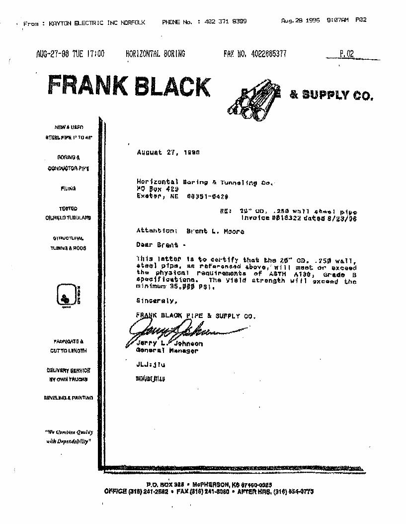
, From : KAYTON ELECTRIC INC NORFOLI< PHONE No. 402 371 8389 Au9.28 1996 8:07AM P02
AUG-27-06 TUE 17:00 HORIZONTAL BORlNG FAX NO. 4022665377 P.02 -----;....,.,""'-'--
FRANK BLACK cl\ IUPPLV CO.
NllMI• uttn
&'raBl. l'llP'& I' TO .. a•
PILIN!i
l"N/ll'llOATG A
CUTTO LINGTH
Dli!LIVSPIY illRVICft' IS\f OWN 'rRUCiq&
,.W., t.'f1MfliRt Q~frf)'
wiib li!lprnda~il(l;Y 11
A1.1euat 2·r, unui
Hor faontta t Bat'inti & 1·unt"lt1111nf Oo, }IQ IJox 42~ £x•t•r, NE 6$~51-G4f$.
Ra: 'liA"oo •• 2!!Hiwt"-ll .i;ortQ,.1 p1fi1,;. lrwoh:e ll'-"18.322 dated 8/'l~l'JG
AttenbiQOi SrQ;nt I.. Moore
Dear lr&i'\t •
)h1s Jattar u to oet·tih t'1a1.i the 1.t!i" oo •. 2S'1 wtt..11, •teel pip•. ag r&faron~~d ~b~vo 1 >~i1l meet or ~xoasd t.h1:r phy<Jtca 1 requ1roo1onta of ASTH A 13$ J arade B 4po~ifio•ttons. The Y181a atronsth will •xca~d the minimum· 35.fll P$l1
81noere1y,.
JLJ; j JIJ
~TA~Ull.l.IJ
. P.O. BOX 121 • MoPHllR80N1 K$ $7tGD-03Q
OJl'FIC2 (3t&)241•2Sl2 ' FAX (816) 241 .. llQIO • Aflf!IHIM, {$10) &54-GTtlJ

• Fr0m, : KAYTON ELECTRIC INC NORFOLK PHONE No. : 402 371 8389
Aug.29 1996 9!07AM P03
' AUG-27-BS TUE 17:00 HORIZONTAL BORING FAX NO, 40226653'l'7
l.alarg1 pipe&steef ~ny
Hov\&QnOAl D~~in~ & Tunnel1~g Company P, O. })int' 4~9 Ex•~er, N~hra~kn 66351
to Whotn :l.t. may r::.rrnc:.t:u:·n:
90'\ Norih 'too\!\ !ii11t;M !;t. Loi..I~ M1.,..,.~,•irl e,3101 '1lt1·231•3400
This is to ca~tif~ thQt the z4H u.o. ~ .500" Wall aa~e Steel Pipe to be shlpp~a on your furchasa Order Mumber 3120 ~nd our Sh:l.ppi.ng NIJlribe.t:" 10~53.l, ~Hl mtieb th.: y!eTd of A~TM A-1.39 G~al"!~ B.
V~ry t~uly yuu~~.
ta&ar~9 Five & St~~l CoMp~ny
0/,Jt1«tr N. S. l~w ll }1
ms~
StAr.~ or MLSSOU~! (SS)
CITY or ST. LOUIS
c~;tleied and subsc~ibod bcfQ~e me a Notary Public in and far the "'bove stata. Artfi city t.Ma .;Jay and date.

!,; From\: KAYTOH ELECTRIC INC NORFOLK PHONE No. 402 TI1 8389 Aug.28 1996 8:06AM P01
FA .. X. TRANSMITTAL. uaoMi KA~~ON S~ECTRIC1 INC.
P.O. BOK 674 3000 OLD UADAR RD. NORgQLK, N~ 60702-0674 (402) 371-5181 (402) 371-9389 PAK
DA'l~~: ..... .0.S/2B/96
SUBJECT• rremont WTP
SEN'r i:t'O; Hawkins Constr;ugt.1 on ---~---
ATTEN'l'IONl Dudley ~~naka~
MESSAGli::
Dudley,
Received these two let.tars by fax this mol:'riing. According to
Horizontal boring, there are no mfg. inst~llation instructions.
aope thia will do.
Milte by myra
The$e Plans have bii!en reviswed os required by the contract. Approval shall not serve to relieve the subcontractor or supplier of controctural re~ponsibility for cmy error or deviation from contract and subcontract requirements.
Reviewed as noted
WKINS CONSP .T!ONiOMPANY
By-~~~ ,!!''""~'-~,_--
~HI5 FAX MEMO CONTAINS ~HIS COVER PAGE PiUS_a._PAGHS.

I
\
EL C DUCT BANK CONCRETE MIX
DESIGN
GERHOLD CtONCRETE, INC. P .0. BOX 964 ~·
COLUMBUS, NE 68602-0964
C402) 564-:2875
C40:2J 564-5133 FAX

SUBSIDIARY OF LYMAN-RICHEY CORPORATION
P.O.BOX964 COLUMBUS, NE 68602·0964
PH: (402) 564·2875 FAX: (402) 564-5133
September 13, 1996
CONCRETE MIX DESIGN
CONTRACTOR: ME Collins Box 83
PROJECT:
MATERIALS
Cement
Wahoo, NE 68066
City of Fremont Water System Improvement
Ash Grove Louisville, NE
Coarse Aggregate Martin Mareitta Weeping Water, NE
Fine Aggregate Lyman Richey Fremont, NE
Ad-Mixtures Con-Chem - Denver, CO Master Builders - Cleveland, OH
Water City of Fremont Tap Water
A. FUflNISl-i t1$ SU3M!TTED 0. FIJBNISH P.S NOTED {} C. REVISE AND RESU8MIT D.Rf.:JECTED C:. ~NGINEER'S REVIEW NOT R:::OUIRED
l'hki review is for i;on~~r::I conform:mco with design concept oi1iy. Any deviation !rom plumi or specifim1tions r.c! clearly r.oted by tho Contrntctor has not beim reviewed. Review by 1110 Engineer shall n:;;t cei·ve t:; rcli.~110 tho Contn;ctm of !he contractu'1l rc:;;;-ion:::ibl!ity for any error or dcviaticn fror:i contract rcquiremcn~:;.
MDR ENGlNEZR!NO. INC.
0 0 0
'"'y DA• ... q~. ")/ _,Q, u ~1tifmw~~ ~""'~~
Shop Drawing Tran~mitt::I No .• ~Project ....J?.c.~.P....am~-1._ __
t<;~~.(~i t-·;~cns hGvc been revie\,ved Lis required
<:(m\rnd. Approval >hall not rnrv0 fo relieve
of contn::1dural
fl;;;- ony error or deviation from
con·irod <.ind subcontrac·t requirements,
Reviewed as noted
CTION s;:otv1PAN'( )! 1'i
"!'g,g.~
The Cement and Ad-Mixture are certified by the manufactures as complying with applicable project specifications.
The aggregates are composed of sound, durable particles from State Highway approved sources.

4000 PSI 30% Limestone 4 " Max Slump
Cement Water Air Fine Agg. (SSD) Coarse Agg. (SSD) Air Entraining Water Reducer
Submitted,
611 Lbs. 265 Lbs. 6% 2062 Lbs. 895 Lbs. 50z. 18 Oz.
~ u.f-ilJm~ Mike Willman Quality Control
MW/tlj
TOTAL
3.11 Cu. Ft. 4.25 Cu. Ft. 1.62 Cu. Ft. 12.61 Cu.Ft. 5.41 Cu. Ft. 27.0 Cu. Ft.

CONCRETE MANHOLES AND HANDHOLES
~IANHOLES CONCRETE INDUSTRIES. INC.
P.O. BOX 29:298
6300 CORNHUSKER H'WY
LINCOLN. NE 685:29-1899
(402) 434-1800
C40:2) 434-1899 FAX
HAND HOLES QUAZITE
3621 INDUSTRIAL PARK DRIVE
LENOIR CITY, TN 37771
(615) 986-97:26
C6.15) 986-0585 FAX
1-800-346-306:2

Qty.
1
1
2
2
2
2
2
2
SUBMITTAL
Mfg. Description
QUAZITE PG4848DA48
QUAZITE PG4848DA36
QUAZITE PG3048DA36
QUAZITE LG3660DA24
QUAZITE LG3660BA24
QUAZITE PG4848HA17
QUAZITE PG3048HA17
QUAZITE PG3660HA17
A. FURNl3H AG SUBMITTED ~ 0. FURNISH AS NOTED 0 C. REVISE AND RESUBMIT [J D. REJECTED 0 E. t::NG!NEER't; REVl'.:W NOT HEQUIRED 0
rt1is review i::; for ger:or;;.t ccnfcrm:mco with design ~c;inc?pl on!y. Ai1\' deviation frorn plnn::; or spec1f1cat1or.:. not ::lourly netcd by tho Contractor. has not been reviewed. Review by the Engineer shall not r.crvu tD r1"!ievo tho Co~trc.;ctor of the c':mtractu~I m"~po~:::ibilily fer .. ~y error or deviation fror.i contract rcqu1rcme11tr
' - . GlNEER' I J, INC.
~ Date~:!~~~ r .. ..,~··n1't•··1 No Y 0 \,;.JI~~ li.;, • 'l'A•!IMl.1L.'\QQ<IJli1l'tl'l"~1'rl'-d-.
Projec1 ... .,..~J~a~~£.~'?.Q=~'£-!.J~~ .. "··
w 9" Sump Hole
w 9 II Sump Hole
w 9" Sump Hole
w 9 II Sump Hole
w 9" Sump Hole
Electric
Electric
Electric

30" x 59" 30" x 60" 36" x 60" 36" x 72" 48" x 48"
BOX WITH COVER
• Lightweight, easy to handle for lower installed cost
• High strength
• Light and heavy duty designs available
• Exceptional resistance to sunlight exposure, weathering and chemicals-unaffected by freeze/ thaw cycles
Applications Standard Cover Design Load: 5000# over a 1 O' square with a minimum test load of 7,500#.
Design is for sidewalk applications with a safety factor for occasional nondellberate light vehicular traffic.
Heavv Duty Covers Design Load: 15,000# over a 10" square with a minimum test load of 22,568#. -
esign is for driveways, parking lots and off roadway applications where subject to occasional non-deliberate heavy vehicles. (See Quazite® In-struction Sheet 102.) • ·
Due to the variation in installations, and applications, this information should be used as a basis for recommendation and not a guarantee of performance.
19
Large Service Box (Stackable) Assemblies
For use as a Splice Box, Pull Box, Equipment Enclosure, Meter Box, Valve Box, or any application requiring
easy access to an underground service.
Standard color is gray-other colors available
• Straight sides permit easy adjustment of box to grade
• Fits flush with sidewalk or grass area
• No grounding required
• Stainless steel inserts and bolts
• Skid resistant covers
• Available in decorative colors
*These ratings are not applicable to covers witll Reader Lids.
Standard Cover Logos
09 Blank 26 High Voltage 10 C.A.T.V. 10 Irrigation 12 Communications 29 Lighting 14 Controls 32 Non-potable water 17 Electric 41 Street Lighting 21 Fiber Optics 43 Telephone 23 Gas 44 Traffic 24 Ground 46 Traffic Signal
50 Water
l
.,)
lJ '

( ..
, SPECIFICATIONS/DATA
SKID RESISTANT SURFACE __ _,
1/2" (13 mm) X 4• (102 mm) PULL SLOT
COVER
BOX
BOXES (Stackable)
DESCRIPTION
W/ No Base
W/ No Bose, Heavy Duty, * W/ W6 X 9 - ""'-"' Wide Flange Beam
-W/ Base -~ W/ Base, Heavy Duty, * W/ W6 X 9
* Wide Flanae Beam
PART NO.
PG4848BAJ6
PG48488A48
PG4848BK36
PG4848BK48
PG4848DA36
PG4848DA48
PG4848DK36
PG48480K48
4811 x 4811 Large Style (Stackable) Assembly
W6 X 9 WIDE FLANGE BEAM (FOR BK STYLE BOXES W/ HEAVY DUTY COVERS)
f' B
l DPDONS; 1 7 /8 -I ~ 1. Specific cover logo
A 2. Green or other colors 3. 1" (25 mm) X 4" (102 mm)
Bell pull slots. 4. See Options, Hardware &
Meter Lid pages.
DESCRIP110N PART NO. WEIGHT
LG4848CAOO 2161# (98 kg)
LG4848WAOO 216# (98 kg)
* PG4848HAOO 637# (269 kg)
WEIGHT DIMENSIONS A B
509# (231 kg) 36" (914 mm) 33" (838 mm)
654# (297 kg) 48" (1219 mm) 45" (1143 mm)
509fl (231 kg) 36" (914 mm) 33" (836 mm)
654/I (297 kg) 48" (1219 mm) 45" (1143 mm)
658# (298 kg) 36 1 /2" (927 mm) 33• (838 mm)
800# (363 kg) 48 1/2" (1232 mm) 45" (1143 mm)
658# (298 kg) 36 1/2" (927 mm) 33• (836 mm)
800# (363 kg) 48 1/2" (1232 mm) 45" {1143 mm)
* PG4848HAOO must be used with either PG4848BK OR PG4848DK BOXES. Dimensions in parenthesis are metric equivalent.
Ouaz1te® -- 3621 Industrial Park Drive• Lenoir Clty, Tennessee 37771 800/346·3062 • 615/986·9726 •FAX 615/986-0585
24

11" x 13" x 17" x 24" x 30" x
18" 24" 30" 36" 48"
"PG" Style (Stackable) Service Box Assemblies
For use as a Splice Box, Pull Box, Equipment Enclosure, Meter Box, Valve Box, or any application requiring
easy access to an underground service.
BOXES ARE STACKABLE BOX WITH COVER FOR EXTRA DEPTH Standard color is gray-other colors available
• Lightweight, easy to handle for lower installed cost
• High strength
• Light and heavy duty designs available
• Exceptional resistance to sunlight exposure, weathering and chemicals-unaffected by freeze/ thaw cycles
Applications Standard Cover Design Load: 8,000# over a 1 O" square with a minimum test load of 12,000#.
Design is for sidewalk applications with a safety factor for occasional nondeliberate light vehicular traffic.
Heavy Duty Covers Design Load: 15,000# over a 10' square with a minimum test load of
2,568#.
Design is for driveways, parking lots and off roadway applications where subject to occasional non-deliberate heavy vehicles. (See Ouazite® Instruction Sheet 102.)
Due to the variation in installations, and applications, this information should be used as a basis for recommendation and not a guarantee of performance.
~ ....
• Straight sides permit easy adjustment of box to grade
• Fits flush with sidewalk or grass area
• No grounding required
• Stainless steel inserts and bolts
• Skid resistant covers
• Available in decorative colors
*These ratings are not applicable to covers with Reader Lids.
Standard Cover Logos
09 Blank 26 High Voltage 10 C.A.T.V. 10 Irrigation 12 Communications 29 Lighting 14 Controls 32 Non-potable water 17 Electric 4i · Street Lighting 21 Fiber Optics 43 Telephone 23 Gas 44 Traffic 24 Ground 46 Traffic Signal
50 Water
l
l
t

\ ..
SPECIFICATIONS/DATA
COVER
BOX
DESCRIPTION PART NO.
3011 x 4811 "PG" Style (Stackable) Assembly
4 3/4" (121 mm) <203n X 4 3/4" (121 mm) tl KNocKours (8) --H--o QPD()NS: 1. Specific cover logo 2. Green or other colors 3. 1" (25 mm) X 4" (102 mm)
Bell pull slots. 4. See Options, Hardware &
Meter Lid pages.
WEIGHT LT. WT. PART NO. 'NEIGHT
W/ 2 Bolts PG3048CAOO 160# (72.6 kg) LG3048CAOO 90# (40.8 kg)
W/ No Bolts PG3048WAOO 161# {73.0 kg) LG3048WAOO 91# (41.3 kg)
PG3048HAOO 167# (75. 7 kg) N/A N/A
PG3048CSOO 186# {84.4 kg) LG3048CSOO 117# (53.1 kg)
BOXES (Stackoble) • 24" & 36" deep boxes must be used os bottom of any stock
DESCRIPTION PART NO. WEIGHT LT. WT. WEIGHT DIMENSIONS PART NO. A B
PG3048BA18 185# (83.9 kg) LG3048BA18 116# (52.6 kg) 18" {457 mm) 15" (381 mm)
W/ No Base • PG3048BA24 224# (101.6 kg) LG3048BA24 141# (64.0 kg) 24" (609 mm) 21• {533 mm)
• PG3048BA36 296# (134.3 kg) LG3048BA36 186# (84.4 kg) 36" (914 mm) 33" (838 mm)
PG3048BB18 183/I (83.0 kg) LG30488818 115# (52.2 kg) 18" (457 mm) 15" (381 mm) W/ No Base, • PG30488B24 222# (100.7 kg) LG3048BB24 139# (63.0 kg) 24• (610 mm) 21" (533 mm) (2) Mouseholes -
• PG3048BB36 294# (133.3 kg) LG3048BB36 184# (83.5 kg) 36" (914 mm) 33" (838 mm)
PG3048DA18 237# (107.5 kg) LG3048DA18 149# (67.6 kg) 18 1/2" (470 mm) 15" (381 mm)
W/ Bose ~ PG3048DA24 276# (125.2 kg) LG3048DA24 174# (78.9 kg) 24 1/2" (622 mm) 21" (533 mm)
• PG3048DA36 348# (157.9 kg} LG3048DA36 219/I ( 99.3 kg) 36 1/2" (927 mm) 33• (838 mm)
EXTEN ON SI S (For use under 18" deei box only, one ier box)
DESCRIPTION PART NO. WEIGHT LT. WT. WEIGHT DIMENSIONS PART NO. c D
W/ No Base PG3048EA08 100# ( 45.3 kg} LG3048EA08 63# (28.6 kg) a 3/4• (222 mm) 1• (25 mm)
W/ Base PG3048RAOB 154# (69.9 kg) LG3048RA08 97# (44.0 kg) 9 1/4" (235 mm) N/A
t,..,, Dimensions in parenthesis are metric equivalent.
Ouaz1te® ~ 3621 Industrial Park Drive • Lenoir City, Tennessee 37771 800/346-3062 • 615/986-9726 • FAX 615/986·0585
18

·SPECIFICATIONS/DATA 36" x 60" Large Style (Stackable) Assembly
x 4" (102 mm)
I.,.· -:·· .. ..
1/2-13 UNC STAINLESS STEEL HEX HEAD BOLTS W/ WASHERS
SKID RESISTANT SURFACE a
L. -i ~c
OPTIONS: 1. Specific cover logo 2. Green or other colors 3. , .. (25 mm) X 4" (102 mm)
Bell pull slots. 4. See Options, Hardware &
Meter Lid pages.
2 PIECE COVERS (Blank unless logo is specifie d)
DESCRIPTION PART NO. WEIGHT
BOXES (Stackable)
'\:__ .. (152 mm) x rr (203 mm) MOUSEHOLES (2) LG36608B
Lightweight LG3660CAOO 220{# (99.8 kg) WI 2 Bolts
lightweight LG3660WAOO 220# (99.8 kg) WI No Bolts
Heavy Duty PG3660HAOO 304# (137.9 kg~ WI 2 Bolts
DESCRIPTION PART NO. WEIGHT DIMENSIONS A 8 G ........ LG3660BA19 178# (81 kg) 19 1/t' (495 mm) 18" (457 mm) 1 1/2" (38 mm)
W/ No LG3660BA24 218# (99 kg) 24" (610 mm) 22 1/2" (572 mm) 1 1 /2" (38 mm)
Bose LG36608A31 270# ( 122 kg) 31 1/2" (800 mm) 3(j (762 mm) 1 1 /2" (38 mm)
LG3660BA36 304# (138 kg) 36" (914 mm) 34 1/2'' {876 mm) 1 1/2" (38 mm)
LG3660BB19 170# (77 kg) 19 1/2" (495 mm} 113" (457 mm) 1 1/Z' (38 mm)
W/ No Bose, LG36608824 210# (95 kg) 24" (610 mm) 22 1/2" (572 mm) 1 1/Z' (38 mm) (2) Mouseholes LG3660BB31 262/I (119 kg) 31 1/2" (BOO mm) 30" (762 mm) 1 1/2" (38 mm)
LG3660B836 296# (134 kg) 36" ·(914 mm) 34 1/t' (876 mm) 1 1/2" (38 mm)
LG3660DA19 238/I (108 kg) 2cr (508 mm) 18" (457 mm) N/A
> LG3660DA24 27 Bfl (126 kg) 24 1/t' {622 mm) 22 1 /2" (572 mm) N/A W/ Bose
LG3660DA31 330# ( 150 kg) JZ' (812 mm) J('j (762 mm) N/A
LG3660DA36 3576 (162 kg) 36 1/'t' (927 mm) 34 1/Z' (876 mm) N/A
Dimensions in parenthesis ore metric equivalent.
3621 Industrial Park Drive • Lenoir City, Tennessee 37771 800/346·3062 • 615/986·9726 •FAX 6151986·0585 A DiviSlOO of lmIB 22

COVER LIVE ELASTIC RATING LOAD DESIGN
(SEE LOAD NOTE 1) (30%
INCREASE)
5 TON GVW 4,000# 5,200# ....... 1
PG/CA COVER* ..iii ...
10 TON GVW 8,000# 10,400# HA COVER*
15 TON GVW CONTACT FACTORY FOR 12,000# 15,600#
AVAILABILITY
AASHTO H-20 20 TON GVW 16,000# 20,800#
HEAVY TRAFFIC
Instruction Sheet 106 Static Vertical Load Ratings
AASHTO ASTMC857 /QUAZITE TEST TEST TEST TEST LOAD AREA LOAD AREA (SEE (SEE (SEE
NOTE 2) NOTE 2) NOTE 2)
11,284# 12" x 12" 11,284# 10" x 10"
22,568# 12" x 12" 22,568# 10" x 10"
33,852# 12" x 12" 33,852# 1O"x20"
** ** 45,136# 12" x 12" 45,136# 10" x 20"
' • QUAZITE TEST AREAS CORRESPOND TO THE FOOT PRINTS OUTLINED IN ASTM C857. • • • OUAZITE RECOMMENDS THE USE Of A CAST IRON FRAME AND COVER AS MANUFACTURED BY OTHERS.
NOTES:
EXAMPLE OF AASHTO (ASTM C857) LOADING AASHTO H-10 (10 TON GROSS VEHICLE WEIGHT (GVW), W=20,000#)
FRONT AXLE/FOOTPRINT
0.1W - 2,000# II 20%
0.1W - 2,000#
REAR AXLE/FOOTPRINT
0.4W - 8,000# 80%
0.4W - 8,000# __ __._.__ _ ___,
1. AASHTO equivalent ratings are as provided in AASHTO "Standard Specifications for Highway Bridges", 13th Edition, paragraphs 3.7.2, 3.7.3 and figures 3.7.6A. Also, reference ASTM C857.
2. The test load is calculated with the factor given in AASHTO T280-87. "Standard Method of Testing for Concrete Pipe, Sections, or Tile", Section 5. Also, reference ASTM C497.
The STATIC VERTICAL LOAD RATING chart has been developed to aid in the specification ol the pr-oper load lor the proper ,. application. This chart covers vertical loading only and it is only meant to be used as an aid in the selection ot cover loads.
It d.oes not cover the eUects of fatigue lrom cyclic loading. The chart shows the ditlerence between elastic design loads and test toads. II a material has an elastic region, then normal design procedures would be used for designing (i.e. ductile materials, mild steel). Howeve~ if a material does not have an elastic region (i.e. brittle materials, gray cast iron, portland cement concrete and polymer concrete), then a minimum test load is usually given along with design load.
sm

DUCT BANK PLAN SEE So-EDQE FCR REHflf!C!"'3
3'-0"
12-408 3 EA. WAU.
12 •4 x 7-0 0 12· 6 EA. 'fAY
8 •4 x 7-0 2 EA. SIDE CF CFNG
8 •4 x 3-0 EA. CORNER OF OPNG
3"
l l/2'
2'
•4 HZ. FIE.Cl 0JT TO L.Et.ilTti, S.OA • 12" MAX
7 SPACES• 12" 2'
BOT. MAT I TO RETNF. PLAN 6P.EO'D
'3<l o:JCS OF 2" X 5-"l SLAB
DUCT REINFORCING SCHEDULE DUCT
DIMENSIONS 12.25· x. s.2s·
28-A411 o 12' 8 EA. WAU.
12"X11.75"
12· x 5'
g· x 4.75'
12" x 5·
9· x 5'
30' x 18'
g· x a·
LENGTH 120 LF
80LF
35 LF
5 LF
10 LF
20 LF
342 LF
50 LF
Move Cor~"' bar r.;of. -l-o as r"''j-"d f,r. ro,~d
h 0 Je ()6-f' q S'}-""'"' hole..
LONGITUDINAL REINFORCING
27 •4 x 30-0. 12"
24 •4 x 30·0. 12·
8 •4 )( 30-0. 12'
, •4 x 30-0 0 12·
3 •4 x 30-0. 13'
3 •4 x 30-0 • 12·
126 •4 x 30-0 • 12"
8 •4 x 30-0 0 12·
TIES 121•A401
B1-A4e2
3e-A403
6•A'104
11-A403
\~. 21-A4ffi
343-M06
51-Al.llJ7
NO. OF LONG.
10
BASE TOP MAT REINF. PLAN 6 REO'O
TOP MAT LID REINF. PLAN 6 REQ'D
20 •4 x 7-6 • 12· 10 EA. WAY 5 EA. SIDE CF ~-
0)4000
~ 3
~ e
" " @ ~ ,, ~ '" .,
' Ll f u 0
u
WALL REINFORCING 6 REO'D
12 '"4 x 7-6 • 12· 3 EA. WAY ----.,_
'I'--.
a:tm=!Ac:ro:i m Fl.RIISH SIZE n:o NO. CF CFENIM3 IN EA. LWKli SO EXTRA REI~I"'3 CAN BE DETAILED.
i·-0· 1·-0· e·
I s·
-·· 1' I
r,
:1 :; r
·-0·
·-0·
·-0·
6'
BASE BOT. MAT RFTNF. PLAN 6 FEO'D
NOT FO>l CONSTRUC1!0N 1 ~ 1
"' (/}
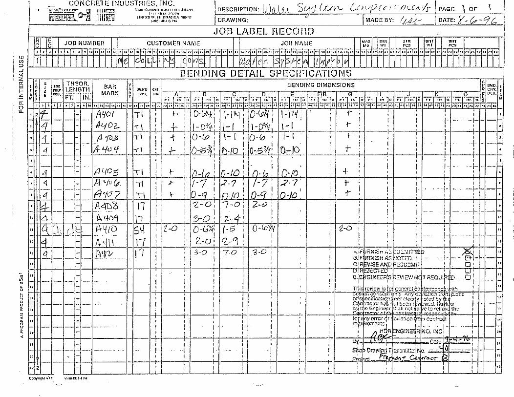
Cnt-f/f r.: ""•"//rJ,.,__:fs PAGE ., OF ~ DESCRIPTION: lJJrL\_P._..!. 'Slfj _{j'J }'t_, i--------->"""'-'"-'"'-'>=--~·-u
DRAWING: MADE 13Y: /,t./.J.t.~· DATE: r- {.p -Cf/;.. !---------------------------'----------·-··-__ , _____________ _L _____ .:::.:;_;_;: __ _L __ ......;.c.__.:i::;:.._.-1..~'--1
..
A c
E c
I 1 l 4 J
.JOB LABEL HECOfHJ JOB NUMBER CUSTOMi=A NAME JOB N/\ME ~~~ux i~l1 ~~~ 1!J}l !JllT
PCS . . . . mT .. ~tj .. ifo~ ~i~in~~ "i~l~~f 'T"T'i" "~·A~i~fl~~l~ff BWf ;·1~ ;; T !:Ff!'. Tff:: T '--"· .:.·~. ~~. ,,~,. ,, ,. ,, ,. ,.1 •• BENDING DETAIL SPECIFICATIONS
-t-H--i--t·--t-·t--1------1- - -f-
n.I -·--
t3 2 ', Corivright ~• 'oun !Kl7·1 IM

!
I-
t I I l
j · 1
l i
: \
d : ::
i I
I I
: I ; ! q
l ! i I \I ! I ; I ; I
'I
ll I • I I I
\ i
Applied Systems Associates, Inc. a$;ar/REBAR SYSTEM STANDARD BAR BENDS
2G81 MOSSIOE BOULEVARD MONAOEVlt.LE, PA 15146 PHONE (412) 373-2780
® . ® 0
~c: £/.7 r I , 'A:.tlyvk~ [-:;?
--!- I
A!._ __ _..;;.ll ___ G_,)
® . A._! ___ o ___ ~
GI
®I 0 I @ [
0.
t ( . b-d·t. I(\
" I c ~ c
I c ~ lc~1:· c !> c J
@ ····· 0 .
·ffi '..I ~ . ~
@ o._I ___ c __ -r
o) cl
® ®~- @
A .c-:;1· I)
:J ---o G ~
lf>OMtTRIC VIEW ISOMETRIC VltW
~LfYC ,t~ .@
0 @~~ I a f c D I .~_j
H. 171 .0
B ! . . . . · .J .
JI~ -~ {('I --~ . ~'
K I
NOlES: , t
t. 11Sa S!Mll31d Oat Oonds lnc:ludo only TypH 1-ll,. ll-116, and Sl·SIS. 2. All dlmonslon• ••• OUl·lo-out ol b3r GXC•P.i MAM •nd --u· on Sl""1cJa11.I wo· and m·
hooks. ·.- · 3. •r <Jlmonslon on 100• hooks lo bo shown onlr •hero no<:ena11 lo resldcl llooll •I.to,
olhOtwlH slandard lfOOkl ••• lo b• used. · · · . . 4. Whoro • J" Is nol shown, • J- *Ill b• ~opl <!qual IO or less lhan "H• on l1uss bills.
Wllore "J" c:an o•ceod "H". II should b• abown. , 5. "H" dlrr 'on sU1iups lo bll nllown whe11 necllU2S}' lo Ill within c:onc:rolo.
© . 0 '
~c • ._)
A'-'11~
® I 0 I nf:ru.:1". II . . ·~71lt ..• I
C D .
@ 0 . ® . I
C F '.'
~ ·fTij e_I c___,o/
1 D I
G
@ I ' 0 I lf~
0 0
6, 'Jnloss 01hc1wl£G nolod, OV..METEA "0" Is 1110 soma lor aH bcnd1 3nd hc>Okl on a bar.
7. W.1010 slope !llilors lrom 45• dlmonslo11s, "H• 11nd "K" mus! bo shown. il. '"'ll!OIO blllS PfO lo bo bnnl mOlO :ICC::tll:llaly lfl:'lll Slllnd:lld bCl>llilll) IOlclanCt;::, ooucll11g
dlmonslons whlch 1oqubo closer lab<lc311on !llKKlhJ bavo llmll~ lnlll<:olciJ.
!>. FlourltS In cltclos show typos. 10 • .-'or roc:ommondod <llamoll!f "0", ol bon<ls, hooks, ale.; soo CflSI or ACI lablos.
11. 'iypo Sl..Sl5, Tl-118 apply lo bar al;:.s 13 liuougb Ill. .. ,
-----',

. Applied Systems Associates, Inc. '
A
asa·/REBAR SYSTEM STANDARD BAR BENDS.
G' A G
..... "
2581 MOSSIDE BOULEVARD MONROEVllLE, PA 15146 PHONE (412) 373-2780
PA G ·u .f- A G ., A G
·tu~, '!ti"' '~, H~ · u e[J .. 5lJ HU· a o aLl c . c
® @. ® ®· @ I ® ® @ @. @
K 6" L..tp B G. ~
~ cr::t -~ CJt G
@ @·•c111c:~<l" ® @
B . @
II SPIR.1'.t. NOTES: 3 • Ti.JIU!.$ l'.T ';' SPACIMG. K • txTRA TUIUi:> (HAU' 1: t 6.).
NOTES:
@ PLAIN SPll\1'.I. WITH SPACERS LOOSE.
f'C:::.. PLAIN SPIAAI.. WITH '<::JI SPACERS MOUNTED,
1. aSa SllSlldard Sar Bonds lnc;lude only Types ~2, T1·T111, and S1·S15. 2. All dimensions at• 011l-lo>01.1l of ban:xcopl .,,. .. and •o• on alandanf 100• and 135•
hookll. . ,. • 3. "J .. dimension on 100• hookll 10 be shOwn onsy 'Wilen! noconaiy lo reslrl<:t book ab:e,
olhetwb• alandllld hooks are lo be 1.1sod. · · · -'. Where •J• Js nol 1hown. ~J" will be kepi •qual to or less than "H" on wn b.;s.
Where •J• can exceed •H'', 11 lllOUld be ahOwn. • · 5. -H" dimension 11Jrrups to be shown whet• necessary lo Ill wllhln ~nc;rete.
e f.T
J[~ ..
I
·~ al
@
<: ~ -K I o· .
~
"I a Gj
@) 0 0 0 B
A/ B ol . ·.fil ® . ·~ @ ' . @ ce3
@
j
0 0 0
II. Unless olhetwlH nolad, OIAMETER •o• 11 tile aama lor all btnds and hooks on a b•r. 7. Where alope dllleni from AS• dimensions. "Hw and "K~ mu11 w shOwn. a. Whore barll ara lo be benl moro ac:curalely 111..n $landard bondlno lolorancos, bending
dimensions whk:ll require cloHr labrlcallon anould have llmlla Indicated. II. FJgurin In c:lrclH shoW types.
10. Ft>r r..commende<I dlamoler •o•, ol bends, hoolt•, elc~ Se<t CRSI or A.Cl lable.L 11. '.>'P" S1..S15, TI-TIO apply lo bar a~es 13 lhrou;ih IS.
__ ..... - ~ .. - -----~· .. ·· ·- ·-·-···"" ·--. -. ·-·~---·

FREMONT WASTE SYSTEM IMPROVEMENTS
SECTION 16150, 16190. 16470, 16474 & 16475
PANEL80ARDS, DRY-TYPE TRANSFORMERS, SWITCHBOARDS, CONTROL EQUIPMENT, AND SAFETY SWITCHES
COVER - MANUFACTURER - SUPPLIER ......................... PAGE 1
BILL OF MATE£FUAL .................................... PAGE 2 & 3
SWITCHBOARD."MDP" .............................. PAGES 4 THRU 12
POWER BREAK CIRCUIT BREAKER .... SEE SEPERATE INSTRUCTION MANUAL
INSTALLATION & MAINTENANCE MANUAL ................... BROCHURE 1
BATTERERY & TRICKLE CHARGER ................... PAGES 13 THRU 18
AUTOMATIC TRANSFER SWITCH - OPERATION & MAINTENANCE MANUAL IS IN THE LAST SECTION OF ENGINE GENERATOR MANUAL
KAYTON ELECTRIC, INC. NORFOL~K BRANCH

PANELBOARDS TRANSFORMER
SWITCHES SWITCHBOARDS
GENERAL ELECTRIC
PURCHASED FROM:
JESCO, INC.
1502 PARK WEST DRIVE
HASTINGS, NE 68901
(402) 463-6859
C402l 463-6850 FAX
1-800-975-3726

FREMONT WASTE SYSTEM IMPROVEMENTS
SECTION 16150, 16190, 16470, 16474 & 1647b
PANELBOARDS, DRY-TYPE TRANSFORMERS, SWITCHBOARDS, CONTROL EQUIPMENT, AND SAFETY SWITCHES
COVER - MANUFACTURER - SUPPLIER ......................... PAGE 1
BILL OF MATERIAL .. ., ................................ PAGE 2 & 3
SWITCHBOARD. "MDP" .............................. PAGE~;; 4 THFW 12
POWER BREAK CIRCUIT BREAKER .... SEE SEPERATE INSTRUCTION MANUAL
INSTALLATION & MAINTENANCE MANUAL ................... BROCHURE 1
BATTERERY & TRICKLE CHARGER ................... PAGES 13 lHRU 18
AUTOMATIC TRANSFER SWITCH - OPERATION & MAINTENANCE MANUAL IS IN THE LAST SECTION OF ENGINE GENERATOR MANUAL
KAYTON ELECTRIC, INC. NORFOU\ BF~ANCH

PANELBOARDS TRANSFORMER
SWITCHES SWITCHBOARDS
GENERAL ELECTRIC
PURCHASED FROM:
JESCO, INC.
150:2 PARK WEST DRIVE
HASTINGS, NE 68901
(402) 463-6859
C402) 463-6850 FAX
1-800-975-3726

FREMONT WASTE SYSTEM IMPROVEMENTS
SECTION 16150, 16190, 16470, 16474 & 16475 PANELBOARDS, DRY-TYPE TRANSFORMERS, SWITCHBOARDS,
CONTROL EQUIPMENT, AND SAFETY SWITCHES
BILL OF MATERIAL
SWBD 201 -- SPECTRA AV2, 3 SECTIONS, SUSE LABLE, WITH 3000A/3P, 480/277V, 3P, 4W, ELECTRICALLY OPERATED PROGRAMMABLE CIRCUIT BREAKER. 24V DC ELECTRICAL OPERATOR WITH POWER SUPPLY AND TRICKLE CHARGER & BATTERY. WITH 15-30A/3P SELA C.B.
2-60A/3P SELA C.B. 1-70A/3P SELA C.B.
1-100A/3P SELA C.B. 2-700A/3P SKLA8 C.B. 2-800A/3P SKLA8 C.B.
CHEMICAL BUILDING MDP -- PANELBOARD, TYPE AD, 24 CKTS, BOTTOM FEED,· SURFACE, 22K
100A/3P MAIN BREAKER (THED6), 3P, 4W, 277/480V WITH 3-60A/3P C.B. THED6
5-20A/3P C.B. THED6
LP-201 -- PANELBOARD, TYPE AQ, 42 CKTS, TOP FEED, SURFACE, 22K 225A/3P MAIN BREAKER (THQD), 3P, 4W, 120/208V WITH 1-20A/2P C.B. THHQB
40-20A/1P C.B. THHQB
LP-301 -- PANELBOARD, TYPE AQ, 42 CKTS, BOTTOM FEED, SURFACE, 225A/3P MAIN BREAKER (THQD), 3P, 4W, 120/208V, 22K WITH 1-50A/2P C.B. THHQB
1-30A/2P C.B. THHQB 38-20A/1P C.B. THHQB
2---9T23B3872 30KVA, 3P, 480V--208Y/120V DRY-TYPE TRANSFORMER
2---9T21S1050 DRY-TYPE TRANSFORMER 5 KVA, lP 120x240 TO 120/240V MINI POWER ZONE WITH/8---THQL1120 20A/1P C.B.
2---800A/3P SPECTRA BREAKERS, K-FRAME 600V, NON-AUTOMATICE SW.
2---ENCLOSED CIRCUIT BREAKERS, 40A/3P 480V TED134040WL BREAKER, TElOOCS ENCLOSURE
2---THN3362SS, 60A/3P, NOT FUSED, 600V, NEMA 4/4X, H.D. S, S.
13---THN3361SS, 30A/3P, NOT FUSED, 600V, NEMA 4/4X, H.D. S. S.
3---COMBINATION STARTER/C.B. SIZE 1, N3R, 120V COIL, CPT W/FUSES, AMBIENT COMP. OVERLOAD RELAY, START/STOP PUSH BUTTON (TP301, TP302, & TP303)
1---COMBINATION STARTER/C,B. SIZE 1, N3R, 120V COIL, CPT W/FUSES, AMBIENT COMP. OVERLOAD RELAY, START/STOP PUSH BUTTON (GClOl)
30---MANUAL MOTOR STARTERS, SURFACE, 1 POLE

..
• GE ED& C 75A662188
aJIT, Oii 9K FL 9K l«l 13 --24V DC BY CUSTOMER
+
SHUNT TRIP OPEN * ~ - - - - - - - - - - - - - 1
--~~~--11 _J_~ _3('7~:~~~ PBl I I
I I
'--------------
!-BELLALARM-j ! r-J ~35 j CLOSE * ! " '{ I i JUMPER 1 _J_ 2
r- -o - -t ~~ o- - ~ ~- - ~:-:-t------1- ----rB-1---- ·,--; : l ! BA I BA2 - j 3 4 5 6 2 : I I ' l I '. OPTIONAL I l
'- - - - - _L.::-..::-..::-.::-.::-..:=-~ - - - - - - - - - - - - - - - - - - - - - - - - - - - - -' ELECTRICALLY OPERATED BREAKER
* REMOTE OPEN ANO CLOSE FUNCTIONS
lS6lm M.K. NILGES I 75A652188 Oot9o 9/2'1/90 CSA 1- "" cu

• IITEH I
ORDER ~
MEB6 I 70662D I Spectra SerlH Swlldbo1rd t e----1 D """ l C~T~5H.FL. SH. t-0. I
r -,- - - -1 ACCESS TO front FHASC 3i'4W
I I""" ClASSi 2 AIN'9l& :3000A
U>llEl.J U/L SE BUSMATu AUn I I 40 va. T AG6 400/277V Pl.Ara Tln Plote I I J I I
I..... - - - _ . .J llUS llRACN> IRlllS SYll\l 65000A
OEV. Mt.I. NTERRLPT RA TN:i !RMS SYNJ 65000A
PLANVEW TllP Cft \ CKT. DEVICE CllO.JT llENTFlCA TON
FUSECU' NO. IJESCl!PTION Iii LABELS [] NANEPl.A TES F·s 13J
409
AHf'S PUE s
I 45 I "' TI' :3000 3 3 I SELA 20 3
II II "' u 2 SELA 20 3 3 SELA 20 3 4 SELA 20 3 5 SELA 100 3 6 SELA 70 3
21 21 7 SKLAB 800 3 !SPACE Al'D El.JS!
i&.ANC I B SKLBB 700 3 13 I 2 ,,. 9 SELA 20 3 14 I 15 3 I 4
10 SELA 20 3 16 17 5 6
II SELA 20 3 18 7 12 SELA 20 3
90 13 SELA 20 3 19 B "' 14 SELA 20 3
15 SELA 20 3 20 21 9 10 16 SELA 60 3 22 23 II 12 17 SELA 60 3
•2 2SX •2 211>< 18 SKLAB 800 3 !SPACE Al'D El.JS! I ko 19 Sl:LBB 700 3
I 20 SELA 20 3
• 21 SELA 20 3 22 SELA 20 3
21 21 '" 23 SELA 20 3 ~ ~
FRONTVEW
~A NOTES. I. ~ splits t..tw•en .och Hcflon. atip -.oeh section s'9PQ'"otely 2. c--t gnxnl bus lurriohed.
:3000A7 3000A_? 3. lkltn fur~d with tnt•oral orOUld fault p-ot•cHon. 24\IOC .i.<:trk op...-otor, UC progrorrmer. ---
I/ I/ VIOOOA VIOOOA
H
1 2:1_i ~ :1'2
"'~·~~ l"T • !TYACAl.AU.IECTIC><Sl
TC-Ta>
•it.mmt'fR~ BC-BOTTCW. - 625DIA 1 lrv:J/"1'3./0Z.. •A MVN 0 ITYPI nATI' NT"'-5
G /Ml'l. MAfl¥.i Sv.t!O 201 PLANT1 MEBAl'E
~ N COST Jal~ FREMONT WATER SYSTEM CUSTOMEl!I .SCO NC.
aoooAS aoooAS '----- F-··--""' U&C~C OE PANEL ·~ ·~. RB<I 44
S'MD. ENGUERi REQN.tO • k'.AYT"""'1 ~ 7 =M
NSP. MAf:E:. 8Y1 ta> ..,,....,°' 09123/96 MEB6 I 70662D BUSSNG DIAGRAM I Mi'a.GES CUST. REL BY1 M "8.GES CONT. ~ 5H. FL. SH.NO. I -

DEM • 1401
GE Switchboards
Spectra 7™ & Spectra 2™ Switchboards MAIN LUG SECTION
.. C""""1'
BRfAKERS ANDIOA FUS8LI
IMTCHl!I
SH BRANCH SIZING TABLES
CCVI"
llTANDAJlll MAIN WG TrlUllNATIONS
.._.. 0..-,Andsmt Wldtll llllllnt Pef#AncHI- w 400& (2) 1IO«JOMCM
llOO
llOO l (3) VO«IOMCM 1000
35
1200 (4) 1IO«JOMCM
~ (5) 1/0-eOOMCM
2000 (8) 1/0-800MCM
SIDI! VllW
-- "X" _,., HolQlll A I c
23)( 28 36
400 Thr\I 33X 14 49 200M
38X 511
43)( ll3
DISTRIBUTION SECTION
r WIDTH (W) -i__!_ 3"
l t COVER "
- ~-
CIRCUIT c BREAKERS ANDIOR FUSIBLE PANeL
SWITCHES ·x· llO HEIGHT
SEE BRANCH SIZING TABLES
- -T
COVER a _L_
' 3"
uo .J l-REF.
FRONT VIEW
-"X"
""""' A a c
23)(
33X
38X
43)(
53)(
21 28
14 21
14 14
1 14
1 0
Distribution Section Side View Same As
35
49
511
ll3
T7
Main Lug Section Side View Except Omit Lugs
MAIN DEVICE SECTION
..
WIOTtt(W)
CIRClftT lfU!AK£R8 .. ..,.. FUstBUIWrTCN
BRANCHES
SEE BAANCH SIZING TABLE
cow:n
ri~ _J l.... FRONT VH!W
CABUI Pl!O MAIH DIVtCl!I WITH Ofll wmtOUl' CTI
Main Device • Group Mounted
..... , ... ......
M .... "-* TopMul --Amp, "X" -"X" 1'fpe OeYtce Range Holoh (W) - A B c A B
TJD, 't!K4, 8 400«>0 6 :15 23X Nill N.IO. Nill 21 THJl<.4,8
ClrcuK TJ4V, 'tll4V
e..- SGDA.SGHA 4()0.800 4 35 33X 21 49 14 SGLA.SGPA
21 SKHA, SKLA UOCJ.1200 8 45 14 SKA'i 3llJ( 14 511 23
' TK4V, TI<L4V 800 8 45 1200
-.K,PI 45 Fuolblll 10 -Swllch ADS 4/800.J,T 40 4JX 1 ll3 0
800 19 45 1200
SECTION LAYOUT NOTF.S • These 1wi1chboard arrangemenu assume line cables enter
top. When line cable• enter from below, neutral and ground bus are mounted at bottom and A and B cover dimensions are rcvened.
• All dimension• are in lnchn and IX• 1 318 inche1.
• When "O" cover is shown. rear access it required. Front access to load cables requires a 7• high cover minimum. Front acccH to neutral and/or ground bu1 requires a u• high cover minimum.
• Any circuit breakers with externally wired accessories, shunt trip, undervoltage release, auxiliary switches. will require a IX filler between any two circuit breakers.
• For double branch units-only same cirroit break.er type dcvice1 can be mounted acrou irom each other.
• All tingle branch circuit break.en. in service entrance equipmen~ are mounted with load lug> on right 1ide of panel board,
• Load side of all single branch circuit brealen, controlled by a main device, arc staggered to aJlow for equaJ cabling in both wire guttcn.
• After determining all applicable conditiont. lavoul panelboard and calrulate branch <1rcu11 "•" heighu, including future 1pace, Add spacn ouflicient to fill panel 10 standard lOX incremenL The total "X" height will be supplied within lhe panel.
PLAN VIEW
.625 DIA MOUNTING
HOLES (TYP.)
c 36
-49
-Sil
-63
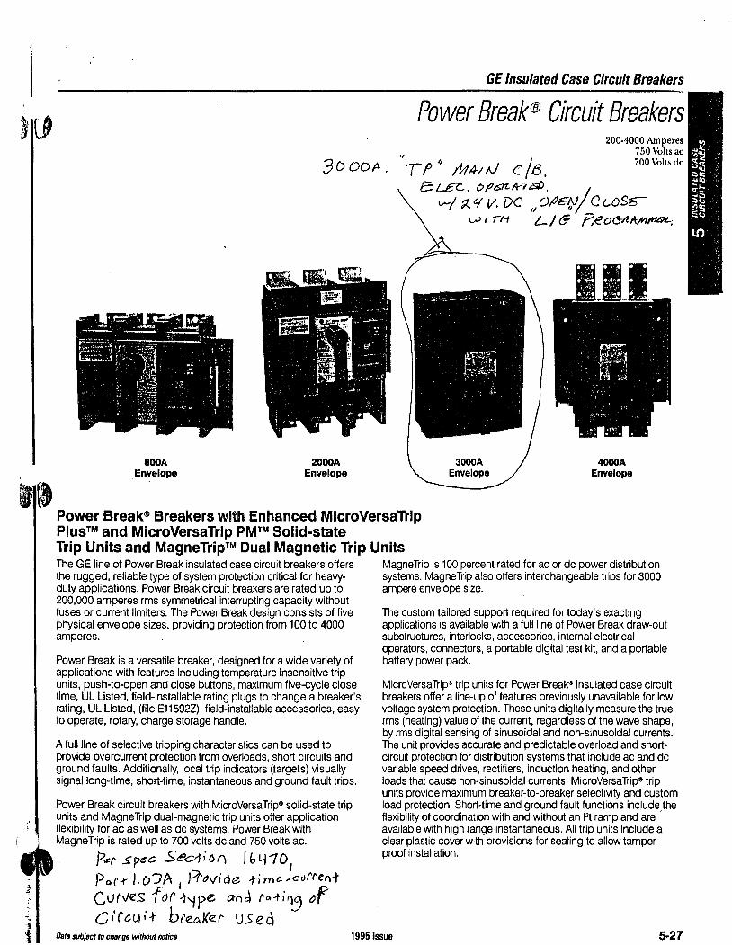
la
''l
t
800A Envelope
3000A.
2000A Envelope
GE Insulated Case Circuit Breakers
Power Break® Circuit Breakers 01
Tf" /WAIN c/B,
200-4000 Amperes 750 Volts ac 700 Volts de
e t..-ec:- . o fl6J'!..1t-7?::/) • , I v--/ ~ lf v. vc ,
1 O//e~; _ c ~osa-
l.,.) I 11-t /_ / e p ~ 0 (5-IZA-tft'l/f'IOL;
3000A Envelope
4000A Envelope
Power Break® Breakers with Enhanced MicroVersaTrip Plus™ and MicroVersaTrip PM™ Solid-state Trip Units and MagneTrip™ Dual Magnetic Trip Units The GE line of Power Break insulated case circuit breakers offers MagneTrip is 100 percent rated for ac or de power distribution the rugged, reliable type of system protection critical for heavy- systems. MagneTrip also offers interchangeable trips for 3000 duty applications. Power Break circuit breakers are rated up to ampere envelope size. 200,000 amperes rms symmetrical interrupting capacity without fuses or current limiters. The Power Break design consists of five physical envelope sizes, providing protection from 100 to 4000 amperes.
Power Break is a versatile breaker, designed for a wide variety of applications with features including temperature insensitive trip units, push-to-open and close buttons, maximum five-cycle close time, UL Listed, field-installable rating plugs to change a breaker's rating, UL Listed, (file E11592Z), field-installable accessories, easy to operate, rotary, charge storage handle.
A full line of selective tripping characteristics can be used to provide overcurrent protection from overloads, short circuits and ground faults. Additionally, local trip indicators (targets) visually signal long-time, short-time, instantaneous and ground fault trips.
Power Break circuit breakers with MicroVersaTrip® solid-state trip units and MagneTrip dual-magnetic trip units offer application flexibility for ac as well as de systems. Power Break with MagneTrip is rated up to 700 volts de and 750 volts ac.
P.er spec Sec1ion lb4"101
Por-r /.o'JA 1
P/'dVlde -time....-ct.1Ne"-t C v NeS for -t'/ pe an J ra -ti~ tJf C i'<'cu i + bteeil<e.r U..S e d
The custom tailored support required for today's exacting applications is available with a full line of Power Break draw-out substructures, interlocks, accessories, internal electrical operators, connectors, a portable digital test kit, and a portable battery power pack.
MicroVersaTrip® trip units for Power Break® insulated case circuit breakers offer a line-up of features previously unavailable for low voltage system protection. These units digitally measure the true rms (heating) value of the current, regardless of the wave shape, by rms digital sensing of sinusoidal and non-sinusoidal currents. The unit provides accurate and predictable overload and shortcircuit protection for distribution systems that include ac and de variable speed drives, rectifiers, induction heating, and other loads that cause non-sinusoidal currents. MicroVersaTrip3 trip units provide maximum breaker-to-breaker selectivity and custom load protection. Short-time and ground fault functions include the flexibility of coordination with and without an l2t ramp and are ' available with high range instantaneous. All trip units include a clear plastic cover with provisions for sealing to allow tamperproot installation.
Data subject ro change without notice 19951ssue 5-27
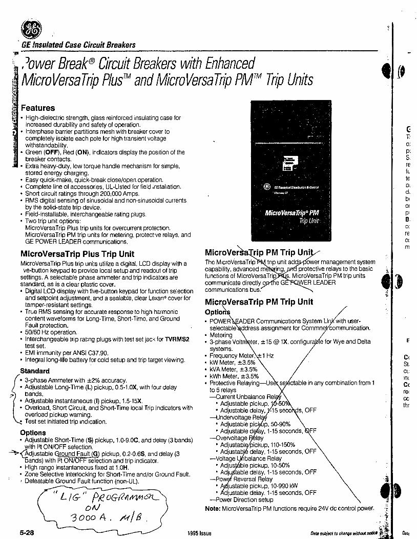
• ' GE Insulated Case Circuit Breakers ~
s~ I Jower Break® Circuit Breakers with Enhanced MicroVersaTrip Plus™ and MicroVersaTrip PM™ Trip Units
Features • High-dielectric strength, glass reinforced insulating case for
increased durability and safety of operation. • lnterphase barrier partitions mesh with breaker cover to
completely isolate each pole for high transient voltage withstandability.
• Green (OFF), Red (ON), indicators display the position of the breaker contacts.
• Extra heavy-duty, low torque handle mechanism for simple, stored energy charging.
• Easy quick-make, quick-break close/open operation. • Complete line of accessories, UL-Listed for field installation. • Short circuit ratings through 200,000 Amps. • RMS digital sensing of sinusoidal and non-sinusoidal currents
by the solid-state trip device. • Field-installable, interchangeable rating plugs. • Two trip unit options:
MicroVersaTrip Plus trip units for overcurrent protection. MicroVersaTrip PM trip units for metering, protective relays, and GE POWER LEADER communications.
MicroVersaTrip Plus Trip Unit MicroVersaTrip Plus trip units utilize a digital, LCD display with a ve-button keypad to provide local setup and readout of trip
settings. A selectable phase ammeter and trip indicators are standard, as is a clear plastic cover. • Digital LCD display with five-button keypad for function selection
and setpoint adjustment, and a sealable, clear Lexan~ cover tor tamper-resistant settings.
• True RMS sensing for accurate response to high harmonic content waveforms for Long-Time, Short-Time, and Ground Fault protection.
• 50/60 Hz operation. • Interchangeable trip rating plugs with test set jack for TVRMS2
test set. • EMI immunity per ANSI C37.90. • Integral long-life battery for cold setup and trip target viewing.
Standard • 3-phase Ammeter with ±2% accuracy. • Adjustable Long-Time (L) pickup, 0.5-1.0X, with four delay
bands. • Adjustable instantaneous (I) pickup, 1.5-15X. • Overload, Short Circuit, and Short-Time local Trip Indicators with
overload pickup warning. • Test set initiated trip indication.
Options • Adjustable Short-Time (S) pickup, 1.0-9.0C, and delay (3 bands)
with 121 ON/OFF selection. --=>t><Adjustable Ground Fault G pickup, 0.2-0.65, and delay (3
'oands) with l2t ON/OF selection and trip indicator. • High range instantaneous fixed at 1.0H. • Zone Selective Interlocking for Short-Time and/or Ground Fault. ' Defeatable Ground Fault function (non-UL).
'' L /G-11 ff!. 0Gfl1JtV!ft16J'L olV
'3 0 OD A . /14 / 8 .
Micro Ver
MicroVersaTrip PM Trip Unit Optio • POWER EADER Communications System Li with user
selectable ddress assignment for Commne communication. • Metering • 3-phase Volt
systems. • Frequency Meter, +1 Hz • kW Meter, ±3.5% • kVA Meter, ±3.5% • kWh Meter, ±3.5% • Protective Relaying-Us
to 5 relays -Current Unbalance Rel
• Adjustable pickup, -50 • Adjustable delay, -15 seco
-Undervoltage Rel • Adjustable pie p, 50-90% • Adjustable d ay, 1-15 seconds, FF
-Overvoltage lay • Adjustabl ickup, 110-150% • Adjustab delay, 1-15 seconds, OFF
-Voltage balance Relay • Adjus ble pickup, 10-50% • Adju table delay, 1-15 seconds, OFF
-Pow Reversal Relay • justable pickup, 10-990 kW • djustable delay, 1-15 seconds, OFF
-Power Direction setup
e for Wye and Delta
Note: MicroVersaTrip PM functions require 24V de control power.
'(f
., ..
c; Ti o; P' s re fL te bt dt bt or pi B. cc re Cl
m
c( St. CL inc Cc rer cc thr
5-28 19951ssue
·! ·~·i
Data subject to change without noticl :¥';;: ·

'.~1 l j
... :
~.:.
GE Molded Case Circuit Breakers
7ooAMf. 5kLf38
-~~ctft:...=-.a RMS Circuit Breakers ---"'~with Micro Versa rip Plus™ Trip Units
Features V-// 4L
MlrcroVersaTrlp Plus Trip Units Standard • 3-phase Ammeter with ±4% accuracy • Adjustable Long Time (L) pickup,
0.5-1.0X, and delay (3-4 bands). • Adjustable Instantaneous (I) pickup,
1.5-10X. • Local Overload and Short Circuit Trip
Indicators (T) with overload pickup warning.
• Interchangeable trip rating plugs with test set jack for TVRMS test set.
• Digital LCD display with four-button keypad for function selection and set point adjustment and sealable, clear Lexan® cover tor tamper-resistant settings.
• True RMS sensing for accurate response to high harmonic content waveforms.
• EMI immunity per ANSI C37.90.
Optional • Adjustable Short Time (S) pickup,
1.0-9.0C, and delay (4 bands) with l2t IN/OUT selection.
• Adjustable Ground fault (G) pickup, 0.2-1.0S, and delay (4 bands) with 12t IN/OUT selection and trip indicator. The 4 short time and ground fault delay bands provide broader system selectivity.
• World Standards - Frames rated to UL, CSA, IEC 947-2, and JIS.
• Universal Internal Accessories -Uses the same front-mounted, fieldinstallable shunt trips, undervoltage releases, bell alarms. and auxiliary switches as standard Spectra RMS breakers.
• Accessory Lead Routing Lett or Right - Side channels mean no extra space required for accessory leads.
• Current Limiting - SG600 frames rated 65kA and 100kA@ 480Vac are UL Listed as current limiting.
• Reverse Feed - Front-mounted interchangeable rating plugs mean all frames are UL Listed for reverse feed.
• Wide Current Setting Range -Interchangeable rating plugs combined with 5 current sensors and 0.5-1.0X long time pickup yield ampere ratings from 30 to 1200A.
• 100% Continuous Current Rated -Optionally available for 100% UL continuous current rating applications.
• Control Power 24V DC - Provides connection capability for +24vdc control power into the breaker via the distribution cable system.
MicroVersaTrip Plus Trip Unit Characteristics Current Setting (C)
Long-time© Short-time Ad1ustab1e Instantaneous
(Pick·U~) Pick·U8 P1ck·UD (Muiliple of ating Delay (Multiple of urrent Delay (Multiple of Rating Plug Amps) (X)
(Seconds) Setting) (C)
(Seconds) Plug Amps) (X)
l't in;QI 0.50to 1.0 1.5to9.0 .44 1.5to 10.0
in increments 2.4,4.9,9.8,20~ QI in increments in increments of0.05 of0.5 l'tout:~ ol0.5
'10 .. 20,.30,.40
SG Frame with MlcroVersaTrlp Plus Trip Unit
Ground Fault
Pick·UEe (Multiple of nsor Delay
Amp Rating) (Seconds) (S)
12tin;® .20to 1.00 .41
in increments of .05 12tout;~
'10,.20,.30.40
X = Rating plug amps S = Sensor amp rating C = Long-time current settings
(pick-up)
<D Pick-up fixed at 1.1C. ® 20 second delay (band) not
available on SG frames.
@l Time delay at 200% of pick-up setting at lower limit of band.
@ Time delay shown at lower limit of each band. Pick-up tolerances ± 10%. Ground fault pick-up not to exceed 1200amps.
@ Time delay at 600% of current setting at lower limit of each band.
Per .:>pee .Sec--rioA /04101 pcr--t J.o3A,
prov'iae -hl'Y\~,,,. cvrfe.(lf curve.s for each t'l l'::> e..
Q f\ J fc:A-t i A j a(' c; (Gil; t 8 f ttt\Ke:t V ~{cl.
Data subject ta change without notice 19951ssue 4-25

• I DIGITAL, SOLID STATE SPECTRA RMS BREAKERS CSC27 91
SK 1 2 0 0 L JN E 300-1200 Amperes, 600 Volts AC, UL/ CSA/ IEC Listed. I
Item Qty Catalog Number Amp
Rattno Volts Poles Rating Plug Lugs Modtrtcatlons
<D ~ 5K DA 3<oAND1<00 ~00 ~00 3
Circuit Breaker Outline
Circuit H:lll. AC
Breaker Ampere Poles Voltage
Type Rating Rating
SKH8 J_ 600 3
SKL6 300- 2 600 -600 3
2 600 SKP8 -3
SKH12 J_ 3
600
SKL12 600- ..2-. 600 1250 3
SKP12 J_ 600
3
Lug Wire Range
TCAL6 l - (3) 3/0-500 kcmtl Cu/ Al.
TCAL91 - same as TCAL6t.
TCAL 121 - ( 4) 250-500 kcm 11 A I. or
(4) 250-350 kcmil Cu.
TCAL I 31 - same as TCAL 121.
UL Llsteo lnterruPtlng Rall119 Federal siiec.
rms Symmetrical Amperes< In ThOusanasl C/B Class
240 vac 480 vac ooo vac W-CJ75B H w
65 50 25 2 ta, 23a
100 65 42 24a
200 100 65 2Sa IS.SO 8.2S
0941 (210)
65 50 25 21a.23a (")
100 65 42 24a
200 100 65 2Sa
( .. , AGO 4.00 1ncnes (I 0 I mm I to upper ena lor SKP (I 00 kAIC. 480Vl IU<J COVtr.
Ratings oo not 31>Ply to mo1oeo case sw1tcnes. I• I JOO Name P. o. Numoer
TCAL.'6/ SC.QI-"\\ \c;
TCA-l..'tl sc.1-1a1c;x o ...... -., I•• -C"I'\ ble
"'
UL, CSA, & IEC File Numbers
UL - E 11592 CSA - LR 84929- I
IEC - 947-2
Dimensions ApproM.
lnehes <mml Ship Wt./
0 A B c E Std. Pack
s.so 8.56 5.69 1.38 .62 47.6 lb/
(1401 (2171 (145) <:JSl (161 I
("I
G.E. ReQ. Number
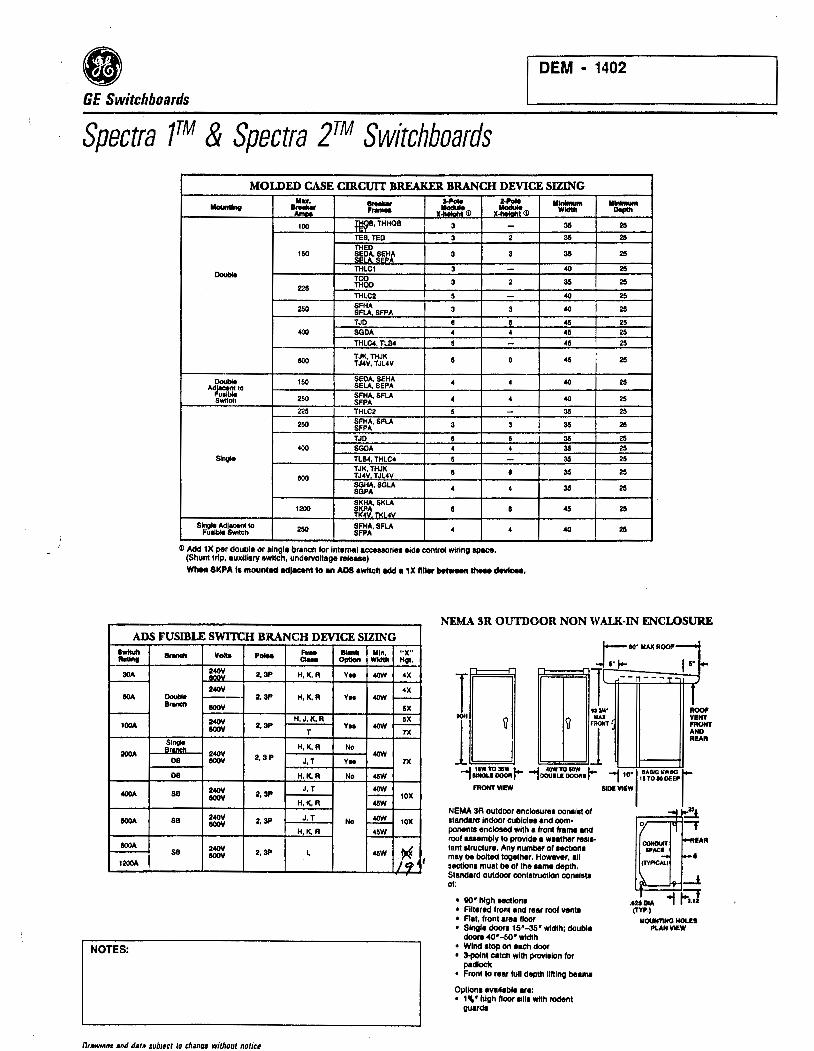
DEM • 1402
GE Switchboards
Spectra 7™ & Spectra 2™ Switchboards MOLDED CASE cmcurr BR.EAKER BRANCH DEVICE SIZING
llU. ,__ Z4'oll -u-itlnt ~ ,_ x~(j) v~(j) 100 :jWB• THHOB 3
TEB, TED 3 THEO
150 ~~p~~~~fo 3
THLC1 3 OOllble TOD
THQO 3 m THLC2 5
250 SFHA 3 SFtA SFPA TJD •
400 SGDA 4 THLC4, TLB4 5
eoo TJK, THJK 0 TJ4V, TJL4V
Dovb4e 150 SEDA. SEHA 4 Ad=to SELA, SEPA
250 SFHA, SFLA 4 Switch SFPA 225 THLC2 5
250 SFHA, SFLA 3 SFPA TJD •
400 SGDA 4 Slnv!e n84, THLC4 5
TJK, THJK • eoo TJ4V TJL4V SGHA, SGLA 4 SGPA
1200 ~~:,SKLA TK4V. Tl<I 4V •
Single Adi-it to 250 SFHA,SFtA 4 Fualble Swtt<:h SFPA
~ Add 1X per double or alngle branch for Internal acceaaorlea aid• contro4 wiring apace. (Shunt trip, auxlllary awltch, undervoltage releaae)
-2
3
-2
-3
• 4
-6
4
4
-3
6 4
-• 4
8
4
Wiien 8KPA I• mounted Mljacent to •n ADS awltch add• 1X ftller betweM'l IMM devlcee.
Minimum Width
35
35
35
40
35
40
40
45 45
45
45
40
40
35
35
35 35
35
35
35
45
40
II-""'*'
25
25
25
25
25
25
25
25 25 25
25
25
25
25
25
25 25
25
25
25
25
25
NEMA 3R OUTDOOR NON W ALK·IN ENCLOSURE ADS FUSIBLE SWITCH BRANCH DEVICE SIZING
~~·llAXROOF~ lwttcll - Volta p- F- -"-'"" et.. Option
30A !!i~ 2,3P H, K,R YH
240\I llOA DoulJle 2,3P H,K,R YH
B- OOOY
240\I H,J,K,R 100A OOOY 2,3P Vn
T
~!~ H,K,R No 200A 240\I 2,3P DB OOOY J, T YH
DB H,K,R No
400A SB 240\I 2,3P J, T
OOOY H,K, R
llOOA SB 240\I OOOY 2,3P J, T No
H,K, R
llOOA 240\I SB OOOY 2,3P L 1200A
NOTES:
Orawina• and data sub1ect to chana1 without notice
llln, "X" Width llQI,
4(fN 4X
4X 4(fN -5X
5X 4(fN >---
7X
4(fN
7X
45W
4(fN - tOX 45W
4(fN 10X
45W
45W t4 /q'
l T ~l --n---T-
I u ~ f ( 1
I VI! llOOI'
NT l'llONT
NO !All
A R
.,~=..r --10:.J'~I-- -; 10·
1.~~.::.o::.r
fllON1" VIEW SIDI VIEW
NEMA 3A outdoor enclosurH oonalll of ~ standard Indoor cubicle• and com· t poMnte enclosed with a front frame and roof .... mbly to provide • WHther resl• tant 1tructure. Any number of 1ectlon1 may be bolted together. H~. all section• muat be of lhe umm depth. Standard outdoor contatructlon con11a11 of:
• 90• high 18Ctlonl • Fiitered front •nd rear roof vent• • Flat, front •re• floor • Single doora 15'-35" width; double
doorl 40•-so• width • Wind •IOfl on each door • 3-polnt catch with provision for
padtoctc • Front to rear lull depth lifting bemme
Option• •vallable •r•: • 1 \ • high Hoor 11111 with rodent
guard•
.121 lllA (TYP.)
llOllNTIHQ HOLH PUNVIEW
II
l

DEM - 1403
GE Switchboards
Spectra 7™ & Spectra 2rM Switchboards
POWEil BREAK CIRCUIT BREAKER DIMENSIONS©
Dwlce ·---Single section arnngementJ with main device and utility cabinet arc furnished through 2000A ratings when the utility docs not require polt:ntial transformcn. If customer metering and/or ground fault relay i1 required. scrvicc cables _n1!!Jj. enter from above otherwise two 1eetion1 are provided.
. ..._ Rottna II- -SPECTRA 2 MAIN SECTION ARRANGEMENT
CUSTOMER METER
,., ...
Power Break
F...,,.
800 1600 2000
2500 2500 3000
(j)4000
Unit - Ht.
~ 20• 80().1800 32
100C). 32 2000
400-2000 40 2500 40 3000 40 4000 40
.......... Unit . ~
Wldlll ......... Ht. Wldlll ~
25• 25• 20· 25• 30' 30 25 32 30 30 30 25 32 30 30
40 30 40 40 35 40 30 40 40 35 40 35 40 40 40 40 40 40 40 45
GROUND FAULT
MONITOR PANEL
Gl Depth dlmentiOfl onciud91 CT'1 for owner melorlng. • Mexlmum conllnuoua rallng i. 3200 em-.
MAIN
UTILITY COMPARTMENT
WHEN -----REQUIRED
UTILITY COMPAKl'MENT DIMENSIONS
Dimension• shown are minimum width and depths of sections which contain er Compartments only. When a main device is included in the same section, width and depth ia based on the larges1 sizing dimension.
Utlllly A._e 9-0lmenalon9 Nome Rlltnt Wldlll Doptlt
All Utilltlff All Rotlnga 35 30 E><eept u Noted Thru 3000A Below
4000A 40 35
RollnQI Thru 35 30 Aliontlc 11lOOA
Eloctrlc.NJ 2000 Thru 4000A 40 35
Dayton-And light Co..
Ratings ThN 80CM 35 30
Ohio 1000 Thfll 4000A 40 30
W.Superior Rallnge 35 30 Dillrlcl Thru 120M PowofCo..MN 1600 Thru 4000A 40 35
Monlllna RatinQI 35 30 Dakalu Thru ,l!OM Ulilltln
1600 Thru 4000A 40 35
MAIN FUSIBLE SWITCH DIMENSIONS - ......... "- Unit -Type Dffltnollon Roling HolQhl Wldlll Deplll ~
High THPR f>r111ure Conl•ct Switch THPC
Bolled Pre11ure CBC Switch
©CT componmerM on line IKle roqlllrw 4' 11110<.
800 2a• I.!)
1200 32'\!J 30• 1800 2000 <-0 30 2500 « 35
~(!) « ~ 52 800
1200 32 30 ~ 2500 38 35
~ 48 ~ 48
<J> II metering CT'e era requiNd odd a• 10 detJlh.
25'
25 30
~
30
<-0
ill - in1eo<ll ground fault lo "'"""' 1 4• filler i. requited on the io..i aide.
BUSED PULL SECllON DIMENSIONS
Lug sizes and quantity also applies to main devices
9-lllllnl.ug-
A-~11111
~AndSln And.,... w- Depllt
800 (3) 250-llOOMCM
25 25 1000 (3) 250-llOOMCM
1200 (4) 250-llOOMCM
1600 (5) 250-llOOMCM 30 25
2000 (8) 250-llOOMCM
2500 (8) 250-llOOMCM 35 30
3000 (9) 250-llOOMCM
4000 (12) 250-600 MCM 40 35
METEll COMBINATIONS AND COMPARTMENT DOOR CONFIGURATIONS Meter Covers are 12" High - Ground Fault Cover is s• High
AMMETER ANO SELECTOR
SWITCH
AMMETER, VOLTMETER
AND SELECTOR SWITCHES
Orawmas and data sub1ect ta change w11hout notice
AMMETER, VOL TllETER,
WITH SELECTOR SWITCHES AND
WATT HOUR METER OR WATT HOUR
METER WITH DEMAND REGISTER
AMMETER, VOLTMETER,
WITH SELECTOR SWITCHES AND
WATTMETER
WATT HOUR METER OR WATT HOUR
METER WITH DEMAND REGISTER
:I GROUND BREAK MONITOR PANEL
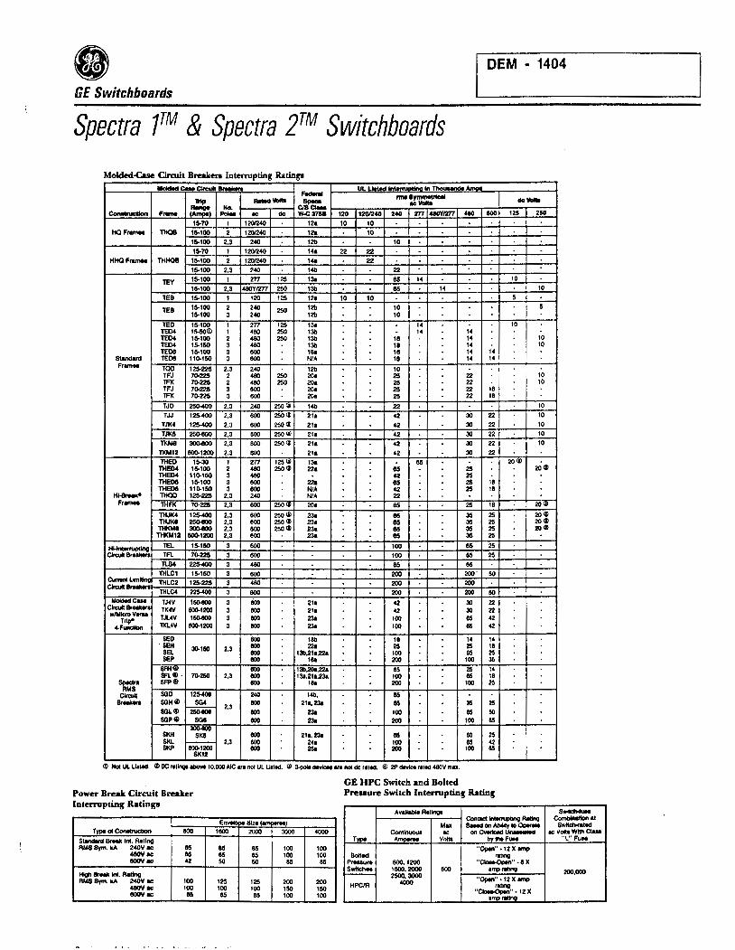
DEM • 1404
GE Switchboards
Spectra 7™ & Spectra 2™ Switchboards
Molded-Case Circuit Breaken Interrupting Ratings
-c.. Cln:ull - UL u.tH lntmU"""" In T-•-- ..... ~ 'IHp ~- cJ:rc::.. IC- de-
.~. Ho. ~ F.- - .. de ~:1758 120 120/240 240 m 48t1'tm7 "° 800 125 250
15-70 1 120/240 12a 10 10 HQFramM TH08 15-100 2 120/240 12a 10
15-100 2.3 240 12b 10 15-70 1 120/240 Iola 22 22
HHQFramM THHOB 15-100 2 120/240 1'4a 22 15-100 2,3 240 1411 22
TEY 15-100 1 'l77 125 131 85 14 10
15-100 2,3 '48/JYl'ZT7 250 131J 85 14 10
TEB 15-100 1 120 125 121 10 10 5
TEB 15-100 2 240 250 12b 10 5 15-100 3 240 12b 10
TED 15-100 1 2n 125 131 14 10 TE04 15-50(1) 1 - 250 131J 14 14 TED4 15-100 2 "80 250 131J 18 14 10 TE04 15-150 3 "80 131J 18 14 10 TEDtl 15-100 3 800 181 18 14 14
S1lndlrd TEDtl 110-150 3 800 NIA 18 14 14 Fr...- TOO 125-225 2,3 240 12b 10
TFJ 70-225 2 "80 250 20a 25 22 10 TFK 7().225 2 400 250 20a 25 22 10 TFJ 70-225 3 800 20a 25 22 18 TFK 70-225 3 800 20a 25 22 18
TJD 250-400 2.3 240 250 f,jl 1411 22 10
TJJ 125-400 2,3 800 250<J) 211 42 30 22 10
TJ1<4 125-400 2,3 800 250<J) 21• 42 30 22 10
TJKa 25o-eOO 2,3 800 250 Ii 21• 42 30 22 10
TKM8 30Q.aOO 2.3 800 250 Ii 211 42 30 22 10
TI<M12 80().1200 2.3 800 211 42 30 22 THEO 15-30 1 'l77 125 Ii 131 85 20W
THED4 15-100 2 "80 250Q) 221 115 25 20 <I) THED4 110-150 3 "80 42 25 THED8 15-100 3 800 221 115 25 18 THED8 110-150 3 llOO NIA 42 25 18
H..- THQO 125-225 2.3 240 NIA 22 Fr...- THF1< 7().225 2,3 800 250<>1 201 85 25 18 20(1)
THJf<4 125-400 2,3 800 250 Ii 231 115 35 25 20 <I) TllJ1<8 25CMIOO 2,3 800 250<J) 231 115 35 25 20 <I) TH1<M8 30Q.aOO 2,3 800 250<1) 231 115 35 25 20<1>
THl<M12 80().1200 2,3 800 231 115 35 25
H~ TEL 15-150 3 800 100 65 25
Circuit BrNl<lfl TFl 70-225 3 800 100 65 25 1lJl4 225-400 3 "80 85 85
THLC1 15-150 3 800 200 200' 50
=~ THLC2 125-2215 3 400 200 200
THLC4 225-400 3 800 200 200 50 MoldldCU. TJ4V 150«JO 3 800 211 42 30 22
Clrcull- TK4V S00-1200 3 800 211 42 30 22 w/MlcftlVlfll TJL4V 150«JO 3 800 231 100 85 42 Trlp9 4-Functlon TKL4V llOQ.1200 3 800 231 100 65 42
BED 800 18b 18 14 14 6EH 3Q.1llO 2,3 800 22a 25 25 18 BEL 800 13b,21a.221 100 85 25 SEP 800 111• 200 100 35
SFH<dl 800 131J,20o,221 85 25 14 SFl I) . 7().250 2,3 800 131,21a,231 100 85 18
~ SFP® 800 1111 200 100 25 RMS
Clrcuil SGD 125-400 240 1411, 65 Br- SGHli> SG4
2,3 800 211, 231 65 35 25 SGI. ® 250«JO 800 231 100 85 50 SGPli> SG8 800 231 200 100 85 .........,., S1<H SKI 800 211, 231 85 50 25 Sl<L ..._ 2,3 800 241 100 85 42 SKP llOQ.1200 800 25a 200 100 85
61<12
<!> Nol IH. U.1'd. <I> DC rallnge - 10,000 AJC ar1 not UL Uatld. a> 3-poll - lfl not de ratld. © 2P - rotld 480V mu.
Power Break Circuit Breaker lnlerrupting Ralings
Type ol ConlCtuctlon 800
Sllndlf<I 8reM Int. R111nQ RMSSym. kA 240V IC 65
4«11/ IC 65 tlOOV1C 42
High - lnl. R.iinO RMS Sym. kA 240V IC 100
lfl(fV IC 100 eoovoc 115
Enw10 oe Stze lamo9rM' 1800 2000 3000 4000
85 85 100 100 85 85 100 100 50 50 85 85
125 125 200 200 100 100 150 150 85 85 100 100
GE HPC Switch and Bolled Presaure Switch Interrupting Rating
Av.-R11ing11 Con- tmnupang RltinQ
Mu S-onAbllitylD~ Contlnuoul ac on Ovoltood ~
T-,.,,,_ Votta bythel'\M
"ep.n". 12 x -Bolted rattno
PrMOUnt 800, 1200 "~".ex
s- 1800, 2000 800 omp-r-- 2500, 3000 4000 "ep.n".12X-
HPC/R ·-"~"·12X lmPrtlbnO
s..-.iuoe ComblnallOn ..
Sw11c1Hatod ac: Volta With ClaN
"L"FuM
200,000

DEM • 1405
GE Switchboards
Spectra 7™ & Spectra 2™ Switchboards SHOKl'-CIRCUIT RATINGS FUSIBLE swnt::ll UNITS
St&ndsrd Cirai.it Breaker Terminaciom (CU/AL Mechanical)
The short-circuit or intemJpting rating of the l\Jsible swhdl is the lower of the fuse or the switch ralln& Spectra Series switches haw: a 200.000 amp shon<ircuit ratin&
Fuee Cluaificacion --,_ lloUnl ..
UI. ,,,,. ..,..._ Ila.
'*- .... A,. ......... ~ H - 10,000 - ~---J - 200,000 800
Fd«:tinQ rWjodlon olzlnQ .,_. __ IJmlUnv
50.000 DUii -.. ne l9jection K - 100.000 250lllOO --...w.u 200.000 ....-11m111n9
R4jodlon-
L ll()().12()( 200,000
_ .. __ 600 • FUl-ectlng malno & -• Timo-delay molor IW!·
Ing CUITlnC Mml1lng
R 100,000 OUlll ...,_ ,.j9ctton - 250/900 meono, mocor IWllnQ 200,000 ........ Mmlllng
T ·- 200,000 250/900 F-1nQ - pllytk:al ma!ne & fNdef9, current llrnillft9
Muimum Honepower © Fu•ible Switch
"'="' Vob,IC Vollll,dc
I~ 2-Pole ~ 2-Pole a.Pole
120 2'40 -800 2'40 -800 125 250
WHhllllndaldFUOM
ao "' 1"11 3 3 3 5 7'11 2 5 to 1"11 3 5 10 w. 15 15 5 10
100 w. 10 15 15 25 30 20
200 15 25 30 25 50 llO '40 400 50 100 125 50 too 75 150 200 50
With "TI~-.1-.u flnM
-TliOll
TEY
TEB TEO TE04 TECO
SEDA
TOO
SODA SGHA
TA<
SfllA
U<A
tJO
tlK8 tJ4V
SKHAI
TI<M8
SKHA12
TKM12 TK4V
Circuit-- r..- Luoo (CU-ALI
~ Hlgll Ca4llo9 .... ~~---.....-. ~ - Polee N- Pole -THHQB 1, 2, 3 Flxod la 1 (1=14-4 CU or '12-4 AL
(3S-1 11 CU or '12·1/0 AL ~ (15-20A) 114-112CUor112·1 AL
1,2,3 Tll<11liMI 1 ~ '11M6 CU or -AL (70-100Aj -1 CU or 112·1/0 AL
1,2,3 TCAl.14 (15-30A. TCAl. 14111 ... THEO 1 TCAl.12 1 ~ TCAl.12) 114'1 CU '12-11 AL
2-3 TCAl.12A (70-110A. TCAL 12A) f&.2/0 CU 14-a/O AL TCAl.15 (110.150A. TCAL 15) 12-3/0 THEO<D 2-3
SEHA m~ 3 TCALIB 1 114-3/0CU or 112-3/0AL
THOO 2-3 TCAl.25 1 11.oooMCM
SGlA 3 ITCl.ICl85C 1 ~Mi;U-IJ.
SGPA 121 2/0'400MCM CU/500 MCM AL THFK 2-3 TCAL24.29 1 M-300MCM
~~ 3 TCAl.29 1 ~CU or M-350MCM AL
TH.JM 2-3 TCAl.43 1 M«X1MCM or (2) 2f0.250MCM
2-3 TCAl.43 1 M«XIMCM or (2) 2f0.250MCM
THJl<ll tll.4V 2-3 TCAl.43 1 M«XIMCM or (2) 2f0.250MCM THJ4V lCAl.43 2 4/0360MCMCUor:J00.600MCMAL
SKU\8 TCAl..81 3 (U-Endl I 3fO.alOMCM SKPM 3 TCALi1 3 (!..-End) I TCAL.41 1 M-«lOMCM or 2-(1f0.250MCM)
THKM8 T1<L4V 2-3 TCAl.81 2 2f0.600MCM
TCAUI 3 ~M
...... End Luv For TCALi1 3 ~M TKL4V
3 TCAUI 3 ~
SKLA12 3 TCAl.121 4 (U-End) I 250-3!50MCM cu
O< SKw.12 TCAl.131 4 (1..-End) I 250600MCM '"' Tl<l.AV 2-3 TCAl..11 3 250-350MCM~ 250-600MCM .&t THKM12 TCAl.121 4
~~-$"' TCAl.131 4 2S().350MCM CU or 250-600MCM AL
(1MQ,\, TCAL 12) 114-13 CU or 112-11 AL THLC1 3 lCAl.21 1 (70-00'. TCAL 12A1 f&.2/0 CU ot M-2/0 Al
(125-llM. 1CAL 15) 11-2111 CU or 1INIO Al
THLC2 3 lCAl.21 1 (125-225A. 1t:AL, TCAl 27) M400MCM
THLC4 Tl.114 3 1CLK43 G 1 :JIO.llOOMCM or 2-(3f0.250MCM)
ao 2 3 Stancbnl Fusible Switch 11'rmiaatlom (CU/AL Mechsnical)
w. 10 w. 15 20 3 to 3 10 20 25 15 30 50
.. _ .. _ 100 15 30 '40 30 llO 75 30
llO 200 15 50 50 eo 125 150 llO
100 400 '125 250 350 . too '400
200 200 500
II> A8llngo --on iat..i-ollhe-Eloclrtcll COde-43CI. ~ratlngl lor--0..H ,,_.,._ononMlme-havtnQ _ __,,, _ _..., ___ ,Iha
...._ ........ muimUllllorlhe-
GENDlAL
• SPECTllA'" Swi1<:hboard1 are designed, built and lfited in accordance wi1h NEMA PB·2 and UndetwTiten Laboratories No. UL·891. All sections are UL listed and labeled.
400 llOO llOO 1200
• SPECTRA I'" Swiochboardl are front acceuible and may be inscallcd mounted again1t a wall. All devices • main• and branches · arc group mounled in panelboard construction. Maximum main device rating i1 1200A.
• SPECTRA 2"' Swi1<:hboard1 are front acce11ible and include an individually mounted main device sec:1ion which feeds group mounted Spectra I Di11ribution Section(•). Maximum main device rating 11 4000A.
• Swiochboard i1 a completely self supporting 1tructure with 90• high venical 11:ction1 bollt'd together to form the required arrangemenl. All section1 are rear aligned and may be rolled, mow:d or lifted into the in1callation po1i1ion and bolted direcdy to the Ooor without the addition of noor sillL The smic· ture frame is die formed 12 gauge steel with reinforcing comer gusse11. Bolt· on endosure coven are code gauge Heel. All steel surfates are chemically deaned to provide an excellent pain1 bonding surface. Exterior paint finish is ANSl61 Light Gray.
Drawings and data subiect to change without notice
- WIN - ICUIAl.I IW.._PW_
240lllOO 114-12 1 2'40 114-12 1 800 114-1'0 1
240/ll00 114-1111 1 240/ll00 -- I 240lllOO 1f0.2eO MCM or 12«JO MCM 2or1 240lllOO 1/0-2!0 MCM or 12«JO MCM 4or2
llOO 1f0.2!0 MCM or IUOO MCM eorl llOO 1/0-2!0 MCMC or 12«>0 MCM eor4
• Standard busban are tin plated aluminum based on density rating of 750 amperes per square inch maximum (copper at IOOO amperes per square Inch is available) and are mounted on 1uppons of high lmput non·tracking insulators. Buses are braced to withstand the medwlical forces exerted during 1hort<ircui11 of 65,000 amperes RMS Symmetrical as standard. Optional bracing up to 200.000A RMS Symmetrical is available. A full length ground bus i1 aecured to each venicaJ teetion.
• All lup •re UL listed for uoe with cable whose ampu1ty is based on 75°C conduccor temperature ratings.
• Swiochboard curTCnt ratinp including devices is bued on operation in • 2~°C room ambienL
NOTES:

GEH5875 Installation Instructions
• Spectra Series™ Switchboards
----~~~----~--~~~__..;__~
Installation And Maintenance

2
Spectra Series™ Switchboards
Receiving, Handling and Storage
RECEIVING Before leaving the factory, the switchboard is gi\'en a final in· speclion and packed by workmen experienced in the proper handling and packing of electrical equipment. Upon receipt of any apparatus, an immediate inspection should be made for any damage sustained in transit. If damage is noted, or indication of rough handling is visible, a claim for damage should be filed with the carrier. Information as to damaged parts, part number, case number, requisition number, etc .• should accom:.. pany the claim.
In regard to claims for damaged shipments, shortages and incorrect material, the following is an excerpt from the published Supplemental Terms and Conditions of Sale for products of the Company.
•"'fitte and risk of loss shall' pass upon delivery of the products lo the carrier at the f.o.b. point and invoices shall be payable
· without deduction for losses in shipment. ll is the Purchaser's responsibility to file claims with the carrier for loss or damage in transit."
"Claims for shortages or incorrect material must be made in writing within 30 days after receipt of the shipment by the Purchaser, and the failure to give the Company such-written no· tice within ~he 30-day period shall be unqualified acceptance of the products and a waiver by the Purchaser of all claims for shortages or incorrect material."
HANDLING Equipment may be moved into position by means of construc· lion rollers under the shipping skids. Remove all outer packaging. Lifting by crane or other hoisting methods done as shown in Figures 1 and 2.
To remove the switchboard from the skids after taking out the shipping bolts, carefully slide the equipment so that the rear side is off the skids, resting on the floor (see Fig. 3). Tilt the en· tire equipment slightly to the rear to release the skids. Caution is advised in sliding and tilting this equipment due to its height and weight. It can become top heavy if tilted too far. Slide the switchboard into place by pushing on the frame. Blow out any dust or loose particles of packing material which may have collected on the device parts. Remove all protective blocking on relays, devices or breakers.
STORAGE If it is necessary to store the equipment for any length of time, the following precautions should~ taken to prevent corrosion or breakage:
· 1. Uncrate equipment.
2. Store in a clean, dry, rodent-free area in moderate tempera· ture. Cover with a suitable canvas to prevent deposits of dirt or other foreign material on movable parts and electrical contact surfaces. (Heavy duty plastic covers are recommended.)
S. If stored in cool or damp areas, heat should be provided to keep the equipment dry. On outdoor switchboards this may be accomplisned by making a temporary power connection to the heaters installed in the equipment. On indoor switchboards, two standard 120 volt lamps rated at 100 watts can be used inside each vertical section.
CAUTION: Remove all cartons and other miscellaneous packing materials from inside the units before energizing any heaters.
Figure 1. Using lifting slings, spreader and blocking are not furnished with equipment.
Figure 2. Using lifting plates, angles or beams which are furnished with equipment.
LIFTING INSTRUCTIONS 1. Do not pass cables or ropes through support holes.
2. Always use load rated shackles or safety hooks in support holes.
3. Rig so that legs of sling (Figs. I and 2) are no less than 45° from horizontal.
REMOVE
Figure 3. Remove lag bolts. Slide unit off side and remove skid.

tl Installing The Switchboard
<• .. 'J
PRIOR TO INSTALLATION Before any installation work is performed. study all drawings furnished by the supplier for the particular installation. These include arrangement drawings (front, encl. and plan \'iew). connection diagrams and schedule of equipment. Any material external to the equipment which may be required to meet any local codes, (mats, screens, railings. etc.), is not furnished.
LOCATION In locating the switchboard, consideration should be gi\'en to the aisle space required. The space at the front must be suflident to permit the opening of doors, and the insertion and withdrawal of remornble breakers. The space at the rear must be sufficient for opening of doors as well as the cables. in· spection, and maintenance. Check local wcles for special aisle space requirements.
REAR ACCESS Some switchhoarcls may require access to field wiring terminals from the rear. Do 1101 install 1hcsc switrhboanls against a bac:k wall.
FOUNDATION REQUIREMENTS
tom of the switchboard (not including Aoor sills). It should be n<>tecl that the switchboard must be lifted <>Yer the conduit stubs. The conduits should terminate at the switchboard with the appropriate conduit connectors. Conduits may require grounding or electrical connection to the switchboard enclosure.
Figure 4. Bolting the switchboard directly to the floor
indoor construction.
Indoor Equipment-The floor or foundation musl be strong enough Lo prcw111 sagging from the weight of' the swit<'hhoarcl FRONT structure. If the foundation is sul~ject to \'ihrations. spcdal mounting must be provided to prc\'enl the transmittal of \'ihrations to the equipment.
necause of its ·high structural strength. the switchboard may he bolled directly to the Hoor (see Fig. 4). The fioor must be entirely le\'cl \\'ilhout any high spots which migh1 cause misalign
. ment. If the lloor is not lc\'el it is rec:ommendecl that Hool' drnnncls be used.
The steel floor channels when used should he cmbeclded in a le\'el concrete slab with the top surface of the channels Hush with the finishcd floor. To a\·oicl distortion of the structure, it is essential that the steel channels be le\'el and aligned wilh each other prior to the final anchoring. The recommended foundation construction and method of mounting the switch-board to the foundation is shown in Fig. 5. Channels should be grouted after installation.
Figure 5, Switchboard mounted on Boor channeJs
indoor construction.
PAD W/O SILLS Outdoor Equipment-Outdoor equipment is usually installed on a concrete pad with a level and smooth surface. \.Vhen op- FRONT tional channel sills are supplied with the switchboard (three), they should set on the pad and be filled with grout. See Fig. 6. Tam per-proof rodent guards are provided with sills.
Conduits-At the time the foundation channels are being installed, any conduits or sleeves required for power and control cables that are to enter the equipment from underneath should be located and installed within the available space shown on the floor plan drawings. Consideration should be gi\'en to installing conduits or slee\'es which might be required for future connections. Conduit stubs should extend abo\'e the Hoor just enough to prevent the entrance of water. Consideration should be gi\'en to the location of components in the switchboard and space should be allowed for swinging cables after they leave the conduit. The lowest li\'e metal part in the switchboard will be approximately 811 minimum above the bot-
Figure 6. Non-walk in type switchboard-outdoor construction.
...
3 'I

4
Spectra Series TM Switchboards
N
Installing the Switchboard (Cont'd)
FIELD CONNECTIONS AND TESTING OF GROUND-FAULT PROTECTION SYSTEMS 1. In the service-entrance section, the neutral conductor shall
be bonded to the switchboard ground bus by a "main bonding jumper" (ground strap) (NEC 250-5). This grounding point on the neutral conductor shall be located on the sup· ply side of any ground-fault sensors involving the neutral conductor. Grounding connections shall not be made to the neutral conductor on the load side oflhe service disconnecting means (NEC 250-23a).
2. On load feeders, run all phase conductors (and neutral if used) through the sensor window(s), with all in the same direction with respect to sensor polarity.
3. Do not run equipment ground conductors through groundfault sensors. Connect them directly to the switchboard ground bus (not to the neutral bus).
4. Connect the service grounding electrode (water pipe, etc.) to the lug provided on the switchboard ground bus for this purpose (NEC 250-26c). · ·
5. Whenever a service is derived from a grounded neutral supply, the grounded neutral conductor must be brought into the service-entrance equipment, even if the grounded conductor is not needed for the load supplied by the service (NEC 250-23b). This is required to provide a lowimpedance ground-fault current return path to the neutral to assure operation of the overcurrent device, for safety to personnel and property.
6. Refer to GE publication GE 1-48907 for instructions for conducting performance tests of new installations of ground-fault protection systems, as required by NEC 230-95(c).
3 PHASf. 4 WIRE SUPPl.Y
I 2 3 N G
ALTERNATE SENSORS FOR MAIN BREAKER OFP
GROUND RETURN
GFR SENSOR
'+--+-+-"''ZERO-SEQUENCE OR RESIDUAL SENSOR
~0~TRAL N
ALTERNATE SENSOR ARRANGEMENTS
I 2 ~ S
@-SEQUENC.:E
RESIDUAL
## RESIDUAL
3 PHASE-4 WIRE LOAD 3 PHASE-3 WIRE LOAD
TYPICAL SINGLE-SOURCE GROUND FAULT PROTECTION
USING GROUND FAULT RELAYS
Figure 7.
:I l'HASF. 4 \\'IRf. Sl'l'PI.\"
s•:R\'l<:f. F.STRASC:F. ~IAI~ llRF.AKf.R
s (; @.__ _____ __,
©
4 \\'IRf. 1<;F
1<;f • l~ffF.<;RAI,
I I I
I I I i 2 :i I f I
: I : I s (; I J
:1 l'HASF.-4 \\'IRt: l.OAI> :1 PHASF.-:1 \\'IRf. l.C>All
@
TYPICAL SlNGLE-SOURCE GROUNO FAULT PROTECTlON
USING INTEGRAL GROUND FAULT TRlPS Figure 8.
FUSE SELECTION
< ;ROl 'Sil FAl'l.T PR<>TF.<~l'l<>S
The proper fuses for each circuit should be selected based on load characteristics (see Ambient Temperatures and Circuit Loading) and available short-circuit cun-ent at the line terminals of the switchboard. Select a fuse for which the rating of' the combination fuse and switch equals or exceeds the available short-circuit current. Removable link-type fuses are not recommended.
TESTING AND INSPECTION After the equipment has been installed and all connections made, it should be tested and inspected BEFORE ENERGIZING. Although the equipment and devices have been inspected at the factory, a final field test should be made to be certain that the equipment has been properly installed and that all connections are correct and have not become loose in transportation. It is recommended that the switchboard be completely wire checked, and all bolts and terminals double checked for tightness. Check all Kirk key interlocking schemes to insure desired performance. The incoming line should be completely de-energized while the tests are in progress.
In addition to these mechanical checks the switchboard should be meggered. Meggering should be performed with all switchboard devices in the open position and all instrumentation and control fuses removed. A megger (megohmmeter) developing 500 volts should be used. As a guide, switchboards tested when leaving the factory have shown typical minimum values of 100 megohms. Any switchboards job tested under the above conditions showing values considerably below this should be inspected for possible tracking on insulation or insul-ation breakdown.
All scraps of wire, plaster, dust and other foreign material must be removed. Vacuum cleaning is the recommended method of removal.'
. . ...
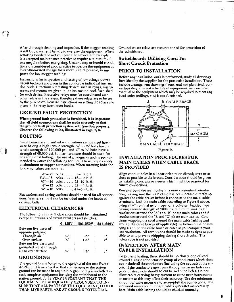
After thorough cleaning and inspection. ir the megger reading is still low. it may still be safe to energize the equipment. When restoring flooded or wet equipment to sen·ice. for example. it is accepted maintenance practice to require a minimum of one megohm before energizing. Under damp or humid conditions it is considered good practice to operate the equipment at lower-than-rated voltage for a short time, if possible, to improve the low megger reading.
Instructions for inspection and testing of low voltage power circuit breakers are gi\'en in the applicable individual instruction book. Directions for testing devices such as relays, instruments and meters are given in the instruction book furnished for each device. Protective relays must be coordinated with other relays in the system, therefore these relays are to be set by the purchaser. General instructions on setting the relays arc given in the relay instruction books.
GROUND FAULT PROTECTION When ground fault protection is furnished, it is important that all field connections shall be made correctly so that the ground fault protection system will Junction properly. Observe the following rules, illustrated in Figs. 7, 8.
BOLTING Switchboards are furnished with medium carbon steel hardware having a high tensile strength. V1" 10 l/il bolts have a tensile strength of 120,000 psi, and W' to YH" bolts have a strength of 60,000 psi. Similar hardware should be used for any additional bolting. The use of a torque wrench is recommended to assure the following torques. These torques apply to aluminum or copper connections. When torquing bolts the following values are nominal:
1/.1" -20 bolts . . . . . . 8- I 0 lb. ft. Y1n"- l 8 bolts . . . . . . 16-19 lb. ft. %"-16 bolts ...... 23-27 lb. ft. W'-13 bolts ...... 35-40 lb. ft. ryK''-16 bolts ...... 45-50 lb. ft.
Flat washers and spring washers should be used for all connections. Washers should not be included under the heads of carriage bolts.
ELECTRICAL CLEARANCES The following minimum clearances should be maintained except at terminals of circuit breakers and switches:
0-125V 126-250V 251-600V Between Jive parts of opposite polarity:
Through air '/2" :1/4" l" Over surface %" l V4" 2"
Between Jive parts and grounded metal through air or over surface 'h" •/2" l"
GROUNDING The ground bus is bolted to the u'prights of the rear frame structure. It is arranged so that connections to the station ground can be made in any unit. A ground lug is included in each complete equipment for tying the switchboard to the station ground. IT IS VERY IMPORTANT THAT THE EQUIPMENT BE ADEQUATELY GROUNDED, TO INSURE THAT ALL PARTS OF THE EQUIPMENT, OTHER THAN LIVE PARTS, ARE AT GROUND POTENTIAL.
Ground sensor relays are recommended for protection of the switchboard.
Switchboards Utilizing Cord For Short Circuit Protection
PRIOR TO INSTALLATION Before any installation work is performed, study all drawings furnished by the supplier for the particular installation. These include arrangement drawings (front, end and plan \'iew), connection diagrams and schedule of equipment. Any material external to the equipment which may be required to meet any local codes (railings, etc.) is not furnished.
CABLE BRACE
MAIN CABLE TERMINALS
Figure 9.
6" MAXIMUM
INSTALLATION PROCEDURES FOR MAIN CABLES WHEN CABLE BRACE IS PROVIDED Align conduit holes in a linear orientation directly over or as close as possible to the braces. Consideration should be given to installing conduits or sleeves which might be required for future connections.
Run and bend the main cable in a most convenient orientation, making sure the main cable has been located directly up against the cable braces before it connects to the main cable terminals. Lash the main cable according to Figure 9 above, using a 3/K" nominal nylon rope, or a polyester braided rope having a tensile strength of 2000 lbs. minimum, making 6 revolutions around the "A" and "B" phase main cables and 6 revolutions around the "B and "C" phase main cables. Continue wrapping the cord around the main cable lashing and around the cable braces )if applicable), in between the phases, tying a knot to the cable brace or cable as you complete your last revolution. All revolutions should be made as tight as possible so as to prevent whipping during short circuits. The nylon rope is not provided.
INSPECTION AFTER MAIN CABLE INSTALLATION To prevent heating, there should be no dosed loop of steel around a single conductor or group of conductors which does not include all the conductors (including the neutral) of the circuit. If the conductors must pass through separate holes in a piece of steel, slots should be cut between the holes. Do not allow cables carrying heavy current to come near instruments or meters as this may affect their accuracy. Use the minimum amount of cable necessary to accomplish the connections. The increased resistance of longer cables generates unnecessary heat. Main cable lashing should be checked annually.
5

' . . ..
Spectra Series™ Switchboards
THIS PAGE IS INTENTIONALLY LEFT BLANK
6

Splicing The Switchboard Sections
Align the sections according to the drawings furnished by the supplier for the particular installation. The splices should be connected as shown in Figures 11 to 68. If enough hardware is pro\'ided to fill all the holes in the splice connections, do so. The additional hardware is necessary due to short circuit bracing requirements.
For indh~dually mounted main/feeder, utility or incoming lug pull sections to individually mounted main/feeder or utility sections, see Figure Group A, page 7.
FIGURE GROUP A
For indMdually mounted main/feeder or utility sections to group mounted distribution sections, see Figure Group B, page 18.
For incoming lug pull sections or group mounted distribution sections to group mounted distribution sections, see Figure Group C, page 26.
MAIN BUS SPLICE, FIGURES 11TO13 OFFSET MAIN BUS SPLICE, FIGURES 14 TO 16 TAPERED MAIN BUS SPLICE, FIGURES 17 TO 21 TAPERED OFFSET MAIN BUS SPLICE, FIGURES 22 TO 24 NEUTRAL DISCONNECT SPLICE, FIGURES 25 TO 27 NEUTRAL BUS SPLICE, FIGURES 28 TO 30 TAPERED NEUTRAL BUS SPLICE, FIGURES 31TO33 GROUND BUS SPLICE, FIGURE 34
IND. MTD. MAIN/FEEDER, UTILITY OR INCOMING LUG
IND. MTD. MAIN/FEEDER OR UTILITY SECTION
IND. MTD. MAIN/FEEDER, IND. MTO. MAIN/FEEDER UTILITY OR INCOMING LUG OR UTILITY SECTION
SECTION
~--m== :;>~~1~---t
MAIN BUS
MAIN BUS BOOA THRU 1200A
ALUMINUM OR COPPER
Figure 11
MAIN BUS
SECTION
MAIN BUS 1600A THRU 2500A
ALUMINUM OR COPPER
Figure 12
7

8
Spectra Series™ Switchboards
Splicing The Switchboard Sections (Cont'd)
MAIN7 BUS
IND. MTD. MAIN/FEEDER OR UTILITY SECTION
(@) ~-~) I @ @ o I c111
F-~(@) 1,o@@I
L=:~@ @~_:=:]
MAIN BUS 3000A & 4000A
ALUMINUM OR COPPER
Figure 13
MAIN7 BUS
MAIN BUS OFFSET SPLICE
MAIN BUS
rc;-~@
\ ~-~@'
~-~@, '~-~@'
IND. MTD. MAIN/FEEDER OR UTILITY SECTION
w~
~MAIN BUS
OFFSET MAIN BUS 800A THRU 1200A
ALUMINUM OR COPPER
Figure 14
I
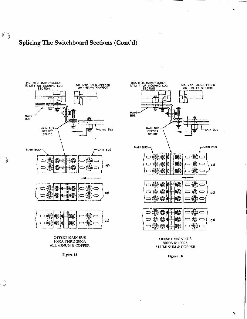
·' ) ~.
Splicing The Switchboard Sections (Cont'd)
MAIN BUS
MAIN BUS OFFSET SPLICE
IND. MTD. MAIN/FEEDER OR UTILITY SECTION
~~
LMAIN BUS
1o-~ @-«1, HtiTlifl©J) I c::> ~ D \
~-(®@' jo~o /A¢
OFFSET MAIN BUS 1600A THRU 2500A
ALUMINUM & COPPER
Figure 15
IND. MTO. MAIN/FEEDER, UTILITY OR INCOMING LUG
SECTION IND. MTD. MAIN/FEEDER
OR UTILITY SECTION
~---:---...-- []F:-;J MAIN_/" BUS
~1F-ti~ tit+HlWJJ : c::> (®) c::> I Biii
~...._._.._._.____. B~-5
F-~~ I c::> (@) o I cl!!
-=------............___ B~~ OFFSET MAIN BUS
3000A & 4000A ALUMINUM & COPPER
Figure 16
9

10
Spectra Series TM Switchboards
Splicing The Switchboard Sections (Cont'd)
MAIN7 BUS
IND. MTD. FEEDER SECTION
\.AIN BUS
IND. MTD. FEEDER SECTION
IND. MTD. FEEDER SECTION
MAIN BUS TAPERED
SPLICE
MAIN BUS
MAIN BUS TAPERED
SPLICE MAIN BUS MAIN BUS MAIN BUS
@)~-~ _......_......._ _ _.l._@__.@W>_j __ ~ / A,B & C~
HIGH AMPS 1200A 1200A 1000A
LOW AMPS IOOOA 800A 800A
TAPERED MAIN BUS ALUMINUM & COPPER
Figure 17
IND. MTD. FEEDER IND. MTD. FEEDER SECTION SECTION
~-AIN BUS
MAIN BUS
@®~ _..__...___._· _~_,_~_'?. -~ r·e & c~
HIGH AMPS 2000A 1600A 1600A
LOW AMPS BOOA 1200A fOOOA
TAPERED MAIN BUS ALUMINUM & COPPER
Figure 18
lo-~~. ~-~~·
HIGH AMPS 2500A 2500A 2000A 2000A 1600A
HIGH AMPS
3000A 3000A
,®»®-~ '®» ®-~ /A,B & Cl!l
LOW AMPS 1200A 1000A 1200A 1000A BOOA
LOW AMPS
1200A 1000A
TAPERED MAIN BUS ALUMINUM & COPPER
Figure 19
. . ...

i( . '\ \ )
)
Splicing The Switchboard Sections (Cont'd)
MAIN_/ BUS '\:"MAJN BUS
IND. MTO. F'EEDER SECTION
MAIN BUS~_.__.,......&..-.---.~
F~@
HIGH AMPS 3000A 3000A
LOW AMPS 2500A 2000A
HIGH AMPS LOW AMPS 2500A 2000A
TAPERED MAIN BUS ALUMINUM & COPPER
Figure 20
\ 0 @\) ®l e_~®
HIGH AMPS 4000A
HIGH AMPS 4000A 4000A 3000A
MAIN BUS
~-~@, \ ~-~@'
HIGH AMPS 2500A 2000A
LOW AMPS 3000A
LOW AMPS 2500A 2000A 1600A
LOW AMPS 1600A 1600A
TAPERED MAIN BUS ALUMINUM & COPPER
Figure 21
A,B at c9)
11

12
Spectra Series TM Switchboards
Splicing The Switchboard Sections (Cont'd)
MAIN7 BUS
MAIN BUS OFFSET SPLICE
MAIN BUS
~-~@. \ ~-~®'
.--------... I C)~®. ~-(@®' HIGH AMPS
1200A 1200A 1000A
IND. MTD. FEEDER SECTION
~ ~MAIN BUS
-.-I'-MAIN BUS
,@\©>C)-\ I'@' I~ c:J' A¢ ~1~"-:!JJ _ _i__::_ __
fl~~-~ :~ le¢
~,~;-~ LOW AMPS
1000A BODA BODA
TAPERED OFFSET MAIN BUS ALUMINUM & COPPER
Figure 22
MAIN7 BUS
MAIN BUS
MAIN BUS OFFSET SPLICE
HIGH AMPS 1600A 1600A 160DA 2DOOA 200CA 2000A 2500A 2500A 3000A 3000.\
IND. MTD. FEEDER SECTION
EIF-~
MAIN BUS
-
~ @@@))-~ ~I@~-~ l c¢
LOW AMPS 1200>. 1000A SOOA 1200A 1000A 800A 1200A 1000A 1200A 1COOA
TAPERED OFFSET MAIN BUS ALUMINUM & COPPER
Figure 23

Splicing The Switchboard Sections (Cont'd)
IND. MTO. FEEDER SECTION
F MAIN_;;;r-BUS
_,-C:Neus
~NOUS
lo~ ID(@ CJ \Al/>
B~-=J ....,.._
~~~ :a(@) o I B!ZS
B~~ ~~~ lo(@) CJ I cf6
B~~ HIGH AMPS LOW AMPS
2000A 1600A 2500A 2000A 2500A 1600A 3000A 2500A 3000A 2000A JOOOA 1600A 4000A JOOOA 4000A 2500A 4000A 2000A 4000A 1600A
TAPERED OFFSET MAIN BUS ALUMINUM & COPPER
Figure 24
13

14
• Spectra Series™ Switchboards
Splicing The Switchboard Sections (Cont'd)
IND. MTD. MAIN/ UTILITY SECTION
NEUTRAL? BUS
NEUTRAL BUS SPLICE
NEUTRAL BUS
UTILITY /IND. MTD. FEEDER SECTION
~EUTRAL BUS
NEUTRAL BUS SPLICE
NEUTRAL
"'""""......,... _____ ~\
t-L-1.-.---(@)-"~~ ~~
BUS
IND. MTD. MAIN/ UTILITY SECTION
NEUTRAL-' BUS
NEUTRAL BUS SPLICE
NEUTRAL· BUS
UTILITY /IND. MTO. FEEDER SECTION
NEUTRAL DISCONNECT 800A THRU 1200A
ALUMINUM & COPPER
NEUTRAL DISCONNECT 1600A THRU 2500A
ALUMINUM & COPPER
Figure 25
NEUTRAL BUS
IND. MTD. MAIN/ UTILITY SECTION
UTILITY /IND. MTD. FEEDER SECTION
NEUTRAL BUS SPLICE
NEUTRAL BUS
NEUTRAL DISCONNECT 3000A & 4000A
ALUMINUM & COPPER
F~gure 27
Figure 26
NEUTRAL BUS
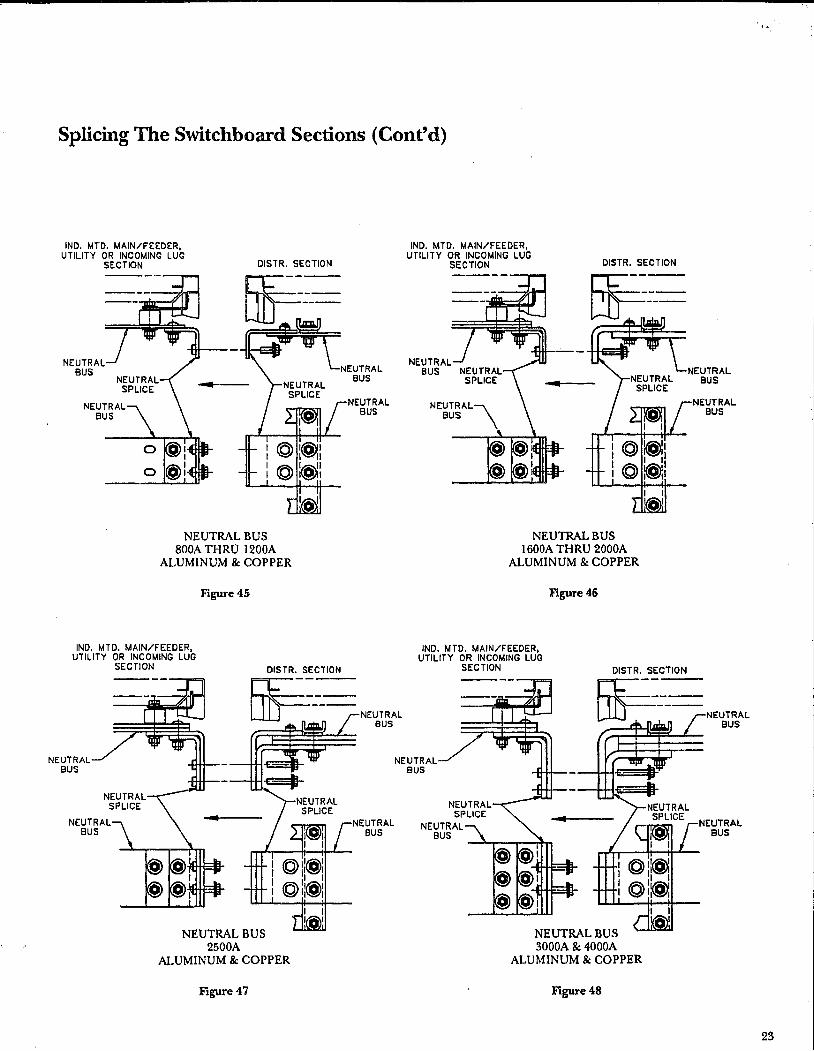
Splicing The Switchboard Sections (Cont'd)
IND. MTD. MAIN/FEEDER, UTILITY OR INCOMING LUG
SECTION
NEUTRAL BUS
NEUTRAL BUS
DISTR. SECTION
NEUTRAL BUS 800A THRU 1200A
ALUMINUM & COPPER
IND. MTD. MAIN/FEEDER, UTILITY OR INCOMING LUG
SECTION
Figure45
OISTR. SECTION
NEUTRAL BUS
NEUTRAL BUS
IND. MTD. MAIN/FEEDER, UTILITY OR INCOMING LUG
SECTION
NEUTRAL BUS
DISTR. SECTION
NEUTRAL BUS l 600A THRU 2000A
ALUMINUM & COPPER
IND. MTD. MAIN/FEEDER, UTILITY OR INCOMING LUG
SECTION
Figure46
~:- NEUTRAL BUS
NEUTRAL BUS
NEUTRAL BUS 2500A
ALUMINUM & COPPER
Figure 47
NEUTRAL BUS
NEUTRAL SUS
NEUTRAL BUS 3000A & 4000A
ALUMINUM & COPPER
Figure48
NEUTRAL BUS
NEUTRAL BUS
NEUTRAL BUS
. . ...
23

24
• Spectra Series TM Switchboards
Splicing The Switchboard Sections (Cont'd)
IND. MTD. MAIN/FEEDER, UTILITY OR INCOMING LUG
SECTION DISTR. SECTION
IND. MTD. MAIN/FEEDER, UTILITY OR INCOMING LUG
SECTION DISTR. SECTION
------
I
NEUTRAL BUS uu
NEUTRAL BUS
OFFSET NEUTRAL BUS 800A THRU 1200A
ALUMINUM & COPPER
Figure 49
IND. MTO. MAIN/FEEDER, UTILITY OR INCOMING LUG
SECTION
I
NEUTRAL BUS
DISTR. SECTION
NEUTRAL BUS
------
-------
NEUTRAL BUS
I
lW
NEUTRAL BUS
OFFSET NEUTRAL BUS 1600A THRU 2000A
ALUMINUM & COPPER
Figure 50
IND. MTO. MAIN/FEEDER, UTILITY OR INCOMING LUG
SECTION
I
NEUTRAL
DISTR. SECTION
NEUTRAL BVS
NEUTRAL BUS
-------
NEUTRAL BUS UlJ NEUTRAL BUS UlJ NEUTRAL
BUS
NEUTRAL OFFSET SPLICE
NEUTRAL BUS
OFFSET NEUTRAL BUS 2500A
ALUMINUM & COPPER
Figure 51
BUS
OFFSET NEUTRAL BUS 3000A & 4000A
' ALUMINUM & COPPER
Figure 52
NEUTRAL BUS

Splicing The Switchboard Sections (Cont'd)
GROUND BUS
IND. MTD. MAIN/FEEDER, UTILITY OR INCOMING LUG
SECTION
GROUND BUS
0
DISTR. SECTION
GROUND BUS
SPLICE
'LJ L __ · I GROUND BUS
800A THRU 4000A ALUMINUM & COPPER
IND. MTD. MAIN/FEEDER. Figure 53
GROUND BUS
GROUND BUS
UTILITY OR INCOMING LUG SECTION DISTR. SECTION
GROUND BUS
GROUND BUS
GROUND BUS
OFFSET SPLICE
o@ I II 1
I LI" L __ OFFSET GROUND BUS
800A THRU 4000A , ALUMINUM & COPPER
Figure 54
GROUND BUS
GROUND BUS
. . ..
25

26
Spectra Series™ Switchboards
Splicing The Switchboard Sections (Cont'd)
INCOMING LUG OR DISTR. SECTION
FIGURE GROUP C
MAIN BUS SPLICES, FIGURES 55 TO 58 TAPERED MAIN BUS SPLICE, FIGURES 59 TO 60 NEUTRAL DISCONNECT SPLICE, FIGURES 61TO62 NEUTRAL BUS SPLICE, FIGURES 63 TO 64 TAPERED NEUTRAL BUS SPLICE, FIGURE 65 OFFSET NEUTRAL SPLICE, FIGURE 66 GROUND BUS SPLICE, FIGURE 67 OFFSET GROUND SPLICE, FIGURE 68
DISTR. SECTION INCOMING LUG OR
DISTR. SECTION DISTR. SECTION
t=:.:~ I . =::::j - --1 --~
- -~
MAIN BUS t t j' .... MAIN BUS
r-~_-----=----' MAIN BUS 1lt t _j' llJ _ MAIN BUS
MAIN BUS
MAIN BUS BOOA THRU 2000A
ALUMINUM & COPPER 65 Be lOOKA SHORT CIRCUIT RATING
Figure 55
MAIN BUS 800A THRU 2000A
ALUMINUM & COPPER 150 & 200KA SHORT CIRCUIT RA TING
Figure 56
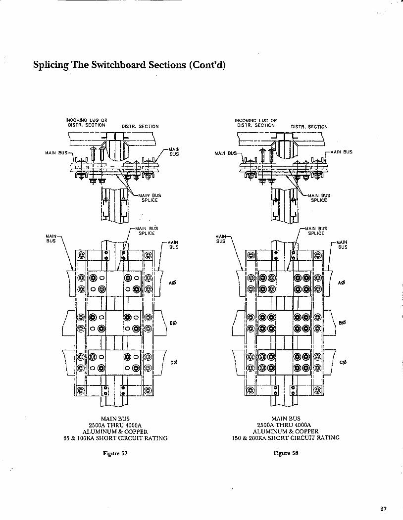
Splicing The Switchboard Sections (Cont'd)
MAIN BUS
INCOMING LUG OR DISTR. SECTION DISTR. SECTION
MAIN BUS 2500A THRU 4000A
ALUMINUM & COPPER 65 & lOOKA SHORT CIRCUIT RATING
Figure 57
MAIN BUS
MAIN BUS
INCOMING LUG OR DISTR. SECTION DISTR. SECTION
MAIN BUS 2500A THRU 4000A
ALUMINUM & COPPER 150 & 200KA SHORT CIRCUIT RATING
Figure 58
27

Splicing The Switchboard Sections (Cont'd)
IND. MTD. MAIN/FEEDER, UTILITY OR INCOMING LUGS IND. MTD. MAIN/FEEDER
IND. MTD. MAIN/FEEDER, UTILITY OR INCOMING LUGS IND. MTD. MAIN/FEEDER
SECTION OR UTILITY SECTION
NEUTRAL BUS
SECTION OR UTILITY SECTION
NEUTRAL BUS SOOA THRU l 200A
ALUMINUM & COPPER
Figure 28
LNEUTRAL BUS
NEUTRAL BUS
NEUTRAL BUS SOOA THRU 1200A
ALUMINUM & COPPER
Figure 29
IND. MTD. MAIN/FEEDER, UTILITY OR INCOMING LUGS
SECTION IND. MTD. MAIN/FEEDER
OR UTILITY SECTION
NEUTRAL BUS
~~~;;:~~~?-"[NEUTRAL
NEUTRAL BUS 3000A & 4000A
ALUMINUM & COPPER
Figure 30
BUS
NEUTRAL BUS
NEUTRAL BUS

---------------------------------------------~
Spectra Series TM Switchboards
Splicing The Switchboard Sections (Cont'd)
MAIN BUS
22
IND. MTD. MAIN/FEEDER, UTILITY OR INCOMING LUG
SECTION
oo@: I
C) C) @:-H-E::n. C) C) @l+H:::=n-
DISTR. SECTION
cm;;j MAIN BUS
MAIN BUS
e¢
c!ll c:::> c:::> @:.ue~ll-+-l+llli
C) C) @l-1+1:::;::mf-l+Hil' I ~"--~'--~-
C) o@I
MAIN BUS 4-000A ALUMINUM
Figure 43
1ND. MTD. MAIN/FEEDER, UTILITY OR INCOMING LUG
SECTION
~---
MAIN BU!>
MAIN BUS SPLICE
MAIN Bl.JS
DISTR. SECTION
~;j MAIN BUS
MAIN BUS
C) 0 @l I #E:EB-1 c!ll
C) c:::> @l : ttE:l.\a-1 ~i..;;;.._.;;;.."--~-
C> 0@1
MAIN BUS 4000A COPPER
Figure 44

' 16
Spectra Series TM Switchboards
Splicing The Switchboard Sections (Cont'd).
IND. MTD. FEEDER SECTION
NEUT RA~ BUS
NEUTRAL BUS
IND. MTD. FEEDER SECTION
LNEUTRAL BUS
/NEUTRAL f_ BUS
r--"'-~~~ -@-I ......___,.,_@....,..('@)-~;· --\
L __ ~@ '@ ~ __ _j HIGH AMPS LOW AM?S
. 1200A 1000A 1200A 800A 1000A 800A
TAPERED NEUTRAL BUS ALUMINUM & COPPER
Figure 31
IND. MTD. FEF.:DER SECTION
NEUTRAL~ BUS
NEUTRAL BUS
HIGH AMPS 1600A 1600A 1600A 2000A 2000A 2000A 2500A 2500.l
-~@ NEUT RA~ BUS
', (@) @I
l __ ®@ HIGH AMPS 3000A 3000A
IND. MTD. FEEDER SECTION
NEUTRAL BUS TAPERED SPLICE
LOW AMPS 1200A 1000A
TAPERED NEUTRAL BUS ALUMINUM & COPPER
Figure 32
' . ...

Splicing The SWitchboard Sections (Cont'd)
MAIN BUS
MAIN BUS SPLICE
MAIN BUS
c:::> C>
CJC>
C>C>
DISTR. SECTION
Dlf ~
@1 I
@: I
@1
MAIN BUS 3000A ALUMINUM
Figure 41
0
0
a CJ
B¢
Cf6
MAIN BUS
IND. MTD. MAIN/FEEDER, UTILITY OR INCOMING LUG
SECTION
MAIN BUS
MAIN BUS
DISTR. SECTION
[f;;l MAIN BUS
0 c:> ~l MAIN BUS
I
0 c:> ~: I
OCJ~I _.J
MAIN BUS 3000A COPPER
Figure 42
C A9J a
a c¢
a
21

20
• Spectra Series™ Switchboards
Splicing The Switchboard Sections (Cont'd)
IND. MTD. MAIN/F'EEDER, UTILITY OR INCOMING LUG
SECllON
~---
MAI!>. aus
MAIN BUS
DISTR. SECTION
f:-~
MAIN BUS SPLICE
MAIN BUS
MAIN BUS
---""'"-+--, 0 c::> @: oo@:
---..L--...l
--, oo@I
I o o @I
---+---'
MAIN BUS 2500A COPPER
Figure 39
a ell}
a
a c{!I
a
MAIN BUS
MAIN BUS
DISTR. SECTION
Dlf ~
--, c.:::> C) <@) :
1-HE-:IG ·+I+ c.::> C) <@) :
---4---' -
C> C> (@) ::-m:::b-+I+ I
0 0 @j!-HE::IS-+I+
Cl ellJ
CJ L.U-.L.--.!.---
---+--, o o @I
I -a a (@)l
_...l
MAIN BUS 2500A ALUMINUM
Figure 40
Cl c!ll
Cl
MAIN BUS
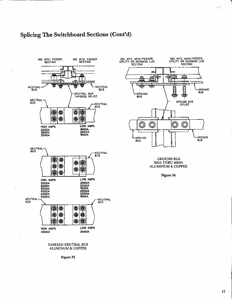
Splicing The Switchboard Sections (Cont'd)
IND. MTO. FEEDER SECTION
IND. MTD. FEEDER SECTION
:ij~~~~~~~-~NEUTRAL BUS
NEUTRAL BUS
-4EUTRAL
BUS
NEUTRAL BUS
HIGH AMPS 2000A 2500A 2500A
HIGH AMPS 3000A 3000A 3000A .4000A .4000A 4000A
HIGH AMPS 4000,t,
.---+---1:c-t
@~ @~ -=
LOW AMPS 1600A~ 2000A 1600A
LOW AMPS 2500A 2000A 1600A 2500A 2000A 1600A
NEUTRAL BUS
NEUTRAL BUS
LOW AMPS
3000A
TAPERED NEUTRAL BUS ALUMINUM & COPPER
Figure 33
IND. MTD. M"AIN/FEEDER, UTILITY OR INCOMING LUG
SECTION
GROUND BUS
GROUND BUS
IND. MTD. MAIN/FEEDER, UTILITY OR INCOMING LUG
SECTION
==c.::UND BUS
GROUND BUS
GROUND BUS SOOA THRU 4000A
ALUMINUM & COPPER
Figure 34
17

Splicing The Switchboard Sections (Cont'd)
IND. MTD. MAIN/f'EEDER, UTILITY OR INCOMING LUG
Sl.:CTION
MAIN BUS SPLICE
MAIN BUS
-., C> C> ®> I c:::> C> (@ I
...J..fil-1-130.
c::> c::> @.., I
c::> a ~.J
c::> a ®)1 @l c::> 0 _.J
DISTR. SECTION
~~ UJJ
MAIN BUS . SPLICE
Cl e{IS
c
Cl c¢
c
MAIN BUS 2000A ALUMINUM
Figure 37
MAIN BUS
MAIN BUS
IND. MTD. MAIN/f'EEDER, UTILITY OR INCOMING LUG
SECTION DISTR. SECTION
c::> 0 @: o e¢ @l a a 0
o c¢ -., C)C) @:
@1 a
c::> C)
MAIN BUS 2000A COPPER
Figure 38
19

18
Spectra Series TM Switchboards
Splicing The Switchboard Sections (Cont'd)
FIGURE GROUP B
MAIN BUS SPLICE, FIGURES 35 TO 44 NEUTRAL BUS SPLICE, FIGURES 45 TO 48 OFFSET NEUTRAL SPLICE, FIGURES 49 TO 52 GROUND BUS SPLICE, FIGURE 53 OFFSET GROUND SPLICE, FIGURE 54
IND, MTD, MAIN/FEEDER, UTILITY OR INCOMING LUG
SECTION DISTR. SECTION
MAIN BUS
--""--+---, c::> c::> @: o o @I
-----.J
--, c:::> C) @: c:> c::> @:
_.J
---+---, c:::> c::> @ : c:::> c::> (@) :
---+--.J
MAIN BUS BOOA THRU l 200A
ALUMINUM & COPPER
Figure 35
MAIN BUS
0 efl}
Cl
CJ clli
CJ
t;;-----
MAIN_/ BUS
V.AlllJ BUS
--, C> c:::> @ I 00@
1
_...J
---+---, C> c:::> @:
:+IH:E--t+ c:> c::> @l
---;--.J
MAIN BUS 1600A
ALUMINUM & COPPER
Figure 36
MAIN BUS
MAIN BUS

Splicing The Switchboard Sections (Cont'd)
NEUTRAL BUS
NEUTRAL DISCONNECT SPLICE
NEUTRAL DISCONNECT SPLICE
NEUTRAL BUS
NEUTRAL DISCONNECT SPLICE
NEUTRAL BUS
_-:---:::=:t
NEUTRAL DISCONNECT 800A THRU 2000A
ALUMINUM & COPPER
Figure 61
--~
NEUTRAL BUS
NEUTRAL DISCONNECT SPLICE
NEUTRAL DISCONNECT 2500A THRU 4000A
ALUMINUM & COPPER
Figure 62
NEUTRAL BUS
29
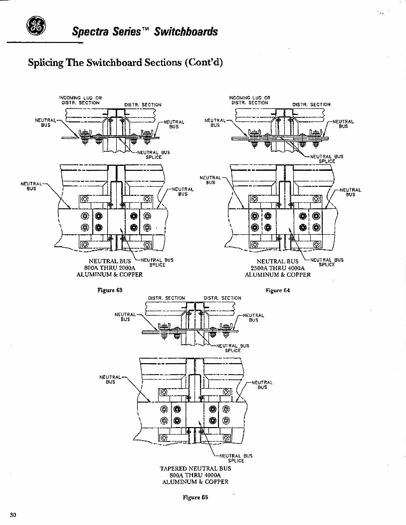
30
Spectra Series™ Switchboards
Splicing The Switchbo.ard Sections (Cont'd)
NEUTRAL BUS
NEUTRAL BUS
NEUTRAL BUS
-:====\ -------,
BUS
NEUTRAL BUS ~~
I
SPLICE --~ -- \ ------, --------If NEUTRAL
<:>, ' '----'r--'-1-"~.J- ) ~-~~.
I
\ \
== ;,1-J --~ NEUTRAL BUS
BOOA THRU 2000A ALUMINUM & COPPER
Figure 63
NEUTRAL BUS 2500A THRU 4000A
ALUMINUM & COPPER
Figure 64
NEUTRAL BUS
-:====\ --~
BUS 0:,
'
-----If NEUTRAL
.____.,__.__...~ ... - ) I
== ~J-1 ..._..;J....J;:"_-~
NEUTRAL BUS SPLICE
TAPERED NEUTRAL BUS BOOA THRU 4000A
ALUMINUM & COPPER
Figure 65
NEUTRAL BUS

Splicing The Switchboard Sections (Cont'd)
INCOMING LINE SECTION MAIN DISTR. SECTION
~-~---_____,,-..--'! I
~--;;;;;;; i I! I I ~--
N£UTRAL v-d:r-~ BUS ~
I 1 I i I l 11 I NEUTRAL BUS
---'4- I l 1
NEUTRAL OFFSET SPLICE
\ M-1-1-4--\ __ .·
-NEUTRAL OFFSET SPLICE
OFFSET NEUTRAL BUS 800A THR U 2000A
ALUMINUM & COPPER
Figure 66
/ ...... ____ .,,,, I
I
NOTE: FOR 2500A THRU 4000A OFFSET NEUTRAL SPLICE SEE FIGURE 64
. . ...
31

32
• Spectra Series TM Switchboards
Splicing The Switchboard Sections (Cont'd)
INCOMING LUG OR DISTR. SECTION
GR OUN~ BUS
GROUND BUS BOOA THRU 4000A
ALUMINUM & COPPER
Figure 67
GROUND BUS

Splicing The Switchboard Sections (Cont'd)
GROUND. BUS OF'FSET SPLICE
INCOMING LINE SECTION
GROUND BUS
GROUND BUS' OFFSET SPLICE
I
~~._..._ ___ -"
' .... "" ' .... _
MAIN DISTR. SECTION
~~;;:} Ull GROUND BUS
OFFSET SPLICE
GROUND BUS
OFFSET GROUND BUS 800A THRU 4000A
ALUMINUM & COPPER
Figure 68
GROUND BUS OFFSET SPLICE
•
33

34
• Spectra Series TM Switchboards
Connecting the Section Frames
The section frames are connected as shown in Figure 24. The joining of the sections contains 2 bolted connections on the top and bottom depth frame members. In addition, 2 bolted connections are made on each vertical frame member. The vertical connections are located Y.1 and% up from the bottom of the switchboard (if90" H switchboard, then connections are made at 30" and 60" off the ground).
SECTION I
Figure 69
SECTION 2

Switchboard Maintenance CAUTION! De-energize this equipment.before performing any work.
A periodic maintenance schedule should be established to ob· tain the best service from the switchboard. An annual check and m·erall maintenance procedure for the switchboard de· \'ices and all connections, should be followed as a minimum re· quirement. Equipment subject to highly repetith·e operation may require more frequent maintenance.
A permanent record of all maintenance work should be kept. The record should include a list of periodic checks and tests made, the date they were made, the condition of the equip· me!'1t, and any repairs or aqjustments that were performed. Mamtenance employees should follow all recognized safety practices, such as those contained in the National Electrical Code, OSHA and in company or other safety regulations during maintenance.
For specific information regarding the maintenance of devices, such as circuit breakers, relays, meters, etc., refer to the separate instruction book furnished for each device.
1. Periodically inspect switchboard, while under load to de· termine if there is any indication of overheating. If O\'er· heating or any other unsatisfactory condition is found, completely de-encrgi1.e switchboard and investigate. Par· ticularly look for loose bolts and connections, or overloading. Remove any accumulation of dirt or other foreign matter in enclosure. Do not touch live parts while switchboard is energized.
2. Plated parts may become dark over a period of time due to oxidation. Do NOT remove this discoloration, as it will reduce the ~hickness of the plating.
3. Retighten lugs and joints to eliminate possible heating points. Transmittal of vibration through building structure and conduit to switchboard may loosen lugs and joints. Turning load off and on causes expansion and contraction between lug and cable tending to loosen lug.
4. Do not open sealed breaker or trip units as calibration may be disturbed. Return to factory for any replacement.
AMBIENT TEMPERATURES AND CIRCUIT LOADING Switchboards are designed for installation where average ambient temperature will not exceed 25°C (77°F). For higher temperatures, derating may be required. The conductor temperatures within the enclosure may be as high as 80°C ( l 76°F). Some parts of breakers, switches and fuses may run hotter. In accordance with NEC Art. 384-16(c) it is recommended that thermal-magnetic molded-case breakers in switchboards not be loaded in excess of 80% of rating where load will continue for three hours or more, even with ambient-compensated breakers.
SHORT CIRCUITS Normally, the overcurrent protective device on the circuit will prevent any electrical damage except at the actual point of short-circuit. A thorough inspection of the entire system after any large fault current should be made to insure that there has been no mechanical damage to conductors, insulation or equipment.
In addition, the individual o\'ercurrent protective device or de\'ices which performed the short-circuit interruption must be inspected for possible arcing damage to contacts, arc chutes and/or insulation. Do not open sealed devices such as breaker trip units. If there is any possibility that sealed units may have been damaged, they should be replaced. For additional details on the particular device involved, refer to the applicable individual instruction book.
ARCING DAMAGE TO INSULATION Some organic insulating materials carbonize when subjected to the heat of an electrical arc and lose their insulating qualities. Any insulation found to be carbon-tracked must be replaced before applying power.
WATER-SOAKED EQUIPMENT l. Completely de-energize switchboard.
2. Carefully clean and dry all parts of the switchboard. When using heaters, do not exceed 180°F.
3. Replace all fuses.
4. Individual devices should be inspected for the possible entrance of water, dirt or foreign matter.
5. Do not open sealed devices such as breaker trip units. Replace them.
6. Prior to re-energizing the switchboard it should be meg· gered. Refer to testing and inspection section on page 4.
7. If assistance or guidance is required contact your local service engineer. Your supplier's service shops have facilities for reconditioning.
SPARE PARTS A spare parts stock for the components of the switchboard, such as bus, insulators, etc. is not recommended. When com· ponents need to be reordered, please refer to the nameplate marking, shop drawing number, and order by description. A spare parts stock of devices such as circuit breakers, meters, switches, etc. will vary due to the variety of installations. Your supplier sales engineer will be glad to assist you in the proper selection for a device stock list.
35

These instructions do not purport to cover all details or variations in equipment nor to provide for every possible contingency to be met in connection with installation operation or maintenance. Should further information be desired or should particular problems arise which are not covered sufficiently for the purchaser's purposes, the matter should be referred to the GE Company.
GE Electrical Distribution & Control
General Electric Company
GEH-5875 41 Woodford Ave .. Plainville, CT 06062
Rev. 03 0695 PSA © 1995 General Electric Company

BATTERIES
PURCHASED FROM:
fJESC~(), INC:. 1-502 PAHi{ WEST DRIVE
HASTINGS, NE 68901
(402) 463-6859
C40:2) 46·3-6850 FAX
1-800-97·5-3726
'! D-2 ., - ., 997 I ·1 : s~w.1 FROH BATTERY PATRDL A 5 ., 52664655 P. I
•Battery• u Patrol"Evarr Battsry You'll Ever Need
1 -
3301 Oak View Dr., On-iaha 4310 N. 27th st., Lincoln
&Wi'P' UC
Fax Tn1nsmission cover Sheet
To __ f rcnj 13ro cK
From Dean
Re: 5 ft!t!.S ot""l /,#ft"ferre .S
1-800~37 3-7 406 ( 402)697-8656
FAX (515) 266-4655
•••••a
No. of pages sent including cover: .J~---
·---<---··---~----
__ , ___ , ............. ~ u ---------·-~-
+--------
-·4----·----
·-----~----;--·
___ j ____ ~
_______ ......... ~---------------~---~----------I

·10-21-1997 12: 00PM
Prod1.1ct Type Industl"'y Sim Volt i:i Amp Ho1.1r Rating Marin~ Cranking Amps Assembly Configur~ti rermin<'l\tion Hor.1sing Styl~ AltGrn~tor Output Quick Charge Rate Flo~t Charge Rate Charge Protection
Djm~nfilians IN/LB Dimensions MM/KG Unit ~I/ C<.15 ~ Unassigned Une\ssigned Una$signed Uriemsigned Notes
FROM BATTERY PATROL A 5152654655
$ At£J002:t65 SCS150 (2Ld 3 YR 150 MIN EA SLID WET LEAD ACID !DEEP CYC~E> 24M GROUP 24 W/MARINE TERMI~ALS
12.00 Minute Reserve C~pa~ity 25 Amp 11Z15.©I<.' Min1Jte Reserve C~p.l1city 75 Amp &50.00 Plates Per Batte~y
1 SINGLE CELL . MAA MARINE TYPE POST PL PLASTIC CASE 13.5
NO ND CHARGE PROT~CTION Diameter Length Width Height
.~0 11.23 &.7~ 9.75
.00 285.75 171.45 ,247.65
.00 Unas5igned
'
-~~·-----.. ·-"···"-~"'""'-""''''"'"~··,-··--
Weight 45.00 20. 45
• 012t
Prr:s ~ <ENTE:R> to cont i rrr..te •••
rJ ') ,.. .. ~.
150.00 • tZllZJ
fu8. 01Zt

1 0-2 ·1 -1 99 7 ·1 2 : 00Pt.1 Fr:;:Qf.1 BA TTEP. Y PA Tr:;DL A 5 ·1 52664655
Product ·rype 'l"ype Volts
Low Charg"" R1'l.t a Madiuru Charge Rate High Ch1"irge RG\te Starting Boost
Dimansion~ IN/LB Dim~nsions MM/KG Units/C.i\se
i
I I
ACHG0160 12V/&V 2-10-&0AMP ~TARTING CH4 AUTO, MRRINE, MOTORCYCL~ CHARS AUTO AUTOMATIC CHARGER I
12.00 I
b.00 I .00 i
I --·-·-.. -···-·-"-'""'·==-====~-~===: ---·-.. ··-···---~~---!~.-~,.-~
2 AMl=1
1'21 AMP
60 60 RMP Diameter Length
• 00 "00 • 00 • 00 • 1211Zl
Width • IZllZI • ~-.,0
Height .1210 .00
---------.-.......... ............. .........,_ ............ ..L._.~.--~-1
Press <ENTER> to continue •••
$ EA
We i.gh·b • eie1 . 00 • (210
P.3
• 00 • !Zl0 • t21l~

FREMONT WASTE SYSTEM IMPROVEMENTS
PANELBOARDS, TRANSFORMERS, AND SWITCH~$
PANEL BOARD. II MDP II (CHEMICAL_ BUILDING) ............ PAGES 1 THRU 4
PANELBOARD. "LP201" ................ , ... , ....... PAGES 5 THF'.\U 11
PANELBOAF~D. "LP301" ................................... PAGES 12
INTEGRAL TRANSFORMER/DISTRIBUTION CENTER ......... PAGES 13 & 14
ENCLOSED CIRCUIT BREAKERS ..................... PAGES 15 THRU 17
DRY-TYPE TRANSFORMERS ............................ PAGES 18 & 19
SAFETY SWITCHES .................................. PAGES 20 & 21
OPERATION & MAINTENANCE MANUALS POWER BREAK CIRCUIT BREAKERS ... 800 TO 2000A .... BROCHURE 1 POWER BREAK CIRCUIT BREAKERS ... 2500 TO 4000A ... 8ROCHURE 2 POWER BREAK TERMINAL BOARD ..................... BROCHURE 3 FIELD REPLACEMENT OF ELECTRlCAL OPERATOR ....... BROCHURE 4
KAYTON ELEClRIC, INC. NORFORK Bt'.\ANCH

G E. N E R A L E L E C T R I C ELECTRICAL DISTRIBUTION & CONTROL 4.4
FACTORY ORDER NO
I FREMONT WAQTER
REQUISITION NO PROPOSITION NO
I 6M4 I 21733
JOB NAME SYSTEM
FRONT DATE BOX
P A N E L B 0 A R D DRAWING
REV DATE PAGE 08/05/96 11
DATE INTERIOR DATE
ITEM 11 MOP CHEM. BLDG
QTY 1
MAIN
BRANCHES
OPTIONS
A-SERIES TYPE AD
22,000 AMPS RMS SC FULLY RATED
100 AMP 3P THED6 CB
1-LUG/PH 1-CABLE/LUG #14 -2/0
3 -5 -
60A 3P THED6 20A 3P THED6
2 - GROUND-BOX BONDED TGL2
3P4W 277/480V
LOC BOTTOM
INTERIOR ADF3241TB
BOX AB43B H 43 1/2 11 W 20" D 5 3/4 11
FRONT AF43S SURFACE MOUNTING

GE Pane/boards
A Series® Pane/boards- Type AD Interrupting Ratings-Molded Case Circuit Breakers
Molded C11e Circuit Breakers Feder1I Trip Rated Volts Specs
Range CJ8 Clan Construction Frame (Amps I Pole IC de W·C·375B 120
15·50 1 125 13b THEO 15·100 2 480 250 13b -
15·150 3 1' 13b Standard
TFJ 70·225 2 480 20a Frames TFJ 70·225 3 600 250 20a -TJJ 125·4-00 2, 3 600 250 \\ 21a -TEL 15-150 3 600 - - -
Hi·interruptmg TFL 70·225 3 600 - - -Circuit Breakers TLB4 250-400 3 480 - - -
TJ4V 150-600 3 600 - - -THLC1 15·150 3 480 - - -
Current Limiting THLC2 125·225 3 480 - - -Circuit Breakers THLC4 225·400 3 480 - - -
· D 3 Pole device not de rated. .:?) IC rating 1s at 125Vdc.
Molded Case Circuit Breakers Circuit Breaker
Frame
Cum1nt High Standard limiting Interrupting
THEO - TEL
TFJ - TFL
TJJ - -
- THLCI TLBl
- THLC2 Tlll2
- THLC4 TLB4
<'.D 3 Pole lug assembly suitable for line or load end.
SPLIT NEUTRAL
1~..Jl'-~._~-1-~4-o..Jl'-~ 3 4 5~..J"-~+-~-1-~ ....... ..J"'- 6 7~..Jl'-~+-~+-~4-..Jf'...~e 9 10
11 12 13 14 15 16 17 18 19 20 21 22 23 24
Poles
1·3
2-3
2·3
J
J
J
No. Per Pole CatNo.
TCAL14 TCAL12
I TCAL18 TCAL12A TCALIS
1 TCAL24, 26
1 TCAL43
TCAL12 1 TCAL12A
TCAL15
1 TCAL27
1 TCKL43 ©
30, 4W 120/208Vac 30. 3W 480Vac 30, 4W 480Y /277Vac 30, 3W 600Vac 30, 4W 600Y/347Vac
Neutral may be plate type and/or located opposite line entrance depending on main breaker type, rating and specified panel options.
nr:aw1nn~ 11nJ 1'11t11 ~,,,,;.,., tn rh:mn• witltn11t nntil"ll
DEM • 1316
UL Usted Interrupting Retings in Thou11nd Amps
RMS Symmetrical 1c Volts de Volts
120/240 240 m 4aJY{1.77 600 250 .
- 65 - 18 10~ - 65 - 25 18 10
65 - 25 18 -25 22 - 10 - 25 - 22 18 -
- 42 - 30 22 10
- 100 - 65 25 -- 100 - 65 25 -- 85 - 65 - -- 42 - 30 22 -- 200 - 150 -- 200 - 150 - -- 200 - 100 -
Terminal lugs (Cu·All
Per lug
1
1
1
1
1
1
Wire-Cu·AI (Unless otherwise notedl
Range
115A·30A, TCALI 41 • 114·8 (30A·60A, TCAL121·114·3Cu, 112·1AI 114·3/0Cu, 112·3/0AI (70A·110A, TCAL12AI · 16·2/0Cu, 14-2/0AI (110A·150A, TCAL15) • 12·3/0
#4·300MCM
16·600MCM or 2·(2/0·250MCMJ
115·60A. TCAL121 #14-13 CU or 112·11 Al (70·110A, TCAL12Al 16·2/0 CU or 14·2/0 AL 1125·150A, TCALISI 11·2/0 CU or 1/0·3/0 Al
l125-225A, TCAL27) 14-JOOMCM
J/O·SOOMCM or 2 (3/0·250MCMJ
PANELBOARDS SHORTCIRCUIT RATING:
The short·circu11 rating of a panelboard 1s limited to the mterrup1mg ra11ng of the lowest rated device or to the applicable UL hsted series rating when proper main and branch device combmauons are used. The short·c1rcu1t current avatlable al the incoming Ima terminals should no1 011.ceed this vatua.
When 1panelboard1s apphed w11h1n its short·cncult ra1ung. ous bar bracing 1s adeQua1e to withstand the forces e•erted by lhe let· through current
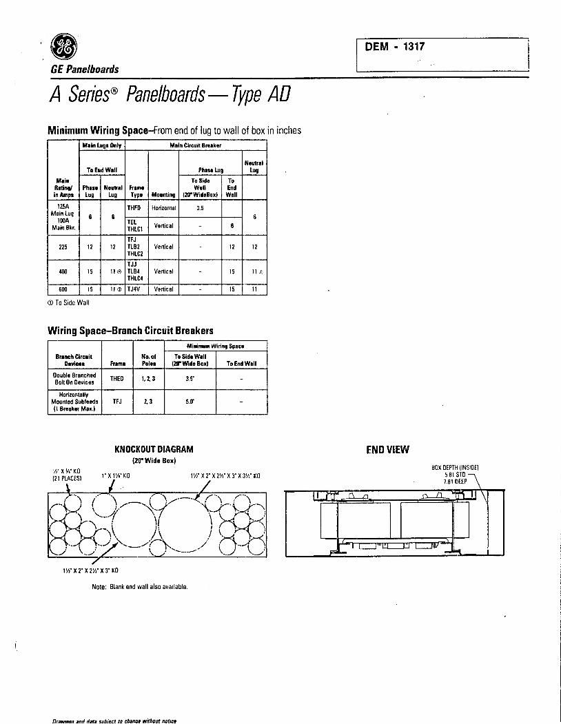
GE Pane/boards
A Series® Pane/boards- Type AD
Minimum Wiring Space-From end of lug to wall of box in inches M1in lugs Only Main Circuit Breaker
Neutrel To End Wall Phase Lug lug
Main To Side To Rating/ Phan Neutr1I Frame Wall End in Amps lug Lug Type Mounting (20" WideBoxl Wall
125A THFD Horizontal 3.5 Main lug 6 6 6 lOOA TEL Main Bkr. THLCl Vertical - 6
TFJ 225 12 12 TLB2 Vertical - 12 12
THLC2
TJJ 400 15 11© TLB4 Vertical - 15 11,.,
THLC4
600 15 11 (]) TJ4V Vertical - 15 11
<D To Side Wall
Wiring Space-Branch Circuit Breakers Minimum Wiring Space
Branch Circuit Oevic11
Double Branched Bolt On Devices
Horizontally Mounted Subfeeds (1 Breaker Max.I
Na.of To Side Wall fnlm1 Poln (20" Wide Box)
THEO 1, 2,3 3.5"
TFJ 2, 3 5.cr
KNOCKOUT DIAGRAM 120" Wide Box)
To End Wall
-
-
\11 X 'Ii" KO (21 PLACES) 1' X 11'•' KO 1 y,· X 2' X 21'1' X 3" X 3'/i" KO
I
11'1' X 2' X 2~· X 3' KO
Note: Blank end wall also available.
Drawina• 11nd data subiect to chanae without notico
DEM • 1317
END VIEW

DEM • 1318
GE Pane/boards
A Series® Pane/boards- Type AD
TYPICAL PANELBOARD TYPICAL FRONT W/CONCEALED HINGES AND TRIM ADJUSTING SCREWS
TYPICAL BOX
WIRING GUTTERS
SEE TABLE
CLEAR LEXAN
DIRECTORY HOLDER
0 ! t : \ :. ___ :
I I k b
k I
3 r--I
@
-13 - --- -.... - - - - - - - -
/0 -· FOR W BOLT
0 0
BOXWIOTH (INSIDE!
SPLIT NEUTRAL COMBINATION
CATCH ANO LOCK
I
~ I
'
0 0
MAIN LUGS @ 1 l I I I @ ©! I
I I
Front View with trim removed Surface mounting - add W' to inside box dimensions Flush mounting - add 11/z" to inside box dimensions
SPECIFICATIONS General • A-Series panelboards and branch breakers meet or exceed
the following standards and specifications: -UL50, cabinets & boxes -UL67, panelboards -UL489, circuit breakers -NEMA AB-1, circuit breakers -NEMA PB-1, panelboards -US Federal Spec. W-P-115b Panelboards -US Federal Spec. W-C375b Gen. circuit breakers -CSA C22.2 No. 29 Panelboards
• Metal gages in accordance with UL and NEMA standards. • Panelboards are of dead front construction.
Boxes • Boxes are of galvanneal G18 steel. • Endwalls furnished with KO's as standard. Blank endwalls
available when specified. · • Boxes furnished with provisions for ground bus as standard.
Fronts • Fronts finished in ANS1-61 grey polyester powder coat paint. • Fronts equipped with corrosion resistant Valox® combination
catch and lock door latch. Doors over 48 inches high provided with 2 latches.
• Fronts equipped with concealed hinges and trim adjusting screws.
• Directory holder of clear, impact resistant Lexan® permanently mounted to door.
01 awings ind data subject ro change without notice
Panels • Panelboard interiors are factory assembled on rigid steel
frames. • Solderless, anti-turn main lugs suitable for copper or
aluminum wire are front removable and branch straps will be silver plated copper fully rated at 150 amperes.
• Main bus will be aluminum with copper branch connections unless otherwise specified.
• Main disconnect device is identified when supplied, and numbers are provided for branch circuits.
• Interior base assemblies will be of Noryl® and provide breaker mounting and bus bar insulation.
• Unless otherwise specified, branch circuits will be arranged as follows: 1. 3 pole devices and specified spaces will be placed
closest to the main in descending order of ampere rating. The higher rated device will be on the right.
2. 2 pole devices are mounted next, also in descending order of ampacity, followed by the 1 pole devices.
3. Unidentified spaces will be installed at the end opposite the main. '
4. Double branched devices will have a total combined ampacity of 180 amperes.
NOTES:
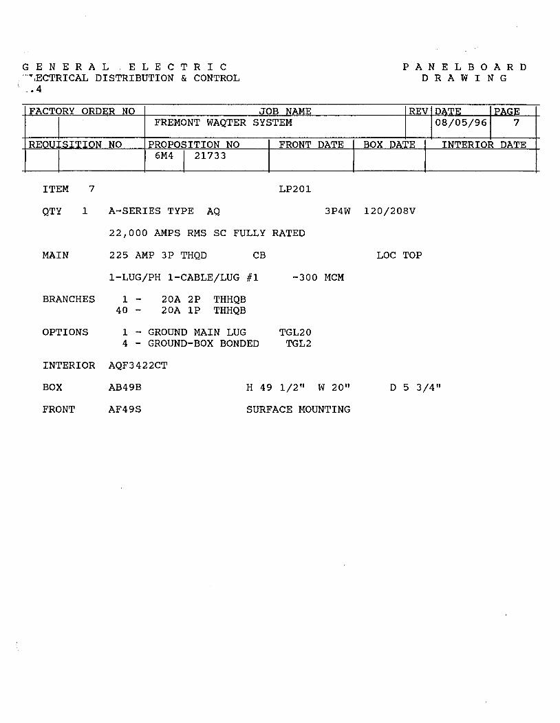
G E N E R A L E L E C T R I C ·-T,ECTRICAL DISTRIBUTION & CONTROL
: - • 4
FACTORY ORDER NO
I FREMONT WAQTER
REOUISITION NO PROPOSITION NO
I 6M4 I 21733
ITEM 7
QTY 1 A-SERIES TYPE AQ
JOB NAME SYSTEM
FRONT DATE
LP201
3P4W
22,000 AMPS RMS SC FULLY RATED
MAIN 225 AMP 3P THQD CB
1-LUG/PH 1-CABLE/LUG #1 -300 MCM
BRANCHES 1 - 20A 2P THHQB 40 - 20A lP THHQB
OPTIONS 1 - GROUND MAIN LUG TGL20 4 - GROUND-BOX BONDED TGL2
INTERIOR AQF3422CT
BOX AB49B H 49 1/2 11 W 20 11
FRONT AF49S SURFACE MOUNTING
BOX
P A N E L B 0 A R D D R A W I N G
REV DATE PAGE 08/05/96 7
DATE INTERIOR DATE
120/208V
LOC TOP
D 5 3/4 11

DEM • 1302
GE Pane/boards
Typical Type AL, Ail Pane/board (Replaces Tl'pes :\LTQ, NLAB)
OUTLINE DRAWINGS FOR 0-LINE BREAKERS (SEE BELOW FOR THQB STRAP DETAIL)
LINE TERMINAL ACCOMMODATES .093 THK. STAB.
THQB STRAP DETAIL
tS ,. NOTE: CAPTIVE LINE SIDE SCREW NOT SHOWN.
Orawmqs and data sub1ect ro change without notice
tt.,1 (1·,o•ll ..... ----z-==--~--.. .. '
1o--------..1·"4(1·ro.ci
Q-LINE BRANCH BREAKER TRIP RANGE IN AMPERES
1 pole
Ty ... Frame 1201240 VoH1
THOL 15·70 THOL·GF 15-30
Plug in THOL·HID 15-20 tor THHOL 15-70 Panel Type THHOl.-GF 15-30 AL 1HHOL·HID 15-20
TXOL 15-30
THOB 15-70 THOB·GF 15·30
Bott on THQB·HID 15·20 lor TH HOB 15·70 Panel Type THHOB·GF 15·30 AO THHOB·HID I •5·20
TXOB 15·30
NOTES:
2 pole 3 pole
1201240 VoHt 240 Voll1 240 VoHI
15·100 15·100 15·100 15-30 15·20
15-100 15·100 15·100
15-20
15·30
15·100 15·100 15·100 15-30 15·20
15·100 15·100 15·100
15·20
15·30

GE pane/boards
Typical Type AL, AO Pane/board (Replaces Types NLTQ. NL.AB)
INTERRUPTING RATINGs-MOLDED CASE CIRCUIT BREAKERS UL Uated lnterupllnQ RaUnQa
- C.H ClrcuH Bl"Mk.,. In Thouaand Ampa
Ratad Volta Fede<al
RMS Bymmetrlcal ac Volta Trip Spaca Conatructlon' · F,.,,,. R11199
("""'91 Pole ..
1!>-70 1 1201240
HO Frames THQS
1S·125 2 1201240 THOL 1!>-100 2, 3 240
1S·70 1 1201240
THHOL 15·12S 2 1201240 HHO Frames TH HOB 15·100 2 240
1S·100 3 240
TXOB 15·30 1, 2 1201240
XO Frames 15·30 3 240
TEY 15·100 1 480Yl277
Slllldard 15-100 2, 3 400Yl277
Frame• TOD 125·22S 2, 3 240
TJD 2so-400 2, 3 240
HI-Break• THOD 125·225 2, 3 240 Frames
TLB1 15-150 3 480 Hl·lntorruptmg TLB2 125-225 3 480 ClfCIJlt Breakera
TLB4 22S-400 3 480
THLC1 15-150 3 4eO Current Limiting THLC2 12!>-225 3 480 ClfCIJH Breokero
THLC4 225-400 3 480
© 3-pole d•lllCOa are not DC rated
MOLDED CASE CIRCUIT BREAKERS
Cln:u"B-
F.-
CulNM High llenUnl Hl·B-• Umlllnl lnlMU!ltlng
THOI. TXQL, THHOL
THOI. TXOL, THHOL
THQB TXOB, THHOB
TEY
TED4 TOD THOD
TJD
THLC1 TLB1
THLC2 TLB2
THLCI TLB4
<D TllrH-pole lug ueombly aurtable lot Hne ar lo<ld end
1~-'""'-~._~~~-+--J""'-~2
3 • 5 6
de c.a craaa W-c-3758 120
121 10
121
12b
14a 22
14a
14b
14b
15a
15b
250 13a
250 13b
12b
250© 14b
""
No. Polft ,.., cat. No.
Pc44I
1
2·3 1
1, 2, 3 Fixed ID Breaker Terminlll
1, 2, 3 1
2·3 1 TCAL12A
2·3 ·1 TCllL2S
2·3 1 TCllL43
3 1 TCALl2 TCAL12A TCAL15
3 1 TCllL27
3 1 TCLK43©
120/2.CO 2'40 27T 480Y!277
10
10
10
22
22
22
22
65
65
6S 14
6S 14
10
22
22
es so es so es so
200 150
200 1SO
200 1SO
Tonnl1181 Luo• (Cu-All
p., Lug
1
1
1
1
1
I
1
Wl....Cu-Al (Unlffa olherwiH notadl
~
(1!>-3011) 114·10 CU or ;t12·8 Ill (3S-OOll) 114-4 CU ot ;t12·3 AL (70-100) #6-1 cu. 14·1/0 Ill
(1S·20A) 114·#12 CU, #10-11112 AL (30-6011) 110-#6 CU, 18·14 Ill (70-10011) #4·#1 CU, 12·1/0 Ill
(70·110111 16-2t0 cu. 14-210 Ill
#1·300MCM
#6-eooMCM or 2·(210·250MCM)
(1S-l!Oi\, TCAL12) #14·#3 CU or #12·1111 AL (70·11011, TCllL12A) 16·210 CU or 1114·2!0 Ill (125-15011, TCllL1Sl 11·210 CU or 1/0·310 Ill
(125·225", TCllL27) #4·300MCM
3/0·SOOMCM ot 2 !310·250MCMI
i I MlllN BREllKE
I OR MAIN LUGS
,-llS REQUIRED I
J
10 3W 240·120 VAC 1~-J"J'---<~~l--~-1---'1'-~ 3~-FJ"'---l~--1-----1~0'~-5~-J""'-~l--~+-~+-.J 7~-J"f'---1>----1~--1~0'~-9~.....i"J'~+-~-+-~-4~.rr'--~ 10
11 12 13 14 15 16 17 18 ~ 20 ~ 22 ~ ~
DEM • 1303
PANELBOARD SHORT· CIRCUIT RATING:
The shor1-crrcu1t rating of a panelboard 1s llmtted ID the in1orrupt1ng rating of the low&St rated devlC9 or to 1he applicable UL listed sanes rating when proper main and branch device comblnattons are used. The short· circuit current available at the incoming line terrmnels ahoUfd not exceed this value.
When a panelt>oard ls applied within its short-arcurt ra!lng, bus bar bracing is adequate to withstand the lorces O)(erted bV the lel·through current
NOTES:
30 4W 208Yl120 VAC G304W 240·120 VAC Mid Tap Delta
30 3W 240 VllC Ungrounded Della (Do not connoCI neutral!
01 poll devtelil cannot be connected to Bl\ 2 pola dell1C8I connected ID BG mus1 be 240V rated

GE Pane/boards
Typical Type AL, All Pane/board (Replaces Types NLTQ, NLAB)
TYPICAL PANELBOARD
i I
1 i SPLIT
NEUTRAL
TYPICAL FRONT W/CONCEALED HINGES AND TRIM ADJUSTING SCREWS
CLEAR LEXAN
DIRECTORY HOLDER
0 i I: \!. ___ : COMBINATION
CATCH AND LOCK
DEM • 1304
TYPICAL BOX
BOX WIDTH llNSIOEI ~
~
~ i I I 1 ' I \ ! a, MAIN LUGS@ I
Surface mounting - add 1/4" to 1ns1de box d1mens10ns Flush moun11ng - add 1112" to inside bOX d1mens1ons
f--@ _ _____,• ti Front View with tnm removed
MINIMUM WIRING SPACE-FROM END OF LUG TO WALL OF BOX IN INCHES
!Uln L1190 Only !Min Circuit BrMl<lf
To End Woll P-lUQ N<1Utra1Luv
!Uln llallllfl Tolkle In~ PNIM - Fromo
Moumlno Woll To End
lU9 LUQ Type (20" Wide Woll Box)
rHOB, 12SA MP1 THHOB Horizontal &'n
LL.IQ 6 e TEY Horizontal s 6 IOOA MP1
TEL Bl<t THLC1
Vlflical e TOO,
Horiz s•n THOO 225 12 12 12
Ttll2, Vert 12 THLC2 TJO
400 15 11(]) TLB4 Vert 15 11(]) THLC4
600 15 11©
©To Siclo Wall
WIRING SPACE-BRANCH CIRCUIT BREAKERS
Broncfl No. WlrlnQ Space to Side Woll
Circuit Fr- of ~ p- 20"W
Box
<Hine BreakorW rHOl.. THHOl.. (~ TXOl.. TXOB © 6'n"
Mounltngl THQB, THHOB,
Sub---Single Branch TOD, THOD 2. 3 51n IAounC1ng
(8 poiel maxi ©S. ''O" Une Br111kor Tnp AanQt "'ampero table on back page
KNOCKOUT DIAGRAM (20" Wide Box)
...... :i-.· KO 1' 11/.' KO 1'n'•2'"•21n'•3"•3'n" KO (21) PLACES x 1'
Nole: Blan!< end wall also available
END VIEW
BOX OEP™ 5.61 STD (INSIOE) 7.81 DEEP
SPECIFICATIONS
• A·Senes p.anelboards an<I branch breakers meet or e1eceeo 1he lollowmg standards and specliicahons: · -ULSO. calltneOI & l>Oxes -NEMA PB·1, panell>Oards -UL67. pane1b01rds -US Federal Spoc. w.po115b PanelbOards -Ul489. circuit brHktt -US Federal Spec. W·C375b Gen circu11 breakers -NEMA AB·1. circu11 breakers
1 ~al gages tn 1ccordance w11h UL and NEMA standards 1 Panett>oa101 ate ol dead tront cons1ruct1on.
Soxn
• Bo•es .tre of ga1Vannea1 G20 stetl. • Endv.fa11s furnished with KO s as slandard. Blan!< ondwaus avauao1e when spec1f1ed e Boles turn1she<I w1tn pt0v1s10ns tor ground bus as standard
Fronts
• Froots hni~ 1n ANS1·61 grey polyester powder coal paint • Fronts equipped with corrosion res1st1n1 Valox • com1Jin1too ca1cn and lock door latch
Doors OYef .a inches t\~n l)f'Ovtded with 2 lalches • Fronts equ!P()ed wllh conceated htnges and tnm a<tiushnq screws • OiredafY flO'der ol clear, 1mpad u1s1stant Le11an' permanenuy mounled to door
- __ _. -'-•- ••• J..: ••• ... • A. ....... o.1i1l.11ut 1111t;,,..,
Pan.lo
• Panelboard Interiors are factory assembled on rigid steel frames. • Soldefress. anti-tum main lugs suitable for coppef' or aluminum wire are lront removatlle
and branch straps will be silver plated copper lully rated at 100 ampents. • Main bus will be atum1num with coppet oranctl connections uniess othel'W1se spec1lled. • Main disconnect dtMce 1s 1dent1hed when supplted, and numbef'S ire provided fOf
branch c11cu1ts. • lnterKM base 1ssemt>11es will be ol No~!' and provide breaker mounung and oos bar
insulation • Unle!t!l 01t1erw1se speclftcd. branch c1rcu1ts will be arranqed as lo11ows
1. 3 pole devices and spec1l1ed spaces w•ll be placed c1oses1 to lhe mam in descen'1111g ordet' of ampere rating. The tugher rated device will be on the fight
2. 2 pole devices are mounted next, also 1n descending order ol amp.Jc11y. lollowed bV lhe t pole devtces.
3. Umdent1hed spaces w111 be mslalled al the end opposite the main
4. Double branched devices will have a 101a1 combined ampac11y of 1ao aml)efes

GE Pane/boards
A Series® Pane/boards- Type AQ 240\'ac Bolt-On Factorv Assembled Three~Phase, 3-Wire/4-Wire
DEM • 1307
SERIES CONNECTED RATINGS FOR MAIN LUG PANELS I
Some or all of the Panelboards on this project are Main Lug Only panels which call for Series connected ratings with an upstream device. Our submittals on these panels are shown as fully rated panels based on the stand-alone interrupting capacity of the branch devices. The attached charts indicate what the appropriate series rating will be when the panelboard is installed in a system with any of the indicated main devices installed upstream.
SUITABLE FOR USE AS SERVICE EQUIPMENT WHEN EQUIPPED WITH A MAIN OVERCURRENT DEVICE OR WHEN NOT MORE THAN SIX SERVICE DISCONNECTING MEANS ARE PROVIDED AND PANEL rs USED AS PERMITIED BY ARTICLE 384 OF THE NATIONAL ELECTRIC CODE.
USE TYPE AF FRONTS WITH AB BOXES. Q PANEL. USE ONLY WITH GE THQB, THHQB. TXOB TYPE CIRCUIT BREAKERS.
IF BREAKER TRIPS TO RESTORE POWER HANDLE WILL BE IN 1. MOVE HANDLE TO OFF POSITION
INTERMEDIATE POSITION. 2. THEN MOVE HANDLE TO ON POSITION.
SHORT CIRCUIT CURRENT RATING THE SHOAT CIRCUIT CURRENT RATING OF THIS PANELBOARD IS EQUAL TO THE LOWEST CURRENT INTERRUPTING RATING OF ANY DEVICE INSTALLED EXCEPT AS NOTED IN THE SERIES RATINGS LISTED BELOW. THE MAXIMUM RMS SYMMETRICAL AMPERE RATING IS:
I 200,000 AMPS@ 240V I WITH AN INTEGRAL OR REMOTE MAIN BREAKER LISTED BELOW
DEVICES TO BE INSTALLED OR REPLACEMENT UNITS SHALL BE FROM THE SAME MANUFACTURER OF THE SAME TYPE AND HAVE EQUAL OR GREATER INTERRUPTING CAPACITY.
MAX. VOLTS MAIN tc. BRANCH AC
TH HOB 22,000 THQB, THQBGF, THOD, TJD TOD
FUTSE 42,000 THOB, THOBGF 1 P (30A MAX) 2P, 3P
600i\ MAX 65,000 THHOB, THHQBGF, 1 P, 2P
TEY 65,000 240 TLB4 85,000
SEL. SFL THOB, THQBGF
TED4, TOD, TFJ, TFK TEL. TFL 100,000 SEO. SFH THLC4
THLC1, THLC2 200,000
NP266881-A
n .. ........_ •1111 "•'• e.11Jtilu~t tn Mana• without natita
Service Information: 3-ph, 3-w; 3-ph, 4-w; 240Vac max.
Bolt-On Branch Breakers: 15-100 amps, 1, 2, 3-poles Types THQB, THHQB, TXQB.
NOTES:
Service Entrance Equipment:
Service entrance rating is standard on all main breaker panels and 12 and 18 circuit, 225 amp max. MLO devices. No need to specify on order.
Mains: 100A-THQB, THHQB, TEY,
TEL, THLC1 225A-TOD, THQD, TFL,
THLC2 400A-TJD, TLB4, THLC4 600A-TJ4V 125-600 amp main lug

GE Pane/boards
A Series® Pane/boards- Type AO 240Vac Bolt-On Factorv Assembled Single'.Phase, 3-Wire
DEM • 1308
I SERIES CONNECTED RATINGS FOR MAIN LUG PANELS
Some or all of the Panelboards on this project are Main Lug Only panels which call for Series connected ratings with an upstream device. Our submittals on these panels are shown as fully rated panels based on the stand-alone interrupting capacity of the branch devices. The attached charts indicate what the appropriate series rating will be when the panelboard is installed in a system with any of the indicated main devices installed upstream.
SUITABLE FOR USE AS SERVICE EQUIPMENT WHEN EQUIPPED WITH A MAIN OVEACUARENT DEVICE OR WHEN NOT MORE THAN SIX SERVICE DISCONNECTING MEANS ARE PROVIDED AND PANEL IS USED AS PERMIITEO BY ARTICLE 384 OF THE NATIONAL ELECTRIC CODE.
USE TYPE AF FRONTS WITH AB BOXES. Q PANEL, USE ONLY WITH GE THOB, THHQB. TXQB TYPE CIRCUIT BREAKERS.
IF BREAKER TRIPS TO RESTORE POWER HANDLE WILL BE IN 1. MOVE HANDLE TO OFF POSITION
INTERMEDIATE POSITION. 2. THEN MOVE HANDLE TO ON POSITION.
SHORT CIRCUIT CURRENT RATING THE SHOAT CIRCUIT CURRENT RATING OF THIS PANELBOARD IS EQUAL TO THE LOWEST CURRENT INTERRUPTING RATING OF ANY DEVICE INSTALLED EXCEPT AS NOTED IN THE SERIES RATINGS LISTED BELOW. THE MAXIMUM RMS SYMMETRICAL AMPERE RATING IS:
I 200,000 AMPS@ 240V I WITH AN INTEGRAL OR REMOTE MAIN BREAKER LISTED BELOW
DEVICES TO BE INSTALLED OR REPLACEMENT UNITS SHALL BE FROM THE SAME MANUFACTURER OF THE SAME TYPE AND HAVE EQUAL OR GREATER INTERRUPTING CAPACITY.
MAX. VOLTS MAIN l.C. BRANCH AC
TH HOB 22,000 THOB, THQBGF, THOD. TJD TOD
T 42,000 THOB, THOBGF FUSE 1 P (30A MAX) 2P, 3P liOOA MAX 65,000 THHOB, THHQBGF, IP, 2P
TEY 65,000 240 TL84 85,000
SEL. SFL THOB, THQBGF
TE04, TOD, TFJ, TFK TEL. TFL 100,000 SED,SFH THLC4
THLC1, THLC2 200,000
NP266881-A
Drawings and data subi11c1 ta chang11 without notice
Service Information: 3-ph, 3-w 240/120 volts ac max.
Bolt-On Branch Breakers: 15-100 amps, 1, 2, 3-poles Types THQB*, THHQB*, TXQB.
NOTES:
Service Entrance Equipment:
Service entrance rating is standard on all 12 circuit panels through 225A max. MLO and on all main breakers. No need to specify on order.
Mains: 100A-THOB, THHOB, TEY,
TEL, THLC1 225A-TQD, THQD, TFL,
THLC2 400A-TJD, TLB~ THLC4 600A-TJ4V 125-600 amp main lug

G E N E R A L E L E C T R I C ELECTRICAL DISTRIBUTION & CONTROL II ,4
FACTORY ORDER NO
I FREMONT WAQTER
REQUISITION NO PROPOSITION NO
I 6M4 I 21733
ITEM 16
QTY 1 A-SERIES TYPE AQ
JOB NAME SYSTEM
FRONT DATE
LP301
3P4W
22,000 AMPS RMS SC FULLY RATED
MAIN 225 AMP 3P THQD CB
1-LUG/PH 1-CABLE/LUG #1 -300 MCM
BRANCHES 1 - 50A 2P THHQB 1 - 30A 2P THHQB
38 - 20A lP THHQB
OPTIONS 1 - GROUND MAIN LUG TGL20 4 - GROUND-BOX BONDED TGL2
INTERIOR AQF3422CT
BOX AB49B H 49 1/2 11 W 20 11
FRONT AF49S SURFACE MOUNTING
BOX
P A N E L B 0 A R D DRAWING
REV DATE PAGE 08/05/96 16
DATE INTERIOR DATE
120/208V
LOC TOP
D 5 3/4"

DEM • 1040
GE Specialty Transformers
Integral Transformer and Distribution Center Servicenter™ Mini-Unit Substations
Description The Servicenter mini-unit substation from GE brings proven rugged, encapsulated transformer benefits together with GE advanced breaker techniques to provide one, highly reliable power supply package. This easily installed and serviceable unit incorporates a Type OMS transformer, a primary main circuit breaker, a secondary main circuit breaker, and a load-center-design breaker panel. Since these components don't have to be installed and interconnected separately, the contractor or user can reduce installation time and costs. Because of the single-unit concept, only one, handy Servicenter need be mounted. Available in single-phase, 5 through 25 kVA, 600-volt class ratings, the GE Servicenter is a convenient, economical way to meet your
Single-phase
kVA Item Catalog Qty.
light industrial and temporary power requirements.
The transformer-The Servicenter utilizes GE transformer design which has twenty years of field proven experience behind it and a long track record for assuring consistent, reliable performance. Type OMS transformers employ a 180°C UL recognized insulation system with a 115°C rise.
The panel-The panel assembly includes the rugged GE Power Mark Plus™ circuit breaker load center interior, a Type TED primary main circuit breaker, and a Type THQL secondary main circuit breaker on units 5 through 15 kVA. Type TOD secondary main circuit breakers are used on the 25 kVA model. The load center will accept one- or two-pole common trip circuit breakers and ground fault breakers. All
480 Valls Primary, Secondary 120/240 Valls. 60 Hz(i)
Maximum Branch Spaces
t• THOL 'h" THQP Total
Servicenters come equipped with the properly sized primary main and secondary main circuit breakers installed and prewired. Branch breakers are not included.
Application The Servicenter can be used wherever 480-volt power is available and 120- or 240-volt branch circuits are required. The unit can be used in such applications as vending machine areas, and construction laboratory test areas, where temporary power is required, or where future expansion of branch circuits is planned.
UL Listed The Servicenter carries a UL Label for unit substations, and is suitable for both indoor and outdoor installation.
NEC Requirements The Servicenter conforms with Article 450-3 of the 1987 National Electric Code.
Breaker Ratings
No. Number 1-pole Primary Secondary 1-pole 2-pole 1-pole 2-pole Main Main Spaces
5 I d 9T21S1050 6 3 12 4 12 25A JOA
7.5 9T21S1070 6 3 12 4 12 35A 40A
10 9T21S 1100 8 4 16 6 16 50A 50A 15 9T21S1150 12 6 24 10 24 60A 70A 25 9T21S 1250 20 10 8 2 24 IOOA 150A
600 Valls Primary, Secondary 120/240 Valls, 60 Hz(i)
5 9T21S 1052 6 3 12 4 12 20A JOA 7.5 9T21S1072 6 3 12 4 12 JOA 40A
10 9T21S 1102 8 4 16 6 16 40A 50A 15 9T21S1152 12 6 24 10 24 60A 70A
0(2) 5% below normal taps.
Dimensions Approximate D1mens1ons tlnchesl
kVA Calalog Number A Max. B Max. C Max. ,_\. Heoghl Wodlh Depth D E F G
5 9T21S1050,1052 32'/• IO'I• 11 91/o 8'/2 6 8"/06 75 9T21S1070, 1072 33'/o 12 12'/• 11 91
/• 6'1•• 9'h 10 9T21S 1100, 1102 34 1/o 12'/• 12'/2 11'/• 10 7'h 91'/t6
15 9T21S1150,1152 39 14 'I• 14 'I• 13'/• 12 71/06 12 1/•
25 9T21S1250 44 16'/e 15'/2 15'/e 13'/• 9 13'/8
NOTES:
Drawings ind data subi1ct ta change without no/Ice
H
2'1• 2"/06 2'/8 3'/• 3'1•
r I
; EJ I I I
: ~I I I I I L--------1
Approx. WI. (Lbs.)
Net , Shop
123 133 161 171 198 208 280 290 418 430

' a L1ne Plug-in Circuit Breakers THO P, TOL. THCL, THHOL, TXOL CSC13 91 I
10-100 AMPER::s. 120/240 and 240 Volts AC Page I of 1
Item Qty Catalog Number Amps Volts Poles Modlf lcatlons
;). z THQL /I diO ao l~O (
Circuit Breaker Outline
f[]wi-• l ~
"o 'i
I Maximum UL L•steo 1n1erruc11no l'la11nos-
Otmensions c;.c .. t rms Symmemcat Amos i1n fhoiisanasl 9,,,..., ~moere NI). llo4tage Aa11nq 11n.1 Sid.
lrpe Rat1nq Po1t} ac Vo41aQe de vonaoe Pack
ac de llO 120/240 240 277 480 600 125 I z;o H w 0 ... e c E
THOP© ,____!._. I
'la 100 15.50 120/240 - - 10 - - - - - - 1'1>: - 2'1a - - - -'Z I 50
,____!._. -
I I 50
120/240 50 - -TOL 10 t - - 50 - - - - - 1'/:u 2 2\lt - - - - 25 -3 240 - J 15
15-70 I - 1 50 120/240 10 - -Tt-iOI.@ 15·125 2 - - - - - - - 1'/n 2 2\lt - - - - 25
10 -15·100 3 240 - J 15
15°70 I -
I 1 50
120/240 22 - -THHOI.@ 15.125 ~ - - - - - - - 3'h: 2 21\ - - - - 25
I 22 ,._ 15·100 ) 240 - J 15
'--'-- I I 50 120/240 65 ,._
lXOI.~ 15·30 7. - - - - - - - I -3•1:: 2 2'11 - - - - 25 -~ 240 - 65 J 15
(!) Not UL Listed. @ UL Lisled as HACR. 60 amps max.
Job Name P. o. Number G.E. ReQ. Numoer

:
CSC6 12/91
Page t or 1
Item Qty Catalog Numoer Amos Volts Poles Modtrtcattons
3 ~ TED/34040WL
C1:::utt BreaKer Outline
40 4'8'0
Lug Wire Range
Copper Aluminum Lugs 15-30A -#14-8
.3
35-60 A - #14-3 Cu, .ir12-1 Al 70-90 A - .ir 6-2/0 Cu,#4-2/0 Al I 00-150 - #2-3/0 Cu, .ir 1-3/0 Al
Ratings not appl1caole to Molded case Switcnes.
: Maiumum Ul l.JSleG 1111~•"1011119 Aa11ngs-
C.rcurt i rms Svmmetnea1 ~mos un lhousanas1 Breaker ~mClefe N<>· ·1041a941 Ra11ng Ty~
Rating PolH I ac vatiaoe ocvan.qe ac oc •ZO 120/240 240 (':""" I J80 600 '25 250 H
I '.20 :25 •O - 5 -10.100 -TEB© 2 I ;50 - - 5 6¥11 0 - - - -- 240 10
3 I - - -10-100 1 ! '77.480 •ZS - •: 10 10 0 - -
TEO© 61/11 15-100 •80 z~o - - 10 18 - 14 14 - -10-150 ' I 600 ;oo 10@
15-30 I 277 125 - ~~ - - 20© -15-100 :ao ::o - - 65
I 20© 6'1·• THEO© - -1s.100 - 65 - 25 18 -3 ' :80.600 - -
110-150 •2
TEl I •5-150 . ~ - - 100 •OO - I ,;5 :s - - .,., .. 0 10 amp no1 UL Lisleo. 0 UL L1s1ed at 10.000 amps. @ UL Listed w•lh poles 1n . series lor ungrounded . battery apptrcattons •
Job Name P. o. Numoer
w
11' 1--
2'1• -4',11
I'll -21/• -•'.41 , .. ,. '-
•'.II
.....
Breaker Suffix
Blank - Load Lugs Only WL -L tne & Load Lugs XL - No Lugs X2 - Line Lugs Only
o.- APlllOI. (In.I ShtO WI.I
Sid. Pldt 0 A B r. e
26111/24 -3 .... 2"/14 2""' ·'1': 24 111/12 -.,,,. 28111/8
211111/24 3'1t 2""' 2""" - -. .,: 24111112 ,.,.,,
2811118
26111/24 - Z411>112 3'/I 2""' 2'" .... ''1-t :,,:
28 111/8
l· 'h: 2 .. /11 2"1•: ''/·• ,.. 3'/ lb/I
© All UL Listed as HACR' type except 10 amp.
G.E. ReQ. Numoer

•• GE Circuit Breaker Enclosures
Circuit Breaker· Enclosures 70-1200 Amperes 240-600 Volts ac, 125-250 Volts de (except Spectra RMS 1 M
breakers which have ac ratings only)
UL Listed. Suitable for use as service
equipment. 60°C/75°C conductor ratings. Short circuit ratings
[Iff 0
DEM • 0301
0
are equal to the rating of the installed breaker.
Type 1, Indoor surface or
flush mounting
Type 3R outdoor, raintlght
Types 12K and 12 rotary handle Integral with breaker
Types 4/4X stainless steel,
watertight, dust tight
Max. Type I© Breaker llem Type Amp Poles No. Oiy. tndoor
Rating Cat No.
TOLIOF 70 1,2,3 TOLIOS
THOL. TOL IOOF THQL-FG. 100 1,2,J
TXOL TOL IOOS
1250 1.2 TPL212C
rHOC, rOCIOOF TH HOC, 100 1,2,3
TXOC, THOE rOCIOOS
TEB, 100 2.J TEIOOF TEO, THEO TEIOOS
SE150 100 2.3 TEIOOF TEIOOS
TEO, THEO 150 2.3 TE150F TE150S
SE150 150 2.3 TE150F TEI SOS
TB1 100 3 -2 -
TOO, THOD 225 2,3
T00225F T00225S
TFJ, TFL 225 2.3
TF225F TFK, THFK TF225S
SF250 250@ 2.3 TF225F TF225S
!JO. TJJ ~o 2.3 TJ400F
TJK, THJK TJ400S
TB4 400 2,3 -TJK, THJK 600 2.3
TJ600F rJ600S
TJ4V, TJ4V600F THJ4V, TJL4V
600 3 TJ4V600S
TJH 600 3 TJ9V600F TJL TJ9V600S
SG400 400 2,3 SG400F SG400S
SG&OO 600 2,3 SG600F
SG600S
TB6 600 3 -
TBS 800 3 -rKMA,
1200 2.3 rK4V1200F
THKMA TK4V1200S
rKL4V. TK4V1200F 1200 3 rK4V fK4V1200S
rKH, TKL 1200 J -
SK1200 1200 2.3 rK4V1200F rK4Vl200S
©2• F-flush; S-surface.
® 70-250 amp devices have removable closing cap. Larger ampere devices require field cut openings. Order hubs separately.
@ D Type 12K wilh KO's. J = Type 12 without KO's.
Drawings and data subject ta change without notice
Type 3R@ Type 12@ llem Hem 01l-l1ght/ No. Oly. Ou I door No Qty. Oust-11gn1 Cal. No. Cat No
TOLIOR
TOLIOOR -TPL212R
TOC100R -TE100R TEIOOO&
TEIOOJ •
TE100R SEIOOO SE100J
TE150R -TE150A -
- TB100J
T00225NR© -
TOD225R
TF225R TF2250 TF225J
TF225R SF2500 SF250J
TJ400R TJ4000 TJ400J
- TB400J
TJ600R TJ600J
TJ4V600R TJ4V600J
TJ9V600A TJ9V600J
SG400R SG4000 SG400J
SG600R SG600J
- TBBOOJ
- TBBOOJ
TK4V1200R TK 1200.J
TK4V1200R TK4V1200J
-K9V1200J9
rK4V1200R SK1200J
~: Suitable only for 2-pole breaker. For three-pole breaker only. Neutral not included; if required, order Catalog Number TNl100.
~.' Do not use with TJ4V or THJ4V.
Do not use with TK4V or THK4V. For 250 amp rating, use copper cable only.
T~pe 414X Neutral 11em 1amtos item No. Qty Steel No 01y. Catalog
Cal. No Number
- included
- Included
+ d TE100CS@ Included
SE100CS@ lncludod
- lncl!Jde<j
- included
- Included
- Included
TF225CS TNIA225
SF250CS TNIA225
TJ400CS TNIA400
- TNIA400
TJ600CS
TJ4V600CS TNIMOO©
TNIA600
-SG400CS TNIA400
- TNIA600
TNIA400 - TNIA600
TNIA400 - TNIA600 TNIABOO
-TNIA400~ TNIA600 I
- TNIABOO TNIAl200 rNIAC1200
-TNIA400 TNIA600 - TNIA800 TNIA1200 TNIAC1200
@ Suitable for parallel 250 MGM maximum. If larger cable is applied. use 600-amp enclosure.
~I Nol UL Listed. @ Not suitable for 100% rated
breakers.
Neutral Current Item for Ground Item Trans. tor No. Qty. Fault No. Qly. Gd. Faull
Cat. No. Cal. No.
- -
- -
- ---- -- -
- -
- -- -- -- -- -
TSRG201 TSRG202
TNIA400VO TSRG203
TNIA600VO TSRG204 TSAG205 TSA0206
TSRG2DI
TNIA400VG TSRG202 TSRG203 TSRG204
TNIA600VG TSAG205 TSAG2D6
- -- -- -
-TNIABOOG -TNIA1200G TSKG40B
TSKG410
TSKG412
TNIASOOG TSK040B TSK0410 TNIAl200G TSKG412
NOTES:

DEM • 0303
GE Circuit Breaker Enclosures
Dimensions
Eal Fig. 1 Suffix F (flush)
Suffix S (surface)
A
Fig 2. Outdoor Enclosure
Fig. 3. Stainless Steel
e 9
l:!--FE ......___OO d Fig. 4. Suffix D (with KO's)
Suffix J (without KO's)
Drawings 11nd data subiect 10 change without notice
Type 1 See Fig. 1
Catalog Number A© Dlmenllon1 In Inches
B© c<D D
TE100F,S 17 - 711• 5'/2 TE150F.S 26rlt• 8r/e 8r/a 6'/t• TF225F,S 291/a 8r/a 8'/a 6'/t• SG400F 31'1a - 155/32 7'/t• SG400S 30'/16 - 141/a ?'It• TJ400F.S0 271/16 151/16 151/16 71/a SG600F 44 - 183/t• 9 SG600S 4231. - 171/a 9 TJ4V600F,S 46'/a 173/16 173/16 91/16 TJ600F.S 46'/a 173/1• 173/16 91/16 TJ9V600F.S 46'/a 173/16 173/16 91/16 TK4V1200F.S 481/a 21 15/16 21 15/16 9•/16 TPL212C 9r;,. 71/2 7112 35/10 TQC100F.S 151/• - 6'/a 4'1• TOD225F.S 26r/t• 81/a 81/e 63/16 TOL70F.S 11 1/6 - 5'/• 4 TOL 100F.S 151/• - 61
/• 4"1•
Type 3R See Fig. 2
Dlmenalon1 In lnche1 Catalog Number
A B c D
TE100R 181/a 71/• 7'/2 5"/16 TE150R 271/16 101/• 10 6'/• TF225R 30 13/16 10'/• 10 7 SG400A 3013/t• 14 15/16 14'/a 91/a SG600A 43 18'/e 181/16 813/16 TJ400A@ 275/16 151/• 15 11/16 8 11/16 TJ4V600R 463/1• 181/16 18 1/IO 8% TJ600R 463/te 181/16 181/18 85/a TJ9V600A 463/te 181/t• 181/18 8% TK4V1200A 47'1• 233/a 22•;,. gr;,. TPL212A gr;,. 7112 7'/2 3'/!• TOC100R 153
/• 7r;. 7112 5"/!• TOD225NR 261'11• 7"/!• 7% 51;. TOD225R 26'/a 1Ql/4 10 61/• TOL70R/ 100R 17 7'1• 6'/a 6
Type 4/4X See Fig. 3
Catalog Number A
SE100CS 191/• TE100CS 19'/• TF225CS 31'/• SF250CS 361/> TJ400CS@ 291/• TJ4V600CS 461/• SG400CS 32 TJ600CS 461/•
Type 12 and 12K See Fig. 4
Catalog Number A B
TB100J 23'/a 21% TB400J 481/!e 4615/!s TB800J 565/to 54 13/te SE100D,J 19'/• 175/16 TE100D 19'/• 17'/16 TE100J 191/• 17'/10 SF250D.J 36V• 35% TF225D 31'/• 301/• TF225J 31'/• 301/• SG400~ 31 3/B 301/> TJ400D ' 29'/" 27"Y1• TJ400J i 29'/" 27 1:Y1• TJ4V600J 48 1/IO 461'/1• SG600J 44 1/8 44
Dlmen1ion1 In lnche1
B c D
181/2 81/2 7 171/• B'h 7 30 101/16 9'/!•
35'/a 103/• 715/16
27'12 161/• 9'/!• 451/2 191/e 91/16 31'/• 141/e 95/16
45'/• 19'/• 9'/!•
Dlmen1iona In lnchn
c D E
9 8 5'/• 17'/• t73/16 931.
22 11/16 22 10'/t• 9 8 5'/• 9 8 5'1• 9 8 5'/•
9"/t• 9'/I• 7''1" 9'1> 9 7•;,. 9'1> 9 7"1"
16'/10 15 11/16 711• 14'/• 131/16 7'/8 14 1/• t3'/I• 711• 17'/• t 71/1• 9'1• t8 t 71/8 9'•/I•
T J600J 48 1/16 46 1!1/16 17 1/• t 71/16 9'/• TJ9V600J 48 1/i• 46 15/16 17-'I• t 71/16 9'/• SK1200J 56'/10 551/16 22 11/16 22 101/16 TK4V1200J 56'/10 54 13/16 22 11/1• 22 101/16 TK9V1200J 56'/ie 54 13/16 22 11/16 22 101/16 TK 1200J 56'/I• 54 13/16 22 11/1• 22 101/16
Outline
E Drawing Number
43/• 139C5651 Sh 1 51/2 139C5497 Sh 1 5'/2 139C5497 Sh 2 6% 208C2891 Sh 1 6% 208C2891 Sh 1 6r/16 139C5497 Sh 3 83/• 208C2891 Sh 2 83/a 208C2891 Sh 2 83/a 139C5497 Sh 4 B'lo 139C5497 Sh 4 8'1o 139C5497 Sh 4
811/16 139C5497 Sh 5 3'/t• -
4 139C5651 Sh 1 5'/2 139C5497 Sh 1 31/• 139C5651 Sh 1 4 139C5651 Sh 1
Oulllne
E Drawing Number
5'/a 139C5652 Sh 1 51;, 139C5498 Sh 1 61/• 139C5498 Sh 2 8 208C2837 Sh 1
711/16 208C2838 Sh 1 8 139C5498 Sh 4
7'/a 139C5519 Sh 1 7% 139C5519 Sh 1 7% 139C5519 Sh 1 85/ie 139C5520 Sh 1 3'/!• -5'/a 139C5652 Sh 1 41/16 139C5498 Sh 3 51/2 139C5498 Sh 1 5 139C5652 Sh 1
Outline E Drawing Number
5 139C5654 Sh 1 5 139C5654 Sh 1
71;. 139C5496 Sh 1 6'/t• 208C2887 Sh 1 71/• 139C5496 Sh 2 71/e 139C5496 Sh 3 7'/t• 208C2888 Sh 1 71/• 139C5496 Sh 3
Outline
F Drawing Number
4'/8 139C5653 Sh 1 8'/8 139C5682 Sh 5
811/16 139C5682 Sh 6 41/e 139C5653 Sh 1 411• 139C5653 Sh 1 411• 139C5653 Sh 1 6'12 208C2884 Sh 1, Sh 2 61/1• 139C5682 Sh 1 61/16 139C5682 Sh 2 69/16 208C2885 Sh 1, Sh 2 61/16 t 39C5682 Sh 3 6'/I• 139C5682 Sh 4 8'/e t 39C5682 Sh 5 8 1/• 208C2886 Sh 2 811• 139C5682 Sh 5 8 1/e 139C5682 Sh 5
911/16 139C5682 Sh 5 8 11/16 139C5682 Sh 6 911;,6 139C5682 Sh 6 811/,. 139C5682 Sh 6
CD Flush front extends approximately %-inch beyond each side.
® Suitable for parallel 250MCM maximum. If larger cable is applied, use 600-amp enclosure.
NOTES:

DEM • 1005
GE Specialty Transformers
Dry Type General Purpose Transformers Three-phase
480 Valls Della Promarv Seconoary 208Y / 120Volts
480 Valls Oe11a Pnmarv Seconoary 240 Vons Della
: ! •em f -e~z J i~o I ::::y I Calalog
Number 0 Wmng
: JPS Diagram No Hertz IDEM-10071 I
3·15 kVA lndoor/Outdoo~ Type ML ' ' 2 I .:o ~9T21A4001 I N 10 60
I 60 9T21A4004 2 12 60 €0 I I • 9T21A4007 4 13 -
.; I .:o ~I IQ 60 ' 3T21A4002 i '30 i 1 9T21A4005 2 12 60
I 60 I i 9T21A4008 4 13 -
J 60 I I '1T21A4003 N 10 60 I 60 I i 9T21A006 2 12 60
I 60 I 1 9T21A4009 4 13 -• 0 I 60 I ' 9T21A9301 N 10 60
I r.o I I 3T2 IA9302 2 12 60 ' I I 9T21A9303 I .:o 4 I) -
•tern No. Cly. Catalog
Number
UL Listed 9T21A4010 9T21A4013
-9T2 IA4011 9T21A4014
-9T21A4012 9T21A4015
-9T21A9304 9T2 IA9305
-
15·1500 kVA, Indoor, Type OL UL Listed For Outdoor NEMA 3R Enclosure add suffix G62 to Catalog Number
., oJ~ 12 3T23B3871 ! iiO 9T23B388 I : ij Ii)
.;G
I i l!23B3872 ti 18 60 9T2383882 .;J b
45 60 i 9T23B3873 6 18 60 9T23B3883 50 60 1 9T23B3864 6 18 - -:s 60 I 3T23B3874 6 18 60 9T2383884
112 5 60 I 9T2383875 6 18 60 9T2383885 150 60 I 9T2383876 6 18 60 9T2383886 225 60 9T23B3877 6 18 60 9T2383887 300 60 9T2383878 6 18 60 9T2383888 400 60 I 9T2383866 6 18 - -500 60 9T2383879 6 18 60 9T2383889 750 60 9T2383867 0 21 - -
1000@ 60 9T2383868 0 21 - -1500@ 60 Consul!
Factory
15-300 kVA, Indoor, Copper-Winding, Type QL UL Listed For Outdoor NEMA 3R Enclosure add suffix G62 to Catalog Number
15 I 60 9T2309071 6 18 60 9T2309881 30
I
60 9T2309872 6 18 60 9T2309882 4~ 60 9T2309873 6 18 60 9T2309883 '00 60 9T2309864 6 18 - --~ i;o 9T2309874 6 19 60 9T2309884
i 12 ~
I '30 9T2309875 6 !B 60 9T2309885
:50 60 9T2309876 6 18 60 9T2309886 225 <iO 9T2309877 6 18 60 9T2309887 300 .;o 9T230987B 6 18 60 9T2309888
© W1ronq I :em Taps Diagram No. Hel'1Z I 'lo
iDEM-1007)
CSA Certified N 15 60 4 16 -- - -N 15 60 4 16 -- - -N 15 60 4 16 -- - -N 15 60 4 16 -- - -
CSA Certified
6 :9 60 I
6 19 60 6 19 60 - - -6 19 60 6 19 60 6 19 60 6 19 60 6 19 60
- - -6 19 60
- - -- - -
CSA Certified
6 19 -6 19 -6 19 -- 19 -6 19 -6 19 -6 !9 -6 19 -6 19 -
208 Vons Della Pnmary Seconoary 408Y /277Volls
240 Vons Della Pnmarv Secondary 208Y / 120 Valls Della
kVA
r<ertz 'lem 'lo. Qty. Calalog
Number 0 Wiring
r Diagram No aps iDEM- to07l
9, 15 kVA, Indoor/Outdoor, Type ML
Henz !!em No Qty Catalog
numoer 0 Wiring
Taps Diagram No (DEM-1007)
I Hertz I :em I •10
'
600 Volts De11a Primary S econaarv 208 Y / 120 Valls
Qly Catalog Numoer
9T21A4019
--
9T21A4020
--
9T21A4021
--
9T21A9307
--
3T23B3891 9T23B3892 9T23B3893
-9T2383894 9T2383895 9T2383896 9T2383897 9T2383898
----
---------
N
--2
--2 --2 --
6 6 6
-6 6 6 6 6
----
---------
480 Volts Della Pnmary Secondary 4BOY 1277 Vons
12
--12
--12
--12
--
18 18 18 -18 18 18 18 18
----
---------
Oly Catalog Numoer
0 Wiring Taps Diagram No
(DEM·1007l
·~
r.o .;o
,__ ___ 9!2183101
9T2183102 60 60
f---+---i 9T2183103 9T2183104
13 13
60 60
t--1---1 9T2183105 9T2183106
13 13
15·1500 kVA, Indoor, Type QL UL Listed For Outdoor NEMA 3R Enclosure add suffix G62 to Catalog Number
CSA Certified
« I oO b JT2383801 ·.3 I ;;o 312383802 4' I .. :c 312383803 ,.
I ~J I I ' 312383014
" "o ; 9!2383804 ~ 1:: ~ i;o
m"""~ 11;0 '.0 3T2383806 ~ ::s .:,J 9!2383807 JCO rJ Jf2383808 400 i i-J J'2383015 ':a i ;; }T2383809
'2) Tap Arrangements: N-No taos 2 ··21 5°-, taos oe1ow ratea
:.. ':marv vo11s 3-· 31 5°·, :aos. I aoove ana 2
ce1ow ra1ea primary vo11s.
I
6 26 60 •i 26 ciO 6 ~6 60 .; "'6 130
" 26 60 Ii 26 60 l ;.;3 60 ,] 23 60 1 23 60 3 23 -1 :1 fiO
4-14) 2 1/, % laps: 2 aoove ana 2
below rated orimary volts 6-16) 2'1. % taos: 2 aoove ana 4
Oelow ra1ea primary vo11s.
3T23838, 1 6 18 60 912383812 6 18 60 ,[2383813 6 18 60 9!2383013 6 18 60 •JT2383814 6 18 6C ,!2383815 6 18 60 9T2383816 3 20 60 9!2383817 3 20 60 912383818 3 20 60
- - - 130 9T2383819 1 20 <'J
·1J 750 kVA has 12) 3 1% full capac1tv primary taps aoove ana below raled voltaqes. 1000 kVA has 111 3.6% full caoac1ty primary tao aoove ana oe1ow ra1ea vo11aae
Q) Nol CSA ceruhed. ·
9T2383851 6 18 I 9!2383852 6 18
~T2383853 6 18 n2383012 6 18 ~!2383854 6 18 9T2383855 6 18 9T2383856 6 18 9T2383857 6 18 9T2383858 6 18 9T2383017 6 IB
I 9!2383859 6 18
NOTES:
' I

DEM • 1006
GE Specialty Transformers
Dry Type General Purpose Transformers
Dimensions and Weights
Type QB Type ML
Max. Max. Max. kVA Height Width Depth
(In.) (In.) (In.)
Type QB-Single-phase, 60, 50/60 Hertz .050 6'/s 51/a 31/, .075 6'/s 5'!• 3'!• .100 6'/s 51/o 3'!• '150 7'/s 61/o 41/, .250 7'/o 61/s 41/• .500 8'1• 611• 4'/s .150 9'/s 7'!• 51/2
1.00 9'/s 77/o 51/2 1.50 11 1/s 9% 623/:12 2.00 11 1/s 9'/s 623/32 3.00 131/s 9'/s 6"/32
Type OMS-Single-phase, 60 Hertz 5 14'/2 103/• 11 5/J> 7.5 15'/s 11 15/16 12 11/32
10 I 7'/J2 12"3> 1223/32 15 19 13'1• 143/• 14 11/3> 25 1911/'2 16 1/16 15 11/i•
Type OMS-Single-phase, 50/60 Hertz 5 7.5
10 15 25
141 k 15'/s 17'/32 18 13/1• 1911/32
10'• v 11 15/IO 125/32 143
/•
161/1•
Type ML-Three-phase, 60 Hertz 3 22'11• 71/02 6 25'11• 911. 9 281'/10 91/s
15 31 1/• 11'/8
Or.wings ind data subject to change without notica
11 5 32 1 12 11/3' 12"/32 14 11/32 15 11/16
6'/I• 71/s 71/o
1011i.
Approx. Net Wt. (lbs.)
6 6 6
10 10 16 25
25 40 40 60
102 140 172 255 370
109 150 187 272 400
68 106 153 268
~
Type OMS
kVA Max.
Height (In.)
Max. Width (In.)
,_.
Max. Depth (In.)
Type OL Slngle-phase 25 167 kVA 60 Hertz - ' - ' 25 25 16'/s 151/• 371/2 341/s 201/• 221/s 50 37'k 20 1/• 22\'o 75 381/s 22'/2 271/2
100 44 1/2 26'k 28 1/• 167 51'/• 29 333/•
Type QL-Three-phase, 15·1000 kVA, 60 Hertz 15 273/s 19 169/1• 30 321/• 24 181/10 45 321/• 24 181/1• 50 32'/• 24 181/1• 75 353/• 32 23 11/10
112.5 40 32 23 11/1• 150 46 35 23 11/1• 225 48 381k 28"/1• 300 51'/• 42Y2 301/• 400 58'/s 47 1/2 34'/• 500 583/s 47 1/2 343/• 750 76 60 50
1000 76 60 50
NOTES:
I-lem:t±(.. e 15 •
•
Approximate Net Wt. (Lbs.)
Al Cu
185 -285 -385 -550 -685 -
1130 -
185 200 275 300 325 360 325 -465 515 605 675 790 880
1030 1180 1370 1535 1900 -2100 -3450 -4300 -

GEl-54409A
General Installation and Operating Instructions for
Dry Type Transformer Products
RECEIVING
Upon receipt of shipment examine the package for damage that may have been sustained in transit. If the shipping container must be opened outdoors, take proper precautions to prevent the entrance of moisture. While unpacking, examine the product for brok~n or loose parts or other damage. If injury from outside sources is evident, file a damage claim with the transportation company and notify the nearest General Electric Apparatus Sales Office. Tighten any parts which may have become loose during shipment.
HAN DUNG In general, units having a net weight in excess of 50 lb. will have provision for lifting. Damage to the finish
and parts may be avoided by using a spreader on lifting chains. Very large units, in addition to lifting holes or lugs, may have provision for rolling, skidding or jacking.
STORAGE
The storage room should be clean and dry and, when possible, without extreme temperature variations. Before placing a dry-type transformer in service after a period of storage, be sure that it is clean and dry by observing the instructions under "Installation".
INSTALLATION
The only foundation necessary is a flat surface strong enough to support the weight of the unit. Regardless of the type of mounting surface, permanent and effective grounding of the metal case is recommended as a safety precaution for personnel. Unless specific instructions supplied with the transformer state that it is suitable for outdoor use, installation should be made only in a dry room reasonably free of dust and corrosive fumes. Free circulation of air is essential for the proper operation of all dry-type transformers.
Any accumulations of dirt or dust may be removed by brushing or by blowing dry air on the unit. If moisture is evident by the appearance of rust or mildew, the unit should be dried out by placing it in an oven or by blowing heated air over it. In either case the temperature should not exceed 110° C.
Make only those connections authorized by the nameplate or connection diagram, and do not change connections while the unit is energized.
MAINTENANCE
In general, dry-type transformer products have no moving parts. The only maintenance required is periodic inspection of connections and removal of accumulated dust, dirt and lint.
RENEWAL PARTS
Because of the unit structure of small transformers, field repairs are usually uneconomical and no spare and renewal parts are recommended. If conditions of operation dictate the need for stand-by equipment, a complete spare unit is recommended. On larger and more complicated equipments where components replacement may be desirable, contact the nearest General Electric Apparatus Sales Office for information.
NOTE
These instructions do not purport to cover all details or variations in equipment, nor to provide for every possible contingency to be met in connection with installation, operation and maintenance. Should further information be desired or should problems arise which are not covered sufficiently for the Purchaser's purposes, the matter should be referred to the General Electric Company.
GENERAL ELECTRIC COMPANY SPECIALTY TRANSFORMER BUSINESS DEPARTMENT FORT WAYNE, INDIANA 46804
6/78 WP-223
GENERAL. ELECTRIC

DEM • 0204
GE Safety Switches
Spec-Setter™ Safety Switches, Heavy Duty Type TH 30-1200 Amperes 480 and 600 Volts ac, 600 Volts de
Max.
lndoo()) Type 1 1
Schematic Ampere
t~~l~· I Diagram Rating Catalog Number
600 Volts-Fusible Two-pole, 600 Volts de
30 TH2261DC
H 60 TH2262DC 100 TH2263DC
Outdoo&> Water. and Dust-tight
Type 3A' Types 4/4X Stainless Steel
I~~ I a~.1 t~~ I Q~.1 Catalog Catalog Number Number
TH2261RDC TH2261SSOC TH2262ADC TH2262SSDC TH2263RDC TH2263SSDC
Three-pole, 480, 480Y /277© and 600 Volts ac-250 Volts de 30 TH3361 TH3361R TH3361SS 60 TH3362 TH3362R TH3362SS
100 TH3363 TH3363A TH3363SS
¢ ~ ~ 200 TH3364 TH3364R TH3364SS 400 TH3365 TH3365R TH3365SS 600 TH3366 TH3366R TH3366SS 800@ TC72367 TC72367R@ -
1200@ TC72368 TC72368R@ -Four-pole, 480 and 600 Volts ac
30 TH6661 TH6661 -
~'~~ 60 TH6662 TH6662 -
100 TH6663 TH6663 -200 TH6664 TH6664 -
600 Volts-No Fuse
Two-pole, 600 Volts de 30 THN2261DC THN2261RDC THN2261 SSDC n 60 THN2262DC THN2262RDC THN2262SSDC
100 THN2263DC THN2263AOC THN2263SSDC
Drip- and Dust-tight Type 5. 12 and JIG Without Knockouts
I~~ I Q~.1 Catalog Number
TH2261JDC TH2262JDC TH2263JDC
TH3361J TH3362J TH3363J TH3364J TH3365J TH3366J
--
TH6661 TH6662 TH6663 TH6664
THN2261JDC THN2262JDC THN2263JDC
Three-pole, 480 and 600 volts ac-250 Volts de or Two-pole with Switching Neutral 30 THN3321© - -30 THN3361 THN3361A (LJ -1~ THN3361SS THN3361J 60 THN3362 THN3362R "f.t. '-I .i'lll: \ THN3362SS THN3362J
100 THN3363 THN3363A 1
THN3363SS THN3363J 200 THN3364 THN3364R THN3364SS THN3364J
((( 400 THN3365 THN3365R THN3365SS THN3365J 600 THN3366 THN3366R THN3366SS THN3366J 800@ TC36367 0 - -
1200@ TC36368 0 - -Four-pole, 480 and 600 Volts ac® ®
30 THN6661 THN6661 - THN6661
t t ~ ~ 60 THN6662 THN6662 - THN6662
100 THN6663 THN6663 - THN6663 200 THN6664 THN6664 - THN6664
CD 200-600 amp devices available factory reversed for bottom· feed. Add "8" suffix to Catalog Number (e.g., TH33658). UL Listed. NOTES:
® 30-200 amp devices have removable closing cap. Larger ampere devices require field cut openings. Order hubs separately.
® Type TH electrical performance does not apply to Type TC switches. Class "L" fuses are ac only.
~ Nol CSA Co•Wod. 250 volts ac or 250 volts de only. Compact enclosure. Use molded case switch in circuit breaker enclosure. Use four poles of six-pole switch. Not CSA Certified.
er
OrlWinos ind data subject to chano• without notice
Horsepower Ratings
ac de NEC Std I nme Delay
480V I 600V I 480V I 600V 125 , 250 1600
3-ph I 3-ph I 3-ph I 3-ph Volts Volts Volts
- - - - - - 15 - - - - - - 25 - - - - - - 25
5 7'/2 15 20 - 5 -15 15 30 50 - 10 -25 30 60 75 - 20 -50 60 125 150 - 40 -100 125 250 350 - 50 -150 200 400 500 - 50 -- - - - - - -- - - - - - -
2-ph 2-ph 2-ph 2-ph
71/2 10 20 25 - 5 -15 20 40 50 - 10 -25 30 50 50 - 20 -50 50 - - - 40 -
240V 240V 480V 600V 1-ph 3-ph 3-ph 3-ph
- - - - - - 15 - - - - - - 25 - - - - - - 25
3 10 - - 3 5 -3 10 20 30 3 5 -10 20 50 60 5 10 -20 40 75 100 - 20 -30 60 125 150 - 40 -- 125 250 350 - 50 -- 200 400 500 - 50 -- - - - - - -- - - - - - -
2-ph 2-ph 2-ph
- 10 20 25 - 5 -- 20 40 50 - 10 -- 30 50 50 - 20 -- 50 - - - 40 -

GE Safety Switches l DEM • 0212
Spec-Setter™ Safety Switches, Dimensions TH, Type 4 I 4X, 12 and Mill Duty Enclosures
Approximate Dimensions In Inches Approximate Dimensions In Inches
lwl 1°1 T~
H
J_
Flg.1
Fig. 2
Drawings and dall subjact to chano• without notice
Switch Catalog Number w H D
TH, Type 4/4X - Figure 1 TH2221SS 7'/e 11'/e 51/18 TH2222SS 9'/11 19'/ll 51/18
TH2261SSDC 93/11 13'/e 55/18 TH2262SSDC 93/11 193/8 55/18 TH2263SSDC 13112 25'1o 5'/18
TH3221SS 73/11 11'1o 51/18 TH3222SS 93/• 19'/ll 51/i• TH3223SS 13112 25'1o 51/16 TH3224SS 14 1/2 35Vo 5'/18 TH3225SS 245/11 599/18 83/o TH3226SS 24'/e 599/1' 83/o
TH3321SS 7'1o 11'1e 55/16 TH3322SS 9'1o 19'/e 55/16
(+~~~~18s) 9'/11 133/e 5'/i• H3 288 93/o 19'1o 55/16
1HJ3t5ooo 13112 253/o 55/io TH3364SS 14 112 35 1/a 55/16 TH33658S 245/a 599/16 8'/a TH336688 245/e 599/16 83/o
TH432188 73/a 11'1e 5'/I• TH432288 9'/11 193/e 511i. TH43238S 13 1/2 253/e 51/1• TH4324SS · 13112 35 1/a 55/10 TH4325SS 245/e 599/1• 8'1e TH4326SS 245/11 59'/i• B'le
THN2261 S8DC 9'1• 133/e 51/16 THN2262SSDC 9'/e 193/• 51/16 THN2263SSDC 131/2 253/11 55/10
THN3361SS 9"/e 133/• 511i. THN3362S8 9'/11 193/e 51/18 THN3363SS 131/2 253/• 5'/18 THN3364SS 14112 35'/e 5'/18 THN336588 245/11 599/i• 83/a THN3366S8 245/11 599/i• 83/e
TH, Type 12 - Figure 1 TH2221J 71/• 11'/a 51/16 TH2222J 93
/• 193/11 51/16
TH2261JDC 9'/11 13'1o 5'/" TH2262JDC 9'/• 193/11 5'110 TH2263JDC 13112 25% 5'/I•
TH3221J 73/a 11'1o 51/18 TH3222J 93/11 193/e 51/10 TH3223J 13112 25'1o 51/18 TH3224J 14112 351/e 55/10 TH3225J 245/e 599/i• 83/e TH3226J 245/11 599/18 83/e
TH3321J 73/a 11 3/s 5'/I• TH3322J 9'/a 193
/• 5'/I•
TH3361J 9'/e 133/a 5'/i• TH3362J 93/a 193/a 5•;,. TH3363J 131/2 253/a 55/18 TH3364J 14112 351/• 55/ie TH3365J 245/11 599/18 83/e TH3366J 245/11 599/1• 83/e
TH4321J 7'/e 11 3/e 511i. TH4322J 93
/• 193/a 51/16 TH4323J 13112 253/a 51/16 TH4324J 14'/2 351/e 5'/i• TH4325J 245/e 599/18 83/e TH4326J 245/11 599/i• 83/e
TH2261JDC 9'/e 133/o 51/1• TH2262JDC 9'/e 19'/8 51/16 TH2263JDC 13112 253
/• 55/18
THN3361J 93/• 133/o 51/16 THN3362J 9'/11 193
/• 51/18 THN3363J 131/2 253/• 55/1• THN3364J 141/2 35 1/• 55/16 THN3365J 245/11 48 1/1• 83/a THN3366J 245/11 48 1/1• 83/e
NOTES:
::C-t em lf-.s
I I Switch W
2 L-~Ca~1~al~og~N~um~b~e~r~....__w~....i..~H-..1...~D~..1--w_2-J
TH, Type Miii Duty - Figure 1
81/8 101/•
101/• 101/•
TH2221M, MSS 7'/a 11'fs 5V18 91;, TH2222M, MSS 9'/e 193/11 51/18 11'1• TH2223M. M8S 13112 253/11 51/18 151/• TH2224M, MSS 14'h 35 1'6 55/10 161/•
14 Y• 81/o 101/• 141/• 151/• 253/• 253/•
8'1• 10'/•
1011, 1011,
TH2261MDC, MSSDC 9"/e 193/11 55/18 11'1•
TH2262MDC, 9'/e 193/6 s•;,. MSSDC 11 1/•
TH2263MDC, 253/6 MSSDC t31/2 5'/" 15'1·
TH3321 M. MSS 7'/a 113/6 51/1• 91/• TH3322M, MS8 9'/a. 193/a 51/18 11 1/• TH3323M, MS8 13'/2 253/a 51/1• 151/• TH3324M, MSS 14 1/2 351/a 5'/1• 161/• TH3325M, MSS 245/11 599/i• 8'/e 253/• TH3326M, MSS 241/e 599/IO 8% 253/•
141/• 151/• 253/• 253/•
81/a 10'1•
TH3361M, MSS 9'/11 193/a 55/10 11'/• TH3362M, MS8 93/11 193/a 5'/1• 11 1/• TH3363M, M8S 131/2 253/a 5'/1• 151/• TH3364M, M8S 14'h 351/a 5'/1• 16'/• TH3365M, MSS 245/11 599/1• 83/a 253/• TH3366M, MSS 245/11 599/1• 8'/8 253/•
14 y, 151/• 253/• 253/•
THN2261MDC, 133/6 MSSDC 9'/e 5'/1• 111/•
THN2262MDC, MSSDC 9'/a 193/6 55/1• 11 1/•
101/• 101/•
THN2263MDC, 253/11 MSSDC 131/2 5'110 151/•
141/•
101/•
101/• 141/• 151/• 253/•
253/•
THN3361M, MSS 9'/e 193/1 5'110 11 1/• THN3362M, MSS 9'/e 193/e 5'11• 11 1/• THN3363M, MS 8 131h 253/11 5'/1• 151/• THN3364M, MSS 14'h 351/a 5'/I• 16'/• THN3365M 245/11 481/18 83/e 253/• THN3365M88 245/11 599/18 83/• 253/• THN3366M 245/11 481/•• 8'/e 253/• THN3366MSS 245/a 599/18 83
/• 253/•
THR, Copper Lug - Figure 1 8'/e 10'1•
10'/• 101/• 141/•
THA3361JCL 9'/a 19''6 5'/1• 101;, THA3362JCL 9'/e 19''6 55/10 10'/• THA3363JCL 131/2 2s•1a 5'/1• 14'/• THA3364JCL 14'h 351/1 5'/I• 151
/• THA3365JCL 245/8 599/1• 83/e 253/• THA3366JCL 245/11 599/11 83/a 25'/•
81fe 101/• 14 1/• 151/• 253/• 253/•
THN3361JCL 93/e 193/e 5o/1• 101/• THN3362JCL 9'/a 193/8 5'/1• 10'/• THN3363JCL 131h 253/8 5'/I• 14'/4 THN3364JCL 14'h 35'/a 5'/1• 151/• THN3365JCL 24'/e 481/18 83/a 253/• THN3366JCL 245/11 48Yt• 83/a 25'1•
81/• 10'/•
10'/• 101;, 141/• 151/• 253/•
TH 6-pole - Figure 1 ' TH6621 19 145/e 6 19'i•
TH6622 19 241/1 6 193/• TH6623 19 241/6 6 193/• TH6624 261/• 353/a 6 27
253/•
81/e 101/• 14'1•
TH6661 19 14'/I 6 193/• TH6662 19 24'/a 6 193/• TH6663 19 241/1 6 193/• TH6664 26V• 353/11 6 27
151/• 253/• 253/•
10'/•
THN6661 19 14'/I 6 19'/• THN6662 19 241/1 6 19'/• THN6663 19 241/1 6 193/• THN6664 261/• 35'1a 6 27
101/• 141/• TH, Receptacle - Figure 2 1011, 101/• 14'/• 151/•
TH3322JCH 91/B 19 le TH3362JCH 93/e 193/e THN3362JCH 93/a 193/6
5110 101/•
5'/1• 101/• 5'/10 10 1
/•
253/• 253/•

Instructions GEH-46938
• POWER BREAK® Circuit Breakers 800-2000 Frames 240-600Vac
GENERAL f/j ELECTRIC
·,, .
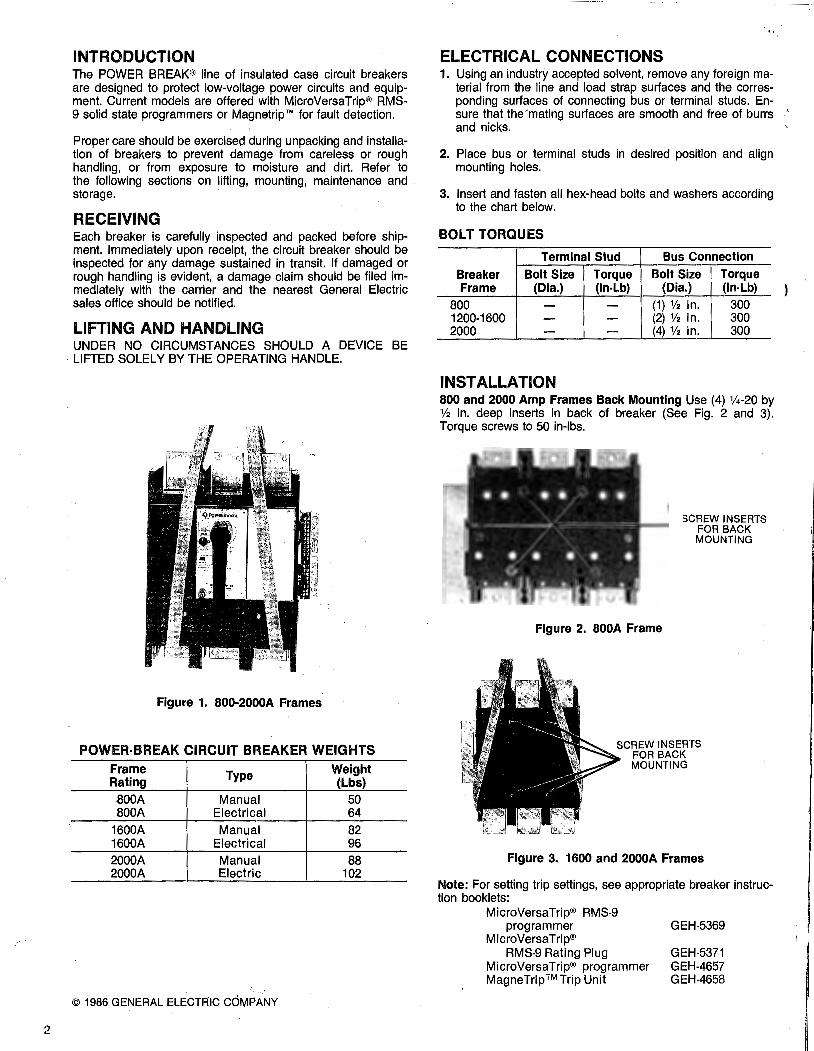
2
INTRODUCTION The POWER BREAK® line of insulated case circuit breakers are designed to protect low-voltage power circuits and equipment. Current models are offered with MicroVersaTrip® RMS-9 solid state programmers or Magnetrip r• for fault detection.
Proper care should be exercised during unpacking and installation of breakers to prevent damage from careless or rough handling, or from exposure to moisture and dirt. Refer to the following sections on lifting, mounting, maintenance and storage. ·
RECEIVING Each breaker is carefully inspected and packed before shipment. Immediately upon receipt, the circuit breaker should be inspected for any damage sustained in transit. If damaged or rough handling is evident, a damage claim should be filed immediately with the carrier and the nearest General Electric sales office should be notified.
LIFTING AND HANDLING UNDER NO CIRCUMSTANCES SHOULD A DEVICE BE LIFTED SOLELY BY THE OPERATING HANDLE.
Figure 1. 800-2000A Frames
POWER·BREAK CIRCUIT BREAKER WEIGHTS Frame Type Weight Rating (Lbs) BOOA Manual 50 800A Electrical 64
1600A Manual 82 1600A Electrical 96 2000A Manual 88 2000A Electric 102
© 1986 GENERAL ELECTRIC COMPANY
· .. ELECTRICAL CONNECTIONS 1. Using an industry accepted solvent, remove any foreign ma
terial from the line and load strap surfaces and the corresponding surfaces of connecting bus or terminal studs. Ensure that the'mating surfaces are smooth and free of burrs and nicks.
2. Place bus or terminal studs in desired position and align mounting holes.
3. Insert and fasten all hex-head bolts and washers according to the chart below.
BOLT TORQUES
Terminal Stud Bus Connection
Breaker Bolt Size Torque Bolt Size Torque Frame (Dia.) (In-Lb) (Dia.) (In-Lb)
800 - - (1) 112 in. 300 1200-1600 - - (2) 112 in. 300 2000 - - (4) 112 in. 300
INSTALLATION 800 and 2000 Amp Frames Back Mounting Use (4) %-20 by % in. deep inserts in back of breaker (See Fig. 2 and 3). Torque screws to 50 in-lbs.
Figure 2. 800A Frame
SCREW INSERTS FOR BACK MOUNTING
SCREW INSERTS FOR BACK MOUNTING
Figure 3. 1600 and 2000A Frames
Note: For setting trip settings, see appropriate breaker instruction booklets:
MicroVersaTrip® RMS-9 programmer
MicroVersaTrip® RMS-9 Rating Plug
MicroVersaTrip® programmer Mag neTrip ™Trip Unit
GEH-5369
GEH-5371 GEH-4657 GEH-4658

\
MAINTENANCE WARNING: Before beginning any maintenance work, the breaker must be disconnected from all voltage sources, both power and control, and must be in the off (open) position.
Note: Accessories listed in this bulletin may be installed/ replaced without voiding the UL listing.
MicroVersaTrip® RMS-9 programmer rating plugs may be changed per GEH-5369 and GEH-5371 without voiding the UL listing. MicroVersaTrip programmers and tap changer cards may be installed/replaced per GEH-4657 and pg. 7 of this manual respectively without voiding the UL listing.
Any other modifications void the UL listing, and the UL label must be destroyed.
Circuit breakers should be maintained through the implementation of a systematic maintenance program. A periodic inspection routine is recommended. The frequency of inspection should depend on the environment conditions of each breaker. All circuit breakers should be inspected at least annually. If it is operated frequently, or installed in an area of high humidity, dust or dirt, maintenance inspections should be increased. Under extreme adverse conditions, monthly inspections are recommended.
The maintenance inspection should begin with an overall visual check.
If dirt, grease, or any other foreign material is found on or in the breaker, it should be thoroughly and carefully cleaned. Do not use solvents on insulating material. ~
A rotating program providing for a periodic withdrawal from service of each breaker in turn for inspection and maintenance, is an excellent means of establishing a high level of service reli-
( ,,\ ability. In such cases, one or more spare circuit breakers and ·, ; all accessories should be available during the maintenance in
spection to replace any breaker that may be removed for repairs.
(
!
NOTE: When ordering spare parts, always .enclose the complete information from the nameplate, including the circuit breaker's serial number.
SEALING BREAKER The breaker cover may be sealed by attaching sealing wire through the programmer window and through a hole provided in the rim of the MicroVersaTrip® RMS-9 programmer. Two sealing wires are recommended for a positive defeat-proof seal. (See Figures 4 and 5.)
STORAGE It is recommended that a breaker be placed in service immedi-· ately in its permanent location. However, if it must be stored for an indefinite period it should be carefully protected against condensation, preferably by storage in a warm dry room. Circuit breakers for outdoor equipment should be stored in that equipment only when power is available and heaters are in operation to prevent condensation. The breaker should be stored in a clean location, free from corrosive gases or fumes. Particular care should be taken to protect the equipment from moisture and cement dust, as this combination may have a corrosive effect.
If the breaker is stored for any length of time, it should be inspected periodically to ensure good mechanical condition. Clean and dry the breaker thoroughly before placing in service.
LUBRICATION Moderate lubrication is all that is required for most circuit breakers. Mechanical bearing points and sliding surfaces should be lubricated at the regular inspection periods with a thin film of molybdenum disulfide (Molykote G), or Mobil grease No. 28. It is recommended that kerosene be used to remove hardened grease and dirt from the latch and bearing surfaces. All excess lubricant should be removed to avoid any accumulation of dirt or dust.
CAUTION: Under no circumstances should lubricant be applied to contact areas.
Figure 4.
MOUNTING SCREWS T
I~DRILL 1/a DIA.---~
Figure 5. Drilling of Programmer Window for Sealing
3

---------------------------------- -- ----
4
L
B
A
D
J
800 AMPERE FRAME
G
Figure 6. Manual Charge with MicroVersaTrip® Programmer
F
0
p
N
B
Figure 7. Electrical Charge with MicroVersaTrip® RMS-9 Programmer
TABLE 1-SEQUENCE OF OPERATION
Indicator Main Breaker
2000 AMPERE FRAME
M
Figure 8. Electrical Charge Mid-Cover with Programmer, and Top Cover Removed
KEY-STANDARD FEATURES A Indicator "On"-Red
"CHG" (Manual, "CHARGED"(MOM)-yellow OFF-Green
B "ON" button C "OFF" button D Manual charging handle E Lockable manual charge engagement button (MOM only) F Terminal board (MOM drive unit only) G Removable protective window J CT tap setting indicator (MicroVersaTrip only) K Removable protective trip unit cover (Magnetrip r• only) L Cover mounting screws (4) M Mid-cover mounting screws (3) (MOM only) N MicroVersaTrip RMS-9 programmer interchangeable rating
plug 0 MOM control circuit fuses P MicroVersaTrip RMS-9 test set connection port
Condition of Next Permissible Operating (A) Contacts Charging Springs Function
Off Open Discharged Mechanism may be charged
CHARGED/CHG Open Fully Charged Conta.cts may be closed
On Closed Discharged Contacts may be opened

115--1-
\
(
I
OPERATING INSTRUCTIONS I. Manually Operated Devices (Manual)
A. To Charge the Mechanism Springs;
1. Charge the mechanism by rotating the operating handle 120° counter-clockwise (until the handle stops). Rotate the handle clockwise back to the home position. THIS OPERATION WILL NOT TURN THE BREAKER "ON"-CLOSE CONTACTS. The indicator will read "CHARGE".
2. If the breaker latch is held tripped by any of the following accessories, the mechanism springs will discharge at the end of the charging stroke and the breaker will revert to the discharged "OFF" condition.
• Kirk lock or padlock devices in locked "OFF" condition.
• Drawout interlock with carriage in any position except "TEST" or "ENGAGED".
• Bell alarm lockout not reset after overcurrent lockout.
• Undervoltage release device not energized.
CAUTION: The above conditions must be corrected to unlock the latch before repeating the charging cycle. Failure to do so may result in equipment damage.
B. To Close the Breaker:
1. Local-Depress the ON button on the breaker escutcheon (Also see Limited Close Access-Accessory).
2. Remote-(Option)-Energize the accessory closing solenoid.
Do not repeatedly trip the device from the charge stage as equipment damage may result.
C. To Open the Breaker:
1. Local-Depress the "PUSH OFF" button on the breaker escutcheon.
2. Remote-(Option)-Energize an accessory shunt trip or de-energize an accessory undervoltage release device.
TABLE 2-CLOSING SOLENOID-Cat. Nos. TPXCC12S, TPXCC14S, TPXCC08S
Operating Close Maximum Maximum
Rated Voltage -- Voltage Solenoid* Closing Operating Cat. No. Range• Amperes Time Time Suffix @Max. Voltage (Seconds) (Seconds)
12S 120V ac, 50/60Hz 102-132 3.3 .083 .050
14S 240V ac, 50/60Hz 204-264 1.7 .083 .050
oas 24V de 19-29 13 .083 .050
The remote charge indicating switch is rated at 15A 250V ac and %A 125V de.
*The power source must stay within the rated operating voltage range of the close solenoid from no load to the full peak current rating of the device.
Remote charge indication TPXCAB
r - - - -, CHARGED I I INDICATING I LIGHT ' IBLACK '\.. /
ICHARGED~L1 I- l..i_ I ~ /\.,__,/'\..
SWITCH T jWHITE I I 01------- L2
L BREAKER _J
FIGURE 9.
OPERATING INSTRUCTIONS II. Motor (Electrically) Operated Devices (MOM)
A. To Charge the Mechanism Springs:
1. Local-(a) Depress the lockable manual charge engagement button until it is flush with the handle surface. Slight rotation of the handle may be required to fully depress the button in order to align the internal coupling.
Remote close and charge indication TPXCC12S,TPXCC14S,TPXCC08S ,---
'
CLOSE .-----1---1 }-
SOLENOID
I CHARGED
L1
I SWITCH T _____ _, ..,_ ____ L2
I I L BREAKER _J
FIGURE 10.
(b) While holding the button down, rotate the operating handle fully 120° counter-clockwise until the handle stops. Return the handle clock-wise to the home position. This cycle will NOT turn the breaker ON. The mechanism indicator will read "CHARGED".
2. Remote-Charge electrically by connecting terminal 3 to terminal 4 (also see notes on automatic operation).
5

6
B. To Close the Device:
1. Local-Depress the ON button on breaker escutcheon.
2. Remote-Electrically close by energizing the closing solenoid provided by connecting terminal 5 to terminal 6 (See notes on Automatic Operation).
C. To Open the Device:
1. Local-Depress the "PUSH OFF" button on breaker escutcheon.
2. Remote--(Ordered with breaker)-Energize the accessory shunt trip or de-energize the undervoltage release provided.
D. For Automatic Operation:
1. Automatic Close: Jumper terminal 5 to terminal 6. Device closes immediately after the charging cycle is complete.
2. Automatic Charging: Jumper terminal 3 to terminal 4. Device charges immediately after device trips open (from faults or local/remote operation).
L1
· ... CAUTION:
1. Do not wire breakers for both automatic charge and automatic close unless a bell alarm overcurrent lockout function is incorporated. Failure to do so may result in repeated,closures into an overcurrent fault.
2. The bell alarm lockout and undervoltage release device both hold the breaker latch open when activated. To prevent continuous cycling (see application note 4) when wired for automatic charging, the following is required:
a) For bell alarm lockout-Interconnect bell alarm switch to motor operator terminal board as shown in Figure 11.
NOTE: The motor operator contains a feature which shuts off control power if the OFF button is held depressed. Thus, electrical operation is prevented if a "Kirk" lock or padlock accessory is used in the breaker locked OPEN condition. If the breaker is equipped with a draw-out interlock (TPD0-1 ), electrical operation is permitted only if the drawout carriage is in the ENGAGED or TEST position.
OPTIONAL I L2 r--CONTROL VOLTAGE-----------,
I .. g~~~~t6.. I
BELL ALARM SWITCH
(SHOWN IN OVERCURRENT
TRIPPED CONDITION)
l~gli~~~NTG I LIGHT I
I . INDICATING LIGHT I I .(10 WATT MAX.) I
I ~o~~~~ J FOR OPTIONAL
I BELL ALARM LOCKOUT APPLICATIONS
\V SEE FIGURE 12
r I I I ~ I I YELLOW
~
(10 WATT MAX.) I
"'- / I 8AowN-X1 'l
I I PURPLE
:-II
0
I I I I I ~
0 (2)
'CUSTOMER SUPPLIED FUNCTIONS
Figure 11.
WIRING NOTES
1. Customer supplied control. contacts (i.e. "CHARGE" and "CLOSE") should be momentary action, rated % amp at 125V de for de motor operators. For ac motor operators these contacts should be rated 3 amp 120Vac.
2. Do not apply power to any terminal board point other than points (1) and (2).
3. Observe proper polarity for de electrical operators (Point (1) positive).
Figure 12.
4. When hi-pot or dielectric testing: a) Remove all power leads-control and power.
b) Short all electrical operator terminal board points.
c) Open circuit preaker.
d) Test between electrical operator terminal board points and load side of breaker center pole (This is connected to the frame).
e) Test at 2200 VAC for one (1) minute using a current limited non-destructive AC hi-pot tester with maximum output of 20 milliamperes.
(
t / I

t;::.' '· 1l i "
(
TABLE 3-APPLICATION DATA
Operating Motor Current (Amperes)
Rated Voltage Locked Full Load Voltage Range Rotor
Average
120Vac 102-132 8 2.5 1.5
125Vdc 100-140 10 2.5 1.5
72Vdc 57-81 13 3.0 2.0
48Vdc 38-58 20 5.0 2.5
24Vdc 19-29 24 7.0 3.0
APPLICATION NOTES 1. Size control power source per data's outlined in Table 3
above. If a single source Is to supply several motor operators, it must be sized appropriately. Where breakers are wired for automatic charge it will be necessary to supply power to several operators simultaneously during startup.
2. The control power source should be sized so that the drop in voltage from "No Load" to "Full Load" does not exceed 7%.
3. Acceptable de power sources are: de generator; battery; three phase, full wave rectified ac; and other de source with a peak-to-peak ripple voltage of not more than 15% of rated voltage at motor full load current (see Table 3).
4. Breakers built after approximately June, 1978 are equipped with an anti-cycling circuit which will lock the breaker out if the latch fails to reset (i.e.: due to a de-energized UVR). Lockout will occur if the charge time exceeds 20 seconds. Reset a locked-out breaker locally by pushing the "OFF" button, or remotely by momentarily removing control power from the electrical operator.
TRIP UNIT AND SETTING I. MicroVersaTrip® RMS-9 and MicroVersaTrip® Program
mers
Trip settings are set at minimal values on all functions. Customers may want to adjust settings to their own requirements.
A. To Adjust Trip Settings
1. Remove clear plastic protective window (Fig. 6).
2. Change settings by twisting indicators to desired value or multipliers. See GEH-4657 for definitions of MVT functions and GEH-5369 for MVT RMS-9 functions.
3. Re-install window.
Figure 13. Manual Breaker-Card Length 2 1/8" Mom Breaker-Card Length 4 3/4"
Close Nominal Maximum Maximum Solenoid Fuses Charge Close Opening
(Peak (Slo Bio) Time Time Time Amperes) 125V (seconds) (seconds) (seconds)
3.0 2A 5.0 0.83 .050
3.5 2A 6.0 .083 .050
5.0 3A 6.0 .083 .050
6.6 4A 6.0 .083 .050
13.2 6%A 7.5 .083 .050
B. Rating Plugs
MicroVersaTrip® RMS-9 programs require the installation of a rating plug in accordance with GEH-5369 and GEH-5371 to set the maximum continuous current rating.
C. Tap Changer Card
Some MicroVersaTrlp® models include a tap changer card. When provided, this function allows the customer to change the rating of the breaker frame (see Fig. 13).
HIGH-100% of Amp rating on nameplate "Sensor Amp"
LOW-50%-75% of Amp rating on nameplate "Sensor Amp"
All devices provided with tap cards are shipped with both HIGH and LOW setting cards. The LOW is packed and supported on the breaker handle. The HIGH is installed in the breaker frame. To change settings, follow these instructions on removing the cover.
DANGER: THE CIRCUIT BREAKER MUST BE REMOVED FROM THE ELECTRICAL SYSTEM
1. Turn the breaker-OFF.
2. Remove the (4) cover mounting screws and remove the top cover. On MOM breakers, remove only the top cover to replace/change the tap changer card.
3. Withdraw the HIGH (LOW) CARD from the tap charger support and install the LOW (HIGH) CARD. The print on the top of the card should be oriented the same as the breaker cover nameplate (refer to Fig. 6 and Fig. 14).
Figure 14. Cover and Programmer Removed
. . ...
7

8
FIXED TAPPED
AOR CT CT #58 BLACK
BOA #59 WHITE
Figure 15. Neutral CT connection for 4 wire ground fault
4. Programmers providing the ground fault function must also have the tap setting changed on the tapped neutral CT (4 wire systems). Change the black wire lead from the HIGH (LOW) terminal to match the desired tap setting of the breaker frame. (Fig. 15).
5. Replace the breaker cover. (See Cover Reassembly-pg. 13).
6. Operate the breaker manually through the ChargeClose-Open cycle to be sure the device mechanically functi6ns before energizing or connecting to the electrical system. ·•
7. Store the extra tap card in a convenient place.
C. Neutral current transformer (4-wire ground fault system)
Ground fault protection· is offered as an optional function of the MicroVersaTrip programmer. However, all MicroVersaTrip generation breaker frames are provided with terminal board points for connection to a neutral CT. DO NOT SHORT THESE TERMINALS IF NOT USED WITH A NEUTRAL CT.
TOP FEED
EQUIPMENT-MOUNTED r r r NEUTRAL SENSOR ~
4-WIRE LOAD
PROGRAMMER UNIT -----,
I I I I I I I I I I I I I I I I I
HARNESS L.. ___ _J
CONNECTOR (AMP 1-350356-9) PROGRAMMER
CONNECTOR
Fig. 15A Wiring Diagram - MVT/MVT RMS·9 With Ground Fault on 4-Wire Load
Always match the CT rating to the rating of circuit breaker frame.
Specifically: 1. Fixed rated breaker frames-
Match the neutral CT amp rating to the breaker sensor amp rating.
2. Tapped or high/low rated breaker Frames-
Wiring:
Match the neutral CT amp rating to the High/Low setting of the breaker sensor amp rating.
MicroVersaTrip RMS-9 equipped breakers are not available with inverted construction (formerly designated by Cat. No. suffix "8"). These breakers may be either top fed (see Fig. 15A) or bottom fed (see figure 158).
NOTE: The neutral CT is mounted in reverse in Fig. 158 when the breaker is bottom (reverse) fed. <
CAUTION: 1. Match the tapped terminal for the black lead to the tap set
ting, if provided, on the breaker frame.
2. Observe the polarity markings on the neutral CT shell and breaker frame.
3. When a neutral CT is not used or not required (3-wire ground fault), DO NOT short the terminal points on the breaker frame for ground fault. Leave them open as supplied by the factory.
D. Programmers 1. MicroVersaTrip® RMS-9 Power Break models are
supplied with non-interchangeable programmers (trip units). The breaker rating may be adjusted by changing the rating plug installed in the face of the programmer. See GEH-5369 and GEH-5371.
2. MicroVersaTrip model PowerBreak devices were or- ) dered complete or as frame or programmer (trip unit) only.
Some programmers/frames have rejection schemes to prevent mismatching of functions.
These are the limitations of interchangeability: a. High short time or H function programmers may
not be used in frames which are not wired for the H function (special CTs)
LOAD
REVERSE FEED
I _J HARNESS
PROGRAMMER UNIT
-----, I I I I I I I I I I I I I I
'V 'V 'V CONNECTOR PROGRAMMER cf.A .pe cpC (AMP 1·1350356·9) CONNECTOR
Fig. 158 Wiring Diagram - MVT/MVT RMS·9 With Ground Fault on 4-Wire Load

~ ) ""--~-·
b. Special programmers for AK Type breakers with the M (No Instantaneous) function may not be used on Power Break devices
Refer to GEH-4657 for installation/replacement of MicroVersaTrip programmers with remote overload indication, and recommended wiring for zone selective interlock.
To change or install programmers without remote indication, follow these instructions:
DANGER:
THE BREAKER MUST BE REMOVED FROM THE ELECTRI· CAL CIRCUIT.
1. Remove the (4) cover mounting screws and remove the top cover. On MOM breakers, remove only the top cover to replace/change the programmer.
2. Remove programmer: a) Push in programmer cover interlock (See Fig. 16).
b) Lift programmer off base-mounting plate and terminal plug.
c) Programmer cover interlock will now swing out and lock over the base to prevent the breaker cover from being replaced without installing another programmer.
3. Install programmer:
a) Align holes in bottom of programmer box with guide pins of frame mounting plate. Lower programmer until it is fully down on the mounting plate and the connecting plug is secure (Fig. 17). -
b) Push in the programmer cover-interlock until it locks in place (See Fig. 16).
NOTE: Programmer has a stud on the box to defeat the programmer-cover-interlock locking spring)
4. Replace top cover and secure (see cover reassembly pg. 13).
5. Manually operate the breaker through the Charge-Close-Open sequence to ensure proper mechanical functioning before energizing in the electrical system. REMINDER: A de-energized undervoltage release will not allow the mechanism to charge and close.
Figure 16.
6. Programmers with ground fault:
If a four-wire system is to be used, a neutral CT must be provided. See the section on Neutral CT for instructions and precautions. DO NOT short the ground fault terminals provided on the breaker frame if not used.
II. Magnetrip
To change trip settings:
A. Remove protective cover (See Fig. 7).
B. Change trip setting by rotating plastic buttons with a screwdriver (See Fig. 18).
C. Replace protective cover.
Figure 17. Aligning Programmer To Base
1600 AMPERE FRAME
Figure 18. Adjusting Trip Unit Setting
9
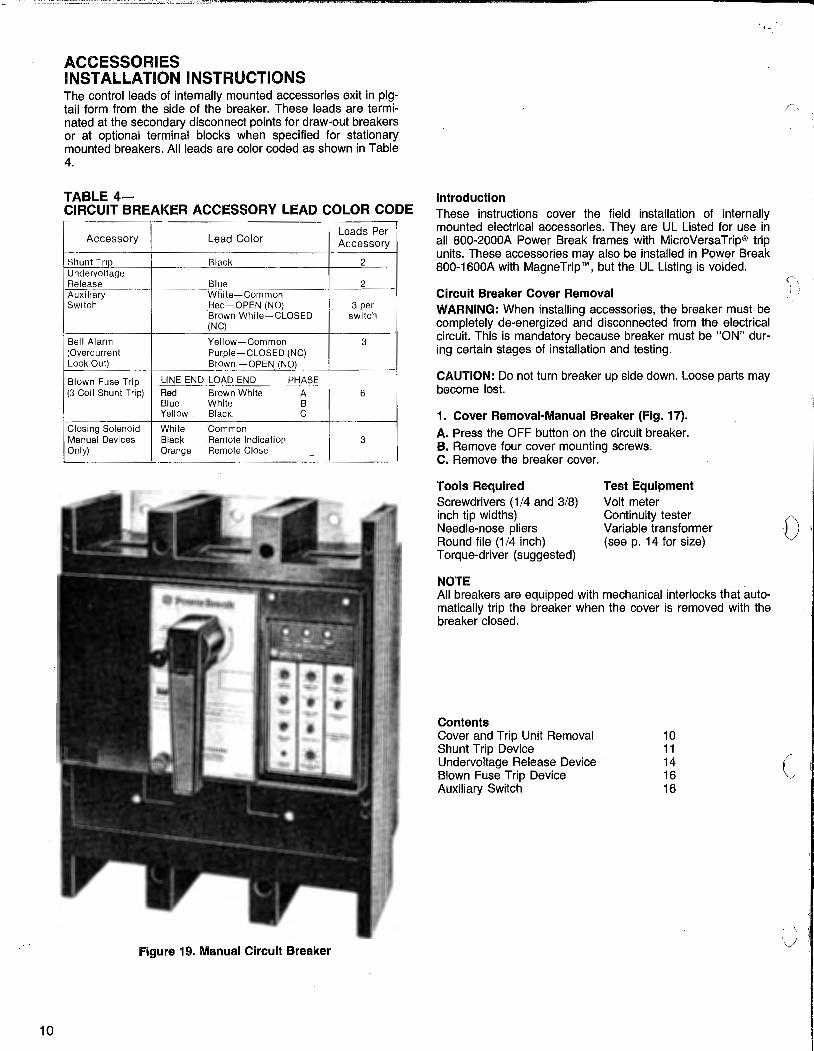
10
., - -· -·-·"°'25EE - LffiJ Q4Pi2L
ACCESSORIES INSTALLATION INSTRUCTIONS The control leads of internally mounted accessories exit in pigtail form from the side of the breaker. These leads are terminated at the secondary disconnect points for draw-out breakers or at optional terminal blocks when specified for stationary mounted breakers. All leads are color coded as shown in Table 4.
TABLE 4-CIRCUIT BREAKER ACCESSORY LEAD COLOR CODE
Accessory Lead Color Leads Per Accessory
Shunt Trip Black 2 Undervoltage Release Blue 2 Auxiliary White-Common Switch Red-OPEN (NO) 3 per
Brown White~CLOSED switch (NC)
Bell Alarm Yellow-Common 3 (Overcurrent Purple-CLOSED (NC) Lock-Out) Brown -OPEN_(NO)
Blown Fuse Trip LINE END LOAD END PHASE --(3 Coil Shunt Trip) Red Brown White A 6
Blue White B Yellow Black c
Closing Solenoid White Common Manual Devices Black Remote Indication 3 Only) Orange Remote Close -
Figure 19. Manual Circuit Breaker
. "
Introduction These instructions cover the field installation of internally mounted electrical accessories. They are UL Listed for use in all 800-2000A Power Break frames with MicroVersaTrip® trip units. These accessories may also be installed in Power Break 800-1600A with MagneTrip ™, but the UL Listing is voided.
Circuit Breaker Cover Removal WARNING: When installing accessories, the breaker must be completely de-energized and disconnected from the electrical circuit. This is mandatory because breaker must be "ON" during certain stages of installation and testing.
CAUTION: Do not turn breaker up side down. Loose parts may become lost.
1. Cover Removal-Manual Breaker (Fig. 17). A. Press the OFF button on the circuit breaker. B. Remove four cover mounting screws. C. Remove the breaker cover.
Tools Required Screwdrivers (1/4 and 3/8) inch tip widths) Needle-nose pliers Round file (1 /4 inch) Torque-driver (suggested)
NOTE
Test Equipment Volt meter Continuity tester Variable transformer (seep. 14 for size)
All breal<ers are equipped with mechanical interlocks that automatically trip the breaker when the cover is removed with the breaker closed.
Contents Cover and Trip Unit Removal Shunt Trip Device Undervoitage Release Device Blown Fuse Trip Device Auxiliary Switch
10 11 14 16 16
l
0"
c
'J

,('\ , I
r,~ .) 110)
2. Electrically Operated Breaker
a. Outer Cover Removal.-See Fig. 20 or 21. 1. Press the OFF button on the circuit breaker. 2. Disconnect all external leads from the terminal
bOard. 3. Remove four outer cover mounting screws (Fig. 20
and 21 ). 4. Remove outer cover.
Figure 20. 800A Frame Electrical Breaker
INNER COVER SCREWS
Figure 21. 1600-2000A Frame Electrical Breaker
b. Inner Cover Removal 1. 1600-2000A Frames only-Remove two inner
cover mounting screws. (See Fig. 21 ). 2. Loosen captive inner cover lock screw as shown in
Fig. 22. 3. Remove inner cover.
Figure 22. Inner Cover Lock Screw
SHUNT TRIP DEVICE FOR 800·2000A FRAMES
GENERAL DESCRIPTION The shunt trip provides the capability of electrically tripping the breaker from a remote location. A cut-off switch is supplied as part of the shunt trip to automatically remove power from its coil when the circuit breaker is tripped.
Figure 23. Shunt Trip and Cut-Off Switch. Coil is Shown Assembled to Mounting Plate, Which is Provided
with Circuit Breaker.
TABLE 5-ELECTRICAL DATA
Shunt Trip Voltage Max. Inrush Cat. No. Rating Current·Amperes
TPST12S 120V ac 2.25 240V ac 4.50
TPST13S 480V ac 1.64 600V ac 2.05
TPST?S 12V de 4.00
TPST8S 24V de 2.18
TPST9S 48V de 1.09
TPST10S 125V de 1.00
TPST11S 250V de 0.21

12
L1 L2
I- - - -, ' Off* l.control
I r f I Black 0... cf-o----1 Power
!M~~:-I B_la_c_k_,0 ,...~~~~~~~~ Internal I *Customer Supplied
I To Breaker
Figure 24. Wiring Diagram
MOUNTING PLATE REMOVAL The mounting plate is used as the anchor position for the shunt trip, blown-fuse trip and undervoltage release accessories. It is supplied with the circuit whether or not any accessories have been installed.
1. Remove three (3) mounting plate retaining screws and isolation barrier, see Fig. 25.
2. Lift out accessory mounting plate and remove molded drive crank. (Fig. 29).
3. If tap changer is supplied, unscrew the two screws from phenolic block before removing mounting plate.
INSTALLATION 1. Assemble coil to mounting plate as shown in Fig. 25). If the
mounting plate is also to be equipped with a blown-fuse trip device, mount the shunt trip as shown in Fig. 26.
NOTE: Shunt trip coils rated 12V de or 24V de must be mounted in a pqsition nearest the latch. These coil ratings may not develop enough force to drive both the latch and blownfuse trip device.
Figure 25.
Figure 26.
2. When supplied with a blown-fuse trip device, the shunt trip plunger stop-nut is placed in contact with the plunger of the blown fuse trip device.
3. Mount cut-off switch by first depressing the switch actuator. Align tapped holes in switch bracket with holes in arm stop (left pole) and secure with No. 8 x 9/16 screws and lock washer. (Tighten to 23 inch pounds, see Fig. 27).
4. Remove knockouts as required in side of base. Each knockout will accommodate up to three bundles of wires (Fig. 25). Remove all sharp edges with a file.
5. Clean all debris from inside of breaker.
Figure 27.
·,,.
t)

(f \.
'l.
NOTE: If shunt trip is being used to replace a defective coil, the cause of the initial failure should be first determined. If necessary consult factory for further guidance.
MOUNTING PLATE REINSTALLATION 1. Replace molded drive crank onto mechanism drive pin en
gaging roll pins into slot in drive crank. (See Fig. 28).
ISOLATING BARRIER
Figure 28.
2. Place mounting plate in position so that its two (2) operating studs engage the molded drive crank, see Fig. 28. Be sure isolating barrier is in place.
3. Fasten three (3) retaining screws, see Fig. 29 and torque to 20 inch-pounds (2 small screws) and 75 inch-pounds (large screws with tubing).
4. Attach wire-ties to leads and secure to mounting plate as shown in Fig. 29.
5. Insert leads into knockout in base sidewall making sure one wire tie is on the inside of the base and the other is on the outside. See Fig. 29.
6. Apply descriptive label to front of circuit breaker cover.
COVER REASSEMBLY Manual Circuit Breakers
1. Verify that all connections are secure and breaker is free of debris.
2. Verify that breaker is "OFF".
3. CAUTION: Verify that the accessory mounting plate insulator is properly located so it will not be damaged when assembling the cover. The cover phase barrier must pass to the right side of this insulator (see Figure 29).
4. Position the manual handle at the home position (6 o'clock) on the cover. Align the cover mounting screw holes with the breaker base. Install the cover screws to 50 to 60 inchpounds torque.
ACCESSORY MOUNTING PLATE INSULATOR
COVER INTERLOCK
Figure 29.
5. Verify that the breaker can be charged per the instructions on page 5. The cover interlock (Figure 29) must properly engage the cover or it will hold the latch in the tripped position.
Figure 30.
Electrical Circuit Breakers
1. Inner Cover Installation
a. Verify that all connections are secure and breaker is free of debris.
b. CAUTION: Verify that the accessory mounting plate insulator is properly located. (Fig. 29) Slide the Inner Cover Assembly onto the breaker base being careful not to damage the insulator. Ensure that the crossbar hook engages the drive stud as shown in Fig. 30.
c. Tighten inner cover lock screw to 10-in. lbs. max., see Fig. 22.
d. 1600A-2000A Frames only-Replace two (2) inner cover mounting screws. See Fig. 21. Tighten to 50-60 inchpounds torque.
13

14
2. Outer Cover Installation
a. Position handle at the home position (6 o'clock) on the outer cover. Align outer cover mounting screw holes with those of the inner cover and install four cover mounting screws, see Figs. 20 and 21. Secure with 50 to 60 inch pounds torque.
b. Connect control and power wiring per instructions provided with circuit breaker.
UNDERVOLTAGE RELEASE DEVICE GENERAL DESCRIPTION
The undervoltage release device (UVR) is used to open the circuit breaker when the supply voltage drops to 35-60 percent of its rated value.
Figure 31. Undervoltage Release Accessory Shown Assembled to Mounting Plate
Dropping Resistor (Provided with 240-600V -UVR Ratings only)
Figure 32.
TABLE 6-ELECTRICAL DATA
Dropping , Conti nous Resistor
Cat. Voltage Current (Ohmite No. Rating (Ma) Type 270)
TPUV1S 120V ae 25 none TPUV2S 240V ae 25 50000, 25 watt TPUV4S 480V ae 25 15,0000, 50 watt TPUV6S 600V ae 25 20,0000, 50 watt TPUV7S 12V de 211 none TPUV8S 24V de 104 none TPUV9S 48V de 54 none TPUV10S 125V de 24 none TPUV11S 250V de 24 50000, 25 watt
L1 L2
DROPPING CONTROL r - - -1 RESISTOR POWER
UVR I (WHEN SUPPLIED)OFF* -fly BLUE --
! [ iBLUE9. MO.Vl"--(IF-<U>S
1
ED)
!MOUNTED I !INTERNAL I 12:_0 BREAKE~
Figure 33. Wiring Diagram
INSTALLATION
1. Disassemble the circuit breaker cover(s) as outlined on pages 1 0 and 11 .
2. Installation of the UVR is accomplished on the accessory mounting plate, which is factory installed in the left pole of the breaker.
3. Remove the slide reset lever spring from the mounting plate as shown in Fig. 34. Care should be exercised not to nick or damage the spring in any way, since it will be needed for reassembly.
.,
)

(
()' \_
Figure 34.
4. Push the latch and slide reset lever forward to provide mounting clearance for the undervoltage release assembly.
5. Position the UVR assembly mounting bracket so that its retaining hole engages the latch pivot post as shown in Fig. 35.
6. Line up the UVR bracket's mounting hole with the tapped hole in the accessory mounting plate. Install screw and lock-washer (Fig. 30). Tighten to 9-11 inch pounds.
7. Replace slide reset lever spring (Fig. 34).
Figure 35.
Figure 36.
8. Remove knockouts as required in side of base. Each knockout will accommodate up to three bundles of wires (Fig. 29). Remove all sharp edges with a file.
9. Clean all debris from Inside of breaker.
10. Use the tie wraps provided to secure leads to mounting plate and to secure .the wire bundle to inside and outside of the breaker base as shown in Fig. 29.
11. Reassemble the breaker as outlined in instructions on pages 13 and 14.
12. Mount the dropping resistor (when supplied) and M.O.V. (Fig. 32). Wire as shown in Fig. 33.
13. Functional Check. a) Apply rated voltage to the UVR coil. b) Turn the circuit breaker "on". c) Reduce control voltage. The circuit breaker should trip
when the voltage drops .to 35-60 percent of its rated value.
14. Apply the undervoltage release descriptive label to the left side of the breaker near the lead exit area.
15

BLOWN-FUSE TRIP DEVICE
Figure 37.
GENERAL DESCRIPTION AND APPLICATION The blown·fuse trip device (three-coil shunt trip) is intended for use In applications where breakers and fuses are used in series. This accessory prevents single-phasing conditions by monitoring the fuses and automatically tripping the circuit breaker when a fuse blows. It does not protect from singlephasing of the power source.
Each coil of the blown-fuse trip device is wired across a fuse so that the voltage across an open fuse is fed back to the accessory coil. When the coil is energized, the solenoid core releases the spring biased latch, allowing the slide to rotate the breaker latch, tripping the breaker. The fuse must be replaced and the breaker reset before it can be reclosed.
If the breaker is closed on an open fuse, the blown-fuse trip device will automatically open the circuit breaker.
INSTALLATION
Installation of the blown-fuse trip device is similar to the shunt trip installation.
1. Complete steps 1-3 under "Mounting Plate Removal" on page 12.
2. Complete steps 1 and 2 under "Installation" on page 12.
3. Perform installation checks listed below:
a. Replace the breaker cover. Close the breaker contacts.
b. To check electrical operation, apply 120 volts to one coil of the blown-fuse trip device for not more than one second. The breaker must trip. Repeat the test for each coil.
11 * BROWN WHITE LEAD-I RED LEAD 1
*FORMERLY GREEN 3-POLE THREE-PHASE APPLICATION
BLOWN-FUSE TRIP DEVICE
Figure 38. Wiring Diagram
4. Attach six (6) lead wires across each of the three fuses as shown in Fig. 38.
5. Apply the descriptive label to the front of the breaker cover.
COVER REASSEMBLY
Be sure cover (or covers) have been properly re-assembled. Refer to instructions on page 13.
AUXILIARY SWITCH
Figure 39. Auxiliary Switch
ELECTRICAL DATA
TABLE 7-AUXILIARY SWITCH KITS
Auxiliary Switch Catalog Number
TPAS2AB*
Number of
Switch Elements
1-12
Maximum Ampere Rating Switch
Elements 6A at 240VAC
.25A at 250VDC
.50A at 125VDC
*Suffix numbers 1 through 12 designate number of switch elements.
(
(
\, ..,i

( '\
(
CIRCUIT BREAKER
MAIN CONTACT
/"f" --- I AUXILIARY I SWITCH I BROWN/WHITE*
B-CIRCUIT I
11 RED
A-CIRCUIT
WHITE COMMON
*FORMERLY GREEN
Figure 40. Wiring Diagram
DESCRIPTION The auxiliary switch is used for remote indication of breaker main contact position-OPEN or CLOSED. No distinction is made between an open or tripped mode. A maximum of 12 switches can be Installed per breaker. Each Is a single-pole, double-throw (AB-type) and rated as shown in Table 7. Two switch positions must be devoted to each shunt trip accessory (if used) per breaker.
INSTALLATION -·
1. Refer to "Cover(s) Removal" instructions on page ten and remove cover (manual breaker) or covers (electrically operated breaker).
2. Installation location. Both left and right circuit breaker poles can accept up to six auxiliary switches. If the left pole contains a shunt trip, two of the six auxiliary switch positions must be used for the cutout switches; therefore only four auxiliary switches may be used in the left pole.
3. If auxiliary switches are to be installed in the right pole, remove Interchangeable solid state trip unit by depressing lock release lever while lifting up on trip unit. Remove trip unit mounting plate. See Fig. 41.
Figure 41.
4. Position the auxiliary switch assembly so that the tapped mounting holes on its bracket line up with the through holes in the arm stop (Fig. 42).
5. Secure auxiliary switch assembly to arm stop with two #8 x 9/16 screws and lock washers (Fig. 43). Tighten to 23 inch-pounds.
6. Remove knockouts as required in side of base. Each knockout will accommodate up to three bundles of wire (Fig. 29). Remove all sharp edges with a file.
7. Clean all debris from inside of breaker.
Figure 42.
Figure 43.
8. Use the wraps provided to secure leads as shown in Fig. 29.
9. Replace solid state trip unit and its mounting plate.
10. Replace cover(s) by following "Cover Reassembly" instruction on page 13.
11. Functional Check
a) With the breaker open ("OFF") use a continuity tester to verify continuity between the white and brown/white leads. An open circuit should exist between the red and white leads.
b) With the circuit breaker closed ("ON") the auxiliary switch contacts should change sense.
12. Apply the auxiliary switch description label on the front of the breaker cover.
..
17

18
OPTIONAL FEATURES
Special features may be ordered as specific accessory catalog numbers or as an integral part of the breaker catalog number. Refer to the BuyLog® catalog GEP-1100 for these features.
I. Limited close access button ("C") suffix in catalog number (Fig. 44).
Provides limited manual accessibility to ON Button. Function allows breaker to be turned ON in an emergency for maintenance by use of 1 /8" diameter pin or rod. Manually operated devices must be ordered with an accessory closing solenoid.
II. Remote Close Only
No means of manually closing device. Manually operated device. Manually operated devices must be ordered with closing solenoid.
Ill. Padlock Function
A. Handle Button Lock-To prevent manual charging of electrically operated breaker mechanism. See Figure 7 item E. Note: This is a standard feature.
B. OFF Button Padlock with Door Interlock.
To prevent Panel Door opening with Breaker "ON" ·or "CHARGED".
1. With breaker OFF paddle may rotate counterclockwise over breaker nameplate to clear enclosure panel door. Rotate clockwise to lock over door. (Fig. 45).
Figure 44.
2. To defeat while breaker is "ON" or "CHARGED", depress spring and rotate to clear door. (Fig. 46).
Figure 45.
Figure 46.

These Instructions do not purport to cover all details or variations In equipment nor to provide for every possible contingency to be met in connection with installation operation or maintenance. Should further information be desired or should particular problems arise which are not covered sufficiently for the purchaser's purposes, the matter should be referred to the General Electric Company.
Outside the U.S. write Construction Equipment Export Operation, 411 Theodore Fremd Ave., Rye, N.Y. 10580 U.S.A. GEH-46938 0687 PSA
For further Information call or write your local General Electric Sales Office or ...
General Electric Company 41 Woodford Avenue Plainville, CT 06062 U.S.A.
GENERAL fj ELECTRIC
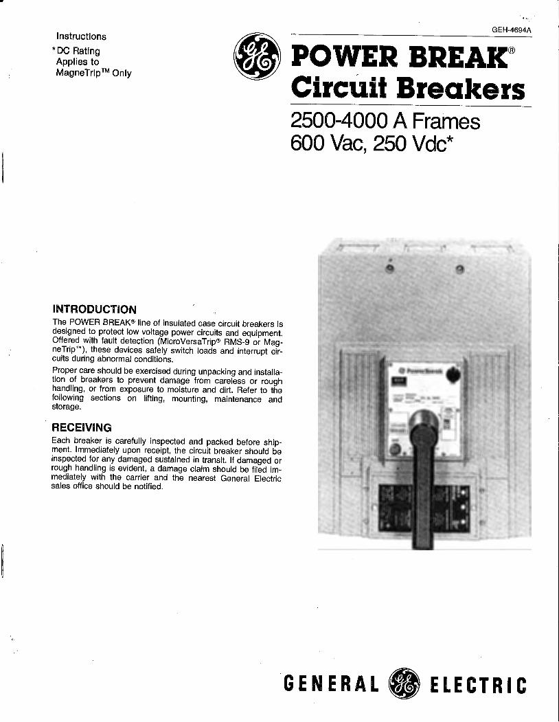
Instructions
*DC Rating Applies to MagneTrip TM Only
INTRODUCTION
•
The POWER BREAK® line of insulated case circuit breakers is designed to protect low voltage power circuits and equipment. Offered with fault detection (MicroVersaTrip® RMS-9 or MagneTrip ™ ), these devices safely switch loads and interrupt circuits during abnormal conditions.
Proper care should be exercised during unpacking and installation of breakers to prevent damage from careless or rough handling, or from exposure to moisture and dirt. Refer to the following sections on lifting, mounting, maintenance and storage.
RECEIVING Each breaker is carefully inspected and packed before shipment. Immediately upon receipt, the circuit breaker should be inspected for any damaged sustained in transit. If damaged or rough handling is evident, a damage claim should be filed immediately with the carrier and the nearest General Electric sales office should be notified.
GEH-4694A
POWER BREAK® CircUit Breakers 2500-4000 A Frames 600 Vac, 250 Vdc*
GENERAL fj ELECTRIC
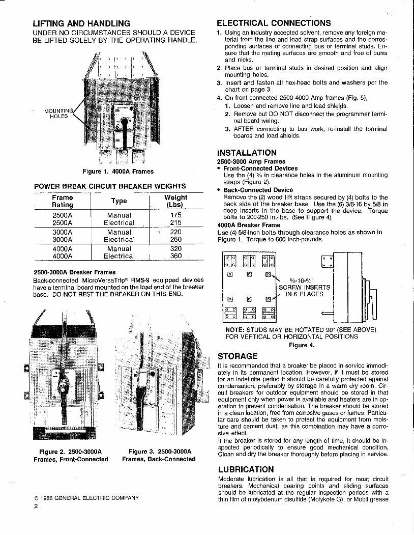
LIFTING AND HANDLING UNDER NO CIRCUMSTANCES SHOULD A DEVICE BE LIFTED SOLELY BY THE OPERATING HANDLE.
MOUNTING HOLES
Figure 1. 4000A Frames
POWER BREAK CIRCUIT BREAKER WEIGHTS
Frame Type Weight Rating (Lbs)
2500A Manual 175 2500A Electrical 215
3000A Manual ., 220 3000A Electrical 260 4000A Manual 320 4000A Electrical 360
2500-3000A Breaker Frames Back-connected MicroVersaTrip® RMS-9 equipped devices have a terminal board mounted on the load end of the breaker base. DO NOT REST THE BREAKER ON THIS END.
Figure 2. 2500-3000A Frames, Front-Connected
Figure 3. 2500-3000A Frames, Back-Connected
© 1986 GENERAL ELECTRIC COMPANY
2
. . .. ELECTRICAL CONNECTIONS 1. Using an industry accepted solvent, remove any foreign ma
terial from the line and load strap surfaces and the corresponding surfaces of connecting bus or terminal studs. Ensure that the rpating surfaces are smooth and free of burrs and nicks.
2. Place bus or terminal studs in desired position and align mounting holes.
3. Insert and fasten all hex-head bolts and washers per the chart on page 3.
4. On front-connected 2500-4000 Amp frames (Fig. 5), 1. Loosen and remove line and load shi~l9s. 2. Remove but DO NOT disconnect the programmer termi
nal board wiring. 3. AFTER connecting to bus work, re-install the terminal
boards and load shields.
INSTALLATION 2500-3000 Amp Frames • Front-Connected Devices
Use the (4) % in clearance holes in the aluminum mounting straps (Figure 2).
• Back-Connected Device Remove the (2) wood lift straps secured by (4) bolts to the back side of the breaker base. Use the (6) 3/8-16 by 5/8 in deep inserts in the base to support the device. Torque bolts to 200-250 in.-lbs. (See Figure 4).
4000A Breaker Frame Use (4) 5/8-inch bolts through clearance holes as shown in Figure 1. Torque to 600 inch-pounds.
rnJ c bI11 0 1~11:1 @) @) @]
%-16-%" SCREW INSERTS
IN 6 PLACES @) @) @]
B () ~ 0 8 NOTE: STUDS MAY BE ROTATED 90° (SEE ABOVE) FOR VERTICAL OR HORIZONTAL POSITIONS
Figure 4.
STORAGE It is recommended that a breaker be placed in service immediately in its permanent location. However, if it must be stored for an indefinite period it should be carefully protected against condensation, preferably by storage in a warm dry room. Circuit breakers for outdoor equipment should be stored in that equipment only when power is available and heaters are in operation to prevent condensation. The breaker should be stored in a clean location, free from corrosive gases or fumes. Particular care should be taken to protect the equipment from moisture and cement dust, as this combination may have a corrosive effect. If the breaker is stored for any length of time, it should be inspected periodically to ensure good mechanical condition. Clean and dry the breaker thoroughly before placing in service.
LUBRICATION Moderate lubrication is all that is required for most circuit breakers. Mechanical bearing points and sliding surfaces should be lubricated at the regular inspection periods with a thin film of molybdenum disulfide (Molykote G), or Mobil grease

\ /
'"
No. 28. It is recommended that kerosene be used to remove hardened grease and dirt from the latch and bearing surfaces. All excess lubricant should be removed to avoid any accumulation of dirt or dust.
CAUTION: Under no circumstances should lubricant be applied to contact areas. NOTE: When ordering spare parts, always enclose the complete information from the nameplate, including the circuit breaker's serial number.
Figure 5. 2500A Frame MicroVersaTrip
Terminal Stud Bus Connection Breaker Bolt Size Torque Bolt Size Torque Frame (DIA) (In· Lb) (DIA) (In-Lb)
2500-3000* (4) 3/8-16 250 (4) 3/8 in. 250 4000 (6) 1/2-13 400 (4) 1/2 in. 400
*3000A back-connected terminal studs are factory brazed to breaker. NOTE: For setting trip settings, see appropriate breaker instruction booklets:
MicroVersaTrip® RMS-9 Programmer MicroVersaTrip® Programmer MagneTrip Trip Unit
MAINTENANCE
GEH-5369 GEH-4657 GEH-4658
WARNING: Before beginning any maintenance work, the breaker must be disconnected from all voltage sources, both power and control, and must be in the off (open) position. NOTE: Accessories listed in this bulletin may be installed/ replaced without voiding the UL listing. MicroVersaTrip® RMS-9 programmer rating plugs may be changed per GEH-5369 and GEH-5371 without voiding the UL listing. Likewise, MicroVersaTrip programmers and tap changer cards may be installed/replaced per GEH 4657 and pg. 8 of this manual respectively. Any other modifications void the UL listing, and the UL label must be destroyed.
Circuit breakers should be maintained through the implementation of a systematic maintenance program. A periodic inspection should depend on the environmental conditions of each breaker. All circuit breakers should be inspected at least annually. If it is operated frequently, or installed in an area of high humidity, dust, or dirt, the frequency of maintenance inspections should be increased. Under extreme adverse conditions, monthly inspections are recommended.
The maintenance inspection should begin with an overall visual check.
If dirt, grease, or any other foreign material is found on or in the breaker, it should be thoroughly and carefully cleaned. Do not use solvents on insulating material.
A rotating program providing for a periodic withdrawal from service of each breaker in turn for inspection and maintenance, is an excellent means of establishing a high level of service reliability. In such cases, one or more spare circuit breakers and all accessories should be available during the maintenance inspection to replace any breaker that may be removed for repairs.
SEALING BREAKER The breaker cover may be sealed by attaching a sealing wire through a hole provided in the rim of the MicroVersaTrip RMS-9 programmer, through a hole in the programmer window and through a hole in the thumb screw shown in figure 6. The hole in the programmer window is not provided and must be drilled when required for sealing the breaker. CAUTION: Remove the programmer window before drilling to
avoid damaging the programmer. (See Figure 7.)
Figure 6. Sealed RMS-9 MicroVersaTrip Breaker
DRILL Va" DIA.
Figure 7. Drilling of Programmer Window for Sealing Wire
3

POWER BREAK® OPERATING FEATURES
[8_]
[QJ
[g
[g]
[HJ
[Ml
[Q] -"'""--+-~
KEY:
Figure 8. 2500A-Manual
MicroVersaTrip® RMS-9 Programmer
A - Indicator Manual: ON-Red; OFF-Green; Electrical: ON-Red; Charged-Yellow; OFF-Green
B - "ON" Button C - "OFF" Button D - Manual Charging Handle E - Mechanism Indicator-Manual
CHG-Yellow; 0--White F - Lockable Manual Charge Engagement Button G - Terminal Board (MOM Drive Unit) H - Cover Escutcheon J - Removable Protective Window (MVT RMS-9 and MVT
Only) K -'Programmer Terminal Board (MVT RMS-9 and MVT Only) L - CT Tap Setting Indication (MlcroVersaTrip® Only) M - Cover Mounting Screws (4); (2) under cover escutcheon) N - MicroVersaTrip RMS-9 programmer interchangeable rating
plug 0 - MicroVersaTrip RMS-9 test set connection port
TABLE 1-SEQUENCE OF OPERATION
Indicators
Manual Electrical
A E A
OFF 0 OFF
OFF CHG CHARGED
ON 0 ON
4
Main Breaker Contacts
Open
Open
Closed
Figure 9. 2500 A-Electrical Front-Connected
<I '"' "' .. ,., " 11!> "' "'
Ill> .. .. 11!> .. ..
,,
Figure 10. 4000A-Manual MagneTrip ™ Trip Unit
Condition Of Charging Springs
Discharged
Charged
Discharged
Next Permissible Operating Function
Mechanism May Be Charged
Contacts May Be Closed Do .Not Open Or Trip From This Stage
Contacts May Be Opened
'\
J

\ ' )
OPERATING INSTRUCTIONS
MANUALLY OPERATED .DEVICES A. To Charge the Mechanism Springs 1. Charge the mechanism by rotating the operating handle
120° counter-clockwise (until the handle stops). Rotate the handle clockwise back to the home position. Repeat this cycle two more times. THIS OPERATION WILL NOT TURN THE BREAKER "ON"-CLOSE CONTACTS. The indicator will read "CHARGE."
2. If the breaker latch is held tripped by any of the following accessories, the mechanism springs will discharge at the end of the charging stroke and the breaker will revert to the discharged "OFF" condition. • Kirk lock or padlock devices in locked "OFF" condition. • Draw-out interlock with carriage in any position except
'TEST" or "ENGAGED". • Bell alarm lockout not reset after overcurrent lockout. • Undervoltage release device not energized.
CAUTION: These conditions must be corrected to unlock the latch before repeating the charging cycle. Failure to do so may result in equipment damage.
B. To Close the Breaker 1. Locally-Depress the ON button on the breaker escutcheon
(Also see Limited Close Access-Optional Features pg. 20) 2. Remotely-(Option)-Energize the accessory closing sole-
noid. Do not repeatedly trip the device from the charge stage as equipment damage may result.
c. To Open the Breaker 1. Locally-Depress the "PUSH OFF" button on the breaker
escutcheon. 2. Remotely-(Option)-Energize an accessory shunt trip or
de-energize an accessory undervoltage release device.
APPLICATION DATA-Catalog Numbers TSXCC12S, TSXCC14S, TSXCCOSS
TABLE 2-CLOSING SOLENOID
-- Close Solenoid"' Maximum Maximum Operating Amperes Closing Time Opening Time
Cat. No. Suffix Rated Voltage Voltge Range* @ Max. Voltage (Seconds) (Seconds) 12S 120V ac, 50/60Hz 102~132 6A .083 .083 14S 240V ac, 50/60Hz 204-264 3A .083 .083 OBS 24V de 19-29 11A .083 .083
NOTE: The remote charge indicating switch is rated at 15A 250V ac and %A 125V de. *The Power Source must stay within the rated operating voltage range of the close solenoid, from no load to the full peak current rating of the device. ·
WIRING DIAGRAMS
r--------..., I I I I I BLACK
CHARGED I SWITCH
l: I I WHITE
I I I
BREAKER I L---------'
0
Figure 11. Remote-Charge Indication
TSXCAS
L1
L2
CLOSE r---------1 J_ 10RANGE
I I
-----<->--- L1 CHARGED CLOSE
SOLENOID
CHARGED SWITCH T
BREAKER
INDICATING LIGHT
,I BLACK '\. /
I I I I WHITE 0 I I I I
L---------..J
Figure 12. Remote-Close and Charge Indication
TSXCC12S TSXCC145 TSXCCOSS
L2
5

OPERATING INSTRUCTIONS
ELECTRICALLY OPERATED DEVICES (MOM) A. To Charge the Mechanism Springs
1. Local-(a) Depress the lockable manual charge engagement button until it is flush with the handle surface. Slight rotation of the handle may be required to fully depress the button in order to align the internal coupling. (b) While holding the button down, rotate the operating handle fully 120° counter-clockwise until the handle stops. Return the handle clockwise to the home position. Repeat two (2) more times. This cycle will NOT turn the Breaker ON. The Mechanism Indicator will read "CHARGED".
2. Remote-Charge electrically by connecting terminal 3 to terminal 4 (also see notes on automatic operation).
B. To Close the Device 1. Local-Depress the ON button on breaker escutcheon. 2. Remote-Electrically close by energizing the closing sole
noid provided by connecting terminal 5 to terminal 6 (see notes on automatic operation).
DO NOT REPEATEDLY TRIP THE BREAKER FROM THIS CHARGE STAGE AS EQUIPMENT DAMAGE MAY RESULT. c;:. To Open The Device 1. Local-Depress the "PUSH OFF" button on breaker
escutcheon. -2. Remote-(Ordered with breaker at no extra charge)-Ener
gize the accessory shunt trip or de-energize the undervoltage release provided.
TABLE 3-0PERATIONAL DATA
Operating Motor Current (Amps)
Rated Voltage Locked Full Average Voltage Range Rotor 1 Load Load
120 Vac 102-132 Vac 20 7.0 4.0 240 Vac 204-264 Vac 10 3.5 2.0 125 Vdc 100-140 Vdc 20 4.0 3.0 72 Vdc 57- 81 Vdc 28 10 7.0 48 Vdc 38- 58 Vdc 30 10 7.0
24 Vdc 19- 29 Vdc 60 20 14
D. Automation Operation 1. Automatic Close: Jumper terminal 5 to terminal 6. Device
closes immediately after the charging cycle is complete. 2. Automatic Charging: Jumper terminal 3 to terminal 4. De
vice charges immediately after device trips open (from faults or local/remote operation).
CAUTION: 1. Do not wire breakers for both automatic charge and auto
matic close unless a bell alarm overcurrent lockout function is incorporated. Failure to do so may result in repeated closures into an overcurrent fault.
2. The bell alarm lockout and undervoltage release devices both hold the breaker latch open when activated. To prevent continuous cycling when wired for automatic charging, the following is required. a) For bell alarm lockout-Interconnect bell alarm switch to motor operator terminal board as shown in Figures 13 and 14.
NOTE: The motor operator contains a feature which shuts off control power if the OFF button is held depressed. Thus, electrical operation is prevented if a "Kirk" lock or padlock accessory is used in the breaker locked OPEN condition. If the breaker is equipped with a drawout interlock (TPD02), electrical operation is permitted only if the drawout carriage is in the ENGAGED or TEST position.
Close Solenoid Fuses Charge Close Opening
(Peak) Type 3AB Time Time Time Amps) (Amps) 5 (Sec.) 2 (Sec.) 3 (Sec.) 4
8.8 MDX4 3.5 .083 .083 4.0 MDA 4 3.5 .083 .083 3.4 ABC5 4.0 .083 .083 8.1 ABC 10 4.0 .083 .083
6.7 ABC10 4.5 .083 .083
14.1 ABC 20 5.0 .083 .083
1 Momentary motor reversing current is 150% locked rotor current. 2 Measured from sequence initiation to motor cutoff at 100% rated voltage. 3 Measured from sequence initiation to contact closure at 100% rated voltage. 4 Measured from sequence initiation to contact opening at 100% rated voltage. s Recommended type is Bussman or equivalent. Do NOT use slo-blo fuses for type ABC.
6
· ...
. )
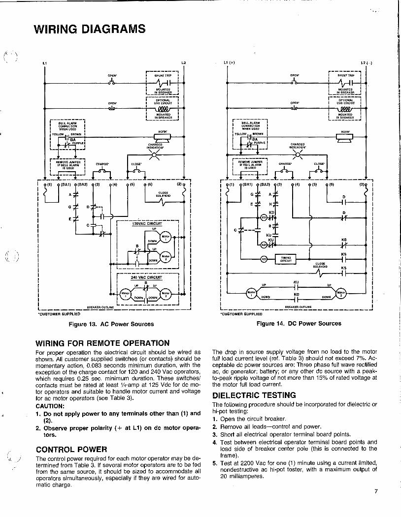
WIRING DIAGRAMS
Lt
r-------, OPEN" I SHUNT TRIP I
1. I I I /\ _J I
._-~-~~-~--o~o~-~--T-1--'V' I I MOUNTED I
OPEN•
'--~!.'!!~F;!!_J ... --------., I OPTIONAL I I UVA CIRCUIT I
.-~~--------<U1>--~---:r--~ : r--------, I g6~~:~,~: , I WHEN USED ~
jVEallOW I BROWN I I I BA 1 I I PURPLE I L- ---- ---'
r- RE-;;;~MP-;~1 CLOSE•
J..
I INM~~~r~~" I ._ ________ ...
HORN'
CHARGED INDICATION' ' /
/'
L2
I IF BELL ALARM I CHARGE"
I ISUSEO I r: r t~f :1~;:.- •• ~.,-
__ :1 ______ _ -, <2> I
I (5)
1 I I I
I I I I
G
E
I I I I I I l-------------.J
Figure 13. AC Power Sources
WIRING FOR REMOTE OPERATION For proper operation the electrical circuit should be wired as shown. All customer supplied switches (or contacts) should be momentary action, 0.083 seconds minimum duration, with the exception of the charge contact for 120 and 240 Vac operators, which requires 0.25 sec. minimum duration. These switches/ contacts must be rated at least %-amp at 125 Vdc for de motor operators and suitable to handle motor current and voltage for ac motor operators (see Table 3). CAUTION: 1. Do not apply power to any terminals other than (1) and
(2). 2. Observe proper polarity ( + at L 1) on de motor opera
tors.
CONTROL POWER The control power required for each motor operator may be determined from Table 3. If several motor operators are to be fed from the same source, it should be sized to accommodate all operators simultaneously, especially if they are wired for automatic charge.
Lt(+)
r-------, OPEN" I SHUNT TRIP I
._ ________ __,.J. I A _1 I 0-----i-1 --'v-i I
f MOUNTED I L _lli!,R!,A~~-J r--~;;.;;;;:--1 I UVA CIRCUIT I OPEN"
..... ~--~-~-~--ctla-~----1-~ I
c
,___-l'IKS
UP
TIMING CIRCUIT
KU
CLOSE SOLENOID
I MOUNTED I I IN BREAKER I L..---------'
HORN'
D
UP
L2 (-)
I I I
'----fMOtor Motor I ' DOWN KO DOWN 2 I
I I
L-------------~~~~~~-----------J 'CUSTOMER SUPPLIED
Figure 14. DC Power Sources
The drop in source supply voltage from no load to the motor full load current level (ref. Table 3) should not exceed 7%. Acceptable de power sources are: Three phase full wave rectified ac, de generator; battery; or any other de source with a peakto-peak ripple voltage of not more than 15% of rated voltage at the motor full load current.
DIELECTRIC TESTING The following procedure should be incorporated for dielectric or hi-pot testing: 1. Open the circuit breaker. 2. Remove all leads-control and power. 3. Short all electrical operator terminal board points. 4. Test between electrical operator terminal board points and
load side of breaker center pole (this is connected to the frame).
5. Test at 2200 Vac for one (1) minute using a current limited, nondestructive ac hi-pot tester, with a maximum output of 20 milliamperes.
7

TRIP UNIT AND SETTING
I. MicroVersaTrip® RMS-9 and MicroVersaTrip® Programmers Trip settings are set at minimal values on all functions. Customers may want to adjust settings to their own requirements.
A. Adjust Trip Settings 1. Remove clear plastic protective window (Figure 8). 2. Change settings by rotating indicators to desired
value or multipliers. See GEH-5369 for definitions of MicroVersaTrip RMS-9 Programmer functions and GEH-4657 for MicroVersaTrlp® Programmer functions.
3. Re-install window. B. Tap Changer Card (Old style MVT only)
When provided, this function allows the customer to change the rating of the breaker frame (see Figure 15). High-100% of ampere rating on nameplate "Sensor Amp" LOW-50-75% of ampere rating on nameplate "Sensor Amp" All devices provided with tap cards are shipped with both HIGH and LOW setting cards. The LOW is packed and supported on the BREAKER HANDLE. The HIGH is installed in the breaker frame. To change settings, follow these instructions on removing the cover.
Figure 15. Tap Changer Card
MANUAL (2.1" LONG)
(High and Low Refer to Rating, Not Length)
DANGER-THE CIRCUIT BREAKER MUST BE REMOVED FROM THE ELECTRICAL SYSTEM 1. Turn the breaker-OFF 2. Loosen the (4) cover escutcheon mounting screws and re
move. Remove the (4) cover mounting screws and remove the top cover. On MOM breakers, do not remove the midcover to replace/change the tap changer card.
3. Withdraw the HIGH (LOW) CARD from the tap changer support and install the LOW (HIGH) CARD. The print on the top of the card should be oriented the same as the breaker cover nameplate (refer to Figure 9 and 16).
4. Programmers providing the ground fault function must also have the tap setting changed on the tapped neutral CT (4 wire systems). Change the black wire lead from the HIGH (LOW) terminal to match the desired tap setting of the breaker frame (Figure 17).
8
Figure 16. Manual Breaker
Cover and Programmer Removed
(AOR (B OR #59) #58) BLACK
WHITE
FIXED CT
Figure 17.
LOAD
TAPPED CT
· ..

:.f )
-----------------------,,.............--------------..,
TRIP UNIT AND SETTING
5. Replace the breaker cover and secure the (4) cover mounting screws to 50 in-lbs. Replace and secure the cover escutcheon.
6. Operate the breaker manually through the Charge-CloseOpen cycle to be sure the device mechanically functions before energizing or connecting to the electrical system.
7. Store the extra tap card in a convenient place.
NOTE: DO NOT SHORT THE GROUND FAULT TERMINALS IF NOT USED WITH A NEUTRAL CT.
C. Neutral Current Transformer (4-Wire Ground Fault System)
Ground fault protection is offered as an optional function of the MicroVersaTrip® Programmer. However, all MicroVersaTrip® Generation Breaker frames are provided with terminal board points for connection to a neutral QT. DO NOT SHORT THESE TERMINALS IF NOT USED WITH A NEUTRAL CT.
Always match the CT Rating to the rating of circuit breaker frame. Specifically: 1. Fixed rated breaker frames-
Match the neutral CT ampere rating to the breaker sensor rating.
2. Tapped or HIGH/LOW Rated Breaker Frames Match the neutral CT amp rating to the HIGH/LOW Setting of the breaker sensor rating.
Wire as shown in Figure 17.
CAUTION:
1. Match the tapped terminal for the black lead to the tap setting, if provided, on the breaker frame.
2. Observe the polarity markings on the neutral CT shell and breaker frame.
3. When a neutral CT is not used or not required (3-wire ground fault), DO NOT short the terminal points on the breaker frame for ground fault. Leave them open as supplied by the factory.
D. Programmers MicroVersaTrip RMS-9 generation POWER BREAK devices are supplied with non-interchangeable programmers. The breaker rating may be changed by replacing thei rating plug installed in the face of the programmer. (See GEH-5369 and G EH-5371.) MicroVersaTrip generation POWER BREAK devices were previously ordered complete or as frame or programmer (trip unit) only.
Some programmers/frames have rejection schemes to prevent mismatching of functions. These are the limitaions of intercha_ngeabjlity: 1. High short time or H function programmers may not be
used in frames which are not wired for the H function (special CTs).
2. Special programmers for AK type breakers with the M (no instantaneous) function may not be used on POWER BREAK devices.
Refer to GEH-4657 for installation/replacement of MicroVersaTrip programmers with overload remote indication and recommended wiring for zone selective interlock. To change or install programmers without remote indication, follow these instructions:
· ..
DANGER: THE BREAKER MUST BE REMOVED FROM THE ELECTRICAL CIRCUIT. LOOSEN THE ESCUTCHEON MOUNTING SCREWS AND REMOVE. 1. Remove the (4) cover mounting screws and remove the top
cover. On MOM breakers, remove only the top cover to replace/change the programmer.
2. Remove programmer a. Push in programmer cover interlock (see Figure 18). b. Lift programmer off base-mounting plate a;id terminal
plug.
c. Programmer cover interlock will now swing out and lock over the base to prevent the breaker cover from being replaced without installing another programmer.
Figure 18. Removing/Installing Programmer
3. Install Programmer
a. Align holes in bottom of programmer box with guide pins of frame mounting plate. Lower programmer until it is fully down on the mounting plate and the connecting plug is secure (Figure 19).
b. Push in the Programmer Cover-Interlock until it locks in place (see Figure 18). (Note: Programmer has a stud on the box to defeat the programmer-cover-interlock locking spring)
Figure 19. Aligning Programmer To Base
9

TRIP UNIT AND SETTING
D. Programmers (Continued)
4. Replace top cover and secure. Replace the escutcheon. 5. Manually operate the breaker through the Charge-Close
Open sequence to ensure proper mechanical functioning before energizing in the electrical system. REMINDER: a de-energized under voltage release will not allow the mechanism to charge and close.
6. Programmers with ground fault If a 4 wire system is to be used, a neutral CT must be provided. See the section on neutral CT for instructions and precautions. DO NOT short the ground fault terminals provided on the breaker frame if not used.
II. MAGNETRIP™ TRIP UNIT
To change trip settings
1. Remove cover escutcheon. 2. Change trip setting by rotating plastic buttons with a
screwdriver (see Figure 20). 3. Replace cover escutcheon.
10
Figure 20. Adjusting Trip Unit Setting
TO CHANGE OR INSTALL TRIP UNITS, SEE GEH-4658. :) r: 'i

~I
11
r(:~ p
--------------------------------------------------,
ACCESSORIES
The control leads of internally mounted accessories exit in pigtail form from the left side of the breaker. Those leads are terminated at the secondary disconnect points for drawout breakers. All leads are color coded as shown in Table 4.
TABLE-4 CIR.CUil BREAKER ACCESSORY LEAD COLOR CODE
Accessory Lead Color
Shunt Trip Black Undervoltage Release Blue
Auxiliary White-Common Red-OPEN (NO) Switch Brown/White-CLOSED (NC)
Bell Alarm Yellow-Common
(Overcurrent Lock-out) Purple-Closed (NC) Brown-OPEN (NO)
Phase Line End Load End
Blown Fuse Trip A Red Brown/White (3 Coil Shunt Trip) B Blue White
c Yellow Black
White Common Closing Solenoid (Manual Devices Only) Black Remote Indication
-- Orange
These instructions cover the field installation of internally mounted electrical accessories as listed under "Contents." The accessories are listed by Underwriters Laboratories, Inc. as "Circuit Breaker Accessories." Since installation of all accessories requires the removal of the circuit breaker frame cover, such steps are presented on page 13 and are not repeated. Likewise, other steps.. which are required for several accessories, are given only once and reference back to them are made.
TOOLS REQUIRED: 6/15
11 wide blade screwdriver Small hammer 5/ia" wrench 9/ia" socket wrench 5/i a" alien hex wrench Torque-wrench (suggested). Round file (% inch)
NOTE:
TEST EQUIPMENT: Volt meter Continuity tester Variable transformer (see Electrical Data Table on page 17 for power requirements).
These accessories also suitable for field installation in 4000A non-interchangeable trip PowerBreak breakers with Magne Trip trip units; field installation, however, voids the UL Listing. Remove and discard the UL label on the circuit breaker.
CONTENTS
Remote Close
Figure 21.
Circuit Breaker Cover Removal
Leads.Per Accessory
2 2
3 per switch
3
6
3
Cover and Trip Unit Removal Shunt Trip Device Undervoltage Release Device Blown Fuse Trip Device Auxiliary Switch
12 14 16 17 19 WARNING: When installing accessories, the breaker must be
completely de-energized and disconnected from the electrical circuit. This is mandatory because breaker must be "ON" during certain stages of installation and testing.
11

CIRCUIT BREAKER COVER REMOVAL
WARNING: When installing accessories, the breaker must be completely de-energized and disconnected from the electrical circuit. This is mandatory since breaker must be on during certain stages of installation and testing.
CAUTION: Do not turn breaker upside down. Loose parts may become lost.
1. Cover Removal-Manual Breakers a. Press the OFF button on the circuit breaker. b. Remove the escutcheon plate from the breaker cover
(4 screws). See Figure 22. c. Remove the four breaker cover screws and lift off the
cover.
ON-OFF INDICATOR T!it-.;.;...;.4-Ji~l!m
MANUAL OFF-~~-~
BUTTON
OPERA Tl NG ..:.-...;.+--r:i;~ HANDLE
2. Outer Cover Removal-Electrically Operated Breakers-See Figure 23. · a. Disconnect all external leads from the terminal board. b. Remove the breaker outer cover. See Manual Circuit
Breakers-Cover Removal.
NOTE: When removing the breaker outer cover, be sure that the terminal board support slips out of the notch in the outer cover and remains with the motor-power unit assembly. (See Figures 23 and 24.)
3. Inner Cover Removal Unscrew the inner cover retaining screw, Figure 24, and remove the inner cover assembly from the breaker base.
CHARGE _.,..... ___ INDICATOR
Figure 22. Manually Operated 3000A With MagneTrip '" Trip Unit
12
f :)1
( 'l\ \, Ii
l :)l

•· i
INNER (MID) COVER
OUTER COVER
HANDLE RELEASE BUTTON
TERMINAL BOARD
LOCAL ON
BUTTON
LOCAL CHARGE BUTTON
· ..
Figure 23. Electrically Operated
4. For easier installation of shunt trip, UVA or blown fuse trip, remove circuit breaker trip unit. a. MicroVersaTrip Programmer-press in lock release
lever on side of trip unit while pulling up unit. b. MagneTrip Trip Unit (Dual-Magnetic-3000A max.)-
1. Unscrew the hex-head bolts from the line end of the trip unit coils, but leave them in position.
SLIDE
Figure 24.
RETAINING SCREW
2. Unscrew the socket-head bolts and washers from the load end of the trip unit coils.
3. Unscrew the round-head screws (4) supporting the trip unit.
4. Remove the trip unit.
RESET ARMS
Figure 25. Breaker Base and Mechanism
13

Once the circuit breaker cover(s) has been removed, installation of the accessory may be completed. Refer to specific accessory installation below.
SHUNT TRIP DEVICE GENERAL DESCRIPTION The shunt trip device provides remote control capability to trip the circuit breaker. A cutoff switch is supplied as part of the shunt trip to automatically remove power from its coil when the circuit breaker is tripped.
Shunt trip device catalog numbers with suffix R or RB are for right side mounting; those with suffix L or LB are for left side mounting.
Figure 26-L Figure 26-R Shunt Trip Device-Left Side and Right Side Mounted.
TABLE 5-ELECTRICAL DATA Voltage Max Inrush
Cat No. Rating Current Amps TSST7 12 Vdc 6.93 TSST8 24 Vdc 4.20 TSST9 48 Vdc 1.09
TSST10 125 Vdc 1.00
TSST11 250 Vdc 0.21 TSST12 120 Vac 2.25
240 Vac 4.50 TSST13 480 Vac 1.64
600 Vac 2.05
14
INSTALLATION 1. Crank the operating handle twice before removing the cover
or block the crossbar down as shown in Figure 30. Either of these actions will position the resetting pin below the shunt trip slide resetting surface. (See Figures 26 and 29.)
2. For left side mounted device, see Figure 26-L. Insert shunt trip leads into mechanism above the trip slide extension arm so that leads come out of the mechanism below the extension arm. See Figure 28.
3. For either right or left side mountings: a. Reset the trip slide as shown in Figure 26 and place the
shunt trip device inside the breaker mechanism frame, as shown in Figure 28 or 29.
NOTE: The left side mounted device requires some care in maneuvering it through the space between the breaker trip slide and latch assembly. (See Figure 28.)
Figure 27. View Showing Knockout Method
· ..
( 1)

~ \ \
\ ! '
'·,
b. Install mounting screws through slotted holes into tapped holes in shunt trip frame.
c. Position unit to provide 1/ia·inch to %2·inch gap, as shown in Figure 29 and tighten screws to 25-inch pounds torque.
d. Check to ensure that the resetting-roll pin is installed beneath the trip slide resetting surface.
e. Check to ensure that the trip slide moves freely. It may be necessary to reposition the solenoid leads slightly to ensure free movement (for left side mounting only).
4. Install the cutoff switch as follows: a. Remove the left hex-head mounting bolt. b. Discard the plain washer and install the switch assem·
bly, as shown in Figure 30 using bolt and lockwasher. c. Torque the bolt to 250-inch pounds while holding the
auxiliary switch in the proper mounting position. d. Insert the wires and flexible sleeving from the shunt trip
through the slot in base. e. Connect insulated spade terminal from shunt trip to mat
ing connector on cut-off switch. f. Pass the other lead through the flexible sleeve on the
switch assembly. Install wire ties on wire bundle on the inside and outside of base to provide strain relief. (See Figure 27).
5. Lead Exit: Use a % " round file. a. File out one knockout in the left side of the base just
deep enough to allow the leads to exit. (Figure 27) Remove all debris.
6. For functional cheqk, replace trip 1.mit f,irst. a. Manual Circuit breakers:
1. Replace the breaker cover but do not tighten mounting screws (four).
Figure 28. View of Left Hand Shunt Trip Mounting
Figure 29. View of Right Hand Shunt Trip Mounting
b. Electrical circuit breakers: 1. Install inner cover. Refer to page 16. 2. Install outer cover but do not tighten mounting screws
(4). 7. Functional check
a. Turn on circuit breaker by cranking handle a third time, then push ON button.
b. Apply 55 percent of the rated accessory coil voltage to check the electrical and mechanical operation of the shunt-trip device. The main breaker contacts should open. Verify that voltage has been removed from the shunt trip coil.
c. Apply descriptive label to front of cover. 8. Reassemble the breaker as outlined on page 16.
SCREWDRIV,ER BLOCKING DOWN
CROSSBAR
Figure 30.
WIRE TIES
LEFT HAND
SHUNT TRIP
WIRE ROUTING
15

COVER REASSEMBLY
1. Manual Circuit Breakers
NOTE: When replacing the circuit breaker outer cover, the phase barriers and the flat area on the handle shaft must be properly aligned.
a. Install the breaker cover (4 screws). b. Install the escutcheon plate (4 screws).
2. Electrically Operated Breakers Inner Cover Installation a. Slide the inner cover and motor-power unit assembly
onto the breaker base and mechanism. Ensure correct alignment of the handle shafts (cam shaft and extension shaft) and that reset arms engage the grooves in' the rollers shown in Figure 24 and 25.
b. It may be necessary to pull the slide shown in Figure 24 towards the top of the breaker to help the indicator lever slide by mechanism reset fork allowing the inner cover assembly to seat properly.
c. Tighten the inner cover retaining screw shown in Figure 24.
Outer Cover Installation d. Install the breaker outer cover (4 screws). See Figure 9.
Be sure that the terminal board slides into the slots ih the circuit breaker cover. See Figure 24.
e. Install the escutcheon plate (4 screws). See Figure 2~. f. Reconnect the power leads at the terminal board. See
Figure 23.
UNDERVOLTAGE RELEASE DEVICE (UVR)
GENERAL DESCRIPTION The undervoltage release device, Figure 31, is used to open the circuit breaker when the supply voltage drops to 35-60 percent of the rated voltage.
16
INSTALLATION Installation of the undervoltage release device is very similar to the shunt trip (right side). 1. Breaker Cover R~moval-follow steps 1-3 on page 12. 2. Refer to steps 1, 3 and 5 under "Shunt Trip Installation" to
install the UVR in the right side of the center pole.
NOTE: It is very important to be sure the resetting roll pin is beneath the resetting surface of the resetting lever. See Figure 29 and Figure 32.
3. Check the leads at the undervoltage release device to be sure they do not interfere with any moving parts.
4. Install wire ties on wire bundle on the inside and outside of base to provide strain relief. See Figure 30.
5. Functional Checks a. Replace the cover or covers (electrically operated). b. Apply 85% of rated voltage to the coil and charge and
close the breaker. Reduce the voltage to 35-60% of rated voltage and verify that the Undervoltage release trips the breaker.
6. Apply descriptive label to circuit breaker cover.
RESEITING SURFACES
Figure 31. Undervoltage Release Device
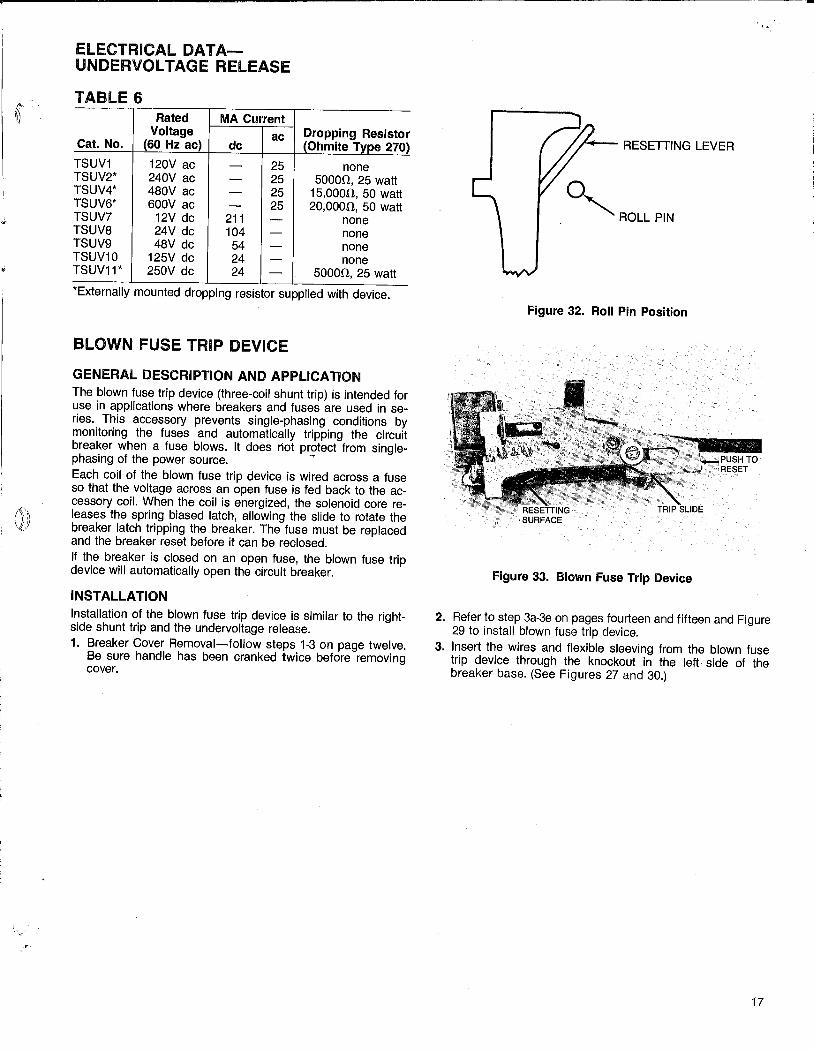
ELECTRICAL DATAUNDERVOL TAGE RELEASE
TABLE 6 Rated MA Current
Voltage ac Cat. No. (60 Hz ac) de
TSUV1 120V ac - 25 TSUV2* 240V ac - 25 TSUV4* 480V ac - 25 TSUV6* 600V ac - 25 TSUV7 12V de 211 -TSUV8 24V de 104 -TSUV9 48V de 54 -TSUV10 125V de 24 -TSUV11* 250V de 24 -
Dropping Resistor (Ohmite Type 270)
none 50000, 25 watt
15,0000, 50 watt 20,0000, 50 watt
none none none none
50000, 25 watt
*Externally mounted dropping resistor supplied with device.
BLOWN FUSE TRIP DEVICE
GENERAL DESCRIPTION AND APPLICATION The blown fuse trip device (three-coil shunt trip) is intended for use in applications where breakers and fuses are used in series. This accessory prevents single-phasing conditions by monitoring the fuses and automatically tripping the circuit breaker when a fuse blows. It does riot protect from single-phasing of the power source. --Each coil of the blown fuse trip device is wired across a fuse so that the voltage across an open fuse is fed back to the accessory coil. When the coil is energized, the solenoid core releases the spring biased latch, allowing the slide to rotate the breaker latch tripping the breaker. The fuse must be replaced and the breaker reset before it can be reclosed. If the breaker is closed on an open fuse, the blown fuse trip device will automatically open the circuit breaker.
INSTALLATION Installation of the blown fuse trip device is similar to the rightside shunt trip and the undervoltage release. 1. Breaker Cover Removal-follow steps 1-3 on page twelve.
Be sure handle has been cranked twice before removing cover.
°"ROLL PIN
Figure 32. Roll Pin Position
Figure 33. Blown Fuse Trip Device
2. Refer to step 3a-3e on pages fourteen and fifteen and Figure 29 to install blown fuse trip device.
3. Insert the wires and flexible sleeving from the blown fuse trip device through the knockout in the left side of the breaker base. (See Figures 27 and 30.)
17
1

--Blown-Fuse Trip Device (cont'd.)
4. Install wire ties on wire bundle on the inside and outside of base to provide strain relief. See Figure 30.
5. Perform installation checks listed below.
a. Replace the breaker cover. Close the breaker contacts. b. To check electrical operation, apply 120 volts to one coil
of the blown fuse trip device for not more than one second. The breaker must trip. Repeat the test for each coil.
6. Attach six (6) lead wires across each of the three fuses as shown in Figure 34.
7. Apply the descriptive label to the front of the breaker cover.
Cover Reassembly Be sure cover (or covers) have been properly reassembled. Refer to steps 1 and 2 on page 16.
3-POLE THREE-PHASE APPLICATION Blown Fuse Trip Device
18
Leads must be connected exactly as shown. Blown fuse trip device may not operate correctly if phase sequence or position is changed.
r i
4
~ I
t---
-- --
Figure 34. \JI.firing Diagram
i
-'-
T r
-----
13 I I
g I OJ JJ
r JJ
OJ :;; m 0
OJ r I r -< r c ::::; m m )> m m )> r 0 r r 0 r l< m m 0
I :;; r )> )> m 0 0
r )>
I m 0 )> 0
I I
0 I :;; z ~ I
I ::::; m r m )>
I 0
I I I I I - - - - - _I
. "
» l

;< . ( \ " I·.
•I -.(,
AUXILIARY SWITCH
DESCRIPTION The auxiliary switch is used for remote indication of breaker main contact position-OPEN or CLOSED. No distinction is made between an open or tripped mode. A maximum of 12 switches can be installed per breaker. Each is single-pole, double-throw (AB-type) and rated as shown in table below. Two switch positions must be devoted to each shunt trip accessory (if used).
Figure 35. Auxiliary Switch
TABLE 7-ELECTRICAL DAT A
Number Maximum Voltage
of Ampere 240V ac max.
Switch Rating 250V de max.
Elements Switch Elements
6A at 240 Vac 1/4A at 250
TSAS2AB* 1-12 volts de 1/2A at 125
volts de *Suffix numbers 1 through 12 designate number of switch elements
INSTALLATION 1. Refer to circuit breaker cover removal instructions on page
twelve. 2. Remove appropriate knockout(s) in the breaker base using
a %'' round file as shown in Figure 36. Remove all debris from the breaker.
3. Remove th~ left hex-head bolt. Discard the plain washer and install the switch assembly as shown in Figure 37, using bolt and lockwasher. Torque the bolt to 250 inchpounds while holding the unit in the correct position.
4. Insert leads and flexible sleeving through the knockout(s). Leads of respective stages should be identified to ensure proper connection after the breaker cover has been replaced and the breaker installed.
Figure 36.
Figure 37.
19

5. Install wire ties on wire bundle(s) on the inside and outside of base to provide strain relief. See Figure 30.
6. Replace breaker cover (or covers for electrically operated breaker).
7. Perform installation checks: a. Verify that "A" contacts Figure 38 (red and white leads)
are open when breaker is open. b. Verify that "B" contacts (brown/white and white leads
are closed when the breaker is open. c. Verify that above circuit conditions are reversed when
breaker is closed. d. Following field installation, apply the descriptive label to
the front of the breaker cover.
___ ..f..---"V-
---+-v----1-v-
coMMoN-wH1TE
---,.......---- B-CIRCUIT-BROWN/WHITE*
AUX. SWITCH *Formerly Green
Figure 38.
4000A Power Break with MagneTrip Non-Interchangeable Trip
Installation of any of these accessories in a 4000A frame MagneTrip requires removal of sealant from one cover screw. Such modification voids the UL Listing. Remove and discard the UL label.
OPTIONAL FEATURES Special features may be ordered as specific accessory catalog numbers or as an integral part of the breaker catalog number. Refer to the Buy Log GEP-1100 for cataloged features. 1. Limited close access button ("C" suffix in catalog number)
Figure 39. Provides limited manual accessibility to ON Button. Function allows breaker to be turned ON in an emergency or for maintenance by use of 3/32" diameter pin or rod. Manually operated devices must be ordered with an accessory closing solenoid.
These instructions do not purport to cover all details or variations in equipment nor to provide for every possible contingency to be met in connection with installation operation or maintenance. Should further information be desired or should particular problems arise which are not covered sufficiently for the purchaser's purposes, the matter should be referred to the General Electric Company.
Outside the U.S. write Construction Equipment Export Operation, 411 Theodore Fremd Ave., Rye, N.Y. 10580 U.S.A. GEH·4694A 0187 PSA
2. Remote Close Only. No means of manually closing device. Manually operated devices must be ordered with closing solenoid.
Figure 39. Manual-Line-Bottom
INSTRUCTION MANUALS Field installable accessories-this manual (GEH-4694) Breaker padlock-GEH-4544 MicroVersaTrip®-GEH-4657 MagneTrip '" (lnstallation)-GEH-4658 MicroVersaTrip RMS·9-GEH-5369 MVT RMS-9 Rating plug-GEH-5371 MicroVersaTrip® RMS-9 Trip Time Curves:
Phase Overcurrent-GES-6235 Ground Fault-GES-6228
For further information call or write your local General Electric Sales Office or ...
General Electric Company 41 Woodford Avenue Plainville, CT 06062 U.S.A.
GENERAL fj ELECTRIC

Installation For Field Installable Accessories •
CAT .. NOS. TPTB 1, TPTB2, TPTB3 FOR 800-2000A FRAMES
DESCRIPTION A terminal board assembly consists of either one (TPTB1 ), two (TPTB2), or three (TPTB3) terminal blocks (six terminals each) mounted on a support bracket. (See Figure 1.) The terminal blocks provide an external means of terminating accessory leads at the breaker. A maximum of 18 terminals can be installed.
TERMINAL BLOCK 2
SUPPORT BRACKET SUPPORT BRACKET ADAPTOR
Figure 1. Terminal board assembly
INSTALLATION
For SOOA Frame Remove the support bracket adaptor before attaching the terminal board to the 800A frame circuit breaker. Using the support bracket as a template, position the terminal board as shown in Figure 2, and drill two 9/64-inch holes (reference two outer holes in support bracket) in the circuit breaker.
GEH-34078
POWER BREAK® Terminal Board For 800- 4000A ·Frames
Insert the self-tapping screws, supplied for installing the board assembly, and torque them to 15 inch-pounds.
For 1600-2000A Frames Using the support bracket adaptor as a template, position the terminal board as shown in Figure 3, and drill two 9/64-inch holes in the breaker as indicated. Insert the self-tapping screws, supplied for installing the board assembly, and torque them to 15 inch-pounds.
Figure 2. Terminal board assembly Installed on the 800A frame
GENERAL fj ELECTRIC

II 0.50
Figure 3. Terminal board assembly installed on the 1600 and 2000A frames
CAT.NOS.TSTB1,TSTB2,TSTB3 FOR 3000-4000A FRAMES
DESCRIPTION A terminal board assembly consists of either one (TSTB1 ), two (TSTB2), or three (TSTB3) terminal blocks mounted on a support bracket. (See Figure 4.) The terminal blocks provide an external means of terminating accessory leads at the breaker. A maximum of 18 terminals can be installed on each side of the breaker.
Figure 4. Terminal board assembly
INSTALLATION
For 2500-3000A Frames Hardware is provided to mount the terminal board in the factory-drilled holes (two) in either side of the
© 1985 GENERAL ELECTRIC COMPANY
These insiructiqns dO not purport to cover all details or variations in equipment nor to provide for every possible contingency to be met in connection with installation operation or maintenance. Should further information be desired or should particular problems arise which are not covered sufficiently for the purchaser's purposes, the matter should be referred to the General Electric Company.
OutsidQ the U.S. and Canada write International Trading Operations. 570 Lexington Avenue, New York, NY 10022 U.S.A. GEH-34078 0485 PSA
breaker base. Secure the board as shown in Figure 5, and torque the mounting screws to 15 inchpounds.
For 4000A Frames Hardware is provided to mount the terminal board in the factory-drilled holes (two) in both lifting brackets, one each located on either side of the circuit breaker base. Secure the board as shown in Figure 6, and torque the mounting screws to 15 inchpounds.
Figure 5. 2500-3000A frame typical mounting
Figure 6. 4000A frame typical mounting
For further information call or write your local General Electric
·Sales Office or ...
General Electric Company 41 Woodford Avenue Plainville; CT 06062 U.S.A.
GENERAL fj ELECTRIC