Management Plan and Public Outreach for WWII Submerged Resources in Saipan
231
Management Plan and Public Outreach for WWII Submerged Resources in Saipan Jennifer F. McKinnon and Toni L. Carrell 2014
Transcript of Management Plan and Public Outreach for WWII Submerged Resources in Saipan

Management Plan and Public Outreach for WWII Submerged Resources in Saipan
Jennifer F. McKinnon and Toni L. Carrell
2014

Cover Photographs by Jon Carpenter 2012

Management Plan and Public Outreach for WWII Submerged Resources in Saipan
Grant Agreement No. GA-2255-11-018 Final Report
Jennifer F. McKinnon and Toni L. Carrell
2014
This material is based upon work assisted by a grant from the Department of the Interior, National Park Service. Any opinions, findings, and conclusions or recommendations expressed in this material are those of the author(s) and do not necessarily reflect the
views of the Department of the Interior.
Copies can be obtained from: Kristen L. McMasters
Government Technical Representative National Park Service
American Battlefield Protection Program 1201 I Street NW (2287), Washington, DC 20005

Title page photograph by Jon Carpenter, 2012

Executive Summary The focus of this project is the underwater cultural heritage (UCH) remains from the World War II (WWII) Battle of Saipan that occurred in June and July of 1944 in the Commonwealth of the Northern Mariana Islands (CNMI). This project builds upon a 2009 ABPP grant (WWII Invasion Beaches Underwater Heritage Trail GA-2255-09-028) to survey and map the submerged archeological sites from the Battle (McKinnon and Carrell 2011). The foundations upon which the 2009 grant was built were a remote sensing survey of key areas by SEARCH, Inc. (2008a, 2008b) and the Maritime History and Archaeology of the Commonwealth of the Northern Mariana Islands (Carrell 2009). The implementation of the maritime heritage trail bought into sharp focus the need to introduce preservation planning for the WWII UCH in Saipan’s waters. The logical next step in the multi-year effort to preserve the UCH was this project and this report: Management Plan and Public Outreach for WWII Sites in Saipan funded under a 2011 APBB grant (GA-2255-11-018). Throughout the 2009-2010 archeological survey, it was clear that certain submerged heritage sites were being negatively impacted by both natural and cultural factors (McKinnon and Carrell 2011). These impacts were identified as contributing to an overall loss of archeological and historical context and affecting the structural integrity of the sites and their long-term survival. To address these concerns and create a framework for long-term preservation, this project focused on two key areas: in situ conservation survey with additional archaeological investigations to gather baseline data and a far-reaching public outreach effort using a 17-minute interpretive film. The WWII submerged sites face a variety of threats that include natural forces, cultural impacts, development and visitation. The report includes recommendations for inter-agency and community partnerships, improving effectiveness of current legislation and enforcement, long term monitoring programs and strategic plans to mitigate cultural and natural impacts, visitor impacts and development. It also addresses the limitations inherent in the funding, personnel, and management at the CNMI Historic Preservation Office (HPO) and CNMI Coastal Resources Management office (CRM). Additionally public outreach and education is a necessary component for the long-term protection of cultural heritage. For fragile sites, and those that are underwater where monitoring is difficult, stakeholders and users must take an active role. Thus a film was produced to raise awareness of both divers and non-divers alike for WWII UCH in the CNMI.
iii

iv

Table of Contents Executive Summary ...................................................................................................................................... iii
Table of Contents .......................................................................................................................................... v
List of Figures ............................................................................................................................................... ix
List of Tables ................................................................................................................................................ xi
Acknowledgements .....................................................................................................................................xiii
Chapter 1: Introduction ................................................................................................................................ 1
Introduction .............................................................................................................................................. 1
In Situ Conservation Survey .................................................................................................................. 1
Public Outreach and Interpretive Film .................................................................................................. 2
Scope ......................................................................................................................................................... 2
The Sites ................................................................................................................................................ 3
Limitations............................................................................................................................................. 4
Legislation ................................................................................................................................................. 4
Jurisdictional Responsibilities ................................................................................................................... 4
Chapter 2: Historical Background 1911-1944 (after SEARCH, Inc. 2008) ..................................................... 7
Historical Context ...................................................................................................................................... 7
The Mariana Islands in WWII, 1941-1945 ............................................................................................. 7
Japanese Defences on Saipan ............................................................................................................... 9
The Aftermath of the Battle of Saipan ................................................................................................ 12
Chapter 3: Cultural Resources .................................................................................................................... 15
Daihatsu Landing Craft ............................................................................................................................ 15
Daihatsu 1 ........................................................................................................................................... 15
Daihatsu 2 ........................................................................................................................................... 16
Daihatsu 3 ........................................................................................................................................... 17
Inter-site Preservation and Deterioration .......................................................................................... 19
Sherman Tanks ........................................................................................................................................ 19
Tank 1 .................................................................................................................................................. 19
Tank 2 .................................................................................................................................................. 20
Tank 3 .................................................................................................................................................. 22
v

Inter-site Preservation and Deterioration .......................................................................................... 23
Landing Vehicle Tracked LVT (A)-4 .......................................................................................................... 24
Landing Vehicle 1 (LVT-1) .................................................................................................................... 24
Landing Vehicle 2 (LVT-2) .................................................................................................................... 25
Inter-site Preservation and Deterioration .......................................................................................... 26
Japanese Merchant Ship, Presumably Shoan Maru aka “Chinsen” ........................................................ 26
Preservation and Deterioration .......................................................................................................... 28
Possible Auxiliary Submarine Chaser ...................................................................................................... 28
Preservation and Deterioration .......................................................................................................... 31
Unidentified Steamship .......................................................................................................................... 31
Preservation and Deterioration .......................................................................................................... 32
Aichi E13A “JAKE” ................................................................................................................................... 32
Preservation and Deterioration .......................................................................................................... 34
Kawanishi H8K “EMILY” .......................................................................................................................... 34
Preservation and Deterioration .......................................................................................................... 35
Martin PBM Mariner ............................................................................................................................... 36
Preservation and Deterioration .......................................................................................................... 37
TBM Avenger ........................................................................................................................................... 37
Preservation and Deterioration .......................................................................................................... 39
Consolidated PB2Y Coronado ................................................................................................................. 39
Preservation and Deterioration .......................................................................................................... 40
Chapter 4: Threats and Impacts .................................................................................................................. 41
Cultural Threats and Impacts .................................................................................................................. 41
Anchor and Mooring Damage ............................................................................................................. 41
Looting and Moving Artifacts .............................................................................................................. 43
Acts of Vandalism ................................................................................................................................ 47
Tourism Services Impacts .................................................................................................................... 48
Memorialization .................................................................................................................................. 49
Environmental Threats and Impacts ....................................................................................................... 49
In Situ and Ex Situ Artifacts ..................................................................................................................... 52
Chapter 5: Public Outreach ......................................................................................................................... 55
Introduction ............................................................................................................................................ 55
vi

Consultation, Public Meetings, Presentations, Press and Digital Media ................................................ 55
Consultation ........................................................................................................................................ 55
Public Meetings and Presentations .................................................................................................... 56
Press and Digital Media....................................................................................................................... 58
Interpretive Materials and Film .............................................................................................................. 59
Poster and Dive Guide ........................................................................................................................ 59
The Film - WWII Maritime Heritage Trail: Battle of Saipan ................................................................ 63
Chapter 6: Recommendations and Relevant Issues.................................................................................... 67
Management of Underwater Cultural Heritage Sites ............................................................................. 68
Consultation and Strategic Planning ....................................................................................................... 68
Legislation and Effective Enforcement ................................................................................................... 69
Complete National Register Nominations .............................................................................................. 70
Site Database and At-Risk Artifacts ......................................................................................................... 71
Programmatic Research and Inventory .................................................................................................. 72
Monitor Material Remains to Identify Natural Impacts ......................................................................... 73
Recognize UCH as Sites of Natural Significance ...................................................................................... 74
Protect Material Remains from Cultural Threats .................................................................................... 75
Monitor Impacts of Development .......................................................................................................... 80
Monitor Visitation to Sites ...................................................................................................................... 81
Strengthen Relationship with the Dive Community ............................................................................... 81
Increase Availability of Interpretive Materials........................................................................................ 82
Chapter 7: Conclusion ................................................................................................................................. 87
Further Contact ....................................................................................................................................... 89
References Cited ......................................................................................................................................... 91
Appendix A: Conservation Survey and Management Program - Saipan WWII Underwater Archaeological Wreck Sites ................................................................................................................................................. 95
vii

viii

List of Figures Figure 1. Map of sites investigated (McKinnon 2012). ................................................................................. 3 Figure 2. Invasion Beaches of Saipan. Map design James W. Hunter, Ships of Discovery. .......................... 9 Figure 3. Daihatsu Landing Craft 1 - stern to bow view (Carpenter 2012). ................................................ 16 Figure 4. Daihatsu Landing Craft 2 – port side view (Carpenter 2012). ...................................................... 17 Figure 5. Daihatsu Landing Craft 3 – port side view (Carpenter 2012). ...................................................... 18 Figure 6. M4 Sherman Tank 1 – port side view (Carpenter 2012). ............................................................. 20 Figure 7. The tank shows evidence of rust, surface spalling, and loss of structural integrity (Carpenter 2012). .......................................................................................................................................................... 21 Figure 8. The tank sits on a bed of seagrass that extends in all directions (Carpenter 2012). ................... 21 Figure 9. M4 Sherman Tank 3 – stern view (Carpenter 2012). ................................................................... 22 Figure 10. Landing Vehicle Tracked 1 – port side view (Carpenter 2012). ................................................. 24 Figure 11. Landing Vehicle Tracked 2 – front view (Carpenter 2012)....................................................... 26 Figure 12. Japanese merchant Ship (bow view) (Carpenter 2012). ............................................................ 27 Figure 13.Photomosaic of possible auxiliary submarine chaser site. ......................................................... 29 Figure 14. Unidentified steamship – boilers (Carpenter 2012). ................................................................. 32 Figure 15. Overview photograph of Aichi E13A JAKE (Carpenter 2012). ................................................... 33 Figure 16. Kawanishi H8K (EMILY) (Carpenter 2012). ................................................................................. 35 Figure 17. Overview shot of central portions of Martin PBM Mariner site; note dihedral wing (D. McHenry, June 2010). ................................................................................................................................. 37 Figure 18. Grumman TBM Avenger (Carpenter 2012). ............................................................................... 38 Figure 19. Consolidated PB2Y Coronado (Carpenter 2012). ....................................................................... 40 Figure 20. Map of Mañagaha Marine Conservation Area (CRM). .............................................................. 42 Figure 21. Avenger landing gear, note shiny metal where concretion has been rubbed away due to mooring (Carpenter 2012). ......................................................................................................................... 42 Figure 22. Korean monument with .50 caliber rounds (Gauvin 2010). ...................................................... 43 Figure 23. Cockpit configuration changes over time on Kawanishi H8K (Bell 2010). ................................. 44 Figure 24. Japanese monument surrounded by gas cylinders and other moveable objects (Seymour 2012). .......................................................................................................................................................... 44 Figure 25. Wireless radio Identification plate recovered from the Kawanishi H8K sites (masadive-saipan.com, accessed June 2010). .............................................................................................................. 45 Figure 26. A portion of a Kawanisihi H8K reported to the HPO (Rogers 2010). ......................................... 45 Figure 27. Artifact pile created by divers and altered over time (Bell 2010). ............................................. 46 Figure 28. Faux airplane wreck created for a submarine tour with artifacts gathered from sites in the vicinity. Note four-blade propeller (foreground) and gun in background (Carpenter 2012). .................... 47 Figure 29. Graffiti etched into the Kawanishi H8K (Bell 2010) ................................................................... 48 Figure 30. Front of Japanese shipwrecks poster. ........................................................................................ 61 Figure 31. Back of Japanese shipwrecks poster. ......................................................................................... 62 Figure 32. Aichi 313A dive guide. ................................................................................................................ 63 Figure 33. Diving Shipwreck brochure produced by South Australia Heritage. .......................................... 77 Figure 34. Anchoring brochure produced by South Australia Heritage Branch. ........................................ 79
ix

x

List of Tables Table 1. Table of sites investigated. .............................................................................................................. 2 Table 2. Quick reference to recommendations, action items and time frame .......................................... 83
xi

xii

Acknowledgements This project would not have occurred without the help of a number of individuals and groups. First and foremost we would like to thank the CNMI Historic Preservation Office for their continuous support from long before this project started to long after it will have finished. Special thanks are extended to Ronnie Rogers (no longer at HPO), John Castro (no longer at HPO), Herman Tudela (no longer at HPO), “JP” John Palacios and Mertie Kani. The Coastal Resources Management Office provided support for this project. We would especially like to thank John “John John” D. San Nicolas for your endless support and for being an integral member of the team. The agencies and organizations that have supported this project on island include: the National Park Service American Memorial Park; the NMI Humanities Council; Power 99; Poseidon’s Maidens Dive Charter and Aqua Connections. Special thanks are extended to two generous individuals, Scott Eck for the use of his vessel and Genevieve Cabrera who continues to educate us about the island. Thank you to Peter Harvey, Jason Raupp, Cos Coroneos, Vicki Richards, Jon Carpenter, Toni Carrell and Jennifer McKinnon for forming the “A-Team,” who collected an incredible amount of conservation survey data in a very short period of time. Without the hard work of Brett Seymour, National Park Service, Maryanne Morin and Louis Lamar, Woods Hole Institution, Veronica Veerkamp and Richard Coberly, Windward Media, there would be no interpretive film. The WWII Maritime Heritage Trail: Battle of Saipan is not only visually beautiful but, as importantly, was scripted and narrated with sensitivity and respect for all who lost their lives in Saipan. We owe the film team a debt of gratitude for their guidance and hard work. Special thanks go to Flinders University for providing staff time and equipment and East Carolina University for providing staff time to this project. A big thank you should be extended to the American Battlefield Protection Program for providing the funding for this project. We would particularly like to thank Kristen McMasters for her availability and willingness to help us through this process.
Jennifer McKinnon, Greenville Toni Carrell, Santa Fe
xiii

xiv

Chapter 1: Introduction
Introduction The implementation of the WWII Invasion Beaches Underwater Heritage Trail under a 2009 ABPP grant (GA-2255-09-028) brought into sharp focus the need to develop a management and preservation plan for the submerged WWII heritage in Saipan’s waters. The foundations upon which the 2009 grant was built were a remote sensing survey of key areas by SEARCH, Inc. (2008a, 2008b) and the Maritime History and Archaeology of the Commonwealth of the Northern Mariana Islands (Carrell 2009). The logical next step in the multi-year effort to preserve WWII UCH was this project funded under a 2011 APBB grant (GA-2255-11-018) and this report: Management Plan and Public Outreach for WWII Sites in Saipan. Throughout the 2009-2010 archeological survey, it was clear that certain UCH sites were being negatively impacted by both natural and cultural factors (McKinnon and Carrell 2011). These impacts were identified as contributing to an overall loss of archeological and historical context and affecting the structural integrity of the sites and their long-term survival. To address these concerns and create a framework for long-term management and preservation, this project focused on two key areas: in situ conservation survey with additional archaeological investigations and a far-reaching public outreach effort. This report details the results of those efforts and makes recommendations for the preservation of WWII submerged heritage. This is the technical report for the current grant (GA-2255-11-018).
In Situ Conservation Survey In situ conservation surveys are different from standard archeological surveys because they include the collection of data related to the natural environment (chemical and physical) that can allow for a better understanding of the destructive forces affecting sites and artifacts (MacLeod and Richards 2011). They also record modern cultural impacts that can be used in the management of sites, including allowing or restricting access to sites and controls for altering behaviors of visitors. Finally, they often collect specific cultural information including data on material composition of objects. This data is vital to understanding the construction of these sites from an archeological or cultural perspective, but also contributes to understanding the longevity of sites with relation to the material composition of metals and organics, how they react to and survive within the environment, and their overall structural integrity. In situ surveys and studies are critical to regions such as the Pacific because there are limited resources (i.e. funding, staff, and facilities) to conduct recovery and conservation of submerged objects and sites. While the CNMI does benefit from grant funds distributed by the National Park Service (NPS), this funding is limited and often only covers a small portion of the compliance needs of the HPO (Ronnie Rodgers personal communication, 2010). This means that the conservation and management of the resources must be done in situ. Further, understanding the condition of the resources through in situ and archeological surveys is an important step in the management process. An agency cannot manage a site if they have no knowledge of its condition.
1

In addition to the conservation study, additional archeological survey was needed on sites included on the heritage trail and also on sites that had yet to be identified and recorded. The purpose of this archeological survey was two-fold: 1) to update information on natural impacts to known sites that affect site formation processes (i.e. scouring, sediment build-up) and cultural impacts (i.e. looting, vandalism, etc.); and 2) to locate, record and identify new “control” sites not on the trail that could be monitored long-term for comparison purposes. Baseline data collected on new sites is useful because they can help managers understand the differential impacts of site visitation on those included in the trail.
Public Outreach and Interpretive Film The interpretive film was conceived during many discussions with the staff of the NPS American Memorial park, NPS War in the Pacific National Park, the CNMI HPO, local divers, dive tour operators and visitors. In those discussions it was clear that although the posters and dive guides produced under the 2009 heritage trail grant were well received, their impact was limited to those individuals who obtained copies. Once those printed copies were used up the ability of any group or individual to raise funds to reprint them was going to be difficult. To create a broad base of support, the preservation message had to reach a much larger audience and be unlimited in its application and use. An interpretive film about the WWII submerged sites targeting divers, non-divers, visitors and residents would not only have an inherent appeal but could use the power of film to reach all audiences.
Scope The scope of this report includes the sites on the WWII Maritime Heritage Trail, an additional four sites not included on the trail, and more generally all submerged WWII heritage sites in the waters of Saipan, CNMI (Table 1). Table 1. Table of sites investigated.
Name of Site Trail (Y/N) Japanese merchant ship, Presumably Shoan Maru/Chinsen (Japanese)
Y
Steamship (Unidentified) N Possible Auxiliary Submarine Chaser (Japanese) Y Sherman Tank 1 (U.S.) Y Sherman Tank 3 (U.S.) Y Landing Vehicle Tracked-(A)-4 (U.S.) Y LVT 2 (U.S.) N Daihatsu Landing Craft 1 (Japanese) Y Daihatsu Landing Craft 2 (Japanese) Y Daihatsu Landing Craft 3 (Japanese) N Kawanishi H8K “EMILY” (Japanese) Y Aichi E13A “JAKE” (Japanese) Y Martin PBM Mariner (U.S.) Y TBM Avenger (U.S.) Y PB2Y Coronado (U.S.) N
2

The Sites All sites are within Garapan, Tanapag and Chalan Kanoa Lagoons on the western side of the island of Saipan. The lagoons were created by a shallow barrier reef and range in width from 375 m to 3.5 km and in depth up to 14 m deep in Tanapag Lagoon with an average of less than 3 m deep in Garapan Lagoon (Amesbury et al. 1996). Much of Chalan Kanoa lagoon is difficult to navigate because it is shallow and interspersed with coral heads and reef flats. A small islet called Mañagaha is located within the lagoon just west of the modern harbor facilities. The sites are scattered throughout the area with the main concentration in Garapan Lagoon (Figure 1 ). They include aircraft, shipwrecks and assault vehicles of varying states of articulation. Each site will be reviewed and described in detail in below chapters.
Figure 1. Map of sites investigated (McKinnon 2012).
3

Limitations An inherent limitation in this project is that the remains of many sites have not yet been identified or are buried beneath the sediments. Nonetheless, the in situ conservation data and the recommendations generated for preservation are broadly applicable to all of the WWII wrecks in Saipan.
Legislation Historic shipwrecks in the CNMI are protected through laws passed by the Commonwealth and the US Federal government. The following is a list of legislation relevant to UCH and military heritage: The Abandoned Shipwreck Act 1987 protects historic shipwrecks “embedded in State’s submerged lands.” The Sunken Military Craft Act 2005 confirms right, title and interest of the US to any sunken military craft anywhere in the world as well as the same rights and protection to non-US military craft sunk in US controlled bottomland. The National Historic Preservation Act 1966 under Section 106 and 110 provides protection for shipwrecks and other submerged sites with regards to the permit and mitigation processes and requires inventory and assessment of such sites as standard procedure. The Archaeological Resources Protection Act 1979 prohibits damage to archeological sites that are 100 years or older and provides archeological and permit guidelines. CNMI Historic Preservation Act of 1982 (Public Law 3-39) protects submerged sites stating, “It shall be unlawful for any person, partnership, business, corporation or other entity who willfully remove or take any artifact that is of historic or cultural significance to the people of the Northern Mariana Island, or knowingly destroy, remove, disturb, displace, or disfigure any cultural or historic property on public or private land or in the water surrounding the Northern Mariana Islands as designated by or eligible for designation by the HPO as a cultural or historic property, unless such activity is pursuant to a permit issued under Section 5 of this Act.”
Jurisdictional Responsibilities The Historic Preservation Office (HPO) has the overall administrative responsibility for cultural heritage in the CNMI. This obligation extends off shore to all UCH, whether they have been identified or are as yet to be investigated. To accomplish the legislative purpose of the Mañagaha Marine Conservation Act, the CNMI Department of Lands and Natural Resources (DLNR) was delegated the exclusive authority to manage the Mañagaha Marine Conservation Area (MMCA), as well as other marine conservation areas in the CNMI (Section 6 of PL 12-12). The role of the DLNR in regard to the management of UCH is to promote public access to the sites while protecting the physical remains. They are also responsible for protecting sites.
4

Coastal Resources Management (CRM) was established on 11 February 1983, with the implementation of Public Law 3-47 within the Office of the Governor. The CRM program was established in order to promote the conservation and wise development of coastal resources. CRM is responsible for general permitting activities that impact coastal resources in Saipan and in particular permits for dive boats and dive tour operations in all Saipan waters. Similarly, the Department of Environmental Quality (DEQ) ismainly concerned with water quality and pollution and the US Fish and Wildlife Service (FWS) with fish and marine life. Their responsibilities extend to all Saipan waters.
5

6

Chapter 2: Historical Background 1911-1944 (after SEARCH, Inc. 2008)
Historical Context As destructive as World War I was in other parts of the world, the Mariana Islands were spared. Still, the end of the war had important ramifications for the islands. The League of Nations approved Japan’s occupation of the Mariana (sans Guam), Caroline, Marshall, and Palau Islands in 1921 with the stipulation that Japan not develop fortifications in the region. For over a decade Japan complied with the agreement and focused on infrastructural development that strengthened the economy of their possessions. Increasingly militaristic and expansionist, Japan sought to strengthen its presence in the Pacific in the late 1930s. For example on Saipan, Aslito Airfield on the southern end of the island and a seaplane base at Flores Point (northeast of Garapan) were constructed. Barracks, ammunition storage, air raid shelters, and other facilities preparatory for an offensive war were installed elsewhere on Saipan in 1941 (Russell 1984). Japan’s moves to fortify the islands abrogated their agreement with the League of Nations, thus losing their legal jurisdiction.
The Mariana Islands in WWII, 1941-1945 Across the Pacific, word spread that war was coming, however, only Japan knew when and where it would start. Shortly after the December 7, 1941 attack on Pearl Harbor in Hawaii, Japanese forces initiated air attacks over Guam, which they had been openly monitoring since November. Commercial airline buildings, fuel supplies, the US Navy yard, vessels in Apra Harbor, and the capital at Agana were bombed. Poorly defended by the Americans, Guam fell on December 10th within six hours of the subsequent Japanese invasion. Guam became the only part of the US to fall under enemy occupation during WWII. With this prize under its belt, the Japanese Imperial Army and Navy mounted very successful aggressive operations across the Pacific in the early years of the war (Rogers 1995; Rottman 2004a). As these events were occurring in the Marianas, Allied powers meeting in Egypt agreed upon a Pacific strategy consisting of two offensive drives. The first, led by General Douglas MacArthur, was an advance from New Guinea to the Philippines. The second, led by Admiral Chester Nimitz, was a push through the Gilbert and Marshall Islands across the Central Pacific to take the Marianas. Once accomplished, a strategic bombing campaign could be mounted against the Japanese mainland. By the start of 1944, this broad strategy proved successful for the US, and the Japanese government realized an invasion of the Marianas was imminent. As Marine historian O.R. Lodge wrote, “A strangling noose was tightening around the inner perimeter guarding the path to their homeland” (Lodge 1954).
Operation Forager The US’s plan to take control of the Marianas from Japanese forces was code-named Operation Forager and included the island of Guam. The plan to invade and take control of Saipan was called Operation Teattersalls. This operation involved thousands of troops from all branches of the military and a bewildering number of vessels, vehicles, and weapons. Japan’s defenses focused on five islands in the
7

Marianas: Guam, Rota, Tinian, Saipan, and Pagan. Saipan, home of the administrative center of the Japanese Marianas, was chosen as the first target with Tinian and Guam as secondary. US war planners opted to bypass a full assault on Rota and Pagan (Rottman 2004a). Air attacks were the first phase of Operation Forager. In February 1944, US bombers destroyed the Orote Peninsula airstrip on Guam. General air raiding also began across the Marianas, resulting in US dominance of the skies. In response, Japanese forces prepared Operation A-Go, which relied upon the support of the Imperial Japanese Navy and air forces to support troops on the ground in the Marianas. Operation Forager was in full swing by June 1944 when the invasion of Saipan was planned. The invasion was set for June 15, D-Day. Responsible for this task was the Marine V Amphibious Corps (VAC) that consisted of the 2nd and 4th Marine Divisions, the 27th Infantry Division (Army), and the XXIV Corps Artillery (Army). US military planners considered landing points on all sides of Saipan. On the eastern side of the island an area designated Brown Beach on the Kagman Peninsula was considered but rejected because it was well-defended and would offer a poor exit. Three other beaches, Purple Beach on Magicienne Bay and White Beach 1 and 2 near Cape Obian on the southern reach of the island were kept as alternates. At Tanapag Harbor were the well-defended Scarlet Beaches 1 and 2, and to the north of this area were Black Beaches 1 and 2, which offered insufficient space for the large unit landing that was planned (Rottman 2004a). The lower western side of Saipan was chosen as the primary invasion area. Stretching approximately four miles and divided into several zones, this area was most favorable because the size would allow two Marine divisions to land simultaneously. A landing here also allowed the immediate capture of the airstrip at Chalan Kanoa placing direct pressure on nearby Aslito Airfield. Once secure, these airstrips were used to support the penetration northward across Saipan. Afetna Point divided the landing beaches. To the north were Red Beaches 1, 2, and 3 and Green Beaches 1 and 2 while to the south were Green Beach 3, Blue Beaches 1 and 2, and Yellow Beaches 1, 2, and 3 (Rottman 2004a) (Figure 2). As favorable as the lower western side of Saipan was for the US invasion, certain limitations remained. Because of its distance from the northern sector of the island, beaches in this area (Scarlet 1 and 2 and Black 1 and 2) had to be captured in order to facilitate the off-loading of supplies from landing craft. Another problem at the beaches off the lower western side of Saipan was the extensive coral reef that abutted the shore. These had to be negotiated with amphibious vehicles including AMTRACS or Landing Vehicle Tracked (LVTs) and amphibious tanks, also known as Landing Vehicle Tanks (LVT(A)s). Both the 2nd Marine Division and the 4th Marine Division had three AMTRAC battalions each, plus one amphibian tank battalion, for the initial shore assault. This amounted to approximately 1,400 AMTRACS, the largest use to date of amphibious vehicles. Once ashore, the AMTRACS were required to push inland from the beach, a tactic that was equally unprecedented and also potentially dangerous. AMTRACS, with their thin armor and low ground clearance, were not designed for cross-country movement.
8

Japanese Defences on Saipan The Japanese defensive strategy used for Saipan and the other Mariana Islands was identical to that of earlier battles at the Gilbert and Marshall Islands: the enemy was to be met and destroyed at the beaches and, if allowed inland, they were to be pushed into the sea by way of counterattacks (Denfield 1992). Japanese defenses on Saipan, while substantial, were incomplete by D-Day. Prior to the outbreak of the war, Japan’s need for troops and material elsewhere in the Pacific hampered the pace of developments on Saipan and the other islands of the Marianas. The Japanese forces established two bases on Saipan by early 1944. The airfield at Aslito (built in the 1930s) served as a repair and maintenance facility for aircraft involved in battles to the east and south. At Tanapag Harbor, a naval base served as a staging area for troops and ships bound elsewhere (Denfield 1992). Due to needs in other parts of the Empire, Japanese troop numbers were fairly low; in February 1944, there were only 1,500 troops on Saipan.
Figure 2. Invasion Beaches of Saipan. Map design James W. Hunter, Ships of Discovery.
9

The impending US campaign against the Marianas hurried Japanese defensive measures and by the end of February thousands of troops were sent to the Marianas to prepare for battle. US submarine attacks on Japanese transports prevented an estimated 2,000 troops from reaching the islands (Denfield 1992), but by early June some 30,000 troops were prepared for battle on Saipan (Rottman 2004b). Once they had sufficient troops and materials available, the Japanese forces commenced defensive improvements on Guam, Tinian, Rota, Pagan, and Saipan. On Saipan, another airfield was built by Lake Susupe near the town of Chalan Kanoa, but this was little more than an emergency landing strip. More airstrips were planned on Saipan and throughout the islands, but most were never completed (Denfield 1992). Forty-six gun installations were established on the beaches and ridges of Saipan, but twelve were not operational on D-Day. An additional three units lay on railcars awaiting installation at the start of the battle and another 42 were in storage at the navy base at Tanapag. Construction of three blockhouses on the beaches of Saipan, each a concrete structure with four ports housing heavy guns, began in early 1944. Between Camp Obiam and Agingan Point (White Beach 1), one of these blockhouses stood incomplete and unarmed on D-Day. Another was located to the east of Cape Obiam (White Beach 2) and the third was on the eastern side of the island at Magicienne Bay (Purple Beach) (Denfield 1992).
The Battle of Saipan – Operation Tattersalls 1944 An intensive barrage presaged the beach invasion foreshadowing the massive confrontation that was set for June 15. On June 12, 200 carrier aircraft bombed Japanese airfields in the southern Marianas, decimating the enemy’s air force. That same day, American B-24 bombers began around-the-clock raids on Saipan and Tinian. The following day (June 13), seven fast battleships leveled the towns of Chalan Kanoa and Garapan and on June 14, more battleships as well as 11 cruisers and 26 destroyers attacked Japanese coastal defenses. On June 14, other crucial preliminary actions took place along the coast of Saipan. Early that morning, Underwater Demolition Teams began their mission to demolish reefs, enemy mines, and mark lanes along the Red, Green, Blue, and Yellow beaches. This effort was largely successful. Simultaneously, a mock attack was held by a “Demonstration Group” off the northwestern coast at Scarlet and Black beaches (refer to Figure 2) in an attempt to trick the Japanese into thinking that the invasion was to occur there. Another was held in the early morning hours of June 15, D-Day. The Demonstration Group consisted of the 2nd Marines, the 1st Battalion, 29th Marines, and the 24th Marines. The feint was supported by naval gunfire as landing craft approached the beach to within 5,000 yards, circled for a few minutes, wheeled about, and returned to their ships. Troops were not embarked, the landing craft drew no fire, and no activity was observed on the shore. Although clearly not convinced by the ploy, the Japanese stopped short of removing troops from here and redeploying them to other beaches. Interestingly, Japanese commanders did wire Tokyo to report that they had repelled an invasion in this area (Rottman 2004a). As the sun rose on June 15, the enormous US amphibian force was assembled for the invasion. AMTRACS and DUKWs were unloaded and LSDs (Landing Ship, Dock) launched LCMs (Landing Craft, Mechanized) that held tanks. Battleships, cruisers, and destroyers closed in on the invasion beach with
10

aircraft screaming overhead toward the shore. With nearly 1,500 vessels in all, this great unpacking of men, weaponry and ammunition was surely an intimidating sight for the Japanese forces and the islanders. At exactly 0830 hours, the AMTRACS carrying hundreds of marines stormed for the beach as supporting ships and aircraft opened fire. The Japanese troops generally held their fire until the AMTRACS reached the lip of the coral reef when they poured artillery, mortar, and machine gun fire on the Marines. Due to the condition of the seas, the Marines had a great deal of difficulty reaching the beach. Numerous AMTRACS were rendered inoperable or destroyed as a result. Dozens of Marines lost their lives when AMTRACS were overturned in the rough surf, but by 0900 hours nearly 8,000 Marines were ashore (Crowl 1960; Rottman 2004a). The beaches, especially the northern Red and Green Beaches, were chaotic and crowded. Because of the heavy swell and long shore current, the US landing in this area was several hundred yards north of its intended location. In all areas Japanese fire was very heavy and came from the high ground beyond, as well as trenches and spiderholes along the immediate shoreline. The overland AMTRAC charge, a calculated risk, proved disastrous as the flimsy AMTRACS became stranded in marshy areas, craters, and other obstructions on the ground. As casualties for the Marines mounted, many chose to abandon their machines in favor of walking or crawling. Problems increased as the morning wore on. At the northern beaches, two 2nd Marine Division command posts were destroyed, killing battalion commanders and key staff and on the south, the 4th Division indecisively struggled with Japanese tanks for hours. The arrival of US tank battalions, howitzer batteries, and other support forces improved the overall situation by the end of the day, although the beachhead remained unconsolidated. On this day, the first of the battle for Saipan, some 2,000 Marines were killed. Mortar and artillery fire were the principal causes of death. Offshore hospital vessels were completely overwhelmed and wounded men were transferred to other, non-hospital ships for treatment (Crowl 1960; Rottman 2004a). Over the next two days, the Marines secured and expanded the beachhead. The morning of June 16 was spent closing the gap between the two divisions, which were separated by a strong Japanese force on Afetna Point. By noon, this goal was accomplished. A huge Japanese counterattack was successfully repelled that afternoon and the Marines engaged in the largest tank battle of the Pacific War. Aslito Airfield was under pressure at the close of the day. In contrast, the 27th Infantry Division (Army) came ashore to support the Marines on the morning of June 17 and bore the brunt of a door-to-door fight through Garapan village, another innovation in the Pacific War. After the beaches were secured, support groups landed on the beachheads to facilitate the massive unloading of supplies. The post-invasion landscape they witnessed was grim. Disabled AMTRACS and boxes of c-rations were scattered across the beach. Bodies of dead Marines that were not yet recovered bobbed in the surf. “The leaves on battered trees and underbrush were covered with a fine, gray dust,” wrote former Naval Construction Battalion (Seabee) commander David Moore. “This whole scene gave an eerie feeling of war” (Moore 2002). On the evening of D-Day, Seabees were ordered to launch the floating causeways held in the LSTs (Landing Ship, Tanks). Throughout the night, the Seabees maneuvered the various pieces through the
11

channel and assembled them at the Chalan Kanoa beachhead. By daybreak supplies were being unloaded from landing craft. Other craft towed pontoon sections that were made into floating piers to unload supplies. Pontoon barges were used to haul ammunition. While vital to the continued success of the American operation on Saipan, unloading supplies and ammunition from barges on the beachhead became monotonous as combat moved farther inland. This “grueling mission of moving ammunition and other supplies to the beach…became a routine of eating bland c-rations and sleeping on the barge for a boring 54 days of blazing sun or miserable rain,” remembered one Seabee who served at Saipan. “The Coxswain often grumbled: it is noble to suffer. We [the Seabees] were granted the undistinguished title, ‘Bastards of the Beaches’” (Moore 2002). There were nevertheless many soldiers on the mainland that would have traded places with the Seabees. Japanese attempts to call in reinforcements from neighboring islands were fruitless, but they continued to fight with resolve. On June 18, they attempted a daring counter-landing from their tattered navy base at Tanapag Harbor. Japanese infantrymen were hastily loaded onto 35 barges and sent toward the US landing beaches. In route, US infantry gunboats and Marine artillery intercepted them, destroying many and deterring all. A larger-scale encounter played out in the Philippine Sea between June 19 and 20 when the US Navy defeated the Japanese Imperial Navy in what is known at the “Marianas Turkey Shoot.” In the meantime, the US secured Aslito Airfield and the southern reaches of the island and prepared the northward fight (Crowl 1960; Rottman 2004a). More gruesome scenes followed in this monstrous battle as June became July and US troops pushed deeper into the island of Saipan. Garapan was secured on July 3, the Tanapag seaplane base on July 4, and on July 6 the Japanese forces staged their last massive banzai charge. After Saipan, Japanese commanders deemed such suicidal charges as wasteful. Rarely effective, they were not used in later battles. Through mountainous terrain, tropical conditions, and intense resistance, US forces reached the northern end of Saipan at Marpi Point on July 9, 1944 (Crowl 1960; Rottman 2004a).
The Aftermath of the Battle of Saipan The loss of life during the Battle of Saipan was tremendous. Approximately 3,426 of the 67,451 US troops who participated in the battle were killed or reported missing in action. Four times this number were confirmed wounded. Japanese losses were far greater. Of the approximately 31,629 Japanese troops who participated in the battle, 29,500 were killed or missing (Rottman 2004b). Japanese sources, however, estimated the total number killed on Saipan to be well over 40,000 (Bulgrin 2005). The long-fought and costly victory at Saipan, the fiercest of the three major battles in the Marianas, was politically and militarily decisive. US successes in the opening two weeks of the battle induced Japanese Emperor Hirohito to attempt a diplomatic end to the war. When news of Saipan’s fall reached Japan, political pressure forced Prime Minister, War Minister, and Chief of Army General Staff Tojo Hideki and his cabinet, as well as navy officials, to resign (Rottman 2004a). Equally as important to the decisiveness of the victory at Saipan was the island’s proximity to Japan. This was also true of Guam and Tinian. The Mariana Islands were ideal for the development of bases for long
12

range, B-29 bombers that were capable of reaching the Japanese mainland. On Saipan, the US wasted no time in developing these bases. Aslito Airfield was renamed Conroy Field and then Isley Field. By December 1944, it was used as the main operating field on the island. Two new airfields, Kobler Field and another at Kagman Peninsula, were also built at this time. The seaplane base at Flores Point was rebuilt and improvements were made to the Marpi Point airfield. Saipan and the Mariana Islands paved the road for more decisive battles at Okinawa and Iwo Jima. Together, the great sacrifices of these and other battles of the Pacific War gave US military planners an impression of what could be expected from an invasion of the Japanese mainland. Plans for such an invasion were in the making when the decision was made to drop the atomic bombs on Hiroshima and Nagasaki, resulting in the surrender of the Japanese Empire and the conclusion of WWII.
13

14

Chapter 3: Cultural Resources This chapter provides basic identification, condition, and environmental dynamics on the archeological sites that were the subject of research on differential preservation and deterioration for this project. A full report of findings resulting from the in situ conservation survey is included as Appendix A (hereafter referred to as Richards and Carpenter 2012). These data provide the basis for selected recommendations in Chapter 6. With the exception of the Daihatsu Landing Craft 3, Landing Vehicle (LVT) 2, an Unidentified Steamship in Tanapag Harbor and the Consolidated PB2Y Coronado aircraft, all sites are included on the WWII Maritime Heritage Trail – Battle of Saipan. Divers and snorkelers are actively encouraged to visit the sites provided they follow the visitation guidelines and do not interfere with the site (i.e. disturb or attempt to remove any components).
Daihatsu Landing Craft The remains of two Japanese Daihatsu landing crafts lying in the vicinity of each other were originally located by Pacific Basin Environmental Consultants (1985) and NPS (Miculka et al. 1984), reported by Carrell (1991:500, 502), relocated by SEARCH, Inc. in 2008 (2008b:54, 59) and archeologically mapped in 2010 (McKinnon and Carrell 2011). A third site was located during the 2012 survey and was not previously recorded. Because Daihatsu 3 is not included on the trail, it can serve as a control to monitor visitor impacts.
Daihatsu 1 The Daihatsu Landing Craft 1 (Figure 3) is located on the southwest side of Saipan, inside Tanapag Harbor at a depth of about 11 m (35 ft) ( ). The wreck, positively identified as a Daihatsu or 14m Japanese Landing Craft (McKinnon and Carrell 2011:93), is constructed primarily of welded steel and the dimensions are 14.58 m in length, 3.35 m in width with a 0.76 m draught (http://pwencycl.kgbudge.com/D/a/Daihatsu class.htm). The vessel is upright and is reasonably intact except for the port side amidships region that has collapsed. A deck winch with wire remains in position on the upper stern deck level. The steering wheel has been displaced and is also lying on this upper deck level. Hull plates are holed in many places and the armor shield lies on the seabed on the port side of the wheelhouse. The vessel is partially buried in the stern and the upper half of the rudder is visible. Limited burial has occurred with sand accumulation in the cargo bay. The maximum height of the main structure rises approximately 2-3m above the seabed. There are some areas of active corrosion evident on the site, indicated by the presence of the typical red/brown “rust” spots on the surface of the vehicle.
15

The wreck lies on a flat, slightly undulating sandy seabed that is comparatively devoid of marine biota. It is covered in brown algal forms and some sporadic secondary colonization was evident (e.g. tunicates, soft and hard corals, seaweed, etc.). Isolated hard coralline growths have formed in places with one large coral formation on the upper stern deck. It appears that the wreck is not subjected to regular burial/exposure cycles. Sediment has partly covered the lower profile areas but the establishment of some hard corals indicates that significant accumulation of sediment does not readily occur. The site lies in the comparatively protected lagoon area but the site has the potential to be affected by storm conditions.
Figure 3. Daihatsu Landing Craft 1 - stern to bow view (Carpenter 2012).
Daihatsu 2 The Daihatsu Landing Craft 2 (Figure 4) is located about 45 m (150 ft) southwest of Daihatsu 1, on the southwest side of Saipan, inside Tanapag Harbor at a depth of about 11 m (UTM ). The wreck, positively identified as a Daihatsu or 14 m Japanese Landing Craft (McKinnon and Carrell 2011:98), is constructed primarily of welded steel and measures 14.58 m in length, 3.35 m in width with a 0.76 m draught (http://pwencycl.kgbudge.com/D/a/Daihatsu class.htm). The vessel is upright on the seabed and is in poor structural condition. Daihatsu 2 is considerably more disarticulated than Daihatsu 1. Large sections lie separate and astern of the wreck and substantial remains have collapsed on the port side of the vessel. The engine is missing and presumed salvaged but the rudder and propeller shaft remain in situ. The maximum height of the main structure rises approximately 2-3m above the seabed. Limited burial has occurred with sand accumulation in the
16

loading zone and around the lower profile areas. There are some areas of active corrosion evident on the site, indicated by the presence of the typical red/brown “rust” spots on the surface of the vehicle. The wreck is in a similar environment as Daihatsu 1, a flat, slightly undulating sandy seabed relatively devoid of marine biota. The wreck is covered in brown algal forms and some sporadic secondary colonization was evident (e.g. tunicates, soft and hard corals, seaweed, etc.). Isolated hard coralline growths have formed in some places. It appears that the wreck is not subjected to regular burial/exposure cycles. Sediment has partly covered the lower profile areas but the establishment of some hard corals indicates that significant accumulation of sediment does not readily occur. The site lies in the comparatively protected lagoon area but the site has the potential to be affected by storm conditions.
Figure 4. Daihatsu Landing Craft 2 – port side view (Carpenter 2012).
Daihatsu 3 The Daihatsu Landing Craft 3 (Figure 5) is located on the southwest side of Saipan, inside Tanapag Harbor at a depth of about 7 m (UTM ). This site was found during the 2012 survey and has not been previously archeologically recorded. The wreck appears to be very similar to Daihatsu 1 and Daihatsu 2, which are constructed primarily of welded steel; the dimensions are 14.58 m in length, 3.35 m in width with a 0.76 m draught (http://pwencycl.kgbudge.com/D/a/Daihatsu class.htm).
17

The vessel is upright on the seabed and is reasonably intact. The maximum height of the main structure rises approximately 2 m above the seabed. Some scouring has occurred around the stern and the rudder and propeller are exposed. Many hull plates are either missing or considerably corroded with significant areas of loss. Most of the port and starboard side hull structure in the amidships area has collapsed. The engine room of this vehicle is visible through perforated hull plates. The engine remains in situ and is complete with the exhaust system and other associated features and ancillary equipment. For example, a funnel is located in the starboard forward corner of the engine room.
Figure 5. Daihatsu Landing Craft 3 – port side view (Carpenter 2012). There are some areas of active corrosion evident, especially in the shallower, more exposed areas (i.e. upper surfaces of the stern section) indicated by the presence of the typical red/brown “rust” spots on the surface of the vehicle. The fact that the engine, other associated machinery and some artifacts (e.g. funnel) are still present in situ supports the fact that this site is not visited frequently and human interference has been minimal to date.
Similar to the other landing craft, the wreck lies on a flat, slightly undulating sandy seabed relatively devoid of marine biota with some isolated coral outcrops in close proximity. The wreck was covered in concretion, some brown algal forms and some secondary colonization was evident (e.g. tunicates, soft and hard corals, etc.) especially in the more protected areas (i.e. in the engine room, under the stern). Isolated hard coralline growths have formed in places with one large coral formation on the upper stern deck adjacent to the windlass. It appears that the wreck is not subjected to regular burial/exposure cycles. Sediment has partly covered the lower profile areas and the loading area but the establishment of hard and soft corals indicates that significant accumulation of sediment does not readily occur.
18
Inter-site Preservation and Deterioration Based upon the 2012 conservation study by Richards and Carpenter, it appears that Daihatsu Landing Craft 2 is corroding at a slightly faster rate than both Daihatsu Landing Craft 1 and Daihatsu 3. In addition, it appears that Daihatsu 1 and Daihatsu 3 are corroding at fairly similar rates, despite the fact that Daihatsu 3 is a much shallower site where it is expected that the corrosion rate would be slightly higher. This seems to suggest that human interference (i.e. recreational diving activities) is having some impact on the deterioration rate of the deeper Daihatsu 1 site. Because of its good condition and photogenic qualities Daihatsu 1 is frequently visited so regular monitoring is recommended.
Sherman Tanks Two Sherman tanks were documented by NPS in 1984 (Miculka et al. 1984:2) and were identified again during a remote sensing survey by SEARCH, Inc. in 2008 (2008a). In 2010, those two and a third tank nearby were surveyed and reported on (McKinnon and Carrell 2011). All three are located near Chalan Kanoa and Susupe beaches on the southwest side of the island on shallow, flat sandy and seagrass seabed inside the barrier reef (refer to Figure 1). They are semi-submerged with their turrets and decks awash during low tides and are the subject of many tourist photographs.
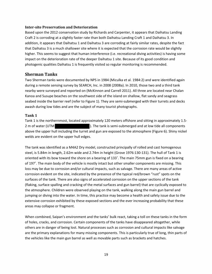
Tank 1 Tank 1 is the northernmost, located approximately 120 meters offshore and sitting in approximately 1.5-2 m of water (UTM ). The tank is semi-submerged and at low tide all components above the upper hull including the turret and gun are exposed to the atmosphere (Figure 6). Shiny nickel welds are evident on the upper hull edges. The tank was identified as a M4A2 Dry model, constructed principally of rolled and cast homogenous steel, is 5.84m in length, 2.62m wide and 2.74m in height (Grove 1976:130-131). The hull of Tank 1 is oriented with its bow toward the shore on a bearing of 133˚. The main 75mm gun is fixed on a bearing of 197˚. The main body of the vehicle is mostly intact but other smaller components are missing. This loss may be due to corrosion and/or cultural impacts, such as salvage. There are many areas of active corrosion evident on the site, indicated by the presence of the typical red/brown “rust” spots on the surfaces of the tank. There are also signs of accelerated corrosion on the upper sections of the tank (flaking, surface spalling and cracking of the metal surfaces and gun barrel) that are cyclically exposed to the atmosphere. Children were observed playing on the tank, walking along the main gun barrel and jumping or diving into the water. In time, this practice may become a health and safety issue due to the extensive corrosion exhibited by these exposed sections and the ever increasing probability that these areas may collapse or fragment. When combined, Saipan’s environment and the tanks’ bulk react, taking a toll on these tanks in the form of holes, cracks, and corrosion. Certain components of the tanks have disappeared altogether, while others are in danger of being lost. Natural processes such as corrosion and cultural impacts like salvage are the primary explanations for many missing components. This is particularly true of long, thin parts of the vehicles like the main gun barrel as well as movable parts such as brackets and hatches.
19

Figure 6. M4 Sherman Tank 1 – port side view (Carpenter 2012).
The surrounding seabed is relatively flat interspersed with large patches of seagrass. The tank lies in a shallow depression with gently sloping edges and the lower section of the track and roller assembly is mostly buried. A circular area about 12m2 surrounding the tank is free of seagrass but algal forms are present on the seabed and on the submerged parts of the hull. High nutrient levels in the lagoon may be contributing to this extensive algal growth (Denton et al. 2001).
Tank 2 Tank 2 is located nearly 300 m south of Tank 1 and about 450 m offshore. This tank is also a M4A2 Dry tank with a 75mm cannon. Therefore, it was also equipped with twin General Motors 6-71 diesel engines. Similar to Tank 1, the fixtures are still present, but none of the auxiliary weapons remain. The welded hull of Tank 2 is oriented with its bow shoreward on a bearing of 145˚. The main gun is fixed on a bearing of 270˚. The tracks, roller assembly, and suspension bogies of Tank 2 are exposed. Because of its shallow location, the tank is semi-submerged and at low tide all components above the upper hull including the turret and gun are exposed to the atmosphere (Figure 7). Many of the removable components have been detached and long, thin parts have become brittle and cracked. Components at risk of being lost include the 75mm main gun barrel, hatches, and tow hooks. The tank exhibits the signs of many years of corrosion and environmental pressure, but less evidence of human disturbance. This may be due to the fact that this tank is further offshore making it less accessible to shore-based traffic. Unlike the sandy environment around Tank 1, seagrass is present right up to the tracks and stretches approximately 20 m from the center of the turret in all directions (Figure 8).
20

Figure 7. The tank shows evidence of rust, surface spalling, and loss of structural integrity (Carpenter 2012).
Figure 8. The tank sits on a bed of seagrass that extends in all directions (Carpenter 2012).
21

Tank 3 Tank 3 is located approximately 1 km south of Tank 1 at a depth of 2 m about 175 m offshore from Chalan Kanoa Beach, near Saipan World Resort and Saipan Grant Hotel (UTM ). The tank is semi-submerged and at low tide all components above the upper hull including the turret and gun are exposed to the atmosphere (Figure 9). Shiny high nickel welds are evident on the upper hull edges. The tank, identified as a M4A3 Wet model, constructed principally of rolled and cast homogenous steel, is 5.91m in length, 2.62m wide and 2.74m in height (Grove 1976:130-131). Tank 3 is orientated with its bow pointing seaward on a bearing of 295° and the 75mm gun fixed on a bearing of 60° (McKinnon and Carrell 2011:109-110). The main body of the vehicle is mostly intact but other smaller components are missing. Most obvious is the loss of the engine cover and cowling and the gun barrel is broken. These remains are lying on the seabed in close proximity to the tank. This loss may be due to corrosion and/or physical damage by natural and/or human impacts. There are many areas of active corrosion evident on the site, indicated by the presence of the typical red/brown “rust” spots on the surfaces of the tank. There are also signs of accelerated corrosion on the upper sections of the tank (flaking, spalling and cracking of the metal surfaces and the broken gun barrel) that are cyclically exposed to the atmosphere.
Figure 9. M4 Sherman Tank 3 – stern view (Carpenter 2012).
No human activity was observed on the site at the time of the survey but on a previous survey in 2011, tour boats and ‘banana’ boats frequently passed near the site, tourists used jet skis on a race course just north of the site and there was significantly more rubbish around the tank than observed on the Tank 1
22

site (McKinnon and Carrell 2011:114). The fact that the site is located in close proximity to two large hotels would account for this increase in human interference. However, divers and snorkelers are still actively encouraged to visit provided they follow the visitation guidelines and do not interfere with the site (i.e. disturb or attempt to remove any components). The surrounding seabed is relatively flat, comprising of calcareous sediment interspersed with large patches of seagrass. The tank is above of the seabed and the lower track is visible. A circular area about 8m2 surrounding the tank is free of sea grass but dead coral and algal forms are present on the seabed. Extensive algal mats are present on the submerged parts of the hull. High nutrient levels in the lagoon may be contributing to this extensive algal growth (Denton et al. 2001). Inter-site Preservation and Deterioration Based on the results from Richards and Carpenter (2012) there is a statistically significant increase in the corrosion rate of the upper sections of Tank 1 (above 1m of water depth) versus lower sections. The primary site variable that affects corrosion is the amount of water movement, which is correlated to water depth. The higher the position on the tank, the greater the amount of water movement and oxygen impact to the concreted iron surface, consequently the corrosion rate will increase. This increase in corrosion rate is further exacerbated by wetting/drying cycles that are experienced by areas of the tank in the splash zone. The corrosion rates noted on Tank 3 were very inconsistent in comparison to those measured on Tank 1. No statistically valid relationships between depth of immersion and corrosion could be observed for this tank. The areas that are constantly immersed (water depth greater than 1m) will tend to provide more consistent corrosion results. However, similar to Tank 1, there were very few secondary colonizing organisms on the concretion with the exception of algal forms and some seaweed species sporadically located on the upper surfaces of the tank. This suggests that there is a significant amount of water movement on this shallow site and possible sediment effect during periods of rough sea conditions, which would significantly reduce colonization rates and increase corrosion rates. The natural and cultural impacts of the local environment on Tank 3 are more aggressive than those experienced by Tank 1. More importantly, because there is more tourist activity associated with Tank 3 it is likely that this increase in human interference is causing the accelerated deterioration. Although Tank 2 was not tested, because it is farther off shore and visited less by casual swimmers and snorkelers, the rate of corrosion may be more similar to Tank 1, simply due to less human impact. Testing of Tank 2 is recommended. All three tanks are fragile and some efforts to educate visitors about both the dangers and the fragile nature of the sites are warranted.
23

Landing Vehicle Tracked LVT (A)-4 The remains of two landing craft were included in the 2012 project. Landing Vehicle 1 was first located during remote sensing surveys conducted by SEARCH, Inc. in 2008 and in 2010 was the subject of intensive archeological survey (McKinnon and Carrell 2011). A second landing vehicle, which appears to be the same type, was located during the 2012 survey and but has not been archaeologically documented.
Landing Vehicle 1 (LVT-1) The remains of a landing vehicle (Figure 10 ) are located approximately 1,100 m (3,600 ft.) from the seaplane base at Tanapag (UTM ) (SEARCH, Inc. 2008a:84). The landing craft is a LVT (A)-4, constructed principally of rolled homogenous steal. Its dimensions are 7.95m in length, 3.25m wide and 3.11m in height, and it is resting at a slight angle in 2-10 ft. (.7 - 3 m).
Figure 10. Landing Vehicle Tracked 1 – port side view (Carpenter 2012).
The LVT(A)-4 is mostly intact with major structural features and a number of field expedient modifications still evident, but many other components are missing, such as armor plating across the deck, tracks and engine room, the guns and many of the controls. The turret has collapsed into the deck space of the wreck. These losses may have been caused by corrosion but it is more likely that they were salvaged, possibly during the disarming and disposal process outlined by the U.S. military (McKinnon and Carrell 2011:123-124). There are some areas of active corrosion evident on the site, indicated by the presence of the typical red/brown “rust” spots on the surface of the vehicle but these are minimal when compared to the tanks.
24

The wreck lies on a flat, slightly undulating sandy seabed, comprising of calcareous sediment. There are small and larger patches of reef surrounding the wreck but none are in direct contact with the wreck. The stern of LVT(A)-4, which faces shoreward, is partially buried in the seabed and there appears to have been significant scouring around the bow (seaward side) of the vessel. The rear and lower track are entirely buried and the upper surfaces are fully exposed to the marine environment. Stormy sea conditions could result in sand movement that is likely to affect the extent of burial/exposure, however it is not anticipated that the entire vehicle would ever become totally buried. The wreck was covered in brown algal forms and some sporadic secondary colonization was evident (e.g. tunicates, soft and hard corals, seaweed, etc.).
Landing Vehicle 2 (LVT-2) LVT-2 is located in close proximity to Tank 1, which lies on the southwest side of Saipan, inside the barrier reef about 180m off shore from Susupe Beach (UTM ). This site was previously unknown and has not been archeologically recorded. It lies at a depth of about 1.5 m dependent on the tide (Figure 11). The model has not been positively identified, but it is similar in design to LVT-1, which is an LVT(A)-4, constructed primarily of rolled homogenous steel. It is orientated parallel to the shoreline with its bow pointing NNE. The vessel is fully submerged at all times. The vehicle has almost totally collapsed and a track sprocket is detached and lies on the port side close to its previously installed position (Figure 11). The tracks themselves are also detached and lie, exposed, in close proximity to the major vessel remains. The vehicle is incomplete with the main components, such as the engine and superstructure missing. The remains are partially buried (lower track wheel bogies were not visible) with the starboard side of the vehicle possessing more sediment coverage. The starboard side of the vessel is extremely damaged and the loss of structure is quite extensive with the bow region almost absent, which facilitates sediment ingress into the interior of the vessel. Stormy sea conditions could result in sand movement that is likely to affect the extent of burial/exposure, however it is not anticipated that the entire vehicle would ever become totally buried. There are many areas of active corrosion evident on the site, indicated by the presence of the typical red/brown “rust” spots on the metal surfaces and at the sediment interface. The surrounding seabed consists primarily of calcareous sediment with dead coral interspersed around the site and is relatively flat with short period undulating sand ripples caused by winnowing. Occasional living coral can be observed on the surrounding seabed but there is very limited coralline growth on the vehicle structure itself. The wreck was densely covered in brown algal forms. High nutrient levels in the lagoon may be contributing to this extensive algal growth (Denton et al. 2001). The poor condition and collapsed state of the LVT2 could be due to a number of human factors including WWII but storm damage through increased wave action, in such shallow water, has very likely contributed to its gradual destruction. Recent impact damage was noted on the higher profile part of the structure and is probably due to a small boat collision. It is not included on the maritime trail, so visitation to the site by divers and snorkelers is expected to be less than to those wrecks that are listed.
25

Figure 11. Landing Vehicle Tracked 2 – front view (Carpenter 2012).
Inter-site Preservation and Deterioration Based on the results of Richards and Carpenter (2012) both LVT sites exhibit less corrosion of hull at the level of the seabed than the shallower, more exposed positions. These lower sections of the vessel near the sediment/seawater interface are subjected to periodic burial cycles, which would reduce the total amount of dissolved oxygen impacting the concretion surface, consequently reducing the overall corrosion rate. It is difficult to say whether LVT- 2 is corroding at a faster rate than LVT-1. Considering the extent of deterioration of LVT-2 in comparison to LVT-1, particularly when one considers its shallower depth, it is not surprising that the natural and cultural impacts on LVT2 are greater than those experienced by LVT1. Visitation at LVT-2 should be limited because of its greater deterioration.
Japanese Merchant Ship, Presumably Shoan Maru aka “Chinsen” The remains of a WWII merchant ship sunk in Tanapag Lagoon were first examined by PBEC and NPS divers in 1984. The site is a popular dive location, locally referred to in Japanese language as Chinsen, or “the shipwreck” and was tentatively identified by Jim Brandt in 1990 as Shoan Maru (Jim Brandt personal communication to Carrell, 1990). The ship was subsequently revisited in 1984, 1991, 2003, 2008, and 2010 (PBEC 1985:9-10, plates 3A, B, C; Carrell 1991:331-335; Lord and Plank 2003:B12-14; SEARCH, Inc. 2008b:69-70; McKinnon and Carrell 2011). If this is Shoan Maru, it was torpedoed in 1943 but did not sink and was towed to Saipan for repairs or salvage. In 1944, it was attacked again by aircraft and damaged beyond repair. During the post-war cleanup of Tanapag Harbor the ship was heavily salvaged and cut-down to the waterline because it was considered a navigational hazard. There are also reports that it was used for explosives training during
26

this time (McKinnon and Carrell 2011:38-40). The remains lie in 35 ft (10.66 m) of water and the overall length of the site is approximately 274 m (900 ft) (UTM ) (Figure 12). A complete site plan for the shipwreck has not been produced due to its sheer size. The vessel lies on its starboard side and although most of the wreck is disarticulated and has collapsed in many areas, major elements such as the engines, boilers, steering mechanism and superstructure are generally located in close proximity to their original position. No apparent cargo was observed.
Figure 12. Japanese merchant Ship (bow view) (Carpenter 2012).
The wreck lies on a flat, slightly undulating sandy seabed interspersed with coral outcrops, especially around the bow area. The vessel is not heavily concreted (e.g. welded overlapping hull plates are discernible) and it has a general layer of encrustation, which may be derived from calcareous and other forms of algae. Patches of low profile hard coral formations and larger hard corals have become established particularly on the side of the port bow, which is angled towards the sea surface. Isolated coral growth exists on other parts of the vessel but it is minimal. As with other sites in the lagoon freshwater run-off and associated pollution may be influencing marine growth. It appears that the wreck is not subjected to regular burial/exposure cycles. Limited sediment coverage has occurred on some hull structure lying on the seabed but due to the relatively high profile of the shipwreck remains, this negates extensive burial. The establishment of hard corals indicates that significant accumulation of sediment does not readily occur. Maximum exposure height of the main structure is approximately 8m. Curved hull structure lying close to the seabed is undercut and free of sand accretion. Relatively strong currents are experienced on this site and scouring under ship structure
27

is a likely consequence. The site lies in the comparatively protected lagoon area but due to the extensive profile of the vessel above the seabed it is conceivable that storms would have an impact on the ship’s structure. Some of the higher profile sections of the vessel are exposed to the atmosphere at low tides but the majority of the wreck is fully submerged at all times. There are a few areas of active corrosion evident on the site, indicated by the presence of the typical red/brown “rust” spots on the surface of the vessel but these are sporadic compared to the size of the wreck remains. Preservation and Deterioration Richards and Carpenter (2012) reported that there were more hard corals on this wreck when compared to the shallower wrecks, such as the LVTs and the tanks, which are subjected to more natural and human interference. And more corals than the other three Daihatsu landing craft. This is probably a reflection of the larger surface area available for colonization rather than an effect of changes in the local environment. Interpretation of the differences in the corrosion rates is problematic because of the sheer size of the site. It appears that in general those portions that have a very high profile, such as vertical plates, or are more damaged, disarticulated and have collapsed completely, have slightly higher corrosion rates than those areas that are lower profile and/or are more protected from wave action and oxygen by deck supports or other structural hull features. It also appears that the bow section is corroding at an elevated rate compared to the stern section, which would be a reflection of the bow section’s higher profile in the water column. Some places on the site the metal is completely gone and can present a hazard to unaware divers.
Possible Auxiliary Submarine Chaser Divers first examined the remains of a possible Japanese Auxiliary Submarine Chaser (Figure 13) sunk in Tanapag Lagoon in 1984 (PBEC 1984:10-11). At that time local tour operators referred to the site as the “submarine.” Careful examination of the remains of this WWII-era ship revealed that it was not a submarine, but was characteristic of an auxiliary submarine chaser or patrol boat (PBEC 1984:10-11, Plates 4A, B, C). The site was re-examined in 1990 by NPS divers (Carrell 1991:335-336), in 2008 by SEARCH, Inc. (SEARCH, Inc. 2008a:67-68) and in 2010 (McKinnon and Carrell 2011). The wreck has not been positively identified but it is thought to be an auxiliary submarine chaser, possibly the Kyo Maru 8 or Kyo Maru 10, which were both steamers of 341 tons built primarily of steel in 1938 and later requisitioned for use during WWII (McKinnon and Carrell 2011:45). Their sleek hull design was suitable for high-speed chases of submarines and they were to be used for whaling after the war. The site is located on the southwest side of Saipan, inside Tanapag Harbor (UTM ). It lies on its starboard side in approximately 30 ft (9.1 m) of water. It is discrete and comprised of a tightly-clustered linear deposit of bow, disarticulated hull plates and minor structural elements approximately 60 m (200 ft) long by 15 m (50 ft) maximum width (Figure 13). There is little scattered debris away from the main concentration and it is fully submerged at all times.
28

Figure 13.Photomosaic of possible auxiliary submarine chaser site.
29

Approximately 12 m (40 ft) of the sharp bow section remains intact and it appears that the upper deck of the bow has been cut away from the vessel. Small hatch holes are present just aft of the stem leading into the narrow below deck space. The beam of the aft end of the remaining bow section is 3.9-4.8 m (13-16 ft) wide. The remainder of the ship is badly disarticulated, although the wreckage generally follows the original line of the ship. No evidence of the engine or boilers is present but there is what appears to be a section of a funnel in the amidships section. Just aft of the amidships section is where the ship is highly fragmented and missing components. There is no obvious evidence of the stern, steering gear, or propellers. The disarticulated nature and missing features makes it difficult to understand what has happened to the site; however this could be the result of post-war cleanup, salvage or explosives training operations. In 1984, munitions were visibly scattered in the wreckage. These were reported as “4 inches in diameter and 15.6 inches long” (101 mm by 396 mm long) (PBEC 1985:10-11). Recent examination of the wreckage site reveals there are still munitions left on the site. The wreck lies on a flat, slightly undulating sandy seabed interspersed with coral outcrops. The vessel is not heavily concreted and has a layer of encrustation that is low in profile and patchy in appearance due to colonizing species variation. Some larger living corals (isolated) have established on the vessel structure but this is not extensive and reflects the minimal growth of coral on the boulders scattered about the surrounding seabed. Fish, observed grazing on algal growth, etc. principally on the upper port side of the bow, inhibit the establishment and extent of growth of potential colonizing marine biota. As with all sites in the lagoon freshwater runoff and associated pollution may be influencing marine growth. It appears that the wreck is not subjected to regular burial/exposure cycles. Limited sediment coverage has occurred on some hull structure lying on the seabed but due to the relatively high profile of the shipwreck remains, this negates extensive burial. The establishment of hard corals indicates that significant accumulation of sediment does not readily occur. Maximum exposure height of the main structure is approximately 3m. Relatively strong currents are experienced on this site and scouring under ship structure is a likely consequence. The site lies in the comparatively protected lagoon area but due to the extensive profile of the vessel above the seabed it is conceivable that storms would have an impact on the ship’s structure. There are a few areas of active corrosion evident on the site, indicated by the presence of the typical red/brown “rust” spots on the surface of the vessel but these are sporadic compared to the size of the wreck remains.
A second site (Possible Auxiliary Submarine Chaser 2), identified by SEARCH, Inc. in 2008 may include the remains of sections of this site. A closer inspection of the second site in 2010 and again in 2012 revealed similar types of hull construction techniques (i.e. welded hull plating). However there were also sections of wreckage that did not match the first site’s construction type (i.e. riveted hull plating). The sections of similar hull plating may indicate that the vessel was cut up and/or blown up just aft of amidships during post-war operations and dumped on the opposite end of the channel. Alternatively, the second site could be the location of a second auxiliary submarine chaser wreck known to have sunk in the lagoon.
30

Preservation and Deterioration There appeared to be no obvious relationship between water depth and corrosion rates at this site according to Richards and Carpenter (2012). Isolated iron features are corroding at a faster rate than elements that are in physical connection over a larger surface area (i.e. the hull structure). Furthermore, articulated hull structure and an anchor lying in direct contact with the collapsed starboard hull plates that are lying flat on the seabed and in a more protected area had a lower corrosion rate than isolated remains. The starboard side is corroding at a slightly higher rate compared to the port side, which would be a reflection of the increased damage, disarticulation and collapse on this side of the vessel. This site is covered with relatively thin aerobic concretions and more hard corals present compared to the shallower wrecks, such as the LVTs and the tanks. This suggests there is a significant amount of water movement on this site despite the greater relative water depth (10m). Generally the thicker the concretion and corrosion layer, the lower the rate of deterioration but only if the concretion layer remains essentially undisturbed (i.e. no damage occurs through human/natural interference). The auxiliary submarine chaser may be corroding at a slightly faster rate than the Japanese merchant ship in part because of natural phenomena (i.e. current or water movement or cyclonic activity) or human intervention (i.e. salvage, explosive damage during WWII).
Unidentified Steamship An unidentified steamship is located on the southwest side of Saipan, inside Tanapag Harbor at a maximum depth of about 10m (UTM ). This site was recorded in 2008 by SEARCH, Inc. (2008a:69) and has not been archaeologically documented; it was only cursorily investigated in 2012. The ship has not been positively identified and is constructed primarily of steel (Figure 14). There is considerable damage and although many pieces are disarticulated they lay in close proximity. Various sections are bent, twisted and distorted suggesting war damage rather than a consequence of impact when it sank or collapse due to corrosion. A dislodged ship’s boiler is basically intact as are some storage tanks. The engine and propeller were not observed and may have been salvaged. Overall impressions of the site were limited by poor visibility. Generally the metal structures appear to be in a strong and robust condition. There were no areas of active corrosion evident. The wreck lies on a flat, slightly undulating sandy seabed interspersed with coral outcrops of varying dimensions. The vessel is not heavily concreted and has a layer of encrustation that is low in profile and patchy in appearance due to colonizing species variation. Some larger living corals (isolated) are established on the vessel structure, but this is not extensive and reflects the minimal growth of coral on the boulders scattered about the surrounding seabed. At the time of the survey there were significant quantities of suspended material in the water column. This limits light penetration and sediment deposition from the water column would deter some forms of marine growth. The source of the increase in water turbidity was not determined but may be derived from land runoff. Relatively few fish
31

were observed at this site. As with all sites in the lagoon freshwater runoff and associated pollution may be affecting marine growth. It appears that the unidentified steamship is not subject to regular burial and exposure cycles, at least to any great extent. Sediment has partially covered the lower profile areas, such as collapsed hull/deck plates, and the mast/king post structures lying on the seabed were approximately one third buried in sediment. Maximum exposure height of the main structure was approximately 4m. However, due to the high profile of the remains and the establishment of hard corals in some areas it is likely that significant accumulation of sediment does not readily occur on this site.
Figure 14. Unidentified steamship – boilers (Carpenter 2012).
Preservation and Deterioration Based on the results from Richards and Carpenter (2012) there is a small but statistically valid decrease in the corrosion of this site, which suggests that it is deteriorating at a slower rate than both the auxiliary submarine chaser and the Japanese merchant ship. This would further suggest that human interference (i.e. recreational diving activities) is having some impact on the deterioration rate of the Japanese merchant ship and auxiliary submarine chaser sites. However, the local environment may also be contributing to this decrease in corrosion rate on the unidentified steamship site.
Aichi E13A “JAKE” The Aichi E13A aircraft wreck is located in Tanapag Lagoon approximately 1200 ft (365 m) south of the eastern edge of Mañagaha Island and 900 ft (275 m) west-northwest of a large coral reef patch exposed
32

at low tide (UTM ). This site was first investigated by PBEC and recorded as CNMI Historic Property Register Site 9 in the 1980s (1984:14). It was also visited and photographed by NPS volunteer divers William Cooper and Dennis Blankenbacker (Miculka et al. 1984:2), was included as Site number 5 in Carrell’s report (1991:502-508) and archeologically investigated in 2010 (Figure 15). This aircraft lies within a Marine Conservation Area and is frequented by snorkelers and is popular with dive instructors for novice diver training. The aircraft remains measure 36 ft (10.9 m) in length from bow to stern with a wingspan of 46 ft (14 m) and it is constructed most probably of duralumin (an aluminum alloy). The aircraft is relatively intact lying inverted on the seabed. It is listing to port with the end of the port wing buried in the surrounding sediment and the starboard wing rising above the seabed with no support. One of the two floats is absent the other lies in close proximity to the port wing. The aircraft structures and components, although damaged, remain in relatively good condition and still retain strength and resilience as attested by the unsupported starboard wing. A piece of landing gear is located a short distance from the tail of the aircraft but does not appear to be associated with the aircraft (McKinnon and Carrell 2011:55). Overall damage to the aircraft structure is not readily distinguishable between crash, storm or potential war damage, however it is thought that the aircraft was intentionally scuttled (McKinnon and Carrell 2011: 57).
Figure 15. Overview photograph of Aichi E13A JAKE (Carpenter 2012).
The aircraft remains are located on a relatively flat, undulating seabed with sporadic large coral outcrops. The port wing and the end of the tail are partially buried in fine sediment and localized, seasonal exposure/reburial cycles occurs in this area as changes to sediment levels are noted with each
33

visit. However, most of the remains are exposed and total burial seems unlikely to occur. The maximum exposure height of the main structure is approximately 1.5 m above the seabed. A thin mucilaginous layer and algal forms cover the aluminum surfaces with coral growth evident on various parts of the aircraft, especially near the engine area where the presence of ferrous components encourage more secondary colonization. The algal growth on the under-surfaces is denser than the growth on the upper surfaces. A greater variety of colonizing species are also apparent on the under-surfaces. A steady and generally light current affecting the site did not visibly move sediment. The site is relatively shallow (6m) and may be affected by turbulent seas generated by storms and cyclones.
Preservation and Deterioration According to Richards and Carpenter (2012) the metal composition of the wings, aft fuselage, propellers and boss head are very similar. The forward part of the fuselage is corroding at a slightly slower rate than other portions of the articulated remains. This is expected as this area of the fuselage is in direct electrical contact with what appears to be machinery associated with the engine, resulting in more contact with iron, copper and other less reactive metals that lowers the overall corrosion rate in this area. The disarticulated float is corroding at a slightly higher rate than the other areas suggesting that the aluminium alloy composition of the float is different from the rest of the aircraft and contains less copper and more aluminium making the corrosion potential higher. Some sections of the Jake, such as the wings and the float, showed discreet areas of perforation but the extent was significantly less than that observed on the TBM Avenger. This suggests that the environment at the Avenger site is considerably more aggressive than that experienced by the Jake. This difference in damage can be attributed, in part, to the fact that the Avenger is much shallower and sits on a reef platform that is subject to much greater overall water movement.
Kawanishi H8K “EMILY” The Kawanishi H8K (Type 2 Large Flying Boat) aircraft (Figure 16) was recorded in 1984 as CNMI Historic Property Register Site 1 with a recommendation that it be made a part of an underwater park (PBEC 1984:8). It was visited and photographed by NPS volunteer divers William Cooper and Dennis Blankenbaker (Miculka et al. 1984:2) and was reported as site number 4 in Carrell’s report (1991:502). During a remote sensing survey of Tanapag Lagoon it was again relocated (UTM ) and identified in 2008 (SEARCH, Inc. 2008b:73) and was intensively mapped in 2010 (McKinnon and Carrell 2011). The main section of wreckage consisting of wing and engine nacelles rests inverted on the seabed. Other components including the four engines and propellers, bow gun turret, cockpit, painted sections of the fuselage, and smaller pieces are scattered over a large area. Most of the aircraft structures and components, although damaged and disconnected, remain in relatively good condition and still retain strength and resilience. However, extensive corrosion is evident on the nacelles. Because damage to the structure is extensive and the site is highly disarticulated and scattered, it suggests a catastrophic wrecking event (McKinnon and Carrel 2011:70).
34
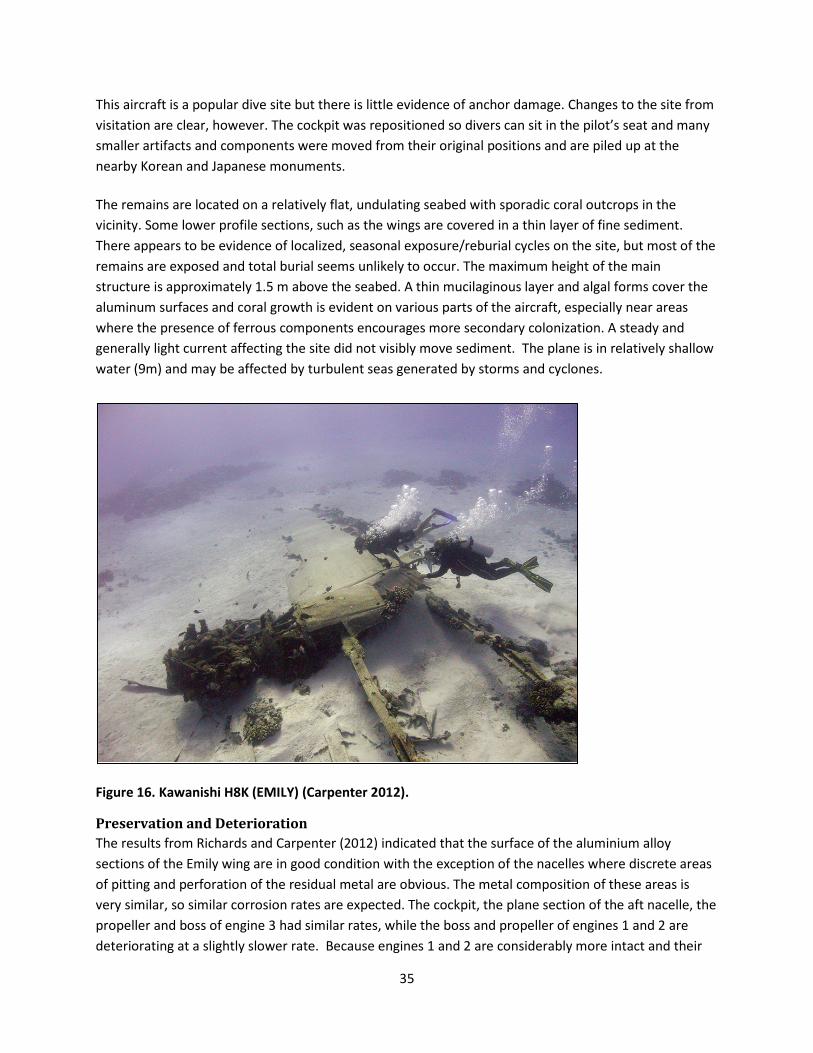
This aircraft is a popular dive site but there is little evidence of anchor damage. Changes to the site from visitation are clear, however. The cockpit was repositioned so divers can sit in the pilot’s seat and many smaller artifacts and components were moved from their original positions and are piled up at the nearby Korean and Japanese monuments. The remains are located on a relatively flat, undulating seabed with sporadic coral outcrops in the vicinity. Some lower profile sections, such as the wings are covered in a thin layer of fine sediment. There appears to be evidence of localized, seasonal exposure/reburial cycles on the site, but most of the remains are exposed and total burial seems unlikely to occur. The maximum height of the main structure is approximately 1.5 m above the seabed. A thin mucilaginous layer and algal forms cover the aluminum surfaces and coral growth is evident on various parts of the aircraft, especially near areas where the presence of ferrous components encourages more secondary colonization. A steady and generally light current affecting the site did not visibly move sediment. The plane is in relatively shallow water (9m) and may be affected by turbulent seas generated by storms and cyclones.
Figure 16. Kawanishi H8K (EMILY) (Carpenter 2012).
Preservation and Deterioration The results from Richards and Carpenter (2012) indicated that the surface of the aluminium alloy sections of the Emily wing are in good condition with the exception of the nacelles where discrete areas of pitting and perforation of the residual metal are obvious. The metal composition of these areas is very similar, so similar corrosion rates are expected. The cockpit, the plane section of the aft nacelle, the propeller and boss of engine 3 had similar rates, while the boss and propeller of engines 1 and 2 are deteriorating at a slightly slower rate. Because engines 1 and 2 are considerably more intact and their
35

bosses and propellers are connected to engine components, this has afforded them some additional protection from corrosion.
Martin PBM Mariner An unidentified aircraft wreck (Figure 17) was first recorded by PBEC as CNMI Historic Property Site Number 7 (1984:12-13). It was visited again in 1990 and reported on by Carrell (1991:508). Preliminary investigations in 1984 postulated that it was a Japanese type 99 2EFB “Cherry.” In July 2009 and 2010 the site was revisited and extensively mapped leading to its identification as a Martin PBM Mariner (McKinnon and Carrell 2011). The wreck is located in Tanapag Lagoon approximately 600 m east of Mañagaha Island and 100 m north of an exposed patch reef (UTM ). This aircraft lies within a Marine Conservation Area. The aircraft is constructed most probably of duralumin (an aluminum alloy) and is 24.33 m in length, 8.38 m high and had a 35.97 m wingspan. The main component is sitting inverted on the seabed at a depth of approximately 7 m (23 ft) and consists largely of the wings with twin engine compartments (minus engines and propellers), gun turrets, tail sections and a portion of cockpit, etc. Most of the aircraft structures and components, although damaged and disconnected, remain in reasonably good condition retaining strength and resilience. Because damage is extensive and the site highly disarticulated and scattered over a relatively large area, it suggests a catastrophic wrecking event (McKinnon and Carrell 2011:85). This site is frequented by divers and there is evidence of recent anchor damage. Many smaller artifacts and components have been moved from their original positions and piled up in one area on the site. Local informants told PBEC researchers that a radio and other electronic instruments removed from the site had U.S. markings on them (PBEC 1984:12). It is also possible that some form of salvage occurred as the engines and propellers are missing. The remains are located on a relatively flat, undulating seabed with sporadic large coral outcrops. Some lower profile sections, such as the wings, were covered in a thin layer of fine sediment. There appears to be evidence of localized, seasonal exposure/reburial cycles, however, most of the remains are exposed and total burial seems unlikely to occur. The maximum exposure height of the main structure is approximately 1.5 m above the seabed. A thin mucilaginous layer and algal forms cover the aluminum surfaces, and coral growth is evident on various parts of the aircraft especially near areas where the presence of ferrous components encourages more secondary colonization. A steady and generally light current affecting the site did not visibly move sediment. Because the site is relatively shallow (7 m) it may be affected by turbulent seas generated by storms and cyclones.
36

Figure 17. Overview shot of central portions of Martin PBM Mariner site; note dihedral wing (D. McHenry, June 2010).
Preservation and Deterioration The results from Richards and Carpenter (2012) revealed that the surfaces of the aluminium alloy sections of the Mariner, such as the wings, floats, engine cowlings, nacelles, etc. were quite corroded and there was significant pitting and perforation of the residual metal. The remains of the Mariner are more deteriorated than the Jake even though they lie in a similar environment at similar depths. This can be attributed in part to increased stress and metal fatigue caused by the wrecking event and because the Mariner is more disarticulated and spread over a wider area with less opportunity for the beneficial effects of proximity to other remains to help preservation.
TBM Avenger A wrecked TBM Avenger (Figure 18) is located just inside the barrier reef near the north edge of the main channel entrance to Tanapag Harbor in approximately 7-10 ft (2.5-3 m) of water (UTM
). The site was recorded by PBEC as CNMI Historic Property Site Number 13 (PBEC 1984:16-17), visited and photographed by NPS volunteer divers William Cooper and Dennis Blankenbacker in 1990, reported by Carrell (1991:508), and extensively surveyed in 2010 (McKinnon and Carrell 2011). Identification is based on the wing size, width, fuselage and landing gear configuration (Carrell 1991:508). The aircraft lies within a designated Marine Conservation Area. The aircraft is most probably constructed of duralumin (an aluminum alloy) and was 12.19 m in length, 5.00 m high and had a 16.51 m wingspan. The aircraft is inverted on the seabed with a concentrated site distribution consisting of the central portion of the wing. The wing measures approximately 50 ft (15 m) in length and is 8 ft (2.5 m) in width at the fuselage. The aircraft remains are mostly submerged, however the hydraulic landing gear, which is in the fully extended position, is exposed to the
37

atmosphere at extreme low tides. The aircraft is missing its tail section, engine and propeller. A few small sections of wreck are scattered within 65-130 ft (20-40 m). The sections include part of a radial engine, a section of fuselage with an observation port and a turret ring. Also, what appears to be a radio box is approximately 20 ft (6 m) aft of the wreckage.
The aircraft remains are located on the top of the barrier reef that creates Tanapag Harbor and are subjected to considerable water movement due to this high energy environment. Large quantities of dead coral are strewn over the seabed, which is comprised of coarse-grained calcareous sediment. The surviving aircraft structure is slowly being integrated into the reef through the growth of corals. The maximum exposure height of the main structure is approximately 1.5 m above the seabed. The aluminum skin of the wings is corroded and has a number of irregular holes and smaller perforations. Its reef top position implies that the Avenger remains are always exposed and overall sediment burial is very unlikely. Sand is present inside and in front of the engine bay cavity which may scour in more turbulent conditions. Localized, limited and partial exposure cycles may occur in this area. The development of coral growth may potentially cover the aircraft remains with time however the limited size and extent of hard coral growths on the aircraft structure after some 65 years of immersion is likely to be a consequence of the more dynamic localized environment (including storm damage). The smooth metal skins of aircraft generally seem to inhibit the establishment of larger forms of marine biota unless there is a break in the surface or a ferrous metal is present. The exception is colonization of the under-surfaces of areas, such as wings, where light levels may exist that are similar to those found in
Figure 18. Grumman TBM Avenger (Carpenter 2012).
38

the entrance to underwater caves, etc. These conditions suit the establishment of lower profile sponges and small gorgonia (sea fans) that colonize these features. The protruding landing struts are essentially devoid of marine growth because they are subjected to a relatively strong and constant current as water streams over the reef into the lagoon. The much lower profile, and largely reef-shielded wing remains are less affected by excessive water movement.
Preservation and Deterioration Richards and Carpenter (2012) reported that the condition of the aluminum alloy is poor compared with those aircraft wrecks located on sandy sediments in calmer areas of the lagoon. It is not possible to distinguish the cause of damage to the site between crash, storm or visitation. The site is shallow (3m) and its reef top position means that it must be affected by turbulent seas generated by storms and cyclones. Local surfers use the protruding landing gear as boat moorings and bright, bare aluminum surfaces are evident suggesting direct impact in these areas.
Consolidated PB2Y Coronado A Consolidated PB2Y Coronado (Figure 19) is located on the southwest side of Saipan, inside Tanapag Lagoon at a depth of about 7 m (UTM ). The aircraft remains were shown to project staff by a captain of the local tourist submarine and positively identified as a Consolidated PB2Y Coronado in 2012, a U.S. four engine maritime patrol flying boat, constructed most probably of duralumin (an aluminum alloy) and was 24.16 m in length, 8.38 m high and had a 35.05 m wingspan. The aircraft remains are disconnected and scattered over a very large area. Among the components identified were a single detached engine, flight instruments with dials, aerial mast, cockpit canopy with windscreen wipers, hatch covers, float support, a chair, concreted forks and a number of unidentifiable hull sections. Damage is extensive and the site is disarticulated and scattered over a large area, suggesting a catastrophic wrecking event. The presence of smaller artifacts (e.g. chair, forks, etc.) in situ supports the fact that this site is not visited frequently and human interference has been minimal to date. The remains are located on a relatively flat, undulating seabed comprising primarily of fine calcareous sediment. There are sporadic large coral outcrops in the vicinity and a very large reef formation lies to the south east of the major site concentration. Some lower profile sections, such as the wings and tail planes were covered in a thin layer of fine sediment. Most of the remains are exposed and total burial seems unlikely to occur. The maximum exposure height of most remains is approximately 50cm with the engine being the exception rising about 1.5 m above the seabed. A thin mucilaginous layer and algal forms cover the aluminum surfaces and coral growth is evident on various parts of the aircraft, especially near areas where the presence of ferrous components encourages more secondary colonization. A steady and generally light current affecting the site did not visibly move sediment. Because the site is in shallow water, it may be affected by turbulent seas generated by storms and cyclones.
39

Preservation and Deterioration Based on the findings of Richards and Carpenter (2012) the surfaces of the aluminium alloy sections of the Coronado exhibited significant pitting and perforation of the residual metal. The average corrosion potentials of the float strut, an area of unidentified wreckage, and the control panel suggest that these have different metal compositions (i.e. higher aluminium contents) than other sections resulting in a higher rate of corrosion. The Coronado is more deteriorated than the Jake and Emily even though they are in similar environments at similar depths. This is due in part to the increased stress and metal fatigue resulting from damage and because it is disarticulated and spread over a wider area, and therefore not afforded the beneficial effects of proximity to other sections to slow rates of deterioration.
Figure 19. Consolidated PB2Y Coronado (Carpenter 2012).
40

Chapter 4: Threats and Impacts
Cultural Threats and Impacts Cultural or human impacts to underwater sites are not that much different from the impacts on their terrestrial counterparts. Over-visitation, looting, vandalism, removal or movement of artifacts, and development affect all cultural heritage sites. The major difference between terrestrial and underwater sites it that is inherently more difficult to identify, mitigate and monitor impacts to underwater sites that are literally-out-of-sight and often out-of-mind to managers and to all but a select few visitors. This often leads to an accumulation of significant impacts. There is no question that the underwater sites in Saipan have suffered as a result of the fundamental difference in their “visibility.” Most often it is development with dredging, filling and construction that impacts sites. Because the lagoon is shallow and the shipping channel has existed and been routinely dredged for many years, few new developmental impacts affect these sites. This type of impact has already happened, most of which was immediately after the successful capture by US forces, subsequent cleanup, and post-war salvage. Going forward, new development can be regulated and potential impacts monitored and mitigated. In what may be a unique problem, the majority of impacts to Saipan’s submerged sites are a direct result of visitation, specifically anchor or mooring damage, looting, moving artifacts, and acts of vandalism. This presents a challenge for managers who have limited staff, time, and funding.
Anchor and Mooring Damage Within the Mañagaha Marine Conservation Area (Figure 20) where there are restrictions on anchoring, steps to prevent damage have been underway since the heritage trail was developed in 2009. The CRM office is in the process of installing mooring buoys at the more heavily visited sites including the Kawanishi H8K “EMILY” site (which now has two moorings) and repairing and replacing moorings on the Japanese merchant ship. Plans are currently in the works for installing more moorings on heritage trail sites within the conservation area. However, for those sites outside of the Marine Conservation Area there is no mandate or support for installing moorings so anchor damage is a greater risk. Conversations with a local boat driver disclosed the Avenger’s landing gear is regularly used as a boat mooring for local surfers (Sheldon Preston personal communication, 2010). The effects of mooring are seen on the landing gear where exposed metal is obvious (Figure 21). Continued use of the landing gear as a mooring will eventually cause severe damage if the boats collide with the aircraft or break the landing gear during rough swell conditions.
41

Figure 20. Map of Mañagaha Marine Conservation Area (CRM).
Figure 21. Avenger landing gear, note shiny metal where concretion has been rubbed away due to mooring (Carpenter 2012).
42

Looting and Moving Artifacts Looting and the movement of artifacts on site are probably the most common and most destructive impacts. By their very nature modern, war-related sites have a considerable amount of associated small portable objects. For many years divers have been removing artifacts or simply rearranging them on site. Because this activity impacts the historical and archeological context or fabric of a site, it can make identification more difficult and also affects the information that can be learned from the way in which the site was created (i.e. crashing, sinking, and dumping). Of the nine sites on the trail, four have had some form of looting or movement of artifacts. At the Daihatsu 1 site the steering wheel for the craft was propped up on the stern deck and glass bottles, not associated with the site, are regularly re-arranged on the deck. The Japanese merchant ship site aka Shoan Maru includes a Korean monument on which 50-caliber bullets have been placed and rearranged into patterns (Figure 22). It is uncertain where the bullets actually originated and if they are from the wreck or another site.
Figure 22. Korean monument with .50 caliber rounds (Gauvin 2010).
Divers are having a major impact on the Kawanishi H8K (EMILY). Impacts in the cockpit area were photographically documented during the February and June 2010 field seasons (McKinnon and Carrell 2011) (Figure 23). The cockpit control panel was shifted and subsequently balanced on its mount giving the appearance of its original position. Furthermore, the steering column was moved to the opposite side of the cockpit chair. Consultation with dive operators confirms that tourist divers like to take photographs while seated in the cockpit. This behavior is detrimental to the preservation of the site and will eventually destroy these unique features.
43

Figure 23. Cockpit configuration changes over time on Kawanishi H8K (Bell 2010).
A ladder-like metal object was propped up against the southern side of the aircraft wing. Smaller artifacts located on the Kawanishi site have been moved from their original positions including stacking ordnance and gas cylinders around the Japanese monument (Figure 24). It is possible that these artifacts were moved to enhance the memorialization of the site. While such movement of artifacts on a historic site destroys contextual evidence, from a socio-cultural perspective it reflects the different norms by which cultural groups memorialize sites and commemorate their visits.
Figure 24. Japanese monument surrounded by gas cylinders and other moveable objects (Seymour 2012).
The present locations of the four engines on the Kawanishi may also be an example of a different sort of cultural impact. There is some question whether the engines are in situ or were moved to their current
44

locations. Engine 2, in particular, has a questionable position as it is standing on its edge on a coral head in a fashion that implies it may have been placed intentionally for the purposes of aesthetics and a potential photographic setting. While there is no evidence of any systematic salvage at the Kawanishi, there are indications of opportunistic salvage. A local dive shop owner is in possession of “identification plates” that were reportedly removed from the plane (McKinnon and Carrell 2011) (Figure 25). Upon further research, the plate was identified as from the plane’s wireless radio. Separately, the Historic Preservation Office was informed of a piece of aircraft deposited on a beach, suspected to have come from the Kawanishi (Figure 26). After careful review of photographs it was determined to be a portion of the nose area. There is no way to accurately determine the extent of or damage caused by such activities.
Figure 25. Wireless radio Identification plate recovered from the Kawanishi H8K sites (masadive-saipan.com, accessed June 2010).
(N.B.: The bottom row of characters is Matsushita Musen Kabushikigaisha. Matsushita is the predecessor company to Panasonic, musen means wireless, and kabushikigaisha is a company classification. The row above the company name is the manufacture date beginning with the year (02), month (8) August, and production or model number (19). The year 02 is most likely a reference to the imperial year system; the zero refers to the production year 2600 (1940), 2602 then is 1942.)
Figure 26. A portion of a Kawanisihi H8K reported to the HPO (Rogers 2010).
45

With the implementation of the underwater trail, the Martin PBM Mariner is being visited more frequently, which is having an impact on its preservation and integrity. Ordnance and smaller artifacts are being moved from their original positions; this was documented in February 2010 and their new locations in June 2010 (Figure 27). They were gathered into one area in a manner similar to that observed at the Japanese Memorial at the Kawanishi H8K site. Fifty-caliber rounds were also located on site with gunpowder spilling from the casings; it is possible that this was caused by divers breaking the casings open. A leather shoe sole was also moved to this location and piled with the rounds.
Figure 27. Artifact pile created by divers and altered over time (Bell 2010).
Because the plane is missing its engines and propellers, and there is no chance they could have disintegrated; salvage or removal is a strong possibility. Interestingly, there are two four-blade propellers at a nearby “site” that was created by the local submarine tour company (Figure 28). While these propellers may belong to the Mariner site or some other aircraft wreck, the artifact pile represents another type of cultural impact – faux site creation.
The artifacts at the “site” include: ammunition boxes, 50-caliber rounds, two propellers, hatches, multiple aircraft seats and other unidentifiable artifacts. It is uncertain when this pile was created but it is now touted to submarine tourists as an “aircraft” wreck. This type of misinformation to tourists is disappointing and now that the artifacts have been displaced, their context will never be recovered and historical and archeological data has been lost forever.
46

Figure 28. Faux airplane wreck created for a submarine tour with artifacts gathered from sites in the vicinity. Note four-blade propeller (foreground) and gun in background (Carpenter 2012).
Acts of Vandalism Vandalism, whether intentional or unintentional, also impacts submerged sites. Local tour boats frequent the Sherman tanks and “banana” boats pull passengers by for a closer look. Tour operators were observed demonstrating how to climb on the tanks and/or swing off the gun barrels, a dangerous and destructive activity. It is suspected that similar behavior at Tank 3 resulted in a portion of the end of the barrel breaking. Certainly there will come a time when the barrels have degraded and can no longer sustain the weight of people jumping or swinging off them. Graffiti has been etched into the mucilaginous layer on the aluminum surface of the Kawanishi H8K aircraft on the wing of the aircraft and the gun turret (Figure 29). These graffiti areas were not noticed during the February 2010 field season but were found in June 2010. The etching on the bow turret is indiscernible; however, initials appear to be etched on the starboard wing. The letters or characters are not distinguishable. They likely represent the initials of the inscriber and may have been etched to personally memorialize one’s attendance at the site. There are several places on the island where initials have been carved into objects. For example, at Suicide Cliff there are large cacti whose pads have been used to etch initials of visitors. Particularly interesting is the fact that the majority of the initials are of Asian languages including Japanese and Korean.
47

Figure 29. Graffiti etched into the Kawanishi H8K (Bell 2010)
Tourism Services Impacts Certain tourist services have a direct impact on sites. The Sherman tanks are subjected to an enormous amount of “foot traffic” when Jet Skis and banana boats pass nearby. These vehicles typically create wakes that wash over the tanks causing a cyclical pattern of wetting and drying. This affects the immediate site environment by increasing oxidization levels in the water that in turn increase corrosion. Tank 3 shows signs of increased corrosion rates that are most likely due to its proximity to two large resorts and a Jet Ski course. The newly investigated LVT 2 site showed signs of a recent impact where a boat or Jet Ski hit the vehicle. Unsightly rubbish, while not a serious impact, is found at sites. Because the Sherman tanks are located just offshore from several large resorts and locally popular picnic beaches, rubbish including plastic bags, beer and soda cans, plastic forks and fishing line accumulate. Not only can trash present hazards to snorkelers and divers, but they certainly have an impact on marine life. Turtles and fish may ingest pieces of plastic; an adverse impact that is well documented elsewhere. Another tourism service impact that affects both the environment (i.e. marine organisms) and cultural heritage is the operation of the local tourist submarine. The Japanese merchant ship is on the tour and as it moves towards the shipwreck the submarine disperses large quantities of fish feed including rice to attract fish to the wreck. No information is available on the impacts of repeated discharges of rice or other non-marine organics into the water in the vicinity of the wrecks. Does this lead to higher rates of pollution and therefore deterioration? More concerning are the submarine’s thrusters that blow onto the shipwreck as it makes its turn. Because the thrusters are powerful enough to move portions of the iron plating up and down, this will almost certainly lead to increased deterioration in those areas and significant impacts.
48

Memorialization The process of memorialization affects the sites in Saipan through the addition of outside material, aggregation of moveable objects, potential damage to buried artifacts, and altering the overall integrity and “feeling” of a site. Two monuments on the Kawanishi wreck site are dedicated to those lost during the battle. The first and largest monument is located north of the port wing and was placed there by Challenge! Earth Exploration, a television adventures series that previously aired on the Korean Broadcasting System (KBS). The larger panels of the monument state in both Korean and English, “Spirits sacrificed in the Pacific War, rest in peace, KBS Challenge! Earth Exploration, Inmolt Engineering Co. Ltd.” One side of the square monument lists the director, producer and others involved in the television program’s placement of the monument. The other side has a series of memorial poems and statements (Jack London personal communication, 2010). One poem on the side of the monument dedicates the memorial, “to spirits who hired to the compulsory military service and died during the Pacific War,” and an additional poem relates, “Anger, tears and grunge.” As only one translation was received for the poem, it is uncertain whether the word “grunge” is accurate or if it is in fact “grudge.” These remarks clearly indicate a Korean connection with those lost during the Battle of Saipan and further emphasize that Korean soldiers were forced into service. Although, it is uncertain why a Japanese aircraft wreck was chosen as the placement site for a Korean monument. The second, Japanese monument is much smaller than the Korean and small artifacts from around the wreck site have been piled around it. The Japanese monument appears to be an epitaph for an individual (Jun Kimura personal communication, 2010). As the first few letters are in a special writing style, they are indiscernible; however the last four characters translate to “Underwater (seabed) War Memorial.” The shape of the monument is similar to that of a wooden stupa used for modern Japanese Buddhist style graves. There is a third monument located on the Japanese merchant ship. Much larger than the two monuments on the Kawanishi, this monument is off the starboard side of the bow and is dedicated to Korean conscripts lost during the battle. Together all the monuments do not largely affect the historical and archeological context of a site but when considered alongside the developments occurring on land, which include significant increases in the numbers, more monuments might begin to impact the context.
Environmental Threats and Impacts In general, the physical-chemical measurements of the local environment surrounding the wreck sites in Saipan reported by Richards and Carpenter (2012) are typical for a shallow, near coastal, open circulation, oxidizing marine environment, where corrosion rates are likely to be relatively high for both ferrous (iron) alloy wrecks and aluminum alloy aircraft. All of the wrecks and the aircraft were mostly exposed with only very thin layers of sediment covering some lower profile areas lying on the seabed, which would be particularly mobile during periods of excessive water movement (i.e. storm and cyclonic activity). Hence, natural protection via seasonal sediment burial would be very unlikely for any of the wrecks identified to date.
49

The results from the examination of a number of locations on each of the iron alloy sites are revealing. While each site and locales with in each site are unique they can be characterized as: actively corroding and will continue to do so until all the iron is consumed, are in equilibrium where the corrosion has slowed and formation of concretions have stabilized the underlying metal, or have moved into the passive zone where little if any residual metal remains and only the concretion layer is left. A shift from equilibrium to active corrosion can be triggered if the concretion layer is damaged through human or natural interference. Because the vast majority of the sites are in shallow water, wind and wave driven sand and debris from a strong storm or cyclonic activity has the potential trigger a return to active corrosion. When comparing sites is it important to look at the data in conjunction with the environmental and site dynamics information. While all the tanks are the same type and in generally similar environments, there is a statically significant increase in the corrosion rate of Tank 3 compared to Tank 1. This suggests that the natural and cultural impacts of the local environment on Tank 3 are more aggressive than those experienced by Tank 1. More importantly, as there appears to be more tourist activity associated with Tank 3, it may be this increase in human interference that is causing the accelerated deterioration of Tank 3 (Richards and Carpenter 2012). It is difficult to say whether the LVT 2 is corroding at a faster rate than the LVT 1 as all average measurements are within their respective statistical errors. However, considering the extent of deterioration of the LVT 2 as compared to the LVT 1 it would appear that the natural and cultural impacts on the LVT 2 would be greater than those experienced by the LVT 1 (Richards and Carpenter 2012). Based on the results from the Daihatsu wrecks some differences in corrosion rate can be ascertained. Daihatsu 2 may be corroding at a slightly faster rate than both Daihatsu 1 and 3. This is not unexpected as it is known that isolated iron artifacts and steel hull structures that have been damaged either through natural phenomena (e.g. cyclonic activity) or human intervention (e.g. salvage, explosive damage during WWII) possess higher corrosion rates than those hull structures that are relatively intact (i.e. Daihatsu 1 and Daihatsu 3). In addition, it appears that Daihatsu 1 and Daihatsu 3 are corroding at relatively similar rates, despite the fact that Daihatsu 3 is a much shallower site, where it would be expected that the corrosion rate would be slightly higher. This would seem to suggest that human interference (i.e. recreational diving activities) is having some impact on the deterioration rate of the deeper Daihatsu 1 site (Richards and Carpenter 2012). It is difficult to determine any changes in corrosion behavior of the larger shipwrecks, Japanese merchant ship, the auxiliary submarine chaser and the unidentified steamship as most average measurements are within their respective statistical errors. However, based on the results, it appears that there is a small but statistically valid decrease in the corrosion potential of the unidentified steamship suggesting that this vessel is corroding at a slower rate than both the auxiliary submarine chaser and the Japanese merchant ship. Further, the results from the auxiliary submarine chaser suggest
50

that it may be corroding at a slightly faster rate than Japanese merchant ship. This is not unexpected as steel hull structures that have been extensively damaged (i.e. auxiliary submarine chaser) possess higher corrosion rates than those hull structures that are relatively intact (i.e. Japanese merchant ship and the unidentified steamship). This would seem to suggest that human interference (i.e. recreational diving activities) is having some impact on the deterioration rate of the Japanese merchant ship and auxiliary submarine chaser sites as the unidentified steamship site is not on the heritage trail. However, the local environment (i.e. increase in turbidity) may also be contributing to this decrease in the corrosion rate on the unidentified steamship site (Richards and Carpenter 2012). The five aluminum alloy aircraft wrecks in Saipan present their own set of problems. Most of the aircraft manufactured during WWII used a variety of aluminum alloys consisting mainly of aluminum but including varying concentrations of minor alloying constituents (e.g. iron, copper, magnesium, manganese, zinc and silicon) in order to change the functionality of the aluminum. One of the most common alloying metals used was copper (e.g. Duralumin), which was added to aluminum to increase its strength. However the presence of copper dramatically decreased the corrosion resistance of the metal to seawater. The other issue that will increase the deterioration rates of the aircraft is galvanic corrosion, where the more reactive aluminum alloys corrode faster effectively protecting the more noble metals, such as iron and copper (Richards and Carpenter 2012). All these issues combined make it extremely difficult to determine any differences in corrosion rates for the five planes. However, because all aluminum alloys are corroding in a common oxidizing marine environment in Tanapag Lagoon, the different values of the corrosion potentials may provide a guide to the underlying differences in alloy composition of the aircraft. Based on the data collected, the metal composition of the aluminum alloys for each aircraft, in order of decreasing concentrations of incorporated copper (or other less reactive metals) is Avenger > Jake > Mariner ~ Coronado > Emily. That is, the Avenger may have the highest concentration of copper in this group of aluminum alloys measured while the EMILY will have the lowest. This has consequences for the corrosion rates of these aircraft as higher concentrations of copper increases the rate of pitting and intergranular corrosion if the aircraft are subjected to similar environmental conditions and other complicating factors, such as increases in corrosion through stress and metal fatigue, are absent. Unfortunately, this is not the case with these aircraft (i.e. the Avenger lies in a very aggressive, shallower marine environment and the Coronado is extensively damaged with separate sections strewn over a very large area) highlighting the problem with interpreting corrosion data based on only one set of corrosion parameter measurements (Richards and Carpenter 2012). It is obvious that there are problems with determining differences in corrosion behavior of wrecks based on only one set of data measurements. Only through continued observation and collection of corrosion measurements will it be possible to tease out the subtle differences in deterioration caused by local environmental conditions versus the more obvious impacts resulting from human activity. This type of information can inform decisions on which sites to actively discourage visitation versus sites that are better able to withstand the bumps and bangs caused by divers. It can also inform decisions on where to place warning markers for boat traffic and how to educate visitors to the fragile nature of these sites.
51

In Situ and Ex Situ Artifacts Material recovered from WWII sites includes objects that were removed at the time of wrecking or post-battle during government sanctioned salvage and harbor-clearing works. However, artifacts removed by private persons since WWII, if associated with US military craft of any type, are legally the property of the US government. Legislation aimed at protecting and preserving cultural heritage has a long history in the U.S. beginning with the Antiquities Act of 1906, the Historic Sites Act of 1935, the Archaeological and Historic Preservation Act of 1974, Archaeological Resources Protection Act of 1979, the Abandoned Shipwreck Act of 1987, and the Sunken Military Craft Act of 2004, among others. Internationally the 1970 UNESCO Convention on the Means of Prohibiting and Preventing the Illicit Import, Export and Transfer of Ownership of Cultural Property, Law of the Sea Convention of 1982, and the UNESCO Convention on the Protection of Underwater Cultural Heritage of 2001 each seek to protect cultural heritage from damage, looting, and treasure salvage. Under the property clause of the US Constitution, the 1982 United Nations Convention on the Law of the Sea (Articles 95 and 96) and established principles of international maritime law and sovereign immunity, the U.S. Department of the Navy retains custody in perpetuity of its ships and aircraft. These laws state the right, title, and ownership of federal property is not lost to the US government due to the passage of time, or by neglect or inaction. This also applies to the remains of Japanese military craft. Under the same international laws, the Japanese government retains control and ownership of those items unless they were specifically and formally disposed of. In the case of WWII wrecks, the Treaty of Peace with Japan, signed 8 September 1951, provides in Chapter V, Article 14(a)2(I) that each of the Allied Powers “shall have the right to seize, retain, liquidate or otherwise dispose of all property, rights and interests” of Japan, “which on the first coming into force of the present Treaty were subject to its [the Allied Powers] jurisdiction” (DOS 1951). This effectively gave ownership and control of Japanese sites to the US government. Because these properties are not considered “abandoned” in the Abandoned Shipwreck Act of 1987 (43 U.S. C. 2101-2106) they did not transfer to the states with adoption of the Act. It is difficult to determine the amount of artifact removal or looting that has taken place since the end of WWII. Because WWII is within the recent past, cultural remains and artifacts associated with the war were not generally recognized by the public as having historical significance. Many objects connected with these sites were routinely collected by local divers as well as by visitors. Only with the passage of time are these sites now seen as an important part of our shared heritage and worthy of protection. On Saipan a great deal of material removed from sites in the past is held in personal, undocumented collections on the island, and some may have left the island. There is no effort by the US government to reclaim these objects nor is there an effort by the CNMI to do so. Rather the emphasis is on insuring that the sites and objects that remain are protected and preserved for future generations. A limited
52

number of artifacts are on display at the American Memorial Park, however it is not known if any of these are from underwater contexts. No material was recovered during the recent archeological site inspections.
53

54

Chapter 5: Public Outreach
Introduction This project is the next phase of a multi-year effort to raise awareness on the importance of protecting WWII UCH on Saipan. Phase one began in 2009 with a grant from the ABPP GA-2255-09-028. Public outreach and community collaboration efforts began with that grant and have continued uninterrupted during this project. By holding both formal and informal meetings with government agencies, tourism offices, dive shops, volunteers, the public and stakeholders with a variety of perspectives made their needs known. In response to stakeholder input, training in basic site documentation and maritime heritage was provided in 2010. Stakeholder input also prompted the development an underwater heritage trail, full color posters and dive guides in two languages—Japanese and English—reflecting the two major user groups of these resources. Outside the confines of Saipan a website and project blog were created to reach beyond the local tourism base and educate the broader public about this unique collection of WWII UCH sites. Because underwater trail, posters, dive guides, websites and blogs reach only a fraction of the public, a 17-minute interpretive film WWII Maritime Heritage Trail: Battle of Saipan, focusing on selected sites, was developed. This interpretive film is shown at the NPS’s American Memorial Park visitor center.
Consultation, Public Meetings, Presentations, Press and Digital Media
Consultation Beginning in 2009, three agencies on the island have played a crucial role in determining the success of project efforts: the Historic Preservation Office (HPO), the Department of Environmental Quality (DEQ), and the Coastal Resources Management Office (CRM). Initial meetings and consultations were held with these agencies to assess their cooperation, interest, and involvement with the archaeological documentation and underwater heritage trail projects (McKinnon and Carrell 2011). All were again consulted for the current project and their direct involvements encouraged.
Because HPO is the regulatory agency that deals with heritage, we have worked hard to maintain an open line of communication through regular email and phone contact. Staff was involved with the conservation study, more fully described elsewhere and provided as Appendix A, and facilitated communication with other agencies and the general public. CRM and DEQ staff met with us to provide useful information on the efficacy of the ongoing mooring buoy project at selected sites on the underwater heritage trail and to discuss preliminary results of the conservation study.
The Marianas Visitor Authority Office (MVA), a government-funded office focused on the development of tourism, was contacted for consultation. By providing demographic information on tourist divers and snorkelers, it quickly became apparent that interpretive products should be produced in Korean, Russian, Japanese, Chamorro and Carolinian in addition to the planned English. They provided assistance
55

with dissemination of the posters in 2011 to locals and tourists and important public feedback that were applied to the interpretive film.
The project team also held meetings with small groups including non-profit organizations. Two that were particularly helpful are the Northern Marianas Council for the Humanities, a non-profit supported by government funding, and the Pacific Marine Resources Institute, a non-profit with interests in traditional Micronesian fishing. Vital support from these organizations was provided in the form of local information and contacts with smaller user groups including diving and fishing organizations.
Consultation with diving and fishing groups included visits to local dive shops to receive feedback on needs at the local level. Two important groups, Marianas Dive and Mariana Sports Club, Inc., were consulted. Several members of the Marianas Dive group participated in training held in 2010 and members of the Mariana Sports Club, Inc. provided valuable historical information and insight into the history of the wrecks.
The NPS American Memorial Park on Saipan and War in the Pacific National Historical Park staff and Superintendent were key consultants. They provided important insights into the needs of visitors and questions often asked. They reviewed the posters and trail guides for accuracy and provided guidance on the interpretive film. Because the film was designed from the outset to be shown in the park visitor centers, their input was particularly important.
The collaboration of the NPS Submerged Resources Center (SRC) was crucial in bringing the film to completion. As the only team of maritime archaeologists and filmmakers focusing on UCH they participated directly in the filming and editing phases. Windward Media, our video producers, went to Denver to meet and review the film with the SRC. The finished product is a testament to the close collaboration between SRC and Windward Media.
Information, participation, and collaboration from all of these organizations materially informed the development of the underwater heritage trail, the posters, dive guides and ultimately the interpretive film.
Public Meetings and Presentations Several public meetings and presentations were given during this multi-year project. The first public meeting was held on Saipan in June 2010 at the American Memorial Park and included an audience of over 100 people. The presentation consisted of a 45-minute presentation on the archeological and historical research, the concept of the underwater heritage trail and the benefits to the community as well as a question and answer session. The meeting was sponsored by the Council for the Humanities and the PowerPoint slide was posted on their website for public viewing. A public meeting was held in April 2011 at the American Memorial Park and included an audience of 57 people. The presentation was an hour long and presented the final results of the trail including drafts of the underwater guides and posters. The meeting was sponsored by the Asia Pacific Academy of Science, Education, and Environmental Management. Following this meeting there was a question and answer period.
56

More than 20 presentations have been given at professional societies and organizations, including the following: 2014 Site Formation Processes of Sunken Aircraft: A Case Study of Four WWII Aircraft In Saipan’s
Tanapag Lagoon. Paper presented at the Society for Historical Archaeology Conference. Quebec, Canada.
2013 A Sea Story of Fluidity in the Mariana Islands. Paper presented at Sea Stories: Maritime Landscapes, Cultures and Histories Conference. Sydney, New South Wales.
2013 Community Archaeology Approaches in the Commonwealth of the Northern Mariana Islands. Paper presented at the Society for American Archaeology Meeting. Honolulu, Hawaii.
2012 Before 3D, there was 2D; Collaborative efforts in creating an interpretive film for underwater heritage in Saipan, CNMI. Seminar given at the Department of Archaeology Seminar Series, Flinders University. Adelaide, South Australia.
2012 The Economic Benefits of Protecting Underwater Cultural Heritage. Invited paper at the 2012 UNESCO Asia-Pacific Regional Meeting for the Protection of Underwater Cultural Heritage. Koh Kong, Cambodia.
2012 Heritage that Hurts: Interpreting Battlefield Sites in Maritime Archaeology. Paper presented at the Society for Historical Archaeology Conference. Baltimore, Maryland.
2011 Saipan’s Underwater Heritage. Presentation given to the Rotary Club. Kissimmee, Florida. 2011 Interpreting Underwater Battlefield Sites for the Public – Inclusion, Negotiation and
Communication. Invited paper presented at the Pacific War: 1941-45 Heritage, Legacies, and Culture Conference. Melbourne, Victoria.
2011 Inclusion and negotiation: Interpreting underwater battlefield sites for the public. Paper presented at the Asia-Pacific Regional Conference on Underwater Cultural Heritage. Manila, Philippines.
2011 The Potential for research on Spanish cultural heritage in the Commonwealth of the Northern Mariana Islands. Paper presented at the Asia-Pacific Regional Conference on Underwater Cultural Heritage. Manila, Philippines.
2011 Recording the Indigenous Maritime Cultural Landscape and Seascape in Saipan. Poster presented at the Asia-Pacific Regional Conference on Underwater Cultural Heritage. Manila, Philippines.
2011 Management and engagement: using maritime heritage trails to interpret and protect submerged WWII heritage from the Battle of Saipan. Paper presented at IKUWA4. Croatia.
2011 The WWII maritime heritage trail – Battle of Saipan project: lessons learned. Paper presented at the Australasian Institute of Maritime Archaeology Conference. Brisbane, Queensland.
2011 Fair winds and following seas: community (maritime) archaeology. Seminar given to the Flinders Institute for Research in the Humanities. Adelaide, South Australia.
2011 Recent underwater archaeological research and “discoveries” in the CNMI. Presentation given to the Asia Pacific Academy of Science, Education and Environmental Management. Saipan, CNMI.
2011 A WWII underwater heritage trail: developing an underwater program in Saipan, CNMI. Paper presented at the Society for Historical Archaeology Conference. Austin, Texas.
2010 The task of reinterpreting: using maritime heritage trails to interpret submerged WWII heritage from the Battle of Saipan. Paper presented at the Maritime Heritage Conference. Baltimore, Maryland.
2010 Saipan’s underwater heritage; developing an underwater WWII heritage trail. Presentation sponsored by the Northern Mariana Islands Council for the Humanities. Saipan, CNMI.
57

2010 From training to tourism; developing a WWII maritime heritage trail in Saipan. Seminar given at the Department of Anthropology Brown Bag Series, Florida State University. Tallahassee, Florida.
2009 Recent archaeological investigations in the Commonwealth of the Northern Mariana Islands. Seminar given at the Department of Archaeology Seminar Series, Flinders University. Adelaide, South Australia.
Press and Digital Media A vital link to the community on Saipan is through written, radio and television press. A number of press announcements were released locally from 2009 to the present.
NMI’s First Public 3D Presentation (Marianas Variety May 2013)
Underwater Heritage Trail 3D Documentary available in June (Marianas Variety May 2013)
NMI to Have First 3D Public Presentation (Marianas Variety April 2013)
Radio Interview on Interpretive Film and Conservation research project (KKMP (1440 AM and 92.1 FM March 2013)
3D Film on Underwater Heritage Trail to Premier (Marianas Variety, 22 January 2013)
Choose your own adventure: Saipan’s New WWII Maritime Heritage Trail Battle of Saipan is now open for business (Mariana’s Variety, 21 September 2011)
Radio Interview with “Your Humanities Half-Hour” (Power 99FM, sponsored by Humanities Council, April 2011)
Television Interview on Underwater Heritage Trail products (KSPN Channel 2 Sport Program, April 2011)
Television Interview on Underwater Heritage Trail (John Gonzales Live Show, KSPN Channel-2, April 2011) (presented in English and Chamorro)
Heritage Tourism Tipped as CNMI Money Spinner (Radio New Zealand International, April 2011)
Commonwealth Can Develop Heritage Tourism (Saipan Tribune, April 2011)
Commonwealth Should Organize "Heritage Tours" (Pacific News Center, April 2011)
Heritage Awareness Seminar Today (Marianas Variety, April 2011)
Archaeologist Discusses Prospects for NMI Heritage Tourism (Marianas Variety, April 2011)
Lecture to preview underwater WWII heritage trail (Marianas Variety, 23 June 2010)
Underwater heritage trail in the works for Saipan lagoon (Saipan Tribune, 30 June 2010)
58

Television interview with two archeology students on project (KSPN Channel 2, July 2010)
Television interview with J. McKinnon on project (KSPN Channel 2, February 2010)
Rusting Relics Still Have Tales to Tell (Flinders Journal, September 2009)
NMI should tap heritage tourism potential (Marianas Business Journal, 3-16 August 2009)
Study of Saipan war relics planned (Saipan Tribune, 30 June 2009)
SDE to develop underwater heritage trail in CNMI (Marianas Variety, 23 June 2009)
$49970K grant to fund underwater mapping of Saipan lagoon (Saipan Tribune, 30 June 2009)
Website A website, http://www.pacificmaritimeheritagetrail.com/ , was created using WordPress to information about the trail, photographs and a location where the dive guides and posters can be downloaded.
Facebook A WWII Maritime Heritage Trail: Battle of Saipan Facebook group was created for the trail, https://www.facebook.com/#!/groups/120863607992582?ap=1 . The idea behind creating a group was mentioned by a local diver who wished to have a space to post photographs and his experiences of diving on sites somewhere. The group is open access which means any person can view and join the group. It includes copies of the dive guides and posters and has already generated a good amount of interest. As of March 2014 there are 114 members in the group. This group will be maintained by Ships of Discovery Facebook members and local divers who have volunteered to be administrators.
Wikipedia A Wikipedia page, http://en.wikipedia.org/wiki/Maritime Heritage Trail - Battle of Saipan, has been created with basic information about the heritage trail. Because Wikipedia is an open source public space, the general public can edit the entry and include factual information about the trail and the heritage sites.
Interpretive Materials and Film Two types of public outreach products were created as part of a larger plan to aid in the preservation and protection of UCH sites that were already being impacted through visitation: printed “hand out” materials that visitors could take with them or download from the internet and print and an interpretive film. The printed materials, a poster and underwater dive guide, were produced under grant GA-2255-09-028. The film is the public outreach component of this grant.
Poster and Dive Guide With the establishment of the WWII underwater heritage trail in Saipan (more fully described in McKinnon and Carrell 2011) we hoped it would solidify the concept that these resources were more
59

than just a collection of random “left-overs” from a time and event that have a direct connection only to the oldest of Saipan’s residents. Today’s post-WWII generations have grown up seeing remnants of ships, barges, landing craft, and tanks poking above the water from the time they were children. Their very commonness made them easy to ignore and their significance easy to overlook. Anecdotal evidence from other areas where similar trails exist suggests that the development and promotion of underwater heritage trails helps to foster an appreciation for local heritage. Saipan’s situation is different from other areas that have underwater trails in one important aspect; the vast majority of users are tourists not locals. The interaction between tourism service providers (locals) and the users (tourists) meant that in order to engender an appreciation in the tourists we needed to educate the service providers. After much public consultation it was clear that posters and re-usable dive guides were the preferred products. The combination meant that both the non-diving and diving public were targeted. The design of the posters, large format, color, and double-sided outlined each site’s history and importance, legal protection and proper etiquette for visiting (Figure 30, and Figure 31). Each was designed to be attractive and include quality photographs. For the diving public, water-proof laminated site guides (Figure 32) including a brief description and a drawing to identify key features were produced in both English and Japanese. A total of 750 posters and 500 waterproof dive guides of nine sites were printed distributed. The National Park Service American Memorial visitor center was the primary distribution point for the posters along with the Mariana’s Visitor Bureau, HPO and the Humanities Council. The dive guides were assembled into 55 sets and distributed to 10 of dive shops. The limitations of this approach are obvious. Once all the posters have been given away, once the all the dive guides are “used up,” their impact and effect on behavior rapidly diminishes. However, all artwork for the guides and posters were given to several agencies including HPO, MVA, NPS and Humanities Council so that they may be printed. Additionally, they were posted for download on the trail website.
60

Figure 30. Front of Japanese shipwrecks poster.
61

Figure 31. Back of Japanese shipwrecks poster.
62

Figure 32. Aichi 313A dive guide.
The Film - WWII Maritime Heritage Trail: Battle of Saipan Why a film? It is an accepted truism that film can consistently reach more people over time than an inherently finite supply of books, pamphlets, posters, and static museum exhibits. Depending upon where a film is shown, for example in the United Kingdom, films about archaeology shown on TV regularly receive 3-5 million viewers per airing (Clack 2006:87). In comparison, the British Museum had slightly fewer than 5 .5 million visitors in all of 2005 (Clack 2006:87). The implication is clear: in a single hour a film can reach nearly as many people as the largest heritage museums in the world can reach in an entire year. The power of film to reach a diverse audience and to reinforce its message is evident. It also has the advantage of being unlimited in its use, reuse, and venue. With the rise of YouTube, it can now be streamed worldwide. Film can do all of this at a fraction of the cost of print media per target audience member. So the question isn’t “why a film?” but “why not a film?” The 17-minute interpretive film produced for this project had two objectives: to educate the local population and tourists about UCH and to encourage its appreciation and preservation. The film was designed to take diving and non-diving visitors on a tour of the WWII Underwater Heritage Trail developed under the 2009 ABPP Grant. It tells the story of the Battle of Saipan through the underwater heritage sites that are scattered across Saipan’s seabed including aircraft, tanks, landing vehicles, and
63

ships. Special care was taken to include all those involved and affected by the Battle and the larger war in general. The video also embraces a strong conservation and preservation message. Western styles of cultural preservation tend to focus on tangible heritage while Micronesians display a preference for non-tangible heritage (e.g. traditional skills and knowledge) (O’Neill and Spennemann 2001:46). According to Spennemann, some have argued that WWII remains are left to deteriorate by the Indigenous Micronesian populations because they do not care about them or at least were not concerned about them in the past. But why should they care about them? With few exceptions, the Pacific islanders did not actively choose to be involved in the War. According to Spennemann (1992:15),
It happened around them; it happened against them. Their islands were bombed and burned; their gardens burned by napalm or destroyed by tanks plowing through them; their villages shelled by naval vessels and canoes sunk by aircraft; the islanders themselves were commandeered for forced labor, experienced food shortages and starvation.
For the descendants of those who lost their lives on Saipan during WWII there is a built-in affinity for the locations where these events occurred, but not necessarily the “debris” resulting from the events. The challenge of the film was to transcend these single views into a shared story and a shared history. As the standard of living has increased in developing countries, visitors from Russia, Japan, Korea, and China have increased exponentially. Special tours arranged by organizations with ties in those countries bring in busloads of tourists. Many of these groups include the National Park Service American Memorial park visitor center on their list of stops. There are also tour organizations that cater to the diving public and they too bring their customers to the visitor center. Visitors by far have the greatest impact on the underwater sites, and visitors, whether they remain on land or venture into the sea, will take home the story that the sites represent. A film that provides accurate information to these target audiences and does so in a respectful manner can take the single perspective and turn it into one that is shared. It can encourage “ownership” across time, distance and cultures. In an effort to broaden and deepen the impact of the film it is also subtitled in Japanese, who are the majority of visitors. By using the NPS American Memorial Park visitor center as a primary point of distribution the park staff can customize the visitor experience depending on the origin of the group. There is also a version that is subtitled in English for the hearing impaired. A secondary point of distribution is the school system. This may prove to be the best and longest-lived impact and where the concept of preserving sites that exemplify a shared history will be the most influential. Teachers can use it as one element in a suite of tools to teach the next generations about their history and their stories. Finally, we live in a digital age where content is available 24-7. Nearly everyone expects that anything can be accessed with the touch of a few keys. The third point of distribution is YouTube, which has become the de facto source for video uploads and searches. To access a global audience Ships of
64

Discovery set up a dedicated YouTube channel (http://www.youtube.com/user/ShipsOfDiscovery) to showcase this film, among others. In addition, copies of the film were provided to the following: Office of the Governor Historic Preservation Office Coastal Resources Management Mariana’s Visitor Authority Northern Marianas Council for the Humanities Saipan Chamber of Commerce Pacific Development, Inc. War in the Pacific National Park (Guam) Prior to finalizing the film, it was shown to a number of different target audiences: university students, family members, friends, resource managers, park staff, tour operators, and members of other ethnic backgrounds. From the professional audience the most often received comment was that the conservation/preservation message was clear and not over-bearing and the overall tone and feeling of the film was positive and respectful. From non-professional friends, family and others, comments (and an audible sigh) occurred when damage through vandalism was mentioned and shown. They generally expressed a deep concern that this would lead to the destruction of the site and a loss to future generations. This feeling was the same whether the individual was a diver or non-diver. It did not matter whether the individual ever anticipated visiting the site. From park staff the response was very positive and only recommended adding Chinese subtitles. Subtitling in Korean and Russian were also suggested. Under the current grant, the funds to accomplish those translations and film editing were unavailable. The true test of the success or failure of the film will be the response of the visitors who see it at the American Memorial Park visitor center. National Parks have a long history of providing intelligent, informative, unbiased information to educate and enlighten the public. It is hoped that this film will support that mission and lead to a greater sense of shared ownership for these and other WWII heritage sites. Only time (and visitor feedback) will tell. WWII in the Pacific, a momentous event in world history from a Western and Eastern perspective, is simply a brief interlude from the Indigenous Pacific islanders’ point of view (Spennemann 1992:15). This perspective, though pragmatic, has the potential to hinder the effective preservation of non-Indigenous heritage resources. The rise of global tourism and more particularly eco- and heritage-tourism is forcing a change in outlook. For a small country such as the CNMI, tourism has arguably become its most important economic driver. Heritage managers in the CNMI face numerous challenges in balancing site protection with public interpretation. The fragility, vulnerability, and significance of the resources make the sites more susceptible to visitor impacts. A film can educate and inspire, but it cannot take the place of committed stakeholders and government agencies to take on the hard tasks of management and protection.
65

66

Chapter 6: Recommendations and Relevant Issues
O’Neill and Spennemann (2001:46) argue that efficacious preservation of cultural resources is dependent upon several factors: political will, community interest, and availability of resources. Saipan struggles in each of these areas. As Saipan’s economy continues to weaken the impact on the agencies that are charged with managing, protecting, and interpreting UCH and the environment has had their budgets and personnel reduced. The HPO has been without a Director since 2010 and a qualified staff archaeologist since 2011. This presents particular challenges in the development of both community and agency action planning and implementation.
An upsurge in the CNMI’s heritage tourism industry will undoubtedly stimulate the local economy, attracting visitors and drawing money to the islands. However, the connection between economic gain and heritage preservation is a precarious one in that heritage sites are vulnerable resources that may be harmed by tourism activities. According to Carrell, “developing tourism operations of the CNMI could cause heavy visitation to these sites by scuba divers. There is already a commercial tour submarine on Saipan that offers tours of some underwater sites. There have been reports of this tour submarine damaging some of the sites” (1991:335). This warning, given nearly 25 years ago, simply reinforces the difficulty in creating a viable environment for heritage protection with limited resources. A framework for managing UCH that both promotes and protects Saipan’s submerged heritage is timely and necessary. Each issue was identified based on discussions with managing agencies and the dive community tempered with knowledge of the sites, their historical and archeological context, the environmental and cultural impacts affecting the sites, and the social, economic and political conditions of Saipan. Because of overlapping responsibilities, limited personnel, and lack of an overarching agency with both the authority and resources to push forward a comprehensive management strategy, these can only be recommendations. The recommendations fall into four broad categories: policies and procedures, programmatic, site specific and public outreach. Included within policies and procedures are legislative initiatives, capacity-sharing and strategic planning and inter-agency cooperative agreements. Programmatic recommendations focus on those areas that are mandated by various legislative requirements. Site specific recommendations include direct and indirect site monitoring, while public outreach is self-explanatory. Each recommendation is followed by a discussion of underlying issues that constrain or impact implementation, and then an action item with a proposed time frame. Table 2 at the end of this section is provided as a quick reference summary to the recommendations, actions and time frames. The time frames are all dependent upon having adequate staffing at the HPO, including hiring a qualified archaeologist as soon as possible. The recommendations require the leadership of HPO staff to initiate consultation and strategic planning as a foundation for action and implementation. Lack of adequate staff, and a qualified archaeologist, at the HPO is the biggest obstacle to the long-term preservation of UCH on Saipan. The current team is simply not able to take on this long-term effort with their current level of staffing.
67

Management of Underwater Cultural Heritage Sites Recommendation. Ensure that the HPO has adequate qualified and trained staff to manage cultural heritage sites. Issue: Lack of Staff. An obstacle in the CNMI is that there are no effective means to protect UCH because of a lack of trained staff in all of the managing agencies. This is particularly problematic at the HPO. As of this writing there is only one archeological technician at the HPO certified to dive and that has undergone training in underwater archeology (having taken the Flinders University training in underwater archeology in 2009). This makes it impossible to manage, monitor, assess and enforce legislation. The archaeologist position at the HPO has been vacant since 2011. This status quo is contradictory to Part II, Guideline 5 of the Abandoned Shipwreck Act 1987 that states “The agencies responsible for the management of State-Owned waters should have (or have access to) adequate professional staff, office and laboratory facilities, vessels, diving and underwater survey equipment to carry out assigned responsibilities.” As a result, the community currently relies on off-island resources and expertise to assist them with the management of their submerged archeological heritage through projects such as this. Action. Hire a qualified archeologist and archeological technicians (a minimum of three), and existing staff be trained in SCUBA and the ability to conduct archeological assessments underwater. Time Frame. As soon as possible
Consultation and Strategic Planning Recommendation. Consultation and strategic planning among the key government bodies in the management of submerged heritage is encouraged. The fundamental principles of site protection as stipulated in the National Historic Preservation Act of 1966, the Archaeological Resources Protection Act of 1979, the Abandoned Shipwreck Act of 1987, the Sunken Military Craft Act of 2005, and the CNMI Historic Preservation Act of 1982. Issue: Cooperation. The sites discussed in this report are all located within CNMI waters and many, but not all, are located within the Mañagaha Marine Conservation Area. This means that there are overlapping jurisdictions and responsibilities in some areas and gaps in management and capabilities in others. The HPO has the overall administrative responsibility for cultural heritage in the CNMI. This obligation extends off shore to all UCH, whether they have been identified or are as yet to be investigated. However, the HPO does not have any on-the-water capacity to monitor sites or enforce violations. To accomplish the legislative purpose of the Mañagaha Marine Conservation Act, the CNMI Department of Lands and Natural Resources (DLNR) was delegated the exclusive authority to manage the Mañagaha Marine Conservation Area (MMCA), as well as other marine conservation areas in the CNMI (Section 6 of PL 12-12). The role of the DLNR in regard to the management of UCH is to promote public access to the
68

sites while protecting the physical remains. The 2005 management plan for the conservation area states that DLNR has a role in providing logistic and financial support for placing moorings on sites to reduce impacts by anchoring. They have on-the-water capability to monitor sites and the ability to enforce laws and cite violators. But they do not have anyone with a cultural heritage background. Coastal Resources Management (CRM) was established on 11 February 1983, with the implementation of Public Law 3-47 within the Office of the Governor. The CRM program was established in order to promote the conservation and wise development of coastal resources. CRM is responsible for general permitting activities that impact coastal resources in Saipan and in particular permits for dive boats and dive tour operations. They have on-the-water capability to monitor sites and enforce violations outside the MMCA. Similarly, the Department of Environmental Quality (DEQ) mainly concerned with water quality and pollution and the US Fish and Wildlife Service (US FWS) all have on-the-water capabilities and enforcement obligations. But none of these agencies have staff with a cultural heritage background. In order to coordinate their natural resources efforts these agencies formed the Marine Monitoring Team (MMT) that is charged with providing statistically sound and relevant scientific information necessary for the management of reef and fish resources. It is comprised of marine biologists and environmental technicians that collect information on coral species diversity, colony populations, benthic percent cover, and fish and macro-invertebrate numbers. Action. Establish an HPO-DNLR-CRM-DEQ-FWS working group (Working Group) to discuss this management plan, to organize effective means to monitor and enforce protection of UCH through capacity-sharing, and to address specific threats to both natural and cultural resources. Where necessary, create additional language for policies and procedures in each agency that support the protection of submerged heritage. This could be a UCH-specific Working Group that follows the MMT model. However, given limited staffs and time, the HPO is urged to partner with the MMT. Time Frame. 2014 Join the MMT/form a UCH Working Group to lay the framework for capacity sharing Time Frame. 2014-2015 Identify additional language in policies and procedures
Legislation and Effective Enforcement Recommendation. Review CNMI legislative mandates to bring them up to international standards. Ensure effective protection under existing legislation. WWII sites are currently protected under the National Historic Preservation Act of 1966, Archaeological Resources Protection Act of 1979, Sunken Military Craft Act of 2005, and the CNMI Historic Preservation Act of 1982. Issue: Legislation. Presently the CNMI does not use the Annex Rules contained in the UNESCO Protection on the Protection of the Underwater Cultural Heritage 2001 as a basis for best practice to conduct under water archaeological investigations or UCH management. Good management requires balancing legislation and capabilities. This is not a call for harsher restrictions but an approach that applies existing legislation most efficiently by layering methods of protection and enforcement.
69

Action. Review CNMI’s legislation as it relates to the protection of UCH and update as necessary. The Annex Rules contained in the UNESCO Protection on the Protection of the Underwater Cultural Heritage 2001 should be used as a model in formulating this process. This falls under the purview of the HPO, but will necessitate the full cooperation of the CNMI legislature and other relevant agencies and departments. Ideally, the CNMI would endorse the UNESCO Convention and adopt the Annex Rules as best practice. Time Frame. 2018-2019 Action. Working Group identifies means to layer protection using existing legislation and agency mandates to manage cultural and natural resources. This could involve something as simple as recognizing the location of the sites within the Conservation Area or National Landmark and applying that legislative framework. Time Frame. 2015-2016 Issue: Effective Enforcement. Because there is only one scuba-certified staff member at the HPO who is currently able to participate in site inspections and the HPO does not have law enforcement training, there is no effective enforcement to ensure protection of the submerged sites. Action. Partner with and enlist other agency staff whose job description already includes enforcement of natural or environmental legislation. The MMT, which includes the CRM, DLNR, DFW, and DEQ, have in place the boat assets and, with heritage training, the staff that could include visits to UCH sites and incorporate them in their routine biodiversity and monitoring studies. Time Frame. 2015 Action. Seek funding for UCH training for MMT members Time Frame. 2016 Action. Working Group establishes intra-agency agreements in which HPO staff accompany other agency enforcement officers during inspections. Section 6 of Public Law 12-12 states that “...the Department [of Lands and Natural Resources] may coordinate and assist other Commonwealth or Federal agencies in performing their emergency or other agency functions within marine conservation areas, if the exercise of such functions is deemed prudent or necessary by the Department, or the performance of such functions is clearly permitted by law within marine conservation areas.” There is a precedent set in law that allows for collaborative efforts in management of marine resources. Time Frame. 2015-2016
Complete National Register Nominations Recommendation. The nomination of significant sites to the National Register of Historic Places is essential in identifying and demonstrating their importance to the local, national and international community; this programmatic requirement should be met as soon as possible
70

Issue: Register nominations. No National Historic Register Nominations exist for submerged WWII sites in CNMI. Action. HPO undertake nominations or seek grant funding for preparation of National Register nominations of the submerged WWII sites. Information from Carrell 2009 and McKinnon and Carrell 2011 can be used in the development of nominations. At a minimum the sites included on the heritage trail should be nominated. Time Frame. 2016-2017
Site Database and At-Risk Artifacts Recommendation. HPO should develop and maintain a submerged sites database that includes a means to record and inventory at-risk artifacts removed from sites or donated to the CNMI. HPO develop a form for documenting submerged sites. Issue: Database and recording form. The HPO does not have a submerged sites database or a site recording form specific to recording submerged sites. By creating a GIS database and form the agency will be able to better manage existing sites and update databases with new sites and current information regarding the condition of sites. Further a database will assist with assessments in the event of development applications. Action. HPO create a GIS database and form for recording submerged sites. Time Frame. 2016 Issue: Artifacts. Since the post-battle period of government sanctioned salvage, no archeological project has raised artifacts from WWII submerged sites. In recent surveys of the wrecks (see McKinnon and Carrell 2011) a variety of personal items and moveable items were noted. These are vulnerable to the environment and looting, and should be assessed and removed from the sites if risks are posed. Action. At minimum photographic documentation of moveable artifacts and inclusion in a database should be completed. This could help track items if removed from the sites. Enlisting the help of the previously trained cadre of divers to photograph these items is a means to encourage stakeholder ownership of the sites and a means to monitor ongoing movement on the sites or removal. Time Frame: 2015-2016 Action. A comprehensive evaluation of sites that have not been heavily visited or still have moveable items should be undertaken by HPO in conjunction with Naval Historical Center staff. If artifacts are removed, it is recommended that professionals properly conserve them. The Naval Historical Center has indicated their support for this process. Time Frame: 2016-2017
71

Programmatic Research and Inventory Recommendation. HPO in conjunction with other agencies, organizations, and stakeholders continue programmatic investigation of submerged sites through historical research, survey, site identification, site documentation, and the collection of oral histories. This research is necessary for comprehensive management of UCH. Issue: Incomplete Information on WWII UCH. Additional historical research into the location, identification and details of WWII submerged wrecks is crucial to completing the history of the Battle of Saipan. For known sites, the research should be specific and geared toward answering questions of identification and circumstances of loss. For sites yet to be identified, research should be more general to obtain information on post-invasion cleanup, cold war demolition, and recent salvage, channel clearing and dredging. Action. HPO seek grant funds to continue programmatic historical research and identification of UCH. Time Frame. 2017 and beyond Issue: Further survey inside the lagoon. A total of 1,543 potential archeological targets were identified during the SEARCH, Inc. 2008 remote sensing surveys of Saipan’s western lagoon. Only a small portion of those targets have been tested and identified. There is a need to conduct further research on these anomalies to determine whether they are UCH. Action. HPO seek grant funds to continue programmatic identification and evaluation of previously located submerged resources. HPO can also partner with and seek cooperation of U.S. Navy, U.S. NPS, Japanese government, CRM, DEQ, universities, recreational divers and community groups to undertake this work. Time Frame. 2016 and beyond Issue: Further survey in potential areas. A number of WWII submerged sites have been reported that fall outside of the western lagoons and that are in need of baseline remote sensing survey and preliminary investigation. There are a few known dumps around the island where U.S. forces simply threw equipment off cliffs into the water. One in particular is just outside of the northern edge of the lagoon and said to be a collection of at least five LVTs. Another known dump is located just north of Bonsai Cliff below a concrete pad on the cliff edge. These and other known or reported dumps should be investigated and documented archeologically. Lau Lau Bay on the east side of Saipan was a significant area to WWII operations. Although it was not an invasion beach, Japanese forces used the bay as a deep-water anchorage. The bay is 731m (2,400 ft) at the deepest point (PBEC 1984:S3). It is also the suspected location of a B-29 crash site. This area has not been archeologically surveyed.
72

An area that is likely to have scattered remains is the deep water off the western edges of the fringing coral reef. The 2008 SEARCH, Inc. survey extended just beyond the reef and identified a number of anomalies. This is an area where large naval vessels or private vessels commissioned by the Navy currently anchor and it is also the U.S. staging area for the invasion. The area has great historical significance and has not been surveyed. Because of its ongoing use as an anchorage, any potential sites are currently under threat. Vessels in deeper water have a better chance of being less impacted by cultural and natural factors and therefore could be significant in terms of what they have to offer archeologically. Action. HPO seeks copies of any previously collected relevant bathymetric mapping and survey data for Lau Lau Bay to determine if further survey with remote sensing equipment would be useful. It is possible that bathymetric mapping and survey has been conducted by other government agencies that could lead to identification of UCH sites. Time Frame. 2015 Action. HPO seek grant funding and develop partnerships to undertake programmatic inventory through remote sensing surveys of areas outside the western lagoon, Lau Lau Bay, and in areas where other significant or threatened sites may be located. Time Frame. 2017 and beyond Issue: Oral histories. Oral histories can provide a more nuanced understanding of historical events particularly in cultures with traditions in oral histories. Individual experiences are often not found in government documents and the only access to those is through the collection of oral histories and review of diaries and personal letters or memoirs. Oral histories can provide a local narrative and understanding of the WWII wrecks that is undocumented. Thus collection of oral histories should be considered in order to record personal accounts and narratives of the battle and understand local values with regard to submerged WWII sites. Action. HPO seek grant funding and partner with relevant CNMI agencies, organizations, community and regional stakeholders to collect oral histories. Time Frame. 2017-2018
Monitor Material Remains to Identify Natural Impacts Recommendation. Implement a long-term monitoring and conservation program to identify natural impacts to UCH and develop of a strategic plan to mitigate adverse impacts. Issue: Corrosion Surveys. The submerged shipwrecks and aircraft wrecks located in Saipan are a significant part of WWII history and are one of the main tourist attractions in Saipan. It is important that an appropriate monitoring and conservation plan is implemented to ensure the future preservation of these sites. The program should include regular monitoring and data collection to determine the status of the natural and cultural features on the wrecks. This is best carried out using a systematic approach to data collection combined with visual inspections. A baseline corrosion study was completed as part of
73

this project and the full report is provided in Appendix A. The optimal information to be gathered under a systematic data collection program is outlined in the On-Site Corrosion Survey Data Sheet included in that report. Action. The Working Group identifies which agency has the capacity to conduct regular site inspections at the identified sites. The most important aspect of the regular site inspections is photographic documentation of any changes that occur. This will allow meaningful comparisons to be made in the future to ascertain if any significant changes to a particular site have occurred. These could be carried out as part of other duties to monitor the health of natural or marine resources and thereby save money and time. The report provided in Appendix A includes the locations of each of the corrosion data collection points. These locations should be photographed and the photographs labeled and filed with appropriate members of the Working Group. Time Frame. 2014-2015 Action. The Working Group establishes an inspection schedule that would allow for two visits to each site per year. Additional inspections are urged following any severe storm or cyclonic activity so any changes in the integrity of the site are noted by direct comparison with earlier surveys. Time Frame. 2014-2015 Action. The Working Group seeks funding for another full corrosion and environmental survey in 3-5 years. In this way, from comparisons of the regular site inspection results and the additional corrosion parameter data for each wreck site, it will be possible to ascertain if there is indeed any effect from diving tourism on the sites and if it is at all comparable to the detrimental effects afforded by natural occurrences, such as seasonal storm and cyclonic activity. Finally, using a combination of information gathered from these surveys it will be possible to prioritize these submerged sites with respect to their overall in situ management requirements and the most appropriate management plans determined and applied to each site. Time Frame. 2016-2017
Recognize UCH as Sites of Natural Significance Recommendation. Undertake additional research on the marine environment and associated marine life at each of the sites investigated. Issue: WWII wrecks as sites of natural significance. A wreck can create a unique local environment for fauna and flora to thrive, and this has a bearing on defining the site's significance and issues of research and interpretation. Biological research was conducted in conjunction with the development of the heritage trail (2009-2010) by a researcher from Sydney University. Fowler conducted two years of fish assemblage studies on the sites included on the trail. His research determined that “well- established vessel-reefs are capable of approximating fish abundances and assemblage parameters on natural coral reefs” (Fowler and Booth 2012). This research indicates that WWII sites are of natural and environmental significance and should be
74

protected as such. There are no provisions within Public Law 12-12, which regulates the Mañagaha Marine Conservation Area, to identify submerged sites as aquatic reserves or equivalent. However access to the sites, if they are environmentally sensitive, maybe be controlled under provisions of the Mañagaha Marine Conservation Area management plan. Action. Working Group with MMT develops a long term research program to gather more biological information at all of the WWII sites identified to date to 1) assess their value as sites of natural resource significance, 2) monitor the impacts of visitor use on the marine biota, and 3) make recommendations for visitor use. The results of this study would better inform the management of the UCH, add to the corpus of information on these sites, and support the mandate of the MMT. Time Frame. 2015-2016-2017
Protect Material Remains from Cultural Threats Recommendation. All WWII shipwrecks, aircraft wrecks and vehicles underwater are protected by the National Historic Preservation Act of 1966, Archaeological Resources Protection Act of 1979, Sunken Military Craft Act of 2005, and the CNMI Historic Preservation Act of 1982. Under this legislation it is illegal to interfere with, damage or remove an historic site or related items. Raising awareness and community outreach using a variety of media and partnerships is strongly urged. Issue: Salvage and looting. Many WWII archeological sites have been partially salvaged during sanctioned post-battle operations (e.g. Japanese merchant ship, Possible auxiliary submarine chaser) More relevant to management issues is the question of whether some sites were salvaged in the recent past after sanctioned government salvage took place. Particularly the iron shipwrecks are vulnerable from those that may salvage for scrap metal value. No records or instances have come to light concerning this type of activity. However, there is knowledge of souvenir hunting or looting and artifact movement that has occurred regularly on these sites (see Chapter 4). All features on all sites are arguably vulnerable from this threat. Those features under greatest threat, because of their individual appeal, are personal objects or small, moveable items such as bullets or serial number plates and recognizable features of the machinery such as handles and gauges. Though not much has been located in terms of personal objects, these may still be buried on site. Action. The HPO and/or Working Group develops partnerships with the MVA, National Park Service American Memorial Park, tourism service providers, dive shops and organizations, and schools to spread the word about heritage protection. A heritage preservation awareness day, poster contest for school children, and radio interviews are all viable options. This message can incorporate protection of natural heritage; protecting one often protects the other. Time Frame. 2015-2016 Action. The HPO and/or Working Group enlist a community leader or community groups to develop an education program that raises people's awareness of the significance of historic wrecks. A public outreach program that reviews protective legislation as well as communicating the historical, cultural
75

and environmental significance of the wrecks would be most effective and should be aimed at all age groups including both local and tourist populations. Time Frame. 2015-2016 Issue: Accidental interference while diving. Damage could be caused by divers who are unaware of appropriate wreck diving practices. Divers could handle, move or accidentally damage artifacts because they do not know that interference is illegal under the law. Divers may also accidentally touch fragile material with fins, tanks or their bodies. Therefore divers need to be made aware of the appropriate diving practices expected when visiting sites. This includes a policy of “look but do not touch” and a request that divers pay attention to their buoyancy, so as to not accidentally damage material. This is the same message given with regards to natural resources and so it should be easy to relate this concept to cultural resources. Action. Because this issue impacts both natural and cultural resources, the Working Group should partner with the community and relevant stakeholders to develop a brochure or educational outreach program aimed at dive operators/shops that outlines the importance of promoting appropriate behavior and buoyancy on wrecks (See Figure 33 for example). Time Frame. 2016-2017
76

Figure 33. Diving Shipwreck brochure produced by South Australia Heritage.
Issue: Anchoring on the site. Visitors drop their anchors onto or drag their anchors across the remains of wrecks to moor over them. Anchors dragged across or dropped onto sites cause damage to the remains. Therefore anchoring on site is interpreted as interference and damage to an historic wreck, which is illegal under the multiple laws that protect these sites. In addition to anchoring, “tying off” to the exposed remains of a wreck also causes interference and damage and is therefore illegal. The destructive effect of anchoring or mooring directly onto a wreck has been documented on several sites in Saipan. Action. Because this issue impacts both natural and cultural resources, the Working Group should partner with the community and stakeholders to expand the existing mooring system outside the MMA to include the more heavily visited or fragile sites. Time Frame. 2016-2017 Action. The Working Group hold public meetings to increase education for boaters and captains of charter vessels about the damages they cause and how their actions are illegal, potentially through a brochure or sticker required on their vessel (See Figure 34 for example). Time Frame. 2015-2016
77

Action. HPO coordinate with the agency responsible for issuing boat permits and ask they include language in permits or licenses about the laws regarding anchoring and mooring on historic sites to prevent future disturbance. Time Frame. 2016-2017
78

Figure 34. Anchoring brochure produced by South Australia Heritage Branch.
Issue: Boat maneuvering. Some wrecks are near the surface and break the water at low tides. A boat being maneuvered around the site may accidentally collide with the remains and cause major structural damage. Therefore a boat collision with the remains of any historic wreck would constitute interference and damage, both acts illegal under the current legislation. Action. The Working Group addresses this issue in public meetings and enlists the help of the community and stakeholders to exercise all possible caution while maneuvering around sites or in transit. Moorings or markers would also contribute to raising awareness about their location. Time Frame: 2015-2016 Action. HPO to work with relevant agency to insure that all sites on the heritage trail as well as any known sites that pose a hazard to navigation (e.g. LVT2) included on NOAA charts. Time Frame: 2016-2017 Issue: Vandalism. Vandalism has occurred on some sites and may be the result of intentional or unintentional behavior. However, any action, intentional or unintentional, that damages or interferes with a site is illegal. Scratching names into the metal fabric of a site causes the metal to enter into an active state of corrosion until such time that it can reach equilibrium again. Further, as has been demonstrated in the in situ corrosion survey, many of these sites are still actively corroding or in some case all of the metallic fabric has been lost. This creates a situation in which the vessels are fragile and
79

should be handled with care. Thus climbing on the sites or holding on to the sites could damage or interfere with the site, which is illegal under current legislation. Action: The Working Group holds public meetings and partners with stakeholders to educate users. Vandalism also impacts natural resources so this is an excellent opportunity to promote an anti-vandalism message. Partner with educators and stakeholders to develop and promote educational outreach. Time Frame: 2015-2016 and beyond Issue: Interference. Tour operators and resorts undertake or promote activities that impact the wrecks negatively. Some sites are too closely visited by small boats, Jet Skis or submarines and are on a regular track or course, which creates a wake or disturbance of the immediate water and the wreck itself. Through the creation of a wake or movement of parts of the hull of a wreck, changes are made to the environment and the structure, which increases corrosion due to oxidization or disturbance of the metal fabric. This disturbance and interference damages the sites and is illegal. Action: The Working Group in cooperation with stakeholders create “no disturbance/no wake” zones around sites that are vulnerable, particularly the Sherman tanks. Regulate the tracks or courses that boats, Jet Skis or submarines make around or nearby sites through the permits required. For example, change the Jet Ski course for those sites nearby or require the submarine to make its turn away rather than towards the Japanese merchant ship so that its thrusters do not affect the wreck. Partner with stakeholders to establish protocols and alternatives. Time Frame. 2016-2017
Monitor Impacts of Development Recommendation. The HPO, the Department of Public Lands (DPL) and DEQ work to insure that future development will not adversely impact UCH. Issue: Development. The DPL is responsible for all lands in the CNMI, including underwater, and is the permitting agency for all land use. Lessees currently include the Hyatt, Shimizu Corporation, Mobil Oil, Shell Oil, and Pacific Telecom Inc. Such leases fuel a significant part of the local economy. There are at present no known plans for development in the vicinity of the WWII wrecks in Saipan’s lagoon. However this does not preclude development from affecting the sites in the future. There are sites located within the intertidal zone on the beaches that could be affected by coastal erosion caused by development or upgrading of beaches for recreation. Additionally, those sites that are located nearby or within the existing working navigational channel may be impacted by future dredging plans or vessel traffic. Thus knowledge of where the sites are and what development plans are projected is vital to protecting these resources. Action. Develop a mechanism to involve the HPO in all lease permits that include submerged or shoreline lands. This type of cooperation already exists for on-shore lands regarding the potential for human remains. This should be built upon to include WWII UCH.
80

Time Frame: 2015-2016 Action. The Working Group includes in its inspections of sites for natural and/or cultural impacts a checklist to identify impacts attributable to development. Time Frame: 2016
Monitor Visitation to Sites Recommendation. Visitation to WWII sites included on the maritime heritage trail should be encouraged and visitor numbers tracked to provide information on potential impacts. Issue: Visitor Numbers. The majority of visitors to the underwater WWII sites are divers and the vast majority of those do so on chartered vessels or as part of a dive tour. To date, there are no data collected and provided to the HPO that give visitation numbers to UCH sites. Because the numbers of users has a direct bearing on the potential for adverse impacts, particularly on fragile sites, this type of information is needed to inform long term management. Dive charter operations are registered and typically they require that divers complete liability paperwork, so visitor use can be tracked. Action. The HPO and CRM in cooperation with stakeholders update the reporting system to include visitor numbers to UCH sites. This should not be a separate report, but simply an expansion of existing CRM requirements to report visits to natural areas. In all discussions with stakeholders, it must be emphasized that this not a means of controlling who visits, but only a non-obtrusive method of monitoring site visitation. The goal is to insure long term preservation of the sites for visitor use. The benefits of this approach are:
• HPO staff will be able to gather information without having to visit the sites, • it is an opportunity for the HPO to distribute interpretation and site access literature and for
visitors to access other forms of interpretation on the wrecks, • registration, as a means of collecting visitation information, is an effective yet non-intrusive
method, and • a formal registration process will likely positively affect the behavior of visitors when on the
sites. Time Frame: 2015-2016
Strengthen Relationship with the Dive Community Recommendation: The HPO develops a stronger public presence with the dive community to increase awareness about the importance of protecting submerged heritage. Issue: Relationship with dive community. Traditionally there has been little communication between local divers and CNMI HPO. Local divers report being frustrated when trying to report new sites to HPO and receive information about their history or significance. This disconnect is a result of HPO’s inability through training, equipment and funding to be involved in the management of submerged sites.
81

Action. HPO should partner with stakeholders and local divers, dive groups and dives shops in the location and identification of new sites. Those who know the waters best are those who use it regularly. Identify a community based leader or point person outside the HPO who can keep up momentum. There is already a small cadre of previously trained divers (McKinnon and Carrell 2011) who could form the basis for this relationship. Education programs, meetings, information sessions and the development of a site-reporting program are all options for increasing communication. Time Frame: 2016 and beyond
Increase Availability of Interpretive Materials Recommendation. Educational outreach is the best method to guarantee appreciation and long term preservation of all cultural heritage sites. The dissemination of information about WWII wrecks should be widespread and cater to the general public, as well as tourists. Interpretation should promote awareness of the wrecks’ significance and of the need to preserve them. Issue: Interpretive materials. Dive guides and posters were produced on the maritime heritage trail in 2010-11. They include site plans, information about the history of the vessels, and site locations. They also state that the sites are protected and what this means in regards to site access. Distribution of this material began in early 2011 and all materials have been distributed. An interpretive film was produced in 2012 that takes the diver and non-diver on a virtual tour of the WWII sites. The film is shown at the American Memorial Park visitor center, but is not readily available elsewhere. Action. The HPO should partner with the Marianas Visitors Authority and other stakeholders as appropriate to raise funds to print more dive guides and/or posters. The posters could be sold in a variety of venues including dive shops and tourist centers. The sales price to the venues should be sufficient to replenish the funds to print more. Dive shops are one logical venue for resale to their customers. The original production files are not copyright protected and are readily available for this use. Time Frame. 2015-2016 and beyond Action. The HPO should partner with the Mariana’s Visitor Authority and other stakeholders to raise funds to duplicate the existing World War II Maritime Heritage Trail: Battle of Saipan interpretive film. The film could be sold in a variety of venues including dive shops and tourist centers. The sales price to the venues should be sufficient to replenish the funds to duplicate more copies. The film is not copyright protected are readily available for this purpose. Time Frame. 2015-2016 and beyond Action. The HPO should partner with the Mariana’s Visitor Authority and other stakeholders to raise funds to obtain Chinese, Korean, and/or Russian language translations and re-editing of the film to include those language subtitles. This would increase visitor outreach and public impact. Time Frame. 2017-2018
82

Issue: Display. The American Memorial Park (AMME) has a WWII display available to visitors to the Park but does not include any information on the underwater sites. Action. Work with AMME to provide supplemental information on the WWII UCH of Saipan. Information could be taken directly from the interpretive material, which has already been produced. Photographs and site plans are not copyright protected and are readily available for this purpose. Time Frame: 2017-2018 Table 2. Quick reference to recommendations, action items and time frame
Recommendation Action Time Frame Ensure adequate professional staffing at HPO
HPO hire a qualified archaeologist and additional staff to manage cultural heritage sites on land and underwater
ASAP
Consultation and Strategic Planning Policies and procedures Create Working Group to lay
framework for capacity sharing 2014
Policies and procedures Identify and create language in existing polices/procedures to support protection of submerged sites
2014-2015
Review CNMI legislation and ensure effective protection and enforcement
Policies and procedures Bring CNMI legislation up to international standards
2018-2019
Policies and procedures Identify means to use existing legislation to layer protection
2015-2016
Policies and procedures Hire qualified archeologist and archeological technicians
ASAP
Policies and procedures Partner with and enlist other agency staff to help with enforcement and protection
2015
Policies and procedures Create intra-agency agreements to accompany other agency officers during routine inspections of natural resources
2015-2016
Complete National Register Nominations
Programmatic
HPO seek funding or complete nominations in house
2016-2017
Develop and maintain submerged Site database
Programmatic
Create GIS database and form for submerged sites and artifacts
2016
Site specific Photographic documentation of 2015-2016
83

Recommendation Action Time Frame artifacts at risk
Site specific Re-evaluation of sites with at risk artifacts
2016-2017
Continue programmatic investigation of submerged sites
Programmatic
HPO seek grant funds to continue historical research to identify submerged sites
2017 and beyond
Programmatic
HPO seek grant funds to continue identification and evaluation of previously located submerged sites
2016 and beyond
Programmatic
HPO seek grant funds to survey other areas for as yet to be located submerged sites
2017 and beyond
Programmatic
HPO seek copies of prior bathymetric mapping and survey for evaluation
2015
Programmatic
HPO seek grant funding to collect oral histories
2017-2018
Implement long-term monitoring and conservation to identify natural impacts to sites
Policies and procedures Working Group identifies CNMI agency to conduct regular site inspections
2014-2015
Policies and procedures Working Group establishes inspection schedule
2014-2015
Programmatic
HPO and/or Working Group seeks grant funding for second full corrosion study
2016-2017
Conduct additional natural resources research on each site
Site activity Working Group assess value of sites for natural resources significance
2015-2016
Site activity Monitor impacts of visitor use on marine biota
2016 and beyond
Protect sites from cultural threats Public outreach HPO/Working Group develop
stakeholder partnerships to conduct public outreach
2015-2016
Public outreach HPO/Working Group enlist a community leader to develop public education program
2015-2016
Public outreach HPO/Working Group with stakeholders develop a public outreach program aimed at divers to protect sites from visitor use damage
2016-2017
Site activity HPO/Working Group with stakeholders 2016-2017
84

Recommendation Action Time Frame to expand existing mooring system
Public outreach Working Group and stakeholders hold public meetings to increase education for boaters
2015-2016
Policies and Procedures HPO work with agency responsible for boating permits to add language in permits about anchoring and mooring on historic sites
2016-2017
Public outreach Working Group with stakeholders hold public meetings to educate boaters about mooring around submerged sites
2015-2016
Policies and Procedures HPO ensure that any sites that pose a hazard to navigation are included on NOAA charts
2016-2017
Public Outreach HPO/Working Group hold public meetings to educate visitors about vandalism
2015-2016
Site activity Working Group with stakeholders establish “no wake” zones around vulnerable sites
2016-2017
Protect sites from impacts of future development
Site activity Working Group includes checklist to identify impacts to sites attributable to development
2016
Policies and procedures Develop mechanism to involve HPO in lease permits that include submerged or shoreline lands
2015-2016
Monitor visitation to sites Policies and procedures HPO/CRM with stakeholders update
existing reporting system to include visitor numbers at submerged sites
2015-2016
Strengthen relationship with dive community
Site activity HPO partner with stakeholders and local dive community to help locate and identify new sites
2016 and beyond
Increase availability of interpretive materials
Public outreach HPO partner with MVA to duplicate and distribute film as a sale item in dive shops and tourist centers
2015-2016 and beyond
Public outreach HPO partner with MVA and stakeholders to reprint dive guides and posters
2015-2016 and beyond
85

Recommendation Action Time Frame Public outreach HPO partner with MVA to raise funds
to add Chinese, Korean and/or Russian subtitles to interpretive film
2017-2018
Public outreach HPO work with AMME to provide supplemental information about submerged sites
2017-2018
86

Chapter 7: Conclusion The Mariana Islands and the Pacific region in general have their own unique set of challenges and issues that are quite different from other parts of the world. It is important, therefore, that other “models” are not applied wholesale to this region. A method that considers the challenges and difficulties the Marianas is facing and a program that is suited to deal with these challenges and resolve them into the future is the most likely successful long term approach. As Anita Smith stated in Contested Heritages in the Pacific Islands (nd), “Communities and governments in the region are keen to engage with international conservation programs not only because they are interested in protecting their heritage and resources but also as they provide a source of income, training and avenue for communication with the global community. The challenge is for processes of heritage protection and national legislation to govern and enforce this protection to be based in and evolve from traditional systems of governance and cultural practices rather than imposed from the outside.” The recommendations in this report were written with the intention of assisting the CNMI HPO and other interested agencies in managing their submerged WWII heritage. The information has the potential to empower the local community with knowledge about their sites and how they might initiate further investigation and research into such sites and protect them from further degradation through cultural and natural factors. While this report specifically focuses on WWII submerged heritage, there are many more sites from previous and later time periods that are significant to the local history. It is hoped that this report will serve as a blueprint to guide the HPO in managing and preserving all sites. Inclusive and collaborative efforts should be made with the regulatory agencies that deal with the marine environment, the community and stakeholders. The interests of the U.S. and Japanese government are at the core of this heritage, but a local perspective that incorporates Chamorro, Carolinian, Filipino and Korean values should be actively pursued. The report includes a range of recommendations and actions. All are dependent on a number of issues local to the island including: staff, training, equipment, funding, cooperation, and priorities. Additional assistance with corrosion surveys using specialized equipment may be needed in the future, although basic corrosion survey using cameras can be conducted by the HPO or its partners using methods outlined in Appendix A. Nevertheless, when corrosion or archeological surveys are needed, there are several partners identified within this document who might assist with these needs including agencies, museums and universities. Additionally, it might be useful to seek the assistance of other Micronesian HPOs who have trained staff, including Guam that has been actively researching and surveying its submerged heritage. A community-centered stakeholder-invested approach to public outreach is particularly important. The film offers an opportunity to reach a wide audience with a positive message of preservation and appreciation that goes beyond one group or ethnic identity. It can be used as a springboard to invite and encourage community involvement. The old adage applies here-- many hands make the work light.
87

Sharing the work and spreading the benefits among the people of Saipan will enrich all of us, whether we live there or not, whether we will ever see the WWII underwater heritage sites first hand or only through vicarious means. These sites may represent the stories of WWII on Saipan but they are our shared history.
88

Further Contact The authors and researchers of this report would be pleased to answer any questions that might arise from its content and would welcome any feedback or suggestions. Should there be a need for additional training or survey, the authors would be happy to assist. The contact details of each author are listed below in case of further questions or contact. Jennifer McKinnon, Ships of Discovery and East Carolina University, Program in Maritime Studies, Admiral Eller House, Room 103, Greenville, NC 27858-4353, +252-328-6788, [email protected] Toni Carrell, Ships of Discovery, 39 Condesa Road, Santa Fe, NM 87508, +505-466-2240, [email protected] Vicki Richards, Western Australian Museum, 45-47 Cliff St., Fremantle, WA 6160 AUSTRALIA, +61 (8) 9431 8472, [email protected]. Jon Carpenter, Western Australian Museum, 45-47 Cliff St., Fremantle, WA 6160 AUSTRALIA, +61 (8) 9431 8472, [email protected].
89

90

References Cited Amesbury, Judith, Darlene Moore and Rosalind Hunter-Anderson 1996 Cultural Adaptations and Late Holocene Sea Level Changes in the Marianas: Recent Excavations at Chalan Piao, Saipan, Micronesia. In Indo-Pacific Prehistory: The Chiang Mai Papers, edited by Ian C. Glover and Peter Bellwood, pp. 53-69. Volume 2. Australian National University, Canberra, ACT. Avenger n.d. Naval Aircraft. Electronic document, http://www.history.navy.mil/branches/hist-ac/tbm-3s.pdf, accessed 4 March 2011. Bulgrin, Lon E. 2005 The Tudela Site: Fire and Steel Over Saipan, 15 June 1944. The Journal of Conflict Archaeology 1:1-17. Carrell, Toni L. (editor) 1991 Micronesia Submerged Cultural Resources Assessment. National Park Service, Santa Fe, New Mexico. 2009 Maritime History and Archaeology of the Commonwealth of the Northern Mariana Islands. Submitted to the CNMI Department of Community and Cultural Affairs, Division of Historic Preservation. Ships of Exploration and Discovery Research, Inc., New Mexico. Clack, T. 2006 Living Archaeology: Conflict and Media. In Remapping the Field: New Approaches in Conflict Archaeology, pp. 87-93. John Schofield, Axel Kausmeier and Louise Purbrick editors. Westkreuz-Druckerei Ahrens KG, Berlin. Crowl, Philip A. 1960 US Army in World War II: The War in the Pacific: Campaign in the Marianas. Office of the Chief of Military History, Department of the Army, Washington, DC. Denfield, D. Colt 1992 Japanese World War II Fortifications and Other Military Structures in the Central Pacific. Northern Mariana Islands Division of Historic Preservation, Saipan. Division of Historic Preservation, Commonwealth of the Northern Mariana Islands. Department of Community and Cultural Affairs, Division of Historic Preservation 2004 Pacific Preservation: The Commonwealth of the Northern Mariana Islands 2004-2008 State Historic Preservation Plan. Department of Community and Cultural Affairs, Saipan. Denton, G. R. W., Concepcion, L. P., Galt Siegrist H., Vann, D.T., Wood, H.R., and Beardon, B.G. 2001 Contaminant Assessment of Surface Sediments from Tanapag Lagoon, Saipan. Unpublished Technical Report No. 93, University of Guam, Water and Environmental Research Institute of the Western Pacific, Guam.
91

Fowler, A.M. and Booth, D.J. 2012 How well do sunken vessels approximate fish assemblages on coral reefs? Conservation implications of vessel-reef deployments. Marine Biology 159:2787-2796. Grove, E. 1976 World War II Tanks. 2nd ed. Excalibur Books, New York, NY. Lodge, O.R. 1954 The Recapture of Guam. Reprinted 1998. Awani Press, Fredericksburg, Texas. Lord, Christine and Colin Plank 2003 Surveys of Abandoned Vessels: Guam and the Commonwealth of the Northern Mariana Islands. Submitted to the National Oceanic and Atmospheric Administration, National Ocean Service, Office of Response and Restoration by Research Planning, Inc. Columbia, South Carolina. M4 Sherman Tank 2010 M4 Sherman Tank. www.2worldwar2.com/sherman.htm, accessed September 2010. MacLeod, Ian D., and Vicki Richards 2011 In situ conservation surveys of iron shipwrecks in Chuuk Lagoon and the impact of human intervention, AICCM Bulletin, Vol. 32:106-122, Australian Institute for the Conservation of Cultural Material, Sydney. McKinnon, Jennifer F. and Toni L. Carrell 2011 Saipan WWII Invasion Beaches Underwater Heritage Trail. Ships of Exploration and Discovery Research, Corpus Christi, Texas. Miculka, James E., Carter, Kevin J., and Nobuo Ichihara 1984 Submerged Cultural Resources Assessment Saipan Lagoon 03 – 05 December 1984. War in the Pacific National Historical Park, Guam. Miculka, James E., Wood, Edward, Cooper, William, and Dennis Blackenbaker 1990 Submerged Cultural Resources Assessment: Saipan. War in the Pacific National Historical Park, Guam. Moore, David 2002 The Battle of Saipan—The Final Curtain. Electronic document, http://www.battle ofsaipan.com/seabee.htm, accessed October 29, 2008. O’Neill, J.G and D.H.R. Spennemann 2001 German Colonial Heritage in Micronesia. Cultural Resource Management 24(1):46-47. Pacific Basin Environmental Consultants (PBEC) 1984 Underwater Survey of Tanapag Lagoon for Historic Properties. Submitted to the Community and Cultural Affairs, Historic Preservation Office by Pacific Basin Environmental Consultants, Guam.
92

1984 Biological and Physical Survey of Bahia LauLau, Saipan Final Report. Prepared for Commonwealth of the Northern Mariana Islands, Planning/Energy Office under a Grant from the U.S. Department of Commerce, Office of Coastal Zone Management, Coastal Energy Impact Program. Richards, Vicki and Jonathan Carpenter 2012 Conservation Survey and Management Program: Saipan WWII Underwater Archaeological Wreck Sites. Unpublished report on file Ships of Exploration and Discovery Research, Inc., Santa Fe, NM. Rogers, R. F. 1995 Destiny’s Landfall: A History of Guam. University of Hawaii Press, Honolulu, Hawaii. Rottman, G. L. 2004a Saipan and Tinian 1944: Piercing the Japanese Empire. Osprey Publishing, Oxford, United Kingdom. 2004b US World War II Amphibious Tactics; Army and Marine Core, Pacific Theater. Osprey Publishing, Oxford, UK. Russell, S. 1984 From Arabwal to Ashes: A Brief History of Garapan Village; 1818 to 1945. Micronesian Archaeological Survey Report Number 19, Department of Education, Commonwealth of the Northern Mariana Islands. SEARCH, Inc. 2008a Archaeological Survey of Lagoons of on the West Coast of Saipan, Commonwealth of the Northern Mariana Islands. Submitted to the CNMI Department of Community and Cultural Affairs, Division of Historic Preservation. Southeastern Archaeological Research, Inc., FL. 2008b Archaeological Survey of Tanapag Lagoon Saipan, Commonwealth of the Northern Mariana Islands. Submitted to the CNMI Department of Community and Cultural Affairs, Division of Historic Preservation. Southeastern Archaeological Research, Inc., FL. Smith, A. n.d. Contested Heritages in the Pacific Islands. Accessed online February 2012. Spennemann , D.H.R. 1992 Apocalypse Now? The Fate of World War II Sites on Central Pacific Islands. Cultural Resource Management Bulletin 15(2):14-16. U.S. Department of State 1951 Treaty of Peace with Japan, signed September 8, 1951
93

94
Appendix A
CONSERVATION SURVEY AND
MANAGEMENT PROGRAM
SAIPAN WW II UNDERWATER ARCHAEOLOGICAL WRECK SITES
Vicki Richards and Jonathan Carpenter 2012

Appendix A
CONSERVATION SURVEY AND MANAGEMENT PROGRAM
SAIPAN WW II UNDERWATER ARCHAEOLOGICAL WRECK SITES
Prepared for
Ships of Exploration and Discovery Research Inc. Grant Agreement No. GA-2255-11-018
By
Vicki Richards and Jonathan Carpenter 2012
The contents, opinions, conclusions and recommendations expressed in this report are those of the authors and do not necessarily reflect the views or policies of the Department of the Interior.
Front Cover: Sherman Tank, Garapan Lagoon, Saipan, CNMI (Carpenter 2012) This Page: Auxillary Submarine Chaser, Tanapag Lagoon, Saipan, CNMI (Carpenter 2012)

Appendix A
CONTENTS ACKNOWLEDGEMENTS .................................................... i LIST OF FIGURES .............................................................. ii LIST OF TABLES ................................................................ v LIST OF APPENDICES ..................................................... vii EXECUTIVE SUMMARY ................................................................. 1 1 INTRODUCTION .................................................................... 3 1.1 BACKGROUND ....................................................................................... 3 1.2 SCOPE OF THE WORK .......................................................................... 3
2 METHODOLOGY ................................................................... 4 3 CONSERVATION ASSESSMENTS – IRON ALLOY WRECKS .................................................................. 5 3.1 M4 SHERMAN TANK 1 – TANK 1 .......................................................... 5 3.2 M4 SHERMAN TANK 3 – TANK 3 ........................................................ 11 3.3 LANDING VEHICLE TRACKED 1 – LVT1 ........................................... 16 3.4 LANDING VEHICLE TRACKED 2 – LVT2 ........................................... 22 3.5 DAIHATSU LANDING CRAFT 1 – DAI1 ............................................... 26 3.6 DAIHATSU LANDING CRAFT 2 – DAI2 ............................................... 32 3.7 DAIHATSU LANDING CRAFT 3 – DAI3 ............................................... 36 3.8 JAPANESE FREIGHTER – JFR .......................................................... 41 3.9 AUXILIARY SUBMARINE CHASER – ASC ........................................ 46 3.10 STEAMSHIP – SS ................................................................................ 51
4 CONSERVATION ASSESSMENTS – ALUMINIUM ALLOY AIRCRAFT WRECKS ................................................................... 56 4.1 GRUMMAN TBM AVENGER – AVR ..................................................... 56 4.2 AICHI E13A – JAKE .............................................................................. 62 4.3 MARTIN PBM MARINER – MNR .......................................................... 67 4.4 KAWANISHI H8K – EMILY ................................................................... 72 4.5 CONSOLIDATED PB2Y CORONADO – CRDO ................................... 77

Appendix A
2
5 CONCLUSIONS ................................................................... 82
6 RECOMMENDATIONS ........................................................ 85 7 REFERENCES ..................................................................... 88 8 APPENDICES ...................................................................... 89

Appendix A
i
ACKNOWLEDGEMENTS The authors wish to sincerely thank Jennifer McKinnon and Toni Carrell, Ships of Exploration and Discovery Research Inc, for providing this unique opportunity to work with some extremely dedicated and highly professional individuals in an unequivocally special part of the world. Special thanks must go to the “A-Team” - Jason Raupp, Peter Harvey, Cosmos Coroneos, John “John John” D. San Nicolas, Jennifer McKinnon and Toni Carrell for their expert assistance in carrying out the corrosion surveys of 15 wreck sites in less than four days. Thanks must also go to the captains and crew of the dive boat, who made the diving an absolute pleasure. Thanks must also go to Genevieve Cabrera who shared with us her extensive knowledge of the history and cultural heritage of Saipan. Finally we would like to thank all of the people that have supported this project over the years in so many ways, whether we met you personally or not and hope that our small contribution will help, in some small way, to better preserve the UCH of Saipan and benefit the local community as a whole.

Appendix A
ii
LIST OF FIGURES Figure 1. M4 Sherman Tank 1 (Tank 1) – port side view (Carpenter 2012) ............................ 5 Figure 2. Change in dissolved oxygen content with increasing water depth measured on the M4 Sherman Tank 1 site .................................................................................................. 6 Figure 3. Location of the M4 Sherman Tanks, Saipan, CNMI (Richards 2012 after Google Earth 2012) 7 Figure 4. Pourbiax diagram for iron (10
-6M) in aerobic seawater at 25°C indicating the intercepts
of the areas measured on the M4 Sherman Tank 1 .................................................................. 8 Figure 5. Schematic plan and profile views of the M4 Sherman Tank 1 indicating the corrosion parameter measurement positions (Richards 2012 after Hanks 2010 in McKinnon and Carrell 2011:107) ................................................................................................ 9 Figure 6. M4 Sherman Tank 3 (Tank 3) – stern view (Carpenter 2012) ................................. 11 Figure 7. Change in dissolved oxygen content with increasing water depth measured on the M4 Sherman Tank 3 site (Richards 2012) .................................................................... 12 Figure 8. Schematic plan and profile views of the M4 Sherman Tank 3 indicating the corrosion parameter measurement positions (Richards 2012 after Hanks 2010) ................................ 14 Figure 9. Pourbiax diagram for iron (10
-6M) in aerobic seawater at 25°C indicating the intercepts
of the areas measured on the M4 Sherman Tank 3 (Richards 2012) .................................... 15 Figure 10. Landing Vehicle Tracked 1 (LVT1) – port side view (Carpenter 2012) ............... 16 Figure 11. Change in dissolved oxygen content with increasing water depth measured on the LVT1 site (Richards 2012) ............................................................................................. 17 Figure 12. Location of the LVT(A)-4 or LVT1 in Tanapag Harbour, Saipan, CNMI (Richards 2012 after Google Earth 2012) ................................................................................ 18 Figure 13. Schematic plan and profile views of the LVT1 indicating the corrosion parameter measurement positions (Richards 2012 after Arnold 2010 in McKinnon and Carrell 2011:118) .................................................................................................................................... 19 Figure 14. Pourbiax diagram for iron (10
-6M) in aerobic seawater at 25°C indicating the
intercepts of the areas measured on the LVT1 (Richards 2012) .......................................... 20 Figure 15. Landing Vehicle Tracked 2 (LVT2) – front view (Carpenter 2012) ...................... 22 Figure 16. Image indicating the corrosion parameter measurement positions 1, 2 and 5 on the LVT2 (Richards after Carpenter 2012) ......................................................................... 24 Figure 17. Image indicating the corrosion parameter measurement positions 3 and 4 on the LVT2 (Richards after Carpenter 2012) ............................................................................... 24 Figure 18. Pourbiax diagram for iron (10
-6M) in aerobic seawater at 25°C indicating the
intercepts of the areas measured on the LVT2 (Richards 2012) .......................................... 25 Figure 19. Daihatsu Landing Craft (DAI1) – stern to bow view (Carpenter 2012) ............... 26

Appendix A
iii
Figure 20. Change in dissolved oxygen content with increasing water depth measured on the DAI1 and DAI2 sites (Richards 2012) ........................................................................... 27 Figure 21. Location of the Landing Vehicle Tracked 1 (LVT1 or LVT(A)-4), Daihatsu Landing Craft 1 and 2 (DAI1 and DAI2), Japanese Freighter (Freighter) and the possible Auxiliary Submarine Chaser (Sub Chaser) in Tanapag Harbour, Saipan, CNMI (Richards 2012 after Google Earth 2012) ........................................................................................................... 29 Figure 22. Schematic plan view of the DAI1 indicating the corrosion parameter measurement positions (Richards 2012 after McAllister and Yamafume 2011 in McKinnon and Carrell 2011:94) ................................................................................................ 30 Figure 23. Pourbiax diagram for iron (10
-6M) in aerobic seawater at 25°C indicating the
intercepts of the areas measured on the DAI1 (Richards 2012) ........................................... 30 Figure 24. Daihatsu Landing Craft 2 (DAI2) – port side view (Carpenter 2012)................... 32 Figure 25. Image indicating the corrosion parameter measurement positions on the DAI2 (Richards after Carpenter 2012) ...................................................................................... 33 Figure 26. Pourbiax diagram for iron (10
-6M) in aerobic seawater at 25°C indicating the
intercepts of the areas measured on the DAI2 (Richards 2012) ........................................... 34 Figure 27. Daihatsu Landing Craft 3 (DAI3) – starboard side view (Carpenter 2012) ......... 36 Figure 28. Change in dissolved oxygen content with increasing water depth measured on the DAI3 site (Richards 2012) .............................................................................................. 37 Figure 29. Image indicating the corrosion parameter measurement positions on the DAI3 (Richards after Carpenter 2012) ...................................................................................... 39 Figure 30. Pourbiax diagram for iron (10
-6M) in aerobic seawater at 25°C indicating the
intercepts of the areas measured on the DAI3 (Richards 2012) ........................................... 39 Figure 31. Japanese Freighter (JFR) – bow view (Carpenter 2012) ...................................... 41 Figure 32. Change in dissolved oxygen content with increasing water depth measured on the JFR site (Richards 2012) ............................................................................................... 42 Figure 33. Pourbiax diagram for iron (10
-6M) in aerobic seawater at 25°C indicating the
intercepts of the areas measured on the JFR site (Richards 2012) ..................................... 44 Figure 34. Auxiliary Submarine Chaser (ASC) – bow view (Carpenter 2012) ...................... 46 Figure 35. Change in dissolved oxygen content with increasing water depth measured on the ASC site (Richards 2012) .............................................................................................. 47 Figure 36. Photomosaic indicating the corrosion parameter measurement positions on the ASC (Richards after McKinnon and Carrell 2011:49) ................................................. 49 Figure 37. Pourbiax diagram for iron (10
-6M) in aerobic seawater at 25°C indicating the
intercepts of the areas measured on the ASC site (Richards 2012) .................................... 50 Figure 38. Steamship (SS) – boilers (Carpenter 2012) ........................................................... 51 Figure 39. Change in dissolved oxygen content with increasing water depth measured on the SS site (Richards 2012) ................................................................................................. 52

Appendix A
iv
Figure 40. Pourbiax diagram for iron (10-6
M) in aerobic seawater at 25°C indicating the intercepts of the areas measured on the SS site (Richards 2012) ....................................... 54 Figure 41. Grumman TBM Avenger (AVR) (Carpenter 2012) ................................................. 56 Figure 42. Change in dissolved oxygen content with increasing water depth measured on the AVR site (Richards 2012) .............................................................................................. 57 Figure 43. Location of the aircraft wrecks, Saipan, CNMI (Richards 2012 after Google Earth 2012) ................................................................................................................................. 58 Figure 44. Schematic plan of the TBM Avenger (AVR) indicating the corrosion parameter measurement positions (Richards 2012 after Bell 2010 in McKinnon and Carrell 2011:89) .......................................................................................................................... 60 Figure 45. Pourbiax diagram for aluminium (3.7 x 10
-6M) in aerobic seawater at 25°C indicating
the intercepts of the areas measured on the AVR site (Richards 2012) .............................. 60 Figure 46. Aichi E13A (JAKE) (Carpenter 2012) ..................................................................... 62 Figure 47. Change in dissolved oxygen content with increasing water depth measured on the JAKE site (Richards 2012) ............................................................................................ 64 Figure 48. Schematic plan of the Aichi E13A (JAKE) indicating the corrosion parameter measurement positions (Richards 2012 after Bell 2010 in McKinnon and Carrell 2011:56) .......................................................................................................................... 65 Figure 49. Pourbiax diagram for aluminium (3.7 x 10
-6M) in aerobic seawater at 25°C indicating
the intercepts of the areas measured on the JAKE site (Richards 2012) ............................ 66 Figure 50. Martin PBM Mariner (MNR) (Carpenter 2012) ........................................................ 67 Figure 51. Change in dissolved oxygen content with increasing water depth measured on the MNR site (Richards 2012) .............................................................................................. 68 Figure 52. Schematic plan of the Martin PBM Mariner (MNR) indicating the corrosion parameter measurement positions (Richards 2012 after Bell 2010 in McKinnon and Carrell 2011:78) .......................................................................................................................... 70 Figure 53. Pourbiax diagram for aluminium (3.7 x 10
-6M) in aerobic seawater at 25°C indicating
the intercepts of the areas measured on the MNR site (Richards 2012) ............................. 71 Figure 54. Kawanishi H8K (EMILY) (Carpenter 2012) ............................................................. 72 Figure 55. Change in dissolved oxygen content with increasing water depth measured on the EMILY site (Richards 2012) ........................................................................................... 73 Figure 56. Schematic plan of the Kawanishi H8K (EMILY) indicating the corrosion parameter measurement positions (Richards 2012 after Bell 2010 in McKinnon and Carrell 2011:63) .......................................................................................................................... 75 Figure 57. Pourbiax diagram for aluminium (3.7 x 10
-6M) in aerobic seawater at 25°C indicating
the intercepts of the areas measured on the EMILY site (Richards 2012) ........................... 76 Figure 58. Coronado (CRDO) (Carpenter 2012) ...................................................................... 77 Figure 59. Change in dissolved oxygen content with increasing water depth measured on the CRDO site (Richards 2012) ........................................................................................... 78

Appendix A
v
Figure 60. Schematic plan of the Consolidated PB2Y Coronado (CRDO) indicating the corrosion parameter measurement positions (Richards 2012 after Harvey and Raupp 2012) ............................................................................................................................... 80 Figure 61. Pourbiax diagram for aluminium (3.7 x 10
-6M) in aerobic seawater at 25°C indicating
the intercepts of the areas measured on the CRDO site (Richards 2012) ........................... 81

Appendix A
vi
LIST OF TABLES Table 1. Tidal variations for Saipan during the survey period (20–24 February 2012) ......... 5 Table 2. Dissolved oxygen content, salinity and temperature of the seawater on the M4 Sherman Tank 1 site .............................................................................................................. 6 Table 3. Corrosion parameter measurements of the M4 Sherman Tank 1 ............................ 8 Table 4. Dissolved oxygen content, salinity and temperature of the seawater on the M4 Sherman Tank 3 site ............................................................................................................ 12 Table 5. Corrosion parameter measurements of the M4 Sherman Tank 3 .......................... 13 Table 6. Dissolved oxygen content, salinity and temperature of the seawater on the LVT1 site ..................................................................................................................................... 17 Table 7. Corrosion parameter measurements of the LVT1 ................................................... 19 Table 8. Corrosion parameter measurements on the LVT2 .................................................. 23 Table 9. Dissolved oxygen content, salinity and temperature of the seawater on the DAI1 and DAI2 sites ................................................................................................................... 27 Table 10. Corrosion parameter measurements on the DAI1 ................................................. 29 Table 11. Corrosion parameter measurements on the DAI2 ................................................. 33 Table 12. Dissolved oxygen content, salinity and temperature of the seawater on the DAI3 site ..................................................................................................................................... 37 Table 13. Corrosion parameter measurements on the DAI3 ................................................. 38 Table 14. Dissolved oxygen content, salinity and temperature of the seawater on the JFR site ....................................................................................................................................... 42 Table 15. Corrosion parameter measurements on the JFR .................................................. 44 Table 16. Dissolved oxygen content, salinity and temperature of the seawater on the ASC site ...................................................................................................................................... 47 Table 17. Corrosion parameter measurements on the ASC .................................................. 49 Table 18. Dissolved oxygen content, salinity and temperature of the seawater on the SS site ........................................................................................................................................ 52 Table 19. Corrosion parameter measurements on the SS .................................................... 54 Table 20. Dissolved oxygen content, salinity and temperature of the seawater on the AVR site ...................................................................................................................................... 57 Table 21. Corrosion parameter measurements on the AVR .................................................. 59 Table 22. Dissolved oxygen content, salinity and temperature of the seawater on the JAKE site .................................................................................................................................... 63

Appendix A
vii
Table 23. Corrosion parameter measurements on the JAKE................................................ 65 Table 24. Dissolved oxygen content, salinity and temperature of the seawater on the MNR site ..................................................................................................................................... 68 Table 25. Corrosion parameter measurements on the MNR ................................................. 70 Table 26. Dissolved oxygen content, salinity and temperature of the seawater on the EMILY site ................................................................................................................................... 73 Table 27. Corrosion parameter measurements on the EMILY .............................................. 75 Table 28. Dissolved oxygen content, salinity and temperature of the seawater on the CRDO site ................................................................................................................................... 78 Table 29. Corrosion parameter measurements on the CRDO............................................... 79 Table 30. Average corrosion parameter measurements for all iron alloy wrecks measured in Saipan, CNMI from 20-24 February 2012 ........................................................... 82 Table 31. Average corrosion parameter measurements for all aluminium alloy aircraft wrecks measured in Saipan, CNMI from 20-24 February 2012 ........................................................... 84

Appendix A
viii
LIST OF APPENDICES
Appendix A. On-Site Conservation Survey Data Sheet ......................................................... 89 Appendix B. On-Site Corrosion Survey Data Sheet ............................................................... 91

Appendix A
1
EXECUTIVE SUMMARY
Ships of Exploration and Discovery Research Inc. (Ships) requested the services of a diving conservation scientist to conduct pre-disturbance conservation surveys on selected World War II underwater archaeological wreck sites in Saipan, Commonwealth of the North Marianas Islands and provide recommendations for the development of a management plan for long-term preservation which will be written by Ships archaeologists. This management plan will be developed by Ships archaeologists in cooperation with the Historic Preservation Office, CNMI (HPO) and will outline an appropriate framework for the monitoring, management and conservation of World War II resources in the CNMI. This plan will be delivered to HPO for future reference and use. Based on the scope of work and the eligibility requirements Dr Jennifer McKinnon awarded the contract to Vicki Richards, Conservation Scientist, Department of Materials Conservation (DMC), Western Australian Museum (WAM) in collaboration with Jonathan Carpenter, Senior Conservator, DMC, WAM. Conservation surveys of 15 individual wreck sites were carried out by Vicki Richards and Jonathan Carpenter, assisted by a small archaeological team, over a one week field season on Saipan, CNMI in February 2012. This report will describe the results obtained from these conservation surveys, discuss the data with respect to site stability and suggest some recommendations for future monitoring and long-term preservation, which may assist in the development of a holistic management program for these UCH sites. In general, the physico-chemical measurements (pH, Eredox, dissolved oxygen, salinity, temperature, etc) of the local environment surrounding the wreck sites in Saipan are typical for a shallow, near coastal, open circulation, oxidising marine environment, where corrosion rates are likely to be relatively high for both ferrous alloy wrecks and aluminium alloy aircraft. All of the wrecks and the aircraft were mostly exposed with only very thin layers of sediment covering some lower profile areas lying on the seabed, which would be particularly mobile during periods of excessive water movement (i.e. storm and cyclonic activity). Hence, natural protection via seasonal sediment burial would be very unlikely for any of the wrecks surveyed in 2012. The corrosion parameters of a number of different areas on each of the ten iron alloy wrecks and the five aluminium alloy aircraft were measured during the survey period from 20-24 February 2012. Based on the corrosion parameter data and the environmental and historical information some conclusions were drawn about the differences in corrosion behaviour of the fifteen wreck sites. The natural and cultural impacts of the local environment on the M4 Sherman Tank 3 (Tank 3) are more aggressive than those experienced by the M4 Sherman Tank 1 (Tank 1). More importantly, as there appears to be more tourist activity associated with Tank 3, it may be this increase in human interference that is causing the accelerated deterioration of Tank 3. It is difficult to say whether the Landing Vehicle Tracked 2 (LVT2) is corroding at a faster rate than the Landing Tracked Vehicle 1 (LVT1), however, considering the extent of deterioration of the LVT2 as compared to the LVT1 it would appear that the natural and cultural impacts on the LVT2 would be greater than those experienced by the LVT1. It appears that the Daihatsu Landing Craft 2 (DAI2) is corroding at a slightly faster rate than both the Daihatsu Landing Craft 1 (DAI1) and the Daihatsu Landing Craft 3 (DAI3). In addition, it appears that DAI1 and DAI3 are corroding at relatively similar rates, despite the fact that DAI3 is a much shallower site, where it would be expected that the corrosion rate would be slightly higher. This would seem to suggest that human interference (i.e. recreational diving activities) is having some impact on the deterioration rate of the deeper DAI1 site. It appears that the small but statistically valid decrease in the corrosion potential (Ecorr) of the unidentified Steamship (SS) suggests that this vessel is corroding at a slower rate than both the Auxiliary Submarine Chaser (ASC) and the Japanese Freighter (JFR) and the small increase in the average Ecorr of the ASC suggests that it may be corroding at a slightly faster rate than JFR. This would seem to suggest that human interference (i.e. recreational diving activities) is having some impact on the deterioration rate of the JFR and ASC sites as the SS site is not on the diving heritage trail. However, the local environment (i.e. increase in turbidity) may also be contributing to this decrease in the corrosion rate on the SS site.

Appendix A
2
It is difficult to determine any differences in corrosion rates based on the corrosion parameter data for the aluminium alloy aircraft wrecks as there are no statistically valid differences between any of the average corrosion parameter measurements as all fall within the maxima/minima range calculated from the standard deviations for each set of data points. However, since all aluminium alloys are corroding in a common oxidising marine environment in Tanapag Lagoon, the different values of the corrosion potentials may provide a guide to the underlying differences in alloy composition of the aircraft. The metal composition of the aluminium alloys for each aircraft, in order of decreasing concentrations of incorporated copper is the Avenger > Jake > Mariner ~ Coronado > Emily. That is the Avenger may have the highest concentration of copper in this group of aluminium alloys measured whilst the Emily will have the lowest based on this data set. This may have consequences for the corrosion rates of these aircraft as higher concentrations of copper will increase the rate of pitting and intergranular corrosion if the aircraft are subjected to similar environmental conditions and other complicating factors, such as increases in corrosion through stress and metal fatigue, are absent. Since this is not the case with these aircraft (i.e. the Avenger lies in a very aggressive, shallower marine environment and the Coronado is extensively damaged with separate sections strewn over a very large area) this highlights the problem with interpreting corrosion rates based on only one set of corrosion parameter measurements for aluminium alloy wrecks. In conclusion, a holistic approach must be taken using all the data obtained including the environmental and historical information in order to understand the corrosion processes occurring on a wreck site. Hence, continued observation of the sites and further corrosion measurements in the future may assist in corroborating or refuting the aforementioned inferences. It is recommended that site inspections of these fifteen wreck sites using the guidelines provided by Richards and Carpenter, are undertaken at regular intervals and after any severe storm or cyclonic activity so any changes in the integrity of the sites are noted. The more surveys carried out the better as it will provide more information regarding the rate of deterioration and the inherent stability of a site, which will assist in recognising which sites are a priority for future implementation of appropriate in situ conservation management strategies. In addition, it is recommended that another full corrosion and environmental survey using the underwater corrosion survey equipment is performed in another few years. In this way, from comparisons of the regular site inspection results and the additional corrosion parameter data for each wreck site, it will be possible to ascertain if there is indeed any effect from diving tourism on the sites and if it is at all comparable to the detrimental effects afforded by natural occurrences, such as seasonal storm and cyclonic activity. Finally, using a combination of information gathered from these surveys it will be possible to prioritise these submerged sites with respect to their overall in situ management requirements and the most appropriate management plans determined and applied to each site.

Appendix A
3
1 INTRODUCTION 1.1 BACKGROUND Ships of Exploration and Discovery Research Inc. (Ships) requested the services of a diving conservation scientist to conduct pre-disturbance conservation surveys on selected World War II underwater archaeological wreck sites in Saipan, Commonwealth of the North Marianas Islands and provide recommendations for the development of a management plan for long-term preservation which will be written by Ships archaeologists. This management plan will be developed by Ships archaeologists in cooperation with the Historic Preservation Office, CNMI (HPO) and will outline an appropriate framework for the monitoring, management and conservation of World War II resources in the CNMI. This plan will be delivered to HPO for future reference and use.
1.2 SCOPE OF THE WORK Working with Ships archaeologists, the contractor will:
1. Review previous archaeological survey results and consult with Ships archaeologists in selecting wreck sites for conservation surveys.
2. Conduct pre-disturbance conservation surveys on selected wreck sites including the collection of environmental, chemical and cultural data.
3. Provide on-site training for Historic Preservation Office and Coastal Resources Management staff on conducting conservation surveys.
4. Conduct conservation assessments on selected sites with regards to site condition, environmental, chemical and cultural factors affecting the site, corrosion activities of metals and degradation of organic materials, and overall stability of wreck sites.
5. Prepare recommendations for the development of an appropriate conservation management program for long-term preservation.
The eligibility requirements for the contractor:
1. Extensive experience in in situ conservation surveys. 2. Ability to meet RFP specifications based on the Scope of Work. 3. Demonstrated understanding of and working on archaeological research projects. 4. Previous experience in the production of conservation management programs. 5. Previous experience in training managers in conservation survey programs.
Preference will be given to producers who have experience working with underwater archaeologists and on WWII underwater wreck sites. Based on the scope of work and the eligibility requirements Dr Jennifer McKinnon awarded the contract to Vicki Richards, Conservation Scientist, Department of Materials Conservation (DMC), Western Australian Museum (WAM) in collaboration with Jonathan Carpenter, Senior Conservator, DMC, WAM. Conservation surveys of 15 individual wreck sites were carried out by Vicki Richards and Jonathan Carpenter, assisted by a small archaeological team, over a one week field season on Saipan, CNMI in February 2012. This report will describe the results obtained from these conservation surveys, discuss the data with respect to site stability and suggest some recommendations for future monitoring and long-term preservation, which may assist in the development of a holistic management program for these UCH sites.

Appendix A
4
2 METHODOLOGY A series of corrosion parameter measurements [pH; corrosion potential; total depth of penetration (concretion + corrosion); water depth] were conducted on each of the fifteen wrecks (10 iron alloy based wrecks and 5 aluminium alloy aircraft) to determine the underlying nature of the corrosion processes. The surface pH measurements were effected by a VWR epoxy body, flat surface pH electrode connected to a Cyberscan 200 pH meter and the corrosion potentials measured via a platinum electrode connected to a high impedence Finest digital multimeter set to read at 2V direct current. Both meters were housed in a custom-built plexiglass waterproof housing. In order to obtain reproducible results, it was essential that the measurements were taken by a two person dive team (one assistant diver; one operating diver): the assistant diver drilled and filled the holes while the operating diver conducted the measurements and took the positional photographs. However, during this fieldwork season, in order expedite the measuring process, a third diver filled the drill holes with epoxy while a fourth diver took the photographs. Contact was made with the underlying residual metal by drilling through the marine growth with an air-powered pneumatic drill equipped with a masonry tungsten-tipped bit. This type of drill bit drilled through the concretion and corrosion product layer but did not penetrate into the sound residual metal. When the drill could not penetrate further (the metal surface had been reached), the drill bit was removed by the assistant diver and the operating diver immediately inserted the flat-surface glass pH electrode into the drill hole. The minimum pH of the microenvironment created by the corroding metal was recorded. Following the pH measurement, the platinum electrode was inserted into the same drill hole and the corrosion potential (in volts) was recorded. Good electrical contact was made with the underlying metal when the voltage only changed by ±0.001V measured against a flow-through silver/silver chloride/ seawater reference electrode attached to the underwater housing lying immediately adjacent to the area of measurement. If the voltage reading was not stable the assistant diver drilled another hole immediately adjacent to the previous position and the entire measurement process was repeated (i.e. pH, corrosion potential, etc). The total depth of penetration (concretion + corrosion) was then measured with a plastic vernier. If possible, the depth of corrosion was also measured. This is where the protective encapsulating layer of marine concretion ceased and the original outer surface of the metal began measured to the bottom of the drill hole. However this interface is extremely difficult to discern under most circumstances. The water depth to the drill hole was then measured with a digital dive computer and a series of photographs taken to indentify the measurement position on-site. The drill hole was then filled with an underwater curing two part epoxy sealant (e.g. Selleys Knead-It). The measurement of pH on the aluminium alloy aircraft surfaces was difficult owing to the very thin layer, often less than 1 mm, of marine growth and corrosion products. The thin nature of this surface deposit and the inherent softness of aluminium alloys meant that the use of any form of drill was inappropriate. The assistant diver used the flat end of a diving knife to scrape the surface and immediately the operating diver placed the pH electrode against the exposed shiny metal surface to record the underlying acidity. These experimental difficulties meant that the pH values on the aircraft were generally very conservative, i.e. generally the pH will be lower than was reported. The corrosion potential, water depth and photographs were then taken but obviously the depth of penetration was not measured and there was no requirement to fill any drill holes with epoxy. The temperature, salinity and dissolved oxygen content of the seawater column were measured on each site at 0.5m intervals to the seabed surface with the appropriate underwater sensors connected to a TPS 90DC microprocessor, which was located on the dive boat. Finally an on-site conservation survey data sheet was completed for every site (Appendix A).

Appendix A
5
3 CONSERVATION ASSESSMENTS – IRON ALLOY WRECKS 3.1 M4 SHERMAN TANK 1 – TANK 1
Figure 1. M4 Sherman Tank 1 (Tank 1) – port side view (Carpenter 2012).
Date of Inspection 20 February 2012
Environmental Conditions Generally fine weather conditions with an average daily temperature of 29ºC over the survey period (20-24 February 2012). In the morning (20/6/2012) the winds were ENE at 13 to 18 knots which tended more easterly in the afternoon, increasing to 15 to 21 knots. Seas were relatively consistent over the entire day with breezy whitecapping conditions and moderate choppy seas with small, short period wind waves (morning - ENE 1.5m at 10 seconds; afternoon – NE 1.7m at 10 seconds). The tides were semi-diurnal over the survey period and are reported in Table 1 (http://buoyweather.com). Table 1. Tidal variations for Saipan during the survey period (20–24 February 2012). Day Lower low water Higher high water Higher low water Lower high water
Mon 20 Feb 2012 -0.07m @ 1236 0.60m @ 0743 0.32m @ 1316 0.55m @ 1818
Tues 21 Feb 2012 -0.05m @ 0119 0.60m @ 0813 0.27m @ 1356 0.55m @ 1910
Wed 22 Feb 2012 -0.02m @ 0157 0.60m @ 0840 0.23m @ 1432 0.54m @ 1956
Thurs 23 Feb 2012 0.02m @ 0231 0.59m @ 0904 0.20m @ 1507 0.53m @ 2051
Fri 24 Feb 2012 0.07m @ 0302 0.58m @ 0927 0.16m @ 1541 0.51m @ 2124


Appendix A
7
indicates that there is very little variation in the dissolved oxygen content with increasing water depth over such a shallow depth range, which is not unexpected. Hence, this trend coupled with the other physico-chemical measurements, are typical for a shallow, near coastal, open circulation, oxidising marine environment, where corrosion rates are likely to be relatively high.
Wreck Site Tank 1 is located on the south western side of Saipan, inside the barrier reef about 180m off shore from Susupe Beach (GPS ) at a depth of about 2m (Figure 3). The tank identified as a M4A2 Dry model, constructed principally of rolled and cast homogenous steel, is 5.84m in length, 2.62m wide and 2.74m in height (Grove 1976:130-131). Tank 1 is orientated with its bow pointing towards the shore on a bearing of 133° and the 75mm gun fixed on a bearing of 197° (McKinnon and Carrell 2011:106). The tank is semi-submerged and at low tide all components above the upper hull including the turret and gun are exposed to the atmosphere (Figure 1). Bright high nickel welds are evident on the upper hull edges.
Figure 3. Location of the M4 Sherman Tanks, Saipan, CNMI (Richards 2012 after Google Earth 2012). The surrounding seabed is relatively flat, comprising of calcareous sediment interspersed with large patches of seagrass. The tank lies in a shallow depression with gently sloping edges and the lower section of the track and roller assembly is mostly buried. A circular area about 12m
2 surrounding the
tank is free of seagrass but algal forms are present on the seabed and on the submerged parts of the hull. High nutrient levels in the lagoon may be contributing to this extensive algal growth (Denton et al. 2001).

Appendix A
8
The main body of the vehicle is mostly intact but other smaller components are missing. This loss may be due to corrosion and/or cultural impacts, such as salvage. There are many areas of active corrosion evident on the site, indicated by the presence of the typical red/brown “rust” spots on the surfaces of the tank (Figure 1). There are also signs of accelerated corrosion on the upper sections of the tank (flaking, spalling and cracking of the metal surfaces and gun barrel) that are cyclically exposed to the atmosphere. Children were observed playing on the tank, walking along the main gun barrel and jumping or diving into the water. In time, this practice may become a health and safety issue due to the extensive corrosion exhibited by these exposed sections and the ever increasing probability that these areas may collapse or fragment. However, divers and snorkelers are actively encouraged to visit the site through the WWII Maritime Heritage Trail – Battle of Saipan, provided they follow the visitation guidelines and do not interfere with the site (i.e. disturb or attempt to remove any components).
Corrosion Survey The corrosion parameters of eleven different areas on Tank 1 were measured over a 70 minute dive on 20 February 2012. The results are presented in Table 3 and the on-site positions shown in Figure 5. In order to compare the corrosion data collected from the different positions measured on Tank 1 and ascertain the thermodynamically stable state of the iron, the corrosion potentials (Ecorr) and the pH of the residual iron alloy surfaces were plotted on the iron Pourbaix diagram in aerobic seawater at 25°C (Figure 4). The exception being the exposed weld as this particular Pourbaix diagram is not applicable due to the high nickel content which will significantly change the corrosion mechanism. The temperature of the seawater on-site was 26°C, however this 1°C increase does not significantly affect the nature or equilibria of the chemical species described in this diagram. Table 3. Corrosion parameter measurements on the M4 Sherman Tank 1.
Position Number
Description pH Ecorr vs NHE (V)
dtotal = depth of concretion + corrosion
(mm)
Water Depth
(m)
1 stbd aft vertical volute spring on the suspension bogie (immersed)
6.95 -0.305 23 1.7
2 stbd side of upper hull (immersed) 6.51 -0.307 39 0.9
3 stbd top surface of upper hull (splash zone)
6.40 -0.306 5 0.7
4 stern midline (immersed) 6.87 -0.304 24 1.0
5 port aft vertical volute spring on the suspension bogie (immersed)
6.89 -0.304 24 1.6
6 port side of upper hull (immersed) 6.53 -0.304 14 0.8
7 port upper track (immersed) 6.73 -0.299 23 1.2
8 port top surface of upper hull (splash zone)
6.51 -0.303 29 0.5
9 bow midline (immersed) 7.38 -0.306 9 0.9
10 stbd side turret (splash zone) 8.06 ns 9 0.3
11 stbd side exposed high nickel weld (splash zone)
nd -0.304 na 0.5
ns = not stable nd = not determined na = not applicable

Appendix A
9
Figure 4. Pourbiax diagram for iron (10
-6M) in aerobic seawater at 25°C indicating the intercepts
of the areas measured on the M4 Sherman Tank 1 (Richards 2012).
0 1 2 3 4 5 6 7 8 9 10 11 12 pH
Eh(v)
0.8
0.6
0.4
0.2
0.0
-0.2
-0.4
-0.6
-0.8
-1.0
Fe2+
Fe3O
4
Fe
FeO.OH
Fe3+
active
passive
active
passive
immune
(b)
(a)
12, 6 & 8
93
4
5
7
�

Appendix A
10
Figure 5. Schematic plan and profile views of the M4 Sherman Tank 1 indicating the corrosion parameter measurement positions (Richards 2012 after Hanks 2010 in McKinnon and Carrell 2011:107).

Appendix A
11
Generally, the areas on the tank that are constantly immersed in this oxidising marine environment were covered with relatively thick aerobic concretions (>20mm). Those areas that are either in the splash zone or subjected to wetting/drying cycles, such as the turret, had significantly reduced concretion layers thicknesses (<10mm). It should be noted that there was very little secondary marine growth on the concretion with the exception of algae and some seaweed species, which suggests that there is a significant amount of water movement on this shallow site and possible sediment impingement during periods of rough sea conditions, which would significantly reduce colonisation rates and increase corrosion rates. In addition, the deleterious effect on the growth by human interference, such as walking on the upper surfaces of the tank, cannot be underestimated and will also lead to thinner concretions subsequently increasing corrosion rates in these areas. Iron is not biologically toxic and increases the growth rate of encrusting organisms but the exposed welds on the edges of the upper section of the tank (11) possessed no concretion. These welds are high in nickel, which inhibits concretion formation. From the Pourbaix diagram (Figure 5), the intercepts of all points (1 – 9) measured on the iron alloy sections of tank 1 (no stable corrosion potential could be obtained on the gun turret 10) lie in the active corrosion region, where ferrous ions are the thermodynamically stable chemical species and corrosion will continue until all iron is consumed. Generally, with film free corrosion mechanisms, such as occurs on concreted iron artefacts, an increase in the corrosion potential (tending more positive) indicates an increase in the corrosion of the metal. However, the average corrosion potential of the nine measurement points was -0.305 ± 0.003V. This 3mV standard deviation is comparatively small and within experimental error for the equipment and measuring procedure suggesting that the entire tank is in electrical connection and the same film free corrosion mechanism applies to all areas on the tank. Hence, it is not possible to determine any differences in corrosion between the positions based on the Ecorr data. It should be noted that Pourbaix diagrams are thermodynamic stability maps and therefore, do not provide kinetic information with regard to corrosion rates. However, it is possible to calculate the annualised corrosion rate if the depth of corrosion of the measurement point and the years of immersion of the wreck is known. Unfortunately, on tank 1 which had been immersed for 68 years, it was not possible to discern where the concretion layer ceased and the corrosion layer began, hence the actual depth of corrosion could not be measured so it was not possible to estimate corrosion rates. Since Ecorr data describes the electrochemical environment of the iron alloy that is electrically connected to the measurement point (e.g. with tank 1 this is a very large surface area as all points are in electrical connection) it is not as sensitive to changes in localised corrosion processes as the value of the pH recorded at the same point, provided no damage has occurred to the protective concretion layer. It has been shown that pH data is a useful guide to the corrosion rate, since the pH is controlled by the dynamic equilibrium (Equation 1) between the concentration of the Fe
2+ ions (represented as
FeCl2 in Equation 1) and their acidic hydrolysis products and is therefore, more sensitive to changes in apparent corrosion rate (MacLeod and Richards 2011). 2FeCl2 + 2H2O [Fe(OH)2.FeCl2] + 2H
+ + 2Cl
- ......................................................................... (1)
So, generally as corrosion rate increases the concentration of Fe
2+ ions underneath the protective
layer of concretion increases, correspondingly the extent of hydrolysis increases producing more hydrogen ions causing the pH to decrease (become more acidic). On tank 1, the deeper positions below 1m (1, 4, 5 & 7) have an average pH value of 6.86 ± 0.09 whereas the shallower positions, above 1m (2, 3, 6 & 8) have a more acidic average pH of 6.49 ± 0.06. This decrease of 0.37 pH units indicates that there has been a statistically significant increase in the corrosion rate of the upper sections of the tank. This is not unexpected as the major site variable that dominates the overall corrosion rate of iron is the amount of water movement and thus the flux of oxygenated seawater to the concreted iron surface, which is directly affected by the water depth. Hence, the shallower the position on the tank the greater the amount of water movement and oxygen impingement to the concreted iron surface, consequently the corrosion rate will increase accordingly. This increase in corrosion rate is further exacerbated by wetting/drying cycles that are experienced by areas of the tank in the splash zone.

Appendix A
12
It has been previously reported (MacLeod et al. 2007) that the thickness of concretion is an important factor in determining how effective the marine growth is in establishing separation of the anodic and cathodic sites of the corrosion cell and this, in turn will be reflected in the pH values. On wreck sites where there have been episodic deconcretion events, either caused by natural phenomena, such as storms and cyclones, cyclic wetting/drying cycles and/or by human intervention, it takes some time for the marine organisms to regrow and the rate of regrowth is dependent on a variety of interrelated factors. Thus when measurement points are accessed there is a chance that the pH recorded is more alkaline than the underlying long term corrosion rates would indicate. In simple terms, more recently deconcreted and recolonised areas tend to present more alkaline pH values (e.g. turret 10 pH = 8.06; dtotal = 9mm) whereas the fully matured sections possess more acidic values. In this instance, it is important not to confuse alkaline pH values with low corrosion rates for without knowledge of the corrosion thickness and the environmental history of the vessel it is not wise to apply simplistic interpretation of the data as this can imply that the rate of corrosion is low whereas it is usually high in these particular areas. Interestingly, using this corrosion parameter data, the limit of the splash zone can be estimated to a maximum depth of about 1m, even though the survey was carried out during high tide and the shallower sections of the tank were fully immersed. This depth also corresponds to the average maximum tidal range experienced on this site.
3.2 M4 SHERMAN TANK 3 – TANK 3
Figure 6. M4 Sherman Tank 3 (Tank 3) – stern view (Carpenter 2012).
Date of Inspection 24 February 2010


Appendix A
14
Similar to the Tank 1 site, the relatively small standard deviation between the measurements and a decrease of only 0.33ppm over 1.5m indicates that there is very little variation in the dissolved oxygen content with increasing water depth over such a shallow depth range, which is not unexpected. There had been a 2ppK decrease in the salinity and a drop in pH (pH = 7.49) on the Tank 3 site, which may indicate some fresh water contamination from land run off as it had rained quite heavily on previous days prior to this survey. However, the measurements are still within range for a shallow, near coastal, open circulation, oxidising marine environment, where corrosion rates are likely to be relatively high.
Wreck Site Tank 3 is located approximately 1 km south of Tank 1 about 200m off shore from Chalan Kanoa Beach, near Saipan World Resort and Saipan Grand Hotel (GPS at a depth of about 2m (Figure 3). The tank, identified as a M4A3 Wet model, constructed principally of rolled and cast homogenous steel, is 5.91m in length, 2.62m wide and 2.74m in height (Grove 1976:130-131). Tank 1 is orientated with its bow pointing seaward on a bearing of 295° and the 75mm gun fixed on a bearing of 60° (McKinnon and Carrell 2011:109-110). The tank is semi-submerged and at low tide all components above the upper hull including the turret and gun are exposed to the atmosphere (Figure 6). Bright high nickel welds are evident on the upper hull edges. The surrounding seabed is relatively flat, comprising of calcareous sediment interspersed with large patches of seagrass. The tank lies proud of the seabed and the lower track is visible. A circular area about 8m
2 surrounding the tank is free of seagrass but dead coral and algal forms are present on the
seabed. Extensive algal mats are present on the submerged parts of the hull. High nutrient levels in the lagoon may be contributing to this extensive algal growth (Denton et al. 2001). The main body of the vehicle is mostly intact but other smaller components are missing. Most obvious is the loss of the engine cover and cowling and the gun barrel is broken. These remains are lying on the seabed in close proximity to the tank. This loss may be due to corrosion and/or physical damage by natural and/or human impacts. There are many areas of active corrosion evident on the site, indicated by the presence of the typical red/brown “rust” spots on the surfaces of the tank (Figure 6). There are also signs of accelerated corrosion on the upper sections of the tank (flaking, spalling and cracking of the metal surfaces and the broken gun barrel) that are cyclically exposed to the atmosphere. No human activity was observed on the site at the time of the survey but on a previous survey in 2011, tour boats and ‘banana’ boats frequently passed near the site, tourists used jet skis on a race course just north of the site and there was significantly more rubbish around the tank than observed on the Tank 1 site (McKinnon and Carrell 2011:114). The fact that the site is located in close proximity to two large hotels would account for this increase in human interference. However, divers and snorkelers are still actively encouraged to visit the site provided they follow the visitation guidelines and do not interfere with the site (i.e. disturb or attempt to remove any components).
Corrosion Survey The corrosion parameters of eleven different areas on Tank 3 were measured over a 40 minute dive on 24 February 2012. The results are presented in Table 5 and the on-site positions shown in Figure 8. In order to compare the corrosion data collected from the different positions measured on Tank 3 and ascertain the thermodynamically stable state of the iron, the corrosion potentials (Ecorr) and the pH of the residual iron alloy surfaces were plotted on the iron Pourbaix diagram in aerobic seawater at 25°C (Figure 9). The exception being the exposed weld as this particular Pourbaix diagram is not applicable due to the high nickel content which will significantly change the corrosion mechanism. The temperature of the seawater on-site was 27°C, however this 2°C increase does not significantly affect the nature of the chemical species described in this diagram. Table 5. Corrosion parameter measurements on the M4 Sherman Tank 3.
Position Number
Description pH Ecorr vs NHE (V)
dtotal = depth of concretion + corrosion
(mm)
Water Depth
(m)
1 port mid vertical volute spring on the suspension bogie (immersed)
6.41 -0.324 5 1.8

Appendix A
15
2 port upper track 6.01 -0.323 4 1.5
3 port side of upper hull (splash zone) 7.09 -0.321 4 0.9
4 port side turret (splash zone) 7.49 -0.316 1 0.4
5 stern midline (immersed) 5.89 -0.323 8 1.2
6 stbd mid vertical volute spring on the suspension bogie (immersed)
6.61 -0.320 5 1.9
7 stbd upper track (immersed) 6.74 -0.319 11 1.5
8 stbd side of upper hull (splash zone) 5.92 -0.320 10 1.0
9 stbd side turret (splash zone) 6.07 -0.318 10 0.5
10 stbd side exposed high nickel weld (splash zone)
7.49 -0.318 na 0.8
11 bow midline (immersed) 6.38 -0.316 1 1.6 na = not applicable

Appendix A
16
Figure 8. Schematic plan and profile views of the M4 Sherman Tank 3 indicating the corrosion parameter measurement positions (Richards 2012 after Hanks 2010).
Figure 9. Pourbiax diagram for iron (10
-6M) in aerobic seawater at 25°C indicating the intercepts
of the areas measured on the M4 Sherman Tank 3 (Richards 2012). Generally, the areas measured on Tank 3, whether they are constantly immersed or lie in the splash zone, were covered with relatively thin aerobic concretions (<11mm) in comparison to Tank 1. Unlike
0 1 2 3 4 5 6 7 8 9 10 11 12 pH
Eh(v)
0.8
0.6
0.4
0.2
0.0
-0.2
-0.4
-0.6
-0.8
-1.0
Fe2+
Fe3O
4
Fe
FeO.OH
Fe3+
active
passive
active
passive
immune
(b)
(a)
19 3
4
5
7
26
8 11
�

Appendix A
17
Tank 1 there appears to be no relationship between the depth of immersion and the concretion thickness. However, similar to Tank 1, there were very few secondary colonising organisms on the concretion with the exception of algal forms and some seaweed species sporadically located on the upper surfaces of the tank. Again this suggests that there is a significant amount of water movement on this shallow site and possible sediment impingement during periods of rough sea conditions, which would significantly reduce colonisation rates and increase corrosion rates. In addition, if the decrease in salinity is due to fresh water ingress then this could also decrease concretion formation and reduce the growth rate of many colonising marine organisms, which generally require very specific salinities for reproduction and proliferation. The exposed high nickel welds on the upper section of Tank 3 (10) were also devoid of concretion. From the Pourbaix diagram (Figure 9), the intercepts of all points (1 – 9 & 11) measured on the iron alloy sections of Tank 3 lie in the active corrosion region, where ferrous ions are the thermodynamically stable chemical species and corrosion will continue until all iron is consumed. Generally, with film free corrosion mechanisms, such as occurs on concreted iron artefacts, an increase in the corrosion potential (tending more positive) indicates an increase in the corrosion of the metal. However, the average corrosion potential of the ten measurement points was -0.320 ± 0.003V. This 3mV standard deviation is comparatively small and within experimental error for the equipment and measuring procedure suggesting that the entire tank is in electrical connection and the same film free corrosion mechanism applies to all areas on the tank. The average corrosion potential for Tank 1 was -0.305 ± 0.003V, which is only 15mV more positive than Tank 3, hence, it is not possible to determine any differences in corrosion behaviour between the measurement points on Tank 3 and between Tank 1 and Tank 3 based on the Ecorr data. Again, it was not possible to discern the interface between the concretion and the corrosion product layers on Tank 3 so the depth of corrosion could not be measured, therefore it was not possible to calculate the annualised corrosion rate for this tank. As mentioned previously, the pH is often a more reliable indicator of changes in localised corrosion rates, however the pHs measured on Tank 3 were very inconsistent in comparison to those measured on Tank 1. Therefore, no statistically valid relationships between depth of immersion and changes in pH could be observed for Tank 3. The areas that are constantly immersed (water depth >1m) will tend to provide more consistent corrosion parameter results. Therefore, the average pH values of these areas for Tank 1 (1, 4, 5 & 7) and for Tank 3 (1, 2, 5, 6, 7 & 11) were 6.86 ± 0.09 and 6.34 ± 0.33, respectively. This decrease of 0.52 pH units for Tank 3 indicates that there has been a statistically significant increase in the corrosion rate of Tank 3 as compared to Tank 1 and in conjunction with the thinner dtotals measured on Tank 3, suggests that the natural and cultural impacts of the local environment on Tank 3 are more aggressive than those experienced by Tank 1. More importantly, as there appears to be more tourist activity associated with Tank 3, it may be this increase in human interference that is causing the accelerated deterioration of Tank 3.

Appendix A
18
3.3 LANDING VEHICLE TRACKED 1 – LVT1
Figure 10. Landing Vehicle Tracked 1 (LVT1) – port side view (Carpenter 2012).
Date of Inspection 21 February 2010
Environmental Conditions Generally fine weather conditions with an average daily temperature of 29ºC over the survey period (20-24 February 2012). On 21 February 2012 the winds were ENE at 17 to 24 knots. Seas were choppy with a moderate long period swell (morning NNW 2m at 10 seconds; afternoon N 2m at 10 seconds). The tides were semi-diurnal over the survey period and are reported in Table 1 (http://buoyweather.com). The in-water visibility was approximately 10m. The depth to the top and base of the wreck at 1431 was 0.5m and 2.7m, respectively. The pH of seawater usually falls within the range of 7.5 to 8.3. The redox potential range of marine environments is -0.300 to 0.000V in reducing environments and 0.000 to +0.250V in oxidising environments. The pH and redox potential of the seawater on-site at 2.6m was 8.27 and 0.200V respectively, indicating a normal, open circulation oxidising marine environment. The change in dissolved oxygen content, salinity and temperature of the water column with depth measured on 21 February 2012 is shown in Table 6.


Appendix A
20
Figure 12. Location of the LVT(A)-4 or LVT1 in Tanapag Harbour, Saipan, CNMI (Richards 2012 after Google Earth 2012). The wreck lies on a flat, slightly undulating sandy seabed, comprising of calcareous sediment. There are small and larger patches of reef surrounding the wreck but none are in direct contact with the wreck. The stern of LVT1, which faces shoreward, was partially buried in the seabed and there appeared to have been significant scouring around the bow (seaward side) of the vessel. The rear and lower track were entirely buried and the upper surfaces were fully exposed to the marine environment. Stormy sea conditions could result in sand movement that is likely to affect the extent of burial/exposure, however it is not anticipated that the entire vehicle would ever become totally buried. The wreck was covered in brown algal forms and some sporadic secondary colonisation was evident (e.g. tunicates, soft and hard corals, seaweed, etc). The LVT1 is mostly intact with major structural features and a number of field expedient modifications still evident but many other components are missing, such as armour plating across the deck, tracks and engine room, the guns and many of the controls. The turret has collapsed into the deck space of the wreck. These losses may have been caused by corrosion but it is more likely that they were salvaged, possibly during the disarming and disposal process outlined by the U.S. military (McKinnon and Carrell 2011:123-124). There are some areas of active corrosion evident on the site, indicated by the presence of the typical red/brown “rust” spots on the surface of the vehicle (Figure 10) but these are minimal when compared to the tanks. This LVT 1 is included on the WWII Maritime Heritage Trail – Battle of Saipan and divers and snorkelers are actively encouraged to visit the site provided they follow the visitation guidelines and do not interfere with the site (i.e. disturb or attempt to remove any components).

Appendix A
21
Corrosion Survey The corrosion parameters of twelve different areas on the LVT1 were measured over a 40 minute dive on 21 February 2012. The results are presented in Table 7 and the on-site positions shown in Figure 13. In order to compare the corrosion data collected from the different positions measured on the LVT1 and ascertain the thermodynamically stable state of the iron, the corrosion potentials (Ecorr) and the pH of the residual iron alloy surfaces were plotted on the iron Pourbaix diagram in aerobic seawater at 25°C (Figure 14). The temperature of the seawater on-site was 28°C, however this 3°C increase does not significantly affect the nature or equilibria of the chemical species described in this diagram. No pH and Ecorr measurements were possible when there was total penetration of the steel structure. Table 7. Corrosion parameter measurements on the LVT1.
Position Number
Description pH Ecorr vs NHE (V)
dtotal = depth of
concretion + corrosion
(mm)
dc = depth of
corrosion (mm)
Annualised corrosion
rate (mmy
-1)
Water Depth
(m)
1 stbd side, aft bow, near seabed
7.50 -0.321 16 6 0.09 2.6
2 stbd side, aft bow, 1m above seabed
total penetration 23 7 0.10 1.6
3 bow, vertical surface
5.46 -0.320 15 2 0.03 1.8
4 upper track, port side, near stern
7.56 -0.321 20 1.9
5 port side, aft bow, 1m above seabed
total penetration 21 1.5
6 port side, aft bow, near seabed
7.88 -0.321 2 2.5
7 bow, top surface total penetration nd 1.0
8 stern, top edge, midships
total penetration 24 2.1
9 upper track, stbd side, near stern
total penetration 25 2.1
10 turret, aft towards stern
5.44 -0.325 27 1.8
11 added aft gun shield, port side
5.27 -0.326 11 1.0
12 fwd gun mount, stbd side
5.66 -0.320 15 1.0
nd = not determined

Appendix A
22
Figure 13. Schematic plan and profile views of the LVT1 indicating the corrosion parameter measurement positions (Richards 2012 after Arnold 2010 in McKinnon and Carrell 2011:118).
Figure 14. Pourbiax diagram for iron (10
-6M) in aerobic seawater at 25°C indicating the
intercepts of the areas measured on the LVT1 (Richards 2012). Generally, the areas measured on LVT1 were covered with relatively thick aerobic concretions (average dtotal = 18 ± 7mm). There were very few secondary colonising organisms on the concretion suggesting that there is a significant amount of water movement on this shallow site and possible sediment impingement during periods of rough sea conditions, which would significantly reduce colonisation rates and increase corrosion rates.
0 1 2 3 4 5 6 7 8 9 10 11 12 pH
Eh(v)
0.8
0.6
0.4
0.2
0.0
-0.2
-0.4
-0.6
-0.8
-1.0
Fe2+
Fe3O
4
Fe
FeO.OH
Fe3+
active
passive
active
passive
immune
(b)
(a)
1
4
6
11 12
3 & 10
�

Appendix A
23
From the Pourbaix diagram (Figure 14), the intercepts of all points (1, 3, 4, 6, 10-12) measured on LVT1, with the exception of the positions where there was total penetration of the metal (2, 5, 7-9) and no corrosion parameters could be recorded, lie in the active corrosion region, where ferrous ions are the thermodynamically stable chemical species and corrosion will continue until all iron is consumed. Generally, with film free corrosion mechanisms, such as occurs on concreted iron artefacts, an increase in the corrosion potential (tending more positive) indicates an increase in the corrosion of the metal. However, the average corrosion potential of the seven measurement points was -0.322 ± 0.002V. This 2mV standard deviation is comparatively small and within experimental error for the equipment and measuring procedure suggesting that the entire vessel is in electrical connection and the same film free corrosion mechanism applies to all areas on the LVT. This very small standard deviation also means that it is not possible to determine any differences in corrosion behaviour between the measurement points based on the Ecorr data. As mentioned previously, the pH is often a more reliable indicator of changes in localised corrosion rates. The average pH value for the more acidic areas (3, 10, 11 & 12) was 5.46 ± 0.16 and for the more alkaline positions (1, 4 & 6) was 7.65 ± 0.20. There appeared to be no obvious relationship between water depth and the average pH values. However, the large difference in average pH values indicates that the more acidic positions are corroding at a faster rate than the more alkaline areas. It is not unexpected that positions 1 and 6, which were located on the hull at the seabed surface at a water depth of 2.5m, would be corroding at a slower rate than the shallower, more exposed positions. These lower sections of the vessel near the sediment/seawater interface would be subjected to periodic burial cycles, which would reduce the total amount of dissolved oxygen impingement to the concretion surface, slow the cathodic reaction (reduction of oxygen at the concretion surface) of the corrosion cell, consequently reducing the overall corrosion rate. In support, positions 2 and 5, which were located on the hull, 1m directly above points 1 and 6 at a water depth of 1.5m and exposed at all times, were totally corroded indicating a higher corrosion rate. Position 4, which was located on the top of the track on the port side near the stern at a depth of 1.9m, also had a more alkaline pH indicating a reduced corrosion rate. However, position 9 was located in a similar position but on the starboard side and had a dtotal of 25mm with no residual metal remaining. The dtotal for position 4 was 20mm, which was significantly thicker than the average dtotal of the other measured positions (12 ± 6mm) with the exception of the turret (27mm), hence, the more alkaline pH on position 4 may not represent a slower corrosion rate but be due to the track having almost no residual metal remaining and under these conditions there is no longer the driving force to maintain the lower pH and Ecorr values inside the concretion and the solution slowly equilibrates to those values of the local environment (higher Ecorr and more alkaline pH). The fact that there were five positions (2, 5, 7-9) where there was no residual metal and total penetration with the drill occurred indicates extensive corrosion in these areas. However there was no obvious relationship between the water depths, the orientation (i.e. vertical versus horizontal) and/or the dtotal at these locations as compared to the positions where residual metal remained (1, 3, 4, 6, 10-12). Therefore it is difficult to explain the reason for the total loss of metal at these particular positions. One possibility is that the original metal thickness in these areas was less than the other areas where residual metal remained. If positions 1 and 6 are discounted because they are near the sediment surface and have a generally lower corrosion rate compared to the exposed positions on the vessel and position 4 is included in the total penetration group because it is likely that very little residual metal remains in the track then this leaves positions 3, 10, 11 and 12 which may have had thicker original metal thicknesses. This assumption is not unfeasible as position 3, was the vertical surface of the bow, 10 was the turret, 11 was the added protective shielding on the turret and 12 was the forward gun mount shield, where thicker metal would be expected affording better protection for the operators of the machine. Some published specifications for the LVT(A)-4 support this inference with the upper front of the hull being 13mm thick steel and the rest of the vessel (i.e. middle front, lower front, sides, upper rear, lower rear and top) being 6.4mm thick and the turret gun shield being 38mm thick with the front, sides and rear being 25mm (http://afvdb.50megs.com/index.html). MacLeod (1998) showed that the depth of corrosion (dc) can be used to calculate the mean corrosion rate. The data for this relationship is obtained by measuring the depth of the corroded layer, which is then divided by the number of years of submersion of the metal to give an average annualised corrosion rate. This depth of corrosion is normally determined on objects where there is no or very little

Appendix A
24
concretion, the concretion has been removed or where there exists a very clear demarcation between the concretion and the corrosion phases. Presently, there are problems with the methodology involved in measuring depths of corrosion and the interpretation of the associated data owing to the non-uniform nature of corrosion across large ferrous alloy objects so there is a need for caution in the interpretation of corrosion depths. However, despite these anomalies, it is well known that the average long-term corrosion rate for isolated iron in aerobic seawater is approximately 0.11 mmy
-1 (La Que
1975). Unlike the tanks, on some positions on LVT1 it was possible to discern where the concretion layer ceased and the corrosion layer began so the depth of corrosion (dc) could be measured (Table 7). It should be noted that the dc measurements are not extremely accurate and the subsequent calculated annualised corrosion rates should only be treated as approximations. If we assume that the LVT1 was sunk in 1944 then it has been immersed for 68 years at the time of this corrosion survey. The calculated annualised corrosion rates for positions 1, 2 and 3 are presented in Table 7 with an average corrosion rate of 0.07 ± 0.04mmy
-1, which is in the range for the standard long-term corrosion rate for
iron in flowing aerobic seawater. So based on this average corrosion rate it is not surprising that areas of the LVT hull structure, which may have had original metal thicknesses of about 6mm, have corroded completely in this open circulation, oxidising marine environment.

Appendix A
25
3.4 LANDING VEHICLE TRACKED 2 – LVT2
Figure 15. Landing Vehicle Tracked 2 (LVT2) – front view (Carpenter 2012).
Date of Inspection 22 February 2010
Environmental Conditions Generally fine weather conditions with an average daily temperature of 29ºC over the survey period (20-24 February 2012). On 22 February 2012 the winds were ENE at 18 to 24 knots in the morning tending ENE at 17 to 23 knots in the afternoon. Seas were choppy with a moderate short period swell (morning E 2.2m at 9 seconds; afternoon ENE 2.1m at 9 seconds). The tides were semi-diurnal over the survey period and are reported in Table 1 (http://buoyweather.com). The in-water visibility was approximately 10m. The depth to the top and base of the wreck at 1501 was 0.5 and 1.5m, respectively. The pH of seawater usually falls within the range of 7.5 to 8.3. The redox potential range of marine environments is -0.300 to 0.000V in reducing environments and 0.000 to +0.250V in oxidising environments. The pH and redox potential of the seawater on-site at 1.5m was 8.12 and 0.122V respectively, indicating a normal, open circulation oxidising marine environment. The LVT2 is in close proximity to Tank 1 so the change in dissolved oxygen content, salinity and temperature of the water column with depth measured on the Tank 1 site will be used for the LVT2 site (Table 2, Figure 2). The same interpretation and conclusions for the environmental conditions on the LVT2 site will be similar to those for the Tank 1 site. Basically all measurements are typical for a shallow, near coastal, open circulation, well-mixed oxidising marine environment, where corrosion rates are likely to be relatively high.
Wreck Site

Appendix A
26
LVT2 is located in close proximity to Tank 1, which lies on the south western side of Saipan, inside the barrier reef about 180m off shore from Susupe Beach (Figure 3). The LVT2 lies at a depth of about 1.5m dependent on the tide (Figure 15). The model has not been positively identified but it is likely to be similar in design to the LVT1, which is a LVT(A)-4 constructed primarily of rolled homogenous steel. The LVT2 is orientated parallel to the shoreline with its bow pointing NNE. The vessel is fully submerged at all times. The surrounding seabed consists primarily of calcareous sediment with dead coral interspersed around the site and is relatively flat with short period undulating sand ripples caused by winnowing. Occasional living coral can be observed on the surrounding seabed but there is very limited coralline growth on the vehicle structure itself. The wreck was densely covered in brown algal forms. High nutrient levels in the lagoon may be contributing to this extensive algal growth (Denton et al. 2001). The vehicle has almost totally collapsed and a track sprocket has detached and lies on the port side close to its previously installed position (Figure 15). The tracks themselves are also detached and lie, exposed, in close proximity to the major vessel remains. The vehicle is incomplete with the main components, such as the engine and superstructure missing. The remains were partially buried (lower track wheel bogies were not visible) with the starboard side of the vehicle possessing more sediment coverage. The starboard side of the vessel is extremely damaged and the loss of structure is quite extensive with the bow region almost absent, which facilitates sediment ingress into the interior of the vessel. Stormy sea conditions could result in sand movement that is likely to affect the extent of burial/exposure, however it is not anticipated that the entire vehicle would ever become totally buried. There are many areas of active corrosion evident on the site, indicated by the presence of the typical red/brown “rust” spots on the metal surfaces and at the sediment interface. The poor condition and collapsed state of the LVT2 could be due to a number of human factors including WWII but storm damage through increased wave action, in such shallow water, has very likely contributed to its gradual destruction. Recent impact damage was noted on the higher profile part of the structure and is probably due to a small boat collision. The LVT2 is not included on the WWII Maritime Heritage Trail – Battle of Saipan therefore visitation to the site by divers and snorkelers would be less than to those wrecks that are listed on the heritage trail.
Corrosion Survey The corrosion parameters of five different areas on the LVT2 were measured over a 28 minute dive on 22 February 2012. The results are presented in Table 8 and the on-site positions shown in Figures 16 and 17. In order to compare the corrosion data collected from the different positions measured on the LVT2 and ascertain the thermodynamically stable state of the iron, the corrosion potentials (Ecorr) and the pH of the residual iron alloy surfaces were plotted on the iron Pourbaix diagram in aerobic seawater at 25°C (Figure 18). The temperature of the seawater on-site was 31°C, however this 6°C increase does not significantly affect the nature or equilibria of the chemical species described in this diagram. No pH and Ecorr measurements were possible when there was total penetration of the steel structure. Table 8. Corrosion parameter measurements on the LVT2.
Position Number
Description pH Ecorr vs NHE (V)
dtotal = depth of concretion + corrosion
(mm)
Water Depth
(m)
1 port side, aft bow, near seabed 6.25 -0.273 13 1.5
2 port side, top surface total penetration 5 0.8
3 stern midships 7.77 -0.327 3 1.0
4 stbd side, aft bow, near seabed 7.36 -0.286 5 1.2
5 track, near bow total penetration 7 1.4
Generally, the areas measured on LVT2 were covered with relatively thin aerobic concretions (average dtotal = 7 ± 4mm). There were very few secondary colonising organisms on the concretion suggesting that there is a significant amount of water movement on this shallow site and possible sediment

Appendix A
27
impingement during periods of rough sea conditions, which would significantly reduce colonisation rates and increase corrosion rates.
Figure 16. Image indicating the corrosion parameter measurement positions 1, 2 and 5 on the LVT2 (Richards after Carpenter 2012).

Appendix A
28
Figure 17. Image indicating the corrosion parameter measurement positions 3 and 4 on the LVT2 (Richards after Carpenter 2012).
Figure 18. Pourbiax diagram for iron (10
-6M) in aerobic seawater at 25°C indicating the
intercepts of the areas measured on the LVT2 (Richards 2012).
0 1 2 3 4 5 6 7 8 9 10 11 12 pH
Eh(v)
0.8
0.6
0.4
0.2
0.0
-0.2
-0.4
-0.6
-0.8
-1.0
Fe2+
Fe3O
4
Fe
FeO.OH
Fe3+
active
passive
active
passive
immune
(b)
(a)
1
4
3

Appendix A
29
From the Pourbaix diagram (Figure 18), the intercepts of all points (1, 3, 4) measured on LVT2, with the exception of the positions where there was total penetration of the metal (2, 5) and no corrosion parameters could be recorded, lie in the active corrosion region, where ferrous ions are the thermodynamically stable chemical species and corrosion will continue until all iron is consumed. Generally, with film free corrosion mechanisms, such as occurs on concreted iron artefacts, an increase in the corrosion potential (tending more positive) indicates an increase in the corrosion of the metal. The average corrosion potential of the three measurement points was -0.295 ± 0.028V. This relatively larger 28mV standard deviation suggests that there is some break in electrical connectivity between the remaining hull structure and there are some statistically valid differences in corrosion behaviour between the areas measured on the LVT2 based on the Ecorr data. The average Ecorr for positions 1 and 4 was -0.280 ± 0.009V, which is 0.047V more positive than position 3 (-0.327V) suggesting that these former positions located on the port and starboard hull sides are more corroded and there is very little residual metal remaining. The pH is often a more reliable indicator of changes in localised corrosion rates but it is difficult to comment based on only thee measurements for the LVT2. However, the average pH and dtotal values were 7.13 ± 0.79 and 7 ± 4mm, respectively. The more alkaline average pH, lower dtotal and the more positive average Ecorr (-0295 ± 0.028V) coupled with the total penetration of two positions (2 and 5) strongly suggests that the LVT2 is extensively corroded with almost no residual metal remaining in the hull structure. Under these conditions there is no longer the driving force to maintain the lower pH and Ecorr values inside the concretion and the solution slowly equilibrates to those values of the local environment (more positive Ecorr and more alkaline pH). Due to the collapsed nature of the LVT2 this is not unexpected as it is known that isolated iron artefacts and steel hull structures that have been damaged either through natural phenomena (e.g. cyclonic activity) or human intervention (e.g. boat collisions, explosive damage during WWII) possess significantly higher corrosion rates than those hull structures that are relatively intact (i.e. LVT1), where the current density of the corrosion process can be spread over a much larger surface area effectively lowering the corrosion rate (MacLeod and Richards 2011; Richards et al. 2011). Again, it was not possible to discern the interface between the concretion and the corrosion product layers on the LVT2 so the depth of corrosion could not be measured, therefore it was not possible to calculate the annualised corrosion rate for this vessel. However, if the average long-term corrosion rate for isolated iron in aerobic seawater (0.11mmy
-1) is used as an approximation of the corrosion rate
on the LVT2 and it is assumed that the vessel was sunk in 1944 then it can be estimated that about 7.5mm of metal could be consumed over a 68 year submersion period. If the original metal thickness of the hull structure was 6.4mm (e.g. sides, upper rear, lower rear) then it is not surprising that very little residual metal remains on the LVT2. Based on the corrosion parameter measurements it is difficult to say whether the LVT2 is corroding at a faster rate than the LVT1 as all average measurements are within their respective statistical errors. However, considering the extent of deterioration of the LVT2 as compared to the LVT1 it would appear that the natural and cultural impacts on the LVT2 would be greater than those experienced by the LVT1.

Appendix A
30
3.5 DAIHATSU LANDING CRAFT 1 – DAI1
Figure 19. Daihatsu Landing Craft 1 (DAI1) – stern to bow view (Carpenter 2012).
Date of Inspection 22 February 2010
Environmental Conditions Generally fine weather conditions with an average daily temperature of 29ºC over the survey period (20-24 February 2012). On 22 February 2012 the winds were ENE at 18 to 24 knots in the morning tending ENE at 17 to 23 knots in the afternoon. Seas were choppy with a moderate short period swell (morning E 2.2m at 9 seconds; afternoon ENE 2.1m at 9 seconds). The tides were semi-diurnal over the survey period and are reported in Table 1 (http://buoyweather.com). There was a slight current (<0.5 knots) running in a NNE direction. The in-water visibility was approximately 20m. The depth to the top and base of the wreck at 1051 was 9.9 and 11.3m, respectively. The pH of seawater usually falls within the range of 7.5 to 8.3. The redox potential range of marine environments is -0.300 to 0.000V in reducing environments and 0.000 to +0.250V in oxidising environments. The pH and redox potential of the seawater on-site at 11.2m was 8.06 and 0.198V respectively, indicating a normal, open circulation oxidising marine environment. The change in dissolved oxygen content, salinity and temperature of the water column with depth measured on 22 February 2012 is shown in Table 9.


Appendix A
32
Figure 20. Change in dissolved oxygen content with increasing water depth measured on the DAI1 and DAI2 sites (Richards 2012). For open circulation ocean environments, there is usually a surface maximum in the dissolved oxygen concentration. This maximum is a direct result of absorption from the atmosphere interface, increased water movement and photosynthetic activity by plants and cyanobacteria. Typically, after this surface maximum the dissolved oxygen concentration of the water column will decrease with increasing depth. Factors contributing to this trend are decreasing water movement, which leads to less oxygen exchange with the atmosphere, decreasing photosynthetic activity due to less light penetration and increasing aerobic respiration of plankton in the photosynthetic zone. Despite the variability in the dissolved oxygen measurements, which would indicate a quite dynamic physical environment on this site, the overall trend was decreasing dissolved oxygen content with increasing water depth. This trend coupled with the other physico-chemical measurements, are typical for a shallow, near coastal, dynamic, open circulation, oxidising marine environment, where corrosion rates are likely to be relatively high.
Wreck Site
The Daihatsu Landing Craft 1 (DAI1) is located on the south western side of Saipan, inside Tanapag Harbour (GPS at a depth of about 11m (Figure 21). The wreck was positively identified as a Daihatsu or 14m Japanese Landing Craft (McKinnon and Carrell 2011:93), constructed primarily of welded steel and the dimensions are 14.58m in length, 3.35m in width with a 0.76m draught (http://pwencycl.kgbudge.com/D/a/Daihatsu class.htm). The vessel is fully submerged at all times. The wreck lies on a flat, slightly undulating sandy seabed, comprising of calcareous sediment. The surrounding seabed is relatively devoid of marine biota. The wreck was covered in brown algal forms and some sporadic secondary colonisation was evident (e.g. tunicates, soft and hard corals, seaweed, etc). Isolated hard coralline growths have formed in places with one large coral formation on the upper stern deck (Figure 19). It appears that the wreck is not subjected to regular burial/exposure cycles. Sediment has partly covered the lower profile areas but the establishment of some hard corals indicates that significant accumulation of sediment does not readily occur. The site lies in the comparatively protected lagoon area but the site has the potential to be affected by storm conditions. The vessel is upright on the seabed and is reasonably intact except for the port side midships region which has collapsed. A deck winch with the wire remains in position on the upper stern deck level. The steering wheel has been displaced and is also lying on this upper deck level. Hull plates are holed in many places and the armour shield lies on the seabed on the port side of the wheel house. The vessel is partially buried around the stern and the upper half of the rudder is visible. Limited burial has occurred with sand accumulation in the loading zone. The maximum height of the main structure rises approximately 2-3m above the seabed. There are some areas of active corrosion evident on the site, indicated by the presence of the typical red/brown “rust” spots on the surface of the vehicle. This DAI1 is included on the WWII Maritime Heritage Trail – Battle of Saipan and divers are actively encouraged to visit the site provided they follow the visitation guidelines and do not interfere with the site (i.e. disturb or attempt to remove any components).
Corrosion Survey The corrosion parameters of ten different areas on the DAI1 were measured over a 56 minute dive on 22 February 2012. The results are presented in Table 10 and the on-site positions shown in Figure 22. In order to compare the corrosion data collected from the different positions measured on the DAI1 and ascertain the thermodynamically stable state of the iron, the corrosion potentials (Ecorr) and the pH of the residual iron alloy surfaces were plotted on the iron Pourbaix diagram in aerobic seawater at 25°C (Figure 23). The temperature of the seawater on-site was 28°C, however this 3°C increase does not significantly affect the nature or equilibria of the chemical species described in this diagram. The

Appendix A
33
Ecorr measurement for position 5 on the outer surface of the starboard hull structure was unstable indicating that electrical connection was not possible and there was no residual metal remaining in that particular area.
Figure 21. Location of the Landing Vehicle Tracked 1 (LVT1 or LVT(A)-4), Daihatsu Landing Craft 1 and 2 (DAI1 and DAI2), Japanese Freighter (Freighter) and the possible Auxiliary Submarine Chaser (Sub Chaser) in Tanapag Harbour, Saipan, CNMI (Richards 2012 after Google Earth 2012). Table 10. Corrosion parameter measurements on the DAI1.
Position Number
Description pH Ecorr vs NHE (V)
dtotal = depth of concretion +
corrosion (mm)
Water Depth
(m)
1 bow ramp midships, top edge 7.24 -0.333 5 10.1
2 bow ramp midships, inner surface 7.07 -0.333 2 10.7
3 port hull, outer surface 7.96 -0.344 16 11.3
4 port hull, gunwale directly above 3 7.78 -0.347 7 11.3
5 stbd hull, outer surface 7.85 ns 23 10.9
6 stbd hull, gunwale directly above 5 6.12 -0.335 3 10.6
7 stern midships, base, near drive shaft 5.87 -0.317 14 11.4
8 stern midships, gunwale, top deck 7.86 -0.330 2 9.9
9 windlass 6.51 -0.325 10 9.9
10 armour shield 7.97 -0.341 3 11.3 ns – not stable

Appendix A
34
Figure 22. Schematic plan view of the DAI1 indicating the corrosion parameter measurement positions (Richards 2012 after McAllister and Yamafume 2011 in McKinnon and Carrell 2011:94).
Figure 23. Pourbiax diagram for iron (10
-6M) in aerobic seawater at 25°C indicating the
intercepts of the areas measured on the DAI1 (Richards 2012). Generally, most areas measured on the DAI1 were covered with relatively thin aerobic concretions (average 9 ± 7mm). There were hard corals and more varieties of colonising biota on this wreck compared to the shallower wrecks, such as the LVTs and the tanks, however, the distribution was sporadic suggesting there is still a significant amount of water movement on this site despite the increase in water depth. From the Pourbaix diagram (Figure 23), the intercepts of points 1, 2, 4, 6-9 measured on DAI1, lie in the active corrosion region, where ferrous ions are the thermodynamically stable chemical species and corrosion will continue until all iron is consumed. Positions 3 and 10 lie on the equilibrium line between
0 1 2 3 4 5 6 7 8 9 10 11 12 pH
Eh(v)
0.8
0.6
0.4
0.2
0.0
-0.2
-0.4
-0.6
-0.8
-1.0
Fe2+
Fe3O
4
Fe
FeO.OH
Fe3+
active
passive
active
passive
immune
(b)
(a)
19
3
4
7
26
810

Appendix A
35
active corrosion and the passive region, which implies that the typical aerobic corrosion mechanism where the major stable chemical species is the ferrous ion (Fe
2+) is in equilibrium with the formation of
an insoluble corrosion product layer of magnetite (Fe3O4). This is a very common corrosion state for large steel ships where a large proportion of the vessel remains are still in electrical contact. No stable voltage could be obtained for position 5 (starboard hull structure, outer surface), which indicates that there was no residual metal remaining in that particular area. Generally, with film free corrosion mechanisms, such as occurs on concreted iron artefacts, an increase in the corrosion potential (tending more positive) indicates an increase in the corrosion of the metal. The average corrosion potential of the nine measurement points was -0.334 ± 0.009V. This 9mV standard deviation is comparatively small and within experimental error for the equipment and measuring procedure suggesting that the entire vessel is in electrical connection and the same film free corrosion mechanism applies to all areas on the DAI1. This very small standard deviation also means that it is not possible to determine any differences in corrosion behaviour between the measurement points based on the Ecorr data. The pH is often a more reliable indicator of changes in localised corrosion rates. The average pH value for the more acidic areas (6, 7 & 9) was 6.17 ± 0.32 and for the more alkaline positions (1 – 5, 8 & 10) was 7.68 ± 0.36. There appeared to be no obvious relationship between water depth and the average pH values as the difference in water depth from the shallowest to the deepest measurement positions was only 1.5m. However, the large difference between the average pH values (1.51) indicates that the more acidic positions are corroding at a faster rate than the more alkaline areas. The greater corrosion rate for position 7, which is located on the base of the stern section, could be explained by the fact that there may be some form of galvanic coupling occurring between the lower stern area and the engine remains, the propeller shaft and the propellers, which will have different metal compositions (i.e. copper alloy propellers). This form of galvanic corrosion would cause the stern section to corrode preferentially to the other electrically connected parts, hereby increasing the corrosion rate in that area. Isolated iron features tend to possess higher corrosion rates than those experienced on large iron vessel remains, where the current density is dispersed over a much larger surface area. This would explain the increase in the corrosion rate of the windlass, position 9. More difficult to explain is the increase in the corrosion rate of position 6, which was on the starboard gunwale, midway along the length of the wreck. However, position 5, which was directly below position 6, on the starboard hull was totally corroded with no residual metal remaining. This particular area on the vessel stands upright approximately 1.5m above the sediment level and is not protected by any other sections of the wreck. Hence, the starboard side, as compared to the port side which lies almost level with the seabed and the bow section which is protect inside the hull structure, would be subjected to the full force of the current, which tends to run north-south across the wreck, increasing the amount of oxygen impingement to the concreted metal surface, subsequently increasing the corrosion rate on the starboard side. Most of the more alkaline areas (1 - 4 & 8) were measured on the hull remains, which are in electrical connection, dispersing the current density over the entire hull and lowering the overall corrosion rate. It has been observed that the pH of corroding residual metal surfaces decrease linearly with increasing total thickness of the corrosion product layer and the encapsulating concretion (MacLeod and Richards 2011). That is, generally the thicker the concretion, the lower the surface pH but only if the concretion layer remains essentially undisturbed (i.e. no damage occurs through human/natural interference). Generally, this relationship applies to this wreck, where the most corroded positions (7, 9 and 5) possessed the thickest concretion and corrosion product layers (dtotal), which is in agreement with the conclusions regarding corrosion rate differences based on the pH measurements. It was not possible to discern the interface between the concretion and the corrosion product layers on DAI1 so the depth of corrosion could not be measured, therefore it was not possible to calculate the annualised corrosion rate for this wreck.

Appendix A
36
3.6 DAIHATSU LANDING CRAFT 2 – DAI2
Figure 24. Daihatsu Landing Craft 2 (DAI2) – port side view (Carpenter 2012).
Date of Inspection 22 February 2010
Environmental Conditions The wreck site of the Daihatsu Landing Craft 2 (DAI2) lies approximately 45m to the southwest of DAI1 and the survey was carried out during the same dive as DAI1. Hence, the environmental conditions were the same as for DAI1 (see Section 3.5). The depth to the top and base of the wreck at 1051 was 11.4 and 12.3m, respectively. The results are typical for a shallow, near coastal, open circulation, oxidising marine environment, where corrosion rates are likely to be relatively high.
Wreck Site
The Daihatsu Landing Craft 2 (DAI2) is located about 45m southwest of DAI1, on the south western side of Saipan, inside Tanapag Harbour (GPS ) at a depth of about 11m (Figure 21). The wreck was positively identified as a Daihatsu or 14m Japanese Landing Craft (McKinnon and Carrell 2011:98), constructed primarily of welded steel and the dimensions are 14.58m in length, 3.35m in width with a 0.76m draught (http://pwencycl.kgbudge.com/D/a/Daihatsu class.htm). The vessel is fully submerged at all times. The wreck lies on a flat, slightly undulating sandy seabed, comprising of calcareous sediment. The surrounding seabed is relatively devoid of marine biota. The wreck was covered in brown algal forms and some sporadic secondary colonisation was evident (e.g. tunicates, soft and hard corals, seaweed, etc). Isolated hard coralline growths have formed in some places (Figure 24).

Appendix A
37
It appears that the wreck is not subjected to regular burial/exposure cycles. Sediment has partly covered the lower profile areas but the establishment of some hard corals indicates that significant accumulation of sediment does not readily occur. The site lies in the comparatively protected lagoon area but the site has the potential to be affected by storm conditions. Limited burial has occurred with sand accumulation in the loading zone and around the lower profile areas. The maximum height of the main structure rises approximately 2-3m above the seabed. The vessel is upright on the seabed and is in poor structural condition. DAI2 is considerably more disarticulated than DAI1. Large sections lie separate, astern of the wreck and substantial remains have collapsed on the port side of the vessel. The engine is missing and presumed salvaged but the rudder and propeller shaft remain in situ. There are some areas of active corrosion evident on the site, indicated by the presence of the typical red/brown “rust” spots on the surface of the vehicle. This DAI2 is included on the WWII Maritime Heritage Trail – Battle of Saipan and divers are actively encouraged to visit the site provided they follow the visitation guidelines and do not interfere with the site (i.e. disturb or attempt to remove any components).
Corrosion Survey The corrosion parameters of five different areas on the DAI2 were measured over a 56 minute dive on 22 February 2012. The results are presented in Table 11 and the on-site positions shown in Figure 25. In order to compare the corrosion data collected from the different positions measured on the DAI2 and ascertain the thermodynamically stable state of the iron, the corrosion potentials (Ecorr) and the pH of the residual iron alloy surfaces were plotted on the iron Pourbaix diagram in aerobic seawater at 25°C (Figure 26). The temperature of the seawater on-site was 28°C, however this 3°C increase does not significantly affect the nature or equilibria of the chemical species described in this diagram. Total penetration occurred at position 1 on the base of the stern structure indicating that there was no residual metal remaining in that particular area. Table 11. Corrosion parameter measurements on the DAI2.
Position Number
Description pH Ecorr vs NHE (V)
dtotal = depth of concretion +
corrosion (mm)
Water Depth
(m)
1 stern midships, base, near drive shaft total penetration 15 12.3
2 stern midships, top deck 6.09 -0.324 3 11.4
3 stbd hull, gunwale 6.09 -0.327 9 11.7
4 port hull, gunwale 6.72 -0.323 28 11.4
5 bow ramp midships, top edge 6.65 -0.327 4 11.5

Appendix A
38
Figure 25. Image indicating the corrosion parameter measurement positions on the DAI2 (Richards after Carpenter 2012).
Figure 26. Pourbiax diagram for iron (10
-6M) in aerobic seawater at 25°C indicating the
intercepts of the areas measured on the DAI2 (Richards 2012). Some areas measured on the DAI2 were covered with relatively thin aerobic concretions (average 2, 3 & 5 = 5 ± 3mm) while positions 1 and 4 had thicker concretions with an average dtotal of 22 ± 9mm. There were hard corals and more varieties of colonising biota on this wreck compared to the shallower
0 1 2 3 4 5 6 7 8 9 10 11 12 pH
Eh(v)
0.8
0.6
0.4
0.2
0.0
-0.2
-0.4
-0.6
-0.8
-1.0
Fe2+
Fe3O
4
Fe
FeO.OH
Fe3+
active
passive
active
passive
immune
(b)
(a)
4
2 & 3
5

Appendix A
39
wrecks, such as the LVTs and the tanks, however, the distribution was sporadic suggesting there is still a significant amount of water movement on this site despite the increase in water depth. From the Pourbaix diagram (Figure 26), the intercepts of points 2 - 5 measured on DAI2, with the exception of position 1 where there was total penetration of the metal and no corrosion parameters could be recorded, lie in the active corrosion region, where ferrous ions are the thermodynamically stable chemical species and corrosion will continue until all iron is consumed. Generally, with film free corrosion mechanisms, such as occurs on concreted iron artefacts, an increase in the corrosion potential (tending more positive) indicates an increase in the corrosion of the metal. The average corrosion potential of the four measurement points was -0.325 ± 0.002V. This 2mV standard deviation is comparatively small and within experimental error for the equipment and measuring procedure suggesting that the entire vessel is in electrical connection and the same film free corrosion mechanism applies to all areas on the DAI2. This very small standard deviation also means that it is not possible to determine any differences in corrosion behaviour between the measurement points based on the Ecorr data. The pH is often a more reliable indicator of changes in localised corrosion rates. The average pH value for the more acidic areas (2 & 3) was 6.09 ± 0.00 and for the more alkaline positions (4 & 5) was 6.68 ± 0.05. There appeared to be no obvious relationship between water depth and the average pH values as the difference in water depth from the shallowest to the deepest measurement positions was only 1.0m. However, the difference between the average pH values of 0.59 indicates that the more acidic positions are corroding at a faster rate than the more alkaline areas. The greater corrosion rate for position 2 (top deck of the stern section) and the total corrosion of position 1 (base of the stern section near the rudder) could be explained by the fact that there may be some form of galvanic coupling occurring between the lower stern area and the propeller shaft, rudder, etc, which will have different metal compositions. This form of galvanic corrosion would cause the stern section to corrode preferentially to the other electrically connected parts, hereby increasing the corrosion rate in that area. The increase in the corrosion rate of position 3 (starboard gunwale) may be due to its higher profile above the seabed, where dissolved oxygen impingement to the concreted gunwale surface will be greater than on more protected, lower profile areas, such as on the bow ramp (5) and port gunwale (4). However, the fact that the dtotal for position 4 (port gunwale) was 23mm, the thickest of all areas measured during this survey tends to suggest that the more alkaline pH for position 4 may not represent a slower corrosion rate but be due to the port gunwale having almost no residual metal remaining and under these conditions there is no longer the driving force to maintain the lower pH and Ecorr values inside the concretion and the solution slowly equilibrates to those values of the local environment (higher Ecorr and more alkaline pH). Again, it was not possible to discern the interface between the concretion and the corrosion product layers on DAI2 so the depth of corrosion could not be measured, therefore it was not possible to calculate the annualised corrosion rate for this wreck. Based on the corrosion parameter measurements it is difficult to say whether the DAI2 is corroding at a faster rate than the DAI1 as most average measurements are within their respective statistical errors, with the exception of the average pH values of the more alkaline positions, which were 6.68 ± 0.05 on DAI2 and 7.68 ± 0.36 on DAI1. This decrease in average pH of DAI2 suggests that it may be corroding at a slightly faster rate than DAI1. This is not unexpected as it is known that isolated iron artefacts and steel hull structures that have been damaged either through natural phenomena (e.g. cyclonic activity) or human intervention (e.g. salvage, explosive damage during WWII) possess higher corrosion rates than those hull structures that are relatively intact (i.e. DAI1), where the current density of the corrosion process can be spread over a much larger surface area effectively lowering the corrosion rate (MacLeod and Richards 2011; Richards et al. 2011).

Appendix A
40
3.7 DAIHATSU LANDING CRAFT 3 – DAI3
Figure 27. Daihatsu Landing Craft 3 (DAI3) – starboard side view (Carpenter 2012).
Date of Inspection 23 February 2010
Environmental Conditions Generally fine weather conditions with an average daily temperature of 29ºC over the survey period (20-24 February 2012). On 23 February 2012 the winds were ENE at 15 to 21 knots in the morning tending E in the afternoon. Seas were moderately choppy with small short period wind waves (E 1.8m at 9 seconds). The tides were semi-diurnal over the survey period and are reported in Table 1 (http://buoyweather.com). There was a slight current (<0.5 knots) running in a NNE direction. The in-water visibility was approximately 20m. The depth to the top and base of the wreck at 1141 was 4.2 and 6.6m, respectively. The pH of seawater usually falls within the range of 7.5 to 8.3. The redox potential range of marine environments is -0.300 to 0.000V in reducing environments and 0.000 to +0.250V in oxidising environments. The pH and redox potential of the seawater on-site at 6.4m was 8.10 and 0.166V respectively, indicating a normal, open circulation oxidising marine environment. The change in dissolved oxygen content, salinity and temperature of the water column with depth measured on 23 February 2012 is shown in Table 12. There was no significant change in salinity and temperature with increasing water depth, which is typical of the hydrology of well mixed near coastal marine waters. The average water temperature was 27.8 ± 0.1°C and the average salinity of the water column was 35.8 ± 0.5ppK, which is within the usual salinity range for the open ocean of 32-37ppK. The average dissolved oxygen content was 6.11 ± 0.12ppm. The change in dissolved oxygen concentration with increasing water depth is shown in Figure 28.

Appendix A
41


Appendix A
43
The Daihatsu Landing Craft 3 (DAI3) is located on the south western side of Saipan, inside Tanapag Harbour at a depth of about 7m. The wreck has not been positively identified but appears to be very similar to DAI1 and DAI2 which are Daihatsu or 14m Japanese Landing Craft, constructed primarily of welded steel and the dimensions are 14.58m in length, 3.35m in width with a 0.76m draught (http://pwencycl.kgbudge.com/D/a/Daihatsu class.htm). The vessel is fully submerged at all times. The wreck lies on a flat, slightly undulating sandy seabed, comprising of calcareous sediment. The surrounding seabed is relatively devoid of marine biota with some isolated coral outcrops in close proximity. The wreck was covered in concretion, some brown algal forms and some secondary colonisation was evident (e.g. tunicates, soft and hard corals, etc) especially in the more protected areas (i.e in the engine room, under the stern). Isolated hard coralline growths have formed in places with one large coral formation on the upper stern deck adjacent to the windlass (Figure 27). It appears that the wreck is not subjected to regular burial/exposure cycles. Sediment has partly covered the lower profile areas and the loading area but the establishment of hard and soft corals indicates that significant accumulation of sediment does not readily occur. The vessel is upright on the seabed and is reasonably intact. The maximum height of the main structure rises approximately 2m above the seabed. Some scouring has occurred around the stern and the rudder and propeller are exposed. Many hull plates are either missing or considerably corroded with significant areas of loss. Most of the port and starboard side hull structure in the midships area has collapsed. The engine room of this vehicle is visible through perforated hull plates. The engine remains in situ and is complete with the exhaust system and other associated features and ancillary equipment. For example, a funnel is located in the starboard forward corner of the engine room. There are some areas of active corrosion evident on the site, especially in the shallower, more exposed areas (i.e. upper surfaces of the stern section) indicated by the presence of the typical red/brown “rust” spots on the surface of the vehicle. This DAI3 is not included on the WWII Maritime Heritage Trail – Battle of Saipan therefore visitation to the site by divers and snorkelers would be less than to those wrecks that are listed on the heritage trail. The fact that the engine, other associated machinery and some artefacts (e.g. funnel) are still present in situ supports the fact that this site is not visited frequently and human interference has been minimal to date.
Corrosion Survey The corrosion parameters of eleven different areas on the DAI3 were measured over a 61 minute dive on 23 February 2012. The results are presented in Table 13 and the on-site positions shown in Figure 29. In order to compare the corrosion data collected from the different positions measured on the DAI3 and ascertain the thermodynamically stable state of the iron, the corrosion potentials (Ecorr) and the pH of the residual iron alloy surfaces were plotted on the iron Pourbaix diagram in aerobic seawater at 25°C (Figure 30). The temperature of the seawater on-site was 28°C, however this 3°C increase does not significantly affect the nature or equilibria of the chemical species described in this diagram. Table 13. Corrosion parameter measurements on the DAI3.
Position Number
Description pH Ecorr vs NHE (V)
dtotal = depth of
concretion +
corrosion (mm)
Water Depth
(m)
1 rudder 7.00 -0.339 15 6.0
2 propeller 6.28 -0.340 3 6.6
3 stern, upper deck, midships 7.36 -0.338 6 5.2
4 windlass 7.90 -0.337 4 4.2
5 stern, upper deck, fwd windlass, midships total penetration 7 5.1
6 stbd support beam, midships 7.10 -0.338 5 5.6
7 port support beam, midships 7.19 -0.338 7 5.8
8 bow ramp midships, inner surface 7.97 -0.337 2 6.4

Appendix A
44
9 stbd gunwale, bow area 7.95 -0.337 2 5.5
10 port gunwale, bow area 6.54 -0.338 4 5.7
11 bow ramp midships, top edge 6.20 -0.340 14 5.9 nd = not determined
Figure 29. Image indicating the corrosion parameter measurement positions on the DAI3 (Richards after Carpenter 2012).

Appendix A
45
Figure 30. Pourbiax diagram for iron (10
-6M) in aerobic seawater at 25°C indicating the
intercepts of the areas measured on the DAI3 (Richards 2012). Generally, the areas measured on the DAI3 were covered with relatively thin aerobic concretions (average 6 ± 4mm). There were more hard corals and more varieties of colonising biota on this wreck compared to the shallower wrecks, such as the LVTs and the tanks, which are subjected to more natural and human interference and the other two Daihatsu landing crafts (DAI1 and DAI2), which were at a depth of about 11m almost twice that of DAI3. This suggests that the DAI3 is subjected to a less aggressive environment however, the distribution of marine biota on the upper surfaces was still sporadic suggesting there is still a significant amount of water movement on this site. From the Pourbaix diagram (Figure 30), the intercepts of points 1 - 3, 6, 7, 10 & 11 measured on DAI3, lie in the active corrosion region, where ferrous ions are the thermodynamically stable chemical species and corrosion will continue until all iron is consumed. Positions 4, 8 & 9 lie on the equilibrium line between active corrosion and the passive region, which implies that the typical aerobic corrosion mechanism where the major stable chemical species is the ferrous ion (Fe
2+) is in equilibrium with the
formation of an insoluble corrosion product layer of magnetite (Fe3O4). This is a very common corrosion state for large steel ships where a large proportion of the vessel remains are still in electrical contact. Total penetration of the metal occurred on position 5 indicating that there was no residual metal remaining in that particular area. Generally, with film free corrosion mechanisms, such as occurs on concreted iron artefacts, an increase in the corrosion potential (tending more positive) indicates an increase in the corrosion of the metal. The average corrosion potential of the nine measurement points was -0.338 ± 0.001V. This 1mV standard deviation is comparatively small and within experimental error for the equipment and measuring procedure suggesting that the entire vessel is in electrical connection and the same film free corrosion mechanism applies to all areas on the DAI3. This very small standard deviation also means that it is not possible to determine any differences in corrosion behaviour between the measurement points based on the Ecorr data. The pH is often a more reliable indicator of changes in localised corrosion rates. The average pH value for the more acidic areas (2, 10 & 11) was 6.34 ± 0.18 and for the more alkaline positions (1, 3, 4, 6 - 9) was 7.50 ± 0.42. There appeared to be no obvious relationship between water depth and the average pH values as the difference in water depth from the shallowest to the deepest measurement positions was only 1.5m. However, the large difference between the average pH values (1.16) indicates that the more acidic positions are corroding at a faster rate than the more alkaline areas. The greater corrosion rate for position 2, which was the propeller, could be explained by the fact that the
0 1 2 3 4 5 6 7 8 9 10 11 12 pH
Eh(v)
0.8
0.6
0.4
0.2
0.0
-0.2
-0.4
-0.6
-0.8
-1.0
Fe2+
Fe3O
4
Fe
FeO.OH
Fe3+
active
passive
active
passive
immune
(b)
(a)
1
3
47
2 6
8 & 910
11

Appendix A
46
propeller would probably possess a different metal composition and this particular Pourbaix diagram is not applicable or there may be some form of galvanic coupling occurring between the propeller and the engine remains. This form of galvanic corrosion would cause the propeller to corrode preferentially to the other electrically connected parts, hereby increasing the corrosion rate in that area. More difficult to explain is the increase in the corrosion rate of position 10, which was on the port gunwale, near the bow and position 11 which was on the upper edge of the bow ramp as these areas appear to have been in direct electrical contact with the rest of the vessel remains. Most of the more alkaline areas (1, 3, 4, 6 - 9) were measured on the hull remains, which are in electrical connection, dispersing the current density over the entire hull and lowering the overall corrosion rate. It has been observed that the pH of corroding residual metal surfaces decrease linearly with increasing total thickness of the corrosion product layer and the encapsulating concretion (MacLeod and Richards 2011). That is, generally the thicker the concretion, the lower the surface pH but only if the concretion layer remains essentially undisturbed (i.e. no damage occurs through human/natural interference). Generally, this relationship applies to this wreck, where the most corroded positions (7, 9 and 5) possessed the thickest concretion and corrosion product layers (dtotal), which is in agreement with the conclusions regarding corrosion rate differences based on the pH measurements. It was not possible to discern the interface between the concretion and the corrosion product layers on DAI3 so the depth of corrosion could not be measured, therefore it was not possible to calculate the annualised corrosion rate for this wreck. Based on the corrosion parameter measurements it is difficult to say which of the Daihatsu landing craft is corroding at a faster rate as most average measurements are within their respective statistical errors, with the exception of the average pH values of the more alkaline positions, which were 6.68 ± 0.05 on DAI2 and 7.68 ± 0.36 and 7.50 ± 0.42 on DAI1 and DAI3, respectively. This decrease in average pH of DAI2 suggests that it may be corroding at a slightly faster rate than both DAI1 and DAI3. This is not unexpected as it is known that isolated iron artefacts and steel hull structures that have been damaged either through natural phenomena (e.g. cyclonic activity) or human intervention (e.g. salvage, explosive damage during WWII) possess higher corrosion rates than those hull structures that are relatively intact (i.e. DAI1 and DAI3), where the current density of the corrosion process can be spread over a much larger surface area effectively lowering the corrosion rate (MacLeod and Richards 2011; Richards et al. 2011). In addition, it appears that DAI1 and DAI3 are corroding at relatively similar rates, despite the fact that DAI3 is a much shallower site, where it would be expected that the corrosion rate would be slightly higher. This would seem to suggest that human interference (i.e. recreational diving activities) is having some impact on the deterioration rate of the deeper DAI1 site.
3.8 JAPANESE FREIGHTER - JFR

Appendix A
47
Figure 31. Japanese Freighter (JFR) – bow view (Carpenter 2012).
Date of Inspection 21 February 2010
Environmental Conditions Generally fine weather conditions with an average daily temperature of 29ºC over the survey period (20-24 February 2012). On 21 February 2012 the winds were ENE at 17 to 24 knots. Seas were choppy with a moderate long period swell (morning NNW 2m at 10 seconds; afternoon N 2m at 10 seconds). The tides were semi-diurnal over the survey period and are reported in Table 1 (http://buoyweather.com). There was quite a strong current (>1 knot) running in a NNE direction. The in-water visibility was approximately 20m. On the day of the survey the highest part of the wreck was breaking the seawater surface and the depth to the base of the wreck at 1010 was 11.2m (Figure 31). The pH of seawater usually falls within the range of 7.5 to 8.3. The redox potential range of marine environments is -0.300 to 0.000V in reducing environments and 0.000 to +0.250V in oxidising environments. The pH and redox potential of the seawater on-site at 8.8m was 8.20 and 0.210V respectively, indicating a normal, open circulation oxidising marine environment. The change in dissolved oxygen content, salinity and temperature of the water column with depth measured on 21 February 2012 is shown in Table 14.


Appendix A
49
maximum the dissolved oxygen concentration of the water column will decrease with increasing depth. Factors contributing to this trend are decreasing water movement, which leads to less oxygen exchange with the atmosphere, decreasing photosynthetic activity due to less light penetration and increasing aerobic respiration of plankton in the photosynthetic zone. The overall trend on the JFR site was a relatively steady decrease in dissolved oxygen content with increasing water depth. This trend coupled with the other physico-chemical measurements, are typical for a shallow, near coastal, open circulation, oxidising marine environment, where corrosion rates are likely to be relatively high.
Wreck Site
The Japanese Freighter (JFR) is located on the south western side of Saipan, inside Tanapag Harbour (GPS ) at a maximum depth of about 11m (Figure 21). The wreck has not been positively identified but may be the Shoan Maru, a steamer of 5624 tons built primarily of steel in 1937 and later requisitioned for use during WWII (McKinnon and Carrell 2011:40-44). Some of the higher profile sections of the vessel are exposed to the atmosphere at low tides but the majority of the wreck is fully submerged at all times. The wreck lies on a flat, slightly undulating sandy seabed, comprising of calcareous sediment. The surrounding seabed is interspersed with coral outcrops, especially around the bow area. The vessel is not heavily concreted (e.g. welded overlapping hull plates are discernable) and it has a general layer of encrustation which may be derived from calcareous and other forms of algae. Patches of low profile hard coral formations and larger hard corals have become established particularly on the side of the port bow which is angle towards the sea surface (Figure 31). Isolated coral out-growths exist on other parts of the vessel but it is minimal. Coral fish predominate and a very large stonefish was noted. Pelagic fish are prevalent around this site in contrast to the other sites investigated. As with other sites in the lagoon freshwater run-off and associated pollution may be influencing marine growth. It appears that the wreck is not subjected to regular burial/exposure cycles. Limited sediment coverage has occurred on some hull structure lying on the seabed but due to the relatively high profile of the shipwreck remains, this negates extensive burial. The establishment of hard corals indicates that significant accumulation of sediment does not readily occur. Maximum exposure height of the main structure is approximately 8m. Curved hull structure lying close to the seabed is undercut and free of sand accretion. Relatively strong currents are experienced on this site and scouring under ship structure is a likely consequence. The site lies in the comparatively protected lagoon area but due to the extensive profile of the vessel above the seabed it is conceivable that storms would have an impact on the ship’s structure. The vessel lies on its starboard side and although most of the wreck is disarticulated and has collapsed in many areas, major elements such as the engines, boilers, steering mechanism and superstructure are generally located in close proximity to their original position. No discernible cargo was observed. The ship was apparently torpedoed in 1943 but did not sink and was towed to Saipan for repairs or salvage. In 1944 it was attacked again by aircraft and damaged beyond repair. During the post-war clean up of Tanapag harbour the ship was heavily salvaged and cut-down to the waterline because it was considered a navigational hazard. There are also reports that it was used for explosives training during this time (McKinnon and Carrell 2011:38-40). There are a few areas of active corrosion evident on the site, indicated by the presence of the typical red/brown “rust” spots on the surface of the vessel but these are sporadic compared to the size of the wreck remains. This JFR is included on the WWII Maritime Heritage Trail – Battle of Saipan and divers are actively encouraged to visit the site provided they follow the visitation guidelines and do not interfere with the site (i.e. disturb or attempt to remove any components).
Corrosion Survey The corrosion parameters of twenty four different areas on the JFR were measured over two dives (80 and 61 minutes) 21 February 2012. The results are presented in Table 15 but due to the large distribution area of the wreck the on-site positions are not shown. In order to compare the corrosion data collected from the different positions measured on the JFR and ascertain the thermodynamically stable state of the iron, the corrosion potentials (Ecorr) and the pH of the residual iron alloy surfaces

Appendix A
50
were plotted on the iron Pourbaix diagram in aerobic seawater at 25°C (Figure 33). The temperature of the seawater on-site was 28°C, however this 3°C increase does not significantly affect the nature or equilibria of the chemical species described in this diagram.

Appendix A
51
Table 15. Corrosion parameter measurements on the JFR.
Position Number
Description pH Ecorr vs NHE (V)
dtotal = depth of
concretion +
corrosion (mm)
Water Depth
(m)
1 rudder 7.62 -0.343 8 7.9
2 stbd hull 11, stern 7.28 -0.340 2 6.7
3 stbd deck 11, stern 6.76 -0.342 9 5.2
4 stbd hull 2 7.76 -0.338 4 6.2
5 stbd deck 2 6.95 -0.329 8 5.9
6 bollard 6.87 -0.330 6 5.8
7 stbd hull 3, vertical plate 5.48 -0.344 13 8.1
8 stbd deck 3 6.75 -0.334 9 5.9
9 stbd hull 4 7.94 -0.347 2 8.0
10 stbd deck 4 7.67 -0.346 2 7.0
11 stbd hull 5, under bow 8.11 -0.342 4 8.0
12 stbd hull 5, vertical bow plate 6.81 -0.345 7 7.8
13 port hull 1, stern 7.93 -0.338 1 5.6
14 port deck 1, stern 7.96 -0.338 2 5.1
15 port hull 2 7.86 -0.337 1 5.7
16 port deck 2 6.38 -0.330 16 5.5
17 engine block 7.89 -0.256 1 3.6
18 port hull 3 8.14 -0.344 1 7.5
19 port deck 3 6.47 -0.330 5 7.0
20 boiler 7.89 -0.330 5 7.2
21 port hull 4 7.45 -0.340 2 7.1
22 port deck 4 7.01 -0.330 2 6.3
23 port hull 5, bow 6.71 -0.340 3 8.1
24 port deck 5, bow 7.21 -0.356 4 5.0 1 stbd hull and deck 1-5; port hull and deck 1-5 = traversing from stern to bow
Figure 33. Pourbiax diagram for iron (10
-6M) in aerobic seawater at 25°C indicating the
intercepts of the areas measured on the JFR site (Richards 2012).
0 1 2 3 4 5 6 7 8 9 10 11 12 pH
Eh(v)
0.8
0.6
0.4
0.2
0.0
-0.2
-0.4
-0.6
-0.8
-1.0
Fe2+
Fe3O
4
Fe
FeO.OH
Fe3+
active
passive
active
passive
immune
(b)
(a)
1,103,8,12,23
472
6
11,18
5
9,13,14,15,20
16
17
19
21
2224

Appendix A
52
Generally, the areas measured on the JFR were covered with relatively thin aerobic concretions (average 5 ± 4mm). There were more hard corals on this wreck compared to the shallower wrecks, such as the LVTs and the tanks, which are subjected to more natural and human interference and the other three Daihatsu landing crafts (DAI1, DAI2 and DAI3). However, this is probably a reflection of the larger surface area available for colonisation than an effect of changes in the local environment. From the Pourbaix diagram (Figure 33), the intercepts of points 1-8, 10, 12, 16, 19, 21-24) measured on the JFR, lie in the active corrosion region, where ferrous ions are the thermodynamically stable chemical species and corrosion will continue until all iron is consumed. Positions 9, 13-15, 20 lie on the equilibrium line between active corrosion and the passive region, which implies that the typical aerobic corrosion mechanism where the major stable chemical species is the ferrous ion (Fe
2+) is in
equilibrium with the formation of an insoluble corrosion product layer of magnetite (Fe3O4). This is a very common corrosion state for large steel ships where a large proportion of the vessel remains are still in electrical contact. Positions 11, 17 and 18, lie in the passive magnetite region (Fe3O4) indicating there is very little if any residual metal remaining in these areas. Generally, with film free corrosion mechanisms, such as occurs on concreted iron artefacts, an increase in the corrosion potential (tending more positive) indicates an increase in the corrosion of the metal. Position 17, which was the engine block had a more positive corrosion potential of -0.256V indicating an increase in the corrosion of the engine. The average corrosion potential of the other twenty three measurement points was -0.339 ± 0.007V. This 7mV standard deviation is comparatively small and within experimental error for the equipment and measuring procedure suggesting that the entire vessel is in electrical connection and the same film free corrosion mechanism applies to all areas on the JFR. This very small standard deviation also means that it is not possible to determine any differences in corrosion behaviour between the measurement points based on the Ecorr data. The pH is often a more reliable indicator of changes in localised corrosion rates. From the Pourbaix diagram the measurement positions were separated in cluster groups based on their pH values. There appeared to be no obvious relationship between water depth and the average pH values of the different groups as the difference in water depth from the shallowest to the deepest measurement positions was only 3.1m. Position 7 had the most acidic pH value at 5.48 of all measurement points indicating it has the highest corrosion rate. This position was located at the base of a 3m high vertical hull plate on the starboard side of the wreck where water movement and oxygen impingement to the concreted steel surface would very high and therefore the rate of the cathodic reaction (oxygen reduction on the concretion/seawater surface) would be high concomitantly increasing the overall corrosion rate of this high profile structural feature. Positions 16 and 19, which were measured on collapsed deck plates on the port side of the wreck, possessed the next most acidic average pH value of 6.42 ± 0.06. Positions 3, 5, 8, hull deck plates on the starboard side; position 22, a deck plate on the port side; positions 12 and 23, bow hull plates on the starboard and port sides, respectively and a bollard (6) near position 5 had the next most acidic average pH value of 6.84 ± 0.11. The next cluster group had an average pH value of 7.50 ± 0.22 and included the rudder (1), starboard hull plates near the stern (2, 4), a starboard deck plate (10) and hull (21) and deck plates (24) on the port side all towards the bow section. The final cluster group had the most alkaline average pH value of 7.98 ± 0.11 and included starboard hull plates (9, 11) towards the bow, port hull and deck plates towards the stern (13, 14, 15, 18) and the boiler (20). Position 17, which was the engine block had an alkaline pH of 7.89 and a corrosion voltage of -0.256V, almost 83mV more positive than the average Ecorr for this site (-0.339V) which indicates there is very little metal remaining. This significant increase in the extent of corrosion of the engine could be due to galvanic corrosion with the engine block preferentially corroding with respect to the other elements of the engine, which would possess different metal compositions. Interpretation of the differences in the corrosion rates between so many measurement positions on this very large site is particularly difficult but on closer inspection of the cluster groups it appears that generally, those positions that have a very high profile, such as position 7 or are more damaged, disarticulated and have collapsed completely, such as positions 16, 19, 3, 5, 6, 8, 12, 22 and 23 have slightly higher corrosion rates than those areas, which are lower profile and/or are more protected from wave action and oxygen impingement by deck supports or other structural hull features, such as positions 1, 2, 4, 9-11, 13-15, 18, 20, 21 and 24. It also appears that generally, the bow section is

Appendix A
53
corroding at an elevated rate compared to the stern section, which would be a reflection of the bow sections higher profile in the water column. Generally the thicker the concretion and corrosion layer, the lower the surface pH but only if the concretion layer remains essentially undisturbed (i.e. no damage occurs through human/natural interference). Generally, this relationship applies to this wreck, where the most corroded positions (7, 16, 3, 5, 8, 12) possessed the thicker concretion and corrosion product layers (dtotal >8mm), which is in general agreement with the conclusions regarding corrosion rate differences based on the pH measurements. Due to the thinner nature of the concretion and corrosion product layers on the JFR (5 ± 4mm), it was possible to discern the interface between the concretion and the corrosion product layer on many of the measurement positions so the depth of corrosion (dc) was measured at about 2 ± 1mm. It should be noted that the dc measurements are not extremely accurate and the subsequent calculated annualised corrosion rates should only be treated as approximations. If we assume that the JFR was sunk in 1944 then it has been immersed for 68 years at the time of this corrosion survey. Therefore the calculated annualised corrosion rate was 0.03 ± 0.01mmy
-1 which is about a third of the average long-
term corrosion rate for isolated iron in aerobic seawater at 0.11mmy-1
. This lower corrosion rate is not unexpected as the corrosion parameter measurements indicate that most of the structural remains on this very large vessel (about 125m in length) are in electrical connection, dispersing the current density over the entire hull thus lowering the overall corrosion rate.
3.9 AUXILIARY SUBMARINE CHASER - ASC
Figure 34. Auxiliary Submarine Chaser (ASC) – bow view (Carpenter 2012).
Date of Inspection 22 February 2010

Appendix A
54
Environmental Conditions Generally fine weather conditions with an average daily temperature of 29ºC over the survey period (20-24 February 2012). On 22 February 2012 the winds were ENE at 18 to 24 knots in the morning tending ENE at 17 to 23 knots in the afternoon. Seas were choppy with a moderate short period swell (morning E 2.2m at 9 seconds; afternoon ENE 2.1m at 9 seconds). The tides were semi-diurnal over the survey period and are reported in Table 1 (http://buoyweather.com). There was a slight current (<0.5 knots) running in a NNE direction. The in-water visibility was approximately 15m. The water depth to the top and base of the wreck at 0911 was 7.2 and 10.3m, respectively (Figure 34). The pH of seawater usually falls within the range of 7.5 to 8.3. The redox potential range of marine environments is -0.300 to 0.000V in reducing environments and 0.000 to +0.250V in oxidising environments. The pH and redox potential of the seawater on-site at 9.7m was 8.03 and 0.223V respectively, indicating a normal, open circulation oxidising marine environment. The change in dissolved oxygen content, salinity and temperature of the water column with depth measured on 23 February 2012 is shown in Table 16. Table 16. Dissolved oxygen content, salinity and temperature of the seawater on the ASC site.
Water Depth (m) Dissolved Oxygen Content [ppm(S)]
Salinity (ppK) Temperature (°C)
0.0 6.16 35.9 27.3
0.5 6.24 35.8 27.5
1.0 6.11 35.7 27.6
1.5 6.01 35.6 27.6
2.0 6.16 35.7 27.6
2.5 5.94 35.7 27.6
3.0 5.86 35.6 27.6
3.5 5.86 35.7 27.6
4.0 5.93 35.7 27.6
4.5 5.88 35.7 27.6
5.0 5.71 35.7 27.6
5.5 5.76 35.7 27.6
6.0 6.02 35.7 27.6
6.5 5.80 35.7 27.6
7.0 5.71 35.7 27.6
7.5 5.63 35.7 27.6
8.0 5.40 35.7 27.6
8.5 5.07 35.7 27.6
Average 5.85 ± 0.29 35.7 ± 0.1 27.6 ± 0.1
There was no significant change in salinity and temperature with increasing water depth, which is typical of the hydrology of well mixed near coastal marine waters. The average water temperature was 27.6 ± 0.1°C and the average salinity of the water column was 35.7 ± 0.1ppK, which is within the usual salinity range for the open ocean of 32-37ppK. The average dissolved oxygen content was 5.85 ± 0.29ppm. The change in dissolved oxygen concentration with increasing water depth is shown in Figure 35.


Appendix A
56
under ship structure is a likely consequence. The site lies in the comparatively protected lagoon area but due to the extensive profile of the vessel above the seabed it is conceivable that storms would have an impact on the ship’s structure. The vessel lies on its starboard side with approximately 12m of the bow section is still intact (Figure 34). The remainder of the hull structure has collapsed. The aft hull structure, stern, propeller, propeller shaft, engines and ancillary equipment all appear to be missing. A small anchor, probably originally stored on the deck, judging by its present location, appears to be in reasonable condition and state of preservation. Most notably were some munitions lying inside the midships structure. The disarticulated nature and missing features could be the result of post-war salvage and clean-up and possible explosive training operations (McKinnon and Carrell 2011:47). There are a few areas of active corrosion evident on the site, indicated by the presence of the typical red/brown “rust” spots on the surface of the vessel but these are sporadic compared to the size of the wreck remains. This ASC is included on the WWII Maritime Heritage Trail – Battle of Saipan and divers are actively encouraged to visit the site provided they follow the visitation guidelines and do not interfere with the site (i.e. disturb or attempt to remove any components).
Corrosion Survey The corrosion parameters of fourteen different areas on the ASC were measured over a 55 minute dive on 22 February 2012. The results are presented in Table 17 and the on-site positions shown in Figure 36. In order to compare the corrosion data collected from the different positions measured on the ASC and ascertain the thermodynamically stable state of the iron, the corrosion potentials (Ecorr) and the pH of the residual iron alloy surfaces were plotted on the iron Pourbaix diagram in aerobic seawater at 25°C (Figure 37). The temperature of the seawater on-site was 28°C, however this 3°C increase does not significantly affect the nature or equilibria of the chemical species described in this diagram. Table 17. Corrosion parameter measurements on the ASC.
Position Number
Description pH Ecorr vs NHE (V)
dtotal = depth of
concretion + corrosion
(mm)
Water Depth
(m)
1 hull 1, bow 7.54 -0.328 2 9.0
2 deck 1, bow 7.97 -0.329 4 8.3
3 hull 2, port side 7.48 -0.327 4 8.7
4 hull 3, port side 5.97 -0.327 4 8.1
5 hull 4, port side, end amidships 8.01 -0.321 2 7.5
6 hull 5, stbd side, end amidships 7.55 -0.323 5 7.2
7 box, stbd side 6.95 -0.324 1 9.3
8 anchor, stbd side 7.37 -0.330 2 10.3
9 hull 6, stbd side, fwd anchor 6.08 -0.327 6 9.9
10 deck 2, end broken bow section total penetration 20 9.5
11 lower deck, port side 8.01 -0.327 1 8.0
12 lower deck, stbd side 7.87 -0.328 4 9.3
13 hull 7, end broken bow section 7.99 -0.321 1 8.8
14 stanchion 6.58 -0.336 23 9.6

Appendix A
57
Figure 36. Photomosaic indicating the corrosion parameter measurement positions on the ASC (Richards after McKinnon and Carrell 2011:49). Generally, the areas measured on the ASC were covered with relatively thin aerobic concretions (average 6 ± 7mm). There were more hard corals on this wreck compared to the shallower wrecks, such as the LVTs and the tanks, which are subjected to more natural and human interference but possessed similar growth densities as was evident on the DAI1 and DAI2 sites (11m), suggesting there is a significant amount of water movement on this site despite the increase in water depth (10m). From the Pourbaix diagram (Figure 37), the intercepts of points 1, 3, 4, 6-9, 14 measured on the ASC, lie in the active corrosion region, where ferrous ions are the thermodynamically stable chemical species and corrosion will continue until all iron is consumed. Positions 2, 5, 11-13 lie on the equilibrium line between active corrosion and the passive region, which implies that the typical aerobic corrosion mechanism where the major stable chemical species is the ferrous ion (Fe
2+) is in
equilibrium with the formation of an insoluble corrosion product layer of magnetite (Fe3O4). This is a very common corrosion state for large steel ships where a large proportion of the vessel remains are still in electrical contact. No corrosion parameters could be measured for position 10, where total penetration of the metal occurred. Generally, with film free corrosion mechanisms, such as occurs on concreted iron artefacts, an increase in the corrosion potential (tending more positive) indicates an increase in the corrosion of the metal. The average corrosion potential of the thirteen measurement points was -0.327 ± 0.004V. This 4mV standard deviation is comparatively small and within experimental error for the equipment and measuring procedure suggesting that the entire vessel is in electrical connection and the same film free corrosion mechanism applies to all areas on the ASC. This very small standard deviation also means that it is not possible to determine any differences in corrosion behaviour between the measurement points based on the Ecorr data.

Appendix A
58
Figure 37. Pourbiax diagram for iron (10
-6M) in aerobic seawater at 25°C indicating the
intercepts of the areas measured on the ASC site (Richards 2012). The pH is often a more reliable indicator of changes in localised corrosion rates. Similar to the JFR the measurement positions from the Pourbaix diagram were separated in cluster groups based on their pH values. Again, there appeared to be no obvious relationship between water depth and the average pH values of the different groups as the difference in water depth from the shallowest to the deepest measurement positions was only 3.1m. Positions 4 and 9 had the most acidic average pH value at 6.02 ± 0.08 indicating the highest corrosion rate. Position 4 was on the upper surface of the port side hull structure, where there was extensive explosive damage and position 9 was an isolated hull plate on the collapsed starboard side of the wreck. Similarly, position 10, which had totally corroded was located on the deck next to the broken end of the bow section where increases in micro-structural stress of the metal would lead to concomitant increases in corrosion rate. Positions 14, a stanchion and 9, a box both located midway along the site possessed the next most acidic pH values at 6.58 and 6.95 respectively. These were also isolated iron features and as such will corrode at a faster rate than positions that are in electrical connection over a larger surface area (i.e. the hull structure). For example, positions, 1, 3 and 6, which were on the hull structure and position 8, which was an anchor lying in direct contact with the collapsed starboard hull plates lying flat on the seabed surface and was hence, in a more protected area had a more alkaline average pH value of 7.48 ± 0.08, indicating a lower corrosion rate than the previously mentioned positions. Similarly, positions 2, 5, 11-13 were all part of the hull structure in relatively protected areas and possessed the most alkaline average pH value of 7.97 ± 0.06 indicating the lowest corrosion rate. In addition, generally it appears that the starboard side is corroding at a slightly elevated rate compared to the port side, which would be a reflection of the increased damage, disarticulation and collapse on this side of the vessel. Generally the thicker the concretion and corrosion layer, the lower the surface pH but only if the concretion layer remains essentially undisturbed (i.e. no damage occurs through human/natural interference). This relationship on the ASC was ambiguous as the average dtotal of the thinner concretion and corrosion product layers was 3 ± 2mm but some of these areas had quite low surface pHs. However, positions 9 (dtotal = 6mm) and 14 (dtotal = 23mm) had acidic pH values in conjunction with thicker concretion and corrosion product layers, which is in agreement with the conclusions regarding corrosion rate differences based on their pH measurements. Unfortunately, unlike the JFR, even though the dtotals on the ASC were relatively thin (6 ± 7mm) it was not possible to discern the interface between the concretion and corrosion product layer on the
0 1 2 3 4 5 6 7 8 9 10 11 12 pH
Eh(v)
0.8
0.6
0.4
0.2
0.0
-0.2
-0.4
-0.6
-0.8
-1.0
Fe2+
Fe3O
4
Fe
FeO.OH
Fe3+
active
passive
active
passive
immune
(b)
(a)
47
2,5,11,13
1214
1,6
3
89

Appendix A
59
positions so the depth of corrosion (dc) could not be measured and therefore the average long-term annualised corrosion rate could not be estimated. Based on the corrosion parameter measurements it is difficult to say whether the ASC is corroding at a faster rate than the JFR as most average measurements are within their respective statistical errors, with the exception of the average Ecorr values which were -0.327 ± 0.004V on ASC and -0.339 ± 0.007V on the JFR. This small increase in average Ecorr of the ASC suggests that it may be corroding at a slightly faster rate than JFR. This is not unexpected as it is known that isolated iron artefacts and steel hull structures that have been damaged either through natural phenomena (e.g. cyclonic activity) or human intervention (e.g. salvage, explosive damage during WWII) possess higher corrosion rates than those hull structures that are relatively intact (i.e. JFR), where the current density of the corrosion process can be spread over a much larger surface area effectively lowering the corrosion rate (MacLeod and Richards 2011; Richards et al. 2011).
3.10 STEAMSHIP - SS
Figure 38. Steamship (SS) – boilers (Carpenter 2012).
Date of Inspection 23 February 2010
Environmental Conditions Generally fine weather conditions with an average daily temperature of 29ºC over the survey period (20-24 February 2012). On 23 February 2012 the winds were ENE at 15 to 21 knots in the morning tending E in the afternoon. Seas were moderately choppy with small short period wind waves (E 1.8m at 9 seconds). The tides were semi-diurnal over the survey period and are reported in Table 1 (http://buoyweather.com). There was no discernible current observed during the survey.

Appendix A
60
The in-water visibility was approximately 5m, which was considerably less than the other sites investigated during the survey period. The depth to the base of the wreck at 0955 was 10.4m. The pH of seawater usually falls within the range of 7.5 to 8.3. The redox potential range of marine environments is -0.300 to 0.000V in reducing environments and 0.000 to +0.250V in oxidising environments. The pH and redox potential of the seawater on-site at 9.9m was 8.05 and 0.278V respectively, indicating a normal, open circulation oxidising marine environment. The change in dissolved oxygen content, salinity and temperature of the water column with depth measured on 23 February 2012 is shown in Table 18. Table 18. Dissolved oxygen content, salinity and temperature of the seawater on the SS site.
Water Depth (m) Dissolved Oxygen Content [ppm(S)]
Salinity (ppK) Temperature (°C)
0.0 5.85 35.6 27.7
0.5 5.76 35.8 27.7 1.0 5.68 35.7 27.7 1.5 5.70 35.7 27.7 2.0 5.65 35.7 27.7 2.5 5.72 35.7 27.7 3.0 5.69 35.8 27.7 3.5 5.88 35.7 27.7 4.0 5.87 35.8 27.7 4.5 5.96 35.8 27.7 5.0 5.48 35.8 27.7 5.5 5.77 35.8 27.7 6.0 5.78 35.8 27.7 6.5 5.48 35.8 27.7 7.0 5.54 35.8 27.7 7.5 5.67 35.8 27.7 8.0 6.70 35.8 27.7 8.5 5.70 35.8 27.7 9.0 5.94 35.8 27.7 9.5 5.53 35.8 27.7
10.0 5.53 35.8 27.7 10.5 5.42 35.8 27.7 11.0 5.22 35.6 27.7
Average 5.72 ± 0.28 35.8 ± 0.1 27.7 ± 0.0
There was no significant change in salinity and temperature with increasing water depth, which is typical of the hydrology of well mixed near coastal marine waters. The average water temperature was 27.7 ± 0.0°C and the average salinity of the water column was 35.8 ± 0.1ppK, which is within the usual salinity range for the open ocean of 32-37ppK. The average dissolved oxygen content was 5.72 ± 0.28ppm. The change in dissolved oxygen concentration with increasing water depth is shown in Figure 39.


Appendix A
62
due to the relatively high profile of the shipwreck remains and the establishment of hard corals in some areas it is likely that significant accumulation of sediment does not readily occur on this site. The vessel is considerably damaged and although many parts are disconnected they lie in close proximity to each other. Various sections are bent, twisted and distorted suggesting war damage rather than a direct consequence of seabed impact when it sank or collapse due to corrosion. A dislodged ships boiler appears intact as do some storage tanks. The vessel’s engine and propeller were not observed and may have been salvaged. Overall impressions of the site were limited by the relatively poor visibility. Generally the metal structures appear to be in a strong and robust condition. There were no areas of active corrosion evident on the wreck remains. This steamship is not included on the WWII Maritime Heritage Trail – Battle of Saipan therefore visitation to the site by divers and snorkelers would be less than to those wrecks that are listed on the heritage trail.
Corrosion Survey The corrosion parameters of twelve different areas on the SS were measured over a 65 minute dive on 23 February 2012. The results are presented in Table 19. The on-site positions are not shown as no site plan or photomosaic has been produced for this wreck at this point in time. In order to compare the corrosion data collected from the different positions measured on the SS and ascertain the thermodynamically stable state of the iron, the corrosion potentials (Ecorr) and the pH of the residual iron alloy surfaces were plotted on the iron Pourbaix diagram in aerobic seawater at 25°C (Figure 40). The temperature of the seawater on-site was 28°C, however this 3°C increase does not significantly affect the nature or equilibria of the chemical species described in this diagram.

Appendix A
63
Table 19. Corrosion parameter measurements on the SS.
Position Number
Description pH Ecorr vs NHE (V)
dtotal = depth of
concretion +
corrosion (mm)
dc = depth of
corrosion (mm)
Water Depth
(m)
1 bow hull plate 8.00 -0.360 2 1 9.3
2 water tank 1 8.04 -0.360 2 1 9.7
3 water tank 2 7.43 -0.358 1 9.7
4 midships hull plate 7.99 -0.353 1 10.1
5 water tank 3 (smaller) 8.00 -0.353 3 1 9.2
6 kingpost 8.04 -0.355 2 8.4
7 stern hull plate 8.00 -0.358 9 8 7.6
8 shaft 8.03 -0.355 0 3 8.4
9 engine 8.04 -0.350 2 1 9.1
10 boiler 1 8.03 -0.352 6 2 9.8
11 boiler 2 7.97 -0.353 6 2 9.3
12 anchor 6.38 -0.357 11 10.4
Figure 40. Pourbiax diagram for iron (10
-6M) in aerobic seawater at 25°C indicating the
intercepts of the areas measured on the SS site (Richards 2012). Generally, the areas measured on the SS were covered with relatively thin aerobic concretions (average 4 ± 3mm). There appeared to be less hard corals on this wreck compared to the other wrecks and this is probably a reflection of the increased turbidity on the site restricting secondary marine growth. From the Pourbaix diagram (Figure 40), the intercepts of points 1, 2, 4-11 measured on the SS, lie on the equilibrium line between active corrosion and the passive region, which implies that the typical aerobic corrosion mechanism where the major stable chemical species is the ferrous ion (Fe
2+) is in
equilibrium with the formation of an insoluble corrosion product layer of magnetite (Fe3O4). This is a very common corrosion state for large steel ships where a large proportion of the vessel remains are still in electrical contact. The intercepts of position 3 (water tank 2) and position 12 (anchor) lie in the active corrosion zone where ferrous ions are the thermodynamically stable chemical species and
0 1 2 3 4 5 6 7 8 9 10 11 12 pH
Eh(v)
0.8
0.6
0.4
0.2
0.0
-0.2
-0.4
-0.6
-0.8
-1.0
Fe2+
Fe3O
4
Fe
FeO.OH
Fe3+
active
passive
active
passive
immune
(b)
(a)
12 3 1,4,5,7,10,11
2,6,8,9

Appendix A
64
corrosion will continue until all iron is consumed. Generally, with film free corrosion mechanisms, such as occurs on concreted iron artefacts, an increase in the corrosion potential (tending more positive) indicates an increase in the corrosion of the metal. The average corrosion potential of the twelve measurement points was -0.355 ± 0.003V. This 3mV standard deviation is comparatively small and within experimental error for the equipment and measuring procedure suggesting that the entire vessel is in electrical connection and the same film free corrosion mechanism applies to all areas on the SS. This very small standard deviation also means that it is not possible to determine any differences in corrosion behaviour between the measurement points based on the Ecorr data. The pH is often a more reliable indicator of changes in localised corrosion rates. Again, there appeared to be no obvious relationship between water depth and the pH values of the different measurement positions as the difference in water depth from the shallowest to the deepest points was only 2.8m. Positions 1, 2, 4-11 possessed the most alkaline average pH value of 8.01 ± 0.02 indicating a lower corrosion rate. This is not unexpected as large steel wreck remains in electrical connection tend to have lower corrosion rates than isolated iron alloy artefacts due to the current density being spread over a much larger surface area. Position 3, which was the water tank 2 had a more acidic pH value of 7.43 and position 12 which was the anchor possessed the most acidic pH value of 6.38 measured on the site. These more acidic values indicate that these features are corroding at a higher rate than the other parts of the vessel and therefore it is probable that this particular water tank and the anchor are electrically isolated from the rest of the vessel remains. Generally the thicker the concretion and corrosion layer, the lower the surface pH but only if the concretion layer remains essentially undisturbed (i.e. no damage occurs through human/natural interference). Generally, this relationship applies to this wreck (with the exception of positions 3 and 7), where the least corroded positions possessed the thinner concretion and corrosion product layers (average dtotal = 2 ± 2mm) and the anchor (12), which had the thickest dtotal of 11mm possessed the most acidic pH value. This is in general agreement with the conclusions regarding corrosion rate differences based on the pH measurements. Due to the thinner nature of the concretion and corrosion product layers on the SS (4 ± 3mm), it was possible to discern the interface between the concretion and the corrosion product layer on many of the measurement positions so the depth of corrosion (dc) was measured at about 2 ± 2mm. It should be noted that the dc measurements are not extremely accurate and the subsequent calculated annualised corrosion rates should only be treated as approximations. If we assume that the SS was sunk in 1944 then it has been immersed for 68 years at the time of this corrosion survey. Therefore the calculated annualised corrosion rate was 0.02 ± 0.01mmy
-1 which is about a fifth of the average long-
term corrosion rate for isolated iron in aerobic seawater at 0.11mmy-1
. This lower corrosion rate is not unexpected as the corrosion parameter measurements indicate that most of the structural remains on this large vessel are in electrical connection, dispersing the current density over the entire hull thus lowering the overall corrosion rate. Based on the average corrosion potentials of the JFR (-0.339 ± 0.007V), the ASC (-0.327 ± 0.004V) and the SS (-0.355 ± 0.003V) it appears that the small but statistically valid decrease in the corrosion potential (Ecorr) of the SS suggests that this vessel is corroding at a slower rate than both the ASC and the JFR. This would seem to suggest that human interference (i.e. recreational diving activities) is having some impact on the deterioration rate of the JFR and ASC sites as the SS site is not on the diving heritage trail. However, the local environment (i.e. increase in turbidity) may also be contributing to this decrease in corrosion rate on the SS site.

Appendix A
65
4 CONSERVATION ASSESSMENTS – ALUMINIUM ALLOY AIRCRAFT WRECKS 4.1 GRUMMAN TBM AVENGER – AVR
Figure 41. Grumman TBM Avenger (AVR) (Carpenter 2012).
Date of Inspection 20 February 2012
Environmental Conditions Generally fine weather conditions with an average daily temperature of 29ºC over the survey period (20-24 February 2012). In the morning (20/6/2012) the winds were ENE at 13 to 18 knots which tended more easterly in the afternoon, increasing to 15 to 21 knots. Seas were relatively consistent over the entire day with breezy whitecapping conditions and moderate choppy seas with small, short period wind waves (morning - ENE 1.5m at 10 seconds; afternoon – NE 1.7m at 10 seconds). The tides were semi-diurnal over the survey period and are reported in Table 1. There was a consistent and relatively strong current (~1 knot) running over the reef into the lagoon. The in-water visibility was approximately 10-15m. The depth to the base of the wreck at 1027 was 2.7m. The pH of seawater usually falls within the range of 7.5 to 8.3. The redox potential range of marine environments is -0.300 to 0.000V in reducing environments and 0.000 to +0.250V in oxidising environments. The pH and redox potential of the seawater on-site at 2.7m was 8.13 and 0.208V respectively, indicating a normal, open circulation oxidising marine environment. The change in dissolved oxygen content, salinity and temperature of the water column with depth measured on 20 February 2012 is shown in Table 20.

Appendix A
66


Appendix A
68
other physico-chemical measurements, are typical for a shallow, near coastal, open circulation, oxidising marine environment, where corrosion rates are likely to be relatively high.
Wreck Site The Grumman TBM Avenger (AVR) is located on the south western side of Saipan, inside the barrier reef near the north edge of the main channel entrance to Tanapag Harbour (GPS
) at a depth of about 3m (Figure 43). The aircraft was identified as a Grumman TBM Avenger torpedo bomber (McKinnon and Carrell 2011), constructed most probably of duralumin (aluminium alloy containing 3-5% Cu, 0.4-1.0% Mn, 0.3-0.6% Mg) and is 12.19m in length, 5.00m high and had a 16.51m wingspan (http://www.flugzeuginfo.net). The aircraft remains are mostly submerged, however the hydraulic landing gear, which is in the fully extended position (Figure 41), is exposed to the atmosphere at extreme low tides.
Figure 43. Location of the aircraft wrecks, Saipan, CNMI (Richards 2012 after Google Earth 2012). The aircraft remains are located on the top of the barrier reef which surrounds Tanapag Harbour and are subjected to considerable water movement due to this high energy environment. Large quantities of dead coral are strewn over the seabed, which is comprised of coarse grained calcareous sediment. The surviving aircraft structure is becoming integrated into the reef as corals have developed. The maximum exposure height of the main structure is approximately 1.5m above the seabed. Its reef top position implies that the AVR remains are always exposed and overall sediment burial is very unlikely. Sand is present inside and in front of the engine bay cavity which may scour in more turbulent conditions. Localised, limited and partial exposure cycles may occur in this area. The development of coral growth may potentially cover the aircraft remains with time however the limited

Appendix A
69
size and extent of hard coral growths on the aircraft structure after some 65 years of immersion is likely to be a consequence of the more dynamic localised environment (including storm damage). The smooth metal skins of aircraft generally seem to inhibit the establishment of larger forms of marine biota unless a purchase can be made due to a break in the surface or a ferrous metal is present. The exception can be the colonisation of the under-surfaces of areas, such as wings, where light levels may exist that are similar to those found in the entrance to underwater caves, etc and therefore the conditions suit the establishment of lower profile sponges, etc and small gorgonia (sea fans) that usually colonize these features. The protruding landing struts are subjected to a relatively strong and constant current as water streams over the reef into the lagoon and are essentially devoid of marine growth. The much lower profile, and largely reef-shielded wing remains are less affected by excessive water movement. The aircraft remains lie inverted and consist principally of the central area between the prominent wheel struts and the incomplete remains of the main wings. The engine and propeller are absent. The aluminium skin of the wings is corroded and has a number of irregular holes and smaller perforations. There is a disconnected gun turret ring about 20-40m north of the main site. The wheel-well openings remain discernable and the fuselage wreckage is covered in very dense coralline growth. The body and tail plane of the aircraft are also absent. The condition of the aluminium alloy is poor in comparison with those aircraft wrecks located on sandy sediments in calmer areas of the lagoon. Overall damage to the aircraft structure is not readily distinguishable between crash, storm or potential war damage. The site is shallow (3m) and its reef top position means that it must be affected by turbulent seas generated by storms and cyclones. McKinnon and Carrell (2011) mention that the local surfers use the protruding landing gear as boat moorings and bright, bare aluminium surfaces are evident suggesting some form of interference in these areas. This aircraft is included in the WWII Maritime Heritage Trail – Battle of Saipan and lies within a Marine Conservation Area. Divers and snorkelers are actively encouraged to visit the site provided they follow the local visitation guidelines and do not interfere with the site (i.e. disturb or attempt to remove any cultural or natural components).
Corrosion Survey The corrosion parameters of twelve different areas on the AVR were measured over a 54 minute dive on 20 February 2012. The results are presented in Table 21 and the on-site positions shown in Figure 44. In order to compare the corrosion data collected from the different positions measured on the AVR and ascertain the thermodynamically stable state of the aluminium, the corrosion potentials (Ecorr) and the pH of the residual aluminium alloy surfaces were plotted on the aluminium Pourbaix diagram in aerobic seawater at 25°C (Figure 45). The temperature of the seawater on-site was 28°C, however this 3°C increase does not significantly affect the nature or equilibria of the chemical species described in this diagram. Table 21. Corrosion parameter measurements on the AVR.
Position Number
Description pH Ecorr vs NHE (V)
Water Depth (m)
1 port wing 7.96 -0.440 2.3
2 stbd wing 7.94 -0.439 2.6
3 cylinder at bow 7.83 -0.498 2.9
4 box aft of cylinder 8.06 -0.438 2.6
5 aft port wing, aft wing support 8.03 -0.440 2.4
6 port wheel support strut 8.18 -0.439 2.0
7 port wheel support (clean metal) 8.16 -0.437 0.5
8 aft stbd win g, aft wheel support 8.09 -0.439 2.5
9 stbd wheel support strut 8.16 -0.438 1.9
10 stbd wheel support 8.16 -0.437 0.5
11 stbd side strut, aft stbd wing 8.16 -0.436 2.6
12 gun turret remains, 20m N off site 8.02 -0.401 3.8

Appendix A
70
Figure 44. Schematic plan of the TBM Avenger (AVR) indicating the corrosion parameter measurement positions (Richards 2012 after Bell 2010 in McKinnon and Carrell 2011:89).
Figure 45. Pourbiax diagram for aluminium (3.7 x 10
-6M) in aerobic seawater at 25°C indicating
the intercepts of the areas measured on the AVR site (Richards 2012). Generally, the areas measured on the AVR were covered with a very thin (<1mm) mucilaginous layer consisting of proteinaceous and algal based material in combination with hydrated aluminium hydroxide gels. Hence measurements of total depth of concretion and corrosion products (dtotal) are not applicable for aluminium alloy aircraft. On some areas of the aircraft patches of blue corrosion products, typical of hydrated oxidised copper corrosion products, were observed, indicating the use of a copper - aluminium alloy, such as Duralumin in these areas.
2 3 4 5 6 7 8 9 10 11 12 pH
Eh(v)
0.8
0.6
0.4
0.2
0.0
-0.2
-0.4
-0.6
-0.8
-1.0
(b)
(a)
Al3+
active
Al2O
3.3H
2O
passive
AlO2
-
active
1,5
23
4,8
6,7,9,10,11
12

Appendix A
71
From the Pourbaix diagram (Figure 45), the intercepts of all points measured on the AVR, lie in the passive region, where Al2O3.3H2O is the dominant corrosion product (Equation 2) and forms a continuous passivating layer, effectively slowing the corrosion rate. This is a very common corrosion state for aluminium alloy aircraft in marine environments (MacLeod 2006). 2 Al + 3H2O → Al2O3 + 6H
+ + 6e
- (2)
However, whilst the addition of copper to aluminium (e.g. Duralumin) increases the strength it dramatically decreases the corrosion resistance of the metal to seawater. Without a protective paint film such alloys suffer severe pitting and total perforation can occur in a few years. In the pitting of aluminium the copper acts as a cathodic site for the reduction of oxygen (Equation 3). More noble impurities, such as Al3Fe, act in a similar manner. Chloride ions are known to be absorbed onto aluminium and as little as 15ppm chloride can initiate pit growth due to the breakdown of the protective oxide film. The corrosion of aluminium (the anodic reaction) occurs at the bottom of the pit (Equation 4) and the aluminium ions migrate towards the interfacial region (the area between the metal and the corrosive medium) where hydrolysis occurs (Equation 5), which makes the pit acidic. Chloride ions migrate into the pit to form aluminium chloride (AlCl3) which dissolves in the solution. There is an equilibrium between the formation of aluminium oxide and AlCl3 at this interfacial region (Equation 6). When aluminium chloride forms a pit develops and when alumina (Al2O3) forms the pit will passivate. The chloride ions directly affect the corrosion potential of aluminium and the higher the chloride ion concentration the more negative the corrosion potential and the faster the metal will corrode. O2 + 2H2O + 4e
- → 4OH
- (3)
Al → Al3+
+ 3e- (4)
Al3+
+ 3H2O → Al(OH)3 + 3H+ (5)
Al2O3 + 6H+ + 6Cl
- 2AlCl3 (aq) + 3H2O (6)
In addition, copper has a limited solubility in aluminium (up 2 wt%) and unless the liquid metal is rapidly cooled copper will not be uniformly distributed throughout the grains of the aluminium phase. If precipitation hardening (increase in hardness of the metal due to the precipitation of the CuAl2 intermetallic phase) occurs, the areas around the grain boundaries become depleted in copper and as such become more anodic (more reactive) than the rest of the grain. Under these conditions the metal is subject to intergranular corrosion. In the absence of complicating factors the more reactive metal or metal phase will have a more negative corrosion potential. For example aluminium has a corrosion potential of -0.520V vs NHE in seawater (more reactive) but 2% copper in a solid solution of aluminium has a corrosion potential of -0.420V vs NHE (less reactive). This difference of 100mV in the Ecorr values is quite large and can lead to markedly different corrosion rates across the different phases of the sheet metal (MacLeod 2006). These types of corrosion behaviour were noted on the aircraft especially on the larger parts of the wings and fuselage, primarily adjacent to the connecting seams of the aluminium alloy metal where significant loss of metal occurred, either through pitting or intergranular corrosion or more likely a combination of both mechanisms. Oxidation of aluminium alloys is largely controlled by the passage of electrons from the metal through defects in the passivating oxide coating to react with oxygen in the surrounding environment. Owing to the nature of the passivating film, less negative Ecorr values generally imply a lower corrosion rate but only if the metal composition of the alloys are very similar. Obviously the incorporation of different alloying metals, such as copper and iron at different percentages will change the corrosion potential of the metal. Therefore it is often difficult to determine differences in corrosion behaviour between different measurement points on aircraft as varying alloys are used for different parts of the machines. However, since all aluminium alloys are corroding in a common oxidising marine environment in Tanapag Harbour, the different values of the corrosion potentials may provide a guide to the underlying differences in alloy composition of the aircraft. Therefore most of the Ecorr values of the positions, namely 1, 2 and 4 to 11 all fall into the average corrosion potential range of -0.438 ± 0.001V indicating that the metal composition in these areas is very similar. The two positions that lie outside this average Ecorr range are 3 and 12. Position 3, which

Appendix A
72
was a cylinder associated with the engine, had a more anodic Ecorr value equal to -0.498V and coupled with a more acidic pH value of 7.83, indicates a higher corrosion rate. This increase in corrosion rate could be due to galvanic corrosion, i.e the more reactive aluminium alloy parts of the engine in electrical connection to the more noble metals, such as copper and iron within the engine, are corroding at a faster rate thus providing protection to these less reactive metals. However, a box measured aft of this cylinder (4) fell within the average Ecorr range for most of the measurement positions hence it is more likely that the aluminium alloy composition of the cylinder is different to the rest of the aircraft and contains less copper and more aluminium making the corrosion potential more anodic and hence, more reactive. On the other hand, position 12, which was the gun turret remains, located about 20m north of the main aircraft wreckage had a less negative Ecorr of -0.401V, indicating that there is probably more iron associated with this section of the aircraft, which is effectively decreasing the corrosion rate. Another factor which may also have an effect on lowering the corrosion rate of the gun turret is the increase in the water depth. The gun turret lies in 3.8m of water, which is 1.7m deeper than the average water depth of the main wreckage (2.1 ± 0.8m). It is well known that corrosion rates tend to fall with increases in water depth as the amount of oxygen impingement to the metal surface decreases with the decrease in overall water movement as the water depth increases. Marine fouling on aluminium alloys tends to be dominated by bacteria, which form thin biofilms and unlike iron wrecks where marine organisms respond to the release of iron ions and therefore the depth of concretion increases with increasing corrosion rates, the overall amount of marine growth found on aircraft tends to be limited. Hence, the pH values measured on aircraft are generally very conservative, that is the underlying acidity will be higher (i.e. pH lower) than reported, since there is no significant reserve of acidic materials trapped under the thin protective corrosion and biofilm layer that can effectively buffer the immediate effect of the corroding surface being directly exposed to the more alkaline seawater (MacLeod 2006). However, owing to the inherent acidity of hydrated trivalent metal ions, such as aluminium, Al
3+, a series of hydrolysis reactions will take place (see equation 5) in the
microenvironment of the pits or underlying the biofilm. Hence, the amount of aluminium corrosion products will be in dynamic equilibrium with the acidity arising from the hydrolysis reactions, thus higher concentrations of Al
3+ ions will be reflected in more acidic pH values. So since the pH is a
measure of the underlying concentration of the metal ion, then more alkaline pH values will reflect lower corrosion rates, as lower concentrations of Al
3+ ions will undergo less hydrolysis and produce
less acid. This is consistent with the more acidic pH value of 7.83 measured on the cylinder at the bow (3) compared to the average pH value of the eleven other positions of 8.08 ± 0.08 indicating the cylinder is corroding at a faster rate than the rest of the aircraft remains due to a difference in metal composition. This is also in general agreement with the conclusions regarding corrosion rate differences based on the Ecorr measurements.

Appendix A
73
4.2 AICHI E13A – JAKE
Figure 46. Aichi E13A (JAKE) (Carpenter 2012).
Date of Inspection 20 February 2012
Environmental Conditions Generally fine weather conditions with an average daily temperature of 29ºC over the survey period (20-24 February 2012). In the morning (20/6/2012) the winds were ENE at 13 to 18 knots which tended more easterly in the afternoon, increasing to 15 to 21 knots. Seas were relatively consistent over the entire day with breezy whitecapping conditions and moderate choppy seas with small, short period wind waves (morning - ENE 1.5m at 10 seconds; afternoon – NE 1.7m at 10 seconds). The tides were semi-diurnal over the survey period and are reported in Table 1. There was a slight current (<0.5 knot) running in a NNE direction. The in-water visibility was approximately 20m. The depth to the base of the wreck at 1156 was 6.8m. The pH of seawater usually falls within the range of 7.5 to 8.3. The redox potential range of marine environments is -0.300 to 0.000V in reducing environments and 0.000 to +0.250V in oxidising environments. The pH and redox potential of the seawater on-site at 2.7m was 8.19 and 0.211V respectively, indicating a normal, open circulation oxidising marine environment. The change in dissolved oxygen content, salinity and temperature of the water column with depth measured on 20 February 2012 is shown in Table 22.

Appendix A
74
Table 22. Dissolved oxygen content, salinity and temperature of the seawater on the JAKE site.
Water Depth (m) Dissolved Oxygen Content [ppm(S)]
Salinity (ppK) Temperature (°C)
0.0 6.65 35.6 27.4
0.5 6.56 35.7 27.4
1.0 6.54 35.8 27.3
1.5 6.56 35.9 27.3
2.0 6.52 35.9 27.2
2.5 6.52 35.9 27.2
3.0 6.53 35.9 27.2
3.5 6.52 36.1 27.1
4.0 6.45 36.1 27.1 4.5 6.45 36.1 27.1 5.0 6.49 36.1 27.1 5.5 6.54 36.2 27.0
6.0 6.48 36.2 27.0
6.5 6.43 36.2 27.1
7.0 6.44 36.2 27.0
Average 6.51 ± 0.06 36.0 ± 0.2 27.2 ± 0.1
There was no significant change in salinity and temperature with increasing water depth, which is typical of the hydrology of well mixed near coastal marine waters. The average water temperature was 27.2 ± 0.1°C and the average salinity of the water column was 36.0 ± 0.2ppK, which is within the usual salinity range for the open ocean of 32-37ppK. The average dissolved oxygen content was 6.51 ± 0.06ppm. The change in dissolved oxygen concentration with increasing water depth is shown in Figure 47. For open circulation ocean environments, there is usually a surface maximum in the dissolved oxygen concentration. This maximum is a direct result of absorption from the atmosphere interface, increased water movement and photosynthetic activity by plants and cyanobacteria. Typically, after this surface maximum the dissolved oxygen concentration of the water column will decrease with increasing depth. Factors contributing to this trend are decreasing water movement, which leads to less oxygen exchange with the atmosphere, decreasing photosynthetic activity due to less light penetration and increasing aerobic respiration of plankton in the photosynthetic zone. However, the relatively small standard deviation between the measurements and a decrease of only 0.22ppm over the 7.0m depth range indicates that there is very little variation in the dissolved oxygen content with increasing water depth over such a shallow depth range, which is not unexpected. Hence, this trend coupled with the other physico-chemical measurements, are typical for a shallow, near coastal, open circulation, oxidising marine environment, where corrosion rates are likely to be relatively high.


Appendix A
76
snorkelers are actively encouraged to visit the site provided they follow the local visitation guidelines and do not interfere with the site (i.e. disturb or attempt to remove any cultural or natural components).
Corrosion Survey The corrosion parameters of eleven different areas on the JAKE were measured over a 44 minute dive on 20 February 2012. The results are presented in Table 23 and the on-site positions shown in Figure 48. In order to compare the corrosion data collected from the different positions measured on the JAKE and ascertain the thermodynamically stable state of the aluminium, the corrosion potentials (Ecorr) and the pH of the residual aluminium alloy surfaces were plotted on the aluminium Pourbaix diagram in aerobic seawater at 25°C (Figure 49). The temperature of the seawater on-site was 28°C, however this 3°C increase does not significantly affect the nature or equilibria of the chemical species described in this diagram. Table 23. Corrosion parameter measurements on the JAKE.
Position Number
Description pH Ecorr vs NHE (V)
Water Depth (m)
1 stbd wing tip 8.01 -0.448 5.9
2 stbd wing near fuselage 7.86 -0.448 5.9
3 stbd fwd fuselage 8.05 -0.421 6.2
4 boss, port side 7.94 -0.442 6.3
5 port propeller 8.03 -0.442 6.6
6 port fwd fuselage 7.93 -0.426 6.3
7 port wing near fuselage 8.02 -0.448 6.0
8 port wing near tip 8.02 -0.448 6.4
9 float 7.83 -0.463 6.3
10 aft fuselage midway 8.13 -0.447 6.0
11 vertical propeller 8.04 -0.442 5.4

Appendix A
77
Figure 48. Schematic plan of the Aichi E13A (JAKE) indicating the corrosion parameter measurement positions (Richards 2012 after Bell 2010 in McKinnon and Carrell 2011:56).
2 3 4 5 6 7 8 9 10 11 12 pH
Eh(v)
0.8
0.6
0.4
0.2
0.0
-0.2
-0.4
-0.6
-0.8
-1.0
(b)
(a)
Al3+
active
Al2O
3.3H
2O
passive
AlO2
-
active
23
1,5,7,8 114
6
9
10

Appendix A
78
Figure 49. Pourbiax diagram for aluminium (3.7 x 10⁻⁶
M) in aerobic seawater at 25°C indicating the intercepts of the areas measured on the JAKE site (Richards 2012). Generally, the areas measured on the JAKE were covered with a very thin (<1mm) mucilaginous layer consisting of proteinaceous and algal based material in combination with hydrated aluminium hydroxide gels. Hence measurements of total depth of concretion and corrosion products (dtotal) are not applicable for aluminium alloy aircraft. Unlike the AVR, there was no observed evidence of the typical blue copper corrosion products on the JAKE. From the Pourbaix diagram (Figure 49), the intercepts of all points measured on the JAKE, lie in the passive region, where Al2O3.3H2O is the dominant corrosion product (Equation 2) and forms a continuous passivating layer, effectively slowing the corrosion rate. This is a very common corrosion state for aluminium alloy aircraft in marine environments. Some sections of the JAKE, such as the wings and the float showed discreet areas of perforation, however the extent was significantly less than that observed on the AVR, suggesting pitting corrosion was the preferred corrosion mechanism in this environment with considerably less intergranular corrosion occurring. This would indicate that the environment on the AVR site is considerably more aggressive than that experienced by the JAKE, which is not unexpected as the AVR site is much shallower and sits on a reef platform which experiences much greater overall water movement. The Ecorr values of eight of the eleven measurement positions, namely 1, 2, 4, 5, 7, 8, 10 and 11 all fall into the average corrosion potential range of -0.446 ± 0.003V indicating that the metal composition of the wings, aft fuselage, propellers and boss head are very similar. Positions 3 and 6, measured on forward part of the fuselage, had an average Ecorr of -0.424 ± 0.002V, which is 22mV more positive than the other areas, indicating that this section is corroding at a slightly slower rate. This would not be unexpected as this area of the fuselage is in direct electrical contact with what appears to be machinery associated with the engine, where there would be more contact with iron, copper and other less reactive metals concomitantly lowering the overall corrosion rate in this area. Position 9, which was the disarticulated float, possessed the most negative Ecorr equal to -0.463V and the most acidic pH value of 7.83, indicating the aluminium alloy composition of the float is different to the rest of the aircraft and contains less copper and more aluminium making the corrosion potential more anodic and hence, more reactive.

Appendix A
79
4.3 MARTIN PBM MARINER – MNR
Figure 50. Martin PBM Mariner (MNR) (Carpenter 2012).
Date of Inspection 20 February 2012
Environmental Conditions Generally fine weather conditions with an average daily temperature of 29ºC over the survey period (20-24 February 2012). In the morning (20/6/2012) the winds were ENE at 13 to 18 knots which tended more easterly in the afternoon, increasing to 15 to 21 knots. Seas were relatively consistent over the entire day with breezy whitecapping conditions and moderate choppy seas with small, short period wind waves (morning - ENE 1.5m at 10 seconds; afternoon – NE 1.7m at 10 seconds). The tides were semi-diurnal over the survey period and are reported in Table 1. There was a slight current (<0.5 knot) running in a NNE direction. The in-water visibility was approximately 25m. The depth to the base of the wreck at 1349 was 7.0m. The pH of seawater usually falls within the range of 7.5 to 8.3. The redox potential range of marine environments is -0.300 to 0.000V in reducing environments and 0.000 to +0.250V in oxidising environments. The pH and redox potential of the seawater on-site at 6.8m was 8.19 and 0.222V respectively, indicating a normal, open circulation oxidising marine environment. The change in dissolved oxygen content, salinity and temperature of the water column with depth measured on 21 February 2012 is shown in Table 24.


Appendix A
81
range indicates that there is very little variation in the dissolved oxygen content with increasing water depth over such a shallow depth range, which is not unexpected. Hence, this trend coupled with the other physico-chemical measurements, are typical for a shallow, near coastal, open circulation, oxidising marine environment, where corrosion rates are likely to be relatively high.
Wreck Site The Martin PBM Mariner (MNR) (Figure 50) is located in Tanapag Harbour approximately 600m SSE of Mañagaha Island (GPS ) at a depth of about 7.0m (Figure 43). After extensive historical and archaeological investigation the aircraft was positively identified in 2010 as a Martin PBM Mariner U.S. twin-engined maritime patrol flying boat (McKinnon and Carrell 2011:74), constructed most probably of duralumin (aluminium alloy containing 3-5% Cu, 0.4-1.0% Mn, 0.3-0.6% Mg) and is 24.33m in length, 8.38m high and had a 35.97m wingspan (McKinnon and Carrell 2011:75). The aircraft remains are totally submerged at all times. The aircraft remains are located on a relatively flat, undulating seabed comprising primarily of fine calcareous sediment. There are sporadic large coral outcrops in close vicinity to the wreck. Some lower profile sections, such as the wings were covered in a thin layer of fine sediment. There appears to be evidence of localised, seasonal exposure/reburial cycles on the site, however, most of the remains are exposed and total burial seems unlikely to occur. The maximum exposure height of the main structure is approximately 1.5m above the seabed. A thin mucilaginous layer consisting of proteinaceous and algal forms cover the aluminium surfaces with coral growth evident on various parts of the aircraft, especially near areas where the presence of ferrous components would encourage more secondary colonisation. A steady and generally light current affecting the site did not visibly move sediment. The main wreckage is lying inverted on the seabed and consists principally of the wings with twin engine compartments minus engines and propellers with other wreck remains, including gun turrets, tail sections and a portion of cockpit, etc distributed over a relatively large area. Most of the aircraft structures and components, although damaged and disconnected, remain in relatively good condition and still retain strength and resilience. However, extensive corrosion is evident on parts of the wings and nacelles. There was also a large anchor, with chain and cable covered in extensive coralline growth, west of the major wing structure. Overall damage to the aircraft structure is quite extensive and the site highly disarticulated and scattered over a relatively large area which may indicate a catastrophic wrecking event (McKinnon and Carrel 2011:85). However, there is evidence of recent anchor damage and over the past two years the site has been frequented by more divers. Many smaller artefacts and components have been moved from their original positions and piled up in one area on the site. It is also possible that some form of salvage occurred as the engines and propellers are missing. The site is relatively shallow (7m) and may be affected by turbulent seas generated by storms and cyclones. This aircraft is included in the WWII Maritime Heritage Trail – Battle of Saipan and lies within a Marine Conservation Area. Divers and snorkelers are actively encouraged to visit the site provided they follow the local visitation guidelines and do not interfere with the site (i.e. disturb or attempt to remove any cultural or natural components).
Corrosion Survey The corrosion parameters of fifteen different areas on the MNR were measured over a 68 minute dive on 20 February 2012. The results are presented in Table 25 and the on-site positions shown in Figure 52. In order to compare the corrosion data collected from the different positions measured on the MNR and ascertain the thermodynamically stable state of the aluminium, the corrosion potentials (Ecorr) and the pH of the residual aluminium alloy surfaces were plotted on the aluminium Pourbaix diagram in aerobic seawater at 25°C (Figure 53). The temperature of the seawater on-site was 28°C, however this 3°C increase does not significantly affect the nature or equilibria of the chemical species described in this diagram.

Appendix A
82
Table 25. Corrosion parameter measurements on the MNR.
Position Number
Description pH Ecorr vs NHE (V)
Water Depth (m)
1 port wing near tip 7.95 -0.464 6.8
2 port wing near tip under sediment 8.04 -0.464 6.8
3 float lying on port wing 8.13 -0.465 6.3
4 float lying fwd of port wing 7.91 -0.450 6.9
5 top surface fwd port engine 7.84 -0.463 5.4
6 stbd side port engine aft 5 8.03 -0.463 5.5
7 top surface dihedral wing stbd side 7.80 -0.464 5.2
8 nacelle stbd wing 8.27 -0.414 6.2
9 stbd wing near tip 7.97 -0.464 6.7
10 float lying aft stbd wing 8.11 -0.448 6.7
11 upper deck gun turret 8.35 -0.323 6.5
12 tail fin 8.01 -0.439 6.8
13 tail gun turret 8.78 -0.448 6.8
14 plate aft fuselage 7.88 -0.458 6.4
15 gun turret fwd port wing 8.41 -0.460 7.0

Appendix A
83
Figure 52. Schematic plan of the Martin PBM Mariner (MNR) indicating the corrosion parameter measurement positions (Richards 2012 after Bell 2010 in McKinnon and Carrell 2011:78).

Appendix A
84
Figure 53. Pourbiax diagram for aluminium (3.7 x 10
-6M) in aerobic seawater at 25°C indicating
the intercepts of the areas measured on the MNR site (Richards 2012). Generally, the areas measured on the MNR were covered with a very thin (<1mm) mucilaginous layer consisting of proteinaceous and algal based material in combination with hydrated aluminium hydroxide gels. Hence measurements of total depth of concretion and corrosion products (dtotal) are not applicable for aluminium alloy aircraft. On some areas, especially position 7, which was the very corroded area on the dihedral wing, patches of blue corrosion products, typical of hydrated oxidised copper corrosion products, were observed, indicating the use of a copper - aluminium alloy, such as Duralumin in these areas. From the Pourbaix diagram (Figure 53), the intercepts of all points measured on the MNR, lie in the passive region, where Al2O3.3H2O is the dominant corrosion product (Equation 2) and forms a continuous passivating layer, effectively slowing the corrosion rate. This is a very common corrosion state for aluminium alloy aircraft in marine environments. The surfaces of the aluminium alloy sections of the MNR, such as the wings, floats, engine cowlings, nacelles, etc were quite corroded and pitting and intergranular corrosion mechanisms had caused significant pitting and perforation of the residual metal. The remains of the MNR are obviously more deteriorated than the JAKE even though they lie in a similar environment at similar depths. However, this is not unexpected as the remains of the JAKE are almost intact, whereas the MNR remains are more damaged, disarticulated and spread over a wider area, therefore there would be more intergranular corrosion occurring on the MNR aircraft remains due to increased stress and metal fatigue. The Ecorr values of the measurement positions, namely 1 to 7, 9, 10, 12, and 14 all fall into the average corrosion potential range of -0.458 ± 0.008V indicating that the metal composition of these areas are very similar. The average pH values for all these positions was 7.97 ± 0.10, however two positions, 5 and 7, had more acidic pH values of 7.84 and 7.80, respectively. This indicates that these areas, which were on the top surfaces of the engine remains and the dihedral wing were corroding at a faster rate than the other measurement positions. This was supported by the extensive pitting observed in these two areas as compared to the other measurement positions. However, it is likely that the reason why the local Ecorr of positions 5 and 7, that had these lower pH values, were similar to the potentials of the other measurement positions is that the pH reflects the local microenvironment of the position while the Ecorr reflects the average voltage of the corrosion cell that consists of the areas that are electrically
2 3 4 5 6 7 8 9 10 11 12 pH
Eh(v)
0.8
0.6
0.4
0.2
0.0
-0.2
-0.4
-0.6
-0.8
-1.0
(b)
(a)
Al3+
active
Al2O
3.3H
2O
passive
AlO2
-
active
2,63
410
1,9
5,7,14
8
1112
13
15

Appendix A
85
connected to the point of measurement. Similar behaviour was observed on the large iron shipwrecks in Saipan. Interestingly, the gun turrets, 11, 13 and 15 and the damaged nacelle 8, had an average pH value of 8.45 ± 0.20, which was more alkaline than the surrounding seawater at pH 8.19 and was much more alkaline than the mean pH of 7.97 ± 0.10 for the rest of the aircraft remains. This significant increase in pH indicates there are higher concentrations of iron associated with these positions and they are being cathodically protected by the corroding aluminium alloy sections, which are more reactive. This is supported by the fact that position 11, upper deck gun turret and position 8, the damaged nacelle, which is close association with extensive engine remains had significantly less negative corrosion potentials (-0.323V and -0.414V, respectively) than the rest of the aircraft remains (-0.458 ± 0.008V) indicating that most of the associated aluminium alloy had corroded away and the average voltage of the corrosion cell was moving towards the more positive corrosion potential of iron in seawater.
4.4 KAWANISHI H8K – EMILY
Figure 54. Kawanishi H8K (EMILY) (Carpenter 2012).
Date of Inspection 21 February 2012
Environmental Conditions Generally fine weather conditions with an average daily temperature of 29ºC over the survey period (20-24 February 2012). On 21 February 2012 the winds were ENE at 17 to 24 knots. Seas were choppy with a moderate long period swell (morning NNW 2m at 10 seconds; afternoon N 2m at 10 seconds). The tides were semi-diurnal over the survey period and are reported in Table 1 (http://buoyweather.com). There was a slight current (<0.5 knot) running in a NNE direction.

Appendix A
86
The in-water visibility was approximately 15m. The depth to the base of the wreck at 0834 was 8.0m. The pH of seawater usually falls within the range of 7.5 to 8.3. The redox potential range of marine environments is -0.300 to 0.000V in reducing environments and 0.000 to +0.250V in oxidising environments. The pH and redox potential of the seawater on-site at 7.4m was 8.18 and 0.237V respectively, indicating a normal, open circulation oxidising marine environment. The change in dissolved oxygen content, salinity and temperature of the water column with depth measured on 21 February 2012 is shown in Table 26. Table 26. Dissolved oxygen content, salinity and temperature of the seawater on the EMILY site.
Water Depth (m) Dissolved Oxygen Content [ppm(S)]
Salinity (ppK) Temperature (°C)
0.0 7.20 35.9 27.1
0.5 7.17 35.8 27.1
1.0 7.08 35.8 27.1
1.5 7.07 35.8 27.1
2.0 7.05 35.8 27.1
2.5 7.05 35.8 27.1
3.0 7.04 35.8 27.0
3.5 7.04 35.8 27.0 4.0 7.01 35.8 27.0 4.5 7.00 35.8 27.0 5.0 6.99 35.8 27.0 5.5 7.01 35.8 27.0 6.0 6.98 35.8 27.0 6.5 6.98 35.8 27.0 7.0 6.99 35.8 27.0 7.5 6.97 35.8 27.0 8.0 6.90 35.8 27.0 8.5 6.85 35.7 27.0 9.0 6.82 35.8 27.0
Average 7.01 ± 0.09 35.8 ± 0.0 27.0 ± 0.1
There was no significant change in salinity and temperature with increasing water depth, which is typical of the hydrology of well mixed near coastal marine waters. The average water temperature was 27.0 ± 0.1°C and the average salinity of the water column was 35.8 ± 0.0ppK, which is within the usual salinity range for the open ocean of 32-37ppK. The average dissolved oxygen content was 7.01 ± 0.09ppm. The change in dissolved oxygen concentration with increasing water depth is shown in Figure 55.


Appendix A
88
area. Most of the aircraft structures and components, although damaged and disconnected, remain in relatively good condition and still retain strength and resilience. However, extensive corrosion is evident on the nacelles. Overall damage to the aircraft structure is quite extensive and the site highly disarticulated and scattered over a relatively large area which may indicate a catastrophic wrecking event (McKinnon and Carrel 2011:70). This aircraft wreck is a popular dive site, however there is little evidence of anchor damage. It appears that the cockpit has been repositioned so divers can sit in the pilots seat and many smaller artefacts and components have been moved from their original positions and are piled up near the Korean and Japanese monuments present on the site. The site is relatively shallow (9m) and may be affected by turbulent seas generated by storms and cyclones. This aircraft is included in the WWII Maritime Heritage Trail – Battle of Saipan and divers and snorkelers are actively encouraged to visit the site provided they follow the local visitation guidelines and do not interfere with the site (i.e. disturb or attempt to remove any cultural or natural components).
Corrosion Survey The corrosion parameters of sixteen different areas on the EMILY were measured over a 46 minute dive on 21 February 2012. The results are presented in Table 27 and the on-site positions shown in Figure 56. In order to compare the corrosion data collected from the different positions measured on the EMILY and ascertain the thermodynamically stable state of the aluminium, the corrosion potentials (Ecorr) and the pH of the residual aluminium alloy surfaces were plotted on the aluminium Pourbaix diagram in aerobic seawater at 25°C (Figure 57). The temperature of the seawater on-site was 27°C, however this 2°C increase does not significantly affect the nature or equilibria of the chemical species described in this diagram.

Appendix A
89
Table 27. Corrosion parameter measurements on the EMILY.
Position Number
Description pH Ecorr vs NHE (V)
Water Depth (m)
1 stbd wing tip 8.15 -0.474 8.7
2 stbd wing midway 8.13 -0.475 8.0
3 nacelle 1 stbd wing 7.92 -0.474 7.6
4 nacelle 2 stbd wing 7.94 -0.475 7.5
5 broken port wing 7.93 -0.475 6.8
6 nacelle 3 port wing 7.52 -0.474 7.6
7 port wing midway 7.94 -0.475 8.5
8 port wing tip 8.04 -0.475 9.0
9 cockpit 8.14 -0.465 8.4
10 bow gun turret 8.02 -0.472 8.9
11 engine 1 propeller 8.19 -0.450 7.5
12 engine 1 boss 7.97 -0.450 7.1
13 engine 2 bent propeller 8.03 -0.452 8.3
14 plane part aft nacelle 2 8.27 -0.461 8.2
15 engine 3 propeller 8.11 -0.465 7.8
16 engine 3 boss 8.06 -0.465 7.4

Appendix A
90
Figure 56. Schematic plan of the Kawanishi H8K (EMILY) indicating the corrosion parameter measurement positions (Richards 2012 after Bell 2010 in McKinnon and Carrell 2011:63).
Figure 57. Pourbiax diagram for aluminium (3.7 x 10
-6M) in aerobic seawater at 25°C indicating
the intercepts of the areas measured on the EMILY site (Richards 2012). Generally, the areas measured on the EMILY were covered with a very thin (<1mm) mucilaginous layer consisting of proteinaceous and algal based material in combination with hydrated aluminium hydroxide gels. Hence measurements of total depth of concretion and corrosion products (dtotal) are not applicable for aluminium alloy aircraft. Unlike the AVR and MNR, there was no observed evidence of the typical blue copper corrosion products on the EMILY. From the Pourbaix diagram (Figure 57), the intercepts of all points measured on the EMILY, lie in the passive region, where Al2O3.3H2O is the dominant corrosion product (Equation 2) and forms a continuous passivating layer, effectively slowing the corrosion rate. This is a very common corrosion state for aluminium alloy aircraft in marine environments. The surface of the aluminium alloy sections of the EMILY wing were generally in good condition with the exception of the nacelles where discrete areas of pitting and perforation of the residual metal were obvious, however the extent was significantly less than that observed on the AVR and MNR, suggesting pitting corrosion was the preferred corrosion mechanism in this environment with considerably less intergranular corrosion occurring. The Ecorr values of the measurement positions 1 to 8 and 10 all fall into the average corrosion potential range of -0.474 ± 0.001V indicating that the metal composition of these areas are very similar. This would not be unexpected as positions 1 to 8 were all part of the wing structure and position 10 was the bow gun turret, which would have been connected to this area in the past. The cockpit (9), the plane section aft of nacelle 2 (14) and the propeller (15) and boss (16) of engine 3 had an average corrosion potential of -0.464 ± 0.002V, whilst the boss of engine 1 (12) and the propellers of engine 1 (11) and 2 (13) had an average corrosion potential of -0.451 ± 0.001. These more positive average Ecorr values indicate that the metal composition of these positions are different to the wing section and probably contain more noble minor alloying constituents, such as copper and iron (e.g. the cast propellers and bosses) and/or are electrically connected to different metal components (e.g. the cockpit). The 13mV increase (more positive) in the Ecorr of positions 11 to 13 is readily explained by the fact that engines 1 and 2 were considerably more intact and the propellers and bosses were electrically connected to
2 3 4 5 6 7 8 9 10 11 12 pH
Eh(v)
0.8
0.6
0.4
0.2
0.0
-0.2
-0.4
-0.6
-0.8
-1.0
(b)
(a)
Al3+
active
Al2O
3.3H
2O
passive
AlO2
-
active
3,4,5,7
8,10
11
12,13
1,2,9,15,16
6
14

Appendix A
91
engine components of differing metal composition (e.g. iron and copper). On the other hand, only small amounts of iron were associated with the cockpit (9) and the plane section aft of nacelle 2 (14) and the propeller (15) and boss (16) of engine 3 were separated from the main engine components. The average pH value for positions 1 to 8 and 10 was 7.95 ± 0.17 but positions 9, 11 to 16, which possessed more positive Ecorr values, had a more alkaline average pH value of 8.11 ± 0.09. This increase in pH indicates that the corrosion rate in these areas is less than on the wing and turret and it is likely these areas are being cathodically protected to some extent and/or the composition of the metal contains less reactive elements, such as iron and copper, which is in agreement with the conclusions based on the corrosion potential data.
4.5 CONSOLIDATED PB2Y CORONADO - CRDO
Figure 58. Coronado (CRDO) (Carpenter 2012).
Date of Inspection 22 February 2012
Environmental Conditions Generally fine weather conditions with an average daily temperature of 29ºC over the survey period (20-24 February 2012). On 22 February 2012 the winds were ENE at 18 to 24 knots in the morning tending ENE at 17 to 23 knots in the afternoon. Seas were choppy with a moderate short period swell (morning E 2.2m at 9 seconds; afternoon ENE 2.1m at 9 seconds). The tides were semi-diurnal over the survey period and are reported in Table 1 (http://buoyweather.com). There was a slight current (<0.5 knots) running in a NNE direction. The in-water visibility was approximately 20m. The depth to the base of the wreck at 1234 was 7.7m. The pH of seawater usually falls within the range of 7.5 to 8.3. The redox potential range of marine

Appendix A
92
environments is -0.300 to 0.000V in reducing environments and 0.000 to +0.250V in oxidising environments. The pH and redox potential of the seawater on-site at 7.7m was 8.06 and 0.263V respectively, indicating a normal, open circulation oxidising marine environment. The change in dissolved oxygen content, salinity and temperature of the water column with depth measured on 23 February 2012 is shown in Table 28.


Appendix A
94
increasing aerobic respiration of plankton in the photosynthetic zone. However, the relatively small standard deviation between the measurements and a decrease of only 0.38ppm over the 9.0m depth range indicates that there is very little variation in the dissolved oxygen content with increasing water depth over such a shallow depth range, which is not unexpected. Hence, this trend coupled with the other physico-chemical measurements, are typical for a shallow, near coastal, open circulation, oxidising marine environment, where corrosion rates are likely to be relatively high.
Wreck Site The Coronado (CRDO) is located on the south western side of Saipan, inside Tanapag Lagoon at a depth of about 7m. The aircraft remains were positively identified as a Consolidated PB2Y Coronado in 2012, a U.S. four engine maritime patrol flying boat, constructed most probably of duralumin (aluminium alloy containing 3-5% Cu, 0.4-1.0% Mn, 0.3-0.6% Mg) and is 24.16m in length, 8.38m high and had a 35.05m wingspan (http://www.flugzeuginfo.net). The aircraft remains are totally submerged at all times. The aircraft remains are located on a relatively flat, undulating seabed comprising primarily of fine calcareous sediment. There are sporadic large coral outcrops in close vicinity to the wreck and a very large reef formation lies to the south east of the major site. Some lower profile sections, such as the wings and tail planes were covered in a thin layer of fine sediment. Most of the remains are exposed and total burial seems unlikely to occur. The maximum exposure height of most remains is approximately 50cm with the engine being the exception rising about 1.5m above the seabed. A thin mucilaginous layer consisting of proteinaceous and algal forms cover the aluminium surfaces with coral growth evident on various parts of the aircraft, especially near areas where the presence of ferrous components would encourage more secondary colonisation. A steady and generally light current affecting the site did not visibly move sediment. The aircraft remains are disconnected and scattered over a very large area. Among the components identified were a single detached engine, a rectangular box structure with dials, etc, aerial mast, cockpit canopy with windscreen wipers, hatch covers, float support, a chair, concreted forks and a number of unidentifiable hull sections. Overall damage to the aircraft structure is quite extensive and the site highly disarticulated and scattered over a relatively large area which may indicate a catastrophic wrecking event. The site is relatively shallow (7m) and may be affected by turbulent seas generated by storms and cyclones. This aircraft is not included on the WWII Maritime Heritage Trail – Battle of Saipan therefore visitation to the site by divers and snorkelers would be less than to those wrecks that are listed on the heritage trail. The fact that smaller artefacts (e.g. chair, forks, etc) are still present in situ supports the fact that this site is not visited frequently and human interference has been minimal to date.
Corrosion Survey The corrosion parameters of fourteen different areas on the CRDO were measured over a 69 minute dive on 22 February 2012. The results are presented in Table 29 and the on-site positions shown in Figure 60. In order to compare the corrosion data collected from the different positions measured on the EMILY and ascertain the thermodynamically stable state of the aluminium, the corrosion potentials (Ecorr) and the pH of the residual aluminium alloy surfaces were plotted on the aluminium Pourbaix diagram in aerobic seawater at 25°C (Figure 61). The temperature of the seawater on-site was 28°C, however this 3°C increase does not significantly affect the nature or equilibria of the chemical species described in this diagram. Table 29. Corrosion parameter measurements on the CRDO.
Position Number
Description pH Ecorr vs NHE (V)
Water Depth (m)
1 wing tip 7.87 -0.459 7.6
2 stbd wing 8.05 -0.464 7.2
3 fuselage 7.96 -0.469 7.3
4 fuselage 7.83 -0.454 7.5
5 cockpit 7.97 -0.461 7.4
6 fuselage 7.93 -0.460 7.6

Appendix A
95
7 float strut 8.08 -0.499 7.6
8 unidentified piece of wreckage 8.01 -0.451 7.3
9 unidentified piece of wreckage 7.95 -0.451 7.5
10 hatch cover 8.07 -0.466 7.7
11 unidentified piece of wreckage 7.93 -0.480 7.5
12 engine 7.89 -0.460 6.3
13 control panel 7.93 -0.483 7.3
14 float ? 7.99 -0.451 7.8

Appendix A
96
Figure 60. Schematic plan of the Consolidated PB2Y Coronado (CRDO) indicating the corrosion parameter measurement positions (Richards 2012 after Harvey and Raupp 2012).

Appendix A
97
Figure 61. Pourbiax diagram for aluminium (3.7 x 10
-6M) in aerobic seawater at 25°C indicating
the intercepts of the areas measured on the CRDO site (Richards 2012). Generally, the areas measured on the CRDO were covered with a very thin (<1mm) mucilaginous layer consisting of proteinaceous and algal based material in combination with hydrated aluminium hydroxide gels. Hence measurements of total depth of concretion and corrosion products (dtotal) are not applicable for aluminium alloy aircraft. Unlike the AVR and MNR, there was no observed evidence of the typical blue copper corrosion products on the CRDO. From the Pourbaix diagram (Figure 61), the intercepts of all points measured on the CRDO, lie in the passive region, where Al2O3.3H2O is the dominant corrosion product (Equation 2) and forms a continuous passivating layer, effectively slowing the corrosion rate. This is a very common corrosion state for aluminium alloy aircraft in marine environments. The surfaces of the aluminium alloy sections of the CRDO were quite corroded and pitting and intergranular corrosion mechanisms had caused significant pitting and perforation of the residual metal. The remains of the CRDO are obviously more deteriorated than the JAKE and EMILY even though they lie in a similar environment at similar depths. However, this is not unexpected as the CRDO remains are more damaged, disarticulated and spread over a wider area, therefore there would be more intergranular corrosion occurring on the CRDO aircraft remains due to increased stress and metal fatigue. The Ecorr values of the measurement positions 1 to 6, 8 to 10, 12 and 14 all fall into the average corrosion potential range of -0.459 ± 0.006V indicating that these areas have similar metal compositions and are corroding at a similar rate. The average corrosion potential of positions 7 (float strut), 11 (unidentified wreckage) and 13 (control panel) was -0.487 ± 0.008V, which is 28mV more negative than the other positions indicating that these areas have different metal compositions (i.e. higher aluminium contents) and are therefore corroding at a higher rate. Unfortunately the average pH values of all groups of measurements all fell within the statistical standard sample deviation so differences in pH cannot be used as an indication of differences in corrosion rates.
2 3 4 5 6 7 8 9 10 11 12 pH
Eh(v)
0.8
0.6
0.4
0.2
0.0
-0.2
-0.4
-0.6
-0.8
-1.0
(b)
(a)
Al3+
active
Al2O
3.3H
2O
passive
AlO2
-
active
11,13
1,4,12
2,10
3,5,6
7
8,9,14

Appendix A
98
5 CONCLUSIONS In general, the physico-chemical measurements (pH, Eredox, dissolved oxygen, salinity, temperature, etc) of the local environment surrounding the wreck sites in Saipan are typical for a shallow, near coastal, open circulation, oxidising marine environment, where corrosion rates are likely to be relatively high for both ferrous alloy wrecks and aluminium alloy aircraft. All of the wrecks and the aircraft were mostly exposed with only very thin layers of sediment covering some lower profile areas lying on the seabed, which would be particularly mobile during periods of excessive water movement (i.e. storm and cyclonic activity). Hence, natural protection via seasonal sediment burial would be very unlikely for any of the wrecks surveyed in 2012. The corrosion parameters of a number of different areas on each of the ten iron alloy wrecks in Saipan were measured during the survey period from 20-24 February 2012. In order to compare the corrosion data collected from the different positions measured on the iron wrecks the corrosion potentials (Ecorr) and the pH of the residual iron alloy surfaces were plotted on the iron Pourbaix diagram in aerobic seawater at 25°C. Generally, the intercepts of all points measured on the iron alloy wrecks either lay in the active corrosion region, where ferrous ions are the thermodynamically stable chemical species and corrosion will continue until all iron is consumed, lay on the equilibrium line between active corrosion and the passive region, which implies that the typical aerobic corrosion mechanism where the major stable chemical species is the ferrous ion (Fe
2+) is in equilibrium with the formation of an insoluble
corrosion product layer of magnetite (Fe3O4) or lay in the passive magnetite region (Fe3O4) indicating there was very little if any residual metal remaining in those areas. Generally, with film free corrosion mechanisms, such as occurs on concreted iron artefacts, an increase in the corrosion potential (tending more positive) indicates an increase in the corrosion of the metal. However, since Ecorr data describes the electrochemical environment of the iron alloy that is electrically connected to the measurement point and as such, it is not as sensitive to changes in localised corrosion processes as the value of the pH recorded at the same point, provided no damage has occurred to the protective concretion layer. It has been shown that pH data is a useful guide to changes in corrosion rate, since as the corrosion rate increases the pH decreases (becomes more acidic). It has also been observed that the pH of corroding residual metal surfaces decrease linearly with increasing total thickness of the corrosion product layer and the encapsulating concretion (d total). That is, generally the thicker the dtotal, the lower the surface pH but only if the concretion layer remains essentially undisturbed (i.e. no damage occurs through human/natural interference). The average corrosion parameters (Ecorr, pH values and dtotal) of all measurement points on each iron wreck are shown in Table 30. However, for many of the wrecks there are no statistically valid differences between the average corrosion parameter measurements as they fall within the maxima/minima range calculated from the standard deviations for each set of data points, making it difficult to determine any differences in corrosion rates between the wrecks based on the corrosion parameter data. However some conclusions can be drawn if only based on some of the corrosion parameter data in conjunction with the environmental and historical information. Table 30. Average corrosion parameter measurements for all iron alloy wrecks measured in Saipan, CNMI from 20-24 February 2012.
Wreck Average Corrosion
Potential vs NHE (V) (all points)
Average pH (acidic)
Average pH (alkaline)
Average pH (all points)
Average dtotal (mm)
Sherman Tank 1 -0.305 ± 0.003 6.86 ± 0.09 19 ± 11
Sherman Tank 3 -0.320 ± 0.003 6.34 ± 0.33 6 ± 4
LVT1 -0.322 ± 0.002 6.40 ± 1.18 18 ± 7
LVT2 -0.295 ± 0.028 7.13 ± 0.79 7 ± 4
DAI1 -0.334 ± 0.009 6.17 ± 0.32 7.68 ± 0.36 7.22 ± 0.80 9 ± 7
DAI2 -0.325 ± 0.002 6.09 ±0.00 6.68 ± 0.05 6.39 ± 0.34 11 ± 12

Appendix A
99
DAI3 -0.338 ± 0.001 6.34 ± 0.18 7.50 ± 0.42 7.15 ± 0.66 6 ± 4
JFR -0.339 ± 0.007 7.29 ± 0.68 5 ± 4
ASC -0.327 ± 0.004 7.34 ± 0.72 6 ± 7
SS -0.355 ± 0.003 7.83 ± 0.49 4 ± 3
The average corrosion potential for Tank 1 was -0.305 ± 0.003V, which is only 15mV more positive than Tank 3, hence, it is not possible to determine any differences in corrosion behaviour between the measurement points on Tank 3 and between Tank 1 and Tank 3 based on the Ecorr data. The decrease of 0.52 pH units for Tank 3 indicates that there has been a statistically significant increase in the corrosion rate of Tank 3 as compared to Tank 1 and in conjunction with the thinner d totals measured on Tank 3, suggests that the natural and cultural impacts of the local environment on Tank 3 are more aggressive than those experienced by Tank 1. More importantly, as there appears to be more tourist activity associated with Tank 3, it may be this increase in human interference that is causing the accelerated deterioration of Tank 3. It is difficult to say whether the LVT2 is corroding at a faster rate than the LVT1 as all average measurements are within their respective statistical errors. However, considering the extent of deterioration of the LVT2 as compared to the LVT1 it would appear that the natural and cultural impacts on the LVT2 would be greater than those experienced by the LVT1. Based on the average pH values of the more alkaline positions on the Daihatsu wrecks, which were 6.68 ± 0.05 on DAI2 and 7.68 ± 0.36 and 7.50 ± 0.42 on DAI1 and DAI3, respectively some differences in corrosion rate can be ascertained. The decrease in average pH of DAI2 suggests that it may be corroding at a slightly faster rate than both DAI1 and DAI3. This is not unexpected as it is known that isolated iron artefacts and steel hull structures that have been damaged either through natural phenomena (e.g. cyclonic activity) or human intervention (e.g. salvage, explosive damage during WWII) possess higher corrosion rates than those hull structures that are relatively intact (i.e. DAI1 and DAI3), where the current density of the corrosion process can be spread over a much larger surface area effectively lowering the corrosion rate. In addition, it appears that DAI1 and DAI3 are corroding at relatively similar rates, despite the fact that DAI3 is a much shallower site, where it would be expected that the corrosion rate would be slightly higher. This would seem to suggest that human interference (i.e. recreational diving activities) is having some impact on the deterioration rate of the deeper DAI1 site. Based on the corrosion parameter measurements it is difficult to determine any changes in corrosion behaviour of the larger shipwrecks, JFR, the ASC and the SS as most average measurements are within their respective statistical errors. However, based on the average corrosion potentials of the JFR (-0.339 ± 0.007V), the ASC (-0.327 ± 0.004V) and the SS (-0.355 ± 0.003V) it appears that the small but statistically valid decrease in the corrosion potential (Ecorr) of the SS suggests that this vessel is corroding at a slower rate than both the ASC and the JFR and the small increase in the average Ecorr of the ASC suggests that it may be corroding at a slightly faster rate than JFR. This is not unexpected as steel hull structures that have been extensively damaged (i.e. ASC) possess higher corrosion rates than those hull structures that are relatively intact (i.e. JFR and the SS). This would seem to suggest that human interference (i.e. recreational diving activities) is having some impact on the deterioration rate of the JFR and ASC sites as the SS site is not on the diving heritage trail. However, the local environment (i.e. increase in turbidity) may also be contributing to this decrease in the corrosion rate on the SS site. The corrosion parameters of a number of different areas on each of the five aluminium alloy aircraft wrecks in Saipan were measured during the survey period from 20-24 February 2012. In order to compare the corrosion data collected from the different positions measured on the aircraft the corrosion potentials (Ecorr) and the pH of the residual aluminium alloy surfaces were plotted on the aluminium Pourbaix diagram in aerobic seawater at 25°C. From these Pourbaix diagrams, the intercepts of all points measured on all aircraft, lie in the passive region, where Al2O3.3H2O is the dominant corrosion product and forms a continuous passivating layer, effectively slowing corrosion rates. This is a very common corrosion state for aluminium alloy aircraft in marine environments. However this particular Pourbaix diagram is only applicable to pure aluminium in seawater and most of the aircraft manufactured during WWII used a variety of aluminium alloys consisting mainly of aluminium but including varying concentrations of minor alloying constituents (e.g. iron, copper,

Appendix A
100
magnesium, manganese, zinc and silicon) in order to change the functionality of the aluminium. One of the most common alloying metals used was copper (e.g. Duralumin) which was added to aluminium to increase its strength, however the presence of the copper dramatically decreased the corrosion resistance of the metal to seawater. The other issue that will increase the deterioration rates of the aircraft is galvanic corrosion, where the more reactive aluminium alloys will corrode faster effectively protecting the more noble metals, such as iron and copper. All these issues combined makes it extremely difficult to determine any differences in corrosion rates based on the corrosion parameter data. For example, the average corrosion potential and pH values for all measurement points for each wreck are shown in Table 31 (columns 2 and 3) and from this data it is obvious that there are no statistically valid differences between any of the average corrosion parameter measurements as all fall within the maxima/minima range calculated from the standard deviations for each set of data points.
Table 31. Average corrosion parameter measurements for all aluminium alloy aircraft wrecks measured in Saipan, CNMI from 20-24 February 2012.
Wreck Average Corrosion
Potential vs NHE (V)
(all points)
Average pH
(all points)
Average Corrosion
Potential vs NHE (V)
(major group)
Average pH
(major group)
Average Water Depth
(m)
Avenger (AVR) -0.440 ± 0.021 8.06 ± 0.11 -0.438 ± 0.001 8.08 ± 0.08 2.2 ± 0.9
Aichi E13A (JAKE) -0.443 ± 0.011 7.99 ± 0.09 -0.446 ± 0.003 8.01 ± 0.07 6.1 ± 0.3
Mariner (MNR) -0.446 ± 0.037 8.10 ± 0.26 -0.458 ± 0.008 7.97 ± 0.10 6.4 ± 0.6
Kawanishi H8K (EMILY) -0.467 ± 0.009 8.02 ± 0.17 -0.474 ± 0.001 7.95 ± 0.17 8.0 ± 0.6
Coronado (CRDO) -0.465 ± 0.014 7.96 ± 0.07 -0.459 ± 0.008 7.95 ± 0.07 7.4 ± 0.4
However, since all aluminium alloys are corroding in a common oxidising marine environment in Tanapag Lagoon, the different values of the corrosion potentials may provide a guide to the underlying differences in alloy composition of the aircraft. Since the corrosion potentials of aluminium alloys containing higher concentrations of less reactive metals, such as copper, become more positive (more anodic) it is possible to determine differences in the metal compositions of the major structural components of the aircraft. Hence, if the average corrosion potentials of the largest group of measurement points with similar Ecorr values on each of the wrecks are compared (Table 31 - column 4) some differences between the aircraft metal compositions become more apparent. Unfortunately, again the average pH values for the same group of points are within statistical error and thus, cannot be used in the interpretation. So based on this average Ecorr data, the metal composition of the aluminium alloys for each aircraft, in order of decreasing concentrations of incorporated copper (or other less reactive metals) is Avenger > Jake > Mariner ~ Coronado > Emily. That is the Avenger may have the highest concentration of copper in this group of aluminium alloys measured whilst the Emily will have the lowest based on this data set. This may have consequences for the corrosion rates of these aircraft as higher concentrations of copper will increase the rate of pitting and intergranular corrosion if the aircraft are subjected to similar environmental conditions and other complicating factors, such as increases in corrosion through stress and metal fatigue, are absent. Since this is not the case with these aircraft (i.e. the Avenger lies in a very aggressive, shallower marine environment and the Coronado is extensively damaged with separate sections strewn over a very large area) this highlights the problem with interpreting corrosion data based on only one set of corrosion parameter measurements. In conclusion, it is obvious that there are problems with determining differences in corrosion behaviour of wrecks based only on one set of corrosion parameter measurements. A holistic approach must be taken using all the data obtained including the environmental and historical information in order to understand the corrosion processes occurring on a wreck site. Hence, continued observation of the sites and further corrosion measurements in the future may assist in corroborating or refuting the aforementioned inferences.

Appendix A
101
6 RECOMMENDATIONS The submerged shipwrecks and aircraft wrecks located in Saipan are a significant part of World War II history and are one of the main tourist attractions in Saipan. It is therefore important that appropriate management plans are implemented to ensure the future preservation of these sites. The scope of the work includes ongoing monitoring of the status of the natural and cultural attributes of the wrecks and the integrity of these underwater archaeological sites. Specific guidelines detailing the range of corrosion aspects to be documented on a regular basis will empower Saipan HPO field staff to implement regular and effective monitoring surveys integral for their future preservation. The guidelines will provide consistent and comparative data, which will assist in the implementation of any future conservation management strategies. Regular site inspections are an integral part of the overall management strategy for a submerged site. The primary focus of an on-site corrosion survey is to collect as much pertinent information as possible to assist in ascertaining the extent of deterioration and structural integrity of a site. Further inspections are then required at regular intervals and especially after any severe storm or cyclonic activity so any changes in the integrity of the site are noted by direct comparison with earlier surveys. The more surveys carried out the better as it will provide more information regarding the rate of deterioration and the inherent stability of a site, which will assist in recognising which sites are a priority for future implementation of appropriate in situ conservation management strategies. The first step in implementing any corrosion survey is to gather the information outlined in the On-Site Corrosion Survey Data Sheet (Appendix B). Much of this information is self explanatory but some basic explanations and examples of some of the criteria included in this form are described below. Weather and Sea Conditions; Swell and Tidal Information; Current – The amount of oxygen impingement to the surface of a metal will directly affect the corrosion rate. Without direct access to probes to measure the dissolved oxygen concentration in the water column it is imperative that the amount of water movement on a site is documented. For example, any increase in water movement (increased swell, tidal movement, current, etc) will increase the amount of oxygen available to a metal surface and in turn, increase the corrosion rate. Water Temperature – The effects of water temperature on corrosion rates is complicated by its effect on biological growth, however in the absence of biological considerations the rate of corrosion would be expected to double with every 10°C rise in water temperature. On the other hand, increases in water temperature will increase the growth rate of encrusting organisms and the depth of the concretion layer on the metal surface, which may reduce the corrosion rate. In addition, the concentration of dissolved oxygen decreases with increasing temperature, therefore it is important to measure the water temperature on-site and when possible, the annual ranges in an area should also be noted. Water Depth to Wreck (minimum, maximum) – The depth range of the submerged site from the shallowest to the deepest section, include the depths of any large structural features (e.g. the shallowest section of the Freighter is the top of the bow at 2m, the major structure at 5-7m and the seabed is 11m). The depth of a site may have an influence on the corrosion rate because in general, as water depth increases the amount of water movement decreases, decreasing the amount of oxygen availability to a metal surface and hence, the corrosion rate. In addition, changes in the maximum and minimum water depth are a simple way to monitor the overall collapse of the vessel on the seabed. Visibility – This should be an approximation. Visibility on submerged sites is quite variable and influenced by many factors, some of which can affect the deterioration rate of sites. For example, increased water movement can lift sediment into the water column, which can then essentially sandblast the metal surface and rapidly erode any protective corrosion/concretion layers, thereby increasing the corrosion rate. Alternatively, sites where the visibility is more often than not, poor may discourage diving activity and therefore decrease damage by limiting human disturbance.

Appendix A
102
Distance from Land/Reef – The distance and direction of a submerged site from land, reef or man-made construction can have an influence on the amount of water movement a site experiences and hence, the corrosion rate. For example, a site located in the lee of an island may be protected from seasonal increases in water movement (e.g. during monsoons, typhoons, etc) effectively lowering the average corrosion rate. Alternatively a site located adjacent to a reef may experience increased water movement and hence, an increased corrosion rate. Freshwater Influence – In general, metal corrosion rates decrease with decreasing salinity, hence metals in freshwater are generally better preserved than those located in marine environments. Therefore if there is a large increase in the volume of freshwater from rain water run off, rivers, etc on a site, the salinity will decrease thus reducing the corrosion rate. Site Dimensions (area) – This is essentially a measure of the scatter of debris on a submerged site which may have an influence on localised turbulence and increase the surface area exposed to dissolved oxygen and hence, change the average corrosion rates of the different sections scattered over a site. Site Orientation – The orientation of a submerged site can affect the corrosion rate by changing the amount of water movement around a site. For example, a wreck that has a list to port may show signs of increased corrosion on the more exposed starboard side compared to the more protected port side of the vessel (e.g. Jake aircraft). Another point that has to be considered, especially on wrecks that are not upright (e.g. Auxiliary Submarine Chaser), is the increase in stress on the vessel’s hull structure causing increased corrosion rates in the long term. Composition of Dominant Wreck Material – It is important to identify the dominant material/s a submerged site primarily consists of as it will have a significant effect on the type and amount of biological growth on the metal surface, the primary corrosion mechanisms and hence, the corrosion rates. For example, iron promotes biological growth and is characterised by relatively thick concretion layers and significant amounts of secondary marine growth, such as corals, etc. This semi-permeable protective layer essentially changes the nature of the local micro-environment from that of normal seawater and effectively slows down the rate of corrosion. On the other hand, aluminium is biologically inert and generally characterised by little marine growth, often only being covered by a thin gelatinous layer of corrosion products and marine algae. Another factor to consider is galvanic corrosion. When two dissimilar metals are in direct electrical contact with each other the more active metal (e.g. aluminium) will corrode faster than normal and the other more noble metal (e.g. iron) will be protected. For example, aluminium in direct physical contact with iron will corrode at a faster rate than just aluminium on its own and therefore the structural integrity of the aluminium of the galvanic couple will deteriorate at a faster rate. Dominant Encrusting Organisms on Surface (type, abundance, photograph) – This need only be a very general survey, photographically documenting the main encrusting organisms present on the dominant material types (e.g. iron, aluminium, etc) comprising the submerged site. If the site is large or scattered over a large area then fully document a few areas (e.g. bow, midships and stern) that can be monitored at regular intervals in the future. The type and abundance of colonising organisms can have a significant effect on the rate of corrosion of metals and the degradation rate of organic materials. For example, a relatively thick concretion layer may decrease the corrosion rate of iron by effectively separating the metal surface from the seawater and protecting the underlying metal from physical damage but conversely, areas that are covered in large, very prominent encrusting organisms may increase localised water turbulence and this in turn, may cause an increase in the corrosion rate. In addition, documenting any areas where changes have occurred (i.e. through storm damage or human interference) can assist in monitoring the rate of recolonisation. If the damage is extensive then fully document a few areas that can be monitored at regular intervals in the future. Evidence of Active Corrosion – Evidence of active corrosion on iron is characterised by the typical red/brown coloured corrosion products (rust). It is more difficult to identify active corrosion on aluminium due to the protective oxide layer that forms on the metal surface and often the first sign of active corrosion is total perforation of thinner structural plates, however sometimes it can be

Appendix A
103
characterised by localised areas of white/grey pustules. In addition, copper-aluminium alloys, such as Duralum suffer from extensive corrosion in seawater. In this case, active corrosion is characterised by a combination of the white/grey aluminium oxide pustules and the typical blue/green copper corrosion products. If the active corrosion is relatively uniform over a site then fully document a few areas (e.g. bow, midships and stern) that can be monitored at regular intervals in the future. It is imperative that these areas of active corrosion are accurately documented in the initial survey (water depth, general description of position and photographic documentation) so the information gathered on any subsequent surveys can be directly compared to this baseline survey so any changes in the number and/or extent of the active areas can be noted. Obviously, a submerged site exhibiting increased active corrosion indicates that there is an increase in the corrosion rate. Evidence of Damage – Damage caused to submerged sites by human interference and/or periods of excessive water movement (storms, typhoons, etc) is easily identified by large areas of exposed metal generally devoid of secondary marine growth. Often the metal will show signs of active corrosion. It is imperative that these damaged areas are accurately documented in the initial survey (water depth, general description of position and photographic documentation) so the information gathered on any subsequent surveys can be directly compared to this baseline survey so any changes in the corrosion activity, extent of colonisation, etc can be noted in the future. A submerged site with large expanses of damage will exhibit increased localised corrosion rates. Evidence of Structural Collapse – It is imperative that a submerged site is accurately documented over its entire length during the initial survey, concentrating on areas that would be more prone to structural collapse. In this way, any changes in the structural integrity of a site can be accurately monitored. Evidence of Human Disturbance – It is imperative that a submerged site is accurately photographically documented over its entire length and breadth during the initial survey so any evidence of human disturbance (e.g. broken corals caused by diver damage, damage due to inappropriate anchoring procedures, removal of artefacts, etc) can be monitored in the future. If feasible, photographically document any conglomeration of artefacts during the initial survey so any changes in the condition of the artefacts or more importantly, removal of the artefacts from the site can be monitored during subsequent surveys. In addition, some general points to consider when performing on-site corrosion surveys are outlined below.
1. It may be advisable to conduct the first dive on any submerged site as a reconnaissance survey on order to plan what information and documentation is actually required for the initial survey and how the survey will be carried out.
2. It is imperative that an initial survey is carried out on every submerged site so the information gathered during subsequent surveys can be directly compared to this baseline survey. This is necessary in order to ascertain if any changes have occurred to the site with respect to its corrosion state (increases in the extent and number of areas exhibiting active corrosion; changes in structural integrity; changes in the extent of damage due to human disturbance, such as anchor damage, salvage, pollution, etc) in the future. The baseline survey must be as comprehensive as possible then it be used as the basis for subsequent surveys where any changes that occur are documented rather than duplicating the initial survey.
3. One of the most important aspects of the corrosion survey is the photographic documentation of any changes that occur on a site. This will then allow meaningful comparisons to be made in the future to ascertain if any significant changes have occurred to the corrosion rate and structural integrity of a particular site.
Without access to the underwater corrosion equipment, the most important aspect of the regular site inspections is the photographic documentation of any changes that occur on a site. This will then allow meaningful comparisons to be made in the future to ascertain if any significant changes to a particular site have occurred. In addition, it is recommended that another full corrosion and environmental survey using the underwater corrosion survey equipment is performed in another few years. In this way, from comparisons of the regular site inspection results and the additional corrosion parameter data for each

Appendix A
104
wreck site, it will be possible to ascertain if there is indeed any effect from diving tourism on the sites and if it is at all comparable to the detrimental effects afforded by natural occurrences, such as seasonal storm and cyclonic activity. Finally, using a combination of information gathered from these surveys it will be possible to prioritise these submerged sites with respect to their overall in situ management requirements and the most appropriate management plans determined and applied to each site.

Appendix A
105
7 REFERENCES Denton, G.R.W., Concepcion, L.P., Galt Siegrist, H., Vann, D.T., Wood, H.R., and Beardon, B.G. 2001. Contaminant Assessment of Surface Sediments from Tanapag Lagoon, Saipan, Unpublished Technical Report No. 93, University of Guam, Water and Environmental Research Institute of the Western Pacific, Guam. Grove, E. 1976. World War II Tanks. Second Edition. Excalibur Books, New York, NY. La Que, F.L. 1975. Marine Corrosion, John Wiley, New York, NY. MacLeod, I.D., 1998. In situ corrosion studies of iron and composite wrecks in South Australian waters: implications for site managers and cultural tourism, Bulletin of the Australasian Institute for Maritime Archaeology, 22:81-92. MacLeod, I.D., 2006. In situ corrosion studies on wrecked aircraft of the Imperial Japanese Navy in Chuuk Lagoon, Federated States of Micronesia, The International Journal of Nautical Archaeology, 35:1-9. MacLeod, I.D., Berger, M., Richards, V.L., Jeffery, W. and Hengeveld, M. 2007. Dynamic interaction of marine ecosystems with wrecks in Chuuk Lagoon, Federated States of Micronesia in Metal 07: Proceedings of the Interim Meeting of the ICOM-CC Metal Working Group, Amsterdam, 17-21 September 2007, eds C. Degrigny, R. van Langh, I. Joosten and B. Ankersmit, Rijksmuseum, Amsterdam, pp. 51-54. MacLeod, I.D. and Richards, V. 2011. In situ conservation surveys of iron shipwrecks in Chuuk Lagoon and the impact of human intervention, Australian Institute for the Conservation of Cultural Material Bulletin, 32:106-122. McKinnon, J. and Carrell, T. 2011. Saipan WWII Invasion Beaches Underwater Heritage Trail. Unpublished final report for Grant Agreement No. GA-2255-09-028, Department of the Interior, National Park Service, Washington, DC. Richards, V., Carpenter, J. and Kasi, K. 2011. Shipwrecks of the Ningaloo Reef - Conservation Surveys 1992-2009 in Shipwrecks of the Ningaloo Reef: Maritime Archaeological Projects from 1978-2009, ed. J. Green, Special Publication No. 15, Australian National Centre of Excellence for Maritime Archaeology, Department of Maritime Archaeology, Western Australian Museum, Fremantle, pp. 1-264.

Appendix A
106
APPENDIX A ON-SITE CONSERVATION SURVEY DATA SHEET Date of Survey
Time of Survey
Aim of Survey
Personnel
Site (name, date and type)
Location
Distance from Land/Reef
Site Classification
Site Dimensions (length, width, area)
Site Orientation
Seabed Topography
Marine Macrofauna and Flora (type and abundance) (photograph)
Wreck Specific Types of Marine Life (photograph)
Composition of Dominant Wreck Material (in situ observation, cargo influence)
Exposed Artefacts (type, material, apparent condition, degree of completeness, distribution)
Degree of Site Exposure (area, height above seabed)
Evidence of Seasonal Exposure
Evidence or Potential for Storm, Cyclone Influence
Evidence of Human Disturbance (salvage, pollution, modern contamination, water activities)
Weather Conditions
Sea Conditions
Swell
Current (rate, direction, speed)
Tidal Information
Freshwater/Saltwater Influence (rivers, springs, sea water)
Water Temperature (surface, at depth)
Salinity/Conductivity Water (surface, at depth)
Dissolved Oxygen Content Water (surface, at depth)
pH Water (surface, at depth)
Redox Potential Water (surface, at depth)
Water Depth (minimum, maximum)
Visibility (material type in suspension)

Appendix A
107
General Sediment Composition (in situ observation)
Mobility of Sediment Surface (rippling, direction and frequency)
Sediment Slope
Probe Depth to Wreck Material (extent of burial)
Depth to Stable Seabed (evident by black/anaerobic layer)
Sediment Gradation (changes in colour)
Sediment Photography (surface, gradation, at depth)
Sediment Sampling (sample all significant layers)
Sediment Analysis (particle size distribution, inorganic elements, organic content, nutrients,
micro-organisms)
pH Sediment (measure all significant layers)
Redox Potential Sediment (measure all significant layers)
Timber Infestation by Marine Borers (active, depth to non activity)
Probe Depths of Timbers (exposed, buried)
pH Profiles of Timbers (exposed, buried)
Timber Samples (wood identification, maximum water content, FT-IR, 13
C-NMR, py-gc-ms)
Corrosion Potential Metals (concretion/metal interface)
Surface pH Metals (concretion/metal interface)
Depth of Concretion and Graphitisation
Depth of Concretion
Depth of Graphitisation
Sample Concretion (optional)
Sample Metals (optional)

Appendix A
108
APPENDIX B ON-SITE CORROSION SURVEY DATA SHEET Date of Survey: ______________________________________________________
Time of Survey: ______________________________________________________
Personnel: __________________________________________________________
Site (name, date and type): ______________________________________________
Location & GPS Co-ordinates: __________________________________________
Weather and Sea Conditions: ___________________________________________
Swell and Tidal Information: ____________________________________________
Current (rate, direction, speed): __________________________________________
Water Temperature: ___________________________________________________
Water Depth to Wreck (minimum, maximum): ______________________________
Visibility (metres): ____________________________________________________
Distance and Direction from Land/Reef: __________________________________
Freshwater Influence (e.g. rivers, springs, rain water run off): __________________
____________________________________________________________________
Site Dimensions (length, width, area): _____________________________________
Site Orientation (e.g. upright, list to port or starboard, upside down): _____________
Composition of Dominant Wreck Material (e.g. iron, aluminium): ______________
____________________________________________________________________
Dominant Encrusting Organisms on Surface (type, abundance & photograph):
____________________________________________________________________
____________________________________________________________________
Evidence of Active Corrosion (depth, position & photograph): Y/N
____________________________________________________________________
____________________________________________________________________
Evidence of Dynamite and/or Storm Damage (depth, position & photograph): Y/N
____________________________________________________________________
____________________________________________________________________
Evidence of Structural Collapse (depth, position & photograph): Y/N
____________________________________________________________________
____________________________________________________________________
Evidence of Human Disturbance (e.g. salvage, pollution) (depth, position &
photograph): Y/N

Appendix A
109
____________________________________________________________________
____________________________________________________________________