MAN B&W G90ME-C10.5
456
MAN B&W G90ME-C10.5 Project Guide
-
Upload
khangminh22 -
Category
Documents
-
view
0 -
download
0
Transcript of MAN B&W G90ME-C10.5

MAN B&W G90ME-C10.5
Project Guide
MAN
Energy Solutions Project G
uideM
AN B&W
G95M
E-C10.5


PrefaceMAN B&W G90ME-C10.5
Project Guide
Electronically Controlled
Two-stroke Engines
This Project Guide is intended to provide the information necessary for thelayout of a marine propulsion plant.The information is to be considered as preliminary. It is intended for the pro-ject stage only and subject to modification in the interest of technical pro-gress. The Project Guide provides the general technical data available at thedate of issue.It should be noted that all figures, values, measurements or information aboutperformance stated in this project guide are for guidance only and should notbe used for detailed design purposes or as a substitute for specific drawingsand instructions prepared for such purposes.
Data UpdatesData not finally calculated at the time of issue is marked ‘Available on re-quest’. Such data may be made available at a later date, however, for a spe-cific project the data can be requested. Pages and table entries marked ‘Notapplicable’ represent an option, function or selection which is not valid.The latest, most current version of the individual Project Guide sections areavailable on the Internet at: www.marine.man-es.com --> 'Two stroke'.
Extent of DeliveryThe final and binding design and outlines are to be supplied by our licensee,the engine maker, see Chapter 20 of this Project Guide.In order to facilitate negotiations between the yard, the engine maker and thecustomer, a set of ‘Extent of Delivery’ forms is available in which the ‘Basic’and the ‘Optional’ executions are specified.
Electronic versionsThis Project Guide book and the 'Extent of Delivery' forms are available on theinternet at: www.marine.man-es.com --> 'Two stroke'. where they can bedownloaded.
Edition 1.0
September 2021
MAN Energy Solutions 199 05 90-4.5
G90ME-C10.5 1 (2)
1.00
Pre
face

All data provided in this document is non-binding. This data serves informa-tional purposes only and is especially not guaranteed in any way.
Depending on the subsequent specific individual projects, the relevant datamay be subject to changes and will be assessed and determined individuallyfor each project. This will depend on the particular characteristics of each indi-vidual project, especially specific site and operational conditions.
If this document is delivered in another language than English and doubtsarise concerning the translation, the English text shall prevail.
MAN Energy SolutionsTeglholmsgade 41DK-2450 Copenhagen SVDenmark Telephone +45 33 85 11 00 Telefax +45 33 85 10 30 [email protected]
Copyright 2021 © MAN Energy Solutions, branch of MAN Energy Solutions SE, Ger-many, registered with the Danish Commerce and Companies Agency under CVR Nr.:31611792, (herein referred to as "MAN Energy Solutions").
This document is the product and property of MAN Energy Solutionsand is protectedby applicable copyright laws. Subject to modification in the interest of technical pro-gress. Reproduction permitted provided source is given. 7020-0233-06ppr September 2021
199 05 90-4.5 MAN Energy Solutions
2 (2) G90ME-C10.5
1.00
Pre
face
MAN B&W
MAN Energy Solutions
Engine Design ....................................................................... 1
Engine Layout and Load Diagrams, SFOC .............................. 2
Turbocharger Selection & Exhaust Gas Bypass ...................... 3
Electricity Production ............................................................ 4
Installation Aspects ............................................................... 5
List of Capacities: Pumps, Coolers & Exhaust Gas .................. 6
Fuel ...................................................................................... 7
Lubricating Oil ...................................................................... 8
Cylinder Lubrication .............................................................. 9
Piston Rod Stuffing Box Drain Oil .......................................... 10
Low-temperature Cooling Water ........................................... 11
High-temperature Cooling Water ........................................... 12
Starting and Control Air ......................................................... 13
Scavenge Air ......................................................................... 14
Exhaust Gas .......................................................................... 15
Engine Control System .......................................................... 16
Vibration Aspects .................................................................. 17
Monitoring Systems and Instrumentation .............................. 18
Dispatch Pattern, Testing, Spares and Tools ........................... 19
Project Support and Documentation ...................................... 20
Appendix .............................................................................. A
Contents


MAN B&W Contents
Chapter Section
MAN B&W G90ME-C10.5
1 Engine Design Preface 1.00 1990590-4.5 The fuel optimised ME Tier II engine 1.01 1991541-9.0 Engine type designation 1.02 1983824-3.11 Power, speed, SFOC 1.03 1990511-5.4 Engine power range and fuel oil consumption 1.04 1984634-3.5 Performance curves 1.05 1985331-6.2 ME engine description 1.06 1991109-6.2 Engine cross section 1.07 1991002-8.0 2 Engine Layout and Load Diagrams, SFOC dot 5 Engine layout and load diagrams 2.01 1990613-4.1 Propellerdiameterandpitch,influenceonoptimumpropellerspeed 2.02 1990626-6.0 Engine layout and load diagrams 2.03 1990611-0.1 Diagram for actual project 2.04 1990612-2.0 SFOC reference conditions and guarantee 2.05 1991524-1.0 Fuel consumption at an arbitrary operating point 2.06 1990614-6.0 3 Turbocharger Selection & Exhaust Gas Bypass Turbocharger selection 3.01 1990516-4.0 Exhaust gas bypass 3.02 1985629-0.3 Emission control 3.03 1988447-2.2 4 Electricity Production Electricity production and hybrid solutions 4.01 1991273-5.1 Space requirement for side-mounted generator 4.02 1990797-8.0 Engine preparations for PTO BW 4.03 1984315-6.4 PTO/BW GCR 4.04 1984758-9.0 Waste Heat Recovery Systems (WHRS) 4.05 1991081-7.0 GenSet data 4.06 1984792-3.0 L21/31 GenSet data 4.07 1991546-8.0 L23/30H Mk. 2 GenSet data 4.08 1991548-1.0 L27/38 GenSet data 4.09 1988284-1.1 L28/32H GenSet data 4.10 1988285-3.1 L32/40-TII GenSet data 4.11 1988286-5.1 5 Installation Aspects Space requirements and overhaul heights 5.01 1984375-4.8 Space requirement 5.02 1984759-0.2 Crane beam for overhaul of turbochargers 5.03 1990869-8.1 Engine room crane 5.04 1990539-2.2 Engine outline, galleries and pipe connections 5.05 1984715-8.3 Engine and gallery outline 5.06 1991309-7.0 Centre of gravity 5.07 1991306-1.0 Mass of water and oil 5.08 1987650-2.0 Mass of water and oil - TIII 5.08 1991303-6.0 Counterflanges,ConnectionsDandE 5.10 1986670-0.12 Engine seating and holding down bolts 5.11 1984176-5.13 Epoxy chocks arrangement 5.12 1991034-0.0 Engine top bracing 5.13 1990483-8.1 Mechanical top bracing 5.14 1991070-9.0

MAN B&W Contents
Chapter Section
MAN B&W G90ME-C10.5
Hydraulic top bracing 5.15 1994792-2.0 Components for Engine Control System 5.16 1991550-3.0 Shaftline earthing device 5.17 1984929-2.4 MAN Alpha Controllable Pitch (CP) propeller 5.18 1986157-3.2 6 List of Capacities: Pumps, Coolers & Exhaust Gas Calculation of capacities 6.01 1990408-6.1 List of capacities and cooling water systems 6.02 1989512-4.0 List of capacities 6.03 1990494-6.0 Auxiliary machinery capacities 6.04 1991562-3.0 7 Fuel Pressurised fuel oil system 7.01 1991501-3.0 Fuel oils 7.02 1983880-4.7 Fuel oil pipes and drain pipes 7.03 1989113-4.3 Fuel oil pipe insulation 7.04 1991505-0.0 Components for fuel oil system 7.05 1983951-2.10 8 Lubricating Oil Lubricating and cooling oil system 8.01 1991506-2.0 Hydraulic power supply unit 8.02 1991507-4.0 Lubricating oil pipes for turbochargers 8.03 1984232-8.6 Lubricating oil consumption, centrifuges and list of lubricating oils 8.04 1983886-5.13 Components for lube oil system 8.05 1991508-6.0 Lubricating oil tank 8.06 1991046-0.0 Crankcase venting 8.07 1991509-8.0 Hydraulicoilback-flushing 8.08 1984829-7.3 Separate system for hydraulic control unit 8.09 1984852-3.6 Hydraulic control oil system 8.09 1990851-7.1 9 Cylinder Lubrication Cylinder lubricating oil system 9.01 1991510-8.0 MAN B&W Alpha cylinder lubrication system 9.02 1991512-1.0 10 PistonRodStuffingBoxDrainOil Stuffingboxdrainoilsystem 10.01 1988345-3.1 11 Low-temperature Cooling Water Low-temperature cooling water system 11.01 1990392-7.4 Central cooling water system 11.02 1990550-9.2 Components for central cooling water system 11.03 1990397-6.1 Seawater cooling system 11.04 1990398-8.2 Components for seawater cooling system 11.05 1990400-1.1 Combined cooling water system 11.06 1990471-8.2 Components for combined cooling water system 11.07 1990473-1.1 Cooling water pipes for scavenge air cooler 11.08 1990885-3.0 12 High-temperature Cooling Water High-temperature cooling water system 12.01 1989252-3.3 Components for high-pressure cooling water system 12.02 1991513-3.0 Jacket cooling water pipes 12.03 1990916-6.0

MAN B&W Contents
Chapter Section
MAN B&W G90ME-C10.5
13 Starting and Control Air Starting and control air systems 13.01 1990779-9.0 Components for starting air system 13.02 1986057-8.3 Starting and control air pipes 13.03 1991514-5.0 Electric motor for turning gear 13.04 1990960-7.0 14 Scavenge Air Scavenge air system 14.01 1984002-8.5 Auxiliary blowers 14.02 1988547-8.1 Scavenge air pipes 14.03 1984013-6.5 Electric motor for auxiliary blower 14.04 1990204-8.0 Air cooler cleaning unit 14.05 1991370-5.0 Scavenge air box drain system 14.06 1990922-5.1 Fire extinguishing system for scavenge air space 14.07 1991009-0.1 15 Exhaust Gas Exhaust gas system 15.01 1984047-2.8 Exhaust gas pipes 15.02 1991230-0.0 Exhaust gas system for main engine 15.03 1984074-6.3 Components of the exhaust gas system 15.04 1984075-8.7 Exhaust gas silencer 15.04 1990815-9.0 Calculation of exhaust gas back-pressure 15.05 1984094-9.5 Forces and moments at turbocharger 15.06 1985298-1.2 Diameter of exhaust gas pipe 15.07 1988545-4.1 16 Engine Control System Engine Control System 16.01 1991531-2.0 17 Vibration Aspects Vibration aspects 17.01 1984140-5.3 2nd order moments on 4, 5 and 6-cylinder engines 17.02 1988361-9.0 Electrically driven moment compensator 17.03 1984222-1.6 Power related unbalance 17.04 1990854-2.0 Guide force moments 17.05 1991555-2.0 Axial vibrations 17.06 1991532-4.0 External forces and momnets in layout point 17.07 1990855-4.0 18 Monitoring Systems and Instrumentation Monitoring systems and instrumentation 18.01 1988529-9.3 Engine Management Services 18.02 1990599-0.0 CoCoS-EDS systems 18.03 1984582-6.9 Alarm - slow down and shut down system 18.04 1991552-7.0 Local instruments 18.05 1984586-3.13 Other alarm functions 18.06 1991533-6.0 Identificationofinstruments 18.07 1984585-1.6 19 Dispatch Pattern, Testing, Spares and Tools Dispatch pattern, testing, spares and tools 19.01 1987620-3.2
MAN B&W Contents
Chapter Section
MAN B&W G90ME-C10.5
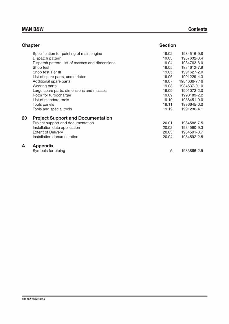
Specificationforpaintingofmainengine 19.02 1984516-9.8 Dispatch pattern 19.03 1987632-3.4 Dispatch pattern, list of masses and dimensions 19.04 1984763-6.0 Shop test 19.05 1984612-7.9 Shop test Tier III 19.05 1991627-2.0 List of spare parts, unrestricted 19.06 1991229-4.3 Additional spare parts 19.07 1984636-7.16 Wearing parts 19.08 1984637-9.10 Large spare parts, dimensions and masses 19.09 1991072-2.0 Rotor for turbocharger 19.09 1990189-2.2 List of standard tools 19.10 1986451-9.0 Tools panels 19.11 1986645-0.0 Tools and special tools 19.12 1991230-4.1 20 Project Support and Documentation Project support and documentation 20.01 1984588-7.5 Installation data application 20.02 1984590-9.3 Extent of Delivery 20.03 1984591-0.7 Installation documentation 20.04 1984592-2.5 A Appendix Symbols for piping A 1983866-2.5

MAN B&W
MAN Energy Solutions
Engine Design
1


The Fuel Optimised ME Tier II EngineThe ever valid requirement of ship operators is to obtain the lowest total oper-ational costs, and especially the lowest possible specific fuel oil consumptionat any load, and under the prevailing operating conditions.However, low-speed two-stroke main engines of the MC-C type, with a chaindriven camshaft, have limited flexibility with regard to fuel injection and ex-haust valve activation, which are the two most important factors in adjustingthe engine to match the prevailing operating conditions.A system with electronically controlled hydraulic activation provides the re-quired flexibility, and such systems form the core of the ME Engine ControlSystem, described later in detail in Chapter 16.
Concept of the ME EngineThe ME engine concept consists of a hydraulic mechanical system for activa-tion of the fuel injection and the exhaust valves. The actuators are electronic-ally controlled by a number of control units forming the complete engine con-trol system.MAN Energy Solutions has specifically developed both the hardware and thesoftware in-house, in order to obtain an integrated solution for the engine con-trol system.The fuel pressure booster consists of a simple plunger powered by a hydraulicpiston activated by oil pressure. The oil pressure is controlled by an electron-ically controlled proportional valve.The exhaust valve is opened hydraulically by means of a two-stroke exhaustvalve actuator activated by the control oil from an electronically controlled pro-portional valve. The exhaust valves are closed by the ‘air spring’.In the hydraulic system, the normal lube oil is used as the medium. It is filteredand pressurised by a hydraulic power supply unit mounted on the engine orplaced in the engine room.The starting valves are opened pneumatically by electronically controlled ‘On/Off’ valves, which make it possible to dispense with the mechanically activ-ated starting air distributor.By electronic control of the fuel injection and exhaust valves according to themeasured instantaneous crankshaft position, the Engine Control System fullycontrols the combustion process.System flexibility is obtained by means of different ‘Engine running modes’,which are selected either automatically, depending on the operating condi-tions, or manually by the operator to meet specific goals. The basic runningmode is ‘Fuel economy mode’ to comply with IMO NOx emission limitation.
Engine Design and IMO Regulation ComplianceThe ME-C engine is the shorter, more compact version of the ME engine. It iswell suited wherever a small engine room is requested, for instance in con-tainer vessels.For MAN B&W ME/ME-C-TII designated engines, the design and performanceparameters comply with the International Maritime Organisation (IMO) Tier IIemission regulations.
MAN Energy Solutions 199 15 41-9.0
95-35ME-C 1 (2)
1.01
The
Fuel
Optim
ised
ME
Tier
II E
ngin
e

For engines built to comply with IMO Tier I emission regulations, please referto the Marine Engine IMO Tier I Project Guide.
Tier II Fuel OptimisationNOx regulations place a limit on the SFOC on two-stroke engines. In general,NOx emissions will increase if SFOC is decreased and vice versa. In the stand-ard configuration, MAN B&W engines are optimised close to the IMO NOx limitand, therefore, NOx emissions cannot be further increased.The IMO NOx limit is given as a weighted average of the NOx emission at 25,50, 75 and 100% load. This relationship can be utilised to tilt the SFOC profileover the load range. This means that SFOC can be reduced at part load orlow load at the expense of a higher SFOC in the high-load range without ex-ceeding the IMO NOx limit.Optimisation of SFOC in the part-load (50-85%) or low-load (25-70%) rangerequires selection of a tuning method:
• EGB: Exhaust Gas Bypass • HPT: High Pressure Tuning (on request and only for ME-C).Each tuning method makes it possible to optimise the fuel consumption whennormally operating at low loads, while maintaining the possibility of operatingat high load when needed.The tuning methods are available for all SMCR in the specific engine layoutdiagram but they cannot be combined. The specific SFOC reduction poten-tials of the EGB tuning method in part- and low-load are shown in Section1.03.For engine types 40 and smaller, as well as for larger types with conventionalturbochargers, only high-load optimisation is applicable.In general, data in this project guide is based on high-load optimisation unlessexplicitly noted. For part- and low-load optimisation, calculations can be madein the CEAS application described in Section 20.02.
199 15 41-9.0 MAN Energy Solutions
2 (2) 95-35ME-C
1.01
The
Fuel
Optim
ised
ME
Tier
II E
ngin
e
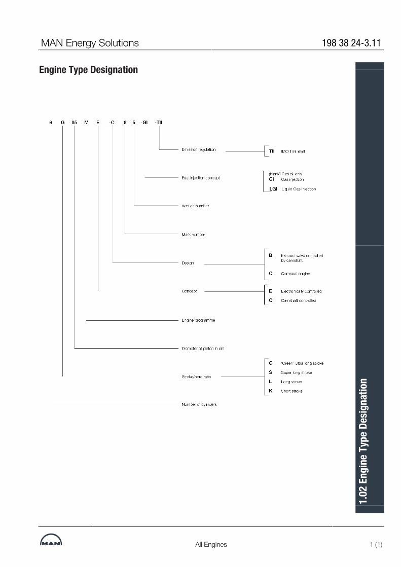
Engine Type Designation
MAN Energy Solutions 198 38 24-3.11
All Engines 1 (1)
1.02
Eng
ine T
ype D
esig
natio
n

Power, speed and fuel oil
Tier llMAN B&W G90ME-C10.5
Fuel oil
MAN B&W G90ME-C10.5 L1 SFOC [g/kWh]Opt. load range 50% 75% 100%High-load 161.5 160.5 165.0Part-load EGB 159.5 159.0 167.5Low-load EGB 157.5 160.0 167.5
Cyl. L1 kW Stroke: 3,260 mm/L1 MEP: 21.5 bar5 31,2006 37,4407 43,6808 49,9209 56,16010 62,40011 68,64012 74,880
kW/cyl.
r/min
L1
L2
6,2405,350
4,6704,010
72 84
L3
L4
Fig. 1.03.01: Power, speed and fuel oil
2021
-09-
02 -
en
MAN Energy Solutions 199 05 11-5.4
G90ME-C10.5 1 (1)
1.03
Pow
er, s
peed
and
fuel
oil
Engine Power Range and Fuel Oil Consumption
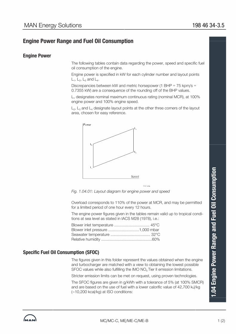
Engine PowerThe following tables contain data regarding the power, speed and specific fueloil consumption of the engine.Engine power is specified in kW for each cylinder number and layout pointsL1, L2, L3 and L4.Discrepancies between kW and metric horsepower (1 BHP = 75 kpm/s =0.7355 kW) are a consequence of the rounding off of the BHP values.L1 designates nominal maximum continuous rating (nominal MCR), at 100%engine power and 100% engine speed.L2, L3 and L4 designate layout points at the other three corners of the layoutarea, chosen for easy reference.
Fig. 1.04.01: Layout diagram for engine power and speed
Overload corresponds to 110% of the power at MCR, and may be permittedfor a limited period of one hour every 12 hours.The engine power figures given in the tables remain valid up to tropical condi-tions at sea level as stated in IACS M28 (1978), i.e.:Blower inlet temperature ................................ 45°C Blower inlet pressure ............................1,000 mbar Seawater temperature .................................... 32°C Relative humidity ..............................................60%
Specific Fuel Oil Consumption (SFOC)The figures given in this folder represent the values obtained when the engineand turbocharger are matched with a view to obtaining the lowest possibleSFOC values while also fulfilling the IMO NOX Tier II emission limitations.Stricter emission limits can be met on request, using proven technologies.The SFOC figures are given in g/kWh with a tolerance of 5% (at 100% SMCR)and are based on the use of fuel with a lower calorific value of 42,700 kJ/kg(~10,200 kcal/kg) at ISO conditions:
MAN Energy Solutions 198 46 34-3.5
MC/MC-C, ME/ME-C/ME-B 1 (2)
1.04
Eng
ine P
ower
Ran
ge a
nd Fu
el Oi
l Con
sum
ptio
n

Ambient air pressure .............................1,000 mbar Ambient air temperature ................................ 25°C Cooling water temperature ............................ 25°CAlthough the engine will develop the power specified up to tropical ambientconditions, specific fuel oil consumption varies with ambient conditions andfuel oil lower calorific value. For calculation of these changes, see Chapter 2.
Lubricating Oil DataThe cylinder oil consumption figures stated in the tables are valid under nor-mal conditions.During running-in periods and under special conditions, feed rates of up to1.5 times the stated values should be used.
198 46 34-3.5 MAN Energy Solutions
2 (2) MC/MC-C, ME/ME-C/ME-B
1.04
Eng
ine P
ower
Ran
ge a
nd Fu
el Oi
l Con
sum
ptio
n

Performance CurvesUpdated engine and capacities data is available from the CEAS program onwww.marine.man-es.com --> ’Two-Stroke’ --> ’CEAS Engine Calculations’.
MAN Energy Solutions 198 53 31-6.2
MC/MC-C, ME/ME-C/ME-B/-GI/-GA 1 (1)
1.05
Per
form
ance
Cur
ves

MAN B&W 1.06Page 1 of 6
199 11 09-6.2MAN B&W G95ME-C10.5-TII, G90ME-C10.5-TIIG80ME-C10.5-TII MAN Energy Solutions
Please note that engines built by our licensees are in accordance with the drawings and standards of MAN Energy Solutions. In certain cases local standards may be applied but all spare parts are interchangeable with parts designed by MAN Energy Solutions.
The design of some components may differ from the design of MAN Energy Solutions because the components are produced on local production facilities or because local standard components are used.
In the following, reference is made to item num-bers specified in the ‘Extent of Delivery’ (EoD) forms, both for the ‘Basic’ delivery extent and for some ‘Options’.
Bedplate and Main Bearing
The bedplate is made with the thrust bearing in the aft end of the engine. The bedplate consists of high, welded, longitudinal girders and welded cross girders with cast steel bearing supports.
To fasten the bedplate to the engine seating in the ship, long elastic holdingdown bolts and hydrau-lic tightening tools are used.
An oil pan made of steel plate is welded to the bedplate. It collects the return oil from the forced lubricating and cooling oil system.
The main bearings consist of thin-walled steel shells lined with white metal. The main bearing bottom shell can be rotated out and in by means of special tools in combination with hydraulic tools for lifting the crankshaft. The shells are kept in po-sition by a bearing cap.
Frame Box
The frame box is welded. On the exhaust side, it is provided with relief valves for each cylinder while, on the manoeuvring side, it is provided with a large hinged door for each cylinder. The crosshead guides are welded onto the frame box.
The frame box is bolted to the bedplate and bed-plate, frame box and cylinder frame are tightened together by stay bolts.
Cylinder Frame and Stuffing Box
The cylinder frame is cast and provided with ac-cess covers for cleaning the scavenge air space, if required, and for inspection of scavenge ports and piston rings from the manoeuvring side. To-gether with the cylinder liner it forms the scavenge air space.
The cylinder frame is fitted with pipes for the pis-ton cooling oil inlet. The scavenge air receiver, tur-bocharger, air cooler box and gallery brackets are located on the cylinder frame. In the bottom of the cylinder frame there is a piston rod stuffing box provided with sealing rings for scavenge air, and with oil scraper rings which prevent crankcase oil from entering the scavenge air space.
Drains from the scavenge air space and the piston rod stuffing box are located at the bottom of the cylinder frame.
Cylinder Liner
The cylinder liner is made of alloyed cast iron. The liner is suspended in the cylinder frame. The top of the cylinder liner is fitted with a cooling jacket. The cylinder liner has scavenge ports and drilled holes for cylinder lubrication.
On engines type 95-80, the basic design includes cylinder liners prepared for installation of tem-perature sensors. On all other engines, this type of liner is available as an option.
Cylinder Cover
The cylinder cover of forged steel is made in one piece with bores for cooling water. It has a central bore for the exhaust valve, bores for fuel valves, a starting valve and an indicator valve.
ME Engine Description
MAN B&W 1.06Page 2 of 6
199 11 09-6.2MAN Energy SolutionsMAN B&W G95ME-C10.5-TII, G90ME-C10.5-TIIG80ME-C10.5-TII
The cylinder cover is attached to the cylinder frame with studs and nuts tightened with hydraulic jacks.
Crankshaft
The crankshaft is of the semibuilt type, made with forged or cast steel throws. For engines with nine cylinders or more, the crankshaft is supplied in two parts.
At the aft end, the crankshaft is provided with:
• a collar for the thrust bearing• a flange for fitting the gear wheel for the
stepup gear to the hydraulic power supply unit
• a flange for the turning wheel and for the coupling bolts to an intermediate shaft.
At the front end, the crankshaft is fitted with a col-lar for the axial vibration damper and a flange for fitting a tuning wheel. The flange can also be used for power take off.
Coupling bolts and nuts for joining the crankshaft together with the intermediate shaft are not nor-mally supplied.
Thrust Bearing
The propeller thrust is transferred through the thrust collar, the segments, and the bedplate, to the end chocks and engine seating, and thus to the ship’s hull.
The thrust bearing is located in the aft end of the engine. It is of the B&WMichell type, and it con-sists primarily of a thrust collar on the crankshaft, a bearing support, and segments of steel lined with white metal.
Engines with nine cylinders or more will be speci-fied with the 360 degree type thrust bearing, while the 240 degree type is used in all other engines. The flexible thrust cam design of MAN Energy So-lutions is used for the thrust collar on a range of engine types.
The thrust shaft is an integrated part of the crank-shaft and it is lubricated by the engine’s lubricat-ing oil system.
Stepup Gear
If a mechanically driven (by the engine) hydrau-lic power supply is installed, the main hydraulic oil pumps are driven from the crankshaft via a stepup gear. The stepup gear is lubricated from the main engine system.
Turning Gear and Turning Wheel
The turning wheel is fitted to the thrust shaft, and it is driven by a pinion on the terminal shaft of the turning gear arrangement, which is mounted on the bedplate. The turning gear is driven by an electric motor with a builtin brake.
A blocking device prevents the main engine from starting when the turning gear is engaged. En-gagement and disengagement of the turning gear is done manually by moving the pinion.
The control device for the turning gear, consisting of starter and manual control box, is included in the basic design.
Axial Vibration Damper
The engine is fitted with an axial vibration damper, mounted on the fore end of the crankshaft. The damper consists of a piston and a splittype hous-ing located forward of the foremost main bearing. The piston is made as an integrated collar on the main crank journal, and the housing is fixed to the main bearing support.
A mechanical guide is fitted to be able to perform a functional check of the vibration damper. An electronic vibration monitor can be supplied as an option.

MAN B&W 1.06Page 3 of 6
199 11 09-6.2MAN B&W G95ME-C10.5-TII, G90ME-C10.5-TIIG80ME-C10.5-TII MAN Energy Solutions
Tuning Wheel/Torsional Vibration Damper
A tuning wheel or torsional vibration damper may have to be ordered separately, depending on the final torsional vibration calculations.
Connecting Rod
The connecting rod is made of forged or cast steel and provided with bearing caps for the crosshead and crankpin bearings.
The crosshead and crankpin bearing caps are secured to the connecting rod with studs and nuts tightened by means of hydraulic jacks.
The crosshead bearing consists of a set of thinwalled steel shells, lined with bearing metal. The crosshead bearing cap is in one piece, with an angular cutout for the piston rod.
The crankpin bearing is provided with thinwalled steel shells, lined with bearing metal. Lube oil is supplied through ducts in the crosshead and con-necting rod.
Piston
The piston consists of a piston crown and piston skirt. The piston crown is made of heatresistant steel. A piston cleaning ring located in the very top of the cylinder liner scrapes off excessive ash and carbon formations on the piston topland.
The piston has three or four ring grooves which are hardchrome plated on both the upper and lower surfaces of the grooves. Three or four piston rings are fitted depending on the engine type.The uppermost piston ring is of the CPR type (controlled pressure relief), whereas the other two or three piston rings are of the CPR type or have an oblique cut. Depending on the engine type, the uppermost piston ring is higher than the others. All rings are alu-coated on the outer surface for running-in.
The piston skirt is made of cast iron with a bronze band or molybdenum coating.
Piston Rod
The piston rod is of forged steel and it is surface-hardened on the running surface for the stuffing box. The piston rod is connected to the crosshead with four bolts. The piston rod has a central bore which, in conjunction with a cooling oil pipe, forms the inlet and outlet for cooling oil.
Crosshead
The crosshead is of forged steel provided with cast steel guide shoes with white metal on the running surface.
The guide shoe is of the low-friction type and crosshead bearings of the wide-pad design.
The telescopic pipe for oil inlet and the pipe for oil outlet are mounted on the guide shoes.
Scavenge Air System
The air intake to the turbocharger takes place directly from the engine room through the turbo-charger intake silencer. From the turbocharger, the air is led via the charging air pipe, air cooler and scavenge air receiver to the scavenge ports of the cylinder liners, see Chapter 14. The scav-enge air receiver is of the D-shape design.
Scavenge Air Cooler
A scavenge air cooler of the mono-block type is fitted for each turbocharger.
The scavenge air cooler is most commonly cooled by freshwater from a central cooling system. Alter-natively, it can be cooled by seawater from either a seawater cooling system or a combined cooling system with separate seawater and freshwater pumps.
Auxiliary Blower
The engine is provided with electricallydriven scavenge air blowers integrated in the scavenge

MAN B&W 1.06Page 4 of 6
199 11 09-6.2MAN Energy SolutionsMAN B&W G95ME-C10.5-TII, G90ME-C10.5-TIIG80ME-C10.5-TII
air cooler. The suction side of the blowers is con-nected to the scavenge air space after the air cooler.
Between the air cooler and the scavenge air re-ceiver, nonreturn valves are fitted which auto-matically close when the auxiliary blowers supply the air.
The auxiliary blowers will start operating con-secutively before the engine is started in order to ensure sufficient scavenge air pressure to obtain a safe start.
Further information is given in Chapter 14.
Exhaust Gas System
From the exhaust valves, exhaust gas is led to the exhaust gas receiver where the fluctuating pressure from the individual cylinders is equal-ised, and the total volume of gas is led to the turbocharger(s). After the turbocharger(s), the gas is led to the external exhaust pipe system.
Compensators are fitted between the exhaust valves and the receiver, and between the receiver and the turbocharger(s).
The exhaust gas receiver and exhaust pipes are provided with insulation, which is covered by gal-vanised steel plating.
A protective grating is installed between the ex-haust gas receiver and the turbocharger.
Exhaust Turbocharger
The engines can be fitted with either MAN, ABB or MHI turbochargers.
The turbocharger selection is described in Chap-ter 3 and the exhaust gas system in Chapter 15.
Reversing
Reversing of the engine is performed electroni-cally and controlled by the engine control system
by changing the timing of the fuel injection, the exhaust valve activation and the starting valves.
Second Order Moment Compensators
Second order moment compensators are in gen-eral relevant only for five or six-cylinder engines, and can be mounted either on the aft end or on both fore and aft end of the engine.
The aft-end compensator consists of balance weights driven by chain. The fore-end compensa-tor consists of balance weights driven from the fore end of the crankshaft.
The second order moment compensators as well as the basic design and options are described in Section 17.02.
The Hydraulic Power Supply
The hydraulic power supply (HPS) filters and pres-surises the lube oil for use in the hydraulic system. The HPS consists of either mechanically driven (by the engine) main pumps with electrically driven start-up pumps or electrically driven combined main and start-up pumps.
The mechanically driven HPS is engine driven and mounted aft for engines with the chain drive aft (eight cylinders or less), and at the middle for engines with the chain drive located in the middle (nine cylinders or more). An electrically driven HPS is usually mounted aft on the engine.A combined HPS, mechanically driven with elec-trically driven start-up/back-up pumps with back-up capacity, is available as an option.
Fuel Booster Injection Valve
The fuel booster injection valve (FBIV), three per cylinder, consists of a fuel booster part and an in-jection valve part. Fuel injection is activated by the ELFI (electronic fuel injection) multi-way valve, which is electroni-cally controlled by the cylinder control unit (CCU) of the engine control system.

MAN B&W 1.06Page 5 of 6
199 11 09-6.2MAN B&W G95ME-C10.5-TII, G90ME-C10.5-TIIG80ME-C10.5-TII MAN Energy Solutions
The injection valve is opened by high-pressure fuel oil delivered by the fuel booster and is it closed by a spring. Internal bores in the injection valve enables fuel oil circulation when the engine is stopped. Drain oil is led away in a closed sys-tem.
Starting Air Valve
The cylinder cover is equipped with two or three fuel valves, a starting air valve, and an indicator cock.
Starting air is supplied by solenoid valves, one per cylinder, which are controlled by the CCUs of the engine control system.
The starting air valve is opened by control air, timed by the engine control system, and is closed by a spring.
Slow turning before starting is a program incorpo-rated in the basic engine control system.
The starting air system is described in detail in Section 13.01.
Top Controlled Exhaust Valve
The top controlled exhaust valve (TCEV) consists of the valve housing, the valve spindle and the hydraulic cylinder unit (HCU). The valve housing is of the un-cooled type and made of cast iron. The housing is provided with a water cooled bottom piece of steel with a hardened seat of the Wide-seat design
The exhaust valve is tightened to the cylinder cover with studs and nuts. The exhaust valve is opened hydraulically by the electronic valve acti-vation system and is closed by an air spring.
The hydraulic cylinder unit (HCU) is a distributor block mounted directly on the exhaust valve. The distributor block is fitted with one or more accu-mulators to ensure that the necessary hydraulic oil peak flow is available during the fuel injection and valve actuation sequence. Multi-way valves con-trol this sequence (FIVA, ELFI/PEVA).
In operation, the valve spindle rotates, driven by the exhaust gas acting on a vane wheel fixed to the spindle.
Sealing of the exhaust valve spindle is provided by means of Controlled Oil Level (COL), an oil bath in the bottom of the air spring, above the seal-ing ring. This oil bath lubricates the exhaust vlave spindle guide and sealing ring as well.
Indicator Cock
The engine is fitted with an indicator cock to which the PMI pressure transducer is connected.
MAN B&W Alpha Cylinder Lubrication
The electronically controlled MAN B&W Alpha cylinder lubrication system is applied to the ME engines, and controlled by the ME engine control system.
The main advantages of the MAN B&W Alpha cyl-inder lubrication system, compared with the con-ventional mechanical lubricator, are:
• Improved injection timing• Increased dosage flexibility• Constant injection pressure• Improved oil distribution in the cylinder liner • Possibility for prelubrication before starting.
The ME/Alpha Lubricator is replaced by the Alpha Lubricator Mk. 2 on some engines.
Further details about the cylinder lubrication sys-tem can be found in Chapter 9.
Gallery Arrangement
The engine is provided with gallery brackets, stanchions, railings and platforms (exclusive of ladders). The brackets are placed at such a height as to provide the best possible overhauling and inspection conditions.
Some main pipes of the engine are suspended from the gallery brackets, and the topmost gallery platform on the manoeuvring side is provided with

MAN B&W 1.06Page 6 of 6
199 11 09-6.2MAN Energy SolutionsMAN B&W G95ME-C10.5-TII, G90ME-C10.5-TIIG80ME-C10.5-TII
overhauling holes for the pistons.
The engine is prepared for top bracings on the ex-haust side, or on the manoeuvring side.
Piping Arrangements
The engine is delivered with piping arrangements for:• Fuel oil• Heating of fuel oil• Lubricating oil, piston cooling oil, hydraulic oil• Cylinder lubricating oil• Cooling water to scavenge air cooler• Jacket and turbocharger cooling water• Cleaning of turbocharger• Fire extinguishing in scavenge air space• Starting air• Control air• Oil mist detector (required only for Visatron VN
215/93, make Schaller Automation)• Various drain pipes.
All piping arrangements are made of steel piping, except the control air and steam heating of fuel pipes, which are made of copper.
The pipes are provided with sockets for local instruments, alarm and safety equipment and, furthermore, with a number of sockets for supple-mentary signal equipment. Chapter 18 deals with the instrumentation.

Engine Cross Section
Fig. 1.07.01: Engine cross section, turbocharger(s) mounted on the exhaust side
MAN B&W 1.07
Page 1 of 1
MAN B&W G90ME-C10.5 MAN Energy Solutions 199 10 02-8.0
MAN B&W
MAN Energy Solutions
Engine Layout and Load Diagrams, SFOC
2


Engine Layout and Load Diagrams
IntroductionThe effective power ‘P’ of a diesel engine is proportional to the mean effectivepressure (mep) pe and engine speed ‘n’, i.e. when using ‘c’ as a constant:
P= c × pe × n
so, for constant mep, the power is proportional to the speed:
P= c × n1 (for constant mep)
When running with a Fixed Pitch Propeller (FPP), the power may be expressedaccording to the propeller law as:
P= c × n3 (propeller law)
Thus, for the above examples, the power P may be expressed as a powerfunction of the speed ‘n’ to the power of ‘i’, i.e.:
P= c × ni
Fig. 2.01.01 shows the relationship for the linear functions, y = ax + b, usinglinear scales.
Fig. 2.01.01: Straight lines in linear scales
MAN Energy Solutions 199 06 13-4.1
Engines dot 5 and higher 1 (5)
2.01
Eng
ine L
ayou
t and
Load
Dia
gram
s

The power functions P = c × ni will be linear functions when using logarithmicscales as shown in Fig. 2.01.02:
log (P) = i × log (n) + log (c)
Fig. 2.01.02: Power function curves in logarithmic scalesThus, propeller curves will be parallel to lines having the inclination i = 3, andlines with constant mep will be parallel to lines with the inclination i = 1.Therefore, in the layout diagrams and load diagrams for diesel engines, logar-ithmic scales are often used, giving simple diagrams with straight lines.
Propulsion and Engine Running Points
Propeller CurveThe relation between power and propeller speed for a fixed pitch propeller isas mentioned above described by means of the propeller law, i.e. the thirdpower curve:
P= c × n3, in which:
P= engine power for propulsion
n = propeller speed
c = constant
The exponent i=3 is valid for frictional resistance. For vessels having sufficientengine power to sail fast enough to experience significant wave-making resist-ance, the exponent may be higher in the high load range.
199 06 13-4.1 MAN Energy Solutions
2 (5) Engines dot 5 and higher
2.01
Eng
ine L
ayou
t and
Load
Dia
gram
s

Propeller Design Point
Fig. 2.01.03: Propulsion running points and engine layout
Line 2 Propulsion curve, fouled hull and heavy weather (heavy running), engine lay-out curve
Line 6 Propulsion curve, clean hull and calm weather (light running), for propellerlayout
MP Specified MCR for propulsion
SP Continuous service rating for propulsion
PD Propeller design point
PD’ Propeller design point incorporating sea margin
HR Heavy running
LR Light running
Normally, estimates of the necessary propeller power and speed are basedon theoretical calculations for loaded ship, and often experimental tank tests,both assuming optimum operating conditions, i.e. a clean hull and goodweather.The combination of speed and power obtained may be called the ship’s pro-peller design point (PD), placed on the light running propeller curve 6, see Fig.2.01.03.On the other hand, some shipyards, and/or propeller manufacturers some-times use a propeller design point (PD’) that incorporates all or part of the so-called sea margin described below.
Fouled HullWhen the ship has sailed for some time, the hull and propeller become fouledand the hull’s resistance will increase. Consequently, the ship’s speed will bereduced unless the engine delivers more power to the propeller, i.e. the pro-peller will be further loaded and will be heavy running (HR).
MAN Energy Solutions 199 06 13-4.1
Engines dot 5 and higher 3 (5)
2.01
Eng
ine L
ayou
t and
Load
Dia
gram
s

Sea Margin and Heavy WeatherIf the weather is bad with headwind, the ship’s resistance may increase com-pared to operating in calm weather conditions. When determining the neces-sary engine power, it is normal practice to add an extra power margin, the so-called sea margin, so that the design speed can be maintained in averageconditions at sea. The sea margin is traditionally about 15% of the power re-quired to achieve design speed with a clean hull in calm weather (PD).
Engine Layout (Heavy Propeller)When determining the necessary engine layout speed that considers the influ-ence of a heavy running propeller for operating at high extra ship resistance, itis (compared to line 6) recommended to choose a heavier propeller line 2. Thepropeller curve for clean hull and calm weather, line 6, may then be said torepresent a ‘light running’ (LR) propeller.We recommend using a light running margin (LRM) of normally 4.0-7.0%,however for special cases up to 10%, that is, for a given engine power, thelight running propeller RPM is 4.0 to 10.0% higher than the RPM on the en-gine layout curve.The recommendation is applicable to all draughts at which the ship is inten-ded to operate, whether ballast, design or scantling draught. The recom-mendation is applicable to engine loads from 50 to 100%. If an average of themeasured (and possibly corrected) values between 50 and 100% load is usedfor verification this will smoothen out the effect of measurement uncertaintyand other variations.The high end of the range, 7 to 10%, is primarily intended for vessels where itis important to be able to develop as much of the full engine power as pos-sible in adverse conditions with a heavy running propeller. For example forvessels that are operating in ice.Vessels with shaft generators may in some cases also benefit from a light run-ning margin in the high range. It is then possible to keep the shaft generator inoperation for a larger proportion of the time spent at sea.
Engine MarginBesides the sea margin, a so-called ‘engine margin’ of some 10% or 15% isfrequently added. The corresponding point is called the ‘specified MCR forpropulsion’ (MP), and refers to the fact that the power for point SP is 10% or15% lower than for point MP.With engine margin, the engine will operate at less than 100% power whensailing at design speed with a vessel resistance corresponding to the selectedsea margin, for example 90% engine load if the engine margin is 10%.Point MP is identical to the engine’s specified MCR point (M) unless a mainengine driven shaft generator is installed. In such a case, the extra power de-mand of the shaft generator must also be considered.
199 06 13-4.1 MAN Energy Solutions
4 (5) Engines dot 5 and higher
2.01
Eng
ine L
ayou
t and
Load
Dia
gram
s

Constant Ship Speed LinesThe constant ship speed lines α are shown at the very top of Fig. 2.01.03.They indicate the power required at various propeller speeds in order to keepthe same ship speed. It is assumed that, for each ship speed, the optimumpropeller diameter is used, taking into consideration the total propulsion effi-ciency. See definition of α in Section 2.02.
Note:Light/heavy running, fouling and sea margin are overlapping terms. Light/heavy running of the propeller refers to hull and propeller deterioration andheavy weather, whereas sea margin i.e. extra power to the propeller, refers tothe influence of the wind and the sea. However, the degree of light runningmust be decided upon experience from the actual trade and hull design of thevessel.
MAN Energy Solutions 199 06 13-4.1
Engines dot 5 and higher 5 (5)
2.01
Eng
ine L
ayou
t and
Load
Dia
gram
s

Propeller Diameter and Pitch, Influence on the Optimum Propeller SpeedIn general, the larger the propeller diameter D, the lower is the optimum pro-peller speed and the kW required for a certain design draught and ship speed,see curve D in the figure below.The maximum possible propeller diameter depends on the given designdraught of the ship, and the clearance needed between the propeller and theaft body hull and the keel.The example shown in the Fig. 2.02.01 is an 80,000 dwt crude oil tanker witha design draught of 12.2 m and a design speed of 14.5 knots.When the propeller diameter D is increased from 6.6 m to 7.2 m, the powerdemand is reduced from about 9,290 kW to 8,820 kW, and the optimum pro-peller speed is reduced from 120 r/min to 100 r/min, corresponding to theconstant ship speed coefficient α = 0.28 (see definition of α in Constant ShipSpeed Lines).Once a propeller diameter of maximum 7.2 m has been chosen, the corres-ponding optimum pitch in this point is given for the design speed of 14.5knots, i.e. P/D = 0.70.However, if the optimum propeller speed of 100 r/min does not suit the pre-ferred / selected main engine speed, a change of pitch away from optimumwill only cause a relatively small extra power demand, keeping the same max-imum propeller diameter:▪ going from 100 to 110 r/min (P/D = 0.62) requires 8,900 kW, i.e. an extra
power demand of 80 kW.▪ going from 100 to 91 r/min (P/D = 0.81) requires 8,900 kW, i.e. an extra
power demand of 80 kW.In both cases the extra power demand is only 0.9%, and the corresponding‘equal speed curves’ are α = +0.1 and α = -0.1, respectively, so there is acertain interval of propeller speeds in which the ‘power penalty’ is very limited.
Fig. 2.02.01: Influence of diameter and pitch on propeller design
MAN Energy Solutions 199 06 26-6.0
All Engines 1 (3)
2.02
Pro
pelle
r Dia
met
er a
nd P
itch,
Influ
ence
on
the O
p-tim
um P
rope
ller S
peed

Constant Ship Speed LinesThe constant ship speed lines α, are shown at the very top of Fig. 2.02.02.These lines indicate the power required at various propeller speeds to keepthe same ship speed provided an optimum pitch diameter ratio is used at anygiven speed, taking into consideration the total propulsion efficiency.Normally, if propellers with optimum pitch are used, the following relationbetween necessary power and propeller speed can be assumed:
P2 = P1 × (n2 /n1)α
where:
P= Propulsion power
n = Propeller speed, and
α= Constant ship speed coefficient.
For any combination of power and speed, each point on lines parallel to theship speed lines gives the same ship speed.When such a constant ship speed line is drawn into the layout diagramthrough a specified propulsion MCR point ‘MP1’, selected in the layout areaand parallel to one of the α-lines, another specified propulsion MCR point‘MP2’ upon this line can be chosen to give the ship the same speed for thenew combination of engine power and speed.Fig. 2.02.02 shows an example of the required power speed point MP1,through which a constant ship speed curve α = 0.25 is drawn, obtaining pointMP2 with a lower engine power and a lower engine speed but achieving thesame ship speed.Provided the optimum pitch is used for a given propeller diameter the follow-ing data applies when changing the propeller diameter:for general cargo, bulk carriers and tankers
α= 0.20 - 0.30
and for reefers and container vessels
α= 0.15 - 0.25
When changing the propeller speed by changing the pitch, the α constant willbe different, see Fig. 2.02.01.
199 06 26-6.0 MAN Energy Solutions
2 (3) All Engines
2.02
Pro
pelle
r Dia
met
er a
nd P
itch,
Influ
ence
on
the O
p-tim
um P
rope
ller S
peed

Fig. 2.02.02: Layout diagram and constant ship speed lines
MAN Energy Solutions 199 06 26-6.0
All Engines 3 (3)
2.02
Pro
pelle
r Dia
met
er a
nd P
itch,
Influ
ence
on
the O
p-tim
um P
rope
ller S
peed

Engine Layout and Load Diagram
Engine Layout DiagramAn engine’s layout diagram is limited by two constant mean effective pressure(mep) lines L1– L3 and L2– L4, and by two constant engine speed lines L1– L2and L3– L4. The L1 point refers to the engine’s nominal maximum continuousrating, see Fig. 2.03.01.Within the layout area there is full freedom to select the engine’s specifiedSMCR point M which suits the demand for power and speed for the ship.On the horizontal axis the engine speed and on the vertical axis the enginepower are shown on percentage scales. The scales are logarithmic whichmeans that, in this diagram, power function curves like propeller curves (3rd
power), constant mean effective pressure curves (1st power) and constantship speed curves (0.15 to 0.30 power) are straight lines.
Fig. 2.03.01: Engine layout diagram
Specified Maximum Continuous Rating (M)Based on the propulsion and engine running points, as previously found, thelayout diagram of a relevant main engine may be drawn in a powerspeed dia-gram like in Fig. 2.03.01. The SMCR point (M) must be inside the limitationlines of the layout diagram; if it is not, the propeller speed will have to bechanged or another main engine type must be chosen. The selected SMCRhas an influence on the mechanical design of the engine, for example the tur-bocharger(s), the piston shims, the liners and the fuel valve nozzles.Once the specified MCR has been chosen, the engine design and the capa-cities of the auxiliary equipment will be adapted to the specified MCR.If the specified MCR is to be changed later on, this may involve a change ofthe shafting system, vibrational characteristics, pump and cooler capacities,fuel valve nozzles, piston shims, cylinder liner cooling and lubrication, as wellas rematching of the turbocharger or even a change to a different turbochar-ger size. In some cases it can also require larger dimensions of the piping sys-tems.It is therefore important to consider, already at the project stage, if the spe-cification should be prepared for a later change of SMCR. This should be in-dicated in the Extent of Delivery.
2021
-08-
20 -
en
MAN Energy Solutions 199 06 11-0.1
All engines 1 (11)
2.03
Eng
ine L
ayou
t and
Load
Dia
gram
For ME and ME-C/-GI/-LGI engines, the timing of the fuel injection and the ex-haust valve activation are electronically optimised over a wide operating rangeof the engine.For ME-B/-GI/-LGI engines, only the fuel injection (and not the exhaust valveactivation) is electronically controlled over a wide operating range of the en-gine.For a standard high-load optimised engine, the lowest specific fuel oil con-sumption for the ME and ME-C engines is optained at 70% and for MC/MC-C/ME-B engines at 80% of the SMCR point (M).
Continuous Service Rating (S)The continuous service rating is the power needed in service – including thespecified sea margin and heavy/light running factor of the propeller – at whichthe engine is to operate, and point S is identical to the service propulsionpoint (SP) unless a main engine-driven shaft generator is installed.
Engine Load Diagram
DefinitionsThe engine’s load diagram, see Fig. 2.03.02, defines the power and speedlimits for continuous as well as overload operation of an installed engine hav-ing a specified MCR point M that corresponds to the ship’s specification.The service points of the installed engine incorporate the engine power re-quired for ship propulsion and shaft generator, if installed.
Operating Curves and LimitsThe service range is limited by four lines: 4, 5, 7 and 3 (9), see Fig. 2.03.02.The propeller curves, line 1, 2 and 6, and overload limits in the load diagramare also described below.Line 1:Propeller curve through specified MCR (M), engine layout curve.Line 2:Propeller curve, fouled hull and heavy weather – heavy running.Line 3 and line 9:Maximum engine speed limits. In Fig. 2.03.02 they are shown for an enginewith a layout point M selected on the L1/L2 line, that is, for an engine which isnot speed derated.The speed limit for normal operation (line 3) is:Maximum 110% of M, but no more than 105% of L1/L2 speed, provided thattorsional vibrations permit. If M is sufficiently speed derated, more than 110%speed is possible by choosing ‘Extended load diagram’ which is describedlater in this chapter.The speed limit for sea trial (line 9) is:Maximum 110% of M, but no more than 107% of L1/L2 speed, provided thattorsional vibrations permit. If M is sufficiently speed derated, more than 110%speed is possible by choosing ‘Extended load diagram’ which is describedlater in this chapter.
2021
-08-
20 -
en
199 06 11-0.1 MAN Energy Solutions
2 (11) All engines
2.03
Eng
ine L
ayou
t and
Load
Dia
gram

Line 4:Represents the limit at which an ample air supply is available for combustionand imposes a limitation on the maximum combination of torque and speed.To the left of line 4 in torque-rich operation, the engine will lack air from theturbocharger to the combustion process, i.e. the heat load limits may be ex-ceeded. Bearing loads may also become too high.Line 5:Represents the maximum mean effective pressure level (mep), which can beaccepted for continuous operation.Line 6:Propeller curve, clean hull and calm weather – light running, often used forpropeller layout/design.Line 7:Represents the maximum power for continuous operation.Line 8:Represents the overload operation limitations.The area between lines 4, 5, 7 and the heavy dashed line 8 is available foroverload running for limited periods only (1 hour per 12 hours).
Fig. 2.03.02: Engine load diagram for an engine specified with MCR on the L1/L2 line of the layout diagram (maximum MCR speed).
M Specified MCR point
Line 1 Propeller curve through point M (i = 3) (engine layout curve)
Line 2 Propeller curve, fouled hull and heavy weather – heavy running (i = 3)
Line 3 Speed limit
Line 4 Torque/speed limit (i = 2)
Line 5 Mean effective pressure limit (i = 1)
Line 6 Propeller curve, clean hull and calm weather– light running (i = 3), for propeller layout.The hatched area indicates the full recommended range for LRM(4.0-10.0%)
Line 7 Power limit for continuous running (i = 0)
2021
-08-
20 -
en
MAN Energy Solutions 199 06 11-0.1
All engines 3 (11)
2.03
Eng
ine L
ayou
t and
Load
Dia
gram

Line 8 Overload limit
Line 9 Speed limit at sea trial
Limits for Low Load RunningAs the fuel injection for ME engines is automatically controlled over the entirepower range, the engine is able to operate down to around 15-20% of thenominal L1 speed, whereas for MC/MC-C engines it is around 20-25% (elec-tronic governor).
Recommendation for OperationThe area between lines 1, 3 and 7 is available for continuous operationwithout limitation.The area between lines 1, 4 and 5 is available for operation in shallow waters,in heavy weather and during acceleration, i.e. for non-steady operationwithout any strict time limitation.The area between lines 4, 5, 7 and 8 is available for overload operation for 1out of every 12 hours.After some time in operation, the ship’s hull and propeller will be fouled, res-ulting in heavier running of the propeller, i.e. the propeller curve will move tothe left from line 6 towards line 2, and extra power is required for propulsion inorder to keep the ship’s speed.In calm weather conditions, the extent of heavy running of the propeller will in-dicate the need for cleaning the hull and polishing the propeller.If the engine and shaft line has a barred speed range (BSR) it is usually a classrequirement to be able to pass the BSR quickly. The quickest way to pass theBSR is the following:
1. Set the rpm setting to a value just below the BSR.2. Wait while the vessel accelerates to a vessel speed corresponding to the
rpm setting.3. Increase the rpm setting to a value above the BSR.
When passing the BSR as described above it will usually happen quickly.
Layout ConsiderationsIn some cases, for example in certain manoeuvring situations inside a harbouror at sea in adverse conditions, it may not be possible to follow the procedurefor passing the BSR outlined above. Either because there is no time to wait forthe vessel speed to build up or because high vessel resistance makes it im-possible to achieve a vessel speed corresponding to the engine rpm setting.In such cases it can be necessary to pass the BSR at a low ship speed.For 5- and 6-cylinder engines with short shaft lines, such as on many bulkersand tankers, the BSR may extend quite high up in the rpm range. If all of theBSR is placed below 60% of specified MCR rpm and the propeller light run-ning margin is within the recommendation, it is normally possible to achievesufficiently quick passage of the BSR in relevant conditions. If the BSR ex-tends further up than 60% of specified MCR rpm it may require additionalstudies to ensure that passage of the BSR will be sufficiently quick.
2021
-08-
20 -
en
199 06 11-0.1 MAN Energy Solutions
4 (11) All engines
2.03
Eng
ine L
ayou
t and
Load
Dia
gram

For support regarding layout of BSR and PTO/PTI, please contact MAN En-ergy Solutions, Copenhagen at [email protected].
Extended Load DiagramWhen a ship with fixed pitch propeller is operating in normal sea service, it willin general be operating in the hatched area around the design propeller curve6, as shown on the standard load diagram in Fig. 2.03.02.Sometimes, when operating in heavy weather, the fixed pitch propeller per-formance will be more heavy running, i.e. for equal power absorption of thepropeller, the propeller speed will be lower and the propeller curve will moveto the left.As the low speed main engines are directly coupled to the propeller, the en-gine has to follow the propeller performance, i.e. also in heavy running pro-peller situations. For this type of operation, there is normally enough margin inthe load area between line 6 and the normal torque/speed limitation line 4,see Fig. 2.03.02.For some ships and operating conditions, it would be an advantage – whenoccasionally needed – to be able to operate the propeller/main engine asmuch as possible to the left of line 6, but inside the torque/speed limit, line 4.This could be relevant in the following cases, especially when more than oneof the listed cases are applicable to the vessel:▪ ships sailing in areas with very heavy weather▪ ships sailing for long periods in shallow or otherwise restricted waters▪ ships with a high ice class▪ ships with two fixed pitch propellers/two main engines, where one pro-
peller/one engine is stopped/declutched for one or the other reason▪ ships with large shaft generators (>10% of SMCR power)The increase of the operating speed range between line 6 and line 4, see Fig.2.03.02, may be carried out as shown for the following engine example withan extended load diagram for a speed derated engine with increased lightrunning margin.
Example of Extended Load Diagram for Speed Derated Engines with Increased Light RunningMargin
For speed derated engines it is possible to extend the maximum speed limitto maximum 105% of the engine’s L1/L2 speed, line 3’, but only provided thatthe torsional vibration conditions permit this. Thus, the shafting, with regard totorsional vibrations, has to be approved by the classification society in ques-tion, based on the selected extended maximum speed limit.When choosing an increased light running margin, the load diagram area maybe extended from line 3 to line 3’, as shown in Fig. 2.03.03, and the propeller/main engine operating curve 6 may have a correspondingly increased heavyrunning margin before exceeding the torque/speed limit, line 4.
2021
-08-
20 -
en
MAN Energy Solutions 199 06 11-0.1
All engines 5 (11)
2.03
Eng
ine L
ayou
t and
Load
Dia
gram

Fig. 2.03.03: Extended load diagram for a speed derated engine with in-creased light running margin.
Line 1 Propeller curve through SMCR point (M)– layout curve for engine
Line 2 Heavy propeller curve– fouled hull and heavy seas
Line 3 Speed limit
Line 3’ Extended speed limit, provided torsional vibration conditions permit
Line 4 Torque/speed limit
Line 5 Mean effective pressure limit
Line 6 Increased light running propeller curve– clean hull and calm weather– layout curve for propeller
Line 7 Power limit for continuous running
Examples of the use of the Load DiagramIn the following some examples illustrating the flexibility of the layout and loaddiagrams are presented, see Figs. 2.03.04 to 06.▪ Example 1 shows how to place the load diagram for an engine without
shaft generator coupled to a fixed pitch propeller.▪ Example 2 shows the same layout for an engine with fixed pitch propeller
(example 1), but with a shaft generator.▪ Example 3 is a special case of example 2, where the specified MCR is
placed near the top of the layout diagram.In this case the shaft generator is cut off, and the GenSets used when theengine runs at specified MCR. This makes it possible to choose a smallerengine with a lower power output, and with changed specified MCR.
▪ Example 4 shows diagrams for an engine coupled to a controllable pitchpropeller, with or without a shaft generator, constant speed or combinatorcurve operation.
For a specific project, the layout diagram for actual project shown later in thischapter may be used for construction of the actual load diagram.
2021
-08-
20 -
en
199 06 11-0.1 MAN Energy Solutions
6 (11) All engines
2.03
Eng
ine L
ayou
t and
Load
Dia
gram

Example 1: Normal Running Conditions.
Engine Coupled to Fixed Pitch Propeller (FPP) and without Shaft GeneratorLayout diagram Load diagram
Fig. 2.03.04: Normal running conditions. Engine coupled to a fixed pitch pro-peller (FPP) and without a shaft generator
M Specified MCR of engine
S Continuous service rating of engine
MP Specified MCR for propulsion
SP Continuous service rating of propulsion
The specified MCR (M) will normally be selected on the engine service curve2.Once point M has been selected in the layout diagram, the load diagram canbe drawn, as shown in the figure, and hence the actual load limitation lines ofthe diesel engine may be found by using the inclinations from the constructionlines and the %-figures stated.
2021
-08-
20 -
en
MAN Energy Solutions 199 06 11-0.1
All engines 7 (11)
2.03
Eng
ine L
ayou
t and
Load
Dia
gram

Example 2: Normal Running Conditions.
Engine Coupled to Fixed Pitch Propeller (FPP) and with Shaft GeneratorLayout diagram Load diagram
Fig. 2.03.05: Normal running conditions. Engine coupled to a fixed pitch pro-peller (FPP) and with a shaft generator
M Specified MCR of engine
S Continuous service rating of engine
MP Specified MCR for propulsion
SP Continuous service rating of propulsion
SG Shaft generator power
In Example 2 a shaft generator (SG) is installed, and therefore the servicepower of the engine also has to incorporate the extra shaft power required forthe shaft generator’s electrical power production.In the figure, the engine service curve shown for heavy running incorporatesthis extra power.The specified MCR M will then be chosen and the load diagram can be drawnas shown in the figure.
2021
-08-
20 -
en
199 06 11-0.1 MAN Energy Solutions
8 (11) All engines
2.03
Eng
ine L
ayou
t and
Load
Dia
gram

Example 3: Special Running Conditions.
Engine Coupled to Fixed Pitch Propeller (FPP) and with Shaft GeneratorLayout diagram Load diagram
Fig. 2.03.06: Special running conditions. Engine coupled to a fixed pitch pro-peller (FPP) and with a shaft generator
M Specified MCR of engine Point M of the load diagram is found:
S Continuous service rating of engine Line 1 Propeller curve through point S
MP Specified MCR for propulsion Point M Intersection between line 1 and line L1 – L3
SP Continuous service rating of propulsion
SG Shaft generator power
Also for this special case in Example 3, a shaft generator is installed but, com-pared to Example 2, this case has a specified MCR for propulsion, MP,placed at the top of the layout diagram.This involves that the intended specified MCR of the engine M’ will be placedoutside the top of the layout diagram.One solution could be to choose a larger diesel engine with an extra cylinder,but another and cheaper solution is to reduce the electrical power productionof the shaft generator when running in the upper propulsion power range.In choosing the latter solution, the required specified MCR power can be re-duced from point M’ to point M as shown. Therefore, when running in the up-per propulsion power range, a diesel generator has to take over all or part ofthe electrical power production.Point M, having the highest possible power, is then found at the intersectionof line L1– L3 with line 1 and the corresponding load diagram is drawn.
2021
-08-
20 -
en
MAN Energy Solutions 199 06 11-0.1
All engines 9 (11)
2.03
Eng
ine L
ayou
t and
Load
Dia
gram

Example 4: Engine coupled to controllable Pitch Propeller (CPP) with or without Shaft Generator
Fig. 2.03.07: Engine with Controllable Pitch Propeller (CPP), with or without ashaft generator
M Specified MCR of engine
S Continuous service rating of engine
Without Shaft GeneratorIf a controllable pitch propeller (CPP) is applied, the combinator curve (of thepropeller) will normally be selected for loaded ship including sea margin.The combinator curve may for a given propeller speed have a given propellerpitch, and this may be heavy running in heavy weather like for a fixed pitchpropeller.Therefore it is recommended to use a light running combinator curve (the dot-ted curve which includes the sea margin) as shown in the figure to obtain anincreased operation margin of the diesel engine in heavy weather to the limitindicated by curves 4 and 5 in Fig. 2.03.07.
With Shaft GeneratorThe hatched area in Fig. 2.03.07 shows the recommended speed rangebetween 100% and 96.9% of the specified MCR speed for an engine withshaft generator running at constant speed.The service point S can be located at any point within the hatched area.The procedure shown in examples 2 and 3 for engines with FPP can also beapplied here for engines with CPP running with a combinator curve.
Load DiagramTherefore, when the engine’s specified MCR point (M) has been chosen in-cluding engine margin, sea margin and the power for a shaft generator, if in-stalled, point M may be used as the basis for drawing the engine load dia-gram.
2021
-08-
20 -
en
199 06 11-0.1 MAN Energy Solutions
10 (11) All engines
2.03
Eng
ine L
ayou
t and
Load
Dia
gram

The position of the combinator curve ensures the maximum load range withinthe permitted speed range for engine operation, and it still leaves a reason-able margin to the limit indicated by curves 4 and 5 in Fig. 2.03.07.For support regarding CPP propeller curves, please contact MAN EnergySolutions, Copenhagen at [email protected].
2021
-08-
20 -
en
MAN Energy Solutions 199 06 11-0.1
All engines 11 (11)
2.03
Eng
ine L
ayou
t and
Load
Dia
gram

Diagram of Actual ProjectThis figure contains a layout diagram that can be used for constructing theload diagram for an actual project, using the %-figures stated and the inclina-tions of the lines.
Fig. 2.04.01: Construction of a load diagram
MAN Energy Solutions 199 06 12-2.0
Engines dot 5 and higher 1 (1)
2.04
Dia
gram
of A
ctua
l Pro
ject

SFOC Reference Conditions and Guarantee
SFOC at Reference ConditionsThe SFOC is given in g/kWh based on the reference ambient conditionsstated in ISO 3046-1:2002(E) and ISO 15550:2002(E):▪ 1,000 mbar ambient air pressure▪ 25°C ambient air temperature▪ 25°C scavenge air coolant temperatureand is related to fuels with lower calorific values (LCV) as specified in Table2.05.01.
Fuel type (Engine type) LCV, kJ/kg
Diesel 42,700
Methane (GI) 50,000
Ethane (GIE) 47,500
Methanol (LGIM) 19,900
LPG (LGIP) 46,000
178 69 17-6.0.0
Table 2.05.01: Lower calorific values of fuelsFor ambient conditions that are different from the ISO reference conditions,the SFOC will be adjusted according to the conversion factors in Table2.05.02.
With Pmax
adjusted
WithoutPmax
adjusted
Parameter Condition change SFOCchange
SFOCchange
Scav. air coolant temperature per 10°C rise +0.60% +0.41%
Blower inlet temperature per 10°C rise +0.20% +0.71%
Blower inlet pressure per 10 mbar rise -0.02% -0.05%
Fuel, lower calorific value per 1 % -1.00% -1.00%
178 69 18-8.0.0
Table 2.05.02: Specific fuel oil consumption conversion factorsWith for instance 1°C increase of the scavenge air coolant temperature, a cor-responding 1°C increase of the scavenge air temperature will occur and in-volves an SFOC increase of 0.06% if pmax is adjusted to the same value.
MAN Energy Solutions 1991524-1.0
All Engines 1 (4)
2.05
SFO
C Re
fere
nce C
ondi
tions
and
Gua
rant
ee

SFOC GuaranteeThe SFOC guarantee refers to the above ISO reference conditions and lowercalorific values and is valid for one running point only.The Energy Efficiency Design Index (EEDI) has increased the focus on part-load SFOC. We therefore offer the option of selecting the SFOC guarantee ata load point in the range between 50% and 100%, EoD: 4 02 002.All engine design criteria, e.g. heat load, bearing load and mechanicalstresses on the construction are defined at 100% load independent of theguarantee point selected. This means that turbocharger matching, engine ad-justment and engine load calibration must also be performed at 100% inde-pendent of guarantee point. At 100% load, the SFOC tolerance is 5%.When choosing an SFOC guarantee below 100%, the tolerances, which werepreviously compensated for by the matching, adjustment and calibration at100%, will affect engine running at the lower SFOC guarantee load point. Thisincludes tolerances on measurement equipment, engine process control andturbocharger performance.Consequently, the SFOC Guarantee is Dependent on the Selected GuaranteePoint and given with a Tolerance of:
Engine load(% of SMCR)
SFOC tolerance
100 - 85% 5%
<85 - 65% 6%
<65 - 50% 7%
Please note that the SFOC guarantee can only be given in one (1) load point.
Consequently, the SFOC Guarantee is Dependent on the Selected Guarantee Point andgiven with a Tolerance of:
Cooling Water Temprature During Normal OperationIn general, it is recommended to operate the main engine with the lowest pos-sible cooling water temperature to the air coolers, as this will reduce the fuelconsumption of the engine, i.e. the engine performance will be improved.When operating with 36°C cooling water instead of for example 10°C (to theair coolers), the specific fuel oil consumption will increase by approx. 2 g/kWh.With a lower cooling water temperature, the air cooler and water mist catcherwill remove more water from the compressed scavenge air. This has a posit-ive effect on the cylinder condition as the humidity level in the combustiongasses is lowered, and the tendency to condensation of acids on the cylinderliner is thereby reduced.
1991524-1.0 MAN Energy Solutions
2 (4) All Engines
2.05
SFO
C Re
fere
nce C
ondi
tions
and
Gua
rant
ee
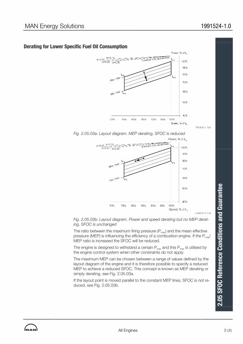
Derating for Lower Specific Fuel Oil Consumption
Fig. 2.05.03a: Layout diagram. MEP derating, SFOC is reduced
Fig. 2.05.03b: Layout diagram. Power and speed derating but no MEP derat-ing, SFOC is unchangedThe ratio between the maximum firing pressure (Pmax) and the mean effectivepressure (MEP) is influencing the efficiency of a combustion engine. If the Pmax/MEP ratio is increased the SFOC will be reduced.The engine is designed to withstand a certain Pmax and this Pmax is utilised bythe engine control system when other constraints do not apply.The maximum MEP can be chosen between a range of values defined by thelayout diagram of the engine and it is therefore possible to specify a reducedMEP to achieve a reduced SFOC. This concept is known as MEP derating orsimply derating, see Fig. 2.05.03a.If the layout point is moved parallel to the constant MEP lines, SFOC is not re-duced, see Fig. 2.05.03b.
MAN Energy Solutions 1991524-1.0
All Engines 3 (4)
2.05
SFO
C Re
fere
nce C
ondi
tions
and
Gua
rant
ee

Engine Choices when DeratingDue to requirements of ship speed and possibly shaft generator power out-put, derating is often not achieved by reducing MCR power. Instead a largerengine is applied in order to be able to choose a lower MEP rating, for ex-ample an engine of the same type but with an extra cylinder.Derating reduces the overall SFOC level. The actual SFOC for a project willalso depend on other parameters such as:▪ Engine tuning method▪ Engine running mode (Tier II, Tier III)▪ Operating curve (fixed pitch propeller, controllable pitch propeller)▪ Actual engine load▪ Ambient conditions.The actual SFOC for an engine can be found using the CEAS applicationavailable at www.man-es.com --> 'Planning Tools & Downloads' --> 'CEASEngines Calculations'It is possible to use CEAS to see the effect of derating for a particular engineby running CEAS for different engine ratings, for example the L1 rating (notMEP derated) and the L2 rating (fully MEP derated). This information can beused in the initial design work where the basic layout of the propulsion plant isdecided.
Example of SFOC CurvesFig. 2.05.04 shows example SFOC curves for high-load tuning as well aspart-load (EGB-PL) and low-load (EGB-LL) exhaust gas bypass tuning for anengine operating with a fixed pitch propeller.
Fig. 2.05.04: Influence on SFOC from engine tuning method and actual en-gine loadThe figure illustrates the relative changes in SFOC due to engine tuningmethod and engine load. The figure is an example only. CEAS should be usedto get actual project values.
1991524-1.0 MAN Energy Solutions
4 (4) All Engines
2.05
SFO
C Re
fere
nce C
ondi
tions
and
Gua
rant
ee
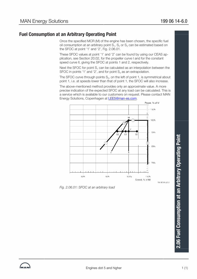
Fuel Consumption at an Arbitrary Operating PointOnce the specified MCR (M) of the engine has been chosen, the specific fueloil consumption at an arbitrary point S1, S2 or S3 can be estimated based onthe SFOC at point ‘1’ and ‘2’, Fig. 2.06.01.These SFOC values at point ‘1’ and ‘2’ can be found by using our CEAS ap-plication, see Section 20.02, for the propeller curve I and for the constantspeed curve II, giving the SFOC at points 1 and 2, respectively.Next the SFOC for point S1 can be calculated as an interpolation between theSFOC in points ‘1’ and ‘2’, and for point S3 as an extrapolation.The SFOC curve through points S2, on the left of point 1, is symmetrical aboutpoint 1, i.e. at speeds lower than that of point 1, the SFOC will also increase.The above-mentioned method provides only an approximate value. A moreprecise indication of the expected SFOC at any load can be calculated. This isa service which is available to our customers on request. Please contact MANEnergy Solutions, Copenhagen at [email protected].
Fig. 2.06.01: SFOC at an arbitrary load
MAN Energy Solutions 199 06 14-6.0
Engines dot 5 and higher 1 (1)
2.06
Fuel
Cons
umpt
ion
at a
n Ar
bitra
ry O
pera
ting
Poin
t


MAN B&W
MAN Energy Solutions
Turbocharger Selection & Exhaust By-pass
3


Turbocharger SelectionUpdated turbocharger data based on the latest information from the tur-bocharger makers are available from the Turbocharger Selection program onwww.marine.man-es.com -->'Two Stroke' --> 'Turbocharger Selection'.The data specified in the printed edition are valid at the time of publishing.The MAN B&W engines are designed for the application of either MAN, ABBor Mitsubishi (MHI) turbochargers.The turbocharger choice is made with a view to obtaining the lowest possibleSpecific Fuel Oil Consumption (SFOC) values at the nominal MCR by applyinghigh efficiency turbochargers.The engines are, as standard, equipped with as few turbochargers as pos-sible, see Table 3.01.01.One more turbocharger can be applied, than the number stated in the tables,if this is desirable due to space requirements, or for other reasons. Additionalcosts are to be expected.However, we recommend the ‘Turbocharger Selection’ program on the Inter-net, which can be used to identify a list of applicable turbochargers for a spe-cific engine layout.For information about turbocharger arrangement and cleaning systems, seeSection 15.01.
High efficiency turbochargers for the G90ME-C10.5 engines - L1 output
Cyl. MAN ABB MHI
5 2 x TCA77 2 x A275-L 2 x MET71MB
6 2 x TCA77 2 x A180-L 2 x MET83MB
7 2 x TCA88 2 x A280-L 2 x MET83MB
8 2 x TCA88 2 x A285-L 2 x MET90MB
9 2 x TCA88 3 x A180-L 2 x MET90MB
10 3 x TCA88 3 x A280-L 3 x MET83MB
11 3 x TCA88 3 x A285-L 3 x MET83MB
12 3 × TCA88 3 x A285-L 3 x MET90MB
Table 3.01.01: High efficiency turbochargers
MAN Energy Solutions 199 05 16-4.0
G90ME-C10.5 1 (1)
3.01
Tur
boch
arge
r Sele
ctio
n

Climate Conditions and Exhaust Gas Bypass
Extreme Ambient ConditionsAs mentioned in Chapter 1, the engine power figures are valid for tropicalconditions at sea level: 45°C air at 1,000 mbar and 32°C seawater, whereasthe reference fuel consumption is given at ISO conditions: 25°C air at 1,000mbar and 25°C charge air coolant temperature.Marine diesel engines are, however, exposed to greatly varying climatic tem-peratures winter and summer in arctic as well as tropical areas. These vari-ations cause changes of the scavenge air pressure, the maximum combustionpressure, the exhaust gas amount and temperatures as well as the specificfuel oil consumption.For further information about the possible countermeasures, please refer toour publication titled:Influence of Ambient Temperature ConditionsThe publication is available at www.marine.man-es.com -->'Two Stroke' -->'Technical Papers'.
Arctic Running ConditionFor air inlet temperatures below -10°C the precautions to be taken dependvery much on the operating profile of the vessel. The following alternative isone of the possible countermeasures. The selection of countermeasures,however, must be evaluated in each individual case.
Exhaust Gas Receiver with Variable BypassOption: 4 60 118Compensation for low ambient temperature can be obtained by using exhaustgas bypass system.This arrangement ensures that only part of the exhaust gas goes via the tur-bine of the turbocharger, thus supplying less energy to the compressor which,in turn, reduces the air supply to the engine.Please note that if an exhaust gas bypass is applied, the turbocharger sizeand specification has to be determined by other means than stated in thisChapter.
MAN Energy Solutions 198 56 29-0.3
98-90MC/MC-C/ME/ME-C/-GI 1 (1)
3.02
Clim
ate C
ondi
tions
and
Exh
aust
Gas
Byp
ass

Emission Control
IMO Tier II NOx Emission LimitsAll ME, ME-B and ME-C/-GI engines are, as standard, fulfilling the IMO Tier IINOx emission requirements, a speed dependent NOx limit measured according to ISO 8178 Test Cycles E2/E3 for Heavy Duty Diesel Engines.The E2/E3 test cycles are referred to in the Extent of Delivery as EoD: 4 06200 Economy mode with the options: 4 06 201 Engine test cycle E3 or 4 06202 Engine test cycle E2.
NOx Reduction Methods for IMO Tier IIIAs adopted by IMO for future enforcement, the engine must fulfil the more re-strictive IMO Tier III NOx requirements when sailing in a NOx Emission ControlArea (NOx ECA).The Tier III NOx requirements can be met by Exhaust Gas Recirculation (EGR),a method which directly affects the combustion process by lowering the gen-eration of NOx.Alternatively, the required NOx level could be met by installing Selective Cata-lytic Reaction (SCR), an after treatment system that reduces the emission ofNOx already generated in the combustion process.Details of MAN Energy Solutions' NOx reduction methods for IMO Tier III canbe found in our publication:Emission Project GuideThe publication is available at www.marine.man-es.com -->’ Two-Stroke’ -->’Project Guides’ -->’Other Guides’.
MAN Energy Solutions 198 84 47-2.2
ME/ME-C/ME-B/-GI TII 1 (1)
3.03
Em
issio
n Co
ntro
l


MAN B&W
MAN Energy Solutions
Electricity Production
4


Electricity Production and Hybrid Solutions
IntroductionHotel load and other electric consumptions are usually significant fuel con-sumers on a vessel, second only to propulsion power. Due to the long voy-ages, it is consistently necessary to produce most, if not all, of the electricityonboard. In order to supply the required electricity, the following machinery isused, running either alone or in parallel:
• Auxiliary diesel or dual fuel generating sets
• Main engine driven generators
• Exhaust gas- or steam driven turbo generator using exhaust gas waste heat
• Marine battery system
• Solar cellsThe machinery installed should be selected on the basis of environmental im-pact and economic evaluation of the first cost, operating costs, spare partscost, and the demand for man-hours for maintenance.In the following, technical information is given regarding main engine drivengenerators (Power Take Off), different configurations with exhaust gas andsteam driven turbo generators, and the auxiliary diesel generating sets pro-duced by MAN Energy Solutions
Power Take OffA generator coupled to a Power Take Off (PTO) from the main engine allowsthe production of electrical power based on the main engine’s low specificfuel and gas consumption (SFOC/SGC). As of 2020, PTO has a positive effecton the attained EEDI, which can be evaluated according to IMO rules. PTOmaximum service power should be evaluated with regard to two independentaspects: thermal overload of the engine and RPM stability/load change cap-ability of the engine. MAN Energy Solutions has developed guidelines to assistwith the layout of systems with PTO, refer to ‘PTO maximum service power’to assess thermal overload. Refer to Section: 17.06 ‘Governor stability evalu-ation for special propulsion plants’ to evaluate RPM stability/load change cap-ability of the engine. Several standardized PTO systems are available; see‘Designation’.
MAN Energy Solutions 199 12 73-5.1
ME-C/-GI/-GA/-LGI 1 (6)
4.01
Elec
tricit
y Pro
duct
ion
and
Hybr
id S
olut
ions

PTO Maximum Service PowerThis document refers to the electrical output of the PTO as PTOE, the mech-anical input to the PTO from the engine as PTOM and the PTO efficiency asηPTO. They are related according to the following law:
PTOM =PTOE _____
ηPTO
The figure below shows an example of maximum service power (not neces-sarily rated power). This maximum service power has to be designed to fit in-side MAN ES guideline, i.e., between the light propeller curve and the PTOlayout limit, see section 2.03 ‘Engine Layout and Load Diagram’. Due to thegeneral shape of the PTO layout limit and the PTO characteristics it is suffi-cient to verify each corner of the operating range with equation 1 and equa-tion 2 to avoid thermal overload. In Fig. 4.01.01, those corners are located at52.5%, 70% and 100% of the engine speed
Fig. 4.01.01: Example of PTO maximum service power
where the PM is SMCR power, nM the SMCR speed of rotation (rpm), LRM thepropeller light running margin and EMP the engine margin for PTO (the min-imum recommended is 5%.
199 12 73-5.1 MAN Energy Solutions
2 (6) ME-C/-GI/-GA/-LGI
4.01
Elec
tricit
y Pro
duct
ion
and
Hybr
id S
olut
ions

DesignationThere are numerous designs for PTO systems. MAN Energy Solutions cat-egorise them following two classifications: engine-to-generator and generator-to-grid.Engine-to-generator is related to the positioning of the PTO system and theconnection between the engine and the system. Generator-to-grid regardsthe frequency of the power fed to the grid and the systems between the gen-erator and the grid with that purpose.There are basically two positions available for the installation of a PTO systemon an engine: on the aft-end (towards the propeller) and on the front-end.Side-mounted systems are currently not available. Front-end mounted gener-ators can be mounted on-engine or on-tank-top. They can either be connec-ted using an elastic coupling or directly coupled to the crankshaft. Aft-endmounted generators are either mounted on the shaft or through a tunnel-gear.Those options are illustrated in Fig. 4.01.02.
Fig. 4.01.02: Types of PTO
MAN Energy Solutions 199 12 73-5.1
ME-C/-GI/-GA/-LGI 3 (6)
4.01
Elec
tricit
y Pro
duct
ion
and
Hybr
id S
olut
ions
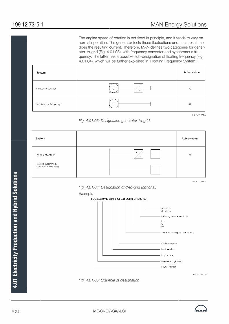
The engine speed of rotation is not fixed in principle, and it tends to vary onnormal operation. The generator feels those fluctuations and, as a result, sodoes the resulting current. Therefore, MAN defines two categories for gener-ator-to-grid (Fig. 4.01.03): with frequency converter and synchronous fre-quency. The latter has a possible sub-designation of floating frequency (Fig.4.01.04), which will be further explained in ‘Floating Frequency System’.
Fig. 4.01.03: Designation generator-to-grid
Fig. 4.01.04: Designation grid-to-grid (optional)Example
Fig. 4.01.05: Example of designation
199 12 73-5.1 MAN Energy Solutions
4 (6) ME-C/-GI/-GA/-LGI
4.01
Elec
tricit
y Pro
duct
ion
and
Hybr
id S
olut
ions
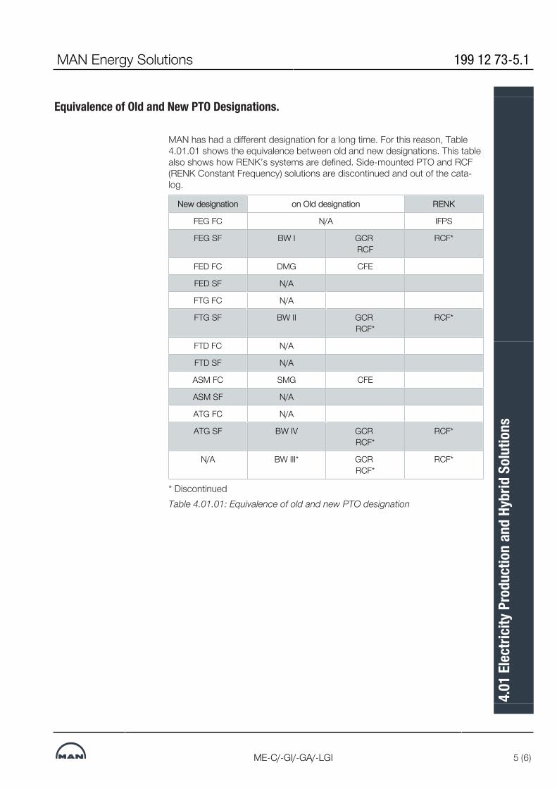
Equivalence of Old and New PTO Designations.
MAN has had a different designation for a long time. For this reason, Table4.01.01 shows the equivalence between old and new designations. This tablealso shows how RENK’s systems are defined. Side-mounted PTO and RCF(RENK Constant Frequency) solutions are discontinued and out of the cata-log.
New designation on Old designation RENK
FEG FC N/A IFPS
FEG SF BW I GCR RCF
RCF*
FED FC DMG CFE
FED SF N/A
FTG FC N/A
FTG SF BW II GCR RCF*
RCF*
FTD FC N/A
FTD SF N/A
ASM FC SMG CFE
ASM SF N/A
ATG FC N/A
ATG SF BW IV GCR RCF*
RCF*
N/A BW III* GCR RCF*
RCF*
* DiscontinuedTable 4.01.01: Equivalence of old and new PTO designation
MAN Energy Solutions 199 12 73-5.1
ME-C/-GI/-GA/-LGI 5 (6)
4.01
Elec
tricit
y Pro
duct
ion
and
Hybr
id S
olut
ions

Floating Frequency System
Should most of the electrical equipment allow operation with varying fre-quency, e.g., between 50 and 60 Hz, a PTO/SF might be a good economicand technical solution. It consists of a constant gear ratio, i.e., the frequencywill follow the engine speed. However, the PTO will be able to supply the re-quired electricity within an engine load range of approximately 52% to 90%(80% to 97% of the SMCR speed) without any problem. For the limited part ofequipment which requires a fixed frequency, a smaller frequency convertercan handle these loads.Bulk Carriers and Tankers, and other vessels with low variation in cruisespeed in this situation would obtain the following advantages:• It is simple and therby reliable• Simple electrical system• Highest possible efficiency (approximately 95%)• Relatively cheap• Lower electrical power consumption at part load as most power consumerswill be reduced due to the lower speed, i.e., this will also work as an optimisa-tion of the auxiliary systems as the power will automatically be reduced atlower engine loads whereas in a normal system the power for the auxiliarieswill be constant.On the other hand, parallel running of an auxiliary engine and the PTO systemis not possible with such systems because that works only with a frequencyconverter.This sort of system is restricted to a certain speed range, but most likely aspeed range can be chosen according to the most typical engine operatingrange. Electric equipment must be evaluated in order to establish whether itshould be dimensioned differently or not, e.g., the main engine lube oil pumpsare to be dimensioned for the required flow at 50 Hz. Therefore, it is recom-mended to use a centrifugal lube oil pump.
199 12 73-5.1 MAN Energy Solutions
6 (6) ME-C/-GI/-GA/-LGI
4.01
Elec
tricit
y Pro
duct
ion
and
Hybr
id S
olut
ions

Space Requirement for Side-Mounted Generator
MAN Energy Solutions 199 07 97-8.0
1 (1)
4.02
Spa
ce R
equi
rem
ent f
or S
ide-
Mou
nted
Gen
erat
or

Engine Preparations for PTO
Fig. 4.03.01a: Engine preparations for PTO
Pos.
1 Special face on bedplate and frame box
2 Ribs and brackets for supporting the face and machined blocks for alignment of gear or stator housing
3 Machined washers placed on frame box part of face to ensure that it is flush with the face on the bedplate
4 Rubber gasket placed on frame box part of face
5 Shim placed on frame box part of face to ensure that it is flush with the face of the bedplate
6 Distance tubes and long bolts
7 Threaded hole size, number and size of spring pins and bolts to be made in agreement with PTO maker
8 Flange of crankshaft, normally the standard execution can be used
9 Studs and nuts for crankshaft flange
10 Free flange end at lubricating oil inlet pipe (incl. blank flange)
11 Oil outlet flange welded to bedplate (incl. blank flange)
12 Engine cover with connecting bolts to bedplate/frame box to be used for shop test without PTO
13 Intermediate shaft between crankshaft and PTO
14 Oil sealing for intermediate shaft
15 Engine cover with hole for intermediate shaft and connecting bolts to bedplate/frame box
MAN Energy Solutions 198 43 15-6.4
98-50 engines 1 (5)
4.03
Eng
ine P
repa
ratio
ns fo
r PTO
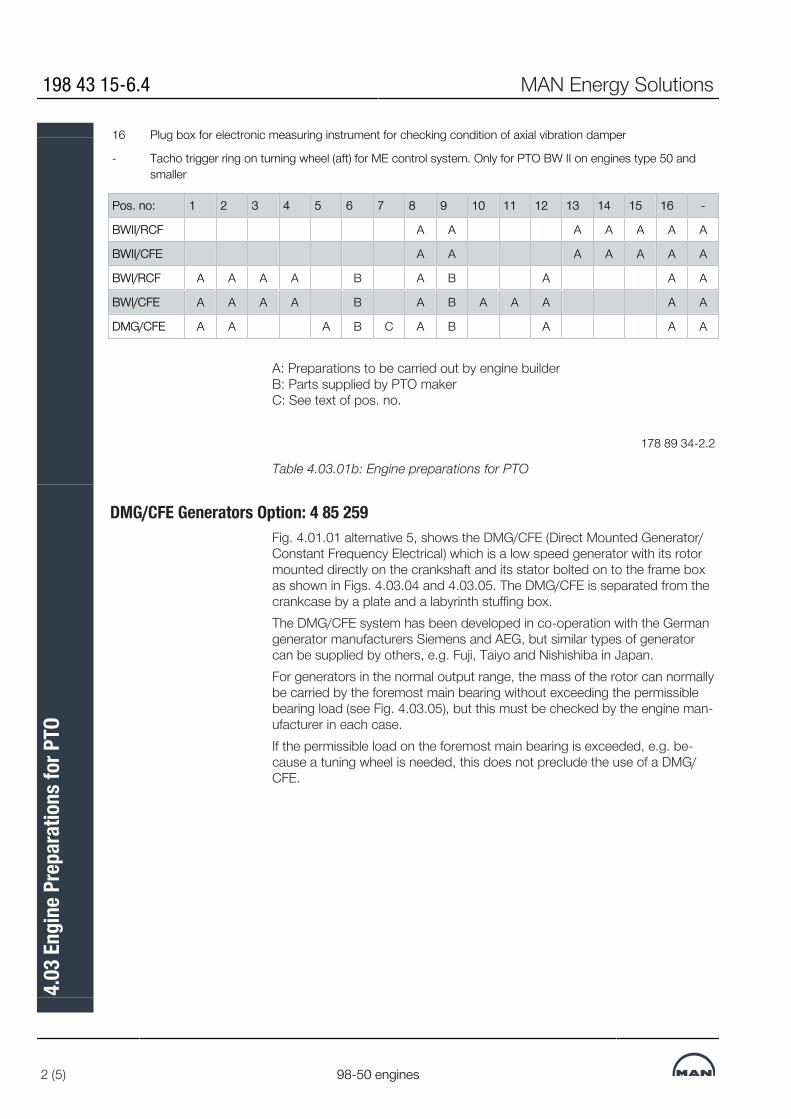
16 Plug box for electronic measuring instrument for checking condition of axial vibration damper
- Tacho trigger ring on turning wheel (aft) for ME control system. Only for PTO BW II on engines type 50 andsmaller
Pos. no: 1 2 3 4 5 6 7 8 9 10 11 12 13 14 15 16 -
BWII/RCF A A A A A A A
BWII/CFE A A A A A A A
BWI/RCF A A A A B A B A A A
BWI/CFE A A A A B A B A A A A A
DMG/CFE A A A B C A B A A A
A: Preparations to be carried out by engine builder B: Parts supplied by PTO maker C: See text of pos. no.
178 89 34-2.2
Table 4.03.01b: Engine preparations for PTO
DMG/CFE Generators Option: 4 85 259Fig. 4.01.01 alternative 5, shows the DMG/CFE (Direct Mounted Generator/Constant Frequency Electrical) which is a low speed generator with its rotormounted directly on the crankshaft and its stator bolted on to the frame boxas shown in Figs. 4.03.04 and 4.03.05. The DMG/CFE is separated from thecrankcase by a plate and a labyrinth stuffing box.The DMG/CFE system has been developed in co-operation with the Germangenerator manufacturers Siemens and AEG, but similar types of generatorcan be supplied by others, e.g. Fuji, Taiyo and Nishishiba in Japan.For generators in the normal output range, the mass of the rotor can normallybe carried by the foremost main bearing without exceeding the permissiblebearing load (see Fig. 4.03.05), but this must be checked by the engine man-ufacturer in each case.If the permissible load on the foremost main bearing is exceeded, e.g. be-cause a tuning wheel is needed, this does not preclude the use of a DMG/CFE.
198 43 15-6.4 MAN Energy Solutions
2 (5) 98-50 engines
4.03
Eng
ine P
repa
ratio
ns fo
r PTO

Fig. 4.03.04: Standard engine, with direct mounted generator (DMG/CFE)
MAN Energy Solutions 198 43 15-6.4
98-50 engines 3 (5)
4.03
Eng
ine P
repa
ratio
ns fo
r PTO

Fig. 4.03.05: Standard engine, with direct mounted generator and tuningwheel
Fig. 4.03.06: Diagram of DMG/CFE with static converterIn such a case, the problem is solved by installing a small, elastically suppor-ted bearing in front of the stator housing, as shown in Fig. 4.03.05.As the DMG type is directly connected to the crankshaft, it has a very low ro-tational speed and, consequently, the electric output current has a low fre-quency–normally of the order of 15 Hz.
198 43 15-6.4 MAN Energy Solutions
4 (5) 98-50 engines
4.03
Eng
ine P
repa
ratio
ns fo
r PTO
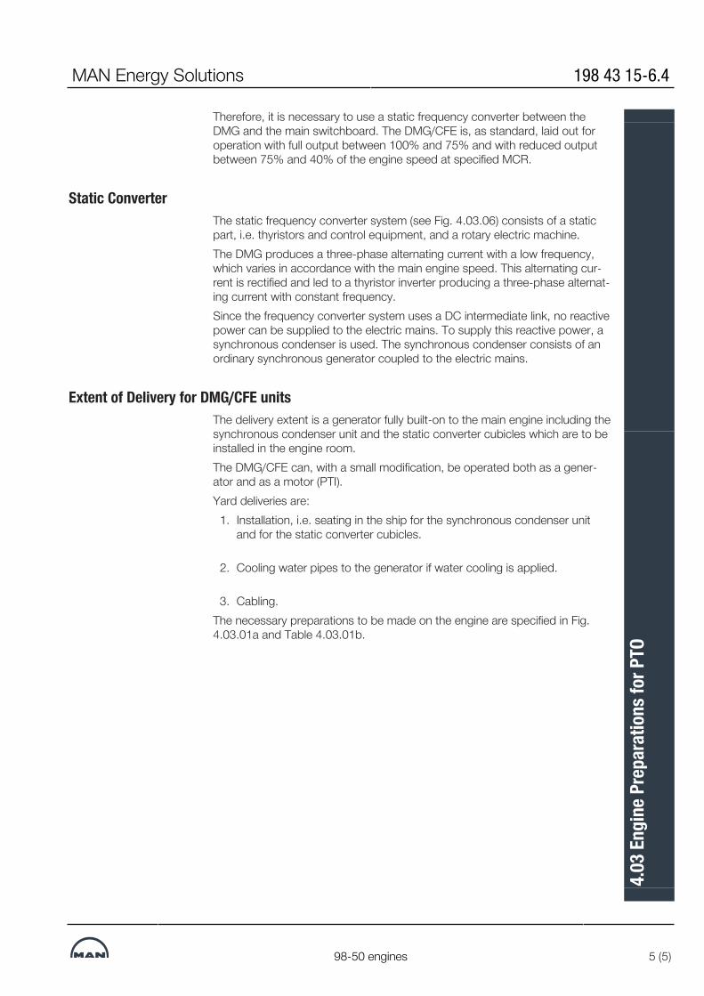
Therefore, it is necessary to use a static frequency converter between theDMG and the main switchboard. The DMG/CFE is, as standard, laid out foroperation with full output between 100% and 75% and with reduced outputbetween 75% and 40% of the engine speed at specified MCR.
Static ConverterThe static frequency converter system (see Fig. 4.03.06) consists of a staticpart, i.e. thyristors and control equipment, and a rotary electric machine.The DMG produces a three-phase alternating current with a low frequency,which varies in accordance with the main engine speed. This alternating cur-rent is rectified and led to a thyristor inverter producing a three-phase alternat-ing current with constant frequency.Since the frequency converter system uses a DC intermediate link, no reactivepower can be supplied to the electric mains. To supply this reactive power, asynchronous condenser is used. The synchronous condenser consists of anordinary synchronous generator coupled to the electric mains.
Extent of Delivery for DMG/CFE unitsThe delivery extent is a generator fully built-on to the main engine including thesynchronous condenser unit and the static converter cubicles which are to beinstalled in the engine room.The DMG/CFE can, with a small modification, be operated both as a gener-ator and as a motor (PTI).Yard deliveries are:
1. Installation, i.e. seating in the ship for the synchronous condenser unitand for the static converter cubicles.
2. Cooling water pipes to the generator if water cooling is applied.
3. Cabling.The necessary preparations to be made on the engine are specified in Fig.4.03.01a and Table 4.03.01b.
MAN Energy Solutions 198 43 15-6.4
98-50 engines 5 (5)
4.03
Eng
ine P
repa
ratio
ns fo
r PTO

PTO BW/GCR
MAN Energy Solutions 198 47 58-9.0
1 (1)
4.04
PTO
BW
/GCR

WWHRS Waste Heat Recovery System (WHRS)
Intro
Due to the increasing fuel prices seen from 2004 and onwards many shipowners have shown inter-est in efficiency improvements of the power sys-tems on board their ships. A modern two-stroke diesel engine has one of the highest thermal effi-ciencies of today’s power systems, but even this high efficiency can be improved by combining the diesel engine with other power systems.
One of the possibilities for improving the effi-ciency is to install one or more systems utilising some of the energy in the exhaust gas after the twostroke engine, which in MAN Energy Solu-tions terms is designated as WHRS (Waste Heat Recovery Systems).
WHRS can be divided into different types of sub-systems, depending on how the system utilises the exhaust gas energy. Choosing the right sys-tem for a specific project depends on the elec-tricity demand on board the ship and the accept-able first cost for the complete installation. MAN Energy Solutions uses the following designations for the current systems on the market:
• PTG (Power Turbine Generator):An exhaust gas driven turbine connected to agenerator via a gearbox.
• STG (Steam Turbine Generator):A steam driven turbine connected to a genera-tor via a gearbox. The steam is produced in alarge exhaust gas driven boiler installed on themain engine exhaust gas piping system.
• Combined Turbines:A combination of the two first systems. Thearrangement is often that the power turbine isconnected to the steam turbine via a gearboxand the steam turbine is further connected to alarge generator, which absorbs the power fromboth turbines.
The PTG system will produce power equivalent to approx. 3.5% of the main engine SMCR, when the engine is running at SMCR. For the STG sys-tem this value is between 5 and 7% depending on the system installed. When combining the two systems, a power output equivalent to 10% of the main engine’s SMCR is possible, when the engine is running at SMCR.
The WHRS output depends on the main engine rating and whether service steam consumption must be deducted or not.
As the electrical power produced by the system needs to be used on board the ship, specifying the correct size system for a specific project must be considered carefully. In cases where the electrical power consumption on board the ship is low, a smaller system than possible for the engine type may be considered. Another possi-bility is to install a shaft generator/motor to absorb excess power produced by the WHRS. The main engine will then be unloaded, or it will be possible to increase the speed of the ship, without penalising the fuel bill.
Because the energy from WHRS is taken from the exhaust gas of the main engine, this power produced can be considered as ”free”. In reality, the main engine SFOC will increase slightly, but the gain in electricity production on board the ship will far surpass this increase in SFOC. As an example, the SFOC of the combined output of both the engine and the system with power and steam turbine can be calculated to be as low as 152 g/kWh (ref. LCV 42,700 kJ/kg).
MAN B&W 4.05
Page 1 of 9
MAN B&W G90ME-C10.5 199 10 81-7.0MAN Energy Solutions

PPower Turbine Generator (PTG)
The power turbines of today are based on the different turbocharger suppliers’ newest designs of high efficiency turbochargers, i.e. MAN TCA, ABB A-L and Mitsubishi MET turbochargers.
MAN Energy Solutions offers PTG solutions called TCS-PTG in the range from approx. 1,000 kW to 5,000 kW, see Fig. 4.05.02.
The power turbine basically is the turbine side of a normal high-efficient turbocharger with some modifications to the bearings and the turbine shaft. This is in order to be able to connect it to a gearbox instead of the normal connection to the compressor side. The power turbine will be instal-led on a separate exhaust gas pipe from the exhaust gas receiver, which bypasses the turbo-chargers.
The performance of the PTG and the main engine will depend on a careful matching of the engine turbochargers and the power turbine, for which reason the turbocharger/s and the power turbine need to be from the same manufacturer. In Fig. 4.05.01, a diagram of the PTG arrangement is shown.
The newest generation of high efficiency turbo-chargers allows bypassing of some of the main engine exhaust gas, thereby creating a new bal-ance of the air flow through the engine. In this way, it is possible to extract power from the power turbine equivalent to 3.5% of the main engine’s SMCR, when the engine is running at SMCR.
Fig. 4.05.01: PTG diagram
MAN B&W 4.05
Page 2 of 9
MAN B&W G90ME-C10.5 199 10 81-7.0MAN Energy Solutions

Fig. 4.05.02: MAN Energy Solutions 1,500 kW TCS-PTG solution
MAN B&W 4.05
Page 3 of 9
MAN B&W G90ME-C10.5 199 10 81-7.0MAN Energy Solutions

SSteam Turbine Generator (STG)
In most cases the exhaust gas pipe system of the main engine is equipped with a boiler system. With this boiler, some of the energy in the exhaust gas is utilised to produce steam for use on board the ship.
If the engine is WHR matched, the exhaust gas temperature will be between 50°C and 65°C higher than on a conventional engine, which makes it possible to install a larger boiler system and, thereby, produce more steam. In short, MAN Energy Solutions designates this system STG. Fig. 4.05.03 shows an example of the STG diagram.
For WHR matching the engine, a bypass is instal-led to increase the temperature of the exhaust gas and improve the boiler output. The bypass valve is controlled by the engine control system.
The extra steam produced in the boiler can be utilised in a steam turbine, which can be used to drive a generator for power production on board the ship. A STG system could be arranged as shown in Fig. 4.05.04, where a typical system size is shown with the outline dimensions.
The steam turbine can either be a single or dual pressure turbine, depending on the size of the system. Steam pressure for a single pressure system is 7 to 10 bara, and for the dual pressure system the high-pressure cycle will be 9 to 10 bara and the low-pressure cycle will be 4 to 5 bara.
Fig. 4.05.03: STG system diagram
MAN B&W 4.05
Page 4 of 9
MAN B&W G90ME-C10.5 199 10 81-7.0MAN Energy Solutions

Fig. 4.05.04 : STG steam turbine generator arrangement with condenser - typical arrangement
MAN B&W 4.05
Page 5 of 9
MAN B&W G90ME-C10.5 199 10 81-7.0MAN Energy Solutions

FFull WHRS Steam and Power Turbines Combined
Because the installation of the power turbine also will result in an increase of the exhaust gas tem-perature after the turbochargers, it is possible to install both the power turbine, the larger boiler and steam turbine on the same engine. This way, the energy from the exhaust gas is utilised in the best way possible by today’s components.
When looking at the system with both power and steam turbine, quite often the power turbine and the steam turbine are connected to the same generator. In some cases, it is also possible to have each turbine on a separate generator. This is, however, mostly seen on stationary engines, where the frequency control is simpler because of the large grid to which the generator is cou-pled.
For marine installations the power turbine is, in most cases, connected to the steam turbine via a
gearbox, and the steam turbine is then connec-ted to the generator. It is also possible to have a generator with connections in both ends, and then connect the power turbine in one end and the steam turbine in the other. In both cases con-trol of one generator only is needed.
For dimensions of a typical full WHRS see Fig. 4.05.06.
As mentioned, the systems with steam turbines require a larger boiler to be installed. The size of the boiler system will be considerably bigger than the size of an ordinary boiler system, and the actual boiler size has to be calculated from case to case. Casing space for the exhaust boiler must be reserved in the initial planning of the ship’s machinery spaces.
Fig. 4.05.05: Full WHRS with both steam and power turbines
MAN B&W 4.05
Page 6 of 9
MAN B&W G90ME-C10.5 199 10 81-7.0MAN Energy Solutions

198 57 97-7.5
Fig. 4.05.06: Full ST & PT full waste heat recovery unit arrangement with condenser - typical arrangement
MAN B&W 4.05
Page 7 of 9
MAN B&W G90ME-C10.5 199 10 81-7.0MAN Energy Solutions

WWHRS generator output
Guidance output of WHR for G90ME-C10.5 engine rated in L1 at ISO conditions
Cyl.Engine power PTG STG Full WHRS with
combined turbines
% SMCR kW kWe kWe kWe
5100 31,200 880 1,850 2,730
75 23,400 730 1,230 1,960
6100 37,440 1,060 2,220 3,280
75 28,080 870 1,480 2,350
7100 43,680 1,230 2,540 3,770
75 32,760 1,020 1,760 2,770
8100 49,920 1,410 2,900 4,310
75 37,440 1,160 2,010 3,170
9100 56,160 1,590 3,260 4,850
75 42,120 1,310 2,260 3,570
10100 62,400 1,760 3,340 5,100
75 46,800 1,440 2,340 3,780
11100 68,640 1,940 3,670 5,610
75 51,480 1,580 2,570 4,160
12100 74,880 2,110 4,010 6,120
75 56,160 1,730 2,810 4,540
Note 1: The above given preliminary WHRS generator outputs is based on HP service steam consumption of 0.3 ton/h and LP service steam consumption of 0.7 ton/h for the ship at ISO condition.
Note 2: 75% SMCR is selected due to the EEDI focus on the engine load.
Because all the components come from different manufacturers, the final output and the system efficiency have to be calculated from case to case.
However, Table 4.05.07 shows a guidance of possible outputs in L1 based on theoretically cal-culated outputs from the system.
WHRS output at a rating lower than L1
As engines are seldom rated in L1, it is recom-mended to contact MAN Energy Solutions Copenhagen, department Marine Project
Engineering, e-mail: [email protected] for spe-cific WHRS generator output.
In order to receive as correctly as possible an engine tuned for WHRS data, please specify requested engine rating (power × rpm) and ship service steam consumption (kg/hour).
Detailed information about the different WHRS systems is found in our publication:
Waste Heat Recovery System (WHRS)
The publication is available at www.marine.man-es.com ’Two-Stroke’ ’Technical Papers/Brochures’ .
Fig. 4.05.07: Theoretically calculated outputs
MAN B&W 4.05
Page 8 of 9
MAN B&W G90ME-C10.5 199 10 81-7.0MAN Energy Solutions

WWaste Heat Recovery Element and Safety Valve
The boiler water or steam for power generator is preheated in the Waste Heat Recovery (WHR) element, also called the first-stage air cooler.
The WHR element is typically built as a high-pres-sure water/steam heat exchanger which is placed on top of the scavenge air cooler, see Fig. 4.05.08.
Full water flow must be passed through the WHR element continuously when the engine is running. This must be considered in the layout of the steam feed water system (the WHR element sup-ply heating). Refer to our ‘WHR element specifi-cation’ which is available from MAN Energy Solu-tions, Copenhagen.
Fig. 4.05.08: WHR element on Scavenge air cooler
Safety valve and blow-off
In normal operation, the temperature and pres-sure of the WHR element is in the range of 140-150 ˚C and 8-21 bar respectively.
In order to prevent leaking components from causing personal injuries or damage to vital parts of the main engine, a safety relief valve will blow off excess pressure. The safety relief valve is connected to an external connection, ‘W’, see Fig. 4.05.09.
Connection ‘W’ must be passed to the funnel or another free space according to the class rules for steam discharge from safety valve.
As the system is pressurised according to class rules, the safety valve must be type approved.
Fig. 4.05.09: WHR safety valve blow-off throughconnection ‘W’ to the funnel
198 82 88-9.1
MAN B&W 4.05
Page 9 of 9
MAN B&W G90ME-C10.5 199 10 81-7.0MAN Energy Solutions

L16/24 GenSet Data
MAN Energy Solutions 198 47 92-3.0
1 (1)
4.06
L16/
24 G
enSe
t Dat
a

L21/31 GenSet Data
MAN Energy Solutions 199 15 46-8.0
1 (1)
4.07
L21/
31 G
enSe
t Dat
a

L23/30H Mk2 GenSet Data
MAN Energy Solutions 199 15 48-1.0
1 (1)
4.08
L23/
30H
Mk2
Gen
Set D
ata
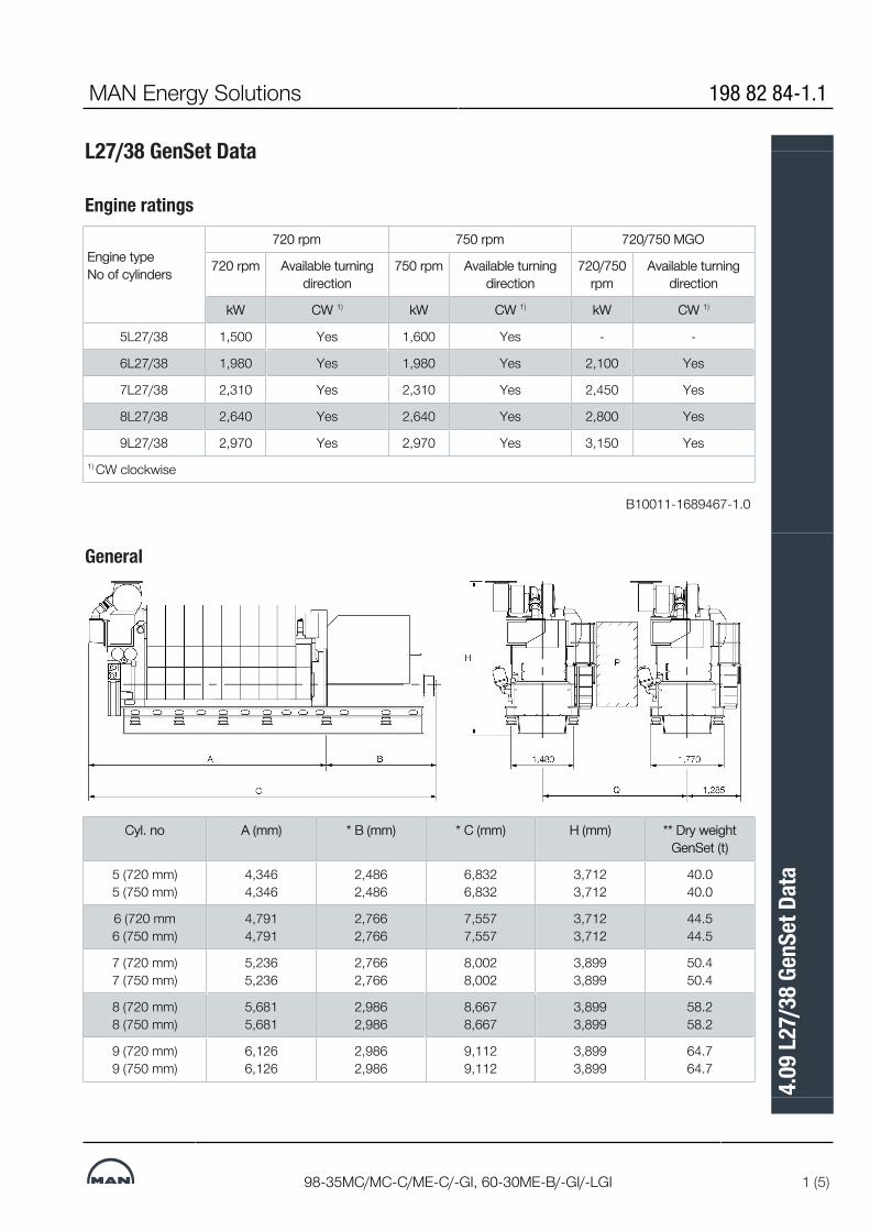
L27/38 GenSet Data
Engine ratings
Engine type No of cylinders
720 rpm 750 rpm 720/750 MGO
720 rpm Available turningdirection
750 rpm Available turningdirection
720/750rpm
Available turningdirection
kW CW 1) kW CW 1) kW CW 1)
5L27/38 1,500 Yes 1,600 Yes - -
6L27/38 1,980 Yes 1,980 Yes 2,100 Yes
7L27/38 2,310 Yes 2,310 Yes 2,450 Yes
8L27/38 2,640 Yes 2,640 Yes 2,800 Yes
9L27/38 2,970 Yes 2,970 Yes 3,150 Yes1) CW clockwise
B10011-1689467-1.0
General
Cyl. no A (mm) * B (mm) * C (mm) H (mm) ** Dry weightGenSet (t)
5 (720 mm)5 (750 mm)
4,3464,346
2,4862,486
6,8326,832
3,7123,712
40.040.0
6 (720 mm6 (750 mm)
4,7914,791
2,7662,766
7,5577,557
3,7123,712
44.544.5
7 (720 mm)7 (750 mm)
5,2365,236
2,7662,766
8,0028,002
3,8993,899
50.450.4
8 (720 mm)8 (750 mm)
5,6815,681
2,9862,986
8,6678,667
3,8993,899
58.258.2
9 (720 mm)9 (750 mm)
6,1266,126
2,9862,986
9,1129,112
3,8993,899
64.764.7
MAN Energy Solutions 198 82 84-1.1
98-35MC/MC-C/ME-C/-GI, 60-30ME-B/-GI/-LGI 1 (5)
4.09
L27/
38 G
enSe
t Dat
a

P Free passage between the engines, width 600 mm and height 2,000 mm.Q Min. distance between engines: 2,900 mm (without gallery) and 3,100 mm(with gallery)* Depending on alternator ** Weight included a standard alternatorAll dimensions and masses are approximate, and subject to changes withoutprior notice.
Capacities5L27/38: 300 kW/cyl., 720 rpm, 6-9L27/38: 330 kW/cyl., 720 rpm
Reference condition : Tropic
Air temperature
LT-water temperature inlet engine (from system)
Air pressure
Relative humidity
°C
°C
bar
%
45
38
1
50
Temperature basis:
Setpoint HT cooling water engine outlet 1)
Setpoint LT cooling water engine outlet 2)
Setpoint Lube oil inlet engine
°C
°C
°C
79°C nominal(Range of mech. thermostatic element 77-85°C)
35°C nominal(Range of mech. thermostatic element 29°-41°C)
66°C nominal(Range of mech. thermostatic element 63-72°C)
Number of cylinders 5
1,500
6
1,980
7
2,310
8
2,640
9
2,970Engine output
Speed
kW
rpm 720
Heat to be dissipated 3)
Cooling water (C.W.) Cylinder
Charge air cooler; cooling water HT
Charge air cooler; cooling water LT
Lube oil (L.O.) cooler
Heat radiation engine
kW
kW
kW
kW
kW
256
466
178
224
63
330
594
216
279
83
385
675
242
325
97
440
750
268
372
111
495
820
297
418
125
Flow rates4)
Internal (inside engine)
HT circuit (cylinder + charge air cooler HT stage)
LT circuit (lube oil + charge air cooler LT stage)
Lube oil
m3/h
m3/h
m3/h
58
58
64
58
58
64
58
58
92
58
58
92
58
58
92
External (from engine to system)
HT water flow (at 40°C inlet)
LT water flow (at 38°C inlet)
m3/h
m3/h
16
58
20.2
58
23
58
25.5
58
28
58
Air data
198 82 84-1.1 MAN Energy Solutions
2 (5) 98-35MC/MC-C/ME-C/-GI, 60-30ME-B/-GI/-LGI
4.09
L27/
38 G
enSe
t Dat
a

Temperature of charge air at charge air cooler outlet
Air flow rate
Charge air pressure
Air required to dissipate heat radiation (eng.)(t2-t1=10°C)
°C
m3/h 5)
kg/kWh
bar
m3/h
50
9,1376.67
4.01
20,414
53
12,0616.67
4.01
26,895
55
14,0716.67
4.01
31,431
56
16,0826.67
4.01
35,968
57
18,0926.67
4.01
40,504
Exhaust gas data 6)
Volume flow (temperature turbocharger outlet)
Mass flow
Temperature at turbine outlet
Heat content (190°C)
Permissible exhaust back pressure
m3/h 7)
t/h
°C
k/W
mbar
19,203
10.3
376
575
< 30
25,348
13.6
376
759
< 30
29,572
15.9
376
886
< 30
33,797
18.1
376
1,012
< 30
38,021
20.4
376
1,139
< 30
Pumps
External pumps 8)
Diesel oil pump
Fuel oil supply pump
Fuel oil circulating pump
(5 bar at fuel oil inlet A1)
(4 bar discharge pressure)
(8 bar at fuel oil inlet A1)
m3/h
m3/h
m3/h
1.06
0.51
1.06
1.40
0.67
1.40
1.63
0.79
1.63
1.87
0.90
1.87
2.10
1.01
2.10
Starting air data
Air consumption per start, incl. air for jet assist (IR/TDI) Nm3 2.5 2.9 3.3 3.8 4.3
1) HT cooling water flows first through HT stage charge air cooler, then throughwater jacket and cylinder head, water temperature outlet engine regulatedby mechanical thermostat.
2) LT cooling water flows first through LT stage charge air cooler, then throughlube oil cooler, water temperature outlet engine regulated by mechanicalthermostat.
3) Tolerance: + 10% for rating coolers, - 15% for heat recovery.
4) Basic values for layout of the coolers.
5) Under above mentioned reference conditions.
6) Tolerance: quantity +/- 5%, temperature +/- 20°C.
7) Under below mentioned temperature at turbine outlet and pressure accord-ing above mentioned reference conditions.
8) Tolerance of the pumps delivery capacities must be considered by the man-ufactures.
D10050_1689471-7.3
MAN Energy Solutions 198 82 84-1.1
98-35MC/MC-C/ME-C/-GI, 60-30ME-B/-GI/-LGI 3 (5)
4.09
L27/
38 G
enSe
t Dat
a

Capacities5L27/38: 320 kW/cyl., 750 rpm, 6-9L27/38: 330 kW/cyl., 750 rpm
Reference condition : Tropic
Air temperature
LT-water temperature inlet engine (from system)
Air pressure
Relative humidity
°C
°C
bar
%
45
38
1
50
Temperature basis:
Setpoint HT cooling water engine outlet 1)
Setpoint LT cooling water engine outlet 2)
Setpoint Lube oil inlet engine
°C
°C
°C
79°C nominal(Range of mech. thermostatic element 77-85°C)
35°C nominal(Range of mech. thermostatic element 29°-41°C)
66°C nominal(Range of mech. thermostatic element 63-72°C)
Number of cylinders 5
1,600
6
1,980
7
2,310
8
2,640
9
2,970Engine output
Speed
kW
rpm 750
Heat to be dissipated 3)
Cooling water (C.W.) Cylinder
Charge air cooler; cooling water HT
Charge air cooler; cooling water LT
Lube oil (L.O.) cooler
Heat radiation engine
kW
kW
kW
kW
kW
263
488
194
230
67
330
587
225
279
83
385
666
252
325
97
440
741
280
372
111
495
811
307
418
125
Flow rates4)
Internal (inside engine)
HT circuit (cylinder + charge air cooler HT stage)
LT circuit (lube oil + charge air cooler LT stage)
Lube oil
m3/h
m3/h
m3/h
69
69
66
69
69
66
69
69
96
69
69
96
69
69
96
External (from engine to system)
HT water flow (at 40°C inlet)
LT water flow (at 38°C inlet)
m3/h
m3/h
16.8
69
20.3
69
23
69
25.7
69
28.2
69
Air data
Temperature of charge air at charge air cooler outlet
Air flow rate
°C
m3/h 5)
kg/kWh
51
9,9516.81
53
12,3146.81
55
14,3676.81
56
16,4196.81
57
18,4726.81
Charge air pressure
Air required to dissipate heat radiation (eng.)(t2-t1= 10°C)
bar
m3/h
4.04
21,710
4.04
26,895
4.04
31,431
4.04
35,968
4.04
40,504
Exhaust gas data 6)
198 82 84-1.1 MAN Energy Solutions
4 (5) 98-35MC/MC-C/ME-C/-GI, 60-30ME-B/-GI/-LGI
4.09
L27/
38 G
enSe
t Dat
a

Volume flow (temperature turbocharger outlet)
Mass flow
Temperature at turbine outlet
Heat content (190°C)
Permissible exhaust back pressure
m3/h 7)
t/h
°C
k/W
mbar
20,546
11.2
365
589
< 30
25,426
13.9
365
729
< 30
29,664
16.2
365
850
< 30
33,901
18.5
365
972
< 30
38,139
20.8
365
1,093
< 30
Pumps
External pumps 8)
Diesel oil pump
Fuel oil supply pump
Fuel oil circulating pump
(5 bar at fuel oil inlet A1)
(4 bar discharge pressure)
(8 bar at fuel oil inlet A1)
m3/h
m3/h
m3/h
1.13
0.54
1.13
1.40
0.67
1.40
1.63
0.79
1.63
1.87
0.90
1.87
2.10
1.01
2.10
Starting air data
Air consumption per start, incl. air for jet assist (IR/TDI) Nm3 2.5 2.9 3.3 3.8 4.3
1) HT cooling water flows first through HT stage charge air cooler, then throughwater jacket and cylinder head, water temperature outlet engine regulatedby mechanical thermostat.
2) LT cooling water flows first through LT stage charge air cooler, then throughlube oil cooler, water temperature outlet engine regulated by mechanicalthermostat.
3) Tolerance: + 10% for rating coolers, - 15% for heat recovery.
4) Basic values for layout of the coolers.
5) Under above mentioned reference conditions.
6) Tolerance: quantity +/- 5%, temperature +/- 20°C.
7) Under below mentioned temperature at turbine outlet and pressure accord-ing above mentioned reference conditions.
8) Tolerance of the pumps delivery capacities must be considered by the man-ufactures.
D10050_1689472-9.3
MAN Energy Solutions 198 82 84-1.1
98-35MC/MC-C/ME-C/-GI, 60-30ME-B/-GI/-LGI 5 (5)
4.09
L27/
38 G
enSe
t Dat
a
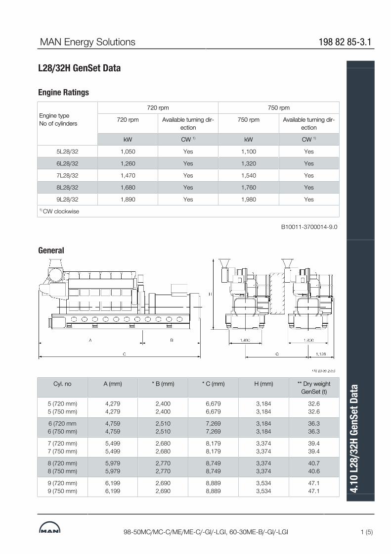
L28/32H GenSet Data
Engine Ratings
Engine type No of cylinders
720 rpm 750 rpm
720 rpm Available turning dir-ection
750 rpm Available turning dir-ection
kW CW 1) kW CW 1)
5L28/32 1,050 Yes 1,100 Yes
6L28/32 1,260 Yes 1,320 Yes
7L28/32 1,470 Yes 1,540 Yes
8L28/32 1,680 Yes 1,760 Yes
9L28/32 1,890 Yes 1,980 Yes1) CW clockwise
B10011-3700014-9.0
General
Cyl. no A (mm) * B (mm) * C (mm) H (mm) ** Dry weightGenSet (t)
5 (720 mm)5 (750 mm)
4,2794,279
2,4002,400
6,6796,679
3,1843,184
32.632.6
6 (720 mm6 (750 mm)
4,7594,759
2,5102,510
7,2697,269
3,1843,184
36.336.3
7 (720 mm)7 (750 mm)
5,4995,499
2,6802,680
8,1798,179
3,3743,374
39.439.4
8 (720 mm)8 (750 mm)
5,9795,979
2,7702,770
8,7498,749
3,3743,374
40.740.6
9 (720 mm)9 (750 mm)
6,1996,199
2,6902,690
8,8898,889
3,5343,534
47.147.1
MAN Energy Solutions 198 82 85-3.1
98-50MC/MC-C/ME/ME-C/-GI/-LGI, 60-30ME-B/-GI/-LGI 1 (5)
4.10
L28/
32H
GenS
et D
ata
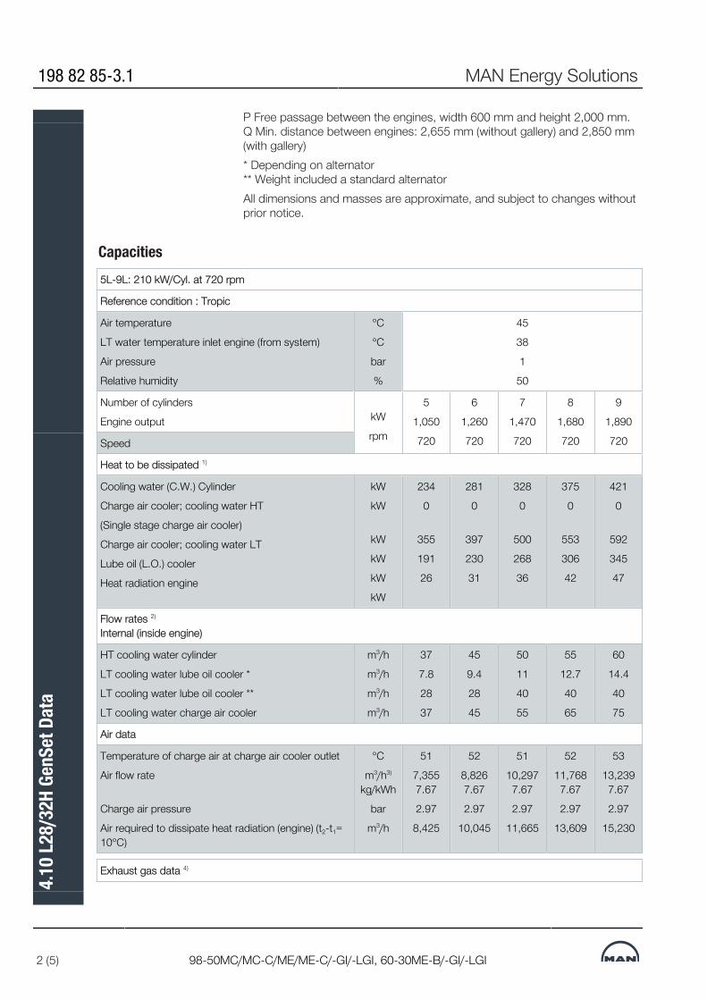
P Free passage between the engines, width 600 mm and height 2,000 mm.Q Min. distance between engines: 2,655 mm (without gallery) and 2,850 mm(with gallery)* Depending on alternator ** Weight included a standard alternatorAll dimensions and masses are approximate, and subject to changes withoutprior notice.
Capacities5L-9L: 210 kW/Cyl. at 720 rpm
Reference condition : Tropic
Air temperature
LT water temperature inlet engine (from system)
Air pressure
Relative humidity
°C
°C
bar
%
45
38
1
50
Number of cylinders
Engine output kW
rpm
5
1,050
720
6
1,260
720
7
1,470
720
8
1,680
720
9
1,890
720Speed
Heat to be dissipated 1)
Cooling water (C.W.) Cylinder
Charge air cooler; cooling water HT
(Single stage charge air cooler)
Charge air cooler; cooling water LT
Lube oil (L.O.) cooler
Heat radiation engine
kW
kW
kW
kW
kW
kW
234
0
355
191
26
281
0
397
230
31
328
0
500
268
36
375
0
553
306
42
421
0
592
345
47
Flow rates 2)
Internal (inside engine)
HT cooling water cylinder
LT cooling water lube oil cooler *
LT cooling water lube oil cooler **
LT cooling water charge air cooler
m3/h
m3/h
m3/h
m3/h
37
7.8
28
37
45
9.4
28
45
50
11
40
55
55
12.7
40
65
60
14.4
40
75
Air data
Temperature of charge air at charge air cooler outlet
Air flow rate
Charge air pressure
Air required to dissipate heat radiation (engine) (t2-t1=10°C)
°C
m3/h3)
kg/kWh
bar
m3/h
51
7,3557.67
2.97
8,425
52
8,8267.67
2.97
10,045
51
10,2977.67
2.97
11,665
52
11,7687.67
2.97
13,609
53
13,2397.67
2.97
15,230
Exhaust gas data 4)
198 82 85-3.1 MAN Energy Solutions
2 (5) 98-50MC/MC-C/ME/ME-C/-GI/-LGI, 60-30ME-B/-GI/-LGI
4.10
L28/
32H
GenS
et D
ata

Volume flow (temperature turbocharger outlet)
Mass flow
Temperature at turbine outlet
Heat content (190°C)
Permissible exhaust back pressure
m3/h5
t/h
°C
kW
mbar
14,711
8.3
347
389
< 30
17,653
9.9
347
467
< 30
20,595
11.6
347
545
< 30
23,537
13.2
347
623
< 30
26,479
14.9
347
701
< 30
Starting air system
Air consumption per start Nm3 2.5 2.5 2.5 2.5 2.5
Pumps Engine driven pumps
Fuel oil feed pump (5.5-7.5 bar)
HT circuit cooling water (1.0-2.5 bar)
LT circuit cooling water (1.0-2.5 bar)
Lube oil (3.0-5.0 bar)
m3/h
m3/h
m3/h
m3/h
1.4
45
45
24
1.4
45
60
24
1.4
60
75
34
1.4
60
75
34
1.4
60
75
34
External pumps 6)
Diesel oil pump (4 bar at fuel oil inlet A1)
Fuel oil supply pump (4 bar discharge pressure)
Fuel oil circulating pump (8 bar at fuel oil inlet A1)
HT circuit cooling water (1.0-2.5 bar)
LT circuit cooling water (1.0-2.5 bar) *
LT circuit cooling water (1.0-2.5 bar) **
Lube oil (3.0-5.0 bar)
m3/h
m3/h
m3/h
m3/h
m3/h
m3/h
m3/h
0.74
0.36
0.74
37
45
65
22
0.89
0.43
0.89
45
54
73
23
1.04
0.50
1.04
50
65
95
35
1.19
0.57
34
55
77
105
27
1.34
0.64
34
60
89
115
28
1) Tolerance: + 10% for rating coolers, - 15% for heat recovery.
2) Basic values for layout of the coolers.
3) Under above mentioned reference conditions.
4) Tolerance: quantity +/- 5%, temperature +/- 20°C.
5) Under below mentioned temperature at turbine outlet and pressure accord-ing above mentioned reference conditions.
6) Tolerance of the pumps delivery capacities must be considered by the man-ufactures.
* Only valid for engines equipped with internal basic cooling water system no.1 and 2.
** Only valid for engines equipped with combined coolers, internal basic cool-ing water system no. 3
D10050_3700075-9.0
MAN Energy Solutions 198 82 85-3.1
98-50MC/MC-C/ME/ME-C/-GI/-LGI, 60-30ME-B/-GI/-LGI 3 (5)
4.10
L28/
32H
GenS
et D
ata

Capacities5L-9L: 220 kW/Cyl. at 750 rpm
Reference condition : Tropic
Air temperature
LT water temperature inlet engine (from system)
Air pressure
Relative humidity
°C
°C
bar
%
45
38
1
50
Number of cylinders 5
1,100
750
6
1,320
750
7
1,540
750
8
1,760
750
9
1,980
750Engine output
Speed
kW
rpm
Heat to be dissipated 1)
Cooling water (C.W.) Cylinder
Charge air cooler; cooling water HT
(Single stage charge air cooler)
Charge air cooler; cooling water LT
Lube oil (L.O.) cooler
Heat radiation engine
kW
kW
kW
kW
kW
245
0
387
201
27
294
0
435
241
33
343
0
545
281
38
392
0
587
321
44
442
0
648
361
49
Flow rates 2)
Internal (inside engine)
HT cooling water cylinder
LT cooling water lube oil cooler *
LT cooling water lube oil cooler **
LT cooling water charge air cooler
m3/h
m3/h
m3/h
m3/h
37
7.8
28
37
45
9.4
28
45
50
11
40
55
55
12.7
40
65
60
14.4
40
75
Air data
Temperature of charge air at charge air cooler outlet
Air flow rate
Charge air pressure
Air required to dissipate heat radiation (engine) (t2-t1=10°C)
°C
m3/h3)
kg/kWh
bar
m3/h
52
7,8267.79
3.07
8,749
54
9,3917.79
3.07
10,693
52
10,9567.79
3.07
12,313
52
12,5217.79
3.07
14,257
55
14,0877.79
3.07
15,878
Exhaust gas data 4)
Volume flow (temperature turbocharger outlet)
Mass flow
Temperature at turbine outlet
Heat content (190°C)
Permissible exhaust back pressure
m3/h5
t/h
°C
kW
mbar
15,520
8.8
342
401
< 30
18,624
10.5
342
481
< 30
21,728
12.3
342
561
< 30
24,832
14.1
342
641
< 30
27,936
15.8
342
721
< 30
Starting air system
Air consumption per start Nm3 2.5 2.5 2.5 2.5 2.5
198 82 85-3.1 MAN Energy Solutions
4 (5) 98-50MC/MC-C/ME/ME-C/-GI/-LGI, 60-30ME-B/-GI/-LGI
4.10
L28/
32H
GenS
et D
ata

Pumps Engine driven pumps
Fuel oil feed pump (5.5-7.5 bar)
HT circuit cooling water (1.0-2.5 bar)
LT circuit cooling water (1.0-2.5 bar)
Lube oil (3.0-5.0 bar)
m3/h
m3/h
m3/h
m3/h
1.4
45
45
24
1.4
45
60
24
1.4
60
75
34
1.4
60
75
34
1.4
60
75
34
External pumps 6)
Diesel oil pump (4 bar at fuel oil inlet A1)
Fuel oil supply pump (4 bar discharge pressure)
Fuel oil circulating pump (8 bar at fuel oil inlet A1)
HT circuit cooling water (1.0-2.5 bar)
LT circuit cooling water (1.0-2.5 bar) *
LT circuit cooling water (1.0-2.5 bar) **
Lube oil (3.0-5.0 bar)
m3/h
m3/h
m3/h
m3/h
m3/h
m3/h
m3/h
0.78
0.37
0.78
37
45
65
22
0.93
0.45
0.93
45
54
73
23
1.09
0.52
1.09
50
65
95
25
1.24
0.60
1.24
55
77
105
27
1.40
0.67
1.40
60
89
115
28
1) Tolerance: + 10% for rating coolers, - 15% for heat recovery.
2) Basic values for layout of the coolers.
3) Under above mentioned reference conditions.
4) Tolerance: quantity +/- 5%, temperature +/- 20°C.
5) Under below mentioned temperature at turbine outlet and pressure accord-ing above mentioned reference conditions.
6) Tolerance of the pumps delivery capacities must be considered by the man-ufactures.
* Only valid for engines equipped with internal basic cooling water system no.1 and 2.
** Only valid for engines equipped with combined coolers, internal basic cool-ing water system no. 3
D10050_3700076-0.0
MAN Energy Solutions 198 82 85-3.1
98-50MC/MC-C/ME/ME-C/-GI/-LGI, 60-30ME-B/-GI/-LGI 5 (5)
4.10
L28/
32H
GenS
et D
ata
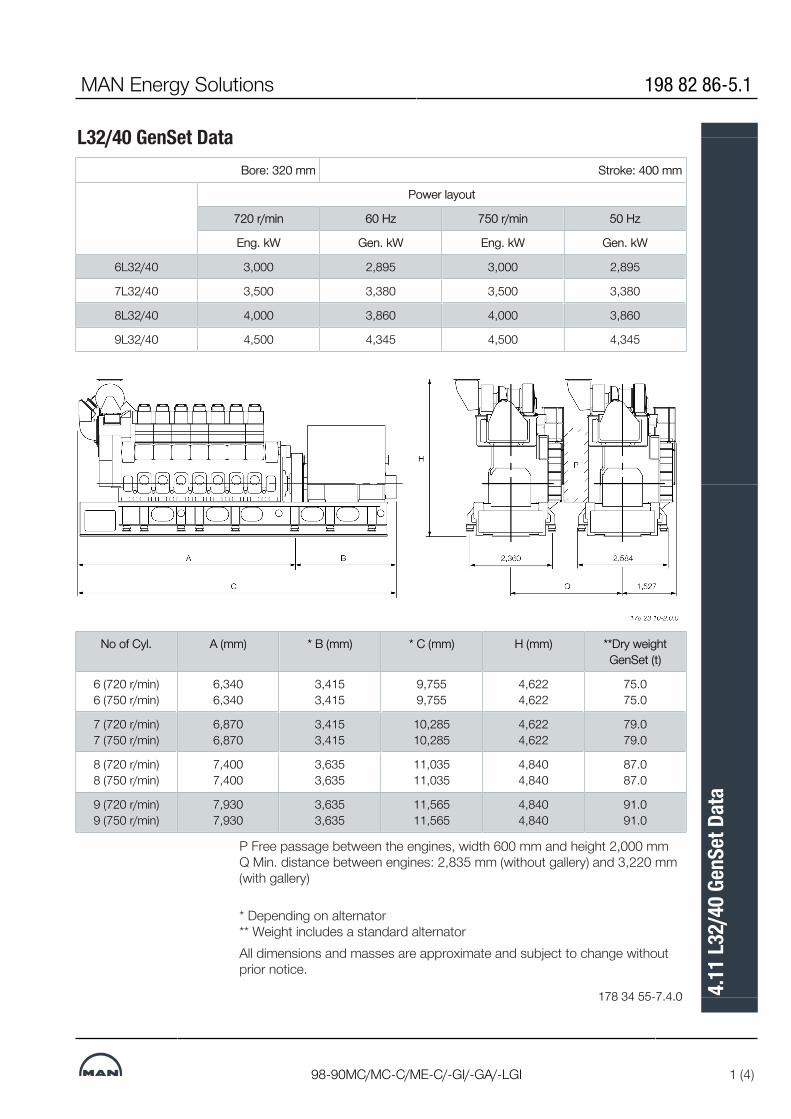
L32/40 GenSet DataBore: 320 mm Stroke: 400 mm
Power layout
720 r/min 60 Hz 750 r/min 50 Hz
Eng. kW Gen. kW Eng. kW Gen. kW
6L32/40 3,000 2,895 3,000 2,895
7L32/40 3,500 3,380 3,500 3,380
8L32/40 4,000 3,860 4,000 3,860
9L32/40 4,500 4,345 4,500 4,345
No of Cyl. A (mm) * B (mm) * C (mm) H (mm) **Dry weightGenSet (t)
6 (720 r/min)6 (750 r/min)
6,3406,340
3,4153,415
9,7559,755
4,6224,622
75.075.0
7 (720 r/min)7 (750 r/min)
6,8706,870
3,4153,415
10,28510,285
4,6224,622
79.079.0
8 (720 r/min)8 (750 r/min)
7,4007,400
3,6353,635
11,03511,035
4,8404,840
87.087.0
9 (720 r/min)9 (750 r/min)
7,9307,930
3,6353,635
11,56511,565
4,8404,840
91.091.0
P Free passage between the engines, width 600 mm and height 2,000 mm Q Min. distance between engines: 2,835 mm (without gallery) and 3,220 mm(with gallery)
* Depending on alternator ** Weight includes a standard alternatorAll dimensions and masses are approximate and subject to change withoutprior notice.
178 34 55-7.4.0
MAN Energy Solutions 198 82 86-5.1
98-90MC/MC-C/ME-C/-GI/-GA/-LGI 1 (4)
4.11
L32/
40 G
enSe
t Dat
a
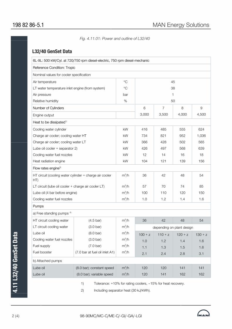
Fig. 4.11.01: Power and outline of L32/40
L32/40 GenSet Data6L-9L: 500 kW/Cyl. at 720/750 rpm diesel-electric, 750 rpm diesel-mechanic
Reference Condition: Tropic
Nominal values for cooler specification
Air temperature
LT water temperature inlet engine (from system)
Air pressure
Relative humidity
°C
°C
bar
%
45
38
1
50
Number of Cylinders 6
3,000
7
3,500
8
4,000
9
4,500Engine output
Heat to be dissipated1)
Cooling water cylinder
Charge air cooler; cooling water HT
Charge air cooler; cooling water LT
Lube oil cooler + separator 2)
Cooling water fuel nozzles
Heat radiation engine
kW
kW
kW
kW
kW
kW
416
734
366
426
12
104
485
821
428
497
14
121
555
952
502
568
16
139
624
1,036
565
639
18
156
Flow rates engine3)
HT circuit (cooling water cylinder + charge air coolerHT)
LT circuit (lube oil cooler + charge air cooler LT)
Lube oil (4 bar before engine)
Cooling water fuel nozzles
m3/h
m3/h
m3/h
m3/h
36
57
100
1.0
42
70
110
1.2
48
74
120
1.4
54
85
150
1.6
Pumps
a) Free standing pumps 4)
HT circuit cooling water
LT circuit cooling water
Lube oil
Cooling water fuel nozzles
Fuel supply
Fuel booster
(4.5 bar)
(3.0 bar)
(8.0 bar)
(3.0 bar)
(7.0 bar)
(7.0 bar at fuel oil inlet A1)
m3/h
m3/h
m3/h
m3/h
m3/h
m3/h
36 42 48 54
depending on plant design
100 + z
1.0
1.1
2.1
110 + z
1.2
1.3
2.4
120 + z
1.4
1.5
2.8
130 + z
1.6
1.6
3.1
b) Attached pumps
Lube oil
Lube oil
(8.0 bar); constant speed
(8.0 bar); variable speed
m3/h
m3/h
120
120
120
141
141
162
141
162
1) Tolerance: +10% for rating coolers, –15% for heat recovery.
2) Including separator heat (30 kJ/kWh).
198 82 86-5.1 MAN Energy Solutions
2 (4) 98-90MC/MC-C/ME-C/-GI/-GA/-LGI
4.11
L32/
40 G
enSe
t Dat
a

3) Basic values for layout of the coolers.
4) Tolerance of the pumps delivery capacities must be considered by the man-ufactures.
z Flushing oil of the automatic filter.
178 23 11-4.1a.0
Fig. 4.11.02a: List of capacities for L32/40
L32/40 GenSet Data6L-9L: 500 kW/Cyl. at 720/750 rpm diesel-electric, 750 rpm diesel-mechanic
Reference Condition: Tropic
Temperature basis, nominal air and exhaust gas data
Air temperature
LT water temperature inlet engine (from system)
Air pressure
Relative humidity
°C
°C
bar
%
45
38
1
50
Number of Cylinders -
kW
6
3,000
7
3,500
8
4,000
9
4,500Engine output
Temperature basis
HT cooling water engine outlet
LT cooling water air cooler inlet
Lube oil inlet engine
Cooling water inlet fuel nozzles
°C
°C
°C
°C
90
38 (Set point 32°C)1)
65
60
Air data
Temperature of charge air at charge air cooler outlet
Air flow rate
Mass flow
Charge air pressure (absolute)
Air required to dissipate heat radiation (engine) (t2-t1=10°C)
°C
m3/h2)
t/h
bar
m3/h
57
18,450
20.2
58
21,550
23.6
57
24,650
27.0
58
27,670
30.3
3.93
33,700 39,200 45,050 50,550
Exhaust gas data 3)
Volume flow (temperature turbocharger outlet)
Mass flow
Temperature at turbine outlet
Heat content (190°C)
Permissible exhaust back pressure after turbocharger
m3/h4)
t/h
°C
kW
mbar
38,100
20.8
44,550
24.3
50,750
27.7
57,150
31.2
365
1,150 1,350 1,500 1,700
30
1) For design see section ‘Cooling water system’.
2) Under above mentioned reference conditions.
MAN Energy Solutions 198 82 86-5.1
98-90MC/MC-C/ME-C/-GI/-GA/-LGI 3 (4)
4.11
L32/
40 G
enSe
t Dat
a

3) Tolerance: Quantity +/– 5%, temperature +/– 20°C.
4) Under below mentioned temperature at turbine outlet and pressure accord-ing above mentioned reference conditions.
178 23 11-4.1b.0
Fig. 4.11.02b: List of capacities for L32/40The latest and most current GenSet data as well as further information aboutMAN Marine GenSets is available at www.marine.man-es.com --> ‘GenSets’.
198 82 86-5.1 MAN Energy Solutions
4 (4) 98-90MC/MC-C/ME-C/-GI/-GA/-LGI
4.11
L32/
40 G
enSe
t Dat
a


MAN B&W
MAN Energy Solutions
Installation Aspects
5


Space Requirements and OverhaulThe latest version of the Installation Drawings of this section is available fordownload at www.marine.man-es.com--> 'Two -Stroke' --> 'InstallationDrawings'. Specify engine and accept the ‘Conditions for use’ before clickingon ‘Download Drawings’.
Space Requirements for the EngineThe space requirements stated in Section 5.02 are valid for engines rated atnominal MCR (L1).The additional space needed for engines equipped with PTO is stated inChapter 4.If, during the project stage, the outer dimensions of the turbocharger seem tocause problems, it is possible, for the same number of cylinders, to use tur-bochargers with smaller dimensions by increasing the indicated number ofturbochargers by one, see Chapter 3.
Overhaul of EngineThe distances stated from the centre of the crankshaft to the crane hook arefor the normal lifting procedure and the reduced height lifting procedure (in-volving tilting of main components). The lifting capacity of a normal engineroom crane can be found in Fig. 5.04.01.The area covered by the engine room crane shall be wide enough to reachany heavy spare part required in the engine room.A lower overhaul height is, however, available by using the MAN B&WDouble”Jib crane, built by Danish Crane Building A/S, shown in Figs. 5.04.02and 5.04.03.Please note that the distance ‘E’ in Fig. 5.02.01, given for a double”jib crane isfrom the centre of the crankshaft to the lower edge of the deck beam.A special crane beam for dismantling the turbocharger must be fitted. The lift-ing capacity of the crane beam for dismantling the turbocharger is stated inSection 5.03.The overhaul tools for the engine are designed to be used with a crane hookaccording to DIN 15400, June 1990, material class M and load capacity 1Amand dimensions of the single hook type according to DIN 15401, part 1.The total length of the engine at the crankshaft level may vary depending onthe equipment to be fitted on the fore end of the engine, such as adjustablecounterweights, tuning wheel, moment compensators or PTO.
MAN Energy Solutions 198 43 75-4.8
All engines 1 (1)
5.01
Spa
ce R
equi
rem
ents
and
Ove
rhau
l

Space Requirement
MAN Energy Solutions 198 47 59-0.2
1 (1)
5.02
Spa
ce R
equi
rem
ent
Crane Beam for Overhaul of TurbochargerIf the travelling area of the engine room crane covers the recommended areain the Engine Room Crane drawing, Fig. 5.04.01, crane beams can be omit-ted for the overhaul of turbocharger. If not, a crane beam with trolleys is re-quired at each end of the turbocharger(s).
Crane Beam and TrolleysTwo trolleys are to be available at the compressor end and one trolley isneeded at the gas inlet end:▪ Crane beam no. 1 is for dismantling of turbocharger components▪ Crane beam no. 2 is for transporting turbocharger componentsas indicated in Figs. 5.03.01a and 5.03.02.
Lifting CapacityThe crane beams are used and dimensioned for lifting the following compon-ents:▪ Exhaust gas inlet casing▪ Turbocharger inlet silencer▪ Compressor casing▪ Turbine rotor with bearings.The crane beams are to be placed in relation to the turbocharger(s) so thatthe components around the gas outlet casing can be removed in connectionwith overhaul of the turbocharger(s).The crane beam can be bolted to brackets that are fastened to the ship struc-ture or to columns that are located on the top platform of the engine.The lifting capacity of the crane beam for the heaviest component ‘W’, is in-dicated in Fig. 5.03.01b for the various turbocharger makes and types.The crane beam shall be dimensioned for lifting the weight ‘W’ with a deflec-tion of some 5 mm only.
Relative Position of the Crane HookHB indicates the position of the crane hook in the vertical plane related to thecentre of the turbocharger. HB and b also specifies the minimum space fordismantling.For engines with the turbocharger(s) located on the exhaust side, EoD: 4 59122, the letter ‘a’ indicates the distance between vertical centrelines of the en-gine and the turbocharger.
MAN Energy Solutions 199 08 69-8.1
All engines 1 (8)
5.03
Cra
ne B
eam
for O
verh
aul o
f Tur
boch
arge
r

Fig. 5.03.01a: Required height and distance
MANTurbocharger W
kgHBmm
bmm
TCR18 1,500 760 500
TCR20 1,500 1,000 500
TCR22 1,500 1,200 500
TCR44 1,000 1,200 500
TCA55 1,000 1,384 600
TCA66 1,200 1,608 700
TCA77 2,000 1,700 800
TCA88 3,080 2,040 1,000
TCT30 500 1,200 700
TCT40 500 1,300 800
TCT50 750 1,450 900
TCT60 1,000 1,600 1,000
TCT70 1,500 1,750 1,100
TCT80 2,000 1,950 1,250
199 08 69-8.1 MAN Energy Solutions
2 (8) All engines
5.03
Cra
ne B
eam
for O
verh
aul o
f Tur
boch
arge
r

ABBTurbocharger W
kgHBmm
bmm
A165-L 750 1,250 800
A170-L 1,000 1,450 950
A175-L 1,470 1,750 1,100
A180-L 1,950 2,000 1,250
A185-L 2,550 2,200 1,400
A190-L 3,150 2,450 1,600
A255-L 530 1,025 700
A260-L 530 1,200 700
A265-L 750 1,475 800
A270-L 1,000 1,750 950
A275-L 1,470 2,000 1,100
A280-L 1,950 2,225 1,250
Mitsubishi (MHI)Turbocharger W
kgHBmm
bmm
MET18 1,000 1,000 500
MET22 1,000 1,000 500
MET26 1,000 1,500 500
MET30 1,000 1,500 500
MET33 1,000 1,500 600
MET37 1,000 1,500 600
MET42 1,000 1,500 600
MET48 1,000 1,500 700
MET53 1,000 1,500 700
MET60 1,000 1,600 700
MET66 1,500 1,800 800
MET71 1,800 1,800 800
MET83 2,700 2,000 1,000
MET90 3,500 2,200 1,000
079 43 38-0.9.0b
The figures ‘a’ are stated in the ‘Engine and Gallery Outline’ drawing, Section5.06.Fig. 5.03.01b: Required height, distance and weight
MAN Energy Solutions 199 08 69-8.1
All engines 3 (8)
5.03
Cra
ne B
eam
for O
verh
aul o
f Tur
boch
arge
r

Crane Beam for Turbochargers
Fig. 5.03.02: Crane beam for turbocharger
199 08 69-8.1 MAN Energy Solutions
4 (8) All engines
5.03
Cra
ne B
eam
for O
verh
aul o
f Tur
boch
arge
r

Crane Beam for overhaul of EGR Cooler, turbocharger on Exhaust SideOverhaul/exchange of scavenge air cooler.Valid for air cooler design for the following engines with more than one tur-bochargers mounted on the exhaust side.
1. Dismantle all the pipes in the area around the cooler.2. Dismantle all the pipes around the inlet cover for the cooler.3. Take out the cooler insert by using the above placed crane beam moun-
ted on the engine.4. Turn the cooler insert to an upright position.5. Dismantle the platforms below the air cooler.6. Lower down the cooler insert between the gallery brackets and down to
the engine room floor.Make sure that the cooler insert is supported, e.g. on a wooden support.
7. Move the cooler insert to an area covered by the engine room crane us-ing the lifting beam mounted below the lower gallery of the engine.
8. By using the engine room crane the cooler insert can be lifted out of theengine room.
Fig. 5.03.03: Crane beam for overhaul of EGR cooler, turbochargers locatedon exhaust side of the engine
MAN Energy Solutions 199 08 69-8.1
All engines 5 (8)
5.03
Cra
ne B
eam
for O
verh
aul o
f Tur
boch
arge
r

Overhaul/exchange of scavenge air and EGR cooler.The text and figure are for guidance only.
Fig. 5.03.03a: Crane beam for overhaul of EGR cooler, turbochargers locatedon exhaust side of the engine
Fig. 5.03.03b: Crane beam for overhaul of EGR cooler, turbochargers locatedon exhaust side of the engine
199 08 69-8.1 MAN Energy Solutions
6 (8) All engines
5.03
Cra
ne B
eam
for O
verh
aul o
f Tur
boch
arge
r

Overhaul/exchange of scavenge air and EGR cooler.The text and figure are for guidance only.
Fig. 5.03.03c: Crane beam for overhaul of EGR cooler, turbochargers locatedon exhaust side of the engine
Fig. 5.03.03d: Crane beam for overhaul of EGR cooler, turbochargers locatedon exhaust side of the engine
MAN Energy Solutions 199 08 69-8.1
All engines 7 (8)
5.03
Cra
ne B
eam
for O
verh
aul o
f Tur
boch
arge
r

Crane beam for overhaul of air cooler, turbocharger on aft end
This section is not applicable for 98-60 bore engines.
199 08 69-8.1 MAN Energy Solutions
8 (8) All engines
5.03
Cra
ne B
eam
for O
verh
aul o
f Tur
boch
arge
r

MAN B&W 5.04Page 1 of 3
199 05 39-2.1MAN B&W G90ME-C10.5/-GI
The crane hook travelling area must cover at least the full length of the engine and a width in accord-ance with dimension A given on the drawing (see cross-hatched area).
It is furthermore recommended that the engine room crane be used for transport of heavy spare parts from the engine room hatch to the spare part stores and to the engine.See example on this drawing.
The crane hook should at least be able to reach down to a level corresponding to the centre line of the crankshaft.
For overhaul of the turbocharger(s), trolley mount-ed chain hoists must be installed on a separate crane beam or, alternatively, in combination with the engine room crane structure, see separate drawing with information about the required lifting capacity for overhaul of turbochargers.
Engine room crane
Fig. 5.04.01: Engine room crane*) Available on request
178 68 58-8.0
1) The lifting tools for the engine are designed to fit together with a standard crane hook with a lifting capacity in accordancewith the figure stated in the table. If a larger crane hook is used, it may not fit directly to the overhaul tools, and the use ofan intermediate shackle or similar between the lifting tool and the crane hook will affect the requirements for the minimumlifting height in the engine room (dimension H1).
2) The hatched area shows the height where an MAN B&W Double-Jib Crane has to be used.
Spares
Engine room hatch
A
Recommended area tobe covered by theengine room crane
Minimum area to be covered by the engine room crane
Deck beam
Crankshaft
Deck
Deck beam
Deck
MAN B&W Double-Jib Crane
Normal crane
2)
1)
Crankshaft
H4
H1
A A
Mass in kg including lifting tools
Crane capacity in tons selected
in accordance with DIN and JIS
standard capacities
Craneoperating
widthin mm
Normal CraneHeight to crane hook in
mm for:
MAN B&W Double-Jib Crane Building-in height
in mm:
Normal liftingprocedure
Normal liftingprocedure
Cylinder cover
complete with
exhaust valve
Cylinder liner with coolingjacket
Piston with
rod andstuffing
box
Normal crane
MAN B&W Double�Jib
Crane
A Minimum distance
H1Minimum height from
centre line crankshaft to centre line crane hook
H4Minimum height from
centre line crankshaft to underside deck beam
*) *) *) 10.0 2x6.3 *) 14,425 13,975
MAN Energy Solutions

Engine Outline, Galleries and Pipe Connections
Engine OutlineThe total length of the engine at the crankshaft level may vary depending onthe equipment to be fitted on the fore end of the engine, such as adjustablecounterweights, tuning wheel, moment compensators or PTO, which areshown as alternatives in Section 5.06
Engine Masses and Centre of GravityThe partial and total engine masses appear from Section 19.04, ‘DispatchPattern’, to which the masses of water and oil in the engine, Section 5.08, areto be added. The centre of gravity is shown in Section 5.07, in both cases in-cluding the water and oil in the engine, but without moment compensators orPTO.
Gallery OutlineSection 5.06 show the gallery outline for engines rated at nominal MCR (L1).
Engine Pipe ConnectionsThe positions of the external pipe connections on the engine are stated inSection 5.09, and the corresponding lists of counterflanges for pipes and tur-bocharger in Section 5.10.The flange connection on the turbocharger gas outlet is rectangular, but atransition piece to a circular form can be supplied as an option: 4 60 601.
MAN Energy Solutions 198 47 15-8.3
MC/MC-C, ME/ME-C/ME-GI/ME-B 1 (1)
5.05
Eng
ine O
utlin
e, Ga
llerie
s and
Pip
e Con
nect
ions

Engine and Gallery Outline - TIII
Fig. 5.06.01a: Gallery outline example: 12G90ME-C with three TCA66+TCA88turbochargers on exhaust side
2021
-07-
29 -
en
MAN Energy Solutions 199 13 09-7.0
G90ME-C10.5 T-III 1 (3)
5.06
Eng
ine a
nd G
aller
y Out
line -
TIII

TC type a1 a2 b1 b2 c1 c2 c3 c4 d
MANTCA66 4,750 - 9,500 - 1,277 - 12,608 -
6,150TCA88 - 4,100 - 8,620 - 6,593 - 17,991
MHIMET53MB 4,750 - 9,500 - 1,277 - 12,608 -
6,200MET83MB - 4,130 - 8,580 - 6,593 - 18,139
Fig. 5.06.01b: Gallery outline example: 12G90ME-C with threeTCA66+TCA88 turbochargers on exhaust side
2021
-07-
29 -
en
199 13 09-7.0 MAN Energy Solutions
2 (3) G90ME-C10.5 T-III
5.06
Eng
ine a
nd G
aller
y Out
line -
TIII

Please note that the latest version of the dimensioned drawing is available fordownload at www.marine.man-es.com --> 'Two-Stroke' --> 'InstallationDrawings'. First choose engine series, then engine type and select ‘Outlinedrawing’ for the actual number of cylinders and type of turbocharger installa-tion in the list of drawings available for download.
2021
-07-
29 -
en
MAN Energy Solutions 199 13 09-7.0
G90ME-C10.5 T-III 3 (3)
5.06
Eng
ine a
nd G
aller
y Out
line -
TIII
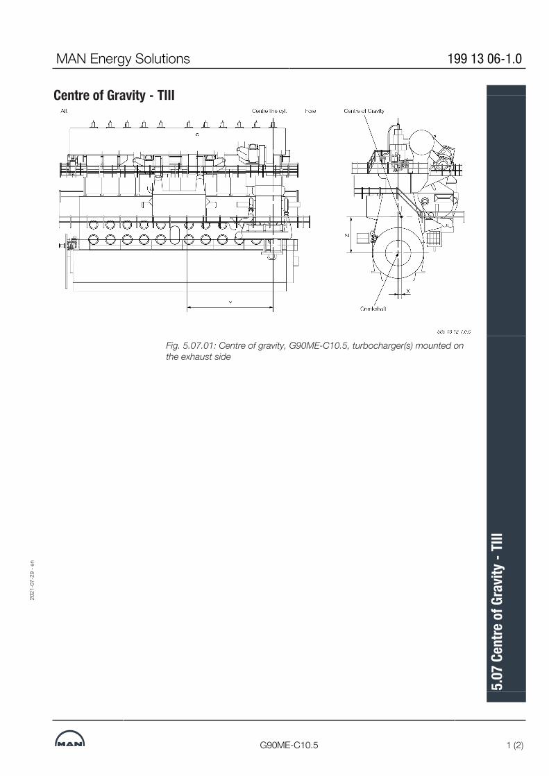
Centre of Gravity - TIII
Fig. 5.07.01: Centre of gravity, G90ME-C10.5, turbocharger(s) mounted onthe exhaust side
2021
-07-
29 -
en
MAN Energy Solutions 199 13 06-1.0
G90ME-C10.5 1 (2)
5.07
Cen
tre o
f Gra
vity -
TIII

No. of cylinders 5 6 7 8 9 10 11 12
Distance X mm
Available on request
301
Availableon
request
Distance Y mm 7,618
Distance Z mm 3,459
DMT *) 1,774
Engine configuration:
Engine divided/ cylinder
Available on request
6/5
Availableon
request
TC configuration 3xA275-L
Chain case Centre position With
Chain case position Aft NA
2nd order moment com-pensator Fore
NA
2nd order moment com-pensator Aft
NA
Tuning wheel NA
Turning wheel 30,000 Kgm2
TVD D360/2V/M
EGR High Sulphur NA
EGR Low Sulphur With
Waste heat recovery system
NA
HPSCR NA
LPSCR NA
Cooler type 2xLKMY-C/1,992EGR-DO/2,334
Electrical driven HPS NA
Engine driven HPS With
585 16 12-7.0.0
All values stated are approximate. Data for engines with a different engine configuration is available on request.*) Dry mass tonnes engine including scavenge air coolers and turning wheelFig. 5.07.01: Centre of gravity, G90ME-C10.5-GI, turbocharger(s) mounted onthe exhaust side
2021
-07-
29 -
en
199 13 06-1.0 MAN Energy Solutions
2 (2) G90ME-C10.5
5.07
Cen
tre o
f Gra
vity -
TIII

Mass of Water and Oil
2021
-07-
19 -
en
MAN Energy Solutions 198 76 50-2.0
1 (1)
5.08
Mas
s of W
ater
and
Oil

Mass of Water and Oil - TIIINo. of cylinders 5 6 7 8 9 10 11 12
Total mass of water, kg
Available on request
9,060
Availableon
request
- Jacket cooling water, kg 6,070
- Scavenge air cooling water, kg
2,990
Total mass of oil, kg 10,880
- Oil in engine system, kg 6,410
- Oil pan, kg 2,680
- Hydraulic system oil, kg 1,790
Engine configuration:
TC configuration
Available on request
3xA275L
Availableon
request
L connection position Fore/Aft Fore
K connection position Fore/Aft Fore
Auto filter-Kanagawa With
Auto filter- Boll filter Type 6.64 NA
Auto filter-Boll filter New Type8.48
NA
Separate Hydr. oil NA
Separate T/C NA
2nd order moment com-pensator / position Fore
Without
2nd order moment com-pensator / position Aft
Without
EGR High Sulphur NA
EGR Low Sulphur With
EGR Configuration 1xRTU90/2xSiemens EGR22
Waste heat recovery system NA
Cooler Type 2xLKMY-C1/1992
Electrical driven HPS NA
Engine driven HPS With
585 09 76-4.0.0
Table 5.08.01: Water and oil in engine
2021
-07-
29 -
en
MAN Energy Solutions 199 13 03-6.0
G90ME-C10.5 1 (1)
5.08
Mas
s of W
ater
and
Oil
- TIII

Counterflanges, Connection D
MAN Type TCA44-88
Type TCA series – Rectangular type
TC L W IL IW A B C D E F G N O
TCA44 1,054 444 949 340 1,001 312 826 408 1,012 104 118 24 ø13.5
TCA55 1,206 516 1,080 390 1,143 360 1,000 472 1,155 120 125 26 ø17.5
TCA66 1,433 613 1,283 463 1,358 420 1,200 560 1,373 140 150 26 ø17.5
TCA77 1,694 720 1,524 550 1,612 480 1,440 664 1,628 160 160 28 ø22
TCA88 2,012 855 1,810 653 1,914 570 1,710 788 1,934 190 190 28 ø22
TCA99 2,207 938 1,985 717 2100 624 1,872 866 2,120 208 208 28 ø22
MAN Energy Solutions 198 66 70-0.12
All engines 1 (11)
5.10
Cou
nter
flang
es, C
onne
ctio
n D
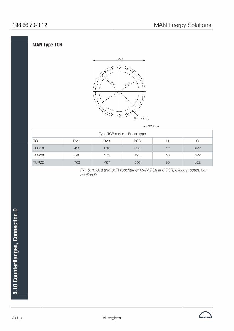
MAN Type TCR
Type TCR series – Round type
TC Dia 1 Dia 2 PCD N O
TCR18 425 310 395 12 ø22
TCR20 540 373 495 16 ø22
TCR22 703 487 650 20 ø22
Fig. 5.10.01a and b: Turbocharger MAN TCA and TCR, exhaust outlet, con-nection D
198 66 70-0.12 MAN Energy Solutions
2 (11) All engines
5.10
Cou
nter
flang
es, C
onne
ctio
n D

ABB Type A100/A200-L
Type A100/200-L series – Rectangular type
TC L W IL IW A B C D F G N O
A255-L Available on request
A260-L
A165/A265-L 1,114 562 950 404 1,050 430 900 511 86 100 32 ø22
A170/A270-L 1,280 625 1,095 466 1,210 450 1,080 568 90 120 32 ø22
A175/A275-L 1,523 770 1,320 562 1,446 510 1,260 710 170 140 28 ø30
A180/A280-L 1,743 856 1,491 634 1,650 630 1,485 786 150 135 36 ø30
A185-L 1,955 958 1,663 707 1,860 725 1,595 886 145 145 36 ø30
Fig. 5.10.01c: Turbocharger ABB A100/200-L, exhaust outlet, connection D
MAN Energy Solutions 198 66 70-0.12
All engines 3 (11)
5.10
Cou
nter
flang
es, C
onne
ctio
n D

MHI Type MET
Type MET – Rectangular type
TC L W IL IW A B C D F G N O
Series MB
MET33 Available on request
MET37 999 353 909 263 969 240 855 323 80 95 28 ø15
MET42 1,094 381 1,004 291 1,061 261 950 351 87 95 30 ø15
MET48 1,240 430 1,140 330 1,206 300 1,070 396 100 107 30 ø15
MET53 1,389 485 1,273 369 1,340 330 1,200 440 110 120 30 ø20
MET60 1,528 522 1,418 410 1,488 330 1,320 482 110 110 34 ø20
MET66 1,713 585 1,587 459 1,663 372 1,536 535 124 128 34 ø20
MET71 1,837 617 1,717 497 1,792 480 1,584 572 120 132 36 ø20
MET83 2,163 731 2,009 581 2,103 480 1,920 671 160 160 34 ø24
MET90 2,378 801 2,218 641 2,318 525 2,100 741 175 175 34 ø24
Series MA
MET33 700 310 605 222 670 180 550 280 90 110 18 ø15
MET42 883 365 793 275 850 240 630 335 80 90 24 ø15
MET53 1,122 465 1,006 349 1,073 300 945 420 100 105 28 ø20
MET60 1,230 500 1,120 388 1,190 315 1,050 460 105 105 30 ø20
MET66 1,380 560 1,254 434 1,330 345 1,200 510 115 120 30 ø20
MET71 1,520 600 1,400 480 1,475 345 1,265 555 115 115 34 ø20
MET83 1,740 700 1,586 550 1,680 450 1,500 640 150 150 30 ø24
MET90 1,910 755 1,750 595 1,850 480 1,650 695 160 165 30 ø24
Fig. 5.10.01d: Turbocharger MHI MET MB and MA, exhaust outlet, connec-tion D
198 66 70-0.12 MAN Energy Solutions
4 (11) All engines
5.10
Cou
nter
flang
es, C
onne
ctio
n D

Counterflanges, Connection E
MAN Type TCA
TC Dia/ISO Dia/JIS OD PCD N O Thickness offlanges
TCA44 61 77 120 90 4 ø14 14
TC Dia/ISO Dia/JIS L W N O Thickness offlanges
TCA55 61 77 86 76 4 ø14 16
TCA66 90 90 110 90 4 ø18 16
Fig. 5.10.01e and f: Turbocharger MAN TCA, venting of lube oil dischargepipe, connection E
MAN Energy Solutions 198 66 70-0.12
All engines 5 (11)
5.10
Cou
nter
flang
es, C
onne
ctio
n D

TC Dia/ISO Dia/JIS L W N O Thickness offlanges
TCA77 115 115 126 72 4 ø18 18
TCA88 141 141 150 86 4 ø18 18
TCA99 141 141 164 94 4 ø22 24
Fig. 5.10.01g: Turbocharger MAN TCA, venting of lube oil discharge pipe,connection E
198 66 70-0.12 MAN Energy Solutions
6 (11) All engines
5.10
Cou
nter
flang
es, C
onne
ctio
n D

ABB Type A100/A200-L
TC Dia 1 PCD L = W N O Thickness offlanges
A255-L Available on request
A260-L
A165/A265-L 43 100 106 8 ø8.5 18
A170/A270-L 77 100 115 8 ø11 18
A175/A275-L 77 126 140 8 ø11 18
A180/A280-L 90 142 158 8 ø13 18
A185-L 115 157 178 8 ø13 18
Fig. 5.10.01h: Turbocharger ABB A100/200-L, venting of lube oil dischargepipe, connection E
MAN Energy Solutions 198 66 70-0.12
All engines 7 (11)
5.10
Cou
nter
flang
es, C
onne
ctio
n D

MHI Type MET MB
TC L = W Dia 2 PCD N O Thicknessof flanges
(A)
MET33MB Available on request
MET42MB 105 61 105 4 ø14 14
MET48MB 125 77 130 4 ø14 14
MET53MB 125 77 130 4 ø14 14
MET60MB 140 90 145 4 ø18 14
MET66MB 140 90 145 4 ø18 14
TC Dia 1 Dia 2 PCD N O Thicknessof flanges
(A)
MET71MB 180 90 145 4 ø18 14
MET83MB 200 115 165 4 ø18 16
MET90MB 200 115 165 4 ø18 16
Fig. 5.10.01i and j: Turbocharger MHI MET MB, venting of lube oil dischargepipe, connection E
198 66 70-0.12 MAN Energy Solutions
8 (11) All engines
5.10
Cou
nter
flang
es, C
onne
ctio
n D

MHI Type MET MA
TC L=W Dia 2 PCD N O Thicknessof flanges
(A)
MET33MA Available on request
MET42MB 105 61 105 4 ø14 14
MET53MB 125 77 130 4 ø14 14
MET60MB 140 90 145 4 ø18 14
MET66MB 140 90 145 4 ø18 14
MET71MB 140 90 145 4 ø18 14
MET90MB 155 115 155 4 ø18 14
TC Dia 1 Dia 2 PCD N O Thicknessof flanges
(A)
MET83MB 180 90 145 4 ø18 148
Fig. 5.10.01k and l: Turbocharger MHI MET MA, venting of lube oil dischargepipe, connection E
MAN Energy Solutions 198 66 70-0.12
All engines 9 (11)
5.10
Cou
nter
flang
es, C
onne
ctio
n D
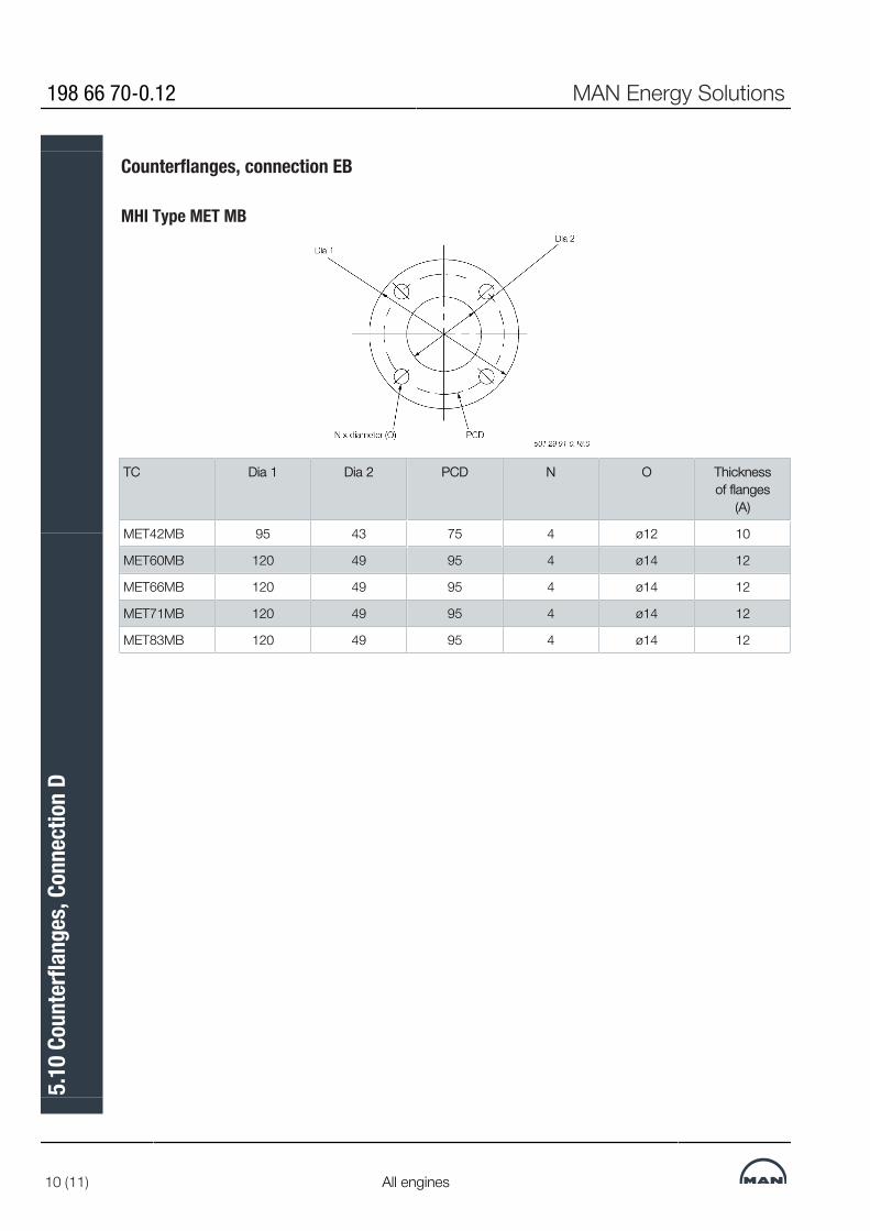
Counterflanges, connection EB
MHI Type MET MB
TC Dia 1 Dia 2 PCD N O Thicknessof flanges
(A)
MET42MB 95 43 75 4 ø12 10
MET60MB 120 49 95 4 ø14 12
MET66MB 120 49 95 4 ø14 12
MET71MB 120 49 95 4 ø14 12
MET83MB 120 49 95 4 ø14 12
198 66 70-0.12 MAN Energy Solutions
10 (11) All engines
5.10
Cou
nter
flang
es, C
onne
ctio
n D

TC L = W Dia 2 PCD N O Thicknessof flanges
(A)
MET48MB 95 49 95 4 ø14 12
MET53MB 95 49 95 4 ø14 12
MET90MB 125 77 130 4 ø14 14
198 70 27-3.5.0
Fig. 5.10.01m and n: Turbocharger MHI MB, cooling air, connection EB
MAN Energy Solutions 198 66 70-0.12
All engines 11 (11)
5.10
Cou
nter
flang
es, C
onne
ctio
n D

Engine Seating and Holding Down BoltsThe latest version of the Installation Drawings of this section is available fordownload at www.marine.man-es.com --> 'Two-Stroke' --> Installation Draw-ings'. Specify engine and accept the ‘Conditions for use’ before clicking on‘Download Drawings’.
Engine Seating and Arrangement of Holding Down BoltsThe dimensions of the seating stated in Figs. 5.12.01 and 5.12.02 are forguidance only.The engine is designed for mounting on epoxy chocks, EoD: 4 82 102, inwhich case the underside of the bedplate’s lower flanges has no taper.The epoxy types approved by MAN Energy Solutions are:▪ ‘Chockfast Orange PR 610 TCF’
and ‘Epocast 36’ from ITW Philadelphia Resins Corporation, USA.▪ ‘Durasin’ from
Daemmstoff Industrie Korea Ltd.▪ ‘EPY’ from
Marine Service Jaroszewicz S.C., Poland.▪ ‘Loctite Fixmaster Marine Chocking’, Henkel.▪ 'CMP Liner Blue' from
Chugoku Marine Paints Ltd, Japan.
MAN Energy Solutions 198 41 76-5.13
All engines 1 (1)
5.11
Eng
ine S
eatin
g an
d Ho
ldin
g Do
wn B
olts

Epoxy Chocks Arrangement
For details of chocks and bolts see special drawings.For securing of supporting chocks see special drawing.
2.The shipyard drills the holes for holding down bolts in the top plates while observing the toleranced locations given on the present drawing.
Preparing holes for holding down bolts 3.The holding down bolts must be made in accordance with MAN Energy Solutionsdrawings of these bolts.
1.The engine builder drills the holes for holding down bolts in the bedplate while observing the toleranced locations indicated on MAN Energy Solutions drawings for machining the bedplate.
Fig. 5.12.01: Arrangement of epoxy chocks and holding down bolts
MAN B&W 5.12
Page 1 of 3
MAN B&W G90ME-C10.5/-GI MAN Energy Solutions 199 10 34-0.0
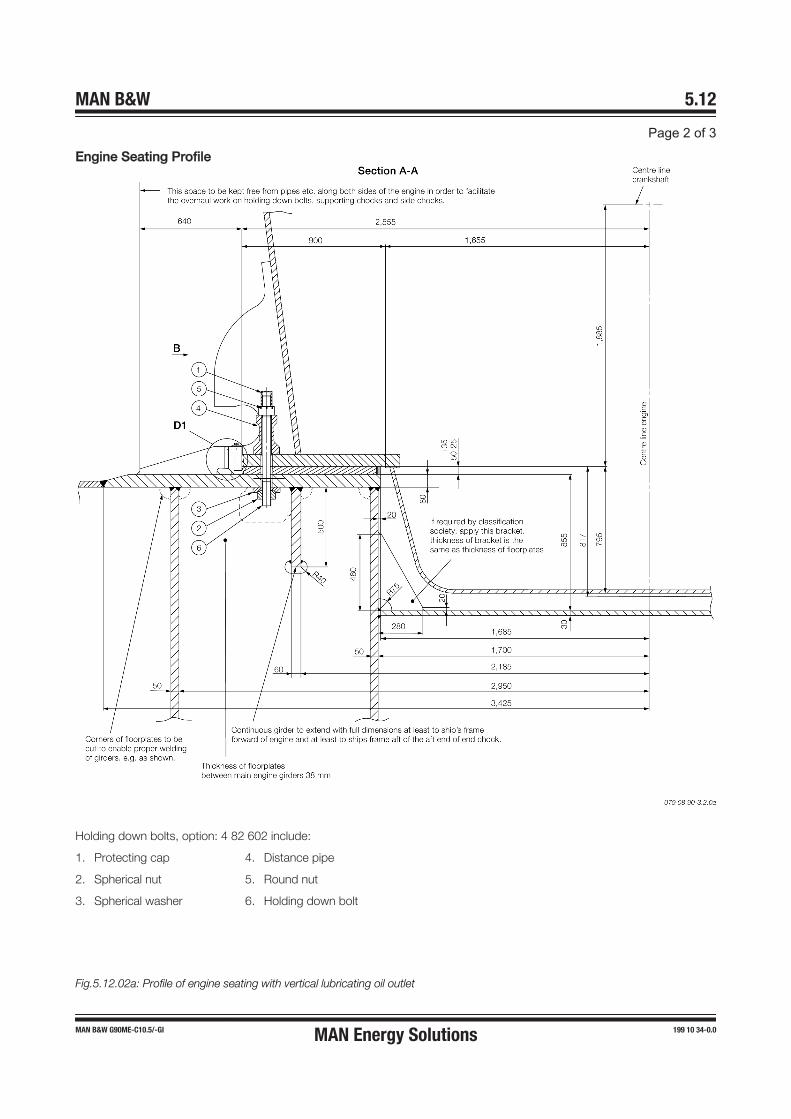
Engine Seating Profile
Holding down bolts, option: 4 82 602 include:
1. Protecting cap 4. Distance pipe
2. Spherical nut 5. Round nut
3. Spherical washer 6. Holding down bolt
Fig.5.12.02a: Profile of engine seating with vertical lubricating oil outlet
MAN B&W 5.12
Page 2 of 3
MAN B&W G90ME-C10.5/-GI MAN Energy Solutions 199 10 34-0.0
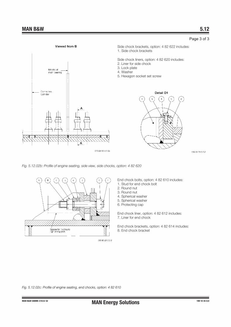
Side chock brackets, option: 4 82 622 includes:1. Side chock brackets
Side chock liners, option: 4 82 620 includes:2. Liner for side chock3. Lock plate4. Washer5. Hexagon socket set screw
Fig. 5.12.02b: Profile of engine seating, side view, side chocks, option: 4 82 620
End chock bolts, option: 4 82 610 includes:1. Stud for end chock bolt2. Round nut3. Round nut4. Spherical washer5. Spherical washer6. Protecting cap
End chock liner, option: 4 82 612 includes:7. Liner for end chock
End chock brackets, option: 4 82 614 includes:8. End chock bracket
Fig. 5.12.02c: Profile of engine seating, end chocks, option: 4 82 610
MAN B&W 5.12
Page 3 of 3
MAN B&W G90ME-C10.5/-GI MAN Energy Solutions 199 10 34-0.0

Engine Top BracingThe so-called guide force moments are caused by the transverse reactionforces acting on the crossheads due to the connecting rod and crankshaftmechanism. When the piston of a cylinder is not exactly in its top or bottomposition the gas force from the combustion, transferred through the connect-ing rod, will have a component acting on the crosshead and the crankshaftperpendicularly to the axis of the cylinder. Its resultant is acting on the guideshoe and together they form a guide force moment.The moments may excite engine vibrations moving the engine top athwartships and causing a rocking (excited by H-moment) or twisting (excited by X-moment) movement of the engine. For engines with less than seven cylinders,this guide force moment tends to rock the engine in the transverse direction,and for engines with seven cylinders or more, it tends to twist the engine.The guide force moments are harmless to the engine except when resonancevibrations occur in the engine/double bottom system. They may, however,cause annoying vibrations in the superstructure and/or engine room, if propercountermeasures are not taken.As a detailed calculation of this system is normally not available, MAN EnergySolutions recommends that top bracing is installed between the engine’s up-per platform brackets and the casing side.However, the top bracing is not needed in all cases. In some cases the vibra-tion level is lower if the top bracing is not installed. This has normally to bechecked by measurements, i.e. with and without top bracing.If a vibration measurement in the first vessel of a series shows that the vibra-tion level is acceptable without the top bracing, we have no objection to thetop bracing being removed and the rest of the series produced without topbracing. It is our experience that especially the 7-cylinder engine will oftenhave a lower vibration level without top bracing.Without top bracing, the natural frequency of the vibrating system comprisingengine, ship’s bottom, and ship’s side is often so low that resonance with theexcitation source (the guide force moment) can occur close to the normalspeed range, resulting in the risk of vibration.With top bracing, such a resonance will occur above the normal speed range,as the natural frequencies of the double bottom/main engine system will in-crease. The impact of vibration is thus lowered.The top bracing system is installed either as a mechanical top bracing (typic-ally on smaller engine types) or a hydraulic top bracing (typically on larger en-gine types). Both systems are described below.The top bracing is normally installed on the exhaust side of the engine, but hy-draulic top bracing can alternatively be installed on the manoeuvring side. Acombination of exhaust side and manoeuvring side installation of hydraulic topbracing is also possible.
Mechanical Top BracingThe mechanical top bracing comprises stiff connections between the engineand the hull.The top bracing stiffener consists of a double bar tightened with friction shimsat each end of the mounting positions. The friction shims allow the top bra-cing stiffener to move in case of displacements caused by thermal expansion
MAN Energy Solutions 199 04 83-8.1
ME/ME-C/ME-B/-GI/-LGI 1 (3)
5.13
Eng
ine T
op B
racin
g
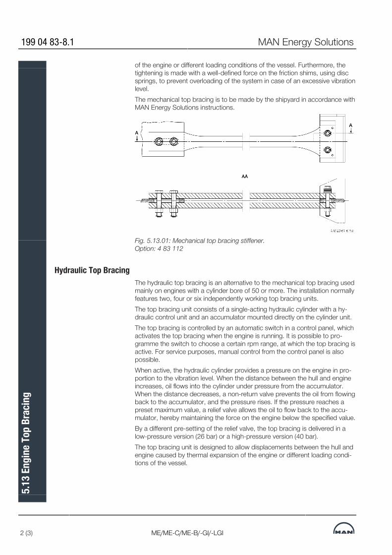
of the engine or different loading conditions of the vessel. Furthermore, thetightening is made with a well-defined force on the friction shims, using discsprings, to prevent overloading of the system in case of an excessive vibrationlevel.The mechanical top bracing is to be made by the shipyard in accordance withMAN Energy Solutions instructions.
Fig. 5.13.01: Mechanical top bracing stiffener. Option: 4 83 112
Hydraulic Top BracingThe hydraulic top bracing is an alternative to the mechanical top bracing usedmainly on engines with a cylinder bore of 50 or more. The installation normallyfeatures two, four or six independently working top bracing units.The top bracing unit consists of a single-acting hydraulic cylinder with a hy-draulic control unit and an accumulator mounted directly on the cylinder unit.The top bracing is controlled by an automatic switch in a control panel, whichactivates the top bracing when the engine is running. It is possible to pro-gramme the switch to choose a certain rpm range, at which the top bracing isactive. For service purposes, manual control from the control panel is alsopossible.When active, the hydraulic cylinder provides a pressure on the engine in pro-portion to the vibration level. When the distance between the hull and engineincreases, oil flows into the cylinder under pressure from the accumulator.When the distance decreases, a non-return valve prevents the oil from flowingback to the accumulator, and the pressure rises. If the pressure reaches apreset maximum value, a relief valve allows the oil to flow back to the accu-mulator, hereby maintaining the force on the engine below the specified value.By a different pre-setting of the relief valve, the top bracing is delivered in alow-pressure version (26 bar) or a high-pressure version (40 bar).The top bracing unit is designed to allow displacements between the hull andengine caused by thermal expansion of the engine or different loading condi-tions of the vessel.
199 04 83-8.1 MAN Energy Solutions
2 (3) ME/ME-C/ME-B/-GI/-LGI
5.13
Eng
ine T
op B
racin
g
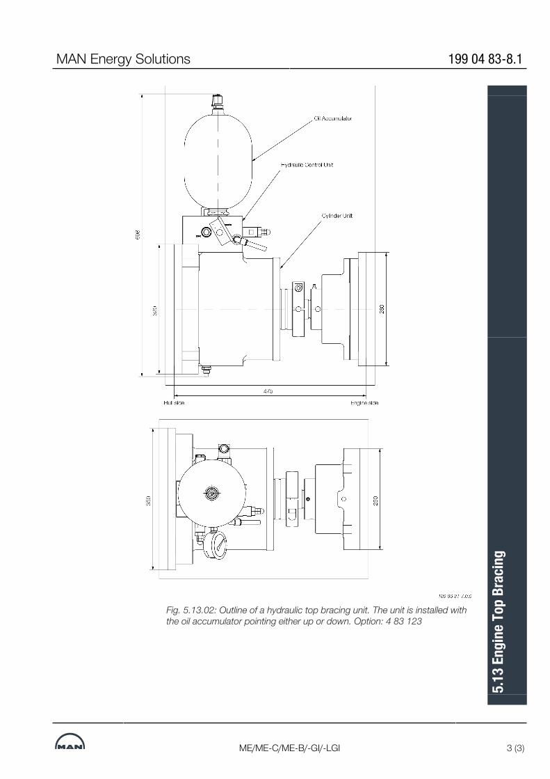
Fig. 5.13.02: Outline of a hydraulic top bracing unit. The unit is installed withthe oil accumulator pointing either up or down. Option: 4 83 123
MAN Energy Solutions 199 04 83-8.1
ME/ME-C/ME-B/-GI/-LGI 3 (3)
5.13
Eng
ine T
op B
racin
g

Mechanical Top Bracing
MAN Energy Solutions 199 10 70-9.0
1 (1)
5.14
Mec
hani
cal T
op B
racin
g

Hydraulic Top Bracing Arrangement
MAN Energy Solutions 198 47 92-2.0
1 (1)
5.15
Hyd
raul
ic To
p Br
acin
g Ar
rang
emen
t

Components for Engine Control System
Installation of ECS in the Engine Control RoomThe following items are to be installed in the ECR (Engine Control Room):
▪ 2 pcs EICU (Engine Interface Control Unit) (1 pcs only for ME-B engines)
▪ 1 pcs ECS MOP-A (Main Operating Panel) EC-MOP with touch display, 15”
▪ 1 pcs ECS MOP-B EC-MOP with touch display, 15”
▪ 1 pcs EMS MOP with system software Display, 24” marine monitor PC unit
▪ 1 pcs Managed switch and VPN router with firewall
The EICU functions as an interface unit to ECR related systems such as AMS(Alarm and Monitoring System), RCS (Remote Control System) and SafetySystem. On ME-B engines the EICU also controls the HPS.MOP-A and -B are redundant and are the operator’s interface to the ECS. Viaboth MOPs, the operator can control and view the status of the ECS. Via theEMS MOP PC, the operator can view the status and operating history of boththe ECS and the engine, EMS is decribed in Section 18.01.The PMI Auto-tuning application is run on the EMS MOP PC. PMI Auto-tuningis used to optimize the combustion process with minimal operator attendanceand improve the efficiency of the engine. See Section 18.01.CoCoS-EDS ME Basic is included as an application in the Engine Manage-ment Services as part of the standard software package installed on the EMSMOP PC. See Section 18.01.
MAN Energy Solutions 199 15 50-3.0
ME/ME-C/-GI/-GA/-LGI 1 (4)
5.16
Com
pone
nts f
or E
ngin
e Con
trol S
yste
m

Abbreviations: # Yard Supply
AMS: Alarm Monitoring Systems
EICU: Engine Interface ControlUnit
¤ Ethernet, 10 m patch cable supplied withswitch. Type:
EMS: Engine Management Ser-vices
RJ45, STP (Shielded Twisted Pair), CAT 5.
MOP: Main Operating Panel In case 10 m cable is not enough, this be-comes Yard supply.
Fig. 5.16.01 Network and PC components for the ME/ME-B Engine ControlSystem
EC-MOP▪ Integrated PC unit and touch display,
15”▪ Direct dimming control (0-100%)▪ USB connections at front▪ IP20 resistant front▪ Dual Arcnet
Pointing Device▪ Keyboard model
▪ UK version, 104 keys▪ USB connection
▪ Trackball mouse
▪ USB connection
EMS MOP PC
▪ Standard industry PC with MS Win-dows operating system, UK version
199 15 50-3.0 MAN Energy Solutions
2 (4) ME/ME-C/-GI/-GA/-LGI
5.16
Com
pone
nts f
or E
ngin
e Con
trol S
yste
m

Marine Monitor for EMS MOP PC▪ LCD (MVA) monitor 24”
▪ Projected capacitive touch▪ Resolution 1,920x1,080,
WSXGA+▪ Direct dimming control
(0-100%)▪ IP54 resistant front▪ For mounting in panel
▪ Bracket for optional mounting ondesktop, with hinges (5° tilt, adjustable95°) or without hinges (10° tilt, not ad-justable
Network Components▪ Managed switch and VPN router with
firewall
Fig. 5.16.02 MOP PC equipment for the ME/ME-B Engine Control System
MAN Energy Solutions 199 15 50-3.0
ME/ME-C/-GI/-GA/-LGI 3 (4)
5.16
Com
pone
nts f
or E
ngin
e Con
trol S
yste
m

EICU Cabinet▪ Engine interface control cabinet for
ME-ECS for installation in ECR (re-commended) or ER
Fig. 5.16.03: The network printer and EICU cabinet unit for the ME EngineControl System
Engine Control Room Console▪ Recommended outline of Engine Control Room console with ME equipment
* Yard supply
Oil mist detector equipment depending on supplier/maker BWM: Bearing Wear Monitoring
Fig. 5.16.04: Example of Engine Control Room console
199 15 50-3.0 MAN Energy Solutions
4 (4) ME/ME-C/-GI/-GA/-LGI
5.16
Com
pone
nts f
or E
ngin
e Con
trol S
yste
m

Shaftline Earthing Device
Scope and Field of ApplicationA difference in the electrical potential between the hull and the propeller shaftwill be generated due to the difference in materials and to the propeller beingimmersed in sea water.In some cases, the difference in the electrical potential has caused sparkerosion on the thrust, main bearings and journals of the crankshaft of the en-gine.In order to reduce the electrical potential between the crankshaft and the hulland thus prevent spark erosion, a highly efficient shaftline earthing devicemust be installed.The shaftline earthing device should be able to keep the electrical potentialdifference below 50 mV DC. A shaft-to-hull monitoring equipment with a mV-meter and with an output signal to the alarm system must be installed so thatthe potential and thus the correct function of the shaftline earthing device canbe monitored.Note that only one shaftline earthing device is needed in the propeller shaftsystem.
Design DescriptionThe shaftline earthing device consists of two silver slip rings, two arrange-ments for holding brushes including connecting cables and monitoring equip-ment with a mV-meter and an output signal for alarm.The slip rings should be made of solid silver or back-up rings of cobber with asilver layer all over. The expected life span of the silver layer on the slip ringsshould be minimum 5 years.slip rings should be minimum 5 years. The brushes should be made of min-imum 80% silver and 20% graphite to ensure a sufficient electrical conductingcapability.Resistivity of the silver should be less than 0.1μ Ohm x m. The total resistancefrom the shaft to the hull must not exceed 0.001 Ohm.Cabling of the shaftline earthing device to the hull must be with a cable with across section not less than 45 mm2. The length of the cable to the hull shouldbe as short as possible.Monitoring equipment should have a 4-20 mA signal for alarm and a mV-meter with a switch for changing range. Primary range from 0 to 50 mV DCand secondary range from 0 to 300 mV DC.When the shaftline earthing device is working correctly, the electrical potentialwill normally be within the range of 10-50 mV DC depending of propeller sizeand revolutions.The alarm set-point should be 80 mV for a high alarm. The alarm signals withan alarm delay of 30 seconds and an alarm cut-off, when the engine isstopped, must be connected to the alarm system.Connection of cables is shown in the sketch, see Fig. 5.17.01.
MAN Energy Solutions 198 49 29-2.4
MC/MC-C/ME-B/ME-C/-GI/-GA 1 (3)
5.17
Sha
ftlin
e Ear
thin
g De
vice

Fig. 5.17.01: Connection of cables for the shaftline earthing device
Shaftline Earthing Device InstallationsThe shaftline earthing device slip rings must be mounted on the foremost in-termediate shaft as close to the engine as possible, see Fig. 5.17.02
Fig. 5.17.02: Installation of shaftline earthing device in an engine plant withoutshaft-mounted generatorWhen a generator is fitted in the propeller shaft system, where the rotor of thegenerator is part of the intermediate shaft, the shaftline earthing device mustbe mounted between the generator and the engine, see Fig. 5.17.03
198 49 29-2.4 MAN Energy Solutions
2 (3) MC/MC-C/ME-B/ME-C/-GI/-GA
5.17
Sha
ftlin
e Ear
thin
g De
vice

Fig. 5.17.03: Installation of shaftline earthing device in an engine plant withshaft-mounted generator
MAN Energy Solutions 198 49 29-2.4
MC/MC-C/ME-B/ME-C/-GI/-GA 3 (3)
5.17
Sha
ftlin
e Ear
thin
g De
vice

MAN Alpha Controllable Pitch (CP) Propeller
MAN Energy Solutions 198 61 57-3.2
1 (1)
5.18
MAN
Alp
ha C
ontro
llabl
e Pitc
h (C
P) P
rope
ller


MAN B&W
MAN Energy Solutions
List of Capacities: Pumps, Coolers &
Exhaust Gas
6

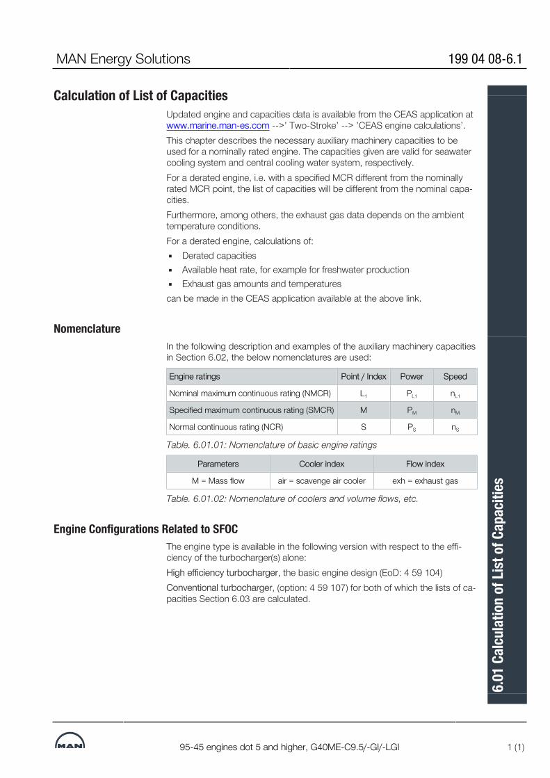
Calculation of List of CapacitiesUpdated engine and capacities data is available from the CEAS application atwww.marine.man-es.com -->’ Two-Stroke’ --> ’CEAS engine calculations’.This chapter describes the necessary auxiliary machinery capacities to beused for a nominally rated engine. The capacities given are valid for seawatercooling system and central cooling water system, respectively.For a derated engine, i.e. with a specified MCR different from the nominallyrated MCR point, the list of capacities will be different from the nominal capa-cities.Furthermore, among others, the exhaust gas data depends on the ambienttemperature conditions.For a derated engine, calculations of:▪ Derated capacities▪ Available heat rate, for example for freshwater production▪ Exhaust gas amounts and temperaturescan be made in the CEAS application available at the above link.
NomenclatureIn the following description and examples of the auxiliary machinery capacitiesin Section 6.02, the below nomenclatures are used:
Engine ratings Point / Index Power Speed
Nominal maximum continuous rating (NMCR) L1 PL1 nL1
Specified maximum continuous rating (SMCR) M PM nM
Normal continuous rating (NCR) S PS nS
Table. 6.01.01: Nomenclature of basic engine ratings
Parameters Cooler index Flow index
M = Mass flow air = scavenge air cooler exh = exhaust gas
Table. 6.01.02: Nomenclature of coolers and volume flows, etc.
Engine Configurations Related to SFOCThe engine type is available in the following version with respect to the effi-ciency of the turbocharger(s) alone:High efficiency turbocharger, the basic engine design (EoD: 4 59 104)Conventional turbocharger, (option: 4 59 107) for both of which the lists of ca-pacities Section 6.03 are calculated.
MAN Energy Solutions 199 04 08-6.1
95-45 engines dot 5 and higher, G40ME-C9.5/-GI/-LGI 1 (1)
6.01
Cal
cula
tion
of Li
st o
f Cap
aciti
es

List of Capacities and Cooling Water SystemsThe List of Capacities contain data regarding the necessary capacities of theauxiliary machinery for the main engine only, and refer to NMCR. Complyingwith IMO Tier II NOx limitations.The heat dissipation figures include 10% extra margin for overload running ex-cept for the scavenge air cooler, which is an integrated part of the diesel en-gine.
Cooling Water SystemsThe capacities given in the tables are based on tropical ambient referenceconditions and refer to engines with high efficiency/conventional turbochargerrunning at NMCR for:▪ Seawater cooling system,
See diagram, Fig. 6.02.01 and nominal capacities in Fig. 6.03.01▪ Central cooling water system,
See diagram, Fig. 6.02.02 and nominal capacities in Fig. 6.03.01The capacities for the starting air receivers and the compressors are stated inFig. 6.03.01.
Heat RadiationThe radiation and convection heat losses to the engine room is around 1% ofthe engine power at NMCR.
Flanges on Engine, etc.The location of the flanges on the engine are shown in: ‘Engine pipe connec-tions’, and the flanges are identified by reference letters stated in the list of‘Counterflanges’; both can be found in Chapter 5.The diagrams use the ‘Basic symbols for piping’, the symbols for instrumenta-tion are according to ‘ISO 1219-1’ / ‘ISO 1219-2’ and the instrumentation listboth found in Appendix A.
Figure 1: Fig. 6.02.01: Diagram for seawater cooling system
MAN Energy Solutions 198 95 12-4.0
G/S95-50ME-C9/10/-GI, G/S50ME-B9 1 (2)
6.02
List
of C
apac
ities
and
Coo
ling
Wat
er S
yste
ms

Figure 2: Fig. 6.02.02: Diagram for central cooling water system
198 95 12-4.0 MAN Energy Solutions
2 (2) G/S95-50ME-C9/10/-GI, G/S50ME-B9
6.02
List
of C
apac
ities
and
Coo
ling
Wat
er S
yste
ms

MAN B&W 6.03Page 1 of 8
MAN B&W G90ME-C10.5 199 04 94-6.0
List of Capacities for 5G90ME-C10.5-TII at NMCR
Seawater cooling Central coolingConventional TC High eff. TC Conventional TC High eff. TC
2xTCA77-21
2xA175-L
1xMET90-MB
2xTCA77-21
2xA275-L
2xMET71-MB
2xTCA77-21
2xA175-L
1xMET90-MB
2xTCA77-21
2xA275-L
2xMET71-MB
PumpsFuel oil circulation m³/h 14.1 14.1 14.1 14.0 14.0 14.0 14.1 14.1 14.1 14.0 14.0 14.0Fuel oil supply m³/h 8.2 8.2 8.2 8.2 8.2 8.2 8.3 8.3 8.3 8.2 8.2 8.2Jacket cooling m³/h 220 220 220 220 220 220 220 220 220 220 220 220Seawater cooling * m³/h 900 900 910 930 930 950 880 880 880 900 900 910Main lubrication oil * m³/h 460 440 450 460 440 450 460 440 450 460 440 450Central cooling * m³/h - - - - - - 690 700 700 710 720 730
Scavenge air cooler(s)Heat diss. app. kW 11,520 11,520 11,520 11,990 11,990 11,990 11,500 11,500 11,500 11,960 11,960 11,960Central water flow m³/h - - - - - - 410 410 410 430 430 430Seawater flow m³/h 560 560 560 590 590 590 - - - - - -
Lubricating oil coolerHeat diss. app. * kW 2,290 2,330 2,360 2,290 2,330 2,430 2,300 2,330 2,360 2,300 2,330 2,440Lube oil flow * m³/h 460 440 450 460 440 450 460 440 450 460 440 450Central water flow m³/h - - - - - - 280 290 290 280 290 300Seawater flow m³/h 340 340 350 340 340 360 - - - - - -
Jacket water coolerHeat diss. app. kW 4,150 4,150 4,150 4,120 4,120 4,120 4,160 4,160 4,160 4,130 4,130 4,130Jacket water flow m³/h 220 220 220 220 220 220 220 220 220 220 220 220Central water flow m³/h - - - - - - 280 290 290 280 290 300Seawater flow m³/h 340 340 350 340 340 360 - - - - - -
Central coolerHeat diss. app. * kW - - - - - - 17,960 17,990 18,020 18,390 18,420 18,530Central water flow m³/h - - - - - - 690 700 700 710 720 730Seawater flow m³/h - - - - - - 880 880 880 900 900 910
Starting air system, 30.0 bar g, 12 starts. Fixed pitch propeller - reversible engineReceiver volume m³ 2 x 14.0 2 x 14.0 2 x 14.0 2 x 14.0 2 x 14.0 2 x 14.0 2 x 14.0 2 x 14.0 2 x 14.0 2 x 14.0 2 x 14.0 2 x 14.0Compressor cap. m³ 840 840 840 840 840 840 840 840 840 840 840 840
Starting air system, 30.0 bar g, 6 starts. Controllable pitch propeller - non-reversible engineReceiver volume m³ 2 x 7.5 2 x 7.5 2 x 7.5 2 x 7.5 2 x 7.5 2 x 7.5 2 x 7.5 2 x 7.5 2 x 7.5 2 x 7.5 2 x 7.5 2 x 7.5Compressor cap. m³ 450 450 450 450 450 450 450 450 450 450 450 450
Other valuesFuel oil heater kW 241 241 241 240 240 240 242 242 242 240 240 240Exh. gas temp. ** °C 260 260 260 240 240 240 260 260 260 240 240 240Exh. gas amount ** kg/h 233,880 233,880 233,880 248,510 248,510 248,510 233,880 233,880 233,880 248,510 248,510 248,510Air consumption ** kg/s 58.0 58.0 58.0 61.7 61.7 61.7 58.5 58.5 58.5 62.2 62.2 62.2
* For main engine arrangements with built-on power take-off (PTO) of a MAN Energy Solutions recommended type and/or torsional
vibration damper the engine's capacities must be increased by those stated for the actual system
** ISO based
For List of Capacities for derated engines and performance data at part load please visit http://www.man-es.com/ceas/LOC Table
6.03.01e: Capacities for seawater and central systems as well as conventional and high efficiency turbochargers stated at NMCR
63.0 63.0 63.0 67.0 67.0 67.0 63.6 63.6 63.6 67.6 67.6 67.6
MAN Energy Solutions

MAN B&W 6.03Page 2 of 8
MAN B&W G90ME-C10.5 199 04 94-6.0
List of Capacities for 6G90ME-C10.5-TII at NMCR
Seawater cooling Central coolingConventional TC High eff. TC Conventional TC High eff. TC
2xTC
A77-21
2xA1
80-L
2xMET
71-M
B
2xTC
A77-26
2xA1
80-L
2xMET
83-M
B
2xTC
A77-21
2xA1
80-L
2xMET
71-M
B
2xTC
A77-26
2xA1
80-L
2xMET
83-M
B
PumpsFuel oil circulation m³/h 16.9 16.9 16.9 16.8 16.8 16.8 16.9 16.9 16.9 16.8 16.8 16.8Fuel oil supply m³/h 9.9 9.9 9.9 9.8 9.8 9.8 9.9 9.9 9.9 9.9 9.9 9.9Jacket cooling m³/h 260 260 260 260 260 260 260 260 260 260 260 260Seawater cooling * m³/h 1080 1090 1100 1100 1110 1130 1050 1060 1060 1080 1080 1090Main lubrication oil * m³/h 540 530 540 540 530 540 540 530 540 540 530 540Central cooling * m³/h - - - - - - 830 840 840 850 860 870
Scavenge air cooler(s)Heat diss. app. kW 13,830 13,830 13,830 14,390 14,390 14,390 13,800 13,800 13,800 14,350 14,350 14,350Central water flow m³/h - - - - - - 490 490 490 510 510 510Seawater flow m³/h 680 680 680 700 700 700 - - - - - -
Lubricating oil coolerHeat diss. app. * kW 2,720 2,800 2,860 2,720 2,800 2,930 2,720 2,810 2,860 2,720 2,810 2,940Lube oil flow * m³/h 540 530 540 540 530 540 540 530 540 540 530 540Central water flow m³/h - - - - - - 340 350 350 340 350 360Seawater flow m³/h 400 410 420 400 410 430 - - - - - -
Jacket water coolerHeat diss. app. kW 4,980 4,980 4,980 4,950 4,950 4,950 4,990 4,990 4,990 4,960 4,960 4,960Jacket water flow m³/h 260 260 260 260 260 260 260 260 260 260 260 260Central water flow m³/h - - - - - - 340 350 350 340 350 360Seawater flow m³/h 400 410 420 400 410 430 - - - - - -
Central coolerHeat diss. app. * kW - - - - - - 21,510 21,600 21,650 22,030 22,120 22,250Central water flow m³/h - - - - - - 830 840 840 850 860 870Seawater flow m³/h - - - - - - 1,050 1,060 1,060 1,080 1,080 1,090
Starting air system, 30.0 bar g, 12 starts. Fixed pitch propeller - reversible engineReceiver volume m³ 2 x 15.0 2 x 15.0 2 x 15.0 2 x 15.0 2 x 15.0 2 x 15.0 2 x 15.0 2 x 15.0 2 x 15.0 2 x 15.0 2 x 15.0 2 x 15.0Compressor cap. m³ 900 900 900 900 900 900 900 900 900 900 900 900
Starting air system, 30.0 bar g, 6 starts. Controllable pitch propeller - non-reversible engineReceiver volume m³ 2 x 8.0 2 x 8.0 2 x 8.0 2 x 8.0 2 x 8.0 2 x 8.0 2 x 8.0 2 x 8.0 2 x 8.0 2 x 8.0 2 x 8.0 2 x 8.0Compressor cap. m³ 480 480 480 480 480 480 480 480 480 480 480 480
Other valuesFuel oil heater kW 289 289 289 288 288 288 290 290 290 289 289 289Exh. gas temp. ** °C 260 260 260 240 240 240 260 260 260 240 240 240Exh. gas amount ** kg/h 280,650 280,650 280,650 298,210 298,210 298,210 280,650 280,650 280,650 298,210 298,210 298,210Air consumption ** kg/s 69.5 69.5 69.5 74.0 74.0 74.0 70.2 70.2 70.2 74.7 74.7 74.7
* For main engine arrangements with built-on power take-off (PTO) of a MAN Energy Solutions recommended type and/or torsional
vibration damper the engine's capacities must be increased by those stated for the actual system
** ISO based
For List of Capacities for derated engines and performance data at part load please visit http://www.man-es.com/ceas/LOC Table
6.03.01f: Capacities for seawater and central systems as well as conventional and high efficiency turbochargers stated at NMCR
75.6 75.6 75.6 80.4 80.4 80.4 76.3 76.3 76.3 81.2 81.2 81.2
MAN Energy Solutions

MAN B&W 6.03Page 3 of 8
MAN B&W G90ME-C10.5 199 04 94-6.0
List of Capacities for 7G90ME-C10.5-TII at NMCR
Seawater cooling Central coolingConventional TC High eff. TC Conventional TC High eff. TC
2xTCA88-21
2xA280-L
2xMET83-M
B
2xTCA88-21
2xA280-L
2xMET83-M
B
2xTCA88-21
2xA280-L
2xMET83-M
B
2xTCA88-21
2xA280-L
2xMET83-M
B
PumpsFuel oil circulation m³/h 19.7 19.7 19.7 19.6 19.6 19.6 19.7 19.7 19.7 19.6 19.6 19.6Fuel oil supply m³/h 11.5 11.5 11.5 11.5 11.5 11.5 11.6 11.6 11.6 11.5 11.5 11.5Jacket cooling m³/h 300 300 300 300 300 300 300 300 300 300 300 300Seawater cooling * m³/h 1260 1260 1280 1290 1290 1310 1230 1230 1240 1260 1260 1270Main lubrication oil * m³/h 640 620 630 640 620 630 640 620 630 640 620 630Central cooling * m³/h - - - - - - 970 980 990 990 1,000 1,010
Scavenge air cooler(s)Heat diss. app. kW 16,130 16,130 16,130 16,790 16,790 16,790 16,100 16,100 16,100 16,740 16,740 16,740Central water flow m³/h - - - - - - 580 580 580 600 600 600Seawater flow m³/h 790 790 790 820 820 820 - - - - - -
Lubricating oil coolerHeat diss. app. * kW 3,190 3,230 3,360 3,190 3,230 3,360 3,200 3,240 3,370 3,200 3,240 3,370Lube oil flow * m³/h 640 620 630 640 620 630 640 620 630 640 620 630Central water flow m³/h - - - - - - 390 400 410 390 400 410Seawater flow m³/h 470 470 490 470 470 490 - - - - - -
Jacket water coolerHeat diss. app. kW 5,810 5,810 5,810 5,770 5,770 5,770 5,820 5,820 5,820 5,790 5,790 5,790Jacket water flow m³/h 300 300 300 300 300 300 300 300 300 300 300 300Central water flow m³/h - - - - - - 390 400 410 390 400 410Seawater flow m³/h 470 470 490 470 470 490 - - - - - -
Central coolerHeat diss. app. * kW - - - - - - 25,120 25,160 25,290 25,730 25,770 25,900Central water flow m³/h - - - - - - 970 980 990 990 1,000 1,010Seawater flow m³/h - - - - - - 1,230 1,230 1,240 1,260 1,260 1,270
Starting air system, 30.0 bar g, 12 starts. Fixed pitch propeller - reversible engineReceiver volume m³ 2 x 15.5 2 x 15.5 2 x 15.5 2 x 15.5 2 x 15.5 2 x 15.5 2 x 15.5 2 x 15.5 2 x 15.5 2 x 15.5 2 x 15.5 2 x 15.5Compressor cap. m³ 930 930 930 930 930 930 930 930 930 930 930 930
Starting air system, 30.0 bar g, 6 starts. Controllable pitch propeller - non-reversible engineReceiver volume m³ 2 x 8.0 2 x 8.0 2 x 8.0 2 x 8.0 2 x 8.0 2 x 8.0 2 x 8.0 2 x 8.0 2 x 8.0 2 x 8.0 2 x 8.0 2 x 8.0Compressor cap. m³ 480 480 480 480 480 480 480 480 480 480 480 480
Other valuesFuel oil heater kW 338 338 338 336 336 336 339 339 339 337 337 337Exh. gas temp. ** °C 260 260 260 240 240 240 260 260 260 240 240 240Exh. gas amount ** kg/h 327,430 327,430 327,430 347,910 347,910 347,910 327,430 327,430 327,430 347,910 347,910 347,910Air consumption ** kg/s 81.1 81.1 81.1 86.3 86.3 86.3 81.9 81.9 81.9 87.1 87.1 87.1
* For main engine arrangements with built-on power take-off (PTO) of a MAN Energy Solutions recommended type and/or torsional
vibration damper the engine's capacities must be increased by those stated for the actual system
** ISO based
For List of Capacities for derated engines and performance data at part load please visit http://www.man-es.com/ceas/LOC Table
6.03.01g: Capacities for seawater and central systems as well as conventional and high efficiency turbochargers stated at NMCR
88.2 88.2 88.2 93.8 93.8 93.8 89.0 89.0 89.0 94.7 94.7 94.7
MAN Energy Solutions

MAN B&W 6.03Page 4 of 8
MAN B&W G90ME-C10.5 199 04 94-6.0
List of Capacities for 8G90ME-C10.5-TII at NMCR
Seawater cooling Central coolingConventional TC High eff. TC Conventional TC High eff. TC
2xTC
A88-21
2xA2
85-L
2xMET
83-M
B
2xTC
A88-21
2xA2
85-L
2xMET
90-M
B
2xTC
A88-21
2xA2
85-L
2xMET
83-M
B
2xTC
A88-21
2xA2
85-L
2xMET
90-M
B
PumpsFuel oil circulation m³/h 22.5 22.5 22.5 22.4 22.4 22.4 22.5 22.5 22.5 22.5 22.5 22.5Fuel oil supply m³/h 13.2 13.2 13.2 13.1 13.1 13.1 13.2 13.2 13.2 13.1 13.1 13.1Jacket cooling m³/h 350 350 350 340 340 340 350 350 350 350 350 350Seawater cooling * m³/h 1430 1440 1460 1470 1480 1510 1400 1410 1410 1440 1440 1450Main lubrication oil * m³/h 720 700 710 720 700 720 720 700 710 720 700 720Central cooling * m³/h - - - - - - 1,110 1,120 1,130 1,140 1,150 1,170
Scavenge air cooler(s)Heat diss. app. kW 18,440 18,440 18,440 19,190 19,190 19,190 18,400 18,400 18,400 19,140 19,140 19,140Central water flow m³/h - - - - - - 660 660 660 690 690 690Seawater flow m³/h 900 900 900 940 940 940 - - - - - -
Lubricating oil coolerHeat diss. app. * kW 3,620 3,710 3,790 3,620 3,710 3,870 3,630 3,720 3,800 3,630 3,720 3,880Lube oil flow * m³/h 720 700 710 720 700 720 720 700 710 720 700 720Central water flow m³/h - - - - - - 450 460 470 450 460 480Seawater flow m³/h 530 540 560 530 540 570 - - - - - -
Jacket water coolerHeat diss. app. kW 6,640 6,640 6,640 6,600 6,600 6,600 6,650 6,650 6,650 6,610 6,610 6,610Jacket water flow m³/h 350 350 350 340 340 340 350 350 350 350 350 350Central water flow m³/h - - - - - - 450 460 470 450 460 480Seawater flow m³/h 530 540 560 530 540 570 - - - - - -
Central coolerHeat diss. app. * kW - - - - - - 28,680 28,770 28,850 29,380 29,470 29,630Central water flow m³/h - - - - - - 1,110 1,120 1,130 1,140 1,150 1,170Seawater flow m³/h - - - - - - 1,400 1,410 1,410 1,440 1,440 1,450
Starting air system, 30.0 bar g, 12 starts. Fixed pitch propeller - reversible engineReceiver volume m³ 2 x 16.0 2 x 16.0 2 x 16.0 2 x 16.0 2 x 16.0 2 x 16.0 2 x 16.0 2 x 16.0 2 x 16.0 2 x 16.0 2 x 16.0 2 x 16.0Compressor cap. m³ 960 960 960 960 960 960 960 960 960 960 960 960
Starting air system, 30.0 bar g, 6 starts. Controllable pitch propeller - non-reversible engineReceiver volume m³ 2 x 8.5 2 x 8.5 2 x 8.5 2 x 8.5 2 x 8.5 2 x 8.5 2 x 8.5 2 x 8.5 2 x 8.5 2 x 8.5 2 x 8.5 2 x 8.5Compressor cap. m³ 510 510 510 510 510 510 510 510 510 510 510 510
Other valuesFuel oil heater kW 386 386 386 384 384 384 387 387 387 385 385 385Exh. gas temp. ** °C 260 260 260 240 240 240 260 260 260 240 240 240Exh. gas amount ** kg/h 374,200 374,200 374,200 397,610 397,610 397,610 374,200 374,200 374,200 397,610 397,610 397,610Air consumption ** kg/s 92.7 92.7 92.7 98.7 98.7 98.7 93.6 93.6 93.6 99.6 99.6 99.6
* For main engine arrangements with built-on power take-off (PTO) of a MAN Energy Solutions recommended type and/or torsional
vibration damper the engine's capacities must be increased by those stated for the actual system
** ISO based
For List of Capacities for derated engines and performance data at part load please visit http://www.man-es.com/ceas/LOC Table
6.03.01h: Capacities for seawater and central systems as well as conventional and high efficiency turbochargers stated at NMCR
100.8 100.8 100.8 107.2 107.2 107.2 101.7 101.7 101.7 108.2 108.2 108.2
MAN Energy Solutions

MAN B&W 6.03Page 5 of 8
MAN B&W G90ME-C10.5 199 04 94-6.0
List of Capacities for 9G90ME-C10.5-TII at NMCR
Seawater cooling Central coolingConventional TC High eff. TC Conventional TC High eff. TC
2xTCA88-26
2xA285-L
2xMET90-MB
2xTCA88-26
3xA180-L
2xMET90-MB
2xTCA88-26
2xA285-L
2xMET90-MB
2xTCA88-26
3xA180-L
2xMET90-MB
PumpsFuel oil circulation m³/h 25.3 25.3 25.3 25.2 25.2 25.2 25.4 25.4 25.4 25.3 25.3 25.3Fuel oil supply m³/h 14.8 14.8 14.8 14.8 14.8 14.8 14.9 14.9 14.9 14.8 14.8 14.8Jacket cooling m³/h 390 390 390 390 390 390 390 390 390 390 390 390Seawater cooling * m³/h 1600 1620 1640 1640 1670 1680 1570 1580 1590 1610 1620 1630Main lubrication oil * m³/h 810 790 810 810 800 810 810 790 810 810 800 810Central cooling * m³/h - - - - - - 1,240 1,250 1,270 1,270 1,290 1,300
Scavenge air cooler(s)Heat diss. app. kW 20,740 20,740 20,740 21,580 21,580 21,580 20,700 20,700 20,700 21,530 21,530 21,530Central water flow m³/h - - - - - - 740 740 740 770 770 770Seawater flow m³/h 1,010 1,010 1,010 1,050 1,050 1,050 - - - - - -
Lubricating oil coolerHeat diss. app. * kW 4,040 4,130 4,290 4,040 4,200 4,290 4,050 4,140 4,300 4,050 4,210 4,300Lube oil flow * m³/h 810 790 810 810 800 810 810 790 810 810 800 810Central water flow m³/h - - - - - - 500 510 530 500 520 530Seawater flow m³/h 590 610 630 590 620 630 - - - - - -
Jacket water coolerHeat diss. app. kW 7,470 7,470 7,470 7,420 7,420 7,420 7,490 7,490 7,490 7,440 7,440 7,440Jacket water flow m³/h 390 390 390 390 390 390 390 390 390 390 390 390Central water flow m³/h - - - - - - 500 510 530 500 520 530Seawater flow m³/h 590 610 630 590 620 630 - - - - - -
Central coolerHeat diss. app. * kW - - - - - - 32,240 32,330 32,490 33,020 33,180 33,270Central water flow m³/h - - - - - - 1,240 1,250 1,270 1,270 1,290 1,300Seawater flow m³/h - - - - - - 1,570 1,580 1,590 1,610 1,620 1,630
Starting air system, 30.0 bar g, 12 starts. Fixed pitch propeller - reversible engineReceiver volume m³ 2 x 16.0 2 x 16.0 2 x 16.0 2 x 16.0 2 x 16.0 2 x 16.0 2 x 16.0 2 x 16.0 2 x 16.0 2 x 16.0 2 x 16.0 2 x 16.0Compressor cap. m³ 960 960 960 960 960 960 960 960 960 960 960 960
Starting air system, 30.0 bar g, 6 starts. Controllable pitch propeller - non-reversible engineReceiver volume m³ 2 x 8.5 2 x 8.5 2 x 8.5 2 x 8.5 2 x 8.5 2 x 8.5 2 x 8.5 2 x 8.5 2 x 8.5 2 x 8.5 2 x 8.5 2 x 8.5Compressor cap. m³ 510 510 510 510 510 510 510 510 510 510 510 510
Other valuesFuel oil heater kW 434 434 434 432 432 432 435 435 435 433 433 433Exh. gas temp. ** °C 260 260 260 240 240 240 260 260 260 240 240 240Exh. gas amount ** kg/h 420,980 420,980 420,980 447,310 447,310 447,310 420,980 420,980 420,980 447,310 447,310 447,310Air consumption ** kg/s 104.3 104.3 104.3 111.0 111.0 111.0 105.3 105.3 105.3 112.0 112.0 112.0
* For main engine arrangements with built-on power take-off (PTO) of a MAN Energy Solutions recommended type and/or torsional
vibration damper the engine's capacities must be increased by those stated for the actual system
** ISO based
For List of Capacities for derated engines and performance data at part load please visit http://www.man-es.com/ceas/LOC Table
6.03.01i: Capacities for seawater and central systems as well as conventional and high efficiency turbochargers stated at NMCR
113.4 113.4 113.4 120.6 120.6 120.6 114.4 114.4 114.4 121.7 121.7 121.7
MAN Energy Solutions

MAN B&W 6.03Page 6 of 8
MAN B&W G90ME-C10.5 199 04 94-6.0
List of Capacities for 10G90ME-C10.5-TII at NMCR
Seawater cooling Central coolingConventional TC High eff. TC Conventional TC High eff. TC
3xTC
A77-26
3xA2
80-L
2xMET
90-M
B
3xTC
A88-21
3xA2
80-L
3xMET
83-M
B
3xTC
A77-26
3xA2
80-L
2xMET
90-M
B
3xTC
A88-21
3xA2
80-L
3xMET
83-M
B
PumpsFuel oil circulation m³/h 28.1 28.1 28.1 28.0 28.0 28.0 28.2 28.2 28.2 28.1 28.1 28.1Fuel oil supply m³/h 16.5 16.5 16.5 16.4 16.4 16.4 16.5 16.5 16.5 16.4 16.4 16.4Jacket cooling m³/h 430 430 430 430 430 430 430 430 430 430 430 430Seawater cooling * m³/h 1790 1810 1820 1840 1850 1880 1750 1760 1760 1800 1800 1810Main lubrication oil * m³/h 890 880 890 910 880 900 890 880 890 910 880 900Central cooling * m³/h - - - - - - 1,370 1,390 1,400 1,420 1,430 1,450
Scavenge air cooler(s)Heat diss. app. kW 23,050 23,050 23,050 23,980 23,980 23,980 23,000 23,000 23,000 23,920 23,920 23,920Central water flow m³/h - - - - - - 820 820 820 860 860 860Seawater flow m³/h 1,130 1,130 1,130 1,170 1,170 1,170 - - - - - -
Lubricating oil coolerHeat diss. app. * kW 4,500 4,630 4,720 4,570 4,630 4,820 4,510 4,640 4,730 4,580 4,640 4,830Lube oil flow * m³/h 890 880 890 910 880 900 890 880 890 910 880 900Central water flow m³/h - - - - - - 550 570 580 560 570 590Seawater flow m³/h 660 680 690 670 680 710 - - - - - -
Jacket water coolerHeat diss. app. kW 8,300 8,300 8,300 8,250 8,250 8,250 8,320 8,320 8,320 8,270 8,270 8,270Jacket water flow m³/h 430 430 430 430 430 430 430 430 430 430 430 430Central water flow m³/h - - - - - - 550 570 580 560 570 590Seawater flow m³/h 660 680 690 670 680 710 - - - - - -
Central coolerHeat diss. app. * kW - - - - - - 35,830 35,960 36,050 36,770 36,830 37,020Central water flow m³/h - - - - - - 1,370 1,390 1,400 1,420 1,430 1,450Seawater flow m³/h - - - - - - 1,750 1,760 1,760 1,800 1,800 1,810
Starting air system, 30.0 bar g, 12 starts. Fixed pitch propeller - reversible engineReceiver volume m³ 2 x 16.0 2 x 16.0 2 x 16.0 2 x 16.0 2 x 16.0 2 x 16.0 2 x 16.0 2 x 16.0 2 x 16.0 2 x 16.0 2 x 16.0 2 x 16.0Compressor cap. m³ 960 960 960 960 960 960 960 960 960 960 960 960
Starting air system, 30.0 bar g, 6 starts. Controllable pitch propeller - non-reversible engineReceiver volume m³ 2 x 8.5 2 x 8.5 2 x 8.5 2 x 8.5 2 x 8.5 2 x 8.5 2 x 8.5 2 x 8.5 2 x 8.5 2 x 8.5 2 x 8.5 2 x 8.5Compressor cap. m³ 510 510 510 510 510 510 510 510 510 510 510 510
Other valuesFuel oil heater kW 483 483 483 480 480 480 484 484 484 481 481 481Exh. gas temp. ** °C 260 260 260 240 240 240 260 260 260 240 240 240Exh. gas amount ** kg/h 467,750 467,750 467,750 497,020 497,020 497,020 467,750 467,750 467,750 497,020 497,020 497,020Air consumption ** kg/s 115.9 115.9 115.9 123.4 123.4 123.4 116.9 116.9 116.9 124.5 124.5 124.5
* For main engine arrangements with built-on power take-off (PTO) of a MAN Energy Solutions recommended type and/or torsional
vibration damper the engine's capacities must be increased by those stated for the actual system
** ISO based
For List of Capacities for derated engines and performance data at part load please visit http://www.man-es.com/ceas/LOC Table
6.03.01j: Capacities for seawater and central systems as well as conventional and high efficiency turbochargers stated at NMCR
126.0 126.0 126.0 134.0 134.0 134.0 127.1 127.1 127.1 135.3 135.3 135.3
MAN Energy Solutions

MAN B&W 6.03Page 7 of 8
MAN B&W G90ME-C10.5 199 04 94-6.0
List of Capacities for 11G90ME-C10.5-TII at NMCR
Seawater cooling Central coolingConventional TC High eff. TC Conventional TC High eff. TC
3xTC
A88-21
3xA2
80-L
3xMET
83-M
B
3xTC
A88-21
3xA2
85-L
3xMET
83-M
B
3xTC
A88-21
3xA2
80-L
3xMET
83-M
B
3xTC
A88-21
3xA2
85-L
3xMET
83-M
B
PumpsFuel oil circulation m³/h 30.9 30.9 30.9 30.8 30.8 30.8 31.0 31.0 31.0 30.9 30.9 30.9Fuel oil supply m³/h 18.1 18.1 18.1 18.0 18.0 18.0 18.2 18.2 18.2 18.1 18.1 18.1Jacket cooling m³/h 480 480 480 470 470 470 480 480 480 470 470 470Seawater cooling * m³/h 1970 1980 2010 2020 2040 2060 1930 1930 1940 1970 1980 1990Main lubrication oil * m³/h 1000 970 990 1000 980 990 1000 970 990 1000 980 990Central cooling * m³/h - - - - - - 1,530 1,530 1,560 1,560 1,570 1,590
Scavenge air cooler(s)Heat diss. app. kW 25,350 25,350 25,350 26,380 26,380 26,380 25,300 25,300 25,300 26,310 26,310 26,310Central water flow m³/h - - - - - - 910 910 910 940 940 940Seawater flow m³/h 1,240 1,240 1,240 1,290 1,290 1,290 - - - - - -
Lubricating oil coolerHeat diss. app. * kW 5,000 5,060 5,250 5,000 5,140 5,250 5,010 5,070 5,260 5,010 5,150 5,260Lube oil flow * m³/h 1,000 970 990 1,000 980 990 1,000 970 990 1,000 980 990Central water flow m³/h - - - - - - 620 620 650 620 630 650Seawater flow m³/h 730 740 770 730 750 770 - - - - - -
Jacket water coolerHeat diss. app. kW 9,130 9,130 9,130 9,070 9,070 9,070 9,150 9,150 9,150 9,090 9,090 9,090Jacket water flow m³/h 480 480 480 470 470 470 480 480 480 470 470 470Central water flow m³/h - - - - - - 620 620 650 620 630 650Seawater flow m³/h 730 740 770 730 750 770 - - - - - -
Central coolerHeat diss. app. * kW - - - - - - 39,460 39,520 39,710 40,410 40,550 40,660Central water flow m³/h - - - - - - 1,530 1,530 1,560 1,560 1,570 1,590Seawater flow m³/h - - - - - - 1,930 1,930 1,940 1,970 1,980 1,990
Starting air system, 30.0 bar g, 12 starts. Fixed pitch propeller - reversible engineReceiver volume m³ 2 x 16.5 2 x 16.5 2 x 16.5 2 x 16.5 2 x 16.5 2 x 16.5 2 x 16.5 2 x 16.5 2 x 16.5 2 x 16.5 2 x 16.5 2 x 16.5Compressor cap. m³ 990 990 990 990 990 990 990 990 990 990 990 990
Starting air system, 30.0 bar g, 6 starts. Controllable pitch propeller - non-reversible engineReceiver volume m³ 2 x 8.5 2 x 8.5 2 x 8.5 2 x 8.5 2 x 8.5 2 x 8.5 2 x 8.5 2 x 8.5 2 x 8.5 2 x 8.5 2 x 8.5 2 x 8.5Compressor cap. m³ 510 510 510 510 510 510 510 510 510 510 510 510
Other valuesFuel oil heater kW 531 531 531 528 528 528 532 532 532 529 529 529Exh. gas temp. ** °C 260 260 260 240 240 240 260 260 260 240 240 240Exh. gas amount ** kg/h 514,530 514,530 514,530 546,720 546,720 546,720 514,530 514,530 514,530 546,720 546,720 546,720Air consumption ** kg/s 127.5 127.5 127.5 135.7 135.7 135.7 128.6 128.6 128.6 136.9 136.9 136.9
* For main engine arrangements with built-on power take-off (PTO) of a MAN Energy Solutions recommended type and/or torsional
vibration damper the engine's capacities must be increased by those stated for the actual system
** ISO based
For List of Capacities for derated engines and performance data at part load please visit http://www.man-es.com/ceas/LOC Table
6.03.01k: Capacities for seawater and central systems as well as conventional and high efficiency turbochargers stated at NMCR
138.6 138.6 138.6 147.4 147.4 147.4 139.8 139.8 139.8 148.8 148.8 148.8
MAN Energy Solutions

MAN B&W 6.03Page 8 of 8
MAN B&W G90ME-C10.5 199 04 94-6.0
List of Capacities for 12G90ME-C10.5-TII at NMCR
Seawater cooling Central coolingConventional TC High eff. TC Conventional TC High eff. TC
3xTC
A88-21
3xA2
85-L
3xMET
83-M
B
3xTC
A88-21
3xA2
85-L
3xMET
90-M
B
3xTC
A88-21
3xA2
85-L
3xMET
83-M
B
3xTC
A88-21
3xA2
85-L
3xMET
90-M
B
PumpsFuel oil circulation m³/h 33.8 33.8 33.8 33.6 33.6 33.6 33.8 33.8 33.8 33.7 33.7 33.7Fuel oil supply m³/h 19.8 19.8 19.8 19.7 19.7 19.7 19.8 19.8 19.8 19.7 19.7 19.7Jacket cooling m³/h 520 520 520 520 520 520 520 520 520 520 520 520Seawater cooling * m³/h 2140 2170 2180 2200 2230 2260 2100 2110 2110 2150 2160 2170Main lubrication oil * m³/h 1080 1060 1070 1080 1060 1080 1080 1060 1070 1080 1060 1080Central cooling * m³/h - - - - - - 1,660 1,680 1,690 1,700 1,720 1,750
Scavenge air cooler(s)Heat diss. app. kW 27,660 27,660 27,660 28,780 28,780 28,780 27,600 27,600 27,600 28,700 28,700 28,700Central water flow m³/h - - - - - - 990 990 990 1,030 1,030 1,030Seawater flow m³/h 1,350 1,350 1,350 1,410 1,410 1,410 - - - - - -
Lubricating oil coolerHeat diss. app. * kW 5,420 5,560 5,680 5,420 5,560 5,800 5,430 5,580 5,690 5,430 5,580 5,820Lube oil flow * m³/h 1,080 1,060 1,070 1,080 1,060 1,080 1,080 1,060 1,070 1,080 1,060 1,080Central water flow m³/h - - - - - - 670 690 700 670 690 720Seawater flow m³/h 790 820 830 790 820 850 - - - - - -
Jacket water coolerHeat diss. app. kW 9,960 9,960 9,960 9,900 9,900 9,900 9,980 9,980 9,980 9,920 9,920 9,920Jacket water flow m³/h 520 520 520 520 520 520 520 520 520 520 520 520Central water flow m³/h - - - - - - 670 690 700 670 690 720Seawater flow m³/h 790 820 830 790 820 850 - - - - - -
Central coolerHeat diss. app. * kW - - - - - - 43,010 43,160 43,270 44,050 44,200 44,440Central water flow m³/h - - - - - - 1,660 1,680 1,690 1,700 1,720 1,750Seawater flow m³/h - - - - - - 2,100 2,110 2,110 2,150 2,160 2,170
Starting air system, 30.0 bar g, 12 starts. Fixed pitch propeller - reversible engineReceiver volume m³ 2 x 16.5 2 x 16.5 2 x 16.5 2 x 16.5 2 x 16.5 2 x 16.5 2 x 16.5 2 x 16.5 2 x 16.5 2 x 16.5 2 x 16.5 2 x 16.5Compressor cap. m³ 990 990 990 990 990 990 990 990 990 990 990 990
Starting air system, 30.0 bar g, 6 starts. Controllable pitch propeller - non-reversible engineReceiver volume m³ 2 x 8.5 2 x 8.5 2 x 8.5 2 x 8.5 2 x 8.5 2 x 8.5 2 x 8.5 2 x 8.5 2 x 8.5 2 x 8.5 2 x 8.5 2 x 8.5Compressor cap. m³ 510 510 510 510 510 510 510 510 510 510 510 510
Other valuesFuel oil heater kW 579 579 579 576 576 576 581 581 581 578 578 578Exh. gas temp. ** °C 260 260 260 240 240 240 260 260 260 240 240 240Exh. gas amount ** kg/h 561,300 561,300 561,300 596,420 596,420 596,420 561,300 561,300 561,300 596,420 596,420 596,420Air consumption ** kg/s 139.1 139.1 139.1 148.0 148.0 148.0 140.3 140.3 140.3 149.4 149.4 149.4
* For main engine arrangements with built-on power take-off (PTO) of a MAN Energy Solutions recommended type and/or torsional
vibration damper the engine's capacities must be increased by those stated for the actual system
** ISO based
For List of Capacities for derated engines and performance data at part load please visit http://www.man-es.com/ceas/LOC Table
6.03.01l: Capacities for seawater and central systems as well as conventional and high efficiency turbochargers stated at NMCR
151.2 151.2 151.2 160.9 160.9 160.9 152.6 152.6 152.6 162.3 162.3 162.3
MAN Energy Solutions
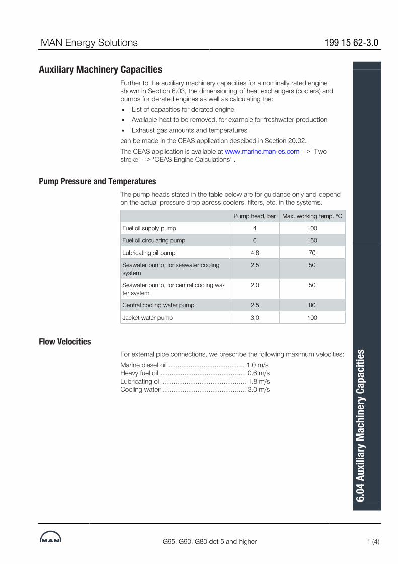
Auxiliary Machinery CapacitiesFurther to the auxiliary machinery capacities for a nominally rated engineshown in Section 6.03, the dimensioning of heat exchangers (coolers) andpumps for derated engines as well as calculating the:▪ List of capacities for derated engine▪ Available heat to be removed, for example for freshwater production▪ Exhaust gas amounts and temperaturescan be made in the CEAS application descibed in Section 20.02.The CEAS application is available at www.marine.man-es.com --> 'Twostroke' --> 'CEAS Engine Calculations' .
Pump Pressure and TemperaturesThe pump heads stated in the table below are for guidance only and dependon the actual pressure drop across coolers, filters, etc. in the systems.
Pump head, bar Max. working temp. °C
Fuel oil supply pump 4 100
Fuel oil circulating pump 6 150
Lubricating oil pump 4.8 70
Seawater pump, for seawater coolingsystem
2.5 50
Seawater pump, for central cooling wa-ter system
2.0 50
Central cooling water pump 2.5 80
Jacket water pump 3.0 100
Flow VelocitiesFor external pipe connections, we prescribe the following maximum velocities:Marine diesel oil ......................................... 1.0 m/s Heavy fuel oil .............................................. 0.6 m/s Lubricating oil ............................................. 1.8 m/s Cooling water ............................................. 3.0 m/s
MAN Energy Solutions 199 15 62-3.0
G95, G90, G80 dot 5 and higher 1 (4)
6.04
Aux
iliar
y Mac
hine
ry C
apac
ities
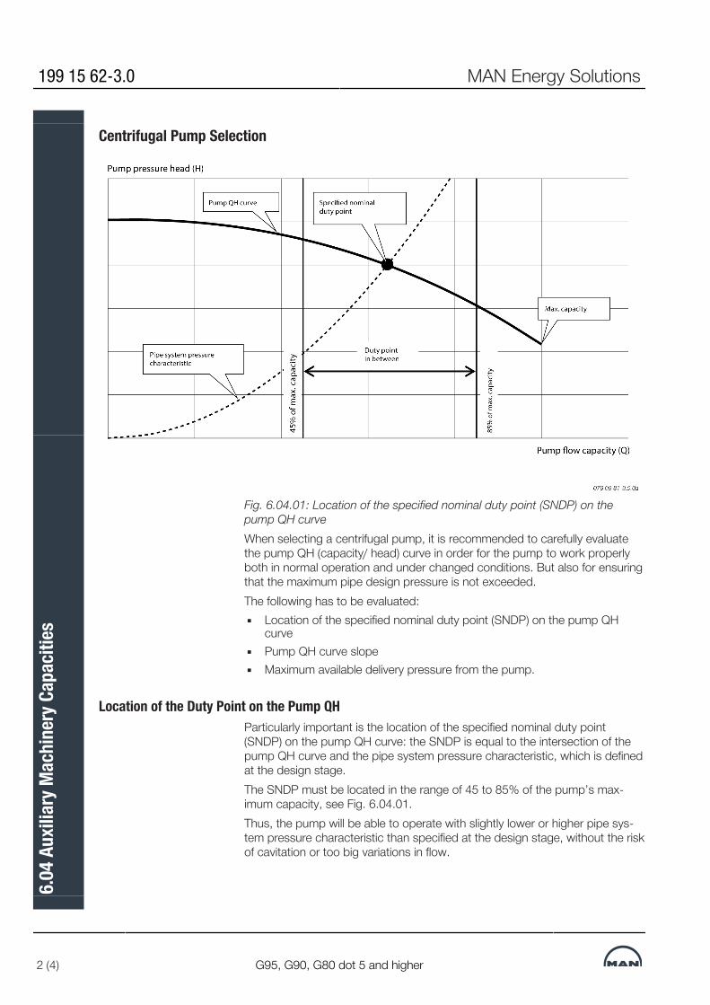
Centrifugal Pump Selection
Fig. 6.04.01: Location of the specified nominal duty point (SNDP) on thepump QH curveWhen selecting a centrifugal pump, it is recommended to carefully evaluatethe pump QH (capacity/ head) curve in order for the pump to work properlyboth in normal operation and under changed conditions. But also for ensuringthat the maximum pipe design pressure is not exceeded.The following has to be evaluated:▪ Location of the specified nominal duty point (SNDP) on the pump QH
curve▪ Pump QH curve slope▪ Maximum available delivery pressure from the pump.
Location of the Duty Point on the Pump QHParticularly important is the location of the specified nominal duty point(SNDP) on the pump QH curve: the SNDP is equal to the intersection of thepump QH curve and the pipe system pressure characteristic, which is definedat the design stage.The SNDP must be located in the range of 45 to 85% of the pump’s max-imum capacity, see Fig. 6.04.01.Thus, the pump will be able to operate with slightly lower or higher pipe sys-tem pressure characteristic than specified at the design stage, without the riskof cavitation or too big variations in flow.
199 15 62-3.0 MAN Energy Solutions
2 (4) G95, G90, G80 dot 5 and higher
6.04
Aux
iliar
y Mac
hine
ry C
apac
ities

Pump QH Curve SlopeAt the location of the SNDP, the pump capacity should not decrease by morethan 10% when the pressure is increased by 5%, see Fig. 6.04.02.This way, the flow stays acceptable even if the pipe system pressure is higherthan expected and the flow does not change too much, for example when athermostatic valve changes position.
Fig. 6.04.02: Pump QH curve slope
MAN Energy Solutions 199 15 62-3.0
G95, G90, G80 dot 5 and higher 3 (4)
6.04
Aux
iliar
y Mac
hine
ry C
apac
ities
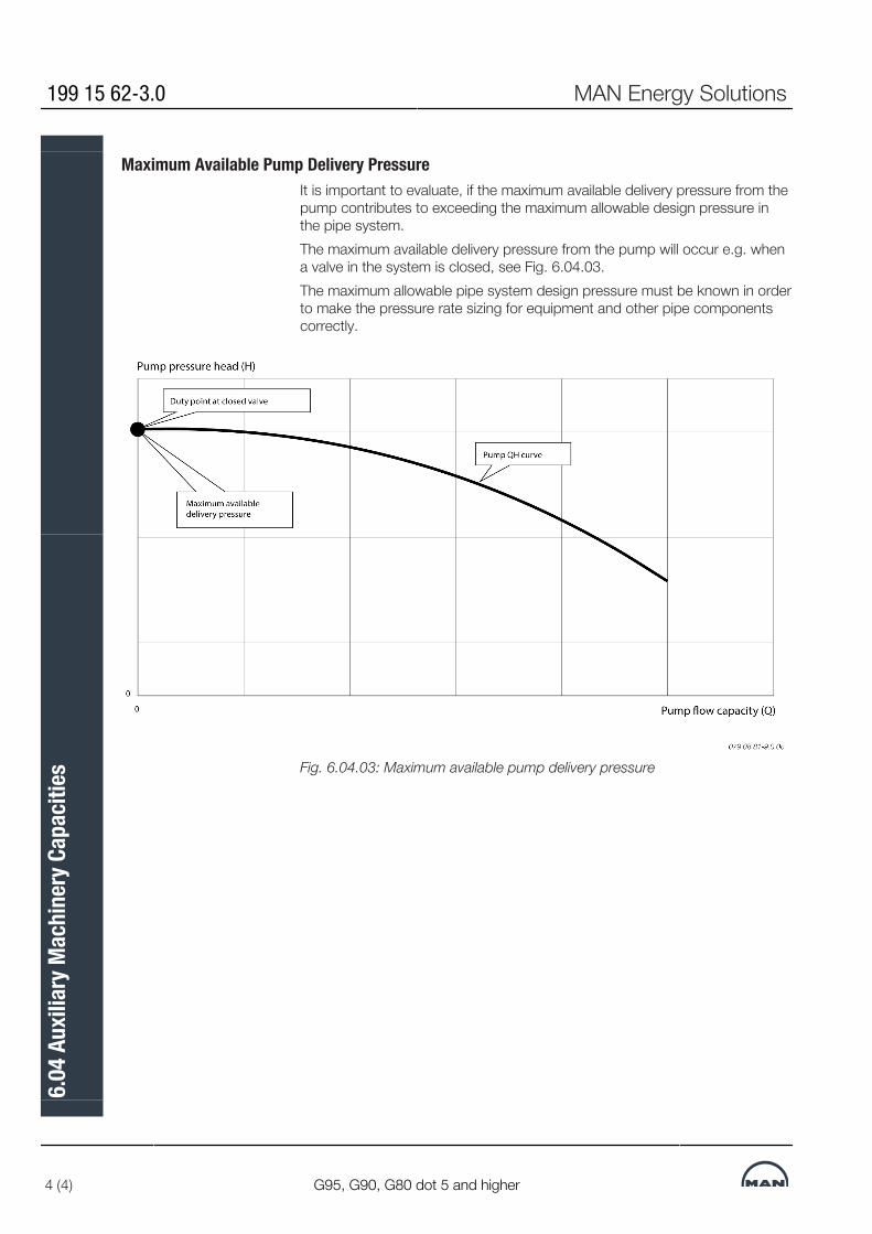
Maximum Available Pump Delivery PressureIt is important to evaluate, if the maximum available delivery pressure from thepump contributes to exceeding the maximum allowable design pressure inthe pipe system.The maximum available delivery pressure from the pump will occur e.g. whena valve in the system is closed, see Fig. 6.04.03.The maximum allowable pipe system design pressure must be known in orderto make the pressure rate sizing for equipment and other pipe componentscorrectly.
Fig. 6.04.03: Maximum available pump delivery pressure
199 15 62-3.0 MAN Energy Solutions
4 (4) G95, G90, G80 dot 5 and higher
6.04
Aux
iliar
y Mac
hine
ry C
apac
ities


MAN B&W
MAN Energy Solutions
Fuel
7


Pressurised Fuel Oil SystemThe system is so arranged that both diesel oil and heavy fuel oil can be used,see Fig. 7.01.01.From the service tank the fuel is led to an electrically driven supply pump bymeans of which a pressure of approximately 4 bar can be maintained in thelow pressure part of the fuel circulating system, thus avoiding gasification ofthe fuel in the venting box in the temperature ranges applied.The venting box is connected to the service tank via an automatic deaeratingvalve, which will release any gases present, but will retain liquids.From the low pressure part of the fuel system the fuel oil is led to an electric-ally-driven circulating pump, which pumps the fuel oil through a heater and afull flow filter situated immediately before the inlet to the engine.The fuel injection is performed by the electronically controlled pressurebooster located on the Hydraulic Cylinder Unit (HCU), one per cylinder, whichalso contains the actuator for the electronic exhaust valve activation.The Cylinder Control Units (CCU) of the Engine Control System (described inSection 16.01) calculate the timing of the fuel injection and the exhaust valveactivation.To ensure ample filling of the HCU, the capacity of the electrically-driven circu-lating pump is higher than the amount of fuel consumed by the diesel engine.Surplus fuel oil is recirculated from the engine through the venting box.To ensure a constant fuel pressure to the fuel injection pumps during all en-gine loads, a spring loaded overflow valve is inserted in the fuel oil system onthe engine.The fuel oil pressure measured on the engine (at fuel pump level) should be7-8 bar, equivalent to a circulating pump pressure of 10 bar.
Fuel ConsiderationsWhen the engine is stopped, the circulating pump will continue to circulateheated heavy fuel through the fuel oil system on the engine, thereby keepingthe fuel pumps heated and the fuel valves deaerated. This automatic circula-tion of preheated fuel during engine standstill is the background for our re-commendation: constant operation on heavy fuel.In addition, if this recommendation was not followed, there would be a latentrisk of diesel oil and heavy fuels of marginal quality forming incompatibleblends during fuel change over or when operating in areas with restrictions onsulphur content in fuel oil due to exhaust gas emission control.In special circumstances a change-over to diesel oil may become necessary –and this can be performed at any time, even when the engine is not running.Such a change-over may become necessary if, for instance, the vessel is ex-pected to be inactive for a prolonged period with cold engine e.g. due to:▪ docking▪ stop for more than five days▪ major repairs of the fuel system, etc.
MAN Energy Solutions 199 15 01-3.0
95-60 ME/ME-C/ME-B/-GI/-GA/-LGI 1 (7)
07.0
1 Pr
essu
rised
Fuel
Oil S
yste
m

The built-on overflow valves, if any, at the supply pumps are to be adjusted to5 bar, whereas the external bypass valve is adjusted to 4 bar. The pipesbetween the tanks and the supply pumps shall have minimum 50% largerpassage area than the pipe between the supply pump and the circulatingpump.If the fuel oil pipe ‘X’ at inlet to engine is made as a straight line immediately atthe end of the engine, it will be necessary to mount an expansion joint. If theconnection is made as indicated, with a bend immediately at the end of theengine, no expansion joint is required.
199 15 01-3.0 MAN Energy Solutions
2 (7) 95-60 ME/ME-C/ME-B/-GI/-GA/-LGI
07.0
1 Pr
essu
rised
Fuel
Oil S
yste
m

Fuel Oil System
MAN Energy Solutions 199 15 01-3.0
95-60 ME/ME-C/ME-B/-GI/-GA/-LGI 3 (7)
07.0
1 Pr
essu
rised
Fuel
Oil S
yste
m

1) MDO/MGO Cooler
For low-viscosity distillate fuels like marine gas oil (MGO), it is necessary to havea cooler to ensure that the viscosity at engine inlet is above 2 cSt.
Location of cooler: As shown or, alternatively, anywhere before inlet to engine.
2) Fuel oil flowmeter (Optional)
Flow rate: See ‘List of Capacities’ (same as fuel supply pump).Type: In case a damaged flow meter can block the fuel supply, a safety bypassvalve is to be placed across the flowmeter.
3) 0.23 litre/kWh in relation to certified Flow Rate (CFR); the engine SMCR can beused to determine the capacity. The separators should be capable of removingcat fines (Al+Si) from 80 ppm to a maximum level of 15 ppm Al+Si but preferablylower.Inlet temperature: Min. 98°C.
4) Valve in engine drain pipe
Valve in engine drain pipe is not acceptable. If the drain is blocked, the pressurebooster top cover seal will be damaged.In case a valve between the engine connection AD and the drain tank is required,the valve should be locked in open position and marked with a text, indicatingthat the valve must only be closed in case of no fuel oil pressure to the engine. Incase of non-return valve, the opening pressure for the valve has to be below 0.2bar.
5) MDO/MGO Cooler (Optional)
For protection of supply pumps against too warm oil and thus too low viscosity.
6) Transfer pump (Optional)
The transfer pump has to be able to return part of the content of the service tankto the settling tank to minimize the risk of supplying fuel to the engine with a highcontent of settled particles, e.g. cat fines, if the service tank has not been usedfor a while.
7) Name of flange connection
AF for engines with a bore of 60 cm and aboveAE for engines with a bore of 50 cm and below
a) Tracing, fuel oil lines: By jacket cooling water
b) Tracing, drain lines: By jacket cooling water– only for engines with bore of 60 cm and above
*) Optional installation
The letters refer to the list of ‘Counterflanges’
079 95 01-2.3.1
Fig. 7.01.01: Fuel oil system
199 15 01-3.0 MAN Energy Solutions
4 (7) 95-60 ME/ME-C/ME-B/-GI/-GA/-LGI
07.0
1 Pr
essu
rised
Fuel
Oil S
yste
m

Heavy Fuel Oil TankThis type of tank should be used for any residual fuel usage. (It can also beused for distillate fuel). The tank must be designed as high as possible andequipped with a sloping bottom in order to collect the solid particles settlingfrom the fuel oil.The tank outlet to the supply pumps must be placed above the slope to pre-vent solid particles to be drawn into the heavy fuel oil supply pumps. An over-flow pipe must be installed inside the tank below the pump outlet pipe to en-sure that only ‘contaminated’ fuel is pumped back to settling tank.A possibility of returning the day tank content to the settling tank must be in-stalled for cases where the day tank content have not been used for sometime.
Drain of Clean Fuel Oil from HCU, Pumps, PipesThe HCU Fuel Oil Pressure Booster has a leakage drain of clean fuel oil fromthe umbrella sealing through ‘AD’ to the fuel oil drain tank.The drain amount in litres per cylinder per hour is approximately as listed inTable 7.01.02.This drained clean oil will, of course, influence the measured SFOC, but the oilis not wasted, and the quantity is well within the measuring accuracy of theflowmeters normally used.
Engine bore, ME/ME-C, ME-B(incl. -GI & -LGI versions)
Flow rate,litres/cyl./hr.
98 On request
95, 90 1.7
80 2.1
70, 65 1.5
60 1.2
Table 7.01.02: Drain amount from fuel oil pump umbrella seal, figures for guid-ance
Leakage Oil Amount DependenciesDue to tolerances in the fuel pumps, the table figures may vary and are there-fore for guidance only. In fact, the leakage amount relates to the clearancebetween plunger and barrel in the third power. Thus, within the drawing toler-ances alone, the table figures can vary quite a lot.The engine load, however, has little influence on the drain amount becausethe leakage does not originate from the high-pressure side of the fuel pump.For the same reason, the varying leakage amount does not influence the in-jection itself.The figures in Table 7.01.02 are based on fuel oil with 12 cSt viscosity. Incase of distillate fuel oil, the figures can be up to 6 times higher due to thelower viscosity.
MAN Energy Solutions 199 15 01-3.0
95-60 ME/ME-C/ME-B/-GI/-GA/-LGI 5 (7)
07.0
1 Pr
essu
rised
Fuel
Oil S
yste
m
Fuel Oil Drains in Service and for OverhaulThe main purpose of the drain ‘AD’ is to collect fuel oil from the fuel pumps.The drain oil is led to an overflow tank and can be pumped to the heavy fueloil (HFO) tank or to the settling tank. In case of ultra low sulphur (ULSFO) ordistillate fuel oil, the piping should allow the fuel oil to be pumped to the ultralow sulphur or distillate fuel oil tank.As a safety measure for the crew during maintenance, an overhaul drain fromthe umbrella leads clean fuel oil from the umbrella directly to drain ‘AF’ andfurther to the sludge tank. Also washing water from the cylinder cover and thebaseplate is led to drain ‘AF’.The ‘AF’ drain is provided with a box for giving alarm in case of leakage in ahigh pressure pipe.The size of the sludge tank is determined on the basis of the draining inter-vals, the classification society rules, and on whether it may be vented directlyto the engine room.Drains ‘AD’, ‘AF’ and the drain for overhaul are shown in Fig. 7.03.01.
Drain of Contaminated Fuel etc.Leakage oil, in shape of fuel and lubricating oil contaminated with water, dirtetc. and collected by the HCU Base Plate top plate (ME only), as well as tur-bocharger cleaning water etc. is drained off through the bedplate drains ‘AE’.Drain ‘AE’ is shown in Fig. 8.07.02.
Heating of Fuel Drain PipesOwing to the relatively high viscosity of the heavy fuel oil, it is recommendedthat the drain pipes and the fuel oil drain tank are heated to min. 50°C, butmax. 100°C.The drain pipes between engine and tanks can be heated by the jacket water,as shown in Fig. 7.01.01 ‘Fuel oil system’ as flange ‘BD’. (Flange BD and thetracing line are not applicable on MC/ MC-C engines type 42 and smaller).
Fuel Oil Flow Velocity and ViscosityFor external pipe connections, we prescribe the following maximum flow vel-cities:Marine diesel oil .......................................... 1.0 m/sHeavy fuel oil ............................................... 0.6 m/sThe fuel viscosity is influenced by factors such as emulsification of water intothe fuel for reducing the NOx emission.
Cat FinesCat fines is a by-product from the catalytic cracking used in fuel distillation.Cat fines is an extremely hard material, very abrasive and damaging to the en-gine and fuel equipment. It is recommended always to purchase fuel with aslow cat fines content as possible.
199 15 01-3.0 MAN Energy Solutions
6 (7) 95-60 ME/ME-C/ME-B/-GI/-GA/-LGI
07.0
1 Pr
essu
rised
Fuel
Oil S
yste
m

Cat fines can to some extent be removed from the fuel by means of a goodand flexible tank design and by having optimum conditions for the separator interms of flow and high temperature.Further information about fuel oil specifications and other fuel considerationsis available in our publications:Guidelines for Fuels and Lubes PurchasingGuidelines for Operation on Fuels with less than 0.1% SulphurThe publications are available at www.marine.man-es.com --> 'Two-Stroke'--> 'Technical Papers'.
MAN Energy Solutions 199 15 01-3.0
95-60 ME/ME-C/ME-B/-GI/-GA/-LGI 7 (7)
07.0
1 Pr
essu
rised
Fuel
Oil S
yste
m
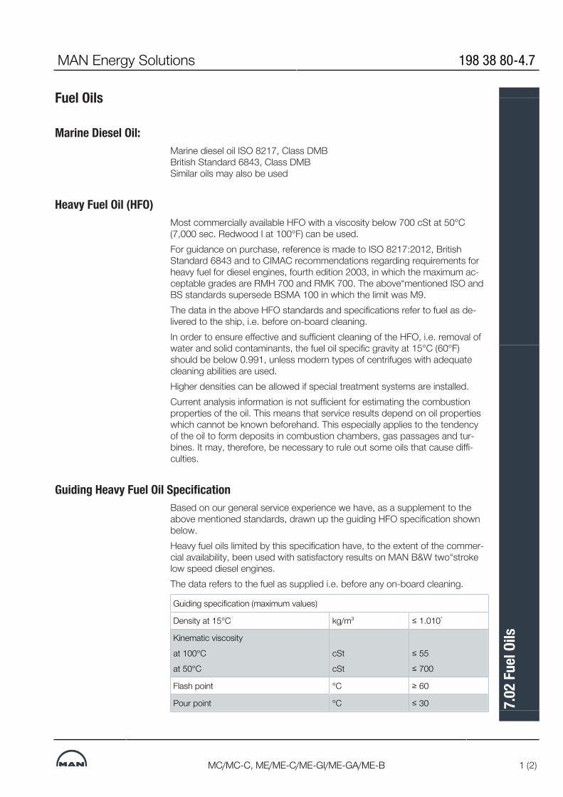
Fuel Oils
Marine Diesel Oil:Marine diesel oil ISO 8217, Class DMBBritish Standard 6843, Class DMBSimilar oils may also be used
Heavy Fuel Oil (HFO)Most commercially available HFO with a viscosity below 700 cSt at 50°C(7,000 sec. Redwood I at 100°F) can be used.For guidance on purchase, reference is made to ISO 8217:2012, BritishStandard 6843 and to CIMAC recommendations regarding requirements forheavy fuel for diesel engines, fourth edition 2003, in which the maximum ac-ceptable grades are RMH 700 and RMK 700. The above“mentioned ISO andBS standards supersede BSMA 100 in which the limit was M9.The data in the above HFO standards and specifications refer to fuel as de-livered to the ship, i.e. before on-board cleaning.In order to ensure effective and sufficient cleaning of the HFO, i.e. removal ofwater and solid contaminants, the fuel oil specific gravity at 15°C (60°F)should be below 0.991, unless modern types of centrifuges with adequatecleaning abilities are used.Higher densities can be allowed if special treatment systems are installed.Current analysis information is not sufficient for estimating the combustionproperties of the oil. This means that service results depend on oil propertieswhich cannot be known beforehand. This especially applies to the tendencyof the oil to form deposits in combustion chambers, gas passages and tur-bines. It may, therefore, be necessary to rule out some oils that cause diffi-culties.
Guiding Heavy Fuel Oil SpecificationBased on our general service experience we have, as a supplement to theabove mentioned standards, drawn up the guiding HFO specification shownbelow.Heavy fuel oils limited by this specification have, to the extent of the commer-cial availability, been used with satisfactory results on MAN B&W two“strokelow speed diesel engines.The data refers to the fuel as supplied i.e. before any on-board cleaning.
Guiding specification (maximum values)
Density at 15°C kg/m3 ≤ 1.010*
Kinematic viscosity
at 100°C
at 50°C
cSt
cSt
≤ 55
≤ 700
Flash point °C ≥ 60
Pour point °C ≤ 30
MAN Energy Solutions 198 38 80-4.7
MC/MC-C, ME/ME-C/ME-GI/ME-GA/ME-B 1 (2)
7.02
Fuel
Oils

Carbon residue % (m/m) ≤ 20
Ash % (m/m) ≤ 0.15
Total sediment potential % (m/m) ≤ 0.10
Water % (v/v) ≤ 0.5
Sulphur % (m/m) ≤ 4.5
Vanadium mg/kg ≤ 450
Aluminum + Silicon mg/kg ≤ 60
Equal to ISO 8217:2010 - RMK 700 / CIMAC recommendation No. 21 - K700
* Provided automatic clarifiers are installed
m/m = mass
v/v = volume
If heavy fuel oils with analysis data exceeding the above figures are to beused, especially with regard to viscosity and specific gravity, the enginebuilder should be contacted for advice regarding possible fuel oil systemchanges.
198 38 80-4.7 MAN Energy Solutions
2 (2) MC/MC-C, ME/ME-C/ME-GI/ME-GA/ME-B
7.02
Fuel
Oils

Fuel Oil Pipes and Drain Pipes
The letters refer to list of ‘Counterflanges’The item nos. refer to ‘Guidance values automation’Fig. 7.03.01: Fuel oil and drain pipes
MAN Energy Solutions 198 91 13-4.3
G/S95-60ME-C10/9/-GI/-GA/-LGI,S/L80-60ME-C8-GI/-LGI 1 (1)
7.03
Fuel
Oil P
ipes
and
Dra
in P
ipes
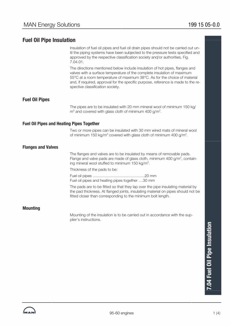
Fuel Oil Pipe InsulationInsulation of fuel oil pipes and fuel oil drain pipes should not be carried out un-til the piping systems have been subjected to the pressure tests specified andapproved by the respective classification society and/or authorities, Fig.7.04.01.The directions mentioned below include insulation of hot pipes, flanges andvalves with a surface temperature of the complete insulation of maximum55°C at a room temperature of maximum 38°C. As for the choice of materialand, if required, approval for the specific purpose, reference is made to the re-spective classification society.
Fuel Oil PipesThe pipes are to be insulated with 20 mm mineral wool of minimum 150 kg/m3 and covered with glass cloth of minimum 400 g/m2.
Fuel Oil Pipes and Heating Pipes TogetherTwo or more pipes can be insulated with 30 mm wired mats of mineral woolof minimum 150 kg/m3 covered with glass cloth of minimum 400 g/m2.
Flanges and ValvesThe flanges and valves are to be insulated by means of removable pads.Flange and valve pads are made of glass cloth, minimum 400 g/m2, contain-ing mineral wool stuffed to minimum 150 kg/m3.Thickness of the pads to be:Fuel oil pipes ................................................20 mmFuel oil pipes and heating pipes together ....30 mmThe pads are to be fitted so that they lap over the pipe insulating material bythe pad thickness. At flanged joints, insulating material on pipes should not befitted closer than corresponding to the minimum bolt length.
MountingMounting of the insulation is to be carried out in accordance with the sup-plier’s instructions.
MAN Energy Solutions 199 15 05-0.0
95-60 engines 1 (4)
7.04
Fuel
Oil P
ipe I
nsul
atio
n

Fig. 7.04.01: Details of fuel oil pipes insulation, option: 4 35 121. Examplefrom 98-50 MC engine
Heat Loss in Piping
Fig. 7.04.02: Heat loss/Pipe cover
199 15 05-0.0 MAN Energy Solutions
2 (4) 95-60 engines
7.04
Fuel
Oil P
ipe I
nsul
atio
n

Fuel Oil Pipe Heat TracingThe steam tracing of the fuel oil pipes is intended to operate in two situations:
1. When the circulation pump is running, there will be a temperature loss in the pip-ing, see Fig. 7.04.02. This loss is very small, therefore tracing in this situation isonly necessary with very long fuel supply lines.
2. When the circulation pump is stopped with heavy fuel oil in the piping and thepipes have cooled down to engine room temperature, as it is not possible topump the heavy fuel oil. In this situation the fuel oil must be heated to pumpingtemperature of about 50˚C.
To heat the pipe to pumping level we recommend to use 100 watt leaking/meterpipe.
Fig. 7.04.03: Fuel oil pipe heat tracing
Fuel Oil and Lubricating Oil Pipe Spray ShieldsTo fulfill IMO regulations, fuel and oil pipe assemblies are to be secured byspray shields.The shields can be made either by a metal flange cover according to IMOMSC/Circ.647 or antisplashing tape wrapped according to makers instructionfor Class approval, see examples shown in Fig. 7.04.04a and b.To ensure tightness, the spray shields are to be applied after pressure test ofthe pipe system.
MAN Energy Solutions 199 15 05-0.0
95-60 engines 3 (4)
7.04
Fuel
Oil P
ipe I
nsul
atio
n

Fig. 7.04.04a: Metal flange cover and clamping band
Fig. 7.04.04b: Anti-splashing tape (FN tape)
199 15 05-0.0 MAN Energy Solutions
4 (4) 95-60 engines
7.04
Fuel
Oil P
ipe I
nsul
atio
n

Components for Fuel Oil System
Fuel Oil SeparatorThe manual cleaning type of separators are not to be recommended. Separ-ators must be self-cleaning, either with total discharge or with partiadischarge.Distinction must be made between installations for:▪ Specific gravities < 0.991 (corresponding to ISO 8217: RMA-RMD grades
and British Standard 6843 from RMA to RMH, and CIMAC from A to H-grades)
▪ Specific gravities > 0.991 (corresponding to ISO 8217: RME-RMK gradesand CIMAC K-grades).
For the latter specific gravities, the manufacturers have developed specialtypes of separators, e.g.:Alfa Laval ........................................................AlcapWestfalia .......................................................UnitrolMitsubishi ..............................................E-Hidens IIMAN Energy Solutions also recommends using high-temperature separators,which will increase the efficiency.The separator should be able to treat approximately the following quantity ofoil:
0.23 litres/kWh in relation to CFR (certified flow rate)
This figure includes a margin for:▪ water content in fuel oil▪ possible sludge, ash and other impurities in the fuel oil▪ increased fuel oil consumption, in connection with other conditions than
ISO standard condition▪ purifier service for cleaning and maintenance.The Specified MCR can be used to determine the capacity. The separator ca-pacity must always be higher than the calculated capacity.Inlet temperature to separator, minimum .......98°C
CFR according to CEN, CWA 15375The size of the separator has to be chosen according to the supplier’s tablevalid for the selected viscosity of the Heavy Fuel Oil and in compliance withCFR or similar. Normally, two separators are installed for Heavy Fuel Oil (HFO),each with adequate capacity to comply with the above recommendation.A separator for Marine Diesel Oil (MDO) is not a must. However, MAN EnergySolutions recommends that at least one of the HFO separators can also treatMDO.If it is decided after all to install an individual purifier for MDO on board, the ca-pacity should be based on the above recommendation, or it should be a sep-arator of the same size as that for HFO.It is recommended to follow the CIMAC Recommendation 25:Recommendations concerning the design of heavy fuel treatment plants fordiesel engines.
MAN Energy Solutions 198 39 51-2.10
All engines 1 (8)
7.05
Com
pone
nts f
or Fu
el Oi
l Sys
tem
Fuel Oil Supply PumpFuel oil viscosity, specified ....up to 700 cSt at 50°CFuel oil viscosity, maximum ....................... 700 cStFuel oil viscosity, minimum ............................ 2 cStPump head ................................................... 4 barFuel oil flow ........................ see ‘List of Capacities’Delivery pressure ........................................... 4 barWorking temperature, maximum ............. 110°C *)*) If a high temperature separator is used, higher working temperature relatedto the separator must be specified.The capacity stated in ‘List of Capacities’ is to be fulfilled with a tolerance of:–0% to +15% and shall also be able to cover the back-flushing, see ‘Fuel oilfilter’.
Fuel Oil Circulating PumpThis is to be of the screw or gear wheel type.Fuel oil viscosity, specified ....up to 700 cSt at 50°CFuel oil viscosity normal ............................... 20 cStFuel oil viscosity, maximum ....................... 700 cStFuel oil viscosity, minimum ............................ 2 cStFuel oil flow ......................... see ‘List of Capacities’Pump head ................................................... 6 barDelivery pressure ..........................................10 barWorking temperature .................................. 150°CThe capacity stated in ‘List of Capacities’ is to be fulfilled with a tolerance of: –0% to +15% and shall also be able to cover the back-flushing, see ‘Fuel oilfilter’.Pump head is based on a total pressure drop in filter and preheater of max-imum 1.5 bar.
198 39 51-2.10 MAN Energy Solutions
2 (8) All engines
7.05
Com
pone
nts f
or Fu
el Oi
l Sys
tem

Fuel Oil HeaterThe heater is to be of the tube or plate heat exchanger type.The required heating temperature for different oil viscosities will appear fromthe ‘Fuel oil heating chart’, Fig. 7.05.01. The chart is based on informationfrom oil suppliers regarding typical marine fuels with viscosity index 70-80.Fig. 7.05.01: Fuel oil heating chartSince the viscosity after the heater is the controlled parameter, the heatingtemperature may vary, depending on the viscosity and viscosity index of thefuel.Recommended viscosity meter setting is 10-15 cSt.Fuel oil viscosity specified ... up to 20 cSt at 150°C fuel oil circulating pumpHeat dissipation ................. see ‘List of Capacities’ Pressure drop on fuel oilside, maximum ..................................... 1 bar at 15 cStWorking pressure ..........................................10 barFuel oil outlet temperature ...........................150°CSteam supply, saturated ..........................7 bar absTo maintain a correct and constant viscosity of the fuel oil at the inlet to themain engine, the steam supply shall be automatically controlled, usually basedon a pneumatic or an electrically controlled system.
MAN Energy Solutions 198 39 51-2.10
All engines 3 (8)
7.05
Com
pone
nts f
or Fu
el Oi
l Sys
tem

Fuel Oil FilterThe filter can be of the manually cleaned duplex type or an automatic filterwith a manually cleaned bypass filter.If a double filter (duplex) is installed, it should have sufficient capacity to allowthe specified full amount of oil to flow through each side of the filter at a givenworking temperature with a max. 0.3 bar pressure drop across the filter (cleanfilter).If a filter with backflushing arrangement is installed, the following should benoted. The required oil flow specified in the ‘List of capacities’, i.e. the deliveryrate of the fuel oil supply pump and the fuel oil circulating pump, should be in-creased by the amount of oil used for the backflushing, so that the fuel oilpressure at the inlet to the main engine can be maintained during cleaning.In those cases where an automatically cleaned filter is installed, it should benoted that in order to activate the cleaning process, certain makers of filtersrequire a greater oil pressure at the inlet to the filter than the pump pressurespecified. Therefore, the pump capacity should be adequate for this purpose,too.Alternatively positioned in the supply circuit after the supply pumps, the filterhas the same flow rate as the fuel oil supply pump. In this case, a duplexsafety filter has to be placed in the circulation circuit before the engine. Theabsolute fineness of the safety filter is recommended to be maximum 60 μmand the flow rate the same as for the circulation oil pump.The fuel oil filter should be based on heavy fuel oil of: 130 cSt at 80°C = 700cSt at 50°C = 7,000 sec Redwood I/100°F.Fuel oil flow ............................see ‘Capacity of fuel oil circulating pump’Working pressure ..........................................10 barTest pressure ..................... according to Class ruleAbsolute fineness, maximum ........................10 μmWorking temperature, maximum .................150°COil viscosity at working temperature, Oil viscosity at working temperature,maximum ...................................................20 cStPressure drop at clean filter,maximum ..................................................0.3 barFilter to be cleaned at a pressuredrop of ......................................................0.5 barNote:Some filter makers refer the fineness of the filters to be ‘nominal fineness’.Thus figures will be approximately 40% lower than the ‘absolute fineness’ (6μm nominal).The filter housing shall be fitted with a steam jacket for heat tracing.Further information about cleaning heavy fuel oil and other fuel oil types isavailable in MAN Energy Solutions' most current Service Letters on this sub-ject.The Service Letters are available at www.marine.man-es.com --> ’ServiceLetters’.
198 39 51-2.10 MAN Energy Solutions
4 (8) All engines
7.05
Com
pone
nts f
or Fu
el Oi
l Sys
tem

Fuel Oil Filter (Option)Located as shown in drawing or alternatively in the supply circuit after thesupply pumps. In this case, a duplex safety filter has to be placed in the circu-lation circuit before the engine, with an absolute fineness of maximum 60 μm.
Pipe Diameter ‘D’ & ‘d’The pipe (D) between the service tank and the supply pump is to have min-imum 50% larger passage area than the pipe (d) between the supply pumpand in the circulating pump. This ensures the best suction conditions for thesupply pump (small pressure drop in the suction pipe).
Overflow ValveSee ‘List of Capacities’ (fuel oil supply oil pump).
Flushing of the Fuel Oil SystemBefore starting the engine for the first time, the system on board has to beflushed in accordance with MAN Energy Solutions recommendations:Flushing of Fuel Oil Systemwhich is available from MAN Energy Solutions, Copenhagen.
Fuel Oil Venting BoxThe design of the fuel oil venting box is shown in Fig. 7.05.02. The size ischosen according to the maximum flow of the fuel oil circulation pump, whichis listed in section 6.03.The venting tank has to be placed at the top service tank. If the venting tank isplaced below the top of the service tank, the drain pipe from the automaticventing valve has to be led to a tank placed lower than the venting valve. Thelower tank can be a ‘Fuel oil over flow tank’, if this tank has venting to deck.
MAN Energy Solutions 198 39 51-2.10
All engines 5 (8)
7.05
Com
pone
nts f
or Fu
el Oi
l Sys
tem

Flowm3/h Q(max.)*
Dimensions in mm
D1 D2 D3 H1 H2 H3 H4 H5
1.3 150 32 15 100 600 171.3 1,000 550
2.1 150 40 15 100 600 171.3 1,000 550
5.0 200 65 15 100 600 171.3 1,000 550
8.4 400 80 15 150 1,200 333.5 1,800 1,100
11.5 400 90 15 150 1,200 333.5 1,800 1,100
19.5 400 125 15 150 1,200 333.5 1,800 1,100
29.4 500 150 15 150 1,500 402.4 2,150 1,350
43.0 500 200 15 150 1,500 402.4 2,150 1,350
* The maximum flow of the fuel oil circulation pumpFig. 07.05.02: Fuel oil venting box
Cooling of Distillate FuelsThe external fuel systems (supply and circulating systems) have a varying ef-fect on the heating of the fuel and, thereby, the viscosity of the fuel when itreaches the engine inlet.Today, external fuel systems on-board are often designed to have an op-timum operation on HFO, which means that the temperature is kept high.
198 39 51-2.10 MAN Energy Solutions
6 (8) All engines
7.05
Com
pone
nts f
or Fu
el Oi
l Sys
tem

For low-viscosity distillate fuels like marine diesel oil (MDO) and marine gas oil(MGO), however, the temperature must be kept as low as possible in order toensure a suitable viscosity at engine inlet.
Fuel Oil Viscosity at Engine InletThe recommended fuel viscosity range for MAN B&W two-stroke engines atengine inlet is listed in Table 7.05.03.
The lower fuel viscosity limit is 2 cSt
However, 3 cSt or higher is preferable as this will minimise the risk of havingproblems caused by wear for instance.For low-viscosity fuel grades, care must be taken not to heat the fuel toomuch and thereby reduce the viscosity.
Range Fuel viscosity at engine inlet, cSt
Minimum 2
Normal, distillate 3 or higher
Normal, HFO 10-15
Maximum 20
Table 7.05.03: Recommended fuel viscosity at engine inletInformation about temperature – viscosity relationship of marine fuels is avail-able in our publication:Guidelines for Operation on Fuels with less than 0.1% Sulphur, SL2014-593The publication is available at www.marine.man-es.com -->'Service Letters'.
Impact of Fuel Viscosity on Engine OperationMany factors influence the actually required minimum viscosity tolerance dur-ing start-up and lowload operation:▪ engine condition and maintenance▪ fuel pump wear▪ engine adjustment (mainly starting index)▪ actual fuel temperature in the fuel systemAlthough achievable, it is difficult to optimize all of these factors at the sametime. This situation complicates operation on fuels in the lowest end of the vis-cosity range.
Fuel Oil CoolerTo build in some margin for safe and reliable operation and to maintain the re-quired viscosity at engine inlet, installation of a cooler will be necessary asshown in Fig. 7.01.01.
MAN Energy Solutions 198 39 51-2.10
All engines 7 (8)
7.05
Com
pone
nts f
or Fu
el Oi
l Sys
tem

Viscosity Requirements of Fuel Pumps etc.The fuel viscosity does not only affect the engine. In fact, most pumps in theexternal system (supply pumps, circulating pumps, transfer pumps and feedpumps for the separator) also need viscosities above 2 cSt to function prop-erly.MAN Energy Solutions recommends contacting the actual pump maker foradvice.
198 39 51-2.10 MAN Energy Solutions
8 (8) All engines
7.05
Com
pone
nts f
or Fu
el Oi
l Sys
tem

MAN B&W
MAN Energy Solutions
Lubricating Oil
8


Lubricating and Cooling Oil SystemThe lubricating oil is pumped from a bottom tank by means of the main lubric-ating oil pump to the lubricating oil cooler, a thermostatic valve and, through afull-flow filter, to the engine inlet RU, Fig. 8.01.01.RU lubricates main bearings, thrust bearing, axial vibration damper, pistoncooling, crosshead bearings, crankpin bearings. It also supplies oil to the Hy-draulic Power Supply unit, moment compensator, torsional vibration damper,exhaust valve and Hydraulic Cylinder Unit.From the engine, the oil collects in the oil pan, from where it is drained off tothe bottom tank, see Fig. 8.06.01a and b ‘Lubricating oil tank, with coffer-dam’. By class demand, a cofferdam must be placed underneath the lubricat-ing oil tank.The engine crankcase is vented through ‘AR’ by a pipe which extends directlyto the deck. This pipe has a drain arrangement so that oil condensed in thepipe can be led to a drain tank, see details in Fig. 8.07.01.Drains from the engine bedplate ‘AE’ are fitted on both sides, see Fig. 8.07.02‘Bedplate drain pipes’. For external pipe connections, we prescribe a max-imum oil velocity of 1.8 m/s.
Lubrication of TurbochargersTurbochargers with slide bearings are normally lubricated from the main en-gine system. AB is outlet from the turbocharger, see Figs. 8.03.01 to 8.03.04.Figs. 8.03.01 to 8.03.04 show the lube oil pipe arrangements for various tur-bocharger makes.
Fig. 8.01.01 Lubricating and cooling oil system
MAN Energy Solutions 199 15 06-2.0
ME/ME-C engines 1 (4)
8.01
Lubr
icatin
g an
d Co
olin
g Oi
l Sys
tem

Turbocharger Venting and Drain Pipes
MANType No. of TC Venting pipe Drain
Each TC DN Collect TC DN Pipe from TCDN
TCR22 1 50 50 65
TCA44 1 65 65 65
2 65 100 100
TCA55 1 65 65 65
2 65 100 100
TCA66 1 80 80 80
2 80 125 125
TCA77 1 100 100 100
2 100 125 125
TCA88 1 125 125 125
2 125 150 150
3 125 200 200
4 125 250 250
ABBType No. of TC Venting pipe Drain
Each TC DN Collect TC DN Pipe from TCDN
A165-LA265-L
1 60 65 65
2 60 80 80
A170-LA270-L
1 65 65 65
2 65 90 90
A175-LA275-L
1 65 65 65
2 65 100 100
3 65 125 125
A180-LA280-L
1 80 80 80
2 80 100 100
3 80 125 125
A185-LA285-L
1 80 80 80
2 80 125 125
199 15 06-2.0 MAN Energy Solutions
2 (4) ME/ME-C engines
8.01
Lubr
icatin
g an
d Co
olin
g Oi
l Sys
tem

3 80 150 150
4 80 150 150
A190-LA290-L
1 80 80 80
2 80 125 125
3 80 150 150
4 80 175 175
A195-LA295-L* )
1 80 90 90
2 80 125 125
3 80 150 150
4 80 175 175
Mitsubishi (MHI)Type No. of TC Venting pipe Drain
Each TC DN Collect TC DN Pipe from TCDN
MET33 1 40 40 65
2 40 80 90
MET42 1 50 50 80
2 50 65 125
MET53 1 65 65 90
2 65 80 125
3 65 100 150
MET66 1 80 80 100
2 80 100 150
3 80 125 175
4 80 150 225
MET71 1 80 80 125
2 80 100 175
3 80 125 225
4 80 150 300
MET83 1 100 100 125
2 100 125 175
3 100 150 225
4 100 175 300
MET90 1 100 100 125
2 100 125 175
3 100 150 225
MAN Energy Solutions 199 15 06-2.0
ME/ME-C engines 3 (4)
8.01
Lubr
icatin
g an
d Co
olin
g Oi
l Sys
tem

4 100 175 300
Table. 8.01.02: Turbocharger venting and drain pipesFor size of turbocharger inlet pipe see ‘List of capacities’* ) PreIiminary
079 27 21-4.8.1
199 15 06-2.0 MAN Energy Solutions
4 (4) ME/ME-C engines
8.01
Lubr
icatin
g an
d Co
olin
g Oi
l Sys
tem

Hydraulic Power Supply UnitHydraulic power for the ME hydraulic-mechanical system for activation of thefuel injection and the exhaust valve is supplied by the Hydraulic Power Supply(HPS) unit.As hydraulic medium, normal lubricating oil is used, as standard taken fromthe engine’s main lubricating oil system and filtered in the HPS unit.
HPS Connection to Lubrication Oil SystemInternally on the engine, the system oil inlet RU is connected to the HPS unitwhich supplies the hydraulic oil to the Hydraulic Cylinder Units (HCUs). SeeFigs. 16.01.02a and 16.01.02b.RW is the oil outlet from the automatic backflushing filter.The hydraulic oil is supplied to the Hydraulic Cylinder Units (HCU) located ateach cylinder. From here the hydraulic oil is diverted to the multi-way valves,which perform the fuel injection and open the exhaust valve respectively: Elec-tronic Fuel Injection (ELFI) and Proportional Exhaust Valve Actuator (PEVA).The exhaust valve is closed by the conventional ‘air spring’.The electronic signals to the multi-way valves are given by the Engine ControlSystem, see Chapter 16, Engine Control System (ECS).
HPS ConfigurationsThe HPS pumps are driven either mechanically by the engine (via a step-upgear from the crankshaft) or electrically.The HPS unit is mounted on the engine no matter how its pumps are driven.With mechanically driven pumps, the HPS unit consists of:▪ an automatic and a redundant filter▪ three to five engine driven main pumps▪ two electrically driven start-up pumps▪ a safety and accumulator blockas shown in Fig. 8.02.01.With electrically driven pumps, the HPS unit differs in having a total of threepumps which serve as combined main and start-up pumps.
Motor Start MethodDirect Online Start (DOL) is required for all the electric motors for the pumpsfor the Hydraulic Power Supply (HPS) to ensure proper operation under allconditions, including the start up against maximum pressure in the system.
HPS unit typesAltogether, three HPS configurations are available:▪ STANDARD mechanically driven HPS, EoD: 4 40 160, with mechanically
driven main pumps and start-up pumps with capacity sufficient to deliverthe start-up pressure only. The engine cannot run with all engine drivenmain pumps out of operation, whereas 66% engine load is available incase one main pump is out.
2021
-08-
31 -
en
MAN Energy Solutions 199 15 07-4.0
95-60ME/ME-C/-GI 1 (3)
8.02
Hyd
raul
ic Po
wer S
uppl
y Uni
t

▪ COMBINED mechanically driven HPS unit, EoD: 4 40 167 with electricallydriven start-up pumps with back-up capacity. In this case, at least 15%engine power is available as back-up power if all engine driven pumps areout
2021
-08-
31 -
en
199 15 07-4.0 MAN Energy Solutions
2 (3) 95-60ME/ME-C/-GI
8.02
Hyd
raul
ic Po
wer S
uppl
y Uni
t
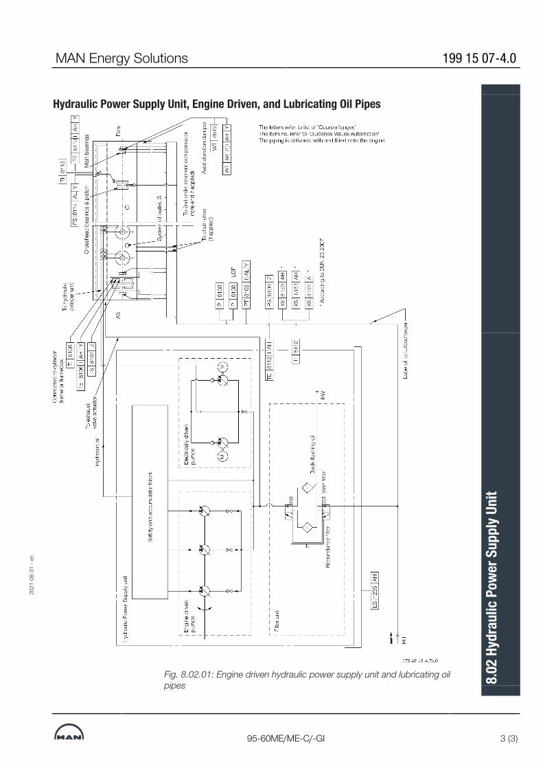
Hydraulic Power Supply Unit, Engine Driven, and Lubricating Oil Pipes
Fig. 8.02.01: Engine driven hydraulic power supply unit and lubricating oilpipes
2021
-08-
31 -
en
MAN Energy Solutions 199 15 07-4.0
95-60ME/ME-C/-GI 3 (3)
8.02
Hyd
raul
ic Po
wer S
uppl
y Uni
t

Lubricating Oil Pipes for Turbochargers
Fig. 8.03.01: MAN turbocharger type TCA Fig. 8.03.02: Mitsubishi turbocharger type MET
Fig. 8.03.03: ABB turbocharger type A-L
MAN Energy Solutions 198 42 32-8.6
ME/ME-C/ME-B/-GI/-GA/-LGI 1 (1)
8.03
Lubr
icatin
g Oi
l Pip
es fo
r Tur
boch
arge
rs

Lubricating Oil Consumption, Centrifuges and List of Lubricating Oils
Lubricating oil consumptionThe system oil consumption from the ship’s system oil plant depends onfactors like back flushing from the purifiers and drain from stuffing boxes.Furthermore, the consumption varies for different engine sizes as well as op-erational and maintenance patterns.
Lubricating oil centrifugesAutomatic centrifuges are to be used, either with total discharge or partial dis-charge.The nominal capacity of the centrifuge is to be according to the supplier’s re-commendation for lubricating oil, based on the figure:0.136 litre/kWhThe Nominal MCR is used as the total installed power.Further information about lubricating oil qualities is available in our publication:Guidelines for Fuels and Lubes PurchasingThe publication is available at www.marine.man-es.com --> ’Two-Stroke’ -->’Technical Papers’.Recommendations regarding engine lubrication is available in MAN EnergySolutions' most current Service Letters on this subject.The Service Letters are available at www.marine.man-es.com --> 'Two-Stroke' --> 'Service Letters'.
List of Lubricating OilsThe circulating oil (lubricating and cooling oil) must be of the rust and oxida-tion inhibited type of oil of SAE 30 viscosity grade.In short, MAN Energy Solutions recommends the use of system oils with thefollowing main properties:▪ SAE 30 viscosity grade▪ BN level 5 - 10▪ adequately corrosion and oxidation inhibited▪ adequate detergengy and dispersancy.The adequate dispersion and detergent properties are in order to keep thecrankcase and piston cooling spaces clean of deposits.Alkaline circulating oils are generally superior in this respect.The major international system oil brands listed below have been tested inservice with acceptable results.
Company Circulating oil SAE 30, BN 5 10
MAN Energy Solutions 198 38 86-5.13
All engines 1 (2)
8.04
Lubr
icatin
g Oi
l Con
sum
ptio
n, C
entri
fuge
s and
List
of
Lubr
icatin
g Oi
ls

AegeanCastrolChevron ExxonMobil Gulf Oil Marine Indian Oil Corp. JX Nippon Oil & Energy Lukoil Shell Sinopec Total
Alfasys 305 Castrol CDX 30Veritas 800 Marine 30Mobilgard 300GulfSea Superbear 3006Servo Marine 0530Marine S30Navigo 6 SOMelina S 30System Oil 3005Atlanta Marine D3005
Do not consider the list complete, as oils from other companies can beequally suitable. Further information can be obtained from the engine builderor MAN Energy Solutions, Copenhagen.
198 38 86-5.13 MAN Energy Solutions
2 (2) All engines
8.04
Lubr
icatin
g Oi
l Con
sum
ptio
n, C
entri
fuge
s and
List
of
Lubr
icatin
g Oi
ls

Components for Lubricating Oil System
Lubricating Oil PumpThe lubricating oil pump can be of the displacement wheel or the centrifugaltype:Lubricating oil viscosity, specified ...75 cSt at 50°C Lubricating oil viscosity ...........maximum 400 cSt * Lubricating oil flow .............. see ‘List of capacities’ Design pump head .......................................4.8 bar Delivery pressure .........................................4.8 bar Max. working temperature ............................. 70°C* 400 cSt is specified, as it is normal practice when starting on cold oil, topartly open the bypass valves of the lubricating oil pumps, so as to reduce theelectric power requirements for the pumps.The flow capacity must be within a range from 100 to 112% of the capacitystated.The pump head is based on a total pressure drop across cooler and filter ofmaximum 1 bar.Referring to Fig. 8.01.01, the bypass valve shown between the main lubricat-ing oil pumps may be omitted in cases where the pumps have a built-in by-pass or if centrifugal pumps are used.If centrifugal pumps are used, it is recommended to install a throttle valve atposition ‘005’ to prevent an excessive oil level in the oil pan if the centrifugalpump is supplying too much oil to the engine.During trials, the valve should be adjusted by means of a device which per-mits the valve to be closed only to the extent that the minimum flow areathrough the valve gives the specified lubricating oil pressure at the inlet to theengine at full normal load conditions. It should be possible to fully open thevalve, e.g. when starting the engine with cold oil.It is recommended to install a 25mm valve (pos. 006), with a hose connectionafter the main lubricating oil pumps, for checking the cleanliness of the lubric-ating oil system during the flushing procedure. The valve is to be located onthe underside of a horizontal pipe just after the discharge from the lubricatingoil pumps.
Lubricating Oil CoolerThe lubricating oil cooler must be of the shell and tube type made of seawaterresistant material, or a plate type heat exchanger with plate material of ti-tanium, unless freshwater is used in a central cooling water system.Lubricating oil viscosity, specified ...75 cSt at 50°C Lubricating oil flow .............. see ‘List of capacities’ Heat dissipation .................. see ‘List of capacities’ Lubricating oil temperature, outlet cooler ...... 45°C Working pressure on oil side ........................4.8 bar Pressure drop on oil side ............maximum 0.5 bar Cooling water flow ............... see ‘List of capacities’ Cooling water temperature at inlet:
MAN Energy Solutions 199 15 08-6.0
G95-80ME-C10/9, S90ME-C10/9 1 (5)
8.05
Com
pone
nts f
or Lu
brica
ting
Oil S
yste
m

seawater ......................................................... 32°C freshwater ....................................................... 36°C Pressure drop on water side .......maximum 0.2 barThe lubricating oil flow capacity must be within a range from 100 to 112% ofthe capacity stated.The cooling water flow capacity must be within a range from 100 to 110% ofthe capacity stated.To ensure the correct functioning of the lubricating oil cooler, we recommendthat the seawater temperature is regulated so that it will not be lower than10°C.The pressure drop may be larger, depending on the actual cooler design.
Lubricating Oil Temperature Control ValveThe temperature control system can, by means of a three-way valve unit, by-pass the cooler totally or partly.Lubricating oil viscosity, specified ....75 cSt at 50°C Lubricating oil flow .............. see ‘List of capacities’ Temperature range, inlet to engine .........40-47°C
Lubricating Oil Full Flow FilterLubricating oil flow .............. see ‘List of capacities’ Working pressure .........................................4.8 bar Test pressure .....................according to class rules Absolute fineness .........................................50 μm* Working temperature ............. approximately 45°C Oil viscosity at working temp. ............. 90-100 cSt Pressure drop with clean filter ....maximum 0.2 bar Filter to be cleaned at a pressure drop .......................maximum 0.5 bar* The absolute fineness corresponds to a nominal fineness of approximately35 μm at a retaining rate of 90%.The flow capacity must be within a range from 100 to 112% of the capacitystated.The full-flow filter should be located as close as possible to the main engine.If a double filter (duplex) is installed, it should have sufficient capacity to allowthe specified full amount of oil to flow through each side of the filter at a givenworking temperature with a pressure drop across the filter of maximum 0.2bar (clean filter).If a filter with a back-flushing arrangement is installed, the following should benoted:• The required oil flow, specified in the ‘List of capacities’, should be in-creased by the amount of oil used for the back-flushing, so that the lubricatingoil pressure at the inlet to the main engine can be maintained during cleaning.• If an automatically cleaned filter is installed, it should be noted that in orderto activate the cleaning process, certain makes of filter require a higher oilpressure at the inlet to the filter than the pump pressure specified. Therefore,the pump capacity should be adequate for this purpose, too.
199 15 08-6.0 MAN Energy Solutions
2 (5) G95-80ME-C10/9, S90ME-C10/9
8.05
Com
pone
nts f
or Lu
brica
ting
Oil S
yste
m

Flushing of Lubricating Oil Components and Piping System at the ShipyardDuring installation of the lubricating oil system for the main engine, it is import-ant to minimise or eliminate foreign particles in the system. This is done as afinal step onboard the vessel by flushing the lubricating oil components andpiping system of the MAN B&W main engine types ME/ ME-C/ME-B/-GI/-GAbefore starting the engine.At the shipyard, the following main points should be observed during handlingand flushing of the lubricating oil components and piping system:▪ Before and During InstallationComponents delivered from subsuppliers, such as pumps, coolers and filters,are expected to be clean and rust protected. However, these must be spot-checked before being connected to the piping system.All piping must be ‘finished’ in the workshop before mounting onboard, i.e. allinternal welds must be ground and piping must be acid-treated followed byneutralisation, cleaned and corrosion protected.Both ends of all pipes must be closed/sealed during transport.Before final installation, carefully check the inside of the pipes for rust andother kinds of foreign particles.Never leave a pipe end uncovered during assembly.▪ Bunkering and Filling the SystemTanks must be cleaned manually and inspected before filling with oil.When filling the oil system, MAN Energy Solutions recommends that new oil is bunkered through 6 μmfine filters, or that a purifier system is used. New oil is normally delivered with acleanliness level of XX/23/19 according to ISO 4406 and, therefore, requiresfurther cleaning to meet our specification.▪ Flushing the Piping with Engine bypassWhen flushing the system, the first step is to bypass the main engine oil sys-tem. Through temporary piping and/or hosing, the oil is circulated through thevessel’s system and directly back to the main engine oil sump tank.If the system has been out of operation, unused for a long time, it may be ne-cessary to spot-check for signs of corrosion in the system. Remove end cov-ers, bends, etc., and inspect accordingly.It is important during flushing to keep the oil warm, approx 60˚C, and the flowof oil as high as possible. For that reason it may be necessary to run twopumps at the same time.
MAN Energy Solutions 199 15 08-6.0
G95-80ME-C10/9, S90ME-C10/9 3 (5)
8.05
Com
pone
nts f
or Lu
brica
ting
Oil S
yste
m

Figure 1: Fig. 8.05.01: Lubricating oil system with temporary hosing/piping for flushing at the shipyard
▪ Filtering and Removing ImpuritiesIn order to remove dirt and impurities from the oil, it is essential to run the pur-ifier system during the complete flushing period and/or use a bypass unit witha 6 μm fine filter and sump-to-sump filtration, see Fig. 8.05.01.Furthermore, it is recommended to reduce the filter mesh size of the main filterunit to 10-25 μm (to be changed again after sea trial) and use the 6 μm fine fil-ter already installed in the auto-filter for this temporary installation, see Fig.8.05.01. This can lead to a reduction of the flushing time.The flushing time depends on the system type, the condition of the piping andthe experience of the yard. (15 to 26 hours should be expected).▪ Cleanliness Level, Measuring Kit and Flushing LogMAN Energy Solutions specifies ISO 4406 XX/16/13 as accepted cleanlinesslevel for the ME/ME-C/ME-B/-GI/-GA hydraulic oil system, and ISO 4406XX/19/15 for the remaining part of the lubricating oil system.The amount of contamination contained in system samples can be estimatedby means of the Pall Fluid Contamination Comparator combined with thePortable Analysis Kit, HPCA-Kit-0, which is used by MAN Energy Solutions.This kit and the Comparator included is supplied by Pall Corporation, USA,www.pall.com.It is important to record the flushing condition in statements to all inspectorsinvolved. The MAN Energy SolutionsFlushing Log form, which is available onrequest, or a similar form is recommended for this purpose.▪ Flushing the Engine Oil SystemThe second step of flushing the system is to flush the complete engine oil sys-tem. The procedure depends on the engine type and the condition in whichthe engine is delivered from the engine builder. For detailed information we re-commend contacting the engine builder or MAN Energy Solutions.▪ Inspection and Recording in OperationInspect the filters before and after the sea trial.
199 15 08-6.0 MAN Energy Solutions
4 (5) G95-80ME-C10/9, S90ME-C10/9
8.05
Com
pone
nts f
or Lu
brica
ting
Oil S
yste
m

During operation of the oil system, check the performance and behavior of allfilters, and note down any abnormal condition. Take immediate action if anyabnormal condition is observed. For instance, if high differential pressure oc-curs at short intervals, or in case of abnormal back flushing, check the filtersand take appropriate action.Further information and recommendations regarding flushing, the specifiedcleanliness level and how to measure it, and how to use the NAS 1638 oilcleanliness code as an alternative to ISO 4406, are available in our publica-tion:Filtration Handbook, Filtration and Flushing StrategyThe publication is available at www.marine.man-es.com → ’Two-Stroke’ →’Technical Papers’.
Lubricating oil outletA protecting ring position 1-4 is to be installed if required, by class rules, andis placed loose on the tanktop and guided by the hole in the flange.In the vertical direction it is secured by means of screw position 4, in order toprevent wear of the rubber plate.
Fig. 8.05.02: Lubricating oil outlet
MAN Energy Solutions 199 15 08-6.0
G95-80ME-C10/9, S90ME-C10/9 5 (5)
8.05
Com
pone
nts f
or Lu
brica
ting
Oil S
yste
m

MAN B&W 8.06Page 1 of 2
MAN B&W G90ME�C10.5/-GI 199 10 46-0.0
Lubricating Oil Tank
079 07 82-5.2.0
Fig. 8.06.01a: Lubricating oil tank, with cofferdam
Drain at cylinder No.
125 mm air pipe
125 mm air pipe
Lubrication oil pump suction
125 mm air pipe
125 mm air pipe
Cyl. 2
9 Cyl.
259 7
6 Cyl.
Oil outlet from turbocharger.See list of ‘Counterflanges’
8 Cyl.
2468
11 Cyl.
25811
10 Cyl.
5 210 7
Top view
Lub. oil pump suction
* Based on 50 mm thickness of epoxy supporting chocks
Min. height accordingto class requirement
A-A
D1
H1
H2
D3
B-B
H0
885
1,93
5
W
3,400
H3
D0
12 Cyl.
7 Cyl.
5 Cyl.
25811
257
25
25
cyl.
1
cyl
. 2
cyl
. 3
cyl
. 4
cyl
. 5
cyl
. 6
cyl
. 7
cyl
. 8
A
A
B
L
OL
*
Oil level with oil in Q m3 bottom tank and with pumps stopped
Outlet from engine, Ø480 mm,having its bottom edge below the oil level (to obtain gas seal between crankcase and bottom tank)
cyl
. 9
cyl
. 10
cyl
. 11
cyl
. 12
B
MAN Energy Solutions

MAN B&W 8.06Page 2 of 2
MAN B&W G90ME�C10.5/-GI 199 10 46-0.0
Note:When calculating tank heights allowance has not been made for the possibility that a quantity of the oil in the lubricating oil system outside the engine may be returned to the bottom tank when the pumps are stopped.
Lubricating oil tank operating conditions
The lubricating oil bottom tank complies with the rules of the classification societies by operation under the following conditions:
Angle of inclination, degreesAthwartships Fore and aft
Static Dynamic Static Dynamic15 22.5 5 7.5
Table 8.06.01b: Lubricating oil tank, with cofferdam
If the system outside the engine is so designed that a quantity of the lubricating oil is drained back to the tank when the pumps are stopped, the height of the bottom tank indicated in Table 8.06.01b has to be increased to include this quan-tity.
However, if space is limited, other solutions are possible. Minimum lubricating oil bottom tank volumes (m3) are:
5 cyl. 6 cyl. 7 cyl. 8 cyl.
25.6 30.0 35.6 40.0
9 cyl. 10 cyl. 11 cyl. 12 cyl.
45.0 50.7 55.4 60.2
Cyl.No.
Drain at Cyl. No.
D0 D1 D3 H0 H1 H2 H3 W L OL Qm³
5 2-5 325 450 2 x 225 1,220 450 90 400 600 8,800 1,120 33.5
6 2-5 350 475 2 x 250 1,300 475 95 600 700 10,400 1,200 42.5
7 2-5-7 375 550 2 x 275 1,385 550 110 600 700 12,000 1,285 52.5
8 2-4-6-8 400 550 2 x 275 1,480 550 110 600 700 14,400 1,380 67.5
9 2-5-7-9 400 600 2 x 300 1,570 600 110 600 700 16,000 1,470 80.0
10 2-5-7-10 425 600 2 x 300 1,580 600 110 600 800 17,600 1,480 85.5
11 2-5-8-11 450 650 3 x 325 1,665 650 120 650 800 19,200 1,565 102.0
12 2-5-8-11 475 700 2 x 350 1,700 700 130 700 900 20,800 1,655 117.0
MAN Energy Solutions

Crankcase Venting
The venting pipe has to be equipped with a drain cowl as shown in detail D2and D3. Note that only one of the above solutions should be chosen.Fig. 8.07.01: Crankcase venting
MAN Energy Solutions 199 15 09-8.0
95-90ME/ME-C 1 (4)
8.07
Cra
nkca
se V
entin
g

Bedplate Drain Pipes
Fig. 8.07.02a: Bedplate drain pipes, aft-mounted HPS: 6-8K98ME/ME-C7/8,5-9S90ME-C9, 6-8S90ME-C8 and 6-8K90ME-C6
Fig. 8.07.02b: Bedplate drain pipes, center-mounted HPS: 8-14K98ME/ME-C6/7, 10-14S90ME-C9, 9S90ME-C8 and 9-12K90ME-C6
199 15 09-8.0 MAN Energy Solutions
2 (4) 95-90ME/ME-C
8.07
Cra
nkca
se V
entin
g
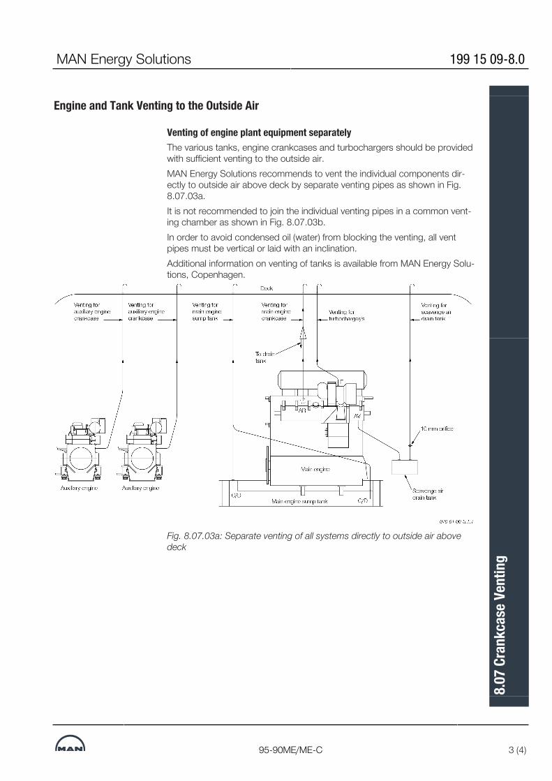
Engine and Tank Venting to the Outside Air
Venting of engine plant equipment separatelyThe various tanks, engine crankcases and turbochargers should be providedwith sufficient venting to the outside air.MAN Energy Solutions recommends to vent the individual components dir-ectly to outside air above deck by separate venting pipes as shown in Fig.8.07.03a.It is not recommended to join the individual venting pipes in a common vent-ing chamber as shown in Fig. 8.07.03b.In order to avoid condensed oil (water) from blocking the venting, all ventpipes must be vertical or laid with an inclination.Additional information on venting of tanks is available from MAN Energy Solu-tions, Copenhagen.
Fig. 8.07.03a: Separate venting of all systems directly to outside air abovedeck
MAN Energy Solutions 199 15 09-8.0
95-90ME/ME-C 3 (4)
8.07
Cra
nkca
se V
entin
g

Venting for auxiliary engine crankcase
Venting for auxiliary engine crankcase
Venting for main engine crankcase
Venting for main engine sump tank
Venting for turbocharger/s
Venting for scavenge air drain tank
Deck
To drain tank
Venting chamber
079 61 00-5.1.1
Fig. 8.07.03b: Venting through a common venting chamber is not recommen-ded
199 15 09-8.0 MAN Energy Solutions
4 (4) 95-90ME/ME-C
8.07
Cra
nkca
se V
entin
g

Hydraulic Oil Back-flushingThe special suction arrangement for purifier suction in connection with the MEengine (Integrated system).The back-flushing oil from the self cleaning 6 μm hydraulic control oil filter unitbuilt onto the engine is contaminated and it is therefore not expedient to leadit directly into the lubricating oil sump tank.The amount of back-flushed oil is large, and it is considered to be too expens-ive to discard it. Therefore, we suggest that the lubricating oil sump tank ismodified for the ME engines in order not to have this contaminated lubricatinghydraulic control oil mixed up in the total amount of lubricating oil. The lubric-ating oil sump tank is designed with a small ‘back-flushing hydraulic control oildrain tank’ to which the back-flushed hydraulic control oil is led and fromwhich the lubricating oil purifier can also suck.This is explained in detail below and the principle is shown in Fig. 8.08.01.Three suggestions for the arrangement of the drain tank in the sump tank areshown in Fig. 8.08.02 illustrates another suggestion for a back-flushing oildrain tank.The special suction arrangement for the purifier is consisting of two connectedtanks (lubricating oil sump tank and back-flushing oil drain tank) and of thisreason the oil level will be the same in both tanks, as explained in detail below.The oil level in the two tanks will be equalizing through the ‘branch pipe toback-flushing oil drain tank’, see Fig. 8.08.01. As the pipes have the samediameters but a different length, the resistance is larger in the ‘branch pipe toback-flushing oil drain tank’, and therefore the purifier will suck primarily fromthe sump tank.The oil level in the sump tank and the back-flushing oil drain tank will remainto be about equal because the tanks are interconnected at the top.When hydraulic control oil is back-flushed from the filter, it will give a higher oillevel in the backflushing hydraulic control oil drain tank and the purifier willsuck from this tank until the oil level is the same in both tanks. After that, thepurifier will suck from the sump tank, as mentioned above.This special arrangement for purifier suction will ensure that a good cleaningeffect on the lubrication oil is obtained.If found profitable the back-flushed lubricating oil from the main lubricating oilfilter (normally a 50 or 40 μm filter) can also be returned into the special back-flushing oil drain tank.
MAN Energy Solutions 198 48 29-7.3
ME/ME-C/ME-GI/ME-GA/ME-B, ME Engine Selection Guide 1 (3)
8.08
Hyd
raul
ic Oi
l Bac
k-flu
shin
g

Fig. 8.08.01: Back flushing servo oil drain tank
198 48 29-7.3 MAN Energy Solutions
2 (3) ME/ME-C/ME-GI/ME-GA/ME-B, ME Engine Selection Guide
8.08
Hyd
raul
ic Oi
l Bac
k-flu
shin
g

Fig. 8.08.02: Alternative design for the back-flushing servo oil drain tank
MAN Energy Solutions 198 48 29-7.3
ME/ME-C/ME-GI/ME-GA/ME-B, ME Engine Selection Guide 3 (3)
8.08
Hyd
raul
ic Oi
l Bac
k-flu
shin
g

MAN B&W 8.09Page 1 of 4
MAN Energy SolutionsMAN B&W ME/ME-C/-GI/-GA engines 198 48 523.6
Separate System for Hydraulic Control Unit
As an option, the engine can be prepared for the use of a separate hydraulic control oil system Fig. 8.09.01.
The separate hydraulic control oil system can be built as a unit, or be built streamlined in the engine room with the various components placed and fastened to the steel structure of the engine room.
The design and the dimensioning of the various components are based on the aim of having a reli-able system that is able to supply lowpressure oil to the inlet of the enginemounted highpressure hydraulic control oil pumps at a constant pres-sure, both at engine standby and at various en-gine loads.
Cleanliness of the hydraulic control oil
The hydraulic control oil must fulfil the same cleanliness level as for our standard integrated lube/cooling/hydrauliccontrol oil system, i.e. ISO 4406 XX/16/13 equivalent to NAS 1638 Class 7.
Information and recommendations regarding flushing, the specified cleanliness level and how to measure it, and how to use the NAS 1638 oil cleanliness code as an alternative to ISO 4406, are available from MAN Diesel & Turbo.
Control oil system components
The hydraulic control oil system comprises: 1 Hydraulic control oil tank2 Hydraulic control oil pumps (one for standby)1 Pressure control valve1 Hydraulic control oil cooler, watercooled by the
low temperature cooling water1 Threeway valve, temperature controlled1 Hydraulic control oil filter, duplex type or auto-
matic selfcleaning type1 Hydraulic control oil fine filter with pump1 Temperature indicator1 Pressure indicator2 Level alarms Valves and cocks Piping.
Hydraulic control oil tank
The tank can be made of mild steel plate or be a part of the ship structure.
The tank is to be equipped with flange connec-tions and the items listed below:1 Oil filling pipe1 Outlet pipe for pump suctions1 Return pipe from engine1 Drain pipe1 Vent pipe.
The hydraulic control oil tank is to be placed at least 1 m below the hydraulic oil outlet flange, RZ.
Hydraulic control oil pump
The pump must be of the displacement type (e.g. gear wheel or screw wheel pump).
The following data is specified in Table 8.09.02:• Pump capacity• Pump head• Delivery pressure• Working temperature• Oil viscosity range.
Pressure control valve
The valve is to be of the selfoperating flow control-ling type, which bases the flow on the predefined pressure set point. The valve must be able to react quickly from the fullyclosed to the fullyopen posi-tion (tmax= 4 sec), and the capacity must be the same as for the hydraulic control oil lowpressure pumps. The set point of the valve has to be within the adjustable range specified in a separate draw-ing.
The following data is specified in Table 8.09.02:• Flow rate• Adjustable differential pressure range across
the valve • Oil viscosity range.

MAN B&W 8.09Page 2 of 4
MAN Energy SolutionsMAN B&W ME/ME-C/-GI/-GA engines 198 48 523.6
Hydraulic control oil cooler
The cooler must be of the plate heat exchanger or shell and tube type.
The following data is specified in Table 8.09.02:• Heat dissipation• Oil flow rate• Oil outlet temperature• Maximum oil pressure drop across the cooler• Cooling water flow rate• Water inlet temperature• Maximum water pressure drop across the cooler.
Temperature controlled threeway valve
The valve must act as a control valve, with an ex-ternal sensor.
The following data is specified in Table 8.09.02:• Capacity• Adjustable temperature range• Maximum pressure drop across the valve.
Hydraulic control oil filter
The filter is to be of the duplex full flow type with manual change over and manual cleaning or of the automatic self cleaning type.
A differential pressure gauge is fitted onto the filter.
The following data is specified in Table 8.09.02:• Filter capacity• Maximum pressure drop across the filter• Filter mesh size (absolute)• Oil viscosity• Design temperature.
Off-line hydraulic control oil fine filter / purifier
Shown in Fig. 8.09.01, the off-line fine filter unit or purifier must be able to treat 15-20% of the total oil volume per hour.
The fine filter is an off-line filter and removes me-tallic and non-metallic particles larger than 0,8 µm as well as water and oxidation residues. The filter has a pertaining pump and is to be fitted on the top of the hydraulic control oil tank.
A suitable fine filter unit is:Make: CJC, C.C. Jensen A/S, Svendborg, Denmark - www.cjc.dk.
For oil volume <10,000 litres: HDU 27/-MZ-Z with a pump flow of 15-20% of the total oil volume per hour.
For oil volume >10,000 litres: HDU 27/-GP-DZ with a pump flow of 15-20% of the total oil volume per hour.
Temperature indicator
The temperature indicator is to be of the liquid straight type.
Pressure indicator
The pressure indicator is to be of the dial type.
Level alarm
The hydraulic control oil tank has to have level alarms for high and low oil level.
Piping
The pipes can be made of mild steel.
The design oil pressure is to be 10 bar.
The return pipes are to be placed vertical or laid with a downwards inclination of minimum 15°.

MAN B&W 8.09Page 3 of 4
MAN Energy SolutionsMAN B&W ME/ME-C/-GI/-GA engines 198 48 523.6
078 83 91-0.1.0
PI 1301 I
Manhole
Oil tank
Cooling water outlet
Cooling water inlet
Oil cooler Temperature control valve
Vent pipe
Deck
Oil filling pipe
Purifier orfine filter unit
Drain to waste oil tank
Water drain
RZ
RW
LS 1320 AH AL
RY
Engine
PDS 1231 AHManual
filter
Autofilter
PI 1303 I
TI 1310 I
TE 1310 AH Y
XS 1350 AH
XS 1351 AH
078 83 91-0.1.0
Fig. 8.09.01: Hydraulic control oil system, manual filter
The letters refer to list of ‘Counterflanges’

MAN B&W 8.09Page 4 of 4
MAN B&W G90ME-C10 199 08 51-7.1
Hydraulic Control Oil System Capacities, G90ME-C10
Fig. 8.09.02: Hydraulic control oil system capacities
178 69 50-9.1
Cylinder no. 6 7 8 9 10 11 12
r/min 84 84 84 84 84 84 84kW 37,440 43,680 49,920 56,160 62,400 68,640 74,880
Hydraulic Control Oil tank:
Volumen, approx. m³ 4.0 5.0 5.5 6.0 6.5 7.5 8.0
Hydraulic Control Oil Pump
Pump capacity m³/h 55 65 75 80 90 100 110Pump head bar 4 4 4 4 4 4 4Delivery pressure bar 4 4 4 4 4 4 4Design temperature °C 70 70 70 70 70 70 70Oil viscosity range cSt 15 - 90 15 - 90 15 - 90 15 - 90 15 - 90 15 - 90 15 - 90
Pressure control valve
Lubricating oil flow m³/h 55 65 75 80 90 100 110Adjustable pressure bar 2 - 4 2 - 4 2 - 4 2 - 4 2 - 4 2 - 4 2 - 4Design temperature °C 55 55 55 55 55 55 55Oil viscosity range cSt 15 - 90 15 - 90 15 - 90 15 - 90 15 - 90 15 - 90 15 - 90
Hydraulic Control Oil Cooler
Heat dissipation kW 210 245 275 310 345 380 415Lubricating oil flow m³/h 55 65 75 80 90 100 110Oil outlet temperature °C 45 45 45 45 45 45 45Oil pressure drop, max bar 0.5 0.5 0.5 0.5 0.5 0.5 0.5Cooling water flow m³/h 31 36 40 45 50 55 60S.W. inlet temperature °C 32 32 32 32 32 32 32F.W. inlet temperature °C 36 36 36 36 36 36 36Water pressure drop, max bar 0.2 0.2 0.2 0.2 0.2 0.2 0.2
Temperature Controlled Three-way Valve
Lubricating oil flow m³/h 55 65 75 80 90 100 110Adjustable temp. range °C 2 - 4 2 - 4 2 - 4 2 - 4 2 - 4 2 - 4 2 - 4Design temperature °C 70 70 70 70 70 70 70Oil pressure drop, max bar 0.3 0.3 0.3 0.3 0.3 0.3 0.3
Hydraulic Control Oil Filter
Lubricating oil flow m³/h 55 65 75 80 90 100 110Absolute fineness µm 6 6 6 6 6 6 6Design temperature °C 55 55 55 55 55 55 55Design pressure bar 4 4 4 4 4 4 4Oil pressure drop, max bar 0.3 0.3 0.3 0.3 0.3 0.3 0.3
MAN Energy Solutions

MAN B&W
MAN Energy Solutions
Cylinder Lubrication
9


Cylinder Lubricating Oil SystemThe cylinder oil lubricates the cylinder and piston. The oil is used in order toreduce friction, introduce wear protection and inhibit corrosion. It cleans theengine parts and keep combustion products in suspension.
Cylinder LubricatorsEach cylinder liner has a number of lubricating quills, through which oil is intro-duced from the MAN B&W Alpha Cylinder Lubricators, see Section 9.02.The oil is pumped into the cylinder (via non-return valves) when the pistonrings pass the lubricating orifices during the upward stroke.The control of the lubricators is integrated in the ECS system. An overview ofthe cylinder lubricating oil control system is shown in Fig. 9.02.02b.
Cylinder Lubrication StrategyThe general lubrication strategy is to match the cylinder oil with the fuel. Tabel9.01.01 gives a general overview of cylinder oils When operating on liquid nat-ural gas (LNG), ethane or methanol, the same cylinder oil is used as forULSFO to LFSO operation. For specific lubrication guidelines, please refer tothe most recent lubrication guideline for your specific engine type, e.g. serviceletters and circular letters. Service letters are publicly available . Circular lettersare only distributed to customers that have the specific engine type/s dealtwith in the specific letter.MAN Energy Solutions recommends using cylinder lubricating oils character-ised primarily by their Base Number (BN) and SAE viscosity and to use a feedrate according to the cylinder oil’s BN and the fuel’s sulphur content.The BN is a measure of the neutralization capacity of the oil. What BN level touse depends on the sulphur content of the fuel.In short, MAN Energy Solutions recommends the use of cylinder oils with thefollowing main properties:
▪ Kinematic viscosity: min. 18.5 cSt at 100°Cmax. 21.9 cSt at 100°C
▪ BN 100 - 140 high sulphur heavy fuel oil over 1%
▪ BN 15 - 40 for ultra to low-sulphur fuel (< 1% S)
▪ BN 15 - 40 when operating on LNG, LPG, ethane and methanol.
BN 15 - 40 are low-BN cylinder lubricating oils, currently available to the mar-ket in the BN levels 16, 25 and 40. However, development continues and inthe future there could be oils with other BN levels. Good performance of thelow-BN oil is the most important factor for deciding.
MAN Energy Solutions 199 15 10-8.0
ME/ME-C/ME-B Mark 8 and higher 1 (6)
9.01
Cyli
nder
Lubr
icatin
g Oi
l Sys
tem

Tabel 9.01.01: General overview of cylinder oils
Two-Tank Cylinder Oil Supply SystemSupporting the cylinder lubrication strategy for MAN B&W engines to use twodifferent BN cylinder oils according to the applied fuel sulphur content, stor-age and settling tanks should be arranged for the two cylinder oils separately.A traditional cylinder lubricating oil supply system with separate storage andservice tanks for highand low-BN cylinder oils is shown in Fig. 9.02.02a. Thealternative layout for the automated cylinder oil mixing (ACOM) system de-scribed below is shown in Fig. 9.02.02b.
Cylinder Oil Feed Rate (Dosage)The minimum feed rate is 0.6 g/kWh and this is the amount of oil that isneeded to lubricate all the parts sufficiently. Continuously monitoring of thecylinder condition and analysing drain oil samples are good ways to optimisethe cylinder oil feed rate and consumption and to safeguard the engineagainst wear.Adjustment of the cylinder oil dosage to the sulphur content in the fuel beingburnt is explained in Section 9.02.Further information about cylinder lubrication is available in MAN Energy Solu-tions' most current Service Letters on this subject.The Service Letters are available at www.marine.man-es.com --> ’Two-Stroke’ --> ’Service Letters’.
Adaptation of Cylinder BN to the Sulphur LevelMatching the actual sulphur content to the right lube oil according to the en-gine type and operating pattern is a key factor in achieving efficient lubrication.Furthermore, the increasing use of ultra-low-sulphur oils in both fuel oil andgas engines makes it recommendable to faster adapt the cylinder oil BN (basenumber) to the sulphur level actually used.
199 15 10-8.0 MAN Energy Solutions
2 (6) ME/ME-C/ME-B Mark 8 and higher
9.01
Cyli
nder
Lubr
icatin
g Oi
l Sys
tem

Fig. 9.01.01: Mixing principle, ACOM
Automated Cylinder Oil Mixing System (ACOM)The automated cylinder oil mixing (ACOM) is a cylinder oil delivery systemwhich automatically mixes to two fully formulated cylinder oils to the optimumBN depending on the sulphur in the fuel. Several lube oil suppliers are testingand have finished the testing of their oil in the ACOM system.
Company Cylinder oil name, SAE 50 BN level
Castrol Cyltech ACT 16
Cyltech ACT 140
Shell Alexia S3 25
Alexia 140 140
Chevron Taro special HT LF 25
Taro special HT 100 100
Taro special HT ultra 140
Gulf Oil Marine Gulfsea Cylcare ECA 50 17
Gulfsea Cylcare 50100X 100
Gulfsea Cylcare 50140X 140
Total Talusia LS 25 25
Talusia HR 140 140
Table 9.01.02 list of companies that have finished the testingMAN Energy Solutions’ ACOM (Automated Cylinder Oil Mixing) system mixescommercially available cylinder oils to the required BN value needed. The res-ulting BN in the cylinder oil supplied to the liners is in the range of the BN val-ues of the two cylinder oils stored on board.
MAN Energy Solutions 199 15 10-8.0
ME/ME-C/ME-B Mark 8 and higher 3 (6)
9.01
Cyli
nder
Lubr
icatin
g Oi
l Sys
tem

The basic principle is to mix an optimal cylinder lubricating oil (optimal BN), asillustrated in Fig. 9.01.01. At a certain sulphur content level, the engine needsto run on the high-BN cylinder oil as usual.
The ACOM Working PrincipleThe mixing is based on input of the sulphur content in the fuel that the engineis running on and the ME-ECS then controls the ACOM accordingly.In gas operation mode, the sulphur content of the resulting fuel depends onthe:▪ In gas operation mode, the sulphur content of the resulting fuel depends
on the:▪ amount of pilot oil in the resulting fuel▪ sulphur content in the pilot fuel.The sulphur content in the resulting fuel is called the Sulphur Equivalent, Se.ACOM automatically calculates the Se and the BN. The system is implemen-ted in the engine control system of the ME-C/-GI/-LGI and ME-B-GI/-LGI andinput on the sulphur content of the pilot fuel must be entered on the MOP bythe crew.On the ME-B, the ACOM is a stand-alone installation. It is controlled from theACOM operating panel separate to the ME-B ECS and with alarms handledby the ship’s alarm system.Mixing volumes are kept small enabling a fast changeover from one BN to an-other.
Two-Tank Cylinder Lubrication System with ACOMThe ACOM design makes it possible to measure the daily consumption of cyl-inder lubricating oil which eliminates the need for the two cylinder oil service /day tanks. Compared to the traditional two-tank cylinder lubrication system,Fig. 9.02.02a, the ACOM system also eliminates the two small tanks withheater element as shown in Fig. 9.02.02b.The cylinder lubricating oil is fed from the storage tanks to the ACOM by grav-ity. The ACOM is located in the engine room near to and above the cylinderlubricating oil inlet flange, AC, in a vertical distance of minimum 2m. The lay-out of the ACOM is shown in Fig. 9.01.02.ME-C-GI and ME-B-GI engines running in specified dual fuel (SDF) mode (i.e.all LNG tankers) and quoted after 2017-01-01 are as standard specified withACOM, EoD: 4 42 171. For all other engines, ACOM is available as an option.
199 15 10-8.0 MAN Energy Solutions
4 (6) ME/ME-C/ME-B Mark 8 and higher
9.01
Cyli
nder
Lubr
icatin
g Oi
l Sys
tem
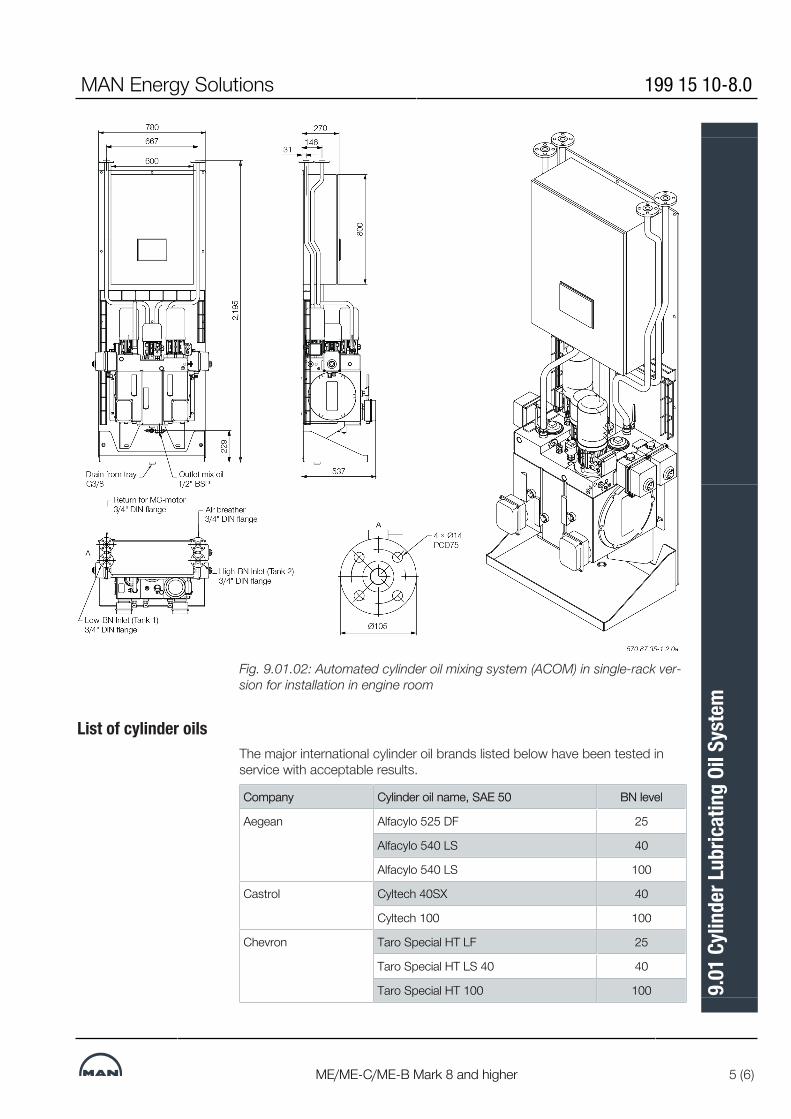
Fig. 9.01.02: Automated cylinder oil mixing system (ACOM) in single-rack ver-sion for installation in engine room
List of cylinder oilsThe major international cylinder oil brands listed below have been tested inservice with acceptable results.
Company Cylinder oil name, SAE 50 BN level
Aegean Alfacylo 525 DF 25
Alfacylo 540 LS 40
Alfacylo 540 LS 100
Castrol Cyltech 40SX 40
Cyltech 100 100
Chevron Taro Special HT LF 25
Taro Special HT LS 40 40
Taro Special HT 100 100
MAN Energy Solutions 199 15 10-8.0
ME/ME-C/ME-B Mark 8 and higher 5 (6)
9.01
Cyli
nder
Lubr
icatin
g Oi
l Sys
tem

ExxonMobil Mobilgard 525 25
Mobilgard 525 100
Gulf Oil Marine GulfSea Cylcare ECA 50 17
GulfSea Cylcare DCA 5040H 40
GulfSea Cylcare 50100 100
Indian Oil Corp. Servo Marine LB 1750 17
JX Nippon Oil & Energy Marine C255 25
Marine C405 40
Marine C1005 100
Lukoil Navigo 40 MCL 40
Navigo 100 MCL 100
Shell Alexia S3 25
Alexia S6 100
Sinopec Marine Cylinder Oil 5025 25
Marine Cylinder Oil 5040 40
Marine Cylinder Oil 50100 100
Total Talusia LS 25 25
Talusia LS 40 40
Talusia Universal 100 100
Do not consider the list complete, as oils from other companies can beequally suitable. Further information can be obtained from the engine builderor MAN Energy Solutions, Copenhagen.
199 15 10-8.0 MAN Energy Solutions
6 (6) ME/ME-C/ME-B Mark 8 and higher
9.01
Cyli
nder
Lubr
icatin
g Oi
l Sys
tem
MAN B&W Alpha Cylinder Lubrication SystemThe MAN B&W Alpha cylinder lubrication system, see Figs. 9.02.02a, 02b and02c, is designed to supply cylinder oil intermittently, for instance every 2, 4 or8 engine revolutions with electronically controlled timing and dosage at adefined position.
Traditional two-tank cylinder lubrication systemSeparate storage and service tanks are installed for each of the different BaseNumber (BN) cylinder oils used onboard ships operating on both high- andlow-sulphur fuels, see Fig. 9.02.02a.The cylinder lubricating oil is pumped from the cylinder oil storage tank to theservice tank, the size of which depends on the owner’s and the yard’s re-quirements, – it is normally dimensioned for about one week’s cylinder lubric-ating oil consumption.
Oil feed to the Alpha cylinder lubrication systemCylinder lubricating oil is fed to the Alpha cylinder lubrication system by gravityfrom the service tank or ACOM.The oil fed to the injectors is pressurised by the Alpha Lubricator which isplaced on the hydraulic cylinder unit (HCU) and equipped with small multi-pis-ton pumps.The oil pipes fitted on the engine are shown in Fig. 9.02.04.The whole system is controlled by the Cylinder Control Unit (CCU) which con-trols the injection frequency based on the engine-speed signal given by thetacho signal and the fuel index.Prior to start-up, the cylinders can be pre-lubricated and, during the running-in period, the operator can choose to increase the lubricating oil feed rate to amax. setting of 200%.The MAN B&W Alpha Cylinder Lubricator is preferably to be controlled in ac-cordance with the Alpha ACC (Adaptable Cylinder Oil Control) feed rate sys-tem.The yard supply should be according to the items shown in Fig. 9.02.02awithin the broken line.Regarding the filter and the small tank for heater, please see Fig. 9.02.05.
Alpha Lubricator variantsSince the Alpha Lubricator on ME and ME-B engines are controlled by the en-gine control system, it is also referred to as the ME lubricator on those en-gines.A more advanced version with improved injection flexibility, the Alpha Lubric-ator Mk 2, is being introduced on the G95/50/45/40ME-C9 and S50MEC9 in-cluding their GI dual fuel variants.Further information about the Alpha Lubricator Mk 2 is available in our public-ation:Service Experience MAN B&W Two-stroke Engines
MAN Energy Solutions 199 15 12-1.0
95-60 ME/ME-C 1 (10)
9.02
MAN
B&W
Alp
ha C
ylind
er Lu
brica
tion
Syst
em

The publication is available at www.marine.man-es.com --> ’Two-Stroke’ -->’Technical Papers'.
Alpha Adaptive Cylinder Oil Control (Alpha ACC)It is a well-known fact that the actual need for cylinder oil quantity varies withthe operational conditions such as load and fuel oil quality. Consequently, inorder to perform the optimal lubrication – cost’effectively as well as technically– the cylinder lubricating oil dosage should follow such operational variationsaccordingly.The Alpha lubricating system offers the possibility of saving a considerableamount of cylinder lubricating oil per year and, at the same time, to obtain asafer and more predictable cylinder condition.Alpha ACC (Adaptive Cylinder-oil Control) is the lubrication mode for MANB&W two-stroke engines, i.e. lube oil dosing proportional to the engine loadand proportional to the sulphur content in the fuel oil being burnt.
Working PrincipleThe feed rate control should be adjusted in relation to the actual fuel qualityand amount being burnt at any given time.The following criteria determine the control:▪ The cylinder oil dosage shall be proportional to the sulphur percentage in
the fuel▪ The cylinder oil dosage shall be proportional to the engine load (i.e. the
amount of fuel entering the cylinders)▪ The actual feed rate is dependent of the operating pattern and determined
based on engine wear, cylinder condition and BN of the cylinder oil.The implementation of the above criteria will lead to an optimal cylinder oildosage.
Specific Minimum Dosage with Alpha ACCThe recommendations are valid for all plants, whether controllable pitch orfixed pitch propellers are used. The specific minimum dosage at lowersulphurfuels is set at 0.6 g/kWh.After a running-in period of 500 hours, the feed rate sulphur proportionalfactor is 0.20 - 0.40 g/kWh × S%. The actual ACC factor will be based on cyl-inder condition, and preferably a cylinder oil feed rate sweep test should beapplied. The ACC factor is also referred to as the Feed Rate Factor (FRF).Examples of average cylinder oil consumption based on calculations of theaverage worldwide sulphur content used on MAN B&W two-stroke enginesare shown in Fig. 9.02.01a and b.
199 15 12-1.0 MAN Energy Solutions
2 (10) 95-60 ME/ME-C
9.02
MAN
B&W
Alp
ha C
ylind
er Lu
brica
tion
Syst
em

Fig. 9.02.01a: FRF = 0.20 g/kWh × S% and BN 100 cylinder oil – averageconsumption less than 0.65 g/kWh
Fig. 9.02.01b: FRF = 0.26 g/kWh × S% and BN 100 cylinder oil – averageconsumption less than 0.7 g/kWhFurther information about cylinder oil dosage is available in MAN Energy Solu-tions' most current Service Letters on this subject available at www.mar-ine.man-es.com --> ’Two-Stroke’ --> ’Service Letters’.
Cylinder Oil Pipe HeatingIn case of low engine room temperature, it can be difficult to keep the cylinderoil temperature at 45°C at the MAN B&W Alpha Lubricator, mounted on thehydraulic cylinder.Therefore the cylinder oil pipe from the small tank for heater element in thevessel, Fig. 9.02.02a, or from the ACOM, Fig. 9.02.02b, and the main cylinderoil pipe on the engine is insulated and electricallly heated.The engine builder is to make the insulation and heating of the main cylinderoil pipe on the engine. Moreover, the engine builder is to mount the terminalbox and the thermostat on the engine, see Fig. 9.02.03.
MAN Energy Solutions 199 15 12-1.0
95-60 ME/ME-C 3 (10)
9.02
MAN
B&W
Alp
ha C
ylind
er Lu
brica
tion
Syst
em

The ship yard is to make the insulation of the cylinder oil pipe in the engineroom. The heating cable is to be mounted from the small tank for heater ele-ment or the ACOM to the terminal box on the engine, see Figs. 9.02.02a and02b.
Fig. 9.02.02a: Cylinder lubricating oil system with dual storage and servicetanks
199 15 12-1.0 MAN Energy Solutions
4 (10) 95-60 ME/ME-C
9.02
MAN
B&W
Alp
ha C
ylind
er Lu
brica
tion
Syst
em
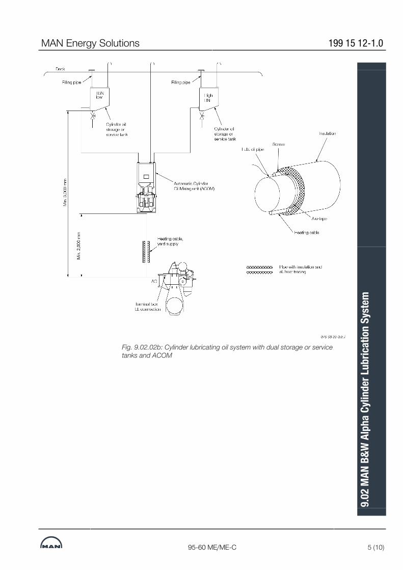
Fig. 9.02.02b: Cylinder lubricating oil system with dual storage or servicetanks and ACOM
MAN Energy Solutions 199 15 12-1.0
95-60 ME/ME-C 5 (10)
9.02
MAN
B&W
Alp
ha C
ylind
er Lu
brica
tion
Syst
em
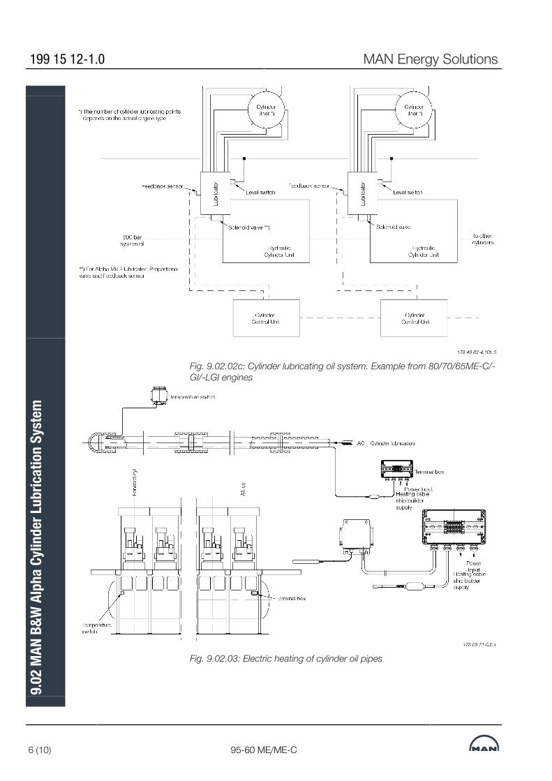
Fig. 9.02.02c: Cylinder lubricating oil system. Example from 80/70/65ME-C/-GI/-LGI engines
Fig. 9.02.03: Electric heating of cylinder oil pipes
199 15 12-1.0 MAN Energy Solutions
6 (10) 95-60 ME/ME-C
9.02
MAN
B&W
Alp
ha C
ylind
er Lu
brica
tion
Syst
em

The item no. refer to ‘Guidance Values Automation’. The letters refer to list of‘Counterflanges’Fig. 9.02.04a: Cylinder lubricating oil pipes, Alpha/ME lubricator
The item no. refer to ‘Guidance Values Automation’. The letters refer to list of‘Counterflanges’Fig. 9.02.04b: Cylinder lubricating oil pipes, Alpha Mk 2 lubricator
MAN Energy Solutions 199 15 12-1.0
95-60 ME/ME-C 7 (10)
9.02
MAN
B&W
Alp
ha C
ylind
er Lu
brica
tion
Syst
em

Fig. 9.02.02c: Cylinder lubricating oil system. Example from 80/70/65ME-C/-GI/-LGI engines
Fig. 9.02.03: Electric heating of cylinder oil pipes
199 15 12-1.0 MAN Energy Solutions
8 (10) 95-60 ME/ME-C
9.02
MAN
B&W
Alp
ha C
ylind
er Lu
brica
tion
Syst
em
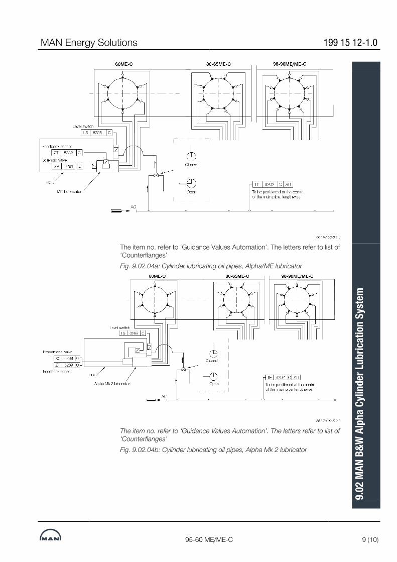
The item no. refer to ‘Guidance Values Automation’. The letters refer to list of‘Counterflanges’Fig. 9.02.04a: Cylinder lubricating oil pipes, Alpha/ME lubricator
The item no. refer to ‘Guidance Values Automation’. The letters refer to list of‘Counterflanges’Fig. 9.02.04b: Cylinder lubricating oil pipes, Alpha Mk 2 lubricator
MAN Energy Solutions 199 15 12-1.0
95-60 ME/ME-C 9 (10)
9.02
MAN
B&W
Alp
ha C
ylind
er Lu
brica
tion
Syst
em
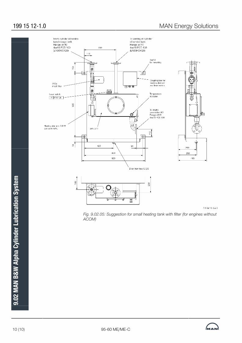
Fig. 9.02.05: Suggestion for small heating tank with filter (for engines withoutACOM)
199 15 12-1.0 MAN Energy Solutions
10 (10) 95-60 ME/ME-C
9.02
MAN
B&W
Alp
ha C
ylind
er Lu
brica
tion
Syst
em
MAN B&W
MAN Energy Solutions
Piston Rod Stuffing Box Drain Oil
10


Stuffing Box Drain Oil SystemFor engines running on heavy fuel, it is important that the oil drained from thepiston rod stuffing boxes is not led directly into the system oil, as the oildrained from the stuffing box is mixed with sludge from the scavenge airspace.The performance of the piston rod stuffing box on the engines has proved tobe very efficient, primarily because the hardened piston rod allows a higherscraper ring pressure.The amount of drain oil from the stuffing boxes is typically about 10 - 15litres/24 hours per cylinder during normal service. In the running-in period, itcan be higher. The drain oil is a mixture of system oil from the crankcase,used cylinder oil, combustion residues and water from humidity in the scav-enge air.The relatively small amount of drain oil is led to the general oily waste draintank or is burnt in the incinerator, Fig. 10.01.01. (Yard’s supply).
Fig. 10.01.01: Stuffing box drain oil system
2021
-07-
30 -
en
MAN Energy Solutions 198 83 45-3.1
95-65ME/ME-C/-GI 1 (1)
10.0
1 St
uffin
g Bo
x Dra
in O
il Sy
stem


MAN B&W
MAN Energy Solutions
Low-temperature Cooling Water
11


Low-temperature Cooling Water SystemThe low-temperature (LT) cooling water system supplies cooling water for thelubricating oil, jacket water and scavenge air coolers.The LT cooling water system can be arranged in several configurations like a:▪ Central cooling water system being the most common system choice and
the basic execution for MAN B&W engines, EoD: 4 45 111▪ Seawater cooling system being the most simple system and available as
an option: 4 45 110▪ Combined cooling water system with seawater cooled scavenge air
cooler but freshwater cooled jacket water and lubricating oil cooler, avail-able as an option: 4 45 117.
Principle diagrams of the above LT cooling water systems are shown in Fig.11.01.01a, b and c and descriptions are found later in this chapter.Further information and the latest recommendations concerning cooling watersystems are found in MAN Energy SolutionsService Letters available atwww.marine.man-es.com --> 'Two-Stroke' --> 'Service Letters'.
Chemical Corrosion InhibitionVarious types of inhibitors are available but, generally, only nitrite-boratebased inhibitors are recommended.Where the inhibitor maker specifies a certain range as normal concentration,we recommend to maintain the actual concentration in the upper end of thatrange.MAN Energy Solutions recommends keeping a record of all tests to follow thecondition and chemical properties of the cooling water and notice how it de-velops. It is recommended to record the quality of water as follows:▪ Once a week:
Take a sample from the circulating water during running, however notfrom the expansion tank nor the pipes leading to the tank. Check the con-dition of the cooling water. Test kits with instructions are normally avail-able from the inhibitor supplier.
▪ Every third month:Take a water sample from the system during running, as described abovein ‘Once a week’. Send the sample for laboratory analysis.
▪ Once a year:Empty, flush and refill the cooling water system. Add the inhibitor. For fur-ther information please refer to our recommendations for treatment of thejacket water/ freshwater. The recommendations are available from MANEnergy Solutions, Copenhagen.
Cooling System for Main Engines with EGRFor main engines with exhaust gas recirculation (EGR), a central cooling sys-tem using freshwater as cooling media will be specified.Further information about cooling water systems for main engines with EGR isavailable from MAN Energy Solutions, Copenhegan.
MAN Energy Solutions 199 03 92-7.4
Engines dot 5 and higher 1 (2)
11.0
1 Lo
w-te
mpe
ratu
re C
oolin
g W
ater
Sys
tem

Fig. 11.01.01a: Principle diagram of central cooling water system
Fig. 11.01.01b: Principle diagram of seawater cooling system
Scav. air cooler
Aux.equipment
Central cooler
Set point:10-36°C
Sea waterFreshwater
Sea water pumpsTin ≥ 0 °C
Jacketwatercooler
Lubr. oil cooler
Central coolingpumps
568 25 97-1.0.1c
Fig. 11.01.01c: Principle diagram of combined cooling water system
199 03 92-7.4 MAN Energy Solutions
2 (2) Engines dot 5 and higher
11.0
1 Lo
w-te
mpe
ratu
re C
oolin
g W
ater
Sys
tem
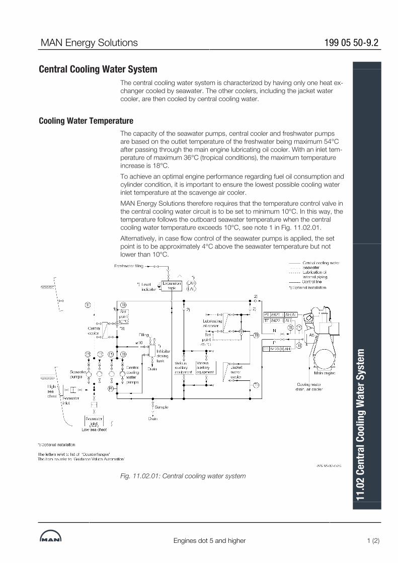
Central Cooling Water SystemThe central cooling water system is characterized by having only one heat ex-changer cooled by seawater. The other coolers, including the jacket watercooler, are then cooled by central cooling water.
Cooling Water TemperatureThe capacity of the seawater pumps, central cooler and freshwater pumpsare based on the outlet temperature of the freshwater being maximum 54°Cafter passing through the main engine lubricating oil cooler. With an inlet tem-perature of maximum 36°C (tropical conditions), the maximum temperatureincrease is 18°C.To achieve an optimal engine performance regarding fuel oil consumption andcylinder condition, it is important to ensure the lowest possible cooling waterinlet temperature at the scavenge air cooler.MAN Energy Solutions therefore requires that the temperature control valve inthe central cooling water circuit is to be set to minimum 10°C. In this way, thetemperature follows the outboard seawater temperature when the centralcooling water temperature exceeds 10°C, see note 1 in Fig. 11.02.01.Alternatively, in case flow control of the seawater pumps is applied, the setpoint is to be approximately 4°C above the seawater temperature but notlower than 10°C.
Fig. 11.02.01: Central cooling water system
MAN Energy Solutions 199 05 50-9.2
Engines dot 5 and higher 1 (2)
11.0
2 Ce
ntra
l Coo
ling
Wat
er S
yste
m
Cooling Water Pump CapacitiesThe pump capacities listed by MAN Energy Solutions cover the requirementfor the main engine only.For any given plant, the specific capacities have to be determined accordingto the actual plant specification and the number of auxiliary equipment. Suchequipment include GenSets, starting air compressors, provision compressors,air-conditioning compressors, etc.A guideline for selecting centrifugal pumps is given in Section 6.04.
Cooling Water PipingOrifices (or lockable adjustable valves for instance) must be installed in orderto create:▪ the proper distribution of flow between each of the central cooling water
consumers, see note 2)▪ a differential pressure identical to that of the central cooler at nominal
central cooling water pump capacity, see note 3).References are made to Fig. 11.02.01.For external pipe connections, we prescribe the following maximum water ve-locities:Central cooling water ..................................3.0 m/s Seawater .....................................................3.0 m/s
Expansion Tank VolumeThe expansion tank shall be designed as open to atmosphere. Venting pipesentering the tank shall terminate below the lowest possible water level i.e. be-low the low level alarm.The expansion tank volume has to be 10% of the total central cooling wateramount in the system.The 10% expansion tank volume is defined as the volume between the lowestlevel (at the low level alarm sensor) and the overflow pipe or high level alarmsensor.If the pipe system is designed with possible air pockets, these have to be ven-ted to the expansion tank.
199 05 50-9.2 MAN Energy Solutions
2 (2) Engines dot 5 and higher
11.0
2 Ce
ntra
l Coo
ling
Wat
er S
yste
m

Components for Central Cooling Water System
Seawater Cooling PumpsThe pumps are to be of the centrifugal type.Seawater flow .....................see ‘List of Capacities’ Pump head ...................................................2.0 bar Test pressure ....................according to Class rules Working temperature, normal .....................0-32°C Working temperature ....................maximum 50°CThe flow capacity must be within a range from 100 to 110% of the capacitystated.The pump head of the pumps is to be determined based on the total actualpressure drop across the seawater cooling water system.A guideline for selecting centrifugal pumps is given in Section 6.04.
Central CoolerThe cooler is to be of the shell and tube or plate heat exchanger type, madeof seawater resistant material.Heat dissipation .................see ‘List of Capacities’ Central cooling water flow ................................see ‘List of Capacities’ Central cooling water temperature, outlet .....36°C Pressure drop on central cooling side ........................max. 0.7 bar Seawater flow .....................see ‘List of Capacities’ Seawater temperature, inlet ...........................32°C Pressure drop on seawater side ..........................maximum 1.0 barThe pressure drop may be larger, depending on the actual cooler design.The heat dissipation and the seawater flow figures are based on MCR outputat tropical conditions, i.e. a seawater temperature of 32°C and an ambient airtemperature of 45°C.Overload running at tropical conditions will slightly increase the temperaturelevel in the cooling system, and will also slightly influence the engine perform-ance.
Central Cooling Water PumpsThe pumps are to be of the centrifugal type.Central cooling water flow ................................see ‘List of Capacities’ Pump head ...................................................2.5 bar Delivery pressure ...............depends on location of expansion tank Test pressure ....................according to Class rules Working temperature .....................................80°C Design temperature ......................................100°C
The flow capacity must be within a range from 100 to 110% of the capacitystated.The ‘List of Capacities’ covers the main engine only. The pump head of thepumps is to be determined based on the total actual pressure drop acrossthe central cooling water system.
MAN Energy Solutions 199 03 97-6.1
Engines dot 5 and higher 1 (2)
11.0
3 Co
mpo
nent
s for
Cen
tral C
oolin
g W
ater
Sys
tem

A guideline for selecting centrifugal pumps is given in Section 6.04.
Central Cooling Water Thermostatic ValveThe low temperature cooling system is to be equipped with a three-‹wayvalve, mounted as a mixing valve, which bypasses all or part of the freshwateraround the central cooler.The sensor is to be located at the outlet pipe from the thermostatic valve andis set to keep a temperature of 10°C.
Lubricating Oil Cooler Thermostatic ValveThe lubricating oil cooler is to be equipped with a three-way valve, mountedas a mixing valve, which bypasses all or part of the freshwater around the lub-ricating cooler.The sensor is to be located at the lubricating oil outlet pipe from the lubricat-ing oil cooler and is set to keep a lubricating oil temperature of 45°C.
Chemical Corrosion Inhibitor and Dosing TankIn order to properly mix the inhibitor into the central cooling water system cir-cuit, the tank shall be designed to receive a small flow of jacket cooling waterthrough the tank from the jacket water pumps. The tank shall be suitable formixing inhibitors in form of both powder and liquid.Recommended tank size ..............................0.3 m3Design pressure ...........max. central cooling water system pressureSuggested inlet orifice size ........................ø10 mm
Lubricating Oil CoolerSee Chapter 8 ‘Lubricating Oil’.
Jacket Water CoolerSee Chapter 12 ‘High-temperature Cooling Water’.
Scavenge Air CoolerThe scavenge air cooler is an integrated part of the main engine.Heat dissipation .................see ‘List of Capacities’ Central cooling water flow ................................see ‘List of Capacities’ Central cooling temperature, inlet ..................36°C Pressure drop on FW-LT water side ..... 0.3-0.8 bar
Cooling Water Pipes for Air CoolerDiagrams of cooling water pipes for scavenge air cooler are shown in Figs.11.08.01.
199 03 97-6.1 MAN Energy Solutions
2 (2) Engines dot 5 and higher
11.0
3 Co
mpo
nent
s for
Cen
tral C
oolin
g W
ater
Sys
tem

Seawater Cooling SystemThe seawater cooling system is an option for cooling the main engine lubricat-ing oil cooler, the jacket water cooler and the scavenge air cooler by seawa-ter, see Fig. 11.04.01. The seawater system consists of pumps and a thermo-static valve.
Cooling Water TemperatureThe capacity of the seawater pump is based on the outlet temperature of theseawater being maximum 50°C after passing through the main engine lubric-ating oil cooler, the jacket water cooler and the scavenge air cooler.With an inlet temperature of maximum 32°C (tropical conditions), the max-imum temperature increase is 18°C.In order to prevent the lubricating oil from stiffening during cold services, athermostatic valve is to be installed. The thermostatic valve recirculates all orpart of the seawater to the suction side of the pumps. A set point of 10°C en-sures that the cooling water to the cooling consumers will never fall below thistemperature, see note 1 in Fig. 11.04.01.
Fig. 11.04.01: Seawater cooling system
Cooling Water Pump CapacitiesThe pump capacities listed by MAN Energy Solutions cover the requirementfor the main engine only.
MAN Energy Solutions 199 03 98-8.2
Engines dot 5 and higher 1 (2)
11.0
4 Se
awat
er C
oolin
g Sy
stem

For any given plant, the specific capacities have to be determined accordingto the actual plant specification and the number of auxiliary equipment. Suchequipment include GenSets, starting air compressors, provision compressors,airconditioning compressors, etc.A guideline for selecting centrifugal pumps is given in Section 6.04.
Cooling Water PipingIn order to create the proper distribution of flow between each of the coolingwater consumers, orifices (or lockable adjustable valves for instance) must beinstalled, see note 2) in Fig. 11.04.01.For external pipe connections, we prescribe the following maximum water ve-locities:Seawater .....................................................3.0 m/sIf the pipe system is designed with possible air pockets, these have to be ven-ted to the expansion tank.
199 03 98-8.2 MAN Energy Solutions
2 (2) Engines dot 5 and higher
11.0
4 Se
awat
er C
oolin
g Sy
stem

Components for Seawater Cooling System
Seawater Cooling PumpsThe pumps are to be of the centrifugal type.Seawater flow .....................see ‘List of Capacities’ Pump head ...................................................2.5 bar Test pressure ......................according to class rule Working temperature ....................maximum 50°CThe flow capacity must be within a range from 100 to 110% of the capacitystated.The pump head of the pumps is to be determined based on the total actualpressure drop across the seawater cooling water system.A guideline for selecting centrifugal pumps is given in Section 6.04.
Seawater Thermostatic ValveThe temperature control valve is a three-way mixing valve. The sensor is to belocated at the seawater inlet to the lubricating oil cooler, and the temperatureset point must be +10 °C.Seawater flow .....................see ‘List of Capacities’ Temperature set point ..................................+10°C
Lubricating Oil CoolerSee Chapter 8 ‘Lubricating Oil’.
Jacket Water CoolerSee Chapter 12 ‘High-temperature Cooling Water’.
Scavenge Air CoolerThe scavenge air cooler is an integrated part of the main engine.Heat dissipation .................see ‘List of Capacities’ Seawater flow ....................see ‘List of Capacities’ Seawater temperature, for seawater cooling inlet, max..................32°C Pressure drop on cooling water side .... 0.3-0.8 barThe heat dissipation and the seawater flow are based on an MCR output attropical conditions, i.e. seawater temperature of 32°C and an ambient air tem-perature of 45°C.
Cooling Water Pipes for Air CoolerDiagrams of cooling water pipes for scavenge air cooler are shown in Figs.11.08.01.
MAN Energy Solutions 199 04 00-1.1
Engines dot 5 and higher 1 (1)
11.0
5 Co
mpo
nent
s for
Sea
wate
r Coo
ling
Syst
em
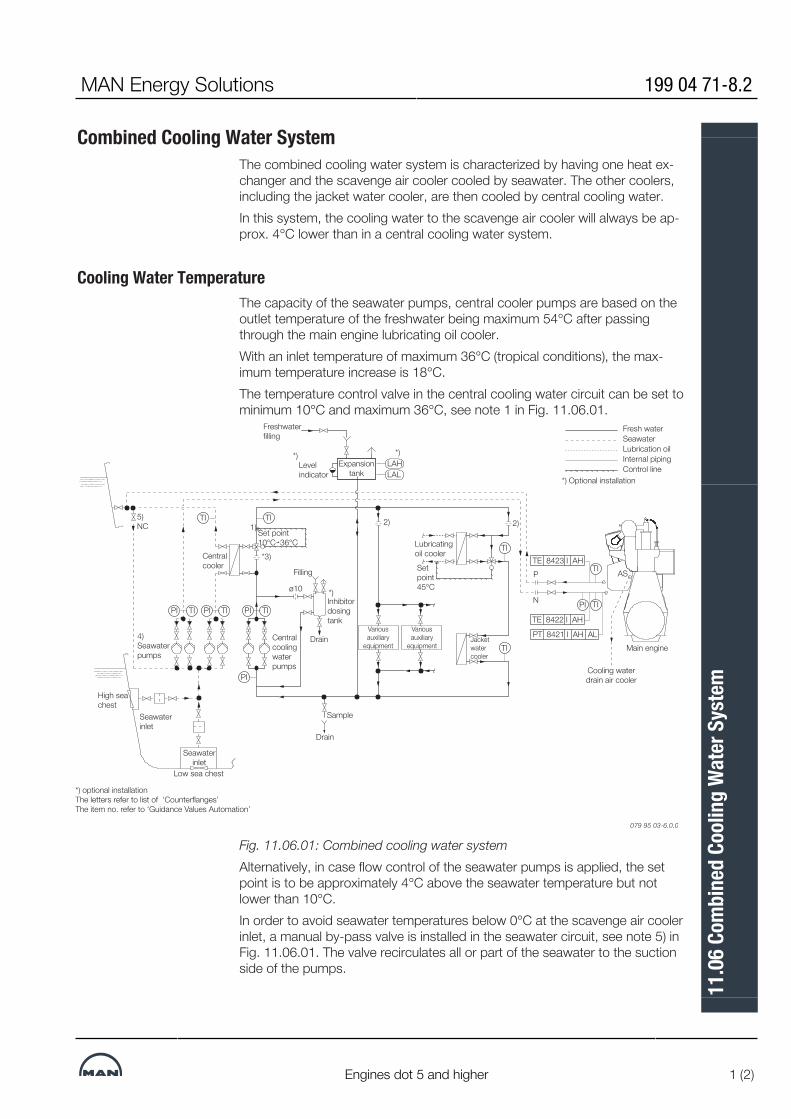
Combined Cooling Water SystemThe combined cooling water system is characterized by having one heat ex-changer and the scavenge air cooler cooled by seawater. The other coolers,including the jacket water cooler, are then cooled by central cooling water.In this system, the cooling water to the scavenge air cooler will always be ap-prox. 4°C lower than in a central cooling water system.
Cooling Water TemperatureThe capacity of the seawater pumps, central cooler pumps are based on theoutlet temperature of the freshwater being maximum 54°C after passingthrough the main engine lubricating oil cooler.With an inlet temperature of maximum 36°C (tropical conditions), the max-imum temperature increase is 18°C.The temperature control valve in the central cooling water circuit can be set tominimum 10°C and maximum 36°C, see note 1 in Fig. 11.06.01.
Freshwaterfilling
*)
Drain
Inhibitordosingtank
Filling
*)
Fresh waterSeawater
Internal pipingControl line
*) Optional installation
Drain
Setpoint45°C
2)2)
*3)
Sample
Cooling waterdrain air cooler
Centralcoolingwater pumps
4)Seawaterpumps
Lubrication oil
1)Set point10°C 36°C
Expansiontank
Levelindicator
ø10N
P
Jacketwatercooler
Lubricatingoil cooler
Variousauxiliary
equipment
Variousauxiliary
equipment
Centralcooler
High seachest
Seawaterinlet
Seawaterinlet
Low sea chest
5)NC
Main engine
AS
*)
LALLAH
TIPI
PI
TIPI TIPI
TI TI
TI
TI
TI
TI
PI
PT 8421 I AH AL
TE 8423 I AH
TE 8422 I AH
079 95 03-6.0.0
*) optional installationThe letters refer to list of ‘Counterflanges’The item no. refer to ‘Guidance Values Automation’
Fig. 11.06.01: Combined cooling water systemAlternatively, in case flow control of the seawater pumps is applied, the setpoint is to be approximately 4°C above the seawater temperature but notlower than 10°C.In order to avoid seawater temperatures below 0°C at the scavenge air coolerinlet, a manual by-pass valve is installed in the seawater circuit, see note 5) inFig. 11.06.01. The valve recirculates all or part of the seawater to the suctionside of the pumps.
MAN Energy Solutions 199 04 71-8.2
Engines dot 5 and higher 1 (2)
11.0
6 Co
mbi
ned
Cool
ing
Wat
er S
yste
m

Cooling Water Pump CapacitiesThe pump capacities listed by MAN Energy Solutions cover the requirementfor the main engine only.For any given plant, the specific capacities have to be determined accordingto the actual plant specification and the number of auxiliary equipment. Suchequipment include GenSets, starting air compressors, provision compressors,airconditioning compressors, etc.In fig. 11.06.01, note 4 both seawater pumps for main engine scavenge aircooler and for central cooling water system are shown. Alternative commonseawater pumps serving both systems can be installed.A guideline for selecting centrifugal pumps is given in Section 6.04.
Cooling Water PipingOrifices (or lockable adjustable valves for instance) must be installed in orderto create:▪ the proper distribution of flow between each of the central cooling water
consumers, see note 2)▪ a differential pressure identical to that of the central cooler at nominal
central cooling water pump capacity, see note 3).References are made to Fig. 11.08.01.For external pipe connections, we prescribe the following maximum water ve-locities:Central cooling water ..................................3.0 m/s Seawater .....................................................3.0 m/s
Expansion Tank VolumeThe expansion tank shall be designed as open to atmosphere. Venting pipesentering the tank shall terminate below the lowest possible water level i.e. be-low the low level alarm.The expansion tank volume has to be 10% of the total central cooling wateramount in the system. The 10% expansion tank volume is defined as thevolume between the lowest level (at the low level alarm sensor) and the over-flow pipe or high level alarm sensor.If the pipe system is designed with possible air pockets, these have to be ven-ted to the expansion tank.
199 04 71-8.2 MAN Energy Solutions
2 (2) Engines dot 5 and higher
11.0
6 Co
mbi
ned
Cool
ing
Wat
er S
yste
m

Components for Combined Cooling Water System
Seawater Cooling PumpsThe pumps are to be of the centrifugal type.Seawater flow .....................see ‘List of Capacities’ Pump head ...................................................2.0 bar Test pressure ....................according to Class rules Working temperature, normal .....................0‰32°C Working temperature ....................maximum 50°CThe flow capacity must be within a range from 100 to 110% of the capacitystated.The pump head of the pumps is to be determined based on the total actualpressure drop across the seawater cooling water system.A guideline for selecting centrifugal pumps is given in Section 6.04.
Central CoolerThe cooler is to be of the shell and tube or plate heat exchanger type, madeof seawater resistant material.Heat dissipation .................see ‘List of Capacities’ Central cooling water flow .. see ‘List of Capacities’ Central cooling water temperature, outlet .......36°C Pressure drop on central cooling side ........................max. 0.7 bar Seawater flow .....................see ‘List of Capacities’ Seawater temperature, inlet ...........................32°C Pressure drop on seawater side ..........................maximum 1.0 barThe pressure drop may be larger, depending on the actual cooler design.The heat dissipation and the seawater flow figures are based on MCR outputat tropical conditions, i.e. a seawater temperature of 32°C and an ambient airtemperature of 45°C.Overload running at tropical conditions will slightly increase the temperaturelevel in the cooling system, and will also slightly influence the engine perform-ance.
Central Cooling Water PumpsThe pumps are to be of the centrifugal type.Central cooling water flow ................................see ‘List of Capacities’ Pump head ...................................................2.5 bar Delivery pressure ...............depends on location of expansion tank Test pressure ....................according to Class rules Working temperature .....................................80°C Design temperature ......................................100°CThe flow capacity must be within a range from 100 to 110% of the capacitystated.
MAN Energy Solutions 199 04 73-1.1
Engines dot 5 and higher 1 (2)
11.0
7 Co
mpo
nent
s for
Com
bine
d Co
olin
g W
ater
Sys
tem

The ‘List of Capacities’ covers the main engine only. The pump head of thepumps is to be determined based on the total actual pressure drop acrossthe central cooling water system.A guideline for selecting centrifugal pumps is given in Section 6.04.
Central Cooling Water Thermostatic ValveThe low temperature cooling system is to be equipped with a three‰-wayvalve, mounted as a mixing valve, which bypasses all or part of the freshwateraround the central cooler.The sensor is to be located at the outlet pipe from the thermostatic valve andis set to keep a temperature of minimum 10 °C and maximum 36°C.
Lubricating Oil Cooler Thermostatic ValveThe lubricating oil cooler is to be equipped with a three-way valve, mountedas a mixing valve, which bypasses all or part of the freshwater around the lub-ricating cooler.The sensor is to be located at the lubricating oil outlet pipe from the lubricat-ing oil cooler and is set to keep a lubricating oil temperature of 45°C.
Chemical Corrosion Inhibitor and Dosing TankIn order to properly mix the inhibitor into the combined cooling water systemcircuit, the tank shall be designed to receive a small flow of jacket cooling wa-ter through the tank from the jacket water pumps. The tank shall be suitablefor mixing inhibitors in form of both powder and liquid.Recommended tank size ..............................0.3 m3 Design pressure ......max. combined cooling water system pressure Suggested inlet orifice size ........................ø10 mm
Lubricating Oil CoolerSee Chapter 8 ‘Lubricating Oil’.
Jacket Water CoolerSee Chapter 12 ‘High-temperature Cooling Water’.
Scavange Air CoolerThe scavenge air cooler is an integrated part of the main engine.Heat dissipation .................see ‘List of Capacities’ Seawater flow .....................see ‘List of Capacities’ Central cooling temperature, inlet ..................32°C Pressure drop on seawater side ........... 0.3-0.8 bar
Cooling Water Pipes for Air CoolerDiagrams of cooling water pipes for scavenge air cooler are shown in Figs.11.08.01.
199 04 73-1.1 MAN Energy Solutions
2 (2) Engines dot 5 and higher
11.0
7 Co
mpo
nent
s for
Com
bine
d Co
olin
g W
ater
Sys
tem

MAN B&W 11.08Page 1 of 1
MAN B&W G90ME-C10.5/-GI/-LGI,S80-60ME-C10.5/-GI/-LGI
199 08 85-3.0*
Cooling Water Pipes for Scavenge Air Cooler
Fig. 11.08.01: Cooling water pipes
The letters refer to list of ‘Counterflanges’. The item no. refer to ‘Guidance Values Automation’
577 87 02-2.1.0b
3/4
3/4 T
T
3/4 Spare 3/4Spare
HV 84232-2
NOHV 84232-1
HV 84231-1 HV 84231-2
NO
NO
NO
P
N
E 84230-1
3/4
Spare
3/4
T
3/4
TI 8422
PI 8421
T
3/4
3/4 T
TI 8423-1 TI 8423-2T
HV 84235-1
NC
HV 84234-1
NC
1/2
P
V 8
421-
1
NO
1/2
P
V 8
421-
2
NO
AS
3/4Spare
3/4Spare
3/4
Spare
3/4
Spare
HV 84252
NO
HV 84251
NO
PT 8421 I AH AL
Scavenge air cooler 1
E 84230-2
HV 84235-2
NC
HV 84234-2
NC
Scavenge air cooler 2
TE 8422 I AH
TE 8423 I AH TE 8423-2 I AH
Fig. 11.08.02: Cooling water pipes with EGR for engines with two or more turbochargers, option
576 95 84-7.1.0
3/4
Spare
3/4
TI 8422
T
3/4
T
TE 8422 I AH
1/2
PI 8421
P
V 8
421-
2
NO
1/2
P
V 8
421-
1
NO
PT 8421 I AL AH
N
HV 84251
NO
P 3/4
Spare
3/4
Spare
HV 84252
NO
Scavenge air cooler
E 84230
HV 84235
NC
HV 84234
NC
AS
FO 84563
3/4
3/4 T
T
3/4 Spare
HV 84562 NO
TE 8456 I AH
TI 8456
3/4 Spare
NOHV 84561
EGR cooler
E 84560
HV 84565
NC
HV 84564
NC
3/4
HV 84231 NO
Spare
FO 84223
3/4
3/4 T
TI 8423T
3/4 Spare
HV 84232 NO
TE 8423 I AH
EGR blower cooling
E 84580
3/4 Spare 3/4 Spare
FO 84583
HV 84582 NO
HV 84581 NO
3/4 TI 8458T
Cooling waterDrain
MAN Energy Solutions

MAN B&W
MAN Energy Solutions
High-temperature Cooling Water
12


High-Temperature Cooling Water SystemThe high-temperature (HT) cooling water system, also known as the jacketcooling water (JCW) system, is used for cooling the cylinder liners, cylindercovers and exhaust gas valves of the main engine and heating of the fuel oildrain pipes, see Fig. 12.01.01.The jacket water pump draws water from the jacket water cooler outlet,through a deaerating tank and delivers it to the engine.A thermostatically controlled regulating valve is located at the inlet to thejacket water cooler, or alternatively at the outlet from the cooler. The regulat-ing valve keeps the main engine cooling water outlet at a fixed temperaturelevel, independent of the engine load. The controller for the thermostaticallycontrolled regulating valve must be able to receive a remote variable set pointfrom the main Engine Control System (ECS).A deaerating tank alarm device is installed between the deaerating tank andthe expansion tank. The purpose of the alarm device is to give an alarm incase of a large amount of gas in the JCW circuit e.g. caused by a cylinderliner rupture.To create a sufficient static pressure in the JCW system and provide space forthe water to expand and contract, an expansion tank is installed. The expan-sion tank must be located at least 15 m above the top of the main engine ex-haust gas valves.The engine jacket water must be carefully treated, maintained and monitoredso as to avoid corrosion, corrosion fatigue, cavitation and scale formation.Therefore, it is recommended to install a chemical corrosion inhibitor dosingtank and a means to take water samples from the JCW system.
Chemical Corrosion InhibitionVarious types of inhibitors are available but, generally, only nitrite-boratebased inhibitors are recommended.Where the inhibitor maker specifies a certain range as normal concentration,we recommend to maintain the actual concentration in the upper end of thatrange.MAN Energy Solutions recommends keeping a record of all tests to follow thecondition and chemical properties of the cooling water and notice how it de-velops. It is recommended to record the quality of water as follows:▪ Once a week:
Take a sample from the circulating water during running, however notfrom the expansion tank nor the pipes leading to the tank. Check the con-dition of the cooling water. Test kits with instructions are normally avail-able from the inhibitor supplier.
▪ Every third month:Take a water sample from the system during running, as described abovein ‘Once a week’. Send the sample for laboratory analysis.
▪ Once a year:Empty, flush and refill the cooling water system. Add the inhibitor.
For further information please refer to our recommendations for treatment ofthe jacket water/ freshwater. The recommendations are available from MANEnergy Solutions, Copenhagen.
MAN Energy Solutions 198 92 52-3.3
G/S95-45ME-C10.5/9.5/-GI, G70ME-C10.5-GA, G/S50ME-C9.5/-GI 1 (3)
12.0
1 Hi
gh-T
empe
ratu
re C
oolin
g W
ater
Sys
tem

Cooling Water Drain for MaintenanceFor maintenance of the main engine, a drain arrangement is installed at theengine. By this drain arrangement, the jacket cooling water can be drained toe.g. a freshwater drain tank for possible reuse of the chemical corrosion inhib-itor-treated water.
Preheater SystemDuring short stays in port (i.e. less than 4-5 days), it is recommended that theengine is kept preheated. The purpose is to prevent temperature variation inthe engine structure and corresponding variation in thermal expansions andpossible leakages.The jacket cooling water outlet temperature should be kept as high as pos-sible and should (before starting up) be increased to at least 50°C. Preheatingcould be provided in form of a built-in preheater in the jacket cooling watersystem or by means of cooling water from the auxiliary engines, or a combina-tion of the two.
Preheating ProcedureIn order to protect the engine, some minimum temperature restrictions haveto be considered before starting the engine and, in order to avoid corrosiveattacks on the cylinder liners during starting.
Normal Start of Engine, Fixed Pitch PropellerNormally, a minimum engine jacket water temperature of 50°C is recommen-ded before the engine may be started and run up gradually from 80% to 90%SMCR speed (SMCR rpm) during 30 minutes.For running up between 90% and 100% SMCR rpm, it is recommended thatthe speed be increased slowly over a period of 60 minutes.
Start of Cold Engine, Fixed Pitch PropellerIn exceptional circumstances where it is not possible to comply with theabove-mentioned recommendation, a minimum of 20°C can be accepted be-fore the engine is started and run up slowly to 80% SMCR rpm.Before exceeding 80% SMCR rpm, a minimum jacket water temperature of50°C should be obtained before the above described normal start load-upprocedure may be continuedBefore exceeding 80% SMCR rpm, a minimum jacket water temperature of50°C should be obtained before the above described normal start load-upprocedure may be continuedNote:The above considerations for start of cold engine are based on the assump-tion that the engine has already been well run-in.For further information, please refer to our publication titled:Influence of Ambient Temperature Conditions
198 92 52-3.3 MAN Energy Solutions
2 (3) G/S95-45ME-C10.5/9.5/-GI, G70ME-C10.5-GA, G/S50ME-C9.5/-GI
12.0
1 Hi
gh-T
empe
ratu
re C
oolin
g W
ater
Sys
tem

The publication is available at www.marine.man-es.com --> ’Two-Stroke’ -->’Technical Papers’.
Freshwater GeneratorA freshwater generator can be installed in the JCW circuit for utilising the heatradiated to the jacket cooling water from the main engine.
Jacket Cooling Water Piping
Notes:1. Orifices (or lockable adjustable valves) to be installed in order to create a
differential pressure identical to that of the jacket water cooler / freshwa-ter generator at nominal jacket water pump capacity.
2. (Optional) Orifices (or lockable adjustable valves) to be installed in order tocreate a min. inlet pressure indicated at sensor PT 8401 above the min.pressure stated in the Guidance Values Automation (GVA) at engine inletconnection ‘K’.
3. Orifices with small size hole to be installed for avoiding jacket water flowthrough the expansion tank.
*) Optional installationThe letters refer to list of ‘Counterflanges’Fig. 12.01.01: Jacket cooling water systemFor external pipe connections, we prescribe the following maximum water ve-locities:Jacket cooling water ................................... 3.0 m/s
MAN Energy Solutions 198 92 52-3.3
G/S95-45ME-C10.5/9.5/-GI, G70ME-C10.5-GA, G/S50ME-C9.5/-GI 3 (3)
12.0
1 Hi
gh-T
empe
ratu
re C
oolin
g W
ater
Sys
tem
Components for High-Temperature Cooling Water System
Jacket Water Cooling PumpThe pumps are to be of the centrifugal type.Pump flow rate/Jacket water flow ................................ see ‘List of Capacities’Pump head (see below note).........................3.0 barDelivery pressure................depends on location of the expansion tankTest pressure.....................according to Class rulesWorking temperature...................................... 85°CMax. temperature (design purpose).............. 100°CThe flow capacity must be within a range from 100 to 110% of the capacitystated.The pump head of the pumps is to be determined based on the total actualpressure drop across the cooling water system i.e. pressure drop across themain engine, jacket water cooler, three-way valve, valves and other pipe com-ponentsA guideline for selecting centrifugal pumps is given in Section 6.04.
Jacket Water CoolerNormally the jacket water cooler is most likely to be of the plate heat ex-changer type but could also be of the shell and tube type.Heat dissipation.................. see ‘List of Capacities’Jacket water flow................ see ‘List of Capacities’Jacket water temperature, inlet....................... 85°CMax. working temperature...................up to 100°CMax. pressure drop on jacket water side................................0.5 barCooling water flow.............. see ‘List of Capacities’Cooling water temp., inlet SW cooled...........~38°CCooling water temp., inlet FW cooled...........~42°CMax pressure drop on cooling side..............0.5 barThe cooler should be built in following materials:Sea water cooled...........SW resistant (e.g. titanium or Cu alloy for tube cool-ers)Freshwater cooled............................. stainless steelThe heat dissipation and flow are based on SMCR output at tropical condi-tions, i.e. seawater temperature of 32°C and an ambient air temperature of45°C.
Jacket Water Thermostatic Regulating ValveThe main engine cooling water outlet should be kept at a fixed temperature of85°C, independently of the engine load. This is done by a three-way thermo-static regulating valve.The controller of the thermostatically controlled regulating valve must be ableto receive a remote, variable set point given by the main Engine Control Sys-tem (ECS). The variable set point corresponds to the main engine jacket waterinlet temperature required for keeping the main engine outlet temperature atthe specified 85°C
2021
-06-
18 -
en
MAN Energy Solutions 199 15 13-3.0
95-80 engines dot 5 and higher 1 (6)
12.0
2 Co
mpo
nent
s for
Hig
h-Te
mpe
ratu
re C
oolin
g W
ater
Syst
em
The reference measurement temperature sensor shall be located after the wa-ter has been mixed. I.e. between the cooler/cooler bypass and the jacket wa-ter pumps as indicated in Fig. 12.01.01.Jacket water flow................ see ‘List of Capacities’Max. working temperature...................up to 100°CMax. pressure drop.....................................~0.3 barActuator type..........................electric or pneumatic Recommendedleak rate.............. less than 0.5% of nominal flowNote:A low valve leak rate specified for the valve port against the cooler will providebetter utilisation of the heat available for the freshwater production.Valve controller specification:Remote set point signal standard.............. 4-20 mARange.................... 0-4 mA = 65°C; 20 mA = 95°C
Expansion TankThe expansion tank shall be designed as open to atmosphere. Venting pipesentering the tank shall terminate below the lowest possible water level i.e. be-low the low level alarm.The expansion tank must be located at least 15 m above the top of the mainengine exhaust gas valves.The expansion tank volume has to be at least 10% of the total jacket coolingwater amount in the system.The 10% expansion tank volume is defined as the volume between the lowestlevel (at the low level alarm sensor) and the overflow pipe or high level alarmsensor.
Deaerating Tank and Alarm DeviceDesign and dimensions of the deaerating tank are shown in Fig. 12.02.01‘Deaerating tank’ and the corresponding alarm device is shown in Fig.12.02.02 ‘Deaerating tank, alarm device’.
Chemical Corrosion Inhibitor and Dosing TankIn order to properly mix the inhibitor into the JCW system circuit, the tank shallbe designed to receive a small flow of jacket cooling water through the tankfrom the jacket water pumps. The tank shall be suitable for mixing inhibitors inform of both powder and liquid.Recommended tank size...............................0.3 m3
Design pressure...........max. JCW system pressureSuggested inlet orifice size......................... ø10 mm 20
21-0
6-18
- en
199 15 13-3.0 MAN Energy Solutions
2 (6) 95-80 engines dot 5 and higher
12.0
2 Co
mpo
nent
s for
Hig
h-Te
mpe
ratu
re C
oolin
g W
ater
Syst
em

Deaerating Tank
Fig. 12.02.01: Deaerating tank, option: 4 46 640
Deaerating tank dimensions
Tank size 0.16 m3 0.70 m3
Max. jacket water capacity 300 m3/h 700 m3/h
Dimensions in mm
Max. nominal diameter 200 300
A 800 1,200
B 210 340
C 5 8
D 150 200
E 500 800
F 1,195 1,728
2021
-06-
18 -
en
MAN Energy Solutions 199 15 13-3.0
95-80 engines dot 5 and higher 3 (6)
12.0
2 Co
mpo
nent
s for
Hig
h-Te
mpe
ratu
re C
oolin
g W
ater
Syst
em

G 350 550
øH 500 800
øI 520 820
øJ ND 80 ND 100
øK ND 50 ND 80
ND: Nominal diameterWorking pressure is according to actual piping arrangement.In order not to impede the rotation of water, the pipe connection must endflush with the tank, so that no internal edges are protruding.
Fig. 12.02.02: Deaerating tank, alarm device, option: 4 46 645
Preheater ComponentsWhen a preheater system is installed like in Fig. 12.01.01, the componentsshall be specified as follows:
Preheater Pump (Optional)The pump is to be of the centrifugal type.Pump flow rate .........10% of the Jacket water flow, see ‘List of Capacities’Working temperature ............................... 50-85°CA guideline for selecting centrifugal pumps is given in Section 6.04.The preheater must be relocated if no preheater pump is installed.
2021
-06-
18 -
en
199 15 13-3.0 MAN Energy Solutions
4 (6) 95-80 engines dot 5 and higher
12.0
2 Co
mpo
nent
s for
Hig
h-Te
mpe
ratu
re C
oolin
g W
ater
Syst
em

PreheaterHeating flow rate ......10% of the Jacket water flow, see ‘List of Capacities’Heating capacity ................... see the note below *)Preheater type ........ steam, thermal oil or electricalWorking temperature ............................... 50-85 °CMax. working temperature ..................up to 100 °CMax. pressure drop on jacket water side ............................. ~0.2 bar
Fig. 12.02.03: Jacket water preheater, example
Freshwater generator installationIf a generator is installed in the ship for production of freshwater by utilisingthe heat in the jacket water cooling system, it should be noted that the actualavailable heat in the jacket water system is lower than indicated by the heatdissipation figures given in the ‘List of Capacities‘.The reason is that the latter figure is used for dimensioning the jacket watercooler and hence incorporate a safety margin which can be needed when theengine is operating under conditions such as, e.g. overload. Normally, thismargin is 10% at SMCR.The calculation of the heat actually available at SMCR for a derated diesel en-gine can be made in the CEAS application described in Section 20.02.A freshwater generator installation is shown in Fig. 12.01.01.
2021
-06-
18 -
en
MAN Energy Solutions 199 15 13-3.0
95-80 engines dot 5 and higher 5 (6)
12.0
2 Co
mpo
nent
s for
Hig
h-Te
mpe
ratu
re C
oolin
g W
ater
Syst
em

Calculation methodWhen using a normal freshwater generator of the single effect vacuum evap-orator type, the freshwater production (based on the available jacket coolingwater heat for design purpose Qd-jw) may, for guidance, be estimated as 0.03t/24h per 1 kW heat, i.e.:Mfw = 0.03 × Qd-jw t/24hwhereMfw = Freshwater production (tons per 24 hours)Qd-jw = Qjw50% × Tol.-15% (kW)whereQjw50% = Jacket water heat at 50% SMCRQjw50% = Jacket water heat at50% SMCR engine load at ISO condition (kW)Tol.-15% = Minus tolerance of 15% = 0.85If more heat is utilised than the heat available at 50% SMCR and/or when us-ing the freshwater generator below 50% engine load, a special temperaturecontrol system shall be incorporated. The purpose is to ensure, that the jacketcooling water temperature at the outlet from the engine does not fall below acertain level.Such a temperature control system may consist of a thermostatic three-wayvalve as shown in Fig. 12.01.01 or a special built-in temperature control in thefreshwater generator, e.g. an automatic start/stop function, or similar.If more heat is utilised than the heat available at 50% SMCR, the freshwaterproduction may for guidance be estimated as:Mfw = 0.03 × Qd-jw t/24hwhereMfw = Freshwater production (tons per 24 hours)Qd-jw = QjwNCR × Tol.-15% (kW)whereQjwNCR = Jacket water heat at NCR engine load at ISO condition (kW)Tol.-15% = Minus tolerance of 15% = 0.85
2021
-06-
18 -
en
199 15 13-3.0 MAN Energy Solutions
6 (6) 95-80 engines dot 5 and higher
12.0
2 Co
mpo
nent
s for
Hig
h-Te
mpe
ratu
re C
oolin
g W
ater
Syst
em

MAN B&W 12.03Page 1 of 1
199 09 16-6.0*MAN B&W G90ME-C10.5/-GI/-LGI and higherS80-60ME�C10.5/-GI/-LGI and higher
Jacket Cooling Water Pipes
The letters refer to list of ‘Counterflanges’The item no. refer to ‘Guidance values automation’
576 31 06-0.0.0
Fig. 12.06.01: Jacket cooling water pipes
Outlet cover
L
Drain
AH
Inlet coverK
Outlet co
oling
jacket
Inlet coo
ling jacket
NO
NO
NO
NO
LDC
L valve
AB
A
B
LDC
L pum
pN
ON
O
NO
NO
NO
NO
NO
NO
NC
NC
M (A
ir out)
NC
NC
NC
NC
NC
NC
NC
NC
NC
TP
TT
P
TT
DP
T
PP
PP
P
P
P
DP
T
T
T
T
Cyl.n
#2#1
#4#3
#6#5
Cyl.n
#2#1
#4#3
#6#5
T
P
#1 Liner inlet#2 Liner o
utlet#3 C
over inlet#4 C
over outlet
#5 Exhaust valve o
utlet#6 E
xhaust valve inlet
Co
oling w
ater pip
eD
rain pip
eA
ir vent. pip
e
#1
#2 #3
#4#5 #6
MAN Energy Solutions

MAN B&W
MAN Energy Solutions
Starting Air
13


Starting and Control Air SystemsThe starting air of 30 bar is supplied by the starting air compressors to thestarting air receivers and from these to the main engine inlet ‘A’.Through a reduction station, filtered compressed air at 7 bar is supplied to thecontrol air for exhaust valve air springs, through engine inlet ‘B’Through a reduction valve, compressed air is supplied at approx. 7 bar to‘AP’ for turbocharger cleaning (soft blast), and a minor volume used for thefuel valve testing unit. The specific air pressure required for turbochargercleaning is subject to make and type of turbocharger.Please note that the air consumption for control air, safety air, turbochargercleaning, sealing air for exhaust valve and for fuel valve testing unit are mo-mentary requirements of the consumers.The components of the starting and control air systems are further describedin Section 13.02.For information about a common starting air system for main engines andMAN Energy Solutions auxiliary engines, please refer to our publication:Uni-concept Auxiliary Systems for Two-Stroke Main Engines and Four-StrokeAuxiliary EnginesThe publication is available at www.marine.man-es.com --> 'Two-Stroke -->'Technical Papers'.
Fig. 13.01.01: Starting and control air systems
MAN Energy Solutions 199 07 79-9.0
G/S90ME-C10 1 (1)
13.0
1 St
artin
g an
d Co
ntro
l Air
Syst
ems
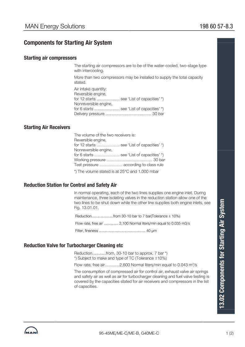
Components for Starting Air System
Starting air compressorsThe starting air compressors are to be of the water-cooled, two-stage typewith intercooling.More than two compressors may be installed to supply the total capacitystated.Air intake quantity:Reversible engine,for 12 starts .................... see ‘List of capacities’ *)Nonreversible engine,for 6 starts ...................... see ‘List of capacities’ *)Delivery pressure ........................................ 30 bar
Starting Air ReceiversThe volume of the two receivers is: Reversible engine,for 12 starts .................... see ‘List of capacities’ *)Nonreversible engine,for 6 starts ...................... see ‘List of capacities’ *)Working pressure ........................................ 30 barTest pressure .................... according to class rule*) The volume stated is at 25°C and 1,000 mbar
Reduction Station for Control and Safety AirIn normal operating, each of the two lines supplies one engine inlet. Duringmaintenance, three isolating valves in the reduction station allow one of thetwo lines to be shut down while the other line supplies both engine inlets, seeFig. 13.01.01.
Reduction.....................from 30-10 bar to 7 bar(Tolerance ± 10%)
Flow rate, free air .............. 2,100 Normal liters/min equal to 0.035 m3/s
Filter, fineness ............................................. 40 μm
Reduction Valve for Turbocharger Cleaning etcReduction............from, 30-10 bar to approx. 7 bar *)*) Subject to make and type of TC (Tolerance ±10%)Flow rate, free air.............2,600 Normal liters/min equal to 0.043 m3/sThe consumption of compressed air for control air, exhaust valve air springsand safety air as well as air for turbocharger cleaning and fuel valve testing iscovered by the capacities stated for air receivers and compressors in the listof capacities.
MAN Energy Solutions 198 60 57-8.3
95-45ME/ME-C/ME-B, G40ME-C 1 (2)
13.0
2 Co
mpo
nent
s for
Sta
rting
Air
Syst
em

Starting and Control Air PipesThe piping delivered with and fitted onto the main engine is shown in the fol-lowing figures in Section 13.03:Fig. 13.03.01 Starting air pipes Fig. 13.03.02 Air spring pipes, exhaust valves
Turning GearThe turning wheel has cylindrical teeth and is fitted to the thrust shaft. Theturning wheel is driven by a pinion on the terminal shaft of the turning gear,which is mounted on the bedplate.Engagement and disengagement of the turning gear is effected by displacingthe pinion and terminal shaft axially. To prevent the main engine from startingwhen the turning gear is engaged, the turning gear is equipped with a safetyarrangement which interlocks with the starting air system.The turning gear is driven by an electric motor with a built-in gear and brake.Key specifications of the electric motor and brake are stated in Section 13.04.
198 60 57-8.3 MAN Energy Solutions
2 (2) 95-45ME/ME-C/ME-B, G40ME-C
13.0
2 Co
mpo
nent
s for
Sta
rting
Air
Syst
em

Starting and Control Air PipesThe starting air pipes, Fig. 13.03.01, contain a main starting valve (a ball valvewith actuator), a nonreturn valve, a solenoid valve and a starting valve. Themain starting valve is controlled by the Engine Control System. Slow turningbefore start of engine, EoD: 4 50 141, is included in the basic design.The Engine Control System regulates the supply of control air to the startingvalves in accordance with the correct firing sequence and the timing.Please note that the air consumption for control air, turbocharger cleaning andfor fuel valve testing unit are momentary requirements of the consumers. Thecapacities stated for the air receivers and compressors in the ‘List of Capacit-ies’ cover all the main engine requirements and starting of the auxiliary en-gines.For information about a common starting air system for main engines andauxiliary engines, please refer to our publication:Uni-concept Auxiliary Systems for Two-Stroke Main Engines and Four-StrokeAuxiliary EnginesThe publication is available at www.marine.man-es.com --> 'Two-Stroke' -->'Technical Papers'.
The letters refer to list of ‘Counterflanges’The item nos. refer to ‘Guidance values automation’The piping is delivered with and fitted onto the engineFig. 13.03.01: Starting air pipes
MAN Energy Solutions 199 15 14-5.0
95-60ME-C/-GI/-GA/-LGI 1 (2)
13.0
3 St
artin
g an
d Co
ntro
l Air
Pipe
s

Exhaust Valve Air Spring PipesThe exhaust valve is opened hydraulically by the Proportional Exhaust ValveActuator (PEVA) valve, which is activated by the Engine Control System.The closing force is provided by an ‘air spring’ which leaves the valve spindlefree to rotate.The compressed air is taken from the control air supply, see Fig. 13.03.02.
The item nos. refer to ‘Guidance values automation’The piping is delivered with and fitted onto the engineFig. 13.03.02: Air spring pipes for exhaust valves
199 15 14-5.0 MAN Energy Solutions
2 (2) 95-60ME-C/-GI/-GA/-LGI
13.0
3 St
artin
g an
d Co
ntro
l Air
Pipe
s
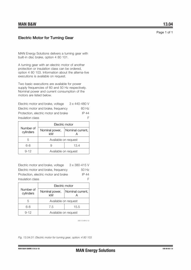
EElectric Motor for Turning Gear
533 12 49-6.1.0
Fig. 13.04.01: Electric motor for turning gear, option: 4 80 103
MAN B&W 13.04
Page 1 of 1
MAN B&W G90ME-C10.5/-GI 199 09 60-7.0MAN Energy Solutions

MAN B&W
MAN Energy Solutions
Scavenge Air
14


Scavenge Air SystemScavenge air is supplied to the engine by two or more turbochargers, locatedon the exhaust side of the engine. The compressor of the turbocharger drawsair from the engine room, through an air filter, and the compressed air iscooled by the scavenge air cooler, one per turbocharger. The scavenge aircooler is provided with a water mist catcher, which prevents condensate wa-ter from being carried with the air into the scavenge air receiver and to thecombustion chamber.The scavenge air system (see Figs. 14.01.01 and 14.02.01) is an integratedpart of the main engine. The engine power figures and the data in the list ofcapacities are based on MCR at tropical conditions, i.e. a seawater temperat-ure of 32°C, or freshwater temperature of 36°C, and an ambient air inlet tem-perature of 45°C.
Fig. 14.01.01: Scavenge Air System
MAN Energy Solutions 198 40 02-8.5
98-90MC/MC-C/ME/ME-C/-GI 1 (1)
14.0
1 Sc
aven
ge A
ir Sy
stem
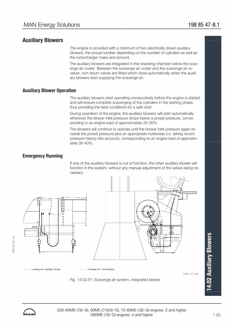
Auxiliary BlowersThe engine is provided with a minimum of two electrically driven auxiliaryblowers, the actual number depending on the number of cylinders as well asthe turbocharger make and amount.The auxiliary blowers are integrated in the reversing chamber below the scav-enge air cooler. Between the scavenge air cooler and the scavenge air re-ceiver, non-return valves are fitted which close automatically when the auxili-ary blowers start supplying the scavenge air.
Auxiliary Blower OperationThe auxiliary blowers start operating consecutively before the engine is startedand will ensure complete scavenging of the cylinders in the starting phase,thus providing the best conditions for a safe start.During operation of the engine, the auxiliary blowers will start automaticallywhenever the blower inlet pressure drops below a preset pressure, corres-ponding to an engine load of approximately 25-35%.The blowers will continue to operate until the blower inlet pressure again ex-ceeds the preset pressure plus an appropriate hysteresis (i.e. taking recentpressure history into account), corresponding to an engine load of approxim-ately 30-40%.
Emergency RunningIf one of the auxiliary blowers is out of function, the other auxiliary blower willfunction in the system, without any manual adjustment of the valves being ne-cessary.
Fig. 14.02.01: Scavenge air system, integrated blower
2021
-07-
19 -
en
MAN Energy Solutions 198 85 47-8.1
G95-60ME-C9/-GI, 90ME-C10/9/-GI, 70-60ME-C8/-GI engines .2 and higherS80ME-C9/-GI engines .4 and higher 1 (3)
14.0
2 Au
xilia
ry B
lowe
rs

Control of the Auxiliary BlowersThe control system for the auxiliary blowers is integrated in the Engine ControlSystem. The auxiliary blowers can be controlled in either automatic (default) ormanual mode.In automatic mode, the auxiliary blowers are started sequentially at the mo-ment the engine is commanded to start. During engine running, the blowersare started and stopped according to preset scavenge air pressure limits.When the engine stops, the blowers are stopped after 30 minutes to preventoverheating of the blowers. When a start is ordered, the blower will be startedin the normal sequence and the actual start of the engine will be delayed untilthe blowers have started.In manual mode, the blowers can be controlled individually from the ECR (En-gine Control Room) panel irrespective of the engine condition.Referring to Fig. 14.02.02, the Auxiliary Blower Starter Panels control and pro-tect the Auxiliary Blower motors, one panel with starter per blower.The starter panels with starters for the auxiliary blower motors are not in-cluded, they can be ordered as an option: 4 55 653. (The starter panel designand function is according to MAN Energy Solutions’s diagram, however, thephysical layout and choice of components has to be decided by the manufac-turer).Heaters for the blower motors are available as an option: 4 55 155.
Scavenge Air Cooler RequirementsThe data for the scavenge air cooler is specified in the description of the cool-ing water system chosen.For further information, please refer to our publication titled: MAN EnergySolutions Influence of Ambient Temperature ConditionsThe publication is available at man-es.com/marine → ’Two-Stroke’ → ’Tech-nical Papers’.
2021
-07-
19 -
en
198 85 47-8.1 MAN Energy Solutions
2 (3)G95-60ME-C9/-GI, 90ME-C10/9/-GI, 70-60ME-C8/-GI engines .2 and higher
S80ME-C9/-GI engines .4 and higher
14.0
2 Au
xilia
ry B
lowe
rs

Fig. 14.02.02: Diagram of auxiliary blower control system
2021
-07-
19 -
en
MAN Energy Solutions 198 85 47-8.1
G95-60ME-C9/-GI, 90ME-C10/9/-GI, 70-60ME-C8/-GI engines .2 and higherS80ME-C9/-GI engines .4 and higher 3 (3)
14.0
2 Au
xilia
ry B
lowe
rs

Scavenge Air Pipes
The item No. refer to ‘Guidance Values Automation’*) Option, see Fig. 15.02.05: Soft blast cleaning of turbine sideFig. 14.03.01: Scavenge air pipes
MAN Energy Solutions 198 40 13-6.5
98-60MC-C, 98-60ME/ME-C/ME-B/-GI/-GA 1 (1)
14.0
3 Sc
aven
ge A
ir Pi
pes
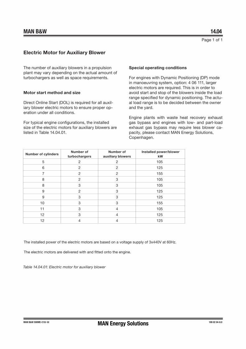
MAN B&W 14.04Page 1 of 1
MAN B&W S90ME-C10/-GI 199 02 04-8.0
Table 14.04.01: Electric motor for auxiliary blower
The installed power of the electric motors are based on a voltage supply of 3x440V at 60Hz.
The electric motors are delivered with and fitted onto the engine.
Electric Motor for Auxiliary Blower
Number of cylindersNumber of
turbochargersNumber of
auxiliary blowersInstalled power/blower
kW
5 2 2 105
6 2 2 125
7 2 2 155
8 2 3 105
8 3 3 105
9 2 3 125
9 3 3 125
10 3 3 155
11 3 4 105
12 3 4 125
12 4 4 125
The number of auxiliary blowers in a propulsion plant may vary depending on the actual amount of turbochargers as well as space requirements.
Motor start method and size
Direct Online Start (DOL) is required for all auxil-iary blower electric motors to ensure proper op-eration under all conditions.
For typical engine configurations, the installed size of the electric motors for auxiliary blowers are listed in Table 14.04.01.
Special operating conditions
For engines with Dynamic Positioning (DP) mode in manoeuvring system, option: 4 06 111, larger electric motors are required. This is in order to avoid start and stop of the blowers inside the load range specified for dynamic positioning. The actu-al load range is to be decided between the owner and the yard.
Engine plants with waste heat recovery exhaust gas bypass and engines with low- and part-load exhaust gas bypass may require less blower ca-pacity, please contact MAN Energy Solutions, Copenhagen.
MAN Energy Solutions

Scavenge Air Cooler Cleaning System
The letters refer to list of 'Counterflanges'. The item nos. refer to 'Guidancevalues automation'.Fig. 14.05.01: Air cooler cleaning pipes, two or more air coolers, for EGRThe air side of the scavenge air cooler can be cleaned by injecting a greasedissolving media through ‘AK’ to a spray pipe arrangement fitted to the airchamber above the air cooler element.
Drain from Water Mist CatcherSludge is drained through ‘AL’ to the drain water collecting tank and the pol-luted grease dissolvent returns from ‘AM’, through a filter, to the chemicalcleaning tank. The cleaning must be carried out while the engine is at stand-still.Dirty water collected after the water mist catcher is drained through ‘DX’ andled to the bilge tank via an open funnel, see Fig. 14.05.02.The ‘AL’ drain line is, during running, used as a permanent drain from the aircooler water mist catcher. The water is led through an orifice to prevent majorlosses of scavenge air.The system is equipped with a drain box with a level switch, indicating any ex-cessive water level.The piping delivered with and fitted on the engine is shown in Fig. 14.05.01.
2021
-02-
25 -
en
MAN Energy Solutions 199 13 70-5.0
G/S95-70ME-C/-GI 1 (3)
14.0
5 Sc
aven
ge A
ir Co
oler
Clea
ning
Sys
tem

Auto Pump Overboard SystemIt is common practice on board to lead drain water directly overboard via acollecting tank. Before pumping the drain water overboard, it is recommendedto measure the oil content. If above 15ppm, the drain water should be lead tothe clean bilge tank / bilge holding tank.If required by the owner, a system for automatic disposal of drain water withoil content monitoring could be built as outlined in Fig. 14.05.02.
198 76 84-9.2
The letters refer to list of 'Counterflanges'.Fig. 14.05.02: Suggested automatic disposal of drain water, if required byowner (not a demand from MAN Energy Solutions)
2021
-02-
25 -
en
199 13 70-5.0 MAN Energy Solutions
2 (3) G/S95-70ME-C/-GI
14.0
5 Sc
aven
ge A
ir Co
oler
Clea
ning
Sys
tem

Air Cooler Cleaning Unit
Engine type No. of cylinders Chemical tank capacity, m3 Circulation pump capacity at 3 bar, m3/h
G70ME-C 5-7 0.6 2
8 0.9 3
S70ME-C 5-7 0.6 2
8 0.9 3
G80ME-C 5-7 0.6 2
8-9 0.9 3
S80ME-C 5-7 0.6 2
8-9 0.9 3
G90ME-C 6-8 0.9 3
9-12 1.5 5
S90ME-C 6-8 0.9 3
9-12 1.5 5
G95ME-C 6-8 0.9 3
9-12 1.5 5
Fig. 14.05.03: Air cooler cleaning system with Air Cooler Cleaning Unit, option: 4 55 665
2021
-02-
25 -
en
MAN Energy Solutions 199 13 70-5.0
G/S95-70ME-C/-GI 3 (3)
14.0
5 Sc
aven
ge A
ir Co
oler
Clea
ning
Sys
tem
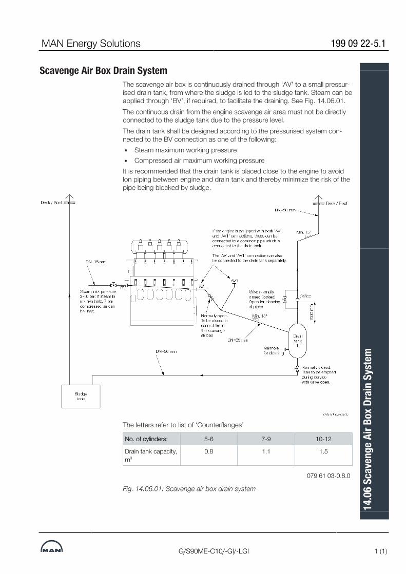
Scavenge Air Box Drain SystemThe scavenge air box is continuously drained through ‘AV’ to a small pressur-ised drain tank, from where the sludge is led to the sludge tank. Steam can beapplied through ‘BV’, if required, to facilitate the draining. See Fig. 14.06.01.The continuous drain from the engine scavenge air area must not be directlyconnected to the sludge tank due to the pressure level.The drain tank shall be designed according to the pressurised system con-nected to the BV connection as one of the following:▪ Steam maximum working pressure▪ Compressed air maximum working pressureIt is recommended that the drain tank is placed close to the engine to avoidlon piping between engine and drain tank and thereby minimize the risk of thepipe being blocked by sludge.
The letters refer to list of ‘Counterflanges’
No. of cylinders: 5-6 7-9 10-12
Drain tank capacity,m3
0.8 1.1 1.5
079 61 03-0.8.0
Fig. 14.06.01: Scavenge air box drain system
MAN Energy Solutions 199 09 22-5.1
G/S90ME-C10/-GI/-LGI 1 (1)
14.0
6 Sc
aven
ge A
ir Bo
x Dra
in S
yste
m

Fire Extinguishing Systems for Scavenge Air Space
Fig. 14.07.01: Fire extinguishing system for scavenge air spaceFire in the scavenge air space can be extinguished by steam, this being thebasic solution, or, optionally, by water mist or CO2.The external system, pipe and flange connections are shown in Fig. 14.07.01and the piping fitted onto the engine in Fig. 14.07.02.In the Extent of Delivery, the fire extinguishing system for scavenge air spaceis selected by the fire extinguishing agent:▪ basic solution: 4 55 140 Steam▪ option: 4 55 142 Water mist▪ option: 4 55 143 CO2
The key specifications of the fire extinguishing agents are:
Steam fire extinguishing for scavenge air space
Steam pressure: 3-10 bar
Steam quantity, approx.: 7.8 kg/cyl.
Water mist fire extinguishing for scavenge air space
Freshwater pressure: min. 3.5 bar
Freshwater quantity, approx.: 6.3 kg/cyl.
CO2 fire extinguishing for scavenge air space
CO2 test pressure: 150 bar
CO2 quantity, approx.: 15.07 kg/cyl.
MAN Energy Solutions 199 10 09-0.1
90ME-C/-GI 1 (2)
14.0
7 Fir
e Ext
ingu
ishin
g Sy
stem
s for
Sca
veng
e Air
Spac
e

Fire Extinguishing in Scavenge Air Space
The letters refer to 'List of flanges'. The item no. refer to 'Guidance Values Automation'.Fig. 14.07.02: Fire extinguishing pipes in scavenge air space
Scavenge Air Space, Drain Pipes
The letters refer to 'List of flanges'.Fig. 14.07.03: Scavenge air space, drain pipes
199 10 09-0.1 MAN Energy Solutions
2 (2) 90ME-C/-GI
14.0
7 Fir
e Ext
ingu
ishin
g Sy
stem
s for
Sca
veng
e Air
Spac
e

MAN B&W
MAN Energy Solutions
Exhaust Gas
15


Exhaust Gas SystemThe exhaust gas is led from the cylinders to the exhaust gas receiver wherethe fluctuating pressures from the cylinders are equalised and from where thegas is led further on to the turbocharger at a constant pressure. See fig.15.01.01.Compensators are fitted between the exhaust valve housings and the exhaustgas receiver and between the receiver and the turbocharger. A protectivegrating is placed between the exhaust gas receiver and the turbocharger. Theturbocharger is fitted with a pick-up for monitoring and remote indication ofthe turbocharger speed.The exhaust gas receiver and the exhaust pipes are provided with insulation,covered by steel plating
Turbocharger Arrangement and Cleaning SystemThe turbochargers are located on the exhaust side of the engine.The engine is designed for the installation of the MAN turbocharger type TCA,option: 4 59 101, ABB turbocharger type A-L, option: 4 59 102, or MHI tur-bocharger type MET, option: 4 59 103.All makes of turbochargers are fitted with an arrangement for water washingof the compressor side, and soft blast cleaning of the turbine side, see Figs.15.02.02, 15.02.03 and 15.02.04. Washing of the turbine side is only applic-able on MAN turbochargers, though not for dual fuel engines.
MAN Energy Solutions 198 40 47-2.8
98-65MC/MC-C/ME/ME-C/-GI/-GA/G/S/L60ME-C/-GI 1 (2)
15.0
1 Ex
haus
t Gas
Sys
tem
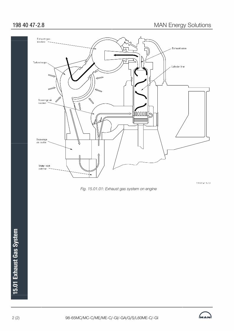
Fig. 15.01.01: Exhaust gas system on engine
198 40 47-2.8 MAN Energy Solutions
2 (2) 98-65MC/MC-C/ME/ME-C/-GI/-GA/G/S/L60ME-C/-GI
15.0
1 Ex
haus
t Gas
Sys
tem
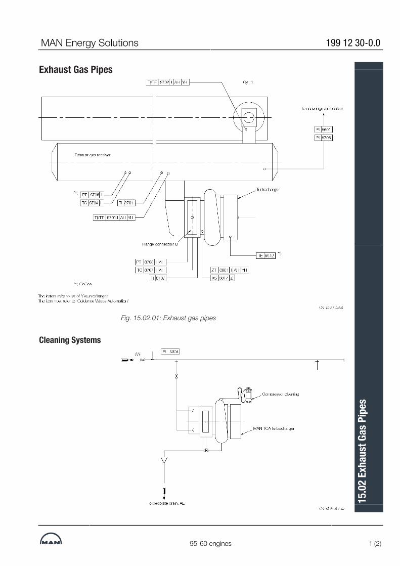
Exhaust Gas Pipes
Fig. 15.02.01: Exhaust gas pipes
Cleaning Systems
MAN Energy Solutions 199 12 30-0.0
95-60 engines 1 (2)
15.0
2 Ex
haus
t Gas
Pip
es

Fig. 15.02.02: MAN TCA turbocharger, water washing of turbine side
Fig. 15.02.03: Soft blast cleaning of turbine side and water washing of com-pressor side for ABB turbochargers
Soft Blast Cleaning Systems
Fig. 15.02.04: Soft blast cleaning of turbine side, basic
199 12 30-0.0 MAN Energy Solutions
2 (2) 95-60 engines
15.0
2 Ex
haus
t Gas
Pip
es

Exhaust Gas System for Main EngineAt the specified MCR of the engine, the total back-pressure in the exhaustgas system after the turbocharger (as indicated by the static pressure meas-ured in the piping after the turbocharger) must not exceed 350 mm WC(0.035 bar).
In order to have a back-pressure margin for the final system, it is recommen-ded at the design stage to initially use a value of about 300 mm WC (0.030bar).
The actual back-pressure in the exhaust gas system at specified MCR de-pends on the gas velocity, i.e. it is proportional to the square of the exhaustgas velocity, and hence inversely proportional to the pipe diameter to the 4thpower. It has by now become normal practice in order to avoid too muchpressure loss in the pipings to have an exhaust gas velocity at specified MCRof about 35 m/sec, but not higher than 50 m/sec.
For dimensioning of the external exhaust pipe connections, see the exhaustpipe diameters for 35 m/sec, 40 m/sec, 45 m/sec and 50 m/sec respectively,shown in Table 15.07.02.
As long as the total back-pressure of the exhaust gas system (incorporatingall resistance losses from pipes and components) complies with the above-mentioned requirements, the pressure losses across each component may bechosen independently, see proposed measuring points (M) in Fig. 15.05.01.The general design guidelines for each component, described below, can beused for guidance purposes at the initial project stage.
Exhaust Gas Piping System for main EngineThe exhaust gas piping system conveys the gas from the outlet of the tur-bocharger(s) to the atmosphere.The exhaust piping is shown schematically in Fig. 15.04.01.The exhaust system for the main engine comprises:▪ Exhaust gas pipes▪ Exhaust gas boiler▪ Silencer▪ Spark arrester (if needed)▪ Expansion joints (compensators)▪ Pipe bracings.In connection with dimensioning the exhaust gas piping system, the followingparameters must be observed:▪ Exhaust gas flow rate▪ Exhaust gas temperature at turbocharger outlet▪ Maximum pressure drop through exhaust gas system▪ Maximum noise level at gas outlet to atmosphere▪ Maximum force from exhaust piping on turbocharger(s)▪ Sufficient axial and lateral elongation ability of expansion joints▪ Utilisation of the heat energy of the exhaust gas.
MAN Energy Solutions 198 40 74-6.3
MC/MC-C, ME/ME-C/ME-GI/ME-B 1 (2)
15.0
3 Ex
haus
t Gas
Sys
tem
for M
ain
Engi
ne

Items that are to be calculated or read from tables are:▪ Exhaust gas mass flow rate, temperature and maximum back pressure at
turbocharger gas outlet▪ Diameter of exhaust gas pipes▪ Utilisation of the exhaust gas energy▪ Attenuation of noise from the exhaust pipe outlet▪ Pressure drop across the exhaust gas system▪ Expansion joints.
198 40 74-6.3 MAN Energy Solutions
2 (2) MC/MC-C, ME/ME-C/ME-GI/ME-B
15.0
3 Ex
haus
t Gas
Sys
tem
for M
ain
Engi
ne
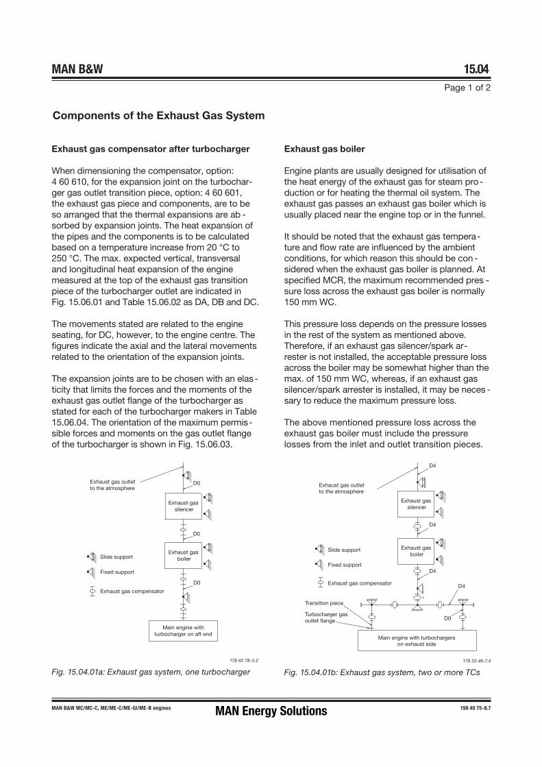
MAN B&W 15.04Page 1 of 2
198 40 75�8.7MAN B&W MC/MC�C, ME/ME�C/ME�GI/ME-B engines
Components of the Exhaust Gas System
Exhaust gas boiler
Engine plants are usually designed for utilisation of the heat energy of the exhaust gas for steam pro-duction or for heating the thermal oil system. The exhaust gas passes an exhaust gas boiler which is usually placed near the engine top or in the funnel.
It should be noted that the exhaust gas tempera-ture and flow rate are influenced by the ambient conditions, for which reason this should be con -sidered when the exhaust gas boiler is planned. At specified MCR, the maximum recommended pres -sure loss across the exhaust gas boiler is normally 150 mm WC.
This pressure loss depends on the pressure losses in the rest of the system as mentioned above. Therefore, if an exhaust gas silencer/spark ar-rester is not installed, the acceptable pressure loss across the boiler may be somewhat higher than the max. of 150 mm WC, whereas, if an exhaust gas silencer/spark arrester is installed, it may be neces -sary to reduce the maximum pressure loss.
The above mentioned pressure loss across the exhaust gas boiler must include the pressure losses from the inlet and outlet transition pieces.
Fig. 15.04.01a: Exhaust gas system, one turbocharger
178 42 78�3.2
Exhaust gas compensator after turbocharger
When dimensioning the compensator, option: 4 60 610, for the expansion joint on the turbochar-ger gas outlet transition piece, option: 4 60 601, the exhaust gas piece and components, are to be so arranged that the thermal expansions are ab -sorbed by expansion joints. The heat expansion of the pipes and the components is to be calculated based on a temperature increase from 20 °C to 250 °C. The max. expected vertical, transversal and longitudinal heat expansion of the engine measured at the top of the exhaust gas transition piece of the turbocharger outlet are indicated in Fig. 15.06.01 and Table 15.06.02 as DA, DB and DC.
The movements stated are related to the engine seating, for DC, however, to the engine centre. The figures indicate the axial and the lateral movements related to the orientation of the expansion joints.
The expansion joints are to be chosen with an elas -ticity that limits the forces and the moments of the exhaust gas outlet flange of the turbocharger as stated for each of the turbocharger makers in Table 15.06.04. The orientation of the maximum permis-sible forces and moments on the gas outlet flange of the turbocharger is shown in Fig. 15.06.03.
urbocharger gasoutlet flange
D
D
D
D
Exhaust gas outletto the atmosphere
Slide support
Fixed support
Exhaust gas compensator
Main engine with turbochargerson exhaust side
ransition piece
Exhaust gas silencer
Exhaust gas boiler
D0
Fig. 15.04.01b: Exhaust gas system, two or more TCs
178 33 46�7.4
Exhaust gas outletto the atmosphere
Slide support
Fixed support
Exhaust gas compensator
Main engine withturbocharger on aft end
D0
D0
D0
Exhaust gas silencer
Exhaust gas boiler
MAN Energy Solutions

MAN B&W 15.04Page 2 of 2
MAN B&W G90ME-C10.5/-GI-TII 199 05 25-9.0
Exhaust gas silencer
The typical octave band sound pressure levels from the diesel engine’s exhaust gas system – at a distance of one meter from the top of theexhaust gas uptake – are shown in Fig.15.04.02.
The need for an exhaust gas silencer can be de-cided based on the requirement of a maximum permissible noise level at a specific position.
The exhaust gas noise data is valid for an exhaust gas system without boiler and silencer, etc.
The noise level is at nominal MCR at a distance of one metre from the exhaust gas pipe outlet edge at an angle of 30° to the gas flow direction.
For each doubling of the distance, the noise level will be reduced by about 6 dB (far�field law).
When the noise level at the exhaust gas outlet to the atmosphere needs to be silenced, a silencer can be placed in the exhaust gas piping system after the exhaust gas boiler.
The exhaust gas silencer is usually of the absorp-tion type and is dimensioned for a gas velocity of approximately 35 m/s through the central tube of the silencer.
An exhaust gas silencer can be designed based on the required damping of noise from the exhaust gas given on the graph.
In the event that an exhaust gas silencer is re-quired – this depends on the actual noise level requirement on the bridge wing, which is normally maximum 60�70 dB(A) – a simple flow silencer of the absorption type is recommended. Dep-ending on the manufacturer, this type of silencer normally has a pressure loss of around 20 mm WC at specified MCR.
Spark arrester
To prevent sparks from the exhaust gas being spread over deck houses, a spark arrester can be fitted as the last component in the exhaust gas system.
It should be noted that a spark arrester contrib-utes with a considerable pressure drop, which is often a disadvantage.
It is recommended that the combined pressure loss across the silencer and/or spark arrester should not be allowed to exceed 100 mm WC at specified MCR. This depends, of course, on the pressure loss in the remaining part of the system, thus if no exhaust gas boiler is installed, 200 mm WC might be allowed.
Fig. 15.04.02: ISO’s NR curves and typical sound pres-sure levels from the engine’s exhaust gas system. The noise levels at nominal MCR and a distance of 1 metre from the edge of the exhaust gas pipe opening at an an -gle of 30 degrees to the gas flow and valid for an exhaust gas system – without boiler and silencer, etc. Data for a specific engine and cylinder no. is available on request.
178 69 12-7.0
Centre frequencies of octave bands
12G90ME-C10.5/-GI
5G90ME-C10.5/-GI
dB dB (A)140
130
120
110
100
90
80
70
60
5031,5 63 125 250 500 1k 2k 4k 8kHz
140
130
120
110
100
90
80
70
NR60504030020
10
MAN Energy Solutions

Calculation of Exhaust Gas Back-PressureThe exhaust gas back pressure after the turbocharger(s) depends on the totalpressure drop in the exhaust gas piping system.The components, exhaust gas boiler, silencer, and spark arrester, if fitted,usually contribute with a major part of the dynamic pressure drop through theentire exhaust gas piping system.The components mentioned are to be specified so that the sum of the dy-namic pressure drop through the different components should, if possible, ap-proach 200 mm WC at an exhaust gas flow volume corresponding to the spe-cified MCR at tropical ambient conditions. Then there will be a pressure dropof 100 mm WC for distribution among the remaining piping system.Fig. 15.05.01 shows some guidelines regarding resistance coefficients andback-pressure loss calculations which can be used, if the maker’s data forback-pressure is not available at an early stage of the project.The pressure loss calculations have to be based on the actual exhaust gasamount and temperature valid for specified MCR. Some general formulas anddefinitions are given in the following.
Exhaust Gas DataM: exhaust gas amount at specified MCR in kg/sec. T: exhaust gas temperature at specified MCR in °CPlease note that the actual exhaust gas temperature is different before andafter the boiler. The exhaust gas data valid after the turbocharger may befound in Chapter 6.
Mass Destiny of Exhaust Gas (ρ)ρ ≅ 1.293 x (273 / [ 273 + T ]) x 1.015 in kg/m3
The factor 1.015 refers to the average back-pressure of 150 mm WC (0.015bar) in the exhaust gas system.
Exhaust Gas Velocity (v)In a pipe with diameter D the exhaust gas velocity is:
V = M/ρ x (4 / [ π x D2] ) in m/s
Pressure Losses in Pipes (Δp)For a pipe element, like a bend etc., with the resistance coefficient ζ, the cor-responding pressure loss is:
Δp = (ζ x ½ ρ [v2 x 1/9.81]) in mm WC
where the expression after ζ is the dynamic pressure of the flow in the pipe.The friction losses in the straight pipes may, as a guidance, be estimated as :1 mm WC per 1 diameter lengthwhereas the positive influence of the up-draught in the vertical pipe is normallynegligible.
MAN Energy Solutions 198 40 94-9.5
MC/MC-C, ME/ME-C/-GI/-GA/ME-B 1 (4)
15.0
5 Ca
lcula
tion
of E
xhau
st G
as B
ack-
Pres
sure

Pressure Losses Across Components (Δp)The pressure loss Δp across silencer, exhaust gas boiler, spark arrester, rainwater trap, etc., to be measured/ stated as shown in Fig. 15.05.01 (at spe-cified MCR) is normally given by the relevant manufacturer.
Total Back-Pressure (ΔpM)The total back-pressure, measured/stated as the static pressure in the pipeafter the turbocharger, is then:
ΔpM = Σ Δp
where Δp incorporates all pipe elements and components etc. as described:
ΔpM has to be lower than 350 mm WC.
(At design stage it is recommended to use max. 300 mm WC in order to havesome margin for fouling).
Mesuring Back PressureAt any given position in the exhaust gas system, the total pressure of the flowcan be divided into dynamic pressure (referring to the gas velocity) and staticpressure (referring to the wall pressure, where the gas velocity is zero).At a given total pressure of the gas flow, the combination of dynamic andstatic pressure may change, depending on the actual gas velocity. The meas-urements, in principle, give an indication of the wall pressure, i.e., the staticpressure of the gas flow.It is, therefore, very important that the back pressure measuring points arelocated on a straight part of the exhaust gas pipe, and at some distance froman ‘obstruction‘, i.e. at a point where the gas flow, and thereby also the staticpressure, is stable. Taking measurements, for example, in a transition piece,may lead to an unreliable measurement of the static pressure.In consideration of the above, therefore, the total back pressure of the systemhas to be measured after the turbocharger in the circular pipe and not in thetransition piece. The same considerations apply to the measuring points be-fore and after the exhaust gas boiler, etc.
198 40 94-9.5 MAN Energy Solutions
2 (4) MC/MC-C, ME/ME-C/-GI/-GA/ME-B
15.0
5 Ca
lcula
tion
of E
xhau
st G
as B
ack-
Pres
sure

Pressure Losses and Coefficients of Resistance in Exhaust PipesChange-over valves
Change-over valves of type with constantcross section
ζa = 0.6 to 1.2ζb = 1.0 to 1.5ζc = 1.5 to 2.0
Change-over valve of type with volume
ζa = ζb = about 2.0
MAN Energy Solutions 198 40 94-9.5
MC/MC-C, ME/ME-C/-GI/-GA/ME-B 3 (4)
15.0
5 Ca
lcula
tion
of E
xhau
st G
as B
ack-
Pres
sure
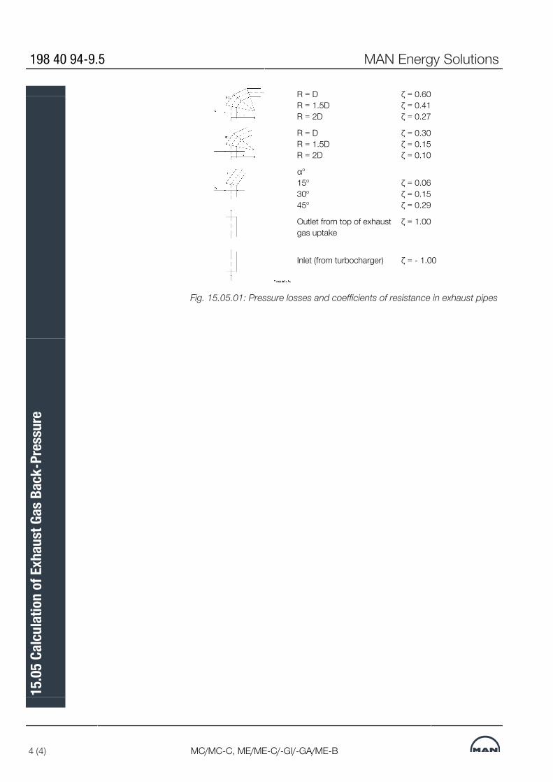
R = D R = 1.5D R = 2D
ζ = 0.60ζ = 0.41ζ = 0.27
R = D R = 1.5D R = 2D
ζ = 0.30ζ = 0.15ζ = 0.10
αo 15o
30o
45o
ζ = 0.06ζ = 0.15ζ = 0.29
Outlet from top of exhaustgas uptake
ζ = 1.00
Inlet (from turbocharger) ζ = - 1.00
Fig. 15.05.01: Pressure losses and coefficients of resistance in exhaust pipes
198 40 94-9.5 MAN Energy Solutions
4 (4) MC/MC-C, ME/ME-C/-GI/-GA/ME-B
15.0
5 Ca
lcula
tion
of E
xhau
st G
as B
ack-
Pres
sure

Forces and Moments at Turbochargers
MAN Energy Solutions 198 52 98-1.2
1 (1)
15.0
6 Fo
rces
and
Mom
ents
at T
urbo
char
gers

MAN B&W 15.07Page 1 of 1
198 85 45-4.1MAN B&W S90ME-C9/10/-GI
Expansion jointoption: 4 60 610
Transition pieceoption: 4 60 601
Centre line turbocharger
D4
D0
D4
D4
Diameter of Exhaust Gas Pipes
178 09 39�5.2
Fig. 15.07.01: Exhaust pipe system, with turbocharger located on exhaust side of engine
Table 15.07.02: Exhaust gas pipe diameters and exhaust gas mass flow at various velocities
The exhaust gas pipe diameters listed in Table 15.07.02 are based on the exhaust gas flow ca-pacity according to ISO ambient conditions and an exhaust gas temperature of 250 ºC.
The exhaust gas velocities and mass flow listed apply to collector pipe D4. The table also lists the diameters of the corresponding exhaust gas pipes D0 for various numbers of turbochargers installed.
Gas velocity Exhaust gas pipe diameters35 m/s 40 m/s 45 m/s 50 m/s D0 D4
Gas mass flow 2 T/C 3 T/C 4 T/Ckg/s kg/s kg/s kg/s [DN] [DN] [DN] [DN]
60.1 68.7 77.3 85.9 1,300 1,050 900 1,800
67.0 76.5 86.1 95.7 1,300 1,100 950 1,900
74.2 84.8 95.4 106.0 1,400 1,150 1,000 2,000
81.8 93.5 105.2 116.9 1,500 1,200 1,050 2,100
89.8 102.6 115.5 128.3 1,600 1,300 1,100 2,200
98.1 112.2 126.2 140.2 1,600 1,300 1,150 2,300
106.9 122.1 137.4 152.7 1,700 1,400 1,200 2,400
116.0 132.5 149.1 165.6 1,800 1,400 1,300 2,500
125.4 143.3 161.2 179.2 1,800 1,500 1,300 2,600
135.2 154.6 173.9 193.2 N.A. 1,600 1,400 2,700
145.5 166.2 187.0 207.8 N.A. 1,600 1,400 2,800
156.0 178.3 200.6 222.9 N.A. 1,700 1,500 2,900
167.0 190.8 214.7 238.5 N.A. 1,700 1,500 3,000
178.3 203.8 229.2 254.7 N.A. 1,800 1,600 3,100
190.0 217.1 244.3 271.4 N.A. 1,800 1,600 3,200
MAN Energy Solutions

MAN B&W
MAN Energy Solutions
Engine Control System
16


Engine Control System METhe Engine Control System (ECS) for the ME engine is prepared for conven-tional remote control, having an interface to the Bridge Control system andthe Local Operating Panel (LOP).A Multi-Purpose Controller (MPC) is applied as control unit for specific tasksdescribed below: ACU, CCU, CWCU, ECU, SCU and EICU. Except for theCCU, the control units are all built on the same identical piece of hardwareand differ only in the software installed. For the CCU on ME and ME-C only, adownsized and cost-optimised controller is applied, the MPC10.The layout of the Engine Control System is shown in Figs. 16.01.01a and b,the mechanical-hydraulic system is shown in Figs. 16.01.02a and b, and thepneumatic system, shown in Fig. 16.01.03.The ME system has a high level of redundancy. It has been a requirement toits design that no single failure related to the system may cause the engine tostop. In most cases, a single failure will not affect the performance or poweravailability, or only partly do so by activating a slow down.It should be noted that any controller could be replaced without stopping theengine, which will revert to normal operation immediately after the replace-ment of the defective unit.
Main Operating PanelTwo redundant main operating panel (MOP) screens are available for the en-gineer to carry out engine commands, adjust the engine parameters, selectthe running modes, and observe the status of the control system. Both MOPscreens are located in the Engine Control Room (ECR), one serving as back-up unit in case of failure or to be used simultaneously, if preferred.Both MOP screens consist of a marine approved Personal Computer with atouch screen and pointing device as shown in Fig. 5.16.02.
Engine Control UnitFor redundancy purposes, the control system comprises two engine controlunits (ECU) operating in parallel and performing the same task, one being ahot stand-by for the other. If one of the ECUs fail, the other unit will take overthe control without any interruption.The ECUs perform such tasks as:▪ Speed governor functions, start/stop sequences, timing of fuel injection,
timing of exhaust valve activation, timing of starting valves, etc.▪ Continuous running control of auxiliary functions handled by the ACUs▪ Alternative running modes and programs
Cylinder Control UnitThe control system includes one cylinder control unit (CCU) per cylinder. TheCCU controls the multi-way valves: Electronic Fuel Injection (ELFI) and Elec-tronic exhaust Valve Actuation (ELVA) or Fuel Injection and exhaust Valve Ac-tivation (FIVA) as well as the Starting Air Valves (SAV) in accordance with thecommands received from the ECU.
MAN Energy Solutions 199 15 31-2.0
G95-80ME-C10.5/10.6/-GI, S/G70-60ME-C10.5/10.6/-GI/-GA 1 (12)
16.0
1 En
gine
Con
trol S
yste
m M
E

All the CCUs are identical, and in the event of a failure of the CCU for one cyl-inder only this cylinder will automatically be cut out of operation.
Auxiliary Control UnitThe control of the auxiliary equipment on the engine is normally dividedamong three auxiliary control units (ACU) so that, in the event of a failure ofone unit, there is sufficient redundancy to permit continuous operation of theengine.The ACUs perform the control of the auxiliary blowers, the control of the elec-trically and engine driven hydraulic oil pumps of the Hydraulic Power Supply(HPS) unit. On engines fitted with ACOM, it is controlled by one of the ACUstoo.
Cooling Water Control UnitOn engines with load dependent cylinder liner (LDCL) cooling water system, acooling water control unit (CWCU) controls the liner circulation string temper-ature by means of a three-way valve.
Scavenge Air Control UnitThe scavenge air control unit (SCU) controls the scavenge air pressure on en-gines with advanced scavenge air systems like exhaust gas bypass (EGB)with on/off or variable valve, waste heat recovery system (WHRS) and tur-bocharger with variable turbine inlet area (VT) technology.For part- and low-load optimised engines with EGB variable bypass regulationvalve, Economiser Engine Control (EEC) is available as an option in order tooptimise the steam production versus SFOC, option: 4 65 342.
Engine Interface Control UnitThe two engine interface control units (EICU) perform such tasks as interfacewith the surrounding control systems, see Fig. 16.01.01a and b. The twoEICU units operate in parallel and ensures redundancy for mission critical in-terfaces.The EICUs are located either in the Engine Control Room (recommended) orin the engine room.In the basic execution, the EICUs are a placed in the Cabinet for EICUs, EoD:4 65 601.
Control NetworkThe MOP, the backup MOP and the MPCs are interconnected by means ofthe redundant Control Networks, A and B respectively.The maximum length of Control Network cabling between the furthermostunits on the engine and in the Engine Control Room (an EICU or a MOP) is230 meter.
199 15 31-2.0 MAN Energy Solutions
2 (12) G95-80ME-C10.5/10.6/-GI, S/G70-60ME-C10.5/10.6/-GI/-GA
16.0
1 En
gine
Con
trol S
yste
m M
E
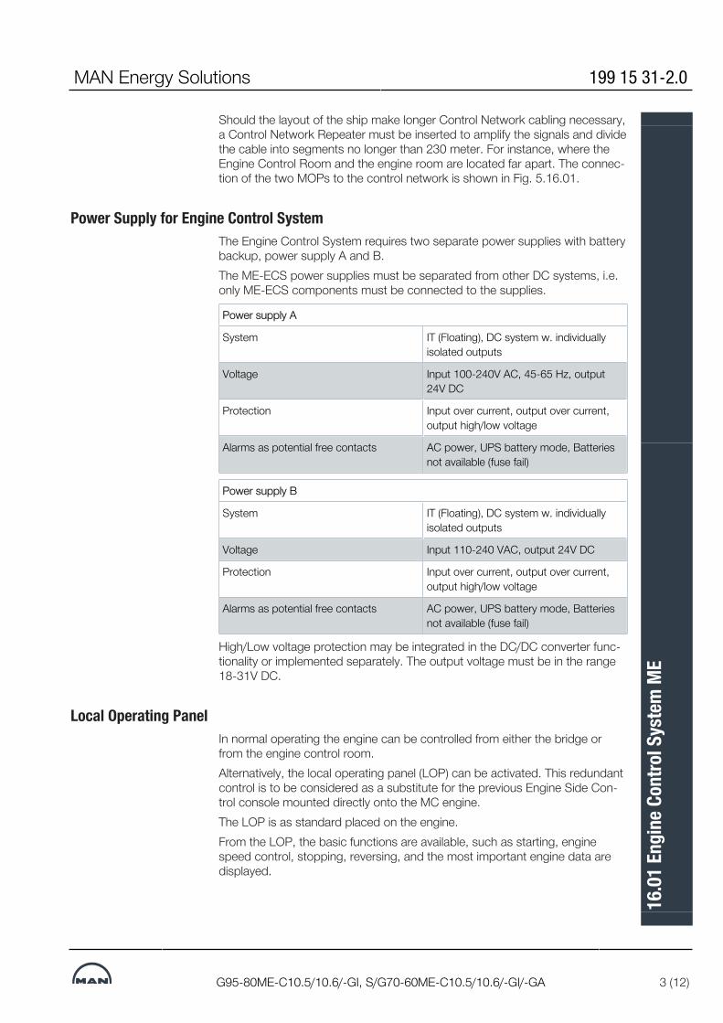
Should the layout of the ship make longer Control Network cabling necessary,a Control Network Repeater must be inserted to amplify the signals and dividethe cable into segments no longer than 230 meter. For instance, where theEngine Control Room and the engine room are located far apart. The connec-tion of the two MOPs to the control network is shown in Fig. 5.16.01.
Power Supply for Engine Control SystemThe Engine Control System requires two separate power supplies with batterybackup, power supply A and B.The ME-ECS power supplies must be separated from other DC systems, i.e.only ME-ECS components must be connected to the supplies.
Power supply A
System IT (Floating), DC system w. individuallyisolated outputs
Voltage Input 100-240V AC, 45-65 Hz, output24V DC
Protection Input over current, output over current,output high/low voltage
Alarms as potential free contacts AC power, UPS battery mode, Batteriesnot available (fuse fail)
Power supply B
System IT (Floating), DC system w. individuallyisolated outputs
Voltage Input 110-240 VAC, output 24V DC
Protection Input over current, output over current,output high/low voltage
Alarms as potential free contacts AC power, UPS battery mode, Batteriesnot available (fuse fail)
High/Low voltage protection may be integrated in the DC/DC converter func-tionality or implemented separately. The output voltage must be in the range18-31V DC.
Local Operating PanelIn normal operating the engine can be controlled from either the bridge orfrom the engine control room.Alternatively, the local operating panel (LOP) can be activated. This redundantcontrol is to be considered as a substitute for the previous Engine Side Con-trol console mounted directly onto the MC engine.The LOP is as standard placed on the engine.From the LOP, the basic functions are available, such as starting, enginespeed control, stopping, reversing, and the most important engine data aredisplayed.
MAN Energy Solutions 199 15 31-2.0
G95-80ME-C10.5/10.6/-GI, S/G70-60ME-C10.5/10.6/-GI/-GA 3 (12)
16.0
1 En
gine
Con
trol S
yste
m M
E

Hydraulic Power SupplyThe purpose of the hydraulic power supply (HPS) unit is to deliver the neces-sary high pressure hydraulic oil flow to the Hydraulic Cylinder Units (HCU) onthe engine at the required pressure (approx. 300 bar) during start-up as wellas in normal service.In case of the STANDARD mechanically driven HPS unit, at start, one of thetwo electrically driven start-up pumps is activated. The start-up pump isstopped 25 seconds after the engine reaches 15% speed.The multiple pump configuration with standby pumps ensures redundancywith regard to the hydraulic power supply. The control of the engine drivenpumps and electrical pumps are divided between the three ACUs.The high pressure pipes between the HPS unit and the HCU are of thedouble-walled type, having a leak detector (210 bar system only). Emergencyrunning is possible using the outer pipe as pressure containment for the highpressure oil supply.The sizes and capacities of the HPS unit depend on the engine type. Furtherdetails about the HPS and the lubricating oil/hydraulic oil system can be foundin Chapter 8.
199 15 31-2.0 MAN Energy Solutions
4 (12) G95-80ME-C10.5/10.6/-GI, S/G70-60ME-C10.5/10.6/-GI/-GA
16.0
1 En
gine
Con
trol S
yste
m M
E

Engine Control System Layout with Cabinet for EICU
Fig. 16.01.01a: Engine Control System layout with cabinet for EICU formounting in ECR or on engine, EoD: 4 65 601
MAN Energy Solutions 199 15 31-2.0
G95-80ME-C10.5/10.6/-GI, S/G70-60ME-C10.5/10.6/-GI/-GA 5 (12)
16.0
1 En
gine
Con
trol S
yste
m M
E

Engine Control System Layout with Common Control Cabinet
Fig. 16.01.01b: Engine Control System layout with ECS Common ControlCabinet for mounting in ECR or on engine, option: 4 65 602
199 15 31-2.0 MAN Energy Solutions
6 (12) G95-80ME-C10.5/10.6/-GI, S/G70-60ME-C10.5/10.6/-GI/-GA
16.0
1 En
gine
Con
trol S
yste
m M
E

Mechanical-Hydraulic System with Mechanically Driven HPS
The letters refer to list of ‘Counterflanges’ The item no. refer to ‘Guidance Values Automation’Fig. 16.01.02a: Mechanical-hydraulic System with mechanically driven Hy-draulic Power Supply, 300 bar, common supply
MAN Energy Solutions 199 15 31-2.0
G95-80ME-C10.5/10.6/-GI, S/G70-60ME-C10.5/10.6/-GI/-GA 7 (12)
16.0
1 En
gine
Con
trol S
yste
m M
E

Mechanical-Hydraulic System with Electrically Driven HPS
The letters refer to list of ‘Counterflanges’ The item no. refer to ‘Guidance Values Automation’Fig. 16.01.02b: Mechanical-hydraulic System with electrically driven HydraulicPower Supply, 300 bar, common supply. Example from S90/80ME-C engine
199 15 31-2.0 MAN Energy Solutions
8 (12) G95-80ME-C10.5/10.6/-GI, S/G70-60ME-C10.5/10.6/-GI/-GA
16.0
1 En
gine
Con
trol S
yste
m M
E
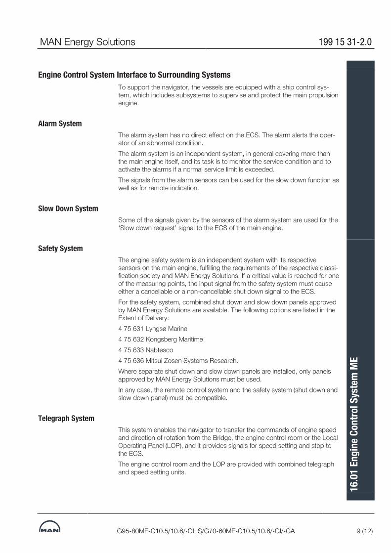
Engine Control System Interface to Surrounding SystemsTo support the navigator, the vessels are equipped with a ship control sys-tem, which includes subsystems to supervise and protect the main propulsionengine.
Alarm SystemThe alarm system has no direct effect on the ECS. The alarm alerts the oper-ator of an abnormal condition.The alarm system is an independent system, in general covering more thanthe main engine itself, and its task is to monitor the service condition and toactivate the alarms if a normal service limit is exceeded.The signals from the alarm sensors can be used for the slow down function aswell as for remote indication.
Slow Down SystemSome of the signals given by the sensors of the alarm system are used for the‘Slow down request’ signal to the ECS of the main engine.
Safety SystemThe engine safety system is an independent system with its respectivesensors on the main engine, fulfilling the requirements of the respective classi-fication society and MAN Energy Solutions. If a critical value is reached for oneof the measuring points, the input signal from the safety system must causeeither a cancellable or a non-cancellable shut down signal to the ECS.For the safety system, combined shut down and slow down panels approvedby MAN Energy Solutions are available. The following options are listed in theExtent of Delivery:4 75 631 Lyngsø Marine4 75 632 Kongsberg Maritime4 75 633 Nabtesco4 75 636 Mitsui Zosen Systems Research.Where separate shut down and slow down panels are installed, only panelsapproved by MAN Energy Solutions must be used.In any case, the remote control system and the safety system (shut down andslow down panel) must be compatible.
Telegraph SystemThis system enables the navigator to transfer the commands of engine speedand direction of rotation from the Bridge, the engine control room or the LocalOperating Panel (LOP), and it provides signals for speed setting and stop tothe ECS.The engine control room and the LOP are provided with combined telegraphand speed setting units.
MAN Energy Solutions 199 15 31-2.0
G95-80ME-C10.5/10.6/-GI, S/G70-60ME-C10.5/10.6/-GI/-GA 9 (12)
16.0
1 En
gine
Con
trol S
yste
m M
E

Remote Control SystemThe remote control system normally has two alternative control stations:▪ the bridge control▪ the engine control room control.The remote control system is to be delivered by a supplier approved byMANEnergy Solutions.Bridge control systems from suppliers approved byMAN Energy Solutions areavailable. The Extent of Delivery lists the following options:▪ • for Fixed Pitch propeller plants, e.g.:
4 95 703 Lyngsø Marine 4 95 704 Mitsui Zosen Systems Research 4 95 705 Nabtesco 4 95 715 Kongsberg Maritime
▪ and for Controllable Pitch propeller plants, e.g.: 4 95 701 Lyngsø Marine 4 95 716 Kongsberg Maritime 4 95 719 MAN Alphatronic.
Power Management SystemThe system handles the supply of electrical power onboard, i. e. the startingand stopping of the generating sets as well as the activation / deactivation ofthe main engine Shaft Generator (SG), if fitted.The normal function involves starting, synchronising, phasing-in, transfer ofelectrical load and stopping of the generators based on the electrical load ofthe grid on board.The activation / deactivation of the SG is to be done within the engine speedrange which fulfils the specified limits of the electrical frequency.
Auxiliary Equipment SystemThe input signals for ‘Auxiliary system ready’ are given partly through the Re-mote Control system based on the status for:▪ fuel oil system▪ lube oil system▪ cooling water systemsand partly from the ECS itself:▪ turning gear disengaged▪ main starting valve ‘open’▪ control air valve for sealing air ‘open’▪ control air valve for air spring ‘open’▪ auxiliary blowers running▪ hydraulic power supply ready.
Monitoring SystemThe Engine Control System (ECS) is supported by the Engine ManagementServices (EMS), which includes the PMI Auto-tuning and the CoCoS-EDS(Computer Controlled Surveillance-Engine Diagnostics System) applications.
199 15 31-2.0 MAN Energy Solutions
10 (12) G95-80ME-C10.5/10.6/-GI, S/G70-60ME-C10.5/10.6/-GI/-GA
16.0
1 En
gine
Con
trol S
yste
m M
E

A description of the EMS is found in Chapter 18 of this Project Guide.
InstrumentationThe following lists of instrumentation are included in Chapter 18:▪ The Class requirements and MAN Energy Solutions' requirements for
alarms, slow down and shut down for Unattended Machinery Spaces▪ Local instruments▪ Control devices.
MAN Energy Solutions 199 15 31-2.0
G95-80ME-C10.5/10.6/-GI, S/G70-60ME-C10.5/10.6/-GI/-GA 11 (12)
16.0
1 En
gine
Con
trol S
yste
m M
E
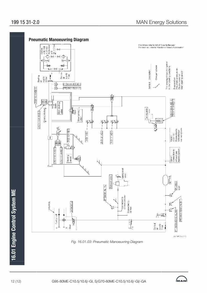
Pneumatic Manoeuvring Diagram
Fig. 16.01.03: Pneumatic Manoeuvring Diagram
199 15 31-2.0 MAN Energy Solutions
12 (12) G95-80ME-C10.5/10.6/-GI, S/G70-60ME-C10.5/10.6/-GI/-GA
16.0
1 En
gine
Con
trol S
yste
m M
E
MAN B&W
MAN Energy Solutions
Vibration Aspects
17


Vibration AspectsThe vibration characteristics of the two-stroke low speed diesel engines canfor practical purposes be split up into four categories, and if the adequatecountermeasures are considered from the early project stage, the influence ofthe excitation sources can be minimised or fully compensated.In general, the marine diesel engine may influence the hull with the following:• External unbalanced moments These can be classified as unbalanced 1stand 2nd order external moments, which need to be considered only for cer-tain cylinder numbers• Guide force moments• Axial vibrations in the shaft system• Torsional vibrations in the shaft system.The external unbalanced moments and guide force moments are illustrated inFig. 17.01.01.In the following, a brief description is given of their origin and of the propercountermeasures needed to render them harmless.
External Unbalanced MomentsThe inertia forces originating from the unbalanced rotating and reciprocatingmasses of the engine create unbalanced external moments although the ex-ternal forces are zero.Of these moments, the 1st order (one cycle per revolution) and the 2nd order(two cycles per revolution) need to be considered for engines with a low num-ber of cylinders. On 7-cylinder engines, also the 4th order external momentmay have to be examined. The inertia forces on engines with more than 6 cyl-inders tend, more or less, to neutralise themselves.Countermeasures have to be taken if hull resonance occurs in the operatingspeed range, and if the vibration level leads to higher accelerations and/or ve-locities than the guidance values given by international standards or recom-mendations (for instance related to special agreement between shipownerand shipyard). The natural frequency of the hull depends on the hull’s rigidityand distribution of masses, whereas the vibration level at resonance dependsmainly on the magnitude of the external moment and the engine’s position inrelation to the vibration nodes of the ship.
MAN Energy Solutions 198 41 40-5.3
All Engines 1 (2)
17.0
1 Vi
brat
ion
Aspe
cts

Fig. 17.01.01: External unbalanced moments and guide force moments
198 41 40-5.3 MAN Energy Solutions
2 (2) All Engines
17.0
1 Vi
brat
ion
Aspe
cts

2nd Order Moments on 5 and 6-cylinder EnginesThe 2nd order moment acts only in the vertical direction. Precautions needonly to be considered for 5 and 6-cylinder engines in general.Resonance with the 2nd order moment may occur in the event of hull vibra-tions with more than 3 nodes. Contrary to the calculation of natural frequencywith 2 and 3 nodes, the calculation of the 4 and 5-node natural frequenciesfor the hull is a rather comprehensive procedure and often not very accurate,despite advanced calculation methods.A 2nd order moment compensator comprises two counter-rotating massesrunning at twice the engine speed.
Fig. 17.02.01: Statistics of vertical hull vibrations in tankers and bulk carriers
Compensator SolutionsSeveral solutions are available to cope with the 2nd order moment, as shownin Fig. 17.03.02, out of which the most cost efficient one can be chosen in theindividual case, e.g.:
1. No compensators, if considered unnecessary on the basis of natural fre-quency, nodal point and size of the 2nd order moment.
2. A compensator mounted on the aft end of the engine, driven by chain,option: 4 31 203.
MAN Energy Solutions 198 83 61-9.0
S90ME-C9 1 (2)
17.0
2 2n
d Or
der M
omen
ts o
n 5
and
6-cy
linde
r Eng
ines

3. A compensator mounted on the fore end, driven from the crankshaftthrough a separate chain drive, option: 4 31 213.
As standard, the compensators reduce the external 2nd order moment to alevel as for a 7-cylinder engine or less.Briefly speaking, solution 1) is applicable if the node is located far from the en-gine, or the engine is positioned more or less between nodes. Solution 2) or 3)should be considered where one of the engine ends is positioned in a node orclose to it, since a compensator is inefficient in a node or close to it and there-fore superfluous.
Determine the NeedA decision regarding the vibrational aspects and the possible use of com-pensators must be taken at the contract stage. If no experience is availablefrom sister ships, which would be the best basis for deciding whether com-pensators are necessary or not, it is advisable to make calculations to determ-ine which of the solutions should be applied.
Preparation for CompensatorsIf compensator(s) are initially omitted, the engine can be delivered preparedfor compensators to be fitted on engine fore end later on, but the decision toprepare or not must be taken at the contract stage, option: 4 31 212. Meas-urements taken during the sea trial, or later in service and with fully loadedship, will be able to show if compensator(s) have to be fitted at all.If no calculations are available at the contract stage, we advise to make pre-parations for the fitting of a compensator in the steering compartment, seeSection 17.03.
Basic Design Regarding CompensatorsFor 5 and 6-cylinder engines with mechanically driven HPS, the basic designregarding 2nd order moment compensators is:• With compensator aft, EoD: 4 31 203• Prepared for compensator fore, EoD: 4 31 212For 5 and 6-cylinder engines with electrically driven HPS, the basic design re-garding 2nd order moment compensators is:• With MAN B&W external electrically driven moment compensator, Rot-Comp, EoD: 4 31 255• Prepared for compensator fore, EoD: 4 31 212The available options are listed in the Extent of Delivery.
1st Order Moments on 4-Cylinder EnginesThis section is not applicable.
198 83 61-9.0 MAN Energy Solutions
2 (2) S90ME-C9
17.0
2 2n
d Or
der M
omen
ts o
n 5
and
6-cy
linde
r Eng
ines
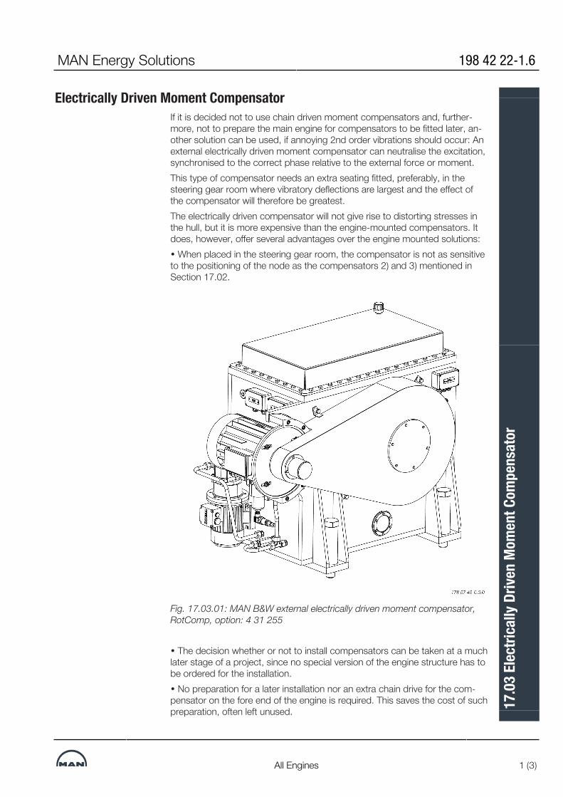
Electrically Driven Moment CompensatorIf it is decided not to use chain driven moment compensators and, further-more, not to prepare the main engine for compensators to be fitted later, an-other solution can be used, if annoying 2nd order vibrations should occur: Anexternal electrically driven moment compensator can neutralise the excitation,synchronised to the correct phase relative to the external force or moment.This type of compensator needs an extra seating fitted, preferably, in thesteering gear room where vibratory deflections are largest and the effect ofthe compensator will therefore be greatest.The electrically driven compensator will not give rise to distorting stresses inthe hull, but it is more expensive than the engine-mounted compensators. Itdoes, however, offer several advantages over the engine mounted solutions:• When placed in the steering gear room, the compensator is not as sensitiveto the positioning of the node as the compensators 2) and 3) mentioned inSection 17.02.
Fig. 17.03.01: MAN B&W external electrically driven moment compensator,RotComp, option: 4 31 255
• The decision whether or not to install compensators can be taken at a muchlater stage of a project, since no special version of the engine structure has tobe ordered for the installation.• No preparation for a later installation nor an extra chain drive for the com-pensator on the fore end of the engine is required. This saves the cost of suchpreparation, often left unused.
MAN Energy Solutions 198 42 22-1.6
All Engines 1 (3)
17.0
3 El
ectri
cally
Driv
en M
omen
t Com
pens
ator

• Compensators could be retrofit, even on ships in service, and also be ap-plied to engines with a higher number of cylinders than is normally consideredrelevant, if found necessary.• The compensator only needs to be active at speeds critical for the hullgirder vibration. Thus, it may be activated or deactivated at specified speedsautomatically or manually.• Combinations with and without moment compensators are not required intorsional and axial vibration calculations, since the electrically driven momentcompensator is not part of the mass-elastic system of the crankshaft.Furthermore, by using the compensator as a vibration exciter a ship’s vibra-tion pattern can easily be identified without having the engine running, e.g. onnewbuildings at an advanced stage of construction. If it is verified that a shipdoes not need the compensator, it can be removed and reused on anothership.It is a condition for the application of the rotating force moment compensatorthat no annoying longitudinal hull girder vibration modes are excited. Basedon our present knowledge, and confirmed by actual vibration measurementsonboard a ship, we do not expect such problems.
Balancing Other Forces and MomentsFurther to compensating 2nd order moments, electrically driven balancers arealso available for balancing other forces and moments. The available optionsare listed in the Extent of Delivery.
198 42 22-1.6 MAN Energy Solutions
2 (3) All Engines
17.0
3 El
ectri
cally
Driv
en M
omen
t Com
pens
ator

Fig. 17.03.02: Compensation of 2nd order vertical external moments
MAN Energy Solutions 198 42 22-1.6
All Engines 3 (3)
17.0
3 El
ectri
cally
Driv
en M
omen
t Com
pens
ator
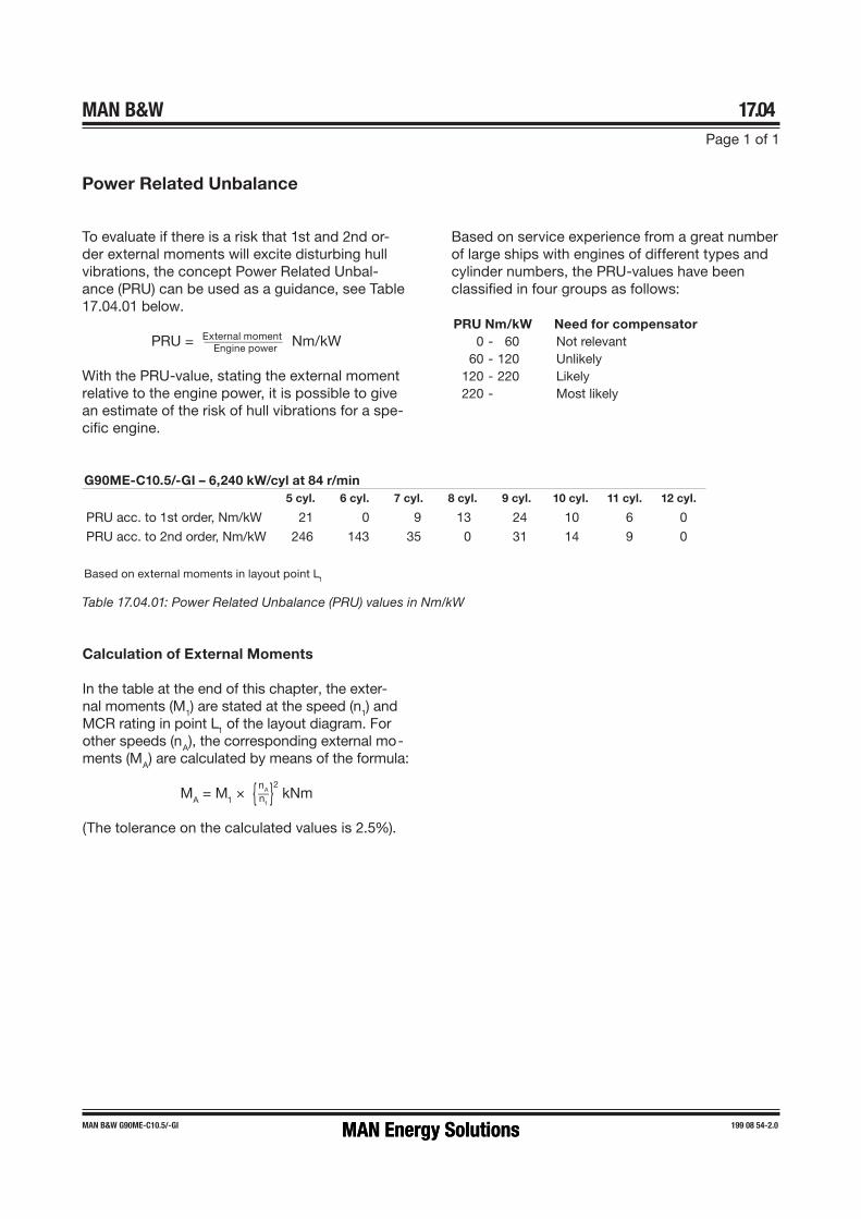
MAN B&W 17.04Page 1 of 1
MAN B&W G90ME-C10.5/-GI 199 08 54-2.0
Power Related Unbalance
To evaluate if there is a risk that 1st and 2nd or-der external moments will excite disturbing hull vibrations, the concept Power Related Unbal-ance (PRU) can be used as a guidance, see Table 17.04.01 below.
PRU = External moment ___________ Engine power Nm/kW
With the PRU�value, stating the external moment relative to the engine power, it is possible to give an estimate of the risk of hull vibrations for a spe-cific engine.
Based on service experience from a great number of large ships with engines of different types and cylinder numbers, the PRU�values have been classified in four groups as follows:
Table 17.04.01: Power Related Unbalance (PRU) values in Nm/kW
Calculation of External Moments
In the table at the end of this chapter, the exter-nal moments (M1) are stated at the speed (n1) and MCR rating in point L1 of the layout diagram. For other speeds (nA), the corresponding external mo-ments (MA) are calculated by means of the formula:
MA = M1 × { nA __ n1 }2 kNm
(The tolerance on the calculated values is 2.5%).
PRU Nm/kW Need for compensator0 - 60 Not relevant
60 - 120 Unlikely120 - 220 Likely220 - Most likely
G90ME-C10.5/-GI – 6,240 kW/cyl at 84 r/min5 cyl. 6 cyl. 7 cyl. 8 cyl. 9 cyl. 10 cyl. 11 cyl. 12 cyl.
PRU acc. to 1st order, Nm/kW 21 0 9 13 24 10 6 0
PRU acc. to 2nd order, Nm/kW 246 143 35 0 31 14 9 0
Based on external moments in layout point L1
MAN Energy SolutionsMAN Energy Solutions

Guide Force MomentsThe so-called guide force moments are caused by the transverse reactionforces acting on the crossheads due to the connecting rod/crankshaft mech-anism. These moments may excite engine vibrations, moving the engine topathwartships and causing a rocking (excited by H-moment) or twisting (ex-cited by X-moment) movement of the engine as illustrated in Fig. 17.05.01.The guide force moments corresponding to the MCR rating (L1) are stated inTable 17.07.01.
Top BracingThe guide force moments are harmless except when resonance vibrations oc-cur in the engine/ double bottom system.As this system is very difficult to calculate with the necessary accuracy, MANEnergy Solutions strongly recommend, as standard, that top bracing is in-stalled between the engine’s upper platform brackets and the casing side.The vibration level on the engine when installed in the vessel must complywith MAN Energy Solutions vibration limits as stated in Fig. 17.05.02.We recommend using the hydraulic top bracing which allow adjustment to theloading conditions of the ship. Mechanical top bracings with stiff connectionsare available on request.With both types of top bracing, the above-mentioned natural frequency will in-crease to a level where resonance will occur above the normal engine speed.Details of the top bracings are shown in Chapter 05.
Definition of Guide Force MomentsOver the years it has been discussed how to define the guide force moments.Especially now that complete FEM-models are made to predict hull/ engineinteraction, the proper definition of these moments has become increasinglyimportant.
MAN Energy Solutions 199 15 55-2.0
95-35ME-C/-GI/-LGI 1 (5)
17.0
5 Gu
ide F
orce
Mom
ents
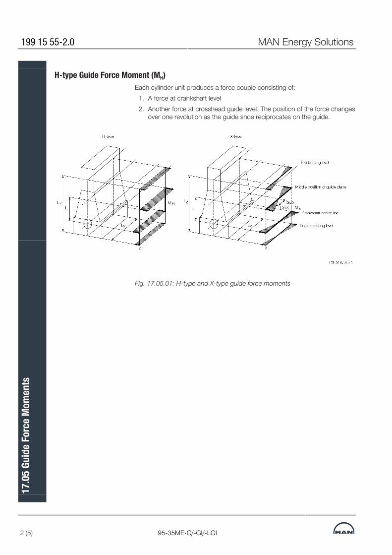
H-type Guide Force Moment (MH)Each cylinder unit produces a force couple consisting of:
1. A force at crankshaft level2. Another force at crosshead guide level. The position of the force changes
over one revolution as the guide shoe reciprocates on the guide.
Fig. 17.05.01: H-type and X-type guide force moments
199 15 55-2.0 MAN Energy Solutions
2 (5) 95-35ME-C/-GI/-LGI
17.0
5 Gu
ide F
orce
Mom
ents

As the deflection shape for the H-type is equal for each cylinder, the Nth orderH-type guide force moment for an N-cylinder engine with regular firing orderis:N × MH(one cylinder)
For modelling purposes, the size of the forces in the force couple is:Force = MH/L [kN]where L is the distance between crankshaft level and the middle position ofthe crosshead guide (i.e. the length of the connecting rod).As the interaction between engine and hull is at the engine seating and thetop bracing positions, this force couple may alternatively be applied in thosepositions with a vertical distance of (LZ). Then the force can be calculated as:ForceZ = MH/LZ [kN]Any other vertical distance may be applied so as to accomodate the actualhull (FEM) model.The force couple may be distributed at any number of points in the longitud-inal direction. A reasonable way of dividing the couple is by the number of topbracing and then applying the forces at those points.ForceZ, one point = ForceZ, total/Ntop bracing, total [kN]
X-type Guide Force Moment (Mx)The X-type guide force moment is calculated based on the same force coupleas described above. However, as the deflection shape is twisting the engine,each cylinder unit does not contribute with an equal amount. The centre unitsdo not contribute very much whereas the units at each end contributes much.A so-called ‘Bi-moment’ can be calculated (Fig. 17.05.01):‘Bi-moment’ = ∑[force-couple(cyl.X) × distX] in kNm2
The X-type guide force moment is then defined as:MX = ‘Bi-Moment’/L kNmFor modelling purpose, the size of the four (4) forces can be calculated:Force = MX/LX [kN]where:LX is the horizontal length between ‘force points’.Similar to the situation for the H-type guide force moment, the forces may beapplied in positions suitable for the FEM model of the hull. Thus the forcesmay be referred to another vertical level LZ above the crankshaft centre line.These forces can be calculated as follows:ForceZ, one point = (Mx X L) / (Lx X Lx) [kN]In order to calculate the forces, it is necessary to know the lengths of the con-necting rods = L, which are:
MAN Energy Solutions 199 15 55-2.0
95-35ME-C/-GI/-LGI 3 (5)
17.0
5 Gu
ide F
orce
Mom
ents

Engine Type L in mm
G95ME-C10/-GI/-LGI 3,720
G90ME-C10/-GI/-LGI 3,342
S90ME-C9/10/-GI/-LGI 3,600
G80ME-C10/-GI/-LGI 3,530
S80ME-C9/-GI/-LGI 3,450
G70ME-C9/10/-GI/-LGI 3,256
S70ME-C10/-GI/-LGI 2,700
S70ME-C7/8/-GI/-LGI 2,870
S65ME-C8/-GI/-LGI 2,730
G60ME-C10/-GI/-LGI 2,790
S60ME-C10/-GI/-LGI 2,310
G50ME-C9/-GI/-LGI 2,500
S50ME-C9/-GI/-LGI 2,214
S50ME-C8/-GI/-LGI 2,050
S46ME-C8/-GI/-LGI 1,980
G45ME-C9/-GI/-LGI 2,250
S40ME-C9/-GI/-LGI 1,770
S35ME-C9/-GI/-LGI 1,550
199 15 55-2.0 MAN Energy Solutions
4 (5) 95-35ME-C/-GI/-LGI
17.0
5 Gu
ide F
orce
Mom
ents

Vibration Limits Valid for Single Order Harmonics
Fig. 17.05.02: Vibration limits
MAN Energy Solutions 199 15 55-2.0
95-35ME-C/-GI/-LGI 5 (5)
17.0
5 Gu
ide F
orce
Mom
ents
Axial VibrationsWhen the crank throw is loaded by the gas pressure through the connectingrod mechanism, the arms of the crank throw deflect in the axial direction ofthe crankshaft, exciting axial vibrations. Through the thrust bearing, the sys-tem is connected to the ship’s hull.Generally, only zero-node axial vibrations are of interest. Thus the effect of theadditional bending stresses in the crankshaft and possible vibrations of theship`s structure due to the reaction force in the thrust bearing are to be con-sideraed.An axial damper is fitted as standard on all engines, minimising the effects ofthe axial vibrations, EoD: 4 31 111.
Torsional VibrationsThe reciprocating and rotating masses of the engine including the crankshaft,the thrust shaft, the intermediate shaft(s), the propeller shaft and the propellerare for calculation purposes considered a system of rotating masses (inertias)interconnected by torsional springs. The gas pressure of the engine actsthrough the connecting rod mechanism with a varying torque on each crankthrow, exciting torsional vibration in the system with different frequencies.In general, only torsional vibrations with one and two nodes need to be con-sidered. The main critical order, causing the largest extra stresses in the shaftline, is normally the vibration with order equal to the number of cylinders, i.e.,six cycles per revolution on a six cylinder engine. This resonance is positionedat the engine speed corresponding to the natural torsional frequency dividedby the number of cylinders.The torsional vibration conditions may, for certain installations require a tor-sional vibration damper, option: 4 31 105.Plants with 11 or 12-cylinder engines type 98-80 require a torsional vibrationdamper.Based on our statistics, this need may arise for the following types of installa-tion:• Plants with controllable pitch propeller• Plants with unusual shafting layout and for special owner/yard requirements• Plants with 8-cylinder engines.The so-called QPT (Quick Passage of a barred speed range Technique), is analternative to a torsional vibration damper, on a plant equipped with a control-lable pitch propeller. The QPT could be implemented in the governor in orderto limit the vibratory stresses during the passage of the barred speed range.The application of the QPT, option: 4 31 108, has to be decided by the enginemaker and MAN Energy Solutions based on final torsional vibration calcula-tions.Six-cylinder engines, require special attention. On account of the heavy excit-ation, the natural frequency of the system with one-node vibration should besituated away from the normal operating speed range, to avoid its effect. Thiscan be achieved by changing the masses and/or the stiffness of the systemso as to give a much higher, or much lower, natural frequency, called under-critical or overcritical running, respectively.
MAN Energy Solutions 199 15 32-4.0
All Engines 1 (4)
17.0
6 Ax
ial V
ibra
tions
Owing to the very large variety of possible shafting arrangements that may beused in combination with a specific engine, only detailed torsional vibrationcalculations of the specific plant can determine whether or not a torsional vi-bration damper is necessary.
Undercritical RunningThe natural frequency of the one-node vibration is so adjusted that resonancewith the main critical order occurs about 35-45% above the engine speed atspecified MCR.Such undercritical conditions can be realised by choosing a rigid shaft sys-tem, leading to a relatively high natural frequency.The characteristics of an undercritical system are normally:• Relatively short shafting system• Probably no tuning wheel• Turning wheel with relatively low inertia• Large diameters of shafting, enabling the use of shafting material with amoderate ultimate tensile strength, but requiring careful shaft alignment,(dueto relatively high bending stiffness)• Without barred speed range.
Critical RunningWhen running undercritical, significant varying torque at MCR conditions ofabout 100-150% of the mean torque is to be expected.This torque (propeller torsional amplitude) induces a significant varying pro-peller thrust which, under adverse conditions, might excite annoying longitud-inal vibrations on engine/double bottom and/or deck house.The yard should be aware of this and ensure that the complete aft body struc-ture of the ship, including the double bottom in the engine room, is designedto be able to cope with the described phenomena.
Overcritical RunningThe natural frequency of the one node vibration is so adjusted that resonancewith the main critical order occurs at about 30-60% of the engine speed atspecified MCR. Such overcritical conditions can be realised by choosing anelastic shaft system, leading to a relatively low natural frequency.The characteristics of overcritical conditions are:• Tuning wheel may be necessary on crankshaft fore end• Turning wheel with relatively high inertia• Shafts with relatively small diameters, requiring shafting material with a relat-ively high ultimate tensile strength• With barred speed range, EoD: 4 07 015, of about ±10% with respect tothe critical engine speed.Torsional vibrations in overcritical conditions may, in special cases, have to beeliminated by the use of a torsional vibration damper.Overcritical layout is normally applied for engines with more than four cylin-ders.
199 15 32-4.0 MAN Energy Solutions
2 (4) All Engines
17.0
6 Ax
ial V
ibra
tions

Please note:We do not include any tuning wheel or torsional vibration damper in thestandard scope of supply, as the proper countermeasure has to be foundafter torsional vibration calculations for the specific plant, and after the de-cision has been taken if and where a barred speed range might be accept-able.
Governor Stability Evaluation For Special Propulsion PlantsMAN Energy Solutions must be contacted for further analysis if a plant fulfillsone of the criteria mentioned below. These special plants need to be handledon an individual basis, preferably at an early stage of the design.A governor stability evaluation, option 4 07 009, is only needed in rare cases.When needed, the evaluation should be made by MAN Energy Solutionsagainst a fee.For plants where one or more of the following criteria are fulfilled, MAN EnergySolutions must be consulted:• PTO output (mechanical) is higher than specified in Fig. 17.06.01, or PTO isused at below 40% NMCR speed (see for calculation examples below).• 1st node torsional vibration frequency in the propeller shaft line or across acoupling to a geared generator is lower than:3 Hz for FPP plants 5 Hz for CPP plants• The design includes a clutch for disconnection of the propeller.• The design deviates from known ‘standard’ plant designs.The governor stability evaluation may lead to changes in the control equip-ment. These may include the need for more signals from the plant and re-quirements to the design of the mechanical components driven by the engine.The evaluation may also lead to changes to the use of the PTO.
PTO layout ExampleA 9S40ME-C9.6 with an SMCR of 7,300 kW at 120 rpm has been chosen fora CPP plant. The NMCR is 10,215 kW at 146 rpm according to the Marineengine programme. A PTO with an electric output of 1,100 kW and an effi-ciency of 90% is installed. Which engine speed is the lowest for full utilisationof the PTO?Mechanical PTO power is 1,100 kW/90% = 1,222 kW.The mechanical power relative to NMCR is 1,222 kW/10,215 kW = 12%.A relative power of 12% corresponds to a minimum of 65% NMCR speed fora CPP plant with an engine with a bore of less than 80 cm, see Fig. 17.06.01.The speed in rpm is 65% * 146 rpm = 95 rpm. This is 95 rpm/120 rpm = 79%relative to the SMCR speed. This is the minimum speed at which the full PTOoutput can be utilised.If the shipowner wants to utilise the full PTO output at lower speeds, MAN En-ergy Solutions must be contacted to evaluate if it is possible. An alternativecould be to reduce the PTO output at lower speeds in accordance with Fig.17.06.01.
MAN Energy Solutions 199 15 32-4.0
All Engines 3 (4)
17.0
6 Ax
ial V
ibra
tions
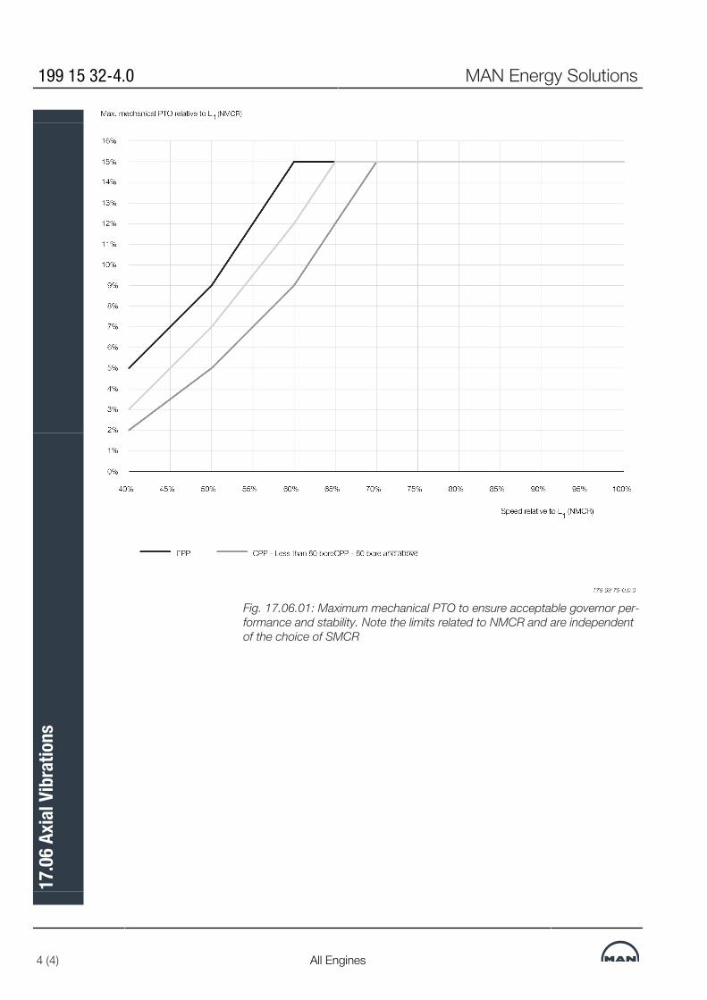
Fig. 17.06.01: Maximum mechanical PTO to ensure acceptable governor per-formance and stability. Note the limits related to NMCR and are independentof the choice of SMCR
199 15 32-4.0 MAN Energy Solutions
4 (4) All Engines
17.0
6 Ax
ial V
ibra
tions

MAN B&W 17.07Page 1 of 1
MAN B&W G90ME-C10.5/-GI 199 08 55-4.0
No of cylinder : 5 6 7 8 9 10 11 12
Firing type : 1-4-3-2-51-5-3-4-
2-61-7-2-5-4-
3-61-8-3-4-7-
2-5-61-9-4-3-7-
5-2-8-6
1-8-7-3-5-9-4-2-
10-6
1-5-11-6-2-7-9-4-3-
8-10
1-6-11-7-3-5-10-9-2-4-12-8
External forces [kN] :
1. Order : Horizontal a) 0 0 0 0 0 0 2 01. Order : Vertical a) 0 0 0 0 0 0 2 02. Order : Vertical 0 0 0 0 0 6 3 04. Order : Vertical 0 0 0 0 0 73 96 06. Order : Vertical 0 32 0 0 0 9 8 0External moments [kNm] :
1. Order : Horizontal a) 665 0 396 672 1,365 623 405 01. Order : Vertical a) 665 0 396 672 1,365 623 405 02. Order : Vertical 7,680 c) 5,343 c) 1,551 0 1,744 872 629 04. Order : Vertical 47 362 1,029 418 521 847 885 7246. Order : Vertical 4 0 2 0 133 61 9 0Guide force H-moments in [kNm] :
1 x No. of cyl. 4,599 3,710 2,966 2,254 1,587 567 439 3802 x No. of cyl. 561 190 98 98 133 48 - -3 x No. of cyl. - - - - - - - -Guide force X-moments in [kNm] :
1. Order : 475 0 283 196 976 568 100 02. Order : 612 426 124 0 139 178 18 03. Order : 563 1,017 1,112 1,620 1,957 2,280 2,796 3,5004. Order : 191 1,476 4,194 1,704 2,125 3,423 3,735 2,9525. Order : 0 0 412 5,879 2,045 339 3,769 06. Order : 124 0 74 0 4,776 2,212 334 07. Order : 941 0 0 35 214 3,569 385 08. Order : 626 435 34 0 116 444 2,539 8709. Order : 35 708 79 14 78 157 428 2,436
10. Order : 0 173 493 0 46 40 353 011. Order : 13 0 282 411 32 131 465 012. Order : 70 0 14 56 245 81 111 013. Order : 39 0 2 113 39 119 5 014. Order : 3 22 0 0 31 100 84 015. Order : 0 50 2 1 96 20 98 17316. Order : 2 19 6 0 6 77 104 38
External Forces and Moments, G90ME-C10.5/-GI Layout point L1
Table 17.07.01
a) 1st order moments are, as standard, balanced so as to obtain equal values for horizontal and verticalmoments for all cylinder numbers.
c) 5 and 6-cylinder engines can be fitted with 2nd order moment compensators on the aft and fore end, re-ducing the 2nd order external moment.
MAN Energy SolutionsMAN Energy Solutions

MAN B&W
MAN Energy Solutions
Monitoring Systems and Instrumentation
18


Monitoring Systems and InstrumentationThe Engine Control System (ECS) is supported by the Engine ManagementServices (EMS), which manages software, data and applications for enginemonitoring and operation.The EMS includes the PMI and the CoCoS-EDS (Computer Controlled Sur-veillance-Engine Diagnostics System) as applications.In its basic design, the ME/ME-B engine instrumentation consists of:▪ Engine Control System (ECS), see Section 16.01▪ Shut-down sensors, EoD: 4 75 124▪ EMS including PMI and CoCoS-EDS software and support for LAN-based
interface to the AMS, EoD: 4 75 217, see Section 18.02▪ Sensors for alarm, slow down and remote indication according to the
classification society’s and MAN Energy Solutions' requirements for UMS,EoD: 4 75 127, see Section 18.04.
All instruments are identified by a combination of symbols and a position num-ber as shown in Section 18.07.
MAN Energy Solutions 198 85 29-9.3
ME/ME-C/ME-B/-GI/-GA/-LGI 1 (1)
18.0
1 M
onito
ring
Syst
ems a
nd In
stru
men
tatio
n

Engine Management Services
Engine Management Services OverviewThe Engine Management Services (EMS) is used on MAN B&W engines fromMAN Energy Solutions for condition monitoring, data logging & data distribu-tion. EMS is integrated with the ECS (Engine Control System) to allow for con-tinuous performance tuning.EMS is executed on the EMS MOP, an industrial type PC designed by MANEnergy Solutions. EMS is implemented as a hardened platform, robust tovirus threats and other unauthorized use and ac-cess.The EMS network topology is shown in Fig. 18.02.01.
Fig 18.02.01: Engine Management Services, EMS, EoD: 4 75 217
EMS ApplicationsEMS includes the applications PMI Auto-tuning, CoCoS-EDS and EMS man-ager.
PMI Auto-tuning▪ Online cylinder pressure monitoring▪ Input to engine control system for closed-loop performance tuning▪ Engine power estimation.PMI Auto-tuning continuously measures the cylinder pressures using onlinesensors mounted on each cylinder cover. Pressure measurements arepresented continuously in real time and the corresponding key performancevalues are transferred to the Engine Control System.
MAN Energy Solutions 199 05 99-0.0
ME/ME-C/ME-B/-GI/-GA/-LGI 1 (2)
18.0
2 En
gine
Man
agem
ent S
ervic
es

The Engine Control System constantly monitors and compares the measuredcombustion pressures to a reference value. As such, the control system auto-matically adjusts the fuel injection and valve timing to reduce the deviationbetween the measured values and the reference. This, in turn, facilitates theoptimal combustion pressures for the next firing. Thus, the system ensuresthat the engine is running at the desired maximum pressure, p(max).
CoCoS-EDS▪ Data logging▪ Engine condition monitoring and reporting▪ Engine operation troubleshooting.With CoCoS-EDS, early intervention as well as preventive maintenance, theengine operators are able to reduce the risk of damages and failures.CoCoS-EDS further allows for easier troubleshooting in cases where unusualengine behavior is observed.
EMS Manager▪ Installation and supervision of EMS applications▪ Network and interface monitoring▪ Optional interface for data exchange with AMS (Alarm Monitoring System).The EMS manager provides a process for integrated installation, commission-ing and maintenance of PMI Auto-tuning and CoCoS-EDS.Further, the EMS Manager includes status information and functionality, e.g.for network status, internal and external interfaces and EMS application exe-cution.
199 05 99-0.0 MAN Energy Solutions
2 (2) ME/ME-C/ME-B/-GI/-GA/-LGI
18.0
2 En
gine
Man
agem
ent S
ervic
es

Condition Monitoring System CoCoS-EDS
MAN Energy Solutions 198 45 82-6.9
1 (1)
18.0
3 Co
nditi
on M
onito
ring
Syst
em C
oCoS
-EDS

Alarm – Slow Down and Shut Down SystemThe shut down system must be electrically separated from other systems byusing independent sensors, or sensors common to the alarm system and themonitoring system but with galvanically separated electrical circuits, i.e. onesensor with two sets of electrically independent terminals. The list of sensorsare shown in Table 18.04.04.
Basic Safety System Design and SupplyThe basic safety sensors for a MAN B&W engine are designed for UnattendedMachinery Space (UMS) and comprises:▪ the temperature sensors and pressure sensors that are specified in the
‘MAN Energy Solutions’ column for shut down in Table 18.04.04.These sensors are included in the basic Extent of Delivery, EoD: 4 75 124.
Alarm and Slow Down System Design and SupplyThe basic alarm and slow down sensors for a MAN B&W engine are designedfor Unattended Machinery Space (UMS) and comprises:▪ The sensors for alarm and slow down.These sensors are included in the basic Extent of Delivery, EoD: 4 75 127.The shut down and slow down panels can be ordered as options: 4 75 630, 475 614 or 4 75 615 whereas the alarm panel is yard’s supply, as it normallyincludes several other alarms than those for the main engine.For practical reasons, the sensors for the engine itself are normally deliveredfrom the engine supplier, so they can be wired to terminal boxes on the en-gine.The number and position of the terminal boxes depends on the degree of dis-mantling specified in the Dispatch Pattern for the transportation of the enginebased on the lifting capacities available at the engine maker and at the yard.
Alarm, Slow Down And Remote Indication SensorsThe International Association of Classification Societies (IACS) indicates that acommon sensor can be used for alarm, slow down and remote indication.A general view of the alarm, slow down and shut down systems is shown inFig. 18.04.01.Tables 18.04.02 and 18.04.03 show the requirements by MAN Energy Solu-tions for alarm and slow down and for UMS by the classification societies(Class), as well as IACS’ recommendations.The number of sensors to be applied to a specific plant is the sum of require-ments of the classification society, the Buyer and MAN Energy Solutions.If further analogue sensors are required, they can be ordered as option: 4 75128.
MAN Energy Solutions 199 15 52-7.0
ME-C/ME-B/-GI/-GA/-LGI 1 (10)
18.0
4 Al
arm
– S
low
Down
and
Shu
t Dow
n Sy
stem
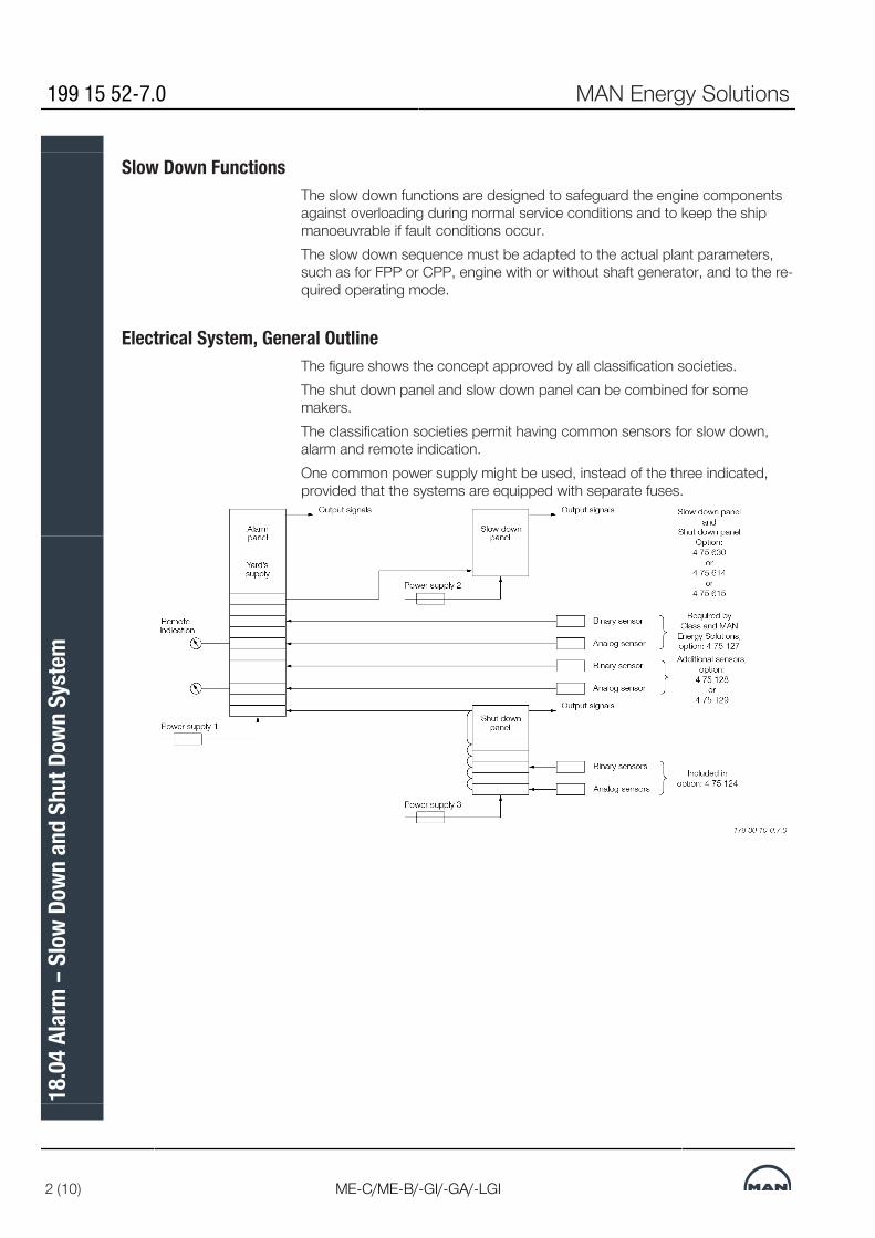
Slow Down FunctionsThe slow down functions are designed to safeguard the engine componentsagainst overloading during normal service conditions and to keep the shipmanoeuvrable if fault conditions occur.The slow down sequence must be adapted to the actual plant parameters,such as for FPP or CPP, engine with or without shaft generator, and to the re-quired operating mode.
Electrical System, General OutlineThe figure shows the concept approved by all classification societies.The shut down panel and slow down panel can be combined for somemakers.The classification societies permit having common sensors for slow down,alarm and remote indication.One common power supply might be used, instead of the three indicated,provided that the systems are equipped with separate fuses.
199 15 52-7.0 MAN Energy Solutions
2 (10) ME-C/ME-B/-GI/-GA/-LGI
18.0
4 Al
arm
– S
low
Down
and
Shu
t Dow
n Sy
stem
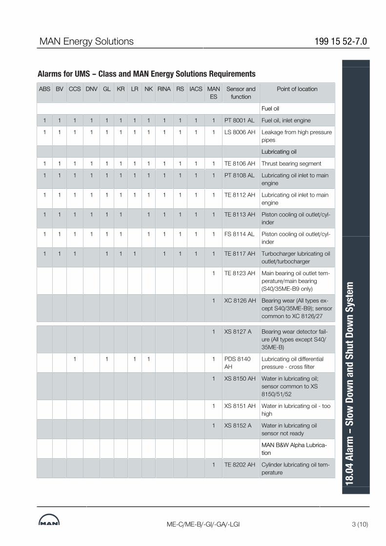
Alarms for UMS – Class and MAN Energy Solutions RequirementsABS BV CCS DNV GL KR LR NK RINA RS IACS MAN
ESSensor and
functionPoint of location
Fuel oil
1 1 1 1 1 1 1 1 1 1 1 1 PT 8001 AL Fuel oil, inlet engine
1 1 1 1 1 1 1 1 1 1 1 1 LS 8006 AH Leakage from high pressurepipes
Lubricating oil
1 1 1 1 1 1 1 1 1 1 1 1 TE 8106 AH Thrust bearing segment
1 1 1 1 1 1 1 1 1 1 1 1 PT 8108 AL Lubricating oil inlet to mainengine
1 1 1 1 1 1 1 1 1 1 1 1 TE 8112 AH Lubricating oil inlet to mainengine
1 1 1 1 1 1 1 1 1 1 1 TE 8113 AH Piston cooling oil outlet/cyl-inder
1 1 1 1 1 1 1 1 1 1 1 FS 8114 AL Piston cooling oil outlet/cyl-inder
1 1 1 1 1 1 1 1 1 1 TE 8117 AH Turbocharger lubricating oiloutlet/turbocharger
1 TE 8123 AH Main bearing oil outlet tem-perature/main bearing(S40/35ME-B9 only)
1 XC 8126 AH Bearing wear (All types ex-cept S40/35ME-B9); sensorcommon to XC 8126/27
1 XS 8127 A Bearing wear detector fail-ure (All types except S40/35ME-B)
1 1 1 1 1 PDS 8140AH
Lubricating oil differentialpressure - cross filter
1 XS 8150 AH Water in lubricating oil;sensor common to XS8150/51/52
1 XS 8151 AH Water in lubricating oil - toohigh
1 XS 8152 A Water in lubricating oilsensor not ready
MAN B&W Alpha Lubrica-tion
1 TE 8202 AH Cylinder lubricating oil tem-perature
MAN Energy Solutions 199 15 52-7.0
ME-C/ME-B/-GI/-GA/-LGI 3 (10)
18.0
4 Al
arm
– S
low
Down
and
Shu
t Dow
n Sy
stem
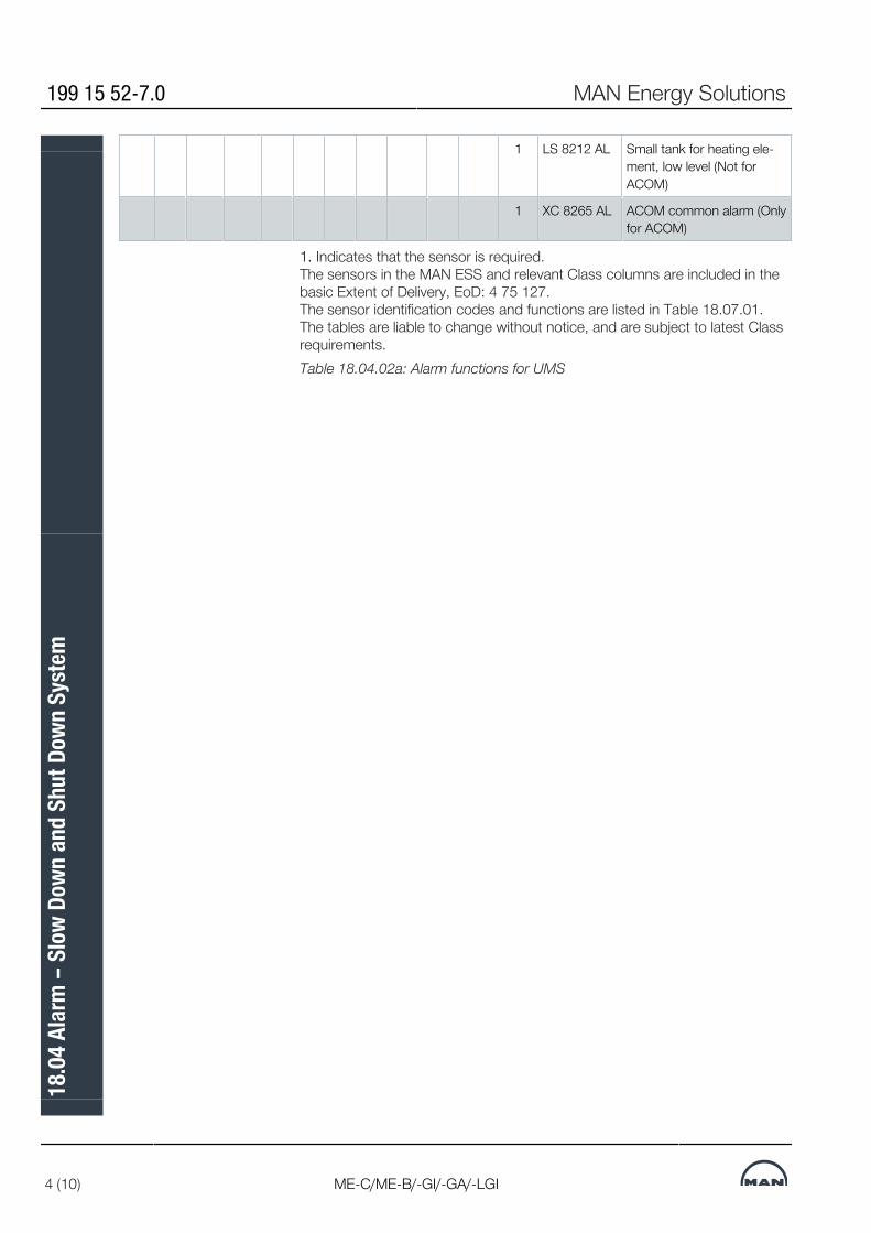
1 LS 8212 AL Small tank for heating ele-ment, low level (Not forACOM)
1 XC 8265 AL ACOM common alarm (Onlyfor ACOM)
1. Indicates that the sensor is required.The sensors in the MAN ESS and relevant Class columns are included in thebasic Extent of Delivery, EoD: 4 75 127.The sensor identification codes and functions are listed in Table 18.07.01.The tables are liable to change without notice, and are subject to latest Classrequirements.Table 18.04.02a: Alarm functions for UMS
199 15 52-7.0 MAN Energy Solutions
4 (10) ME-C/ME-B/-GI/-GA/-LGI
18.0
4 Al
arm
– S
low
Down
and
Shu
t Dow
n Sy
stem

Alarms for UMS – Class and MAN Energy Solutions’ requirementsABS BV CCS DNV GL KR LR NK RINA RS IACS MAN
ESSensor andfunction
Point of location
Hydraulic PowerSupply
1 PT 1228 AL LPS booster, oilpresure after pump(Only if LPS pump)
1 PDS 1231 A ME (Auto) filter dif-ferential pressureacross filter
1 1 TE 1310 AH Lubrication oil inlet(Only for ME/-GIwith separate oilsystem to HPS in-stalled)
Cooling water
1 1 1 1 1 1 1 1 1 1 1 1 PT 8401 AL Jacket cooling wa-ter inlet
1 PDT 8403AL
Jacket cooling wa-ter across engine;to be calculated inalarm system fromsensor no. 8402and 8413 3)
1 PDT 8404AL
Jacket cooling wa-ter across cylinderliners 2)
1 PDT 8405AL
Jacket cooling wa-ter across cylindercovers and exhaustvalves 2)
1 1 TE 8407 AL Jacket cooling wa-ter inlet
1 1 1 1 1 1 1 1 1 1 1 1 1 TE 8408AH
Jacket cooling wa-ter outlet, cylinder
1 TT 8410 AH Cylinder cover cool-ing water outlet,cylinder 2)
1 PT 8413 I Jacket cooling wa-ter outlet, commonpipe
1 1 1 1 1 1 1 1 1 1 1 PT 8421 AL Cooling water inletair cooler
MAN Energy Solutions 199 15 52-7.0
ME-C/ME-B/-GI/-GA/-LGI 5 (10)
18.0
4 Al
arm
– S
low
Down
and
Shu
t Dow
n Sy
stem
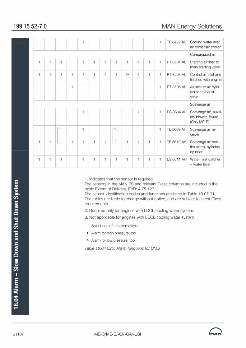
1 1 TE 8422 AH Cooling water inletair cooler/air cooler
Compressed air
1 1 1 1 1 1 1 1 1 1 1 PT 8501 AL Starting air inlet tomain starting valve
1 1 1 1 1 1 1 1 1+ 1 1 1 PT 8503 AL Control air inlet andfinished with engine
1 1 PT 8505 AL Air inlet to air cylin-der for exhaustvalve
Scavenge air
1 1 1 PS 8604 AL Scavenge air, auxili-ary blower, failure(Only ME-B)
1 1 TE 8609 AH Scavenge air re-ceiver
1 1 1 1 1 1 1 1 1 1 TE 8610 AH Scavenge air box –fire alarm, cylinder/cylinder
1 1 1 1 1 1 1 1 1 1 1 LS 8611 AH Water mist catcher– water level
1. Indicates that the sensor is required.The sensors in the MAN ES and relevant Class columns are included in thebasic Extent of Delivery, EoD: 4 75 127.The sensor identification codes and functions are listed in Table 18.07.01.The tables are liable to change without notice, and are subject to latest Classrequirements.2. Required only for engines wirh LDCL cooling water system.3. Not applicable for engines with LDCL cooling water system.
Select one of the alternatives
Alarm for high pressure, too
Alarm for low pressure, too
Table 18.04.02b: Alarm functions for UMS
199 15 52-7.0 MAN Energy Solutions
6 (10) ME-C/ME-B/-GI/-GA/-LGI
18.0
4 Al
arm
– S
low
Down
and
Shu
t Dow
n Sy
stem

Alarms for UMS – Class and MAN Energy Solutions’ requirementsABS BV CCS DNV GL KR LR NK RIN
ARS IAC
SMANES
Sensor andfunction
Point of location
Exhaust gas
1 1 1 1 1 1 (1) 1 1 1 1 1 TC8701 AH Exhaust gas before tur-bocharger/turbocharger
1 1 1 1 1 1 1 1 1 1 TC8702 AH Exhaust gas after ex-haust valve, cylinder/cyl-inder
1 1 1 1 1 1 1 1 1 1 1 TC8707 AH Exhaust gas outlet tur-bocharger/turbocharger(Yard’s supply)
Miscellaneous
1 ZT8801 AH Turbocharger speed/turbocharger
1 WT8812AH
Axial vibration monitor2)
1 1 1 1 1 1 1 1 1 1 1 XS8813 AH Oil mist in crankcase/cylinder; sensor com-mon to XS 8813/14
1 1 XS8814 AL Oil mist detector failure
1 XC8816 AH Shaftline earthing device
1 TE8820 AH Cylinder liner monitor-ing/cylinder 3)
Engine Control System
1 1 1 1 1 1 1 1 1 1 1 1 XC2201 A Power failure
1 1 1 1 1 1 1 1 1 1 XC2202 A ME common failure
1 XC2202-AA
ME common failure(ME-GI only)
1 XC2213 A Double-pipe HC alarm(ME-GI only)
Power Supply Units toAlarm System
1 XC2901 A Low voltage ME powersupply A
1 XC2902 A Low voltage ME powersupply B
1 XC2903 A Earth failure ME powersupply
MAN Energy Solutions 199 15 52-7.0
ME-C/ME-B/-GI/-GA/-LGI 7 (10)
18.0
4 Al
arm
– S
low
Down
and
Shu
t Dow
n Sy
stem
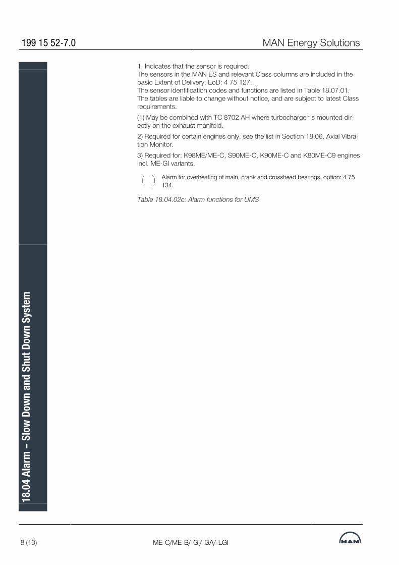
1. Indicates that the sensor is required.The sensors in the MAN ES and relevant Class columns are included in thebasic Extent of Delivery, EoD: 4 75 127.The sensor identification codes and functions are listed in Table 18.07.01.The tables are liable to change without notice, and are subject to latest Classrequirements.(1) May be combined with TC 8702 AH where turbocharger is mounted dir-ectly on the exhaust manifold.2) Required for certain engines only, see the list in Section 18.06, Axial Vibra-tion Monitor.3) Required for: K98ME/ME-C, S90ME-C, K90ME-C and K80ME-C9 enginesincl. ME-GI variants.
Alarm for overheating of main, crank and crosshead bearings, option: 4 75134.
Table 18.04.02c: Alarm functions for UMS
199 15 52-7.0 MAN Energy Solutions
8 (10) ME-C/ME-B/-GI/-GA/-LGI
18.0
4 Al
arm
– S
low
Down
and
Shu
t Dow
n Sy
stem

Slow down for UMS – Class and MAN Energy Solutions’ requirements
MAN Energy Solutions 199 15 52-7.0
ME-C/ME-B/-GI/-GA/-LGI 9 (10)
18.0
4 Al
arm
– S
low
Down
and
Shu
t Dow
n Sy
stem

Shut down for AMS and UMS – Class and MAN Energy Solutions’ requirements
199 15 52-7.0 MAN Energy Solutions
10 (10) ME-C/ME-B/-GI/-GA/-LGI
18.0
4 Al
arm
– S
low
Down
and
Shu
t Dow
n Sy
stem

Local InstrumentsThe basic local instrumentation on the engine, options: 4 70 119 comprisesthermometers, pressure gauges and other indicators located on the piping ormounted on panels on the engine. The tables 18.05.01a, b and c list those aswell as sensors for slow down, alarm and remote indication, option: 4 75 127.
Local instruments Remote sensors Point of location
Thermometer,stem type
Temperature element/switch
TE 1270Hydraulic power supplyHPS bearing temperature (Only ME/ME-C with HPS in centre position)
TI 8005 TE 8005Fuel oilFuel oil, inlet engine
TI 8106
TI 8112TI 8113TI 8117
TE 8106TE/TS 8107TE 8112TE 8113TE 8117
TE 8123
Lubricating oilThrust bearing segmentThrust bearing segmentLubricating oil inlet to main enginePiston cooling oil outlet/cylinderLubricating oil outlet from turbocharger/turbocharger (depends on turbocharger design)Main bearing oil outlet temperature/main bearing (S40/35ME-B9 only)
TE 8202TS 8213
Cylinder lubricating oilCylinder lubricating oil inletCylinder lubricating heating
TI 8407TI 8408TI 8409TI 8410
TE 8407TE 8408TE 8409TT 8410
High temperature cooling water, jacket cooling waterJacket cooling water inletJacket cooling water outlet, cylinder/cylinderJacket cooling water outlet/turbochargerCylinder cover cooling water outlet, cylinder (Only for LDCL)
TI 8422TI 8423
TE 8422TE 8423
Low temperature cooling water, seawater or freshwater for centralcoolingCooling water inlet, air coolerCooling water outlet, air cooler/air cooler
TI 8605TI 8608TI 8609
TE 8605TE 8608TE 8609TE 8610
Scavenge airScavenge air before air cooler/air coolerScavenge air after air cooler/air coolerScavenge air receiverScavenge air box – fire alarm, cylinder/cylinder
Thermometer, dial type
Thermo couple
TI 8701
TI 8707
TC 8701TI/TC 8702TC 8704TC 8707
Exhaust gasExhaust gas before turbocharger/turbochargerExhaust gas after exhaust valve, cylinder/cylinderExhaust gas inlet exhaust gas receiverExhaust gas outlet turbocharger
Table 18.05.01a: Local thermometers on engine, options 4 70 119, and re-mote indication sensors, option: 4 75 127
MAN Energy Solutions 198 45 86-3.13
ME/ME-C/ME-B/-GI 1 (3)
18.0
5 Lo
cal I
nstru
men
ts

Local instruments Remote sensors Point of location
Pressure gauge (manometer)
Pressure transmitter/switch
PI 8001 PT 8001Fuel oilFuel oil, inlet engine
PI 8103PI 8108
PT 8103PT 8108PS/PT 8109PDS 8140
Lubricating oilLubricating oil inlet to turbocharger/turbochargerLubricating oil inlet to main engineLubricating oil inlet to main engine and thrust bearingLubricating oil differential pressure – cross filter
PI 8401 PT 8401PS/PT 8402PDT 8403
PDT 8404PDT 8405
PT 8413
High temperature jacket cooling water, jacket cooling waterJacket cooling water inletJacket cooling water inlet (Only Germanischer Lloyd)Jacket cooling water across engine (or PT 8401 and PT 8413) (Not for LDCL)Jacket cooling water across cylinder liners (Only for LDCL)Jacket cooling water across cylinder covers and exhaust valves (Only for LDCL)Jacket cooling water outlet, common pipe
PI 8421 PT 8421
Low temperature cooling water, seawater or freshwater for centralcoolingCooling water inlet, air cooler
PI 8501PI 8503
PT 8501PT 8503PT 8505
Compressed airStarting air inlet to main starting valveControl air inletAir inlet to air cylinder for exhaust valve (Only ME-B)
PI 8601PDI 8606
PT 8601PDT 8606
Scavenge airScavenge air receiver (PI 8601 instrument same as PI 8706)Pressure drop of air across cooler/air cooler
PI 8706Exhaust gasExhaust gas receiver/Exhaust gas outlet turbocharger
PI 8803PI 8804
Miscellaneous functionsAir inlet for dry cleaning of turbochargerWater inlet for cleaning of turbocharger (Not applicable for MHI turbochargers) Table
Table 18.05.01b: Local pressure gauges on engine, options: 4 70 119, andremote indication sensors, option: 4 75 127
198 45 86-3.13 MAN Energy Solutions
2 (3) ME/ME-C/ME-B/-GI
18.0
5 Lo
cal I
nstru
men
ts

Local instruments Remote sensors Point of location
Other indicators Other transmitters/ switches
XC 1231LS 1235
Hydraulic power supplyAutomatic main lube oil filter, failure (Boll & Kirch)Leakage oil from hydraulic system
LS 4112Engine cylinder componentsLeakage from hydraulic cylinder unit
LS 8006Fuel oilLeakage from high pressure pipes
FS 8114XC 8126XS 8127XS 8150XS 8151XS 8152
Lubricating oilPiston cooling oil outlet/cylinderBearing wear (All types except S40/35ME-B9)Bearing wear detector failure (All types except S40-35ME-B9)Water in lubricating oilWater in lubricating oil – too highWater in lubricating oil sensor not ready
LS 8212XC 8265LS 8285
Cylinder lube oilSmall tank for heating element, low level (Not for ACOM)ACOM (Only for ACOM)Level switch
LS 8611Scavenge airWater mist catcher – water level
WI 8812ZT 8801 IWT 8812
XS 8813XS 8814XC 8816XS/XT 8817
Miscellaneous functionsTurbocharger speed/turbochargerAxial vibration monitor (For certain engines only, see note in Table 18.04.04) (WI 8812 instrument is part of the transmitter WT 8812)Oil mist in crankcase/cylinderOil mist detector failureShaftline earthing deviceTurbocharger overspeed (Only in case of EGB, VT TC, power turbine/hybridTC, TC Cut-out, see Table 18.06.03)
Table 18.05.01c: Other indicators on engine, options: 4 70 119, and remoteindication sensors, option: 4 75 127
MAN Energy Solutions 198 45 86-3.13
ME/ME-C/ME-B/-GI 3 (3)
18.0
5 Lo
cal I
nstru
men
ts
Other Alarm Functions
Drain Box for Fuel Oil Leakage AlarmAny leakage from the fuel oil high pressure pipes of any cylinder is drained toa common drain box fitted with a level alarm. This is included in the basicdesign of MAN B&W engines.
Bearing Condition MonitoringBased on our experience, we decided in 1990 that all plants must include anoil mist detector specilfied by MAN Energy SolutionsSince then an Oil MistDetector (OMD) and optionally some extent of Bearing Temperature Monitor-ing (BTM) equipment have made up the warning arrangements for preventionof crankcase explosions on two-stroke engines. Both warning systems areapproved by the classification societies.In order to achieve a response to damage faster than possible with Oil MistDetection and Bearing Temperature Monitoring alone we introduce BearingWear Monitoring (BWM) systems. By monitoring the actual bearing wear con-tinuously, mechanical damage to the crank-train bearings (main-, crank- andcrosshead bearings) can be predicted in time to react and avoid damagingthe journal and bearing housing.If the oil supply to a main bearing fails, the bearing temperature will rise and insuch a case a Bear-ing Temperature Monitoring system will trigger an alarmbefore wear actually takes place. For that reason the ultimate protectionagainst severe bearing damage and the optimum way of providing early warn-ing, is a combined bearing wear and temperature monitoring system.For all types of error situations detected by the different bearing conditionmonitoring systems applies that in addition to damaging the components, inextreme cases, a risk of a crankcase explosion exists.
Oil Mist DetectorThe oil mist detector system constantly measures samples of the atmospherein the crankcase compartments and registers the results on an optical meas-uring track, where the opacity (degree of haziness) is compared with the opa-city of the atmospheric air. If an increased difference is recorded, a slow downis activated (a shut down in case of Germanischer Lloyd).Furthermore, for shop trials only MAN Energy Solutions requires that the oilmist detector is connected to the shut down system.For personnel safety, the oil mist detectors and related equipment are locatedon the manoeuvring side of the engine.The following oil mist detectors are available:
4 75 162 Graviner Mk 7, make: Kidde Fire Protection
4 75 163 Visatron VN 215/93, make: Schaller Automation GmbH & Co. KG *)
4 75 166 MD-SX, make: Daihatsu Diesel Mfg. Co., Ltd.
4 75 167 Vision III C, make: Specs Corporation
4 75 168 GDMS-OMDN09, make: MSS AG
MAN Energy Solutions 199 15 33-6.0
ME-C/ME-B/-GI/-LGI 1 (10)
18.0
6 Ot
her A
larm
Func
tions
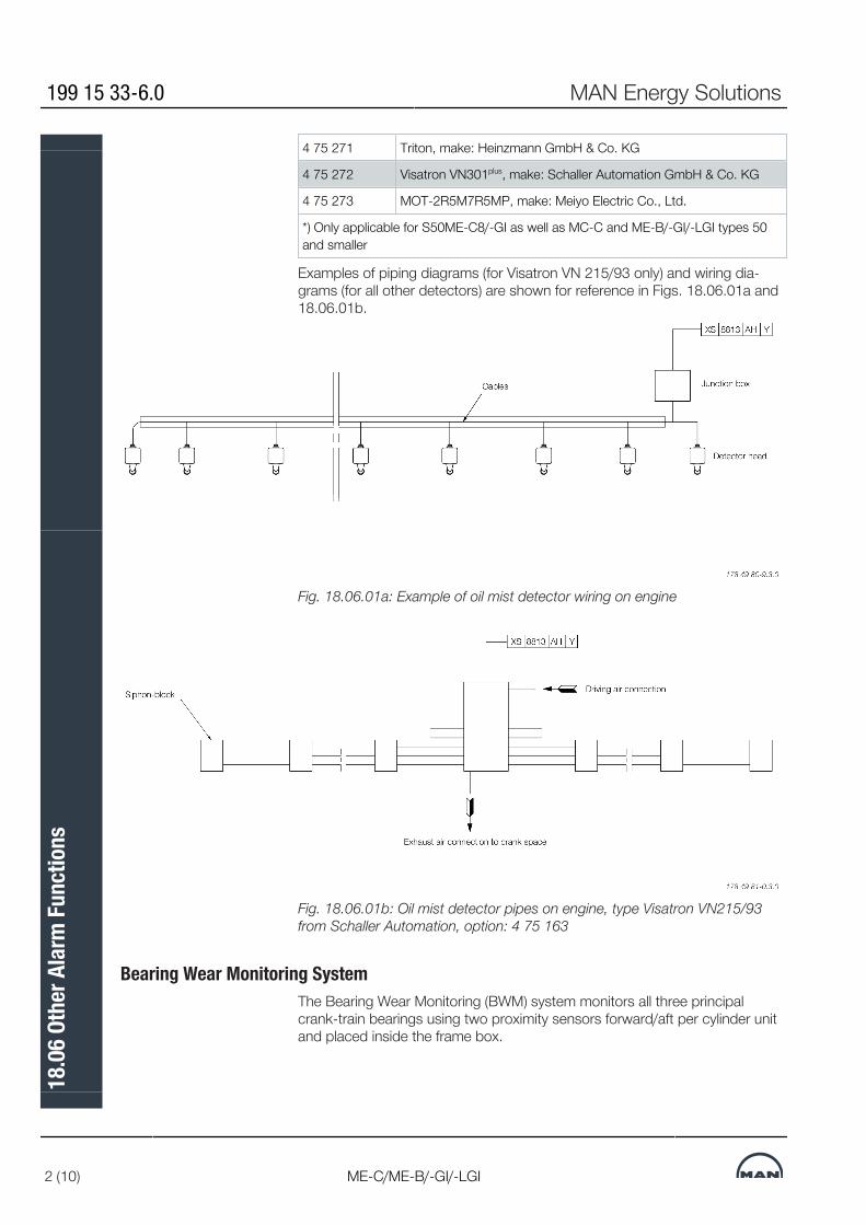
4 75 271 Triton, make: Heinzmann GmbH & Co. KG
4 75 272 Visatron VN301plus, make: Schaller Automation GmbH & Co. KG
4 75 273 MOT-2R5M7R5MP, make: Meiyo Electric Co., Ltd.
*) Only applicable for S50ME-C8/-GI as well as MC-C and ME-B/-GI/-LGI types 50and smaller
Examples of piping diagrams (for Visatron VN 215/93 only) and wiring dia-grams (for all other detectors) are shown for reference in Figs. 18.06.01a and18.06.01b.
Fig. 18.06.01a: Example of oil mist detector wiring on engine
Fig. 18.06.01b: Oil mist detector pipes on engine, type Visatron VN215/93from Schaller Automation, option: 4 75 163
Bearing Wear Monitoring SystemThe Bearing Wear Monitoring (BWM) system monitors all three principalcrank-train bearings using two proximity sensors forward/aft per cylinder unitand placed inside the frame box.
199 15 33-6.0 MAN Energy Solutions
2 (10) ME-C/ME-B/-GI/-LGI
18.0
6 Ot
her A
larm
Func
tions
Targeting the guide shoe bottom ends continuously, the sensors measure thedistance to the crosshead in Bottom Dead Center (BDC). Signals are computed and digitally presented to computer hardware, fromwhich a useable and easily interpretable interface is presented to the user.
The measuring precision is more than adequate to obtain an alarm well beforesteel-to-steel contact in the bearings occur. Also the long-term stability of the measurements has shown to be excellent.
In fact, BWM is expected to provide long-term wear data at better precisionand reliability than the manual vertical clearance measurements normally per-formed by the crew during regular service checks.
For the above reasons, we consider unscheduled open-up inspections of thecrank-train bearings to be superfluous, given BWM has been installed.
Two BWM ‘high wear’ alarm levels including deviation alarm apply. The firstlevel of the high wear / deviation alarm is indicated in the alarm panel onlywhile the second level also activates a slow down.
he Extent of Delivery lists the following Bearing Wear Monitoring options:
4 75 261 XTS–W (BWM), make: AMOT
4 75 262 BDMS (BW&TMS), make: Dr. E. Horn
4 75 263 BWCM, make: Kongsberg Maritime
4 75 265 B-WACS, make: Doosan Engine Co., Ltd.
4 75 266 BWCMS, make: KOMECO
4 75 267 BCM-1, make: Mitsui Zosen Systems Research Inc.
ME, ME-C/-GI/-LGI engines are as standard specified with Bearing WearMonitoring for which any of the above mentioned options could be chosen.
Bearing Temperature Monitoring SystemThe Bearing Temperature Monitoring (BTM) system continuously monitors thetemperature of the bearing. Some systems measure the temperature on thebackside of the bearing shell directly, other systems detect it by sampling asmall part of the return oil from each bearing in the crankcase.
In case a specified temperature is recorded, either a bearing shell/housingtemperature or bearing oil outlet temperature alarm is triggered.
In main bearings, the shell/housing temperature or the oil outlet temperature ismonitored depending on how the temperature sensor of the BTM system, op-tion: 4 75 133, is installed.
MAN Energy Solutions 199 15 33-6.0
ME-C/ME-B/-GI/-LGI 3 (10)
18.0
6 Ot
her A
larm
Func
tions

In crankpin and crosshead bearings, the shell/ housing temperature or the oiloutlet temperature is monitored depending on which BTM system is installed,options: 4 75 134 or 4 75 135.
For shell/housing temperature in main, crankpin and crosshead bearings twohigh temperature alarm levels apply. The first level alarm is indicated in thealarm panel while the second level activates a slow down.
For oil outlet temperature in main, crankpin and crosshead bearings two hightemperature alarm levels including deviation alarm apply. The first level of thehigh temperature / deviation alarm is indicated in the alarm panel while thesecond level activates a slow down.
In the Extent of Delivery, there are three options:
4 75 133 Temperature sensors fitted to main bearings
4 75 134 Temperature sensors fitted to main bearings, crankpin bearings,crosshead bearings and for moment compensator, if any
4 75 135 Temperature sensors fitted to main bearings, crankpin bearingsand crosshead bearings
Water In Oil Monitoring SystemAll MAN B&W engines are as standard specified with Water In Oil monitoringsystem in order to detect and avoid free water in the lubricating oil.
In case the lubricating oil becomes contaminated with an amount of water ex-ceeding our limit of 50% of the saturation point (corresponding to approx.0.2% water content), acute corrosive wear of the crosshead bearing overlayermay occur. The higher the water content, the faster the wear rate.
To prevent water from accumulating in the lube oil and, thereby, causingdamage to the bearings, the oil should be monitored manually or automatic-ally by means of a Water In Oil (WIO) monitoring system connected to the en-gine alarm and monitoring system. In case of water contamination the sourceshould be found and the equipment inspected and repaired accordingly.
The saturation point of the water content in the lubricating oil varies depend-ing on the age of the lubricating oil, the degree of contamination and the tem-perature. For this reason, we have chosen to specify the water activity meas-uring principle and the aw-type sensor. Among the available methods ofmeasuring the water content in the lubricating oil, only the aw-type sensormeasures the relationship between the water content and the saturation pointregardless of the properties of the lubricating oil.
WIO systems with aw-type sensor measure water activity expressed in ‘aw’on a scale from 0 to 1. Here, ‘0’ indicates oil totally free of water and ‘1’ oilfully saturated by water.
Alarm levels are specified as follows:
199 15 33-6.0 MAN Energy Solutions
4 (10) ME-C/ME-B/-GI/-LGI
18.0
6 Ot
her A
larm
Func
tions

Engine condition Water activity, aw
High alarm level 0.5
High High alarm level 0.9
The aw = 0.5 alarm level gives sufficient margin to the satuartion point in orderto avoid free water in the lubricating oil. If the aw = 0.9 alarm level is reachedwithin a short time after the aw = 0.5 alarm, this may be an indication of a wa-ter leak into the lubricating oil system.
Please note: Corrosion of the overlayer is a potential problem only forcrosshead bearings, because only crosshead bearings are designed with anoverlayer. Main, thrust and crankpin bearings may also suffer irreparable dam-age from water contamination, but the damage mechanism would be differentand not as acute.
Liner Wall Monitoring SystemThe Liner Wall Monitoring (LWM) system monitors the temperature of eachcylinder liner. It is to be regarded as a tool providing the engine room crew thepossibility to react with appropriate countermeasures in case the cylinder oilfilm is indicating early signs of breakdown.
In doing so, the LWM system can assist the crew in the recognition phaseand help avoid consequential scuffing of the cylinder liner and piston rings.
Signs of oil film breakdown in a cylinder liner will appear by way of increasedand fluctuating temperatures. Therefore, recording a preset max allowable ab-solute temperature for the individual cylinder or a max allowed deviation froma calculated average of all sensors will trigger a cylinder liner temperaturealarm.
The LWM system includes two sensors placed in the manoeuvring and ex-haust side of the liners, near the piston skirt TDC position. The sensors are in-terfaced to the ship alarm system which monitors the liner temperatures.
For each individual engine, the max and deviation alarm levels are optimisedby monitoring the temperature level of each sensor during normal service op-eration and setting the levels accordingly.
The temperature data is logged on a PC for one week at least and preferablyfor the duration of a round trip for reference of temperature development.
All types 98 and 90 ME and ME-C engines as well as K80ME-C9 are asstandard specified with Liner Wall Monitoring system. For all other engines,the LWM system is available as an option: 4 75 136.
MAN Energy Solutions 199 15 33-6.0
ME-C/ME-B/-GI/-LGI 5 (10)
18.0
6 Ot
her A
larm
Func
tions

Axial Vibration MonitorFor functional check of the vibration damper a mechanical guide is fitted,while an electronic vibration monitor can be supplied as an option.
An Axial Vibration Monitor (AVM) with indication for condition check of theaxial vibration damper and terminals for alarm and slow down ia available asan option: 4 31 117. It is required for the following engines:
• All ME-C9/10 engines incl. their -GI and -LGI variants• All ME-C7/8 engines with 5 and 6 cylinders incl. their -GI and -LGI variants• K-ME-C6/7 and K98ME6/7 engines with 11 and 14 cylinders incl. their -GIand -LGI variants.
The requirement for AVM on 4-cylinder engines is available on request.
The alarm and slow down system should include the filtration necessary toprevent the AVM from unintentionally activating the alarm and slow downfunctions at torsional vibration resonances, i.e. in the barred speed range, andwhen running Astern.
In the low speed range and when running Astern, the alarm and slow downfunctions are to be disabled so that the AVM only gives an indication of the vi-bration level.
The AVM alarm and slow down functions shall be enabled when the engine isrunning Ahead and at speeds above the barred range.
To prevent rapid hunting of the engine speed in a slow down situation, a hold-ing time function has been introduced in order to delay the automatic re-set-ting of the slow down function.
The specification of the AVM interface to the alarm and slow down system isavailable from MAN Energy Solutions Copenhagen.
(LDCL) Cooling Water SystemWith the Load Dependent Cylinder Liner (LDCL) cooling water system, thecooling water outlet temperature from the cylinder liner is controlled relative tothe engine load, independent of the cooling water outlet from the cylindercover.
The interval for the liner outlet may be wide, for instance from 70 to 130 de-gree Celsius. The cooling water outlet temperature is measured by one sensorfor each cylinder liner of the engine.
For monitoring the LDCL cooling water system the following alarm and slowdown functionality must be fulfilled:
199 15 33-6.0 MAN Energy Solutions
6 (10) ME-C/ME-B/-GI/-LGI
18.0
6 Ot
her A
larm
Func
tions

The Alarm system must be able, from one common analog sensor, to detecttwo alarm limits and two slow down limits as follows:
• Upper slow down limit• Upper alarm limit• Load dependent slow down limit• Load dependent alarm limit.
An example of the limits is shown in Fig. 18.06.02.
Fig. 18.06.02: Example of set points versus slow down and alarm limits forLDCL cooling water system
The load dependent limits must include at least one break point to allow cut-in/-out of the lower limits. The upper limits are fixed limits without breakpoints.
The values of the load dependent limits are defined as a temperature differ-ence (DT) to actual cooling water temperature (which vary relative to the en-gine load).
The cooling water temperature is plant dependent and consequently, the ac-tual values of both upper limits and load dependent limits are defined duringcommissioning of the engine.
All 95-50ME-C10/9/-GI dot 2 and higher as well as G50ME-B9.5/.3 andS50ME-B9.5 are as standard specified with LDCL Cooling Water MonitoringSystem while S50ME-B9.3 and G45ME-C9.5/-GI are prepared for the installa-tion of it.
MAN Energy Solutions 199 15 33-6.0
ME-C/ME-B/-GI/-LGI 7 (10)
18.0
6 Ot
her A
larm
Func
tions
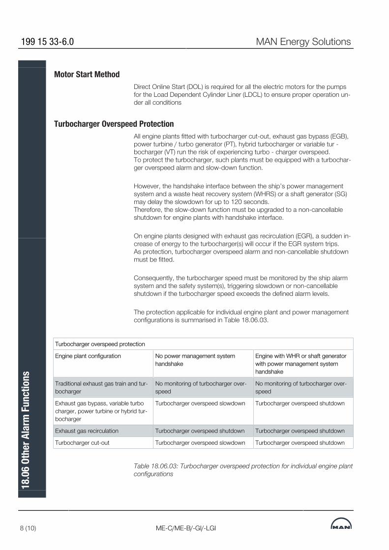
Motor Start MethodDirect Online Start (DOL) is required for all the electric motors for the pumpsfor the Load Dependent Cylinder Liner (LDCL) to ensure proper operation un-der all conditions
Turbocharger Overspeed ProtectionAll engine plants fitted with turbocharger cut-out, exhaust gas bypass (EGB),power turbine / turbo generator (PT), hybrid turbocharger or variable tur -bocharger (VT) run the risk of experiencing turbo - charger overspeed. To protect the turbocharger, such plants must be equipped with a turbochar-ger overspeed alarm and slow-down function.
However, the handshake interface between the ship’s power managementsystem and a waste heat recovery system (WHRS) or a shaft generator (SG)may delay the slowdown for up to 120 seconds. Therefore, the slow-down function must be upgraded to a non-cancellableshutdown for engine plants with handshake interface.
On engine plants designed with exhaust gas recirculation (EGR), a sudden in-crease of energy to the turbocharger(s) will occur if the EGR system trips. As protection, turbocharger overspeed alarm and non-cancellable shutdownmust be fitted.
Consequently, the turbocharger speed must be monitored by the ship alarmsystem and the safety system(s), triggering slowdown or non-cancellableshutdown if the turbocharger speed exceeds the defined alarm levels.
The protection applicable for individual engine plant and power managementconfigurations is summarised in Table 18.06.03.
Turbocharger overspeed protection
Engine plant configuration No power management systemhandshake
Engine with WHR or shaft generatorwith power management systemhandshake
Traditional exhaust gas train and tur-bocharger
No monitoring of turbocharger over-speed
No monitoring of turbocharger over-speed
Exhaust gas bypass, variable turbocharger, power turbine or hybrid tur-bocharger
Turbocharger overspeed slowdown Turbocharger overspeed shutdown
Exhaust gas recirculation Turbocharger overspeed shutdown Turbocharger overspeed shutdown
Turbocharger cut-out Turbocharger overspeed slowdown Turbocharger overspeed shutdown
Table 18.06.03: Turbocharger overspeed protection for individual engine plantconfigurations
199 15 33-6.0 MAN Energy Solutions
8 (10) ME-C/ME-B/-GI/-LGI
18.0
6 Ot
her A
larm
Func
tions
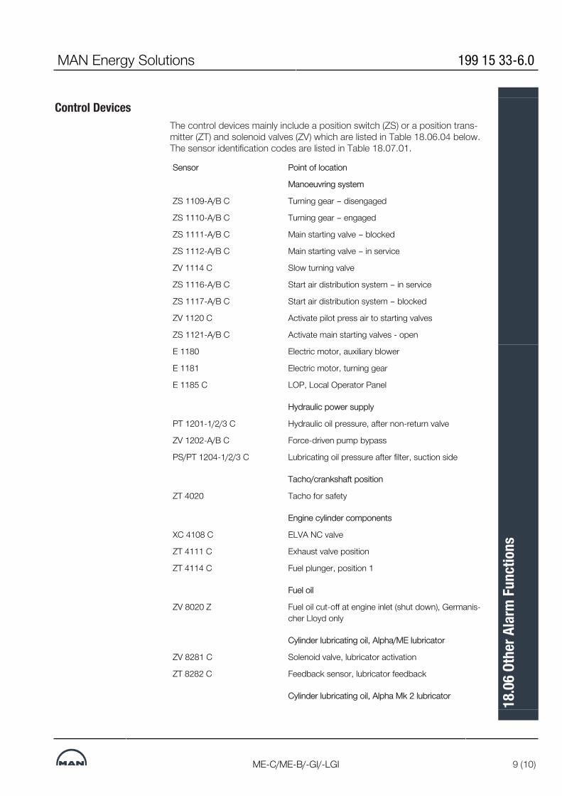
Control DevicesThe control devices mainly include a position switch (ZS) or a position trans-mitter (ZT) and solenoid valves (ZV) which are listed in Table 18.06.04 below.The sensor identification codes are listed in Table 18.07.01.
Sensor Point of location
Manoeuvring system
ZS 1109-A/B C Turning gear – disengaged
ZS 1110-A/B C Turning gear – engaged
ZS 1111-A/B C Main starting valve – blocked
ZS 1112-A/B C Main starting valve – in service
ZV 1114 C Slow turning valve
ZS 1116-A/B C Start air distribution system – in service
ZS 1117-A/B C Start air distribution system – blocked
ZV 1120 C Activate pilot press air to starting valves
ZS 1121-A/B C Activate main starting valves - open
E 1180 Electric motor, auxiliary blower
E 1181 Electric motor, turning gear
E 1185 C LOP, Local Operator Panel
Hydraulic power supply
PT 1201-1/2/3 C Hydraulic oil pressure, after non-return valve
ZV 1202-A/B C Force-driven pump bypass
PS/PT 1204-1/2/3 C Lubricating oil pressure after filter, suction side
Tacho/crankshaft position
ZT 4020 Tacho for safety
Engine cylinder components
XC 4108 C ELVA NC valve
ZT 4111 C Exhaust valve position
ZT 4114 C Fuel plunger, position 1
Fuel oil
ZV 8020 Z Fuel oil cut-off at engine inlet (shut down), Germanis-cher Lloyd only
Cylinder lubricating oil, Alpha/ME lubricator
ZV 8281 C Solenoid valve, lubricator activation
ZT 8282 C Feedback sensor, lubricator feedback
Cylinder lubricating oil, Alpha Mk 2 lubricator
MAN Energy Solutions 199 15 33-6.0
ME-C/ME-B/-GI/-LGI 9 (10)
18.0
6 Ot
her A
larm
Func
tions

XC 8288 C Propoprtional valve
ZT 8289 C Feedback sensor
Scavenge air
PS 8603 C Scavenge air receiver, auxiliary blower control
ME-GI alarm system (ME-GI only)
XC 2212 External gas shut down (request)
ME-GI safety system (ME-GI only)
XC 2001 Engine shut down (command)
XC 6360 Gas plant shut down (command)
Table 18.06.04b: Control devices on engine
199 15 33-6.0 MAN Energy Solutions
10 (10) ME-C/ME-B/-GI/-LGI
18.0
6 Ot
her A
larm
Func
tions

Identification of InstrumentsThe instruments and sensors are identified by a position number which ismade up of a combination of letters and an identification number.
Measured or Indicating VariablesFirst letters:
DS Density switch
DT Density transmitter
E Electrical component
FS Flow switch
FT Flow transmitter
GT Gauging transmitter, index/load transmitter
LI Level indication, local
LS Level switch
LT Level transmitter
PDI Pressure difference indication, local
PDS Pressure difference switch
PDT Pressure difference transmitter
PI Pressure indication, local
PS Pressure switch
PT Pressure transmitter
ST Speed transmitter
TC Thermo couple (NiCr-Ni)
TE Temperature element (Pt 100)
TI Temperature indication, local
TS Temperature switch
TT Temperature transmitter
VS Viscosity switch
VT Viscosity transmitter
WI Vibration indication, local
WS Vibration switch
WT Vibration transmitter
XC Unclassified control
XS Unclassified switch
XT Unclassified transmitter
ZS Position switch (limit switch)
ZT Position transmitter (proximity sensor)
ZV Position valve (solenoid valve)
MAN Energy Solutions 198 45 85-1.6
MC/MC-C, ME/ME-C/ME-B/-GI 1 (3)
18.0
7 Id
entif
icatio
n of
Inst
rum
ents
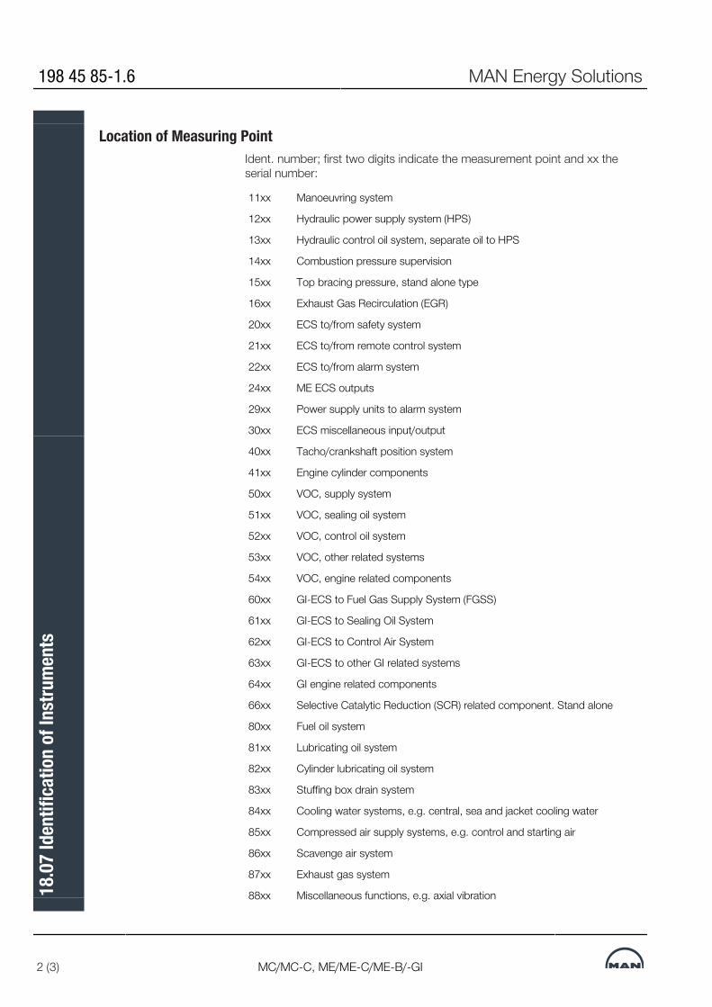
Location of Measuring PointIdent. number; first two digits indicate the measurement point and xx theserial number:
11xx Manoeuvring system
12xx Hydraulic power supply system (HPS)
13xx Hydraulic control oil system, separate oil to HPS
14xx Combustion pressure supervision
15xx Top bracing pressure, stand alone type
16xx Exhaust Gas Recirculation (EGR)
20xx ECS to/from safety system
21xx ECS to/from remote control system
22xx ECS to/from alarm system
24xx ME ECS outputs
29xx Power supply units to alarm system
30xx ECS miscellaneous input/output
40xx Tacho/crankshaft position system
41xx Engine cylinder components
50xx VOC, supply system
51xx VOC, sealing oil system
52xx VOC, control oil system
53xx VOC, other related systems
54xx VOC, engine related components
60xx GI-ECS to Fuel Gas Supply System (FGSS)
61xx GI-ECS to Sealing Oil System
62xx GI-ECS to Control Air System
63xx GI-ECS to other GI related systems
64xx GI engine related components
66xx Selective Catalytic Reduction (SCR) related component. Stand alone
80xx Fuel oil system
81xx Lubricating oil system
82xx Cylinder lubricating oil system
83xx Stuffing box drain system
84xx Cooling water systems, e.g. central, sea and jacket cooling water
85xx Compressed air supply systems, e.g. control and starting air
86xx Scavenge air system
87xx Exhaust gas system
88xx Miscellaneous functions, e.g. axial vibration
198 45 85-1.6 MAN Energy Solutions
2 (3) MC/MC-C, ME/ME-C/ME-B/-GI
18.0
7 Id
entif
icatio
n of
Inst
rum
ents

90xx Project specific functions
A0xx Temporary sensors for projects
xxxx-A Alternative redundant sensors
xxxx-1 Cylinder/turbocharger numbers
ECS: Engine Control System
GI: Gas Injection engine
VOC: Volatile Organic Compound
Table 18.07.01a: Identification of instruments
FunctionsSecondary letters:
A Alarm
C Control
H High
I Indication, remote
L Low
R Recording
S Switching
X Unclassified function
Y Slow down
Z Shut down
Repeated SignalsSignals which are repeated, for example measurements for each cylinder orturbocharger, are provided with a suffix number indicating the location, ‘1’ forcylinder 1, etc.If redundant sensors are applied for the same measuring point, the suffix is aletter: A, B, C, etc.
Examples indicates a local temperature indication (thermometer) in the fuel oil
system.
and indicate two redundant position switches in themanoeuvring system, A and B, for control of the main starting air valve posi-tion.
indicates a pressure transmitter located in the control air supplyfor remote indication, alarm for low pressure and slow down for low pressure.
078 89 33-9.6.0
Table 18.07.01b: Identification of instruments
MAN Energy Solutions 198 45 85-1.6
MC/MC-C, ME/ME-C/ME-B/-GI 3 (3)
18.0
7 Id
entif
icatio
n of
Inst
rum
ents

MAN B&W
MAN Energy Solutions
Dispatch Pattern, Testing, Spares and Tools
19


Dispatch Pattern, Testing, Spares and Tools
Painting of Main EngineThe painting specification, Section 19.02, indicates the minimum require-ments regarding the quality and the dry film thickness of the coats of, as wellas the standard colours applied on MAN B&W engines built in accordancewith the ‘Copenhagen’ standard.Paints according to builder’s standard may be used provided they at least ful-fil the requirements stated.
Dispatch PatternThe dispatch patterns are divided into two classes, see Section 19.03:A: Short distance transportation and short term storageB: Overseas or long distance transportation or long term storage.
Short distance transportation (A) is limited by a duration of a few days fromdelivery ex works until installation, or a distance of approximately 1,000 kmand short term storage.The duration from engine delivery until installation must not exceed 8 weeks.Dismantling of the engine is limited as much as possible.
Overseas or long distance transportation or long term storage require a classB dispatch pattern.The duration from engine delivery until installation is assumed to be between 8weeks and maximum 6 months.Dismantling is effected to a certain degree with the aim of reducing the trans-portation volume of the individual units to a suitable extent.Note: Long term preservation and seaworthy packing are always to be usedfor class B.Furthermore, the dispatch patterns are divided into several degrees of dis-mantling in which ‘1’ comprises the complete or almost complete engine.Other degrees of dismantling can be agreed upon in each case.When determining the degree of dismantling, consideration should be given tothe lifting capacities and number of crane hooks available at the engine makerand, in particular, at the yard (purchaser).The approximate masses of the sections appear in Section 19.04. Themasses can vary up to 10% depending on the design and options chosen.Lifting tools and lifting instructions are required for all levels of dispatch pat-tern. The lifting tools, options: 4 12 110 or 4 12 111, are to be specified whenordering and it should be agreed whether the tools are to be returned to theengine maker, option: 4 12 120, or not, option: 4 12 121.MAN Energy Solutions' recommendations for preservation of disassembled /assembled engines are available on request.Furthermore, it must be considered whether a drying machine, option: 4 12601, is to be installed during the transportation and/or storage period.
MAN Energy Solutions 198 76 20-3.2
MC/MC-C, ME/ME-C/ME-B/-GI 1 (3)
19.0
1 Di
spat
ch P
atte
rn, T
estin
g, S
pare
s and
Too
ls

Shop Trials/Delivery TestBefore leaving the engine maker’s works, the engine is to be carefully testedon diesel oil in the presence of representatives of the yard, the shipowner andthe classification society.The shop trial test is to be carried out in accordance with the requirements ofthe relevant classification society, however a minimum as stated in Section19.05.MAN Energy Solutions' recommendations for shop trial, quay trial and sea trialare available on request.In connection with the shop trial test, it is required to perform a precertificationsurvey on engine plants with FPP or CPP, options: 4 06 201 Engine test cycleE3 or 4 06 202 Engine test cycle E2 respectively.
Spare Parts
List of spare parts, unrestricted serviceThe tendency today is for the classification societies to change their rulessuch that required spare parts are changed into recommended spare parts.MAN Energy Solutions, however, has decided to keep a set of spare parts in-cluded in the basic extent of delivery, EoD: 4 87 601, covering the require-ments and recommendations of the major classification societies, see Section19.06.This amount is to be considered as minimum safety stock for emergency situ-ations.
Additional Spare Parts Recommended by MAN Energy SolutionsThe aboveœmentioned set of spare parts can be extended with the ‘Addi-tional Spare Parts Recommended by MAN Energy Solutions', option: 4 87603, which facilitates maintenance because, in that case, all the componentssuch as gaskets, sealings, etc. required for an overhaul will be readily avail-able, see Section 19.07.
Wearing PartsThe consumable spare parts for a certain period are not included in the abovementioned sets, but can be ordered for the first 1, 2, up to 10 years’ serviceof a new engine, option: 4 87 629.The wearing parts that, based on our service experience, are estimated to berequired, are listed with service hours in Tables 19.08.01 and 19.08.02.
Large Spare Parts, Dimensions and MassesThe approximate dimensions and masses of the larger spare parts are indic-ated in Section 19.09. A complete list will be delivered by the engine maker.
198 76 20-3.2 MAN Energy Solutions
2 (3) MC/MC-C, ME/ME-C/ME-B/-GI
19.0
1 Di
spat
ch P
atte
rn, T
estin
g, S
pare
s and
Too
ls

Tools
List of standard toolsThe engine is delivered with the necessary special tools for overhauling pur-poses. The extent, dimen sions and masses of the main tools is stated in Sec-tion 19.10. A complete list will be delivered by the engine maker.
Tool PanelsMost of the tools are arranged on steel plate pan els, EoD: 4 88 660, seeSection 19.11 ‘Tool Panels’.It is recommended to place the panels close to the location where the over-haul is to be carried out.
MAN Energy Solutions 198 76 20-3.2
MC/MC-C, ME/ME-C/ME-B/-GI 3 (3)
19.0
1 Di
spat
ch P
atte
rn, T
estin
g, S
pare
s and
Too
ls
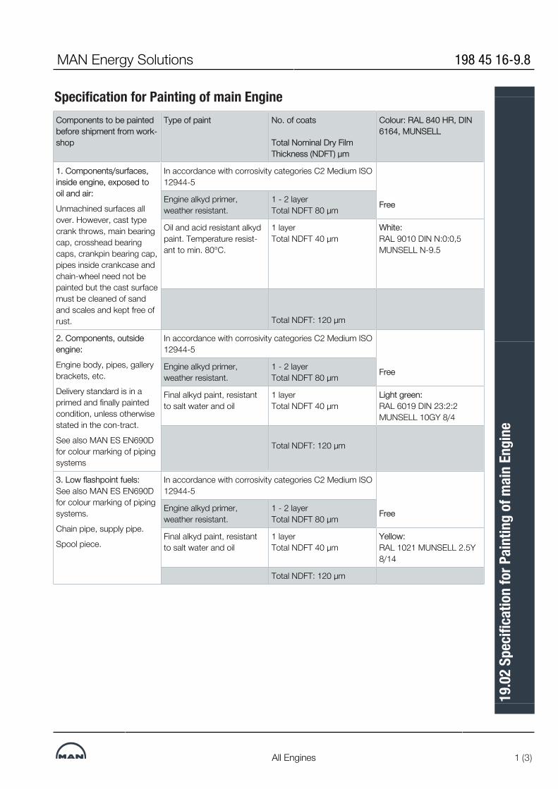
Specification for Painting of main EngineComponents to be paintedbefore shipment from work-shop
Type of paint No. of coats
Total Nominal Dry FilmThickness (NDFT) μm
Colour: RAL 840 HR, DIN6164, MUNSELL
1. Components/surfaces,inside engine, exposed tooil and air:
Unmachined surfaces allover. However, cast typecrank throws, main bearingcap, crosshead bearingcaps, crankpin bearing cap,pipes inside crankcase andchain-wheel need not bepainted but the cast surfacemust be cleaned of sandand scales and kept free ofrust.
In accordance with corrosivity categories C2 Medium ISO12944-5
FreeEngine alkyd primer,weather resistant.
1 - 2 layer Total NDFT 80 μm
Oil and acid resistant alkydpaint. Temperature resist-ant to min. 80°C.
1 layer Total NDFT 40 μm
White:RAL 9010 DIN N:0:0,5MUNSELL N-9.5
Total NDFT: 120 μm
2. Components, outsideengine:
Engine body, pipes, gallerybrackets, etc.
Delivery standard is in aprimed and finally paintedcondition, unless otherwisestated in the con-tract.
See also MAN ES EN690Dfor colour marking of pipingsystems
In accordance with corrosivity categories C2 Medium ISO12944-5
FreeEngine alkyd primer,weather resistant.
1 - 2 layer Total NDFT 80 μm
Final alkyd paint, resistantto salt water and oil
1 layer Total NDFT 40 μm
Light green:RAL 6019 DIN 23:2:2MUNSELL 10GY 8/4
Total NDFT: 120 μm
3. Low flashpoint fuels:See also MAN ES EN690Dfor colour marking of pipingsystems.
Chain pipe, supply pipe.
Spool piece.
In accordance with corrosivity categories C2 Medium ISO12944-5
FreeEngine alkyd primer,weather resistant.
1 - 2 layer Total NDFT 80 μm
Final alkyd paint, resistantto salt water and oil
1 layer Total NDFT 40 μm
Yellow:RAL 1021 MUNSELL 2.5Y8/14
Total NDFT: 120 μm
MAN Energy Solutions 198 45 16-9.8
All Engines 1 (3)
19.0
2 Sp
ecifi
catio
n fo
r Pai
ntin
g of
mai
n En
gine

Components to be paintedbefore shipment from work-shop
Type of paint No. of coats
Total Nominal Dry FilmThickness (NDFT) μm
Colour: RAL 840 HR, DIN 6164,MUNSELL
4. Heat affected compon-ents:
Supports for exhaust re-ceiver. Air cooler housinginside and outside. No sur-face may be left unpaintedin the cooler housing.
Exhaust valve housing (ex-haust flange), (Non watercooled only)
In accordance with corrosivity categories C3 Medium ISO12944-5
Ethyl silicate based zincrichpaint, heat resistant to min.300 ºC.
1 layer Total NDFT 80 μm
5. Components affected bywater, cleaning agents, andacid fluid below neutral Ph:Scavenge air cooler box in-side. (Reversing chamber).
Preparation, actual numberof coats, film thickness percoat, etc. has to be accord-ing to the paint manufac-turer specifications.
Air flow reversing chamberinside and outside.
No surfaces may be left un-painted Supervision frommanufacturer is recommen-ded, in the phase of intro-duction of the paint system.
In accordance with corrosivity categories C5-M High ISO12944-5
FreeTwo component epoxyphenolic
3 layer Total NDFT 350 μm
See specifications fromproduct data sheet
6. Gallery plates topside:
Engine alkyd primer,weather resistant
C2 medium
1 - 2 layer Total NDFT 80 μm
198 45 16-9.8 MAN Energy Solutions
2 (3) All Engines
19.0
2 Sp
ecifi
catio
n fo
r Pai
ntin
g of
mai
n En
gine

Components to be paintedbefore shipment from work-shop
Type of paint No. of coats
Total Nominal Dry FilmThickness (NDFT) μm
Colour: RAL 840 HR, DIN 6164,MUNSELL
7. EGR-system - Mixingchamber *) To be applied after WaterMist Catcher (WMC) toNon-return Valve at scav-enge air reciever. See figure2 for details.
Optional: EGR paint can beapplied from Air cooler out-let, (reversing chamber).See figure 2 for details.
*) Only for engines specifiedwith EGR or prepared forEGR installation Vinyl ESTER Acrylic copoly-
mer
Total NDFT 500 -1200 μm Free
8. Purchased equipment and instruments painted in makers colour are acceptable, unless otherwise stated in thecontract:
Tools are to be surfacetreated according to spe-cifications stated on thedrawings.
Purchased equipmentpainted in markers colour isacceptable, unless other-wise stated in the contract/drawing.
Electro(-) galvanised See specifications fromproduct data sheet
Tool panels Oil resistant paint 1 - 2 layer Total NDFT 80 μm
Light grey: RAL 7038 DIN 24:1:2MUNSELL N-7.5
9. Lifting points: Pad eyes, wholes, clamps,threaded wholes, eyescrews, eye nuts and otherlifting points
Alkyd paint, resistant to wa-ter, lubricants, hydraulic oiland degreaser.
1 layer Total NDFT 80 ym (my)
Yellow: RAL 1021 MUNSELL 2.5y8/14
All paints must be of good quality. Paints according to builder‘s standard may beused provided they at least fulfil the above requirements. The data stated are only to be considered as guidelines. Preparation, number ofcoats, film thickness per coat, etc., must be in accordance with the paint manufac-turer’s specifications.
074 33 57-9.21.0
Fig. 19.02.01: Painting of main engine, option: 4 81 101, 4 81 102 or 4 81103
MAN Energy Solutions 198 45 16-9.8
All Engines 3 (3)
19.0
2 Sp
ecifi
catio
n fo
r Pai
ntin
g of
mai
n En
gine

Dispatch PatternThe relevant engine supplier is responsible for the actual execution and deliv-ery extent. As differences may appear in the individual suppliers’ extent anddispatch variants.
Dispatch Pattern A – Short:Short distance transportation limited by duration of transportation time withina few days or a distance of approximately 1,000 km and short term storage.
Duration from engine delivery to installation must not exceed eight weeks.
Dismantling must be limited.
Dispatch Pattern B – Long:Overseas and other long distance transportation, as well as long-term stor-age.
Dismantling is effected to reduce the transport volume to a suitable extent.
Long-term preservation and seaworthy packing must always be used.
NoteThe engine supplier is responsible for the necessary lifting tools and lifting in-structions for transportation purposes to the yard. The delivery extent of lifting tools, ownership and lend/lease conditions are tobe stated in the contract. (Options: 4 12 120 or 4 12 121)
Furthermore, it must be stated whether a drying machine is to be installedduring the transportation and/or storage period. (Option: 4 12 601)
MAN Energy Solutions 198 76 32-3.4
K98ME/ME-C, G95ME-C, G90ME-C, S90ME-C, K90ME/ME-C, G80ME-C,S80ME-C, K80ME-C 1 (5)
19.0
3 Di
spat
ch P
atte
rn

Dispatch Pattern Variants
A1 + B1 (option 4 12 021 + 4 12 031) Engine complete, i.e. not disassembled
Fig. 19.03.01: Dispatch pattern, engine with turbocharger on exhaust side (459 123)
198 76 32-3.4 MAN Energy Solutions
2 (5)K98ME/ME-C, G95ME-C, G90ME-C, S90ME-C, K90ME/ME-C, G80ME-C,
S80ME-C, K80ME-C
19.0
3 Di
spat
ch P
atte
rn

A2 + B2 (option 4 12 022 + 4 12 032) • Top section including cylinder frame complete, cylinder covers complete,scavenge air receiver including cooler box and cooler insert, turbocharger(s),piston complete and galleries with pipes, HCU units and oil filter • Bottom section including bedplate complete, frame box complete, connect-ing rods, turning gear, crankshaft complete and galleries • Remaining parts including stay bolts, chains, multi-way valves, etc.
Fig. 19.03.02: Dispatch pattern, engine with turbocharger on exhaust side (459 123)
MAN Energy Solutions 198 76 32-3.4
K98ME/ME-C, G95ME-C, G90ME-C, S90ME-C, K90ME/ME-C, G80ME-C,S80ME-C, K80ME-C 3 (5)
19.0
3 Di
spat
ch P
atte
rn

A3 + B3 (option 4 12 023 + 4 12 033) • Top section including cylinder frame complete, cylinder covers complete,scavenge air receiver including cooler box and cooler insert, turbocharger(s),piston complete and galleries with pipes, HCU Units • Frame box section including frame box complete, chain drive, connectingrods and galleries, gearbox for hydraulic power supply, hydraulic pump stationand oil flter • Bedplate/crankshaft section including bedplate complete, crankshaft com-plete with chainwheels and turning gear • Remaining parts including stay bolts, chains, multi-way valves, etc.
Fig. 19.03.03: Dispatch pattern, engine with turbocharger on exhaust side (459 123)
198 76 32-3.4 MAN Energy Solutions
4 (5)K98ME/ME-C, G95ME-C, G90ME-C, S90ME-C, K90ME/ME-C, G80ME-C,
S80ME-C, K80ME-C
19.0
3 Di
spat
ch P
atte
rn

A4 + B4 (option 4 12 024 + 4 12 034)• Top section including cylinder frame complete, cylinder covers complete,piston complete and galleries with pipes on manoeuvring side, HCU units • Exhaust receiver with pipes • Scavenge air receiver with galleries and pipes • Turbocharger • Air cooler box with cooler insert • Frame box section including frame box complete, chain drive, connectingrods and galleries, gearbox for hydraulic power supply, hydraulic power sta-tion and oil flter • Crankshaft with chain wheels • Bedplate with pipes and turning gear • Remaining parts including stay bolts, auxiliary blowers, chains, multi-wayvalves, etc.
Fig. 19.03.03: Dispatch pattern, engine with turbocharger on exhaust side (459 123)
MAN Energy Solutions 198 76 32-3.4
K98ME/ME-C, G95ME-C, G90ME-C, S90ME-C, K90ME/ME-C, G80ME-C,S80ME-C, K80ME-C 5 (5)
19.0
3 Di
spat
ch P
atte
rn

Dispatch Pattern, List of Masses and Dimensions
MAN Energy Solutions 198 47 63-6.0
1 (1)
19.0
4 Di
spat
ch P
atte
rn, L
ist o
f Mas
ses a
nd D
imen
sions
Shop TestThe minimum delivery test for MAN B&W two-stroke engines, EoD: 4 14 001, involves:
• Starting and manoeuvring test at no load • Load test Engine to be started and run up to 50% of Specified MCR (M) in 1 hour.
and is followed by the below mentioned tests.
Load Test at Specific Load PointsThe engine performance is recorded running at:
• 25% of specified MCR • 50% of specified MCR • 75% of specified MCR • 90% of specified MCR or at NCR • 100% of specified MCR *) • 110% of specified MCR.
Records are to be taken after 15 minutes or after steady conditions have beenreached, whichever is shorter.
*) Two sets of recordings are to be taken at a minimum interval of 30 minutes.
Governor Test and more:• Integration test of ECS • Governor test • Minimum speed test • Overspeed test • Shut down test • Starting and reversing test • Turning gear blocking device test • Start, stop and reversing from the Local Operating Panel (LOP).
Fuel Oil TestBefore leaving the factory, the engine is to be carefully tested on diesel oil inthe presence of representatives of Yard, Shipowner, Classification Society,and MAN Energy Solutions
Fuel oil analysis is to be presented. All load point measurements are to be car-ried out on diesel or gas oil.
The shop tests are all carried out according to:
Factory Acceptance Test and Shipboard Trials of I.C. Engines, UR M51
by International Association of Classification Societies LTD. (IACS),www.iacs.org.uk
MAN Energy Solutions 1984612-7.9
MC/MC-C, ME/ME-C/ME-B 1 (2)
19.0
5 Sh
op T
est

EIAPP CertificateMost marine engines installed on ocean going vessels are required to have an‘Engine International Air Pollution Prevention’ (EIAPP) Certificate, or similar.Therefore, a pre-certification survey is to be carried out for all engines accord-ing to the survey method described in the engine’s NOx Technical File, whichis prepared by the engine manufacturer. For MAN B&W engines, the UnifiedTechnical File (UTF) format is recommended.
The EIAPP certificate documents that the specific engine meets the interna-tional NOx emission limitations specified in Regulation 13 of MARPOL AnnexVI. The basic engine ‘Economy running mode’, EoD: 4 06 200, complies withthese limitations.
The pre-certification survey for a ‘Parent’ or an ‘Individual’ engine includesNOx measurements during the delivery test. For ‘Member’ engines, a surveyaccording to the group definition for the engine group is needed. This surveyshould be based on the delivery test.
The applicable test cycles are:
• E3, marine engine, propeller law for FPP, option: 4 06 201 or • E2, marine engine, constant speed for CPP, option: 4 06 202
For further options regarding shop test, see the Extent of Delivery.
1984612-7.9 MAN Energy Solutions
2 (2) MC/MC-C, ME/ME-C/ME-B
19.0
5 Sh
op T
est

Shop Test - TIII
2021
-08-
17 -
en
MAN Energy Solutions 199 16 27-2.0
1 (1)
19.0
5 Sh
op T
est -
TIII

MAN B&W 19.06Page 1 of 2
MAN B&W G95/90/80ME-C10 199 12 29-4.3MAN Energy Solutions
Cylinder cover, plate 2272-0300, 2272-10001 Cylinder cover complete (disassembled)1 Indicator valve1 Cooling jacket1 set Sealing rings½ set Studs for 1 cylinder cover
Piston and piston rod, plates 2272-0400/0420/05001 Piston complete (with cooling pipe), piston rod,
piston rings and stuffing box, studs and nuts1 set Piston rings for 1 cylinder
Cylinder liner, plate 2272-0600
1 Cylinder liner complete, including cooling jack-et, non-return valves, sealing rings and gaskets (assembled)
Cylinder lubricating oil system, plates 3072-0600,6670-0100 1)1 Lubricator complete1 Inductive sensor1 set O-rings and seals2 Lubricator backup cable
Connecting rod, and crosshead bearing, plates 1472-0300, 2572-0300/02001 Telescopic pipe with bushing for 1 cylinder1 Crankpin bearing shell (1 upper and 1 lower part)
with studs and nuts1 Crosshead bearing shell lower part with studs
and nuts2 Thrust piece
Thrust block, plate 2572-06001 set Thrust pads, complete FWD set for ‘Ahead’1 set For KR and NK also 1 set ‘Astern’ if different
from ‘Ahead’
HPS Hydraulic Power Supply, plates 4572-1000/0750, 4572-1100/1200/1250 1 and 2)1 Proportional valve for hydraulic pumps1 Leak indicator1 Drive shaft for hydraulic pump, of each type
(length)1 Membrane plus seals for accumulator
1 set Minimess for accumulator1 Compensator, fluid type6 Chain links. Only for ABS, LR and NK1 set Flexible hoses, one of each size and length1 set High-pressure gasket kit1 Hydraulic pump1 Coupling for start-up pump
ME filter, plate 4572-08001 set Filter cartridges for redundancy filter. Cartridge
filtration ability, minimum Beta6=16. Only for filter make Kanagawa
Engine control system, plates 4772-1500/1550, 7072-0800/1100/1250 2)1 set Controller spares:
1 Base module1 CPU module1 Power supervision module1 Modbus module1 Digital I/O module (DI, DO, DRO)1 Analog I/O module1 Digital I/O module (DI, DO)1 Combi I/O module (AI/DO) Only GI
1 Trigger sensor for tacho system. Only if trigger ring and no angular encoder on fore end
1 Marker sensor for tacho system1 Tacho signal amplifier1 IDkey1 Encoder, steel compensator and bearing set
Starting valve, plates 3472-0200/02501 Starting valve, complete1 Solenoid valve 1)
Main hydraulic, plates 4572-0400/0900, 4272-0020 1 and 2)1 set Hydraulic supply pipe
1 Packing kit (O-rings, square seals and bonded seals)
1 set Fuel oil injection valve hydraulic pipes1 set Supply oil pipes for FBIV
Exhaust valve (TCEV), plates 2272-0200/0205/0210, 4572-0500/05501 Top controlled Exhaust Valve complete (with HCU)1 Top controlled Exhaust Valve without HCU1 Exhaust valve position sensor1 ELFI + PEVA valves complete1 set Membrane plus seals for accumulator, 1 set for 1 Packing kit (O-rings, square seals)
List of Spare Parts, Unrestricted Service
Fig. 19.06.01a: List of spare parts, unrestricted service: 4 87 601
Spare parts are requested by the following Classes only: KR, NK and RS, while just recommended by: ABS and LR, but neither requested nor recommended by: BV, CCS, DNV and RINA. The final scope of spare parts is to be agreed between the owner and engine builder/yard.

MAN B&W 19.06Page 2 of 2
MAN B&W G95/90/80ME-C10 199 12 29-4.3MAN Energy Solutions
Fuel valve, plate 4272-05001 set FBIV complete for one cylinder (ie. 2 FBIVs for
covers with 2 fuel valves per cylinder and 3 for covers with 3 fuel valves per cylinder)
1 set Fuel valves for the remaining cylinders (ie. 1 fuel valve for covers with 2 fuel valves per cylinder and 2 fuel valves for covers with 3 fuel valves per cylinder)
Turbocharger, plate 5472-07001 set Marker’s standard spare parts
1 a)Spare rotor for 1 turbocharger, including compres-sore wheel, rotor shaft with turbine blades and partition wall, if any
Bedplate, plates 1072-0400, 2572-04001 Main bearing shell (1 upper and 1 lower part) of
each size1 set Studs and nuts for 1 main bearing
1) MAN ES required spare parts.2) All spare parts are requested by all Classes.a) Only required for RS. To be ordered separately as
option: 4 87 660 for other classification societies
Footnotes
a) Engines with one or two fuel valves per cylinder: one set of fuel valves complete.
b) Engines with three or more fuel valves per cylinder: two fuel valves complete per cylinder, and a suf-ficient number of valve parts, excluding the body, to form, with those fitted in the complete valve, a full engine set

Additional Spares
Beyond class requirements or recommendation, for easier maintenance andincreased security in operation.
The final scope of spare parts is to be agreed between the owner and enginebuilder/yard.
Cylinder Cover, Plate 2272-0300 (901)4 Studs for exhaust valve 4 Nuts for exhaust valve ½ eng O-rings for cooling jacket ½ eng Sealing between cylinder cover and liner 4 Spring housings for fuel valve. Only for 98-60 ME/ME-C
Hydraulic Tool For Cylinder Cover, Plates 2270-0310/0315 (901)1 set Hydraulic hoses with protection hose complete with couplings 8 pcs O-rings with backup rings, upper 8 pcs O-rings with backup rings, lower
Piston And Piston Rod, Plates 2272-0400/0420 (902)1 box Locking wire, L=63 m 5 Piston rings of each kind 2 D-rings for piston skirt 2 D-rings for piston rod
Piston Rod Stuffing Box, Plate 2272-0500 (902)15 Self-locking nuts 5 O-rings 5 Top scraper rings 15 Pack sealing rings 10 Cover sealing rings 120 Lamellas for scraper rings 30 Springs for top scraper and sealing rings 20 Springs for scraper rings
Cylinder Frame, Plate 1072-0710 (903)½ set Studs for cylinder cover for 1 cylinder 1 Bushing for stuffing box
Cylinder liner and Cooling Jacket, Plate 2272-0600/0660/0665 (903)4 set Non-return valves. For K90ME-C two types/ cylinder 1 eng O-rings for cylinder liner ½ eng Gaskets for cooling water connection ½ eng O-rings for cooling water pipes
MAN Energy Solutions 198 46 36-7.16
98-60ME/ME-C, S50ME-C8 1 (5)
19.0
7 Ad
ditio
nal S
pare
s

1 set Cooling water pipes with blocks between liner and cover for 1 cylinder 1 *) Repair kit for LDCL circulation pump 1 *) Repair kit for LDCL three-way control valve *) if fitted
Cylinder lubricating Oil System, Plate 3072-0600(903)1 Solenoid valve 1 Level switch for lubricator
Hydaulic Power Supply, HPS, Plates 4572-1000/0750, 4572-1100/1200/1250 (906)1 Electric motor for start-up pump 1 Pressure relief valve for start-up pump 2 Pressure reducer for pump inlet 25% Plug screws for hydraulic system (HPS & HCU) 1 Accumulator, complete 1 Proportional valve 1 Swashplate transducer 1 Rubber compensator for inlet
Engine Control System, ECS, Plate 4772-1550 (906)1 set Fuses for MPC, TSA, CNR
Hydraulic Cylinder Unit, HCU, Plate 4572-0500 (906)1 set Packings for booster & actuator, complete set 1 ELFI + ELVA valves, or FIVA if applied 1 Ball valve, pos. 420 1 Ball valve DN10 1 set Accumulator complete 25% Plug screws, shared with HPS & accumulator block
Accumulator/safety Block, Plate 4572-0700 (906)1 Pressure transducer, pos. 320 25% Plug screws, shared with HPS & HCU 1 Ball valve DN10 1 Solenoid valve for valve pos. 310 (shut down)Fig. 19.07.01a: Additional spare parts beyond class requirements or recom-mendation, option: 4 87 603
Alarm and Safety System, Plate 4772-1 Pressure sensor for scavenge air receiver, PT 8601 1 Pressure switch for lubricating oil inlet, PS 8109 1 Thrust bearing temperature sensor, TS 8107 (sensor only) 1 Pressure switch for jacket cooling water inlet, PS 8402
Main Starting Valve, Plate 3472-0300 (907)The below main starting valve parts are all to be in accordance with the sup-plier’s recommendation: 1 Repair kit for main actuator
198 46 36-7.16 MAN Energy Solutions
2 (5) 98-60ME/ME-C, S50ME-C8
19.0
7 Ad
ditio
nal S
pare
s

1 Repair kit for main ball valve 1 *) Repair kit for actuator, slow turning 1 *) Repair kit for ball valve, slow turning
*) if fitted
Starting Valve, Plate 3472-0200 (907)2 Locking plates 2 Pistons 2 Springs 2 Bushing 1 set O-rings 1 Valve spindle
Exhaust Valve, Plates 2272-0200/0210 (908)1 Exhaust valve spindle 1 Exhaust valve seat ½ eng Sealing rings between exhaust valve and cylinder cover 4 Piston rings ½ eng Guide rings for air piston ½ eng Sealing rings ½ eng Safety valves 1 eng Gaskets and O-rings for safety valve 1 Piston complete 1 Opening damper piston 1 eng O-rings and sealings between air piston and exhaust valve housing/spindle 1 Spindle guide 1 eng Gaskets and O-rings for cooling water connection 1 Conical ring in 2/2. Only for low-force design 1 eng O-rings for spindle/air piston 1 eng Non-return valve 1 Sealing oil unit. Only for engines without lowforce design/COL 1 Inductive sensor for exhaust valve positioning
Exhaust Valve Pipe, Plate 2272-0240 (908)1 High pressure pipe from actuator to exhaust valve
Cooling Water Outlet, Plate 5072-0100 (908)2 Ball valve 1 Butterfly valve 1 Gaskets for butterfly valve 1 eng Packings for cooling water compensator. Only for S50ME-C8
Fuel Injection System, Plate 4272-0500 (909)1 Fuel oil pressure booster complete, for 1 cylinder
MAN Energy Solutions 198 46 36-7.16
98-60ME/ME-C, S50ME-C8 3 (5)
19.0
7 Ad
ditio
nal S
pare
s

Fuel Valve, Plate 4272-0200 (909)1 eng Spindle guides, complete with fuel nozzle 1 eng O-rings and guide rings for fuel valve½ eng Springs ½ eng Discs, +30 bar 3 Thrust spindles 3 Non-return valve, if mounted
Fuel Oil high-pressure Pipes, Plate 4272-0100 (909)1 set High-pressure pipe, from fuel oil pressure booster to fuel valve 1 set O-rings for high-pressure pipes
Fuel Oil Regulating Valve, Plate 4272-0030 (909)1 Fuel oil regulating valve, complete 1 O-ring of each kind
Turbocharger, Plate 5472-0700 (910)1 set Spare parts for 1 turbocharger in accordance with the supplier’s recom-mendation
Scavenge Air Receiver, Plates 5472-0400/0630 (910)1 set Non-return valves for turbocharger, complete1 Compensator between TC and air cooler
Exhaust Pipes and Receiver, Plates 5472-0750/0900(910)1 Compensator between TC and receiver 2 Compensator between exhaust valve and receiver 1 set Gaskets for each compensator 1 Compensator between FWD and Aft part, if anyFig. 19.07.01b: Additional spare parts beyond class requirements or recom-mendation, option: 4 87 603
Safety Valve, Plate 2272-0330 (911)1 set Gaskets for safety valve. Only for CR and NK 2 Safety valve complete. Only for CR and NK
Air Cooler, Plate 5472-0100 (910)1 set Anodes (Corrosion blocks) 1 set Packings. Only for cooler type LKMY
Auxiliary Blower, Plate 5472-0500 (910)1 set Bearings for electric motor 1 set Shaft sealings 1 set Bearings/belt/sealings for gearbox. Only for belt-driven blowers
198 46 36-7.16 MAN Energy Solutions
4 (5) 98-60ME/ME-C, S50ME-C8
19.0
7 Ad
ditio
nal S
pare
s

Arrangement of Safety Cap, Plate 3472-0900 (911)1 eng Bursting disc
ME Filter, Plate 4572-0800 (912)1 set Filter cartridges for redundancy filter. Cartridge filtration ability, minimum Beta6=16. Only for filter make Boll & KirchNotes: In the pcs/set column, ‘eng’ means ‘engine set’, i.e. a set for one en-gine, whereas ‘set’ means a set for the specific component(s).Section numbers refer to Instruction Book, Vol. III containing plates with sparepartsFig. 19.07.01c: Additional spare parts beyond class requirements or recom-mendation, option: 4 87 603
MAN Energy Solutions 198 46 36-7.16
98-60ME/ME-C, S50ME-C8 5 (5)
19.0
7 Ad
ditio
nal S
pare
s

Wearing PartsMAN Energy Solutions Service Letter SL-681 provides Guiding Overhaul Inter-vals and expected service life for key engine components.
The wearing parts expected to be replaced at the service hours mentioned inthe Service Letter are listed in the tables below.
A 8,000 B 12,000 C 16,000 D 20,000 E 24,000 F 32,000
G 36,000 H 40,000 I 48,000 J 56,000 K 60,000 L 64,000
M 72,000 N 80,000 O 84,000 P 88,000 Q 96,000
Service hours A B C D E F G H I J K L M N O P Q
Description Replace parts
Piston
▪ Soft iron gasket (1 set per cylinder) x x x x
▪ Piston crown (1 pc per cylinder) x
▪ O-rings for piston (1 set per cylinder) x
▪ Piston rings (1 set per cylinder) x x x x
▪ Piston cleaning ring (1 pc per cylinder)
x
Stuffing box
▪ Lamellas (1 set per cylinder) x x x x
▪ Top scraper ring (1 pc per cylinder) x x x x
▪ O-rings (1 set per cylinder) x x x x
Cylinder liner (1 pc per cylinder) x
▪ O-rings for cylinder liner (1 set percylinder)
x
▪ O-rings for cooling water jacket (1 setper cylinder)
x
▪ O-rings for cooling water connections(1 set per cyl.)
x
Exhaust valve
▪ DuraSpindle (1 pc per cylinder) x
▪ Nimonic spindle (1 pc per cylinder) x
▪ Bottom piece (1 pc per cylinder) x
▪ Piston rings for exhaust valve & oilpiston (1 set per cyl.)
x
▪ O-rings for bottom piece (1 set percylinder)
x x x x
Table 19.08.01a: Wearing parts according to Service Letter SL-681
MAN Energy Solutions 198 46 37-9.10
98-80ME/ME-C/-GI/-LGI 1 (3)
19.0
8 W
earin
g Pa
rts

Service hours A B C D E F G H I J K L M N O P Q
Description Replace parts
Fuel valves
▪ Valve nozzle (3 sets per cylinder) x x x x x x
▪ Spindle guide (3 sets per cylinder) x x x x x x
▪ O-ring (3 sets per cylinder) x x x x x x x x x x x x
▪ Spring housings (1 set per cylinder) x
Bearings
▪ Crosshead bearing (1 set per cylinder) x
▪ Crankpin bearing (1 set per cylinder) x
▪ Main bearing (1 set per cylinder) x
▪ Thrust bearing (1 set per engine) x
Cylinder cover (1 pc per cylinder) x
▪ O-rings for cooling water jacket (1 setper cylinder)
x x x x
▪ O-ring for starting valve (1 pc per cyl-inder)
x x x x x x x x
Air cooler(s) (1 pc per turbocharger) x x
Chains (1 set per engine) x
Turbocharger(s) *)
Alpha Lubricator
▪ Solenoid valve (1 pc per pump) x x x x
▪ Non-return valve (1 pc per pump piston)
x x x x
▪ O-rings (1 set per lubricator) x x x x
Mechanical cylinder lubricator *)
ME Parts
▪ Hydraulic hoses (1 set per engine) x x x
▪ ELFI + ELVA valves, or FIVA (1 pc percylinder)
x
▪ Fuel oil pressure booster (1 pc percylinder)
x
▪ Angle encoder (2 pcs per engine) x
▪ MOP A (1 pc per engine) x
Table 19.08.01b: Wearing parts according to Service Letter SL-681
198 46 37-9.10 MAN Energy Solutions
2 (3) 98-80ME/ME-C/-GI/-LGI
19.0
8 W
earin
g Pa
rts

Service hours A B C D E F G H I J K L M N O P Q
Description Replace parts
▪ MOP B (1 pc per engine) x
▪ CCU amplifier (1 pc per cylinder) x
▪ ACU amplifier (3 pcs per engine) x
▪ LVDT hydraulic pump amplifier (3 pcsper engine)
x
▪ LDI hydraulic pump amplifier (3 pcsper engine)
x
▪ Proportional valve for main hydraulicpump
x x x x
▪ Hydrostatic bearings for main hydraulic pump
x x x
▪ Sealings for pressure relief valve formain hydr. pump
x x
▪ Static sealing rings for exh. valve actuator (1 pc per cyl.)
x x x
▪ Membranes for accumulators on HPS x x x
▪ Membranes for accumulators onHCU
x x x
▪ Fuel booster sensor (1 pc per cylinder)
x
▪ Exhaust valve sensor (1 pc per cylinder)
x
▪ Marker sensor (1 pc per engine) x
▪ Cables (1 set per engine) x
▪ Gear wheel bearings (1 set per engine)
x
ME-GI/-LGI Parts
▪ Gas/LFL nozzles (1 set per cylinder)**)
x x x x x x
▪ Sealing rings and gaskets for gas/LFLinjection valves (1 set per cylinder) **)
x x x x x x x x x x x x
▪ Sealing rings for arrangement of con-trol oil pipes (1 set per cylinder) ***)
x x x x x x x x x x x x
*) According to manufacturer’s recommendations.**) For -GI/-LGI engines only***) For -GI engines only
Table 19.08.01c: Wearing parts according to Service Letter SL-681
MAN Energy Solutions 198 46 37-9.10
98-80ME/ME-C/-GI/-LGI 3 (3)
19.0
8 W
earin
g Pa
rts
Large Spare Parts, Dimensions and Masses
MAN Energy Solutions 199 10 72-2.0
1 (1)
19.0
9 La
rge S
pare
Par
ts, D
imen
sions
and
Mas
ses

MAN B&W 19.09Page 2 of 2
MAN B&W engines 199 01 89-2.2MAN Energy Solutions
Fig. 19.09.02: Large spare parts, dimensions and masses
Rotor for turbocharger
MAN
TypeMax Mass Dimensions (mm)
kg. A (ø) B C (ø)
TCA44 90 480 880 460
TCA55 140 570 990 515
TCA66 230 670 1,200 670
TCA77 390 800 1,380 730
TCA88 760 940 1,640 980
TCR18 24 280 469
TCR20 42 337 566
TCR22 95 440 739
561 70 21-6.0.1
ABB
Type
Max Mass
Dimensions (mm)
kg. A (ø) B C (ø)
A165-L 90 500 940 395
A170-L 130 580 1,080 455
A175-L 220 700 1,300 550
A180-L 330 790 1,470 620
A185-L 460 880 1,640 690
A190-L 610 970 1,810 760
A255-L 50 440 830 -
A260-L 60 440 830 -
A265-L 100 500 930 395
A270-L 140 580 1,090 455
A275-L 240 700 1,320 550
A280-L 350 790 1,490 620
A285-L 490 880 1,660 690
561 66 78-9.0.0
MHI
Type
Max Mass
Dimensions (mm)
kg. A (ø) B C (ø)
MET33MA 45 373 662 364
MET33MB 55 373 692 364
MET42MA 68.5 462 807 451
MET42MB 85 462 847 451
MET48MB 155 524 954 511
MET53MA 190 586 1,035 571
MET53MB 210 586 1,068 571
MET60MA 240 652 1,188 636
MET60MB 270 652 1,185 636
MET66MA 330 730 1,271 712
MET66MB 370 730 1,327 712
MET71MA 400 790 1,318 771
MET71MB 480 790 1,410 771
MET83MA 600 924 1,555 902
MET83MB 750 924 1,608 902
MET90MA 850 1,020 1,723 996
MET90MB 950 1,020 1,794 996
561 68 37-2.1.0
A
B
C
178 68 17-0.1

List of Standard Tools for Maintenance
MAN Energy Solutions 198 64 51-9.0
1 (1)
19.1
0 Lis
t of S
tand
ard
Tool
s for
Mai
nten
ance

Tool Panels
MAN Energy Solutions 198 66 45-0.0
1 (1)
19.1
1 To
ol P
anels
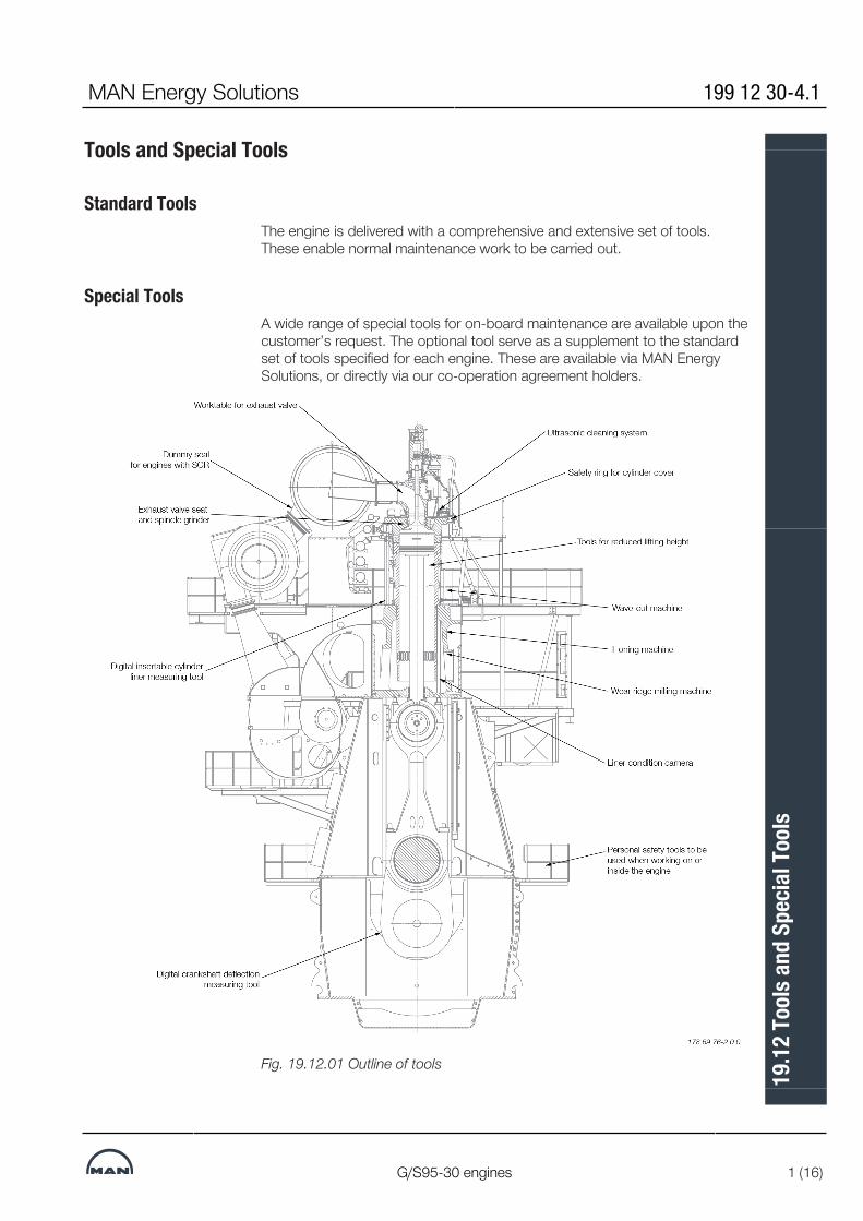
Tools and Special Tools
Standard ToolsThe engine is delivered with a comprehensive and extensive set of tools.These enable normal maintenance work to be carried out.
Special ToolsA wide range of special tools for on-board maintenance are available upon thecustomer’s request. The optional tool serve as a supplement to the standardset of tools specified for each engine. These are available via MAN EnergySolutions, or directly via our co-operation agreement holders.
Fig. 19.12.01 Outline of tools
MAN Energy Solutions 199 12 30-4.1
G/S95-30 engines 1 (16)
19.1
2 To
ols a
nd S
pecia
l Too
ls

Optional Inspection Tools to Assist Condition-Based Overhaul (CBO)The objective of the Condition-Based Overhaul (CBO) strategy is to obtain thehighest number possible of safe running hours. Overhauling should only becarried out when necessary and the most important factor in a CBO strategyis the evaluation of the actual condition of the engine. This is done by regularscavenge port inspections and logging of wear and hot corrosion.MAN Energy Solutions recommends the following optional measuring tools toassist with the CBO strategy.
Digital Insertable Cylinder Liner Measuring ToolThe insertable tool facilitates liner condition monitoring. The cylinder liner trendwear profile can be revealed and predicted by taking measurements regularlyduring scavenge port inspections at engine stand-stills. The measurementsare done without removing the cylinder cover or exhaust valve housing, whichis very time saving and allows for more frequent measurements than using thestandard version of the tool. The output is digital, see Fig. 19.12.02.
Fig. 19.12.02 The insertable tool is available from different makers, startingfrom bore size 40
Liner Condition CameraThe liner condition camera is used for in situ photography of the cylinder linerwalls and piston ring packs in 2-stroke engines.The photos can be used for evaluating cylinder condition parameters such ascleanliness of ring land, size of cylinder wear edge, cylinder honing mark andwave-cut groove extension, black lacquering from corrosive wear and borepolish. See Fig. 19.12.03.
199 12 30-4.1 MAN Energy Solutions
2 (16) G/S95-30 engines
19.1
2 To
ols a
nd S
pecia
l Too
ls
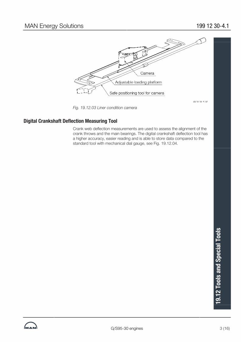
Fig. 19.12.03 Liner condition camera
Digital Crankshaft Deflection Measuring ToolCrank web deflection measurements are used to assess the alignment of thecrank throws and the main bearings. The digital crankshaft deflection tool hasa higher accuracy, easier reading and is able to store data compared to thestandard tool with mechanical dial gauge, see Fig. 19.12.04.
MAN Energy Solutions 199 12 30-4.1
G/S95-30 engines 3 (16)
19.1
2 To
ols a
nd S
pecia
l Too
ls

Fig. 19.12.04 The digital measuring tool is available for all engine bore sizes
Optional Handling, Grinding or Refreshing ToolThe following tools are recommended for best practice overhaul.
Wear Ridge Milling MachineThe machine is used to remove the wear ridge created in the top of the cylin-der liner. This edge must be removed before the pulling of piston, to preventdamage of the piston and/or lifting of the cylinder liner. The risk of damage topiston rings when pulling piston without removing the wear ridge is especiallyhigh for CPR rings. The wear ridge milling machine minimizes the risk of linerdamage due to un-controlled grinding. The wear ridge milling machine canalso be used to create a groove in the top of the liner to prevent the buildup ofa new wear ridge.The wear ridge milling machine is available in two different versions: A stand-ard milling machine and a customized milling machine for which a Hot WorksPermit is not necessary. see Fig. 19.12.05.
199 12 30-4.1 MAN Energy Solutions
4 (16) G/S95-30 engines
19.1
2 To
ols a
nd S
pecia
l Too
ls

Fig. 19.12.05 The wear ridge milling machine is available for all engine boresizes
Honing MachineHoning is the best method to remove liner ovality, which cause premature ringbreakage. Honing will also remove liner surface hardening and re-establish anormal wear rate of a hardened liner.The honing machine can be used on its own or combined with the wave-cutmachine, see Fig. 19.12.06.
MAN Energy Solutions 199 12 30-4.1
G/S95-30 engines 5 (16)
19.1
2 To
ols a
nd S
pecia
l Too
ls

Fig. 19.12.06 Cylinder liner with honing machine
199 12 30-4.1 MAN Energy Solutions
6 (16) G/S95-30 engines
19.1
2 To
ols a
nd S
pecia
l Too
ls

Wave-cut MachineThe purpose of the wave-cut machine is to reestablish the wave-cut patternof the cylinder liner wall, which retains oil and facilitates the running-in of newpiston rings. Wave-cutting does not compensate for liner ovality. The wave-cut machine can be used on its own or combined with honing, see Fig.19.12.07.
Fig. 19.12.07 Cylinder with wave-cut machine and wave-cut pattern
MAN Energy Solutions 199 12 30-4.1
G/S95-30 engines 7 (16)
19.1
2 To
ols a
nd S
pecia
l Too
ls

Worktable for Exhaust ValveThe worktable for exhaust valve ensures that maintenance of the completeexhaust valve or the exhaust valve housing can be carried out safe and easy,see Fig. 19.12.08.
Fig. 19.12.08 Worktable is available for all bore sizes
Exhaust Valve Seat and Spindle GrinderThe exhaust valve seat and spindle grinder provides easy and accurate on-board grinding of the exhaust valve spindle and bottom piece sealing sur-faces. See fig. 19.12.09.Different versions of the grinder exist and can be ordered for all engine boresizes.
199 12 30-4.1 MAN Energy Solutions
8 (16) G/S95-30 engines
19.1
2 To
ols a
nd S
pecia
l Too
ls

Fig. 19.12.09. Exhaust valve seat and spindle grinder
MAN Energy Solutions 199 12 30-4.1
G/S95-30 engines 9 (16)
19.1
2 To
ols a
nd S
pecia
l Too
ls

Dummy Seal for SCR
Fig. 19.12.10 Dummy seal for SCR
Optional Safety Tools
Personal Safety ToolsWorking on or inside two-stroke engines are very often connected with risk offalling down. The risk of falling down can be mitigated by using fall protectionequipment.The supplementary fall arrest safety equipment is CE or ANSI approved andincludes a safety harness and lanyardsFull body harness, lightweight 1,3 kg. Attack point in the back. Easy donningand adjustment. Certified to North American, European and Russian stand-ards. It is available in three sizes, see Fig. 19.12.11.
a)
Full body harness, lightweight 1.3 kg. At-tack point in the back. Easy donning andadjustment. American
n, European and Russian standards It isavailable in three sizes.
199 12 30-4.1 MAN Energy Solutions
10 (16) G/S95-30 engines
19.1
2 To
ols a
nd S
pecia
l Too
ls

b)
Mini fall arrest block with steel hook. Ex-tracted up to 2 m max. gives the flexibil-ity. Th brake will arrest a free fall withinfew inches. Connect it directly to harnessattach point at the hip and hook it to asafe anchor point. It is designed to avoidfalling and must not be used as.
c)
Working positioning lanyard 2 m, ad-justable length and a one- hand operatedsteel hook. Connect it to harness attackpoint at the hip and hook it to a safe an-chor point. It is designed to avoid fallingand must not be used as.
Fig. 19.12.11 Full body harness (a), mini fall arrest block (b) and working posi-tioning lanyard (c)
Safety Ring for Cylinder CoverThe safety ring is used for allowing access to the cylinder liner through the ex-haust valve bore of the cylinder cover. This option is available for bore size 90and above. For bore sizes below the the cylinder cover are to be dismantled,see Fig. 19.12.12.
MAN Energy Solutions 199 12 30-4.1
G/S95-30 engines 11 (16)
19.1
2 To
ols a
nd S
pecia
l Too
ls

Optional Tools for Special Design
Tools for Reduced Lifting HeightThe optional tool package for reduced lifting height includes a collar ringwhich makes it possible to tilt the piston, hence reducing the required liftingheight of the engine room.Engines with bore size less than 70 can be ordered with reduced lifting heightin the engine room. Engines with bore size from 70 can receive reduced liftingheight upon special request.Tilted lift is not allowed for the cylinder liner, but by using the MAN B&Wdouble jib engine room crane the necessary lifting height is greatly reducedcompared to the single crane standard solution. Lifting screws for the doublejib crane is included in the tool package for reduced lifting height, see Fig.19.12.13 and 19.12.14.
199 12 30-4.1 MAN Energy Solutions
12 (16) G/S95-30 engines
19.1
2 To
ols a
nd S
pecia
l Too
ls

Fig. 19.12.13 Piston tool for reduced lifting height
MAN Energy Solutions 199 12 30-4.1
G/S95-30 engines 13 (16)
19.1
2 To
ols a
nd S
pecia
l Too
ls

Fig. 19.12.14 Cylinder liner tool for reduced lifting height
Ultrasonic Cleaning SystemUltrasonic cleaning system can be installed onboard to give the possibility ofcleaning of smaller engine parts such as fuel and spray nozzles, filters etc. us-ing ultrasound waves in a specific cleaning chemical bath. The system is avail-able in different sizes. See Fig. 19.12.15.
Fig. 19.12.15 Onboard ultrasonic cleaning system
199 12 30-4.1 MAN Energy Solutions
14 (16) G/S95-30 engines
19.1
2 To
ols a
nd S
pecia
l Too
ls

Rig for large fuel valveThe working rig facilitates overhaul work on large injection valves e.g. dismant-ling and cleaning.
Fig. 19.12.16 Rig for large fuel valve.
MAN Energy Solutions 199 12 30-4.1
G/S95-30 engines 15 (16)
19.1
2 To
ols a
nd S
pecia
l Too
ls
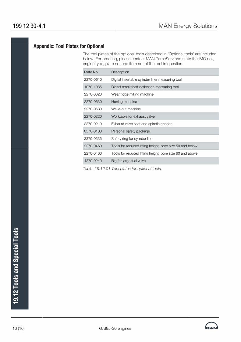
Appendix: Tool Plates for OptionalThe tool plates of the optional tools described in ‘Optional tools’ are includedbelow. For ordering, please contact MAN PrimeServ and state the IMO no.,engine type, plate no. and item no. of the tool in question.
Plate No. Description
2270-0610 Digital insertable cylinder liner measuring tool
1070-1035 Digital crankshaft deflection measuring tool
2270-0620 Wear ridge milling machine
2270-0630 Honing machine
2270-0630 Wave-cut machine
2270-0220 Worktable for exhaust valve
2270-0210 Exhaust valve seat and spindle grinder
0570-0100 Personal safety package
2270-0335 Safety ring for cylinder liner
2270-0460 Tools for reduced lifting height, bore size 50 and below
2270-0460 Tools for reduced lifting height, bore size 60 and above
4270-0240 Rig for large fuel valve
Table. 19.12.01 Tool plates for optional tools.
199 12 30-4.1 MAN Energy Solutions
16 (16) G/S95-30 engines
19.1
2 To
ols a
nd S
pecia
l Too
ls


MAN B&W
MAN Energy Solutions
Project Support and Documentation
20


Project Support and DocumentationThe selection of the ideal propulsion plant for a specific newbuilding is a com-prehensive task. However, as this selection is a key factor for the profitabilityof the ship, it is of the utmost importance for the end-user that the rightchoice is made.MAN Energy Solutions is able to provide a wide variety of support for the ship-ping and shipbuilding industries all over the world.The knowledge accumulated over many decades by MAN Energy Solutionscovering such fields as the selection of the best propulsion machinery, optim-ization of the engine installation, choice and suitability of a Power Take Off fora specific project, vibration aspects, environmental control etc., is available toshipowners, shipbuilders and ship designers alike.Part of this information can be found in the following documentation:• Marine Engine Programme • Turbocharger Selection • Installation Drawings • CEAS - Engine Room Dimensioning • Project Guides • Extent of Delivery (EOD) • Technical PapersThe publications are available at: www.marine.man-es.com--> Two-stroke.
Engine Selection GuidesThe ‘Engine Selection Guides’ are intended as a tool to provide assistance atthe very initial stage of the project work. The guides give a general view of theMAN B&W two-stroke Programme for MC as well as for ME and ME-B en-gines and include information on the following subjects:• Engine data • Engine layout and load diagrams specific fuel oil consumption • Turbocharger selection • Electricity production, including power take off • Installation aspects• Auxiliary systems • Vibration aspects.After selecting the engine type on the basis of this general information, andafter making sure that the engine fits into the ship’s design, then a more de-tailed project can be carried out based on the ‘Project Guide’ for the specificengine type selected.
Project GuidesFor each engine type of MC, ME or ME-B design a ‘Project Guide’ has beenprepared, describing the general technical features of that specific enginetype, and also including some optional features and equipment.The information is general, and some deviations may appear in a final enginedocumentation, depending on the content specified in the contract and onthe individual licensee supplying the engine. The Project Guides comprise anextension of the general information in the Engine Selection Guide, as well asspecific information on such subjects as:
MAN Energy Solutions 198 45 88-7.5
MC/MC-C, ME/ME-C/ME-B/-GI 1 (2)
20.0
1 Pr
ojec
t Sup
port
and
Docu
men
tatio
n

• Engine Design • Engine Layout and Load Diagrams, SFOC • Turbocharger Selection & Exhaust Gas By-pass • Electricity Production • Installation Aspects • List of Capacities: Pumps, Coolers & Exhaust Gas • Fuel Oil • Lubricating Oil • Cylinder Lubrication • Piston Rod Stuffing Box Drain Oil • Central Cooling Water System • Seawater Cooling • Starting and Control Air • Scavenge Air • Exhaust Gas • Engine Control System • Vibration Aspects • Monitoring Systems and Instrumentation • Dispatch Pattern, Testing, Spares and Tools • Project Support and Documentation.
198 45 88-7.5 MAN Energy Solutions
2 (2) MC/MC-C, ME/ME-C/ME-B/-GI
20.0
1 Pr
ojec
t Sup
port
and
Docu
men
tatio
n

Installation Data ApplicationAdditional customised information can be obtained from MAN Energy Solu-tions as project support. For this purpose, we have developed the CEAS ap-plication, by means of which specific calculations can be made during theproject stage.
The CEAS ApplicationThe CEAS application is found at www.marine.man-es.com-->Two-Stroke --> CEAS En-gine Calculation.On completion of the CEAS application, a report is generated covering the fol-lowing:• Main engine room data • Specified main engine and ratings • Ambient reference conditions • Expected SFOC, lube oil consumption, air and exhaust gas data • Necessary capacities of auxiliary machinery (SMCR) • Starting air system, engine dimensions, tanks, etc. • Tables of SFOC and exhaust gas data • Heat dissipation of engine • Water condensation separation in air coolers • Noise – engine room, exhaust gas, structure borne • Preheating of diesel engine • Alternative engines and turbochargers, further reading.Links to related MAN Energy Solutions publications and papers are provided,too.
Supplementary Project Data on RequestFurther to the data generated by the CEAS application, the following data areavailable on request at the project stage:• Estimation of ship’s dimensions • Propeller calculation and power prediction • Selection of main engine • Main engines comparison • Maintenance and spare parts costs of the engine • Total economy – comparison of engine rooms • Steam and electrical power – ships’ requirement • Utilisation of exhaust gas heat • Utilisation of jacket cooling water heat, fresh water production • Exhaust gas back pressure • Layout/load diagrams of engine.
Contact MAN Energy Solutions Copenhagen in this regard.
MAN Energy Solutions 198 45 90-9.3
MC/MC-C, ME/ME-C/ME-B/-GI 1 (1)
20.0
2 In
stal
latio
n Da
ta A
pplic
atio
n

Extent of DeliveryMAN Energy Solutions' ‘Extent of Delivery’ (EoD) is provided to facilitate nego-tiations between the yard, the engine maker, consultants and the customer inspecifying the scope of supply for a specific project involving MAN B&W two-stroke engines.We provide two different EoDs:EoD 95-40 ME-C/-GI/-LGI Tier ll Engines EoD 50-30 ME-B/-GI/-LGI Tier ll EnginesThese publications are available in print and at: www.marine.man-es.com -->Two-Stroke --> Extemt of Delivery (EoD).
Basic Items and OptionsThe ‘Extent of Delivery’ (EoD) is the basis for specifying the scope of supplyfor a specific order.The list consists of ‘Basic’ and ‘Optional’ items.The ‘Basic’ items define the simplest engine, designed for unattended ma-chinery space (UMS), without taking into consideration any further require-ments from the classification society, the yard, the owner or any specific regu-lations.The ‘Options’ are extra items that can be alternatives to the ‘Basic’ , or addi-tional items available to fulfil the requirements/functions for a specific project.
Copenhagen Standard Extent of DeliveryAt MAN Energy Solutions Copenhagen, we base our first quotations on a‘mostly required’ scope of supply. This is the so-called ‘Copenhagen Stand-ard Extent of Delivery’, which is made up by options marked with an asterisk *in the far left column in the EoD.The Copenhagen Standard Extent of Delivery includes:• Minimum of alarm sensors recommended by the classification societies andMAN Energy Solutions • Moment compensator for certain numbers of cylinders • MAN turbochargers • The basic engine control system • Engine Management Services (EMS) incl. PMI software and LAN-based in-terface to AMS • Spare parts either required or recommended by the classification societiesand MAN Energy Solutions • Tools required or recommended by the classification societies and MAN En-ergy SolutionsMAN Energy Solutions licencees may select a differ-ent extent of delivery astheir standard.
EoD and the Final ContractThe filled-in EoD is often used as an integral part of the final contract.The final and binding extent of delivery of MAN B&W two-stroke engines is tobe supplied by our licensee, the engine maker, who should be contacted inorder to determine the execution for the actual project.
MAN Energy Solutions 198 45 91-0.7
All Engines 1 (1)
20.0
3 Ex
tent
of D
elive
ry

Installation DocumentationWhen a final contract is signed, a complete set of documentation, in the fol-lowing called ‘Installation Documentation’, will be supplied to the buyer by theengine maker.The extent of Installation Documentation is decided by the engine maker andmay vary from order to order.As an example, for an engine delivered according to MAN Energy Solutions‘Copenhagen Standard Extent of Delivery’, the Installation Documentation isdivided into the volumes ‘A’ and ‘B’:• 4 09 602 Volume ‘A’ Mainly comprises general guiding system drawings for the engine room• 4 09 603 Volume ‘B’Mainly comprises specific drawings for the main engine itself.Most of the documentation in volume ‘A’ are similar to those contained in therespective Project Guides, but the Installation Documentation will only coverthe order-relevant designs.The engine layout drawings in volume ‘B’ will, in each case, be customisedaccording to the buyer’s requirements and the engine maker’s production fa-cilities.A typical extent of a set of volume ‘A’ and B’ drawings is listed in the follow-ing.For questions concerning the actual extent of Installation Documentation,please contact the engine maker.
Engine-relevant Documentation
Engine Data, on EngineExternal forces and moments Guide force moments Water and oil in engine Centre of gravity Basic symbols for piping Instrument symbols for piping Balancing
Engine ConnectionsEngine outline List of flanges/counterflanges Engine pipe connections
Engine InstrumentationList of instruments Connections for electric components Guidance values automation, engine Electrical wiring
MAN Energy Solutions 198 45 92-2.5
MC/MC-C, ME/ME-C/ME-B/-GI 1 (7)
20.0
4 In
stal
latio
n Do
cum
enta
tion

Engine Control SystemEngine Control System, description Engine Control System, diagrams Pneumatic system Speed correlation to telegraph List of components Sequence diagram
Control Equipment for Auxiliary BlowerElectric wiring diagram Auxiliary blower Starter for electric motors
Shaft line, on engineCrankshaft driving end Fitted bolts
Turning GearTurning gear arrangement Turning gear, control system Turning gear, with motor
Spare PartsList of spare parts
Engine PaintSpecification of paint
Gaskets, Sealings, O-ringsInstructions Packings Gaskets, sealings, O-rings
Engine Pipe DiagramsEngine pipe diagrams Bedplate drain pipes Instrument symbols for piping Basic symbols for piping Lubricating oil, cooling oil and hydraulic oil piping Cylinder lubricating oil pipes Stuffing box drain pipes Cooling water pipes, air cooler Jacket water cooling pipes Fuel oil drain pipes Fuel oil pipes Control air pipes
198 45 92-2.5 MAN Energy Solutions
2 (7) MC/MC-C, ME/ME-C/ME-B/-GI
20.0
4 In
stal
latio
n Do
cum
enta
tion
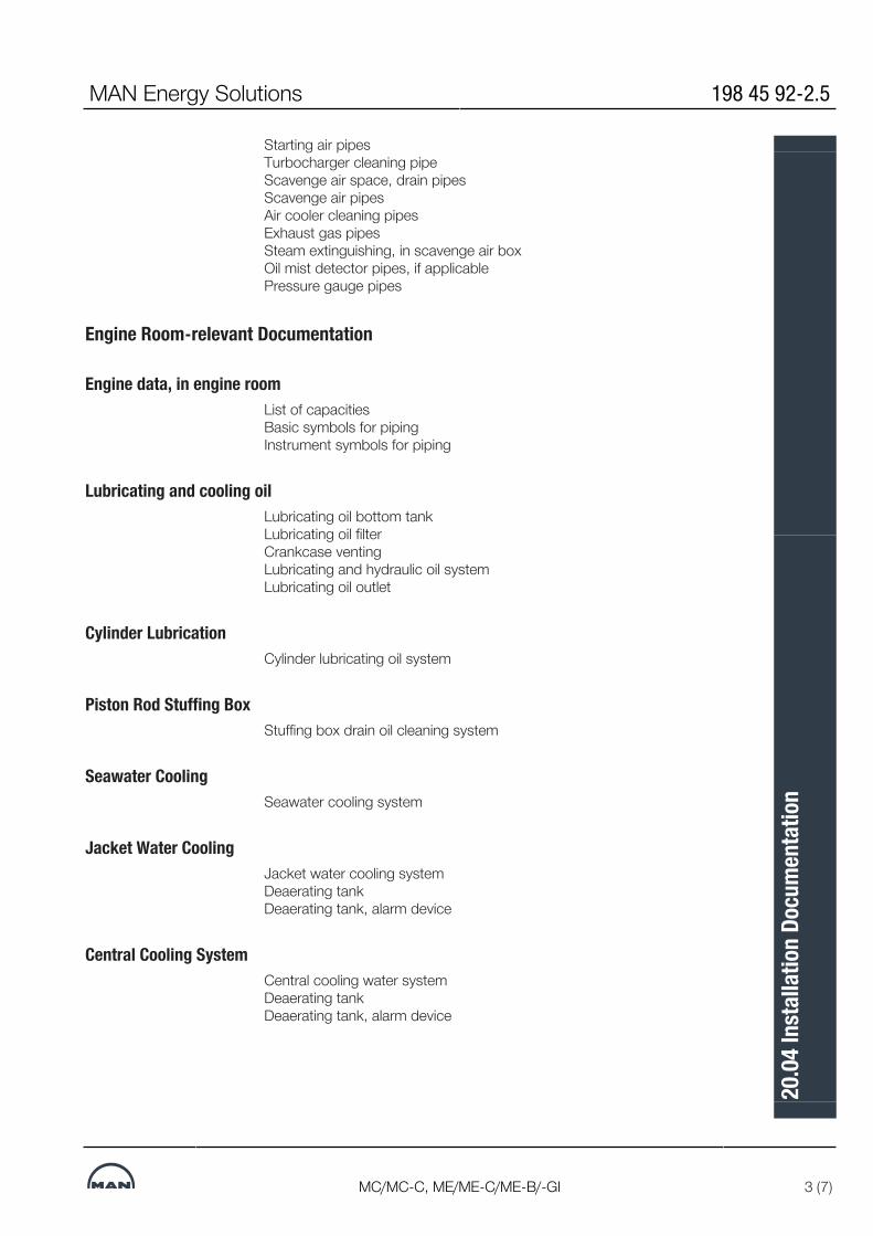
Starting air pipes Turbocharger cleaning pipe Scavenge air space, drain pipes Scavenge air pipes Air cooler cleaning pipes Exhaust gas pipes Steam extinguishing, in scavenge air box Oil mist detector pipes, if applicable Pressure gauge pipes
Engine Room-relevant Documentation
Engine data, in engine roomList of capacities Basic symbols for piping Instrument symbols for piping
Lubricating and cooling oilLubricating oil bottom tank Lubricating oil filter Crankcase venting Lubricating and hydraulic oil system Lubricating oil outlet
Cylinder LubricationCylinder lubricating oil system
Piston Rod Stuffing BoxStuffing box drain oil cleaning system
Seawater CoolingSeawater cooling system
Jacket Water CoolingJacket water cooling system Deaerating tank Deaerating tank, alarm device
Central Cooling SystemCentral cooling water system Deaerating tank Deaerating tank, alarm device
MAN Energy Solutions 198 45 92-2.5
MC/MC-C, ME/ME-C/ME-B/-GI 3 (7)
20.0
4 In
stal
latio
n Do
cum
enta
tion

Fuel Oil SystemFuel oil heating chart Fuel oil system Fuel oil venting box Fuel oil filter
Compressed AirStarting air system
Scavenge AirScavenge air drain system
Air Cooler CleaningAir cooler cleaning system
Exhaust GasExhaust pipes, bracing Exhaust pipe system, dimensions
Engine Room CraneEngine room crane capacity, overhauling space
Torsiograph ArrangementTorsiograph arrangement
Shaft Earthing DeviceEarthing device
Fire Extinguishing in Scavenge air SpaceFire extinguishing in scavenge air space
InstrumentationAxial vibration monitor
Engine SeatingProfile of engine seating Epoxy chocks Alignment screws
198 45 92-2.5 MAN Energy Solutions
4 (7) MC/MC-C, ME/ME-C/ME-B/-GI
20.0
4 In
stal
latio
n Do
cum
enta
tion

Holding-Down BoltsHolding down bolt Round nut Distance pipe Spherical washer Spherical nut Assembly of holding down bolt Protecting cap Arrangement of holding down bolts
Side ChocksSide chocks Liner for side chocks, starboard Liner for side chocks, port side
End ChocksStud for end chock bolt End chock Round nut Spherical washer, concave Spherical washer, convex Assembly of end chock bolt Liner for end chock Protecting cap
Engine Top BracingTop bracing outline Top bracing arrangement Friction materials Top bracing instructions Top bracing forces Top bracing tension data
Shaft Line, in Engine RoomStatic thrust shaft load Fitted bolt
Power Take-OffList of capacities PTO/RCF arrangement,if fitted
Large Spare Parts, DimensionsConnecting rod studs Cooling jacket Crankpin bearing shell Crosshead bearing Cylinder cover stud
MAN Energy Solutions 198 45 92-2.5
MC/MC-C, ME/ME-C/ME-B/-GI 5 (7)
20.0
4 In
stal
latio
n Do
cum
enta
tion

Cylinder cover Cylinder liner Exhaust valve Exhaust valve bottom piece Exhaust valve spindle Exhaust valve studs Fuel valve Main bearing shell Main bearing studs Piston complete Starting valve Telescope pipe Thrust block segment Turbocharger rotor
Gaskets, Sealings, O-ringsGaskets, sealings, O-rings
Material SheetsMAN Energy Solutions Standard Sheets Nos.:• S19R • S45R • S25Cr1 • S34Cr1R • C4
Engine Production and Installation-relevant Documentation
Main Engine Production Records, Engine Installation drawingsInstallation of engine on board Dispatch pattern 1, or Dispatch pattern 2 Check of alignment and bearing clearances Optical instrument or laser Reference sag line for piano wire Alignment of bedplate Piano wire measurement of bedplate Check of twist of bedplate Crankshaft alignment reading Bearing clearances Check of reciprocating parts Production schedule Inspection after shop trials Dispatch pattern, outline Preservation instructions
Shop TrialsShop trials, delivery test Shop trial report
198 45 92-2.5 MAN Energy Solutions
6 (7) MC/MC-C, ME/ME-C/ME-B/-GI
20.0
4 In
stal
latio
n Do
cum
enta
tion

Quay Trial and Sea TrialStuffing box drain cleaning Fuel oil preheating chart Flushing of lubricating oil system Fresh water system treatment Fresh water system preheating Quay trial and sea trial Adjustment of control air system Adjustment of fuel pump Heavy fuel operation Guidance values automation
Flushing ProceduresLubricating oil system cleaning instruction
Tools
Engine ToolList of tools Outline dimensions, main tools
List of ToolsTool panels
Engine Seating ToolsHydraulic jack for holding down bolts Hydraulic jack for end chock bolts
Auxiliary EquipmentOrdered auxiliary equipment
MAN Energy Solutions 198 45 92-2.5
MC/MC-C, ME/ME-C/ME-B/-GI 7 (7)
20.0
4 In
stal
latio
n Do
cum
enta
tion


MAN B&W
MAN Energy Solutions
Appendix
A


Symbols for Piping
Lines, Pipes etc.Line, primary process
Line, secondary process
Control line, general type
Control line, capilar type
Lines connected
Crossing lines, connected
Crossing lines, not connected
Interruption of pipe line
Interruption of pipe line with reference indication
Pipeline or duct with thermal insulation
Pipeline with thermal insulation, heated or cooled by a separate circuit, end
Pipeline with thermal insulation, heated or cooled by a separate circuit
Pipeline with thermal insulation, heated or cooled by a separate circuit, end
Jacketed (sleeved) pipeline with thermal insulated
Jacketed (sleeved) pipeline with thermal insulated, end
Jacketed (sleeved) pipeline
Jacketed (sleeved) pipeline, end
Change of pipe diameter, pipe reducer
Pipe slope, located above pipe
MAN Energy Solutions 198 38 66-2.5
All Engines 1 (11)
21.0
0 Sy
mbo
ls fo
r Pip
ing

Interlocked, located in interlocked line
Indication of valve normally open. With the symbol ‘function’ field
Indication of valve normally closed. With the symbol ‘function’ field
Flanges, Connections and Other in-line Pipe FittingsFlange, single
Flange coupling, flange pair, blind flange
Flange coupling, clamped
Screw joint
Quick release coupling
Quick release coupling, with automatically closing when uncoupled
End cap, threaded
End cap
Orifice
Swing blind, closed
Swing blind, open
Rupture disc
Siphon
Boss
Boss with intersection pipe
Spray nozzle, single
Spray nozzle, multiple
198 38 66-2.5 MAN Energy Solutions
2 (11) All Engines
21.0
0 Sy
mbo
ls fo
r Pip
ing

Pipe SupportsPipe support, fixation type
Pipe support, sliding type
Wall Penetrations, Drains and VentsWall or roof penetration, general
Wall or roof penetration, general, jacketed (sleeved) pipeline
Wall or roof penetration, sealed. * Shall be replaced with a designation for the type of seal, e.g. fire
Drain, funnel etc.
Drain pan
Vent, outlet to atmosphere
Vent, outlet to atmosphere outside enclosure
Valve Symbols2-way on-off valve, straight type, general
2-way on-off valve, angle type, general
3-way valve, general
4-way valve, general
Non-return function, check function, flow left to right
Control valve, straight type, general
Control valve, angle type, general
Control valve, 3-way type, general
Pre-set control valve, e.g. flow balancing valve
MAN Energy Solutions 198 38 66-2.5
All Engines 3 (11)
21.0
0 Sy
mbo
ls fo
r Pip
ing
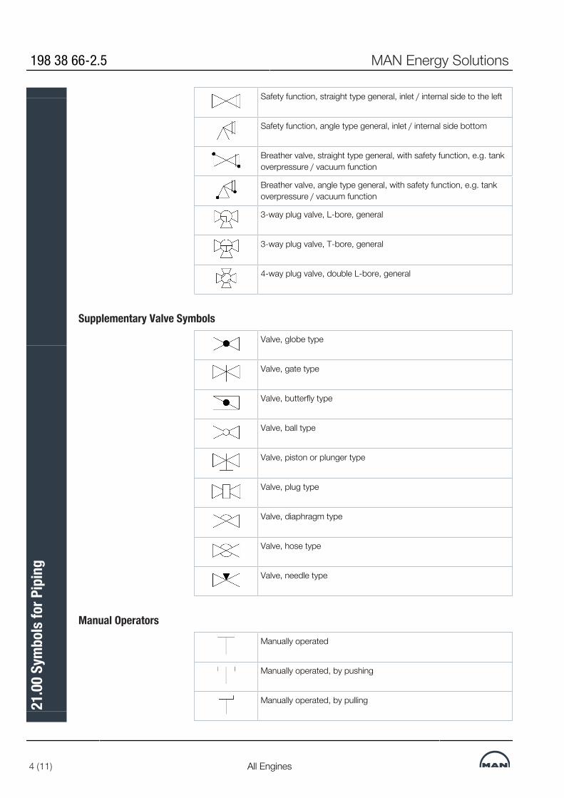
Safety function, straight type general, inlet / internal side to the left
Safety function, angle type general, inlet / internal side bottom
Breather valve, straight type general, with safety function, e.g. tankoverpressure / vacuum function
Breather valve, angle type general, with safety function, e.g. tankoverpressure / vacuum function
3-way plug valve, L-bore, general
3-way plug valve, T-bore, general
4-way plug valve, double L-bore, general
Supplementary Valve SymbolsValve, globe type
Valve, gate type
Valve, butterfly type
Valve, ball type
Valve, piston or plunger type
Valve, plug type
Valve, diaphragm type
Valve, hose type
Valve, needle type
Manual OperatorsManually operated
Manually operated, by pushing
Manually operated, by pulling
198 38 66-2.5 MAN Energy Solutions
4 (11) All Engines
21.0
0 Sy
mbo
ls fo
r Pip
ing

Manually operated, by pulling and pushing
Manually operated, by a lever
Manually operated, by a pedal
Manually operated, incl. locking device
Mechanical OperatorsMechanically operated, by weight
Mechanically operated, by float
Mechanically operated, by spring
Electric DrivesElectrical motor
Electrical motor, adjustable
Automatic OperatorsActuator, without indication of type
Single-acting hydraulic actuator
Double-acting hydraulic actuator
Single-acting pneumatic actuator
Double-acting pneumatic actuator
Single-acting diaphragm actuator
Double-acting diaphragm actuator
Single- or double-acting fluid actuator. (For double- acting, two pilotlines are needed)
MAN Energy Solutions 198 38 66-2.5
All Engines 5 (11)
21.0
0 Sy
mbo
ls fo
r Pip
ing

Electromagnetic actuator
Self-operated pressure sustaining control diaphragm. Upstream tovalve, right side
Self-operated pressure reducing control diaphragm. Upstream tovalve, right side
Spindle Information, e.g. Safety OperatorsFail to close
Fail to open
Quick-closing
Quick-opening
Double-acting, fail freeze
Double-acting, fail freeze, drifting against open position
Double-acting, fail freeze, drifting against closed position
Limit switch, mechanical type
Flow MetersFlow meter, general
Flow meter, propeller, turbine and screw type
Flow meter, orifice type
Flow meter, flow nozzle type
Flow meter, venturi type
Flow meter, pitot tube type
Flow meter, vortex type
198 38 66-2.5 MAN Energy Solutions
6 (11) All Engines
21.0
0 Sy
mbo
ls fo
r Pip
ing

Flow meter, ultrasonic in-line type
Flow meter, ultrasonic clamp-on type
Flow meter, magnetic type
Flow meter, Coriolis type
Flow switch, paddle type
VariousAir release valve
Condensate release valve
Restrictor, multistage type
Flow straightener
Viewing glass
Silencer
Flow restriction
Flow restriction, adjustable
Dampers2-way on-off damper, general
Multi-leaf damper, louvre type
3-way on-off damper, general
Non return damper, general
Safety damper, general
MAN Energy Solutions 198 38 66-2.5
All Engines 7 (11)
21.0
0 Sy
mbo
ls fo
r Pip
ing
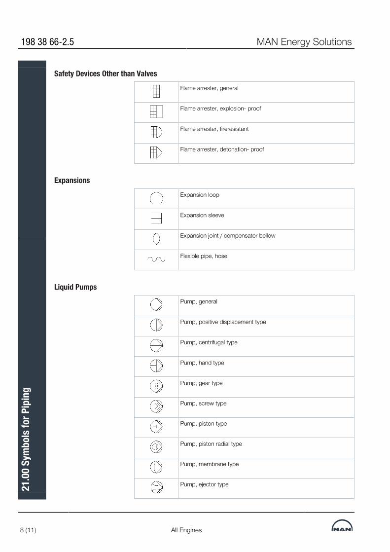
Safety Devices Other than ValvesFlame arrester, general
Flame arrester, explosion- proof
Flame arrester, fireresistant
Flame arrester, detonation- proof
ExpansionsExpansion loop
Expansion sleeve
Expansion joint / compensator bellow
Flexible pipe, hose
Liquid PumpsPump, general
Pump, positive displacement type
Pump, centrifugal type
Pump, hand type
Pump, gear type
Pump, screw type
Pump, piston type
Pump, piston radial type
Pump, membrane type
Pump, ejector type
198 38 66-2.5 MAN Energy Solutions
8 (11) All Engines
21.0
0 Sy
mbo
ls fo
r Pip
ing

Fans, Ventilators and CompressorsFan, ventilator, blower, compressor. General
Fan, ventilator, blower, compressor. Rotary vane type
Fan, ventilator, blower, compressor. Impeller type
Fan, ventilator, blower, compressor. Screw type
Fan, ventilator, blower, compressor. Reciprocating piston type
Fan, ventilator, blower, compressor. Rotary reciprocating pistontype
Fan, ventilator, blower, compressor. Reciprocating diaphragm type
Fan, ventilator, blower, compressor. Turbo type
Fan, ventilator, blower, compressor. Rotary piston type, e.g. Rootstype
Turbocharger
Filters, SeparatorsScreen, strainer, general
Screen, strainer with pit for draining
In-line strainer, general
Cartridge filter, bag filter etc, general
Cartridge filter, bag filter etc flow direction outside - in, general
Cartridge filter, bag filter etc, flow direction inside - out, general
Permanent magnet filter
Filter with backflush, Bernoulli type
Filter with continuous backflush
MAN Energy Solutions 198 38 66-2.5
All Engines 9 (11)
21.0
0 Sy
mbo
ls fo
r Pip
ing

Separator, cyclone type
Separator, centrifuge type
Separator, impact type
Heat ExchangersHeat exchanger, general
Condenser with hot well
Electrical heater, superheater
Heat exchanger with plate
Heat exchanger with tubes
Heat exchanger with ubend tubes
Heat exchanger with coil-shaped tubes
Electrical heating element
Heating or cooling coil
Finned tube
TanksOpen tank, basin
Closed tank
Closed tank with sloped bottom
Tank with flat bottom and conical roof
Tank with flat bottom and dished roof
Vessel with dished ends
198 38 66-2.5 MAN Energy Solutions
10 (11) All Engines
21.0
0 Sy
mbo
ls fo
r Pip
ing
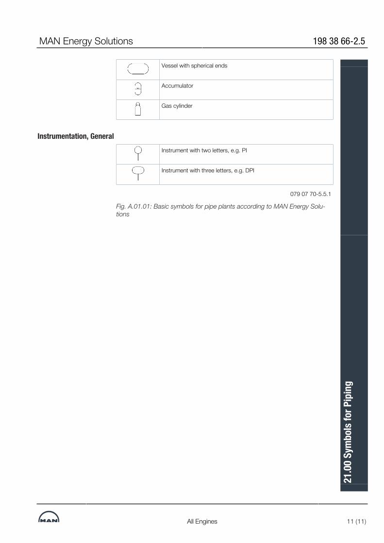
Vessel with spherical ends
Accumulator
Gas cylinder
Instrumentation, GeneralInstrument with two letters, e.g. PI
Instrument with three letters, e.g. DPI
079 07 70-5.5.1
Fig. A.01.01: Basic symbols for pipe plants according to MAN Energy Solu-tions
MAN Energy Solutions 198 38 66-2.5
All Engines 11 (11)
21.0
0 Sy
mbo
ls fo
r Pip
ing


MAN Energy Solutions 2450 Copenhagen SV, DenmarkP +45 33 85 11 00F +45 33 85 10 [email protected]
All data provided in this document is non-binding. This data serves informational purposes only and is not guaranteed in any way. Depending on the subsequent specific individual projects, the relevant data may be subject to changes and will be assessed and determined individually for each project. This will depend on the particular characteristics of each individual project, especially specific site and operational conditions.
Copyright © MAN Energy Solutions. 7020-0233-06ppr Sep 2021 Printed in Denmark
MAN
Energy Solutions Project G
uideM
AN B&W
G50M
E-C9.6-LG
IP