
MAKE BUILD HACK CREATE - Framboise 314
132
Build a course to test your piloting skills DRONE RACING 3D PRINT CLOTHES Add details to fabric with molten plastic BEAUTIFUL FOOD Decorate your snacks with lasers HUMANITARIAN MAKERS Making the world a better place SCRAP hsmag.cc Issue #03 February 2018 NEW TECHNOLOGY IN YOUR Feb.2018 Issue #03 £6 03 9 772515 514006 KEEP CHICKENS WORK WITH LEATHER HOT GLUE ESP8266 TRASH HEAP PROTECT THE ENVIRONMENT MAKE BUILD HACK CREATE HACKING RESURRECT VINTAGE GEAR Make new things with parts scavenged from junk SAVE MONEY
-
Upload
khangminh22 -
Category
Documents
-
view
6 -
download
0
Transcript of MAKE BUILD HACK CREATE - Framboise 314

Build a course to test your piloting skills
DRONE RACING
3D PRINTCLOTHESAdd details to fabric with molten plastic
BEAUTIFULFOODDecorate your snacks with lasers
HUMANITARIAN
MAKERSMaking the world
a better placeSCRAP
hsmag.cc Issue #03February 2018
NEW
TECHNOLOGY IN YOUR
Feb.2018Issue #03 £6
03
9 772515 514006
KEEP CHICKENS WORK WITH LEATHER HOT GLUE ESP8266
TRASH
HEAP
PRO
TECT TH
E
ENVIR
ON
MEN
T
MAKE BUILD HACK CREATE
HACKING
RES
UR
REC
T
VIN
TAG
E G
EAR
Make new things with parts scavenged from junk
SAVEMONEY
WELCOME
SUBSCRIBETODAY
PAGE52
3
We live in a throw-away society, and it’s destroying the planet. Perfectly good items are discarded when the next latest-and-greatest iteration comes along. Manufacturers often exacerbate the situation by making gadgets that aren’t
designed to survive more than a few years of active use.
As makers and hackers, we’re in a
position to change this. This month we’re taking a look at how to move in the opposite direction and reuse parts from scrapped products. This isn’t so much a skill as a state of mind. If you stop seeing old products as something to dispose of and start seeing them as the parts for your next project, you can save money, save the planet, and make some truly unique creations.
Welcome to
EDITORIAL Editor Ben Everard
Features Editor Andrew Gregory
Sub Editors Jem Roberts, Nicola King
DESIGNCritical Media
criticalmedia.co.uk
Head of Design Dougal Matthews
Designer Lee Allen
Photography Brian O’Halloran, Mark McNulty, Heather Gunn
Illustrator Sam Alder
CONTRIBUTORSLucy Rogers, Andrew Huang, Cameron Coward, Jenny List, Archie Roques, Andrew Lewis, Cameron Norris, Mayank Sharma, Andy Clarke, John Wargo, Sai Yamanoor, Michael Fischthal, Jen Botezat, Bill Grainger, Les Pounder, Gareth Halfacree
PUBLISHINGPublishing Director: Russell Barnes
DISTRIBUTIONSeymour Distribution Ltd2 East Poultry Ave, London EC1A 9PT
+44 (0)207 429 4000
SUBSCRIPTIONSSelect Publisher Services Ltd, PO Box 6337, BH1 9EH
+44 (0)1202 586 848
Mann Enterprises Ltd, Unit E, Brocks Business Centre, CB9 8QP hsmag.cc/subscribe
BEN EVERARD Editor [email protected]
This magazine is printed on paper sourced from sustainable forests. The printer operates an environmental management system which has been assessed as conforming to ISO 14001.
HackSpace magazine is published by Raspberry Pi (Trading) Ltd., Station Road, Cambridge, CB1 2JH. The publisher, editor, and contributors accept no responsibility in respect of any omissions or errors relating to goods, products or services referred to or advertised. Except where otherwise noted, content in this magazine is licensed under a Creative Commons Attribution-NonCommercial-ShareAlike 3.0 Unported (CC BY-NC-SA 3.0). ISSN: 2515-5148.
GET IN TOUCH
hackspacemag
hackspacemag
ONLINE hsmag.cc
HackSpace magazine
when the next latest-and-greatestPerfectly good items are often discarded
iteration comes along

4
Contents06 Top Projects The Louvre of DIY projects
16 Objet 3d’art Feast your eyes on 3D printed beauties
18 Consumer Electronics Show The most intelligent toys from CES
22 Columns On the patterns that shape our electronics
24 Letters More requests (and a bit of showing off)
28 Hackspace Nottingham A community owned and run Hackspace
32 Scavenging Electronics Rescue old bits of equipment and make them useful again
42 How I Made: A Chicken Door Follow the build of an automated poultry portal
46 Humanitarian Makers 3D printing for the developing world
54 Interview Farm Urban Open source DIY science that’s safeguarding our food
62 Improvisor’s Toolbox Glue Gun Why there’s more to glue than sticking things together
66 We Learn Belt Making Get started working with leather
3106
42
54
SPARK LENS
heapSCRAP
hacking
32

CONTENTS
5
76 SoM Metalwork Build a silver-soldered toolbox
82 SoM Coding For Arduino Reading data from devices
86 Tutorial Food Stencilling Make unique decorations for cakes/steaks
88 Tutorial Internet Counter Keep count of big numbers on the internet
92 Tutorial Build a Drone Racetrack Track flying drones with lasers and woodwork
98 Tutorial 3D Printing Print designs directly on to fabric
102 Tutorial Oscilloscope Interpret wavy lines on a glowing screen
106 Tutorial ESP8266 Rangefinder Build a location scanner LIKE IN ALIENS!!
114 Direct from Shenzhen Mechanical Keyboard Customise the clickiness of your input device
116 Best in Breed Vector drawing tools to power your laser cutter
120 Can I Hack It? Hackers don’t shoot people: Nerf guns do
122 Review Squix A programmable e-paper display right out of the box
123 Review Leatherman Surge The granddaddy of all-in-one multi-tools
124 Review SparkFun Inventor’s Kit Want to get started with electronics? Start here!
126 Review ElectroSmash Pedal Pi Programmable guitar effects to learn while you rock
128 Review Coinkite Opendime Make secure Bitcoin purchases in person
129 Book Review Much Ado About Almost Nothing A history of electronic geekery
75 113
Some of the tools and techniques shown in HackSpace Magazine are dangerous unless used with skill, experience and appropriate personal protection equipment. While we attempt to guide the reader, ultimately you are responsible for your own safety and understanding the limits of yourself and your equipment. HackSpace Magazine is intended for an adult audience and some projects may be dangerous for children. Raspberry Pi (Trading) Ltd does not accept responsibility for any injuries, damage to equipment, or costs incurred from projects, tutorials or suggestions in HackSpace Magazine. Laws and regulations covering many of the topics in HackSpace Magazine are different between countries, and are always subject to change. You are responsible for understanding the requirements in your jurisdiction and ensuring that you comply with them. Some manufacturers place limits on the use of their hardware which some projects or suggestions in HackSpace Magazine may go beyond. It is your responsibility to understand the manufacturer’s limits.
46 18
123
FORGE FIELD TEST
06
102

6
Top Projects
REGULAR
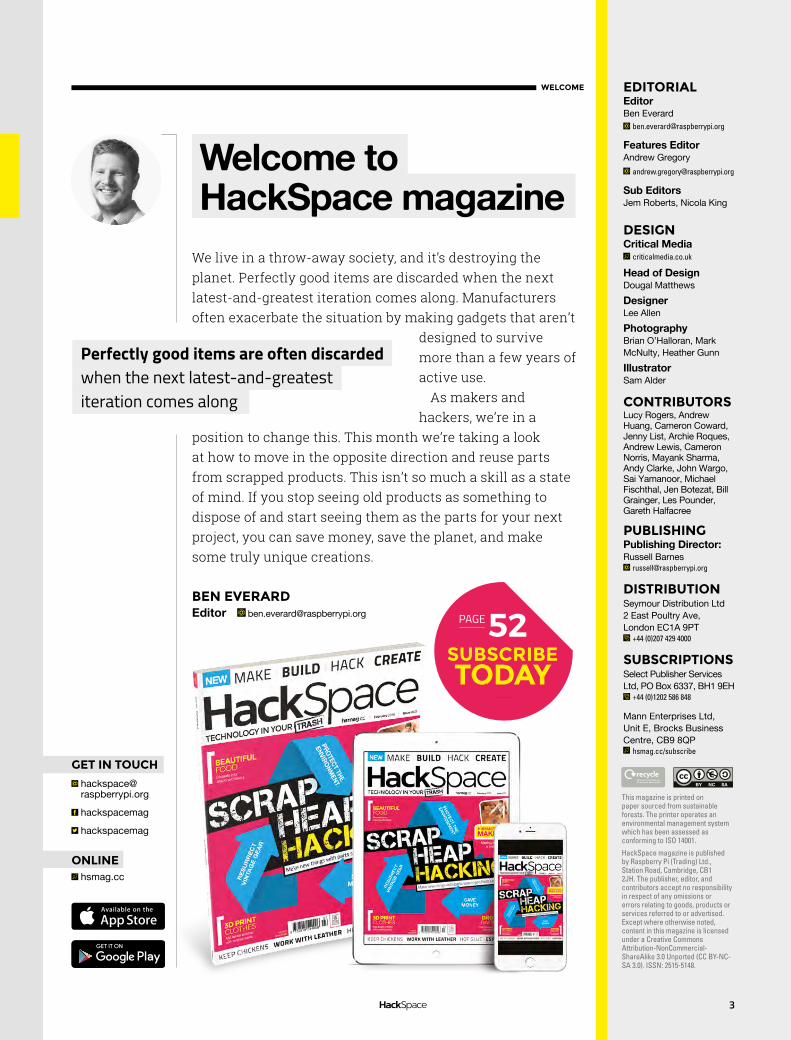
t’s around five or six years ago that I first saw these Bao Bao bags. The remarkable pattern of the bag impressed me, and has stayed with me since then. Six years later I began my journey by watching Daniel Shiffman videos, which led me into this creative computing world. It is a dream come true to change
the static boring world with new technologies. With this project I try to explore the possibilities that this
144-triangle bag can generate, and what the potential use of a smart bag in 2018 could be like. This project used one Arduino Uno to control 144 smart LEDS (ws2812b). The project adopted an Adafruit Neopixel library in the Arduino IDE for convenient coding.
IBy Natthakit Kangsadansenanon
Bao Bao Bagskimbab.me
Top Projects
Right In case you want one, these aren’t actual bags yet – but they are a pretty solid proof of concept
SPARK
7
SPARK

8
Top Projects
REGULAR

9
SPARK
Internet radio toaster
I like to make things, but am not very handy. Also, my coding skills fall somewhere on the spectrum between lamentable and laughable. For these reasons, I have to choose my projects carefully. Which is to say I need someone else to have already done the heavy lifting of fabrication and software development.
Turning a 1990’s era Dualit Four-Slice toaster into a Raspberry Pi-based Google Assistant and internet radio was right in my sweet spot. Very Red Dwarf.
Why not just buy a Google Home or Amazon Alexa, you ask? Too easy! Also, while many people seem to have no issues talking to a plastic speaker, I prefer to speak to a beautifully sculpted chunk of metal that also makes toast (NB. some care and electrical expertise is required here to avoid burning down your house).
The Google Assistant SDK allows easy deployment of the Assistant to a Raspberry Pi, and there are many tutorials on YouTube and elsewhere if further assistance is required.
What makes the Dualit ideal for this project (aside from iconic design status) is that it has plenty of unused real estate inside – room aplenty to stuff a Pi 3B, mini digital amp, OLED display, speakers, power supplies, and assorted other gubbins. If you prefer, you can omit much of this and output a line-level or Bluetooth signal to external components. The ends of the Dualit are aluminium, so easy to work with for the minor alterations necessary.
Of course, you can ask the Assistant to play the radio but I wanted dedicated physical controls – and a station indicator display. I had to write a bit more custom code for this side of the project but nothing outside my spectrum.
“By Peter Kent timetogoclocks.com
Left Google’s weird intrusive 1984-themed spy device has never looked so attractive

10
Top Projects
REGULAR
RUDE-OLPH
he idea to build an angry, animatronic reindeer had been floating around our office since mid-summer. But it was only at the end of November that our client, Scottish lager brand Tennent’s, gave us the go-ahead to build it.
My starting point with Rude-olph was to build a small prototype from wood. I decided to base the neck movement around a flexible spine to give a more realistic animal movement than you’d get from a fixed hinge or pivot.
For the full-scale version, we wanted to keep the reindeer lightweight, so we built the head around a foam model. Servos were added for mouth movement, and LEDs embedded to give him his trademark glowing nose. For the main neck movement, we opted for a heavy-duty 270° servo, mated to a pulley driving two bicycle brake cables that run the length of Rudy’s neck. The spine uses heavy-gauge piano wire and foam pipe lagging.
Rude-olph runs off a Raspberry Pi 3, which provides both motor control and a live video feed from the reindeer. My web-based soundboard – also running on the Pi – lets operators choose from over 140 stock phrases, all of which are synchronised to the reindeer’s head, mouth, and light-up nose.
TBy Grant Gibson @grant_gibson
Right With just ten days from green light to his first public appearance, it was a mad rush to get Rude-olph built, tested, and out the door for the season

11
SPARK

Top Projects
REGULAR
12

13
SPARK
Robot that shoots you in the face
imply put, this is an intricately designed, far-from-practical, over-the-top robot that shoots you in the face. It uses a dirt-cheap Logitech webcam, three servo motors, an Arduino, a Nerf gun, and some code from projectsentrygun.rudolphlabs.com to track your face and shoot it.
The robot has X-axis and Y-axis modules, mounted on a simple wooden frame, that support and move the shooting mechanism – a toy Nerf gun. Each axis and the trigger of the Nerf gun is controlled by high-torque Futaba servos. A webcam mounted at the top of the wooden frame is used to locate your face.
The servos controlling the axes and the trigger are controlled by an Arduino that is programmed to use processing code running on my laptop. This processing code is the brain of the computer vision functionality of the robot. The original code aimed a paintball gun at the chest of a person but, with a few quick modifications, I managed to get it to aim at my face reliably.
This processing code spits out coordinates that are sent to the Arduino, which controls all three servos to correctly position and shoot the gun. The servos have a heavy current draw and need an external 5 V power supply. For testing purposes, I added an external switch with a servo controller to fire the gun.
Now, considering that I have essentially built an automated turret, I just had to add a green laser as a sight to satisfy the stereotypes of every futuristic weapon ever, thanks to sci-fi movies. The laser needs 3 V, sourced from the power supply using an LM317-based voltage regulator.
I believe in building over buying and reusing as much as possible, and so I kept the build as inexpensive as I could. The wood is all recycled pallet wood from a florist and the metal parts are scrap aluminium from e-waste. I used a modified ATX power supply to power it all with stable DC 5 V. The electronics were the only part of the build that I did not manage to find a recycled source for.
SBy Mihir Vardhan Makingwithmihir.com
Left Mihir’s on a mission to show that making can be cheap and fun
Top Projects
REGULAR
14
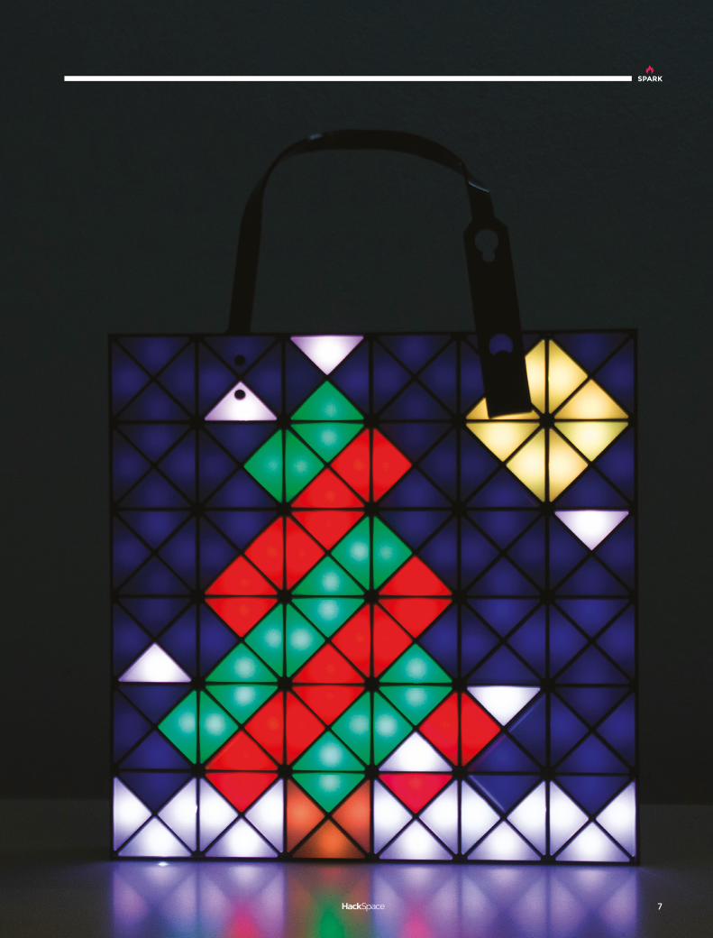
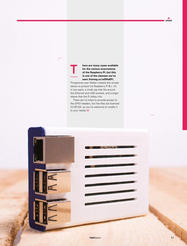
DIY Bluetooth speaker
designed and built a DIY Bluetooth speaker with an integrated LED matrix. The LED matrix includes a number of different visualisation modes, including a fireplace mode, an abstract ‘moving art’ mode, and several that react to the music via a microphone inside of the speaker box. I haven’t seen any other product designed for the home which
marries sight and sound in this way. The idea for this project came about in a somewhat
unorthodox way. I wanted to build something for several friends expecting newborns. I wanted a gift that would help their children develop neurologically, and a gift that they wouldn’t outgrow. Having done a number of LED projects, and having some woodworking experience, I came up with the idea to integrate an audio-reactive LED matrix in a Bluetooth speaker.
The speaker box involved a fair amount of woodworking. The outside of the box is made from rough curly maple lumber, which I milled to ¾”. The front and back panels are made from MDF.
Internally, I used a 2 × 15 w Dayton Audio bluetooth amplifier board for the audio, and an Arduino Mega to control a 16 × 16 LED matrix (WS2812 LEDs). A small electret microphone inside the speaker box detects the music that is playing, and provides a signal the Arduino can use to create reactive display on the LEDs.
The design also allows for mechanical adjustment to entirely change the look of the LED matrix; from pixellated to abstract. I am particularly proud of this feature, as I haven’t seen it anywhere else before, and the effect is very cool (it is shown towards the end of this video hsmag.cc/ojCwxn). The LED matrix is mounted to a baffle behind the white semi-transparent acrylic diffuser, and by twisting a thumb screw on the back of the speaker, you can move the LED baffle towards or away from the diffuser. The thumb screw thus allows you to go from a pixellated display (where individual LEDs are visible), to an abstract display, where the LEDs blur together to form moving art, with an almost 3D-like effect. -
IBy Mike Clifford modustrialmaker.com
Right The curly maple finish was inspired by electric guitar finishes, like those on some of Mike’s favourite PRS guitars

15
SPARK

Objet 3d’art
REGULAR
16
3D printed artwork to bring more beauty into your life
Objet 3d’art
3D printed screw clamp sounds like a completely impractical idea, so hats off to jakejake, who designed each part of this clamp
(hsmag.cc/JPdFkL) with the grain of the print in mind to provide the necessary strength. Like the case on page 17, we’ve printed it in 100 micron PLA.
It looks to us like a grown-up version of a toy, so would be ideal for any small engineers who need a clamp you can trust that won’t damage your surfaces.
A
3DPRINTING
Head to 3dhubs.com/book to check out the
#1 3D printing book on Amazon
Supplied by
17
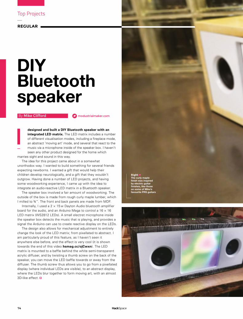
here are many cases available for the various incarnations of the Raspberry Pi, but this is one of the cleanest we’ve seen (hsmag.cc/wDHaKP).
Thingiverse user Walter created this simple sleeve to protect his Raspberry Pi B+. It’s in two parts: a small cap that fits around the Ethernet and USB sockets, and a larger sleeve that the Pi slides into.
There are no holes to provide access to the GPIO headers, but the files are licensed CC-BY-SA, so you’re welcome to modify it to your needs.
T
SPARK

What CES had to offer makers and hackers
FEATURE
18
Here’s the best of what we found at CES 2018 for your Hackspace
What CES had to offer makers and hackers
T he Consumer Electronics Show (CES) is the biggest convention of its kind every year. But, while most of the world is waiting eagerly to find out which new TV has the most Ks, or how smart toasters have become,
we were there looking for the real treasure. CES is, as the name suggests, mostly focused on consumer gadgets, but that doesn’t mean there isn’t plenty of tech to interest makers. Here is the best of what we saw at this year’s show.
While XYZprinting’s closed-source nature is a turn-off, the pricing of its line-up is hard to resist. It unveiled two new products at the show: a 3D printing pen, and a new full colour da Vinci AiO. The da Vinci Color AiO uses an impressive inkjet system to inject colour into the filament as it’s being printed. It also contains an integrated 3D scanner, which captures colour in order to create 3D models that take advantage of the colour-printing capability
Formlabs is best-known for its high-quality SLA (stereolithography) printers directed towards the prosumer market. Now the company has an entirely new product called the Fuse 1 that uses an entirely different printing process — SLS (selective-laser sintering). At $10 000, the Fuse 1 is aimed more at professionals, but the speed and quality of the nylon SLS printing may make it ideal for your Hackspace
Formlabs Fuse 1
XYZprinting da Vinci AiO
By Cameron Coward

SPARK
19
3D printing has become the go-to technology for fabrication in the maker community, but Glowforge wants to bring laser cutting up to that level. The company describes its first device as a ‘3D laser printer’, but really it’s just a consumer-friendly laser cutter/engraver. It’s fairly low-power compared to similarly-priced competitors, but the main selling point here is ease of use and software integration
Glowforge
Aimed at children aged 3–7, Robotix’s Taco Robobricks are designed to teach the basics of robotics with ‘tangible coding’. Young makers can put together the Lego/Duplo-compatible blocks to form interactive creations, and then program them with computer-free coding chips. There are a variety of Taco Robobricks available, for light, sound, movement, and even touch-sensing
We believe one of the key features of the hacker/maker movement is inclusivity, and that has to include the visually impaired. Unfortunately, consumer products have become less friendly to people with less than perfect vision as they have become less tactile. Project-RAY has a new product which could help: Click stickers. These are simple NFC-connected tactile buttons that are designed to stick onto the back of your smartphone in order to provide an input method that can actually be felt
RobotixTaco
RayClick
Robot-based learning toys are a growing trend, and Makeblock’s Codey Rocky appears to be the next big thing in that arena. It’s a stand-alone rover-type robot that is intended to teach programming to kids aged six and up. Users start with programming in Scratch, and then move up to Python. The standout feature here is that it can separate into two units: a controller (Codey) and the rover itself (Rocky), which introduces a number of unique ways for children to play
Codey RockyPlott Cubit
When you’re measuring small objects, the most useful tools are calipers, micrometers, or even just a simple ruler. Taking measurements of entire rooms — for instance when building large installations — can be difficult. Enter the Plott Cubit, which is a sort of bi-directional digital multi-tool. With the augmented reality app, users can use the Cubit to plot detailed measurements of a room, and then create digital layouts for your project. Once the virtual design is completed, the Cubit can then be used to physically locate designated points in order to help bring your creation into reality

What CES had to offer makers and hackers
FEATURE
20
Cubibot generated a lot of buzz with its Indiegogo campaign last year, and was ready to show off its flagship 3D printer at CES this year. The little printer isn’t doing anything revolutionary, but combines affordability with ease of use. The enclosure in particular makes it ideal for younger users, as it protects them from burns and filters fumes. Cloud-based slicing and printing should also make it easy to use for those new to 3D printingCubibot 3D Printer
MAKERbuinoAlexa Development Kit Amazon has made the SDK for Alexa available for a while now, and it’s proven to be massively popular in the maker community. But so far, the only hardware Amazon has put out has been consumer Echo devices. Now it’s partnering with various manufacturers to create hardware development kits. These are designed to fit a range of applications, and start at $129. We’re excited to see what hobbyists will do with them
MAKERbuino gained a lot of attention at CES, and it’s easy to see why. It’s a complete portable gaming platform, and is very affordable at €49.00. But it’s not just a toy – it’s fully compatible with the Arduino IDE, and lots of the hardware components you’re used to. MAKERbuino is designed both for fun and for education, and is suitable for tinkerers of all ages
Root Robotics Continuing the theme of teaching kids programming with robots is Root. Root is a little robot that fits in your hand and guides children through coding from graphical to full-text. It’s packed with sensors, and even has the ability to drop and lift a pen for drawing. It can also drive on vertical surfaces as long as they’re magnetic (like school whiteboards)

21
SPARK
SimpleLink Microcontroller
Texas Instruments is expanding its LaunchPad-compatible series of products with the SimpleLink Microcontroller Platform. LaunchPad is TI’s Arduino-esque microcontroller, and the SimpleLink ecosystem is designed to add industrial-scale IoT capabilities. There are a number of booster modules for both input and output, and connectivity options for just about every wired and wireless communication protocol you can think of. Most importantly, the modules are priced reasonably enough to be accessible to hobbyists — not just commercial operations
A large portion of a hacker’s work is good old-fashioned typing. Unfortunately, our smartphones use touchscreens that don’t lend themselves to that, and use hamstrung mobile operating systems. The Gemini PDA from Planet Computers is looking to solve both of those problems by providing both a full QWERTY keyboard, and dual-booting for Android and Linux. It looks like the perfect device for doing real work on-the-go without having to lug around a laptop
Also from Makeblock, but stepping away from robotics, is Neuron. This product comprises an entire line-up of magnetic-connected electronic blocks for creating and programming circuits. There are blocks for connectivity, sensor input, control, and various kinds of output. Neuron can be integrated with LEGO, and even with a Raspberry Pi as tinkerers move towards more advanced creations
Gemini PDANeuron blocks

Lucy Rogers
COLUMN SPARK
ave you ever thought “If it wasn’t for that person, I wouldn’t be here doing this now”?
There are many people in our lives who probably
fit this description, but for me, and for the makers, scientists, and engineers in the UK who recently gave their own tributes, Professor Heinz Wolff, who died in December aged 89, was a huge influence.
Professor Heinz Wolff was a scientist, an inventor, an academic, and a television personality – he was best known for hosting BBC Two’s The Great Egg Race from 1977 until 1986. He made being inquisitive, clever and enthusiastic, and even being a geek – cool. This was back before the internet, when my main role models were from the TV or magazines.
In The Great Egg Race, teams of three were asked to “perform miracles in science and technology using the sort of materials which you would find in your household or in your garage”. This ranged from moving an egg, powered only by an elastic band, to making a cup of tea. Professor Heinz Wolff had a natural sense of fun, and, through his enthusiasm, he managed to share the enjoyment he found in engineering.
I believe The Great Egg Race was the first programme on TV that highlighted making things using creativity and imagination. To me, this helped make being a Maker become acceptable. People building things in their own homes and sheds. Inventing, designing, and making was not just for academics or big industry. The Great Egg Race led to other technology shows, such as Scrap Heap Challenge and Robot Wars.
Professor Heinz Wolff thought it was very important for people to be able to
use their hands – in a lecture he gave, when awarded the Edinburgh medal, he said:
“Let me tell you an anecdote about my two sons – from the age of three, each had a work bench that I had made, that had telescopic legs, so that as the
children grew, the workbenches grew with them. They were furnished with proper adult tools, which gave rise to comments amongst concerned relations about how dangerous this could be, however, my reply always was ‘even a three year old will stop sawing before the finger fell right off’.”
If the measure of your life is how you positively affected the lives of others, Professor Heinz Wolff absolutely lived life to the full.
Heinz WolffA tribute to a pioneering maker
H
Lucy Rogers@DrLucyRogers
Lucy is a maker, an engineer, and a problem solver. She is adept at bringing ideas to life. She is one of the cheerleaders for the maker industry and is Maker-In-Chief for the Guild of Makers: guildofmakers.org
22
Professor Heinz Wolff was a scientist, an
inventor, an academic, and a television
personality – he was best known for hosting BBC
Two’s The Great Egg Race from 1977 until 1986

Bunnie Huang
COLUMN
23
SPARK
ardware hacking can seem unapproachable, but the good news is that its core framework – namely physics – has been stable since the beginning of the
universe. This is unlike software, where it’s a constant struggle to keep up with the deluge of new platforms, languages, and trends.
One of the best ways to learn about hardware is to just start opening stuff up and looking inside. I started a monthly ‘name that ware’ competition on my blog [bunniestudios.com] about twelve years ago to encourage this kind of thinking, and now you have iFixit [ifixit.com] and eevblog [eevblog.com] doing amazing teardowns all the time. The purpose of taking things apart isn’t to understand everything. Rather, it’s to start populating your brain with patterns and memes. There’s a certain shape and size to everything, and there are common themes.
And then you start making observations. Why, for example, is it that almost every circuit board is somewhere between the size of your palm and a sheet of paper? Turns out it has something to do with the speed of light. It also has something to do with the fact that it’s hard to make things absolutely perfect.
And it also has to do with how quickly you can get heat out of objects. Pick any thread and pull, and you’ll find frameworks that go all the way down to quantum mechanics. The deeper you go, the more you’ll discover that everything is related to everything else in some way – it’s all choreographed by the laws of nature.
Now imagine you are presented with a piece of unknown electronics that you
want to hack. It’s like looking at a chess match, in its final positions, and figuring out what went through the players’ minds. First, look for exceptions to common design patterns. It takes real effort to make new design patterns,
so engineers only make exceptions, or create new ones, if they really have to. Then, look for debug and test facilities; economic realities inevitably demand their presence. Finally, feel out the cracks between abstraction layers. Look for assumptions that might not have been checked carefully. Standard interfaces can often be exploited to do new and interesting things.
This is where it helps to be a practising design engineer – when implementing standard interfaces, take note of where the specs are weak or have ambiguities. Drive wedges into these weak spots; often just the tiniest breach in the wall is all that’s needed to bring about the flood!
Hacking hardwareLearn how things work by taking them apart
H
And then you start making observations.
Why, for example, is it that almost every circuit board is somewhere between the
size of your palm and a sheet of paper?
Bunnie Huang
Andrew ‘Bunnie’ Huang is a hacker by night, entrepreneur by day, and writer by procrastination. He’s a co‑founder of Chibitronics, troublemaker‑at‑large for the MIT Media Lab, and a mentor for HAX in Shenzhen.
@bunniestudios

Letters
REGULAR
MAKING REVISITEDLucy Rogers’ column in HackSpace issue 1 really struck a chord with me. When I was a kid I used to love taking things to bits and putting them back together. Sometimes they worked just the same as they did before; sometimes they worked better, and sometimes they didn’t work at all, usually because I’d forgotten to put a screw back in somewhere.
Being a reader, as well as a maker, I was steered away from practical things towards ‘proper’ subjects. After a long, dull, safe career I’m now making things again, and extremely happy about it too. I think there used to be a stigma about working with your hands that hopefully kids today won’t suffer from.
BeckyMinnesota
Letters
WHERE’S YOUR TOOLS?Thanks to Stuart and the rest of the members from fizzPOP, I’ve got a serious case of gear envy. I’m planning launching a maker space in my little corner of Ireland and the hardest thing, apart from finding the space itself, is getting hold of tools that aren’t broken. Actually no – it’s fixing all the broken tools that local businesses have donated. Keep up the good work, and maybe one day you’ll be writing about my as-yet-unnamed maker space.
DavidIreland Above
You can get back in to making at any time in your career. It can even become your new career – just ask Paul Parry of Bad Dog Designs
Above We’ve learned today that if you’re stuck for equipment, your local police force may have some lying around that they can donate to you
ATTENTION ALL MAKERS!
If you have something you’d like to get off your chest (or even throw a word of praise
in our direction) let us know at hsmag.cc/hello
To anyone else out there who misses putting things together, there’s nothing holding you back. Your local hackspace will welcome you with open arms, and the internet is full of cheap, quick, accessible projects to build. As, we hope, are the pages of HackSpace magazine. Let us know if you agree!
24
SPARK
25
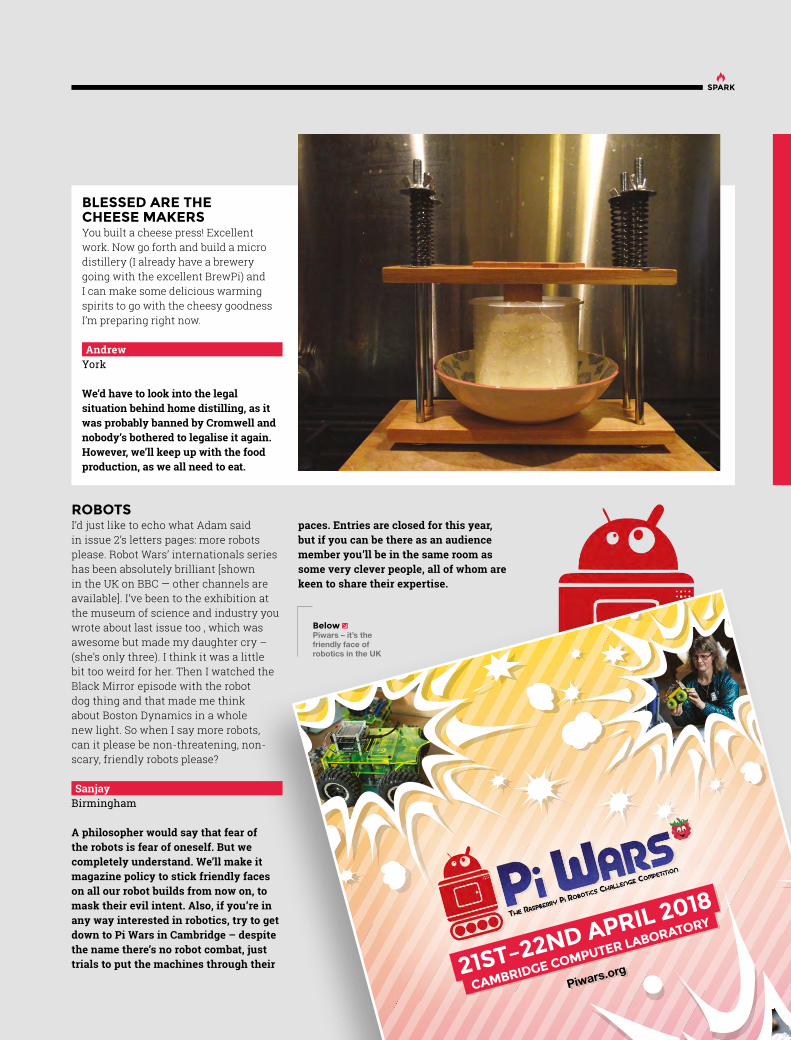
BLESSED ARE THE CHEESE MAKERSYou built a cheese press! Excellent work. Now go forth and build a micro distillery (I already have a brewery going with the excellent BrewPi) and I can make some delicious warming spirits to go with the cheesy goodness I’m preparing right now.
AndrewYork
We’d have to look into the legal situation behind home distilling, as it was probably banned by Cromwell and nobody’s bothered to legalise it again. However, we’ll keep up with the food production, as we all need to eat.
Piwars.org21ST–22ND APRIL 2018
CAMBRIDGE COMPUTER LABORATORY
068_HS#2_PiWars-BE_NK_JR_AG.indd 68
14/12/2017 15:28
ROBOTSI’d just like to echo what Adam said in issue 2’s letters pages: more robots please. Robot Wars’ internationals series has been absolutely brilliant [shown in the UK on BBC — other channels are available]. I’ve been to the exhibition at the museum of science and industry you wrote about last issue too , which was awesome but made my daughter cry – (she’s only three). I think it was a little bit too weird for her. Then I watched the Black Mirror episode with the robot dog thing and that made me think about Boston Dynamics in a whole new light. So when I say more robots, can it please be non-threatening, non-scary, friendly robots please?
SanjayBirmingham
A philosopher would say that fear of the robots is fear of oneself. But we completely understand. We’ll make it magazine policy to stick friendly faces on all our robot builds from now on, to mask their evil intent. Also, if you’re in any way interested in robotics, try to get down to Pi Wars in Cambridge – despite the name there’s no robot combat, just trials to put the machines through their
paces. Entries are closed for this year, but if you can be there as an audience member you’ll be in the same room as some very clever people, all of whom are keen to share their expertise.
Below Piwars – it’s the friendly face of robotics in the UK

Letters
REGULAR
ARDUINO FOR THE WINThanks for the custom Arduino tutorial — it’s a bit over my head at the moment, but it’s given me something to aim for. Last year I used an Arduino Due to control a watering system in my back yard. It was pretty rudimentary, just using a timer to turn a servo and water the tomatoes. This year I’m adding sensors, so it can water as and when the soil gets too dry, keep an eye on the temperature, and how much water everything needs in total. Just one more reason to look forward to summer!
DanStockport
Cheers Dan, making things automatic is good, but making them smart is even better.
If you’ve got an Arduino project you want to see in print, let us know – there’s got to be potential for a great readers’ gallery, given all the gardening projects out there.
BRAIN EXPANSIONThanks very much for the free issue 1s; they’ve gone down a treat. I was waiting for issue 2 to come out to see if it was a fluke, but if anything it’s even better than issue 1. You’ve got yourself a subscriber! I love the mix of content that you pack in – it’s so inspiring seeing other people’s work and thinking ‘ I could do that’. You’ve given me a load of ideas already. I just need a few more hours in a day so I can turn them into reality!
MichaelNewcastle
26
Above The brains of many a project: get an Arduino, learn to program it and make your builds smart

27
Crowdfunding now
REGULAR
CROWDFUNDINGNOW
When backing a crowdfunding campaign, you are not purchasing a finished product, but supporting a project working on something new. There is a very real chance that the product will never ship and you’ll lose your money. It’s a great way to support projects you like and get some cheap hardware in the process, but if you use it purely as a chance to snag cheap stuff, you may find that you get burned.
BUYER BEWARE !
ost microcontroller boards are designed to run as stand-alone machines – you might add more hardware to them, but not usually any more processing power. Tomu is different. It’s an ARM-
powered microcontroller board that fits inside a USB port with just enough sticking out for two LEDs and two touch switches. Essentially, it’s an extra programmable LED button for any computer with a spare USB port. The makers suggest that it could be used as a volume button or as a two-factor authentication tag. We can also imagine Tomu being useful for adding a little input to a semi-embedded Raspberry Pi or other small Linux machine.
The price of Tomu depends heavily on the number you buy. A single Tomu is $30, but you can get five for $60. At the larger numbers, it becomes much easier to justify the price for small projects. Of course, all this is dependent on actually having a spare USB port – a luxury that’s becoming rare on modern ultra-books.
EFLO is low-price reflow soldering oven with one big caveat – the maximum PCB size is 5 cm 5 cm (or 2 inches by 2 inches). This is small, but it’s not ridiculous and there are lots of makers whose PCBs would always
fit in this size – wearables designers for instance. By keeping the size small, the REFLO fits nicely into even the most cramped workshop. The oven is controlled via a mobile app (iOS and Android), so there’s no fiddly display or controls on the unit itself.
Another side effect of the small size is the lower power requirement – a peak use of 300 W.
The controller is Arduino-compatible and you can change the software running the oven if, for example, you want a different heating profile.
If – and it’s a big if – you can put up with the size limit, the REFLO looks like a great option for a no-fuss reflow soldering oven.
M R
Tomu REFLOA microcontroller in every USB port Automatic soldering for small PCBs
$345 crowdsupply.com Delivery: Feb 2018$30 crowdsupply.com Delivery: July 2018

Hackspace of the month
REGULAR
28
e started out casually meeting up in pubs in 2010 – just a couple of people, but then we found a space by the train station, and we started collecting tools and running workshops.
After roughly a year there, we moved into our current premises, where we are in the process of expanding out to two floors filled with hackspace delights!
WHO IS IT FOR?Our hackspace is for anyone in Nottingham who is looking for a place to make things. Whether you’re interested in electronics, woodworking, craftwork, textiles, metalworking, art, programming, music, or just having a good time in a space with people who also like to make things, we try to be a welcoming place.
Our members get 24 hour access to the space, the ability to use the tools and consumable items, and the chance to become a part of the space. Everything is driven by our members, whether they’re spending
W
Hackspace of the month:Nottingham Hackspace
their time keeping the space tidy, answering emails and questions from the public, donating extra money to help buy new tools, helping remodel the new areas we’re building, running a workshop, inducting new members, or even just being on hand to help out a fellow member with something. Our space is entirely funded by our members and everything inside has been either paid for or donated by members.
And with over 570 members, it can be a lot of work, but very rewarding for everyone who volunteers.
WHAT EQUIPMENT DO YOU HAVE?We have a wide range of tools and equipment for our members to use, including a laser cutter with an A0 bed, a Bridgeport metal mill, an Ultimaker 3D printer, industrial and home sewing machines, fully equipped electronics workstations, a full-sized table saw, a kitchen with cooking equipment, a computerised full-colour embroidery machine, bike parking and tools, arc and MIG welding equipment, a wood-turning lathe, screen-printing equipment, hand tools, and so much more.
Right Open nights at Nottinghack are every Wednesday from 6.30pm
Kate Bolin
nottinghack.org.uk
Nottinghack
@HSNOTTS

29
SPARK
Right Nottinghack is big – 4 300 square feet of space and things
Below There are often helpful humans hanging out near the duck (its name is Ein)
All our tools are purchased through pledge drives, where members suggest buying a new tool, and then other members pitch in with money in order to buy it. This way, each member who participates feels like they own a part of that tool, and that they’re helping to make the space even better.
HOW DO I BECOME A MEMBER?Come down any Wednesday night, from 6:30 until 8:30, and have a tour! Our team of volunteers will show you around the space, point out some of the tools and resources available, and explain how membership works at Nottingham Hackspace.
Once you have your tour, you can sign up for membership and start the process.
Because we know everyone is different, we don’t have a set flat rate for membership. We ask all our members to pay what they think is right for how they’re using the space. It costs around £12 an hour to keep the space running, though, so we like people to think about that when they’re choosing their monthly fee. But we’d hate to lose experience and talent just because someone isn’t earning as much as someone else.
HOW DO YOU SHARE YOUR IDEAS?Along with our website (nottinghack.org.uk), we have a Google Group where most of our conversations are held: hsmag.cc/GouOwi. We also have a Slack workspace for our volunteers, who join teams to help out at the space. So if you’re interested in woodworking, the laser cutter, the craft area, software, helping members, or anything else – we have a team for you...
WHAT HAVE YOU MADE RECENTLY?Our biggest task right now is Hackspace 2.5 – renovating several rooms downstairs to expand our space to nearly twice the size it is currently.
We have stripped these rooms down to bare studs and concrete floors, and then we built new walls, added in new wiring and cabling, repainted everything, and are working to make it a fantastic new space for even more tools.
We’ll have a dedicated laser cutting/clean CNC room, a classroom that can be booked for regular classes instead of one-off events, and an even larger metalworking area, with a concrete floor that will allow for more complicated metal work.
Every Tuesday night, we have members who volunteer their free time to come and help. And it might take us a while, but we’re making excellent progress!
WHAT TRAINING DO YOU DO?We have workshops to teach new skills to not just our members, but also members of the public. We regularly have an Introduction to Arduino workshop that takes people through using Ardunios, whether they’re adept with microcontrollers or have never programmed a line of code in their life. We’ve also had workshops building electronic kits, designing jewellery, making soap, constructing models, programming software, and more. All our workshops are listed on our website.
Some of our tools do require inductions before they can be used. Members can request an induction, and then meet up with our volunteer inductors to learn how to use it. Once you learn how to use it, then you can book time on it, and embroider, print, or laser away!

DON’T MISS THE BRAND NEW ISSUE!
Buy online: store.rpipress.cc
magpi.cc/Subs1PLUS! FREE
CASE, THREE
COVERS &
CABLES
FREE PI ZERO WWith your 12-month subscription to the print magazine

LENSHACK MAKE BUILD CREATEUncover the technology that’s powering the future
We learn to work with leather and get a nice way to keep our trousers up
66PG
How a few cheap parts and some open source knowledge can feed our cities
54PG
46PG
3D printing goes out into the developing world to make a difference to people’s lives
HUMANITARIAN MAKERS Rescue junk from the scrap yard
and turn it into sweet, sweet hacking materials
SCRAP HEAP HACKING
PG 3242
PG
Ration your livestock’s freedom with an automatic door
HOW I MADE:CHICKEN COOP OPENER
62PG
Make things (including a robot caterpillar and a pair of sandals) out of glue
GLUE GUNINTERVIEWFARM URBAN
WE LEARNBELT MAKING

Scavenging parts from old electronics
32
FEATURE
TECH TRASH CAN BE A GOLDMINE – GET OUT THERE AND FIND YOUR NEXT PROJECT!
heapSCRAP
hackingArchie Roques
@archieroques
A-level student by day, hardware engineer and Norwich Hackspacer by night. Archie blogs at roques.xyz

33
LENS
t’s no secret that e-waste is a huge problem in the world. The UN estimates that up to 90% (£12bn worth) of the tech we’re done with ends up dumped where it shouldn’t be. Lots of these contraptions contain a feast of parts and components that can be put to good use in projects.
There’s also a big cost advantage – the more you scavenge, the less you have to spend on parts.
It pays to be careful when taking apart old junk, especially anything that involves electricity. Always turn things off well in advance of going near them with a screwdriver – and if you don’t know what you’re doing, don’t do it!
It’s important to evaluate any broken gear that’s offered to you or your local hackspace, or you’ll end up with too much hack and too little space, which is annoying for everyone. Think about the item in question – if you’re planning to use it as it comes, what work will need doing and who will do it? Are the tools, parts, and space available at the moment to do it properly? Often things that get offered are worth a lot of money – but only to those who need
them. Your hackspace probably doesn’t need a giant power-sucking data-centre-grade server, or half a dozen high-end computer uninterruptible power supplies. It often helps to think of it from the other direction: if the hackspace saw this advertised for sale at a fair price, would it buy it? The answer is often no, and if that’s the case you should probably turn down the donation.
If you’re planning to strip your item of its parts, it’s wise to set a deadline. Some hackspaces use different bins with time limits on to prevent junk piling up; others log storage requests and assign times to them when the items are stored. Once you’ve got the parts, it pays to store them sensibly too – labelled boxes go a long way! Test electronic parts for voltages and pinouts before filing them away, and write your findings down on the item (your future self and other hackers will thank you for it).
This article looks at four common pieces of broken machinery found in junk-rooms around the world: the microwave, the PC, the washing machine and the printer.
I

Scavenging parts from old electronics
34
FEATURE
A USEFUL SOURCE OF HIGH-VOLTAGE GUBBINS, SWITCHES, DIALS, AND OTHER BITS AND BOBS
THEMICROWAVE
Right When your trusty oven has frazzled its last pitta bread…

35
LENS
One useful bit that can be salvaged from the microwave is the motor that rotates the platform inside. This might be an AC motor, which means you’ll need a power supply to drive it; once disconnected from the other parts, however, the original control circuitry can be used for that. The folks at Norwich Hackspace are currently working on repurposing an old microwave turntable to become a UV curing box for their new SLA 3D printer. The platform will be used to rotate the model to ensure even curing from the UV light, which itself will be contained in the casing from the original microwave.
One of the most coveted parts of a microwave is the transformer. It turns the mains electricity, supplied to the microwave when you plug it in, into high-voltage but low-current electricity. In the microwave oven, this powers a magnetron to make the microwaves which cook the food, but it can be repurposed into a rudimentary arc welder. It’s unlikely to replace a proper setup, but can be a fun experiment and a learning exercise in high-voltage electronics.
MOTOR BECOMES UV CURING OVEN
TRANSFORMER BECOMES STICK WELDER
icrowaves contain a lot of high-voltage electronics. Even when unplugged, these can be extremely dangerous. If you are not suitably qualified, and do not know what you are doing, don’t take microwaves apart.
Microwaves are, however, home to a few components you won’t find anywhere else. For starters, the turntable can be removed and reused for all sorts of purposes. You might also find a few seven-segment displays, a rotary dial or some buttons, or perhaps a bell with that satisfying ‘ding’ sound.
Older microwaves will contain a rotary timer-dial, which could be recycled to make a timer-switch so you don’t forget to turn off your soldering iron or hot-glue gun after use (the bell also makes a useful timer). The seven-segment display that some microwaves have for the controller can be useful once salvaged from the circuit board – and usually has a standard pinout. Other components can be salvaged from the control circuitry too – dials and buttons are fairly commonplace. Small microswitches are often used to detect when the door is shut, and can be used as limit switches on 3D printers and CNC machines.
It’s worth leaving behind the controller PCB once any components of use have been stripped from it, and much of the high-voltage stuff is unlikely to be of use to the average hobbyist. You can, however, net a free light bulb and holder, which almost every microwave seems to have.
M
Left Microswitches are a useful part to have on hand. This one, salvaged from an old microwave, has been fitted to a cheap laser cutter as a useful door interlock switch
Left Norwich Hackspace’s UV curing cabinet was made from an old microwave and scrap anglepoise lamp

Scavenging parts from old electronics
36
FEATURE
BEIGE BOXES YIELD SOLDER EXTRACTORS, ROBOT ORCHESTRAS, AND POWER!
ld PCs are commonplace in hackspaces around the UK, and make for a great source of really useful components. The main electronic hardware is usually pretty useless – nobody wants a slow
old processor, and the reason the PC has been donated is probably because it wasn’t up to the job any more. But there can be some exciting parts for an eager maker to scavenge from the remains.
It’s highly likely that if your PC is of a fair age, it’ll be designed to be opened and repaired, so a Phillips screwdriver should let you in. Usually one of the side panels will come clean off, and lets you get to everything else. If it’s a newer or fancier model, it will probably be harder to crack into – in general, the older the PC the better – but sites like iFixit might have instructions for your particular model. PCs are often really dusty on the inside, so a good vacuum (or air blast) is a good first step.
O
PCSold Hard drives also contain some useful bits.
They can be a pain to open (lots now use non-standard screws and hefty metal cases for data protection), but once you crack into them there are some useful parts to loot.
The powerful brushless motors inside them use three-phase electricity – they’re probably not worth salvaging (there are plenty of other places to find motors). One part that is worthwhile, though, is the powerful Neodymium-Iron-Boron magnets that magnetise and demagnetise the discs inside the hard drive to store data. They’re super-useful for making cases snap open and shut in a really satisfying way, for hanging steel tools, or for finding escaped screws. You’ll find them in the corner near the writing arm.
Paweł Zadrozniak uses old computer and scanner parts along with some Arduinos to make awesome-sounding electronic renditions of popular music. The ‘voice coils’ in hard drives provide the percussion section – you’ve probably heard his music, and can see ‘The Floppotron’ in action over on his YouTube channel at hsmag.cc/pHufAc. He’s also written an extensive series of blogs about his project.
HARD DRIVES
Right Old PCs are a lot easier to meddle with than hermetically sealed Macs

37
LENS
It’s usually pretty easy to tell where the PSU is – firstly from the power socket on the back of the case, and because there are bundles of wires snaking towards it. Remove the screws from the back, cut the wires, and slide the metal box out to release it. PCs use a variety of voltages, which means that the power supply will likely power whatever low-voltage tech you’re using. Typical supplies include GND, 12 V, 5 V, 3.3 V and also usually -5 V and -12 V (white and blue). Most units also have the facility for a power switch and a ‘power good’ indicator built into the supply. From this you can create a bench power supply: a really useful tool to have on your workbench for testing components and powering projects. All it takes is a nice case and some 4 mm jack terminals.
The CD or DVD drive on a computer contains another load of useful motors – this time a brushless one (used to rotate the CD), some DC motors (used to eject the drive), and a stepper (used to move the laser head). They also have plenty of gears and mechanisms, and are generally a lot easier to take apart than hard drives.
One thing that’s normally best to leave is the laser diode that reads the CD or DVD. These are pretty low-power by modern standards, are a pain to drive, and are also potentially quite dangerous. If you’re in the market for a laser diode, you’re probably better off just ordering one direct from China.
A very cool project is Andrey Chilikin’s CD drive tea dunker. He hooked up his CD drive to a Raspberry Pi and used it to ensure his cuppa was the perfect shade. You can find out more on Andrey’s GitHub page at hsmag.cc/VwSBDm.
As well as keeping you cool, PC fans make great fume extractors for use while soldering. Generally, fans will run fine from just a DC voltage, but with three- or four-wire fans there’s a chance you’ll need a microcontroller and some guesswork to make them spin. The wires often plug into the motherboard with standard 0.1 mm connections, which makes them super-easy to connect to your projects. They usually work from 12 V.
POWER SUPPLY
DISC DRIVES
FANS BECOME SOLDER EXTRACTORS
Far Left Tim Parnell housed some PC power supplies in laser-cut and sheet-metal cases to make these sweet bench supplies
Left This fan was salvaged from an old PC. One coat hanger later, and it’s an adjustable solder fume extractor or desk fan!
Below One awesome thing to make out of old CD drive mechanisms is a CNC machine. Adi Dax made this cool pen plotter machine out of a couple of old CD drives, some H-bridge motor drivers, and an Arduino. There’s an in-depth (though German-language) tutorial on his blog at hsmag.cc/qxZeQg

Scavenging parts from old electronics
38
FEATURE
WHO NEEDS CLEAN CLOTHES WHEN YOU CAN HAVE A BARBECUE?
MACHINESWASHING
(AND OTHER WHITE GOODS)ashing machines are somewhat bigger than the other appliances featured in this article, but in turn lend some bigger and beefier parts. They also seem to be discarded moderately often (average lifespan
eleven years), so they aren’t too hard to get hold of (as long as you can transport them to your teardown location). More often than not it seems that the controller circuitry is the first thing to break – so all the mechanical and high-voltage electrical goodness is there for the taking.
They’re also not too tricky to dismantle – occasionally requiring specialist screwdriver heads, but otherwise simple. Some side panels will usually come off first, revealing more and more screws. Once you’ve removed the panels you can start removing the other components, until you find the drum.
It’s worth leaving most of the seals, pipes, and such-like. After a few years at the daily grind, they’re likely to be less than pristine, and probably won’t be pleasantly scented either. They also aren’t terribly useful, usually being custom-made to fit proprietary parts. The control circuitry is likely to be fairly proprietary too, though it can yield some nice LEDs and dial switches.
W

39
LENS
The motors in a washing machine are usually really beefy, and can be used to power some pretty crazy contraptions. You can’t simply hook up the motors and go – you’ll need specialist control circuitry for that. The Post Apocalyptic Inventor does a great job of explaining the ins and outs of controlling these motors on his YouTube channel at hsmag.cc/sFbTqA. These motors have been used for all sorts of things – large-scale robotics and DIY power tools to name just two.
A really ingenious use for the motor is in DIY power generation systems, where the motor can be reconfigured to generate power from motion rather than the other way around. Timot Peter built a wind turbine from an old washing machine motor, blades made from PVC piping, and a custom electronic control circuit. The turbine can produce up to 600 W of power, plenty of juice for keeping your phone topped up in the wild. He’s produced a video guide to his build on YouTube at hsmag.cc/SNTxON.
MOTOR BECOMES WIND TURBINE
Sheet metal is a pretty useful thing for makers, and you’re almost guaranteed to find a good amount in any large white goods machine. It’s also easy to remove, because it’s the first thing to come off and is just held in place with screws. Most panels are steel, powder-coated, or painted on one side. Many common tools can be used for cutting sheet metal, including shears, angle grinders, or the appropriately named ‘nibblers’ – most hackspaces have one or more of these in their armoury.
Sheet metal is very useful for making professional-looking cases for projects – especially those that have to be heatproof, or used outdoors. It’s tricky to weld thin steel without specialist equipment, but it’s easy to bolt or rivet it together to make custom shapes, and it can be bent using a straight edge, or curved with the aid of a roller.
SHEET METALThe most commonly reused part of the washing machine is the drum. If you attach a light source, and construct a suitable mounting for the relatively heavy drum, it can make for a funky luminaire with very little effort.
Washing machine drums can make useful portable fire pits or patio warmers; the metal won’t melt or rust (it’s stainless steel), and the holes allow plenty of oxygen in to feed the fire. Just attach a set of feet to keep the heat from scorching your patio. It’s worth double-checking and removing any plastic or rubber from the drum, though – you don’t want to end up producing any toxic gases. Sometimes the drums are used to make rudimentary barbecues – or, simpler still, a garden planter.
THE WASHING DRUM Above The beefy motor often comes with an associated pulley belt and wheel. Remove the big bolt in the centre, and the pulley wheel is all yours…
CreditWapster (Flickr) CC
Left Fire is usually safer well contained!
CreditQuinn Comendant (CC-BY-SA)

Scavenging parts from old electronics
40
FEATURE
A FEAST OF MOTORS, MECHANISMS, AND MORE!rinters are another hackspace junk-room staple. Whilst a little more challenging to take apart than PCs (lots of highly customised bits of clip-together plastic), they provide an excellent source of motors, mechanical parts, and
miscellaneous other stuff. To begin with, remove any rubber feet, which will likely hide screws. Undo all the screws, and then snap off all the plastic parts you can until you can see some useful bits.
The main attractions in the printer are of course the motors – you can usually find a variety of types. Printers also contain nice meaty power supplies, but the documentation can be hard to find because they are all customised units – and with wires often all the same colour, figuring out what’s what is really hard.
The rods and driving belts are also useful spares for any 3D printer enthusiast, though whether they’ll fit your machine is another story altogether. Another thing to look out for is the LEDs and optoelectronic gear in the scanner head. If you can extract them and work out how to drive them, they can be a useful extra for your box of blinkies. The LCD screen, buttons, and control circuitry are likely to take more effort than is sensible to get working – better to chuck that and focus on the fun stuff. It’s also worth getting rid of the bulky, customised casing, ink-head, and plastic mechanisms – it’s unlikely they’ll be useful for anything else.
P
MULTI-FUNCTION
PRINTER
Right No home is complete without a printer graveyard

41
LENS
DC motors, which are often used to move the scanner head (in conjunction with an optical encoder), are easy to drive and use in a few projects. They often have their voltage written on them, but if not you can test them out with a variable power supply (start low and gradually move the voltage up). When it comes to driving these motors from your favourite microcontroller or single-board computer, you’ll likely want to use a motor driver. Motors use a lot of current (and sometimes a different voltage), and little circuit boards often don’t like having large ‘spikes’ of electricity rushing through their delicate circuitry. Motor drivers are fairly low-cost and easy to use, however, with lots available from all the usual maker-electronics outlets.
The glass plate that you put documents on when scanning is a useful piece for makes. The glass is sturdy and A4- or A3-sized, making it ideal for a rudimentary lightbox. Your author has made one using an old Amazon cardboard box and a reclaimed fluorescent tube. The plate is supported at each corner on some old blocks of wood, and a bit of hot glue and duct tape holds it all together. I use it often when tracing print-out drawings and sketching project ideas, and it would be easy enough to make a more polished model with a nicer box.
The opto-encoder is a useful and often underrated component. Put simply, it allows you to see how much something has rotated, what angle it’s at and, when the motor is linked to a scanning arm, how much of the document the arm has scanned. Encoders are usually customised components, but are fairly easy to work with because they are so simple. The device itself is a small U-shaped plastic casing. One side contains an infrared LED, and the other a photodiode. A disc with black lines painted or engraved onto it rotates between them. When the photodiode doesn’t pick up light, the disc is over a black area; when it does, it’s in a clear area. You can calculate the angle of rotation by using the equation angle = (number of pulses detected / number of strips on a the disc) * 360. You can use this to work out the distance travelled on a wheel, which is especially useful for robotics.
Stepper motors are a bit harder to drive, but potentially much more useful. A stepper motor works by moving a certain number of steps and then holding its position, which makes them ideally suited to use in CNC machines, laser cutters, and 3D printers, for instance.
You can identify a stepper motor because, unlike a normal motor, it has four (sometimes more) wires leading to it. If you try to turn the motor by hand, it will also be a lot harder with a stepper motor than with a DC motor. You’ll need a motor controller for stepper motors too, mainly for the same reasons as DC motors. Controllers usually work for one stepper motor, or two DC motors, and send pulses to a stepper motor to get it to move the desired amount.
DC MOTORS
GLASS PLATE BECOMES LIGHTBOX
OPTICAL ENCODER
STEPPER MOTORS
Above Optical encoders are used in all sorts of applications, from cars to the Roomba robotic vacuum cleaner seen here
Left This light-box was made from an old Amazon box, scanner glass, and spare fluorescent tube. It’s a useful addition to the workshop – great for tracing patterns from mechanical drawings
Have you made something clever out of a broken gadget? Show us (and everyone else) on Twitter @HackSpaceMag
SHARING

How I Made: A Chicken Coop Opener
FEATURE
42
The making of some fowl technology
hickens are great. They’re like little dinosaurs that turn slugs and plants into eggs and fertilizer for your garden. Aside from food and water, chickens mostly look after
themselves. The only real chore is that they need to be shut into their coop when the sun sets, and let back out again when the sun rises. If you find yourself away from home unexpectedly, you inevitably end up worrying about the chicken door. After a month of chicken door anxiety, I decided that I’d find a technological solution to the problem.
The requirements for a door opener are very straightforward. It needs to open a wooden door when it’s light outside, and close it again when it’s dark. It also needs to lock the door closed if we want to keep our chickens confined for some reason. I’m no stranger to electronics or making things, but I was surprised how much of a challenge this ‘simple’ chicken door opener presented. The chicken door mechanism isn’t complicated, but in our case, running a power cable to the chicken run wasn’t practical. That meant the door opener needed to run from batteries, and
Above The MK2 chicken door opener assembled in a 3D printed case, with batteries
CBy Andrew Lewis
A CHICKENCOOP OPENER
my initial plans for a fancy Internet of Things -enabled chicken door with a phone app and a webcam were modified into something
a fair bit simpler. I had to think very hard about how much power the project was going to need.
The first issue I had to consider was idle power consumption. A standard Arduino Uno uses
roughly 40–50 mA of power at idle. Even if you put the Arduino to sleep when it’s not being used, the on-board monolithic voltage regulator still uses a fair amount of power. The 5 V version of the Arduino Pro Mini is much more frugal, using around 20 mA when idle, and
3 mA when asleep. A little bit of internet research told me that
bypassing the on-board power regulator and disabling the power
LED could reduce this number to roughly 0.005 mA during sleep mode. That
level of power could be sustained for quite a long time by a bank of four AA batteries.
The type and power consumption of the motor was also a factor in the design. I initially wanted to use a geared motor to control the door, but realised that there would be a couple of problems with this. The geared motor would lock into position
How I Made

43
LENS
when the power was disconnected, which would mean that I couldn’t move the door by hand if the mechanism failed. I would also need to add sensors or limit switches to monitor the position of the door. I already had some high torque servos in my workshop, and I decided to use one of those. The current draw from a permanently activated servo would have drained any batteries I had in a few hours, so I added a relay that would only power the servo when the door needed to move.
Although the power used by the light-dependent resistor is trivial, I decided to apply the same principle that I had used with the servo and only supplied power when a reading was being taken. In addition to the LDR, I added a potentiometer to set the threshold light level that the door would trigger at, and a simple push-button that would be used to close and lock the door for ten minutes. I thought that ten minutes would be enough time for us to clean or move the coop, and I didn’t want to accidentally lock the chickens in for an extended period. I came to regret this decision later, as we were chasing three fugitive birds around the vegetable garden.
I assembled the door opener into a waterproof electrical box, programmed the Arduino, and gave the system a test. It worked initially, but started to misbehave when any load was put onto the servo. I realised that the current being drawn from the batteries was too great, and the servos were making the Arduino brown-out and reset. I modified my design, added a separate battery bank just for the servo, and tried again. This time the door operated as expected, so I sealed everything into the box and fitted the unit to the chicken coop.
Several weeks later, the door of the coop failed to open. This failure was sooner
The Rocket Scream Low-Power LibraryAn Arduino Pro Mini is usually based on the Atmega328p processor, running at either 8 MHz or 16 MHz, depending on the version of the board. The Low-Power library by Rocket Scream (rocketscream.com) allows you to put the Atmega328p into a power-saving state using simple commands, which vastly improve longevity while running on battery power. As an example, to make the chicken door go into power-saving mode every two seconds, I imported the Low-Power library and used the following command:
LowPower.powerDown(SLEEP_2S, ADC_OFF, BOD_OFF);
This command tells the Arduino to sleep for two seconds, and to turn off the ADC (analogue to digital converter) and the BOD (brownout detector) during this sleep period. You can also do more advanced things with the library, like using hardware interrupts to wake the Arduino from sleep.
Above The MK1 chicken door opener, with lid removed to show the potentiometer and battery boxes. It’s a mess of wires, and that makes it easy to knock something loose when the batteries are being changed
Below The MK1 chicken door, installed on the coop. It’s a bulky unit and it’s difficult to set the light level using the potentiometer, but it does work
How I Made: A Chicken Coop Opener
FEATURE
44
than I had expected, but I replaced the batteries and ran another test. The door opened and closed properly, and I thought nothing more of it. The following morning, I faced the same situation again. I concluded that something must have happened to either the wiring or the Arduino, and chose to make a new improved version. I had a functional workshop, and so I thought that I would be able to make a better job the second time around.
I opted to use 18650 batteries on the new door opener. 18650 batteries have a
much higher drain current and voltage than AA batteries, and are rechargeable. Two 18650 batteries should be enough to power the Arduino and servo for several weeks at a time, and the more compact batteries meant that I could reduce the size of the whole project significantly. Connected in series, the 18650 batteries give 7.4 volts when fully charged, which is serendipitously
the same as the maximum recommended voltage for the servo.
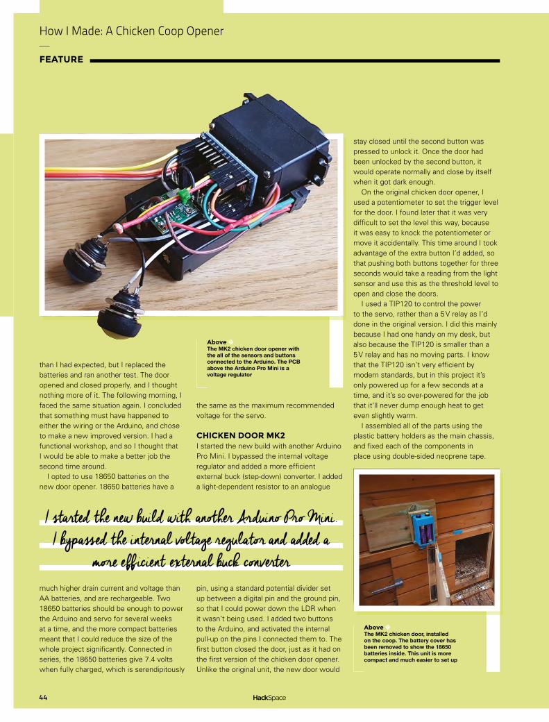
CHICKEN DOOR MK2I started the new build with another Arduino Pro Mini. I bypassed the internal voltage regulator and added a more efficient external buck (step-down) converter. I added a light-dependent resistor to an analogue
pin, using a standard potential divider set up between a digital pin and the ground pin, so that I could power down the LDR when it wasn’t being used. I added two buttons to the Arduino, and activated the internal pull-up on the pins I connected them to. The first button closed the door, just as it had on the first version of the chicken door opener. Unlike the original unit, the new door would
stay closed until the second button was pressed to unlock it. Once the door had been unlocked by the second button, it would operate normally and close by itself when it got dark enough.
On the original chicken door opener, I used a potentiometer to set the trigger level for the door. I found later that it was very difficult to set the level this way, because it was easy to knock the potentiometer or move it accidentally. This time around I took advantage of the extra button I’d added, so that pushing both buttons together for three seconds would take a reading from the light sensor and use this as the threshold level to open and close the doors.
I used a TIP120 to control the power to the servo, rather than a 5 V relay as I’d done in the original version. I did this mainly because I had one handy on my desk, but also because the TIP120 is smaller than a 5 V relay and has no moving parts. I know that the TIP120 isn’t very efficient by modern standards, but in this project it’s only powered up for a few seconds at a time, and it’s so over-powered for the job that it’ll never dump enough heat to get even slightly warm.
I assembled all of the parts using the plastic battery holders as the main chassis, and fixed each of the components in place using double-sided neoprene tape.
Above The MK2 chicken door opener with the all of the sensors and buttons connected to the Arduino. The PCB above the Arduino Pro Mini is a voltage regulator
Above The MK2 chicken door, installed on the coop. The battery cover has been removed to show the 18650 batteries inside. This unit is more compact and much easier to set up
I started the new build with another Arduino Pro Mini. I bypassed the internal voltage regulator and added a
more efficient external buck converter

45
LENS
I 3D-printed a suitable case, and sealed the seams of the unit together using a hot soldering iron. I was feeling quite pleased with the project at this point, and it’s a pity that it only worked for three days.
POINTS OF FAILUREI’d made a couple of mistakes in my design, and misunderstood the cause of the original unit’s failure. Firstly, I hadn’t included a backwash diode, to absorb reverse current feeding back from the servo. This wasn’t a big problem in the original version, because it used a relay and had an independent battery bank. In the new version of the door opener, the relay was replaced with a transistor, and wired to the same supply as the Arduino. This caused some stability problems.
The most important issue was that the servo still seemed to be drawing too much current from the batteries. This confused me at first because I knew that the output current of an 18650 battery should be able to power the servo. Even more confusingly, after I’d tried to open and close the door a few times, the opener started working properly. It took me quite a while to realise that the problem wasn’t inside the box, it was actually the environment that I’d put it in. Like most batteries, 18650 cells are very sensitive to cold conditions. The capacity rating printed on batteries is usually calculated for a temperature of around 25 degrees Celsius. The chicken door opener had worked perfectly through the warm summer months, but the capacity of the batteries had fallen as the temperature approached freezing. The final point of failure was that I’d used some unprotected batteries from my spare parts bin, and the voltage had dropped too low for them to be recharged.
IMPROVEMENTSOnce I realised the problem, the solution was simple enough. I added a 5 V ultra-capacitor after the power regulator, and this made sure that the Arduino still receives enough current when the servo is draining all of the power from the battery. Capacitors are less affected by low temperatures than batteries are and, with a new set of
protected 18650 batteries, the Chicken Door Opener MK2 has been working for several weeks without incident.
When the weather improves, I’ll probably update the code on the Arduino so that the light level that triggers the door is stored in EEPROM rather than RAM. There’s no rush to do this, because the ultra-cap can keep the Arduino powered up for several hours even without batteries installed.
GND
Arduino Pro Mini v13
SuperCap 5v
VOUT
Se
rvo
pu
lse- +
+
VIN
GN
D
FIXEDLM2931
Q1
R3
4.7Ω
R1
2.2
kΩ
D11N4002
2 × 18650 7.2 V
VCC
S2
1 2
2
2
22
2
2
2
2
23
3
3
1
1
1
1
1
1
1
1
1
S1
RAW
RE
SE
T
Arduino Pro
Mini
v13
DT
R
A0
A1
A2
A3
A4
A5
D13/S
CK
D12
/M
ISO
D11 P
WM
/M
OS
ID
10 P
WM
/SS
D9
PW
MD8
D7
D6
PW
MD
5 PW
MD4
D3 P
WMD2
D1/
RX
D0
/T
X
Above The customers inspect our handiwork
Below The final circuit has proved reliable and easy to use

Humanitarian makers: 3D printing for disaster relief
FEATURE
46
Meet the network of change-makers tackling the world’s great humanitarian challenges together
HUMANITARIAN MAKERS
Humanitarian Makers is a network of engineers, designers, and humanitarians who believe in a grassroots community approach to providing effective disaster relief. Their mission is to provide solutions to
pressing human needs by designing, testing, and producing humanitarian-use hardware built on the
Right 3D printers aren’t just for hackspaces, they’re portable manufacturing devices
CreditField Ready
Cameron Norris
Cameron is a technology and communications specialist, passionate about the use of open-source hardware for social innovation
@cameronsnorris
principles of ‘locally manufacturable’ and ‘open industrial design’. Field Ready, its founding member and current ‘parent’ organisation, is furthering humanitarian making in countries facing natural and human-made disasters. They solve a range of problems by making useful things locally. This includes rescue equipment to free people trapped beneath building rubble in Syria, as well as medical supplies that will provide essential healthcare to villagers following Nepal’s most recent earthquake and flooding.
Conflict, earthquakes, and storms cause enormous destruction and human suffering. Researchers at Citadel Investment Group believe that access to food, water, shelter, education, and basic health care are among “humanity’s top ten problems over the next 50 years”. According to Alessandra Cozzolino, author of Humanitarian Logistics, the estimated cost of aid logistics is $15 billion per year, representing 60–80% of the entire humanitarian aid budget.
After talking with a Field Ready founder, Eric James, and reflecting on her experience in the Kenyan healthcare sector, social entrepreneur Naiomi Lundman set up Humanitarian Makers in 2015. Initially, it was a LinkedIn group to explore community interest in bringing together aid workers, makers, and logistics experts interested in crowdsourcing their expertise to support humanitarian-focused problem-solving in disaster and recovery settings.
Since 2015, Humanitarian Makers has piloted several design challenges to explore the potential of leveraging the remote maker community for prototype testing, particularly within the general maker community that seeks to apply their talents towards social-good product developments.
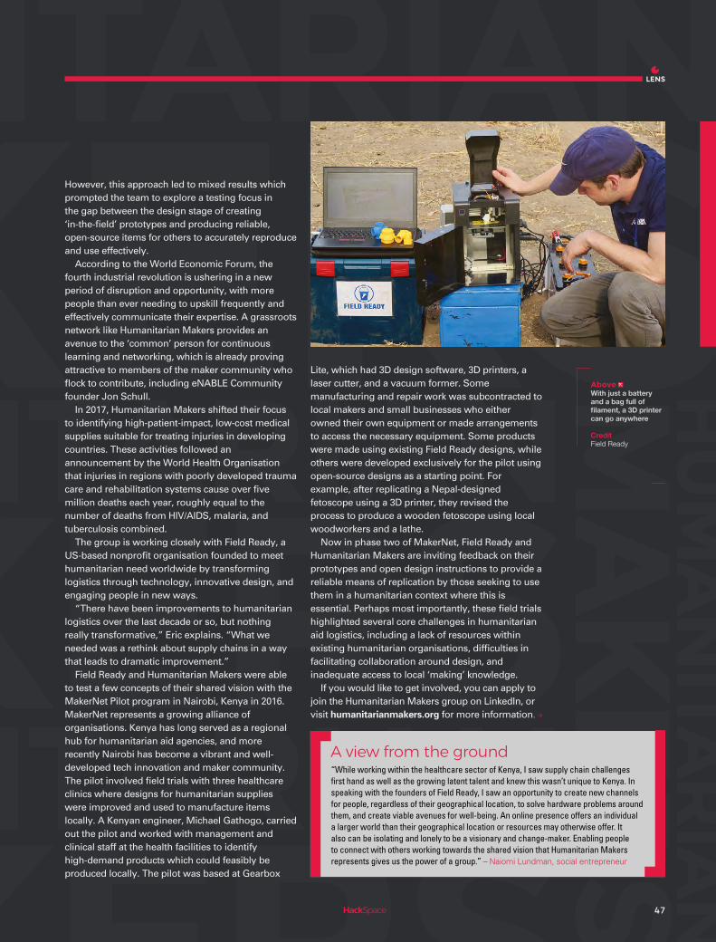
47
LENS
However, this approach led to mixed results which prompted the team to explore a testing focus in the gap between the design stage of creating ‘in‑the‑field’ prototypes and producing reliable, open-source items for others to accurately reproduce and use effectively.
According to the World Economic Forum, the fourth industrial revolution is ushering in a new period of disruption and opportunity, with more people than ever needing to upskill frequently and effectively communicate their expertise. A grassroots network like Humanitarian Makers provides an avenue to the ‘common’ person for continuous learning and networking, which is already proving attractive to members of the maker community who flock to contribute, including eNABLE Community founder Jon Schull.
In 2017, Humanitarian Makers shifted their focus to identifying high-patient-impact, low-cost medical supplies suitable for treating injuries in developing countries. These activities followed an announcement by the World Health Organisation that injuries in regions with poorly developed trauma care and rehabilitation systems cause over five million deaths each year, roughly equal to the number of deaths from HIV/AIDS, malaria, and tuberculosis combined.
The group is working closely with Field Ready, a US‑based nonprofit organisation founded to meet humanitarian need worldwide by transforming logistics through technology, innovative design, and engaging people in new ways.
“There have been improvements to humanitarian logistics over the last decade or so, but nothing really transformative,” Eric explains. “What we needed was a rethink about supply chains in a way that leads to dramatic improvement.”
Field Ready and Humanitarian Makers were able to test a few concepts of their shared vision with the MakerNet Pilot program in Nairobi, Kenya in 2016. MakerNet represents a growing alliance of organisations. Kenya has long served as a regional hub for humanitarian aid agencies, and more recently Nairobi has become a vibrant and well-developed tech innovation and maker community. The pilot involved field trials with three healthcare clinics where designs for humanitarian supplies were improved and used to manufacture items locally. A Kenyan engineer, Michael Gathogo, carried out the pilot and worked with management and clinical staff at the health facilities to identify high-demand products which could feasibly be produced locally. The pilot was based at Gearbox
Lite, which had 3D design software, 3D printers, a laser cutter, and a vacuum former. Some manufacturing and repair work was subcontracted to local makers and small businesses who either owned their own equipment or made arrangements to access the necessary equipment. Some products were made using existing Field Ready designs, while others were developed exclusively for the pilot using open-source designs as a starting point. For example, after replicating a Nepal-designed fetoscope using a 3D printer, they revised the process to produce a wooden fetoscope using local woodworkers and a lathe.
Now in phase two of MakerNet, Field Ready and Humanitarian Makers are inviting feedback on their prototypes and open design instructions to provide a reliable means of replication by those seeking to use them in a humanitarian context where this is essential. Perhaps most importantly, these field trials highlighted several core challenges in humanitarian aid logistics, including a lack of resources within existing humanitarian organisations, difficulties in facilitating collaboration around design, and inadequate access to local ‘making’ knowledge.
If you would like to get involved, you can apply to join the Humanitarian Makers group on LinkedIn, or visit humanitarianmakers.org for more information.
Above With just a battery and a bag full of filament, a 3D printer can go anywhere
CreditField Ready
“While working within the healthcare sector of Kenya, I saw supply chain challenges first hand as well as the growing latent talent and knew this wasn’t unique to Kenya. In speaking with the founders of Field Ready, I saw an opportunity to create new channels for people, regardless of their geographical location, to solve hardware problems around them, and create viable avenues for well-being. An online presence offers an individual a larger world than their geographical location or resources may otherwise offer. It also can be isolating and lonely to be a visionary and change-maker. Enabling people to connect with others working towards the shared vision that Humanitarian Makers represents gives us the power of a group.” – Naiomi Lundman, social entrepreneur
A view from the ground

Humanitarian makers: 3D printing for disaster relief
FEATURE
48
o lift heavy debris such as concrete slabs weighing several tons, specialist equipment is required, but the extremes of war make obtaining these necessary rescue tools an almost impossible task. Lifting airbags are
available to well-supplied search and rescue teams, but are prohibitively expensive to all but the most well-funded humanitarian organisations. In response, Field Ready has developed a means to locally produce lifting airbags for less than 10% of the commercial cost while still meeting international safety standards.
In March of 2017, Field Ready’s airbag system was used to save lives in Syria after a car bomb explosion caused extreme destruction to a hospital and residential area in Idlib. The area search and rescue team were informed that a family of four
LOCALLY MADEAIRBAGSDeveloping rescue equipment for Syria
were still trapped beneath the rubble of their collapsed home, including a little girl who was pinned by a large piece of the collapsed ceiling.
A safe passage was created within the building by removing as much debris as possible before placing the airbag system under one corner of the house to lift the collapsed roof and carry the family out from rubble to safety. Although the little girl sustained a broken leg that required surgery, she is recovering well and already back on her feet. So far eight people have been saved by the airbag system, and many more lives will be spared thanks to this critical device.
Field Ready’s lifting airbags comply with the same conventional UK safety standards of airbags already used commercially. In Europe, CE marking is the standard that new products must meet before they can be sold, imported, or put into service. Where
T
Above A 90% reduction in manufacturing costs leads directly to more lives being saved
CreditField Ready

49
LENS
LOCALLY MADEAIRBAGS practical, Field Ready has followed the principles of
CE marking to ensure its designs are safe to use. The not‑for‑profit is also aiming to meet British safety standards for lifting bag systems used by professional fire and rescue services. Field Ready’s process and test results are openly shared and encouraged to be reproduced to ensure authenticity; however, Field Ready strongly recommends requesting its technical support due to safety concerns. The resulting devices are not only able to be locally manufactured, but are capable of lifting up to five tons in an emergency situation.
Usamah Shamma and Hamada Aaroub represent Field Ready’s team on the ground. Usamah, who attended school in Aleppo and earned his university degree in Mechanical Engineering, developed the design and process to locally manufacture the airbag systems himself. Until the onset of the Syrian Civil War, he lived and worked in Aleppo, producing horizontal lifters and hydraulic pistons while consulting in the development of rescue and firefighting equipment. Hamada was born in a small town in the countryside of Aleppo where he graduated from Aleppo University with a degree in Engineering. Later, Hamada worked as part of the Syrian Civil Defence as head of the technical office in Aleppo, responsible for cars and technical equipment until the opportunity to join Field Ready emerged.
MAKING IN THE FIELD!When Usamah was asked what interested him in working with Field Ready, he replied, “The most important thing that motivated me to work with Field Ready is the idea that humanitarian supplies can be made in the field, using modern technology to make products that help people who are suffering from crises. That’s exactly what my people need nowadays. It’s like I found my passion for making things and inventions with Field Ready. What is impressive when we work together is that
we deal with each other like a family, and that’s really great”.
Hamanda was intrigued by Field Ready for similar reasons, “I was most attracted to work at Field Ready because of the wonderful nature of its work. It’s about approaching the most difficult challenges differently. This stimulates creativity within us and provides a chance to serve my community differently from other organisations. My ambition is to invent easy and uncomplicated ways of addressing technical problems in my country. With Field Ready, I am working, learning, and always add to my experience.”
Together, Usamah and Hamada have handmade and distributed 100 airbags for Syrian Civil Defence, saving the organisation over $450 000 in humanitarian supply costs when compared with the commercial alternatives. Every kit consists of four airbags, pressure regulators, valve boxes, and connection accessories – with all parts produced and assembled by Usamah and Hamada in Syria.
The airbags are constructed from two layers of 1 mm thick polyester with a protective vinyl coating. Vinyl-coated polyester is more commonly used for tent covers and truck sides as it is waterproof and resistant to dirt, mildew, oil, salt, chemicals, and UV rays.
When Usamah was asked how people have responded to their work in Syria, he simply replies, “They are inspired and amazed that we could make things with simple materials and equipment, and those products are efficient and reliable. People now really respect what we do, and try to help us. It’s something totally new in Syria. We won’t leave our country – and Field Ready helps me help my people. And the whole world could help us by stopping this crazy war.”
“Working in Syria involves a lot of risks. You’re exposed to bombing, air strikes, and car bombs at any time, so you’ll probably get hurt or lose your life at any moment. Moreover, travelling is not easy and not safe. You can’t go and travel any time you like. Sometimes a whole area and villages are closed temporarily because of war conditions, and there are very dangerous areas like areas on the front lines.” – Usamah Shamma, Field Ready engineer
A view from the ground
Left “Humanitarian supplies can be made in the field, using modern technology to make products that help people who are suffering from crises”
CreditField Ready

Humanitarian makers: 3D printing for disaster relief
FEATURE
50
n the immediate aftermath of an emergency, providing aid to those in need as quickly as possible is the number one priority, with the preservation of life as the greatest concern. However, after the emergency zone begins to stabilise, the focus gradually shifts from
preserving life to rebuilding the community affected by catastrophe.
COMBINING MODERN MANUFACTURINGWITH TRADITIONAL CRAFT Field Ready is combining 3D printing with traditional lost-wax casting to enable local manufacturers to provide key engineering and medical components to areas affected by natural disaster
This rebuilding process brings its own unique challenges, and careful planning must be given to best support reconstruction efforts without accidentally damaging existing local industries.
For example, transporting engineering components from Kathmandu to remote villages affected by the recent earthquake in Nepal has its own dangers. Local manufacturers can find themselves pushed out of the market and unable to sustain their business, resulting in increased unemployment and other negative economic consequences. Equally, imagine the difficulties that ensue when cooking stoves are imported and distributed for free when existing distributors and manufacturers are trying to sustain their business within Nepal.
There is a responsibility by international aid agencies to ensure that, as recovery gains momentum, local economies are adequately supported, and the community’s own efforts to rebuild are not undermined. Field Ready believes a key way to do this is through partnerships with existing local manufacturers and artisans.
Nepal has a rich history of lost-wax casting. For hundreds of years, the craft has been passed down generation to generation, with these craftsmen
IBelow Improving airflow in the stove leads to lower fuel requirements
CreditField Ready

51
LENS
capable of creating magnificently detailed works of art from brass, copper, tin, and bronze.
The lost‑wax casting process works by first shaping the desired object by hand from beeswax, and then coating the wax shape in clay. This clay-encased wax is then heated in a small furnace to melt the wax, leaving only the clay mould behind. This mould is then filled with molten metal; after cooling, the clay is broken to reveal a metal casting of the original wax shape.
Many different industries around the world utilise this simple method of manufacture to produce a wide array of useful products and components, many of which can increase the chance of survival in an emergency.
In relation to this, one of the lesser known capabilities of consumer 3D printers is the ability to print wax filament. As a result, Field Ready is working on a training program with local artisans, teaching them how to take and copy a 3D-printed wax pattern, and then to use those patterns with their own process. This will enable the production of a wide range of metal components from relatively low‑cost 3D printers, significantly improving manufacturing capabilities within a disaster setting, while supporting local businesses as the response moves from relief into recovery and reconstruction.
Following the earthquake in Nepal, Field Ready worked directly with staff from a partially destroyed hospital in Nuwakot to identify equipment that could be repaired using 3D-printed parts. This resulted in a number of items being produced, including components to fix ECG clamps, parts to mend dental chairs, and connectors for supplying electricity.
As part of this initiative, Field Ready and World Vision are developing a catalogue of 3D-printable medical items, which includes everything from tweezers, Cheatle forceps, kidney trays, fetoscope, and stethoscope, to an otoscope.
Nepalese Field Ready engineer Ram Chandra Thapa is the designer behind the 3D-printable otoscope, a simple device used in the diagnosis of ear, nose, and throat diseases. Ram used an open source prototype designed by Andrew Wallis as the basis for his design after gaining user feedback from medical practitioners in the UK and Nepal.
What’s more, Ram Chandra Thapa has been working closely with Nepalese inventor Madhukar KC on a low-cost wood burning stove, which has helped to demonstrate further how 3D printers can be used as a useful tool for metal casting in emergency situations.
TEN YEARS OF DESIGN ITERATION!Madhukar spent ten years continuously iterating his design to improve the flow of oxygen to the wood inside his burner, enabling it to burn more efficiently. For years, his designs were hand-crafted from wood using basic carpentry tools, with the resulting wooden patterns being sent to a sand casting manufacturer, which created sand moulds to produce cast iron components for his stoves.
However, due to the increasing complexity of the manufacturing process, the simple hand tools Madhukar had available were no longer capable of producing his latest designs. To overcome this obstacle, Ram Chandra Thapa created digital designs of Madhukar’s work, which were 3D printed and provided to the sand casting foundry for production.
Once tested, the new design burned with significantly higher efficiency than previous designs, signalling significant potential for this process to produce humanitarian items in the field. Small metal foundries are not uncommon in Nepal, meaning local businesses can be supported in the process.
In the next few years, Field Ready predicts that international aid agencies will be able to sidestep the typical three-month procurement period for humanitarian supplies by sending digital design files to manufacturers like Madhukar, makin g it more affordable than ever for emergency organisations to replace single defective products while at the same time supporting the local community.
“Field Ready is doing some amazing work in Nepal. I see Field Ready as the outsourced innovation unit to all of our amazing partner organisations. We have a great team of designers, engineers, and humanitarian professionals who see challenging problems in the aid sector as opportunities to do things better, cheaper, faster or, ideally, all three. The work we do starts with on-the-ground needs assessments, develops through partnerships, and ends with direct benefits to those people we engaged with and learned from in the first place.” – Ben Britton, Innovation Advisor
A view from the ground
Below By working with local craftsmen, Ram Chandra has been able to blend modern manufacturing with traditional crafts
CreditField Ready
Right 3D-printed medical supplies mean remote hospitals can be better equipped
CreditAbi Bush, Field Ready

52
on the cover price
SAVE35%
UPTO
SUBSCRIBE
Visit: hsmag.cc/subscribe
AND SAVE!
FROM JUST
£4per month

SUBSCRIPTION
53
FREE DELIVERY TO YOUR DOOR
GET YOUR COPY BEFORE STORESEXCLUSIVE OFFERS AND GIFTS
SAVE UP TO 35% ON THE PRICE
SUBSCRIPTION
Visit: hsmag.cc/subscribe
SUBSCRIBERBENEFITS
Rolling subscriptionfrom £4 a month:
12-month subscription from £55:
Quick and easy to set up
No long-term commitment
Cancel any time
No large up-front cost
UK: £55 per year
US: £90 per year
EU: £80 per year
RoW: £95 per year
Digital subscriptions from £2.29 per monthPLUS

FARM
URBANFarm Urban
INTERVIEW
54
HackSpace magazine meets…
Dr Paul Myers and Dr Jens Thomas
FARM URBAN
e’re ruining the planet, but the system we’re locked into means that as long as someone is making plenty of
money, there’s no economic incentive to changing the status quo.
Rather than running around preaching, Dr Jens Thomas and Dr Paul Myers of Farm Urban are doing something about this sorry state of affairs. They’re developing systems to grow food where it’s needed — where people are — to minimise food wasted in the distribution chain. They’re involving schools, taking real food out to children so that they can learn for themselves about healthy eating.
They’re also thinking about how the science is going to fit in with our current agricultural practices, so rather than advocating a utopian dream of everyone living off lentils, they’re running competitions to inspire kids to come up with business ideas around food.
We went to their secret underground lair to find more about open source food production, how Arduino and Raspberry Pi are powering the next wave of research, and why Ikea is more than just a cheap furniture store…
W

FARM
URBAN55
LENS
Above Dr Jens Thomas (left) and Dr Paul Myers, co-founders of Farm Urban
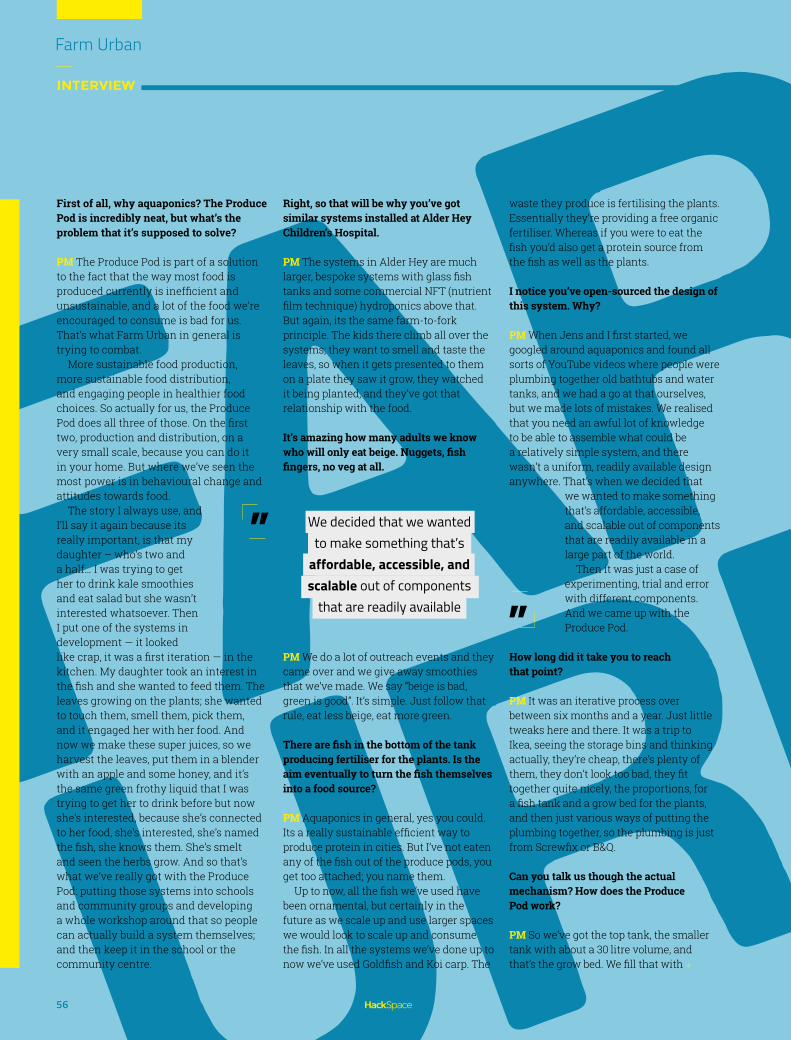
FARM
URBANFarm Urban
INTERVIEW
56
First of all, why aquaponics? The Produce Pod is incredibly neat, but what’s the problem that it’s supposed to solve?
PM The Produce Pod is part of a solution to the fact that the way most food is produced currently is inefficient and unsustainable, and a lot of the food we’re encouraged to consume is bad for us. That’s what Farm Urban in general is trying to combat.
More sustainable food production, more sustainable food distribution, and engaging people in healthier food choices. So actually for us, the Produce Pod does all three of those. On the first two, production and distribution, on a very small scale, because you can do it in your home. But where we’ve seen the most power is in behavioural change and attitudes towards food.
The story I always use, and I’ll say it again because its really important, is that my daughter – who’s two and a half… I was trying to get her to drink kale smoothies and eat salad but she wasn’t interested whatsoever. Then I put one of the systems in development — it looked like crap, it was a first iteration — in the kitchen. My daughter took an interest in the fish and she wanted to feed them. The leaves growing on the plants; she wanted to touch them, smell them, pick them, and it engaged her with her food. And now we make these super juices, so we harvest the leaves, put them in a blender with an apple and some honey, and it’s the same green frothy liquid that I was trying to get her to drink before but now she’s interested, because she’s connected to her food, she’s interested, she’s named the fish, she knows them. She’s smelt and seen the herbs grow. And so that’s what we’ve really got with the Produce Pod: putting those systems into schools and community groups and developing a whole workshop around that so people can actually build a system themselves; and then keep it in the school or the community centre.
Right, so that will be why you’ve got similar systems installed at Alder Hey Children’s Hospital.
PM The systems in Alder Hey are much larger, bespoke systems with glass fish tanks and some commercial NFT (nutrient film technique) hydroponics above that. But again, its the same farm-to-fork principle. The kids there climb all over the systems; they want to smell and taste the leaves, so when it gets presented to them on a plate they saw it grow, they watched it being planted, and they’ve got that relationship with the food.
It’s amazing how many adults we know who will only eat beige. Nuggets, fish fingers, no veg at all.
PM We do a lot of outreach events and they came over and we give away smoothies that we’ve made. We say “beige is bad, green is good”. It’s simple. Just follow that rule, eat less beige, eat more green.
There are fish in the bottom of the tank producing fertiliser for the plants. Is the aim eventually to turn the fish themselves into a food source?
PM Aquaponics in general, yes you could. Its a really sustainable efficient way to produce protein in cities. But I’ve not eaten any of the fish out of the produce pods, you get too attached; you name them.
Up to now, all the fish we’ve used have been ornamental, but certainly in the future as we scale up and use larger spaces we would look to scale up and consume the fish. In all the systems we’ve done up to now we’ve used Goldfish and Koi carp. The
waste they produce is fertilising the plants. Essentially they’re providing a free organic fertiliser. Whereas if you were to eat the fish you’d also get a protein source from the fish as well as the plants.
I notice you’ve open-sourced the design of this system. Why?
PM When Jens and I first started, we googled around aquaponics and found all sorts of YouTube videos where people were plumbing together old bathtubs and water tanks, and we had a go at that ourselves, but we made lots of mistakes. We realised that you need an awful lot of knowledge to be able to assemble what could be a relatively simple system, and there wasn’t a uniform, readily available design anywhere. That’s when we decided that
we wanted to make something that’s affordable, accessible, and scalable out of components that are readily available in a large part of the world.
Then it was just a case of experimenting, trial and error with different components. And we came up with the Produce Pod.
How long did it take you to reach that point?
PM It was an iterative process over between six months and a year. Just little tweaks here and there. It was a trip to Ikea, seeing the storage bins and thinking actually, they’re cheap, there’s plenty of them, they don’t look too bad, they fit together quite nicely, the proportions, for a fish tank and a grow bed for the plants, and then just various ways of putting the plumbing together, so the plumbing is just from Screwfix or B&Q.
Can you talk us though the actual mechanism? How does the Produce Pod work?
PM So we’ve got the top tank, the smaller tank with about a 30 litre volume, and that’s the grow bed. We fill that with
”
We decided that we wanted to make something that’s
affordable, accessible, and scalable out of components
that are readily available
”

FARM
URBAN57
LENS
Above These are cucumber plants, growing in water contaminated with varying amounts of arsenic

Farm Urban
INTERVIEW
58
FARM
URBANAbove The design for the Produce Pod is open source, and you’re encouraged to build your own: hsmag.cc/QzuxND

59
LENS
FARM
URBANexpanded clay, which acts as a synthetic soils for the plants to root into. The tank below is the fish tank, so it’s about 60 L. We have a pump that pumps water up from the bottom tank to the top tank. There’s an overflow level set and a standpipe, and once the water reaches the right level it just returns back to the fish tanks. That continues for 15 minutes, so it floods the top tank for 15 minutes to provide the nutrients to the plants and there’s a timer on the pump, so that cuts out and it drains back down, so it’s without water for 45 minutes. That’s how the roots get their oxygen.
It’s a very basic question, but what sort of tools would you need to make one from scratch? You’ve been to Screwfix, bought the Ikea bins; what else would you need?
PM You need a drill and a couple of drill bits, pipe cutters, and that’s it. It’s about as accessible as you can get.
And the expanded clay, where do you get that from?
PM You an get that from all good hydroponic supply stores. It’s about £15 for a bag of that. We’re just developing another version that doesn’t use the expanded clay; one of the problems with this is that it’s heavy and it’s expensive to ship. It’s really dusty and it’s a nightmare to wash it clean, so we’re doing a floating raft system which uses insulation board, and that sits on top and the plants just float on the raft.
The Produce Pods you’ve got here are all growing lettuce and herbs and soft things; is there potential for something more solid like potatoes?
PM Starchy food, yes. Theoretically there’s no reason why you can’t. Instead of using expanded clay, you would use a softer medium like coconut husk, so the vegetables can root into that. In Japan
they’ve done a lot with aeroponics, where they mist water up on to the root tubers, so you see the potatoes just growing in fresh air, having the nutrients misted on to them.
The reason we concentrate on leafy greens and on herbs is that they’re perishable, and that’s where you get the highest rates of waste. We import most of our herbs and leafy greens from southern Spain and Italy, and about 60% doesn’t actually make it to us because it doesn’t
transport well, so it makes more sense to be growing those perishable items in cities so you can maintain the freshness, the nutrient density. There’s a lot less waste. Whereas a potato, for example, it makes sense to grow it in a field outside a city, because they store and transport really well.
So I guess the aim is not to replace standard agriculture but to complement it?
PM The aim is to take the pressure off. People often say to us “aquaponics, hydroponics, what about the soil?” Jens and I first met through permaculture, a real deep appreciation for the soil and the whole process. So we just think this is part of the solution that can take the pressure off, to allow for more sustainable organic farming practices. The technologies in aquaponics and hydroponics will continue to evolve, so that we’ll be growing other foods besides leafy greens.
JT There’s an absolute time bomb waiting to go off with soil nutrients and that’s
why we need these alternative ways of growing stuff to supplement this while we fix the problems that we’ve got with the current system. The current farming system is completely extractive. In some farms the soil is just there to provide somewhere to grow the food, it’s just a matrix for the plant roots, so it’s basically dead in a lot of places. There are areas in the USA where they grow potatoes and it’s completely dead, there’s just sand. So you have to bring everything
in, bring all your fertiliser in. And then, because all the fertiliser washes away in the rain anyway, you constantly have to have those inputs. Everything’s running off, and that’s what ’s causing ocean dead zones and rivers are dying because of all the run-off from agriculture. It’s been known about for decades, but it’s only now getting to
a point where it’s really becoming a serious problem.
You mention the USA; how far down the road are we in England to that in terms of agricultural dead zones? You go down to Cambridge, to what used to be the Fens, and the soil looks like peat, it’s completely black. That doesn’t look like it’s in any danger of running out of nutrients any time soon. Should we be as worried as Americans about our food production?
JENS Probably, but it depends on the area. Each place is different, and just by looking at the soil you can’t really tell anything: different soils have different structures. The important thing is what is it like to grow on that soil, what are the inputs that you need? I think we all need to be worried, because it’s a worldwide problem.
The food web is so fundamentally interconnected, there’s so much coming from different areas. The year before last, for example, you couldn’t buy any salad for a while because they had floods in Spain, so all the salad harvest failed. That was it for us: no salad!
”
The reason we concentrate on leafy greens and on herbs
is that they’re perishable, and that’s where you get the
highest rates of waste
”

60
FARM
URBANFarm Urban
INTERVIEW
Do you envisage every house having a Produce Pod or something similar? How is it likely to spread in a best-case scenario?
PM The beauty is that it’s completely scalable, I would say the smallest you’d go to is the Produce Pod. Everyone could have one of those in their kitchen. And then you could scale up from that. We’re developing a living salad wall at the moment that a business could have in the canteen for the business – they’d have a living salad wall for everyone, and restaurants and bars could do that.
Our next step is to turn the space we’re in now into a 200 square metre vertical farming system. If within a one or two mile radius you had one of these… it’s not small, it’s kind of a commercial scale system, with the communities involved in the growing, kind of nodes, around the country… that would work quite well.
Would supermarkets be interested in growing fresh crops themselves? They seem to have a quasi monopoly on food production anyway, so it would make sense.
PM I think that’s what’s really exciting about this, is that maybe supermarkets will buy it, but do they actually need to? Can you just sell direct to consumers? I think the States are further ahead in this than us. There’s an organisation called Bright Agrotech, and they’ve developed something called the Zip Tower. They just had a $200 million investment from Jeff Bezos and SoftBank, and they’re looking to put these farms outside every major city on quite a large scale. But I don’t see why you couldn’t be selling through farmers’ markets direct to consumers and even into supermarkets.
JENS There’s also the idea that you can actually grow within the supermarkets, of course. In Canada they’ve done this where they’ve got supermarkets, on the top they’ve got greenhouses that are growing the vegetables. In Spain, they do live sales in the supermarket where it comes off the roof or the basement, the customer cuts off the bits that they want. They’re literally harvesting it themselves, so you couldn’t get any fresher. That means its going to last that much longer. Whether you do that in a supermarket or a smaller kind of shop, all of these are open questions, which is why it’s so exciting. No one knows what the model’s going to be yet.
Above The Water Elf: an Arduino and a bunch of sensors
Above Much gear was donated by Merseyside Police – confiscated from cannabis growers

61
FARM
URBANYou said you’d extended a scheme with local school pupils working on their own systems – what have the next generation been coming up with?
PM The UTC, which is the building we’re in now, has a school above us, and we’ve worked with them for the past four years. The first ever aquaponics system we built is the double helix design that’s in their reception. That was part of a twelve week programme where students learnt what aquaponics, urban farming is , why it’s important, and then they designed that system and we built it with them.
That’s now evolved into a twelve week enterprise program where we teach the kids about startups. What a startup business is, what’s an eco-startup, what’s a social enterprise, and they form their eco-enterprise, learn about project management, how to be a managing director, marketing, finance, sales, and then they have to design their own aquaponics system.
We give them a £1 000 equipment bundle, which is largely equipment that the police have donated to us from the cannabis dismantling team. So we’ve got these kids repurposing this equipment, designing, and building these systems in order to solve food security issues.
Do you get much donated equipment from the police? A lot of hackspaces would jump at the chance to get free stuff from their local constabulary.
PM They’ve donated a lot to us, to the point where we’ve said we need to find homes for all of this now. We started off getting the old sodium lightbulbs, 600 W ones, but luckily the cannabis growers cottoned on to LED technology, so we’re getting some really nice energy-efficient lights. We give them away with the systems that we put into schools, and the kids here are using them to build their own systems. We’re just launching schemes at the end of February, we’re going to roll that project out to ten schools across Liverpool, so they’ll all be competing against each other to come up with the best business and the
best aquaponics system made out of this equipment. We’ll have a Dragons’ Den-style pitching competition at the end.
Do you use any smart devices?
JENS We do have one called the Water Elf. It was developed by a team at Sheffield University, a mix of academics, a professor called Hamish Cunningham, and a little group of hackers. You’ve got an Arduino Uno and a board with various sensors on it. It connects to WiFi and you can use that to connect your computer or an online database. It collects data, then pushes that data to it.
It’s got pH, temperature, light sensors, and you can also link it to a Raspberry Pi, so that allows them to do stuff like link a webcam so you can have a webcam monitoring the fish and the plants.
One of our collaborators at the University of Liverpool, Iain Young, has done some work using a standard webcam, doing a kind of artificial intelligence project to monitor the fish and to track whether they’re unwell, whether they’re behaving unusually.
And one really cool project is, they’re getting the fish to feed themselves. At one end the tank itself is quite well laid out, it’s got plants, it’s somewhere the fish want to be. In contrast, the bit where they get
fed is horrible. It’s bare, the fish don’t like going there. There’s just nothing. But they realised that’s where they go to get fed. The webcam monitors them and when there are enough fish in the area, it feeds them, but only then. Otherwise you feed the fish and you’re never quite sure whether you’ve given them enough, but this way the fish tell you, because when they’re hungry they swim into that end, so they only get fed when they’re hungry.
We’ve done a little bit of work with Daresbury Laboratory on the Pi Sense and Python to do a similar job with a different technology stack. And that’s quite nice, because it comes with Python embedded in it. With the Arduino you have to learn a sort of sub-set of C, so it’s a little bit tricky, whereas Python’s a sort of de facto language that everybody uses.
It’s so easy for us to extend and develop that, but also if we want to take it into schools or use it in education, chances are that the kids are already going to know Python.
PM That’s probably the next step for us with the Produce Pod: add the sensor rig and the kids to run their own experiments. See how light levels affect plant growth, see how the water temperature affects the fish growth rate; there’s a whole raft of experiments that can be done.
Above Lettuce and parsley don’t travel well, so they’re perfect for home growing

Improviser’s toolbox: Hot glue
FEATURE
62
glue gun is one of those essential bits of kit that all makers should have safely stashed away in their toolbox. The active ingredient in this all-purpose device is hot melt adhesive (HMA), more commonly
known as hot glue. Initially fabricated to bond shoe soles, HMA is now the go-to glue for most crafters and is useful in a number of different hobbies. All kinds of makers use hot glue as a quick-assembly prototyping adhesive. You can use it to quickly glue up the test parts for your build, have them strong enough to hold together to make sure that everything fits and works, but it’s all still weak enough that it can be easily taken apart again to make changes before final assembly. And while its primary purpose is to glue, if you look at it as a molten plastic dispenser, you start to see a lot more uses for it, in moulding and casting, sealing, and many other applications.
Hot glue is most commonly available as solid cylindrical sticks. They were introduced in the 1940s as an improvement to water-based adhesives that were prone to weakening when exposed to humidity. HMAs are applied to a
material in the molten (liquid) state by glue guns that have a heating element to melt the plastic glue. The glue sticks are pushed through a cavity at the end of the device either manually or by pulling a trigger, depending on the gun. When a second material is brought into contact, the glue cools down and solidifies very quickly.
Hot melt adhesives contain no water and no solvents of any kind. They are designed to set and form a bond by the loss of heat which translates into a very fast setting speed. HMAs can bond both similar and dissimilar materials. They vary in width and length and are generally made up of waxes, resins, and a variation of thermoplastic polymers. The polymers give them strength, the resins are responsible mainly for the adhesion, and the wax helps thin the adhesive for easier application. The chemical composition of HMAs varies depending on their use. The strength of the bond depends on several factors such as the temperature at which they are applied -- a hotter adhesive takes longer to set and a cold one sets before the materials are bonded. Typically HMAs are waterproof and can withstand chemical treatments, but they are usually not suitable in high-temperature applications.
AMayank Sharma
@geekybodhi
Mayank is a Padawan maker with an irrational fear of drills. He likes to replicate electronics builds and gets a kick out of hacking everyday objects creatively
Bind all kinds of projects with this versatile fastener
HOTG ue

63
LENS
Left It took eight 11-inch glue sticks to cast the robot: two each for the head and limbs, the rest for the body
Creditinstructables.com
Below The friction-inducing spikes at the tail compliment the ones at the front and give it a personality
Creditinstructables.com
SIDDHARTH JAIN
Project Maker
Project Linkhsmag.cc/KXSCoh
W
IPAVEL MIHAYLOV
Project Maker
Project Linkhsmag.cc/mHYtGI
hile it’s a very good adhesive, hot glue can also be used for casting objects. For a simple shape, you just make a plaster mould of the object you want to
duplicate and then squirt hot glue into the negative space once the mould has hardened. Siddharth Jain applied this technique to create a hot glue cast of the Instructables Robot (that appears in the website’s logo) which can double up as a geeky night lamp. He used cardboard to create the mould for the robot’s head, a bowl for its belly, baking foil wrapped over a thick marker pen to mould its legs, and epoxy putty for its hands. He then filled the moulds with hot glue and inserted a couple of LEDs in the head and the legs as the glue cooled. Siddharth has shared assembly details and other nuances, with pictures of every step to make it easier to replicate his build.
f you’ve handled hot glue sticks, you’ll have noticed their spring-like nature when bent. Pavel Mihaylov, an engineering student in the University of Edinburgh,
decided to exploit this behaviour to make a neat little robotic toy that propels itself using glue sticks. Pavel’s robot has a bunch of hot glue sticks between the front and the tail, along with a couple of strings. He uses Arduino-controlled servo motor actuators to pull the strings from the tail to the front, which also bends the glue sticks. The actuator then lets go and the bent glue sticks straighten and push the robot’s front forward. Explaining the physics behind the movement, Pavel says the robot’s tail has very little friction with the ground on one end and very high friction at the other end, which keeps it stuck to the ground as the glue sticks unfold. Pavel has also shared the simple code for controlling the servo.
HOT GLUE CASTING
GLUE STICK ROBOT
G ue

Improviser’s toolbox: Hot glue
FEATURE
64
he creative individual behind the DIYatHOME YouTube channel, who prefers to remain anonymous, hot glues some easily accessible knick-
knacks and puts them to innovative uses. Being a macro photographer, one of my favourite is the rotating photography stand that you can put together in a matter of minutes. Just hot glue the cap of a pen to a ball bearing and then glue a strip of cardboard around it and stick them to another piece of round cardboard. Next, splice a small DC motor along with an on/off switch to a USB cable.
en grew tired of the clear-coloured glue sticks. Instead of shelling out the premium for buying coloured hot glue sticks, he decided to make some of his own. Ken’s
written up the procedure on his blog and also made a video of the process after popular demand. The process is simple and wouldn’t take much time, but is labour-intensive and not suitable for children because of the temperatures and smells involved. The key to this process is the Reynolds parchment paper, which is coated on both sides with silicone. Hot glue won’t stick to parchment paper, which makes it an ideal material for a mould when wrapped inside a brass tube. Ken then heats up some glue sticks with a Crayola crayon and pours the mixture inside the mould that then solidifies in about half an hour. In the write-up, Ken has also shared some tips to ease the pouring process, including using a silicone funnel or one created with cardboard lined up with parchment paper.
T
K
DIYATHOMEProject Maker
Project Linkhsmag.cc/aZZFpQ
KENProject Maker
Project Linkhsmag.cc/tojaac
ROTATINGPHOTOGRAPHYSTAND
Finally, put them together, while making sure the shaft of the motor is in contact with the circular cardboard. DIYatHOME’s instructables page has brief but well illustrated step-by-step instructions to better understand the process.
Above Head to DIYatHOME’s YouTube channel (hsmag.cc/bhfxmp) for more fun projects built with cardboard
Credityoutube.com
Above Ken says the wax from the crayon doesn’t really change the bond strength of the hot glue
Creditobservationsblog.com
DIY COLOURHOT GLUE STICK

65
LENS
hen Brooke’s dog chewed up one of her slippers, like any good maker she decided to fabricate a set of her own. She recalled seeing a video of a
hot glue DIY for a pair of flip-flops and decided to build upon the process. Brooke’s process is fairly straightforward and easy to replicate. She makes a stencil out of cardboard, then places a sheet of parchment paper over it and applies a layer of hot glue. A similar process is used to fabricate the bands. She then trims the base to make them prettier and glues them together. Brooke writes that her hot glue sandals will not let moisture, rocks, and dirt come through and the noise they make initially will eventually die down. The first time she attempted the sandals though she used aluminium foil instead of parchment paper: “Once I glued all the parts and let them dry, I attached the pieces of the sandals together with the aluminium still on, so that I could peel it off as a final reveal. When I finished, I gathered everyone around to watch me peel off the foil, except that it didn’t come off, and there was no reveal. My family had a great time laughing about my silver shoes for the next few weeks.”
W
HOT GLUE HACKS
A WATERTIGHT AND AIRTIGHT SEALHot glue is a handy little fix to seal small holes and will also work under water. Remember however that it won’t take much abuse, so use it with caution.
COVER EXPOSED WIRESMixing hot glue and electronics isn’t usually a good idea since electronics produce heat, but you can use hot glue to cover wires peeling out of earphones and USB cables.
GIVE RUGS A NON-SLIP GRIPRugs are pretty slippery, especially over smooth tiled or polished floors. Apply dollops of hot glue to the bottom to increase the friction and make them less slippery.
ADD TEXTURE Create a design with hot glue on any surface—canvas, eggs, wood, bottles, vases, etc. Once dry, paint over it for more personality.
HANG LIGHTSIt can be tricky to hang lights on a brick wall. Save time by applying a small amount of glue to the wall and then paste the lights. Reheat the glue with a lighter to take them off.
HOT GLUE MATCHSTICKSPoke a hole and pierce pieces of hot glue near the striking end of the match. In an emergency, light the match, let the flame heat the glue, and then spread the glue.
TEMPORARY SOLESIf you have worn out the soles of those comfortable pair of shoes, make them grip again with a coat of hot glue.
BASKET FOR TRINKETSUse a brush to coat any kind of oil on the outside of a glass bowl. Then draw lines on it in the form of a spider web and peel it off once it dries.
GLUE GUNSANDALS
BROOKEProject Maker
Project Linkhsmag.cc/FqKmtI
Below Make sure you don’t apply a lot of glue to one spot – it’ll layer up and feel uncomfortable
Creditinstructables.com

We Learn to make a leather belt
FEATURE
66
Keeping our trousers up the hacker way
We Learn
TO MAKE A LEATHER BELT
he M5 runs straight up the Severn Valley while the river snakes around on the left. The hills of the Forest of Dean rise up on the west side while the Cotswold’s escarpment dominates the skyline on the other. There’s just
time to stop to pick up some cave-aged cheddar at Gloucester services before my evening appointment.
My satnav takes me safely through Cheltenham’s infamous one-way system to an inauspicious industrial estate on the outskirts of town, and a Hackspace ‘H’ identifies the Cheltenham Hackspace.
Right A glowing H just to remind everyone what sort of building they’re in
TInside, the members’ storage in the porch is
dominated by 3D printers, and this leads into the electronics section of the Hackspace where a few members are busy at work on a LED cube. Upstairs, there’s space for textiles and computer work. I meet Tim, Cheltenham’s leather work guru and my instructor for the evening.
Tim explains that quality leather work starts with quality leather, and a significant part of that comes from the treatment that the material has received. Much consumer leather is made with low-quality and cheaper leathers such as chrome tan. When
By Ben Everard

67
LENS
Below Our finished belt is strong enough to hold our trousers up despite the Christmas indulgences…
Above Keeping all the dust-generating tools in one room helps keep the rest of Cheltenham HackSpace clean and tidy
Tim opens a box of leather tools, and the contents looks disturbingly like they might have been
designed for a Victorian dentist.”
”you’re making your own leather goods, you can use whatever quality you like (or can afford) and we’re working with veg tan, which feels much thicker and sturdier than leather goods I’ve bought previously. This ability to bring the quality of leather you want with the design you want gives the maker a far greater range of leather options than someone buying off-the-shelf options.
As a brewer, Tim’s particularly interested in tankards – mugs for drinking beer. These are first cut and sewn together, then dipped in molten wax which makes them waterproof and strong.
After showing off what’s possible with the skills of an experienced craftsman, it’s time for me to find out what’s possible in the hands of an inexperienced journalist.
Tim opens a box of leather tools, and the contents looks disturbingly like they might have been designed for a Victorian dentist.
Belts are fundamentally a fashion item (otherwise we’d just hold our trousers up with string), and
as such, much of the evening is taken up with decorating. Including a stitched effect around the edge of the belt and some embossing – I opted for a rather (in my opinion) tasteful oak leaf and acorn motif. You can see the complete process overleaf. Nothing is fundamentally difficult, but it does require a few specialist tools and a knowledge of how to handle the leather, including treatments,
The pay-off/difficulty ratio for belt making is quite high. In a few hours (with instruction) I was able to make an item of clothing I’m proud to wear despite having no experience in the field. This alone makes it a great area for makers.

We Learn to make a leather belt
FEATURE
68
MAKING A LEATHER BELT
STEP 1CUTTING THE SHAPEUsing a strap cutter, create a strip of leather the right width for your belt buckle
STEP 3SHAPING THE LOOSE END
STEP 2MEASURE THE LENGTHEnsure your strip is long enough to fit once it’s been turned into a belt
Cut the loose end of the belt into whatever shape you want, such as a rounded point

69
LENS
SADDLE STITCHINGWhile most of belt making is cutting and designing the leather, there is one skill that you’ll need: saddle stitching.
The first thing to do is punch holes in the leather that the needle will go through. As this is done before the needles get anywhere near the leather, there’s no need for the needles to be sharp, so leather needles are blunt. Ensure that your leather is lined up properly before starting or it’ll end up wonky.
Perhaps the most unusual thing for someone who sews is that you’ll need two needles threaded on the same thread. We’ll name our needles 1 and 2. Start at one end of the row of stitches and push needle 1 through the first hole and needle 2 through the second (both from the same side). You should now have a single stitch on one side of the leather with the thread coming out of two holes on the other.
Now, push needle 1 through the hole that needle 2 just came out of – this should complete a loop of thread and you can pull it tight. Push needle 2 through the next hole up and you should once again have both ends of the thread coming out of the same side of the leather. You can now repeat this pattern until you have completed the row of stitches.
You’ll need to stitch back over the row a few times to make sure that the join is secure. Each time, you should find that it gets a bit tighter as the thread fills in the hole. Once it’s strong and secure, you can simply trim off the ends of the thread and the join is complete.
STEP 4GROOVING THE EDGE
STEP 5‘STITCHING’ THE EDGE
Use a groover to create an indentation in the leather along both sides of the belt
Run an overstitching tool along the groove to create the impression of a sewn edge

We Learn to make a leather belt
FEATURE
70
STEP 6PUNCHING THE HOLES
STEP 7EMBOSSING THE LEATHER
STEP 8OIL THE LEATHERS
Wet the area to be embossed, then with a single mallet-blow, use the punch to create an impression in the leather
Add whatever treatment you want to preserve and colour the leather. I opted for a simple oiling
Punch holes at 3 cm intervals along the tail end of the belt. You also need a larger hole in the other end to fit the buckle through
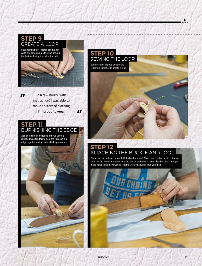
71
LENS
In a few hours (with instruction) I was able to make an item of clothing
I’m proud to wear
””
STEP 11BURNISHING THE EDGE
STEP 10SEWING THE LOOP
STEP 12ATTACHING THE BUCKLE AND LOOP
STEP 9CREATE A LOOP
Add burnishing compound and rub using a rounded wooden tool to hold the fibres in the edge together and give it a sleek appearance
Saddle-stitch the two ends of the rectangle together to create a loop
Place the buckle in place and fold the leather round. Then punch holes to stitch the two layers of the folded leather to hold the buckle and loop in place. Saddle-stitch through these holes to hold everything together. You’ve now finished your belt
Cut a rectangle of leather about 5 mm wide and long enough to wrap around the belt (including the tail of the belt)
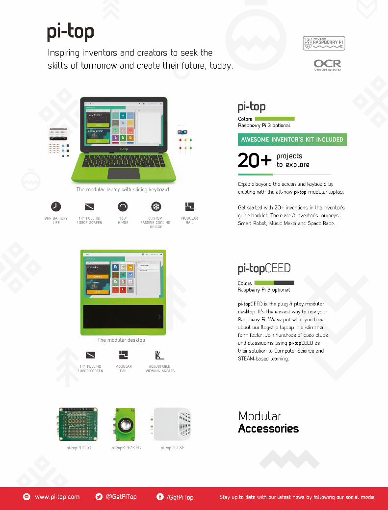


Start your journey to craftsmanship with these essential skills
SCHOOL OFMAKING
PG76
76 Silver soldered storage box82 Arduino programming: reading data from devices
102PG
GET TO KNOW OSCILLOSCOPES
106PG
MAKE AN INFRAREDRANGEFINDER
HACK MAKE BUILD CREATEImprove your skills, learn something new, or just have fun tinkering – we hope you enjoy these hand-picked projects
98PG
3D PRINT ON FABRICTake over the catwalk with textures printed directly onto your clothes
Poke and prod your way to a better understanding of electronic circuits
Connect sensors to your ESP8266 with just two wires using I2C
FORGE
88PG
Bring web data directly into your living room
DIY COUNTER
92PG
DRONE RACING RINGSBuild a custom race track to put your driving details to the test
86PG
LASER-CUT FOOD STENCILSIf your food looks this good, no one will notice if it tastes terrible

Silver soldered storage box
SCHOOL OF MAKING
76
ice have a tendency to nibble on power cables. Some people say it’s because they’re attracted to plasticisers, but maybe they’re just mistaking the orange cable for cheese. Whatever the case, it
can be important to protect your power tools from these hungry visitors, and a metal storage box should do just that.
The box is designed to be folded from thin sheet metal and silver soldered together. The folds add to the strength of the box and stop it from flexing. The design of the box incorporates tabs or flanges. These provide the silver solder joints a large surface area for bonding.
CAD DESIGN FOR SHEET METALThe box and lid were created using the sheet metal feature of Fusion 360 which was released earlier this year. You can download a trial copy of the software and then license that as a student,
Protect your tools from furry intruders
Silver soldered storage box
M
enthusiast, or start-up for a free license. Fusion 360 requires an internet connection and an AutoDesk account to work. Your work is saved to the cloud although the software is installed and runs locally – hsmag.cc/QtvwtU.
Before starting, it’s worth setting up the ‘Sheet metal rules’ which define the properties of the material you are working with. These control how the metal bends and how much material the CAD package includes for the folding. When metal is bent, the metal on the outside is stretched and the metal on the inside is compressed. How each metal behaves is defined by the k-factor and the software uses that and the parameters of the bend to determine the characteristics of the fold. The default for steel sheet is 2.5 mm thick, so we created a new rule for 0.5 mm.
Once you’ve defined your rule, sketch a rectangle for the base of the box on the X-Z plane. Switch to the sheet metal workspace and create a flange representing the first side of the box. When creating the first side you’ll be prompted to choose
Right Rules control how the metal bends
Above Our tools are stored safely away from any hungry animals
Andy Clark
After an aerospace apprenticeship and electronics degree at Imperial College, Andy took a job as a software engineer. For the last ten years he’s been making and repairing in a shed at the bottom of the garden. You can see more of his exploits at workshopshed.com
@workshopshed
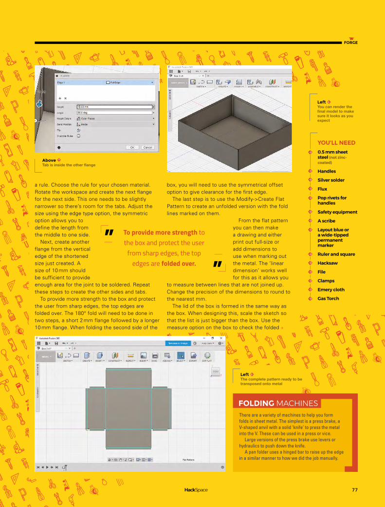
77
FORGE
a rule. Choose the rule for your chosen material.Rotate the workspace and create the next flange for the next side. This one needs to be slightly narrower so there’s room for the tabs. Adjust the size using the edge type option, the symmetric option allows you to define the length from the middle to one side.
Next, create another flange from the vertical edge of the shortened size just created. A size of 10 mm should be sufficient to provide enough area for the joint to be soldered. Repeat these steps to create the other sides and tabs.
To provide more strength to the box and protect the user from sharp edges, the top edges are folded over. The 180° fold will need to be done in two steps, a short 2 mm flange followed by a longer 10 mm flange. When folding the second side of the
box, you will need to use the symmetrical offset option to give clearance for the first edge.
The last step is to use the Modify->Create Flat Pattern to create an unfolded version with the fold lines marked on them.
From the flat pattern you can then make a drawing and either print out full-size or add dimensions to use when marking out the metal. The ‘linear dimension’ works well for this as it allows you
to measure between lines that are not joined up. Change the precision of the dimensions to round to the nearest mm.
The lid of the box is formed in the same way as the box. When designing this, scale the sketch so that the list is just bigger than the box. Use the measure option on the box to check the folded
There are a variety of machines to help you form folds in sheet metal. The simplest is a press brake, a V-shaped anvil with a solid ‘knife’ to press the metal into the V. These can be used in a press or vice.
Large versions of the press brake use levers or hydraulics to push down the knife.
A pan folder uses a hinged bar to raise up the edge in a similar manner to how we did the job manually.
FOLDING MACHINES
To provide more strength to the box and protect the user
from sharp edges, the top edges are folded over.
””
Above Tab is inside the other flange
YOU’LL NEED
0.5 mm sheet steel (not zinc-coated)
Handles
Silver solder
Flux
Pop rivets for handles
Safety equipment
A scribe
Layout blue or a wide-tipped permanent marker
Ruler and square
Hacksaw
File
Clamps
Emery cloth
Gas Torch
Left The complete pattern ready to be transposed onto metal
Left You can render the final model to make sure it looks as you expect

Silver soldered storage box
SCHOOL OF MAKING
78
size as this will be slightly larger than your original sketched rectangle. Allow 0.1 mm clearance so that the box does not wedge in place, and don’t forget to allow for the tabs which are folded on the inside of the lid. Model the box and create another flat pattern. You’ll now be able to determine how large a sheet of metal will be required. We picked a 1000 mm × 500 mm sheet and then adjusted the design to use the full width of the sheet, this saved quite a bit of sawing.
Simple gas torches consist of a brass nozzle and regulator that screw into a fitting on the top of a disposable canister. Bigger torches have pipes so they can be used with large, and hence less portable, canisters. The canisters contain liquefied gas which boils as soon as it is released into the air. Some torches have a sparker built in to light the gas, it’s also possible to purchase a flint cup sparker to light the gas.
The regulators and nozzles are designed to work with specific gases so if you want to use more than one gas you’ll need to get the right burners.
Gas should be stored somewhere that is well ventilated but also protected from the weather. For larger bottles, a cage with a roof is typically recommended.
There are several gases that are available in DIY stores:
Butane Gas is the same gas you find in lighters. It’s cheap and readily available. It has the lowest boiling point of all of the options and hence, when working in cold weather, this gas may refuse to leave its container.
Propane is the next up the scale and is typically found in larger burners such as the type for melting roofing felt or killing weeds. The canisters for propane are typically larger and, combined with a bigger burner, can provide more heat. We found this was the best option for the size of box being made.
Butane Propane Mix is cheaper than propane and is a combination of both the above. It shares the properties with both, providing more heat than pure butane but is available in smaller canisters.
It’s worth briefly mentioning oxyacetylene, it is possible to silver solder with this but you are more likely to melt your metal. Oxyacetylene is great for welding but might be tricky to adjust down to a good temperature for silver soldering.
DIFFERENT TYPES OFGAS TORCH
Above Create dimensioned drawings to aid marking out
Below Avoid frustration by getting your tools ready before you start
You can also use cardboard to prototype your box if you are not so familiar with CAD
QUICK TIP

79
FORGE
SOURCING METALThis kind of box design will work with a variety of metals. Mild steel is the cheapest but you’ll need to apply paint to protect it from the elements, 0.5-0.7 mm is a good thickness for hand-folding. If you have a folding machine, then thicker 1 mm steel can be used and is slightly easier to source. Ensure you avoid zinc-coated steel as that is not appropriate for silver soldering. Stainless steel does not need paint but you will need to take care when working it as any scratches will need to be polished out afterwards. Aim for thinner stainless steel such as 0.3 mm as it is stiffer and hence harder to fold. Silver soldering also works well with brass sheet which can be a good choice for smaller boxes as it is more expensive than steel.
For small metal orders the delivery charges can be as much as the cost of the material. Take advantage of your local Hackspace by clubbing together on a larger order.
MEASURE TWICE, CUT ONCEBefore starting, check that your sheet is square. If not, mark off and cut the sheet so you’ve two sides that are square that you can measure from. One
There are a few specific things to think about when working with sheet metal.
• Protect your eyes from sparks and metal fragments with some goggles.
• Protect your hands when handling the sharp edges of the sheet metal, leather gloves work well.
• Protect your feet from falling sheet metal and tools with sturdy steel toecap boots.
• Protect yourself and work area from the heat and flame of the gas torch by having a fireproof work area and keeping flammables out of the way.
• Protect your lungs from fumes by working in a well ventilated area.
• Avoid silver soldering zinc plated steel as the zinc will melt and form poisonous fumes.
SAFETY
of the best ways to mark out the pattern is a metal scribe. This has a hardened point so cuts a very thin line in the metal. It can be hard to see these lines, so use layout blue or a permanent marker to provide a background so that the scribed lines are more visible. You may find it helpful to mark the folding lines with a dotted line to distinguish them from the cutting lines. We also like to mark the pieces to remove with red so that we don’t accidentally cut off an important tab.
CAN YOU CUT IT?When cutting sheet metal, it is important to support the metal close to the cutting line. It is also helpful to clamp the work to the bench with several clamps. Make sure you have lots of space to move around the sheet so you are not restricted when cutting. For 0.5 mm steel, a hacksaw will quickly cut
Left Blue helps the scribe marks show clearly
When cutting sheet with a hacksaw, keep the blade at a shallow angle to the work
QUICK TIP

Silver soldered storage box
SCHOOL OF MAKING
80
through, but for a thicker sheet you may want to use an angle grinder with a slitting disk. Saw on the waste side of your line to avoid cutting undersize. First cut out the big sections then return, perhaps with a smaller saw, to cut out any details. Once you’ve cut out the pattern, debur the edges with a file to remove any big snags. Then smooth the sharp edges with an emery cloth. It is also worth cleaning the metal at this point as it will be easier than when it is folded up. Remove any dirt and grease, paying attention to the edges that will be silver soldered.
FOLD ALONG THE DOTTED LINEThin sheet metal can be folded by hand but it will need some support. Start with the short tabs as those will be inaccessible later. Clamp blocks of
wood along the line of the fold, these are called formers. Don’t try to form the complete fold in one go. Use a mallet or hammer with gentle taps and work along the tab folding a little each pass. Once the fold is nearly complete you may find it easier to remove the clamps and hold the former by hand. This allows you to fold just a little bit more than 90° to compensate for the springiness of the metal.
Repeat this process with each of the side folds. For the last side we had to carefully remove the clamps before we got to 90°, as they were obstructing the fold.
To form the top edges, first clamp and fold them to 90°, then you should be able to remove
the formers and fold them completely back on themselves. Ensure you fold each of these identically so that the corners line up.
Folding the box lid follows the same process as for the box body, first fold the tabs then fold up each of the sides. Do a test fit once you’ve folded two of the sides to ensure that the lid is large enough to fit but sufficiently snug to stay on by itself.
SILVER SOLDERING FOR STRENGTHOnce your box is folded you can silver solder the tabs to give it more strength. Silver solder has a higher melting point than electronics solder and is supplied in the form of thin rods.
To form a good joint, a flux is required. The flux comes in the form of a powder that is mixed up as required. This is toxic so avoid skin contact and do not eat or breath it in.
Ensure the surfaces to be joined are clean and free of grease. Mix up the flux powder with a small amount of water to form a paste that can be
Silver solder has a higher melting point than electronics
solder and is supplied in the form of thin rods.
””
The tabbed approach to building this box could be easily adapted for a spot welder or pop rivets.
ALTERNATIVE ASSEMBLY
Above Fold against the wooden former

81
FORGE
applied to the surfaces. Paint it onto the parts to be bonded. Try not to get flux on parts that you don’t want soldered. Clamp the parts together with some heat-proof clamps. We find welding clamps are good for this task. Position the box so the joint is flat, hot solder will flow downhill.
Heat the joint with a torch until it flows red. Keep the torch moving so that the surrounding areas are not heated too. You should see the flux melt and bubble. Once the joint is red hot, apply the solder along the edge of the joint, you should find it melts readily and flows into the joint.
Once the joint is formed then leave the work to cool naturally before removing the clamps or they will come undone. Repeat this for each of the
corners and for the tabs on the lid. If any of the joints are not bonded then wait till they are cool before cleaning and refluxing.
FINISHING TOUCHESOnce you’ve finished soldering and the box and lid have cooled, you’ll need to clean off any flux residue. If this is excessive you can use an acid cleaner but we find you can remove it with wire wool or an emery cloth. Clean the box well and apply a metal primer before adding the top coats of paint. If spray-painting, lots of thin coats work best and always work with suitable ventilation.
The box handles we found were already zinc-plated so we did not want to solder those to the box. They also had some handy holes in each corner which are ideal for bolts or rivets.
Sheet Metal Work (Workshop Practice Series #8) by R.E.Wakeford
Sheet Metal Work (Crowood Metalworking Guides) by Marcus Bowman
Soldering and Brazing (Workshop Practice Series #9) by Tubal Cain
FURTHER READING
Above Aim for a dull red or orange colour
Below Choose a suitable size and shape of clamp
Below A sturdy metal storage box
When working with larger sheets, a framing square will be easier to use than a smaller engineer’s square
QUICK TIP

Arduino Programming: Reading data from devices
SCHOOL OF MAKING
82
o you want to read information about your environment using a digital temperature and humidity sensor, and drive the status of an LED based on the current temperature? Well, let’s go! This project expands on
an existing sample application available online using the simple, inexpensive DHT22 sensor.
In previous articles, we’ve shown how to read both analogue and digital data values from connected devices. Most digital devices transmit more than a simple on/off value, streaming numeric or string values as a series of digital bits. In this scenario, the sending device varies its output in a pre-defined pattern that both the Arduino and the DHT22 understand. The device sends each data bit one by one until it has sent everything. It sends the appropriate value (high or low, depending on the bit value), then waits before sending the next. On the receiving end, the Arduino uses special code that reads those values.
To read this data, your Arduino needs to know the particular pattern of digital values the device sends. Fortunately, there are many libraries available, so
Measure information from your environment using simple digital devices and use the data to control hardware
Arduino Programming: Reading data from devices
most of the time, you can communicate with devices without having to do the low-level code yourself.
We’ll use the DHT22, a widely available, inexpensive temperature and humidity sensor. Arduino sketches retrieve environment data values from the device using a library provided by the folks at Adafruit. The device provides four electrical connections (only three of which are used); its connections, by pin number from left to right in the figure, are:
1. V+ 2. Data out3. Not connected4. Ground
When you connect the DHT22 to an Arduino, wire the DHT22’s pin 1 to a 3 V or 5 V power source, pin 2 to a digital input on the Arduino, and pin 4 to the Arduino’s ground. For this project (and associated source code), we’ll connect the data output (pin 2 on the DHT22) to the Arduino’s digital input 2.
With those connections in place, it’s time to start looking at the code that reads sensor values. Before you use the sensor, install additional libraries in the Arduino IDE. The folks at Adafruit provide two libraries that you’ll need in order to talk with the sensor.
ADDITIONAL CAPABILITIESLet’s do the manual installation first. Adafruit’s DHT sensor library and example files are stored in a GitHub repository at hsmag.cc/wyGYGY. The Arduino IDE installs all libraries in a common folder; any Arduino libraries you place in folders in that location are automatically loaded by the IDE on startup. To determine the location where the IDE stores its libraries, open the IDE’s preferences dialog by opening the application’s File menu and selecting Preferences from the menu. The IDE will open the preferences pane shown in Figure 3. At the top of the Settings tab in the dialog is an input field labelled Sketchbook Location; this is where the IDE stores its libraries folder.
John Wargo
@johnwargo
John is a professional software developer, writer, presenter, father, husband, and geek. He is currently a Program Manager at Microsoft, working on Visual Studio Mobile Center. You can find him at johnwargo.com
Figure 1 The DHT22 is available from sellers including Adafruit, who package it with the resistor needed to build the circuit hsmag.cc/OBhmYH
D

83
FORGE
On my system (which is the example shown below in Figure 3) sketchbooks are stored in the d:\dev\hardware\arduino folder. Arduino libraries go in the libraries folder in the sketchbook storage location.
Note: The Arduino IDE loads libraries at startup, so before continuing, close the Arduino IDE now, or it won’t recognise the library installed in the next step.
INSTALL LIBRARIES MANUALLYTo install the library manually, download the library from the GitHub page or use the git command to clone the repository to your local system. To install the library files via download, click the green Clone or Download button on the repository page to download the files, then extract the files into the IDE’s libraries folder for your system. After you’ve extracted the files, rename the extracted folder to DHT.
If you have git installed on your system, there’s an easier way to extract the library files. Open a terminal window (or Windows command prompt), navigate to the IDE’s libraries folder, and then simply execute the following command:
git clone https://github.com/adafruit/DHT-sensor-
library DHT
git will connect to the repository, download the files, then store them in a new DHT folder in the current location. When you’re done, you should be able to execute the dir command and see the resulting DHT folder as shown in the figure.
The Adafruit DHT sensor library uses a library provided by Adafruit; this library is published through the Arduino library catalogue, so it’s easy to install. Open the Arduino IDE then go into the Sketch menu, select Include Library, and then Manage Libraries…. In the Library Manager dialog that opens, enter Adafruit_Sensor in the search field, then locate the Adafruit Unified Sensor library highlighted in the figure. Click the Install button to install the library: hsmag.cc/gpKgkR.
With the libraries installed, load a sample application to measure temperature and humidity through the sensor. In the Arduino IDE, open the File menu, select
Examples, then DHT Sensor Library. In the menu that appears, select the DHTtester sample application. Follow the instructions in the code to configure the sketch for your hardware configuration. If you used the DHT22 sensor connected to Arduino digital input 2, you’re all set. If you have different hardware, you’ll need to make some changes to the code.
THE DHT EXAMPLE SKETCHES INSTALL WITH THE DHT LIBRARYBefore executing the sketch, open the IDE’s Serial Monitor; to do this, open the Tools menu, and then select Serial Monitor. Now, upload the sketch to the Arduino and look for the temperature and humidity data displayed in the Serial Monitor window as shown in Figure 4 on the next spread.
Now, it’s time to do something with the temperature data we’re collecting.
Imagine you’re monitoring the temperature of a particular device and you want some sort of visual notification that the temperature’s exceeded a threshold. You could do all sorts of things in this case: light an indicator light, sound an alarm, even send an email or text message to your phone. As we’re just starting out with Arduino programming, let’s do the easy one: lighting an indicator light.
To add an LED to the circuit, you’ll need both an LED and a resistor; the resistor acts a current limiter, reducing the amount of current that passes through the LED. You could connect the LED directly, and eliminate the resistor, but the LED would burn out more quickly. In general, a 220 Ohm resistor is sufficience to protect the LED, but other values may be more appropriate.
YOU’LL NEED
An Arduino Uno or compatible device
DHT22 Temperature and Humidity Sensor adafruit.com/product/385
A 10 kΩ resistor
One or more 5 V colour LEDs and the appropriate resistors
Breadboard
Breadboard jumper wires
11
55
1010
1515
2020
2525
3030
3535
4040
4545
5050
5555
6060
A A
B B
C C
D D
E E
F F
G G
H H
I I
J J
13 12 11 10
9 8 7 6 5 4 3 2
L
5V A0
ANALOG IN
AR
EF
1
GN
D
TXRX
RE
SE
T
3V3
A1
A2
A3
A4
A5
VIN
GN
D
GN
D
DIGITAL (PWM= )
Arduino TM
IOR
EF
ICS
P
ICSP2
ON
POWER
01TX
0
RX
0RESET
Figure 2 Complete Arduino Circuit using the DHT22
Figure 3 Arduino IDE Preferences

Arduino Programming: Reading data from devices
SCHOOL OF MAKING
84
is defined in the TRIGGER_TEMP constant; set this constant to the temperature value you want to use as the temperature threshold. The TRIGGER_DIRECTION constant specifies whether the LED should turn on when the temperature is higher (greater than) or lower (less than) the trigger temperature. When TRIGGER_TEMP is 72, and TRIGGER_DIRECTION is GREATER_THAN, the LED will illuminate when the temperature is higher than 72 degrees.
#define LEDPIN 3 // the pin the LED is connected to // constants used to determine the trigger direction // greater or less than the trigger value const int LESS_THAN = 0; const int GREATER_THAN = 1; // set this value to the temperature you want // to trigger the LED on/off const int TRIGGER_TEMP = 72; // Degrees F // Trigger direction const int TRIGGER_DIRECTION = GREATER_THAN;
//const int TRIGGER_DIRECTION = LESS_THAN;
In the setup function, the sketch performs the same setup from the previous sketch; the only difference is that it validates that TRIGGER_DIRECTION is a valid value before continuing. The function also sets the pin mode for the LED to output and flashes the LED twice to let you know (visually) that the sketch is running.
void setup() // initialize the serial communication link between // the Arduino device and the computer system // running the Serial Monitor Serial.begin(9600); Serial.println(“DHT Temperature Monitor”); Serial.println(“Validating sketch configuration”); // check to make sure trigger direction is // a valid value if ((TRIGGER_DIRECTION < LESS_THAN) || (TRIGGER_DIRECTION > GREATER_THAN)) Serial.println(“Invalid value for TRIGGER_DIRECTION, please fix the sketch and try again”); // The code is broken, so loop infinitely while (true); // the sketch gets stuck here, // and never blinks the LED. Serial.println(“Configuration validated”); // configure the LED pin for output mode
Figure 4 Serial Monitor output
Figure 5 Cloning the Adafruit DHT Library
When you buy LEDs in bulk from Amazon, they usually come with the appropriate resistor for the LED, otherwise you’ll need to figure it out based on the LED voltage, your voltage source (5 V for most Arduino devices). There are a lot of great articles online that walk you through the process of determining the best resistor; here’s a good example: hsmag.cc/fTXDmC.
USE A RESISTOR WITH YOUR LED CIRCUITAdd an LED to the circuit, connecting the Arduino’s digital output pin 3 to one leg of the resistor. Connect the other leg of the resistor to the LED’s anode (the longer wire on the LED). Finally, connect the other LED connector (the negative, or cathode connector) to ground. Figure 5 shows the updated circuit diagram, and final assembly is shown in Figure 6.
The code for this version of the project is based on the demo code from the libaray; We’ve removed the output to the serial monitor and added code that checks the current temperature against a threshold and sets the LED mode (on or off), appropriately.
At the beginning of the sketch, the code defines a new value called LEDPIN – this defines the digital output pin used to power the LED.
For this example, I’ve used pin 3, if your hardware has a different configuration, change the value for LEDPIN to match your hardware configuration.
Next, the sketch defines two constants: LESS_THAN and GREATER_THAN. These are numeric values that help the sketch understand how to determine if the temperature has exceeded a threshold. The threshold

85
FORGE
pinMode(LEDPIN, OUTPUT); // Initialize the dht object dht.begin(); // blink the LED twice so you can tell the // sketch is working. blinkLED(2, 250);
Finally, in the loop function, the sketch reads the current temperature and figures out if the LED should be on or off. The sketch first checks to see if it’s doing a less than or greater than comparison, then sets the LEDPIN output based on the results.
void loop() // Wait two seconds between measurements delay(2000); // Read temperature in degrees Fahrenheit float currTemp = dht.readTemperature(true); // To work in degrees Celsius, do the following: //float currTemp = dht.readTemperature(false); // Make sure the sketch was able to read values if (isnan(currTemp)) Serial.println(“Failed to read from DHT sensor!”); Return; if (TRIGGER_DIRECTION < GREATER_THAN) // Then we’re doing a less than option, // so check to see if the current temp // is less than the trigger temp and write // the appropriate value to the output pin digitalWrite(LEDPIN, (currTemp < TRIGGER_TEMP) ? HIGH : LOW); else // Otherwise, we’re doing a greater than option, // so check to see if the current temp is greater // than the trigger temp and write the appropriate // value to the output pin digitalWrite(LEDPIN, (currTemp > TRIGGER_TEMP) ? HIGH : LOW);
To turn the LED on or off, the sketch simply writes either a HIGH or LOW value to the digital pin. In the past, you’ve seen it written like this:
digitalWrite(LEDPIN, HIGH);
In the sketch, we’ve dramatically reduced the amount of code needed by using what’s known as
a ternary expression, which is basically a three-part expression that looks like this:
currTemp < TRIGGER_TEMP ? HIGH : LOW
The first part is an expression that calculates to a true or false result, in this case, whether the current temperature is less than the trigger temperature. For a true result, the expression returns the value immediately following the question mark (in this case, HIGH). For a false result, the code returns the value after the colon (in this case, LOW). The call to digitalWrite writes a HIGH or LOW value to the output pin depending on the result of currTemp < TRIGGER_TEMP.
digitalWrite(LEDPIN, (currTemp < TRIGGER_TEMP) ? HIGH : LOW);
Upload this code to the Arduino and your DHT22 temperature sensor circuit should start monitoring the local environment.
Figure 5 Adding an LED to the circuit
Figure 6 Completed hardware with LED

Make laser-cut food decorating stencils
TUTORIAL
86
Use the hackspace workhorse to make professional-looking edible treats.
Make laser-cut food decorating stencils
aser cutters have become a staple of hackspaces across the UK, usually employed to produce plywood boxes, acrylic constructions, and engraved signage. It’s easy to use them for making in the kitchen, and it can result
in some unique and beautiful edibles. It can be really fun to use tools with unintended materials, and you can end up with some really funky makes, (or just some piles of junk!)
THE HACKSPACE BAKE-OFFGenerally speaking, there are two ways of using stencils in the kitchen. The first is to paint an edible adhesive (glucose or golden syrup) through the stencil, remove it, and then apply whatever you’d like to on top. This works well on cakes and with heavier sprinkles. The second is to hold the stencil above the item, and sprinkle something through. This tends to work best for decorating sticky items (self-adhesive if you will), and if you want to sprinkle powder.
It’s important to choose your materials carefully – you don’t want to poison anyone if you can avoid it! If you’re painting through, you need your material to be waterproof, food safe, and (ideally) flexible. Mylar is one such material (though at the time of writing is only certified as food safe in the US, not the EU). Whilst it can brown a little when cutting, once you’ve got the settings spot, on you can limit this. It’s also easy to clean after use. You can pick sheets up from a variety of places on the internet – eBay is a good source.
For rigid stencils, you just need material that’s not going to contaminate what you’re sprinkling through (it won’t touch the food). Cardboard works fine for this.
To design the stencil, you’ll need a 2D CAD (computer-aided-design) software package. Two of the most popular available are, Inkscape and QCAD (both free downloads), which is what we’ll be using in this tutorial – though the principles are much the same for any software.
If you want to make a stencil from an existing image, you need to generate paths from the image, and Inkscape is usually the best bet for that. Black and
YOU’LL NEED
A laser cutter
Computer with 2D CAD software (inkscape and/or QCAD are good, free ones)
Food-safe sheet material
Washing up equipment
Edible adhesive
Cocoa powder, hundreds-and-thousands or other sprinkling medium
Archie Roques
By day a humble A level student, by night a hardware engineer, Norwich Hackspacer, and general projects man. Also blogs at roques.xyz.
L
@archieroques
Right It’s always important to make sure your coffees are entirely on-brand!

87
FORGE
white files generally tend to work better for tracing. You’ll need to import the image, and then use the Path > Trace Bitmap > Edge Detection command to trace the image’s outline. Play around with the threshold setting until the preview shows you something you’re happy with, (normally, you want to get the threshold as high as possible for a clearer set of paths). Click OK, and then delete the original image from behind the newly-created paths. Once you’ve done this, you might end up with double lines (a quirk of the way Inkscape traces outlines), so zoom in and delete anything you don’t want cut, (it can be easier to do this stage in QCAD, as the individual paths are easier to see when they aren’t filled in).
If you’re designing something custom to cut, QCAD may be easier, especially if you’re not well-versed in graphics software. Draw out the design you want with the tools on the left-hand side of the window, (again bearing in mind that anything inside the outermost line won’t show up – use stencil fonts to help with this).
When you’ve got a design you’re happy with, draw an outline as big as you want the stencil. Position the image in the middle, leaving about 25mm safety margin around the actual image (you’ll need to hold/support it when applying). Save it as a DXF file, (or whatever your laser-cutter software accepts).
You’ll need to import the design into your laser-cutter software, and select an appropriate cutting speed and power. We successfully cut our X mm Mylar at about 50% power and 100 mm s-1 on a 30 W cutter. Position your design, and get cutting.
After your design is finished, the next step is to wash it thoroughly, if you’re applying it directly to food. Wash it with hot water and washing up liquid several times, (not with a dishwasher though – it’s likely to do funny things to the plastic).
STENCILLED SNACKSNow all that remains is to use the stencil. If you’re painting, lay your stencil so it is as flush to the material as possible. You might want to use some small weights to keep the stencil pressed down. Use a food paintbrush, (available from any cooking shop) to paint through some adhesive – golden syrup, warm glucose syrup, honey, or sieved jam work well. Then, remove your stencil and sprinkle on whatever
you want to stick to the food. Let the adhesive dry for ten minutes, and gently touch up any problem areas.
BE YOUR OWN BARISTAIf you’re sprinkling powder directly on to
your food, hold the stencil as low as possible without touching, for a clearer image. Sprinkle fine powders through a sieve to get even distribution. And that’s it! Go mad with designs, see what works, and what doesn’t, and play around!
Above Picking the bits out can be a little tricky – you can usually double-click in QCAD to select an entire set of paths in one go
After your design is finished, the next step is to wash it
thoroughly, if you’re applying it directly to food.
””
Above This is the tracing box in Inkscape. As well as converting your image to outline paths, it also has a few other options which can be good for manipulating bitmap images
Below This cake was made by painting watered-down glucose through a Mylar stencil onto roll out icing, and applying green sugar crystals
Mylar is a great material for all sorts of projects. It’s often used to make solder paste stencils for surface mount circuit boards, for example.
QUICK TIP

88
DIY internet-connected counter
TUTORIAL
Build a giant Raspberry Pi Zero-based counter that displays a number relevant to you. This could be the total views of a YouTube video, subscriber count of a YouTube channel, or the progress of your daily physical activity
DIY internet- connected counter
n this tutorial, you will learn to build a gigantic counter that could be used as a visual aid to motivate yourself. This visual aid could be a countdown towards your charity fundraiser goal or your daily step goal on your fitness tracker. At the end of
this tutorial, we have included some ideas on how to use the counter to motivate yourself.
We got the idea of building a gigantic counter from the book Deep Work by Cal Newport. The author states that in order to overcome procrastination, you need to make a big gesture for yourself. Hence, we built this gigantic counter to motivate ourselves to stay physically active. In this tutorial, we would like to share how to build one for your own goals.
LET’S GET STARTED!Before you start building your own internet-connected counter, you need to determine its feasibility; i.e. you need to find out if it is indeed possible to fetch the data in question in a known format (such as JSON).
GUTS OF THE SYSTEMThe display consists of five seven-segment displays that are interfaced to an Arduino board. The Arduino drives the seven-segment displays. The Arduino is interfaced to the Raspberry Pi Zero via USB. The Raspberry Pi Zero connects to the internet and fetches the requested information.
Sai Yamanoor
Sai Yamanoor is a Mechatronics Engineer and a DIY enthusiast. In his free time he likes to build things using the Raspberry Pi and the Arduino. You can check out Sai’s projects at saiyamanoor.com
yamanoor.com
I

89
FORGE
YOU’LL NEED
1 × Raspberry Pi Zero W
5 × 6.5” Seven-segment display sparkfun.com/products/8530
5 × Sparkfun large digit driver sparkfun.com/products/13279
1 × Sparkfun redboard/Arduino Uno
1 × 12 V, 1 A power supply
Set of jumper cables
1 × 18” by 24” shadow box (available at arts & crafts stores)
2 × micro USB cables
1 × USB A to C adapter
Set of M3 screws and nuts
SETTING UP SEVEN-SEGMENT DISPLAYSWe chose to use five seven-segment displays in our project. This enabled us to display any number up to 99 999.
The first step is to solder the display drivers on to the seven-segment display (as shown in Figure 1). Ensure that the ten castellated pins are soldered facing the bottom side of the seven-segment display. The ten pins of the driver need to be aligned with the traces of the display (as shown in Figure 2).
The seven-segment display driver comes with two sets of six header pins named IN and OUT. Connect the five seven-segment displays in series, such that the OUT pins of one display are connected to the IN pins of the next display (as shown in Figure 3).
Once this is done, connect the IN pins of the first display to the Arduino (Figure 4) in the following order:
> GND to Arduino GND> LAT to Arduino 5> CLK to Arduino 6> SER to Arduino 7> 5v to Arduino 5v>12v to Arduino VinThe seven-segment display requires a 12 V power
supply, and the power supply pin of the isplay driver is connected to the ‘VIN’ pin of the Arduino. Therefore, connect a 12 V, 1 A power supply to the Arduino. The seven-segment display and the Arduino interface needs to be tested. The test code sample (seven_segment_interface_test.ino) is available from hsmag.cc/ZYrmkT. Compile and flash the Arduino with the code sample. The seven-segment display should start displaying numbers. It should incrementally display numbers from ‘00000’ to ‘99 999’. If the numbers aren’t displayed, check the connections between the Arduino and the Raspberry Pi Zero. If the segments of the display don’t light up properly, check the solder connections for lack of continuity or whether the displays are heating up due to short circuit etc.
After verification of the seven-segment display setup, it is time to flash the device firmware that drives the display. The firmware file (sketch_sep01a.ino) is available in the repository provided earlier in this article.
The Arduino listens for any incoming messages from the Raspberry Pi via the serial port. When the display needs to be updated, the Raspberry Pi transmits a number (between 0 and 99 999) as a string with a preceding ‘S’.
If you notice the digits of your display flickering or the brightness of the display is not the same across all digits, check your connections and ensure that you are using a power supply of appropriate current rating. Connect the 12 V power supply to both the ends of the seven-segment display. This would ensure that the brightness is even across all the digits of the display.
FIXING FLICKERS
Figure 1 Guts of the display
credit: SparkFun CC BY-SA 4.0
Figure 2 Solder the drivers onto the seven-segment display
Source: sparkfun.com

DIY internet-connected counter
TUTORIAL
90
if(c == ‘S’) while(Serial.available()) c = Serial.read(); steps = (steps * 10) + (c - ‘0’); Serial.println(steps); showNumber(steps);
The Arduino converts the string into a number and updates the display.
void showNumber(long value) long number = abs(value); //Remove negative signs and any decimals for (byte x = 0 ; x < 5 ; x++) int remainder = number % 10; postNumber(remainder, false); number /= 10; //Latch the current segment data digitalWrite(segmentLatch, LOW); digitalWrite(segmentLatch, HIGH);
ASSEMBLY OF THE DISPLAYNow that the display and the Arduino are operational, it is time to assemble the seven-segment display and the Arduino into a shadow box. Shadow boxes are a type of a picture frame available from craft stores.
Line up the seven-segment displays in a straight line on the shadow box frame. Then, mark the drill points to mount the display. Before mounting the display, wire them up (as shown earlier) and cover the back frame using a liner material (preferably black). Assemble the back frame into the shadow box and verify that the displays are in a straight line and also verify the overall operation of the display. When the Arduino turns on, it displays zero by default.
LET’S FETCH SOME NUMBERS! We are assuming that you are familiar with the Raspberry Pi Zero and that you have already completed setup of your Raspberry Pi Zero (including network setup etc.). We are going to discuss some potential uses for this giant counter. For example: let’s track the total number of subscribers on the Raspberry Pi Foundation’s YouTube channel. We are going to write some
Python code to track the subscriber count. When we started writing this article, the total subscriber count was at 25 970 and it ticked up by two in 60 minutes.
The first step is to install some requisite Python libraries:
sudo pip install --upgrade configparser request google-api-python-client
In order to get started, you need a Google developer account. The instructions to sign up are available from here: hsmag.cc/UDbAZZ. Sign up for a developer account and save the API key to a file called youtube_config.ini in the following format:
[CREDENTIALS]API_KEY = keyThe Python code sample for this example is
available along with this project’s repository. By making use of the YouTube API, we can obtain the subscriber count as follows:
URL=( “https://www.googleapis.com/youtube/v3/channels?part=statistics&id=” + CHANNEL + “&key=” + API_KEY ) def get_subscriber_count(): data = None try: response = requests.get(URL) except: logging.info(“Requests error”) data = response.json() return data[“items”][0][“statistics”][“subscriberCount”]
Figure 3 Connect the seven-segment displays in series
Source:sparkfun.com
We originally built this dashboard to keep track of our physical activity. We made use of the Fitbit API to count down from our daily step goal. Check out the Python client for the Fitbit API at: hsmag.cc/FvrDcZ
FITSTAY
Figure 4 Interface the seven-segment display to the Arduino
Source: sparkfun.com
It is possible to drive the seven-segment display directly using the Raspberry Pi Zero. You need to write some drivers (clocking, latching etc.) for the serial bus of the seven-segment driver.
QUICK TIP

91
FORGE
The subscriber count obtained using the YouTube API is written to the serial port as follows:
def serial_write(serial_client,count): message = ‘S’ + count serial_client.write(bytes(message,
encoding=’utf-8’))
The Arduino will parse the string and update the display.
Once the Raspberry Pi’s function is tested, you can mount the Arduino and the Raspberry Pi Zero on the backside of the panel.
Install this display somewhere and watch it perform a live update of the total subscriber count. We use this giant counter to keep track of our daily physical activity goals. It counts down from our daily step goal. The code sample for the fitness goal tracker is also available in the repository.
Here are some recommendations for potential uses of this giant display:
• Tracking your savings (check out ifttt.com)• Tracking your social media statistics
(YouTube views, Twitter followers)• Displaying the total number of people in
a given space• Tracking your sales/marketing target etc.
Below Raspberry Pi Zero and the Arduino mounted on the back panel
In this tutorial, we mounted the Raspberry Pi Zero and the Arduino on the back of the shadow box for easy trouble-shooting. This made things difficult when we tried to mount the shadow box on a wall. Consider mounting the electronics on the front side of the frame and concealing it using a cloth matching the same colour as the background of the frame.
MINDFUL MOUNTING
If you install this gigantic display in a darker area of your home, it would light up the room and act as a night light.
LIGHTSBRIGHT
Left Interface the seven-segment display to the Arduino
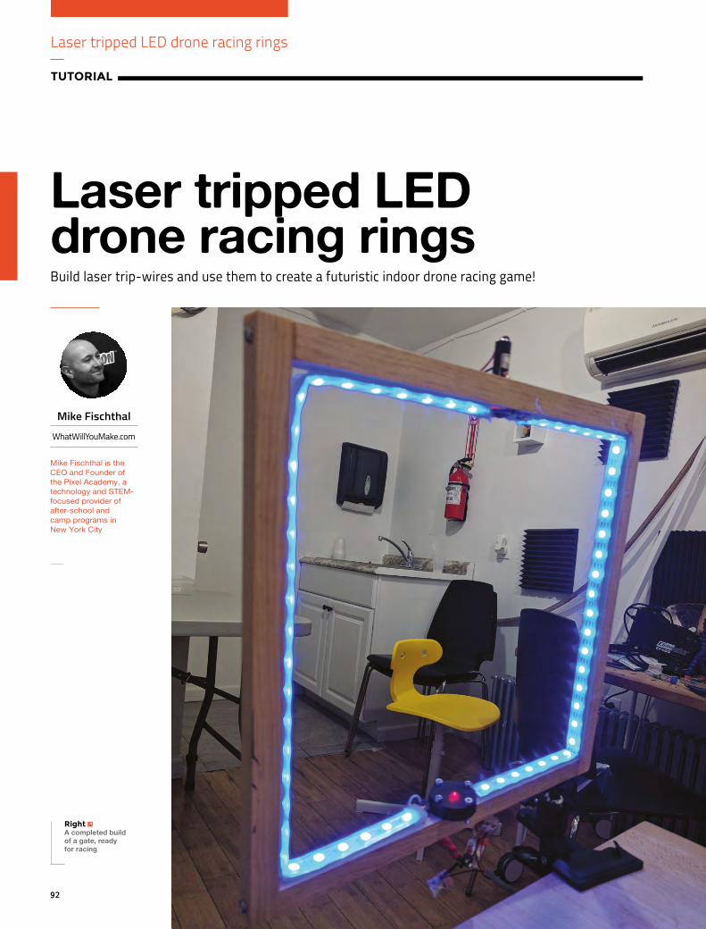
Laser tripped LED drone racing rings
TUTORIAL
92
Build laser trip-wires and use them to create a futuristic indoor drone racing game!
Laser tripped LED drone racing rings
Right A completed build of a gate, ready for racing
Mike Fischthal
WhatWillYouMake.com
Mike Fischthal is the CEO and Founder of the Pixel Academy, a technology and STEM-focused provider of after-school and camp programs in New York City

FORGE
93
n this tutorial we’ll make an Arduino powered laser ‘trip-wire’ that we can use to build an indoor drone racing game. The end product will be a series of glowing LED gates that can each detect when a drone flies through it (and breaks the laser beam). A gate
will light up and when the drone passes through, we will record the success and light up the next gate.
HERE’S HOW OUR PROJECT IS GOING TO WORK:
1. We’ll use an Arduino to tell a gate to light up its LEDs.
2. After a short (500 ms) delay that gives the LEDs time to reach full brightness, we'll measure the voltage produced by a tiny solar cell. This will be our baseline voltage that accounts for the ambient room light, the LED lights, and a red laser beam targeted at it.
3. The laser beam is the biggest single factor contributing to the solar cell’s voltage, so we can confidently record a beam break when the cell’s voltage drops a certain amount below the baseline.
4. An optional tilt sensor will be triggered if a drone hits the gate walls instead of passing cleanly through. Acting as a simple switch, the tilt switch, when triggered, will short the power line with the solar cell output and send a measurable voltage spike over the baseline.
5. When one of these conditions is met, we’ll send a signal to that gate to perform an animation or colour change.
6. Finally, a new gate is selected and the process repeats.
LET’S TAKE A LOOK AT THE INDIVIDUAL COMPONENTS OF OUR CIRCUIT:
1. The laser beam: needs 5 V power.
2. The solar cell: will need a reference ground line and a Vout line that the Arduino will measure.
3. A mechanical tilt sensor and resistor that we’ll splice between the 5 V power and the Vout.
4. The RGB LEDS: need 5 V power, GND, and an analogue data input to control the colours.
We can see from these components that we’ll need four seperate lines to each gate. The control box, which will house the Arduino, will therefore use four pins: 5 V, GND, Analog In (Ain), and PWM out (~Dout). The power and ground can be shared, but each gate will require a unique Ain and ~Dout.
Drone racing isn’t a tabletop game, so these gates are going to need to be far apart from each other and far from the control box. To avoid having to deal with four separate wires running along the floor, I decided to use a basic telephone cable, which conveniently has four wires bundled together. Phone cables are cheap, flexible, and come in many lengths.
Below is the code used to control the two gates. These addressable LEDs work with Adafruit’s NeoPixel library, which you can add to your Arduino IDE by going to Manage Libraries and searching for NeoPixel.
#include <Adafruit_NeoPixel.h> #include <math.h> #define LED_COUNT 60 //The number of total LEDs in each gate int currentRing = 0; // Tracks the active gate int numRings = 2; // The total number of gates int rings_output[] = 5,6; //Arduino pins that send data to the LEDs int rings_input[] = A0,A1; //Arduino pins that read the voltage from a gate's solar cell
I
Left Using phone wires has the added benefit of allowing for easy swapping of gates at the control box by using phone jacks as the connection point
YOU’LL NEED
Addressable RGB LED light strip (e.g. WS2812) sparkfun.com/products/12027
An Arduino and computer with Arduino IDE
4 × M3 30 mm screws hsmag.cc/dZEPCl
4 × M3 nuts hsmag.cc/qdbiyx
Square pine moulding (at least 6 ft / 1.8 m) hsmag.cc/NIWKwb
Red laser (1 per gate) ($6 ea) adafruit.com/product/1054
Miniature solar cell (1 per gate) ($1.50 ea) sparkfun.com/products/9541
Solid core colour wires
Drill, soldering iron and various common equipment
Wood glue and wood screws
Hot glue gun

Laser tripped LED drone racing rings
TUTORIAL
94
int sensorState = 0, lastState=0; int onlyShowActive = 1; float Vstart[] = 0.0,0.0; //Saves our baseline voltage recordings float margin_of_error = .05; // The threshold of voltage drop that triggers a 'hit' int firstTime = 1; Adafruit_NeoPixel led1 = Adafruit_NeoPixel(LED_COUNT, rings_output[0], NEO_GRB + NEO_KHZ800); Adafruit_NeoPixel led2 = Adafruit_NeoPixel(LED_COUNT, rings_output[1], NEO_GRB + NEO_KHZ800); Adafruit_NeoPixel gate_leds[2] = led1, led2 ; //Sets a specific gate to all of one color void setAllToColor(int gate, int r, int g, int b) for (int j=0; j<LED_COUNT; j++) gate_leds[gate].setPixelColor(j, gate_leds[gate].Color(r,g,b)); gate_leds[gate].show(); //Turns off all of the LEDs in a specific gate void clearLEDs(int j) setAllToColor(j, 0,0,0);
void setup() pinMode(5, OUTPUT); pinMode(A0, INPUT); pinMode(6, OUTPUT); pinMode(A1, INPUT); for (int i=0; i < 2; i++) gate_leds[i].begin(); //Call this to start up the LED strip. setAllToColor(i, 0,0,255); //Turns all gates on to make sure they are working gate_leds[i].show(); //The LEDs don't acrtually light up until you show() them delay(500); //Pause for LEDs to reach full brightness before taking the baseline reading //Sets the new baseline for a specific gate void resetVStart(int i) float voltage= analogRead(rings_input[i]) * (5.0 / 1023.0); Vstart[i] = voltage; void loop() if (firstTime) for (int i=0; i < numRings; i++) resetVStart(i);
DIGITAL AND PWM
In order to output an analogue signal, the Arduino uses a technique called pulse width modulation (abbreviated as PWM and indicated on the Arduino as a an asterisk or a tilde) that rapidly modulates the digital signal to fake an analogue output.
OPTIONAL
Mechanical tilt sensor (1 per gate) ($2 ea) hsmag.cc/XFgUHZ
Any resistor (1 per gate)
RJ11 Keystone Jack (1 per gate) ($0.67 each at Monoprice)
RJ11 25 foot phone cable (1 per gate) ($1.17 each at Monoprice)
Square clamp
¼ inch wood inserts (3 per gate) ($14.03 for 100) hsmag.cc/cemjoV
Below Here is the circuit diagram for two independent gates. Notice the laser (represented by a red LED) is spliced between the two LED strips. It’s important that the data line follow the Din line on the LED strips

FORGE
95
firstTime = 0; //if this is the first loop, record the baseline voltage for (int i=0; i < numRings; i++) float voltage= analogRead(rings_input[i]) * (5.0 / 1023.0); //Read the current voltage input from the sensor if (currentRing==i) //If this is the active ring check if the current reading indicates a beam break if (voltage < (Vstart[i] - margin_of_error)) //The beam is broken, flash green to indicate success setAllToColor(i, 0,255,0); gate_leds[i].show(); delay(250); setAllToColor(i, 0,0,0); gate_leds[i].show(); delay(250); setAllToColor(i, 0,255,0); gate_leds[i].show(); delay(250); setAllToColor(i, 0,0,0); gate_leds[i].show(); delay(250); setAllToColor(i, 0,255,0); gate_leds[i].show(); delay(250); setAllToColor(i, 0,0,0); gate_leds[i].show(); delay(250); gate_leds[i].show(); currentRing++; //Cycle to next gate in the series if (currentRing>=numRings) currentRing = 0; //If that was the last gate, start over setAllToColor(currentRing, 0,0,255); //Turn the new gate blue delay(500);
//Pause again before taking the new baseline reading else //If the beam is unbroken, keep the same color setAllToColor(i, 0,0,255); else //If the gate is not an active one, keep it OFF setAllToColor(i, 0,0,0); gate_leds[i].show(); //Show the LEDs
We want to ensure that the drone breaks the laser beam when passing through the gate, even if it doesn’t go through directly in the centre. So we’re going to make the inside width slightly smaller than double the width of the drone. Even a near miss of either wall will have part of the drone hitting the laser beam.
The drone I’m using is a regular indoor drone that cost under $100 and has a wingspan of about 7” (18 cm), which is about average. An interior width of 11” (28 cm) will ensure the drone hits the beam and will not make the gate too easy to fly through.
Using the wood moulding, cut two each of 11” (28 cm) and 12.25” (31 cm).
Above Once your beam is lined up, hot-glue it in place so it stays lined up
Below Why just glue something when you can 3D-print a custom holder?

Laser tripped LED drone racing rings
TUTORIAL
96
Use a right-angle clamp and wood glue to build the square. If you don’t have a right-angle clamp (you should get one), just be careful about alignment. If the top and bottom aren’t parallel, it will be a little trickier to get the laser and sensor to line up.
Once the glue dried, I used some wood screws to secure the joints. Knowing that drones may be flying full speed into the gates, I wanted to make them as strong as possible.
Now that we have our (hopefully) perfect square, we’re going to add the laser. Find the centre of one of the sides of the square and mark it. We’re going to make a small through-hole and a larger half-hole so the laser emitter doesn’t go completely through the wood, only the laser beam does. If we make the hole for the beam aperture ¼” (0.6 cm), that will allow us to still get to the focus adjustment (that slot on the front of the emitter) with a screwdriver. Drill the ¼” hole all the way through the wood, keeping the drill as vertical as possible. The laser emitter has a diameter of about 7/16” (1.1 cm), so we’re going to drill a hole slightly smaller than that and then sand the inside until the emitter fits perfectly. Use a locking collar on your bit
to drill about half-way through the wood, using the smaller hole as a pilot hole. If you don’t have a collar for your bit, mark the desired depth on it with tape and just go slow. Use a Dremel or any other sanding tool to slowly widen the hole until the laser emitter fits inside.
ALIGN THE LASERPower up your laser with any 5 V source and check the alignment. You want to hit as close to centre on the opposite side of the square as possible. If you’re way off the mark, you can widen the hole further to give your emitter more of an angle. Once the beam is where you want it, use hot glue to lock it in place.
Now we need to install the solar cell. Before you attach it to the gate, you should solder a couple of wires onto the leads. There is a small metal strip on one side of the solar cell that indicates the positive lead. The easiest thing to do now is line the solar cell up so it’s hit directly by the laser beam, create a little bed of hot glue, and hold the sensor perfectly in place until it cools and sets. You could do that, but
because the sensor is so small I decided to 3D-print a shell for it, and make some functional improvements. The shell has two holes in the centre for the solar cell’s leads to make soldering to them, and attaching to the wooden gate, much simpler. Instead
of stopping there, I also added an optional frosted diffusion dome that can fit on top of the sensor and a laser-cut red acrylic circle (also frosted) to filter the incoming light and make the solar cell less sensitive to other colours. While none of this is necessary, it does improve functionality and you can achieve similar results with hacked together solutions like wrapping it in red cellophane. All of the files for these parts are available at hsmag.cc/yAeCPQ.
You can test the trip-wire by connecting the laser to a 5 V power source and reading the voltage off the solar cell. I’ve been able to get a maximum of around 500 mV with the laser hitting even a portion of the solar cell. Using my hand to break the beam, I was able to see a drop to 180 mV from just the ambient light in my apartment. That’s the best-case scenario; once the LEDs are lit and shining around the gate, I’ve consistently seen a drop of at least 50 mV. If you avoid lighting the LEDs red, you’ll get a better result as well.
The last part of the sensor-system is the tilt switch. These mechanical switches have a little metal ball
Above Adding a diffuser allows more margin for misalignment of the laser, and adding red acrylic cuts down on the ambient light
RED LIGHT…
Why use a red laser? Although the solar cell we’re using has peak sensitivity at lower wavelengths (like red), blue and green lasers would have a more noticeable impact on the voltage change since they are much brighter. But that added brightness also makes them more dangerous for our eyes – even the scattered light off the solar cell can quickly become uncomfortable. You should never use a laser outside of the visible spectrum (like UV) because you won’t be able to see it and will be clueless while it burns out your retina.
DOESN'T SPELL DANGER
You can test the trip wire by connecting the laser
to a 5 V power source and reading the voltage off
the solar cell
”
”
When screwing together thin wood like this, you should always drill a pilot hole first to prevent splitting.
QUICK TIP

FORGE
97
inside and when it’s tilted, the ball rolls down to the contacts and closes the switch. Drill a hole and glue in your tilt switch and make sure that it is in the OFF state while the gate is vertical. You can even angle it down a little bit to prevent accidental triggers.
If you want, you can drill a few holes in the bottom of the gate and screw in some 1/4" (0.6 cm) inserts. That will let you easily attach each gate to any tripod or camera mount. We put one on each end and one in the centre to keep our options open.
ADD THE LEDSWe’re almost done with the gate; we just need to add the LEDs. These strips can be cut between any LED along the dotted lines. Run the perimeter of the gate starting at the sensor and cut the strip when you reach the laser aperture. Line up the strip on the other side of the laser and run the perimeter back down the other side. We made some very small cuts on the sides of the protective plastic at each corner to get a sharp bend. Be careful not to cut any of the electronics inside! Pay attention to the direction of the data in the LED strips. You want to make sure the data is always flowing in the same direction and you don’t accidentally line up two Din connections around the laser. Tape the LED strips until you’re done soldering all the wires. Once they’re hooked up, you should use hot glue to secure the strips in place.
All that’s left now is to follow the circuit diagram and solder everything together!
Make as many gates as you want (and can fit on the Arduino) to create a fun indoor drone racing course. There’s plenty of room to expand the game: try to make the gates count down to put time pressure on the player and change faster with each successful pass; add a score counter, and track fastest times; add speakers to play cool sound effects; put the gates
on servos to make them spin; or make a two-player race with gates that light different colours. We’ve also tinkered with making a laser maze that you have to snake through. In that scenario you want to see the beam, so you may want to upgrade to blue or green lasers. Throw in a fog machine or some spray haze and you’ve got a great party game.
Above Everything else you can connect directly to a stripped end of one of the phone cables
Above You can test the trip wire by connecting the laser to a 5 V power source and reading the voltage off of the solar cell with a multimeter
Left Have all of your wires exit the gate on the same side. You’ll want to bundle and hide them to prevent the drones from getting snagged

3D print on fabric
TUTORIAL
98
Take clothing design to a new level with 3D art
3D print on fabric
PART 1DESIGN The first step, as with all 3D printing, is obtaining a digital model of your 3D design. For this tutorial, we used Fusion 360 modelling software to write the text ‘Make it Yourself’, and extruded it to a height of 2 mm. We also used open source models from Thingiverse of a heart (hsmag.cc/hTxzNp), and spikes (hsmag.cc/ZDNHSp).
Whether you decide to make your own design or use an existing model, you will end up with an STL file that is now ready for slicing.
PART 2SLICESlicing your STL is the step where you tell the 3D printer exactly how you want to print the model. You will do this with slicing software such as Simplify3D,
Jen Botezat
Jen is a technology and DIY enthusiast with a passion for making. She is excited about the use of 3D printing, because it propels so many new ideas in art, science, renewable energy, and medicine.
@neurojenerator
YOU’LL NEED
Fabric for testing
Item of clothing to decorate
8 bulldog clips (available in office supply shops)
3D Printer or access to one
3D printing filament (we recommend you start with PLA)
D printing is becoming ubiquitous – it’s being used for everything from building houses to chocolate creations to the next generation of space rockets.
But in fashion especially, 3D printing has given unprecedented freedom to
create and experiment with new shapes, materials, and ideas. The creativity spurt from fashion designers has inspired us to try applying 3D printing to our own clothing. Directly onto clothing that is.
Printing directly onto fabric is perhaps the fastest way to get your 3D design onto clothing, but it requires some best practices to avoid damaging your fabric.
Here, we show you our safe method to print directly onto a garment of your choice using a standard desktop 3D printer – so get your fabrics ready, and let’s get started!
3
Right Decorate your clothes in a new way by 3D printing directly onto fabric

99
FORGE
can involve some trial and error. Once you have set the settings, export the sliced file as gcode, which will be read by your 3D printer.
PART 3PREPARE THE PRINTER (IMPORTANT!)The trick to 3D printing directly onto fabric is preparing your 3D printer for the task. Everything depends on the nozzle of the printer being just the right height above the fabric. Too close, and it will scratch the fabric; too far, and it won’t lay down the first layer (and all following layers!) properly, resulting in a tangled mess and residue on your fabric.
Fabrics have some thickness, which will change based on the type of fabric, and throw off your printer’s calibration. So, here is our general method for getting your model to print safely onto any fabric.
Step 1: Safety offset! Before you do anything with the fabric, first and foremost, adjust the offset on your printer. Think of it like this: typically, your printer is ‘zeroed’ at the point where the tip of the nozzle just about touches the print bed. If your thick fabric were on the print bed at this point, the nozzle would come down and press into it, likely damaging the fabric with a hole. So firstly, we will lower the offset (‘the zero point’)
which we used to slice the models prior to printing on our Witbox 2 printer.
Tuning the slicer settings for your specific printer model can be a fine art. We used these settings for printing PLA onto fabric: nozzle temperature of 200, layer height of 200 microns, 50 mm/sec print speed, 2 mm retraction (extruder specific).
Most slicing software will require you to enter these settings, but you may have to fine-tune them slightly if you are using a different 3D printer. This
TOOLS
One sheet of regular A4 copy paper
3D Slicing software (such as Simplify3D)
3D modelling software (such as Fusion 360, to make your own designs)
FASHION DESIGNERS 3D
• Order a custom 3D-printed jacket by Danit Peleg. Globally known for her graduate work on fully 3D-printed outfits, Danit now has a customiser where you can create and order your own jacket. Find it here: hsmag.cc/ApDxBG
• Designers like XYZBag 3D print unique bags, as designed by you: xyzbag.com
• Adidas launched their custom shoe Futurecraft 4D, with a 3D-printed sole made of liquid resin material, which they plan to mass customise and mass produce.
PRINT EVERYTHING,SO CAN YOU!
Above These edgy spikes could easily be used for cosplay. The printer had no trouble printing high 3D shapes directly onto fabric
Left We attached the fabric securely with clips on all sides. It must be as taut as possible

3D print on fabric
TUTORIAL
100
by around three times the thickness of your fabric. This increases the distance between the print bed and the nozzle. We chose to lower the offset to -3 mm for all our prints, which we like to call ‘the safety offset’.
Most modern firmware will allow you to change the offset on your 3D printer. If you have old firmware on your machine with no offset capability, we wouldn’t recommend printing directly on fabric. Make sure you update your firmware first!
Step 2: Position fabricNow that you’ve set your safety offset, place your fabric on the print bed.
Always test on some scrap fabric before you attempt to print on your favourite clothing. We placed the fabric evenly on the print bed, and attached it
around the perimeter with several bulldog clips. Pull the fabric as taut as possible on all sides, to prevent it from sliding around on the print bed. Make sure the clips won’t be in the way of your extruder as it travels to the start point.
Position the fabric so that the excess hangs to the most unused part of your printer — away from the extruder and any moving rods.
With a Witbox, the nozzle moves in relation
to the print bed, whereas with other printers, the print bed will move in relation to the nozzle. This latter mechanism wouldn’t be ideal for printing on fabric because the excess fabric would get dragged around and likely get caught in the printer’s mechanism.
Step 3: Tune the offsetNow, with your fabric securely on the print bed, we need to fine-tune the offset again to make sure the
Most modern firmware will allow you to change the
offset on your 3D printer”
”
OTHER WAYS TO ATTACH
• In the 3D slicer settings, add a ‘skirt’ to your design, which is basically an outline around your model, several shells thick, that will adhere to the fabric (as in the photo with the spikes). You can then sew through this skirt with a needle and thread, which will permanently attach the print.
• Print the text letters or design you need directly onto the print bed as you would normally (not onto fabric), and then attach them to the fabric with thread, as you would attach an embellishment.
3D PRINTS TO FABRIC
RESULTS WITH DIFFERENT FABRICSFor this tutorial, we experimented with cotton, satin, denim, and linen. They had slightly different properties, but all produced wearable prints. We even threw them in the wash, inside out, and surprisingly, the smaller parts stayed on (although the large spike didn’t).
Fabric Warping Attachment Tidiness of 1st layer
Cotton Med Good Yes
Satin Low Very Good No
Denim Med Poor Yes
Linen Low Good Yes
Above Testing out the satin, moments before the clip snapped!
Below You can usually find the ‘Adjust offset’ feature in your 3D printer’s settings

101
FORGE
nozzle is perfectly positioned above the fabric for the best 3D printing.
Because you have done a safety offset in Step 1, the distance between the tip of the nozzle and your fabric should be quite large. Now, we are going to gradually reduce this distance by upping the offset. This should bring the tip of the nozzle and print bed closer together. How far up you go will all depend on the thickness of your fabric, (eg denim vs satin).
How do you tell when the distance is perfect? Wedge a regular A4 sheet of copy paper between the nozzle and the fabric as you keep upping the offset. Move the paper back and forth until you start to feel some serious resistance, but you can still move the paper back and forth. This step is more of an art than a science, but some experimentation will give you a good feel for it.
Once you have adjusted the offset to perfection, you will also need to level the print bed. This ensures that the distance between the tip of the nozzle and the print bed is the same on all parts of the bed, which results in an evenly stuck-on print.
The printer we used had auto-levelling by means of an inductive sensor, so it performed the bed-levelling automatically after we set the offset. If your printer comes with auto-levelling, definitely use it at this point.
If it doesn’t auto-level, you can manually level the print bed now using the same copy paper method, but moving the nozzle to different parts of the print bed (ideally, 4–5 points).
Below Early prep for Valentine’s day. The filament lays down neatly once the settings are right
TAKE IT FURTHER• Want more flexible prints? It’s possible. You can print with flexible 3D filaments, like
Ninjaflex or Semiflex, in pretty much the same way as you would print with PLA. Check out this project by Becky Stern to design your own custom cap with flexible filament and sewing: hsmag.cc/CxgCGg
• Several makers have designed their own 3D-printable fabrics, made from tiny interlocking pieces you can print in one go on the print bed. Often, they open-source their designs. Check out designs by Devin Montes here: hsmag.cc/LCjsKp
• 3D print some custom buttons! You can design and 3D print buttons in rigid or hard plastics and attach them to your clothing (We recently printed some banana-themed buttons for a quirky custom shirt).
PART 4PRINT! Wow, so many settings, but we promise it’s worth it. Now it’s time for the fun part. Print!
With your gcode ready, you can now pass it on to the printer and start seeing your 3D design emerge on the fabric, as if by science.
You can print with any standard PLA filament. We printed our designs with 1.75mm PLA filament in white and black, but you can go mad.
The prints do come off the fabric (cleanly!) if you pull them hard enough, so we see this as a one-time decoration method that you can peel off and change for a different one after a few wears.
This is just the beginning of our experiments, and we are constantly learning. Do you have tips or tricks to share? Get in touch!
This tutorial is the result of our collaboration with Josef Dunne at Champion 3D, who consulted us on best practices for 3D printing and helped make these 3D prints possible on fabric (champion3d.com).
Above Sprucing up an old pair of jeans!

102
TUTORIAL
Get to know your oscilloscope
The oscilloscope is probably the most useful and versatile electronic instrument that you can have on your bench, but its many functions can be a daunting prospect
Get to know your oscilloscope
The oscilloscope is most simply described as an instrument for displaying voltages and waveforms as they change over time. An oscilloscope screen can be thought of as a piece of graph paper upon which a
graph is drawn of input voltage on the X axis versus time on the Y axis. The scale of each axis is under the user’s control, with a pair of selectors to set the number of volts per vertical square on the screen, and the number of seconds per horizontal square, referred to as the timebase. Voltages and time intervals can thus be easily measured by counting squares between intervals on the screen, and even though the squares may not be exactly a centimetre in size you will hear them referred to as centimetres. A typical oscilloscope will have a voltage resolution from a fraction of a millivolt to tens of volts per centimetre, and a time resolution from a fraction of a microsecond to a few seconds per centimetre,
Above A typical CRT oscilloscope screen showing a triangle wave. Voltage is in the vertical axis, and time in the horizontal
PROBES
The input to an oscilloscope is designed to have a high bandwidth: it can accept many frequencies. Physically it will almost always take the form of a BNC socket, into which a coaxial cable can be plugged to feed in whatever signal is to be displayed. You can connect up a lead from a source such as a signal generator and display the waveform, but sometimes you will see distortion on the screen. Waveforms that should be square become rounded, and the instrument does not give a correct picture.
This distortion is due to the capacitance of the cable having a different effect on the different frequencies passing through it, and it must be compensated for before the waveforms displayed can be trusted. The essential companion to an oscilloscope is therefore a dedicated oscilloscope probe containing the required circuitry for this compensation. Oscilloscopes have a calibrated square wave source to which a probe can be connected, and probes have a small variable capacitor which can be adjusted with a screwdriver until the displayed waveform is perfectly square. Many probes will also include an attenuator which reduces the signal level by 10, having the effect of increasing the voltage range of the instrument by a factor of 10.
Above Two identical waveforms; the top one is displayed through a correctly adjusted probe, while the probe carrying the bottom one needs some attention
Jenny List
@Jenny_Alto
Jenny is the creator of the @LanguageSpy electronics kits for Raspberry Pi and ham radio. She’s also a key member of Oxford Hackspace.

103
FORGE
allowing a wide range of voltages and frequencies to be measured.
An oscilloscope will attempt to display any voltage or waveform presented to its input, but is at its most useful when showing cyclical waveforms in which the same pattern is repeated continuously. It works by triggering the start of the waveform it displays at
the left-hand side of the screen from the same point in every cycle, such that successive cycles of the waveform simply overlay each other on the screen and appear as a single one. This triggering is governed by a trigger control, which sets a particular voltage point that the waveform passes through as where the leftmost part of the display will be placed. There will be an option to set this either on a falling or a rising voltage, allowing the user to line up a particular point of interest on the screen.
We’ve described a basic oscilloscope that is able to display a single waveform, but a typical real instrument will have the ability to display two or even four waveforms at once. These so-called dual-trace models have one timebase for all channels, but separate voltage selectors and inputs for all. Modern oscilloscopes are often computerised instruments with many once-unimaginable features governed by software, but a traditional oscilloscope is an analogue device with a CRT screen. Both are
Above Two traces on a four-channel digital oscilloscope. The top trace is a sine wave; the bottom one is a complex waveform
FINDING AN OSCILLOSCOPEWhen looking for an oscilloscope, it seems that there is an almost infinite array of choices at prices to suit all budgets. Indeed, there seems to be no upper limit to the price of a new oscilloscope; there are specialist models for use with extremely high frequencies that come with six- and even seven-figure price tags. Fortunately, these are the exception rather than the norm, and there are plenty of options for the oscilloscope user on a budget.
When considering a purchase, there are several factors to consider:
• Bandwidth. Quoted in MHz, the maximum frequency you’d expect to use it with.
• Number of channels. The majority of oscilloscopes have two, but you will find models with more, and even also one or two single-channel instruments.
• Digital or analogue? Analogue oscilloscopes use CRT displays, and may be quite bulky. They are, however, simple to use and can be very cheap to buy. Digital models, especially the newer ones, often have LCD displays, are quite compact, and have a lot of features in their software. They are often more expensive, though.
• New or second-hand? After decades of oscilloscope production, there are huge numbers of second-hand instruments to be had, often for very little money indeed. It’s worth asking around your hackspace or other community: someone may have an old CRT oscilloscope they are willing to pass on to you. However, an older instrument may lack the features of a new model and, if you have the resources, a wise purchase can provide many years of service.
Below A large pile of second-hand test equipment for sale at the legendary Black Hole Surplus, Los Alamos. Jeff Keyzer (CC BY-SA 2.0)
A basic oscilloscope can display a single waveform,
but a typical real instrument will display two or even four
waveforms at once
”
”

TUTORIAL
104
you would see the flat horizontal line move upwards by an amount equivalent to its voltage. So for example if the voltage selector is set to 1 volt per centimetre and a 9 V battery is connected, its voltage can be measured through the 9 cm by which the line moves up the screen.
The same voltage measurement can be performed on waveforms. For instance, should you wish to measure the peak-to-peak voltage of a sine wave, you need simply count the squares between the lower edge of the trace and its upper edge. Modern computerised oscilloscopes will often calculate this and other useful figures automatically, but even if you are lucky enough to have one it is still worth knowing how to take measurements without it.
FREQUENCY AND PERIODTime periods on an oscilloscope are displayed as distance across the screen from left to right and, just as with a voltage, you can measure a time by measuring the distance between two points on the screen and applying the relevant scale to which the timebase is set.
You can measure the period of a waveform by taking the distance between two adjacent identical points upon it. So, for example, if the measurement is 5 centimetres at 200 microseconds per centimetre then the period is 1 millisecond.
The relationship between period and frequency is as follows: Frequency(Hz) = 1/Period(S). Therefore once you have a reading for the period, it is easy to calculate the frequency. In our example above, 1 millisecond is 0.001 seconds, so the frequency in Hz is 1/0.001, 1000 Hz, or 1 kHz. The probe calibration terminal mentioned above is a 1 kHz square wave on most oscilloscopes, so you can measure this for yourself with relative ease.
If your oscilloscope has more than one trace, it can be used for measurements involving the comparison of more than one waveform. In digital circuits using a clock, for example, a data line on one trace can be compared with its clock on the other trace to spot timing issues; or in an analogue circuit, the phase difference between two waveforms can be measured by calculating the time difference between them. If you work with video it can be especially useful to have multiple channels, as one can be triggered by the video synchronisation pulses, keeping the others in sync with them for monitoring video waveforms.
The basic functions we have described so far are common to all oscilloscopes, whether digital or
extremely useful to have on your bench, and for the purposes of this piece we have ensured that we use both types in our examples.
VOLTAGEVoltages on an oscilloscope are displayed as vertical distances on the screen. If you were to connect a DC source such as a battery to your oscilloscope,
Get To Know Your Oscilloscope
The DS1054Z is a four-channel 50 MHz digital storage oscilloscope, from the Chinese manufacturer Rigol, that has become something of a standard in the hobby and professional electronic worlds alike. It has the full range of features you would expect from a modern instrument, as well as a network interface, a USB interface for a computer, and another USB socket on its front for a disk drive. It has emerged as the leader of a crop of superficially similar models from Chinese manufacturers, and is known for being a quality addition to any bench. It is also
known for an unauthorised software hack that unlocks some hidden features, including allowing access to the full capabilities of its chipset and turning it from a 50 MHz oscilloscope into a 100 MHz one. Including UK taxes it costs somewhere over £300 so it is hardly an inexpensive purchase, but it provides some of the things you might expect from one costing much more.
A TYPICAL MODERN BENCH OSCILLOSCOPE: THE RIGOL DS1054Z
Below The Rigol DS1054Z four-channel digital storage oscilloscope Dave Jones/EEVBlog (CC BY 2.0)
If you were to connect a battery to your oscilloscope, you would see the flat horizontal line move
upwards by an amount equivalent to its voltage” ”

105
FORGE
analogue. We have mentioned some of the extra functions a digital instrument may have, such as automatic calculation of voltages or period, but the signature feature of a digital oscilloscope is something beyond the capabilities of its analogue cousins. Because it is at heart a computer, it can store its waveforms in memory for capture and closer examination. It can therefore catch one-off events such as a transient spike from a switching
event, making it an even more powerful instrument than you might at first imagine.
We have given you a relatively brief introduction to the oscilloscope in these pages, but of course paper is not the ideal medium for this particular task. The best way to understand one of these instruments is to have one on your bench and put it through its paces, so if you do not possess one we’d like to encourage you to take the plunge. Good luck!
IS IT A TOY OR AN OSCILLOSCOPE? THE JYE TECH DSO 15001 OSCILLOSCOPE KIT
A TYPICAL ANALOGUE BENCH OSCILLOSCOPE: THE HITACHI V-212The Hitachi dual-scan oscilloscope used for the purposes of this article was borrowed from the folks at MK Makerspace, and is typical of similar models of its age from multiple manufacturers. It is a 20 MHz instrument manufactured somewhere over two decades ago, and is a very solid and reliable oscilloscope that remains accurate and easy to use. It does not have any of the frills you might expect from
a digital model, but it will serve its owners well for many more years. The best thing about the Hitachi, though, was its price: it was bought for £5 at a radio rally, from a vendor who had acquired a significant number of them on the surplus market. If you do not want the latest and greatest in an oscilloscope then this one shows that there are some serious bargains to be found for those prepared to seek them out.
Above The Hitachi is typical of many dual-scan oscilloscopes from the 1970s to the 1990s
If you take a look on an electronics vendor website that sources its components
from China, you will find a variety of oscilloscope soldering kits among
the component testers and Arduino clones. They take the form of a fast
microcontroller with an analogue input and an LCD screen, along
with an input conditioning circuit. Some of them are
bare PCB kits while others have laser-cut
enclosures bundled, and still more have
snap-together plastic cases.
The JYE Tech DSO 15001 is typical among the final group and, after a bit of soldering and assembly, makes a smart little handheld unit.
It requires a separate 9 volt power supply to operate, it only has a meagre 200 kHz bandwidth, and its input voltage range is not as wide as any bench instrument. But it has a perfectly acceptable software interface, it’s small enough to hold in your hand, and it cost just under £15 by mail order.
You might be tempted by one of these kits, and should you build one you will find it to be perfectly usable within its specification. It’s fair to say, though, that a second-hand CRT instrument will give you a huge performance boost for a similar investment. There are two places in which this kit can shine, though; in the first instance, it’s a pocket-sized unit that can be taken almost anywhere that there is a need for a low-bandwidth oscilloscope. In the second instance, it’s also a soldering kit that anyone with moderate soldering ability should be able to assemble. So if you have a teenage electronics enthusiast in your life, it might make an excellent project and a first oscilloscope for them.
Left The JYE kit oscilloscope is tiny, but limited in functionality

Make an infrared rangefinder with ESP8266
TUTORIAL
106
Learn to use I2C to add hardware to your microcontrollers
Make an infrared rangefinder with ESP8266
ost robotics projects need to measure distance for navigation, but distance measurement is also necessary for other projects such as camera focusing and surface level determination. In
this project an infrared laser rangefinder is used to measure target distance, with the results shown on an OLED display. The rangefinder and the OLED display are available budget-priced, as adapter boards, only requiring I2C signals and power. The heart of the device is a NodeMCU embedded-computer board, using the ESP8266 processor.
The VL53L0X infrared laser rangefinder is more accurate and has a much smaller sensing element than the popular ultrasonic rangefinder, the HR-SC04,
and is almost as cheap. The ESP8266 is a very useful
processor and this project provides a practical introduction to using it. The NodeMCU board is a great board to start with, as
it has all the ancillary components and a USB interface to allow it to be programmed straight out of the box. The same
code and interface wiring can be used in a final project based
on a raw ESP12E, for even lower cost and power consumption.
ASSEMBLING THE HARDWARE
The black and white 0.96”, 128 × 64 pixel, OLED display has graphics and text
capability. It connects to the host processor via the I2C interface. Modules are available,
ready to plug into a breadboard.The IR rangefinder VL53L0X sensor module,
from ST Microelectronics, is tiny, but several suppliers provide breakout boards. It has a range of
1.5 metres, runs off 3.3 V and, like the OLED module, connects via an I2C interface. The XSHUT terminal can be used to put this module into low-power mode, when measurements are not being taken.
The same I2C interface can be used for both modules, minimising the GPIOs used, as they have different addresses, 0x52 for the IR rangefinder and 0x3C for the OLED display.
The NodeMCU board is almost too wide for a standard breadboard, but can easily be mounted on two mini-breadboards to allow connection to the modules, as shown in the photograph and Figure 1 diagram.
The two modules are connected to the NodeMCU via the I2C interface. To use this interface, connect the two signal lines, SDA and CLK, power lines and let the ESP8266 version of the wire.h library in the Arduino IDE handle all the details.
The ESP8266 can be set up to use almost any pair of GPIO pins to form an I2C bus. Here D3(GPIO0) is used as the SDA line and D2(GPIO2) as the SCL line, as these lines already have pull-up resistors fitted on the NodeMCU.
CONNECTING EVERYTHING TOGETHERAll three modules are plugged into a breadboard and wired up with links, as shown in Figure 1.
The NodeMCU already has pull-up resistors on D3(GPIO0) and D2(GPIO2), so only wire links to the OLED and IR rangefinder modules are required. The XSHUT connection on the IR rangefinder module is also shown connected to D5(GPIO14).
The NodeMCU provides the power for the display and sensor modules via the +3.3 V connections, enabling the whole circuit to be powered from the PC over the USB or a USB battery pack.
SETTING UP THE ARDUINO IDE FOR USE WITH ESP8266 BOARDSThe simplest way to program ESP8266 boards is via the Arduino IDE. The core Arduino IDE package must
MBill Grainger
Bill Grainger is a physicist and design engineer who loves coding and having computers interact with the real world. He works with wind energy on all scales and enjoys running, sea kayaking, and mountaineering.
Below VL53LOX IR laser rangefinder on breakout board

107
FORGE
be extended with a Board Manager to work with the ESP8266. Many hackers will have experience of the Arduino IDE in other projects. Many sketches and libraries developed for the Arduino series of computers can be used on the ESP8266 – a huge advantage, given the wealth of Arduino applications.
The Arduino IDE runs on PCs using the Linux, Windows, and macOS operating systems. Go the Arduino site arduino.cc and download the appropriate version for your computer.
To set up the Arduino IDE for ESP8266 boards, follow the straightforward instructions at hsmag.cc/AmcDAQ.
Once this is complete, select the correct board in the IDE by using Tools / Board and choosing NodeMCU 1.0.
The two libraries are needed for this project – SSD1306.h for the OLED and VL53L0X.h for the IR rangefinder.
The first must be downloaded from GitHub athsmag.cc/xGrpjJ.
1. On the webpage, select Clone or download, then Download .ZIP.
2. Note where the .ZIP file is downloaded.3. In the Arduino IDE, use the feature at Sketch
> Include Library > Add .ZIP library to install it.
The second library can be directly loaded in the Arduino IDE using:
1. In the Arduino IDE, select Sketch > Include Library > Manage Libraries.
2. This will display a new window. The IDE
will contact a server to update a reasonably comprehensive list of libraries available. Once this has finished, type VL53L0X in the filter box to find library for this project, the VL53L0X library from Pololu.
3. Click More Info, select the latest version, and then Install.
LOOKING SKETCHYThe sketch, IOT-IRdistance.ino, is available to download from the GitHub repository at hsmag.cc/dtJPRT.
In this sketch, libraries used are included first.
#include “SSD1306.h” // library for display #include <Wire.h> // I2C library #include <VL53L0X.h> // laser rangefinder library
The I2C connections used are detailed.
//I2C connections #define SDA 0 //GPIO0 / D3 #define SCL 2 //GPIO2 / D4
Above There are loads of add-ons available to give more capabilities to the basic Arduino IDE
Boards based on the ESP8266 are not only very cheap, but have the essentials for an Internet of Things project:
• General Purpose Input / Output pins• Integrated WiFi with TCP/IP stack• EEPROM for program storage• Low-power mode • I2C and SPI interfaces • Programmed via the Arduino IDE
The ESP01 is a basic board with few GPIOs, and no direct access to the low-power mode. The ESP12E board is easier to use, has more GPIOs, an analogue input, and low-power mode. The NodeMCU V1.0 board adds to the ESP12E all the necessary external components and a micro-USB interface for direct connection to a PC for programming, making it ideal for a first project.
ESP8266 BOARDS
YOU’LL NEED
NodeMCU v.1.0
VL53L0X sensor module
0.96”, 128 × 64 pixel, OLED display
Two mini breadboards

Make an infrared rangefinder with ESP8266
TUTORIAL
108
The IR rangefinder instances and functions are set out. A function to switch the sensor between low power mode is included using D5/GPIO14. The GPIO is set to an output using the pinMode instruction and the output set with the digitalWrite instruction. Debug information is sent to the serial monitor in the Arduino IDE (Tools > Serial Monitor) using Serial.print and Serial.println instructions.
VL53L0X sensor; #define maxDistance 2000 #define sensorXSHUT 14 const boolean ON = HIGH; const boolean OFF = LOW; void switchLaserRangefinder(boolean state) pinMode(sensorXSHUT, OUTPUT); digitalWrite(sensorXSHUT, state); if (state == ON) Serial.println(“Laser Rangefinder powered up”); else Serial.println(“Laser Rangefinder powered down”); delay(300);
Setting up the IR rangefinder is performed in a separate function to keep the main setup function uncluttered. The sensor is switched on, initialised and various parameters set. Further details of the instructions to set up the IR rangefinder are given in the VL53L0X datasheet and in the examples which come with the Pololu library.
void setupLaserRangefinder() switchLaserRangefinder(ON); sensor.init();
sensor.setTimeout(500); // lower the return signal rate limit (default is 0.25 MCPS) sensor.setSignalRateLimit(0.1); // increase laser pulse periods (defaults are 14 and 10 PCLKs) sensor.setVcselPulsePeriod(VL53L0X:: VcselPeriodPreRange, 18); sensor.setVcselPulsePeriod(VL53L0X:: VcselPeriodFinalRange, 14); // increase timing budget to 200 ms sensor.setMeasurementTimingBudget(200000); Serial.println(“Laser range finder configured”);
Now attention is given to the OLED display. Again, it is set up in its own function for clarity.
#define I2Caddress 0x3c SSD1306 display(I2Caddress, SDA, SCL); void setupOLEDdisplay() display.init(); display.flipScreenVertically(); display.setFont(ArialMT_Plain_10);
The main setup function is streamlined with the use of the two module-specific setup functions. The Serial Monitor communications are also initialised.
void setup() Serial.begin(115200); Serial.println(); Serial.println(“Starting”); delay(20); Wire.begin(SDA, SCL); setupLaserRangefinder(); delay(200); setupOLEDdisplay();
The OLED display has many graphics capabilities, and these are available in the SSD1306 library. Only a few are demonstrated here. First of all, a function is declared to draw a bar display using the draw rectangle, fill rectangle and draw string methods. The length of the bar to be filled in is calculated each time the function is called, depending on the current distance reading in variable value. A full bar of width, width, corresponds to the maxdistance, set out earlier. The calculated length is first found as a real value, Posreal, e.g. 43.2 pixels, and then changed to an integer value, Posint, like 43, as the methods drawing the image require integer arguments.
int width=80;
The VL53L0X infrared laser rangefinder is more accurate and has a much smaller sensing element than the popular ultrasonic rangefinder, the HR‑SC04, and is almost as cheap
””
Figure 1 Keeping the different modules on different breadboards is a little cumbersome, but does make it easy to keep different bits of the circuit separate

109
FORGE
int height=20; void drawBar(int x, int y, int w, int h, int value) float posReal; //needed to calculate the width of the bar to fill int posInt; // converts the real width to an integer one display.drawRect(x, y, w, h); // draw the outline box posReal= 1.0*value*width/maxDistance; posInt=posReal; display.fillRect(x, y, posInt, h); display.drawString(x+w+2,y,String(value));
The main control loop takes readings every 0.5 seconds from the sensor using the instruction sensor.readRangeSingleMillimeters and shows these on the display, with drawbar, and on the Serial Monitor with Serial.print.
The axes on the display are as follows: x goes from 0 – 127 pixels, left to right y goes from 0 – 63 pixels, top to bottom.All drawing instructions use this convention. The
image is assembled in memory first and then the information copied in one move to the display using the instruction display.display. A do while loop is used to trap any error codes returned and only display valid readings.
void loop() display.clear(); display.drawString(0,0,”ESP Laser Rangefinder”); display.drawString(0,18, “Distance in mm”); do reading = sensor.readRangeSingleMillimeters(); while (reading > 5000); Serial.print(“Reading / mm - “); Serial.println(reading); if (sensor.timeoutOccurred()) Serial.print(“ TIMEOUT”); drawBar(0,34,width,height,reading); display.display(); delay(500);
This project demonstrates how to use three commonly available modules, which can be used in many devices. In the photograph, the VL53L0X IR rangefinder is at the top, the ESP8266 based NodeMCU board is in the middle and the small OLED display at the bottom. The sensor module can be mounted on flying leads for more flexibility, but these should be kept to less than 30 cm in length to preserve the correct operation of the I2C interface.
The I2C serial interface has a data line, SDA, a clock line (CLK) for timing, and a GND line for voltage reference. One device on the bus is the Master, usually the host processor, and the other devices connected are Slaves, each with their own address. Data is sent in a standard format, which contains the address of the Slave and the data being transmitted. The SDA line is bi-directional, as it can carry messages from the Master to a Slave and messages from a Slave to the Master. The CLK line is controlled by the Master only. The SDA and SCL lines must be pulled up to a positive supply line with resistors.
WIRING UP I2C
SCL
SDA
GND
VCC
Pull-up resistors
Master
Slave 1 Slave 1 Slave 1
Many devices can be connected to the same I2C bus provided they have different addresses
Left Our final build. Now find those xenomorphs!

with an annual subscription
SAVE25%
Out now for smartphones & tabletsDownload the app
or£2.29 rolling subscription
£26.99 subscribe for a year

SUBSCRIPTION
111
Includes Pi Zero W computer
Official case with three covers
USB and HDMI adapters
8GB microSD card
116-page beginner’s book
LEARN COMPUTING THE EASY WAY!
Buy online: store.rpipress.cc

Orientation With Sense HAT
TUTORIAL
112
THE Official
PROJECTS BOOKAmazing hacking & making projects
from the creators of
magazine
Inside: How to get started coding on Raspberry Pi
The most inspirational community projects
Essential tutorials, guides, and ideas
Expert reviews and buying advice
plus all good newsagents and:
store.rpipress.cc
200 pages of Raspberry Pi
£12.99
RASPBERRY PI

FIELD TESTHACK MAKE BUILD CREATEHacker gear poked, prodded, taken apart, and investigated
Get out your soldering irons: it’s time to fully customise your input
114PG
DIRECT FROM SHENZHEN:
MECHANICAL KEYBOARD
BEST OFBREED
PG116
Four of the best vector design programs for your next laser-cutting project
tested and rated
The Nerf Stryfe gun is ripe for modification – let’s take a look inside
120PG
CAN I HACK IT?
REVIEWS Squix ESPaper
Plus Kit
Leatherman Surge
SparkFun Inventors Kit
ElectroSmash Pedal Pi
Coinkite Opendime
Much Ado About Almost Nothing
122 126
123 128
124 129

REGULAR
Direct From Shenzen
s humble magazine journalists, we spend much of our day in front of a computer banging away at little switches. The keyboard is the tool with we physically interact most frequently with by a large margin,
and so it’s important to us to get it feeling great under our hands. This is important for far more than the simple pleasure of a good clack – repetitive strain injury (RSI) is a significant risk for anyone who regularly uses a computer, and having a properly set up keyboard goes a long way to alleviating the problem.
At a basic level, keyboards aren’t complex things. They’re just a lot of switches arranged nicely, with a
Right The finished keyboard with a few caps removed to show the stainless steel backing plate and the PCB
DIRECT FROMSHENZHEN
A
Hacking your way to superior computer input
Mechanical keyboard kit
114
By Ben Everard ben_everard
microcontroller to convert these switch presses into USB commands.
Most keyboard PCBs are designed to have surface-mounted components for the microcontroller and associated bits, and through-hole keys. We opted for a kit that already had the surface-mount components soldered on and just the switches to add. This makes it easier to assemble, but still gives you control over the choice of keys.
Picking the switches is where things get interesting. It’s easiest opt for a keyboard that takes Cherry MX style switches (usually the three-pin variety). There are a few manufacturers that make switches that fit these, but the most common are Cherry and Gateron. Both manufacturers produce keys with a range of

115
different feels. The different profiles are identified by colour (the same colour does not mean the same thing across manufacturers).
The classic Cherry Red switches compress linearly until they bottom out, while others such as the Cherry black have a defined clack; there they compress up to a point you push through, and they pop to the limit. There’s a wide range between these and it’s entirely a matter of preference which you prefer (you can get small keyboards with a range of different key types on to test them out such as this one: hsmag.cc/kyKWqR).
A second option that affects the press of a switch is the addition of a rubber ‘O’ ring. This adds a very subtle cushioning to the bottom of the key press. You can add these to any type of Cherry or Gateron switch.
There are a few keyboard sizes available. The most common is the 60% size, which is about comparable with most laptops. The keys are the same size as a full keyboard, but there aren’t as many of them, and this size lacks function and arrow keys. These PCBs are available from a wide variety of sellers of direct-from-China websites, and the biggest difference is usually the bits you get with the PCB. Some places just sell the PCB; some bundle it with all the bits you need to make a working keyboard. We got a complete kit with PCB, steel backing plate, and switches (but no key caps).
All the parts arrived, but no instructions. We probably should have spent a little more time than
we did looking into how to assemble a keyboard, but with hubris we set about soldering the switches into the PCB. About half way through, we discovered that you have to put the switches into the stainless steel backing plate before soldering them into the PCB. A bit of impromptu desoldering practice later, we started again. The correct order for assembling the keyboard is:
• Push keys into steel backing plate
• Make sure they’re in the right place for the key caps you want to use
• Add joiners for the longer keys (e.g. space bar) if you’re using them
• Solder the keys into the board
These kits are set up so that you can use a variety of different key layouts by soldering into different places, so be sure that you’ve pushed your keys in to the correct place in the backing plate.
Provided you do everything in the correct order, keyboards are fairly straightforward to assemble. There’s quite a lot of soldering, but it’s all through-hole and the backing plate holds the components in place so there’s no fiddling about once you’re going.
Once we’d assembled our keyboard, we found that one key wasn’t working. On inspection, it turned out that there was a diode missing (there’s one surface-mount diode per key). It’s entirely possible that we knocked this off during our marathon desoldering session. We moved a diode from an unused key and it worked.
Our one complaint with the bundle is that it came with an old-fashioned mini USB connector, rather than the more modern micro. It wouldn’t be too hard a job to replace this, but it does need to be done before the keys are soldered on otherwise it’s difficult to access the solder pads.
There are a few advantages of building your own keyboard – it can be hard to find keyboards with some of the less common switch types, and there’s the enjoyment from building your own stuff. You can also design your own case and have a complete, custom keyboard. Mechanical keyboards are particularly popular with gamers as they allow highly precise key presses, and your custom-built keyboard could be incorporated into some larger gaming setup. Alternatively, you could partner this up with a single-board computer and a screen to build your own mechanical-keyboard laptop.
FIELD TEST
DIR
ECT FRO
M S
HE
NZ
HE
N

BEST OF BREED
116
ONLYTHE
BEST
laser cutter is one of the most versatile tools in a makerspace; its speed, precision, and the vast array of materials it can score and slice make it an ideal choice for prototyping. No matter what
brand or power of laser cutter you have, it’s a sure bet that its software will require using a vector file, which is literally a series of paths that the laser can follow.
Most people are familiar with bitmap (or raster) images, which are composed of thousands (or millions) of coloured pixels. Vector images, on the other hand, are defined by maths. Remember at school when you plotted points on a co-ordinate grid? Vector art is that – a collection of points and rules that define how they are connected, coloured, and styled.
The most common graphics editing programs, like Photoshop or GIMP or MS Paint, have a toolset that is best suited for creating bitmap or raster images. So for vector image design, your best bet is to use software that was built with vectors in mind.
WHAT SHOULD A GOOD PRODUCT DO?Vector design comes down to the nitty-gritty of your art – tinkering with the points and lines that define your image and allowing for their precise manipulation. The ideal software will get you up and running quickly by helping you create basic geometry with exactly the right parameters (size, shape, and placement) in just a few clicks. You should be able to adjust all of these numbers at any time and, ideally, the rest of your design should not be affected.
The control points (also sometimes called anchors) lie along your lines and control how the lines behave as they pass through them. Control points should be
Aeasy to manipulate, add, remove, and align. Tools to control alignment of everything, in every way, are a must-have. Having the ability to create compound shapes with Boolean operations, which is combining shapes into new ones or subtracting shapes from each other, will save lots of time.
For all the talk about vectors, you may actually want to include raster images in your file for your laser to etch on to your piece. Good vector software will allow you to include raster images and should let you convert them to vector format if you want.
Finally, the ideal software should create a ready-to-laser file with all the correct settings for your specific laser cutter. These usually include precise stroke widths and colours, and a standard vector file format such as SVG, EPS, or PDF.
Save time by using the right software for the job
Vector design programs for laser cutting
Right Inkscape’s UI takes getting used to, but the descriptive icons take away some of the pain of finding the tool you’re looking for
Below Adobe’s standard icons, layout, and keyboard shortcuts keep you focused on the product and not the process
By Mike Fischthal mikefish
Vector design programs for laser cutting
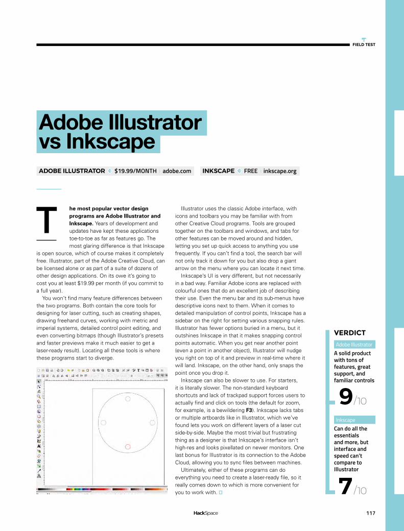
117
FIELD TEST
he most popular vector design programs are Adobe Illustrator and Inkscape. Years of development and updates have kept these applications toe-to-toe as far as features go. The most glaring difference is that Inkscape
is open source, which of course makes it completely free. Illustrator, part of the Adobe Creative Cloud, can be licensed alone or as part of a suite of dozens of other design applications. On its owe it’s going to cost you at least $19.99 per month (if you commit to a full year).
You won’t find many feature differences between the two programs. Both contain the core tools for designing for laser cutting, such as creating shapes, drawing freehand curves, working with metric and imperial systems, detailed control point editing, and even converting bitmaps (though Illustrator’s presets and faster previews make it much easier to get a laser-ready result). Locating all these tools is where these programs start to diverge.
T
Adobe Illustrator vs InkscapeADOBE ILLUSTRATOR $19.99/MONTH adobe.com INKSCAPE FREE inkscape.org
Adobe Illustrator A solid product with tons of features, great support, and familiar controls
Inkscape Can do all the essentials and more, but interface and speed can’t compare to Illustrator
9
7
/10
/10
VERDICT
Illustrator uses the classic Adobe interface, with icons and toolbars you may be familiar with from other Creative Cloud programs. Tools are grouped together on the toolbars and windows, and tabs for other features can be moved around and hidden, letting you set up quick access to anything you use frequently. If you can’t find a tool, the search bar will not only track it down for you but also drop a giant arrow on the menu where you can locate it next time.
Inkscape’s UI is very different, but not necessarily in a bad way. Familiar Adobe icons are replaced with colourful ones that do an excellent job of describing their use. Even the menu bar and its sub-menus have descriptive icons next to them. When it comes to detailed manipulation of control points, Inkscape has a sidebar on the right for setting various snapping rules. Illustrator has fewer options buried in a menu, but it outshines Inkscape in that it makes snapping control points automatic. When you get near another point (even a point in another object), Illustrator will nudge you right on top of it and preview in real-time where it will land. Inkscape, on the other hand, only snaps the point once you drop it.
Inkscape can also be slower to use. For starters, it is literally slower. The non-standard keyboard shortcuts and lack of trackpad support forces users to actually find and click on tools (the default for zoom, for example, is a bewildering F3). Inkscape lacks tabs or multiple artboards like in Illustrator, which we’ve found lets you work on different layers of a laser cut side-by-side. Maybe the most trivial but frustrating thing as a designer is that Inkscape’s interface isn’t high-res and looks pixellated on newer monitors. One last bonus for Illustrator is its connection to the Adobe Cloud, allowing you to sync files between machines.
Ultimately, either of these programs can do everything you need to create a laser-ready file, so it really comes down to which is more convenient for you to work with.

Vector design programs for laser cutting
BEST OF BREED
118
Gravit
nother free option available is Gravit Designer. Like Illustrator and Inkscape it’s available for Mac and PC, but it also has a free web app that can do everything the desktop versions can.
Gravit is a bare-bones, basic vector design program. It’s not trying to compete with the ever-expanding feature-set of Adobe. It knows what you need to do 95% of the time, and focuses on making that as easy as possible.
Getting started is incredibly intuitive, so much so that this has become our go-to vector design software for teaching kids. The pen tool behaves exactly as you would expect and smart guides pop up to help you align your points with other objects. Along with the pen is a freehand drawing tool that, like other applications, will automatically smooth your line and minimise control points. Like most of its features, though, the freehand tool lacks settings to fine-tune how it smooths. Another example is the basic alignment tools that are there (and they work for objects and control points), but there isn’t an option to align to the page.
Key laser-cutter design features, like working with multiple measurement systems and allowing maths within text fields, let you create and edit objects that require precision, and a dashed stroke within the line options (which you can expand to individual paths) lets you prepare an object to be lasered as perforations.
Other features that let you go beyond the basics include Boolean operations and symbol creation (allowing you to create linked clones of objects). It even has a robust text tool with an extensive web font library and the ability to import your own fonts. You can then convert that text to paths, as you would need to do to make it laser-ready.
One thing missing that we find critical is the ability to perform transforms on multiple objects simultaneously from each object’s origin. Let’s say
GRAVIT FREE designer.gravit.io
A
you have four holes around a case you’re going to laser-cut and you decide to make them all 5 mm instead of 3 mm. Ideally you want a tool that lets you select them all and scale them, while keeping their centre point in the same place. Gravit’s more advanced counterparts all have that ability. A bitmap image trace feature would also be nice for converting existing art, but it won’t be missed by most users.
Gravit has some interesting and useful features among its limited arsenal. In addition to layer control, it has the option to create pages that mimic the artboards in Illustrator and allow you to view, move, and resize them all side by side.
Overall, Gravit makes a great beginner and even intermediate vector design program. It’s easy to get started, does pretty much everything you might need, and can export an SVG or PDF file with all the right settings to make it ready to laser.
Above Gravit has most of the tools you would need for vector work and presents them with a clear and intuitive UI
Quick and easy for basic work. Has the core features but lacks tools for experts
VERDICT
6/10

119
FIELD TEST
nShape isn’t a vector art program, it’s a CAD program. Its purpose is to design 3D files for fabrication. That said, it’s one of the more powerful solutions for a laser-cutting workflow.
If you’re not familiar with CAD programs, working in OnShape will require a shift in thinking from how you would work in a 2D design program like Illustrator, though it’s one of the easier CAD programs to learn. Drawings are created as sketches, and although you have the ability to work with a pen tool to make curves and control points, its true strength comes from defining the precise measurements of shapes and setting relationships between them. Your work is still defined by maths and not pixels, but you’re letting the software do most of the point and line manipulation for you.
If you’re laser-cutting a functional part or a prototype, the automated propagation of changes in OnShape will save you hours of work. If your objects are defined well by setting measurements, distances, and relationships to other objects then one minor adjustment to a single object will flow throughout the design and update everything. For example, if all of your holes are set to 3 mm and you want to change them all to 5 mm, that can be done with a single edit and OnShape will recalculate all of your other measurements (like spacing or distance from the edge).
When setting those specific dimensions, OnShape allows you to enter both metric and imperial units interchangeably and, unlike the other programs here, it will retain your equations (so if you define a length as 3 mm + ½ in, you can return to that setting later and make it 3 mm + ¼ in just by changing the 2 to 4).
Another plus of it being a CAD program is that with one more click you can extrude your design and preview it in 3D, which is extra helpful if you’re laser-cutting something that has multiple layers. Included FeatureScripts even let you add common laser-cut features such as finger joints and T-joints, which is a huge time saver if your project requires those.
O
OnShapeONSHAPE FREE FOR HOBBYISTS, $125/MONTH FOR PROFESSIONALS CAD.ONSHAPE.COM
Where OnShape starts to fall apart as a laser-cutting solution is when you’re ready to convert your finished design into a laser-ready file. The current embedded solution is to export your drawing as a DXF, but even that requires quite a bit of post-processing in another vector program. Shapes are broken into unconnected segments (a square becomes four separate lines), so forget about making any edits after export. You’ll also need to set all of your stroke widths and colours in another program before you can even export a PDF or SVG to laser.
At the time of writing, we have to mention that there is a very useful free extension for OnShape called Kiri:Moto which fixes all of the above problems. Kiri:Moto will slice your 3D model, set the stroke widths, set the colours, and even optimise the layout of individual parts to best fit your material. Given the fact that OnShape pushes out non-stop updates, we wouldn’t be surprised if these features show up integrated soon.
If you invest the time in learning the CAD and feature-based design process, OnShape will become so useful you’ll wonder how you could design vector work with anything else. But its major flaw at this time is that it doesn’t stand up as an all-in-one solution to make laser-ready files.
Left OnShape’s true power comes from its ability to take your parameters and solve your design problems for you
Despite its steep learning curve, the CAD features and regular updates make this a great tool for prototyping
VERDICT
8/10

120
CAN I HACK IT?
A Nerf Gun
Can a Nerf gun be modified and used in a microcontroller / computer project?
Les Pounder@biglesp
Les Pounder is a maker and author who works with the Raspberry Pi Foundation to deliver Picademy. He also helps teachers/learners to become creative technologists. He blogs at bigl.es
YOU’LL NEEDNerf N-Strike Elite Stryfe
COST£15.99
WHEREsmythstoys.com
on-Expanding Recreational Foam, better known as Nerf, has been with us since 1969, originally created by Parker Brothers, but now owned by Hasbro, as a safe alternative to harder plastics for
use in toy weapons. Nerf has been made into many forms of weapon, from swords and crossbows to fully automatic sentry turrets, but the iconic Nerf dart – a foam dart with a rubber tip – is the most popular and pervasive. There are many guns that use these darts, the majority of them using a tension spring to launch the projectiles over vast distances. However, for this issue, we will take a look inside a battery-powered semi-automatic blaster, and see how it works and how we can modify it for use in a toy hacking project; for example a Twitter-triggered Nerf turret, or as part of a cosplay concept for conventions.
GENERAL CONSTRUCTIONThe gun is constructed of heavy-duty thick plastic that can easily be drilled to accommodate internal and external modifications. The chassis is held together with 17 Phillips flat head machine screws, measuring approximately 10 mm. This enables easy access to the internals, as there is no glue and no ultrasonic welds that need to be broken. The N-Strike range uses a series of add-ons sold separately, which offer expanded parts (scopes, extended magazines, and stock) that slot on to the gun using a H-shaped connector. This can easily be used with 3D printed parts – just take careful measurements and ensure strict tolerances.
BATTERY POWERThe gun is powered by 4 × AA batteries, which can be rechargeable or alkaline cells. This gives us between
A Nerf GunCan I Hack It?
N
Right Fluorescent orange, highly accurate and easy to hack; the Nerf Stryfe is an ideal platform for cosplayers and makers alike. It runs on 4 × AA batteries, but can be used with LiPo

121
4.8 V and 6 V. Ideally the gun needs 6 V but it runs just as well with 4.8 V rechargeable batteries. At 6 V, the unit will use approximately 14 W of power to fire the darts, that’s 2.33 A for the two motors.
MOTORSIn the forward third of the gun there are two opposing DC motors that use polyester/ hard plastic wheels to squeeze the darts through the barrel and generate the speed necessary for them to fire. These motors each use around 1.16 A of current at ~6 V. The balance of the gun is forward-heavy, so when looking to mount the gun to a rail or a servo/stepper, be mindful of where the weight is and balance accordingly.
SAFETY SWITCHESWhile Nerf darts are relatively safe, it is great to see that there are two safety switches that prevent the gun from firing. First of all, the magazine containing the darts must be inserted in order for the motor to spin. The magazine pushes a normally closed switch, enabling the motor to be triggered using the ‘accelerator’ button; without the magazine the switch is open. The second safety is located in a hatch at the very top of the gun. This hatch is used to clear any jams that may occur when the darts are pushed through a soft plastic aperture. The hatch forms a normally closed switch by pushing upon a black plastic switch. These switches can be bypassed, as electronically they are just momentary switches/ microswitches that can be soldered into an always-closed circuit. Obviously this is done at your own risk, so don’t look down the barrel when operating the gun!
ELECTRONICSThe electronics for the gun are remarkably simple: we see a capacitor connecting the batteries to the
main circuit. The capacitor is used to stop a rush of current being pulled by the motors. As long as the safety switches are closed (magazine loaded and the hatch closed), then the user can fire the weapon. The motor noise could prove to be a handy by-product for cosplayers, as it is close to the chainsaw bayonet found in the Gears of War series. Internally there is space to install small microcontrollers (Arduino Mini/Micro, Teensy, micro:bit etc), or even a Pi Zero W. Obviously this would require a better power solution than AA batteries, but the battery holder could be easily modified using a rotary tool to accommodate a USB LiPo battery back.
COSPLAYThis is a fantastic gun for cosplay use, and it bears a resemblance to the Lawgiver weapon used in the 2012 Dredd movie. The plastic is hard-wearing, and it can be easily modified and drilled into, so adding a laser sight and other ‘greebles’ (fine detail added to a prop to make it look more complex), is extremely easy to do.
To fully customise the gun, of course, it needs a paint job! A light sanding to roughen the surface will also enable smooth spray-painting, to a colour of your choosing. Careful – this will depend upon local laws regarding replica firearms and, for cosplay use, it will need to be vetted by event staff.
CONCLUSIONThis is a fantastically cheap and robust base for many projects. The user-accessible chassis is easy to modify, the electronics are simple and easy to incorporate into a microcontroller/computer project, so seven-segment LED panels, OLEDs and audio playback can bring this gun to life – just remember to improve the power. The plastic used for the gun can also be primed for painting and used in many cosplay scenarios. All of this can be yours for less than £20, a bargain for those taking their first steps in modifying toys and cosplay.
EXTRASTYLE
Adding custom features to the Nerf gun is easy, the plastic is easy to work with and can be shaped and drilled into with a rotary tool or basic hand tools. Adding LEDs and sound effects, using audio boards, is possible thanks to the large internal space available; all you need to do is add a better power supply. If you have never done anything like that, then now is the time to learn new skills from those who have.
Left The magazine locks directly inline with an aperture that covers the opposing motors that fire the darts. The spring-powered trigger pushes the dart into the aperture as part of the firing process
Above The internal structure merges simple mechanical steps, such as a spring-powered trigger, with electronic safeties to prevent fingers being trapped when the motor starts
FIELD TEST

Squix ESPaper Plus
REVIEW
122
he Squix ESPaper kit is an ESP8266 module that comes with a ready-to-use ePaper display. The kit comes in two varieties: Lite and Plus. The Lite kit contains an ESP8266 Wroom-02 module, 296 × 128 black and white
ePaper, and LiPo charging circuit and costs $39.90. For an extra $10, you can get the Plus kit, which also includes an acrylic enclosure, a USB-to-serial adapter, and a 600 mAh battery.
The ESP8266 provides a WiFi connection, three buttons for user input, and a micro USB port for charging, but that’s about it. There aren’t any easily accessible pins (other than the serial connection), so this is primarily for displaying data that’s pulled in over the network. The hardware is designed for low-power usage, so it can run for days at a time on a single charge.
The setup guide shows you how to install a sample application that displays the local weather information (pulled from Wunderground). For someone who’s at least moderately familiar with using the Arduino IDE, it’s nicely straightforward to follow and doesn’t take very long to get the unit working. That, however, is where the documentation ends.
If you follow the setup guide, you should have the Arduino IDE running and able to connect to your device. The extra information you need to get things working on your ESPaper device is understanding how to write data to the display. Daniel Eichhorn – the man behind Squix – has
T
Squix ESPaper Plus
Above The three buttons allow you to add some user input to your projects
Left The example application gives you a weather forecast for your local area
$49.90 squix.org
created a library for doing this (Mini Grafx), however, it’s not well documented. You’ll need to take a look at the code for the weather station to see how it works. Experienced programmers should find it fairly straightforward to get to grips with, but beginners may struggle.
The acrylic case that it comes in is functional, but not very aesthetically pleasing, and depending on your tastes, you may feel the need to create some other housing for it.
If you’re looking for an out-of the-box weather reporter, this kit takes a bit of setting up, and the Wunderground API it relies on has limited coverage outside of the USA (in England we were only able to get data for London and Birmingham). However, if you’re after a hackable ePaper display, the Squix ESPaper Plus is a great option.
By Ben Everard @ben_everard
An easy-to-use, low-power ePaper display, but limited by the documentation
7/10
VERDICT
The ESP8266 provides a WiFi connection, three
buttons for user input, and a micro USB port for charging,
but that’s about it
”
”

REVIEW
Leatherman Surge
123
FIELD TEST
here’s one tool that’s been our go-to for a while now, the Leatherman Surge. Leatherman make quite a wide range of multi-tools aimed at different groups of people, but it’s the Surge that we think suits hackers the most. It’s the
largest of the ‘folding plier’-type Leathermans in terms of official tool-count, with 21 tools for cutting, poking, twisting, and turning all sorts of materials.
The pliers are the most obvious part of most Leathermans, and the Surge is no exception. Leatherman claim that they are both needlenose and regular pliers (and counts them twice in the 21 stated tools). This seems a bit of a stretch to us. In fact, including the wire cutter (with replaceable blades should they dull) and crimper parts of the pliers, they count for six of the 21 tools. In total there are ten ‘things’ that fold out from the main tool handle.
There are two knife blades (one serrated) that, as you would expect from a Leatherman, are razor-sharp and have kept their edge well through our use. A pair of scissors fold out from the handle to complete the Surge’s complement of smooth blades. All of these can be used comfortably with one hand and lock in place, so there’s no risk of accidental folding while in use.
There’s a T-Shank connector that comes with two attachments – a saw and a file. This is a standard connector that’s also used in some electric saws, so it’s possible to swap the blade out for one more appropriate for your use. Different types of wood and metal blades are available, but not all are the same length and some are too long to fold neatly back into the main handle.
The screwdrivers (three flat head and one Philips) are surprisingly useful for a fold-out tool, but are obviously not going to work in all circumstances. There’s also an awl (narrow, sharp tool with an eye in the middle) which is often overlooked but can be useful when you need to enlarge a hole in a soft material or leather.
T
Leatherman Surge
All of the most useful hand tools in a pocket-sized multi tool, but the Surge loses points for the price.
8/10
VERDICT
£169.95 leatherman.co.uk
Multi-tools can never match a full tool kit, but they’re about fitting the most possible power into the smallest possible space. We think the Surge offers the right compromises for most hackers – it’s small enough to fit in your pocket but still packs pliers, knives, and screwdrivers that are large enough to be useful when working on real projects. However, this convenience comes at an eye-watering price and it’s not much cheaper than a fully-equipped toolbox. If you find yourself out and about without tools frequently, it’s a great option. If you’re more workshop-based, it might be a little harder to justify the expense – after all, you can now get a 3D printer for the same price.
Above It’s easy to damage the one Philips screw driver by using it on the wrong-sized screws (replacements and a wider variety of sizes are available)
Below The Leatherman’s casing shows little wear even after several months of hard use
By Ben Everard @ben_everard

SparkFun Inventor’s Kit version 4
REVIEW
124
he SparkFun Inventor’s Kit (SIK) is an electronics set that comes with a guide-book and a storage box for keeping everything tidy. The kit is set up around the SparkFun RedBoard which is pretty similar to an Arduino Uno R3. As
far as most beginners are concerned, it might as well be an Arduino Uno – you program it in the same way and the pinouts are the same. There is a version that comes with an Arduino Uno R3 for an additional $10.
T
SparkFun Inventor’s Kit version 4$99.95 sparkfun.com
By Ben Everard ben_everard
Alongside the RedBoard, there’s enough bits and pieces to complete a range of projects. It’s clear that quite a bit of thought has gone into the balance of this kit. There are bits to display information (LEDs, LCD display), bits to get data (ultrasonic sensor, potentiometer, and temperature sensor), bits to make things move (motors and a servo), and associated bits (resistors and motor drivers).
Along with the electronics bits, there’s a breadboard which allows you to assemble circuits without having to solder them together and, once you’re finished, everything comes apart and you can reuse the bits in your next circuit. Together, there’s almost everything
you need to make the projects in the guide (you’ll also need scissors, pliers, four AA batteries,
and a paper clip).It’s the guide-book that really sets the
SparkFun Inventor’s Kit above the many other electronic component kits that we’ve seen. It includes a basic setup guide and then five projects, each of which includes three or four circuits as well as suggestions for different ways you could modify the build to take it in different directions. The guide is available online at hsmag.cc/NyzLmA.
The projects start with the classic blinking LED and build up to a wheeled robot that navigates the world by itself. If you complete these and are still looking for more, there are also some additional resources at hsmag.cc/uMJoEj.
The guide is well laid out and easy to follow. It includes explanations of the
different concepts and components that you’re using, so it’s not just a list of steps that
you complete in turn. There’s also trouble-shooting advice for when things don’t work, and suggestions for extending each project.
Below Keeping our electronic components tidy is a constant struggle for us – the SparkFun Inventor’s Kit gets you off to the right start

FIELD TEST
125
We would have liked to have seen a little more coverage of the programming side of things in the guide. The code for all the projects is downloadable and, while the electronics side of things is well explained, the guide goes into less detail about how to program. It does explain the key concepts, and important bits of code, but a little more detail on how to create programs would – in our view – help readers with no background in coding. Perhaps we’re being a little pedantic here because it is a beginner’s kit, and as such it can’t cover everything. What it does cover, it covers well and interested users could, no doubt, find more information about Arduino programming that they can use alongside their Inventor’s Kit.
While all the components are straightforward to use, there’s nothing specifically ‘beginner’ about them. They’re the same components that are used by experienced makers, and assembled in the same way that most people prototype their projects (on a breadboard).
Because there’s no proprietary gubbins or secret sauce in this kit, there’s not really a point where you outgrow it. You’ll probably find that you want to add more bits to it, but there’s a wide range of breadboard-compatible components available from just about every hobbyist electronics store on the planet that will work seamlessly with the bits in this kit (the only caveat is that they need to be 5 V-tolerant to work with the RedBoard (or an Uno) – parts
Above The selection of parts is well thought out to give you experience with a range of different components
FIELD TEST
designed for a 3.3 V board like a Raspberry Pi may not work successfully.
If you decide that you want to try out a different controller to the RedBoard, you can work with anything else that will connect to the breadboard (which is most things). In this way, the SIK isn’t so much a beginner’s kit, as the start of your collection of electronics bits and pieces. We feel it’s only fair to warn anyone reading, and looking to get started in electronics, that these collections have a habit of growing at a faster rate than the available space. It starts with a nice neat collection in a tidy plastic box and soon you’ll be wondering if you need to build a new shed.
SparkFun claims that the SIK is suitable for anyone aged ten or older. Obviously everyone’s different, but broadly this seems about right to us. It’s a bit fiddly and doesn’t obfuscate the details, so many children younger than this may struggle. However, there’s nothing particularly childish about it and it could equally be interesting for people well beyond this age looking to get started with electronics.
There isn’t a killer feature of the SparkFun Inventor’s Kit, but it is well thought out, comes with a great guide, and is easily expandable as your experience and knowledge grows.
A well-thought-out kit for anyone getting started with electronics.
9/10
VERDICT

Electrosmash Pedal Pi
REVIEW
126
T
ElectroSmash Pedal Pi£49.95 electrosmash.com
By Andrew Gregory AndrewGregory83
he world of the guitarist is full of expensive gear. Online discussions rage about what types of wire are best in guitar pickups, which kinds of transistors (germanium or silicon) provide the best fuzz tone, and, possibly
the biggest question of all: pentode or tetrode rectifier? In short, the electronics geek and the guitar geek have loads in common, and this pedal promises to give some overlap between the two worlds.
The ElectroSmash Pedal Pi is a programmable guitar effects pedal that uses a Raspberry Pi zero and some code (written in the C programming language), that the user downloads on to the Pi, compiles, and runs to provide the brains of the effect. There’s nothing to stop you writing your own effects from scratch, but the sensible way to get started is to use ElectroSmash’s own samples and go from either using code contributed by the Pedal Pi’s user community or modifying the code parameters yourself. The pedal comes in kit form, so first of all you have to build it.
CONSTRUCTIONWith almost no soldering experience, we found the Pedal Pi pleasingly straightforward to put together. With just a few exceptions, the components were clearly labelled, and the instructions on the ElectroSmash website are clear and easy to follow.
Being afflicted by colour-blindness, the bands on resistors were impossible to read, so we had to take a trip to our friendly local electronics store to get someone to confirm the resistance values for two of the unlabelled resistors. There are also two chips (the op-amp and the analogue to digital converter) that could go on the board in a number of ways. The troubleshooting guide says to check that these are the right way round, but we couldn’t find anywhere in the instructions to show what this right way round was; the information is there on the ElectroSmash site, it just took us a while to look for it.
It’s also not mentioned in the instructions that you need to solder the included header pins to the

FIELD TEST
127
Raspberry Pi Zero – just as well, since with the release of the Raspberry Pi Zero WH you don’t have to do this anyway.
What you get at the end of the fiddly, though hugely rewarding build process, is something that looks like a guitar pedal that you’ve built yourself. It’s not robust enough to stand up to gigging, but that doesn’t matter to us: ElectroSmash says that, ”The project was created with the aim of having fun and learning about guitar pedals… [it] does not feel like a finished pedal that you could buy in a shop.”
SOUNDSAt £49.95 for the full kit (you could also pay £9.95 for the PCB on its own and source the parts yourself if you preferred), the Pedal Pi is outrageously good value. Most shop-bought effects, such as the current incarnation of Ibanez’s classic Tube Screamer distortion pedal, will set you back double that, and then there are ten other effects built in – more than that actually, because the range of effects is limited only by the imagination and programming skills of whoever writes the code.
The code samples are listed in order of complexity, ranging from a simple, clean tone, which demonstrates how to get a signal into and out of the pedal, to a looper effect. The most fun we had was playing with the various kinds of distortion. The fuzz, distortion, and bit-crusher effects have a processed quality that feels very 80s and early 90s. Think Smashing Pumpkins and Rage Against The Machine rather than Stevie Ray Vaughan and you’re in the right ballpark. We love it.
SOFTWAREYou don’t need any prior knowledge of coding to get started working on new effects. Just open the fuzz.c file-in a text editor, change a few numbers, recompile, and run the code, and you’ve got a brand-new effect. The degree of control this gives you is intoxicating. Bedroom Brian Enos will love tweaking delay lengths and distortion characteristics, for no practical reason other than you can. As a first coding project for a guitarist who’s interested in learning to program, this is a hell of a lot more interesting than the standard ‘Hello World’. For anyone else who has tried Python and wants to go further, it’s an ideal step-up into compiled languages, and the process of building the pedal is also a great excuse to pick up a soldering iron.
Top Even with our sub-par soldering, the Pedal Pi worked first time – testament to the clear instructions
Below If you specify at the time of purchase, ElectroSmash will substitute one of the capacitors, making the Pedal Pi suitable for bass guitars
FIELD TEST
With almost no soldering experience, we found the Pedal Pi pleasingly
straightforward to put together.
”
”
The Pedal Pi is a wonderful bit of kit, full of potential and opportunities for noisy learning.
10/10
VERDICT
• Clean-Transparent tone
• Booster
• Distortion
• Fuzz
• Bit-Crusher
• Delay
THOSE GUITAR EFFECTS IN FULL

Coinkite Opendime
REVIEW
128
FIELD TEST
017 was the year cryptocurrencies truly went mainstream. Previously the reserve of computer scientists and crypto-anarchists, cryptocurrencies like Bitcoin and Litecoin dominated headlines – thanks in no small part to an explosion
in value that saw the value of Bitcoin increase tenfold over the year.
Bitcoin, though, has a problem: scaling. Its peer-to-peer trustless ‘blockchain’ technology only supports between four and eight transactions per second, gathered and processed in 1MB blocks every ten minutes. What was plenty in 2010, when a handful of early adopters were buying pizzas for 10 000 Bitcoin, is woefully inadequate now millions of users around the globe are looking to play.
Coinkite’s solution to the problem is unique: the Opendime, a hardware wallet which turns Bitcoin into a highly secure and tamperproof digital bearer bond.
Measuring 47 mm long, the Opendime looks like a USB flash drive stripped of its casing. When first connected to a PC it shows up as a flash drive with a set of instructions telling you to drag-and-drop a file of at least 256kB in size. This file provides entropy, or randomness, which is combined with data from a hardware true random number generator (TRNG) to generate a Bitcoin private key – the part of a Bitcoin wallet you need in order to actually spend your hard-earned cryptocurrency.
So far, so standard-hardware-wallet. Where the Opendime differs is in how it uses the private key post-generation: the key is stored in a secure enclave on the device’s processor, wholly inaccessible to the user. In this state you can load Bitcoin onto the Opendime – the public key being accessible on any PC, smartphone, or tablet with USB mass storage support – but have no way to retrieve it again.
To spend any stored Bitcoin, you need to physically cut off the transparent protective heat-shrink wrapping surrounding the device and push a pin through a hole on the underside of the Opendime. Doing so pops a small resistor off the board, and the
2
Coinkite Opendime
A smart, secure, attractive, but ultimately expensive way to transact Bitcoin in person.
7/10
VERDICT
Below An Opendime’s public key is always accessible, but its private key stays locked away
Above The Coinkite Opendime offers a secure way to transact the Bitcoin cryptocurrency in person
$37.50 for three opendime.com
next time the Opendime is connected it permanently and irrevocably unlocks itself – providing a copy of the previously hidden private key which can then be used to ‘sweep’ the coins away from the Opendime and into a more traditional ‘hot’ Bitcoin wallet for spending on whatever you fancy.
It’s a trick that makes the Opendime an expensive way to spend Bitcoin: while you can technically reuse an Opendime once unlocked, doing so loses its security. Coinkite’s vision is that Opendimes can be used for in-person transactions – buying a car, say, or giving someone Bitcoin as a birthday present – with the cast-iron guarantee, not available from traditional wallets, that nobody has sneakily kept a copy of the private key in order to steal the coins away again.
It’s a fantastic idea with only one issue: price. At $37.50 plus shipping and VAT for a three-pack, a single Opendime will set you back around £15 – an expensive ‘gift card’ to be handing someone, but one they are sure to find interesting.
By Gareth Halfacree @ghalfacree

FIELD TESTREVIEW
Much ADO about Almost Nothing: Man’s Encounter with the Electron
129
to more tales of a motley cast of early experimenters and makers. The histories are imbued with a real passion for the subject, and the late author knew a thing or two about silicon chips (Camenzind’s venerable 555 timer IC is a true classic, and only a small part of his prodigious output).
Starting with a knowledge of where we are now, the reader is gripped by the early inching towards understanding of just what electricity and magnetism are, then the discovery of the electron, and development of radio technology. This could have been a complete book in itself, but we continue right through the parallel developments of the first computers on both sides of the Atlantic, then on to the first microprocessor.
There’s a startling array of names immortalised in electrical terms: Volta, Ampère, Coulomb, Galvani, Henry, Ohm, Faraday, Wheatstone – but many figures are overlooked, too. What’s striking is the role of less well-known figures who were often chemists – yes, chemistry and materials science drove much of the development of electro-magnetic discovery, and then modern electronics. Everything from better vacuums for thermionic valves, to pioneering single crystal germanium and silicon for semiconductors.
This is a very well written story. True, there are problems with the book – it’s full of the small errors that a traditional publisher’s editorial team would have quickly remedied (Booklocker is a print-on-demand company). But you’ll quickly forgive these as you turn the pages and are treated to more insights on curiosity, inventiveness, and commercial shenanigans. Who was motivated by money, and who was just impelled by creativity and the drive to discover – often with the same results. Essential reading!
ow, what a winding road was travelled towards the discovery of the electron, and the development of the devices we all depend upon. From early observations of lodestone and
lightening, through to the founding and development of Intel, stories familiar and new are told with dry humour and subtle observations on human character.
All of this helps keep rather a meandering tale on track, or at least keeps the reader turning the page
W
Much ADO about Almost Nothing: Man’s Encounter with the Electron
Stories of geekery, greed, and single-minded endeavour – informative, educational, and a gripping read.
VERDICT
Hans Camenzind £13.99 historyofelectronics.com
9/10
By Richard Smedley

If you love to hack and make stuff, why not get paid to share this with the world? We need passionate people to write
features, tutorials, and reviews.
GET IN TOUCH
We want your tips, comments, and questions!
WENEED
Y Uhsmag.cc/hello
@HackSpaceMag
TIP US OFF TO AN
INTERESTING PROJECT BE HACKSPACE OF THE MONTH
SHARE YOUR
THOUGHTS ON THE LETTERS
PAGE
REACH OUT TO FELLOW HACKERS