LV 5490 / LV 5480 Instruction Manual
537
LV 5490 / LV 5480 MULTI WAVEFORM MONITOR LV 5490SER01 SDI INPUT LV 5490SER02 SDI INPUT / EYE LV 5490SER03 DIGITAL AUDIO Dolby (Option) LV 5490SER04 FOCUS ASSIST LV 5490SER05 CIE DIAGRAM LV 5490SER06 12G-SDI INPUT LV 5490SER07 HDR LV 5490SER08 IP (NMI) LV 5490SER09 12G-SDI EYE LV 5490SER10 VIDEO NOISE METER LV 5480SER20 4K LV 5480SER21 TSG Instruction Manual Thank you for purchasing. Please carefully read this instruction manual and the included "GENERAL SAFETY SUMMARY". Please use the product safely.
-
Upload
khangminh22 -
Category
Documents
-
view
0 -
download
0
Transcript of LV 5490 / LV 5480 Instruction Manual

LV 5490 / LV 5480 MULTI WAVEFORM MONITOR LV 5490SER01 SDI INPUT
LV 5490SER02 SDI INPUT / EYE
LV 5490SER03 DIGITAL AUDIO Dolby (Option)
LV 5490SER04 FOCUS ASSIST
LV 5490SER05 CIE DIAGRAM
LV 5490SER06 12G-SDI INPUT
LV 5490SER07 HDR
LV 5490SER08 IP (NMI)
LV 5490SER09 12G-SDI EYE
LV 5490SER10 VIDEO NOISE METER
LV 5480SER20 4K
LV 5480SER21 TSG Instruction Manual Thank you for purchasing.
Please carefully read this instruction manual and the included "GENERAL SAFETY SUMMARY". Please use the product safely.

TABLE OF CONTENTS
GENERAL SAFETY SUMMARY ....................................................................... I
1. INTRODUCTION ................................................................................... 1
1.1 Scope of Warranty ......................................................................................... 1 1.2 Operating Precautions .................................................................................... 2
1.2.1 Maximum Allowable Input Voltage ............................................................. 2 1.2.2 Mechanical Shock .................................................................................... 2 1.2.3 Electrostatic Damage ............................................................................... 2 1.2.4 Warming Up ............................................................................................ 2 1.2.5 About Standby Mode ................................................................................ 2 1.2.6 Backup ................................................................................................... 3 1.2.7 About the LCD Panel ................................................................................ 3
1.3 About Trademarks and Licenses ...................................................................... 3 1.4 About Terminology Used in this Manual ............................................................ 4 1.5 About the LV 5480 ........................................................................................ 5
2. Product Configuration ........................................................................... 6
2.1 Lineup ......................................................................................................... 6 2.2 About Units .................................................................................................. 6 2.3 About Options ............................................................................................... 6
3. SPECIFICATIONS .................................................................................. 7
3.1 General ........................................................................................................ 7 3.2 Features ....................................................................................................... 8 3.3 Specifications ............................................................................................... 12
3.3.1 SDI Formats and Standards ..................................................................... 12 3.3.2 Supported IP (NMI) Input Signal Formats (SER08) ...................................... 18 3.3.3 Embedded Audio Playback Format (SER03) ................................................ 19 3.3.4 SDI I/O Connectors ................................................................................. 19 3.3.5 IP(NMI) Input Connectors (SER08) ........................................................... 20 3.3.6 External Reference Input ......................................................................... 21 3.3.7 Audio Input/Output Connectors (SER03) ................................................... 21 3.3.8 Monitor Output Connector ........................................................................ 22 3.3.9 Control Connectors ................................................................................. 23 3.3.10 Front Panel ............................................................................................ 24 3.3.11 Screen Capture ...................................................................................... 24 3.3.12 Frame Capture ....................................................................................... 25 3.3.13 Pattern Generator ................................................................................... 25 3.3.14 Preset ................................................................................................... 26 3.3.15 Display .................................................................................................. 27 3.3.16 SDI Video Signal Waveform Display .......................................................... 27 3.3.17 SDI Vector Waveform Display ................................................................... 29

3.3.18 SDI Signal 5-Bar Display .......................................................................... 29 3.3.19 SDI Picture Display ................................................................................. 30 3.3.20 SDI CINELITE Display .............................................................................. 31 3.3.21 SDI CINEZONE Display ............................................................................ 32 3.3.22 Digital Audio Display (SER03) ................................................................... 32 3.3.23 SDI Signal Status Display ......................................................................... 34 3.3.24 SDI Analysis Features .............................................................................. 36 3.3.25 Eye Pattern Display (SER02/SER09) .......................................................... 39 3.3.26 Jitter Display (SER02/SER09) ................................................................... 40 3.3.27 Eye Pattern and Jitter Detection (SER02/SER09) ........................................ 41 3.3.28 Focus Assist Display (SER04) ................................................................... 42 3.3.29 CIE Diagram Display (SER05) ................................................................... 42 3.3.30 HDR Display (SER07) .............................................................................. 42 3.3.31 IP(NMI) Status Display (SER08) ............................................................... 43 3.3.32 Video Noise Meter (SER10) ...................................................................... 43 3.3.33 General Specifications ............................................................................. 45
4. PANEL DESCRIPTION .......................................................................... 46
4.1 Front Panel .................................................................................................. 46 4.2 Rear Panel ................................................................................................... 48
5. BEFORE YOU BEGIN MEASURING ......................................................... 52
5.1 Attaching the Cover Inlet Stopper ................................................................... 52 5.2 Removing the Protection Panel ....................................................................... 53 5.3 Using the Stand ........................................................................................... 53 5.4 Turning the Instrument On and Off ................................................................. 54 5.5 Connecting USB Devices ................................................................................ 54 5.6 Installing the SFP+ Transceiver Module (SER08) ............................................... 55 5.7 Signal I/O .................................................................................................... 56
5.7.1 SDI Signal I/O ........................................................................................ 56 5.7.2 IP(NMI) Signal Input (SER08) .................................................................. 59 5.7.3 External Sync Signal Input ....................................................................... 60 5.7.4 Digital Audio I/O (SER03) ........................................................................ 64 5.7.5 Monitor Signal Output ............................................................................. 65
5.8 Operation Basics .......................................................................................... 66 5.8.1 Displaying the Function Menu ................................................................... 66 5.8.2 Function Menu Operations ....................................................................... 66 5.8.3 Mouse Operations ................................................................................... 67 5.8.4 Tab Menu Operations .............................................................................. 68 5.8.5 Setting the Key Lock ............................................................................... 69
5.9 Measurement Screen Explanation ................................................................... 70
6. BASIC OPERATION ............................................................................. 72
6.1 Setting the Input Signals ............................................................................... 72 6.1.1 Selecting the Input Mode ......................................................................... 72 6.1.2 Selecting Simul Operation ........................................................................ 73

6.1.3 Selecting the Measurement Group ............................................................ 73 6.1.4 Selecting the Channels to Measure ............................................................ 74 6.1.5 Input Format Error Display ...................................................................... 75
6.2 Setting the Signals to Measure ....................................................................... 76 6.2.1 Measuring SD, HD, 3G-A, and 3G-B-DL Signals .......................................... 76 6.2.2 Measuring 3G-B-DS Signals ...................................................................... 79 6.2.3 Measuring 12G Signals (SER06/SER08) ..................................................... 81 6.2.4 Measuring HD (DL) Signals ...................................................................... 83 6.2.5 Measuring 3G (DL)-2K Signals .................................................................. 85 6.2.6 Measuring 3G (DL)-4K Signals .................................................................. 87 6.2.7 Measuring HD (QL) Signals ...................................................................... 89 6.2.8 Measuring 3G (QL) Signals ....................................................................... 91 6.2.9 Measuring 4K NMI Signals (SER08) ........................................................... 93 6.2.10 Measuring NMI Signals (SER08) ................................................................ 95
6.3 Selecting the Measurement Mode ................................................................... 97 6.3.1 Video Signal Waveform Display ................................................................. 97 6.3.2 Vector Waveform Display ......................................................................... 97 6.3.3 Picture Display ....................................................................................... 98 6.3.4 Audio Display (SER03) ............................................................................ 98 6.3.5 Status Display ........................................................................................ 99 6.3.6 Eye Pattern Display (SER02/SER09) .......................................................... 99 6.3.7 Multi Display ........................................................................................ 100
6.4 Arranging the Measurement Screen Layout .................................................... 102 6.4.1 Notes .................................................................................................. 102 6.4.2 Layout Procedure .................................................................................. 103 6.4.3 Layout Screen Description ..................................................................... 106
7. SYSTEM SETTINGS ........................................................................... 116
7.1 Configuring the I/O Connectors .................................................................... 116 7.1.1 Configuring the SDI Input Connectors ..................................................... 116 7.1.2 Configuring the IP(NMI) Input (SER08) ................................................... 123 7.1.3 Configuring FORMAT ALARM .................................................................. 124 7.1.4 Configuring the SDI I/O Connectors ........................................................ 127 7.1.5 Configuring HDR (SER07) ...................................................................... 132 7.1.6 Configuring Audio I/O Connectors (SER03) .............................................. 134 7.1.7 Configuring the Monitor Output Connectors .............................................. 135 7.1.8 Configuring the 12G SDI I/O Connector (SER06) ...................................... 137 7.1.9 Configuring IP (NMI) Pat 1 (SER08) ........................................................ 138 7.1.10 Configuring IP (NMI) Pat 2 (SER08) ........................................................ 140
7.2 LV 5490 Configuration ................................................................................ 141 7.2.1 General Settings ................................................................................... 141 7.2.2 Configuring Ethernet Settings ................................................................. 144 7.2.3 Remote Control Settings ........................................................................ 146 7.2.4 Setting the Date and Time ..................................................................... 147
7.3 Displaying System Information ..................................................................... 147 7.4 Installing Options ....................................................................................... 149 7.5 Adjusting the Backlight ............................................................................... 150

7.6 Turning Off the LCD Panel ............................................................................ 150 7.7 Initialization ............................................................................................... 151
7.7.1 Initializing Settings ............................................................................... 151 7.7.2 Initializing the Layout ............................................................................ 152 7.7.3 Initializing the Settings and Layout ......................................................... 152
8. CAPTURE FEATURE .......................................................................... 153
8.1 Screen Capture .......................................................................................... 154 8.1.1 Capturing the Screen ............................................................................ 154 8.1.2 Displaying Screen Capture Data .............................................................. 154 8.1.3 Saving to USB Memory Device................................................................ 155 8.1.4 Displaying Screen Capture Data Saved to a USB Memory Device ................ 156 8.1.5 Deleting Screen Capture Data Saved to a USB Memory Device ................... 157
8.2 Frame Capture ........................................................................................... 158 8.2.1 Capturing Frame Data ........................................................................... 158 8.2.2 Displaying Frame Capture Data .............................................................. 160 8.2.3 Saving to a USB Memory Device ............................................................. 161 8.2.4 Displaying Frame Capture Data Saved to a USB Memory Device ................. 162 8.2.5 Deleting Frame Capture Data Saved to a USB Memory Device .................... 163
9. PRESET SETTINGS ........................................................................... 164
9.1 Registering Presets ..................................................................................... 164 9.2 Recalling Presets ........................................................................................ 166 9.3 Deleting Presets ......................................................................................... 167 9.4 Copying All Presets from the LV 5490 to USB Memory ..................................... 168 9.5 Copying All Presets from USB Memory to the LV 5490 ..................................... 169
10. VIDEO SIGNAL WAVEFORM DISPLAY .................................................. 170
10.1 Setting the Waveform Display Position .......................................................... 171 10.2 Configuring the Display Settings ................................................................... 172
10.2.1 Adjusting the Vector Intensity ................................................................ 172 10.2.2 Selecting the Vector Color ...................................................................... 172 10.2.3 Adjusting the Scale Intensity .................................................................. 173 10.2.4 Selecting the Scale Color ....................................................................... 173 10.2.5 Selecting the Scale Unit ......................................................................... 173 10.2.6 Displaying a Scale for 75 % Intensity Color Bars ....................................... 176 10.2.7 Selecting the Display Mode .................................................................... 177 10.2.8 Turning the Channels On and Off ............................................................ 178 10.2.9 4Y Parade Display ................................................................................. 179 10.2.10 Configuring the 3G-B-DS Display Settings ................................................ 180
10.3 Configuring the Gain and Filter Settings ........................................................ 181 10.3.1 Selecting the Fixed Gain ........................................................................ 181 10.3.2 Setting the Variable Gain ....................................................................... 181 10.3.3 Selecting the Filter ................................................................................ 182 10.3.4 Setting the Scale Jump .......................................................................... 185
10.4 Configuring Sweep Settings ......................................................................... 187

10.4.1 Selecting the Sweep Method .................................................................. 187 10.4.2 Selecting the Line Display Format ........................................................... 188 10.4.3 Selecting the Field Display Format .......................................................... 189 10.4.4 Selecting the Horizontal Magnification ..................................................... 190 10.4.5 Displaying the Blanking Interval ............................................................. 192
10.5 Configuring Line Selection Settings ............................................................... 193 10.5.1 Turning Line Selection On and Off ........................................................... 193 10.5.2 Setting the Line Selection Range ............................................................. 194
10.6 Configuring Cursor Settings ......................................................................... 195 10.6.1 Turning Cursors On and Off .................................................................... 195 10.6.2 Selecting the Cursor .............................................................................. 196 10.6.3 Moving Cursors .................................................................................... 196 10.6.4 Selecting the Y-Axis Measurement Unit ................................................... 197 10.6.5 Selecting the X-Axis Measurement Unit ................................................... 197 10.6.6 Turning the Cursor Value Display On and Off ............................................ 198
10.7 Configuring the Color System Settings .......................................................... 199 10.7.1 Selecting the Color Matrix ...................................................................... 199 10.7.2 Turning the Luminance Signal On and Off ................................................ 201 10.7.3 Selecting the Composite Display Format .................................................. 202 10.7.4 Selecting the Setup Level ....................................................................... 202
11. VECTOR WAVEFORM DISPLAY ........................................................... 203
11.1 Configuring the Intensity and Scale Settings .................................................. 204 11.1.1 Adjusting the Vector Intensity ................................................................ 204 11.1.2 Selecting the Vector Color ...................................................................... 204 11.1.3 Adjusting the Scale Intensity .................................................................. 204 11.1.4 Selecting the Scale Color ....................................................................... 205 11.1.5 Turning the Display of the I and Q Axes On and Off ................................... 205 11.1.6 Selecting the Scale ................................................................................ 206
11.2 Setting the Gain ......................................................................................... 207 11.2.1 Selecting the Fixed Gain ........................................................................ 207 11.2.2 Setting the Variable Gain ....................................................................... 208
11.3 Configuring Line Selection Settings ............................................................... 209 11.3.1 Turning Line Selection On and Off ........................................................... 209 11.3.2 Setting the Line Selection Range ............................................................. 210
11.4 Configuring Marker Settings ......................................................................... 211 11.4.1 Displaying the Vector Marker .................................................................. 211
11.5 Configuring the Display Settings ................................................................... 212 11.5.1 Switching the Display Mode .................................................................... 212 11.5.2 Configuring the 3G-B-DS Display Settings ................................................ 212
11.6 Configuring the Color System Settings .......................................................... 214 11.6.1 Selecting the Color Matrix ...................................................................... 214 11.6.2 Selecting the Composite Display Format .................................................. 215 11.6.3 Selecting the Setup Level ....................................................................... 216 11.6.4 Displaying a Scale for 75 % Intensity Color Bars ....................................... 216
11.7 5-Bar Display ............................................................................................. 217 11.7.1 Selecting the Scale Unit ......................................................................... 218

11.7.2 Selecting the Display Order .................................................................... 219 11.8 Histogram Display ...................................................................................... 220
12. CIE DIAGRAM DISPLAY (SER05)......................................................... 221
12.1 Configuring the Scale Settings ...................................................................... 222 12.1.1 Selecting the Triangle ............................................................................ 222 12.1.2 Setting the User-defined Triangle ............................................................ 223 12.1.3 Selecting the Color Scale ....................................................................... 225 12.1.4 Turning the Sub Scale On and Off ........................................................... 226
12.2 Setting the Chromaticity Diagram Mode ........................................................ 227 12.2.1 Selecting the Display Type ..................................................................... 227 12.2.2 Selecting the Display Standard ............................................................... 228 12.2.3 Turning Clipping On and Off ................................................................... 228 12.2.4 Turning the Filter On and Off .................................................................. 228 12.2.5 Setting the Gamma Value ...................................................................... 228
12.3 Configuring Line Selection Settings ............................................................... 229 12.4 Configuring Cursor Settings ......................................................................... 229
12.4.1 Displaying the Chromaticity Diagram Cursor ............................................. 229 12.5 Configuring the Display Settings ................................................................... 229
13. PICTURE DISPLAY ............................................................................ 230
13.1 Adjusting the Picture .................................................................................. 230 13.1.1 Switching between the Color and Monochrome Displays ............................ 230 13.1.2 Setting the Chroma Gain ....................................................................... 231 13.1.3 Adjusting the Brightness ........................................................................ 231 13.1.4 Adjusting the Contrast ........................................................................... 231 13.1.5 Adjusting the Gain ................................................................................ 231 13.1.6 Adjusting the Bias ................................................................................. 232
13.2 Configuring Marker Settings ......................................................................... 232 13.2.1 Turning the Display of the Frame Marker On and Off ................................. 233 13.2.2 Turning the Display of the Center Marker On and Off ................................. 233 13.2.3 Setting the Aspect Marker ...................................................................... 233 13.2.4 Setting the Aspect Shadow .................................................................... 235 13.2.5 Setting the Safe Action Marker ............................................................... 236 13.2.6 Setting the Safe Title Marker .................................................................. 236 13.2.7 Setting User Markers ............................................................................. 237
13.3 Configuring Line Selection Settings ............................................................... 238 13.3.1 Turning Line Selection On and Off ........................................................... 238 13.3.2 Setting the Line Selection Range ............................................................. 239 13.3.3 Setting the Lip Sync Measurement Range (SER03) .................................... 239
13.4 Configuring CINELITE Settings ..................................................................... 240 13.4.1 f Stop Screen Explanation ...................................................................... 241 13.4.2 Procedure for Displaying the f Stop Screen ............................................... 242 13.4.3 %DISPLAY Screen Explanation ............................................................... 243 13.4.4 Selecting the Points to Display ................................................................ 245 13.4.5 Setting Measurement Points ................................................................... 246

13.4.6 Setting the Area of Luminance Measurement ........................................... 246 13.4.7 Configuring User-Defined Correction Tables .............................................. 247 13.4.8 Displaying Synchronized Markers ............................................................ 252
13.5 Configuring CINEZONE Settings ................................................................... 253 13.5.1 Gradation Display Mode ......................................................................... 253 13.5.2 Step Display Mode ................................................................................ 254 13.5.3 Search Display Mode ............................................................................. 255
13.6 Focus Assist Display (SER04) ....................................................................... 256 13.6.1 Selecting the Display Size ...................................................................... 256 13.6.2 Turning Focus Assist On and Off ............................................................. 256 13.6.3 Selecting the Detection Sensitivity .......................................................... 256 13.6.4 Selecting the Luminance Level ............................................................... 257 13.6.5 Selecting the Highlight Color .................................................................. 257
13.7 Video Noise Meter (SER10) .......................................................................... 258 13.7.1 Turning Video Noise Meter On and Off ..................................................... 258 13.7.2 Configuring the Measurement Window .................................................... 259 13.7.3 Selecting the Signal to Measure .............................................................. 260 13.7.4 Selecting the Filter ................................................................................ 260 13.7.5 Selecting the Measurement Result Display Size ......................................... 260 13.7.6 Turning the Alarm Function On and Off .................................................... 261 13.7.7 Setting the Threshold of the Alarm Function ............................................. 261
13.8 Configuring the Display Settings ................................................................... 262 13.8.1 Selecting the Display Size ...................................................................... 262 13.8.2 Gamut Error Display .............................................................................. 263 13.8.3 Turning the Information On and Off ........................................................ 264 13.8.4 Configuring the 3G-B-DS Display Settings ................................................ 264
14. HDR DISPLAY (SER07) ...................................................................... 266
14.1 Video Signal Waveform Display .................................................................... 267 14.1.1 Scale Display ........................................................................................ 267 14.1.2 Cursor Display ...................................................................................... 269
14.2 Vector Waveform Display ............................................................................. 270 14.2.1 Histogram Display ................................................................................. 270
14.3 Picture Display ........................................................................................... 271 14.3.1 Turning Brightness Information On and Off .............................................. 271 14.3.2 Selecting the SDR Conversion Format ...................................................... 272 14.3.3 f Stop Screen ....................................................................................... 274 14.3.4 %DISPLAY Screen ................................................................................ 274 14.3.5 CINEZONE Display ................................................................................ 275
15. AUDIO DISPLAY ............................................................................... 277
15.1 Setting the Signals to Measure ..................................................................... 279 15.2 Configuring the Dolby Settings (option) ......................................................... 283 15.3 Selecting the Display Mode .......................................................................... 284 15.4 Configuring Error Detection Settings ............................................................. 286 15.5 Adjusting the Volume .................................................................................. 287

15.6 Meter Display ............................................................................................. 287 15.6.1 Selecting the Scale ................................................................................ 287 15.6.2 Selecting the Response Model ................................................................ 288 15.6.3 Setting the Peak Hold ............................................................................ 288 15.6.4 Setting the Reference Level.................................................................... 289
15.7 Lissajous Display ........................................................................................ 290 15.7.1 Adjusting the Lissajous Curve Intensity ................................................... 290 15.7.2 Adjusting the Scale Intensity .................................................................. 290 15.7.3 Selecting the Lissajous Curve Display Format ........................................... 291 15.7.4 Selecting the Scale Display Format .......................................................... 292 15.7.5 Setting the Lissajous Curve Gain ............................................................. 293
15.8 Surround Display ........................................................................................ 294 15.8.1 Adjusting the Surround Waveform Intensity ............................................. 294 15.8.2 Adjusting the Scale Intensity .................................................................. 294 15.8.3 Selecting the Surround Display Format .................................................... 295 15.8.4 Setting the Surround Waveform Gain ...................................................... 295
15.9 Status Display ............................................................................................ 296 15.9.1 Status Display Explanation ..................................................................... 296 15.9.2 Event Log Display ................................................................................. 298 15.9.3 Metadata Display (Option) ..................................................................... 299 15.9.4 Displaying the Channel Status ................................................................ 302 15.9.5 Displaying User Bits .............................................................................. 303 15.9.6 Resetting Errors ................................................................................... 303
16. STATUS DISPLAY ............................................................................. 304
16.1 Status Screen Explanation ........................................................................... 304 16.2 Configuring Error Detection Settings ............................................................. 308
16.2.1 Error Setup 1 ....................................................................................... 308 16.2.2 Error Setup 2 ....................................................................................... 311 16.2.3 Error Setup 3 ....................................................................................... 312 16.2.4 Error Setup 4 ....................................................................................... 315
16.3 Clearing Error Counts .................................................................................. 318 16.4 Configuring Event Log Settings .................................................................... 318
16.4.1 Event Log Screen Explanation ................................................................ 319 16.4.2 Starting the Event Log .......................................................................... 323 16.4.3 Deleting the Event Log .......................................................................... 323 16.4.4 Selecting the Overwrite Mode ................................................................. 323 16.4.5 Saving to USB Memory .......................................................................... 324
16.5 Configuring Data Dump Settings .................................................................. 326 16.5.1 Data Dump Display Explanation .............................................................. 327 16.5.2 Selecting the Display Mode .................................................................... 329 16.5.3 Selecting the Display Format .................................................................. 329 16.5.4 Selecting the Displayed Information ........................................................ 331 16.5.5 Moving the Display Position .................................................................... 331 16.5.6 Selecting the Adjustment Step Resolution ................................................ 331 16.5.7 Selecting What the Function Dial Controls ................................................ 332 16.5.8 Saving to USB Memory .......................................................................... 332

16.6 Configuring Phase Difference Measurement Settings ....................................... 333 16.6.1 Phase Difference Measurement Display Explanation .................................. 334
16.7 Setting the Lip Sync Measurement (SER03) ................................................... 337 16.7.1 Selecting the Measurement Range .......................................................... 338 16.7.2 Updating the Measurement Screen ......................................................... 338 16.7.3 Setting the Measurement Range ............................................................. 339
16.8 Displaying a List of Ancillary Data ................................................................. 342 16.8.1 Ancillary Data Display Explanation .......................................................... 342 16.8.2 Displaying a Dump of Ancillary Data ........................................................ 343 16.8.3 Updating the Dump Display.................................................................... 343 16.8.4 Selecting the Dump Mode ...................................................................... 344
16.9 Detecting Ancillary Packets .......................................................................... 345 16.9.1 Ancillary Packet Display Explanation ........................................................ 345 16.9.2 Displaying EDH Packets ......................................................................... 347 16.9.3 Displaying Payload IDs .......................................................................... 348 16.9.4 Displaying Audio Control Packets ............................................................ 349 16.9.5 V-ANC ARIB Display .............................................................................. 350 16.9.6 Displaying Closed Caption Packets .......................................................... 350 16.9.7 Displaying the Inter-Stationary Control Signal .......................................... 351 16.9.8 Displaying the Data Broadcast Trigger Signal ............................................ 354 16.9.9 Displaying User Data ............................................................................. 355 16.9.10 V-ANC SMPTE Display ........................................................................... 355 16.9.11 Displaying AFD Packets .......................................................................... 356 16.9.12 Performing Custom Searches ................................................................. 357
16.10 IP(NMI) Status Screen Explanation (SER08) .................................................. 359
17. EYE PATTERN DISPLAY (SER02/SER09) .............................................. 361
17.1 Eye Pattern Display Explanation ................................................................... 363 17.2 Jitter Display Explanation ............................................................................ 365 17.3 Setting the Waveform Display Position .......................................................... 366 17.4 Switching between Eye Pattern and Jitter ...................................................... 366 17.5 Selecting Which Link to Display .................................................................... 366 17.6 Configuring the Intensity and Scale Settings .................................................. 367
17.6.1 Adjusting the Waveform Intensity ........................................................... 367 17.6.2 Selecting the Waveform Color ................................................................ 367 17.6.3 Adjusting the Scale Intensity .................................................................. 367 17.6.4 Selecting the Scale Color ....................................................................... 367
17.7 Configuring Eye Pattern Display Settings ....................................................... 368 17.7.1 Adjusting the Gain ................................................................................ 368 17.7.2 Selecting the Sweep Time ...................................................................... 369 17.7.3 Selecting the Filter ................................................................................ 370 17.7.4 Turning Cursors On and Off .................................................................... 371 17.7.5 Selecting the Cursor .............................................................................. 372 17.7.6 Moving Cursors .................................................................................... 374 17.7.7 Selecting the X-Axis Measurement Unit ................................................... 374 17.7.8 Selecting the Y-Axis Measurement Unit ................................................... 374 17.7.9 Selecting the Display Mode .................................................................... 375

17.7.10 Resetting Cursors ................................................................................. 375 17.8 Configuring the Jitter Display Settings ........................................................... 376
17.8.1 Selecting the Magnification .................................................................... 376 17.8.2 Selecting the Sweep Time ...................................................................... 376 17.8.3 Selecting the Filter ................................................................................ 377 17.8.4 Turning Cursors On and Off .................................................................... 377 17.8.5 Selecting the Cursor .............................................................................. 378 17.8.6 Moving Cursors .................................................................................... 378 17.8.7 Selecting the X-Axis Measurement Unit ................................................... 379 17.8.8 Selecting the Y-Axis Measurement Unit ................................................... 379 17.8.9 Selecting the Display Mode .................................................................... 379 17.8.10 Resetting Cursors ................................................................................. 379 17.8.11 Turning the Peak Hold On and Off ........................................................... 380 17.8.12 Clearing the Peak Hold .......................................................................... 380
17.9 Configuring Error Detection Settings ............................................................. 381 17.9.1 Configuring 12G Error Settings ............................................................... 381 17.9.2 Configuring 3G Error Settings ................................................................. 383 17.9.3 Configuring HD Error Settings ................................................................ 385 17.9.4 Configuring SD Error Settings ................................................................. 387
18. プラグインのインストール (SER08) ...................................................... 389
19. REMOTE CONTROL ........................................................................... 393
20. ETHERNET REMOTE CONTROL ........................................................... 398
20.1 TELNET ..................................................................................................... 398 20.1.1 Procedure ............................................................................................ 398 20.1.2 How to Enter Commands ....................................................................... 399 20.1.3 TELNET Commands .............................................................................. 400
20.2 FTP........................................................................................................... 430 20.2.1 Procedure ............................................................................................ 430 20.2.2 How to Enter Commands ....................................................................... 431 20.2.3 FTP Commands .................................................................................... 431
20.3 SNMP ........................................................................................................ 432 20.3.1 SMI Definitions ..................................................................................... 432 20.3.2 Procedure ............................................................................................ 432 20.3.3 Standard MIB ....................................................................................... 434 20.3.4 Enterprise MIB ..................................................................................... 438 20.3.5 Extended TRAP (Variable Binding List) ..................................................... 479
20.4 HTTP Server Feature .................................................................................. 488 20.4.1 Operating Environment ......................................................................... 488 20.4.2 Precautions .......................................................................................... 488 20.4.3 Procedure ............................................................................................ 489
20.5 SNTP Client Function .................................................................................. 492 20.5.1 Procedure ............................................................................................ 492 20.5.2 Time Adjustment Value ......................................................................... 493

21. MENU TREE ..................................................................................... 494
21.1 MULTI Menu .............................................................................................. 494 21.2 INPUT Menu .............................................................................................. 495 21.3 SYS Menu .................................................................................................. 496 21.4 CAP Menu .................................................................................................. 497 21.5 PSET Menu ................................................................................................ 498 21.6 WFM Menu ................................................................................................ 499 21.7 VECT Menu ................................................................................................ 501 21.8 PIC Menu .................................................................................................. 504 21.9 AUDIO Menu (SER03) ................................................................................. 507 21.10 STATUS Menu ............................................................................................ 509 21.11 EYE Menu (SER02/SER09) ........................................................................... 513
22. FIRMWARE UPDATE HISTORY ............................................................ 515
I
GENERAL SAFETY SUMMARY
■ Read This before Using the Instrument
This instrument should only be used by persons with sufficient knowledge of electronics who thoroughly understand the contents of this manual.
This instrument is not designed or manufactured for households or ordinary consumers. If unqualified personnel are to use the instrument, be sure the instrument is handled under the supervision of qualified personnel (those who have electrical knowledge). This is to prevent the possibility of personal injury or damage to the instrument.
■ Note about Reading This Manual
The contents of this manual contain specialized terminology and may be difficult to understand. If you have any questions about the contents of this manual, please contact your local LEADER agent.
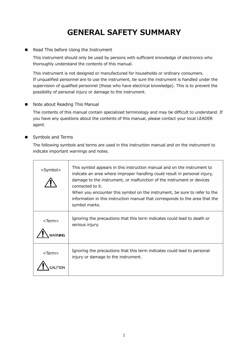
■ Symbols and Terms
The following symbols and terms are used in this instruction manual and on the instrument to indicate important warnings and notes.
<Symbol>
This symbol appears in this instruction manual and on the instrument to indicate an area where improper handling could result in personal injury, damage to the instrument, or malfunction of the instrument or devices connected to it. When you encounter this symbol on the instrument, be sure to refer to the information in this instruction manual that corresponds to the area that the symbol marks.
<Term>
Ignoring the precautions that this term indicates could lead to death or serious injury.
<Term>
Ignoring the precautions that this term indicates could lead to personal injury or damage to the instrument.
II
GENERAL SAFETY SUMMARY
Read the warnings and information below thoroughly to avoid death, personal injury, and damage and deterioration of the instrument.
■ Warnings Concerning the Case and Panels
Do not remove the instrument’s case or panels for any reason. Touching the internal components of the instrument could lead to fire or electric shock. Also, do not allow foreign materials, such as liquids, combustible matter, and metal, to enter the instrument. Turning the instrument on when such materials are inside it could lead to fire, electric shock, damage to the instrument, or some other accident.
■ Installation Environment
• Operating Temperature Range Use this instrument in a 0 to 40 °C environment. Using the instrument with its vents blocked or in a high temperature environment could lead to fire. Drastic changes in temperature, such as might be caused by moving the instrument between two rooms with different temperatures, can damage the instrument by causing condensation to form within it. If there is a possibility that the instrument has condensation within it, wait for approximately 30 minutes before turning on the power.
• Operating Humidity Range
Use this instrument in an environment whose relative humidity is 85 %RH or less where there is no threat of condensation forming. Also, do not operate this instrument with wet hands. Doing so could lead to electric shock or fire.
• Do Not Operate in an Explosive Atmosphere
Using this instrument in an environment where flammable gasses, explosive gasses, or steam is emitted or stored could lead to an explosion or fire. Do not use the instrument in such an environment.
• Do Not Insert Foreign Materials
Do not insert foreign materials, such as metal and flammable objects, through the vents or allow liquid to enter the instrument. Such acts can lead to fire, electric shock, damage to the instrument, or some other accident.
■ If You Notice Something Wrong during Operation
If you notice smoke, fire, a strange smell, or something else that is wrong with the instrument while you are operating it, stop operation immediately. Failing to do so could lead to fire. Turn OFF the power switch, and remove the power cord from the outlet. After making sure that fire has not spread anywhere, contact your local LEADER agent.
III
GENERAL SAFETY SUMMARY
■ Warnings Concerning the Power Source
Do not use a power source with a voltage other than the rated power source voltage for the instrument. Doing so could lead to fire. Confirm the voltage of the power source before you connect the power cord to it. Only use a power source whose frequency is 50/60 Hz.
Use a power cord that is appropriate for the voltage of the power source. Also, use a power cord that meets the safety standards of the country that you are using it in. Using a power cord that does not meet the standards could lead to fire. If the power cord is damaged, stop using it, and contact your local LEADER agent. Using a damaged power cord could lead to electrical shock or fire. When removing the power cord from the power outlet, do not pull on the cord. Pull from the plug.
■ Warnings Concerning Grounding
The instrument has a ground terminal to protect the user and the instrument from electric shock. Ensure that the product is properly grounded for safe operation.
■ Warnings Concerning the Panel
Sections of the panel are made out of glass. If the glass breaks, the broken glass may lead to injury. Do not apply a strong shock to the panel, cut it with sharp metal, or damage it in any similar manner.
■ Cautions Concerning the Input and Output Connectors
To avoid damaging the instrument, only apply signals to the input connectors that conform to the specifications in this instruction manual. Do not short or apply external voltage to the output connectors. Doing so could damage the instrument.
■ Cautions Concerning the Ethernet Port
When you are connecting the instrument to the communication provider's equipment, connect to the Ethernet port through a hub that is authorized for use in the country that you are using the instrument in.

IV
GENERAL SAFETY SUMMARY
■ Calibration and Repairs
This instrument has been carefully examined at the factory to ensure that its performance is in accordance with the standards. However, because of factors such as parts wearing out over time, the performance of the instrument may degrade. To ensure stable performance, we recommend that you have the instrument calibrated regularly. Also, if the instrument malfunctions, repairs are necessary. For repairs and calibration, contact your local LEADER agent.
■ Routine Maintenance
When you clean the instrument, remove the power plug from the outlet. Do not use thinner or benzene when you clean the instrument's case, panels, or knobs. Doing so could lead to paint chipping and the corrosion of plastic components. To clean the case, panels, and knobs, use a soft cloth with mild detergent, and wipe gently. While cleaning, make sure that foreign materials, such as water and detergent, do not enter the product. If liquid or a metal object enters into the instrument, fire or electric shock may result.
■ About the European WEEE Directive
This instrument and its accessories are subject to the European WEEE Directive. Follow the applicable regulations of your country or region when discarding this instrument or its accessories. Follow the EU Battery Directive when discarding the batteries that you removed from this instrument. (WEEE stands for Waste Electrical and Electronic Equipment.)
Follow the warnings and precautions that have been listed in this section to use the instrument correctly and safely. Precautions are also contained in various other sections of this instruction manual. To use the instrument correctly, be sure to follow those precautions as well. If you have any questions or comments about this instruction manual, please contact your local LEADER agent.

1. INTRODUCTION
1
1. INTRODUCTION Thank you for purchasing this LEADER instrument. To use this instrument safely, read this instruction manual thoroughly, and make sure that you know how to use the instrument properly.
If some point about the operation of this instrument is still unclear after you have read this instruction manual, refer to the contact information on the back cover of the manual to contact LEADER, or contact your local LEADER agent. After you have finished reading this manual, keep it in a convenient place so that you can refer to it when necessary.
1.1 Scope of Warranty
This LEADER instrument has been manufactured under the strictest quality control guidelines. LEADER shall not be obligated to furnish the following free services during the warranty period.
1. Repair of malfunction or damages resulting from fire, natural calamity, or improper voltage
applied by the user. 2. Repair of a product that has been improperly repaired, adjusted, or modified by personnel
other than a factory-trained LEADER representative. 3. Repair of malfunctions or damages resulting from improper use. 4. Repair of malfunctions caused by devices other than this instrument. 5. Repair of malfunctions or damages without the presentation of a proof of purchase or
receipt bill for the instrument.

1. INTRODUCTION
2
1.2 Operating Precautions
1.2.1 Maximum Allowable Input Voltage
The maximum signal voltage that can be applied to the input connectors is indicated below. Do not apply excessive voltage to the connectors. Doing so may damage the device or lead to injury.
Table 1-1 Maximum allowable input voltage
Input Connector Maximum Allowable Input Voltage LV 5490 EXT REF ±5 V (DC + peak AC)
REMOTE 0 to +5 V SER01 SDI INPUT ±2 V (DC + peak AC) SER02 SDI INPUT (1A to 1D) 0 to +12 V (DC), ±1V (AC)
SDI INPUT (2A to 2D) ±2 V (DC + peak AC) SER03 DIGITAL AUDIO INPUT ±5 V (DC + peak AC) SER06 12G-SDI INPUT (1A to 1D)
3G-SDI INPUT (2A to 2D) ±2 V (DC + peak AC)
SER08 12G-SDI INPUT (1A to 1D) 3G-SDI INPUT (2A to 2D)
±2 V (DC + peak AC)
1.2.2 Mechanical Shock
This instrument contains sensitive components, so it may be damaged if it is dropped or otherwise exposed to a strong shock.
1.2.3 Electrostatic Damage
Electronic components can be damaged by static discharge. Static electricity can build up in the core wire of a coaxial cable. Before connecting a coaxial cable to the instrument, short the core wire of the cable with the external conductor.
1.2.4 Warming Up
To ensure more accurate measurements, turn ON the instrument approximately 30 minutes before you intend to use it to allow its internal temperature to stabilize.
1.2.5 About Standby Mode
Even if you press the power switch to turn off this instrument, the instrument remains in standby mode as long as the power cord is connected to the outlet. In standby mode, some of the internal circuits operate and may generate heat. Unless necessary, keep the power cord disconnected from the outlet.

1. INTRODUCTION
3
1.2.6 Backup
This instrument has a last-memory feature. When you turn the power on, the instrument starts with the panel settings that were in use the last time that it was turned off. If the backup battery is out of power, the message “The last memory feature is disabled.” will appear, and this last-memory feature will no longer work.
To continually use the last-memory feature, we recommend that you replace the backup battery with a new one every five years after you purchase the instrument. You cannot replace the backup battery yourself. For details, contact your nearest LEADER agent.
1.2.7 About the LCD Panel
There may be a small number of pixels in the LCD panel that do not light or are always on. Note that this is not a malfunction.
The LCD panel supports a large number of video signals. SDI input signals are displayed asynchronously on the LCD. Therefore, images may appear to flicker on the waveform and picture displays. In addition, the input SDI signal is temporarily stored in frame memory and is loaded by using the LCD display synchronization signal—which is not synchronized with the input SDI signal. Therefore, because frame skip—which skips over frames in the memory—and frame repeat—which reads the same frames of the memory twice—occur, the image may appear to flicker. (An external sync signal can be used to synchronize the LCD to the input signal.)
1.3 About Trademarks and Licenses
The company and product names in this document are trademarks or registered trademarks of their respective holders.

1. INTRODUCTION
4
1.4 About Terminology Used in this Manual
● SER**
LV 5490SER** is referred to as SER**.
● Single Input Mode
This refers to the mode in which on the INPUT menu, F•7 DISPLAY is set to SINGLE. It is a mode for measuring a single input signal.
● Simul Mode
This refers to the mode in which on the INPUT menu, F•7 DISPLAY is set to SIMUL. It is a mode for measuring multiple input signals simultaneously.
● Multi Display
This refers to the mode in which the MULTI key is on.
● About Underlining (_)
Underlined options indicate the default values.
● Input Formats and Link Systems
The following names are used for the input formats and link systems. Multi link may be used as a collective term to refer to dual link and quad link.
Table 1-2 Input formats and link systems
Name Description Link System SD SD-SDI Single link HD HD-SDI Single link 3G-A 3G-SDI level A Single link 3G-B-DL 3G-SDI level B dual link mapping Single link 3G-B-DS 3G-SDI level B dual stream mapping Single link 12G 12G-SDI TYPE 1 Single link HD (DL) HD-SDI dual link Dual Link HD (QL) HD-SDI quad link Quad link 3G (DL)-2K 3G-A, 3G-B-DL dual link
Resolution 1920(2048)×1080 Dual Link
3G (DL)-4K 3G-B-DS dual link Resolution 3840(4096)×2160
Dual Link
3G (QL) 3G-A, 3G-B-DL quad link Quad link 3G Collective name for 3G links - 3G-B Collective name for 3G-B-DL and 3G-B-DS - 3G (DL) Collective name for 3G (DL)-2K and 3G (DL)-4K - 4K Collective name for HD (QL), 3G (DL)-4K, 3G (QL) and 12G -

1. INTRODUCTION
5
1.5 About the LV 5480
This manual explains the LV 5490. If you are using the LV 5480, refer to the LV 5490 vs. LV 5480 comparison table below, and read LV 5490 as LV 5480 in this manual.
Table 1-3 LV 5490 vs. LV 5480 comparison
Item LV 5490 LV 5480 Supported units LV 5490SER01
LV 5490SER02 LV 5490SER03 LV 5490SER06 LV 5490SER08
LV 5490SER01 LV 5490SER02 LV 5490SER03 LV 5490SER06 (*1) LV 5490SER08 (*1)
Supported options LV 5490SER04 LV 5490SER05 LV 5490SER07 LV 5490SER09 (*2) LV 5490SER10
LV 5490SER04 LV 5490SER05 LV 5490SER07 LV 5490SER09 (*2) LV 5490SER10 LV 5480SER20 LV 5480SER21
4K function Standard support Supported with LV 5480SER20 (*3) Signal generation function Standard support Supported with LV 5480SER21 (*4) USB save destination folder name LV5490_USER LV5480_USER TELNET login and password LV5490 LV5480 FTP login and password LV5490 LV5480 SNMP MIB file name lv5490.my lv5490.my (*5)
*1 The LV 5480SER20 must be installed to install the LV 5490SER06 or LV 5490SER08. *2 The LV 5490SER06 must be installed, to install LV 5490SER09. *3 Installing the LV 5480SER20 enables you to select 4K 3G Quad Link, 4K 3G Dual Link, and 4K HD Quad
Link for SDI System on the SDI IN tab. *4 Installing the LV 5480SER21 enables you to select Test Signal for Mode on the SDI OUT tab. *5 The MIB file is shared with the LV 5490, but the SNMP manager detects it as “LV5480.” The other aspects
of the SNMP function are the same as those of the LV 5490.

2. Product Configuration
6
2. Product Configuration 2.1 Lineup
LV 5490 MULTI WAVEFORM MONITOR Built-in LCD Multi Waveform Monitor 2.2 About Units
This instrument only functions as a measuring instrument after at least one unit is installed. To replace or add a unit, contact your local LEADER agent. You cannot install or uninstall units.
Table 2-1 Unit types
Unit Name Main Function LV 5490SER01 SDI INPUT SDI signal measurement LV 5490SER02 SDI INPUT / EYE SDI signal measurement and eye pattern display LV 5490SER03 DIGITAL AUDIO Embedded audio signal measurement
External Audio Signal Measurement Dolby signal measurement (option)
LV 5490SER06 12G-SDI INPUT 12G SDI signal measurement LV 5490SER08 IP(NMI) IP(NMI), 12G SDI signal measurement
* The LV 5490 requires an LV 5490SER01, LV 5490SER02, LV 5490SER06, or LV 5490SER08 to be installed.
These units cannot be installed simultaneously. 2.3 About Options
The following options (sold separately) can be installed in the LV 5490. If you want to obtain an option, provide your local LEADER agent with the LV 5490’s MAC address (see the LICENSE tab) and serial number (see the rear panel). We will issue a license key. When you receive the license key, install the option by referring to section 7.4, “Installing Options.” Each LV 5490 requires a unique license key. You cannot use the same key for multiple instruments.
Table 2-2 Types of options
Option Name Main Function LV 5490SER04 FOCUS ASSIST Assists focusing LV 5490SER05 CIE DIAGRAM Displays CIE chromaticity diagrams LV 5490SER07 HDR HDR signal measurement LV 5490SER09 12G-SDI EYE Eye pattern display of 12G SDI signal
3. SPECIFICATIONS
7
3. SPECIFICATIONS 3.1 General
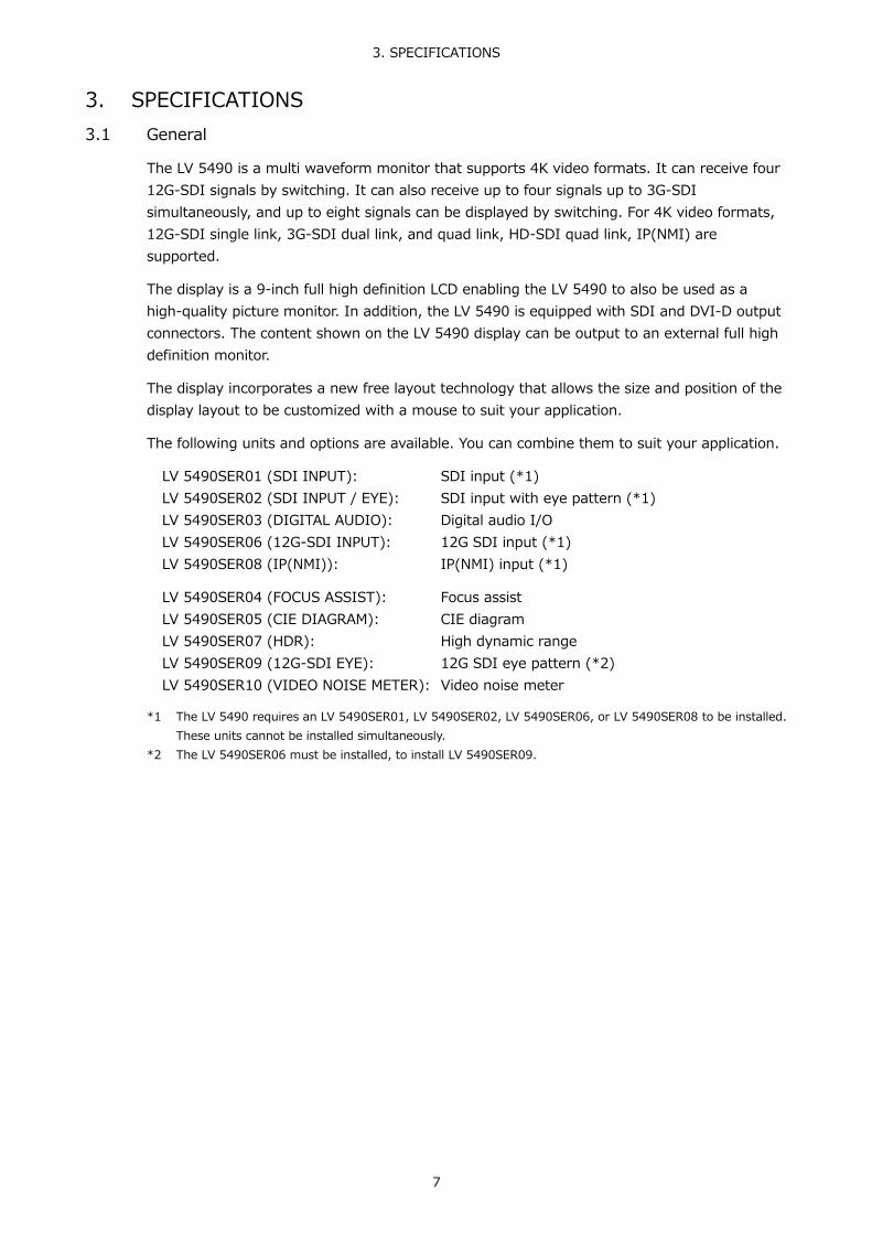
The LV 5490 is a multi waveform monitor that supports 4K video formats. It can receive four 12G-SDI signals by switching. It can also receive up to four signals up to 3G-SDI simultaneously, and up to eight signals can be displayed by switching. For 4K video formats, 12G-SDI single link, 3G-SDI dual link, and quad link, HD-SDI quad link, IP(NMI) are supported.
The display is a 9-inch full high definition LCD enabling the LV 5490 to also be used as a high-quality picture monitor. In addition, the LV 5490 is equipped with SDI and DVI-D output connectors. The content shown on the LV 5490 display can be output to an external full high definition monitor.
The display incorporates a new free layout technology that allows the size and position of the display layout to be customized with a mouse to suit your application.
The following units and options are available. You can combine them to suit your application.
LV 5490SER01 (SDI INPUT): SDI input (*1) LV 5490SER02 (SDI INPUT / EYE): SDI input with eye pattern (*1) LV 5490SER03 (DIGITAL AUDIO): Digital audio I/O LV 5490SER06 (12G-SDI INPUT): 12G SDI input (*1) LV 5490SER08 (IP(NMI)): IP(NMI) input (*1)
LV 5490SER04 (FOCUS ASSIST): Focus assist LV 5490SER05 (CIE DIAGRAM): CIE diagram LV 5490SER07 (HDR): High dynamic range LV 5490SER09 (12G-SDI EYE): 12G SDI eye pattern (*2) LV 5490SER10 (VIDEO NOISE METER): Video noise meter
*1 The LV 5490 requires an LV 5490SER01, LV 5490SER02, LV 5490SER06, or LV 5490SER08 to be installed.
These units cannot be installed simultaneously. *2 The LV 5490SER06 must be installed, to install LV 5490SER09.

3. SPECIFICATIONS
8
3.2 Features
● 4K Video Format
The LV 5490 supports 4K video formats (4096×2160 and 3840×2160) based on 12G single link, 3G dual link and quad link and HD quad link. Up to four 12G single link or 3G dual link 4K video signals can be displayed by switching. Up to two 3G quad link or HD quad link 4K video signals can be displayed by switching. In addition, IP (NMI) supports video signals in 4K video format (3840×2160). If 4K video is input into IP (NMI), only one input is displayed.
● Full High Definition LCD
The LV 5490 is equipped with a 9-inch LCD with excellent viewing angle and color reproducibility. It can also be used as a high-quality high definition picture monitor.
● Free Layout
The LV 5490 can display not only the video signal waveform, vector waveform, picture, and the like of an input SDI signal simultaneously, but it can also display multiple input signals simultaneously and overlay them for comparison. The measurement screens can be adjusted in size and position as you like. Different layout configurations can be achieved simply by using the mouse.
● Eight Inputs and Simultaneous Four Input Display
The LV 5490 has four SDI input connectors compatible with 3G, HD, and SD and can display up to four SDI input signals simultaneously. It also has four additional SDI I/O connectors. (*1) If these connectors are used as inputs, the LV 5490 can receive up to eight SDI input signals.
*1 For the I/O connectors, the maximum length of 5C2V cables that SD signals can be received is 100
meters. See section 5.7.1, “SDI Signal I/O.”
● Up to Four 12G-SDI Inputs and Reclock Output (SER06/SER08)
The LV 5490 has four SDI input connectors compatible with 12G and can display the SDI signal of one of these inputs by switching. Further, it also provides reclock output of the displayed 12G-SDI signal.
● Equivalent Cable Length Measurement (SER01/SER02)
The four SDI input connectors are equipped with an equivalent cable length measurement function. This function displays SDI signal attenuation in terms of a coaxial cable length, which can be used to check the margin that the system has.
● Pattern Generator Function and Reclock Output
By using the four SDI I/O connectors as outputs, you can use them as reclock outputs of the SDI signals received through the SDI input connectors. They can also be used as outputs for generating patterns such as color bars with embedded audio. In pattern output, the phase of each SDI output can be varied up to ±0.5 lines or ±1/2 frames. This feature can be used to check the system’s phase margin.

3. SPECIFICATIONS
9
● External Monitor Output and SDI Routing
The measurement screen can be output in SDI or DVI-D from the monitor output connector. The output signal can be displayed on an external LCD in full high definition resolution. In addition, an SDI signal received through one of the SDI input or SDI I/O connectors can be reclocked and output, serving as a routing function. (excluding 12G-SDI)
● USB Mouse Operation
A USB mouse can be used to operate the panel. If the measurement screen is displayed on an external monitor in SDI or DVI-D, you can control the LV 5490 by using a USB mouse while viewing the external monitor.
● SDI Signal Analysis
On the status display, SDI signal transmission errors and various errors related to the embedded audio signal, ancillary data, and video data can be detected. It also has event log, data dump, phase difference measurement features, and lip sync measurement (SER03) enabling you to perform detailed SDI signal analysis.
● Screen Capture
The LV 5490 is equipped with a screen capture feature, which captures the entire display as still-image data. Not only can captured data be displayed by the LV 5490, but it can also be compared with an input signal or saved to a USB memory device as bitmap data for viewing on a PC.
● Frame Capture
The LV 5490 is equipped with a frame capture feature, which captures single frames in an SDI signal. Frames can be captured manually or automatically when errors occur.
● Time Code Display
The LV 5490 can display the LTC or VITC that is embedded in an SDI signal and the D-VITC of an SD signal. The timecode can also be used for time stamps in the event log.
● External Remote Connector
The remote control connector can be used to load presets, switch the input signal, and transmit alarms.
● Ethernet Port
By connecting the Ethernet interface to a PC, you can control the LV 5490 remotely over TELNET, transfer files over FTP, control the LV 5490 remotely and detect errors over SNMP, and control the LV 5490 over HTTP (to be supported in the future). You can also connect to the separately-sold LV 5490-01 (REMOTECONTROLLER).
● Eye Pattern Display (SER02/SER09)
This feature can display eye pattern waveforms and jitter waveforms of SDI signals as well as measurement results of various parameters. The feature displays the information of the SDI signals received through the four SDI input connectors, one input at a time.

3. SPECIFICATIONS
10
● Embedded Audio Display (SER03)
Embedded audio can be separated from the SDI signal and shown in Lissajous, surround, and meter displays. Other types of analysis displays are also available. 16 channels of one SDI signal or 4 channels of four SDI signals can be displayed simultaneously.
● Digital Audio I/O (SER03)
The digital Audio I/O option has eight digital I/O connectors. Switching between input and output is possible in groups of four connectors (eight channels). When used as inputs, digital audio can be shown in Lissajous, surround, and meter displays. Other types of analysis displays are also available. When used as outputs, embedded audio is separated from SDI signals and output as digital audio signals.
● Dolby Option (SER03)
When the Dolby option is added, the Dolby audio signal in the embedded audio or digital audio signal can be decoded and displayed. Dolby E, Dolby Digital, and Dolby Digital Plus are supported.
● Focus Assist (SER04)
A new focusing algorithm based on nonlinear super-resolution technology has been developed, allowing highly sensitive focusing even on low-contrast images that were difficult to be focused in on in the past. You can select the sensitivity from the five available levels according to the image scene.
● CIE Diagram (SER05)
Chromaticity diagrams based on ITU-R BT.601, ITU-R BT.709, and ITU-R BT.2020 colorimetries can be displayed. Display mode supports CIE 1931 (xy display) and CIE 1976 (u'v' display).
● HDR (SER07)
On CINEZONE display, the SDR area is displayed in monochrome, while the HDR area is displayed using colors corresponding to the brightness. This makes it easy to view the brightness distribution in the HDR area. In addition, displaying the peak and average values of brightness reduces the grading time. On video signal waveform display and histogram display, displaying a scale corresponding to the HDR standard makes it possible to manage video in Scene linear.
● IP(NMI) Input (SER08)
As the IP input supports Networked Media Interface (NMI), 4K (compressed) and HD (compressed or uncompressed) video signals can be displayed with little delay. If the input signal is HD, the video signals of up to four inputs can be displayed simultaneously. In addition, IP and SDI can be displayed simultaneously.
● Video Noise Meter (SER10)
Noise included in the Y, G, B, or R signal of the SDI signal applied to the LV 5490 can be measured.

3. SPECIFICATIONS
11
● RS-422/485 Connector (custom order feature)
The camera ID can be displayed using serial communication.
● Remote Controller (LV 5490-01; sold separately)
Equipped with keys that correspond to the front panel keys of the LV 5490. They can be used to remotely control the LV 5490 via Ethernet. (You cannot use TELNET while you are using the LV 5490-01.)

3. SPECIFICATIONS
12
3.3 Specifications
3.3.1 SDI Formats and Standards
Table 3-1 SD video signal formats and standards
Color System Quantization Image Field Frequency/Scanning Compliant Standard YCBCR 4:2:2 10 bits 720×487 59.94/I SMPTE ST 259
720×576 50/I
Table 3-2 HD video signal formats and standards
Color System Quantization Image Frame (Field) Frequency/Scanning Compliant Standard YCBCR 4:2:2 10 bits 1280×720 60/59.94/50/30/29.97/25/24/23.98/P SMPTE ST 292-1
SMPTE ST 296 1920×1080 60/59.94/50/I SMPTE ST 274
SMPTE ST 292-1 30/29.97/25/24/23.98/P 30/29.97/25/24/23.98/PsF
Table 3-3 3G-A video signal formats and standards
Color System Quantization Image Frame (Field) Frequency/Scanning Compliant Standard YCBCR 4:2:2 10 bits 1920×1080 60/59.94/50/P SMPTE ST 274
SMPTE ST 425-1 48/47.95/P -
2048×1080 60/59.94/50/48/47.95/P SMPTE ST 425-1 SMPTE ST 2048-2
12 bits 1920×1080 60/59.94/50/I SMPTE ST 274 SMPTE ST 425-1 30/29.97/25/24/23.98/P
30/29.97/25/24/23.98/PsF 2048×1080 30/29.97/25/24/23.98/P SMPTE ST 425-1
SMPTE ST 2048-2 30/29.97/25/24/23.98/PsF YCBCR 4:4:4 10 bits 1280×720 60/59.94/50/30/29.97/25/24/23.98/P SMPTE ST 296
SMPTE ST 425-1 1920×1080 60/59.94/50/I SMPTE ST 274
SMPTE ST 425-1 30/29.97/25/24/23.98/P 30/29.97/25/24/23.98/PsF
2048×1080 30/29.97/25/24/23.98/P SMPTE ST 425-1 SMPTE ST 2048-2 30/29.97/25/24/23.98/PsF
12 bits 1920×1080 60/59.94/50/I SMPTE ST 274 SMPTE ST 425-1 30/29.97/25/24/23.98/P
2048×1080 30/29.97/25/24/23.98/P SMPTE ST 425-1 SMPTE ST 2048-2 30/29.97/25/24/23.98/PsF

3. SPECIFICATIONS
13
Color System Quantization Image Frame (Field) Frequency/Scanning Compliant Standard RGB 4:4:4 10 bits 1280×720 60/59.94/50/30/29.97/25/24/23.98/P SMPTE ST 296
SMPTE ST 425-1 1920×1080 60/59.94/50/I SMPTE ST 274
SMPTE ST 425-1 30/29.97/25/24/23.98/P 30/29.97/25/24/23.98/PsF
2048×1080 30/29.97/25/24/23.98/P SMPTE ST 425-1 SMPTE ST 2048-2 30/29.97/25/24/23.98/PsF
12 bits 1920×1080 60/59.94/50/I SMPTE ST 274 SMPTE ST 425-1 30/29.97/25/24/23.98/P
2048×1080 30/29.97/25/24/23.98/P SMPTE ST 425-1 SMPTE ST 2048-2 30/29.97/25/24/23.98/PsF
XYZ 4:4:4 12 bits 2048×1080 30/25/24/P SMPTE ST 425-1 SMPTE ST 428 30/25/24/PsF
Table 3-4 3G-B-DL and HD (DL) video signal formats and standards
Color System Quantization Image Frame (Field) Frequency/Scanning Compliant Standard YCBCR 4:2:2 10 bits 1920×1080 60/59.94/50/P SMPTE ST 274
SMPTE ST 372 SMPTE ST 425-1
2048×1080 60/59.94/50/48/47.95/P SMPTE ST 372 SMPTE ST 425-1 SMPTE ST 2048-2
12 bits 1920×1080 60/59.94/50/I SMPTE ST 274 SMPTE ST 372 SMPTE ST 425-1
30/29.97/25/24/23.98/P 30/29.97/25/24/23.98/PsF
2048×1080 30/29.97/25/24/23.98/P SMPTE ST 372 SMPTE ST 425-1 SMPTE ST 2048-2
30/29.97/25/24/23.98/PsF
YCBCR 4:4:4 10 bits 1920×1080 60/59.94/50/I SMPTE ST 274 SMPTE ST 372 SMPTE ST 425-1
30/29.97/25/24/23.98/P 30/29.97/25/24/23.98/PsF
2048×1080 30/29.97/25/24/23.98/P SMPTE ST 372 SMPTE ST 425-1 SMPTE ST 2048-2
30/29.97/25/24/23.98/PsF
12 bits 1920×1080 60/59.94/50/I SMPTE ST 274 SMPTE ST 372 SMPTE ST 425-1
30/29.97/25/24/23.98/P 30/29.97/25/24/23.98/PsF
2048×1080 30/29.97/25/24/23.98/P SMPTE ST 372 SMPTE ST 425-1 SMPTE ST 2048-2
30/29.97/25/24/23.98/PsF

3. SPECIFICATIONS
14
Color System Quantization Image Frame (Field) Frequency/Scanning Compliant Standard RGB 4:4:4 10 bits 1920×1080 60/59.94/50/I SMPTE ST 274
SMPTE ST 372 SMPTE ST 425-1
30/29.97/25/24/23.98/P 30/29.97/25/24/23.98/PsF
2048×1080 30/29.97/25/24/23.98/P SMPTE ST 372 SMPTE ST 425-1 SMPTE ST 2048-2
30/29.97/25/24/23.98/PsF
12 bits 1920×1080 60/59.94/50/I SMPTE ST 274 SMPTE ST 372 SMPTE ST 425-1
30/29.97/25/24/23.98/P 30/29.97/25/24/23.98/PsF
2048×1080 30/29.97/25/24/23.98/P SMPTE ST 372 SMPTE ST 425-1 SMPTE ST 2048-2
30/29.97/25/24/23.98/PsF
XYZ 4:4:4 12 bits 2048×1080 30/25/24/P SMPTE ST 372 SMPTE ST 425-1 SMPTE ST 428
30/25/24/PsF
* When these signals are displayed, phase differences of up to 100 clocks (approx. 1.34 us) between HD
(DL) links are automatically corrected.
Table 3-5 3G-B-DS video signal formats and standards
Color System Quantization Image Frame (Field) Frequency/Scanning Compliant Standard YCBCR 4:2:2 10 bits 1920×1080 60/59.94/50/I SMPTE ST 274
SMPTE ST 425-1 30/29.97/25/24/23.98/P 30/29.97/25/24/23.98/PsF
1280×720 60/59.94/50/30/29.97/25/24/23.98/P SMPTE ST 296 SMPTE ST 425-1
Table 3-6 3G(DL)-2K video signal formats and standards
Color System Quantization Image Frame (Field) Frequency/Scanning Compliant Standard YCBCR 4:2:2 12 bits 1920×1080 60/59.94/50/P SMPTE ST 274
SMPTE ST 425-3 48/47.95/P -
2048×1080 60/59.94/50/48/47.95/P SMPTE ST 2048-2 SMPTE ST 425-3
YCBCR 4:4:4 10 bits 1920×1080 60/59.94/50/P SMPTE ST 274 SMPTE ST 425-3
2048×1080 60/59.94/50/48/47.95/P SMPTE ST 2048-2 SMPTE ST 425-3
12 bits 1920×1080 60/59.94/50/P SMPTE ST 274 SMPTE ST 425-3
2048×1080 60/59.94/50/48/47.95/P SMPTE ST 2048-2 SMPTE ST 425-3

3. SPECIFICATIONS
15
Color System Quantization Image Frame (Field) Frequency/Scanning Compliant Standard RGB 4:4:4 10 bits 1920×1080 60/59.94/50/P SMPTE ST 274
SMPTE ST 425-3 2048×1080 60/59.94/50/48/47.95/P SMPTE ST 2048-2
SMPTE ST 425-3 12 bits 1920×1080 60/59.94/50/P SMPTE ST 274
SMPTE ST 425-3 2048×1080 60/59.94/50/48/47.95/P SMPTE ST 2048-2
SMPTE ST 425-3
* When these signals are displayed, phase differences of up to 100 clocks (approx. 0.67 us) between links are automatically corrected.
* 3G-A and 3G-B-DL links are supported.
Table 3-7 3G (DL)-4K video signal formats and standards
Division Transmission
System Color System Quantization Image Frame Frequency/Scanning
Compliant Standard
Square YCBCR 4:2:2 10 bits 3840×2160 30/29.97/25/24/23.98/P SMPTE ST 425-3 SMPTE ST 2036-1
30/29.97/25/24/23.98/PsF - 4096×2160 30/29.97/25/24/23.98/P SMPTE ST 425-3
SMPTE ST 2048-1 30/29.97/25/24/23.98/PsF -
2 sample interleave
YCBCR 4:2:2 10 bits 3840×2160 30/29.97/25/24/23.98/P SMPTE ST 425-3 SMPTE ST 2036-1
4096×2160 30/29.97/25/24/23.98/P SMPTE ST 425-3 SMPTE ST 2048-1
* When these signals are displayed, phase differences of up to 100 clocks (approx. 0.67 us) between
links are automatically corrected. * 3G-B-DS links are supported.
Table 3-8 HD (QL) video signal formats and standards
Division Transmission
System Color System Quantization Image Frame Frequency/Scanning
Compliant Standard
Square YCBCR 4:2:2 10 bits 3840×2160 30/29.97/25/24/23.98/P - 30/29.97/25/24/23.98/PsF -
4096×2160 30/29.97/25/24/23.98/P - 30/29.97/25/24/23.98/PsF -
* When these signals are displayed, phase differences of up to 100 clocks (approx. 0.67 us) between
links are automatically corrected.

3. SPECIFICATIONS
16
Table 3-9 3G (QL) video signal formats and standards
Division Transmission
System Color System Quantization Image Frame Frequency/Scanning
Compliant Standard
Square YCBCR 4:2:2 10 bits 3840×2160 60/59.94/50/P SMPTE ST 425-5 SMPTE ST 2036-1
48/47.95/P - 4096×2160 60/59.94/50/48/47.95/P SMPTE ST 425-5
SMPTE ST 2048-1 12 bits 3840×2160 30/29.97/25/24/23.98/P SMPTE ST 425-5
SMPTE ST 2036-1 30/29.97/25/24/23.98/PsF -
4096×2160 30/29.97/25/24/23.98/P SMPTE ST 425-5 SMPTE ST 2048-1
30/29.97/25/24/23.98/PsF - YCBCR 4:4:4 10 bits 3840×2160 30/29.97/25/24/23.98/P SMPTE ST 425-5
SMPTE ST 2036-1 30/29.97/25/24/23.98/PsF -
4096×2160 30/29.97/25/24/23.98/P SMPTE ST 425-5 SMPTE ST 2048-1
30/29.97/25/24/23.98/PsF - 12 bits 3840×2160 30/29.97/25/24/23.98/P SMPTE ST 425-5
SMPTE ST 2036-1 30/29.97/25/24/23.98/PsF -
4096×2160 30/29.97/25/24/23.98/P SMPTE ST 425-5 SMPTE ST 2048-1
30/29.97/25/24/23.98/PsF - RGB 4:4:4 10 bits 3840×2160 30/29.97/25/24/23.98/P SMPTE ST 425-5
SMPTE ST 2036-1 30/29.97/25/24/23.98/PsF -
4096×2160 30/29.97/25/24/23.98/P SMPTE ST 425-5 SMPTE ST 2048-1
30/29.97/25/24/23.98/PsF - 12 bits 3840×2160 30/29.97/25/24/23.98/P SMPTE ST 425-5
SMPTE ST 2036-1 30/29.97/25/24/23.98/PsF -
4096×2160 30/29.97/25/24/23.98/P SMPTE ST 425-5 SMPTE ST 2048-1
30/29.97/25/24/23.98/PsF - XYZ 4:4:4 12 bits 4096×2160 30/25/24/P SMPTE ST 425-5
SMPTE ST 428 30/25/24/PsF -

3. SPECIFICATIONS
17
Division Transmission
System Color System Quantization Image Frame Frequency/Scanning
Compliant Standard
2 sample interleave
YCBCR 4:2:2 10 bits 3840×2160 60/59.94/50/P SMPTE ST 425-5 SMPTE ST 2036-1
48/47.95/P - 4096×2160 60/59.94/50/48/47.95/P SMPTE ST 425-5
SMPTE ST 2048-1 12 bits 3840×2160 30/29.97/25/24/23.98/P SMPTE ST 425-5
SMPTE ST 2036-1 4096×2160 30/29.97/25/24/23.98/P SMPTE ST 425-5
SMPTE ST 2048-1 YCBCR 4:4:4 10 bits 3840×2160 30/29.97/25/24/23.98/P SMPTE ST 425-5
SMPTE ST 2036-1 4096×2160 30/29.97/25/24/23.98/P SMPTE ST 425-5
SMPTE ST 2048-1 12 bits 3840×2160 30/29.97/25/24/23.98/P SMPTE ST 425-5
SMPTE ST 2036-1 4096×2160 30/29.97/25/24/23.98/P SMPTE ST 425-5
SMPTE ST 2048-1 RGB 4:4:4 10 bits 3840×2160 30/29.97/25/24/23.98/P SMPTE ST 425-5
SMPTE ST 2036-1 4096×2160 30/29.97/25/24/23.98/P SMPTE ST 425-5
SMPTE ST 2048-1 12 bits 3840×2160 30/29.97/25/24/23.98/P SMPTE ST 425-5
SMPTE ST 2036-1 4096×2160 30/29.97/25/24/23.98/P SMPTE ST 425-5
SMPTE ST 2048-1 XYZ 4:4:4 12 bits 4096×2160 30/25/24/P SMPTE ST 425-5
SMPTE ST 428
* When these signals are displayed, phase differences of up to 100 clocks (approx. 0.67 us) between links are automatically corrected.
* 3G-A and 3G-B-DL links are supported.

3. SPECIFICATIONS
18
Table 3-10 12G video signal formats and standards (SER06/SER08)
Division Transmission
System Color System Quantization Image Frame Frequency/Scanning Compliant Standard
2 sample interleave
YCBCR 4:2:2 10 bits 3840×2160 60/59.94/50/P SMPTE ST 2036-1 SMPTE ST 2082-10
48/47.95/P (SER08 only) - 4096×2160 60/59.94/50/48/47.95/P SMPTE ST 2036-1
SMPTE ST 2082-10 12 bits 3840×2160 30/29.97/25/24/23.98/P SMPTE ST 2036-1
SMPTE ST 2082-10 4096×2160 30/29.97/25/24/23.98/P SMPTE ST 2036-1
SMPTE ST 2082-10 YCBCR 4:4:4 10 bits 3840×2160 30/29.97/25/24/23.98/P SMPTE ST 2036-1
SMPTE ST 2082-10 4096×2160 30/29.97/25/24/23.98/P SMPTE ST 2036-1
SMPTE ST 2082-10 12 bits 3840×2160 30/29.97/25/24/23.98/P SMPTE ST 2036-1
SMPTE ST 2082-10 4096×2160 30/29.97/25/24/23.98/P SMPTE ST 2036-1
SMPTE ST 2082-10 RGB 4:4:4 10 bits 3840×2160 30/29.97/25/24/23.98/P SMPTE ST 2036-1
SMPTE ST 2082-10 4096×2160 30/29.97/25/24/23.98/P SMPTE ST 2036-1
SMPTE ST 2082-10 12 bits 3840×2160 30/29.97/25/24/23.98/P SMPTE ST 2036-1
SMPTE ST 2082-10 4096×2160 30/29.97/25/24/23.98/P SMPTE ST 2036-1
SMPTE ST 2082-10
* 12G-SDI TYPE 1 links are supported. 3.3.2 Supported IP (NMI) Input Signal Formats (SER08)
Table 3-11 IP (NMI) input signal format
Color System Quantization Image Frame (Field) Frequency/Scanning YCBCR 4:2:2 10 bits 1920x1080 59.94/50/I YCBCR 4:2:2 10 bits 3840x2160 59.94/50/P
* The IP transmission input system supports NMI. * The supported IP control system is IP Live System Manager.

3. SPECIFICATIONS
19
3.3.3 Embedded Audio Playback Format (SER03)
Compliant Standards 3G, HD, HD (DL) SMPTE ST 299 SD SMPTE ST 272
Format L-PCM, Dolby-E (option), Dolby Digital (option), Dolby Digital Plus (option)
Sampling Frequency 48 kHz Quantization 24 bits Clock Generation Generated from the video clock Synchronization Must be synchronized to the video clock.
All SDI signals must be synchronized. Channel Separation Separates up to four groups (16 channels) from an SDI
input. 3.3.4 SDI I/O Connectors
SDI Input Connectors Connector Type BNC Number of Input Connectors
4 (1A, 1B, 1C, 1D) Input Impedance 75 Ω Input Return Loss
5 MHz to 1.485 GHz 15 dB or more 1.485 to 2.97 GHz 10 dB or more
Maximum Input Voltage SER01/SER06/SER08 ±2 V (DC + peak AC) SER02 0 to +12 V (DC), ±1 V (AC)
SDI I/O Connectors
Connector Type BNC Number of I/O Connectors 4 (2A, 2B, 2C, 2D) I/O Impedance 75 Ω I/O Return Loss
5 MHz to 1.485 GHz 15 dB or more 1.485 to 2.97 GHz 10 dB or more
Maximum Input Voltage ±2 V (DC + peak AC) Output Voltage 800 mVp-p ± 10 % (into 75 Ω) Output Signals Reclocked signal of SDI input, pattern generator

3. SPECIFICATIONS
20
12G-SDI Output Connector (SER06/SER08) Connector Type BNC Number of Output Connectors
1 Output Impedance 75 Ω Output Return Loss
5 MHz to 1.485 GHz 15 dB or more 1.485 to 2.97 GHz 10 dB or more
Output Voltage 800 mVp-p ± 10 % (into 75 Ω) Output Signals Reclocked signal of the SDI signal received through 1A to 1D
Input Signal Selection (*1)
When the I/O Connector Is Set to Input SD/HD/3G-A/3G-B-DL Four input signals consisting of 1A, 1B, 1C, and 1D or
four input signals consisting of 2A, 2B, 2C, and 2D 3G-B-DS One input signal selected from 1A, 1B, 1C, and 1D or
one input signal selected from 2A, 2B, 2C, and 2D HD (DL), 3G (DL)-2K Two input signals consisting of (1A, 1B) and (1C, 1D) or
two input signals consisting of (2A, 2B) and (2C, 2D) 3G (DL)-4K One input signal selected from (1A, 1B) and (1C, 1D) or
one input signal selected from (2A, 2B) and (2C, 2D) 3G (QL), HD (QL) One input signal selected from (1A, 1B, 1C, 1D) and (2A,
2B, 2C, 2D) 12G (SER06/SER08) One input signal selected from 1A, 1B, 1C, and 1D
When the I/O Connector Is Set to Output
SD/HD/3G-A/3G-B-DL Input signals 1A, 1B, 1C, 1D 3G-B-DS, 12G (SER06/SER08) One input signal selected from 1A, 1B, 1C, and 1D HD (DL), 3G (DL)-2K Two input signals consisting of (1A, 1B) and (1C, 1D) 3G (DL)-4K One input signal selected from (1A, 1B) and (1C, 1D) 3G (QL), HD (QL) One input signal consisting of (1A, 1B, 1C, 1D)
*1 Parentheses indicate multi link combinations.
3.3.5 IP(NMI) Input Connectors (SER08)
Input terminal (SFP+) DLC/DLC connector Number of Ports 2 Compliant Standard 10GBASE-SR Fiber Type Multi mode Optical fiber diameter 50 μm Wavelength 850 nm
* The SFP+ transceivers are accessories.
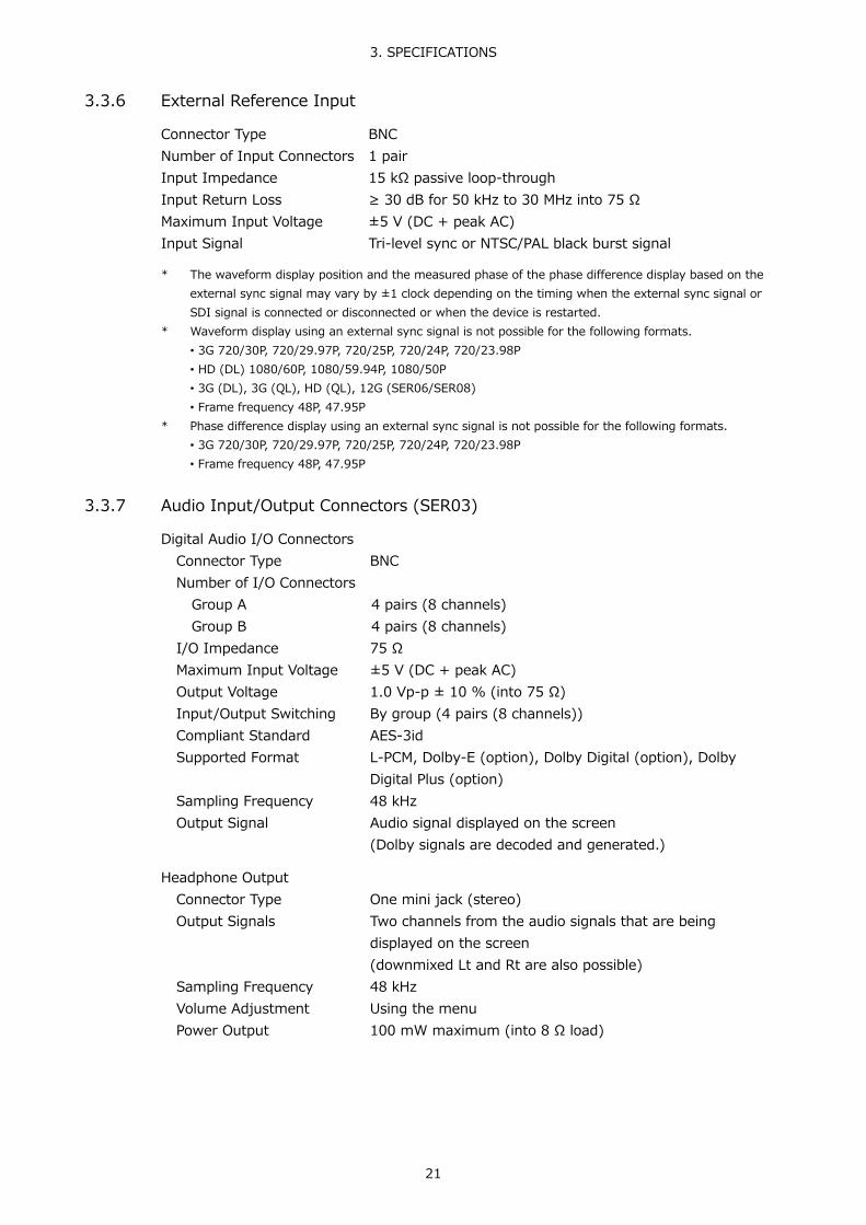
3. SPECIFICATIONS
21
3.3.6 External Reference Input
Connector Type BNC Number of Input Connectors 1 pair Input Impedance 15 kΩ passive loop-through Input Return Loss ≥ 30 dB for 50 kHz to 30 MHz into 75 Ω Maximum Input Voltage ±5 V (DC + peak AC) Input Signal Tri-level sync or NTSC/PAL black burst signal
* The waveform display position and the measured phase of the phase difference display based on the
external sync signal may vary by ±1 clock depending on the timing when the external sync signal or SDI signal is connected or disconnected or when the device is restarted.
* Waveform display using an external sync signal is not possible for the following formats. • 3G 720/30P, 720/29.97P, 720/25P, 720/24P, 720/23.98P • HD (DL) 1080/60P, 1080/59.94P, 1080/50P • 3G (DL), 3G (QL), HD (QL), 12G (SER06/SER08) • Frame frequency 48P, 47.95P
* Phase difference display using an external sync signal is not possible for the following formats. • 3G 720/30P, 720/29.97P, 720/25P, 720/24P, 720/23.98P • Frame frequency 48P, 47.95P
3.3.7 Audio Input/Output Connectors (SER03)
Digital Audio I/O Connectors Connector Type BNC Number of I/O Connectors
Group A 4 pairs (8 channels) Group B 4 pairs (8 channels)
I/O Impedance 75 Ω Maximum Input Voltage ±5 V (DC + peak AC) Output Voltage 1.0 Vp-p ± 10 % (into 75 Ω) Input/Output Switching By group (4 pairs (8 channels)) Compliant Standard AES-3id Supported Format L-PCM, Dolby-E (option), Dolby Digital (option), Dolby
Digital Plus (option) Sampling Frequency 48 kHz Output Signal Audio signal displayed on the screen
(Dolby signals are decoded and generated.)
Headphone Output Connector Type One mini jack (stereo) Output Signals Two channels from the audio signals that are being
displayed on the screen (downmixed Lt and Rt are also possible)
Sampling Frequency 48 kHz Volume Adjustment Using the menu Power Output 100 mW maximum (into 8 Ω load)

3. SPECIFICATIONS
22
3.3.8 Monitor Output Connector
SDI Output Connector Connector Type BNC Number of Output Connectors
1 Output Impedance 75 Ω Output Return Loss
5 MHz to 1.485 GHz 15 dB or more 1.485 to 2.97 GHz 10 dB or more
Output Voltage 800 mVp-p ± 10 % (into 75 Ω) Output Signal Outputs the LCD screen in HD, 3G-A, or 3G-B-DL. Output Format
Color System Quantization Image Frame (Field) Frequency/Scanning Compliant Standard
YCBCR 4:2:2 10 bits 1920×1080 60/59.94/50/I SMPTE ST 274 60/59.94/50/P
Synchronization Synchronized with the LCD refresh rate
(free run or frequency synchronization with the external reference signal(*1))
Routing Outputs the SDI signal received through I/O connectors 1A to 1D or 2A to 2D (excluding 12G-SDI)
DVI-D Output Connector
Connector Type DVI-D Number of Output Connectors
1 Signal Format Single Link T.M.D.S DDC Not supported HOT PLUG Detection Not supported Output Signal Outputs the LCD screen Image 1920×1080 Frame Frequency 60P, 59.94P, 50P Synchronization Synchronized with the LCD refresh rate
(free run or frequency synchronization with the external reference signal(*1))
*1 Frame (field) frequencies 24 Hz and 23.98 Hz are not supported.

3. SPECIFICATIONS
23
3.3.9 Control Connectors
USB Port Port Type Standard A Number of Ports 2 (one on front, one on rear) Specifications USB 2.0 Compatible Devices USB memory, USB mouse
USB Memory Feature Saves captured data, preset data, and data dumps USB Mouse Feature Used to control on the screen
Ethernet Port (*1)
Compliant Standard IEEE802.3 Supported Protocol TELNET, FTP, SNMP, HTTP, SNTP I/O Connectors RJ-45 Function Remote control from an external PC or the LV 5490-
01 Type 10Base-T, 100Base-TX
Remote Connector
Port Type 15-pin D-sub (female) Locking screws Inch screws (No.4-40UNC) Number of Ports 1 Control Signal LV-TTL level (low active) Input Voltage Range 0 to 5 VDC
All inputs are pulled up to +3.3 V (control is also possible using +5 V)
Function Used to load preset settings, switch input signals, and transmit the alarm signal
Alarm Output Outputs alarms signals when format alarms occur, when various errors occur, when the fan malfunctions, or when the internal temperature is abnormal
RS-422/485 Connector Custom order feature
*1 You cannot use TELNET and the LV 5490-01 at the same time.

3. SPECIFICATIONS
24
3.3.10 Front Panel
Display LCD Type 9-inch color TFT Resolution 1920×1080P Refresh Rate 60 Hz, 59.94 Hz, 50 Hz
(free run or frequency synchronization with the external reference signal (*1))
Backlight Brightness 32 levels Key LEDs All the keys are dimly back-lit.
The selected key is lit more brightly. Power Switch Electronic switch (which remembers whether the instrument
is on or off) Last Memory Backs up the panel settings to memory Key Lock Prevents erroneous operation
*1 The LCD refresh rate changes automatically depending on the frame rate of the external reference
signal.
Frame Rate of the External Reference Signal LCD Refresh Rate 23.98 Hz Free run
24 Hz Free run 25 Hz 50 Hz
29.97 Hz 59.94 Hz 30 Hz 60 Hz
3.3.11 Screen Capture
Function Captures the screen Indication Displays only the captured image or overlays the captured
image over the input signal Media Internal memory (RAM) and USB memory
You can only record one screen capture to the internal memory.
Data Output Screen captures can be saved as bitmap files to USB memory, or they can be saved in a file format that the LV 5490 can load.
Data Input Data saved to USB memory can be loaded and displayed on the LV 5490.

3. SPECIFICATIONS
25
3.3.12 Frame Capture
Function Captures frame data Indication Displays the captured frame data or superimposes the
captured frame data over the input signal Media Internal memory (RAM) and USB memory
You can only record one frame of data to the internal memory
Data Output Frame captures can be saved to USB memory as .dpx files, .tif files, or in a file format that the instrument can load
Data Input Data saved to USB memory can be loaded and displayed on the instrument (*1)
Capture Timing Manual and automatic (error capture) Error Capturing Automatically captures frame data when an error occurs
*1 An input signal in the same format as the frame data is required.
3.3.13 Pattern Generator
Table 3-12 HD video signal formats and standards
Color System Quantization Image Frame (Field) Frequency/Scanning Compliant Standard YCBCR 4:2:2 10 bits 1920×1080 60/59.94/50/I SMPTE ST 274
SMPTE ST 292-1 30/29.97/25/24/23.98/P 30/29.97/25/24/23.98/PsF
Table 3-13 3G-A, 3G-B-DL video signal formats and standards
Color System Quantization Image Frame (Field) Frequency/Scanning Compliant Standard YCBCR 4:2:2 10 bits 1920×1080 60/59.94/50/48/47.95/P SMPTE ST 274
SMPTE ST 425-1 48/47.95/P -
2048×1080 60/59.94/50/48/47.95/P SMPTE ST 425-1 SMPTE ST 2048-2
YCBCR 4:4:4 RGB 4:4:4
10 bits 1920×1080 60/59.94/50/I SMPTE ST 274 SMPTE ST 425-1 30/29.97/25/24/23.98/P
30/29.97/25/24/23.98/PsF 2048×1080 30/29.97/25/24/23.98/P SMPTE ST 425-1
SMPTE ST 2048-2 30/29.97/25/24/23.98/PsF
Table 3-14 3G (DL)-4K video signal formats and standards
Color System Quantization Image Frame Frequency/Scanning Compliant Standard YCBCR 4:2:2 10 bits 3840×2160 30/29.97/25/24/23.98/P SMPTE ST 425-3
SMPTE ST 2036-1 30/29.97/25/24/23.98/PsF -
4096×2160 30/29.97/25/24/23.98/P SMPTE ST 425-3 SMPTE ST 2048-1
30/29.97/25/24/23.98/PsF - * The supported division transmission systems are square and 2 sample interleave.

3. SPECIFICATIONS
26
Table 3-15 3G (QL) video signal formats and standards
Color System Quantization Image Frame Frequency/Scanning Compliant Standard YCBCR 4:2:2 10 bits 3840×2160 60/59.94/50/48/47.95/P SMPTE ST 425-5
SMPTE ST 2036-1 48/47.95/P -
4096×2160 60/59.94/50/48/47.95/P SMPTE ST 425-5 SMPTE ST 2048-1
YCBCR 4:4:4 RGB 4:4:4
10 bits 3840×2160 30/29.97/25/24/23.98/P SMPTE ST 425-5 SMPTE ST 2036-1
30/29.97/25/24/23.98/PsF - 4096×2160 30/29.97/25/24/23.98/P SMPTE ST 425-5
SMPTE ST 2048-1 30/29.97/25/24/23.98/PsF -
* The supported division transmission systems are square and 2 sample interleave. * 3G-A and 3G-B-DL links are supported.
Output Pattern Color bar 100%, color bar 75%, multiformat color bar, color
raster, cross hatch, 10 step, limit ramp Scroll
Direction Eight directions (up, down, left, right, and their combinations)
Speed Range and Unit 4 to 124 dots, in 4 dot steps Moving Box ON, OFF Frequency Phase Adjustment (*1)
Quad Link Adjust the phase of Bch, Cch, and Dch separately relative to Ach
Dual Link Adjust the phase of Bch relative to Ach and the phase of Dch relative to Cch
Adjustment Range ± 0.5 line (in units of video clocks) ± 1/2 frame (in unit of lines)
Embedded Audio Number of Embedded Channels
16 or 8 channels depending on the video format Embedding On/Off On/off at the audio group level Audio Level -20dBFS, -18dBFS, 0dBFS, Mute
*1 The output phase may be off by ±1 clock from the specified value as a result of switching the format or
turning on and off the power. 3.3.14 Preset
Preset Saves panel settings (with a few exceptions) Number of Presets 60 Preset Loading Method Front panel or remote control connector (*1) Copying All preset data can be copied from the LV 5490 to a USB
memory device or from a USB memory device to the LV 5490.
*1 The number of presets loaded from the remote control connector can be 8 or 60.

3. SPECIFICATIONS
27
3.3.15 Display
Free Layout Function Freely arrange the windows shown with WFM, VECT, PIC,
AUDIO (SER03), STATUS, EYE (SER02/SER09) (one of each), and a window consisting of five displays shown with MULTI
Display Format Displays up to four input signals in tiled, mixed, V aligned, or H aligned mode.
Tiled Display The screen is divided into windows. Mixed Display The windows are cascaded. V Aligned Display The windows are arranged top to bottom. H Aligned Display The windows are arranged side by side.
3G-B-DS Display Format
Aligned Display The screen is divided into windows. Mixed Display The windows are cascaded.
Time Display
Displayed Contents Current time, time code Current Time Display The time based on the internal clock Time Code Display LTC, VITC, D-VITC (SD only) Compliant Standards
LTC, VITC SMPTE ST 12-2 D-VITC SMPTE ST 266
Alarm Indications Displayed on the screen when various alarms occur, when
various errors occur, when the fan malfunctions, or when the internal temperature is abnormal
Format Alarm Displays an alarm when a signal in a format other than the specified format is received
Colorimetry Alarm Displays an alarm when a signal with a colorimetry other than the specified colorimetry is received
3.3.16 SDI Video Signal Waveform Display
Waveform Operations Display Mode
Overlay Overlays component signals Parade Displays component signals side by side
Blanking Interval H and V blanking periods can be masked. RGB Conversion Converts a Y,CB,CR signal into an RGB signal and displays
the result Channel Assignment GBR or RGB order
Pseudo-Composite Display Artificially converts component signals into composite signals and displays the result
Line Select Displays the selected line Sweep Modes H, V Color 7 colors to choose from

3. SPECIFICATIONS
28
Vertical Axis Gain ×1 / ×5 Scale Jump Sets the scale display position at ×5 gain (*1)
0, +10, +20, +30, +40, +50, +60, +70, +80, +90, CURSOR (sets the display position near the selected cursor)
Variable Gain ×0.2 to ×2.0 Amplitude Accuracy
×1 ±0.5 % ×5 ±0.2 % 3G, HD (DL) (1080/60P, 1080/59.94P, 1080/50P)
Y Signal ±0.5 % (1 to 60 MHz) CBCR Signal ±0.5 % (0.5 to 30 MHz) Low-Pass Attenuation 20 dB or greater (at 40 MHz)
3G, HD, HD (DL) (excluding 1080/60P, 1080/59.94P, 1080/50P) Y Signal ±0.5 % (1 to 30 MHz) CBCR Signal ±0.5 % (0.5 to 15 MHz) Low-Pass Attenuation ≥ 20 dB (at 20 MHz)
SD Y Signal ±0.5 % (1 to 5.75 MHz) CBCR Signal ±0.5 % (0.5 to 2.75 MHz) Low-Pass Attenuation ≥ 20 dB (at 3.8 MHz)
Horizontal Axis
Line Display Display Format Overlay (1H, 2H) (*2)
Parade (1H, 2H, 3H) 4Y parade (4H)
Magnification ×1, ×10, ×20, ACTIVE, or BLANK Field Display
Display Format Overlay (1V, 2V) (*3) Parade (1V, 2V, 3V)
Magnification ×1 / ×20 / ×40 Time Accuracy ±0.5 %
Cursor Measurement
Composition Horizontal Cursors 2 (REF and DELTA) Vertical Cursors 2 (REF and DELTA) Simultaneous Display Displays both the horizontal cursors and vertical cursors
Amplitude Measurement mV, %, R%, DEC, HEX, HDR (SER07) Time Measurement Second display Frequency Display Computes and displays the frequency with the length of one
period set to the time between two cursors Cursor Value Display Displays measured values on the cursors

3. SPECIFICATIONS
29
Scale Type %, V, decimal, hexadecimal Color 7 colors to choose from
*1 The jump range varies depending on COLOR MATRIX, SCALE UNIT, and the like. *2 2H display is not possible when the input signal is 4K. *3 2V display is not possible when the input signal is progressive.
3.3.17 SDI Vector Waveform Display
Color 7 colors to choose from Blanking Interval H and V blanking periods can be masked (according to the
video signal waveform display settings). Pseudo-Composite Display Artificially converts component signals into composite signals
and displays the result Line Select Displays the selected line Gain ×1, ×5, IQ-MAG Variable Gain ×0.2 to ×2.0 Amplitude Accuracy ±0.5 % Scale
Type ITU-R BT.601, ITU-R BT.709, AUTO Setting the Color Bar Saturation
75 %, 100 % IQ Axis Show or hide Color 7 colors to choose from
Vector Marker Display Displays a marker and numeric value at the specified location on the vector display
Number of Markers 1 Numeric Display Displays the marker position numerically
Cb Displays the CB position as a percentage Cr Displays the CR position as a percentage deg Displays the hue in degrees. d Displays the distance from the center as a percentage
Histogram Display Displays the luminance distribution 3.3.18 SDI Signal 5-Bar Display
Function Converts an SDI signal into Y, R, G, B, and composite values and then displays the five peak levels
Channel Assignment RGB / GBR Scale mV / % Error Level Based on the gamut error, composite gamut error, and
luminance error thresholds Line Select Selected line display Low-Pass Filter The same as gamut errors
Removes transient errors
* This function is not supported in some of the LV 5490 products. To check, see section 7.3, “Displaying System Information.”

3. SPECIFICATIONS
30
3.3.19 SDI Picture Display
Quantization 8 bits Display Sizes Reduced, actual size, ×2, full frame Quality Adjustment and Color Selection
Brightness, contrast, gain, bias, chroma gain, monochrome display
Frame Rate Converts the frame rate based on the LCD frame rate (60P, 59.94P, 50P)
Aspect Marker 3G (17:9 aspect ratio) 16:9, 14:9, 13:9, 4:3, 2.39:1 3G (16:9 aspect ratio), HD, HD (DL)
17:9, 14:9, 13:9, 4:3, 2.39:1, AFD (*1) SD 16:9, 14:9, 13:9, AFD (*1)
Aspect Marker Format Line, shadow (99 levels), black Safety Marker Size ARIB TR-B4, SMPTE RP-218, or user-defined AFD Display (*1) Displays abbreviations for SMPTE 2016-1-2007 standard
AFD codes Line Select Marks the selected line Gamut Error Display (*2) The positions of gamut errors are displayed on the picture
(this is the logical sum of gamut, composite gamut, and luminance errors)
*1 Supports SD or HD. *2 This function is not supported in some of the LV 5490 products. To check, see section 7.3, “Displaying
System Information.”

3. SPECIFICATIONS
31
3.3.20 SDI CINELITE Display
CINELITE Display Function f Stop display, percentage display, and 256 level gradation
display f Stop Display Displays f Stop values relative to a reference point
Set in reference to an object with an 18% reflectance f Stop Gamma Correction
Fundamental Gamma 0.45 (ITU-R BT.709) User Correction Table 3 types
% Display Displays the luminance level or RGB level as a percentage Gradation Display RGB components are displayed with 8-bit, 256-level
gradation. Code Value Display Displays the video data values of SDI signals Measured Points 3 Measurement Sizes 1 x 1 pixel, 3 x 3 pixels, and 9 x 9 pixels
CINELITE Advanced Display
Function Synchronizes the markers on the waveform display or vectorscope display to the points selected with CINELITE
Waveform Display Link Markers Synchronizes the markers on the waveform display to the
points selected with CINELITE Number of Link Markers Up to 16 (for YRGB, YGBR display)
Vector Link Markers Synchronizes the markers on the vectorscope display to the points selected with CINELITE
Number of Link Markers Up to 4 Vector Numeric Display Displays numerically the active marker position Cb Displays the CB position as a percentage Cr Displays the CR position as a percentage deg Displays the hue in degrees. d Displays the distance from the center as a percentage
CIE Chromaticity Diagram Display (SER05) Link Markers
Synchronizes the markers on the CIE chromaticity diagram display to the points selected with CINELITE
Number of Link Markers Up to 4
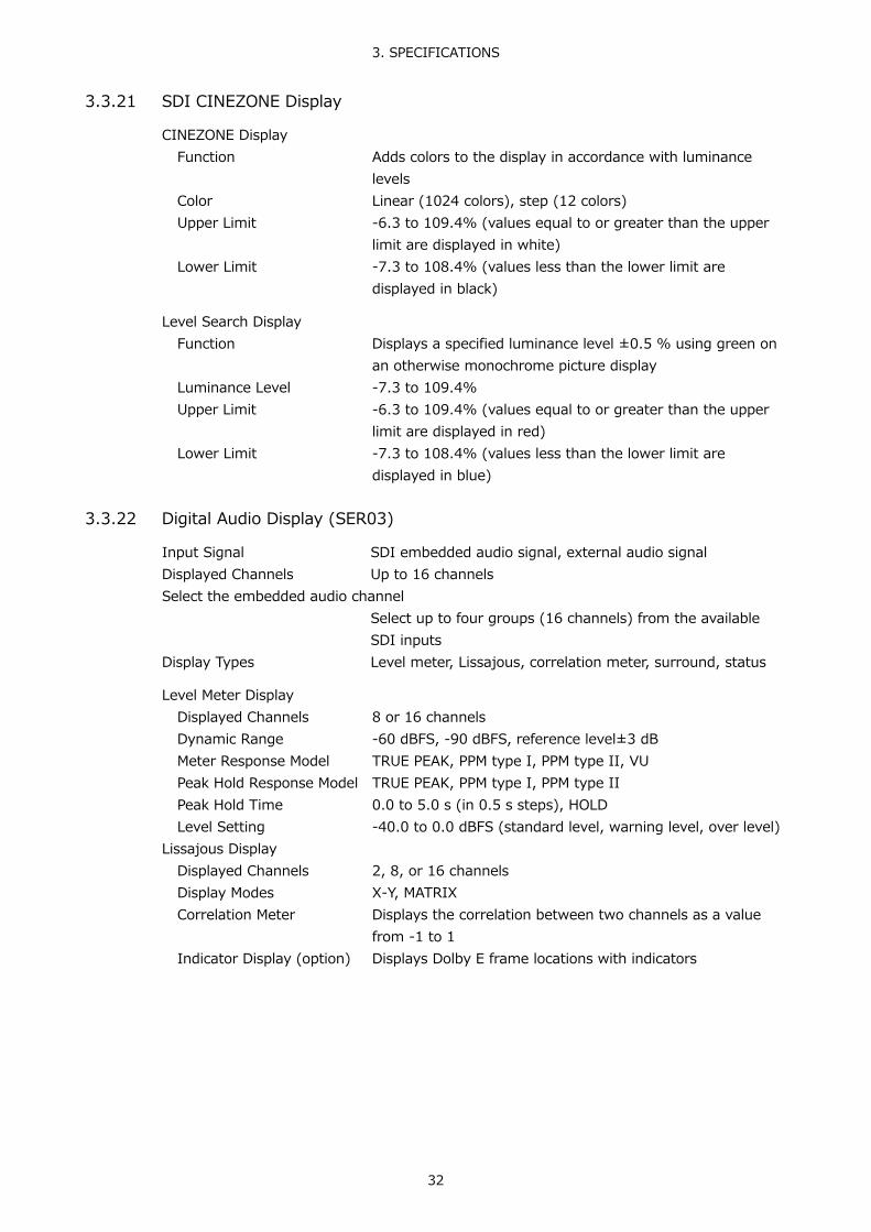
3. SPECIFICATIONS
32
3.3.21 SDI CINEZONE Display
CINEZONE Display Function Adds colors to the display in accordance with luminance
levels Color Linear (1024 colors), step (12 colors) Upper Limit -6.3 to 109.4% (values equal to or greater than the upper
limit are displayed in white) Lower Limit -7.3 to 108.4% (values less than the lower limit are
displayed in black)
Level Search Display Function Displays a specified luminance level ±0.5 % using green on
an otherwise monochrome picture display Luminance Level -7.3 to 109.4% Upper Limit -6.3 to 109.4% (values equal to or greater than the upper
limit are displayed in red) Lower Limit -7.3 to 108.4% (values less than the lower limit are
displayed in blue) 3.3.22 Digital Audio Display (SER03)
Input Signal SDI embedded audio signal, external audio signal Displayed Channels Up to 16 channels Select the embedded audio channel
Select up to four groups (16 channels) from the available SDI inputs
Display Types Level meter, Lissajous, correlation meter, surround, status
Level Meter Display Displayed Channels 8 or 16 channels Dynamic Range -60 dBFS, -90 dBFS, reference level±3 dB Meter Response Model TRUE PEAK, PPM type I, PPM type II, VU Peak Hold Response Model TRUE PEAK, PPM type I, PPM type II Peak Hold Time 0.0 to 5.0 s (in 0.5 s steps), HOLD Level Setting -40.0 to 0.0 dBFS (standard level, warning level, over level)
Lissajous Display Displayed Channels 2, 8, or 16 channels Display Modes X-Y, MATRIX Correlation Meter Displays the correlation between two channels as a value
from -1 to 1 Indicator Display (option) Displays Dolby E frame locations with indicators

3. SPECIFICATIONS
33
Surround Display Function Displays a graphical representation of a sound field Surround Format 5.1 Channel Mapping L, R, C, LFE, Ls, Rs, Lt, Rt Center Channel Format Normal, phantom center Gain ×1, AUTO
Status Display
Level Audio levels are displayed using numbers (dBFS). Error Detection Counts the number of errors that occur for each channel
Level Over Counts the number of times that the level of the input signal exceeds the set value
Detection Setting -40.0 to 0.0 dBFS Clipping Counts the number of times that a received signal exceeds
the maximum signal value for the specified number of consecutive samples
Detection Setting 1 to 100 samples Mute Counts the number of times that the length of a received
mute signal exceeds the specified period Detection Setting 1 to 5000 ms
Parity Error Counts the number of times that the input signal's parity bit and the parity bit recalculated by the LV 5490 differ
Validity Error Counts the number of times that the input signal's validity bit is 1
CRC Error Counts the number of times that the CRC of the channel status bits and the calculated CRC are different
Code Violation Counts the number of times that the state of the input signal's biphase modulation is abnormal
Elapsed Time Displays the amount of time that has elapsed since the instrument was reset
Channel Status Bits Dump display, text display User Data Bits Dump display Dolby-E Metadata Text display (option) Dolby Digital Metadata Text display (option)
3. SPECIFICATIONS
34
3.3.23 SDI Signal Status Display
Signal Detection Detects the presence of an SDI signal Format Display Displays the video signal format Frequency Deviation Display
Function Displays the sampling frequency deviation Displays an error if ±10 ppm is exceeded
Measurement Range ±100 ppm Precision ±2 ppm
Equivalent Cable Length Display (1A to 1D on the SER01/SER02 only) Function Displays SDI signal attenuation in terms of cable length
Displays an error if the specified cable length is exceeded Supported Cables
3G, HD LS-5CFB, 1694A SD L-5C2V, 8281
Display Range 3G < 10 m, 10 to 105 m, > 105 m HD < 5 m, 5 to 130 m, > 130 m SD < 50 m, 50 to 300 m, > 300 m
Precision ±20 m Resolution 5 m
Error Count Display Up to 999,999 errors for each error type Count Period 1 second, 1 field (frame) Embedded Audio Channel Display (*1)
Displays the embedded audio channel numbers
SDI Signal Error Detection CRC Error Detects 12G (SER06/SER08), 3G and HD signal transmission
errors EDH Error Detects SD signal transmission errors TRS Position Error Detects TRS embedding position errors TRS Code Error Detects TRS protection bit errors Line Number Error Detects errors with the line numbers embedded in 12G
(SER06/SER08), 3G and HD signals Illegal Code Error Detects data within the range of 000 to 003h and 3FC to
3FFh in locations other than TRS and ADF
Ancillary Data Packet Error Detection Checksum Error Detects ancillary data transmission errors Parity Error Detects ancillary data header parity errors
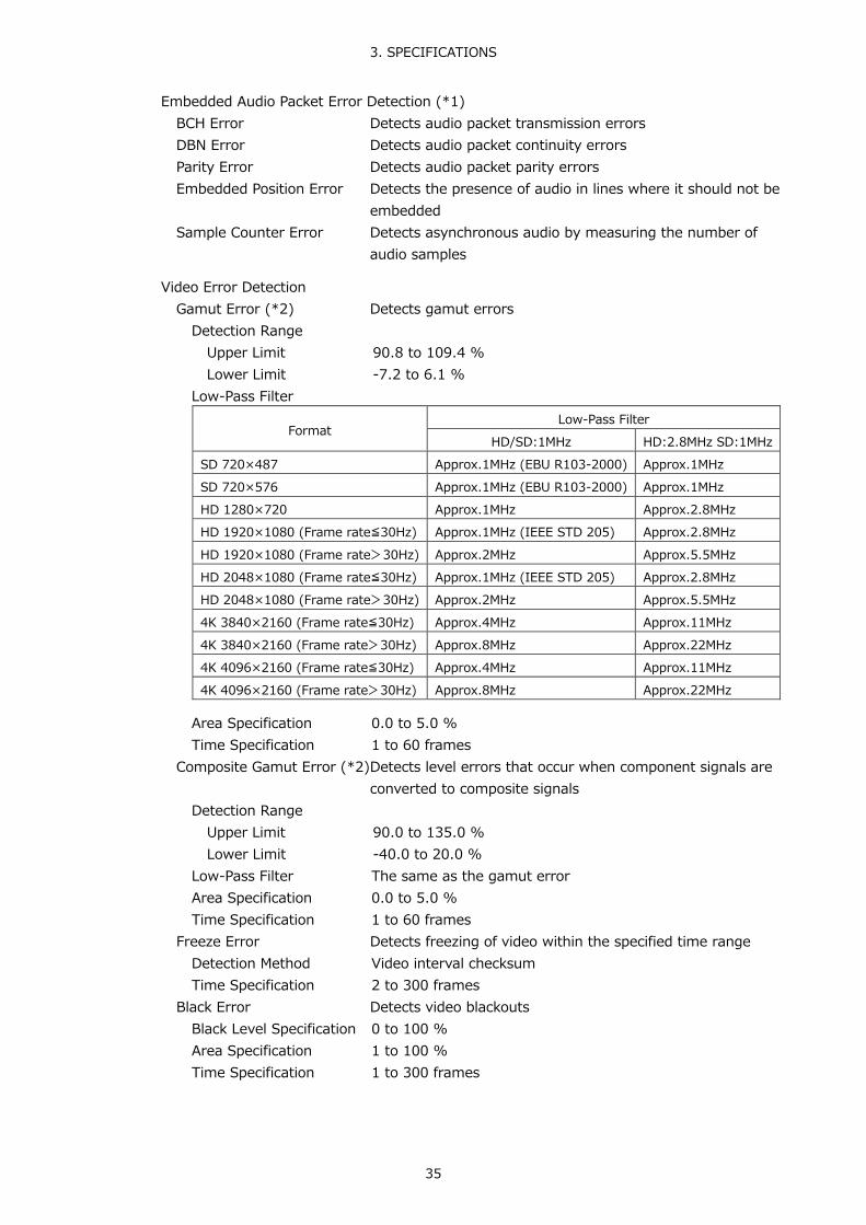
3. SPECIFICATIONS
35
Embedded Audio Packet Error Detection (*1) BCH Error Detects audio packet transmission errors DBN Error Detects audio packet continuity errors Parity Error Detects audio packet parity errors Embedded Position Error Detects the presence of audio in lines where it should not be
embedded Sample Counter Error Detects asynchronous audio by measuring the number of
audio samples
Video Error Detection Gamut Error (*2) Detects gamut errors
Detection Range Upper Limit 90.8 to 109.4 % Lower Limit -7.2 to 6.1 %
Low-Pass Filter
Format Low-Pass Filter
HD/SD:1MHz HD:2.8MHz SD:1MHz SD 720×487 Approx.1MHz (EBU R103-2000) Approx.1MHz SD 720×576 Approx.1MHz (EBU R103-2000) Approx.1MHz HD 1280×720 Approx.1MHz Approx.2.8MHz HD 1920×1080 (Frame rate≦30Hz) Approx.1MHz (IEEE STD 205) Approx.2.8MHz HD 1920×1080 (Frame rate>30Hz) Approx.2MHz Approx.5.5MHz HD 2048×1080 (Frame rate≦30Hz) Approx.1MHz (IEEE STD 205) Approx.2.8MHz HD 2048×1080 (Frame rate>30Hz) Approx.2MHz Approx.5.5MHz 4K 3840×2160 (Frame rate≦30Hz) Approx.4MHz Approx.11MHz 4K 3840×2160 (Frame rate>30Hz) Approx.8MHz Approx.22MHz 4K 4096×2160 (Frame rate≦30Hz) Approx.4MHz Approx.11MHz 4K 4096×2160 (Frame rate>30Hz) Approx.8MHz Approx.22MHz
Area Specification 0.0 to 5.0 % Time Specification 1 to 60 frames
Composite Gamut Error (*2) Detects level errors that occur when component signals are converted to composite signals
Detection Range Upper Limit 90.0 to 135.0 % Lower Limit -40.0 to 20.0 %
Low-Pass Filter The same as the gamut error Area Specification 0.0 to 5.0 % Time Specification 1 to 60 frames
Freeze Error Detects freezing of video within the specified time range Detection Method Video interval checksum Time Specification 2 to 300 frames
Black Error Detects video blackouts Black Level Specification 0 to 100 % Area Specification 1 to 100 % Time Specification 1 to 300 frames

3. SPECIFICATIONS
36
Level Error Detects YCBCR level errors Upper Y Limit -51 to 766 mV Lower Y Limit -51 to 766 mV Upper CBCR Limit -400 to 399 mV Lower CBCR Limit -400 to 399 mV Low-Pass Filter The same as the gamut error
*1 If the input signal is 3G-B-DL, only stream 1 is supported. *2 This function is not supported in some of the LV 5490 products. To check, see section 7.3, “Displaying
System Information.” 3.3.24 SDI Analysis Features
Event Log Display Function Records detected errors, events—such as the LV 5490
switching between input signals, and time stamps. Recording Capacity Up to 1000 events Operation Records all events from start to finish Data Output Data can be saved as text files to USB memory
Data Dump Display
Display Format HD, SD, 3G-A, 3G-B-DS Displays serial data sequence or displays each color
component separately 3G-B-DL PICTURE, stream 1, stream 2 HD (DL) PICTURE, link A, link B 3G (DL) PICTURE, link 1, link 2 3G (QL), HD (QL), 12G (SER06/SER08)
PICTURE, link 1, link 2, link 3, link 4 Display Format Details
PICTURE Combines inks or streams 1 and 2 and shows in a picture structure (displays only the image area for 4K)
Stream 1/2 Displays each stream in a transmission structure Link A/B/1/2/3/4 Displays the selected link
Line Select Displays the selected line Sample Select Displays from the selected sample Jump Feature Moves to EAV or SAV
(Moves to 0 or 3839/4095 for 4K in PICTURE format) Data Output Text output to USB memory

3. SPECIFICATIONS
37
Phase Difference Display (*1) Function Displays the phase difference between a reference signal
and an SDI signal or between two SDI signals numerically and graphically
Reference Signal SD, HD, 3G, 3G (QL), HD (QL)
External sync signal, Ach HD (DL), 3G (DL) External sync signal, Ach, Cch 12G External sync signal
Display Range Vertical 1 frame Horizontal ± 1 line
SDI Ancillary Data List Display
List Display Details Presence or absence of each ancillary data type, embedded line number, and number of packets per frame
Dump Display The selected ancillary data is displayed in hexadecimal or binary.
EDH Display (Only for SD)
Compliant Standard SMPTE RP 165 Display Details Analyzes and displays EDH packets and displays received
CRC errors Display Format Text, hexadecimal, binary
Payload ID Display
Compliant Standard SMPTE ST 352 Display Details Analyzes and displays payload information Display Format Text and binary
Audio Control Packet
Compliant Standard SMPTE ST 299-1, SMPTE ST 272 Display Details Displays audio control packet analysis Display Format Text, hexadecimal, binary Group Select 1, 2, 3, 4
Closed Caption Display (*2)
Compliant Standard ARIB STD-B37 Display Details Analyzes and displays the closed caption signal Display Format Text, hexadecimal, binary
Inter-Stationary Control Signal (NET-Q) Display (*2)
Compliant Standard ARIB STD-B39 Display Details Analyzes and displays inter-stationary control signals Display Format Text, hexadecimal, binary Logging Feature Q-signal logging Format ID Display Feature Analyzes and displays the format ID Data Output Outputs Q signal logs in CSV format through a USB memory
device

3. SPECIFICATIONS
38
Data Broadcast Trigger Signal (*2) Compliant Standard ARIB STD-B35 Display Format Text, hexadecimal, binary
V-ANC User Data Display (*2)
Compliant Standard ARIB TR-B23 Display Format Hexadecimal and binary
AFD Packet Display
Compliant Standard SMPTE ST 2016-3 Display Format Text, hexadecimal, binary
User-Defined ANC Packet Display
ANC Specification Method DID, SDID Display Details Y, C
*1 If the reference signal is set to an external sync signal, the measured phase may vary by ±1 clock
depending on the timing when the external sync signal or SDI signal is connected or disconnected or when the power is turned on and off. If the reference signal is set to an SDI signal, the measured phase may vary by ±2 clock depending on the timing when the SDI signal is connected or disconnected or when the power is turned on and off.
*2 This is not supported when the input signal is 3G, 12G (SER06/SER08).
Lip Sync Display (SER03) Displays the phase difference between the video and audio Lip Sync Measurement
Function Measures the time difference between the SDI signal and digital audio signal and displays the results numerically and graphically
Reference Signal A Leader TSG that supports lip syncing (*1) Measurement Method Measures the time difference when the luminance level of
the video signal exceeds the specified value and when the audio level signal exceeds the specified value
Luminance Level Setting 25 to 100% Audio Signal Level Setting
-30 to 0 dBFS Supported Audio Signals Embedded audio signal, digital audio signal Measurement Range (Bar Display)
±50 ms / ±100 ms / ±500 ms / ±1.0 s / ±2.5 s Measurement Range (Numeric Display)
±3999 ms Measurement Resolution 1 ms
*1 TSG patterns not made by Leader may be supportable by specifying the video signal setting and audio
signal setting.

3. SPECIFICATIONS
39
3.3.25 Eye Pattern Display (SER02/SER09)
Display Displays the input SDI waveform before equalizing 12G (SER09), 3G, HD, SD Displays channel A, B, C, or D, whichever is selected HD (DL) Displays link A or B, whichever is selected 3G (DL) Displays link 1 or 2, whichever is selected 3G (QL), HD (QL) Displays link 1, 2, 3, or 4, whichever is selected Waveform Display Color 7 colors to choose from Scale Display Color 7 colors to choose from
Method Equivalent time sampling Frequency Response (SER02) 7 GHZ -3dB (converted from the rise time) Amplitude Accuracy 800 mV ± 5 % (for 800 mV input) Time Axis
2 UI Display 12G (SER09) 12.5 ps/div 3G 50 ps/div HD 100 ps/div SD 550 ps/div
4 UI Display 12G (SER09) 25 ps/div 3G 100 ps/div HD 200 ps/div SD 1100 ps/div
16 UI Display 12G (SER09) 100 ps/div 3G 400 ps/div HD 800 ps/div SD 4400 ps/div
Time Axis Accuracy ±3 % Jitter Filter
10 Hz HPF 10 Hz 100 Hz HPF 100 Hz 1 kHz HPF 1 kHz 100 kHz HPF 100 kHz Timing HPF 10 Hz Alignment
12G (SER09), 3G, HD HPF 100 kHz SD HPF 1 kHz
Cursor Measurement Amplitude measurement using Y cursors Time measurement using X cursors Rise time and fall time measurement using the TrTf cursor

3. SPECIFICATIONS
40
Automatic Measurement Items Eye pattern's amplitude Rise time (the time for the signal to rise from 20 to 80 % of its amplitude) Fall time (the time for the signal to fall from 80 to 20 % of its amplitude) Timing jitter Current jitter Overshoot of the rising edge Overshoot of the falling edge
3.3.26 Jitter Display (SER02/SER09)
Display Displays the jitter component of an SDI signal 12G (SER09), 3G, HD, SD Displays channel A, B, C, or D, whichever is selected HD (DL) Displays link A or B, whichever is selected 3G (DL) Displays link 1 or 2, whichever is selected 3G (QL), HD (QL) Displays link 1, 2, 3, or 4, whichever is selected Waveform Display Color 7 colors to choose from Scale Display Color 7 colors to choose from
Method Phase detection method Gain ×16, ×8, ×4, ×2, ×1 Measurement Range
3G, HD, SD ×8 0.00 to 1.20 UI ×2 1.20 to 4.80 UI ×1 4.80 to 9.60 UI
12G (SER09) ×16 0.00 to 1.20 UI ×4 1.20 to 4.80 UI ×2 4.80 to 9.60 UI ×1 9.60 to 19.20 UI
Time Axis 1 H, 2 H, 1 V, 2 V (*1) Time Axis Accuracy ±3 % Jitter Filter
10 Hz HPF 10 Hz 100 Hz HPF 100 Hz 1 kHz HPF 1 kHz 100 kHz HPF 100 kHz Timing HPF 10 Hz Alignment
12G (SER09), 3G, HD HPF 100 kHz SD HPF 1 kHz

3. SPECIFICATIONS
41
Cursor Measurement Jitter value measurement through the use of cursors Automatic Measurement Display Feature
Displays the jitter value in seconds (sec) and unit intervals (UI)
Automatic Measurement Items Timing jitter, current jitter
Accuracy Input jitter frequency: 1 kHz. Filter setting: 10 Hz, within measurement range
0 UI < automatic measurement value ≤ 1 UI SER02 ±10 % + 0.05 UI SER09 ±10 % + 0.07 UI
1 UI < automatic measurement value ≤ 7 UI ±10 %
*1 2V display is not possible when the input signal is progressive except for 60/59.94/50P of HD (DL).
3.3.27 Eye Pattern and Jitter Detection (SER02/SER09)
Error Detection On or off per item Error Threshold Settings Can be set individually for 12G (SER09), 3G, HD, and SD
signals Event Log Stores eye patterns and jitter errors Threshold Values 100 % of the values in the SMPTE standard
Eye-Pattern Amplitude Upper Limit 80 to 140 % (640 to 1120 mV) Lower Limit 40 to 100 % (320 to 800 mV)
Rise Time, Fall Time 12G (SER09) 40 to 140 % (18.0 to 63.0 ps) 3G 40 to 140 % (54.0 to 189.0 ps) HD 40 to 140 % (108.0 to 378.0 ps) SD 40 to 140 % (0.60 to 2.10 ns)
Difference between the Rise and Fall Times 12G (SER09) 40 to 140 % (7.2 to 25.2 ps) 3G 40 to 140 % (20 to 70 ps) HD 40 to 140 % (40 to 140 ps) SD 40 to 140 % (0.20 to 0.70 ns)
Timing Jitter 12G (SER09) 10 to 200 % (0.80 to 16.00 UI, 67.2 to 1344.0 ps) 3G 10 to 200 % (0.20 to 4.00 UI, 67.4 to 1348.0 ps) HD 10 to 200 % (0.10 to 2.00 UI, 67.4 to 1348.0 ps) SD 10 to 200 % (0.02 to 0.40 UI, 0.07 to 1.48 ns)
Current Jitter 12G (SER09) 10 to 200 % (0.03 to 0.60 UI, 2.5 to 50.4 ps) 3G 10 to 200 % (0.03 to 0.60 UI, 10.1 to 202.5 ps) HD 10 to 200 % (0.02 to 0.40 UI, 13.5 to 270.0 ps) SD 10 to 200 % (0.02 to 0.40 UI, 0.07 to 1.48 ns)
3. SPECIFICATIONS
42
Overshoot of the Rising Edge 0 to 200 % (0.0 to 20.0 %)
Overshoot of the Falling Edge 0 to 200 % (0.0 to 20.0 %)
3.3.28 Focus Assist Display (SER04)
Detection Sensitivity LOW, MIDDLE, HIGH, V-HIGH (*1), U-HIGH (*1) Highlight Display Color WHITE, GREEN, BLUE, RED Picture Luminance Level OFF, EMBOSS, 25 %, 50 %, 75 %, 100 %
*1 If there is noise in the image, the noise will also be enhanced.
3.3.29 CIE Diagram Display (SER05)
Display Standard CIE1931 (xy display), CIE1976 (u'v' display) Display Type Chromaticity diagram display, color temperature display Display Mode
Chromaticity Diagram Display Luminance display, color display
Color Temperature Display Luminance display Colorimetry BT.601(525), BT.601(625), BT.709, DCI, BT.2020 Clipping
ON Clips negative values of the input signal to zero OFF Displays negative values of the input signal according to
BT.1361 Smoothing Displays by averaging data every two pixels Accuracy ± 0.005 (relative to the measurement coordinate value) Chromaticity Diagram Display Scale
Triangle Select two from BT.601(525), BT.601(625), BT.709, DCI, and BT.2020
User-defined Triangle Set a single user-defined triangle Background Color sample, white background Sub Scale Color temperature curve, grid (0.1 steps), white point
(D65), triangle name (each can be turned on or off) Cursor Displays the cursor position in coordinates User-defined gamma 1.5 to 3.0
3.3.30 HDR Display (SER07)
Compliant Standards ARIB STD-B67 (HLG; Hybrid Log Gamma) SMPTE ST 2084 (PQ curve, Narrow Range only) S-Log3
Supported Format All inputs except SD and XYZ inputs CINEZONE Display Color
Upper limit or higher Magenta HDR area Coloring according to the brightness SDR area Monochrome Lower limit or less Black

3. SPECIFICATIONS
43
3.3.31 IP(NMI) Status Display (SER08)
NMI Display Displays the IP address, gateway address, subnet mask, and PTP domain number of IP (NMI) A/B
IP Live System Manager Display Displays the IP address, port number, protocol, and communication status of IP Live System Manager
NMI Status Display (*1) Displays the set format and the PTP synchronization state
*1 Only Network Media Interface (NMI) signals are supported. 3.3.32 Video Noise Meter (SER10)
Measurement Function Measured Signal Select Y, G, B, or R. Measurement Area Set the size and position of the area to be measured Noise Level Display mVrms、dB Alart Function Displays measured values in red when the values exceed the
specified threshold Low-Pass Filter -12 dB±1 dB at the cutoff frequencies in the following table
Format Cutoff frequencies SD 720×487 5.5MHz 4.4MHz 3.6MHz 2.7MHz 1.4MHz 0.7MHz Through SD 720×576 5.5MHz 4.4MHz 3.6MHz 2.7MHz 1.4MHz 0.7MHz Through HD 1280×720 30MHz 24MHz 20MHz 15MHz 7.5MHz 3.7MHz Through HD 1920×1080 (Frame rate≦30Hz)
30MHz 24MHz 20MHz 15MHz 7.5MHz 3.7MHz Through
HD 1920×1080 (Frame rate>30Hz)
60MHz 48MHz 40MHz 30MHz 15MHz 7.5MHz Through
HD 2048×1080 (Frame rate≦30Hz)
30MHz 24MHz 20MHz 15MHz 7.5MHz 3.7MHz Through
HD 2048×1080 (Frame rate>30Hz)
60MHz 48MHz 40MHz 30MHz 15MHz 7.5MHz Through
4K 3840×2160 (Frame rate≦30Hz)
120MHz 96MHz 80MHz 60MHz 30MHz 15MHz Through
4K 3840×2160 (Frame rate>30Hz)
240MHz 192MHz 160MHz 120MHz 60MHz 30MHz Through
4K 4096×2160 (Frame rate≦30Hz)
120MHz 96MHz 80MHz 60MHz 30MHz 15MHz Through
4K 4096×2160 (Frame rate>30Hz)
240MHz 192MHz 160MHz 120MHz 60MHz 30MHz Through
Passband Ripple ±0.5dB

3. SPECIFICATIONS
44
High-Pass Filter -12 dB±1 dB at the cutoff frequencies in the following table
Format Cutoff frequencies
ON OFF SD 720×487 36kHz Through SD 720×576 36kHz Through HD 1280×720 200kHz Through HD 1920×1080 (Frame rate≦30Hz) 200kHz Through HD 1920×1080 (Frame rate>30Hz) 400kHz Through HD 2048×1080 (Frame rate≦30Hz) 200kHz Through HD 2048×1080 (Frame rate>30Hz) 400kHz Through 4K 3840×2160 (Frame rate≦30Hz) 800kHz Through 4K 3840×2160 (Frame rate>30Hz) 1.6MHz Through 4K 4096×2160 (Frame rate≦30Hz) 800kHz Through 4K 4096×2160 (Frame rate>30Hz) 1.6MHz Through
Passband Ripple ±0.5dB
Measurement Accuracy (when filters are not applied) 0 to -65.00dB ±0.3dB -65.01 to -70.00dB ±0.7dB -70.01 to -75.00dB ±2.0dB
* This function is not supported in some of the LV 5490 products. To check, see section 7.3, “Displaying
System Information.”

3. SPECIFICATIONS
45
3.3.33 General Specifications
Environmental Conditions Operating Temperature 0 to 40 °C Operating Humidity Range 85 %RH or less (no condensation) Optimal Temperature 10 to 30 °C Operating Environment Indoors Elevation Up to 2,000 m Overvoltage Category II Pollution Degree 2
Power Requirements Voltage 90 to 250 VAC Frequency 50/60 Hz Power Consumption 150 W max.
Dimensions 223 (W) × 172 (H) × 360 (D) mm (excluding protrusions) Weight 5.6 kg max. (including options, excluding accessories) Accessories Power cord ................................................... 1
Cover/Inlet stopper ....................................... 1 15-pin D-sub connector .................................. 1 15-pin D-sub connector cover ......................... 1 SFP+ Transceiver Module AFBR-709SMZ) (SER08) ................................................................... 2 Instruction manual ........................................ 1

4. PANEL DESCRIPTION
46
4. PANEL DESCRIPTION 4.1 Front Panel
Figure 4-1 Front panel
Table 4-1 Front panel description
No. Name Description 1 Handle Use this when you carry the LV 5980. 2 LCD Displays measurement and setup screens The protection panel can be
removed. See section 5.2, “Removing the Protection Panel.”
3 F•1 to F•7 Carries out the corresponding function menu operation. See section 5.8.2, “Function Menu Operations.”
4 Power Switch Press this switch to turn the instrument on. Hold this switch down to turn the instrument off. See section 5.4, “Turning the Instrument On and Off.”
5 Headphone jack (SER03)
This is a mini-plug headphone jack. When a pair of headphones are connected to this jack, the LV 5490 transmits the audio signal embedded in the SDI signal or the audio signal received through its rear panel.
6 INPUT Used to set the measurement channels. See section 6.1, “Setting the Input Signals”
7 SYS Configures the settings

4. PANEL DESCRIPTION
47
No. Name Description See chapter 7, “SYSTEM SETTINGS.”
8 EXT Switches the sync signal. When the internal sync signal is being used, this key’s LED turns off. When the external sync signal is being used, this key’s LED lights. See section 5.7.2, “External Sync Signal Input.”
9 CAP Captures the screen See chapter 8, “CAPTURE FEATURE.”
10 MULTI Displays a combination of measurement screens. You can change the layout as you like. See section 6.3.7, “Multi Display.”
11 PSET Click to recall a preset; hold down to register, delete, or collectively copy presets. See chapter 9, “PRESET SETTINGS”
12 WFM Shows the video signal waveform display. You can change the layout as you like. See section 6.3.1, “Video Signal Waveform Display.”
13 AUDIO (SER03)
Shows the audio display. You can change the layout as you like. See section 6.3.4, “Audio Display (SER03).”
14 VECT Shows the vector waveform display. You can change the layout as you like. See section 6.3.2, “Vector Waveform Display.”
15 STATUS Shows the status display. You can change the layout as you like. See section 6.3.5, “Status Display.”
16 PIC Shows the picture display. You can change the layout as you like. See section 6.3.3, “Picture Display.”
17 EYE (SER02/SER09)
Switches to the eye pattern display. You can change the layout as you like. See section 6.3.6 “Eye Pattern Display (SER02/SER09).”
18 V POS Turn to adjust the vertical position of the video signal waveform or other item. Press to return to the reference position.
19 H POS Turn to adjust the horizontal position of the video signal waveform or other item. Press to return to the reference position.
20 F•D Turn to specify a numeric value or to move cursors. In most cases, press to reset the value to its default value.
21 USB Connect a USB memory device or USB mouse. See section 5.5, “Connecting USB Devices.”

4. PANEL DESCRIPTION
48
4.2 Rear Panel
Figure 4-2 Rear panel (SER01/SER02)

4. PANEL DESCRIPTION
49
Figure 4-3 Rear panel (SER06)

4. PANEL DESCRIPTION
50
Figure 4-4 Rear panel (SER08)
Table 4-2 Rear panel description
No. Name Description 1 USB Connect a USB memory device or USB mouse.
See section 5.5, “Connecting USB Devices.” 2 RS-422/485
(custom order feature)
Displays the camera ID using serial communication.
3 ETHERNET Ethernet port. Supports TELNET, FTP, SNMP, HTTP, and SNTP. See section 20, “ETHERNET REMOTE CONTROL.”
4 AC inlet Attach the included cover/inlet stopper to the AC inlet. See section 5.1, “Attaching the Cover Inlet Stopper.”
5 Ground terminal Connect the instrument to an external ground. 6 MONITOR
OUTPUT Transmits the screen image. The SDI connector can transmit a reclocked SDI signal. See section 5.7.5, “Transmitting Monitor Signals.”
7 REMOTE 15-pin D-sub remote control connector. Can be used to execute actions such as recalling preset settings.

4. PANEL DESCRIPTION
51
No. Name Description 8 DIGITAL AUDIO
INPUT/OUTPUT (SER03)
Audio signal I/O connectors. Switch between input and output using system settings. See section 5.7.4, “Digital Audio I/O (SER03).”
9 SDI INPUT (SER01/SER02)
SDI signal input connectors. See section 5.7.1, “SDI Signal I/O.”
10 12G-SDI INPUT (SER06)
11 12G-SDI INPUT (SER08)
12 NMI (SER08)
IP (NMI) signal input connectors. These are used by installing the included SFP+ transceiver modules. See section 5.6, “Installing the SFP+ Transceiver Module (SER08)”
13 SDI INPUT/OUTPUT (SER01/SER02)
SDI signal input/output connectors. Switch between input and output using system settings. Eye patterns and cable lengths cannot be measured. See section 5.7.1, “SDI Signal I/O.” 14 3G-SDI
INPUT/OUTPUT (SER06)
15 3G-SDI INPUT/OUTPUT (SER08)
16 EXT REF External reference input connector. This is a loop-through connector. See section 5.7.2, “External Sync Signal Input.”
17 Serial number label
The serial number is printed on this label.
18 OUTPUT (SER06)
12G SDI output Connector. Reclocked signals 1A to 1D or a test pattern is output. See section 5.7.1, “SDI Signal I/O.” 19 OUTPUT
(SER08)

5. BEFORE YOU BEGIN MEASURING
52
5. BEFORE YOU BEGIN MEASURING 5.1 Attaching the Cover Inlet Stopper
A cover/inlet stopper is included with the LV 5490. Use this device to prevent the power cord from being pulled free of the AC inlet. To attach the cover/inlet stopper, follow the procedure below.
● Attaching the Cover/Inlet Stopper
1. Cover the power cord with the cover/inlet stopper.
2. Push the cover/inlet stopper, until you hear a click, to attach it to the AC inlet.
3. Check that the cover/inlet stopper is securely attached to the AC inlet.
● Removing the Cover/Inlet Stopper
1. Release the lock by using two fingers to press the cover/inlet stopper levers.
2. Pull the cover/inlet stopper away from the AC inlet.
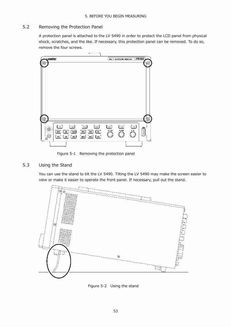
5. BEFORE YOU BEGIN MEASURING
53
5.2 Removing the Protection Panel
A protection panel is attached to the LV 5490 in order to protect the LCD panel from physical shock, scratches, and the like. If necessary, this protection panel can be removed. To do so, remove the four screws.
Figure 5-1 Removing the protection panel 5.3 Using the Stand
You can use the stand to tilt the LV 5490. Tilting the LV 5490 may make the screen easier to view or make it easier to operate the front panel. If necessary, pull out the stand.
Figure 5-2 Using the stand

5. BEFORE YOU BEGIN MEASURING
54
5.4 Turning the Instrument On and Off
To turn on the power, press the power switch. The power switch LED lights, and the instrument turns ON. When you turn ON the power, the LV 5490 starts up with the same panel settings that were set when it was last turned OFF.
To turn off the power, hold down the power switch for 2 seconds or more. The power switch LED and the instrument turn OFF.
You can set the time from when the power is turned on until the LV 5490 starts on the GENERAL SETUP tab in the system settings. Reference GENERAL SETUP tab → 7.2.1, “General Settings.”
5.5 Connecting USB Devices
The front and rear panels each has a USB port. You can connect a USB memory device or USB mouse to the ports. You can connect the devices to either USB port, but you cannot connect the same type of devices to the LV 5490 simultaneously. USB devices can be connected or removed with the power turned on.
● USB Memory Device
When a USB memory devices is connected, a USB memory icon appears in the upper right of the screen. You can save various types of data in a USB memory device.
This icon is normally green, but it changes to red when the USB memory device is being accessed. Do not turn the power OFF or remove the USB memory device when the icon is red.
● USB Mouse
When a USB mouse is connected, a mouse icon appears in the upper right of the screen. Basic operations can be performed without a mouse, but arranging the measurement screen layout requires a mouse. Reference 6.4, “Arranging the Measurement Screen Layout”

5. BEFORE YOU BEGIN MEASURING
55
5.6 Installing the SFP+ Transceiver Module (SER08)
If the SER08 is installed, the rear panel has two IP (NMI) input connectors. Use these connectors by installing the included SFP+ transceiver modules. You can connect and disconnect an SFP+ transceiver module with the power turned on. To install it, follow the procedure below.
● Installation
1. Insert an SFP+ transceiver module into the IP A NMI input connector with the correct orientation.
2. Push it in until a click is heard.
3. Install another module into IP B in a similar manner.
● Uninstallation
Pinch the SFP+ transceiver module with your fingers, and pull it out. Do not pull the cable.

5. BEFORE YOU BEGIN MEASURING
56
5.7 Signal I/O
5.7.1 SDI Signal I/O
Figure 5-3 SDI I/O connectors

5. BEFORE YOU BEGIN MEASURING
57
● Input/Output Switching
1A to 1D are fixed to input. 2A to 2D can be switched between input and output. On the SDI OUT tab in the system settings, select Input or Output. Reference SDI OUT tab → 7.1.4, “Configuring the SDI I/O Connectors.”
● SDI Signal Input : 1A to 1D, 2A to 2D
The input connector assignments to the link system when 2A to 2D are set to input are shown below. Apply signals that are specified in section 3.3.1, “SDI Formats and Standards.”
Table 5-1 SDI signal input
Link System Input Connector Single link Input to 1A, 1B, 1C, 1D, 2A, 2B, 2C, 2D (up to 8 signals) Dual link Input to 1A/1B, 1C/1D, 2A/2B, and 2C/2D (up to 4 signals) Quad link Input to 1A/1B/1C/1D and 2A/2B/2C/2D (up to 2 signals)
● 12G SDI Signal Input : 1A to 1D (SER06/SER08)
On the SDI IN tab in the system settings, set SDI System to 4K 12G, and then apply signals to 1A to 1D. When 12G is being measured, even if 2A to 2D are set to input, signals received through 2A to 2D cannot be measured. Further, even if 2A to 2D are set to output (Input Through), the reclocked signals of 1A to 1D are not output. Reference SDI IN tab → 7.1.1, “Configuring the SDI Input Connectors.”
● SDI Signal Output : 2A to 2D
There are two SDI signal output settings: Input Through and Test Signal. You can set it on the SDI OUT tab in the system settings.
• Input Through
2A to 2D output reclocked signals of the signals received through 1A to 1D. Use the signals for monitoring.
For 3G (DL)-4K, the output signals are different as follows: • When 1A-1B is selected: Both 2A-2B and 2C-2D output reclocked signals of the
signals received through 1A-1B. • When 1C-1D is selected: Both 2A-2B and 2C-2D output reclocked signals of the
signals received through 1C-1D.
For single link, you can select whether to set the 2A output to channel A or a channel that you select on the SDI OUT tab. If you select to use a channel that you select, set the output channel using the INPUT menu or F•6 SELECT CH in the appropriate measurement screen.
For 4K 12G, signals are converted into 3G-SDI×4ch and output through 2A to 2D. However, because the 12G-SDI payload ID is embedded in the 3G-SDI signal, the format has to be set manually on the receiving device.
For 4K NMI, NMI signals are converted into 3G-SDI×4ch and output through 2A to 2D.
For NMI, signals are converted into HD-SDI and output.

5. BEFORE YOU BEGIN MEASURING
58
• Test Signal
2A-2D output various patterns. You can superimpose a moving box, vary the phase, and so on. You can use the LV 5490 as a signal generator.
● 12G SDI Signal Output : 1A/1B/1C/1D (SER06)
There are two 12G SDI signal output settings: Input Through and Test Signal. You can set it on the 12G SDI OUT tab in the system settings. Reference 12G SDI OUT tab → 7.1.8, “Configuring the 12G SDI Output Connector (SER06).”
• Input Through
For 4K 12G, SD/HD/3G-A/3G-B-DL or 3G-B-DS, the channel selected by the INPUT menu or F•6 SELECT CH on each measurement screen is output. Use the signals for monitoring.
• Test Signal
OUTPUT transmits 12G SDI signals. You can use the LV 5490 as a signal generator.
● 12G SDI Signal Output : 1A/1B/1C/1D (SER08)
12G SDI signal output is fixed to Input Through.
For 4K 12G, SD/HD/3G-A/3G-B-DL or 3G-B-DS, the channel selected by the INPUT menu or F•6 SELECT CH on each measurement screen is output. Use the signals for monitoring.
● Terminators
The SDI input connectors are terminated internally at 75 Ω, so there is no need to connect terminators to them. Connect cables with a characteristic impedance of 75 Ω.
● Configuring Measurement Channels
Configure the measurement channels using the SDI IN tab in the system settings and the INPUT menu. Eye patterns and cable lengths for signals applied to 2A to 2D cannot be measured. Reference 6.1, “Configuring Measurement Channels”
● Cables
It has been confirmed that errors do not occur when the LV 5490 receives an 800 mVp-p stress pattern through the following cables.
Input Signal Cable Type Input Connectors
(1A to 1D) I/O Connectors
(2A to 2D) Video Pattern
12G L5.5CUHD cable 70m None COLOR BAR 3G LS-5CFB cable 70m 70m CHECK FIELD HD LS-5CFB cable 110m 110m CHECK FIELD SD L-5C2V cable 260m 100m CHECK FIELD

5. BEFORE YOU BEGIN MEASURING
59
5.7.2 IP(NMI) Signal Input (SER08)
Figure 5-4 IP(NMI) Signal Input connectors
● Signal Input : IP A, IP B (SER08)
On the SDI IN tab in the system settings, set SDI System to 4K NMI or NMI, and then apply signals to IP A and IP B. Reference 7.1.1, “Configuring the SDI Input Connectors”

5. BEFORE YOU BEGIN MEASURING
60
5.7.3 External Sync Signal Input
Figure 5-5 External sync signal input connectors
On the video-signal-waveform and vector displays, you can apply an external sync signal to display waveforms. (*1) Apply an external sync signal to an external sync signal input connector, and then press EXT. The LV 5490 determines the sync signal format automatically.
As shown in the figure below, the external sync signal input connectors are loop-through. Apply the input signal to one of the two connectors, and terminate the other connector at 75 Ω, or connect it to another 75 Ω device. If you connect to another device, be sure to terminate the device at the end of the chain at 75 Ω. Connect cables with a characteristic impedance of 75 Ω.
Figure 5-6 Loop-through
*1 Waveform display using an external sync signal is not possible for the following formats. • 3G 720/30P, 720/29.97P, 720/25P, 720/24P, 720/23.98P • HD (DL) 1080/60P, 1080/59.94P, 1080/50P • 3G (DL), 3G (QL), HD (QL), 12G (SER06/SER08) • Frame frequency 48P, 47.95P

5. BEFORE YOU BEGIN MEASURING
61
External sync signals that are compatible with each input signal are indicated with a check mark in the following table. Proper measurement is possible only for combinations that are indicated with check marks.
Table 5-2 External sync signal formats (SD, HD)
SDI (SD, HD) Input Signal Format
525/
59.9
4I
625/
50I
1080
/60I
1080
/59.
94I
1080
/50I
1080
/30P
sF
1080
/29.
97Ps
F
1080
/25P
sF
1080
/24P
sF
1080
/23.
98Ps
F
1080
/30P
1080
/29.
97P
1080
/25P
1080
/24P
1080
/23.
98P
720/
60P
720/
59.9
4P
720/
50P
720/
30P
720/
29.9
7P
720/
25P
720/
24P
720/
23.9
8P
Exte
rnal
Syn
c Si
gnal
For
mat
NTSC with 10 field ID (59.94Hz)(*1)
NTSC (59.94Hz) PAL (50Hz) 1080/60I 1080/59.94I 1080/50I 1080/30PsF 1080/29.97PsF 1080/25PsF 1080/24PsF 1080/23.98PsF 1080/30P 1080/29.97P 1080/25P 1080/24P 1080/23.98P 720/60P 720/59.94P 720/50P 720/30P 720/29.97P 720/25P 720/24P 720/23.98P
*1 If the input signal is 1080/23.98PsF or 1080/23.98P, the 10 field ID is automatically detected.

5. BEFORE YOU BEGIN MEASURING
62
Table 5-3 External sync signal formats (3G)
1080
/60P
1080
/59.
94P
1080
/50P
1080
/60I
1080
/59.
94I
1080
/50I
1080
/30P
sF
1080
/29.
97Ps
F
1080
/25P
sF
1080
/24P
sF
1080
/23.
98Ps
F
1080
/30P
1080
/29.
97P
1080
/25P
1080
/24P
1080
/23.
98P
720/
60P
720/
59.9
4P
720/
50P
Exte
rnal
Syn
c Si
gnal
For
mat
NTSC with 10 field ID (59.94Hz)(*1)
NTSC (59.94Hz) PAL (50Hz) 1080/60I 1080/59.94I 1080/50I 1080/30PsF 1080/29.97PsF 1080/25PsF 1080/24PsF 1080/23.98PsF 1080/30P 1080/29.97P 1080/25P 1080/24P 1080/23.98P 720/60P 720/59.94P 720/50P
*1 If the input signal is 1080/23.98PsF or 1080/23.98P, the 10 field ID is automatically detected.

5. BEFORE YOU BEGIN MEASURING
63
Table 5-4 External sync signal formats (12G)
SDI (12G) Sub Image Input Signal Format (*1)
1080
/60P
1080
/59.
94P
1080
/50P
1080
/30P
1080
/29.
97P
1080
/25P
1080
/24P
1080
/23.
98P
Exte
rnal
Syn
c Si
gnal
For
mat
NTSC with 10 field ID (59.94Hz) (*2)
NTSC (59.94Hz) PAL (50Hz) 1080/60I 1080/59.94I 1080/50I 1080/30P 1080/29.97P 1080/25P 1080/24P 1080/23.98P
*1 If the input signal is 12G, the phase difference is measured for the 4k sub image format. *2 If the input signal is 1080/23.98PsF or 1080/23.98P, the 10 field ID is automatically detected.

5. BEFORE YOU BEGIN MEASURING
64
5.7.4 Digital Audio I/O (SER03)
Figure 5-7 Digital audio I/O connectors
● Input/Output Switching
The connectors can be switched between input and output in groups (A and B). On the AUDIO IN/OUT tab in the system settings, select Input or Output. Reference AUDIO IN/OUT tab → 7.1.6, “Configuring the Audio I/O Connectors (SER03)”
● Audio Signal Output
If group A or B is set to output, the following signals are output. Use the signals for monitoring.
Table 5-5 Audio signal output
INPUT CH MODE Group A Output Group B Output SDI 8ch The 8 channels from 1st
GROUP and 2nd GROUP The 8 channels from 1st GROUP and 2nd GROUP
16ch The 8 channels from 1st GROUP and 2nd GROUP
The 8 channels from 3rd GROUP and 4th GROUP
EXT AUDIO 8ch - (Input) 8 channels applied to group A 8 channels applied to group B - (Input)
16ch - (Input) - (Input)

5. BEFORE YOU BEGIN MEASURING
65
5.7.5 Monitor Signal Output
Figure 5-8 Monitor output connectors
The SDI output connector and DVI-D output connector transmit the LV 5490 screen for a monitor device. Connect to a full high definition (1920×1080) display.
● Selecting the Sync Mode
On the MONITOR OUT tab in the system settings, select internal synchronization or external synchronization. If you select internal synchronization, you can also select the output format. Reference MONITOR OUT tab → 7.1.7, “Configuring the Monitor Output Connectors”
● SDI Routing Output
In single link mode (excluding 12G and 3G-B-DS), in place of transmitting the LV 5490 screen, the SDI output connector can transmit a reclocked signal of a signal received through SDI INPUT. On the MONITOR OUT tab in the system settings, select INPUT ROUTER.
The output channel when INPUT ROUTER is selected is the displayed channel in single input mode or the channel selected with F•6 SELECT CH on the appropriate measurement screen in simul mode.

5. BEFORE YOU BEGIN MEASURING
66
5.8 Operation Basics
5.8.1 Displaying the Function Menu
The function menu is used to specify a variety of settings. Normally the function menu is displayed, but it can be cleared by pressing the measurement key that is currently selected. You can also set it to disappear automatically on the GENERAL SETUP tab in the system settings. Reference GENERAL SETUP tab → 7.2.1, “General Settings”
If the measurement menu disappears, carry out one of the following operations to display it again.
● Pressing a Measurement Key to Display the Menu
Press the measurement key (WFM, VECT, PIC, AUDIO, STATUS, or EYE) that corresponds to the currently selected display mode to display the menu. When you perform this operation, the top-level menu is displayed.
● Pressing a Function Key to Display a Menu
Press one of the function keys to display the menu. When you perform this operation, the menu is displayed at the level that was displayed before it disappeared.
5.8.2 Function Menu Operations
This section explains how to operate the function menu, using the function menu on the VECT display as an example.
Figure 5-9 Function menu operations
● Specifying Values
To set the value of a setting like F•1 VECT INTEN, which is shown in the figure above, press F•1, and then turn the function dial (F•D). You can reset most settings to their default values by pressing the function dial (F•D).
● Selecting Settings
To select a setting from a list like the one shown in the figure above for F•2 VECT COLOR, press F•2 repeatedly to select the setting you want. The setting changes each time you press F•2. After you stop pressing F•2, the setting is confirmed and the pop-up menu disappears.

5. BEFORE YOU BEGIN MEASURING
67
5.8.3 Mouse Operations
You can use the mouse to operate the keys on the screen to specify settings in the same manner as using the front panel keys. To display the keys, connect a mouse, and click in the screen.
Figure 5-10 Mouse operations
● Measurement Screen Settings
Click the keys on the screen and the function menu.
You can change a value in the function menu by using the +- buttons to the right of FD, the +- buttons to the right of the value, or the wheel on the mouse.
The preset feature is divided into PRESET and MEM keys on the screen. PRESET is used to recall, and MEM is used to store.
● Tab Screen Settings
Click the items on the screen and the function menu.
You can change a value on a tab screen by using the +- buttons to the right of FD or the wheel on the mouse.
● Moving the Cursors
Cursors on video signal waveforms can be moved easily with a mouse.
To do so, click a cursor to select it, and then click a position of your choice. To unselect, right-click.
A portion of the cursors can be moved with a mouse wheel. If you use a mouse wheel, right-click to set the position.

5. BEFORE YOU BEGIN MEASURING
68
● Right-Click Menu
The menu below appears when you right-click the mouse. LAYOUT is an item that can only be set using the mouse.
Table 5-6 Right-click menu
Menu Description ALL CLEAR Hides the keys and function menu from the screen.
Click in the screen to redisplay them. KEY CLEAR Hides the keys from the screen.
Click in the screen to redisplay them. MENU CLEAR Hides the function menu.
Click in the screen to redisplay it. LAYOUT Creates a measurement screen layout.
Reference 6.4, “Arranging the Measurement Screen Layout” 5.8.4 Tab Menu Operations
Normally, the function menus are used to configure the various settings. However, tab menus—such as that shown below—are displayed in some situations. This section explains how to operate the tab menu, using the GENERAL SETUP tab menu as an example.
Figure 5-11 Tab menu operations
● Moving Cursors
To move the cursor, turn the function dial (F•D). Depending on what you are setting, there are some items in which you cannot move the cursor.
● Switching Tabs
When there are multiple tabs, such as in the figure above, press F•2 PREV TAB and F•3 NEXT TAB to change between tabs. If you switch to another tab, the settings are retained, but they are not confirmed until you press F•1 COMPLETE.

5. BEFORE YOU BEGIN MEASURING
69
● Selecting a Check Box
Move the cursor to the check box that you want to select, and press the function dial (F•D).
● Entering Values
Move the cursor to the item that you want to enter the value for, and press the function dial (F•D). Turn the function dial (F•D) to set the value. To confirm the value that you have set, press the function dial (F•D) again.
● Confirming Settings
Press F•1 COMPLETE to apply the settings from all the tabs and return to the screen that is one level up.
● Canceling Settings
Press F•7 up menu to cancel the settings from all the tabs and return to the screen that is one level up.
5.8.5 Setting the Key Lock
You can prevent unintentional operations on the LV 5490 by enabling the key lock. The key lock disables all LV 5490 keys except for the power switch.
● Enabling the Key Lock
Hold down SYS until the following message is displayed on the screen. While the key lock is enabled, the key lock icon appears in the upper right of the screen.
Figure 5-12 Enabling the key lock
● Releasing the Key Lock
Hold down SYS until the following message is displayed on the screen.
Figure 5-13 Releasing the key lock

5. BEFORE YOU BEGIN MEASURING
70
5.9 Measurement Screen Explanation
The measurement screen layout can be arranged as you like. This section explains items that are common to all displays.
Figure 5-14 Measurement screen explanation

5. BEFORE YOU BEGIN MEASURING
71
Table 5-7 Measurement screen explanation No.
Name Description
1 TEMPERATURE Appears when the internal temperature increases. You can also choose to hide this information. See sections 7.3, “Displaying System Information” and 7.2.1, “General Settings.”
2 ERROR Appears when an input signal error occurs.(*1) To configure error detection settings, use F•5 STATUS SETUP on the STATUS menu or F•4 ERROR SETUP on the EYE menu.
3 Mouse icon Appears when a USB mouse is connected. You can also choose to hide this information. See section 5.5, “Connecting USB Devices” and 7.2.1, “General Settings.”
4 Key lock icon Appears when key lock is enabled. You can also choose to hide this information. See section 5.8.5, “Enabling the Key Lock” and 7.2.1, “General Settings.”
5 USB memory icon
Appears when a USB memory device is connected. You can also choose to hide this information. See section 5.5, “Connecting USB Devices” and 7.2.1, “General Settings.”
6 Screen keys Keys on the screen that you operate with a mouse. See section 5.8.3, “Mouse Operations.”
7 OVER HEAT FAN ALARM
“OVER HEAT” appears when the internal temperature increases. “FAN ALARM” appears when a fan error occurs. If either of these alarm appears, immediately turn the power off, and then check for problems with the operating environment. If this alarm appears even though there are no problems with the operating environment, contact your local LEADER agent. See section 7.3, “Displaying System Information.”
8 Function menu A menu for configuring settings. See section 5.8.1, “Displaying the Function Menu.”
*1 The applicable channels are all channels in the selected group (1A to 1D or 2A to 2D).
However, when measuring 3G-B-DS or 3G (DL)-4K, only on the currently displayed channels are applicable.

6. BASIC OPERATION
72
6. BASIC OPERATION 6.1 Setting the Input Signals
This section explains the INPUT menu settings and input format display. 6.1.1 Selecting the Input Mode
When SDI System on the SDI IN tab is set to SD/HD/3G-A/3G-B-DL, HD Dual Link, or NMI to select the input mode, follow the procedure below.
Procedure INPUT → F•7 DISPLAY: SINGLE, SIMUL
Settings
SINGLE: The LV 5490 operates in single input mode. It is a mode for measuring a single signal that has been turned on using F•1 to F•4.
SIMUL: The LV 5490 operates in simul mode. It is a mode for measuring multiple signals that have been turned on using F•1 to F•4.
DISPLAY = SINGLE

6. BASIC OPERATION
73
DISPLAY = SIMUL
Figure 6-1 Selecting the Input Mode 6.1.2 Selecting Simul Operation
When in simul mode, to select how to set each channel, follow the procedure below. If you change INDIVIDUAL to COM, all the settings are changed to those of the channel selected with F•6 SELECT CH on each measurement screen.
Procedure INPUT → F•6 OPERATE CH MODE: COM / INDIVIDUAL
Settings
COM: Measurement settings are made for all channels. A portion of the settings, such as the line selection when signals of different formats are applied, are not shared by all channels.
INDIVIDUAL: Measurement settings are made for each channel. To select the channel you want to set, use F•6 SELECT CH on each measurement screen. A portion of the settings, such as ERROR CLEAR on the STATUS menu are shared by all channels.
6.1.3 Selecting the Measurement Group
When SDI In/Out BNC on the SDI OUT tab is set to Input, to select the measurement group, follow the procedure below. When SDI System on the SDI IN tab is 4K 12G, the group is fixed to 1, and this menu item is not displayed.
Procedure INPUT → F•5 INPUT GROUP: 1 / 2
Settings
1: Signals received through 1A to 1D are measured 2: Signals received through 2A to 2D are measured

6. BASIC OPERATION
74
6.1.4 Selecting the Channels to Measure
To select the channels to measure in the group selected with F•5 INPUT GROUP, follow the procedure below.
Procedure (when the link format is set to single) INPUT → F•1 1A: ON / OFF F•1 2A: ON / OFF → F•2 1B: ON / OFF F•2 2B: ON / OFF → F•3 1C: ON / OFF F•3 2C: ON / OFF → F•4 1D: ON / OFF F•4 2D: ON / OFF
Procedure (when the link format is set to dual) INPUT → F•1 1A - 1B: ON / OFF F•3 2A - 2B: ON / OFF → F•2 1C - 1D: ON / OFF F•4 2C - 2D: ON / OFF
Procedure (when the link format is set to quad) INPUT → F•1 1A - 1D: ON F•2 2A - 2D: ON
Procedure (when SDI System is set to 4K NMI, SER08) INPUT → F•1 1 - 4: ON
Procedure (when SDI System is set to NMI, SER08) INPUT → F•1 1: ON / OFF → F•2 1: ON / OFF → F•3 1: ON / OFF → F•4 1: ON / OFF
You can also use F•6 SELECT CH on each measurement screen to select the channel you want to measure. F•6 SELECT CH works as follows:
• In single input mode, select the measurement channel. • Selects the signal that is output from SDI OUTPUT (2A) when Select Out on the SDI OUT
tab is set to A/B/C/D ch. • Selects the signal that is output from MONITOR OUTPUT (SDI) when Mode on the
MONITOR OUT tab is set to INPUT ROUTER. • Selects that channel to be configured when F•6 OPERATE CH MODE of the INPUT menu
is set to INDIVIDUAL. • Selects where to recall captured frame data from.

6. BASIC OPERATION
75
6.1.5 Input Format Error Display
If the format of the received signal is not appropriate for the setting specified on the SDI IN tab in the system settings, the LV 5490 displays the format in red or an INPUT FORMAT window in the center of the screen. If this occurs, check the settings on the SDI IN tab, the input signal, and payload ID.
The format is displayed in red in the following situations. ・If the format is 2 sample interleave of 3G(DL)-4K or 3G(QL), and the order of the link is
not correct ・When the payload ID is not appropriate
An INPUT FORMAT window is displayed in the following situations. ・If the input signal is multi link, and the format specified on the SDI IN tab is not received
Reference SDI IN tab → 7.1.1, “Configuring the SDI Input Connectors.”
Figure 6-2 Input Format Error Display

6. BASIC OPERATION
76
6.2 Setting the Signals to Measure
This section explains the procedure from applying an input to displaying the measurement screen for each of the different input signal formats.
6.2.1 Measuring SD, HD, 3G-A, and 3G-B-DL Signals
1. On the SDI IN tab in the system settings, set SDI System to SD/HD/3G-A/3G-B-DL.
SYS → F•1 SIGNAL IN OUT →
Figure 6-3 SDI IN tab
2. If the input signal is HD or 3G, set the payload ID.
Select Use or Not Use. If you select Not Use, specify the following settings. • HD Set i/PsF Select. • 3G Set i/PsF Select, Color System, and Pixel Depth. Reference 7.1.1, “Configuring the SDI Input Connectors”

6. BASIC OPERATION
77
3. Press F•2 PREV TAB or F•3 NEXT TAB, and then set SDI In/Out BNC.
Select Input to apply up to eight signals (1A to 1D and 2A to 2D). Select Output to apply up to four signals (1A to 1D). (2A to 2D are set to output.)
SYS → F•1 SIGNAL IN OUT → F•2 PREV TAB or F•3 NEXT TAB →
Figure 6-4 SDI OUT tab
4. Press COMPLETE.
5. Apply SDI signals to the SDI INPUT connectors on the rear panel.
If Output is selected in step 3, do not apply signals to 2A to 2D.
Figure 6-5 SDI input connectors

6. BASIC OPERATION
78
6. Press INPUT to select the channels you want to measure.
First, press F•7 DISPLAY to select whether to measure a single channel (SINGLE) or multiple channels (SIMUL).
Next, press F•5 INPUT GROUP to select whether to measure 1A to 1D (1) or 2A to 2D (2). This does not appear if Output was selected in step 3.
Finally, press F•1 to F•4 to turn on the channels you want to measure.
Figure 6-6 Measurement screen

6. BASIC OPERATION
79
6.2.2 Measuring 3G-B-DS Signals
1. On the SDI IN tab in the system settings, set SDI System to 3G-B-DS.
SYS → F•1 SIGNAL IN OUT →
Figure 6-7 SDI IN tab
2. Set the payload ID.
Select Use or Not Use. If you select Not Use, set i/PsF Select. Even if Use is selected, if a 3G-B-DL signal is applied, the LV 5490 will detect is as a 3G-B-DS signal. Reference 7.1.1, “Configuring the SDI Input Connectors”
3. Press F•2 PREV TAB or F•3 NEXT TAB, and then set SDI In/Out BNC.
Select Input to apply up to eight signals (1A to 1D and 2A to 2D). Select Output to apply up to four signals (1A to 1D). (2A to 2D are set to output.)
SYS → F•1 SIGNAL IN OUT → F•2 PREV TAB or F•3 NEXT TAB →
Figure 6-8 SDI OUT tab

6. BASIC OPERATION
80
4. Press COMPLETE.
5. Apply 3G-B-DS signals to the SDI INPUT connectors on the rear panel.
If Output is selected in step 3, do not apply signals to 2A to 2D.
Figure 6-9 SDI input connectors
6. Press INPUT to select the channels you want to measure.
First, press F•5 INPUT GROUP to select whether to measure 1A to 1D (1) or 2A to 2D (2). This does not appear if Output was selected in step 3.
Next, press F•1 to F•4 to turn on the channels you want to measure. Simul mode cannot be used.
Figure 6-10 Measurement screen

6. BASIC OPERATION
81
6.2.3 Measuring 12G Signals (SER06/SER08)
1. On the SDI IN tab in the system settings, set SDI System to 4K 12G.
SYS → F•1 SIGNAL IN OUT →
Figure 6-11 SDI IN tab
2. Set the payload ID.
Select Use or Not Use. If you select Not Use, set Division, Color System, and Pixel Depth. Reference 7.1.1, “Configuring the SDI Input Connectors”
3. Press COMPLETE.
4. Apply 12G signals to the 12G-SDI INPUT (1A to 1D) connectors on the rear panel.
Even if SDI In/Out BNC on the SDI OUT tab is set to Input, signals received through 2A to 2D cannot be measured.
Figure 6-12 12G-SDI input connectors

6. BASIC OPERATION
82
5. Press INPUT to select the channels you want to measure.
Press F•1 to F•4 to turn on the channels you want to measure. Simul mode cannot be used.
Figure 6-13 Measurement screen
* To measure 12G-SDI signals, use cables and connectors that are appropriate for transmitting 12G-SDI signals. Using incompatible or degraded cables or connectors may cause the transmission characteristics to degrade drastically.

6. BASIC OPERATION
83
6.2.4 Measuring HD (DL) Signals
1. On the SDI IN tab in the system settings, set SDI System to HD Dual Link.
SYS → F•1 SIGNAL IN OUT →
Figure 6-14 SDI IN tab
2. Set the payload ID.
Select Use or Not Use. If you select Not Use, set i/PsF Select, Color System, and Pixel Depth. Even if Use is selected, if a HD signal is applied, the LV 5490 will detect is as a HD (DL) signal. Reference 7.1.1, “Configuring the SDI Input Connectors”
3. Press F•2 PREV TAB or F•3 NEXT TAB, and then set SDI In/Out BNC.
Select Input to apply up to four signals (1A/1B, 1C/1D, 2A/2B, and 2C/2D). Select Output to apply up to two signals (1A/1B and 1C/1D). (2A to 2D are set to output.)
SYS → F•1 SIGNAL IN OUT → F•2 PREV TAB or F•3 NEXT TAB →
Figure 6-15 SDI OUT tab

6. BASIC OPERATION
84
4. Press COMPLETE.
5. Apply HD signals to the SDI INPUT connectors on the rear panel.
1A/1B, 1C/1D, 2A/2B, and 2C/2D are pairs. If Output is selected in step 3, do not apply signals to 2A to 2D.
Figure 6-16 SDI input connectors
6. Press INPUT to select the channels you want to measure.
First, press F•7 DISPLAY to select whether to measure a single channel (SINGLE) or multiple channels (SIMUL).
Next, press F•5 INPUT GROUP to select whether to measure 1A to 1D (1) or 2A to 2D (2). This does not appear if Output was selected in step 3.
Finally, press F•1 to F•4 to turn on the channels you want to measure.
Figure 6-17 Measurement screen

6. BASIC OPERATION
85
6.2.5 Measuring 3G (DL)-2K Signals
1. On the SDI IN tab in the system settings, set SDI System to 3G Dual Link.
SYS → F•1 SIGNAL IN OUT →
Figure 6-18 SDI IN tab
2. Set the payload ID.
Select Use or Not Use. If you select Not Use, set Color System and Pixel Depth. Even if Use is selected, if a 3G-A or 3G-B-DL signal is applied, the LV 5490 will detect is as a 3G(DL)-2K signal. Reference 7.1.1, “Configuring the SDI Input Connectors”
3. Press F•2 PREV TAB or F•3 NEXT TAB, and then set SDI In/Out BNC.
Select Input to apply up to four signals (1A/1B, 1C/1D, 2A/2B, and 2C/2D). Select Output to apply up to two signals (1A/1B and 1C/1D). (2A to 2D are set to output.)
SYS → F•1 SIGNAL IN OUT → F•2 PREV TAB or F•3 NEXT TAB →
Figure 6-19 SDI OUT tab

6. BASIC OPERATION
86
4. Press COMPLETE.
5. Apply a 3G-A or 3G-B-DL signal to the SDI INPUT connectors on the rear panel.
1A/1B, 1C/1D, 2A/2B, and 2C/2D are pairs. If Output is selected in step 3, do not apply signals to 2A to 2D.
Figure 6-20 SDI input connectors
6. Press INPUT to select the channels you want to measure.
First, press F•7 DISPLAY to select whether to measure a single channel (SINGLE) or multiple channels (SIMUL).
Next, press F•5 INPUT GROUP to select whether to measure 1A to 1D (1) or 2A to 2D (2). This does not appear if Output was selected in step 3.
Finally, press F•1 to F•4 to turn on the channels you want to measure.
Figure 6-21 Measurement screen

6. BASIC OPERATION
87
6.2.6 Measuring 3G (DL)-4K Signals
1. On the SDI IN tab in the system settings, set SDI System to 4K 3G Dual Link.
SYS → F•1 SIGNAL IN OUT →
Figure 6-22 SDI IN tab
2. Set the payload ID.
Select Use or Not Use. If you select Not Use, set Division. Even if Use is selected, if a 3G-B-DL signal is applied, the LV 5490 will detect is as a 3G-B-DS signal. Reference 7.1.1, “Configuring the SDI Input Connectors”
3. Press F•2 PREV TAB or F•3 NEXT TAB, and then set SDI In/Out BNC.
Select Input to apply up to four signals (1A/1B, 1C/1D, 2A/2B, and 2C/2D). Select Output to apply up to two signals (1A/1B and 1C/1D). (2A to 2D are set to output.)
SYS → F•1 SIGNAL IN OUT → F•2 PREV TAB or F•3 NEXT TAB →
Figure 6-23 SDI OUT tab
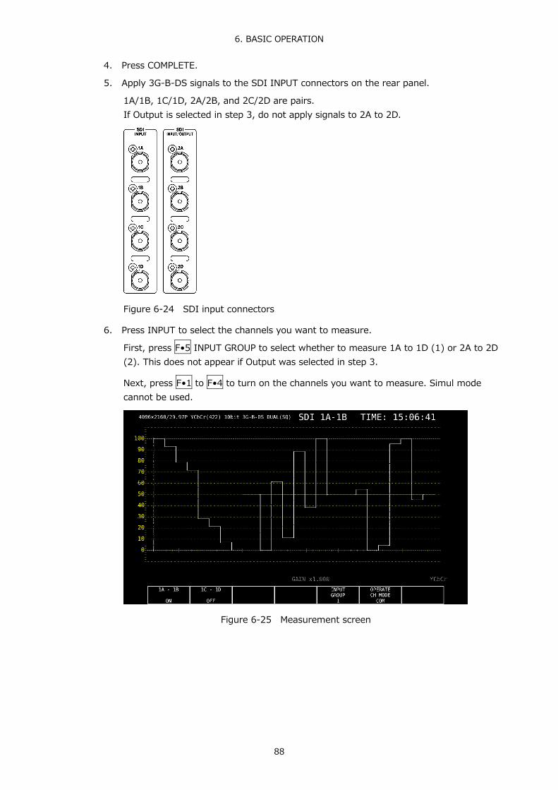
6. BASIC OPERATION
88
4. Press COMPLETE.
5. Apply 3G-B-DS signals to the SDI INPUT connectors on the rear panel.
1A/1B, 1C/1D, 2A/2B, and 2C/2D are pairs. If Output is selected in step 3, do not apply signals to 2A to 2D.
Figure 6-24 SDI input connectors
6. Press INPUT to select the channels you want to measure.
First, press F•5 INPUT GROUP to select whether to measure 1A to 1D (1) or 2A to 2D (2). This does not appear if Output was selected in step 3.
Next, press F•1 to F•4 to turn on the channels you want to measure. Simul mode cannot be used.
Figure 6-25 Measurement screen

6. BASIC OPERATION
89
6.2.7 Measuring HD (QL) Signals
1. On the SDI IN tab in the system settings, set SDI System to 4K HD Quad Link.
SYS → F•1 SIGNAL IN OUT →
Figure 6-26 SDI IN tab
2. Press F•2 PREV TAB or F•3 NEXT TAB, and then set SDI In/Out BNC.
Select Input to apply up to two signals (1A to 1D and 2A to 2D). Select Output to apply up to one signals (1A to 1D). (2A to 2D are set to output.)
SYS → F•1 SIGNAL IN OUT → F•2 PREV TAB or F•3 NEXT TAB →
Figure 6-27 SDI OUT tab

6. BASIC OPERATION
90
3. Press COMPLETE.
4. Apply HD signals to the SDI INPUT connectors on the rear panel.
If Output is selected in step 2, do not apply signals to 2A to 2D.
Figure 6-28 SDI input connectors
5. Press INPUT to select the channels you want to measure.
Press F•5 INPUT GROUP to select whether to measure 1A to 1D (1) or 2A to 2D (2). This does not appear if Output was selected in step 2.
Figure 6-29 Measurement screen
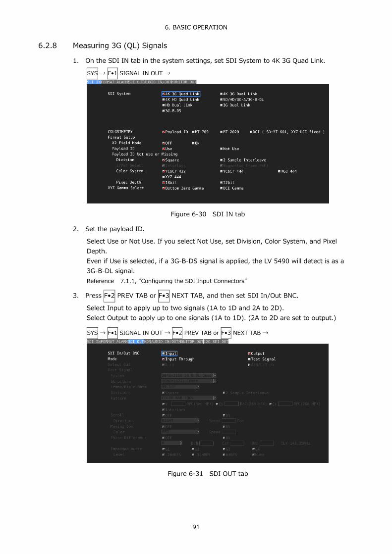
6. BASIC OPERATION
91
6.2.8 Measuring 3G (QL) Signals
1. On the SDI IN tab in the system settings, set SDI System to 4K 3G Quad Link.
SYS → F•1 SIGNAL IN OUT →
Figure 6-30 SDI IN tab
2. Set the payload ID.
Select Use or Not Use. If you select Not Use, set Division, Color System, and Pixel Depth. Even if Use is selected, if a 3G-B-DS signal is applied, the LV 5490 will detect is as a 3G-B-DL signal. Reference 7.1.1, “Configuring the SDI Input Connectors”
3. Press F•2 PREV TAB or F•3 NEXT TAB, and then set SDI In/Out BNC.
Select Input to apply up to two signals (1A to 1D and 2A to 2D). Select Output to apply up to one signals (1A to 1D). (2A to 2D are set to output.)
SYS → F•1 SIGNAL IN OUT → F•2 PREV TAB or F•3 NEXT TAB →
Figure 6-31 SDI OUT tab

6. BASIC OPERATION
92
4. Press COMPLETE.
5. Apply a 3G-A or 3G-B-DL signal to the SDI INPUT connectors on the rear panel.
If Output is selected in step 3, do not apply signals to 2A to 2D.
Figure 6-32 SDI input connectors
6. Press INPUT to select the channels you want to measure.
Press F•5 INPUT GROUP to select whether to measure 1A to 1D (1) or 2A to 2D (2). This does not appear if Output was selected in step 3.
Figure 6-33 Measurement screen

6. BASIC OPERATION
93
6.2.9 Measuring 4K NMI Signals (SER08)
1. On the SDI IN tab in the system settings, set SDI System to 4K NMI.
SYS → F•1 SIGNAL IN OUT →
Figure 6-34 SDI IN tab
2. Set the payload ID.
Select Use or Not Use. Division is fixed to 2 Sample Interleave. i/PsF Select is fixed to Interlace. Color System is fixed to YCbCr 422. Pixel Depth is fixed to 10 bit. Even if Use is selected, if a 4K NMI signal is applied, the LV 5490 will detect is as a 4K NMI signal. Reference 7.1.1, “Configuring the SDI Input Connectors”
3. Press COMPLETE.
4. Apply 4K NMI signals to the NMI connectors on the rear panel.
Figure 6-35 NMI input connectors

6. BASIC OPERATION
94
5. Press INPUT to select the channels you want to measure.
Figure 6-36 Measurement screen

6. BASIC OPERATION
95
6.2.10 Measuring NMI Signals (SER08)
1. On the SDI IN tab in the system settings, set SDI System to NMI.
SYS → F•1 SIGNAL IN OUT →
Figure 6-37 SDI IN tab
2. Set the payload ID.
Select Use or Not Use. Division is fixed to 2 Sample Interleave. i/PsF Select is fixed to Interlace. Color System is fixed to YCbCr 422. Pixel Depth is fixed to 10 bit. Even if Use is selected, if a 4K NMI signal is applied, the LV 5490 will detect is as a 4K NMI signal. Reference 7.1.1, “Configuring the SDI Input Connectors”
3. Press COMPLETE.
4. Apply NMI signals to the NMI connectors on the rear panel.
Figure 6-38 NMI input connectors

6. BASIC OPERATION
96
5. Press INPUT to select the channels you want to measure.
Figure 6-39 Measurement screen

6. BASIC OPERATION
97
6.3 Selecting the Measurement Mode
The types of measurement screens available are WFM, VECT, PIC, AUDIO, STATUS, and EYE. There is also another type, MULTI, that combines these six types. Press a measurement key on the front panel to select the type.
6.3.1 Video Signal Waveform Display
To display video signal waveforms, press WFM. The available features include line select display, which displays the waveform of the selected line, RGB display, and pseudo-composite display.
Figure 6-40 Video signal waveform display 6.3.2 Vector Waveform Display
To display vectors, press VECT. The available features include line select display, marker display, pseudo-composite display, 5 bar display, and CIE diagram display (SER05).
Figure 6-41 Vector waveform display

6. BASIC OPERATION
98
6.3.3 Picture Display
To show the picture display, press PIC. The available features include monochrome display, marker display, line select display, and focus assist display (SER04).
Figure 6-42 Picture display 6.3.4 Audio Display (SER03)
To show the audio display, press AUDIO. (If SER03 is not installed, the AUDIO key is disabled.) The available features include Lissajous display, surround display, meter display, and status display of the signal selected with F•1 MAPPING.
Figure 6-43 Audio display

6. BASIC OPERATION
99
6.3.5 Status Display
To show the status display, press STATUS. The available features include event log display and data dump display.
Figure 6-44 Status display 6.3.6 Eye Pattern Display (SER02/SER09)
To show eye patterns, press EYE. (If SER02/SER09 is not installed, the EYE key is disabled.) You can also show jitter by switching F•2 MODE. Simul mode is not supported. In addition signals applied to 2A to 2D cannot be displayed.
Figure 6-45 Eye pattern display

6. BASIC OPERATION
100
6.3.7 Multi Display
To show a multi screen, which is a combination of measurement screens, press MULTI. You can select between five types of layouts by using F•1 LAYOUT SELECT. To set each measurement screen, use F•2 MULTI WFM to F•7 MULTI EYE.
● USER 1
The vector, video signal waveform, status, and picture are displayed in four divided screens.
Figure 6-46 Multi display (USER 1)
● USER 2
The picture is displayed in the main screen, and the video signal waveform and vector are displayed as thumbnails.
Figure 6-47 Multi display (USER 2)

6. BASIC OPERATION
101
● USER 3
The vector is displayed in the main screen, and the video signal waveform and picture are displayed as thumbnails.
Figure 6-48 Multi display (USER 3)
● USER 4
The picture, video-signal-waveform, and vector are displayed top to bottom. This is suitable for simul mode.
Figure 6-49 Multi display (USER 4)

6. BASIC OPERATION
102
● USER 5
The picture and video signal waveform are displayed in the top and bottom screens. This is suitable for simul mode.
Figure 6-50 Multi display (USER 5) 6.4 Arranging the Measurement Screen Layout
The layout of the measurement screen that appears when the WFM, VECT, PIC, AUDIO, STATUS, or EYE key is pressed (one type each) and the screen that appears when the MULTI key is pressed (five types) can be arranged freely. To do so, connect a mouse to the front or rear panel USB port.
The layout that you specify will not be initialized even if you initialize the LV 5490. To initialize, perform any of the procedures below. Reference 7.7, “Initialization”
LAYOUT INIT YES on the SYS menu: The entire layout is initialized. ALL INIT YES on the SYS menu: The entire layout is initialized. Factory default settings: The entire layout is initialized. DEFAULT LAYOUT in the layout window: The layout of the selected measurement display is
initialized. 6.4.1 Notes
● The maximum number of items that can be arranged is determined by 64 ÷ the number of measurement channels (1 to 4). Item, here, includes the items on the Main and Sub tabs as well as Format, Input, and Time on the Option tab.

6. BASIC OPERATION
103
6.4.2 Layout Procedure
As an example, this section explains how to change the layout of a multi display (User 1) in the following manner.
a) Display the layout screen b) Change TIME in the upper right of the screen to DATE c) Superimpose the vector on the picture d) Add audio e) Add TIME to the status f) Apply the changes
Before change
After change
Figure 6-51 Arranging the multi display layout

6. BASIC OPERATION
104
a) Display the layout screen
1. Press MULTI, and set F•1 LAYOUT SELECT to USER 1.
There are five layouts for the multi screen. You can use USER 1 to USER 5 to switch between the layouts.
2. Right-click in the measurement screen, and click LAYOUT.
The layout screen appears.
Figure 6-52 Layout screen
b) Change TIME in the upper right of the screen to DATE
3. Click the TIME item in the upper right of the screen.
The color of the frame and text changes to light blue, and Select Item in the layout window displays TIME. This indicates that the TIME item is selected.
4. Click DELETE.
The TIME item is deleted.
5. On the Sub tab, click DATE.
The DATE item appears.
6. Place the DATE item in the area where the TIME item was displayed.
To move an item, drag it. To resize an item, drag the green handles at the four corners of the item. The position and size of an item snap to the grid selected by Grid Size in the layout window.
You can also use the Area tab to move and resize an item. The coordinates at the upper left corner of the screen are (0, 0). Those at the lower right corner are (1920, 1080). Using these references, set the coordinates of the upper left corner of the item (x0, y0) and the lower right corner (x1, y1). The minimum size is 90×60.

6. BASIC OPERATION
105
If the layout window gets in the way, move it or close it. If you close it, you can redisplay it by double-clicking in the layout screen.
If multiple items are on top of each other, items in the back may not be selectable. If you need to select such item, click the item on the Main or Sub tab. The selected item will move to the front.
c) Superimpose the vector on the picture
7. Select the VECT item, and click Background Transparent on the Option tab.
Background Transparent is for making the background transparent when an item is superimposed on a picture.
8. Place the VECT item on top of the picture.
Resize as necessary.
d) Add audio
9. Click AUDIO on the Main tab.
The AUDIO item appears. You can place an AUDIO item even if SER03 is not installed, but the message “Not installed” will appear.
10. Place the AUDIO item in the area where the VECT item was originally displayed.
e) Add TIME to the status
11. Click the STATUS item.
12. Click Time on the Option tab.
The TIME item on the Sub tab can be placed anywhere. Time on the Option tab is displayed at the top of the selected item. You cannot change the display position or size.
f) Apply the changes
13. Right-click in the layout screen, and click COMPLETE.
The measurement screen returns. If you click CANCEL, all the changes that you made up to that point will be canceled.
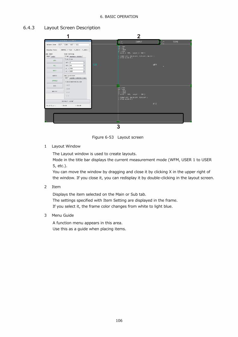
6. BASIC OPERATION
106
6.4.3 Layout Screen Description
Figure 6-53 Layout screen
1 Layout Window
The Layout window is used to create layouts. Mode in the title bar displays the current measurement mode (WFM, USER 1 to USER 5, etc.). You can move the window by dragging and close it by clicking X in the upper right of the window. If you close it, you can redisplay it by double-clicking in the layout screen.
2 Item
Displays the item selected on the Main or Sub tab. The settings specified with Item Setting are displayed in the frame. If you select it, the frame color changes from white to light blue.
3 Menu Guide
A function menu appears in this area. Use this as a guide when placing items.

6. BASIC OPERATION
107
Figure 6-54 Layout window
4 Select Item
Displays the selected item.
5 Display Mode / Style
Select the display format for simul mode. Display Mode applies to the entire screen, Style applies to the selected item.
If Display Mode is not set to NORMAL or if the selected item is AUDIO or EYE, Style cannot be selected. If the selected item is VECT(5BAR), VECT(HIST), VECT(CIE), STATUS, or an item on the Sub tab, you cannot set Style to MIX.

6. BASIC OPERATION
108
If Display Mode is not set to NORMAL and multiple channels are displayed in simul mode, even if you place AUDIO or EYE items in the layout, “Not supported” will appear and will not work.
For example, if the following screens are displayed in single input mode and you change to simul mode, the display changes depending on Display Mode as follows.
Figure 6-55 Single input mode
● When Display Mode Is NORMAL
The screen is divided by channel within each item. Select the division format with Style.
TILE (tile the screens) MIX (cascade the screens)
ALIGN-V (arrange vertically) ALIGN-H (arrange horizontally)
Figure 6-56 Normal display

6. BASIC OPERATION
109
● When Display Mode Is TILE
The screen is divided by channel.
Ach Bch
Cch
Figure 6-57 Tiled display
● When Display Mode Is ALIGN-H
The screen is divided by channel and arranged side by side.
Ach Bch Cch
Figure 6-58 ALIGN-H display

6. BASIC OPERATION
110
● When Display Mode Is ALIGN-V
The screen is divided by channel and arranged top to bottom.
Figure 6-59 ALIGN-V display
6 Main
Measurement item.
• WFM
Shows the video signal waveform display.
• PIC
Shows the picture display.
• VECT
Click this after selecting the display mode on the VECT tab to show the vector waveform display. A CIE chromaticity diagram (SER05) will not be displayed properly if the VECT item is overlapping other items.
• AUDIO
Click this after selecting the display mode on the AUDIO tab to show the audio display. If SER03 is not installed, the message “Not installed” is displayed.
• STATUS
Click this after selecting the display mode on the STATUS tab to show the status display.
• EYE
Click this after selecting the display mode on the EYE tab to show the eye pattern or jitter. If SER02/SER09 is not installed, the message “Not installed” is displayed.

6. BASIC OPERATION
111
7 Sub
Items for displaying information.
• FORMAT
Displays the format (e.g., 1920x1080/59.94I YCbCr(422) 10bit HD). If you place this item, you can show and hide it using the GENERAL SETUP tab in the system settings. It is normally displayed in white, but if the input format is not appropriate, it turns red.
• INPUT
Displays the input signal (e.g., SDI 1A). If you place this item, you can show and hide it using the GENERAL SETUP tab in the system settings.
• TIME
Displays the time (e.g., TIME: 00:00:00). If you place this item, you can select the display format using the GENERAL SETUP tab in the system settings.
• DATE
Displays the date (e.g., DATE: 2000/01/01). If you place this item, you can select the display format using the GENERAL SETUP tab in the system settings. Only one item is displayed even if you switch to simul mode.
8 Area
Set the position and size of the selected item. The coordinates at the upper left corner of the screen are (0, 0). Those at the lower right corner are (1920, 1080). Based on these references, the coordinates of the upper left corner of the item is (x0, y0), and those of the lower right corner is (x1, y1). You can change the values using the ▲▼ button or the wheel on the mouse.
9 Option
Set the options for the selected item.
• Format
Turns on and off the format display (e.g., 1920x1080/59.94I YCbCr(422) 10bit HD). This option cannot be displayed for an AUDIO item, an EYE item, or an item on the Sub tab. If you enable this option, you can show and hide it using the GENERAL SETUP tab in the system settings. It is normally displayed in white, but if the input format is not appropriate, it turns red.
• Input
Turns on and off the input signal display (e.g., SDI 1A). This option cannot be displayed for an AUDIO item, an EYE item, or an item on the Sub tab. If you enable this option, you can show and hide it using the GENERAL SETUP tab in the system settings.

6. BASIC OPERATION
112
• Time
Turns on and off the time display (e.g., TIME: 00:00:00). This option cannot be displayed for an AUDIO item, an EYE item, or an item on the Sub tab. If you enable this option, you can select the display format using the GENERAL SETUP tab in the system settings.
• Background Transparent
Selects the transmittance of the background when the sub item is superimposed on a picture. When enabled, the transmittance is set to 100 %; when disabled, the transmittance is set to 50 %. You cannot set this option for a PIC item.
10 VECT
Selects the display mode of the VECT item. Select the mode before clicking the VECT item.
VECT / HIST / CIE This is the normal vector waveform display. You can switch the display
between vector waveform, histogram, and CIE chromaticity diagram. It cannot be arranged with the items below at the same time. If you want to arrange the items below, delete this item first.
VECT The vector waveform is displayed. 5BAR The 5 bar is displayed. HIST The histogram is displayed. CIE The CIE diagram is displayed.
If SER05 is not installed, the message “Not installed” is displayed.
For example, you can arrange VECT and HIST to be displayed at the same time.
Figure 6-60 Vector waveform display

6. BASIC OPERATION
113
11 AUDIO
Selects the display mode of the AUDIO item. Select the mode before clicking the AUDIO item.
LEVEL BAR + etc. This is the normal audio display. The display switches between
Lissajous, surround, meter, and status. It cannot be arranged with the items below at the same time. If you want to arrange the items below, delete this item first.
LEVEL BAR Meters are displayed. When 16 channels are being measured, meters will not be displayed correctly if arranged at the same time with LISSAJOU, STATUS, and SURROUND.
LISSAJOU Lissajous curves are displayed. It cannot be arranged with STATUS or SURROUND at the same time. When 16 channels are being measured, lissajous curves will not be displayed correctly if arranged at the same time with LEVEL BAR.
STATUS The status is displayed. It cannot be arranged with LISSAJOU or SURROUND at the same time. When 16 channels are being measured, the status will not be displayed correctly if arranged at the same time with LEVEL BAR.
SURROUND Surround waveforms are displayed. It cannot be arranged with LISSAJOU or STATUS at the same time. Surround waveforms will not be displayed correctly when 16 channels are being measured or when in embedded audio measurement Simul mode.

6. BASIC OPERATION
114
12 STATUS
Selects the display mode of the STATUS item. Select the mode before clicking the STATUS item.
STATUS ALL This is the normal status display. The display switches between
error count, data dump, etc. It cannot be arranged with the items below at the same time. If you want to arrange the items below, delete this item first.
STATUS ERROR Error counts are displayed. DATA DUMP Data dump is displayed. EVENT LOG The event log is displayed. EXT REF Phase differences are displayed.
If the input signal is 12G, the message “Not supported” is displayed.
ANC PACKET SUMMARY A summary of ancillary pockets is displayed. ANC One of the following is displayed.
• STATUS EDH: EDH display • STATUS PAYLOAD: Payload ID display • STATUS CONTROL: Audio control packet display • STATUS ARIB CC: Closed caption display • STATUS ARIB NETQ: NET-Q display • STATUS ARIB TRIG: Data trigger display • STATUS ARIB USER1: User data 1 display • STATUS ARIB USER2: User data 2 display • STATUS SMPTE AFD: AFD display • STATUS SEARCH: Ancillary packet search display
For example, you can arrange DATA DUMP, EXT REF, and ANC STATUS SEARCH to be displayed at the same time.
Figure 6-61 Status display

6. BASIC OPERATION
115
13 EYE
Selects the display mode of the EYE item. Select the mode before clicking the EYE item.
EYE / JITTER This is the normal eye pattern display. The display switches between eye
pattern and jitter. It cannot be arranged with the items below at the same time. If you want to arrange the items below, delete this item first.
EYE The eye pattern is displayed. JITTER The jitter waveform is displayed.
For example, you can arrange EYE and JITTER to be displayed at the same time.
Figure 6-62 Eye pattern display
14 DELETE
Deletes the selected item.
15 DEFAULT LAYOUT
Resets the layout to the initial settings defined for each measurement mode. Grid Size is not reset.
16 Grid Size: 10x10 / 30x30
Select the grid size. The position and size of items snap to the grid specified here.

7. SYSTEM SETTINGS
116
7. SYSTEM SETTINGS The system settings can be used to configure the LV 5490 and unit settings. Press SYS, and use the SYS menu.
SYS →
Figure 7-1 SYS menu 7.1 Configuring the I/O Connectors
To configure the I/O connector settings, use F•1 SIGNAL IN OUT on the SYS menu. 7.1.1 Configuring the SDI Input Connectors
Use the SDI IN tab to configure the format of the SDI signals applied to SDI INPUT or the IP (NMI) signals applied to NMI on the rear panel.
SYS → F•1 SIGNAL IN OUT →
Figure 7-2 SDI IN tab
● SDI System
Select the input format.
4K 12G / 4K 3G Quad Link / 4K 3G Dual Link / 4K HD Quad Link / SD/HD/3G-A/3G-B-DL / HD Dual Link / 3G Dual Link / 3G-B-DS / 4K NMI / NMI

7. SYSTEM SETTINGS
117
● COLORIMETRY
Select the colorimetry to use on the video-signal-waveform, vector, picture, and CIE-chromaticity-diagram (SER05) displays.
During XYZ input, if you change the colorimetry between BT-709 or BT2020 and DCI, a message “TONE CURVE SETUP” will be displayed for 10 to 20 seconds when you press F•1 COMPLETE.
The current applied colorimetry is displayed in cyan in the upper right of the vectorscope display and in the lower right of the CIE chromaticity diagram (SER05) display. For 3G(DL)-4K, 3G(QL), 4K NMI and NMI, if you select a payload ID, the current applied colorimetry is displayed in yellow if the colorimetries of all links are not matched.
For SD input, the colorimetry is fixed to BT.601, regardless of the colorimetry selection.
The picture display on the LV 5490 LCD is not capable of expressing the color space of the applied colorimetry.
Payload ID: If SDI System is 4K 12G, 4K 3G Quad Link, or 4K 3G Dual Link and the
division transmission system is 2 sample interleave of if SDI System is 4K NMI or NMI, the LV 5490 automatically detects BT.2020 from the payload ID and operates. For the square format or for modes other than BT.2020, the LV 5490 runs in BT.709 mode.
BT-709: Runs in BT.709 mode. BT-2020: Runs in BT.2020 mode. DCI: Runs in DCI mode.
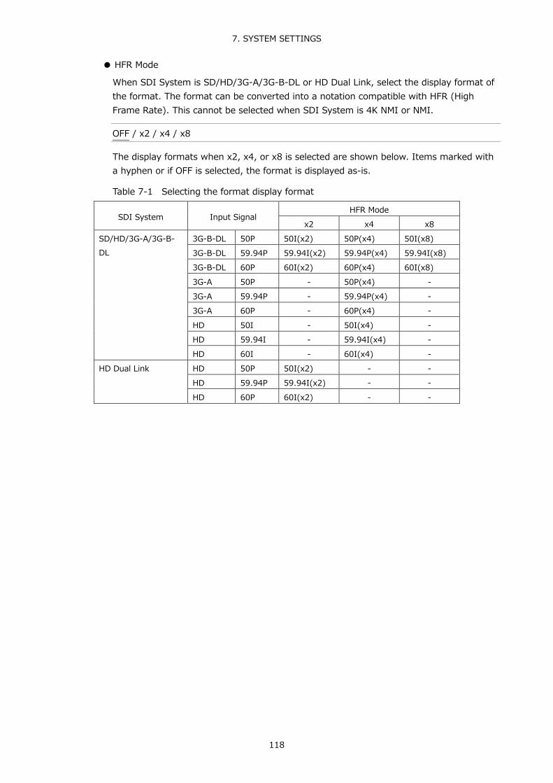
7. SYSTEM SETTINGS
118
● HFR Mode
When SDI System is SD/HD/3G-A/3G-B-DL or HD Dual Link, select the display format of the format. The format can be converted into a notation compatible with HFR (High Frame Rate). This cannot be selected when SDI System is 4K NMI or NMI.
OFF / x2 / x4 / x8
The display formats when x2, x4, or x8 is selected are shown below. Items marked with a hyphen or if OFF is selected, the format is displayed as-is.
Table 7-1 Selecting the format display format
SDI System Input Signal HFR Mode
x2 x4 x8 SD/HD/3G-A/3G-B-DL
3G-B-DL 50P 50I(x2) 50P(x4) 50I(x8) 3G-B-DL 59.94P 59.94I(x2) 59.94P(x4) 59.94I(x8) 3G-B-DL 60P 60I(x2) 60P(x4) 60I(x8) 3G-A 50P - 50P(x4) - 3G-A 59.94P - 59.94P(x4) - 3G-A 60P - 60P(x4) - HD 50I - 50I(x4) - HD 59.94I - 59.94I(x4) - HD 60I - 60I(x4) -
HD Dual Link HD 50P 50I(x2) - - HD 59.94P 59.94I(x2) - - HD 60P 60I(x2) - -

7. SYSTEM SETTINGS
119
● Payload ID
Select whether to use the payload ID for input format identification. This cannot be selected when SDI System is 4K HD Quad Link.
Use / Not Use
If you select Not Use, set the items marked with a in the table below. The LV 5490 will operate using the specified settings.
If you select Use, the items marked with a will be detected from the payload ID. There is no need to set these items, but if you set them and a payload ID is not embedded in the input signal, the LV 5490 will operate using the specified settings.
Regardless of whether you select Use or Not Use, items such as scanning and frame frequency will be detected from the TRS.
Table 7-2 Payload ID settings
Input Signal Division i/PsF Select Color System Pixel Depth HD Cannot be set No need to set
(fixed to YCbCr 422) No need to set
(fixed to 10 bits) SD Cannot be set No need to set
(fixed to interlace) No need to set
(fixed to YCbCr 422) No need to set
(fixed to 10 bits) 3G-A, 3G-B-DL Cannot be set 3G-B-DS Cannot be set Cannot be set Cannot be set 12G Cannot be set HD (DL) Cannot be set 3G (DL)-2K Cannot be set Cannot be set 3G (DL)-4K Cannot be set Cannot be set Cannot be set 3G (QL) Cannot be set 4K NMI Cannot be set
(fixed to 2 Sample Interleave) Cannot be set
(fixed to interlace) Cannot be set
(fixed to YCbCr 422) Cannot be set
(fixed to 10 bits) NMI Cannot be set
(fixed to 2 Sample Interleave) Cannot be set
(fixed to interlace) Cannot be set
(fixed to YCbCr 422) Cannot be set
(fixed to 10 bits)
● Division
Selects the division transmission system when SDI System is 4K. When SDI System is 4K NMI or NMI, this is fixed to 2 Sample Interleave and cannot be changed.
Square / 2 Sample Interleave

7. SYSTEM SETTINGS
120
● i/PsF Select
The LV 5490 cannot detect the following formats. Therefore, select whether to use interlace or segmented frame for displaying. This cannot be selected when SDI System is 4K or 3G Dual Link. When SDI System is 4K NMI or NMI, this is fixed to Interlace and cannot be changed.
• 1080/60I and 1080/30PsF • 1080/59.94I and 1080/29.97PsF • 1080/50I and 1080/25PsF
Interlace / Segmented Frame(PsF)
● Color System
Select the color system of the input signal. SDI System is 3G-B-DS, 4K 3G Dual Link, 4K NMI or NMI, this is fixed to YCbCr 422, and you cannot change it.
YCbCr 422 / YCbCr 444 / RGB 444 / XYZ 444
● Pixel Depth
Select the quantization of the input signal. SDI System is 3G-B-DS, 4K 3G Dual Link, 4K NMI or NMI, this is fixed to 10bit, and you cannot change it.
10bit / 12bit

7. SYSTEM SETTINGS
121
● XYZ Gamma Select
Select the gamma correction system for XYZ input.
XYZ signals can be converted into RGB signals and shown on the video signal waveform display or vector display, but at the 12-bit quantization defined in the standard (when DCI Gamma is selected), the conversion error near 0% input will be large. As such, showing an RGB display or vector display using the SMPTE RP 431 color bar (color patch) will cause the bright line to deviate greatly from the scale in some areas.
To reduce the error, the LV 5490 uses “Bottom Zero Gamma” in which input up to 0.05% is fixed at 0% as the default setting. Select this setting when adjusting devices and the like.
Bottom Zero Gamma: Gamma in which input up to 0.05% is fixed at 0% in comparison
to DCI Gamma DCI Gamma: Input to the (1/2.6) power gamma
Gamma curve (0 to 100% input)
Gamma curve (0 to 0.2% input exploded)
0%
20%
40%
60%
80%
100%
0% 20% 40% 60% 80% 100%
OUT
PUT
INPUT
DCI Gamma Bottom Zero Gamma
0.0%
2.0%
4.0%
6.0%
8.0%
10.0%
0.00% 0.05% 0.10% 0.15% 0.20%
OUT
PUT
INPUT
DCI Gamma Bottom Zero Gamma

7. SYSTEM SETTINGS
122
Vector display example
Ideal Value DCI Gamma Bottom Zero Gamma

7. SYSTEM SETTINGS
123
7.1.2 Configuring the IP(NMI) Input (SER08)
On the NMI IN tab, select the input from the IP (NMI) signals received through NMI on the rear panel or the SDI signal received through SDI INPUT when SDI System is set to NMI on the SDI IN tab. When SDI System on the SDI IN tab is 4K NMI, you cannot select the input.
SYS → F•1 SIGNAL IN OUT →F•2 PREV TAB or F•3 NEXT TAB →
図 7-3 NMI IN tab
● Ach
Selects the input received through Ach.
SDI 1A / NMI-1
● Bch
Selects the input received through Bch.
SDI 1B / NMI-2
● Cch
Selects the input received through Cch.
SDI 1C / NMI-3
● Dch
Selects the input received through Dch.
SDI 1D / NMI-4

7. SYSTEM SETTINGS
124
7.1.3 Configuring FORMAT ALARM
Use the FORMAT ALARM tab to configure the expected SDI signal format. When SDI System is 4K NMI or NMI, cannot be changed.
SYS → F•1 SIGNAL IN OUT → F•2 PREV TAB or F•3 NEXT TAB →
Figure 7-4 FORMAT ALARM tab
● Format Alarm
Turn on and off the format alarm detection. If alarm detection is set to ON and a format other than the format specified with Format Set is received, the LV 5490 operates in the following manner. • Displays the format in yellow • Displays errors in the event log of the status display • Displays “ERROR” in the upper right of the display • Alarm output from the remote connector
OFF / ON

7. SYSTEM SETTINGS
125
● Format Set
When Format Alarm is set to ON, specify the expected format. For information on the format combinations that are available, see section 3.3.1, “SDI Formats and Standards.”
Table 7-3 Selecting the format
SDI System System Structure Frame/Field Rate Division 4K 12G 3840x2160 12G TYPE 1
4096x2160 12G TYPE 1 YCbCr(422) 10bit YCbCr(422) 12bit YCbCr(444) 10bit YCbCr(444) 12bit RGB(444) 10bit RGB(444) 12bit
60/59.94/50/48/47.95/ 30/29.97/25/24/23.98/P
-
4K 3G Quad Link 3840x2160 3G-B-DL Quad 4096x2160 3G-B-DL Quad 3840x2160 3G-A Quad 4096x2160 3G-A Quad
YCbCr(422) 10bit YCbCr(422) 12bit YCbCr(444) 10bit YCbCr(444) 12bit RGB(444) 10bit RGB(444) 12bit XYZ(444) 12bit
60/59.94/50/48/47.95/ 30/29.97/25/24/23.98/P 30/29.97/25/24/23.98/PsF
Square/ 2 Sample Interleave
4K 3G Dual Link 3840x2160 3G-B-DS Dual 4096x2160 3G-B-DS Dual
YCbCr(422) 10bit 30/29.97/25/24/23.98/P 30/29.97/25/24/23.98/PsF
Square/ 2 Sample Interleave
4K HD Quad Link 3840x2160 HD Quad 4096x2160 HD Quad
YCbCr(422) 10bit 30/29.97/25/24/23.98/P 30/29.97/25/24/23.98/PsF
-
SD/HD/3G-A/3G-B-DL 1920x1080 3G-B-DL 2048x1080 3G-B-DL 1280x720 3G-A 1920x1080 3G-A 2048x1080 3G-A 1280x720 HD 1920x1080 HD 720x487 SD 720x576 SD
YCbCr(422) 10bit YCbCr(422) 12bit YCbCr(444) 10bit YCbCr(444) 12bit RGB(444) 10bit RGB(444) 12bit XYZ(444) 12bit
60/59.94/50/I 60/59.94/50/48/47.95/ 30/29.97/25/24/23.98/P 30/29.97/25/24/23.98/PsF
-
HD Dual Link 1920x1080 HD Dual 2048x1080 HD Dual
YCbCr(422) 10bit YCbCr(422) 12bit YCbCr(444) 10bit YCbCr(444) 12bit RGB(444) 10bit RGB(444) 12bit XYZ(444) 12bit
60/59.94/50/I 60/59.94/50/48/47.95/ 30/29.97/25/24/23.98/P 30/29.97/25/24/23.98/PsF
-
3G Dual Link 1920x1080 3G-B-DL Dual 2048x1080 3G-B-DL Dual 1920x1080 3G-A Dual 2048x1080 3G-A Dual
YCbCr(422) 12bit YCbCr(444) 10bit YCbCr(444) 12bit RGB(444) 10bit RGB(444) 12bit
60/59.94/50/48/47.95/P -
3G-B-DS 1280x720 3G-B-DS 1920x1080 3G-B-DS
YCbCr(422) 10bit 60/59.94/50/I 60/59.94/50/ 30/29.97/25/24/23.98/P 30/29.97/25/24/23.98/PsF
-

7. SYSTEM SETTINGS
126
● Colorimetry Alarm
Turn on and off the colorimetry alarm detection.
Normally, colorimetry is displayed in cyan on the vector waveform display and CIE chromaticity diagram display (SER05). But for 3G(QL) and 3G(DL)-4K, if any of the colorimetries does not match, it is displayed in yellow.
If alarm detection is set to ON and a colorimetry other than that specified with Colorimetry Set is received, the colorimetry is displayed in red. It is also displayed in red on the video signal waveform display.
Note that this is invalid when the input signal is SD.
OFF / ON
● Colorimetry Set
If Colorimetry Alarm is set to ON, specify the colorimetry.
BT-709 / BT-2020 / DCI

7. SYSTEM SETTINGS
127
7.1.4 Configuring the SDI I/O Connectors
Use the SDI OUT tab to configure the SDI INPUT/OUTPUT connectors on the rear panel.
SYS → F•1 SIGNAL IN OUT → F•2 PREV TAB or F•3 NEXT TAB →
Figure 7-5 SDI OUT tab
● SDI In/Out BNC
Select whether to use SDI INPUT/OUTPUT as input connectors or output connectors. If SDI System on the SDI IN tab is set to 4K 12G, signals received through 3G-SDI INPUT/OUTPUT cannot be measured even if input is specified.
Input / Output
● Mode
Select the signal to output from SDI INPUT/OUTPUT for when SDI In/Out BNC is set to Output.
Input Through: Transmits the reclocked version of the signals that have been received
by the SDI INPUT 1A to 1D connectors. However, if SDI System on the SDI IN tab is set to 4K 12G, reclocked signals are not transmitted.
Test Signal: Transmits the pattern specified by Test Signal.
● Select Out
Select the signal to output from SDI INPUT/OUTPUT 2A for when Mode is set to Input Through. This is fixed to A ch (except for 3G(DL)-4K) during multi link (cannot be set).
A ch: Transmits the reclocked version of the signal that has been received by
the SDI INPUT 1A connector. A/B/C/D ch: Transmits the reclocked version of the signals that have been received
by the SDI INPUT 1A to 1D connectors. To select the output channel, use the INPUT menu or F•6 SELECT CH on each measurement screen.
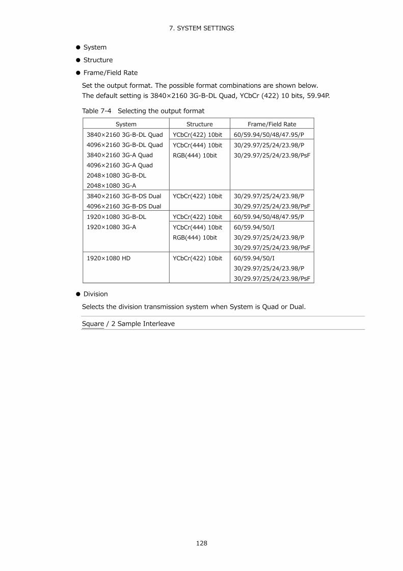
7. SYSTEM SETTINGS
128
● System
● Structure
● Frame/Field Rate
Set the output format. The possible format combinations are shown below. The default setting is 3840×2160 3G-B-DL Quad, YCbCr (422) 10 bits, 59.94P.
Table 7-4 Selecting the output format
System Structure Frame/Field Rate 3840×2160 3G-B-DL Quad 4096×2160 3G-B-DL Quad 3840×2160 3G-A Quad 4096×2160 3G-A Quad 2048×1080 3G-B-DL 2048×1080 3G-A
YCbCr(422) 10bit 60/59.94/50/48/47.95/P YCbCr(444) 10bit RGB(444) 10bit
30/29.97/25/24/23.98/P 30/29.97/25/24/23.98/PsF
3840×2160 3G-B-DS Dual 4096×2160 3G-B-DS Dual
YCbCr(422) 10bit 30/29.97/25/24/23.98/P 30/29.97/25/24/23.98/PsF
1920×1080 3G-B-DL 1920×1080 3G-A
YCbCr(422) 10bit 60/59.94/50/48/47.95/P YCbCr(444) 10bit RGB(444) 10bit
60/59.94/50/I 30/29.97/25/24/23.98/P 30/29.97/25/24/23.98/PsF
1920×1080 HD YCbCr(422) 10bit 60/59.94/50/I 30/29.97/25/24/23.98/P 30/29.97/25/24/23.98/PsF
● Division
Selects the division transmission system when System is Quad or Dual.
Square / 2 Sample Interleave

7. SYSTEM SETTINGS
129
● Pattern
Select the output pattern. The selectable patterns are shown below. Depending on the pattern, you can turn on and off YCbCr or RGB separately.
For COLOR RASTER, you can set the YCbCr or RGB levels separately. Moreover, if Structure is set to RGB, you can select the Interlock check box to synchronize the RGB levels.
Bandwidth is not limited for MULTI COLOR BAR, COLOR RASTER, CROSS HATCH, 10 STEP, or LIMIT RAMP.
Table 7-5 Selecting the output pattern
Pattern YCbCr/RGB on/off Level adjustment COLOR BAR 100% Yes No COLOR BAR 75% Yes No MULTI COLOR BAR(*1) Yes No COLOR RASTER Yes Yes CROSS HATCH Yes No 10 STEP Yes No LIMIT RAMP Yes No
*1 This cannot be selected when the system is 4096x2160 or 2048x1080. * The signal will be interrupted when the pattern is changed.
● Scroll
Scrolls the pattern. When set to ON, Moving Box and Phase Difference are turned off. You cannot select this when Pattern is set to CROSS HATCH.
OFF / ON
● Direction
When Scroll is set to ON, set the scroll direction.
RIGHT: Scrolls from left to right. LEFT: Scrolls from right to left. UP: Scrolls from down to up. DOWN: Scrolls from up to down. RIGHT & UP: Scrolls from left_down to right_up. RIGHT & DOWN: Scrolls from left_up to right_down. LEFT & UP: Scrolls from right_down to left_up. LEFT & DOWN: Scrolls from right_up to left_down.
● Speed
When Scroll is set to ON, set the scroll speed.
4 - 124 Dot (in 4 dot steps)

7. SYSTEM SETTINGS
130
● Moving Box
Superimposes a square that moves randomly. When set to ON, Scroll and Phase Difference are turned off.
OFF / ON
● Color
When Moving Box is set to ON, set the moving box color.
WHITE / YELLOW / CYAN / GREEN / MAGENTA / RED / BLUE / BLACK
● Speed
When Moving Box is set to ON, set the moving box speed. Greater the value, higher the speed.
1 - 3
● Phase Difference
When System is set to Quad, you can adjust the Bch, Cch, and Dch phases relative to Ach. When System is set to Dual, you can adjust the Bch phase relative to Ach and the Dch phase relative to Cch. When set to ON, Scroll and Moving Box are turned off.
OFF / ON
● Bch, Cch, Dch
When Phase Difference is set to ON, you can adjust the Bch, Cch, and Dch phases. Switch between H and V to set each value. When System is set to Dual, the Bch and Dch phases are shared.
H: -1374 - 0 - 1374 Dot (depending on frame/field rate) V: -562 - 0 - 562 Dot

7. SYSTEM SETTINGS
131
● Embedded Audio
When the pattern is set to COLOR BAR 100%, COLOR BAR 75%, or MULTI COLOR BAR, select the audio channels to embed in the SDI signal. Channels 1 to 4 are called group 1, channels 5 to 8 group 2, channels 9 to 12 group 3, and channels 13 to 16 group 4.
The channels that can be embedded are 8 channels or 16 channels depending on the system and frame/field rate as shown below.
Table 7-6 Configuring Embedded Audio
System Frame/Field Rate G1 G2 G3 G4 3840x2160 3G-B-DL Quad 3840x2160 3G-A Quad 4096x2160 3G-A Quad 3840x2160 3G-B-DS Dual 1920x1080 3G-B-DL 1920x1080 3G-A 2048x1080 3G-A 1920x1080 HD
- Yes Yes Yes Yes
4096x2160 3G-B-DL Quad 2048x1080 3G-B-DL
60/59.94/30/29.97/P 30/29.97/PsF
Yes Yes No No
50/48/47.95/25/24/23.98/P 25/24/23.98/PsF
Yes Yes Yes Yes
4096x2160 3G-B-DS Dual 30/29.97/P 30/29.97/PsF
Yes Yes No No
25/24/23.98/P 25/24/23.98/PsF
Yes Yes Yes Yes
● Level
Select the embedded audio level.
-20dBFS / -18dBFS / 0dBFS / Mute
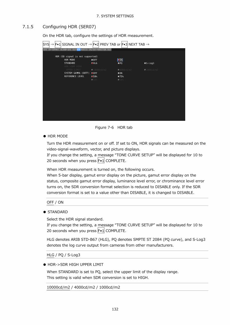
7. SYSTEM SETTINGS
132
7.1.5 Configuring HDR (SER07)
On the HDR tab, configure the settings of HDR measurement.
SYS → F•1 SIGNAL IN OUT → F•2 PREV TAB or F•3 NEXT TAB →
Figure 7-6 HDR tab
● HDR MODE
Turn the HDR measurement on or off. If set to ON, HDR signals can be measured on the video-signal-waveform, vector, and picture displays. If you change the setting, a message “TONE CURVE SETUP” will be displayed for 10 to 20 seconds when you press F•1 COMPLETE.
When HDR measurement is turned on, the following occurs. When 5-bar display, gamut error display on the picture, gamut error display on the status, composite gamut error display, luminance level error, or chrominance level error turns on, the SDR conversion format selection is reduced to DISABLE only. If the SDR conversion format is set to a value other than DISABLE, it is changed to DISABLE.
OFF / ON
● STANDARD
Select the HDR signal standard. If you change the setting, a message “TONE CURVE SETUP” will be displayed for 10 to 20 seconds when you press F•1 COMPLETE.
HLG denotes ARIB STD-B67 (HLG), PQ denotes SMPTE ST 2084 (PQ curve), and S-Log3 denotes the log curve output from cameras from other manufacturers.
HLG / PQ / S-Log3
● HDR->SDR HIGH UPPER LIMIT
When STANDARD is set to PQ, select the upper limit of the display range. This setting is valid when SDR conversion is set to HIGH.
10000cd/m2 / 4000cd/m2 / 1000cd/m2

7. SYSTEM SETTINGS
133
●SYSTEM GAMMA (OOTF)
If SYSTEM GAMMA (OOTF) is set to ON when STANDARD is set to HLG or S-Log3, the scale corresponding to the HDR signal of the video signal waveform display and picture display is shown in cd/m2, which is a unit of display intensity for HLG displays. When STANDARD is set to HLG, gamma 1.2 is used to calculate the intensity with the full scale ranging up to 1000cd/m2. When STANDARD is set to S-Log3, the intensity is displayed with the full scale ranging up to 3000cd/m2.
OFF / ON
● REFERENCE LEVEL
When STANDARD is set to HLG or PQ, select the reference level for the program production. On the video signal waveform display, the selected reference level is shown using broken lines on the scale. On the picture display, the selected reference level is set to the REF default value on the HDR signal CINEZONE display. The REF default value is applied when you press the function dial (F•D).
When STANDARD is HLG
50% / 75%
When STANDARD is PQ
51% / 58%
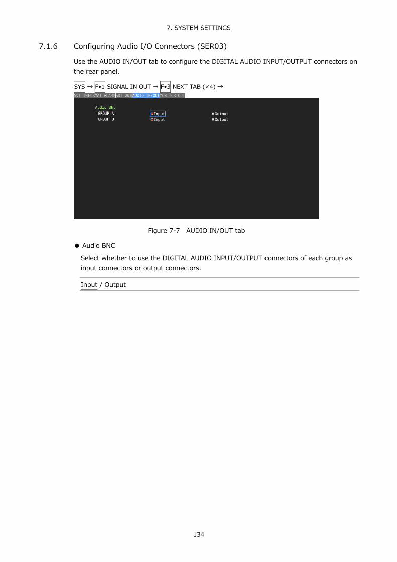
7. SYSTEM SETTINGS
134
7.1.6 Configuring Audio I/O Connectors (SER03)
Use the AUDIO IN/OUT tab to configure the DIGITAL AUDIO INPUT/OUTPUT connectors on the rear panel.
SYS → F•1 SIGNAL IN OUT → F•3 NEXT TAB (×4) →
Figure 7-7 AUDIO IN/OUT tab
● Audio BNC
Select whether to use the DIGITAL AUDIO INPUT/OUTPUT connectors of each group as input connectors or output connectors.
Input / Output

7. SYSTEM SETTINGS
135
7.1.7 Configuring the Monitor Output Connectors
Use the MONITOR OUT tab to configure the MONITOR OUTPUT connectors on the rear panel and the LV 5490 LCD.
SYS → F•1 SIGNAL IN OUT → F•2 PREV TAB or F•3 NEXT TAB →
Figure 7-8 MONITOR OUT tab
● Freq. Sync Mode
Select the sync mode.
INT: Transmits in the selected format by using the internal clock. EXT: Transmits by using the external sync signal received through EXT REF.
The output signal format varies depending on the frame frequency of the external sync signal as follows. 30 Hz: 1080/60p 29.97 Hz: 1080/59.94p 25 Hz: 1080/50p 24 Hz or 23.98 Hz: INT When there is no external sync signal: INT
● Format
When Freq Sync Mode is set to INT, select the output signal format.
1080/60p / 1080/59.94p / 1080/50p

7. SYSTEM SETTINGS
136
● SDI Out
Select the signal to transmit from the SDI connector of MONITOR OUTPUT.
RASTER: Transmits the measurement screen. Set the output format to HD-SDI (converted to interlace), 3G-SDI Level-A or 3G-SDI Level-B.
INPUT ROUTER: Transmits the reclocked version of the signals that have been received by the SDI INPUT 1A to 1D connectors. The output channel is the displayed channel in single input mode or the channel selected with F•6 SELECT CH on the appropriate measurement screen in simul mode. This option cannot be selected for 3G-B-DS or multi link.

7. SYSTEM SETTINGS
137
7.1.8 Configuring the 12G SDI I/O Connector (SER06)
Use the 12G SDI tab to configure the 12G-SDI INPUT connector and the 12G-SDI OUTPUT connector on the rear panel.
SYS → F•1 SIGNAL IN OUT → F•2 PREV TAB or F•3 NEXT TAB →
Figure 7-9 12G SDI tab
● Mode
Select the signal to output from 12G-SDI OUTPUT.
Input Through: Transmits the reclocked version of the signals that have been received by the SDI INPUT 1A to 1D connectors.
12G Test Signal: Transmits the 12G SDI signal specified by Test Signal No Output: 12G SDI is not output. The receiving performance of 12G SDI input
will improve.
● Frame/Field Rate
If Mode is set to 12G Test Signal, select the frame frequency of the output signal.
60P / 59.94P / 50P
● Tr/Tf
If a 12G-SDI is being received, select the automatic measurement algorithm for Tr/Tf.
Improved: This mode supports the high data rate of 12G-SDI and is optimized for automatic measurement. Under normal conditions, using the Improved setting is recommended.
Normal: This mode is compatible with the conventional mode.

7. SYSTEM SETTINGS
138
7.1.9 Configuring IP (NMI) Pat 1 (SER08)
Use the NMI SETUP1 tab to configure the NMI(IP A, IP B) on the rear panel.
SYS → F•1 SIGNAL IN OUT → F•2 PREV TAB or F•3 NEXT TAB →
Figure 7-10 NMI SETUP1 tab
● NMI Setup DHCP
Select how to set the IP address. If set to OFF, manually set the IP address, subnet mask, and default gateway of the IP Live Production System devices connected to IP A and IP B. If set to ON, the IP address, subnet mask, and default gateway of devices connected to IP A and IP B are assigned automatically.
OFF / ON
● NMI Setup IP A、IP B (IP Address / Subnet Mask / Default Gateway)
Set the IP address, subnet mask, and default gateway of the IP Live Production System devices connected to IP A and IP B.
● IP Live System Manager IP A
Configure the communication with IP A and IP Live System Manager. When set to Enable, communication is activated. When set to Enable, set the IP address of the IP Live System Manager.
Disable / Enable
● IP Live System Manager IP A IP Address
Set the IP address of the IP Live System Manager connected to IP A.
● IP Live System Manager IP B
Configure the communication with IP B and IP Live System Manager. When set to Enable, communication is activated. When set to Enable, set the IP address of the IP Live System
Disable / Enable

7. SYSTEM SETTINGS
139
● IP Live System Manager IP B IP Address
Set the IP address of the IP Live System Manager connected to IP B.
● NMI System Name
Set the NMI system name to read from the IP Live System Manager. The default name is LV5490SER08, but you can change is with F•5 EDIT SYSTEM NAME. Enter up to 10 characters.
You can use the following keys on the NMI system name input screen.
F•1 CLEAR ALL Deletes all characters F•2 DELETE Deletes the character at the cursor F•4 <= Moves the cursor to the left F•5 => Moves the cursor to the right F•6 CHAR SET Enters the character Function dial (F•D) Turn to select a character, and press to enter the character.
Figure 7-11 NMI SYSTEM NAME input screen
● Serial No.
Displays the SER08 serial number.
● MAC Address A, B
Displays the MAC addresses of IP A and IP B.

7. SYSTEM SETTINGS
140
7.1.10 Configuring IP (NMI) Pat 2 (SER08)
Use the NMI SETUP1 tab to configure the format of the NMI(IP A, IP B) on the rear panel.
SYS → F•1 SIGNAL IN OUT → F•2 PREV TAB or F•3 NEXT TAB →
Figure 7-12 NMI SETUP2 tab
● System
When SDI System is 4K NMI on the SDI IN tab, this is fixed to 3840X2160 3G-A Quad. When SDI System is NMI, this is fixed to 1920x1080 HD.
● Structure
This is fixed to YCbCr (422) 10 bit.
● Frame/Field Rate
When SDI System is 4K NMI on the SDI IN tab, select 59.94P or 50P.
59.94P / 50P
When SDI System is NMI on the SDI IN tab, select 59.94I or 50I.
59.94I / 50I

7. SYSTEM SETTINGS
141
7.2 LV 5490 Configuration
To configure the LV 5490, press F•2 SYSTEM SETUP on the SYS menu. 7.2.1 General Settings
Use the GENERAL SETUP tab to configure general LV 5490 settings.
SYS → F•2 SYSTEM SETUP →
Figure 7-13 GENERAL SETUP tab
● Boot Mode
Select the boot mode.
Normal: The LV 5490 starts normally. Fast: The LV 5490 starts quickly. The mode must be set to Normal when
updating the firmware.
● Capture Mode
Select the capture mode for when you press CAP. Reference 8, “CAPTURE FEATURE”
Screen: The screen will be captured as still images. Video Frame: Single frames of data will be captured.

7. SYSTEM SETTINGS
142
● Format
Turns on and off the format display (e.g., 1920x1080/59.94I YCbCr(422) 10bit HD). This setting is valid when a FORMAT item or Format option is placed in the layout.
OFF / ON
● Date
Select the display format of the date. y is the Gregorian year, m is the month, and d is the day. This setting is valid when a DATE item is placed in the layout.
OFF / y/m/d / m/d/y / d/m/y
● Time
Select the display format of the time. This setting is valid when a TIME item or Time option is placed in the layout and in the event log of the status display.
OFF / Real Time / LTC / VITC / D-VITC
● Input
Turns on and off the input signal display (e.g., SDI 1A). This setting is valid when a INPUT item or Input option is placed in the layout.
OFF / ON
● Icon
Turns on and off the mouse icon , key lock icon , and USB memory icon .
OFF / ON
● Error
Turns on and off the error display in the upper right of the measurement screen. Reference 5.9, “Measurement Screen Explanation”
OFF / ON
● Auto Off
Select whether to make the function menu automatically disappear.
OFF: The menu does not disappear automatically. For example, the measurement menu can be temporarily hidden by pressing the appropriate measurement key again.
ON: The menu disappears automatically when the time specified by Time elapses after the last key operation. Some menus, such as the SYS menu, never automatically disappear.

7. SYSTEM SETTINGS
143
● Time
When Auto Off is set to ON, select the length of time that must elapse without any key operations for the menu to disappear automatically.
1 - 5 - 60 Sec
● Recall
Select the menu to be displayed when recalling presets. Select this first, and then register presets.
Recall Menu: The PSET menu is displayed. Function Menu: The measurement menu is displayed.
● LCD Auto Off
Select the length of time that must elapse without any key operations for the backlight to turn off automatically. To turn it on again, press any key excluding the power switch, or double-click.
OFF / 5min / 30min / 60min
● FAN Speed
Select the fan speed. The larger the value, the higher the speed and the higher the cooling capability. In contrast, the smaller the value, the quieter the fan noise.
1 - 5
● Temperature Warning
Turns on and off the alarm display (TEMPERATURE) that appears when the internal temperature increases. “OVER HEAT” will still be displayed even if this is set to off. Reference 7.3, “Displaying System Information”
OFF / ON

7. SYSTEM SETTINGS
144
7.2.2 Configuring Ethernet Settings
Use the ETHERNET SETUP tab to configure Ethernet settings and view the MAC address. The settings that you specify here will not be initialized even if you initialize the LV 5490. In addition, they are not recorded to presets.
SYS → F•2 SYSTEM SETUP → F•2 PREV TAB or F•3 NEXT TAB →
Figure 7-14 ETHERNET SETUP tab
● Ethernet Select
Select how to set the IP address.
DHCP: The IP address, subnet mask, and default gateway are set automatically.
IP: Set the IP address, subnet mask, and default gateway manually.
● SNTP Client Select
Select whether to enable the SNTP client feature. When set to ON, Server IP Address is set to the IP address of the NTP server, and Time Zone Adjust is set to the appropriate clock adjustment value.
OFF / ON
● TELNET Server
Select whether to enable the TELNET server feature and the LV 5490-01 (REMOTE CONTROLLER). You cannot use TELNET and the LV 5490-01 at the same time.
OFF / ON / LV5490-01
● FTP Server
Select whether to enable the FTP server feature.
OFF / ON

7. SYSTEM SETTINGS
145
● HTTP Server
Select whether to enable the HTTP server feature.
OFF / ON
● SNMP Read
Select the SNMP access mode.
OFF: SNMP cannot be used. ON: Settings can be read. Write: Settings can be read and written.
● SNMP Trap
Select whether to enable SNMP trap output.
OFF / ON
● MAC Address
Displays the MAC address.

7. SYSTEM SETTINGS
146
7.2.3 Remote Control Settings
Use the REMOTE SETUP tab to configure remote control settings. The settings that you specify here will not be initialized even if you initialize the LV 5490. In addition, they are not registered to presets. Reference 10, “REMOTE CONTROL”
SYS → F•2 SYSTEM SETUP → F•2 PREV TAB or F•3 NEXT TAB →
Figure 7-15 REMOTE SETUP tab
● Remote Mode
Select the method for loading presets.
Bit: Use pin 2 (/P1) to pin 9 (/P8) to load presets 1 to 8. Binary: Set pin 2 (/P1) as the least significant bit and pin 7 (/P6) as the most
significant bit, and use binary code to load presets 1 to 60.
● Alarm Polarity
Select the alarm output polarity.
Positive: A high signal is transmitted when an error is detected. Negative: A low signal is transmitted when an error is detected.
● Alarm Select
Select the channel that errors are detected on for transmitting alarms. By default, all the check boxes are selected.
A / B / C / D

7. SYSTEM SETTINGS
147
7.2.4 Setting the Date and Time
Use the DATE&TIME tab to set the date and time. The settings that you specify here will not be initialized even if you initialize the LV 5490. In addition, they are not recorded to presets.
SYS → F•2 SYSTEM SETUP → F•2 PREV TAB or F•3 NEXT TAB →
Figure 7-16 DATE&TIME tab 7.3 Displaying System Information
To display the system information, press F•3 SYSTEM INFO on the SYS menu. You can view the LV 5490 version and the internal temperature on this tab.
SYS → F•3 SYSTEM INFO →
Figure 7-17 INFORMATION tab

7. SYSTEM SETTINGS
148
● Firmware
Displays the firmware version.
● Mother, CPU, SERDES, SDI/WFM
Displays the hardware versions.
For LV 5490 products that do not support the gamut error detection function, 5-bar display function or Video Noise Meter (SER10), the upper two digits of the four-digit version number displayed next to “PIC1:” under “Mother” will not be “00.” In this case, the menu for the gamut error detection function, 5-bar display function and Video Noise Meter (SER10) will not be displayed.
● LV5490SER01, LV5490SER02, LV5490SER03, LV5490SER06, LV5490SER08
Displays the versions of the installed units. Units displayed as “NONE” are not installed.
● Temperature
The internal temperature is displayed in a bar graph.
The internal temperature is displayed using 10 levels. Green levels indicate normal temperature. If the temperature increases and reaches the red area, a “TEMPERATURE” alarm appears at the top of the screen. If the internal temperature increases still further, “OVER HEAT” appears. When a specific temperature is reached, the power will be shut down.
If either of these alarm appears, immediately turn the power off, and then check for problems with the operating environment. If this alarm appears even though there are no problems with the operating environment, contact your local LEADER agent.

7. SYSTEM SETTINGS
149
7.4 Installing Options
To install options, use F•4 LICENSE on the SYS menu. You can use this screen to view the MAC address and install options. Reference 2.3, “About Options”
SYS → F•4 LICENSE →
Figure 7-18 LICENSE tab
● Installing an Option
Have your license key ready, and follow the procedure below.
1. Use the function dial (F•D) to enter the license key number.
Press F•2 CLEAR to clear the license key to 0000000000.
2. Press F•3 REGISTER.
“Accepted” appears if the license key has been entered correctly, and the corresponding option becomes usable. The name of the option that has been installed appears in the License List. “Failed” appears if the license key is not correct. Reenter the license key correctly.
● Disabling an Option
Have your license key ready, and follow the procedure below.
1. Use the function dial (F•D) to enter the license key number.
Press F•2 CLEAR to clear the license key to 0000000000.
2. Press F•4 REMOVE.
“Accepted” appears if the license key has been entered correctly, and the corresponding option is disabled. The name of the option is deleted from the License List. “Failed” appears if the license key is not correct. Reenter the license key correctly.
3. Restart the LV 5490.

7. SYSTEM SETTINGS
150
7.5 Adjusting the Backlight
To adjust the backlight, use F•5 LCD BACK LIGHT in the SYS menu. The larger the value, the brighter the backlight. Press the function dial (F•D) to return the setting to its default value (28).
1 - 28 - 32
7.6 Turning Off the LCD Panel
To turn off the LCD, press F•6 LCD OFF on the SYS menu. To turn it on again, press any key excluding the power switch, or double-click.

7. SYSTEM SETTINGS
151
7.7 Initialization
To initialize the LV 5490 settings and layout, use F•7 INITIALIZE in the SYS menu.
SYS → F•7 INITIALIZE →
Figure 7-19 INITIALIZE menu 7.7.1 Initializing Settings
To initialize the settings, press F•1 PARAM INIT YES. To cancel, press F•5 INIT CANCEL. When you initialize the settings, all the settings—excluding those listed below—are initialized. For information about the default values, see chapter 20, “MENU TREES.”
• Ethernet settings (ETHERNET SETUP tab) • Remote settings (REMOTE SETUP tab) • Date and time settings (DATE&TIME tab) • Preset contents • Measurement screen layout
● Factory Default Settings
If you also want to initialize the above settings (excluding the date and time settings), turn on the power while holding down the V POS and H POS knobs. Release them when about 3 seconds (after the key LED switch from bright to dim) elapse after the power is turned on, and then press F•3 SRAM/FLASH INIT YES.
Figure 7-20 Factory default settings

7. SYSTEM SETTINGS
152
7.7.2 Initializing the Layout
To initialize the layout, press F•2 LAYOUT INIT YES. To cancel, press F•5 INIT CANCEL.
When you initialize the layout, the layouts configured in all measurement displays (11 total) will be initialized. To initialize the layout in each measurement display, click DEFAULT LAYOUT in the appropriate layout window. Reference DEFAULT LAYOUT → 6.4.3, “Layout Screen Description”
7.7.3 Initializing the Settings and Layout
To initialize the settings and layout, press F•3 ALL INIT YES. To cancel, press F•5 INIT CANCEL.

8. CAPTURE FEATURE
153
8. CAPTURE FEATURE The capture feature consists of screen capture and frame capture.
● Screen Capture
You can use the screen capture feature to capture still-image data of the screen. You can save the captured data to USB memory or overlay it on the input signal on the LV 5490 display.
● Frame Capture
You can use the frame capture feature to capture single frames of data from the SDI signal. You can save the captured data to USB memory or overlay it on the input signal on the LV 5490 display.
Because data is captured as frame data, the data can be displayed on the LV 5490 in different display modes. The supported display modes are the video signal waveform, vector waveform, picture, and status (data dump) displays. For details on the data dump display, see the FUNCTION MENU EXPLANATIONS.
● Switching between Screen Capture and Frame Capture
Change the Capture Mode setting on the GENERAL SETUP tab.
SYS → F•2 SYSTEM SETUP →
Figure 8-1 GENERAL SETUP tab

8. CAPTURE FEATURE
154
8.1 Screen Capture
8.1.1 Capturing the Screen
To take a screen capture of the display, follow the procedure below. You cannot take screen captures of some screens such as tab menus and file lists.
1. Display the screen you want to capture.
2. Press CAP.
When you press CAP, the LV 5490 stores a screen capture of the display in its internal memory. You can also take screen captures by pressing F•2 REFRESH while the CAP menu is displayed.
Note that if you perform one of the following operations after capturing a display, the captured data will be deleted.
• Change the measurement screen • Press INPUT, MULTI, SYS, or PSET • Turn OFF the power
CAP →
Figure 8-2 CAP menu 8.1.2 Displaying Screen Capture Data
If you press CAP, you can display the acquired screen capture data on the LV 5490 or overlay it on the current input signal.
You can display captured video signal waveform, vector waveform, picture, audio waveform, and eye pattern waveform display data on the LV 5490. Other kinds of data (such as status and scale data) cannot be displayed. However, these other kinds of data can be saved to USB memory as BMP files.
To display screen capture data, press F•3 DISPLAY on the CAP menu.
REAL The current input signal is displayed. HOLD: The screen capture data is displayed. The video signal waveforms,
vectors, and eye pattern waveforms are shown in cyan. BOTH: The current input signal and the screen capture data are displayed on
top of each other with their intensities halved.

8. CAPTURE FEATURE
155
8.1.3 Saving to USB Memory Device
If you press CAP and perform an operation such as changing the measurement screen, the acquired screen capture data is deleted. However, by saving the screen capture data to a USB memory device in BSG format, you can display the screen capture data on the LV 5490 even after you restart the instrument. Also, if you save the screen capture data in BMP format, you can view the captured data on a PC.
1. Connect a USB memory device to the LV 5490.
2. Press F•4 FILE TYPE on the CAP menu.
The FILE TYPE menu appears.
CAP → F•4 FILE TYPE →
Figure 8-3 FILE TYPE menu
3. Select the file format.
If you set F•1 BMP to ON, the screen capture data will be saved to the USB memory device as .bmp files. You can view the saved files on a PC. If you set F•2 BSG to ON, the screen capture data will be saved to the USB memory device as .bsg files. You can view the saved data on the LV 5490. The default setting for both F•1 BMP and F•2 BSG is ON. You cannot set both of these settings to OFF.
4. Press F•7 up menu.
The CAP menu appears.
5. Press F•5 STORE.
The message “Please wait. Saving file” is displayed on the screen, and the screen capture data is saved to USB memory.
It takes approximately 10 seconds to save a file. The file size is approximately 6 MB for a BMP file and 9 MB for a BSG file.
The file is automatically assigned a name that consists of the year, month, day, hour, minute, and second (in that order) that are set in the system settings. (Example: 20090501100859.bmp)
Screen capture data is saved to the following locations.
USB memory device └ LV5490_USER └ BMP ├ YYYYMMDDhhmmss.bmp └ YYYYMMDDhhmmss.bsg

8. CAPTURE FEATURE
156
8.1.4 Displaying Screen Capture Data Saved to a USB Memory Device
To display or overlay on the current input signal the BSG-format screen capture data that has been saved to USB memory, follow the procedure below. (Screen capture data that has been saved in BMP format and screen capture data that has been saved in BSG format on a different model cannot be displayed on the LV 5490.)
1. Connect a USB memory device to the LV 5490.
2. Press CAP.
The CAP menu appears.
3. Press F•6 RECALL.
The file list display appears.
Figure 8-4 File list display
4. Turn the function dial (F•D) to select the .bsg file that you want to display.
5. Press F•1 RECALL.
The file list display closes, and the CAP menu appears.
6. Press F•3 DISPLAY to select the display format.
After you press F•1 RECALL, the display format is BOTH.
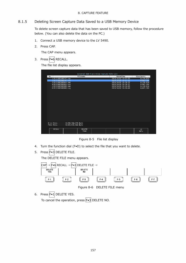
8. CAPTURE FEATURE
157
8.1.5 Deleting Screen Capture Data Saved to a USB Memory Device
To delete screen capture data that has been saved to USB memory, follow the procedure below. (You can also delete the data on the PC.)
1. Connect a USB memory device to the LV 5490.
2. Press CAP.
The CAP menu appears.
3. Press F•6 RECALL.
The file list display appears.
Figure 8-5 File list display
4. Turn the function dial (F•D) to select the file that you want to delete.
5. Press F•3 DELETE FILE.
The DELETE FILE menu appears.
CAP → F•6 RECALL → F•3 DELETE FILE →
Figure 8-6 DELETE FILE menu
6. Press F•1 DELETE YES.
To cancel the operation, press F•3 DELETE NO.

8. CAPTURE FEATURE
158
8.2 Frame Capture
8.2.1 Capturing Frame Data
There are two ways to capture frame data. One way is to capture frame data manually, and the other is to capture frame data automatically when errors occur (error capture). When using error capture, use single input mode. It will not work properly in simul mode.
1. Display the screen you want to capture.
The display must be showing video signal waveforms, vector waveforms, or a picture. However, capturing is not possible if an eye pattern (SER02/SER09) or audio (SER03) is shown in the same display. For vector waveforms, press F•6 DISPLAY and then F•1 MODE to select VECTOR. This feature does not support the 5-bar display.
2. Press CAP.
The CAP menu appears. Unlike screen captures, frame data is not captured when you press CAP.
CAP →
Figure 8-7 CAP menu
● Capturing frame data manually
3. Press F•1 TRIGGER to select MANUAL.
4. Press F•2 REFRESH.
One frame of data is captured in the LV 5490.

8. CAPTURE FEATURE
159
● Capturing frame data automatically (error capture)
3. Press F•1 TRIGGER to select ERROR.
4. Press F•7 SELECT CH to select a channel.
5. Press F•2 REFRESH.
Error capture for the selected channel begins. To begin error capture on other channels, repeat steps 4 and 5. The LV 5490 switches to error standby mode and Channels for which capture is in progress appear in the upper right of the screen. Standby mode is cleared by setting F•1 TRIGGER to MANUAL. In Simul mode, “Capture is invalid” will appear, and the capture function will not work.
Figure 8-8 Error standby
6. When the message below appears, press any key except for the power key.
If an error occurs during error standby, the LV 5490 captures the frame data at that point and stops the frame capture.
The applicable errors are those listed under “Applicable Errors” below whose detection setting has been set to ON through F•5 STATUS SETUP on the STATUS menu.

8. CAPTURE FEATURE
160
Table 8-1 Applicable errors for error capturing
Applicable Errors Inapplicable Errors SDI Error TRS, Line Number, CRC, EDH, Illegal Code Frequency, Cable Ancillary Data Error Parity, Checksum - Embedded Audio Error BCH, DBN, Parity, Inhibit Line Sample Count Video Error Gamut, Composite Gamut, Level Freeze, Black
Figure 8-9 Error capture end 8.2.2 Displaying Frame Capture Data
You can display the captured frame data on the LV 5490 or overlay it on the current input signal. You can also display the frame data in different display modes. To select the display mode, follow the procedure below.
• First, show the video signal waveform display, vector waveform display (except the 5-bar
display), or picture display. • To display frame data, the LV 5490 must be receiving a signal whose format is the same
as that of the captured data. • The display may blink when you operate the V POS knob, H POS knob, or function dial
(F•D). • The scale and measured values are those of the current signal, not those of the captured
data.
Procedure
CAP → F•3 DISPLAY: REAL / HOLD / BOTH
Settings
REAL: The current input signal is displayed. HOLD: The frame capture data is displayed. The video signal waveforms and
vectors are shown in cyan. BOTH: The current input signal and the frame capture data are displayed on top
of each other with their intensities halved.

8. CAPTURE FEATURE
161
8.2.3 Saving to a USB Memory Device
The frame data captured in the LV 5490 is cleared when the power is turned off. If you want to display it later even after the power is turned off, save the data to USB memory by following the procedure below (save the data in FRM format).
1. Connect a USB memory device to the LV 5490.
2. Press F•4 FILE TYPE on the CAP menu.
The FILE TYPE menu appears.
CAP → F•4 FILE TYPE →
Figure 8-10 FILE TYPE menu
3. Select the file format.
Set the file types for saving the data to ON. By default, all types are set to ON. You cannot turn all the settings off.
F•3 DPX: Only the picture area is saved as 10-bit .dpx files.
Even when the input signal is 12 bits, it is rounded to 10 bits and saved. F•4 TIF: Only the picture area is saved as .tif files.
This data is DPX converted into TIF. F•5 FRM: A single frame of data is saved.
4. Press F•7 up menu.
The CAP menu appears.
5. Press F•5 STORE.
The message “Please wait. Saving file...” is displayed on the screen, and the frame capture data is saved to the USB memory device. This menu item does not appear when there is no frame data captured in the LV 5490.
When the input signal is 1080i/59.94 and all the file types that you can select with F•4 FILE TYPE are set to ON, it takes about 50 seconds to save the data. The approximate file sizes for saving the data are 7.9 MB for DPX, 11.8 MB for TIF, and 9.4 MB for FRM.
The file is automatically assigned a name that consists of the year, month, day, hour, minute, second, and CH(in that order) that are set in the system settings. (Example: 20090501100859A.bmp)
Frame capture data is saved to the following locations.
USB memory device
└ LV5490_USER └ BMP ├ yyyymmddhhmmss.dpx ├ yyyymmddhhmmss.frm └ yyyymmddhhmmss.tif

8. CAPTURE FEATURE
162
8.2.4 Displaying Frame Capture Data Saved to a USB Memory Device
To display or overlay on the current input signal the frame capture data that has been saved to USB memory as .frm files, follow the procedure below. (Frame capture data that has been saved in FRM format on a different model cannot be displayed on the LV 5490.)
1. Connect a USB memory device to the LV 5490.
2. Press CAP.
The CAP menu appears.
3. Press F•6 RECALL.
The file list display appears.
Figure 8-11 File list display
4. Turn the function dial (F•D) to select the .frm file that you want to display.
5. Press F•1 RECALL.
To display frame data, the LV 5490 must be receiving a signal whose format is the same as that of the saved data. The FORMAT item at the bottom of the display shows the format of the saved data. It is displayed in green if the format is the same as the current format or in red if the format is not the same. If the FORMAT item is in red, F•1 RECALL does not appear.
6. Press F•3 DISPLAY to select the display format.

8. CAPTURE FEATURE
163
8.2.5 Deleting Frame Capture Data Saved to a USB Memory Device
To delete frame capture data that has been saved to a USB memory device, follow the procedure below. (You can also use a PC to delete the data.)
1. Connect a USB memory device to the LV 5490.
2. Press CAP.
The CAP menu appears.
3. Press F•6 RECALL.
The file list display appears.
Figure 8-12 File list display
4. Turn the function dial (F•D) to select the file that you want to delete.
5. Press F•3 DELETE FILE.
The DELETE FILE menu appears.
CAP → F•6 RECALL → F•3 DELETE FILE →
Figure 8-13 DELETE FILE menu
6. Press F•1 DELETE YES.
To cancel the deletion operation, press F•3 DELETE NO.

9. PRESET SETTINGS
164
9. PRESET SETTINGS The preset feature stores up to 60 sets of panel settings. It can be used to easily recall fixed settings. Also, you can use the same settings on multiple LV 5490s by copying presets to USB memory.
All items except the items below are stored in a preset. Stored items are not deleted even if you initialize the settings.
• Ethernet settings (ETHERNET SETUP tab) • Remote settings (REMOTE SETUP tab) • Date and time settings (DATE&TIME tab)
9.1 Registering Presets
To register a preset, follow the procedure below.
1. Display the screen you want to register.
You can set the menu that appears when a preset is recalled by setting Recall on the GENERAL SETUP tab in the system settings in advance. Reference GENERAL SETUP tab → 7.2.1, “General Settings.”
2. Hold down PSET.
The preset registration display appears.
Figure 9-1 Preset registration display

9. PRESET SETTINGS
165
3. Press F•1 COMMENT INPUT
The comment input display appears. You can also copy a comment from a preset that already has a comment saved to it. To copy a comment, on the preset registration display, move the cursor to the preset that has the comment that you want to copy, and press the function dial (F•D).
Figure 9-2 Comment input display
4. Enter a comment of up to 16 characters.
You can use the following keys on the comment input display. F•1 CLEAR ALL: Deletes all characters F•2 DELETE: Deletes the character at the cursor F•3 INSERT: Inserts the selected character at the cursor position F•4 <=: Moves the cursor to the left F•5 =>: Moves the cursor to the right F•6 CHAR SET: Enters the character Function dial (F•D): Turn to select a character, and press to enter the character.
5. Press F•7 up menu.
6. Turn the function dial (F•D) to select the number of the preset you want to register.
7. Press F•2 STORE.
If a preset has already been stored with the number that you selected, the STORE menu appears. To overwrite the existing preset, press F•1 OVER WRITE YES. Otherwise, press F•3 OVER WRITE NO.
Figure 9-3 STORE menu

9. PRESET SETTINGS
166
9.2 Recalling Presets
To recall a preset, follow the procedure below.
1. Press PSET.
The PSET menu appears.
Figure 9-4 PSET menu
2. Press a key from F•1 No.1 to F•6 No.6.
If the preset that you want to load is number 7 or greater, press F•7 more or turn the function dial (F•D).
The menu that appears immediately after loading the preset is either the PSET menu or measurement menu depending on the setting that was specified on the GENERAL SETUP tab when the preset was registered. Reference GENERAL SETUP tab → 7.2.1, “General Settings.”
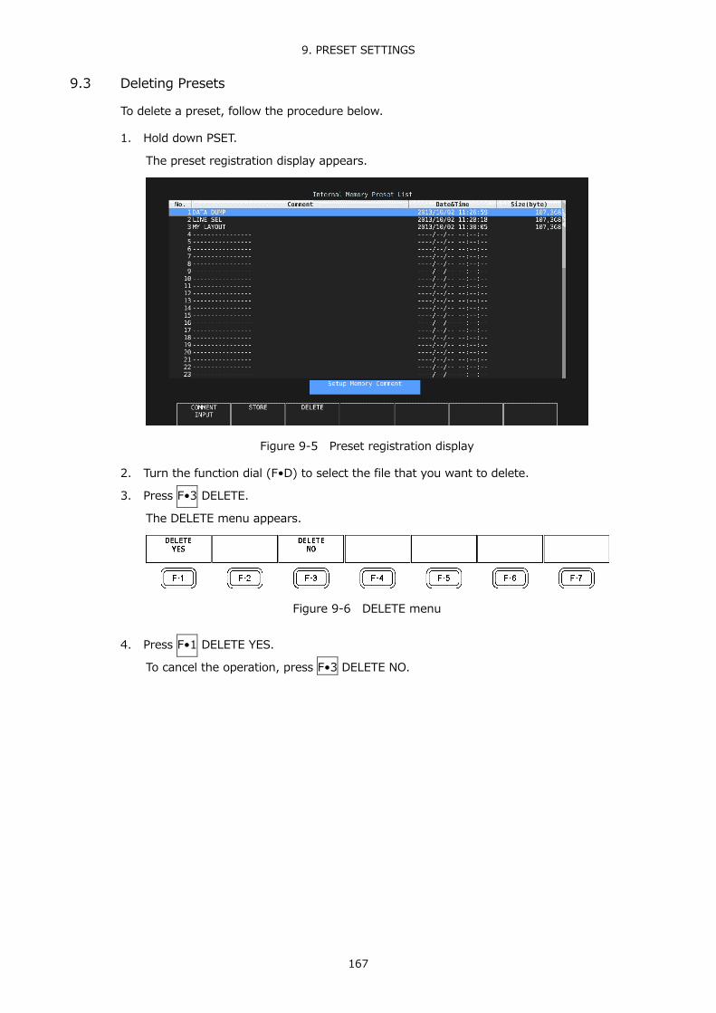
9. PRESET SETTINGS
167
9.3 Deleting Presets
To delete a preset, follow the procedure below.
1. Hold down PSET.
The preset registration display appears.
Figure 9-5 Preset registration display
2. Turn the function dial (F•D) to select the file that you want to delete.
3. Press F•3 DELETE.
The DELETE menu appears.
Figure 9-6 DELETE menu
4. Press F•1 DELETE YES.
To cancel the operation, press F•3 DELETE NO.

9. PRESET SETTINGS
168
9.4 Copying All Presets from the LV 5490 to USB Memory
To copy all the presets from the LV 5490 to USB memory, follow the procedure below.
1. Connect a USB memory device to the LV 5490.
2. Hold down PSET.
The preset registration display appears.
Figure 9-7 Preset registration display
3. Press F•6 ALL COPY INT->USB.
The ALL COPY INT->USB menu appears.
Figure 9-8 ALL COPY INT->USB menu
4. Press F•1 COPY INT->USB YES.
To cancel the copy operation, press F•3 COPY INT->USB NO. If presets already exist on the USB memory, they will be overwritten.
Presets are saved to the following location. Note that if you use a PC to change the names of the files stored in the USB memory, you will no longer be able to copy the altered presets from USB memory to an LV 5490.
USB memory device
└ LV5490_USER └ pset └ PRESET_01.PRE (to PRESET_60.PRE)

9. PRESET SETTINGS
169
9.5 Copying All Presets from USB Memory to the LV 5490
To copy all the presets from USB memory to the LV 5490, follow the procedure below.
1. Connect a USB memory device to the LV 5490.
2. Hold down PSET.
The preset registration display appears.
Figure 9-9 Preset registration display
3. Press F•5 ALL COPY USB->INT.
The ALL COPY USB->INT menu appears.
Figure 9-10 ALL COPY USB->INT menu
4. Press F•1 COPY USB->INT YES.
To cancel the copy operation, press F•3 COPY USB->INT NO. If presets already exist within the LV 5490 internal memory, they will be overwritten.

10. VIDEO SIGNAL WAVEFORM DISPLAY
170
10. VIDEO SIGNAL WAVEFORM DISPLAY To display the video signal waveform, press WFM.
Figure 10-1 Video signal waveform display
● Colorimetry
Normally, colorimetry is not displayed, but when the colorimetry alarm is set to on in the system settings and a colorimetry different from the one specified is received, the alarm is indicated in red in the upper left of the screen.

10. VIDEO SIGNAL WAVEFORM DISPLAY
171
10.1 Setting the Waveform Display Position
Use the V POS and H POS knobs to adjust the display position of video signal waveforms. On the multi display, these are valid when you press F•2 MULTI WFM on the MULTI menu.
Figure 10-2 V POS and H POS knobs
● V POS Knob
This knob adjusts the vertical position of the video signal waveform. Pressing the knob returns the waveform to its default position.
● H POS Knob
This knob adjusts the horizontal position of the video signal waveform. Pressing the knob returns the waveform to its default position.
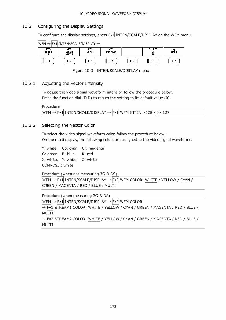
10. VIDEO SIGNAL WAVEFORM DISPLAY
172
10.2 Configuring the Display Settings
To configure the display settings, press F•1 INTEN/SCALE/DISPLAY on the WFM menu.
WFM → F•1 INTEN/SCALE/DISPLAY →
Figure 10-3 INTEN/SCALE/DISPLAY menu
10.2.1 Adjusting the Vector Intensity
To adjust the video signal waveform intensity, follow the procedure below. Press the function dial (F•D) to return the setting to its default value (0).
Procedure WFM → F•1 INTEN/SCALE/DISPLAY → F•1 WFM INTEN: -128 - 0 - 127
10.2.2 Selecting the Vector Color
To select the video signal waveform color, follow the procedure below. On the multi display, the following colors are assigned to the video signal waveforms.
Y: white, Cb: cyan, Cr: magenta G: green, B: blue, R: red X: white, Y: white, Z: white COMPOSIT: white
Procedure (when not measuring 3G-B-DS) WFM → F•1 INTEN/SCALE/DISPLAY → F•2 WFM COLOR: WHITE / YELLOW / CYAN / GREEN / MAGENTA / RED / BLUE / MULTI
Procedure (when measuring 3G-B-DS) WFM → F•1 INTEN/SCALE/DISPLAY → F•2 WFM COLOR → F•1 STREAM1 COLOR: WHITE / YELLOW / CYAN / GREEN / MAGENTA / RED / BLUE / MULTI → F•2 STREAM2 COLOR: WHITE / YELLOW / CYAN / GREEN / MAGENTA / RED / BLUE / MULTI

10. VIDEO SIGNAL WAVEFORM DISPLAY
173
10.2.3 Adjusting the Scale Intensity
To configure the scale, press F•3 WFM SCALE on the INTEN/SCALE/DISPLAY menu.
WFM → F•1 INTEN/SCALE/DISPLAY → F•3 WFM SCALE →
Figure 10-4 WFM SCALE menu
To adjust the scale intensity, follow the procedure below. Press the function dial (F•D) to return the setting to its default value (4).
Procedure WFM → F•1 INTEN/SCALE/DISPLAY → F•3 WFM SCALE → F•1 SCALE INTEN: -8 - 4 - 7
10.2.4 Selecting the Scale Color
To select the scale color, follow the procedure below.
Procedure WFM → F•1 INTEN/SCALE/DISPLAY → F•3 WFM SCALE → F•2 SCALE COLOR: WHITE / YELLOW / CYAN / GREEN / MAGENTA / RED / BLUE
10.2.5 Selecting the Scale Unit
To select the scale unit, follow the procedure below.
When COLOR MATRIX is set to XYZ, the scale unit is set to “HD%,SD%” or 150%. When COLOR MATRIX is set to COMPOSIT and the composite display format is NTSC, this is fixed to HD%,SD%. When the composite display format is PAL, this is fixed to HDV,SDV.
Video signal white (100 %) becomes 0.7 V or 100 % on the scale. Video signal black (0 %) becomes 0 V or 0 % on the scale. Reference COLOR MATRIX → section 10.7.1, “Selecting the Color Matrix.”
Procedure WFM → F•1 INTEN/SCALE/DISPLAY → F•3 WFM SCALE → F•3 SCALE UNIT: HDV,SD% / HDV,SDV / HD%,SD% / 150% / 1023 / 1023,255 / 3FF
Settings
HDV,SD%: The scale shows voltages when the input signal is not SD and percentages when the input signal is SD.
HDV,SDV: The scale shows voltages. HD%,SD%: The scale shows percentages. 150%: The scale shows percentages. (The scale starts from -50 %.) 1023: 0 to 100 % is displayed as 64 to 940 (YGBR) or 64 to 960 (CbCr). 1023,255: 0 to 100 % is displayed as 64 to 940 (YGBR) or 16 to 235 (YGBR). 3FF: 0 to 100 % is displayed as 040 to 3AC (YGBR) or 040 to 3C0 (CbCr).
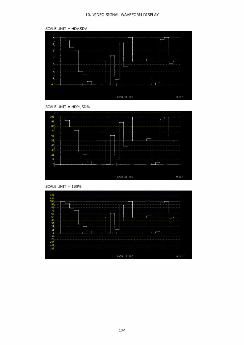
10. VIDEO SIGNAL WAVEFORM DISPLAY
174
SCALE UNIT = HDV,SDV
SCALE UNIT = HD%,SD%
SCALE UNIT = 150%

10. VIDEO SIGNAL WAVEFORM DISPLAY
175
SCALE UNIT = 1023
SCALE UNIT = 1023,255
SCALE UNIT = 3FF
Figure 10-5 Selecting the scale unit

10. VIDEO SIGNAL WAVEFORM DISPLAY
176
10.2.6 Displaying a Scale for 75 % Intensity Color Bars
When COLOR MATRIX is set to YCbCr, to display a scale that matches the peak levels of the color difference signals for 75 % intensity color bars, follow the procedure below. Reference COLOR MATRIX → section 10.7.1, “Selecting the Color Matrix.”
Procedure WFM → F•1 INTEN/SCALE/DISPLAY → F•3 WFM SCALE → F•4 75%COLOR SCALE: ON / OFF
75%COLOR SCALE = ON
Figure 10-6 Displaying a scale for 75 % intensity color bars

10. VIDEO SIGNAL WAVEFORM DISPLAY
177
10.2.7 Selecting the Display Mode
To configure the display, press F•4 WFM DISPLAY on the INTEN/SCALE/DISPLAY menu.
WFM → F•1 INTEN/SCALE/DISPLAY → F•4 WFM DISPLAY →
Figure 10-7 WFM DISPLAY menu
To select the video signal waveform display mode, follow the procedure below. This setting is invalid when COLOR MATRIX is set to COMPOSIT. Reference COLOR MATRIX → section 10.7.1, “Selecting the Color Matrix.”
Procedure WFM → F•1 INTEN/SCALE/DISPLAY → F•4 WFM DISPLAY → F•1 WFM MODE: OVERLAY / PARADE
Settings
OVERLAY: Input signal is displayed on top of each other. PARADE: Input signal is displayed side by side.
WFM MODE = OVERLAY
WFM MODE = PARADE
Figure 10-8 Selecting the display mode

10. VIDEO SIGNAL WAVEFORM DISPLAY
178
10.2.8 Turning the Channels On and Off
To turn individual channels on and off, follow the procedure below. You cannot turn off all the channels. This menu item is not available when COLOR MATRIX is set to COMPOSIT or when YGBR or YRGB is set to ON. Reference COLOR MATRIX → section 10.7.1, “Selecting the Color Matrix.”
YGBR, YRGB → section 10.7.2, “Turning Luminance Signals On and Off.”
Procedure WFM → F•1 INTEN/SCALE/DISPLAY → F•4 WFM DISPLAY → F•2 CH1 Y / CH1 X / CH1 G / CH1 R: ON / OFF → F•3 CH2 Cb / CH2 Y / CH2 B / CH2 G: ON / OFF → F•4 CH3 Cr / CH3 Z / CH3 R / CH3 B: ON / OFF

10. VIDEO SIGNAL WAVEFORM DISPLAY
179
10.2.9 4Y Parade Display
To extract the Y signals from channels A to D and display them side by side, follow the procedure below.
The conditions for displaying the 4Y parade display are listed below. • Single link • Simul mode • F•7 COLOR SYSTEM → F•1 COLOR MATRIX on the WFM menu is set to YCbCr or
COMPOSIT. • F•6 OPERATE CH MODE on the INPUT menu is set to COM. • The layout display mode is set to NORMAL.
Also, note the following points. • Only the channels that have been set to ON on the INPUT menu are displayed. • Option in layout will be hidden. • Style in layout will be invalid. • The scale jump function cannot be used.
Procedure WFM → F•1 INTEN/SCALE/DISPLAY → F•4 WFM DISPLAY → F•5 4Y PARADE: ON / OFF
4Y PARADE = OFF
4Y PARADE = ON
Figure 10-9 4Y parade display

10. VIDEO SIGNAL WAVEFORM DISPLAY
180
10.2.10 Configuring the 3G-B-DS Display Settings
When measuring 3G-B-DS, to select the display mode, follow the procedure below.
Procedure WFM → F•1 INTEN/SCALE/DISPLAY → F•4 WFM DISPLAY → F•5 3G-B-DS DISPLAY: STREAM1 / STREAM2 / MIX / ALIGN
Settings
STREAM1: Stream 1 is displayed. STREAM2: Stream 2 is displayed. MIX: Streams 1 and 2 are displayed on top of each other. ALIGN: Streams 1 and 2 are displayed side by side.
3G-B-DS DISPLAY = MIX
3G-B-DS DISPLAY = ALIGN
Figure 10-10 Configuring the 3G-B-DS display settings

10. VIDEO SIGNAL WAVEFORM DISPLAY
181
10.3 Configuring the Gain and Filter Settings
To configure the gain and filter settings, press F•2 GAIN/FILTER on the WFM menu.
WFM → F•2 GAIN/FILTER →
Figure 10-11 GAIN/FILTER menu
10.3.1 Selecting the Fixed Gain
To select the fixed video signal waveform gain, follow the procedure below.
Procedure WFM → F•2 GAIN/FILTER → F•2 GAIN MAG: X1 / X5
10.3.2 Setting the Variable Gain
To set the variable video signal waveform gain, follow the procedure below.
Procedure WFM → F•2 GAIN/FILTER → F•1 GAIN VARIABLE: CAL / VARIABLE
Settings
CAL: The waveform gain is fixed. VARIABLE: You can adjust the waveform gain by turning the function dial (F•D).
Press the function dial (F•D) to return the setting to its default value (1.000 or 5.000). The adjusted gain value (the combination of F•1 GAIN VARIABLE and F•2 GAIN MAG) appears at the bottom of the screen. 0.200 - 1.000 - 2.000 (for X1) 1.000 - 5.000 - 10.000 (for X5)

10. VIDEO SIGNAL WAVEFORM DISPLAY
182
10.3.3 Selecting the Filter
To select the filter to apply to video signal waveforms, follow the procedure below. The filters that you can select vary depending on the COLOR MATRIX setting. Reference COLOR MATRIX → section 10.7.1, “Selecting the Color Matrix.”
Procedure (When COLOR MATRIX is set to YCbCr, XYZ, GBR, or RGB) WFM → F•2 GAIN/FILTER → F•3 FILTER: FLAT / LOWPASS
Settings
FLAT: A filter with a flat frequency response over the entire bandwidth of the input signal is applied.
LOWPASS: A low-pass filter with the following characteristics is applied. At 40 MHz, 20 dB attenuation or more (when the input signal is 1080/60P, 59.94P, or 50P) At 20 MHz, 20 dB attenuation or more (when the input signal is 3G, HD, or HD (DL) excluding 1080/60P, 59.94P, or 50P) At 3.8 MHz, 20 dB attenuation or more (when the input signal is SD)
FILTER = FLAT
FILTER = LOWPASS
Figure 10-12 Selecting the filter (component)

10. VIDEO SIGNAL WAVEFORM DISPLAY
183
Procedure (When COLOR MATRIX is set to COMPOSIT) WFM → F•2 GAIN/FILTER → F•3 FILTER: FLAT / LUM / FLAT+LUM / LUM+CRMA
Settings
FLAT: Only the pseudo-composite signal is displayed. LUM: Only the luminance signal is displayed. FLAT+LUM: The pseudo-composite and luminance signals are displayed side by side.
A filter with an attenuation of 20 dB or more at 40 MHz is applied to the luminance signal.
LUM+CRMA: The luminance and chrominance signals are displayed side by side. A filter with an attenuation of 20 dB or more at 40 MHz is applied to the luminance signal.
FILTER = FLAT
FILTER = LUM

10. VIDEO SIGNAL WAVEFORM DISPLAY
184
FILTER = FLAT+LUM
FILTER = LUM+CRMA
Figure 10-13 Selecting the filter (composite)

10. VIDEO SIGNAL WAVEFORM DISPLAY
185
10.3.4 Setting the Scale Jump
If F•2 GAIN MAG is set to X5, the waveform is expanded five times in the Y-axis direction. To select the area you want to see expanded, follow the procedure below. You can view the area that is currently displayed with respect to the entire waveform on the scale shown on the right side of the screen.
This menu appears when F•1 GAIN VARIABLE is set to CAL. When set to VARIABLE, the value is fixed to 0, and the scale on the right side of the screen does not appear.
Procedure WFM → F•2 GAIN/FILTER → F•4 SCALE JUMP: 0, 10, 20, 30, 40, 50, 60, 70, 80, 90, CURSOR (when the scale unit is not V) → F•4 SCALE JUMP: .0, .1, .2, .3, .4, .5, .6, .7, CURSOR (when the scale unit is V)
● 0 to 90
The LV 5490 has 10 types of screens in the Y-axis direction, and 0 to 90 is used to switch between these screens. For example, if the scale unit is % and YCbCr is displayed, selecting 0 displays the 0 to 20% range, selecting 10 displays the 10 to 30% range, and selecting 90 displays the 90 to 110% range. The same holds true for .0 to .7.

10. VIDEO SIGNAL WAVEFORM DISPLAY
186
● CURSOR
The scale jump function operates based on the Y-axis cursor, and the area near the currently selected cursor (▼ mark) is expanded. An example operation is indicated below.
【Preparation】 1. On the CURSOR menu, set F•1 CURSOR to ON and F•2 XY SEL to Y. 2. On the GAIN/FILTER menu, set F•2 GAIN MAG to X5. 3. Set F•4 SCALE JUMP to CURSOR.
【Operation】 4. Set F•2 GAIN MAG to X1. 5. Move the Y-axis cursor to the area you want to display expanded. (You can move the
cursor on the GAIN/FILTER menu. You can switch between REF, DELTA, and TRACK by pressing the function dial (F•D).)
6. Set F•2 GAIN MAG to X5 to expand the area near the Y-axis cursor.
SCALE JUMP = CURSOR
Figure 10-14 Setting the Scale Jump

10. VIDEO SIGNAL WAVEFORM DISPLAY
187
10.4 Configuring Sweep Settings
To configure the sweep settings, press F•3 SWEEP on the WFM menu.
WFM → F•3 SWEEP →
Figure 10-15 SWEEP menu
10.4.1 Selecting the Sweep Method
To select the video signal waveform sweep method, follow the procedure below.
Procedure WFM → F•3 SWEEP → F•1 SWEEP: H / V
Settings
H: Lines are displayed. V: Fields or frames are displayed. Because the sampled data is
downsampled, aliasing distortion occurs.
SWEEP = H
SWEEP = V
Figure 10-16 Selecting the sweep method

10. VIDEO SIGNAL WAVEFORM DISPLAY
188
10.4.2 Selecting the Line Display Format
When F•1 SWEEP is set to H, to select the sweep time, follow the procedure below.
Procedure WFM → F•3 SWEEP → F•2 H SWEEP: 1H / 2H
Settings
1H: One line is displayed. 2H: Two lines are displayed. This cannot be selected in the following
situations. • When using 4K • When F•1 INTEN/SCALE/DISPLAY → F•4 WFM DISPLAY → F•1 WFM MODE is set to PARADE • When F•7 COLOR SYSTEM → F•1 COLOR MATRIX is set to COMPOSIT
H SWEEP = 1H
H SWEEP = 2H
Figure 10-17 Selecting the line display format

10. VIDEO SIGNAL WAVEFORM DISPLAY
189
10.4.3 Selecting the Field Display Format
When F•1 SWEEP is set to V, to select the sweep time, follow the procedure below.
Procedure WFM → F•3 SWEEP → F•2 V SWEEP: 1V / 2V
Settings
1V: One field is displayed. 2V: One frame is displayed. This option cannot be selected when the input
signal is progressive.
V SWEEP = 1V
V SWEEP = 2V
Figure 10-18 Selecting the field display format
Furthermore, when the input signal is interlace or segmented frame and F•2 V SWEEP is set to 1V, to select which field is displayed, follow the procedure below.
Procedure WFM → F•3 SWEEP → F•4 FIELD: FIELD1 / FIELD2

10. VIDEO SIGNAL WAVEFORM DISPLAY
190
10.4.4 Selecting the Horizontal Magnification
To select the horizontal magnification, follow the procedure below. The magnifications that you can select vary as shown below depending on settings such as COLOR MATRIX. Reference COLOR MATRIX → section 10.7.1, “Selecting the Color Matrix.”
Table 10-1 Horizontal magnifications
F•1 SWEEP COLOR MATRIX F•2 H SWEEP X1 X10 X20 X40 ACTIVE BLANK H YCbCr, XYZ,
GBR, RGB 1H Yes Yes Yes No Yes Yes 2H Yes Yes Yes No No Yes
COMPOSIT - Yes Yes Yes No Yes No V - - Yes No Yes Yes No No
(Yes: Settable. No: Not settable.)
Procedure WFM → F•3 SWEEP → F•3 SWEEP MAG: X1 / X10 / X20 / X40 / ACTIVE / BLANK
Settings
X1: The video signal waveforms are displayed so that they fit on the screen. X10: The video signal waveforms are magnified from the center of the display
to 10 times the size of X1. X20: The video signal waveforms are magnified from the center of the display
to 20 times the size of X1. X40: The video signal waveforms are magnified from the center of the display
to 40 times the size of X1. ACTIVE: Everything but the video signal waveform blanking interval is magnified. BLANK: The video signal waveform blanking interval is magnified.
The vertical blanking interval is also displayed on the vector waveform display.
SWEEP MAG = X1

10. VIDEO SIGNAL WAVEFORM DISPLAY
191
SWEEP MAG = X10
SWEEP MAG = ACTIVE
v
SWEEP MAG = BLANK
Figure 10-19 Horizontal magnifications

10. VIDEO SIGNAL WAVEFORM DISPLAY
192
10.4.5 Displaying the Blanking Interval
To set how the waveforms in the blanking interval are displayed, follow the procedure below. If a setting other than REMOVE is selected, the vertical blanking interval is also displayed on the vector waveform display. Reference COLOR MATRIX → section 10.7.1, “Selecting the Color Matrix.”
Procedure WFM → F•3 SWEEP → F•5 BLANKING: REMOVE / V VIEW / H VIEW / ALL VIEW
Settings
REMOVE: Only the active interval is displayed. V VIEW: The active interval and the vertical blanking interval are displayed. H VIEW: The active interval and the horizontal blanking interval are displayed.
This option cannot be selected when COLOR MATRIX is set to COMPOSIT. ALL VIEW: The entire input signal is displayed.
This option cannot be selected when COLOR MATRIX is set to COMPOSIT.
BLANKING = ALL VIEW
Figure 10-20 Displaying blanking intervals

10. VIDEO SIGNAL WAVEFORM DISPLAY
193
10.5 Configuring Line Selection Settings
To configure line selection settings, press F•4 LINE SEL on the WFM menu.
WFM → F•4 LINE SEL →
Figure 10-21 LINE SEL menu
10.5.1 Turning Line Selection On and Off
To display the vector of the selected line, follow the procedure below. You can use the function dial (F•D) to select a line. The number of the selected line appears in the lower left of the display. Changing this setting will also change the vector-display and picture-display line selection settings. This menu item does not appear when SWEEP is set to V. Reference SWEEP → Section 10.4.1, “Selecting the Sweep Method”
Procedure WFM → F•4 LINE SEL → F•1 LINE SELECT: ON / OFF
LINE SELECT = ON

10. VIDEO SIGNAL WAVEFORM DISPLAY
194
LINE SELECT = OFF
Figure 10-22 Turning line selection on and off
10.5.2 Setting the Line Selection Range
When F•1 LINE SELECT is set to ON and the input signal format is interlaced or segmented frame, to set the line selection range, follow the procedure below. Changing this setting will also change the selected line on the vector, picture, and status (data dump) displays.
Procedure WFM → F•4 LINE SEL → F•2 FIELD: FIELD1 / FIELD2 / FRAME
Settings
FIELD1: A line from field 1 can be selected. (Example: 1 to 563) FIELD2: A line from field 2 can be selected. (Example: 564 to 1125) FRAME: All lines can be selected. (Example: 1 to 1125)

10. VIDEO SIGNAL WAVEFORM DISPLAY
195
10.6 Configuring Cursor Settings
To configure cursor settings, press F•5 CURSOR on the WFM menu.
WFM → F•5 CURSOR →
Figure 10-23 CURSOR menu
10.6.1 Turning Cursors On and Off
To turn cursors on and off, follow the procedure shown below. The REF cursor is displayed in blue, and the DELTA cursor is displayed in green. The value of DELTA - REF appears as a measured value in the lower right of the screen. (When F•3 Y UNIT is set to DEC or HEX, absolute values are displayed.) If ON XY is selected, the X-axis cursors and Y-axis cursors are displayed simultaneously.
Procedure WFM → F•5 CURSOR → F•1 CURSOR: ON / ON XY / OFF

10. VIDEO SIGNAL WAVEFORM DISPLAY
196
10.6.2 Selecting the Cursor
To select the X (time measurement) or Y (amplitude measurement) cursor, follow the procedure below. If F•1 CURSOR is set to ON XY, select the cursor to move here.
Procedure WFM → F•5 CURSOR → F•2 XY SEL: X / Y
XY SEL = X
XY SEL = Y
Figure 10-24 Selecting the cursor
10.6.3 Moving Cursors
To move a cursor, follow the procedure shown below to select a cursor. Then, move the cursor by turning the function dial (F•D). Triangles appear on both ends of the selected cursor.
You can also select a cursor by pressing the function dial (F•D). Each time you press the function dial (F•D), the selected cursor switches from REF, to DELTA, to TRACK, and then back to REF.
Procedure WFM → F•5 CURSOR → F•4 FD VAR: REF / DELTA / TRACK
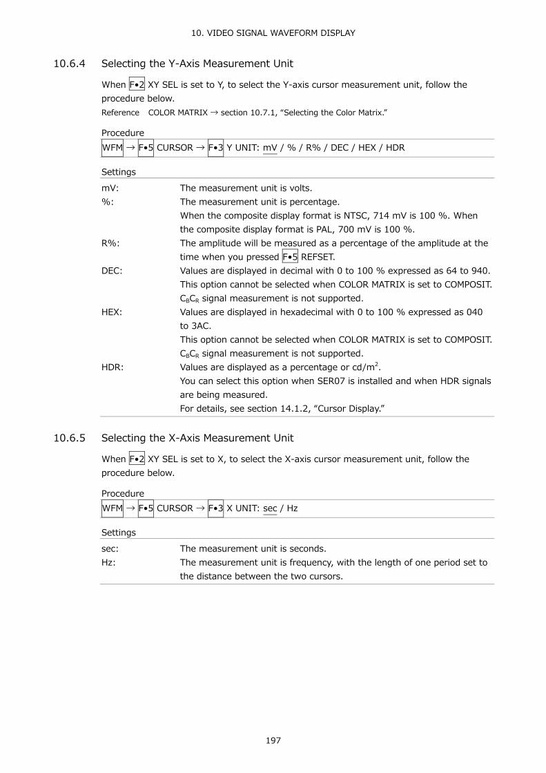
10. VIDEO SIGNAL WAVEFORM DISPLAY
197
10.6.4 Selecting the Y-Axis Measurement Unit
When F•2 XY SEL is set to Y, to select the Y-axis cursor measurement unit, follow the procedure below. Reference COLOR MATRIX → section 10.7.1, “Selecting the Color Matrix.”
Procedure WFM → F•5 CURSOR → F•3 Y UNIT: mV / % / R% / DEC / HEX / HDR
Settings
mV: The measurement unit is volts. %: The measurement unit is percentage.
When the composite display format is NTSC, 714 mV is 100 %. When the composite display format is PAL, 700 mV is 100 %.
R%: The amplitude will be measured as a percentage of the amplitude at the time when you pressed F•5 REFSET.
DEC: Values are displayed in decimal with 0 to 100 % expressed as 64 to 940. This option cannot be selected when COLOR MATRIX is set to COMPOSIT. CBCR signal measurement is not supported.
HEX: Values are displayed in hexadecimal with 0 to 100 % expressed as 040 to 3AC. This option cannot be selected when COLOR MATRIX is set to COMPOSIT. CBCR signal measurement is not supported.
HDR: Values are displayed as a percentage or cd/m2. You can select this option when SER07 is installed and when HDR signals are being measured. For details, see section 14.1.2, “Cursor Display.”
10.6.5 Selecting the X-Axis Measurement Unit
When F•2 XY SEL is set to X, to select the X-axis cursor measurement unit, follow the procedure below.
Procedure WFM → F•5 CURSOR → F•3 X UNIT: sec / Hz
Settings
sec: The measurement unit is seconds. Hz: The measurement unit is frequency, with the length of one period set to
the distance between the two cursors.

10. VIDEO SIGNAL WAVEFORM DISPLAY
198
10.6.6 Turning the Cursor Value Display On and Off
To display cursor values, follow the procedure shown below (except when F•3 Y UNIT is set to R%). The display unit is the unit specified with F•3 Y UNIT or F•3 X UNIT. If F•1 CURSOR is set to ON XY, the value is displayed on the cursor selected with F•2 XY SEL.
Procedure WFM → F•5 CURSOR → F•5 CURSOR VALUE: ON / OFF
CURSOR VALUE = ON
Figure 10-25 Turning the cursor value display on and off

10. VIDEO SIGNAL WAVEFORM DISPLAY
199
10.7 Configuring the Color System Settings
To configure the color system settings, press F•7 COLOR SYSTEM on the WFM menu.
WFM → F•7 COLOR SYSTEM →
Figure 10-26 COLOR SYSTEM menu
10.7.1 Selecting the Color Matrix
The LV 5490SER01 or LV 5490SER02 performs a matrix conversion on a input signal to convert it into a GBR, RGB or pseudo-composite signal. To select the waveform display format, follow the procedure below. The selected display format is indicated in the lower right of the display.
Procedure WFM → F•7 COLOR SYSTEM → F•1 COLOR MATRIX: YCbCr / XYZ / GBR / RGB / COMPOSIT
Settings
YCbCr: The YCBCR signal is displayed without changes. This option cannot be selected when the input signal is RGB or XYZ.
XYZ: The XYZ signal is displayed without changes. This option cannot be selected when the input signal is YCBCR or RGB.
GBR: The input signal is converted into a GBR signal and displayed. RGB: The input signal is converted into a RGB signal and displayed. COMPOSIT: The input signal is converted into a pseudo NTSC or PAL composite
signal and displayed. • Color burst frequencies do not match those of PAL and NTSC. • Color burst and sync signal widths and locations are different from those of PAL and NTSC. • The signal bandwidth is that of the original signal.
COLOR MATRIX = YCbCr
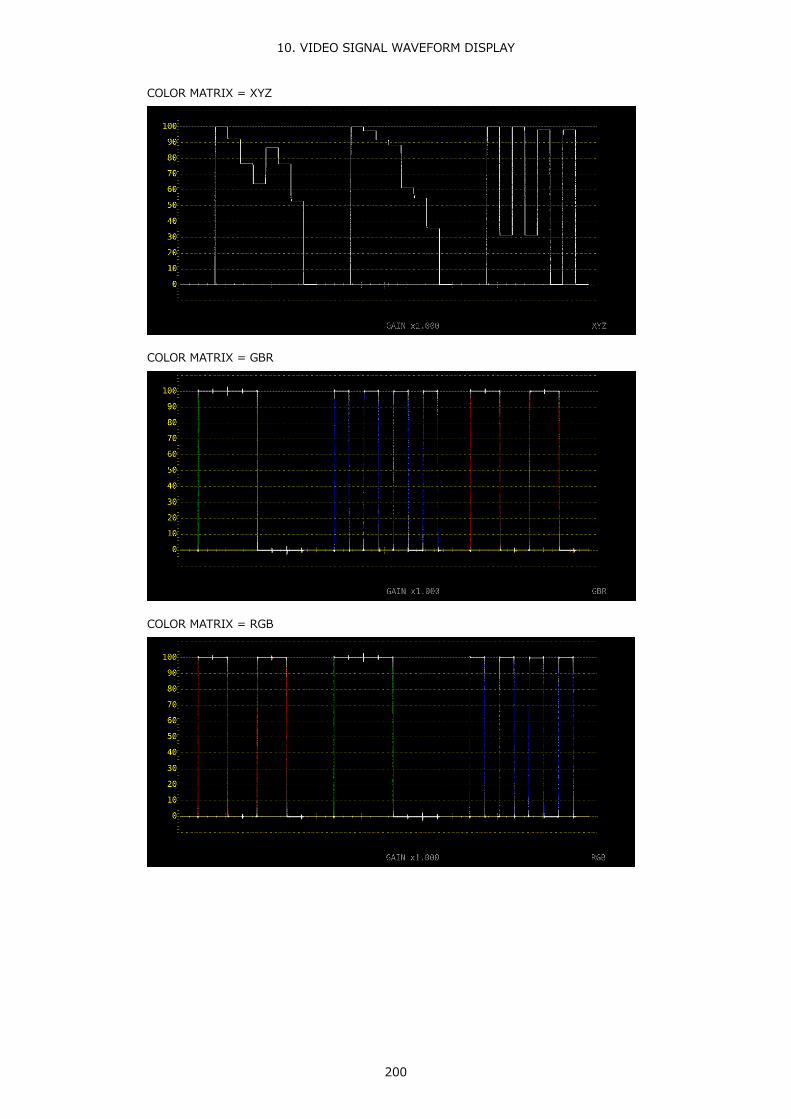
10. VIDEO SIGNAL WAVEFORM DISPLAY
200
COLOR MATRIX = XYZ
COLOR MATRIX = GBR
COLOR MATRIX = RGB
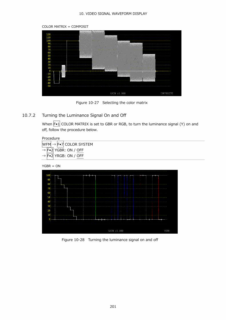
10. VIDEO SIGNAL WAVEFORM DISPLAY
201
COLOR MATRIX = COMPOSIT
Figure 10-27 Selecting the color matrix
10.7.2 Turning the Luminance Signal On and Off
When F•1 COLOR MATRIX is set to GBR or RGB, to turn the luminance signal (Y) on and off, follow the procedure below.
Procedure WFM → F•7 COLOR SYSTEM → F•2 YGBR: ON / OFF → F•2 YRGB: ON / OFF
YGBR = ON
Figure 10-28 Turning the luminance signal on and off

10. VIDEO SIGNAL WAVEFORM DISPLAY
202
10.7.3 Selecting the Composite Display Format
To select the composite display format, follow the procedure below.
Procedure WFM → F•7 COLOR SYSTEM → F•4 COMPOSIT FORMAT: AUTO / NTSC / PAL
Settings
AUTO: When the input signal frame rate is 25 Hz or 50 Hz, the format is PAL. Otherwise, the format is NTSC.
NTSC: The format is NTSC. The scale is fixed to percentage. PAL: The format is PAL. The scale is fixed to V.
10.7.4 Selecting the Setup Level
When F•1 COLOR MATRIX is set to COMPOSIT, to select the setup level, follow the procedure below. This menu does not appear if the composite display format is PAL.
Procedure WFM → F•7 COLOR SYSTEM → F•5 SETUP: 0% / 7.5%
SETUP = 7.5%
Figure 10-29 Selecting the setup level

11. VECTOR WAVEFORM DISPLAY
203
11. VECTOR WAVEFORM DISPLAY To display vectors, press VECT, F•5 DISPLAY, and then F•1 MODE to select VECTOR.
For an explanation when MODE is set to 5BAR, see section 11.7, “5-Bar Display.” For an explanation when MODE is set to HISTOGRAM, see section 11.8, “Histogram Display.” For an explanation when MODE is set to CIE DIAGRAM, see chapter 12, “CIE DIAGRAM DISPLAY (SER05).” You can select CIE DIAGRAM when SER05 is installed.
Figure 11-1 Vector waveform display
● Vectors
Component signal vector displays are X-Y displays based on CB (horizontal) and CR (vertical). The vector display scale has the following qualities.
Frame: ±5 % of the full scale value of 0.7 V (for component display) ±3 % of the full scale value of 0.7 V (for pseudo-composite display)
Circle: +20 % with respect to green
● Blanking interval
Normally, blanking interval is not displayed with vector waveforms, but if SWEEP MAG is set to BLANK on the WFM menu or BLANKING is set to REMOVE, it is displayed.
● Colorimetry
The colorimetry selected in the system settings is displayed in cyan in the upper right of the screen. However, for 3G(DL)-4K and 3G(QL), the current applied colorimetry is displayed in yellow if the colorimetry information of all links specified by the payload ID are not matched. When the colorimetry alarm is set to on in the system settings, the alarm is indicated in red.

11. VECTOR WAVEFORM DISPLAY
204
11.1 Configuring the Intensity and Scale Settings
To configure the intensity and scale settings, press F•1 INTEN / SCALE on the VECT menu.
VECT → F•1 INTEN/SCALE →
Figure 11-2 INTEN/SCALE menu
11.1.1 Adjusting the Vector Intensity
To adjust the vector intensity, follow the procedure below. Press the function dial (F•D) to return the setting to its default value (0).
Procedure VECT → F•1 INTEN/SCALE → F•1 VECT INTEN: -128 - 0 - 127
11.1.2 Selecting the Vector Color
To select the vector waveform color, follow the procedure below.
Procedure (when not measuring 3G-B-DS) VECT → F•1 INTEN/SCALE → F•2 VECT COLOR: WHITE / YELLOW / CYAN / GREEN / MAGENTA / RED / BLUE
Procedure (when measuring 3G-B-DS) VECT → F•1 INTEN/SCALE → F•2 VECT COLOR → F•1 STREAM1 COLOR: WHITE / YELLOW / CYAN / GREEN / MAGENTA / RED / BLUE → F•2 STREAM2 COLOR: WHITE / YELLOW / CYAN / GREEN / MAGENTA / RED / BLUE
11.1.3 Adjusting the Scale Intensity
To configure the scale, press F•3 VECT SCALE on the INTEN/SCALE menu.
VECT → F•1 INTEN/SCALE → F•3 VECT SCALE →
Figure 11-3 VECT SCALE menu
To adjust the scale intensity, follow the procedure below. Press the function dial (F•D) to return the setting to its default value (4).
Procedure VECT → F•1 INTEN/SCALE → F•1 SCALE INTEN: -8 - 4 - 7

11. VECTOR WAVEFORM DISPLAY
205
11.1.4 Selecting the Scale Color
To select the scale color, follow the procedure below.
Procedure VECT → F•1 INTEN/SCALE → F•2 SCALE COLOR: WHITE / YELLOW / CYAN / GREEN / MAGENTA / RED / BLUE
11.1.5 Turning the Display of the I and Q Axes On and Off
To turn the display of the I and Q axes on and off, follow the procedure below. This menu item does not appear when VECT SCALE is set to DCI or BT.2020. When the full scale value of 0.7 V is 100 %, the I and Q axes are displayed at the following values.
Table 11-1 Displaying the I and Q axes
I Axis Q Axis G 44.559% 37.056% B 27.865% 84.085% R 69.120% 62.417%
Procedure VECT → F•1 INTEN/SCALE → F•3 IQ AXIS: ON / OFF
IQ AXIS = ON
Figure 11-4 Turning the display of the I and Q axes on and off

11. VECTOR WAVEFORM DISPLAY
206
11.1.6 Selecting the Scale
When COLOR MATRIX is set to COMPONEN, follow the procedure below to select the scale type. Reference COLOR MATRIX → section 11.6.1, “Selecting the Color Matrix.”
Procedure VECT → F•1 INTEN/SCALE → F•3 VECT SCALE → F•4 VECT SCALE: AUTO / BT.601 / BT.709 / DCI / BT.2020
Settings
AUTO: A scale for the colorimetry selected in the system settings is displayed. BT.601: A scale defined in ITU-R BT.601 is displayed. When the input signal is SD
and a 100 % color bar signal is being applied, the peak levels match the ends of the scale.
BT.709: A scale defined in ITU-R BT.709 is displayed. When the input signal is HD and a 100 % color bar signal is being applied, the peak levels match the ends of the scale.
DCI: A scale defined in DCI is displayed. BT.2020: A scale defined in ITU-R BT.2020 is displayed. When the input signal is
4K, the division transmission system is 2 sample interleave, and a 100% color bar signal is being applied, the peak levels match the ends of the scale.
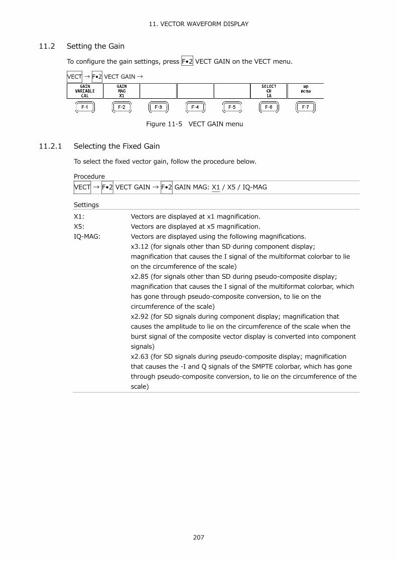
11. VECTOR WAVEFORM DISPLAY
207
11.2 Setting the Gain
To configure the gain settings, press F•2 VECT GAIN on the VECT menu.
VECT → F•2 VECT GAIN →
Figure 11-5 VECT GAIN menu
11.2.1 Selecting the Fixed Gain
To select the fixed vector gain, follow the procedure below.
Procedure VECT → F•2 VECT GAIN → F•2 GAIN MAG: X1 / X5 / IQ-MAG
Settings
X1: Vectors are displayed at x1 magnification. X5: Vectors are displayed at x5 magnification. IQ-MAG: Vectors are displayed using the following magnifications.
x3.12 (for signals other than SD during component display; magnification that causes the I signal of the multiformat colorbar to lie on the circumference of the scale) x2.85 (for signals other than SD during pseudo-composite display; magnification that causes the I signal of the multiformat colorbar, which has gone through pseudo-composite conversion, to lie on the circumference of the scale) x2.92 (for SD signals during component display; magnification that causes the amplitude to lie on the circumference of the scale when the burst signal of the composite vector display is converted into component signals) x2.63 (for SD signals during pseudo-composite display; magnification that causes the -I and Q signals of the SMPTE colorbar, which has gone through pseudo-composite conversion, to lie on the circumference of the scale)

11. VECTOR WAVEFORM DISPLAY
208
11.2.2 Setting the Variable Gain
To set the variable vector gain, follow the procedure below.
Procedure VECT → F•2 VECT GAIN → F•1 GAIN VARIABLE: CAL / VARIABLE
Settings
CAL: The waveform gain is fixed. VARIABLE: You can adjust the waveform gain by turning the function dial (F•D).
Press the function dial (F•D) to return the setting to its default value. The adjusted gain value (the combination of F•1 GAIN VARIABLE and F•2 GAIN MAG) appears in the lower right of the screen. 0.200 - 1.000 - 2.000 (for X1) 1.000 - 5.000 - 10.000 (for X5) 0.620 - 3.120 - 6.240 (not IQ-MAG or SD, for component display) 0.570 - 2.850 - 5.700 (not IQ-MAG or SD, for pseudo-composite display) 0.580 - 2.920 - 5.840 (IQ-MAG or SD, for component display) 0.520 - 2.630 - 5.260 (IQ-MAG or SD, for pseudo-composite display)

11. VECTOR WAVEFORM DISPLAY
209
11.3 Configuring Line Selection Settings
To configure line selection settings, press F•3 LINE SEL on the VECT menu.
VECT → F•3 LINE SEL →
Figure 11-6 LINE SEL menu
11.3.1 Turning Line Selection On and Off
To display the vector of the selected line, follow the procedure below. You can use the function dial (F•D) to select a line. The number of the selected line appears in the lower left of the display. Changing this setting will also change the video-signal-waveform-display and picture-display line selection settings. This menu item does not appear when SWEEP on the WFM menu is set to V. Reference SWEEP → Section 10.4.1, “Selecting the Sweep Method”
Procedure VECT → F•3 LINE SEL → F•1 LINE SELECT: ON / OFF
LINE SEL = ON

11. VECTOR WAVEFORM DISPLAY
210
LINE SEL = OFF
Figure 11-7 Turning line selection on and off
11.3.2 Setting the Line Selection Range
When F•1 LINE SELECT is set to ON and the input signal format is interlaced or segmented frame, to set the line selection range, follow the procedure below. Changing this setting will also change the selected line on the video-signal-waveform, picture, and status (data dump) displays.
Procedure VECT → F•3 LINE SEL → F•2 FIELD: FIELD1 / FIELD2 / FRAME
Settings
FIELD1: A line from field 1 can be selected. (Example: 1 to 563) FIELD2: A line from field 2 can be selected. (Example: 564 to 1125) FRAME: All lines can be selected. (Example: 1 to 1125)

11. VECTOR WAVEFORM DISPLAY
211
11.4 Configuring Marker Settings
To configure marker settings, press F•4 MARKER in the VECT menu.
VECT → F•4 MARKER →
Figure 11-8 MARKER menu
11.4.1 Displaying the Vector Marker
To display a marker on the vector display, follow the procedure below.
You can move the marker horizontally using the H POS knob and vertically using the V POS knob. The measured values are displayed in the lower right of the display. Press the H POS knob to move the marker to the Cb = 0.0% position. Press the V POS knob to move the marker to the Cr = 0.0% position.
Measured values are displayed using the following references: Cb at position B = 100.0% and Cr at position R = 100.0%. The distance from the center is expressed as “d,” and hue is expressed as “deg.” Normally, the marker is displayed in green. When if falls outside the display area, it blinks in red. If this occurs, “OVER” appears above the measured values.
Procedure VECT → F•4 MARKER → F•1 MARKER: ON / OFF
Figure 11-9 Displaying the vector marker

11. VECTOR WAVEFORM DISPLAY
212
11.5 Configuring the Display Settings
To configure the display settings, press F•5 DISPLAY on the VECT menu.
VECT → F•5 DISPLAY →
Figure 11-10 DISPLAY menu
11.5.1 Switching the Display Mode
To select the display mode, follow the procedure below.
Procedure VECT → F•5 DISPLAY → F•1 MODE: VECTOR / 5BAR / HISTOGRAM / CIE DIAGRAM
Settings
VECTOR: Vector waveforms are displayed. 5BAR: 5-Bar are displayed.
For detail on 5 BAR, see section 11.7, “5-Bar Display.” HISTOGRAM: Histogram is displayed.
For detail on histogram, see section 11.8, “Histogram Display.” CIE DIAGRAM: CIE diagram is displayed.
This option can be selected when SER05 is installed. For detail on chromaticity diagram, see chapter 12, “CIE DIAGRAM DISPLAY (SER05).”
11.5.2 Configuring the 3G-B-DS Display Settings
When measuring 3G-B-DS, to select the display mode, follow the procedure below.
Procedure VECT → F•5 DISPLAY → F•5 3G-B-DS DISPLAY: STREAM1 / STREAM2 / MIX / ALIGN
Settings
STREAM1: Stream 1 is displayed. STREAM2: Stream 2 is displayed. MIX: Streams 1 and 2 are displayed on top of each other. ALIGN: Streams 1 and 2 are displayed side by side.

11. VECTOR WAVEFORM DISPLAY
213
3G-B-DS DISPLAY = MIX
3G-B-DS DISPLAY = ALIGN
Figure 11-11 Configuring the 3G-B-DS display settings

11. VECTOR WAVEFORM DISPLAY
214
11.6 Configuring the Color System Settings
To configure the color system settings, press F•7 COLOR SYSTEM on the VECT menu.
VECT → F•7 COLOR SYSTEM →
Figure 11-12 COLOR SYSTEM menu
11.6.1 Selecting the Color Matrix
To select the vector display format, follow the procedure below. The selected display format is indicated in the lower right of the display.
Procedure VECT → F•7 COLOR SYSTEM → F•1 COLOR MATRIX: COMPONEN / COMPOSIT
Settings
COMPONEN: The component chrominance signal is displayed on the X and Y axes. COMPOSIT: The component signal is converted into a pseudo-composite signal, and the
pseudo-composite signal's chrominance signal is displayed on the X and Y axes.
COLOR MATRIX = COMPONEN

11. VECTOR WAVEFORM DISPLAY
215
COLOR MATRIX = COMPOSIT
Figure 11-13 Selecting the color matrix
11.6.2 Selecting the Composite Display Format
To select the composite display format, follow the procedure below.
Procedure VECT → F•7 COLOR SYSTEM → F•2 COMPOSIT FORMAT: AUTO / NTSC / PAL
Settings
AUTO: When the input signal frame rate is 25 Hz or 50 Hz, the format is PAL. Otherwise, the format is NTSC.
NTSC: The format is NTSC. PAL: The format is PAL.
COMPOSIT FORMAT = NTSC

11. VECTOR WAVEFORM DISPLAY
216
COMPOSIT FORMAT = PAL
Figure 11-14 Selecting the composite display format
11.6.3 Selecting the Setup Level
When F•1 COLOR MATRIX is set to COMPOSIT, to select the setup level, follow the procedure below. This menu does not appear if the composite display format is PAL.
Procedure VECT → F•7 COLOR SYSTEM → F•3 SETUP: 0% / 7.5%
11.6.4 Displaying a Scale for 75 % Intensity Color Bars
To display a scale for 75 % intensity color bars, follow the procedure below.
Procedure VECT → F•7 COLOR SYSTEM → F•4 COLOR BAR: 100% / 75%
Settings
100%: A scale that matches the peak levels of 100 % intensity color bars is displayed.
75%: A scale that matches the peak levels of 75 % intensity color bars is displayed.

11. VECTOR WAVEFORM DISPLAY
217
COLOR BAR = 75%
Figure 11-15 Displaying a scale for 75 % intensity color bars (when receiving a 75 % intensity color bar signal)
11.7 5-Bar Display
In the 5-bar display, the YCBCR signal is converted into a GBR or pseudo-composite signal, and the peak levels of the converted signal's Y, G, B, R, and CMP (composite) components are displayed simultaneously using five bars.
Figure 11-16 5-bar display
● Y
Levels that fall outside of the range that you set using Luminance Upper and Luminance Lower on the status menu are displayed in red. Reference Luminance Upper/Lower → Section 16.2.4, “Error Setup 4”

11. VECTOR WAVEFORM DISPLAY
218
● GBR
Levels that fall outside of the range that you set using Gamut Upper and Gamut Lower on the status menu are displayed in red. Reference Gamut Upper/Lower → Section 16.2.3, “Error Setup 3”
● CMP
Levels that fall outside of the range that you set using Composite Upper and Composite Lower on the status menu are displayed in red. Reference Composite Upper/Lower → Section 16.2.3, “Error Setup 3”
● Menu
Use the vector menu to configure the 5-bar display settings.
VECT →
Figure 11-17 Vector menu
11.7.1 Selecting the Scale Unit
When MODE is set to 5BAR, to select the scale unit, follow the procedure below. Reference MODE → Section 11.5.1, “Switching the Display Mode”, Section 11.6.2, “Selecting the
Composite Display Format”
Procedure VECT → F•1 5BAR SCALE: % / mV
Settings
%: The display unit for YGBR is percentage, and the display unit for CMP is IRE.
mV: The display unit is mV. Depending on the composite display format, the scale differs as follows: NTSC: 100 % = 700 mV (YGBR), 100IRE = 714 mV (CMP) PAL: 100 % (IRE) = 700 mV
5BAR SCALE = % 5BAR SCALE = mV
Figure 11-18 Selecting the scale unit

11. VECTOR WAVEFORM DISPLAY
219
11.7.2 Selecting the Display Order
To select the 5-bar display order, follow the procedure shown below.
Procedure VECT → F•2 5BAR SEQUENCE: GBR / RGB
Settings
GBR: From the left, the signals are displayed in this order: Y, G, B, R, CMP. RGB: From the left, the signals are displayed in this order: Y, R, G, B, CMP.
5BAR SEQUENCE = GBR 5BAR SEQUENCE = RGB
Figure 11-19 Selecting the display order

11. VECTOR WAVEFORM DISPLAY
220
11.8 Histogram Display
To display histogram, press VECT, F•5 DISPLAY, and then F•1 MODE to select HISTOGRAM.
The histogram display shows the image data distribution by plotting the luminance level on the horizontal axis and the number of pixels at each luminance level on the vertical axis.
If SER07 is installed, you can change the horizontal scale. See section 14.2.1, “Histogram Display.”
Figure 11-20 Histogram display
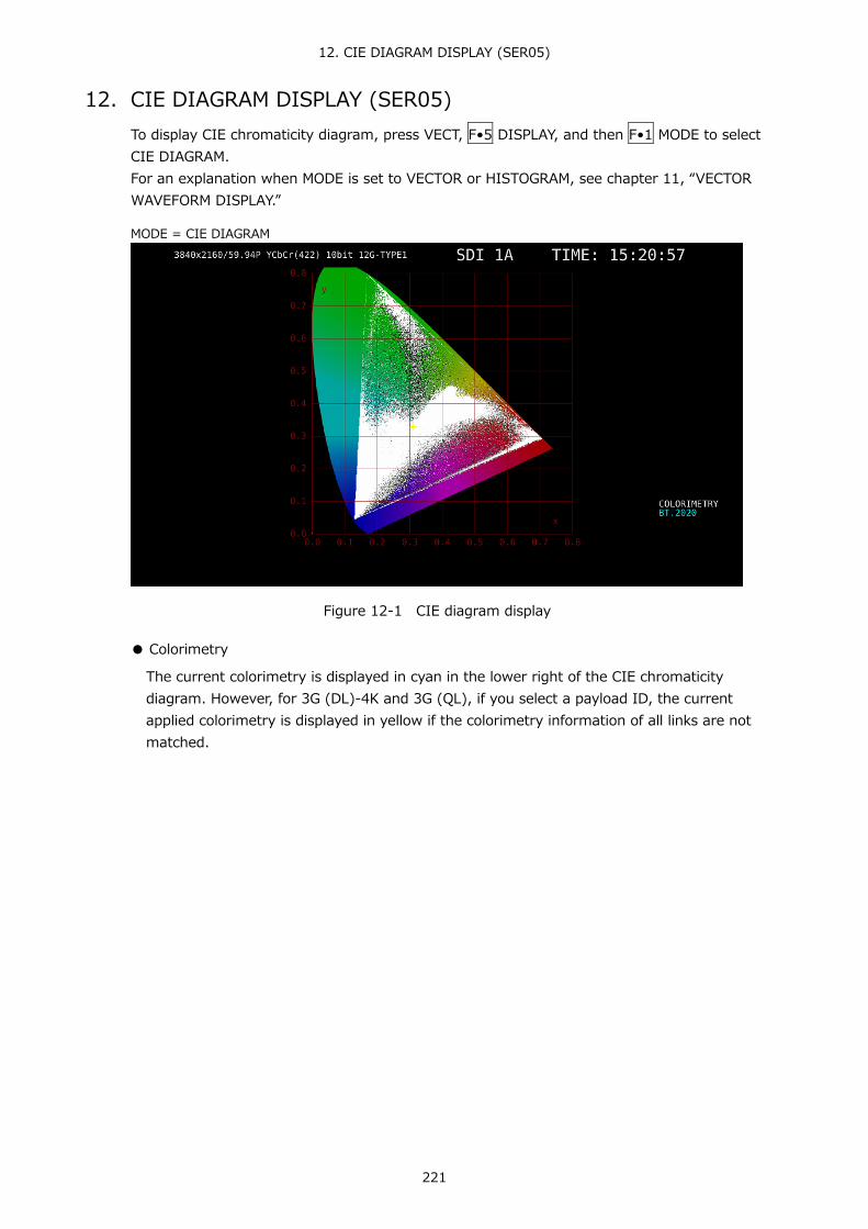
12. CIE DIAGRAM DISPLAY (SER05)
221
12. CIE DIAGRAM DISPLAY (SER05) To display CIE chromaticity diagram, press VECT, F•5 DISPLAY, and then F•1 MODE to select CIE DIAGRAM. For an explanation when MODE is set to VECTOR or HISTOGRAM, see chapter 11, “VECTOR WAVEFORM DISPLAY.”
MODE = CIE DIAGRAM
Figure 12-1 CIE diagram display
● Colorimetry
The current colorimetry is displayed in cyan in the lower right of the CIE chromaticity diagram. However, for 3G (DL)-4K and 3G (QL), if you select a payload ID, the current applied colorimetry is displayed in yellow if the colorimetry information of all links are not matched.

12. CIE DIAGRAM DISPLAY (SER05)
222
12.1 Configuring the Scale Settings
To configure the scale settings, press F•1 SCALE on the VECT menu. This menu item does not appear when DISP TYPE is set to TEMP. Reference DISP TYPE → Section 12.2.1, “Selecting the Display Type”
VECT → F•1 SCALE →
Figure 12-2 SCALE menu
12.1.1 Selecting the Triangle
To display up to three color triangles, follow the procedure below.
Procedure VECT → F•1 SCALE → F•1 TRIANGLE1: BT.601(525) / BT.601(625) / BT.709 / DCI / BT.2020 / OFF → F•2 TRIANGLE2: BT.601(525) / BT.601(625) / BT.709 / DCI / BT.2020 / OFF → F•5 USER TRIANGLE → F•1 TRIANGLE: 1 / 2 / OFF
The color triangle vertex coordinates are shown below. u’v’ coordinates are calculated from the xy coordinates.
Table 12-1 Color triangle vertex coordinates
F•1 TRIANGLE1 F•2 TRIANGLE2
CIE1931 CIE1976 x y u' v'
BT.601(525) R 0.630 0.340 0.433 0.526 G 0.310 0.595 0.130 0.563 B 0.155 0.070 0.176 0.178
BT.601(625) R 0.640 0.330 0.451 0.523 G 0.290 0.600 0.121 0.561 B 0.150 0.060 0.175 0.158
BT.709 R 0.640 0.330 0.451 0.523 G 0.300 0.600 0.125 0.563 B 0.150 0.060 0.175 0.158
DCI R 0.680 0.320 0.496 0.526 G 0.265 0.690 0.099 0.578 B 0.150 0.060 0.175 0.158
BT.2020 R 0.708 0.292 0.557 0.517 G 0.170 0.797 0.056 0.587 B 0.131 0.046 0.159 0.126
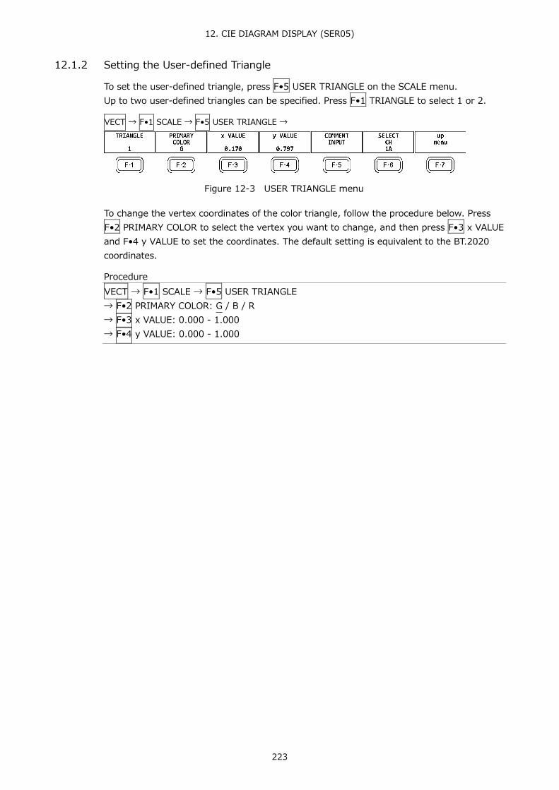
12. CIE DIAGRAM DISPLAY (SER05)
223
12.1.2 Setting the User-defined Triangle
To set the user-defined triangle, press F•5 USER TRIANGLE on the SCALE menu. Up to two user-defined triangles can be specified. Press F•1 TRIANGLE to select 1 or 2.
VECT → F•1 SCALE → F•5 USER TRIANGLE →
Figure 12-3 USER TRIANGLE menu
To change the vertex coordinates of the color triangle, follow the procedure below. Press F•2 PRIMARY COLOR to select the vertex you want to change, and then press F•3 x VALUE and F•4 y VALUE to set the coordinates. The default setting is equivalent to the BT.2020 coordinates.
Procedure VECT → F•1 SCALE → F•5 USER TRIANGLE → F•2 PRIMARY COLOR: G / B / R → F•3 x VALUE: 0.000 - 1.000 → F•4 y VALUE: 0.000 - 1.000

12. CIE DIAGRAM DISPLAY (SER05)
224
Press F•5 COMMENT INPUT to assign names of your choice to user-defined triangles. Enter a file name using up to 8 characters.
Figure 12-4 Triangle name input screen
The key operations that you can perform in the triangle name input display are as follows:
F•1 CLEAR ALL : Deletes all characters F•2 DELETE : Deletes the character at the cursor F•3 INSERT : Inserts a character at the cursor F•4 <= : Moves the cursor to the left F•5 => : Moves the cursor to the right F•6 CHAR SET : Enters the character Function dial (F•D) : Turn to select a character, and press to enter the character.

12. CIE DIAGRAM DISPLAY (SER05)
225
12.1.3 Selecting the Color Scale
To select the horseshoe-shaped color scale, follow the procedure below.
Procedure VECT → F•1 SCALE → F•3 COLOR: B.G.COLOR / B.G.WHITE / B.G.BLACK
Settings
B.G.COLOR: The color scale is displayed. The background is black, and the waveform is displayed according to the luminance level.
B.G.WHITE: The color scale is not displayed. The background is white, and the waveform is displayed according to the picture color.
B.G.BLACK: The color scale is not displayed. The background is black, and the waveform is displayed according to the picture color.
COLOR = B.G.WHITE
Figure 12-5 Selecting the color scale

12. CIE DIAGRAM DISPLAY (SER05)
226
12.1.4 Turning the Sub Scale On and Off
To set the sub scale, press F•4 SUB SCALE on the SCALE menu.
VECT → F•1 SCALE → F•4 SUB SCALE →
Figure 12-6 SUB SCALE menu
To turn on and off the color temperature curve, grid, white point (D65), or triangle name, follow the procedure below.
Procedure VECT → F•1 SCALE → F•4 SUB SCALE → F•1 TEMP SCALE: ON / OFF → F•2 GRID: ON / OFF → F•3 D65: ON / OFF → F•4 TRIANGLE CAPTION: ON / OFF
TEMP SCALE = ON / GRID = ON / D65 = ON / TRIANGLE CAPTION = ON
Figure 12-7 Turning the sub scale on and off

12. CIE DIAGRAM DISPLAY (SER05)
227
12.2 Setting the Chromaticity Diagram Mode
To set the chromaticity diagram mode, press F•2 CIE DIAGRAM on the VECT menu.
VECT → F•2 CIE DIAGRAM →
Figure 12-8 CIE DIAGRAM menu
12.2.1 Selecting the Display Type
To select the display type, follow the procedure below.
Procedure VECT → F•2 CIE DIAGRAM → F•1 DISP TYPE: DIAGRAM / TEMP
Settings
DIAGRAM: The chromaticity diagram is displayed. TEMP: The color temperature is displayed.
DISP TYPE = TEMP
Figure 12-9 Selecting the display type

12. CIE DIAGRAM DISPLAY (SER05)
228
12.2.2 Selecting the Display Standard
To select the display standard, follow the procedure below.
Procedure VECT → F•2 CIE DIAGRAM → F•2 CIE STD: CIE1931 / CIE1976
Settings
CIE1931: Chromaticity diagram based on CIE 1931 is displayed. CIE1976: Chromaticity diagram based on CIE 1976 is displayed.
12.2.3 Turning Clipping On and Off
To turn clipping on and off, follow the procedure below.
Procedure VECT → F•2 CIE DIAGRAM → F•3 CLIP: ON / OFF
Settings
ON: Negative values of the input signal are clipped to zero. OFF: Negative values of the input signal are displayed according to BT.1361.
12.2.4 Turning the Filter On and Off
To turn the filter on and off, follow the procedure below. When set to ON, data is averaged every two pixels and displayed.
Procedure VECT → F•2 CIE DIAGRAM → F•4 FILTER: ON / OFF
12.2.5 Setting the Gamma Value
To set the gamma value, follow the procedure below.
Procedure VECT → F•2 CIE DIAGRAM → F•5 MANUAL SETUP → F•1 MANUAL SETUP: ON / OFF
Settings
ON: The gamma set with F•5 GAMMA SETUP(1.50 - 2.20 - 3.00) is used. However, this is not applied to the video-signal-waveform, vector, or picture display. The gamma calculation expression is (input signal level)^(gamma value). In addition, negative input signal values are clipped to zero, regardless of whether F•3 CLIP is set to on or off.
OFF: The colorimetry standard selected in the system settings is used.

12. CIE DIAGRAM DISPLAY (SER05)
229
12.3 Configuring Line Selection Settings
To configure line selection settings, press F•3 LINE SEL on the VECT menu. See section 11.3, “Configuring Line Selection Settings.”
12.4 Configuring Cursor Settings
To configure cursor settings, press F•4 CURSOR on the VECT menu.
VECT → F•4 CURSOR →
Figure 12-10 CURSOR menu
12.4.1 Displaying the Chromaticity Diagram Cursor
To display a cursor on the chromaticity diagram, follow the procedure shown below. You can move the cursor horizontally using the H POS knob and vertically using the V POS knob. The measured values are shown in the upper right of the display. Press the H POS and V POS knobs to move the cursor to the following position.
Chromaticity diagram display: (x, y) = (u', v') = (0, 0) Color temperature display: Lower left of the display
Procedure VECT → F•4 CURSOR → F•1 CURSOR: ON / OFF
Figure 12-11 Displaying the chromaticity diagram cursor
12.5 Configuring the Display Settings
To configure the display settings, press F•5 DISPLAY on the VECT menu. See section 11.5, “Configuring the Display Settings.”

13. PICTURE DISPLAY
230
13. PICTURE DISPLAY To display the picture, press PIC.
Figure 13-1 Picture display
13.1 Adjusting the Picture
To adjust the picture, press F•1 ADJUST in the PIC menu.
PIC → F•1 ADJUST →
Figure 13-2 ADJUST menu
13.1.1 Switching between the Color and Monochrome Displays
To switch between the color and monochrome displays, follow the procedure below.
Procedure PIC → F•1 ADJUST → F•1 MONO/COLOR: COLOR / MONO

13. PICTURE DISPLAY
231
13.1.2 Setting the Chroma Gain
To switch the chroma gain, follow the procedure below.
Procedure PIC → F•1 ADJUST → F•2 CHROMA UP: NORMAL / UP
Settings
NORMAL: The chroma gain is set to the value that you have set using F•5 GAIN/BIAS → F•1 GAIN.
UP: The chroma gain is set to 2 (200.0 %).
13.1.3 Adjusting the Brightness
To adjust the brightness, follow the procedure below. Press the function dial (F•D) to return the setting to its default value (0.0).
Procedure PIC → F•1 ADJUST → F•3 BRIGHTNESS[%]: -50.0 - 0.0 - 50.0
13.1.4 Adjusting the Contrast
To adjust the contrast, follow the procedure below. Press the function dial (F•D) to return the setting to its default value (100.0).
Procedure PIC → F•1 ADJUST → F•4 CONTRAST[%]: 0.0 - 100.0 - 200.0
13.1.5 Adjusting the Gain
To adjust the gain, press F•1 GAIN on the GAIN/BIAS menu.
PIC → F•1 ADJUST → F•5 GAIN/BIAS → F•1 GAIN →
Figure 13-3 GAIN menu
To adjust the gain separately for the R, G, B, and chroma signals, follow the procedure below. Press the function dial (F•D) to return the setting to its default value (100.0). When F•2 CHROMA UP is set to UP, F•4 CHROMA GAIN does not appear. If is fixed at 200.0.
Procedure PIC → F•1 ADJUST → F•5 GAIN/BIAS → F•1 GAIN → F•1 R GAIN[%]: 0.0 - 100.0 - 200.0 → F•2 G GAIN[%]: 0.0 - 100.0 - 200.0 → F•3 B GAIN[%]: 0.0 - 100.0 - 200.0 → F•4 CHROMA GAIN[%]: 0.0 - 100.0 - 200.0
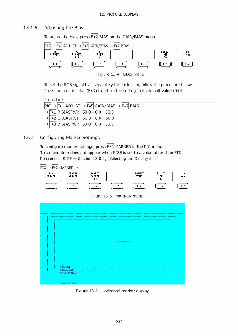
13. PICTURE DISPLAY
232
13.1.6 Adjusting the Bias
To adjust the bias, press F•2 BIAS on the GAIN/BIAS menu.
PIC → F•1 ADJUST → F•5 GAIN/BIAS → F•2 BIAS →
Figure 13-4 BIAS menu
To set the RGB signal bias separately for each color, follow the procedure below. Press the function dial (F•D) to return the setting to its default value (0.0).
Procedure PIC → F•1 ADJUST → F•5 GAIN/BIAS → F•2 BIAS → F•1 R BIAS[%]: -50.0 - 0.0 - 50.0 → F•2 G BIAS[%]: -50.0 - 0.0 - 50.0 → F•3 B BIAS[%]: -50.0 - 0.0 - 50.0
13.2 Configuring Marker Settings
To configure marker settings, press F•2 MARKER in the PIC menu. This menu item does not appear when SIZE is set to a value other than FIT. Reference SIZE → Section 13.8.1, “Selecting the Display Size”
PIC → F•2 MARKER →
Figure 13-5 MARKER menu
Figure 13-6 Horizontal marker display

13. PICTURE DISPLAY
233
13.2.1 Turning the Display of the Frame Marker On and Off
To turn the display of the frame marker on and off, follow the procedure below.
Procedure PIC → F•2 MARKER → F•1 FRAME MARKER: ON / OFF
13.2.2 Turning the Display of the Center Marker On and Off
To turn the display of the center marker on and off, follow the procedure below.
Procedure PIC → F•2 MARKER → F•2 CENTER MARKER: ON / OFF
13.2.3 Setting the Aspect Marker
To display the aspect marker, follow the procedure below.
Procedure PIC → F•2 MARKER → F•3 ASPECT MARKER: OFF / 17:9 / 16:9 / 14:9 / 13:9 / 4:3 / 2.39:1 / AFD
Settings
OFF: An aspect marker is not displayed. 17:9 A 17:9 aspect marker is displayed.
This option cannot be selected when the input signal is a 17:9 frame signal or an SD signal.
16:9: A 16:9 aspect marker is displayed. This option cannot be selected when the input signal is a 16:9 frame signal.
14:9: A 14:9 aspect marker is displayed. 13:9: A 13:9 aspect marker is displayed. 4:3: A 4:3 aspect marker is displayed.
This option cannot be selected when the input signal is SD. 2.39:1: A 2.39:1 aspect marker is displayed.
This option cannot be selected when the input signal is SD. AFD: The aspect marker included in the AFD (Active Format Description)
packets is displayed. Also, abbreviations for SMPTE ST 2016-1-2007 standard AFD codes are displayed in the upper left of the screen. This option can be selected when the input signal is SD or HD.

13. PICTURE DISPLAY
234
The AFD codes that are displayed in the upper left of the screen are displayed as shown below according to the coded frame and the AFD code. If there are no AFD packets embedded in the input signal, “---------” is displayed.
Table 13-1 Displaying AFD
Displayed AFD Coded Frame
AFD Code
Explanation
0000- UNDEFINED 0 (4:3) 0000 Undefined 0001- RESERVED 0 (4:3) 0001 Reserved 0010- 16:9LBTop 0 (4:3) 0010 Letterbox 16:9 image, at top of the coded frame 0011- 14:9LBTop 0 (4:3) 0011 Letterbox 14:9 image, at top of the coded frame 0100- >16:9LBox 0 (4:3) 0100 Letterbox image with an aspect ratio greater than 16:9, vertically
centered in the coded frame 0101- RESERVED 0 (4:3) 0101 Reserved 0110- RESERVED 0 (4:3) 0110 Reserved 0111- RESERVED 0 (4:3) 0111 Reserved 1000- FullFrame 0 (4:3) 1000 Full frame 4:3 image, the same as the coded frame 1001- Full Frame 0 (4:3) 1001 Full frame 4:3 image, the same as the coded frame 1010- 16:9LBox 0 (4:3) 1010 Letterbox 16:9 image, vertically centered in the coded frame with all
image areas protected 1011- 14:9LBox 0 (4:3) 1011 Letterbox 14:9 image, vertically centered in the coded frame 1100- RESERVED 0 (4:3) 1100 Reserved 1101-4:3Full14:9 0 (4:3) 1101 Full frame 4:3 image, with alternative 14:9 center 1110-16:9LB14:9 0 (4:3) 1110 Letterbox 16:9 image, with alternative 14:9 center 1111-16:9LB4:3 0 (4:3) 1111 Letterbox 16:9 image, with alternative 4:3 center 0000w UNDEFINED 1 (16:9) 0000 Undefined 0001w RESERVED 1 (16:9) 0001 Reserved 0010w Full Frame 1 (16:9) 0010 Full frame 16:9 image, the same as the coded frame 0011w 14:9Pillbox 1 (16:9) 0011 Pillarbox 14:9 image, horizontally centered in the coded frame 0100w >16:9LBox 1 (16:9) 0100 Letterbox image with an aspect ratio greater than 16:9, vertically
centered in the coded frame 0101w RESERVED 1 (16:9) 0101 Reserved 0110w RESERVED 1 (16:9) 0110 Reserved 0111w RESERVED 1 (16:9) 0111 Reserved 1000w FullFrame 1 (16:9) 1000 Full frame 16:9 image, the same as the coded frame 1001w 4:3Pillbox 1 (16:9) 1001 Pillarbox 4:3 image, horizontally centered in the coded frame 1010w FullNoCrop 1 (16:9) 1010 Full frame 16:9 image, with all image areas protected 1011w14:9Pillbox 1 (16:9) 1011 Pillarbox 14:9 image, horizontally centered in the coded frame 1100w RESERVED 1 (16:9) 1100 Reserved 1101w4:3PB14:9 1 (16:9) 1101 Pillarbox 4:3 image, with alternative 14:9 center 1110wFul14:9Safe 1 (16:9) 1110 Full frame 16:9 image, with alternative 14:9 center 1111wFull4:3Safe 1 (16:9) 1111 Full frame 16:9 image, with alternative 4:3 center

13. PICTURE DISPLAY
235
13.2.4 Setting the Aspect Shadow
When F•3 ASPECT MARKER is set to a value other than OFF, to adjust the darkness of the aspect marker shadow, follow the procedure below. The larger the number, the darker the shadow. If you specify 0, the aspect marker will be indicated with a line. Press the function dial (F•D) to return the setting to its default value (50).
Procedure PIC → F•2 MARKER → F•4 ASPECT SHADOW[%]: 0 - 50 - 100
ASPECT SHADOW[%] = 50
Figure 13-7 Setting the aspect shadow

13. PICTURE DISPLAY
236
13.2.5 Setting the Safe Action Marker
To configure safety marker settings, press F•5 SAFETY ZONE on the MARKER menu. This menu item does not appear when F•3 ASPECT MARKER is set to AFD.
PIC → F•2 MARKER → F•5 SAFETY ZONE →
Figure 13-8 SAFETY ZONE menu
To display the safe action marker, follow the procedure below. When an aspect marker is displayed, the safe action marker is displayed relative to the aspect marker.
Procedure PIC → F•2 MARKER → F•5 SAFETY ZONE → F•1 SAFE ACTION: ARIB / SMPTE / USER1 / OFF
Settings
ARIB: An ARIB TR-B4 safe action marker is displayed. This option cannot be selected when the input signal is 4K.
SMPTE: An SMPTE RP-218 safe action marker is displayed. This option cannot be selected when the input signal is 4K.
USER1: A marker that has been set with F•1 USER1 WIDTH[%] and F•2 USER1 HEIGHT[%] for F•3 USER1/2 SET is displayed.
OFF: A safe action marker is not displayed.
13.2.6 Setting the Safe Title Marker
To display the safe title marker, follow the procedure below. When an aspect marker is displayed, the safe action marker is displayed relative to the aspect marker.
Procedure PIC → F•2 MARKER → F•5 SAFETY ZONE → F•2 SAFE TITLE: ARIB / SMPTE / USER2 / OFF
Settings
ARIB: An ARIB TR-B4 safe title marker is displayed. This option cannot be selected when the input signal is 4K.
SMPTE: An SMPTE RP-218 safe title marker is displayed. This option cannot be selected when the input signal is 4K.
USER2: A marker that has been set with F•3 USER2 WIDTH[%] and F•2 USER2 HEIGHT[%] for F•3 USER1/4 SET is displayed.
OFF: A safe title marker is not displayed.

13. PICTURE DISPLAY
237
13.2.7 Setting User Markers
By setting F•1 SAFE ACTION to USER1 and F•2 SAFE TITLE to USER2, you can display up to two user-defined markers. To configure user-defined marker settings, press F•3 USER1/2 SET on the SAFETY ZONE menu.
PIC → F•2 MARKER → F•5 SAFETY ZONE → F•3 USER1/2 SET →
Figure 13-9 USER1/2 SET menu
To set the width and height of a user marker and turn the aspect ratio display on and off, follow one of the procedures below. Press the function dial (F•D) to return the width and height settings to their default value. The aspect ratio display on/off setting applies both to USER1 and USER2.
Procedure PIC → F•2 MARKER → F•5 SAFETY ZONE → F•3 USER1/2 SET → F•1 USER1 WIDTH[%]: 0 - 90 - 100 → F•2 USER1 HEIGHT[%]: 0 - 90 - 100 → F•3 USER2 WIDTH[%]: 0 - 80 - 100 → F•4 USER2 HEIGHT[%]: 0 - 80 – 100 → F•5 USER1/2 ASPECT: ON / OFF

13. PICTURE DISPLAY
238
13.3 Configuring Line Selection Settings
To configure line selection settings, press F•3 LINE SEL on the PIC menu. This menu item does not appear when SIZE is set to a value other than FIT. Reference SIZE → Section 13.8.1, “Selecting the Display Size”
PIC → F•3 LINE SEL →
Figure 13-10 LINE SEL menu
13.3.1 Turning Line Selection On and Off
To display a marker on the selected line, follow the procedure below. You can use the function dial (F•D) to select a line. The number of the selected line appears in the upper left of the display. Changing this setting will also change the video-signal-waveform-display and vector-display line selection settings.
Procedure PIC → F•3 LINE SEL → F•1 LINE SELECT: ON / OFF
LINE SELECT = ON
Figure 13-11 Turning line selection on and off

13. PICTURE DISPLAY
239
13.3.2 Setting the Line Selection Range
When F•1 LINE SELECT is set to ON and the input signal format is interlaced or segmented frame, to set the line selection range, follow the procedure below. Changing this setting will also change the selected line on the video-signal-waveform, vector, and status (data dump) displays.
Procedure PIC → F•3 LINE SEL → F•2 FIELD: FIELD1 / FIELD2 / FRAME
Settings
FIELD1: A line from field 1 can be selected. (Example: 1 to 563) FIELD2: A line from field 2 can be selected. (Example: 564 to 1125) FRAME: All lines can be selected. (Example: 1 to 1125)
13.3.3 Setting the Lip Sync Measurement Range (SER03)
To set the lip sync measurement range, press F•3 AV PHASE on the LINE SELCT menu.
PIC → F・3 LINE SELECT → F・3 AV PHASE →
Figure 13-12 AV PHASE menu
To set the lip sync measurement range, follow the procedure below. Markers are displayed at the specified lines. You can also set these using AV PHASE SETUP of the STATUS menu, but here you can set them while viewing the picture. For details on the settings, section 16.7.3, “Setting the Measurement Range.”
Procedure PIC → F•3 LINE SEL → F•3 AV PHASE → F•1 AV MEASURE TOP: 0 - 50 - 100 → F•2 AV MEASURE LEFT: 0 - 99 → F•3 AV MEASURE RIGHT: 0 - 99 → F•4AV MEASURE SUB IMAGE: SUB 1 / SUB 2 / SUB 3 / SUB 4
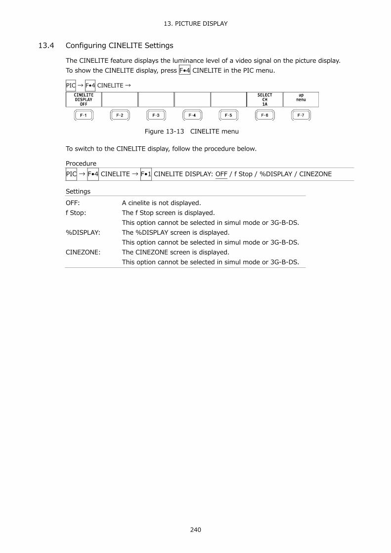
13. PICTURE DISPLAY
240
13.4 Configuring CINELITE Settings
The CINELITE feature displays the luminance level of a video signal on the picture display. To show the CINELITE display, press F•4 CINELITE in the PIC menu.
PIC → F•4 CINELITE →
Figure 13-13 CINELITE menu
To switch to the CINELITE display, follow the procedure below.
Procedure PIC → F•4 CINELITE → F•1 CINELITE DISPLAY: OFF / f Stop / %DISPLAY / CINEZONE
Settings
OFF: A cinelite is not displayed. f Stop: The f Stop screen is displayed.
This option cannot be selected in simul mode or 3G-B-DS. %DISPLAY: The %DISPLAY screen is displayed.
This option cannot be selected in simul mode or 3G-B-DS. CINEZONE: The CINEZONE screen is displayed.
This option cannot be selected in simul mode or 3G-B-DS.

13. PICTURE DISPLAY
241
13.4.1 f Stop Screen Explanation
To set f Stop, press F•1 CINELITE DISPLAY to select f Stop and then press F•2 f Stop SETUP.
On the f Stop screen, luminance levels are displayed using f-stop (exposure) values. The measured f Stop value for a group of measured points is typically displayed using white, but it will be displayed using yellow when it corresponds to a luminance level of 80 % or more. Additionally, f Stop values that correspond to luminance levels equal to or less than 0 % can not be measured. They are displayed in yellow as “****.”
PIC → F•4 CINELITE → F•1 CINELITE DISPLAY → F•2 f Stop SETUP
Figure 13-14 f Stop screen
1 Reference Position
The position where the cursors intersected when F•4 18% REF-SET was pressed is displayed in red. This is the reference position for f-stop measurement.
2 Cursor
You can set up to three measurement points. The cursor coordinates are indicated using sample numbers and line numbers. Additionally, The f Stop value relative to the reference point is displayed at each point.
3 Gamma Correction Value
The gamma correction value that you selected using F•5 GAMMA SELECT appears here.
4 Reference Value
The f Stop value at the reference position appears here. The value immediately after you have pressed F•4 18% REF-SET is zero, but it will change when the picture changes.

13. PICTURE DISPLAY
242
13.4.2 Procedure for Displaying the f Stop Screen
The following example shows how to display luminance levels as f Stop numbers relative to the luminance level of 18 % gray chart. Include an 18 % gray chart with the objects that you are filming.
1. Press PIC.
2. Press F•4 CINELITE.
3. Press F•1 CINELITE DISPLAY to select f Stop.
4. Press F•2 f Stop SETUP.
5. Press F•5 GAMMA and then F•1 GAMMA SELECT to select the gamma correction table type.
The default gamma correction value is 0.45, but you can also use a user-defined gamma correction table that matches the gamma characteristics of the camera that you are using. For details, see section 13.4.7, “Configuring User-Defined Correction Tables.” The selected gamma correction value is indicated in the upper left of the display.
6. Press F•7 up menu.
7. Make sure that the cursors are over the 18 % gray chart, and press F•4 18% REF-SET.
The f Stop value for 18 % gray chart becomes 0.0 and is displayed in the upper part of the screen next to “REF:.” The reference position is displayed with a red cursor.
8. Use the cursors to set the measurement points.
The f Stop value relative to 18 % gray chart appears next to each measurement point. You can set up to three measurement points.

13. PICTURE DISPLAY
243
13.4.3 %DISPLAY Screen Explanation
To set %DISPLAY, press F•1 CINELITE DISPLAY to select %DISPLAY and then press F•2 %DISPLAY SETUP.
On the %DISPLAY screen, you can display luminance levels as Y percentages, RGB percentages, 255 RGB, using CODE VALUE levels, or using CODE VALUE DEC levels. Use F•4 UNIT SELECT to select the display format. The measured values are typically displayed using white, but they are displayed using yellow when the luminance level is 80 % or more or 0 % or less.
● Y% Display
Luminance levels are indicated as percentages.
Figure 13-15 Y% display
● RGB% Display
Each R, G, and B level is indicated using a percentage. The levels are also indicated using bars on the left side of the display (the order is R, G, and then B).
Figure 13-16 RGB% display

13. PICTURE DISPLAY
244
● RGB255 Display
Each R, G, and B level is indicated using 256 steps from 0 to 255. The levels are also indicated using bars on the left side of the display (the order is R, G, and then B). The value of an RGB level that is 100 % or greater is 255. The value of an RGB level that is 0 % or less is 0.
Figure 13-17 RGB255 display
● CODE VALUE Display
The SDI signal video data is displayed in hexadecimal notation. If the input signal is YCbCr, the data is displayed in YCbCr. If the input signal is RGB, the data is displayed in RGB. If the input signal is XYZ, data is displayed using values converted into RGB (with black level offset added). You can select CODE VALUE when F•3 MEAS SIZE is 1×1.
Figure 13-18 CODE VALUE display
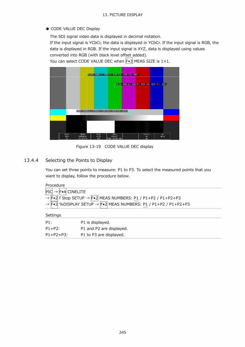
13. PICTURE DISPLAY
245
● CODE VALUE DEC Display
The SDI signal video data is displayed in decimal notation. If the input signal is YCbCr, the data is displayed in YCbCr. If the input signal is RGB, the data is displayed in RGB. If the input signal is XYZ, data is displayed using values converted into RGB (with black level offset added). You can select CODE VALUE DEC when F•3 MEAS SIZE is 1×1.
Figure 13-19 CODE VALUE DEC display
13.4.4 Selecting the Points to Display
You can set three points to measure: P1 to P3. To select the measured points that you want to display, follow the procedure below.
Procedure PIC → F•4 CINELITE → F•2 f Stop SETUP → F•2 MEAS NUMBERS: P1 / P1+P2 / P1+P2+P3 → F•2 %DISPLAY SETUP → F•2 MEAS NUMBERS: P1 / P1+P2 / P1+P2+P3
Settings
P1: P1 is displayed. P1+P2: P1 and P2 are displayed. P1+P2+P3: P1 to P3 are displayed.

13. PICTURE DISPLAY
246
13.4.5 Setting Measurement Points
Follow the procedure below to select which measurement point to set with the cursors, and then move the X cursor by using the H POS knob and the Y cursor by using the V POS knob. Press the H POS and V POS knobs at the same time to move the cursors to the center of the picture.
The cursors are not displayed if they are within the blanking interval. To display cursors that do not appear, move them within the screen. The measurement point settings made on the menus accessed by pressing fStop and %DISPLAY are the same.
Procedure PIC → F•4 CINELITE → F•2 f Stop SETUP → F•1 MEAS POS: P1 / P2 / P3 → F•2 %DISPLAY SETUP → F•1 MEAS POS: P1 / P2 / P3
13.4.6 Setting the Area of Luminance Measurement
To select the area of luminance measurement, follow the procedure below. This setting is applied to P1 to P3 and REF. The luminance measurement area settings made on the menus accessed by pressing fStop and %DISPLAY are the same.
Procedure PIC → F•4 CINELITE → F•2 f Stop SETUP → F•3 MEAS SIZE: 1X1 / 3X3 / 9X9 → F•2 %DISPLAY SETUP → F•3 MEAS SIZE: 1X1 / 3X3 / 9X9
Settings
1X1: The single pixel at the intersection of the cursors is measured.
3X3: The 3×3 area of pixels with its center at the intersection of the cursors is averaged and measured.
9X9: The 9×9 area of pixels with its center at the intersection of the cursors is averaged and measured.

13. PICTURE DISPLAY
247
13.4.7 Configuring User-Defined Correction Tables
The default gamma correction value when measuring f Stop levels is 0.45, but you can also use a user-defined gamma correction table that matches the gamma characteristics of the camera that you are using. There are two types of user-defined correction tables. The first type consists of tables that are created using the LV 5490 and is made up of the USER1 to USER3 tables. The second type consists of tables that have been created externally using a device such as a PC and is made up of the USER_A to USER_E tables. These tables are not deleted even if you initialize the LV 5490.
● Creating User-Defined Correction Tables Using the LV 5490.
You can create and store up to three user-defined correction tables on the LV 5490. As an example, the following procedure shows how to create a user-defined correction table that matches a camera's gamma characteristics. Set the camera's f Stop value to F5.6 beforehand, and put an 18 % gray chart in the area that you will film.
1. Adjust the lighting so that the displayed luminance level of the 18 % gray chart is
45.0 % (for example) on a camera whose f Stop value is set to F5.6.
For details, see section 13.4.3, “%DISPLAY Screen Description.”
2. Press F•7 up menu.
3. Press F•1 CINELITE DISPLAY to select f Stop.
4. Press F•2 f Stop SETUP.
5. Press F•5 GAMMA and then F•1 GAMMA SELECT to select USER1.
In this example, explanation will be given for USER-1, but USER2 and USER3 can also be created in the same way.

13. PICTURE DISPLAY
248
6. Press F•2 GAMMA CAL.
When you press F•2 GAMMA CAL, a user-defined correction table appears in the bottom left of the screen, and the luminance level appears as a 10-bit value (0 % is displayed as 64, and 100 % is displayed as 940) close to the cursor. This setting is available when F•1 GAMMA SELECT is set to an option from USER1 to USER3.
Figure 13-20 User-defined correction table creation screen
7. Press F•1 TABLE CLEAR.
All the values in the user-defined correction table that is currently being edited are initialized. Be sure to initialize the values first when you create a new user-defined correction table.
8. Press F•1 CLEAR YES.
To cancel the initialization of a user-defined correction table, press F•3 CLEAR NO.
9. Place the cursors over the 18 % gray chart.
10. Press F•4 CAL F, and select 5.6.
11. Press F•3 CAL SET
The luminance level when the camera f Stop value is F5.6 is input into Lev in the user-defined correction table. To delete a line of data, press F•2 1 DATA CLEAR.
12. Change F•4 CAL F and the camera f Stop value together in the following order: 4.0,
2.8, 2.0, 8.0, 11.0, 16.0, 22.0. Press F•3 CAL SET each time you change the value to input the luminance level for each value.
Do not change the lighting or the position of the 18 % gray chart. Also, make sure that the Lev value for f Stop values 22.0 to 2.0 increases linearly.

13. PICTURE DISPLAY
249
The REF value in the user-defined correction table is entered when you press F•4 18% REF-SET on the f Stop display.
For example, if you use the left-hand table shown below and press F•4 18% REF-SET when the luminance value at the intersection of the cursors is 416 (10-bit value), the f Stop value at that point (3.0) is displayed as the REF value.
→
Figure 13-21 User-defined correction tables
When the above user-defined correction tables are used, f Stop values are indicated as shown below. The values between specified values are interpolated linearly. When Lv = 152 f Stop = -3.0 When Lv = 240 f Stop = -2.0 When Lv = 328 f Stop = -1.0 When Lv = 416 f Stop = 0.0 When Lv = 504 f Stop = 1.0 When Lv = 592 f Stop = 2.0 When Lv = 680 f Stop = 3.0 When Lv = 768 f Stop = 4.0

13. PICTURE DISPLAY
250
● Loading a User-Defined Correction Table into the LV 5490
You can load up to five user-defined correction tables into the LV 5490. To load a user-defined correction table into the LV 5490, follow the procedure below.
1. Create a user-defined correction table.
Example (TEST.CLT) ################################# NAME:SAMPLE_1 TYPE:0 #Input -7% 0 # 109% 4095 #Output 0% 0 # 1000% 65535 #Input Output ################################# 0 0 1 16 2 32 (Omitted) 4093 65488 4094 65504 4095 65520 # EOF
Comment Keyword Keyword Comment Comment Comment Comment Comment Comment Data Data Data Data Data Data Comment
When you create a correction table, make sure that it conforms to the specifications listed below.
Overall File Specifications
File Type: ASCII text file Extension: .CLT End-of-Line Character: CR+LF Number of Lines: 5000 or less Number of Characters per Line: 255 or less (including CR+LF) File Name Length: 20 characters or less (excluding the extension) Permitted File Name Characters: Letters of the alphabet (A to Z; uppercase and
lowercase), numerals (0 to 9), and underscores (_).
Comment Specifications
If you start a line with the number sign (#), the line is treated as a comment and does not affect operations. You can put comments anywhere.

13. PICTURE DISPLAY
251
Keyword Specifications
Be sure to put the keyword lines before the data lines and to enter a keyword without anything preceding it at the beginning of each keyword line. NAME: The LV 5770A/7770 displays the eight characters that follow the
separator (colon) as the name of the correction table. After the separator, enter the correction table name using letters of the alphabet (A to Z; uppercase and lowercase), numbers (0 to 9), and underscores (_). You can enter up to 10 characters.
TYPE: This is a code for identifying the file type. Enter a zero after the separator (colon).
Data Specifications
From the start of a line, enter the input value, a separator, and then the output value, in that order. Input Value: Enter values from 0 to 4095 (12 bits), increasing the value by one for
each line. A luminance level of 100 % is defined as 940 (10 bits) × 4 = 3760 (12 bits). A luminance level of 0 % is defined as 64 (10 bits) × 4 = 256 (12 bits).
Separator: Enter a single tab code. Output Value: Enter a value from 0 to 65535 (16 bits).
2. Save the user-defined correction table to USB memory, and connect the USB memory
to the LV 5490.
Save the correction table in the following directory.
USB memory └ LV5490_USER └ CLT └ TEST.CLT (for example)
3. Press PIC.
4. Press F•4 CINELITE.
5. Press F•1 CINELITE DISPLAY to select f Stop.
6. Press F•2 f Stop SETUP.
7. Press F•5 GAMMA and then F•1 GAMMA SELECT to select USER_A.
In this example, a user-defined correction table is copied to USER_A, but user-defined correction tables can be copied to USER_B through USER_E in the same way.
8. Press F•2 GAMMA FILE.
This setting is available when F•1 GAMMA SELECT is set to an option from USER_A to USER_E.
9. Press F•1 FILE LIST.
The file list screen appears. This setting appears when USB memory is connected. To clear the table that has been copied to USER_A, press F•2 TABLE CLEAR.
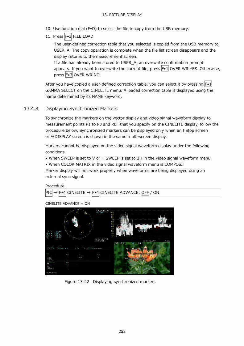
13. PICTURE DISPLAY
252
10. Use function dial (F•D) to select the file to copy from the USB memory.
11. Press F•3 FILE LOAD
The user-defined correction table that you selected is copied from the USB memory to USER_A. The copy operation is complete when the file list screen disappears and the display returns to the measurement screen. If a file has already been stored to USER_A, an overwrite confirmation prompt appears. If you want to overwrite the current file, press F•1 OVER WR YES. Otherwise, press F•3 OVER WR NO.
After you have copied a user-defined correction table, you can select it by pressing F•1 GAMMA SELECT on the CINELITE menu. A loaded correction table is displayed using the name determined by its NAME keyword.
13.4.8 Displaying Synchronized Markers
To synchronize the markers on the vector display and video signal waveform display to measurement points P1 to P3 and REF that you specify on the CINELITE display, follow the procedure below. Synchronized markers can be displayed only when an f Stop screen or %DISPLAY screen is shown in the same multi-screen display.
Markers cannot be displayed on the video signal waveform display under the following conditions. • When SWEEP is set to V or H SWEEP is set to 2H in the video signal waveform menu • When COLOR MATRIX in the video signal waveform menu is COMPOSIT Marker display will not work properly when waveforms are being displayed using an external sync signal.
Procedure PIC → F•4 CINELITE → F•4 CINELITE ADVANCE: OFF / ON
CINELITE ADVANCE = ON
Figure 13-22 Displaying synchronized markers

13. PICTURE DISPLAY
253
13.5 Configuring CINEZONE Settings
The CINEZONE display has a gradation (step) display mode, in which the picture luminance levels are converted into RGB colors and displayed and a search display mode, in which the specified luminance level is displayed using green. To set either of these modes, on the picture menu, press F•4 CINELITE and then F•2 CINEZONE SETUP. Reference CINEZONE SETUP → section13.3.3, “Configuring CINELITE Settings.”
13.5.1 Gradation Display Mode
To display picture luminance levels through color gradation, follow the procedure below. In the gradation display mode, luminance levels are displayed using 1024 colors. The picture is displayed such that luminance levels above F•2 UPPER are displayed using white, and levels below F•3 LOWER are displayed using black. You can see what colors correspond to what luminance levels by looking at the scale on the right of the display.
If F•2 UPPER is 1 % greater than F•3 LOWER and you lower the value of F•2 UPPER, the value of F•3 LOWER is automatically lowered to maintain a difference of 1 % between the two values. In the same way, if you raise the value of F•3 LOWER, the value of F•2 UPPER is automatically raised to maintain a difference of 1 % between the two values.
F•2 UPPER and F•3 LOWER appear when you set F•1 CINEZONE FORM to GRADATE or STEP.
Procedure PIC → F•4 CINELITE → F•1 CINELITE DISPLAY → F•2 CINEZONE SETUP → F•1 CINEZONE FORM to select GRADATE → F•2 UPPER: -6.3 - 100.0 - 109.4 → F•3 LOWER: -7.3 - 0.0 - 108.4
Picture Display Gradation Display (0% = B, 50% = G, 100% = R)
Figure 13-23 Gradation display

13. PICTURE DISPLAY
254
13.5.2 Step Display Mode
To display picture luminance levels in steps, follow the procedure below. In the step display mode, luminance levels are divided into 10 % steps and assigned to 12 different colors. For information about F•2 UPPER and F•3 LOWER, see section 13.5.1, “Gradation Display Mode.”
Procedure PIC → F•4 CINELITE → F•1 CINELITE DISPLAY → F•2 CINEZONE SETUP → F•1 CINEZONE FORM to select STEP → F•2 UPPER → F•3 LOWER
CINEZONE FORM = GRADATE CINEZONE FORM = STEP
Figure 13-24 Step display

13. PICTURE DISPLAY
255
13.5.3 Search Display Mode
In the search display mode, the specified luminance level ±0.5 % is displayed using green on an otherwise monochrome picture display. The picture is displayed such that luminance levels at and above F•2 UPPER are displayed using red, and levels below F•3 LOWER are displayed using blue.
To set the level that is displayed using green, follow the procedure below. F•2 LEVEL appears when F•1 CINEZONE FORM is set to SEARCH.
F•2 UPPER and F•3 LOWER appear when F•1 CINEZONE FORM is set to GRADATE or STEP. For details, see section 13.5.1, “Gradation Display Mode.”
Procedure PIC → F•4 CINELITE → F•1 CINELITE DISPLAY → F•2 CINEZONE SETUP → F•1 CINEZONE FORM to select SEARCH → F•2 LEVEL: -7.3 - 40.0 - 109.4
CINEZONE FORM = SEARCH
Figure 13-25 Search display

13. PICTURE DISPLAY
256
13.6 Focus Assist Display (SER04)
The focus assist display makes it easy to verify the focus by highlighting the image according to the amount of detected edges.
To configure the focus assist settings, press F•5 FOCUS on the PIC menu. This menu item does not appear when SIZE is set to FULL FRM. Reference SIZE → Section 13.8.1, “Selecting the Display Size”
PIC → F•5 FOCUS →
Figure 13-26 Focus assist display
13.6.1 Selecting the Display Size
To select the picture display size, follow the procedure shown below. See section 13.8.1, “Selecting the Display Size.”
Procedure PIC → F•5 FOCUS → F•1 SIZE: FIT / REAL / X2
13.6.2 Turning Focus Assist On and Off
To turn the focus assist display on and off, follow the procedure below.
Procedure PIC → F•5 FOCUS → F•2 FOCUS ASSIST: ON / OFF
13.6.3 Selecting the Detection Sensitivity
When F•2 FOCUS ASSIST is set to ON, to select the edge detection sensitivity, follow the procedure below.
Procedure PIC → F•5 FOCUS → F•3 EDGE SENSITIVE: LOW / MIDDLE / HIGH / V-HIGH / U-HIGH

13. PICTURE DISPLAY
257
13.6.4 Selecting the Luminance Level
When F•2 FOCUS ASSIST is set to ON, to select the picture luminance level as a percentage, follow the procedure below. Select OFF to hide the picture. Select EMBOSS to emboss the edges.
Procedure PIC → F•5 FOCUS → F•4 PIC LEVEL: OFF / EMBOSS / 25 / 50 / 75 / 100
PIC LEVEL = OFF PIC LEVEL = EMBOSS
Figure 13-27 Selecting the luminance level
13.6.5 Selecting the Highlight Color
When F•4 PIC LEVEL is 25, 50, 75, or 100, to select the edge display color, follow the procedure below.
Procedure PIC → F•5 FOCUS → F•5 EDGE COLOR: WHITE / RED / GREEN / BLUE

13. PICTURE DISPLAY
258
13.7 Video Noise Meter (SER10)
The video noise meter measures the noise included in the Y, G, B, or R signal of the SDI signal applied to the LV 5490 and displays it on the picture.
To configure the video noise meter, press F•4 NOISE SETUP and F•5 NOISE STOP/START on the PIC menu. This menu item does not appear when the SER10 is not installed.
PIC → F•3 LINE SEL / NOISE → F•4 NOISE SETUP →
PIC → F•3 LINE SEL / NOISE → F•5 NOISE STOP/START
Figure 13-28 Video Noise Meter
13.7.1 Turning Video Noise Meter On and Off
To turn the Video Noise Meter on and off, follow the procedure below.
Procedure PIC → F•3 LINE SEL / NOISE → F•5 NOISE: STOP / START
Settings
STOP: Indicates that the video noise meter is off. Press F•5 to turn on the video noise meter.
START: Indicates that the video noise meter is on. Press F•5 to turn off the video noise meter.
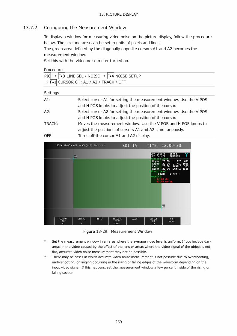
13. PICTURE DISPLAY
259
13.7.2 Configuring the Measurement Window
To display a window for measuring video noise on the picture display, follow the procedure below. The size and area can be set in units of pixels and lines. The green area defined by the diagonally opposite cursors A1 and A2 becomes the measurement window. Set this with the video noise meter turned on.
Procedure PIC → F•3 LINE SEL / NOISE → F•4 NOISE SETUP → F•1 CURSOR CH: A1 / A2 / TRACK / OFF
Settings
A1: Select cursor A1 for setting the measurement window. Use the V POS and H POS knobs to adjust the position of the cursor.
A2: Select cursor A2 for setting the measurement window. Use the V POS and H POS knobs to adjust the position of the cursor.
TRACK: Moves the measurement window. Use the V POS and H POS knobs to adjust the positions of cursors A1 and A2 simultaneously.
OFF: Turns off the cursor A1 and A2 display.
Figure 13-29 Measurement Window
* Set the measurement window in an area where the average video level is uniform. If you include dark areas in the video caused by the effect of the lens or areas where the video signal of the object is not flat, accurate video noise measurement may not be possible.
* There may be cases in which accurate video noise measurement is not possible due to overshooting, undershooting, or ringing occurring in the rising or falling edges of the waveform depending on the input video signal. If this happens, set the measurement window a few percent inside of the rising or falling section.

13. PICTURE DISPLAY
260
13.7.3 Selecting the Signal to Measure
To select the signal to measure, follow the procedure below.
Procedure PIC → F•3 LINE SEL / NOISE → F•4 NOISE SETUP → F•2 SIGNAL: Y / G / B / R
13.7.4 Selecting the Filter
To set the cutoff frequencies of the low-pass filter and high-pass filter, follow the procedure below.
Procedure PIC → F•3 LINE SEL / NOISE → F•4 NOISE SETUP → F•3 FILTER → F•1 LPF: 5.5MHz / 4.4MHz / 3.6MHz / 2.7MHz / 1.4MHz / 0.7MHz / THROUGH → F•1 LPF: 30MHz / 24MHz / 20MHz / 15MHz / 7.5MHz / 3.7MHz / THROUGH → F•1 LPF: 60MHz / 48MHz / 40MHz / 30MHz / 15MHz / 7.5MHz / THROUGH → F•1 LPF: 120MHz / 96MHz / 80MHz / 60MHz / 30MHz / 15MHz / THROUGH → F•1 LPF: 240MHz / 192MHz / 160MHz / 120MHz / 60MHz / 30MHz / THROUGH → F•1 LPF: 0.404 / 0.323 / 0.269 / 0.202 / 0.101 / 0.0505 / THROUGH (*1) → F•2 HPF: OFF / ON
*1 When the input format cannot be detected, a normalized frequency is displayed. * The cutoff frequencies of the low-pass filter and high-pass filter vary depending on the input format.
For details, see section 7.1.5, “Configuring HDR (SER07).” 13.7.5 Selecting the Measurement Result Display Size
To select the measurement result display size, follow the procedure below.
Procedure PIC → F•3 LINE SEL / NOISE → F•4 NOISE SETUP → F•4 RESULTS SIZE: SMALL / LARGE
RESULTS SIZE = SMALL RESULTS SIZE = LARGE
Figure 13-30 Selecting the Measurement Result Display Size

13. PICTURE DISPLAY
261
13.7.6 Turning the Alart Function On and Off
To turn the alart function on and off, follow the procedure below. When set to on, F•2 ALART LEVEL appears, and you can set the threshold of the alart function.
Procedure PIC → F•3 LINE SEL / NOISE → F•4 NOISE SETUP → F•5 ALART → F•1 ALART UNIT: OFF / ON
13.7.7 Setting the Threshold of the Alarm Function
When the alart function is on, to set the threshold of the alart function, follow the procedure below. When the measurement result is greater than or equal to the specified threshold, the measurement result display turns red.
Procedure PIC → F•3 LINE SEL / NOISE → F•4 NOISE SETUP → F•5 ALART → F•2 ALART LEVEL: -80dB ( 0.1mV ) – 0dB ( 700.0mV )
When the measurement result is less than the threshold
When the measurement result is greater than or equal to the threshold
Figure 13-31 Alart display

13. PICTURE DISPLAY
262
13.8 Configuring the Display Settings
To configure the display settings, press F•7 DISPLAY on the PIC menu.
PIC → F•7 DISPLAY →
Figure 13-32 DISPLAY menu
13.8.1 Selecting the Display Size
To select the picture display size, follow the procedure shown below.
Procedure PIC → F•7 DISPLAY → F•1 SIZE: FIT / REAL / X2 / FULL FRM
Settings
FIT: The picture is displayed at the optimal size for the display area. Because the picture is enlarged or reduced, the display may become coarse or pixels may drop out. The LV 5490SER01 and LV 5490SER02 use simple filtering to enlarge and reduce the picture.
REAL: A single sample of the video signal is displayed with a single pixel on the screen. If the picture is larger than the display area, use the V•POS and H•POS knobs to adjust the picture display position. Press a knob to return the picture to the corresponding default location.
X2: A single sample of the video signal is displayed with 4 pixels (2 horizontal and 2 vertical pixels) on the screen. If the picture is larger than the display area, use the V•POS and H•POS knobs to adjust the picture display position. Press a knob to return the picture to the corresponding default location.
FULL FRM: A single frame, including the blanking interval, is displayed.
SIZE = FIT

13. PICTURE DISPLAY
263
SIZE = REAL
Figure 13-33 Selecting the display size
13.8.2 Gamut Error Display
To display the locations of gamut errors and luminance errors on the picture, follow the procedure below. These errors are defined by the ranges that you specify by setting Gamut Upper and Gamut Lower, Composite Upper and Composite Lower, and Luminance Upper and Luminance Lower in the status menu. If Gamut Error, Composite Gamut Error, or Level Error is set to OFF, the corresponding errors are not displayed. Reference Gamut Upper/Lower, Composite Upper/Lower → Section 16.2.3, “Error Setup 3”, Section
16.2.4, “Error Setup 4”
Procedure PIC → F•7 DISPLAY → F•2 GAMUT ERR DISP: OFF / WHITE / RED / MESH
Settings
OFF: Gamut errors are not displayed. WHITE: The picture intensity is halved, and gamut error are marked in white. RED: The picture intensity is halved, and gamut error are marked in red. MESH: Gamut errors are marked with a mesh pattern.

13. PICTURE DISPLAY
264
13.8.3 Turning the Information On and Off
To turn on and off the display of the following information that you arranged in the layout, follow the procedure below. This setting is valid on the display that appears when PIC is pressed. For multi display and other displays, it is fixed to ON.
• Sub tab items (FORMAT, INPUT, TIME, DATE) • Option tab options (Format, Input, Time)
Procedure PIC → F•7 DISPLAY → F•4 STATUS INFO: ON / OFF
STATUS INFO = ON
Figure 13-34 Turning the information on and off
13.8.4 Configuring the 3G-B-DS Display Settings
When measuring 3G-B-DS, to select the display mode, follow the procedure below.
Procedure PIC → F•7 DISPLAY → F•3 3G-B-DS DISPLAY: STREAM1 / STREAM2 / MIX / ALIGN
Settings
STREAM1: Stream 1 is displayed. STREAM2: Stream 2 is displayed. MIX: Streams 1 and 2 are displayed on top of each other. ALIGN: Streams 1 and 2 are displayed side by side.

13. PICTURE DISPLAY
265
3G-B-DS DISPLAY = MIX
3G-B-DS DISPLAY = ALIGN
Figure 13-35 Configuring the 3G-B-DS display settings

14. HDR DISPLAY (SER07)
266
14. HDR DISPLAY (SER07) You can measure HDR signals by installing SER07. HDR signal measurement supports all formats except for SD and XYZ.
To measure HDR signals, on the SYS →F•1 SIGNAL IN OUT → HDR tab, set HDR MODE to ON. If necessary, set the STANDARD, HDR->SDR HIGH UPPER LIMIT, SYSTEM GAMMA (OOTF) and REFERENCE LEVEL parameters. For details, see section 7.1.5, “Configuring HDR (SER07).”
When HDR measurement is turned on, the following occurs. When 5-bar display, gamut error display on the picture, gamut error display on the status, composite gamut error display, luminance level error, or chrominance level error turns on, the SDR conversion format selection is reduced to DISABLE only. If the SDR conversion format is set to a value other than DISABLE, it is changed to DISABLE.
Figure 14-1 HDR tab

14. HDR DISPLAY (SER07)
267
14.1 Video Signal Waveform Display
On the video signal waveform display, scales and cursors for HDR signals can be displayed. 14.1.1 Scale Display
During HDR measurement, a scale corresponding to the HDR signal is displayed on the right side of the video signal waveform. The scale on the right side varies as follows depending on the STANDARD and SYSTEM GAMMA (OOTF) parameters of the HDR tab. • When STANDARD is HLG and
SYSTEM GAMMA (OOTF) is OFF: 0 to 100 [%] is displayed as 0 to 1200 [%]. SYSTEM GAMMA (OOTF) is ON: 0 to 100 [%] is displayed as 0 to 1000 [cd/m2].
• When STANDARD is PQ: 0 to 100 [%] is displayed as 0 to 10000 [cd/m2]. (If the scale unit is 1023,255 and 0 to 100 [%] is set to 64 to 940, 4 to 1019 is displayed as 0 to 10000 [cd/m2])
• When STANDARD is S-Log3 and SYSTEM GAMMA is OFF: If 0 to 100 [%] is set to 64 to 940, 95 to 940 is
displayed as 0 to 2055 [%]. SYSTEM GAMMA is ON: 0 to 100 [%] is displayed as 0 to 3000 [cd/m2].
If GAIN VARIABLE is set to VARIABLE or if COLOR MATRIX is set to COMPOSITE, the scale on the right side will not appear.
STANDARD = HLG, SYSTEM GAMMA (OOTF) = OFF

14. HDR DISPLAY (SER07)
268
STANDARD = HLG, SYSTEM GAMMA (OOTF) = ON
STANDARD = PQ
STANDARD = S-Log3, SYSTEM GAMMA (OOTF) = OFF

14. HDR DISPLAY (SER07)
269
STANDARD = S-Log3, SYSTEM GAMMA (OOTF) = ON
Figure 14-2 Scale display
14.1.2 Cursor Display
During cursor measurement, to display measured values for HDR signals, follow the procedure below. The unit of measurement is % when on the HDR tab, STANDARD is HLG or S-Log3 and SYSTEM GAMMA (OOTF) is OFF and cd/m2 when STANDARD is HLG or S-Log3 and SYSTEM GAMMA (OOTF) is ON or when STANDARD is PQ. If GAIN VARIABLE is set to VARIABLE or if GAIN MAG is set to X5, measured values for HDR signals will not be displayed even when HDR is selected. The display will be the same as when Y UNIT is set to mV.
Procedure WFM → F•5 CURSOR → F•3 Y UNIT: HDR
Y UNIT = HDR
Figure 14-3 Cursor display (PQ)
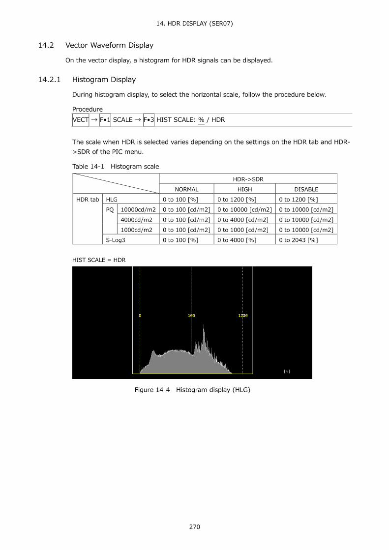
14. HDR DISPLAY (SER07)
270
14.2 Vector Waveform Display
On the vector display, a histogram for HDR signals can be displayed. 14.2.1 Histogram Display
During histogram display, to select the horizontal scale, follow the procedure below.
Procedure VECT → F•1 SCALE → F•3 HIST SCALE: % / HDR
The scale when HDR is selected varies depending on the settings on the HDR tab and HDR->SDR of the PIC menu.
Table 14-1 Histogram scale
HDR->SDR NORMAL HIGH DISABLE
HDR tab HLG 0 to 100 [%] 0 to 1200 [%] 0 to 1200 [%] PQ 10000cd/m2 0 to 100 [cd/m2] 0 to 10000 [cd/m2] 0 to 10000 [cd/m2]
4000cd/m2 0 to 100 [cd/m2] 0 to 4000 [cd/m2] 0 to 10000 [cd/m2] 1000cd/m2 0 to 100 [cd/m2] 0 to 1000 [cd/m2] 0 to 10000 [cd/m2]
S-Log3 0 to 100 [%] 0 to 4000 [%] 0 to 2043 [%]
HIST SCALE = HDR
Figure 14-4 Histogram display (HLG)

14. HDR DISPLAY (SER07)
271
14.3 Picture Display
On the picture display, CINELITE and CINEZONE for HDR signals can be displayed. During HDR measurement F•4 CINELITE of the PIC menu changes to F•4 CINELITE/HDR. You can use this to display CINELITE and CINEZONE.
PIC → F•4 CINELITE/HDR →
Figure 14-5 CINELITE/HDR menu
14.3.1 Turning Brightness Information On and Off
If ON is selected in the following procedure, the maximum brightness (MAX), minimum brightness (MIN), and average brightness (AVG) are displayed at the top of the screen. In addition, on the CINEZONE display, the HDR equivalents of the display color settings are displayed in the upper left corner of the screen.
Procedure PIC → F•4 CINELITE/HDR → F•2 HDR->SDR SETUP → F•5 BRIGHTNESS INFO: OFF / ON (Normal display) → F•2 f Stop SETUP → F•5 BRIGHTNESS INFO: OFF / ON (f Stop screen) → F•2 %DISPLAY SETUP → F•5 BRIGHTNESS INFO: OFF / ON (%DISPLAY screen) → F•2 CINEZONE SETUP → F•5 BRIGHTNESS INFO: OFF / ON (CINEZONE display)
BRIGHTNESS INFO = ON
Figure 14-6 Turning brightness information on and off

14. HDR DISPLAY (SER07)
272
14.3.2 Selecting the SDR Conversion Format
To select the conversion format for converting HDR signals to SDR signals, follow the procedure below.
Procedure PIC → F•4 CINELITE/HDR → F•3 HDR->SDR: NORMAL / HIGH / DISABLE
Settings
NORMAL: HDR signals are converted into linear signals, and the SDR area is displayed. This option cannot be selected for CINEZONE display. This cannot be selected when 5-bar display, gamut error display on the picture, gamut error display on the status, composite gamut error display, luminance level error, or chrominance level error turns on.
HIGH: HDR signals are converted into linear signals, and all areas are displayed. However, if STANDARD on the HDR tab is PQ, brightness up to the level specified by HDR->SDR HIGH UPPER LIMIT is displayed. This option cannot be selected for CINEZONE display. This cannot be selected when 5-bar display, gamut error display on the picture, gamut error display on the status, composite gamut error display, luminance level error, or chrominance level error turns on.
DISABLE: The HDR signal is displayed as-is.
HDR->SDR = NORMAL

14. HDR DISPLAY (SER07)
273
HDR->SDR = HIGH
HDR->SDR = DISABLE
Figure 14-7 Selecting the SDR conversion format

14. HDR DISPLAY (SER07)
274
14.3.3 f Stop Screen
In the f Stop display of HDR signal, HLG, PQ, or S-Log3 is displayed for GAMMA in the upper left corner of the screen depending on the standard selected with STANDARD on the HDR tab. In addition, even if the brightness level is 80% or higher, measured values are displayed in white, not yellow.
Figure 14-8 f Stop screen
14.3.4 %DISPLAY Screen
On the %DISPLAY of HDR signals, to display measured values for HDR signals, follow the procedure below. In addition, even if the brightness level is 80% or higher or 0% or lower, measured values are displayed in white, not yellow.
Procedure PIC → F•4 CINELITE/HDR → F•2 %DISPLAY SETUP → F•4 UNIT SELECT: HDR
Figure 14-9 %DISPLAY screen

14. HDR DISPLAY (SER07)
275
14.3.5 CINEZONE Display
On the CINEZONE display of HDR signals, to display the SDR area in monochrome and HDR area in color, follow the procedure below to select ON. Note that if F•5 HDR ZONE is set to ON, STEP and SEARCH cannot be selected for F•1 CINEZONE FORM.
Procedure PIC → F•4 CINELITE/HDR → F•5 HDR ZONE: ON / OFF
HDR ZONE = OFF
HDR ZONE = ON
Figure 14-10 CINEZONE display

14. HDR DISPLAY (SER07)
276
To set the display colors, follow the procedure below. If you set REF at boundary of the SDR area and HDR area, the SDR area can be displayed in monochrome and HDR area in color.
UPPER or higher: magenta REF or higher, UPPER or lower: Gradation from blue to red LOWER or higher, REF or lower: monochrome LOWER or lower: black
Procedure PIC → F•4 CINELITE/HDR → F•2 CINEZONE SETUP → F•2 UPPER → F•3 LOWER → F•4 REF
The values vary depending on the HDR tab settings as follows. Set the values as percentages of the input video level. If F•5 BRIGHTNESS INFO is set to ON, HDR equivalent values are displayed in the upper left corner of the screen.
Table 14-2 Display color values
Setting range UPPER Default LOWER Default REF Default HDR tab HLG 0.0 to 100.0 100.0 0.0 50.0
PQ 10000cd/m2 0.0 to 100.0 100.0 0.0 50.8 4000cd/m2 0.0 to 100.0 90.0 0.0 50.8 1000cd/m2 0.0 to 100.0 75.2 0.0 50.8
S-Log3 3.5 to 109.4 100.0 3.5 61.0

15. AUDIO DISPLAY
277
15. AUDIO DISPLAY To display audio, press AUDIO.
On the audio display, embedded audio signals applied to SDI INPUT and external audio signals applied to DIGITAL AUDIO INPUT can be measured. DIGITAL AUDIO INPUT can be used as output terminals by switching AUDIO IN/OUT in the system settings.
When measuring embedded audio, switching to simul mode enables SDI inputs A to D to be displayed in combination with the audio. (They can be displayed even if F•1 1A(2A) to F•4 1D(2D) on the INPUT menu are set to OFF.)
Figure 15-1 Audio display
● Indicators (option)
During Dolby E measurement, set Dolby E LINE POSITION on the DOLBY SETTING tab to ON to display the frame location value with a line and ▲ below the Lissajous and surround displays. These are normally shown in cyan, but when the value exceeds the specified threshold, they turn red.
● pgmcfg, acmod (option)
During Dolby measurement, the program configuration and audio configuration mode are displayed in the upper right of the screen.

15. AUDIO DISPLAY
278
● Src
The Src line in the lower right of the display shows the following information in order from the left.
Table 15-1 Src explanation
Display Description Reference 1. Input signal display AES Dolby off 15.1
DE Dolby E (option) DD Dolby Digital (option) DDP Dolby Digital Plus (option)
2. Meter response model display TRUE PEAK / PPM(I) / PPM(II) / VU+TRUE / VU+PPM(I) / VU+PPM(II)
- 0
3. Measurement signal display EMB Embedded audio 15.1 AES External audio

15. AUDIO DISPLAY
279
15.1 Setting the Signals to Measure
To set the signal to measure, follow the procedure below. Here you can select input signals and assign channels.
Procedure AUDIO → F•1 MAPPING
Figure 15-2 AUDIO MAPPING tab

15. AUDIO DISPLAY
280
Table 15-2 AUDIO MAPPING tab explanation
Item Description INPUT Set the input signal to SDI or EXT AUDIO.
If both Audio BNC settings are set to Output in the system settings, you cannot select EXT AUDIO. SDI: The embedded audio signal applied to SDI INPUT is measured. EXT AUDIO: The external audio signal applied to DIGITAL AUDIO INPUT is measured.
3G-B STREAM SELECT If INPUT is set to SDI, select the 3G-B stream. This is invalid when the input signal is not 3G-B.
LINK SELECT If INPUT is set to SDI and multi link or 12G is used, select the link. DOLBY (option)
During single input mode, turn the Dolby signal measurement on or off. When turned on, Dolby E, Dolby Digital and Dolby Digital Plus are automatically detected and measured.
MIX (option)
When DOLBY is set to ON, turn mix mode on or off. For details, see the next section, “Mix mode.”
DECODE CH GROUP (option)
When DOLBY is set to ON, select the decode channel. If INPUT is set to SDI and MIX is set to OFF, CH9/10 to CH15/16 cannot be selected.
CH MODE Select the number of measurement channels. If INPUT is set to EXT AUDIO and if either Audio BNC setting is set to Output in the system settings, you cannot select 16ch.
GROUP SELECT Select the audio group. If INPUT is set to SDI in simul mode, also select the input channel. (G1: 1 to 4ch, G2: 5 to 8ch, G3: 9 to 12ch, G4: 13 to 16ch)
EXT AUDIO INPUT GROUP If INPUT is set to EXT AUDIO and if both Audio BNC settings are set to Input in the system settings, select the input group.
LISSAJOU MAPPING Assign channels from the audio group selected with GROUP SELECT and Lt and Rt (excluding some channels).
SURROUND Assign channels from the audio group selected with GROUP SELECT. PHONES Assign channels from the audio group selected with GROUP SELECT
and Lt and Rt (excluding some channels).

15. AUDIO DISPLAY
281
● Mix mode
Mix mode is a feature that simultaneously displays the audio signal before decoding and the Dolby signal after decoding. The measurement signal varies as follows depending on the INPUT and MIX settings.
• When INPUT is set to SDI and MIX is set to OFF
Channels selected using DECODE CH GROUP are decoded and displayed as channels D1 to D8.
Figure 15-3 EMB Dolby display
• When INPUT is set to SDI and MIX is set to ON
The left half shows the embedded audio signals of the channels selected with GROUP SELECT. The right half shows channels D1 to D8, which are the decoded signals of the channels selected using DECODE CH GROUP.
Figure 15-4 EMB Dolby display (MIX)

15. AUDIO DISPLAY
282
• When INPUT is set to EXT AUDIO and MIX is set to OFF
Channels selected using DECODE CH GROUP are decoded and displayed as channels D1 to D8.
Figure 15-5 AES Dolby display
• When INPUT is set to EXT AUDIO and MIX is set to ON
The left half shows the external audio signals of the group selected with EXT AUDIO INPUT GROUP. The right half shows channels D1 to D8, which are the decoded signals of the channels selected using DECODE CH GROUP.
Figure 15-6 AES Dolby display (MIX)

15. AUDIO DISPLAY
283
15.2 Configuring the Dolby Settings (option)
When DOLBY is set to ON, to configure the Dolby settings, follow the procedure below.
Procedure AUDIO → F•1 MAPPING → F•3 MAPPING
Figure 15-7 DOLBY SETTING tab
Table 15-3 DOLBY SETTING tab explanation
Item Description Dolby E ONAIR MODE Turn ONAIR MODE on or off.
DRC MAIN CH Select DRC. DRC AUX CH Select auxiliary DRC. Dolby E LINE POSITION Turns the frame location indicator display on and off. SELECT Select the type of frame location threshold value.
The lower limit (EARLIEST) and upper limit (LATEST) when VALID or IDEAL is selected automatically change depending on the format. If you select CUSTOM, you can specify a value between 8 and 105.
AC-3 (Dolby Digital)
DRC MAIN CH Select DRC. DRC AUX CH Select auxiliary DRC. Pro Logic Turn Pro Logic II on or off. DOWNMIX Select the downmix mode.

15. AUDIO DISPLAY
284
15.3 Selecting the Display Mode
To select the display mode, follow the procedure below.
Procedure AUDIO → F•2 DISPLAY MODE: LISSAJOU / METER / SURROUND / STATUS
Settings
LISSAJOU: The Lissajous curves are displayed. During 8-channel measurement, audio meters are also displayed.
METER: The audio meters are displayed. This option cannot be selected during 8-channel measurement.
SURROUND: The surround display is shown on the left side of the screen, and the audio meter is displayed on the right side of the screen. This option cannot be selected in simul mode when measuring 16 channels or embedded audio.
STATUS: The status is displayed. During 8-channel measurement, audio meters are also displayed.
DISPLAY MODE = LISSAJOU

15. AUDIO DISPLAY
285
DISPLAY MODE = METER
DISPLAY MODE = SURROUND
DISPLAY MODE = STATUS
Figure 15-8 Selecting the display mode

15. AUDIO DISPLAY
286
15.4 Configuring Error Detection Settings
To configure the error detection and meter display settings, follow the procedure below.
Procedure AUDIO → F•5 ERROR SETUP
Figure 15-9 ERROR SETUP tab
Table 15-4 ERROR SETUP tab explanation
Item Description AUDIO ERROR SETUP Turn the error detection on or off.
When error detection is set to ON, the following actions are performed when an error occurs. • Counts errors on the status display • Displays errors in the event log of the status display
METER INDICATION
Clip If Clip is set to ON, turn on or off the CLIP display that appears when errors occur.
Mute If Mute is set to ON, turn on or off the MUTE display that appears when errors occur.
Dolby E Acmod (option)
During Dolby E measurement, turn on or off the NOT USE display that appears when LFEch is not used.

15. AUDIO DISPLAY
287
15.5 Adjusting the Volume
To adjust the headphone volume, follow the procedure below. Press the function dial (F•D) to return the setting to its default value (0).
Procedure AUDIO → F•7 PHONES VOLUME: 0 - 63
15.6 Meter Display
Meters are always displayed excluding the Lissajous display and status display during 16-channel management. To configure meter display settings, press F•3 METER SETUP on the AUDIO menu.
AUDIO → F•3 METER SETUP →
Figure 15-10 Meter display
15.6.1 Selecting the Scale
To select the meter's scale, follow the procedure below.
Procedure AUDIO → F•3 METER SETUP → F•1 DYNAMIC RANGE: 60DBFS / 90DBFS / MAG
Settings
60DBFS: The meter's scale is set to -60 to 0 (dBFS). 90DBFS: The meter's scale is set to -90 to 0 (dBFS). MAG: The meter's scale is set to the level specified by F•5 LEVEL SETTING →
F•3 REF dBFS ±3 dB.

15. AUDIO DISPLAY
288
15.6.2 Selecting the Response Model
To select the meter's response model, follow the procedure below. The selected response model is indicated in the lower right of the screen.
Procedure AUDIO → F•3 METER SETUP → F•2 RESPONSE: TRUEPEAK / PPM / VU → F•3 PPM MODE: PPM(I) / PPM(II) (for PPM) → F•3 PEAK METER: TRUE / PPM(I) / PPM(II) (for VU)
The response model details are shown in the following table.
Table 15-5 Response model settings
F•2 RESPONSE F•3 PPM MODE / F•3 PEAK METER
Display Delay time (*1)
Return time (*2)
Average time
TRUEPEAK - TRUE PEAK 0 msec 1.7 sec - PPM PPM(I) PPM(I) 10 msec 1.7 sec -
PPM(II) PPM(II) 10 msec 2.8 sec - VU TRUE VU+TRUE - - 300 msec
PPM(I) VU+PPM(I) - - 300 msec PPM(II) VU+PPM(II) - - 300 msec
*1 The amount of time it takes for the meter to show -20 dBFS when a -20 dBFS/1 kHz sine-wave signal
is applied with no input preceding it. *2 The amount of time it takes for the meter to show -40 dBFS when a -20 dBFS/1 kHz sine-wave signal
is removed from the input. 15.6.3 Setting the Peak Hold
When F•2 RESPONSE is set to VU, to set the peak hold time, follow the procedure below. The unit is seconds. You can set the value in 0.5-second steps. Press the function dial (F•D) to return the setting to its default value (0.5).
Procedure AUDIO → F•3 METER SETUP → F•4 PEAK HOLD: 0.0 - 0.5 - 5.0 / HOLD

15. AUDIO DISPLAY
289
15.6.4 Setting the Reference Level
To set the reference level, press F•5 LEVEL SETTING on the METER SETUP menu.
AUDIO → F•3 METER SETUP → F•5 LEVEL SETTING →
Figure 15-11 LEVEL SETTING menu
To set the meter reference level, follow the procedure below. OVER dBFS: Set the threshold level for audio level errors. WARNING dBFS: The portion of the meter that exceeds the level specified here is
displayed in red. The portion of the meter below this level is displayed in yellow.
REF dBFS: The portion of the meter that exceeds the level specified here is displayed in yellow. The portion of the meter below this level is displayed in green.
Procedure AUDIO → F•3 METER SETUP → F•5 LEVEL SETTING → F•1 OVER dBFS: -40.0 - 0.0 → F•2 WARNING dBFS: -40.0 - -18.0 - 0.0 → F•3 REF dBFS: -40.0 - -20.0 - 0.0

15. AUDIO DISPLAY
290
15.7 Lissajous Display
To display Lissajous curves, set F•2 DISPLAY MODE on the AUDIO menu to LISSAJOU. To configure the Lissajous display settings, press F•4 LISSAJOU SETUP. This setting is available when F•2 DISPLAY MODE is set to LISSAJOU.
AUDIO → set F•2 DISPLAY MODE to LISSAJOU → F•4 LISSAJOU SETUP →
Figure 15-12 Lissajous display
● Correlation Meter
The correlation meter indicates the phase difference between the two signals. A reading of +1 indicates that the signals are in-phase, a reading of -1 indicates that the signals are 180 ° out of phase, and a reading of 0 indicates that the signals are not correlated.
15.7.1 Adjusting the Lissajous Curve Intensity
To set the Lissajous curve intensity, follow the procedure below. Press the function dial (F•D) to return the setting to its default value (0).
Procedure AUDIO → F•4 LISSAJOU SETUP → F•1 LISSAJOU INTEN: -8 - 0 - 7
15.7.2 Adjusting the Scale Intensity
To adjust the intensity of the Lissajous and meter scales, follow the procedure below. Press the function dial (F•D) to return the setting to its default value (4).
Procedure AUDIO → F•4 LISSAJOU SETUP → F•2 SCALE INTEN: -8 - 4 - 7

15. AUDIO DISPLAY
291
15.7.3 Selecting the Lissajous Curve Display Format
To select the Lissajous curve display format, follow the procedure below.
Procedure AUDIO → F•4 LISSAJOU SETUP → F•3 DISPLAY: MULTI / SINGLE
Settings
MULTI: Eight channels of Lissajous waveforms and eight channels of audio meters are displayed or 16 channels of Lissajous waveforms are displayed.
SINGLE: Two channels of Lissajous waveforms and eight channels of audio meters are displayed. This option cannot be selected in simul mode or 16-channel measurement.
DISPLAY = MULTI
DISPLAY = SINGLE
Figure 15-13 Selecting the Lissajous curve display format

15. AUDIO DISPLAY
292
15.7.4 Selecting the Scale Display Format
To select the scale display format, follow the procedure below.
Procedure AUDIO → F•4 LISSAJOU SETUP → F•4 FORM: X-Y / MATRIX
Settings
X-Y: R is assigned to the X-axis (horizontal), and L is assigned to the Y-axis (vertical).
MATRIX: The R and L axes are positioned at 45 ° angles to the X and Y axes.
FORM = X-Y FORM = MATRIX
Figure 15-14 Selecting the scale display format

15. AUDIO DISPLAY
293
15.7.5 Setting the Lissajous Curve Gain
To select the Lissajous curve gain, follow the procedure below.
Procedure AUDIO → F•4 LISSAJOU SETUP → F•5 AUTO GAIN: ON / OFF
Settings
ON: The gain is automatically adjusted so that the waveform fits the scale. OFF: The waveform is displayed with a fixed gain.
AUTO GAIN = ON AUTO GAIN = OFF
Figure 15-15 Setting the Lissajous curve gain

15. AUDIO DISPLAY
294
15.8 Surround Display
To show the surround display, set F•2 DISPLAY MODE on the AUDIO menu to SURROUND. To configure the surround display settings, press F•4 SURROUND SETUP. This setting is available when F•2 DISPLAY MODE is set to SURROUND.
AUDIO → set F•2 DISPLAY MODE to SURROUND → F•4 SURROUND SETUP →
Figure 15-16 Surround display
15.8.1 Adjusting the Surround Waveform Intensity
To adjust the surround waveform intensity, follow the procedure below. Press the function dial (F•D) to return the setting to its default value (4).
Procedure AUDIO → F•4 SURROUND SETUP → F•1 SURROUND INTEN: -8 - 4 - 7
15.8.2 Adjusting the Scale Intensity
To adjust the intensity of the surround and meter scales, follow the procedure below. Press the function dial (F•D) to return the setting to its default value (4).
Procedure AUDIO → F•4 SURROUND SETUP → F•2 SCALE INTEN: -8 - 4 - 7

15. AUDIO DISPLAY
295
15.8.3 Selecting the Surround Display Format
To select the surround display format, follow the procedure below.
Procedure AUDIO → F•4 SURROUND SETUP → F•3 SURROUND 5.1: NORMAL / PHANTOM
Settings
NORMAL: A waveform that combines Lch, Rch, Lsch, Rsch, and Cch (hard center) is displayed.
PHANTOM: A waveform that combines Lch, Rch, Lsch, Rsch, and phantom center and a Cch (hard center) waveform are displayed separately.
SURROUND 5.1 = NORMAL SURROUND 5.1 = PHANTOM
Figure 15-17 Selecting the surround display format
15.8.4 Setting the Surround Waveform Gain
To select the surround waveform gain, follow the procedure below.
Procedure AUDIO → F•4 SURROUND SETUP → F•5 AUTO GAIN: ON / OFF
Settings
ON: The gain is automatically adjusted so that the waveform fits the scale. OFF: The waveform is displayed with a fixed gain.

15. AUDIO DISPLAY
296
15.9 Status Display
To show the status display, set F•2 DISPLAY MODE on the AUDIO menu to STATUS. To configure the status display settings, press F•4 STATUS SETUP. This setting is available when F•2 DISPLAY MODE is set to STATUS.
AUDIO → set F•2 DISPLAY MODE to STATUS → F•4 STATUS SETUP →
Figure 15-18 Status display
15.9.1 Status Display Explanation
On the status display, the levels and the number of detected errors are displayed for the selected channels (up to 9999). Errors are only detected for the items that have been set to ON in section 15.4, “Configuring Error Detection Settings.”
● Channel
Displays audio channels. Each item below this item is displayed in two lines. The top line corresponds to the channel to the left of the slash, and the bottom line corresponds to the channel to the right of the slash.
● Level (dBFS)
Display audio levels numerically.
● Level Over
Displays the number of times the level is greater than equal to the OVER dBFS value set in section 15.6.4, “Setting the Reference Level.”
● Clip
Displays the number of times that a received signal exceeds the maximum signal value for the number of consecutive samples specified in section 15.4, “Configuring Error Detection Settings.”

15. AUDIO DISPLAY
297
● Mute
Displays the number of times that a mute signal exceeding the duration specified in section 15.4, “Configuring Error Detection Settings” is received.
● Parity Error
Counts the number of times that the input signal’s parity bit and the recalculated parity bit differ.
● Validity Error
Counts the number of times that the input signal’s validity bit is 1.
● CRC Error
Counts the number of times that the CRC of the channel status bits and the calculated CRC are different.
● Code Violation
Counts the number of times that the state of the input signal’s biphase modulation is abnormal.
● Reset
The time that has elapsed since F•6 ERROR RESET was pressed is displayed here.
In Dolby signal measurements, Frame Location (header position and mode) is displayed in addition to the number of detected errors. During external digital audio measurements, H and mode are not displayed.
Figure 15-19 Status display (Dolby E)

15. AUDIO DISPLAY
298
15.9.2 Event Log Display
To view the event log, follow the procedure below. This screen is the same as the event log screen of the status display. For details, see section 16.4, “Configuring Event Log Settings.”
Procedure AUDIO → F•4 STATUS SETUP → F•1 EVENT LOG
Figure 15-20 Event log

15. AUDIO DISPLAY
299
15.9.3 Metadata Display (Option)
● Dolby E Metadata Display
During Dolby E measurement, to view the metadata of the selected program number, follow the procedure below. To select the program number, press F•1 DOLBY PROGRAM.
Procedure AUDIO → F•4 STATUS SETUP → F•2 METADATA → F•1 DOLBY E METADATA
Figure 15-21 Dolby E metadata display
● Dolby E EBI Metadata Display
During Dolby E measurement, to view the EBI (Extended Bitstream Info) metadata of the selected program number, follow the procedure below. To select the program number, press F•1 DISPLAY PROGRAM.
Procedure AUDIO → F•4 STATUS SETUP → F•2 METADATA → F•2 EBI METADATA
Figure 15-22 Dolby E EBI metadata display

15. AUDIO DISPLAY
300
● Dolby Digital Metadata Display
During Dolby Digital measurement, to view the metadata, follow the procedure below.
Procedure AUDIO → F•4 STATUS SETUP → F•2 METADATA → F•1 DOLBY D METADATA
Figure 15-23 Dolby Digital metadata display
● Dolby Digital EBI Metadata Display
During Dolby Digital measurement, to view the EBI (Extended Bitstream Info) metadata, follow the procedure below.
Procedure AUDIO → F•4 STATUS SETUP → F•2 METADATA → F•2 EBI METADATA
Figure 15-24 Dolby Digital EBI metadata display

15. AUDIO DISPLAY
301
● Dolby Digital Plus Metadata Display
During Dolby Digital Plus measurement, to view the metadata, follow the procedure below.
Procedure AUDIO → F•4 STATUS SETUP → F•2 METADATA → F•1 DOLBY D+ METADATA
Figure 15-25 Dolby Digital Plus metadata display
● Dolby Digital Plus EBI Metadata Display
During Dolby Digital Plus measurement, to view the EBI (Extended Bitstream Info) metadata, follow the procedure below.
Procedure AUDIO → F•4 STATUS SETUP → F•2 METADATA → F•2 EBI METADATA
Figure 15-26 Dolby Digital Plus EBI metadata display
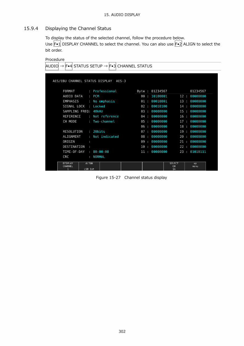
15. AUDIO DISPLAY
302
15.9.4 Displaying the Channel Status
To display the status of the selected channel, follow the procedure below. Use F•1 DISPLAY CHANNEL to select the channel. You can also use F•2 ALIGN to select the bit order.
Procedure AUDIO → F•4 STATUS SETUP → F•3 CHANNEL STATUS
Figure 15-27 Channel status display

15. AUDIO DISPLAY
303
15.9.5 Displaying User Bits
To display the user bits of the selected channel, follow the procedure below. Use F•1 DISPLAY CHANNEL to select the channel. You can also use F•2 ALIGN to select the bit order.
Procedure AUDIO → F•4 STATUS SETUP → F•4 USER BIT
Figure 15-28 User bit display
15.9.6 Resetting Errors
To reset the error counts that appear on the audio status display to 0, follow the procedure below. Also, the Reset indication at the lower left of the screen will be reset to 00:00:00.
Procedure AUDIO → F•4 STATUS SETUP → F•5 ERROR RESET

16. STATUS DISPLAY
304
16. STATUS DISPLAY To display the status, press STATUS.
If on the SDI IN tab in the system settings, SDI System is set to 4K NMI or NMI, pressing STATUS displays the IP (NMI) status. Reference Section 16.10, “IP(NMI) Status Screen Explanation (SER08)”
To return to the normal status display from IP (NMI) status, press F•1 STATUS. To return to the IP (NMI) status again, press F•2 SDI ANALYSIS and then F•3 NMI INFO.
Figure 16-1 Status display
16.1 Status Screen Explanation
● SIGNAL
If the LV 5490SER01 or LV 5490SER02 is receiving an SDI signal, “DETECT” is displayed. Otherwise, “NO SIGNAL” is displayed. If “NO SIGNAL” is displayed, the following items are not displayed.
● FORMAT/SUB IMAGE FORMAT
The input signal format is indicated here. It is normally displayed in light blue, but if the input is not appropriate, it turns red.
● Freq
The sampling frequency deviation is displayed. Normally, this is displayed in light blue. If Frequency Error on the ERROR SETUP1 tab is set to ON, the color changes to red when ±10 ppm is exceeded. The display range is “<-100 ppm, -100 to +100 ppm, >+100 ppm,” and the accuracy is ±2 ppm. Reference ERROR SETUP1 tab → section 16.2.1, “Error Setup 1”

16. STATUS DISPLAY
305
● Cable (1A to 1D on the SER01/SER02 only)
The input signal attenuation is converted into a cable length that you selected and displayed. Normally the value is displayed in light blue, but by setting Cable Error on the ERROR SETUP1 tab to ON, if the value exceeds the specified Warning value, it will change to yellow. If the value exceeds the Error value, it will change to red. The display range is shown below. The accuracy is ±20 m.
3G: < 10 m, 10 to 105 m, > 105 m (5 m steps) HD: < 5 m, 5 to 130 m, > 130 m (5 m steps) SD: < 50 m, 50 to 300 m, > 300 m (5 m steps)
Reference ERROR SETUP1 tab → section 16.2.1, “Error Setup 1”
● Embedded Audio
The channels of the audio packets embedded in the input signal are displayed here. If the input signal is 3G-B-DL, only stream 1 is displayed. (When measuring 3G-B-DS, stream 2 is also displayed.)
● ERROR
The counts of the errors for the items whose detection setting was set to ON with F•5 STATUS SETUP are displayed here. Errors are counted once per second or once per field. The maximum number of errors that can be counted is 999999. Switching video formats or input channels may cause disturbances in the signal that will cause errors to be detected.
• CRC (Other than SD)
An error is counted when the CRC embedded in the input signal is different from the CRC that the LV 5490 detects.
• EDH (SD only)
An error is counted when the EDH packet contains an ancillary data error flag, an active picture error flag, or a full-field error flag and when the CRC in the EDH packet is different from the CRC that the LV 5490 calculates from the video data.
• TRS Pos
Input signal TRS (Timing Reference Signal) errors are displayed here. An error is counted when the EAV (End of Active Video) and SAV (Start of Active Video) header word (3FFh, 000h, and 000h) locations are wrong and when the F, V, and H TRS protection bits do not conform to the video standard.
• TRS Code
Input signal TRS (Timing Reference Signal) protection bit errors are displayed here. An error is counted when the F, V, and H protection bits in the XYZ word in the EAV (End of Active Video) and SAV (Start of Active Video) packets and the response to the P3, P2, P1, and P0 error correction flags do not conform to the video standard.

16. STATUS DISPLAY
306
• ILLEGAL Code
An error is counted when the input signal data falls within the timing reference signal (TRS) range or 000h to 003h and 3FCh to 3FFh are detected in the data other than those specified by the ancillary data flag (ADF). In SDI signals, 10-bit levels 000h through 003h and 3FCh through 3FFh are reserved for the timing reference signal and the ancillary data flag, so they cannot be used for video signal data or ancillary data. When data other than TRS and ADF data is found in these bits, an error is counted.
• Line Number (Other than SD)
An error is counted when the line number that is embedded in the input signal does not match the line number that has been counted by the LV 5490.
• Check Sum
The LV 5490 uses the checksum in the input signal's ancillary data header to count errors.
• Parity
The LV 5490 uses the parity bit in the input signal's ancillary data header to count errors.
• BCH (Other than SD)
Errors in the BCH code in the input signal's embedded audio are displayed here.
• Parity (Other than SD)
Parity errors in the input signal's embedded audio are displayed here.
• DBN
Continuity errors in the input signal's embedded audio are displayed here. Embedded audio packets contain data block number (DBN) words that indicate the packet's continuity. Packets are cyclically numbered from 1 to 255. An error is counted when a packet's DBN is out of sequence.
• Inhibit
An error is counted when embedded audio packets are found in lines where they should not be embedded. The embedding inhibit lines are as follows. However, for 3G-B-DL 60p, 59.94p, 50p, 48p, and 47.95p, the transmission scanning mode is interlace.
Table 16-1 Embedding Inhibit Lines
Format Transmission Scanning Mode Progressive Interlace
HD/3G 1280×720 Line 8 - 1920×1080 Line 8 Lines 8, 570
SD 720×487 - Lines 11, 274 720×576 - Lines 7, 320

16. STATUS DISPLAY
307
● Audio Sample
An error is counted when audio that is asynchronous to the video is embedded. For the video and audio to be synchronized, there is a specific number of audio data samples that need to be embedded in a given number of video frames. If this rule is not met, it is considered an error.
● Freeze
An error is counted when the video data is the same between video frames. Specify an area of the video to use for detection and the number of continuous frames that is required for the condition to be detected as an error. Video data is compared using checksums.
● Black
An error is counted when the video luminance level is less than the specified value. Set the luminance level for detecting error pixels, the ratio of error pixels in a frame, and the number of continuous frames that is required for the condition to be detected as an error.
● Gamut
Gamut errors are counted. Set the upper and lower limits for detecting errors, the ratio of error pixels in a frame, and the number of continuous frames that is required for the condition to be detected as an error.
● Comp Gamut
Composite gamut errors are counted. Set the upper and lower limits for detecting errors, the ratio of error pixels in a frame, and the number of continuous frames that is required for the condition to be detected as an error.
● Level Y
An error is counted when the luminance level is outside the specified range. Set the upper and lower limits for detecting errors.
● Level C
An error is counted when the chrominance level is outside the specified range. Set the upper and lower limits for detecting errors.
● SinceReset
The time that has elapsed since F•7 ERROR CLEAR was pressed, the LV 5490 was initialized, or the LV 5490 was restarted is displayed here.

16. STATUS DISPLAY
308
16.2 Configuring Error Detection Settings
To configure the error detection settings, use F•5 STATUS SETUP. When error detection is set to ON, the following actions are performed when an error occurs. • Counts errors on the status display. • Displays errors in the event log of the status display • Displays “ERROR” in the upper-right of the display. • Transmits a signal from the alarm output remote terminal
16.2.1 Error Setup 1
Use the ERROR SETUP1 tab to configure error detection settings for SDI signals.
STATUS → F•5 STATUS SETUP →
Figure 16-2 ERROR SETUP1 tab
● Error Counter
Sec: Errors are counted in units of seconds. Even if multiple errors occur within the same second, only a single error is counted.
Field: Errors are counted in units of fields (frames). Even if multiple errors occur within the same field (frame), only a single error is counted.
● TRS Error
Select whether to detect TRS Pos and TRS Code errors.
OFF / ON
● Line Number Error(Except SD)
Select whether to detect line number errors. This setting is valid when the input signal is not SD.
OFF / ON

16. STATUS DISPLAY
309
● CRC Error(Except SD)
Select whether to detect CRC errors. This setting is valid when the input signal is not SD.
OFF / ON
● EDH Error(SD)
Select whether to detect EDH errors. This setting is valid when the input signal is SD.
OFF / ON
● Illegal Code Error
Select whether to detect illegal code errors.
OFF / ON
● Frequency Error
Select whether to detect frequency deviation errors. Even when this is set to OFF, the frequency deviation is still shown in the status display.
OFF / ON
● Cable Error
Select whether to detect cable errors. Even when this is set to OFF, the cable length is still shown in the status display.
OFF / ON
● 3G Cable
Select the cable to use for cable length measurements when the input signal is 3G.
LS-5CFB / 1694A
● 3G Cable Error
Set the upper limit for the cable error when the input signal is 3G. If this value is exceeded, an error will occur, and the measured value on the status display will be displayed in red.
10 - 105 m
● 3G Cable Warning
Set the upper limit for the cable warning when the input signal is 3G. If this value is exceeded, a warning will occur, and the measured value on the status display will be displayed in yellow.
10 - 105 m
● HD Cable
Select the cable to use for cable length measurements when the input signal is HD.
LS-5CFB / 1694A

16. STATUS DISPLAY
310
● HD Cable Error
Set the upper limit for the cable error when the input signal is HD. If this value is exceeded, an error will occur, and the measured value on the status display will be displayed in red.
5 - 130 m
● HD Cable Warning
Set the upper limit for the cable warning when the input signal is HD. If this value is exceeded, a warning will occur, and the measured value on the status display will be displayed in yellow.
5 - 130 m
● SD Cable
Select the cable to use for cable length measurements when the input signal is SD.
L-5C2V / 8281
● SD Cable Error
Set the upper limit for the cable error when the input signal is SD. If this value is exceeded, an error will occur, and the measured value on the status display will be displayed in red.
50 - 300 m
● SD Cable Warning
Set the upper limit for the cable warning when the input signal is SD. If this value is exceeded, a warning will occur, and the measured value on the status display will be displayed in yellow.
50 - 300 m
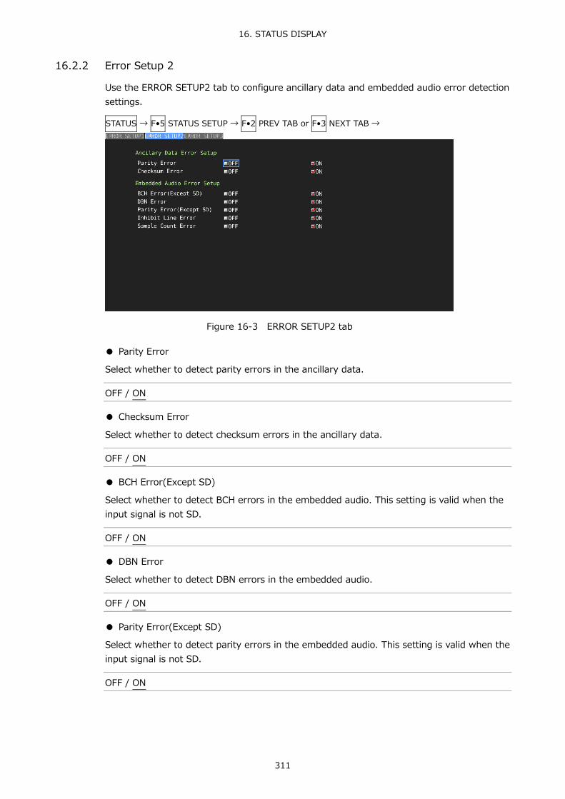
16. STATUS DISPLAY
311
16.2.2 Error Setup 2
Use the ERROR SETUP2 tab to configure ancillary data and embedded audio error detection settings.
STATUS → F•5 STATUS SETUP → F•2 PREV TAB or F•3 NEXT TAB →
Figure 16-3 ERROR SETUP2 tab
● Parity Error
Select whether to detect parity errors in the ancillary data.
OFF / ON
● Checksum Error
Select whether to detect checksum errors in the ancillary data.
OFF / ON
● BCH Error(Except SD)
Select whether to detect BCH errors in the embedded audio. This setting is valid when the input signal is not SD.
OFF / ON
● DBN Error
Select whether to detect DBN errors in the embedded audio.
OFF / ON
● Parity Error(Except SD)
Select whether to detect parity errors in the embedded audio. This setting is valid when the input signal is not SD.
OFF / ON

16. STATUS DISPLAY
312
● Inhibit Line Error
Select whether to detect embedding errors in the embedded audio.
OFF / ON
● Sample Count Error
Select whether to detect sample number errors in the embedded audio. An error is counted when audio that is asynchronous to the video is embedded. If a certain number of audio data samples are not embedded in a certain number of video frames, it will be considered and error (as defined in SMPTE ST 299 and SMPTE ST 272).
OFF / ON
16.2.3 Error Setup 3
Use the ERROR SETUP3 tab to configure gamut error settings.
STATUS → F•5 STATUS SETUP → F•2 PREV TAB or F•3 NEXT TAB →
Figure 16-4 ERROR SETUP3 tab
● LowPass Filter
Select the frequency response of the low-pass filter used for gamut error and composite gamut error detection. Set this to remove transient errors caused by overshoot and other anomalies.
HD/SD:1MHz / HD:2.8MHz SD:1MHz / OFF

16. STATUS DISPLAY
313
● Gamut Error
Select whether to detect gamut errors.
ON / OFF
● Gamut Upper
Set the gamut error upper limit. An error occurs when the input signal level exceeds the specified value. In the 5-bar GBR display, levels that are greater than or equal to the specified value are displayed in red.
90.8 - 109.4 %
● Gamut Lower
Set the gamut error lower limit. An error occurs when the input signal level goes below the specified value. In the 5-bar GBR display, levels that are less than or equal to the specified value are displayed in red.
-7.2 - 6.1 %
● Area
Specify the percentage of the active picture area over which errors must occur to be recognized as an error. You cannot configure this setting when Gamut Error is set to OFF.
0.0 - 1.0 - 5.0 %
● Duration
Set the number of consecutive video frames over which errors must occur to be recognized as an error. You cannot configure this setting when Gamut Error is set to OFF.
1 - 60 Frames
● Composite Gamut Error
Select whether to detect composite gamut errors.
ON / OFF
● Setup
Select the setup level to add when converting component signals to composite signals.
0%: No setup level is added. 7.5%: A setup level of 7.5 % is added.

16. STATUS DISPLAY
314
● Composite Upper
Set the composite gamut error upper limit. An error occurs when the input signal level exceeds the specified value. In the 5-bar CMP display, levels that are greater than or equal to the specified value are displayed in red.
90.0 - 135.0 %
● Composite Lower
Set the composite gamut error lower limit. An error occurs when the input signal level goes below the specified value. In the 5-bar CMP display, levels that are less than or equal to the specified value are displayed in red.
-40.0 - 20.0 %
● Area
Specify the percentage of the active picture area over which errors must occur to be recognized as an error. You cannot configure this setting when Composite Gamut Error is set to OFF.
0.0 - 1.0 - 5.0 %
● Duration
Set the number of consecutive video frames over which errors must occur to be recognized as an error. You cannot configure this setting when Composite Gamut Error is set to OFF.
1 - 60 Frames

16. STATUS DISPLAY
315
16.2.4 Error Setup 4
Use the ERROR SETUP4 tab to configure freeze error, black error and level error settings.
Figure 16-5 ERROR SETUP4 tab
● Freeze Error
Select whether to detect freeze errors. If you set this to OFF, you cannot configure the following settings.
ON / OFF
● Area Upper, Area Lower, Area Left, Area Right
Set what percent of each active picture area (the upper, lower, left, and right areas) will not be subject to error detection.
0 to 100 %
● Duration
Set the number of consecutive video frames over which errors must occur to be recognized as an error.
2 to 300 frames

16. STATUS DISPLAY
316
● Black Error
Select whether to detect black errors. If you set this to OFF, you cannot configure the following settings.
ON / OFF
● Level
Set the black error level. Any signals that are less than or equal to the specified value will be detected as errors.
0 to 100 %
● Area
Specify the percentage of the active picture area over which errors must occur to be recognized as an error.
1 to 100 %
● Duration
Set the number of consecutive video frames over which errors must occur to be recognized as an error.
1 to 300 frames
● Level Error
Select whether to detect level errors. If you set this to OFF, you cannot configure the following settings.
ON / OFF
● Luminance Upper
Set the luminance level error upper limit. An error occurs when the input signal level exceeds the specified value. In the 5-bar Y display, levels that are greater than or equal to the specified value are displayed in red.
-51 – 766 mV
● Luminance Lower
Set the luminance level error lower limit. An error occurs when the input signal level goes below the specified value. In the 5-bar Y display, levels that are less than or equal to the specified value are displayed in red.
-51 – 766 mV

16. STATUS DISPLAY
317
● Chroma Upper
Set the chroma level error upper limit. An error occurs when the input signal level exceeds the specified value.
-400 – 399 mV
● Chroma Lower
Set the chroma level error lower limit. An error occurs when the input signal level goes below the specified value.
-400 – 399 mV
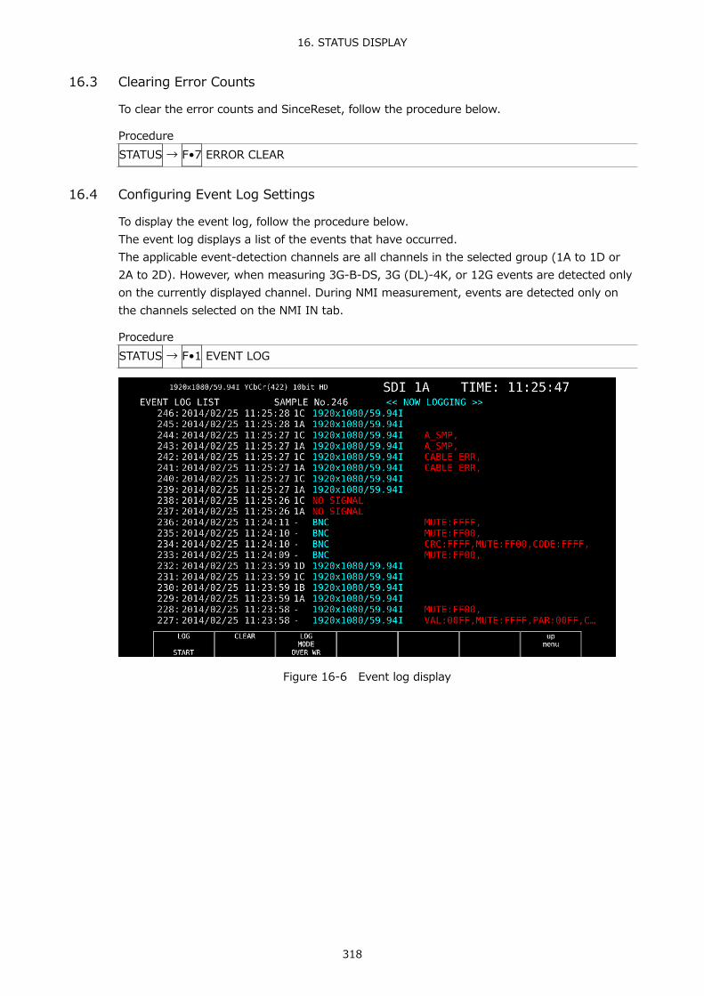
16. STATUS DISPLAY
318
16.3 Clearing Error Counts
To clear the error counts and SinceReset, follow the procedure below.
Procedure STATUS → F•7 ERROR CLEAR
16.4 Configuring Event Log Settings
To display the event log, follow the procedure below. The event log displays a list of the events that have occurred. The applicable event-detection channels are all channels in the selected group (1A to 1D or 2A to 2D). However, when measuring 3G-B-DS, 3G (DL)-4K, or 12G events are detected only on the currently displayed channel. During NMI measurement, events are detected only on the channels selected on the NMI IN tab.
Procedure STATUS → F•1 EVENT LOG
Figure 16-6 Event log display
16. STATUS DISPLAY
319
16.4.1 Event Log Screen Explanation
Events are listed on the event log screen by the time of their occurrence. Turn the function dial (F•D) to the right to scroll the screen and view older events in the log. Press the function dial (F•D) to display the latest events.
● Note
• When the same event occurs successively and when multiple events occur at the same time, they are treated as a single event.
• When multiple events occur at the same time, you may not be able to check all the events on the screen. When this happens, you can view all the events by saving them to a USB memory device.
• The event display is cleared when you turn the power off. • Switching video formats or input channels may cause disturbances in the signal that will
cause errors to be displayed.
● Time Display
The time is displayed in the format specified by Time that you select by pressing SYS and then F•2 SYSTEM SETUP.
● Channel Display
The input channel is displayed. A “-” is displayed for audio events detected by SER03. “N1/N2•N3/N4” is displayed for IP (NMI) input signal events detected by the SER08.
● Format Display
The input format is displayed. If there is no input signal, “NO SIGNAL” is displayed. “BNC” is displayed for external audio events detected by SER03.

16. STATUS DISPLAY
320
● Event Display
The events that are displayed in the event log are listed below. Of the items listed below, only those whose detection settings have been set to ON in
FORMAT ALARM tab of the SYS menu, STATUS SETUP of the STATUS menu, ERROR SETUP of the EYE menu, and ERROR SETUP of the AUDIO menu are displayed.
Table 16-2 Events
Applicable Unit Event Name Description SER01/SER02/SER06/SER08 FORMAT_ALARM Format Alarm
TRS_P TRS Position Error TRS_C TRS Code Error LINE Line Number Error(Except SD) CRC CRC Error(Except SD) EDH EDH Error(SD) ILLEGAL Illegal Code Error FREQ Frequency Error CABLE_ERR Cable Error CABLE_WAR Cable Warning PRTY Ancillary Data Parity Error CHK Ancillary Data Checksum Error A_BCH Embedded Audio BCH Error(Except SD) A_DBN Embedded Audio DBN Error A_PRTY Embedded Audio Parity Error(Except SD) A_INH Embedded Audio Inhibit Line Error A_SMP Embedded Audio Sample Count Error GMUT Gamut Error GMUT_ST1 Gamut Error Stream 1 GMUT_ST2 Gamut Error Stream 2 CGMUT Composite Gamut Error CGMUT_ST1 Composite Gamut Error Stream 1 CGMUT_ST2 Composite Gamut Error Stream 2 FRZ Freeze Error FRZ_ST1 Freeze Error Stream 1 FRZ_ST2 Freeze Error Stream 2 BLK Black Error BLK_ST1 Black Error Stream 1 BLK_ST2 Black Error Stream 2 LVL_Y Luminance Error LVL_Y_ST1 Luminance Error Stream 1 LVL_Y_ST2 Luminance Error Stream 2 LVL_C Chroma Error LVL_C_ST1 Chroma Error Stream 1 LVL_C_ST2 Chroma Error Stream 2
SER02/SER09 EYE_3G_AMP 3G Amplitude Error EYE_3G_TR 3G Risetime Error EYE_3G_TF 3G Falltime Error

16. STATUS DISPLAY
321
Applicable Unit Event Name Description EYE_3G_TR_TF 3G Deltatime Error(Tr-Tf) EYE_3G_T_JIT 3G Timing Jitter Error EYE_3G_A_JIT 3G Current Jitter Error EYE_3G_OR 3G OverShoot Rising Error EYE_3G_OF 3G OverShoot Falling Error EYE_HD_AMP HD Amplitude Error EYE_HD_TR HD Risetime Error EYE_HD_TF HD Falltime Error EYE_HD_TR_TF HD Deltatime Error(Tr-Tf) EYE_HD_T_JIT HD Timing Jitter Error EYE_HD_A_JIT HD Current Jitter Error EYE_HD_OR HD OverShoot Rising Error EYE_HD_OF HD OverShoot Falling Error EYE_SD_AMP SD Amplitude Error EYE_SD_TR SD Risetime Error EYE_SD_TF SD Falltime Error EYE_SD_TR_TF SD Deltatime Error(Tr-Tf) EYE_SD_T_JIT SD Timing Jitter Error EYE_SD_A_JIT SD Current Jitter Error EYE_SD_OR SD OverShoot Rising Error EYE_SD_OF SD OverShoot Falling Error
SER09 EYE_12G_AMP 12G Amplitude Error EYE_12G_TR 12G Risetime Error EYE_12G_TF 12G Falltime Error EYE_12G_TR_TF 12G Deltatime Error(Tr-Tf) EYE_12G_T_JIT 12G Timing Jitter Error EYE_12G_A_JIT 12G Current Jitter Error EYE_12G_OR 12G Overshoot Rising Error EYE_12G_OF 12G Overshoot Falling Error
SER03 OVER Level Over CLIP Clip MUTE Mute PAR Parity Error VAL Validity Error CRC CRC Error CODE Code Violation
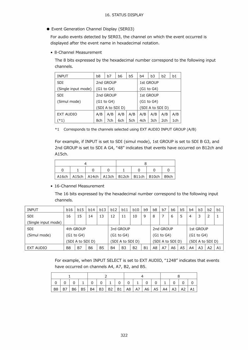
16. STATUS DISPLAY
322
● Event Generation Channel Display (SER03)
For audio events detected by SER03, the channel on which the event occurred is displayed after the event name in hexadecimal notation.
• 8-Channel Measurement
The 8 bits expressed by the hexadecimal number correspond to the following input channels.
INPUT b8 b7 b6 b5 b4 b3 b2 b1 SDI (Single input mode)
2nd GROUP (G1 to G4)
1st GROUP (G1 to G4)
SDI (Simul mode)
2nd GROUP (G1 to G4) (SDI A to SDI D)
1st GROUP (G1 to G4) (SDI A to SDI D)
EXT AUDIO (*1)
A/B 8ch
A/B 7ch
A/B 6ch
A/B 5ch
A/B 4ch
A/B 3ch
A/B 2ch
A/B 1ch
*1 Corresponds to the channels selected using EXT AUDIO INPUT GROUP (A/B)
For example, if INPUT is set to SDI (simul mode), 1st GROUP is set to SDI B G3, and 2nd GROUP is set to SDI A G4, “48” indicates that events have occurred on B12ch and A15ch.
4 8
0 1 0 0 1 0 0 0 A16ch A15ch A14ch A13ch B12ch B11ch B10ch B9ch
• 16-Channel Measurement
The 16 bits expressed by the hexadecimal number correspond to the following input channels.
INPUT b16 b15 b14 b13 b12 b11 b10 b9 b8 b7 b6 b5 b4 b3 b2 b1 SDI (Single input mode)
16 15 14 13 12 11 10 9 8 7 6 5 4 3 2 1
SDI (Simul mode)
4th GROUP (G1 to G4) (SDI A to SDI D)
3rd GROUP (G1 to G4) (SDI A to SDI D)
2nd GROUP (G1 to G4) (SDI A to SDI D)
1st GROUP (G1 to G4) (SDI A to SDI D)
EXT AUDIO B8 B7 B6 B5 B4 B3 B2 B1 A8 A7 A6 A5 A4 A3 A2 A1
For example, when INPUT SELECT is set to EXT AUDIO, “1248” indicates that events have occurred on channels A4, A7, B2, and B5.
1 2 4 8
0 0 0 1 0 0 1 0 0 1 0 0 1 0 0 0 B8 B7 B6 B5 B4 B3 B2 B1 A8 A7 A6 A5 A4 A3 A2 A1
16. STATUS DISPLAY
323
16.4.2 Starting the Event Log
To start the event log, follow the procedure below.
Procedure STATUS → F•1 EVENT LOG → F•1 LOG: START / STOP
Settings
START: The event log is started. “NOW LOGGING” appears in the upper right of the event log.
STOP: The event log is stopped. “LOGGING STOPPED” appears in the upper right of the event log.
16.4.3 Deleting the Event Log
To delete the event log, follow the procedure below.
Procedure STATUS → F•1 EVENT LOG → F•2 CLEAR
16.4.4 Selecting the Overwrite Mode
Up to 1000 events can be displayed. To select the action to perform when more than 1000 events occur, follow the procedure below.
Procedure STATUS → F•1 EVENT LOG → F•3 LOG MODE: OVER WR / STOP
Settings
OVER WR: Oldest events are overwritten. STOP: Additional events are not recorded.

16. STATUS DISPLAY
324
16.4.5 Saving to USB Memory
You can save the event log to a USB memory device as a text file. To save a file with a name that you specify, follow the procedure below.
1. Used to connect USB memory.
2. Press F•6 USB MEMORY.
The file list display appears. This setting appears when USB memory is connected.
Figure 16-7 File list display
3. Set F•1 AUTO FILENAME to OFF.
4. Press F•2 NAME INPUT.
The file name input display appears.
Figure 16-8 File name input screen

16. STATUS DISPLAY
325
5. Enter a file name using up to 14 characters.
The key operations that you can perform in the file name input display are as follows:
F•1 CLEAR ALL Deletes all characters F•2 DELETE Deletes the character at the cursor F•4 <= Moves the cursor to the left F•5 => Moves the cursor to the right F•6 CHAR SET Enters the character Function dial (F•D) Turn to select a character, and press to enter the character.
You can also copy the file name of an already saved file. To copy a file name, move the cursor to the file in the file list whose name you want to copy, and then press the function dial (F•D).
6. Press F•7 up menu.
7. Press F•3 STORE.
If a file with the same name that you have specified already exists on the USB memory device, an overwrite confirmation menu appears. To overwrite the current file, press F•1 OVER WR YES. To cancel the save operation, press F•3 OVER WR NO.
● Deleting an Event Log
To delete an event log that has been saved to the USB memory device, select the log file on the file list display, and then press F•4 FILE DELETE. To delete the file, press F•1 DELETE YES. To cancel the delete operation, press F•3 DELETE NO.
● Automatic File Name Generation
If you set F•1 AUTO FILENAME to ON, the file name will be generated automatically in the format “YYYYMMDDhhmmss” when you save the file. In this situation, F•2 NAME INPUT is not displayed.
● USB Memory Device Folder Structure
Event logs are saved in the LOG folder.
USB memory device └ LV5490_USER └ LOG └ YYYYMMDDhhmmss.txt
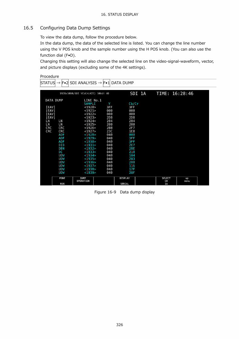
16. STATUS DISPLAY
326
16.5 Configuring Data Dump Settings
To view the data dump, follow the procedure below. In the data dump, the data of the selected line is listed. You can change the line number using the V POS knob and the sample number using the H POS knob. (You can also use the function dial (F•D). Changing this setting will also change the selected line on the video-signal-waveform, vector, and picture displays (excluding some of the 4K settings).
Procedure STATUS → F•2 SDI ANALYSIS → F•1 DATA DUMP
Figure 16-9 Data dump display

16. STATUS DISPLAY
327
16.5.1 Data Dump Display Explanation
● Detection Code Display
The input signal's embedded ancillary data is detected, and the following detection codes are displayed.
Table 16-3 Detection code list
Detection Code Color Description ADF Cyan Ancillary data flags (000h, 3FFh, and 3FFh) DID Cyan Data identification (the data after ADF) SDID Cyan Secondary data identification
(the secondary format data when the DID is smaller than 80h) DBN Cyan Data block numbers
(the primary data format when the DID is larger than 80h) DC Cyan Data count (the data after the SDID/DBN) UDW Cyan User data words (the user data words of the data count length after
ADF) CS Magenta Checksum (the data immediately after UDW) AP Yellow Active picture
(the active picture from after the SAV to just before the EAV when the selected line is within the active video area)
● Line Number Display
Pictures sent in SDI signals are assigned line numbers as part of the transmission format. The line number is displayed in one of the following formats at the top of the screen.
Table 16-4 Line number display
Line number display Description LINE No. The picture scan line numbers and the line numbers during
transmission are matched. I/F LINE No. The picture scan line numbers and the line numbers during
transmission are not matched. Line numbers during transmission are displayed.
PIC LINE No. The picture scan line numbers and the line numbers during transmission are not matched. Picture scan line numbers are displayed.

16. STATUS DISPLAY
328
Normally, the picture scan line numbers and the line numbers for storing those line numbers during transmission are matched. However, they do not match when the following format is received. If this is the case, you can switch between the picture scan line number (PICTURE) and line numbers during transmission.
Table 16-5 Format
Format Frame rate Switching operation 3G-B-DL 60/59.94/50/48/47.95/P F•4 DISPLAY (PICTURE/STREAM1/STREAM2) HD (DL) 60/59.94/50/48/47.95/P F•5 LINK (PICTURE/A/B) 3G (DL)-2K 60/59.94/50/48/47.95/P F•5 LINK (PICTURE/1/2)
As an example, the switching procedure for setting the picture scan line number to 42 when 3G-B-DL (1920×1080/59.94P) is applied is shown below.
1. Display the data dump. 2. Set F•4 DISPLAY to PICTURE. 3. Use the V POS knob to set PIC LINE No. to 42. 4. Set F•4 DISPLAY to STREAM1.
The line number display changes to I/F LINE No.21. This indicates that the line number in which the picture scan line number 42 is stored for transmission is 21.
The relationship of other 3G-B-DL line numbers is shown below.
Table 16-6 3G-B-DL line number relationship
Picture scan line number (PIC LINE No.)
Line number during transmission (I/F LINE No.)
PICTURE STREAM1 STREAM2 1 563 1125 2 1 563 n (odd number) (n+1)/2+562 (n-1)/2 m (even number) m/2 m/2+562

16. STATUS DISPLAY
329
16.5.2 Selecting the Display Mode
To select the data dump display mode, follow the procedure below.
Procedure STATUS → F•2 SDI ANALYSIS → F•1 DATA DUMP → F•1 MODE: RUN / HOLD / FRM CAP
Settings
RUN: The input signal data is automatically updated and displayed. HOLD: The input signal data is displayed statically. FRM CAP: The frame data is displayed. If frame data has not been captured in the
LV 5490, nothing is displayed. This setting can be selected in frame capture mode.
16.5.3 Selecting the Display Format
To select the data dump display format, follow the procedure below. This menu does not appear when F•5 LINK or F•5 SUB is set to PICTURE.
Procedure STATUS → F•2 SDI ANALYSIS → F•1 DATA DUMP → F•4 DISPLAY : SERIAL / COMPO / BINARY (for HD, SD, 3G-A, HD (QL), 3G-A of 3G (QL), 12G) : PICTURE / STREAM1 / STREAM2 (for 3G-B-DL, 3G-B-DL of 3G (QL)) : STREAM12 / STREAM1 / STREAM2 (for 3G-B-DL of 3G (DL)-2K) : S1 SERIAL / S1 COMPO / S1 BINARY / S2 SERIAL / S2 COMPO / S2 BINARY (for 3G (DL)-4K, 3G-B-DS)
Settings
SERIAL: The parallel converted data sequences are displayed. COMPO: The parallel converted data sequences are divided into each component
and displayed. BINARY: The parallel converted data sequences are displayed in binary. PICTURE: Links or streams 1 and 2 are combined and displayed in a picture
structure. STREAM1: Stream 1 is displayed. STREAM2: Stream 2 is displayed. STREAM12: Stream 1 and 2 are combined and displayed. S1 SERIAL: Stream 1 is displayed serially. S1 COMPO: Stream 1 is separated and displayed. S1 BINARY: Stream 1 is displayed in binary. S2 SERIAL: Stream 2 is displayed serially. S2 COMPO: Stream 2 is separated and displayed. S2 BINARY: Stream 2 is displayed in binary.

16. STATUS DISPLAY
330
DISPLAY = SERIAL
DISPLAY = COMPO
DISPLAY = BINARY
Figure 16-10 Selecting the display format

16. STATUS DISPLAY
331
16.5.4 Selecting the Displayed Information
When the link format is set to multi, to select which link to display the data dump of, follow the procedure below. Links or streams 1 and 2 are combined and displayed in a picture structure.
Procedure (Multi link) STATUS → F•2 SDI ANALYSIS → F•1 DATA DUMP → F•5 LINK : PICTURE / A[1A] / B[1B] / A[1C] / B[1D] / A[2A] / B[2B] / A[2C] / B[2D] (for HD (DL)) : PICTURE / 1[1A] / 2[1B] / 1[1C] / 2[1D] / 1[2A] / 2[2B] / 1[2C] / 2[2D] (for 3G (DL)) : PICTURE / 1[1A] / 2[1B] / 3[1C] / 4[1D] / 1[2A] / 2[2B] / 3[2C] / 4[2D] (for 3G (QL), HD(QL))
Procedure (12G) STATUS → F•2 SDI ANALYSIS → F•1 DATA DUMP → F•5 SUB : PICTURE / 1[1A] / 2[1B] / 3[1C] / 4[1D]
16.5.5 Moving the Display Position
To configure data dump operation settings, press F•2 DUMP OPERATION in the DATA DUMP menu.
STATUS → F•2 SDI ANALYSIS → F•1 DATA DUMP → F•2 DUMP OPERATION →
Figure 16-11 DUMP OPERATION menu
To move the data dump sample number to a specific location, follow the procedure below.
Procedure STATUS → F•2 SDI ANALYSIS → F•1 DATA DUMP → F•2 DUMP OPERATION → F•1 JUMP : EAV / SAV : END / START (when the input signal is 4K and F•5 LINK or F•5 SUB is set to PICTURE)
Settings
EAV: The display starts with the EAV sample number. SAV: The display starts with the SAV sample number. END: The last sample number is displayed. START: The display starts with sample number 0.
16.5.6 Selecting the Adjustment Step Resolution
To select the line or sample number adjustment step resolution for when the function dial (F•D) is turned, follow the procedure below.
Procedure STATUS → F•2 SDI ANALYSIS → F•1 DATA DUMP → F•2 DUMP OPERATION → F•2 FD 1CLICK: 1 / 10 / 50

16. STATUS DISPLAY
332
16.5.7 Selecting What the Function Dial Controls
To select whether the line number or sample number is controlled with the function dial (F•D), follow the procedure below. You can also change the line number using the V POS knob and the sample number using the H POS knob.
Procedure STATUS → F•2 SDI ANALYSIS → F•1 DATA DUMP → F•2 DUMP OPERATION → F•3 FD FUNCTION: LINE / SAMPLE
Settings
LINE: Turning the function dial (F•D) changes the line number. If you press the function dial (F•D), the data of line number 0 or 1 is displayed.
SAMPLE: Turning the function dial (F•D) changes the sample number. If you press the function dial (F•D), EAV or sample number 0 is displayed.
16.5.8 Saving to USB Memory
You can save the data dump to a USB memory device as a text file. The procedure to follow to save data is the same as the procedure that was given for the event log. See section 16.4.5, “Saving to a USB Memory Device.” Data dumps are saved in the DUMP folder.
USB memory device
└ LV5490_USER └ DUMP └ YYYYMMDDhhmmss.txt

16. STATUS DISPLAY
333
16.6 Configuring Phase Difference Measurement Settings
To show the phase difference measurement display, follow the procedure below. You can use the phase difference measurement display to measure the phase difference between an SDI signal and an external sync signal or the phase difference between a pair of SDI signals.
Procedure STATUS → F•2 SDI ANALYSIS → F•2 EXT REF PHASE
Figure 16-12 Phase difference measurement display
● Measuring the Phase Difference between an SDI Signal and an External Sync Signal
You can measure the phase difference between an SDI signal and an external sync signal by setting F•3 REF SELECT to EXT. Apply the external sync signal.
Note that the following input formats are not supported. • 3G's 720/30P, 720/29.97P, 720/25P, 720/24P, and 720/23.98P • Frame frequency 48P, 47.95P
● Measuring the Phase Difference between SDI Signals
You can measure the phase difference between SDI signals by setting F•3 REF SELECT to SDI. This measurement is not possible when SDI System is set to 3G-B-DS on the SYS > F•1 SIGNAL IN OUT > SDI IN tab. The reference signal varies depending on the input signal as shown below.
Table 16-7 Reference signal
Input signal Reference signal SD, HD, 3G A ch HD (DL) Link A 3G (DL)-2K, 3G (DL)-4K, 3G (QL), HD (QL) Link 1

16. STATUS DISPLAY
334
16.6.1 Phase Difference Measurement Display Explanation
● CURRENT PHASE
V PHASE: The phase difference is displayed in units of lines. H PHASE: The phase difference is displayed in units of time and in units of
pixels or dots. (*1) TOTAL PHASE: The total of the V PHASE and H PHASE differences is displayed here
in units of time.
*1 When the input signal is HD (DL) 1080/60P, 1080/59.94P, 1080/50P, or SD, the unit will be dots. Pixels are in units of the video's sampling frequency. Dots are in units of the parallel video's transmission clock frequency.
● REF
This displays the reference signal as shown below.
Table 16-8 REF indications
F•3 REF SELECT Display Indication Description EXT EXT BB : DEFAULT Indicates that the external sync signal is BB and the
phase difference is the default value. EXT BB : USER REF Indicates that the external sync signal is BB and a
user-defined reference is being used. EXT HD : DEFAULT Indicates that the external sync signal is an HD tri-
level sync signal and the phase difference is the default value.
EXT HD : USER REF Indicates that the external sync signal is an HD tri-level sync signal and a user-defined reference is being used.
NO SIGNAL Indicates that no external sync signal is being applied. SDI SDI 1A Indicates that the input signal is SD, HD, or 3G and
the reference signal is 1A SDI 2A Indicates that the input signal is SD, HD, or 3G and
the reference signal is 2A LINK A Indicates that the input signal is HD (DL) and the
reference signal is link A LINK 1 Indicates that the input signal is 3G (DL)-2K, 3G
(DL)-4K, 3G (QL), or HD (QL) and the reference signal is link 1
NO SIGNAL Indicates that the reference SDI signal is not being received.

16. STATUS DISPLAY
335
• User-Defined References for the Phase Difference
When F•3 REF SELECT is set to EXT, you can set the current phase difference to zero by pressing F•1 REF SET USER. You can change the reference to match the system that you are using. (During multi link, the phase difference of link A or link 1 is set to zero.)
To reset the phase difference to its default value (see below), press F•2 REF SET DEFAULT.
• Default Phase Difference Setting
If the input signal is HD or SD and F•3 REF SELECT is set to EXT, you can use F•4 0H TIMING to select the reference where the phase difference is assumed to be zero. When using a LEADER signal generator that allows you to select LEGACY or SERIAL, this setting must be matched to the setting selected on the LV 5490. In addition, depending on the output accuracy of the signal generator and measurement accuracy of the LV 5490, there may be an offset of around 0 ± 4 clocks in the display.
LEGACY: The phase difference is zero when the external sync signal without timing
offset transmitted from a LEADER signal generator and an SDI signal are received.
SERIAL: The phase difference is zero when the external sync signal and the SDI signal are received at the times defined in the signal standard.
● Graphical Display
The vertical axis indicates the V phase difference in lines. The horizontal axis represents the H phase difference in time. When the circles that represent V and H overlap with each other in the center, there is no phase difference.
The circles are normally displayed in white, but they will be displayed in green under the following circumstances.
Horizontal: When the circle is within ±3 clocks of the center. Vertical: When the circle is within ±0 clocks of the center.
When the signal is behind the reference signal, the circle is displayed on the Delay (+) side. When the signal is ahead of the reference signal, the circle is displayed on the Advance (-) side. For both the V and H axes, differences of up to approximately +1/2 frames from the center are displayed on the Delay axis and differences of up to approximately -1/2 frames from the center are displayed on the Advance axis. (See the table below.)
When the phase difference between an SDI signal and an external sync signal is being measured, the H axis phase difference may vary within a range of ±1 clock in cases such as when the signal is switched. When the phase difference between SDI signals is being measured, the H difference may vary within a range of ±2 clock in cases such as when the signal is switched.

16. STATUS DISPLAY
336
Table 16-9 Delay and Advance axis display ranges (3G-A, 3G-B, HD, SD)
3G-A, 3G-B, HD, SD Format
Displayed on the Advance Axis Displayed on the Delay Axis
V PHASE [Lines]
H PHASE [us]
V
PHASE [Lines]
H PHASE [us]
V
PHASE [Lines]
H PHASE [us]
3G-A 1080/59.94P -562 -14.822 to 0 0 to 562 0 1080/60P -562 -14.808 to 0 0 to 562 0 1080/50P -532 -17.771 to 0 0 to 562 0
3G-B 1080/59.94P -1124 -14.822 to 0 0 to 1125 0 1080/60P -1124 -14.808 to 0 0 to 1125 0 1080/50P -1124 -17.771 to 0 0 to 1125 0
3G-A 3G-B HD
1080/59.94I, 1080/29.97P, 1080/29.97PsF
-562 -29.645 to 0 0 to 562 0
1080/60I, 1080/30P, 1080/30PsF -562 -29.616 to 0 0 to 562 0 1080/50I, 1080/25P, 1080/25PsF -562 -35.542 to 0 0 to 562 0 1080/23.98P, 1080/23.98PsF -562 -37.060 to 0 0 to 562 0 1080/24P, 1080/24PsF -562 -37.023 to 0 0 to 562 0 720/59.94P -375 0 to 0 0 to 374 22.230 720/60P -375 0 to 0 0 to 374 22.208 720/50P -375 0 to 0 0 to 374 26.653 720/29.97P -375 0 to 0 0 to 374 44.475 720/30P -375 0 to 0 0 to 374 44.430 720/25P -375 0 to 0 0 to 374 53.319 720/23.98P -375 0 to 0 0 to 374 55.597 720/24P -375 0 to 0 0 to 374 55.542
SD 525/59.94I -262 -63.518 to 0 0 to 262 0 625/50I -312 -63.962 to 0 0 to 312 0
Table 16-10 Delay and Advance axis display ranges (12G)
12G Sub Image Format
Displayed on the Advance Axis Displayed on the Delay Axis
V PHASE [Lines]
H PHASE [us]
V PHASE [Lines]
H PHASE [us]
V PHASE [Lines]
H PHASE [us]
12G 1080/59.94P -562 -14.822 to 0 0 to 562 0 1080/60P -562 -14.808 to 0 0 to 562 0 1080/50P -532 -17.771 to 0 0 to 562 0 1080/29.97P -562 -29.645 to 0 0 to 562 0 1080/30P -562 -29.616 to 0 0 to 562 0 1080/25P -562 -35.542 to 0 0 to 562 0 1080/23.98P -562 -37.060 to 0 0 to 562 0 1080/24P -562 -37.023 to 0 0 to 562 0

16. STATUS DISPLAY
337
16.7 Setting the Lip Sync Measurement (SER03)
To show the lip sync measurement screen, follow the procedure below. By combining a Leader signal generator that supports lip syncing with this instrument, you can use the lip sync measurement screen to measure the offset between the video signal and the audio signal that occurs in the transfer route.
Procedure STATUS → F・2 SDI ANALYSIS → F・4 AV PHASE
Figure 16-13 Lip sync measurement screen
As an example, below is the procedure for when the LT4600A, LT4610 (with LT4610-SER02 and LT4610-SER24 installed according to the format), or LT4611 (with LT4610-SER22 installed and LT4610-SER02 and LT4611-SER24 installed according to the format) is used for the signal generator with a lip sync feature when the audio output is set to SDI embedded audio.
1. Turn the signal generator that supports lip syncing lip sync feature on.
• On the LT4600A
Select SDI SETTING→SDI→LIPSYNC to turn lip sync on. Select AES/EBU SETTING→AES/EBU 1→LIPSYNC ENABLE to set the audio. For details, see the LT4600A instruction manual.
• On the LT4610 or LT4611
Depending on the format, select ETC→LIPSYNC→SDI1+AES / SDI2 or 12G OPTION→SDI 1 / 2 / 3 / 4→VIDEO→LIPSYNC to turn lip sync on. Then, select SDI→ SDI1 / 2→ AUDIO or 12G OPTION→SDI 1 / 2 / 3 / 4→AUDIO to set the audio. For details, see the LT4610 / LT4611 instruction manual.
2. Send the signal generated from the signal generator that supports lip syncing SDI output
connector to the transfer route. Apply the signal received from the transfer route to the SDI connector of this instrument.
If the output audio is external audio, apply the video signal to the SDI input connector and the audio signal to the digital audio I/O connector.

16. STATUS DISPLAY
338
3. Select the audio signal.
On the instrument’s AUDIO → F•1 MAPPING →AUDIO MAPPING tab, set the audio signal to EMB AUDIO (for embedded audio) or EXT AUDIO (for digital audio I/O connector). For EXT AUDIO, EXTERNAL AUDIO on the AUDIO IN/OUT tab must be set to INPUT.
4. The lip sync measurement screen is displayed.
Press STATUS → F•2 SDI ANALYSIS → F•4 AV PHASE.
The time difference when the luminance level of the video signal (the G signal level when the input signal is RGB) exceeds the specified value or when the audio level signal exceeds the specified value is measured, and the results are displayed numerically and graphically for each channel.
The measured value is displayed in units of time and frames. If the audio signal cannot be detected, "UNLOCK" is displayed. If the audio signal cannot be measured correctly, "MISSING" is displayed. Further, when the measured value is updated, an asterisk is displayed next to the channel.
You can set the video signal measurement range, video signal luminance level, and audio signal level using F•5 AV PHASE SETUP.
16.7.1 Selecting the Measurement Range
To select the graph measurement range, follow the procedure below.
Procedure STATUS → F•2 SDI ANALYSIS → F•4 AV PHASE → F•1 SCALE MAX: 50ms / 100ms / 500ms / 1.0s / 2.5s
16.7.2 Updating the Measurement Screen
To update the measurement screen, follow the procedure below.
Procedure STATUS → F•2 SDI ANALYSIS → F•4 AV PHASE → F•2 REFRESH

16. STATUS DISPLAY
339
16.7.3 Setting the Measurement Range
To set the measurement range, follow the procedure below. Use the AV PHASE SETUP tab to configure these settings.
Procedure STATUS → F•2 SDI ANALYSIS → F•4 AV PHASE → F•5 AV PHASE SETUP
Figure 16-14 AV PHASE SETUP tab
● AV MES TOP
Set the video signal measurement line with the top edge of the picture taken to be 0 % and the bottom edge to be 100 %. You can also set this using LINE SELECT on the PIC menu while viewing the picture. [See also] 13.3.3, “Setting the Lip Sync Measurement Range (SER03)”
0 - 50 - 100%
● AV MES LEFT
Set the video signal measurement range (left side) with the left edge of the picture taken to be 0 % and the right edge to be 100 %. You cannot set this to the right of the line set with AV MES RIGHT. You can also set this using LINE SELECT on the PIC menu while viewing the picture. [See also] 13.3.3, “Setting the Lip Sync Measurement Range (SER03)”
0 - 99%

16. STATUS DISPLAY
340
● AV MES RIGHT
Set the video signal measurement range (right side) with the right edge of the picture taken to be 0 % and the left edge to be 100 %. You cannot set this to the left of the line set with AV MES LEFT. You can also set this using LINE SELECT on the PIC menu while viewing the picture. [See also] 13.3.3, “Setting the Lip Sync Measurement Range (SER03)”
0 - 99%
Figure 16-15 Setting the measurement range (video signal)
● Video Level
Set the video signal luminance level. The time difference from the audio signal is measured when the luminance level of the measurement range specified with AV MES exceeds the level specified here.
25 - 75 - 100%
● Audio Level
Set the audio signal level. The time difference from the video signal is measured when the audio signal level exceeds the level specified here.
-30 - 0dBFS
● MES Gate
Select whether to specify the measurement range of the audio signal. Set this to ON such as when using a pattern containing multiple audio signals for a single video signal.
OFF / ON
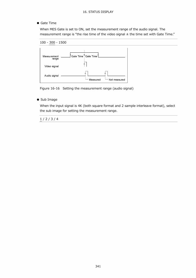
16. STATUS DISPLAY
341
● Gate Time
When MES Gate is set to ON, set the measurement range of the audio signal. The measurement range is “the rise time of the video signal ± the time set with Gate Time.”
100 - 300 - 1500
Figure 16-16 Setting the measurement range (audio signal)
● Sub Image
When the input signal is 4K (both square format and 2 sample interleave format), select the sub image for setting the measurement range.
1 / 2 / 3 / 4
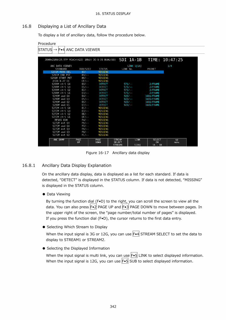
16. STATUS DISPLAY
342
16.8 Displaying a List of Ancillary Data
To display a list of ancillary data, follow the procedure below.
Procedure STATUS → F•4 ANC DATA VIEWER
Figure 16-17 Ancillary data display
16.8.1 Ancillary Data Display Explanation
On the ancillary data display, data is displayed as a list for each standard. If data is detected, “DETECT” is displayed in the STATUS column. If data is not detected, “MISSING” is displayed in the STATUS column.
● Data Viewing
By turning the function dial (F•D) to the right, you can scroll the screen to view all the data. You can also press F•2 PAGE UP and F•3 PAGE DOWN to move between pages. In the upper right of the screen, the “page number/total number of pages” is displayed. If you press the function dial (F•D), the cursor returns to the first data entry.
● Selecting Which Stream to Display
When the input signal is 3G or 12G, you can use F•4 STREAM SELECT to set the data to display to STREAM1 or STREAM2.
● Selecting the Displayed Information
When the input signal is multi link, you can use F•5 LINK to select displayed information. When the input signal is 12G, you can use F•5 SUB to select displayed information.

16. STATUS DISPLAY
343
16.8.2 Displaying a Dump of Ancillary Data
To display a dump of the data that you have selected on the ancillary data display, follow the procedure below. By turning the function dial (F•D) to the right, you can scroll the screen to view all the data. If you press the function dial (F•D), the cursor returns to the first data entry.
Procedure STATUS → F•3 ANC DATA VIEWER → F•1 ANC DUMP
Figure 16-18 Ancillary dump display
16.8.3 Updating the Dump Display
When the selected data is embedded in multiple lines, the line number that is displayed on the ancillary dump display is switched at a regular interval. (However, the line numbers are switched at an irregular interval.) To select the dump display update time, follow the procedure below.
Procedure STATUS → F•3 ANC DATA VIEWER → F•1 ANC DUMP → F•2 HOLD TIME: HOLD / 1s / 3s
Setting
HOLD: The screen is not updated. 1s: The screen is updated once per second. 3s: The screen is updated once every 3 seconds.

16. STATUS DISPLAY
344
16.8.4 Selecting the Dump Mode
To select the dump mode, follow the procedure below.
Procedure STATUS → F•3 ANC DATA VIEWER → F•1 ANC DUMP → F•3 DUMP MODE: HEX / BINARY
Setting
HEX: Data is displayed in hexadecimal format. BINARY: Data is displayed in binary format.
DUMP MODE = HEX
DUMP MODE = BINARY
Figure 16-19 Selecting the dump mode

16. STATUS DISPLAY
345
16.9 Detecting Ancillary Packets
To display the ancillary packet display, follow the procedure below. If an ancillary packet is detected, “DETECT” appears. If not, “MISSING” appears. If a dummy packet is detected, “DUMMY” appears.
Procedure STATUS → F•5 ANC PACKET
Figure 16-20 Ancillary packet display
16.9.1 Ancillary Packet Display Explanation
● AUDIO CONTROL PACKET
The embedded audio consists of 4 groups that each contain 4 channels. This makes for a total of 16 channels. A single audio control packet is embedded in each group. Reference Section 16.9.4, “Displaying Audio Control Packets”
● EDH (Error Detection and Handling) (for SD)
This packet is used for detecting transmission errors. When multiple devices are connected, this packet can be used to determine which device caused an error. Both full-field and active picture errors are detected. Reference Section 16.9.2, “Displaying EDH Packets”
● LTC (Linear/Longitudinal Time Code)
This is a type of timecode. One is embedded per frame.
● VITC (Vertical Interval Time Code)
This is a type of timecode. One is embedded per field.

16. STATUS DISPLAY
346
● PAYLOAD ID
This is a packet that is used to identify the video format. It conforms to SMPTE ST 352. Reference Section 16.9.3, “Displaying Payload IDs”
● AFD
A packet embedded in the V-ANC area. Reference Section 16.9.11, “Displaying AFD Packets”
● CLOSED CAPTION 1 to 3 (for HD or SD)
This is a closed caption information packet that is embedded in the V-ANC area. Up to three closed caption data entries can be embedded. Reference Section 16.9.6, “Displaying Closed Caption Packets”
● NET-Q (for HD or SD)
This is the inter-stationary control signal. Reference Section 10.7.1, “Displaying the Inter-Stationary Control Signal”
● TRIGGER PACKET (for HD or SD)
This is the data broadcast trigger signal. Reference Section 16.9.8, “Displaying the Data Broadcast Trigger Signal”
● USER DATA 1 and 2 (for HD or SD)
Up to two packets of user data. Reference Section 16.9.9, “Displaying User Data”

16. STATUS DISPLAY
347
16.9.2 Displaying EDH Packets
When the input signal is SD, to display EDH packets, follow the procedure below.
Procedure STATUS → F•4 ANC PACKET → F•1 PACKET ANALYSIS → F•1 EDH
Figure 16-21 EDH packet display
● Selecting the Display Format
You can use F•1 DISPLAY to set the display format to TEXT (text display) or DUMP (dump display). If you select DUMP, the dump display appears, and you can use the function dial (F•D) to view the entire data. If you press the function dial (F•D), the first data entry is displayed.
● Selecting the Dump Mode
When F•1 DISPLAY is set to DUMP, you can use F•2 DUMP MODE to set the dump mode to HEX (hexadecimal display) or BINARY (binary display).

16. STATUS DISPLAY
348
16.9.3 Displaying Payload IDs
To show the payload ID display, follow the procedure below.
Procedure STATUS → F•4 ANC PACKET → F•1 PACKET ANALYSIS → F•2 PAYLOAD ID
Figure 16-22 Payload ID display
● Selecting Which Stream to Display
When the input signal is 3G or 12G, you can use F•4 STREAM SELECT to set the data to display to STREAM1 or STREAM2.
● Selecting the Displayed Information
When the input signal is multi link, you can use F•5 LINK to select displayed information. When the input signal is 12G, you can use F•5 SUB to select displayed information.

16. STATUS DISPLAY
349
16.9.4 Displaying Audio Control Packets
To display audio control packets, follow the procedure below.
Procedure STATUS → F•4 ANC PACKET → F•1 PACKET ANALYSIS → F•3 CONTROL PACKET
Figure 16-23 Audio control packet display
● Selecting the Display Format
You can use F•1 DISPLAY to set the display format to TEXT (text display) or DUMP (dump display). If you select DUMP, the dump display appears, and you can use the function dial (F•D) to view the entire data. If you press the function dial (F•D), the first data entry is displayed.
● Selecting the Dump Mode
When F•1 DISPLAY is set to DUMP, you can use F•2 DUMP MODE to set the dump mode to HEX (hexadecimal display) or BINARY (binary display).
● Selecting the Group to Display
You can use F•3 GROUP to set the group to display to a group from groups 1 to 4. A single group in the audio signal consists of four channels.
● Selecting Which Stream to Display
When the input signal is 3G-B, you can use F•4 STREAM SELECT to set the data to display to STREAM1 or STREAM2.
● Selecting the Displayed Information
When the input signal is multi link, you can use F•5 LINK to select displayed information. When the input signal is 12G, you can use F•5 SUB to select displayed information.

16. STATUS DISPLAY
350
16.9.5 V-ANC ARIB Display
To display the V blanking ancillary packets defined in the ARIB standard, use the ARIB menu. When the input signal is 3G or 12G, this menu item is not displayed.
STATUS → F•4 ANC PACKET → F•1 PACKET ANALYSIS → F•4 V-ANC → F•1 ARIB →
Figure 16-24 ARIB menu
16.9.6 Displaying Closed Caption Packets
To display closed caption packets, follow the procedure below.
Procedure STATUS → F•4 ANC PACKET → F•1 PACKET ANALYSIS → F•4 V-ANC → F•1 ARIB → F•1 CLOSED CAPTION
Figure 16-25 Closed caption packet display
● Selecting the Closed Caption Type
You can use F•2 TYPE to set the closed caption type to HD, SD, ANALOG, or CELLULAR.
● Selecting the Display Format
You can use F•1 DISPLAY to set the display format to TEXT (text display) or DUMP (dump display). If you select DUMP, the dump display appears, and you can use the function dial (F•D) to view the entire data. If you press the function dial (F•D), the first data entry is displayed.

16. STATUS DISPLAY
351
● Selecting the Dump Mode
When F•1 DISPLAY is set to DUMP, you can use F•2 DUMP MODE to set the dump mode to HEX (hexadecimal display) or BINARY (binary display).
● Selecting the Displayed Information
When the input signal is HD(DL) or HD(QL), you can use F•5 LINK to select displayed information.
16.9.7 Displaying the Inter-Stationary Control Signal
To display the inter-stationary control signal, follow the procedure below.
Procedure STATUS → F•4 ANC PACKET → F•1 PACKET ANALYSIS → F•4 V-ANC → F•1 ARIB → F•2 NET-Q
Figure 16-26 Inter-stationary control signal display

16. STATUS DISPLAY
352
● Selecting the Display Format
You can use F•1 DISPLAY to set the display format to TEXT (text display), DUMP (dump display), Q LOG (Q-signal log display), or FORMAT (format ID display). If you select DUMP, the dump display appears. If you select Q LOG, the log display appears. In either case, you can use the function dial (F•D) to view the entire data. If you press the function dial (F•D), the first data entry is displayed.
DISPLAY = DUMP
DISPLAY = QLOG
DISPLAY = FORMAT
Figure 16-27 Selecting the display format

16. STATUS DISPLAY
353
● Selecting the Dump Mode
When F•1 DISPLAY is set to DUMP, you can use F•2 DUMP MODE to set the dump mode to HEX (hexadecimal display) or BINARY (binary display).
● Clearing the Q-Signal Log
When F•1 DISPLAY is set to Q LOG, press F•2 Q LOG CLEAR to clear the Q-signal log.
● Setting the Bit Mask
When F•1 DISPLAY is set to TEXT, you can use F•3 BIT MASK to mask the Q and status signals independently. Press F•4 ALL ON to set all the bit mask entries to ON. Press F•5 ALL OFF to set all the bit mask entries to OFF.
Figure 16-28 NET-Q Bit Mask tab
● Selecting the Displayed Information
When the input signal is HD(DL) or HD(QL), you can use F•5 LINK to select displayed information.
● Saving to USB Memory
If F•1 DISPLAY is set to Q LOG, you can press F•6 USB MEMORY to save the Q signal log to a USB memory device in CSV format. The procedure to follow to save data is the same as the procedure that was given for the event log. See section 16.4.5, “Saving to a USB Memory Device.” Q signal logs are saved in the NETQ folder.
USB memory device
└ LV5490_USER └ NETQ └ YYYYMMDDhhmmss.csv

16. STATUS DISPLAY
354
16.9.8 Displaying the Data Broadcast Trigger Signal
To display the data broadcast trigger signal, follow the procedure below.
Procedure STATUS → F•4 ANC PACKET → F•1 PACKET ANALYSIS → F•4 V-ANC → F•1 ARIB → F•3 DATA TRIGGER
Figure 16-29 Data broadcast trigger signal display
● Selecting the Display Format
You can use F•1 DISPLAY to set the display format to TEXT (text display) or DUMP (dump display). If you select DUMP, the dump display appears, and you can use the function dial (F•D) to view the entire data. If you press the function dial (F•D), the first data entry is displayed.
● Selecting the Dump Mode
When F•1 DISPLAY is set to DUMP, you can use F•2 DUMP MODE to set the dump mode to HEX (hexadecimal display) or BINARY (binary display).
● Selecting the Displayed Information
When the input signal is HD(DL) or HD(QL), you can use F•5 LINK to select displayed information.

16. STATUS DISPLAY
355
16.9.9 Displaying User Data
To display user data entries 1 and 2, follow the procedure below. You can use the function dial (F•D) to view all the data. If you press the function dial (F•D), the first data entry is displayed.
Procedure STATUS → F•4 ANC PACKET → F•1 PACKET ANALYSIS → F•4 V-ANC → F•1 ARIB → F•4 USER DATA 1 → F•5 USER DATA 2
Figure 16-30 User data display
● Selecting the Dump Mode
You can use F•2 DUMP MODE to set the dump mode to HEX (hexadecimal display) or BINARY (binary display).
● Selecting the Displayed Information
When the input signal is HD(DL) or HD(QL), you can use F•5 LINK to select displayed information.
16.9.10 V-ANC SMPTE Display
To display the V blanking ancillary packets defined in the SMPTE standard, use the SMPTE menu.
STATUS → F•4 ANC PACKET → F•1 PACKET ANALYSIS → F•4 V-ANC → F•2 SMPTE →
Figure 16-31 SMPTE menu

16. STATUS DISPLAY
356
16.9.11 Displaying AFD Packets
To display AFD packets, follow the procedure below.
Procedure STATUS → F•4 ANC PACKET → F•1 PACKET ANALYSIS → F•4 V-ANC → F•2 SMPTE → F•5 AFD
Figure 16-32 AFD packet display
● Selecting the Display Format
You can use F•1 DISPLAY to set the display format to TEXT (text display) or DUMP (dump display). If you select DUMP, the dump display appears, and you can use the function dial (F•D) to view the entire data. If you press the function dial (F•D), the first data entry is displayed.
● Selecting the Dump Mode
When F•1 DISPLAY is set to DUMP, you can use F•2 DUMP MODE to set the dump mode to HEX (hexadecimal display) or BINARY (binary display).
● Selecting Which Stream to Display
When the input signal is 3G-B, you can use F•4 STREAM SELECT to set the data to display to STREAM1 or STREAM2.
● Selecting the Displayed Information
When the input signal is multi link, you can use F•5 LINK to select displayed information. When the input signal is 12G, you can use F•5 SUB to select displayed information.

16. STATUS DISPLAY
357
16.9.12 Performing Custom Searches
To show the custom search display, follow the procedure below. You can use the function dial (F•D) to view all the data. If you press the function dial (F•D), the first data entry is displayed.
Procedure STATUS → F•4 ANC PACKET → F•1 PACKET ANALYSIS → F•5 CUSTOM SEARCH
Figure 16-33 Custom search display
● Detecting Ancillary Packets
You can search ancillary packets by using F•1 ID SET in the CUSTOM SEARCH menu.
STATUS → F•4 ANC PACKET → F•1 PACKET ANALYSIS → F•5 CUSTOM SEARCH → F•1 ID SET →
Figure 16-34 ID SET menu
Set F•1 DID and F•2 SDID/DBN to display ancillary packets on the basis of the combination of the DID and SDID/DBN. You can set F•1 DID in the range of 00 to FF. Press the function dial (F•D) to return the setting to its default value (00). You can set F•2 SDID/DBN in the range of 00 to FF or select “--” to not specify a value. Press the function dial (F•D) to return the setting to its default value (--). Press F•3 SET to clear the blue cursor assigned to F•1 DID or F•2 SDID/DBN. Use this key when you want to view all the data using the function dial (F•D).

16. STATUS DISPLAY
358
● Selecting the Dump Mode
You can use F•2 DUMP MODE to set the dump mode to HEX (hexadecimal display) or BINARY (binary display).
● Selecting Which Signal to Display
When the input signal is not SD, you can use F•3 Y/C SELECT to set the data to display to that of the Y signal or the C signal.
● Selecting Which Stream to Display
When the input signal is 3G-B, you can use F•4 STREAM SELECT to set the data to display to STREAM1 or STREAM2.
● Selecting the Displayed Information
When the input signal is multi link, you can use F•5 LINK to select displayed information. When the input signal is 12G, you can use F•5 SUB to select displayed information.

16. STATUS DISPLAY
359
16.10 IP(NMI) Status Screen Explanation (SER08)
If on the SDI IN tab in the system settings, SDI System is set to 4K NMI or NMI, pressing STATUS displays the IP (NMI) status. To return to the normal status display from IP (NMI) status, press F•1 STATUS.
Figure 16-35 NMI Status screen
● NMI
・IP Address / Gateway / Subnet Mask / PTP Domain Number
These show the IP address, gateway address, subnet mask, and PTP domain number of NMI input connectors IP A and IP B on the rear panel.
● IP Live System Manager
・IP Address / Port / Protocol
These show the IP address, port, and protocol of IP Live System Manager connected to the NMI input connectors IP A and IP B on the rear panel.
・Connection Status
This shows the connection status of IP Live System Manager and the NMI input connectors IP A and IP B on the rear panel.
Displayed text Color Connection status Connected Cyan Connected to IP Live System Manager Connecting White Establishing connection to IP Live System Manager Disable White Connection disabled

16. STATUS DISPLAY
360
● NMI STATUS
・Format
This shows the format information. Normally the text is cyan, but if the format is not appropriate, it turns red.
・Reference
This shows the IP (NMI) network genlock status.
Displayed text Color Connection status Locked Cyan Locked Unlocked Yellow Not locked

17. EYE PATTERN DISPLAY (SER02/SER09)
361
17. EYE PATTERN DISPLAY (SER02/SER09) To display the eye pattern, press EYE.
On the eye pattern display you can use F•2 MODE to display the eye pattern or jitter.
The channel that can be displayed is a single system selected with F•6 SELECT CH and F•5 LINK SELECT. Simul mode is not supported. In addition signals applied to 2A to 2D cannot be displayed.
Figure 17-1 Eye pattern display
Figure 17-2 Jitter display

17. EYE PATTERN DISPLAY (SER02/SER09)
362
● Displaying the Eye Pattern and Jitter Simultaneously
By using the layout feature, you can display the eye pattern and jitter simultaneously. For details, see section, 6.4 “Arranging the Measurement Screen Layout.”
Figure 17-3 Eye pattern and jitter display

17. EYE PATTERN DISPLAY (SER02/SER09)
363
17.1 Eye Pattern Display Explanation
● Automatic Measurement
On the eye pattern display, values such as the amplitude of the eye pattern and the jitter are measured automatically and displayed. Measured values are normally displayed in white, but they are displayed in yellow until they stabilize and in red if they exceed the values that you have specified in the error setup. If automatic measurements cannot be performed due to noise in the waveform or other reason, measured values are displayed as "----.” If this occurs, use cursors to measure manually. Reference Section 17.9, “Configuring Error Detection Settings”
The timing jitter and current jitter measurement items show the values that were measured in jitter display mode. The LV 5490SER02 use a phase detector to perform these measurements. Other measurement items show the measured values calculated from the eye pattern waveform. Therefore, if the waveform degrades significantly, the difference between the automatically measured values and the cursor-measured values may become large.
● Measurement items
The items that can be automatically measured are shown below.
Table 17-1 Measurement items
Symbol Display Description a Amp Eye-pattern amplitude b Tr Rise time (time from 20% to 80% of amplitude) c Tf Fall time (time from 80% to 20% of amplitude, and not shown in the following
figure) d T.J Timing Jitter e C.J Current jitter (jitter value when the currently selected filter is applied) f Or Overshoot of the rising edge g Of Overshoot of the falling edge
Figure 17-4 Explanation of measurement items
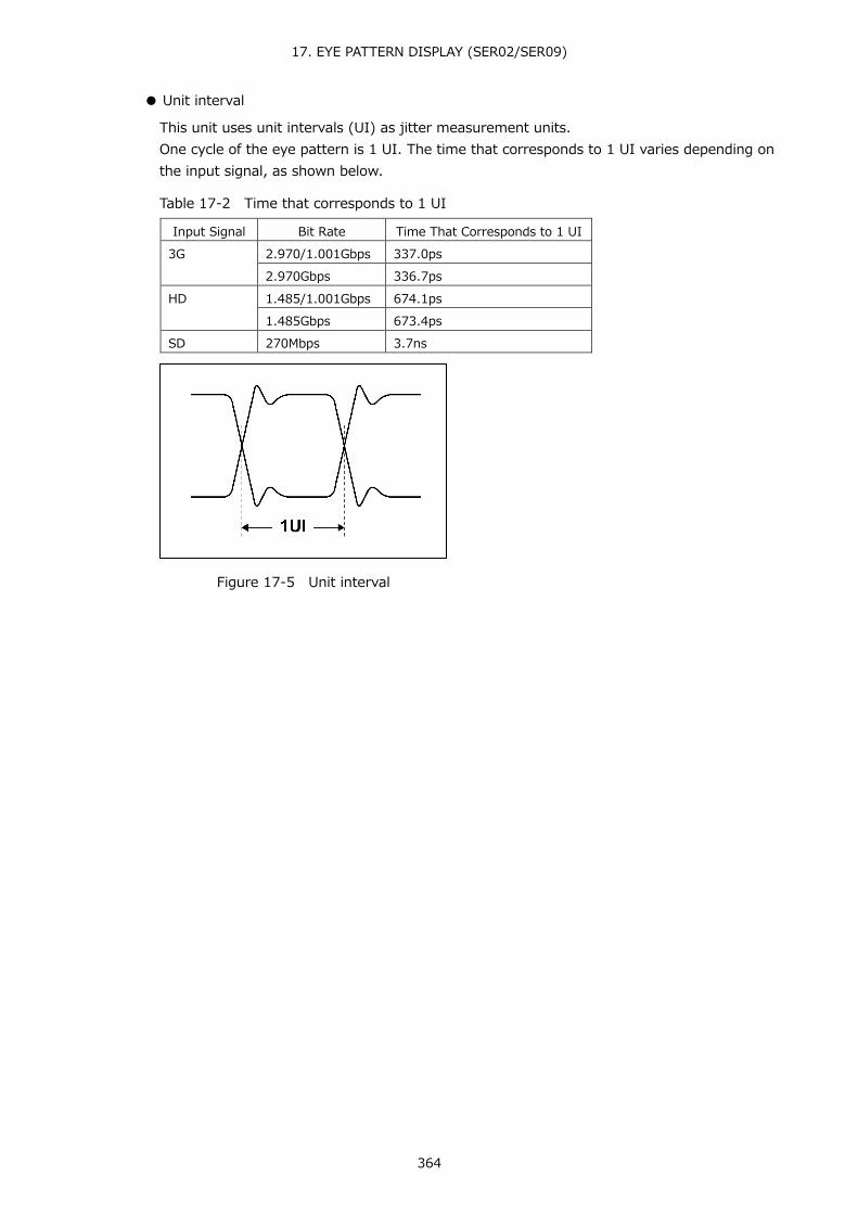
17. EYE PATTERN DISPLAY (SER02/SER09)
364
● Unit interval
This unit uses unit intervals (UI) as jitter measurement units. One cycle of the eye pattern is 1 UI. The time that corresponds to 1 UI varies depending on the input signal, as shown below.
Table 17-2 Time that corresponds to 1 UI
Input Signal Bit Rate Time That Corresponds to 1 UI 3G 2.970/1.001Gbps 337.0ps
2.970Gbps 336.7ps HD 1.485/1.001Gbps 674.1ps
1.485Gbps 673.4ps SD 270Mbps 3.7ns
Figure 17-5 Unit interval

17. EYE PATTERN DISPLAY (SER02/SER09)
365
17.2 Jitter Display Explanation
● Measurement
In the jitter display mode, the jitter component is extracted from the input signal and plotted on a time graph. The time (horizontal) axis can be displayed in different ways depending on the data interval of the lines, fields, or frames, which are being transmitted in the SDI signal.
● Automatic Measurement
Timing jitter (T.J) and current jitter (C.J) are automatically measured and displayed on the jitter display screen. The measurement range is 0.00 to 9.60 UI.
SMPTE defines two methods of measuring jitter. One method uses an eye pattern, and the other method uses a phase detector. The eye pattern method has disadvantages not only that measurements are difficult when the eye is not open but that measurements are prone to errors because the distinction between waveform distortion (such as noise and sags) and jitter is difficult. In contrast, the phase detector method makes jitter measurements with small errors possible even when the eye pattern is closed and even when the amount of jitter is 1 UI or more. The LV 5490SER02 uses the phase detector method.
Measured values are normally displayed in white, but they are displayed in red if they exceed the values that you have specified in the error setup. If 10.00 UI is exceeded, “OVER” is displayed. Reference Section 17.9, “Configuring Error Detection Settings”

17. EYE PATTERN DISPLAY (SER02/SER09)
366
17.3 Setting the Waveform Display Position
Use the V POS and H POS knobs to adjust the display position of the waveform. On the multi display, these are valid when you press F•7 MULTI EYE on the MULTI menu.
Figure 17-6 V POS and H POS knobs
● V POS Knob
Adjusts the vertical position of the waveform. Pressing the knob returns the waveform to its default position.
● H POS Knob
Adjusts the horizontal position of the waveform. Pressing the knob returns the waveform to its default position.
17.4 Switching between Eye Pattern and Jitter
To switch between eye pattern and jitter, follow the procedure below.
Procedure EYE → F•2 MODE: EYE / JITTER
17.5 Selecting Which Link to Display
You cannot display eye patterns of multiple channels at the same time. When the link format is set to multi, to select which link to display, follow the procedure below. This menu appears in other menu hierarchies; you can select the link in the same manner.
Procedure (for HD (DL)) EYE → F•5 LINK SELECT: A[1A] / B[1B] or A[1C] / B[1D]
Procedure (for 3G (DL)-4K) EYE → F•5 LINK SELECT: 1[1A] / 2[1B] or 1[1C] / 2[1D]
Procedure (for 3G (QL)) EYE → F•5 LINK SELECT: 1[1A] / 2[1B] / 3[1C] / 4[1D]
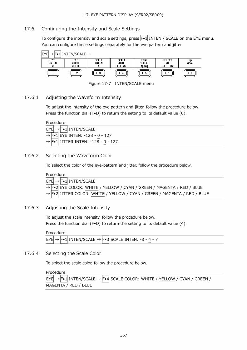
17. EYE PATTERN DISPLAY (SER02/SER09)
367
17.6 Configuring the Intensity and Scale Settings
To configure the intensity and scale settings, press F•1 INTEN / SCALE on the EYE menu. You can configure these settings separately for the eye pattern and jitter.
EYE → F•1 INTEN/SCALE →
Figure 17-7 INTEN/SCALE menu
17.6.1 Adjusting the Waveform Intensity
To adjust the intensity of the eye pattern and jitter, follow the procedure below. Press the function dial (F•D) to return the setting to its default value (0).
Procedure EYE → F•1 INTEN/SCALE → F•1 EYE INTEN: -128 - 0 - 127 → F•1 JITTER INTEN: -128 - 0 - 127
17.6.2 Selecting the Waveform Color
To select the color of the eye-pattern and jitter, follow the procedure below.
Procedure EYE → F•1 INTEN/SCALE → F•2 EYE COLOR: WHITE / YELLOW / CYAN / GREEN / MAGENTA / RED / BLUE → F•2 JITTER COLOR: WHITE / YELLOW / CYAN / GREEN / MAGENTA / RED / BLUE
17.6.3 Adjusting the Scale Intensity
To adjust the scale intensity, follow the procedure below. Press the function dial (F•D) to return the setting to its default value (4).
Procedure EYE → F•1 INTEN/SCALE → F•3 SCALE INTEN: -8 - 4 - 7
17.6.4 Selecting the Scale Color
To select the scale color, follow the procedure below.
Procedure EYE → F•1 INTEN/SCALE → F•4 SCALE COLOR: WHITE / YELLOW / CYAN / GREEN / MAGENTA / RED / BLUE

17. EYE PATTERN DISPLAY (SER02/SER09)
368
17.7 Configuring Eye Pattern Display Settings
To configure eye pattern display settings, press F•3 EYE SETUP on the EYE menu. This appears when F•2 MODE is set to EYE.
EYE → F•3 EYE SETUP →
Figure 17-8 EYE SETUP menu
17.7.1 Adjusting the Gain
To adjust the eye-pattern gain, follow the procedure below.
Procedure EYE → F•3 EYE SETUP → F•1 GAIN VARIABLE: CAL / VARIABLE
Settings
CAL: The eye pattern is shown without gain. VARIABLE: The eye pattern is shown with the specified gain (x0.50 to x2.00). The
gain value appears in the upper right of the screen. Turn the function dial (F•D) to adjust the gain. Press the function dial (F•D) to return the setting to its default value (x1.00).
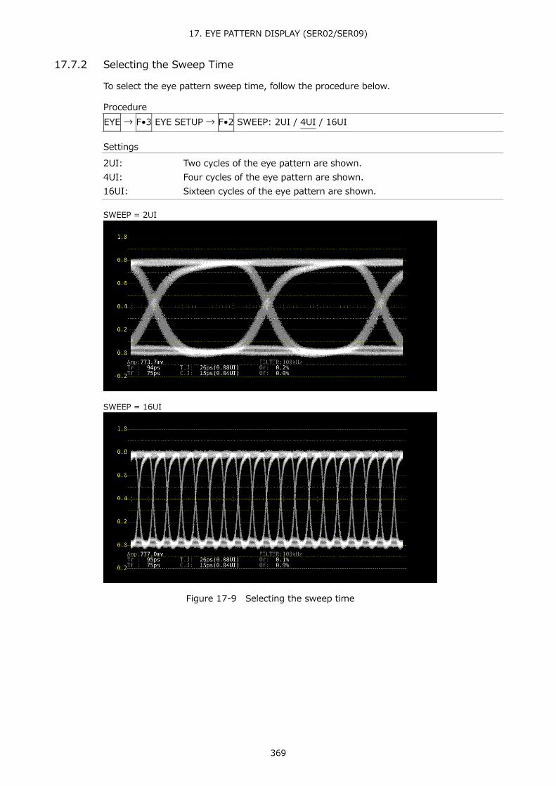
17. EYE PATTERN DISPLAY (SER02/SER09)
369
17.7.2 Selecting the Sweep Time
To select the eye pattern sweep time, follow the procedure below.
Procedure EYE → F•3 EYE SETUP → F•2 SWEEP: 2UI / 4UI / 16UI
Settings
2UI: Two cycles of the eye pattern are shown. 4UI: Four cycles of the eye pattern are shown. 16UI: Sixteen cycles of the eye pattern are shown.
SWEEP = 2UI
SWEEP = 16UI
Figure 17-9 Selecting the sweep time

17. EYE PATTERN DISPLAY (SER02/SER09)
370
17.7.3 Selecting the Filter
To select the filter that is used during jitter measurement, follow the procedure below. The selected filter is indicated in the lower right of the display. If you change this setting, the filter that you selected for jitter display also changes. Reference Section 17.8.3, “Selecting the Filter”
Procedure EYE → F•3 EYE SETUP → F•3 FILTER: 100kHz / 1kHz / 100Hz / 10Hz / TIMING / ALIGNMENT
Settings
100kHz: Jitter at 100 kHz or higher is measured. 1kHz: Jitter at 1 kHz or higher is measured. 100Hz: Jitter at 100 Hz or higher is measured. 10Hz: Jitter at 10 Hz or higher is measured. TIMING: Timing jitter is measured. Jitter at 10 Hz or higher is measured. ALIGNMENT: Alignment jitter is measured. When the input signal is not SD, jitter at 100
kHz and higher is measured. When the input signal is SD, jitter at 1 kHz and higher is measured.

17. EYE PATTERN DISPLAY (SER02/SER09)
371
17.7.4 Turning Cursors On and Off
To configure cursor settings, press F•4 CURSOR/TRIGGER on the EYE SETUP menu.
EYE → F•3 EYE SETUP → F•4 CURSOR/TRIGGER →
Figure 17-10 CURSOR/TRIGGER menu
To turn cursors on and off, follow the procedure shown below. When the cursors are turned on, the REF cursors are displayed in yellow (X) and light blue (Y), and the DELTA cursors are displayed in purple (X) and green (Y). The values of DELTA-REF appear as measured values in the upper part of the screen.
Procedure EYE → F•3 EYE SETUP → F•4 CURSOR/TRIGGER → F•1 ON/OFF RESET → F•1 CURSOR: ON / OFF
CURSOR = ON
Figure 17-11 Cursor display
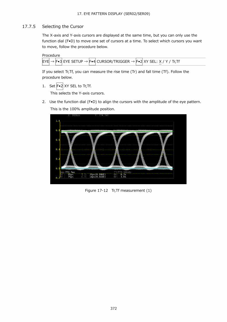
17. EYE PATTERN DISPLAY (SER02/SER09)
372
17.7.5 Selecting the Cursor
The X-axis and Y-axis cursors are displayed at the same time, but you can only use the function dial (F•D) to move one set of cursors at a time. To select which cursors you want to move, follow the procedure below.
Procedure EYE → F•3 EYE SETUP → F•4 CURSOR/TRIGGER → F•2 XY SEL: X / Y / Tr,Tf
If you select Tr,Tf, you can measure the rise time (Tr) and fall time (Tf). Follow the procedure below.
1. Set F•2 XY SEL to Tr,Tf.
This selects the Y-axis cursors.
2. Use the function dial (F•D) to align the cursors with the amplitude of the eye pattern.
This is the 100% amplitude position.
Figure 17-12 Tr,Tf measurement (1)

17. EYE PATTERN DISPLAY (SER02/SER09)
373
3. Press F•5 REF SET.
The Y-axis cursors move to the 20 % and 80 % positions of the amplitude, and then F•2 XY SEL is automatically set to X.
Figure 17-13 Tr,Tf measurement (2)
4. Align the X-axis cursors with the intersections of the Y-axis cursors and the eye pattern.
Align with the rising edge of the pattern to measure Tr and the falling edge to measure Tf. (Figure 17-14 is an example for Tr) The measured value is displayed next to X in the upper part of the screen.
Figure 17-15 Tr,Tf measurement (3)
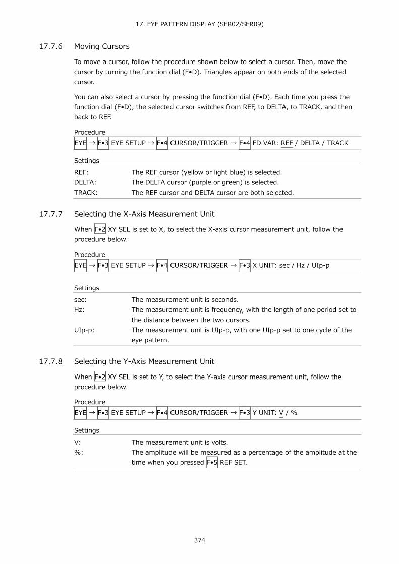
17. EYE PATTERN DISPLAY (SER02/SER09)
374
17.7.6 Moving Cursors
To move a cursor, follow the procedure shown below to select a cursor. Then, move the cursor by turning the function dial (F•D). Triangles appear on both ends of the selected cursor.
You can also select a cursor by pressing the function dial (F•D). Each time you press the function dial (F•D), the selected cursor switches from REF, to DELTA, to TRACK, and then back to REF.
Procedure EYE → F•3 EYE SETUP → F•4 CURSOR/TRIGGER → F•4 FD VAR: REF / DELTA / TRACK
Settings
REF: The REF cursor (yellow or light blue) is selected. DELTA: The DELTA cursor (purple or green) is selected. TRACK: The REF cursor and DELTA cursor are both selected.
17.7.7 Selecting the X-Axis Measurement Unit
When F•2 XY SEL is set to X, to select the X-axis cursor measurement unit, follow the procedure below.
Procedure EYE → F•3 EYE SETUP → F•4 CURSOR/TRIGGER → F•3 X UNIT: sec / Hz / UIp-p
Settings
sec: The measurement unit is seconds. Hz: The measurement unit is frequency, with the length of one period set to
the distance between the two cursors. UIp-p: The measurement unit is UIp-p, with one UIp-p set to one cycle of the
eye pattern.
17.7.8 Selecting the Y-Axis Measurement Unit
When F•2 XY SEL is set to Y, to select the Y-axis cursor measurement unit, follow the procedure below.
Procedure EYE → F•3 EYE SETUP → F•4 CURSOR/TRIGGER → F•3 Y UNIT: V / %
Settings
V: The measurement unit is volts. %: The amplitude will be measured as a percentage of the amplitude at the
time when you pressed F•5 REF SET.

17. EYE PATTERN DISPLAY (SER02/SER09)
375
17.7.9 Selecting the Display Mode
To select the eye pattern display mode, follow the procedure below. If the eye pattern and jitter are displayed simultaneously, the setting specified here also applies to the jitter.
Procedure EYE → F•3 EYE SETUP → F•4 CURSOR/TRIGGER → F•6 TRIGGER: RUN / STOP
Settings
RUN: The input signal is automatically updated and displayed. STOP: The input signal is displayed statically. This is convenient for cursor
measurement. Even if STOP is selected, if you change the measurement conditions, such as switching to jitter, the mode switches to RUN.
17.7.10 Resetting Cursors
To reset the cursor positions, follow the procedure below.
Procedure EYE → F•3 EYE SETUP → F•4 CURSOR/TRIGGER → F•1 ON/OFF RESET → F•6 CURSOR RESET

17. EYE PATTERN DISPLAY (SER02/SER09)
376
17.8 Configuring the Jitter Display Settings
To configure jitter display settings, press F•3 JITTER SETUP on the EYE menu. This setting appears when F•2 MODE is set to JITTER.
EYE → F•3 JITTER SETUP →
Figure 17-16 JITTER SETUP menu
17.8.1 Selecting the Magnification
To configure the gain and sweep settings, press F•1 GAIN SWEEP on the JITTER SETUP menu.
EYE → F•3 JITTER SETUP → F•1 GAIN SWEEP →
Figure 17-17 GAIN/SWEEP menu
To select the jitter magnification, follow the procedure below.
Procedure EYE → F•3 JITTER SETUP → F•1 GAIN SWEEP → F•1 GAIN MAG : x1 / x2 / x8 (excluding 12G) : X1 / X2 / X4 / X16 (12G)
17.8.2 Selecting the Sweep Time
To select the sweep time, follow the procedure below.
Procedure EYE → F•3 JITTER SETUP → F•1 GAIN SWEEP → F•2 SWEEP: 1H / 2H / 1V / 2V
Settings
1H: The jitter from a period of one line is shown. 2H: The jitter from a period of two lines is shown. 1V: When the input signal is interlace or segmented frame, the jitter from a
period of one field is shown. When the input signal is progressive, the jitter from a period of one frame is shown.
2V: When the input signal is interlace or segmented frame, the jitter from a period of one frame is shown. When the input signal is progressive, the jitter from a period of two frames is shown. This option cannot be selected when the input signal is progressive except for 60/59.94/50P of HD (DL).

17. EYE PATTERN DISPLAY (SER02/SER09)
377
17.8.3 Selecting the Filter
To select the filter that is used during jitter measurement, follow the procedure below. The selected filter is indicated in the lower right of the display. If you change this setting, the filter that you selected for the eye pattern display also changes. Reference Section 17.7.3, “Selecting the Filter”
Procedure EYE → F•3 JITTER SETUP → F•3 FILTER: 100kHz / 1kHz / 100Hz / 10Hz / TIMING / ALIGNMENT
17.8.4 Turning Cursors On and Off
To configure cursor settings, press F•3 CURSOR/TRIGGER on the JITTER SETUP menu.
EYE → F•3 JITTER SETUP → F•3 CURSOR/TRIGGER →
Figure 17-18 CURSOR/TRIGGER menu
To turn cursors on and off, follow the procedure shown below. When the cursors are turned on, the REF cursors are displayed in yellow (X) and light blue (Y), and the DELTA cursors are displayed in purple (X) and green (Y). The values of DELTA-REF appear as measured values in the upper part of the screen.
Procedure EYE → F•3 JITTER SETUP → F•3 CURSOR/TRIGGER → F•1 ON/OFF RESET → F•1 CURSOR: ON / OFF

17. EYE PATTERN DISPLAY (SER02/SER09)
378
CURSOR = ON
Figure 17-19 Cursor display
17.8.5 Selecting the Cursor
The X-axis and Y-axis cursors are displayed at the same time, but you can only use the function dial (F•D) to move one set of cursors at a time. To select which cursors you want to move, follow the procedure below.
Procedure EYE → F•3 JITTER SETUP → F•3 CURSOR/TRIGGER → F•2 XY SEL: X / Y
17.8.6 Moving Cursors
To move a cursor, follow the procedure shown below to select a cursor. Then, move the cursor by turning the function dial (F•D). Triangles appear on both ends of the selected cursor.
You can also select a cursor by pressing the function dial (F•D). Each time you press the function dial (F•D), the selected cursor switches from REF, to DELTA, to TRACK, and then back to REF.
Procedure EYE → F•3 JITTER SETUP → F•3 CURSOR/TRIGGER → F•4 FD VAR: REF / DELTA / TRACK
Settings
REF: The REF cursor (yellow or light blue) is selected. DELTA: The DELTA cursor (purple or green) is selected. TRACK: The REF cursor and DELTA cursor are both selected.

17. EYE PATTERN DISPLAY (SER02/SER09)
379
17.8.7 Selecting the X-Axis Measurement Unit
When F•2 XY SEL is set to X, to select the X-axis cursor measurement unit, follow the procedure below.
Procedure EYE → F•3 JITTER SETUP → F•3 CURSOR/TRIGGER → F•3 X UNIT: sec / Hz
Settings
sec: The measurement unit is seconds. Hz: The measurement unit is frequency, with the length of one period set to
the distance between the two cursors.
17.8.8 Selecting the Y-Axis Measurement Unit
When F•2 XY SEL is set to Y, to select the Y-axis cursor measurement unit, follow the procedure below.
Procedure EYE → F•3 JITTER SETUP → F•3 CURSOR/TRIGGER → F•3 Y UNIT: sec / UIp-p
Settings
sec: The measurement unit is seconds. UIp-p: The measurement unit is UIp-p, with one UIp-p set to one cycle of the
eye pattern.
17.8.9 Selecting the Display Mode
To select the jitter display mode, follow the procedure below. If the eye pattern and jitter are displayed simultaneously, the setting specified here also applies to the eye pattern.
Procedure EYE → F•3 JITTER SETUP → F•3 CURSOR/TRIGGER → F•6 TRIGGER: RUN / STOP
Settings
RUN: The input signal is automatically updated and displayed. STOP: The input signal is displayed statically. This is convenient for cursor
measurement. Even if STOP is selected, if you change the measurement conditions, such as switching to eye pattern, the mode switches to RUN.
17.8.10 Resetting Cursors
To reset the cursor positions, follow the procedure below.
Procedure EYE → F•3 JITTER SETUP → F•3 CURSOR/TRIGGER → F•1 ON/OFF RESET → F•6 CURSOR RESET

17. EYE PATTERN DISPLAY (SER02/SER09)
380
17.8.11 Turning the Peak Hold On and Off
To configure the peak hold settings, press F•4 PEAK HOLD on the JITTER SETUP menu.
EYE → F•3 JITTER SETUP → F•4 PEAK HOLD →
Figure 17-20 PEAK HOLD menu
To measure the peak values of the timing jitter (T.J) and the current jitter (C.J), follow the procedure below. When you set F•1 PEAK HOLD to ON, the peak values are displayed in the lower part of the screen next to “PEAK.” The peak values are retained until you press F•2 CLEAR. If a peak value exceeds 10.00UI, “OVER” is displayed.
Procedure EYE → F•3 JITTER SETUP → F•4 PEAK HOLD → F•1 PEAK HOLD: ON / OFF
PEAK HOLD = ON
Figure 17-21 Peak hold display
17.8.12 Clearing the Peak Hold
When F•1 PEAK HOLD is set to ON, to clear the peak hold, follow the procedure below.
Procedure EYE → F•3 JITTER SETUP → F•4 PEAK HOLD → F•2 CLEAR

17. EYE PATTERN DISPLAY (SER02/SER09)
381
17.9 Configuring Error Detection Settings
To configure the error detection settings, use F•4 ERROR SETUP. When error detection is set to ON, the following actions are performed when an error occurs. • Displays measured values on the eye pattern display and jitter display in red • Displays errors in the event log of the status display • Displays “ERROR” in the upper-right of the display. • Transmits a signal from the alarm output remote terminal Reference Section 16.4.1, “Event Log Screen Explanation”
17.9.1 Configuring 12G Error Settings
Use the 12G-SDI ERROR SETUP tab to configure error detection settings for 12G signals.
You can set the threshold values when you set the error detection to ON. Measured values given in SMPTE ST 2082-1 are used as 100 %.
EYE → F•4 ERROR SETUP →
Figure 17-22 12G-SDI ERROR SETUP tab
A configuration example showing threshold values that correspond to SMPTE ST 2082-1 is given below.
Table 17-3 12G-SDI ERROR SETUP configuration example
Item Setting Example Corresponding Value Amplitude Error Upper 110% 880mV
Lower 90% 720mV Risetime Error Max 100% 45.0ps Falltime Error Max 100% 45.0ps Deltatime Error(Tr-Tf) Max 100% 18ps Timing Jitter Error Max 100% 8.00UI (672.0ps) Current Jitter Error Max 100% 0.30UI (25.2ps) Overshoot Rising Error Max 100% 10.0% Overshoot Falling Error Max 100% 10.0%

17. EYE PATTERN DISPLAY (SER02/SER09)
382
● Amplitude Error
Turns the eye pattern's amplitude error detection on and off. You cannot set Lower to a value that is greater than Upper, even if the value is within the selectable range.
Upper: 80 - 140% (640 - 1120mV) Lower: 40 - 100% (320 - 800mV)
● Risetime Error
Turns the eye pattern's rise time (the time for the signal to rise from 20 to 80 % of its amplitude) error detection on and off.
Max: 40 - 140% (18.0 - 63.0ps)
● Falltime Error
Turns the eye pattern's fall time (the time for the signal to fall from 80 to 20 % of its amplitude) error detection on and off.
Max: 40 - 140% (18.0 - 63.0ps)
● Deltatime Error(Tr-Tf)
Turns the eye pattern's time difference (between the rise and fall times) error detection on and off. When the measured values exceed the specified value, Tr and Tf are displayed in red.
Max: 40 - 140% (7 - 25ps)
● Timing Jitter Error
Turns the eye pattern and jitter's timing jitter error detection on and off.
Max: 10 - 200% (0.80 - 16.00UI、67.2 - 1344.0ps)
● Current Jitter Error
Turns the eye pattern and jitter's current jitter error detection on and off.
Max: 10 - 200% (0.03 - 0.60UI、2.5 - 50.4ps)
● OverShoot Rising Error
Turns the overshoot of the rising edge error detection on and off.
Max: 0 - 100 - 200% (0.0 - 20.0%)
● OverShoot Falling Error
Turns the overshoot of the falling edge error detection on and off.
Max: 0 - 100 - 200% (0.0 - 20.0%)

17. EYE PATTERN DISPLAY (SER02/SER09)
383
17.9.2 Configuring 3G Error Settings
Use the 3G-SDI ERROR SETUP tab to configure error detection settings for 3G signals.
You can set the threshold values when you set the error detection to ON. Measured values given in SMPTE ST 424 are used as 100 %.
EYE → F•4 ERROR SETUP → F•2 PREV TAB or F•3 NEXT TAB →
Figure 17-23 3G-SDI ERROR SETUP tab
A configuration example showing threshold values that correspond to SMPTE ST 424 is given below.
Table 17-4 3G-SDI ERROR SETUP configuration example
Item Setting Example Corresponding Value Amplitude Error Upper 110% 880mV
Lower 90% 720mV Risetime Error Max 100% 135.0ps Falltime Error Max 100% 135.0ps Deltatime Error(Tr-Tf) Max 100% 50ps Timing Jitter Error Max 100% 2.00UI (674.0ps) Current Jitter Error Max 100% 0.30UI (101.2ps) OverShoot Rising Error Max 100% 10.0% OverShoot Falling Error Max 100% 10.0%
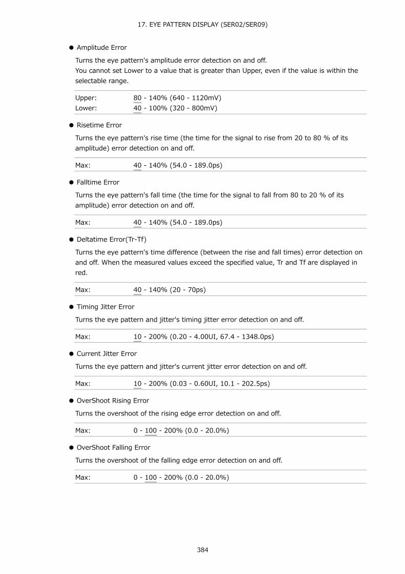
17. EYE PATTERN DISPLAY (SER02/SER09)
384
● Amplitude Error
Turns the eye pattern's amplitude error detection on and off. You cannot set Lower to a value that is greater than Upper, even if the value is within the selectable range.
Upper: 80 - 140% (640 - 1120mV) Lower: 40 - 100% (320 - 800mV)
● Risetime Error
Turns the eye pattern's rise time (the time for the signal to rise from 20 to 80 % of its amplitude) error detection on and off.
Max: 40 - 140% (54.0 - 189.0ps)
● Falltime Error
Turns the eye pattern's fall time (the time for the signal to fall from 80 to 20 % of its amplitude) error detection on and off.
Max: 40 - 140% (54.0 - 189.0ps)
● Deltatime Error(Tr-Tf)
Turns the eye pattern's time difference (between the rise and fall times) error detection on and off. When the measured values exceed the specified value, Tr and Tf are displayed in red.
Max: 40 - 140% (20 - 70ps)
● Timing Jitter Error
Turns the eye pattern and jitter's timing jitter error detection on and off.
Max: 10 - 200% (0.20 - 4.00UI, 67.4 - 1348.0ps)
● Current Jitter Error
Turns the eye pattern and jitter's current jitter error detection on and off.
Max: 10 - 200% (0.03 - 0.60UI, 10.1 - 202.5ps)
● OverShoot Rising Error
Turns the overshoot of the rising edge error detection on and off.
Max: 0 - 100 - 200% (0.0 - 20.0%)
● OverShoot Falling Error
Turns the overshoot of the falling edge error detection on and off.
Max: 0 - 100 - 200% (0.0 - 20.0%)

17. EYE PATTERN DISPLAY (SER02/SER09)
385
17.9.3 Configuring HD Error Settings
Use the HD-SDI ERROR SETUP tab to configure error detection settings for HD signals.
You can set the threshold values when you set the error detection to ON. Measured values given in SMPTE ST 292 are used as 100 %.
EYE → F•4 ERROR SETUP → F•2 PREV TAB or F•3 NEXT TAB →
Figure 17-24 HD-SDI ERROR SETUP tab
A configuration example showing threshold values that correspond to SMPTE ST 292 is given below.
Table 17-5 HD-SDI ERROR SETUP configuration example
Item Setting Example Corresponding Value Amplitude Error Upper 110% 880mV
Lower 90% 720mV Risetime Error Max 100% 270.0ps Falltime Error Max 100% 270.0ps Deltatime Error(Tr-Tf) Max 100% 100ps Timing Jitter Error Max 100% 1.00UI (674.0ps) Current Jitter Error Max 100% 0.20UI (135.0ps) OverShoot Rising Error Max 100% 10.0% OverShoot Falling Error Max 100% 10.0%
● Amplitude Error
Turns the eye pattern's amplitude error detection on and off. You cannot set Lower to a value that is greater than Upper, even if the value is within the selectable range.
Upper: 80 - 140% (640 - 1120mV) Lower: 40 - 100% (320 - 800mV)

17. EYE PATTERN DISPLAY (SER02/SER09)
386
● Risetime Error
Turns the eye pattern's rise time (the time for the signal to rise from 20 to 80 % of its amplitude) error detection on and off.
Max: 40 - 140% (108.0 - 378.0ps)
● Falltime Error
Turns the eye pattern's fall time (the time for the signal to fall from 80 to 20 % of its amplitude) error detection on and off.
Max: 40 - 140% (108.0 - 378.0ps)
● Deltatime Error(Tr-Tf)
Turns the eye pattern's time difference (between the rise and fall times) error detection on and off. When the measured values exceed the specified value, Tr and Tf are displayed in red.
Max: 40 - 140% (40 - 140ps)
● Timing Jitter Error
Turns the eye pattern and jitter's timing jitter error detection on and off.
Max: 10 - 200% (0.10 - 2.00UI, 67.4 - 1348.0ps)
● Current Jitter Error
Turns the eye pattern and jitter's current jitter error detection on and off.
Max: 10 - 200% (0.02 - 0.40UI, 13.5 - 270.0ps)
● OverShoot Rising Error
Turns the overshoot of the rising edge error detection on and off.
Max: 0 - 100 - 200% (0.0 - 20.0%)
● OverShoot Falling Error
Turns the overshoot of the falling edge error detection on and off.
Max: 0 - 100 - 200% (0.0 - 20.0%)

17. EYE PATTERN DISPLAY (SER02/SER09)
387
17.9.4 Configuring SD Error Settings
Use the SD-SDI ERROR SETUP tab to configure error detection settings for SD signals.
You can set the threshold values when you set the error detection to ON. Measured values given in SMPTE ST 259 are used as 100 %.
EYE → F•4 ERROR SETUP → F•2 PREV TAB or F•3 NEXT TAB →
Figure 17-25 SD-SDI ERROR SETUP tab
A configuration example showing threshold values that correspond to SMPTE ST 259 is given below.
Table 17-6 SD-SDI ERROR SETUP configuration example
Item Setting Example Corresponding Value Amplitude Error Upper 110% 880mV
Lower 90% 720mV Risetime Error Max 100% 1.50ns Falltime Error Max 100% 1.50ns Deltatime Error(Tr-Tf) Max 100% 0.50ns Timing Jitter Error Max 100% 0.20UI (0.74ns) Current Jitter Error Max 100% 0.20UI (0.74ns) OverShoot Rising Error Max 100% 10.0% OverShoot Falling Error Max 100% 10.0%
● Amplitude Error
Turns the eye pattern's amplitude error detection on and off. You cannot set Lower to a value that is greater than Upper, even if the value is within the selectable range.
Upper: 80 - 140% (640 - 1120mV) Lower: 40 - 100% (320 - 800mV)

17. EYE PATTERN DISPLAY (SER02/SER09)
388
● Risetime Error
Turns the eye pattern's rise time (the time for the signal to rise from 20 to 80 % of its amplitude) error detection on and off.
Max: 40 - 140% (0.60 - 2.10ns)
● Falltime Error
Turns the eye pattern's fall time (the time for the signal to fall from 80 to 20 % of its amplitude) error detection on and off.
Max: 40 - 140% (0.60 - 2.10ns)
● Deltatime Error(Tr-Tf)
Turns the eye pattern's time difference (between the rise and fall times) error detection on and off. When the measured values exceed the specified value, Tr and Tf are displayed in red.
Max: 40 - 140% (0.20 - 0.70ns)
● Timing Jitter Error
Turns the eye pattern and jitter's timing jitter error detection on and off.
Max: 10 - 200% (0.02 - 0.40UI, 0.07 - 1.48ns)
● Current Jitter Error
Turns the eye pattern and jitter's current jitter error detection on and off.
Max: 10 - 200% (0.02 - 0.40UI, 0.07 - 1.48ns)
● OverShoot Rising Error
Turns the overshoot of the rising edge error detection on and off.
Max: 0 - 100 - 200% (0.0 - 20.0%)
● OverShoot Falling Error
Turns the overshoot of the falling edge error detection on and off.
Max: 0 - 100 - 200% (0.0 - 20.0%)
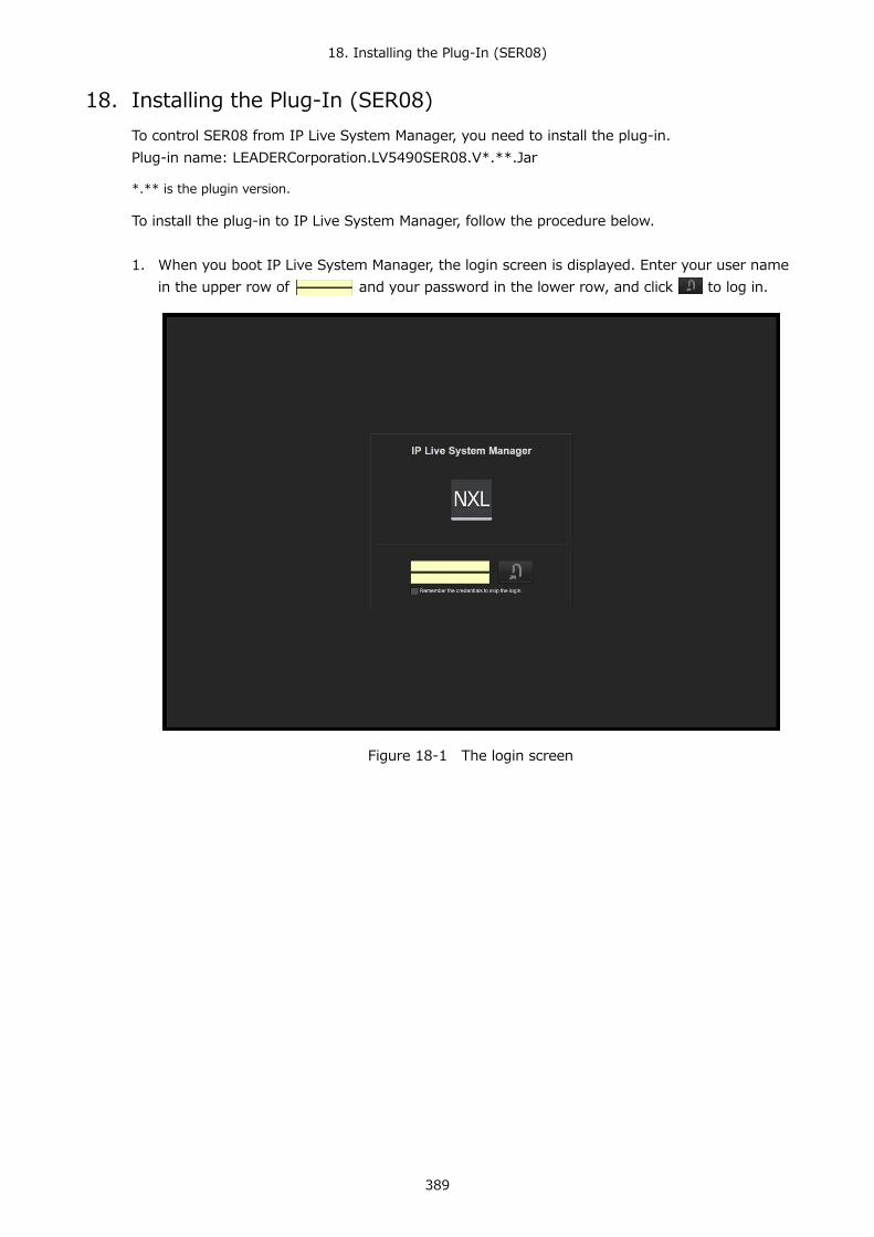
18. Installing the Plug-In (SER08)
389
18. Installing the Plug-In (SER08) To control SER08 from IP Live System Manager, you need to install the plug-in. Plug-in name: LEADERCorporation.LV5490SER08.V*.**.Jar
*.** is the plugin version.
To install the plug-in to IP Live System Manager, follow the procedure below.
1. When you boot IP Live System Manager, the login screen is displayed. Enter your user name
in the upper row of and your password in the lower row, and click to log in.
Figure 18-1 The login screen

18. Installing the Plug-In (SER08)
390
2. The top screen is displayed. Click Plug-in in the second column on the left.
Figure 18-2 The top screen
3. The plug-in list screen is displayed. Click Install at the bottom right.
Figure 18-3 The plug-in list screen

18. Installing the Plug-In (SER08)
391
4. The Select Installation File dialog is displayed in the center of the screen. Click Browse on the right side of Plug-in (LEADERCorporation.LV5490SER08.V *. **. Jar), select a plug-in and click OK.
Figure 18-4 The Select Installation File dialog
5. If the installation is successful, File upload is succeeded is displayed in the Select Install File dialog. Click OK to complete the installation.
Figure 18-5 The Select Install File dialog
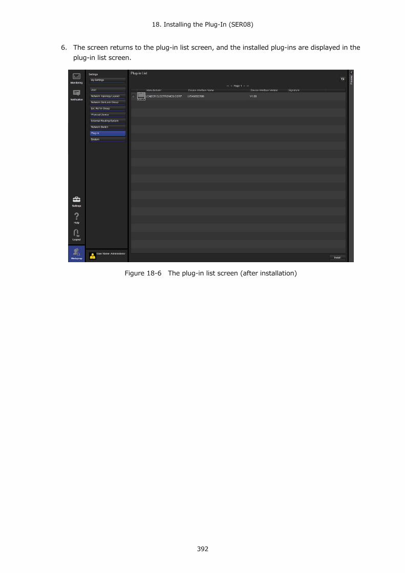
18. Installing the Plug-In (SER08)
392
6. The screen returns to the plug-in list screen, and the installed plug-ins are displayed in the plug-in list screen.
Figure 18-6 The plug-in list screen (after installation)

19. REMOTE CONTROL
393
19. REMOTE CONTROL You can use the remote control connector on the rear panel to load presets, transmit alarm signals, and perform other operations. Use the supplied 15-pin D-sub connector to control the LV 5490.
● Pinout Example
This section contains a diagram of the remote control connector, displayed as it appears on the rear panel, and a table that describes the connector's pinout.
Figure 19-1 Remote control connector (female, inch screws)
Table 19-1 Remote control connector pinout example
Pin No. Name I/O (*1) Function 1 OPEN - Open (*2) 2 /P1 I Loads preset 1 3 /P2 I Loads preset 2 4 /P3 I Loads preset 3 5 /P4 I Loads preset 4 6 /P5 I Loads preset 5 7 /P6 I Loads preset 6 8 /P7 I Loads preset 7 9 /P8 I Loads preset 8 10 /ACH I Selects channel A 11 /BCH I Selects channel B 12 /CCH I Selects channel C 13 /DCH I Selects channel D 14 ALARM O Transmits alarms 15 GND - Ground
*1 Is (inputs) are all pulled up to +3.3 V but can also receive +5 V. *2 Do not connect anything.

19. REMOTE CONTROL
394
● Configuring the LV 5490
To set the remote control connector, use the system settings. For details, see section 7.2.3, “Remote Control Settings.”
SYS → F•2 SYSTEM SETUP → F•3 NEXT TAB (×2) →
Figure 19-2 REMOTE SETUP tab
● Remote Control
The input connectors respond to active-low signals. Do not apply negative voltages or voltages that exceed +5 V. After you make a setting, a period of time of 350 ms or more in which the electrical potential is stable is required, so wait at least 1 second before you make the subsequent setting.
Figure 19-3 Remote control timing 1
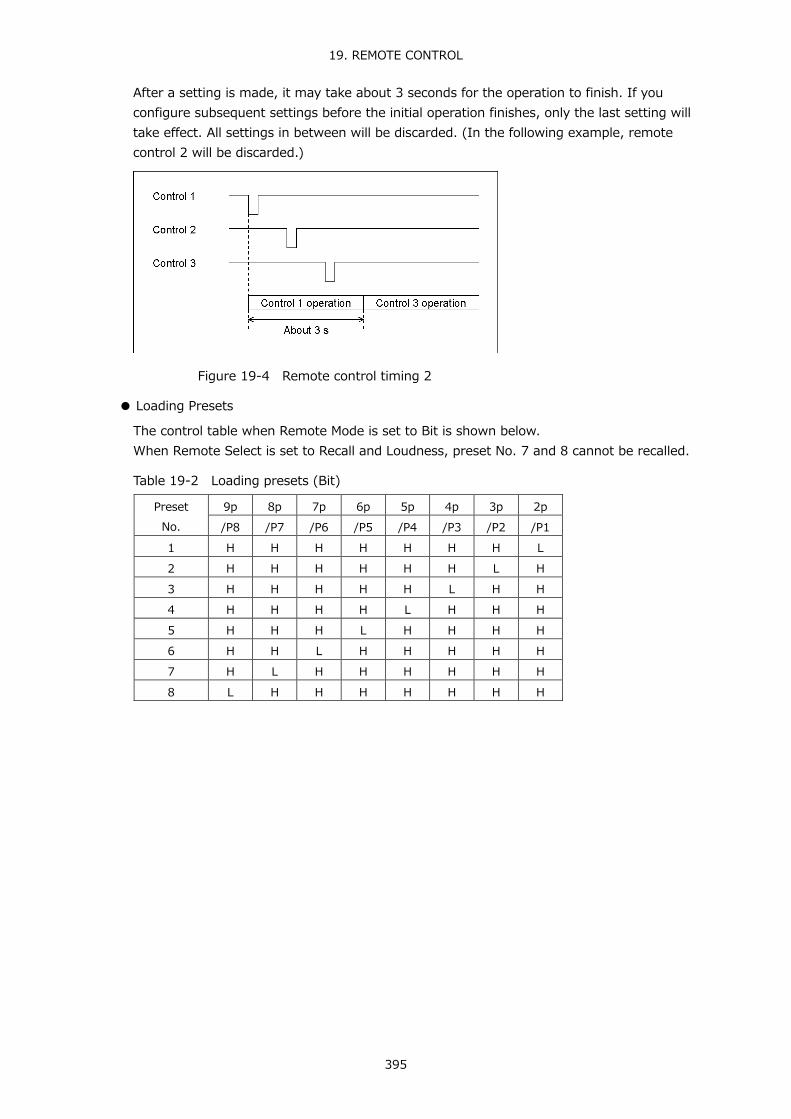
19. REMOTE CONTROL
395
After a setting is made, it may take about 3 seconds for the operation to finish. If you configure subsequent settings before the initial operation finishes, only the last setting will take effect. All settings in between will be discarded. (In the following example, remote control 2 will be discarded.)
Figure 19-4 Remote control timing 2
● Loading Presets
The control table when Remote Mode is set to Bit is shown below. When Remote Select is set to Recall and Loudness, preset No. 7 and 8 cannot be recalled.
Table 19-2 Loading presets (Bit)
Preset No.
9p 8p 7p 6p 5p 4p 3p 2p /P8 /P7 /P6 /P5 /P4 /P3 /P2 /P1
1 H H H H H H H L 2 H H H H H H L H 3 H H H H H L H H 4 H H H H L H H H 5 H H H L H H H H 6 H H L H H H H H 7 H L H H H H H H 8 L H H H H H H H
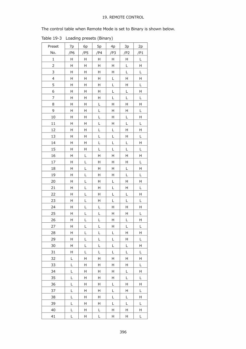
19. REMOTE CONTROL
396
The control table when Remote Mode is set to Binary is shown below.
Table 19-3 Loading presets (Binary)
Preset No.
7p 6p 5p 4p 3p 2p /P6 /P5 /P4 /P3 /P2 /P1
1 H H H H H L 2 H H H H L H 3 H H H H L L 4 H H H L H H 5 H H H L H L 6 H H H L L H 7 H H H L L L 8 H H L H H H 9 H H L H H L 10 H H L H L H 11 H H L H L L 12 H H L L H H 13 H H L L H L 14 H H L L L H 15 H H L L L L 16 H L H H H H 17 H L H H H L 18 H L H H L H 19 H L H H L L 20 H L H L H H 21 H L H L H L 22 H L H L L H 23 H L H L L L 24 H L L H H H 25 H L L H H L 26 H L L H L H 27 H L L H L L 28 H L L L H H 29 H L L L H L 30 H L L L L H 31 H L L L L L 32 L H H H H H 33 L H H H H L 34 L H H H L H 35 L H H H L L 36 L H H L H H 37 L H H L H L 38 L H H L L H 39 L H H L L L 40 L H L H H H 41 L H L H H L
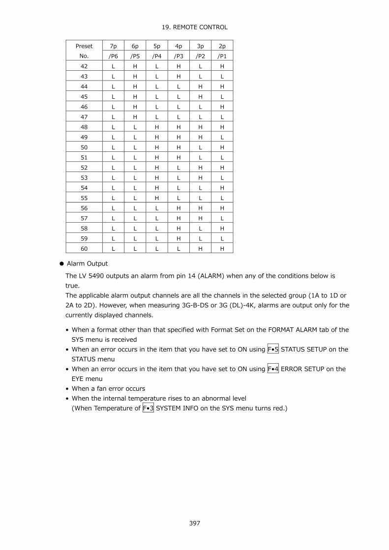
19. REMOTE CONTROL
397
Preset No.
7p 6p 5p 4p 3p 2p /P6 /P5 /P4 /P3 /P2 /P1
42 L H L H L H 43 L H L H L L 44 L H L L H H 45 L H L L H L 46 L H L L L H 47 L H L L L L 48 L L H H H H 49 L L H H H L 50 L L H H L H 51 L L H H L L 52 L L H L H H 53 L L H L H L 54 L L H L L H 55 L L H L L L 56 L L L H H H 57 L L L H H L 58 L L L H L H 59 L L L H L L 60 L L L L H H
● Alarm Output
The LV 5490 outputs an alarm from pin 14 (ALARM) when any of the conditions below is true. The applicable alarm output channels are all the channels in the selected group (1A to 1D or 2A to 2D). However, when measuring 3G-B-DS or 3G (DL)-4K, alarms are output only for the currently displayed channels.
• When a format other than that specified with Format Set on the FORMAT ALARM tab of the
SYS menu is received • When an error occurs in the item that you have set to ON using F•5 STATUS SETUP on the
STATUS menu • When an error occurs in the item that you have set to ON using F•4 ERROR SETUP on the
EYE menu • When a fan error occurs • When the internal temperature rises to an abnormal level
(When Temperature of F•3 SYSTEM INFO on the SYS menu turns red.)

20. ETHERNET REMOTE CONTROL
398
20. ETHERNET REMOTE CONTROL The LV 5490 can be remotely controlled through its Ethernet port on the rear panel. Controlling an LV 5490 remotely through its Ethernet interface has only been confirmed to work in a local network environment. LEADER does not guarantee that this feature will work in any network environment.
20.1 TELNET
From a PC connected to the same network as the LV 5490, most of the operations that you can perform from the front panel can be controlled remotely.
20.1.1 Procedure
1. Configure the Ethernet settings on the LV 5490's ETHERNET SETUP tab.
Set the IP Address, and set TELNET Server Select to ON. You cannot use the LV 5490-01 (REMOTE CONTROLLER) while you are using TELNET. Conversely, if you set LV 5490-01 to ON, you cannot use TELNET. Reference 7.2.2, "Configuring Ethernet Settings"
SYS → F•2 SYSTEM SETUP → F•2 PREV TAB or F•3 NEXT TAB →
Figure 20-1 ETHERNET SETUP tab
2. Press F•1 COMPLETE.
3. Connect the LV 5490's Ethernet port to the network.
4. On the PC, start a TELNET client.
On Windows 7, on the taskbar, click Start, and then click Run. Type "TELNET " and the IP address that you set in step 1. Then, click OK. (To use TELNET, open Control Panel, click Turn Windows features on or off under Program and Features, and select the Telnet Client check box.)

20. ETHERNET REMOTE CONTROL
399
5. Type the login name and password.
The login name and password are "LV5490". Use uppercase for all characters. When the login name and password are entered correctly, "LV5490@LV5490:~$" appears.
LV5490 login: LV5490 Password: ****** LV5490@LV5490:~$
6. Enter TELNET commands.
Enter commands while referring to sections 20.1.2, "How to Enter Commands," and 20.1.3, "TELNET Commands." To end a TELNET session, type “exit” in lowercase letters.
LV5490@LV5490:~$ exit
20.1.2 How to Enter Commands
The command syntax is explained below. (Some commands do not have parameters.) To query a current setting, use a question mark as the parameter.
LV5490@LV5490: ~$ [Command] + [Space] + [Parameter]
Examples of how to enter commands are shown below.
● Showing the Status Display
LV5490@LV5490: ~$ STATUS
● Displaying the Center Marker in the Picture Display
LV5490@LV5490: ~$ PIC:MARKER:CENTER ON
● Querying the Vector Intensity
LV5490@LV5490: ~$ VECTOR:INTEN ?
* You can enter commands using uppercase or lowercase letters. * Because the display channel selection command is different depending on the display
mode (single or simul) and SDI signal input settings, check the INPUT KEY command. * To query the measured value or detected value, you must use the INPUT KEY
command to show the measurement screen of the appropriate channel. Further, for 4K 3G QUAD LINK, 4K 3G DUAL LINK, 4K HD QUAD LINK, 3G DUAL LINK, and HD DUAL LINK settings, you must also select the link according to the link selection command of each measurement item.
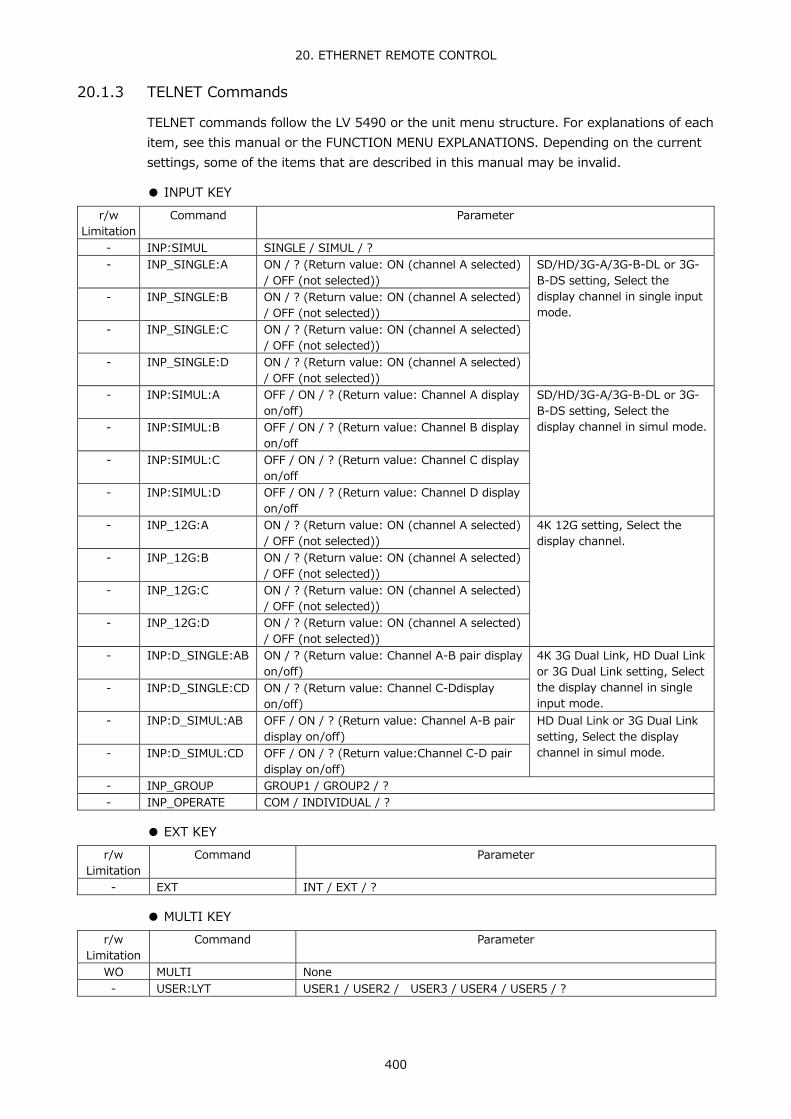
20. ETHERNET REMOTE CONTROL
400
20.1.3 TELNET Commands
TELNET commands follow the LV 5490 or the unit menu structure. For explanations of each item, see this manual or the FUNCTION MENU EXPLANATIONS. Depending on the current settings, some of the items that are described in this manual may be invalid.
● INPUT KEY
r/w Limitation
Command Parameter
- INP:SIMUL SINGLE / SIMUL / ? - INP_SINGLE:A ON / ? (Return value: ON (channel A selected)
/ OFF (not selected)) SD/HD/3G-A/3G-B-DL or 3G-B-DS setting, Select the display channel in single input mode.
- INP_SINGLE:B ON / ? (Return value: ON (channel A selected) / OFF (not selected))
- INP_SINGLE:C ON / ? (Return value: ON (channel A selected) / OFF (not selected))
- INP_SINGLE:D ON / ? (Return value: ON (channel A selected) / OFF (not selected))
- INP:SIMUL:A OFF / ON / ? (Return value: Channel A display on/off)
SD/HD/3G-A/3G-B-DL or 3G-B-DS setting, Select the display channel in simul mode. - INP:SIMUL:B OFF / ON / ? (Return value: Channel B display
on/off - INP:SIMUL:C OFF / ON / ? (Return value: Channel C display
on/off - INP:SIMUL:D OFF / ON / ? (Return value: Channel D display
on/off - INP_12G:A ON / ? (Return value: ON (channel A selected)
/ OFF (not selected)) 4K 12G setting, Select the display channel.
- INP_12G:B ON / ? (Return value: ON (channel A selected) / OFF (not selected))
- INP_12G:C ON / ? (Return value: ON (channel A selected) / OFF (not selected))
- INP_12G:D ON / ? (Return value: ON (channel A selected) / OFF (not selected))
- INP:D_SINGLE:AB ON / ? (Return value: Channel A-B pair display on/off)
4K 3G Dual Link, HD Dual Link or 3G Dual Link setting, Select the display channel in single input mode.
- INP:D_SINGLE:CD ON / ? (Return value: Channel C-Ddisplay on/off)
- INP:D_SIMUL:AB OFF / ON / ? (Return value: Channel A-B pair display on/off)
HD Dual Link or 3G Dual Link setting, Select the display channel in simul mode. - INP:D_SIMUL:CD OFF / ON / ? (Return value:Channel C-D pair
display on/off) - INP_GROUP GROUP1 / GROUP2 / ? - INP_OPERATE COM / INDIVIDUAL / ?
● EXT KEY
r/w Limitation
Command Parameter
- EXT INT / EXT / ?
● MULTI KEY r/w
Limitation Command Parameter
WO MULTI None - USER:LYT USER1 / USER2 / USER3 / USER4 / USER5 / ?
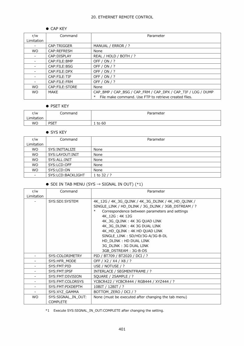
20. ETHERNET REMOTE CONTROL
401
● CAP KEY r/w
Limitation Command Parameter
- CAP:TRIGGER MANUAL / ERROR / ? WO CAP:REFRESH None - CAP:DISPLAY REAL / HOLD / BOTH / ? - CAP:FILE:BMP OFF / ON / ? - CAP:FILE:BSG OFF / ON / ? - CAP:FILE:DPX OFF / ON / ? - CAP:FILE:TIF OFF / ON / ? - CAP:FILE:FRM OFF / ON / ?
WO CAP:FILE:STORE None WO MAKE CAP_BMP / CAP_BSG / CAP_FRM / CAP_DPX / CAP_TIF / LOG / DUMP
* File make command. Use FTP to retrieve created files.
● PSET KEY r/w
Limitation Command Parameter
WO PSET 1 to 60
● SYS KEY r/w
Limitation Command Parameter
WO SYS:INITIALIZE None WO SYS:LAYOUT:INIT None WO SYS:ALL:INIT None WO SYS:LCD:OFF None WO SYS:LCD:ON None - SYS:LCD:BACKLIGHT 1 to 32 / ?
● SDI IN TAB MENU (SYS → SIGNAL IN OUT) (*1)
r/w Limitation
Command Parameter
- SYS:SDI:SYSTEM 4K_12G / 4K_3G_QLINK / 4K_3G_DLINK / 4K_HD_QLINK / SINGLE_LINK / HD_DLINK / 3G_DLINK / 3GB_DSTREAM / ? * Correspondence between parameters and settings
4K_12G : 4K 12G 4K_3G_QLINK : 4K 3G QUAD LINK 4K_3G_DLINK : 4K 3G DUAL LINK 4K_HD_QLINK : 4K HD QUAD LINK SINGLE_LINK : SD/HD/3G-A/3G-B-DL HD_DLINK : HD DUAL LINK 3G_DLINK : 3G DUAL LINK 3GB_DSTREAM : 3G-B-DS
- SYS:COLORIMETRY PID / BT709 / BT2020 / DCI / ? - SYS:HFR_MODE OFF / X2 / X4 / X8 / ? - SYS:FMT:PID USE / NOTUSE / ? - SYS:FMT:IPSF INTERLACE / SEGMENTFRAME / ? - SYS:FMT:DIVISION SQUARE / 2SAMPLE / ? - SYS:FMT:COLORSYS YCBCR422 / YCBCR444 / RGB444 / XYZ444 / ? - SYS:FMT:PIXDEPTH 10BIT / 12BIT / ? - SYS:XYZ_GAMMA BOTTOM_ZERO / DCI / ?
WO SYS:SIGNAL_IN_OUT:COMPLETE
None (must be executed after changing the tab menu)
*1 Execute SYS:SIGNAL_IN_OUT:COMPLETE after changing the setting.
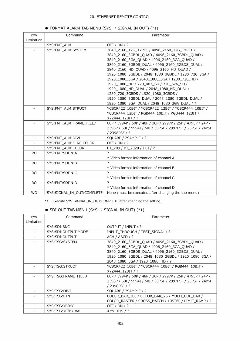
20. ETHERNET REMOTE CONTROL
402
● FORMAT ALARM TAB MENU (SYS → SIGNAL IN OUT) (*1) r/w
Limitation Command Parameter
- SYS:FMT_ALM OFF / ON / ? - SYS:FMT_ALM:SYSTEM 3840_2160_12G_TYPE1 / 4096_2160_12G_TYPE1 /
3840_2160_3GBDL_QUAD / 4096_2160_3GBDL_QUAD / 3840_2160_3GA_QUAD / 4096_2160_3GA_QUAD / 3840_2160_3GBDS_DUAL / 4096_2160_3GBDS_DUAL / 3840_2160_HD_QUAD / 4096_2160_HD_QUAD / 1920_1080_3GBDL / 2048_1080_3GBDL / 1280_720_3GA / 1920_1080_3GA / 2048_1080_3GA / 1280_720_HD / 1920_1080_HD / 720_487_SD / 720_576_SD / 1920_1080_HD_DUAL / 2048_1080_HD_DUAL / 1280_720_3GBDS / 1920_1080_3GBDS / 1920_1080_3GBDL_DUAL / 2048_1080_3GBDL_DUAL / 1920_1080_3GA_DUAL / 2048_1080_3GA_DUAL / ?
- SYS:FMT_ALM:STRUCT YCBCR422_10BIT / YCBCR422_12BIT / YCBCR444_10BIT / YCBCR444_12BIT / RGB444_10BIT / RGB444_12BIT / XYZ444_12BIT / ?
- SYS:FMT_ALM:FRAME_FIELD 60P / 5994P / 50P / 48P / 30P / 2997P / 25P / 4795P / 24P / 2398P / 60I / 5994I / 50I / 30PSF / 2997PSF / 25PSF / 24PSF / 2398PSF / ?
- SYS:FMT_ALM:DIVI SQUARE / 2SAMPLE / ? - SYS:FMT_ALM:FLAG:COLOR OFF / ON / ? - SYS:FMT_ALM:COLOR BT_709 / BT_2020 / DCI / ?
RO SYS:FMT:SDIIN:A ? * Video format information of channel A
RO SYS:FMT:SDIIN:B ? * Video format information of channel B
RO SYS:FMT:SDIIN:C ? * Video format information of channel C
RO SYS:FMT:SDIIN:D ? * Video format information of channel D
WO SYS:SIGNAL_IN_OUT:COMPLETE None (must be executed after changing the tab menu)
*1 Execute SYS:SIGNAL_IN_OUT:COMPLETE after changing the setting.
● SDI OUT TAB MENU (SYS → SIGNAL IN OUT) (*1) r/w
Limitation Command Parameter
- SYS:SDI:BNC OUTPUT / INPUT / ? - SYS:SDI:OUTPUT:MODE INPUT_THROUGH / TEST_SIGNAL / ? - SYS:SDI:OUTPUT ACH / ABCD / ? - SYS:TSG:SYSTEM 3840_2160_3GBDL_QUAD / 4096_2160_3GBDL_QUAD /
3840_2160_3GA_QUAD / 4096_2160_3GA_QUAD / 3840_2160_3GBDS_DUAL / 4096_2160_3GBDS_DUAL / 1920_1080_3GBDL / 2048_1080_3GBDL / 1920_1080_3GA / 2048_1080_3GA / 1920_1080_HD / ?
- SYS:TSG:STRUCT YCBCR422_10BIT / YCBCR444_10BIT / RGB444_10BIT / XYZ444_12BIT / ?
- SYS:TSG:FRAME_FIELD 60P / 5994P / 50P / 48P / 30P / 2997P / 25P / 4795P / 24P / 2398P / 60I / 5994I / 50I / 30PSF / 2997PSF / 25PSF / 24PSF / 2398PSF / ?
- SYS:TSG:DIVI SQUARE / 2SAMPLE / ? - SYS:TSG:PTN COLOR_BAR_100 / COLOR_BAR_75 / MULTI_COL_BAR /
COLOR_RASTER / CROSS_HATCH / 10STEP / LIMIT_RAMP / ? - SYS:TSG:YCB:Y OFF / ON / ? - SYS:TSG:YCB:Y:VAL 4 to 1019 / ?

20. ETHERNET REMOTE CONTROL
403
r/w Limitation
Command Parameter
- SYS:TSG:YCB:CB OFF / ON / ? - SYS:TSG:YCB:CB:VAL 4 to 1019 / ? - SYS:TSG:YCB:CR OFF / ON / ? - SYS:TSG:YCB:CR:VAL 4 to 1019 / ? - SYS:TSG:RGB:R OFF / ON / ? - SYS:TSG:RGB:R:VAL 4 to 1019 / ? - SYS:TSG:RGB:G OFF / ON / ? - SYS:TSG:RGB:G:VAL 4 to 1019 / ? - SYS:TSG:RGB:B OFF / ON / ? - SYS:TSG:RGB:B:VAL 4 to 1019 / ? - SYS:TSG:SCRL OFF / ON / ? - SYS:TSG:SCRL:DIREC RIGHT / LEFT / UP / DOWN / RIGHT_UP / RIGHT_DOWN /
LEFT_UP / LEFT_DOWN / ? - SYS:TSG:SCRL:SPEED 4 to 124 / ? - SYS:TSG:BOX OFF / ON / ? - SYS:TSG:BOX:COLOR WHITE / YELLOW / CYAN / GREEN / MAGENTA / RED / BLUE /
BLACK / ? - SYS:TSG:BOX:SPEED 1 to 3 / ? - SYS:TSG:PHS OFF / ON / ? - SYS:TSG:PHS:DIREC H / V / ? - SYS:TSG:PHS:H:BCH -1374 to 1374 / ? - SYS:TSG:PHS:H:CCH -1374 to 1374 / ? - SYS:TSG:PHS:H:DCH -1374 to 1374 / ? - SYS:TSG:PHS:V:BCH -562 to 562 / ? - SYS:TSG:PHS:V:CCH -562 to 562 / ? - SYS:TSG:PHS:V:DCH -562 to 562 / ? - SYS:TSG:AUDIO:G1 OFF / ON / ? - SYS:TSG:AUDIO:G2 OFF / ON / ? - SYS:TSG:AUDIO:G3 OFF / ON / ? - SYS:TSG:AUDIO:G4 OFF / ON / ? - SYS:TSG:AUDIO:LVL M20DBFS / M18DBFS / 0DBFS / MUTE / ?
WO SYS:SIGNAL_IN_OUT:COMPLETE None (must be executed after changing the tab menu)
*1 Execute SYS:SIGNAL_IN_OUT:COMPLETE after changing the setting.
● HDR TAB MENU (SYS → SIGNAL IN OUT) (*1) r/w
Limitation Command Parameter
- SYS:HDR:ENABLE OFF / ON / ? - SYS:HDR:HDR_CURVE HLG / PQ / SLOG3 / ? - SYS:HDR:MAX MAX_10000 / MAX_4000 / MAX_1000 / ? - SYS:HDR:GAMMA OFF / ON / ? - SYS:HDR:REF:PQ P51 / P58 / ? - SYS:HDR:REF:HLG P50 / P75 / ?
WO SYS:SIGNAL_IN_OUT:COMPLETE None (must be executed after changing the tab menu)
*1 Execute SYS:SIGNAL_IN_OUT:COMPLETE after changing the setting.
● AUDIO IN/OUT TAB MENU ( SYS → SIGNAL IN OUT) (*1) r/w
Limitation Command Parameter
- SYS:AUD:BNC:A INPUT / OUTPUT / ? - SYS:AUD:BNC:B INPUT / OUTPUT / ?
WO SYS:SIGNAL_IN_OUT:COMPLETE None (must be executed after changing the tab menu)
*1 Execute SYS:SIGNAL_IN_OUT:COMPLETE after changing the setting.

20. ETHERNET REMOTE CONTROL
404
● MONITOR OUT TAB MENU (SYS → SIGNAL IN OUT) (*1)
r/w Limitation
Command Parameter
- SYS:RASTER:SYNC INT / EXTSIG / ? - SYS:RASTER:FORMAT 1080_60P / 1080_5994P / 1080_50P / ? - SYS:RASTER:SDIOUT:MODE RASTER / ROUTER / ? - SYS:RASTER:SDIOUT:FMT HD_SDI / 3G_SDI-A / 3G_SDI-B / ?
WO SYS:SIGNAL_IN_OUT:COMPLETE None (must be executed after changing the tab menu)
*1 Execute SYS:SIGNAL_IN_OUT:COMPLETE after changing the setting.
● 12G SDI OUT TAB MENU (SYS → SIGNAL IN OUT) (*1) r/w
Limitation Command Parameter
- SYS:12G:OUTPUT INPUT / 12G / NO / ? - SYS:12G:FRAME_RATE 60P / 5994P / 50P / ?
WO SYS:SIGNAL_IN_OUT:COMPLETE None (must be executed after changing the tab menu)
*1 Execute SYS:SIGNAL_IN_OUT:COMPLETE after changing the setting.
● GENERAL SETUP TAB MENU (SYS → SYSTEM SETUP) (*2)
r/w Limitation
Command Parameter
- SYS:BOOT:MODE NORMAL / FAST / ? - SYS:CAPMODE SCREEN / VIDEO_FRAME / ? - SYS:INFODISP:FORMAT OFF / ON / ? - SYS:INFODISP:DATE OFF / YMD / MDY / DMY / ? - SYS:INFODISP:TIME OFF / REALTIME / LTC / VITC / DVITC / ? - SYS:INFODISP:INPUT OFF / ON / ? - SYS:INFODISP:ICON OFF / ON / ? SYS:INFODISP:ERROR OFF / ON / ? - SYS:MENU:AUTOOFF OFF / ON / ? - SYS:MENU:OFFTIME 1 to 60 / ? - SYS:MENU:RECALL_MENU RECALL / FUNCTION / ? - SYS:LCD:AUTO:OFF OFF / 5MIN / 30MIN / 60MIN / ? - SYS:FAN:SPEED 1 to 5 / ? - SYS:FAN:WARNING OFF / ON / ?
WO SYS:SYSTEM_SETUP:COMPLETE None (must be executed after changing the tab menu)
*2 Execute SYS:SYSTEM_SETUP:COMPLETE after changing the setting.
● ETHERNET SETUP TAB MENU (SYS → SYSTEM SETUP) (*3) r/w
Limitation Command Parameter
- SYS:ETHERNET:SELECT DHCP / IP / ? - SYS:IP:IPADR:SEG1 0 to 255 / ? - SYS:IP:IPADR:SEG2 0 to 255 / ? - SYS:IP:IPADR:SEG3 0 to 255 / ? - SYS:IP:IPADR:SEG4 0 to 255 / ? - SYS:IP:MASK:SEG1 0 to 255 / ? - SYS:IP:MASK:SEG2 0 to 255 / ? - SYS:IP:MASK:SEG3 0 to 255 / ?

20. ETHERNET REMOTE CONTROL
405
r/w Limitation
Command Parameter
- SYS:IP:MASK:SEG4 0 to 255 / ? - SYS:IP:GATE:SEG1 0 to 255 / ? - SYS:IP:GATE:SEG2 0 to 255 / ? - SYS:IP:GATE:SEG3 0 to 255 / ? - SYS:IP:GATE:SEG4 0 to 255 / ? - SYS:SNTP:SELECT OFF / ON / ? - SYS:SNTP:IPADR:SEG1 0 to 255 / ? - SYS:SNTP:IPADR:SEG2 0 to 255 / ? - SYS:SNTP:IPADR:SEG3 0 to 255 / ? - SYS:SNTP:IPADR:SEG4 0 to 255 / ? - SYS:SNTP:TZ:ADJ 0(-12) to 24(+12) - SYS:TELNET:SELECT OFF / ON / ? - SYS:FTP:SELECT OFF / ON / ? - SYS:HTP:SELECT OFF / ON / ? - SYS:SNMP:READ OFF / ONLY(read only) / WRITE / ? - SYS:SNMP:TRAP OFF / ON / ?
WO SYS:ETHERNET:UPDATE None
*3 Execute SYS:ETHERNET:UPDATE after changing the setting.
● REMOTE SETUP TAB MENU (SYS → SYSTEM SETUP) (*2) r/w
Limitation Command Parameter
- SYS:REMOTE:MODE BIT / BINARY / ? - SYS:REMOTE:ALM:POLARITY POSITIVE / NEGATIVE / ? - SYS:REMOTE:ALM:A OFF / ON / ? - SYS:REMOTE:ALM:B OFF / ON / ? - SYS:REMOTE:ALM:C OFF / ON / ? - SYS:REMOTE:ALM:D OFF / ON / ?
WO SYS:SYSTEM_SETUP:COMPLETE None (must be executed after changing the tab menu)
*2 Execute SYS:SYSTEM_SETUP:COMPLETE after changing the setting.
● DATA & TIME TAB MENU (SYS → SYSTEM SETUP) (*4) r/w
Limitation Command Parameter
- SYS:DATE:DAY 1 to 31 / ? - SYS:DATE:MONTH 1 to 12 / ? - SYS:DATE:YEAR 2000 to 2099 / ? - SYS:TIME:HOUR 0 to 23 / ? - SYS:TIME:MIN 0 to 59 / ? - SYS:TIME:SEC 0 to 59 / ?
WO SYS:SET:DATE_TIME None * To synchronize the clock to a specific time, specify all commands: DAY,
MONTH, YEAR, HOUR, MIN, and SEC.
*4 Execute SYS:SET:DATE_TIME after changing the setting.

20. ETHERNET REMOTE CONTROL
406
● INFORMATION TAB MENU (SYS → SYSTEM INFO) r/w
Limitation Command Parameter
RO SYS:INFO:FIRMWARE ? RO SYS:INFO:BOARD:SDIIN ? / not installed / installed
* LV5490SER01 SDI INPUT board, LV 5490SER02 SDI INPUT/EYE board, LV 5490SER06 12G INPUT/EYE board installation status
RO SYS:INFO:BOARD:SDIEYE ? / not installed / installed * LV5490SER02 SDI INPUT/EYE board, LV 5490SER06 12G INPUT/EYE board installation status
RO SYS:INFO:BOARD:AUDIO ? / not installed / installed * LV5490SER03 DIGITAL AUDIO board installation status
RO SYS:IP:MAC ?
● WFM KEY r/w
Limitation Command Parameter
WO WFM None - WFM:INTEN -128 to 127 / ? - WFM:COLOR WHITE / YELLOW / CYAN / GREEN / MAGENTA / RED / BLUE /
MULTI / ? - WFM:COLOR:S1 WHITE / YELLOW / CYAN / GREEN / MAGENTA / RED / BLUE /
MULTI / ? - WFM:COLOR:S2 WHITE / YELLOW / CYAN / GREEN / MAGENTA / RED / BLUE /
MULTI / ? - WFM:SCALE:INTEN -8 to 7 / ? - WFM:SCALE:COLOR WHITE / YELLOW / CYAN / GREEN / MAGENTA / RED / BLUE / ? - WFM:SCALE:UNIT HDV_SDP / HDV_SDV / HDP_SDP / 150P / 1023_NRM /
1023_255 / 3FF / ? - WFM:SCALE:UNIT:NTSC HDP_SDP / ? - WFM:SCALE:UNIT:PAL HDV_SDV / ? - WFM:SCALE:75_COLOR OFF / ON / ? - WFM:GAIN:VAR CAL / VAR / ? - WFM:GAIN:MAG X1 / X5 / ? - WFM:GAIN:VAL 20 to 200 / ?
* Correspondence 20: x0.200 to 200: x2.000 - WFM:FILTER:NORMAL LOWPASS / FLAT / ? - WFM:FILTER:CMPST FLAT / LUM / FLAT_LUM / LUM_CRMA / ? - WFM:SWEEP:SWEEP H / V / ? - WFM:SWEEP:H_MAG X1 / X10 / X20 / BLANK / ACTIVE / ? - WFM:SWEEP:V_MAG X1 / X20 / X40 / ? - WFM:SWEEP:H_SWEEP 1H / 2H / ? - WFM:SWEEP:V_SWEEP 1V / 2V / ? - WFM:SWEEP:FIELD FIELD1 / FIELD2 / ? - WFM:BLANKING:NORMAL REMOVE / V_VIEW / H_VIEW / ALL_VIEW / ? - WFM:BLANKING:CMPST REMOVE / V_VIEW / ? - WFM:CURSOR ON / ON_XY / OFF / ? - WFM:CURSOR:SEL X / Y / ? - WFM:CURSOR:FD REF / DELTA / TRACK / ? - WFM:CURSOR:UNIT sec / Hz / ? (when X is selected)
MV / % / R% / DEC / HEX / HDR / ? (when Y is selected) - WFM:CURSOR:REF 0 to 927 / ? (when X is selected)
0 to 504 / ? (when Y is selected) - WFM:CURSOR:DELTA 0 to 927 / ? (when X is selected)
0 to 504 / ? (when Y is selected)

20. ETHERNET REMOTE CONTROL
407
r/w Limitation
Command Parameter
WO WFM:CURSOR:TRACK -927 to 927 / ? (when X is selected) -504 to 504 / ? (when Y is selected)
WO WFM:CURSOR:REFSET None - WFM:MATRIX:YCBCR YCBCR / GBR / RGB / COMPOSIT / ? - WFM:MATRIX:RGB GBR / RGB / COMPOSIT / ? - WFM:MATRIX:YGBR OFF / ON / ? - WFM:MATRIX:YRGB OFF / ON / ? - WFM:MATRIX:XYZ XYZ / GBR / RGB / COMPOSIT / ? - WFM:MATRIX:CMPST:FORMAT AUTO / NTSC / PAL / ? - WFM:MATRIX:CMPST:SETUP 0P / 7.5P / ? - WFM:DISP:OVLAY PARADE / OVERLAY / ? - WFM:DISP:YCBCR:CH1 OFF / ON / ? - WFM:DISP:YCBCR:CH2 OFF / ON / ? - WFM:DISP:YCBCR:CH3 OFF / ON / ? - WFM:DISP:GBR:CH1 OFF / ON / ? - WFM:DISP:GBR:CH2 OFF / ON / ? - WFM:DISP:GBR:CH3 OFF / ON / ? - WFM:DISP:RGB:CH1 OFF / ON / ? - WFM:DISP:RGB:CH2 OFF / ON / ? - WFM:DISP:RGB:CH3 OFF / ON / ? - WFM:DISP:XYZ:CH1 OFF / ON / ? - WFM:DISP:XYZ:CH2 OFF / ON / ? - WFM:DISP:XYZ:CH3 OFF / ON / ? - WFM:DISP:3G-B-DS STREAM1 / STREAM2 / MIX / ALIGN / ? - WFM:DISP:4Y_PARADE OFF / ON / ?
WO WFM:POS:MOVE:H -32768 to 32767 WO WFM:POS:MOVE:V -32768 to 32767 RO WFM:POS:ABS:H ? RO WFM:POS:ABS:V ? - WFM:LINE_SELECT OFF / ON / ? - WFM:LINE_NUMBER -32768 to 32767 / ? - WFM:LINE_FIELD FRAME / FIELD1 / FIELD2 / ?
● VECTOR KEY
r/w Limitation
Command Parameter
WO VECTOR None - VECTOR:MODE VECTOR / 5BAR / HISTOGRAM / CIE_DIAGRAM / ? - VECTOR:INTEN -128 to 127 / ? - VECTOR:COLOR WHITE / YELLOW / CYAN / GREEN / MAGENTA / RED / BLUE
/ ? - VECTOR:COLOR:S1 WHITE / YELLOW / CYAN / GREEN / MAGENTA / RED / BLUE
/ ? * Valid for 3G-B-DS stream 1
- VECTOR:COLOR:S2 WHITE / YELLOW / CYAN / GREEN / MAGENTA / RED / BLUE / ? * Valid for 3G-B-DS stream 2
- VECTOR:SCALE:INTEN -8 to 7 / ? - VECTOR:SCALE:COLOR WHITE / YELLOW / CYAN / GREEN / MAGENTA / RED / BLUE
/ ? - VECTOR:SCALE:IQ OFF / ON / ? - VECTOR:SCALE:VEC AUTO / BT_601 / BT_709 / DCI / BT_2020 / ? - VECTOR:SCALE:5BAR P / MV - VECTOR:SCALE:5BAR:SEQ GBR / RGB - VECTOR:GAIN:VARIABLE CAL / VARIABLE / ?

20. ETHERNET REMOTE CONTROL
408
r/w Limitation
Command Parameter
- VECTOR:GAIN:MAG X1 / X5 / IQ / ? - VECTOR:GAIN:VAR 200 to 10000 / ?
* Correspondence 200: x0.200 to 10000: x10.000 - VECTOR:MATRIX COMPONENT / COMPOSITE / ? - VECTOR:MATRIX:COLORBAR 100P / 75P / ? - VECTOR:MATRIX:CMPST:FORMAT AUTO / NTSC / PAL / ? - VECTOR:MATRIX:CMPST:SETUP 0P / 7.5P / ? - VECTOR:MARKER OFF / ON / ? - VECTOR:MARKER:POS_H -32768 to 32767 / ? - VECTOR:MARKER:POS_V -32768 to 32767 / ? - VECTOR:DISP:3G-B-DS STREAM1 / STREAM2 / MIX / ALIGN / ? - VEC:LINE_SELECT OFF / ON / ? - VEC:LINE_NUMBER -32768 to 32767 / ? - VEC:LINE_FIELD FRAME / FIELD1 / FIELD2 / ? - VECTOR:HIST:SCALE:HDR % / HDR / ?
● LV 5490SER05 CIE DIAGRAM
r/w Limitation
Command Parameter
- VECTOR:CIE:CURSOR OFF / ON / ? - VECTOR:CIE:CURSOR:POS_H -32768 to 32767 / ? - VECTOR:CIE:CURSOR:POS_V -32768 to 32767 / ? - VECTOR:CIE:SCALE:SUB:TEMP_SCALE OFF / ON / ? - VECTOR:CIE:SCALE:COLOR VEC_CIE_COLOR_BG_COLOR /
VEC_CIE_COLOR_BG_WHITE / VEC_CIE_COLOR_BG_BLACK / ?
- VECTOR:CIE:SCALE:TRIANGLE1 OFF / BT_601_525 / BT_601_625 / BT_709 / DCI / BT_2020 / ?
- VECTOR:CIE:SCALE:TRIANGLE2 OFF / BT_601_525 / BT_601_625 / BT_709 / DCI / BT_2020 / ?
- VECTOR:CIE:SCALE:SUB:GRID OFF / ON / ? - VECTOR:CIE:SCALE:SUB:D65 OFF / ON / ? - VECTOR:CIE:SCALE:SUB:CAP OFF / ON / ? - VECTOR:CIE:SCALE:USER_TRIANGLE OFF / 1 / 2 / ? - VECTOR:CIE:SCALE:USER_TRIANGLE:COLOR G / B / R / ? - VECTOR:CIE:SCALE:USER_TRIANGLE1:G:X 0 to 1000 / ?
* Correspondence 0: 0.000 to 1000: 1.000 - VECTOR:CIE:SCALE:USER_TRIANGLE1:B:X 0 to 1000 / ?
* Correspondence 0: 0.000 to 1000: 1.000 - VECTOR:CIE:SCALE:USER_TRIANGLE1:R:X 0 to 1000 / ?
* Correspondence 0: 0.000 to 1000: 1.000 - VECTOR:CIE:SCALE:USER_TRIANGLE1:G:Y 0 to 1000 / ?
* Correspondence 0: 0.000 to 1000: 1.000 - VECTOR:CIE:SCALE:USER_TRIANGLE1:B:Y 0 to 1000 / ?
* Correspondence 0: 0.000 to 1000: 1.000 - VECTOR:CIE:SCALE:USER_TRIANGLE1:R:Y 0 to 1000 / ?
* Correspondence 0: 0.000 to 1000: 1.000 - VECTOR:CIE:SCALE:USER_TRIANGLE2:G:X 0 to 1000 / ?
* Correspondence 0: 0.000 to 1000: 1.000 - VECTOR:CIE:SCALE:USER_TRIANGLE2:B:X 0 to 1000 / ?
* Correspondence 0: 0.000 to 1000: 1.000 - VECTOR:CIE:SCALE:USER_TRIANGLE2:R:X 0 to 1000 / ?
* Correspondence 0: 0.000 to 1000: 1.000 - VECTOR:CIE:SCALE:USER_TRIANGLE2:G:Y 0 to 1000 / ?
* Correspondence 0: 0.000 to 1000: 1.000

20. ETHERNET REMOTE CONTROL
409
r/w Limitation
Command Parameter
- VECTOR:CIE:SCALE:USER_TRIANGLE2:B:Y 0 to 1000 / ? * Correspondence 0: 0.000 to 1000: 1.000
- VECTOR:CIE:SCALE:USER_TRIANGLE2:R:Y 0 to 1000 / ? * Correspondence 0: 0.000 to 1000: 1.000
- VECTOR:CIE:DIAGRAM:TYPE DIAGRAM / TEMP / ? - VECTOR:CIE:DIAGRAM:FILTER OFF / ON / ? - VECTOR:CIE:DIAGRAM:CLIP OFF / ON / ? - VECTOR:CIE:DIAGRAM:CIE_STD CIE1931 / CIE1976 / ? - VECTOR:CIE:DIAGRAM:MANUAL OFF / ON / ? - VECTOR:CIE:DIAGRAM:MANUAL:GAMMA 2_2 / 2_6 / ? - VECTOR:CIE:DIAGRAM:MANUAL:COLORIMETRY BT_601_525 / BT_601_625 / BT_709 / DCI /
BT_2020 / ? - VECTOR:CIE:DIAGRAM:MANUAL:GAMMA:SETUP 150 to 300 / ?
* Correspondence 150: 1.50 to 300: 3.00
● PICTURE KEY r/w
Limitation Command Parameter
WO PICTURE None - PIC:COLOR COLOR / MONO / ? - PIC:CHROMA NORMAL / UP / ? - PIC:BRIGHTNESS -500 to 500 / ?
* -500: -50.0% to 500: 50.0% - PIC:CONTRAST 0 to 2000 / ?
* 0: 0.0% to 2000: 200.0% - PIC:GAIN:R 0 to 2000 / ?
* 0: 0.0% to 2000: 200.0% - PIC:GAIN:G 0 to 2000 / ?
* 0: 0.0% to 2000: 200.0% - PIC:GAIN:B 0 to 2000 / ?
* 0: 0.0% to 2000: 200.0% - PIC:BIAS:R -500 to 500 / ?
* -500: -50.0% to 500: 50.0% - PIC:BIAS:G -500 to 500 / ?
* -500: -50.0% to 500: 50.0% - PIC:BIAS:B -500 to 500 / ?
* -500: -50.0% to 500: 50.0% - PIC:GAIN:CHROMA 0 to 2000 / ?
* 0: 0.0% to 2000: 200.0% - PIC:MARKER:FRAME OFF / ON / ? - PIC:MARKER:CENTER OFF / ON / ? - PIC:MARKER:ASPECT OFF / 17_9 / 16_9 / 14_9 / 13_9 / 4_3 /
2.39_1 / AFD / ? - PIC:MARKER:ASPECT:SHADOW 0 to 100 / ? - PIC:MARKER:SAFETY:ACTION OFF / ARIB / SMPTE / USER1 / ? - PIC:MARKER:SAFETY:TITLE OFF / ARIB / SMPTE / USER2 / ? - PIC:MARKER:SAFETY:USER1_W 0 to 100 / ? - PIC:MARKER:SAFETY:USER1_H 0 to 100 / ? - PIC:MARKER:SAFETY:USER2_W 0 to 100 / ? - PIC:MARKER:SAFETY:USER2_H 0 to 100 / ? - PIC:DISPLAY:SIZE FIT / REAL / X2 / FULL_FRM / ? - PIC:DISPLAY:GAMUT OFF / WHITE / RED / MESH - PIC:DISPLAY:3G-B-DS STREAM1 / STREAM2 / MIX / ALIGN / ? - PIC:POS:H -32768 to 32767 / ? - PIC:POS:V -32768 to 32767 / ?

20. ETHERNET REMOTE CONTROL
410
r/w Limitation
Command Parameter
- PIC:CINELITE:DISPLAY OFF / f_Stop / P_DISPLAY / CINEZONE / ? - PIC:CINELITE:ADVANCE OFF / ON / ? - PIC:CINELITE:MEAS_POS P1 / P2 / P3 / ? - PIC:CINELITE:MEAS_NUMS P1 / P1+P2 / P1+P2+P3 / ? - PIC:CINELITE:MEAS_SIZE 1X1 / 3X3 / 9X9 / ? - PIC:CINELITE:RGB:UNIT Y_P / RGB_P / RGB_255 / REAL /
CODE_VALUE/ CODE_VALUE_DEC / HDR / ? WO PIC:CINELITE:FSTOP:18P_REFSET None - PIC:CINELITE:FSTOP:GAMMA_SEL 0.45 / USER1 / USER2 / USER3 / USER_A /
USER_B / USER_C / USER_D / USER_E / ? - PIC:CINELITE:FSTOP:GAMMA:CAL:F 22_0 / 16_0 / 11_0 / 8_0 / 5_6 / 4_0 / 2_8 /
2_0 / ? WO PIC:CINELITE:FSTOP:GAMMA:CAL:SET None WO PIC:CINELITE:FSTOP:GAMMA:CAL:1DATACLEAR None WO PIC:CINELITE:FSTOP:GAMMA:CAL:TABLECLEAR None WO PIC:CINELITE:FSTOP:GAMMA:FILE:TABLECLEAR None RO PIC:CINELITE:DATA:P1 ? RO PIC:CINELITE:DATA:P2 ? RO PIC:CINELITE:DATA:P3 ? - PIC:CINELITE:CINEZONE:FORM GRADATE / STEP / SEARCH / ? - PIC:CINELITE:CINEZONE:UPPER -63 to 1094 / ?
* -63: -6.3 to 1094: 109.4 - PIC:CINELITE:CINEZONE:LOWER -73(-7.3) to 1084(108.4) / ?
* -73: -7.3 to 1084: 108.4 - PIC:CINELITE:CINEZONE:LEVEL -73(-7.3) to 1094(109.4) / ?
* -73: -7.3 to 1094: 109.4 - PIC:LINE_SELECT OFF / ON - PIC:LINE_NUMBER -32768 to 32767 / ? - PIC:LINE_FIELD FRAME / FIELD1 / FIELD2 / ? - PIC:STATUS_INFO OFF / ON - PIC:SN:NOISE STOP / START / ? - PIC:SN:CH A1 / A2 / TRACK / OFF / ? - PIC:SN:SIGNAL Y / G / B / R / ? - PIC:SN:LPF 0_404 / 0_323 / 0_269 / 0_202 / 0_101 /
0_0505 / THROUGH / ? - PIC:SN:SIZE SMALL / LARGE / ? - PIC:SN:HPF ON / OFF / ? - PIC:SN:ALART:UNIT ON / OFF / ? - PIC:SN:ALART:LEVEL -80 to 0 / ?
● LV5490SER04 FOCUS ASSIST
r/w Limitation
Command Parameter
- PIC:FOCUS:ASSIST OFF / ON / ? - PIC:FOCUS:EDGE_COLOR WHITE / GREEN / RED / BLUE / ? - PIC:FOCUS:PIC_LEVEL OFF / LVL25 / LVL50 / LVL75 / LVL100 /
EMBOSS / ? - PIC:FOCUS:SENSITIVE LOW / MIDDLE / HIGH / V_HIGH / U_HIGH / ?

20. ETHERNET REMOTE CONTROL
411
● LV 5490SER07 HDR r/w
Limitation Command Parameter
- PIC:HDR:UPPER:HLG 0 to 1000 / ? * 0: 0.0% to 1000: 100.0%
- PIC:HDR:LOWER:HLG 0 to 1000 / ? * 0: 0.0% to 1000: 100.0%
- PIC:HDR:REF:HLG 0 to 1000 / ? * 0: 0.0% to 1000: 100.0%
- PIC:HDR:UPPER:PQ_10000 0 to 1000 / ? * 0: 0.0% to 1000: 100.0%
- PIC:HDR:LOWER:PQ_10000 0 to 1000 / ? * 0: 0.0% to 1000: 100.0%
- PIC:HDR:REF:PQ_10000 0 to 1000 / ? * 0: 0.0% to 1000: 100.0%
- PIC:HDR:UPPER:PQ_4000 0 to 1000 / ? * 0: 0.0% to 1000: 100.0%
- PIC:HDR:LOWER:PQ_4000 0 to 1000 / ? * 0: 0.0% to 1000: 100.0%
- PIC:HDR:REF:PQ_4000 0 to 1000 / ? * 0: 0.0% to 1000: 100.0%
- PIC:HDR:UPPER:PQ_1000 0 to 1000 / ? * 0: 0.0% to 1000: 100.0%
- PIC:HDR:LOWER:PQ_1000 0 to 1000 / ? * 0: 0.0% to 1000: 100.0%
- PIC:HDR:REF:PQ_1000 0 to 1000 / ? * 0: 0.0% to 1000: 100.0%
- PIC:HDR:UPPER:SLOG 35 to 1094 / ? * 35: 3.5% to 1094: 109.4%
- PIC:HDR:REF:SLOG 35 to 1094 / ? * 35: 3.5% to 1094: 109.4%
- PIC:HDR:LOWER:SLOG 35 to 1094 / ? * 35: 3.5% to 1094: 109.4%
- PIC:HDR:D_RANGE NORMAL / HIGH / DISABLE / ? - PIC:HDR:MODE OFF / ON / ? - PIC:HDR:BRIGHTNESS OFF / ON / ?
● STATUS KEY
r/w Limitation
Command Parameter
WO STATUS None WO STS:SDI_ANLYS:DUMP None WO STS:SDI_ANLYS:EXT_REF None WO STS:ANCVIEW None WO STS:ANCVIEW:DUMP None WO STS:LOG None WO STS:ANCPKT None WO STS:ANCPKT:PKT_ANLYS:EDH None WO STS:ANCPKT:PKT_ANLYS:PAYLOAD None WO STS:ANCPKT:PKT_ANLYS:CTRL_PKT None WO STS:ANCPKT:PKT_ANLYS:V_ANC:ARIB:CC None WO STS:ANCPKT:PKT_ANLYS:V_ANC:ARIB:NETQ None WO STS:ANCPKT:PKT_ANLYS:V_ANC:ARIB:TRIG None WO STS:ANCPKT:PKT_ANLYS:V_ANC:ARIB:USER1 None WO STS:ANCPKT:PKT_ANLYS:V_ANC:ARIB:USER2 None WO STS:ANCPKT:PKT_ANLYS:V_ANC:SMPTE:AFD None WO STS:ANCPKT:PKT_ANLYS:SEARCH None

20. ETHERNET REMOTE CONTROL
412
r/w Limitation
Command Parameter
WO STS:ERROR:CLEAR None - STS:LOG:LOG STOP / START / ? - STS:LOG:MODE OVER_WR / STOP / ? - STS:LOG:USB:AUTO_NAME OFF / ON / ?
WO STS:LOG:USB:FILE:STORE None * Valid only when STS:LOG:USB:AUTO_NAME is
set to ON - STS:SDI_ANLYS:DUMP:MODE RUN / HOLD / ? - STS:SDI_ANLYS:DUMP:MODE_CAP RUN / HOLD / FRMCAP / ? - STS:SDI_ANLYS:DUMP:DISPLAY SERIAL / COMPONENT / BINARY / LINK_A /
LINK_B / LINK_AB / STREAM1 / STREAM2 / PICTURE / S1_SERIAL / S1_COMPONENT / S1_BINARY / S2_SERIAL / S2_COMPONENT / S2_BINARY / ?
- STS:SDI_ANLYS:DUMP:OPE:JUMP EAV / SAV / END / START / ? - STS:SDI_ANLYS:DUMP:OPE:USB:AUTO_NAME OFF / ON / ?
WO STS:SDI_ANLYS:DUMP:OPE:USB:FILE:STORE None * Valid only when
STS:SDI_ANLYS:DUMP:OPE:USB:AUTO_NAME is set to ON
- STS:SDI_ANLYS:DUMP:OPE:SAMPLE 0 to 32767 / ? - STS:SDI_ANLYS:DUMP:OPE:LINE 0 to 32767 / ? - STS:SDI_ANLYS:DUMP:LINK_SELECT PICTURE / LINK_A / LINK_B / LINK_C / LINK_D /
LINK_1 / LINK_2 / ? * Supports links LINK_A: channel A, and LINK_B:
channel B : when using 4K 3G DUAL LINK, 3G DUAL LINK, or HD DUAL LINK and channel A-B is selected
Supports links LINK_A: channel C and LINK_B: channel D link selection
: when channel C-D is selected Supports LINK_1: channel 1 and LINK_2: channel 2 link selection
: when SIMUL is selected WO STS:SDI_ANLYS:EXT_REF:USER_REF None WO STS:SDI_ANLYS:EXT_REF:DEFAULT None - STS:SDI_ANLYS:EXT_REF:SELECT EXT / SDI / ? - STS:SDI_ANLYS:EXT_REF:TIMING LEGACY / SERIAL / ? - STS:ANCVIEW:CURSOR 0 to 73 / ?
* 0: S291M MARK DEL to 73: RP196 VITC - STS:ANCVIEW:DUMP:HOLD HOLD / 1S / 3S / ? - STS:ANCVIEW:DUMP:MODE HEX / BINARY / ? - STS:ANCVIEW:DUMP:SAMPLE 0 to 258 / ?
WO STS:ANCVIEW:PAGE:UP None WO STS:ANCVIEW:PAGE:DOWN None - STS:ANCVIEW:STREAM STREAM1 / STREAM2 / ? - STS:ANCPKT:PKT_ANLYS:EDH:DISP TEXT / DUMP / ? - STS:ANCPKT:PKT_ANLYS:EDH:MODE HEX / BINARY / ? - STS:ANCPKT:PKT_ANLYS:PAYLOAD_ID:STREA
M STREAM1 / STREAM2 / ?
- STS:ANCPKT:PKT_ANLYS:CTRL_PKT:DISPLAY TEXT / DUMP / ? - STS:ANCPKT:PKT_ANLYS:CTRL_PKT:MODE HEX / BINARY / ? - STS:ANCPKT:PKT_ANLYS:CTRL_PKT:GROUP 0 / 1 / 2 / 3 / ?
* 0: 1GROUP / 1: 2GROUP / 2: 3GROUP / 3: 4GROUP

20. ETHERNET REMOTE CONTROL
413
r/w Limitation
Command Parameter
- STS:ANCPKT:PKT_ANLYS:CTRL_PKT:STREAM STREAM1 / STREAM2 / ? - STS:ANCPKT:PKT_ANLYS:V_ANC:ARIB:CC:DI
SP TEXT / DUMP / ?
- STS:ANCPKT:PKT_ANLYS:V_ANC:ARIB:CC:TYPE
HD / SD / ANALOG / CELLULAR / ?
- STS:ANCPKT:PKT_ANLYS:V_ANC:ARIB:CC:MODE
HEX / BINARY / ?
- STS:ANCPKT:PKT_ANLYS:V_ANC:ARIB:CC:SMPL
0 to 258 / ?
- STS:ANCPKT:PKT_ANLYS:V_ANC:ARIB:CC:STREAM
STREAM1 / STREAM2 / ?
- STS:ANCPKT:PKT_ANLYS:V_ANC:ARIB:NETQ:DISP
TEXT / DUMP / Q_LOG / FORMAT / ?
- STS:ANCPKT:PKT_ANLYS:V_ANC:ARIB:NETQ:MODE
HEX / BINARY / ?
- STS:ANCPKT:PKT_ANLYS:V_ANC:ARIB:NETQ:DUMP
0 to 258 / ?
- STS:ANCPKT:PKT_ANLYS:V_ANC:ARIB:NETQ:LOG
-50 to 50 / ?
- STS:ANCPKT:PKT_ANLYS:V_ANC:ARIB:NETQ:STREAM
STREAM1 / STREAM2 / ?
WO STS:ANCPKT:PKT_ANLYS:V_ANC:ARIB:NETQ:CLEAR
None
- STS:ANCPKT:PKT_ANLYS:V_ANC:ARIB:NETQ:BIT:Q1
OFF / ON / ?
- STS:ANCPKT:PKT_ANLYS:V_ANC:ARIB:NETQ:BIT:Q2
OFF / ON / ?
- STS:ANCPKT:PKT_ANLYS:V_ANC:ARIB:NETQ:BIT:Q3
OFF / ON / ?
- STS:ANCPKT:PKT_ANLYS:V_ANC:ARIB:NETQ:BIT:Q4
OFF / ON / ?
- STS:ANCPKT:PKT_ANLYS:V_ANC:ARIB:NETQ:BIT:Q5
OFF / ON / ?
- STS:ANCPKT:PKT_ANLYS:V_ANC:ARIB:NETQ:BIT:Q6
OFF / ON / ?
- STS:ANCPKT:PKT_ANLYS:V_ANC:ARIB:NETQ:BIT:Q7
OFF / ON / ?
- STS:ANCPKT:PKT_ANLYS:V_ANC:ARIB:NETQ:BIT:Q8
OFF / ON / ?
- STS:ANCPKT:PKT_ANLYS:V_ANC:ARIB:NETQ:BIT:Q9
OFF / ON / ?
- STS:ANCPKT:PKT_ANLYS:V_ANC:ARIB:NETQ:BIT:Q10
OFF / ON / ?
- STS:ANCPKT:PKT_ANLYS:V_ANC:ARIB:NETQ:BIT:Q11
OFF / ON / ?
- STS:ANCPKT:PKT_ANLYS:V_ANC:ARIB:NETQ:BIT:Q12
OFF / ON / ?
- STS:ANCPKT:PKT_ANLYS:V_ANC:ARIB:NETQ:BIT:Q13
OFF / ON / ?
- STS:ANCPKT:PKT_ANLYS:V_ANC:ARIB:NETQ:BIT:Q14
OFF / ON / ?
- STS:ANCPKT:PKT_ANLYS:V_ANC:ARIB:NETQ:BIT:Q15
OFF / ON / ?
- STS:ANCPKT:PKT_ANLYS:V_ANC:ARIB:NETQ:BIT:Q16
OFF / ON / ?

20. ETHERNET REMOTE CONTROL
414
r/w Limitation
Command Parameter
- STS:ANCPKT:PKT_ANLYS:V_ANC:ARIB:NETQ:BIT:Q17
OFF / ON / ?
- STS:ANCPKT:PKT_ANLYS:V_ANC:ARIB:NETQ:BIT:Q18
OFF / ON / ?
- STS:ANCPKT:PKT_ANLYS:V_ANC:ARIB:NETQ:BIT:Q19
OFF / ON / ?
- STS:ANCPKT:PKT_ANLYS:V_ANC:ARIB:NETQ:BIT:Q20
OFF / ON / ?
- STS:ANCPKT:PKT_ANLYS:V_ANC:ARIB:NETQ:BIT:Q21
OFF / ON / ?
- STS:ANCPKT:PKT_ANLYS:V_ANC:ARIB:NETQ:BIT:Q22
OFF / ON / ?
- STS:ANCPKT:PKT_ANLYS:V_ANC:ARIB:NETQ:BIT:Q23
OFF / ON / ?
- STS:ANCPKT:PKT_ANLYS:V_ANC:ARIB:NETQ:BIT:Q24
OFF / ON / ?
- STS:ANCPKT:PKT_ANLYS:V_ANC:ARIB:NETQ:BIT:Q25
OFF / ON / ?
- STS:ANCPKT:PKT_ANLYS:V_ANC:ARIB:NETQ:BIT:Q26
OFF / ON / ?
- STS:ANCPKT:PKT_ANLYS:V_ANC:ARIB:NETQ:BIT:Q27
OFF / ON / ?
- STS:ANCPKT:PKT_ANLYS:V_ANC:ARIB:NETQ:BIT:Q28
OFF / ON / ?
- STS:ANCPKT:PKT_ANLYS:V_ANC:ARIB:NETQ:BIT:Q29
OFF / ON / ?
- STS:ANCPKT:PKT_ANLYS:V_ANC:ARIB:NETQ:BIT:Q30
OFF / ON / ?
- STS:ANCPKT:PKT_ANLYS:V_ANC:ARIB:NETQ:BIT:Q31
OFF / ON / ?
- STS:ANCPKT:PKT_ANLYS:V_ANC:ARIB:NETQ:BIT:Q32
OFF / ON / ?
- STS:ANCPKT:PKT_ANLYS:V_ANC:ARIB:NETQ:BIT:S1
OFF / ON / ?
- STS:ANCPKT:PKT_ANLYS:V_ANC:ARIB:NETQ:BIT:S2
OFF / ON / ?
- STS:ANCPKT:PKT_ANLYS:V_ANC:ARIB:NETQ:BIT:S3
OFF / ON / ?
- STS:ANCPKT:PKT_ANLYS:V_ANC:ARIB:NETQ:BIT:S4
OFF / ON / ?
- STS:ANCPKT:PKT_ANLYS:V_ANC:ARIB:NETQ:BIT:S5
OFF / ON / ?
- STS:ANCPKT:PKT_ANLYS:V_ANC:ARIB:NETQ:BIT:S6
OFF / ON / ?
- STS:ANCPKT:PKT_ANLYS:V_ANC:ARIB:NETQ:BIT:S7
OFF / ON / ?
- STS:ANCPKT:PKT_ANLYS:V_ANC:ARIB:NETQ:BIT:S8
OFF / ON / ?
- STS:ANCPKT:PKT_ANLYS:V_ANC:ARIB:NETQ:BIT:S9
OFF / ON / ?
- STS:ANCPKT:PKT_ANLYS:V_ANC:ARIB:NETQ:BIT:S10
OFF / ON / ?
- STS:ANCPKT:PKT_ANLYS:V_ANC:ARIB:NETQ:BIT:S11
OFF / ON / ?
- STS:ANCPKT:PKT_ANLYS:V_ANC:ARIB:NETQ:BIT:S12
OFF / ON / ?

20. ETHERNET REMOTE CONTROL
415
r/w Limitation
Command Parameter
- STS:ANCPKT:PKT_ANLYS:V_ANC:ARIB:NETQ:BIT:S13
OFF / ON / ?
- STS:ANCPKT:PKT_ANLYS:V_ANC:ARIB:NETQ:BIT:S14
OFF / ON / ?
- STS:ANCPKT:PKT_ANLYS:V_ANC:ARIB:NETQ:BIT:S15
OFF / ON / ?
- STS:ANCPKT:PKT_ANLYS:V_ANC:ARIB:NETQ:BIT:S16
OFF / ON / ?
- STS:ANCPKT:PKT_ANLYS:V_ANC:ARIB:NETQ:USB:AUTO_NAME
OFF / ON / ?
- STS:ANCPKT:PKT_ANLYS:V_ANC:ARIB:NETQ:USB:FILE:STORE
None
- STS:ANCPKT:PKT_ANLYS:V_ANC:ARIB:TRIG:DISP
TEXT / DUMP / ?
- STS:ANCPKT:PKT_ANLYS:V_ANC:ARIB:TRIG:MODE
HEX / BINARY / ?
- STS:ANCPKT:PKT_ANLYS:V_ANC:ARIB:TRIG:SMPL
0 to 258 / ?
- STS:ANCPKT:PKT_ANLYS:V_ANC:ARIB:TRIG:STREAM
STREAM1 / STREAM2 / ?
- STS:ANCPKT:PKT_ANLYS:V_ANC:ARIB:USER1:MODE
HEX / BINARY / ?
- STS:ANCPKT:PKT_ANLYS:V_ANC:ARIB:USER1:DUMP
0 to 258 / ?
- STS:ANCPKT:PKT_ANLYS:V_ANC:ARIB:USER1:STREAM
STREAM1 / STREAM2 / ?
- STS:ANCPKT:PKT_ANLYS:V_ANC:ARIB:USER2:MODE
HEX / BINARY / ?
- STS:ANCPKT:PKT_ANLYS:V_ANC:ARIB:USER2:DUMP
0 to 258 / ?
- STS:ANCPKT:PKT_ANLYS:V_ANC:ARIB:USER2:STREAM
STREAM1 / STREAM2 / ?
- STS:ANCPKT:PKT_ANLYS:V_ANC:SMPTE:AFD:DISP
TEXT / DUMP / ?
- STS:ANCPKT:PKT_ANLYS:V_ANC:SMPTE:AFD:MODE
HEX / BINARY / ?
- STS:ANCPKT:PKT_ANLYS:V_ANC:SMPTE:AFD:STREAM
STREAM1 / STREAM2 / ?
- STS:ANCPKT:PKT_ANLYS:CSTM:ID_SET:DID 0 to 255 / ? - STS:ANCPKT:PKT_ANLYS:CSTM:ID_SET:SDID -1 to 255 / ?
WO STS:ANCPKT:PKT_ANLYS:CSTM:ID_SET:SET None - STS:ANCPKT:PKT_ANLYS:CSTM:MODE HEX / BINARY / ? - STS:ANCPKT:PKT_ANLYS:CSTM:YC Y / C / ? - STS:ANCPKT:PKT_ANLYS:CSTM:STREAM STREAM1 / STREAM2 / ? - STS:ANCPKT:PKT_ANLYS:CSTM:SMPL 0 to 258 / ?

20. ETHERNET REMOTE CONTROL
416
r/w Limitation
Command Parameter
- STS:ANCPKT:LINK_SELECT PICTURE / LINK_A / LINK_B / LINK_C / LINK_D / LINK_1 / LINK_2 / ? * Supports links LINK_A: channel A, and LINK_B:
channel B : when using 4K 3G DUAL LINK, 3G DUAL LINK, or HD DUAL LINK and channel A-B is selected
Supports links LINK_A: channel C and LINK_B: channel D link selection
: when channel C-D is selected Supports LINK_1: channel 1 and LINK_2: channel 2 link selection
: when SIMUL is selected
● ERROR SETUP1 TAB MENU(STATUS → STATUS SETUP) (*5) r/w
Limitation Command Parameter
- STS:ERROR:SDI:COUNTER SEC / FIELD / ? - STS:ERROR:SDI:TRS OFF / ON / ? - STS:ERROR:SDI:HD_LINE OFF / ON / ? - STS:ERROR:SDI:HD_CRC OFF / ON / ? - STS:ERROR:SDI:SD_EDH OFF / ON / ? - STS:ERROR:SDI:ILLEGAL_CODE OFF / ON / ? - STS:ERROR:SDI:FREQ OFF / ON / ? - STS:ERROR:SDI:CABLE OFF / ON / ? - STS:ERROR:SDI:CABLE_3G LS_5CFB / 1694A / ? - STS:ERROR:SDI:CABLE_HD LS_5CFB / 1694A / ? - STS:ERROR:SDI:CABLE_SD L_5C2V / SD_8281 / ? - STS:ERROR:SDI:CABLE_ERR_3G 10 to 105 / ? - STS:ERROR:SDI:CABLE_WAR_3G 10 to 105 / ? - STS:ERROR:SDI:CABLE_ERR_HD 5 to 130 / ? - STS:ERROR:SDI:CABLE_WAR_HD 5 to 130 / ? - STS:ERROR:SDI:CABLE_ERR_SD 50 to 300 / ? - STS:ERROR:SDI:CABLE_WAR_SD 50 to 300 / ?
WO STS:SETUP:COMPLETE None (must be executed after changing the tab menu)
*5 Execute STS:SETUP:COMPLETE after changing the setting.
● ERROR SETUP2 TAB MENU (STATUS → STATUS SETUP) (*5) r/w
Limitation Command Parameter
- STS:ERROR:ANC:PARITY OFF / ON / ? - STS:ERROR:ANC:CHECKSUM OFF / ON / ? - STS:ERROR:AUDIO:BCH OFF / ON / ? - STS:ERROR:AUDIO:DBN OFF / ON / ? - STS:ERROR:AUDIO:PARITY OFF / ON / ? - STS:ERROR:AUDIO:INHIBIT OFF / ON / ? - STS:ERROR:AUDIO:SAMPLE OFF / ON / ?
WO STS:SETUP:COMPLETE None (must be executed after changing the tab menu)
*5 Execute STS:SETUP:COMPLETE after changing the setting.

20. ETHERNET REMOTE CONTROL
417
● ERROR SETUP3 TAB MENU (STATUS → STATUS SETUP) (*5)
r/w Limitation
Command Parameter
- STS:ERROR:GAMUT:LPF OFF / HD1M_SD1M / HD28M_SD1M / ? - STS:ERROR:GAMUT OFF / ON / ? - STS:ERROR:GAMUT:UPPER 908 to 1094 / ? - STS:ERROR:GAMUT:LOWER -72 to 61 / ? - STS:ERROR:GAMUT:AREA 0 to 50 / ? - STS:ERROR:GAMUT:DURATION 1 to 60 / ? - STS:ERROR:C_GAMUT OFF / ON / ? - STS:ERROR:C_GAMUT:SETUP 0% / 7.5 % / ? - STS:ERROR:C_GAMUT:UPPER 900 to 1350 / ? - STS:ERROR:C_GAMUT:LOWER -400 to 200 / ? - STS:ERROR:C_GAMUT:AREA 0 to 50 / ? - STS:ERROR:C_GAMUT:DURATION 1 to 60 / ?
WO STS:SETUP:COMPLETE None (must be executed after changing the tab menu)
*5 Execute STS:SETUP:COMPLETE after changing the setting.
● ERROR SETUP4 TAB MENU (STATUS → STATUS SETUP) (*5)
r/w Limitation
Command Parameter
- STS:ERROR:FREEZE OFF / ON / ? - STS:ERROR:FREEZE:UPPER 0 to 100 / ? - STS:ERROR:FREEZE:LOWER 0 to 100 / ? - STS:ERROR:FREEZE:LEFT 0 to 100 / ? - STS:ERROR:FREEZE:RIGHT 0 to 100 / ? - STS:ERROR:FREEZE:DURATION 2 to 300 / ? - STS:ERROR:BLACK OFF / ON / ? - STS:ERROR:BLACK:LEVEL 0 to 100 / ? - STS:ERROR:BLACK:AREA 1 to 100 / ? - STS:ERROR:BLACK:DURATION 1 to 300 / ? - STS:ERROR:LEVEL OFF / ON / ? - STS:ERROR:LEVEL:LUMA:UPPER -51 to 766 / ? - STS:ERROR:LEVEL:LUMA:LOWER -51 to 766 / ? - STS:ERROR:LEVEL:CHROMA:UPPER -400 to 399 / ? - STS:ERROR:LEVEL:CHROMA:LOWER -400 to 399 / ?
WO STS:SETUP:COMPLETE None (must be executed after changing the tab menu)
*5 Execute STS:SETUP:COMPLETE after changing the setting.
● STATUS Query measured or detected values r/w
Limitation Command Parameter
RO STS:DATA:SIGNAL_A ? (Return value: DETECT(installed) / NO_SIGNAL(not installed)) * Signal available or not available only
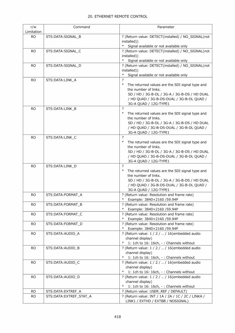
20. ETHERNET REMOTE CONTROL
418
r/w Limitation
Command Parameter
RO STS:DATA:SIGNAL_B ? (Return value: DETECT(installed) / NO_SIGNAL(not installed)) * Signal available or not available only
RO STS:DATA:SIGNAL_C ? (Return value: DETECT(installed) / NO_SIGNAL(not installed)) * Signal available or not available only
RO STS:DATA:SIGNAL_D ? (Return value: DETECT(installed) / NO_SIGNAL(not installed)) * Signal available or not available only
RO STS:DATA:LINK_A ? * The returned values are the SDI signal type and
the number of links. SD / HD / 3G-B-DL / 3G-A / 3G-B-DS / HD DUAL / HD QUAD / 3G-B-DS-DUAL / 3G-B-DL QUAD / 3G-A QUAD / 12G-TYPE1
RO STS:DATA:LINK_B ? * The returned values are the SDI signal type and
the number of links. SD / HD / 3G-B-DL / 3G-A / 3G-B-DS / HD DUAL / HD QUAD / 3G-B-DS-DUAL / 3G-B-DL QUAD / 3G-A QUAD / 12G-TYPE1
RO STS:DATA:LINK_C ? * The returned values are the SDI signal type and
the number of links. SD / HD / 3G-B-DL / 3G-A / 3G-B-DS / HD DUAL / HD QUAD / 3G-B-DS-DUAL / 3G-B-DL QUAD / 3G-A QUAD / 12G-TYPE1
RO STS:DATA:LINK_D ? * The returned values are the SDI signal type and
the number of links. SD / HD / 3G-B-DL / 3G-A / 3G-B-DS / HD DUAL / HD QUAD / 3G-B-DS-DUAL / 3G-B-DL QUAD / 3G-A QUAD / 12G-TYPE1
RO STS:DATA:FORMAT_A ? (Return value: Resolution and frame rate) * Example: 3840×2160 /59.94P
RO STS:DATA:FORMAT_B ? (Return value: Resolution and frame rate) * Example: 3840×2160 /59.94P
RO STS:DATA:FORMAT_C ? (Return value: Resolution and frame rate) * Example: 3840×2160 /59.94P
RO STS:DATA:FORMAT_D ? (Return value: Resolution and frame rate) * Example: 3840×2160 /59.94P
RO STS:DATA:AUDIO_A ? (Return value: 1 / 2 / .. / 16(embedded audio channel display)
* 1: 1ch to 16: 16ch, - : Channels without RO STS:DATA:AUDIO_B ? (Return value: 1 / 2 / .. / 16(embedded audio
channel display) * 1: 1ch to 16: 16ch, - : Channels without
RO STS:DATA:AUDIO_C ? (Return value: 1 / 2 / .. / 16(embedded audio channel display)
* 1: 1ch to 16: 16ch, - : Channels without RO STS:DATA:AUDIO_D ? (Return value: 1 / 2 / .. / 16(embedded audio
channel display) * 1: 1ch to 16: 16ch, - : Channels without
RO STS:DATA:EXTREF_A ? (Return value: USER_REF / DEFAULT) RO STS:DATA:EXTREF_STAT_A ? (Return value: INT / 1A / 2A / 1C / 2C / LINKA /
LINK1 / EXTHD / EXTBB / NOSIGNAL)

20. ETHERNET REMOTE CONTROL
419
r/w Limitation
Command Parameter
RO STS:DATA:EXTREF_HTIME_A ? (Return value: time (us)) * Horizontal axis phase difference of channel A
RO STS:DATA:EXTREF_HPIX_A ? (Return value: Number of samples) * Horizontal axis phase difference of channel A
RO STS:DATA:EXTREF_VLINE_A ? (Return value: Number of lines) * Vertical axis phase difference of channel A
RO STS:DATA:EXTREF_TOTAL_A ? (Return value: time (us)) * Total phase difference of horizontal and vertical axes of channel A
RO STS:DATA:EXTREF_B ? (Return value: USER_REF / DEFAULT) RO STS:DATA:EXTREF_STAT_B ? (Return value: INT / 1A / 2A / 1C / 2C / LINKA /
LINK1 / EXTHD / EXTBB / NOSIGNAL) RO STS:DATA:EXTREF_HTIME_B ? (Return value: time(us))
* Horizontal axis phase difference of channel B RO STS:DATA:EXTREF_HPIX_B ? (Return value: Number of samples)
* Horizontal axis phase difference of channel B RO STS:DATA:EXTREF_VLINE_B ? (Return value: Number of lines)
* Vertical axis phase difference of channel B RO STS:DATA:EXTREF_TOTAL_B ? (Return value: time (us))
* Total phase difference of horizontal and vertical axes of channel B
RO STS:DATA:EXTREF_C ? (Return value: USER_REF / DEFAULT) RO STS:DATA:EXTREF_STAT_C ? (Return value: INT / 1A / 2A / 1C / 2C / LINKA /
LINK1 / EXTHD / EXTBB / NOSIGNAL) RO STS:DATA:EXTREF_HTIME_C ? (Return value: time(us))
* Horizontal axis phase difference of channel C RO STS:DATA:EXTREF_HPIX_C ? (Return value: Number of samples)
* Horizontal axis phase difference of channel C RO STS:DATA:EXTREF_VLINE_C ? (Return value: Number of lines)
* Vertical axis phase difference of channel C RO STS:DATA:EXTREF_TOTAL_C ? (Return value: time (us))
* Total phase difference of horizontal and vertical axes of channel C
RO STS:DATA:EXTREF_D ? (Return value: USER_REF / DEFAULT) RO STS:DATA:EXTREF_STAT_D ? (Return value: INT / 1A / 2A / 1C / 2C / LINKA /
LINK1 / EXTHD / EXTBB / NOSIGNAL) RO STS:DATA:EXTREF_HTIME_D ? (Return value: time(us))
* Horizontal axis phase difference of channel D RO STS:DATA:EXTREF_HPIX_D ? (Return value: Number of samples)
* Horizontal axis phase difference of channel D RO STS:DATA:EXTREF_VLINE_D ? (Return value: Number of lines)
* Vertical axis phase difference of channel D RO STS:DATA:EXTREF_TOTAL_D ? (Return value: time (us))
* Total phase difference of horizontal and vertical axes of channel C
RO STS:DATA:ANC:AUDIO_CTRL1 ? (Return value: DETECT / MISSING) RO STS:DATA:ANC:AUDIO_CTRL2 ? (Return value: DETECT / MISSING) RO STS:DATA:ANC:EDH ? (Return value: DETECT / MISSING) RO STS:DATA:ANC:LTC1 ? (Return value: DETECT / MISSING) RO STS:DATA:ANC:LTC2 ? (Return value: DETECT / MISSING) RO STS:DATA:ANC:VLTC1 ? (Return value: DETECT / MISSING) RO STS:DATA:ANC:VLTC2 ? (Return value: DETECT / MISSING) RO STS:DATA:ANC:PAYLOAD1 ? (Return value: DETECT / MISSING) RO STS:DATA:ANC:PAYLOAD2 ? (Return value: DETECT / MISSING) RO STS:DATA:ANC:AFD1 ? (Return value: DETECT / MISSING) RO STS:DATA:ANC:AFD2 ? (Return value: DETECT / MISSING)

20. ETHERNET REMOTE CONTROL
420
r/w Limitation
Command Parameter
RO STS:DATA:ANC:JPN_CC1 ? (Return value: DETECT / MISSING) RO STS:DATA:ANC:JPN_CC2 ? (Return value: DETECT / MISSING) RO STS:DATA:ANC:JPN_CC3 ? (Return value: DETECT / MISSING) RO STS:DATA:ANC:NETQ1 ? (Return value: DETECT / MISSING) RO STS:DATA:ANC:NETQ2 ? (Return value: DETECT / MISSING) RO STS:DATA:ANC:TRIGGER ? (Return value: DETECT / MISSING) RO STS:DATA:ANC:USER1 ? (Return value: DETECT / MISSING) RO STS:DATA:ANC:USER2 ? (Return value: DETECT / MISSING) RO STS:DATA:ANC:PKT:PAYLOAD ? (Return value: Payload ID (4 byte display))
* Example: 8A 4A 20 01 RO STS:DATA:ANC:PKT:ARIB:NETQ:STATION ? (Return value: Station code) RO STS:DATA:ANC:PKT:ARIB:NETQ:VCURR ? (Return value: Current video format) RO STS:DATA:ANC:PKT:ARIB:NETQ:VNEXT ? (Return value: Next video format) RO STS:DATA:ANC:PKT:ARIB:NETQ:ACURR ? (Return value: Current audio mode) RO STS:DATA:ANC:PKT:ARIB:NETQ:ANEXT ? (Return value: Next audio mode) RO STS:DATA:ANC:PKT:ARIB:NETQ:DCURR ? (Return value: Current audio downmix mode) RO STS:DATA:ANC:PKT:ARIB:NETQ:DNEXT ? (Return value: Next audio downmix mode) RO STS:DATA:ANC:PKT:SMPTE:AFD:CODE ? (Return value: AFD code) RO STS:DATA:ANC:PKT:SMPTE:AFD:FRAME ? (Return value: Aspect ratio) RO STS:DATA:ANC:PKT:SMPTE:AFD:BAR:FLG ? (Return value: AFD bar data flag) RO STS:DATA:ANC:PKT:SMPTE:AFD:BAR:VAL1 ? (Return value: AFD bar data 1) RO STS:DATA:ANC:PKT:SMPTE:AFD:BAR:VAL2 ? (Return value: AFD bar data 2)
● EYE KEY
r/w Limitation
Command Parameter
WO EYE None - EYE:EYE:INTEN -128 to 127 / ? - EYE:EYE:COLOR WHITE / YELLOW / CYAN / GREEN / MAGENTA / RED /
BLUE / ? - EYE:EYE:SCALE:INTEN -8 to 7 / ? - EYE:EYE:SCALE:COLOR WHITE / YELLOW / CYAN / GREEN / MAGENTA / RED /
BLUE / ? - EYE:MODE EYE / JITTER / ? - EYE:EYE:SETUP:GAIN:VAR CAL / VAR / ? - EYE:EYE:SETUP:GAIN:VAL 50 to 200 / ?
* 50: x0.50 to 200: x2.00 - EYE:EYE:SETUP:SWEEP 2UI / 4UI / 16UI / ? - EYE:EYE:SETUP:FILTER 100KHZ / 1KHZ / 100HZ / 10HZ / TIMING / ALIGNMENT
/ ? - EYE:EYE:SETUP:CURSOR OFF / ON - EYE:EYE:SETUP:CURSOR:XY_SEL X / Y / TR_TF / ? - EYE:EYE:SETUP:CURSOR:FD REF / DELTA / TRACK / ?
WO EYE:EYE:SETUP:CURSOR:REFSET None WO EYE:EYE:SETUP:CURSOR:RESET None WO EYE:JIT:SETUP:CURSOR:RESET None - EYE:EYE:SETUP:CURSOR:X:UNIT SEC / HZ / UI_PP / ? - EYE:EYE:SETUP:CURSOR:X:REF 0 to 1710 / ?
WO EYE:EYE:SETUP:CURSOR:X:TRACK -1710 to 1710 - EYE:EYE:SETUP:CURSOR:X:DELTA 0 to 1710 / ? - EYE:EYE:SETUP:CURSOR:Y:UNIT V / P / ? - EYE:EYE:SETUP:CURSOR:Y:REF 0 to 900 / ?
WO EYE:EYE:SETUP:CURSOR:Y:TRACK -900 to 900 - EYE:EYE:SETUP:CURSOR:Y:DELTA 0 to 900 / ? - EYE:JIT:INTEN -128 to 127 / ?

20. ETHERNET REMOTE CONTROL
421
r/w Limitation
Command Parameter
- EYE:JIT:COLOR WHITE / YELLOW / CYAN / GREEN / MAGENTA / RED / BLUE / ?
- EYE:JIT:SCALE:INTEN -8 to 7 / ? - EYE:JIT:SCALE:COLOR WHITE / YELLOW / CYAN / GREEN / MAGENTA / RED /
BLUE / ? - EYE:JIT:SETUP:GAIN_SWEEP:MAG X1 / X2 / X8 / ? - EYE:JIT:SETUP:GAIN_SWEEP:12G:MAG X1 / X2 / X4 / X16 / ? - EYE:JIT:SETUP:GAIN_SWEEP:SWEEP 1H / 2H / 1V / 2V / ? - EYE:JIT:SETUP:FILTER 100KHZ / 1KHZ / 100HZ / 10HZ / TIMING / ALIGNMENT
/ ? - EYE:JIT:SETUP:PEAK_HOLD OFF / ON
WO EYE:JIT:SETUP:PEAK_CLEAR None - EYE:JIT:SETUP:CURSOR OFF / ON - EYE:JIT:SETUP:CURSOR:XY_SEL X / Y / ? - EYE:JIT:SETUP:CURSOR:FD REF / DELTA / TRACK / ? - EYE:JIT:SETUP:CURSOR:X:UNIT SEC / HZ / ? - EYE:JIT:SETUP:CURSOR:X:REF 0 to 1710 / ?
WO EYE:JIT:SETUP:CURSOR:X:TRACK -1710 to 1710 - EYE:JIT:SETUP:CURSOR:X:DELTA 0 to 1710 / ? - EYE:JIT:SETUP:CURSOR:Y:UNIT SEC / UI_PP / ? - EYE:JIT:SETUP:CURSOR:Y:REF 0 to 624 / ?
WO EYE:JIT:SETUP:CURSOR:Y:TRACK -624 to 624 - EYE:JIT:SETUP:CURSOR:Y:DELTA 0 to 624 / ? - EYE:LINK_SEL:HD_DLINK:AB A / B / ?
* Displayed link selection for HD DUAL LINK - EYE:LINK_SEL:HD_DLINK:CD C / D / ?
* Displayed link selection for HD DUAL LINK - EYE:LINK_SEL:4K3G_DLINK:AB A / B / ?
* Displayed link selection for 4K 3G DUAL LINK / 3G DHUAL LINK
- EYE:LINK_SEL:4K3G_DLINK:CD C / D / ? * Displayed link selection for 4K 3G DUAL LINK / 3G
DHUAL LINK - EYE:LINK_SEL:QLINK A / B / C / D / ?
* Displayed link selection for 4K 3G QUAD LINK / 4K HD QUAD LINK
● 12G-SDI ERROR SETUP TAB MENU (EYE → ERROR SETUP) (*6)
r/w Limitation
Command Parameter
- EYE:ERROR:12G:AMP OFF / ON / ? - EYE:ERROR:12G:AMP:UPPER 80 to 140 / ? - EYE:ERROR:12G:AMP:LOWER 40 to 100 / ? - EYE:ERROR:12G:RISE OFF / ON / ? - EYE:ERROR:12G:RISE:MAX 40 to 140 / ? - EYE:ERROR:12G:FALL OFF / ON / ? - EYE:ERROR:12G:FALL:MAX 40 to 140 / ? - EYE:ERROR:12G:DELTA OFF / ON / ? - EYE:ERROR:12G:DELTA:MAX 40 to 140 / ? - EYE:ERROR:12G:TIMING_JIT OFF / ON / ? - EYE:ERROR:12G:TIMING_JIT:MAX 10 to 200 / ? - EYE:ERROR:12G:CURRENT_JIT OFF / ON / ? - EYE:ERROR:12G:CURRENT_JIT:MAX 10 to 200 / ? - EYE:ERROR:12G:OVERSHOOT_RISE OFF / ON / ? - EYE:ERROR:12G:OVERSHOOT_RISE:MAX 0 to 200 / ?

20. ETHERNET REMOTE CONTROL
422
r/w Limitation
Command Parameter
- EYE:ERROR:12G:OVERSHOOT_FALL OFF / ON / ? - EYE:ERROR:12G:OVERSHOOT_FALL:MAX 0 to 200 / ?
WO EYE:ERROR:SETUP:COMPLETE None (must be executed after changing the tab menu)
*6 Execute EYE:ERROR:SETUP:COMPLETE after changing the setting.
● 3G-SDI ERROR SETUP TAB MENU (EYE → ERROR SETUP) (*6)
r/w Limitation
Command Parameter
- EYE:ERROR:3G:AMP OFF / ON / ? - EYE:ERROR:3G:AMP:UPPER 80 to 140 / ? - EYE:ERROR:3G:AMP:LOWER 40 to 100 / ? - EYE:ERROR:3G:RISE OFF / ON / ? - EYE:ERROR:3G:RISE:MAX 40 to 140 / ? - EYE:ERROR:3G:FALL OFF / ON / ? - EYE:ERROR:3G:FALL:MAX 40 to 140 / ? - EYE:ERROR:3G:DELTA OFF / ON / ? - EYE:ERROR:3G:DELTA:MAX 40 to 140 / ? - EYE:ERROR:3G:TIMING_JIT OFF / ON / ? - EYE:ERROR:3G:TIMING_JIT:MAX 10 to 200 / ? - EYE:ERROR:3G:CURRENT_JIT OFF / ON / ? - EYE:ERROR:3G:CURRENT_JIT:MAX 10 to 200 / ? - EYE:ERROR:3G:OVERSHOOT_RISE OFF / ON / ? - EYE:ERROR:3G:OVERSHOOT_RISE:MAX 0 to 200 / ? - EYE:ERROR:3G:OVERSHOOT_FALL OFF / ON / ? - EYE:ERROR:3G:OVERSHOOT_FALL:MAX 0 to 200 / ?
WO EYE:ERROR:SETUP:COMPLETE None (must be executed after changing the tab menu)
*6 Execute EYE:ERROR:SETUP:COMPLETE after changing the setting.
● HD-SDI ERROR SETUP TAB MENU (EYE → ERROR SETUP) (*6) r/w
Limitation Command Parameter
- EYE:ERROR:HD:AMP OFF / ON / ? - EYE:ERROR:HD:AMP:UPPER 80 to 140 / ? - EYE:ERROR:HD:AMP:LOWER 40 to 100 / ? - EYE:ERROR:HD:RISE OFF / ON / ? - EYE:ERROR:HD:RISE:MAX 40 to 140 / ? - EYE:ERROR:HD:FALL OFF / ON / ? - EYE:ERROR:HD:FALL:MAX 40 to 140 / ? - EYE:ERROR:HD:DELTA OFF / ON / ? - EYE:ERROR:HD:DELTA:MAX 40 to 140 / ? - EYE:ERROR:HD:TIMING_JIT OFF / ON / ? - EYE:ERROR:HD:TIMING_JIT:MAX 10 to 200 / ? - EYE:ERROR:HD:CURRENT_JIT OFF / ON / ? - EYE:ERROR:HD:CURRENT_JIT:MAX 10 to 200 / ? - EYE:ERROR:HD:OVERSHOOT_RISE OFF / ON / ? - EYE:ERROR:HD:OVERSHOOT_RISE:MAX 0 to 200 / ? - EYE:ERROR:HD:OVERSHOOT_FALL OFF / ON / ? - EYE:ERROR:HD:OVERSHOOT_FALL:MAX 0 to 200 / ?
WO EYE:ERROR:SETUP:COMPLETE None (must be executed after changing the tab menu)

20. ETHERNET REMOTE CONTROL
423
*6 Execute EYE:ERROR:SETUP:COMPLETE after changing the setting.
● SD-SDI ERROR SETUP TAB MENU (EYE → ERROR SETUP) (*6)
r/w Limitation
Command Parameter
- EYE:ERROR:SD:AMP OFF / ON / ? - EYE:ERROR:SD:AMP:UPPER 80 to 140 / ? - EYE:ERROR:SD:AMP:LOWER 40 to 100 / ? - EYE:ERROR:SD:RISE OFF / ON / ? - EYE:ERROR:SD:RISE:MAX 40 to 140 / ? - EYE:ERROR:SD:FALL OFF / ON / ? - EYE:ERROR:SD:FALL:MAX 40 to 140 / ? - EYE:ERROR:SD:DELTA OFF / ON / ? - EYE:ERROR:SD:DELTA:MAX 40 to 140 / ? - EYE:ERROR:SD:TIMING_JIT OFF / ON / ? - EYE:ERROR:SD:TIMING_JIT:MAX 10 to 200 / ? - EYE:ERROR:SD:CURRENT_JIT OFF / ON / ? - EYE:ERROR:SD:CURRENT_JIT:MAX 10 to 200 / ? - EYE:ERROR:SD:OVERSHOOT_RISE OFF / ON / ? - EYE:ERROR:SD:OVERSHOOT_RISE:MAX 0 to 200 / ? - EYE:ERROR:SD:OVERSHOOT_FALL OFF / ON / ? - EYE:ERROR:SD:OVERSHOOT_FALL:MAX 0 to 200 / ? - EYE:EYE:OFFSET:X -32768 to 32767 / ? - EYE:EYE:OFFSET:Y -32768 to 32767 / ? - EYE:JIT:OFFSET:X -32768 to 32767 / ? - EYE:JIT:OFFSET:Y -32768 to 32767 / ? - EYE:TRIGGER RUN / STOP / ?
WO EYE:ERROR:SETUP:COMPLETE None (must be executed after changing the tab menu)
*6 Execute EYE:ERROR:SETUP:COMPLETE after changing the setting.
● EYE Query measured or detected values r/w
Limitation Command Parameter
RO EYE:DATA:AMP ? RO EYE:DATA:TR ? RO EYE:DATA:TF ? RO EYE:DATA:TJ ? RO EYE:DATA:CJ ? RO EYE:DATA:OR ? RO EYE:DATA:OF ?
● AUDIO KEY
r/w Limitation
Command Parameter
WO AUDIO None - AUDIO:DISPLAY_MODE LISSAJOU / SURROUND / METER / STATUS / ? - AUDIO:METER:RANGE 60DBFS / 90DBFS / MAG / ? - AUDIO:METER:RESPONSE TRUEPEAK / PPM / VU / ? - AUDIO:METER:RESPONSE:PPM PPM_I / PPM_II / ? - AUDIO:METER:RESPONSE:VU TRUE / PPM_I / PPM_II / ? - AUDIO:METER:PEAK_HOLD 0 / 5 / 10 / 15 / 20 / 25 / 30 / 35 / 40 / 45 / 50 /
55 / ? * 0: 0.0, 5: 0.5, to 50: 5.0, 55: HOLD
- AUDIO:METER:LEVEL_SET:OVER_LEVEL_DB -400 to 0 / ? * -400: -40.0 to 0: 0.0

20. ETHERNET REMOTE CONTROL
424
r/w Limitation
Command Parameter
- AUDIO:METER:LEVEL_SET:WARNING_LEVEL_DB -400 to 0 / ? * -400: -40.0 to 0: 0.0
- AUDIO:METER:LEVEL_SET:REF_LEVEL_DB -400 to 0 / ? * -400: -40.0 to 0: 0.0
- AUDIO:LISSAJOU:LISSAJOU:INTEN -8 to 7 / ? - AUDIO:LISSAJOU:SCALE:INTEN -8 to 7 / ? - AUDIO:LISSAJOU:DISPLAY MULTI / SINGLE / ? - AUDIO:LISSAJOU:FORM X_Y / MATRIX / ? - AUDIO:LISSAJOU:AUTO_GAIN OFF / ON / ? - AUDIO:SURROUND:SURROUND:INTEN -8 to 7 / ? - AUDIO:SURROUND:SCALE:INTEN -8 to 7 / ? - AUDIO:SURROUND:5.1 NORMAL / PHANTOM / ? - AUDIO:SURROUND:AUTO_GAIN OFF / ON / ? - AUDIO:DOLBY:META:PROGRAM PRM1 / PRM2 / PRM3 / PRM4 / PRM5 / PRM6 /
PRM7 / PRM8 / ? - AUDIO:STATUS:CH_STATUS 1 to 16 / ? - AUDIO:STATUS:CH_STATUS_SIMUL A1 to A16 / B1 to B16 / C1 to C16 / D1 to D16 / ? - AUDIO:STATUS:CH_STATUS_DOLBY 1 to 16 / ? - AUDIO:STATUS:CH_STATUS_EXT A:CH1 to A:CH8 / B:CH1 to B:CH8 / ? - AUDIO:STATUS:CH_STATUS:ALIGN LSB 1st / MSB 1st / ? - AUDIO:STATUS:USER_BIT 1 to 16 / ? - AUDIO:STATUS:USER_BIT_SIMUL A1 to A16 / B1 to B16 / C1 to C16 / D1 to D16 / ? - AUDIO:STATUS:USER_BIT_DOLBY 1 to 16 / ? - AUDIO:STATUS:USER_BIT_EXT A:CH1 to A:CH8 / B:CH1 to B:CH8 / ? - AUDIO:STATUS:USER_BIT:ALIGN LSB / MSB / ?
WO AUDIO:STATUS:ERROR_RESET None - AUDIO:PHONES:VOLUME 0 to 63 / ?
RO AUDIO:DOLBY:DETECT ? (Return value: E / D / DP)
● AUDIO MAPPING (AUDIO → MAPPING) (*7) r/w
Limitation Command Parameter
- AUDIO:MAPPING:INPUT SDI / EXT DIGI / ? - AUDIO:MAPPING:LINK_SELECT 1 / 2 / 3 / 4 / ?
* Supports links 1: channel A, 2: channel B, 3: channel C, and 4: channel D
: when using 4K 3G QUAD LINK or 4K HD QUAD LINK
Supports links 1: channel A and 2: channel B : when using 4K 3G DUAL LINK, 3G
DUAL LINK, or HD DUAL LINK and channels A and B are selected
Supports links 1: channel C and 2: channel D : when channels C and D are selected
- AUDIO:MAPPING:STREAM:SELECT STREAM1 / STREAM2 / ? - AUDIO:MAPPING:CH_MODE 8ch / 16ch / ? - AUDIO:MAPPING:SOURCE:SDI:1ST_GRP G1 / G2 / G3 / G4 / ? - AUDIO:MAPPING:SOURCE:SDI:2ND_GRP G1 / G2 / G3 / G4 / ? - AUDIO:MAPPING:SOURCE:SDI:3RD_GRP G1 / G2 / G3 / G4 / ? - AUDIO:MAPPING:SOURCE:SDI:4TH_GRP G1 / G2 / G3 / G4 / ? - AUDIO:MAPPING:PHONES:L CH1 / CH2 / CH3 / CH4 / CH5 / CH6 / CH7 /
CH8 / CH9 / CH10 / CH11 / CH12 / CH13 / CH14 / CH15 / CH16 / LT / ?

20. ETHERNET REMOTE CONTROL
425
r/w Limitation
Command Parameter
- AUDIO:MAPPING:PHONES:R CH1 / CH2 / CH3 / CH4 / CH5 / CH6 / CH7 / CH8 / CH9 / CH10 / CH11 / CH12 / CH13 / CH14 / CH15 / CH16 / RT / ?
- AUDIO:MAPPING:DOLBY OFF / ON / ? - AUDIO:MAPPING:DOLBY:E:LINE:POS OFF / ON / ? - AUDIO:MAPPING:DOLBY:E:LINE:SELECT VALID / IDEAL / CUSTOM / ? - AUDIO:MAPPING:DOLBY:E:EARLIEST 8 to 104 / ? - AUDIO:MAPPING:DOLBY:E:LATEST 9 to 105 / ? - AUDIO:MAPPING:LISSAJOU:SINGLE_L CH1 / CH2 / CH3 / CH4 / CH5 / CH6 / CH7 /
CH8 / CH9 / CH10 / CH11 / CH12 / CH13 / CH14 / CH15 / CH16 / LT / ?
- AUDIO:MAPPING:LISSAJOU:SINGLE_R CH1 / CH2 / CH3 / CH4 / CH5 / CH6 / CH7 / CH8 / CH9 / CH10 / CH11 / CH12 / CH13 / CH14 / CH15 / CH16 / RT / ?
- AUDIO:MAPPING:LISSAJOU:MULTI_L1 CH1 / CH2 / CH3 / CH4 / CH5 / CH6 / CH7 / CH8 / CH9 / CH10 / CH11 / CH12 / CH13 / CH14 / CH15 / CH16 / ?
- AUDIO:MAPPING:LISSAJOU:MULTI_R1 CH1 / CH2 / CH3 / CH4 / CH5 / CH6 / CH7 / CH8 / CH9 / CH10 / CH11 / CH12 / CH13 / CH14 / CH15 / CH16 / ?
- AUDIO:MAPPING:LISSAJOU:MULTI_L2 CH1 / CH2 / CH3 / CH4 / CH5 / CH6 / CH7 / CH8 / CH9 / CH10 / CH11 / CH12 / CH13 / CH14 / CH15 / CH16 / ?
- AUDIO:MAPPING:LISSAJOU:MULTI_R2 CH1 / CH2 / CH3 / CH4 / CH5 / CH6 / CH7 / CH8 / CH9 / CH10 / CH11 / CH12 / CH13 / CH14 / CH15 / CH16 / ?
- AUDIO:MAPPING:LISSAJOU:MULTI_L3 CH1 / CH2 / CH3 / CH4 / CH5 / CH6 / CH7 / CH8 / CH9 / CH10 / CH11 / CH12 / CH13 / CH14 / CH15 / CH16 / ?
- AUDIO:MAPPING:LISSAJOU:MULTI_R3 CH1 / CH2 / CH3 / CH4 / CH5 / CH6 / CH7 / CH8 / CH9 / CH10 / CH11 / CH12 / CH13 / CH14 / CH15 / CH16 / ?
- AUDIO:MAPPING:LISSAJOU:MULTI_L4 CH1 / CH2 / CH3 / CH4 / CH5 / CH6 / CH7 / CH8 / CH9 / CH10 / CH11 / CH12 / CH13 / CH14 / CH15 / CH16 / ?
- AUDIO:MAPPING:LISSAJOU:MULTI_R4 CH1 / CH2 / CH3 / CH4 / CH5 / CH6 / CH7 / CH8 / CH9 / CH10 / CH11 / CH12 / CH13 / CH14 / CH15 / CH16 / ?
- AUDIO:MAPPING:LISSAJOU:MULTI_L5 CH1 / CH2 / CH3 / CH4 / CH5 / CH6 / CH7 / CH8 / CH9 / CH10 / CH11 / CH12 / CH13 / CH14 / CH15 / CH16 / ?
- AUDIO:MAPPING:LISSAJOU:MULTI_R5 CH1 / CH2 / CH3 / CH4 / CH5 / CH6 / CH7 / CH8 / CH9 / CH10 / CH11 / CH12 / CH13 / CH14 / CH15 / CH16 / ?
- AUDIO:MAPPING:LISSAJOU:MULTI_L6 CH1 / CH2 / CH3 / CH4 / CH5 / CH6 / CH7 / CH8 / CH9 / CH10 / CH11 / CH12 / CH13 / CH14 / CH15 / CH16 / ?
- AUDIO:MAPPING:LISSAJOU:MULTI_R6 CH1 / CH2 / CH3 / CH4 / CH5 / CH6 / CH7 / CH8 / CH9 / CH10 / CH11 / CH12 / CH13 / CH14 / CH15 / CH16 / ?
- AUDIO:MAPPING:LISSAJOU:MULTI_L7 CH1 / CH2 / CH3 / CH4 / CH5 / CH6 / CH7 / CH8 / CH9 / CH10 / CH11 / CH12 / CH13 / CH14 / CH15 / CH16 / ?
- AUDIO:MAPPING:LISSAJOU:MULTI_R7 CH1 / CH2 / CH3 / CH4 / CH5 / CH6 / CH7 / CH8 / CH9 / CH10 / CH11 / CH12 / CH13 / CH14 / CH15 / CH16 / ?

20. ETHERNET REMOTE CONTROL
426
r/w Limitation
Command Parameter
- AUDIO:MAPPING:LISSAJOU:MULTI_L8 CH1 / CH2 / CH3 / CH4 / CH5 / CH6 / CH7 / CH8 / CH9 / CH10 / CH11 / CH12 / CH13 / CH14 / CH15 / CH16 / ?
- AUDIO:MAPPING:LISSAJOU:MULTI_R8 CH1 / CH2 / CH3 / CH4 / CH5 / CH6 / CH7 / CH8 / CH9 / CH10 / CH11 / CH12 / CH13 / CH14 / CH15 / CH16 / ?
- AUDIO:MAPPING:SURROUND:CH:L CH1 / CH2 / CH3 / CH4 / CH5 / CH6 / CH7 / CH8 / CH9 / CH10 / CH11 / CH12 / CH13 / CH14 / CH15 / CH16 / ?
- AUDIO:MAPPING:SURROUND:CH:R CH1 / CH2 / CH3 / CH4 / CH5 / CH6 / CH7 / CH8 / CH9 / CH10 / CH11 / CH12 / CH13 / CH14 / CH15 / CH16 / ?
- AUDIO:MAPPING:SURROUND:CH:C CH1 / CH2 / CH3 / CH4 / CH5 / CH6 / CH7 / CH8 / CH9 / CH10 / CH11 / CH12 / CH13 / CH14 / CH15 / CH16 / ?
- AUDIO:MAPPING:SURROUND:CH:LFE CH1 / CH2 / CH3 / CH4 / CH5 / CH6 / CH7 / CH8 / CH9 / CH10 / CH11 / CH12 / CH13 / CH14 / CH15 / CH16 / ?
- AUDIO:MAPPING:SURROUND:CH:LS CH1 / CH2 / CH3 / CH4 / CH5 / CH6 / CH7 / CH8 / CH9 / CH10 / CH11 / CH12 / CH13 / CH14 / CH15 / CH16 / ?
- AUDIO:MAPPING:SURROUND:CH:RS CH1 / CH2 / CH3 / CH4 / CH5 / CH6 / CH7 / CH8 / CH9 / CH10 / CH11 / CH12 / CH13 / CH14 / CH15 / CH16 / ?
- AUDIO:MAPPING:SURROUND:CH:LL CH1 / CH2 / CH3 / CH4 / CH5 / CH6 / CH7 / CH8 / CH9 / CH10 / CH11 / CH12 / CH13 / CH14 / CH15 / CH16 / ?
- AUDIO:MAPPING:SURROUND:CH:RR CH1 / CH2 / CH3 / CH4 / CH5 / CH6 / CH7 / CH8 / CH9 / CH10 / CH11 / CH12 / CH13 / CH14 / CH15 / CH16 / ?
- AUDIO:MAPPING:LISSAJOU:DOLBY:SINGLE_L D1 / D2 / D3 / D4 / D5 / D6 / D7 / D8 / LT / ?
- AUDIO:MAPPING:LISSAJOU:DOLBY:SINGLE_R D1 / D2 / D3 / D4 / D5 / D6 / D7 / D8 / RT / ?
- AUDIO:MAPPING:LISSAJOU:DOLBY:MULTI_L1 D1 / D2 / D3 / D4 / D5 / D6 / D7 / D8 / ? - AUDIO:MAPPING:LISSAJOU:DOLBY:MULTI_R1 D1 / D2 / D3 / D4 / D5 / D6 / D7 / D8 / ? - AUDIO:MAPPING:LISSAJOU:DOLBY:MULTI_L2 D1 / D2 / D3 / D4 / D5 / D6 / D7 / D8 / ? - AUDIO:MAPPING:LISSAJOU:DOLBY:MULTI_R2 D1 / D2 / D3 / D4 / D5 / D6 / D7 / D8 / ? - AUDIO:MAPPING:LISSAJOU:DOLBY:MULTI_L3 D1 / D2 / D3 / D4 / D5 / D6 / D7 / D8 / ? - AUDIO:MAPPING:LISSAJOU:DOLBY:MULTI_R3 D1 / D2 / D3 / D4 / D5 / D6 / D7 / D8 / ? - AUDIO:MAPPING:LISSAJOU:DOLBY:MULTI_L4 D1 / D2 / D3 / D4 / D5 / D6 / D7 / D8 / ? - AUDIO:MAPPING:LISSAJOU:DOLBY:MULTI_R4 D1 / D2 / D3 / D4 / D5 / D6 / D7 / D8 / ? - AUDIO:MAPPING:SURROUND:CH:DOLBY:L D1 / D2 / D3 / D4 / D5 / D6 / D7 / D8 / ? - AUDIO:MAPPING:SURROUND:CH:DOLBY:R D1 / D2 / D3 / D4 / D5 / D6 / D7 / D8 / ? - AUDIO:MAPPING:SURROUND:CH:DOLBY:C D1 / D2 / D3 / D4 / D5 / D6 / D7 / D8 / ? - AUDIO:MAPPING:SURROUND:CH:DOLBY:LFE D1 / D2 / D3 / D4 / D5 / D6 / D7 / D8 / ? - AUDIO:MAPPING:SURROUND:CH:DOLBY:LS D1 / D2 / D3 / D4 / D5 / D6 / D7 / D8 / ? - AUDIO:MAPPING:SURROUND:CH:DOLBY:RS D1 / D2 / D3 / D4 / D5 / D6 / D7 / D8 / ? - AUDIO:MAPPING:SURROUND:CH:DOLBY:LL D1 / D2 / D3 / D4 / D5 / D6 / D7 / D8 / ? - AUDIO:MAPPING:SURROUND:CH:DOLBY:RR D1 / D2 / D3 / D4 / D5 / D6 / D7 / D8 / ? - AUDIO:MAPPING:PHONES:DOLBY:L D1 / D2 / D3 / D4 / D5 / D6 / D7 / D8 /
DAUX / ? - AUDIO:MAPPING:PHONES:DOLBY:R D1 / D2 / D3 / D4 / D5 / D6 / D7 / D8 /
DAUX / ?

20. ETHERNET REMOTE CONTROL
427
r/w Limitation
Command Parameter
- AUDIO:MAPPING:SOURCE:SIM:SDI:1ST_GRP G1 / G2 / G3 / G4 / ? * 0: GROUP1 / 1: GROUP2 / 2: GROUP3 / 3: GROUP4
- AUDIO:MAPPING:SOURCE:SIM:SDI:2ND_GRP G1 / G2 / G3 / G4 / ? * 0: GROUP1 / 1: GROUP2 / 2: GROUP3 / 3: GROUP4
- AUDIO:MAPPING:SOURCE:SIM:SDI:3RD_GRP G1 / G2 / G3 / G4 / ? * 0: GROUP1 / 1: GROUP2 / 2: GROUP3 / 3: GROUP4
- AUDIO:MAPPING:SOURCE:SIM:SDI:4TH_GRP G1 / G2 / G3 / G4 / ? * 0: GROUP1 / 1: GROUP2 / 2: GROUP3 / 3: GROUP4
- AUDIO:MAPPING:SOURCE:SIM:SDI:1ST_GRP_CH SDI_A / SDI_B / SDI_C / SDI_D / ? - AUDIO:MAPPING:SOURCE:SIM:SDI:2ND_GRP_CH SDI_A / SDI_B / SDI_C / SDI_D / ? - AUDIO:MAPPING:SOURCE:SIM:SDI:3RD_GRP_CH SDI_A / SDI_B / SDI_C / SDI_D / ? - AUDIO:MAPPING:SOURCE:SIM:SDI:4TH_GRP_CH SDI_A / SDI_B / SDI_C / SDI_D / ? - AUDIO:MAPPING:LISSAJOU:SIM:MULTI_L1 A:CH1 to A:CH16 / B:CH1 to B:CH16 / C:CH1
to C:CH16 /D:CH1 to D:CH16 / ? - AUDIO:MAPPING:LISSAJOU:SIM:MULTI_R1 A:CH1 to A:CH16 / B:CH1 to B:CH16 / C:CH1
to C:CH16 /D:CH1 to D:CH16 / ? - AUDIO:MAPPING:LISSAJOU:SIM:MULTI_L2 A:CH1 to A:CH16 / B:CH1 to B:CH16 / C:CH1
to C:CH16 /D:CH1 to D:CH16 / ? - AUDIO:MAPPING:LISSAJOU:SIM:MULTI_R2 A:CH1 to A:CH16 / B:CH1 to B:CH16 / C:CH1
to C:CH16 /D:CH1 to D:CH16 / ? - AUDIO:MAPPING:LISSAJOU:SIM:MULTI_L3 A:CH1 to A:CH16 / B:CH1 to B:CH16 / C:CH1
to C:CH16 /D:CH1 to D:CH16 / ? - AUDIO:MAPPING:LISSAJOU:SIM:MULTI_R3 A:CH1 to A:CH16 / B:CH1 to B:CH16 / C:CH1
to C:CH16 /D:CH1 to D:CH16 / ? - AUDIO:MAPPING:LISSAJOU:SIM:MULTI_L4 A:CH1 to A:CH16 / B:CH1 to B:CH16 / C:CH1
to C:CH16 /D:CH1 to D:CH16 / ? - AUDIO:MAPPING:LISSAJOU:SIM:MULTI_R4 A:CH1 to A:CH16 / B:CH1 to B:CH16 / C:CH1
to C:CH16 /D:CH1 to D:CH16 / ? - AUDIO:MAPPING:LISSAJOU:SIM:MULTI_L5 A:CH1 to A:CH16 / B:CH1 to B:CH16 / C:CH1
to C:CH16 /D:CH1 to D:CH16 / ? - AUDIO:MAPPING:LISSAJOU:SIM:MULTI_R5 A:CH1 to A:CH16 / B:CH1 to B:CH16 / C:CH1
to C:CH16 /D:CH1 to D:CH16 / ? - AUDIO:MAPPING:LISSAJOU:SIM:MULTI_L6 A:CH1 to A:CH16 / B:CH1 to B:CH16 / C:CH1
to C:CH16 /D:CH1 to D:CH16 / ? - AUDIO:MAPPING:LISSAJOU:SIM:MULTI_R6 A:CH1 to A:CH16 / B:CH1 to B:CH16 / C:CH1
to C:CH16 /D:CH1 to D:CH16 / ? - AUDIO:MAPPING:LISSAJOU:SIM:MULTI_L7 A:CH1 to A:CH16 / B:CH1 to B:CH16 / C:CH1
to C:CH16 /D:CH1 to D:CH16 / ? - AUDIO:MAPPING:LISSAJOU:SIM:MULTI_R7 A:CH1 to A:CH16 / B:CH1 to B:CH16 / C:CH1
to C:CH16 /D:CH1 to D:CH16 / ? - AUDIO:MAPPING:LISSAJOU:SIM:MULTI_L8 A:CH1 to A:CH16 / B:CH1 to B:CH16 / C:CH1
to C:CH16 /D:CH1 to D:CH16 / ? - AUDIO:MAPPING:LISSAJOU:SIM:MULTI_R8 A:CH1 to A:CH16 / B:CH1 to B:CH16 / C:CH1
to C:CH16 /D:CH1 to D:CH16 / ? - AUDIO:MAPPING:SIM:PHONES:L A:CH1 to A:CH16 / B:CH1 to B:CH16 / C:CH1
to C:CH16 /D:CH1 to D:CH16 / ? - AUDIO:MAPPING:SIM:PHONES:R A:CH1 to A:CH16 / B:CH1 to B:CH16 / C:CH1
to C:CH16 /D:CH1 to D:CH16 / ? - AUDIO:MAPPING:SOURCE:EXT:GRP A / B / ? - AUDIO:MAPPING:EXT:LISSAJOU:SINGLE_L A:CH1 to A:CH8 / B:CH1 to B:CH8 / LT / ? - AUDIO:MAPPING:EXT:LISSAJOU:SINGLE_R A:CH1 to A:CH8 / B:CH1 to B:CH8 / RT / ? - AUDIO:MAPPING:EXT:LISSAJOU:MULTI_L1 A:CH1 to A:CH8 / B:CH1 to B:CH8 / ?

20. ETHERNET REMOTE CONTROL
428
r/w Limitation
Command Parameter
- AUDIO:MAPPING:EXT:LISSAJOU:MULTI_R1 A:CH1 to A:CH8 / B:CH1 to B:CH8 / ? - AUDIO:MAPPING:EXT:LISSAJOU:MULTI_L2 A:CH1 to A:CH8 / B:CH1 to B:CH8 / ? - AUDIO:MAPPING:EXT:LISSAJOU:MULTI_R2 A:CH1 to A:CH8 / B:CH1 to B:CH8 / ? - AUDIO:MAPPING:EXT:LISSAJOU:MULTI_L3 A:CH1 to A:CH8 / B:CH1 to B:CH8 / ? - AUDIO:MAPPING:EXT:LISSAJOU:MULTI_R3 A:CH1 to A:CH8 / B:CH1 to B:CH8 / ? - AUDIO:MAPPING:EXT:LISSAJOU:MULTI_L4 A:CH1 to A:CH8 / B:CH1 to B:CH8 / ? - AUDIO:MAPPING:EXT:LISSAJOU:MULTI_R4 A:CH1 to A:CH8 / B:CH1 to B:CH8 / ? - AUDIO:MAPPING:EXT:LISSAJOU:MULTI_L5 A:CH1 to A:CH8 / B:CH1 to B:CH8 / ? - AUDIO:MAPPING:EXT:LISSAJOU:MULTI_R5 A:CH1 to A:CH8 / B:CH1 to B:CH8 / ? - AUDIO:MAPPING:EXT:LISSAJOU:MULTI_L6 A:CH1 to A:CH8 / B:CH1 to B:CH8 / ? - AUDIO:MAPPING:EXT:LISSAJOU:MULTI_R6 A:CH1 to A:CH8 / B:CH1 to B:CH8 / ? - AUDIO:MAPPING:EXT:LISSAJOU:MULTI_L7 A:CH1 to A:CH8 / B:CH1 to B:CH8 / ? - AUDIO:MAPPING:EXT:LISSAJOU:MULTI_R7 A:CH1 to A:CH8 / B:CH1 to B:CH8 / ? - AUDIO:MAPPING:EXT:LISSAJOU:MULTI_L8 A:CH1 to A:CH8 / B:CH1 to B:CH8 / ? - AUDIO:MAPPING:EXT:LISSAJOU:MULTI_R8 A:CH1 to A:CH8 / B:CH1 to B:CH8 / ? - AUDIO:MAPPING:EXT:SURROUND:CH:L A:CH1 to A:CH8 / B:CH1 to B:CH8 / ? - AUDIO:MAPPING:EXT:SURROUND:CH:R A:CH1 to A:CH8 / B:CH1 to B:CH8 / ? - AUDIO:MAPPING:EXT:SURROUND:CH:C A:CH1 to A:CH8 / B:CH1 to B:CH8 / ? - AUDIO:MAPPING:EXT:SURROUND:CH:LFE A:CH1 to A:CH8 / B:CH1 to B:CH8 / ? - AUDIO:MAPPING:EXT:SURROUND:CH:LS A:CH1 to A:CH8 / B:CH1 to B:CH8 / ? - AUDIO:MAPPING:EXT:SURROUND:CH:RS A:CH1 to A:CH8 / B:CH1 to B:CH8 / ? - AUDIO:MAPPING:EXT:SURROUND:CH:LL A:CH1 to A:CH8 / B:CH1 to B:CH8 / ? - AUDIO:MAPPING:EXT:SURROUND:CH:RR A:CH1 to A:CH8 / B:CH1 to B:CH8 / ? - AUDIO:MAPPING:EXT:PHONES:L A:CH1 to A:CH8 / B:CH1 to B:CH8 / LT / ? - AUDIO:MAPPING:EXT:PHONES:R A:CH1 to A:CH8 / B:CH1 to B:CH8 / RT / ? - AUDIO:MAPPING:EXT:LISSAJOU:DOLBY:SINGLE_L D1 / D2 / D3 / D4 / D5 / D6 / D7 / D8 / LT
/ ? - AUDIO:MAPPING:EXT:LISSAJOU:DOLBY:SINGLE_R D1 / D2 / D3 / D4 / D5 / D6 / D7 / D8 / RT
/ ? - AUDIO:MAPPING:EXT:LISSAJOU:DOLBY:MULTI_L1 D1 / D2 / D3 / D4 / D5 / D6 / D7 / D8 / ? - AUDIO:MAPPING:EXT:LISSAJOU:DOLBY:MULTI_R1 D1 / D2 / D3 / D4 / D5 / D6 / D7 / D8 / ? - AUDIO:MAPPING:EXT:LISSAJOU:DOLBY:MULTI_L2 D1 / D2 / D3 / D4 / D5 / D6 / D7 / D8 / ? - AUDIO:MAPPING:EXT:LISSAJOU:DOLBY:MULTI_R2 D1 / D2 / D3 / D4 / D5 / D6 / D7 / D8 / ? - AUDIO:MAPPING:EXT:LISSAJOU:DOLBY:MULTI_L3 D1 / D2 / D3 / D4 / D5 / D6 / D7 / D8 / ? - AUDIO:MAPPING:EXT:LISSAJOU:DOLBY:MULTI_R3 D1 / D2 / D3 / D4 / D5 / D6 / D7 / D8 / ? - AUDIO:MAPPING:EXT:LISSAJOU:DOLBY:MULTI_L4 D1 / D2 / D3 / D4 / D5 / D6 / D7 / D8 / ? - AUDIO:MAPPING:EXT:LISSAJOU:DOLBY:MULTI_R4 D1 / D2 / D3 / D4 / D5 / D6 / D7 / D8 / ? - AUDIO:MAPPING:EXT:SURROUND:CH:DOLBY:L D1 / D2 / D3 / D4 / D5 / D6 / D7 / D8 / ? - AUDIO:MAPPING:EXT:SURROUND:CH:DOLBY:R D1 / D2 / D3 / D4 / D5 / D6 / D7 / D8 / ? - AUDIO:MAPPING:EXT:SURROUND:CH:DOLBY:C D1 / D2 / D3 / D4 / D5 / D6 / D7 / D8 / ? - AUDIO:MAPPING:EXT:SURROUND:CH:DOLBY:LFE D1 / D2 / D3 / D4 / D5 / D6 / D7 / D8 / ? - AUDIO:MAPPING:EXT:SURROUND:CH:DOLBY:LS D1 / D2 / D3 / D4 / D5 / D6 / D7 / D8 / ? - AUDIO:MAPPING:EXT:SURROUND:CH:DOLBY:RS D1 / D2 / D3 / D4 / D5 / D6 / D7 / D8 / ? - AUDIO:MAPPING:EXT:SURROUND:CH:DOLBY:LL D1 / D2 / D3 / D4 / D5 / D6 / D7 / D8 / ? - AUDIO:MAPPING:EXT:SURROUND:CH:DOLBY:RR D1 / D2 / D3 / D4 / D5 / D6 / D7 / D8 / ? - AUDIO:MAPPING:EXT:PHONES:DOLBY:L D1 / D2 / D3 / D4 / D5 / D6 / D7 / D8 /
DAUX / ? - AUDIO:MAPPING:EXT:PHONES:DOLBY:R D1 / D2 / D3 / D4 / D5 / D6 / D7 / D8 /
DAUX / ? WO AUDIO:MAPPING:MAPPING_COMPLETE None (must be executed after changing the
tab menu)
*7 Execute AUDIO:MAPPING:MAPPING_COMPLETE after changing the setting.

20. ETHERNET REMOTE CONTROL
429
● DOLBY SETTING (AUDIO → MAPPING) (*7) r/w
Limitation Command Parameter
- AUDIO:MAPPING:DOLBY:GROUP CH_1_2 / CH_3_4 / CH_5_6 / CH_7_8 / CH_9_10 / CH11_12 / CH13_14 / CH15_16 / ?
- AUDIO:MAPPING:DOLBY:E:ONAIR OFF / ON / ? - AUDIO:MAPPING:DOLBY:E:DRC:MAIN BYPASS / DIALNORM / LINE / RF / ? - AUDIO:MAPPING:DOLBY:E:DRC:AUX BYPASS / DIALNORM / LINE / RF / ? - AUDIO:MAPPING:DOLBY:D:DRC:MAIN DIALNORM / LINE / RF / ? - AUDIO:MAPPING:DOLBY:D:DRC:AUX DIALNORM / LINE / RF / ? - AUDIO:MAPPING:DOLBY:D:PROLOGIC OFF / ON / ? - AUDIO:MAPPING:DOLBY:D:DOWNMIX AUTO / LT_RT / LO_RO / PROLOGIC_II / PROLOGIC_IIP
/ ? - AUDIO:MAPPING:DOLBY:MIX OFF / ON / ?
WO AUDIO:MAPPING:MAPPING_COMPLETE None (must be executed after changing the tab menu)
*7 Execute AUDIO:MAPPING:MAPPING_COMPLETE after changing the setting.
● ERROR SETUP (AUDIO → ERROR SETUP) (*8) r/w
Limitation Command Parameter
- AUDIO:ERROR_SETUP:LEVEL_OVER OFF / ON / ? - AUDIO:ERROR_SETUP:CLIP OFF / ON / ? - AUDIO:ERROR_SETUP:MUTE OFF / ON / ? - AUDIO:ERROR_SETUP:PARITY OFF / ON / ? - AUDIO:ERROR_SETUP:VALIDITY OFF / ON / ? - AUDIO:ERROR_SETUP:CRC OFF / ON / ? - AUDIO:ERROR_SETUP:CODE_VIOLATION OFF / ON / ? - AUDIO:ERROR_SETUP:CLIP:DURATION 1 to 100 / ? - AUDIO:ERROR_SETUP:MUTE:DURATION 1 to 5000 / ? - AUDIO:ERROR_SETUP:METER:CLIP OFF / ON / ? - AUDIO:ERROR_SETUP:METER:MUTE OFF / ON / ? - AUDIO:ERROR_SETUP:METER:E_ACMOD OFF / ON / ?
WO AUDIO:ERROR_SETUP:COMPLETE None (must be executed after changing the tab menu)
*8 Execute AUDIO:ERROR_SETUP:COMPLETE after changing the setting.
● AUDIO Query measured or detected values r/w
Limitation Command Parameter
RO AUDIO:DATA:STATUS:LEVEL:CH1 ? RO AUDIO:DATA:STATUS:LEVEL:CH2 ? RO AUDIO:DATA:STATUS:LEVEL:CH3 ? RO AUDIO:DATA:STATUS:LEVEL:CH4 ? RO AUDIO:DATA:STATUS:LEVEL:CH5 ? RO AUDIO:DATA:STATUS:LEVEL:CH6 ? RO AUDIO:DATA:STATUS:LEVEL:CH7 ? RO AUDIO:DATA:STATUS:LEVEL:CH8 ? RO AUDIO:DATA:STATUS:LEVEL:CH9 ? RO AUDIO:DATA:STATUS:LEVEL:CH10 ? RO AUDIO:DATA:STATUS:LEVEL:CH11 ? RO AUDIO:DATA:STATUS:LEVEL:CH12 ? RO AUDIO:DATA:STATUS:LEVEL:CH13 ? RO AUDIO:DATA:STATUS:LEVEL:CH14 ? RO AUDIO:DATA:STATUS:LEVEL:CH15 ? RO AUDIO:DATA:STATUS:LEVEL:CH16 ?

20. ETHERNET REMOTE CONTROL
430
20.2 FTP
The files that are generated by the LV 5490 can be transferred to a PC connected to the same network.
20.2.1 Procedure
1. Configure the Ethernet settings on the LV 5490's ETHERNET SETUP tab.
Set the IP Address, and set FTP Server Select to ON. Reference 7.2.2, "Configuring Ethernet Settings"
SYS → F•2 SYSTEM SETUP → F•2 PREV TAB or F•3 NEXT TAB →
Figure 20-2 ETHERNET SETUP tab
2. Press F•1 COMPLETE.
3. Connect the LV 5490's Ethernet port to the network.
4. On the PC, start an FTP client.
On Windows 7, on the taskbar, click Start, and then click Run. Type "FTP" and the IP address that you set in step 1. Then, click OK.
5. Type the user name and password.
The user name and password are "LV5490". Use uppercase for all characters. When the user name and password are entered correctly, "ftp>" appears.
Connected to ***.***.***.***. 220 Walcome to LV5490 FTP service. User (***.***.***.***:(none)): LV5490 user name 331 Please specify the password. Password: LV5490 password (The password is not actually displayed.) 230 Login successful ftp>

20. ETHERNET REMOTE CONTROL
431
6. Enter FTP commands.
Enter commands while referring to sections 20.2.2, "How to Enter Commands," and 20.2.3, "FTP Commands." You must generate files using the TELNET "MAKE" command before you use FTP commands. To end an FTP session, type “bye.”
ftp> bye
20.2.2 How to Enter Commands
The command syntax is explained below.
ftp> [Command] + [Space] + [Parameter 1] + [Space] + [Parameter 2]
Examples of how to enter commands are shown below.
ftp> get log.txt D:\log.txt Transfer the event log file to the PC. 200 PORT Command successful Return value
… ftp>
20.2.3 FTP Commands
Table 20-1 FTP commands Command Parameter 1 Parameter 2 get log.txt Storage location on the PC and file name (example: D:\log.txt)
dump.txt Storage location on the PC and file name (example: D:\dump.txt) cap_bmp.bmp Storage location on the PC and file name (example: D:\capture.bmp) cap_bsg.bsg Storage location on the PC and file name (example: D:\capture.bsg) cap_frm.frm Storage location on the PC and file name (example: D:\capture.frm) cap_dpx.dpx Storage location on the PC and file name (example: D:\capture.dpx) cap_tif.tif Storage location on the PC and file name (example: D:\capture.tif)

20. ETHERNET REMOTE CONTROL
432
20.3 SNMP
By using SNMP (Simple Network Management Protocol), you can control an LV 5490 from SNMP managers. Additionally, you can notify the SNMP managers of errors that the LV 5490 generates. The LV 5490 supports SNMPv2.
20.3.1 SMI Definitions
INPORTS MODULE-IDENTITY, OBJECT-TYPE, NOTIFICATION-TYPE, enterprises FROM SNMPv2-SMI DisplayString FROM SNMPv2-TC OBJECT-GROUP, MODULE-COMPLIANCE FROM SNMPv2-CONF;
20.3.2 Procedure
1. Configure the Ethernet settings on the LV 5490's ETHERNET SETUP tab.
Set the IP Address, and set SNMP READ to WRITE and SNMP TRAP to ON. Reference 7.2.2, "Configuring Ethernet Settings"
SYS → F•2 SYSTEM SETUP → F•2 PREV TAB or F•3 NEXT TAB →
Figure 20-3 ETHERNET SETUP tab
2. Press F•1 COMPLETE.
3. Connect the LV 5490's Ethernet port to the network.
4. On the PC, start an SNMP manager.
You must provide the SNMP manager yourself. The community name is shown below.
Read community: LDRUser Write community: LDRAdm TRAP community: LDRUser

20. ETHERNET REMOTE CONTROL
433
5. Check that the SNMP managers can perform GET and SET operations.
6. From the SNMP manager, set the following MIB items to the SNMP managers' IP addresses.
Up to four locations can be set.
[IP address of TRAP transmission destination 1] 1.3.6.1.4.1.leader(20111).lv5490(30).lv5490ST1(1).l30trapTBL(9).l30trapIpTBL(1).l30trapIp1TBL(1).l30trapManagerIp1(1).0
[IP address of TRAP transmission destination 2] 1.3.6.1.4.1.leader(20111).lv5490(30).lv5490ST1(1).l30trapTBL(9).l30trapIpTBL(1).l30trapIp2TBL(2).l30trapManagerIp1(1).0
[IP address of TRAP transmission destination 3] 1.3.6.1.4.1.leader(20111).lv5490(30).lv5490ST1(1).l30trapTBL(9).l30trapIpTBL(1).l30trapIp3TBL(3).l30trapManagerIp1(1).0
[IP address of TRAP transmission destination 4] 1.3.6.1.4.1.leader(20111).lv5490(30).lv5490ST1(1).l30trapTBL(9).l30trapIpTBL(1).l30trapIp4TBL(4).l30trapManagerIp1(1).0
7. Enable the TRAP transmission destinations.
To alleviate communication load, disable the transmission destinations that you are not using. The factory default setting is disabled.
[Enable (1) or disable (2) TRAP transmission destination 1] 1.3.6.1.4.1.leader(20111).lv5490(30).lv5490ST1(1).l30trapTBL(9).l30trapIpTBL(1).l30trapIp1TBL(1).l30trapManagerIp1Act(2).0
[Enable (1) or disable (2) TRAP transmission destination 2] 1.3.6.1.4.1.leader(20111).lv5490(30).lv5490ST1(1).l30trapTBL(9).l30trapIpTBL(1).l30trapIp2TBL(2).l30trapManagerIp1Act(2).0
[Enable (1) or disable (2) TRAP transmission destination 3] 1.3.6.1.4.1.leader(20111).lv5490(30).lv5490ST1(1).l30trapTBL(9).l30trapIpTBL(1).l30trapIp3TBL(3).l30trapManagerIp1Act(2).0
[Enable (1) or disable (2) TRAP transmission destination 4] 1.3.6.1.4.1.leader(20111).lv5490(30).lv5490ST1(1).l30trapTBL(9).l30trapIpTBL(1).l30trapIp4TBL(4).l30trapManagerIp1Act(2).0
8. Restart the LV 5490.
9. When the LV 5490 starts, it transmits the standard TRAP "coldStart(0)." Check that
this is received by the SNMP managers.
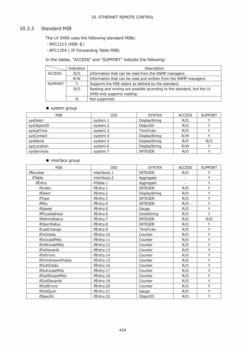
20. ETHERNET REMOTE CONTROL
434
20.3.3 Standard MIB
The LV 5490 uses the following standard MIBs: ・RFC1213 (MIB-Ⅱ) ・RFC1354 ( IP Forwarding Table MIB)
In the tables, "ACCESS" and "SUPPORT" indicate the following:
Indication Description
ACCESS R/O Information that can be read from the SNMP managers. R/W Information that can be read and written from the SNMP managers.
SUPPORT Y Supports the MIB object as defined by the standard. R/O Reading and writing are possible according to the standard, but the LV
5490 only supports reading. N Not supported.
● system group
MIB OID SYNTAX ACCESS SUPPORT sysDescr system.1 DisplayString R/O Y sysObjectID system.2 ObjectID R/O Y sysUpTime system.3 TimeTicks R/O Y sysContact system.4 DisplayString R/W Y sysName system.5 DisplayString R/O R/O sysLocation system.6 DisplayString R/W Y sysServices system.7 INTEGER R/O Y
● interface group
MIB OID SYNTAX ACCESS SUPPORT ifNumber interfaces.1 INTEGER R/O Y ifTable interfaces.2 Aggregate - Y ifEntry ifTable.1 Aggregate - Y ifIndex ifEntry.1 INTEGER R/O Y ifDescr ifEntry.2 DisplayString R/O Y ifType ifEntry.3 INTEGER R/O Y ifMtu ifEntry.4 INTEGER R/O Y ifSpeed ifEntry.5 Gauge R/O Y ifPhysAddress ifEntry.6 OctetString R/O Y ifAdminStatus ifEntry.7 INTEGER R/O R/O ifOperStatus ifEntry.8 INTEGER R/O Y ifLastChange ifEntry.9 TimeTicks R/O Y ifInOctets ifEntry.10 Counter R/O Y ifInUcastPkts ifEntry.11 Counter R/O Y ifInNUcastPkts ifEntry.12 Counter R/O Y ifInDiscards ifEntry.13 Counter R/O Y ifInErrors ifEntry.14 Counter R/O Y ifInUnknownProtos ifEntry.15 Counter R/O Y ifOutOctets ifEntry.16 Counter R/O Y ifOutUcastPkts ifEntry.17 Counter R/O Y ifOutNUcastPkts ifEntry.18 Counter R/O Y ifOutDiscards ifEntry.19 Counter R/O Y ifOutErrors ifEntry.20 Counter R/O Y ifOutQLen ifEntry.21 Gauge R/O Y ifSpecific ifEntry.22 ObjectID R/O Y
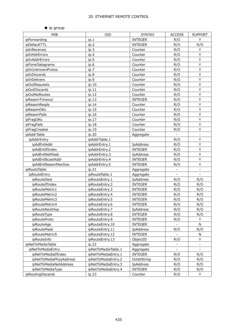
20. ETHERNET REMOTE CONTROL
435
● ip group MIB OID SYNTAX ACCESS SUPPORT
ipForwarding ip.1 INTEGER R/O Y ipDefaultTTL ip.2 INTEGER R/O R/O ipInReceives ip.3 Counter R/O Y ipInHdrErrors ip.4 Counter R/O Y ipInAddrErrors ip.5 Counter R/O Y ipForwDatagrams ip.6 Counter R/O Y ipInUnknownProtos ip.7 Counter R/O Y ipInDiscards ip.8 Counter R/O Y ipInDelivers ip.9 Counter R/O Y ipOutRequests ip.10 Counter R/O Y ipOutDiscards ip.11 Counter R/O Y ipOutNoRoutes ip.12 Counter R/O Y ipReasmTimeout ip.13 INTEGER R/O Y ipReasmReqds ip.14 Counter R/O Y ipReasmOKs ip.15 Counter R/O Y ipReasmFails ip.16 Counter R/O Y ipFragOKs ip.17 Counter R/O Y ipFragFails ip.18 Counter R/O Y ipFragCreates ip.19 Counter R/O Y ipAddrTable ip.20 Aggregate - - ipAddrEntry ipAddrTable.1 R/O Y ipAdEntAddr ipAddrEntry.1 IpAddress R/O Y ipAdEntIfIndex ipAddrEntry.2 INTEGER R/O Y ipAdEntNetMask ipAddrEntry.3 IpAddress R/O Y ipAdEntBcastAddr ipAddrEntry.4 INTEGER R/O Y ipAdEntReasmMaxSize ipAddrEntry.5 INTEGER R/O Y ipRouteTable ip.21 Aggregate - - ipRouteEntry ipRouteTable.1 Aggregate - - ipRouteDest ipRouteEntry.1 IpAddress R/O R/O ipRouteIfIndex ipRouteEntry.2 INTEGER R/O R/O ipRouteMetric1 ipRouteEntry.3 INTEGER R/O R/O ipRouteMetric2 ipRouteEntry.4 INTEGER R/O R/O ipRouteMetric3 ipRouteEntry.5 INTEGER R/O R/O ipRouteMetric4 ipRouteEntry.6 INTEGER R/O R/O ipRouteNextHop ipRouteEntry.7 IpAddress R/O R/O ipRouteType ipRouteEntry.8 INTEGER R/O R/O ipRouteProto ipRouteEntry.9 INTEGER R/O Y ipRouteAge ipRouteEntry.10 INTEGER - N ipRouteMask ipRouteEntry.11 IpAddress R/O R/O ipRouteMetric5 ipRouteEntry.12 INTEGER - N ipRouteInfo ipRouteEntry.13 ObjectID R/O Y ipNetToMediaTable ip.22 Aggregate - - ipNetToMediaEntry ipNetToMediaTable.1 Aggregate - - ipNetToMediaIfIndex ipNetToMediaEntry.1 INTEGER R/O R/O ipNetToMediaPhysAddress ipNetToMediaEntry.2 OctetString R/O R/O ipNetToMediaNetAddress ipNetToMediaEntry.3 IpAddress R/O R/O ipNetToMediaType ipNetToMediaEntry.4 INTEGER R/O R/O ipRoutingDiscards ip.23 Counter R/O Y

20. ETHERNET REMOTE CONTROL
436
● icmp group MIB OID SYNTAX ACCESS SUPPORT
icmpInMsgs icmp.1 Counter R/O Y icmpInErrors icmp.2 Counter R/O Y icmpInDestUnreachs icmp.3 Counter R/O Y icmpInTimeExcds icmp.4 Counter R/O Y icmpInParmProbs icmp.5 Counter R/O Y icmpInSrcQuenchs icmp.6 Counter R/O Y icmpInRedirects icmp.7 Counter R/O Y icmpInEchos icmp.8 Counter R/O Y icmpInEchoReps icmp.9 Counter R/O Y icmpInTimestamps icmp.10 Counter R/O Y icmpInTimestampReps icmp.11 Counter R/O Y icmpInAddrMasks icmp.12 Counter R/O Y icmpInAddrMaskReps icmp.13 Counter R/O Y icmpOutMsgs icmp.14 Counter R/O Y icmpOutErrors icmp.15 Counter R/O Y icmpOutDestUnreachs icmp.16 Counter R/O Y icmpOutTimeExcds icmp.17 Counter R/O Y icmpOutParmProbs icmp.18 Counter R/O Y icmpOutSrcQuenchs icmp.19 Counter R/O Y icmpOutRedirects icmp.20 Counter R/O Y icmpOutEchos icmp.21 Counter R/O Y icmpOutEchoReps icmp.22 Counter R/O Y icmpOutTimestamps icmp.23 Counter R/O Y icmpOutTimestampReps icmp.24 Counter R/O Y icmpOutAddrMasks icmp.25 Counter R/O Y icmpOutAddrMaskReps icmp.26 Counter R/O Y
● tcp group
MIB OID SYNTAX ACCESS SUPPORT tcpRtoAlgorithm tcp.1 INTEGER R/O Y tcpRtoMin tcp.2 INTEGER R/O Y tcpRtoMax tcp.3 INTEGER R/O Y tcpMaxConn tcp.4 INTEGER R/O Y tcpActiveOpens tcp.5 Counter R/O Y tcpPassiveOpens tcp.6 Counter R/O Y tcpAttemptFails tcp.7 Counter R/O Y tcpEstabResets tcp.8 Counter R/O Y tcpCurrEstab tcp.9 Gauge R/O Y tcpInSegs tcp.10 Counter R/O Y tcpOutSegs tcp.11 Counter R/O Y tcpRetransSegs tcp.12 Counter R/O Y tcpConnTable tcp.13 Aggregate - - tcpConnEntry tcpConnTable.1 Aggregate - - tcpConnState tcpConnEntry.1 INTEGER R/O R/O tcpConnLocalAddress tcpConnEntry.2 IpAddress R/O Y tcpConnLocalPort tcpConnEntry.3 INTEGER R/O Y tcpConnRemAddress tcpConnEntry.4 IpAddress R/O Y tcpConnRemPort tcpConnEntry.5 INTEGER R/O Y tcpInErrs tcp.14 Counter R/O Y tcpOutRsts tcp.15 Counter R/O Y

20. ETHERNET REMOTE CONTROL
437
● udp group MIB OID SYNTAX ACCESS SUPPORT
udpInDatagrams udp.1 Counter R/O Y udpNoPorts udp.2 Counter R/O Y udpInErrors udp.3 Counter R/O Y udpOutDatagrams udp.4 Counter R/O Y udpTable udp.5 Aggregate - - udpEntry udpTable.1 Aggregate - - udpLocalAddress udpEntry.1 IpAddress R/O Y udpLocalPort udpEntry.2 INTEGER R/O Y
● snmp group
MIB OID SYNTAX ACCESS SUPPORT snmpInPkts snmp.1 Counter R/O Y snmpOutPkts snmp.2 Counter R/O Y snmpInBadVersions snmp.3 Counter R/O Y snmpInBadCommunityNames snmp.4 Counter R/O Y snmpInBadCommunityUses snmp.5 Counter R/O Y snmpInASNParseErrs snmp.6 Counter R/O Y snmpInTooBigs snmp.7 Counter R/O Y snmpInNoSuchNames snmp.8 Counter R/O Y snmpInBadValues snmp.9 Counter R/O Y snmpInReadOnlys snmp.10 Counter R/O Y snmpInGenErrs snmp.11 Counter R/O Y snmpInTotalReqVars snmp.12 Counter R/O Y snmpInTotalSetVars snmp.13 Counter R/O Y snmpInGetRequests snmp.14 Counter R/O Y snmpInGetNexts snmp.15 Counter R/O Y snmpInSetRequests snmp.16 Counter R/O Y snmpInGetResponses snmp.17 Counter R/O Y snmpInTraps snmp.18 Counter R/O Y snmpOutTooBigs snmp.19 Counter R/O Y snmpOutNoSuchNames snmp.20 Counter R/O Y snmpOutBadValues snmp.21 Counter R/O Y snmpOutGenErrs snmp.22 Counter R/O Y snmpOutGetRequests snmp.23 Counter R/O Y snmpOutGetNexts snmp.24 Counter R/O Y snmpOutSetRequests snmp.25 Counter R/O Y snmpOutGetResponses snmp.26 Counter R/O Y snmpOutTraps snmp.27 Counter R/O Y snmpEnableAuthenTraps snmp.28 IpAddress R/W Y

20. ETHERNET REMOTE CONTROL
438
20.3.4 Enterprise MIB
● Enterprise Number
The Enterprise Number of LEADER ELECTRONICS CORP. is 20111. iso(1).org(3).dod(6).internet(1).private(4).enterprises(1).leader(20111)
● Enterprise MIB File
Download the enterprise MIB file using FTP. The file name is "lv5490.my." (Example: get lv5490.my D:\lv5490.my)
● Enterprise MIB Structure
The enterprise MIB structure is shown below. On products that do not have units installed, the MIBs for the units cannot be controlled.
leader OBJECT IDENTIFIER ::= { enterprises 20111 } lv5490 OBJECT IDENTIFIER ::= { leader 30 } lv5490ST1 OBJECT IDENTIFIER ::= { lv5490 1 } l30notificationTBL OBJECT IDENTIFIER ::= { lv5490ST1 0 } l30basicTBL OBJECT IDENTIFIER ::= { lv5490ST1 1 } l30systemTBL OBJECT IDENTIFIER ::= { lv5490ST1 2 } l30wfmTBL OBJECT IDENTIFIER ::= { lv5490ST1 3 } l30vectorTBL OBJECT IDENTIFIER ::= { lv5490ST1 4 } l30pictureTBL OBJECT IDENTIFIER ::= { lv5490ST1 5 } l30statusTBL OBJECT IDENTIFIER ::= { lv5490ST1 6 } l30eyeTBL OBJECT IDENTIFIER ::= { lv5490ST1 7 } l30audioTBL OBJECT IDENTIFIER ::= { lv5490ST1 8 } l30trapTBL OBJECT IDENTIFIER ::= { lv5490ST1 9 }
● ACCESS
In the tables, "ACCESS" indicates the following:
Indication Description ACCESS R/O Information that can be read from the SNMP managers.
R/W Information that can be read and written from the SNMP managers. R/WO Information that can be read and written from the SNMP managers.
(However, the retrieved data consists of meaningless fixed values.)

20. ETHERNET REMOTE CONTROL
439
● l30basicTBL(1) group MIB OID SYNTAX ACCESS VALUE/RANGE
l30basInputTBL l30basicTBL.1 Aggregate - - l30basInputCh l30basInputTBL.1 INTEGER R/W 1 = a
2 = b 3 = c 4 = d
l30basInputSimul l30basInputTBL.2 INTEGER R/W 1 = off 2 = on
l30basInputOperate l30basInputTBL.3 INTEGER R/W 1 = com 2 = individual
l30basInputExtref l30basInputTBL.4 INTEGER R/W 1 = int 2 = ext
l30basInputGroupSelect l30basInputTBL.5 INTEGER R/W 1 = group1 2 = group2
l30basInput12gCh l30basInputTBL.6 INTEGER R/W 1 = ch-1a 2 = ch-1b 3 = ch-1c 4 = ch-1d
l30basDispTBL l30basicTBL.3 Aggregate - - l30basDispMulti l30basDispTBL.1 INTEGER R/WO 1 (fixed) l30basDispAssignWfm l30basDispTBL.2 INTEGER R/WO 1 (fixed) l30basDispAssignVec l30basDispTBL.3 INTEGER R/WO 1 (fixed) l30basDispAssignPic l30basDispTBL.4 INTEGER R/WO 1 (fixed) l30basDispAssignSts l30basDispTBL.5 INTEGER R/WO 1 (fixed) l30basDispAssignEye l30basDispTBL.6 INTEGER R/WO 1 (fixed) l30basDispAssignAud l30basDispTBL.7 INTEGER R/WO 1 (fixed) l30basPresetTBL l30basicTBL.4 Aggregate - - l30basPresetStore l30basPresetTBL.1 INTEGER R/W 1 to 60 l30basPresetDelete l30basPresetTBL.2 INTEGER R/W 1 to 60 l30basPresetCopyUsbInt l30basPresetTBL.3 INTEGER R/WO 1 (fixed) l30basPresetCopyIntUsb l30basPresetTBL.4 INTEGER R/WO 1 (fixed) l30basPresetRecall l30basPresetTBL.5 INTEGER R/W 1 to 60 l30basCaptureTBL l30basicTBL.5 Aggregate - - l30basCaptureMode l30basCaptureTBL.1 INTEGER R/W 1 = screen
2 = frame l30basCaptureTrigger l30basCaptureTBL.2 INTEGER R/W 1 = manual
2 = error l30basCaptureRefresh l30basCaptureTBL.3 INTEGER R/WO 1 (fixed) l30basCaptureDisplay l30basCaptureTBL.4 INTEGER R/W 1 = real
2 = hold 3 = both
l30basCaptureFileBmp l30basCaptureTBL.5 INTEGER R/W 1 = off 2 = on
l30basCaptureFileBsg l30basCaptureTBL.6 INTEGER R/W 1 = off 2 = on
l30basCaptureFileDpx l30basCaptureTBL.7 INTEGER R/W 1 = off 2 = on
l30basCaptureFileTif l30basCaptureTBL.8 INTEGER R/W 1 = off 2 = on
l30basCaptureFileFrm l30basCaptureTBL.9 INTEGER R/W 1 = off 2 = on
l30basCaptureFileStore l30basCaptureTBL.10 INTEGER R/WO 1 (fixed) l30basMakeTBL l30basicTBL.6 Aggregate - - l30basMakeFile l30basMakeTBL.1 INTEGER R/WO 1 = cap-bmp
2 = cap-bsg 3 = cap-frm
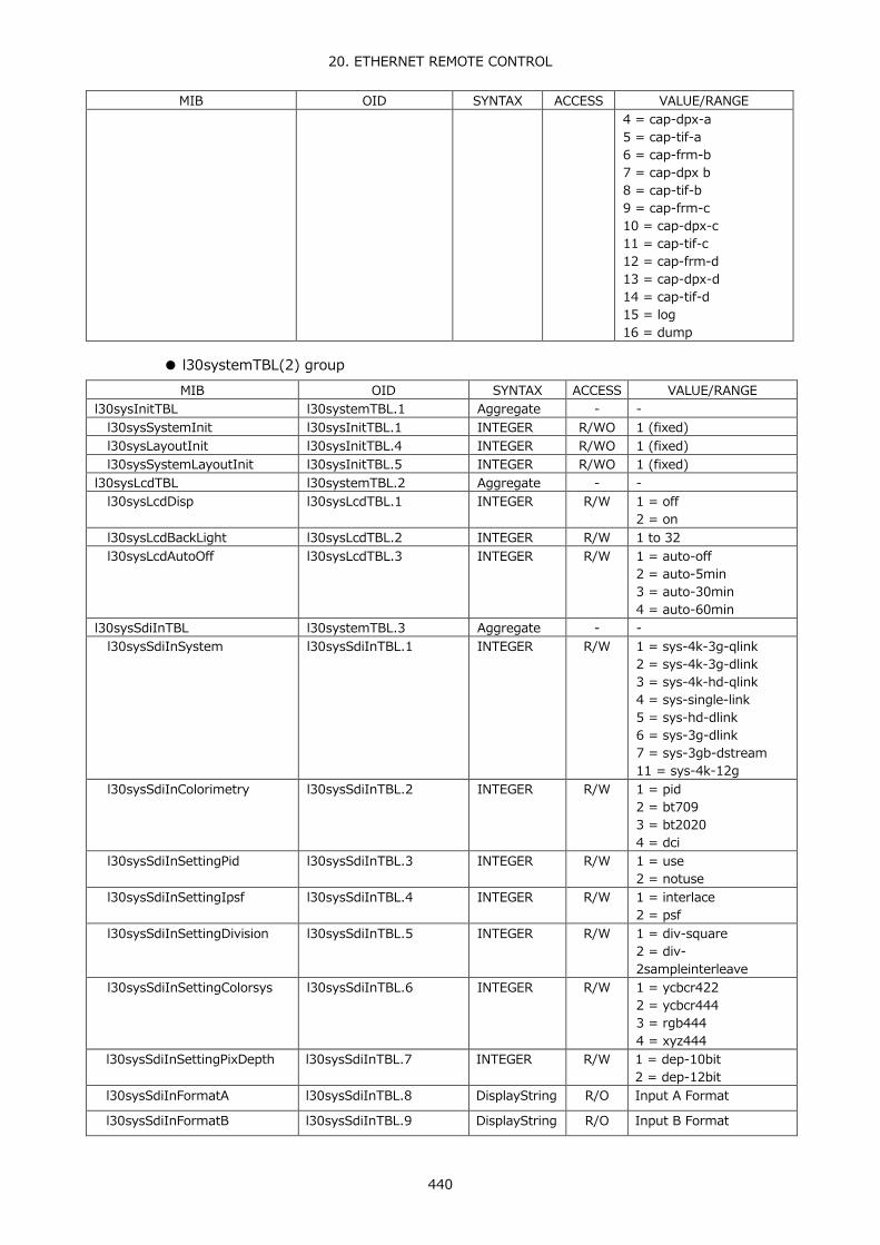
20. ETHERNET REMOTE CONTROL
440
MIB OID SYNTAX ACCESS VALUE/RANGE 4 = cap-dpx-a 5 = cap-tif-a 6 = cap-frm-b 7 = cap-dpx b 8 = cap-tif-b 9 = cap-frm-c 10 = cap-dpx-c 11 = cap-tif-c 12 = cap-frm-d 13 = cap-dpx-d 14 = cap-tif-d 15 = log 16 = dump
● l30systemTBL(2) group
MIB OID SYNTAX ACCESS VALUE/RANGE l30sysInitTBL l30systemTBL.1 Aggregate - - l30sysSystemInit l30sysInitTBL.1 INTEGER R/WO 1 (fixed) l30sysLayoutInit l30sysInitTBL.4 INTEGER R/WO 1 (fixed) l30sysSystemLayoutInit l30sysInitTBL.5 INTEGER R/WO 1 (fixed) l30sysLcdTBL l30systemTBL.2 Aggregate - - l30sysLcdDisp l30sysLcdTBL.1 INTEGER R/W 1 = off
2 = on l30sysLcdBackLight l30sysLcdTBL.2 INTEGER R/W 1 to 32 l30sysLcdAutoOff l30sysLcdTBL.3 INTEGER R/W 1 = auto-off
2 = auto-5min 3 = auto-30min 4 = auto-60min
l30sysSdiInTBL l30systemTBL.3 Aggregate - - l30sysSdiInSystem l30sysSdiInTBL.1 INTEGER R/W 1 = sys-4k-3g-qlink
2 = sys-4k-3g-dlink 3 = sys-4k-hd-qlink 4 = sys-single-link 5 = sys-hd-dlink 6 = sys-3g-dlink 7 = sys-3gb-dstream 11 = sys-4k-12g
l30sysSdiInColorimetry l30sysSdiInTBL.2 INTEGER R/W 1 = pid 2 = bt709 3 = bt2020 4 = dci
l30sysSdiInSettingPid l30sysSdiInTBL.3 INTEGER R/W 1 = use 2 = notuse
l30sysSdiInSettingIpsf l30sysSdiInTBL.4 INTEGER R/W 1 = interlace 2 = psf
l30sysSdiInSettingDivision l30sysSdiInTBL.5 INTEGER R/W 1 = div-square 2 = div-2sampleinterleave
l30sysSdiInSettingColorsys l30sysSdiInTBL.6 INTEGER R/W 1 = ycbcr422 2 = ycbcr444 3 = rgb444 4 = xyz444
l30sysSdiInSettingPixDepth l30sysSdiInTBL.7 INTEGER R/W 1 = dep-10bit 2 = dep-12bit
l30sysSdiInFormatA l30sysSdiInTBL.8 DisplayString R/O Input A Format
l30sysSdiInFormatB l30sysSdiInTBL.9 DisplayString R/O Input B Format

20. ETHERNET REMOTE CONTROL
441
MIB OID SYNTAX ACCESS VALUE/RANGE l30sysSdiInFormatC l30sysSdiInTBL.10 DisplayString R/O Input C Format
l30sysSdiInFormatD l30sysSdiInTBL.11 DisplayString R/O Input D Format
l30sysSdiInXyzGammaSelect l30sysSdiInTBL.12 INTEGER R/W 1 = bottom-zero 2 = dci
l30sysSdiInHfrMode l30sysSdiInTBL.13 INTEGER R/W 1 = off 2 = x2 3 = x4 4 = x8
l30sysSdiOutTBL l30systemTBL.4 Aggregate - - l30sysSdiOutBncInOut l30sysSdiOutTBL.1 INTEGER R/W 1 = input
2 = output l30sysSdiOutInOut l30sysSdiOutTBL.2 INTEGER R/W 1 = a
2 = abcd l30sysSdiOutMode l30sysSdiOutTBL.3 INTEGER R/W 1 = through
2 = test l30sysSdiOutSystem l30sysSdiOutTBL.4 INTEGER R/W 1 = sys-3840-3gbdl-quad
2 = sys-4096-3gbdl-quad 3 = sys-3840-3ga-quad 4 = sys-4096-3ga-quad 5 = sys-3840-3gbds-dual 6 = sys-4096-3gbds-dual 7 = sys-1920-3gbdl 8 = sys-2048-3gbdl 9 = sys-1920-3ga 10 = sys-2048-3ga 11 = sys-1920-hd
l30sysSdiOutStruct l30sysSdiOutTBL.5 INTEGER R/W 1 = ycbcr422 2 = ycbcr444 3 = rgb444 4 = xyz444
l30sysSdiOutFrameRate l30sysSdiOutTBL.6 INTEGER R/W 1 = frm-60p 2 = frm-5994p 3 = frm-50p 4 = frm-48p 5 = frm-30p 6 = frm-2997p 7 = frm-25p 8 = frm-4795p 9 = frm-24p 10 = frm-2398p 11 = frm-60i 12 = frm-5994i 13 = frm-50i 14 = frm-30psf 15 = frm-2997psf 16 = frm-25psf 17 = frm-24psf 18 = frm-2398psf
l30sysSdiOutDivision l30sysSdiOutTBL.7 INTEGER R/W 1 = div-square 2 = div-2sampleinterleave
l30sysSdiOutPattern l30sysSdiOutTBL.8 INTEGER R/W 1 = ptn-colbar100 2 = ptn-colbar75 3 = ptn-multicol 4 = ptn-colraster 5 = ptn-cross 6 = ptn-10step 7 = ptn-ramp

20. ETHERNET REMOTE CONTROL
442
MIB OID SYNTAX ACCESS VALUE/RANGE 8 = ptn-limitramp
l30sysSdiOutYOn l30sysSdiOutTBL.9 INTEGER R/W 1 = off 2 = on
l30sysSdiOutYValue l30sysSdiOutTBL.10 INTEGER R/W 4 to 1019 l30sysSdiOutCbOn l30sysSdiOutTBL.11 INTEGER R/W 1 = off
2 = on l30sysSdiOutCbValue l30sysSdiOutTBL.12 INTEGER R/W 4 to 1019 l30sysSdiOutCrOn l30sysSdiOutTBL.13 INTEGER R/W 1 = off
2 = on l30sysSdiOutCrValue l30sysSdiOutTBL.14 INTEGER R/W 4 to 1019 l30sysSdiOutROn l30sysSdiOutTBL.15 INTEGER R/W 1 = off
2 = on l30sysSdiOutRValue l30sysSdiOutTBL.16 INTEGER R/W 4 to 1019 l30sysSdiOutGOn l30sysSdiOutTBL.17 INTEGER R/W 1 = off
2 = on l30sysSdiOutGValue l30sysSdiOutTBL.18 INTEGER R/W 4 to 1019 l30sysSdiOutBOn l30sysSdiOutTBL.19 INTEGER R/W 1 = off
2 = on l30sysSdiOutBValue l30sysSdiOutTBL.20 INTEGER R/W 4 to 1019 l30sysSdiOutScroll l30sysSdiOutTBL.21 INTEGER R/W 1 = off
2 = on l30sysSdiOutScrollDirection l30sysSdiOutTBL.22 INTEGER R/W 1 = right
2 = left 3 = up 4 = down 5 = right_up 6 = right_down 7 = left_up 8 = left_down
l30sysSdiOutScrollSpeed l30sysSdiOutTBL.23 INTEGER R/W 4 to 124 l30sysSdiOutBox l30sysSdiOutTBL.24 INTEGER R/W 1 = off
2 = on l30sysSdiOutBoxColor l30sysSdiOutTBL.25 INTEGER R/W 1 = white
2 = yellow 3 = cyan 4 = green 5 = magenta 6 = red 7 = blue 8 = black
l30sysSdiOutBoxSpeed l30sysSdiOutTBL.26 INTEGER R/W 1 to 3 l30sysSdiOutPhaseDiff l30sysSdiOutTBL.27 INTEGER R/W 1 = off
2 = on l30sysSdiOutPhaseDirection l30sysSdiOutTBL.28 INTEGER R/W 1 = h
2 = v l30sysSdiOutPhaseHBch l30sysSdiOutTBL.29 INTEGER R/W -1374 to 1374 l30sysSdiOutPhaseHCch l30sysSdiOutTBL.30 INTEGER R/W -1374 to 1374 l30sysSdiOutPhaseHDch l30sysSdiOutTBL.31 INTEGER R/W -1374 to 1374 l30sysSdiOutPhaseVBch l30sysSdiOutTBL.32 INTEGER R/W -562 to 562 l30sysSdiOutPhaseVCch l30sysSdiOutTBL.33 INTEGER R/W -562 to 562 l30sysSdiOutPhaseVDch l30sysSdiOutTBL.34 INTEGER R/W -562 to 562 l30sysSdiOutAudioG1 l30sysSdiOutTBL.35 INTEGER R/W 1 = off
2 = on l30sysSdiOutAudioG2 l30sysSdiOutTBL.36 INTEGER R/W 1 = off
2 = on l30sysSdiOutAudioG3 l30sysSdiOutTBL.37 INTEGER R/W 1 = off
2 = on

20. ETHERNET REMOTE CONTROL
443
MIB OID SYNTAX ACCESS VALUE/RANGE l30sysSdiOutAudioG4 l30sysSdiOutTBL.38 INTEGER R/W 1 = off
2 = on l30sysSdiOutAudioLevel l30sysSdiOutTBL.39 INTEGER R/W 1 = lvl-20dBFS
2 = lvl-18 dBFS 3 = lvl-0 dBFS 4 = lvl-mute
l30sysAudioInOutTBL l30systemTBL.5 Aggregate - - l30sysAudBncGrpA l30sysAudioInOutTBL.1 INTEGER R/W 1 = input
2 = output l30sysAudBncGrpB l30sysAudioInOutTBL.2 INTEGER R/W 1 = input
2 = output l30sysMonitorOutTBL l30systemTBL.6 Aggregate - -
l30sysRasterSync l30sysMonitorOutTBL.1 INTEGER R/W 1 = int 2 = external
l30sysRasterFmt l30sysMonitorOutTBL.2 INTEGER R/W 1 = fmt-1080-60p 2 = fmt-1080-59p 3 = fmt-1080-50p
l30sysRasterSdiOut l30sysMonitorOutTBL.3 INTEGER R/W 1 = raster 2 = input
l30sysRasterSdiOutFmt l30sysMonitorOutTBL.4 INTEGER R/W 1 = fmt-hd 2 = fmt-3ga 3 = fmt-3gb
l30sysGeneralTBL l30systemTBL.7 Aggregate - -
l30sysGeneralBootMode l30sysGeneralTBL.1 INTEGER R/W 1 = Normal 2 = Fast
l30sysGeneralInfoDispFmt l30sysGeneralTBL.2 INTEGER R/W 1 = off 2 = on
l30sysGeneralInfoDispDate l30sysGeneralTBL.3 INTEGER R/W 1 = off 2 = ymd 3 = mdy 4 = dmy
l30sysGeneralInfoDispTime l30sysGeneralTBL.4 INTEGER R/W 1 = off 2 = real 3 = ltc 4 = vitc 5 = d-vitc
l30sysGeneralInfoDispInput l30sysGeneralTBL.6 INTEGER R/W 1 = off 2 = on
l30sysGeneralInfoDispIcon l30sysGeneralTBL.7 INTEGER R/W 1 = off 2 = on
l30sysGeneralMenuAutoOff l30sysGeneralTBL.8 INTEGER R/W 1 = off 2 = on
l30sysGeneralMenuAutoOffTime l30sysGeneralTBL.9 INTEGER R/W 1 to 60 l30sysGeneralFanSpeed l30sysGeneralTBL.11 INTEGER R/W 1 to 5 l30sysGeneralFanWarning l30sysGeneralTBL.12 INTEGER R/W 1 = off
2 = on l30sysGeneralInfoDispError l30sysGeneralTBL.13 INTEGER R/W 1 = off
2 = on l30sysEthernetTBL l30systemTBL.8 Aggregate - - l30sysEthernetSel l30sysEthernetTBL.1 INTEGER R/O 1 = dhcp
2 = ip l30sysEthernetAddress l30sysEthernetTBL.2 IpAddress R/O IP Address l30sysEthernetSubnet l30sysEthernetTBL.3 IpAddress R/O Subnet Mask l30sysEthernetGateway l30sysEthernetTBL.4 IpAddress R/O Default Gateway l30sysEthernetSntp l30sysEthernetTBL.5 INTEGER R/W 1 = off
2 = on

20. ETHERNET REMOTE CONTROL
444
MIB OID SYNTAX ACCESS VALUE/RANGE l30sysEthernetSntpAddress l30sysEthernetTBL.6 IpAddress R/W IP Address l30sysEthernetSntpTz l30sysEthernetTBL.7 INTEGER R/W 1 = m12
2 = m11 3 = m10 4 = m9 5 = m8 6 = m7 7 = m6 8 = m5 9 = m4 10 = m3 11 = m2 12 = m1 13 = p0 14 = p1 15 = p2 16 = p3 17 = p4 18 = p5 19 = p6 20 = p7 21 = p8 22 = p9 23 = p10 24 = p11 25 = p12
l30sysEthernetTelnet l30sysEthernetTBL.8 INTEGER R/W 1 = off 2 = on
l30sysEthernetFtp l30sysEthernetTBL.9 INTEGER R/W 1 = off 2 = on
l30sysEthernetSnmpTrap l30sysEthernetTBL.11 INTEGER R/W 1 = off 2 = on
l30sysEthernetMacAddr l30sysEthernetTBL.12 DisplayString R/O MAC Address l30sysRemoteTBL l30systemTBL.9 Aggregate - - l30sysRemoteMode l30sysRemoteTBL.1 INTEGER R/W 1 = bit
2 = binary l30sysRemotePole l30sysRemoteTBL.2 INTEGER R/W 1 = positive
2 = negative l30sysRemoteAlarmAch l30sysRemoteTBL.3 INTEGER R/W 1 = off
2 = on l30sysRemoteAlarmBch l30sysRemoteTBL.4 INTEGER R/W 1 = off
2 = on l30sysRemoteAlarmCch l30sysRemoteTBL.5 INTEGER R/W 1 = off
2 = on l30sysRemoteAlarmDch l30sysRemoteTBL.6 INTEGER R/W 1 = off
2 = on l30sysRemoteTallyColor1 l30sysRemoteTBL.8 INTEGER R/W 1 = white
2 = red 3 = green 4 = blue 5 = cyan 6 = magenta 7 = yellow 8 = orange
l30sysRemoteTallyColor2 l30sysRemoteTBL.9 INTEGER R/W 1 = white 2 = red 3 = green 4 = blue

20. ETHERNET REMOTE CONTROL
445
MIB OID SYNTAX ACCESS VALUE/RANGE 5 = cyan 6 = magenta 7 = yellow 8 = orange
l30sysRemoteTallyColor3 l30sysRemoteTBL.10 INTEGER R/W 1 = white 2 = red 3 = green 4 = blue 5 = cyan 6 = magenta 7 = yellow 8 = orange
l30sysRemoteTallyFrame l30sysRemoteTBL.11 INTEGER R/W 1 = off 2 = on
l30sysRemoteTallyLayout l30sysRemoteTBL.12 INTEGER R/W 1 = left 2 = right
l30sysDateTBL l30systemTBL.10 Aggregate - - l30sysDateTime l30sysDateTBL.3 DisplayString R/O Date and Time l30sysFormatAlarmTBL l30systemTBL.11 Aggregate - - l30sysFormatAlarm l30sysFormatAlarmTBL.1 INTEGER R/W 1 = off
2 = on l30sysFormatAlarmSystem l30sysFormatAlarmTBL.2 INTEGER R/W 1 = fmt-3840-3gbdl-
quad 2 = fmt-4096-3gbdl-quad 3 = fmt-3840-3ga-quad 4 = fmt-4096-3ga-quad 5 = fmt-3840-3gbds-dual 6 = fmt-4096-3gbds-dual 7 = fmt-3840-hd-quad 8 = fmt-4096-hd-quad 9 = fmt-1920-3gbdl 10 = fmt-2048-3gbdl 11 = fmt-1280-3ga 12 = fmt-1920-3ga 13 = fmt-2048-3ga 14 = fmt-1280-hd 15 = fmt-1920-hd 16 = fmt-487-sd 17 = fmt-576-sd 18 = fmt-1920-hd-dual 19 = fmt-2048-hd-dual 20 = fmt-1280-3gbds 21 = fmt-1920-3gbds 22 = fmt-1920-3gbdl-dual 23 = fmt-2048-3gbdl-dual 24 = fmt-1920-3ga-dual 25 = fmt-2048-3ga-dual 26 = fmt-3840-12g-type1 27 = fmt-4096-12g-type1
l30sysFormatAlarmStruct l30sysFormatAlarmTBL.3 INTEGER R/W 1 = ycbcr422-10bit 2 = ycbcr422-12bit

20. ETHERNET REMOTE CONTROL
446
MIB OID SYNTAX ACCESS VALUE/RANGE 3 = ycbcr444-10bit 4 = ycbcr444-12bit 5 = rgb444-10bit 6 = rgb444-12bit 7 = xyz444-12bit
l30sysFormatAlarmFramerate l30sysFormatAlarmTBL.4 INTEGER R/W 1 = fmt-60p 2 = fmt-5994p 3 = fmt-50p 4 = fmt-48p 5 = fmt-30p 6 = fmt-2997p 7 = fmt-25p 8 = fmt-4795p 9 = fmt-24p 10 = fmt-2398p 11 = fmt-60i 12 = fmt-5994i 13 = fmt-50i 14 = fmt-30psf 15 = fmt-2997psf 16 = fmt-25psf 17 = fmt-24psf 18 = fmt-2398psf
l30sysFormatAlarmDiv l30sysFormatAlarmTBL.5 INTEGER R/W 1 = div-square 2 = div-2sampleinterleave
l30sysFormatAlarmColor l30sysFormatAlarmTBL.6 INTEGER R/W 1 = bt709 2 = bt2020 3 = dci
l30sysFormatAlarmFlagColor l30sysFormatAlarmTBL.7 INTEGER R/W 1 = off 2 = on
l30sysCompleteTBL l30systemTBL.12 Aggregate - - l30sysSignalInOutComplete l30sysCompleteTBL.1 INTEGER R/WO 1 (fixed) l30sysSystemSetupComplete l30sysCompleteTBL.2 INTEGER R/WO 1 (fixed) l30sysEthernetSettingUpdate l30sysCompleteTBL.3 INTEGER R/WO 1 (fixed) l30sysInfoTBL l30systemTBL.13 Aggregate - - l30sysInfoFirmware l30sysInfoTBL.1 DisplayString R/O Firmware Version l30sysInfoBoardSdiIn l30sysInfoTBL.2 INTEGER R/O 1 = notavailable
2 = available l30sysInfoBoardSdiEye l30sysInfoTBL.3 INTEGER R/O 1 = notavailable
2 = available l30sysInfoBoardAudio l30sysInfoTBL.4 INTEGER R/O 1 = notavailable
2 = available l30sysHdrTBL l30systemTBL.14 Aggregate - - l30sysHdrEnable l30sysHdrTBL.1 INTEGER R/W 1 = off
2 = on l30sysHdrHdrCurve l30sysHdrTBL.2 INTEGER R/W 2 = hlg
3 = pq 4 = slog3
l30sysHdrMax l30sysHdrTBL.3 INTEGER R/W 1 = cd10000 2 = cd4000 3 = cd1000
l30sysHdrGamma l30sysHdrTBL.4 INTEGER R/W 1 = off 2 = on
l30sysHdrRefPq l30sysHdrTBL.5 INTEGER R/W 3 = p51 4 = p58
l30sysHdrRefHlg l30sysHdrTBL.6 INTEGER R/W 1 = p50

20. ETHERNET REMOTE CONTROL
447
MIB OID SYNTAX ACCESS VALUE/RANGE 2 = p75
● l30wfmTBL(1) group
MIB OID SYNTAX ACCESS VALUE/RANGE l30wfmIntenTBL l30wfmTBL.1 Aggregate - - l30wfmInten l30wfmIntenTBL.1 INTEGER R/W -128 to 127 l30wfmColor l30wfmIntenTBL.2 INTEGER R/W 1 = white
2 = yellow 3 = cyan 4 = green 5 = magenta 6 = red 7 = blue 8 = multi
l30wfmColorS1 l30wfmIntenTBL.3 INTEGER R/W 1 = white 2 = yellow 3 = cyan 4 = green 5 = magenta 6 = red 7 = blue 8 = multi
l30wfmColorS2 l30wfmIntenTBL.4 INTEGER R/W 1 = white 2 = yellow 3 = cyan 4 = green 5 = magenta 6 = red 7 = blue 8 = multi
l30wfmScaleTBL l30wfmTBL.2 Aggregate - - l30wfmScaleInten l30wfmScaleTBL.1 INTEGER R/W -8 to 7 l30wfmScaleColor l30wfmScaleTBL.2 INTEGER R/W 1 = white
2 = yellow 3 = cyan 4 = green 5 = magenta 6 = red 7 = blue
l30wfmScaleUnit l30wfmScaleTBL.3 INTEGER R/W 1 = unit-hdv-sdp 2 = unit-hdv-sdv 3 = unit-hdp-sdp 4 = unit-150p 5 = unit-1023 6 = unit-1023-255 7 = unit-3ff
l30wfmScaleUnitNtsc l30wfmScaleTBL.4 INTEGER R/W 3 = unit-hdp-sdp l30wfmScaleUnitPal l30wfmScaleTBL.5 INTEGER R/W 2 = unit-hdv-sdv l30wfmScale75perCol l30wfmScaleTBL.6 INTEGER R/W 1 = off
2 = on l30wfmGainTBL l30wfmTBL.3 Aggregate - - l30wfmGainVar l30wfmGainTBL.1 INTEGER R/W 1 = cal
2 = variable l30wfmGainMag l30wfmGainTBL.2 INTEGER R/W 1 = x1
2 = x5 l30wfmGainValue l30wfmGainTBL.3 DisplayString R/W 0.2 to 2.000 l30wfmGainFilter l30wfmGainTBL.4 INTEGER R/W 1 = lowpass

20. ETHERNET REMOTE CONTROL
448
MIB OID SYNTAX ACCESS VALUE/RANGE 2 = flat
l30wfmGainFilterCmp l30wfmGainTBL.5 INTEGER R/W 2 = flat 3 = lum 4 = flatlum 5 = lumchroma
l30wfmSweepTBL l30wfmTBL.4 Aggregate - - l30wfmSweep l30wfmSweepTBL.1 INTEGER R/W 1 = h
2 = v l30wfmSweepMagH l30wfmSweepTBL.2 INTEGER R/W 1 = x1
2 = x10 3 = x20 4 = blank 5 = active
l30wfmSweepMagV l30wfmSweepTBL.3 INTEGER R/W 1 = x1 2 = x20 3 = x40
l30wfmSweepH l30wfmSweepTBL.4 INTEGER R/W 1 = sweep-1h 2 = sweep-2h
l30wfmSweepV l30wfmSweepTBL.5 INTEGER R/W 1 = sweep-1v 2 = sweep-2v
l30wfmSweepField l30wfmSweepTBL.6 INTEGER R/W 1 = field1 2 = field2
l30wfmBlanking l30wfmSweepTBL.7 INTEGER R/W 1 = remove 2 = v 3 = h 4 = all
l30wfmBlankingCmp l30wfmSweepTBL.8 INTEGER R/W 1 = remove 2 = v
l30wfmMatrixTBL l30wfmTBL.5 Aggregate - - l30wfmMatrix l30wfmMatrixTBL.1 INTEGER R/W 1 = ycbcr
2 = gbr 3 = rgb 4 = composite
l30wfmMatrixRgb l30wfmMatrixTBL.2 INTEGER R/W 2 = gbr 3 = rgb 4 = composite
l30wfmMatrixYgbr l30wfmMatrixTBL.3 INTEGER R/W 1 = off 2 = on
l30wfmMatrixYrgb l30wfmMatrixTBL.4 INTEGER R/W 1 = off 2 = on
l30wfmCmpFormat l30wfmMatrixTBL.5 INTEGER R/W 1 = auto 2 = ntsc 3 = pal
l30wfmCmpSetup l30wfmMatrixTBL.6 INTEGER R/W 1 = setup-0p 2 = setup-75p
l30wfmMatrixXyz l30wfmMatrixTBL.7 INTEGER R/W 2 = gbr 3 = rgb 4 = composite 5 = xyz
l30wfmDisplayTBL l30wfmTBL.6 Aggregate - - l30wfmDisplayMode l30wfmDisplayTBL.1 INTEGER R/W 1 = parade
2 = overlay l30wfmDisplayCh1Y l30wfmDisplayTBL.2 INTEGER R/W 1 = off
2 = on l30wfmDisplayCh2Cb l30wfmDisplayTBL.3 INTEGER R/W 1 = off
2 = on l30wfmDisplayCh3Cr l30wfmDisplayTBL.4 INTEGER R/W 1 = off

20. ETHERNET REMOTE CONTROL
449
MIB OID SYNTAX ACCESS VALUE/RANGE 2 = on
l30wfmDisplayCh1G l30wfmDisplayTBL.5 INTEGER R/W 1 = off 2 = on
l30wfmDisplayCh2B l30wfmDisplayTBL.6 INTEGER R/W 1 = off 2 = on
l30wfmDisplayCh3R l30wfmDisplayTBL.7 INTEGER R/W 1 = off 2 = on
l30wfmDisplayCh1R l30wfmDisplayTBL.8 INTEGER R/W 1 = off 2 = on
l30wfmDisplayCh2G l30wfmDisplayTBL.9 INTEGER R/W 1 = off 2 = on
l30wfmDisplayCh3B l30wfmDisplayTBL.10 INTEGER R/W 1 = off 2 = on
l30wfmDisplay3gbds l30wfmDisplayTBL.11 INTEGER R/W 1 = stream1 2 = stream2 3 = mix 4 = align
l30wfmDisplayYParade l30wfmDisplayTBL.12 INTEGER R/W 1 = off 2 = on
l30wfmDisplayCh1X l30wfmDisplayTBL.13 INTEGER R/W 1 = off 2 = on
l30wfmDisplayCh2Y l30wfmDisplayTBL.14 INTEGER R/W 1 = off 2 = on
l30wfmDisplayCh3Z l30wfmDisplayTBL.15 INTEGER R/W 1 = off 2 = on
l30wfmLineselTBL l30wfmTBL.7 Aggregate - - l30wfmLinesel l30wfmLineselTBL.1 INTEGER R/W 1 = off
2 = on l30wfmLineselNo l30wfmLineselTBL.2 INTEGER R/W 0 to 32767 l30wfmLineselField l30wfmLineselTBL.3 INTEGER R/W 1 = frame
2 = field1 3 = field2
●l30vectorTBL(1) group
MIB OID SYNTAX ACCESS VALUE/RANGE l30vectorIntenTBL l30vectorTBL.1 Aggregate - - l30vctorInten l30vectorIntenTBL.1 INTEGER R/W -128 to 127 l30vctorColor l30vectorIntenTBL.2 INTEGER R/W 1 = white
2 = yellow 3 = cyan 4 = green 5 = magenta 6 = red 7 = blue
l30vectorColorS1 l30vectorIntenTBL.3 INTEGER R/W 1 = white 2 = yellow 3 = cyan 4 = green 5 = magenta 6 = red 7 = blue
l30vectorColorS2 l30vectorIntenTBL.4 INTEGER R/W 1 = white 2 = yellow 3 = cyan 4 = green 5 = magenta 6 = red
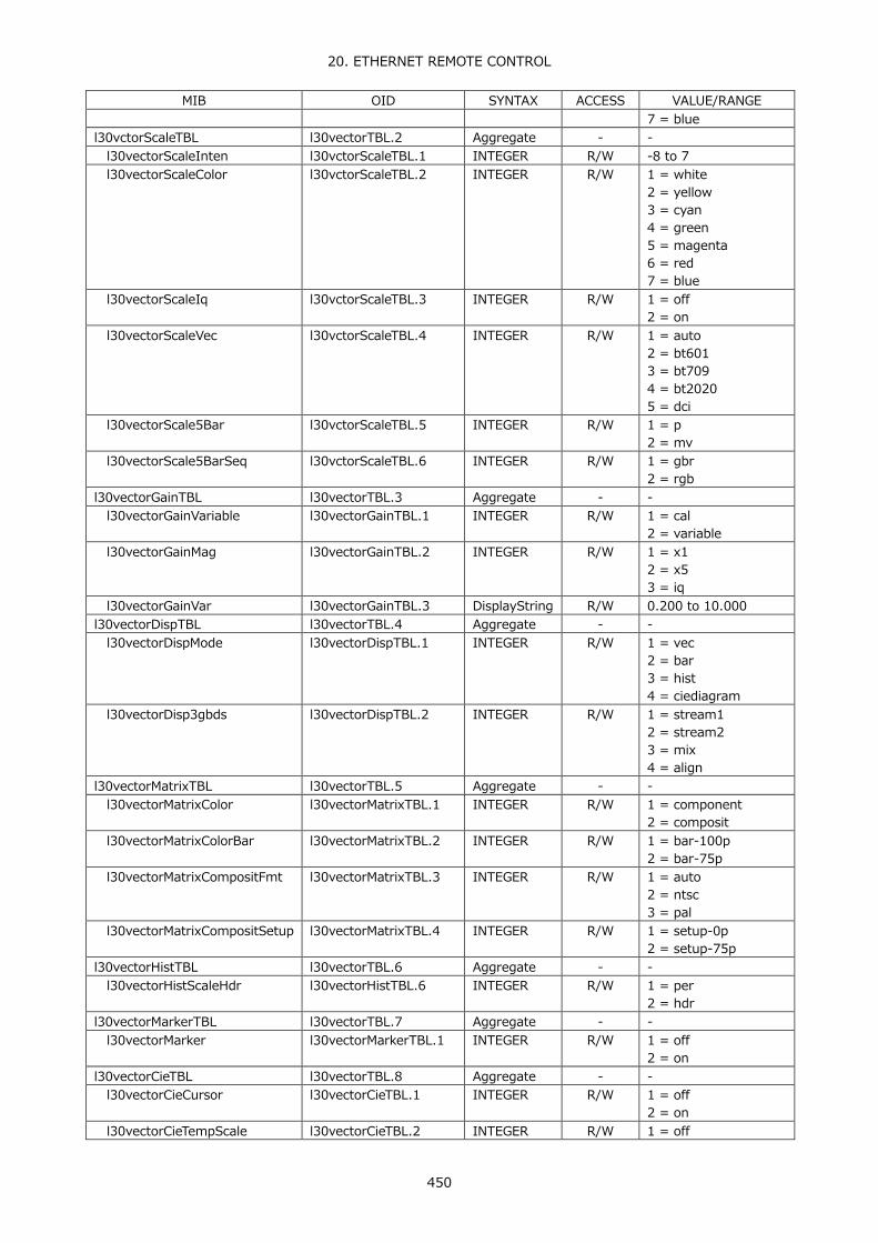
20. ETHERNET REMOTE CONTROL
450
MIB OID SYNTAX ACCESS VALUE/RANGE 7 = blue
l30vctorScaleTBL l30vectorTBL.2 Aggregate - - l30vectorScaleInten l30vctorScaleTBL.1 INTEGER R/W -8 to 7 l30vectorScaleColor l30vctorScaleTBL.2 INTEGER R/W 1 = white
2 = yellow 3 = cyan 4 = green 5 = magenta 6 = red 7 = blue
l30vectorScaleIq l30vctorScaleTBL.3 INTEGER R/W 1 = off 2 = on
l30vectorScaleVec l30vctorScaleTBL.4 INTEGER R/W 1 = auto 2 = bt601 3 = bt709 4 = bt2020 5 = dci
l30vectorScale5Bar l30vctorScaleTBL.5 INTEGER R/W 1 = p 2 = mv
l30vectorScale5BarSeq l30vctorScaleTBL.6 INTEGER R/W 1 = gbr 2 = rgb
l30vectorGainTBL l30vectorTBL.3 Aggregate - - l30vectorGainVariable l30vectorGainTBL.1 INTEGER R/W 1 = cal
2 = variable l30vectorGainMag l30vectorGainTBL.2 INTEGER R/W 1 = x1
2 = x5 3 = iq
l30vectorGainVar l30vectorGainTBL.3 DisplayString R/W 0.200 to 10.000 l30vectorDispTBL l30vectorTBL.4 Aggregate - - l30vectorDispMode l30vectorDispTBL.1 INTEGER R/W 1 = vec
2 = bar 3 = hist 4 = ciediagram
l30vectorDisp3gbds l30vectorDispTBL.2 INTEGER R/W 1 = stream1 2 = stream2 3 = mix 4 = align
l30vectorMatrixTBL l30vectorTBL.5 Aggregate - - l30vectorMatrixColor l30vectorMatrixTBL.1 INTEGER R/W 1 = component
2 = composit l30vectorMatrixColorBar l30vectorMatrixTBL.2 INTEGER R/W 1 = bar-100p
2 = bar-75p l30vectorMatrixCompositFmt l30vectorMatrixTBL.3 INTEGER R/W 1 = auto
2 = ntsc 3 = pal
l30vectorMatrixCompositSetup l30vectorMatrixTBL.4 INTEGER R/W 1 = setup-0p 2 = setup-75p
l30vectorHistTBL l30vectorTBL.6 Aggregate - - l30vectorHistScaleHdr l30vectorHistTBL.6 INTEGER R/W 1 = per
2 = hdr l30vectorMarkerTBL l30vectorTBL.7 Aggregate - - l30vectorMarker l30vectorMarkerTBL.1 INTEGER R/W 1 = off
2 = on l30vectorCieTBL l30vectorTBL.8 Aggregate - - l30vectorCieCursor l30vectorCieTBL.1 INTEGER R/W 1 = off
2 = on l30vectorCieTempScale l30vectorCieTBL.2 INTEGER R/W 1 = off

20. ETHERNET REMOTE CONTROL
451
MIB OID SYNTAX ACCESS VALUE/RANGE 2 = on
l30vectorCieMode l30vectorCieTBL.3 INTEGER R/W 1 = diagram 2 = temp
l30vectorCieFilter l30vectorCieTBL.4 INTEGER R/W 1 = off 2 = on
l30vectorCieColor l30vectorCieTBL.6 INTEGER R/W 1 = bg-white 2 = bg-color 3 = bg-black
l30vectorCieFigure1 l30vectorCieTBL.7 INTEGER R/W 1 = off 4 = bt601-525 5 = bt601-625 6 = bt709 7 = dci 8 = bt2020
l30vectorCieFigure2 l30vectorCieTBL.8 INTEGER R/W 1 = off 4 = bt601-525 5 = bt601-625 6 = bt709 7 = dci 8 = bt2020
l30vectorCieGamma l30vectorCieTBL.9 INTEGER R/W 2 = gamma22 3 = gamma26
l30vectorCieColorimetry l30vectorCieTBL.10 INTEGER R/W 1 = bt601-525 2 = bt601-625 3 = bt709 4 = dci 5 = bt2020
l30vectorCieStandard l30vectorCieTBL.11 INTEGER R/W 5 = cie1391 6 = cie1976
l30vectorCieGrid l30vectorCieTBL.12 INTEGER R/W 1 = off 2 = on
l30vectorCieD65 l30vectorCieTBL.13 INTEGER R/W 1 = off 2 = on
l30vectorCieFigureCap l30vectorCieTBL.14 INTEGER R/W 1 = off 2 = on
l30vectoCieClip l30vectorCieTBL.15 INTEGER R/W 1 = off 2 = on
l30vectorCieManualSetup l30vectorCieTBL.16 INTEGER R/W 1 = off 2 = on
l30vectorCieGammaSetup l30vectorCieTBL.17 DisplayString R/W 1.50 to 3.00 l30vectorCieUserTriangle l30vectorCieTBL.18 INTEGER R/W 1 = off
2 = user1 3 = user2
l30vectorCieUserTriangleColor l30vectorCieTBL.19 INTEGER R/W 1 = g 2 = b 3 = r
l30vectorCieUserTriangle1GX l30vectorCieTBL.20 DisplayString R/W 0 to 1.000 l30vectorCieUserTriangle1BX l30vectorCieTBL.21 DisplayString R/W 0 to 1.000 l30vectorCieUserTriangle1RX l30vectorCieTBL.22 DisplayString R/W 0 to 1.000 l30vectorCieUserTriangle1GY l30vectorCieTBL.23 DisplayString R/W 0 to 1.000 l30vectorCieUserTriangle1BY l30vectorCieTBL.24 DisplayString R/W 0 to 1.000 l30vectorCieUserTriangle1RY l30vectorCieTBL.25 DisplayString R/W 0 to 1.000 l30vectorCieUserTriangle2GX l30vectorCieTBL.26 DisplayString R/W 0 to 1.000 l30vectorCieUserTriangle2BX l30vectorCieTBL.27 DisplayString R/W 0 to 1.000 l30vectorCieUserTriangle2RX l30vectorCieTBL.28 DisplayString R/W 0 to 1.000 l30vectorCieUserTriangle2GY l30vectorCieTBL.29 DisplayString R/W 0 to 1.000 l30vectorCieUserTriangle2BY l30vectorCieTBL.30 DisplayString R/W 0 to 1.000

20. ETHERNET REMOTE CONTROL
452
MIB OID SYNTAX ACCESS VALUE/RANGE l30vectorCieUserTriangle2RY l30vectorCieTBL.31 DisplayString R/W 0 to 1.000 l30vectorLineselTBL l30vectorTBL.9 Aggregate - - l30vectorLinesel l30vectorLineselTBL.1 INTEGER R/W 1 = off
2 = on l30vectorLineselNo l30vectorLineselTBL.2 INTEGER R/W 0 to 32767 l30vectorLineselField l30vectorLineselTBL.7 INTEGER R/W 1 = frame
2 = field1 3 = fiedl2
● l30pictureTBL(1) group
MIB OID SYNTAX ACCESS VALUE/RANGE l30pictureAdjustTBL l30pictureTBL.1 Aggregate - - l30pictureAdjustColor l30pictureAdjustTBL.1 INTEGER R/W 1 = color
2 = mono l30pictureChroma l30pictureAdjustTBL.2 INTEGER R/W 1 = normal
2 = up l30pictureBrightness l30pictureAdjustTBL.3 DisplayString R/W -50.0 to 50.0 l30pictureContrast l30pictureAdjustTBL.4 DisplayString R/W 0 to 200.0 l30pictureGainR l30pictureAdjustTBL.5 DisplayString R/W 0 to 200.0 l30pictureGainG l30pictureAdjustTBL.6 DisplayString R/W 0 to 200.0 l30pictureGainB l30pictureAdjustTBL.7 DisplayString R/W 0 to 200.0 l30pictureBiasR l30pictureAdjustTBL.8 DisplayString R/W -50.0 to 50.0 l30pictureBiasG l30pictureAdjustTBL.9 DisplayString R/W -50.0 to 50.0 l30pictureBiasB l30pictureAdjustTBL.10 DisplayString R/W -50.0 to 50.0 l30pictureGainChroma l30pictureAdjustTBL.11 DisplayString R/W 0 to 200.0 l30pictureMarkerTBL l30pictureTBL.2 Aggregate - - l30pictureMarkerFrame l30pictureMarkerTBL.1 INTEGER R/W 1 = off
2 = on l30pictureMarkerCenter l30pictureMarkerTBL.2 INTEGER R/W 1 = off
2 = on l30pictureMarkerAspect l30pictureMarkerTBL.3 INTEGER R/W 1 = off
2 = asp-17x9 3 = asp-16x9 4 = asp-14x9 5 = asp-13x9 6 = asp-4x3 7 = asp-239x1 8 = asp-afd
l30pictureAspectShadow l30pictureMarkerTBL.4 INTEGER R/W 0 to 100 l30pictureSafeAction l30pictureMarkerTBL.5 INTEGER R/W 1 = off
2 = arib 3 = smpte 4 = user
l30pictureSafeTitle l30pictureMarkerTBL.6 INTEGER R/W 1 = off 2 = arib 3 = smpte 4 = user
l30pictureUserZone1W l30pictureMarkerTBL.7 INTEGER R/W 0 to 100 l30pictureUserZone1H l30pictureMarkerTBL.8 INTEGER R/W 0 to 100 l30pictureUserZone2W l30pictureMarkerTBL.9 INTEGER R/W 0 to 100 l30pictureUserZone2H l30pictureMarkerTBL.1
0 INTEGER R/W 0 to 100
l30pictureDispTBL l30pictureTBL.4 Aggregate - - l30pictureDispSize l30pictureDispTBL.1 INTEGER R/W 1 = fit
2 = real 3 = x2 4 = full

20. ETHERNET REMOTE CONTROL
453
MIB OID SYNTAX ACCESS VALUE/RANGE l30pictureDispGamut l30pictureDispTBL.2 INTEGER R/W 1 = off
2 = white 3 = red 4 = mesh
l30pictureDisp3gbds l30pictureDispTBL.3 INTEGER R/W 1 = Stream1 2 = Stream2 3 = Mix 4 = Align
l30pictureDispPosH l30pictureDispTBL.4 INTEGER R/W -32768 to 32767 l30pictureDispPosV l30pictureDispTBL.5 INTEGER R/W -32768 to 32767 l30pictureDispStatusInfo l30pictureDispTBL.6 INTEGER R/W 1 = off
2 = on l30pictureEdgeTBL l30pictureTBL.6 Aggregate - - l30pictureAperture l30pictureEdgeTBL.1 INTEGER R/W 0 to 100 l30pictureEdgeDetect l30pictureEdgeTBL.2 INTEGER R/W 1 = off
2 = on l30pictureEdgeLevel l30pictureEdgeTBL.3 INTEGER R/W 0 to 100 l30pictureEdgeColor l30pictureEdgeTBL.4 INTEGER R/W 1 = white
4 = green 6 = red 7 = blue
l30pictureEdgePicLevel l30pictureEdgeTBL.5 INTEGER R/W 1 = lvl-off 2 = lvl-25 3 = lvl-50 4 = lvl-75 5 = lvl-100 6 = lvl-emboss
l30pictureEdgeDisp l30pictureEdgeTBL.6 INTEGER R/W 1 = off 2 = on
l30pictureEdgeSensitive l30pictureEdgeTBL.7 INTEGER R/W 1 = low 2 = middle 3 = high 4 = v-high 5 = u-high
l30pictureClTBL l30pictureTBL.7 Aggregate - - l30pictureClDisplay l30pictureClTBL.1 INTEGER R/W 1 = off
2 = fstop 3 = perdisplay 4 = cinezone
l30pictureClAdvance l30pictureClTBL.2 INTEGER R/W 1 = off 2 = on
l30pictureClMeasurePos l30pictureClTBL.3 INTEGER R/W 1 = p1 2 = p2 3 = p3
l30pictureClMeasureNums l30pictureClTBL.4 INTEGER R/W 1 = p1 2 = p1p2 3 = p1p2p3
l30pictureClMeasureSize l30pictureClTBL.5 INTEGER R/W 1 = size-1x1 2 = size-3x3 3 = size-9x9
l30pictureClRgbUnit l30pictureClTBL.6 INTEGER R/W 1 = yper 2 = rgbper 3 = rgb255 4 = codevalue 5 = hdr 6 = codevaluedec
l30pictureClFstopRefSet l30pictureClTBL.7 INTEGER R/WO 1 (fixed)

20. ETHERNET REMOTE CONTROL
454
MIB OID SYNTAX ACCESS VALUE/RANGE l30pictureClFstopGammaSel l30pictureClTBL.8 INTEGER R/W 2 = user1
3 = user2 4 = user3 5 = usera 6 = userb 7 = userc 8 = userd 9 = usere
l30pictureClFstopGammaCalF l30pictureClTBL.9 INTEGER R/W 1 = gamma220 2 = gamma160 3 = gamma110 4 = gamma080 5 = gamma056 6 = gamma040 7 = gamma028 8 = gamma020
l30pictureClFstopGammaCalSet
l30pictureClTBL.10 INTEGER R/WO 1 (fixed)
l30pictureClFstopGammaCalDataClear
l30pictureClTBL.11 INTEGER R/WO 1 (fixed)
l30pictureClFstopGammaCalTableClear
l30pictureClTBL.12 INTEGER R/WO 1 (fixed)
l30pictureClSample l30pictureClTBL.13 INTEGER R/W 0 to 32767 l30pictureClLine l30pictureClTBL.14 INTEGER R/W 0 to 32767 l30pictureClCzDisplay l30pictureClTBL.15 INTEGER R/W 1 = gradate
2 = step 3 = search
l30pictureClCzUpper l30pictureClTBL.16 DisplayString R/W -6.3 to 109.4 l30pictureClCzLower l30pictureClTBL.17 DisplayString R/W -7.3 to 108.4 l30pictureClCzLevel l30pictureClTBL.18 DisplayString R/W -7.3 to 109.4 l30pictureLineselTBL l30pictureTBL.8 Aggregate - - l30pictureLinesel l30pictureLineselTBL.1 INTEGER R/W 1 = off
2 = on l30pictureLineselNo l30pictureLineselTBL.2 INTEGER R/W 0 to 32767 l30pictureLineselField l30pictureLineselTBL.3 INTEGER R/W 1 = frame
2 = field1 3 = field2
l30pictureDataTBL l30pictureTBL.9 Aggregate - - l30pictureDataCineliteP1 l30pictureDataTBL.1 DisplayString R/O Cinelite Data l30pictureDataCineliteP2 l30pictureDataTBL.2 DisplayString R/O Cinelite Data l30pictureDataCineliteP3 l30pictureDataTBL.3 DisplayString R/O Cinelite Data l30pictureHdrTBL l30pictureTBL.10 Aggregate - - l30pictureHdrUpperPq10000 l30pictureHdrTBL.1 DisplayString R/W 0.0 to 100.0 l30pictureHdrUpperPq4000 l30pictureHdrTBL.2 DisplayString R/W 0.0 to 100.0 l30pictureHdrUpperPq1000 l30pictureHdrTBL.3 DisplayString R/W 0.0 to 100.0 l30pictureHdrUpperHlg l30pictureHdrTBL.4 DisplayString R/W 0.0 to 100.0 l30pictureHdrUpperSlog l30pictureHdrTBL.5 DisplayString R/W 3.5 to 109.4 l30pictureHdrRefPq10000 l30pictureHdrTBL.6 DisplayString R/W 0.0 to 100.0 l30pictureHdrRefPq4000 l30pictureHdrTBL.7 DisplayString R/W 0.0 to 100.0 l30pictureHdrRefPq1000 l30pictureHdrTBL.8 DisplayString R/W 0.0 to 100.0 l30pictureHdrRefHlg l30pictureHdrTBL.9 DisplayString R/W 0.0 to 100.0 l30pictureHdrRefSlog l30pictureHdrTBL.10 DisplayString R/W 3.5 to 109.4 l30pictureHdrLowerPq10000 l30pictureHdrTBL.11 DisplayString R/W 0.0 to 100.0 l30pictureHdrLowerPq4000 l30pictureHdrTBL.12 DisplayString R/W 0.0 to 100.0 l30pictureHdrLowerPq1000 l30pictureHdrTBL.13 DisplayString R/W 0.0 to 100.0

20. ETHERNET REMOTE CONTROL
455
MIB OID SYNTAX ACCESS VALUE/RANGE l30pictureHdrLowerHlg l30pictureHdrTBL.14 DisplayString R/W 0.0 to 100.0 l30pictureHdrLowerSlog l30pictureHdrTBL.15 DisplayString R/W 3.5 to 109.4 l30pictureHdrDrange l30pictureHdrTBL.16 INTEGER R/W 1 = normal
2 = high 4 = disable
l30pictureHdrMode l30pictureHdrTBL.17 INTEGER R/W 1 = off 2 = on
l30pictureHdrBrightness l30pictureHdrTBL.18 INTEGER R/W 1 = off 2 = on
● l30statusTBL(1) group
MIB OID SYNTAX ACCESS VALUE/RANGE l30statusModeTBL l30statusTBL.1 Aggregate - - l30statusModeTop l30statusModeTBL.1 INTEGER R/WO 1 (fixed) l30statusModeDump l30statusModeTBL.2 INTEGER R/WO 1 (fixed) l30statusModeExtref l30statusModeTBL.3 INTEGER R/WO 1 (fixed) l30statusModeAncView l30statusModeTBL.5 INTEGER R/WO 1 (fixed) l30statusModeAncViewDump l30statusModeTBL.6 INTEGER R/WO 1 (fixed) l30statusModeLog l30statusModeTBL.7 INTEGER R/WO 1 (fixed) l30statusModeAncPkt l30statusModeTBL.8 INTEGER R/WO 1 (fixed) l30statusModeEdh l30statusModeTBL.9 INTEGER R/WO 1 (fixed) l30statusModePayload l30statusModeTBL.10 INTEGER R/WO 1 (fixed) l30statusCtrlPkt l30statusModeTBL.11 INTEGER R/WO 1 (fixed) l30statusModeAribCc l30statusModeTBL.12 INTEGER R/WO 1 (fixed) l30statusAribNetq l30statusModeTBL.13 INTEGER R/WO 1 (fixed) l30statusModeAribTrig l30statusModeTBL.14 INTEGER R/WO 1 (fixed) l30statusModeAribUser1 l30statusModeTBL.15 INTEGER R/WO 1 (fixed) l30statusModeAribUser2 l30statusModeTBL.16 INTEGER R/WO 1 (fixed) l30statusModeSmpteAfd l30statusModeTBL.19 INTEGER R/WO 1 (fixed) l30statusModeSearch l30statusModeTBL.22 INTEGER R/WO 1 (fixed) l30statusErrClear l30statusModeTBL.23 INTEGER R/WO 1 (fixed) l30statusLogTBL l30statusTBL.2 Aggregate - - l30statusLogging l30statusLogTBL.1 INTEGER R/W 1 = stop
2 = start l30statusLogMode l30statusLogTBL.2 INTEGER R/W 1 = overwr
2 = stop l30statusLogAutoFilename l30statusLogTBL.3 INTEGER R/W 1 = off
2 = on l30statusLogClear l30statusLogTBL.4 INTEGER R/WO 1 (fixed) l30statusLogStore l30statusLogTBL.5 INTEGER R/WO 1 (fixed) l30statusDumpTBL l30statusTBL.3 Aggregate - - l30statusDumpMode l30statusDumpTBL.1 INTEGER R/W 1 = run
2 = hold l30statusDumpModeCap l30statusDumpTBL.2 INTEGER R/W 1 = run
2 = hold 3 = frmcap
l30statusDumpDisp l30statusDumpTBL.3 INTEGER R/W 1 = serial 2 = compo 3 = binary 4 = linka 5 = linkb 6 = linkab 7 = stream1 8 = stream2 9 = stream12 10 = s1serial

20. ETHERNET REMOTE CONTROL
456
MIB OID SYNTAX ACCESS VALUE/RANGE 11 = s1compo 12 = s1binary 13 = s2serial 14 = s2compo 15 = s2binary
l30statusDumpJump l30statusDumpTBL.4 INTEGER R/W 1 = eav 2 = sav
l30statusDumpAutoFilename l30statusDumpTBL.6 INTEGER R/W 1 = off 2 = on
l30statusDumpUsbFileStore l30statusDumpTBL.7 INTEGER R/W 1 (fixed) l30statusDumpSample l30statusDumpTBL.8 INTEGER R/W 0 to 32767 l30statusDumpLine l30statusDumpTBL.9 INTEGER R/W 0 to 32767 l30statusExtrefTBL l30statusTBL.4 Aggregate - - l30statusExtrefUserRef l30statusExtrefTBL.1 INTEGER R/WO 1 (fixed) l30statusExtrefDefaultRef l30statusExtrefTBL.2 INTEGER R/WO 1 (fixed) l30statusExtrefSel l30statusExtrefTBL.3 INTEGER R/W 1 = ext
2 = sdi l30statusExtrefTiming l30statusExtrefTBL.4 INTEGER R/W 1 = legacy
2 = serial l30statusAncTBL l30statusTBL.6 Aggregate - - l30statusAncDumpHold l30statusAncTBL.1 INTEGER R/W 1 = hold-hold
2 = hold-1s 3 = hold-3s
l30statusAncDumpMode l30statusAncTBL.2 INTEGER R/W 1 = hex 2 = binary
l30statusAncDumpSample l30statusAncTBL.3 INTEGER R/W 0 to 258 l30statusAncEdhDisp l30statusAncTBL.4 INTEGER R/W 1 = text
2 = dump l30statusAncEdhMode l30statusAncTBL.5 INTEGER R/W 1 = hex
2 = binary l30statusAncEdhSample l30statusAncTBL.6 INTEGER R/W 0 to 19 l30statusAncViewStream l30statusAncTBL.7 INTEGER R/W 1 = stream1
2 = stream2 l30statusAncPayloadStream l30statusAncTBL.8 INTEGER R/W 1 = stream1
2 = stream2 l30statusAncCtrlDisp l30statusAncTBL.9 INTEGER R/W 1 = text
2 = dump l30statusAncCtrlMode l30statusAncTBL.10 INTEGER R/W 1 = hex
2 = binary l30statusAncCtrlGroup l30statusAncTBL.11 INTEGER R/W 1 = group1
2 = group2 3 = group3 4 = group4
l30statusAncCtrlStream l30statusAncTBL.12 INTEGER R/W 1 = stream1 2 = stream2
l30statusAribTBL l30statusTBL.7 Aggregate - - l30statusAribCcDisp l30statusAribTBL.1 INTEGER R/W 1 = text
2 = dump l30statusAribCcType l30statusAribTBL.2 INTEGER R/W 1 = hd
2 = sd 3 = analog 4 = cellular
l30statusAribCcMode l30statusAribTBL.3 INTEGER R/W 1 = hex 2 = binary
l30statusAribCcSample l30statusAribTBL.4 INTEGER R/W 0 to 258 l30statusAribCcStream l30statusAribTBL.5 INTEGER R/W 1 = stream1
2 = stream2

20. ETHERNET REMOTE CONTROL
457
MIB OID SYNTAX ACCESS VALUE/RANGE l30statusAribNetqDisp l30statusAribTBL.6 INTEGER R/W 1 = text
2 = dump 3 = qlog 4 = format
l30statusAribNetqMode l30statusAribTBL.7 INTEGER R/W 1 = hex 2 = binary
l30statusAribNetqSample l30statusAribTBL.9 INTEGER R/W 0 to 258 l30statusAribNetqLogPos l30statusAribTBL.10 INTEGER R/W -50 to 50 l30statusAribNetqStream l30statusAribTBL.11 INTEGER R/W 1 = stream1
2 = stream2 l30statusAribNetqClear l30statusAribTBL.12 INTEGER R/WO 1 (fixed) l30statusAribNetqMaskNetQ1 l30statusAribTBL.13 INTEGER R/W 1 = off
2 = on l30statusAribNetqMaskNetQ2 l30statusAribTBL.14 INTEGER R/W 1 = off
2 = on l30statusAribNetqMaskNetQ3 l30statusAribTBL.15 INTEGER R/W 1 = off
2 = on l30statusAribNetqMaskNetQ4 l30statusAribTBL.16 INTEGER R/W 1 = off
2 = on l30statusAribNetqMaskNetQ5 l30statusAribTBL.17 INTEGER R/W 1 = off
2 = on l30statusAribNetqMaskNetQ6 l30statusAribTBL.18 INTEGER R/W 1 = off
2 = on l30statusAribNetqMaskNetQ7 l30statusAribTBL.19 INTEGER R/W 1 = off
2 = on l30statusAribNetqMaskNetQ8 l30statusAribTBL.20 INTEGER R/W 1 = off
2 = on l30statusAribNetqMaskNetQ9 l30statusAribTBL.21 INTEGER R/W 1 = off
2 = on l30statusAribNetqMaskNetQ10 l30statusAribTBL.22 INTEGER R/W 1 = off
2 = on l30statusAribNetqMaskNetQ11 l30statusAribTBL.23 INTEGER R/W 1 = off
2 = on l30statusAribNetqMaskNetQ12 l30statusAribTBL.24 INTEGER R/W 1 = off
2 = on l30statusAribNetqMaskNetQ13 l30statusAribTBL.25 INTEGER R/W 1 = off
2 = on l30statusAribNetqMaskNetQ14 l30statusAribTBL.26 INTEGER R/W 1 = off
2 = on l30statusAribNetqMaskNetQ15 l30statusAribTBL.27 INTEGER R/W 1 = off
2 = on l30statusAribNetqMaskNetQ16 l30statusAribTBL.28 INTEGER R/W 1 = off
2 = on l30statusAribNetqMaskNetQ17 l30statusAribTBL.29 INTEGER R/W 1 = off
2 = on l30statusAribNetqMaskNetQ18 l30statusAribTBL.30 INTEGER R/W 1 = off
2 = on l30statusAribNetqMaskNetQ19 l30statusAribTBL.31 INTEGER R/W 1 = off
2 = on l30statusAribNetqMaskNetQ20 l30statusAribTBL.32 INTEGER R/W 1 = off
2 = on l30statusAribNetqMaskNetQ21 l30statusAribTBL.33 INTEGER R/W 1 = off
2 = on l30statusAribNetqMaskNetQ22 l30statusAribTBL.34 INTEGER R/W 1 = off
2 = on l30statusAribNetqMaskNetQ23 l30statusAribTBL.35 INTEGER R/W 1 = off
2 = on

20. ETHERNET REMOTE CONTROL
458
MIB OID SYNTAX ACCESS VALUE/RANGE l30statusAribNetqMaskNetQ24 l30statusAribTBL.36 INTEGER R/W 1 = off
2 = on l30statusAribNetqMaskNetQ25 l30statusAribTBL.37 INTEGER R/W 1 = off
2 = on l30statusAribNetqMaskNetQ26 l30statusAribTBL.38 INTEGER R/W 1 = off
2 = on l30statusAribNetqMaskNetQ27 l30statusAribTBL.39 INTEGER R/W 1 = off
2 = on l30statusAribNetqMaskNetQ28 l30statusAribTBL.40 INTEGER R/W 1 = off
2 = on l30statusAribNetqMaskNetQ29 l30statusAribTBL.41 INTEGER R/W 1 = off
2 = on l30statusAribNetqMaskNetQ30 l30statusAribTBL.42 INTEGER R/W 1 = off
2 = on l30statusAribNetqMaskNetQ31 l30statusAribTBL.43 INTEGER R/W 1 = off
2 = on l30statusAribNetqMaskNetQ32 l30statusAribTBL.44 INTEGER R/W 1 = off
2 = on l30statusAribNetqMaskNetS1 l30statusAribTBL.45 INTEGER R/W 1 = off
2 = on l30statusAribNetqMaskNetS2 l30statusAribTBL.46 INTEGER R/W 1 = off
2 = on l30statusAribNetqMaskNetS3 l30statusAribTBL.47 INTEGER R/W 1 = off
2 = on l30statusAribNetqMaskNetS4 l30statusAribTBL.48 INTEGER R/W 1 = off
2 = on l30statusAribNetqMaskNetS5 l30statusAribTBL.49 INTEGER R/W 1 = off
2 = on l30statusAribNetqMaskNetS6 l30statusAribTBL.50 INTEGER R/W 1 = off
2 = on l30statusAribNetqMaskNetS7 l30statusAribTBL.51 INTEGER R/W 1 = off
2 = on l30statusAribNetqMaskNetS8 l30statusAribTBL.52 INTEGER R/W 1 = off
2 = on l30statusAribNetqMaskNetS9 l30statusAribTBL.53 INTEGER R/W 1 = off
2 = on l30statusAribNetqMaskNetS10 l30statusAribTBL.54 INTEGER R/W 1 = off
2 = on l30statusAribNetqMaskNetS11 l30statusAribTBL.55 INTEGER R/W 1 = off
2 = on l30statusAribNetqMaskNetS12 l30statusAribTBL.56 INTEGER R/W 1 = off
2 = on l30statusAribNetqMaskNetS13 l30statusAribTBL.57 INTEGER R/W 1 = off
2 = on l30statusAribNetqMaskNetS14 l30statusAribTBL.58 INTEGER R/W 1 = off
2 = on l30statusAribNetqMaskNetS15 l30statusAribTBL.59 INTEGER R/W 1 = off
2 = on l30statusAribNetqMaskNetS16 l30statusAribTBL.60 INTEGER R/W 1 = off
2 = on l30statusAribTriggerDisp l30statusAribTBL.61 INTEGER R/W 1 = text
2 = dump l30statusAribTriggerMode l30statusAribTBL.62 INTEGER R/W 1 = hex
2 = binary l30statusAribTriggerSample l30statusAribTBL.63 INTEGER R/W 0 to 258 l30statusAribTriggerStream l30statusAribTBL.64 INTEGER R/W 1 = stream1
2 = stream2

20. ETHERNET REMOTE CONTROL
459
MIB OID SYNTAX ACCESS VALUE/RANGE l30statusAribTriggerUser1Mode l30statusAribTBL.65 INTEGER R/W 1 = hex
2 = binary l30statusAribTriggerUser1Sample
l30statusAribTBL.66 INTEGER R/W 0 to 258
l30statusAribTriggerUser1Stream
l30statusAribTBL.67 INTEGER R/W 1 = stream1 2 = stream2
l30statusAribTriggerUser2Mode l30statusAribTBL.68 INTEGER R/W 1 = hex 2 = binary
l30statusAribTriggerUser2Sample
l30statusAribTBL.69 INTEGER R/W 0 to 258
l30statusAribTriggerUser2Stream
l30statusAribTBL.70 INTEGER R/W 1 = stream1 2 = stream2
l30statusAribNetqUsbAutoFilename
l30statusAribTBL.71 INTEGER R/W 1 = off 2 = on
l30statusAribNetqUsbFileStore l30statusAribTBL.72 INTEGER R/W 1 (fixed) l30statusSmpteTBL l30statusTBL.8 Aggregate - - l30statusSmpteAfdDisp l30statusSmpteTBL.11 INTEGER R/W 1 = text
2 = dump l30statusSmpteAfdMode l30statusSmpteTBL.12 INTEGER R/W 1 = hex
2 = binary l30statusSmpteAfdStream l30statusSmpteTBL.13 INTEGER R/W 1 = stream1
2 = stream2 l30statusCustomTBL l30statusTBL.9 Aggregate - - l30statusCustomSearchDid l30statusCustomTBL.1 DisplayString R/W 0 to FF l30statusCustomSearchSdid l30statusCustomTBL.2 DisplayString R/W -1 to FF l30statusCustomSearchMode l30statusCustomTBL.3 INTEGER R/W 1 = hex
2 = binary l30statusCustomSearchYc l30statusCustomTBL.4 INTEGER R/W 1 = y
2 = c l30statusCustomSearchStream l30statusCustomTBL.5 INTEGER R/W 1 = stream1
2 = stream2 l30statusCustomSearchSet l30statusCustomTBL.6 INTEGER R/WO 1 (fixed) l30statusCustomSearchSample l30statusCustomTBL.7 INTEGER R/W 0 to 258 l30statusLinkTBL l30statusTBL.10 Aggregate - - l30statusLinkSelect l30statusLinkSelect INTEGER R/W 1 = picture
2 = ach 3 = bch 4 = cch 5 = dch
l30statusLinkAncSelect l30statusLinkTBL.2 INTEGER R/W 1 = ach 2 = bch 3 = cch 4 = dch
l30statusSetupTBL l30statusTBL.11 Aggregate - - l30statusSetupErrCounter l30statusSetupTBL.1 INTEGER R/W 1 = sec
2 = field l30statusSetupTrsErr l30statusSetupTBL.2 INTEGER R/W 1 = off
2 = on l30statusSetupLineErr l30statusSetupTBL.3 INTEGER R/W 1 = off
2 = on l30statusSetupCrcErr l30statusSetupTBL.4 INTEGER R/W 1 = off
2 = on l30statusSetupEdhErr l30statusSetupTBL.5 INTEGER R/W 1 = off
2 = on l30statusSetupIllegalErr l30statusSetupTBL.6 INTEGER R/W 1 = off
2 = on l30statusSetupFreqErr l30statusSetupTBL.7 INTEGER R/W 1 = off

20. ETHERNET REMOTE CONTROL
460
MIB OID SYNTAX ACCESS VALUE/RANGE 2 = on
l30statusSetupCableErr l30statusSetupTBL.8 INTEGER R/W 1 = off 2 = on
l30statusSetupCable3g l30statusSetupTBL.9 INTEGER R/W 1 = cable-ls5cfb 2 = cable-1694a
l30statusSetupCableHd l30statusSetupTBL.10 INTEGER R/W 1 = cable-ls5cfb 2 = cable-1694a
l30statusSetupCableSd l30statusSetupTBL.11 INTEGER R/W 1 = cable-l5c2v 2 = cable-8281
l30statusSetupCable3gErr l30statusSetupTBL.12 INTEGER R/W 10 to 105 l30statusSetupCable3gWarn l30statusSetupTBL.13 INTEGER R/W 10 to 105 l30statusSetupCableHdErr l30statusSetupTBL.14 INTEGER R/W 5 to 130 l30statusSetupCableHdWarn l30statusSetupTBL.15 INTEGER R/W 5 to 130 l30statusSetupCableSdErr l30statusSetupTBL.16 INTEGER R/W 50 to 300 l30statusSetupCableSdWarn l30statusSetupTBL.17 INTEGER R/W 50 to 300 l30statusSetupParityErr l30statusSetupTBL.18 INTEGER R/W 1 = off
2 = on l30statusSetupChecksumErr l30statusSetupTBL.19 INTEGER R/W 1 = off
2 = on l30statusSetupAudioBch l30statusSetupTBL.20 INTEGER R/W 1 = off
2 = on l30statusSetupAudioDbnErr l30statusSetupTBL.21 INTEGER R/W 1 = off
2 = on l30statusSetupAudioPrityErr l30statusSetupTBL.22 INTEGER R/W 1 = off
2 = on l30statusSetupAudioInhibitErr l30statusSetupTBL.23 INTEGER R/W 1 = off
2 = on l30statusSetupAudioSampleErr l30statusSetupTBL.24 INTEGER R/W 1 = off
2 = on l30statusSetupLowpassFreq l30statusSetupTBL.25 INTEGER R/W 1 = off
2 = hdsd1mhz 3 = hd2p8sd1mhz
l30statusSetupGamutErr l30statusSetupTBL.26 INTEGER R/W 1 = off 2 = on
l30statusSetupGamutUpper l30statusSetupTBL.27 INTEGER R/W 908 to 1094 l30statusSetupGamutLower l30statusSetupTBL.28 INTEGER R/W -72 to 61 l30statusGamutArea l30statusSetupTBL.31 INTEGER R/W 0 to 50 l30statusGamutDuration l30statusSetupTBL.32 INTEGER R/W 1 to 60 l30statusCmpstGamut l30statusSetupTBL.33 INTEGER R/W 1 = off
2 = on l30statusCmstSetup l30statusSetupTBL.34 INTEGER R/W 1 = setup-0
2 = setup-75 l30statusCmpstUpper l30statusSetupTBL.35 INTEGER R/W 900 to 1350 l30statusCmpstLower l30statusSetupTBL.36 INTEGER R/W -400 to 200 l30statusCmpstArea l30statusSetupTBL.39 INTEGER R/W 0 to 50 l30statusCmpstDuration l30statusSetupTBL.40 INTEGER R/W 1 to 60 l30statusFreezeErr l30statusSetupTBL.41 INTEGER R/W 1 = off
2 = on l30statusFreezeUpper l30statusSetupTBL.42 INTEGER R/W 0 to 100 l30statusFreezeLower l30statusSetupTBL.43 INTEGER R/W 0 to 100 l30statusFreezeLeft l30statusSetupTBL.44 INTEGER R/W 0 to 100 l30statusFreezeRight l30statusSetupTBL.45 INTEGER R/W 0 to 100 l30statusFreezeDuration l30statusSetupTBL.46 INTEGER R/W 2 to 300 l30statusBlackErr l30statusSetupTBL.47 INTEGER R/W 1 = off
2 = on l30statusBlackLevel l30statusSetupTBL.48 INTEGER R/W 0 to 100 l30statusBlackArea l30statusSetupTBL.49 INTEGER R/W 1 to 100

20. ETHERNET REMOTE CONTROL
461
MIB OID SYNTAX ACCESS VALUE/RANGE l30statusBlackDuration l30statusSetupTBL.50 INTEGER R/W 1 to 300 l30statusLevelErr l30statusSetupTBL.51 INTEGER R/W 1 = off
2 = on l30statusLevelLumUpper l30statusSetupTBL.52 INTEGER R/W -51 to 766 l30statusLevelLumLower l30statusSetupTBL.53 INTEGER R/W -51 to 766 l30statusLevelChromaUpper l30statusSetupTBL.54 INTEGER R/W -400 to 399 l30statusLevelChromaLower l30statusSetupTBL.55 INTEGER R/W -400 to 399 l30statusDataTBL l30statusTBL.12 Aggregate - - l30statusDataSignalA l30statusDataTBL.1 DisplayString R/O Signal Data l30statusDataSignalB l30statusDataTBL.2 DisplayString R/O Signal Data l30statusDataSignalC l30statusDataTBL.3 DisplayString R/O Signal Data l30statusDataSignalD l30statusDataTBL.4 DisplayString R/O Signal Data l30statusDataLinkA l30statusDataTBL.5 DisplayString R/O Link Data l30statusDataLinkB l30statusDataTBL.6 DisplayString R/O Link Data l30statusDataLinkC l30statusDataTBL.7 DisplayString R/O Link Data l30statusDataLinkD l30statusDataTBL.8 DisplayString R/O Link Data l30statusDataFormatA l30statusDataTBL.9 DisplayString R/O Format Data l30statusDataFormatB l30statusDataTBL.10 DisplayString R/O Format Data l30statusDataFormatC l30statusDataTBL.11 DisplayString R/O Format Data l30statusDataFormatD l30statusDataTBL.12 DisplayString R/O Format Data l30statusDataAudioA l30statusDataTBL.13 DisplayString R/O Audio Data l30statusDataAudioB l30statusDataTBL.14 DisplayString R/O Audio Data l30statusDataAudioC l30statusDataTBL.15 DisplayString R/O Audio Data l30statusDataAudioD l30statusDataTBL.16 DisplayString R/O Audio Data l30statusDataExtrefA l30statusDataTBL.17 INTEGER R/O 1 = userref
2 = default l30statusDataExtrefStatA l30statusDataTBL.18 INTEGER R/O 1 = int
2 = sdi1a 3 = sdi2a 4 = sdi1c 5 = sdi2c 6 = linka 7 = link1 8 = exthd 9 = extbb 10 = nosignal
l30statusDataExtrefHtimeA l30statusDataTBL.19 DisplayString R/O H Phase [us] l30statusDataExtrefHpixA l30statusDataTBL.20 DisplayString R/O H Phase [pix/dot] l30statusDataExtrefVlineA l30statusDataTBL.21 DisplayString R/O V Phase l30statusDataExtrefTotalA l30statusDataTBL.22 DisplayString R/O Total Pahse l30statusDataExtrefB l30statusDataTBL.23 INTEGER R/O 1 = userref
2 = default l30statusDataExtrefStatB l30statusDataTBL.24 INTEGER R/O 1 = int
2 = sdi1a 3 = sdi2a 4 = sdi1c 5 = sdi2c 6 = linka 7 = link1 8 = exthd 9 = extbb 10 = nosignal
l30statusDataExtrefHtimeB l30statusDataTBL.25 DisplayString R/O H Phase [us] l30statusDataExtrefHpixB l30statusDataTBL.26 DisplayString R/O H Phase [pix/dot] l30statusDataExtrefVlineB l30statusDataTBL.27 DisplayString R/O V Phase l30statusDataExtrefTotalB l30statusDataTBL.28 DisplayString R/O Total Phase l30statusDataExtrefC l30statusDataTBL.29 INTEGER R/O 1 = userref

20. ETHERNET REMOTE CONTROL
462
MIB OID SYNTAX ACCESS VALUE/RANGE 2 = default
l30statusDataExtrefStatC l30statusDataTBL.30 INTEGER R/O 1 = int 2 = sdi1a 3 = sdi2a 4 = sdi1c 5 = sdi2c 6 = linka 7 = link1 8 = exthd 9 = extbb 10 = nosignal
l30statusDataExtrefHtimeC l30statusDataTBL.31 DisplayString R/O H Phase [us] l30statusDataExtrefHpixC l30statusDataTBL.32 DisplayString R/O H Phase [pix/dot] l30statusDataExtrefVlineC l30statusDataTBL.33 DisplayString R/O V Phase l30statusDataExtrefTotalC l30statusDataTBL.34 DisplayString R/O Total Phase l30statusDataExtrefD l30statusDataTBL.35 INTEGER R/O 1 = userref
2 = default l30statusDataExtrefStatD l30statusDataTBL.36 INTEGER R/O 1 = int
2 = sdi1a 3 = sdi2a 4 = sdi1c 5 = sdi2c 6 = linka 7 = link1 8 = exthd 9 = extbb 10 = nosignal
l30statusDataExtrefHtimeD l30statusDataTBL.37 DisplayString R/O H Phase [us] l30statusDataExtrefHpixD l30statusDataTBL.38 DisplayString R/O H Phase [pix/dot] l30statusDataExtrefVlineD l30statusDataTBL.39 DisplayString R/O V Phase l30statusDataExtrefTotalD l30statusDataTBL.40 DisplayString R/O Total Phase l30statusDataAncAudioCtrl1 l30statusDataTBL.49 INTEGER R/O 1 = detect
2 = missing l30statusDataAncAudioCtrl2 l30statusDataTBL.50 INTEGER R/O 1 = detect
2 = missing l30statusDataAncEdh l30statusDataTBL.51 INTEGER R/O 1 = detect
2 = missing l30statusDataAncLtc1 l30statusDataTBL.52 INTEGER R/O 1 = detect
2 = missing l30statusDataAncLtc2 l30statusDataTBL.53 INTEGER R/O 1 = detect
2 = missing l30statusDataAncVitc1 l30statusDataTBL.54 INTEGER R/O 1 = detect
2 = missing l30statusDataAncVitc2 l30statusDataTBL.55 INTEGER R/O 1 = detect
2 = missing l30statusDataAncPayload1 l30statusDataTBL.56 INTEGER R/O 1 = detect
2 = missing l30statusDataAncPayload2 l30statusDataTBL.57 INTEGER R/O 1 = detect
2 = missing l30statusDataAncAfd1 l30statusDataTBL.64 INTEGER R/O 1 = detect
2 = missing l30statusDataAncAfd2 l30statusDataTBL.65 INTEGER R/O 1 = detect
2 = missing l30statusDataAncJpnCc1 l30statusDataTBL.66 INTEGER R/O 1 = detect
2 = missing l30statusDataAncJpnCc2 l30statusDataTBL.67 INTEGER R/O 1 = detect
2 = missing
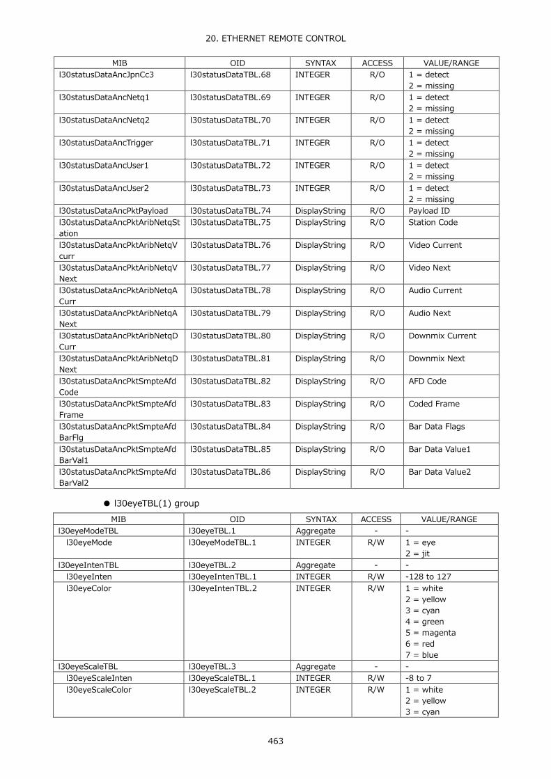
20. ETHERNET REMOTE CONTROL
463
MIB OID SYNTAX ACCESS VALUE/RANGE l30statusDataAncJpnCc3 l30statusDataTBL.68 INTEGER R/O 1 = detect
2 = missing l30statusDataAncNetq1 l30statusDataTBL.69 INTEGER R/O 1 = detect
2 = missing l30statusDataAncNetq2 l30statusDataTBL.70 INTEGER R/O 1 = detect
2 = missing l30statusDataAncTrigger l30statusDataTBL.71 INTEGER R/O 1 = detect
2 = missing l30statusDataAncUser1 l30statusDataTBL.72 INTEGER R/O 1 = detect
2 = missing l30statusDataAncUser2 l30statusDataTBL.73 INTEGER R/O 1 = detect
2 = missing l30statusDataAncPktPayload l30statusDataTBL.74 DisplayString R/O Payload ID l30statusDataAncPktAribNetqStation
l30statusDataTBL.75 DisplayString R/O Station Code
l30statusDataAncPktAribNetqVcurr
l30statusDataTBL.76 DisplayString R/O Video Current
l30statusDataAncPktAribNetqVNext
l30statusDataTBL.77 DisplayString R/O Video Next
l30statusDataAncPktAribNetqACurr
l30statusDataTBL.78 DisplayString R/O Audio Current
l30statusDataAncPktAribNetqANext
l30statusDataTBL.79 DisplayString R/O Audio Next
l30statusDataAncPktAribNetqDCurr
l30statusDataTBL.80 DisplayString R/O Downmix Current
l30statusDataAncPktAribNetqDNext
l30statusDataTBL.81 DisplayString R/O Downmix Next
l30statusDataAncPktSmpteAfdCode
l30statusDataTBL.82 DisplayString R/O AFD Code
l30statusDataAncPktSmpteAfdFrame
l30statusDataTBL.83 DisplayString R/O Coded Frame
l30statusDataAncPktSmpteAfdBarFlg
l30statusDataTBL.84 DisplayString R/O Bar Data Flags
l30statusDataAncPktSmpteAfdBarVal1
l30statusDataTBL.85 DisplayString R/O Bar Data Value1
l30statusDataAncPktSmpteAfdBarVal2
l30statusDataTBL.86 DisplayString R/O Bar Data Value2
● l30eyeTBL(1) group
MIB OID SYNTAX ACCESS VALUE/RANGE l30eyeModeTBL l30eyeTBL.1 Aggregate - - l30eyeMode l30eyeModeTBL.1 INTEGER R/W 1 = eye
2 = jit l30eyeIntenTBL l30eyeTBL.2 Aggregate - - l30eyeInten l30eyeIntenTBL.1 INTEGER R/W -128 to 127 l30eyeColor l30eyeIntenTBL.2 INTEGER R/W 1 = white
2 = yellow 3 = cyan 4 = green 5 = magenta 6 = red 7 = blue
l30eyeScaleTBL l30eyeTBL.3 Aggregate - - l30eyeScaleInten l30eyeScaleTBL.1 INTEGER R/W -8 to 7 l30eyeScaleColor l30eyeScaleTBL.2 INTEGER R/W 1 = white
2 = yellow 3 = cyan

20. ETHERNET REMOTE CONTROL
464
MIB OID SYNTAX ACCESS VALUE/RANGE 4 = green 5 = magenta 6 = red 7 = blue
l30eyeGainTBL l30eyeTBL.4 Aggregate - - l30eyeGainMode l30eyeGainTBL.1 INTEGER R/W 1 = cal
2 = variable l30eyeGainVar l30eyeGainTBL.2 DisplayString R/W 0.50 to 2.00 l30eyeSweep l30eyeGainTBL.3 INTEGER R/W 1 = sweep-2ui
2 = sweep-4ui 3 = sweep-16ui
l30eyeFilter l30eyeGainTBL.4 INTEGER R/W 1 = filter-100khz 2 = filter-1khz 3 = filter-100hz 4 = filter-10hz 5 = filter-timing 6 = filter-alignment
l30eyeJitTBL l30eyeTBL.5 Aggregate - - l30eyeJitIntenTBL l30eyeJitTBL.5 Aggregate - - l30eyeJitInten l30eyeJitIntenTBL.1 INTEGER R/W -128 to 127 l30eyeJitColor l30eyeJitIntenTBL.2 INTEGER R/W 1 = white
2 = yellow 3 = cyan 4 = green 5 = magenta 6 = red 7 = blue
l30eyeJitScaleTBL l30eyeJitTBL.5 Aggregate - - l30eyeJitScaleInten l30eyeJitScaleTBL.1 INTEGER R/W -8 to 7 l30eyeJitScaleColor l30eyeJitScaleTBL.2 INTEGER R/W 1 = white
2 = yellow 3 = cyan 4 = green 5 = magenta 6 = red 7 = blue
l30eyeJitSweepTBL l30eyeJitTBL.5 Aggregate - - l30eyeJitMag l30eyeJitSweepTBL.1 INTEGER R/W 1 = x1
2 = x2 3 = x8
l30eyeJitSweep l30eyeJitSweepTBL.2 INTEGER R/W 1 = sweep-1h 2 = sweep-2h 3 = sweep-1v 4 = sweep-2v
l30eyeJitMag12g l30eyeJitSweepTBL.3 INTEGER R/W 1 = x1 2 = x2 3 = x4 4 = x16
l30eyeJitFilterTBL l30eyeJitTBL.5 Aggregate - - l30eyeJitFilter l30eyeJitFilterTBL.1 INTEGER R/W 1 = filter-100khz
2 = filter-1khz 3 = filter-100hz 4 = filter-10hz 5 = filter-timing 6 = filter-alignment
l30eyeJitFilterPeakHold l30eyeJitFilterTBL.2 INTEGER R/W 1 = off 2 = on
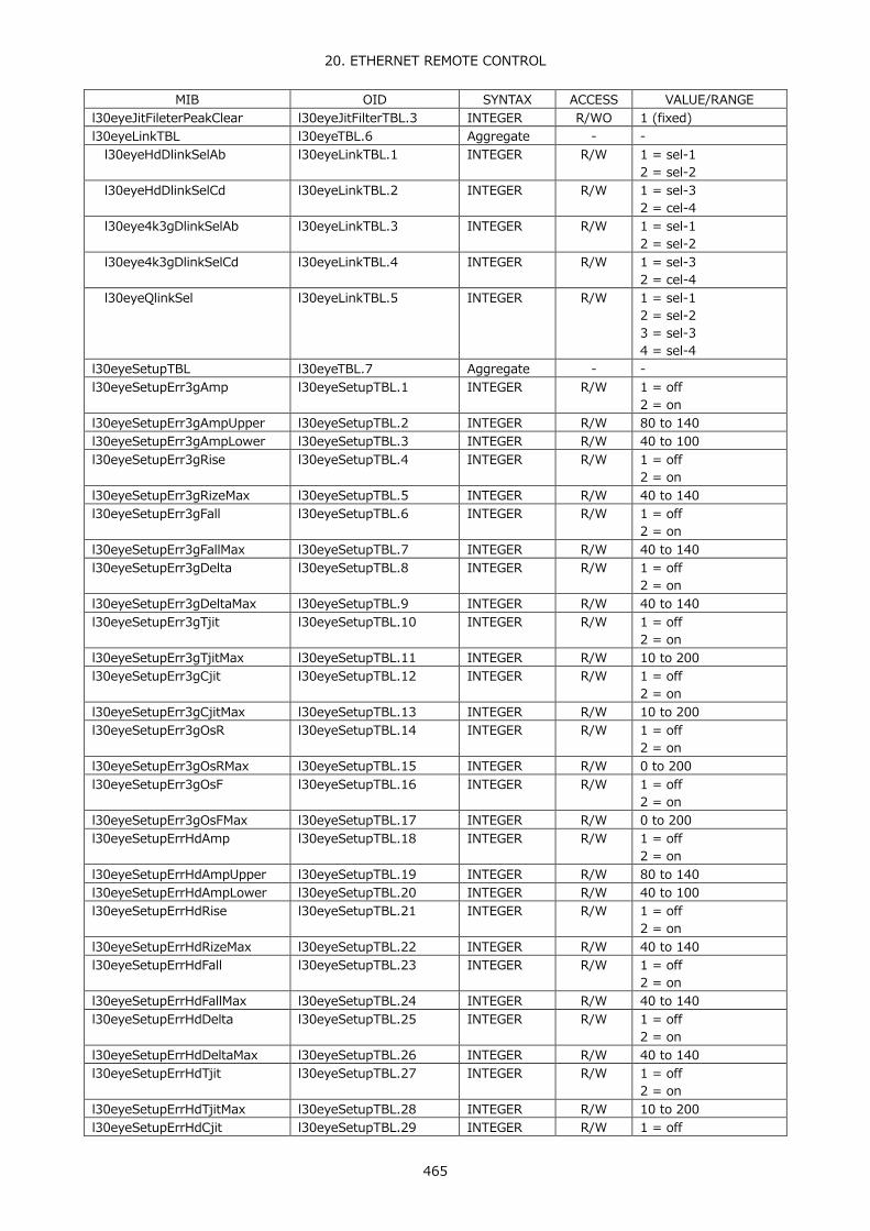
20. ETHERNET REMOTE CONTROL
465
MIB OID SYNTAX ACCESS VALUE/RANGE l30eyeJitFileterPeakClear l30eyeJitFilterTBL.3 INTEGER R/WO 1 (fixed) l30eyeLinkTBL l30eyeTBL.6 Aggregate - - l30eyeHdDlinkSelAb l30eyeLinkTBL.1 INTEGER R/W 1 = sel-1
2 = sel-2 l30eyeHdDlinkSelCd l30eyeLinkTBL.2 INTEGER R/W 1 = sel-3
2 = cel-4 l30eye4k3gDlinkSelAb l30eyeLinkTBL.3 INTEGER R/W 1 = sel-1
2 = sel-2 l30eye4k3gDlinkSelCd l30eyeLinkTBL.4 INTEGER R/W 1 = sel-3
2 = cel-4 l30eyeQlinkSel l30eyeLinkTBL.5 INTEGER R/W 1 = sel-1
2 = sel-2 3 = sel-3 4 = sel-4
l30eyeSetupTBL l30eyeTBL.7 Aggregate - - l30eyeSetupErr3gAmp l30eyeSetupTBL.1 INTEGER R/W 1 = off
2 = on l30eyeSetupErr3gAmpUpper l30eyeSetupTBL.2 INTEGER R/W 80 to 140 l30eyeSetupErr3gAmpLower l30eyeSetupTBL.3 INTEGER R/W 40 to 100 l30eyeSetupErr3gRise l30eyeSetupTBL.4 INTEGER R/W 1 = off
2 = on l30eyeSetupErr3gRizeMax l30eyeSetupTBL.5 INTEGER R/W 40 to 140 l30eyeSetupErr3gFall l30eyeSetupTBL.6 INTEGER R/W 1 = off
2 = on l30eyeSetupErr3gFallMax l30eyeSetupTBL.7 INTEGER R/W 40 to 140 l30eyeSetupErr3gDelta l30eyeSetupTBL.8 INTEGER R/W 1 = off
2 = on l30eyeSetupErr3gDeltaMax l30eyeSetupTBL.9 INTEGER R/W 40 to 140 l30eyeSetupErr3gTjit l30eyeSetupTBL.10 INTEGER R/W 1 = off
2 = on l30eyeSetupErr3gTjitMax l30eyeSetupTBL.11 INTEGER R/W 10 to 200 l30eyeSetupErr3gCjit l30eyeSetupTBL.12 INTEGER R/W 1 = off
2 = on l30eyeSetupErr3gCjitMax l30eyeSetupTBL.13 INTEGER R/W 10 to 200 l30eyeSetupErr3gOsR l30eyeSetupTBL.14 INTEGER R/W 1 = off
2 = on l30eyeSetupErr3gOsRMax l30eyeSetupTBL.15 INTEGER R/W 0 to 200 l30eyeSetupErr3gOsF l30eyeSetupTBL.16 INTEGER R/W 1 = off
2 = on l30eyeSetupErr3gOsFMax l30eyeSetupTBL.17 INTEGER R/W 0 to 200 l30eyeSetupErrHdAmp l30eyeSetupTBL.18 INTEGER R/W 1 = off
2 = on l30eyeSetupErrHdAmpUpper l30eyeSetupTBL.19 INTEGER R/W 80 to 140 l30eyeSetupErrHdAmpLower l30eyeSetupTBL.20 INTEGER R/W 40 to 100 l30eyeSetupErrHdRise l30eyeSetupTBL.21 INTEGER R/W 1 = off
2 = on l30eyeSetupErrHdRizeMax l30eyeSetupTBL.22 INTEGER R/W 40 to 140 l30eyeSetupErrHdFall l30eyeSetupTBL.23 INTEGER R/W 1 = off
2 = on l30eyeSetupErrHdFallMax l30eyeSetupTBL.24 INTEGER R/W 40 to 140 l30eyeSetupErrHdDelta l30eyeSetupTBL.25 INTEGER R/W 1 = off
2 = on l30eyeSetupErrHdDeltaMax l30eyeSetupTBL.26 INTEGER R/W 40 to 140 l30eyeSetupErrHdTjit l30eyeSetupTBL.27 INTEGER R/W 1 = off
2 = on l30eyeSetupErrHdTjitMax l30eyeSetupTBL.28 INTEGER R/W 10 to 200 l30eyeSetupErrHdCjit l30eyeSetupTBL.29 INTEGER R/W 1 = off
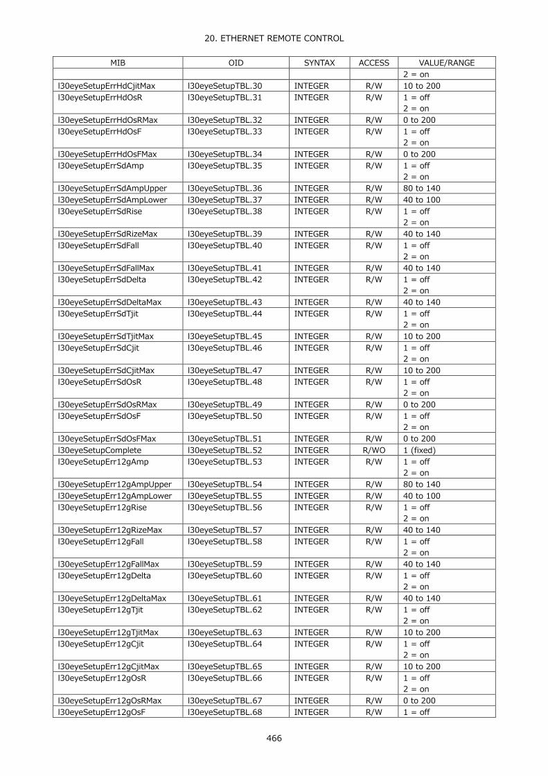
20. ETHERNET REMOTE CONTROL
466
MIB OID SYNTAX ACCESS VALUE/RANGE 2 = on
l30eyeSetupErrHdCjitMax l30eyeSetupTBL.30 INTEGER R/W 10 to 200 l30eyeSetupErrHdOsR l30eyeSetupTBL.31 INTEGER R/W 1 = off
2 = on l30eyeSetupErrHdOsRMax l30eyeSetupTBL.32 INTEGER R/W 0 to 200 l30eyeSetupErrHdOsF l30eyeSetupTBL.33 INTEGER R/W 1 = off
2 = on l30eyeSetupErrHdOsFMax l30eyeSetupTBL.34 INTEGER R/W 0 to 200 l30eyeSetupErrSdAmp l30eyeSetupTBL.35 INTEGER R/W 1 = off
2 = on l30eyeSetupErrSdAmpUpper l30eyeSetupTBL.36 INTEGER R/W 80 to 140 l30eyeSetupErrSdAmpLower l30eyeSetupTBL.37 INTEGER R/W 40 to 100 l30eyeSetupErrSdRise l30eyeSetupTBL.38 INTEGER R/W 1 = off
2 = on l30eyeSetupErrSdRizeMax l30eyeSetupTBL.39 INTEGER R/W 40 to 140 l30eyeSetupErrSdFall l30eyeSetupTBL.40 INTEGER R/W 1 = off
2 = on l30eyeSetupErrSdFallMax l30eyeSetupTBL.41 INTEGER R/W 40 to 140 l30eyeSetupErrSdDelta l30eyeSetupTBL.42 INTEGER R/W 1 = off
2 = on l30eyeSetupErrSdDeltaMax l30eyeSetupTBL.43 INTEGER R/W 40 to 140 l30eyeSetupErrSdTjit l30eyeSetupTBL.44 INTEGER R/W 1 = off
2 = on l30eyeSetupErrSdTjitMax l30eyeSetupTBL.45 INTEGER R/W 10 to 200 l30eyeSetupErrSdCjit l30eyeSetupTBL.46 INTEGER R/W 1 = off
2 = on l30eyeSetupErrSdCjitMax l30eyeSetupTBL.47 INTEGER R/W 10 to 200 l30eyeSetupErrSdOsR l30eyeSetupTBL.48 INTEGER R/W 1 = off
2 = on l30eyeSetupErrSdOsRMax l30eyeSetupTBL.49 INTEGER R/W 0 to 200 l30eyeSetupErrSdOsF l30eyeSetupTBL.50 INTEGER R/W 1 = off
2 = on l30eyeSetupErrSdOsFMax l30eyeSetupTBL.51 INTEGER R/W 0 to 200 l30eyeSetupComplete l30eyeSetupTBL.52 INTEGER R/WO 1 (fixed) l30eyeSetupErr12gAmp l30eyeSetupTBL.53 INTEGER R/W 1 = off
2 = on l30eyeSetupErr12gAmpUpper l30eyeSetupTBL.54 INTEGER R/W 80 to 140 l30eyeSetupErr12gAmpLower l30eyeSetupTBL.55 INTEGER R/W 40 to 100 l30eyeSetupErr12gRise l30eyeSetupTBL.56 INTEGER R/W 1 = off
2 = on l30eyeSetupErr12gRizeMax l30eyeSetupTBL.57 INTEGER R/W 40 to 140 l30eyeSetupErr12gFall l30eyeSetupTBL.58 INTEGER R/W 1 = off
2 = on l30eyeSetupErr12gFallMax l30eyeSetupTBL.59 INTEGER R/W 40 to 140 l30eyeSetupErr12gDelta l30eyeSetupTBL.60 INTEGER R/W 1 = off
2 = on l30eyeSetupErr12gDeltaMax l30eyeSetupTBL.61 INTEGER R/W 40 to 140 l30eyeSetupErr12gTjit l30eyeSetupTBL.62 INTEGER R/W 1 = off
2 = on l30eyeSetupErr12gTjitMax l30eyeSetupTBL.63 INTEGER R/W 10 to 200 l30eyeSetupErr12gCjit l30eyeSetupTBL.64 INTEGER R/W 1 = off
2 = on l30eyeSetupErr12gCjitMax l30eyeSetupTBL.65 INTEGER R/W 10 to 200 l30eyeSetupErr12gOsR l30eyeSetupTBL.66 INTEGER R/W 1 = off
2 = on l30eyeSetupErr12gOsRMax l30eyeSetupTBL.67 INTEGER R/W 0 to 200 l30eyeSetupErr12gOsF l30eyeSetupTBL.68 INTEGER R/W 1 = off

20. ETHERNET REMOTE CONTROL
467
MIB OID SYNTAX ACCESS VALUE/RANGE 2 = on
l30eyeSetupErr12gOsFMax l30eyeSetupTBL.69 INTEGER R/W 0 to 200 l30eyeTrigTBL l30eyeTBL.8 Aggregate - - l30eyeTrigStop l30eyeSetupTBL.1 INTEGER R/W 1 = off
2 = on l30eyeDataTBL l30eyeTBL.10 Aggregate - - l30eyeDataAmp l30eyeSetupTBL.1 DisplayString R/O Amp l30eyeDataTr l30eyeSetupTBL.2 DisplayString R/O Tr l30eyeDataTf l30eyeSetupTBL.3 DisplayString R/O Tf l30eyeDataTj l30eyeSetupTBL.4 DisplayString R/O Tj l30eyeDataCj l30eyeSetupTBL.5 DisplayString R/O Cj l30eyeDataOr l30eyeSetupTBL.6 DisplayString R/O Or l30eyeDataOf l30eyeSetupTBL.7 DisplayString R/O Of
● l30audioTBL(1) group
MIB OID SYNTAX ACCESS VALUE/RANGE l30audioMapTBL l30audioTBL.1 Aggregate - - l30audioMapInputSrc l30audioMapTBL.1 INTEGER R/W 1 = sdi
2 = ext-digi l30audioMapLinkSelect l30audioMapTBL.2 INTEGER R/W 1 = a
2 = b 3 = c 4 = d
l30audioMapStreamSelect l30audioMapTBL.3 INTEGER R/W 1 = stream1 2 = stream2
l30audioMapChMode l30audioMapTBL.4 INTEGER R/W 1 = mode-8ch 2 = mode-16ch
l30audioMapSdiGroup1 l30audioMapTBL.5 INTEGER R/W 1 = g1 2 = g2 3 = g3 4 = g4
l30audioMapSdiGroup2 l30audioMapTBL.6 INTEGER R/W 1 = g1 2 = g2 3 = g3 4 = g4
l30audioMapSdiGroup3 l30audioMapTBL.7 INTEGER R/W 1 = g1 2 = g2 3 = g3 4 = g4
l30audioMapSdiGroup4 l30audioMapTBL.8 INTEGER R/W 1 = g1 2 = g2 3 = g3 4 = g4
l30audioMapPhonesL l30audioMapTBL.9 INTEGER R/W 1 = ch1 (omitted) 16 = ch16 17 = chlt
l30audioMapPhonesR l30audioMapTBL.10 INTEGER R/W 1 = ch1 (omitted) 16 = ch16 18 = chrt
l30audioMapDolbyDec l30audioMapTBL.13 INTEGER R/W 1 = off 2 = on
l30audioMapDolbyCh l30audioMapTBL.14 INTEGER R/W 1 = ch1-2 2 = ch3-4 3 = ch5-6 4 = ch7-8

20. ETHERNET REMOTE CONTROL
468
MIB OID SYNTAX ACCESS VALUE/RANGE 5 = ch9-10 6 = ch11-12 7 = ch13-14 9 = ch15-16
l30audioDolbyDetect l30audioMapTBL.15 INTEGER R/W 2 = e 3 = d 4 = dp
l30audioDolbyEOnair l30audioMapTBL.16 INTEGER R/W 1 = off 2 = on
l30audioDolbyEDrcMain l30audioMapTBL.17 INTEGER R/W 1 = bypass 2 = dialnorm 3 = line 4 = rf
l30audioDolbyEDrcAux l30audioMapTBL.18 INTEGER R/W 1 = bypass 2 = dialnorm 3 = line 4 = rf
l30audioDolbyELinePos l30audioMapTBL.19 INTEGER R/W 1 = off 2 = on
l30audioDolbyELineSelect l30audioMapTBL.20 INTEGER R/W 1 = valid 2 = ideal 3 = custom
l30audioDolbyEEarliest l30audioMapTBL.21 DisplayString R/W 8 to 104 l30audioDolbyELatest l30audioMapTBL.22 DisplayString R/W 9 to 105 l30audioDolbyDDrcMain l30audioMapTBL.23 INTEGER R/W 1 = dialnorm
2 = line 3 = rf
l30audioDolbyDDrcAux l30audioMapTBL.24 INTEGER R/W 1 = dialnorm 2 = line 3 = rf
l30audioDolbyDPrologic l30audioMapTBL.25 INTEGER R/W 1 = off 2 = on
l30audioDolbyDDownmix l30audioMapTBL.26 INTEGER R/W 1 = auto 2 = lt-rt 3 = lo-ro 4 = pro-ii 5 = pro-ii-pro
l30audioMapDolbyMix l30audioMapTBL.31 INTEGER R/W 1 = off 2 = on
l30audioMapLissajouSL l30audioMapTBL.32 INTEGER R/W 1 = ch1 (omitted) 16 = ch16 17 = chlt
l30audioMapLissajouSR l30audioMapTBL.33 INTEGER R/W 1 = ch1 (omitted) 16 = ch16 18 = chrt
l30audioMapLissajouML1 l30audioMapTBL.34 INTEGER R/W 1 = ch1 (omitted) 16 = ch16
l30audioMapLissajouMR1 l30audioMapTBL.35 INTEGER R/W 1 = ch1 (omitted) 16 = ch16
l30audioMapLissajouML2 l30audioMapTBL.36 INTEGER R/W 1 = ch1 (omitted) 16 = ch16
l30audioMapLissajouMR2 l30audioMapTBL.37 INTEGER R/W 1 = ch1

20. ETHERNET REMOTE CONTROL
469
MIB OID SYNTAX ACCESS VALUE/RANGE (omitted) 16 = ch16
l30audioMapLissajouML3 l30audioMapTBL.38 INTEGER R/W 1 = ch1 (omitted) 16 = ch16
l30audioMapLissajouMR3 l30audioMapTBL.39 INTEGER R/W 1 = ch1 (omitted) 16 = ch16
l30audioMapLissajouML4 l30audioMapTBL.40 INTEGER R/W 1 = ch1 (omitted) 16 = ch16
l30audioMapLissajouMR4 l30audioMapTBL.41 INTEGER R/W 1 = ch1 (omitted) 16 = ch16
l30audioMapLissajouML5 l30audioMapTBL.42 INTEGER R/W 1 = ch1 (omitted) 16 = ch16
l30audioMapLissajouMR5 l30audioMapTBL.43 INTEGER R/W 1 = ch1 (omitted) 16 = ch16
l30audioMapLissajouML6 l30audioMapTBL.44 INTEGER R/W 1 = ch1 (omitted) 16 = ch16
l30audioMapLissajouMR6 l30audioMapTBL.45 INTEGER R/W 1 = ch1 (omitted) 16 = ch16
l30audioMapLissajouML7 l30audioMapTBL.46 INTEGER R/W 1 = ch1 (omitted) 16 = ch16
l30audioMapLissajouMR7 l30audioMapTBL.47 INTEGER R/W 1 = ch1 (omitted) 16 = ch16
l30audioMapLissajouML8 l30audioMapTBL.48 INTEGER R/W 1 = ch1 (omitted) 16 = ch16
l30audioMapLissajouMR8 l30audioMapTBL.49 INTEGER R/W 1 = ch1 (omitted) 16 = ch16
l30audioMapSurroundL l30audioMapTBL.50 INTEGER R/W 1 = ch1 (omitted) 16 = ch16
l30audioMapSurroundR l30audioMapTBL.51 INTEGER R/W 1 = ch1 (omitted) 16 = ch16
l30audioMapSurroundC l30audioMapTBL.52 INTEGER R/W 1 = ch1 (omitted) 16 = ch16
l30audioMapSurroundLfe l30audioMapTBL.53 INTEGER R/W 1 = ch1 (omitted) 16 = ch16
l30audioMapSurroundLs l30audioMapTBL.54 INTEGER R/W 1 = ch1 (omitted) 16 = ch16
l30audioMapSurroundRs l30audioMapTBL.55 INTEGER R/W 1 = ch1 (omitted) 16 = ch16
l30audioMapSurroundLl l30audioMapTBL.56 INTEGER R/W 1 = ch1

20. ETHERNET REMOTE CONTROL
470
MIB OID SYNTAX ACCESS VALUE/RANGE (omitted) 16 = ch16
l30audioMapSurroundRr l30audioMapTBL.57 INTEGER R/W 1 = ch1 (omitted) 16 = ch16
l30audioMapDolbyLissajouSL l30audioMapTBL.58 INTEGER R/W 17 = chlt 83 = d1 (omitted) 90 = d8
l30audioMapDolbyLissajouSR l30audioMapTBL.59 INTEGER R/W 18 = chrt 83 = d1 (omitted) 90 = d8
l30audioMapDolbyLissajouML1 l30audioMapTBL.60 INTEGER R/W 83 = d1 (omitted) 90 = d8
l30audioMapDolbyLissajouMR1 l30audioMapTBL.61 INTEGER R/W 83 = d1 (omitted) 90 = d8
l30audioMapDolbyLissajouML2 l30audioMapTBL.62 INTEGER R/W 83 = d1 (omitted) 90 = d8
l30audioMapDolbyLissajouMR2 l30audioMapTBL.63 INTEGER R/W 83 = d1 (omitted) 90 = d8
l30audioMapDolbyLissajouML3 l30audioMapTBL.64 INTEGER R/W 83 = d1 (omitted) 90 = d8
l30audioMapDolbyLissajouMR3 l30audioMapTBL.65 INTEGER R/W 83 = d1 (omitted) 90 = d8
l30audioMapDolbyLissajouML4 l30audioMapTBL.66 INTEGER R/W 83 = d1 (omitted) 90 = d8
l30audioMapDolbyLissajouMR4 l30audioMapTBL.67 INTEGER R/W 83 = d1 (omitted) 90 = d8
l30audioDolbySurroundL l30audioMapTBL.68 INTEGER R/W 83 = d1 (omitted) 90 = d8
l30audioDolbySurroundR l30audioMapTBL.69 INTEGER R/W 83 = d1 (omitted) 90 = d8
l30audioDolbySurroundC l30audioMapTBL.70 INTEGER R/W 83 = d1 (omitted) 90 = d8
l30audioDolbySurroundLfe l30audioMapTBL.71 INTEGER R/W 83 = d1 (omitted) 90 = d8
l30audioDolbySurroundLs l30audioMapTBL.72 INTEGER R/W 83 = d1 (omitted) 90 = d8
l30audioDolbySurroundRs l30audioMapTBL.73 INTEGER R/W 83 = d1 (omitted) 90 = d8
l30audioDolbySurroundLl l30audioMapTBL.74 INTEGER R/W 83 = d1 (omitted)

20. ETHERNET REMOTE CONTROL
471
MIB OID SYNTAX ACCESS VALUE/RANGE 90 = d8
l30audioDolbySurroundRr l30audioMapTBL.75 INTEGER R/W 83 = d1 (omitted) 90 = d8
l30audioMapDolbyPhonesL l30audioMapTBL.76 INTEGER R/W 17 = chlt 83 = d1 (omitted) 90 = d8 91 = daux
l30audioMapDolbyPhonesR l30audioMapTBL.77 INTEGER R/W 18 = chrt 83 = d1 (omitted) 90 = d8 91 = daux
l30audioMapSimSdiGroup1 l30audioMapTBL.78 INTEGER R/W 1 = group1 2 = group2 3 = group3 4 = group4
l30audioMapSimSdiGroup2 l30audioMapTBL.79 INTEGER R/W 1 = group1 2 = group2 3 = group3 4 = group4
l30audioMapSimSdiGroup3 l30audioMapTBL.80 INTEGER R/W 1 = group1 2 = group2 3 = group3 4 = group4
l30audioMapSimSdiGroup4 l30audioMapTBL.81 INTEGER R/W 1 = group1 2 = group2 3 = group3 4 = group4
l30audioMapSimSdiGroup1Ch l30audioMapTBL.82 INTEGER R/W 1 = a 2 = b 3 = c 4 = d
l30audioMapSimSdiGroup2Ch l30audioMapTBL.83 INTEGER R/W 1 = a 2 = b 3 = c 4 = d
l30audioMapSimSdiGroup3Ch l30audioMapTBL.84 INTEGER R/W 1 = a 2 = b 3 = c 4 = d
l30audioMapSimSdiGroup4Ch l30audioMapTBL.85 INTEGER R/W 1 = a 2 = b 3 = c 4 = d
l30audioMapSimLissajouML1 l30audioMapTBL.88 INTEGER R/W 19 = a-ch1 (omitted) 82 = d-ch16
l30audioMapSimLissajouMR1 l30audioMapTBL.89 INTEGER R/W 19 = a-ch1 (omitted) 82 = d-ch16
l30audioMapSimLissajouML2 l30audioMapTBL.90 INTEGER R/W 19 = a-ch1 (omitted) 82 = d-ch16
l30audioMapSimLissajouMR2 l30audioMapTBL.91 INTEGER R/W 19 = a-ch1 (omitted) 82 = d-ch16

20. ETHERNET REMOTE CONTROL
472
MIB OID SYNTAX ACCESS VALUE/RANGE l30audioMapSimLissajouML3 l30audioMapTBL.92 INTEGER R/W 19 = a-ch1
(omitted) 82 = d-ch16
l30audioMapSimLissajouMR3 l30audioMapTBL.93 INTEGER R/W 19 = a-ch1 (omitted) 82 = d-ch16
l30audioMapSimLissajouML4 l30audioMapTBL.94 INTEGER R/W 19 = a-ch1 (omitted) 82 = d-ch16
l30audioMapSimLissajouMR4 l30audioMapTBL.95 INTEGER R/W 19 = a-ch1 (omitted) 82 = d-ch16
l30audioMapSimLissajouML5 l30audioMapTBL.96 INTEGER R/W 19 = a-ch1 (omitted) 82 = d-ch16
l30audioMapSimLissajouMR5 l30audioMapTBL.97 INTEGER R/W 19 = a-ch1 (omitted) 82 = d-ch16
l30audioMapSimLissajouML6 l30audioMapTBL.98 INTEGER R/W 19 = a-ch1 (omitted) 82 = d-ch16
l30audioMapSimLissajouMR6 l30audioMapTBL.99 INTEGER R/W 19 = a-ch1 (omitted) 82 = d-ch16
l30audioMapSimLissajouML7 l30audioMapTBL.100 INTEGER R/W 19 = a-ch1 (omitted) 82 = d-ch16
l30audioMapSimLissajouMR7 l30audioMapTBL.101 INTEGER R/W 19 = a-ch1 (omitted) 82 = d-ch16
l30audioMapSimLissajouML8 l30audioMapTBL.102 INTEGER R/W 19 = a-ch1 (omitted) 82 = d-ch16
l30audioMapSimLissajouMR8 l30audioMapTBL.103 INTEGER R/W 19 = a-ch1 (omitted) 82 = d-ch16
l30audioMapSimPhonesL l30audioMapTBL.104 INTEGER R/W 19 = a-ch1 (omitted) 82 = d-ch16
l30audioMapSimPhonesR l30audioMapTBL.105 INTEGER R/W 19 = a-ch1 (omitted) 82 = d-ch16
l30audioMapExtInputGroup l30audioMapTBL.108 INTEGER R/W 1 = group1 2 = group2
l30audioMapExtLissajouSL l30audioMapTBL.109 INTEGER R/W 19 = a-ch1 (omitted) 50 = b-ch16 17 = chlt
l30audioMapExtLissajouSR l30audioMapTBL.110 INTEGER R/W 19 = a-ch1 (omitted) 50 = b-ch16 18 = chrt
l30audioMapExtLissajouML1 l30audioMapTBL.111 INTEGER R/W 19 = a-ch1 (omitted) 50 = b-ch16
l30audioMapExtLissajouMR1 l30audioMapTBL.112 INTEGER R/W 19 = a-ch1 (omitted)
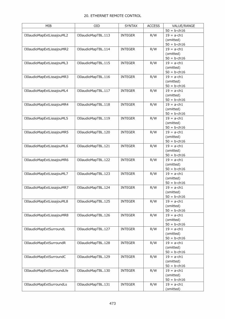
20. ETHERNET REMOTE CONTROL
473
MIB OID SYNTAX ACCESS VALUE/RANGE 50 = b-ch16
l30audioMapExtLissajouML2 l30audioMapTBL.113 INTEGER R/W 19 = a-ch1 (omitted) 50 = b-ch16
l30audioMapExtLissajouMR2 l30audioMapTBL.114 INTEGER R/W 19 = a-ch1 (omitted) 50 = b-ch16
l30audioMapExtLissajouML3 l30audioMapTBL.115 INTEGER R/W 19 = a-ch1 (omitted) 50 = b-ch16
l30audioMapExtLissajouMR3 l30audioMapTBL.116 INTEGER R/W 19 = a-ch1 (omitted) 50 = b-ch16
l30audioMapExtLissajouML4 l30audioMapTBL.117 INTEGER R/W 19 = a-ch1 (omitted) 50 = b-ch16
l30audioMapExtLissajouMR4 l30audioMapTBL.118 INTEGER R/W 19 = a-ch1 (omitted) 50 = b-ch16
l30audioMapExtLissajouML5 l30audioMapTBL.119 INTEGER R/W 19 = a-ch1 (omitted) 50 = b-ch16
l30audioMapExtLissajouMR5 l30audioMapTBL.120 INTEGER R/W 19 = a-ch1 (omitted) 50 = b-ch16
l30audioMapExtLissajouML6 l30audioMapTBL.121 INTEGER R/W 19 = a-ch1 (omitted) 50 = b-ch16
l30audioMapExtLissajouMR6 l30audioMapTBL.122 INTEGER R/W 19 = a-ch1 (omitted) 50 = b-ch16
l30audioMapExtLissajouML7 l30audioMapTBL.123 INTEGER R/W 19 = a-ch1 (omitted) 50 = b-ch16
l30audioMapExtLissajouMR7 l30audioMapTBL.124 INTEGER R/W 19 = a-ch1 (omitted) 50 = b-ch16
l30audioMapExtLissajouML8 l30audioMapTBL.125 INTEGER R/W 19 = a-ch1 (omitted) 50 = b-ch16
l30audioMapExtLissajouMR8 l30audioMapTBL.126 INTEGER R/W 19 = a-ch1 (omitted) 50 = b-ch16
l30audioMapExtSurroundL l30audioMapTBL.127 INTEGER R/W 19 = a-ch1 (omitted) 50 = b-ch16
l30audioMapExtSurroundR l30audioMapTBL.128 INTEGER R/W 19 = a-ch1 (omitted) 50 = b-ch16
l30audioMapExtSurroundC l30audioMapTBL.129 INTEGER R/W 19 = a-ch1 (omitted) 50 = b-ch16
l30audioMapExtSurroundLfe l30audioMapTBL.130 INTEGER R/W 19 = a-ch1 (omitted) 50 = b-ch16
l30audioMapExtSurroundLs l30audioMapTBL.131 INTEGER R/W 19 = a-ch1 (omitted)

20. ETHERNET REMOTE CONTROL
474
MIB OID SYNTAX ACCESS VALUE/RANGE 50 = b-ch16
l30audioMapExtSurroundRs l30audioMapTBL.132 INTEGER R/W 19 = a-ch1 (omitted) 50 = b-ch16
l30audioMapExtSurroundLl l30audioMapTBL.133 INTEGER R/W 19 = a-ch1 (omitted) 50 = b-ch16
l30audioMapExtSurroundRr l30audioMapTBL.134 INTEGER R/W 19 = a-ch1 (omitted) 50 = b-ch16
l30audioMapExtPhonesL l30audioMapTBL.135 INTEGER R/W 19 = a-ch1 (omitted) 50 = b-ch16 17 = chlt
l30audioMapExtPhonesR l30audioMapTBL.136 INTEGER R/W 19 = a-ch1 (omitted) 50 = b-ch16 18 = chrt
l30audioMapExtDolbyLissajouSL
l30audioMapTBL.139 INTEGER R/W 83 = d1 (omitted) 90 = d8 91 = daux
l30audioMapExtDolbyLissajouSR
l30audioMapTBL.140 INTEGER R/W 83 = d1 (omitted) 90 = d8 91 = daux
l30audioMapExtDolbyLissajouML1
l30audioMapTBL.141 INTEGER R/W 83 = d1 (omitted) 90 = d8
l30audioMapExtDolbyLissajouMR1
l30audioMapTBL.142 INTEGER R/W 83 = d1 (omitted) 90 = d8
l30audioMapExtDolbyLissajouML2
l30audioMapTBL.143 INTEGER R/W 83 = d1 (omitted) 90 = d8
l30audioMapExtDolbyLissajouMR2
l30audioMapTBL.144 INTEGER R/W 83 = d1 (omitted) 90 = d8
l30audioMapExtDolbyLissajouML3
l30audioMapTBL.145 INTEGER R/W 83 = d1 (omitted) 90 = d8
l30audioMapExtDolbyLissajouMR3
l30audioMapTBL.146 INTEGER R/W 83 = d1 (omitted) 90 = d8
l30audioMapExtDolbyLissajouML4
l30audioMapTBL.147 INTEGER R/W 83 = d1 (omitted) 90 = d8
l30audioMapExtDolbyLissajouMR4
l30audioMapTBL.148 INTEGER R/W 83 = d1 (omitted) 90 = d8
l30audioMapExtDolbySurroundL
l30audioMapTBL.149 INTEGER R/W 83 = d1 (omitted) 90 = d8
l30audioMapExtDolbySurroundR
l30audioMapTBL.150 INTEGER R/W 83 = d1 (omitted) 90 = d8
l30audioMapExtDolbySurround l30audioMapTBL.151 INTEGER R/W 83 = d1
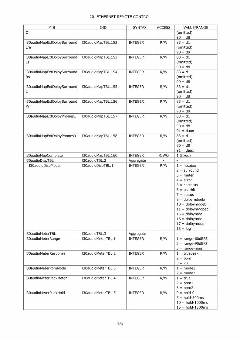
20. ETHERNET REMOTE CONTROL
475
MIB OID SYNTAX ACCESS VALUE/RANGE C (omitted)
90 = d8 l30audioMapExtDolbySurroundLfe
l30audioMapTBL.152 INTEGER R/W 83 = d1 (omitted) 90 = d8
l30audioMapExtDolbySurroundLs
l30audioMapTBL.153 INTEGER R/W 83 = d1 (omitted) 90 = d8
l30audioMapExtDolbySurroundRs
l30audioMapTBL.154 INTEGER R/W 83 = d1 (omitted) 90 = d8
l30audioMapExtDolbySurroundLl
l30audioMapTBL.155 INTEGER R/W 83 = d1 (omitted) 90 = d8
l30audioMapExtDolbySurroundRr
l30audioMapTBL.156 INTEGER R/W 83 = d1 (omitted) 90 = d8
l30audioMapExtDolbyPhonesL l30audioMapTBL.157 INTEGER R/W 83 = d1 (omitted) 90 = d8 91 = daux
l30audioMapExtDolbyPhonesR l30audioMapTBL.158 INTEGER R/W 83 = d1 (omitted) 90 = d8 91 = daux
l30audioMapComplete l30audioMapTBL.160 INTEGER R/WO 1 (fixed) l30audioDispTBL l30audioTBL.2 Aggregate - - l30audioDispMode l30audioDispTBL.1 INTEGER R/W 1 = lissajou
2 = surround 3 = meter 4 = error 5 = chstatus 6 = userbit 7 = status 9 = dolbymdeebi 10 = dolbymddebi 11 = dolbymddpebi 15 = dolbymde 16 = dolbymdd 17 = dolbymddp 18 = log
l30audioMeterTBL l30audioTBL.3 Aggregate - - l30audioMeterRange l30audioMeterTBL.1 INTEGER R/W 1 = range-60dBFS
2 = range-90dBFS 3 = range-mag
l30audioMeterResponse l30audioMeterTBL.2 INTEGER R/W 1 = truepeak 2 = ppm 3 = vu
l30audioMeterPpmMode l30audioMeterTBL.3 INTEGER R/W 1 = mode1 2 = mode2
l30audioMeterPeakMeter l30audioMeterTBL.4 INTEGER R/W 1 = true 2 = ppm1 3 = ppm2
l30audioMeterPeakHold l30audioMeterTBL.5 INTEGER R/W 0 = hold-0 5 = hold-500ms 10 = hold-1000ms 15 = hold-1500ms

20. ETHERNET REMOTE CONTROL
476
MIB OID SYNTAX ACCESS VALUE/RANGE 20 = hold-2000ms 25 = hold-2500ms 30 = hold-3000ms 35 = hold-3500ms 40 = hold-4000ms 45 = hold-4500ms 50 = hold-5000ms 55 = hold-hold
l30audioMeterOverDbfs l30audioMeterTBL.6 DisplayString R/W -40.0 to 0 l30audioMeterWarnDbfs l30audioMeterTBL.8 DisplayString R/W -40.0 to 0 l30audioMeterRefDbfs l30audioMeterTBL.10 DisplayString R/W -40.0 to 0 l30audioLissajouIntenTBL l30audioTBL.4 Aggregate - - l30audioLissajouInten l30audioLissajouIntenTB
L.1 INTEGER R/W -8 to 7
l30audioLissajouScaleInten l30audioLissajouIntenTBL.2
INTEGER R/W -8 to 7
l30audioLissajouMode l30audioLissajouIntenTBL.3
INTEGER R/W 1 = multi 2 = single
l30audioLissajouForm l30audioLissajouIntenTBL.4
INTEGER R/W 1 = xy 2 = matrix
l30audioLissajouAutoGain l30audioLissajouIntenTBL.5
INTEGER R/W 1 = off 2 = on
l30audioSurroundTBL l30audioTBL.5 Aggregate - - l30audioSurroundInten l30audioSurroundTBL.1 INTEGER R/W -8 to 7 l30audioSurroundScaleInten l30audioSurroundTBL.2 INTEGER R/W -8 to 7 l30audioSurroundMode l30audioSurroundTBL.3 INTEGER R/W 1 = normal
2 = phantom l30audioSurroundAutoGain l30audioSurroundTBL.4 INTEGER R/W 1 = off
2 = on l30audioStatusTBL l30audioTBL.6 Aggregate - - l30audioStatusDolbyProg l30audioStatusTBL.1 INTEGER R/W 1 = prm1
(omitted) 8 = prm8
l30audioStatusCh l30audioStatusTBL.3 INTEGER R/W 1 = ch1 (omitted) 16 = ch16
l30audioStatusChSimul l30audioStatusTBL.4 INTEGER R/W 19 = cha1 (omitted) 34 = cha16 35 = chb1 (omitted) 50 = chb16 51 = chc1 (omitted) 66 = chc16 67 = chd1 (omitted) 82 = chd16
l30audioStatusChDolby l30audioStatusTBL.5 INTEGER R/W 1 = ch1 (omitted) 16 = ch16
l30audioStatusChExt l30audioStatusTBL.6 INTEGER R/W 19 = cha1 (omitted) 26 = cha8 35 = chb1 (omitted) 42 = chb8
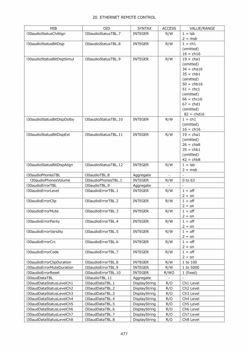
20. ETHERNET REMOTE CONTROL
477
MIB OID SYNTAX ACCESS VALUE/RANGE l30audioStatusChAlign l30audioStatusTBL.7 INTEGER R/W 1 = lsb
2 = msb l30audioStatusBitDisp l30audioStatusTBL.8 INTEGER R/W 1 = ch1
(omitted) 16 = ch16
l30audioStatusBitDispSimul l30audioStatusTBL.9 INTEGER R/W 19 = cha1 (omitted) 34 = cha16 35 = chb1 (omitted) 50 = chb16 51 = chc1 (omitted) 66 = chc16 67 = chd1 (omitted) 82 = chd16
l30audioStatusBitDispDolby l30audioStatusTBL.10 INTEGER R/W 1 = ch1 (omitted) 16 = ch16
l30audioStatusBitDispExt l30audioStatusTBL.11 INTEGER R/W 19 = cha1 (omitted) 26 = cha8 35 = chb1 (omitted) 42 = chb8
l30audioStatusBitDispAlign l30audioStatusTBL.12 INTEGER R/W 1 = lsb 2 = msb
l30audioPhonesTBL l30audioTBL.8 Aggregate - - l30audioPhonesVolume l30audioPhonesTBL.1 INTEGER R/W 0 to 63 l30audioErrorTBL l30audioTBL.9 Aggregate - - l30audioErrorLevel l30audioErrorTBL.1 INTEGER R/W 1 = off
2 = on l30audioErrorClip l30audioErrorTBL.2 INTEGER R/W 1 = off
2 = on l30audioErrorMute l30audioErrorTBL.3 INTEGER R/W 1 = off
2 = on l30audioErrorParity l30audioErrorTBL.4 INTEGER R/W 1 = off
2 = on l30audioErrorVaridity l30audioErrorTBL.5 INTEGER R/W 1 = off
2 = on l30audioErrorCrc l30audioErrorTBL.6 INTEGER R/W 1 = off
2 = on l30audioErrorCode l30audioErrorTBL.7 INTEGER R/W 1 = off
2 = on l30audioErrorClipDuration l30audioErrorTBL.8 INTEGER R/W 1 to 100 l30audioErrorMuteDuration l30audioErrorTBL.9 INTEGER R/W 1 to 5000 l30audioErrorReset l30audioErrorTBL.10 INTEGER R/WO 1 (fixed) l30audDataTBL l30audioTBL.11 Aggregate - - l30audDataStatusLevelCh1 l30audDataTBL.1 DisplayString R/O Ch1 Level l30audDataStatusLevelCh2 l30audDataTBL.2 DisplayString R/O Ch2 Level l30audDataStatusLevelCh3 l30audDataTBL.3 DisplayString R/O Ch3 Level l30audDataStatusLevelCh4 l30audDataTBL.4 DisplayString R/O Ch4 Level l30audDataStatusLevelCh5 l30audDataTBL.5 DisplayString R/O Ch5 Level l30audDataStatusLevelCh6 l30audDataTBL.6 DisplayString R/O Ch6 Level l30audDataStatusLevelCh7 l30audDataTBL.7 DisplayString R/O Ch7 Level l30audDataStatusLevelCh8 l30audDataTBL.8 DisplayString R/O Ch8 Level
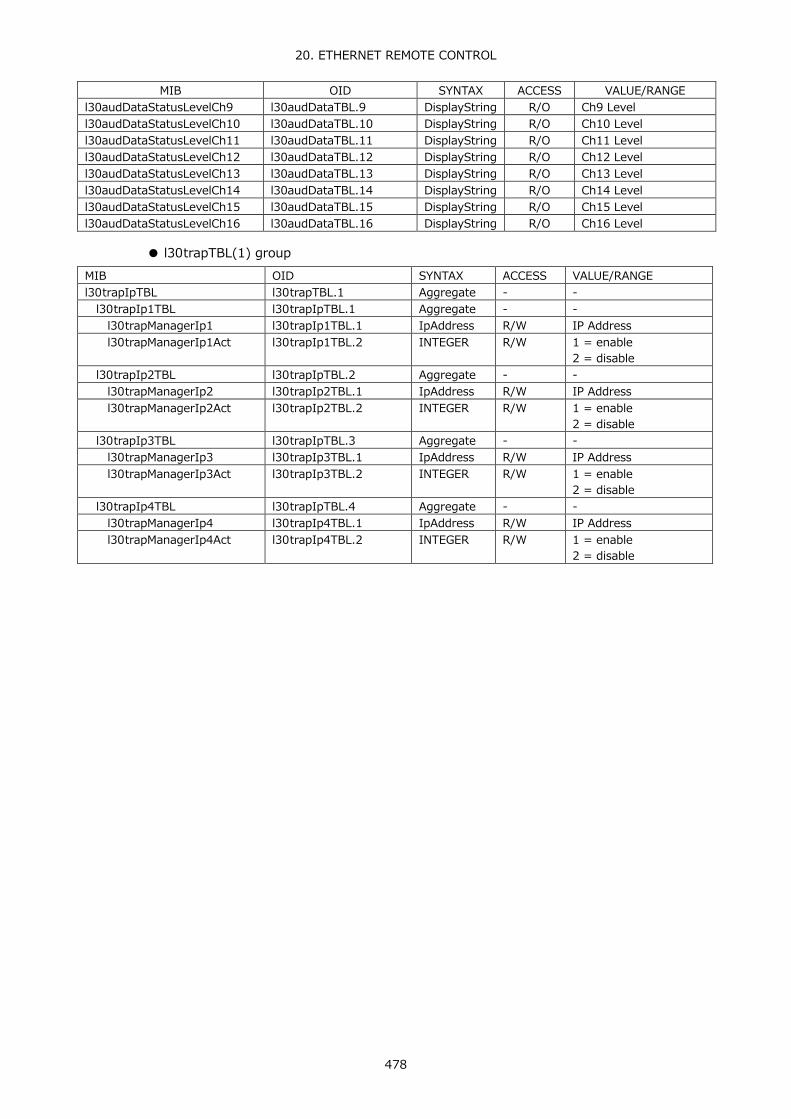
20. ETHERNET REMOTE CONTROL
478
MIB OID SYNTAX ACCESS VALUE/RANGE l30audDataStatusLevelCh9 l30audDataTBL.9 DisplayString R/O Ch9 Level l30audDataStatusLevelCh10 l30audDataTBL.10 DisplayString R/O Ch10 Level l30audDataStatusLevelCh11 l30audDataTBL.11 DisplayString R/O Ch11 Level l30audDataStatusLevelCh12 l30audDataTBL.12 DisplayString R/O Ch12 Level l30audDataStatusLevelCh13 l30audDataTBL.13 DisplayString R/O Ch13 Level l30audDataStatusLevelCh14 l30audDataTBL.14 DisplayString R/O Ch14 Level l30audDataStatusLevelCh15 l30audDataTBL.15 DisplayString R/O Ch15 Level l30audDataStatusLevelCh16 l30audDataTBL.16 DisplayString R/O Ch16 Level
● l30trapTBL(1) group
MIB OID SYNTAX ACCESS VALUE/RANGE l30trapIpTBL l30trapTBL.1 Aggregate - - l30trapIp1TBL l30trapIpTBL.1 Aggregate - - l30trapManagerIp1 l30trapIp1TBL.1 IpAddress R/W IP Address l30trapManagerIp1Act l30trapIp1TBL.2 INTEGER R/W 1 = enable
2 = disable l30trapIp2TBL l30trapIpTBL.2 Aggregate - - l30trapManagerIp2 l30trapIp2TBL.1 IpAddress R/W IP Address l30trapManagerIp2Act l30trapIp2TBL.2 INTEGER R/W 1 = enable
2 = disable l30trapIp3TBL l30trapIpTBL.3 Aggregate - - l30trapManagerIp3 l30trapIp3TBL.1 IpAddress R/W IP Address l30trapManagerIp3Act l30trapIp3TBL.2 INTEGER R/W 1 = enable
2 = disable l30trapIp4TBL l30trapIpTBL.4 Aggregate - - l30trapManagerIp4 l30trapIp4TBL.1 IpAddress R/W IP Address l30trapManagerIp4Act l30trapIp4TBL.2 INTEGER R/W 1 = enable
2 = disable
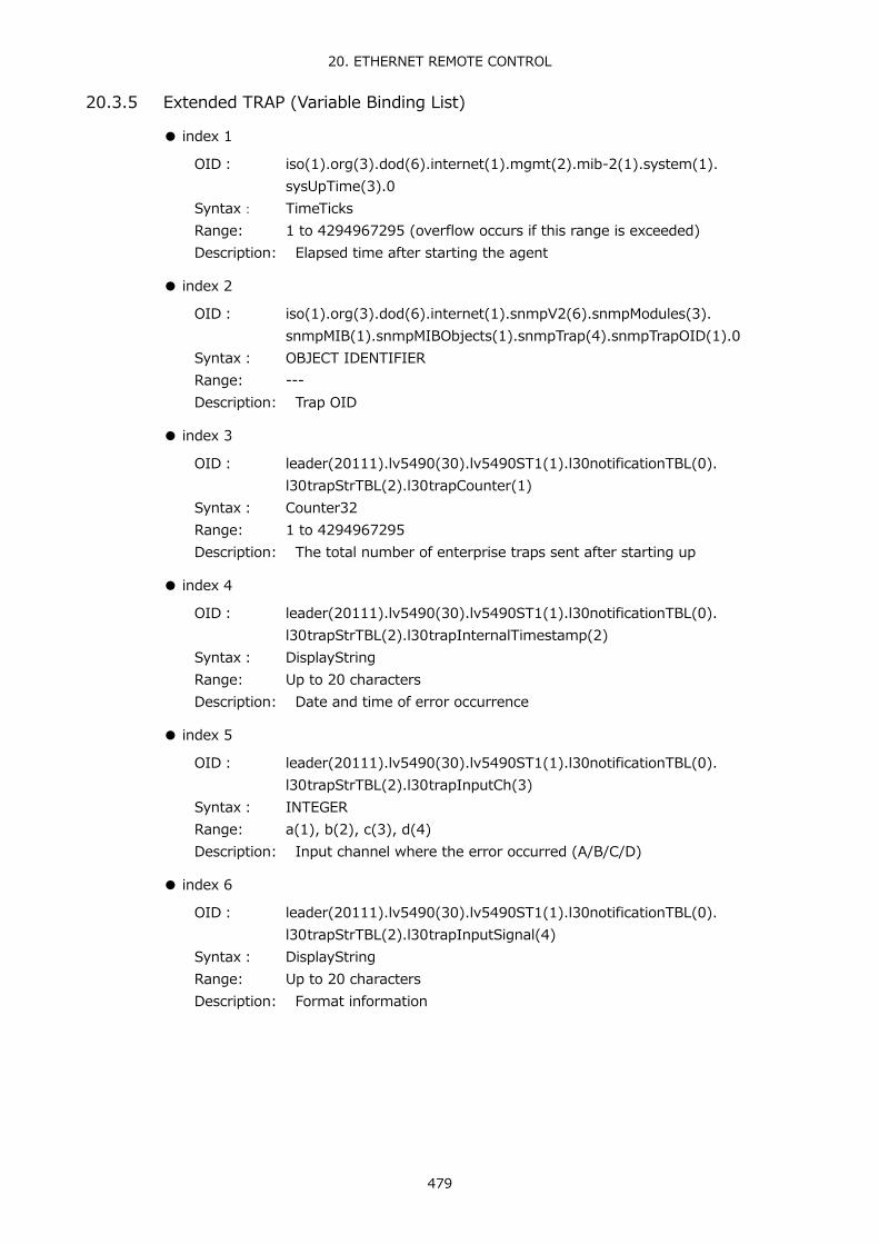
20. ETHERNET REMOTE CONTROL
479
20.3.5 Extended TRAP (Variable Binding List)
● index 1
OID: iso(1).org(3).dod(6).internet(1).mgmt(2).mib-2(1).system(1). sysUpTime(3).0
Syntax: TimeTicks Range: 1 to 4294967295 (overflow occurs if this range is exceeded) Description: Elapsed time after starting the agent
● index 2
OID: iso(1).org(3).dod(6).internet(1).snmpV2(6).snmpModules(3). snmpMIB(1).snmpMIBObjects(1).snmpTrap(4).snmpTrapOID(1).0
Syntax: OBJECT IDENTIFIER Range: --- Description: Trap OID
● index 3
OID: leader(20111).lv5490(30).lv5490ST1(1).l30notificationTBL(0). l30trapStrTBL(2).l30trapCounter(1)
Syntax: Counter32 Range: 1 to 4294967295 Description: The total number of enterprise traps sent after starting up
● index 4
OID: leader(20111).lv5490(30).lv5490ST1(1).l30notificationTBL(0). l30trapStrTBL(2).l30trapInternalTimestamp(2)
Syntax: DisplayString Range: Up to 20 characters Description: Date and time of error occurrence
● index 5
OID: leader(20111).lv5490(30).lv5490ST1(1).l30notificationTBL(0). l30trapStrTBL(2).l30trapInputCh(3)
Syntax: INTEGER Range: a(1), b(2), c(3), d(4) Description: Input channel where the error occurred (A/B/C/D)
● index 6
OID: leader(20111).lv5490(30).lv5490ST1(1).l30notificationTBL(0). l30trapStrTBL(2).l30trapInputSignal(4)
Syntax: DisplayString Range: Up to 20 characters Description: Format information

20. ETHERNET REMOTE CONTROL
480
● index 7
OID: leader(20111).lv5490(30).lv5490ST1(1).l30notificationTBL(0). l30trapContentTBL(1).l30trapErrorTBL(1).X Or leader(20111).lv5490(30).lv5490ST1(1).l30notificationTBL(0). l30trapContentTBL(1).l30trapNormalTBL(2).X
Syntax: DisplayString Range: Up to 16 characters Description: OID indicating the error and error information character string (see the
table below) When an error occurs, OID and error information character string of l30notificationTBL(0).l30trapContentTBL(1).l30trapErrorTBL(1).X (see the table below) When an error restores, OID and error information character string of l30notificationTBL(0).l30trapContentTBL(1). l30trapNormalTBL(2).X (see the table below)
● index 8
OID: leader(20111).lv5490(30).lv5490ST1(1).l30notificationTBL(0). l30trapStrTBL(2).l30trapCableLen(5)
Syntax: INTEGER Range: 1 to 32767 Description: Cable length
Output only when index7 is l30trapContentTBL(1).l30TrapErrorTBL(1). l30trapErrorCableWarn(5)

20. ETHERNET REMOTE CONTROL
481
● l30notificationTBL(1) group MIB OID SYNTAX ACCESS VALUE/RANGE
l30trapContentTBL l30notificationTBL.1 - - l30trapErrorTBL l30trapContentTBL.1 Aggregate - - l30trapErrorFan l30TrapErrorTBL.1 - - FAN_STOP l30trapErrorNoSignal l30TrapErrorTBL.2 - - NO_SIGNAL l30trapErrorUnknown l30TrapErrorTBL.3 - - FORMAT_UNKNOWN l30trapErrorCable l30TrapErrorTBL.4 - - CABLE_ERR l30trapErrorCableWarn l30TrapErrorTBL.5 - - CABLE_WAR l30trapErrorAudioSample l30TrapErrorTBL.6 - - A_SMPL_ERR l30trapErrorAudioInhibit l30TrapErrorTBL.7 - - A_INH_ERR l30trapErrorAudioDbn l30TrapErrorTBL.8 - - A_DBN_ERR l30trapErrorAudioParity l30TrapErrorTBL.9 - - A_PRTY_ERR l30trapErrorAudioBch l30TrapErrorTBL.10 - - A_BCH_ERR l30trapErrorSdiLevelC l30TrapErrorTBL.11 - - LVL_C_ERR l30trapErrorSdiLevelY l30TrapErrorTBL.12 - - LVL_Y_ERR l30trapErrorSdiBlack l30TrapErrorTBL.13 - - BLK_ERR l30trapErrorSdiFreeze l30TrapErrorTBL.14 - - FRZ_ERR l30trapErrorSdiCompGamut l30TrapErrorTBL.15 - - CGMUT_ERR l30trapErrorSdiGamut l30TrapErrorTBL.16 - - GMUT_ERR l30trapErrorSdiAncParity l30TrapErrorTBL.17 - - PRTY_ERR l30trapErrorSdiAncChecksum l30TrapErrorTBL.18 - - CHK_ERR l30trapErrorSdiLineNumber l30TrapErrorTBL.19 - - LINE_ERR l30trapErrorSdiIllegalCode l30TrapErrorTBL.20 - - ILLEGAL_ERR l30trapErrorSdiTrsCode l30TrapErrorTBL.21 - - TRS_C_ERR l30trapErrorSdiTrsPos l30TrapErrorTBL.22 - - TRS_P_ERR l30trapErrorSdiEdh l30TrapErrorTBL.23 - - EDH_ERR l30trapErrorSdiCrc l30TrapErrorTBL.24 - - CRC_ERR l30trapErrorSdiDualDelay l30TrapErrorTBL.25 - - SDI_DELAY_ERR l30trapErrorSdiFrequency l30TrapErrorTBL.26 - - FREQ_ERR l30trapErrorEyeSdUndershoot l30TrapErrorTBL.27 - - EYE_SD_OF_ERR l30trapErrorEyeSdOvershoot l30TrapErrorTBL.28 - - EYE_SD_OR_ERR l30trapErrorEyeSdCjit l30TrapErrorTBL.29 - - EYE_SD_C_JIT_ERR l30trapErrorEyeSdTjit l30TrapErrorTBL.30 - - EYE_SD_T_JIT_ERR l30trapErrorEyeSdTrTf l30TrapErrorTBL.31 - - EYE_SD_TR_TF_ERR l30trapErrorEyeSdTf l30TrapErrorTBL.32 - - EYE_SD_TF_ERR l30trapErrorEyeSdTr l30TrapErrorTBL.33 - - EYE_SD_TR_ERR l30trapErrorEyeSdAmp l30TrapErrorTBL.34 - - EYE_SD_AMP_ERR l30trapErrorEyeHdUndershoot l30TrapErrorTBL.35 - - EYE_HD_OF_ERR l30trapErrorEyeHdOvershoot l30TrapErrorTBL.36 - - EYE_HD_OR_ERR l30trapErrorEyeHdCJit l30TrapErrorTBL.37 - - EYE_HD_C_JIT_ERR l30trapErrorEyeHdTJit l30TrapErrorTBL.38 - - EYE_HD_T_JIT_ERR l30trapErrorEyeHdTrTf l30TrapErrorTBL.39 - - EYE_HD_TR_TF_ERR l30trapErrorEyeHdTf l30TrapErrorTBL.40 - - EYE_HD_TF_ERR l30trapErrorEyeHdTr l30TrapErrorTBL.41 - - EYE_HD_TR_ERR l30trapErrorEyeHdAmp l30TrapErrorTBL.42 - - EYE_HD_AMP_ERR l30trapErrorEye3gUndershoot l30TrapErrorTBL.43 - - EYE_3G_OF_ERR l30trapErrorEye3gOvershoot l30TrapErrorTBL.44 - - EYE_3G_OR_ERR l30trapErrorEyeCJit l30TrapErrorTBL.45 - - EYE_3G_C_JIT_ERR l30trapErrorEyeTJit l30TrapErrorTBL.46 - - EYE_3G_T_JIT_ERR l30trapErrorEyeTrTf l30TrapErrorTBL.47 - - EYE_3G_TR_TF_ERR l30trapErrorEyeTf l30TrapErrorTBL.48 - - EYE_3G_TF_ERR l30trapErrorEyeTr l30TrapErrorTBL.49 - - EYE_3G_TR_ERR l30trapErrorEyeAmp l30TrapErrorTBL.50 - - EYE_3G_AMP_ERR l30trapErrorAudioValidity l30TrapErrorTBL.51 - - VAL:XX (where XX is
the channel on which

20. ETHERNET REMOTE CONTROL
482
MIB OID SYNTAX ACCESS VALUE/RANGE the error is occurring in hexadecimal notation)
l30trapErrorAudioCrc l30TrapErrorTBL.52 - - CRC:XX (where XX is the channel on which the error is occurring in hexadecimal notation)
l30trapErrorAudioClip l30TrapErrorTBL.53 - - CLIP:XX (where XX is the channel on which the error is occurring in hexadecimal notation)
l30trapErrorAudioMute l30TrapErrorTBL.54 - - MUTE:XX (where XX is the channel on which the error is occurring in hexadecimal notation)
l30trapErrorAudioLevel l30TrapErrorTBL.55 - - OVER:XX (where XX is the channel on which the error is occurring in hexadecimal notation)
l30trapErrorAudioParity l30TrapErrorTBL.56 - - PAR:XX (where XX is the channel on which the error is occurring in hexadecimal notation)
l30trapErrorAudioCode l30TrapErrorTBL.57 - - CODE:XX (where XX is the channel on which the error is occurring in hexadecimal notation)
l30trapErrorSdiBlackSt2 l30TrapErrorTBL.58 - - BLK_ST2_ERR l30trapErrorSdiFreezeSt2 l30TrapErrorTBL.59 - - FRZ_ST2_ERR l30trapErrorSdiLevelC_St2 l30TrapErrorTBL.69 - - LVL_C_ST2_ERR l30trapErrorSdiLevelY_St2 l30TrapErrorTBL.70 - - LVL_Y_ST2_ERR l30trapErrorSdiCompGamutSt2 l30TrapErrorTBL.71 - - CGMUT_ST2_ERR l30trapErrorSdiGamutSt2 l30TrapErrorTBL.72 - - GMUT_ST2_ERR l30trapNormalTBL l30trapContentTBL.2 Aggregate - - l30trapNormalFan l30TrapNormalTBL.1 - - FAN_STOP l30trapNormalNoSignal l30TrapNormalTBL.2 - - NO_SIGNAL l30trapNormalUnknown l30TrapNormalTBL.3 - - FORMAT_UNKNOWN l30trapNormalCable l30TrapNormalTBL.4 - - CABLE_ERR l30trapNormalCableWarn l30TrapNormalTBL.5 - - CABLE_WAR l30trapNormalAudioSample l30TrapNormalTBL.6 - - A_SMPL_ERR l30trapNormalAudioInhibit l30TrapNormalTBL.7 - - A_INH_ERR l30trapNormalAudioDbn l30TrapNormalTBL.8 - - A_DBN_ERR l30trapNormalAudioParity l30TrapNormalTBL.9 - - A_PRTY_ERR l30trapNormalAudioBch l30TrapNormalTBL.1
0 - - A_BCH_ERR
l30trapNormalSdiLevelC l30TrapNormalTBL.11
- - LVL_C_ERR
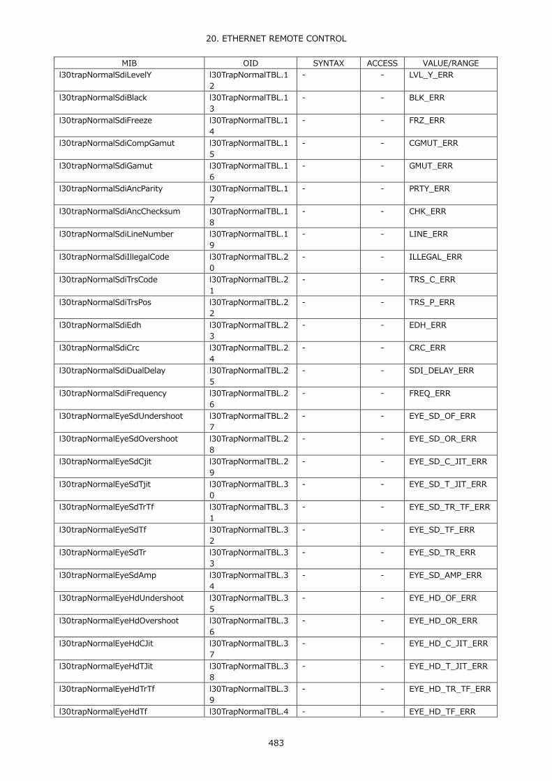
20. ETHERNET REMOTE CONTROL
483
MIB OID SYNTAX ACCESS VALUE/RANGE l30trapNormalSdiLevelY l30TrapNormalTBL.1
2 - - LVL_Y_ERR
l30trapNormalSdiBlack l30TrapNormalTBL.13
- - BLK_ERR
l30trapNormalSdiFreeze l30TrapNormalTBL.14
- - FRZ_ERR
l30trapNormalSdiCompGamut l30TrapNormalTBL.15
- - CGMUT_ERR
l30trapNormalSdiGamut l30TrapNormalTBL.16
- - GMUT_ERR
l30trapNormalSdiAncParity l30TrapNormalTBL.17
- - PRTY_ERR
l30trapNormalSdiAncChecksum l30TrapNormalTBL.18
- - CHK_ERR
l30trapNormalSdiLineNumber l30TrapNormalTBL.19
- - LINE_ERR
l30trapNormalSdiIllegalCode l30TrapNormalTBL.20
- - ILLEGAL_ERR
l30trapNormalSdiTrsCode l30TrapNormalTBL.21
- - TRS_C_ERR
l30trapNormalSdiTrsPos l30TrapNormalTBL.22
- - TRS_P_ERR
l30trapNormalSdiEdh l30TrapNormalTBL.23
- - EDH_ERR
l30trapNormalSdiCrc l30TrapNormalTBL.24
- - CRC_ERR
l30trapNormalSdiDualDelay l30TrapNormalTBL.25
- - SDI_DELAY_ERR
l30trapNormalSdiFrequency l30TrapNormalTBL.26
- - FREQ_ERR
l30trapNormalEyeSdUndershoot l30TrapNormalTBL.27
- - EYE_SD_OF_ERR
l30trapNormalEyeSdOvershoot l30TrapNormalTBL.28
- - EYE_SD_OR_ERR
l30trapNormalEyeSdCjit l30TrapNormalTBL.29
- - EYE_SD_C_JIT_ERR
l30trapNormalEyeSdTjit l30TrapNormalTBL.30
- - EYE_SD_T_JIT_ERR
l30trapNormalEyeSdTrTf l30TrapNormalTBL.31
- - EYE_SD_TR_TF_ERR
l30trapNormalEyeSdTf l30TrapNormalTBL.32
- - EYE_SD_TF_ERR
l30trapNormalEyeSdTr l30TrapNormalTBL.33
- - EYE_SD_TR_ERR
l30trapNormalEyeSdAmp l30TrapNormalTBL.34
- - EYE_SD_AMP_ERR
l30trapNormalEyeHdUndershoot l30TrapNormalTBL.35
- - EYE_HD_OF_ERR
l30trapNormalEyeHdOvershoot l30TrapNormalTBL.36
- - EYE_HD_OR_ERR
l30trapNormalEyeHdCJit l30TrapNormalTBL.37
- - EYE_HD_C_JIT_ERR
l30trapNormalEyeHdTJit l30TrapNormalTBL.38
- - EYE_HD_T_JIT_ERR
l30trapNormalEyeHdTrTf l30TrapNormalTBL.39
- - EYE_HD_TR_TF_ERR
l30trapNormalEyeHdTf l30TrapNormalTBL.4 - - EYE_HD_TF_ERR

20. ETHERNET REMOTE CONTROL
484
MIB OID SYNTAX ACCESS VALUE/RANGE 0
l30trapNormalEyeHdTr l30TrapNormalTBL.41
- - EYE_HD_TR_ERR
l30trapNormalEyeHdAmp l30TrapNormalTBL.42
- - EYE_HD_AMP_ERR
l30trapNormalEye3gUndershoot l30TrapNormalTBL.43
- - EYE_3G_OF_ERR
l30trapNormalEye3gOvershoot l30TrapNormalTBL.44
- - EYE_3G_OR_ERR
l30trapNormalEyeCJit l30TrapNormalTBL.45
- - EYE_3G_C_JIT_ERR
l30trapNormalEyeTJit l30TrapNormalTBL.46
- - EYE_3G_T_JIT_ERR
l30trapNormalEyeTrTf l30TrapNormalTBL.47
- - EYE_3G_TR_TF_ERR
l30trapNormalEyeTf l30TrapNormalTBL.48
- - EYE_3G_TF_ERR
l30trapNormalEyeTr l30TrapNormalTBL.49
- - EYE_3G_TR_ERR
l30trapNormalEyeAmp l30TrapNormalTBL.50
- - EYE_3G_AMP_ERR
l30trapNormalAudioValidity l30TrapNormalTBL.51
- - VAL
l30trapNormalAudioCrc l30TrapNormalTBL.52
- - CRC
l30trapNormalAudioClip l30TrapNormalTBL.53
- - CLIP
l30trapNormalAudioMute l30TrapNormalTBL.54
- - MUTE
l30trapNormalAudioLevel l30TrapNormalTBL.55
- - OVER
l30trapNormalAudioParity l30TrapNormalTBL.56
- - PAR
l30trapNormalAudioCode l30TrapNormalTBL.57
- - CODE
l30trapNormalSdiBlackSt2 l30TrapNormalTBL.58
- - BLK_ST2_ERR
l30trapNormalSdiFreezeSt2 l30TrapNormalTBL.59
- - FRZ_ST2_ERR
l30trapNormalNoError l30TrapNormalTBL.60
- - NO_ERROR
l30trapErrorSdiLevelC_St2 l30TrapNormalTBL.69
- - LVL_C_ST2_ERR
l30trapErrorSdiLevelY_St2 l30TrapNormalTBL.70
- - LVL_Y_ST2_ERR
l30trapErrorSdiCompGamutSt2 l30TrapNormalTBL.71
- - CGMUT_ST2_ERR
l30trapErrorSdiGamutSt2 l30TrapNormalTBL.72
- - GMUT_ST2_ERR
l30trapStrTBL l30notificationTBL.2 Aggregate - - l30trapCounter l30trapStrTBL.1 INTEGER R/O 1 to 4294967295 l30trapInternalTimestamp l30trapStrTBL.2 DisplayString R/O Date and time l30trapInputCh l30trapStrTBL.3 INTEGER R/O 1 = a
2 = b 3 = c 4 = d
l30trapInputSignal l30trapStrTBL.4 DisplayString R/O Signal format

20. ETHERNET REMOTE CONTROL
485
MIB OID SYNTAX ACCESS VALUE/RANGE l30trapCableLen l30trapStrTBL.5 INTEGER R/O 0 to 32767

20. ETHERNET REMOTE CONTROL
486
● Error information Error Number (*1) Error Information Character String Description
1 FAN_STOP Fan stop detection 2 NO_SIGNAL No input signal detection 3 FORMAT_UNKNOWN Unknown signal format detection 4 CABLE_ERR Cable length measurement error detection 5 CABLE_WAR Cable length measurement warning detection 6 A_SMPL_ERR (EMB AUDIO) SAMPLE error detection 7 A_INH_ERR (EMB AUDIO) INH error detection 8 A_DBN_ERR (EMB AUDIO) DBN error detection 9 A_PRTY_ERR (EMB AUDIO) PARITY error detection 10 A_BCH_ERR (EMB AUDIO) BCH error detection 11 LVL_C_ERR Chroma level error detection 12 LVL_Y_ERR Luminance level error detection 13 BLK_ERR Black error detection 14 FRZ_ERR Freeze error detection 15 CGMUT_ERR Composite gamut error detection 16 GMUT_ERR Gamut error detection 17 PRTY_ERR Parity error detection 18 CHK_ERR Checksum error detection 19 LINE_ERR Line number error detection 20 ILLEGAL_ERR Illegal command error detection 21 TRS_C_ERR TRS Code error detection 22 TRS_P_ERR TRS Pos error detection 23 EDH_ERR EDH error detection 24 CRC_ERR CRC error detection 25 SDI_DELAY_ERR SDI delay error detection 26 FREQ_ERR FREQUENCY error detection 27 EYE_SD_OF_ERR (EYE) SD Overshoot Falling error detection 28 EYE_SD_OR_ERR (EYE) SD Overshoot Rising error detection 29 EYE_SD_C_JIT_ERR (EYE) SD Current jitter error detection 30 EYE_SD_T_JIT_ERR (EYE) SD Timing jitter error detection 31 EYE_SD_TR_TF_ERR (EYE) SD Delta Time error detection 32 EYE_SD_TF_ERR (EYE) SD Fall Time error detection 33 EYE_SD_TR_ERR (EYE) SD Rise Time error detection 34 EYE_SD_AMP_ERR (EYE) SD amplitude error detection 35 EYE_HD_OF_ERR (EYE) HD Overshoot Falling error detection 36 EYE_HD_OR_ERR (EYE) HD Overshoot Rising error detection 37 EYE_HD_C_JIT_ERR (EYE) HD Current jitter error detection 38 EYE_HD_T_JIT_ERR (EYE) HD Timing jitter error detection 39 EYE_HD_TR_TF_ERR (EYE) HD Delta Time error detection 40 EYE_HD_TF_ERR (EYE) HD Fall Time error detection 41 EYE_HD_TR_ERR (EYE) HD Rise Time error detection 42 EYE_HD_AMP_ERR (EYE) HD amplitude error detection 43 EYE_3G_OF_ERR (EYE) 3G Overshoot Falling error detection 44 EYE_3G_OR_ERR (EYE) 3G Overshoot Rising error detection 45 EYE_3G_C_JIT_ERR (EYE) 3G Current jitter error detection 46 EYE_3G_T_JIT_ERR (EYE) 3G Timing jitter error detection 47 EYE_3G_TR_TF_ERR (EYE) 3G Delta Time error detection 48 EYE_3G_TF_ERR (EYE) 3G Fall Time error detection 49 EYE_3G_TR_ERR (EYE) 3G Rise Time error detection 50 EYE_3G_AMP_ERR (EYE) 3G amplitude error detection 51 VAL (AUDIO) VALIDITY error detection 52 CRC (AUDIO) CRC error detection 53 CLIP (AUDIO) CLIP error detection 54 MUTE (AUDIO) MUTE error detection
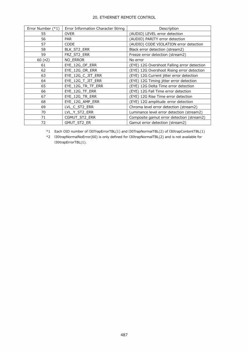
20. ETHERNET REMOTE CONTROL
487
Error Number (*1) Error Information Character String Description 55 OVER (AUDIO) LEVEL error detection 56 PAR (AUDIO) PARITY error detection 57 CODE (AUDIO) CODE VIOLATION error detection 58 BLK_ST2_ERR Black error detection (stream2) 59 FRZ_ST2_ERR Freeze error detection (stream2)
60 (*2) NO_ERROR No error 61 EYE_12G_OF_ERR (EYE) 12G Overshoot Falling error detection 62 EYE_12G_OR_ERR (EYE) 12G Overshoot Rising error detection 63 EYE_12G_C_JIT_ERR (EYE) 12G Current jitter error detection 64 EYE_12G_T_JIT_ERR (EYE) 12G Timing jitter error detection 65 EYE_12G_TR_TF_ERR (EYE) 12G Delta Time error detection 66 EYE_12G_TF_ERR (EYE) 12G Fall Time error detection 67 EYE_12G_TR_ERR (EYE) 12G Rise Time error detection 68 EYE_12G_AMP_ERR (EYE) 12G amplitude error detection 69 LVL_C_ST2_ERR Chroma level error detection (stream2) 70 LVL_Y_ST2_ERR Luminance level error detection (stream2) 71 CGMUT_ST2_ERR Composite gamut error detection (stream2) 72 GMUT_ST2_ER Gamut error detection (stream2)
*1 Each OID number of l30TrapErrorTBL(1) and l30TrapNormalTBL(2) of l30trapContentTBL(1) *2 l30trapNormalNoError(60) is only defined for l30trapNormalTBL(2) and is not available for
l30trapErrorTBL(1).

20. ETHERNET REMOTE CONTROL
488
20.4 HTTP Server Feature
You can use this feature to control the LV 5490 from a web browser on a PC in the same manner as you would control the LV 5490 from the panel.
20.4.1 Operating Environment
The following web browsers have been confirmed to work.
・ Internet Explorer Ver.11.0 ・ Mozilla Firefox Ver.37.0.2
20.4.2 Precautions
・ After you press a key in the web browser interface, wait for the screen to update before you perform the next operation. The screen cannot redraw fast enough to keep up with consecutive key presses. In this situation, a completely gray screen may be displayed temporarily. (After a few seconds the screen will return to normal.)
・ When you are using the HTTP server feature, perform as few panel operations on the LV
5490 as possible. The LV 5490's internal processing load increases when it is redrawing the web browser screen, so there is a lag of 1 to 2 seconds from the time that you perform panel operations on the LV 5490 to the time that the operations are actually carried out.
・ The HTTP server feature only supports a single connection to a PC at any one time.
Multiple simultaneous connections are not supported.

20. ETHERNET REMOTE CONTROL
489
20.4.3 Procedure
1. Configure the Ethernet settings on the LV 5490's ETHERNET SETUP tab.
Set the IP Address, and set HTTP Server Select to ON. See section 7.2.2, “Configuring Ethernet Settings.”
SYS → F•2 SYSTEM SETUP → F•2 PREV TAB or F•3 NEXT TAB →
Figure 20-4 ETHERNET SETUP display
2. Press F•1 COMPLETE.
3. Connect the LV 5490's Ethernet port to the network.
4. Start the web browser on your PC.
The HTTP server feature uses JavaScript. Enable JavaScript in your web browser.
5. In the address box, enter “http://” and the IP address that you set in step 1.
Figure 20-5 IP address input

20. ETHERNET REMOTE CONTROL
490
6. When the display selection page appears, select Web Server (with Display) or Web Server.
If you select Web Server (with Display), a screen much like the screen on the LV 5490 is displayed, but responses to operations can take 4 to 10 seconds, and auto display updating is every 10 seconds. If you select Web Server, a screen is not displayed, but the response time is reduced to 2 to 3 seconds. Select the mode that meets your needs.
Figure 20-6 Display selection page
7. After the main screen is displayed, you can click the keys in the web browser to control the LV 5490.
Figure 20-7 Main display

20. ETHERNET REMOTE CONTROL
491
Table 20-2 Main display description
No. Name Description 1 Return Menu Click this to return to the display selection page. 2 Preset Memory Click this to perform the same action as when the PSET key is held down.
See chapter 9, “PRESET SETTINGS.” 3 Screen Capture(JPG)
Screen Capture(BMP) (*1)
Click this to capture the currently displayed screen and display it in a different window. You can use the window's menu to save the screen as a jpeg file or a .bmp file.
4 Display screen (*1)
Click this to update the screen. (The screen updates automatically every 10 seconds even if you do not click the screen.)
5 V POS H POS F•D
-50, -1, +1, and +50 are assigned to the four areas. Click the square in the center of each of these controls to perform the same operation as pressing the corresponding control on the LV 5490. On tab menus and some screens, -50 operates as -5 and +50 operates as +5. Also, in places where the setting resolution is a value other than 1, the value that is set is “resolution × the setting specified by the knob.”
6 CAP Pressing the CAP key does not capture the screen correctly. Use the Screen Capture button on the Web Server (with Display).
8 Power switch Pressing the power switch has no effect. 7 Function keys When you use the function keys to select settings, pop-ups are displayed in the
web browser, so select the option within 2 seconds of the pop-up being displayed. Also, since the function menu disappears automatically, the display and operation may not match. In this case, set MENU Auto Off for a long time in the system menu. For information on the MENU Auto Off setting, see section 7.2.1, “General Settings.”
*1 Not displayed in Web Server mode.

20. ETHERNET REMOTE CONTROL
492
20.5 SNTP Client Function
The LV 5490 can display time that is synchronized to an NTP server on the network. 20.5.1 Procedure
1. Configure the Ethernet settings on the LV 5490's ETHERNET SETUP tab.
Set SNTP Client Select to ON, and set the IP address, server IP address, and time zone adjustment. For details on time zone adjustment, see the next section. Reference 7.2.2, "Configuring Ethernet Settings"
SYS → F•2 SYSTEM SETUP → F•2 PREV TAB or F•3 NEXT TAB →
Figure 20-8 ETHERNET SETUP tab
2. Press F•1 COMPLETE.
3. Connect the LV 5490's Ethernet port to the network.
The LV 5490 connects to the NTP server at the following times. • When you press F•1 COMPLETE in SYSTEM SETUP • Once every approximately 10 minutes
When the LV 5490 connects normally to an NTP server, the date and time are displayed at the upper right of the screen. Otherwise, "NTP ERR" appears next to TIME.
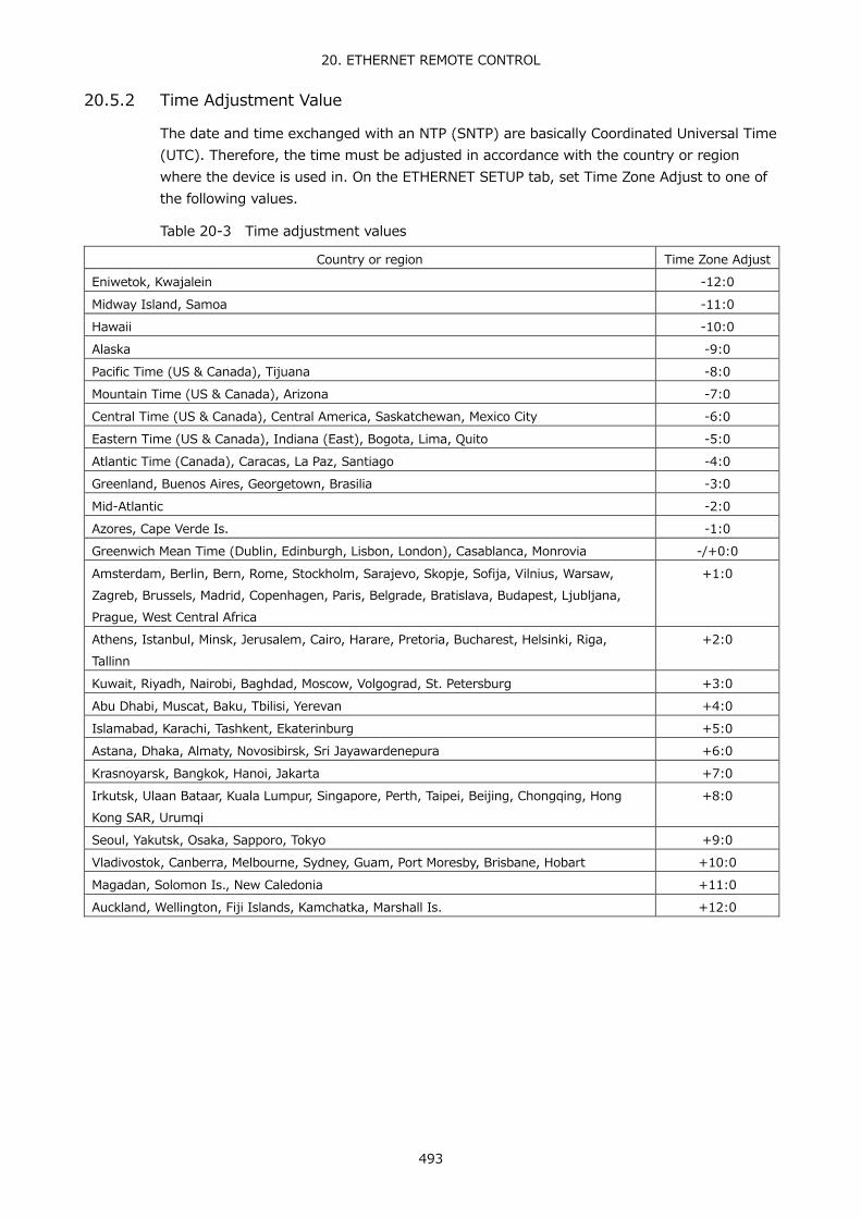
20. ETHERNET REMOTE CONTROL
493
20.5.2 Time Adjustment Value
The date and time exchanged with an NTP (SNTP) are basically Coordinated Universal Time (UTC). Therefore, the time must be adjusted in accordance with the country or region where the device is used in. On the ETHERNET SETUP tab, set Time Zone Adjust to one of the following values.
Table 20-3 Time adjustment values
Country or region Time Zone Adjust Eniwetok, Kwajalein -12:0 Midway Island, Samoa -11:0 Hawaii -10:0 Alaska -9:0 Pacific Time (US & Canada), Tijuana -8:0 Mountain Time (US & Canada), Arizona -7:0 Central Time (US & Canada), Central America, Saskatchewan, Mexico City -6:0 Eastern Time (US & Canada), Indiana (East), Bogota, Lima, Quito -5:0 Atlantic Time (Canada), Caracas, La Paz, Santiago -4:0 Greenland, Buenos Aires, Georgetown, Brasilia -3:0 Mid-Atlantic -2:0 Azores, Cape Verde Is. -1:0 Greenwich Mean Time (Dublin, Edinburgh, Lisbon, London), Casablanca, Monrovia -/+0:0 Amsterdam, Berlin, Bern, Rome, Stockholm, Sarajevo, Skopje, Sofija, Vilnius, Warsaw, Zagreb, Brussels, Madrid, Copenhagen, Paris, Belgrade, Bratislava, Budapest, Ljubljana, Prague, West Central Africa
+1:0
Athens, Istanbul, Minsk, Jerusalem, Cairo, Harare, Pretoria, Bucharest, Helsinki, Riga, Tallinn
+2:0
Kuwait, Riyadh, Nairobi, Baghdad, Moscow, Volgograd, St. Petersburg +3:0 Abu Dhabi, Muscat, Baku, Tbilisi, Yerevan +4:0 Islamabad, Karachi, Tashkent, Ekaterinburg +5:0 Astana, Dhaka, Almaty, Novosibirsk, Sri Jayawardenepura +6:0 Krasnoyarsk, Bangkok, Hanoi, Jakarta +7:0 Irkutsk, Ulaan Bataar, Kuala Lumpur, Singapore, Perth, Taipei, Beijing, Chongqing, Hong Kong SAR, Urumqi
+8:0
Seoul, Yakutsk, Osaka, Sapporo, Tokyo +9:0 Vladivostok, Canberra, Melbourne, Sydney, Guam, Port Moresby, Brisbane, Hobart +10:0 Magadan, Solomon Is., New Caledonia +11:0 Auckland, Wellington, Fiji Islands, Kamchatka, Marshall Is. +12:0
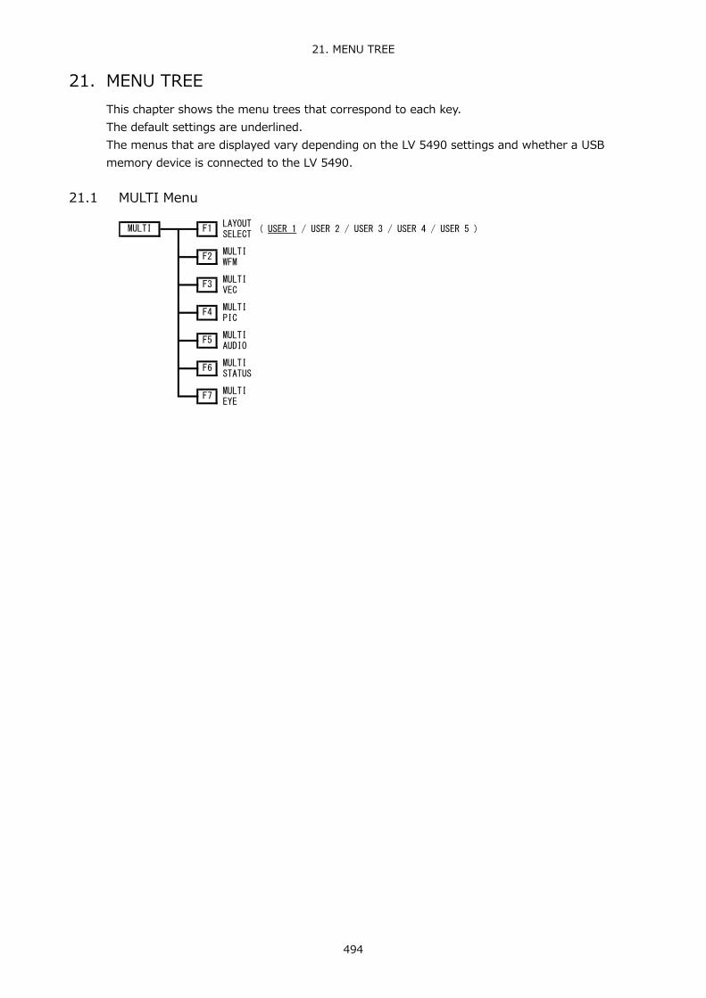
21. MENU TREE
494
21. MENU TREE This chapter shows the menu trees that correspond to each key. The default settings are underlined. The menus that are displayed vary depending on the LV 5490 settings and whether a USB memory device is connected to the LV 5490.
21.1 MULTI Menu
F7MULTIEYE
F5
F4MULTIPIC
MULTISTATUS
MULTIAUDIO
F3MULTIVEC
F2
F6
MULTI F1LAYOUTSELECT
( USER 1 / USER 2 / USER 3 / USER 4 / USER 5 )
MULTIWFM

21. MENU TREE
495
21.2 INPUT Menu
1 - 4 ( ON )F1
3 ( ON / OFF )F3
( ON / OFF )F4
1 ( ON / OFF )F1
( ON / OFF )F2
4
( 1 / 2 )
2A - 2B
( ON )
2C - 2D
1C - 1D ( ON / OFF )
F5
F1
F2
F4
2A
F4
F1
F2
1A - 1B
F3
2
( ON / OFF )INPUT F1
1B ( ON / OFF )F2
1A
( ON / OFF )
( ON / OFF )F3
1D ( ON / OFF )F4
1C
( ON / OFF )
( ON / OFF )F1
( ON / OFF )
2C
2BF2
F3
INPUTGROUP
( ON / OFF )
1A - 1D
2D
( ON )
( ON / OFF )
( ON / OFF )
( COM / INDIVIDUAL )
( SINGLE / SIMUL )F7 DISPLAY
2A - 2D
F6OPERATECH MODE
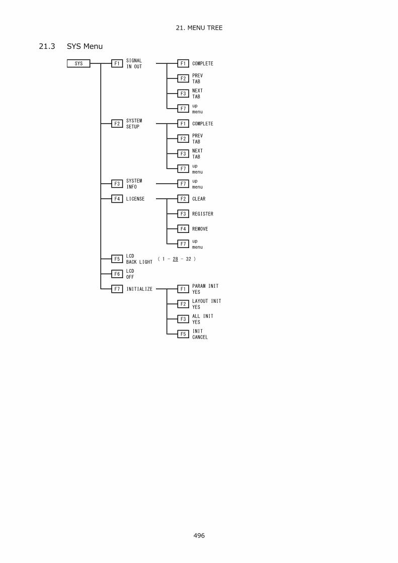
21. MENU TREE
496
21.3 SYS Menu
upmenu
F7
REMOVEF4
REGISTERF3
CLEARLICENSEF4 F2
F3ALL INITYES
F2LAYOUT INITYES
F7
F5
F1
upmenu
F7
F7
F3NEXTTAB
F1
upmenu
COMPLETE
F7
upmenu
F2
F3
PREVTAB
F2
F6
SYSTEMINFO
F3
F2SYSTEMSETUP
PARAM INITYES
INITCANCEL
F5
( 1 - 28 - 32 )LCDBACK LIGHT
INITIALIZE
LCDOFF
PREVTAB
NEXTTAB
F1 COMPLETESIGNALIN OUT
SYS F1

21. MENU TREE
497
21.4 CAP Menu
F7( 1A / 1B / 1C / 1D / 2A / 2B / 2C / 2D / 1A - 1B / 1C - 1D / 2A - 2B / 2C - 2D / 1A - 1D / 2A - 2D )
SELECTCH
( ON / OFF )F5 FRM
F4 TIF
DPXF3
( MANUAL / ERROR )CAP F1 TRIGGER
DELETEFILE
F3
upmenu
F4FILETYPE
( REAL / HOLD / BOTH )
( ON / OFF )
DISPLAY
REFRESH
F2
F7
( ON / OFF )
( ON / OFF )
F2
( ON / OFF )BSG
BMPF1
F5 STORE
F6 F1RECALL RECALL
DELETEYES
F1F3
upmenu
F3
F7
DELETENO

21. MENU TREE
498
21.5 PSET Menu
・・・・
PSET F1
No.2F2
No.1
F3
No.4
No.3
F4
No.55F1
No.6F6
moreF7
No.5F5
No.59F5
No.56F2
No.57F3
No.58F4
No.60F6
moreF7 F3
F3
COPY INT->USBNO
COPY INT->USBYES
COPY USB->INTNO
ALL COPYINT->USB
F3
F1
F1F6
DELETEDELETEYES
F3
F5
F6
OVER WRITENO
CHAR SET
PSET F1 F1
F3
F2
COMMENTINPUT
CLEARALL
F7
F1
upmenu
=>
DELETE
INSERT
F4 <=
F2
F3
STORE
COPY USB->INTYES
F5 F1ALL COPYUSB->INT
OVER WRITEYES
DELETENO

21. MENU TREE
499
21.6 WFM Menu
SCALEINTEN
F4
F3 F1 ( -8 - 4 - 7 )
( 1A / 1B / 1C / 1D / 2A / 2B / 2C / 2D / 1A - 1B / 1C - 1D / 2A - 2B / 2C - 2D / 1A - 1D / 2A - 2D / 1 / 2 / 3 / 4 / 1 - 4 )
3G-B-DSDISPLAY
( STREAM1 / STREAM2 / MIX / ALIGN )
F5
F3
F3CH2B
CH3R
( ON / OFF )
( ON / OFF )
( ON / OFF )
F6
F4
( ON / OFF )
( ON / OFF )
( ON / OFF )
CH2G
( ON / OFF )CH3B
CH1R
( ON / OFF )
F7
CH1G
( ON / OFF )F2
CH1X
( ON / OFF )
CH2Y
( ON / OFF )
CH1Y
( ON / OFF )F2
F3CH2Cb
F4CH3Cr
upmenu
F2
( 1A / 1B / 1C / 1D / 2A / 2B / 2C / 2D / 1A - 1B / 1C - 1D / 2A - 2B / 2C - 2D / 1A - 1D / 2A - 2D / 1 / 2 / 3 / 4 / 1 - 4 )
SELECTCH
4YPARADE
F7
( OVERLAY / PARADE )WFMMODE
F1
( 1A / 1B / 1C / 1D / 2A / 2B / 2C / 2D / 1A - 1B / 1C - 1D / 2A - 2B / 2C - 2D / 1A - 1D / 2A - 2D / 1 / 2 / 3 / 4 / 1 - 4 )
SELECTCH
F6
F6SELECTCH
( WHITE / YELLOW / CYAN / GREEN / MAGENTA / RED / BLUE / MULTI )
upmenu
F4
( ON / OFF )F475%COLORSCALE
F1WFM
WFMSCALE
WFMCOLOR
WFMCOLOR
F2
SCALEUNIT
F3
F2SCALECOLOR
( HDV,SD% / HDV,SDV / HD%,SD% / 150% / 1023 / 1023,255 / 3FF )
F1 ( -128 - 0 - 127 )
upmenu
F7
WFMINTEN
INTEN/SCALE/DISPLAY
( WHITE / YELLOW / CYAN / GREEN / MAGENTA / RED / BLUE )
WFMDISPLAY
STREAM1COLOR
F2( WHITE / YELLOW / CYAN / GREEN / MAGENTA / RED / BLUE / MULTI )
F1
STREAM2COLOR
( WHITE / YELLOW / CYAN / GREEN / MAGENTA / RED / BLUE / MULTI )
F2
SELECTCH
( 1A / 1B / 1C / 1D / 2A / 2B / 2C / 2D )F6
F7upmenu
F5
F2
F3
CH3Z
( ON / OFF )F4

21. MENU TREE
500
SCALEJUMP
( .0 / .1 / .2 / .3 / .4 / .5 / .6 / .7 / CURSOR )F4
SCALEJUMP
( 0 / 10 / 20 / 30 / 40 / 50 / 60 / 70 / 80 / 90 / CURSOR )F4
F1COLORMATRIX
( GBR / RGB / COMPOSIT )
F3
F2
( 1A / 1B / 1C / 1D / 2A / 2B / 2C / 2D / 1A - 1B / 1C - 1D / 2A - 2B / 2C - 2D / 1A - 1D / 2A - 2D / 1 / 2 / 3 / 4 / 1 - 4 )
( FLAT / LUM / FLAT+LUM / LUM+CRMA )
GAINVARIABLE
F1
GAINMAG
SELECTCH
F7upmenu
F2
( CAL / VARIABLE )
F3 FILTER ( FLAT / LOWPASS )
SELECTCH
F4
( 1A / 1B / 1C / 1D / 2A / 2B / 2C / 2D / 1A - 1B / 1C - 1D / 2A - 2B / 2C - 2D / 1A - 1D / 2A - 2D / 1 / 2 / 3 / 4 / 1 - 4 )
( AUTO / NTSC / PAL )
F3
FD VAR
F6
F5 REFSET
( 1A / 1B / 1C / 1D / 2A / 2B / 2C / 2D / 1A - 1B / 1C - 1D / 2A - 2B / 2C - 2D / 1A - 1D / 2A - 2D / 1 / 2 / 3 / 4 / 1 - 4 )
SELECTCH
( 0% / 7.5% )
( ON / OFF )
F6
F7
F2
F3
F5
F4
LINE SEL
F6
FILTER
V SWEEP
SWEEP
( 1H / 2H )H SWEEP
( X1 / X5 )
( H / V )
( REF / DELTA / TRACK )
( X1 / X10 / X20 / X40 / ACTIVE / BLANK )
( 1A / 1B / 1C / 1D / 2A / 2B / 2C / 2D / 1A - 1B / 1C - 1D / 2A - 2B / 2C - 2D / 1A - 1D / 2A - 2D / 1 / 2 / 3 / 4 / 1 - 4 )
( 1V / 2V )
( ON / OFF )
( YCbCr / GBR / RGB / COMPOSIT )COLORMATRIX
upmenu
F7
F6
COLORSYSTEM
F3
F7
FIELD
SELECTCH
LINESELECT
( REMOVE / H VIEW / V VIEW / ALL VIEW )
( 1A / 1B / 1C / 1D / 2A / 2B / 2C / 2D / 1A - 1B / 1C - 1D / 2A - 2B / 2C - 2D / 1A - 1D / 2A - 2D / 1 / 2 / 3 / 4 / 1 - 4 )
BLANKING
( FIELD1 / FIELD2 )
F2
FIELD
SWEEPMAG
F2
F2
F1
F7
F6
CURSOR
XY SEL
upmenu
upmenu
SELECTCH
Y UNIT
X UNIT
( mV / % / R% / DEC / HEX / HDR )
( X / Y )
( sec / Hz )
( ON / ON XY / OFF )
( ON / OFF )
COMPOSITFORMAT
F6
F2
upmenu
F1
F2
YGBR
F3
( FIELD1 / FIELD2 / FRAME )
F1
F1
F7
SELECTCH
( 1A / 1B / 1C / 1D / 2A / 2B / 2C / 2D / 1A - 1B / 1C - 1D / 2A - 2B / 2C - 2D / 1A - 1D / 2A - 2D / 1 / 2 / 3 / 4 / 1 - 4 )
SETUP
YRGB
F4
GAIN/FILTER
SWEEP
F5 CURSOR
F5
F4
F1
CURSORVALUE
( ON / OFF )
COLORMATRIX
( XYZ / GBR / RGB / COMPOSIT )
F5

21. MENU TREE
501
21.7 VECT Menu
F1 ( % / mV )5BARSCALE
( 1A / 1B / 1C / 1D / 2A / 2B / 2C / 2D / 1A - 1B / 1C - 1D / 2A - 2B / 2C - 2D / 1A - 1D / 2A - 2D / 1 / 2 / 3 / 4 / 1 - 4 )
( ON / OFF )
( ON / OFF )
( ON / OFF )
( 1 / 2 / OFF )
( ON / OFF )
( WHITE / YELLOW / CYAN / GREEN / MAGENTA / RED / BLUE )
( -8 - 4 - 7 )
( 0.000 - 0.292 - 1.000 )
( 0.000 - 0.046 - 1.000 )
( 0.000 - 0.797 - 1.000 )
( 0.000 - 0.708 - 1.000 )
( 0.000 - 0.131 - 1.000 )
( 0.000 - 0.170 - 1.000 )
( G / B / R )
( 1A / 1B / 1C / 1D / 2A / 2B / 2C / 2D / 1A - 1B / 1C - 1D / 2A - 2B / 2C - 2D / 1A - 1D / 2A - 2D / 1 / 2 / 3 / 4 / 1 - 4 )
( 1A / 1B / 1C / 1D / 2A / 2B / 2C / 2D / 1A - 1B / 1C - 1D / 2A - 2B / 2C - 2D / 1A - 1D / 2A - 2D / 1 / 2 / 3 / 4 / 1 - 4 )
( AUTO / BT.601 / BT.709 / DCI / BT.2020 )
( ON / OFF )
upmenu
( 1A / 1B / 1C / 1D / 2A / 2B / 2C / 2D )
( WHITE / YELLOW / CYAN / GREEN / MAGENTA / RED / BLUE / MULTI )
( WHITE / YELLOW / CYAN / GREEN / MAGENTA / RED / BLUE / MULTI )
( WHITE / YELLOW / CYAN / GREEN / MAGENTA / RED / BLUE )
( -128 - 0 - 127 )
upmenu
F4 y VALUE
y VALUEF4
F3 x VALUE
x VALUEF3
F4 y VALUE
x VALUEF3
F2
TRIANGLE
PRIMARYCOLOR
F5 F1USERTRIANGLE
F7upmenu
SELECTCH
F6
F4TRIANGLECAPTION
D65F3
F2 GRID
TEMPSCALE
SUB SCALEF4 F1
F3 COLOR ( ON / OFF )
F2 TRIANGLE2 ( BT.601(525) / BT.601(625) / BT.709 / DCI / BT.2020 / OFF )
F1 F1 TRIANGLE1 ( BT.601(525) / BT.601(625) / BT.709 / DCI / BT.2020 / OFF )SCALE
upmenu
F7
SELECTCH
F6
F7
F6SELECTCH
VECTSCALE
F4
F3 IQ AXIS
SCALECOLOR
F2
VECTSCALE
F3 F1SCALEINTEN
F7
F6SELECTCH
STREAM2COLOR
F2
STREAM1COLOR
F2 F1VECTCOLOR
F2VECTCOLOR
VECT F1 F1VECTINTEN
INTEN/SCALE
SCALEHISTSCALE
( % / HDR )F1 F3
SELECTCH
( 1A - 1B / 1C - 1D / 2A - 2B / 2C - 2D / 1A - 1D / 2A - 2D / 1 / 2 / 3 / 4 / 1 - 4 )F6
upmenu
F7

21. MENU TREE
502
F25BARSEQUENCE
( GBR / RGB )
F7upmenu
SELECTCH
( 1A / 1B / 1C / 1D / 2A / 2B / 2C / 2D / 1A - 1B / 1C - 1D / 2A - 2B / 2C - 2D / 1A - 1D / 2A - 2D )
F6
F5
( 1A / 1B / 1C / 1D / 2A / 2B / 2C / 2D / 1A - 1B / 1C - 1D / 2A - 2B / 2C - 2D / 1A - 1D / 2A - 2D / 1 / 2 / 3 / 4 / 1 - 4 )
( 1A / 1B / 1C / 1D / 2A / 2B / 2C / 2D / 1A - 1B / 1C - 1D / 2A - 2B / 2C - 2D / 1A - 1D / 2A - 2D / 1 / 2 / 3 / 4 / 1 - 4 )
GAMMASETUP
( 1.50 - 2.20 - 3.00 )
up menuF7
CHAR SETF6
F5 =>
F4 <=
F3 INSERT
F2 DELETE
CLEARALL
F1COMMENTINPUT
F5
F7upmenu
SELECTCH
F6
( STREAM1 / STREAM2 / MIX / ALIGN )
MANUALSETUP
MANUALSETUP
( ON / OFF )F5 F1
upmenu
F7
SELECTCH
F6
F53G-B-DSDISPLAY
F5 F1 MODE ( VECTOR / 5BAR / HISTOGRAM / CIE DIAGRAM )DISPLAY
F7upmenu
F6SELECTCH
( 1A / 1B / 1C / 1D / 2A / 2B / 2C / 2D / 1A - 1B / 1C - 1D / 2A - 2B / 2C - 2D / 1A - 1D / 2A - 2D / 1 / 2 / 3 / 4 / 1 - 4 )
F4 F1 CURSOR ( ON / OFF )CURSOR
F7upmenu
F6SELECTCH
( 1A / 1B / 1C / 1D / 2A / 2B / 2C / 2D / 1A - 1B / 1C - 1D / 2A - 2B / 2C - 2D / 1A - 1D / 2A - 2D / 1 / 2 / 3 / 4 / 1 - 4 )
F4 F1 MARKER ( ON / OFF )MARKER
F7upmenu
F6SELECTCH
( 1A / 1B / 1C / 1D / 2A / 2B / 2C / 2D / 1A - 1B / 1C - 1D / 2A - 2B / 2C - 2D / 1A - 1D / 2A - 2D / 1 / 2 / 3 / 4 / 1 - 4 )
F2 FIELD ( FIELD1 / FIELD2 / FRAME )
F3 F1LINESELECT
( ON / OFF )LINE SEL
F7upmenu
F6( 1A / 1B / 1C / 1D / 2A / 2B / 2C / 2D / 1A - 1B / 1C - 1D / 2A - 2B / 2C - 2D / 1A - 1D / 2A - 2D / 1 / 2 / 3 / 4 / 1 - 4 )
SELECTCH
( ON / OFF )F4
F3 CLIP
FILTER
( ON / OFF )
F2 CIE STD ( CIE1931 / CIE1976 )
F2 F1 DISP TYPE ( DIAGRAM / TEMP )CIE DIAGRAM
F7upmenu
F6SELECTCH
( 1A / 1B / 1C / 1D / 2A / 2B / 2C / 2D / 1A - 1B / 1C - 1D / 2A - 2B / 2C - 2D / 1A - 1D / 2A - 2D / 1 / 2 / 3 / 4 / 1 - 4 )
F2GAINMAG
( X1 / X5 / IQ-MAG )
F2 F1GAINVARIABLE
( CAL / VARIABLE )VECTGAIN
F7upmenu
F6SELECTCH
( 1A / 1B / 1C / 1D / 2A / 2B / 2C / 2D / 1A - 1B / 1C - 1D / 2A - 2B / 2C - 2D / 1A - 1D / 2A - 2D / 1 / 2 / 3 / 4 / 1 - 4 )

21. MENU TREE
503
( 100% / 75% )
( 0% / 7.5% )
( AUTO / NTSC / PAL )
( COMPONEN / COMPOSIT )
( 1A / 1B / 1C / 1D / 2A / 2B / 2C / 2D / 1A - 1B / 1C - 1D / 2A - 2B / 2C - 2D / 1A - 1D / 2A - 2D / 1 / 2 / 3 / 4 / 1 - 4 )
COLORBAR
F7upmenu
F6SELECTCH
( 1A / 1B / 1C / 1D / 2A / 2B / 2C / 2D / 1A - 1B / 1C - 1D / 2A - 2B / 2C - 2D / 1A - 1D / 2A - 2D / 1 / 2 / 3 / 4 / 1 - 4 )
F4
SETUPF3
COMPOSITFORMAT
F2
F7 F1COLORMATRIX
COLORSYSTEM
F6SELECTCH

21. MENU TREE
504
21.8 PIC Menu
F5USER1/2ASPECT
( OFF / ON )
MONO/COLOR
PIC F1 F1ADJUST
CHROMAUP
F2
BRIGHT-NESS[%]
F3
CONTRAST[%]
F4
( 0.0 - 100.0 - 200.0 )GAIN/BIAS
GAINRGAIN[%]
F5 F1 F1
GGAIN[%]
F2
BGAIN[%]
F3
CHROMAGAIN[%]
F4
SELECTCH
F6
upmenu
F7
BIASRBIAS[%]
F2 F1
GBIAS[%]
F2
BBIAS[%]
F3
SELECTCH
F6
upmenu
F7
SELECTCH
F6
upmenu
F7
SELECTCH
F6
upmenu
F7
FRAMEMARKER
F2 F1MARKER
CENTERMARKER
F2
ASPECTMARKER
F3
ASPECTSHADOW[%]
F4
SAFEACTION
F5 F1SAFETYZONE
SAFETITLE
F2
( 0 - 90 - 100 )USER1/2SET
USER1WIDTH[%]
F3 F1
USER1HEIGHT[%]
F2
USER2WIDTH[%]
F3
USER2HEIGHT[%]
F4
SELECTCH
F6
upmenu
F7
SELECTCH
F6
upmenu
F7
SELECTCH
F6
upmenu
F7
( 0.0 - 100.0 - 200.0 )
( -50.0 - 0.0 - 50.0 )
( NORMAL / UP )
( 1A / 1B / 1C / 1D / 2A / 2B / 2C / 2D / 1A - 1B / 1C - 1D / 2A - 2B / 2C - 2D / 1A - 1D / 2A - 2D / 1 / 2 / 3 / 4 / 1 - 4 )
( 0.0 - 100.0 - 200.0 )
( 0.0 - 100.0 - 200.0 )
( 0.0 - 100.0 - 200.0 )
( COLOR / MONO )
( 1A / 1B / 1C / 1D / 2A / 2B / 2C / 2D / 1A - 1B / 1C - 1D / 2A - 2B / 2C - 2D / 1A - 1D / 2A - 2D / 1 / 2 / 3 / 4 / 1 - 4 )
( 1A / 1B / 1C / 1D / 2A / 2B / 2C / 2D / 1A - 1B / 1C - 1D / 2A - 2B / 2C - 2D / 1A - 1D / 2A - 2D / 1 / 2 / 3 / 4 / 1 - 4 )
( 1A / 1B / 1C / 1D / 2A / 2B / 2C / 2D / 1A - 1B / 1C - 1D / 2A - 2B / 2C - 2D / 1A - 1D / 2A - 2D / 1 / 2 / 3 / 4 / 1 - 4 )
( -50.0 - 0.0 - 50.0 )
( -50.0 - 0.0 - 50.0 )
( -50.0 - 0.0 - 50.0 )
( 1A / 1B / 1C / 1D / 2A / 2B / 2C / 2D / 1A - 1B / 1C - 1D / 2A - 2B / 2C - 2D / 1A - 1D / 2A - 2D / 1 / 2 / 3 / 4 / 1 - 4 )
( 1A / 1B / 1C / 1D / 2A / 2B / 2C / 2D / 1A - 1B / 1C - 1D / 2A - 2B / 2C - 2D / 1A - 1D / 2A - 2D / 1 / 2 / 3 / 4 / 1 - 4 )
( 1A / 1B / 1C / 1D / 2A / 2B / 2C / 2D / 1A - 1B / 1C - 1D / 2A - 2B / 2C - 2D / 1A - 1D / 2A - 2D / 1 / 2 / 3 / 4 / 1 - 4 )
( 0 - 80 - 100 )
( 0 - 80 - 100 )
( 0 - 90 - 100 )
( ARIB / SMPTE / USER2 / OFF )
( ARIB / SMPTE / USER1 / OFF )
( 0 - 50 - 100 )
( OFF / 17:9 / 16:9 / 14:9 / 13:9 / 4:3 / 2.39:1 / AFD )
( ON / OFF )
( ON / OFF )

21. MENU TREE
505
SELECTCH
( 1A / 1B / 1C / 1D / 2A / 2B / 2C / 2D / 1A - 1B / 1C - 1D / 2A - 2B / 2C - 2D / 1A - 1D / 2A - 2D / 1 / 2 / 3 / 4 / 1 - 4 )
F6
upmenu
F7
AV MEASURESUB IMAGE
( SUB 1 / SUB 2 / SUB 3 / SUB 4 )F4
AV MEASURERIGHT
( 0 - 99 )F3
AV MEASURELEFT
( 0 - 99 )F2
AV MEASURETOP
( 0 - 50 - 100 )F3 F1AVPHASE
( 0.404 / 0.323 / 0.269 / 0.202 / 0.101 / 0.0505 / 5.5MHz / 4.4MHz / 3.6MHz / 2.7MHz / 1.4MHz / 0.7MHz /
30MHz / 24MHz / 20MHz / 15MHz / 7.5MHz / 3.7MHz / 60MHz / 48MHz / 40MHz / 30MHz / 15MHz / 7.5MHz /
120MHz / 96MHz / 80MHz / 60MHz / 30MHz / 15MHz / 240MHz / 192MHz / 160MHz / 120MHz / 60MHz / 30MHz / THROUGH )
( 1A / 1B / 1C / 1D / 2A / 2B / 2C / 2D / 1A - 1B / 1C - 1D / 2A - 2B / 2C - 2D / 1A - 1D / 2A - 2D / 1 / 2 / 3 / 4 / 1 - 4 )
( SMALL / LARGE )
( OFF / ON )
LPF
( A1 / A2 / TRACK / OFF)
( Y / G / B / R )
( OFF / ON )
( 1A / 1B / 1C / 1D / 2A / 2B / 2C / 2D / 1A - 1B / 1C - 1D / 2A - 2B / 2C - 2D / 1A - 1D / 2A - 2D / 1 / 2 / 3 / 4 / 1 - 4 )
( -80dB - 0dB )
( STOP / START )
( 1A / 1B / 1C / 1D / 2A / 2B / 2C / 2D / 1A - 1B / 1C - 1D / 2A - 2B / 2C - 2D / 1A - 1D / 2A - 2D / 1 / 2 / 3 / 4 / 1 - 4 )
LINE SEL/ NOISE
LINESELECT
F3 F1
FIELDF2
SELECTCH
F6
F7upmenu
CINELITE/HDR
F4
MEASPOS
f StopSETUP
MEASSIZE
GAMMA
TABLECLEAR
1 DATACLEAR
CAL SET
CALF
SELECTCH
upmenu
FILELIST
F2 F1
TABLECLEAR
SELECTCH
upmenu
upmenu
upmenu
F7
F7upmenu
( 1A / 1B / 1C / 1D / 2A / 2B / 2C / 2D / 1A - 1B / 1C - 1D / 2A - 2B / 2C - 2D / 1A - 1D / 2A - 2D / 1 / 2 / 3 / 4 / 1 - 4 )
FILELOAD
F3
( P1 / P2 / P3 )F2 F1
( P1 / P1+P2 / P1+P2+P3 )F2MEASNUMBERS
( 1X1 / 3X3 / 9X9 )F3
F418%REF-SET
GAMMASELECT
( 0.45 / USER1 / USER2 / USER3 / USER_A / USER_B / USER_C / USER_D / USER_E )
F5 F1
GAMMACAL
CLEARYES
F2 F1 F1
CLEARNO
F3
F2
F3
( 22.0 / 16.0 / 11.0 / 8.0 / 5.6 / 4.0 / 2.8 / 2.0 )
F4
( 1A / 1B / 1C / 1D / 2A / 2B / 2C / 2D / 1A - 1B / 1C - 1D / 2A - 2B / 2C - 2D / 1A - 1D / 2A - 2D / 1 / 2 / 3 / 4 / 1 - 4 )
F6
F7
GAMMAFILE
CLEARYES
F2 F1
CLEARNO
F3
F3OVER WRNO
OVER WRYES
F1
F6
F7
( 1A / 1B / 1C / 1D / 2A / 2B / 2C / 2D / 1A - 1B / 1C - 1D / 2A - 2B / 2C - 2D / 1A - 1D / 2A - 2D / 1 / 2 / 3 / 4 / 1 - 4 )
F6SELECTCH
F7
( 1A / 1B / 1C / 1D / 2A / 2B / 2C / 2D / 1A - 1B / 1C - 1D / 2A - 2B / 2C - 2D / 1A - 1D / 2A - 2D / 1 / 2 / 3 / 4 / 1 - 4 )
( FIELD1 / FIELD2 / FRAME )
( ON / OFF )
CINELITEF4
CINELITEDISPLAY
( OFF / f Stop / %DISPLAY / CINEZONE )F1
BRIGHTNESSINFO
( OFF / ON )F5
HDR->SDRSETUP
BRIGHTNESSINFO
( OFF / ON )F2 F5
SELECTCH
( 1A - 1B / 1C - 1D / 2A - 2B / 2C - 2D / 1A - 1D / 2A - 2D )F6
upmenu
F7
NOISESETUP
CURSORCH
F4 F1
upmenu
F7
SELECTCH
F6
SIGNALF2
F3 F1FILTER
F4
SELECTCH
F6
RESULTSSIZE
F7upmenu
HPFF2
F5 F1ALARMUNIT
ALARM
F2ALARMLEVEL
SELECTCH
F6
upmenu
F7
NOISEF5

21. MENU TREE
506
REF ( 0.0 - 50.8 - 100.0 )F4
LOWER ( 0.0 - 100.0 )F3
UPPER ( 0.0 - 75.2 - 100.0 )F2
REF ( 0.0 - 50.8 - 100.0 )F4
LOWER ( 0.0 - 100.0 )F3
UPPER ( 0.0 - 90.0 - 100.0 )F2
REF ( 0.0 - 50.8 - 100.0 )F4
LOWER ( 0.0 - 100.0 )F3
UPPER ( 0.0 - 100.0 )F2
FOCUSF5 F1
FOCUSASSIST
F2
EDGESENSITIVE
F3
PICLEVEL
F4
EDGECOLOR
F5
SELECTCH
F6
F7
SELECTCH
upmenu
SIZE
F6
F7 F1DISPLAY
3G-B-DSDISPLAY
F3
STATUSINFO
F4
SELECTCH
F6
upmenu
F7
%DISPLAYSETUP
MEASPOS
MEASNUMBERS
MEASSIZE
UNITSELECT
SELECTCH
upmenu
CINEZONESETUP
CINEZONEFORM
UPPER
LEVEL
LOWER
F4CINELITEADVANCE
( OFF / ON )
SIZE
SELECTCH
( 1A / 1B / 1C / 1D / 2A / 2B / 2C / 2D / 1A - 1B / 1C - 1D / 2A - 2B / 2C - 2D / 1A - 1D / 2A - 2D / 1 / 2 / 3 / 4 / 1 - 4 )
upmenu
( 1A / 1B / 1C / 1D / 2A / 2B / 2C / 2D / 1A - 1B / 1C - 1D / 2A - 2B / 2C - 2D / 1A - 1D / 2A - 2D / 1 / 2 / 3 / 4 / 1 - 4 )
( WHITE / RED / GREEN / BLUE )
( OFF / EMBOSS / 25 / 50 / 75 / 100 )
( LOW / MIDDLE / HIGH / V-HIGH / U-HIGH )
( ON / OFF )
( FIT / REAL / X2 )
F6
F7
( P1 / P2 / P3 )F2 F1
( P1 / P1+P2 / P1+P2+P3 )F2
( 1X1 / 3X3 / 9X9 )F3
( Y% / RGB% / RGB255 / CODE VALUE / CODE VALUE DEC / HDR )F4
( 1A / 1B / 1C / 1D / 2A / 2B / 2C / 2D / 1A - 1B / 1C - 1D / 2A - 2B / 2C - 2D / 1A - 1D / 2A - 2D / 1 / 2 / 3 / 4 / 1 - 4 )
F6
F7
( GRADATE / STEP / SEARCH )F2 F1
( -6.3 - 100.0 - 109.4 )F2
( -7.3 - 40.0 - 109.4 )F2
( -7.3 - 0.0 - 108.4 )F3
( 1A / 1B / 1C / 1D / 2A / 2B / 2C / 2D / 1A - 1B / 1C - 1D / 2A - 2B / 2C - 2D / 1A - 1D / 2A - 2D / 1 / 2 / 3 / 4 / 1 - 4 )
F6SELECTCH
F7upmenu
( 1A / 1B / 1C / 1D / 2A / 2B / 2C / 2D / 1A - 1B / 1C - 1D / 2A - 2B / 2C - 2D / 1A - 1D / 2A - 2D / 1 / 2 / 3 / 4 / 1 - 4 )
( ON / OFF )
( STREAM1 / STREAM2 / MIX / ALIGN )
( FIT / REAL / X2 / FULL FRM )
( 1A / 1B / 1C / 1D / 2A / 2B / 2C / 2D / 1A - 1B / 1C - 1D / 2A - 2B / 2C - 2D / 1A - 1D / 2A - 2D / 1 / 2 / 3 / 4 / 1 - 4 )
HDR->SDR ( NORMAL / HIGH / DISABLE )F3
HDR ZONE ( OFF / ON )F5
BRIGHTNESSINFO
( OFF / ON )F5
BRIGHTNESSINFO
( OFF / ON )F5
F2 UPPER ( 0.0 - 100.0 )
( 0.0 - 100.0 )F3 LOWER
REF ( 0.0 - 50.0 - 100.0 )F4
UPPER ( 3.5 - 100.0 - 109.4 )F2
LOWER ( 3.5 - 109.4 )F3
REF ( 3.5 - 61.0 - 109.4 )F4
GAMUTERR DISP
( OFF / WHITE / RED / MESH )F2

21. MENU TREE
507
21.9 AUDIO Menu (SER03)
F2
PREVTAB
NEXTTAB
F3
LOGMODE
( OVER WR / STOP )F3
CLEARF2
LOG ( START / STOP )F4 F1 F1EVENTLOG
STATUSSETUP
F7upmenu
F6SELECTCH
( 1A / 1B / 1C / 1D / 2A / 2B / 2C / 2D / 1A - 1B / 1C - 1D / 2A - 2B / 2C - 2D / 1A - 1D / 2A - 2D / 1 / 2 / 3 / 4 / 1 - 4 )
F5AUTOGAIN
( ON / OFF )
F3SURROUND5.1
( NORMAL / PHANTOM )
F2SCALEINTEN
( -8 - 4 - 7 )
F4 F1SURROUNDINTEN
( -8 - 4 - 7 )SURROUNDSETUP
F7upmenu
F6SELECTCH
( 1A / 1B / 1C / 1D / 2A / 2B / 2C / 2D / 1A - 1B / 1C - 1D / 2A - 2B / 2C - 2D / 1A - 1D / 2A - 2D / 1 / 2 / 3 / 4 / 1 - 4 )
F5AUTOGAIN
( ON / OFF )
F4 FORM ( X-Y / MATRIX )
F3 DISPLAY ( MULTI / SINGLE )
F2SCALEINTEN
( -8 - 4 - 7 )
F4 F1LISSAJOUINTEN
( -8 - 0 - 7 )LISSAJOUSETUP
F7upmenu
F6SELECTCH
( 1A / 1B / 1C / 1D / 2A / 2B / 2C / 2D / 1A - 1B / 1C - 1D / 2A - 2B / 2C - 2D / 1A - 1D / 2A - 2D / 1 / 2 / 3 / 4 / 1 - 4 )
upmenu
F7
REFdBFS
( -40.0 - -20.0 - 0.0 )F3
WARNINGdBFS
( -40.0 - -18.0 - 0.0 )F2
OVERdBFS
( -40.0 - 0.0 )F5 F1LEVELSETTING
F4PEAKHOLD
( 0.0 - 0.5 - 5.0 / HOLD )
F3PEAKMETER
( TRUE / PPM(I) / PPM(II) )
F3 PPM MODE ( PPM(I) / PPM(II) )
F2 RESPONSE ( TRUEPEAK / PPM / VU )
F3 F1DYNAMICRANGE
( 60DBFS / 90DBFS / MAG )METERSETUP
F2
F7
DISPLAYMODE
( LISSAJOU / METER / SURROUND / STATUS )
upmenu
MAPPINGAUDIO F1 COMPLETEF1

21. MENU TREE
508
upmenu
F2 F7EBIMETADATA
upmenu
F1 F7DOLBY D+METADATA
F7
( 1A / 1B / 1C / 1D / 2A / 2B / 2C / 2D / 1A - 1B / 1C - 1D / 2A - 2B / 2C - 2D / 1A - 1D / 2A - 2D / 1 / 2 / 3 / 4 / 1 - 4 )
upmenu
upmenu
DISPLAYPROGRAM
upmenu
upmenu
( PRM1 / PRM2 / PRM3 / PRM4 / PRM5 / PRM6 / PRM7 / PRM8 )
( PRM1 / PRM2 / PRM3 / PRM4 / PRM5 / PRM6 / PRM7 / PRM8 )
F7upmenu
SELECTCH
F6
EBIMETADATA
F2
F7
F2 F1EBIMETADATA
F1 F7DOLBY DMETADATA
F7
DOLBYPROGRAM
F2 F1 F1DOLBY EMETADATA
METADATA
PHONESVOLUME
( 0 - 63 )F7
F6
F7
SELECTCH
( 1A / 1B / 1C / 1D / 2A / 2B / 2C / 2D / 1A - 1B / 1C - 1D / 2A - 2B / 2C - 2D / 1A - 1D / 2A - 2D / 1 / 2 / 3 / 4 / 1 - 4 )
upmenu
F5 F1 COMPLETEERRORSETUP
F7upmenu
F6SELECTCH
( 1A / 1B / 1C / 1D / 2A / 2B / 2C / 2D / 1A - 1B / 1C - 1D / 2A - 2B / 2C - 2D / 1A - 1D / 2A - 2D / 1 / 2 / 3 / 4 / 1 - 4 )
F5ERRORRESET
upmenu
F7
SELECTCH
( 1A / 1B / 1C / 1D / 2A / 2B / 2C / 2D / 1A - 1B / 1C - 1D / 2A - 2B / 2C - 2D / 1A - 1D / 2A - 2D / 1 / 2 / 3 / 4 / 1 - 4 )
F6
ALIGN ( LSB 1st / MSB 1st )F2
DISPLAYCHANNEL
( 1 - 16 / A:CH1 - A:CH8 / B:CH1 - B:CH8 / A1 - A16 / B1 - B16 / C1 - C16 / D1 - D16 )
F4 F1USERBIT
upmenu
F7
SELECTCH
( 1A / 1B / 1C / 1D / 2A / 2B / 2C / 2D / 1A - 1B / 1C - 1D / 2A - 2B / 2C - 2D / 1A - 1D / 2A - 2D / 1 / 2 / 3 / 4 / 1 - 4 )
F6
ALIGN ( LSB 1st / MSB 1st )F2
DISPLAYCHANNEL
( 1 - 16 / A:CH1 - A:CH8 / B:CH1 - B:CH8 / A1 - A16 / B1 - B16 / C1 - C16 / D1 - D16 )
F3 F1CHANNELSTATUS
upmenu
F7
F7upmenu
F3DELETENO
DELETEYES
F4 F1FILEDELETE
F3OVER WRNO
OVER WRYES
F3 F1STORE
F7upmenu
F6 CHAR SET
F5 =>
F4 <=
F2 DELETE
CLEARALL
F2 F1NAMEINPUT
F6 F1USBMEMORY
AUTOFILENAME
( ON / OFF )

21. MENU TREE
509
21.10 STATUS Menu
F1 STATUS
( S1 SERIAL / S1 COMPO / S1 BINARY / S2 SERIAL / S2 COMPO / S2 BINARY )
( PICTURE / STREAM1 / STREAM2 )
( SERIAL / COMPO / BINARY )
( OVER WR / STOP )
( EAV / SAV )
( RUN / HOLD / FRM CAP )
( START / STOP )
( ON / OFF )
( PICTURE / 1[1A] / 2[1B] / 1[1C] / 2[1D] / 1[2A] / 2[2B] / 1[2C] / 2[2D] / A[1A] / B[1B] / A[1C] / B[1D] / A[2A] / B[2B] / A[2C] / B[2D] )
( PICTURE / 1[1A] / 2[1B] / 3[1C] / 4[1D] / 1[2A] / 2[2B] / 3[2C] / 4[2D] )
( S1 SERIAL / S1 COMPO / S1 BINARY / S2 SERIAL / S2 COMPO / S2 BINARY )
( PICTURE / STREAM1 / STREAM2 )
DELETENO
( SERIAL / COMPO / BINARY )
( LINE / SAMPLE )
( 1 / 10 / 50 )
( END / START )
MODE
F7upmenu
F3
F4 F1FILEDELETE
DELETEYES
F3OVER WRNO
<=F4
=>F5
CLEARALL
F1
DELETEF2
F1AUTOFILENAME
( ON / OFF )
F3 STOREOVER WRYES
F1
upmenu
F7
CHAR SETF6
NAMEINPUT
F2
F7upmenu
F6USBMEMORY
F3LOGMODE
F2 CLEAR
STATUS F1 F1 LOGEVENTLOG
F5 LINK
JUMPF1
DISPLAYF4
DISPLAYF4
LINK
CLEARALL
F1
DUMPOPERATION
F2
F2 F1 F1DATADUMP
SDIANALYSIS
DISPLAYF4
F4 DISPLAY
NAMEINPUT
DISPLAYF4
FDFUNCTION
F3
FD1CLICK
F2
JUMPF1
F1AUTOFILENAME
USBMEMORY
F6
F5
upmenu
F7
F2
DELETEF2
<=
F5
F4
=>
CHAR SETF6
upmenu
F7
OVER WRYES
F3 F1STORE
OVER WRNO
F3
DELETEYES
F4 F1FILEDELETE
DELETENO
F3
upmenu
F7
DISPLAYF4
DISPLAY ( STREAM12 / STREAM1 / STREAM2 )F4
DISPLAY ( STREAM12 / STREAM1 / STREAM2 )F4
SUB ( PICTURE / 1[1A] / 2[1B] / 3[1C] / 4[1D] )F5

21. MENU TREE
510
upmenu
F7
COMPLETEF1
upmenu
F6
AV PHASESETUP
F5
REFRESHF2
SCALEMAX
( 50ms / 100ms / 500ms / 1.0s / 2.5s )F4 F1AVPHASE
SUB ( 1[1A] / 2[1B] / 3[1C] / 4[1D] )F5
SUB ( 1[1A] / 2[1B] / 3[1C] / 4[1D] )F5
F5 SUB
SUB ( PICTURE / 1[1A] / 2[1B] / 3[1C] / 4[1D] )F5
( 1[1A] / 2[1B] / 1[1C] / 2[1D] / 1[2A] / 2[2B] / 1[2C] / 2[2D] / A[1A] / B[1B] / A[1C] / B[1D] / A[2A] / B[2B] / A[2C] / B[2D] )
( 1[1A] / 2[1B] / 3[1C] / 4[1D] / 1[2A] / 2[2B] / 3[2C] / 4[2D] )
( 1A / 1B / 1C / 1D / 2A / 2B / 2C / 2D / 1A - 1B / 1C - 1D / 2A - 2B / 2C - 2D / 1A - 1D / 2A - 2D / 1 / 2 / 3 / 4 / 1 - 4 )
SELECTCH
F6
F5
F4STREAMSELECT
F2
F3
F3
F3 F1 F2
F7
PAGEDOWN
LINKF5
PAGEUP
ANC DUMP
DUMPMODE
( STREAM1 / STREAM2 )STREAMSELECT
PAYLOADID
( 1A / 1B / 1C / 1D / 2A / 2B / 2C / 2D / 1A - 1B / 1C - 1D / 2A - 2B / 2C - 2D / 1A - 1D / 2A - 2D / 1 / 2 / 3 / 4 / 1 - 4 )
upmenu
upmenu
SELECTCH
( TEXT / DUMP )EDHPACKETANALYSIS
DISPLAY
F5 LINK( 1[1A] / 2[1B] / 1[1C] / 2[1D] / 1[2A] / 2[2B] / 1[2C] / 2[2D] / A[1A] / B[1B] / A[1C] / B[1D] / A[2A] / B[2B] / A[2C] / B[2D] )
F5 LINK ( 1[1A] / 2[1B] / 3[1C] / 4[1D] / 1[2A] / 2[2B] / 3[2C] / 4[2D] )
LINK ( 1[1A] / 2[1B] / 3[1C] / 4[1D] / 1[2A] / 2[2B] / 3[2C] / 4[2D] )F5
F5 LINK( 1[1A] / 2[1B] / 1[1C] / 2[1D] / 1[2A] / 2[2B] / 1[2C] / 2[2D] / A[1A] / B[1B] / A[1C] / B[1D] / A[2A] / B[2B] / A[2C] / B[2D] )
SELECTCH
F5 LINK
upmenu
F7
F6
upmenu
F7
F6SELECTCH
LINKF5
EXT REFPHASE
REF SETUSER
F2 F1
upmenu
F7
F2REF SETDEFAULT
F6
F3
ANC DATAVIEWER
REFSELECT
F4 F1
LINK
F1
upmenu
HOLDTIME
( HOLD / 1s / 3s )
( HEX / BINARY )
F7
( 1A / 1B / 1C / 1D / 2A / 2B / 2C / 2D / 1A - 1B / 1C - 1D / 2A - 2B / 2C - 2D / 1A - 1D / 2A - 2D / 1 / 2 / 3 / 4 / 1 - 4 )
( 1A / 1B / 1C / 1D / 2A / 2B / 2C / 2D / 1A - 1B / 1C - 1D / 2A - 2B / 2C - 2D / 1A - 1D / 2A - 2D / 1 / 2 / 3 / 4 / 1 - 4 )
( EXT / SDI )
SELECTCH
( 1A / 1B / 1C / 1D / 2A / 2B / 2C / 2D / 1A - 1B / 1C - 1D / 2A - 2B / 2C - 2D / 1A - 1D / 2A - 2D / 1 / 2 / 3 / 4 / 1 - 4 )
( PICTURE / 1[1A] / 2[1B] / 1[1C] / 2[1D] / 1[2A] / 2[2B] / 1[2C] / 2[2D] / A[1A] / B[1B] / A[1C] / B[1D] / A[2A] / B[2B] / A[2C] / B[2D] )
( PICTURE / 1[1A] / 2[1B] / 3[1C] / 4[1D] / 1[2A] / 2[2B] / 3[2C] / 4[2D] )
upmenu
F1
CONTROLPACKET
F3 DISPLAY ( TEXT / DUMP )F1
upmenu
F7
GROUP ( 1 / 2 / 3 / 4 )F3
F6SELECTCH
( 1A / 1B / 1C / 1D / 2A / 2B / 2C / 2D / 1A - 1B / 1C - 1D / 2A - 2B / 2C - 2D / 1A - 1D / 2A - 2D / 1 / 2 / 3 / 4 / 1 - 4 )
F2 ( HEX / BINARY )
SELECTCH
( 1A / 1B / 1C / 1D / 2A / 2B / 2C / 2D / 1A - 1B / 1C - 1D / 2A - 2B / 2C - 2D / 1A - 1D / 2A - 2D / 1 / 2 / 3 / 4 / 1 - 4 )
F6
STREAMSELECT
( STREAM1 / STREAM2 )F4
F2DUMPMODE
( HEX / BINARY )
F6
F4F2
ANCPACKET
F7
0HTIMING
( LEGACY / SERIAL )F4
F7
( 1[1A] / 2[1B] / 3[1C] / 4[1D] )
( STREAM1 / STREAM2 )
DUMPMODE
NMI INFOF3

21. MENU TREE
511
F4 ALL ON
F1 COMPLETE
F5 ALL OFF
F7upmenu
F7upmenu
F6SELECTCH
F5 LINK
F5 LINK
F2DUMPMODE
F5USERDATA 2
F7upmenu
F6SELECTCH
F5 LINK
F5 LINK
F2DUMPMODE
F4USERDATA 1
F7upmenu
F6SELECTCH
F5 LINK
F5 LINK
F2DUMPMODE
F2DUMPMODE
F2Q LOGCLEAR
F7upmenu
F6SELECTCH
F5 LINK
F5 LINK
F3BITMASK
F1 DISPLAYF2 NET-Q
F6SELECTCH
( 1A / 1B / 1C / 1D / 2A / 2B / 2C / 2D / 1A - 1B / 1C - 1D / 2A - 2B / 2C - 2D / 1A - 1D / 2A - 2D / 1 / 2 / 3 / 4 / 1 - 4 )
F2 TYPE
F7upmenu
F7upmenu
F6SELECTCH
LINKF5
F5 LINK
DATATRIGGER
F3 DISPLAYF1
F3DUMPMODE
F1 DISPLAYF4 F1 F1CLOSEDCAPTION
ARIBV-ANC
F4STREAMSELECT
( STREAM1 / STREAM2 )
F7upmenu
F6SELECTCH
F2DUMPMODE
F7
DISPLAYF1
upmenu
SMPTEF2 AFD
USBMEMORY
F6
F5
( HEX / BINARY )
( TEXT / DUMP / Q LOG / FORMAT )
( 1A / 1B / 1C / ・・・
( A[1A] / B[1B] / ・・・
( 1[1A] / 2[1B] / ・・・
( HEX / BINARY )
( HD / SD / ANALOG / CELLULAR )
( TEXT / DUMP )
( 1A / 1B / 1C / ・・・
( A[1A] / B[1B] / ・・・
( 1[1A] / 2[1B] / ・・・
( HEX / BINARY )
( TEXT / DUMP )
( 1A / 1B / 1C / ・・・
( A[1A] / B[1B] / ・・・
( 1[1A] / 2[1B] / ・・・
LINKF5
LINKF5
( 1A / 1B / 1C / ・・・
( A[1A] / B[1B] / ・・・
( 1[1A] / 2[1B] / ・・・
( HEX / BINARY )
( 1A / 1B / 1C / ・・・
( A[1A] / B[1B] / ・・・
( 1[1A] / 2[1B] / ・・・
( HEX / BINARY )
( 1A / 1B / 1C / ・・・
( 1[1A] / 2[1B] / ・・・
( 1[1A] / 2[1B] / ・・・
( HEX / BINARY )
( TEXT / DUMP )
SUB ( 1[1A] / 2[1B] / ・・・F5

21. MENU TREE
512
STREAMSELECT
( STREAM1 / STREAM2 )F4
F7upmenu
F7upmenu
F2 SDID/DBN ( -- / 00 - FF )
upmenu
F7
SELECTCH
( 1A / 1B / 1C / 1D / 2A / 2B / 2C / 2D / 1A - 1B / 1C - 1D / 2A - 2B / 2C - 2D / 1A - 1D / 2A - 2D / 1 / 2 / 3 / 4 / 1 - 4 )
F6
F3
F2
F1F5IDSET
CUSTOMSEARCH
DID ( 00 - FF )F1
( HEX / BINARY )
Y/CSELECT
LINK ( 1[1A] / 2[1B] / 3[1C] / 4[1D] / 1[2A] / 2[2B] / 3[2C] / 4[2D] )
DUMPMODE
( Y / C )
F5
upmenu
SELECTCH
( 1A / 1B / 1C / 1D / 2A / 2B / 2C / 2D / 1A - 1B / 1C - 1D / 2A - 2B / 2C - 2D / 1A - 1D / 2A - 2D / 1 / 2 / 3 / 4 / 1 - 4 )
F7
F6
( 1A / 1B / 1C / 1D / 2A / 2B / 2C / 2D / 1A - 1B / 1C - 1D / 2A - 2B / 2C - 2D / 1A - 1D / 2A - 2D / 1 / 2 / 3 / 4 / 1 - 4 )
( 1A / 1B / 1C / 1D / 2A / 2B / 2C / 2D / 1A - 1B / 1C - 1D / 2A - 2B / 2C - 2D / 1A - 1D / 2A - 2D / 1 / 2 / 3 / 4 / 1 - 4 )
F7upmenu
F6SELECTCH
F7
SELECTCH
ERRORCLEAR
F6
upmenu
F7
F3NEXTTAB
PREVTAB
F2
COMPLETEF5 F1STATUSSETUP
SETF3
LINK ( 1[1A] / 2[1B] / 3[1C] / 4[1D] / 1[2A] / 2[2B] / 3[2C] / 4[2D] )F5
LINK( 1[1A] / 2[1B] / 1[1C] / 2[1D] / 1[2A] / 2[2B] / 1[2C] / 2[2D] / A[1A] / B[1B] / A[1C] / B[1D] / A[2A] / B[2B] / A[2C] / B[2D] )
F5
LINK ( 1[1A] / 2[1B] / 3[1C] / 4[1D] / 1[2A] / 2[2B] / 3[2C] / 4[2D] )F5
LINK( 1[1A] / 2[1B] / 1[1C] / 2[1D] / 1[2A] / 2[2B] / 1[2C] / 2[2D] / A[1A] / B[1B] / A[1C] / B[1D] / A[2A] / B[2B] / A[2C] / B[2D] )
F5
LINK( 1[1A] / 2[1B] / 1[1C] / 2[1D] / 1[2A] / 2[2B] / 1[2C] / 2[2D] / A[1A] / B[1B] / A[1C] / B[1D] / A[2A] / B[2B] / A[2C] / B[2D] )
F5
SUB ( 1[1A] / 2[1B] / 3[1C] / 4[1D] )F5
SUB ( 1[1A] / 2[1B] / 3[1C] / 4[1D] )F5
SUB ( 1[1A] / 2[1B] / 3[1C] / 4[1D] )F5

21. MENU TREE
513
21.11 EYE Menu (SER02/SER09)
LINKSELECT
LINKSELECT
( 1[1A] / 2[1B] / 3[1C] / 4[1D] / 1[2A] / 2[2B] / 3[2C] / 4[2D] )
INTEN/SCALE
( WHITE / YELLOW / CYAN / GREEN / MAGENTA / RED / BLUE )
EYEINTEN
( -128 - 0 - 127 )
LINKSELECT
( 1[1A] / 2[1B] / 3[1C] / 4[1D] / 1[2A] / 2[2B] / 3[2C] / 4[2D] )
EYECOLOR
( WHITE / YELLOW / CYAN / GREEN / MAGENTA / RED / BLUE )
SCALECOLOR
EYE F1 F1
F5
SCALEINTEN
F3 ( -8 - 4 - 7 )
JITTERCOLOR
( WHITE / YELLOW / CYAN / GREEN / MAGENTA / RED / BLUE )
F2
F4
LINKSELECT
( 1[1A] / 2[1B] / 1[1C] / 2[1D] / 1[2A] / 2[2B] / 1[2C] / 2[2D] / A[1A] / B[1B] / A[1C] / B[1D] / A[2A] / B[2B] / A[2C] / B[2D] )
F5
MODE ( EYE / JITTER )F2
SELECTCH
( 1A / 1B / 1C / 1D / 2A / 2B / 2C / 2D / 1A - 1B / 1C - 1D / 2A - 2B / 2C - 2D / 1A - 1D / 2A - 2D )
F6
( CAL / VARIABLE )
( 2UI / 4UI / 16UI )
F5
( 1[1A] / 2[1B] / 1[1C] / 2[1D] / 1[2A] / 2[2B] / 1[2C] / 2[2D] / A[1A] / B[1B] / A[1C] / B[1D] / A[2A] / B[2B] / A[2C] / B[2D] )
F5
SELECTCH
( 1A / 1B / 1C / 1D / 2A / 2B / 2C / 2D / 1A - 1B / 1C - 1D / 2A - 2B / 2C - 2D / 1A - 1D / 2A - 2D )
F6
F7
F2
upmenu
F7
SWEEP
GAINVARIABLE
F3 F1EYESETUP
upmenu
( V / % )
FILTER ( 100kHz / 1kHz / 100Hz / 10Hz / TIMING / ALIGNMENT )F3
CURSOR/TRIGGER
ON/OFFRESET
( ON / OFF )CURSORF1F4 F1
XY SEL ( X / Y / Tr,Tf )F2
X UNIT ( sec / Hz / UIp-p )F3
Y UNITF3
FD VAR ( REF / DELTA / TRACK )F4
REF SETF5
TRIGGER ( RUN / STOP )F6
upmenu
F7
F6CURSORRESET
F7upmenu
JITTERINTEN
( -128 - 0 - 127 )F1
F2

21. MENU TREE
514
GAINMAG
( X1 / X2 / X4 / X16 )F1
F7upmenu
F6CURSORRESET
F1 CURSOR ( ON / OFF )
SWEEPF2
upmenu
F5
( 1A / 1B / 1C / 1D / 2A / 2B / 2C / 2D / 1A - 1B / 1C - 1D / 2A - 2B / 2C - 2D / 1A - 1D / 2A - 2D )
LINKSELECT
( 1[1A] / 2[1B] / 1[1C] / 2[1D] / 1[2A] / 2[2B] / 1[2C] / 2[2D] / A[1A] / B[1B] / A[1C] / B[1D] / A[2A] / B[2B] / A[2C] / B[2D] )
SELECTCH
F6
F5LINKSELECT
( 1[1A] / 2[1B] / 3[1C] / 4[1D] / 1[2A] / 2[2B] / 3[2C] / 4[2D] )
F7upmenu
F3NEXTTAB
PREVTAB
F2
F4 F1ERRORSETUP
COMPLETE
upmenu
F7
upmenu
F7
CLEARF2
PEAKHOLD
F4 F1PEAKHOLD
upmenu
F7
TRIGGERF6
FD VARF4
Y UNITF3
X UNITF3
XY SELF2
ON/OFFRESET
F3 F1CURSOR/TRIGGER
( 100kHz / 1kHz / 100Hz / 10Hz / TIMING / ALIGNMENT )F2 FILTER
F3 F1JITTERSETUP
GAINSWEEP
( X1 / X2 / X8 )
F7
F1GAINMAG
SELECTCH
F6( 1A / 1B / 1C / 1D / 2A / 2B / 2C / 2D / 1A - 1B / 1C - 1D / 2A - 2B / 2C - 2D / 1A - 1D / 2A - 2D )
LINKSELECT
( 1[1A] / 2[1B] / 1[1C] / 2[1D] / 1[2A] / 2[2B] / 1[2C] / 2[2D] / A[1A] / B[1B] / A[1C] / B[1D] / A[2A] / B[2B] / A[2C] / B[2D] )
F5
LINKSELECT
( 1[1A] / 2[1B] / 3[1C] / 4[1D] / 1[2A] / 2[2B] / 3[2C] / 4[2D] )F5
( sec / UIp-p )
( sec / Hz )
( X / Y )
( ON / OFF )
( RUN / STOP )
( REF / DELTA / TRACK )
( 1H / 2H / 1V / 2V )
LINKSELECT
( 1[1A] / 2[1B] / 3[1C] / 4[1D] / 1[2A] / 2[2B] / 3[2C] / 4[2D] )F5
F5LINKSELECT
( 1[1A] / 2[1B] / 1[1C] / 2[1D] / 1[2A] / 2[2B] / 1[2C] / 2[2D] / A[1A] / B[1B] / A[1C] / B[1D] / A[2A] / B[2B] / A[2C] / B[2D] )
SELECTCH
( 1A / 1B / 1C / 1D / 2A / 2B / 2C / 2D / 1A - 1B / 1C - 1D / 2A - 2B / 2C - 2D / 1A - 1D / 2A - 2D )
F6
LINKSELECT
( 1[1A] / 2[1B] / 3[1C] / 4[1D] / 1[2A] / 2[2B] / 3[2C] / 4[2D] )F5
LINKSELECT
( 1[1A] / 2[1B] / 1[1C] / 2[1D] / 1[2A] / 2[2B] / 1[2C] / 2[2D] / A[1A] / B[1B] / A[1C] / B[1D] / A[2A] / B[2B] / A[2C] / B[2D] )
F5
( 1A / 1B / 1C / 1D / 2A / 2B / 2C / 2D / 1A - 1B / 1C - 1D / 2A - 2B / 2C - 2D / 1A - 1D / 2A - 2D )
F6SELECTCH
22. FIRMWARE UPDATE HISTORY
515
22. FIRMWARE UPDATE HISTORY This manual was written for the following firmware version: • Ver. 6.0 on the LV 5490 • Ver. 4.4 on the LV 5480 You can view the firmware version by pressing F•3 SYSTEM INFO on the SYS menu.
Ver. 6.0 on the LV 5490, Ver. 4.4 on the LV 5480
• Minor changes
Ver. 5.9 on the LV 5490, Ver. 4.3 on the LV 5480
• [SER08] PTP BMCA for NMI signals is now supported.
Ver. 5.8 on the LV 5490, Ver. 4.2 on the LV 5480
• Minor changes
Ver. 5.7 on the LV 5490, Ver. 4.1 on the LV 5480
• Minor changes
Ver. 5.6 on the LV 5490, Ver. 4.0 on the LV 5480
• Minor changes
Ver. 5.5 on the LV 5490, Ver. 3.9 on the LV 5480
• [SER06] Fixed so that SDI signals including CRC errors on all lines can be received.
Ver. 5.4 on the LV 5490, Ver. 3.8 on the LV 5480
• Minor changes
Ver. 5.3 on the LV 5490, Ver. 3.7 on the LV 5480
• Minor changes
Ver. 5.2 on the LV 5490, Ver. 3.6 on the LV 5480
• [SER03] Lip sync measurement was added.
Ver. 5.1 on the LV 5490, Ver. 3.5 on the LV 5480
• [SER01/02/06/08] Improved to support 4K NETQ.
Ver. 5.0 on the LV 5490, Ver. 3.4 on the LV 5480
• Minor changes
Ver. 4.9 on the LV 5490, Ver. 3.3 on the LV 5480
• [SER07] For PQ, improved the ease of observation by changing the waveform scale for HD% / 1023 / 1023,255 / 3FF to rounding values such as 4000, 2000, 1000 cd/m2, and adding auxiliary lines.
• [SER07] Improved to display more than 3000cd/m2 for Slog3 system gamma.
Ver. 4.8 on the LV 5490, Ver. 3.2 on the LV 5480
• Minor changes

22. FIRMWARE UPDATE HISTORY
516
Ver. 4.7 on the LV 5490, Ver. 3.1 on the LV 5480
• [LV 5490/5480] Improved so that ERROR displayed on the upper left of the screen can be turned ON / OFF.
• [LV 5490/5480] Corrected the logo display at startup to support the new logo. • [SER05] A black background is added to improve visibility when displaying CIE diagram
waveforms in color.
Ver. 4.6 on the LV 5490, Ver. 3.0 on the LV 5480
• Minor changes
Ver. 4.5 on the LV 5490, Ver. 2.9 on the LV 5480
• Minor changes
Ver. 4.4 on the LV 5490, Ver. 2.8 on the LV 5480
• [SER06] For the 12G-SDI eye pattern, added the Improved mode that applies optimization processing to TrTf automatic measurement, and improved the measurement difference with the latest wideband oscilloscope. It also supports normal mode, which is compatible with conventional displaying. These modes can be selected on the 12G-SDI tab menu. The TrTf setting is not subject to the preset function.
Ver. 4.3 on the LV 5490, Ver. 2.7 on the LV 5480
• Minor changes
Ver. 4.2 on the LV 5490, Ver. 2.6 on the LV 5480
• Minor changes
Ver. 4.1 on the LV 5490, Ver. 2.5 on the LV 5480
• Minor changes
Ver. 4.0 on the LV 5490, Ver. 2.4 on the LV 5480
• Minor changes
Ver. 3.9 on the LV 5490, Ver. 2.3 on the LV 5480
• [LV 5490/5480] Improved the speed of the preset recall function by external remote control (15-pin D-SUB terminal).
Ver. 3.8 on the LV 5490, Ver. 2.2 on the LV 5480
• [SER06/08] Supports 12G-SDI phase difference display function.
Ver. 3.7 on the LV 5490, Ver. 2.1 on the LV 5480)
• [SER10] Support has been added for LV 5490SER10 (VIDEO NOISE METER).
Ver. 3.6 on the LV 5490, Ver.2.0 on the LV 5480
• Minor changes
Ver. 3.5 on the LV 5490, Ver. 1.9 on the LV 5480
• Minor changes
Ver. 3.4 on the LV 5490, Ver. 1.8 on the LV 5480
• Minor changes

22. FIRMWARE UPDATE HISTORY
517
Ver. 3.3 on the LV 5490, Ver. 1.7 on the LV 5480)
• [SER08] Support has been added for LV 5490SER08 (IP(NMI)).
Ver. 3.2 on the LV 5490, Ver. 1.6 on the LV 5480)
• [SER01/02/06] Gamut error detection function was added. • [SER01/02/06] 5-bar display function was added. • [SER01/02/06] Aspect ratio display was added to the user markers on the picture display.
Ver. 3.1 on the LV 5490, Ver. 1.5 on the LV 5480
• Minor changes
Ver. 3.0 on the LV 5490, Ver. 1.4 on the LV 5480
• Minor changes
Ver. 2.9 on the LV 5490, Ver. 1.3 on the LV 5480)
• [SER06] Support has been added for LV 5490SER06 (12G-SDI INPUT). • [SER09] Support has been added for LV 5490SER09 (12G-SDI EYE).
Ver. 2.7 on the LV 5490, Ver. 1.1 on the LV 5480
• [LV 5490/5480] The waveform color during capturing has been changed to cyan. • [LV 5490/5480] BT.709 and BT.2020 color spaces is now supported for XYZ input. • [LV 5490/5480] Colorimetry alarm function has been added. • [SER01/SER02] Simultaneous display of cursor values and X/Y is now supported in the cursor
measurement of waveform display. • [SER01/SER02] In the frequency deviation measurement of the status display, the display
range has been improved from ±50 ppm to ±100 ppm. • [LV 5480SER01/SER02] The Q signal log of the status display has been improved so that it
can be saved to a USB memory device. • [SER03] The Dolby option now supports frame location display. • [SER07] Support has been added for LV 5490SER07 (HDR).
Ver. 2.6 on the LV 5490
• Minor changes
Ver. 2.5 on the LV 5490
• [SER01/SER02] Support for XYZ signals has been added. • [SER01/SER02] A histogram function has been added to the vector display. • [LV 5490SER01/SER02] The Q signal log of the status display has been improved so that it
can be saved to a USB memory device.
Ver. 2.4 on the LV 5490
• Minor changes

22. FIRMWARE UPDATE HISTORY
518
Ver. 2.3 on the LV 5490, Ver. 1.0 on the LV 5480
• [LV 5490] WEB server support has been added. • [LV 5480] Support has been added for LV 5480 (MULTI WAVEFORM MONITOR). • [SER01/SER02] Support for freeze and black errors has been added. • [SER01/SER02] Pattern diagonal scrolling has been added to the test signal generation
function. • [SER01/SER02] DCI color space has been added to the waveform display, vectorscope
display, and CINELITE display. • [SER01/SER02] The color space settings of the waveform display and vectorscope display has
been improved so that they can be set at once on the system menu. • [SER05] The color spaces of the chromaticity diagram has been improved so that they can be
set at once on the system menu. Manual color space settings has been deleted.
Ver. 2.2 on the LV 5490
• Minor changes
Ver. 2.1 on the LV 5490
• Minor changes
Ver. 2.0 on the LV 5490
• [LV 5490] Support for remote control using TELNET, FTP, and SNMP has been added. • [LV 5490] Support for time configuration function using an SNTP server has been added. • [LV 5490] Support for the LV5490-01 remote controller (sold separately) has been added. • [LV 5490] ALIGN-H and ALIGN-V have been added to DISPLAY MODE of user-defined layout. • [SER01/SER02] Embedded audio has been added to the test signal generation function. • [SER01/SER02] Multiformat color bar pattern has been added to the test signal generation
function. • [SER01/SER02] Support for double-speed format display has been added. • [SER01/SER02] CODE VALUE, which shows the video data value on the CINELITE % display,
has been added. • [SER03] Dolby support (option) • [SER05] User-defined triangle, which shows a specified triangle on the chromaticity diagram,
has been added. • [SER05] User-defined gamma, which is used to vary the gamma between 1.5 and 3.0, has
been added. • [SER05] Coordinate value display has been added to the link marker of CINELITE Advanced.
Ver. 1.9 on the LV 5490
• Minor changes

22. FIRMWARE UPDATE HISTORY
519
Ver. 1.8 on the LV 5490
• [SER01/SER02] Support for 3G-SDI dual link RGB444 and other formats has been added. • [SER01/SER02] A function that indicates a warning when an SDI signal in a format other than
the expected format is received has been added. • [SER01/SER02] ANC DATA VIEWER is now supported in the status display. • [SER01/SER02] Support for 2020 color space on the waveform and vectorscope displays has
been added. • [SER01/SER02] Support for the CINELITE II. • [SER01/SER02] A progress bar is now displayed when saving to USB memory during a frame
capture. • [SER01/SER02] Waveform display now includes 1023 and 255 scales.
Ver. 1.7 on the LV 5490
• Minor changes
Ver. 1.6 on the LV 5490
• Minor changes
Ver. 1.5 on the LV 5490
• [SER01/SER02] Support for the focus assist option (LV 5490SER04) has been added. • [SER01/SER02] Support for the CIE chromaticity diagram option (LV 5490SER05) has been
added. • [SER01/SER02] Square (SQ) and 2 sample interleave (2S) have been added to the format
display. • [SER01/SER02] 16:9 has been added to the aspect marker of the picture display (during 17:9
aspect ratio input). • [SER01/SER02] Data dump in the status display has been improved so that line and sample
can be selected using the V POS and H POS knobs. • [SER01/SER02] In the phase difference measurement of the status display, the measurement
range for 3G-B (1080/60P, 59.94P, and 60P) has been changed to ±1 frame. • [SER01/SER02] A 0H reference setting (legacy or serial) has been added to the phase
difference measurement of the status display. • [SER01/SER02] An ARIB ancillary analysis feature has been added to the status display.

22. FIRMWARE UPDATE HISTORY
520
Ver. 1.4 on the LV 5490
• [LV 5490] A test signal generation function has been added. • [LV 5490] Fast startup mode has been added. • [LV 5490] A feature has been added that allows multiple functions to be arranged
simultaneously in the status and audio of the free layout. • [LV 5490] A preset feature has been added that allows either the recall menu or function
menu to be displayed when a preset is recalled. • [LV 5490] A feature for clearing icons, such as that appears when a USB connection is made,
has been added. • [LV 5490] The tab menu that was used previously is now displayed until the power is turn off
and on. • [LV 5490] ALL INIT has been added to the initialization feature in the system settings. • [SER01/SER02] A frame capture feature has been added. • [SER01/SER02] 4K HD quad link is now supported. • [SER01/SER02] A phase difference display feature has been added to the status. • [SER01/SER02] EDH, payload ID, audio control packet, custom search, and AFD ancillary
analysis features have been added to the status. • [SER01/SER02] A shadow feature has been added to the picture aspect marker. • [SER01/SER02] An AFD feature has been added to the picture aspect marker. • [SER01/SER02] Full frame display and 2x display have been added to picture. • [SER01/SER02] The format display now appears in red when the SDI signal is inconsistent
with the payload ID embedded in the SDI signal or the SDI system settings. • [SER03] A status display feature has been added. • [SER03] The scale and Lissajous waveform are now updated simultaneously when a switch is
made between multi-Lissajous display and single-Lissajous display.
Ver. 1.2 on the LV 5490
• [LV 5490] Remote control feature using a 15-pin D-sub connector has been added. • [LV 5490] The LCD backlight can now be turned off automatically. • [LV 5490] The layouts of all measurement displays can now be initialized at once. • [SER01] Support has been added for HD dual link and 3G-SDI level B dual stream. • [SER01] An event logging feature has been added to the status display. • [SER02] Support has been added for LV 5490SER02(SDI INPUT /EYE).
Ver. 1.1 on the LV 5490
• New release
Ver.3

Contact Us Head office Sales Department Tel 81-45-541-2123 Fax 81-45-541-2823 Email [email protected]
2-6-33 Tsunashimahigashi , Kohoku-ku , Yokohama-shi , Kanagawa , 223-8505 , Japan www.leader.co.jp Aug. 4, 2021 Ver.17 (Firmware Ver.6.0)