instruction manual - Dellmeco
20
Serial no. INSTRUCTION MANUAL Air operated double diaphragm pumps Ver. 7.12 Models: SEMI T SEMI H SEMI E SEMI S
-
Upload
khangminh22 -
Category
Documents
-
view
7 -
download
0
Transcript of instruction manual - Dellmeco

1 I DELLMECO I AODD DIAPHRAGM PUMPS
Serial no.
INSTRUCTION MANUAL Air operated double diaphragm pumps
Ver. 7.12
Models: SEMI T
SEMI H
SEMI E
SEMI S

2 I DELLMECO I AODD DIAPHRAGM PUMPS
DECLARATION OF CONFORMITY
Directive 2006/42/EC, Annex 2A
Company: DELLMECO LTD
Address: Unit 1, Willow Row
Longton, Stoke on Trent
Staffordshire, ST3 2PU, United Kingdom
declares under our sole responsibility, that the product:
Product name: Air Operated Double Diaphragm Pumps
Models: DM - series
Referred to in this declaration conforms with the:
- Directive 2006/42/EC
Date: June 1st 2012
K. Ziemann
Managing Director
General information

3 I DELLMECO I AODD DIAPHRAGM PUMPS
The pumps from SEMI series have been designed especially for the purpose of semiconductor
industry. The whole assembly process of these unique products is completed in a class 100 clean
room, involving a double cleaning of the parts, their testing with de-ionized water, and finally
sealing in plastic foils.
Due to specific features of the product, the following manual must be studied carefully before
mounting and operating a pump, regardless of experience that a user may have. The numbers in
square brackets, used throughout the manual, refer to the numbers of parts as presented in the
technical scheme (see page 11).
The detailed procedure of assembly of the pump is given in the further part of the manual, together
with a technical drawing. In case of any doubt or difficulty, please contact DELLMECO
immediately.
Commissioning operations
All parts of the SEMI T and SEMI H pumps coming in touch with liquids are made of PTFE. The
housing parts of the SEMI E pump coming in contact with liquids are made of UPPE (ultra pure
polyethylene).The housing parts of SEMI S pump coming in contact with liquid are made of AISI
316L stainless steel. Therefore it must be checked that any liquid to be used in the pump comply
with the construction materials.
In case of the SEMI E pump, it is an absolute must to obey the limits set to operating pressure
(max. 6 bar) and the temperature of a liquid (max. 70°C). In case of the SEMI T, SEMI H or
SEMI S pumps, the temperature limits and dependable driving pressure are different. The chart
below presents maximum permissible values.
Driving air pressure 6 bar 5 bar 4 bar 3 bar 2 bar
SEMI T : max. permissible temperature 100°C 110°C 120°C 130°C 130°C
SEMI H : max. permissible temperature
100°C
130°C
150°C
180°C
200°C
SEMI S : max. permissible temperature 130°C 130°C 130°C 130°C 130°C
After the pump has run for the first few hours, it is necessary to check the union nuts [9] for
tightness. This must be done before a full start-up. If needed, tighten the nuts. A similar
check-up should be carried out after each longer stoppage, transportation, disassembly or
when huge variations of temperature were in use.
Connection to the piping system
The SEMI pumps are installed with anchor bolt bushings [20] or they stand free.
Remember that the pumps must not be treated as a fixed point for the piping and that they
must be always connected free of load. Otherwise leakage or damage may follow!
When the pump is installed into the piping where vibrations are unavoidable, it is
!
! !
4 I DELLMECO I AODD DIAPHRAGM PUMPS
strongly advised to mount the compensators either downstream or upstream the pump.
Suction and discharge lines
In deciding on the width of the connection pipes, keep in mind the nominal port size of the pump.
If the piping size is smaller than required, cavitation may appear in the suction line, or the
performance of both the suction and discharge lines can deteriorate. If the piping size is bigger than
required, the dry suction capacity may be lowered. The chart below presents the nominal port sizes
for the pumps.
Pump size 10 20 50 100
Nominal port size 3/8'' 1/2'' 1'' 1 1/4”
The center housing [2] has two ports – the lower is meant for the suction piping, the upper
for the discharge piping. It is not permissible to reverse the ports!
In order to avoid air bubbles and possible performance problems, the suction line should have a
steady upward gradient. Optionally, Flaterek® connectors for PFA pipes can be used (see the
section on special equipment, code CF).
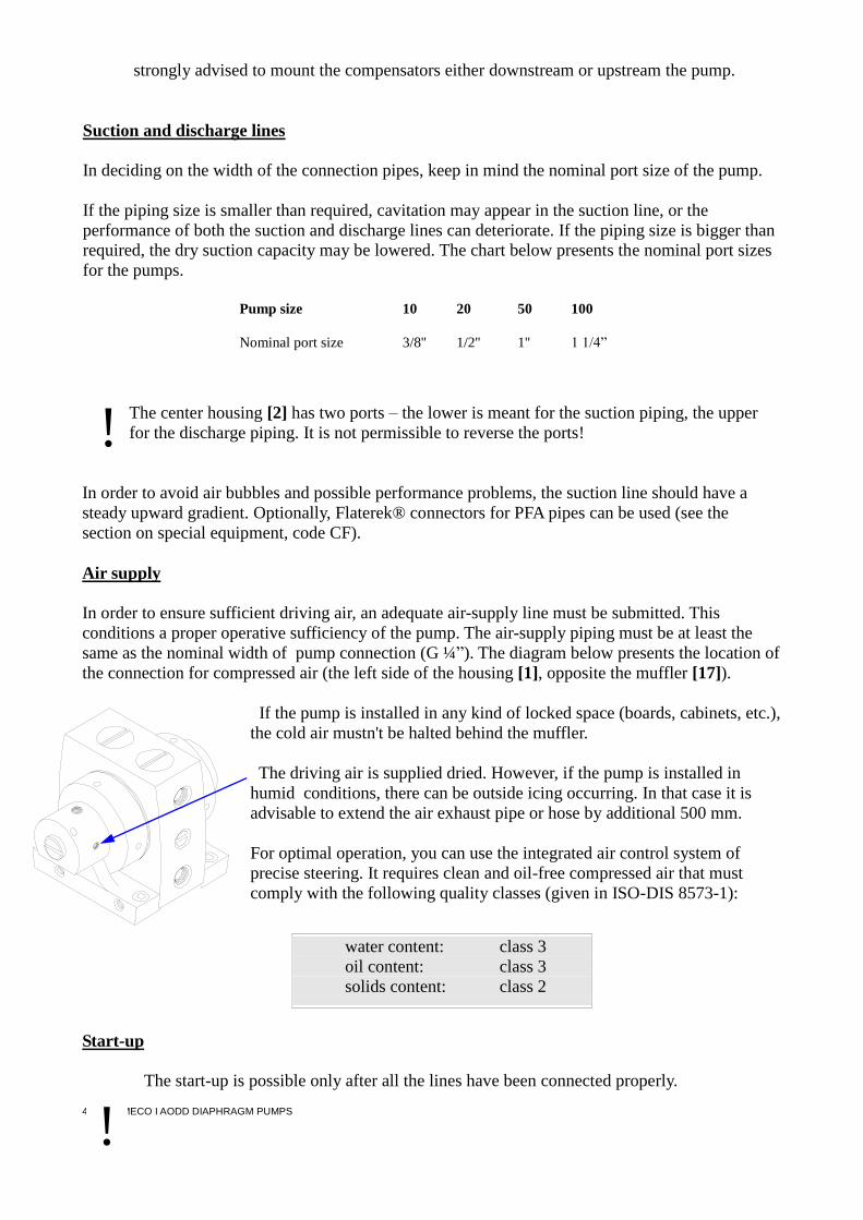
Air supply
In order to ensure sufficient driving air, an adequate air-supply line must be submitted. This
conditions a proper operative sufficiency of the pump. The air-supply piping must be at least the
same as the nominal width of pump connection (G ¼”). The diagram below presents the location of
the connection for compressed air (the left side of the housing [1], opposite the muffler [17]).
If the pump is installed in any kind of locked space (boards, cabinets, etc.),
the cold air mustn't be halted behind the muffler.
The driving air is supplied dried. However, if the pump is installed in
humid conditions, there can be outside icing occurring. In that case it is
advisable to extend the air exhaust pipe or hose by additional 500 mm.
For optimal operation, you can use the integrated air control system of
precise steering. It requires clean and oil-free compressed air that must
comply with the following quality classes (given in ISO-DIS 8573-1):
Start-up
The start-up is possible only after all the lines have been connected properly.
!
water content: class 3
oil content: class 3
solids content: class 2
!

5 I DELLMECO I AODD DIAPHRAGM PUMPS
Limit the driving air pressure to the needed level. Too high pressure will cause excessive
air consumption and improper work of the pump.
The start-up of the pump is initiated automatically when the air supply is turned on.
To keep a steady flow, do not let the pressure drop lower than 1.5 bar. The flow rate of the pump is
adjusted by a needle valve. Pre-filling the suction line or the pump itself is not required, as the
SEMI pumps operate on self-priming principle. Remember, though, that a filled pump has a
considerably higher capacity.
When empty, the pump must be driven slowly.
In case of air-operated double-diaphragm pumps with a centered flow, avoid dry running for
longer periods of time or at higher frequency. Otherwise damage may follow!
Avoid throttling or blocking the suction line. Damage may follow!
It is permissible to operate the pump for a short period of time with a closed discharge in order to
test the pressure. If prolonged special operation of this or similar kind is required, check it first with
the producer of the pump. It is not allowed, though, to carry out a pressure test of the installation in
which the pump is set unless the both ports of the pump are disconnected – the pressure from the
plant can be too high and is due to damage the pump! This kind of test can be done only when the
pressure used is the operating pressure of the pump.
Do not exceed the maximal permissible stroke frequencies during normal operation.
Otherwise damage may follow. (Study the table below for the values of strokes allowed at
nominal performance).
Pump size 10 20 50 100
Max number of strokes/ min. at nominal performance 400 320 210 240
If the diaphragm of the pump has been fractured in any way and the pump keeps operating, it is
possible that the pump medium will come through the muffler. In that case stop the pump and check
the diaphragm.
Pneumatic diaphragm pumps must never be allowed to work with a positive suction pressure.
It is against their construction principle and may lead to damage.
Rinsing procedure
In order to clean the pump before disassembly, rinse it with a neutral product. Next turn the pump
around to the top and rinse again. Then turn it to the side and rinse again. Finally turn back to the
top and rinse again. Repeat these steps several times.
Disassembly
To disassemble the pump, first disconnect both of the ports from the pressure, disconnect the
air supply, empty the pump of the medium and rinse it thoroughly.
!
!
!
!

6 I DELLMECO I AODD DIAPHRAGM PUMPS
If the medium used in the pump was toxic, hazardous or corrosive, the disassembly of the
pump must be carried out in accordance with adequate safety regulations.
The steps for disassembly of the pump are as follows:
1. Remove the head screws [26, 33] on both sides of the pump with a screwdriver, remove the base
frame [19], and take out air channel O-rings [25].
2. On the left side of the housing [1] remove the muffler [17] (in case of pump size 10 also the
adapter muffler [30]) and the plug [29].
3. Put a suitable round bar into one of the bore holes in the union nut [9] on the left side housing and
with its help unscrew and remove the union nut [9] from the housing [1]. Then take the sliding
ring [12] out of the left side housing [1], and take the union nut O-ring [10] out of the union nut
[9].
4. Unscrew the air valve cover [32] from the left side housing [1] and then put the housing down
flat on the side. The air control system [13] – except pilot piston – can be moved into the air
valve cover side.
5. Take the diaphragm bolt piston rings [16] and then the pilot piston of the air control system out of
the diaphragm bolt on the left [24].
6. Put a bar into one of the bore holes in the union nut [9] of the right side housing [6] and unscrew
the union nut [9], then set apart the right side housing [6] and the union nut [9].
7. Take the sliding ring [12] out of the right side housing [6] and the union nut O-ring [10] out of
the union nut [9].
8. Put the center housing [2] upright, with the connectors directed to the front. Take out the both
diaphragm outer O-rings [7]. Separate the right and left diaphragm bolts [21, 24] from
diaphragms [4]. Unscrew one of the diaphragms [4] out of the cascade sleeve [14] and then take
out the other diaphragm [4] together with the cascade sleeve [14] and unscrew them.
9. If needed, replace the diaphragm inner O-ring [23] with a new one to prevent twisting. The
diaphragm gaskets [8] must be replaced with no exception!
10. Put the center housing [2] upright unscrew both the discharge valve stops [27] at the top of the
housing [2]. Take the check valves [5] out. Then unscrew the both suction valve stops [22] (one is
situated at the front of the housing [2] between the connectors, the other one is at the back) and
take the check valves [5] out.
Assembly
After disassembly, no piston rings [16] or diaphragm gaskets [8] can be used again – new
rings and gaskets must be set in!
All damaged sealing parts must be replaced!
Remember that the newly changed diaphragm gaskets need some time to settle, therefore the
assembly must be completed at least 2 hours before a start-up. After the two-hour rest tighten the
both union nuts [9] - study the table below to check the nominal dimensions of the acceptable space
between the outer edge of the union nut and the center housing.
Pump size 10 20 50 100
mm (tolerance +0.3/ -0.5 mm) 28,8 31,3 35,5 41,3
When tightening the nuts, be careful to keep the described lock-pin of the side housing [1, 6], as
!

7 I DELLMECO I AODD DIAPHRAGM PUMPS
well as the parallel array to the center housing [2].
Moisten the O-rings before assembly to avoid their damaging!
Basically, assembly is carried out in reverse order to disassembly. The steps for assembly are as
follows:
1. Move the air control system cartridge [13] back from the air valve cover into the left side housing
[1].
2. Screw the valve stops [22, 27] into the center housing [2] – make sure they match the surface and
do not protrude above.
3. Put the center housing [2] on the left side and insert the diaphragm gasket [8]. Be careful not to
fracture the gasket. Screw the right diaphragm bolt [21] into the diaphragm [4] and then screw
the diaphragm [4] into the cascade sleeve [14]. Put the ready sleeve [14] into the center housing
[2]. Finally place the diaphragm outer O-ring [7] in the diaphragm recess.
4. Put the right side housing [6] making sure that the straight surface with the bore holes for air is in
a parallel position to lower part of the center housing [2], and then insert the sliding ring [12].
5. Insert the union nut O-ring [10] into the union nut [9]. Then put a bar into a bore hole of the right
side housing [6] to make any rotation impossible, and screw the union nut [9] with the center
housing [2].
6. Place the diaphragm gasket into the left side housing [1]. Be careful not to fracture the gasket.
Now use the air bore hole (in the middle) on the right side of the center housing [2] to treat the
first installed diaphragm [4] from point 3 with the compressed air. Maintain the air stream until
the other (left) diaphragm [4] is inserted into the center housing [2]. Screw the left diaphragm
bolt [24] into the diaphragm [4].
7. Place the air control system pilot piston [13] into the left diaphragm bolt [24].
8. Assemble the left side housing [1] following the same procedure steps as in the case of the right
side housing [6].
9. Place the fifth air valve housing O-ring before closing and screwing the air valve cover [32].
10. Screw in the muffler [17] and the plug [29].
Possible problems and their solutions
Problem Reason
The pump will not start. air supply line is blocked
muffler is blocked
assembly of diaphragms was defective
!

8 I DELLMECO I AODD DIAPHRAGM PUMPS
air control is faulty
The pump operates, but suction doesn't work. suction line is blocked
suction line leaks
suction needed for the medium is higher than
suction capacity of the pump
Air bubbles form in the pumped medium. diaphragm is fractured
The pump doesn't operate smoothly. diaphragm is fractured
air control needs replacement
The pump stops operating. air pressure dropped too low
air control is faulty
air control is iced
muffler is iced or blocked
discharge line is blocked
diaphragm is fractured
pressure in the system is higher than driving
pressure
Delivery falls down. air pressure dropped too low
air control is iced
muffler is blocked
suction line is blocked
discharge line is blocked
viscosity of medium is not steady

9 I DELLMECO I AODD DIAPHRAGM PUMPS
Technical details - independent of the pump model
Pump size 10 20 50 100
Dimensions [mm], length 184 207 255 315
width 114 154 207 269
height 133 172 215 267
Nominal port size (NPS) 3/8” 1/2” 1” 1 1/4”
Air connection (NPT) 1/4”
Air classification (ISO-DIS 8573-1)
solids class 2 class 2 class 2 class 2
water class 3 class 3 class 3 class 3
oil class 3 class 3 class 3 class 3
Weight [kg]
SEMI T 2,5 4,5 9 18
SEMI H 3,5 6 - -
SEMI E 2 3 6 12
SEMI S - 14 30 -
Suction head, dry [m.w.c.] 1 2,5 3,5 4
Suction head, with product [m.w.c] 8 9 9 9
Max. permissible pressure driving [bar] 6 6 6 6
Max. sound pressure level acc. to DIN 45635, part 24, at maximum load [dB]
72 72 72 72
Max. permissible temperature [ºC]
Pump model SEMI T SEMI H SEMI E SEMI S
at max. 6 bar 100 100 70 130
at max. 5 bar 110 130 70 130
at max. 4 bar 120 150 70 130
at max. 3 bar 130 180 70 130
at max. 2 bar 130 200 70 130
10 I DELLMECO I AODD DIAPHRAGM PUMPS
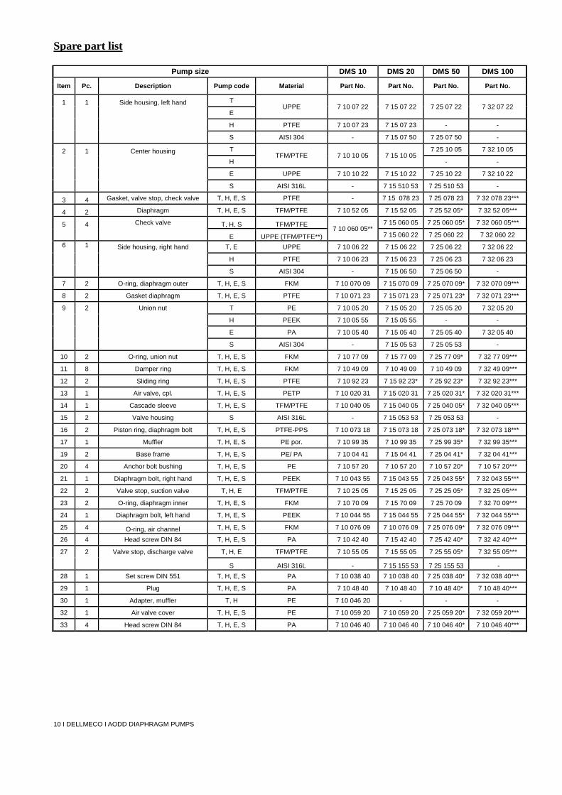
Spare part list
Pump size DMS 10 DMS 20 DMS 50 DMS 100
Item Pc. Description Pump code Material Part No. Part No. Part No. Part No.
1 1 Side housing, left hand T UPPE 7 10 07 22 7 15 07 22 7 25 07 22 7 32 07 22
E
H PTFE 7 10 07 23 7 15 07 23 - -
S AISI 304 - 7 15 07 50 7 25 07 50 -
2 1 Center housing T TFM/PTFE 7 10 10 05 7 15 10 05
7 25 10 05 7 32 10 05
H - -
E UPPE 7 10 10 22 7 15 10 22 7 25 10 22 7 32 10 22
S AISI 316L - 7 15 510 53 7 25 510 53 -
3 4 Gasket, valve stop, check valve T, H, E, S PTFE - 7 15 078 23 7 25 078 23 7 32 078 23***
4 2 Diaphragm T, H, E, S TFM/PTFE 7 10 52 05 7 15 52 05 7 25 52 05* 7 32 52 05***
5 4 Check valve T, H, S TFM/PTFE 7 10 060 05**
7 15 060 05 7 25 060 05* 7 32 060 05***
E UPPE (TFM/PTFE**) 7 15 060 22 7 25 060 22 7 32 060 22
6 1
Side housing, right hand T, E UPPE 7 10 06 22 7 15 06 22 7 25 06 22 7 32 06 22
H PTFE 7 10 06 23 7 15 06 23 7 25 06 23 7 32 06 23
S AISI 304 - 7 15 06 50 7 25 06 50 -
7 2 O-ring, diaphragm outer T, H, E, S FKM 7 10 070 09 7 15 070 09 7 25 070 09* 7 32 070 09***
8 2 Gasket diaphragm T, H, E, S PTFE 7 10 071 23 7 15 071 23 7 25 071 23* 7 32 071 23***
9 2 Union nut T PE 7 10 05 20 7 15 05 20 7 25 05 20 7 32 05 20
H PEEK 7 10 05 55 7 15 05 55 - -
E PA 7 10 05 40 7 15 05 40 7 25 05 40 7 32 05 40
S AISI 304 - 7 15 05 53 7 25 05 53 -
10 2 O-ring, union nut T, H, E, S FKM 7 10 77 09 7 15 77 09 7 25 77 09* 7 32 77 09***
11 8 Damper ring T, H, E, S FKM 7 10 49 09 7 10 49 09 7 10 49 09 7 32 49 09***
12 2 Sliding ring T, H, E, S PTFE 7 10 92 23 7 15 92 23* 7 25 92 23* 7 32 92 23***
13 1 Air valve, cpl. T, H, E, S PETP 7 10 020 31 7 15 020 31 7 25 020 31* 7 32 020 31***
14 1 Cascade sleeve T, H, E, S TFM/PTFE 7 10 040 05 7 15 040 05 7 25 040 05* 7 32 040 05***
15 2 Valve housing S AISI 316L - 7 15 053 53 7 25 053 53 -
16 2 Piston ring, diaphragm bolt T, H, E, S PTFE-PPS 7 10 073 18 7 15 073 18 7 25 073 18* 7 32 073 18***
17 1 Muffler T, H, E, S PE por. 7 10 99 35 7 10 99 35 7 25 99 35* 7 32 99 35***
19 2 Base frame T, H, E, S PE/ PA 7 10 04 41 7 15 04 41 7 25 04 41* 7 32 04 41***
20 4 Anchor bolt bushing T, H, E, S PE 7 10 57 20 7 10 57 20 7 10 57 20* 7 10 57 20***
21 1 Diaphragm bolt, right hand T, H, E, S PEEK 7 10 043 55 7 15 043 55 7 25 043 55* 7 32 043 55***
22 2 Valve stop, suction valve T, H, E TFM/PTFE 7 10 25 05 7 15 25 05 7 25 25 05* 7 32 25 05***
23 2 O-ring, diaphragm inner T, H, E, S FKM 7 10 70 09 7 15 70 09 7 25 70 09 7 32 70 09***
24 1 Diaphragm bolt, left hand T, H, E, S PEEK 7 10 044 55 7 15 044 55 7 25 044 55* 7 32 044 55***
25 4 O-ring, air channel T, H, E, S FKM 7 10 076 09 7 10 076 09 7 25 076 09* 7 32 076 09***
26 4 Head screw DIN 84 T, H, E, S PA 7 10 42 40 7 15 42 40 7 25 42 40* 7 32 42 40***
27 2 Valve stop, discharge valve T, H, E TFM/PTFE 7 10 55 05 7 15 55 05 7 25 55 05* 7 32 55 05***
S AISI 316L - 7 15 155 53 7 25 155 53 -
28 1 Set screw DIN 551 T, H, E, S PA 7 10 038 40 7 10 038 40 7 25 038 40* 7 32 038 40***
29 1 Plug T, H, E, S PA 7 10 48 40 7 10 48 40 7 10 48 40* 7 10 48 40***
30 1 Adapter, muffler T, H PE 7 10 046 20 - - -
32 1 Air valve cover T, H, E, S PE 7 10 059 20 7 10 059 20 7 25 059 20* 7 32 059 20***
33 4 Head screw DIN 84 T, H, E, S PA 7 10 046 40 7 10 046 40 7 10 046 40* 7 10 046 40***

11 I DELLMECO I AODD DIAPHRAGM PUMPS
Exploded view
7
5
1
2
4
3
4
5
6
7
8
8
9
9
10
10
11
11
11
11
11
11
11
11
12
12
13
13
14
15
16
16
17
19
19
20
20
20
20
21
22
22
23
23
24
25
25
25
25
26
26
26
26
27
27
28
29
30
32
33
33
33
33
3
2
On
ly f
or D
MS
20
S
an
d D
MS
50
S
11
34
35

12 I DELLMECO I AODD DIAPHRAGM PUMPS
Additional equipment
Pneumatic stroke counting system (code SC5, SC6)
The strokes of the pump will be automatically counted after introducing the codes SC5 and SC6.
The pressure change in the air chamber behind one of the diaphragms will be noted by the pressure
switch. To function well, the counting system must be fed with the pressure of at least 1.5 bar.
The two types of the counting system are:
SC5 - pressure switch 1 - 10 bar, cpl. assembled with socket with
cable 5 m; adapter straight NPT ¼”; hose DN 4/6, 2.5 m
SC6 - as SC5 and a stroke counter.
The steps for assembling the pneumatic stroke counting are as follows:
1. Take the plug [29] out of the extra air connection in the left side housing [1]
and screw in the adapter straight (the location of the plug is presented in the
picture).
2. Put a hose linking the adapter straight with the pressure switch.
3. The socket must be now connected to the electrical connection plug of the
pressure switch.
4. The cable is to be connected to an already existing registering device (in case
of SC5) or the enclosed stroke counter (in case of SC6).
For details, refer to the technical data and installment schemes supplied by the producer of the
counter.
Diaphragm sensor (code DM1, DM3, DM4)
The role of the diaphragm sensor is to detect a diaphragm fracture. It is installed in the muffler and
is designed to be able to operate for any liquid. There are three types of diaphragm sensors:
DM1: 2-wire-Namur, intrinsically safe EEx ia IIC T6
DM3: 3-wire
DM4: 3-wire with plug (only for pumps sizes 10, 20, 50)
A false alert may sometimes occur due to humid surroundings.
For details, refer to the technical data supplied by the producer of the sensor.
Flaretek© - connectors for PFA pipe (code CF)
Flaretek©-connectors can be used with the SEMI T and SEMI H pumps in their suction and
discharge ports.
Flaretek© - connectors are installed by the producer. No one else is authorized to remove or
replace them. The violation of this point will jeopardize the purity and proper work of the
pump, and will invalidate the warranty!
!
!

13 I DELLMECO I AODD DIAPHRAGM PUMPS
Spare part list for additional equipment
Pump size SEMI
10 SEMI
20 SEMI
50 SEMI 100
Code It. Pc. Description Pump
code Material Part no. Part no. Part no. Part no.
SC
5
- 1 Adaptor straight T, H, E, S PP 1 08 192 28 1 08 192 28 1 08 192 28 1 08 192 28
- 1 Hose T, H, E, S PE 1 08 292 20 1 08 292 20 1 08 292 20 1 08 292 20
- 1 Pressure transmitter T, H, E, S diverse 9 08 28 00 9 08 28 00 9 08 28 00 9 08 28 00
- 1 Socket with cable T, H, E, S diverse 1 08 392 00 1 08 392 00 1 08 392 00 1 08 392 00
SC
6
As SC5 but additionally
contains:
- 1 Stroke counter T, H, E, S diverse 9 15 17 00 9 15 17 00 9 15 17 00 9 15 17 00
DM1 - 1 Diaphragm sensor,
2-wire Namur T, H, E, S diverse 9 15 19 00 9 15 19 00 9 15 19 00 9 15 19 00
DM3 - 1 Diaphragm sensor,
3-wire T, H, E, S PTFE 9 15 019 00 9 15 019 00 9 15 019 00 9 15 019 00
DM4 - 1 Diaphragm sensor,
3-wire with plug T, H, E, S PTFE 9 15 119 00 9 15 119 00 9 15 119 00
CF
35 2 Flaretek® Connector for PFA-
pipe T PFA/PVDF 7 10 95 44 7 20 95 44 7 50 90 44 7 100 90 44
35 2 Flaretek®-connector for PFA
pipe H PFA/PFA 7 10 95 43 7 20 95 43 7 50 95 43 7 100 95 43
34 2 O-ring, Flaretek®-connector T, H FEP/FKM 7 10 095 04 7 20 095 04 7 50 095 04 7 100 095 04
SEMI pumps summary
Model: SEMI T
Materials: center housing TFM/PTFE; side housings UPPE/PA
Pump sizes: 10, 20, 50, 100100
Products: acids and caustics
Model: SEMI H
Materials: center housing TFM/PTFE; side housings PTFE
Pump sizes: 10, 20
Products: hot applications with acids and caustics
Model: SEMI E
Materials: center housing UPPE; side housings UPPE/PA
Pump sizes: 10, 20, 50, 10000
Products: slurries
Model: SEMI S
Materials: center housing SS 316 L; side housings SS 316 L
Pump sizes: 20, 50
Products: solvents

14 I DELLMECO I AODD DIAPHRAGM PUMPS
OPERATION MANUAL – PULSATION DAMPER FOR SEMI PUMPS
TYPES D 10T/ 20T/ 50T
D 10H/ 20H
The manual must be studied carefully before installing a damper.
DELLMECO is a distinguished, certified enterprise, aiming at modernity and best quality of our
products.
The SEMI pumps are specially designed to reduce a pulsating flow, typical of replacement pumps.
However, if the remaining pulsation does not achieve a satisfactory level, we offer a range of
dampers. Type D is suitable for all sizes and configurations of the SEMI pumps.
Every single damper undergoes a strict control process and is delivered in a separate packaging to
maintain the highest purity standards.
Remember that depending on the phase of process a pulsation damper can reduce the over-
whole capacity of the system!
Make sure that the construction materials of a damper are resistant to the medium to be
pumped!
Installing procedure
The special design of a pulsation damper allows to install it at any time in order reduce the
unsatisfactory pulsation on the discharge side, with no interference into product connections.
The steps for installation are as follows:
1. Remove the discharge stop valve at the front of the pump.
2. Set the pump upright on its feet and see if the check valve of the pump is in a correct position.
3. See if the damper housing O-ring [37] is in a correct position in the groove.
4. Gently screw the damper to the pump. Be careful not to tighten too much – otherwise a damage
of the thread may follow!
Do not install any valves or stops between the pump and the air supply of the damper!
Both the pump and the damper must be fed with the same pressure!
Never operate the pump and the damper with a positive suction pressure!
The damper must have its own separate air connection in order to function well. The air connection
of the damper is situated on the top of the head [38] and it should start at the air connection of the
pump. The minimal counter pressure demanded for a proper work of the damper is 1 bar. For the
requirements concerning the air quality, refer to the table in Technical Details section.
An empty damper must be run slowly together with the pump. The dampers are self-regulating –
when the working conditions change, they adapt automatically.
!
!
!

15 I DELLMECO I AODD DIAPHRAGM PUMPS
Disassembly
To disassemble the damper, first disconnect both the pump and the damper from the air
supply, empty them of the medium and rinse thoroughly.
If the medium used in the pump was toxic, hazardous or corrosive, the disassembly of the
damper must be carried out in accordance with adequate safety regulations.
The steps for disassembly are as follows:
1. Unscrew the damper from the pump. Be careful with the damper housing O-ring [37]!
2. Unscrew the damper housing [36] from the damper head [38].
3. Gently take the diaphragm outer O-ring [46].
4. Take out the diaphragm [44] together with an actuator shaft [48]
5. Take the diaphragm gasket [47] out.
6. See if the diaphragm inner O-ring [45] is intact. If necessary, replace it to prevent twisting.
7. Take the piston rings [40] and their O-rings [41].
8. Take the damper head O-ring [39] out.
Assembly
After disassembly, no piston rings [40] or gaskets [47] can be used again – new rings must be
set in!
All damaged or dirty sealing parts must be replaced!
Remember that the newly changed damper diaphragm gasket [47] needs some time to settle,
therefore the assembly must be completed at least 2 hours before screwing the damper back to the
pump. After the two-hour rest tighten the housing parts [36]. The damper is now ready to be
installed back onto the pump.
Basically, assembly is carried out in reverse order to disassembly. There are however a few points to
follow when assembling the new piston rings [40]:
1. Bend the new piston ring [40] into a kidney shape. Put it into the groove.
2. Press the protruding part into the groove with the help of a round tool.
3. Place the diaphragm outer O-ring [46] in the right groove of the diaphragm [44].
4. Put the diaphragm [44] back in its place.
!
!
!

16 I DELLMECO I AODD DIAPHRAGM PUMPS
Technical details
Damper code D 10/20/50/100 T D 10/20 H D 10/20/50/100 T
for SEMI T for SEMI H for SEMI E
Size 10 20 50 100 10 20 10 20 50 100
Dimensions* [mm], length 184 207 255 305 184 207 184 207 255 305
width 136 163 224 265 136 163 136 163 224 265
height 245 287 346 430 245 287 245 287 346 430
Air connection (NPT) 1/4” 1/4” 1/4”
Air classification (ISO-DIS 8573-1)
solids class 2 class 2 class 2
water class 3 class 3 class 3
oil class 3 class 3 class 3
Weight* [kg] 3,5 6 11 24 4 7 3 5 9 18
Max. permissible driving pressure [bar] 6 6 6
Max. permissible temperature [ºC]:
at max. 6 bar pressure 100 100 70
at max. 6 bar pressure 110 130 70
at max. 6 bar pressure 120 150 70
at max. 6 bar pressure 130 180 70
at max. 6 bar pressure 130 200 70
* dimensions and weights are given for the pump with pulsation damper
Spare parts list
Damper size D 10 T /
H D 20 T /
H D 50 T D 100 T
Item Pc. Description Damper code Material Part No. Part No. Part No. Part No.
36 1 Damper housing T, H TFM/PTFE 8 10 701 05 8 20 701 05 8 50 701 05 8 100 701 05
37 1 O-ring, damper housing T, H EPDM 8 10 79 08 8 20 79 08 8 50 79 08 8 100 79 08
38 1 Damper head T UPPE 8 10 103 22 8 20 103 22 8 50 103 22 8 100 103 22
Damper head H PTFE 8 10 103 23 8 20 103 23
39 1 O-ring, damper head T, H FKM 8 10 179 09 8 20 179 09 8 50 179 09 8 100 179 09
40 3 Piston ring T, H PTFE-PPS 8 10 090 18 8 20 090 18 8 50 090 18 8 100 090 18
41 3 O-ring, piston ring T, H FKM 8 10 082 09 8 20 082 09 8 50 082 09 8 100 082 89
42 1 Muffler T, H PE 8 10 099 20 8 20 099 20 8 50 099 20 8 100 099 20
43 1 Supporting disc T, H PA 8 10 53 40 8 20 53 40 8 50 53 40 8 100 53 40
44 1 Damper diaphragm T, H PTFE 8 10 052 23 8 20 052 23 8 50 052 23 8 100 053 23
45 1 O-ring, diaphragm inner T, H FKM 8 10 169 09 8 20 169 09 8 50 169 09 8 100 169 09
46 1 O- ring, diaphragm outer T, H FKM 8 10 170 09 8 20 170 09 8 50 179 09 8 100 179 09
47 1 Diaphragm gasket T, H PTFE 8 10 171 23 8 20 171 23 8 50 171 23 8 100 171 23
48 1 Actuator shaft. T, H PEEK 8 10 140 55 8 20 140 55 8 50 140 55 8 100 140 55
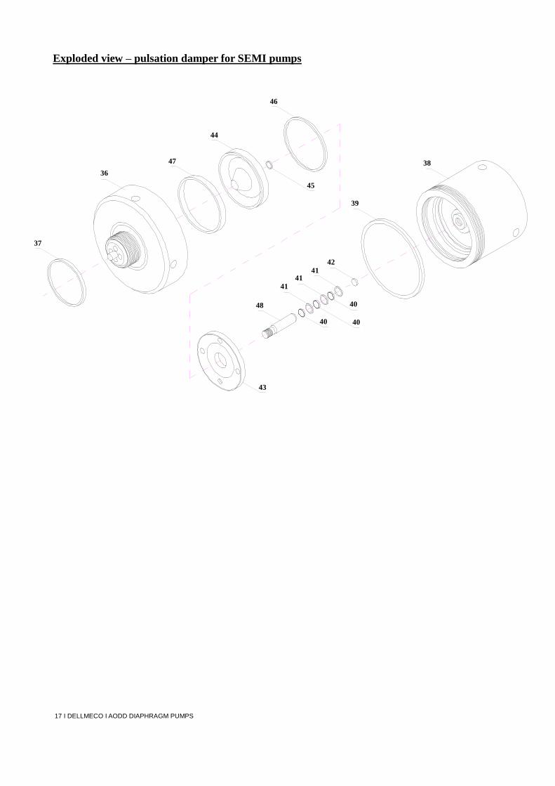
17 I DELLMECO I AODD DIAPHRAGM PUMPS
Exploded view – pulsation damper for SEMI pumps
36
37
38
39
40
40 40
41
41 41
42
43
44
45
46
47
48

18 I DELLMECO I AODD DIAPHRAGM PUMPS
SEMI pump with Pulsation damper – main dimensions
X
3/8
"
1/2
"
1"
1 1
/4”
W
1/4
" N
PT
1/4
" N
PT
1/4
" N
PT
1/4
” N
PT
V
3/8
" N
PT
1/2
" N
PT
1"
NP
T
11
/4”
NP
T
U
246,0
283,0
348,0
429,0
T
110,0
110,0
140,0
200,0
S
33,0
44,0
55,0
74,0
R
136,0
161,0
215,0
286,0
Q
155,0
196,0
251,0
313,0
O
104,0
140,0
178,0
223,0
N
35,0
33,0
34,0
39,0
M
79,0
115,0
165,0
225,0
L
72,0
88,0
111,0
136,0
K
131,0
168,0
216,0
266,0
I
57,0
75,0
100,0
130,0
H
114,0
150,0
200,0
260,0
G
143,0
160,0
194,0
236,0
F
93,0
105,0
125,0
149,0
E
10,5
10,5
10,5
10,5
D
35,5
35,5
41,5
51,0
C
73,0
82,0
98,0
119,0
B
112,0
119,0
148,0
184,0
A
185,0
201,0
246,0
303,0
mm
SE
MI 1
0
SE
MI 2
0
SE
MI 5
0
SE
MI 1
00

19 I DELLMECO I AODD DIAPHRAGM PUMPS
Notes:

20 I DELLMECO I AODD DIAPHRAGM PUMPS
DELLMECO LTD
Unit 1, Willow Row Longton Stoke on Trent Staffordshire ST3 2 PU United Kingdom tel. +44 1782 793 029
fax: +44 1782 501 721
[email protected] www.dellmeco.com