LPG trucks Original instructions - STILL Luxembourg
432
LPG trucks RX70-20/600 RX70-25 RX70-25/600 RX70-30 RX70-30/600 RX70-35 Original instructions 7400 7401 7402 7403 7404 7405 57378011501 EN - 10/2020 - 04
-
Upload
khangminh22 -
Category
Documents
-
view
1 -
download
0
Transcript of LPG trucks Original instructions - STILL Luxembourg

LPG trucks
RX70-20/600RX70-25RX70-25/600RX70-30RX70-30/600RX70-35
Original instructions
7400 7401 7402 7403 7404 7405
57378011501 EN - 10/2020 - 04


Address of manufacturer andcontact details
STILL GmbHBerzeliusstraße 1022113 Hamburg, GermanyTel. +49 (0) 40 7339-0Fax: +49 (0) 40 7339-1622Email: [email protected]: http://www.still.de
Rules for the operating com-pany of industrial trucksIn addition to these operating instructions, acode of practice containing additional informa-tion for the operating companies of industrialtrucks is also available.
This guide provides information for handlingindustrial trucks: Information on how to select suitable indus-
trial trucks for a particular area of applica-tion
Prerequisites for the safe operation of in-dustrial trucks
Information on the use of industrial trucks Information on transport, initial commission-
ing and storage of industrial trucks
Internet address and QR codeThe information can be accessed at any timeby pasting the address https://m.still.de/vdmain a web browser or by scanning the QR code.
Z
Z
Preface
I57368011501 EN - 10/2020 - 04


1 Foreword Your truck . . . . . . . . . . . . . . . . . . . . . . . . . . . . . . . . . . . . . . . . . . . . . . . . . . . . . . . . . . 2Description of the truck . . . . . . . . . . . . . . . . . . . . . . . . . . . . . . . . . . . . . . . . . . . . . . . . . . 2General . . . . . . . . . . . . . . . . . . . . . . . . . . . . . . . . . . . . . . . . . . . . . . . . . . . . . . . . . . . . . . 4CE labelling . . . . . . . . . . . . . . . . . . . . . . . . . . . . . . . . . . . . . . . . . . . . . . . . . . . . . . . . . . . 5EC declaration of conformity in accordance with Machinery Directive . . . . . . . . . . . . . . 6Accessories . . . . . . . . . . . . . . . . . . . . . . . . . . . . . . . . . . . . . . . . . . . . . . . . . . . . . . . . . . . 6Overview . . . . . . . . . . . . . . . . . . . . . . . . . . . . . . . . . . . . . . . . . . . . . . . . . . . . . . . . . . . . . 8Nameplate . . . . . . . . . . . . . . . . . . . . . . . . . . . . . . . . . . . . . . . . . . . . . . . . . . . . . . . . . . . . 11Production number . . . . . . . . . . . . . . . . . . . . . . . . . . . . . . . . . . . . . . . . . . . . . . . . . . . . . 12StVZO (Road Traffic Licensing Regulations) information . . . . . . . . . . . . . . . . . . . . . . . . 12
Using the truck. . . . . . . . . . . . . . . . . . . . . . . . . . . . . . . . . . . . . . . . . . . . . . . . . . . . . . . 13Proper usage . . . . . . . . . . . . . . . . . . . . . . . . . . . . . . . . . . . . . . . . . . . . . . . . . . . . . . . . . . 13Proper use during towing. . . . . . . . . . . . . . . . . . . . . . . . . . . . . . . . . . . . . . . . . . . . . . . . . 13Impermissible use . . . . . . . . . . . . . . . . . . . . . . . . . . . . . . . . . . . . . . . . . . . . . . . . . . . . . . 13Place of use. . . . . . . . . . . . . . . . . . . . . . . . . . . . . . . . . . . . . . . . . . . . . . . . . . . . . . . . . . . 14Using working platforms . . . . . . . . . . . . . . . . . . . . . . . . . . . . . . . . . . . . . . . . . . . . . . . . . 15
Information about the documentation . . . . . . . . . . . . . . . . . . . . . . . . . . . . . . . . . . . . . 16Scope of the documentation . . . . . . . . . . . . . . . . . . . . . . . . . . . . . . . . . . . . . . . . . . . . . . 16Supplementary documentation . . . . . . . . . . . . . . . . . . . . . . . . . . . . . . . . . . . . . . . . . . . . 17Issue date and topicality of the operating instructions. . . . . . . . . . . . . . . . . . . . . . . . . . . 18Copyright and trademark rights . . . . . . . . . . . . . . . . . . . . . . . . . . . . . . . . . . . . . . . . . . . . 18Explanation of information symbols used . . . . . . . . . . . . . . . . . . . . . . . . . . . . . . . . . . . . 18Definition of directions . . . . . . . . . . . . . . . . . . . . . . . . . . . . . . . . . . . . . . . . . . . . . . . . . . 19Schematic views . . . . . . . . . . . . . . . . . . . . . . . . . . . . . . . . . . . . . . . . . . . . . . . . . . . . . . . 19List of abbreviations. . . . . . . . . . . . . . . . . . . . . . . . . . . . . . . . . . . . . . . . . . . . . . . . . . . . . 20
Environmental considerations . . . . . . . . . . . . . . . . . . . . . . . . . . . . . . . . . . . . . . . . . . . 22Packaging . . . . . . . . . . . . . . . . . . . . . . . . . . . . . . . . . . . . . . . . . . . . . . . . . . . . . . . . . . . . 22Disposal of components and batteries . . . . . . . . . . . . . . . . . . . . . . . . . . . . . . . . . . . . . . 22
2 Safety Definition of responsible persons. . . . . . . . . . . . . . . . . . . . . . . . . . . . . . . . . . . . . . . . . 24Operating company . . . . . . . . . . . . . . . . . . . . . . . . . . . . . . . . . . . . . . . . . . . . . . . . . . . . . 24Specialist . . . . . . . . . . . . . . . . . . . . . . . . . . . . . . . . . . . . . . . . . . . . . . . . . . . . . . . . . . . . . 24Drivers . . . . . . . . . . . . . . . . . . . . . . . . . . . . . . . . . . . . . . . . . . . . . . . . . . . . . . . . . . . . . . . 25
Basic principles for safe operation. . . . . . . . . . . . . . . . . . . . . . . . . . . . . . . . . . . . . . . . 27Insurance cover on company premises. . . . . . . . . . . . . . . . . . . . . . . . . . . . . . . . . . . . . . 27Modifications and retrofitting . . . . . . . . . . . . . . . . . . . . . . . . . . . . . . . . . . . . . . . . . . . . . . 27Changes to the overhead guard and roof loads . . . . . . . . . . . . . . . . . . . . . . . . . . . . . . . 28Warning about any manipulation of the internal combustion engine . . . . . . . . . . . . . . . . 29
Table of contents
III57368011501 EN - 10/2020 - 04

Warning regarding non-original parts . . . . . . . . . . . . . . . . . . . . . . . . . . . . . . . . . . . . . . . 29Damage, defects and misuse of safety systems . . . . . . . . . . . . . . . . . . . . . . . . . . . . . . . 30Tyres . . . . . . . . . . . . . . . . . . . . . . . . . . . . . . . . . . . . . . . . . . . . . . . . . . . . . . . . . . . . . . . . 30Medical equipment . . . . . . . . . . . . . . . . . . . . . . . . . . . . . . . . . . . . . . . . . . . . . . . . . . . . . 31Exercise caution when handling gas springs and accumulators . . . . . . . . . . . . . . . . . . . 32Length of the fork arms . . . . . . . . . . . . . . . . . . . . . . . . . . . . . . . . . . . . . . . . . . . . . . . . . . 32
Residual risk . . . . . . . . . . . . . . . . . . . . . . . . . . . . . . . . . . . . . . . . . . . . . . . . . . . . . . . . 34Residual dangers, residual risks . . . . . . . . . . . . . . . . . . . . . . . . . . . . . . . . . . . . . . . . . . . 34Special risks associated with using the truck and attachments. . . . . . . . . . . . . . . . . . . . 35Overview of hazards and countermeasures . . . . . . . . . . . . . . . . . . . . . . . . . . . . . . . . . . 38Danger to employees . . . . . . . . . . . . . . . . . . . . . . . . . . . . . . . . . . . . . . . . . . . . . . . . . . . 40
Safety tests . . . . . . . . . . . . . . . . . . . . . . . . . . . . . . . . . . . . . . . . . . . . . . . . . . . . . . . . . 42Regular safety inspection of the truck . . . . . . . . . . . . . . . . . . . . . . . . . . . . . . . . . . . . . . . 42Carrying out regular safety inspections on the LPG system . . . . . . . . . . . . . . . . . . . . . . 42Regularly checking the level of harmful substances in the exhaust gas . . . . . . . . . . . . . 43Insulation testing . . . . . . . . . . . . . . . . . . . . . . . . . . . . . . . . . . . . . . . . . . . . . . . . . . . . . . . 44
Safety regulations for handling consumables . . . . . . . . . . . . . . . . . . . . . . . . . . . . . . . 45Permissible consumables . . . . . . . . . . . . . . . . . . . . . . . . . . . . . . . . . . . . . . . . . . . . . . . . 45Oils . . . . . . . . . . . . . . . . . . . . . . . . . . . . . . . . . . . . . . . . . . . . . . . . . . . . . . . . . . . . . . . . . 46Hydraulic fluid . . . . . . . . . . . . . . . . . . . . . . . . . . . . . . . . . . . . . . . . . . . . . . . . . . . . . . . . . 47Battery acid . . . . . . . . . . . . . . . . . . . . . . . . . . . . . . . . . . . . . . . . . . . . . . . . . . . . . . . . . . . 48LPG . . . . . . . . . . . . . . . . . . . . . . . . . . . . . . . . . . . . . . . . . . . . . . . . . . . . . . . . . . . . . . . . . 49Coolant and cooling fluid . . . . . . . . . . . . . . . . . . . . . . . . . . . . . . . . . . . . . . . . . . . . . . . . . 52Brake fluid . . . . . . . . . . . . . . . . . . . . . . . . . . . . . . . . . . . . . . . . . . . . . . . . . . . . . . . . . . . . 52Disposal of consumables. . . . . . . . . . . . . . . . . . . . . . . . . . . . . . . . . . . . . . . . . . . . . . . . . 54
Emissions . . . . . . . . . . . . . . . . . . . . . . . . . . . . . . . . . . . . . . . . . . . . . . . . . . . . . . . . . . 55
3 Overviews Overview . . . . . . . . . . . . . . . . . . . . . . . . . . . . . . . . . . . . . . . . . . . . . . . . . . . . . . . . . . . 60
Driver's compartment. . . . . . . . . . . . . . . . . . . . . . . . . . . . . . . . . . . . . . . . . . . . . . . . . . 61
Shelves and cup holders . . . . . . . . . . . . . . . . . . . . . . . . . . . . . . . . . . . . . . . . . . . . . . . 62
Operating devices and display elements . . . . . . . . . . . . . . . . . . . . . . . . . . . . . . . . . . . 63Display/control unit "STILL Easy Control" . . . . . . . . . . . . . . . . . . . . . . . . . . . . . . . . . . . . 63Operating devices for hydraulic and driving functions . . . . . . . . . . . . . . . . . . . . . . . . . . . 64Double mini-lever. . . . . . . . . . . . . . . . . . . . . . . . . . . . . . . . . . . . . . . . . . . . . . . . . . . . . . . 65Triple mini-lever . . . . . . . . . . . . . . . . . . . . . . . . . . . . . . . . . . . . . . . . . . . . . . . . . . . . . . . . 65Quadruple mini-lever . . . . . . . . . . . . . . . . . . . . . . . . . . . . . . . . . . . . . . . . . . . . . . . . . . . . 69Joystick 4Plus . . . . . . . . . . . . . . . . . . . . . . . . . . . . . . . . . . . . . . . . . . . . . . . . . . . . . . . . . 71
Table of contents
IV 57368011501 EN - 10/2020 - 04

Fingertip. . . . . . . . . . . . . . . . . . . . . . . . . . . . . . . . . . . . . . . . . . . . . . . . . . . . . . . . . . . . . . 72Travel direction selector and indicator module (variant) . . . . . . . . . . . . . . . . . . . . . . . . . 73
4 Operation Checks and tasks before daily use . . . . . . . . . . . . . . . . . . . . . . . . . . . . . . . . . . . . . . . 76Visual inspections and function checking . . . . . . . . . . . . . . . . . . . . . . . . . . . . . . . . . . . . 76Climbing in and out of the truck . . . . . . . . . . . . . . . . . . . . . . . . . . . . . . . . . . . . . . . . . . . . 79Operating the signal horn . . . . . . . . . . . . . . . . . . . . . . . . . . . . . . . . . . . . . . . . . . . . . . . . 81Driver's cab . . . . . . . . . . . . . . . . . . . . . . . . . . . . . . . . . . . . . . . . . . . . . . . . . . . . . . . . . . . 82Checking the condition of the wheels and tyres . . . . . . . . . . . . . . . . . . . . . . . . . . . . . . . 82Checking the brake system for correct function . . . . . . . . . . . . . . . . . . . . . . . . . . . . . . . 83Checking the steering system for correct function. . . . . . . . . . . . . . . . . . . . . . . . . . . . . . 86Function checking of the automatic mast vertical positioning function (variant) . . . . . . . 87
Driver's seats . . . . . . . . . . . . . . . . . . . . . . . . . . . . . . . . . . . . . . . . . . . . . . . . . . . . . . . . 88Adjusting the MSG 65/MSG 75 driver's seat . . . . . . . . . . . . . . . . . . . . . . . . . . . . . . . . . . 88Adjusting the armrest. . . . . . . . . . . . . . . . . . . . . . . . . . . . . . . . . . . . . . . . . . . . . . . . . . . . 93Longitudinal horizontal suspension (variant) . . . . . . . . . . . . . . . . . . . . . . . . . . . . . . . . . . 94Seat belt . . . . . . . . . . . . . . . . . . . . . . . . . . . . . . . . . . . . . . . . . . . . . . . . . . . . . . . . . . . . . 95
Pre-Shift Check . . . . . . . . . . . . . . . . . . . . . . . . . . . . . . . . . . . . . . . . . . . . . . . . . . . . . . 98Description of the Pre-Shift Check (variant) . . . . . . . . . . . . . . . . . . . . . . . . . . . . . . . . . . 98Process . . . . . . . . . . . . . . . . . . . . . . . . . . . . . . . . . . . . . . . . . . . . . . . . . . . . . . . . . . . . . . 99All questions . . . . . . . . . . . . . . . . . . . . . . . . . . . . . . . . . . . . . . . . . . . . . . . . . . . . . . . . . . 100Defining the question sequence . . . . . . . . . . . . . . . . . . . . . . . . . . . . . . . . . . . . . . . . . . . 102Displaying the history . . . . . . . . . . . . . . . . . . . . . . . . . . . . . . . . . . . . . . . . . . . . . . . . . . . 103Defining the shift start . . . . . . . . . . . . . . . . . . . . . . . . . . . . . . . . . . . . . . . . . . . . . . . . . . . 105Resetting the truck restrictions . . . . . . . . . . . . . . . . . . . . . . . . . . . . . . . . . . . . . . . . . . . . 109
Driver profiles. . . . . . . . . . . . . . . . . . . . . . . . . . . . . . . . . . . . . . . . . . . . . . . . . . . . . . . . 112Driver profiles (variant) . . . . . . . . . . . . . . . . . . . . . . . . . . . . . . . . . . . . . . . . . . . . . . . . . . 112Selecting driver profiles . . . . . . . . . . . . . . . . . . . . . . . . . . . . . . . . . . . . . . . . . . . . . . . . . . 112Creating driver profiles . . . . . . . . . . . . . . . . . . . . . . . . . . . . . . . . . . . . . . . . . . . . . . . . . . 114Renaming driver profiles . . . . . . . . . . . . . . . . . . . . . . . . . . . . . . . . . . . . . . . . . . . . . . . . . 116Deleting driver profiles. . . . . . . . . . . . . . . . . . . . . . . . . . . . . . . . . . . . . . . . . . . . . . . . . . . 119
Switching on and starting. . . . . . . . . . . . . . . . . . . . . . . . . . . . . . . . . . . . . . . . . . . . . . . 121Engine preheating (variant) . . . . . . . . . . . . . . . . . . . . . . . . . . . . . . . . . . . . . . . . . . . . . . . 121Opening the LPG cylinder valve . . . . . . . . . . . . . . . . . . . . . . . . . . . . . . . . . . . . . . . . . . . 122Opening the LPG cylinder valve for a double-cylinder holder . . . . . . . . . . . . . . . . . . . . . 123Opening the shut-off valve of an LPG tank (variant) . . . . . . . . . . . . . . . . . . . . . . . . . . . . 125Switching on the key switch. . . . . . . . . . . . . . . . . . . . . . . . . . . . . . . . . . . . . . . . . . . . . . . 127Access authorisation with PIN code (variant) . . . . . . . . . . . . . . . . . . . . . . . . . . . . . . . . . 128
Table of contents
V57368011501 EN - 10/2020 - 04

Access authorisation for the fleet manager (variant) . . . . . . . . . . . . . . . . . . . . . . . . . . . . 130Starting the engine . . . . . . . . . . . . . . . . . . . . . . . . . . . . . . . . . . . . . . . . . . . . . . . . . . . . . 132
Lighting . . . . . . . . . . . . . . . . . . . . . . . . . . . . . . . . . . . . . . . . . . . . . . . . . . . . . . . . . . . . 135Meaning of the symbols. . . . . . . . . . . . . . . . . . . . . . . . . . . . . . . . . . . . . . . . . . . . . . . . . . 135Driving lights . . . . . . . . . . . . . . . . . . . . . . . . . . . . . . . . . . . . . . . . . . . . . . . . . . . . . . . . . . 136Working spotlights . . . . . . . . . . . . . . . . . . . . . . . . . . . . . . . . . . . . . . . . . . . . . . . . . . . . . . 136Working spotlight for reverse travel (variant). . . . . . . . . . . . . . . . . . . . . . . . . . . . . . . . . . 138Turn indicators. . . . . . . . . . . . . . . . . . . . . . . . . . . . . . . . . . . . . . . . . . . . . . . . . . . . . . . . . 138Hazard warning system. . . . . . . . . . . . . . . . . . . . . . . . . . . . . . . . . . . . . . . . . . . . . . . . . . 140StVZO equipment . . . . . . . . . . . . . . . . . . . . . . . . . . . . . . . . . . . . . . . . . . . . . . . . . . . . . . 141Rotating beacon . . . . . . . . . . . . . . . . . . . . . . . . . . . . . . . . . . . . . . . . . . . . . . . . . . . . . . . 142STILL SafetyLight (variant) . . . . . . . . . . . . . . . . . . . . . . . . . . . . . . . . . . . . . . . . . . . . . . . 142
Blue-Q efficiency mode . . . . . . . . . . . . . . . . . . . . . . . . . . . . . . . . . . . . . . . . . . . . . . . . 144Functional description . . . . . . . . . . . . . . . . . . . . . . . . . . . . . . . . . . . . . . . . . . . . . . . . . . . 144Switching Blue-Q on and off . . . . . . . . . . . . . . . . . . . . . . . . . . . . . . . . . . . . . . . . . . . . . . 145Switching off additional consumers . . . . . . . . . . . . . . . . . . . . . . . . . . . . . . . . . . . . . . . . . 146STILL Classic and sprint mode . . . . . . . . . . . . . . . . . . . . . . . . . . . . . . . . . . . . . . . . . . . . 147
Driving . . . . . . . . . . . . . . . . . . . . . . . . . . . . . . . . . . . . . . . . . . . . . . . . . . . . . . . . . . . . . 149Safety regulations when driving. . . . . . . . . . . . . . . . . . . . . . . . . . . . . . . . . . . . . . . . . . . . 149Roadways . . . . . . . . . . . . . . . . . . . . . . . . . . . . . . . . . . . . . . . . . . . . . . . . . . . . . . . . . . . . 151Selecting drive programmes 1 to 3 . . . . . . . . . . . . . . . . . . . . . . . . . . . . . . . . . . . . . . . . . 154Selecting drive programme A or B. . . . . . . . . . . . . . . . . . . . . . . . . . . . . . . . . . . . . . . . . . 155Configuring drive programmes A and B . . . . . . . . . . . . . . . . . . . . . . . . . . . . . . . . . . . . . 155Selecting the drive direction . . . . . . . . . . . . . . . . . . . . . . . . . . . . . . . . . . . . . . . . . . . . . . 157Actuating the drive direction switch with the mini-lever version. . . . . . . . . . . . . . . . . . . . 158Actuating the vertical rocker button for the "drive direction", Joystick 4Plus version. . . . 158Actuating the drive direction switch with the Fingertip version . . . . . . . . . . . . . . . . . . . . 158Actuating the drive direction switch, mini-console version . . . . . . . . . . . . . . . . . . . . . . . 159Starting drive mode . . . . . . . . . . . . . . . . . . . . . . . . . . . . . . . . . . . . . . . . . . . . . . . . . . . . . 159Starting drive mode, dual pedal version (variant) . . . . . . . . . . . . . . . . . . . . . . . . . . . . . . 162Operating the service brake . . . . . . . . . . . . . . . . . . . . . . . . . . . . . . . . . . . . . . . . . . . . . . 164Actuating the electric parking brake . . . . . . . . . . . . . . . . . . . . . . . . . . . . . . . . . . . . . . . . 165Malfunctions in the electric parking brake . . . . . . . . . . . . . . . . . . . . . . . . . . . . . . . . . . . . 169Steering . . . . . . . . . . . . . . . . . . . . . . . . . . . . . . . . . . . . . . . . . . . . . . . . . . . . . . . . . . . . . . 173Driving on ascending and descending gradients. . . . . . . . . . . . . . . . . . . . . . . . . . . . . . . 174Speed reduction when the fork carriage is raised (variant) . . . . . . . . . . . . . . . . . . . . . . . 175Engine automatic shut-off function (variant) . . . . . . . . . . . . . . . . . . . . . . . . . . . . . . . . . . 175Engine stalls because the evaporator has iced over . . . . . . . . . . . . . . . . . . . . . . . . . . . . 176Cruise control (variant) . . . . . . . . . . . . . . . . . . . . . . . . . . . . . . . . . . . . . . . . . . . . . . . . . . 179
Table of contents
VI 57368011501 EN - 10/2020 - 04

Parking. . . . . . . . . . . . . . . . . . . . . . . . . . . . . . . . . . . . . . . . . . . . . . . . . . . . . . . . . . . . . 183Parking the truck securely and switching it off. . . . . . . . . . . . . . . . . . . . . . . . . . . . . . . . . 183Wheel chock (variant) . . . . . . . . . . . . . . . . . . . . . . . . . . . . . . . . . . . . . . . . . . . . . . . . . . . 185
Lifting . . . . . . . . . . . . . . . . . . . . . . . . . . . . . . . . . . . . . . . . . . . . . . . . . . . . . . . . . . . . . . 186Lifting system variants . . . . . . . . . . . . . . . . . . . . . . . . . . . . . . . . . . . . . . . . . . . . . . . . . . . 186Automatic mast vertical positioning (variant) . . . . . . . . . . . . . . . . . . . . . . . . . . . . . . . . . . 186Types of lift mast . . . . . . . . . . . . . . . . . . . . . . . . . . . . . . . . . . . . . . . . . . . . . . . . . . . . . . . 188Malfunctions during lifting mode . . . . . . . . . . . . . . . . . . . . . . . . . . . . . . . . . . . . . . . . . . . 189Hydraulic blocking function . . . . . . . . . . . . . . . . . . . . . . . . . . . . . . . . . . . . . . . . . . . . . . . 190Lifting system operating devices . . . . . . . . . . . . . . . . . . . . . . . . . . . . . . . . . . . . . . . . . . . 191Controlling the lifting system using a double mini-lever. . . . . . . . . . . . . . . . . . . . . . . . . . 192Controlling the lifting system using a triple mini-lever . . . . . . . . . . . . . . . . . . . . . . . . . . . 194Controlling the lifting system using a quadruple mini-lever . . . . . . . . . . . . . . . . . . . . . . . 196Controlling the lifting system using the Joystick 4Plus . . . . . . . . . . . . . . . . . . . . . . . . . . 197Controlling the lifting system using the Fingertip . . . . . . . . . . . . . . . . . . . . . . . . . . . . . . . 196Fork wear protection (variant) . . . . . . . . . . . . . . . . . . . . . . . . . . . . . . . . . . . . . . . . . . . . . 201Changing the fork arms . . . . . . . . . . . . . . . . . . . . . . . . . . . . . . . . . . . . . . . . . . . . . . . . . . 201Fork extension (variant). . . . . . . . . . . . . . . . . . . . . . . . . . . . . . . . . . . . . . . . . . . . . . . . . . 204Operation with reversible fork arms (variant). . . . . . . . . . . . . . . . . . . . . . . . . . . . . . . . . . 206
Handling loads . . . . . . . . . . . . . . . . . . . . . . . . . . . . . . . . . . . . . . . . . . . . . . . . . . . . . . . 208Safety regulations when handing loads. . . . . . . . . . . . . . . . . . . . . . . . . . . . . . . . . . . . . . 208Before taking up load. . . . . . . . . . . . . . . . . . . . . . . . . . . . . . . . . . . . . . . . . . . . . . . . . . . . 209Load measurement (variant) . . . . . . . . . . . . . . . . . . . . . . . . . . . . . . . . . . . . . . . . . . . . . . 211Picking up loads . . . . . . . . . . . . . . . . . . . . . . . . . . . . . . . . . . . . . . . . . . . . . . . . . . . . . . . 212Danger area. . . . . . . . . . . . . . . . . . . . . . . . . . . . . . . . . . . . . . . . . . . . . . . . . . . . . . . . . . . 212Transporting pallets . . . . . . . . . . . . . . . . . . . . . . . . . . . . . . . . . . . . . . . . . . . . . . . . . . . . . 213Transporting suspended loads . . . . . . . . . . . . . . . . . . . . . . . . . . . . . . . . . . . . . . . . . . . . 214Picking up a load . . . . . . . . . . . . . . . . . . . . . . . . . . . . . . . . . . . . . . . . . . . . . . . . . . . . . . . 215Transporting loads. . . . . . . . . . . . . . . . . . . . . . . . . . . . . . . . . . . . . . . . . . . . . . . . . . . . . . 218Setting down loads . . . . . . . . . . . . . . . . . . . . . . . . . . . . . . . . . . . . . . . . . . . . . . . . . . . . . 219Shake function (variant). . . . . . . . . . . . . . . . . . . . . . . . . . . . . . . . . . . . . . . . . . . . . . . . . . 221Driving on lifts . . . . . . . . . . . . . . . . . . . . . . . . . . . . . . . . . . . . . . . . . . . . . . . . . . . . . . . . . 224Driving on loading bridges . . . . . . . . . . . . . . . . . . . . . . . . . . . . . . . . . . . . . . . . . . . . . . . . 225
Attachments. . . . . . . . . . . . . . . . . . . . . . . . . . . . . . . . . . . . . . . . . . . . . . . . . . . . . . . . . 227Fitting attachments . . . . . . . . . . . . . . . . . . . . . . . . . . . . . . . . . . . . . . . . . . . . . . . . . . . . . 227Depressurising the hydraulic system. . . . . . . . . . . . . . . . . . . . . . . . . . . . . . . . . . . . . . . . 229General instructions for controlling attachments . . . . . . . . . . . . . . . . . . . . . . . . . . . . . . . 232Attachment example for the connection of the auxiliary hydraulics. . . . . . . . . . . . . . . . . 233Adjusting the hydraulic speed for attachments . . . . . . . . . . . . . . . . . . . . . . . . . . . . . . . . 234Controlling attachments using a double mini-lever . . . . . . . . . . . . . . . . . . . . . . . . . . . . . 237Controlling attachments using the double mini-lever and the 5th function . . . . . . . . . . . 239
Table of contents
VII57368011501 EN - 10/2020 - 04

Controlling attachments using a triple mini-lever. . . . . . . . . . . . . . . . . . . . . . . . . . . . . . . 241Controlling attachments using the triple mini-lever and the 5th function . . . . . . . . . . . . . 243Controlling attachments using a quadruple mini-lever. . . . . . . . . . . . . . . . . . . . . . . . . . . 245Controlling attachments using the quadruple mini-lever and the 5th function . . . . . . . . . 247Controlling attachments using the Joystick 4Plus . . . . . . . . . . . . . . . . . . . . . . . . . . . . . . 249Controlling attachments with Joystick 4Plus and the 5th function . . . . . . . . . . . . . . . . . . 250Controlling attachments using the Fingertip . . . . . . . . . . . . . . . . . . . . . . . . . . . . . . . . . . 251Controlling attachments using the Fingertip and the 5th function . . . . . . . . . . . . . . . . . . 253Clamp locking mechanism (variant) . . . . . . . . . . . . . . . . . . . . . . . . . . . . . . . . . . . . . . . . 254Taking up a load using attachments . . . . . . . . . . . . . . . . . . . . . . . . . . . . . . . . . . . . . . . . 257
Auxiliary equipment . . . . . . . . . . . . . . . . . . . . . . . . . . . . . . . . . . . . . . . . . . . . . . . . . . . 259Actuating the windscreen wipers and windscreen washers (variant) . . . . . . . . . . . . . . . 259Filling the washer system . . . . . . . . . . . . . . . . . . . . . . . . . . . . . . . . . . . . . . . . . . . . . . . . 261FleetManager (variant) . . . . . . . . . . . . . . . . . . . . . . . . . . . . . . . . . . . . . . . . . . . . . . . . . . 261Shock recognition (variant) . . . . . . . . . . . . . . . . . . . . . . . . . . . . . . . . . . . . . . . . . . . . . . . 261Driver restraint systems (variants). . . . . . . . . . . . . . . . . . . . . . . . . . . . . . . . . . . . . . . . . . 262Ceiling sensor (variant) . . . . . . . . . . . . . . . . . . . . . . . . . . . . . . . . . . . . . . . . . . . . . . . . . . 262
Cab . . . . . . . . . . . . . . . . . . . . . . . . . . . . . . . . . . . . . . . . . . . . . . . . . . . . . . . . . . . . . . . 268Opening the cab door . . . . . . . . . . . . . . . . . . . . . . . . . . . . . . . . . . . . . . . . . . . . . . . . . . . 268Closing the cab door . . . . . . . . . . . . . . . . . . . . . . . . . . . . . . . . . . . . . . . . . . . . . . . . . . . . 269Opening the side windows. . . . . . . . . . . . . . . . . . . . . . . . . . . . . . . . . . . . . . . . . . . . . . . . 270Closing the side windows . . . . . . . . . . . . . . . . . . . . . . . . . . . . . . . . . . . . . . . . . . . . . . . . 270Turning the interior lighting on or off (variant) . . . . . . . . . . . . . . . . . . . . . . . . . . . . . . . . . 271Operating the rear window heating . . . . . . . . . . . . . . . . . . . . . . . . . . . . . . . . . . . . . . . . . 271Radio (variant) . . . . . . . . . . . . . . . . . . . . . . . . . . . . . . . . . . . . . . . . . . . . . . . . . . . . . . . . . 272Radio with Bluetooth interface (variant). . . . . . . . . . . . . . . . . . . . . . . . . . . . . . . . . . . . . . 273Heating system (variant) . . . . . . . . . . . . . . . . . . . . . . . . . . . . . . . . . . . . . . . . . . . . . . . . . 275Air conditioning (variant) . . . . . . . . . . . . . . . . . . . . . . . . . . . . . . . . . . . . . . . . . . . . . . . . . 275Clipboard (variant) . . . . . . . . . . . . . . . . . . . . . . . . . . . . . . . . . . . . . . . . . . . . . . . . . . . . . . 279Push-up roof window (variant). . . . . . . . . . . . . . . . . . . . . . . . . . . . . . . . . . . . . . . . . . . . . 28012 V socket . . . . . . . . . . . . . . . . . . . . . . . . . . . . . . . . . . . . . . . . . . . . . . . . . . . . . . . . . . . 280
Trailer operation. . . . . . . . . . . . . . . . . . . . . . . . . . . . . . . . . . . . . . . . . . . . . . . . . . . . . . 282Towed load . . . . . . . . . . . . . . . . . . . . . . . . . . . . . . . . . . . . . . . . . . . . . . . . . . . . . . . . . . . 282Coupling pin in the counterweight . . . . . . . . . . . . . . . . . . . . . . . . . . . . . . . . . . . . . . . . . . 283Automatic tow coupling . . . . . . . . . . . . . . . . . . . . . . . . . . . . . . . . . . . . . . . . . . . . . . . . . . 285Towing trailers . . . . . . . . . . . . . . . . . . . . . . . . . . . . . . . . . . . . . . . . . . . . . . . . . . . . . . . . . 293
Display messages . . . . . . . . . . . . . . . . . . . . . . . . . . . . . . . . . . . . . . . . . . . . . . . . . . . . 295Messages . . . . . . . . . . . . . . . . . . . . . . . . . . . . . . . . . . . . . . . . . . . . . . . . . . . . . . . . . . . . 295Messages about operation . . . . . . . . . . . . . . . . . . . . . . . . . . . . . . . . . . . . . . . . . . . . . . . 296Messages about the truck . . . . . . . . . . . . . . . . . . . . . . . . . . . . . . . . . . . . . . . . . . . . . . . 300
Table of contents
VIII 57368011501 EN - 10/2020 - 04

Refuelling. . . . . . . . . . . . . . . . . . . . . . . . . . . . . . . . . . . . . . . . . . . . . . . . . . . . . . . . . . . 302Changing the LPG cylinder . . . . . . . . . . . . . . . . . . . . . . . . . . . . . . . . . . . . . . . . . . . . . . . 302Changing the LPG cylinder in a double-cylinder holder . . . . . . . . . . . . . . . . . . . . . . . . . 305Filling the LPG tank (variant) . . . . . . . . . . . . . . . . . . . . . . . . . . . . . . . . . . . . . . . . . . . . . . 307
Cleaning. . . . . . . . . . . . . . . . . . . . . . . . . . . . . . . . . . . . . . . . . . . . . . . . . . . . . . . . . . . . 311Cleaning the truck . . . . . . . . . . . . . . . . . . . . . . . . . . . . . . . . . . . . . . . . . . . . . . . . . . . . . . 311Cleaning the electrical system. . . . . . . . . . . . . . . . . . . . . . . . . . . . . . . . . . . . . . . . . . . . . 313Cleaning load chains . . . . . . . . . . . . . . . . . . . . . . . . . . . . . . . . . . . . . . . . . . . . . . . . . . . . 313Cleaning the windows . . . . . . . . . . . . . . . . . . . . . . . . . . . . . . . . . . . . . . . . . . . . . . . . . . . 314After washing. . . . . . . . . . . . . . . . . . . . . . . . . . . . . . . . . . . . . . . . . . . . . . . . . . . . . . . . . . 314
Procedure in emergencies. . . . . . . . . . . . . . . . . . . . . . . . . . . . . . . . . . . . . . . . . . . . . . 315Procedure if truck tips over . . . . . . . . . . . . . . . . . . . . . . . . . . . . . . . . . . . . . . . . . . . . . . . 315Emergency hammer . . . . . . . . . . . . . . . . . . . . . . . . . . . . . . . . . . . . . . . . . . . . . . . . . . . . 315Emergency lowering . . . . . . . . . . . . . . . . . . . . . . . . . . . . . . . . . . . . . . . . . . . . . . . . . . . . 316Emergency operation of the electric parking brake . . . . . . . . . . . . . . . . . . . . . . . . . . . . . 318Disconnecting the battery . . . . . . . . . . . . . . . . . . . . . . . . . . . . . . . . . . . . . . . . . . . . . . . . 320Jump-starting. . . . . . . . . . . . . . . . . . . . . . . . . . . . . . . . . . . . . . . . . . . . . . . . . . . . . . . . . . 321Towing . . . . . . . . . . . . . . . . . . . . . . . . . . . . . . . . . . . . . . . . . . . . . . . . . . . . . . . . . . . . . . . 322
Transporting the truck . . . . . . . . . . . . . . . . . . . . . . . . . . . . . . . . . . . . . . . . . . . . . . . . . 325Transporting . . . . . . . . . . . . . . . . . . . . . . . . . . . . . . . . . . . . . . . . . . . . . . . . . . . . . . . . . . 325Crane loading . . . . . . . . . . . . . . . . . . . . . . . . . . . . . . . . . . . . . . . . . . . . . . . . . . . . . . . . . 327Short-term operation . . . . . . . . . . . . . . . . . . . . . . . . . . . . . . . . . . . . . . . . . . . . . . . . . . . . 331
Decommissioning . . . . . . . . . . . . . . . . . . . . . . . . . . . . . . . . . . . . . . . . . . . . . . . . . . . . 332Shutting down and storing the truck . . . . . . . . . . . . . . . . . . . . . . . . . . . . . . . . . . . . . . . . 332Returning to service after decommissioning . . . . . . . . . . . . . . . . . . . . . . . . . . . . . . . . . . 333
5 Maintenance Safety regulations for maintenance . . . . . . . . . . . . . . . . . . . . . . . . . . . . . . . . . . . . . . . 336General information . . . . . . . . . . . . . . . . . . . . . . . . . . . . . . . . . . . . . . . . . . . . . . . . . . . . . 336Working on the hydraulic equipment . . . . . . . . . . . . . . . . . . . . . . . . . . . . . . . . . . . . . . . . 336Working on the electrical equipment . . . . . . . . . . . . . . . . . . . . . . . . . . . . . . . . . . . . . . . . 335Working on the ignition system . . . . . . . . . . . . . . . . . . . . . . . . . . . . . . . . . . . . . . . . . . . . 337Working on the LPG system . . . . . . . . . . . . . . . . . . . . . . . . . . . . . . . . . . . . . . . . . . . . . . 338Safety devices . . . . . . . . . . . . . . . . . . . . . . . . . . . . . . . . . . . . . . . . . . . . . . . . . . . . . . . . . 339Set values . . . . . . . . . . . . . . . . . . . . . . . . . . . . . . . . . . . . . . . . . . . . . . . . . . . . . . . . . . . . 339Lifting and jacking up. . . . . . . . . . . . . . . . . . . . . . . . . . . . . . . . . . . . . . . . . . . . . . . . . . . . 339Working at the front of the truck . . . . . . . . . . . . . . . . . . . . . . . . . . . . . . . . . . . . . . . . . . . 339
General maintenance information . . . . . . . . . . . . . . . . . . . . . . . . . . . . . . . . . . . . . . . . 341Personnel qualifications. . . . . . . . . . . . . . . . . . . . . . . . . . . . . . . . . . . . . . . . . . . . . . . . . . 341Information for carrying out maintenance . . . . . . . . . . . . . . . . . . . . . . . . . . . . . . . . . . . . 341
Table of contents
IX57368011501 EN - 10/2020 - 04

Maintenance - 1000 hours/annually . . . . . . . . . . . . . . . . . . . . . . . . . . . . . . . . . . . . . . . . 343Maintenance - 3000 hours/every two years. . . . . . . . . . . . . . . . . . . . . . . . . . . . . . . . . . . 347Ordering spare parts and wearing parts . . . . . . . . . . . . . . . . . . . . . . . . . . . . . . . . . . . . . 347Quality and quantity of the required operating materials . . . . . . . . . . . . . . . . . . . . . . . . . 348Lubrication plan . . . . . . . . . . . . . . . . . . . . . . . . . . . . . . . . . . . . . . . . . . . . . . . . . . . . . . . . 349Maintenance data table . . . . . . . . . . . . . . . . . . . . . . . . . . . . . . . . . . . . . . . . . . . . . . . . . . 351
Providing access to maintenance points . . . . . . . . . . . . . . . . . . . . . . . . . . . . . . . . . . . 354Opening the bonnet . . . . . . . . . . . . . . . . . . . . . . . . . . . . . . . . . . . . . . . . . . . . . . . . . . . . . 354Closing the bonnet. . . . . . . . . . . . . . . . . . . . . . . . . . . . . . . . . . . . . . . . . . . . . . . . . . . . . . 356Removing and attaching the rear cover. . . . . . . . . . . . . . . . . . . . . . . . . . . . . . . . . . . . . . 358Installing and removing the bottom plate. . . . . . . . . . . . . . . . . . . . . . . . . . . . . . . . . . . . . 359
Maintenance after the first 50 operating hours . . . . . . . . . . . . . . . . . . . . . . . . . . . . . . 361Maintenance during the break-in period . . . . . . . . . . . . . . . . . . . . . . . . . . . . . . . . . . . . . 361
Preserving operational readiness . . . . . . . . . . . . . . . . . . . . . . . . . . . . . . . . . . . . . . . . 362Checking the engine oil level. . . . . . . . . . . . . . . . . . . . . . . . . . . . . . . . . . . . . . . . . . . . . . 362Cleaning the dust valve . . . . . . . . . . . . . . . . . . . . . . . . . . . . . . . . . . . . . . . . . . . . . . . . . . 363Filling the washer system . . . . . . . . . . . . . . . . . . . . . . . . . . . . . . . . . . . . . . . . . . . . . . . . 363Cleaning the radiator, checking for leaks . . . . . . . . . . . . . . . . . . . . . . . . . . . . . . . . . . . . 364Check the cooling fluid level . . . . . . . . . . . . . . . . . . . . . . . . . . . . . . . . . . . . . . . . . . . . . . 364Topping up the cooling fluid and checking the coolant concentration . . . . . . . . . . . . . . . 365Replacing the air filter cartridges . . . . . . . . . . . . . . . . . . . . . . . . . . . . . . . . . . . . . . . . . . . 367Lubricating the joints and controls . . . . . . . . . . . . . . . . . . . . . . . . . . . . . . . . . . . . . . . . . . 369Maintaining the seat belt . . . . . . . . . . . . . . . . . . . . . . . . . . . . . . . . . . . . . . . . . . . . . . . . . 370Checking the driver's seat . . . . . . . . . . . . . . . . . . . . . . . . . . . . . . . . . . . . . . . . . . . . . . . . 372Checking the door latch. . . . . . . . . . . . . . . . . . . . . . . . . . . . . . . . . . . . . . . . . . . . . . . . . . 372Maintaining wheels and tyres . . . . . . . . . . . . . . . . . . . . . . . . . . . . . . . . . . . . . . . . . . . . . 372Maintaining the battery . . . . . . . . . . . . . . . . . . . . . . . . . . . . . . . . . . . . . . . . . . . . . . . . . . 375Replacing fuses . . . . . . . . . . . . . . . . . . . . . . . . . . . . . . . . . . . . . . . . . . . . . . . . . . . . . . . . 378Checking the hydraulic system for leak tightness . . . . . . . . . . . . . . . . . . . . . . . . . . . . . . 378Lubricating the lift mast and roller track . . . . . . . . . . . . . . . . . . . . . . . . . . . . . . . . . . . . . 379Greasing the automatic tow coupling . . . . . . . . . . . . . . . . . . . . . . . . . . . . . . . . . . . . . . . 380Check the hydraulic oil level . . . . . . . . . . . . . . . . . . . . . . . . . . . . . . . . . . . . . . . . . . . . . . 382
1000-hour maintenance/yearly maintenance. . . . . . . . . . . . . . . . . . . . . . . . . . . . . . . . 385Other work that must be carried out . . . . . . . . . . . . . . . . . . . . . . . . . . . . . . . . . . . . . . . . 385Checking the exhaust gas system . . . . . . . . . . . . . . . . . . . . . . . . . . . . . . . . . . . . . . . . . 385Changing the LPG filter . . . . . . . . . . . . . . . . . . . . . . . . . . . . . . . . . . . . . . . . . . . . . . . . . . 385Checking the lift cylinders and connections for leaks . . . . . . . . . . . . . . . . . . . . . . . . . . . 387
Table of contents
X 57368011501 EN - 10/2020 - 04

Checking the fork arms . . . . . . . . . . . . . . . . . . . . . . . . . . . . . . . . . . . . . . . . . . . . . . . . . . 387Checking the reversible fork arms . . . . . . . . . . . . . . . . . . . . . . . . . . . . . . . . . . . . . . . . . . 388
10-year maintenance . . . . . . . . . . . . . . . . . . . . . . . . . . . . . . . . . . . . . . . . . . . . . . . . . . 389Checking the LPG tank (variant) . . . . . . . . . . . . . . . . . . . . . . . . . . . . . . . . . . . . . . . . . . . 389
6 Technical data Dimensions . . . . . . . . . . . . . . . . . . . . . . . . . . . . . . . . . . . . . . . . . . . . . . . . . . . . . . . . . 392
VDI datasheet for RX70-20/600 and RX70-25 . . . . . . . . . . . . . . . . . . . . . . . . . . . . . . 394
VDI datasheet for RX70-25/600 and RX70-30 . . . . . . . . . . . . . . . . . . . . . . . . . . . . . . 398
VDI datasheet for RX70-30/600 and RX70-35 . . . . . . . . . . . . . . . . . . . . . . . . . . . . . . 402
Ergonomic dimensions . . . . . . . . . . . . . . . . . . . . . . . . . . . . . . . . . . . . . . . . . . . . . . . . 406
Fuse assignment . . . . . . . . . . . . . . . . . . . . . . . . . . . . . . . . . . . . . . . . . . . . . . . . . . . . . 407
Table of contents
XI57368011501 EN - 10/2020 - 04


1
Foreword

Your truckDescription of the truckGeneralThe trucks in the RX70-20/25/30/35 serieswith a load capacity of up to 3.5 t are equip-ped with an internal combustion engine/elec-tric drive. This drive combines the advantagesof the internal combustion engine with the pre-cise control of an electric drive. The maximumspeed is 21 km/h (without load).
The bend-resistant and warp-resistant lift mastenables safe load handling, even with heavyloads. The comfortable driver's compartmentfeatures the most up-to-date ergonomic de-sign to prevent signs of fatigue and increasesafety.
The truck supports all of the functions of Fleet-Manager 4.0.
Brake system
The brake system of the truck is comprised ofthree different brakes: Service brake Regenerative brake Parking brake
The service brake is based on a wear-free, oil-immersed multi-disc brake. This multi-discbrake is used as the service brake for heavybraking or emergency braking with the brakepedal. In the normal working mode, the regen-erative brake of the electric traction motortakes effect. The regenerative brake convertsthe acceleration energy of the truck into elec-trical energy. This causes the truck to deceler-ate as soon as the accelerator pedal is re-leased. Completely removing your foot fromthe accelerator pedal causes the truck tobrake until it comes to a standstill. A parkingbrake ensures that the truck remains securelyin place when parked.
SteeringThe truck is equipped with a swing axle andhas kickback-free, hydraulic rear-wheel steer-ing. Stability is guaranteed when cornering
Foreword1Your truck
2 57368011501 EN - 10/2020 - 04

thanks to speed limitation based on the steer-ing angle. Simple handling of the truck is as-sisted by the manoeuvrable steering axle.
Hydraulic systemAll lift cylinders are hydraulically actuated. Theoil volume flow required for the steering andthe lift mast is provided by a gear pump con-nected to the internal combustion engine. Thedirectional control valve block with electricalproportional technology enables extremelysensitive movements and safe handling of theload. The hydraulic functions can be parame-terised individually by the authorised servicecentre.
Up to three hydraulic circuits can be used toactivate attachments (variant). Depending onthe equipment, the lifting circuit may have ahydraulic accumulator for load-damping pur-poses. This will help to reduce knocks to theload in the lift line due to uneven ground, forexample.
Drive conceptThe internal combustion engine drives anelectric three-phase generator. The generatedcurrent is routed to two maintenance-free,electrical 11.7-kW three-phase AC tractionmotors, which drive the truck using the twofront wheels. Electronic revolution control gen-tly provides high torque for both forwards andbackwards travel.
The components for the drive unit and the liftdrive are enclosed in order to prevent the in-gress of dust or moisture. This means that thetruck is suitable for indoor and outdoor use. Inaddition, all drives for traction, steering andlifting are maintenance-free.
The driving characteristics and lifting behav-iour can be adapted to the application or driv-ing habits. Five drive programmes are availa-ble for this purpose. The maximum drivingspeed is 21 km/h. The Blue-Q energy-savingmode reduces energy consumption by up to10% without impairing performance.
Foreword 1Your truck
357368011501 EN - 10/2020 - 04

Operating devicesThe truck is characterised by its accessibleoperating concept. When purchasing thetruck, a variety of operating devices andequipment variants are available: Double mini-lever Triple mini-lever Quadruple mini-lever Joystick 4Plus Fingertip Single pedal Dual pedal
Hands are always kept free for steering andfor controlling the operational movements toallow efficient working. The forces that need tobe applied for this purpose are reduced to aminimum thanks to the compact steeringwheel.
Operational information, such as the fuel levelor an indication that the Blue-Q energy-savingmode is enabled, is shown on theSTILL Easy Control display-operating unit.
For drive mode, the truck features either sin-gle-pedal or dual-pedal operation. The accel-erator pedal is used to accelerate and brake(electric brake) the truck. In emergency situa-tions or when carrying heavy loads, the drivercan also brake the truck using the servicebrake by pressing the brake pedal. In dual-pedal operation, the truck has one pedal forthe "Forwards" drive direction and one pedalfor the "Reverse" drive direction. The acceler-ation and braking behaviour can be selectedindividually using five different driving pro-grammes.
GeneralThe truck described in these operating instruc-tions corresponds to the applicable standardsand safety regulations.
If the truck is to be operated on public roads, itmust conform to the existing national regula-tions for the country in which it is being used.The driving permit must be obtained from theappropriate office.
Foreword1Your truck
4 57368011501 EN - 10/2020 - 04

The truck has been fitted with state-of-the-arttechnology. Following these operating instruc-tions will allow the truck to be handled safely.By complying with the specifications in theseoperating instructions, the functionality and theapproved features of the truck will be retained.
Get to know the technology, understand it anduse it safely - these operating instructions pro-vide the necessary information and help toavoid accidents and to keep the truck readyfor operation beyond the warranty period.
Therefore:
– Before commissioning the truck, read theoperating instructions and follow the instruc-tions.
– Always follow all of the safety informationcontained in the operating instructions andon the truck.
CE labellingThe manufacturer uses CE labelling to indi-cate that the truck complies with the standardsand regulations valid at the time of marketing.This is confirmed by the issued EC declarationof conformity. The CE labelling is attached tothe nameplate.
An independent structural change or additionto the truck can compromise safety, thus inva-lidating the EC declaration of conformity.
The EC declaration of conformity must becarefully stored and made available to the re-sponsible authorities.
CE-Symbol
Z
Foreword 1Your truck
557368011501 EN - 10/2020 - 04

EC declaration of conformity in accordance with Machinery Directive
Declaration
STILL GmbHBerzeliusstraße 10D-22113 Hamburg Germany We declare that the Industrial truck according to these operating instructionsModel according to these operating instructions conforms to the latest version of the Machinery Directive 2006/42/EC. Personnel authorised to compile the technical documents: See EC compliance declaration STILL GmbH
Accessories Key for key switch (two pieces) Key for cab (variant) Hexagon socket wrench for emergency low-
ering
Foreword1Your truck
6 57368011501 EN - 10/2020 - 04

Foreword 1Your truck
757368011501 EN - 10/2020 - 04

OverviewLabelling points on the left of the truck
6
7
1
4
5
DANGER
DANGER
64
DANGER
DANGER
310 bar
2
2
2
3
7
9 10
8
9
WAL
10 11
11
78
98
1
Decal information: Check head clearanceDecal information: Tyre filling pressure
12
Decal information: Emergency operation ofthe parking brake
3
Foreword1Your truck
8 57368011501 EN - 10/2020 - 04

Manufacturer's label textWarning sign: Danger due to shearing/Danger due to high fluid pressureDecal information: NameplateDecal information: StVZO (German RoadTraffic Licensing Regulations) information(variant)
56
78
Decal information: Sound power levelDecal information: Load capacity: Attach-mentDecal information: Load capacity: Basic ta-ble
910
11
Foreword 1Your truck
957368011501 EN - 10/2020 - 04

Labelling points on the right of the truck
5
3
17
10 bar
4
DANGER
DANGER
6
DANGER
20xx
10
11 98
1
2
34
6
7
8
5
1110
9
Foreword1Your truck
10 57368011501 EN - 10/2020 - 04

Decal information: Fixing point for lifting gearManufacturer's label textDecal information: Caution/Read the operat-ing instructions/Fasten seat belt/Apply park-ing brake when leaving the truck/Passen-gers are not allowed/Do not jump off if thetruck is tipping over/Lean in the opposite di-rection to which the truck is tippingWarning sign: Danger due to shearing/Danger due to high fluid pressure
123
4
Decal information: Caution/Read the operat-ing instructions/Fasten seat beltDecal information: Tyre filling pressureDecal information: Lifting gear fixing pointDecal information: Hydraulic oil tankDecal information: Regular testingInspection stickerDecal information: Battery service
5
67891011
NameplateThe truck can be identified from the informa-tion on the nameplate.
The information for the battery weights (5, 6)and the ballast weight (7) only applies to elec-tric forklift trucks.
Type-Modèle-Typ / Serial no.-No. de série-Serien-Nr. / year-année-Baujahr
Rated capacityCapacité nominaleNenn-Tragfähigkeit
Battery voltageTension batterieBatteriespannung
Rated drive powerPuissance motr.nom.Nenn-Antriebsleist.
Unladen massMasse à videLeergewicht
maxmin.*
* see Operating instructions voir Mode d'emploi siehe Betriebsanleitung
kg kg
kgkg
kgkW
V
*
D-22113 HamburgBerzeliusstr. 10
1 2 3
44
56
7
910
111213
6210_921-003_V3
8
TypeProduction numberYear of manufactureTare weight in kgMax. permissible battery weight in kgMin. permissible battery weight in kgBallast weight in kgAddress of manufacturerRefer to the technical data listed in theseoperating instructions for more detailed in-formationCE labellingNominal drive power in kWBattery voltage in VRated capacity in kg
123456789
10111213
Z
Foreword 1Your truck
1157368011501 EN - 10/2020 - 04

Production number
NOTE
The production number is used to identify thetruck. It can be found on the nameplate andmust be referred to in all technical questions.
The production number contains the followingcoded information:
(1) Production location
(2) Model
(3) Year of manufacture
(4) Sequential number
StVZO (Road Traffic Licensing Reg-ulations) informationThis label includes information on the weightand load distribution of the truck.
7090_921-004
xx xxxx x xxxxx
1
2
3
4
Z
7094_003-098
1 2
3 45
Tare weight (in kg)Permitted total weight (in kg)Permitted front axle weight (in kg)Permitted rear axle weight (in kg)Payload (in kg)
12345
Z
Foreword1Your truck
12 57368011501 EN - 10/2020 - 04
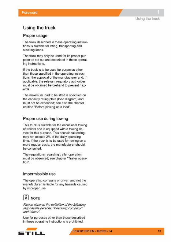
Using the truckProper usageThe truck described in these operating instruc-tions is suitable for lifting, transporting andstacking loads.
The truck may only be used for its proper pur-pose as set out and described in these operat-ing instructions.
If the truck is to be used for purposes otherthan those specified in the operating instruc-tions, the approval of the manufacturer and, ifapplicable, the relevant regulatory authoritiesmust be obtained beforehand to prevent haz-ards.
The maximum load to be lifted is specified onthe capacity rating plate (load diagram) andmust not be exceeded; see also the chapterentitled "Before picking up a load".
Proper use during towingThis truck is suitable for the occasional towingof trailers and is equipped with a towing de-vice for this purpose. This occasional towingmay not exceed 2% of the daily operatingtime. If the truck is to be used for towing on amore regular basis, the manufacturer shouldbe consulted.
The regulations regarding trailer operationmust be observed; see chapter "Trailer opera-tion".
Impermissible useThe operating company or driver, and not themanufacturer, is liable for any hazards causedby improper use.
NOTE
Please observe the definition of the followingresponsible persons: "operating company"and "driver".
Use for purposes other than those describedin these operating instructions is prohibited.
Foreword 1Using the truck
1357368011501 EN - 10/2020 - 04

DANGER
There is a risk of fatal injury from fallingoff the truck while it is moving!– It is prohibited to carry passengers on
the truck.
The truck may not be operated in areas wherethere is a risk of fire, explosion or corrosion, orin areas that are particularly dusty.
Stacking or unstacking is not permissible oninclined surfaces or ramps.
Place of useThe truck can be used outside and, with thecorrect equipment, in buildings.
Operation on public roads is only permittedwith the "StVZO" (Road Traffic Licensing Reg-ulations) equipment variant.
If the truck is to be operated on public roads, itmust conform to the existing national regula-tions for the country in which it is being used.
The ground must have an adequate load ca-pacity (concrete, asphalt) and a rough surface.Routes, working areas and aisle widths mustconform to the specifications in these operat-ing instructions; see chapter entitled "Routes".
Driving on upward and downward gradients ispermitted provided the specified data andspecifications are observed; see chapter enti-tled "Routes".
The truck is suitable for use in countries rang-ing from the Tropics to Nordic regions (tem-perature range: -12 °C to +40 °C).
This truck is not designed to be operated incold stores.
The operating company must ensure that suit-able fire protection is available for the relevantapplication in the truck's surroundings. De-pending on the application, additional fire pro-tection must be provided on the truck. If indoubt, contact the relevant authorities.
Foreword1Using the truck
14 57368011501 EN - 10/2020 - 04
NOTE
Please observe the definition of the followingresponsible person: "operating company".
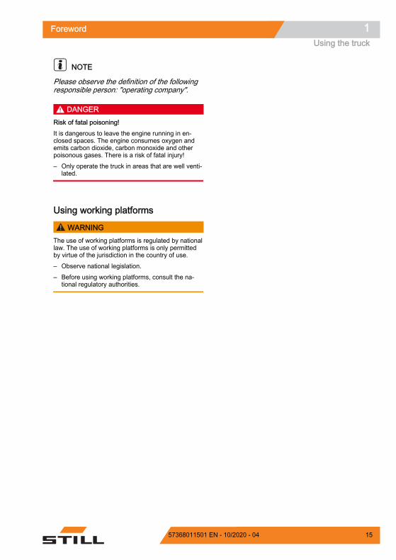
DANGERRisk of fatal poisoning!It is dangerous to leave the engine running in en-closed spaces. The engine consumes oxygen andemits carbon dioxide, carbon monoxide and otherpoisonous gases. There is a risk of fatal injury!– Only operate the truck in areas that are well venti-
lated.
Using working platforms
WARNINGThe use of working platforms is regulated by nationallaw. The use of working platforms is only permittedby virtue of the jurisdiction in the country of use.– Observe national legislation.– Before using working platforms, consult the na-
tional regulatory authorities.
Foreword 1Using the truck
1557368011501 EN - 10/2020 - 04
Information about the documentationScope of the documentation Original operating instructions of the truck Original operating instructions of the dis-
play-operating unit Operating instructions of the installed var-
iants that are not mentioned in the afore-mentioned original operating instructions
"UPA"Operating instructions or inserts (de-pending on the truck equipment)
Spare parts list
NOTE
Refer to the additional information in the sec-tion entitled "Rules for the operating companyof industrial trucks".
These operating instructions describe allmeasures necessary for the safe operationand proper maintenance of the truck in all pos-sible variants available at the time of printing.Special versions to meet customer require-ments (UPA) are documented in separate op-erating instructions.
– If you have any questions, contact your au-thorised service centre.
Enter the production number and year of man-ufacture from the nameplate in the space pro-vided:Production number: Year of manufacture:
– Please quote the production number in alltechnical enquiries.
Each truck comes with a set of operating in-structions. These instructions must be storedcarefully and must be available to the driverand operating company at all times. The stor-age location is specified in the chapter entitled"Driver's compartment".
If the operating instructions are lost, the oper-ating company must obtain a replacementfrom the manufacturer immediately.
Foreword1Information about the documentation
16 57368011501 EN - 10/2020 - 04
The operating instructions are included in thespare parts list and can be reordered as aspare part.
The personnel responsible for operating andmaintaining the equipment must be familiarwith these operating instructions.
The operating company must ensure that allusers have received, read and understoodthese operating instructions.
Safely store the complete documentation andpass on to the subsequent operating companywhen transferring or selling the truck.
NOTE
Please note the definition of the following re-sponsible persons: "operating company" and"driver".
Thank you for reading and complying withthese operating instructions. If you have anyquestions or suggestions for improvements, orif you have found any errors, please contactthe authorised service centre.
Supplementary documentationThis industrial truck can be fitted with unplan-ned equipment (UPA) that deviates from thestandard equipment and/or the variants.
The UPA may be, for example: Special sensors Special attachments Towing devices Customised attachments
In this case, the industrial truck has additionaldocumentation. This may be in the form of aninsert or separate operating instructions.
The original operating instructions for this in-dustrial truck are valid for the operation ofstandard equipment and variants without re-striction. The operational and safety informa-tion in the original operating instructions con-tinues to be valid in its entirety unless it iscountermanded in this additional documenta-tion.
Foreword 1Information about the documentation
1757368011501 EN - 10/2020 - 04

The requirements for the qualification of per-sonnel as well as the time for maintenancemay vary. This is defined in the additional doc-umentation.
– If you have any questions, please contactyour authorised service centre.
Issue date and topicality of the op-erating instructionsThe issue date and the version of these oper-ating instructions can be found on the titlepage.
STILL is constantly engaged in the further de-velopment of trucks. These operating instruc-tions are subject to change, and any claimsbased on the information and/or illustrationscontained in them cannot be asserted.
Please contact your authorised service centrefor technical support relating to your truck.
Copyright and trademark rightsThese instructions must not be reproduced,translated or made accessible to third parties—including as excerpts—except with the ex-press written approval of the manufacturer.
Explanation of information symbolsused
DANGERIndicates procedures that must be strictly adheredto in order to prevent the risk of fatalities.
WARNINGIndicates procedures that must be strictly adhered toin order to prevent the risk of injuries.
CAUTIONIndicates procedures that must be strictly adhered toin order to prevent material damage and/or destruc-tion.
Foreword1Information about the documentation
18 57368011501 EN - 10/2020 - 04

NOTE
For technical requirements that require specialattention.
ENVIRONMENT NOTE
To prevent environmental damage.
Definition of directionsThe directions "forwards" (1), "backwards" (3),"right" (2) and "left" (4) refer to the installationposition of the parts as seen from the driver'scompartment; the load is to the front.
Schematic viewsView of functions and operating proce-duresAt many points in this documentation, the(mostly sequential) operation of certain func-tions or operating procedures is explained.Schematic diagrams of a counterbalance truckare used to illustrate these procedures.
NOTE
These schematic views are not representativeof the construction of the documented truck.The views are used solely for the purpose ofclarifying procedures.
6210_001-031
4 2
3
1Z
6210_003-062
Z
Foreword 1Information about the documentation
1957368011501 EN - 10/2020 - 04

View of the display-operating unit
NOTE
Views of operating statuses and values in thedisplay of the display and operating unit areexamples and partly dependent on the truckequipment. As a result, the displays shown ofthe actual operating statuses and values mayvary.
List of abbreviationsThis list of abbreviations applies to all types ofoperating instructions. Not all of the abbrevia-tions that are listed here will necessarily ap-pear in these operating instructions.
Abbrevi-ation Meaning Explanation
ArbSchG Arbeitsschutzgesetz German implementation of EU occupation-al health and safety directives
Betr-SichV Betriebssicherheitsverordnung German implementation of the EU working
equipment directive
BG Berufsgenossenschaft German insurance company for the com-pany and employees
BGG Berufsgenossenschaftlicher Grundsatz German principles and test specificationsfor occupational health and safety
BGR Berufsgenossenschaftliche Regel German rules and recommendations foroccupational health and safety
DGUV Berufsgenossenschaftliche Vorschrift German accident prevention regulations
CE Communauté Européenne Confirms conformity with product-specificEuropean directives (CE labelling)
CEE Commission on the Rules for the Approvalof the Electrical Equipment
International commission on the rules forthe approval of electrical equipment
DC Direct Current Direct currentDFÜ Datenfernübertragung Remote data transferDIN Deutsches Institut für Normung German standardisation organisationEG European Community EN European standard
FEM Fédération Européene de la Manutention European Federation of Materials Han-dling and Storage Equipment
Fmax maximum Force Maximum power
12,6 h 10:35
6219_003-021_V3
Z
Foreword1Information about the documentation
20 57368011501 EN - 10/2020 - 04

Abbrevi-ation Meaning Explanation
GAA Gewerbeaufsichtsamt
German authority for monitoring/issuingregulations for worker protection, environ-mental protection, and consumer protec-tion
GPRS General Packet Radio Service Transfer of data packets in wireless net-works
ID no. Identification number
ISO International Organization for Standardi-zation International standardisation organisation
KpAUncertainty of measurement of soundpressure levels
LAN Local Area Network Local area networkLED Light Emitting Diode Light emitting diode
Lp Sound pressure level at the workplace
LpAZAverage continuous sound pressure levelin the driver's compartment
LSP Load centre of gravity Distance of the centre of gravity of theload from the front face of the fork backs
MAK Maximum workplace concentration Maximum permissible air concentrationsof a substance at the workplace
Max. Maximum Highest value of an amountMin. Minimum Lowest value of an amountPIN Personal Identification Number Personal identification numberPPE Personal protective equipment SE Super-Elastic Superelastic tyres (solid rubber tyres)
SIT Snap-In Tyre Tyres for simplified assembly, withoutloose rim parts
StVZO Straßenverkehrs-Zulassungs-Ordnung German regulations for approval of vehi-cles on public roads
TRGS Technische Regel für Gefahrstoffe Ordinance on hazardous materials appli-cable in the Federal Republic of Germany
VDE Verband der Elektrotechnik Elektronik In-formationstechnik e. V. German technical/scientific association
VDI Verein Deutscher Ingenieure German technical/scientific association
VDMA Verband Deutscher Maschinen- und Anla-genbau e. V.
German Mechanical Engineering IndustryAssociation
WLAN Wireless LAN Wireless local area network
Foreword 1Information about the documentation
2157368011501 EN - 10/2020 - 04

Environmental considerationsPackagingDuring delivery of the truck, certain parts arepackaged to provide protection during trans-port. This packaging must be removed com-pletely prior to initial start-up.
ENVIRONMENT NOTE
The packaging material must be disposed ofproperly after delivery of the truck.
Disposal of components and batter-iesThe truck is composed of different materials. Ifcomponents or batteries need to be replacedand disposed of, they must be: disposed of, treated or recycled in accordance with regional and
national regulations.
NOTE
The documentation provided by the batterymanufacturer must be observed when dispos-ing of batteries.
ENVIRONMENT NOTE
We recommend working with a waste man-agement company for disposal purposes.
Foreword1Environmental considerations
22 57368011501 EN - 10/2020 - 04

2
Safety

Definition of responsible personsOperating companyThe operating company is the natural or legalperson or group who operates the truck or onwhose authority the truck is used.
The operating company must ensure that thetruck is only used for its proper purpose and incompliance with the safety regulations set outin these operating instructions.
The operating company must ensure that allusers read and understand the safety informa-tion.
The operating company is responsible for thescheduling and correct performance of regularsafety checks.
We recommend that the national performancespecifications are adhered to.
SpecialistA qualified person is defined as a service en-gineer or a person who fulfils the following re-quirements: A completed vocational qualification that
demonstrably proves their professional ex-pertise. This proof should consist of a voca-tional qualification or a similar document.
Professional experience indicating that thequalified person has gained practical expe-rience of industrial trucks over a proven pe-riod during their career During this time, thisperson has become familiar with a widerange of symptoms that require checks tobe carried out, such as based on the resultsof a hazard assessment or a daily inspec-tion
Recent professional involvement in the fieldof the industrial truck test in question andan appropriate further qualification are es-sential. The qualified person must have ex-perience of carrying out the test in questionor of carrying out similar tests. Moreover,this person must be aware of the latesttechnological developments regarding theindustrial truck to be tested and the risk be-ing assessed
Safety2Definition of responsible persons
24 57368011501 EN - 10/2020 - 04

DriversThis truck may only be driven by suitable per-sons who are at least 18 years of age, havebeen trained in driving, have demonstratedtheir skills in driving and handling loads to theoperating company or an authorised represen-tative, and have been specifically instructed todrive the truck. Specific knowledge of the truckto be operated is also required.
The training requirements under §3 of theHealth and Safety at Work Act and §9 of theplant safety regulations are deemed to havebeen satisfied if the driver has been trained inaccordance with BGG (General Employers' Li-ability Insurance Association Act) 925. Ob-serve the national regulations for your country.
Driver rights, duties and rules of behav-iourThe driver must be trained in his rights andduties.
The driver must be granted the required rights.
The driver must wear protective equipment(protection suit, safety footwear, safety hel-met, industrial goggles and gloves) that is ap-propriate for the conditions, the job and theload to be lifted. Solid footwear should beworn to ensure safe driving and braking.
The driver must be familiar with the operatinginstructions and have access to them at alltimes.
The driver must: have read and understood the operating
manual have familiarised himself with safe opera-
tion of the truck be physically and mentally able to drive the
truck safely
DANGERThe use of drugs, alcohol or medications that affectreactions impair the ability to drive the truck!Individuals under the influence of the aforementionedsubstances are not permitted to perform work of anykind on or with the truck.
Safety 2Definition of responsible persons
2557368011501 EN - 10/2020 - 04

Prohibition of use by unauthorised per-sonsThe driver is responsible for the truck duringworking hours. He must not allow unauthor-ised persons to operate the truck.
When leaving the truck, the driver must secureit against unauthorised use, e.g. by pulling outthe key.
Safety2Definition of responsible persons
26 57368011501 EN - 10/2020 - 04

Basic principles for safe operationInsurance cover on company prem-isesIn many cases, company premises are restric-ted public traffic areas.
NOTE
The business liability insurance should be re-viewed to ensure that, in the event of anydamage caused in restricted public trafficareas, there is insurance cover for the truck inrespect of third parties.
Modifications and retrofittingIf the truck will be used for work that is not lis-ted in the directives or in these instructions,convert or retrofit the truck for this purpose asrequired. Any structural modification can im-pair the handling and stability of the truck, andcan result in accidents.
Any modifications that adversely affect thestability, the load capacity or the circumferen-tial view of the truck require written approvalfrom the manufacturer.
The following components may only be modi-fied with prior written approval from the manu-facturer: Brakes Steering Operating devices Safety systems Equipment variants Attachments
The truck may only be converted with writtenapproval from the manufacturer. If necessary,obtain approval from the relevant authorities.
– Only the authorised service centre is per-mitted to perform welding work on the truck.
We warn against installing and using restraintsystems that have not been approved by themanufacturer.
Safety 2Basic principles for safe operation
2757368011501 EN - 10/2020 - 04

– Contact the authorised service centre be-fore converting or retrofitting the truck.
The operating company is only permitted tomake modifications to the truck independentlyif the manufacturer goes into liquidation andthe company is not taken over by another le-gal person.
The operating company must also fulfil the fol-lowing prerequisites: Design documents, test documents and as-
sembly instructions associated with themodification must be permanently archivedand remain accessible at all times.
The capacity rating plate, the decal informa-tion, the hazard warnings and the operatinginstructions must be checked to ensure thatthey are consistent with the modificationsand must be amended if required.
Modifications must be designed, checkedand implemented by a design office thatspecialises in industrial trucks. The designoffice must comply with the standards anddirectives valid at the time that modifica-tions are made.
Decal information with the following data mustbe permanently affixed to the truck so that it isclearly visible: Type of modification Date of modification Name and address of the company that car-
ried out the modification
Changes to the overhead guard androof loads
DANGERIn the event of the overhead guard failing due to afalling load or the truck tipping over, there are po-tentially fatal consequences for the driver. There isa risk to life!Welding and drilling on the overhead guard changesthe material characteristics and the structural designof the overhead guard. Excessive forces caused byfalling loads or the truck tipping over may result inbuckling of the modified overhead guard and no pro-tection for the driver.– Do not perform welding on the overhead guard.– Do not perform drilling on the overhead guard.
Safety2Basic principles for safe operation
28 57368011501 EN - 10/2020 - 04

CAUTIONHeavy roof loads damage the overhead guard!To ensure the stability of the overhead guard at alltimes, a roof load may only be mounted on the over-head guard if the structural design has been testedand the manufacturer has given approval.– Seek advice from the authorised service centre for
the mounting of roof loads.
Warning about any manipulation ofthe internal combustion engineThe internal combustion engine used in thistruck possesses an EU type approval, which isrequired for the legitimate operation of thistruck.
Manipulation of the internal combustion en-gine in any way invalidates this EU type ap-proval. In this case, operation of the truck isalso no longer permitted.
Warning regarding non-originalpartsOriginal parts, attachments and accessoriesare specially designed for this truck. We spe-cifically draw your attention to the fact thatparts, attachments and accessories suppliedby other companies have not been tested andapproved by STILL.
CAUTIONInstallation and/or use of such products may there-fore have a negative impact on the design features ofthe truck and thus impair active and/or passive driv-ing safety.We recommend that you obtain approval from themanufacturer and, if necessary, from the relevantregulatory authorities before installing such parts.The manufacturer accepts no liability for any damagecaused by the use of non-original parts and accesso-ries without approval.
Safety 2Basic principles for safe operation
2957368011501 EN - 10/2020 - 04

Damage, defects and misuse ofsafety systemsDamage or other defects on the truck or at-tachment must be reported to the supervisoror responsible fleet manager immediately sothat they can have the defect rectified.
Trucks and attachments that are not functionalor safe to drive may not be used until theyhave been properly repaired.
Do not remove or deactivate safety systemsand switches.
Fixed set values may only be changed withthe approval of the manufacturer.
Work on the electrical system (e.g. connectinga radio, additional headlights etc.) is only per-mitted with the manufacturer's written appro-val. All electrical system interventions must bedocumented.
Even if they are removable, roof panels maynot be removed, as they are designed to pro-tect against small falling objects.
Tyres DANGER
Risk to stability!Failure to observe the following information and in-structions can lead to a loss of stability. The truckmay tip over, risk of accident!
The following factors can lead to a loss of sta-bility and are therefore prohibited: Different tyres on the same axle, e.g. pneu-
matic tyres and superelastic tyres Tyres not approved by the manufacturer Excessive tyre wear Tyres of inferior quality Changing rim wheel parts Combining rim wheel parts from different
manufacturers
Safety2Basic principles for safe operation
30 57368011501 EN - 10/2020 - 04
The following rules must be observed to en-sure stability: Only use tyres with equal and permitted lev-
els of wear on the same axle Only use wheels and tyres of the same type
on the same axle, e.g. only superelastictyres
Only use wheels and tyres approved by themanufacturer
Only use high-quality products
Wheels and tyres approved by the manufac-turer can be found on the spare parts list. Ifother wheels or tyres are to be used, authori-sation from the manufacturer must be ob-tained beforehand.
– Contact the authorised service centre onthis matter.
When changing wheels or tyres, always en-sure that this does not cause the truck to tilt toone side (e.g. always replace right-hand andleft-hand wheels at the same time). Changesmust only be made following consultation withthe manufacturer.
If the type of tyre used on an axle is changed,for example from superelastic tyres to pneu-matic tyres, the load diagram must bechanged accordingly.
– Contact the authorised service centre onthis matter.
Medical equipment
WARNINGElectromagnetic interference may occur on medicaldevices!Only use equipment that is sufficiently protectedagainst electromagnetic interference.
Medical equipment, such as pacemakers orhearing aids, may not work properly when thetruck is in operation.
– Ask your doctor or the manufacturer of themedical equipment to confirm that the medi-cal equipment is sufficiently protectedagainst electromagnetic interference.
Safety 2Basic principles for safe operation
3157368011501 EN - 10/2020 - 04

Exercise caution when handling gassprings and accumulators
WARNINGGas springs are under high pressure. Improper re-moval results in an elevated risk of injury.For ease of operation, various functions on the truckcan be supported by gas springs. Gas springs arecomplex components that are subject to high internalpressures (up to 300 bar). They may under no cir-cumstances be opened unless instructed to do so,and may be installed only when not under pressure.If required, the authorised service centre will de-pressurise the gas spring in accordance with the reg-ulations before removal. Gas springs must be dep-ressurised before recycling.– Avoid damage, lateral forces, buckling, tempera-
tures over 80°C and heavy contamination.– Damaged or defective gas springs must be
changed immediately.– Contact the authorised service centre.
WARNINGAccumulators are under high pressure. Improper in-stallation of an accumulator results in an elevatedrisk of injury.Before starting work on the accumulator it must bedepressurised.– Contact the authorised service centre.
Length of the fork arms DANGER
Risk of accident due to the incorrect selection offork arms!– The fork arms must match the depth of the load.
If the fork arms are too short, the load may falloff the arms after it has been picked up. In ad-dition, be aware that the load centre of gravitymay shift as a result of dynamic forces, suchas braking. A load that is otherwise restingsafely on the fork arms may move forwardsand fall.
If the fork arms are too long, they can catch onloading units behind the load that is to bepicked up. These other loading units then fallover when the load is raised.
Safety2Basic principles for safe operation
32 57368011501 EN - 10/2020 - 04

– For help with selecting the correct forkarms, contact the authorised service centre.
Safety 2Basic principles for safe operation
3357368011501 EN - 10/2020 - 04

Residual riskResidual dangers, residual risksDespite careful working and compliance withstandards and regulations, the occurrence ofother risks when using the truck cannot be en-tirely excluded.
The truck and all other system componentscomply with current safety requirements. Nev-ertheless, even when the truck is used for itsproper purpose and all instructions are fol-lowed, some residual risk cannot be excluded.
Even beyond the narrow danger areas of thetruck itself, a residual risk cannot be excluded.Persons in this area around the truck must ex-ercise a heightened degree of awareness, sothat they can react immediately in the event ofany malfunction, incident or breakdown etc.
WARNINGAll persons that are in the vicinity of the truck mustbe instructed regarding these risks that arise throughuse of the truck.In addition, we draw attention to the safety regula-tions in these operating instructions.
Risks can include: Escape of consumables due to leakages,
rupture of lines and containers etc. Risk of accident when driving over difficult
ground such as gradients, smooth or irregu-lar surfaces, or with poor visibility etc.
Falling, tripping etc. when moving on thetruck, especially in wet weather, with leak-ing consumables or on icy surfaces
Fire and explosion risks due to batteriesand electrical voltages
Human error resulting from failure to ob-serve the safety regulations,
Unrepaired damage or defective and worncomponents,
Insufficient maintenance and testing Use of incorrect consumables Exceeding test intervals
The manufacturer is not held responsible foraccidents involving the truck caused by thefailure of the operating company to comply
Safety2Residual risk
34 57368011501 EN - 10/2020 - 04

with these regulations either intentionally orcarelessly.
StabilityThe stability of the truck has been tested tothe latest technological standards and is guar-anteed provided that the truck is used properlyand according to its intended purpose. Thesestandards only take into account the dynamicand static tipping forces that can arise duringspecified use in accordance with the operatingrules and intended purpose. However, thedanger of exceeding the moment of tilt due toimproper use or incorrect operation and losingstability can never be excluded.
The loss of stability can be avoided or mini-mised by the following actions:
– Always secure the load against slipping,e.g. by lashing.
– Always transport unstable loads in suitablecontainers.
– Always drive slowly when cornering.
– Drive with the load lowered.
– Even with sideshifts, align the load as cen-trally as possible with the truck and trans-port in this position.
– Avoid turning and diagonally driving acrossslopes or gradients.
– Never have the load facing downhill whentravelling on slopes or gradients.
– Pick up only loads of the approved width.
– Always take great care when transportingsuspended loads.
– Do not drive over ramp edges or steps.
Special risks associated with usingthe truck and attachmentsApproval from the manufacturer and attach-ment manufacturer must be obtained eachtime the truck is used in a manner that fallsoutside the scope of normal use, and in caseswhere the driver is not certain that he can use
Safety 2Residual risk
3557368011501 EN - 10/2020 - 04

the truck correctly and without the risk of acci-dents.
Safety2Residual risk
36 57368011501 EN - 10/2020 - 04

Safety 2Residual risk
3757368011501 EN - 10/2020 - 04

Overview of hazards and countermeasures
NOTE
This table is intended to help evaluate thehazards in your facility and applies to all drivetypes. It does not claim to be complete.
– Observe the national regulations for thecountry in which the truck is being used.
Hazard Course of action Check note√ done- Not applicable
Notes
Truck equipment doesnot comply with localregulations
Testing O If in doubt, consult theresponsible factory in-spectorate or employ-ers' liability insuranceassociation
Driver's lack of skills orqualifications
Driver training (sit-onand stand-on)
O DGUV principle308-001VDI 3313 driver's li-cence
Usage by unauthorisedpersons
Access with key onlyfor authorised persons
O
Truck not safe for op-eration
Periodic inspectionand rectification of de-fects
O German Ordinance onIndustrial Safety andHealth (BetrSichV)
Risk of falling when us-ing working platforms
Compliance with na-tional regulations(different nationallaws)
O German Ordinance onIndustrial Safety andHealth (BetrSichV) andemployer's liability in-surance associations
Impaired visibility dueto load
Application planning O German Ordinance onIndustrial Safety andHealth (BetrSichV)
Contamination ofbreathable air
Assessment of dieselexhaust gases
O Technical Regulationsfor Hazardous Sub-stances (TRGS) 554and the German Ordi-nance on IndustrialSafety and Health(BetrSichV)
Assessment of LPGexhaust gases
O German threshold limitvalues list (MAK-Liste)and the German Ordi-nance on IndustrialSafety and Health(BetrSichV)
Safety2Residual risk
38 57368011501 EN - 10/2020 - 04

Hazard Course of action Check note√ done- Not applicable
Notes
Impermissible usage(improper usage)
Provide operating in-structions
O German Ordinance onIndustrial Safety andHealth (BetrSichV) andGerman Health and la-bour protection law(ArbSchG)
Written notice of in-struction to driver
O German Ordinance onIndustrial Safety andHealth (BetrSichV) andGerman Health and la-bour protection law(ArbSchG)
German Ordinance onIndustrial Safety andHealth (BetrSichV), ob-serve the operating in-structions
O
When fuellinga) Diesel German Ordinance on
Industrial Safety andHealth (BetrSichV), ob-serve the operating in-structions
O
b) LPG DGUV regulation 79,observe the operatinginstructions
O
When charging thedrive battery
German Ordinance onIndustrial Safety andHealth (BetrSichV), ob-serve the operating in-structions
O VDE 0510-47(= DIN EN 62485-3): Inparticular- Ensure adequateventilation- Insulation value with-in the permissiblerange
When using batterychargers
German Ordinance onIndustrial Safety andHealth (BetrSichV),DGUV rule 113-001and observe the oper-ating instructions
O German Ordinance onIndustrial Safety andHealth (BetrSichV) andDGUV rule 113-001
When parking LPGtrucks
German Ordinance onIndustrial Safety andHealth (BetrSichV),DGUV rule 113-001and observe the oper-ating instructions
O German Ordinance onIndustrial Safety andHealth (BetrSichV) andDGUV rule 113-001
Safety 2Residual risk
3957368011501 EN - 10/2020 - 04

Hazard Course of action Check note√ done- Not applicable
Notes
When operating driverless transport systemsRoadway quality inad-equate
Clean/clear roadways O German Ordinance onIndustrial Safety andHealth (BetrSichV)
Loading equipment in-correct/slipped
Reposition load on pal-let
O German Ordinance onIndustrial Safety andHealth (BetrSichV)
Unpredictable drivingbehaviour
Employee training O German Ordinance onIndustrial Safety andHealth (BetrSichV)
Routes blocked Mark routesKeep roadways clear
O German Ordinance onIndustrial Safety andHealth (BetrSichV)
Routes intersect Announce right-of-wayrule
O German Ordinance onIndustrial Safety andHealth (BetrSichV)
No person detectionwhen placing goods in-to stock and removinggoods from stock
Employee training O German Ordinance onIndustrial Safety andHealth (BetrSichV)
Danger to employeesAccording to the German Ordinance on Indus-trial Safety and Health (BetrSichV) and labourprotection law (ArbSchG), the operating com-pany must determine and assess hazards dur-ing operation, and establish the labour protec-tion measures required for employees (Betr-SichVO). The operating company must there-fore draw up appropriate operating instruc-tions (§ 6 ArbSchG) and make them availableto the driver. A responsible person must beappointed.
NOTE
Please observe the definition of the followingresponsible persons: "operating company"and "driver".
The construction and equipment of the truckcorrespond to the Machinery Directive2006/42/EC and are therefore marked with CElabelling. These elements are therefore not
Safety2Residual risk
40 57368011501 EN - 10/2020 - 04

included in the hazard assessment. Attach-ments possess their own CE labelling andlikewise are not included for that reason. Theoperating company must, however, select thetype and equipment of the trucks so as tocomply with the local provisions for deploy-ment.
The result must be documented (§ 6ArbSchG). In the case of truck applications in-volving similar hazard situations, the resultsmay be summarised. This overview (seechapter "Overview of hazards and counter-measures") provides help on complying withthis regulation. The overview specifies themain hazards that are the most frequentcause of accidents in the event of non-compli-ance. If other major operational hazards areinvolved, they must also be taken into consid-eration.
The conditions of use for trucks are broadlysimilar in many plants, so the hazards can besummarised in one overview. Observe the in-formation provided by the relevant employers'liability insurance association on this subject.
Safety 2Residual risk
4157368011501 EN - 10/2020 - 04

Safety testsRegular safety inspection of thetruck
Safety inspection based on time and ex-traordinary incidentsThe operating company must ensure that thetruck is checked by a specialist at least once ayear or after particular incidents.
As part of this inspection, a complete check ofthe technical condition of the truck must beperformed with regard to accident safety. Inaddition, the truck must be thoroughlychecked for damage that could potentiallyhave been caused by improper use. A test logmust be created. The results from the inspec-tion must be retained until a further two in-spections have been carried out.
The inspection date is indicated by an adhe-sive label on the truck.
– Arrange for the service centre to performperiodic safety inspections on the truck.
– Observe guidelines for checks carried outon the truck in accordance with FEM 4.004.
The operator is responsible for ensuring anydefects are remedied without delay.
– Contact your service centre.
NOTE
Observe the national regulations for yourcountry!
Carrying out regular safety inspec-tions on the LPG systemTechnical safety inspection of the LPGsystemThe operating company must commission acompetent person to check the LPG system.Observe the national regulations in the rele-vant country! In Germany, check the system inaccordance with § 37 of the employers' liability
Z
Safety2Safety tests
42 57368011501 EN - 10/2020 - 04

association regulations BGV D34 entitled "Ac-cident prevention regulation for the use ofLPG".
NOTE
Please observe the definition of the followingresponsible persons: "operating company"and "competent person".
The LPG system must be checked: Recurring in regular intervals, but at least
once per year After repair work that may affect operational
safety After changes that may affect operational
safety After breaks in operation of more than one
year.
The following will be checked: proper condi-tion, the possibility of leakages, function, in-stallation and the functionality of the safety de-vices.
The results from the inspection must be recor-ded in an inspection document in accordancewith BGG 936 (observe the applicable nationalregulations). The results must be retained untilthe next inspection. The inspection documentsmust be available for viewing by the authori-ties at any time.
The type and scope of tests may differ accord-ing to the country. Any differing legal provi-sions in the respective country of operationmust be observed when using trucks with anLPG system.
The operating company is responsible for en-suring any defects are remedied without de-lay. In the event of defects, notify the author-ised service centre.
Regularly checking the level ofharmful substances in the exhaustgasThe operating company must ensure that thelevel of harmful substances in the exhaust gasis checked recurrently by a competent personat regular intervals, at least every six months.
Safety 2Safety tests
4357368011501 EN - 10/2020 - 04

Observe the national regulations in the rele-vant country! In Germany, perform checks inaccordance with § 37 of the employers' liabilityinsurance association regulations BGV D34entitled "Accident prevention regulation for theuse of LPG".
The type and scope of tests may differ accord-ing to the country. Any differing legal provi-sions in the respective country of operationmust be observed when using trucks with anLPG system.
NOTE
Please observe the definition of the followingresponsible persons: "operating company"and "competent person".
Insulation testingThe truck insulation must have sufficient insu-lation resistance. For this reason, insulationtesting in accordance with DIN EN 1175 andDIN 43539, VDE 0117 and VDE 0510 must beconducted at least once every year.
NOTE
Contact your service centre to arrange for aninsulation test.
Measuring the insulation resistance ofthe electrical system
NOTE
Nominal battery voltage < test voltage <500 V.
– Ensure that all voltage sources have beendisconnected from the circuit to be tested.
– Measure the insulation resistance with asuitable measuring device.
The insulation resistance can be consideredsufficient if it measures at least 1000 Ω/V fornominal battery voltage against ground.
– Contact the authorised service centre.
Safety2Safety tests
44 57368011501 EN - 10/2020 - 04

Safety regulations for handling consumablesPermissible consumables
WARNINGConsumables can be dangerous!– Observe the safety regulations for handling these
materials; refer to the section entitled "Safety reg-ulations for handling consumables".
– Note the safety datasheets provided by the manu-facturer of the consumables in question.
– The consumables permitted for truck opera-tion can be found in the maintenance datatable.
LPGApproved for the VW engine: LPG with a propane concentration of max.
95% LPG with a butane concentration of max.
80% and a propane concentration of atleast 20%
The LPG quality must comply with the require-ments of DIN 51622 as a minimum. In thebest case scenario, the LPG complies with therequirements of EN 589 (automotive gas).
Condition of the LPG cylinders
DANGERRisk of explosion!LPG cylinders must not protrude beyond the edgesof the truck body, because collisions with objects orother trucks could cause them to be torn off.– Only use LPG cylinders that have been approved
for operation of the LPG system.
Safety 2Safety regulations for handling consumables
4557368011501 EN - 10/2020 - 04

Oils DANGER
Oils are flammable!– Follow the statutory regulations.– Do not allow oils to come into contact
with hot engine parts.– No smoking, fires or naked flames!
DANGER
Oils are toxic!– Avoid contact and consumption.– If vapour or fumes are inhaled, move
to fresh air immediately.– In the event of contact with the eyes,
rinse thoroughly (for at least 10 mi-nutes) with water and then consult aneye specialist.
– If swallowed, do not induce vomiting.Seek immediate medical attention.
WARNING
Prolonged intensive contact with the skincan result in dryness and irritate theskin!– Avoid contact and consumption.– Wear protective gloves.– After any contact, wash the skin with
soap and water, and then apply a skincare product.
– Immediately change soaked clothingand shoes.
WARNINGThere is a risk of slipping on spilled oil, particularlywhen combined with water!– Spilt oil should be removed immediately with oil-
binding agents and disposed of according to theregulations.
Safety2Safety regulations for handling consumables
46 57368011501 EN - 10/2020 - 04

ENVIRONMENT NOTE
Oil is a water-polluting substance!
Always store oil in containers that complywith the applicable regulations.
Avoid spilling oils. Spilt oil should be removed immediately
with oil-binding agents and disposed of ac-cording to the regulations.
Dispose of old oils according to the regula-tions.
Hydraulic fluid
WARNING
These fluids are pressurised during op-eration of the truck and are hazardous toyour health.– Do not spill the fluids.– Follow the statutory regulations.– Do not allow the fluids to come into
contact with hot engine parts.
WARNING
These fluids are pressurised during op-eration of the truck and are hazardous toyour health.– Do not allow the fluids to come into
contact with the skin.– Avoid inhaling spray.– Penetration of pressurised fluids into
the skin is particularly dangerous ifthese fluids escape at high pressuredue to leaks in the hydraulic system.In case of such injury, immediatemedical assistance is required.
– To avoid injury, use appropriate per-sonal protective equipment (e.g. pro-tective gloves, industrial goggles, skinprotection and skin care products).
Safety 2Safety regulations for handling consumables
4757368011501 EN - 10/2020 - 04

ENVIRONMENT NOTE
Hydraulic fluid is a water-polluting substance.
Always store hydraulic fluid in containersthat comply with regulations
Avoid spills Spilt hydraulic fluid should be removed im-
mediately with oil-binding agents and dis-posed of according to the regulations
Dispose of old hydraulic fluid according tothe regulations
Battery acid
WARNING
Battery acid contains dissolved sulphuricacid. This is toxic.– Avoid touching or swallowing the bat-
tery acid at all costs.– In case of injury, seek medical advice
immediately.
WARNING
Battery acid contains dissolved sulphuricacid. This is corrosive.– When working with battery acid, use
appropriate PSA (rubber gloves,apron, protection goggles).
– When working with battery acid, nev-er wear a watch or jewellery.
– Do not allow any acid to get ontoclothing or skin or into the eyes. If thisdoes happen, rinse immediately withplenty of clean water.
– In case of injury, seek medical adviceimmediately.
– Immediately rinse away spilt batteryacid with plenty of water.
– Follow the statutory regulations.
ENVIRONMENT NOTE
– Dispose of used battery acid in line with theapplicable regulations.
Safety2Safety regulations for handling consumables
48 57368011501 EN - 10/2020 - 04

LPGAlways observe the "Use of LPG" (BGV D34)accident prevention regulations published bythe main trade association of employers' liabil-ity insurance carriers, as well as the relevantnational guidelines.
LPG includes the flammable gases PRO-PANE, BUTANE and mixtures of these sub-stances.
LPG is stored in LPG cylinders or LPG tanksand is kept there ready to drive internal com-bustion engines.
The pressure of these gases in the containerdepends on the outside temperature and canreach up to 25 bar or more.
NOTE
In these operating instructions, liquid gasesare called LPG.
DANGER
Risk of explosion! LPG immediately be-comes gaseous when it escapes,meaning that a hazardous explosive at-mosphere is created immediately.– Use only anti-static-treated tools that
do not produce sparks.– Anti-static clothing and footwear are
recommended.
DANGER
Risk of fire!No open flames (stoves, storm lanterns,activities producing sparks etc.) and nosmoking in storage rooms and whenworking on the LPG system!– In the event of fires involving LPG,
only carbon dioxide dry fire extin-guishers or carbon dioxide gas extin-guishers may be used.
Safety 2Safety regulations for handling consumables
4957368011501 EN - 10/2020 - 04

DANGER
Risk of poisoning!Please ensure that trucks with LPG sys-tems are only operated in rooms that areentirely or partially enclosed if there is nopossibility that hazardous concentrationsof noxious exhaust gas components ex-ist in the air.
CAUTIONHighly flammable! Vapours spread along the ground.Vapours spread over large areas and can cause firesand reignition.– Trucks fuelled by LPG should only be parked in
rooms that are above ground level and have ade-quate ventilation. They must not be parked nearopenings to rooms below ground level.
– Sufficient space must be left around trucks thathave been parked; such areas must not includecellar openings or access points, pits or similarcavities, drains without liquid traps, ventilationshafts and light wells or combustible material.
Safe use of LPG trucksThe LPG system must be checked for damageand leaks at least once a year by a personqualified in LPG systems; see the chapter en-titled "Carrying out regular safety inspectionson the LPG system".
A person qualified in LPG systems should behired immediately to carry out testing if youare unsure of the type and condition of theevaporator pressure regulator, or if the LPGsystem has not been checked in a long time.
WARNING
Risk of explosion!When operating a truck with an LPGsystem, make sure that the floor opening(1) below the engine compartment is notclosed. Make sure there are sufficientlylarge ventilation openings (at least200 cm2 in total) in the engine compart-ment floor, so that gas cannot accumu-late.
7311_003-0381
Z
Safety2Safety regulations for handling consumables
50 57368011501 EN - 10/2020 - 04

Storing pressurised-gas vesselsThe cylinder and main shut-off valves must beclosed as soon as the truck is parked.
The special regulations governing the storageof pressurised-gas containers must be ob-served without fail, in addition to country-spe-cific regulations where applicable.
Pressurised gas containers must be stored asfollows: Away from sources of ignition and heat Protected from sunlight Locked away and not accessible to children Not in rooms below ground level Not in stairwells, hallways/landings, con-
fined yards and passageways/thorough-fares or in their immediate vicinity
Not on steps of outdoor installations Not in specially marked escape routes Not in garages Not in work rooms
NOTE
Please also observe the section entitled "Gen-eral requirements for pressurised-gas contain-ers; Operating pressurised-gas containers" inthe technical regulations for pressurised-gascontainers (TRG 380 and 404), in addition tothe relevant national guidelines.
Electric hand lamps used in these rooms mustbe equipped with an enclosed sealed coverand a strong basket guard.
Set-down rooms, storage rooms and mainte-nance workshops must be well ventilated. It isimportant to bear in mind that LPG is heavierthan air. It collects at floor level, in work pitsand other depressions in the ground, whereexplosive mixtures of gas and air may accu-mulate.
Safety 2Safety regulations for handling consumables
5157368011501 EN - 10/2020 - 04

Coolant and cooling fluid
WARNING
Coolant and cooling fluid can be hazard-ous to your health and the environment!Coolants are chemical corrosion inhibi-tors and cooling system protectingagents such as Glysantin. The coolingfluid is an appropriate mixture of waterand coolant. Coolant in both concentra-ted and dilute form can be hazardous toyour health if swallowed, or hazardous tothe environment if spilled.– Store coolant and cooling fluid only in
their original containers and do notspill them.
– Never store coolant or cooling fluid inempty food containers, bottles or oth-er containers.
– Observe the national regulations forthe country of use.
ENVIRONMENT NOTE
– Soak up any spilt coolant or cooling fluid im-mediately using an oil binding agent anddispose of it in accordance with the nationalregulations for the country of use.
– Dispose of old coolant or cooling fluid in ac-cordance with the national regulations forthe country of use.
Brake fluid
WARNING
Brake fluid is poisonous!– Avoid swallowing. In the event of
swallowing, do not induce vomiting.Rinse out your mouth thoroughly withwater and ask a doctor for advice.
– Avoid aerosolisation and inhalation. Inthe event of inhalation, seek fresh air.Ask a doctor for advice if necessary.
Safety2Safety regulations for handling consumables
52 57368011501 EN - 10/2020 - 04

WARNING
Brake fluid is hazardous to your health!Brake fluid irritates the eyes and can dryout the skin upon prolonged contact.– Coat your hands with a protective
skin cream prior to starting work.– Avoid prolonged or intensive skin
contact. In the event of skin contact,clean the wetted skin with water andsoap, and subsequently apply a skincare product.
– Prevent contact with the eyes. In theevent of contact with the eyes, washout the affected eye(s) with clean wa-ter for ten minutes and then ask adoctor for advice.
– Change clothing soiled with brake flu-id as soon as possible.
CAUTIONBrake fluid is flammable!– Do not allow brake fluid to come into contact with
hot motor parts.– Smoking, fires and naked flames are prohibited.
CAUTIONBrake fluid has strong dissolving and colour-chang-ing properties.– Immediately rinse off any brake fluid that has
splashed on paint, clothing, and shoes with plentyof water
ENVIRONMENT NOTE
Brake fluid is a water pollutant!
Always store brake fluid in containers com-plying with the regulations..
Do not spill brake fluid. Spilt brake fluid must be removed immedi-
ately using an oil binding agent and dis-posed of in accordance with regulations
Dispose of old brake fluid according to theregulations.
Observe the national regulations for thecountry in which the truck is being used.
Safety 2Safety regulations for handling consumables
5357368011501 EN - 10/2020 - 04

Disposal of consumables
ENVIRONMENT NOTE
Materials that accumulate during repair, main-tenance and cleaning must be collected prop-erly and disposed of in accordance with thenational regulations for the country in whichthe truck is being used. Work must only becarried out in areas designated for the pur-pose. Care must be taken to minimise any en-vironmental pollution.
– Soak up any spilt fluids such as hydraulicoil, brake fluid or gearbox oil using an oil-binding agent.
– Neutralise any spilt battery acid immediate-ly.
– Always observe national regulations con-cerning the disposal of used oil.
Safety2Safety regulations for handling consumables
54 57368011501 EN - 10/2020 - 04

EmissionsThe values specified apply to a standard truck(compare the specifications in the "Technicaldata" chapter). Different tyres, lift masts, addi-tional units etc. may produce different values.
Noise emissionsThe values were determined based on meas-uring procedures from the standard EN 12053"Safety of industrial trucks - Test methods formeasuring noise emissions", based onEN 12001, EN ISO 3744 and the requirementsof EN ISO 4871.
This machine emits the following sound pres-sure level:
Continuous sound pressure level in the driv-er's compartment
LpAZMeasurement uncer-
tainty KpA< 77 dB(A) 4 dB(A)
The values were determined in the test cycleon an identical machine from the weighted val-ues for operating statuses and idling.
Time proportions: Lifting 18% Idling 58% Driving 24%
However, the indicated noise levels at thetruck cannot be used to determine the noiseemissions at workplaces according to themost recent version of Directive 2003/10/EC(daily personal noise pollution). If necessary,these noise emissions must be determined bythe operating company directly at the workpla-ces under the actual conditions there (addi-tional noise sources, special application condi-tions, sound reflections).
NOTE
Please observe the definition of the followingresponsible person: "operating company".
Safety 2Emissions
5557368011501 EN - 10/2020 - 04

VibrationsThe vibrations of the machine have been de-termined on an identical machine in accord-ance with the standards DIN EN 13059 "Safe-ty of industrial trucks - Test methods for meas-uring vibration" and DIN EN 12096 "Mechani-cal vibration - Declaration and verification ofvibration emission values".
Frequency-weighted effective value of accel-eration on the seat
MSG 65 driver's seat Uncertainty of meas-urement
< 0.58 m/s2 0.174 m/s2
Tests have indicated that the amplitude of thehand and arm vibrations on the steering wheelor on the operating devices in the truck is lessthan 2.5 m/s2. There are therefore no meas-urement guidelines for these measurements.
The personal vibration load on the driver overa working day must be determined by the op-erating company at the actual place of use inaccordance with Directive 2002/44/EC, in or-der to consider all additional influences, suchas driving route, intensity of use etc.
NOTE
Please observe the definition of the followingresponsible person: "operating company".
Safety2Emissions
56 57368011501 EN - 10/2020 - 04

Exhaust gases
DANGERRisk to health from exhaust gases!Exhaust gases from internal combustion engines areharmful to your health. In particular, the soot particlescontained in the diesel exhaust gas can cause can-cer. When the internal combustion engine is running,there is a risk of poisoning from the CO, CH and NOxcomponents contained in the exhaust gas.
Modern exhaust gas treatment systems (e.g. catalyt-ic converters, particle filters or comparable systems)can clean exhaust gases in a way that reduces thehealth hazard and risk of poisoning when operatingthe truck.– Always observe the national laws and regulations
of the country of use when using trucks with an in-ternal combustion engine in entirely or partiallyenclosed working areas.
– Always ensure that there is sufficient ventilationavailable.
Heat
DANGER
Risk of burns due to hot exhaust gases!Exhaust gases or components that carryexhaust gases (e.g. exhaust pipes) canbecome so hot that direct body contactcan cause burns to the skin and materi-als that are too close can be burned orsinged.– Do not grasp or touch hot exhaust
pipes.– Keep combustible materials away
from the exhaust pipe.– In the event of burns, seek first aid
immediately.– If materials are burning, take appro-
priate fire protection measures imme-diately.
RadiationIn accordance with the guidelinesDIN EN 62471:2009-03(VDE 0837-471:2009-03), the STILL Safety-Light (variant) is assigned to risk group 2 (me-dium risk) due to its photobiological hazardpotential.
Safety 2Emissions
5757368011501 EN - 10/2020 - 04

Safety2Emissions
58 57368011501 EN - 10/2020 - 04

3
Overviews

Overview
15
16 171 2
3
4
6
5
7
89
10
11
12
14
13
7400_003-012
Rotating beacon (variant)Rear working spotlight (variant)Rear lighting (variant)Driver's compartmentStarter batteryLPG cylinder/LPG tank (variant)Towing deviceSteering axleDrive axle
123456789
Fork armsFork carriageHydraulic connection for an attachmentFront lighting (variant)Lift mastFront working spotlight (variant)Overhead guardExhaust pipe
1011121314151617
Overviews3Overview
60 57368011501 EN - 10/2020 - 04

Driver's compartment
7400 003-001
6
8
9
7
10
11
12
13
14
HandleSteering wheelMini-consoleKey switchCompartmentDisplay/control unit "STILL Easy Control"Operating devicesCompartment and storage location for oper-ating instructions
12345678
Cup holderDriver's seatAccelerator pedalBrake pedalSteering column adjustment leverParking brake
91011121314
Overviews 3Driver's compartment
6157368011501 EN - 10/2020 - 04

NOTE
The truck equipment may differ from theequipment shown.
Shelves and cup holders
WARNINGRisk of accident as a result of objects that are not se-cure!Objects that are not safely stowed may fall into thefootwell and slide between the pedals (3). As a re-sult, the pedals may get stuck. This could preventbraking.– Stow away objects and check that objects are se-
cure.
– Make sure that stored objects cannot fallfrom the shelf (1) when the truck sets off, issteered or braked.
– Bottles of max. 1.5 l may be stored in thecup holder (2).
1
2
3
7400 003-003
Z
Overviews3Shelves and cup holders
62 57368011501 EN - 10/2020 - 04

Operating devices and display elementsDisplay/control unit "STILL Easy Control"
432 h 08:20
1,6 t
12 km/h
7°2,71 m
SoftkeysLeft-hand favourites barSelected drive programme with driving dy-namics displayBlue-Q symbolLoad information (variants):Load measurementLift-mast tilt angleLift heightStatus bar: fuel level, operating hours, timeSelected load programme with load dynam-ics displayRight-hand favourites barLift height restriction
123
45
67
89
Automatic mast vertical positioningMenu buttonScrolling buttons"Right" turn indicator displayBack buttonMain-display buttonDriving speed or parking brake "Left" turn indicator display"Reverse" drive direction indicator"Forward" drive direction indicatorDisplay for direction of movement of thetruckBrightness sensor
1011121314151617181920
21
The "STILL Easy Control" is a display-operat-ing unit that serves as an operating device forvarious truck functions, such as lighting ordriving dynamics. It uses various symbols, val-ues and display messages to provide informa-tion about the status of the truck, e.g. the loadstatuses, the operating hours and tasks that
Overviews 3Operating devices and display elements
6357368011501 EN - 10/2020 - 04

are necessary for truck operation. Examplesof the displays are provided in this figure. Thedisplay-operating unit provides further displayoptions that can be configured by the driver orfleet manager.
– For information about the other display op-tions, see the original operating instructionsentitled "STILL Easy Control display-operat-ing unit".
NOTE
Do not put a label over the brightness sen-sor (21) or cover it with anything. This sensorallows the display to adapt to the current lightconditions.
Operating devices for hydraulic anddriving functionsDifferent versions of the operating devices areavailable for operating the truck's hydraulicfunctions and drive functions.
The truck can be equipped with the followingoperating devices: Double mini-lever Triple mini-lever Quadruple mini-lever Joystick 4Plus Fingertip Mini-console
Overviews3Operating devices and display elements
64 57368011501 EN - 10/2020 - 04
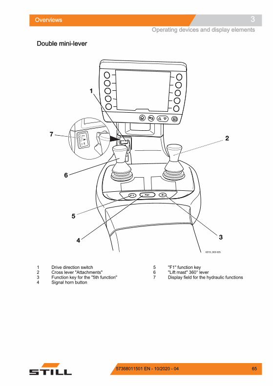
Double mini-lever
Drive direction switchCross lever "Attachments"Function key for the "5th function"Signal horn button
1234
"F1" function key"Lift mast" 360° leverDisplay field for the hydraulic functions
567
Overviews 3Operating devices and display elements
6557368011501 EN - 10/2020 - 04

NOTE
In the dual-pedal version (variant), the drivedirection switch (1) is used exclusively toactivate the cruise control function (variant).The drive direction is selected exclusivelyvia the pedals in the dual-pedal version.
The authorised service centre can assigndifferent functions to the "F1" functionkey (5).
Overviews3Operating devices and display elements
66 57368011501 EN - 10/2020 - 04

Triple mini-lever
Drive direction switch"Auxiliary hydraulics 1" operating lever"Auxiliary hydraulics 2" operating leverFunction key for the "5th function"
1234
Signal horn button"F1" function key"Lift mast" 360° leverDisplay field for the hydraulic functions
5678
Overviews 3Operating devices and display elements
6757368011501 EN - 10/2020 - 04
NOTE
In the dual-pedal version (variant), the drivedirection switch (1) is used exclusively toactivate the cruise control function (variant).The drive direction is selected exclusivelyvia the pedals in the dual-pedal version.
The authorised service centre can assigndifferent functions to the "F1" functionkey (6).
Overviews3Operating devices and display elements
68 57368011501 EN - 10/2020 - 04

Quadruple mini-lever
Drive direction switch"Tilt" operating lever"Auxiliary hydraulics 1" operating lever"Auxiliary hydraulics 2" operating leverFunction key for the "5th function"
12345
Signal horn button"F1" function key"Lift/lower" operating leverDisplay field for the hydraulic functions
6789
Overviews 3Operating devices and display elements
6957368011501 EN - 10/2020 - 04

NOTE
In the dual-pedal version (variant), the drivedirection switch (1) is used exclusively toactivate the cruise control function (variant).The drive direction is selected exclusivelyvia the pedals in the dual-pedal version.
The authorised service centre can assigndifferent functions to the "F1" functionkey (7).
Overviews3Operating devices and display elements
70 57368011501 EN - 10/2020 - 04

Joystick 4Plus
1
2
3
4
5
9
8
7
6
6210_003-087
Horizontal rocker button for the "3rd hydraul-ic function", tilting the lift mastSymbols for the basic hydraulic functionsPictograms for the 5th hydraulic function andfor the clamp locking mechanism (variant)Pictograms for the 3rd & 4th hydraulic func-tion
1
23
4
LED for the clamp locking mechanism (var-iant)Slider for the "4th hydraulic function", e.g.side shift frame forwards/backwardsVertical rocker button for the "drive direction"Shift key "F"Signal horn button
5
6
789
Overviews 3Operating devices and display elements
7157368011501 EN - 10/2020 - 04

Fingertip
1234
5
67
8
9
1011
Signal horn buttonLED for the "5th function"Function key for the "5th function"LED for the "Clamp release"Operating lever for "Auxiliary hydraulics 1"Operating lever for "Auxiliary hydraulics 2"
123456
Drive direction switch"Lift/lower" operating lever"Tilt" operating lever"F1" function keyLED for "F1"
7891011
NOTE
In the dual-pedal version (variant), the drivedirection switch (7) is used exclusively toactivate the cruise control function (variant).The drive direction is selected exclusivelyvia the pedals in the dual-pedal version.
The authorised service centre can assigndifferent functions to the "F1" functionkey (10).
Overviews3Operating devices and display elements
72 57368011501 EN - 10/2020 - 04

Travel direction selector and indica-tor module (variant)The travel direction selector and indicatormodule is located on the steering column be-low the steering wheel.
NOTE
If the drive direction switch on the operatingdevice is defective and the truck stops in adanger area, the drive direction selection leveron the travel direction selector and indicatormodule can be used for emergency driving.Refer to the section entitled "Emergency driv-ing via the drive direction switch/drive directionselection lever" in the chapter entitled "Proce-dure in emergencies".
Drive direction selection leverTurn indicator switch
12
Z
Overviews 3Operating devices and display elements
7357368011501 EN - 10/2020 - 04

Overviews3Operating devices and display elements
74 57368011501 EN - 10/2020 - 04

4
Operation

Checks and tasks before daily useVisual inspections and function checking
WARNING
Risk of injury from falling off the truck!When climbing onto the truck, there is arisk of getting stuck or slipping and fall-ing. Use suitable equipment to reachhigher points on the truck.– Use only the steps provided for this
purpose to climb onto the truck.– Use equipment such as stepladders
or platforms to reach inaccessibleareas.
Damage to the truck or the attachment(variant), non-functional switches or safe-ty systems and modification of predefinedset values can lead to unpredictable anddangerous situations.The following checks and tasks enablecauses of this type to be identified ingood time. It is important to run throughall the checks and tasks listed in the fol-lowing table from top to bottom beforedaily use of the truck.If damage or other defects are identifiedon the truck or the attachment (variant),the truck must not be used until it hasbeen properly repaired.
Ensure that the truck is safe for operation each day before it is used:Component Course of action
Fork arms, general lifting accessories
Perform a visual inspection to check for deformationand wear (e.g. to check if they are bent, broken orfeature significant wear).Check the condition and function of the fork lockingdevices for preventing lifting and shifting.
Lift mast roller tracks Make sure that there is a film of grease.
Load chainsPerform a visual inspection to ensure that thechains are intact and have adequate and even ten-sion.
Attachments (variant)
Ensure that the attachments are mounted correctlyin accordance with the operating instructions fromthe manufacturer.Perform a visual inspection to ensure that the at-tachments are intact and are leak-tight.Perform checks to ensure the attachments areworking correctly.
Operation4Checks and tasks before daily use
76 57368011501 EN - 10/2020 - 04

Component Course of action
Underside Check the area under the truck for leaking consum-ables.
Overhead guard, guard grille (variant) Perform a visual inspection for integrity.Check for secure mounting.
Steps Make sure they are clean (free of ice, not slippery).
Panes of glass (variant) Perform a visual inspection for integrity.Make sure they are clean (also free of ice).
Handholds Check for secure mounting.Maintenance lids Check the close function and close.
Fuel system, fuel tank
Perform a visual inspection for damage and leak-ages.Have damaged components replaced only by theauthorised service centre.
Battery Perform a visual inspection for integrity and defor-mation.
Bonnet and side flap
Perform a visual inspection for integrity and defor-mation.Check that the interlock is in good condition and isworking correctly.Check the close function and close.
Coupling pin, tow coupling (variant)
Perform a visual inspection for deformation andwear (for example: bent, torn, broken).Check the securing bush in the counterweight forintegrity and to ensure that it is working correctly.Check that the linchpin is present and working cor-rectly (chain, rope, split pin).
Labelling, adhesive labelCheck for presence, integrity and legibility.Replace damaged or missing adhesive labels in ac-cordance with the section entitled "Labelling points".
Driver's seat, seat belt Check the integrity and function.Lighting, warning units Check the integrity and function.
Antistatic belt
Perform a visual inspection for integrity.Ensure cleanliness.The antistatic belt must be long enough to touch theground adequately.
Lift and tilt cylinders, tank, valve block, ho-ses, pipes, connections
Perform a visual inspection for damage and leak-ages.Check the area under the truck for leaking consum-ables.Have damaged components replaced only by theauthorised service centre.
Operation 4Checks and tasks before daily use
7757368011501 EN - 10/2020 - 04

Component Course of action
Wheels, tyres
Perform a visual inspection for wear and damage.Make sure that only rims of the same type from thesame manufacturer are fitted.In the event of uneven tyre wear, replace bothtyres.Observe the safety regulations in the section enti-tled "Tyres".
Axle Make sure that no consumables are escaping fromthe axle.
Engine Check the engine oil level. Top up if necessary.Check the coolant level. Top up if necessary.
– Do not use the truck if there is any damageor defects.
– Contact the authorised service centre.
Operation4Checks and tasks before daily use
78 57368011501 EN - 10/2020 - 04

Climbing in and out of the truck
WARNINGRisk of injury when climbing in and out of the truckdue to slipping, hitting yourself on parts of the truckor becoming stuck!If the footwell cover is very dirty or smeared with oil,there is a risk of slipping. There is a risk of hittingyour head on the post of the overhead guard or ofyour clothes becoming stuck when climbing out ofthe truck.– Ensure that the footwell cover is non-slip.– Do not jump into or out of the truck.– Ensure that you have a secure grip on the truck.
WARNINGRisk of injury when jumping off the truck!If your clothing or jewellery (e.g. watch, ring etc.) be-comes stuck on a component while you are jumpingout of the truck, this can lead to serious injuries (e.g.from falling, loss of fingers etc.). It is forbidden tojump off the truck.– Do not jump off the truck.– Do not wear jewellery at work.– Do not wear loose-fitting workwear.
CAUTIONComponents may become damaged through incor-rect use!Truck components, such as the driver's seat, steer-ing wheel, parking brake lever etc., are not designedto be used for climbing in and out of the truck andcan be damaged due to misuse.– Only use the devices specifically designed for the
purpose of climbing in and out of the truck.
Operation 4Checks and tasks before daily use
7957368011501 EN - 10/2020 - 04
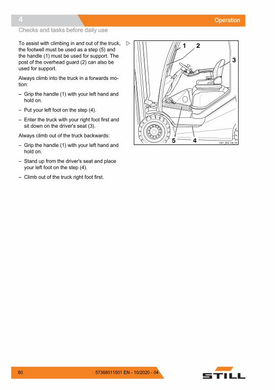
To assist with climbing in and out of the truck,the footwell must be used as a step (5) andthe handle (1) must be used for support. Thepost of the overhead guard (2) can also beused for support.
Always climb into the truck in a forwards mo-tion:
– Grip the handle (1) with your left hand andhold on.
– Put your left foot on the step (4).
– Enter the truck with your right foot first andsit down on the driver's seat (3).
Always climb out of the truck backwards:
– Grip the handle (1) with your left hand andhold on.
– Stand up from the driver's seat and placeyour left foot on the step (4).
– Climb out of the truck right foot first.
7321_003-126_V2
1 2
3
45
Z
Operation4Checks and tasks before daily use
80 57368011501 EN - 10/2020 - 04

Operating the signal horn– Push the signal horn button (1).
The signal horn sounds.
NOTE
The signal horn is used to warn peopleagainst imminent danger or to announce yourintention to overtake.
1
1
1
Z
Operation 4Checks and tasks before daily use
8157368011501 EN - 10/2020 - 04

Driver's cab
DANGERRisk of fatal injury in the event of falling from thetruck if it tips over!In order to prevent the driver from sliding underneaththe truck and being crushed if the truck tips over, arestraint system must be in place and must be used.The restraint system prevents the driver from beingthrown from the truck if it tips over. The cab doormust be sturdy and be closed in order for the driver'scab to function as a driver restraint system. Fabric-covered cabs (variant) with doors made of plastic orcanvas do not constitute a driver restraint systemand offer no protection from the consequences of thetruck tipping over!– Close the cab door prior to commissioning.– If the door is open or has been removed, use a
comparably secure restraint system.– We recommend that you always use the seat belt.
Checking the condition of thewheels and tyres
WARNINGRisk of accident! With uneven wear or incorrect airpressure, the stability of the truck decreases and thebraking distance increases.– Change worn or damaged tyres without delay.
WARNINGRisk of tipping!Tyre quality affects the stability of the truck.
If you wish to use a different type of tyre on the truckfrom the tyres approved by the truck manufacturer,or tyres from a different manufacturer, you must firstobtain approval from the truck manufacturer.
WARNINGRisk to stability!When using pneumatic tyres or solid rubber tyres,rim wheel parts must never be changed and rimwheel parts from different manufacturers must not bemixed.
7312_003-027
1
Z
Operation4Checks and tasks before daily use
82 57368011501 EN - 10/2020 - 04

NOTE
Only approved types of tyre may be used; seechapter entitled "Tyres".
– Check tyres (1) for wear or damage.
Tyres must not be damaged or excessivelyworn. They must be worn evenly on bothsides.
– If pneumatic tyres are fitted, check the airpressure. The air pressure indicated on theadhesive labels (2) must be observed.
NOTE
Observe the safety principles outlined in thechapter entitled "Tyres".
Checking the brake system for cor-rect function
DANGERRisk of accident due to failure of the brake system!If the brake system fails, the truck will be insufficient-ly braked or will not be braked at all.– Do not operate the truck with a defective brake
system.
1Z
Operation 4Checks and tasks before daily use
8357368011501 EN - 10/2020 - 04

Checking the service brake– Release the parking brake.
– Depress the brake pedal (1).
There must be a slight pedal clearance andthen a noticeable pressure point at the brake.
– Accelerate the unladen truck in a cleararea.
– Depress the brake pedal firmly.
The truck must decelerate noticeably.
Checking the parking brakeOn a gradient or a ramp:
DANGER
Risk to life if the truck rolls away!The truck could run people over if theparking brake is not applied.– Do not exit the truck during the follow-
ing check.
– Stop the truck on a steep gradient (e.g. aramp) and actuate the parking brake.
The parking brake must hold the truck on theincline.
If the truck rolls back despite the parkingbrake being applied:
– Secure the truck using the service brake.
– Secure the truck with chocks so that thetruck does not roll away.
– Contact the authorised service centre.
On level ground:
WARNINGRisk of accident!The truck may decelerate abruptly.– Fasten the seat belt.– Activate the available restraint systems.
1
5060_003-015
Z
Operation4Checks and tasks before daily use
84 57368011501 EN - 10/2020 - 04

WARNINGThere is no electric braking assistance when the keyswitch is switched off!Switching off the key switch will de-energise the en-tire electrical system. After this, the regenerativebrake will not be available.
CAUTIONThere is no power steering when the key switch isswitched off!The truck is equipped with hydraulic power steering.Switching off the key switch switches off the hydraul-ics. Steering forces are increased due to the remain-ing emergency steering function.– Steer with a higher level of force.
– Find a sufficiently large, open area in whichnobody will be obstructed.
– Accelerate the truck to walking speed.
– Use the key switch to switch off the engine.
– Apply the parking brake.
The truck must decelerate and remain station-ary.
If the truck only coasts and does not deceler-ate or decelerates only slightly:
– Secure the truck using the service brake.
– Secure the truck with chocks so that thetruck does not roll away.
– Have the parking brake checked and re-paired by the authorised service centre.
NOTE
Special features of the electric parking brake:
The deceleration cannot be influenced. The electric parking brake is applied moder-
ately until the truck comes to a stop. The internal combustion engine must be
switched on in order to release the electricparking brake.
Operation 4Checks and tasks before daily use
8557368011501 EN - 10/2020 - 04

Checking the electric brake
DANGERRisk of accident due to reduced braking power!The regenerative brake may not be sufficient foremergency braking.– Always actuate the brake pedal (2) for emergency
braking.
If the driving speed is restricted or if the oppo-site drive direction is selected, the truckbrakes electrically.
– Release the accelerator pedal (1).
The truck must brake to a standstill.
If the truck only coasts and does not deceler-ate or decelerates only slightly:
– Secure the truck using the service brake.
– Apply the parking brake.
– Have the service brake checked and re-paired by the authorised service centre.
Checking the steering system forcorrect function
DANGERIf the hydraulics fail, there is a risk of accident asthe steering characteristics have changed.– Do not operate the truck if it has a defective steer-
ing system.
– Operate steering wheel (1). The steeringplay while stationary must not be more thantwo finger widths.
NOTE
If the truck is switched on with the steeringwheel turned, the maximum driving speed islimited. Travel speed limitation is removed assoon as the steering wheel is moved out of acornering position into the straight-ahead posi-tion. This requires a change in steering angleof about half a revolution.
1
2
5060_003-006
Z
5060_003-031
1Z
Operation4Checks and tasks before daily use
86 57368011501 EN - 10/2020 - 04

Function checking of the automaticmast vertical positioning function(variant)
CAUTIONRisk of damage to property due to the lift mast collid-ing with racks or other objects!– Before using the "automatic mast vertical position-
ing" assistance system, position the truck at a suf-ficient distance from racks and other objects.
– To check the function of the automatic mastvertical positioning function, proceed as fol-lows:
– Push the "automatic mast vertical position-ing" softkey .
The symbol appears in the display.
– Tilt back the lift mast until it reaches the endstop.
– Tilt the lift mast forwards.
The lift mast must stop in the vertical position.
The automatic mast vertical positioning can beused.
– If the lift mast does not stop in the verticalposition, do not use the assistance system.
– In this case, contact your authorised servicecentre.
Operation 4Checks and tasks before daily use
8757368011501 EN - 10/2020 - 04

Driver's seatsAdjusting the MSG 65/MSG 75 driv-er's seat
WARNINGSlipping of the seat poses a risk of accident duringtravel!If the driver's seat slips from the set position whiledriving, the seat position is unstable. This may resultin unintentional actuation of the steering or operatingdevices and cause the truck or load to move in anuncontrolled fashion.– Adjust the seat and the seat backrest only when
the truck is at a standstill.– Adjust the seat and the seat backrest so that all
operating devices can be actuated safely.– Make sure that the seat and the seat backrest are
engaged.
WARNING
On some equipment variants, theamount of head clearance on the truckmay be restricted.On these specific equipment variants,the distance between the head and thelower edge of the roofing sheet must beat least 40 mm.
WARNINGOptimum seat cushioning is better for your back andprotects your health.To obtain optimum seat cushioning, adjust the seatsuspension to your own body weight.– Make sure that there are no objects within the
swivel area of the seat.
NOTE
Observe any separate operating instructionsfor the seat.
Operation4Driver's seats
88 57368011501 EN - 10/2020 - 04

Moving the driver's seat– Lift the lever (1) and hold the lever in posi-
tion.
– Push the driver's seat into the desired posi-tion.
– Release the lever.
– Make sure that the driver's seat is engaged.
Adjusting the seat backrestWhen the seat backrest is occupied, it can bedifficult to release the seat backrest.
– Release the seat backrest.
– Lift the lever (2) and hold the lever in posi-tion.
– Push the seat backrest into the desired po-sition.
– Release the lever.
– Make sure that the seat backrest is engag-ed.
NOTE
The backwards tilt angle of the seat backrestcan be restricted by means of the truck'sstructure.
7094_003-0061
Z
7094_003-008
2
Z
Operation 4Driver's seats
8957368011501 EN - 10/2020 - 04

Adjusting the seat suspension
NOTE
The driver's seat can be adjusted to the driv-er's weight. To ensure optimum adjustment ofthe seat suspension, the driver must be sittingon the seat.
NOTE
The MSG 65/MSG 75 driver's seat is designedfor people weighing between 45 kg and170 kg.
NOTE
The MSG 75 seat is equipped with electric airsuspension that is activated using an electricswitch instead of the lever (3).
– Sit in the driver's seat.
– Fully fold out the weight-adjusting lever (3).
– Pump the lever up or down to set the driv-er's weight.
– After each stroke, move the weight-adjust-ing lever back to the centre position until theweight-adjusting lever audibly engages.
– Fully fold in the weight-adjusting lever oncethe adjustment is complete.
NOTE
The correct driver's weight has been selectedwhen the arrow (4) is in the centre position inthe inspection window. A noticeable emptystroke on the weight-adjusting lever indicatesthat the minimum or maximum weight settinghas been reached.
6321_003-038
3
4
Z
Operation4Driver's seats
90 57368011501 EN - 10/2020 - 04

Adjusting the lumbar support (variant)The lumbar support can be adjusted to suityour own lumbar vertebrae. Adjusting the lum-bar support moves a convex support cushioninto the upper or lower part of the backrest.
– To move the lumbar support into the re-quired position, turn the turning knob (5) upor down.
Adjusting the backrest extension (var-iant)The backrest extension (6) is in the seat back-rest and is height-adjustable.
– To move the backrest extension into the re-quired position, pull up or push in the back-rest extension.
– To remove the backrest extension, tug thebackrest extension up past the end stopand out.
6321_003-039
5Z
6321_003-040
6Z
Operation 4Driver's seats
9157368011501 EN - 10/2020 - 04
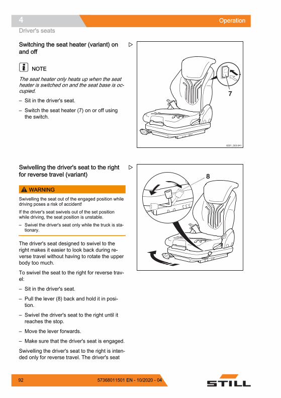
Switching the seat heater (variant) onand off
NOTE
The seat heater only heats up when the seatheater is switched on and the seat base is oc-cupied.
– Sit in the driver's seat.
– Switch the seat heater (7) on or off usingthe switch.
Swivelling the driver's seat to the rightfor reverse travel (variant)
WARNINGSwivelling the seat out of the engaged position whiledriving poses a risk of accident!If the driver's seat swivels out of the set positionwhile driving, the seat position is unstable.– Swivel the driver's seat only while the truck is sta-
tionary.
The driver's seat designed to swivel to theright makes it easier to look back during re-verse travel without having to rotate the upperbody too much.
To swivel the seat to the right for reverse trav-el:
– Sit in the driver's seat.
– Pull the lever (8) back and hold it in posi-tion.
– Swivel the driver's seat to the right until itreaches the stop.
– Move the lever forwards.
– Make sure that the driver's seat is engaged.
Swivelling the driver's seat to the right is inten-ded only for reverse travel. The driver's seat
6321_003-041
7
Z
8Z
Operation4Driver's seats
92 57368011501 EN - 10/2020 - 04

must be swivelled back into place for forwardtravel.
To swivel back for forward travel:
– Pull the lever (8) back and hold it in posi-tion.
– Swivel the driver's seat to the left until itreaches the stop.
– Move the lever forwards.
– Make sure that the driver's seat is engaged.
Adjusting the armrest DANGER
There is a risk of accident if the armrest lowerssuddenly, causing the driver to move in an uncon-trolled manner.This may result in unintentional actuation of thesteering or operating devices and thus cause thetruck or load to move in an uncontrolled fashion.– Do not adjust the armrest while driving.– Adjust the armrest so that all operating devices
can be actuated safely.– Ensure that the armrest is securely tightened.
Adjusting the length of the armrest– Release the star-grip handle (1) by turning
to the left.
– Shift the armrest (2) into the desired posi-tion.
– Tighten the star-grip handle by turning tothe right.
– Check that the armrest is firmly attached.
Adjusting the height of the armrest– Release the hand wheel (3) by turning to
the left.
– Shift the armrest (2) into the desired posi-tion.
– Tighten the hand wheel by turning to theright.
– Check that the armrest is firmly attached.
Z
Operation 4Driver's seats
9357368011501 EN - 10/2020 - 04

Longitudinal horizontal suspension(variant)If the driver's seat is equipped with the "longi-tudinal horizontal suspension" variant, impactsin the drive direction are damped by additionalseat suspension.
Longitudinal seat adjustmentAs with a standard driver's seat, the lever (1)on the front right-hand side of the driver's seatcan be used to adjust the longitudinal positionof the driver's seat.
– To unlock the driver's seat, pull up the lev-er (1) and hold it place.
– Push the driver's seat into the required po-sition.
– To lock the driver's seat again, release thelever (1).
– Gently slide the seat back and forth to lockthe seat in place.
Blocking the longitudinal horizontal sus-pension– To block the longitudinal horizontal suspen-
sion, push down the locking lever (2) on theleft-hand side of the driver's seat (A).
CAUTIONSuspension comfort reduced!If the longitudinal horizontal suspension is blocked,the suspension comfort is significantly lower. Impactsare much more noticeable.– To activate the longitudinal horizontal suspension,
pull up the locking lever (2) on the left-hand sideof the driver's seat (B).
1
Z
B
A
2
Longitudinal horizontal suspension activatedLongitudinal horizontal suspension blocked
AB
Z
Operation4Driver's seats
94 57368011501 EN - 10/2020 - 04
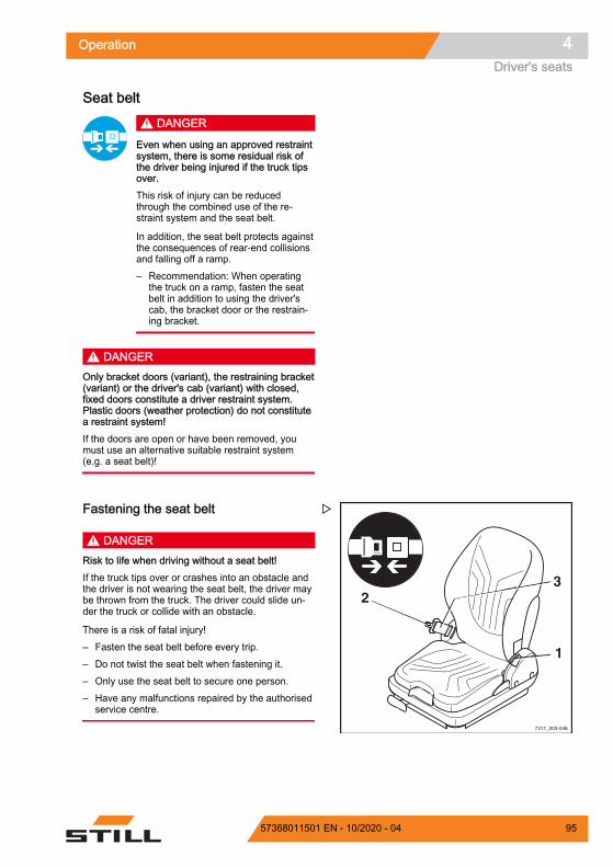
Seat belt DANGER
Even when using an approved restraintsystem, there is some residual risk ofthe driver being injured if the truck tipsover.This risk of injury can be reducedthrough the combined use of the re-straint system and the seat belt.
In addition, the seat belt protects againstthe consequences of rear-end collisionsand falling off a ramp.– Recommendation: When operating
the truck on a ramp, fasten the seatbelt in addition to using the driver'scab, the bracket door or the restrain-ing bracket.
DANGEROnly bracket doors (variant), the restraining bracket(variant) or the driver's cab (variant) with closed,fixed doors constitute a driver restraint system.Plastic doors (weather protection) do not constitutea restraint system!If the doors are open or have been removed, youmust use an alternative suitable restraint system(e.g. a seat belt)!
Fastening the seat belt
DANGERRisk to life when driving without a seat belt!If the truck tips over or crashes into an obstacle andthe driver is not wearing the seat belt, the driver maybe thrown from the truck. The driver could slide un-der the truck or collide with an obstacle.
There is a risk of fatal injury!– Fasten the seat belt before every trip.– Do not twist the seat belt when fastening it.– Only use the seat belt to secure one person.– Have any malfunctions repaired by the authorised
service centre.
7311_003-048
1
23
Z
Operation 4Driver's seats
9557368011501 EN - 10/2020 - 04

NOTE
The buckle has a buckle switch (variant). Inthe event of an operating error or malfunction,the message SAFETY BELT appears in thedisplay and operating unit, see the chapter en-titled "Display messages".
– Pull the seat belt (3) smoothly out of the beltretractor and fasten closely around the bodyover the thighs.
NOTE
Sit as far back as possible so that your back isleaning against the seat backrest. The auto-matic blocking mechanism permits sufficientfreedom of movement on the seat.
– Click the belt tongue (2) into the buckle (1).
– Check the tension of the seat belt. The beltshould fit closely around your body.
Fastening on a steep slopeThe automatic blocking mechanism preventsthe belt from being extended whenever thetruck is on a steep gradient. It is no longerpossible to pull the seat belt out of the belt re-tractor.
– Move away carefully from the slope.
– Fasten the seat belt.
6210_342-005
Z
Operation4Driver's seats
96 57368011501 EN - 10/2020 - 04

Releasing the seat belt– Push the red button (4) on the buckle (1).
– Slowly guide the belt tongue back to the re-tractor by hand.
NOTE
Do not allow the seat belt to retract too quick-ly. The automatic blocking mechanism may betriggered if the belt tongue strikes the housing.It will then no longer be possible to pull theseat belt out with the usual force.
– Using increased force, pull the seat beltaround 10-15 mm out of the retractor to dis-engage the blocking mechanism.
– Slowly allow the seat belt to retract again.
– Protect the seat belt from dirt (for example,by covering it).
Malfunction due to cold weather condi-tions– If the buckle or belt retractor is frozen, thaw
them out and dry them thoroughly to pre-vent recurrence.
CAUTIONThe seat belt may be damaged by heat!Do not subject the buckle or belt retractor to exces-sive heat when thawing.– Do not use air warmer than 60°C when thawing.
7090_342-0051
4
Z
Operation 4Driver's seats
9757368011501 EN - 10/2020 - 04

Pre-Shift CheckDescription of the Pre-Shift Check(variant)The Pre-Shift Check is a guided dialogue inthe display-operating unit. It also helps thedriver conduct the necessary "visual inspec-tions and function checking" before everydayuse. After the truck has been switched on, thedriver must answer questions about the condi-tion of the forklift truck with "Yes" or "No".
While the driver is doing this, the truck func-tions are available with restrictions. The driv-ing speed and hydraulic functions are restric-ted.
To commission the truck, the authorised serv-ice centre can compile the Pre-Shift Checkfrom a question catalogue in consultation withthe fleet manager. If no question cataloguehas been compiled, only the question "Truckready for operation?" is stored in the factorysettings.
The authorised service centre can then restrictthe truck functions in the event of a negativetest result.
There are fixed responses: No response Speed limitation Restriction of hydraulics to 33%
In addition, the fleet manager has the follow-ing options: The fleet manager can view the results of
all checks via the "History". The fleet manager can define the shift start
for three different shifts. The Pre-ShiftCheck must be performed when these shiftsstart.If the truck is equipped with "FleetManag-er", the shifts are defined on the FleetMan-ager interface. See the relevant operatinginstructions.
If, due to a negative test result, truck func-tions are restricted, the fleet manager canreset these restrictions.
The fleet manager can specify the questionsequence.
Operation4Pre-Shift Check
98 57368011501 EN - 10/2020 - 04

NOTE
During commissioning, the first question canalso be answered with "No". Truck functionsare not restricted until the question cataloguehas been compiled by the authorised servicecentre and the restrictions have been set bythe fleet manager.
Process– Switch the truck on.
The first question appears.
– Press the "Yes" or "No" softkey.
The next question appears.
Some of the questions require a functionaltest, such as the functional test of the lighting.
NOTE
The main display symbol appears onlywhen it is required for the test.
– To access the main display, press the maindisplay button or the softkey .
The main display contains the message Tocomplete Pre-Shift Check,press .
This means that the Pre-Shift Check is still ac-tive and the truck functions are restricted.
– To acknowledge the message, press the softkey.
Pre-Shift Check
Truck ready for operation?
1/1
No
Yes
6219_003-264_en
Z
Pre-Shift Check 4/6
No
Yes
6219_003-265_en
Does the truck lighting work?
Z
Operation 4Pre-Shift Check
9957368011501 EN - 10/2020 - 04

– Switch on and check the function to be tes-ted, e.g. lighting.
– Press the back button to go back to thePre-Shift Check.
– Answer the question based on the result ofthe function check.
The next question appears.
NOTE
If no questions regarding the Pre-Shift Checkhave been compiled, the question Truckready for operation? is displayed.
If the truck has to be moved for a test, e.g. fora brake test, you can simply release the park-ing brake. The message To completePre-Shift Check, press is dis-played. The truck can be moved at reducedspeed. If you apply the parking brake again,the view goes back to the Pre-Shift Check.
At the end of the check, truck functions are re-stricted if they have been adjusted as a reac-tion to a negative test result. The messagePre-Shift Check truck restric-tions active shows that truck functionsare restricted. As long as the truck functionsare restricted, no further Pre-Shift Check is re-quested at the start of a new shift. The checkis only requested again after the fleet managerhas reset the restrictions.
All questionsThe authorised service centre can use this question catalogue to put together the Pre-Shift Checkduring commissioning:Are the fork arms damaged (e.g. bent or cracked)?Are the fork arms securely mounted and the locking devices un-damaged?Are the roller tracks on the lift mast sufficiently greased?Are the load chains damaged?Are the load chains sufficiently tensioned and loaded equally.?Are all attachments securely mounted and undamaged? Are they inworking order?Are operating fluids (e.g. oil, water, fuel) visibly leaking?Are the wheels damaged? Are they worn beyond permissible limits?
0,0°6,89 m2,8 t
6219_003-266_en
Pre-S
To complete Pre-Shift Check,
press
Z
Operation4Pre-Shift Check
100 57368011501 EN - 10/2020 - 04
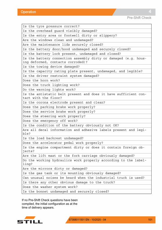
Is the tyre pressure correct?Is the overhead guard visibly damaged?Is the entry area or footwell dirty or slippery?Are the windows clean and undamaged?Are the maintenance lids securely closed?Is the battery door/hood undamaged and securely closed?Is the battery lock present, undamaged and closed?Is the battery connection assembly dirty or damaged (e.g. hous-ing deformed, contacts corroded)?Is the towing device damaged?Is the capacity rating plate present, undamaged, and legible?Is the driver restraint system damaged?Does the horn work?Does the truck lighting work?Do the warning lights work?Is the antistatic belt present and does it have sufficient con-tact with the floor?Is the corona electrode present and clean?Does the parking brake work properly?Does the service brake work properly?Does the steering work properly?Does the emergency off work?Is the condition of the battery obviously not OK?Are all decal information and adhesive labels present and legi-ble?Is the load backrest undamaged?Does the accelerator pedal work properly?Is the engine compartment dirty or does it contain foreign ob-jects?Are the lift mast or the fork carriage obviously damaged?Do the working hydraulics work properly according to the label-ling?Are the mirrors dirty or damaged?Is the gas tank or its mounting obviously damaged?Can unusual noises be heard when the industrial truck is used?Is there any other obvious damage to the truck?Does the washer system work?Is the bonnet undamaged and securely closed?
If no Pre-Shift Check questions have beencompiled, the initial configuration as at thetime of delivery appears.
Operation 4Pre-Shift Check
10157368011501 EN - 10/2020 - 04

Defining the question sequenceThe questions for the Pre-Shift Check can bedefined in a random sequence or in a fixed se-quence.
The random sequence is advisable, becausethe questions are then read more consciouslyby the driver. This means that there is no rou-tine aspect.
– Activate the "Access authorisation for thefleet manager".
– Press the Service softkey .
– Press the scroll keys until the Pre-Shift Check menu appears.
– Press the Pre-Shift Check softkey.
Z
Fleet manager
Maintenance interval
Version list
Pre-Shift Check
Calibration
Message list
6219_003-268_en
Z
Operation4Pre-Shift Check
102 57368011501 EN - 10/2020 - 04

The Pre-Shift Check menu appears.
– Press the Question sequence softkey.
Pressing the softkey allows fixed or randomquestion sequences to be selected.
The orange activation bar displays the currentselection.
– To access the main display, press the maindisplay button .
Displaying the historyThe fleet manager can display a Pre-ShiftCheck history.
– Activate the "Access authorisation for thefleet manager".
Fleet manager
Reset restriction
Shift start
Question sequence
History
6219_003-269_en
Z
Fleet manager
Random sequence
Fixed sequence
6219_003-273_en
Z
Operation 4Pre-Shift Check
10357368011501 EN - 10/2020 - 04

– Press the Service softkey .
– Press the scroll keys until the Pre-Shift Check menu appears.
– Press the Pre-Shift Check softkey.
Z
Fleet manager
Maintenance interval
Version list
Pre-Shift Check
Calibration
Message list
6219_003-268_en
Z
Operation4Pre-Shift Check
104 57368011501 EN - 10/2020 - 04

The Pre-Shift Check menu appears.
– Press the History softkey.
The "Pre-Shift Check results" display opens.
This display shows all checks and questionsthat have been answered with the date andtime.
To see more results, press the scroll but-tons .
– To go back to the previous menu, press thesoftkey .
– To access the main display, press the maindisplay button .
Defining the shift startAs a standard setting after commissioning, thePre-Shift Check is always requested 24 hoursafter the last check was performed. The fleetmanager can define up to three shifts andtheir start times. The Pre-Shift Check is thenalways requested at this time.
NOTE
If the truck is equipped with FleetManager, theshifts are defined on the FleetManager inter-face. See the relevant operating instructions.
Fleet manager
Reset restriction
Shift start
Question sequence
History
6219_003-269_en
Z
Pre-Shift Check results
27.09.19 15:11 nicht ok Funktioniert die Feststellbremse einwandfrei?
27.09.19 15:06 nicht ok Sind die Gabeln beschädigt (z. B. verbogen oder gerissen)?
27.09.19 14:57 nicht ok Geht es dir gut?
27.09.19 14:46 ok
27.09.19 14:45 abgebrochen
13.05.19 15:09 nicht ok
6219_003-270_en
Fleet manager
Z
Operation 4Pre-Shift Check
10557368011501 EN - 10/2020 - 04

– Activate the "Access authorisation for thefleet manager".
– Press the Service softkey.
– Press the scroll keys until the Pre-Shift Check menu appears.
– Press the Pre-Shift Check softkey.
Z
Fleet manager
Maintenance interval
Version list
Pre-Shift Check
Calibration
Message list
6219_003-268_en
Z
Operation4Pre-Shift Check
106 57368011501 EN - 10/2020 - 04

The Pre-Shift Check menu appears.
– Press the "Shift start" softkey.
In this menu, you can call up the shift to bedefined and its start time.
The orange activation bar indicates whichshifts are activated.
– To edit a shift, press the corresponding soft-key.
Fleet manager
Reset restriction
Shift start
Question sequence
History
6219_003-269_en
Z
Fleet manager
Shift start 2
Shift start 3
Shift start 1
6219_003-271_en
Z
Operation 4Pre-Shift Check
10757368011501 EN - 10/2020 - 04

In this menu you can define the shift start.
– Enter the time using softkeys "0 to 9".
– To save, press the button.
The shift start is now defined. The Pre-ShiftCheck is always requested from this shift starttime.
The display returns to the previous menu.
– To deactivate a certain shift start, select therelevant shift.
Fleet manager
Enter shift start
= Clear
06
Shift start 1
00:
= Deactivate
= Save = Cancel
6219_003-272_en
Z
Fleet manager
Shift start 2
Shift start 3
Shift start 1
6219_003-271_en
Z
Operation4Pre-Shift Check
108 57368011501 EN - 10/2020 - 04

– Press the scroll button to deactivate theshift.
– To confirm, press the button.
The time is shown in grey.
The shift is deactivated. The display returns tothe previous menu. There is no activation barnext to this shift.
– To cancel, press the back button .
– To access the main display, press the maindisplay button .
Resetting the truck restrictionsIf truck functions are restricted due to checkswith a bad result, the fleet manager can resetthese restrictions. The fleet manager can alsodo this if a problem on the truck has been rec-tified.
– Activate the "Access authorisation for thefleet manager".
– Press the Service softkey.
Fleet manager
Enter shift start
= Clear
06
Shift start 1
00:
= Deactivate
= Save = Cancel
6219_003-272_en
Z
Z
Operation 4Pre-Shift Check
10957368011501 EN - 10/2020 - 04

– Press the scroll keys until the Pre-Shift Check menu appears.
– Press the Pre-Shift Check softkey.
The Pre-Shift Check menu appears.
– Press the "Reset vehicle restrictions" soft-key.
Fleet manager
Maintenance interval
Version list
Pre-Shift Check
Calibration
Message list
6219_003-268_en
Z
Fleet manager
Reset restriction
Shift start
Question sequence
History
6219_003-269_en
Z
Operation4Pre-Shift Check
110 57368011501 EN - 10/2020 - 04

A question pops up asking if you want to resetthe truck restrictions.
– To confirm, press the softkey.
The full scope of the truck functions is nowavailable. The display returns to the previousmenu.
– To cancel, press the softkey.
The truck functions remain restricted. The dis-play returns to the previous menu.
– To access the main display, press the maindisplay button .
6219_003-274_en
Fleet manager
Reset the truck restrictions?The entry remains in the history
Z
Operation 4Pre-Shift Check
11157368011501 EN - 10/2020 - 04

Driver profilesDriver profiles (variant)This variant allows up to ten individual driverprofiles to be created. The driver is greetedwith the selected name after logging in. Oncethe softkey is pressed, the main display isshown.
If the truck is equipped with the "Access au-thorisation with PIN code" or "FleetManager"variants, these driver profiles can be linked tothe relevant variant.
The driver profile allows the following settingsto be saved: Language Favourites Configuration of the status line Configuration of drive programmes A and B
In addition, the operating statuses saved forthe last selected driver profile are called upagain the next time a user logs in with thisdriver profile: Selected drive programme 1 to 3 Load dynamics Efficiency and drive modes
(Blue-Q/sprint mode)
If a driver without an existing driver profile logsin using the "Access authorisation with PINcode" or "FleetManager" variants, a driver pro-file is generated. This driver profile corre-sponds to the settings when the truck was de-livered.
If the truck is not equipped with these variants,drivers must select their profiles manually.
Any changes that drivers make to the settingswhile they are logged in are saved. These willthen be available the next time that the driverlogs in.
Selecting driver profilesIf the truck is equipped with the "Access au-thorisation with PIN code" or "FleetManager"variants, the corresponding driver profile is ac-tive after logging in. If the truck is not
0,0°0,0 m0,0 t
6219_003-291_en
Hello,Horst
Z
Operation4Driver profiles
112 57368011501 EN - 10/2020 - 04

equipped with these variants, drivers must se-lect their profiles manually.
NOTE
Access to the settings menu is only available ifthe truck is at a standstill and the parkingbrake is applied. If the parking brake is re-leased prematurely, the settings menu willclose.
– Stop the truck.
– Actuate the parking brake.
– Press the button .
– Press the "Settings" softkey .
– Press the Driver profiles soft-key .
Con!gure favourites
Truck settings
Truck information
Driver pro!les
Display settings
6219_003-293_en
Z
Operation 4Driver profiles
11357368011501 EN - 10/2020 - 04

The orange activation bar displays the currentselection.
– Press the softkey for the required driverprofile.
The driver profile is active. The driver is gree-ted with the selected name the next time thatthe truck is switched on.
Creating driver profilesBoth the fleet manager and the driver can cre-ate up to ten driver profiles.
NOTE
If the truck is equipped with the "Access au-thorisation with PIN code" or "FleetManager"variants, the driver profile is generated auto-matically when logging in for the first time.
– Apply the parking brake.
– Press the button .
– Press the "Settings" softkey .
Horst
Lisa
Driver 4
Available storage position 5
Guido
6219_003-294_en
Z
Operation4Driver profiles
114 57368011501 EN - 10/2020 - 04

– Press the Driver profiles soft-key .
This menu provides storage space for savingten driver profiles.
– Press the softkey for the required storagelocation.
NOTE
Unoccupied storage locations that do not con-tain a driver profile are indicated by Availa-ble storage position.
Con!gure favourites
Truck settings
Truck information
Driver pro!les
Display settings
6219_003-293_en
Z
Horst
Lisa
Driver 4
Available storage position 5
Guido
6219_003-294_en
Z
Operation 4Driver profiles
11557368011501 EN - 10/2020 - 04

The Driver name menu is displayed.
– Use the softkeys to enter the desired name.
– To confirm, press the button.
The driver profile is active. The driver is gree-ted with the selected name after the next log-in.
Any changes that drivers make to the settingswhile they are logged in are saved. These willthen be available the next time that the driverlogs in.
Renaming driver profilesDriver profiles can be renamed. Drivers canonly rename their own driver profile. The fleetmanager has access authorisation to renameall driver profiles.
Renaming by the driver– Apply the parking brake.
– Press the button .
– Press the "Settings" softkey .
– Press the Truck settings softkey.
Enter driver name
= Clear
Driver name
Horst
= abc -> ABC
= Save = Cancel
6219_003-295_en
0
Z
Operation4Driver profiles
116 57368011501 EN - 10/2020 - 04

– Press the Rename driver profilessoftkey.
The Driver name menu is displayed.
– Use the softkeys to enter the desired name.
– To confirm, press the button.
Renaming by the fleet manager– Activate the "Access authorisation for the
fleet manager".
– Press the Truck settings softkey.
Rename driver pro!les
Driving programme
6219_003-298_en
Z
Enter driver name
= Clear
Driver name
Horst
= abc -> ABC
= Save = Cancel
6219_003-295_en
0
Z
Operation 4Driver profiles
11757368011501 EN - 10/2020 - 04

– Press the Manage driver profilessoftkey.
– Press the Rename driver profilessoftkey.
Fleet manager
Auxiliary hydraulics
Change PIN codes
Manage driver pro!les
On-board charger
Lift height preselection
6219_003-296_en
Z
Fleet manager
Delete driver pro!les
Rename driver pro!les
6219_003-297_en
Z
Operation4Driver profiles
118 57368011501 EN - 10/2020 - 04

The Driver name menu is displayed.
– Use the softkeys to enter the desired name.
– To confirm, press the button.
Deleting driver profilesThe fleet manager has access authorisation todelete driver profiles.
– Activate the "Access authorisation for thefleet manager".
– Press the Truck settings softkey .
– Press the Manage driver profilessoftkey.
Enter driver name
= Clear
Driver name
Horst
= abc -> ABC
= Save = Cancel
6219_003-295_en
0
Z
Fleet manager
Auxiliary hydraulics
Change PIN codes
Manage driver pro!les
On-board charger
Lift height preselection
6219_003-296_en
Z
Operation 4Driver profiles
11957368011501 EN - 10/2020 - 04

– Press the Delete driver profilessoftkey.
– Press the softkey for the driver profile to bedeleted.
The driver profile is deleted.
Fleet manager
Delete driver pro!les
Rename driver pro!les
6219_003-297_en
Z
Horst
Lisa
Driver 4
Available storage position 5
Guido
6219_003-294_en
Z
Operation4Driver profiles
120 57368011501 EN - 10/2020 - 04

Switching on and startingEngine preheating (variant)FunctionAt ambient temperatures below the freezingpoint, a preheated engine is easier to start.The starter battery is protected. The engineconsumes less fuel.
In trucks with the engine preheating function,a heating element (1) that is connected to abuilt-in plug (3) in the engine compartment islocated in the cooling system of the internalcombustion engine.
Connecting the connecting cable (2) (230V)switches on the heating element. The activa-ted heating element heats the coolant. Thepreheating time depends on the ambient tem-perature. The preheating time is at least2 hours.
Engine preheating can be safely used continu-ously. Temperature control prevents the cool-ant temperature from exceeding 58°C.
Engine preheating
CAUTIONOverheating can damage the heating element!Contaminants such as dirt, ice, air or radiator sealingcompound, or insufficient coolant in the cooling sys-tem, can cause the heating element to overheat.– Check the coolant level.– If there are contaminants in the cooling system,
do not preheat the engine.
DANGERDanger to life from electric shock!– Use only marked connecting cables (2) in accord-
ance with CEE IP67, 3 x 1.5 mm2.– Connect the connecting cable only to an earthed
230V socket.
7321_003-089
230 V
1 2
3
Z
Operation 4Switching on and starting
12157368011501 EN - 10/2020 - 04

– Plug the connecting cable (2) into the built-in socket (3).
– Plug the connecting plug (4) into an earthed230V socket.
– Preheat the engine for at least 2 hours.
The preheating time may be longer than thisdepending on the ambient temperature. Dur-ing preheating, a quiet bubbling sound may beheard.
CAUTIONRisk of damage to the connecting cable!– Before starting the engine, remove the connecting
cable from the 230V socket and from the built-insocket.
– Start the engine.
Opening the LPG cylinder valve DANGER
There is a risk of explosion if LPG es-capes.Escaping LPG may explode when ex-posed to ignition sources and cause se-rious accidents.– Do not smoke or use a naked flame/
lighter.– Do not start the engine.– Close the cylinder valve.– Notify your authorised service centre.– LPG cylinders should be opened in
well-ventilated spaces, away fromopenings in the ground.
DANGER
Risk of explosion from spark discharge!– Do not use a striking tool when open-
ing and closing.
WARNING
LPG can cause frostbite on the skin.– Wear protective gloves.
7090_133-004
2 4
3
Z
Operation4Switching on and starting
122 57368011501 EN - 10/2020 - 04

CAUTIONOpening the cylinder valve too quickly can lead tothe system icing over.– Open the cylinder valve slowly.
– Open the cylinder valve (1) by slowly turn-ing the star-grip handle anti-clockwise.
– Check whether the smell of gas is evident.
– Check whether the hose (2) is securely con-nected to the gas cylinder.
– Check to see whether the hose and con-nection screw joints have iced over.
Opening the LPG cylinder valve fora double-cylinder holder
DANGER
There is a risk of explosion if LPG es-capes.Escaping LPG may explode when ex-posed to ignition sources and cause se-rious accidents.– Do not smoke or use a naked flame/
lighter.– Do not start the engine.– Close the cylinder valve.– Notify your authorised service centre.– LPG cylinders should be opened in
well-ventilated spaces, away fromopenings in the ground.
DANGER
Risk of explosion from spark discharge!– Do not use a striking tool when open-
ing and closing.
7311_136-003
2
1
Z
Operation 4Switching on and starting
12357368011501 EN - 10/2020 - 04

WARNING
LPG can cause frostbite on the skin!– Wear protective gloves.
CAUTIONOpening the cylinder valve too quickly can lead tothe system icing over.– Open the cylinder valve slowly.
– To open the upper gas cylinder (1), pushthe lever (2) down.
– Open the cylinder valve (3) of the upper gascylinder by slowly turning the star-grip han-dle anti-clockwise.
– Check the cylinder valve (4) of the lowergas cylinder.
The valve must be closed.
– If necessary, close the valve of the lowergas cylinder by turning it clockwise.
1
24
3Z
Operation4Switching on and starting
124 57368011501 EN - 10/2020 - 04

– To open the lower gas cylinder (1), push thelever (2) up.
– Open the cylinder valve (3) of the lower gascylinder by slowly turning the star-grip han-dle anti-clockwise.
– Check the cylinder valve (4) of the uppergas cylinder.
The valve must be closed.
– If necessary, close the valve of the uppergas cylinder by turning it clockwise.
– Check whether the smell of gas is evident.
– Check whether the hose is securely con-nected to the gas cylinder.
– Check to see whether the hose and con-nection screw joints have iced over.
Opening the shut-off valve of anLPG tank (variant)
DANGER
There is a risk of explosion if LPG es-capes.Escaping LPG may explode when ex-posed to ignition sources and cause se-rious accidents#.– Do not smoke or use a naked flame/
lighter.– Do not start the engine.– Close the shut-off valve.– Notify your authorised service centre.– Only open the shut-off valve in well-
ventilated rooms and not near open-ings in the ground.
DANGER
Risk of explosion from spark discharge!– Do not use any striking tools when
opening and closing.
1
23
4Z
Operation 4Switching on and starting
12557368011501 EN - 10/2020 - 04

WARNING
LPG can cause frostbite on the skin.– Always wear protective gloves.
CAUTIONOpening quickly can lead to the system icing over.– Slowly open the shut-off valve.
– Open the shut-off valve (2) by slowly turningthe valve anti-clockwise.
– Check whether it smells of gas.
– Check whether the hose (1) is securely con-nected to the LPG tank.
– Check to see whether the hose and con-nection screw joints have iced over.
The fill level display (4) on the LPG containerdisplays how much LPG is available.
7314_003-010
2
1
Z
7314_003-057
450 60
70
80859010
20
3040
955 Inhalt
Z
Operation4Switching on and starting
126 57368011501 EN - 10/2020 - 04

Switching on the key switch
WARNINGBefore switching on the key switch, all visual inspec-tions and function checking must be carried out with-out any defects being identified.– Perform the visual inspections and function check-
ing.– Do not operate the truck if defects have been de-
tected; contact the authorised service centre.
– Insert the switch key (1) into the key switchand turn it to the "I" position.
NOTE
If the truck is equipped with the "Access au-thorisation with PIN code" variant, the displayinitially changes to the input menu for accessauthorisation.
Once the truck is ready for operation, the mainscreen is shown on the display.
Main screen1 Selected drive programme with driving
dynamics display2 Load information (variants)3 Status bar1: fuel level, operating hours,
time4 Selected load dynamics programme with
dynamics bar5 "Right" turn indicator display6 Driving speed or parking brake 7 "Left" turn indicator display8 "Reverse" drive direction indicator9 "Forward" drive direction indicator10 Steering angle display
Additional information may appear on the dis-play.
7090_001-002
0 I
1
Z
432 h 08:20
1,6 t
7°2,71 m
Z
1 An example status bar (3) is shown in this figure.
Operation 4Switching on and starting
12757368011501 EN - 10/2020 - 04

– Refer to the chapter entitled "Display mes-sages".
Access authorisation with PIN code(variant)Trucks equipped with the "Access authorisa-tion with PIN code" variant are protectedagainst unauthorised use by a PIN code. Sothat the same truck can be used by differentdrivers, individual PIN codes can be specified.
An initial PIN code of "11111" is preset at thefactory for the first use.
NOTE
We recommend that the fleet managerchanges this PIN code using their access au-thorisation. See also the section entitled "Ac-cess authorisation for the fleet manager (var-iant)".
When the key switch is switched on, the Ac-cess authorisation input menu ap-pears.
All hydraulic functions and drive functions ofthe truck are blocked. In the StVZO (GermanRoad Traffic Licensing Regulations) variant,the function of the hazard warning system(variant) is guaranteed.
– To activate the blocked functions, use thesoftkeys to enter the PIN code.
– To confirm, push the button.
If the input was correct, the display changes tothe main display. The truck is ready for use.
– If the input was incorrect, enter the PINcode again.
NOTE
The authorised service centre can configureaccess authorisation so that the PIN code hasto be re-entered each time after someoneleaves the truck.
When the driver's seat is occupied again, themessage Log in appears. The display
Z
Operation4Switching on and starting
128 57368011501 EN - 10/2020 - 04

then changes to the "Access authorisation" in-put menu.
Changing the PIN codesThe fleet manager can change the PIN codes.See also the following section entitled "Accessauthorisation for the fleet manager (variant)".
– Activate the "Access authorisation for thefleet manager".
– Press the Service softkey.
– Press the scroll keys until theChange PIN codes menu appears.
– Press the Change PIN codes softkey.
– Follow the instructions on the display.
Z
Fleet manager
Calibration
Relieve hydraulics
Shock sensor
Change password (access auth.)
Change PIN codes
6219_003-276_en
Z
Operation 4Switching on and starting
12957368011501 EN - 10/2020 - 04

Access authorisation for the fleetmanager (variant)Trucks equipped with the "Access authorisa-tion for the fleet manager" variant can be con-figured by the users themselves. Access tothese settings is protected by a fleet managerpassword.
The initial fleet manager password was sentwith the invoicing documents. For safety rea-sons, change this password after the first use.See also the section entitled "Changing thefleet manager password".
NOTE
Access to the settings menu is only available ifthe truck is at a standstill and the parkingbrake is applied. If the parking brake is re-leased prematurely, the settings menu willclose.
– Stop the truck.
– Actuate the parking brake.
– Press the button .
– Press the "Settings" softkey .
The first menu level appears.
– Press the Access authorisa-tion softkey .
Fleet manager
Con!gure favourites
Truck settings
Service
Access authorisation
Display settings
6219_003-267_en
Z
Operation4Switching on and starting
130 57368011501 EN - 10/2020 - 04

The display changes to the Access au-thorisation menu.
– Enter the fleet manager password using thesoftkeys.
– To confirm, press the button.
The message Fleet manager accessauthorisation granted appears.
– To confirm, press the softkey.
"Access authorisation for the fleet manager" isactivated. The display returns to the settingsmenu.
If the password entered was incorrect, themessage Password incorrect is dis-played.
– If this happens, enter the password again.
NOTE
While the "Access authorisation for the fleetmanager" is activated, Fleet manager isdisplayed in an orange bar at the bottom ofthe screen. When the users switches to themain display, the access authorisation expiresagain.
Changing the fleet manager password– Activate the "Access authorisation for the
fleet manager".
Enter password
Z
Fleet manageraccess authorisation
granted
6219_003-208
Z
Operation 4Switching on and starting
13157368011501 EN - 10/2020 - 04
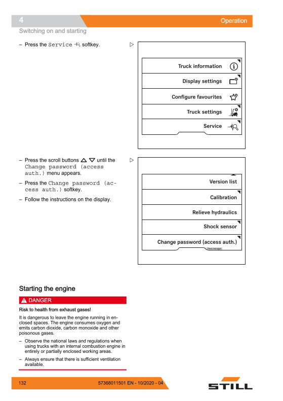
– Press the Service softkey.
– Press the scroll buttons until theChange password (accessauth.) menu appears.
– Press the Change password (ac-cess auth.) softkey.
– Follow the instructions on the display.
Starting the engine DANGER
Risk to health from exhaust gases!It is dangerous to leave the engine running in en-closed spaces. The engine consumes oxygen andemits carbon dioxide, carbon monoxide and otherpoisonous gases.– Observe the national laws and regulations when
using trucks with an internal combustion engine inentirely or partially enclosed working areas.
– Always ensure that there is sufficient ventilationavailable.
Z
Fleet manager
Calibration
Relieve hydraulics
Shock sensor
Change password (access auth.)
Version list
6219_003-275_en
Z
Operation4Switching on and starting
132 57368011501 EN - 10/2020 - 04

– Apply the parking brake.
– Insert the switch key (1) into the key switchand turn to position "I".
If the truck controller is powered up, the mes-sage "Start" appears on the display.
NOTE
The engine will not start until the truck control-ler is powered up.
– Turn the switch key to position "II" and holdit there until the engine starts.
– Release the switch key when the enginestarts.
If the engine does not start after 20 seconds,stop the starting procedure to protect the start-er battery then repeat after one minute.
CAUTIONRisk of engine damage!If an error message appears on the display after theengine has been started, the engine lubrication maybe insufficient. Insufficient lubrication may cause en-gine damage.– Stop the engine immediately.– Check the engine oil level and top up if necessary– If the message continues to appear, notify the au-
thorised service centre.
– Please note the information in the chapterentitled "Malfunctions".
7071_003-101
0 I
1
IIZ
Z
Operation 4Switching on and starting
13357368011501 EN - 10/2020 - 04

NOTE
If the engine does not start due to a dis-charged battery, charge the battery or jump-start the engine.
Operation4Switching on and starting
134 57368011501 EN - 10/2020 - 04

LightingMeaning of the symbolsIndividual lighting devices are switched on andoff using the "Lighting" sub-menu.
– To access this sub-menu, push the but-ton .
Symbols for the lighting and their meaningsParking lightHeadlightsHazard warning system1
Rotating beaconSTILL SafetyLightWarning zone lightFront working spotlightsRear working spotlightsRoof working spotlights
Only the symbols of the lighting devices thatare installed in the truck can be selected.When one of the lighting devices is switchedon, the activation bar next to the relevant sym-bol lights up orange.
NOTE
If the truck is equipped with the "StVZO" (Ger-man Road Traffic Licensing Regulations) var-iant, the hazard warning system works evenwhen the truck is switched off.
Z
1 This function is not available if the truck is equipped with the "StVZO" (German Road TrafficLicensing Regulations) variant. In this case, the hazard warning system is switched on andoff via the hazard warning button on the steering column. For more information, refer to thesection entitled "Hazard warning system".
Operation 4Lighting
13557368011501 EN - 10/2020 - 04

Driving lights– To switch on the parking light (1), push the
associated Softkey on the display-operatingunit.
The front side lights and the tail lights light up.
– To switch on the driving light (2), press theassociated Softkey on the display-operatingunit.
The headlights and tail lights light up. If thetruck has StVZO (German Road Traffic Li-censing Regulations) equipment (variant) anda licence plate lamp, then this also lights up.
– To switch off the driving light (2), press theSoftkey again.
The driving light and licence plate lamp go out.
– To switch off the parking light (1), push theSoftkey again.
The front side lights and the tail lights go out.
If the truck does not have StVZO (GermanRoad Traffic Licensing Regulations) equip-ment (variant), then the parking light and driv-ing light can be switched on and off independ-ently of each other.
6219_003-063_V2
Parking lightDriving light
12
Z
Operation4Lighting
136 57368011501 EN - 10/2020 - 04

Working spotlightsFront and rear working spotlights– To switch on the front working spot-
lights (3), push the associated Softkey onthe display-operating unit.
The front working spotlights light up.
– To switch off the front working spot-lights (3), push the Softkey again.
The front working spotlights go out.
– To switch on the rear working spotlights (4),push the associated Softkey on the display-operating unit.
The rear working spotlights light up.
– To switch off the rear working spotlights (4),push the Softkey again.
The rear working spotlights go out.
NOTE
For the StVZO (German Road Traffic Licens-ing Regulations) variant, the parking light is al-so switched on when the working spotlightsare switched on. The licence plate lamp (ifpresent) is also switched on when the forward-facing working spotlights are switched on.
Working spotlights on the roof and theside of the lift mastThe roof spotlights light up the working areawhen the fork carriage is raised.
– To switch on the roof spotlights (5), pushthe associated Softkey on the display-oper-ating unit.
The roof spotlights (5) light up.
– To switch off the roof spotlights (5), pushthe Softkey again.
The roof spotlights (5) go out.
NOTE
Depending on the configuration, the roof spot-lights automatically switch on when the forkcarriage is raised.
Front working spotlightsRear working spotlightsRoof spotlights
345
Z
Operation 4Lighting
13757368011501 EN - 10/2020 - 04

Working spotlight for reverse travel(variant)In this equipment variant, a working spotlightfor reverse travel is fitted on the rear of theoverhead guard and provides optimum illumi-nation of the roadway during reverse travel.
– Press the softkey.
The activation bar next to the symbol lights up.The working spotlight does not yet light up.
– Set the drive direction to "Reverse".
The working spotlight for reverse travel lightsup.
If the drive direction is set to "Forward", theworking spotlight goes out.
Turn indicatorsThe turn indicators are switched on and off viathe travel direction selector and indicator mod-ule.
Z
Operation4Lighting
138 57368011501 EN - 10/2020 - 04

– To switch on the left or right turn indicator,move the lever (1) to the desired direction.
The turn indicators and the turn indicator dis-play (2) or (3) on the display-operating unitflash.
– To switch off the turn indicators, push thelever (1) back to the centre position.
All turn indicators and the turn indicator dis-plays on the display/operating unit stop flash-ing.
6219_003-098
Z
2,71 m7°1,6 t
2 36219_003-301
432 h 08:20
Z
Operation 4Lighting
13957368011501 EN - 10/2020 - 04

Hazard warning systemSwitching the hazard warning system on andoff is different for trucks with and without theStVZO (German Road Traffic Licensing Regu-lations) variant.
– To switch on the hazard warning system,push the associated Softkey on the display-operating unit.
All direction indicators and the turn indicatordisplays on the display-operating unit flash.
– To switch off the hazard warning system,push the Softkey again.
All direction indicators and the turn indicatordisplays on the display-operating unit stopflashing.
Specific features of the StVZO (GermanRoad Traffic Licensing Regulations) variant
For the StVZO (German Road Traffic Licens-ing Regulations) variant, the hazard warningsystem cannot be switched on and off via thedisplay/operating unit. It is switched on and offusing the hazard warning button on the steer-ing column. The hazard warning system in thisvariant works even when the truck is switchedoff.
– To switch on the hazard warning system,push the hazard warning button (1).
All direction indicators and the turn indicatordisplays on the display/operating unit flash.
– To switch off the hazard warning system,push the hazard warning button (1) again.
All direction indicators and the turn indicatordisplays on the display-operating unit stopflashing.
Z
1
Z
Operation4Lighting
140 57368011501 EN - 10/2020 - 04

StVZO equipmentIf the truck is fitted with StVZO (German RoadTraffic Licensing Regulations) equipment, the"StVZO" softkey is stored in the favouritesbar. This softkey is used to switch off all light-ing devices that are not permitted on roadssubject to the StVZO.
This relates to the following variants of lightingequipment: STILL SafetyLight Warning zone light Working spotlight Rotating beacon
– To switch off this lighting equipment, pushthe "StVZO" softkey .
The orange activation bar lights up next to thesoftkey.
– To switch on this lighting equipment, pushthe "StVZO" softkey again.
The orange activation bar goes out.
NOTE
This function is configured for the GermanStVZO ex works.
Outside of Germany, observe the nationalregulations for the country of use.
The authorised service centre can amendthe function so that fewer lighting devices ormore lighting devices are switched off.
The softkey is also located in the "Driving"menu.
Z
Operation 4Lighting
14157368011501 EN - 10/2020 - 04

Rotating beacon– To switch on the rotating beacon, push the
associated Softkey on the display-operatingunit.
The rotating beacon is switched on.
– To switch off the rotating beacon, push theSoftkey again.
The rotating beacon goes out.
STILL SafetyLight (variant)
WARNING
Danger of damage to eyes from lookinginto the STILL SafetyLight.Do not look into the STILL SafetyLight.
The STILL SafetyLight is a visual warning unitdesigned to enable early detection of trucks indriving areas with low visibility (such as drivelanes, high racks), as well as at blind junc-tions. The STILL SafetyLight is mounted on asupport on the overhead guard such that it isnot affected by jolts and vibrations.
Depending on the version, the STILL Safety-Light projects one or more light-blue lightspots in front of or behind the truck and thuswarns others about the approaching truck.Several light spots are projected as a chaselight. The chase light indicates the location ofthe truck with its direction of travel.
Depending on the configuration of the truck,the STILL SafetyLight automatically switchesitself on when the truck is moving. This meansthat, during reverse travel (variant), for exam-ple, it can be used as an additional light for theworking spotlight for reverse travel. TheSTILL SafetyLight can also be switched onand off on the display-operating unit.
Z
Z
Operation4Lighting
142 57368011501 EN - 10/2020 - 04

– To do so, push the Softkey .
NOTE
If the truck is to be operated on public roads,the STILL SafetyLight must be switched off.
Operation 4Lighting
14357368011501 EN - 10/2020 - 04

Blue-Q efficiency modeFunctional descriptionThe Blue-Q efficiency mode affects both thedrive unit and the activation of the additionalconsumers and reduces the truck's energyconsumption.
If the efficiency mode has been activated, theacceleration behaviour of the truck changes tomake acceleration more moderate.
When travelling at low speeds, normally whenmanoeuvring, no reduction is noticeable de-spite the activated efficiency mode. For mod-erate speeds of at least approx. 7 km/h, accel-eration is gentler. Therefore, on distances ofup to approx. 40 m, lower speeds are reachedthan would be the case if the efficiency modewas not activated. The maximum speed is18 km/h, compared to a maximum speed of21 km/h in the mode STILL-Classic.
To reduce fuel consumption and noise vol-ume, Blue-Q lowers the number of revolutionsof the internal combustion engine in drivemode.
Blue-Q has no influence on: Climbing capability Pulling force Braking characteristics
NOTE
If no other energy mode is selected, STILL-Classic is automatically active. No pictogramis displayed for STILL-Classic.
Operation4Blue-Q efficiency mode
144 57368011501 EN - 10/2020 - 04

Switching Blue-Q on and off– To switch on Blue-Q efficiency mode, push
the softkey .
The Blue-Q symbol appears on the dis-play/operating unit and Blue-Q efficiencymode is switched on.
– To switch off Blue-Q efficiency mode, pushthe associated softkey again.
The Blue-Q symbol disappears and Blue-Q ef-ficiency mode is switched off.
NOTE
The fleet manager can also use his accessauthorisation to activate Blue-Q efficiencymode permanently. See the next section.
Operation 4Blue-Q efficiency mode
14557368011501 EN - 10/2020 - 04

Switching off additional consumersIf the Blue-Q efficiency mode is activated, thecontroller switches off various additional con-sumers after a few seconds in certain condi-tions. The additional consumers available de-pend on the truck equipment. The following ta-ble shows the conditions that cause additionalconsumers to be switched off. Only one of theconditions listed must be met.
Additional consumers ConditionSeat switch not actu-
ated Truck stopped Truck is in motion
Front working spot-lights X X Backwards > 3 km/h
Rear working spot-lights X X Forwards
Top double workingspotlight X X > 3 km/h
Headlights X X -Front wiper X X Backwards > 3 km/hRear wiper X X ForwardsSeat heater X - -
Cab heating X - -
NOTE
On the version with StVZO (German RoadTraffic Licensing Regulations) equipment, theBlue-Q efficiency mode does not switch off thelighting devices headlights and working spot-lights, side lights, rear lights and license platelamps.
Operation4Blue-Q efficiency mode
146 57368011501 EN - 10/2020 - 04

STILL Classic and sprint modeDrive modes influence the driving perform-ance and the lifting performance of the electricdrive.
Two different drive modes are available:1 STILL Classic
This mode is active after the truck hasbeen switched on. This mode is the de-fault setting and provides a balance be-tween hydraulic functions and drivingfunctions. The maximum speed is18 km/h. No symbol is shown on the dis-play.
2 Sprint modeIn sprint mode, the truck acceleratesmore quickly to a maximum speed of21 km/h. Sprint mode is for driving onclear and spacious terrain.
NOTE
If sprint mode is used, the drive units heat upmore quickly.
Switching sprint mode on and off– To switch on sprint mode, push the associ-
ated Softkey.
The "sprint mode" symbol (2) appears onthe display of the display-operating unit. Sprintmode is switched on.
– To switch off the mode, push the Softkeyagain.
The symbol disappears and the mode isswitched off. The truck is then back inSTILL Classic mode.
Automatic switch off for sprint modeIf the truck is operated in sprint mode at themaximum performance level, the truck willconsume more energy. This means that boththe drive units and the energy supply may gettoo hot.
The temperatures of the drive units and theenergy supply are monitored continuously. Ifan excessively high temperature occurs, sprintmode is automatically deactivated.
Z
Operation 4Blue-Q efficiency mode
14757368011501 EN - 10/2020 - 04

If the truck is automatically switched off, sprintmode can then only be switched on again ifthe following conditions are met: The temperatures of the drive units and the
energy supply are not too high The truck has been restarted.
Operation4Blue-Q efficiency mode
148 57368011501 EN - 10/2020 - 04

DrivingSafety regulations when drivingDriving conductThe driver must follow the public rules of theroad when driving in company traffic.
The speed must be appropriate to the localconditions.
For example, the driver must drive slowlyaround corners, in tight passageways, whendriving through swing-doors, at blind spots, oron uneven surfaces.
The driver must always maintain a safe brak-ing distance from vehicles and persons infront, and must always have the truck undercontrol. Stopping suddenly, turning quicklyand overtaking at dangerous or blind spotsmust be avoided.
– Initial driving practice must be carried out inan empty space or on a clear roadway.
The following are forbidden during driving: Allowing arms and legs to hang outside the
truck Leaning the body over the outer contour of
the truck Climbing out of the truck Moving the driver's seat Adjusting the steering column Releasing the seat belt Disabling the restraint system Raising the load higher than 300 mm above
the ground (with the exception of manoeu-vring processes during the placement intostock/removal from stock of loads)
Using electronic devices, for example ra-dios, mobile phones etc.
Operation 4Driving
14957368011501 EN - 10/2020 - 04

WARNINGThe use of multimedia and communication equip-ment as well as playing these devices at an exces-sive volume during travel or when handling loads canaffect the operator's attention. There is a risk of acci-dent!– Do not use devices during travel or when handling
loads.– Set the volume so that warning signals can still be
heard.
WARNINGIn areas where use of mobile phones is prohibited,use of a mobile phone or radio telephone is not per-mitted.– Switch off the devices.
Visibility when drivingThe driver must look in the drive direction andhave a sufficient view of the driving lane.
Particularly for reverse travel, the driver mustbe sure that the driving lane is clear.
When transporting goods that impair visibility,the driver must drive the truck in reverse.
If this is not possible, a second person actingas a guide must walk in front of the truck.
In this case the driver must only move at walk-ing pace and with extra care. The truck mustbe stopped immediately if eye contact with theguide is lost.
Rear-view mirrors are only to be used for ob-serving the road area behind the truck and notfor reverse travel. If visual aids (mirror, moni-tor) are necessary to achieve sufficient visibili-ty, it is necessary to practise using them. Forreverse travel using visual aids, extra careshould be taken.
When using attachments, special conditionsapply; see the chapter entitled "Fitting attach-ments".
Any glass (variant, e.g. windscreen) and mir-rors must always be clean and free of ice.
Operation4Driving
150 57368011501 EN - 10/2020 - 04

RoadwaysDimensions of roadways and aislewidthsTo ensure safe manoeuvring, the following di-mensions and aisle widths apply under speci-fied conditions. In individual cases, check todetermine whether a larger aisle width is nec-essary, e.g. in the case of load dimensions, at-tachments or lift masts that deviate from thestandard configuration.
In the European Union, Directive 89/654/EECconcerning the "minimum safety and healthrequirements for the workplace" applies. Out-side the European Union, the respective na-tional regulations apply.
The required aisle widths depend on the di-mensions of the load.
For pallets, these are:
Model Type
Aisle width [mm]With pallet1000x1200crosswise
With pallet800x1200lengthwise
RX70-20/600 7400 3963 4163RX70-25 7401 3963 4163RX70-25/600 7402 4047 4247RX70-30 7403 4060 4260RX70-30/600 7404 4127 4352RX70-35 7405 4127 4327
The truck must be used only on roadways thatdo not have excessively sharp curves, exces-sively steep gradients or excessively narrowor low entrances.
Driving on gradients
WARNINGDriving up and down longer gradients can cause thedrive unit to overheat and switch off.Driving up and down longer gradients greater than15% is not permitted due to the minimum specifiedbraking values. The climbing capability values givenbelow apply only to negotiating obstacles on theroadway and to temporary differences in level, e.g.ramps.
Operation 4Driving
15157368011501 EN - 10/2020 - 04

The truck is approved for driving on the follow-ing ascending and descending gradients:
Model TypeMaximum gradient [%]
With a load Without a loadRX70-20/600 7400 29 26RX70-25 7401 29 26RX70-25/600 7402 25 24RX70-30 7403 25 24RX70-30/600 7404 24 20RX70-35 7405 24 20
The stated values are used only to comparethe performance of trucks in the same catego-ry. The gradient values in no way representthe normal daily operating conditions.
CAUTIONTo use the truck safely—with or without a load—themaximum permitted ascending or descending gradi-ent for travel is 15%.– If you have any questions, contact your authorised
service centre.
The ascending and descending slopes mustnot exceed the above gradient.
A rough road surface is non-slip and increasestyre grip.
Even transitions of the road surface to the gra-dient prevent impact with the ground. Thishelps to avoid damage to the load, the truckand the road surface.
Warning about components that pro-trude beyond the truck contour
Trucks are designed to enter very narrow orvery low areas, such as aisles and containers.Moving components may protrude beyond thetruck contour and become damaged or sev-ered. Examples of these components are: A folding roof panel in the driver's cab Cab doors LPG cylinders that can be swung out
Operation4Driving
152 57368011501 EN - 10/2020 - 04

Condition of the roadwaysRoadways must be firm, level and free fromcontamination and fallen objects.
The structural design of drains, level crossingsand other similar facilities must enable them tobe driven over with as few bumps as possible.If necessary, use ramps to compensate for un-even roadways.
Note the load capacity of manhole covers,drain covers etc.
There must be sufficient distance between thehighest points of the truck or the load and thefixed elements of the surrounding area. Theheight is based on the overall height of the liftmast and the dimensions of the load; see thechapter entitled "Technical data".
Rules for roadways and the workingareaOnly routes approved by the operating compa-ny or its representative may be driven on. Theroadways must be free of obstacles. The loadmust only be set down and stored in the des-ignated locations. The operating company andits representative must ensure that unauthor-ised persons do not enter the working area.
NOTE
Please note the definition of the following re-sponsible person: "operating company".
Hazardous areasHazardous areas on roadways must be indica-ted by the customary road traffic signs.
Operation 4Driving
15357368011501 EN - 10/2020 - 04

Selecting drive programmes 1 to 3The truck has three drive programmes withdifferent preset driving and braking character-istics. The basic principle is that the higher thenumber of the drive programme selected, thegreater the driving dynamics.
The drive programme is selected using thedisplay-operating unit under the "Drive" menu item.
– Press the Softkey ... to select the desireddrive programme.
– If the drive programmes are saved as a fa-vourite on a Softkey, press the "Drive pro-gramme" Softkey until the number of thedesired drive programme is shown on thedisplay.
The number of dynamic bar segments indi-cates the driving dynamics of the selecteddrive programme: One bar: slower acceleration and decelera-
tion Three bars: faster acceleration and deceler-
ation
Z
Z
Operation4Driving
154 57368011501 EN - 10/2020 - 04

Selecting drive programme A or BThe truck has two driving programmes for per-sonalised handling and braking characteris-tics.
Unlike the fixed drive programmes "1 to 3", theprograms "A" and "B" can be configured. Theprocedure for this is described in the followingsection.
The drive programme is selected using thedisplay-operating unit under the "Drive" menu item.
– Press the or softkey to select the de-sired drive programme.
– If the drive programmes are saved as a fa-vourite on a softkey, press the "Drive pro-gramme" Softkey until the letter of thedesired drive programme is shown on thedisplay.
Configuring drive programmes Aand BThe drive programmes can be configured bythe driver.
NOTE
Access to the settings menu is only available ifthe truck is at a standstill and the parkingbrake is applied. If the parking brake is re-leased prematurely, the settings menu willclose.
– Stop the truck.
– Actuate the parking brake.
– Press the button .
The first menu level appears.
– Press the "Settings" Softkey.
– Press the Truck settings Softkey.
– Press the drive programme Softkey.
The "drive programme" menu appears.
Z
Operation 4Driving
15557368011501 EN - 10/2020 - 04

– Press the associated Softkey for driveprogramme A or driveprogramme B.
The process for configuring the drive pro-grammes using "drive programme A" is ex-plained here.
The menu Set drive programme Aappears.
The following parameters can be set: Max. speed
Determines the maximum speed (max. 21km/h).
AgilityDetermines the acceleration behaviour andthe reversing behaviour using five levels."1" indicates the lowest agility and "5" indi-cates the greatest agility
DecelerationDetermines the deceleration using five lev-els."1" indicates the lowest deceleration and "5"indicates the greatest deceleration
– To select a higher level, press the appropri-ate "plus" Softkey .
– To select a lower level, press the appropri-ate "minus" Softkey .
– To save the setting, press the "confirm" Softkey .
The settings are saved.
– To cancel the setting, press the "cancel" Softkey.
The settings return to the most recently savedvalue.
Press the button once to return to the pre-vious menu level.
3
2
6219_003-187_V5_en
Deceleration
Z
Operation4Driving
156 57368011501 EN - 10/2020 - 04

Selecting the drive directionThe drive direction of the truck must be selec-ted using the drive direction switch/drive direc-tion selection lever before attempting to drive.The method of actuating the drive directionswitch/drive direction selection lever dependson the operating devices that are fitted in thetruck.
The drive direction switch is located on the op-erating devices for the hydraulic functions.The drive direction selection lever is locatedon the travel direction selector and indicatormodule (variant).
NOTE
The drive direction can also be changed dur-ing travel. Your foot can remain on the accel-erator pedal while you do so. The truck is thendecelerated and accelerated again in the op-posite direction (reversing).
The indicator for the selected drive direction("forwards" (1) or "backwards" (2)) lights up onthe display-operating unit.
Neutral positionIf leaving the truck for a prolonged period, theneutral position must be selected in order toavoid the truck suddenly moving off due to aninadvertent actuation of the accelerator pedal.
– Briefly select the drive direction switch/drivedirection selection lever for the direction op-posite to the current drive direction.
The drive direction indicator on the display-op-erating unit goes out.
NOTE
When the seat is vacated, the selected drivedirection is set to the "neutral position". Todrive, the drive direction switch/drive directionselection lever must be actuated again.
1
2
Z
Operation 4Driving
15757368011501 EN - 10/2020 - 04

Actuating the drive direction switchwith the mini-lever version– For the "forwards" drive direction, push the
drive direction switch (1) forwards.
– For the "backwards" drive direction, pull thedrive direction switch (1) backwards.
NOTE
If the drive direction switch (1) is defective andthe truck stops in a danger area, the drive di-rection selection lever on the travel directionselector and indicator module (variant) can beused for emergency driving. Refer to the sec-tion entitled "Emergency driving via the drivedirection switch/drive direction selection lever"in the chapter entitled "Procedure in emergen-cies".
Actuating the vertical rocker buttonfor the "drive direction", Joy-stick 4Plus version– For the "forward" drive direction, push the
vertical rocker button for the "drive direc-tion" (1) upwards (A).
– For the "backward" drive direction, push thevertical rocker button for the "drive direc-tion" (1) downwards (B).
1
6219_003-005
Z
1
6210_003-101
A
B
Z
Operation4Driving
158 57368011501 EN - 10/2020 - 04

Actuating the drive direction switchwith the Fingertip version– For the "forwards" drive direction, push the
drive direction switch (1) forwards.
– For the "backwards" drive direction, pull thedrive direction switch (1) backwards.
NOTE
If the drive direction switch (1) is defective andthe truck stops in a danger area, the drive di-rection selection lever on the travel directionselector and indicator module (variant) can beused for emergency driving. Refer to the sec-tion entitled "Emergency driving via the drivedirection switch/drive direction selection lever"in the chapter entitled "Procedure in emergen-cies".
Actuating the drive direction switch,mini-console version– For the "forwards" drive direction, push the
drive direction switch (1) forwards.
– For the "backwards" drive direction, pushthe drive direction switch to the rear.
NOTE
Alternatively, the drive direction can also beselected using the drive direction switches onthe operating devices.
Starting drive mode DANGER
Risk to life if the truck rolls away or tips over!– Sit on the driver's seat.– Fasten the seat belt.– Activate the available restraint systems.
1
Z
5060_003-005
1
Z
Operation 4Driving
15957368011501 EN - 10/2020 - 04

– Observe the information in the chapter enti-tled "Safety regulations when driving".
The driver's seat is equipped with a seatswitch. This seat switch checks whether thedriver's seat is occupied. If the driver's seat isnot occupied or if the seat switch is malfunc-tioning, the truck cannot be moved and all lift-ing functions are locked. In these situations,the message Sit in the driver’sseat is shown on the display of the display-operating unit.
– Sit on the driver's seat. Fasten the seat belt.
– Lift the fork carriage until the necessaryground clearance is achieved.
– Tilt the lift mast backwards.
– Release the parking brake.
– Select the desired drive direction.
The indicator for the selected drive direction("forwards" (1) or "backwards" (2)) lights up onthe display-operating unit.
NOTE
Depending on the equipment, one of theequipment variants activates as a warning forreverse travel:
Signal tone Warning light Hazard warning system
1
2
Z
Operation4Driving
160 57368011501 EN - 10/2020 - 04

– Press the accelerator pedal (3).
The truck travels in the selected drive direc-tion. The speed is controlled by the accelera-tor pedal position. The truck brakes when theaccelerator pedal is released.
NOTE
The truck is also held in place on ascending ordescending gradients even if the electric park-ing brake is not engaged.
DANGERRisk of accident due to brake failure!The regenerative brake functions only while the truckis switched on and the parking brake is released.– Use the brake pedal if the regenerative brake mal-
functions.– Engage the parking brake before leaving the
truck.
Changing the drive direction– Take your foot off the accelerator pedal.
– Select the desired drive direction.
– Press the accelerator pedal.
The truck will travel in the selected drive direc-tion.
NOTE
The drive direction can also be changed dur-ing travel. Your foot can remain on the accel-erator pedal while you do so. The truck is thendecelerated and accelerated again in the op-posite direction (reversing).
NOTE
If an electrical fault occurs in the accelerator,the drive unit is switched off. In this situation,the truck is not electrically braked. Once theelectrical fault has been corrected, it will bepossible to drive the truck again by releasingthe accelerator pedal and then actuating theaccelerator pedal again. If the truck still cannotbe operated, park the truck securely and con-tact the authorised service centre.
3
5060_003-084
Z
Operation 4Driving
16157368011501 EN - 10/2020 - 04

Starting drive mode, dual pedal ver-sion (variant)
DANGERRisk to life if the truck rolls away or tips over!– Sit on the driver's seat.– Fasten the seat belt.– Activate the available restraint systems.
– Observe the information in the chapter enti-tled "Safety regulations when driving".
The driver's seat is equipped with a seatswitch. This seat switch checks whether thedriver's seat is occupied. If the driver's seat isnot occupied or if the seat switch is malfunc-tioning, the truck cannot be moved and all lift-ing functions are locked. In these situations,the message Sit in the driver’sseat is shown on the display of the display-operating unit.
– Sit on the driver's seat. Fasten the seat belt.
– Lift the fork carriage until the necessaryground clearance is achieved.
– Tilt the lift mast backwards.
– Release the parking brake.
– Press the right accelerator pedal (1) for the"forwards" drive direction and press the leftaccelerator pedal (2) for the "backwards"drive direction.
NOTE
In the dual pedal version, the drive directionswitches do not function.
5060_003-085
2 1
Z
Operation4Driving
162 57368011501 EN - 10/2020 - 04

The indicator for the selected drive direction("forwards" (1) or "backwards" (2)) lights up onthe display-operating unit.
NOTE
Depending on the equipment, one of theequipment variants activates as a warning forreverse travel:
Signal tone Warning light Hazard warning system
The truck travels in the selected drive direc-tion. The speed is controlled by the accelera-tor pedal position. The truck brakes when theaccelerator pedal is released.
NOTE
The truck is also held in place on ascending ordescending gradients even if the electric park-ing brake is not engaged.
DANGERRisk of accident due to brake failure!The regenerative brake functions only while the truckis switched on and the parking brake is released.– Use the brake pedal if the regenerative brake mal-
functions.– Engage the parking brake before leaving the
truck.
Changing the drive direction– Remove your foot from the actuated accel-
erator pedal.
– Press down the accelerator pedal for theopposite direction.
The truck will travel in the selected drive direc-tion.
1
2
Z
Operation 4Driving
16357368011501 EN - 10/2020 - 04

NOTE
If an electrical fault occurs in the accelerator,the drive unit is switched off. In this situation,the truck is not electrically braked. Once theelectrical fault has been corrected, it will bepossible to drive the truck again by releasingthe accelerator pedal and then actuating theaccelerator pedal again. If the truck still cannotbe operated, park the truck securely and con-tact the authorised service centre.
Operating the service brakeThe electric brake converts the accelerationenergy of the truck into electrical energy. Thiscauses the truck to decelerate.
In addition, the truck can be braked using theservice brake:
– Press the brake pedal (2).
In the first section of the brake pedal's travel,only the regenerative braking takes effect. Asthe pedal is depressed further, the servicebrake is also activated and acts on the drivewheels.
DANGERRisk of accident!If the service brake fails, the truck cannot brake suffi-ciently.– Bring the truck to a standstill by applying the park-
ing brake.– Do not operate the truck again until the service
brake has been repaired.
DANGERRisk of tipping and risk of slipping!The braking distance of the truck depends on theweather conditions and the level of contamination onthe roadway. The braking distance increases with thesquare of the speed. There is a danger that the truckcould slip or overturn.– Adapt your driving and braking style to suit the
weather conditions and the level of contaminationon the roadway.
– Always choose a driving speed that will provide asufficient stopping distance.
1
2
5060_003-006
Z
Operation4Driving
164 57368011501 EN - 10/2020 - 04

– Brake the truck by releasing the acceleratorpedal (1).
– If the braking effect is inadequate, brake us-ing the service brake (2) as well.
Zero braking (variant)
DANGERRisk of accident!Trucks with zero braking (variant) are not brakedwhen the accelerator pedal is released.– Bring the truck to a standstill by actuating the
brake pedal.
If your truck features the zero braking equip-ment variant, the electric brake function is dis-abled. Taking your foot off the acceleratorpedal does not brake the truck.
In this case, the truck can only be slowed byapplying the service brake via the brake pedal.
Actuating the electric parking brake
DANGER
There is a risk of fatal injury from beingrun over if the truck rolls away.– Do not park the truck on a gradient.– Do not leave the truck until the park-
ing brake has been applied.– In an emergency, secure the truck
with wedges on the downhill-facingside to prevent it from rolling away.
This truck is equipped with an electric parkingbrake. The parking brake is applied automati-cally when leaving the truck.
Despite these automatic aids, the driver is al-ways responsible for parking the truck safely.The safety information about parking the trucksafely applies.
NOTE
The internal combustion engine must beswitched on in order to apply and release theelectric parking brake.
6219_003-006_V2
Z
Operation 4Driving
16557368011501 EN - 10/2020 - 04

If the parking brake is applied, this is indicatedby a symbol in the display-operating unit inplace of the driving speed.
Symbols for the parking brake in the display-operating unitSymbol Description
The parking brake was applied automatically.Actuating the accelerator pedal automatically releases the parking brake.The parking brake was applied by pressing the push button.Pressing the push button is the only way to release the parking brake.
Releasing the electric parking brake af-ter the truck has been switched on– Press the push button (1) to release the
parking brake.
The traction motor keeps the truck at a stand-still.
Manually actuating the electric parkingbrake when the truck is stationaryApplying the parking brake manually
– Press the push button (1).
The electric parking brake will make a noisewhen it is applied and the LED (2) lights upcontinuously. The symbol appears in thedisplay.
Releasing the parking brake manually
– Sit on the driver's seat.
– Press the push button (1).
The electric parking brake will make a noisewhen it releases and the LED (2) goes out.
The driving speed display is replaced by the symbol.
Automatic actuation of the electric park-ing brake when the truck is stationaryThe electric parking brake is applied automati-cally when the truck is stationary in the follow-ing situations:
6219_003-006_V2
Z
Operation4Driving
166 57368011501 EN - 10/2020 - 04

Automatically triggered actuation when the truck is stationaryCause Effect
The driver's seat is vacated.The electric parking brake will make a noisewhen it is applied.The LED (2) lights up.
The internal combustion engine is switched off.
The electric parking brake is immediately ap-plied with an audible sound.The LED (2) lights up until the control unitsswitch off.
If the electric parking brake has applied auto-matically, the symbol appears in the dis-play-operating unit. The LED (2) lights up.
– To release the electric parking brake, thedriver must sit down on the driver's seatagain.
– Press the accelerator pedal.
The electric parking brake will make a noisewhen it is released. The LED (2) goes out.
NOTE
If the symbol appears in the display, thetruck cannot be driven until the electric parkingbrake has been released by pressing the pushbutton (1). The symbol may appear if the park-ing brake was not applied as a result of re-leasing the accelerator pedal or vacating thedriver's seat.
Actuation of the electric parking brakewhen the truck is in motionManual actuation when the truck is in motion
– Press the push button (1).
The truck is braked with the drive unit in ac-cordance with the selected drive programme.Once the truck has come to a standstill, theelectric parking brake is applied with an audi-ble sound. The LED (2) lights up with a steadylight. The symbol appears in the display-operating unit.
– If the braking effect is insufficient, also usethe service brake.
6219_003-006_V2
Z
Operation 4Driving
16757368011501 EN - 10/2020 - 04

NOTE
If the drive unit fails, the truck can be brakedby pressing the push button (1). The truckbrakes more strongly if the push button (1) ispressed and held or pressed several times.The electric parking brake cannot be releasedby actuating the accelerator pedal.
WARNINGRisk of accident!The truck may decelerate abruptly.– Fasten the seat belt.
Automatically triggered actuation when the truck is in motionCause Effect
The driver's seat is vacated.
The truck is braked in accordance with the se-lected drive programme.Once the truck has come to a standstill, theelectric parking brake is applied with an audiblesound.The LED (2) lights up. The symbol appearsin the display.
The key switch is switched off.
The truck will coast to a stop.Once the truck has come to a standstill, theelectric parking brake is applied with an audiblesound.The LED (2) lights up. The symbol appearsin the display until the control units switch off.
The truck accelerates sharply, even though thedriver's seat has been vacated.
The electric parking brake is immediately ap-plied with an audible sound.The LED (2) lights up. The symbol appearsin the display.
The truck accelerates sharply, even though theaccelerator pedal has not been actuated.
The parking brake is immediately applied withan audible sound.The LED (2) lights up. The symbol appearsin the display.
Operation4Driving
168 57368011501 EN - 10/2020 - 04

Malfunctions in the electric parkingbrake
DANGER
There is a risk of fatal injury from beingrun over if the truck rolls away.– Do not park the truck on a gradient.– Do not leave the truck until the park-
ing brake has been applied.– In an emergency, secure the truck
with wedges on the downhill-facingside to prevent it from rolling away.
– Before leaving the truck, make sure that theparking brake is properly applied.
Message:Apply parking brake via button.If the truck control unit detects a malfunction inthe parking brake, the truck cannot be switch-ed off. The Apply parking brake viabutton message appears on the display-operating unit.
The LED (1) on the push button (2) flashes. A warning signal sounds.
NOTE
If it becomes necessary to switch off a truckwith a faulty parking brake, always secure thetruck to prevent it from rolling.
A possible cause of the malfunction is that theparking brake cannot determine whether thetruck is stationary or still in motion. The follow-ing section describes how to actuate the park-ing brake when it is faulty:
Actuating a faulty parking brake when thetruck is stationary
There are two ways to apply the parkingbrake:
– Press and hold the push button (1) for atleast five seconds and then release thepush button.
OR
6219_003-006_V2
Z
Operation 4Driving
16957368011501 EN - 10/2020 - 04

– Press the push button (1) several times insuccession so that the push button is actu-ated for a total of 5 seconds.
The parking brake is applied with an audiblesound. After the push button is released, theparking brake should not make any furthersounds; if a sound is heard, this means thepush button was pressed for less thanfive seconds. In this case, press the push but-ton again to apply the parking brake again.Repeat this process as necessary until theparking brake applies and the symbol ap-pears.
Actuating a parking brake with a malfunctionwhen the truck is in motion
– Press the push button (1).
The parking brake is applied.
NOTE
The truck brakes more strongly if the pushbutton (1) is pressed and held down for longeror pressed several times.
"Safe parking" functionThis function monitors the braking effect afterthe truck is parked. If a sensor is fitted on thelift mast (variant), it also checks whether thefork carriage is lowered.
This function alerts the driver with an audiblewarning signal if: The driver leaves the driver's seat and it
has not been possible to apply the parkingbrake
The driver leaves the driver's seat withoutlowering the fork carriage (variant)
The driver attempts to switch off the truckand it has not been possible to apply theparking brake
The truck starts moving within the next 20seconds after the parking brake is applied
Operation4Driving
170 57368011501 EN - 10/2020 - 04

Activation and intervention by the "Safe parking" functionCause Effect
The driver's seat is vacated. The electric park-ing brake cannot be applied or previously couldnot be applied.
The following message appears in the display:Parking brake cannot be applied.- To confirm the message, press the Soft-key.A warning signal sounds when the driver's seatis vacated. Sitting in the driver's seat silencesthe warning signal again.
The truck must be switched off. The electricparking brake cannot be applied or previouslycould not be applied.
The truck cannot be switched off. A warningsignal sounds.The following messages appear in the display:Parking brake cannot be ap-plied. - To confirm the message, press the Soft-key.Switch off truck anyway? - To confirm the message, press the Soft-key.Secure the truck to prevent itfrom rolling. - Secure the truck with wedges so that the truckdoes not roll away.- To confirm the message, press the Soft-key.It is now possible to switch off the truck.
DANGERRisk of fatal injury from being run over if the truckrolls away!Park the truck securely if the parking brake is faulty.Secure the industrial truck to prevent it from rollingaway.– To do this, strictly adhere to the following instruc-
tions:
– If the parking brake cannot be applied auto-matically or via the push button, perform anemergency actuation of the parking brake.Refer to the section entitled "Emergencyoperation of the parking brake" in the chap-ter "Procedure in emergencies".
– If the parking brake cannot be applied viathe emergency actuation mechanism, se-cure the truck with wedges so that the truckcannot roll away.
– Have the parking brake repaired by an au-thorised service centre.
Operation 4Driving
17157368011501 EN - 10/2020 - 04

Message:Parking brake cannot be appliedIf the truck control unit detects a malfunction inthe parking brake, the truck cannot be switch-ed off. The Parking brake cannot beapplied message appears on the dis-play-operating unit.
The LED (2) on the push button (1) flashes. A warning signal sounds.
NOTE
If it is necessary to switch off a truck with afaulty parking brake, the section entitled"Switching off the truck when the electric park-ing brake is faulty" must be observed. It is es-sential to secure the truck to prevent it fromrolling away.
NOTE
If the parking brake is released via the emer-gency actuation mechanism, it is possible todrive the truck at a low speed.
The truck can be moved out of the hazard-ous situation or to the repair location.
Driving with a faulty parking brake requiresthe driver to be especially vigilant.
– If the parking brake cannot be applied auto-matically or via the push button, apply theparking brake via the emergency actuationprocess. Refer to the section entitled"Emergency operation of the parking brake"in the chapter "Procedure in emergencies".
– If the parking brake cannot be applied viathe emergency actuation process, securethe truck with wedges so that the truck can-not roll away.
– Have the parking brake repaired by an au-thorised service centre.
6219_003-006_V2
Z
Operation4Driving
172 57368011501 EN - 10/2020 - 04

Steering
DANGERIf the hydraulics fail, there is a risk of accident asthe steering characteristics have changed.– Do not operate the truck if it has a defective steer-
ing system.
– Steer the truck by turning the steeringwheel (1) accordingly.
Turning the steering wheel in the direction ofarrow (A) steers the truck in drive direction(A).
Turning the steering wheel in the direction ofarrow (B) steers the truck in drive direction(B).
For turning radius information, see ⇒ Chapter"Technical data", Page 391 .
A
A B
A B
B
5060_003-007
1
Z
Operation 4Driving
17357368011501 EN - 10/2020 - 04

Driving on ascending and descend-ing gradients
DANGERDanger to life!Driving on ascending and descending gradients car-ries special dangers!– Always follow the instructions below.
– On ascending and descending gradients,the load must be carried facing uphill.
– It is only permitted to drive on ascendingand descending gradients that are markedas traffic routes and that can be used safe-ly.
– Ensure that the ground to be traversed isclean and provides a good grip.
– Do not turn on ascending and descendinggradients.
– Do not drive onto or along ascending anddescending gradients at an angle.
– Do not park the truck on ascending or de-scending gradients.
– In case of emergency, secure the truck withwedges so that the truck does not roll away.
– Reduce the driving speed on descendinggradients.
It is not permitted to drive on long ascendingand descending gradients greater than 15%due to the specified minimum braking and sta-bility values.
– Before driving on ascending and descend-ing gradients greater than 15%, consult theauthorised service centre.
The process of placing loads into stock andremoving loads from stock while on an as-cending or descending gradient is not permit-ted!
– Always place loads into stock and removeloads from stock on a horizontal plane.
6210_001-008
Z
Operation4Driving
174 57368011501 EN - 10/2020 - 04

Speed reduction when the fork car-riage is raised (variant)If the truck is equipped with this variant, thedriving speed is automatically reduced to5 km/h (forwards and backwards) from a liftheight of more than 500 mm.
If the fork carriage is lowered below this liftheight again, the driving speed limitation is de-activated.
NOTE
If the lift height measuring system is not work-ing correctly, e.g. due to contamination of thesensor, the driving speed is permanently limi-ted to 5 km/h.
Engine automatic shut-off function(variant)If certain conditions are met and a pre-set re-sponse time has elapsed, the engine automat-ic shut-off function (variant) automaticallyswitches off the internal combustion engine.
The message CUTOUT MODE appears in thedisplay.
Conditions that apply simultaneously: The truck is stationary. The driver's seat is not occupied. Energy-intensive consumers are switched
off, e.g. the air conditioning.
Response time
The response time is set between 30 secondsand 30 minutes at the factory.
If all the conditions are met simultaneously,the response time starts to count down.
As soon as one of the conditions is no longermet, the response time stops counting down.
If all the conditions are met again, the re-sponse time starts to count down again fromthe beginning.
Operation 4Driving
17557368011501 EN - 10/2020 - 04

10 seconds before the response time elapses,the following message appears: Switchoff combustion engine.
The following driver responses are possible:
– No response
The engine switches off after 10 seconds.
– Press softkey .
The engine does not switch off.
– Press softkey .
The engine switches off immediately.
After the automatic shut-off function hasswitched off the engine, the driver can startthe engine again via the display-operatingunit.
– Sit on the driver's seat.
The message Start internal com-bustion engine appears.
The following driver responses are possible:
– Press softkey .
The engine does not start; the message disap-pears.
– Press softkey .
The engine starts; the message disappears.
– To change the response time, contact theauthorised service centre.
Engine stalls because the evapora-tor has iced over
NOTE
Gas cools significantly upon evaporation. Ifthe evaporator is not warmed sufficiently bythe coolant circulation in the engine, it may iceover. This can interrupt the gas supply and theengine stalls.
If the engine stalls directly after the key switchis actuated, proceed as follows:
Switch o!Switch o!combustioncombustion
engineengine
STOP
12
Z
Start internalStart internalcombustioncombustion
engineengine
12
Z
Operation4Driving
176 57368011501 EN - 10/2020 - 04
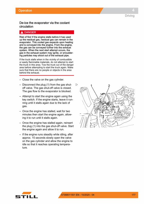
De-ice the evaporator via the coolantcirculation
DANGERRisk of fire! If the engine stalls before it has usedup the residual gas, residual gas can remain in theevaporator. This cooled gas expands upon heatingand is conveyed into the engine. From the engine,the gas can be conveyed further into the exhaustsystem. When the next start attempt occurs, thegas in the exhaust system may ignite, or smoulder-ing particles may shoot out of the exhaust pipe.If the truck stalls when in the vicinity of combustibleor easily flammable materials, do not attempt to startthe truck in this area. Tow the truck out of the dangerarea before attempting to start the truck again. Makesure that there are no people or objects in the areabehind the exhaust.
– Close the valve on the gas cylinder.
– Disconnect the plug (1) from the gas shut-off valve. The gas shut-off valve is closed.The gas flow to the evaporator is blocked.
– Attempt to start the engine again using thekey switch. If the engine starts, leave it run-ning until it stalls again due to the lack ofgas.
– Once the engine has stalled, wait for twominutes then start the engine again, allow-ing it to run until it stalls again.
– Once the engine has stalled again, reinsertthe plug (1) into the gas shut-off valve. Startthe engine again and allow it to run.
– If the engine runs steadily while idling, afterapprox. 15 seconds slowly open the valveon the gas cylinder and allow the engine toidle so that it reaches operating tempera-ture.
Z
Operation 4Driving
17757368011501 EN - 10/2020 - 04

– Check that the cooling water supply (2) tothe evaporator is warm.
– Wait until the evaporator has reached oper-ating temperature as a result of the truckidling.
– If the evaporator has not warmed up, slowlyclose the valve on the gas cylinder and al-low the engine to run until it stalls by itselfdue to the lack of gas.
– You can now attempt to de-ice the evapora-tor using a different method. To do this, pro-ceed as described in the following chapter.
Manually de-icing the evaporator
DANGER
Risk of explosion when de-icing the gassystem! Gas can ignite and explodewhen exposed to excessive heat, nak-ed flames, smouldering objects and ob-jects that produce sparks.Never thaw frozen system componentsby means of a naked flame or smoulder-ing objects! Carefully follow the instruc-tions below.
DANGERRisk of explosion! Escaping gas can ignite when itcomes into contact with the heating coil in heatingdevices such as a hot air gun. During de-icingtasks, the heat source must not exceed 50°C.Do not deliver the warm air straight from a heatingdevice. However, it is acceptable to deliver the warmair via a warm air hose.
The following resources are suitable for thaw-ing frozen system components: Warm air Warm water Warm sandbags
– Once the system components have beenthawed, de-ice the evaporator using theabove resources.
– Switch on the key switch and start the en-gine.
– If the engine still stalls, do not attempt tostart the truck; contact the authorised serv-ice centre.
Z
Operation4Driving
178 57368011501 EN - 10/2020 - 04
Cruise control (variant)The cruise control function keeps the drivingspeed constant. In addition, the cruise controlfunction can be used to comply with anyspeed limitation that is in force. The cruisecontrol function operates when driving for-wards at a speed of 6 km/h or faster. Thefunction is put on standby via the display-oper-ating unit and can be activated and deactiva-ted using the drive direction switch on the op-erating device for the hydraulic functions.
When the cruise control function is activated,the speed can be saved when driving forwardsat a speed of at least 6.0 km/h by pressing abutton and the truck can continue driving with-out the accelerator pedal being actuated.
The pictogram for operating the cruise con-trol function is located on the operating devicefor the hydraulic functions.
Putting the cruise control function onstandbyIn order for the cruise control function to beactivated via the drive direction switch, thefunction must first be put on standby using thedisplay-operating unit.
– Press the button.
The first menu level appears.
– Press the "Drive" softkey .
The "Drive" menu appears.
Operation 4Driving
17957368011501 EN - 10/2020 - 04

– Press the "cruise control" softkey.
The orange-coloured activation bar next to the"cruise control" softkey lights up. Thecruise control function is ready.
The greyed-out "cruise control" symbol (1)appears on the display.
Taking the cruise control function offstandbyPressing the "cruise control" softkey againtakes the function off standby.
A signal sounds. The "cruise control" sym-bol goes out.
Activating cruise control function
WARNINGRisk of accident from failing to adjust speed!Driving at excessive speeds can cause accidents,e.g. the truck could tip over when cornering.– Adjust speed along the entire distance being trav-
elled– Pay particular attention to cornering speed– Observe safety regulations when driving– Observe the special behaviour of the cruise con-
trol function and the dangers associated with it
– Accelerate the truck to the required speed(at least 6.0 km/h)
16219_003-307
08:20
Z
Operation4Driving
180 57368011501 EN - 10/2020 - 04

– Actuate the drive direction switch (1) for for-wards travel.
NOTE
In the dual pedal version (variant), the drive di-rection switch is used exclusively to activateand deactivate the cruise control function (var-iant).
The cruise control function is active. The cur-rent speed is saved.
Two signals sound. The symbol appears inblack on the display.
– Take your foot off the accelerator pedal.
The truck continues to drive at the selectedspeed until the cruise control function is deac-tivated.
– To save a different speed, deactivate thecruise control function and activate thefunction at the newly selected speed.
Deactivating cruise controlDeactivating the cruise control function meansthat the speed is again controlled by the accel-erator pedal. The cruise control function re-mains on standby. The function can be activa-ted at any time when the accelerator pedal isdepressed by pressing the drive directionswitch for forwards travel again.
When the cruise control function is deactiva-ted, the symbol is greyed out.
NOTE
The easiest way to deactivate the cruise con-trol function is to touch the accelerator pedal.
The following actions deactivate the cruisecontrol function: Actuating the foot brake Actuating the parking brake Actuating the accelerator pedal
Depressing the accelerator pedal beyondthe set speed accelerates the truck.
Changing the travel direction
1
+ F
1
1Z
Operation 4Driving
18157368011501 EN - 10/2020 - 04

Press the drive direction switch for forwardstravel again without actuating the accelera-tor pedal
Press the "cruise control" softkeyActuating the "cruise control" softkeyswitches off the cruise control function.
Other conditions that will cause the truck con-trol unit to deactivate the cruise control func-tion are: Vacating the driver's seat Truck speed less than 2.5 km/h. Speed limit set to less than 4.5 km/h. The truck control unit detects abnormalities,
e.g. a voltage drop
If the accelerator pedal is actuated in thesecircumstances, the truck is initially braked viathe drive unit. The following message appearson the display: Release the accelera-tor pedal.
– To continue driving, release the acceleratorpedal and actuate it again.
If these circumstances have changed again,the speed that was initially saved is set again.
NOTE
If the truck is configured with automatic func-tions to reduce the driving speed and the driv-ing speed is reduced to 6.0 km/h or less, thecruise control function is automatically deacti-vated.
Operation4Driving
182 57368011501 EN - 10/2020 - 04

ParkingParking the truck securely andswitching it off
DANGER
Risk of fatal injury from the truck rollingaway!– Do not park the truck on gradients.– In emergencies, secure the truck us-
ing wedges on the side facing down-hill.
– Only leave the truck when the parkingbrake has been applied.
DANGERThere is a risk of fatal injury from a falling load orparts of the truck being lowered!– Lower the load fully before leaving the truck.
WARNING
Volatile LPG can build up and ignite.There is a risk of explosion!LPG is heavier than air. It collects on theground, where it may form hazardousexplosive mixtures of gas and air.– Do not park the truck near pits, cel-
lars, stairwells, heating systems orother heat sources.
– Do not park the truck below groundlevel.
– Protect gas cylinders from heat.– Observe the safety regulations for
working with LPG.
– Apply the parking brake.
– Lower the fork to the ground.
– Tilt the lift mast forwards until the tips of thefork arms rest on the ground.
– If attachments (variant) are fitted, retract theworking cylinders; see the chapter entitled"General instructions for controlling attach-ments".
– Take your foot off the accelerator pedal andallow the engine to continue idling for ashort while.
5060_003-130
Z
Operation 4Parking
18357368011501 EN - 10/2020 - 04

– Turn the switch key to the left and removeit.
The solenoid valve in the LPG system willclose. The engine will continue to run for a fewseconds in order to burn off the gas remainingin the LPG system. This process can takeanything from 2–20 seconds, depending onthe temperature of the LPG.
NOTE
An error has occurred if the engine switchesoff only after around 60 seconds and the LPGAUTO.VALVE error message appears on thedisplay and operating unit. The truck can stillbe operated but your authorised service cen-tre must be notified of the error immediately.The error message is shown on the displayand operating unit until the error has been rec-tified by the authorised service centre.
NOTE
Switch keys, FleetManager cards (variant),FleetManager transponder chips (variant) andthe PIN code for access authorisation (variant)must not be handed over to other persons un-less explicit instructions to this effect havebeen given.
– For trucks with an LPG tank (variant), closethe shut-off valve (6).
7314_003-015
6Z
Operation4Parking
184 57368011501 EN - 10/2020 - 04

– For trucks with LPG cylinders, close the cyl-inder valve (7).
Wheel chock (variant)The wheel chock (variant) is used to preventthe truck from rolling away on a slope.
– Lift handle (2) on the support mounting.
– Remove wheel chock (1) from the supportmounting.
– Push the wheel chock under a front axlewheel on the side facing the downhill slope.
NOTE
After use, return the wheel chock to the sup-port mounting and press the handle (2) downagain.
7
7314_003-016
Z
7321_003-039_V2
2
1
1
Z
Operation 4Parking
18557368011501 EN - 10/2020 - 04

LiftingLifting system variantsThe movement of the fork carriage and the liftmast heavily depends on the following equip-ment: The lift mast with which the truck is equip-
ped, see ⇒ Chapter "Types of lift mast",Page 188
The operating device with which the hy-draulic functions are controlled, see⇒ Chapter "Lifting system operating devi-ces", Page 191
Regardless of the equipment variants of thetruck, the basic specifications and proceduresmust be complied with, see ⇒ Chapter "Safetyregulations when handing loads", Page 208 .
Automatic mast vertical positioning(variant)
CAUTIONRisk of damage to property due to the lift mast collid-ing with racks or other objects!– Before using the "automatic mast vertical position-
ing" assistance system, position the truck at a suf-ficient distance from racks and other objects.
The "automatic mast vertical positioning" as-sistance system can be used to set down thegoods so that the goods are exactly vertical,e.g. paper rolls. This prevents damage whensetting down the load. "Automatic mast verti-cal positioning" functions when tilting for-wards. A further variant is available which alsofunctions when tilting backwards. The tilt cylin-ders run into the end stops gently to preventhard vibrations and impacts. Oscillating mo-tions of the truck are minimised, thus increas-ing work safety. Automatic mast vertical posi-tioning reduces wear on various components,thereby reducing repair costs.
Z
Operation4Lifting
186 57368011501 EN - 10/2020 - 04

The "automatic mast vertical positioning" as-sistance system consists of the following indi-vidual functions: Display of the "Automatic mast vertical posi-
tioning" feature Automatic startup of the "Automatic mast
vertical position" feature
The truck can also be equipped with only the"mast tilt angle display" feature.
NOTE
Check the function of automatic mast verticalpositioning whenever the truck is used.
– See the section entitled "Function checkingof the automatic mast vertical positioningfunction".
– Push the "automatic mast vertical position-ing" softkey .
The symbol appears in the display.
– Tilt back the lift mast until it reaches the endstop.
– Tilt the lift mast forwards.
The lift mast stops in the vertical position.
NOTE
The lift mast also stops in the vertical positionif it is tilted forwards by 3° from a backwardtilt.
NOTE
The automatic mast vertical positioning mustbe calibrated in order to ensure accuracy at alltimes. The "access authorisation for the fleetmanager" is required for the calibration. Thisaccess is required:
When placing loads into stock and remov-ing loads from stock on HGV ramps
In the event of tyre wear If the lift mast is obviously not in the vertical
position
– See the section entitled "Calibrating the au-tomatic mast vertical positioning".
Operation 4Lifting
18757368011501 EN - 10/2020 - 04

Types of lift mastOne of the following lift masts may be installedin the truck:
Telescopic mastDuring lifting, the lift mast rises over the outerlift cylinders, bringing the fork carriage with itvia the chains (fork carriage rises twice as fastas the inner lift mast). The top edge (1) of theinner lift mast can therefore be higher than thefork carriage.
DANGERRisk of accident due to collision of the lift mast orload with low ceilings or entrances.– Note that the inner lift mast or load may be higher
than the fork carriage.– Note the heights of ceilings and entrances.
Hi-Lo lift mast (variant)During lifting, the inner lift cylinder moves upto free lift (3), and then the outer lift cylindersraise the inner lift mast up to the max. height(2).
NOTE
When lifting above the free lift, the fork car-riage always remains at the upper edge of theextending lift mast.
DANGERRisk of accident due to collision of the lift mast orload with low ceilings or entrances.– Note that the inner lift mast or load may be higher
than the fork carriage.– Note the heights of ceilings and entrances.
6210_810-001
1
Z
6210_810-002
2
3
Z
Operation4Lifting
188 57368011501 EN - 10/2020 - 04

Triplex lift mast (variant)During lifting, the inner lift cylinder moves upto free lift (3), and then the outer lift cylindersraise the inner lift mast up to the max. height(2).
DANGERRisk of accident due to collision of the lift mast orload with low ceilings or entrances.– Note that the inner lift mast or load may be higher
than the fork carriage.– Note the heights of ceilings and entrances.
Malfunctions during lifting modeIncorrect extension sequence
DANGERRisk of accidents!In the case of Hi-Lo lift masts (variant) and triplex liftmasts (variant), an incorrect extension sequencemay occur, i.e. the inner lift mast may extend beforethe free lift is complete. As a result, the overall heightis exceeded and damage may occur in passagewaysor from low ceilings.
An incorrect extension sequence may, for in-stance, result from: The hydraulic oil temperature being too low. Blocking of the fork carriage in the inner lift
mast. Blocking of the free lift cylinder. Blocking of the chain roller on the free lift
cylinder.
– If the hydraulic oil temperature is too low,slowly actuate the lift mast functions severaltimes in order to raise the oil temperature.
In the event that the fork carriage is blocked inthe inner lift mast, or the free lift cylinder orchain roller are blocked, the cause of theblockage must be eliminated before resumingwork.
– Notify your service centre
6210_810-002
2
3
Z
Operation 4Lifting
18957368011501 EN - 10/2020 - 04

Load chains not under tension
DANGERDanger caused by a falling load!– Make sure that the chain(s) does (do) not become
slack when lowering the load.
Slack chains can, for instance, result from: Resting the fork carriage or the load on the
racking. Fork carriage rollers blocking in the lift mast
due to contamination.
– If the fork carriage or the load comes to anunexpected stop, lift the fork carriage untilthe chains are under tension again and low-er the load at another suitable location.
– If the fork carriage rollers in the lift mast be-come blocked due to contamination, lift thefork carriage until the chains are under ten-sion again. Remove the contamination be-fore resuming work.
WARNINGRisk of injury!– Observe the safety regulations for working on the
lift mast, see the chapter entitled "Working at thefront of the truck".
Hydraulic blocking functionThe hydraulic blocking function ensures thatall the functions of the working hydraulics aredisabled whenever the seat switch in the driv-er's seat is unloaded.
If the driver stands up from the driver's seat,the blocking function prevents the hydraulicfunctions that: Lift the load Lower the load Tilt the lift mast Additional functions
Releasing the block on the hydraulicsProceed as follows to release the block on thehydraulics:
Operation4Lifting
190 57368011501 EN - 10/2020 - 04

– Sit down on the driver's seat.
All the relevant functions of the working hy-draulics will be available again.
NOTE
If it is not possible to release the block on thehydraulics when the load is raised because ofa technical fault, the load must be lowered us-ing the "emergency lowering" mechanism be-fore any further action is taken. Do not operatethe truck again until the fault has been recti-fied by the authorised service centre.
Lifting system operating devicesThe method of operating the lifting system de-pends on the operating devices included in thetruck's equipment.
Possible equipment variants include: Double mini-lever Triple mini-lever Quadruple mini-lever Joystick 4Plus Fingertip
– The following information must be observedregardless of the equipment variant.
DANGERReaching into or climbing between moving parts ofthe truck (e.g. lift mast, sideshifts, working equip-ment, load carrying devices etc.) can lead to seri-ous injury or death and is therefore prohibited.– Observe the safety regulations for handling loads.– Only operate the lifting system from the driver's
seat.
Operation 4Lifting
19157368011501 EN - 10/2020 - 04

Controlling the lifting system using adouble mini-lever
DANGERReaching into or climbing between moving parts ofthe truck (e.g. lift mast, sideshifts, working equip-ment, load carrying devices etc.) can lead to seri-ous injury or death and is therefore prohibited.– Observe the safety regulations for handling loads.– Operate the lifting system from the driver's seat
only.
The lifting, lowering and tilting movements ofthe lift mast are controlled using the "liftmast" 360° lever (3). The adhesive label bear-ing the pictograms for the hydraulic func-tions (1) or (2) is affixed at the designatedpoint (4).
– If the adhesive label becomes illegible or ismissing, please contact your authorisedservice centre.
– Observe the pictograms on the adhesive la-bels (1) and (2).
The pictograms are arranged according to thedirection of movement of the "lift mast" 360°lever (3).
NOTE
The truck is configured at the factory in ac-cordance with the adhesive label (1). The fol-lowing steps for moving the fork carriage andlift mast are based on this configuration.
Lifting/lowering the fork carriageTo lift the fork carriage:
– Move the "lift mast" 360° lever (3) in the di-rection of the arrow (B).
To lower the fork carriage:
– Move the "lift mast" 360° lever (3) in the di-rection of the arrow (A).
Tilting the lift mastTo tilt the lift mast forwards:
DC
B
A
Z
Operation4Lifting
192 57368011501 EN - 10/2020 - 04

– Move the "lift mast" 360° lever (4) in the di-rection of the arrow (C).
To tilt the lift mast backwards:
– Move the "lift mast" 360° lever (4) in the di-rection of the arrow (D).
Movements of the lifting system andmeanings of the pictogramsA LoweringB LiftingC Tilting forwardsD Tilting backwards
Operation 4Lifting
19357368011501 EN - 10/2020 - 04
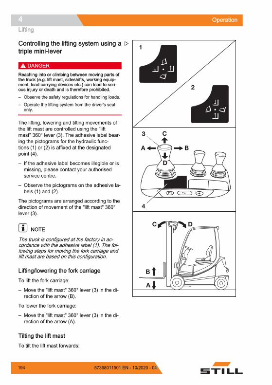
Controlling the lifting system using atriple mini-lever
DANGERReaching into or climbing between moving parts ofthe truck (e.g. lift mast, sideshifts, working equip-ment, load carrying devices etc.) can lead to seri-ous injury or death and is therefore prohibited.– Observe the safety regulations for handling loads.– Operate the lifting system from the driver's seat
only.
The lifting, lowering and tilting movements ofthe lift mast are controlled using the "liftmast" 360° lever (3). The adhesive label bear-ing the pictograms for the hydraulic func-tions (1) or (2) is affixed at the designatedpoint (4).
– If the adhesive label becomes illegible or ismissing, please contact your authorisedservice centre.
– Observe the pictograms on the adhesive la-bels (1) and (2).
The pictograms are arranged according to thedirection of movement of the "lift mast" 360°lever (3).
NOTE
The truck is configured at the factory in ac-cordance with the adhesive label (1). The fol-lowing steps for moving the fork carriage andlift mast are based on this configuration.
Lifting/lowering the fork carriageTo lift the fork carriage:
– Move the "lift mast" 360° lever (3) in the di-rection of the arrow (B).
To lower the fork carriage:
– Move the "lift mast" 360° lever (3) in the di-rection of the arrow (A).
Tilting the lift mastTo tilt the lift mast forwards:
DC
B
A
A B
C
D
Z
Operation4Lifting
194 57368011501 EN - 10/2020 - 04

– Move the "lift mast" 360° lever (4) in the di-rection of the arrow (C).
To tilt the lift mast backwards:
– Move the "lift mast" 360° lever (4) in the di-rection of the arrow (D).
Movements of the lifting system andmeanings of the pictogramsA LoweringB LiftingC Tilting forwardsD Tilting backwards
Operation 4Lifting
19557368011501 EN - 10/2020 - 04

Controlling the lifting system using aquadruple mini-lever
DANGERReaching into or climbing between moving parts ofthe truck (e.g. lift mast, sideshifts, working equip-ment, load carrying devices etc.) can lead to seri-ous injury or death and is therefore prohibited.– Observe the safety regulations for handling loads.– Operate the lifting system from the driver's seat
only.
The lifting, lowering and tilting functions of thelift mast are controlled using the "lifting/lower-ing" operating lever (3) and the "lift mast" op-erating lever (4). The adhesive label bearingthe pictograms for the hydraulic functions (1)is affixed at the designated point (6). The ad-hesive label (2) is attached at the designatedpoint (5). The truck is configured at the factoryin accordance with the adhesive label (1).
– Observe the pictograms on the adhesive la-bels (1) and (2).
The pictograms are arranged according to thedirection of movement of the operating lev-er (3) or (4).
Lifting/lowering the fork carriageTo lift the fork carriage:
– Move the "lifting/lowering" operating lev-er (3) in the direction of the arrow (D).
To lower the fork carriage:
– Move the "lifting/lowering" operating lev-er (3) in the direction of the arrow (C).
Tilting the lift mastTo tilt the lift mast forwards:
– Move the "lift mast" operating lever (4) inthe direction of the arrow (A).
To tilt the lift mast backwards:
– Move the "lift mast" operating lever (4) inthe direction of the arrow (B).
DC
B
A
Z
Operation4Lifting
196 57368011501 EN - 10/2020 - 04

Movements of the lifting system andmeanings of the pictogramsA LoweringB LiftingC Tilting forwardsD Tilting backwards
Controlling the lifting system usingthe Joystick 4Plus
DANGERReaching into or climbing between moving parts ofthe truck (e.g. lift mast, sideshifts, working equip-ment, load carrying devices etc.) can lead to seri-ous injury or death and is therefore prohibited.– Observe the safety regulations for handling loads.– Only operate the lifting system from the driver's
seat.
Lifting/lowering the fork carriageTo lift the fork carriage:
– Pull the Joystick 4Plus (1) backwards (B).
To lower the fork carriage:
– Push the Joystick 4Plus (1) forwards (A).
6210_003-089
1
A
B
Z
Operation 4Lifting
19757368011501 EN - 10/2020 - 04

Tilting the lift mastTo tilt the lift mast forwards:
– Tilt the horizontal rocker button (2) to theleft (C).
To tilt the lift mast backwards:
– Tilt the horizontal rocker button (2) to theright (D).
6210_003-090
DC
2
7312_003-022_V2
DC
B
A
Z
Operation4Lifting
198 57368011501 EN - 10/2020 - 04

Fork carriage sideshiftTo move the fork carriage to the left:
– Push the Joystick 4Plus (1) to the left (E).
To move the fork carriage to the right:
– Push the Joystick 4Plus (1) to the right (F).
NOTE
The symbols on the Joystick 4Plus indicatethe direction of movement of the lift mast orfork carriage.
1
6210_003-091
E
F
Z
Operation 4Lifting
19957368011501 EN - 10/2020 - 04

Controlling the lifting system usingthe Fingertip
DANGERReaching into or climbing between moving parts ofthe truck (e.g. lift mast, sideshifts, working equip-ment, load carrying devices etc.) can lead to seri-ous injury or death and is therefore prohibited.– Observe the safety regulations for handling loads.– Operate the lifting system from the driver's seat
only.
The lifting, lowering and tilting functions of thelift mast are controlled using the "lifting/lower-ing" operating lever (1) and the "tilting" operat-ing lever (4). The adhesive labels bearing thepictograms for the hydraulic functions (2, 3)are affixed on the operating levers.
– Observe the pictograms on the adhesive la-bels (2) and (3).
The pictograms are arranged according to thedirection of movement of the operating lev-er (1) or (2).
Lifting/lowering the fork carriageTo lift the fork carriage:
– Move the "lifting/lowering" operating lev-er (1) in the direction of the arrow (A).
To lower the fork carriage:
– Move the "lifting/lowering" operating lev-er (1) in the direction of the arrow (B).
Tilting the lift mastTo tilt the lift mast forwards:
– Move the "tilting" operating lever (2) in thedirection of the arrow (C).
To tilt the lift mast backwards:
– Move the "tilting" operating lever (2) in thedirection of the arrow (D).
C
D
A
B
21
4
3
DC
B
A
Z
Operation4Lifting
200 57368011501 EN - 10/2020 - 04

Movements of the lifting system andmeanings of the pictogramsA LoweringB LiftingC Tilting forwardsD Tilting backwards
Fork wear protection (variant)The "fork wear protection" variant ensures thatthe fork arms do not touch the ground. Thefork arms are protected against wear and thebuilding floor is protected against damage.
The lift cylinders have in-built fixed stops toprevent the fork arms from hitting the ground.The lower stop makes inserting the forks intoa pallet more comfortable.
Mechanical versionFixed stops in the lift cylinder prevent the forkarms from hitting the ground. No symbol ap-pears in the display-operating unit.
This version cannot be adjusted.
NOTE
The mechanical fork wear protection must becontinually adjusted as the wear on the fronttyres increases. For help with this, call the au-thorised service centre.
Changing the fork arms DANGER
Risk of fatal injury from being run over if the truckrolls away!– Do not park the truck on a gradient.– Apply the parking brake.– Change the fork arms in a separate, safe location
on a level surface.
Operation 4Lifting
20157368011501 EN - 10/2020 - 04

WARNINGThere is a risk of injury when changing the fork arms;the weight of the fork arms could cause them to fallon your legs, feet or knees. The space to the left andright of the fork is a danger area.– Always wear protective gloves and safety foot-
wear when changing the fork arms.– Ensure that no one stands in the danger area!– Do not pull on the fork arms.– The fork arms must always be carried by two peo-
ple; if necessary, use a hoist.
NOTE
For installation and removal, a transportpallet is recommended for supporting thefork arms. The pallet size depends on thefork arm size used and should be dimen-sioned such that the fork arms do not pro-trude after being placed on the pallet. Thismeans the fork arms can be safely placeddown and transported.
Both fork arms can be pushed over to thesame side. It is possible to choose the sidevia which the forks are removed
Operation4Lifting
202 57368011501 EN - 10/2020 - 04

Removal– Select a pallet corresponding to the fork
arm size.
– Set down the pallet next to the fork carriageon the side chosen for removal.
– Lift the fork carriage until the fork arms areapprox. 3 cm above the pallet.
– Apply the parking brake.
– Remove the switch key.
– Unscrew the locking screw (2) on the sidechosen for removal.
– Pull up the locking lever (1) and push thefork arms onto the pallet one after the other.
Installation– Make sure that the locking screw is un-
screwed on the side chosen for installation.
– Place the fork arms on a pallet next to thefork carriage on the side chosen for installa-tion.
– Pull up the locking lever (1) and push thefork arms onto the fork carriage one afterthe other.
– Place the fork arms in the required positionand push down the locking lever. Ensurethat the locking lever snaps into place.
– Screw in and tighten the locking screw (2).
DANGERThere is a risk of fatal injury from a falling load orfork!– Tighten the locking screw each time a fork is
changed.– Driving and moving loads without the locking
screw is prohibited.
1
2
6210_003-027
Z
Operation 4Lifting
20357368011501 EN - 10/2020 - 04

NOTE
If the truck is equipped with the "load meas-urement" comfort feature, a "zero adjustmentof the load measurement" must always beperformed after the fork arms have beenchanged. Otherwise, correct loadmeasurement cannot be guaranteed.
Fork extension (variant) DANGER
There is a risk of being run over if the truck rollsaway and therefore a danger to life.– Do not park the truck on a slope.– Apply the parking brake.– Change the fork extension in a separate, safe lo-
cation on a level surface.
WARNINGThere is a risk of crushing!The weight of the fork extension can cause crushingor cuts on sharp edges or burrs.– Always wear protective gloves and safety foot-
wear.
WARNINGThere is a risk of tipping!The weight and dimensions of the fork extension af-fect the stability of the truck. The permissible weightsstated on the capacity rating plate must be reducedin proportion to the actual load distance.
The truck is equipped with a fork extension ex works,the capacity rating plate is already adjusted accord-ingly.– Observe load capacity, see the "Before picking up
a load" chapter.
NOTE
If the truck is equipped with the "load meas-urement" comfort feature, a "zero adjustmentof the load measurement" must always beperformed after the fork extensions have beenchanged. Otherwise, correct load measure-ment cannot be guaranteed.
Operation4Lifting
204 57368011501 EN - 10/2020 - 04

Attachment
DANGERRisk to life from falling load!At least 60% of the length of the fork extension mustlie on the fork arm. A maximum 40% overhang overthe fork arm end is permissible. The fork extensionmust also be secured against slipping from the forkarm.
If the fork extension (1) is not secured with a secur-ing bolt (2) and linch pin (3), the load with the fork ex-tension may fall.– Push the fork extension completely to the back of
the fork.– Make sure that 60% of the length of the fork ex-
tension is on the fork arm.– Always secure the fork extension with a securing
bolt.– Always secure the securing bolt with a linch pin.
– Remove the linch pin (3) from the securingbolt (2).
– Remove the securing bolt from the fork ex-tension (1).
– Push the fork extension onto the fork armsuntil it is flush with the fork back.
– Insert the securing bolts located behind thefork back fully into the fork extension.
– Insert the linch pin into the securing boltand secure.
Removal– Remove the linch pin (3) from the securing
bolt (2).
– Remove the securing bolt from the fork ex-tension (1).
– Pull the fork extension from the fork arms.
– Insert the securing bolt fully into the fork ex-tension.
– Insert the linch pin into the securing boltand secure.
7071_003-104_V2
1
2
3
Z
Operation 4Lifting
20557368011501 EN - 10/2020 - 04

Operation with reversible fork arms(variant)
DANGERRisk to life from falling load!Standard fork arms are not structurally designed forreverse operation. If this instruction is not observed,it can lead to material failure and the load falling.– Only work in reverse operation using reversible
fork arms (1)
WARNINGRisk of accident from slipping load!Loads may slip on the reversible fork arms if there isno load support. A fork extension (variant) cannot besecured against slipping.– Do not use a fork extension (variant)
WARNINGRisk of accident from the truck tipping over.When driving, the centre of gravity of the load (2)must not be higher than 600 mm above the ground.The truck may tip forwards when driving or braking.– Only drive with a load centre of gravity up to a
max. of 600 mm above the ground
NOTE
If the truck is equipped with the "load meas-urement" comfort feature, a "zero adjustmentof the load measurement" must always beperformed after the reversible fork arms havebeen changed. Otherwise, correct load meas-urement cannot be guaranteed.
Z
Operation4Lifting
206 57368011501 EN - 10/2020 - 04

Reversible fork arms (1) can be used to reachan additional lift height. The reversible forkarms are installed on the fork carriage in thesame manner as standard fork arms. Loadsmay be lifted on and beneath the reversiblefork arms. The mast is lifted and tilted in thesame manner.
– Only work in reverse operation using rever-sible fork arms
– Do not use a fork extension (variant)
– If the "load measurement" comfort feature isavailable, perform a "zero adjustment of theload measurement"
– To drive, raise the load centre of gravity (2)to a max. of 600 mm above the ground
– Observe the information in the section enti-tled "Transporting suspended loads"
6341_862-001
Z
Operation 4Lifting
20757368011501 EN - 10/2020 - 04

Handling loadsSafety regulations when handingloadsThe safety regulations for handling loads areshown in the following sections.
DANGERThere is a risk to life caused by falling loads or ifparts of the truck are being lowered.– Never walk or stand underneath suspended loads
or raised fork arms.– Never exceed the maximum load indicated on the
capacity rating plate. Otherwise stability cannot beguaranteed!
DANGERRisk of accident from falling or crushing!– Do not step onto the forks.– Do not lift people.– Never grab or climb on moving parts of the truck.
DANGERRisk of accident from a falling load!– When transporting small items, attach a load safe-
ty guard (variant) to prevent the load from fallingon the driver.
– Use a closed roof covering (variant) in addition.
6210_003-030
Z
Operation4Handling loads
208 57368011501 EN - 10/2020 - 04

Before taking up loadLoad capacityThe load capacity indicated for the truck onthe capacity rating plate may not be excee-ded. The load capacity is influenced by theload centre of gravity and the lift height as wellas by the tyres, if applicable.
The position of the capacity rating plate canbe found in the chapter entitled "Identificationpoints".
WARNINGThe figures show examples.Only the capacity rating plates on the truck are valid!
The attachment of additional weights to in-crease load capacity is prohibited.
DANGERRisk to life from the truck losing stability!Never exceed the maximum loads shown! These val-ues apply to compact and homogenous loads. Other-wise, the stability as well as the rigidity of the forkarms and lift mast cannot be guaranteed.
Improper or incorrect operation or the placement ofpersons to increase load capacity is prohibited.
2
1
780
910131093012306801500950126069015009708607101500
10008807301500
600500
6401080
4830463042303830
kg
3
5051_003-006
800
800 5030660
5230
500
880
Z
Operation 4Handling loads
20957368011501 EN - 10/2020 - 04

ExampleWeight of load to be lifted: 880 kg (3)
Load distance from fork back: 500 mm (1)
Permitted lift height: 5230 mm (2)
WARNINGRisk of accident from the truck losing stability!The permissible load of the attachments (variant)and the reduced lifting capacity of the combination oftruck and attachment must not be exceeded.– Observe the special capacity rating plate informa-
tion shown on the truck and the attachment.
5051_003-007
3
5230
500
2
880 Kg
1
Z
Operation4Handling loads
210 57368011501 EN - 10/2020 - 04

Load measurement (variant)Knowing the weight of the load to be transpor-ted gives the driver greater security. If thetruck is equipped with the "load measurement"assistance system, the weight of the lifted loadis measured and displayed in the display-op-erating unit (1). The measuring accuracy is5% of the rated capacity.
– Observe the following safety information.
DANGERRisk of accident from a falling load!The load may fall if the load centre of gravity has notbeen taken into account or the load has not beenpicked up securely.– Pick up the load securely; see the chapter entitled
"Picking up loads".
WARNINGRisk of accident as a result of exceeding the residualload capacity.If the weight determined by a load measurement ex-ceeds the permissible residual load capacity of thetruck, the truck cannot be operated safely.– Set down and reduce the load immediately.– If necessary, use another truck with sufficient
load-bearing capacity.
NOTE
The load measurement must be calibrated inorder to ensure accuracy at all times. The "ac-cess authorisation for the fleet manager" is re-quired for the calibration. This access is re-quired:
After changing the fork arms, After fitting or changing attachments If the displayed values are obviously incor-
rect
If -.-- t is displayed permanently, thismeans that the function is calibrated incorrect-ly (load < 0 kg).
– See the section entitled "Calibrating theload measurement".
6219_003-112_V4
1,6 t
2,71 m7,0°
Z
Operation 4Handling loads
21157368011501 EN - 10/2020 - 04

Picking up loadsTo make sure that the load is securely suppor-ted, it must be ensured that the fork arms aresufficiently far apart and are positioned as faras possible under the load.
If possible, the load should rest on the back ofthe fork.
The load must not protrude too far over thefork tips, nor should the fork tips protrude toofar out from the load.
Loads are to be picked up and transported asclose to the middle as possible.
DANGERRisk of accident from a falling load!When transporting small items, attach a load safetyguard (variant) to prevent the load from falling on thedriver.
A closed roof covering (variant) should also be used.
Removable roof panels may not be removed.
Adjusting the fork– Lift the locking lever (1) and move the fork
arms to the desired position.
– Allow the locking lever to snap back intoplace.
The load centre of gravity must be midway be-tween the fork arms.
– Only actuate the fork prong positioner (var-iant) when the fork is not carrying a load.
Danger areaThe danger area is the area in which peopleare at risk due to the movements of the truck,its working equipment, its load-carrying equip-ment (e.g. attachments) or the load. Also
1
6210_842-001
Z
Operation4Handling loads
212 57368011501 EN - 10/2020 - 04

included are the areas where loads could fallor working equipment could fall or be lowered.
DANGER
Risk of injury!– Do not step on the fork.
DANGER
Risk of injury!– Do not step under the raised forks.
DANGERPeople may be injured in the danger area of thetruck!The danger area of the truck must be completelyclear of all personnel, except the driver in his normaloperating position. If persons fail to leave the dangerarea despite warnings:– Cease work with the truck immediately.– Secure the truck against use by unauthorised par-
ties.
DANGER
Danger of death from falling loads!– Never walk or stand underneath sus-
pended loads.
Transporting palletsAs a rule, loads (e.g. pallets) must be trans-ported individually. Transporting multiple loadsat the same time is only permitted: when instructed by the supervisor and when the technical requirements have been
met.
The driver must ensure proper condition of theload. Only safely and carefully positionedloads may be transported.
6327_003-009
Z
Operation 4Handling loads
21357368011501 EN - 10/2020 - 04
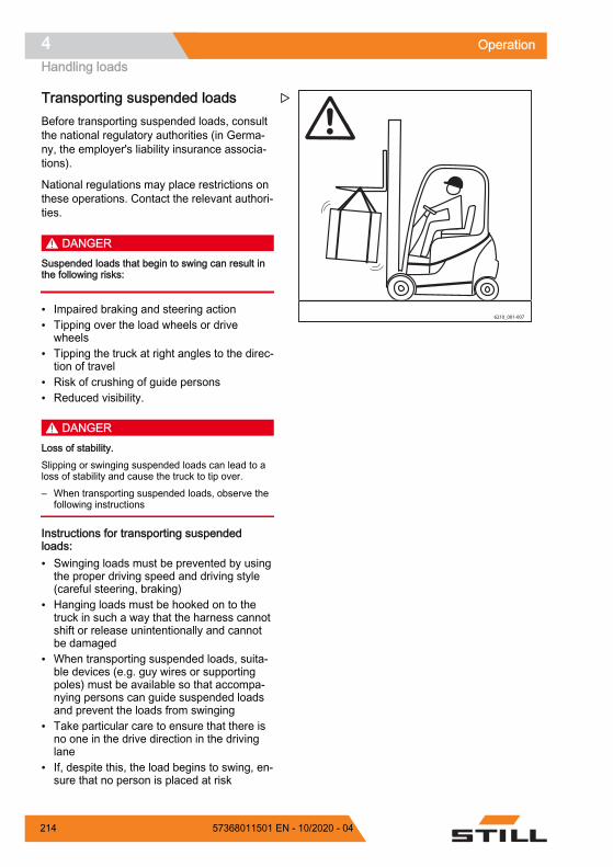
Transporting suspended loadsBefore transporting suspended loads, consultthe national regulatory authorities (in Germa-ny, the employer's liability insurance associa-tions).
National regulations may place restrictions onthese operations. Contact the relevant authori-ties.
DANGERSuspended loads that begin to swing can result inthe following risks:
Impaired braking and steering action Tipping over the load wheels or drive
wheels Tipping the truck at right angles to the direc-
tion of travel Risk of crushing of guide persons Reduced visibility.
DANGERLoss of stability.Slipping or swinging suspended loads can lead to aloss of stability and cause the truck to tip over.– When transporting suspended loads, observe the
following instructions
Instructions for transporting suspendedloads: Swinging loads must be prevented by using
the proper driving speed and driving style(careful steering, braking)
Hanging loads must be hooked on to thetruck in such a way that the harness cannotshift or release unintentionally and cannotbe damaged
When transporting suspended loads, suita-ble devices (e.g. guy wires or supportingpoles) must be available so that accompa-nying persons can guide suspended loadsand prevent the loads from swinging
Take particular care to ensure that there isno one in the drive direction in the drivinglane
If, despite this, the load begins to swing, en-sure that no person is placed at risk
6210_001-007
Z
Operation4Handling loads
214 57368011501 EN - 10/2020 - 04

DANGERRisk of accidents!When transporting hanging loads, never perform orend driving and load movements abruptly.
Never drive on slopes with a suspended load.
Transporting containers holding fluids as hangingloads is not permitted.
Picking up a load DANGER
There is a risk to life caused by a falling load or ifparts of the truck are being lowered.– Never walk or stand underneath suspended loads
or raised fork arms.– Never exceed the maximum load values specified
on the capacity rating plate. Otherwise, stabilitycannot be guaranteed.
– Only store pallets that do not exceed thespecified maximum size. Damaged loadingequipment and incorrectly formed loadsmust not be stored.
– Attach or secure the load to the lifting ac-cessory so that the load cannot move orfall.
– Store the load so that the specified aislewidth is not reduced by protruding parts.
– Approach the rack carefully, brake gentlyand stop just in front of the rack.
6210_800-005
Z
Operation 4Handling loads
21557368011501 EN - 10/2020 - 04

– Position the forks.
– Set the lift mast to vertical.
– Lift the fork carriage to the stacking height.
CAUTIONRisk of component damage!Ensure that the rack and load do not become dam-aged when inserting the fork into the rack.
– Insert the fork as far under the load as pos-sible. Stop the truck as soon as the forkback is resting on the load. The load centreof gravity must be midway between the forkarms.
6210_800-006
Z
6210_800-007
Z
Operation4Handling loads
216 57368011501 EN - 10/2020 - 04

– Lift the fork carriage until the load is restingentirely on the fork.
DANGERRisk of accident!– Beware of any people in the danger area.– Ensure that the roadway behind you is clear.
DANGERDue to the risk of tipping, never tilt the lift mast witha raised load!– Lower the load before tilting the lift mast.
– Reverse carefully and slowly until the loadis clear of the rack. Brake gently.
– Lower the load while maintaining groundclearance.
6210_800-008
Z
5060_003-102
Z
Operation 4Handling loads
21757368011501 EN - 10/2020 - 04

– Tilt the lift mast backwards.
The load can be transported.
Transporting loads
NOTE
Observe the information in the chapter entitled"Safety regulations when driving".
DANGERThe higher a load is lifted, the less stable it be-comes. The truck can tip over or the load can fall,increasing the risk of accident!Driving with a raised load and the lift mast tilted for-ward is not permitted.– Only drive with the load lowered.– Lower the load until ground clearance is reached
(not over 300 mm).– Only drive with the lift mast tilted backwards.
5060_003-101
Z
6210_800-011
Z
Operation4Handling loads
218 57368011501 EN - 10/2020 - 04
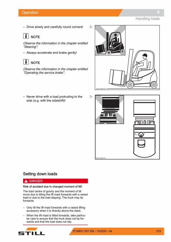
– Drive slowly and carefully round corners!
NOTE
Observe the information in the chapter entitled"Steering".
– Always accelerate and brake gently!
NOTE
Observe the information in the chapter entitled"Operating the service brake".
– Never drive with a load protruding to theside (e.g. with the sideshift)!
Setting down loads DANGER
Risk of accident due to changed moment of tilt!The load centre of gravity and the moment of tiltmove due to tilting the lift mast forwards with a raisedload or due to the load slipping. The truck may tipforwards.
– Only tilt the lift mast forwards with a raised liftingaccessory when it is directly above the stack.
– When the lift mast is tilted forwards, take particu-lar care to ensure that the truck does not tip for-wards and that the load does not slip.
6210_800-013
Z
6210_800-014
Z
Operation 4Handling loads
21957368011501 EN - 10/2020 - 04

WARNINGRisk of accident from a falling load!If the fork or the load remains suspended during low-ering, the load may fall.– When removing from stock, move the truck far
enough back so that the load and the fork can belowered freely.
– Drive up to the stack with the load loweredin accordance with regulations.
– Set lift mast to vertical.
– Lift the load to the stacking height.
– Drive the truck towards the rack carefully.
– Lower the load until it rests securely on therack.
DANGERRisk of accident!– Beware of any people in the danger area.– Ensure that the roadway behind you is clear.
– Move the truck back until the fork arms canbe lowered without touching the stack.
– Lower the fork while maintaining groundclearance.
– Tilt the lift mast backwards and drive away.
6210_800-015
Z
6210_800-016
Z
Operation4Handling loads
220 57368011501 EN - 10/2020 - 04

Shake function (variant)
NOTE
The shake function is intended only for short-term use, as it reduces the service life of theload chains due to the increased loading onthem.
DescriptionThe shake function of the hydraulics makes iteasier for the driver to perform tasks such asemptying containers of bulk material. Theshake function moves the fork carriage quicklyup and down via the "Lifting" function.
This function may only be used for a limitedload and must not be used with a full nominalload.
Maximum permissible load for the shakefunction: Maximum 30% of the nominal load. If an at-
tachment is being used, its weight must besubtracted from this value.
NOTE
The weight of an attachment can be seen onits nameplate.
OperationTo activate the shake function:
– Move the corresponding operating devicefor the "Lifting" function over the zero posi-tion four times in quick succession.
The fork carriage moves as normal. Theshake function is active after the fourth timethe operating device is moved.
– Continue to move the operating device backand forth.
The fork carriage moves up and down morequickly and more jerkily.
The intensity of the shaking is controlled viathe vigour with which the operating device ismoved. The more vigorously and frequentlythe operating device is moved, the more in-tense the shaking is.
Operation 4Handling loads
22157368011501 EN - 10/2020 - 04

NOTE
After the function has been activated, the driv-er has two seconds to start the shaking. If thetwo seconds elapse without the shake functionbeing used, the shake function is deactivatedagain.
WARNINGThe shake function remains active for two secondsfollowing activation.If the driver simply wants to lift or lower the load dur-ing this time, note that the fork carriage may movesignificantly more jerkily with the load than in normaloperation. If the two seconds elapse without theshake function being used, the fork carriage can bemoved normally again with the load.
The following section shows how the shakefunction is activated via the standard assign-ment for "lifting/lowering" using the differentvariants of the operating devices. If the "lifting/lowering" function is assigned differently onthe operating device, the shake function is ac-tivated via this other assignment.
Joystick 4Plus:
– Move the Joystick 4Plus (1) back and forthbetween positions (A) and (B) four times.Then continue to move the component inthe same way.
6210_003-089
1
A
B
Z
Operation4Handling loads
222 57368011501 EN - 10/2020 - 04

Double mini-lever:
– Move the 360° lever (2) back and forth be-tween positions (A) and (B) four times.Then continue to move the component inthe same way.
Triple mini-lever:
– Move the 360° lever (3) back and forth be-tween positions (A) and (B) four times.Then continue to move the component inthe same way.
Quadruple mini-lever:
– Move the operating lever (4) back and forthbetween positions (A) and (B) four times.Then continue to move the component inthe same way.
Z
Z
Z
Operation 4Handling loads
22357368011501 EN - 10/2020 - 04

Fingertip:
– Move the operating lever (5) back and forthfour times. Then continue to move the com-ponent in the same way.
Driving on liftsThe driver may only use this truck on lifts witha sufficient rated capacity and for which theoperating company has been granted authori-sation.
DANGERThere is a risk to life if you are crushed or run overby the truck.– There must be no personnel already in the lift
when the truck is driven into the lift.– Personnel are only permitted to enter the lift once
the truck is secure, and must exit the lift beforethe truck is driven out.
Z
5060_003-071
Z
Operation4Handling loads
224 57368011501 EN - 10/2020 - 04

Determining the actual total weight– Park the truck securely.
– Determine the unit weights by reading thetruck nameplate and, if necessary, the at-tachment (variant) nameplate and, if neces-sary, by weighing the load to be lifted.
– Add the determined unit weights to obtainthe actual total weight of the truck:
Tare weight (1)
+ Ballast weight (variant) (2)
+ Attachment net weight (variant)
+ Weight of the load to be lifted+ 100 kg allowance for driver= Actual total weight
– Drive the truck with the forks forwards intothe lift without touching the shaft walls.
– Park the truck securely in the lift to preventuncontrolled movements of the load or thetruck.
Driving on loading bridges
DANGERRisk of accident if the truck crashes!Steering movements can cause the tail end to veeroff the loading bridge towards the edge. This maycause the truck to crash.
The lorry driver and the truck driver must agree onthe lorry's departure time.– Before driving across a loading bridge, ensure
that it is properly attached and secured and has asufficient load capacity (lorry, bridge etc.).
– Drive slowly and with care on the loading bridge.– Ensure that the vehicle onto which you will be
driving is secured to prevent it from shifting andthat it can support the load of the truck.
Type-Modèle-Typ / Serial no.-No. de série-Serien-Nr. / year-année-Baujahr
Rated capacityCapacité nominaleNenn-Tragfähigkeit
Battery voltageTension batterieBatteriespannung
Rated drive powerPuissance motr.nom.Nenn-Antriebsleist.
Unladen massMasse à videLeergewicht
maxmin.*
* see Operating instructions voir Mode d'emploi siehe Betriebsanleitung
kg kg
kgkg
kgkW
V
*
D-22113 HamburgBerzeliusstr. 10 2
1
Z
6210_001-010
Z
Operation 4Handling loads
22557368011501 EN - 10/2020 - 04

Determining the actual total weight– Park the truck securely.
– Determine the unit weights by reading thetruck nameplate and, if necessary, the at-tachment (variant) nameplate and, if neces-sary, by weighing the load to be lifted.
– Add the determined unit weights to obtainthe actual total weight of the truck:
Tare weight (1)
+ Ballast weight (variant) (2)
+ Attachment net weight (variant)
+ Weight of the load to be lifted+ 100 kg allowance for driver= Actual total weight
Type-Modèle-Typ / Serial no.-No. de série-Serien-Nr. / year-année-Baujahr
Rated capacityCapacité nominaleNenn-Tragfähigkeit
Battery voltageTension batterieBatteriespannung
Rated drive powerPuissance motr.nom.Nenn-Antriebsleist.
Unladen massMasse à videLeergewicht
maxmin.*
* see Operating instructions voir Mode d'emploi siehe Betriebsanleitung
kg kg
kgkg
kgkW
V
*
D-22113 HamburgBerzeliusstr. 10 2
1
Z
Operation4Handling loads
226 57368011501 EN - 10/2020 - 04

AttachmentsFitting attachmentsIf the truck is equipped with an integrated at-tachment (variant) at the factory, the specifica-tions in the STILL operating instructions for in-tegrated attachments must be observed.
If attachments are fitted at the place of use,the specifications in the operating instructionsof the attachment manufacturer must be ob-served.
If an attachment is not delivered together withthe forklift truck, the specifications and operat-ing instructions of the attachment manufactur-er must be observed.
Before initial commissioning, the function ofthe attachment and the visibility from the driv-er's position with and without a load must bechecked by a competent person. If the visibili-ty is deemed insufficient, visual aids such asmirrors, a camera/monitor system etc. must beused.
In addition, it is essential that the warnings be-low are observed.
CAUTIONAttachments must be CE-certified. If the truck is notfitted with an attachment-specific residual load ca-pacity rating plate and the operating devices are notmarked with corresponding pictograms, the truckmust not be used.– Order the residual load capacity rating plate and
pictograms from your authorised service centre ingood time.
– The authorised service centre must adapt the hy-draulic system to the requirements of the attach-ment (e.g. by adjusting the pump motor speed).
Operation 4Attachments
22757368011501 EN - 10/2020 - 04
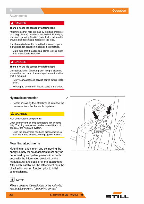
DANGERThere is risk to life caused by a falling load!Attachments that hold the load by exerting pressureon it (e.g. clamps) must be controlled additionally bya second operating function (lock) that is actuated toprevent an unintentional release of the load.
If such an attachment is retrofitted, a second operat-ing function for actuation must also be retrofitted.– Make sure that the additional clamp locking mech-
anism function is available.
DANGERThere is risk to life caused by a falling load!During installation of a clamp with integral sideshift,ensure that the clamp does not open when the side-shift is actuated.– Notify your authorised service centre before instal-
lation.– Never grab or climb on moving parts of the truck.
Hydraulic connection– Before installing the attachment, release the
pressure from the hydraulic system.
CAUTIONRisk of damage to components!Open connections of plug connectors can becomedirty. The plug connectors can become stiff and dirtcan enter the hydraulic system.– Once the attachment has been disassembled, at-
tach the protective caps to the plug connectors.
Mounting attachmentsMounting an attachment and connecting theenergy supply for an attachment must only beperformed by competent persons in accord-ance with the information provided by themanufacturer and supplier of the attachment.After each installation, the attachment must bechecked for correct function prior to initialcommissioning.
NOTE
Please observe the definition of the followingresponsible person: "competent person".
7090_900-001
Z
Operation4Attachments
228 57368011501 EN - 10/2020 - 04
Load capacity with attachmentThe permissible load capacity of the attach-ment and the allowable load (load capacityand load moment) of the truck must not be ex-ceeded by the combination of attachment andpayload. The specifications of the manufactur-er and supplier of the attachment must becomplied with.
– Observe the residual load capacity ratingplate, see the chapter entitled "Taking up aload using attachments".
Depressurising the hydraulic sys-tem
WARNINGThe movements of the load lift system present a riskof crushing.During the process described below, the fork car-riage or the lift mast can only be moved slightly.– Do not reach into or stand below the components
of the load lift system.
NOTE
The internal combustion engine must beswitched off in order to depressurise the sys-tem.
– Insert the switch key into the key switch andturn it to the "I" position.
The valves are supplied with power and thehydraulic system is depressurised.
Depressurising the hydraulic circuits forthe basic functionsThe basic functions include the first four hy-draulic functions. The basic functions are con-trolled via the first two hydraulic circuits.
The basic functions are: Lifting the fork carriage Lowering the fork carriage Tilting the lift mast forwards Tilting the lift mast backwards
Operation 4Attachments
22957368011501 EN - 10/2020 - 04

– Actuate the operating levers for controllingthe hydraulic functions once in the direc-tions of the arrows as far as the end posi-tions.
The hydraulic circuits of the basic functionsare now depressurised.
Depressurising the hydraulic circuits forthe "5th hydraulic function"If the truck has a "5th hydraulic function", thehydraulic circuits of these functions must alsobe depressurised. The procedure is similar tothe depressurisation of the hydraulic circuitsfor the basic functions. In addition, the hy-draulic circuits are depressurised in the sameway as the attachments are operated.
The hydraulic circuits for the "5th hydraulicfunctions" are actuated via the correspondingbuttons on the operating devices. Function key for the "5th function" with mini-
lever control and Fingertip operation Shift key "F" with Joystick 4Plus operation
(hereinafter referred to as the "button")
– Press and hold the button (1) for the operat-ing devices.
– Again, actuate the operating levers for con-trolling the hydraulic functions once in thedirections of the arrows as far as the endpositions.
– With Joystick 4Plus operation, also actuatethe slider and the rocker buttons.
The hydraulic circuits for the "5th hydraulicfunction" are depressurised. The plug connec-tors on the lift mast are depressurised.
– Release the button (1).
+ F
1
1
1
1 1
Z
Operation4Attachments
230 57368011501 EN - 10/2020 - 04

Special feature for clamping attach-ments
NOTE
If a clamping attachment is fitted, please ob-serve the following: Depressurising the hydraulic circuit for
clamping attachments is performed in thesame way as opening and closing theclamp.
Loosen the clamp locking mechanism; seethe relevant sections related to the clamplocking mechanism.
Push the operating device once in the"Open" direction.
Push the operating device once in the"Close" direction.
Completing the depressurisation– After the hydraulics have been depressur-
ised, press the Softkey to confirm.
– Switch off the truck.
– Install the attachment.
– Switch on the truck.
The function for depressurising the hydraulicsis inactive. The truck is ready for operation.
– Check and ensure all functions of the instal-led attachment are working properly.
Operation 4Attachments
23157368011501 EN - 10/2020 - 04

General instructions for controllingattachmentsThe way in which attachments (variant) arecontrolled depends on the operating devicesincluded in the truck's equipment.
Essentially, a distinction is drawn between: Double mini-lever Double mini-lever and 5th function (var-
iant) Triple mini-lever Triple mini-lever with a 5th function (var-
iant) Quadruple mini-lever Quadruple mini-lever with a 5th function
(variant) Joystick 4Plus Joystick 4Plus with a 5th function (variant) Fingertip Fingertip with a 5th function (variant)
– For information on controlling attachmentswith the respective operating devices, seethe relevant sections in this chapter.
WARNINGUse of attachments can give rise to additional haz-ards such as a change in the centre of gravity, addi-tional danger areas etc.Attachments must only be deployed for their inten-ded use as described in the relevant operating in-structions. Drivers must be taught how to operate theattachments.
Loads may only be picked up and transported withattachments if the loads are securely grasped and at-tached. Where necessary, loads must also be se-cured against slipping, rolling away, falling over,swinging or tipping over. Note that any change to theposition of the load centre of gravity will affect thestability of the truck.– Refer to the capacity rating plate for the attach-
ments being used.
NOTE
Further variants and functions are available inaddition to the functions described below. Thedirections of movement can be seen in thepictograms on the operating devices.
Operation4Attachments
232 57368011501 EN - 10/2020 - 04

NOTE
All the attachments described fall into the cat-egory of equipment variants. Please see therespective operating instructions for an exactdescription of the respective movements/actions of the attachment fitted.
With fleet manager access authorisation (var-iant), the fleet manager can adjust the speedof the auxiliary hydraulics for attachments.
– See also the section entitled "Adjusting thehydraulic speed for attachments" in thischapter.
Attachment example for the con-nection of the auxiliary hydraulics
NOTE
The authorised service centre will tell youwhich attachments can be used with this truck.
The connection of attachments to the auxiliaryhydraulics is performed as per the diagram, ashighlighted in the operating instructions for theattachment.
In the menu for the available hydraulic axlesfor attachments, the designation Hydraulicaxle specifies the connection of the corre-sponding auxiliary hydraulics. See also thesection entitled "Adjusting the hydraulic speedfor attachments" in this chapter.
Attachment example for an attachment for ad-justment of the fork arms1 Auxiliary hydraulics 12 Auxiliary hydraulics 23 Electrical connection for switch valve 1
(two switch valves are possible)
If an attachment is connected to the auxiliaryhydraulics 1 (1) and this attachment requiresanother function, this is referred to as thefunction of the auxiliary hydraulics 3.
There is an electrical connection (3) for theswitch valve that is required for this purpose.
The same applies to the auxiliary hydraulics 4,which is fed from the auxiliary hydraulics 2 (2)and is implemented by an additional
1
3
2Z
Operation 4Attachments
23357368011501 EN - 10/2020 - 04

connection for a switch valve that is not shownhere.
NOTE
If one switch valve is used, the auxiliary hy-draulic functions 1 & 3 and 2 & 4 that are sup-plied by this switch valve cannot be operatedsimultaneously. The switch valve supplies ei-ther auxiliary hydraulics 1 & 3 or 2 & 4.
Adjusting the hydraulic speed for at-tachmentsIf different attachments are mounted, the fleetmanager can adjust the hydraulic speed for at-tachments and thus the flow rate of hydraulicoil. Obtain the necessary values from the op-erating instructions for the attachment. Theauthorised service centre will help to make thecorrect adjustments.
The "Information on the auxiliary hydraulics"differs depending on the truck. Take this intoconsideration when selecting the attachment.
NOTE
The adjustment procedure requires accessauthorisation for the fleet manager. Access tothe settings menu is only available if the truckis at a standstill and the parking brake is ap-plied. If the parking brake is released prema-turely, the settings menu will close.
– Apply the parking brake.
– Press the button.
– Press the "Settings" Softkey .
– Activate the "Access authorisation for thefleet manager".
– Push the "Auxiliary hydraulics" Softkey.
Operation4Attachments
234 57368011501 EN - 10/2020 - 04

This menu lists all the available hydraulicaxles for attachments.
– Refer to the operating instructions of the at-tachment to determine which hydraulic axleis occupied by the attachment.
The authorised service centre will help you de-termine the axles.
Setting the revolution speed– Push the softkey for the hydraulic axle to be
configured.
This menu indicates the supply flow.
The return flow is shown in a lighter colour. The currently set speed of the hydraulic
pump is given in rpm The currently set supply flow rate is given inL/min.
NOTE
The supply flow rate depends on the speed.
The return flow automatically adjusts to the setsupply flow. When the orange activation barnext to the "Synchronise auxiliary hydraul-ics" softkey lights up, synchronisationtakes place automatically. The return flow isshown only dimly on the display.
To adjust the speed, push the "Plus" or"Minus" softkey.
– To save the setting, press the "Confirm" softkey.
The settings are saved.
– To cancel the setting, press the "Can-cel" softkey.
The settings return to the most recently setvalue.
Fleet manager
Hydraulic axle 2
Hydraulic axle 3
Hydraulic axle 4
Hydraulic axle 5
Hydraulic axle 1
6219_003-283_en
Z
Fleet manager
Forwards
Auxiliary hydraulics 2
3 300 1/min
46,2 L/min
Backwards 3 300 1/min
46,2 L/min
6219_003-284_V2_en
Z
Operation 4Attachments
23557368011501 EN - 10/2020 - 04

Locking the flow rateYou can also lock the hydraulic oil flow rate infull.
– To do this, push the "Deactivate auxiliaryhydraulics" softkey .
The hydraulic oil flow rate for this hydraulicaxle is locked.
Setting the return flow rate separatelyDepending on the attachment, the return flowrate may need to be set separately.
– To do this, push the "Synchronise auxiliaryhydraulics" softkey .
The return flow is displayed in addition to thesupply flow at full brightness.
To adjust the speed, push the "Plus" or"Minus" softkey.
– To save the setting, press the "Confirm" softkey.
The settings are saved.
– To cancel the setting, press the "Can-cel" softkey.
The settings return to the most recently setvalue.
Fleet manager
Forwards
Auxiliary hydraulics 2
3 900 1/min
54,6 L/min
Backwards 3 300 1/min
46,2 L/min
6219_003-284_en
Z
Operation4Attachments
236 57368011501 EN - 10/2020 - 04

Controlling attachments using adouble mini-leverIn this version, the attachments (variant) arecontrolled using the "attachments" cross lev-er (1). The adhesive label bearing the picto-grams for the hydraulic functions (2) is affixedat the designated point.
– If the adhesive label becomes illegible or ismissing, please contact your authorisedservice centre.
– Observe the pictograms for the attachmentfunctions on the adhesive label (2).
The pictograms on the "attachments" crosslever (1) show the respective functions thatare activated by this lever.
The pictograms are arranged according to thedirection of movement of the "attach-ments" cross lever (1).
The following applies:
– Move the "attachments" cross lever(1) inthe direction of arrow (A), (B), (C) or (D).
The attachment moves accordingly in the di-rections (A), (B), (C) or (D) as shown in thepictogram.
Picto-gram Attachment function
Move the side shift frame or fork for-wardsMove the side shift frame or forkbackwardsMove the sideshift to the leftMove sideshift to the rightAdjust fork arms: openAdjust fork arms: closeRelease load retainerClamp load retainerOpen clampsClose clampsRotate to the leftRotate to the rightTip shovel overTip shovel back
26219_003-047_V2
Z
Operation 4Attachments
23757368011501 EN - 10/2020 - 04

NOTE
The pictograms are affixed according to theattachment fitted at the factory. If an attach-ment with different functions is fitted, the au-thorised service centre must check that thepictograms bear the correct representationand must change them if necessary.
Clamp locking mechanism– To release the clamp locking mechanism,
push the operating lever (2) forwards.
The clamp locking mechanism is released.The LED for the "clamp release" (1) lights upand remains lit while the clamp locking mech-anism is released.
NOTE
The hydraulic function for opening the clampis available for one second after the clamplocking mechanism is released. After one sec-ond, the clamp locking mechanism is automat-ically reactivated.
– To open the clamp, push the operating lev-er (2) forwards again.
It is not necessary to release the clamp lock-ing mechanism in order to close the clamp.
– To close the clamp, pull the operating lev-er (2) backwards.
Z
Operation4Attachments
238 57368011501 EN - 10/2020 - 04
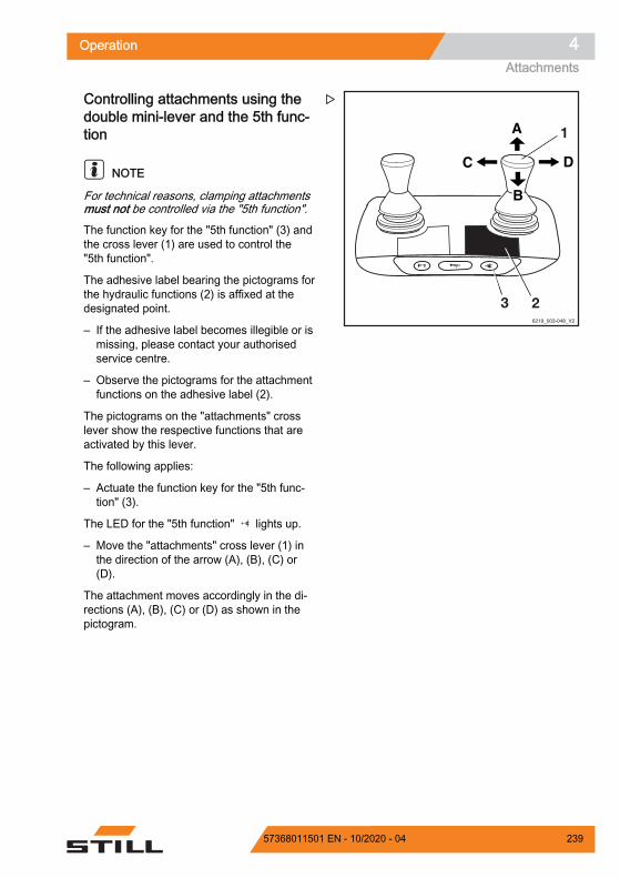
Controlling attachments using thedouble mini-lever and the 5th func-tion
NOTE
For technical reasons, clamping attachmentsmust not be controlled via the "5th function".
The function key for the "5th function" (3) andthe cross lever (1) are used to control the"5th function".
The adhesive label bearing the pictograms forthe hydraulic functions (2) is affixed at thedesignated point.
– If the adhesive label becomes illegible or ismissing, please contact your authorisedservice centre.
– Observe the pictograms for the attachmentfunctions on the adhesive label (2).
The pictograms on the "attachments" crosslever show the respective functions that areactivated by this lever.
The following applies:
– Actuate the function key for the "5th func-tion" (3).
The LED for the "5th function" lights up.
– Move the "attachments" cross lever (1) inthe direction of the arrow (A), (B), (C) or(D).
The attachment moves accordingly in the di-rections (A), (B), (C) or (D) as shown in thepictogram.
Z
Operation 4Attachments
23957368011501 EN - 10/2020 - 04

Example using the pictograms for configura-tion (1):
If the "attachments" cross lever (1) is moved inthe direction of the arrow (A), the fork is exten-ded.
If the function key for the "5th function" (3) isactuated and the "attachments" cross lever (1)is moved in the direction of the arrow (A), thefork arms open.
Picto-gram Attachment function
Auxiliary hydraulics "5th function"Move the side shift frame or fork for-wardsMove the side shift frame or forkbackwardsMove the sideshift to the leftMove sideshift to the rightAdjust fork arms: openAdjust fork arms: closeRotate to the leftRotate to the right
NOTE
The pictograms are affixed according to theattachment fitted at the factory. If an attach-ment with different functions is fitted, the au-thorised service centre must check that thepictograms bear the correct representationand must change them if necessary.
Z
Operation4Attachments
240 57368011501 EN - 10/2020 - 04

Controlling attachments using a tri-ple mini-leverIn this version, the attachments (variant) arecontrolled using the operating levers (1, 2).The adhesive label bearing the pictograms forthe hydraulic functions (3) for the operatinglever (2) and the adhesive label (4) for the op-erating lever (1) are affixed at the designatedpoints.
– If the adhesive labels become illegible orare missing, please contact your authorisedservice centre.
– Observe the pictograms for the attachmentfunctions on the adhesive labels (3, 4).
The pictograms on the operating levers showthe respective functions that are activated bythese levers.
The following applies:
– Move the operating lever (1) in the directionof the arrow (A) or (B).
The attachment moves accordingly in the di-rections (A) or (B) as shown in the pictogram.
– Move the operating lever (2) in the directionof the arrow (C) or (D).
The attachment moves accordingly in the di-rections (C) or (D) as shown in the pictogram.
Picto-gram Attachment function
Move the side shift frame or fork for-wardsMove the side shift frame or forkbackwardsMove the sideshift to the leftMove sideshift to the rightAdjust fork arms: openAdjust fork arms: closeRelease load retainerClamp load retainerOpen clampsClose clampsRotate to the leftRotate to the right
Z
Operation 4Attachments
24157368011501 EN - 10/2020 - 04

Picto-gram Attachment function
Tip shovel overTip shovel back
NOTE
The pictograms are affixed according to theattachment fitted at the factory. If an attach-ment with different functions is fitted, the au-thorised service centre must check that thepictograms bear the correct representationand must change them if necessary.
Clamp locking mechanism– To release the clamp locking mechanism,
push the operating lever (2) forwards.
The clamp locking mechanism is released.The LED for the "clamp release" (1) lights upand remains lit while the clamp locking mech-anism is released.
NOTE
The hydraulic function for opening the clampis available for one second after the clamplocking mechanism is released. After one sec-ond, the clamp locking mechanism is automat-ically reactivated.
– To open the clamp, push the operating lev-er (2) forwards again.
It is not necessary to release the clamp lock-ing mechanism in order to close the clamp.
– To close the clamp, pull the operating lev-er (2) backwards.
Z
Operation4Attachments
242 57368011501 EN - 10/2020 - 04

Controlling attachments using thetriple mini-lever and the 5th function
NOTE
For technical reasons, clamping attachmentsmust not be controlled via the "5th function".
The function key for the "5th function" (2) andthe operating lever (1) are used to control the"5th function".
The adhesive label bearing the pictograms forthe hydraulic functions (3) is affixed at thedesignated point.
– If the adhesive label becomes illegible or ismissing, please contact your authorisedservice centre.
– Observe the pictograms for the attachmentfunctions on the adhesive label (3).
The pictograms on the operating lever showthe respective functions that are activated bythis lever.
The following applies:
– Actuate the function key for the "5th func-tion" (2).
The LED for the "5th function" lights up.
– Move the operating lever (1) in the direc-tion (E) or (F).
The attachment moves accordingly in the di-rections (E) or (F) as shown in the pictogram.
6219_003-050_V3
Z
Operation 4Attachments
24357368011501 EN - 10/2020 - 04

Example using the pictograms for configura-tion (1):
If the operating lever (1) is moved in the direc-tion of the arrow (E), the sideshift moves tothe left.
If the function key for the "5th function" (2) isactuated and the operating lever (1) is movedin the direction of the arrow (E), the fork armsopen.
Picto-gram Attachment function
Auxiliary hydraulics "5th function"Move the sideshift to the leftMove sideshift to the rightAdjust fork arms: openAdjust fork arms: closeRotate to the leftRotate to the right
NOTE
The pictograms are affixed according to theattachment fitted at the factory. If an attach-ment with different functions is fitted, the au-thorised service centre must check that thepictograms bear the correct representationand must change them if necessary.
Z
Operation4Attachments
244 57368011501 EN - 10/2020 - 04

Controlling attachments using aquadruple mini-leverIn this version, the attachments (variant) arecontrolled using the operating levers (1, 2).The adhesive label bearing the pictograms forthe hydraulic functions (3) for the operatinglever (2) and the adhesive label (4) for the op-erating lever (1) are affixed at the designatedpoints.
– If the adhesive labels become illegible orare missing, please contact your authorisedservice centre.
– Observe the pictograms for the attachmentfunctions on the adhesive labels (3, 4).
The pictograms on the operating levers showthe respective functions that are activated bythese levers.
The following applies:
– Move the operating lever (1) in the directionof the arrow (A) or (B).
The attachment moves accordingly in the di-rections (A) or (B) as shown in the pictogram.
– Move the operating lever (2) in the directionof the arrow (C) or (D).
The attachment moves accordingly in the di-rections (C) or (D) as shown in the pictogram.
Picto-gram Attachment function
Move the side shift frame or fork for-wardsMove the side shift frame or forkbackwardsMove the sideshift to the leftMove sideshift to the rightAdjust fork arms: openAdjust fork arms: closeRelease load retainerClamp load retainerOpen clampsClose clampsRotate to the leftRotate to the right
Z
Operation 4Attachments
24557368011501 EN - 10/2020 - 04

Picto-gram Attachment function
Tip shovel overTip shovel back
NOTE
The pictograms are affixed according to theattachment fitted at the factory. If an attach-ment with different functions is fitted, the au-thorised service centre must check that thepictograms bear the correct representationand must change them if necessary.
Clamp locking mechanism– To release the clamp locking mechanism,
push the operating lever (2) forwards.
The clamp locking mechanism is released.The LED for the "clamp release" (1) lights upand remains lit while the clamp locking mech-anism is released.
NOTE
The hydraulic function for opening the clampis available for one second after the clamplocking mechanism is released. After one sec-ond, the clamp locking mechanism is automat-ically reactivated.
– To open the clamp, push the operating lev-er (2) forwards again.
It is not necessary to release the clamp lock-ing mechanism in order to close the clamp.
– To close the clamp, pull the operating lev-er (2) backwards.
Z
Operation4Attachments
246 57368011501 EN - 10/2020 - 04

Controlling attachments using thequadruple mini-lever and the5th function
NOTE
For technical reasons, clamping attachmentsmust not be controlled via the "5th function".
The function key for the "5th function" (2) andthe operating lever (1) are used to control the"5th function".
The adhesive label bearing the pictograms forthe hydraulic functions (3) is affixed at thedesignated point.
– If the adhesive label becomes illegible or ismissing, please contact your authorisedservice centre.
– Observe the pictograms for the attachmentfunctions on the adhesive label (3).
This essentially involves the following:
– Actuate the function key for the "5th func-tion" (2).
The LED for the "5th function" lights up.
– Move the operating lever (1) in the direc-tion (E) or (F).
The attachment moves accordingly in the di-rections (E) or (F) as shown in the pictogram.
Example using the pictograms for configura-tion (1):
If the operating lever (1) is moved in the direc-tion of the arrow (E), the sideshift moves tothe left.
If the function key for the "5th function" (2) isactuated and the operating lever (1) is movedin the direction of the arrow (E), the fork armsopen.
Picto-gram Attachment function
Auxiliary hydraulics "5th function"Move the sideshift to the leftMove sideshift to the rightAdjust fork arms: open
6219_003-052_V3
Z
Z
Operation 4Attachments
24757368011501 EN - 10/2020 - 04

Picto-gram Attachment function
Adjust fork arms: closeRotate to the leftRotate to the right
NOTE
The pictograms are affixed according to theattachment fitted at the factory. If an attach-ment with different functions is fitted, the au-thorised service centre must check that thepictograms bear the correct representationand must change them if necessary.
Operation4Attachments
248 57368011501 EN - 10/2020 - 04

Controlling attachments using theJoystick 4PlusIn this equipment, the attachments (variant)are controlled using the Joystick 4Plus (1).
The pictograms on the decal information re-garding operation of the Joystick 4Plus showthe respective functions that are activated bythe individual operating devices of the Joy-stick 4Plus.
– Observe the following attachment functionsand pictograms.
Operating device Function of the at-tachment
1 Joystick 4Plus Move sideshift to theleft/right
2 Joystick 4Plus orslider
Adjust fork arms:open/close
3 SliderMove side shift frameor fork carriage for-wards/backwards
4 Joystick 4Plus orslider
Rotate attachmentleft/right
5 Slider Tip shovel over/tipshovel back
NOTE
The pictograms are affixed according to theattachment fitted at the factory. If an attach-ment with different functions is fitted, the au-thorised service centre must check that thepictograms bear the correct representationand must change them if necessary.
1
6210_003-085
Z
6210_003-098
1
4
2
5
3
Z
Operation 4Attachments
24957368011501 EN - 10/2020 - 04

Controlling attachments with Joy-stick 4Plus and the 5th function
NOTE
For technical reasons, clamping attachmentsmust not be controlled via the 5th function.
NOTE
The 5th hydraulic function can be used to con-trol an attachment. The pictograms on theJoystick 4Plus show which attachment func-tions can be controlled using the 5th function.
For attachments that are controlled using the5th hydraulic function, the procedures for op-eration are as follows:
– Press and hold shift key "F" (1) on the Joy-stick 4Plus.
– Simultaneously actuate the horizontal rock-er button (2) in the direction shown in thepictogram.
The attachment moves in the selected direc-tion.
NOTE
The pictograms are affixed according to theattachment fitted at the factory. If an attach-ment with different functions is fitted, the au-thorised service centre must check that thepictograms bear the correct representationand must change them if necessary.
2
1
6210_003-086
Z
Operation4Attachments
250 57368011501 EN - 10/2020 - 04
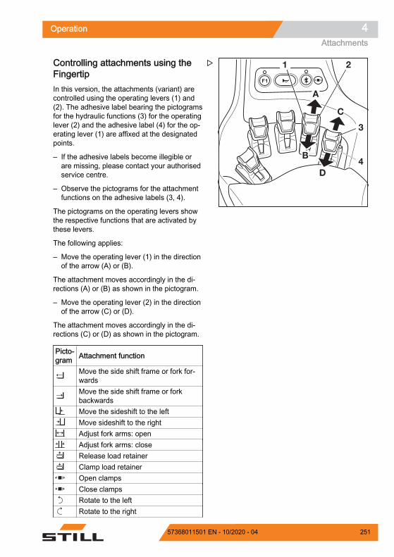
Controlling attachments using theFingertipIn this version, the attachments (variant) arecontrolled using the operating levers (1) and(2). The adhesive label bearing the pictogramsfor the hydraulic functions (3) for the operatinglever (2) and the adhesive label (4) for the op-erating lever (1) are affixed at the designatedpoints.
– If the adhesive labels become illegible orare missing, please contact your authorisedservice centre.
– Observe the pictograms for the attachmentfunctions on the adhesive labels (3, 4).
The pictograms on the operating levers showthe respective functions that are activated bythese levers.
The following applies:
– Move the operating lever (1) in the directionof the arrow (A) or (B).
The attachment moves accordingly in the di-rections (A) or (B) as shown in the pictogram.
– Move the operating lever (2) in the directionof the arrow (C) or (D).
The attachment moves accordingly in the di-rections (C) or (D) as shown in the pictogram.
Picto-gram Attachment function
Move the side shift frame or fork for-wardsMove the side shift frame or forkbackwardsMove the sideshift to the leftMove sideshift to the rightAdjust fork arms: openAdjust fork arms: closeRelease load retainerClamp load retainerOpen clampsClose clampsRotate to the leftRotate to the right
A
B
C
D
1 2
3
4
Z
Operation 4Attachments
25157368011501 EN - 10/2020 - 04

Picto-gram Attachment function
Tip shovel overTip shovel back
NOTE
The pictograms are affixed according to theattachment fitted at the factory. If an attach-ment with different functions is fitted, the au-thorised service centre must check that thepictograms bear the correct representationand must change them if necessary.
Clamp locking mechanism– To release the clamp locking mechanism,
push the operating lever (2) forwards.
The clamp locking mechanism is released.The LED for the "clamp release" (1) lights upand remains lit while the clamp locking mech-anism is released.
NOTE
The hydraulic function for opening the clampis available for one second after the clamplocking mechanism is released. After one sec-ond, the clamp locking mechanism is automat-ically reactivated.
– To open the clamp, push the operating lev-er (2) forwards again.
It is not necessary to release the clamp lock-ing mechanism in order to close the clamp.
– To close the clamp, pull the operating lev-er (2) backwards.
1
2
6219_003-207
Z
Operation4Attachments
252 57368011501 EN - 10/2020 - 04

Controlling attachments using theFingertip and the 5th function
NOTE
For technical reasons, clamping attachmentsmust not be controlled via the 5th function.
The function key for the "5th function" (2) andthe operating levers (1, 6) are used to controlthe "5th function".
The pictograms (1, 5) behind the operatinglevers show the functions that are activated bythe respective levers.
– If the adhesive labels become illegible orare missing, please contact your authorisedservice centre.
The following applies:
– Actuate the function key for the "5th func-tion" (2).
The LED for the "5th function" (3) lights up.
– Move the operating lever (4) or (6) in the di-rection of the arrow (E) or (F).
The attachment moves accordingly in the di-rections (E) or (F) as shown in the pictogram.
NOTE
The place where the adhesive label bearingthe pictograms (1) or (5) is affixed showswhich operating lever is intended to operatethe "5th function". The pictograms show thefunctions that are activated by switching withthe function key (2).
Picto-gram Attachment function
Auxiliary hydraulics "5th function"Move the sideshift to the leftMove sideshift to the rightAdjust fork arms: openAdjust fork arms: closeRotate to the leftRotate to the right
E
F
E
F
1 2 3 4
6
5
6219_003-204_V2
Z
Operation 4Attachments
25357368011501 EN - 10/2020 - 04

NOTE
The pictograms are affixed according to theattachment fitted at the factory. If an attach-ment with different functions is fitted, the au-thorised service centre must check that thepictograms bear the correct representationand must change them if necessary.
Clamp locking mechanism (variant)This truck can be fitted with a clamp lockingmechanism for clamping attachments. Thisprevents the clamp from opening unintention-ally if the operating function is inadvertentlytriggered.
DANGERIf the correct function of the clamp locking mecha-nism is not guaranteed, there is a risk to life from afalling load!If other attachments are used on this truck in additionto the clamp, make sure that the function of theclamp locking mechanism is reassigned to the corre-sponding operating device every time the clamp isrefitted. See the section entitled "Fitting attach-ments".– Make sure that the additional clamp locking mech-
anism function is available.
NOTE
For technical reasons, clamping attachmentsmust not be controlled via the "5th function".
Operation4Attachments
254 57368011501 EN - 10/2020 - 04

Double mini-lever– To release the clamp locking mechanism,
push the operating lever (2) forwards.
The clamp locking mechanism is released.The LED for the "clamp release" (1) lights upand remains lit while the clamp locking mech-anism is released.
NOTE
The hydraulic function for opening the clampis available for one second after the clamplocking mechanism is released. After one sec-ond, the clamp locking mechanism is automat-ically reactivated.
– To open the clamp, push the operating lev-er (2) forwards again.
It is not necessary to release the clamp lock-ing mechanism in order to close the clamp.
– To close the clamp, pull the operating lev-er (2) backwards.
Triple mini-lever– To release the clamp locking mechanism,
push the operating lever (2) forwards.
The clamp locking mechanism is released.The LED for the "clamp release" (1) lights upand remains lit while the clamp locking mech-anism is released.
NOTE
The hydraulic function for opening the clampis available for one second after the clamplocking mechanism is released. After one sec-ond, the clamp locking mechanism is automat-ically reactivated.
– To open the clamp, push the operating lev-er (2) forwards again.
It is not necessary to release the clamp lock-ing mechanism in order to close the clamp.
– To close the clamp, pull the operating lev-er (2) backwards.
Z
Z
Operation 4Attachments
25557368011501 EN - 10/2020 - 04

Quadruple mini-lever– To release the clamp locking mechanism,
push the operating lever (2) forwards.
The clamp locking mechanism is released.The LED for the "clamp release" (1) lights upand remains lit while the clamp locking mech-anism is released.
NOTE
The hydraulic function for opening the clampis available for one second after the clamplocking mechanism is released. After one sec-ond, the clamp locking mechanism is automat-ically reactivated.
– To open the clamp, push the operating lev-er (2) forwards again.
It is not necessary to release the clamp lock-ing mechanism in order to close the clamp.
– To close the clamp, pull the operating lev-er (2) backwards.
Fingertip– To release the clamp locking mechanism,
push the operating lever (2) forwards.
The clamp locking mechanism is released.The LED for the "clamp release" (1) lights upand remains lit while the clamp locking mech-anism is released.
NOTE
The hydraulic function for opening the clampis available for one second after the clamplocking mechanism is released. After one sec-ond, the clamp locking mechanism is automat-ically reactivated.
– To open the clamp, push the operating lev-er (2) forwards again.
It is not necessary to release the clamp lock-ing mechanism in order to close the clamp.
– To close the clamp, pull the operating lev-er (2) backwards.
Z
1
2
6219_003-207
Z
Operation4Attachments
256 57368011501 EN - 10/2020 - 04

Joystick 4Plus– To release the clamp locking mechanism,
push the slider (1) to the left.
The clamp locking mechanism is released.The LED for the "clamp release" (2) lights upand remains lit while the clamp locking mech-anism is released.
– To open the clamp, push the slider (1) tothe left again.
NOTE
The hydraulic function for opening the clampis available for one second after the clamplocking mechanism is released. After one sec-ond, the clamp locking mechanism is automat-ically reactivated.
It is not necessary to release the clamp lock-ing mechanism in order to close the clamp.
– To close the clamp, push the slider (1) tothe right again.
Taking up a load using attachments
WARNINGRisk of accidents!Attachments may only be used for their intended pur-pose as described in the relevant operating instruc-tions.
Drivers must be instructed in the handling of the at-tachments.
WARNINGRisk of accidents!Loads may only be picked up and transported withattachments if they are securely attached. Wherenecessary, loads should also be secured againstslipping, rolling, falling over, swinging or tipping over.Note that any change to the position of the load'scentre of gravity will affect the stability of the forklifttruck.
Check the capacity rating plates for the attachmentsor combination of attachments.
– The rating plates show the permissible val-ues for:
+ F
1
2
Z
1
2
3
7090_860-002
Z
Operation 4Attachments
25757368011501 EN - 10/2020 - 04

Load capacity Q (kg) (1) Lift height h (mm) (2) Load distance C (mm) (3)
Operation4Attachments
258 57368011501 EN - 10/2020 - 04

Auxiliary equipmentActuating the windscreen wipersand windscreen washers (variant)Pressing the softkey switches between the op-erating stages in the sequence shown below.Press softkey Operating stage Off1st time On2nd time Interval3rd time OffHold (possible in alloperating stages) Washer
Front windscreen wiper and washer– To activate the "On" operating stage, press
the softkey (1).
The "On" operating stage is activated. Thesymbol (3) appears
– To activate the "Intermittent mode" operat-ing stage, press the softkey again.
The symbol (2) is shown with an orange back-ground.
– To activate the "Washer" operating stage,press and hold the softkey.
The "Washer" operating stage is activated.The symbol (4) is displayed for as long as thesoftkey is pressed.
– Once the window is clean, release the soft-key.
The previous operating stage is reactivated.
– To switch this operating stage off, press thesoftkey repeatedly until the symbol (1) ap-pears again on the display. The activationbar next to the symbol goes out.
6219_003-069_V2
Z
Operation 4Auxiliary equipment
25957368011501 EN - 10/2020 - 04

Rear window wiper and washer– To activate the "On" operating stage, press
the corresponding softkey (5).
The "On" operating stage is activated. Thesymbol (7) appears
– To activate the "Intermittent mode" operat-ing stage, press the softkey again.
The symbol (6) is shown with an orange back-ground.
– To activate the "Washer" operating stage,press and hold the softkey.
The "Washer" operating stage is activated.The symbol (8) is displayed for as long as thesoftkey is pressed.
– Once the window is clean, release the soft-key.
The previous operating stage is reactivated.
– To switch this operating stage off, press thesoftkey repeatedly until the symbol (1) ap-pears again on the display.
Roof panel wiper and washer– To activate the "On" operating stage, press
the corresponding softkey (9).
The "On" operating stage is activated. Thesymbol (11) appears
– To activate the "Intermittent mode" operat-ing stage, press the softkey again.
The symbol (10) is shown with an orangebackground.
– To activate the "Washer" operating stage,press and hold the softkey.
The "Washer" operating stage is activated.The symbol (12) is displayed for as long asthe softkey is pressed.
– Once the window is clean, release the soft-key.
The previous operating stage is reactivated.
– To switch off the speed limitation, press thesoftkey again.
6219_003-070_V2
Z
6219_003-117_V3
9
11
10
12
Z
Operation4Auxiliary equipment
260 57368011501 EN - 10/2020 - 04

Filling the washer system– Open the bonnet; see ⇒ Chapter "Opening
the bonnet", Page 354 .
CAUTIONComponents may become damaged due to the ef-fects of frost!Water expands when it freezes. If there is no anti-freeze in the washer system (variant), the systemmay be damaged due to the build up of ice in freez-ing conditions.– Always use washer fluid containing anti-freeze.
– Open the filler cap (1) of the washer systemcontainer (2).
– Fill the windscreen washer fluid containerwith washer fluid containing anti-freeze inaccordance with the maintenance data ta-ble (see ⇒ Chapter "Maintenance data ta-ble", Page 351 ).
– Close the filler cap.
– Close the bonnet.
– Operate washer system until washer fluid isdischarged from the spray nozzles.
FleetManager (variant)FleetManager is an equipment variant and canbe fitted to the truck in different versions. Thedescription and operation information can befound in the separate operating instructions forthe corresponding FleetManager versions.
Shock recognition (variant)The shock recognition is an equipment variantof the FleetManager (variant) in which an ac-celeration sensor is installed in the truck. Theacceleration sensor records data arising fromrapid accelerations or decelerations of thetruck, e.g. in the event of an accident. This da-ta can be electronically read out and evalu-ated.
– If you have any questions, please contactyour authorised service centre.
7311_341-001
1 2Z
Operation 4Auxiliary equipment
26157368011501 EN - 10/2020 - 04

Driver restraint systems (variants)Different driver restraint systems are availableas variants for this truck. The description andoperation for these systems can be found inthe separate "Driver restraint systems" operat-ing instructions.
Ceiling sensor (variant)DescriptionThe ceiling sensor (1) on the overhead guardis an assistance system that automatically re-duces the driving speed of the truck withinhalls. However, this assistance system doesnot release the driver from the responsibility ofobserving the speed limits on company prem-ises.
Depending on the system setting, the ceilingsensor can detect overhead structures abovethe truck at a height of 2 m to 24 m above thesensor.
If the truck is equipped with a ceiling sensor,this assistance system is listed in the "Assis-tance systems" menu in the display-operatingunit.
Operating the ceiling sensor systemThe drivers must be instructed on the use ofthe ceiling sensor system by the operatingcompany.
When the driver enters a hall for the first timeafter starting work, they must be certain thatthe ceiling sensor system is working correctly.Despite the ceiling sensor system being instal-led, the driver must also check the speed indi-cator on the display-operating unit on a regu-lar basis to ensure that they do not exceed themaximum speed permitted for the environ-ment. Entering a hall
The ceiling sensor system automatically de-tects when the truck enters a hall. The sys-tem then automatically slows the truck tothe maximum speed that is set for the hall.
Deckensensor_Anbau
1Z
Operation4Auxiliary equipment
262 57368011501 EN - 10/2020 - 04

The "Speed restriction" symbol appearsin the display.
Leaving a hallIf the truck leaves the hall again, the ceilingsensor system enables the maximum speedset for areas outside the hall. Due to therange of the sensor, this may not happenuntil the truck is a few metres away from thehall exit. Before the truck is able to acceler-ate to the maximum speed permitted foroutdoor areas, the speed limitation must stillbe unlocked. To do this, release the accel-erator briefly and then operate the accelera-tor again.
Switching on the truck in a hallIf the truck is switched on inside a hall, theceiling sensor system detects the hall ceil-ing and reduces the driving speed to themaximum speed that is set for halls.
Possible limitations for object recogni-tion If the truck moves under larger overhead
structures outdoors, e.g. a pedestrianbridge, the ceiling sensor system may inter-pret this overhead structure to be a hall ceil-ing and reduce the maximum speed.
In rare cases, it may occur that the ceilingsensor system does not recognize a ceilingand does not then reduce the speed. Thiscan happen if the signals from the ceilingsensor are insufficiently reflected due to theceiling geometry; for example, if there arelarge window areas at a 45° angle.
In these cases, the sensitivity and the range ofthe ceiling sensor system must be adjusted.See the following section.
Changing the sensor settings
NOTE
The ceiling sensor system is supplied bySTILL with the following factory settings: Sensitivity: High Ceiling height: 24 m
– Park the truck securely and switch it off.
Operation 4Auxiliary equipment
26357368011501 EN - 10/2020 - 04

– Turn the union nut (4) anti-clockwise toloosen it. Disconnect the electrical connec-tion assembly by pulling out the plug.
– On the underside of the assembly base-plate on the overhead guard, hold four nuts(3) in place.
– Unscrew four socket head screws (2).
The key (5) is secured with a nut under the as-sembly baseplate.
– Carefully remove the ceiling sensor (1).
The sensor is adjusted using DIP switches (6).
– To access the DIP switches, open the coveron the underside of the sensor housing withthe key (5).
During this process, the two tabs of the key (5)fit into the recesses of the cover.
– Using the DIP switches "1 to 5" (6), adjustthe range and the sensitivity of the sensor.The DIP switches can be adjusted using asmall screwdriver.
Deckensensor_Anbau
14 2
3
Z
5Deckensensor_Einstellschlüssel_V2
Z
1 2 3 4 5 6 7 8
6 DIP-Schalter_V2
Z
Operation4Auxiliary equipment
264 57368011501 EN - 10/2020 - 04

CAUTIONThe settings for DIP switches "6 to 8" are the factorysettings of the manufacturer.Do not change the factory settings of the manufac-turer!
Factory settings of the manufacturerDIP switch
6 7 81 1 0
The possible settings for DIP switches "1 to 5"are shown in the following tables:
DIP switch 1 2 3 Range0 0 0 2 m0 0 1 3 m0 1 0 4 m0 1 1 6 m1 0 0 8 m1 0 1 12 m1 1 0 16 m1 1 1 24 m
4 5 Sensitivity0 0 Very high0 1 High1 0 Medium1 1 Low
Operation 4Auxiliary equipment
26557368011501 EN - 10/2020 - 04

Representation of the beam angle dependingon the sensitivity of the sensor that has beenset, from (1) "low" to (4) "very high".
The sensor has different beam angles de-pending on the combination of range and sen-sitivity that has been set. See the following ta-ble:
Sensitivity Range Beam angle
Low (1)
2 m 22.5°4 m 22.5°8 m 20°16 m 15°24 m 5°
Medium (2)
2 m 35°4 m 30°8 m 25°16 m 22.5°24 m 10°
2 3 41234
Z
Operation4Auxiliary equipment
266 57368011501 EN - 10/2020 - 04

Sensitivity Range Beam angle
High (3)
2 m 42°4 m 33°8 m 22.5°
16 m 20°24 m 15°
Very high (4)
2 m 45°4 m 43°8 m 30°
16 m 22.5°24 m 18°
– After the adjustment, refit the cover.
– Refit the ceiling sensor and connect it.
– Check that it is working correctly.
Operation 4Auxiliary equipment
26757368011501 EN - 10/2020 - 04
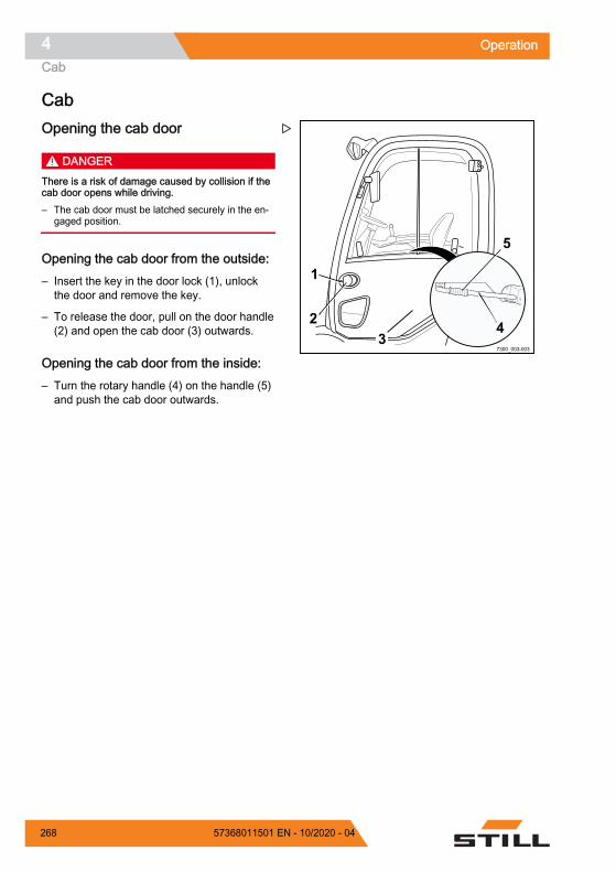
CabOpening the cab door
DANGERThere is a risk of damage caused by collision if thecab door opens while driving.– The cab door must be latched securely in the en-
gaged position.
Opening the cab door from the outside:– Insert the key in the door lock (1), unlock
the door and remove the key.
– To release the door, pull on the door handle(2) and open the cab door (3) outwards.
Opening the cab door from the inside:– Turn the rotary handle (4) on the handle (5)
and push the cab door outwards.
7300_003-003
5
2
1
34
Z
Operation4Cab
268 57368011501 EN - 10/2020 - 04

Closing the cab door
DANGERThere is a risk of damage caused by collision if thecab door opens while driving.– The cab door must be latched securely in the en-
gaged position.
Closing the cab door from the outside:– Push the cab door (3) inwards until the door
lock engages.
– Make sure that the cab door is fully closed.
– Insert the key in the door lock (1), lock thedoor and remove the key.
NOTE
Do not close the cab door while pulling thedoor handle (2), otherwise the locking mecha-nism in the lock will not function. Use the doorhandle only to open the cab door.
Closing the cab door from the inside:– Take hold of the handle (5).
– Pull the cab door inwards until the door lockengages.
– Make sure that the cab door is fully closed.
NOTE
Do not turn the rotary handle (4) when closingthe door or when the cab door is closed. Do-ing so will cause the lock to unlock, meaningthat the door will not be securely closed. Usethe rotary handle only to open the cab door.
7300_003-003
5
2
1
34
Z
Operation 4Cab
26957368011501 EN - 10/2020 - 04
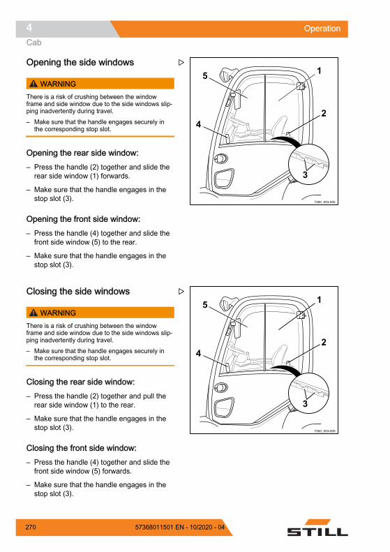
Opening the side windows
WARNINGThere is a risk of crushing between the windowframe and side window due to the side windows slip-ping inadvertently during travel.– Make sure that the handle engages securely in
the corresponding stop slot.
Opening the rear side window:– Press the handle (2) together and slide the
rear side window (1) forwards.
– Make sure that the handle engages in thestop slot (3).
Opening the front side window:– Press the handle (4) together and slide the
front side window (5) to the rear.
– Make sure that the handle engages in thestop slot (3).
Closing the side windows
WARNINGThere is a risk of crushing between the windowframe and side window due to the side windows slip-ping inadvertently during travel.– Make sure that the handle engages securely in
the corresponding stop slot.
Closing the rear side window:– Press the handle (2) together and pull the
rear side window (1) to the rear.
– Make sure that the handle engages in thestop slot (3).
Closing the front side window:– Press the handle (4) together and slide the
front side window (5) forwards.
– Make sure that the handle engages in thestop slot (3).
7300_003-005
4
5
2
1
3
Z
7300_003-005
4
5
2
1
3
Z
Operation4Cab
270 57368011501 EN - 10/2020 - 04

Turning the interior lighting on or off(variant)– To turn the interior lighting on or off, press
the push button switch (1) in the middle ofthe interior lighting.
Operating the rear window heating– To switch on the rear window heating, push
the associated Softkey on the display-oper-ating unit.
The rear window heating is switched on.
– To switch off the rear window heating, pushthe Softkey again.
The rear window heating is switched off.
NOTE
The screen heating will switch off automatical-ly after approx. 10 minutes.
1
Z
Z
Operation 4Cab
27157368011501 EN - 10/2020 - 04

Radio (variant)
WARNINGRisk of accident as a result of impaired perception!The driver's attention is adversely affected by operat-ing the radio or listening to it at excessive volumeswhile driving or handling loads.– Do not operate the radio when driving or when
handling loads.– Keep the radio at a volume that allows you to hear
warning signals.
The radio (1) and the loudspeakers (2) are anequipment variant. If the truck is equipped witha radio and loudspeakers, they are integratedinto the roof lining.
The description and information relating to theoperation of this equipment can be found inthe separate operating instructions for the ra-dio.
1
2
Z
Operation4Cab
272 57368011501 EN - 10/2020 - 04

Radio with Bluetooth interface (var-iant)
WARNINGThe driver's attention is adversely affected by operat-ing the radio or listening to it at excessive volumeswhile driving or handling loads. Risk of accident!– Do not operate the radio when driving or when
handling loads.– Adjust the radio volume so that you can still hear
warning signals.
Pairing a smartphoneThe Bluetooth interface on the radio is alwaysactive. The radio can be paired with a smart-phone at any time using the Bluetooth func-tion.
Carry out the following steps on your smart-phone: Switch on the Bluetooth function. Go to the Bluetooth settings. Select the relevant device with the name of
the radio. Enter the code 1234.
The symbols "A2DP" (4), "HFP" (5) and "Blue-tooth" (6) appear on the radio display.
The smartphone is paired with the radio.
Unpairing a smartphone– Select mode "A2DP" (4) on the radio using
the SRC button (1).
– Press and hold the 6D+ button (2) for 2seconds.
The symbols "A2DP" (4), "HFP" (5) and "Blue-tooth" (6) will disappear from the radio display.
The smartphone is no longer paired with theradio.
7300_003-020
VOL
+
-
1
BAND SEL DISP
2 3 4 5 6RND D - D + AUXRPT
SRC
R-D-S
AST
SCN
PTY TA TP AF P.LOUD EQ HFP A2DP REC
1
23456
Z
7300_003-020
VOL
+
-
1
BAND SEL DISP
2 3 4 5 6RND D - D + AUXRPT
SRC
R-D-S
AST
SCN
PTY TA TP AF P.LOUD EQ HFP A2DP REC
1
23456
Z
Operation 4Cab
27357368011501 EN - 10/2020 - 04

Hands-free devicePrerequisite: The smartphone is paired withthe radio.
Incoming calls:
Regardless of the mode (Radio, AUX, A2DP),the ringtones are broadcast via the radiospeaker.
– Accept the call using the smartphone or bypressing the button depicting a green hand-set (3).
– End the call using the smartphone or bypressing the button depicting a red hand-set (2).
Outgoing calls:
– Regardless of the mode (Radio, AUX,A2DP), dial the number on the smartphoneand make the call.
The acoustic signals are automatically broad-cast via the radio speaker.
– End the call using the smartphone or bypressing the button depicting a red hand-set (2).
NOTE
The telephone number can also be selectedvia the radio; refer to the original operating in-structions for the radio.
7300_003-020
VOL
+
-
1
BAND SEL DISP
2 3 4 5 6RND D - D + AUXRPT
SRC
R-D-S
AST
SCN
PTY TA TP AF P.LOUD EQ HFP A2DP REC
1
23456
Z
Operation4Cab
274 57368011501 EN - 10/2020 - 04

Wireless music playback (A2DP)Prerequisite: The smartphone is paired withthe radio.
– Select mode "A2DP" (4) on the radio usingthe SRC button (1).
– The music starts to play on the smartphone.
The music is broadcast via the radio speaker.
NOTE
For more general information and informationon operating the system, refer to the originaloperating instructions for the radio.
Heating system (variant) DANGER
There is a risk of poisoning if heavilypolluted surrounding air is aspirated in-to the closed cab!– Do not operate the heating system in
the vicinity of storage areas or similarareas in which fuel vapours or finedust (e.g. coal, wood or grain dust)can build up.
DANGER
Risk of explosion due to heat!The heat can cause gases to expandconsiderably or to ignite.– Do not expose spray cans or gas car-
tridges to the flow of hot air.
7300_003-020
VOL
+
-
1
BAND SEL DISP
2 3 4 5 6RND D - D + AUXRPT
SRC
R-D-S
AST
SCN
PTY TA TP AF P.LOUD EQ HFP A2DP REC
1
23456
Z
Operation 4Cab
27557368011501 EN - 10/2020 - 04

DANGER
Risk of fire due to overheating!The heating system can overheat if thehot air cannot escape from it.
The heating system may only be switch-ed on if the blower is running and theheating system is not covered by objects(such as a jacket or cover).– Always switch the blower on first.– Do not switch the heating system on
until the blower is switched on.– Move any objects away from the
heating system or air distributors.
DANGER
The heating system housing can be-come very hot during heating opera-tion. There is a risk of burns if it istouched!– Do not touch the heating system
housing during operation.– Only touch the switches provided.
Operating devices of the heating sys-tem
The operating devices of the heating systeminclude:1 Heating level control knob2 Fan control knob3 Air vent control knob
Switching on the blower and heatingsystem– Turn the fan control knob (2) to the desired
blower position.
The blower runs at the speed level selectedvia the fan control knob (2).
– Turn the heating level control knob (1) tothe desired heating level.
The heater warms the air to the heating levelselected via the heating level control knob (1)
– Turn the air vent control knob (3) to the de-sired position.
0
Z
Operation4Cab
276 57368011501 EN - 10/2020 - 04

Selecting blower settings– To select a lower fan output, turn the fan
control knob (2) anticlockwise.
– To select a high blower output, turn the fancontrol knob (2) clockwise.
Setting heating levels– To set a lower heater power, turn the heat-
ing level control knob (1) anticlockwise.
– To set a higher heater power, turn the heat-ing level control knob (1) clockwise.
Setting the air vent control knob– To direct the air flow to the footwell, turn the
air vent control knob (3) in an anticlockwisedirection to position .
– To direct the air flow to the windscreen, turnthe air vent control knob (3) in a clockwisedirection to position .
The centre position directs the air flow tothe footwell and the windscreen.
Switching off the heating system andblower– Turn the heating level control knob (1) in an
anticlockwise direction until it reaches thestop.
The heating system is shut off.
– Turn the fan control knob (2) in an anti-clockwise direction until it reaches the stop.
The blower is shut off.
Operation 4Cab
27757368011501 EN - 10/2020 - 04

Adjusting the air distributorsThe air distributors for the driver are alwayssupplied with air. It is not necessary to adjustthe heating system using the operating devi-ces.
– To open the air distributor, push the inden-tation (1) on the disc.
The discs open.
– Grasp the discs to align the air flow:
The discs can be adjusted to the desired an-gle. The air distributor can be rotated.
– Press down again to close the discs.
Changing fuses
DANGER
Risk of fire as a result of short circuits!Using the wrong fuses can result in shortcircuits.– Use only fuses with the prescribed
nominal current.
Air conditioning (variant)The air conditioning dries the air in the cab toprevent the glass panes misting up. The tem-perature of the air that is blown out is basedon the heating level that has been set. The de-frost function can be used to de-ice the wind-screen quickly.
The operating devices of the air conditioninginclude:1 Heating level control knob2 Fan control knob3 Air vent control knob4 Defrost switch5 On/off switch
– To adjust the air distributors and to controlthe blower positions, the heat settings andthe air vent control knob, see the sectionentitled "Heating system (variant)".
Z
0
45
Z
Operation4Cab
278 57368011501 EN - 10/2020 - 04

Switching the air conditioning on and off– Push the on/off switch (5).
The LED on the switch lights up green. The airconditioning is switched on.
– Press the on/off switch (5) again.
The LED on the switch goes out. The air con-ditioning is switched off.
Defrost functionThe defrost function can be used to de-ice anddehumidify the windscreen quickly. To do this,turn the air vent control knob (3) clockwise tothe position. Open the air distributors anddirect them onto the windscreen.
– Switch on the air conditioning.
– Push the defrost switch (4).
The LED on the switch lights up green. The airconditioning operates at full power. The high-est heating level is selected. This feature op-erates for a limited period only. To save ener-gy, it switches itself off automatically.
– Press the defrost switch (4) again.
The defrost function is switched off.
Clipboard (variant)The clipboard (1) with reading lamp (2) is anequipment variant.
6210_003-107
21
Z
Operation 4Cab
27957368011501 EN - 10/2020 - 04

Push-up roof window (variant)
WARNINGRisk of crushing!– When closing the roof window, do not reach be-
tween the roof window and the overhead guard.– Do not reach in to touch components as they are
being closed.
The push-up roof window (1) is an equipmentvariant.
– To unlock and open the roof window, rotatethe handle (2) in an anti-clockwise directionand use it to push the roof window upwards.
The roof window is held in the open positionby means of gas springs (3).
– To close and lock the roof window, pull theroof window downwards using the handleand rotate the handle in a clockwise direc-tion
12 V socketA 12 V socket (1) is fitted to the right of thedriver's seat for connecting an external electri-cal consumer.
CAUTIONRisk of short circuit!The nominal current of the connected consumermust not exceed 10 A.– Before connecting, check the nominal current of
the device in question.
– Lift up the dust guard cover (2).
– Insert the plug of the device to be connec-ted into the socket (1).
– Rest the dust guard cover on the plug.
– Perform a functional check of the electricalconnection on the connected device.
6210_003-105_V2
1
2
3
3
Z
7300_003-002
12
Z
Operation4Cab
280 57368011501 EN - 10/2020 - 04

CAUTIONMalfunctions possible.The exposed socket may become dirty and dusty ifno plug is inserted or the dust guard cover is notclosed. Over time, this can lead to problems with theelectrical connection.– Push the dust guard cover all the way down after
using the socket.
Operation 4Cab
28157368011501 EN - 10/2020 - 04

Trailer operationTowed load
DANGERThere is an increased risk of accident when using atrailer.Using a trailer changes the truck handling character-istics. When towing, operate the truck such that thetrailer train can be safely driven and braked at alltimes. The maximum permissible speed when towingis 5 km/h.– Do not exceed the permissible speed of 5 km/h.– Do not couple the truck in front of rail vehicles.– The truck must not be used to push any kind of
trolley.– It must be possible to drive and brake at all times.
CAUTIONRisk of damage to components!The maximum towed load for occasional towing isthe rated capacity specified on the nameplate. Over-loading can lead to component damage on the truck.The sum of the actual towed load and the actual loadon the fork must not exceed the rated capacity. If theexisting towed load corresponds to the rated capacityof the truck, no load may be transported on the forkat the same time. The load can be distributed be-tween the fork and the trailer.– Check the load distribution and adjust it to corre-
spond to the rated capacity.– Observe the permissible rigidity value of the tow
coupling.
CAUTIONRisk of damage to components!The maximum towed load only applies when towingunbraked trailers on a level surface (maximum devia-tion +/- 1%) and on firm ground. The towed loadmust be reduced if towing on gradients. If necessary,notify the authorised service centre of the applicationconditions. The service centre will provide the re-quired data.– Inform the authorised service centre.
6210_313-001
Z
Operation4Trailer operation
282 57368011501 EN - 10/2020 - 04

CAUTIONRisk of damage to components!A support load is not permitted.– Do not use trailers with tillers supported by the
tow coupling.
This truck is suitable for the occasional towingof trailers. If the truck is equipped with a tow-ing device, this occasional towing must not ex-ceed 2% of the daily operating time. If thetruck is to be used for towing on a more regu-lar basis, the manufacturer should be consul-ted.
Coupling pin in the counterweightCoupling the trailer
DANGERIf you leave the truck briefly to couple or uncouplethe trailer, there is a risk of fatal injury from thetruck rolling away.– Apply the parking brake.– Lower the fork to the ground.– Switch off the key switch and remove the key.
– Take measures to prevent the trailer fromrolling away, e.g. using wheel chocks (1).
1 7090_900-008
Z
Operation 4Trailer operation
28357368011501 EN - 10/2020 - 04

– Push the coupling pin (2) down, rotate by90° and pull out.
– Adjust the tiller height.
DANGERPeople can become trapped between the truck andtrailer.When coupling, ensure that there are no personspresent between the truck and the trailer.
– Slowly move the truck backwards.
– By moving the truck back, introduce the till-er into the recess (3) in the counterweight.
DANGERIf the coupling pin or securing bush are lost or de-stroyed during towing, the trailer will work looseand become uncontrollable. This poses a risk of ac-cident!– Only use original coupling bolts that have been
checked.– Ensure that the coupling pin is correctly inserted
and secured.
– Insert the coupling pin into the counter-weight, press downwards against the springpressure and rotate by 90° (the coupling pinis locked in this position).
– Remove any items used to prevent the trail-er from rolling away.
Uncoupling the trailer– Take measures to prevent the trailer from
rolling away, e.g. using wheel chocks.
– Push the coupling pin (2) down, rotate by90° and pull out.
– Slowly move the truck forwards and guidethe tow-bar eye completely out of the coun-terweight.
– Insert the coupling pin into the counter-weight, press downwards against the springpressure and rotate by 90° (the coupling pinis locked in this position).
7300_003-014
23
Z
Operation4Trailer operation
284 57368011501 EN - 10/2020 - 04

Automatic tow coupling DANGER
People may be trapped between the truck and trail-er.When hooking up, ensure that no one is between thetruck and trailer.
DANGERNever jack up the truck on the tow coupling or useit for crane lifting. The tow coupling is not designedfor this and could be deformed or damaged. Thiscould cause the truck to fall, with potentially fatalconsequences!– Use the tow coupling only for towing.– For jacking up and crane loading, use only the
designated lifting points.
DANGERThe tow coupling is not designed to support loadsand could become deformed or destroyed. Thiscould cause the supported load to fall, with poten-tially fatal consequences!– The tow coupling should be subjected only to hori-
zontal loads, i.e. the tiller must be horizontal.
DANGERIf you briefly leave the truck to couple or uncouplethe trailer, there is a risk to life caused by the truckrolling away and running you over.– Apply the parking brake.– Lower the forks to the ground.– Switch off the key switch and remove the key.
WARNINGNever reach between the coupling pins and the tow-ing jaws. If the component moves suddenly there is arisk of injury!– To release the coupling pin, actuate the corre-
sponding lever or use a suitable device (e.g. as-sembly lever).
– When not in use, close the automatic tow cou-pling.
Operation 4Trailer operation
28557368011501 EN - 10/2020 - 04

WARNINGRisk of damage due to component collision.A truck with tow coupling needs more room for ma-noeuvring due to its overhang. The tow coupling candamage the racking or the tow coupling itself whenmanoeuvring. If there is a collision with the tow cou-pling, test the tow coupling for damage such ascracks. A damaged tow coupling must not be usedagain.– Always manoeuvre carefully and with sufficient
room.– In the case of a collision, test the tow coupling for
damage.– Replace tow coupling if damaged, if necessary
contact the authorised service centre.
WARNINGRisk of damage to the tow bar eye or tiller!Due to the truck's rear wheel steering, the side slew-ing angle of the tiller may not be adequate. The cou-pling or the tiller may be damaged! The tow bar eyeof the tiller must fit the tow coupling in terms of shapeand size.– Ensure that the tow bar eye and tiller fit correctly.– Avoid sharp cornering.– Exercise care when travelling and manoeuvring in
reverse.
WARNINGRisk of component damage if the tiller in the tow cou-pling is tilted!The tiller should be kept as horizontal as possiblewhen towing. This ensures that the rotation range issufficient at the top and bottom. The authorised serv-ice centre can adjust the assembly height for the towcoupling to the tiller height if necessary.
– Make sure that the tiller is level.– To change the coupling height, contact the author-
ised service centre.
Operation4Trailer operation
286 57368011501 EN - 10/2020 - 04

Coupling model RO*243
NOTE
Tow coupling RO 243 is intended for a tow-bareye in accordance with DIN 74054 (bore diam-eter: 40 mm).
– Take measures to prevent the trailer fromrolling away, e.g. use wheel chocks (1).
– Adjust the tow bar eye of the tiller so that itis at the centre of the towing jaws.
– Pull out the safety handle (3).
– Push the hand lever (2) upwards.
DANGERPersons may become trapped between the truckand trailer.When hooking up, ensure that no one is between thetruck and trailer.
CAUTIONWhen being coupled, the tow-bar eye must engagein the middle of the coupling jaw. Failure to followthese instructions could result in damage to the cou-pling jaw or to the tow-bar eye!– Ensure that the tow-bar eye enters the coupling
jaw centrally.
– Slowly move the truck back.
DANGERIf the coupling pin drops out during towing, the trail-er will work loose and can no longer be controlled.There is a risk of accident!A protruding safety handle means that the tow bareye has not been coupled correctly. The trailer mustnot be towed in this condition.– Ensure that the safety handle is flush with the se-
curing bush.– If the safety handle protrudes, repeat the coupling
process.
1 7090_900-008
Z
3
7321_003-064
2
Z
Operation 4Trailer operation
28757368011501 EN - 10/2020 - 04

– Remove any items used to prevent the trail-er from rolling away.
– Tow the trailer.
Closing model RO*243 by hand
DANGERRisk of injury from hand becoming trapped!Do not reach into the coupling pin area. If, for exam-ple, a tow rope is to be secured in the tow coupling,use only a suitable device to close the tow coupling(e.g. assembly lever).
– Use a suitable device (e.g. assembly lever)to push the coupling pin up.
The coupling pin is released from the latchand the tow coupling then closes automatical-ly.
Uncoupling model RO*243– Take measures to prevent the trailer from
rolling away, e.g. use wheel chocks.
– Pull out the safety handle (3).
– Push the hand lever (2) upwards.
– Slowly drive the truck forwards until the tow-bar eye and towing jaws are disconnected.
– Close the tow coupling by hand.
3
7321_003-064
2
Z
Operation4Trailer operation
288 57368011501 EN - 10/2020 - 04
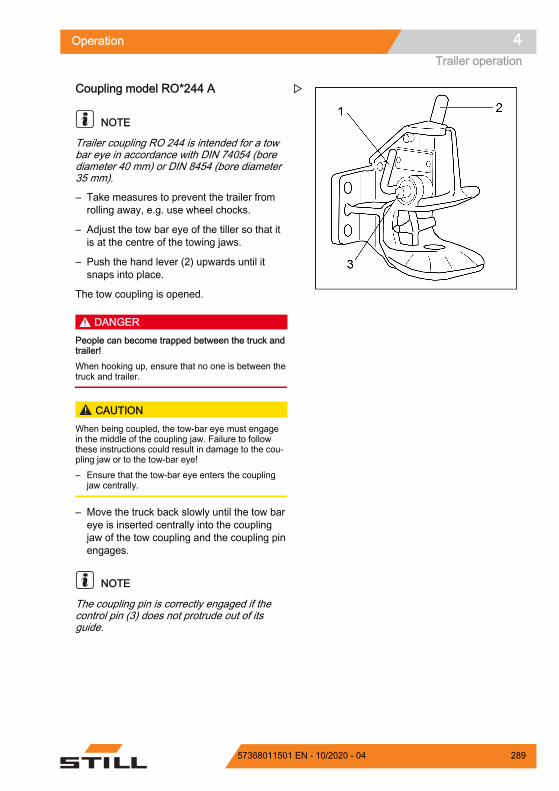
Coupling model RO*244 A
NOTE
Trailer coupling RO 244 is intended for a towbar eye in accordance with DIN 74054 (borediameter 40 mm) or DIN 8454 (bore diameter35 mm).
– Take measures to prevent the trailer fromrolling away, e.g. use wheel chocks.
– Adjust the tow bar eye of the tiller so that itis at the centre of the towing jaws.
– Push the hand lever (2) upwards until itsnaps into place.
The tow coupling is opened.
DANGERPeople can become trapped between the truck andtrailer!When hooking up, ensure that no one is between thetruck and trailer.
CAUTIONWhen being coupled, the tow-bar eye must engagein the middle of the coupling jaw. Failure to followthese instructions could result in damage to the cou-pling jaw or to the tow-bar eye!– Ensure that the tow-bar eye enters the coupling
jaw centrally.
– Move the truck back slowly until the tow bareye is inserted centrally into the couplingjaw of the tow coupling and the coupling pinengages.
NOTE
The coupling pin is correctly engaged if thecontrol pin (3) does not protrude out of itsguide.
Z
Operation 4Trailer operation
28957368011501 EN - 10/2020 - 04

DANGERIf the coupling pin drops out during towing, the trail-er will work loose and can no longer be controlled.There is a risk of accident!The control pin (3) must not protrude out of its guide.– Ensure that the coupling pin is engaged correctly.
If the coupling pin is not correctly engaged:– Remove any items used to prevent the trailer from
rolling away.– Move the truck with the trailer forwards approx. 1
m and then move it back slightly.– On the coupling pin, check again that the control
pin does not protrude out of its guide.
– Remove any items used to prevent the trail-er from rolling away.
– Tow the trailer.
Closing model RO*244 A by hand
DANGERRisk of injury from hand becoming trapped!Do not reach into the coupling pin area. If, for exam-ple, a tow rope is to be secured in the tow coupling,only actuate the tow coupling via the closing lever(1).
– Press the closing lever (1) downwards asfar as it will go.
The tow coupling is closed.
Uncoupling model RO*244 A– Take measures to prevent the trailer from
rolling away, e.g. use wheel chocks.
– Push the hand lever (2) upwards until itsnaps into place.
The tow coupling is opened.
– Slowly drive the truck forwards until the tow-bar eye and towing jaws are disconnected.
– Close the tow coupling by actuating theclosing lever (1).
Z
Operation4Trailer operation
290 57368011501 EN - 10/2020 - 04

NOTE
To protect the lower coupling pin bush againstcontamination, always keep the tow couplingclosed.
Coupling model RO*245
NOTE
Trailer coupling RO 245 is intended for a tow-bar eye in accordance with DIN 74054 (borediameter 40 mm) or DIN 8454 (bore diameter35 mm).
– Take measures to prevent the trailer fromrolling away, e.g. use wheel chocks.
– Adjust the tow bar eye of the tiller so that itis at the centre of the towing jaws.
– Push the hand lever (5) upwards.
– The tow coupling is opened.
DANGERPeople can become trapped between the truck andtrailer!When hooking up, ensure that no one is between thetruck and trailer.
– Slowly move the truck back.
DANGERIf the coupling pin drops out during towing, the trail-er will work loose and can no longer be controlled.There is a risk of accident!A protruding safety handle means that the tow bareye has not been coupled correctly. The trailer mustnot be towed in this condition.– Make sure that the control pin does not protrude
from the control bush.– Repeat the coupling process if necessary.
– Remove any items used to prevent the trail-er from rolling away.
– Tow the trailer.
7321_003-066_V2
57
6
Z
Operation 4Trailer operation
29157368011501 EN - 10/2020 - 04

Uncoupling model RO*245– Take measures to prevent the trailer from
rolling away, e.g. use wheel chocks.
– Push the hand lever (5) upwards.
– Slowly drive the truck forwards until the tow-bar eye and towing jaws are disconnected.
– Push the closing lever (7) on the left side ofthe tow coupling down as far as it will go.
The tow coupling is closed.
Coupling model RO*841
NOTE
Tow coupling RO 841 is intended for a tow-bareye in accordance with DIN 74054 (bore diam-eter 40 mm).
– Take measures to prevent the trailer fromrolling away, e.g. use wheel chocks.
– Push the hand lever (7) upwards until itsnaps into place.
DANGERPeople may be trapped between truck and trailer.When hooking up, ensure that no one is between thetruck and trailer.
CAUTIONWhen being coupled, the tow-bar eye must engagein the middle of the coupling jaw. Failure to followthese instructions could result in damage to the cou-pling jaw or to the tow-bar eye!– Ensure that the tow-bar eye enters the coupling
jaw centrally.
– Slowly move the truck back.
7321_003-066_V2
57
6
Z
7
8
7321_003-067
Z
Operation4Trailer operation
292 57368011501 EN - 10/2020 - 04

DANGERIf the coupling pin drops out during towing, the trail-er will work loose and can no longer be controlled.There is a risk of accident!A protruding safety handle means that the tow bareye has not been coupled correctly. The trailer mustnot be towed in this condition.– Make sure that the control pin does not protrude
from the control bush.– Repeat the coupling process if necessary.
– Remove any items used to prevent the trail-er from rolling away.
– Tow the trailer.
Uncoupling model RO*841– Take measures to prevent the trailer from
rolling away, e.g. use wheel chocks.
– Push the hand lever (7) upwards.
– Slowly drive the truck forwards until the tow-bar eye and towing jaws are disconnected.
– Close the tow coupling.
Towing trailers– Drivers who are towing a trailer for the first
time must practise driving with a trailer in asuitable area.
– When passing through narrow road areas(entrances, gates etc.), observe the dimen-sions of the trailer and load.
– When towing multiple trailers, ensure a suf-ficient minimum distance to fixed installa-tions when turning and cornering.
The permissible length of the trailer trains de-pends on the roadways to be driven and mayneed to be determined during the test drive.
It is the responsibility of the operating compa-ny to instruct the drivers regarding the permis-sible number of trailers and, where required,any additional speed reductions on individualsections of the route.
7090_900-011Z
Operation 4Trailer operation
29357368011501 EN - 10/2020 - 04

NOTE
Please observe the definition of the followingresponsible persons: "operating company"and "driver".
Operation4Trailer operation
294 57368011501 EN - 10/2020 - 04

Display messagesMessagesCertain truck conditions may cause event-rela-ted messages to be shown on the display ofthe display-operating unit.
There are messages about operation andmessages about the truck. If a message aboutoperation appears, the display-operating unitwill prompt you to perform an action. A mes-sage about the truck means that the truck con-trol unit has detected a fault.
The following types of message may appearindividually or in combination: A graphic symbol The message A code consisting of a letter and a four-digit
number
The message is displayed until either thecause has been corrected or the message hasbeen acknowledged.
In the case of successive events, the respec-tive messages are displayed one after anotheron the display.
Operation 4Display messages
29557368011501 EN - 10/2020 - 04

Messages about operationIf messages about operation appear on thedisplay-operating unit, an action must be car-ried out.
Shown on display Cause/action
Log in The access authorisation (variant) is preventing theuse of the truck.- Enable the access authorisation.
Release brake pedal The desired action is only possible after releasing thebrake pedal.- Release the brake pedal.
Curve Speed Control Ac-tive
Curve Speed Control reduces the curve speed.- No action is required.
Data transmission re-quired
If the truck is equipped with this variant, data trans-mission must be carried out.- See the associated instructions.
Diagnostic mode active This message is not displayed during normal opera-tion.- Contact the authorised service centre.
Set revolution speed
If an attachment is fitted and no pump speed hasbeen set for its direction of movement, this messagewill be displayed.- Set the revolution speed with the access authorisa-tion.
Development mode active This message is not displayed during normal opera-tion.- Contact the authorised service centre.
Drive unit blocked
This message follows earlier messages, e.g. over-temperature. It is not possible to drive the truck.- Wait until the message disappears. If necessary,switch the truck off and on again.If the message continues to appear, please contactthe authorised service centre.
Sit on driver's seat
The truck is equipped with a seat contact switch. Ifthe driver's seat is not occupied, the drives and thehydraulic functions are disabled.- Sit on the driver's seat.
Secure the truck to preventit rolling away
If the truck control unit detects a movement of thetruck without the accelerator pedal being actuated,this message appears.- Apply the parking brake.- If necessary, secure the truck with wedges so that itcannot roll away.
Switch off truck? If the truck is switched off without having first appliedthe parking brake, this message appears.- Apply the parking brake.
Operation4Display messages
296 57368011501 EN - 10/2020 - 04

Shown on display Cause/action
Switch off truck anyway?
If the truck is to be switched off although the parkingbrake is not applied, this message appears.- Secure the truck with wedges so that it cannot rollaway.
Truck stop: Access system
The access authorisation (variant) is preventing theuse of the truck. This can be caused by entry of anincorrect code.- Enable the access authorisation.
Apply parking brake
If the truck control unit detects a movement of thetruck without the accelerator pedal being actuated,this message appears.- Apply the parking brake.
Release parking brake The desired action is only possible after releasing theparking brake.- Release the brake pedal.
Check parking brake
The truck control unit detects that the braking force ofthe electric parking brake is reducing.- Secure the truck with wedges so that the truck doesnot roll away.- Contact your authorised service centre.
Parking brake cannot be ap-plied
The parking brake cannot be applied due to a techni-cal fault.- Apply the parking brake according to the sectionentitled "Malfunctions in the electric parking brake".- Secure the truck with wedges so that it cannot rollaway.
Apply parking brake via but-ton
The electric parking brake is not applying automati-cally.- Apply the parking brake by pressing the button.
Release parking brake viabutton
The electric parking brake cannot be released auto-matically.- Release the parking brake by pressing the button.
Parking brake: Maintenancerequired
The truck control unit detects that the electric parkingbrake needs a service.- Secure the truck with wedges so that the truck doesnot roll away.- Contact your authorised service centre.
Lower forks This message appears e.g. for precision load meas-urement (variant).- Lower the fork carriage.
Lift height restriction ac-tive
The lift height restriction (variant) is switched on.- Observe the heights of ceilings and entrances.
Close cab door or seatbelt
If the seat belt is not fastened and the cab door (var-iant) is not closed, the driving speed is limited to4 km/h and this message appears.- Close the cab door or fasten the seat belt.
Operation 4Display messages
29757368011501 EN - 10/2020 - 04

Shown on display Cause/action
Close cab door If the cab door is opened while the truck is in motion,the truck brakes automatically to a speed of 4 km/h.- Close the cab door.
Configuration: Pleasewait
This message is not displayed during normal opera-tion.- Contact the authorised service centre.
Unsent data will be over-written
If the truck is equipped with this variant, data trans-mission must be carried out.- See the associated instructions.
Emergency drive directionvia drive direction selec-tion lever
If the truck control unit has detected a fault that af-fects the drive functions, it is possible to activateemergency running.- Set the direction selection lever to the desired direc-tion.- Drive the truck to a safe area and park it safely.- Contact the authorised service centre.
Emergency drive directionvia drive directionswitch
If the truck control unit has detected a fault that af-fects the drive functions, it is possible to activateemergency running.- Set the drive direction switch to the desired direc-tion.- Drive the truck to a safe area and park it safely.- Contact the authorised service centre.
Parameter calibration This message is not displayed during normal opera-tion.- Contact the authorised service centre.
Seatbelt sequence If the configured sequence for applying the restraintsystems is not observed, this message appears.- Fasten the seat belt.
Close restraint system
If, for example, the truck is equipped with a bracketas a restraint system and the accelerator pedal is ac-tuated, this message appears. The truck will notmove.- Close the restraint system.
Shaking blocked — over-load
If the shaking function (variant) is overloaded by anexcessive load, this message appears. The shakefunction will remain unavailable as long as this situa-tion persists.
Switch on switch lock
If the hazard warning system (variant) is switched onwhen the truck is switched off, the display-operatingunit remains active. Then, when a truck function iscalled up, this message appears.- Switch on the truck.
Shock event detected If the truck control unit detects a very strong acceler-ation or deceleration, e.g. in the event of an accident,this message appears.
Operation4Display messages
298 57368011501 EN - 10/2020 - 04

Shown on display Cause/action
Service required If the maintenance interval has been reached, thismessage appears.- Contact the authorised service centre.
Service mode active This message is not displayed during normal opera-tion.- Contact the authorised service centre.
Close seat belt If the seat belt is not fastened, the driving speed islimited to 4 km/h and this message appears.- Fasten the seat belt.
Are you sure? If the display-operating unit is expecting confirmationfrom the driver, this message appears.- Continue with or cancel the input prompt.
Sprint mode blocked — tem-perature
If the temperature at the drive units is too high, thismessage appears. Sprint mode is no longer availa-ble.- Observe the previous message.
Foot switch
If the truck is equipped with a foot switch, and a truckfunction is called up when the foot switch is not actu-ated, this message appears.- Actuate the foot switch.
Overload With the "overload protection" variant, this messageappears if an excessive load is picked up.- Set down the load.
Factory mode active This message is not displayed during normal opera-tion.- Contact the authorised service centre.
Access expired
If the truck is equipped with this variant, this mes-sage might appear.- See the associated instructions.
Access denied Access expires in < 1month Access expires in < 1 day Access expires in < 1week Access expires in < 2days Access expires in < 3days
Operation 4Display messages
29957368011501 EN - 10/2020 - 04

Messages about the truck If messages with a code appear on the dis-play-operating unit, the truck control unit hasdetected a fault. The message with a code isstored in the message list until the cause ofthe message is corrected. The saved messag-es can be called up from the "message list".
If, for example, the reflector or the lift-heightsensor is contaminated, it usually helps toclean these components.
– Switch the truck off and on again.
– If the message still appears, please contactthe authorised service centre.
The messages are sorted in ascending order according to their code:Code Shown on display Description/possible solutionA2103 Parameter faulty Collective fault of the parametersA2305 Fault: Control unit Collective fault on the control unit
A2545 Actuator error 9:
Actuator breakdownIf no attachment is fitted, this message can beignored.- If there is an attachment fitted, contact the au-thorised service centre.
A2801 Monitoring Process monitoring, proc 1A2802 Monitoring Process monitoring, proc 2A2803 Monitoring Process monitoring, proc 3A2804 Monitoring Process monitoring, proc 4A2805 Monitoring Process monitoring, proc 5A2806 Monitoring Process monitoring, proc 6A2807 Monitoring Process monitoring, proc 7A2808 Monitoring Process monitoring, proc 8A2809 Monitoring Process monitoring, proc 9A2810 Monitoring Process monitoring, proc 10A2811 Monitoring Process monitoring, proc 11A2899 Monitoring Collective fault of the process monitoringA3015 Fault: Brake sensor Collective fault on the brake sensor
A3027 Fault: Seat switch The seat switch does not open- Stand up from the driver's seat and sit downagain.
A3035 Fault: Brake fluid Brake fluid switch
A3143 Check lift height sensorand reflector Lift-height sensor measurement error
Operation4Display messages
300 57368011501 EN - 10/2020 - 04

Code Shown on display Description/possible solution
A3151 Plausibility of shiftfunction hydraulics
If no attachment is fitted, this message can beignored.- If there is an attachment fitted, contact the au-thorised service centre.
A3230 Fault: Monitoring ofsteering Collective fault on the steering
A3340 Monitoring: Electrics Collective fault on the additional electrical instal-lation
A3345 Monitoring: Electrics Collective fault on the powertrainA3346 Monitoring: Drive unit Collective fault on the drivetrain
A3347 Hydraulics
If no attachment is fitted, this message can beignored.- If there is an attachment fitted, contact the au-thorised service centre.
A5090 Overtemp.: Drive unit Drive unit overtemperature collective fault- Switch off the truck and leave it to cool down.
A5091 Overtemp.: Hydraulicdrive
Hydraulic drive overtemperature collective fault- Switch off the truck and leave it to cool down.
A5632 Check the engine oil lev-el
Engine oil level too high/too lowThe driving speed is reduced.- Check the engine oil level and if necessarydrain or refill the engine oil.
A5986 Fault: Control unit General battery current measurement
A6502 Overtemp.: Parkingbrake Electric parking brake detects overtemperature
A6510 Fault: Parking brake Electric parking brake detects fatal faultA6511 Fault: Parking brake Brake cannot releaseA6512 Fault: Parking brake Brake cannot apply
A6701 Fault: Monitoring of as-sistance system Collective fault on the assistance systems
None Error General fault
Operation 4Display messages
30157368011501 EN - 10/2020 - 04

RefuellingChanging the LPG cylinder
DANGER
There is a risk of explosion if LPG es-capes!LPG cylinders with an expired inspectiondate must not be used.
The inspection intervals stipulated in thePressure Equipment Directive must beobserved under all circumstances. Themost recent inspection date marked onthe LPG cylinder is the date that applies.Observe the national regulations in therelevant country!– Switch off the engine.– Do not smoke, and do not use an
open flame or fire.– Check that the LPG cylinders are ap-
proved.– Only change LPG cylinders in well-
ventilated spaces, away from open-ings in the ground.
– Observe the safety regulations forworking with LPG.
DANGER
Risk of explosion from spark discharge!Striking tools must not be used to aidopening and closing.
DANGER
Open flames, red-hot objects etc. maycause explosions.Frozen system parts must be thawed outusing only hot water, hot sandbags orsimilar.
Observe the following safety regulations inall cases: Observe the safety guidelines for LPG
trucks Cylinders must only be changed by trained
personnel. Before releasing pipe or hose connections,
the cylinder valves and main shut-off valvesmust be closed.
Operation4Refuelling
302 57368011501 EN - 10/2020 - 04

The connecting nuts on the cylinders mustonly be released slowly and, at first, onlyvery slightly; otherwise, the gas remainingin the line will spurt out.
The lines and related equipment for gas inthe liquid phase and LPG containers mustnot be exposed to an impermissible level ofheat.
Removable LPG containers (LPG cylinders)must be positioned on the truck such thatthey are lying with the collar opening facingdownwards.
Upon installation and removal, the gas out-let connection of the cylinder valve must besealed with a lock nut that has been secure-ly tightened using a wrench.
Before the LPG cylinders are connected,the pipe connections must be checked toensure that they are in good condition.
After removal, the cylinder cap must imme-diately be screwed onto the cylinders fittedwith a lock nut.
The valves must be opened slowly. Leaking gas cylinders must not be reused.
Taking all precautions into account, leakinggas cylinders must immediately be emptiedoutside by blowing and marked as leaking.
If damaged gas cylinders are supplied, theprovider or a representative (service-stationattendant etc.) must be immediately notifiedof the damage present, where possible inwriting.
Even if no accident occurs as a result, ex-plosions involving gas cylinders or LPG sys-tems must be immediately reported to theemployers' liability insurance associationand the trade supervision agency responsi-ble (applies to Germany). Damaged partsmust be stored carefully until the conclusionof the investigation. Observe the nationalregulations in the relevant country!
Removable LPG containers may only bechanged in storage rooms if there is no pos-sibility of a hazardous explosive atmos-phere being produced.
WARNING
LPG can cause frostbite on the skin.– Wear protective gloves.
Operation 4Refuelling
30357368011501 EN - 10/2020 - 04

– Close the cylinder valve (1).
– Securely grip the connection nipple usingthe handhold (3) and carefully (2) loosenthe union nut (left-hand thread).
– Swivel the handle of the tensioning device(4) upwards and remove the hook (6) fromthe support mounting.
– Remove the upper part of the cylinder hold-er (5).
– Exchange the empty gas cylinder for a fullone.
– When installing the gas cylinder, make surethat the connection screw joint of the cylin-der shut-off valve points vertically down-wards.
– Secure the gas cylinder properly in the cyl-inder holder.
– Open the cylinder valve (1) by slowly turn-ing the star-grip handle anti-clockwise.
– Check whether the hose or connectionscrew joints have iced over.
DANGER
There is a risk of explosion if LPG es-capes!Do not start the engine if there is a leak-age, gas smell etc.– Close the cylinder valve again.– Notify your supervisor or the author-
ised service centre.
1
237311_136-001
Z
4
7311_136-002
5
6
Z
Operation4Refuelling
304 57368011501 EN - 10/2020 - 04

Changing the LPG cylinder in adouble-cylinder holder
DANGER
There is a risk of explosion if LPG es-capes!Escaping LPG may explode when ex-posed to ignition sources and cause se-rious accidents.– Do not use LPG cylinders with an ex-
pired inspection date.– Observe the inspection intervals
stipulated in the Pressure EquipmentDirective. The most recent inspectiondate marked on the LPG cylinder isthe date that applies. Observe the na-tional regulations in the relevantcountry!
– Switch off the engine.– Do not smoke or use a naked flame/
lighter.– Ensure that permissible LPG cylin-
ders are used.– Only change LPG cylinders in well-
ventilated spaces, away from open-ings in the ground.
– Thaw frozen system parts with hotwater, hot sandbags or similar.
DANGER
Risk of explosion from spark discharge!– Do not use a striking tool when open-
ing and closing.
WARNING
LPG can cause frostbite on the skin!– Wear protective gloves.
The process for changing the gas cylinder isthe same for both cylinders.
Operation 4Refuelling
30557368011501 EN - 10/2020 - 04

– Close the cylinder valve (1) of the gas cylin-der to be changed.
– Securely grip the connection nipple usingthe handhold (3) and carefully loosen theunion nut (2) (left-hand thread).
– Swivel the handle of the tensioning device(4) upwards and remove the hook (5) fromthe holder.
– Remove the upper part of the cylinder hold-er (6).
– Remove the empty gas cylinder and screwon the cylinder cap (7).
– Install the full gas cylinder.
– When installing the gas cylinder, make surethat the connection screw joint of the cylin-der shut-off valve points vertically down-wards.
– Insert the upper part of the cylinder holder.
– Fit the hook to the holder and swivel thehandle of the tensioning device downwards.
– Securely grip the connection nipple usingthe handhold and screw on the union nut.
– Open the cylinder valve by slowly turningthe star-grip handle anti-clockwise.
– Check to see whether the hose and con-nection screw joints have iced over.
16
23
754
Z
Operation4Refuelling
306 57368011501 EN - 10/2020 - 04

Filling the LPG tank (variant)
DANGER
There is a risk of explosion if LPG es-capes!If LPG escapes when filling the LPGtank (1), exposure to ignition sourcescan cause the LPG to explode.– Switch off the engine.– Do not smoke or use a naked flame/
fire.– Observe the safety regulations for
working with LPG.– Observe the safety information for the
filling station.
DANGER
Risk of explosion from spark discharge!Striking tools can generate sparks.– Open or close the shut-off valve or
the locking cap without using strikingtools.
DANGER
Risk of explosion during thawing of gassystem!Gas can ignite and explode when ex-posed to excessive heat, naked flames,glowing objects and objects that producesparks. Frozen system componentsmust only be thawed using warm air,warm water, warm sand bags or similar.The temperature of the applied heatmust not exceed 50°C. Do not applywarm air directly using a heating device,e.g. a hot air blower. The gas can ignitewhen it comes into contact with the heat-ing coil in devices of this kind. It is ac-ceptable to deliver the warm air via awarm-air hose.– Thaw frozen system parts with a tem-
perature < 50°C.– Set up heating appliances at a suffi-
ciently safe distance from the truck.
7311_003-041
1 2Z
Operation 4Refuelling
30757368011501 EN - 10/2020 - 04

Observe the following safety regulations inall cases: Observe the safety guidelines for LPG
trucks Only allow trained personnel to fill the LPG
tank Only fill the LPG tank at filling stations in
which compressed gases in pressurisedgas containers are filled exclusively for yourown use ("filling stations that do not requireprior authorisation").
Before connecting the pistol-type nozzle,check whether the LPG tank (1) or the fit-ting (2) exhibit any defects.
Adhere to the inspection intervals in thepressure vessel code. The most recent in-spection date marked on the container isthe date that applies. Do not use containerswith an expired inspection date.
If defects are detected or if the inspectiondeadline has passed, do not fill the LPGtank.
The piping and related accessories for gasin the liquid phase and in the LPG containermust not be exposed to an impermissiblelevel of heat.
Explosions involving a gas cylinder or anLPG system must always be reported im-mediately (in Germany, to the employers' li-ability insurance association and the re-sponsible industrial inspectorate). Storedamaged components until the investigationhas been completed.
Replace removable LPG containers in stor-age rooms only when there is no risk of anexplosive atmosphere being produced.
Observe the national regulations for thecountry in which the truck is being used.
NOTE
We recommend refuelling the truck beforestarting work and when the engine is cold. Ifthere is a major difference in temperature be-tween the storage tank out in the open and theLPG tank on the truck, the delivery pressure ofthe pump may no longer be sufficient to en-sure that filling occurs properly.
7311_003-041
1 2Z
Operation4Refuelling
308 57368011501 EN - 10/2020 - 04

WARNING
LPG can cause frostbite on the skin.– Wear protective gloves.
– Switch off the engine and heating system.
– Close the shut-off valve (3).
– Unscrew the locking cap (5) from the fillingvalve.
– Check that the connection thread of the pis-tol-type nozzle is clean.
– Screw the pistol-type nozzle to the fillingvalve securely.
– Open the main shut-off valve for the fillingsystem.
– Switch on the pump motor and actuate thepistol-type nozzle until the tank valveswitches off the filling process.
CAUTIONIt is possible to underfill or overfill the LPG tank!– Only fill the LPG tank until the tank valve switches
itself off.
– Do not fill according to the fill level indicator(4).
– Release the actuating lever for the pistol-type nozzle immediately after the tank valvehas switched off and stop the fillingprocess.
– Switch off the pump motor and close themain shut-off valve of the filling station.
– Carefully unscrew the pistol-type nozzlefrom the filling valve.
– Screw the locking cap (5) back onto the fill-ing valve.
50 6070
80859010
20
3040
955 Inhalt
ZU
AUF
7097_136-003
3 4 5Z
7314_003-057
450 60
70
80859010
20
3040
955 Inhalt
Z
Operation 4Refuelling
30957368011501 EN - 10/2020 - 04

DANGER
Risk of explosion in the event of irregu-larities!If irregularities or noteworthy incidentsoccur during the filling process that arenot covered in these operating instruc-tions, there is a risk of serious accidentsin certain circumstances.– Take the following measures immedi-
ately.
Action in the event of irregularities:
– Stop filling the tank immediately.
– If possible, remove the pistol-type nozzleand screw on the locking cap.
– In the event of faults in the gas system, donot operate the truck until the fault is re-solved.
– Contact your supervisor, the fleet manageror the authorised service centre.
Operation4Refuelling
310 57368011501 EN - 10/2020 - 04
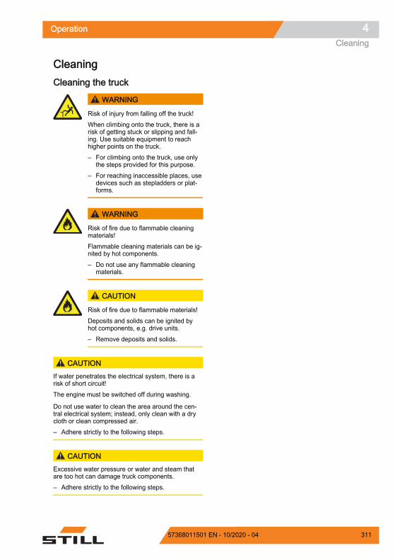
CleaningCleaning the truck
WARNING
Risk of injury from falling off the truck!When climbing onto the truck, there is arisk of getting stuck or slipping and fall-ing. Use suitable equipment to reachhigher points on the truck.– For climbing onto the truck, use only
the steps provided for this purpose.– For reaching inaccessible places, use
devices such as stepladders or plat-forms.
WARNING
Risk of fire due to flammable cleaningmaterials!Flammable cleaning materials can be ig-nited by hot components.– Do not use any flammable cleaning
materials.
CAUTION
Risk of fire due to flammable materials!Deposits and solids can be ignited byhot components, e.g. drive units.– Remove deposits and solids.
CAUTIONIf water penetrates the electrical system, there is arisk of short circuit!The engine must be switched off during washing.
Do not use water to clean the area around the cen-tral electrical system; instead, only clean with a drycloth or clean compressed air.– Adhere strictly to the following steps.
CAUTIONExcessive water pressure or water and steam thatare too hot can damage truck components.– Adhere strictly to the following steps.
Operation 4Cleaning
31157368011501 EN - 10/2020 - 04

CAUTIONAbrasive cleaning materials can damage the surfa-ces of components!Using abrasive cleaning materials that are unsuitablefor plastics can cause plastic parts to dissolve or be-come brittle. The screen on the display-operating unitcould become cloudy.– Adhere strictly to the following steps.
– Park the truck securely.
– Switch off the key switch.
– Do not spray electric motors and other elec-trical components or their covers directlywith water.
– Use only high-pressure cleaners with amaximum output power of up to 50 bar and85°C.
– If a high-pressure cleaner is used, maintaina distance of at least 20 cm between thenozzle and the object being cleaned.
– Do not aim the cleaning jet directly at adhe-sive labels or decal information.
– Remove all deposits and accumulations offoreign materials in the vicinity of hot com-ponents.
– Use only non-flammable fluids for cleaning.
– Observe the manufacturer's guidelines forworking with cleaning materials.
– Clean plastics only with cleaning materialsintended for plastics.
– Observe the manufacturer's guidelines forworking with cleaning materials.
– Clean the truck exterior using water-solublecleaning materials and water. Cleaning witha water jet, a sponge or a cloth is recom-mended.
– Clean all accessible areas.
– Before lubrication, clean the oil filling open-ings and the area around the oil filling open-ings, as well as the lubricating nipples.
Operation4Cleaning
312 57368011501 EN - 10/2020 - 04

Cleaning the electrical system
CAUTION
Cleaning electrical system parts with wa-ter can damage the electrical system.– Cleaning electrical system parts with
water is forbidden!– Use dry cleaning materials in accord-
ance with the manufacturer's specifi-cations.
– Do not remove covers etc.
– Clean the electrical system parts with ametal-free brush and blow the dust off withlow-pressure compressed air.
Cleaning load chains
WARNINGRisk of accident!Load chains are safety elements.
The use of cold/chemical cleaners or fluids that arecorrosive or contain acid or chlorine can damage thechains and is forbidden!– Observe the manufacturer's guidelines for working
with cleaning materials.
– Place a collection vessel under the lift mast.
– Clean with paraffin derivatives, such asbenzine.
– When using a steam jet, do not use addi-tional cleaning agents.
– Remove any water in the chain links usingcompressed air immediately after cleaning.Move the chain several times during thisprocedure.
– Immediately after drying the chain, spray itwith chain spray. Move the chain severaltimes during this procedure.
For chain spray specifications, see the "Main-tenance data table" chapter.
7071_003-091
Z
6210_810-004
Z
Operation 4Cleaning
31357368011501 EN - 10/2020 - 04

ENVIRONMENT NOTE
Dispose of any fluid that has been spilled orcollected in the collection vessel in an environ-mentally friendly manner. Follow the statutoryregulations.
Cleaning the windowsAny panes of glass, e.g. cab windows (var-iant), must always be kept clean and free ofice. This is the only means of guaranteeinggood visibility.
CAUTIONDo not damage the rear window heater (inside)!– Take great care when cleaning the rear window
and do not use any objects with sharp edges.
– Clean the windows using a commerciallyavailable glass cleaner.
After washing– Carefully dry the truck (e.g. with com-
pressed air).
– Sit on the driver's seat and start up thetruck in accordance with regulations.
CAUTIONRisk of short circuit!– If any moisture has penetrated into the engine de-
spite the precautionary measures taken, this mustfirst be dried with compressed air.
– The truck must then be started up to prevent pos-sible corrosion damage.
7311_003-058
Z
Operation4Cleaning
314 57368011501 EN - 10/2020 - 04

Procedure in emergenciesProcedure if truck tips over
DANGERIf the truck tips over, the driver could fall out andslide under the truck with potentially fatal conse-quences. There is a risk to life.Failure to comply with the limits specified in theseoperating instructions, e.g. driving on unacceptablysteep gradients or failing to adjust speed when cor-nering, can cause the truck to tip over. If the truckstarts to tip over, do not leave the truck under anycircumstances. This increases the danger of beinghit by the truck.– Do not release your seat belt.– Never jump off the truck.– You must adhere to the rules of behaviour if the
truck tips over.
Rules of behaviour if truck tips over:
– Hold onto the steering wheel with yourhands.
– Brace your feet in the footwell.
– Bend your upper body over the steeringwheel.
– Bend your body against the direction of thefall.
Emergency hammerThe emergency hammer is used to rescue thedriver if he is shut inside the cab in a hazard-ous situation, for example if the truck has top-pled over and the cab door cannot be opened.
Single-pane safety glass can be struck rela-tively safely using the emergency hammer inorder for the driver to escape or be rescuedfrom the danger area.
Using the emergency hammer
7090_001-005
Z
6321_003-097_V3
1
Z
Operation 4Procedure in emergencies
31557368011501 EN - 10/2020 - 04

WARNINGWhen glass is smashed there is a risk of injurycaused by glass splinters!When the cab glass is smashed, splinters of glasscan shoot into the face and cause damage to skinand eyes through cuts. When a pane of glass issmashed, the face should be turned away and cov-ered with the crook of the free arm.– Protect the face when smashing a pane of glass.
– Pull the emergency hammer out of its sup-port mounting at the handle.
– Using one of the two metal tips on the headof the emergency hammer, hit the pane ofglass with force until it breaks.
Emergency loweringIf the hydraulic controller fails whilst a load israised, emergency lowering can be performed.An emergency lowering screw designed forthis purpose is located on the valve block.
DANGER
There is a risk to life from falling loadsor from truck components being low-ered.– Do not walk beneath the raised load.– Adhere to the steps detailed below.
– Remove the lid (1) on the right-hand side ofthe footwell panelling near the acceleratorpedal.
1
Z
Operation4Procedure in emergencies
316 57368011501 EN - 10/2020 - 04

– Remove the hexagon socket wrench (2)from the compartment on the right next tothe driver's seat.
– Using the hexagon socket wrench, turn theemergency lowering screw (3) a maximumof 1.5 revolutions to loosen it.
WARNINGThe load is lowered!Unscrewing the emergency lowering screw regulatesthe lowering speed.– Observe the list of points below.
The following applies: Tightening torque:
Max. 2.5 Nm Unscrewing the emergency lowering screw
slightly:The load is lowered slowly
Unscrewing the emergency lowering screwfurther:The load is lowered quickly
After lowering:
– Re-tighten the emergency lowering screw.
– Return the hexagon socket wrench to thesupport mounting in the compartment.
– Refit the lid.
2
Z
3
Z
Operation 4Procedure in emergencies
31757368011501 EN - 10/2020 - 04

DANGERIf the truck is operated while the hydraulic controlleris blocked, there is an increased risk of accidents.– After the emergency lowering procedure, have the
malfunction rectified.– Notify the authorised service centre.
Emergency operation of the electricparking brake
DANGER
Risk of fatal injury from being run over ifthe truck rolls away!Emergency operation of the parkingbrake can be initiated only when the forkis lowered and the truck is switched off.
The truck can roll away when the park-ing brake is released.
– Use wedges to prevent the truck from roll-ing away.
– Lower the fork to the ground.
– Switch off the key switch.
The electric parking brake can be releasedand applied via an emergency actuationmechanism.
The emergency operation of the electric park-ing brake is required under the following con-ditions: The parking brake is not functioning proper-
ly. No power supply to the parking brake, e.g.
if the starter battery is discharged or re-moved
NOTE
If the parking brake is released via the emer-gency actuation mechanism, it is possible todrive the truck at a low speed.
This allows the truck to be moved out of thehazardous situation or to the repair location.
Driving with a faulty parking brake requiresthe driver to be especially vigilant.
Operation4Procedure in emergencies
318 57368011501 EN - 10/2020 - 04

– Lift the cover (1) and fold it up.
Release parking brake
CAUTIONRisk of component damage by pulling on the emer-gency actuation mechanism with excessive force!– Apply a maximum force of 50 N to the emergency
actuation mechanism.– If the emergency actuation mechanism does not
move, depress the brake pedal.
– To release the mechanism, fully depressthe brake pedal and hold it down.
– Remove and hold on to the emergency ac-tuation mechanism (2).
– Release the brake pedal. Let go of theemergency actuation mechanism (2).
Once two grooves are visible (see arrow), theparking brake is released.
Apply parking brake
– Fully depress the brake pedal.
The emergency actuation mechanism (2) re-turns to its initial position.
– Release the brake pedal.
Once only one groove is visible (see arrow),the parking brake is applied.
– If the status of the parking brake cannot bereliably determined from the position of theemergency actuation mechanism, securethe truck with wedges.
6301_003-002_V2
Z
Operation 4Procedure in emergencies
31957368011501 EN - 10/2020 - 04

Disconnecting the batteryIn order to quickly disconnect the battery inthe event of a dangerous situation (e.g. aburning cable or electrical malfunction), thenegative battery terminal is fitted with a quicklyremovable battery-terminal clip.
Proceed as follows to quickly disconnect thebattery:
– Unscrew star-grip screws (1) to the left andright of the rear cover and fold the cover (2)back.
– Pull the negative terminal battery-terminalclip upward.
– Lift the battery-terminal clip off the negativeterminal of the battery and place it to theside.
7321_003-062
1
2
Z
7311_003-068
Z
Operation4Procedure in emergencies
320 57368011501 EN - 10/2020 - 04

Jump-starting
DANGER
Risk of explosion from spark discharge!If the electrical system on the truck isswitched on, or a live cable touches ametal part of the truck, this can cause aspark discharge. Any escaping gas mayexplode as a result.– If the truck has not been used for a
long period of time and before startingwork, ensure that the closed room iswell ventilated before operating thetruck.
– The metal parts of the truck must nottouch the connecting terminals.
NOTE
A 12-V power source (e.g. second forklift truckof the same type) must be available.
WARNINGRisk of short circuit if the jump leads are connectedor disconnected in the incorrect order!If the battery's negative terminals are connected tothe negative cable, both bodies are also conductivelyconnected to one another. If the positive cable touch-es one of the two bodies as further cables are con-nected, a short circuit can occur.– Ensure that the correct order is followed when
connecting and disconnecting the jump leads.
– Remove covering from the back, see⇒ Chapter "Removing and attaching the rearcover", Page 358 .
– Leave the engine of the current-giving truckto run.
Connect the jump leads:
– Connect the positive cable (2) to the posi-tive terminal on the discharged battery.
– Connect the positive cable to the positiveterminal on the current-giving battery.
– Connect the negative cable (1) to the nega-tive terminal on the current-giving battery.
– Connect the negative cable to negative ter-minal on the discharged battery.
- +21
+
-
7311_606-001
Z
Operation 4Procedure in emergencies
32157368011501 EN - 10/2020 - 04
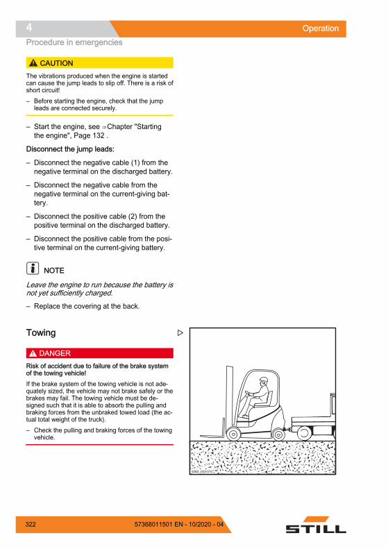
CAUTIONThe vibrations produced when the engine is startedcan cause the jump leads to slip off. There is a risk ofshort circuit!– Before starting the engine, check that the jump
leads are connected securely.
– Start the engine, see ⇒ Chapter "Startingthe engine", Page 132 .
Disconnect the jump leads:
– Disconnect the negative cable (1) from thenegative terminal on the discharged battery.
– Disconnect the negative cable from thenegative terminal on the current-giving bat-tery.
– Disconnect the positive cable (2) from thepositive terminal on the discharged battery.
– Disconnect the positive cable from the posi-tive terminal on the current-giving battery.
NOTE
Leave the engine to run because the battery isnot yet sufficiently charged.
– Replace the covering at the back.
Towing
DANGERRisk of accident due to failure of the brake systemof the towing vehicle!If the brake system of the towing vehicle is not ade-quately sized, the vehicle may not brake safely or thebrakes may fail. The towing vehicle must be de-signed such that it is able to absorb the pulling andbraking forces from the unbraked towed load (the ac-tual total weight of the truck).– Check the pulling and braking forces of the towing
vehicle.
6036Ba-0265060_003-070
Z
Operation4Procedure in emergencies
322 57368011501 EN - 10/2020 - 04

DANGERIf the towing vehicle brakes, there is a risk that thetruck will drive into the towing vehicle!If a rigid connection has not been used for powertransmission in two directions during towing, thetruck may drive into the towing vehicle when the tow-ing vehicle brakes. Use a tested tow bar for safetyreasons.– Use a tested tow bar.
CAUTIONIf the truck drive between the drive motor and thedrive axle is not interrupted, the drive may be dam-aged.– Place the drive direction switch in the neutral posi-
tion.
DANGERWhile manoeuvring, there is a risk of fatal injury inthe area between the truck and the towing vehicle!Inform the driver of the towing vehicle and the me-chanic attaching the tow bar about the risks. Whenyou fit the tow bar, always use a second person toguide the towing vehicle manoeuvres.– Manoeuvre with a second person as a guide.
CAUTIONSteering is stiff! There is no power steering if the hy-draulics fail!– Select a slow towing speed to ensure that the
truck and the towing vehicle can be braked andcontrolled effectively at all times.
CAUTIONIf the truck is not steered while it is being towed, thetruck may veer out in an uncontrolled manner!– The truck being towed must also be steered by a
driver.– The driver of the truck being towed must sit in the
driver's seat and fasten the seat belt before tow-ing.
– Where possible, activate the restraint systemsprovided.
– Set down the load and lower the fork armsso that they are close to the ground.
Operation 4Procedure in emergencies
32357368011501 EN - 10/2020 - 04

– Set the drive direction switch to the neutralposition.
– Apply the parking brake.
– Switch off the key switch.
– Check the pulling and braking forces of thetowing vehicle.
– With a second person as a guide, manoeu-vre the towing vehicle to the truck.
– Secure the tow bar to the tow coupling onthe towing vehicle and on the truck.
– Sit in the driver's seat of the truck beingtowed and fasten the seat belt.
– Where possible, activate the restraint sys-tems provided.
– Release the parking brake.
– Select a slow towing speed.
– Tow the truck.
– After towing, secure the truck so that it can-not roll away (e.g. by applying the parkingbrake or by using wedges).
– Remove the tow bar.
Operation4Procedure in emergencies
324 57368011501 EN - 10/2020 - 04

Transporting the truckTransporting
CAUTIONRisk of material damage from overloading!If the truck is driven onto a means of transport, theload capacity of the means of transport, the rampsand the loading bridges must be greater than the ac-tual total weight of the truck. Components can bepermanently deformed or damaged due to overload-ing.– Determine the total actual weight of the truck.– Only load the truck if the load capacity of the
means of transport, the ramps and the loadingbridges is greater than the actual total weight ofthe truck.
Determining the total actual weight– Park the truck safely.
– Determine the unit weights by reading thetruck nameplate and, if necessary, the at-tachment nameplate (variant).
– Add together the determined unit weights toobtain the total actual weight of the truck:
Net weight (1)
+ Ballast weight (variant) (2)
+ Net weight of attachment (variant)+ 100 kg allowance for driver= Total actual weight
Type-Modèle-Typ / Serial no.-No. de série-Serien-Nr. / year-année-Baujahr
Rated capacityCapacité nominaleNenn-Tragfähigkeit
Battery voltageTension batterieBatteriespannung
Rated drive powerPuissance motr.nom.Nenn-Antriebsleist.
Unladen massMasse à videLeergewicht
maxmin.*
* see Operating instructions voir Mode d'emploi siehe Betriebsanleitung
kg kg
kgkg
kgkW
V
*
D-22113 HamburgBerzeliusstr. 10 2
1
Z
Operation 4Transporting the truck
32557368011501 EN - 10/2020 - 04

DANGERRisk of accident from the truck crashing!Steering movements can cause the rear of the truckto veer off the loading bridge towards the edge. Thismay cause the truck to crash.– Before driving across a loading bridge, ensure
that the loading bridge is properly attached andsecured.
– Ensure that the transport vehicle onto which thetruck is to be driven has been sufficiently securedagainst moving.
– Maintain a safety distance from edges, loadingbridges, ramps, working platforms etc.
– Drive slowly and carefully onto the transport vehi-cle.
Wedging the wheels– Use two wedges to secure each of the front
and rear wheels against sliding or rollingaway.
Lashing down
CAUTIONHarnesses can rub against the seating and causedamage!– Place a slip-resistant material between the har-
ness and the seating, e.g. rubber mats or foam.
6210_001-012_V3
Z
Operation4Transporting the truck
326 57368011501 EN - 10/2020 - 04

– Attach the harness (1) to each side of thetruck.
– Lash the truck towards the rear.
– Attach the harness (1) to the couplingpin (2) or loop the harness around the cou-pling pin.
– Lash the truck at both sides.
DANGERThe truck may slip if the harnesses slip!The truck must be lashed securely to ensure that itdoes not move during transportation.– Ensure that the harnesses are tightened securely
and that the pads cannot slip off.
Crane loadingCrane loading is only intended for transportingthe complete truck, including the lift mast, forits initial commissioning. For application condi-tions that require frequent loading or that arenot presented here, please contact the manu-facturer with regard to special equipment var-iants.
Trucks may only be laden by persons with suf-ficient experience of suitable harnesses andhoists.
6321_003-104
1
Z
7321_003-010
1
2
Z
Operation 4Transporting the truck
32757368011501 EN - 10/2020 - 04

Determining the loading weight– Park the truck securely; see ⇒ Chapter
"Parking the truck securely and switching itoff", Page 183 .
– Determine the unit weights by reading themoff the truck nameplate and, if necessary,the attachment (variant) nameplate.
– Add the determined unit weights to obtainthe loading weight of the truck:
Tare weight (1)
+ Ballast weight (variant) (2)
+ Attachment net weight (variant)
= Loading weight
Hooking on the lifting straps
CAUTIONHarnesses may damage the truck's paintwork!Harnesses may damage paintwork by chafing andpressing on the surface of the truck. Hard or sharp-edged harnesses, such as wires or chains, canquickly damage the surfaces.– Use textile harnesses, e.g. lifting straps, with edge
protectors or similar protective devices if necessa-ry.
DANGERThere is a risk of being hit if the hoists and har-nesses fail and cause the truck to fall. Danger tolife!– Only use hoists and harnesses with adequate
load capacity for the determined loading weight.– Only use the truck's designated lifting points.– Make sure that harnesses such as hooks, shack-
les, belts etc. are only used in the indicated loaddirection.
– The harnesses must not be damaged by truckparts.
Type-Modèle-Typ / Serial no.-No. de série-Serien-Nr. / year-année-Baujahr
Rated capacityCapacité nominaleNenn-Tragfähigkeit
Battery voltageTension batterieBatteriespannung
Rated drive powerPuissance motr.nom.Nenn-Antriebsleist.
Unladen massMasse à videLeergewicht
maxmin.*
* see Operating instructions voir Mode d'emploi siehe Betriebsanleitung
kg kg
kgkg
kgkW
V
*
D-22113 HamburgBerzeliusstr. 10 2
1
Z
Operation4Transporting the truck
328 57368011501 EN - 10/2020 - 04

– Loop the lifting straps around the main tra-verse (3) on the outer mast of the lift mast.
NOTE
The lifting points are indicated by a hook sym-bol.
– Loop the lifting straps around the tow bolt(4) in the tow-bar eye of the towing device.
– Secure the tow bolt.
– Determine the truck's centre of gravity; see⇒ Chapter "Dimensions", Page 392 .
3
7321_003-012Z
7311_003-060
4
Z
Operation 4Transporting the truck
32957368011501 EN - 10/2020 - 04
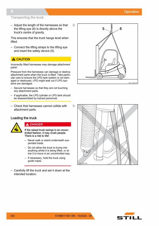
– Adjust the length of the harnesses so thatthe lifting eye (6) is directly above thetruck's centre of gravity.
This ensures that the truck hangs level whenlifted.
– Connect the lifting straps to the lifting eyeand insert the safety device (5).
CAUTIONIncorrectly fitted harnesses may damage attachmentparts!Pressure from the harnesses can damage or destroyattachment parts when the truck is lifted. Take partic-ular care to ensure the LPG tank system is not dam-aged or destroyed. LPG might leak out if LPG sys-tems are damaged.– Secure harnesses so that they are not touching
any attachment parts.– If applicable, the LPG cylinder or LPG tank should
be disassembled by trained personnel.
– Check that harnesses cannot collide withattachment parts.
Loading the truck
DANGER
If the raised truck swings in an uncon-trolled fashion, it may crush people.There is a risk to life!– Never walk or stand underneath sus-
pended loads.– Do not allow the truck to bump into
anything whilst it is being lifted, or al-low it to move in an uncontrolled way.
– If necessary, hold the truck usingguide ropes.
– Carefully lift the truck and set it down at theintended location.
7321_003-013
5 6Z
7314_003-046
Z
Operation4Transporting the truck
330 57368011501 EN - 10/2020 - 04

Short-term operation
NOTE
If the truck is operated frequently and only forshort periods, the cooling circuit of the enginecannot reach the operating temperature. Theevaporator of the LPG system is heated by thecoolant circuit of the engine. This prevents theevaporator from icing over because gas coolssignificantly upon evaporation. The gas supplycan be interrupted if the evaporator ices over.This causes the engine to come to a halt.
The evaporator can ice over as a result of: Frequent operation for short periods High engine loads at low ambient tempera-
tures
NOTE
Avoid short-term operation and high motorloads in low ambient temperature whereverpossible. If necessary, run the engine until theoperating temperature is reached.
If the engine stalls suddenly and does not startagain, check whether the evaporator has icedover and de-ice the evaporator as necessary;refer to the section entitled "De-icing the evap-orator".
Operation 4Transporting the truck
33157368011501 EN - 10/2020 - 04

DecommissioningShutting down and storing the truck
CAUTIONComponent damage due to incorrect storage!If the truck is stored or shut down incorrectly for morethan two months, it may suffer corrosion damage. Ifthe truck is parked in an ambient temperature of lessthan –10°C for an extended period, the battery willcool down. The electrolyte may freeze and damagethe battery.– Carry out the following measures before shut-
down.
CAUTIONDanger of tyre deformation by continuously loadingon one side!Have the truck raised and jacked up only by the au-thorised service centre so that all the wheels areclear of the ground. This prevents permanent defor-mation of the tyres.
CAUTIONDanger of damage from corrosion due to condensa-tion on the truck!Many plastic films and synthetic materials are water-tight. Condensation water on the truck cannot es-cape through these covers.– Do not use plastic film as this facilitates the forma-
tion of condensation water.
NOTE
Store only fully charged batteries.
Measures before shutdown– Store the truck in a dry, clean, frost-free and
well-ventilated environment.
– Clean the truck thoroughly; see the chapterentitled "Cleaning".
– Lift fork carriage to stop several times.
– Tilt the lift mast forwards and backwardsseveral times and, if fitted, move attach-ment repeatedly.
Operation4Decommissioning
332 57368011501 EN - 10/2020 - 04

– To relieve the strain on the load chains,lower the fork onto a suitable supportingsurface, e.g. a pallet.
– Check the hydraulic oil level and top up ifrequired.
– Apply a thin layer of oil or grease to all un-treated moving parts.
– Grease the forklift truck.
– Lubricate the joints and controls.
– Remove LPG cylinder.
– Remove the battery and store in a warmand dry location.
– Regularly check the charge state of the bat-tery and recharge if necessary.
– Apply a suitable contact spray to all ex-posed electrical contacts.
– Preserve the engine as specified by themanufacturer.
– Cover the truck with vapour-permeable ma-terials, such as cotton, in order to protectagainst dust.
– If the truck is to be shut down for even lon-ger periods, contact your authorised servicecentre to find out about additional meas-ures.
Returning to service after decom-missioning
DANGER
Risk of explosion!If the truck has been parked in an en-closed space for an extended period oftime, there is a risk of explosive gasesforming as a result of potential leakageson the truck or as a result of gas emis-sions.– Ventilate the room well before switch-
ing on the electrical system.
If the truck has been decommissioned for lon-ger than six months, the truck must be careful-ly checked before being recommissioned. Aswith the yearly safety inspection, this check
Operation 4Decommissioning
33357368011501 EN - 10/2020 - 04

must also include all safety-related aspects ofthe truck.
– Thoroughly clean the truck.
– Oil joints and controls.
– Check the battery condition and acid densi-ty, and recharge the battery if necessary.
– Restore the engine to normal condition asspecified by the engine manufacturer.
– Check if there is any condensation water inthe hydraulic oil and replace the oil if neces-sary.
– Change the brake fluid.
– Connect the LPG cylinder; see the chapterentitled "Changing the LPG cylinder".
– Check the LPG tank (variant).
– Check the LPG system for leak tightnessusing leak spray.
– Check the screw joints of the LPG systemfor tightness.
– Have the same checks and tasks carriedout by the authorised service centre thatwere carried out before initial commission-ing.
– Carry out the checks and tasks that are tobe performed before daily use.
– Recommission the truck.
During commissioning, the following pointsmust be checked in particular: Leak tightness and function of the LPG sys-
tem Drive, controller, steering Brake system (service brake, parking brake,
regenerative brake) Lifting system (lifting accessories, load
chains, mounting)
NOTE
For further information, see the workshopmanual for the truck or contact the authorisedservice centre.
Operation4Decommissioning
334 57368011501 EN - 10/2020 - 04

5
Maintenance

Safety regulations for maintenanceGeneral information
DANGERRisk of fatal poisoning!It is dangerous to leave the engine running in en-closed spaces. The engine consumes oxygen andemits carbon dioxide, carbon monoxide and otherpoisonous gases. There is a risk of fatal poisoning!– Only operate the truck in areas that are well venti-
lated.
To prevent accidents during maintenancework and repair work, all necessary safetymeasures must be taken, e.g.:
– Apply the parking brake.
– Switch off the key switch and remove thekey.
– Ensure that the truck cannot move uninten-tionally or start up inadvertently.
– If required, have the truck jacked up by theauthorised service centre.
– Have the raised fork carriage or the exten-ded lift mast secured against accidentallowering by the authorised service centre.
– Insert an appropriately sized wooden beamas an abutment between the lift mast andthe cab, and secure the lift mast to preventit tilting backwards unintentionally.
– Observe the maximum lift height of the liftmast, and compare the dimensions from thetechnical data with the dimensions of thehall into which the truck is to be driven.These steps are taken to prevent a collisionwith the ceiling of the hall and to avoid anydamage caused as a result.
Working on the hydraulic equipmentThe hydraulic system must be depressurisedprior to all work on the system.
Maintenance5Safety regulations for maintenance
336 57368011501 EN - 10/2020 - 04

Working on the electrical equipmentWork may only be performed on the electricalequipment of the truck when it is in a voltage-free state. Function checks, inspections andadjustments on energised parts must only beperformed by trained and authorised persons,taking the necessary precautions into account.Rings, metal bracelets etc. must be removedbefore working on electric components.
To prevent damage to electronic systems withelectronic components, such as an electronicdriving regulator or lift control, these compo-nents must be removed from the truck prior tothe start of electric welding.
Work on the electrical system (e.g. connectinga radio, additional headlights etc.) is only per-mitted with approval from the authorised serv-ice centre.
Working on the ignition systemTo prevent personal injury and/or destructionof the ignition system, please observe the fol-lowing: Only connect and disconnect ignition sys-
tem lines, including high-voltage lines andmeasuring device lines, with the ignitionswitched off.
If the engine is to be operated at startingspeed but not actually started (e.g. for acompression pressure test), disconnect theconnection assembly from the ignition coil.
Use of a quick charger to jump start the en-gine is only permitted for a period of up to 1minute at max. 16.5 volts.
The engine may only be washed when theignition is switched off.
When performing electric or point welding,completely disconnect the battery.
Trucks that have a fault in the ignition sys-tem, or a suspected fault, may only be tow-ed if the plug is disconnected from the igni-tion coil.
Maintenance 5Safety regulations for maintenance
33757368011501 EN - 10/2020 - 04

Working on the LPG system DANGER
Risk of explosion!Observe the safety regulations for work-ing with LPG.
The condition of the entire LPG system mustbe kept under constant surveillance to ensuresafety of operation, in particular in terms ofleakage. It is not permitted to use the truck ifthe gas system is leaking. When checking forleaks, soapy water, a solution of Nekal or oth-er foaming products must be used.
DANGER
Risk of explosion!It is not permitted to inspect the gas sys-tem using a naked flame for illumination.
The level of harmful substances in the exhaustgases must be set at the lowest possible value(CO content lower than 0.1 vol. % during idlingwith engine at operating temperature).
When replacing individual system parts, themanufacturers' installation instructions mustbe observed. The cylinder and main shut-offvalves must be closed when doing so.
The condition of the electrical system of trucksrunning on LPG must be kept under constantsurveillance. Sparks may cause explosions ifsystem parts containing gas are leaking. Aftera truck running on LPG has been shut downfor a long period of time, the storage roommust be ventilated thoroughly before startingup the truck or its electrical system.
When working in maintenance workshops, thecylinder and main shut-off valves must beclosed and the LPG cylinders protected fromheat.
Before work breaks and the end of the day'swork, a responsible person must check that allvalves, in particular cylinder valves, areclosed.
Do not perform any work involving fire, in par-ticular welding and cutting jobs, near the LPGcylinders.
Maintenance5Safety regulations for maintenance
338 57368011501 EN - 10/2020 - 04

LPG cylinders, even when empty, must not bestored in workshops.
Safety devicesAfter maintenance and repair work, all safetydevices must be reinstalled and tested for op-erational reliability.
Set valuesThe device-dependent set values must be ob-served when making repairs and when chang-ing hydraulic and electrical components.These are listed in the appropriate sections.
Lifting and jacking up DANGER
There is a risk to life if the truck tips over!If not raised and jacked up properly, the truck may tipover and fall off. Only the hoists specified in theworkshop manual for this truck are allowed and aretested for the necessary safety and load capacity.– Only have the truck raised and jacked up by the
authorised service centre.– Only jack the truck up at the points specified in the
workshop manual.
The truck must be raised and jacked up forvarious types of maintenance work. The au-thorised service centre must be informed thatthis is to take place. Safe handling of the truckand the corresponding hoists is described inthe truck's workshop manual.
Working at the front of the truck DANGER
Risk of accident!If the lift mast or fork carriage is raised, no work maybe performed on the lift mast or at the front of thetruck unless the following safety measures are ob-served.– When securing, only use chains with sufficient
load-bearing capacity.– Contact the authorised service centre.
Maintenance 5Safety regulations for maintenance
33957368011501 EN - 10/2020 - 04

CAUTIONPossibility of damage to the ceiling!– Note the maximum lift height of the lift mast.
Securing the lift mast against tiltingbackwardsA hardwood beam with a cross-section of 120x 120 mm is required. The length of the hard-wood beam must approximately correspond tothe width of the fork carriage (b3). To avoidimpact injuries, the hardwood beam must notprotrude beyond the outer contour of the truck.A maximum length matching the total width(b1) of the truck is recommended.
– Obtain the dimensions (b1) and (b3) fromthe corresponding VDI datasheet.
– Clamp the hardwood beam (1) between thedriver protection structure (2) and the liftmast (3).
Removing the lift mast
DANGERRisk of accident!This work must only be performed by an authorisedservice technician.– Arrange for an authorised service technician to re-
move the lift mast.
Securing the lift mast against falling off
DANGERRisk of accident!This work must only be performed by an authorisedservice technician.– Arrange for an authorised service technician to
secure the lift mast.
1 2
3
6210_001-030_V3
Z
Maintenance5Safety regulations for maintenance
340 57368011501 EN - 10/2020 - 04

General maintenance infor-mationPersonnel qualificationsOnly qualified and authorised personnel areallowed to perform maintenance work. Regu-lar safety checks and checks after unusual in-cidents must be performed by a competentperson. The competent person must conducttheir evaluation and assessment from a safetystandpoint, unaffected by operational and eco-nomic conditions. The competent person musthave sufficient knowledge and experience tobe able to assess the condition of a truck andthe effectiveness of the protective devices inaccordance with technical conventions andthe principles for testing trucks.
Maintenance work without special quali-ficationsSimple maintenance work, such as checkingthe hydraulic oil level, may be carried out byuntrained personnel. A qualification such asthose held by a competent person is not re-quired to carry out this work. The requiredtasks are described in the chapter entitled"Remaining ready for operation".
Information for carrying out mainte-nanceThis section contains all information requiredto determine when the truck needs mainte-nance. Carry out maintenance work within thetime limits according to the hour meter and us-ing the following maintenance check lists. Thisis the only way to ensure that the truck re-mains ready for operation and provides opti-mal performance and service life. It is also aprecondition for any warranty claims.
Maintenance 5General maintenance information
34157368011501 EN - 10/2020 - 04

Maintenance timeframe– Carry out maintenance work on the truck in
accordance with the "Service in" display (1).
– The maintenance check lists indicate themaintenance work that is due.
The intervals are defined for standard use.Shorter maintenance intervals can be definedin consultation with the operating company,depending on the application conditions of thetruck.
The following factors may necessitate shortermaintenance intervals: Contaminated, poor quality roads Dusty or salty air High levels of air humidity Extremely high or low ambient tempera-
tures, or extreme changes in temperature Multi-shift operation with a high duty cycle Specific national regulations for the truck or
individual components
CAUTIONRisk of component damage!Any deviating technical information in these operat-ing instructions takes precedence over the informa-tion in the original engine operating instructions.– If you have any questions, please contact your au-
thorised service centre.
7312_003-156_V2
1Z
Maintenance5General maintenance information
342 57368011501 EN - 10/2020 - 04

Maintenance - 1000 hours/annually
At operating hours
1000 2000 4000 5000 7000 8000 10000 11000 13000 14000
Carriedout
9 8
Chassis, bodywork and fittings
Check the chassis for cracks.
Check the overhead guard, plus the cab and glass panes where relevant, for dam-age.
Variant: Check that the cab door sensor is working correctly and check for damage.
Check the controls, switches and joints for damage, and apply grease and oil.
Check that the driver's seat is working correctly and check for damage.
Check that the driver restraint system is working correctly and check for damage,and clean.
Check the signal horn.
Variant: Check the dual-pedal variant for damage and that it is working correctly,and lubricate.
Tyres and wheels
Check tyres for wear and check the air pressure if necessary.
Check the wheels for damage and check the tightening torques.
Internal combustion engine
Check the condition of the internal combustion engine (visual inspection).
Check the V-belt.
Change the engine oil and replace the oil filter.
Replace the air filter (main cartridge).
Check the cooling system for leak tightness and correct function.
Check the coolant and top up if necessary.
Fuel system
Check the fuel system for leak tightness and correct function.
Replace the fuel filter (yearly).
LPG system
Check the LPG system for damage.
Check the solenoid shut-off valve.
Check the gas cylinder valve for cleanliness and correct function; check the over-pressure safety device (30 bar).
Replace the LPG filter.
Maintenance 5General maintenance information
34357368011501 EN - 10/2020 - 04

At operating hours
1000 2000 4000 5000 7000 8000 10000 11000 13000 14000
Carriedout
9 8
Check the screw joints for secure attachment and perform a leak test.
Exhaust system
Check the exhaust system.
Remove the particle filter and perform ash cleaning every 10,000 operating hours.
Drive axle
Check the mounting of the drive axle and check the drive axle for leak tightness.
Check the power cable and sensor cable for damage.
Check the oil level in the drive wheel units.
Change the gearbox oil in the drive wheel units (once after the first 1000 operatinghours).
Steering systems
Check the steering system for leaks and check that it is working correctly.
Check that the steering wheel is securely attached and check the rotary handle fordamage.
Check the mounting of the steering axle and check the steering axle for leak tight-ness.
Grease all lubricating nipples on the steering axle.
Check the steering stop.
Brake system
Check the condition of all mechanical brake parts and check that they are workingcorrectly.
Check the actuation distance of the brake pedal and adjust if necessary.
Check the filling level in the brake reservoir.
Check that the electrical filling level monitoring function is working correctly.
Check that the emergency actuation of the parking brake is working correctly.
Perform a brake test.
Electrical system
Check all power cable connections.
Check that the switches, transmitters and sensors are working correctly.
Check the lighting and indicator lights.
Cooling system (converter)
Check the cooling system for leak tightness and correct function.
Maintenance5General maintenance information
344 57368011501 EN - 10/2020 - 04

At operating hours
1000 2000 4000 5000 7000 8000 10000 11000 13000 14000
Carriedout
9 8
Check the coolant and top up if necessary.
Clean the fan and the water cooler.
Starter battery
Measure the cold-start current; recharge or replace the battery if necessary.
Hydraulics
Check the condition of the hydraulic system, check that it is working correctly andcheck for leak tightness.
Check the hydraulics blocking function (ISO valve).
Check the oil level.
Lift mast
Check the mast fixation for damage. Lubricate the mast fixation and check the tight-ening torque.
Check the mast profiles for damage and wear. Lubricate the mast profiles.
Check the guide in the lower (load reversal) mast profile for damage and for wear.
Check the load chains for damage and wear. Adjust and lubricate the load chains.
Check the lift cylinders and connections for damage and for leak tightness.
Check the guide pulleys for damage and for wear.
Check the support rollers and chain rollers for damage and for wear.
Check the play between the fork carriage stop and the run-out barrier.
Check the tilt cylinders and connections for damage and for leaks.
Check the fork carriage for damage and for wear.
Check the fork arm interlock for damage and check that it is working correctly.
Check the fork arms for wear and deformation.
Check that there is a safety screw on the fork carriage or on the attachment.
Special equipment
Check the condition of the antistatic belt or antistatic electrode.
Check the filter mat in the heating system or air conditioning, and replace if neces-sary.
Check that the heating system is working correctly; observe the manufacturer'smaintenance instructions.
Check that the air conditioning is working correctly; observe the manufacturer'smaintenance instructions.
Maintenance 5General maintenance information
34557368011501 EN - 10/2020 - 04
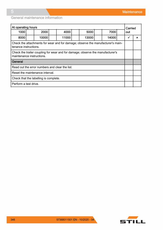
At operating hours
1000 2000 4000 5000 7000 8000 10000 11000 13000 14000
Carriedout
9 8
Check the attachments for wear and for damage; observe the manufacturer's main-tenance instructions.
Check the trailer coupling for wear and for damage; observe the manufacturer'smaintenance instructions.
General
Read out the error numbers and clear the list.
Reset the maintenance interval.
Check that the labelling is complete.
Perform a test drive.
Maintenance5General maintenance information
346 57368011501 EN - 10/2020 - 04

Maintenance - 3000 hours/every two years
At operating hours
3000 6000 9000 12000 15000
Carriedout
9 8
Note
Perform all 1000-hour maintenance work
Internal combustion engine
Replace the air filter (safety cartridge).
Replace the V-belt.
Replace the coolant every 6000 operating hours or every 3 years.
LPG: Replace the spark plugs.
LPG system
Replace all hoses on the LPG system.
Replace the evaporator. Replace the sticker. Every 3000 operating hours or every3 years.
Drive axle
Change the gearbox oil in the drive wheel units.
Brake
Change the actuation oil for the foot brake.
Hydraulics
Change the hydraulic oil
Replace the return line filter and the breather filter.
Replace the high-pressure filter.
Ordering spare parts and wearingpartsSpare parts are provided by our spare partsservice department. The information requiredfor ordering parts can be found in the spareparts list.
Only use spare parts as per the manufactur-er's instructions. The use of unapproved spareparts can result in an increased risk of acci-dents due to insufficient quality or incorrect as-signment. Anyone using unapproved spareparts shall assume unlimited liability in theevent of damage or harm.
Maintenance 5General maintenance information
34757368011501 EN - 10/2020 - 04

Quality and quantity of the requiredoperating materialsOnly the operating materials specified in themaintenance data table may be used.
– The required consumables and lubricantscan be found in the maintenance data table.
Oil and grease types of a different quality mustnot be mixed. This negatively affects the lu-bricity. If a change between different manufac-turers cannot be avoided, drain the old oilthoroughly.
Before carrying out lubricating work, filterchanges or any work on the hydraulic system,carefully clean the area around the part in-volved.
When topping up working materials, use onlyclean containers!
Maintenance5General maintenance information
348 57368011501 EN - 10/2020 - 04

Lubrication plan
Code1 Lubrication point
(A) Four lubricating nipples on each side of the steering axle for the axle stub bearing andtrack rod arm
(B) Sliding surfaces on the lift mast
(C) Load chains
Maintenance 5General maintenance information
34957368011501 EN - 10/2020 - 04

Code1 Lubrication point
(D) One lubricating nipple each on both lift mast bearings1See the following chapter, "Maintenance data table", under this Code.for the respective lubricant specificationThis lubrication plan describes the series-productiontruck with standard equipment. For maintenance points on variant trucks, see the relevant chap-ter and/or instructions provided by the manufacturer.
Maintenance5General maintenance information
350 57368011501 EN - 10/2020 - 04

Maintenance data tableGeneral lubrication points
Code Unit Operating materials Specifications Dimension Lubrication Multi-purpose grease DIN 51825 KPF2 As required
Controls/jointsCode Unit Operating materials Specifications Dimension
Lubrication Multi-purpose grease DIN 51825 KPF2 As requiredOil SAE 80
MIL-L2105API GL-4
As required
Dual-pedal opera-tion
Multi-purpose grease DIN 51825 KPF2 As required
BatteryCode Unit Operating materials Specifications Dimension
System filling Distilled water As required
Insulation resistance For further information, refer to the work-shop manual for the truck in question.
Electrical systemCode Unit Operating materials Specifications Dimension
Insulation resistance For further information, refer to the work-shop manual for the truck in question.
Hydraulic systemCode Unit Operating materials Specifications Dimension
System filling Hydraulic oil HVLP 68DIN 51524, Part 3
Max. 58 lHydraulic oil for thefood industry (var-iant)
USDA H1DIN 51524
TyresCode Unit Operating materials Specifications Dimension
Superelastic tyres Wear limit To wear markSolid rubber tyres Wear limit To wear markPneumatic tyres Minimum tread depth 1.6 mm
Air pressure See information ontruck
Maintenance 5General maintenance information
35157368011501 EN - 10/2020 - 04

Steering axleCode Unit Operating materials Specifications Dimension
Wheel nuts/screws Torque wrench For further informa-tion, refer to the
workshop manual forthe truck in question.
Axle stub nuts Torque wrench For further informa-tion, refer to the
workshop manual forthe truck in question.
(A) Axle stub bearings,track rod bearings
Grease Aralub 4320DIN 51825-KPF2N20ID no. 0148659
Fill with grease untila small amount of
fresh grease es-capes
Drive axleCode Unit Operating materials Specifications Dimension
Wheel nuts/screws Torque wrench For further informa-tion, refer to the
workshop manual forthe truck in question.
Wheel gear Mineral oil FUCHS TITANGEAR HYP LDSAE 80W-90API GL-5
Brake Mineral oil ARAL HGS FLUID127830
Lift mastCode Unit Operating materials Specifications Dimension(B) Lubrication Multi-purpose grease DIN 51825 KPF2 As required Stop Play Min. 2 mm Screws for the lift
mast bearingTorque wrench For further informa-
tion, refer to theworkshop manual forthe truck in question.
(D) Lift mast bearing Grease Aralub 4320DIN 51825-KPF2N20ID no. 0148659
Fill with grease untila small amount of
fresh grease es-capes
Maintenance5General maintenance information
352 57368011501 EN - 10/2020 - 04

Load chainsCode Unit Operating materials Specifications Dimension(C) Lubrication High-load chain
sprayFully syntheticTemperature range:-35°C to +250°CID no. 0156428
As required
Cooling systemCode Unit Operating materials Specifications Dimension
System filling Corrosion inhibitorand cooling systemprotecting agent/water
G12 plusTL-VW 774 F
approx. 12 l
Air conditioningCode Unit Operating materials Specifications Dimension
System filling Refrigerant ID no. 7449600005 Standard cab: 800 g
LPG cylinderCode Unit Operating materials Specifications Dimension System filling LPG DIN 51622
EN 58911 kg
Brake systemCode Unit Operating materials Specifications Dimension
System filling Brake fluid ARAL HGS FLUID127830
0.25 l
EngineCode Unit Operating materials Specifications Dimension
System filling Engine oil API CI4SAE10-W40Low ash
With filter change8.6 l
Air filter Filter cartridge andsafety cartridge
Ignition system Spark plugs 14L-NGK Electrode gap:1.0 ± 0.1 mm
Tightening torque:20 Nm
Washer systemCode Unit Operating materials Specifications Dimension
System filling Screen wash Winter, IDno. 172566
As required
Maintenance 5General maintenance information
35357368011501 EN - 10/2020 - 04

Providing access to maintenance pointsOpening the bonnet
WARNINGRisk of injury!– Switch off the engine before opening the bonnet!
CAUTIONWhen opening the bonnet, the driver's seat may bedamaged if it is not in its forwardmost position.– Slide the driver's seat all the way forwards.
CAUTIONIf the right-hand door of the cab (variant) is closed,door fittings can be damaged when the bonnet isopened.– Make sure that the right-hand cab door is open.
– On forklift trucks equipped with a cab (var-iant), open the right-hand cab door.
– Remove all loose objects from the right-hand shelf.
– Move the steering column (1) as far for-wards as possible and secure; see sectionentitled "Adjusting the steering column".
– Slide the driver's seat (2) all the way for-ward; see section entitled "Adjusting theMSG 65/MSG 75 driver's seat".
– On trucks equipped with a rear window(variant), push the seat backrest forwards;see section entitled "Adjusting theMSG 65/MSG 75 driver's seat".
7311_120-001
12
Z
Maintenance5Providing access to maintenance points
354 57368011501 EN - 10/2020 - 04

– Firmly insert a narrow screwdriver into theslot (4) of the bonnet release until the inter-lock opens.
– Use the handle to open the bonnet fully.
– If the gas spring is equipped with a positionlock (variant), open the bonnet until thelatch (1) of the gas spring (2) snaps intoplace.
WARNINGRisk of injury from the bonnet lowering!The bonnet is fitted with a gas spring that holds thebonnet in the open position. When additional load ispresent, for example heavy objects, strong wind orother persons, the bonnet can lower suddenly. Coldweather and ageing can also reduce the perform-ance of the gas spring and cause the bonnet to low-er.– If the force of the gas spring is deteriorating, re-
place the gas spring.– If the gas spring has a position lock (variant),
make sure that the latch is engaged.– To replace the gas spring, contact the authorised
service centre.
7300_003-007_V2
4
Z
7300_003-008
2
1
Z
Maintenance 5Providing access to maintenance points
35557368011501 EN - 10/2020 - 04

Closing the bonnet
WARNINGWhen closing the bonnet, there is a risk of crushing!When closing the bonnet, nothing must come be-tween the bonnet and the edge of the chassis.– Do not grasp any edges. Always close the bonnet
by grasping one of the handles in each hand.
CAUTIONRisk of damage!The bonnet can be equipped with a gas spring (2)with a prop (variant). This prevents the gas springfrom being compressed. Exerting force when closingthe bonnet will damage the gas spring or bonnet sus-pension.– Before closing the bonnet, make sure that the gas
spring is equipped with a prop (variant).– For gas springs with props (variant), release the
latch (1) before closing the bonnet.
Releasing the prop latch (variant)
– Press the latch (1) at the marking PRESSand lower the bonnet slightly.
– Release the latch.
Closing the bonnet
– Holding it by the handle, pull down the bon-net until the lock audibly engages.
7300_003-008
2
1
Z
7300_003-008
2
1
Z
Maintenance5Providing access to maintenance points
356 57368011501 EN - 10/2020 - 04

– Adjust the seat (2); see section entitled "Ad-justing the MSG 65/MSG 75 driver's seat".
– Adjust the steering column (1); see sectionentitled "Adjusting the steering column".
– On forklift trucks equipped with a cab (var-iant), close the right-hand cab door.
7311_120-001
12
Z
Maintenance 5Providing access to maintenance points
35757368011501 EN - 10/2020 - 04

Removing and attaching the rearcover
CAUTIONRisk of damage to components!Improper handling can cause the surface or the cov-er itself to be damaged.– Always remove and install covers carefully, and
safely place to one side after removal.
Removing the cover– Unscrew the star-grip screws (1) on the
right and left.
– Fold back the cover (2).
– Lift up and remove the cover.
Attaching the cover– Fit the cover (2) from above.
– Fold the cover forwards.
– Securely tighten the star-grip screws (1) onthe right and left.
7321_003-062
1
2
Z
7321_003-062
1
2
Z
Maintenance5Providing access to maintenance points
358 57368011501 EN - 10/2020 - 04

Installing and removing the bottomplateRemoving the bottom plate
CAUTIONRisk of short circuit if cables are damaged!– Check the connection cables for damage.– When removing and reinstalling the bottom plate,
make sure that the connecting cables are notdamaged.
NOTE
The bottom plate has a recess into which theoperator can insert their fingers in order to liftit. The recess is beneath the rubber mat.
NOTE
The accelerator pedal is attached to the bot-tom plate and is removed with the bottomplate. The connecting plug for the acceleratoris located underneath the bottom plate.
– Open the bonnet.
– Remove the rubber mat.
– Grasp the recess in the bottom plate (1).
– Raise the bottom plate slightly.
– Pull out the bottom plate under the brakepedal and set it down upright.
7311_003-013
1Z
Maintenance 5Providing access to maintenance points
35957368011501 EN - 10/2020 - 04

– Disconnect the plug connection from the ac-celerator pedal (2).
– Remove the floor plate and place it in a se-cure location.
Installing the bottom plate
WARNINGRisk of crushing between the bottom plate and theframe edge!If limbs or objects are between the bottom plate andframe edge when the bottom plate is closed, theycan be crushed.– Make sure that, when you close the bottom plate,
there is nothing between the bottom plate and theframe edge.
– Set down the bottom plate upright in thefootwell.
– Connect the connection assembly to the ac-celerator pedal.
– Position the bottom plate at the front.
– Carefully guide the bottom plate down andclose.
– Insert the rubber mat.
– Close the bonnet.
7311_003-014
2
Z
Maintenance5Providing access to maintenance points
360 57368011501 EN - 10/2020 - 04

Maintenance after the first 50 operating hoursMaintenance during the break-inperiod
NOTE
Some of the following checks require specialtools. Notify your authorised service centre.
– Have the LPG system checked for leakagesusing leak spray.
– Have the screw joints of the LPG systemchecked for tightness.
– Check the condition and tension of the V-ribbed belt (1).
NOTE
If the V-ribbed belt is damaged, have it re-placed by the authorised service centre.
7311_003-026
1
Z
Maintenance 5Maintenance after the first 50 operating hours
36157368011501 EN - 10/2020 - 04

Preserving operational readinessChecking the engine oil level
NOTE
The truck must be positioned on level groundfor this test.
– Open the bonnet.
– Pull out the oil dipstick (1) and wipe it.
– Insert the oil dipstick as far as it will go andpull it out again.
The oil level must be between the marks (ar-rows).
– If the oil level reaches only up to the lowermark, unscrew the filler cap (2) and top upthe oil. Do not top up beyond the uppermark.
– Observe the information regarding thequantity and specification of the motor oil inthe chapter entitled "Maintenance data ta-ble".
– Insert the oil dipstick as far as it will go.
– Screw the filler cap back on tightly.
– Close the bonnet.
NOTE
Remove spilt oil immediately using oil bindingagent and dispose of the oil in accordancewith the applicable regulations.
1Z
2
Z
Maintenance5Preserving operational readiness
362 57368011501 EN - 10/2020 - 04

Cleaning the dust valve– Press the dust valve (1) on the air filter
housing between your fingers until no moredust is emitted.
Filling the washer system
CAUTIONComponents may become damaged due to the ef-fects of frost!Water expands when it freezes. If there is no anti-freeze in the washer system (variant), the screenwash can freeze at temperatures below freezing anddamage the washer system.– Always use screen wash that contains anti-freeze.
– Open the bonnet.
– Open the filler cap (1) on the screen washreservoir.
– Fill the screen wash reservoir with screenwash and anti-freeze in accordance with themaintenance data table.
– Close the filler cap.
– Close the bonnet.
– Operate the washer system until washer flu-id is discharged from the spray nozzles.
1
Z
Z
Maintenance 5Preserving operational readiness
36357368011501 EN - 10/2020 - 04
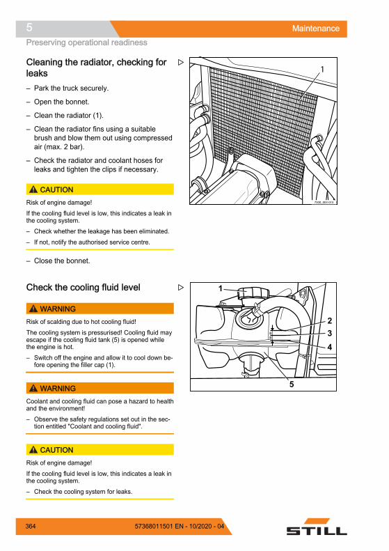
Cleaning the radiator, checking forleaks– Park the truck securely.
– Open the bonnet.
– Clean the radiator (1).
– Clean the radiator fins using a suitablebrush and blow them out using compressedair (max. 2 bar).
– Check the radiator and coolant hoses forleaks and tighten the clips if necessary.
CAUTIONRisk of engine damage!If the cooling fluid level is low, this indicates a leak inthe cooling system.– Check whether the leakage has been eliminated.– If not, notify the authorised service centre.
– Close the bonnet.
Check the cooling fluid level
WARNINGRisk of scalding due to hot cooling fluid!The cooling system is pressurised! Cooling fluid mayescape if the cooling fluid tank (5) is opened whilethe engine is hot.– Switch off the engine and allow it to cool down be-
fore opening the filler cap (1).
WARNINGCoolant and cooling fluid can pose a hazard to healthand the environment!– Observe the safety regulations set out in the sec-
tion entitled "Coolant and cooling fluid".
CAUTIONRisk of engine damage!If the cooling fluid level is low, this indicates a leak inthe cooling system.– Check the cooling system for leaks.
7300_003-015
1Z
1
234
IIII
5
Z
Maintenance5Preserving operational readiness
364 57368011501 EN - 10/2020 - 04

The cooling fluid level is monitored by a sen-sor. As soon as the COOLANT LEVEL mes-sage appears on the display, proceed as de-scribed below:
– Switch off the engine and let it cool down.
– Remove the rear cover.
– Slowly open the filler cap (1) of the coolingfluid tank (5) and release the excess pres-sure.
– Unscrew further and remove the filler cap.
– Check the cooling fluid level.
The cooling fluid level must be between (3)the upper marking (2) and the lower mark-ing (4), at an equal distance from each mark-ing.
– Top up the cooling fluid to no higher thanthe upper marking, if necessary.
– Make sure that the tank cap (1) is screwedon and is tightly sealed.
– Check the leak tightness of the cooling sys-tem; see the section entitled "Cleaning theradiator, checking for leaks".
– Replace the rear cover.
Topping up the cooling fluid andchecking the coolant concentration
WARNINGRisk of scalding due to hot cooling fluid!The cooling system is pressurised! Cooling fluid mayescape if the cooling fluid tank (5) is opened whilethe engine is hot.– Switch off the engine and allow it to cool down be-
fore opening the filler cap (1).
WARNINGCoolant and cooling fluid can pose a hazard to healthand the environment!– Observe the safety regulations set out in the sec-
tion entitled "Coolant and cooling fluid".
1
234
IIII
5
Z
1
234
IIII
5
Z
Maintenance 5Preserving operational readiness
36557368011501 EN - 10/2020 - 04

CAUTIONRisk of engine damage!If the cooling fluid level is low, this indicates a leak inthe cooling system.– Check the cooling system for leaks.
– Switch off the engine and let it cool down.
– Remove the rear cover.
– Slowly open the filler cap (1) of the coolingfluid tank (5) and release the excess pres-sure.
– Unscrew further and remove the filler cap.
– Check the concentration of the coolant.
Concentration of the coolant
CAUTIONRisk of corrosion!The percentage of coolant must always be at least40%, even if frost protection is not needed in warmerclimates.
If greater frost protection is required for climatic rea-sons, the percentage of coolant additive can be in-creased to up to 60%.
The percentage of coolant must not exceed 60%,otherwise the frost protection is reduced. In addition,the cooling effect is also reduced.– Only use clean, softened water for the water per-
centage.
Frost protectionup to °C
Water percentage%
Coolant percentage%
-25 60 40-30 55 45-35 50 50-40 40 60
For information about the filling quantity in thecooling system, see the "Maintenance data ta-ble".
1
234
IIII
5
Z
Maintenance5Preserving operational readiness
366 57368011501 EN - 10/2020 - 04
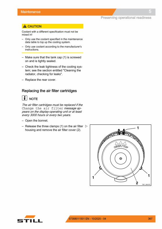
CAUTIONCoolant with a different specification must not bemixed in!– Only use the coolant specified in the maintenance
data table to top up the cooling system.– Only use coolant according to the manufacturer's
instructions.
– Make sure that the tank cap (1) is screwedon and is tightly sealed.
– Check the leak tightness of the cooling sys-tem; see the section entitled "Cleaning theradiator, checking for leaks".
– Replace the rear cover.
Replacing the air filter cartridges
NOTE
The air filter cartridges must be replaced if theChange the air filter message ap-pears on the display-operating unit or at leastevery 3000 hours or every two years.
– Open the bonnet.
– Release the three clamps (1) on the air filterhousing and remove the air filter cover (2).
7321_003-075
1
112
Z
Maintenance 5Preserving operational readiness
36757368011501 EN - 10/2020 - 04
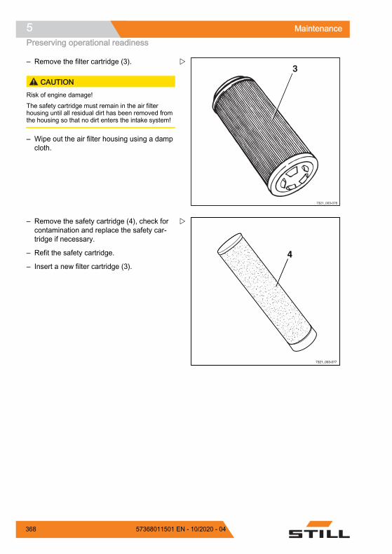
– Remove the filter cartridge (3).
CAUTIONRisk of engine damage!The safety cartridge must remain in the air filterhousing until all residual dirt has been removed fromthe housing so that no dirt enters the intake system!
– Wipe out the air filter housing using a dampcloth.
– Remove the safety cartridge (4), check forcontamination and replace the safety car-tridge if necessary.
– Refit the safety cartridge.
– Insert a new filter cartridge (3).
3
7321_003-076
Z
4
7321_003-077
Z
Maintenance5Preserving operational readiness
368 57368011501 EN - 10/2020 - 04

– Fit the air filter cover (5) with the mark (6)facing upwards.
– Lock the clamps (7) on the air filter.
– Close the bonnet.
Lubricating the joints and controls– Oil or grease other bearing points and joints
according to the maintenance data table;see ⇒ Chapter "Maintenance data table",Page 351 .
Driver's seat guide Lubricate bonnet hinges at the lubricating
nipple Control linkage for valves In the cab, lubricate door hinges at the lubri-
cating nipple (variant) Lubricate shafts and joints in dual-pedal op-
eration (variant)
7321_003-078
7
77
6
5
Z
Maintenance 5Preserving operational readiness
36957368011501 EN - 10/2020 - 04

Maintaining the seat belt DANGER
There is a risk to life if the seat belt fails during anaccident!If the seat belt is faulty, it may tear or open during anaccident and no longer keep the driver in the driver'sseat. The driver may therefore be hurled against thetruck components or out of the truck.– Ensure operational reliability by continually test-
ing.– Do not use a truck with a defective seat belt.– Have any defective seat belts replaced by your
authorised service centre.– Only use genuine spare parts.– Do not make any changes to the seat belt.
NOTE
The checks below must be carried out on aregular basis (monthly). In the case of signifi-cant strain, a daily check is necessary.
Checking the seat belt– Pull out the seat belt (3) completely and
check for fraying.
The seat belt must not be frayed or cut. Thestitching must not be loose.
– Check that the seat belt is not dirty.
– Check whether parts are worn or damaged(including the anchor points).
6327_342-009
1
23
Z
Maintenance5Preserving operational readiness
370 57368011501 EN - 10/2020 - 04

– Check the buckle (1) for proper locking.
When the belt tongue (2) is inserted, the seatbelt must be held securely. The belt tongue (2)must release when the red button (4) is press-ed.
– The automatic blocking mechanism must betested at least once a year:
– Park the forklift truck on level ground.
– Pull out the seat belt using a jerking move-ment.
The automatic blocking mechanism mustblock extension of the belt.
– Tilt the seat at least 30°; to do this, tilt thebonnet.
– Slowly pull out the seat belt.
The automatic blocking mechanism mustblock extension of the belt.
Cleaning the seat belt– Clean the seat belt if it is dirty but without
using chemical cleaning materials (a brushwill suffice).
Replacement after an accidentThe seat belt must always be replaced by theauthorised service centre after an accident.
7090_342-0051
4
Z
Maintenance 5Preserving operational readiness
37157368011501 EN - 10/2020 - 04

Checking the driver's seat
WARNINGRisk of injury!– After an accident, check the driver's seat with at-
tached restraining belt and fastening.
– Check the controls for correct operation.
– Check the condition of the seat (e.g. wearon the upholstery) and secure fastening tothe hood.
WARNINGRisk of injury!– Have the seat repaired by the service centre if you
identify any damage during the checks.
Checking the door latch– Inspect the condition of the catch bolt and
check for wear.
– Check the lock mechanism for easy opera-tion.
Maintaining wheels and tyres
WARNINGRisk of accident!Uneven wear reduces the stability of the truck and in-creases the braking distance. The level of wear ex-hibited by tyres on the same axle must be approxi-mately the same.– Worn or damaged tyres (left or right) must be re-
placed immediately.– When changing wheels or tyres, ensure that this
does not cause the truck to tilt to one side (e.g. al-ways replace right-hand and left-hand wheels atthe same time).
– Changes must only be made following consulta-tion with the manufacturer.
6327_342-010
Z
Maintenance5Preserving operational readiness
372 57368011501 EN - 10/2020 - 04
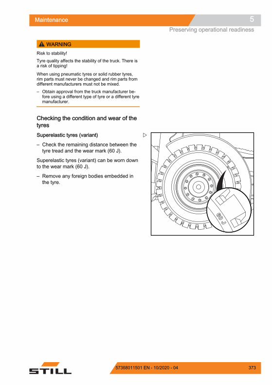
WARNINGRisk to stability!Tyre quality affects the stability of the truck. There isa risk of tipping!
When using pneumatic tyres or solid rubber tyres,rim parts must never be changed and rim parts fromdifferent manufacturers must not be mixed.– Obtain approval from the truck manufacturer be-
fore using a different type of tyre or a different tyremanufacturer.
Checking the condition and wear of thetyresSuperelastic tyres (variant)
– Check the remaining distance between thetyre tread and the wear mark (60 J).
Superelastic tyres (variant) can be worn downto the wear mark (60 J).
– Remove any foreign bodies embedded inthe tyre.
60 J
60 J
Z
Maintenance 5Preserving operational readiness
37357368011501 EN - 10/2020 - 04

Pneumatic tyres (variant)
– Check the tread depth on all four tyres.
The tread depth for pneumatic tyres (variant)must be at least 1.6 mm at every point on thetread. If the tread is worn down to the wearmark (2) at any point on the tyre, replace thetires on one axle.
– Remove any foreign bodies embedded inthe tyre.
Checking the air pressure
NOTE
The correct air pressure for pneumatic tyres(variant) is determined by the type of tyreused. The air pressure measured must corre-spond to the manufacturer's information.
– See the air pressure values stated on theadhesive label (1) on the truck.
– Check the air pressure of all four tyres andcompare with the air pressure values statedon the adhesive labels.
– Add or release air as required if the airpressure deviates from the values stated.
Z
1Z
Maintenance5Preserving operational readiness
374 57368011501 EN - 10/2020 - 04

Checking the wheel fastenings– Check that all wheel fastenings (1) are se-
curely fastened and retighten as necessary.
– Observe the relevant torques; see sectionentitled "Maintenance data table".
Maintaining the battery
NOTE
Battery servicing is carried out in accordancewith the battery manufacturer's operatingmanual.
WARNING
Risk of short circuit and explosion!
– Do not place any metal objects ortools on the battery.
– Keep away from naked flames andfire. Smoking is forbidden.
Checking the battery charge state– Remove the rear cover.
7300_003-018
1
Z
Maintenance 5Preserving operational readiness
37557368011501 EN - 10/2020 - 04

– With maintenance-free batteries, check thecharge state at the inspection window (1):
GreenThe battery is fully charged.
BlackThe charge state of the battery is no longeroptimal. The battery must be recharged. Af-ter recharging, the indicator changes backto green.
Transparent (light-coloured)The charge state is no longer sufficient toensure reliable starting. The battery mustbe replaced.
Charging the battery
WARNING
The electrolyte (diluted sulphuric acid) ispoisonous and corrosive!– Observe the safety regulations for
handling battery acid.– Observe the safety information from
the battery manufacturer.
– With batteries that are not maintenance-free, check the level of the battery acid.
The battery acid must come up to the loweredge of the insert in the battery housing or5 mm above the upper edge of the plates.
CAUTIONThe battery can be damaged!– Only fill up missing fluid with distilled water.
7071_003-071
1
Z
Maintenance5Preserving operational readiness
376 57368011501 EN - 10/2020 - 04

– Unscrew the battery cell covers and checkthe acid density with an acid siphon.
WARNING
Risk of explosion!Charging releases gases that are explo-sive. During the charging process, thesurface of the battery cells must be keptexposed to ensure sufficient ventilation.– Expose the surface of the battery
cells before charging the battery.– Ensure effective ventilation during
charging.– Keep the engine compartment open
during charging.– Avoid the formation of sparks in the
vicinity of the battery.
The acid density must reach the values in thetable. The listed acid densities refer to an acidtemperature of 27°C.
Charge state Batterycharge (%)
Acid density(kg/l)
Full 100% approx. 1.28Normal 75% approx. 1.21Weak 50% approx. 1.16Discharged 25% approx. 1.13Deep dis-charged 0-10% < 1.06
NOTE
Temperature fluctuations can cause the meas-urement results to change. In the event of adifference in temperature of 35°C, the valuesdeviate from each other by approx. 0.05 kg/l.
– Charge discharged batteries immediatelyuntil they are fully charged again.
The charging current shall not exceed 1/10 ofcapacity.
The cell covers of the batteries must be keptdry and clean.
Any spillage of battery acid must be neutral-ised immediately.
7090_606-002Z
Maintenance 5Preserving operational readiness
37757368011501 EN - 10/2020 - 04

Terminals and cable shoes must be clean,lightly coated with battery grease and screwedon tightly.
– After charging, screw the battery cell coversback on.
– Reattach the covering on the back.
Replacing fuses DANGER
Risk of fire!Using the wrong fuses can result in short circuits.– Use only fuses with the prescribed nominal cur-
rent, see the section entitled "Fuse assignment".
– Remove the cover at the back.
– Open the cover fastenings (1) and removethe cover.
– Replace the defective fuse with one that israted for the nominal current according to"Fuse assignment".
– Close the cover to secure the fuse box.
– Install the back covers.
– Perform a function check. If the error per-sists or if the fuse is still defective, notifyyour authorised service centre.
Checking the hydraulic system forleak tightness
WARNING
Hydraulic oil is hazardous to health!Hydraulic oil under pressure can escapefrom leaking pipes and lines, and causeinjuries.– Wear suitable protective gloves, pro-
tection goggles etc.
1 1
117311_003-021
Z
Maintenance5Preserving operational readiness
378 57368011501 EN - 10/2020 - 04

CAUTIONHydraulic hoses become brittle!– Do not store hydraulic hoses for more than two
years.– Do not use hydraulic hoses for more than six
years if they are subject to normal wear.– Do not use hydraulic hoses for more than two
years if they are subject to a high level of wear.– Comply with the specifications of DGUV 113-020
in Germany.– Outside of Germany, observe the national regula-
tions for the country of use.
– Check pipe and hose connection screwjoints for leaks (traces of oil).
Replace hose lines if they display the followingabnormalities: Outer layer has been damaged, or is brittle
or cracked Leaking Deformation (e.g. with blisters or kinks) A fitting has come loose A fitting is badly damaged or corroded
Replace pipes if they display the following ab-normalities: Abrasion Deformation and bending Leaking
Lubricating the lift mast and rollertrack– Remove dirt and lubricant residue from the
roller track.
– Lubricate the roller tracks (1) of the outside,middle, and inside mast with a super-pres-sure adhesion lubricant to reduce wear.See ⇒ Chapter "Maintenance data table",Page 351 .
NOTE
Spray the roller track evenly from a distance ofapprox. 15-20 cm. Wait approx. 15 minutesuntil the equipment is ready to use again.
16210_800-020
Z
Maintenance 5Preserving operational readiness
37957368011501 EN - 10/2020 - 04

Greasing the automatic tow cou-pling
NOTE
Wear to moving parts can be significantly re-duced by appropriate servicing and regular lu-brication of the coupling.
– Avoid over-greasing!
NOTE
Close the coupling before cleaning with ahigh-pressure cleaner. After cleaning, lubri-cate the coupling pin, tow bar eye and its sup-porting surface again.
Model RO*243– Pull out the safety handle (3).
– Push the hand lever (2) upwards.
– Grease using the lubricating nipple(1) in ac-cordance with the maintenance data table;see ⇒ Chapter "Maintenance data table",Page 351 .
– Close the coupling by raising the couplingpin with a suitable tool.
– For journeys with a rigid drawbar trailer, lu-bricate the underside of the tow bar eye andthe supporting surface on the coupling.
– Determine the wear on the coupling pin.
The diameter of the spherical part must not beless than 36.5 mm.
Model RO*244 A– Open coupling.
3
7321_003-091
21
Z
7321_003-092
Z
Maintenance5Preserving operational readiness
380 57368011501 EN - 10/2020 - 04

– Grease using the lubricating nipple(1) in ac-cordance with the maintenance data table;see ⇒ Chapter "Maintenance data table",Page 351 .
– Grease coupling pin, tow bar eye and itssupporting surface.
Model RO*245– Lubricate via the points provided for this
purpose (lubricating nipple, opened cou-pling) in accordance with the maintenancedata table; see ⇒ Chapter "Maintenance da-ta table", Page 351 .
– Grease the supporting surface for the tow-bar eye.
Wartung_Rockinger 244 A
1Z
7321_003-094
Z
Maintenance 5Preserving operational readiness
38157368011501 EN - 10/2020 - 04

Model RO*841– Lubricate via the points provided for this
purpose (lubricating nipple, opened cou-pling) in accordance with the maintenancedata table; see ⇒ Chapter "Maintenance da-ta table", Page 351 .
– Grease the supporting surface for the tow-bar eye.
Check the hydraulic oil level
CAUTIONHydraulic oils are hazardous to health and are pres-surised during operation.– Observe the safety regulations for working with
hydraulic oils; see ⇒ Chapter "Hydraulic fluid",Page 47 .
– Park the truck securely; see ⇒ Chapter"Parking the truck securely and switching itoff", Page 183 .
– Open the bonnet; see ⇒ Chapter "Openingthe bonnet", Page 354 .
– Unscrew the breather filter with the oil dip-stick (1) in an anti-clockwise direction andremove.
The breather filter with the dipstick is locatedon the left-hand side of the truck chassis whenviewed in the drive direction.
7321_003-095
Z
1
Z
Maintenance5Preserving operational readiness
382 57368011501 EN - 10/2020 - 04

– Keep the dipstick in a horizontal positionand check the oil level. The oil level mustbe at least up to the mark (2) on the dip-stick.
– If the oil level does not reach the specifiedlevel, pour hydraulic oil of the correspond-ing specification (see ⇒ Chapter "Mainte-nance data table", Page 351 ) into the fillerneck until it reaches the upper marking as amaximum.
NOTE
Use a funnel.
– Screw in the breather filter with oil dipstick.
– Close bonnet again.
ENVIRONMENT NOTE
Carefully collect any spilled oil. Dispose ofthese substances in an environmentally friend-ly manner.
7094_700-002
1
2
Z
Maintenance 5Preserving operational readiness
38357368011501 EN - 10/2020 - 04

Maintenance5Preserving operational readiness
384 57368011501 EN - 10/2020 - 04
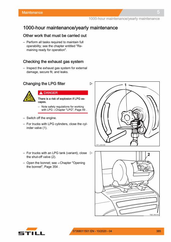
1000-hour maintenance/yearly maintenanceOther work that must be carried out– Perform all tasks required to maintain full
operability; see the chapter entitled "Re-maining ready for operation".
Checking the exhaust gas system– Inspect the exhaust gas system for external
damage, secure fit, and leaks.
Changing the LPG filter
DANGER
There is a risk of explosion if LPG es-capes.– Note safety regulations for working
with LPG ⇒ Chapter "LPG", Page 49 .
– Switch off the engine.
– For trucks with LPG cylinders, close the cyl-inder valve (1).
– For trucks with an LPG tank (variant), closethe shut-off valve (2).
– Open the bonnet; see ⇒ Chapter "Openingthe bonnet", Page 354 .
1
7311_003-036
Z
7325_003-012
2Z
Maintenance 51000-hour maintenance/yearly maintenance
38557368011501 EN - 10/2020 - 04

– Unscrew the mounting screw (3) on the fil-ter housing.
– Remove the filter housing (4).
– Remove the filter insert (5).
– Carefully remove any dirt inside the hous-ing.
– Fit a new filter insert (5) with new sealingring (6).
CAUTIONThere may be a malfunction.– Ensure that the sealing ring is properly seated in
the recess of the filter insert and that the filter iscorrectly installed.
– Check the seals (7) for damage and changeif necessary.
– Screw filter housing back on.
– Open the cylinder valve (1) or the shut-offvalve (2).
– Check all connections for leakages usingleak spray.
– Close the bonnet.
7325_003-013
4
3
Z
7081_003-038
3 45
67
7
Z
Maintenance51000-hour maintenance/yearly maintenance
386 57368011501 EN - 10/2020 - 04

Checking the lift cylinders and con-nections for leaks
WARNINGRisk of injuryObserve safety regulations for working on the liftmast, see the "Working at the front of the truck"chapter.
– Check hydraulic connections and lift cylin-ders for leaks (visual inspection).
– Have leaking screw joints or leaking hy-draulic cylinders repaired by the authorisedservice centre.
Checking the fork arms
CAUTIONFork arms must not be uneven!– Always replace both fork arms.
– Check the fork arms (1) for visible deforma-tion and excessive wear.
No cracks or deformations must be visible onthe fork arms in the area around the fork bend.Wear must not amount to more than 10% ofthe original thickness.
– Check that the locking screws (2) arepresent and securely attached.
– Replace any worn or deformed fork arms.
Check the condition and correct operation ofthe fork latch:
– Move the locking lever (3) into a vertical po-sition.
It must be possible to move the fork arm.
– Move the locking lever into a horizontal po-sition.
The latch must engage in a recess on the forkcarriage. It must not be possible to move thefork arm.
7094_810-004
Z
1
2
2
3
d3911398
Z
Maintenance 51000-hour maintenance/yearly maintenance
38757368011501 EN - 10/2020 - 04

– Replace faulty fork latches.
Checking the reversible fork arms
NOTE
This check is only required for reversible forkarms (variant).
– Check the outside of the fork bend (1) forcracks. Contact your service centre.
Z
Maintenance51000-hour maintenance/yearly maintenance
388 57368011501 EN - 10/2020 - 04

10-year maintenanceChecking the LPG tank (variant)
NOTE
LPG tanks are liquid gas containers. LPGtanks are pressure tanks that must be moni-tored and that are subject to specific testingand specific inspection intervals. The testingmust be conducted only by an approved in-spection body and by a competent person. InGermany, testing is conducted by TÜV, for ex-ample.
– Have the LPG tank tested by an approvedinspection body and by a competent per-son.
– Observe the national regulations for thecountry in which the truck is being used.
7311_003-043
Z
Maintenance 510-year maintenance
38957368011501 EN - 10/2020 - 04

Maintenance510-year maintenance
390 57368011501 EN - 10/2020 - 04

6
Technical data
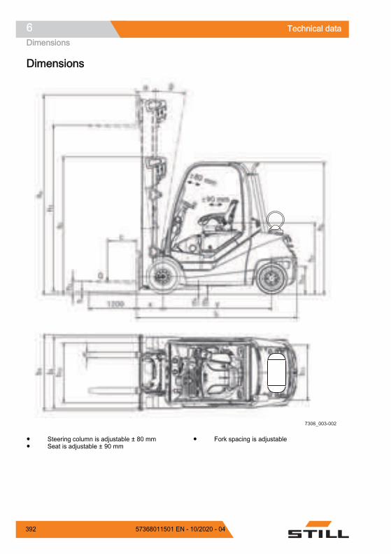
Dimensions
7306_003-002
Steering column is adjustable ± 80 mmSeat is adjustable ± 90 mm
Fork spacing is adjustable
Technical data6Dimensions
392 57368011501 EN - 10/2020 - 04
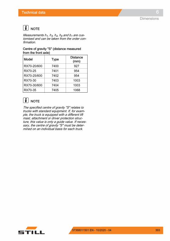
NOTE
Measurements h1, h3, h4, h6 and b1 are cus-tomised and can be taken from the order con-firmation.
Centre of gravity "S" (distance measuredfrom the front axle)
Model Type Distance(mm)
RX70-20/600 7400 927RX70-25 7401 954RX70-25/600 7402 954RX70-30 7403 1003RX70-30/600 7404 1003RX70-35 7405 1068
NOTE
The specified centre of gravity "S" relates totrucks with standard equipment. If, for exam-ple, the truck is equipped with a different liftmast, attachment or driver protection struc-ture, this value is only a guide value. If neces-sary, the centre of gravity "S" must be deter-mined on an individual basis for each truck.
Technical data 6Dimensions
39357368011501 EN - 10/2020 - 04

VDI datasheet forRX70-20/600 and RX70-25
NOTE
This VDI datasheet specifies only the techni-cal values for trucks with standard equipment.Different tyres, lift masts, additional units etc.can produce different values.
Key data
Model RX70-20/600 RX70-25
Type number 7400 7401
Manufacturer STILL GmbH STILL GmbH
Drive LPG engine/electrical
LPG engine/elec-trical
Operation Seat SeatLoad capacity/load Q (kg) 2000 2500Load centre of gravity c (mm) 600 500Load distance x (mm) 459 459Wheelbase y (mm) 1760 1760
Weights
Model RX70-20/600 RX70-25
Type number 7400 7401
Net weight kg 3834 3834Front axle load, laden kg 4993 5652Rear axle load, laden kg 841 682
Front axle load, unladen kg 1790 1790
Rear axle load, unladen kg 2044 2044
Wheels, chassis frame
Model RX70-20/600 RX70-25
Type number 7400 7401
Tyres SE SETyre size, front 23x9-10 23x9-10Tyre size, rear 21x8-9 21x8-9
Technical data6VDI datasheet for RX70-20/600 and RX70-25
394 57368011501 EN - 10/2020 - 04

Model RX70-20/600 RX70-25
Type number 7400 7401
Number of front wheels (x = driven) 2x 2xNumber of rear wheels (x = driven) 2 2Track width, front b10 (mm) 984 984Track width, rear b11 (mm) 920 920
Basic dimensions
Model RX70-20/600 RX70-25
Type number 7400 7401
Forwards tilt of lift mast/fork carriage Degrees 6 6Backwards tilt of lift mast/fork carriage Degrees 7 7Height with lift mast retracted h1 (mm) 2175 2175Free lift h2 (mm) 160 160Lift height1 h3 (mm) 2970 2970Height with lift mast extended h4 (mm) 3600 3600Height above overhead guard h6 (mm) 2190 2190Seat height h7 (mm) 1074 1074Coupling height h10 (mm) 340/455 340/455Overall length l1 (mm) 3605 3605Length including fork back l2 (mm) 2605 2605Overall width b1 (mm) 1192 1192Fork arm thickness s (mm) 40 40Fork arm width e (mm) 100 100Fork arm length l (mm) 1000 1000Fork carriage in acc. with ISO 2328, class /form II / A II / A
Fork carriage width b3 (mm) 1150 1150Ground clearance with load below lift mast m1 (mm) 125 125Ground clearance at the middle of thewheelbase m2 (mm) 150 140
Aisle width for pallet 1000 x 1200 cross-wise Ast (mm) 3963 3963
Aisle width for pallet 800 x 1200 length-wise Ast (mm) 4163 4163
1 The specified lift takes into account the tyre deflection and the tolerances of the tyre diame-ter.
Technical data 6VDI datasheet for RX70-20/600 and RX70-25
39557368011501 EN - 10/2020 - 04

Model RX70-20/600 RX70-25
Type number 7400 7401
Turning radius Wa (mm) 2313 2313Smallest pivot point distance b13 (mm) 611 611
Performance data
Model RX70-20/600 RX70-25
Type number 7400 7401
Driving speed with load km/h 21 21Driving speed without load km/h 21 21Lifting speed with load m/s 0.53 0.53Lifting speed without load m/s 0.55 0.55Lowering speed with load m/s 0.60 0.60Lowering speed without load m/s 0.53 0.53Pulling force with load N 17500 17,500Pulling force without load N 12140 12,140Climbing capability1 with load % 29 29Climbing capability without load % 26 26Acceleration time with load s 5.1 5.1Acceleration time without load s 4.5 4.5Service brake Electr./hydr. Electr./hydr.
CAUTIONTo use the truck safely—with or without a load—themaximum permitted ascending or descending gradi-ent for travel is 15%.– If you have any questions, contact your authorised
service centre.
Engine
Model RX70-20/600 RX70-25
Type number 7400 7401
Type of engine P24 P24Engine power rating in accordance withISO 1585 kW 37 37
1 The stated values are used only to compare the performance of trucks in the same category.The gradient values in no way represent the normal daily operating conditions.
Technical data6VDI datasheet for RX70-20/600 and RX70-25
396 57368011501 EN - 10/2020 - 04
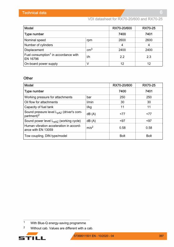
Model RX70-20/600 RX70-25
Type number 7400 7401
Nominal speed rpm 2600 2600Number of cylinders 4 4Displacement cm3 2400 2400Fuel consumption1 in accordance withEN 16796 l/h 2.2 2.3
On-board power supply V 12 12
Other
Model RX70-20/600 RX70-25
Type number 7400 7401
Working pressure for attachments bar 250 250Oil flow for attachments l/min 30 30Capacity of fuel tank l/kg 11 11Sound pressure level LpAZ (driver's com-partment)2 dB (A) <77 <77
Sound power level LwAZ (working cycle) dB (A) <97 <97Human vibration acceleration in accord-ance with EN 13059 m/s2 0.58 0.58
Tow coupling, DIN type/model Bolt Bolt
1 With Blue-Q energy-saving programme2 Without cab. Values are different with a cab.
Technical data 6VDI datasheet for RX70-20/600 and RX70-25
39757368011501 EN - 10/2020 - 04

VDI datasheet forRX70-25/600 and RX70-30
NOTE
This VDI datasheet specifies only the techni-cal values for trucks with standard equipment.Different tyres, lift masts, additional units etc.can produce different values.
Key data
Model RX70-25/600 RX70-30
Type number 7402 7403
Manufacturer STILL GmbH STILL GmbH
Drive LPG engine/electrical
LPG engine/elec-trical
Operation Seat SeatLoad capacity/load Q (kg) 2500 3000Load centre of gravity c (mm) 600 500Load distance x (mm) 464 469Wheelbase y (mm) 1820 1820
Weights
Model RX70-25/600 RX70-30
Type number 7402 7403
Net weight kg 4135 4168Front axle load, laden kg 5788 6462Rear axle load, laden kg 847 706
Front axle load, unladen kg 1827 1865
Rear axle load, unladen kg 2308 2303
Wheels, chassis frame
Model RX70-25/600 RX70-30
Type number 7402 7403
Tyres SE SETyre size, front 23x9-10 23x9-10Tyre size, rear 21x8-9 21x8-9
Technical data6VDI datasheet for RX70-25/600 and RX70-30
398 57368011501 EN - 10/2020 - 04

Model RX70-25/600 RX70-30
Type number 7402 7403
Number of front wheels (x = driven) 2x 2xNumber of rear wheels (x = driven) 2 2Track width, front b10 (mm) 984 984Track width, rear b11 (mm) 920 920
Basic dimensions
Model RX70-25/600 RX70-30
Type number 7402 7403
Forwards tilt of lift mast/fork carriage Degrees 6 6Backwards tilt of lift mast/fork carriage Degrees 7 7Height with lift mast retracted h1 (mm) 2175 2175Free lift h2 (mm) 160 160Lift height1 h3 (mm) 2970 2970Height with lift mast extended h4 (mm) 3750 3750Height above overhead guard h6 (mm) 2190 2190Seat height h7 (mm) 1074 1074Coupling height h10 (mm) 340/455 340/455Overall length l1 (mm) 3705 3705Length including fork back l2 (mm) 2705 2705Overall width b1 (mm) 1192 1192Fork arm thickness s (mm) 45 50Fork arm width e (mm) 100 100Fork arm length l (mm) 1000 1000Fork carriage in acc. with ISO 2328, class /form II / A III / A
Fork carriage width b3 (mm) 1150 1150Ground clearance with load below lift mast m1 (mm) 125 125Ground clearance at the middle of thewheelbase m2 (mm) 150 150
Aisle width for pallet 1000 x 1200 cross-wise Ast (mm) 4047 4060
Aisle width for pallet 800 x 1200 length-wise Ast (mm) 4247 4260
1 The specified lift takes into account the tyre deflection and the tolerances of the tyre diame-ter.
Technical data 6VDI datasheet for RX70-25/600 and RX70-30
39957368011501 EN - 10/2020 - 04

Model RX70-25/600 RX70-30
Type number 7402 7403
Turning radius Wa (mm) 2397 2397Smallest pivot point distance b13 (mm) 632 632
Performance data
Model RX70-25/600 RX70-30
Type number 7402 7403
Driving speed with load km/h 21 21Driving speed without load km/h 21 21Lifting speed with load m/s 0.53 0.48Lifting speed without load m/s 0.55 0.50Lowering speed with load m/s 0.60 0.60Lowering speed without load m/s 0.53 0.53Pulling force with load N 17500 17,500Pulling force without load N 12300 12300Climbing capability1 with load % 25 25Climbing capability without load % 24 24Acceleration time with load s 5.1 5.1Acceleration time without load s 4.5 4.5Service brake Electr./hydr. Electr./hydr.
CAUTIONTo use the truck safely—with or without a load—themaximum permitted ascending or descending gradi-ent for travel is 15%.– If you have any questions, contact your authorised
service centre.
Engine
Model RX70-25/600 RX70-30
Type number 7402 7403
Type of engine P24 P24Engine power rating in accordance withISO 1585 kW 37 37
1 The stated values are used only to compare the performance of trucks in the same category.The gradient values in no way represent the normal daily operating conditions.
Technical data6VDI datasheet for RX70-25/600 and RX70-30
400 57368011501 EN - 10/2020 - 04

Model RX70-25/600 RX70-30
Type number 7402 7403
Nominal speed rpm 2600 2600Number of cylinders 4 4Displacement cm3 2400 2400Fuel consumption1 in accordance withEN 16796 l/h 2.4 2.4
On-board power supply V 12 12
Other
Model RX70-25/600 RX70-30
Type number 7402 7403
Working pressure for attachments bar 250 250Oil flow for attachments l/min 30 30Capacity of fuel tank l/kg 11 11Sound pressure level LpAZ (driver's com-partment)2 dB (A) <77 <77
Sound power level LwAZ (working cycle) dB (A) <97 <97Human vibration acceleration in accord-ance with EN 13059 m/s2 0.58 0.58
Tow coupling, DIN type/model Bolt Bolt
1 With Blue-Q energy-saving programme2 Without cab. Values are different with a cab.
Technical data 6VDI datasheet for RX70-25/600 and RX70-30
40157368011501 EN - 10/2020 - 04

VDI datasheet forRX70-30/600 and RX70-35
NOTE
This VDI datasheet specifies only the techni-cal values for trucks with standard equipment.Different tyres, lift masts, additional units etc.can produce different values.
Key data
Model RX70-30/600 RX70-35
Type number 7404 7405
Manufacturer STILL GmbH STILL GmbH
Drive LPG engine/electrical
LPG engine/elec-trical
Operation Seat SeatLoad capacity/load Q (kg) 3000 3500Load centre of gravity c (mm) 600 500Load distance x (mm) 469 469Wheelbase y (mm) 1820 1820
Weights
Model RX70-30/600 RX70-35
Type number 7404 7405
Net weight kg 4460 4460Front axle load, laden kg 6652 7253Rear axle load, laden kg 808 707
Front axle load, unladen kg 1890 1890
Rear axle load, unladen kg 2570 2570
Wheels, chassis frame
Model RX70-30/600 RX70-35
Type number 7404 7405
Tyres SE SETyre size, front 23x10-12 23x10-12Tyre size, rear 21x8-9 21x8-9
Technical data6VDI datasheet for RX70-30/600 and RX70-35
402 57368011501 EN - 10/2020 - 04

Model RX70-30/600 RX70-35
Type number 7404 7405
Number of front wheels (x = driven) 2x 2xNumber of rear wheels (x = driven) 2 2Track width, front b10 (mm) 975 975Track width, rear b11 (mm) 920 920
Basic dimensions
Model RX70-30/600 RX70-35
Type number 7404 7405
Forwards tilt of lift mast/fork carriage Degrees 6 6Backwards tilt of lift mast/fork carriage Degrees 7 7Height with lift mast retracted h1 (mm) 2175 2175Free lift h2 (mm) 160 160Lift height1 h3 (mm) 2970 2970Height with lift mast extended h4 (mm) 3750 3750Height above overhead guard h6 (mm) 2195 2195Seat height h7 (mm) 1074 1074Coupling height h10 (mm) 340/455 340/455Overall length l1 (mm) 3770 3770Length including fork back l2 (mm) 2770 2770Overall width b1 (mm) 1224 1224Fork arm thickness s (mm) 50 50Fork arm width e (mm) 100 100Fork arm length l (mm) 1000 1000Fork carriage in acc. with ISO 2328, class /form III / A III / A
Fork carriage width b3 (mm) 1150 1150Ground clearance with load below lift mast m1 (mm) 125 125Ground clearance at the middle of thewheelbase m2 (mm) 150 150
Aisle width for pallet 1000 x 1200 cross-wise Ast (mm) 4127 4127
Aisle width for pallet 800 x 1200 length-wise Ast (mm) 4352 4327
1 The specified lift takes into account the tyre deflection and the tolerances of the tyre diame-ter.
Technical data 6VDI datasheet for RX70-30/600 and RX70-35
40357368011501 EN - 10/2020 - 04

Model RX70-30/600 RX70-35
Type number 7404 7405
Turning radius Wa (mm) 2464 2464Smallest pivot point distance b13 (mm) 632 632
Performance data
Model RX70-30/600 RX70-35
Type number 7404 7405
Driving speed with load km/h 21 21Driving speed without load km/h 21 21Lifting speed with load m/s 0.48 0.48Lifting speed without load m/s 0.50 0.50Lowering speed with load m/s 0.60 0.60Lowering speed without load m/s 0.53 0.53Pulling force with load N 17000 17,000Pulling force without load N 13400 13,400Climbing capability1 with load % 24 24Climbing capability without load % 20 20Acceleration time with load s 5.4 5.4Acceleration time without load s 4.8 4.8Service brake Electr./hydr. Electr./hydr.
CAUTIONTo use the truck safely—with or without a load—themaximum permitted ascending or descending gradi-ent for travel is 15%.– If you have any questions, contact your authorised
service centre.
Engine
Model RX70-30/600 RX70-35
Type number 7404 7405
Type of engine P24 P24Engine power rating in accordance withISO 1585 kW 37 37
1 The stated values are used only to compare the performance of trucks in the same category.The gradient values in no way represent the normal daily operating conditions.
Technical data6VDI datasheet for RX70-30/600 and RX70-35
404 57368011501 EN - 10/2020 - 04

Model RX70-30/600 RX70-35
Type number 7404 7405
Nominal speed rpm 2600 2600Number of cylinders 4 4Displacement cm3 2400 2400Fuel consumption1 in accordance withEN 16796 l/h 2.7 3.0
On-board power supply V 12 12
Other
Model RX70-30/600 RX70-35
Type number 7404 7405
Working pressure for attachments bar 250 250Oil flow for attachments l/min 30 30Capacity of fuel tank l/kg 11 11Sound pressure level LpAZ (driver's com-partment)2 dB (A) <77 <77
Sound power level LwAZ (working cycle) dB (A) <97 <97Human vibration acceleration in accord-ance with EN 13059 m/s2 0.58 0.58
Tow coupling, DIN type/model Bolt Bolt
1 With Blue-Q energy-saving programme2 Without cab. Values are different with a cab.
Technical data 6VDI datasheet for RX70-30/600 and RX70-35
40557368011501 EN - 10/2020 - 04

Ergonomic dimensions
WARNINGDanger of impact injuries to the head!If the head of the operator is located too close to theunderside of the roof, the suspension of the driver'sseat or an accident may cause the head to strike theoverhead guard.
To avoid head injuries, a minimum distance of40 mm must be ensured between the underside ofthe roof and the head of the tallest operator.
To determine the actual head clearance, the operatormust sit in the driver's seat and the seat suspensionmust be set to this driver's requirements.
Due to the individual nature of height and bodyweight as well as the wide variety of types of driver'sseat and overhead guard, the minimum head clear-ance must be ensured in every truck.
The driver's compartment has been designedtaking ergonomics in the workplace into ac-count and in accordance with EN ISO 3411. Ingeneral, from the seat position, the operatorhas sufficient space to reach the operating de-vices safely, to operate the truck and to viewthe outline of the truck. Operators whose bodysize deviates from the specified dimensionson which EN ISO 3411 is based must be indi-vidually considered by the operating company.
0000_003-002
40 mm
Z
Technical data6Ergonomic dimensions
406 57368011501 EN - 10/2020 - 04

Fuse assignment
MMS, 10 ASwitch lock, terminal 30, 10 AEngine control unit ECU, terminal 15, Doo-san diagnostics, fuel priming pump, 10 AConverter, 10 AConverter for coolant pump/coolant fan,15 AMCU3 hazard warning lights, MCU3 Vers,10 AMCU3 servo hydraulics, 10 AMCU3 time-delay relay, 10 ARes. CPP4, 10 ARelay for glow plug, 10 ALevel sensor for engine oil, 10 A
1F081F091F10
1F111F12
1F15
1F161F171F181F191F21
ECU K01, ECU K03, ECU K05, 15 ASignal horn, 10 ACAN power port 1 (CPP 1), roof top, 30 ACAN power port 5 (CPP 5), roof bottom,20 ACAN power port 3 (CPP 3), driver's seat,wiper, 30 AElectric parking brake, 30 ASAE 12-V socket, 10 AStarter motor, terminal 50, 30 ARelay for glow plug monitor, 10 AAir-conditioning condenser, 20 AAir-conditioning compressor/evaporator, 25A
1F224F015F115F12
5F13
5F149F039F049F07F1F2
Technical data 6Fuse assignment
40757368011501 EN - 10/2020 - 04

Additional fuses
In this truck, additional fuses are located on afuse holder to the left of the fuse box on thestarter battery.
NOTE
Depending on the equipment, not all fuses willbe present in the truck.
7300_003-009
9F06 9F36
Sheathed-element heater plug (only on dieseltrucks), 25 A12 V socket, 10 A
9F06
9F36
Z
Technical data6Fuse assignment
408 57368011501 EN - 10/2020 - 04

NUMBERS AND SYMBOLS
12 V socket. . . . . . . . . . . . . . . . . . . . . . . 280
AAccess authorisation for the fleet manag-
er. . . . . . . . . . . . . . . . . . . . . . . . . . . . . . 130Changing the fleet manager password. 131Changing the PIN code for the driver. 129
Access authorisation with PIN code. . . . 128Changing the PIN codes. . . . . . . . . . . 129
Accessories. . . . . . . . . . . . . . . . . . . . . . . . . 6Actuating the drive direction switch
Fingertip version. . . . . . . . . . . . . . . . . 159 Joystick 4Plus version. . . . . . . . . . . . 158Mini-console version. . . . . . . . . . . . . . 159Mini-lever version. . . . . . . . . . . . . . . . 158
Address of manufacturer. . . . . . . . . . . . . . . IAdjusting the armrest. . . . . . . . . . . . . . . . . 93Adjusting the fork. . . . . . . . . . . . . . . . . . . 212After washing. . . . . . . . . . . . . . . . . . . . . . 314Air conditioning. . . . . . . . . . . . . . . . . . . . 278Aisle widths. . . . . . . . . . . . . . . . . . . . . . . 151Attachments
Adjusting the hydraulic speed. . . . . . . 234Assembly. . . . . . . . . . . . . . . . . . . . . . 227Attachment example. . . . . . . . . . . . . . 233Controlling using a double mini-lever. 237Controlling using a quadruple mini-lev-
er. . . . . . . . . . . . . . . . . . . . . . . . . . . 245Controlling using a triple mini-lever. . 241Controlling using the double mini-lever
and the 5th function. . . . . . . . . . . . . 239Controlling using the joystick 4Plus. . 249Controlling using the quadruple mini-
lever and the 5th function. . . . . . . . . 247Controlling using the triple mini-lever
and the 5th function. . . . . . . . . . . . . 243Controlling with Joystick 4Plus and the
5th function. . . . . . . . . . . . . . . . . . . 250Controlling with the fingertip. . . . . . . . 251Controlling with the fingertip and the
5th function. . . . . . . . . . . . . . . . . . . 253Depressurising the connections. . . . . 229General controlling. . . . . . . . . . . . . . . 232Mounting. . . . . . . . . . . . . . . . . . . . . . . 228Special risks. . . . . . . . . . . . . . . . . . . . . 35Taking up a load. . . . . . . . . . . . . . . . . 257
Automatic mast vertical positioningChecking for correct function. . . . . . . . 87Operation. . . . . . . . . . . . . . . . . . . . . . 186
Automatic tow coupling. . . . . . . . . . . . . . 285Coupling RO*243. . . . . . . . . . . . . . . . 287Coupling RO*244 A. . . . . . . . . . . . . . 289Coupling RO*245. . . . . . . . . . . . . . . . 291Coupling RO*841. . . . . . . . . . . . . . . . 292Uncoupling RO*243. . . . . . . . . . . . . . 288Uncoupling RO*244 A. . . . . . . . . . . . 290Uncoupling RO*245. . . . . . . . . . . . . . 292Uncoupling RO*841. . . . . . . . . . . . . . 293
BBasic principles for safe operation. . . . . . . 27Battery
Charging. . . . . . . . . . . . . . . . . . . . . . . 376Checking the charge state. . . . . . . . . 375Disposal. . . . . . . . . . . . . . . . . . . . . . . . 22Maintaining. . . . . . . . . . . . . . . . . . . . . 375
Battery acid. . . . . . . . . . . . . . . . . . . . . . . . 48Before taking up load. . . . . . . . . . . . . . . . 209Blue-Q
Functional description. . . . . . . . . . . . . 144Switching off additional consumers. . 146Switching on and off. . . . . . . . . . . . . . 145
Bonnet, closing. . . . . . . . . . . . . . . . . . . . 356Bonnet, opening. . . . . . . . . . . . . . . . . . . . 354Bottom plate
Installing. . . . . . . . . . . . . . . . . . . . . . . 360Removing. . . . . . . . . . . . . . . . . . . . . . 359
Brake fluid. . . . . . . . . . . . . . . . . . . . . . . . . 52
CCab
Operating the rear window heating. . . 271Turning the interior lighting on or off. . 271
Cab door, closing. . . . . . . . . . . . . . . . . . . 269Cab door, opening. . . . . . . . . . . . . . . . . . 268Ceiling sensor. . . . . . . . . . . . . . . . . . . . . 262CE labelling. . . . . . . . . . . . . . . . . . . . . . . . . 5Changes to the truck. . . . . . . . . . . . . . . . . 27Changing the fork arms. . . . . . . . . . . . . . 201Changing the LPG cylinder. . . . . . . . . . . 302
Double-cylinder holder. . . . . . . . . . . . 305Changing the LPG filter. . . . . . . . . . . . . . 385Checking the coolant concentration. . . . . 365
Index
40957368011501 EN - 10/2020 - 04

Checking the door latch. . . . . . . . . . . . . . 372Checking the driver's seat. . . . . . . . . . . . 372Checking the engine oil level. . . . . . . . . . 362Checking the exhaust gas system. . . . . . 385Checking the fork arms. . . . . . . . . . . . . . 387Checking the lift cylinders and connections
for leaks. . . . . . . . . . . . . . . . . . . . . . . . . 387Check the cooling fluid level. . . . . . . . . . 364Clamp locking mechanism. . . . . . . . . . . . 254
Double mini-lever. . . . . . . . . . . . . . . . 255Fingertip. . . . . . . . . . . . . . . . . . . . . . . 256Joystick 4Plus. . . . . . . . . . . . . . . . . . . 257Quadruple mini-lever. . . . . . . . . . . . . 256Releasing the mechanism with a double
mini-lever. . . . . . . . . . . . . . . . . . . . . 238Releasing the mechanism with a quad-
ruple mini-lever. . . . . . . . . . . . . . . . 246Releasing the mechanism with a triple
mini-lever. . . . . . . . . . . . . . . . . . . . . 242Releasing the mechanism with the fin-
gertip. . . . . . . . . . . . . . . . . . . . . . . . 252Triple mini-lever. . . . . . . . . . . . . . . . . 255
Cleaning. . . . . . . . . . . . . . . . . . . . . . . . . . 311Cleaning the dust valve. . . . . . . . . . . . . . 363Cleaning the electrical system. . . . . . . . . 313Cleaning the truck. . . . . . . . . . . . . . . . . . 311Cleaning the windows. . . . . . . . . . . . . . . 314Climbing in the truck. . . . . . . . . . . . . . . . . 79Climbing out of the truck. . . . . . . . . . . . . . 79Clipboard. . . . . . . . . . . . . . . . . . . . . . . . . 279Condition of the roadways. . . . . . . . . . . . 153Consumables. . . . . . . . . . . . . . . . . . . . . . . 45
Brake fluid safety information. . . . . . . . 52Coolant and cooling fluid safety infor-
mation. . . . . . . . . . . . . . . . . . . . . . . . 52Disposal. . . . . . . . . . . . . . . . . . . . . . . . 54Safety information for handling battery
acid. . . . . . . . . . . . . . . . . . . . . . . . . . 48Safety information for handling oils. . . 46Safety information for hydraulic fluid. . 47Safety precautions for LPG. . . . . . . . . 49
Contact details. . . . . . . . . . . . . . . . . . . . . . . ICoolant. . . . . . . . . . . . . . . . . . . . . . . . . . 365Coolant and cooling fluid. . . . . . . . . . . . . . 52Cooling fluid
Topping up. . . . . . . . . . . . . . . . . . . . . 365Copyright and trademark rights. . . . . . . . . 18
Crane loading. . . . . . . . . . . . . . . . . . . . . 327Cruise control. . . . . . . . . . . . . . . . . . . . . . 179Cup holders. . . . . . . . . . . . . . . . . . . . . . . . 62
DDamage. . . . . . . . . . . . . . . . . . . . . . . . . . . 30Danger area. . . . . . . . . . . . . . . . . . . . . . . 212Danger to employees. . . . . . . . . . . . . . . . . 40De-icing the evaporator. . . . . . . . . . . . . . 176Declaration of conformity. . . . . . . . . . . . . . . 6Decommissioning. . . . . . . . . . . . . . . . . . 333Defects. . . . . . . . . . . . . . . . . . . . . . . . . . . . 30Definition of directions. . . . . . . . . . . . . . . . 19Dimensions. . . . . . . . . . . . . . . . . . . . . . . 392Display-operating unit
Main display. . . . . . . . . . . . . . . . . . . . 127Messages. . . . . . . . . . . . . . . . . . . . . . 295
Display/control unit. . . . . . . . . . . . . . . . . . 63Disposal
Battery. . . . . . . . . . . . . . . . . . . . . . . . . 22Components. . . . . . . . . . . . . . . . . . . . . 22
Double mini-leverLifting/lowering the fork carriage. 192, 194Tilting the lift mast. . . . . . . . . . . . 192, 194
Drive directionChanging. . . . . . . . . . . . . . . . . . . . . . 161Neutral position. . . . . . . . . . . . . . . . . . 157Selecting. . . . . . . . . . . . . . . . . . . . . . . 157Selecting with the dual pedal version. 163
Drive modesSprint mode. . . . . . . . . . . . . . . . . . . . 147STILL Classic. . . . . . . . . . . . . . . . . . . 147
Drive programmeConfiguring A/B. . . . . . . . . . . . . . . . . 155Selecting 1 to 3. . . . . . . . . . . . . . . . . . 154Selecting A/B. . . . . . . . . . . . . . . . . . . 155
Driver profilesCreating. . . . . . . . . . . . . . . . . . . . . . . 114Delete. . . . . . . . . . . . . . . . . . . . . . . . . 119Description. . . . . . . . . . . . . . . . . . . . . 112Renaming. . . . . . . . . . . . . . . . . . . . . . 116Selecting. . . . . . . . . . . . . . . . . . . . . . . 112
Driver rights, duties and rules of behaviour. 25Drivers. . . . . . . . . . . . . . . . . . . . . . . . . . . . 25Driver's cab. . . . . . . . . . . . . . . . . . . . . . . . 82Driver's compartment. . . . . . . . . . . . . . . . . 61
Index
410 57368011501 EN - 10/2020 - 04

Driving. . . . . . . . . . . . . . . . . . . . . . . . . . . 149Ascending gradients. . . . . . . . . . . . . . 174Descending gradients. . . . . . . . . . . . . 174
Driving lightsSwitching on and off. . . . . . . . . . . . . . 136
Driving on lifts. . . . . . . . . . . . . . . . . . . . . 224Driving on loading bridges. . . . . . . . . . . . 225
EEC declaration of conformity in accordance
with Machinery Directive. . . . . . . . . . . . . . 6Electric parking brake
Symbols in the display-operating unit. 166Emergencies
Disconnecting the battery. . . . . . . . . . 320Emergency operation of the parking
brake. . . . . . . . . . . . . . . . . . . . . . . . 318Truck tipping over. . . . . . . . . . . . . . . . 315Using the emergency hammer. . . . . . 315
Emergency hammer. . . . . . . . . . . . . . . . 315Emergency lowering. . . . . . . . . . . . . . . . 316Emissions. . . . . . . . . . . . . . . . . . . . . . . . . 55
Exhaust gases. . . . . . . . . . . . . . . . . . . 57Heat. . . . . . . . . . . . . . . . . . . . . . . . . . . 57Noise emissions. . . . . . . . . . . . . . . . . . 55Radiation. . . . . . . . . . . . . . . . . . . . . . . 57Vibrations. . . . . . . . . . . . . . . . . . . . . . . 56
EngineAutomatic shut-off function. . . . . . . . . 175Preheating (variant). . . . . . . . . . . . . . 121Starting. . . . . . . . . . . . . . . . . . . . . . . . 132
Engine preheating. . . . . . . . . . . . . . . . . . 121Function. . . . . . . . . . . . . . . . . . . . . . . 121Preheating. . . . . . . . . . . . . . . . . . . . . 121
Environmental considerations. . . . . . . . . . 22Ergonomic dimensions. . . . . . . . . . . . . . 406Example. . . . . . . . . . . . . . . . . . . . . . . . . . 210
FFilling the washer system. . . . . . . . 261, 363Fingertip switch
Lifting/lowering the fork carriage. . . . . 200Tilting the lift mast. . . . . . . . . . . . . . . . 200
Fitting attachments. . . . . . . . . . . . . . . . . 227FleetManager. . . . . . . . . . . . . . . . . . . . . . 261
Shock recognition. . . . . . . . . . . . . . . . 261Foreword. . . . . . . . . . . . . . . . . . . . . . . . . . . 0
Fork armsLength. . . . . . . . . . . . . . . . . . . . . . . . . . 32
Fork extension. . . . . . . . . . . . . . . . . . . . . 204Fork wear protection. . . . . . . . . . . . . . . . 201Function checking. . . . . . . . . . . . . . . . . . . 76Fuse assignment. . . . . . . . . . . . . . . . . . . 407
GGas spring with prop (variant)
Releasing the latch. . . . . . . . . . . . . . . 356General. . . . . . . . . . . . . . . . . . . . . . . . . . . . 4
HHandling gas springs and accumulators. . 32Handling loads. . . . . . . . . . . . . . . . . . . . . 208Hazardous areas. . . . . . . . . . . . . . . . . . . 153Hazards and countermeasures. . . . . . . . . 38Hazard warning system
Switching on and off. . . . . . . . . . . . . . 140Heating system. . . . . . . . . . . . . . . . . . . . 275Hydraulic blocking function. . . . . . . . . . . 190
Releasing. . . . . . . . . . . . . . . . . . . . . . 190Hydraulic fluid. . . . . . . . . . . . . . . . . . . . . . 47Hydraulic system
Checking for leak tightness. . . . . . . . 378Checking the oil level. . . . . . . . . . . . . 382Depressurising. . . . . . . . . . . . . . . . . . 229
IImpermissible use. . . . . . . . . . . . . . . . . . . 13Information about the documentation. . . . 16Information for carrying out maintenance. 341
Maintenance timeframe. . . . . . . . . . . 342Information symbols. . . . . . . . . . . . . . . . . . 18Insulation testing. . . . . . . . . . . . . . . . . . . . 44Insurance cover on company premises. . . 27Interior lighting. . . . . . . . . . . . . . . . . . . . . 271Issue date of the operating instructions. . . 18
JJacking up. . . . . . . . . . . . . . . . . . . . . . . . 339Joystick 4Plus. . . . . . . . . . . . . . . . . . . . . . 71
Fork carriage sideshift. . . . . . . . . . . . 199Lifting/lowering the fork carriage. . . . . 197Tilting the lift mast. . . . . . . . . . . . . . . . 198
Jump-starting. . . . . . . . . . . . . . . . . . . . . . 321
Index
41157368011501 EN - 10/2020 - 04

LLabelling points
Overview. . . . . . . . . . . . . . . . . . . . . . . . . 8Lashing down. . . . . . . . . . . . . . . . . . . . . . 326Lift height-dependent functions
Speed reduction when the fork carriageis raised. . . . . . . . . . . . . . . . . . . . . . 175
Lifting. . . . . . . . . . . . . . . . . . . . . . . . 186, 339Lifting system
Controlling using a double mini-lever. 192Controlling using a quadruple mini-lev-
er. . . . . . . . . . . . . . . . . . . . . . . . . . . 196Controlling using a triple mini-lever. . 194Controlling using the joystick 4Plus. . 197Controlling with the fingertip. . . . . . . . 200Operating devices. . . . . . . . . . . . . . . . 191
Lift mastLubricating the roller track. . . . . . . . . 379Removing. . . . . . . . . . . . . . . . . . . . . . 340Securing against falling off. . . . . . . . . 340Securing against tilting backwards. . . 340
Lift mast versionsHi-Lo lift mast. . . . . . . . . . . . . . . . . . . 188Triplex lift mast. . . . . . . . . . . . . . . . . . 189
LightingMeaning of the symbols. . . . . . . . . . . 135STILL SafetyLight. . . . . . . . . . . . . . . . 142StVZO equipment. . . . . . . . . . . . . . . . 141
List of abbreviations. . . . . . . . . . . . . . . . . . 20Load
Picking up. . . . . . . . . . . . . . . . . . . . . . 215Setting down. . . . . . . . . . . . . . . . . . . . 219transporting. . . . . . . . . . . . . . . . . . . . . 218
Load-dependant assistance systemsLoad measurement. . . . . . . . . . . . . . . 211
Load capacity. . . . . . . . . . . . . . . . . . . . . . 209Load chains
Cleaning. . . . . . . . . . . . . . . . . . . . . . . 313Load measurement. . . . . . . . . . . . . . . . . 211LPG. . . . . . . . . . . . . . . . . . . . . . . . . . . . . . 49LPG tank (variant)
Checking. . . . . . . . . . . . . . . . . . . . . . . 389Filling. . . . . . . . . . . . . . . . . . . . . . . . . 307Opening the shut-off valve. . . . . . . . . 125
Lubricating the joints and controls. . . . . . 369
MMain display. . . . . . . . . . . . . . . . . . . . . . . 127Maintenance. . . . . . . . . . . . . . . . . . . . . . . . 0
10-year. . . . . . . . . . . . . . . . . . . . . . . . 3891000-hour. . . . . . . . . . . . . . . . . . . . . . 385After the first 50 operating hours. . . . 361General information. . . . . . . . . . . . . . 341Yearly. . . . . . . . . . . . . . . . . . . . . . . . . 385
Maintenance data table. . . . . . . . . . . . . . 351Air conditioning. . . . . . . . . . . . . . . . . . 353Battery. . . . . . . . . . . . . . . . . . . . . . . . 351Brake system. . . . . . . . . . . . . . . . . . . 353Controls/joints. . . . . . . . . . . . . . . . . . . 351Cooling system. . . . . . . . . . . . . . . . . . 353Drive axle. . . . . . . . . . . . . . . . . . . . . . 352Electrical system. . . . . . . . . . . . . . . . . 351Engine. . . . . . . . . . . . . . . . . . . . . . . . 353General lubrication points. . . . . . . . . . 351Hydraulic system. . . . . . . . . . . . . . . . 351Lift mast. . . . . . . . . . . . . . . . . . . . . . . 352Load chains. . . . . . . . . . . . . . . . . . . . 353LPG cylinder. . . . . . . . . . . . . . . . . . . . 353Steering axle. . . . . . . . . . . . . . . . . . . . 352Tyres. . . . . . . . . . . . . . . . . . . . . . . . . . 351Washer system. . . . . . . . . . . . . . . . . . 353
Maintenance during the break-in period. 361Maintenance work without special qualifi-
cations. . . . . . . . . . . . . . . . . . . . . . . . . . 341Malfunctions during lifting mode. . . . . . . 189Malfunctions in the parking brake. . . . . . 169Manual tow coupling. . . . . . . . . . . . . . . . 283
Coupling. . . . . . . . . . . . . . . . . . . . . . . 283Uncoupling. . . . . . . . . . . . . . . . . . . . . 284
Measuring the insulation resistance of theelectrical system. . . . . . . . . . . . . . . . . . . 44
Medical equipment. . . . . . . . . . . . . . . . . . . 31Messages
about operation. . . . . . . . . . . . . . . . . . 296about the truck. . . . . . . . . . . . . . . . . . 300Introduction. . . . . . . . . . . . . . . . . . . . . 295
Misuse of safety systems. . . . . . . . . . . . . . 30MSG 65/MSG 75 driver's seat
Adjusting. . . . . . . . . . . . . . . . . . . . . . . . 88Adjusting the backrest extension. . . . . 91Adjusting the lumbar support. . . . . . . . 91Adjusting the seat backrest. . . . . . . . . 89
Index
412 57368011501 EN - 10/2020 - 04

Adjusting the seat suspension. . . . . . . 90Moving. . . . . . . . . . . . . . . . . . . . . . . . . 89Switching the seat heater on and off. . 92Swivelling for reverse travel. . . . . . . . . 92
NNameplate. . . . . . . . . . . . . . . . . . . . . . . . . 11Neutral position. . . . . . . . . . . . . . . . . . . . 157
OOils. . . . . . . . . . . . . . . . . . . . . . . . . . . . . . . 46Opening the LPG cylinder valve. . . . . . . 122
Double-cylinder holder. . . . . . . . . . . . 123Operating company. . . . . . . . . . . . . . . . . . 24Operating devices and display elements. . 63Operating devices for hydraulic and driving
functions. . . . . . . . . . . . . . . . . . . . . . . . . 64Double mini-lever. . . . . . . . . . . . . . . . . 65Fingertip. . . . . . . . . . . . . . . . . . . . . . . . 72Quadruple mini-lever. . . . . . . . . . . . . . 69Triple mini-lever. . . . . . . . . . . . . . . . . . 67
Operating materialsQuality and quantity. . . . . . . . . . . . . . 348
Operating procedures. . . . . . . . . . . . . . . . 19Operating the service brake. . . . . . . . . . . 164Operating the signal horn. . . . . . . . . . . . . 81Operation. . . . . . . . . . . . . . . . . . . . . . . . . . . 0Ordering spare parts and wearing parts. 347Overhead guard
Drilling. . . . . . . . . . . . . . . . . . . . . . . . . . 28Roof loads. . . . . . . . . . . . . . . . . . . . . . 28Welding. . . . . . . . . . . . . . . . . . . . . . . . . 28
OverviewTruck. . . . . . . . . . . . . . . . . . . . . . . . . . . 60
Overviews. . . . . . . . . . . . . . . . . . . . . . . . . . 0Display/control unit. . . . . . . . . . . . . . . . 63Driver's compartment. . . . . . . . . . . . . . 61
PPackaging. . . . . . . . . . . . . . . . . . . . . . . . . 22Parking brake. . . . . . . . . . . . . . . . . . . . . . 165
Actuation when the truck is in motion. 167Actuation when the truck is stationary. 166Emergency operation. . . . . . . . . . . . . 318Malfunctions. . . . . . . . . . . . . . . . . . . . 169Parking the vehicle safely. . . . . . . . . . 170
Parking the truck securely. . . . . . . . . . . . 183
Personnel qualifications. . . . . . . . . . . . . . 341Picking up loads. . . . . . . . . . . . . . . . . . . . 212Place of use. . . . . . . . . . . . . . . . . . . . . . . . 14Pre-Shift Check
All questions. . . . . . . . . . . . . . . . . . . . 100Description. . . . . . . . . . . . . . . . . . . . . . 98History. . . . . . . . . . . . . . . . . . . . . . . . 103Process. . . . . . . . . . . . . . . . . . . . . . . . . 99Question sequence. . . . . . . . . . . . . . . 102Shift start. . . . . . . . . . . . . . . . . . . . . . 105Truck restrictions. . . . . . . . . . . . . . . . 109
Procedure if truck tips over. . . . . . . . . . . 315Production number. . . . . . . . . . . . . . . . . . 12Prohibition of use by unauthorised persons. 26Proper usage. . . . . . . . . . . . . . . . . . . . . . . 13Push-up roof window. . . . . . . . . . . . . . . . 280
QQuadruple mini-lever
Lifting/lowering the fork carriage. . . . . 196Tilting the lift mast. . . . . . . . . . . . . . . . 196
RRadiator
Checking for leak tightness. . . . . . . . 364Cleaning. . . . . . . . . . . . . . . . . . . . . . . 364
Radio. . . . . . . . . . . . . . . . . . . . . . . . . . . . 272Radio with Bluetooth interface. . . . . . . . . 273Rear cover
Attaching. . . . . . . . . . . . . . . . . . . . . . . 358Removing. . . . . . . . . . . . . . . . . . . . . . 358
Rear window heatingSwitching on and off. . . . . . . . . . . . . . 271
Refuelling. . . . . . . . . . . . . . . . . . . . . . . . . 302Replacing fuses. . . . . . . . . . . . . . . . . . . . 378Replacing the air filter cartridges. . . . . . . 367Residual dangers. . . . . . . . . . . . . . . . . . . . 34Residual risk. . . . . . . . . . . . . . . . . . . . . . . 34Residual risks. . . . . . . . . . . . . . . . . . . . . . 34Retrofitting. . . . . . . . . . . . . . . . . . . . . . . . . 27Returning to service after decommission-
ing. . . . . . . . . . . . . . . . . . . . . . . . . . . . . 333Reversible fork arm
Checking. . . . . . . . . . . . . . . . . . . . . . . 388Reversible fork arms. . . . . . . . . . . . . . . . 206
Index
41357368011501 EN - 10/2020 - 04

Roadways. . . . . . . . . . . . . . . . . . . . 151, 153Dimensions of aisle widths. . . . . . . . . 151Dimensions of roadways. . . . . . . . . . 151Gradients. . . . . . . . . . . . . . . . . . . . . . 151
Rotating beaconSwitching on and off. . . . . . . . . . . . . . 142
Rules for roadways and the working area. 153
SSafety. . . . . . . . . . . . . . . . . . . . . . . . . . . . . . 0Safety devices. . . . . . . . . . . . . . . . . . . . . 339Safety inspection. . . . . . . . . . . . . . . . . . . . 42Safety regulations
Consumables. . . . . . . . . . . . . . . . . . . . 45Safety regulations for maintenance
General information. . . . . . . . . . . . . . 336Safety devices. . . . . . . . . . . . . . . . . . 339Set values. . . . . . . . . . . . . . . . . . . . . . 339Working on the electrical equipment. 337Working on the hydraulic equipment. 336Working on the ignition system. . . . . . 337Working on the LPG system. . . . . . . . 338
Safety regulations for working on the liftmast. . . . . . . . . . . . . . . . . . . . . . . . . . . 339
Safety regulations when driving. . . . . . . . 149Safety regulations when handing loads. . 208Safety tests. . . . . . . . . . . . . . . . . . . . . . . . 42Schematic views. . . . . . . . . . . . . . . . . . . . 19Scope of the documentation. . . . . . . . . . . 16
UPA solutions. . . . . . . . . . . . . . . . . . . . 17Seat belt. . . . . . . . . . . . . . . . . . . . . . . . . . . 95
Checking. . . . . . . . . . . . . . . . . . . . . . . 370Cleaning. . . . . . . . . . . . . . . . . . . . . . . 371Fastening. . . . . . . . . . . . . . . . . . . . . . . 95Fastening on a steep slope. . . . . . . . . 96Maintaining. . . . . . . . . . . . . . . . . . . . . 370Malfunction due to cold weather condi-
tions. . . . . . . . . . . . . . . . . . . . . . . . . . 97Releasing. . . . . . . . . . . . . . . . . . . . . . . 97Replacement after an accident. . . . . . 371
Set values. . . . . . . . . . . . . . . . . . . . . . . . 339Shake function. . . . . . . . . . . . . . . . . . . . . 221
Double mini-lever. . . . . . . . . . . . . . . . 223Fingertip switch. . . . . . . . . . . . . . . . . . 224Joystick 4Plus. . . . . . . . . . . . . . . . . . . 222Quadruple mini-lever. . . . . . . . . . . . . 223Triple mini-lever. . . . . . . . . . . . . . . . . 223
Shelves. . . . . . . . . . . . . . . . . . . . . . . . . . . 62Shock recognition. . . . . . . . . . . . . . . . . . 261Short-term operation. . . . . . . . . . . . . . . . 331Shutting down the truck. . . . . . . . . . . . . . 332Side windows, closing. . . . . . . . . . . . . . . 270Side windows, opening. . . . . . . . . . . . . . 270Special risks. . . . . . . . . . . . . . . . . . . . . . . . 35Sprint mode
Automatic switch off. . . . . . . . . . . . . . 147Switching on and off. . . . . . . . . . . . . . 147
Stability. . . . . . . . . . . . . . . . . . . . . . . . . . . 35Starting drive mode. . . . . . . . . . . . . . . . . 159
Dual pedal version. . . . . . . . . . . . . . . 162Steering. . . . . . . . . . . . . . . . . . . . . . . . . . 173Steering system
Checking for correct function. . . . . . . . 86Storing the truck. . . . . . . . . . . . . . . . . . . . 332StVZO (Road Traffic Licensing Regula-
tions) information. . . . . . . . . . . . . . . . . . . 12Switching off the truck. . . . . . . . . . . . . . . 183Switching on the key switch. . . . . . . . . . . 127
TTechnical data. . . . . . . . . . . . . . . . . . . . . . . 0
Dimensions. . . . . . . . . . . . . . . . . . . . . 392Tilt-angle-dependent assistance systems
Automatic mast vertical positioning. . 186Topicality of the operating instructions. . . 18Towed load. . . . . . . . . . . . . . . . . . . . . . . 282Towing. . . . . . . . . . . . . . . . . . . . . . . . . . . 322
Proper use. . . . . . . . . . . . . . . . . . . . . . 13Trailer operation. . . . . . . . . . . . . . . . . . . . 282Trailers
Towing. . . . . . . . . . . . . . . . . . . . . . . . 293Transporting. . . . . . . . . . . . . . . . . . . . . . . 325Transporting pallets. . . . . . . . . . . . . . . . . 213Transporting suspended loads. . . . . . . . 214Travel direction selector and indicator
module. . . . . . . . . . . . . . . . . . . . . . . . . . 73Turn indicators
Switching on and off. . . . . . . . . . . . . . 138Types of lift mast. . . . . . . . . . . . . . . . . . . 188
Telescopic mast. . . . . . . . . . . . . . . . . 188Tyres
Safety principles. . . . . . . . . . . . . . . . . . 30
Index
414 57368011501 EN - 10/2020 - 04

UUsing the truck. . . . . . . . . . . . . . . . . . . . . . 13Using working platforms. . . . . . . . . . . . . . 15
VVariant
Adjusting the backrest extension. . . . . 91Adjusting the lumbar support. . . . . . . . 91Ceiling sensor. . . . . . . . . . . . . . . . . . . 262Switching the seat heater on and off. . 92Swivelling the driver's seat. . . . . . . . . . 92
VariantsAccess authorisation for the fleet man-
ager. . . . . . . . . . . . . . . . . . . . . . . . . 130Access authorisation with PIN code. . 128Air conditioning. . . . . . . . . . . . . . . . . . 278Automatic mast vertical positioning. .
87, 186Checking the LPG tank. . . . . . . . . . . . 389Clamp locking mechanism. . . . . . . . . 254Clipboard. . . . . . . . . . . . . . . . . . . . . . 279Cruise control. . . . . . . . . . . . . . . . . . . 179Driver profiles. . . . . . . . . . . . . . . . . . . 112Engine automatic shut-off function. . . 175Engine preheating. . . . . . . . . . . . . . . 121Filling the LPG tank. . . . . . . . . . . . . . 307FleetManager. . . . . . . . . . . . . . . . . . . 261Fork extension. . . . . . . . . . . . . . . . . . 204Fork wear protection. . . . . . . . . . . . . . 201Gas spring with prop. . . . . . . . . . . . . . 356Heating system. . . . . . . . . . . . . . . . . . 275Hi-Lo lift mast. . . . . . . . . . . . . . . . . . . 188Interior lighting. . . . . . . . . . . . . . . . . . 271Lifting systems. . . . . . . . . . . . . . . . . . 186Load measurement. . . . . . . . . . . . . . . 211Opening the shut-off valve of an LPG
tank. . . . . . . . . . . . . . . . . . . . . . . . . 125Pre-Shift Check. . . . . . . . . . . . . . . . . . 98Push-up roof window. . . . . . . . . . . . . 280Radio. . . . . . . . . . . . . . . . . . . . . . . . . 272Radio with Bluetooth interface. . . . . . 273Reversible fork arms. . . . . . . . . . . . . . 206Shake function. . . . . . . . . . . . . . . . . . 221Shock recognition. . . . . . . . . . . . . . . . 261Speed reduction when the fork carriage
is raised. . . . . . . . . . . . . . . . . . . . . . 175
Travel direction selector and indicatormodule. . . . . . . . . . . . . . . . . . . . . . . . 73
Triplex lift mast. . . . . . . . . . . . . . . . . . 189Wheel chock. . . . . . . . . . . . . . . . . . . . 185Windscreen wipers and washers. . . . 259Zero braking. . . . . . . . . . . . . . . . . . . . 165
VDI datasheetRX70-20/600. . . . . . . . . . . . . . . . . . . 394RX70-25. . . . . . . . . . . . . . . . . . . . . . . 394RX70-25/600. . . . . . . . . . . . . . . . . . . 398RX70-30. . . . . . . . . . . . . . . . . . . . . . . 398RX70-30/600. . . . . . . . . . . . . . . . . . . 402RX70-35. . . . . . . . . . . . . . . . . . . . . . . 402
View of functions and operating proce-dures. . . . . . . . . . . . . . . . . . . . . . . . . . . . 19
View of operating procedures. . . . . . . . . . 19Views of the display and operating unit. . . 20Visual inspections. . . . . . . . . . . . . . . . . . . 76
WWarning regarding non-original parts. . . . 29Wedging the wheels. . . . . . . . . . . . . . . . 326Wheel chock. . . . . . . . . . . . . . . . . . . . . . 185Wheel fastenings, checking. . . . . . . . . . . 375Wheels and tyres
Checking the air pressure. . . . . . . . . . 374Checking the condition and wear of the
tyres. . . . . . . . . . . . . . . . . . . . . . . . . 373Checking the wheel fastenings. . . . . . 375Maintaining. . . . . . . . . . . . . . . . . . . . . 372
Windscreen wipers and washersSwitching on and off. . . . . . . . . . . . . . 259
Working at the front of the truck. . . . . . . . 339Working on the electrical equipment. . . . 337Working on the hydraulic equipment. . . . 336Working on the ignition system. . . . . . . . 337Working on the LPG system. . . . . . . . . . 338Working spotlight for reverse travel
Switching on and off. . . . . . . . . . . . . . 138Working spotlights
Switching on and off. . . . . . . . . . . . . . 137
YYour truck. . . . . . . . . . . . . . . . . . . . . . . . . . 2
Index
41557368011501 EN - 10/2020 - 04


STILL GmbH
57368011501 EN - 10/2020 - 04