
Live Cloud for Teams- End Customers - AudioCodes
164
User’s Manual AudioCodes Live Cloud for Teams Live Cloud for Teams- End Customers Version 1.0.220
-
Upload
khangminh22 -
Category
Documents
-
view
3 -
download
0
Transcript of Live Cloud for Teams- End Customers - AudioCodes

User’s Manual
AudioCodes Live Cloud for Teams
Live Cloud for Teams- End Customers
Version 1.0.220

Ver. 1.0.220 3 End Customers
User's Manual Contents
Table of Contents 1 Overview .............................................................................................................. 9
Getting Started .........................................................................................................13
2 Introduction ....................................................................................................... 15
3 Initial Login ........................................................................................................ 17
4 Customer Details Quick Glance ....................................................................... 25
5 Filtering .............................................................................................................. 31
5.1 Filtering by 'Time Range' ........................................................................................ 31 5.2 Filtering by 'Status' ................................................................................................. 34
6 Deployment Statuses ........................................................................................ 37
Day-to-Day Operations ............................................................................................39
7 Editing Customers ............................................................................................ 41
7.1 Editing Policies for Individual Users ....................................................................... 43 7.2 Assigning Phone Numbers ..................................................................................... 44 7.3 Lifecycle Management ........................................................................................... 46
7.3.1 Managing Unassigned Number Ranges .................................................................. 46 7.3.2 Creating a Bundle .................................................................................................... 48 7.3.3 Editing a Bundle ....................................................................................................... 51 7.3.4 Deleting a Bundle .................................................................................................... 52
7.3.4.1 Troubleshooting ........................................................................................53 7.3.5 Lifecycle Management Templates ........................................................................... 55
7.3.5.1 Binding Templates to Security Groups .....................................................59 7.4 Configuring Online Voice Routing .......................................................................... 61
7.4.1 PSTN Usage ............................................................................................................ 61 7.4.2 Voice Routing Policy ................................................................................................ 62
7.4.2.1 Adding Voice Routing Policy ....................................................................63 7.4.2.2 Edit Voice Routing Policy .........................................................................63 7.4.2.3 Delete/Cancel Voice Routing Policy .........................................................64 7.4.2.4 Applying a Voice Routing Policy to a Group of Users ..............................65
7.4.3 Voice Route ............................................................................................................. 65 7.4.4 PSTN Gateways ...................................................................................................... 66 7.4.5 Dial Plan & Normalization Rules .............................................................................. 66
7.5 Reserving Customer Phone Numbers ................................................................... 71 7.6 Audit and Roll Back Historical Changes ................................................................. 72 7.7 Queued Changes ................................................................................................... 73 7.8 Office 365 Setting ................................................................................................... 75 7.9 Manage Site Locations ........................................................................................... 78
7.9.1 Onboard SBC Devices ............................................................................................. 79 7.9.2 Configure SBC Prefixes ........................................................................................... 89
8 Browser Setting - IETF SameSite Cookie Attribute ........................................ 91
Monitoring and Reporting .......................................................................................93

Live Cloud for Teams
User's Manual 4 Document #: LTRT-26811
9 Monitoring Alarms from Customer Sites ........................................................ 95
9.1 Active Alarms ......................................................................................................... 95 9.1.1 Active Alarms Summary .......................................................................................... 97
9.2 History Alarms ........................................................................................................ 98 9.3 Alarms Filtering ...................................................................................................... 98
9.3.1 Filtering by 'Severity' ................................................................................................ 99 9.3.2 Filtering by 'More Filters' ........................................................................................101
9.3.2.1 Filtering by 'Type' .................................................................................. 102 9.3.2.2 Filtering by 'Alarm Names' ..................................................................... 103 9.3.2.3 Filtering by 'Sources' ............................................................................. 103
10 Monitoring Voice Quality Statistics from Customer Sites ........................... 105
10.1 Metrics Bar Charts ............................................................................................... 107 10.2 Statistics Summary .............................................................................................. 108 10.3 Filtering ................................................................................................................ 109
10.3.1 Filtering by Metrics .................................................................................................109
11 Monitoring Calls .............................................................................................. 111
11.1 Call Details ........................................................................................................... 114 11.2 Filtering ................................................................................................................ 116
11.2.1 Filtering by ‘Active Directory User Location’ ..........................................................116 11.2.2 Filtering by ‘Source Type’ ......................................................................................117 11.2.3 Filtering by 'Quality' ................................................................................................118 11.2.4 Filtering by 'More Filters' ........................................................................................119
12 Managing Customers Users ........................................................................... 123
12.1 Assessing a Specific User's Experience .............................................................. 123 12.1.1 User Experience Details ........................................................................................125 12.1.2 User Experience Filters .........................................................................................126
12.1.2.1 Filtering According to More Filters ........................................................ 126 12.2 User Details .......................................................................................................... 127
12.2.1 Viewing User Details ..............................................................................................128 12.2.2 User Details Filters ................................................................................................130
13 Running Reports ............................................................................................. 133
13.1 Viewing a Predefined Report ............................................................................... 134 13.2 Displaying Report Results .................................................................................... 135 13.3 Element (Entity) Statistics' Report Type ............................................................... 136 13.4 'Aggregated Statistics Trends' Report Type ......................................................... 138 13.5 Viewing a Snapshot of all Reports Statistics ........................................................ 139
13.5.1 Report Scheduling .................................................................................................141 13.5.2 Viewing Schedulers and Reports Executed ..........................................................141
13.6 Adding a Report Scheduler .................................................................................. 144 13.7 Editing a Scheduler .............................................................................................. 146 13.8 Deactivate a Scheduler ........................................................................................ 146
14 Managing Service Requests ........................................................................... 147
14.1 Logging in to the Services Portal ......................................................................... 148 14.2 Viewing the Services Portal Home Page ............................................................. 148
14.2.1 Ticket History .........................................................................................................149 14.2.2 New Ticket .............................................................................................................149
14.3 Viewing Ticket History .......................................................................................... 149

Ver. 1.0.220 5 End Customers
User's Manual Contents
14.4 Creating New Tickets – Technical Assistance ..................................................... 151 14.4.1 New Technical Assistance Ticket Details ..............................................................152 14.4.2 Product Details ......................................................................................................154 14.4.3 Contact Details ......................................................................................................154
14.5 Creating New Tickets – Service Request ............................................................. 156 14.5.1 New Service Request Ticket Details .....................................................................156
14.6 Creating New Tickets – Hardware Service .......................................................... 158 14.6.1 New Hardware Service Ticket Details ...................................................................158
14.7 Product Details ..................................................................................................... 159 14.7.1 Shipping Details .....................................................................................................160
14.8 Contact Details ..................................................................................................... 161 14.9 Updating Existing Tickets ..................................................................................... 162

Live Cloud for Teams
User's Manual 6 Document #: LTRT-26811
This page is intentionally left blank.

Ver. 1.0.220 7 End Customers
User's Manual Notices
Notice Information contained in this document is believed to be accurate and reliable at the time of printing. However, due to ongoing product improvements and revisions, AudioCodes cannot guarantee accuracy of printed material after the Date Published nor can it accept responsibility for errors or omissions. Updates to this document can be downloaded from https://www.audiocodes.com/library/technical-documents.
This document is subject to change without notice.
Date Published: December-28-2021
WEEE EU Directive Pursuant to the WEEE EU Directive, electronic and electrical waste must not be disposed of with unsorted waste. Please contact your local recycling authority for disposal of this product.
M365 Tenant Support M365 Tenant technical support and services are provided by AudioCodes or by an authorized AudioCodes Service Partner. For more information on how to buy technical support for AudioCodes products and for contact information, please visit our website at https://www.audiocodes.com/services-support/maintenance-and-support.
Stay in the Loop with AudioCodes
Abbreviations and Terminology Each abbreviation, unless widely used, is spelled out in full when first used. This document includes references to “Endpoints” and “Sites”. These entities are relevant for phone and Jabra device deployments which are not applicable for this version.
Document Revision Record
LTRT Description
26811 Initial document release.

Live Cloud for Teams
User's Manual 8 Document #: LTRT-26811
Software Revision Record The following table lists the software versions released.
Table 1-1: Software Revision Record
Software Version Date
1.0.220 29/08/2021

User's Manual 1. Overview
Ver. 1.0.220 9 End Customers
1 Overview Live Cloud for Teams is the easy way for Service Providers, channel resellers and customers to build a multi-tenant managed service to connect Microsoft Teams with enterprise telephony. Microsoft Teams Direct Routing setup requires in depth PowerShell expertise and SBC configuration knowledge. Setup and maintenance of such an infrastructure comes at a high cost and is tedious. Live Cloud for Teams service significantly simplifies the deployment through a sophisticated MS Teams Tenant onboarding and service automation solution. Once onboarded to the platform, the service simplifies day to day operations via a user lifecycle and identity management system. Customers can modify their configuration to best fit the rapidly changing requirements of voice services and leverage the rich capabilities of Microsoft 365. User lifecycle and Identity Management system allows customers to create templates with specific Teams policies, assign templates to users and or security groups, DID management, assign DID’s using a range and other telephony settings. Live Cloud for Teams Service is a multi-tenant solution and provides tiered access. Different access levels include System Administrator Access, Service Provider Operator Access, Channel Service Provider Operator Access, and Customer Operator Access. At each tier there are three application roles for access: Administrator, Operator and Monitor. Each tier must subscribe to the enterprise application via Azure Active Directory and assign appropriate roles to the users and or security groups. Service Provider Operators can view their customers, view the user configuration, and modify user configuration via the Life Cycle Management on behalf of the customer. Similarly, the Channel operators can perform these tasks on behalf of their Customers. Live Cloud for Teams is a white-label managed Microsoft Teams voice solution including full tenant, connectivity, and operations service, priced per-user-per-month with a Onetime fee for M365 tenant on boarding. The figure below illustrates the End-to-End Service topology.

User's Manual 10 Document #: LTRT-26811
Live Cloud for Teams
Figure 1-1: Topology

User's Manual 1. Overview
Ver. 1.0.220 11 End Customers
A dedicated resource pool per provider ensures: Complete separation between the provider infrastructure and management tools Highly secure & resilient service High availability Rapid scaling Backup & recovery Remote monitoring service (24x7x365) Proactive triage Periodic reporting

User's Manual 12 Document #: LTRT-26811
Live Cloud for Teams
This page is intentionally left blank.

Part I Getting Started


User's Manual 2. Introduction
Ver. 1.0.220 15 End Customers
2 Introduction Service Provider operators (Tenant Operators), Channel operators and customer operators can access the Live Cloud for Teams Interface. System Administrators can define the Service Provider (Tenant) operator. Customer and Channel operators are directly defined through the Azure Portal. Professional Services engineers will assist the customer Microsoft Administrator to define the users with application roles as part of the Onboarding procedure.

User's Manual 16 Document #: LTRT-26811
Live Cloud for Teams
This page is intentionally left blank.

User's Manual 3. Initial Login
Ver. 1.0.220 17 End Customers
3 Initial Login Users’ login to the LTC interface using Azure Multi-Factor Authentication.
Note: Verify with Professional Services that you have the required Admin permissions. Portal access supports Multi-Factor Authentication if Service Provider/Channel/Customer Microsoft 365 Tenants are configured for MFA .
To login using Azure authentication: 1. Enter the portal FQDN in the web browser 2. In the Username field, enter the operator username. 3. Ensure that the “Use Azure Authentication” check box is selected. 4. A new window opens, ensure that pop-ups are allowed. Enter operator password and
then click Sign-in.
Figure 3-1: Login Screen

User's Manual 18 Document #: LTRT-26811
Live Cloud for Teams
Figure 3-2: Enter Password
5. Click Sign in.

User's Manual 3. Initial Login
Ver. 1.0.220 19 End Customers
Figure 3-3: Stay Signed In
6. Click Yes to continue.

User's Manual 20 Document #: LTRT-26811
Live Cloud for Teams
The Customer dashboard is displayed
Figure 3-4: Customer Dashboard
Table 3-1: Dashboard Elements
Element Description
Service Provider Logo The Service provider logo that appears in the interface can be customized by the global administrator.
Menu bar The menu options for the interface.
Link to Lifecycle management users page on the portal.
Link to the User Details page on the portal.
Link to the Site Locations page of the Lifecycle Management on portal.
Link to the Statistics > AD User Locations page on the portal.
Operator Login details and Actions menu Link to details of the logged in operator (see example in Figure 3-5 below. In this screen, you can do the following: Activate the Workspace Manager Enable Debug Mode Download logs for the Web client Change the password of the logged
in operator

User's Manual 3. Initial Login
Ver. 1.0.220 21 End Customers
Lock the screen Logout Display details of the Web interface
software version
Active Alarms Summary
Call Statistics Summary

User's Manual 22 Document #: LTRT-26811
Live Cloud for Teams
The interface includes: Link to Life Cycle Management Alarms and Call statistics summary Summary of the number of managed users and link to the User Details page Summary on total, used and unused DID’s The number of Active Directory user locations of the users managed by the provider’s
customers and links to a statistics summary screen for these entities. The following screen displays an example for operator login details:
Figure 3-5: Customer Operator Login

User's Manual 3. Initial Login
Ver. 1.0.220 23 End Customers
For detailed view, select Network from the Menu bar
Figure 3-6: Customers Screen
Table 3-2: Customers Screen Elements
Description
Customers Logo The Service Provider logo in the menu bar.
Menu bar The configuration and monitoring menu options in this interface.
Service Portal Link to the Service Portal (see Chapter 14)
Operator Actions menu The logged in operator credentials and lets you perform actions such as logging out.
Customer details Displays the details of the customer configuration, provides carrier details, license status, Teams status and Teams QoE status.
Customer Summary Summary of the customer configuration, key statistics summaries for the managed Customer (for information on Statistics, see Chapter 4)
Filters pane Provides time range and status filters (see Chapter 5).
Scrollbar Lets you scroll between pages in the screen.

User's Manual 24 Document #: LTRT-26811
Live Cloud for Teams
This page is intentionally left blank.

User's Manual 4. Customer Details Quick Glance
Ver. 1.0.220 25 End Customers
4 Customer Details Quick Glance The Customer Summary pane displays current status, active alarms, total streams and maximum concurrent streams, Quality details for Provider Side and Teams Side of the call
Figure 4-1: Customer Details

User's Manual 26 Document #: LTRT-26811
Live Cloud for Teams

User's Manual 4. Customer Details Quick Glance
Ver. 1.0.220 27 End Customers

User's Manual 28 Document #: LTRT-26811
Live Cloud for Teams
Use the following table as a reference for management entity details.
Table 4-1: Customer Details
Info About Status Type Description
Customer Name The customer name.
Status The status of the customer for Provider side and Teams side.
Deploy Status Customer deployment status for Provider side, Teams side and Teams QoE (see Chapter 6).
Full Name Full customer name.
Users count Counter representing the Customer voice-enabled users.
Is Enabled Indicates whether the Customer mode is enabled.
CAC Profile The number of sessions enabled in the CAC profile.
Carrier Name The name of the carrier provider.
Total Number of DIDs The total number of DIDs assigned to the customer by the configured carrier.
Used DIDs The number of DIDs currently in use.
Unused DIDs The number of unused DIDs.
Providers Side The Providers name (the Link or Group name).
Teams Side The name of the Teams device used by carrier.
Table 4-2: Devices Calls Statistics (Real Time)
Parameter Description
Total Calls The total number of calls made in the last three hours.
MOS The average MOS value that is calculated from call statistics accumulated in the last three hours. MOS - Mean Opinion Score (specified by ITU-T recommendation P.800) - the average grade on quality scales of Good to Failed, given to voice calls made over a VoIP network at the conclusion of the testing.

User's Manual 4. Customer Details Quick Glance
Ver. 1.0.220 29 End Customers
Parameter Description
Delay (msec) q The average Delay value that is calculated from call statistics accumulated in the last three hours. Delay (or latency) - the time it takes for information to travel from source to destination (round-trip time). Sources of delay include voice encoding / decoding, link bandwidth and jitter buffer depth. Two Delay values are shown, one value for the caller side and one value for the callee side.
Jitter (msec) The average Jitter value that is calculated from call statistics accumulated in the last three hours. Jitter can result from uneven delays between received voice packets. To space packets evenly, the jitter buffer adds delay. The higher the measurement, the greater the impact of the jitter buffer’s delay on audio quality. Two Jitter values are shown, one value for the caller side and one value for the callee side.
Packet Loss (%) The average Packet Loss value that is calculated from call statistics accumulated in the last three hours. Lost packets - RTP packets that aren’t received by the voice endpoint for processing, resulting in distorted voice transmission. Two Packet Loss % values are shown, one value for the caller side and one value for the callee side. Packet Loss can be more than 100%.
Successful/Failed Calls Click a pie segment to directly access those calls whose performance status is FAILED or SUCCESSFUL; the Calls List page opens displaying only those calls. In that page, you can select any call and show its details in the Call Details page.
Quality Distribution (Good, Fair, Poor) Click a pie segment to directly access those calls whose quality is assessed to be Poor, Fair or Good; the Calls List page opens displaying only calls of that quality. In that page, you can select any call and show its details in the Call Details dynamic tab that opens.

User's Manual 30 Document #: LTRT-26811
Live Cloud for Teams
This page is intentionally left blank.

User's Manual 5. Filtering
Ver. 1.0.220 31 End Customers
5 Filtering This section describes the filtering options in the Customers screen.
5.1 Filtering by 'Time Range' You can filter the Network page and other pages by 'Time Range'. The 'Time Range' filter allows you to display time range specific information on the page.
Figure 5-1: Time Range Filter

User's Manual 32 Document #: LTRT-26811
Live Cloud for Teams
Use the following table as reference.
Table 5-1: Time Range Filter
Filter Feature
Description
Pin all selected
Select this option (default) to 'preserve' the filter; the filter remains selected and displays status for filtered time range on every page and every tab of the portal, unless cleared. If you clear the option, the filter will only apply locally - to the page in which you apply the filter. The feature facilitates troubleshooting.
Back to real time
The link is enabled when you select a filter. Clicking the link removes the filter; the LTC Portal returns to real time.
Last 3 | 6 | 12 | 24 hours
Select one of these 'quick' filters in order to display only network data collected over the last 3 | 6 | 12 | 24 hours, to the exclusion of all other times.
Custom Select Custom date and time as filters from the drop-down.
In the calendar on the left, select from when to filter: Choose a month and a day and optionally enter a time – the hour and the minutes past the hour. In the calendar on the right, select until when to filter: Choose a month and day and optionally enter the time – the hour and the minutes past the hour. Click Apply.
Apply Click to implement the filter. To remove the filter as desired, click the Back to real time link – see above.

User's Manual 5. Filtering
Ver. 1.0.220 33 End Customers
Notes:
• No limitations on defining date and time range. • For a six-hour time range - the portal calculates and displays a summation of all
statistics calculated for five-minute time intervals for the specified time range. The time interval when the filter was being defined, will not be included in the calculation. Only complete five-minute intervals are included in the calculation.
• For a six-to-forty-eight-hour time range – the portal calculates and displays a summation of all statistics calculated for hourly intervals for the specified range. The time interval when the filter was being defined, will not be included in the calculation. Only complete one-hour intervals are included in the calculation.
• For greater than a forty-eight-hour time range – the portal calculates and displays a summation of all statistics calculated for each day in the specified range. The time interval when the filter was defined, will not be included in the calculation. Only complete one day interval is included in the calculation.

User's Manual 34 Document #: LTRT-26811
Live Cloud for Teams
5.2 Filtering by 'Status' The 'Status' filter enables you to filter a page according to alarm statuses.
Figure 5-2: 'Status' Filter

User's Manual 5. Filtering
Ver. 1.0.220 35 End Customers
Use the following table as reference.
Table 5-2: Status Filter
Filter Description
OK Select to display entities whose status is clear (OK), color coded green, for example, indicates a Customer whose status is 'OK'
WARNING Select to display entities whose status is warning, color coded orange, for example, indicates a Customer whose status is 'Warning'
ERROR Select to display entities whose status is error, color coded red, for example, indicates a Customer whose status is Error. Open a ticket with Support for more information (see Chapter 14). If Onboarding is in process, consult with a Professional Services engineer.
UNMONITORED Select to display entities whose status is unmonitored, color coded black, for example, indicates a Customer whose status is 'Unmonitored' Open a ticket with Support for more information. If Onboarding is in process, consult with a Professional Services engineer.

User's Manual 36 Document #: LTRT-26811
Live Cloud for Teams
This page is intentionally left blank.

User's Manual 6. Deployment Statuses
Ver. 1.0.220 37 End Customers
6 Deployment Statuses The table below shows the Deployment statuses .
Table 6-1: Deploy Status
Deploy Status Description Description
Indicates that the Customer’s Teams Phones System has been successfully deployed.
OK
Indicates that the request to deploy the Customer’s Teams Phones System has been submitted.
Warning
Indicates that the Customer’s Teams Phones System is currently being deployed.
Warning
Indicates that the Customer’s Teams Phones System is ready for deployment.
Warning
Indicates that the Customer’s Teams Phones System is ready for Disable Mode.
Unmonitored
Indicates that the Customer’s Teams Phones System is currently being Disable.
Unmonitored
Indicates that the Customer’s Teams Phones System has been Disabled.
Unmonitored
Indicates that an error has occurred in the deployment of the Customer’s Teams Phones System.
Error
Indicates that the Customer’s Teams Phones System does not exist.
Indicates a Customer’s Teams Phones System connection error.

User's Manual 38 Document #: LTRT-26811
Live Cloud for Teams
This page is intentionally left blank.

Part II Day-to-Day Operations


User's Manual 7. Editing Customers
Ver. 1.0.220 41 End Customers
7 Editing Customers This section describes how to edit a customer’s configuration for day-to-day management.
To edit a customer:
1. From the Customer Actions drop-down list, select Edit Customer.
2. To access the Site Locations directly, select Edit Customer DID (see Section 7.9)
Figure 7-1: Edit Customer-Customer Operator Login
A list of all managed users is displayed.
Figure 7-2: Users View

Live Cloud for Teams
User's Manual 42 Document #: LTRT-26811
This interface allows you to do perform the following actions: Search for users (see Section 7.1) Assign Phone Number (see Section 7.2) Users Lifecycle Management configuration (see Section 7.3) Configure Online Routing (see Section 7.4) Reserve Customer Phone Numbers (see Section 7.5) Audit activities (see Section 7.6) View queue for tasks status and results (see Section 7.7) Update the Microsoft 365 Setting (see Section 7.8)
Note: If you have an Essentials license configured, only the Site Locations screen is available for configuration as shown in the figure below.
Figure 7-3: Essentials License

User's Manual 7. Editing Customers
Ver. 1.0.220 43 End Customers
7.1 Editing Policies for Individual Users You can search for specific users to display their details in the screen and edit the assigned policies.
To search for a user: 1. In the search field enter the user’s name or DID to view a specific user.
Figure 7-4: Users List
2. Select a user, right-click and choose Assign Phone Number (see Section ‘Assigning Phone Numbers’ below).
Figure 7-5: Assign a Phone Number (Hosted Essentials + login)
3.

Live Cloud for Teams
User's Manual 44 Document #: LTRT-26811
4. Right-click and choose Grant/revoke Admin rights to enable additional users as
administrators.
Figure 7-6: Grant Admin Rights
7.2 Assigning Phone Numbers You can manually assign phone numbers that you do not wish to be automatically assigned.
To assign a phone number: 1. On the User view page, select a user and right click to assign a phone number
.
Figure 7-7: Assign Phone to Subscriber
2. Enter the phone number that you wish to assign to the user, and then click OK.
• Phone number format – tel:+xxxxxxxx 3. From the OnlineVoiceRoutingPolicy drop-down list, select Global or Unrestricted.

User's Manual 7. Editing Customers
Ver. 1.0.220 45 End Customers
Figure 7-8: Assign Phone Numbers

Live Cloud for Teams
User's Manual 46 Document #: LTRT-26811
7.3 Lifecycle Management Lifecycle Management is a key element in the management of the users. It allows user management based on Azure AD security groups. Users that are added or are part of the security groups, will be automatically enabled for Microsoft Teams policies and telephony settings, like DID assignment per the defined “persona” templates. An Azure AD Security Group may represent a group of users in a department or a site location. Customers can tailor the template per the department or site location needs. Lifecycle management is built on three components; you must configure the components in the following order: 1. Configure unassigned number ranges 2. Create templates with holding policies, telephony settings and assign number range 3. Assign Templates to security groups
7.3.1 Managing Unassigned Number Ranges The Unassigned Number Range section allows customers or service provider administrators to define number ranges that belong to the customer. DID’s can be added or edited individually or in bundles. On user creation, DID can be assigned automatically from the Unassigned Number Range.
To configure an unassigned number range, do the following: 1. Click the Unassigned Number Range tab.
Figure 7-9: Unassigned Number Range
A dialog appears from where you can provide a number range name as well as set a limit of the desired phone numbers.

User's Manual 7. Editing Customers
Ver. 1.0.220 47 End Customers
2. Click to add a new number range.
Figure 7-10: Number Range
3. Select the Identity Name and the DID Range. 4. Click OK.
The newly created number range should appear in the table below.
Figure 7-11: New Number Range
5. Repeat the above steps for creating another number range, filling in the required fields
with different values. At this point you can go ahead and create a bundle whose content should be newly created number ranges.

Live Cloud for Teams
User's Manual 48 Document #: LTRT-26811
7.3.2 Creating a Bundle A bundle contains a collection of one or more number ranges, therefore, make sure that you have created the desired number ranges as described above in Section 7.3.1 before proceeding.
To create a new bundle:
1. Click Add/Edit Bundle. 2. In the Bundle Name field, enter the desired name of the bundle.
Note: If you want the new Number Ranges to be part of a previously created bundle, it can be selected from the Select bundle drop-down list.
Figure 7-12: Select Bundle
Number ranges will already be displayed in the Available Ranges pane. Select the desired number range then click the right arrow button to move it to the Selected Ranges pane. A number range cannot be moved if it is not first selected, also multiple selected ranges cannot be moved at the same time.

User's Manual 7. Editing Customers
Ver. 1.0.220 49 End Customers
Figure 7-13: Add/Edit DID Bundle
3. The selected number ranges should appear in Selected Ranges table in popup. Click Save.
Figure 7-14: Save Bundle
After clicking Save the window closes and the newly created bundle appears in the table on the Unassigned Number Ranges page. Notice that in the Identity column next to the bundle name, the number ranges names that are part of the new bundle are listed. Also the NumbersAvailable column in the table next to the new bundle is displayed including the total sum of the two number ranges that are part of the same bundle.

Live Cloud for Teams
User's Manual 50 Document #: LTRT-26811
Figure 7-15: Bundle Details
Note: It is possible for one or more phone numbers to be part of both number ranges in the bundle. For example, if phone number counting of Number Range B starts from a phone number which is inside Number Range A. The bundle for which the two number ranges belong will still calculate the phone numbers as a sum of two number ranges. In this case, there is no phone number duplication; the bundle treats the phone number as if it exists in each number range even if the same phone number is common to both of these two number ranges (see example in figure below).
Figure 7-16: Number Overlap

User's Manual 7. Editing Customers
Ver. 1.0.220 51 End Customers
7.3.3 Editing a Bundle This section describes how to edit a bundle.
To edit a bundle: 1. In the table on the Unassigned Number Ranges page, select the desired bundle, right
click and then choose Edit. A dialog similar to the one creating the bundle will open where you can add another number range, remove the number range from the bundle, change the name of the bundle. Complete the operation by clicking Save.
Figure 7-17: Editing a Bundle
Figure 7-18: Bundle Edit Details

Live Cloud for Teams
User's Manual 52 Document #: LTRT-26811
7.3.4 Deleting a Bundle This section describes how to delete a bundle.
To delete a bundle: 1. On the UnassignedNumberRanges page select the bundle that you wish to delete, right-
click and choose Delete. A confirmation popup opens. 2. Click OK to delete or Cancel to abort the operation. After deleting the bundle it will no
longer apear in the table on the UnassignedNumberRanges page.
Figure 7-19: Delete a Bundle
3. You are prompted whether you wish to permanently delete the number range/bundle.
Figure 7-20: Delete the Number Range

User's Manual 7. Editing Customers
Ver. 1.0.220 53 End Customers
7.3.4.1 Troubleshooting If a Template is assigned to a Bundle from the Template Manager, it automatically assigns the templates to the number ranges within the bundle. Assigned template appears in the table on the UnasignedNumberRanges page next to the bundle and the number ranges appear in UsedIn column.
Figure 7-21: Delete Warning Message
If a Bundle is associated to a template, it cannot be simply deleted. A warning is displayed. First delete, the template associated with the bundle, then delete the bundle.
Figure 7-22: Bundle is in Use – Deletion Derived
To resolve this issue, firstly its necessary to delete the template wich is assigned to the bundle from the Template Manager, then the bundle can be deleted as described above.

Live Cloud for Teams
User's Manual 54 Document #: LTRT-26811
To delete the template assigned to a bundle: Click ManageTemplate, select the template name from the drop-down list > click
Delete > click Yes in popup for confirmation. Note that once the template is deleted, the ‘Used In’ column for Bundle and Number ranges are updated automatically. After deleting the template assigned to the bundle, the template name will no longer apear next to the bundle or number ranges in the table on the Unassigned Number Range page.
Figure 7-23: Bundle Successfully Deleted

User's Manual 7. Editing Customers
Ver. 1.0.220 55 End Customers
7.3.5 Lifecycle Management Templates Templates are created under Manage Templates and can be assigned to Azure AD Security groups in Lifecycle Management to automate the policy and number assignment process for users.
To manage templates: 1. In the navigation pane, select Manage Templates.
Figure 7-24: Manage Templates
Figure 7-25: Telephony Template
To create a new template, perform the following steps:
1. From the template drop-down list, select . A new template will be created with a random number (like New-Template).
2. In the Selected Template box, you can override the default text with the desired name.

Live Cloud for Teams
User's Manual 56 Document #: LTRT-26811
Figure 7-26: New Template
3. Complete the Policy and Telephony settings section and select the policies you want to
assign, from the Additional Policies drop-down list , select the desired Teams Policies,
and then click .
Figure 7-27: Add Policy
4. Select the Policy Value for the selected policies.

User's Manual 7. Editing Customers
Ver. 1.0.220 57 End Customers
Figure 7-28: Set Policy Value
5. Do one of the following: 6. Select Telephony setting template Dial Plan. You must select “Enable Enterprise Voice”
checkbox, in order to enable Phone System in Microsoft 365 voice services. When creating a custom template, select a number source for assigning numbers. This helps with automatic user provisioning using the template.
Figure 7-29: Set Telephony setting

Live Cloud for Teams
User's Manual 58 Document #: LTRT-26811
Note: Telephone numbers are only assigned as follows:
• Phone – according to the Azure Active Directory Phone value, the Azure Active Directory value is enforced the URI value.
• NumberRange – only assign during the automatic creation of the user and unlike policies (or Phone) is not enforced / changed during the lifecycle scheduled policy replication.
7. From the NumberRange drop-down list, manually select a Number Range (as defined in Section 7.3.1) .
Figure 7-30: Select Number Range
8. When you have completed the configuration, click .

User's Manual 7. Editing Customers
Ver. 1.0.220 59 End Customers
For Additional Templates Management :
1. Click to reload an existing template.
2. Click as to clone an existing template.
3. Click to delete an existing template.
7.3.5.1 Binding Templates to Security Groups This section describes how to assign templates to Security Groups.
To assign templates to security groups : 1. Click the Lifecycle Management tab. A list of the assignments of templates to security
groups are displayed.
Figure 7-31: Life Cycle Management
2. Click to assign a Template to a Security Group.
Figure 7-32: Binding Template to AAD Security Group
Live Cloud for Teams
User's Manual 60 Document #: LTRT-26811
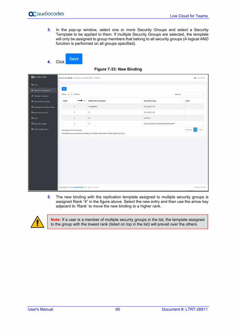
3. In the pop-up window, select one or more Security Groups and select a Security Template to be applied to them. If multiple Security Groups are selected, the template will only be assigned to group members that belong to all security groups (A logical AND function is performed on all groups specified).
4. Click .
Figure 7-33: New Binding
5. The new binding with the replication template assigned to multiple security groups is
assigned Rank “4” in the figure above. Select the new entry and then use the arrow key adjacent to ‘Rank’ to move the new binding to a higher rank.
Note: If a user is a member of multiple security groups in the list, the template assigned to the group with the lowest rank (listed on top in the list) will prevail over the others.

User's Manual 7. Editing Customers
Ver. 1.0.220 61 End Customers
7.4 Configuring Online Voice Routing The Online Voice Routing Policy screen allows you to define following polices: PSTN Usage (see below) Voice Routing Policy (see Section 7.4.2) Voice Route (see Section 0) PSTN Gateways (see note below and see Section 7.4.4) Normalization Rule Template (see Section 7.4.5) Dial Plan (see Section 7.4.5)
Note:
• A PSTN Gateway is not required on the customer tenant; instead only the derived trunk FQDN must be added to the voice routing policies of the users.
• As part of the Onboarding process, the solution creates a new Online Voice Routing policy (Default name ‘Unrestricted’, this can change per Provider).
7.4.1 PSTN Usage A container for voice routes and PSTN usages can be shared in different voice routing policies.
Figure 7-34: PSTN Usage
Live Cloud for Teams
User's Manual 62 Document #: LTRT-26811
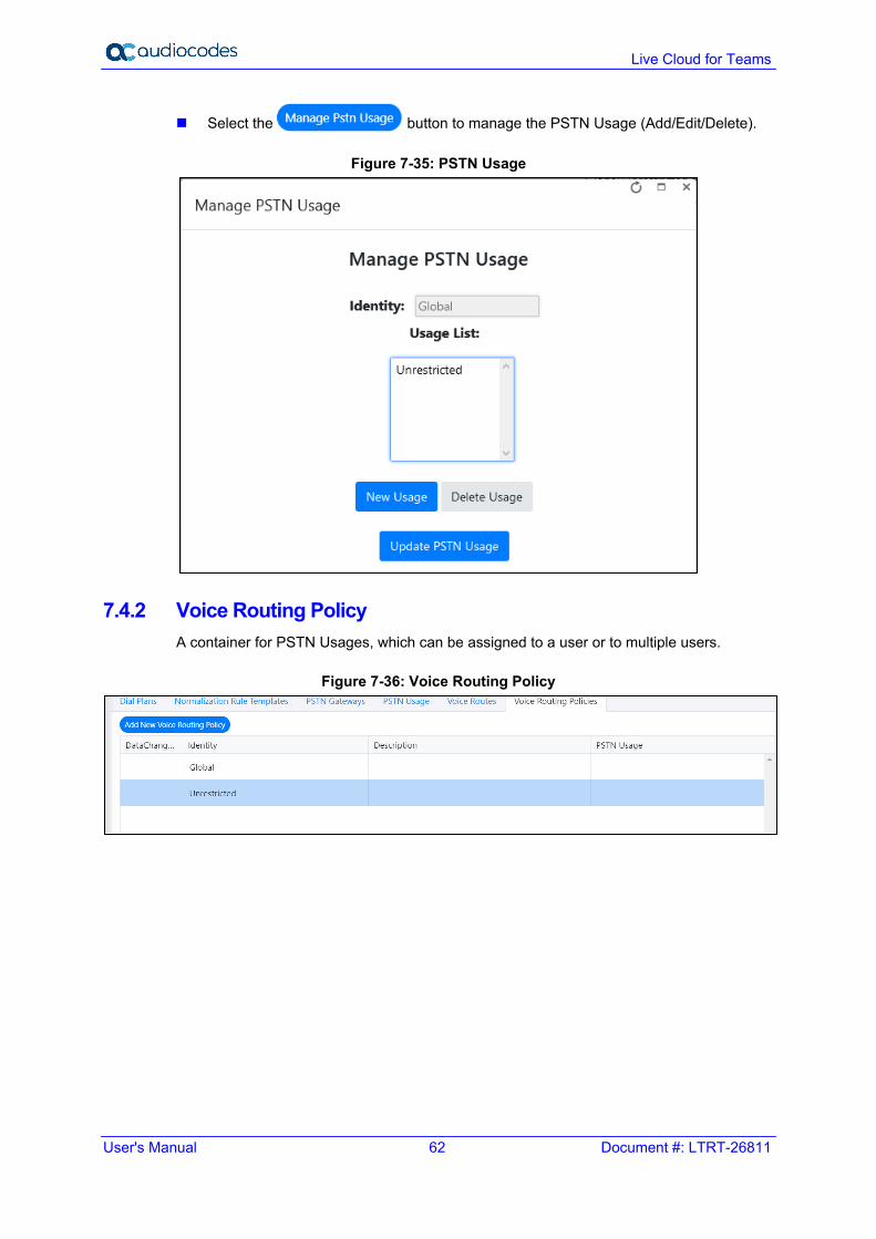
Select the button to manage the PSTN Usage (Add/Edit/Delete).
Figure 7-35: PSTN Usage
7.4.2 Voice Routing Policy A container for PSTN Usages, which can be assigned to a user or to multiple users.
Figure 7-36: Voice Routing Policy

User's Manual 7. Editing Customers
Ver. 1.0.220 63 End Customers
7.4.2.1 Adding Voice Routing Policy
Select the button to add a New Voice Route
Figure 7-37: Add New Voice Routing Policy
7.4.2.2 Edit Voice Routing Policy To edit Voice Routing Policy, select a Voice Routing policy, right-click the selection
and then select Edit Voice Routing Policy option.
Figure 7-38: Edit Voice Routing Policy Step 1

Live Cloud for Teams
User's Manual 64 Document #: LTRT-26811
Figure 7-39: Edit Voice Routing Policy Step 2
7.4.2.3 Delete/Cancel Voice Routing Policy To Delete (or Cancel) Voice Routing Policy, select one Voice Routing policy and then right-click on the selection. Select Delete Voice Routing Policy option and confirm at the pop-up Window.
Figure 7-40: Delete Voice Routing Policy
Figure 7-41: Edit Voice Routing Policy step 2

User's Manual 7. Editing Customers
Ver. 1.0.220 65 End Customers
7.4.2.4 Applying a Voice Routing Policy to a Group of Users By right clicking a Voice routing policy, the policy can be applied to all users within the Microsoft 365 environment or to a subset of users based on a security group membership:
Figure 7-42: Apply Voice Routing Policy to a Group of Users
7.4.3 Voice Route A number pattern and set of online PSTN gateways to use for calls where the calling number matches the pattern.
Figure 7-43:Voice Routes
To create a new Voice Route with a selection of assigned PSTN Usage records and
assigned PSTN Gateway (Hosting solution - derived trunk FQDN), click to add new Voice Route in the Voice.

Live Cloud for Teams
User's Manual 66 Document #: LTRT-26811
Figure 7-44: Add New Voice Route
The Voice Routing decisions are made top-down, so the table should be prioritized by using the green arrow buttons or Drag and Drop to make sure that a proper route is chosen if multiple routes to the same destination exist. Voice Routing Policies will be assigned to subscribers, allowing them to reach certain destinations based on the PSTN Usage record that is assigned within the policy.
7.4.4 PSTN Gateways A pointer to an SBC that also stores the configuration that is applied when a call is placed through the SBC, such as forward P-Asserted-Identity (PAI) or Preferred Codecs; can be added to voice routes. For the Hosting model ( Microsoft Super Trunk), only the Carriers need to set up and manage a single trunk (carrier trunk in the carrier domain). For the customer tenant, the carrier needs to only add the derived trunk FQDN to the voice routing policies of the users. There is no need to create a New PSTN Gateway for a Customer trunk.
7.4.5 Dial Plan & Normalization Rules A dial plan is a named set of normalization rules that translate phone numbers dialed by an individual user into an alternate format (typically E.164) for purposes of call authorization and call routing. Each dial plan consists of one or more normalization rules that define how phone numbers are expressed in various formats and are translated to an alternate format. Normalization rules define how phone numbers expressed in various formats are to be translated. The same number string may be interpreted and translated differently, depending on the locale from which it is dialed. Normalization rules may be necessary if users need to be able to dial abbreviated internal or external numbers.
Note: If Dial Plans have been created in Microsoft 365 using PowerShell before Live Cloud for Teams has been installed, the normalization rules that are assigned to it will not be shown in the Normalization Rule Templates in this version. Only templates that are created using before Live Cloud for Teams are displayed.
User's Manual 7. Editing Customers
Ver. 1.0.220 67 End Customers
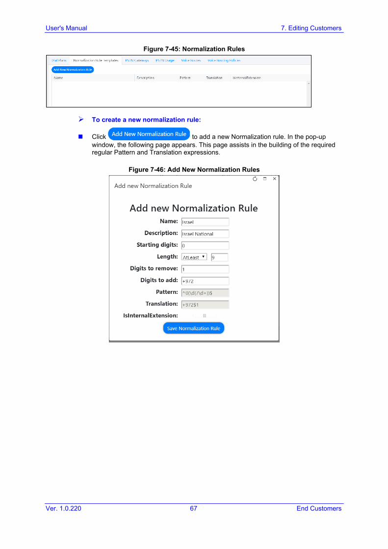
Figure 7-45: Normalization Rules
To create a new normalization rule:
Click to add a new Normalization rule. In the pop-up window, the following page appears. This page assists in the building of the required regular Pattern and Translation expressions.
Figure 7-46: Add New Normalization Rules

Live Cloud for Teams
User's Manual 68 Document #: LTRT-26811
Normalization Rule Templates can be assigned to new or existing Dial Plans by double-clicking the normalization rule from the Normalization Rules section in the new or Edit Dial Plan screens. If multiple rules exist, they can be ordered by either using the green arrow buttons or by Drag-and-Drop, by placing one rule above or below the another.
Figure 7-47: Dial Plan

User's Manual 7. Editing Customers
Ver. 1.0.220 69 End Customers
To add Normalization Rules to New Dial Plan:
Click to add a new dial plan.
Figure 7-48: Add New Dial Plan
To add Normalization Rules to an existing Dial Plan: 1. Select a Dial Plan, right-click the selection, and then select Edit.
Figure 7-49: Select Dial Plan

Live Cloud for Teams
User's Manual 70 Document #: LTRT-26811
2. In the pop-up window, add Normalization Rules to the Dial Plan.
Figure 7-50: Edit Dial Plan
If multiple rules exist, they can be ordered by either using the green arrow buttons or by Drag- and-Drop, by placing one rule above or below the other.

User's Manual 7. Editing Customers
Ver. 1.0.220 71 End Customers
7.5 Reserving Customer Phone Numbers You can reserve a phone number from the DID Range to assign to a specific user. When the phone number is reserved, it is not allocated in the automatic assignment as shown in Section 7.3.1.
To configure a reserved number range: 1. Click the Reserved Numbers tab. The Reserved Numbers screen is displayed.
Figure 7-51: Reserved Numbers
2. Click to add a new record. 3. Add the required fields and click Save Changes to add the new record.
Figure 7-52: Reserved Number

Live Cloud for Teams
User's Manual 72 Document #: LTRT-26811
7.6 Audit and Roll Back Historical Changes Live Cloud for Teams includes tracking for changes made by administrators. Under Audit, all changes performed are shown and can be reverted by right-clicking a line. If multiple changes were performed in one action, a list is shown with the changes, where the appropriate change can be selected. Select the entry for the change that you wish to rollback
and click to roll back to the previous value.
To view audit history and perform rollback: 1. In the Navigation pane, select the Audit tab. The Audit History is displayed.
Figure 7-53: Audit History
2. Right-click an entry and click to undo the policy update for selected user.
Figure 7-54: Rollback
3. Choose the specific fields that you wish to rollback and then click .

User's Manual 7. Editing Customers
Ver. 1.0.220 73 End Customers
7.7 Queued Changes You can view the queue for all actions including those that have been executed and those in waiting.
To view queued changes: 1. In the navigation pane, select Queued Changes. A list of updates is displayed.
Figure 7-55: Queued Changes
2. Hover over a specific column to view a callout of the text in the selection (this is useful
when text is too detailed to be easily read in the initial view) as is shown in the example screen below. You can also Drag-and-Drop to group by a specific column.
Figure 7-56: Queued Changes Entry Tooltip

Live Cloud for Teams
User's Manual 74 Document #: LTRT-26811
3. Use the table below as a guide to the actions available in this screen.
Table 7-32: Queued Actions
Action Description
Show all actions, including both executed and non-executed.
Show all executed actions.
Show the latest actions.
Process all actions.
Delete selected actions.
Delete all actions.

User's Manual 7. Editing Customers
Ver. 1.0.220 75 End Customers
7.8 Office 365 Setting You can update Microsoft 365 connection credentials and also configure whether the logged in operator logs in with Token authentication or with username/password.
To update Microsoft 365 connection credentials: 1. In the navigation pane, select O365 Configuration.
Figure 7-57: Office 365 Settings (Hosted Pro Login)

Live Cloud for Teams
User's Manual 76 Document #: LTRT-26811
Figure 7-58: O365 Settings (Hosted Essentials + Login)
Figure 7-59: O365 Settings

User's Manual 7. Editing Customers
Ver. 1.0.220 77 End Customers
2. Configuration the Microsoft 365 credentials as described in the table below:
Table 7-1: Office 365 Settings
Parameter Description
User Name Microsoft 365 UC Admin User (User with Teams Admin Credentials). Admin roles Teams Admin & Skype for Business Admin Optional: User admin to manage usernames
Password Microsoft 365 UC Admin Password.
Switch to auth token Enables you to login by sending link to customer IT administrator for authentication.
Override Admin Domain Customer Tenant original Microsoft 365 domain prior to applying vanity domain names (“example.onmicrosoft.com”)
Save Office 365 settings Saves the settings updated in this screen.
QOE Integration with Microsoft Teams
Azure Application ID The username for connecting to the Microsoft Teams Notification Service.
Azure Application password Application password for connecting to the Microsoft Teams Notification Service.
Save QOE Integration Settings Saves the QOE settings.

Live Cloud for Teams
User's Manual 78 Document #: LTRT-26811
7.9 Manage Site Locations This section describes how to manage multiple site locations. Once the onboarding wizard has added the M365 tenant and performed initial synchronization with Microsoft Teams, you can do the following: Onboard additional SBC devices for new sites (see Section 7.9.1) Add and edit SBC prefixes (see Section 7.9.2)
To manage site locations 1. In the Navigation pane, click Site Locations. You can also open this screen directly
from the Customer Actions menu.
Figure 7-60: Add SBC Site
The table below describes the site location parameters.
Table 7-2: Site Locations
Parameter Description
Site FQDN of the site location
SIP Address IP address of the site location.
Configuration Configuration type e.g. SIP Trunk (how is this field filled)
PSTN Gateway PSTN Online Gateway
SbcDeploymentState Indicates the SBC deployment state.
M365DeploymentState Indicates the M365 deployment state.

User's Manual 7. Editing Customers
Ver. 1.0.220 79 End Customers
Parameter Description
Notes Lists commands yet to be executed.
Actions Describes the specific actions that can be performed in the location: Add and edit SBC prefixes Import PBX users
7.9.1 Onboard SBC Devices You can provision additional SBC devices that are deployed in multiple sites locations. When selecting this option, you are redirected to the Onboarding wizard where customer credentials are automatically authenticated with Single Sign-on.
To onboard an SBC site:
1. From the Customer Actions drop-down list, select Edit Customer.
Figure 7-61: Edit Customer-Tenant Operator Login
The Self-service portal opens.
2. In the Navigation pane select Site Locations. 3. Click Add SBC Site to connect an SBC device deployed in a specific site.

Live Cloud for Teams
User's Manual 80 Document #: LTRT-26811
Figure 7-62: Add SBC Site (Hosted Pro Login)
Figure 7-63: Add SBC Site (Hosted Essentials +)
4. Click Next to continue. Credentials are validated and the Onboarding wizard opens.

User's Manual 7. Editing Customers
Ver. 1.0.220 81 End Customers
Figure 7-64: Configure Default Routing
5. Do one of the following:
• Configure M365 default routing: the wizard creates default routing in the customer tenant based on the derived trunk model for service providers and optionally configures DNS server.
• Click Next and proceed to Step 7.
Figure 7-65: Configure M365 Default Routing

Live Cloud for Teams
User's Manual 82 Document #: LTRT-26811
Figure 7-66: DNS Zone
6. Configure parameters as described in the table below and then click Next.
Table 7-3: M365 Default Routing
O365 Setting Description
Click here to Provision M365 Domain and DNS Automatically
Support Service Providers that use Azure DNS.
Online PSTN Gateway
See above
M365 Onboarding Script
Preconfigured script that is prepared by Professional services and that can be
customized by setting Customer Variables. Click the to edit the Onboarding script file. For example, when a service provider needs a separate registration per customer tenant.
M365 Cleanup Script
Preconfigured script that is prepared by Professional services and that can be
customized by setting Customer Variables. Click the to edit the Cleanup script file.
Customer Variables
Script variables can be customized and loaded to the M365 Onboarding and Cleanup scripts.
DNS
DNS Zone Indicates the DNS zone.
SBC Site Name The wizard uses the customer ID, for example customers.finebak.com to provision a new service provider subdomain to be used as the voice routing domain for the customer.

User's Manual 7. Editing Customers
Ver. 1.0.220 83 End Customers
Figure 7-67: Configure SBC with Default Routing
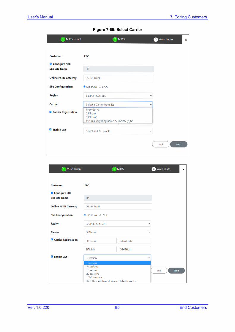
7. Configure parameters as described in the table below.
Table 7-4: Direct Routing Configuration
O365 Setting Description
Configure SBC Select check box if you wish to configure the SBC.
SBC Site Name Name of the SBC site location.
Online PSTN Gateway
Unique subdomain name per M365 Tenant (CSOnlinePSTNGateway –FQDN) which represents the desired host name added for the carrier trunk. This name must be preconfigured on the M365 Tenant Domain or via DNS provisioning.
SBC Configuration Select one of the following SBC configuration modes: • SIP Trunk • IP-PBX • BYOC
Region Select the required SBC device according to site location IP address.

Live Cloud for Teams
User's Manual 84 Document #: LTRT-26811
O365 Setting Description
Carrier This option is available If you selected SIP Trunk or BYOC for SBC Configuration above. The selected carrier binds to the configured SIP Interface, Proxy Set and IP Profile on the SBC (where the same name is configured for all three entities on the SBC).
Carrier Registration Select this option to perform SIP Account Registration for the Carrier trunk: • Username: Defines the digest MD5 Authentication username. The valid
value is a string of up to 60 characters. By default, no value is defined. • Password: Defines the digest MD5 Authentication password. The valid
value is a string of up to 50 characters. Note: The password cannot be configured with wide characters.
• MainLine (Contact User): Defines the AOR username. This appears in REGISTER From/To headers as ContactUser@HostName
Host Name: Defines the Address of Record (AOR) host name. The host name appears in SIP REGISTER From/To headers as ContactUser@HostName.
Enable CAC Enable Call Admission Control (CAC). From the drop-down list, select the desired CAC Profile including the desired number of call sessions.
Figure 7-68: Select Region
User's Manual 7. Editing Customers
Ver. 1.0.220 85 End Customers
Figure 7-69: Select Carrier

Live Cloud for Teams
User's Manual 86 Document #: LTRT-26811
8. Click Next to continue.
Figure 7-70: SBC Number Prefixes
9. Define a prefix number range by either by uploading a CSV file or by entering specific number prefixes.
Figure 7-71: Add Individual Prefixes

User's Manual 7. Editing Customers
Ver. 1.0.220 87 End Customers
Figure 7-72: Load CSV Prefix File
Table 7-5: Load Prefix Files
Setting Description
Update from CSV
Browse to load a CSV file containing a range of telephone prefixes.
Telephone Number Prefix
Enter a specific telephone number prefix.
Note: A Dial file xxxname must be preconfigured on the SBC or IP-PBX for applying this configuration.
Figure 7-73: SBC Scripts

Live Cloud for Teams
User's Manual 88 Document #: LTRT-26811
10. Click the to edit the SBC Onboarding Script file. This is a Preconfigured script that is prepared by Professional services and that can be customized by setting Customer Variables.
11. Click the to edit the SBC Cleanup Script file. Each SBC Onboarding script file has a corresponding Cleanup script file to restore the configuration to their original settings. This is a Preconfigured script that is prepared by Professional services and that can be customized by setting Customer Variables.
12. Script variables can be customized and loaded to the SBC Onboarding and Cleanup scripts above.
13. When you have completed the configuration, click . The following screen is displayed:
Figure 7-74: Configuration Complete

User's Manual 7. Editing Customers
Ver. 1.0.220 89 End Customers
7.9.2 Configure SBC Prefixes This section describes how to configure SBC prefixes for specific sites.
To configure SBC prefixes:
1. From the Customer Actions drop-down list, select Edit Customer.
Figure 7-75: Edit Customer-Tenant Operator Login
The Self-service portal opens. 2. In the Navigation pane select Site Locations. 3. Chose the site for which you wish to configure prefixes.
Figure 7-76: Add and Edit SBC Prefixes (Hosted Essentials Login)

Live Cloud for Teams
User's Manual 90 Document #: LTRT-26811
Figure 7-77: Add and Edit SBC Prefixes (Hosted Pro Login)
4. Click Add/Edit SBC Prefixes.
Figure 7-78: SBC Prefixes
5. Browse to choose a prefix file to upload or enter the desired prefixes to configure and
then click . The configured prefixes are displayed.
6. Click to apply configuration.

User's Manual 8. Browser Setting - IETF SameSite Cookie Attribute
Ver. 1.0.220 91 End Customers
8 Browser Setting - IETF SameSite Cookie Attribute Due to the introduction of the IETF SameSite cookie attribute, default browsers addressing the UMP web pages using the http protocol requires to disable this new default behavior in the browser to prevent an access denied message. These problems do not occur when https is used and properly configured. The following describes the steps required to prevent this issue for each respective browser: Chrome:
1. Go to: "chrome://flags/#cookies-without-same-site-must-be-secure" 2. Disable option "Cookies without SameSite must be secure" 3. Restart Chrome.
Figure 8-1: Chrome Setting
Edge:
1. Go to: "edge://flags/#same-site-by-default-cookies“ 2. Disable option "SameSite by default cookies" 3. Restart Edge.
Figure 8-2: Edge Setting

Live Cloud for Teams
User's Manual 92 Document #: LTRT-26811
Firefox: (works for version 75 and above): 1. In the URL bar, navigate to about:config. (accept the warning prompt, if shown).
Figure 8-3: FireFOX Setting - about:config
2. Type SameSite into the “Search Preference Name” bar. 3. Set network.cookie.sameSite.laxByDefault to false using the toggle icon. 4. Set network.cookie.sameSite.noneRequiresSecure to false using the
toggle icon. 5. Restart Firefox.
Figure 8-4: FireFOX Setting
Note: Public Customer/ Channel URL Portal, require secure connection (HTTPS) as default (Mandatory requirement), Channel and Customer Admin will not need to edit the browser setting IETF SameSite cookie attribute.

Part II Monitoring and Reporting


User's Manual 9. Monitoring Alarms from Customer Sites
Ver. 1.0.220 95 End Customers
9 Monitoring Alarms from Customer Sites This chapter describes how to monitor alarms that have been retrieved from Customer sites.
9.1 Active Alarms The Active Alarms page displays all alarms for managed Customers. Management includes performing actions such as deleting, acknowledging and saving alarms to file, as well as monitoring active alarms in the network to determine network health.
Figure 9-1: Active Alarms
Use the following table as a reference.
Table 9-1: Active Alarms
Parameter Description
Severity Indicates the alarm severity.
Received Date and
Time
Indicates the date and time when the alarm was raised.
Entity Name Indicates the name of the managed entity upon which the alarm was raised.
Source Indicates the source management object upon which the alarm was raised.
Name Indicates the SNMP alarm name.
Description Indicates the alarm text description.

User's Manual 96 Document #: LTRT-26811
Live Cloud for Teams
The Active Alarms Details pane displays detailed SNMP information for the alarm.
Figure 9-2: Alarm Details
User's Manual 9. Monitoring Alarms from Customer Sites
Ver. 1.0.220 97 End Customers
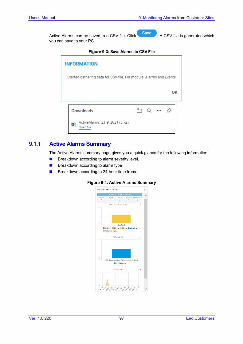
Active Alarms can be saved to a CSV file. Click . A CSV file is generated which you can save to your PC.
Figure 9-3: Save Alarms to CSV File
9.1.1 Active Alarms Summary The Active Alarms summary page gives you a quick glance for the following information: Breakdown according to alarm severity level. Breakdown according to alarm type Breakdown according to 24-hour time frame
Figure 9-4: Active Alarms Summary

User's Manual 98 Document #: LTRT-26811
Live Cloud for Teams
9.2 History Alarms The History Alarms page displays an archive of all previously raised alarms. Once an active alarm is cleared, its moved from the Active Alarms table to the History Alarms table. History Alarms can be saved to an external file. History Alarms can be saved to a CSV file.
Figure 9-5: History Alarms
9.3 Alarms Filtering For filtering by Time Range, see Section 5.1. For filtering by Severity, see Section 9.3.1 For filtering by More Filters, see Section 9.3.2

User's Manual 9. Monitoring Alarms from Customer Sites
Ver. 1.0.220 99 End Customers
9.3.1 Filtering by 'Severity' The 'Severity' filter applies to the pages under the Alarms menu: Active, Journal and History pages.
Figure 9-6: Alarm 'Severity' Filter
Click ALL to select all check boxes Click CLEAR to clear selection Click INVERT to select all check boxes that have not been selected and clear those
that are currently selected.

User's Manual 100 Document #: LTRT-26811
Live Cloud for Teams
Use the following table as reference.
Table 9-2: Severity Filter
Filter Description
Critical Select to display entities whose alarm severity level is critical, color coded red.
Major Select to display entities whose alarm severity level is major, color coded orange.
Minor Select to display entities whose alarm severity level is minor, color coded yellow.
Warning Select to display entities whose alarm severity level is warning, color coded blue.
Indeterminate Select to display entities whose alarm severity level is indeterminate, color coded black.
Clear Select to display entities whose alarm severity level is clear, color coded green.

User's Manual 9. Monitoring Alarms from Customer Sites
Ver. 1.0.220 101 End Customers
9.3.2 Filtering by 'More Filters' In the Active Alarms page, click Add Filter, choose More Filters and then from the
'Alarm Names' drop-down, select the filter. Use the following table as reference.
Table 9-3: More Filters – Alarms Active Page
Filter Description
Alarm Type
Select the 'Events' option for the page to display only alarms that are of type events.
Alarm Names
Enter the name of the alarm that you wish to display.
Sources Enter the name of the entity from which the alarm originated.
Figure 9-7: More Filters – Alarms Active Page

User's Manual 102 Document #: LTRT-26811
Live Cloud for Teams
9.3.2.1 Filtering by 'Type' The 'Type' filter augments existing filtering capability in the Alarms – Active page; you can filter the page for 'Only Alarms' or 'Only Events'.
To filter for 'Type': 1. In the Active Alarms page, click Add Filter, choose More Filters and then from the 'Type'
drop-down, select All, Only Alarms or Only Events.
Figure 9-8: Type Filter
2. View in the Active Alarms page, in the 'Name' column: 3. Bell icons if you filtered for 'Only Alarms' 4. Flag icons if you filtered for 'Only Events'
Figure 9-9: Type - Only Alarms - Bells in 'Name' Column

User's Manual 9. Monitoring Alarms from Customer Sites
Ver. 1.0.220 103 End Customers
9.3.2.2 Filtering by 'Alarm Names'
To filter by 'Alarm Names': In the Active Alarms page, click Add Filter, choose More Filters and then from the
Name drop-down, Select the desired alarms.
Figure 9-10: Alarm Name Filter
9.3.2.3 Filtering by 'Sources' You can filter a page using the 'Sources filter. The filter lets you display alarms according to the customer. In the Active Alarms page, click Add Filter, choose More Filters and then from the
Sources drop-down, Select the desired alarm sources.

User's Manual 104 Document #: LTRT-26811
Live Cloud for Teams
This page is intentionally left blank.

User's Manual 10. Monitoring Voice Quality Statistics from Customer Sites
Ver. 1.0.220 105 End Customers
10 Monitoring Voice Quality Statistics from Customer Sites The Statistics page summarizes call quality for the customer including Successful/Failed Calls, Maximum Concurrent Streams and the Streams Quality. The Statistics Summary pane lets you quickly assess the voice quality metrics and the call quality distribution for the deployed Customer.
To view statistics on calls over devices:
Figure 10-1: Provider Side Statistics
5. Select the Teams Side tab to display statistics for the connection with Microsoft Teams
(used for the Microsoft Calls Notification service)

User's Manual 106 Document #: LTRT-26811
Live Cloud for Teams
Figure 10-2: Teams Side Statistics
6. Select the AD User Locations tab to display statistics for the Active Directory
connection.
The page displays the following:
Metrics (see Metrics Bar Charts on the next page) Bar Charts (see below ) Statistics Summary (see Section 10.2)

User's Manual 10. Monitoring Voice Quality Statistics from Customer Sites
Ver. 1.0.220 107 End Customers
10.1 Metrics Bar Charts Three metrics / bar charts are displayed by default: Successful / Failed Calls chart shows the % and # of calls whose performance was
evaluated as successful or failed, distributed over time. The chart lets you assess calls performance at a glance. The chart shows when successful calls peaked compared to when failed calls peaked. You can compare this to other charts to identify correlations.
Max Concurrent Calls chart shows the maximum concurrent calls distributed over time. The chart shows when the maximum concurrent calls peaked compared to when they dipped. You can compare this to other charts to identify correlation. Max Concurrent Calls is the maximum number of calls opened at the same time in the server. Note that if you click a bar to open the Calls List page, the number of calls shown in the Calls List page might be different to the number shown in the graph; only calls that end within the time range are displayed in the Calls List page; if a call exceeds the time range, it won't be displayed in the Calls List page.
Calls Quality chart shows the distribution of voice quality (% and # of calls whose voice quality scored Good Fair or Poor) over time. Gray indicates 'Unknown' voice quality. Point the cursor over a color-coded bar segment in any time period to view this pop-up. The date and time indicates when the period has ended.
Compare charts. If, for example, you identify a correlation over time between 'Poor' voice quality and Jitter, then Jitter is the reason for the poor voice quality.
Utilization Distribution chart shows distribution of the media packets network utilization over time. A glance shows when a high rate (in Kbps) was received or transmitted (Rx/Tx rate in Kbps). The chart shows when a network is congested or uncongested, i.e., when voice quality scores may be lower. To view information on a time period, position the cursor over the bar representing the time period; the pop-up shows the date and time on which the period ended and the Rx / Tx rate in Kbps and the kilobits consumed per second during the time period.
Average Call Duration (ACD) chart shows distribution of ACD in the network over time. Point your mouse over a bar to determine average call duration in that time interval.
MOS chart. Point your mouse over a bar to determine the average MOS scored in that time interval.
Packet Loss chart. Point your mouse over the time axis to determine the average packet loss, as a percentage of the total number of packets sent, measured at that time.
Jitter chart. Point your mouse over the time axis to determine the average jitter measured at that time, in milliseconds.
Delay chart. Point your mouse over a bar to determine the average delay measured in that time interval, in milliseconds.
Echo chart. Point your mouse over the time axis to determine the precise average echo measured at that time, in DB.
Note: Values displayed in the charts are reported by devices for representation in Live Cloud for Teams. Sometimes when reported values are higher than expected, for example, packet loss might be higher than 100%, please contact Live Cloud for Teams support for clarification.

User's Manual 108 Document #: LTRT-26811
Live Cloud for Teams
10.2 Statistics Summary On the right side of the Customers Statistics page, you can view the Statistics Summary pane.
Figure 10-4: Statistics Summary
the total # of calls made over devices in the time period. the maximum concurrent calls measured over devices in the time period. the values of MOS, Jitter, Delay and Packet Loss quality metrics measured over devices
in the time period. The pane also displays two metrics as pie charts: Successful/Failed Calls pie chart. Point your mouse over a segment of the color-coded pie
chart to determine the # and % of calls that were evaluated as Successful or Failed in that time interval.
Quality Distribution pie chart. Point your mouse over a segment of the color-coded pie chart to determine the # and % of calls whose voice quality scored Good Fair or Poor in that time interval.

User's Manual 10. Monitoring Voice Quality Statistics from Customer Sites
Ver. 1.0.220 109 End Customers
10.3 Filtering For filtering by Time Range, see Section 5.1 For filtering by Metrics (see below) For filtering by Active Directory Location, see Section 11.2.1
10.3.1 Filtering by Metrics You can filter by voice quality metrics.
Figure 10-5: Voice Quality Metrics

User's Manual 110 Document #: LTRT-26811
Live Cloud for Teams
By default, the options shown in the figure above are selected. Select the check box metric that you wish to filter: Click ALL to select all check boxes. Click CLEAR to clear selection. Click INVERT to select all check boxes that have not been selected and clear those
that are currently selected.
User's Manual 11. Monitoring Calls
Ver. 1.0.220 111 End Customers
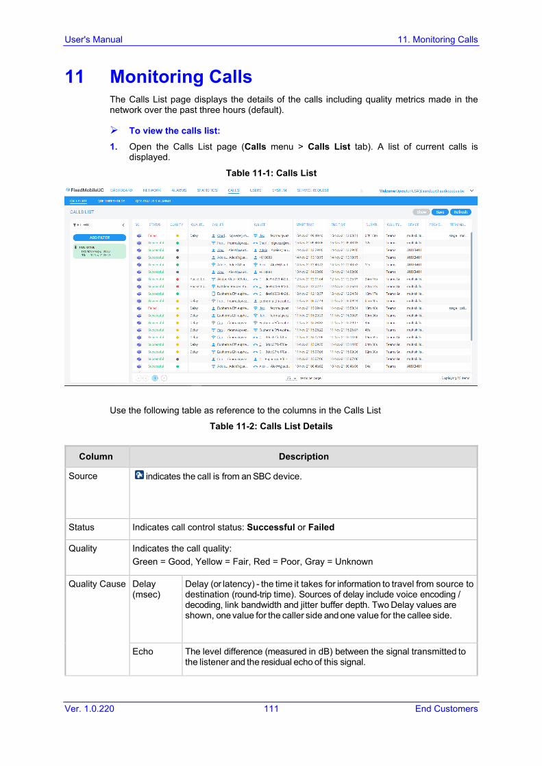
11 Monitoring Calls The Calls List page displays the details of the calls including quality metrics made in the network over the past three hours (default).
To view the calls list: 1. Open the Calls List page (Calls menu > Calls List tab). A list of current calls is
displayed.
Table 11-1: Calls List
Use the following table as reference to the columns in the Calls List
Table 11-2: Calls List Details
Column Description
Source indicates the call is from an SBC device.
Status Indicates call control status: Successful or Failed
Quality Indicates the call quality: Green = Good, Yellow = Fair, Red = Poor, Gray = Unknown
Quality Cause Delay (msec)
Delay (or latency) - the time it takes for information to travel from source to destination (round-trip time). Sources of delay include voice encoding / decoding, link bandwidth and jitter buffer depth. Two Delay values are shown, one value for the caller side and one value for the callee side.
Echo The level difference (measured in dB) between the signal transmitted to the listener and the residual echo of this signal.

User's Manual 112 Document #: LTRT-26811
Live Cloud for Teams
Column Description
Jitter (msec)
Jitter can result from uneven delays between received voice packets. To space packets evenly, the jitter buffer adds delay. The higher the measurement, the greater the impact of the jitter buffer’s delay on audio quality. Two Jitter values are shown, one value for the caller side and one value for the callee side.
MOS MOS - Mean Opinion Score (specified by ITU-T recommendation P.800) - the average grade on quality scales of Good to Failed, given to voice calls made over a VoIP network at the conclusion of the testing.
Packet Loss (%)
Lost packets - RTP packets that aren’t received by the voice endpoint for processing, resulting in distorted voice transmission. Two Packet Loss % values are shown, one value for the caller side and one value for the callee side. Packet Loss can be more than 100%.
None Indeterminate cause
Caller The phone number or address of the person who initiated the call.
Callee The phone number or address of the person who answered the call.
Start Time The precise time (hour, minutes and seconds) and date (month, day and year) when the call was started.
End Time The precise time (hour, minutes and seconds) and date (month, day and year) when the call was terminated.
Duration (sec) The duration of the call, in seconds. See the note following.
Call Type Indicates the call type.
Device Indicates the device/s over which the call passed.
Provider Side Indicates the Customer whose link/s (groups) over which the call passed.
Termination Reason
Indicates the reason why the call was terminated.
Note: An SBC call (exclusively) whose duration is longer than three hours (e.g., the session of a participant in a Teams conference call over an SBC) or an SBC call that is incompletely reported to the Live Cloud for Teams server, won't be displayed in the Calls List.
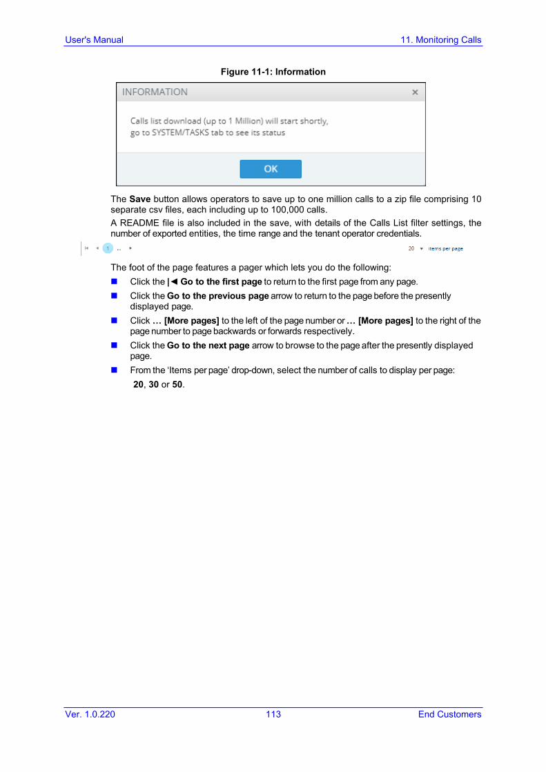
User's Manual 11. Monitoring Calls
Ver. 1.0.220 113 End Customers
Figure 11-1: Information
The Save button allows operators to save up to one million calls to a zip file comprising 10 separate csv files, each including up to 100,000 calls. A README file is also included in the save, with details of the Calls List filter settings, the number of exported entities, the time range and the tenant operator credentials.
The foot of the page features a pager which lets you do the following: Click the |◄ Go to the first page to return to the first page from any page. Click the Go to the previous page arrow to return to the page before the presently
displayed page. Click … [More pages] to the left of the page number or … [More pages] to the right of the
page number to page backwards or forwards respectively. Click the Go to the next page arrow to browse to the page after the presently displayed
page. From the ‘Items per page’ drop-down, select the number of calls to display per page:
20, 30 or 50.

User's Manual 114 Document #: LTRT-26811
Live Cloud for Teams
11.1 Call Details To display the details of a call, select a call whose details you wish to view and then click Show. The figures below display example call details.
Figure 11-2: Call Details

User's Manual 11. Monitoring Calls
Ver. 1.0.220 115 End Customers
To assess voice quality: Select a quality metric graph option (MOS, Jitter, Packet Loss, Delay and/or Echo) and
then select a leg; the graph displayed indicates: • The voice quality of the call for the selected quality metric across the selected leg • How long the leg lasted • The time the leg started and ended
Note: Legs over PSTN are not measured for quality, only legs over IP.

User's Manual 116 Document #: LTRT-26811
Live Cloud for Teams
11.2 Filtering For filtering by Time Range, see Section 5.1 For filtering by Active Directory User Location, see Section 11.2.1 For filtering by Source Type, see Section 11.2.2. For filtering by Quality, see Section 11.2.3 For filtering by More Filters, see Section 11.2.4
11.2.1 Filtering by ‘Active Directory User Location’ Figure 11-3: User Location

User's Manual 11. Monitoring Calls
Ver. 1.0.220 117 End Customers
11.2.2 Filtering by ‘Source Type’ Figure 11-4: Source Type
Choose one of the following options: Teams Side: Filter passing through the SBC call leg Provider Side: Filter calls passing through the Provider leg

User's Manual 118 Document #: LTRT-26811
Live Cloud for Teams
11.2.3 Filtering by 'Quality' You can filter a page using the 'Quality' filter. The filter applies to the Calls List page under the Calls menu. The filter lets you display calls according to quality.
Figure 11-5: Call Quality

User's Manual 11. Monitoring Calls
Ver. 1.0.220 119 End Customers
Table 11-3: Filtering by Quality
Filter Description
Failed | Success
Filters calls according to their status. If you clear Success and select Failed, only calls whose status was Failed are displayed in the page.
Poor, Fair, Good or Unknown
Filters calls according to their quality. If you clear all except Poor, only calls whose quality was Poor will be displayed.
None, MOS, Jitter, Delay, P. Loss or Echo
Filters calls according to the cause of the quality. If - after displaying only calls whose quality was poor/fair - you clear all except Delay, the page will display only calls whose quality was poor/fair because there was a delay on the line.
11.2.4 Filtering by 'More Filters' The Calls List page can be filtered using the 'More Filters' filter. This filter lets you display calls according to Callers, Callees, Caller/Callee Connection Types, Media Types, AC Termination Reasons and Teams Termination Reasons.
Figure 11-6: Additional Filters

User's Manual 120 Document #: LTRT-26811
Live Cloud for Teams
Use the following table as reference.
Table 11-4: Additional Filters – Calls List Page
Filter Description
Caller Enter the name of a caller (or the names of callers) whose calls you want to display in the page. The filter is case sensitive.
Callee Enter the name of a called party (or the names of called parties) whose calls you want to display in the page. The filter is case sensitive.
Caller Connection Types
One of the following call types: audio, video or screen sharing.
Media Type From the drop-down list, select the media type to display on the page (or enter a search string). Select one of the following: Application Sharing (a Teams media type), Audio, Audio V150 MSRP (Message Session Relay Protocol), Voice, Image, Data, Audio Video, Chat, Data, Image, MSRP, Screen Sharing, Text, Unknown, Video or All (and then optionally remove unwanted media types). By default, all media types are selected.
Call Type From the drop-down list, select the call type to display on the page, or enter a search string. Select one of the following: Endpoint, GW (Gateway), HTTP, IP2IP SBC, Skype, Skype Conference, Teams, Teams Group Call, Test SBC or All (and then optionally remove unwanted call types). Skype Conference can be of media type 'Audio Video' or 'Chat'. The conference participant's name is shown in the ‘Caller’ column. To retrieve conference calls information, the Live Cloud for Teams uses the Microsoft Teams ConferenceSessionDetailsView Monitoring Server report. For example, from the 'Media Type' drop-down choose Chat; the Media Type column then displays only MS Teams conferences whose Media Type is Chat.
Termination Reason
Enter the reason why the call was terminated. Some termination reasons are: Access Info Subs Class Incons Access Information Discarded Bc Not Authorized Bc Not Implemented Bc Not Presently Available Call Awarded And Call Having Call Id Cleared Call Id in Use Call Rejected Channel Type Not Implemented Channel Unacceptable Circuit Congestion Cug Inc Calls Barred Cug Non-Existent Cug Out Calls Barred Exchange Routing Error Facility Reject Identified Channel Not Exist Incompatible Destination Some MS Teams Termination Reasons are:

User's Manual 11. Monitoring Calls
Ver. 1.0.220 121 End Customers
Filter Description
OK. Indicates the request was successful. Accepted. Indicates that the request has been accepted for processing, but the
processing has not been completed. No Notification Multiple Choices Moved Permanently Moved Temporarily Use Proxy Alternative Service
Teams Termination Reason
Some MS Teams Termination Reasons are: OK. Indicates the request was successful. Accepted. Indicates that the request has been accepted for processing, but the
processing has not been completed. No Notification Multiple Choices Moved Permanently Moved Temporarily Use Proxy Alternative Service

User's Manual 122 Document #: LTRT-26811
Live Cloud for Teams
This page is intentionally left blank.
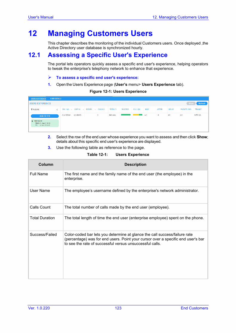
User's Manual 12. Managing Customers Users
Ver. 1.0.220 123 End Customers
12 Managing Customers Users This chapter describes the monitoring of the individual Customers users. Once deployed ,the Active Directory user database is synchronized hourly.
12.1 Assessing a Specific User's Experience The portal lets operators quickly assess a specific end user's experience, helping operators to tweak the enterprise's telephony network to enhance that experience.
To assess a specific end user's experience: 1. Open the Users Experience page (User’s menu> Users Experience tab).
Figure 12-1: Users Experience
2. Select the row of the end user whose experience you want to assess and then click Show;
details about this specific end user's experience are displayed. 3. Use the following table as reference to the page.
Table 12-1: Users Experience
Column Description
Full Name The first name and the family name of the end user (the employee) in the enterprise.
User Name The employee’s username defined by the enterprise's network administrator.
Calls Count The total number of calls made by the end user (employee).
Total Duration The total length of time the end user (enterprise employee) spent on the phone.
Success/Failed Color-coded bar lets you determine at glance the call success/failure rate (percentage) was for end users. Point your cursor over a specific end user's bar to see the rate of successful versus unsuccessful calls.

User's Manual 124 Document #: LTRT-26811
Live Cloud for Teams
Column Description
Call Quality Let’s you determine at glance end users calls whose voice quality was measured as Good (green), Fair (yellow) or Poor (red). Point your cursor over a specific end user's bar to see that specific end user's % of calls whose voice quality was measured as Good (green), Fair (yellow) or Poor (red).
MOS MOS - Mean Opinion Score (specified by ITU-T recommendation P.800) - the average grade on quality scales of Good to Failed, for voice calls made over a VoIP network at the conclusion of the testing.
Jitter Jitter (in msec) can result from uneven delays between received voice packets. To space packets evenly, the jitter buffer adds delay. The higher the measurement, the greater the impact of the jitter buffer’s delay on audio quality.
Delay Delay (or latency) (in msec) - the time it takes for information to travel from source to destination (round-trip time). Sources of delay include voice encoding / decoding, link bandwidth and jitter buffer depth.
Packet Loss Lost packets, as a percentage - RTP packets that aren’t received by the voice endpoint for processing, resulting in distorted voice transmission. Packet Loss can be more than 100%.
Description The end user's professional position in the enterprise.

User's Manual 12. Managing Customers Users
Ver. 1.0.220 125 End Customers
12.1.1 User Experience Details Select the row of the end user whose experience you want to assess and then click Show; details for the end user's experience are displayed.
Figure 12-2: User Experience Details
This screen is divided into the following panes: Contact Details: Displays personal Contact Details User Statistics: Displays a statistics summary for all calls made by the user Microsoft Teams/Skype for Business Attributes including:
• Skype Connection Details • Active Directory Organization unit • Assigned Plan • Site Location details • Microsoft Policies applied to the user • Telephony Policies applied to the user • Teams Policies applied to the user
A list of recent calls made by the user You can also do one of the following: Click Call to place a call to the user Click IM to send an instant chat message to the user Click Email to send an email to the user.
Note: This page displays specific information related to this end user's experience and is automatically dynamically tabbed on the menu bar as a pin (labeled A1_User in the page shown above) that facilitates quick and easy future access and troubleshooting management. Operators can delete the pin from the menu bar at any time.

User's Manual 126 Document #: LTRT-26811
Live Cloud for Teams
12.1.2 User Experience Filters For filtering according to time range, see Section 5.1 For filtering according to Active Directory User Location, see Section 11.2.1 For filtering according to More Filters, see below
12.1.2.1 Filtering According to More Filters The More Filters option allows you to filter according to the following: Attached tenants for the user Full Name of the user User’s Country location User’s work department The Line URI of the user
Figure 12-3: More Filters

User's Manual 12. Managing Customers Users
Ver. 1.0.220 127 End Customers
12.2 User Details Usernames and passwords of the Customers users are by default locally stored in the Live Cloud for Teams application's database. The User Details page allows operators to locally manage end users. The page mirrors the Customer Azure Active Directory. Any change to the AD is reflected in the User Details page immediately after synchronization is performed.
To manage end users: 1. Open the User Details page (Users menu> User Details tab).
Figure 12-4: User Details
View contact information regarding end users from under the columns in the table: Full Name, User Name, Description, Department, Office, Mobile, Home, Skype Line URI, Email, Customer (Customer), Server, Country.

User's Manual 128 Document #: LTRT-26811
Live Cloud for Teams
12.2.1 Viewing User Details Click Show to view details for a specific user.
Figure 12-5: Show User Details
This screen is divided into the following panes:
2. Contact Details: Displays personal Contact Details 3. User Statistics: Displays a statistics summary for all calls made by the user 4. Microsoft Teams/Skype for Business Attributes including:
• Skype Connection Details • Active Directory Organization unit • Assigned Plan • Site Location details • Microsoft Policies applied to the user • Telephony Policies applied to the user • Teams Policies applied to the user
5. A list of recent calls made by the user You can also do one of the following:
6. Click Call to place a call to the user 7. Click IM to send an instant chat message to the user 8. Click Email to send an email to the user.

User's Manual 12. Managing Customers Users
Ver. 1.0.220 129 End Customers
Click Edit Customer to open the full Users List on the Customer to which the selected user belongs.
Figure 12-6: M365 Users List

User's Manual 130 Document #: LTRT-26811
Live Cloud for Teams
12.2.2 User Details Filters For filtering according to Active Directory User Location, see Section 11.2.1 For filtering according to More Filters, see Section 12.1.2.1
Figure 12-7: Users Filter

User's Manual 12. Managing Customers Users
Ver. 1.0.220 131 End Customers
Use the following table as a reference.
Table 12-2: 'Users' Filter
Filter Description
Customers (Customers)
From the drop-down list, select a configured Customer. Only calls made by and received from users assigned to this Customer are displayed in the page.
User Locations Select a configured user location to retrieve a list of users for this location.
Tenants Select a configured Provider. Only calls made by and received from users assigned to that tenant will be displayed in the page.
Name Enter the name of a user. Only calls made by and received from that user will be displayed in the page.
Country Enter the name of a country. Only calls made and received by users in the specified country are displayed in the page.
Department Enter the name of a department in the enterprise. Only calls made and received by users in the specified department are displayed in the page.
Line URI Applies line URI for user.

User's Manual 132 Document #: LTRT-26811
Live Cloud for Teams
This page is intentionally left blank.

User's Manual 13. Running Reports
Ver. 1.0.220 133 End Customers
13 Running Reports Reports can be run for management analysis of call and voice quality data. Customers can run predefined reports for managed entities including Device and Link Monthly reports, Device and Link Monthly Aggregation reports and Top URI Monthly Element Reports. Reports include Element Statistics, Aggregated Statistics Trends and Trends Statistics Comparison. The following summarizes the types of reports that can be run (if predefined): Aggregation Providers Side Operator Reports Teams Side Reports Custom Reports Top URI Monthly Element Reports Trend Reports Reports can be scheduled to run hourly, daily, weekly or monthly. Reports can be imported and replicated. Report definitions can be saved to a JSON file and output can be saved to a PDF or CSV file.
To define a report: 1. Open the Reports page (Statistics menu > Reports tab > Reports folder). The Reports
page is displayed.
Figure 13-1: Customer Reports

User's Manual 134 Document #: LTRT-26811
Live Cloud for Teams
13.1 Viewing a Predefined Report You can view its definition and if necessary, make the required updates.
To view a defined report: 1. In the Reports page (Statistics menu > Reports tab > Reports), select the report whose
definition you want to view, and then click the View button.
Figure 13-2: Report
2. View the read-only parameter definitions under the tabs Definition, Filter, Table Layout
and Graphs View. Make a note of definitions that do not conform to your requirements.

User's Manual 13. Running Reports
Ver. 1.0.220 135 End Customers
13.2 Displaying Report Results After defining a report, the report can be run and displayed on your browser, and / or saved.
To run and display a report: 1. Open the Reports page (Statistics > Reports > Reports), select the report you want to run
and display, and then click Run; the Report Result is dynamically tabbed and displayed and an 'Execute Report Succeeded' message is momentarily displayed.
Figure 13-3: Report Result
2. Use the 'Report Details' pane on the right of the page for quick reference. You can see in
the preceding figure that this report is of type 'Aggregation'. 3. [Optionally] Click the x in the dynamic tab to remove the Report Result; you're returned to
the Reports page. 4. In the Reports page, optionally select another report and click Run; as with the previous
run, the Report Result is dynamically tabbed and displayed and an 'Execute Report Succeeded' message is momentarily displayed. Multiple Report Results can be dynamically tabbed facilitating comparative analysis.
5. [Optionally] Click the Save button located above the Report Details pane and select CSV or PDF from the drop-down to save the result as a file for distribution purposes.

User's Manual 136 Document #: LTRT-26811
Live Cloud for Teams
13.3 Element (Entity) Statistics' Report Type After defining a report of type 'Element (Entity) Statistics', it can be run and displayed in your browser as shown in the figure below.
Figure 13-4: 'Element (Entity) Devices Call Quality Report - Teams Side
Use the following to get acquainted: Indicates a predefined report integrated with Live Cloud for Teams; cannot be deleted
or edited
indicates a public report; anyone can view, edit and delete it 'Devices Calls Report' indicates the defined name of the report Each bar in the chart shows the value (values, if it's a stack chart) of the metric,
according to the chart legend: • Red = Failed calls / streams (as shown in the preceding figure) • Green = Successful calls / streams (as shown in the preceding figure)
The y axis shows number of calls The x axis shows each device's name The Report Details pane on the right displays among other details:
• the report category • the defined time period • the date and time the report was executed • the number of entities in the topology
The lowermost table columns show the following: • Provider name • element name • # of calls • % of calls • Success/fail ratio • total calls duration • average calls duration • # of established calls

User's Manual 13. Running Reports
Ver. 1.0.220 137 End Customers
• calls / streams quality ratio • maximum concurrent calls • # of voice calls • # of fax calls
Note: Colors of bars in a stack chart depend on metric name. In the preceding figure, for example, the metric name 'Success Calls / Streams Ratio' contains 'Success', so the stack chart is green.
• If the name of the metric contains 'Good' or 'Success', the stack chart will be green • If the name of the metric contains 'Fail', 'Bad' or 'Poor', the stack chart will be red • If the name of the metric contains 'fair', the stack chart will be yellow • If the name of the metric contains 'Unknown', the stack chart will be gray

User's Manual 138 Document #: LTRT-26811
Live Cloud for Teams
13.4 'Aggregated Statistics Trends' Report Type After defining a report of type 'Aggregated Statistics Trends', it can be run and displayed in your browser as shown in the figure below.
Figure 13-5: 'Aggregated Statistics Trends' Report
Use the following to get acquainted: indicates an administrator-defined report
indicates the report is public; anyone can view, edit and delete it
indicates the report is private and only authorized persons can view the report
indicates the currently logged in operator is the owner of the report 'Devices Calls Quality Aggregation Report' indicates the defined name of the report The bar chart indicates the number of voice calls made per time period The pie chart presents the same information differently; a glance reveals during which
time interval (segment) most calls were made; tooltips provide details The Report Details pane on the right displays among other details:
• the report category • the report interval • the date and time the report was executed • the number of entities in the topology
The lowermost table columns show among other details the time, # of calls, call quality metrics, etc.

User's Manual 13. Running Reports
Ver. 1.0.220 139 End Customers
13.5 Viewing a Snapshot of all Reports Statistics The Reports Summary page provides network administrators with a snapshot view of all statistics related to reports. The pane gives operators quick and deep insight into management accountability status.
Figure 13-6: Reports Summary

User's Manual 140 Document #: LTRT-26811
Live Cloud for Teams
The uppermost section of the pane displays the following: • the number of reports • the number of private reports • the number of scheduled reports
The middle section of the pane shows a table indicating the breakdown between the number of allocated and used reports (calculated according to the license totals).
The lower section of the pane shows a pie chart depicting how report types (Trend, Aggregation and Element) are distributed. Optionally, magnify the chart by clicking ; a full- screen view of the pie chart is then displayed; in the full-screen view, click to return to the pie chart in Summary Pane view. Hover your mouse over a segment of the pie. Use the preceding figure as reference; a popup indicates report type, # of reports of this type and the % of reports of this type. You can immediately determine for example for which report type most reports were run and for which least.
The lowermost section of the pane shows a pie chart depicting how report categories are distributed. Optionally magnify the chart by clicking ; a full-screen view of the pie chart is then displayed; in the full-screen view, click to return to the pie chart in Summary Pane view. Hover your mouse over a segment of the pie; a popup indicates report category, e.g., Devices Monthly Reports, # of reports in this category and the % of reports in this category. You can immediately determine for example in which report category most reports were run and in which least.

User's Manual 13. Running Reports
Ver. 1.0.220 141 End Customers
13.5.1 Report Scheduling The 'Report Scheduler' feature allows administrators to schedule call reports. A report can be scheduled for every hour, day, week or month, infinitely or for a specified number of times. The feature automates report generation, reducing administrator workload and providing built-in account- ability. By presenting information about IP network telephony performance and quality of experience over time, the feature facilitates longitudinal comparative analysis.
13.5.2 Viewing Schedulers and Reports Executed The scheduled reports page allows you to view report schedulers that have been configured and the reports that have been executed.
To view Report Schedulers: 1. Open the Scheduled Reports page (Statistics > Reports > Scheduled Reports).
Figure 13-7: Viewing Schedulers and Reports Executed by them
2. On the left side of the page, view the configured Report Schedulers. The table following
explains the columns on the left side of the page in which the Report Schedulers are listed.
Table 13-1: Viewing the Listed Report Schedulers
Column Description
Active Indicates whether the scheduled report is active or inactive. A scheduled report is activated or deactivated when it's added, by toggling the 'Active' switch in the Scheduler Report dialog.
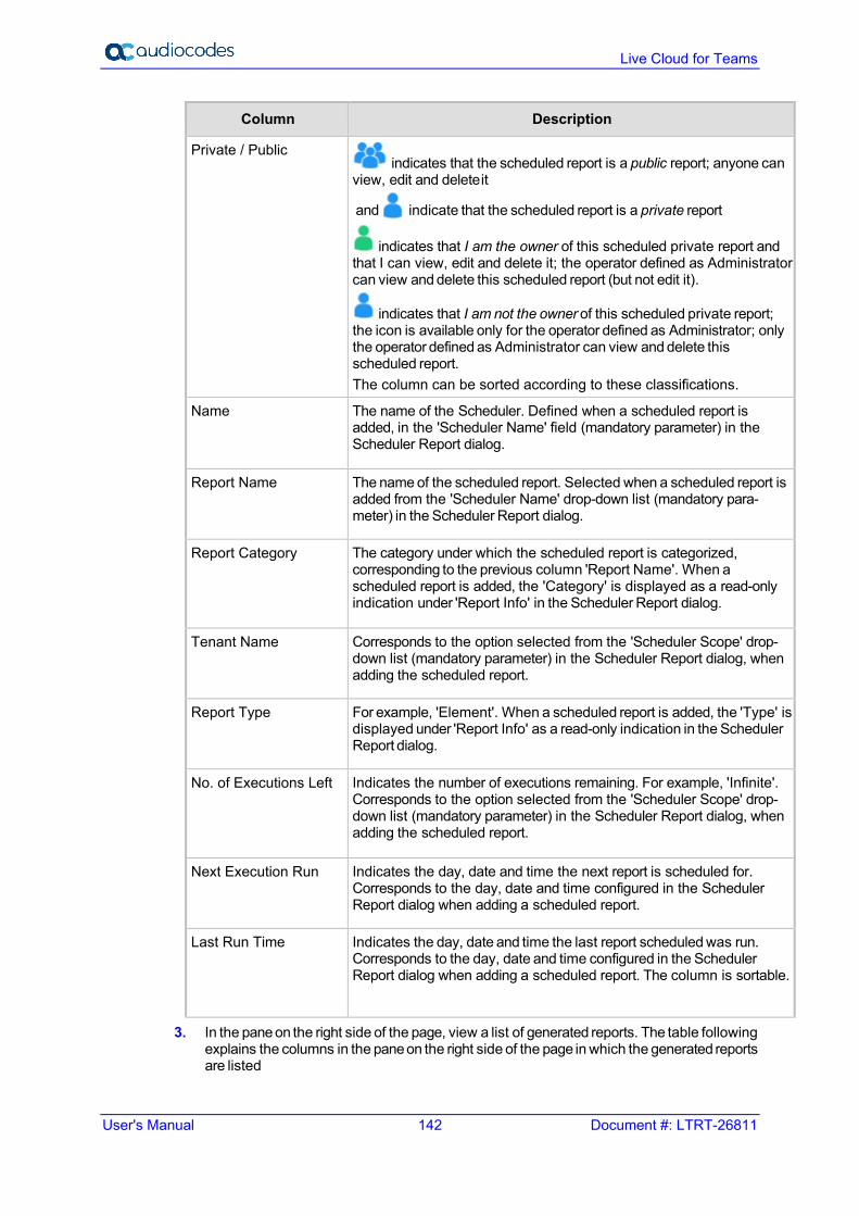
User's Manual 142 Document #: LTRT-26811
Live Cloud for Teams
Column Description
Private / Public indicates that the scheduled report is a public report; anyone can
view, edit and delete it
and indicate that the scheduled report is a private report
indicates that I am the owner of this scheduled private report and that I can view, edit and delete it; the operator defined as Administrator can view and delete this scheduled report (but not edit it).
indicates that I am not the owner of this scheduled private report; the icon is available only for the operator defined as Administrator; only the operator defined as Administrator can view and delete this scheduled report. The column can be sorted according to these classifications.
Name The name of the Scheduler. Defined when a scheduled report is added, in the 'Scheduler Name' field (mandatory parameter) in the Scheduler Report dialog.
Report Name The name of the scheduled report. Selected when a scheduled report is added from the 'Scheduler Name' drop-down list (mandatory para- meter) in the Scheduler Report dialog.
Report Category The category under which the scheduled report is categorized, corresponding to the previous column 'Report Name'. When a scheduled report is added, the 'Category' is displayed as a read-only indication under 'Report Info' in the Scheduler Report dialog.
Tenant Name Corresponds to the option selected from the 'Scheduler Scope' drop- down list (mandatory parameter) in the Scheduler Report dialog, when adding the scheduled report.
Report Type For example, 'Element'. When a scheduled report is added, the 'Type' is displayed under 'Report Info' as a read-only indication in the Scheduler Report dialog.
No. of Executions Left Indicates the number of executions remaining. For example, 'Infinite'. Corresponds to the option selected from the 'Scheduler Scope' drop- down list (mandatory parameter) in the Scheduler Report dialog, when adding the scheduled report.
Next Execution Run Indicates the day, date and time the next report is scheduled for. Corresponds to the day, date and time configured in the Scheduler Report dialog when adding a scheduled report.
Last Run Time Indicates the day, date and time the last report scheduled was run. Corresponds to the day, date and time configured in the Scheduler Report dialog when adding a scheduled report. The column is sortable.
3. In the pane on the right side of the page, view a list of generated reports. The table following explains the columns in the pane on the right side of the page in which the generated reports are listed

User's Manual 13. Running Reports
Ver. 1.0.220 143 End Customers
Table 13-2: Viewing the Listed Generated Reports
Column Description
Time Indicates the time of the day and the day of the month on which the report was generated, in the following format: DD-Month-YY HH:MM:SS
Name Indicates the name of the report. Tallies with the 'Report Name' column displayed in the left side of the Scheduled Reports page. The name is selected from the 'Scheduler Name' drop-down list (mandatory parameter) in the Scheduler Report dialog when a scheduled report is added. The column also displays the 'Report Type' (Element, in the figure below), Tenant / System, and the year / month / day / time.
File Type Indicates the type of file in which the report is formatted. CSV or PDF format. The column is sortable.
4. In the left side of the Scheduled Reports page, select a Report Scheduler; the pane on the right side of the page displays a list of reports executed by that scheduler.

User's Manual 144 Document #: LTRT-26811
Live Cloud for Teams
13.6 Adding a Report Scheduler This section describes how to add a new Report Scheduler.
To add a report scheduler: 1. In the Scheduled Reports page (Statistics > Reports > Scheduled Reports), click the
Add Report Scheduler button.
Figure 13-8: Add Report Scheduler

User's Manual 13. Running Reports
Ver. 1.0.220 145 End Customers
2. Configure a schedule using the table below as a reference.
Table 13-3: Report Scheduler
Column Description
Active Toggle the 'Active' switch to activate or deactivate the scheduler.
Scheduler Name Enter an intuitive, management friendly name for the scheduler.
Description Enter a description for the scheduler to facilitate management for other operators.
Report Name From the drop-down, select a report name. Scroll down to view the full list of options. Auto complete is also supported.
Scheduler Scope From the drop-down, select the relevant service provider for the scope of the scheduler to be for that specified tenant
Customer From the drop-down list, select the relevant customers of the selected service provider; this drop-down list is automatically filled according to the selected “Scheduler Scope” above.
Report Generation Period Select either Hourly (default), Daily, Weekly or Monthly. Determines how frequently reports will be generated. Select one of the following: Hourly then 'Minutes' will also be configurable. Daily then 'Hours' and 'Minutes' will also become configurable. Weekly then 'Days', 'Hours' and 'Minutes' will also become configurable. Monthly then 'Days', 'Hours' and 'Minutes' will also become configurable.

User's Manual 146 Document #: LTRT-26811
Live Cloud for Teams
Column Description
Repeat Select Infinite for the scheduler to run reports endlessly, without limitation; or Run, in which case the scheduler will by default generate the report 10 times. This value can be changed to suit individual requirements. After the nth time, the scheduler stops running and transitions to 'Disabled' state.
File to Save Select either None, CSV or PDF.
Max Number Of Files To Save
Defines the number of historical reports. Default: 60. If CSV or PDF is selected for the preceding parameter, the field is activated, and the default can be modified.
File to Send Select either None, CSV or PDF.
Mail To If CSV or PDF is selected for the preceding parameter, the 'Mail To' field is activated and a destination email address or multiple destination email addresses can be entered.
3. Click OK.
13.7 Editing a Scheduler You can edit a 'Report Scheduler'.
To edit a report scheduler: In the Scheduled Reports page (Statistics > Reports > Scheduled Reports), select
the scheduler to edit, and then click the Edit button. See Section 13.5.1 0 for more information.
13.8 Deactivate a Scheduler You can deactivate a 'Report Scheduler'.
To deactivate a report scheduler: In the Scheduled Reports page (Statistics > Reports > Scheduled Reports), select
the scheduler to edit, and then from the Actions drop-down list, select Deactivate.
Figure 13-9: Deactivate a Scheduler
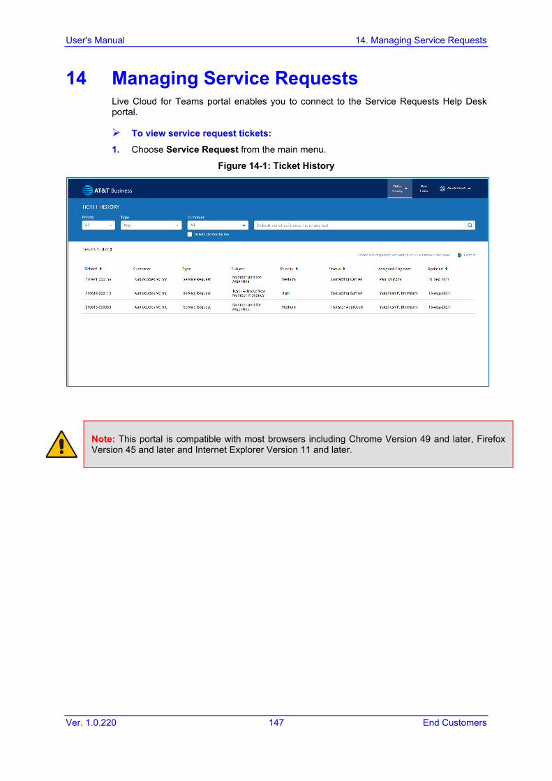
User's Manual 14. Managing Service Requests
Ver. 1.0.220 147 End Customers
14 Managing Service Requests Live Cloud for Teams portal enables you to connect to the Service Requests Help Desk portal.
To view service request tickets: 1. Choose Service Request from the main menu.
Figure 14-1: Ticket History
Note: This portal is compatible with most browsers including Chrome Version 49 and later, Firefox Version 45 and later and Internet Explorer Version 11 and later.

User's Manual 148 Document #: LTRT-26811
Live Cloud for Teams
14.1 Logging in to the Services Portal The Live Cloud for Teams portal enables you to connect to the Services portal to submit incidents and Service Requests.
To view service request tickets: 1. Choose Service Request from the main portal page.
Figure 14-2: Log in Screen
Note: This portal is compatible with most browsers including Chrome Version 49 and later, Firefox Version 45 and later and Internet Explorer Version 11 and later.
14.2 Viewing the Services Portal Home Page Upon login, the Home page appears on the screen. All open tickets are listed and can be sorted and searched. .
Figure 14-3: Ticket History Home Page Screen

User's Manual 14. Managing Service Requests
Ver. 1.0.220 149 End Customers
14.2.1 Ticket History To View closed tickets, select the Closed tickets option from Ticket History.
Figure 14-4: Ticket History
14.2.2 New Ticket Select this tab to create a new ticket.
14.3 Viewing Ticket History Figure 14-5: Viewing Ticket History
The Ticket History page provides a list of all the tickets opened by your organization as shown in the figure above. You can sort the tickets by specific fields: Ticket number ( yymmdd-xxxxxx) (sortable field) Customer - Typically identifies the name of your organization. If you are a Channel
Partner or Service Provider, you may see tickets for all customers with whom you are affiliated with and provide support to.
Type – Identifies the type of ticket: • Technical Assistance • Remote Monitor • Repair (RMA) • Advanced Hardware Replacement (AHR) • Dead on Arrival(DOA) • Managed Spares(MGSP)

User's Manual 150 Document #: LTRT-26811
Live Cloud for Teams
• On Site Spare Unit(OSSU) • Service Request
Subject – Provides a short description of the reported issue Priority – Indicates the priority of the issue Status – Identifies the current status of the ticket. Some of the most commonly used
statuses are listed below: • New: New ticket created and has not yet been assigned to an Engineer. • Awaiting Customer Approval: A solution/response has been reached and the
ticket can be closed. • Awaiting Customer Info: Additional information is required from you to advance
to the next level of troubleshooting. • On Hold: Ticket has been put on hold per customer request. • Closed: The issue has been fully resolved and the ticket is closed. • In Process: The support engineer assigned to the ticket is reviewing the details
of the ticket. • In Process_v: The ticket has been sent to R&D for further evaluation. • Updated by Customer: Status following a ticket update from you through the
service portal or email. • Updated by Support Engineer: Status following a ticket update from the
Support Engineer assigned via email. • Waiting for Fixed Version: A solution has been identified and a software release
is in process. • CCM Completed, Awaiting Approval: The change request submitted has been
completed and is awaiting customer approval to close. • Contacting Carrier: Service Request is being worked by the engineer assigned
and we are working with the carrier to complete your request. • Transfer Pending: Service Request submitted is being worked by the support
engineer and is pending carrier approval. • Transfer Approved: Transfer request has been approved by the carrier. • Transfer Complete: Transfer request has been completed. • DID Onboarding: Your request to enable the DIDs is in process.
Assignee: Identifies the assigned engineer for this ticket. Updated: Identifies the date the ticket was last updated.
Note: Please be advised that all times are displayed in US Eastern Time. Currently we do not have an option to display the time according to the various global time zones.

User's Manual 14. Managing Service Requests
Ver. 1.0.220 151 End Customers
The following features are also available on the Ticket History page: Search: Ticket History can be searched by Keyword, Status, Customer, Priority, and
Type, in order to find specific tickets for customers that have extensive ticket history. You can also search for the tickets that you have created.
Figure 14-6: Search Bar
Export: The displayed ticket history can be exported into a comma-separated (CSV) file spreadsheet for further customer exploration and reports.
Figure 14-7: Export
14.4 Creating New Tickets – Technical Assistance Create a Technical Assistance ticket for device operation, troubleshooting and software related questions and issues. To create a new ticket, click on the New Ticket tab from the Home page; the following page appears.
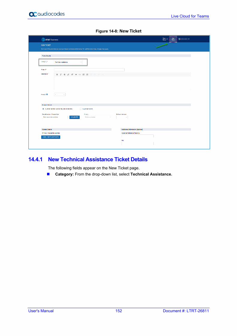
User's Manual 152 Document #: LTRT-26811
Live Cloud for Teams
Figure 14-8: New Ticket
14.4.1 New Technical Assistance Ticket Details The following fields appear on the New Ticket page. Category: From the drop-down list, select Technical Assistance.

User's Manual 14. Managing Service Requests
Ver. 1.0.220 153 End Customers
Figure 14-9: Technical Assistance Details
Subject: Enter a short description of the reported issue. Description: Use this field to accurately describe the problem summary. Provide Call
Flows, other devices, and all relevant information to help the assigned engineer understand the issue and assist with resolving the issue.
Priority: Choose from the following priorities. • Urgent:
♦ System is down ♦ Service is unavailable or severely degraded ♦ No work around exists
• High: ♦ Service is affected ♦ Partial outage ♦ Ability to administer the product is lost ♦ No workaround exists
• Medium: ♦ Calls are processing but there is an issue with a specific feature or function ♦ Ability to administer the product is affected ♦ Intermittent issue ♦ Workaround exists
• Low ♦ Service and/or performance is unaffected ♦ General question, information, documentation, or firmware request

User's Manual 154 Document #: LTRT-26811
Live Cloud for Teams
14.4.2 Product Details You can either enter the Serial Number or select the Product Name from the list. By Serial Number: Provide the Serial Number/Machine ID for your device when
opening the ticket as shown in the figure below. This enables us to validate your support entitlement for this device. The support coverage for the specific Serial Number will also be displayed on screen.
Figure 14-10: Serial Number
By Product Name: Use this option if you do not know the Serial Number of the
device. Without the Serial Number or Service Contract number, support may be limited, but please provide the product details as shown in the figure below. You will be able to submit a ticket without entering the Service Contract Number if you do not have the Service Order number available at the time of submitting the ticket.
Figure 14-11: Product Name
14.4.3 Contact Details Your login name and contact email should appear here. You can also add additional contacts from the existing customer database, or a new contact on a one-time basis for this ticket.
Figure 14-12: Contact Details
Additional Information
• Customer Reference Ticket No: You may enter your internal ticket reference number.
• Site: You may enter a site name or other site information for reference. Attachments: Please attach any configuration files and/or log files you might have to
the ticket before you submit the ticket. Files and Folder Operation: • Share: Creates a public link so public network users can see the file. • Upload: You can browse a folder and select files to be uploaded. • Create: You can create subfolders to help isolate new captures in new folders for
different dates.
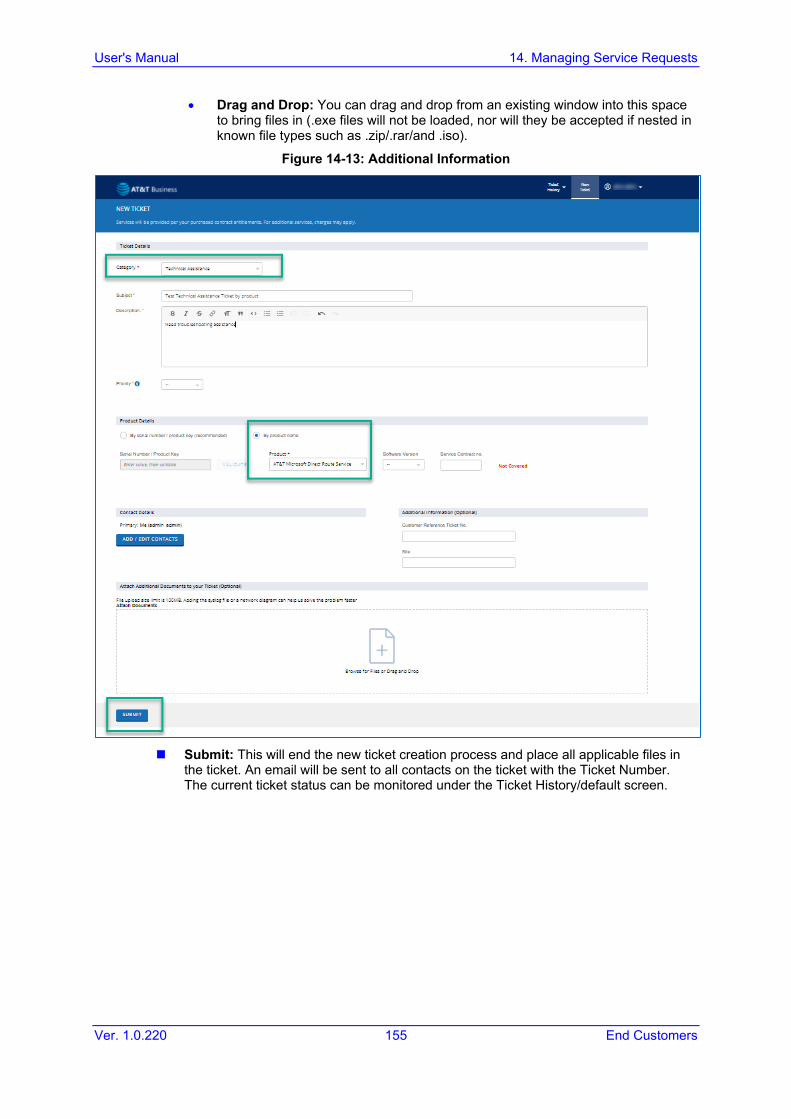
User's Manual 14. Managing Service Requests
Ver. 1.0.220 155 End Customers
• Drag and Drop: You can drag and drop from an existing window into this space to bring files in (.exe files will not be loaded, nor will they be accepted if nested in known file types such as .zip/.rar/and .iso).
Figure 14-13: Additional Information
Submit: This will end the new ticket creation process and place all applicable files in
the ticket. An email will be sent to all contacts on the ticket with the Ticket Number. The current ticket status can be monitored under the Ticket History/default screen.

User's Manual 156 Document #: LTRT-26811
Live Cloud for Teams
14.5 Creating New Tickets – Service Request Create a Hardware Service ticket for suspected hardware faults. From the Home page, click on the New Ticket tab and then Select the relevant Service Request ticket you want to create.
14.5.1 New Service Request Ticket Details This section describes how to open a new Ticket.
Do the following: 1. From the Category drop-down list, select Service Request.
Figure 14-14: New Service Request Ticket Details
2. Enter the relevant sub-level:
• Number Port Request • Activate New Number • Park/Unpark Number • Calling Plan Change • Request New User • Add DIDs to ARM • New Route/Change Route • Call Forwarding Request • Whitelist/Blacklist Number • Add New Device (MP/SBC/GW)

User's Manual 14. Managing Service Requests
Ver. 1.0.220 157 End Customers
Figure 14-15: Sub-level
3. Fill in the ticket details:
• Subject: Short description of the Service being requested. • Description: Use this field to accurately describe the type of Service Request. • Priority: Service Request tickets should be submitted with Medium Priority as
there is a lead time of 7 Days (minimum) to complete the request. • Country: Select the Country from the list • Location: Select the location of the site to which the number porting is requested
for. • Desired Date: Select the desired date for the port. • Count of DIDs: Enter numeric value for the number of DIDs being requested to
port. • Carrier: Enter the details of the losing carrier • Attachments: Attach the Porting template duly completed along with any other
required documents before you hit submit.
Figure 14-16: Contact Details

User's Manual 158 Document #: LTRT-26811
Live Cloud for Teams
14.6 Creating New Tickets – Hardware Service
14.6.1 New Hardware Service Ticket Details This section describes how to create a new hardware service ticket.
Do the following: 1. From the Category drop-down list, select Hardware Service.
Figure 14-17: Hardware Service
2. Enter the relevant sub-level:
• Repair (RMA): Devices that need to be returned for repair and then returned back to customer after repair. No replacement.
• Advanced Hardware Replacement (AHR): Devices that have a contract for replacement prior to return.
• Dead On Arrival (DOA): New devices that arrived on the site unworkable and need replacement.
• Managed Spares (MGSP): Devices that have managed spares services requiring replacement on site.
• On Site Spare Unit (OSSU): Devices that must be replaced as a spare after the main device has had a failure.
• Subject: Short description of the reported issue. • Description: Use this field to accurately describe the type of Hardware failure.
Provide details on the LED status, symptoms of HW failure and all relevant information to help the assigned engineer understand the issue and assist with processing the hardware service.
3. Priority: Choose from the following priorities. • Urgent:
♦ System is down ♦ Service is unavailable or severely degraded ♦ No work around exists

User's Manual 14. Managing Service Requests
Ver. 1.0.220 159 End Customers
• High: ♦ Service is affected ♦ Partial outage ♦ Ability to administer the product is lost ♦ No workaround exists
• Medium: ♦ Calls are processing but an issue exists with a specific feature or function ♦ Ability to administer the product is affected ♦ Intermittent issue ♦ Workaround exists
• Low: ♦ Service and/or Performance is unaffected ♦ General question, information, documentation, or firmware request
14.7 Product Details Serial Numbers: Please enter the Serial Number of your device in this box and click
“ADD”. This adds the Serial Number to the list of devices you would like to process the RMA, when opening the ticket. You can add up to 10 Serial Numbers separated by a comma (,) between the two serial numbers.
Figure 14-18: Serial Number - 1
The Support coverage for each Serial Number will also be displayed on screen after you click “ADD”.
Figure 14-19: Serial Number - 2

User's Manual 160 Document #: LTRT-26811
Live Cloud for Teams
14.7.1 Shipping Details Bill To Address: Select the Address from the list of the Bill To Company address. Bill To Contact: Enter the Name, Email Address and Phone number of the Bill To
contact. Ship To Address: Select the Address from the list of the Ship To Company address. Ship To Contact: Enter the Name, Email Address and Phone Number of the Ship To
contact.
Figure 14-20: Shipping Details – Adding Addresses from the list
One Time Ship To Address: If you would like to enter a One Time Ship To Address,
you can enter it by selecting “Other” in the “Ship To Address” field.
Figure 14-21: Shipping Details – Adding One Time Ship To Address
Note: Providing incomplete shipping details might delay the processing of the Hardware Service.

User's Manual 14. Managing Service Requests
Ver. 1.0.220 161 End Customers
14.8 Contact Details Your login name and contact email should appear here. You can also add additional contacts from the existing customer database, or a new contact on a one time basis for this ticket.
Figure 14-22: Contact Details
Additional Information
• Customer Reference Ticket No: You may enter your internal ticket reference number.
• Site: You may enter a Site Name or other site information for reference. NEXT: This moves the ticket to the next page where you can add attachments before
submitting the ticket.
Attachments: The Attachments screen will appear as shown in the figure below.
Figure 14-23: Attachments - 1
Submit: This will end the new ticket creation process and place all applicable files in
the ticket. An email will be sent to all contacts on the ticket with the Ticket Number. The current ticket status can be monitored under the Ticket History/default screen.

User's Manual 162 Document #: LTRT-26811
Live Cloud for Teams
14.9 Updating Existing Tickets Existing tickets can be updated by email or by logging in to the Services portal. Update via Email: Emails from the Services Portal can be replied to with new
attachments and updates. These upates will be included in the ticket. Please be mindful not to attach .exe files as these will not be processed.
Update via Services Portal: Click on a ticket you want to update from the list on your Home screen, and the following page will be displayed.
Figure 14-24: Existing Ticket Status
The Notes & Attachments tab allows you to add new notes to the ticket as well as
modify or add new attachments to the ticket. Additional Details: This tab provides basic information regarding the ticket. From
this page, you can modify the Contact Details and update the Additional Information fields. Once finished, click UPDATE.
Figure 14-25: Additional Details
Escalate: The Escalate button is accessible from the Update Ticket Notes and
Attachments page as well as the Additional Details page. You can use this to escalate a ticket to higher priority.

User's Manual 14. Managing Service Requests
Ver. 1.0.220 163 End Customers
This page is intentionally left blank.

International Headquarters 1 Hayarden Street, Airport City Lod 7019900, Israel Tel: +972-3-976-4000 Fax: +972-3-976-4040 AudioCodes Inc. 200 Cottontail Lane Suite A101E Somerset NJ 08873 Tel: +1-732-469-0880 Fax: +1-732-469-2298 Contact us: https://www.audiocodes.com/corporate/offices-worldwide website: https://www.audiocodes.com/ ©2021 AudioCodes Ltd. All rights reserved. AudioCodes, AC, HD VoIP, HD VoIP Sounds Better, IPmedia, Mediant, MediaPack, What’s Inside Matters, OSN, SmartTAP, User Management Pack, VMAS, VoIPerfect, VoIPerfectHD, Your Gateway To VoIP, 3GX, VocaNom, AudioCodes One Voice, AudioCodes Meeting Insights, AudioCodes Room Experience and CloudBond are trademarks or registered trademarks of AudioCodes Limited. All other products or trademarks are property of their respective owners. Product specifications are subject to change without notice. Document #: LTRT-26811